A307_2853_1300_ENQ_REV0.pdf - Tenders
351
Click on the Document Title to go to that section of the document Table of Contents Document Number Rev. Document Title Page Number A307-000-YF-MR- 2853-1300-RFQ 0 ENQUIRY DOCUMENT 2 A307-000-YF-MR- 2853 A Ultrasonic Flowmeters 102 A307-000-16-51- VDR-2853 0 VENDOR DATA REQUIREMENTS 107 A307-000-16-51-SIV- 2853 0 SPECIAL INSTRUCTION TO VENDOR 110 A307-000-YF-TQS- 2853 A TECHNICAL QUESTIONAIRE 117 A307-000-16-51-CF- 2853 1 COMPLIANCE FORMAT 118 A307-000-16-51-MD- 2853 0 DEVIATION LIST 120 A307-000-16-51-ID- 2853 0 DATASHEET INDEX AND DATASHEETS 121 A307-000-16-51- 0200 0 Installation Schematic for Flare gas Ultrasonic Flowmeter 166 A307-000-16-51- 0201 0 Process Ultrasonic Flowmeter with Spool Piece Schematic 167 A307-000-16-51- 0203 0 Ultrasonic Flowmeter Schematic (Insertion type) 168 A307-000-16-51-OD- 2853 0 UPSTREAM/DOWNSTREAM STRAIGHT LENGTH 169 6-52-0011 0 Standard Specification for Ultrasonic Flow Meter 171 6-52-0032 4 Standard specification for electronic / pneumatic instruments. 185 6-52-0042 3 Standard specification for thermocouples, RTDs and thermowells. 201 7-52-0035 3 Thermowell. 210 A307-000-16-51-MD- 0012 0 PIPING MATERIAL SPECIFICATION 213 A307-000-16-51-SP- 0016 0 JOB SPECIFICATION FOR NON-DESTRUCTIVE EXAMINATION REQUIREMENT OF PIPING 257 6-79-0013 1 Material requirements for carbon steel components used in sour service for petroleum refinery environments 277 A307-000-16-51-MD- 0010 0 Job Specifiaction for Surface Preparation & Protective Coating 283 6-78-0001 0 Specification for Quality Mgt. System Requirements from Bidders 331 6-78-0003 0 Specification for Documentation Requirement from Suppliers 340 Page 1 of 351
-
Upload
khangminh22 -
Category
Documents
-
view
1 -
download
0
Transcript of A307_2853_1300_ENQ_REV0.pdf - Tenders

Click on the Document Title to go to that section of the document
Table of ContentsDocument Number Rev. Document Title Page
NumberA307-000-YF-MR-2853-1300-RFQ
0 ENQUIRY DOCUMENT 2
A307-000-YF-MR-2853
A Ultrasonic Flowmeters 102
A307-000-16-51-VDR-2853
0 VENDOR DATA REQUIREMENTS 107
A307-000-16-51-SIV-2853
0 SPECIAL INSTRUCTION TO VENDOR 110
A307-000-YF-TQS-2853
A TECHNICAL QUESTIONAIRE 117
A307-000-16-51-CF-2853
1 COMPLIANCE FORMAT 118
A307-000-16-51-MD-2853
0 DEVIATION LIST 120
A307-000-16-51-ID-2853
0 DATASHEET INDEX AND DATASHEETS 121
A307-000-16-51-0200
0 Installation Schematic for Flare gas Ultrasonic Flowmeter 166
A307-000-16-51-0201
0 Process Ultrasonic Flowmeter with Spool Piece Schematic 167
A307-000-16-51-0203
0 Ultrasonic Flowmeter Schematic (Insertion type) 168
A307-000-16-51-OD-2853
0 UPSTREAM/DOWNSTREAM STRAIGHT LENGTH 169
6-52-0011 0 Standard Specification for Ultrasonic Flow Meter 1716-52-0032 4 Standard specification for electronic / pneumatic instruments. 1856-52-0042 3 Standard specification for thermocouples, RTDs and thermowells. 2017-52-0035 3 Thermowell. 210A307-000-16-51-MD-0012
0 PIPING MATERIAL SPECIFICATION 213
A307-000-16-51-SP-0016
0 JOB SPECIFICATION FOR NON-DESTRUCTIVE EXAMINATIONREQUIREMENT OF PIPING
257
6-79-0013 1 Material requirements for carbon steel components used in sourservice for petroleum refinery environments
277
A307-000-16-51-MD-0010
0 Job Specifiaction for Surface Preparation & Protective Coating 283
6-78-0001 0 Specification for Quality Mgt. System Requirements from Bidders 3316-78-0003 0 Specification for Documentation Requirement from Suppliers 340
Page 1 of 351

Page 1 of 7
EI Bhawan Annexe, Bhikaiji Cama Place, RK Puram, New Delhi – 110 066, INDIA
Phone No : 0091-11-26762121 ; Fax No : 0091-11-26191714, 26167664
REQUEST FOR QUOTATION (RFQ)
RFQ No. : SM/ A307-000-YF-MR-2853/1300 Date: 11–JUN-2014
Client : BHARAT PETROLEUM CORPN. LIMITED
Project: INTEGRATED REFINERY EXPANSION PROJECT AT KOCHI REFINERY
MR No.: A307-000-YF-MR-2853 Item: ULTRASONIC FLOWMETERS Due Date & Time: 10-JUL-2014 & Up to 1200 Hrs. (IST)
PRE-BID MEETING:
A Pre-bid conference will be held on 23-JUN-2014 at 1100
Hrs. (IST) at R&D Complex, Engineers India Limited, Gurgaon
UNPRICED BID OPENING:
At 1400 Hrs. (IST) on 10-JUL-2014 (at EIB - 5th Floor,
Engineers India Limited, Bhikaiji Cama Place, R.K. Puram,
New Delhi – 110066, India) (In case the bid due date happens to fall on Holiday, the next working day shall be deemed to be due date)
PRICED BID OPENING: TIME & VENUE SHALL BE INTIMATED LATER.
Gentlemen,
Bids are requested on behalf of our Client M/s Bharat Petroleum Corporation Limited on e-procurement system for the subject item in total compliance to technical specifications, scope, terms & conditions of enquiry documents / attachments.
1. Bidder should submit their bids strictly as per the requirements outlined hereunder and as specified in the material requisition.
2. The bidders are required to submit soft copies of their bids electronically on the CPP Portal only (URL: http://eprocure.gov.in/cppp) using valid Digital Signature Certificates, on or before the bid submission date and time. Bidders are required to register themselves at http://eprocure.gov.in/cppp).
Bidders to refer attached E-TENDERING METHODOLOGY (ANNEXURE-I) for detailed instructions on registration and online bid submission.
3. Special Notes for e-tendering:
a. NIC Portal mandates that the bidders are to be registered on the portal. The enquiry is being issued through EIL Tender Portal http://tenders.eil.co.in and Bidders can download the complete RFQ documents from the EIL Tender Portal only. And bidders shall submit their bids through NIC Portal
(https://eprocure.gov.in/eprocure/cppp) only. b. All those vendors who have still not registered on the NIC Portal are required to register on the same
(immediately after issue of enquiry on EIL Tender portal but not later than ten days before the bid due date) for facilitating uploading of their bids on the NIC Portal failing which it will not be possible for them to upload their bids. Pursuant to registration, the vendors are required to inform regarding NIC registration details.
Page 2 of 351

Page 2 of 7
c. Only NIC registered vendors can upload their bids on the NIC portal. Therefore, all those bidders who have not complied with the above registration requirements will not be eligible to bid. NIC registered bidders will be able to upload their bids from about one week before the bid due date up to Bid Due Date. However, an EIL enlisted vendor for the subject Limited RFQ who completes their NIC
Registration (including Digital Signature Certificate Registration) on NIC Portal atleast 2 (two) working
days prior to the Final Bid Due Date shall be allowed to upload their bids through a Corrigendum issued by EIL in the NIC Portal, provided such request from the concerned Vendor is received in EIL
through E-mail by concerned Dealing Officer/RFQ Issuing Authority at least 2 (two) working days prior
to Bid Due Date. Request for extension in due date of submission of bids due to non registration
or delayed registration in NIC portal shall not be entertained. d. The bid has to be necessarily submitted on the NIC Portal only. Inability of the bidders to upload their
bids on account of not completing the registration with NIC portal as mentioned above will not be a reason for seeking BDD extension.
e. Enlisted vendors of EIL who have completed the registration on NIC shall only be allowed to submit the
bids through NIC Portal. Therefore, it is in the interest of the bidders that they register on the NIC Portal at the earliest.
f. The vendor registration on NIC Portal is a very user friendly process. However, in case of any doubt,
the vendor may contact the 24 X 7 CPP Portal helpdesk at Contact No. 1800 3070 2232 or Mr. Amrit
Chaswal at Ph. No. +91-7532022483 / 011 2676 2073 and E-mail: [email protected].
4. Bidders in their own interest are requested to register on CPP Portal and upload/submit their bid well in time. Bidder will be responsible for any delay due to other issues.
5. Bidders are required to upload the complete bid comprising of Part-I:- Unpriced Bid along with all supporting documents & Part-II :- Priced Bid on the CPP Portal (http://eprocure.gov.in/cppp) only.- Refer E-Tendering Methodology (ANNEXURE-I) enclosed with RFQ documents.
6. Upon the successful and timely submission of bids, the portal will give a successful bid submission message & a bid summary will be displayed with the bid no. and the date & time of submission of the bid with all other relevant details. The bid summary has to be printed and kept as an acknowledgment of the submission of bid. This acknowledgment may be used as an entry pass for attending the un-priced bid opening, if bidders so desire.
7. Technical specification should be strictly as per the Material Requisition attached. It may be noted that the Bid shal be evaluated as received and technical queries may not be issued.
8. Commercial requirements are specified in the Special Instructions to Bidders, General Purchase Conditions, Agreed Terms & Conditions (ATC) questionnaire and all other RFQ documents. The pre-filled Agreed Terms & Conditions Questionnaire should be returned duly signed and stamped along with copy of your un-priced bid.
9. The order, if placed, will be issued by our above-mentioned client.
10. If not bidding, please inform vide E-mail with attached regret letter within the due date & time, with reasons(s) of not participating in the RFQ. In case there is no response, names of such bidder may not be considered for issuance of future enquiries.
11. Direct bids only, without the intermediary of an Indian Agent will be considered from Foreign Bidder.
12. Repeat Order is applicable to this RFQ / MR as per GPC.
13. Delivery Period:- FOR INDIAN BIDDERS: Within 8 Months on FOT Despatch Point Basis from the date of Fax of
Acceptance. Date of LR/GR shall be considered the date of delivery.
FOR FOREIGN BIDDERS: Within 7 Months on FOB International Sea Port of Exit Basis from the Date of Fax of Acceptance. Date of clean bill of lading shall be considered the date of delivery.
Page 3 of 351

Page 3 of 7
14. Payment Terms shall be as per following:- For Indian bidders: The payment to Indian bidders shall be made in accordance with S. No. 1.2,1.6 & 1.7 Under Section A of Special Instruction to Bidders (SIB). For Foreign Bidders: The payment to foreign bidders shall be made in accordance with S. No. 2.1 & 2.5 Under Section A of Special Instruction to Bidders (SIB).
The offer should be valid for 04 (FOUR) months from final bid due date.
15. Only E-Bids uploaded in the e-tendering portal (http://eprocure.gov.in/cppp) shall be acceptable. Physical bids and Bids/ Offer through Email or fax/ Telex/Telegraphic or Bids received in open condition or Bids in any other mode shall not be accepted.
13. The bidder shall bear all costs associated with the preparation and submission of its bid, and the Purchaser/Consultant shall in no case be responsible or liable for these costs regardless of the conduct or outcome of the bidding process.
14 . Canvassing in any form by the Bidder or by any other agency on their behalf may lead to disqualification of their bid.
15 . The E-bids received online shall be opened at EIL office on due date and time as specified above. Bidder can view online the name of the other bidders who have submitted their e-bids after opening is performed by EIL.
16 . All technically and commercially acceptable bidders will be advised of venue, date and time of priced bid opening. Bids shall be opened online, hence bidders may review opening status at their places. Interested bidder may sent their representatives (duly authorised by a competent person and having the Letter of Authority as per proforma enclosed), of such technically and commercially acceptable bidders. Time and Date of opening of Price Bids shall be notified to the qualified and acceptable bidders at a later date.
17 . As Purchaser intends to contract directly with suppliers of the goods for which bids are invited, the bids should be prepared by the suppliers and submitted directly. Purchaser reserves the right to reject offers made by intermediaries.
18 . Addendum / corrigendum to the RFQ documents if issued must be signed and submitted along with the bid.
19 . Bidders to note that price changes against Technical / commercial clarifications, in line with terms & conditions of enquiry documents are not allowed. In case any bidder gives revised prices / price implications against such clarifications, their bid shall be liable for rejection.
20 EIL reserves the right to use in-house information for assessment of bidder’s capability for consideration of bid.
21 In case any bidder is found to be involved in cartel formation, his bid will not be considered for evaluation / placement of order. Such bidder will also be debarred from bidding in future.
22 The bidder who is providing the technology from the company which is recently acquired / taken over by them or purchasing the technology by other companies, shall provide proper documentary evidence. In the absence of the same their offer shall be liable for rejection.
23 Bidders are requested to quote as per their capability as registered in EIL, as on the date of issue of RFQ.
24 Owner reserves its right to allow Public Sector Enterprises (Central/State), Micro & Small Enterprises (MSEs) and MSEs owned by Scheduled Caste (SC)/ Scheduled tribe (ST) entrepreneurs, purchase preference as admissible/applicable from time to time under the existing Govt. policy. Bidder to submit documentary evidence for the same duly certified by Statutory Auditor of the bidder or a practicing Chartered Accountant (not being an employee or a Director or not having any interest in the Bidder’s company / firm) where audited accounts are not mandatory as per law.). In this regard, item wise quantity may be splitted and the quoted price shall remain valid.
25 The Net Worth of the bidder should be positive as per the immediate preceding year's audited
Page 4 of 351
Page 4 of 7
financial results. If the bidder is not meeting the above criteria their bid shall not be evaluated further. Bidders are therefore requested to furnish the Audited Financial Statement for the immediate preceding year including Profit & Loss Account.
Bidders are required to submit the complete audited financial report for the preceding financial year including balance sheet, profit and loss statements along with all relevant annexures required to assess the positive net worth of the bidder in that financial year. Failure to submit the same may render your bid liable for rejection.
In place of complete Annual Financial Documents required for the assessment of the Net Worth, the bidder can provide a certificate from any Practicing Chartered Accountant or their Statutory Auditor in case of foreign bidders and from statutory auditor in case of indigenous bidders that their net worth is positive as per the last audited financial statement as per formula given in Annexure-II
26 PRE-BID MEETING
26.1 The bidder(s) or his official representative are invited to attend a Pre-Bid Meeting on 23-JUN-2014 at 1100 hours (IST) which will take place at R&D Complex, Gurgaon.
26.2 The bidder is requested to submit any questions by courier/fax/e-mail to reach EIL at least two working days before pre bid meeting. These questions shall be replied during the pre bid
meeting. 26.3 Record Notes including the test of the questions raised (without identifying the sources of the query) and the responses given will be transmitted to all bidders.
27 Purchaser reserve the right to make any changes in the terms and conditions of purchase and to reject any or all the bids.
Contact Persons for this RFQ are:
Mr Subhendu Mondal, AGM(C&P),
Phone No. +91-(0)11-2676-3883 & email: [email protected]
Mr L.Thavurya, Senior Manager (C&P),
Phone No. +91-(0)11-2676-3873 & email: [email protected]
Ms. Chandreyee M Das, Engineer (C&P),
Phone No. +91-(0)11-2676-3881 & email: [email protected]
Page 5 of 351

Page 5 of 7
* Please specify RFQ. No. SM/ A307-000-YF-MR-2853/1300 in all Correspondence.
THIS IS NOT AN ORDER Very truly yours, For & on behalf of
Bharat Petroleum Corporation Limited
(SUBHENDU MONDAL) ASST. GEN. MANAGER(C&P) ENGINEERS INDIA LIMITED Enclosure: As per List Attached
LIST OF ENCLOSURES
DOCUMENT
A) Request For Quotation (RFQ)
B) Proforma of Letter of Authority for Attending Un-priced / Priced Bid Opening
C) Price Schedule Format (For Indian Bidders)
D) Price Schedule Format (For Foreign Bidders)
E) Commercial document:
i) Agreed Terms & Conditions (For Indian Bidders)
ii) Agreed Terms & Conditions (For Foreign Bidders)
iii) Agreed terms and Conditions (For Indian Sourced Items supplied by
Foreign Bidder)
iv) Special Instruction to Bidders (SIB)
v) General Purchase Conditions (Indian)
vi) General Purchase Conditions (Imported)
vii) Terms & Conditions for Supervision (For Indian Bidders)
viii) Terms & Conditions for Supervision (For Foreign Bidders)
ix) Special Packaging Requirements ( For Foreign Bidders)
x) Tax Residency Certificate
xi) Proforma of Bank Guarantee (Performance)
xii) Integrity Pact
xiii) E-tendering Methodology (Annexure-I).
xiv) Instructions for Foreign bidders for DSC
F) Technical document MR No. A307-000-YF-MR-2853
Page 6 of 351

Page 6 of 7
Proforma of Letter of Authority
for Attending Unpriced / Priced Bid Opening
No. Date: The Asst.General Manager (C&P) Engineers India Limited Engineers India Bhawan EIB-5th Floor 1-Bhikaiji Cama Place New Delhi – 110 066 India Attn.: Mr. S.MONDAL Dear Sir,
We ………………………………………..hereby authorise following representative(s) to attend the
Unpriced / Priced Bid Opening against your RFQ No……………..……… .……………..………… for
……………..….……………………… (Item Name)
1. Name & Designation …………………………. Signature ……………………….
2. Name & Designation …………………………. Signature ……………………….
We confirm that we shall be bound by all and whatsoever our representative(s) shall commit.
Yours faithfully,
Signature _________________________ Name & Designation ________________ For & on behalf of __________________
Note:
This Letter of Authority should be on the letterhead of the bidder and should be signed by a
person competent and having the Power of Attorney to bind the bidder.
Page 7 of 351

Page 7 of 7
ANNEXURE-I
PROVISIONS FOR MICRO AND SMALL ENTERPRISES UNDER PPP, 2012
i) In Tender, participating Micro and Small Enterprises quoting price within price band of L1+15% shall also be allowed to supply a portion of requirement by bringing down their prices to L1 price in a situation where L1 price is from someone other than a micro and small enterprises and such micro and small enterprises shall be allowed to supply upto 20% of the total tendered value. In case of more than one such Micro and Small Enterprises, the supply shall be shared proportionately (to tendered quantity). Further, out of above 20%, 4% (20% of 20%) shall be from MSEs owned by SC/ST entrepreneurs. This quota is to be transferred to other MSEs in case of non-availability of MSEs owned by SC/ST entrepreneurs.
ii) The quoted prices against various items shall remain valid in case of splitting of quantities of the
items as above. iii) In case bidder is a micro or Small Enterprise under the Micro, Small and Medium Enterprises
Development Act, 2006, the bidder shall submit the following:
a) Documentary evidence that the bidder is a Micro or Small Enterprises registered with District Industries Centers or Khadi and Village Industries Commission or Khadi and Village Industries Board or Coir Board or National Small Industries Corporation or Directorate of Handicrafts and Handloom or any other body specified by Ministry of Micro, Small and Medium Enterprises.
b) If the MSE is owned by SC/ST Entrepreneurs, the bidder shall furnish appropriate
documentary evidence in this regard.
c) The above documents submitted by the bidder shall be duly certified by the Statutory Auditor of the bidder or a practicing Chartered Accountant (not being an employee or a Director or not having any interest in the bidder’s company/ firm) where audited accounts are not mandatory as per law.
If the bidder does not provide the above confirmation or appropriate document or any evidence, then it will be presumed that they do not qualify for any preference admissible in the Public Procurement Policy (PPP), 2012. Note :- The provisions for micro & small enterprises under PPP, 2012 mentioned above shall only
be applicable for such items for which evaluation shall be done on item wise basis and the same shall not be applicable for items for which group wise / block wise (more than one tag/ item) evaluation is to be done.
Page 8 of 351

1
2
3
4
5
6
7
8
9
10
11
12
13
14
15
NOTES:
2.Price Schedule contains total 6 pages .
Bidder to clearly indicate 'Quoted' or "Not Quoted" against each group in the price column in the unpriced Price Schedule. Bidders to submit Price Part of above Price
Schedule in their Priced Bid and Unpriced Part with the Unpriced Bid.
Bidder must quote the price in enclosed Price Schedule formats only. The formats shall not be changed and/or retyped.
Quoted prices are firm and fixed till complete execution of the entire order and no variation on any account is allowed.
Evaluation shall be done on groupwise basis. Hence Bidder shall quote for all items in a group, failing which bid shall be liable for rejection on account of incomplete
scope.
Bidder to confirm that he has noted the contents of the Preamble to the Price Schedule, Price Schedule, RFQ, Material Requisition etc and quoted his prices
accordingly without any deviation.
In case of any discrepancy between Unit Price and Total Price, Unit Price shall prevail.
Itemised Prices for 2 years operation & maintenance spares shall be furnished as per enclosed format and shall not be included in the quoted supply prices. Prices for
2 years operation & maintenance spares should be valid for 12 months from Contractual Delivery Date for main equipment.
Bidders shall quote per diem supervision charges as per Material Requisition in the relevant Price Schedule Format enclosed herewith.
1. Bidders are mandatorily required to enter their name in the each page of excel file / pdf file of Price Schedule provided in the e-tender portal for
submission of Unpriced & price bid.
All the Columns of quoted items in the Price Schedule must be filled with required information, as applicable.
Bidder shall furnish prices/details as above, in accordance with Instructions To Bidders/ Request for Quotation.
TPI shall be done by EIL/BPCL & charges for the same shall be borne by them. However for Imported components charges for TPI shall be done by the agencies
mentioned in SIB & should be included in quoted supply price.
Bidder must upload scanned copy of Unit Rates of each Tag/items of all groups & submit alongwith their Priced Bid in separate folder in the e-tendering
portal. Blank (Unpriced) copy of the same, duly stamped & signed on each page specifying "Quoted/Not Quoted", as applicable shall also be submitted
with the Unpriced Bid.
PREAMBLE TO PRICE SCHEDULE (INDIAN BIDDER)
COMPANY'S NAME: M/s -------------------------------------
Scope of supply including testing, inspection, documentation etc., shall be strictly as per Material Requisition and other documents which are part of RFQ.
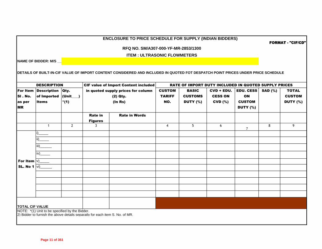
Bidder shall furnish built-in CIF value if any, against each quoted item, giving details of description of goods, qty. rate of Custom Duty etc. in attached Format-"CIF/CD".
ITEM : ULTRASONIC FLOWMETERS
Indian Bidders must quote item wise Freight charges in the space provided in the price schedule.
RFQ NO. SM/A307-000-YF-MR-2853/1300
Page 9 of 351

1 2 3 4 5 6
1
GROUP A: Ultrasonic Flowmeter with Spool Piece (Process Liquid-0ID
Qty - 1 no.)1
GROUP B: Ultrasonic Flowmeter with Spool Piece (Process Liquid-0IF
Qty - 1 no.)1
GROUP C: Ultrasonic Flowmeter with Spool Piece (Process Liquid-0IY
Qty - 1 no.)1
GROUP D: Ultrasonic Flowmeter without Spool Piece (Process Liquid-0IY
Qty - 2 nos.)1
GROUP E: Ultrasonic Flowmeter with Spool Piece (Process Gas-0IY Qty -
2 nos.)1
GROUP F: Ultrasonic Flowmeter Cooling Water (IUS Qty- 1 no.) 1
GROUP G: Ultrasonic Flowmeter Raw Water (IUR Qty- 2 nos.) 1
GROUP H: Ultrasonic Flowmeter Flare (IUF & IUS Qty- 2 nos.) 1
GROUP I: Ultrasonic Flowmeter Flare (IFP Qty- 2 nos.) 1
GROUP J: Ultrasonic Flowmeter Flare (00H Qty- 1 no.) 1
5
6
8 Supervision of erection,testing and commissioning of items specified at
item 1.00 above as per MR.
Furnished itemwise Unit Rates for addition/ deletion as per Cl. No. A1 (e) of Special
Instruction to Vendors.
Bidder shall quote Per Diem Rate for Supervision in separate sheet enclosed with this
price schedule.
SUPPLY OF FOLLOWING ITEMS AS PER COMPLETE SCOPE MENTIONED IN MR. NO. A307-000-YF-MR2853 COMPLETE IN ALL RESPECTS
ITEM : ULTRASONIC FLOWMETERS
Supply of two years operation and Maintenance Spares, as per MR.
Qty (LOT) Total Freight Charges upto
Project Site (Including
service Tax) (INR)
Unit Rates of items for addition/deletion purpose, as per MR.
Items Code
Bidder to furnish itemised price list for each tag no. as per MR in the Format enclosed with
this price schedule.
Cenvatable Service Tax
included Transportation
Charges in %
Total Price on FOT Despatch
Point Price including P&F
(INR)
Group as per
MR.
PRICE SCHEDULE FOR SUPPLY (INDIAN BIDDERS)
NAME OF BIDDER: M/S
RFQ NO. SM/A307-000-YF-MR-2853/1300
Page 10 of 351
For Item
Sl . No.
as per
MR
Description
of Imported
Items
Qty.
(Unit____)
*(1)
CUSTOM
TARIFF
NO.
BASIC
CUSTOMS
DUTY (%)
CVD + EDU.
CESS ON
CVD (%)
EDU. CESS
ON
CUSTOM
DUTY (%)
SAD (%) TOTAL
CUSTOM
DUTY (%)
Rate in
Figures
Rate in Words
1 2 3 4 5 67
8 9
i)_____
ii)_____
iii)______
iv)_____
v)_____
vi)______
2) Bidder to furnish the above details separatly for each item S. No. of MR.NOTE: *(1) Unit to be specified by the Bidder.
TOTAL CIF VALUE
CIF value of Import Content included
in quoted supply prices for column
(2) Qty.
(In Rs)
DESCRIPTION RATE OF IMPORT DUTY INCLUDED IN QUOTED SUPPLY PRICES
For Item
SL. No 1
DETAILS OF BUILT-IN-CIF VALUE OF IMPORT CONTENT CONSIDERED AND INCLUDED IN QUOTED FOT DESPATCH POINT PRICES UNDER PRICE SCHEDULE
FORMAT - "CIF/CD"
ENCLOSURE TO PRICE SCHEDULE FOR SUPPLY (INDIAN BIDDERS)
NAME OF BIDDER: M/S __________________________
RFQ NO. SM/A307-000-YF-MR-2853/1300
ITEM : ULTRASONIC FLOWMETERS
Page 11 of 351

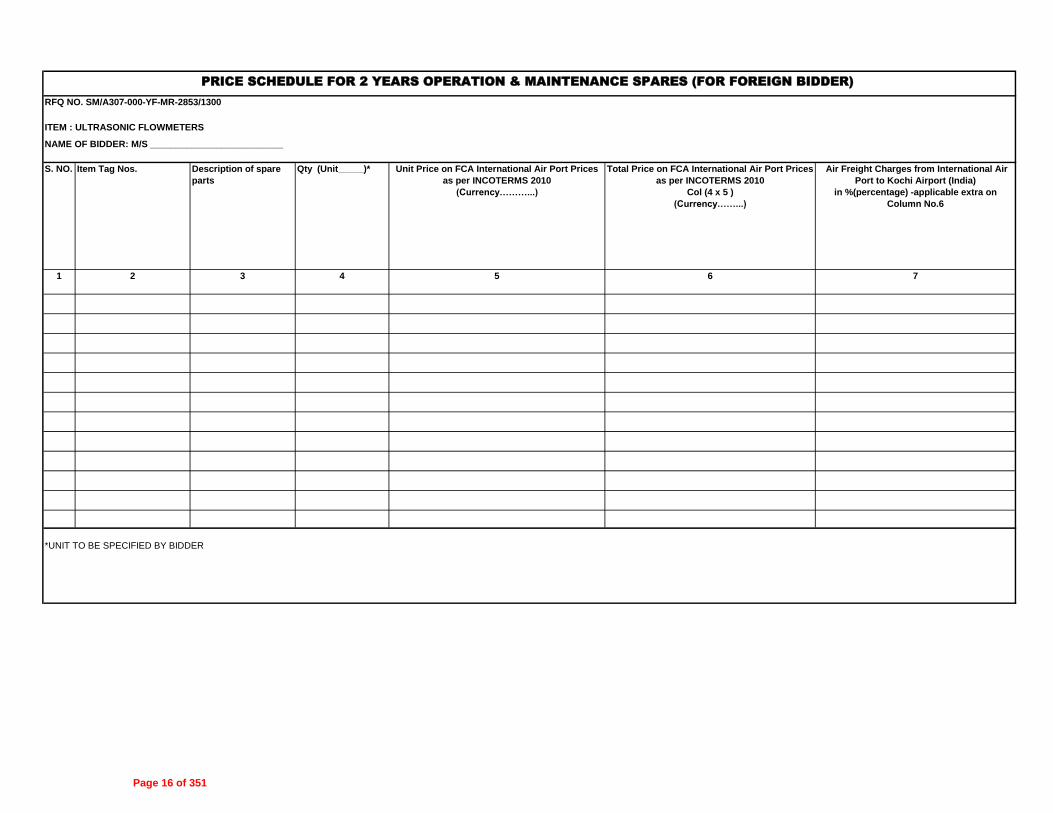
S. NO. Item Tag Nos. Description of spare
parts
Qty
(Unit_____)*
Unit FOT Despatch Point
Price including P&F
(INR)
Total FOT Despatch Point
Price including P&F
(INR)
Transportation Charges up to
Site excluding Service Tax in
percentage of price
mentioned in column 6
1 2 3 4 5 6 7
*UNIT TO BE SPECIFIED BY BIDDER
PRICE SCHEDULE FOR 2 YEARS OPERATION & MAINTENANCE SPARES (FOR INDIAN BIDDER)
RFQ NO. SM/A307-000-YF-MR-2853/1300
ITEM : ULTRASONIC FLOWMETERS
NAME OF BIDDER: M/S __________________________
Page 12 of 351

1 2 3 7
8
8 For Sr. No. 1 of MR
08.01 GROUP A:
08.02 GROUP B:
08.03 GROUP C:
08.04 GROUP D:
08.05 GROUP E:
08.06 GROUP F:
08.07 GROUP G:
08.08 GROUP H:
08.09 GROUP I:
08.10 GROUP J:
Note1
2
3
Per manday charges quoted by the bidder at Col 4 shall be in accordance with the "Terms & Conditions for Supervision of Erection & Commissioning" enclosed with the
RFQ Document and shall be inclusive of all charges including To& Fro travelling charges. Bidder to note that nothing extra shall be paid by the owner over and above the
quoted per manday charges except Cenvabale Service Tax which shall be payable extra..
For evaluation purpose, 1 (One) manday for each group as per MR shall be considered for supervision. If bidder quotes different per manday charges for different
supervisory personnel then maximum per manday charges quoted shall be considered for evaluation.
Bidder to note that apart from above quoted price, no price for supervision shall be quoted elsewhere.
Overtime rate/ hour for work on
weekly off days / holidays (as
applicable to Refinery Site)
excluding Service Tax & Edu.
Cess thereon. (INR)
Service Tax Plus Ed.
Cess in %
4 5 6
Per-Diem rate for Supervision of erection, testing and commissioing of items as per scope mentioned in MR.
PRICE SCHEDULE FOR SUPERVISION (FOR INDIAN BIDDER) RFQ NO. SM/A307-000-YF-MR-2853/1300
ITEM : ULTRASONIC FLOWMETERS
NAME OF BIDDER:
M/s__________________________
Item SL.
No. as
per MR
Description of Items as per
MR
No. of Personnel
Required
Per Manday charges (Per person)
for 8 hours work on normal
working day excluding Service
Tax & Edu. Cess thereon. (INR)
Overtime rate/ hour beyond normal
8 hours work on normal working
days excluding Service Tax & Edu.
Cess thereon.
(INR)
Page 13 of 351

1
2
3
4
5
6
7
8
9
10
11
12
13
14
NOTES:
2.Price Schedule contains total 5 pages .
PREAMBLE TO PRICE SCHEDULE (FOREIGN BIDDER)
Bidder must quote the price in enclosed Price Schedule formats only. The formats shall not be changed and/or retyped.
RFQ NO. SM/A307-000-YF-MR-2853/1300
ITEM : ULTRASONIC FLOWMETERS
Foreign Bidder shall quote in USD / Euro / INR only.
Quoted prices are firm and fixed till complete execution of the entire order and no variation on any account is allowed.
NAME OF BIDDER: M/S __________________________
Bidder must submit signed and stamped Un-Priced copy of Price Schedule indicated "Quoted" or "Not Quoted" against each item with their Unpriced offer.
Scope of supply including testing, inspection, documentation etc., shall be strictly as per Material Requisition and other documents which are part of RFQ.
All the Columns of quoted items in the Price Schedule must be filled with required information, as applicable.
Bidder must quote Air Freight Charges in the space provided in the price schedule.
Bidder must upload scanned copy of Unit Rates of each Tag/items of all groups & submit alongwith their Priced Bid in separate folder in the e-tendering portal. Blank (Unpriced)
copy of the same, duly stamped & signed on each page specifying "Quoted/Not Quoted", as applicable shall also be submitted with the Unpriced Bid.
Evaluation shall be done on groupwise basis. Hence Bidder shall quote for all the requirements of MR / RFQ, failing which bid shall be liable for rejection on account of incomplete scope.
1.Bidders must submit this document duly signed and stamped with both unpriced & priced offer.
Itemised Prices for 2 years operation & maintenance spares shall be furnished as per enclosed format and shall not be included in the quoted supply prices. Prices for 2 years operation &
maintenance spares should be valid for 12 months over and above the bid validity.
Bidders shall quote per diem supervision charges as per Material Requisition in the format enclosed.
In case of any discrepancy between Unit Price and Total Price, Unit Price shall prevail.
Bidder's quoted prices are inclusive of TPI Charges, TPI Agency will be Lloyds/BV/DNV/TUV/CEIL.
Bidder to confirm that he has noted the contents of the Preamble to the Price Schedule, Price Schedule, RFQ, Material Requisition etc and quoted his prices accordingly without any deviation.
Page 14 of 351
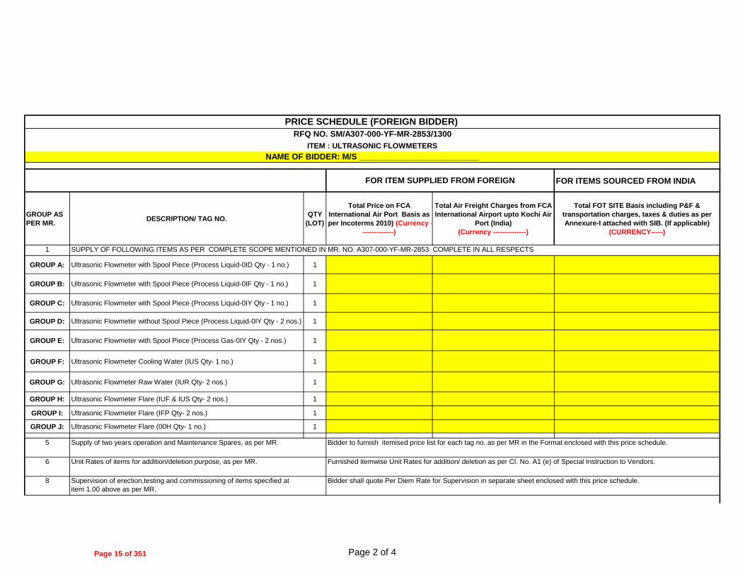
FOR ITEMS SOURCED FROM INDIA
GROUP AS
PER MR.DESCRIPTION/ TAG NO.
QTY
(LOT)
Total Price on FCA
International Air Port Basis as
per Incoterms 2010) (Currency -
-------------)
Total Air Freight Charges from FCA
International Airport upto Kochi Air
Port (India)
(Currency --------------)
Total FOT SITE Basis including P&F &
transportation charges, taxes & duties as per
Annexure-I attached with SIB. (If applicable)
(CURRENCY-----)
1
GROUP A: Ultrasonic Flowmeter with Spool Piece (Process Liquid-0ID Qty - 1 no.) 1
GROUP B: Ultrasonic Flowmeter with Spool Piece (Process Liquid-0IF Qty - 1 no.) 1
GROUP C: Ultrasonic Flowmeter with Spool Piece (Process Liquid-0IY Qty - 1 no.) 1
GROUP D: Ultrasonic Flowmeter without Spool Piece (Process Liquid-0IY Qty - 2 nos.) 1
GROUP E: Ultrasonic Flowmeter with Spool Piece (Process Gas-0IY Qty - 2 nos.) 1
GROUP F: Ultrasonic Flowmeter Cooling Water (IUS Qty- 1 no.) 1
GROUP G: Ultrasonic Flowmeter Raw Water (IUR Qty- 2 nos.) 1
GROUP H: Ultrasonic Flowmeter Flare (IUF & IUS Qty- 2 nos.) 1
GROUP I: Ultrasonic Flowmeter Flare (IFP Qty- 2 nos.) 1
GROUP J: Ultrasonic Flowmeter Flare (00H Qty- 1 no.) 1
5
6
8
PRICE SCHEDULE (FOREIGN BIDDER)
ITEM : ULTRASONIC FLOWMETERS
NAME OF BIDDER: M/S __________________________
FOR ITEM SUPPLIED FROM FOREIGN
Supervision of erection,testing and commissioning of items specified at
item 1.00 above as per MR.
Bidder shall quote Per Diem Rate for Supervision in separate sheet enclosed with this price schedule.
RFQ NO. SM/A307-000-YF-MR-2853/1300
SUPPLY OF FOLLOWING ITEMS AS PER COMPLETE SCOPE MENTIONED IN MR. NO. A307-000-YF-MR-2853 COMPLETE IN ALL RESPECTS
Supply of two years operation and Maintenance Spares, as per MR. Bidder to furnish itemised price list for each tag no. as per MR in the Format enclosed with this price schedule.
Unit Rates of items for addition/deletion purpose, as per MR. Furnished itemwise Unit Rates for addition/ deletion as per Cl. No. A1 (e) of Special Instruction to Vendors.
Page 2 of 4Page 15 of 351
RFQ NO. SM/A307-000-YF-MR-2853/1300
NAME OF BIDDER: M/S __________________________
S. NO. Item Tag Nos. Description of spare
parts
Qty (Unit_____)*
1 2 3 4
*UNIT TO BE SPECIFIED BY BIDDER
PRICE SCHEDULE FOR 2 YEARS OPERATION & MAINTENANCE SPARES (FOR FOREIGN BIDDER)
ITEM : ULTRASONIC FLOWMETERS
Unit Price on FCA International Air Port Prices
as per INCOTERMS 2010
(Currency………...)
Total Price on FCA International Air Port Prices
as per INCOTERMS 2010
Col (4 x 5 )
(Currency……...)
Air Freight Charges from International Air
Port to Kochi Airport (India)
in %(percentage) -applicable extra on
Column No.6
5 6 7
Page 16 of 351

1 2
8
8 For Sr. No. 1 of MR
08.01 GROUP A:
08.02 GROUP B:
08.03 GROUP C:
08.04 GROUP D:
08.05 GROUP E:
08.06 GROUP F:
08.07 GROUP G:
08.08 GROUP H:
08.09 GROUP I:
08.10 GROUP J:
Note1
2
3
PRICE SCHEDULE FOR SUPERVISION (FOR FOREIGN BIDDER)
RFQ NO. SM/A307-000-YF-MR-2853/1300
ITEM : ULTRASONIC FLOWMETERS
NAME OF BIDDER: M/S __________________________
Item SL.
No. as per
MR
Description of Items as per MR No. of Personnel
Required
Per diem charges (per person) for 8 hours
work on normal working days excluding
Service Tax & Edu. Cess thereon.
Overtime rate/ hour beyond normal 8
hours work on normal working days
excluding Service Tax & Edu. Cess
thereon.
Overtime rate/ hour for work on weekly off
days/ holidays (as applicable to Refinery site)
excluding Service Tax & Edu. Cess thereon.
Bidder to note that apart from above quoted price, no price for supervision shall be quoted elsewhere.
CURRENCY (--------------)
3 4
Per-Diem rate for Supervision of erection, testing and commissioing of items as per scope mentioned in MR.
Per manday charges quoted by the bidder at Col 4 shall be in accordance with the "Terms & Conditions for Supervision of Erection, Testing & Commissioning" enclosed with the RFQ Document,
Inclusive of all charges including to & fro airfare (Travelling) charges . Bidder to note that nothing extra shall be paid by the owner over and above the quoted per manday charges except
Cenvabale Service Tax which shall be payable extra.
For evaluation purpose, 1 (One) manday for each group as per MR shall be considered for supervision. If bidder quotes different per manday charges for different supervisory personnel then
maximum per manday charges quoted shall be considered for evaluation.
Page 17 of 351

A307_ATC (I) Page 1 of 8
SUPPLIER’S SIGNATURE WITH STAMP/SEAL
BHARAT PETROLEUM CORPORATION LTD IREP-Kochi Refinery
(Job No. A307) AGREED TERMS & CONDITIONS (ATC)
(FOR INDIAN BIDDERS) Supplier Name: M/s ______________________________________________________________
RFQ No.: __________________________________________________________________
Supplier’s Offer Ref No. & Date: ______________________________________________________
Tel. No. ___________________Mob. No. ______________________ Fax No. ________________
Contact Person: ___________________________ E-mail _________________________________
1. ALL CORRESPONDENCE MUST BE IN ENGLISH LANGUAGE ONLY.
2. DULY SIGNED & STAMPED COPIES OF THIS “QUESTIONNAIRE”, WITH ALL THE
CLAUSES DULY CONFIRMED/ PRECISELY REPLIED TO BY THE SUPPLIER, SHALL BE ENCLOSED.
3. ALL COMMERCIAL TERMS ARE GIVEN/CONFIRMED IN THE QUESTIONNAIRE ITSELF
AND NOT ELSEWHERE IN THE QUOTATION. IN CASE OF CONTRADICTION, THE SAME GIVEN HEREIN SHALL PREVAIL.
4. FAILURE ON PART OF THE SUPPLIER IN SUBMITTING THIS DULY FILLED-IN “QUESTIONNAIRE” WITH UN-PRICED BID AND/ OR SUBMITTING INCOMPLETE REPLIES MAY LEAD TO REJECTION OF SUPPLIER’S BID.
5. YOUR OFFER SHALL BE IN TOTAL COMPLIANCE WITH RFQ DOCUMENTS
CONTAINING COMMERCIAL AND TECHNICAL SPECIFICATIONS INCLUDING GENERAL/ TECHNICAL NOTES AND SCOPE OF SUPPLY/SERVICES/ SITE WORK, AS APPLICABLE INCLUDING DOCUMENTATION AS PER MATERIAL REQUISITION (MR) AND SUBSEQUENT TECHNICAL/ COMMERCIAL AMENDMENT AND TECHNICAL/ COMMERCIAL CORRIGENDUM, IF ANY.
SL. NO.
DESCRIPTION SUPPLIER’S CONFIRMATION
1.
i)
Price Basis:
Quoted supply prices are on FOT - Despatch Point basis inclusive of Packing & Forwarding.
Confirmed
ii) Specify Despatch Point
----------------------- iii)
a)
b)
Freight Charges:
Confirm firm transportation charges inclusive of Service Tax and Ed Cess, upto project site, has been quoted separately by you in Price Schedule.
No Variation on any account (including Statutory Variation) on Service Tax on Transportation Charges shall be paid by the owner.
a) Confirmed , Quoted in Price
Schedule
b) Confirmed
iv) Insurance:
a) For Supply Only
Transit/Marine Insurance of Equipment/ Item has been taken care by the Owner & charges of the same have not been included in the quoted prices.
Confirmed.
Page 18 of 351

A307_ATC (I) Page 2 of 8
SUPPLIER’S SIGNATURE WITH STAMP/SEAL
SL. NO.
DESCRIPTION SUPPLIER’S CONFIRMATION
b) For Supply + Site Work
Comprehensive Insurance (Transit/Marine-cum-storage-cum-erection till handing over of equipment) has been taken care by the Seller & charges of the same have been included in the quoted prices.
Confirmed
2.
a.
b.
c.
d.
e. f.
g.
h.
Excise Duty applicable extra on Finished Goods: Specify Excise Tariff Sub-Heading No. Present Rate of Excise Duty & Edu. Cess payable extra on finished goods (including Spares) Any variations in Excise Duty & Edu. Cess at the time of supplies for any reasons including variation due to Turnover shall be borne by the Seller. Only Statutory Variations within the Contractual Delivery / completion period shall be borne by Purchaser. If Excise Duty & Edu. Cess is not applicable at present due to any reason, the same shall be borne by Seller if it becomes applicable later. Confirm Excise Duty & Edu. Cess will not be applicable on transportation charges. If Excise Duty & Edu. Cess is not applicable on transportation charges presently, and if it becomes applicable at the time of delivery due to any reasons other than statutory, the same will be borne by the Supplier. Confirm acceptance. Non Cenvatable Excise Duty, if any is included in quoted prices & no variation on any account (including statutory variation) shall be paid by Owner. Only Statutory Variations, if any, in the present rate of Excise Duty, upto the Contractual Delivery Date / Completion Period shall be to Owner’s account subject to documentary evidence to be furnished by Seller.
_________________
………..%
Confirmed
Confirmed
Confirmed
Confirmed
Confirmed
Confirmed
3.
a.
b.
c.
d.
e.
Sales Tax applicable extra on finished goods:
Central Sales Tax against Concessional Form “C” payable extra on finished goods (including spares) is applicable & the present rate (in %age) is indicated Kerala VAT payable extra on finished goods (including spares) without concessional form is applicable & the present rate (in %age) is indicated If CST / Kerala VAT is not applicable at present due to any reason, the same shall be borne by Supplier if it becomes applicable later. Confirm CST/ Kerala VAT will not be applicable on transportation charges. If CST / Kerala VAT is not applicable on transportation charges presently, and if it becomes applicable at the time of delivery due to any reasons other than statutory, the same will be borne by the Supplier. Confirm acceptance.
(Applicable / Not Applicable) (Please tick whichever is applicable)
…………%
(Applicable / Not Applicable) (Please tick whichever is applicable)
………….%
Confirmed
Confirmed
Confirmed
Page 19 of 351

A307_ATC (I) Page 3 of 8
SUPPLIER’S SIGNATURE WITH STAMP/SEAL
SL. NO.
DESCRIPTION SUPPLIER’S CONFIRMATION
h. Only Statutory Variations, if any, in the present rate of CST / Kerala VAT, upto the Contractual Delivery Date / Completion Period shall be to Owner’s account subject to documentary evidence to be furnished by Seller.
Confirmed
4. Octroi / Entry Tax:
Octroi / Entry Tax, if applicable on finished goods (including spares) shall be borne and paid directly by Owner. Confirm that Octroi / Entry Tax has not been included in the quoted prices.
Confirmed
5. Any new or additional taxes/ duties and any increase in the existing Cenvatable taxes/duties imposed after contractual completion period shall be to Supplier’s account whereas any corresponding decrease in the existing Cenvatable taxes/ duties shall be passed on to the Owner.
Confirmed
6.
a.
Spares Parts:
Confirm item wise unit price (FOT Despatch Point) of following spare parts as required in Material Requisition (MR) have been included indicating itemised quantity.
i) Mandatory Spares are quoted as per MR.
ii) Commissioning spares as specified in MR are included in the quoted Price.
iii) Special Tools & Tackles as specified in the MR are included in the quoted prices.
iv) Confirm spares wherever required have been included in the quoted price and list of spares is also furnished.
v) Recommended Spares for Two Years Operation & Maintenance, as specified in MR have been quoted separately with Price validity of One (1) year from Contractual Delivery Date for Main Items/Equipment & List of such spares has been furnished in the Unpriced Bid.
Confirmed
Confirmed (if Applicable as per MR)
Confirmed (if Applicable as per MR)
Confirmed (if Applicable as per MR)
Confirmed (if Applicable as per MR)
Confirmed (if Applicable as per MR)
7.
a.
b.
c.
d.
Site Work:
For Site Work, if in the scope of the Bidder as per MR, please confirm the following:
Confirm that quoted site work prices are exclusive of Service Tax & Edu. Cess but inclusive of VAT on Works Contract and all other applicable taxes & duties.
Percentage of Service Tax & Edu. Cess as applicable extra on Site Work.
Supplier shall submit the Assessment/ Liability Certificate from Sales Tax authorities indicating the VAT on Works Contract payable for enabling Owner to deduct the same from Supplier Invoices & make payment to the tax authorities. TDS Certificate towards VAT on Works Contract shall be provided by Owner. Statutory variation on VAT on Works Contract shall not be payable by Owner. Statutory Variation on Service Tax & Edu. Cess on Site work shall be paid by the Owner against documentary evidence within Contractual completion period.
Confirmed
-------------------%
Confirmed
Confirmed
Page 20 of 351

A307_ATC (I) Page 4 of 8
SUPPLIER’S SIGNATURE WITH STAMP/SEAL
SL. NO.
DESCRIPTION SUPPLIER’S CONFIRMATION
e.
Confirm that Entry Tax / Octroi applicable on Construction Machinery/Equipment brought by the supplier to site to execute / complete the site work shall be borne by the Supplier and same is included in the quoted prices. No variation (including statutory) on such entry tax shall be paid by the Owner.
Confirmed
8.
a.
b.
c.
d.
e.
Supervision / Training Charges: Charges for Supervision / Training, if in the scope of the Bidder as per MR have been indicated by bidder separately in the Price Schedule. Percentage of Service Tax & Edu. Cess as applicable extra on Supervision / Training Per-diem rate for supervision has been quoted in accordance with the Terms & Conditions for Supervision enclosed with the RFQ Documents. Where erection/ testing/ commissioning supervision, commissioning assistance is required as per RFQ Documents / Material requisition, penalty for non mobilization/delay in mobilization as per order shall be applicable. The penalty shall generally be 1.5 times the per diem rate for each day of delay of reporting to site and shall be in addition to price reduction for delayed delivery. Bidders shall also provide additional BG of an amount equal to the per diem charges for the number of days considered for evaluation, over and above 10% PBG to cover compensation for delay in mobilizing the erection/ commissioning personnel. This BG will be released to the bidder upon the erection/ commissioning personnel reporting at site. This BG shall be furnished along with payment milestone for submission of final documentation as per MR and shall be initially valid up to six months which shall be extended based on the request by Owner.
Confirmed, Quoted in Price Schedule
----------------%
Confirmed
Noted & Confirmed
Noted & Confirmed
9. Confirm documentation charges as per MR are included in quoted prices.
Confirmed
10. Price Reduction for delay in delivery/ completion: a) Confirm acceptance of price reduction schedule for delay in
deliveries / completion as specified in GPC & Special Instructions to Bidders (SIB) enclosed in RFQ Document. Liquidated damages or penalty are not acceptable.
b) In case of delay, vendor will reduce the invoice amount by
applicable reduction.
Confirmed
Confirmed
11. Delivery / Completion Period: Please confirm delivery / completion period as specified in the RFQ Covering Letter.
Confirmed
12.
Payment Terms: Confirm acceptance of “Terms and Mode of Payment” as per respective clause(s) given in SIB and RFQ covering letter.
Confirmed
Page 21 of 351

A307_ATC (I) Page 5 of 8
SUPPLIER’S SIGNATURE WITH STAMP/SEAL
SL. NO.
DESCRIPTION SUPPLIER’S CONFIRMATION
13.1 a.
PART ORDER: Confirm acceptance of Part Order clause as per GPC (Indigenous). And bidder also confirm acceptance to part quantity orders of any items (having quantities 5 Nos. & more) to facilitate purchase preference to MSME bidders as per Govt. guide lines.
Confirmed (If Applicable as per MR)
13.2 MSME BIDDERS:
a Confirm whether the bidder is a MSME bidder or not. YES/ NO
(Please tick whichever is applicable)
b In case bidder is a MSME bidder, they must submit documentary evidence for the same duly certified by Statutory Auditor of the bidder or a practicing Charted Account (not being an employee or a Director or not having any interest in the Bidder’s company/ firm) where audited accounts are not mandatory as per law.
_________________
c In case bidder does not submit duly authenticated
documentary evidence as required above, bidder shall not be considered eligible for availing MSME benefits.
Confirmed
d Any charges quoted extra as lumpsum (like IBR, Testing, freight, etc.) shall be applicable prorata on value basis in the event of part order / part quantities/ split order.
Confirmed
14. Repeat Order: Confirm Acceptance of Repeat Order clause as per RFQ Covering Letter / SIB / GPC.
Confirmed
15.
Performance Bank Guarantee: a) In the event of award of order, submission of Performance
Bank Guarantee for 10% of total order value along with Final supply payment valid till full guarantee period plus 3 (Three) months.
b) The Performance Bank Guarantee shall be strictly as per
enclosed proforma and shall be from any Indian Scheduled Bank or branch of an International Bank situated in India and registered with Reserve Bank of India as scheduled foreign Bank.
Confirmed
Confirmed
16. Guarantee / Warranty: Confirm acceptance to Guarantee / Warranty clause as mentioned in the GPC/SIB.
Confirmed
17. Firmness of prices: Confirm quoted prices shall remain firm and fixed till complete execution of order. Price Variation shall not be considered on any account.
Confirmed
18. a.
b.
Testing and Inspection charges: Goods supplied are subject to stage wise and final inspection as specified in MR by EIL and no extra charges shall be payable by Owner towards the same. Travel, Living and Personnel expenses of EIL’s Representative shall be borne by Owner. Quoted prices are: i) Inclusive of all testing and inspection charges (if applicable)
as per MR. ii) Inclusive of all IBR/IGC/NACE charges (if applicable) as
required in the Material Requisition.
Confirmed
Confirmed
Page 22 of 351

A307_ATC (I) Page 6 of 8
SUPPLIER’S SIGNATURE WITH STAMP/SEAL
SL. NO.
DESCRIPTION SUPPLIER’S CONFIRMATION
c.
iii) Inclusive of all statutory certification charges PESO/CCOE
etc. (if applicable) as required in the Material Requisition Is your shop approved by IBR/CCE authority, if yes, indicate validity. i. IBR ii. CCE It is the responsibility of supplier to get the entire imported materials and the built in imported contents inspected by TPIA (i.e. Lloyds/BV/DNV/TUV/CEIL) in the country of origin and the quoted prices are inclusive of charges towards the same.
Confirmed
Confirmed
IBR Approved
Confirmed
19.
a.
b.
c.
d.
e.
f.
g.
h.
i.
Import Content: If your offer is based on certain imported raw materials required for equipments/ materials offered, please specify the following : Confirm that quoted prices are based on Merit rate of Customs duty, CVD, Educational Cess and SAD as applicable. Indicate rate of Import Duties considered and included in the quoted prices. Indicate brief description/ specification with itemised CIF value and country of origin of imported material. Indicate classification with tariff no. under which Vendor intends to import. Confirm prices shall be firm on account of variation in foreign exchange rate. Owner shall not provide any import licence. Quoted prices are after considering the benefit of CENVAT on CVD including Edu. Cess. In case material is shipped directly to Port/Project Site, quoted prices are excluding CENVAT benefit. In case material is directly dispatched from port, CVD amount shall be reimbursed subject to submission of bill of entry documents along with CVD invoice. Any upward variation due to change in Customs Duty classifications shall be absorbed by the vendor. However, any reduction in customs duty due to change in classification shall be passed on to Owner.
(Applicable / Not Applicable) (Please tick whichever is applicable)
Confirmed
Refer Annexure to Price Schedule
Refer Annexure to Price Schedule
Refer Annexure to Price Schedule
Confirmed
Noted
Confirmed
Confirmed
Confirmed
j. k.
Statutory variations, if any, in the rate of Import Duties upto 2/3
rd contractual delivery period shall be to Owner’s account.
Any increase in price due to increase in the rate of Import Duties, due to any reasons, whatsoever, beyond the 2/3 rd contractual delivery period, shall be to vendor's account. However, any decrease in Import Duties rate at the time of actual clearance of imported materials shall be passed on to Owner.
Confirmed
Confirmed
Page 23 of 351
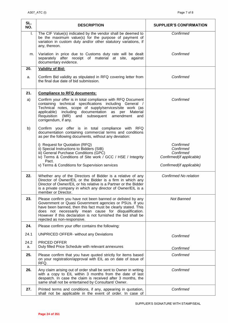
A307_ATC (I) Page 7 of 8
SUPPLIER’S SIGNATURE WITH STAMP/SEAL
SL. NO.
DESCRIPTION SUPPLIER’S CONFIRMATION
l. m.
The CIF Value(s) indicated by the vendor shall be deemed to be the maximum value(s) for the purpose of payment of variation in custom duty and/or other statutory variations, if any, thereon. Variation in price due to Customs duty rate will be dealt separately after receipt of material at site, against documentary evidence.
Confirmed
Confirmed
20.
a.
Validity of Bid: Confirm Bid validity as stipulated in RFQ covering letter from the final due date of bid submission.
Confirmed
21.
a)
b)
Compliance to RFQ documents:
Confirm your offer is in total compliance with RFQ Document containing technical specifications including General / Technical notes, scope of supply/services/site work (as applicable) including documentation as per Material Requisition (MR) and subsequent amendment and corrigendum, if any. Confirm your offer is in total compliance with RFQ documentation containing commercial terms and conditions as per the following documents, without any deviation: i) Request for Quotation (RFQ) ii) Special Instructions to Bidders (SIB) iii) General Purchase Conditions (GPC) iv) Terms & Conditions of Site work / GCC / HSE / Integrity
Pact. v) Terms & Conditions for Supervision services
Confirmed
Confirmed Confirmed Confirmed
Confirmed(if applicable)
Confirmed(if applicable)
22. Whether any of the Directors of Bidder is a relative of any Director of Owner/EIL or the Bidder is a firm in which any Director of Owner/EIL or his relative is a Partner or the Bidder is a private company in which any director of Owner/EIL is a member or Director.
Confirmed No relation
23. Please confirm you have not been banned or delisted by any Government or Quasi Government agencies or PSUs. If you have been banned, then this fact must be clearly stated. This does not necessarily mean cause for disqualification. However if this declaration is not furnished the bid shall be rejected as non-responsive.
Not Banned
24. 24.1
24.2 a.
Please confirm your offer contains the following: UNPRICED OFFER- without any Deviations PRICED OFFER Duly filled Price Schedule with relevant annexures
Confirmed
Confirmed
25. Please confirm that you have quoted strictly for items based on your registration/approval with EIL as on date of issue of RFQ.
Confirmed
26. Any claim arising out of order shall be sent to Owner in writing with a copy to EIL within 3 months from the date of last despatch. In case the claim is received after 3 months, the same shall not be entertained by Consultant/ Owner.
Confirmed
27. Printed terms and conditions, if any, appearing in quotation, shall not be applicable in the event of order. In case of
Confirmed
Page 24 of 351

A307_ATC (I) Page 8 of 8
SUPPLIER’S SIGNATURE WITH STAMP/SEAL
SL. NO.
DESCRIPTION SUPPLIER’S CONFIRMATION
contradiction between the confirmations given above and terms & conditions mentioned elsewhere in the offer, the confirmation given/confirmed herein above shall prevail.
28. Confirm that Net worth of the Bidder’s company is positive as per the immediate preceding year’s audited financial results & Immediate preceding year’s audited annual financial results has been submitted along with un-priced bid.
Confirmed & Submitted
Page 25 of 351

A307_ATC (F) Page 1 of 7
SUPPLIER’S SIGNATURE WITH STAMP/SEAL
M/s BHARAT PETROLEUM CORPORATION LIMITED IREP-Kochi Refinery
(Job No. A307)
AGREED TERMS & CONDITIONS (ATC) (FOR FOREIGN BIDDERS)
Supplier Name: M/s ______________________________________________________________
RFQ No.: __________________________________________________________________
Supplier’s Offer Ref No. & Date: ______________________________________________________
Tel. No. ___________________Mob. No. ______________________ Fax No. ________________
Contact Person: ___________________________ E-mail _________________________________
1. ALL CORRESPONDENCE MUST BE IN ENGLISH LANGUAGE ONLY.
2. DULY SIGNED & STAMPED COPIES OF THIS “QUESTIONNAIRE”, WITH ALL THE CLAUSES
DULY CONFIRMED/ PRECISELY REPLIED TO BY THE SUPPLIER, SHALL BE ENCLOSED.
3. ALL COMMERCIAL TERMS ARE GIVEN/CONFIRMED IN THE QUESTIONNAIRE ITSELF AND NOT ELSEWHERE IN THE QUOTATION. IN CASE OF CONTRADICTION, THE SAME GIVEN HEREIN SHALL PREVAIL.
4. FAILURE ON PART OF THE SUPPLIER IN SUBMITTING THIS DULY FILLED-IN “QUESTIONNAIRE” WITH UN-PRICED BID AND / OR SUBMITTING INCOMPLETE REPLIES MAY LEAD TO REJECTION OF SUPPLIER’S BID.
5. YOUR OFFER SHALL BE IN TOTAL COMPLIANCE WITH RFQ DOCUMENTS CONTAINING
COMMERCIAL AND TECHNICAL SPECIFICATIONS INCLUDING GENERAL / TECHNICAL NOTES AND SCOPE OF SUPPLY/SERVICES/SITE WORK, AS APPLICABLE INCLUDING DOCUMENTATION AS PER MATERIAL REQUISITION (MR) AND SUBSEQUENT TECHNICAL/COMMERCIAL AMENDMENT AND TECHNICAL/ COMMERCIAL CORRIGENDUM, IF ANY.
SL. NO.
DESCRIPTION SUPPLIER’S CONFIRMATION
1. a) Confirm that the offer contains firm prices on F.O.B. International Seaport of Exit Basis
b) Indicate International Seaport of Exit c) Indicate the HSN Code of the Items
d) Details of any Free Trade Agreement (FTA) /
Comprehensive Economic Partnership Agreement (CEPA) / Treaty between Bidders country Govt. & Indian Government for availing custom duty exemption / concession. If bidder will not specifically mention the same, it is to be considered that there is no specific Agreement / Treaty between Govt. of Bidders & Purchasers County.
e) Confirm quoted prices are inclusive of stowage charges.
f) Confirm that ocean freight charges upto port of
entry- Kochi, (India) has been quoted separately
by you in the price schedule.
Confirmed
-----------------------------
__________________
Applicable / Not Applicable
Confirmed
Confirmed , Quoted in Price Schedule
Page 26 of 351

A307_ATC (F) Page 2 of 7
SUPPLIER’S SIGNATURE WITH STAMP/SEAL
SL. NO.
DESCRIPTION SUPPLIER’S CONFIRMATION
g) In case you have not indicated the ocean freight charges separately in the price schedule please quote the same in terms of Percentage of the quoted FOB Price.
h) In case ocean freight charges are repeated anywhere in the bid/Price Schedule/ATC, then higher shall be considered for evaluation & lower for ordering. (In case of CFR)
------------ %
Confirmed
2. Insurance:
a) For Supply Only
Price quoted must exclude Marine insurance charges from FOB International Port of Exit, as same shall be arranged by the Owner. However all marine insurance charges for inland transit upto FOB International Port of Exit must be included by you in your prices.
b) For Supply + Site Work
Comprehensive Insurance (Transit/Marine-cum-storage-cum-erection till handing over of equipment) has been taken care by the Seller & charges of the same have been included in the quoted prices.
Confirmed
Confirmed
3. Owner reserves the option to place order either on FOB or CFR basis (applicable only as per requirement mentioned in RFQ documents).
Confirmed
4. Delivery / Completion Period:
a) Delivery / Completion period shall be as mentioned in the RFQ covering letter.
b) Confirm delivery period shall be reckoned from the date of Fax of Acceptance.
c) Confirm date of clean Bill of Lading shall be considered as date of delivery. (In case order is placed on FOB port of Exit basis or on CFR basis)
Confirmed
Confirmed
Confirmed
5.
a.
b.
Taxes & Duties:
All taxes, duties and levies of any kind payable upto FOB International Port of Exit shall be borne by Bidder.
Export permit/ licence if required shall be vendor’s responsibility & any expenditure towards same will be borne by Bidder.
Confirmed
Confirmed
6. a.
b.
c.
Supervision / Training Charges: Charges for Supervision / Training, if in the scope of the Bidder as per MR have been indicated by bidder separately in the Price Schedule.
Per-diem rate for supervision has been quoted in accordance with the Terms & Conditions for Supervision enclosed with the RFQ Documents. Bidder to indicate Permanent Account Number (PAN) to avoid any additional Tax deduction at source as per the prevailing Indian Income Tax Acts / Rules.
Confirmed, Quoted in Price Schedule
Confirmed
---------------------------
Page 27 of 351

A307_ATC (F) Page 3 of 7
SUPPLIER’S SIGNATURE WITH STAMP/SEAL
SL. NO.
DESCRIPTION SUPPLIER’S CONFIRMATION
d.
e.
Where erection/testing/commissioning supervision, commissioning assistance is required as per RFQ Documents / Material requisition, penalty for non mobilization/delay in mobilization as per order shall be applicable. The penalty shall generally be 1.5 times the per diem rate for each day of delay of reporting to site and shall be in addition to price reduction for delayed delivery. Bidders shall also provide additional BG of an amount equal to the per diem charges for the number of days considered for evaluation, over and above 10% PBG to cover compensation for delay in mobilizing the erection/ commissioning personnel. This BG will be released to the bidder upon the erection/ commissioning personnel reporting at site. This BG shall be furnished along with shipping documents and shall be initially valid up to six months which shall be extended based on the request by BPCL.
Noted & Confirmed
Noted & Confirmed
7.
a.
b.
c.
d.
e.
Site Work: For Site Work, if in the scope of the Bidder as per MR, please confirm the following:
Confirm that quoted site work prices are exclusive of Service Tax & Edu. Cess but inclusive of VAT on Works Contract and all other applicable taxes & duties.
Percentage of Service Tax & Edu. Cess as applicable extra on Site Work. Supplier shall submit the Assessment/ Liability Certificate from Sales Tax authorities indicating the VAT on Works Contract payable for enabling Owner to deduct the same from Supplier Invoices & make payment to the tax authorities. TDS Certificate towards VAT on Works Contract shall be provided by Owner. Statutory variation on VAT on Works Contract shall not be payable by Owner. Statutory Variation on Service Tax & Edu. Cess on Site work shall be paid by the Owner against documentary evidence within Contractual completion period. Confirm that Entry Tax / Octroi applicable on Construction Machinery/Equipment brought by the supplier to site to execute / complete the site work shall be borne by the Supplier and same is included in the quoted prices. No variation (including statutory) on such entry tax shall be paid by the Owner.
Confirmed
-------------------%
Confirmed
Confirmed
Confirmed
8.
Validity:
a. Confirm Bid validity as stipulated in RFQ covering letter from the final due date of bid submission.
Confirmed
9. Manufacturer’s Name and Address
Page 28 of 351

A307_ATC (F) Page 4 of 7
SUPPLIER’S SIGNATURE WITH STAMP/SEAL
SL. NO.
DESCRIPTION SUPPLIER’S CONFIRMATION
10. a.
b.
Inspection Charges: Goods supplied are subject to stage wise and final inspection as specified in MR by TPI agency i.e. Lloyds/BV/DNV/TUV/CEIL in the country of origin and charges of the same shall be included in quoted prices and it is supplier’s responsibility to arrange for the same. No additional charges shall be paid by owner towards the same.
Quoted prices are:
i) Inclusive of all testing and inspection charges (if applicable) as per MR.
ii) Inclusive of all IBR/IGC/NACE charges (if applicable) as required in the Material Requisition.
iii) Inclusive of all statutory certification charges PESO/CCOE etc. (if applicable) as required in the Material Requisition.
Confirmed
Confirmed
Confirmed
Confirmed
11. Country of Origin: Country of origin from where the goods have been offered.
--------------------------
12. Currency of Quote: Furnish the currency of quote. Change in currency once quoted will not be allowed. Bidder shall quote either in USD / Euro / INR only.
-----------------------------
13.
a)
b)
Spares Parts:
Confirm item wise unit price (FOB Port of Exit bais)of following spare parts as required in Material Requisition (MR) have been quoted indicating itemised quantity. i) Mandatory Spares are quoted as per MR.
ii) Commissioning spares as specified in MR are included in the quoted Price.
iii) Special Tools & Tackles as specified in the MR are included in the quoted prices.
iv) Confirm spares wherever required have been included in the quoted price and list of spares is also furnished.
Recommended Spares for Two Years Operation & Maintenance, as specified in MR have been quoted separately with Price validity of One (1) year from Contractual Delivery Date for Main Items/Equipment & List of such spares has been furnished in the Unpriced Bid. Also itemwsie Ocean freight charges upto port of entry, Kochi (India) for the spares has been quoted.
Confirmed
Confirmed (if Applicable as per MR)
Confirmed (if Applicable as per MR)
Confirmed (if Applicable as per MR)
Confirmed (if Applicable as per MR)
Confirmed (if Applicable as per MR)
14. Confirm documentation charges as per MR are inclusive in your quoted prices. Confirmed
15. Confirm customer references list for the item/model quoted by you, is given in offer.
Confirmed
Page 29 of 351

A307_ATC (F) Page 5 of 7
SUPPLIER’S SIGNATURE WITH STAMP/SEAL
SL. NO.
DESCRIPTION SUPPLIER’S CONFIRMATION
16. Indicate shipping weight (net and gross) and volume of the consignment.
---------------------------
17. a.
Performance Bank Guarantee: Confirm goods to be supplied by you shall be guaranteed for performance as per the General Purchase Conditions (Imports) & Special Instructions to Bidders (SIB) and submission of the Bank Guarantee 15% of Order Total Value (10% towards Performance and 5% towards Price Reduction Schedule for delay in Delivery) shall be valid till full guarantee period plus 3 (Three) Months.
Confirmed
b. i) The Performance Bank Guarantee shall be strictly as per proforma enclosed with the GPC document and shall be from any Indian Scheduled Bank or any reputed International Bank and shall be submitted within 15 days from date of FOA.
ii) However, if Performance Bank Guarantee are furnished other than the Nationalised Indian Bank, the banks where BGs are furnished, must be Commercial Bank having net worth in excess of Rs. 100 crore or USD 22 Millions and any declaration to this effect will be furnished by such Commercial Bank either in the bank guarantee itself or separately on a letter head.
Confirmed
Confirmed
18. Guarantee / Warranty Confirm acceptance to Guarantee / Warranty clause as mentioned in the General Purchase Conditions & Special Instructions to Bidders.
Confirmed
19. Firmness of prices: Confirm quoted prices shall remain firm and fixed till complete execution of order. Price Variation shall not be considered on any account.
Confirmed
20. Part Order: a) Confirm acceptance of Part Order clause as per
GPC (Imports). And bidder also confirm acceptance to part quantity orders of any items (having quantities 5 Nos. & more) to facilitate purchase preference to MSME bidders as per Govt. guide lines.
b) In case of part order confirm all lumpsum charges quoted extra if any viz. Documentation, testing, packing, crating, handling, FOB, IBR etc., shall be applicable prorata on value basis in the event of part order / part quantities/ split order.
Confirmed if applicable as per MR()
Confirmed
Confirmed
21. Repeat Order: Confirm Acceptance to Repeat Order as per RFQ Covering Letter/SIB/GPC/Material Requisition.
Confirmed
Page 30 of 351
A307_ATC (F) Page 6 of 7
SUPPLIER’S SIGNATURE WITH STAMP/SEAL
SL. NO.
DESCRIPTION SUPPLIER’S CONFIRMATION
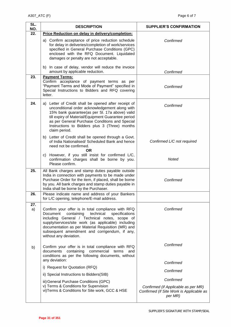
22. Price Reduction on delay in delivery/completion:
a) Confirm acceptance of price reduction schedule for delay in deliveries/completion of work/services specified in General Purchase Conditions (GPC) enclosed with the RFQ Document. Liquidated damages or penalty are not acceptable.
b) In case of delay, vendor will reduce the invoice amount by applicable reduction.
Confirmed
Confirmed
23. Payment Terms: Confirm acceptance of payment terms as per “Payment Terms and Mode of Payment” specified in Special Instructions to Bidders and RFQ covering letter.
Confirmed
24. a) Letter of Credit shall be opened after receipt of unconditional order acknowledgement along with 15% bank guarantee(as per Sl. 17a above) valid till expiry of Material/Equipment Guarantee period as per General Purchase Conditions and Special Instructions to Bidders plus 3 (Three) months claim period.
b) Letter of Credit shall be opened through a Govt. of India Nationalised/ Scheduled Bank and hence need not be confirmed.
OR c) However, if you still insist for confirmed L/C,
confirmation charges shall be borne by you. Please confirm.
Confirmed
Confirmed L/C not required
Noted
25. All Bank charges and stamp duties payable outside India in connection with payments to be made under Purchase Order for the item, if placed, shall be borne by you. All bank charges and stamp duties payable in India shall be borne by the Purchaser.
Confirmed
26. Please indicate name and address of your Bankers for L/C opening, telephone/E-mail address.
27. a)
b)
Confirm your offer is in total compliance with RFQ Document containing technical specifications including General / Technical notes, scope of supply/services/site work (as applicable) including documentation as per Material Requisition (MR) and subsequent amendment and corrigendum, if any, without any deviation.
Confirm your offer is in total compliance with RFQ documents containing commercial terms and conditions as per the following documents, without any deviation:
i) Request for Quotation (RFQ)
ii) Special Instructions to Bidders(SIB)
iii) General Purchase Conditions (GPC) v) Terms & Conditions for Supervision vi)Terms & Conditions for Site work, GCC & HSE
Confirmed
Confirmed
Confirmed
Confirmed
Confirmed
Confirmed (if Applicable as per MR) Confirmed (if Site Work is Applicable as
per MR)
Page 31 of 351

A307_ATC (F) Page 7 of 7
SUPPLIER’S SIGNATURE WITH STAMP/SEAL
SL. NO.
DESCRIPTION SUPPLIER’S CONFIRMATION
vii) Integrity Pact
viii) Commercial / Technical Amendments, if any
Confirmed
Confirmed
28. Direct offer without the intermediary of an Indian Agent will only be considered. Noted & Confirmed.
29. Please confirm you have not been banned or delisted by any Government or Quasi Government agencies or PSUs. If you have been banned, then this fact must be clearly stated. This does not necessarily be cause for disqualification. However if this declaration is not furnished the bid shall be rejected as non-responsive.
Not Banned
30.
30.1
30.2
Please confirm your offer contains the following:
Unpriced offer- without any deviations
Priced Offer Price Schedule with annexures only.
Confirmed
Confirmed
31. Any claim arising out of order shall be sent to Owner in writing with a copy to EIL within 3 months from the date of last despatch. In case the claim is received after 3 months, the same shall not be entertained by consultant / Owner.
Confirmed
32. Printed terms and conditions, if any, appearing in quotation, shall not be applicable in the event of order. In case of contradiction between the confirmations given above and terms & conditions mentioned elsewhere in the offer, the confirmation given/confirmed herein above shall prevail.
Confirmed
33. Confirm that Net worth of the Bidder’s company is positive as per the immediate preceding year’s audited financial results & Immediate preceding year’s audited annual financial results has been submitted along with unpriced bid.
Confirmed & Submitted
VENDOR’S NAME: SIGNATURE & SEAL:
Page 32 of 351

A307_ATC (I) Page 1 of 6
SUPPLIER’S SIGNATURE WITH STAMP/SEAL
BHARAT PETROLEUM CORPORATION LTD IREP-Kochi Refinery
(Job No. A307) AGREED TERMS & CONDITIONS (ATC)
(FOR INDIAN SOURCED COMPONENTS / SERVICES BY FOREIGN BIDDER) Supplier Name: M/s ______________________________________________________________
RFQ No.: __________________________________________________________________
Supplier’s Offer Ref No. & Date: ______________________________________________________
Tel. No. ___________________Mob. No. ______________________ Fax No. ________________
Contact Person: ___________________________ E-mail _________________________________
1. ALL CORRESPONDENCE MUST BE IN ENGLISH LANGUAGE ONLY.
2. DULY SIGNED & STAMPED COPIES OF THIS “QUESTIONNAIRE”, WITH ALL THE
CLAUSES DULY CONFIRMED/ PRECISELY REPLIED TO BY THE SUPPLIER, SHALL BE ENCLOSED.
3. ALL COMMERCIAL TERMS ARE GIVEN/CONFIRMED IN THE QUESTIONNAIRE ITSELF
AND NOT ELSEWHERE IN THE QUOTATION. IN CASE OF CONTRADICTION, THE SAME GIVEN HEREIN SHALL PREVAIL.
4. FAILURE ON PART OF THE SUPPLIER IN SUBMITTING THIS DULY FILLED-IN “QUESTIONNAIRE” WITH UN-PRICED BID AND/ OR SUBMITTING INCOMPLETE REPLIES MAY LEAD TO REJECTION OF SUPPLIER’S BID.
5. YOUR OFFER SHALL BE IN TOTAL COMPLIANCE WITH RFQ DOCUMENTS
CONTAINING COMMERCIAL AND TECHNICAL SPECIFICATIONS INCLUDING GENERAL/ TECHNICAL NOTES AND SCOPE OF SUPPLY/SERVICES/ SITE WORK, AS APPLICABLE INCLUDING DOCUMENTATION AS PER MATERIAL REQUISITION (MR) AND SUBSEQUENT TECHNICAL/ COMMERCIAL AMENDMENT AND TECHNICAL/ COMMERCIAL CORRIGENDUM, IF ANY.
SL. NO.
DESCRIPTION SUPPLIER’S CONFIRMATION
1.
i)
Price Basis:
Quoted supply prices are on FOT - Site basis inclusive of Packing & Forwarding, Taxes & Duties and Freight Charges
Confirmed
ii) Specify Despatch Point
----------------------- iii)
a)
b)
Freight Charges:
Confirm firm transportation charges inclusive of Service Tax and Ed Cess, upto project site, has already been included in supply price in Price Schedule.
No Variation on any account (including Statutory Variation) on Service Tax on Transportation Charges shall be paid by the owner.
a) Confirmed , Quoted in Price
Schedule
b) Confirmed
iv) Insurance:
a) For Supply Only
Transit/Marine Insurance of Equipment/ Item has been taken care by the Owner & charges of the same have not been included in the quoted prices.
(Applicable / Not Applicable) (Please tick whichever is applicable)
Page 33 of 351

A307_ATC (I) Page 2 of 6
SUPPLIER’S SIGNATURE WITH STAMP/SEAL
SL. NO.
DESCRIPTION SUPPLIER’S CONFIRMATION
b) For Supply + Site Work
Comprehensive Insurance (Transit/Marine-cum-storage-cum-erection till handing over of equipment) has been taken care by the Seller & charges of the same have been included in the quoted prices.
(Applicable / Not Applicable) (Please tick whichever is applicable)
2.
a.
b.
c.
d.
e. f.
g.
h.
Excise Duty applicable & included in Finished Goods price: Specify Excise Tariff Sub-Heading No. Present Rate of Excise Duty & Edu. Cess applicable on finished goods (including Spares) Any variations in Excise Duty & Edu. Cess at the time of supplies for any reasons including variation due to Turnover shall be borne by the Seller. Only Statutory Variations within the Contractual Delivery / completion period shall be borne by Purchaser. If Excise Duty & Edu. Cess is not applicable at present due to any reason, the same shall be borne by Seller if it becomes applicable later. Confirm Excise Duty & Edu. Cess will not be applicable on transportation charges. If Excise Duty & Edu. Cess is not applicable on transportation charges presently, and if it becomes applicable at the time of delivery due to any reasons other than statutory, the same will be borne by the Supplier. Confirm acceptance. Non Cenvatable Excise Duty, if any is included in quoted prices & no variation on any account (including statutory variation) shall be paid by Owner. Only Statutory Variations, if any, in the present rate of Excise Duty, upto the Contractual Delivery Date / Completion Period shall be to Owner’s account subject to documentary evidence to be furnished by Seller.
_________________
………..%
Confirmed
Confirmed
Confirmed
Confirmed
Confirmed
Confirmed
3.
a.
b.
c.
d.
e.
Sales Tax applicable included in finished goods price:
Central Sales Tax against Concessional Form “C” applicable on finished goods (including spares) is applicable & the present rate (in %age) is indicated
Kerala VAT applicable on finished goods (including spares) without concessional form & the present rate (in %age) is indicated
If CST / Kerala VAT is not applicable at present due to any reason, the same shall be borne by Supplier if it becomes applicable later.
Confirm CST/ Kerala VAT will not be applicable on transportation charges.
If CST / Kerala VAT is not applicable on transportation charges presently, and if it becomes applicable at the time of delivery due to any reasons other than statutory, the same will be borne by the Supplier. Confirm acceptance.
(Applicable / Not Applicable) (Please tick whichever is applicable)
…………%
(Applicable / Not Applicable) (Please tick whichever is applicable)
………….%
Confirmed
Confirmed
Confirmed
Page 34 of 351

A307_ATC (I) Page 3 of 6
SUPPLIER’S SIGNATURE WITH STAMP/SEAL
SL. NO.
DESCRIPTION SUPPLIER’S CONFIRMATION
h. Only Statutory Variations, if any, in the present rate of CST / Kerala VAT, upto the Contractual Delivery Date / Completion Period shall be to Owner’s account subject to documentary evidence to be furnished by Seller.
Confirmed
4. Octroi / Entry Tax:
Octroi / Entry Tax, if applicable on finished goods (including spares) shall be borne and paid directly by Owner. Confirm that Octroi / Entry Tax has not been included in the quoted prices.
Confirmed
5. Any new or additional taxes/ duties and any increase in the existing Cenvatable taxes/duties imposed after contractual completion period shall be to Supplier’s account whereas any corresponding decrease in the existing Cenvatable taxes/ duties shall be passed on to the Owner.
Confirmed
6.
a.
Spares Parts:
Confirm item wise unit price (FOT Site Basis) of following spare parts as required in Material Requisition (MR) have been included indicating itemised quantity.
i) Mandatory Spares are quoted as per MR.
ii) Commissioning spares as specified in MR are included in the quoted Price.
iii) Special Tools & Tackles as specified in the MR are included in the quoted prices.
iv) Confirm spares wherever required have been included in the quoted price and list of spares is also furnished.
v) Recommended Spares for Two Years Operation & Maintenance, as specified in MR have been quoted separately with Price validity of One (1) year from Contractual Delivery Date for Main Items/Equipment & List of such spares has been furnished in the Unpriced Bid.
Confirmed
Confirmed (if Applicable as per MR)
Confirmed (if Applicable as per MR)
Confirmed (if Applicable as per MR)
Confirmed (if Applicable as per MR)
Confirmed (if Applicable as per MR)
7.
a.
b.
c.
d.
Site Work:
For Site Work, if in the scope of the Bidder as per MR, please confirm the following:
Confirm that quoted site work prices are exclusive of Service Tax & Edu. Cess but inclusive of VAT on Works Contract and all other applicable taxes & duties.
Percentage of Service Tax & Edu. Cess as applicable extra on Site Work.
Supplier shall submit the Assessment/ Liability Certificate from Sales Tax authorities indicating the VAT on Works Contract payable for enabling Owner to deduct the same from Supplier Invoices & make payment to the tax authorities. TDS Certificate towards VAT on Works Contract shall be provided by Owner. Statutory variation on VAT on Works Contract shall not be payable by Owner. Statutory Variation on Service Tax & Edu. Cess on Site work shall be paid by the Owner against documentary evidence within Contractual completion period.
Confirmed
-------------------%
Confirmed
Confirmed
Page 35 of 351

A307_ATC (I) Page 4 of 6
SUPPLIER’S SIGNATURE WITH STAMP/SEAL
SL. NO.
DESCRIPTION SUPPLIER’S CONFIRMATION
e.
Confirm that Entry Tax / Octroi applicable on Construction Machinery/Equipment brought by the supplier to site to execute / complete the site work shall be borne by the Supplier and same is included in the quoted prices. No variation (including statutory) on such entry tax shall be paid by the Owner.
Confirmed
8.
a.
b.
c.
d.
e. f.
Supervision / Training Charges: Charges for Supervision / Training, if in the scope of the Bidder as per MR have been indicated by bidder separately in the Price Schedule. Percentage of Service Tax & Edu. Cess as applicable extra on Supervision / Training Per-diem rate for supervision has been quoted in accordance with the Terms & Conditions for Supervision enclosed with the RFQ Documents. Where erection/ testing/ commissioning supervision, commissioning assistance is required as per RFQ Documents / Material requisition, penalty for non mobilization/delay in mobilization as per order shall be applicable. The penalty shall generally be 1.5 times the per diem rate for each day of delay of reporting to site and shall be in addition to price reduction for delayed delivery. Bidders shall also provide additional BG of an amount equal to the per diem charges for the number of days considered for evaluation, over and above 10% PBG to cover compensation for delay in mobilizing the erection/ commissioning personnel. This BG will be released to the bidder upon the erection/ commissioning personnel reporting at site. This BG shall be furnished along with payment milestone for submission of final documentation as per MR and shall be initially valid up to six months which shall be extended based on the request by Owner. Principal Foreign Bidder will takecare BG / penalty supervision services for complete package including Indigenous supervision services if applicable.
Confirmed, Quoted in Price Schedule
----------------%
Confirmed
Noted & Confirmed
Noted & Confirmed
Noted & Confirmed
9. Confirm documentation charges as per MR are included in quoted prices.
Confirmed
10. Price Reduction for delay in delivery/ completion: a) Confirm acceptance of price reduction schedule for delay in
deliveries / completion as specified in GPC & Special Instructions to Bidders (SIB) enclosed in RFQ Document. Liquidated damages or penalty are not acceptable.
c) In case of delay, vendor will reduce the invoice amount by
applicable reduction. d) Principal Foreign Bidder will be responsible for all
obligation & liability of PRS applicable on Indian Source Items / services.
Confirmed
Confirmed
Confirmed
Page 36 of 351

A307_ATC (I) Page 5 of 6
SUPPLIER’S SIGNATURE WITH STAMP/SEAL
SL. NO.
DESCRIPTION SUPPLIER’S CONFIRMATION
11. Delivery / Completion Period: Please confirm delivery / completion period shall be as specified in the RFQ Covering Letter for foreign bidder on FOT Site Basis. Date of Good Receipt (GR) shall be considered as the date of delivery.
Confirmed
12.
Payment Terms: Confirm acceptance of “Terms and Mode of Payment” as per respective clause(s) given in SIB (Annexure-A)
Confirmed
14. Repeat Order: Confirm Acceptance of Repeat Order clause as per RFQ Covering Letter / SIB / GPC.
Confirmed
15.
Performance Bank Guarantee: a) In the event of award of order, submission of Performance
Bank Guarantee for 10% of total order value along with Final supply payment valid till full guarantee period plus 3 (Three) months.
b) The Performance Bank Guarantee shall be strictly as per enclosed proforma and shall be from any Indian Scheduled Bank or branch of an International Bank situated in India and registered with Reserve Bank of India as scheduled foreign Bank.
c) Principal Foreign Bidder will submit PBG for complete package including Indian Source Items / services.
Confirmed
Confirmed
Confirmed
16. Guarantee / Warranty: Confirm acceptance to Guarantee / Warranty clause as mentioned in the GPC/SIB. Principal Foreign Bidder will be responsible for all obligation & liability of Guarantee / Warranty of Indian Source Items / services.
Confirmed
Confirmed
17. Firmness of prices: Confirm quoted prices shall remain firm and fixed till complete execution of order. Price Variation shall not be considered on any account.
Confirmed
18. a.
b.
c.
Testing and Inspection charges: Goods supplied are subject to stage wise and final inspection as specified in MR by EIL and no extra charges shall be payable by Owner towards the same. Travel, Living and Personnel expenses of EIL’s Representative shall be borne by Owner.
Quoted prices are: i) Inclusive of all testing and inspection charges (if applicable)
as per MR. ii) Inclusive of all IBR/IGC/NACE charges (if applicable) as
required in the Material Requisition. iii) Inclusive of all statutory certification charges PESO/CCOE
etc. (if applicable) as required in the Material Requisition
Is your shop approved by IBR/CCE authority, if yes, indicate validity. i. IBR ii. CCE It is the responsibility of supplier to get the entire imported materials and the built in imported contents inspected by TPIA (i.e. Lloyds/BV/DNV/TUV/CEIL) in the country of origin and the quoted prices are inclusive of charges towards the same.
Confirmed
Confirmed
Confirmed
Confirmed
IBR Approved
Confirmed
Page 37 of 351

A307_ATC (I) Page 6 of 6
SUPPLIER’S SIGNATURE WITH STAMP/SEAL
SL. NO.
DESCRIPTION SUPPLIER’S CONFIRMATION
d. Considering EIL Inspection charges, during evaluation prices of Indigenous source item shall be loaded by @1.25% of FOT Despatch Point price.
Confirmed
19.
a.
Validity of Bid:
Confirm Bid validity as stipulated in RFQ covering letter from the final due date of bid submission.
Confirmed
20.
a)
b)
Compliance to RFQ documents:
Confirm your offer is in total compliance with RFQ Document containing technical specifications including General / Technical notes, scope of supply/services/site work (as applicable) including documentation as per Material Requisition (MR) and subsequent amendment and corrigendum, if any.
Confirm your offer is in total compliance with RFQ documentation containing commercial terms and conditions as per the following documents, without any deviation:
i) Request for Quotation (RFQ) ii) Special Instructions to Bidders (SIB) iii) General Purchase Conditions (GPC) iv) Terms & Conditions of Site work / GCC / HSE / Integrity
Pact. v) Terms & Conditions for Supervision services
Confirmed
Confirmed Confirmed Confirmed
Confirmed(if applicable)
Confirmed(if applicable)
21. Whether any of the Directors of Bidder is a relative of any Director of Owner/EIL or the Bidder is a firm in which any Director of Owner/EIL or his relative is a Partner or the Bidder is a private company in which any director of Owner/EIL is a member or Director.
Confirmed No relation
22. Please confirm you have not been banned or delisted by any Government or Quasi Government agencies or PSUs. If you have been banned, then this fact must be clearly stated. This does not necessarily mean cause for disqualification. However if this declaration is not furnished the bid shall be rejected as non-responsive.
Not Banned
23.
23.1
23.2 a.
Please confirm your offer contains the following:
UNPRICED OFFER- without any Deviations
PRICED OFFER Duly filled Price Schedule with relevant annexures
Confirmed
Confirmed
24. Please confirm that you have quoted strictly for items based on your registration/approval with EIL as on date of issue of RFQ.
Confirmed
25. Any claim arising out of order shall be sent to Owner in writing with a copy to EIL within 3 months from the date of last despatch. In case the claim is received after 3 months, the same shall not be entertained by Consultant/ Owner.
Confirmed
26. Printed terms and conditions, if any, appearing in quotation, shall not be applicable in the event of order. In case of contradiction between the confirmations given above and terms & conditions mentioned elsewhere in the offer, the confirmation given/confirmed herein above shall prevail.
Confirmed
Page 38 of 351

BPCL-KR Job: A307
A307_SIB Rev.6 dt. 14.04.2014 Page 1 of 20
INTEGRATED REFINERY EXPANSION PROJECT
OF M/s BHARAT PETROLEUM CORPORATION LTD,
KOCHI REFINERY, KOCHI, KERALA
SPECIAL INSTRUCTION TO BIDDER (SIB)
Page 39 of 351

BPCL-KR Job: A307
A307_SIB Rev.6 dt. 14.04.2014 Page 2 of 20
INDEX
SECTION – A (TERMS OF PAYMENT) 1.0 Payment Terms For Indian Bidders 2.0 Payment Terms For Foreign Bidders 3.0 Ocean Freight
SECTION – B: EVALUATION CRITERIA FOR COMPARISION OF BIDS 4.0 Where only Indian Bids are under comparison 5.0 Where only Foreign Bids are under comparison 6.0 Where Indian as well as Foreign Bids are under comparison 7.0 General Notes 8.0 Special Notes on Taxes/Duties and CENVAT benefits 9.0 Price Reduction Schedule Towards Delay In Delivery 10.0 Guarantee / Warranty Period SECTION-C: (COMMERCIAL LOADING OF OFFERS IN CASE OF DEVIATIONS) 11.0 Basis of Loading 12.0 Payment Terms 13.0 Performance Bank Guarantee (PBG) 14.0 Delayed Deliveries 15.0 Price Variation 16.0 Freight charges 17.0 Indian taxes/ duties 18.0 Utilities 19.0 Delivery/Completion Period 20.0 Foreign Exchange Rate Variation/Custom Duty Variation For Indian Bidders (On
Built-In Import Content) 21.0 VAT on Works Contracts/ Service Tax/ Splitting Of Orders 22.0 Entry Tax 23.0 Rejection Criteria 24.0 Suo-Moto Changes In Prices 25.0 Price Implication Not Permitted 26.0 Integrity Pact SECTION-D: SPECIAL CONDITIONS. 27.0 Delivery Schedule/ Completion Period 28.0 Despatch Instructions for Indigenous Supplies 29.0 Additional Taxes & Duties (Applicable For Indian Bidder) 30.0 Recovery Of Custom Duty, Excise Duty And Sales Tax 31.0 Governing Law 32.0 Purchaser’s Rights And Remedies 33.0 Deduction At Source 34.0 Statutory Approval 35.0 Lien 36.0 Limitation Of Liability SECTION-E: GENERAL INSTRUCTIONS 37.0 General 38.0 Fraudulent Practices 39.0 One Bid Per Bidder 40.0 Language Of Bid 41.0 Earnest Money Deposit: 42.0 Modification And Withdrawal Of Bids 43.0 Examination Of Bids And Determination Of Responsiveness 44.0 Owner’s Right To Accept Any Bid And To Reject Any Bid 45.0 Notification Of Award 46.0 Waiver Or Transfer Of The Agreement 47.0 T&C For Foreign Suppliers (To Whom RFQ Issued) Operated Through Their Indian
Office / Subsidiaries 48.0 Tax Residency Certificate (TRC) Format For Foreign Bidder 49.0 Requirement of Employment Visa For Foreign Nationals
SECTION-F: ADDITIONAL CLAUSES TO GPC 50.0 Settlement of dispute between CPSEs or CPSEs & Government Departments
Annexure-A ( Terms & Conditions For Indian Sourced Components / Services By Foreign Bidder)
Page 40 of 351

BPCL-KR Job: A307
A307_SIB Rev.6 dt. 14.04.2014 Page 3 of 20
SPECIAL INSTRUCTIONS TO BIDDERS
BHARAT PETROLEUM CORPORATION LIMITED, KOCHI REFINERY
INTEGRATED REFINERY EXPANSION PROJECT
SECTION-A: TERMS OF PAYMENT
In partial modification of the Payment Terms as mentioned in the General Purchase Conditions, the following payment terms shall be applicable.
1.0 PAYMENT TERMS FOR INDIAN BIDDERS:
1.1 Where the Material Requisition is only for supply of materials and there is no Supplier Data Requirement specified in MR e.g. Bulk Piping Items, etc.
1.1.1 100% Payment within 30 days after receipt and acceptance of materials at site and on submission of Performance Bank Guarantee for 10% of Total Order Value, valid till the full guarantee period plus Three months claim period.
1.2 Where the Material Requisition calls for Supplier Drawings/Technical Documentation.
1.2.1 90% Payment within 30 days of receipt and acceptance of materials at Site and on submission of dispatch documents.
1.2.2 10% Payment after receipt of final technical documentation as per PR against EIL’s certification and on submission of Performance Bank Guarantee for 10% of Total Order Value, valid till full guarantee period plus Three months claim period.
1.3 Where Supply of materials and Erection or Site Work are in the scope of Supplier and Package Items.
1.3.1 Supply
1.3.1.1 5% Payment on approval of all drawings atleast in CODE-2 by EIL against submission of Bank Guarantee of equivalent amount valid till complete execution of Order plus Three months claim period.
1.3.1.2 15% Payment after receipt of identified raw materials at Supplier’s Works and against certification by EIL and submission of Bank Guarantee of equivalent amount valid till complete execution of Order plus Three months claim period.
1.3.1.3 60% Payment after receipt of equipment/materials at BPCL’s Site. Billing Schedule to be furnished by the Supplier in case pro-rata payments are required.
1.3.1.4 10% payment after completion of Site Work and submission of final Technical documents as specified in the Purchase Requisition against EIL’s Certification and submission of Performance Bank Guarantee for 10% of Total Order Value (Supply plus Site Work), valid till full guarantee period plus three months claim period.
In case of delay in start of the site work beyond 6 months, the above 10% Payment shall be released against submission of Bank Guarantee of equivalent amount valid initially for 1 year and subject to extension upto completion of the site work. However, in the event of delay in the site work, the Supplier is not relieved of his responsibility to carry out the same.
1.3.1.5 10% payment within 30 days of handing over the successfully commissioned equipment. Wherever commissioning is not in the Supplier’s scope, the payment will be released after completion of Site Work as per PR and handing over of equipment.
1.3.2 Erection/ Site work
1.3.2.1 90% Payment against monthly running bills (based on agreed Billing Schedule), duly certified by EIL.
1.3.2.2 10% Payment within 30 days after final handing over of equipment package to BPCL at site.
1.4 Fabricated Items (Vessels, Columns, Heat Exchangers, etc.)
1.4.1 5% Payment on approval of all drawings atleast in CODE-2 by EIL against submission of Bank Guarantee of equivalent amount valid till complete execution of Order plus Three months claim period.
Page 41 of 351

BPCL-KR Job: A307
A307_SIB Rev.6 dt. 14.04.2014 Page 4 of 20
1.4.2 15% after receipt of identified raw materials at Supplier’s Works and against certification by EIL and submission of Bank Guarantee of equivalent amount valid till complete execution of Order plus Three months claim period.
1.4.3 60% Payment through NEFT against receipt of materials at BPCL’s Site. Billing Schedule to be furnished by the Supplier in case pro-rata payments are required.
1.4.4 10% Payment after receipt of final documents as required in Purchase Requisition against EIL’s certification and on submission of Performance Bank Guarantee for 10% of Total Order Value, valid till full guarantee period plus Three months claim period.
1.4.5 Balance 10% Payment within 30 days of receipt of equipment at Site.
1.5 Other Items (Pumps, Compressors, Switchgears, etc.)
1.5.1 5% Payment on approval of all drawings atleast in CODE-2 by EIL against submission of Bank Guarantee of equivalent amount valid till complete execution of Order plus Three months claim period.
1.5.2 75% Payment against receipt of materials at BPCL’s Site. Billing Schedule to be furnished by the Supplier in case pro-rata payments are required.
1.5.3 10% Payment after receipt of final documents as required in Purchase Requisition against EIL’s certification and on submission of Performance Bank Guarantee for 10% of Total Order Value, valid till full guarantee period plus three months claim period
1.5.4 Balance 10% Payment against Commissioning/Demonstration of Performance Guarantee (if applicable) or 6 months from receipt of material at Site (against Bank Guarantee of equivalent amount valid for 1 year), whichever is earlier. However, in the event of delay in conducting the Performance Guarantee Run, the Supplier is not relieved of his responsibility to carry out the same. No additional payment shall be made for visit of Supplier to Site for demonstrating the performance, if the same is included in the scope of Supplier.
For items where supervision during erection, testing and commissioning is not required, the last 10% Payment shall be released within 30 days of receipt of material at Site.
1.6 Payment for PGTR / Per Diem Charges for Supervision of Erection, Testing &
Commissioning
1.6.1 100% Payment of Invoice Amount shall be paid on completion of supervision services / PGTR against submission of Invoice along with Time Sheet duly certified by EIL/BPCL Site-In-Charge. Payment shall be made after deducting Income Tax at applicable rate. Service Tax, if any, shall be paid on submission of Service Tax Invoice.
1.6.2 Where erection/commissioning supervision, commissioning assistance is required from the vendor, penalty for non mobilization/delay in mobilization as per order shall also be specified in the specifications. The penalty shall generally be 1.5 times the per diem rate for each day of delay of reporting to site and shall be in addition to price reduction for delayed delivery.
1.6.3 Wherever supervision is in the scope of MR, bidders shall provide additional BG of an amount equal
to the per diem charges for the number of days considered for evaluation over and above 10% PBG to cover compensation for delay in mobilising the erection/ commissioning personnel. This BG will be released to the bidder upon the erection/ commissioning personnel reporting at site. This BG shall be furnished along with payment milestone for submission of final documentation as per PR and shall be valid up to six months which shall be extended based on the request by BPCL. (In case where commissioning, Performance Guarantee Test, etc. are required and the 10% is under hold, this condition shall not be applicable).
1.7 Transportation charges
1.7.1 100% Payment within 4 weeks after receipt of materials at site.
1.8 General
1.8.1 Excise Duty, Service Tax & VAT on Supplies shall be released only on receipt of Cenvatable/ Vatable copy of corresponding Invoice enabling availing of Input Credit by BPCL.
1.8.2 No initial advance payment along with Order shall be made by the Owner against Supplies as well as Services (i.e. Transportation, Erection, Site Work, etc.). If a Supplier insists on the same, their Offer shall be rejected.
1.8.3 Bank Guarantee(s) shall be issued through Scheduled Commercial Bank in India/ Indian Branch of Foreign Bank, directly to BPCL as per the Pro-forma enclosed with RFQ documents and Supplier shall also enclose copy of the same along with Invoice.
Page 42 of 351
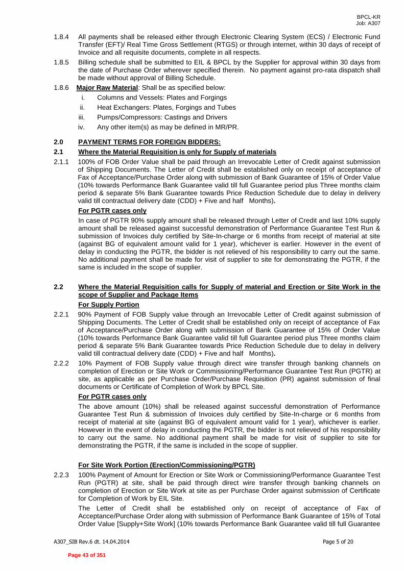
BPCL-KR Job: A307
A307_SIB Rev.6 dt. 14.04.2014 Page 5 of 20
1.8.4 All payments shall be released either through Electronic Clearing System (ECS) / Electronic Fund Transfer (EFT)/ Real Time Gross Settlement (RTGS) or through internet, within 30 days of receipt of Invoice and all requisite documents, complete in all respects.
1.8.5 Billing schedule shall be submitted to EIL & BPCL by the Supplier for approval within 30 days from the date of Purchase Order wherever specified therein. No payment against pro-rata dispatch shall be made without approval of Billing Schedule.
1.8.6 Major Raw Material: Shall be as specified below:
i. Columns and Vessels: Plates and Forgings
ii. Heat Exchangers: Plates, Forgings and Tubes
iii. Pumps/Compressors: Castings and Drivers
iv. Any other item(s) as may be defined in MR/PR.
2.0 PAYMENT TERMS FOR FOREIGN BIDDERS:
2.1 Where the Material Requisition is only for Supply of materials
2.1.1 100% of FOB Order Value shall be paid through an Irrevocable Letter of Credit against submission of Shipping Documents. The Letter of Credit shall be established only on receipt of acceptance of Fax of Acceptance/Purchase Order along with submission of Bank Guarantee of 15% of Order Value (10% towards Performance Bank Guarantee valid till full Guarantee period plus Three months claim period & separate 5% Bank Guarantee towards Price Reduction Schedule due to delay in delivery valid till contractual delivery date (CDD) + Five and half Months).
For PGTR cases only
In case of PGTR 90% supply amount shall be released through Letter of Credit and last 10% supply amount shall be released against successful demonstration of Performance Guarantee Test Run & submission of Invoices duly certified by Site-In-charge or 6 months from receipt of material at site (against BG of equivalent amount valid for 1 year), whichever is earlier. However in the event of delay in conducting the PGTR, the bidder is not relieved of his responsibility to carry out the same. No additional payment shall be made for visit of supplier to site for demonstrating the PGTR, if the same is included in the scope of supplier.
2.2 Where the Material Requisition calls for Supply of material and Erection or Site Work in the scope of Supplier and Package Items
For Supply Portion
2.2.1 90% Payment of FOB Supply value through an Irrevocable Letter of Credit against submission of Shipping Documents. The Letter of Credit shall be established only on receipt of acceptance of Fax of Acceptance/Purchase Order along with submission of Bank Guarantee of 15% of Order Value (10% towards Performance Bank Guarantee valid till full Guarantee period plus Three months claim period & separate 5% Bank Guarantee towards Price Reduction Schedule due to delay in delivery valid till contractual delivery date (CDD) + Five and half Months).
2.2.2 10% Payment of FOB Supply value through direct wire transfer through banking channels on completion of Erection or Site Work or Commissioning/Performance Guarantee Test Run (PGTR) at site, as applicable as per Purchase Order/Purchase Requisition (PR) against submission of final documents or Certificate of Completion of Work by BPCL Site.
For PGTR cases only
The above amount (10%) shall be released against successful demonstration of Performance Guarantee Test Run & submission of Invoices duly certified by Site-In-charge or 6 months from receipt of material at site (against BG of equivalent amount valid for 1 year), whichever is earlier. However in the event of delay in conducting the PGTR, the bidder is not relieved of his responsibility to carry out the same. No additional payment shall be made for visit of supplier to site for demonstrating the PGTR, if the same is included in the scope of supplier.
For Site Work Portion (Erection/Commissioning/PGTR)
2.2.3 100% Payment of Amount for Erection or Site Work or Commissioning/Performance Guarantee Test Run (PGTR) at site, shall be paid through direct wire transfer through banking channels on completion of Erection or Site Work at site as per Purchase Order against submission of Certificate for Completion of Work by EIL Site.
The Letter of Credit shall be established only on receipt of acceptance of Fax of Acceptance/Purchase Order along with submission of Performance Bank Guarantee of 15% of Total Order Value [Supply+Site Work] (10% towards Performance Bank Guarantee valid till full Guarantee
Page 43 of 351

BPCL-KR Job: A307
A307_SIB Rev.6 dt. 14.04.2014 Page 6 of 20
period plus Three months claim period & separate 5% Bank Guarantee towards Price Reduction Schedule due to delay in delivery valid till contractual delivery date (CDD) + Five and half Months).
2.3 For Training
2.3.1 At Site: 100% payment against final bill to be submitted by seller after completion of training duly certified by site-in-charge.
2.3.2 At Supplier’s Works: 100% payment against final bill to be submitted by seller after completion of training.
2.4 Annual Maintenance Contract
100% payment shall be paid at the end of each quarter of the contractual year against quarterly progressive bills to be submitted by Seller duly certified by Site-in-Charge.
2.5 Payment for PGTR / Per Diem Charges for Supervision of Erection, Testing &
Commissioning
2.5.1 100% Payment of Invoice amount through direct wire transfer as per normal banking channels on completion of supervision activity / PGTR upon submission of Invoice, Time Sheet duly certified by Site In-Charge at BPCL Site, legible copy of visa (showing date of entry and date of exit from India) and passport (showing Name and Nationality of the personnel). Payment shall be made after deducting Income Tax at applicable rate.
2.5.2 Where erection/commissioning supervision, commissioning assistance is required from the vendor, penalty for non mobilization/delay in mobilization as per order shall also be specified in the specifications. The penalty shall generally be 1.5 times the per diem rate for each day of delay of reporting to site and shall be in addition to price reduction for delayed delivery.
2.5.3 Wherever supervision is in the scope of MR, bidders shall provide additional BG of an amount equal
to the per diem charges for the number of days considered for evaluation over and above 10% PBG to cover compensation for delay in mobilising the erection/ commissioning personnel. This BG will be released to the bidder upon the erection/ commissioning personnel reporting at site. This BG shall be furnish along with dispatch documents which shall be initially valid up to six months whixh shall be extended based on the request by BPCL.
2.6 General
2.6.1 No initial advance payment along with Order shall be made by the Owner against Supplies as well as Services (i.e. Transportation, Erection, Site Work, etc.). If a Supplier insists on the same, their Offer shall be rejected.
2.6.2 All Bank Guarantee(s) shall be issued through any Indian Scheduled Bank or branch of an International Bank situated in India and registered with Reserve Bank of India as scheduled foreign Bank as per Pro-forma provided in RFQ documents. All Bank Guarantees will be directly to BPCL by the Bank.
2.6.3 All bank charges and stamp duties payable outside India in connection with payments shall be borne by the Supplier. All bank charges and stamp duties payable in India shall be borne by BPCL except L/C Amendment charges for delays in delivery. Confirmation charges for Confirmed L/C shall be borne by Supplier.
2.6.4 Billing schedule shall be submitted to EIL & BPCL by the Supplier for approval within 30 days from the date of Purchase Order wherever specified therein. No part shipment shall be made without approval of billing schedule.
2.6.5 Subject to Technical Acceptability, For supplies sourced within India (if any) by Foreign Bidder & directly dispatched to Site shall have following provisions: (Refer Annexure-A)
3.0 OCEAN FREIGHT:
3.1 Ocean freight from FOB Port of Exit to designated Indian Port shall be arranged by BPCL through their nominated Freight Forwarder. Supplier shall arrange handing over the material to BPCL Freight Forwarder at the designated Port of Exit.
3.2 In cases where the RFQ requires the Supplier to quote Ocean Freight, BPCL reserves the right to ask the Supplier to arrange shipment through their own Freight Forwarder at the quoted freight rates.
3.3 Owner/EIL reserves the right to place the order for foreign bidder either on FOB basis or CFR basis. In case of award, initially the order shall be placed on FOB basis and Owner reserves the right to convert the same to CFR basis within 4 months, from placement of order. Therefore, the Ocean
Page 44 of 351
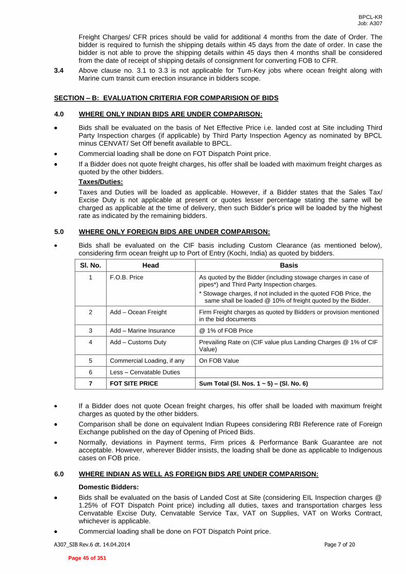
BPCL-KR Job: A307
A307_SIB Rev.6 dt. 14.04.2014 Page 7 of 20
Freight Charges/ CFR prices should be valid for additional 4 months from the date of Order. The bidder is required to furnish the shipping details within 45 days from the date of order. In case the bidder is not able to prove the shipping details within 45 days then 4 months shall be considered from the date of receipt of shipping details of consignment for converting FOB to CFR.
3.4 Above clause no. 3.1 to 3.3 is not applicable for Turn-Key jobs where ocean freight along with Marine cum transit cum erection insurance in bidders scope.
SECTION – B: EVALUATION CRITERIA FOR COMPARISION OF BIDS
4.0 WHERE ONLY INDIAN BIDS ARE UNDER COMPARISON:
Bids shall be evaluated on the basis of Net Effective Price i.e. landed cost at Site including Third Party Inspection charges (if applicable) by Third Party Inspection Agency as nominated by BPCL minus CENVAT/ Set Off benefit available to BPCL.
Commercial loading shall be done on FOT Dispatch Point price.
If a Bidder does not quote freight charges, his offer shall be loaded with maximum freight charges as quoted by the other bidders.
Taxes/Duties:
Taxes and Duties will be loaded as applicable. However, if a Bidder states that the Sales Tax/ Excise Duty is not applicable at present or quotes lesser percentage stating the same will be charged as applicable at the time of delivery, then such Bidder’s price will be loaded by the highest rate as indicated by the remaining bidders.
5.0 WHERE ONLY FOREIGN BIDS ARE UNDER COMPARISON:
Bids shall be evaluated on the CIF basis including Custom Clearance (as mentioned below), considering firm ocean freight up to Port of Entry (Kochi, India) as quoted by bidders.
Sl. No. Head Basis
1 F.O.B. Price As quoted by the Bidder (including stowage charges in case of pipes*) and Third Party Inspection charges.
* Stowage charges, if not included in the quoted FOB Price, the same shall be loaded @ 10% of freight quoted by the Bidder.
2 Add – Ocean Freight Firm Freight charges as quoted by Bidders or provision mentioned in the bid documents
3 Add – Marine Insurance @ 1% of FOB Price
4 Add – Customs Duty Prevailing Rate on (CIF value plus Landing Charges @ 1% of CIF Value)
5 Commercial Loading, if any On FOB Value
6 Less – Cenvatable Duties
7 FOT SITE PRICE Sum Total (Sl. Nos. 1 ~ 5) – (Sl. No. 6)
If a Bidder does not quote Ocean freight charges, his offer shall be loaded with maximum freight charges as quoted by the other bidders.
Comparison shall be done on equivalent Indian Rupees considering RBI Reference rate of Foreign Exchange published on the day of Opening of Priced Bids.
Normally, deviations in Payment terms, Firm prices & Performance Bank Guarantee are not acceptable. However, wherever Bidder insists, the loading shall be done as applicable to Indigenous cases on FOB price.
6.0 WHERE INDIAN AS WELL AS FOREIGN BIDS ARE UNDER COMPARISON:
Domestic Bidders:
Bids shall be evaluated on the basis of Landed Cost at Site (considering EIL Inspection charges @ 1.25% of FOT Dispatch Point price) including all duties, taxes and transportation charges less Cenvatable Excise Duty, Cenvatable Service Tax, VAT on Supplies, VAT on Works Contract, whichever is applicable.
Commercial loading shall be done on FOT Dispatch Point price.
Page 45 of 351

BPCL-KR Job: A307
A307_SIB Rev.6 dt. 14.04.2014 Page 8 of 20
Foreign Bidders:
Bids shall be evaluated on the basis of landed cost at Site including the charges of inspection by Third Party Inspection Agency, all duties, taxes and ocean freight charges as under less Cenvatable
CVD/SAD, Cenvatable Service Tax, VAT on Supplies, VAT on Works Contract, whichever is
applicable.
Sl. No. Head Basis
1 F.O.B. Price As quoted by the Bidder (including stowage charges in case of pipes*) and Third Party Inspection charges.
* Stowage charges, if not included in the quoted FOB Price, the same shall be loaded @ 10% of freight quoted by the Bidder.
2 Add – Ocean Freight Firm Freight charges as quoted by Bidders
3 Add – Marine Insurance @ 1% of FOB Price
4 Add – Customs Duty Prevailing Rate on (CIF value plus Landing Charges @ 1% of CIF Value)
5 Add – Port Handling Charges @ 2% of CIF Value
Sl. No. Head Basis
6 Add – Inland Freight Charges from Port of Entry in India to Project Site
1% of Landed Cost i.e. Sl. Nos. 1 to 5
7 Add – L/C charges @ 1% of FOB Price
8 Commercial Loading, if any On FOB Value
9 Less – Cenvatable Duties
10 FOT SITE PRICE Sum Total (Sl. Nos. 1 ~ 8) – (Sl. No. 9)
Wherever supervision and site works are involved, in that cases service tax plus Ed. Cess shall be loaded with as applicable rates
7.0 GENERAL NOTES:
i. Cost of Mandatory (Insurance) Spares, if identified in the Material Requisition, Commissioning spares and Special Tools & Tackles will be included for price evaluation of bids, but costs of Spares for Two Years Normal Operation & Maintenance shall be excluded.
ii. Cost of loading towards Technical Parameters (Utilities, etc.) wherever applicable shall be carried out.
iii. BPCL shall claim CENVAT benefits on Excise Duty, CVD/SAD, Service Tax as well as the Cess applicable and accordingly Excise Duty/ CVD/ SAD/ Cess/ Service Tax shall be considered and necessary credit shall be given for evaluation and comparison of bids.
Wherever Site Work, AMC, Training, Supervision, etc. are required as per MR/RFQ, the same shall be considered for evaluation.
iv. Bidders shall indicate the Customs Duty at Merit Rate in their Offer.
v. The Bidder must ascertain and confirm along with supporting documents in the bid, if any Custom duty exemption / waiver is applicable to the products being supplied by bidder under any multi-lateral / bi-lateral trade agreement between India and Bidder’s country. The bidder shall liable to provide all documentation to ensure availment of the exemption / waiver. In case the bidder defaults on this due to any reason whatsoever, they shall be liable to bear the incremental Custom Duty applicable, if any. Any Custom Duty applicability on account of any change in the bi-lateral / multi-lateral agreement shall be in bidder’s account.
Page 46 of 351

BPCL-KR Job: A307
A307_SIB Rev.6 dt. 14.04.2014 Page 9 of 20
Documentation to be furnished for availing any exemption / waiver of Custom Duty shall be specifically listed in Letter of Credit also as the pre-requisite for release of payment against shipping documents and this documentation shall necessarily from a part of shipping documents.
vi. BPCL shall issue Concessional Form ‘C’ for Central SalesTax, for all applicable cases. vii. Comparison shall be done on equivalent Indian Rupees considering RBI Reference Rate of Foreign
Exchange published on the day of opening of the Price Bids. viii. Third Party Inspection charges for foreign bidder must be included in quoted prices or anything
specifically mentioned in RFQ documents.. ix. Excise Duty, Central Sales Tax, VAT on Supplies & Service Tax shall not be included in the quoted
prices and shall be payable extra at actual. BPCL shall claim eligible credit on CENVAT/Service Tax/VAT quoted by the Bidder and therefore eligible portion of CENVAT/Service Tax/VAT shall be considered for price comparison. Bidder shall be required to furnish proper invoices issued in accordance with relevant rules for enabling BPCL to avail CENVAT benefits. Further, the amount of Excise Duty, Service Tax & VAT shall only be payable against submission of CENVATABLE/ VATABLE Invoices, subject to maximum amount quoted in the Offer and in case of non-submission, will not be paid.
x. Bidders quoted transportation charges shall be inclusive of service tax plus education cess thereupon applicable on transportation.
xi. Transit Insurance/ Marine Insurance shall be excluded from Supplier’s scope for the items where only supply is involved, and in such cases, the same shall be arranged by the Owner. For purchases involving Site Work, the Comprehensive Insurance (Transit/Marine cum Storage, Erection, till handing over of equipment) shall be in the scope of Supplier.
xii. Owner reserves its right to allow Public Sector Enterprises (Central/State), Micro & Small Enterprises (MSEs) and MSEs owned by Scheduled Caste (SC)/ Scheduled tribe (ST) entrepreneurs, purchase preference as admissible/applicable from time to time under the existing Govt. policy. Bidder to submit documentary evidence for the same duly certified by Statutory Auditor of the bidder or a practicing Charted Account (not being an employee or a Director or not having any interest in the Bidder’s company / firm) where audited accounts are not mandatory as per law.). In this regard, item wise quantity may be splitted and the quoted price shall remain valid.
xiii. If various item rates are present in the RFQ and if there is correction/wrong entry or a difference between the values entered in figures and in words, the following procedure shall be adopted for evaluation.
i. When there is a difference between the rate in figures and in words for an item, the rate which corresponds to the amount worked out by the Bidder for the item based on the notional quantity specified, shall be taken as correct.
ii. When the rate quoted by the Bidder in figures and words tallies but the amount is incorrect, the rate quoted by the Bidder shall be taken as correct.
iii. When it is not possible to ascertain the correct rate as detailed above, the rate quoted for the item in words shall be adopted as the quoted rate.
iv. If the total amount written against an item does not correspond to the rate written in figures and if the rate in words is missing, then the higher of the rates, i.e. higher of the rate worked out by dividing the amount by the notional quantity and the rate quoted shall be considered for evaluation In the event that such a bid is determined as the lowest bid, the lower of the rates shall be considered for award of works.
8.0 SPECIAL NOTES ON TAXES/DUTIES AND CENVAT BENEFITS:
(i) CST/ Kerala VAT (Applicable only on supplies being made from within state of Kerala), as applicable during the contractual delivery period, shall be paid by the supplier and the same shall be reimbursed on submission of the documentary proof. 'C' Form for CST will be issued for all applicable cases. However no concessional form is applicable for Kerala VAT.
(ii) CENVAT BENEFITS: In view of CENVAT/ Input credit benefits being available to BPCL on Excise Duty, no loading on Cenvatable excise duty and/ or interest thereon shall be considered for comparison of bids. In the case of Kerala VAT on Supplies, loading will be done to extent of 80% of VAT rate (since VAT credit is available for 20% only) In the case of Service Tax, Cenvat credit against Service Tax shall be available to BPCL to the extent of 96% only. Hence loading of 4% of Service Tax rate shall be considered for Price evaluation.
(iii) BPCL shall claim CENVAT benefits on Excise Duty, Kerala VAT /CVD/SAD/Service Tax as well as the cess applicable and accordingly Excise Duty /VAT/CVD/SAD/Service Tax, Cess shall be considered and necessary credit shall be given for evaluation and comparison of
Page 47 of 351

BPCL-KR Job: A307
A307_SIB Rev.6 dt. 14.04.2014 Page 10 of 20
bids. Credit shall be taken during evaluation for 20% of Kerala VAT rate, 96% of Service Tax rate and full amount for other Cenvatable taxes and duties.
(iv) Excise Duty, Central Sales Tax, Kerala VAT & Service Tax shall not be included in the quoted prices and shall be payable extra at actuals. Further, the amount of Excise Duty, Service Tax, Central Sales Tax, KVAT shall only be payable against submission of supporting documents/Cenvatable/Vatable invoices subject to maximum amount quoted in the offer and in case of non-submission, will not be paid.
(v) Non Cenvatable Excise Duty, if any is to be included in quoted prices & no variation on any
account (including statutory variation) shall be paid by Owner. (vi) All New taxes/duties/cess/levies notified after the last date of submission of bid (final bid due
date) but within contractual delivery/ completion period, shall be to Owner’s account.
(vii) The bidder shall be required to furnish details of any special dispensation regarding concessional/ exempted taxes/ duties.
9.0 PRICE REDUCTION SCHEDULE TOWARDS DELAY IN DELIVERY:
i. For Indigenous Vendor:
a) In case item involving supply and site work:- Price Reduction Schedule towards delay in delivery for domestic bidder shall be applicable as per clause no. 9.0 of GPC Indigenous of RFQ subject to following modification:
“Price Reduction schedule for (Supply + Site work) shall be @ 0.5% of value of total order value (TOV) of per week of delay or part thereof subject to maximum of 5% total order value (TOV)”.
b) In case item involving only supply:- Delayed Delivery shall be as per clause 9 of GPC (For Indigenous materials & equipments).
ii. For Foreign Vendor:
c) In case item involving supply and site work:-
Price Reduction Schedule (Supply + Site work) towards delay in delivery for foreign bidder shall be applicable as per clause no. 17 of GPC Import of RFQ subject to following modification: “Imports, for any delay in delivery of equipments / materials or part thereof beyond the delivery date stipulated, the vendor shall be liable to pay, compensation at 0. 5% of the total FOB Value of order per week of delay or part thereof subject to maximum of 5% of the total FOB Value of order”.
a) In case item involving only supply:- Delayed Delivery shall be as per clause 17 of GPC (For Foreign materials & equipments).
iii. Wherever the supply period and site work are indicated as two separate periods and notice of site readiness is required for site work, intervening period, if any shall be excluded, while calculating the price schedule for delay.”
10.0 Guarantee / Warranty Period :-
i) For Indigenous Vendor:
a) In case item involving supply and site work including comprehensive Insurance policy:-
In partial modification of the terms specified in clause 30 of GPC –12 months from the date of handing over of duly completed plant/equipment/system as per the contract at site to the owner.
b) In case item involving supply and site work excluding comprehensive Insurance policy:- Performance Guarantee shall be as per clause 30 of GPC (For Indigenous materials & equipments).
c) In case item involving only supply:- Performance Guarantee shall be as per clause 30 of GPC (For Indigenous materials & equipments).
Page 48 of 351

BPCL-KR Job: A307
A307_SIB Rev.6 dt. 14.04.2014 Page 11 of 20
ii) For Foreign Vendor:
a. In case item involving supply and site work including comprehensive Insurance policy:-
In partial modification of the terms specified in clause 26 of GPC –12 months from the date of handing over of duly completed plant/equipment/system as per the contract at site to the owner.
b. In case item involving supply and site work Excluding comprehensive Insurance policy:- Performance Guarantee shall be as per clause 26 of GPC (For Foreign materials & equipments).
c. In case item involving only supply:- Performance Guarantee shall be as per clause 26 of GPC (For Foreign materials & equipments).
SECTION-C: COMMERCIAL LOADING OF OFFERS IN CASE OF DEVIATIONS
11.0 BASIS OF LOADING:
The Foreign Bids shall be loaded on FOB Port of Exit prices and the Indian Bids shall be loaded on FOT Despatch Point prices.
12.0 PAYMENT TERMS:
i. Any differential payment terms offered by an Indian supplier as against the terms specified in the RFQ/ GPC shall be loaded @ 15% (simple interest) per annum for the applicable period as under: Drawing approval : 80% of the delivery period Sub-ordering of raw materials : 75% of the delivery period Receipt of raw material at vendor’s works : 50% of the delivery period Final 10% also against dispatch documents : one month
Period of any other stage shall be suitably decided at the time of evaluation. In cases like turnkey jobs, to derive the delivery period of supply items, the total period of turnkey jobs shall be split into delivery period of supplies & site work period in the ratio of 70:30 for loading of differential payment terms for the supply periods as defined above.
ii. Foreign suppliers shall not be permitted to offer differential payment terms as against the terms specified in the RFQ/ GPC and in case they insist, their offer shall be rejected.
iii. Advance along with FOA/ PO will not be allowed. If a supplier insists for advance payment along with FOA/PO, his offer shall be rejected.
13.0 PERFORMANCE BANK GUARANTEE (PBG):
i. Performance Bank Guarantee shall be required in all cases of supplies of all values. In case a supplier offers to give a PBG for less than 10% of order value, or for a lesser period than what is provided in GPC, loading shall be done for the differential amount and/ or the differential period. For differential period/ amount, the following example will amplify the methodology of loading (if GPC specifies 10% PBG for 18 months + 3 months claim period = Total 21 months):
For differential period: Period offered by Bidder Loading 10% for 21 months - No loading 10% for 18 months - 10% x 3/21 = 1.43% 10% for 12 months - 10% x 9/21 = 4.29% 10% for 6 months - 10% x 15/21 = 7.14%
For differential Amount: Other than 10%: To be loaded by percentage by which PBG is short of 10%.
ii. In case, bidder does not agree to submit the PBG, 10% payment shall be deducted and withheld till the guarantee period.
iii. In case, Bidder does not agree to submit the PBG or agree for deduction as per Cl. 13.(ii) above, the offer shall be liable for rejection.
14.0 DELAYED DELIVERIES:
i. For Supply Only: [considering 0.5% un-delivered order value (UDOV) ~ 5% total order value
(TOV)]
Page 49 of 351
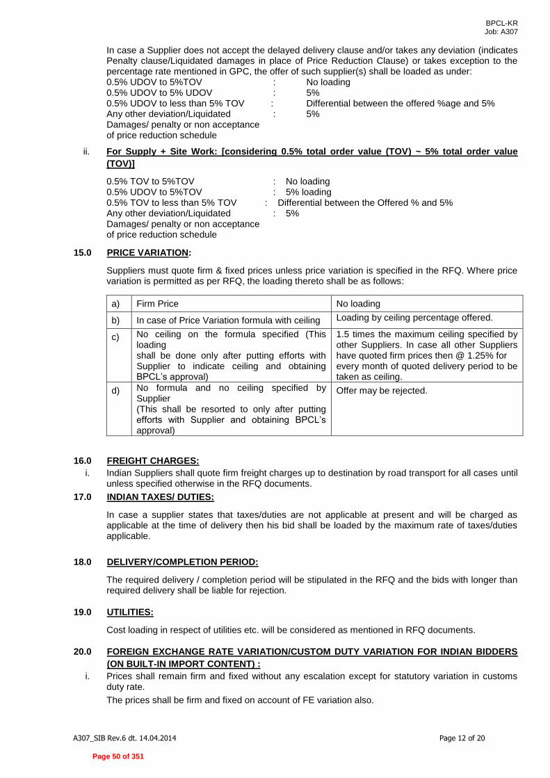
BPCL-KR Job: A307
A307_SIB Rev.6 dt. 14.04.2014 Page 12 of 20
In case a Supplier does not accept the delayed delivery clause and/or takes any deviation (indicates Penalty clause/Liquidated damages in place of Price Reduction Clause) or takes exception to the percentage rate mentioned in GPC, the offer of such supplier(s) shall be loaded as under:
0.5% UDOV to 5%TOV : No loading 0.5% UDOV to 5% UDOV : 5%
0.5% UDOV to less than 5% TOV : Differential between the offered %age and 5% Any other deviation/Liquidated : 5% Damages/ penalty or non acceptance of price reduction schedule
ii. For Supply + Site Work: [considering 0.5% total order value (TOV) ~ 5% total order value
(TOV)]
0.5% TOV to 5%TOV : No loading 0.5% UDOV to 5%TOV : 5% loading 0.5% TOV to less than 5% TOV : Differential between the Offered % and 5% Any other deviation/Liquidated : 5% Damages/ penalty or non acceptance of price reduction schedule
15.0 PRICE VARIATION:
Suppliers must quote firm & fixed prices unless price variation is specified in the RFQ. Where price variation is permitted as per RFQ, the loading thereto shall be as follows:
a) Firm Price No loading
b) In case of Price Variation formula with ceiling Loading by ceiling percentage offered.
c) No ceiling on the formula specified (This loading shall be done only after putting efforts with Supplier to indicate ceiling and obtaining BPCL’s approval)
1.5 times the maximum ceiling specified by other Suppliers. In case all other Suppliers have quoted firm prices then @ 1.25% for every month of quoted delivery period to be taken as ceiling.
d) No formula and no ceiling specified by Supplier (This shall be resorted to only after putting efforts with Supplier and obtaining BPCL’s approval)
Offer may be rejected.
16.0 FREIGHT CHARGES:
i. Indian Suppliers shall quote firm freight charges up to destination by road transport for all cases until unless specified otherwise in the RFQ documents.
17.0 INDIAN TAXES/ DUTIES:
In case a supplier states that taxes/duties are not applicable at present and will be charged as applicable at the time of delivery then his bid shall be loaded by the maximum rate of taxes/duties applicable.
18.0 DELIVERY/COMPLETION PERIOD:
The required delivery / completion period will be stipulated in the RFQ and the bids with longer than required delivery shall be liable for rejection.
19.0 UTILITIES:
Cost loading in respect of utilities etc. will be considered as mentioned in RFQ documents.
20.0 FOREIGN EXCHANGE RATE VARIATION/CUSTOM DUTY VARIATION FOR INDIAN BIDDERS
(ON BUILT-IN IMPORT CONTENT) :
i. Prices shall remain firm and fixed without any escalation except for statutory variation in customs duty rate.
The prices shall be firm and fixed on account of FE variation also.
Page 50 of 351

BPCL-KR Job: A307
A307_SIB Rev.6 dt. 14.04.2014 Page 13 of 20
ii. Indigenous bidders shall be required to quote their prices including customs duty (Merit rate) towards their built in import content. CIF content in Indian Rupees shall also be furnished by Bidders along with the merit rate of customs duty considered.
iii. The statutory variation in customs duty shall be subject to the following guidelines and the supplier shall confirm the following in their bid:
(a) Maximum CIF value of import content shall be furnished in the bid.
(b) The material to be imported covering the above CIF value to be indicated in the bid.
(c) Any increase in price due to increase in customs duty rate beyond two-third of the quoted delivery period will be to supplier’s account. However, any decrease in price due to decrease in customs duty rate at the time of actual clearance of imported materials shall be passed on to BPCL.
(d) Variation in price due to customs duty rate will be dealt with separately after receipt of materials at site against documentary evidence.
21.0 VAT ON WORKS CONTRACTS/ SERVICE TAX/ SPLITTING OF ORDERS:
i. Wherever site work is involved, suppliers shall quote their prices inclusive of VAT on Works Contracts. The Supplier shall submit the assessment/ liability certificate from Sales Tax Authority stating the tax due on Contract/ Running bill submitted for payment for enabling BPCL to deduct the VAT on Works Contract as per the certificate, from Suppliers Invoices and remittance to tax authorities. TDS Certificate towards deduction of VAT on Works Contract shall be provided to supplier by owner. Payment to the Supplier will be released only on receipt of the aforesaid certificate. The Supplier shall submit the total tax liability certificate along with final bill. Under no circumstance, the Supplier should remit VAT on Works Contract directly to the Department. Any loss to BPCL, due to direct remittance of VAT on Works Contract by Supplier will be recovered from Supplier. BPCL shall not be responsible for any delay in payment/ non-payment of bill due to delay in submission/ non-submission of the aforesaid certificate. Order for Supply and Site Work shall not be split and only single order covering the entire scope of work on each supplier shall be placed.
ii. Wherever, Service Tax is applicable, Suppliers shall quote their prices exclusive of Service Tax. Supplier shall be required to furnish Invoices towards Service Tax in order to enable BPCL to avail credit of the same. Presently BPCL is able to avail credit of 96% of the Service Tax rate only. Hence, 4% of Service Tax rate shall be loaded for price evaluation. The same is not applicable for service tax on transportation charges, since CENVAT Benefits not available.
22.0 ENTRY TAX:
Entry Tax is not applicable presently in the State of Kerala and Bidder’s should not include the same in their quoted rates/prices. In case Entry Tax is leviable at a later date, the same shall be borne by Owner.
23.0 REJECTION CRITERIA:
Bidder shall strictly comply with the technical and commercial requirements. Bid shall be considered non responsive and rejected, if bidder insists on deviations to the under mentioned provisions of RFQ/Bidding document:
i) Bid Security amount, Bid security validity, issuing bank and any major deviation to format of Bid security. However this shall not be applicable in case Bid security is not required as per RFQ/Bidding Document.
ii) Advance payment along with FOA/ PO.
iii) Unless specified in the RFQ, Price variation with no formula and no ceiling.
iv) Price change/implication against TQ/CQ when there is no change in scope of work, specification and terms & conditions of MR/RFQ.
v) Delivery / completion schedule.
vi) Guarantee/ Defects Liability Period
vii) Inadequate Bid Validity
viii) Performance bank Guarantee or any other bank guarantee mandatorily required against Milestone or supervision or Price Reduction Schedule (PRS)
Page 51 of 351

BPCL-KR Job: A307
A307_SIB Rev.6 dt. 14.04.2014 Page 14 of 20
24.0 SUO-MOTO CHANGES IN PRICES:
(i.) Any Suo-moto reduction in price offered by a supplier within the bid validity by way of discount or revised prices subsequent to the bid due date and which is not as a result of any change in scope of supply or terms and conditions, shall not be taken into account for evaluation. However, such reduction in price shall be taken into account for ordering if such supplier happens to be the recommended supplier as per the originally quoted prices.
(ii.) However, in the event of any suo-moto price increase sought by a supplier subsequent to the bid due date and which is not as a result of any change in scope of supply or terms and conditions, the bid of such a supplier shall be rejected for the items in which such suo-moto increase is made.
(iii.) Any wrong interpretation of taxes & duties or any taxes & duties not specified in the offer shall be borne by Bidder.
25.0 PRICE IMPLICATION NOT PERMITTED:
Price implications on account of technical clarifications shall not be permitted as long as BPCL/EIL do not change the specifications/ scope spelt out in the RFQ.
26.0 INTEGRITY PACT:
For all RFQs/ enquiries of value exceeding Rs 1 (One) Crore, the bidder shall comply with the requirements of the Integrity Pact (IP) and Integrity Pact of RFQ/Bidding document shall be accepted and Bidder must submit the same duly signed & stamped along with their bid. Failure to submit the Integrity Pact shall lead to outright rejection of Bid.
Bidding shall be through E-tendering methodology as per Enclosed Annexure-I to RFQ..
SECTION-D: SPECIAL CONDITIONS.
27.0 DELIVERY SCHEDULE/ COMPLETION PERIOD:
i. All goods under the scope of the Supplier shall be delivered as per delivery schedule/ completion period specified in Request for Quotation (RFQ) and no variation shall be permitted.
ii. Failing to meet the delivery schedule/ completion period will be subject to price reduction and/or other remedies available to the purchaser in RFQ documents.
iii. Price Reduction Schedule (PRS) shall be applicable as per Clause 9.0 of GPC (Indian) & clause no. 17 of GPC (Imported) and mentioned in RFQ Covering letter.
(iv.) The delivery schedule/ completion period shall be reckoned from the date of Fax of Acceptance.
(V.) For Indian Bidder date of LR/GR shall be considered as date of delivery or date of receipt of material at site shall be the date of delivery as specified in RFQ/FOA/PO. For Foreign Bidder date of clean bill of Lading shall be considered as date of Delivery.
(VI.) In case of foreign bidder, quoted FOB Port of Exit prices shall be inclusive of all charges, all taxes & duties, applicable upto FOB port of exit.
28.0 DESPATCH INSTRUCTIONS FOR INDIGENOUS SUPPLIES:
i. Supplier shall obtain despatch clearance from the purchaser prior to despatch.
ii. Following despatch documents are required to be submitted by the Indigenous supplier immediately after shipment is made.
Commercial Invoice
Dispatch instructions/ clearance by Purchaser/Consultant.
Inspection Release Note by Third Party Inspection Agency/ Purchaser/ Consultant.
LR/ GR
Packing List
Test Certificates (NDT reports, MTC, etc. as per MR)
Certificate of Measurement and Weight
List of documents as specified in Vendor Data Requirement in Material Requisition & counter signed & stamped by EIL.
Page 52 of 351

BPCL-KR Job: A307
A307_SIB Rev.6 dt. 14.04.2014 Page 15 of 20
29.0 NEW / ADDITIONAL TAXES & DUTIES (Applicable for Indian Bidder):
i. Within the contractual delivery period, if any new taxes and/or duties come into force the same will be reimbursed to bidder against documentary evidence. However any new or additional taxes/ duties imposed after contractual delivery shall be to borne by seller.
ii. All necessary taxes & duties registration, if required for carrying out the site activities shall be done by the bidder and cost towards the same shall be included in quoted prices.
iii. The statutory variations on Customs duty (rate) considered on above CIF value of built – in import content, within contractual delivery period shall be to Employer’s account against submission of the documentary evidence. However, any increase in the rate of Customs duty beyond the contractual completion period shall be to bidder’s account. In case of wrong classification, no variation including statutory variation of Customs Duty will be payable extra. Any decrease in the rate of Customs duty shall be passed on to the Employer.
iv. The statutory variations on Excise rate and amount of Excise Duty, CST with concessional form & VAT without concessional form, which will be payable on the finished goods and Cenvatable Service Tax, as applicable, within the contractual delivery period shall be to Employer’s account against submission of the documentary evidence. Any increase in the rate of these taxes and duties beyond the contractual completion period shall be to bidder’s account. However, any decrease in the rate of taxes & duties shall be passed on to the Employer.
v. Works Contract Tax & service tax on transportation, if applicable, shall be included in the quoted prices and no variation including statutory variations shall be payable by BPCL.
30.0 RECOVERY OF CUSTOM DUTY, EXCISE DUTY AND SALES TAX:
In case of Indian Bidders, if the Statutory Variation entitles the employer to recover the amount (irrespective of contractual delivery) such amount will be recovered from any bill of the Supplier immediately on enforcement of such variation under intimation to the Supplier.
31.0 GOVERNING LAW:
Laws of India will govern the Agreement. All matters relating to this contract are subject to the exclusive jurisdiction of the Courts situated in Kochi, Ambalamugal (District), Kerala (India).
32.0 PURCHASER’S RIGHTS AND REMEDIES:
Without prejudice to PURCHASER’s right and remedies under Agreement, if SUPPLIER fails to commence delivery as per agreed schedule and/or in reasonable opinion of the PURCHASER, SUPPLIER is not in a position to makeup the delay to meet the intended purpose, the PURCHASER may terminate the AGREEMENT in full or part at SUPPLIER’s default and may get supplies from other sources at SUPPLIER’s risk and cost.
33.0 DEDUCTION AT SOURCE:
i. Purchaser will release the payment to the Supplier after effecting deductions as per applicable law in force. Purchaser will release the payment to the Supplier after effecting deductions as per applicable law in force. Owner shall deduct VAT on Works Contract as applicable & shall furnish TDS certificate to supplier.
ii. Purchaser will release payments to the Supplier after offsetting all dues to the Purchaser payable by the Supplier under the Contract.
34.0 STATUTORY APPROVAL RELATED WITH SUPPLIES / WORKS:
Approval from any authority (i.e. Inspector of Boiler, Electrical Inspector, and Municipal Corporation
of Greater Kochi (MCGK) etc.) required as per statutory rules and regulations of Central/ State
Government shall be the responsibility of Contractor agency.
The application on behalf of the OWNER for submission to relevant authorities along with copies of
required certificate complete in all respects shall be prepared and submitted by the Contractor
agency well ahead of time so that the actual construction/ commissioning of the work is not delayed
for want of the approval/ inspection by concerned authorities. The Contractor agency shall arrange
the inspection of the works by the authorities and necessary coordination and liaison work in this
respect shall be the responsibility of the Contractor agency. Reimbursement by the OWNER of the
Page 53 of 351

BPCL-KR Job: A307
A307_SIB Rev.6 dt. 14.04.2014 Page 16 of 20
statutory fees payable by Contractor agency (as per advance approval of OWNER) may be provided
for, subject to submission of receipt.
The Contractor agency shall carry out any change/ addition required to meet the requirements of the
statutory authorities, within the quoted rates. The inspection and acceptance of the work by statutory
authorities shall be the responsibility of the Contractor agency. List of all documents, drawings, forms, affidavits etc required for the approvals shall be submitted by the contractor agency.
35.0 LIEN:
Supplier shall ensure that the Scope of Supply supplied under the Agreement shall be free from any claims of title/liens from any third party. In the event of such claims by any party, Supplier shall at his own cost defend, indemnify and hold harmless Purchaser or its authorised representative from such disputes of title/liens, costs, consequences etc.
36.0 LIMITATION OF LIABILITY:
Notwithstanding anything contrary contained herein, the aggregate total liability of Seller under the Agreement or otherwise shall be limited to 100% of Agreement/ Order price. However, neither party shall be liable to the other party for any indirect and consequential damages, loss of profits or loss of production.
SECTION-E: GENERAL INSTRUCTIONS
37.0 GENERAL: Bidders shall submit their Bids in following manner & containing the listed inputs, duly
filled-in, stamped & signed by authorized signatory of Bidder holding Power of Attorney, as a
minimum requirement:
a) PART-I: UNPRICED OFFER
A. All technical specifications as per requirement of MR.
B. Agreed Terms & Conditions duly filled in.
C. Terms & Conditions for Supervision of Erection/Testing/Commissioning, if applicable
D. Terms & Conditions for Site Work, if applicable
E. Copy of Registration with EIL, if applicable
F. Copy of MOU/ MOM, if any, signed with EIL and referred in offer.
G. Integrity Pact, duly filled-in, stamped & signed on each page (if applicable).
H. Complete Audited Financial Report of latest preceding Financial year.
I. Deviation sheet, if any.
J. Price Schedule with prices blanked out but “Quoted/ Not quoted” to be mentioned & its relevant enclosures, duly filled-in, stamped & signed on each page.
b) PART-II: PRICED OFFER
A. Price Schedule with prices filled in.
B. Statement that all specifications and terms & conditions are as per un-priced part of offer.
Note:
Bidding currency shall be Indian Rupees for supplies dispatched from India & and USD/EURO for supplies dispatched from foreign.
38.0 FRAUDULENT PRACTICES:
The OWNER requires that Bidders/ Contractors observe the highest standard of ethics du ring the award/ execution of Contract. "Fraudulent Practice" means a misrepresentation of facts in order to influence the award of a Contract to the detriment of the Owner, and includes collusive practice among bidders (prior to or after bid submission) designed to establish bid prices at artificial non-competitive levels and to deprive the Owner of the benefits of free and open competition. a) The OWNER will reject a proposal for award if it determines that the bidder recommended for
award has engaged in fraudulent practices in competing for the Contract in question. Bidder is required to furnish the complete and correct information/ documents required for evaluation of their bids. If the information/ documents forming basis of evaluation is found to be false/ forged, the same shall be considered adequate ground for rejection of bids and forfeiture of Earnest Money Deposit.
Page 54 of 351

BPCL-KR Job: A307
A307_SIB Rev.6 dt. 14.04.2014 Page 17 of 20
b) In case, the information/ document furnished by the Bidder/ Contractor forming basis of evaluation of his bid is found to be false/ forged after the award of the contract, Owner shall have full right to terminate the contract and get the remaining job executed at the risk & cost of such Bidder/ Contractor without any prejudice to other rights available to Owner under the contract such as forfeiture of CPBG/ Security Deposit, withholding of payment etc.
c) In case, this issue of submission of false documents comes to the notice after execution of work, Owner shall have full right to forfeit any amount due to the Bidder/ Contractor along with forfeiture of CPBG/ Security Deposit furnished by the bidder/ contractor.
d) Further, such bidder/ contractor shall be put on Blacklist/ Holiday/ Negative List of OWNER/EIL debarring them from future business with Owner & EIL for a time period, as per the prevailing policy of OWNER & EIL.
39.0 ONE BID PER BIDDER:
a. A Bidder shall submit only one bid in the same bidding process. A Bidder who submits or
participates in more than one bid will cause all the proposals in which the bidder has
participated to be disqualified.
b. Alternative price bids are not acceptable.
40.0 LANGUAGE OF BID:
a) The Bid prepared by the bidder, all correspondence/drawings and documents relating to the
bid exchanged by the bidder with the Owner/Consultant shall be in English Language alone
provided that any document furnished by the bidder may be written in another language so
long as accompanied by an English translation, in which case, for the purpose of interpretation
of the bid, the English translation shall govern.
b) In the event of submission of any document/ certificate by the Bidder in a language other than
English, the English translation of the same duly authenticated by Chamber of Commerce of
Bidder’s country shall be submitted by the Bidder. Metric measurement system shall be
applied.
41.0 EARNEST MONEY DEPOSIT:
Bidder shall furnish, as part of its Bid, EMD for an amount as indicated in the NIT/ IFB. If the Bidder is unable to submit Bid Document Fee & EMD in original within the due date & time, then bidder shall submit the original Bid Document Fee & EMD within 7 days from the date of unpriced bid opening, provided copy of the same have been uploaded on E-Tendering Website. In case the bidder fails to submit the same in original within 7 days, then their bid shall be rejected, irrespective of their status/ ranking in tender and notwithstanding the fact that a copy of Bid Document Fee & EMD was earlier uploaded by the bidder. OWNER shall not pay any interest on EMD furnished. The EMD shall be in favour of BPCL and shall be acceptable in the form of Crossed Demand Draft or Bank Guarantee in the prescribed pro-forma.
The Bank Guarantees/DD for EMD shall be issued by any Scheduled Commercial Bank (other than co-operative Bank) in India or any Indian Branch of Foreign Bank and same shall be as per the format given in this bidding document. Swift Message or Cash or Cheque in lieu EMD shall not be acceptable.
The bank guarantee for submission of EMD shall be valid as period mentioned in EMD / Bid Security format or elsewhere mentioned in Bid Document / RFQ. EMD/ Bid securities of unsuccessful bidders will be returned upon award of Contract. However, EMD of the successful Bidder will be returned upon the Bidder's acceptance of PO/ signing the Contract and furnishing the PBG. The EMD may be forfeited:
If a Bidder withdraws its bid during the period of Bid Validity or does any breach of tendering terms and conditions, or
If a bidder modifies his bid on his own.
In case of a successful Bidder, if the Bidder fails, within the specified period:
i. To submit the order acceptance.
ii. To furnish the PBG.
Page 55 of 351

BPCL-KR Job: A307
A307_SIB Rev.6 dt. 14.04.2014 Page 18 of 20
42.0 MODIFICATION AND WITHDRAWAL OF BIDS:
a) The Bidder may modify / withdraw its Bid prior to the due date prescribed for submission of Bids.
b) No bid shall be modified subsequent to the deadline for submission of bids. c) No bid shall be allowed to be withdrawn in the interval between the deadline for submission
of bids and the expiration of the period of bid validity specified by the bidder. Withdrawal of a bid during this interval shall result in the forfeiture of bidder’s bid security.
43.0 EXAMINATION OF BIDS AND DETERMINATION OF RESPONSIVENESS:
a. The Owner/EIL will examine the bids to determine whether they are complete, whether any computational errors have been made, whether the documents have been properly signed, and whether the bids are generally in order.
c) Prior to the detailed evaluation, the Owner/EIL will determine whether each bid is of acceptable quality, is generally complete and is responsive to the RFQ Documents. For the purposes of this determination, a responsive bid is one that conforms to all the terms, conditions and specifications of the RFQ Documents without deviations, objections, conditionality or reservations.
c. Bidder shall not be allowed to submit any Price Implication or Revised Price after submission of Bid, unless there is change in the stipulations of the RFQ Document and such changes are incorporated through an Amendment. In case Exceptions and Deviations submitted by Bidder along with Bid are not considered as acceptable and no Amendment is issued, then in such a case the Bidders would be required to withdraw such Exceptions/Deviations in favour of stipulations of the RFQ document and Bidders would not be eligible for submission of Price Implication/Revised Price, failing which such Bid(s) shall be considered as non responsive and rejected.
d. The Owner/EIL determination of a bid’s responsiveness is to be based on the contents of the bid itself without recourse to extrinsic evidence. If a bid is not responsive, it will be rejected by the Owner/EIL, and may not subsequently be made responsive by the bidder by correction of the nonconformity.
44.0 OWNER’S RIGHT TO ACCEPT ANY BID AND TO REJECT ANY BID:
The Owner/EIL reserves the right to accept or reject any bid, and to annul the bidding process and reject all bids at any time prior to award of the order without thereby incurring any liability to the affected bidder or bidders or any obligations to inform the affected bidder or bidders of the ground for Owner/EIL’s action.
45.0 NOTIFICATION OF AWARD:
d) Prior to the expiration of period of bid validity Owner /EIL will notify the successful bidder in writing by fax/e-mail to be confirmed in writing, that his bid has been accepted. The notification of award/ Fax of Acceptance will constitute the formation of the Order.
e) The Delivery Schedule shall commence from the date of notification of award/ Fax of Acceptance (FOA).
f) Award of Contract/Order will be by issuing Fax of Acceptance (FOA) of your bid. FOA will contain price, delivery and other salient terms of bid and RFQ Document.
Bidder will be required to confirm receipt of the same by returning “Copy of the FOA” duly signed and stamped by the bidder as a token of acknowledgement to Owner and EIL. On receipt of acknowledgement without any deviation/ condition, detail Purchase Order/ Contract will be issued in quadruplicate. Three copies of the same without any condition/ deviation will be returned duly signed and stamped by the bidder as a token of acknowledgement to Owner and EIL.
46.0 WAIVER OR TRANSFER OF THE AGREEMENT:
The successful bidder shall not waive the Agreement or transfer it to third parties, whether in part or in whole, nor waive any interest that is included in the Agreement without the prior written permission of the Owner.
47.0 T&C FOR FOREIGN SUPPLIERS OPERATED THROUGH THEIR INDIAN OFFICE /
SUBSIDIARIES:
Page 56 of 351

BPCL-KR Job: A307
A307_SIB Rev.6 dt. 14.04.2014 Page 19 of 20
I. The parent company shall issue an authorization from the authorized signatory like CEO, CFO, CS to confirm their authorization to the subsidiary to manufacture & supply the equipments.
II. The parent company shall furnish a back-up guarantee duly signed by above signatory for the performance of the equipment.
III. The order shall be placed on Indian subsidiary and the payment shall be released to Indian subsidiary.
IV. Indian subsidiary shall be a manufacturing company in the same product & not a liaison / representative office.
V. Bidder to submit bipartite agreement between parent & subsidiary to ensure experience & compliance to contract.
VI. All critical components / parts to be supplied by parent company only which is enlisted with EIL.
48.0 TAX RESIDENCY CERTIFICATE (TRC) FORMAT FOR FOREIGN BIDDER:
Foreign Bidder shall submit Tax Residency Certificate (TRC) duly filled in detailed format enclosed
with RFQ Document.
49.0 REQUIREMENT OF EMPLOYMENT VISA FOR FOREIGN NATIONALS:
i) All Foreign nationals coming to India for execution of Projects/ Contracts will have to apply for Employment Visa only and that grant of Employment Visa would be subject to strict adherence of following norms:
a. Employment Visa is granted only for the skilled and qualified professionals or to a person who is
being engaged or appointed by a Company, Organization, Industry or Undertaking etc. in India
on contract or employment basis at a senior level, skilled position such as technical expert, senior
executive or in managerial position etc.
b. Request for Employment Visa for jobs for which large number of qualified Indians are available, is
not considered.
c. Under no circumstances an Employment Visa is granted for routine, ordinary secretarial/ clerical
jobs.
ii) Suppliers are advised in their own interest to check latest Visa rules from Indian Embassy/ High Commission in their country in case Foreign nationals are required to be deputed to India during execution of the Contract.
50.0 Order of Precedence of Commercial Documents:
In case of an irreconcilable conflict between RFQ, Special Instructions to Bidders & General Purchase Conditions (GPC), the following shall prevail to the extent of such irreconcilable conflict in order of precedence: i) RFQ ii) Special Instructions to Bidders iii) General Purchase Conditions (GPC)
SECTION-F: ADDITIONAL CLAUSES TO GPC
51.0 The following is additional to Clause No. 38.0 of GPC(Indigenous):
Settlement of dispute between CPSEs or CPSEs & Government Departments
In the event of any dispute or difference relating to the interpretation and application of the provisions of the contracts, such dispute or difference shall be referred by either party for Arbitration to the sole Arbitrator in the Department of Public Enterprises to be nominated by the Secretary to the Government of India in-charge of the Department of Public Enterprises. The Arbitration and Conciliation Act, 1996 shall not be applicable to arbitration under this clause. The award of the Arbitrator shall be binding upon the parties to the dispute, provided, however, any party aggrieved by such award may make a further reference for setting aside or revision of the award to the Law Secretary, Department of Legal Affairs, Ministry of Law & Justice, Government of India. Upon such reference, the dispute shall be decided by the Law Secretary or the Special Secretary/Additional Secretary, when so authorized by the Law Secretary, whose decision shall bind the Parties finally and conclusively. The Parties to the dispute will share equally the cost of arbitration as intimated by the Arbitrator.
Page 57 of 351

BPCL-KR Job: A307
A307_SIB Rev.6 dt. 14.04.2014 Page 20 of 20
ANNEXURE-A INTEGRATED REFINERY EXPANSION PROJECT (IREP) OF
M/s BPCL KOCHI REFINERY, KOCHI, KERALA (INDIA) (Job No. A307)
TERMS & CONDITIONS FOR INDIAN SOURCED COMPONENTS / SERVICES BY FOREIGN BIDDER
Foreign bidder may source components / sub-supplies and services from India, if allowed as per Material Requisition. Such sub-supplies / services shall be subject to following Commercial Terms & Conditions:
1. PRICING:
1.1 The Foreign bidder shall quote firm price for items being sourced from India in Indian rupees on FOT Site basis inclusive of packing, forwarding, transportation, all applicable taxes, duties & levies payable upto site.
1.2 Materials if ordered against this Bidding Document are required to be dispatched on door delivery basis through a reliable bank approved Road Transport Company unless the transport company is named by the Owner.
2. AWARD OF ORDER:
Client will place single order for Main Supplies/ Services including Indian source supplies/ Services
with single point responsibility taken care by foreign (principal) bidder. However obligation of
Performance Bank Guarantee & Price Reduction Schedule for complete package shall always be in
scope of foreign (principal) Bidder.
3. DELIVERY: The delivery period for items being sourced from India, shall be on FOT site basis within the delivery period specified for foreign bidder as per Terms of Bidding document.
4. PRICE REDUCTION SCHEDULE FOR DELAY IN DELIVERY / SERVICES: PRS for delay in deliver / services shall be applicable on total order value including Indian sourced component / Service.
5. OVERALL RESPONSIBILTY:
Overall responsibility towards the contractual obligations like delivery, bid security, order execution,
performance guarantee etc. including supplies being sourced from India shall be only with the
foreign (principal) bidder.
6. PERFORMANCE BANK GUARANTEE Foreign (principal) bidder shall submit one performance bank guarantee as per GPC for total order
value including value of items source from India.
7. INSPECTION
i. Inspection of Item being sourced from India shall be by EIL/Owner.
ii. Any change in sourcing from indigenous supplies to imported supplies and vice-versa after bid
submission is not permitted.
iii. Considering EIL Inspection charges, during evaluation prices of Indigenous source item shall be
loaded by @1.25% of FOT Despatch Point Price price.
8. PAYMENT TERMS:
8.1 Indian Sourced supplies:
100% payment along with taxes and duties will be paid against receipt & acceptance of Indian sourced goods/material at project site and on presentation of invoice suitable for availing Cenvat.
8.2 Payment of Indian source supplies/Services shall be released directly to Indian counterpart against Invoices raised by Indian counterpart duly endorsed by Foreign principal for payment.
8.3 The payments shall be made after Adjustment of Price Reduction Schedule.
9. In case of any deviation to above requirement, loading shall be applicable as mentioned for Indian Bidder.
Page 58 of 351

Page 59 of 351

Page 60 of 351

Page 61 of 351

Page 62 of 351

Page 63 of 351

Page 64 of 351

Page 65 of 351

Page 66 of 351

ShamPatroleUI"
BHARAT PETROLEUM CORPORATION LIMITEDKOCHI REFINERY
GENERAL PURCHASE CONDITIONS
FOR IMPORTED MATERIALS AND EQUIPMENTS
INDEX
1. DEFINITIONS 19.REJECTION, REMOVAL OF REJECTED
GOODS AND REPLACEMENT2.
REFERENCE FOR DOCUMENTATION
20.
PRICE3.
IMPORT LICENCE
21.
TERMS OF PAYMENT4.
CONFIRMATION OF ORDER
22.
RECOVERY OF SUMS DUE5.
SALES CONDITIONS
23.
MODIFICATIONS6.
COMPLETE AGREEMENT
24.
CANCELLATION7.
INSPECTION-CHECKING- TESTING
25.
PATENTS AND ROYALTIES8.
EXPEDITING
26.
PERFORMANCE GUARANTEE9.
WEIGHTS AND MEASURES
27.
NON-WAIVER10.
OILS & LUBRICANTS
28.
NO ASSIGNMENT11.
SPARE PARTS
29.
VENDOR'S DRAWINGS AND12.
PACKING AND MARKINGDATA REQUIREMENT
13.
SHIPMENT AND SHIPMENT NOTICES30.
TECHNICAL INFORMATION
14.
SHIPPING31.
SERVICES OF VENDOR'S PERSONNEL
15.
TRANSIT RISK INSURANCE32.
ARBITRATION
16.
RESPECT FOR DELIVERY DATES33.
PART ORDER/REPEAT ORDER
17.
DELAYED DELIVERY34.
ADDRESSES
18.
DELAYS DUE TO FORCE MAJEURE
-1-
•Page 67 of 351
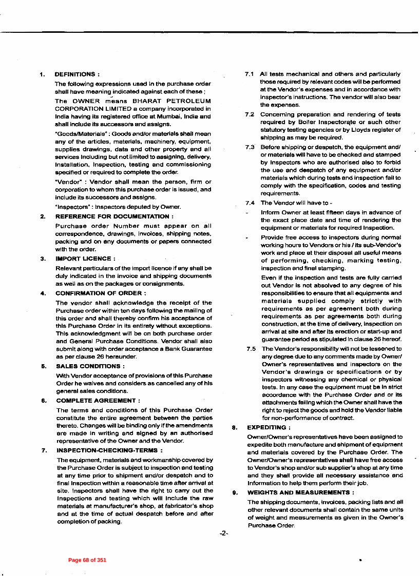
1. DEFINITIONS:
The following expressions used in the purchase ordershall have meaning indicated against each of these;The OWNER means BHARAT PETROLEUMCORPORATION LIMITED a company incorporated inIndia having its registered office at Mumbai. India andshall include its successors and assigns."GoodslMaterials" : Goods and/or materials shall meanany of the articles, materials, machinery, equipment,supplies drawings, data and other property and allservices Including but not limited to assigning, delivery,Installation, Inspection. testing and commissioningspecified or required to complete the order.
·Vendor" : Vendor shall mean the person, firm orcorporation to whom this purchase order is issued, andinclude its successors and assigns.
"Inspectors" : Inspectors deputed by Owner.2. REFERENCE FOR DOCUMENTATION:
Purchase order Number must appear on allcorrespondence, drawings, invoices, shipping notes,packing and on any documents or papers connectedwith the order.
3. IMPORT LICENCE:
Relevant particulars of the import licence if any shall beduly indicated in the invoice and shipping documentsas well as on the packages or consignments.
4. CONFIRMATION OF ORDER:
The vendor shall acknowledge the receipt of thePurchase order within ten days following the mailing ofthis order and shall thereby confirm his acceptance ofthis Purchase Order in its entirety without exceptions.This acknowledgment will be on both purchase orderand General Purchase Conditions. Vendor shall alsosubmit along with order acceptance a Bank Guaranteeas per clause 26 hereunder.
6. SALES CONDITIONS:
With Vendor acceptance of provisions of this PurchaseOrder he waives and considers as cancelled any of hisgeneral sales conditions.
6. COMPLETE AGREEMENT:
The terms and conditions of this Purchase Orderconstitute the entire agreement between the partiesthereto. Changes will be binding only if the amendmentsare made in writing and signed by an authorisedrepresentative of the Owner and the Vendor.
7. INSPECTION-CHECKING-TERMS:
The equipment, materials and workmanship covered bythe Purchase Order is subject to inspection and testingat any time prior to shipment and/or despatch and tofinal Inspection within a reasonable time after arrival atsite. Inspectors shall have the right to carry out theInspections and testing which will Include the rawmaterials at manufacturer's shop, at fabricator's shopand at the time of actual despatch before and aftercompletion of packing.
-2-
7.1 All tests mechanical and others and particularlythose required by relevant codes will be performedat the Vendor's expenses and in accordance withinspector's instructions. The vendor will also bearthe expenses.
7.2 Concerning preparation and rendering of testsrequired by Boiler Inspector~te or such otherstatutory testing agencies or by L10yds register ofshipping as may be required.
7.3 Before shipping or despatch, the equipment and/or materials will have to be checked and stampedby Inspectors who are authorised also to forbidthe use and despatch of any equipment and/ormaterials which during tests and inspection fail tocomply with the specification. codes and testingrequirements.
7.4 The Vendor will have to-
Inform Owner at least fifteen days in advance ofthe exact place date and time of rendering theequipment or materials for required Inspection.
Provide free access to inspectors during normalworking hours to Vendors or his /lts sub-Vendor'swork and place at their disposal all useful meansof performing, checking, marklhg testing,inspection and final stamping.
Even if the inspection and tests are fully carriedout Vendor is not absolved to any degree of hisresponsibilities to ensure that all equipments andmaterials supplied comply strictly withrequirements as per agreement both duringrequirements as per agreements both duringconstruction, at the time of delivery, inspection onarrival at site and after Its erection or start-up andguarantee period as stipulated In clause 26 hereof.
7.5 The Vendor's responsibility will not be lessened toany degree due to any comments made by Owner/Owner's representatives and inspectors on theVendor's drawings or specifications or byinspectors witnessing any chemical or physicaltests. In any case the equipment must be in strictaccordance with the Purchase Order and or itsattachments failing which the Owner shall have theright to reject the goods and hold the Vendor liablefor non-performance of contract.
8. EXPEDITING:
Owner/Owner's representatives have been assigned toexpedite both manufacture and shipment of equipmentand materials covered by the Purchase Order. TheOwner/Owner's representatives shall have free accessto Vendor's shop and/or sub supplier's shop at any timeand they shall provide all necessary assistance andInformation to help them perform their job.
9. WEIGHTS AND MEASUREMENTS:
The shipping documents, invoices, packing lists and allother relevant documents shall contain the same unitsof weight and measurements as given in the Owner'sPurchase Order.
•Page 68 of 351

10. OILS & LUBRICANTS:
The first filling of oils and lubricants for every equipmentshall be included In the price. The vendor shall alsorecommend for quality and quantity of oils and lubricantsrequired for one year's continuous operation.
11. SPARE PARTS:
The vendor must furnish itemised and priced list of spareparts required for two years operation of the equipment.
The vendor shall provide the necessary cross sectionaldrawing to Identify the spare parts numbers and theirlocation as well as inter-changeability chart.
12. PACKING AND MARKING:
All equipment/materials shall be suitably packed inweather proof, seaworthy packing for ocean transportunder tropical conditions and for rail or road or otherappropriate transport in India. The packing shall bestrong and efficient enough to ensure safe preservanceupto the final point of destination.
Equipment / Materials shall be protected by suitablecoat of paint and all bright parts protected from rust byapplication of rust preventive as may be necessary. Allmachined surface shall be suitably protected.
All fragile and all exposed parts will be packed with careand the packages shall bear the words -HANDLE WITH
CARE GLASS FRAGilE, DON'T ROLL. THIS END UP.THIS END DOWN.· to be indicated by arrow.
A distinct colour splash in say red-black around eachpackage crate/bundle shall be given for identification.
Ail pipes and sheets shall be marked with strips bearingprogressive No.
In case of bundles, the shipping marks shall beembossed on metal or similar tag and wired securelyon each end.
For bulk uniform material when packed in several cases,progressive serial numbers shall be indicated on eachcases. All nozzles, holes and opening and also alldelicate surfaces shall be carefully protected againstdamage and bad weather. Flange faces of all nozzlesshall be protected by blanks. All manufactured surfacesshall be painted with rust proof paint.
All threaded fittings shall be packed in cases.
The vendor shall be held liable for all damages orbreakages to the goods due to defective or Insufficientpacking as well as for corrosion due to insufficientgreasing/ protection.
On three sides of the packages, the following marksshall appear clearly visible in indeliable paint and onVendor's care and expense.
BHARAT PETROLEUM CORPORATION LIMITEDKOCHI REFINERYAMBALAMUGAlKOCHI-682302
From
To:
Chief Manager (Projects)
Bharat Petroleum Corporation Ltd.
Koehl Refinery, AmbalamugalKochi - 682 302
Purchase Order No.
Item:
Equipment:
NetWeight:
Gross Weight:
Case No.
Dimensions:
Kgs.
Kgs.
of
-3-
Total Cases:
•Page 69 of 351

l!!RI§.;. MarKIngshall be bold-minimum letter height 5cm.for every order and every shipment, packages must bemarked with serial progressive numbering. All packageswill bear warning signs on the outside denoting thecenter of gravity and sling marks. Packages that requirespecial handing and transport should have their centresof gravity and points at which they may be grippedclearly indicated and marked -Attention Special LoadHandle with Care" In English Language. Any otherdirection for handling shall be clearly indicated on thepackage.
Top heavy containers will be so marked either TopHeavy or Heavy Ends. When packing material is cleanand light coloured, a dark black stencil paint shall beacceptable. However, where packaging material issoiled or dark, a coat of flat zinc white paint shall beapplied and allowed to dry before applying the specificmarkings.
In case of large equipments like vessels, heatexchangers, etc. documents contained in the envelopeshall be fastened Inside a shell connection with anidentifying arrow sign -documents" applied with Indeliblepaint.
13. SHIPMENT AND SHIPMENT NOTICES:
The Vendor shall make shipment only after priorapproval of Inspector whenever specifically mentioned.As soon as any shipment is made, the Foreign Suppliershall send advance information by way of Fax messageto Chief Manager (Projects), Bharat PetroleumCorporation Ltd., Koehl Refinery, Ambalamugal, Kochi682 302 giving particulars of the shipment, vessel'sname, port of shipment, bill of lading number and date,total FOB and freight value with confirmation copies bypost to the owner, Bharat Petroleum CorporationLimited, Koehl Refinery, Ambalamugal, Kochi -682 302In case of air shipment a copy each of airway bill &Invoice shall be sent by fax to BPCL as soon asshipment is made.
14 SHIPPING:
14.1 SEA SHIPMENT:
All shipment of materials shall be made by firstclass direct vessels, through the chartering wing,Ministry of Surface Transport Govt, of India, NewDelhi as per procedure detailed hereunder. TheForeign supplier shall arrange with VesselsOwners or Forwarding Agents for proper storageof the entire Cargo intended for the project in aspecific manner so as to facilitate and to avoidany over carriage at the port of discharge. Allshipment shall be under deck unless carriage ondeck is unavoidable.
The bills of lading should be made out in favour ofBharat Petroleum Corporation Ltd.,
All columns in the body of the bill of lading namelymarks and nos. material description, weightparticulars, etc. should be uniform in all theshipping documents. The freight particulars shouldmention the basis of freight tonnage, heavy lift
-4-
charges, if any, surcharge, discount, etc. clealand separately and the net total freight payabshown at the bottom.
All documents vlz. bill of lading/airway bi,Invoices/packing list, freight memos, country 4
origin certificates, test certificate, drawings ancatalogues should be in English language.
In addition to the bill of lading which should bobtained In 3 stamped original plus as many copieias required, Invoices packing lists, freight memos(If the freight particulars are not shown In the billlof lading), country of origin certificate, testcomposition certificate, shall be made out agains',each shipment in as many number of copies asshown below. The bill of lading, invoice andpacking list specifically must show uniformly, themarks and numbers, contents case wise countryof origin, consignees name, port of destination andall other particulars as indicated under clause 12.The invoice must show the unit rates and net totalEO.B. prices. Items packed separately should alsobe Invoiced and the value shown accordingly.Packing list must show apart from other particularsactual contents in each case, net and grossweights and dimensions, and the total number ofpackages. All documents should be duly signedby the Vendor's authorised representatives.
Shipping arrangements shall be made byChartering Wing Ministry of Surface Transport,New Delhi through their respective forwardingagents, M/s. Schenker & Co., P.O. Box 11031302043 Hamburg West Germany, Ph. 49 (040)361350, Fax (040) 36135216 Gr.2/a, Telex217004-33 Sh.d, for shipping consignments fromUK / continent port; M/s. OPT Overseas ProjectTransport Inc. 46 sellers Street, kearny, N.J.07032, Tel (201) 998-7771, Telex 673-3586, Fax(201)998-7833. In respect of consignments formUS/CANADA, MEXICO & SOUTH AMERICA andthe Embassy of India in Japan, Tokyo in respectof consignments from Japaneses ports. Suppliershall furnish to the respective agents the full detailsof consignments such as outside dimensions,weights (both gross and net) No. of packages,technical descriptions and drawings, name oftheSupplier, ports of loading, etc. 6 weeks notice shallbe given by the supplier to enable the concernedagency to arrange shipping space.
The bill of lading Shall Indicate the following:
Shipper: Government of India
Consignee:Bharat Petroleum Corporation Ltd.Koehi Refinery,Ambalamugal,Kochl - 682 302.
In case of supplies from USA, Export licences, ifany required from the American Authorities shallbe obtained by the U.S. suppliers. If need be
•Page 70 of 351

Insurance against all marine and transit risk on FOB towarehouse basis shall be covered under the owner'smarine policy. However, the Vendor shall ensure the ineffecting shipments clear bills of lading/airway bills areobtained and the carriers responsibility is fully retainedthe carriers so that the consignee's interests are fullysecured and are in no way jeopardized.RESPECT FOR DELIVERY DATES:
Time of delivery mentioned in the Purchase Order shallbe the essence of the agreement and no variation shallbe permitted except with prior authorisation in writingfrom the Owner. Goods should be delivered securelypacked and in good order and condition at the placeand within the time specified in the Purchase Order for
assistance for obtaining such export licenceswould be available from India supply Mission atWashington.
14.2 AIRSHIPMENT:
In case of Airshipment, the material shall beshipped through freight consolidator (approved byus). The airway bill shall be made out in favour ofBHARAT PETROLEUM CORPORATION LTD,Kochi Refinery, Ambalamugal, Kochi - 682 302Tel: 91-484-2722061-69, Fax: 91-484- 2721094/2720855/56.
14.3 TRANSMISSION OF SHIPPING DOCUMENTS:
Foreign supplier shall obtain the shippingdocuments in eleven complete sets including threeoriginal stamped copies of the Bill of lading/AirwayBill as quickly as possible is made, and airmail asshown below so that they are received at leastthree weeks before the Vessels' arrival in case ofsea shipment and immediately on air freighting incase of air-shipment. Foreign supplier shall be fullyresponsible for any delay and/or demurrage inclearance of the consignment at the port due todelay in transmittal of the shipping documents.
If in terms of latter of otherwise, the completeoriginal set of documents are required to be sentto BPCL through Bank the distribution indicatedbelow will confine to copies of documents onlyminus originals.
their delivery. By time delivery, is meant the date on theBill of lading/Air way Bill at FOB port of despatch.
17. DELAYED DELIVERY:
The time and date of delivery of materials/equipmentas stipulated in the Purchase Order shall be deemedto be the essence of the agreement. For any delay indelivery of equipment materials or part thereof beyondthe delivery date stipulated, the vendor shall be liableto pay compensation at O. 5% per week or part thereofthe FOB Port of embarkation value of the non-delivereditems of equipment subject to maximum of 5% of thetotal FOB value. The Owner reserves the right ofcancelling the Purchase Order for any delay exceedingthe period of maximum compensation and the vendorshall be liable to all consequences thereof. If the delayin delivery is due to Force Majeure, the owner shall befree to act in terms under clause 18 of this text.
18. DELAYS DUE TO FORCE MAJEURE:
In the event of causes of Force Majeure occuring within,the contractual date of delivery the Owner on receipt ofapplication from the Vendor may extend the contractualdate of delivery without imposition of penalty. Only thosecauses which depend on natural calamities, civil warsand national strikes which have a duration of more thanseven consecutive calendar days are considered thecauses of force majeure. The decision of Owner shallbe final and binding on Vendor.
The Vendor must advise the Owner by a Registeredletter duly certified by a local chamber of statutoryauthorities, the beginning and the end of the delayimmediately, but in no case later than within 10 days ofthe beginning and end of such cause of Force Majeurecondition as defined above.
19. REJECTION, REMOVAL OF REJECTED GOODSAND REPLACEMENT:
In case the testing and inspection at any stage ofinspection reveal that the equipment, materials andworkmanship do not comply with the specification andrequirements, the same shall be removed by the Vendorat his/its own expense and risk within the time allowedby the Owner. The Owner shall be at liberty to disposeof such rejected goods in such a manner as he maythink appropriate. In the event the Vendor fails to removethe rejected goods within the period as aforesaid, allexpenses incurred by the Owner for such disposal shallbe to the account of the Vendor. The freight paid by theOwner, if any, on the inward joumey of the rejectedmaterials shall be reimbursed by the vendor to theOwner before the rejected materials are removed bythe Vendor. The Vendor will have to proceed with thereplacement of that equipment without claiming anyextra payment if so required by the Owner. The timetaken for replacement in such event will not be addedto the contractual delivery period.
20. PRICE:
Unless otherwise agreed to in the terms of the PurchaseOrder, the price shall be :
4414
BPCL, Kochi Refinery
4 (including 1original)
444
Documents
Bill of lading/Airway BillInvoicePacking ListFreight MemoCountry of OriginCertificateDrawingCatalogueInvoice ofthirdParty/Lloyd forInspection charges,wherever applicable.
TRANSIT RISK INSURANCE:
16.
15.
-5-
•Page 71 of 351

Firm and not subject to escalation for any reasonwhatsoever even though It might be necessary for theorder execution to take longer than the delivery periodspecified in the order.
21. TERMS OF PAYMENT:
Payment will be made by the Owner against submissionof despatch documents by Cash Against Documents/Letter of Credit.
22. RECOVERY OF SUMS DUE:
Whenever any claim against the Vendor for paymentof a sum of money arises out of or under the contract,the Owner shall be entitled to recover such sums fromany sum them due or when at any time thereafter maybecome due from the Vendor under this or any othercontract with the Owner and should this sum be notsufficient to cover the recoverable amount, the vendorshall pay to the Owner on demand the balanceremaining due.
23. MODIFICATIONS:
The Owner shall have the right to make technicalchanges or modifications in the technical documents/specifications. Any major changes or modifications shallbe at the cost, if any, of the Owner. As soon as possibleafter receipt of the written request for changes thevendor shall furnish in writing to the owner an estimateof cost for such major changes and modifications andits effect on the FOB delivery date. On receipt ofOwner's written authorisation, the Vendor shall promptlyproceed with the changes/modifications.
24. CANCELLATION:
The owner reserves the right to cancel this PurchaseOrder or any part thereof and shall be entitled to rescindthe contract wholly or in part In a written notice to theVendor if:
The Vendor fails to comply with the terms of thisPurchase Order.
The Vendor fails to deliver the goods on time and/orreplace the rejected goods promptly:
The Vendor makes a general assignment for the benefitof creditors; and
A receiver is appointed for any of the property ownedby the Vendor.
Upon receipt of the said cancellation notice, the Vendorshall discontinue all work on the Purchase Order andmatters connected with it.
The owner in that event will be entitled to procure therequirement in the open market and recover excesspayment over the Vendor reserving to Itself the right toforfeit the security deposit, if any, placed by the Vendoragainst the contract.
25. PATENTS AND ROYALTIES:
On acceptance of this order, the Vendor will be deemedto have entirely indemnified the Owner's representativesfrom any legal action or claims regarding compensationfor breach of patent rights which the Vendor deemsnecessary to comply for manufacturing the orclefed
-6-
equipment and/or materials or which can, in any way.26. PERFORMANCE GUARANTEE:
The Vendor shall guarantee that any and all materialsused in execution of the Purchase Order shall in strictcompliance with characteristics, requirements andspecifications and that the same shall be free from anydefects. Checking of the Vendor's drawings by theOwner/Owner's representatives and their approval andpermission to ship or despatch the equipment andmaterials granted by Inspectors shall not relieve theVendor from any part of hlsllts responsibilities for properfulfillment of the requirements. The Vendor willguarantee that all materials and equlpments shall berepaired or replaced as the case may be at site, at itsown expense, in case the same have been found to bedefective in respect of material, workmanship or smoothand rated operation within a period of twelve monthsafter the same have been Commissioned or 18 monthsfrom despatch whichever is earlier.
The guarantee period for the part that may be altered,repaired or replaced shall be 12 months from the dateon which the same is commissioned.
Acceptance by the Owner or Its inspectors of anyequipment and materials or its replacement will notrelieve the Vendor of its responsibility of supplying theequipment/materials strictly according to the guaranteeagreed by the Vendor. The Vendor shall furnish a BankGuarantee along with the order acceptance for theamount equivalent to 10% of the F.O.B. value ofequipment/ materials to support Vendor's performance(as per proforma hereunder). This Bank Guarantee shallremain in force for the entire period covered by theperformance guarantee. It will be the responsibility ofthe Vendor to keep the Bank Guarantee fullysubscribed. Any shortfall in the value of the BankGuarantee as a result of encashment by the ownereither in full or in part in terms of the performanceGuarantee shall be made good by the Vendor withinone week thereof.
27. NON-WAIVER:
Failure of the Owner/Owner's representatives to insistupon any of the terms or conditions incorporated in thePurchase Order or failure or delay to exercise any rightsor remedies specified herein or by law or failure toproperly notify Vendor in the event of breach, or theacceptance of payment of any goods hereunder orapproval of design shall not release the Vendor andshall not be deemed waiver of any right of the Owneror Owner's representatives to Insist upon the strictperformance thereof or any of his or their rights orremedies as to any such goods regardless of whengoods are shipped, received or accepted nor shall anypurported modification or revision ofthe order by Owner/Owner's representative act as waiver of the termshereof.
28. NO ASSIGNMENT:
The purchase Order shall not be assigned to any otheragency by the Vendor without obtaining prIor-written
•Page 72 of 351

consent of the Owner.
29. VENDOR'S DRAWINGS AND DATA REQUIREMENT:
The Vendor shall submit drawings data anddocumentation in accordance with but not limited to
what is specified in the bid document and lor InVendor'sdrawings and data form attached to the Purchase Orderand as called for in clause 8, vlz, 'Expediting' above.The types, quantities and time limits of submitting thismust be respected in its entirety failing which thepurchase Order shall not be deemed to have beenexecuted for all purposes including settlement ofpayment since the said submission is an integral partof purchase Order execution.
30. TECHNICAL INFORMATION:
Drawings, specifications & details shall be the propertyof the Owner and shall be returned by the Vendor ondemand. The Vendor shall not make use of drawingsand specifications for any purpose at any time saveand except for the purposes of the Owner. The Vendorshall not disclose the technical Information furnished
or gained by the Vendor to any person, firm or body orcorporate authority and shall make all endeavours toensure that the technical Information is keptCONFIDENTIAL. The technical information impartedand supplied to the Vendor by the Owner shall at alltimes remain the absolute property ofthe Owner.
31. SERVICES OF VENDOR'S PERSONNEL:
Upon two weeks advance notice, the Vendor shalldepute the necessary personnel to India for supervisionof erection and start up of the equipment and train afew of the Owner's personnel for the operation and
-7-
maintenance of the equipment if required by the Owner.The terms and conditions for the services of the
Vendor's personnel shall be indicated in the quotationitself.
32. ARBITRATION:
Any dispute or difference between the Vendor on onehand and the Owner on the other. of any kindwhatsoever at any time or times, arising out of or inconnection with or incidental to the Purchase Orderincluding any dispute or difference regarding theinterpretation of the terms and conditions or any clausethereof shall be referred to arbitration under the Rulesof International Chamber of Commerce in Paris. Thevenue of such arbitration shall be in India. The Indian
law shall apply.33. PART ORDER I REPEAT ORDER:
Vendor shall agree to accept part order at owner'soption without any limitations whatsoever and alsoaccept repeat order during a period of six months afterplacement of purchase order at the same unit pricesterms and conditions.
34. ADDRESS:
Bharat Petroleum Corporation Ltd.
Kochi Refinery
AmbalamugalKochi - 682 302
INDIA
Tel: 91-484-2722061-69
Fax: 91-484-2721094/2720855/56
•Page 73 of 351

PROFORMA OF BANK GUARANTEE
( Performance )
(Ref. clause 26)
To
Bharat Petroleum Corporation LimitedKoehl Refinery, Ambalamugal, Kerala- 682302
Dear Sir,
In consideration of the Bharat Petroleum Corporation Limited (hereinafter called 8theCompany8 which expression shallinclude its suceessorsand assigns) having awarded to MIs. (Name) (address)..................................................•....................................................................................................................... (hereinafterreferred to as ~he Supplier- which expression wherever the subject or context so permits Include Its successors and assigns) asupply contract In terms Interalia, of the Company's Purchase Order No dated and theGeneral Purchase Conditions of the company and upon the condition of supplier's fumishing security for the Performance of thesupplier's obligation and/or discharge of the supplier's liability under and/or In connection with the said supply contract up to asum of (in figure) (in words) ................. ) contract value.
we, (Name) (constitution) ; (hereinafter called8the Bank8 which expression shall include its successors and assigns) hereby jointly and severally undertake the guarantee topay to the Company In (Currency) forthwith on demand in writing and without protest or demur of any and all moneys anywisepayable by the Supplier to the Company under in respect of or in connection with the said supply contract inclusive of all theCompany's losses and damages and costs, (Inclusive between attorney and client), charges and expenses and other moneysanywise payable In respect to the above as specified in any notice of demand made by the Company to the Bank with referenceto this Guarantee up to aggregate limit of Rs (Rupees ... . .. . ... .. . .. . ... .. . ... .. . .. . .. . .. . .. .... ..only)
AND the Bank hereby agrees with company that:
This Guarantee / Undertaking shall be a continuing / undertaking and shall remain valid and irrevocable for all claims of theCompany and liabilities of the Supplier arising up to and until midnight of .
This date shall be 6 months from the last date of guarantee period
This Guarantee / Undertaking shall be in addition to any other guarantee or security whatsoever that the company may now or atany time anywise have in relation to the Supplier's obligationslliabilities under and/or connection with the said supply contract,and the Company shall have full authority to take recourse to or reinforce this security in preference to the other securlty(ies) atits sole discretion, and failure on the part of the Company in enforcing or requiring enforcement of any other security shall havethe effect of releasing the Bank from its liability hereunder.
The company shall be at liberty without reference to the bank and without affecting the full liability of the Bank hereunder to takeany other security in respect of the Supplier's obligations and/or liabilities under or In connection with the said supply contractand to vary the terms vis a vis the supplier of the said supply contract or to grant time and/or Indulgence to the supplier or toreduce or to Increase or otherwise vary the prices of the total contract value or and/or the remedies of the company under anyother security (Ies) now or hereafter held by the company and no such dealing(s), varlation(s), reduction(s), Increase(s) or theindulgence(s) or arrangement(s) with the supplier or release or forbearance whatsoever shall have the effect of releasing theBank from its full liability to the Company hereunder or of prejudicing rights of the Company, against the Bank.
The Guarantee / Undertaking shall not be determined or affected by the liquidation or winding up, dissolution or change ofconstitution or insolvency of the supplier but shall in all respects and for all purposes be binding and operative until payment of allmoneys payable to the Company in terms hereof.
The Bank hereby waives all rights at any time inconsistent with the terms of its Guarantee / Undertaking and the obligations of theBank in terms hereof shall not be anywise affected or suspended by reason of any dispute or disputes having been raised by thesupplier (whether or not pending before any Arbitrator, office, Tribunal or Court) or any denial of liability by the supplier or anyother of communication whatsoever by the supplier stopping or preventing or purporting to stop or prevent any payment by theBank to the Company in terms hereof.
The amount stated in any notice of demand addressed by the Company to the Guarantor as liable to be paid to the Company bythe supplier or as suffered or incurred by the Company on account of any losses or damages of costs, charges and or expensesshall as between the Bank and the company be conclusive of the amount so liable to be paid to the Company or suffered orincurred by the Company, as the case may be and payable by the Guarantor to Company in terms hereof.
Yours faithfully,
-8-
•Page 74 of 351

BPCL-KR JOB NO.: A307
A307_T&C-SUP(IND) Rev.0 Page 1 of 1
BHARAT PETROLEUM CORPORATION LIMITED-KOCHI REFINERY INTEGRATED REFINERY EXPANSION PROJECT
TERMS & CONDITIONS FOR SUPERVISION OF ERECTION, TESTING AND COMMISSIONING
FOR INDIGENOUS PERSONNEL
1) Bidder shall quote per diem charges which shall include to & fro fare ,lodging, boarding, medical ,
local transport, all insurances including Bidder’s personnel and third party insurance , all taxes
including income tax etc. & all other incidental charges but exclude Service Tax which will be extra .
2) Per Diem rates shall apply from the day the supervisory personnel reach site and upto the day they leave site. No per Diem payment will be made for travel days / period.
3) Working hours as those prevailing at site – normally eight hours a day, Monday through Saturday and holidays as applicable to site personnel shall apply.
4) Supplier’s supervisory personnel to observe/abide by site working conditions prevailing in the
existing refinery, safety codes & Indian laws. 5) A notice period of one month will be given for supervision of erection / testing / commissioning.
CHARGES FOR SUPERVISION OF ERECTION/TESTING/COMMISSIONING
NOTES: In case bidder recommends more than one category level of supervisory personnel the
information desired at S. No. (i) to (vi) shall be furnished separately for each category of supervisory personnel.
RFQ NO: VENDOR’S SIGNATURE & DATE
ITEM: NAME OFFER NO: DESIGNATION
SEAL / STAMP
Sl. No.
Description Vendor’s Reply / information
i.
ii.
iii.
iv.
v.
vi.
Number of supervisory personnel required.
Per diem charges (per person) for 8 hours work on normal working days.
Overtime rate/ hour beyond normal 8 hours
work on normal working days.
Overtime rate/ hour for work on weekly off
days/ holidays (as applicable to Refinery site).
Maximum estimated time (number of days) for job completion.
Service tax excluded in the above rates & payable extra.
(Vendor shall provide cenvatable invoices in accordance with service tax rules)
(Refer Priced Schedule)
Page 75 of 351

BPCL-KR JOB NO.: A307
A307_T&C-SUP(FOREIGN) Rev.0 Page 1 of 2
BHARAT PETROLEUM CORPORATION LIMITED-KOCHI REFINERY INTEGRATED REFINERY EXPANSION PROJECT
TERMS & CONDITIONS FOR SUPERVISION OF ERECTION, TESTING AND COMMISSIONING FOR FOREIGN PERSONNEL
1) Bidder shall quote all inclusive per diem charges which shall also include lodging, boarding, medical, To & Fro traveling including local transportation, all insurances including Bidder’s personnel and third party insurance, income tax, corporate tax (as may be applicable), etc. and all other incidental charges, but excluding Service tax which will be paid extra by owner.
2) No additional cost shall be payable towards travel, lodging & boarding, etc. by BPCL. 3) Per Diem rates shall apply from the day the supervisory personnel reach site and upto the day they
leave site. No per Diem payment will be made for travel days / period. 4) Working hours as those prevailing at site – normally eight hours a day, Monday through Saturday
and holidays as applicable to site personnel shall apply. 5) Supplier’s supervisory personnel to observe/abide by site working conditions prevailing in the
existing refinery, safety codes & Indian laws.
6) A notice period of one month will be given for supervision of erection / testing / commissioning. 7) Bidder will be responsible for all liabilities towards corporate tax, personal income tax etc. (except
Cenvatable Service Tax for their personnel deputed for the supervision job). Tax(s) as per Government policy shall be deducted at source by Purchaser while making payments against each
invoice.
8) Requirement of Employment Visa for Foreign Nationals
All foreign nationals coming to India for execution of Projects / Orders will have to apply for
Employment Visa only and that grant of Employment Visa would be subject to strict adherence of
following norms: a) Employment Visa is granted only for the skilled and qualified professional or to a person who is
being engaged or appointed by a company, organisation, Industry or undertaking etc. in India on contract or employment basis at a senior level, skilled position such as technical expert, senior
executive or in managerial position etc. b) Request for employment Visa for jobs for which large number of qualified Indian are available, is
not considered.
c) Under no circumstances an Employment Visa is granted for routine, ordinary secretarial / clerical jobs.
Bidders are advised in their own interest to check latest Visa rules from Indian Embassy/ High Commission in their country in case foreign nationals are required to be deputed to Indian during execution of the Order.
CHARGES FOR SUPERVISION OF ERECTION/TESTING/COMMISSIONING
Sl. No. Description Vendor’s Reply / information
i.
ii.
iii.
iv.
v.
Number of supervisory personnel required.
Per diem charges (per person) for 8 hours
work on normal working days.
Overtime rate/ hour beyond normal 8 hours
work on normal working days.
Overtime rate/ hour for work on weekly off
days/ holidays (as applicable to Refinery site).
Maximum estimated time (number of days) for job completion.
(Refer Priced Schedule)
Page 76 of 351

BPCL-KR JOB NO.: A307
A307_T&C-SUP(FOREIGN) Rev.0 Page 2 of 2
(* ) The per diem charges shall be exclusive of service tax & education cess applicable
thereupon , which shall be paid extra by Owner . Evaluation shall be done based on prevailing rate of Service tax.
NOTES: In case bidder recommends more than one category level of supervisory personnel the
information desired at Sl. No. (i) to (v) shall be furnished separately for each category of supervisory personnel.
RFQ NO: VENDOR’S SIGNATURE & DATE
ITEM: NAME OFFER NO: DESIGNATION
SEAL / STAMP
Page 77 of 351

Job No. : A307 BPCL-KR - IREP
SPR-Foreign Page 1 of 1
SPECIAL PACKAGING REQUIREMENTS
All raw/solid wood packaging material used for packaging shall be appropriately treated and marked as per ISPM-15 (International Standards of Phyto-sanitary measures 15) OR shall be accompanied by a Phytosanitary Certificate with the treatment endorsed. The treatment of raw/solid wood packaging material prior to export shall include either Methyl Bromide (MB) @ 48 g/m3 for 16 hrs at 21º C and above or any equivalent thereof or heat treatment (HT) at 56º C for 30 min (core temperature of wood) or Kiln Drying (KD) or Chemical Pressure Impregnation (CPI) or any other treatments provided that these meet the HT specifications of the ISPM-15. However, the above conditions shall not be applicable to wood packaging material wholly made of processed wood products such as ply wood, particle board, oriental strand board of veneer that have been created using glue, heat and pressure or combination thereof. The above conditions shall also not be applicable to wood packaging material such as veneer peeler cores, wood wool & shavings and thin wood pieces (less than 6mm thickness) unless they are found to be harboring any pests.
Page 78 of 351

Tax Residency Certificate (TRC) Format for Foreign Bidder
Sl. No. Description 1. Name of the assessee
2. Status ( Individual, Company, Firm etc…) of the assesse
3. Nationality ( in case of individual)
4. Country / Specified territory of incorporation / registration
5. Assessee’s tax identification number in the country / specified territory of residence or in case no such number, then, a unique number on the basis of which the person is identified by the Govt. of the country or the specified territory
6. Residential status for the purpose of tax
7. Period for which the certificate is applicable
8. Address of the applicant for the period for which the certificate is applicable.
Note:-
1. Tax Residency Certificate (TRC) containing above details is compulsory for claiming tax
relief under Double Taxation Avoidance Agreement (DTAA) in respect of foreign
remittances. 2. TRC containing the details as above shall be verified by the Govt of the country or the
specified territory of which the contractor/ Licensor (ie, assessee) claims to be a resident
for the purpose of tax. 3. Bidder must submit TRC containing the details as above along with invoice for the
purpose of effecting payment. Please be noted that non furnishing of TRC will delay
the payment to non – residents.
Page 79 of 351
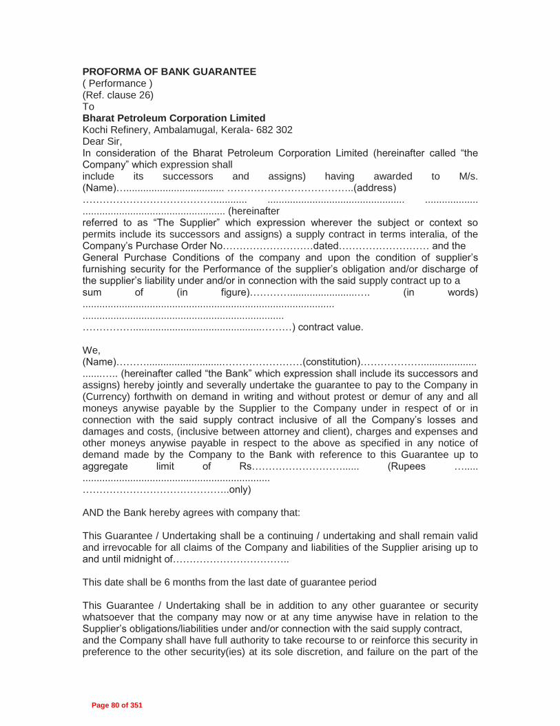
PROFORMA OF BANK GUARANTEE ( Performance ) (Ref. clause 26) To Bharat Petroleum Corporation Limited Kochi Refinery, Ambalamugal, Kerala- 682 302 Dear Sir, In consideration of the Bharat Petroleum Corporation Limited (hereinafter called “the Company” which expression shall include its successors and assigns) having awarded to M/s. (Name)…................................... ………………………………..(address) …………………………………............ ................................................. ................... ................................................... (hereinafter referred to as “The Supplier” which expression wherever the subject or context so permits include its successors and assigns) a supply contract in terms interalia, of the Company’s Purchase Order No………………………dated……………………… and the General Purchase Conditions of the company and upon the condition of supplier’s furnishing security for the Performance of the supplier’s obligation and/or discharge of the supplier’s liability under and/or in connection with the said supply contract up to a sum of (in figure)…………........................…. (in words) .......................................................................................... ........................................................................ ……………..............................................………) contract value. We, (Name)………...........................……………………(constitution)………………...........................….. (hereinafter called “the Bank” which expression shall include its successors and assigns) hereby jointly and severally undertake the guarantee to pay to the Company in (Currency) forthwith on demand in writing and without protest or demur of any and all moneys anywise payable by the Supplier to the Company under in respect of or in connection with the said supply contract inclusive of all the Company’s losses and damages and costs, (inclusive between attorney and client), charges and expenses and other moneys anywise payable in respect to the above as specified in any notice of demand made by the Company to the Bank with reference to this Guarantee up to aggregate limit of Rs………………………...... (Rupees …..... ................................................................... ……………………………………..only) AND the Bank hereby agrees with company that: This Guarantee / Undertaking shall be a continuing / undertaking and shall remain valid and irrevocable for all claims of the Company and liabilities of the Supplier arising up to and until midnight of…………………………….. This date shall be 6 months from the last date of guarantee period This Guarantee / Undertaking shall be in addition to any other guarantee or security whatsoever that the company may now or at any time anywise have in relation to the Supplier’s obligations/liabilities under and/or connection with the said supply contract, and the Company shall have full authority to take recourse to or reinforce this security in preference to the other security(ies) at its sole discretion, and failure on the part of the
Page 80 of 351

Company in enforcing or requiring enforcement of any other security shall have the effect of releasing the Bank from its liability hereunder. The company shall be at liberty without reference to the bank and without affecting the full liability of the Bank hereunder to take any other security in respect of the Supplier’s obligations and/or liabilities under or in connection with the said supply contract and to vary the terms vis a vis the supplier of the said supply contract or to grant time and/or indulgence to the supplier or to reduce or to increase or otherwise vary the prices of the total contract value or and/or the remedies of the company under any other security (ies) now or hereafter held by the company and no such dealing(s), variation(s), reduction(s), increase(s) or the indulgence(s) or arrangement(s) with the supplier or release or forbearance whatsoever shall have the effect of releasing the Bank from its full liability to the Company hereunder or of prejudicing rights of the Company, against the Bank. The Guarantee / Undertaking shall not be determined or affected by the liquidation or winding up, dissolution or change of constitution or insolvency of the supplier but shall in all respects and for all purposes be binding and operative until payment of all moneys payable to the Company in terms hereof. The Bank hereby waives all rights at any time inconsistent with the terms of its Guarantee / Undertaking and the obligations of the Bank in terms hereof shall not be anywise affected or suspended by reason of any dispute or disputes having been raised by the supplier (whether or not pending before any Arbitrator, office, Tribunal or Court) or any denial of liability by the supplier or any other of communication whatsoever by the supplier stopping or preventing or purporting to stop or prevent any payment by the Bank to the Company in terms hereof. The amount stated in any notice of demand addressed by the Company to the Guarantor as liable to be paid to the Company by the supplier or as suffered or incurred by the Company on account of any losses or damages of costs, charges and or expenses shall as between the Bank and the company be conclusive of the amount so liable to be paid to the Company or suffered or incurred by the Company, as the case may be and payable by the Guarantor to Company in terms hereof. Yours faithfully,
Page 81 of 351

Page 82 of 351
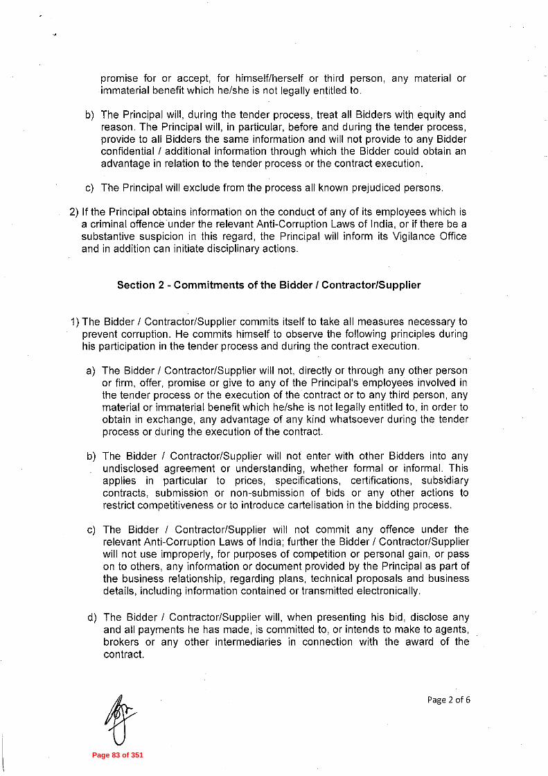
Page 83 of 351

Page 84 of 351

Page 85 of 351

Page 86 of 351

Page 87 of 351

Dated 02-06-2014 Page 1
Annexure – 1
E-TENDERING METHODOLOGY
Instructions for Online Bid Submission:
The bidders are required to submit soft copies of their bids electronically on the CPP Portal (URL:
http://eprocure.gov.in) only, using valid Digital Signature Certificates. The instructions given below are
meant to assist the bidders in registering on the CPP Portal, prepare their bids in accordance with the
requirements and submitting their bids online on the CPP Portal.
More detailed information useful for submitting online bids on the CPP Portal may be obtained at:
https://eprocure.gov.in/eprocure/app .
REGISTRATION
1) Bidders are required to enroll on the e-Procurement module of the Central Public
Procurement Portal (URL: https://eprocure.gov.in/eprocure/app) by clicking on the link “Click
here to Enroll” on the CPP Portal is free of charge.
2) As part of the enrolment process, the bidders will be required to choose a unique username
and assign a password for their accounts.
3) Bidders are advised to register their valid email address and mobile numbers as part of the
registration process and submit in EIL tender portal for updation of records
(http://tenders.eil.co.in) . These details would be used for any communication from the CPP
Portal.
4) Upon enrolment, the bidders will be required to register their valid Digital Signature
Certificate (DSC) (Class II or Class III Certificates with signing key usage) issued by any
Certifying Authority recognized by CCA India (e.g. Sify / TCS / nCode / eMudhra etc.), with
their profile.
5) Foreign Bidders have to refer “DSC details for foreign Bidders” for Digital signature
Certificates requirements which comes under Download Tab at
https://eprocure.gov.in/eprocure/app and the remaining part is same as above and below.
6) Only one valid DSC should be registered by a bidder. Please note that the bidders are
responsible to ensure that they do not lend their DSC‟s to others which may lead to misuse.
7) Bidder then logs in to the site through the secured log-in by entering their user ID / password
and the password of the DSC / e-Token.
SEARCHING FOR TENDER DOCUMENTS
1) There are various search options built in the CPP Portal, to facilitate bidders to search active
tenders by several parameters. These parameters could include Tender ID, organization
name, location, date, value, etc. There is also an option of advanced search for tenders,
wherein the bidders may combine a number of search parameters such as organization
name, form of contract, location, date, other keywords etc. to search for a tender published
on the CPP Portal.
2) Once the bidders have selected the tenders they are interested in, the same can be moved
to the respective „My Tenders‟ folder. This would enable the CPP Portal to intimate the
bidders through SMS / e-mail in case there is any corrigendum issued to the tender
document.
Page 88 of 351

Dated 02-06-2014 Page 2
3) The bidder should make a note of the unique Tender ID assigned to each tender, in case
they want to obtain any clarification / help from the Helpdesk.
PREPARATION OF BIDS
1) Bidder should take into account any corrigendum published on the tender document before
submitting their bids.
2) Please go through the tender advertisement and the tender document carefully to
understand the documents required to be submitted as part of the bid. Please note the
number of covers in which the bid documents have to be submitted, the number of
documents - including the names and content of each of the document that need to be
submitted. Any deviations from these may lead to rejection of the bid.
3) Bidder, in advance, should get ready the bid documents to be submitted as indicated in the
tender document and generally, they can be in PDF / XLS / RAR / DWF formats. Bid
documents may be scanned with 100 dpi with black and white option. However, Price
Schedule / SOR shall be strictly in RAR format without altering any contents of the
formats uploaded by EIL in their Bidding Document.
4) To avoid the time and effort required in uploading the same set of standard documents which
are required to be submitted as a part of every bid, a provision of uploading such standard
documents (e.g. PAN card copy, annual reports, auditor certificates etc.) has been provided
to the bidders. Bidders can use “My Space” area available to them to upload such
documents. These documents may be directly submitted from the “My Space” area while
submitting a bid, and need not be uploaded again and again. This will lead to a reduction in
the time required for bid submission process.
SUBMISSION OF BIDS
1) Bidder should log into the site well in advance for bid submission so that he/she upload the
bid in time i.e. on or before the bid submission time. Bidder will be responsible for any delay
due to other issues.
2) The bidder has to digitally sign and upload the required bid documents one by one as
indicated in the tender document.
3) Bidder has to select the payment option as “offline” to pay the tender fee / EMD as
applicable and enter details of the instrument.
4) Bidder should prepare the EMD as per the instructions specified in the tender document. The
original should be posted/couriered/given in person to the Tender Processing Section, with
in 7 calendar days of the date of Unpriced bid opening. The details of the DD/any other
accepted instrument, physically sent, should tally with the details available in the scanned
copy and the data entered during bid submission time. Otherwise the uploaded bid will be
rejected.
5) A Price Bid format has been provided with the tender document to be filled by all the bidders.
Bidders are requested to note that they should necessarily submit their financial bids in the
format provided and no other format is acceptable. Bidders are required to download the
Price Bid file, open it and complete the cells with their respective financial quotes and other
details (such as name of the bidder). No other cells should be changed. Once the details
have been completed, the bidder should save it and submit it online, without changing the
filename. If the Price Bid file is found to be modified by the bidder, the bid will be rejected.
Page 89 of 351

Dated 02-06-2014 Page 3
6) The server time (which is displayed on the bidders‟ dashboard) will be considered as the
standard time for referencing the deadlines for submission of the bids by the bidders,
opening of bids etc. The bidders should follow this time during bid submission.
7) All the documents being submitted by the bidders would be encrypted using PKI encryption
techniques to ensure the secrecy of the data. The data entered cannot be viewed by
unauthorized persons until the time of bid opening. The confidentiality of the bids is
maintained using the secured Socket Layer 128 bit encryption technology. Data storage
encryption of sensitive fields is done.
8) The uploaded tender documents become readable only after the tender opening by the
authorized bid openers.
9) Upon the successful and timely submission of bids, the portal will give a successful bid
submission message & a bid summary will be displayed with the bid no. and the date & time
of submission of the bid with all other relevant details.
10) The bid summary has to be printed and kept as an acknowledgement of the submission of
the bid. This acknowledgement may be used as an entry pass for any bid opening meetings.
RETENDER
1) Please note that if Tender has been retendered, than it is mandatory for the bidder to
submit their offer again on CPP Portal.
ASSISTANCE TO BIDDERS
1) Any queries relating to the tender document and the terms and conditions contained therein
should be addressed to the Tender Inviting Authority for a tender or the relevant contact
person indicated in the tender.
2) Any queries relating to the process of online bid submission or queries relating to CPP Portal
in general may be directed to the 24x7 CPP Portal Helpdesk. The contact number for the
helpdesk is 1800 3070 2232.
Page 90 of 351

Government eProcurement System
D S C f o r F o r e i g n N a t i o n a l s Version 1.0
Procedure for obtaining Digital Signature by Foreign Vendors
This document gives the procedure to be followed by bidders who are resident of countries other
than India for participating in Online Tendering Activity.
As per the IT ACT 2000, all bidders who participate in the online bidding process in this site
should possess a valid Digital Signature issued by any of the Digital Signature Certificate (DSC)
vendors approved by CCA, India (https://cca.gov.in). The following document gives the procedure
that is generally followed by various vendors.
Generally, the documents that are required to be submitted by Foreign Nationals are as follows:
1. Identity Proof (ID Proof) of the person in whose name DSC has to be issued (E.g.
Passport copy)
2. Bank account statement in country of residence, duly attested by Indian Embassy / High
Commission / Consulate / Apostille in the country where the applicant is currently
located. (At least 6 months of Bank transactions) with the proof indicating the account is
owned by the Individual.
3. Copy of the Trade license attested by any one of the authorities as specified in Point 2
above.
4. As the Individual is representing the company, an Authorization on company’s letter head
as given in the form
5. Copy of the Authorization letter or invitation letter from department for the
participation in the tender by any one of the tender inviting authority.
As of now, it is learnt that GNFC, TCS, eMudhra issue DSCs with the above procedure. The
copy of the nCodes, TCS and eMudhra Format is enclosed as Annexure; the Copies of other
vendors will be made available on receipt of information from these vendors.
Note: The Information given by the vendors is attached for facilitating the Foreign Nationals to
procure DSCs from the Indian CA authorized vendors for information purpose only as shared by
the respective CA's.
Please find below the details of various vendors and procedure for obtaining DSC:
GNFC
Tata Consultancy Services
eMudhra
Page 91 of 351
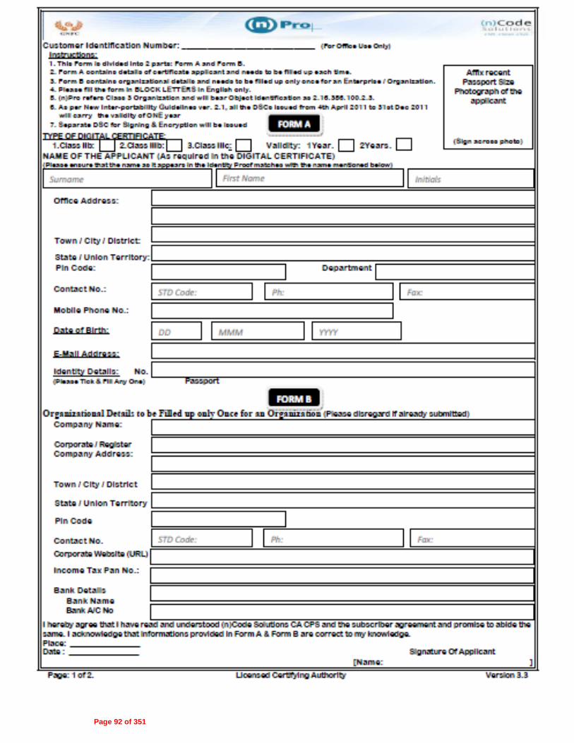
Page 92 of 351

Page 93 of 351

Page 94 of 351

Page 95 of 351

Page 96 of 351

Page 97 of 351

Page 98 of 351
Page 99 of 351

Page 100 of 351

Page 101 of 351

ENGINEERS INDIA LIMITED
NEW DELHI
Project :
Client :
IREP
BPCL-KOCHI
The
draw
ing,
des
ign
and
deta
ils g
iven
on
this
form
at a
re th
e pr
oper
ty o
f EN
GIN
EE
RS
IND
IA L
IMIT
ED
. The
y ar
e m
erel
y lo
aned
and
on
the
borr
ower
's e
xpre
ss a
gree
men
t tha
t the
y w
ill n
ot b
e re
prod
uced
,co
pied
, exh
ibite
d or
use
d, e
xcep
t in
limite
d w
ay p
erm
itted
by
a w
ritte
n co
nsen
t giv
en b
y th
e le
nder
to th
e bo
rrow
er fo
r the
inde
nded
use
. E
IL-1
641-
515
Rev
.1 A
4-21
0x29
7
Sheet 1 Of 5
DOCUMENT NUMBER(Always quote the Document Number given below as reference)
MATERIAL REQUISITION (TOP SHEET)
Notes:1. This page is a record of all Revisions of this Requisition2. The nature of the Revision is briefly stated in the "Details" column below, the Requisition in its entirety shall be considered for contractual pupose.
3.Vendor shall note the MR category and shall submit his offer in line with the requirements included in attached 'Instructions to Bidders'
5115/05/2014
DATE
16
ORIGINATOR
DIVN. DEPT.REVJOB NO
AUNIT/ MAIN
COSTDOC.
CODE SR.NO.
A307 000 YF MR 2853
SKS AR MN Issued for Bids.A 15/05/2014
REV APPDCHKBYDATE D E T A I L S
Ultrasonic Flowmeters15ND KOCHI REFINERY, KOCHI, KER
ITEM DESCRIPTION:
GROUP ITEM CODE DESTINATION :
DELIVERY PERIOD :IIITEM CATEGORY
This is a system generated approved document and does not require signature.
Page 102 of 351

ENGINEERS INDIA LIMITED
NEW DELHI
Project :
Client :
REQUISITION No. REVIREP
BPCL-KOCHI A307-000-YF-MR-2853 A
The
draw
ing,
des
ign
and
deta
ils g
iven
on
this
form
at a
re th
e pr
oper
ty o
f EN
GIN
EE
RS
IND
IA L
IMIT
ED
. The
y ar
e m
erel
y lo
aned
and
on
the
borr
ower
's e
xpre
ss a
gree
men
t tha
t the
y w
ill n
ot b
e re
prod
uced
,co
pied
, exh
ibite
d or
use
d, e
xcep
t in
limite
d w
ay p
erm
itted
by
a w
ritte
n co
nsen
t giv
en b
y th
e le
nder
to th
e bo
rrow
er fo
r the
inde
nded
use
. E
IL-1
641-
515
Rev
.1 A
4-21
0x29
7
Sheet 2 Of 5
DESCRIPTION QUANTITYS.NO TAG NO ./ ITEM CODE
Ultrasonic Flowmeter
Ultrasonic Flowmeter
Ultrasonic Flowmeter
Ultrasonic Flowmeter
Ultrasonic Flowmeter
Ultrasonic Flowmeter
Ultrasonic Flowmeter
Ultrasonic Flowmeter
Ultrasonic Flowmeter
Ultrasonic Flowmeter
Ultrasonic Flowmeter
Ultrasonic Flowmeter
Ultrasonic Flowmeter
Ultrasonic Flowmeter
Ultrasonic Flowmeter
Supply of two years operation and Maintenance Spares,as perenclosed instructions to vendorUnit Rates
Unit Rates of items for addition/deletion purpose,as per the enclosedinstructions to vendor.
Supervision of erection,testing and commissioning of items specified atitem 1.00 above as per enclosed instructions to vendor
0ID-FT-1207
0IF-FT-4902
0IY-FT-3901
0IY-FT-3401
0IY-FT-4102
0IY-FT-5401
0IY-FT-5605
IUS-FT-1801
IUR-FT-1601
IUR-FT-1602
IUF-FT-1401
IUS-FT-2401
IFP-FT-5901
IFP-FT-5902
00H-FT-8801
1.02
1.03
1.05
1.04
1.06
1.07
1.08
1.14
1.12
1.13
1.11
1.15
1.09
1.10
1.01
5
6
6.001
8
1
1
1
1
1
1
1
1
1
1
1
1
1
1
1
1
Nos
Nos
Nos
Nos
Nos
Nos
Nos
Nos
Nos
Nos
Nos
Nos
Nos
Nos
Nos
Lot
GROUP:
GROUP:
GROUP:
GROUP:
GROUP:
GROUP:
GROUP:
GROUP:
GROUP:
GROUP:
A
B
C
D
E
F
G
H
I
J
Design ,engineering,manufacture,procurement of materials andbought out components, assembly at shop,inspection,testing atmanufacturer's works, packing, delivery, documentation as per theenclosed EIL standard specifications, Special instruction to vendor,job specification, data sheets etc
1
Ultrasonic Flowmeter with Spool Piece (Process Liquid-0ID Qty - 1 no.)
Ultrasonic Flowmeter with Spool Piece (Process Liquid-0IF Qty - 1 no.)
Ultrasonic Flowmeter with Spool Piece (Process Liquid-0IY Qty - 1 no.)
Ultrasonic Flowmeter without Spool Piece (Process Liquid-0IY Qty - 2 nos.)
Ultrasonic Flowmeter with Spool Piece (Process Gas-0IY Qty - 2 nos.)
Ultrasonic Flowmeter Cooling Water (IUS Qty- 1 no.)
Ultrasonic Flowmeter Raw Water (IUR Qty- 2 nos.)
Ultrasonic Flowmeter Flare (IUF & IUS Qty- 2 nos.)
Ultrasonic Flowmeter Flare (IFP Qty- 2 nos.)
Ultrasonic Flowmeter Flare (00H Qty- 1 no.)
Page 103 of 351

ENGINEERS INDIA LIMITED
NEW DELHI
Project :
Client :
REQUISITION No. REVIREP
BPCL-KOCHI A307-000-YF-MR-2853 A
The
draw
ing,
des
ign
and
deta
ils g
iven
on
this
form
at a
re th
e pr
oper
ty o
f EN
GIN
EE
RS
IND
IA L
IMIT
ED
. The
y ar
e m
erel
y lo
aned
and
on
the
borr
ower
's e
xpre
ss a
gree
men
t tha
t the
y w
ill n
ot b
e re
prod
uced
,co
pied
, exh
ibite
d or
use
d, e
xcep
t in
limite
d w
ay p
erm
itted
by
a w
ritte
n co
nsen
t giv
en b
y th
e le
nder
to th
e bo
rrow
er fo
r the
inde
nded
use
. E
IL-1
641-
515
Rev
.1 A
4-21
0x29
7
Sheet 3 Of 5
DESCRIPTION QUANTITYS.NO TAG NO ./ ITEM CODE
Vendors shall quote prices against these items in their price scheduleVendor to note that the numbers given in square '[]' and curly '{}' brackets are not for their use andmeant for store purpose only.Items shall be tagged as per equipment Tag No. only.
Page 104 of 351

ENGINEERS INDIA LIMITED
NEW DELHI
Project :
Client :
REQUISITION No. REVIREP
BPCL-KOCHI A307-000-YF-MR-2853 A
The
draw
ing,
des
ign
and
deta
ils g
iven
on
this
form
at a
re th
e pr
oper
ty o
f EN
GIN
EE
RS
IND
IA L
IMIT
ED
. The
y ar
e m
erel
y lo
aned
and
on
the
borr
ower
's e
xpre
ss a
gree
men
t tha
t the
y w
ill n
ot b
e re
prod
uced
,co
pied
, exh
ibite
d or
use
d, e
xcep
t in
limite
d w
ay p
erm
itted
by
a w
ritte
n co
nsen
t giv
en b
y th
e le
nder
to th
e bo
rrow
er fo
r the
inde
nded
use
. E
IL-1
641-
515
Rev
.1 A
4-21
0x29
7
Sheet 4 Of 5
1
2
3
4
5
6
7
8
9
10
11
12
13
14
15
16
17
18
19
S. No.
Vendor Data Requirement
Special Instruction to Vendor
Technical Questionarrie
Compliance Statement
Deviation List Format
Datahseet Index & Datasheets
Installation Schematic for Flare GasUltrasonic Flowmeter
Process Ultrasonic Flowmeter with SpoolPiece Schematic
Ultrasonic Flowmeter Schematic (InsertionType)
Standard Specification for UltrasonicFlowmeter
Standard spec for Electronic/PneumaticInstruments
Std spec for Thermowells
Thermowell
Piping Material Specification
Job Specification for Non DestructiveExamination Requirement of Piping
Material Requirements for Carbon SteelComponents used in Petroleum RefineryEnv
Job Specification for Surface Preparation& Protective Coating
Spec. for quality management sys.req.from bidders
Spec. for documentation requirementsfrom supplier
DOCUMENT TITLE
A307-000-YF-VD-2853
A307-000-YF-SI-2853
A307-000-YF-TM-2853
A307-000-YF-CF-2853
A307-000-16-51-MD-2853
A307-000-16-51-ID-2853
A307-000-16-51-0200
A307-000-16-51-0201
A307-000-16-51-0203
6-52-0011
6-52-0032
6-52-0042
7-52-0035
A307-000-16-51-MD-0012
A307-6-44-0016
6-79-0013
A307-000-16-51-MD-0010
6-78-0001
6-78-0003
DOCUMENT NO.
0
0
A
0
0
0
0
0
0
0
4
3
3
0
0
1
0
0
0
REV
15/05/2014
15/05/2014
15/05/2014
08/05/2014
08/05/2014
08/05/2014
06/11/2013
06/11/2013
06/11/2013
27/11/2013
12/03/2012
15/12/2010
21/03/2012
15/05/2014
21/12/2012
07/10/2011
25/06/2013
04/06/2009
04/06/2009
DATE
In case of any subsequent revision of MR or PR,only revised sheets of the attachments listed above shall be issuedalongwith the revision.
LIST OF ATTACHMENTS
GENERAL NOTES:
SHEETS
3
7
1
1
1
45
1
1
1
14
16
9
3
44
20
6
48
9
12
Page 105 of 351

Eng
inee
rs In
dia
Lim
ited
Clie
nt/ P
roje
ct:B
PC
L-K
OC
HI/
IRE
P
S.N
o.D
rg/ D
oc. N
omen
clat
ure
as p
er E
IL V
endo
r Dat
aR
equi
rem
ent
Title
Rev
. 0R
ev. 1
Rev
. 2
Ven
dor D
rg/ D
oc N
o.Fo
rmE
lect
roni
c(E
)/ P
rint (
P)
Cat
egor
yR
evie
w(R
)/R
ecor
ds(I)
Sch
edul
eD
ate
of 1
stS
ubm
issi
on(R
ev. 0
)
Ant
icip
ated
(Ant
) Dat
e of
sub
mis
sion
by
vend
orA
ctua
l (A
ct) D
ate
of s
ubm
issi
on b
y ve
ndor
Dat
e of
Ret
urn
(Rew
) by
EIL
Rev
iew
Sta
tus
(Cod
e)R
ev. 3
Cod
eR
ewAct
Ant
Cod
eR
ewAct
Ant
Cod
eR
ewAct
Ant
Cod
eR
ewAct
Ant
Cod
eR
ewAct
Ant
Rem
arks
Ven
dor
Dra
win
g/ D
ocum
ent S
ubm
issi
on S
ched
ule
Item
Des
crip
tion:
Ultr
ason
icFl
owm
eter
s
Ven
dor's
Nam
e
:C
onta
ct P
erso
n (N
ame/
Tel
/ Fax
/ em
ail)
:S
tatu
s D
ate:
Con
tact
Per
son(
EIL
):E
IL O
rigi
natin
g D
epar
tmen
t :I
nstr
umen
tatio
n
PR
No.
:
Dat
e of
LO
I:
PO
No.
:
Dat
e of
PO
:
Rev
iew
Sta
tus
Cod
e:
1. N
o C
omm
ents
2. P
roce
ed w
ith m
anuf
actu
re/ f
abric
atio
n as
per
com
men
ted
docu
men
t.R
evis
ed d
ocum
ent r
equi
red.
3. D
ocum
ent d
oes
not c
onfo
rm to
bas
ic re
quire
men
ts a
s m
arke
d.R
esub
mit
for R
evie
w. R
: Ret
aine
d fo
r Ref
eren
ce
V: V
oid
Form
No.
EIL
-164
1-19
23 R
ev.1
Page 106 of 351

VENDOR DATA REQUIRMENT
ENGINEERS INDIA LIMITED
NEW DELHIUNIT :CLIENT
VENDOR :
ORDER NO. :
REV APPVDCHKDBYDATE
PLANT :
000
A307-000-YF-MR-2853MNARSKS15/05/2014
A307-000-YF-VD-2853 0
IREP
BPCL-KOCHI
SPECIFICATION REV
REQ. NO. :
The
draw
ing,
des
ign
and
deta
ils g
iven
on
this
form
at a
re th
e pr
oper
ty o
f EN
GIN
EE
RS
IND
IA L
IMIT
ED
. The
y ar
e m
erel
y lo
aned
and
on
the
borr
ower
's e
xpre
ss a
gree
men
t tha
t the
y w
illno
t be
repr
oduc
ed, c
opie
d, e
xhib
ited
or u
sed,
exc
ept i
n lim
ited
way
per
mitt
ed b
y a
writ
ten
cons
ent g
iven
by
the
lend
er to
the
borr
ower
for t
he in
dend
ed u
se.
EIL
-165
1-72
6 R
ev.0
A4-
210x
297
0
Page 1 Of 3
Dimensional details with mounting details and model number Connections by purchase(Piping,Electrical Etc.) Wiring diagramsProven Track Record Recommended spare parts list(for two years operation ) Installation, Operation and maintenance manual Nomograph and sizing calculations Test certificates Certificate from statutory body Assembly details Catalogues in englishDeviation ListFilled in DatasheetsStraight Length RequirementCompliance StatementGA Drawings & DatasheetsFinal Documentation in CD
Prints
WithProposal(Prints)
Date Needed
AFTER PURCHASE ORDERDescription
XX
X
X
XXXXX
X(i) X(i) X(i)
X(a)
X(i) X(i)
X(i)
1. 2. 3. 4. 5. 6. 7. 8. 9. 10. 11. 12. 13. 14. 15. 16. 17.
FinalDocumentation
/ As Built
XXX
XXXXXX
X
XX
Page 107 of 351

VENDOR DATA REQUIRMENT
ENGINEERS INDIA LIMITED
NEW DELHIUNIT :CLIENT
VENDOR :
ORDER NO. :
REV APPVDCHKDBYDATE
PLANT :
000
A307-000-YF-MR-2853MNARSKS15/05/2014
A307-000-YF-VD-2853 0
IREP
BPCL-KOCHI
SPECIFICATION REV
REQ. NO. :
The
draw
ing,
des
ign
and
deta
ils g
iven
on
this
form
at a
re th
e pr
oper
ty o
f EN
GIN
EE
RS
IND
IA L
IMIT
ED
. The
y ar
e m
erel
y lo
aned
and
on
the
borr
ower
's e
xpre
ss a
gree
men
t tha
t the
y w
illno
t be
repr
oduc
ed, c
opie
d, e
xhib
ited
or u
sed,
exc
ept i
n lim
ited
way
per
mitt
ed b
y a
writ
ten
cons
ent g
iven
by
the
lend
er to
the
borr
ower
for t
he in
dend
ed u
se.
EIL
-165
1-72
6 R
ev.0
A4-
210x
297
0
Page 2 Of 3
NOTES :
1. Fold all drawings to 216mm X 279mm and roll transparencies.
2. Vendor to provide all printed matter to ENGINEERS INDIA LIMITED (EIL). ATTENTION -
LEGEND:
Categories preceeded with * will be approved for fabrication by Engineers India Limited. The remaining drawings are needed for information only.
A/C = As compiled A/R = As required W/S = With shipment W = Weeks
IMPORTANT
While submittimg drawings and documents for review as indicated in vendor data requirement, vendor must ensure the following :
1. A blank space measuring 75 mm W x 38 mm H shall be provided on all vendor drawings (on the front side) for marking review codes etc. by ENGINEERS INDIA LIMITED.
2. The review of the drawings shall be done as applicable, under the following review codes : a) Review Code 1 : No Comments. b) Review Code 2 : Proceed with manufacture / fabrication as per commented drawing. Revised drawing required. c) Review Code 3 : Document does not conform to the basic requirements as marked. Resubmit for review.
3. Review of the vendor drawings by EIL would be only to check compatibility with basic design and concepts and would in no way absolve the manufacturer / fabricator of his responsibility to meet the applicable codes, specifications and statutory rules and regulations.
4. For drawings / documents indicated as FOR INFORMATION in the vendor data requirement, vendor must clearly mark FOR INFORMATION ONLY on the submitted drawings / documents.
Vendor Drawing Control5th Floor EI House, 1, Bhikaji Cama Place, New Delhi-110066.
I. Any drawing/document not indicated in the list above but required during erection, commissioning or forreconfiguration of the system shall also be supplied by the Vendor on demand.
II. X indicates required. Suffix Codes mean the following: - (i) For Information - (a) For Approval
III. The soft copy of documentation shall be in editable form (CAD. Excel, Database etc ).
IV. Refer to the column for 'Date needed' in the table above. The same shall be discussed and finalised
Page 108 of 351

VENDOR DATA REQUIRMENT
ENGINEERS INDIA LIMITED
NEW DELHIUNIT :CLIENT
VENDOR :
ORDER NO. :
REV APPVDCHKDBYDATE
PLANT :
000
A307-000-YF-MR-2853MNARSKS15/05/2014
A307-000-YF-VD-2853 0
IREP
BPCL-KOCHI
SPECIFICATION REV
REQ. NO. :
The
draw
ing,
des
ign
and
deta
ils g
iven
on
this
form
at a
re th
e pr
oper
ty o
f EN
GIN
EE
RS
IND
IA L
IMIT
ED
. The
y ar
e m
erel
y lo
aned
and
on
the
borr
ower
's e
xpre
ss a
gree
men
t tha
t the
y w
illno
t be
repr
oduc
ed, c
opie
d, e
xhib
ited
or u
sed,
exc
ept i
n lim
ited
way
per
mitt
ed b
y a
writ
ten
cons
ent g
iven
by
the
lend
er to
the
borr
ower
for t
he in
dend
ed u
se.
EIL
-165
1-72
6 R
ev.0
A4-
210x
297
0
Page 3 Of 3
during kick off meeting, for achieving the overall schedule.
V. Note-1 & 2 above is not applicable as document shall be submitted as soft copies through eDMS.
Page 109 of 351

ENGINEERS INDIA LIMITED
NEW DELHIUNIT :CLIENT
SPECIAL INSTRUCTION TO VENDORS
VENDOR :
ORDER NO. :
REV APPVDCHKDBYDATE
PLANT :
000
A307-000-YF-MR-28530 MNARSKS15/05/2014
A307-000-YF-SI-2853 0
IREP
BPCL-KOCHI
SPECIFICATION REV
REQ. NO. :
The
draw
ing,
des
ign
and
deta
ils g
iven
on
this
form
at a
re th
e pr
oper
ty o
f EN
GIN
EE
RS
IND
IA L
IMIT
ED
. The
y ar
e m
erel
y lo
aned
and
on
the
borr
ower
's e
xpre
ss a
gree
men
t tha
t the
y w
illno
t be
repr
oduc
ed, c
opie
d, e
xhib
ited
or u
sed,
exc
ept i
n lim
ited
way
per
mitt
ed b
y a
writ
ten
cons
ent g
iven
by
the
lend
er to
the
borr
ower
for t
he in
dend
ed u
se.
EIL
-165
1-72
6 R
ev.0
A4-
210x
297 Page 1 Of 7
BIDDING INSTRUCTIONS.
A1. Bidder must follow the following guidelines while submitting their offer. Offers not complying with these guidelines shallbe rejected summarily without any intimation to the bidder.
a) The Material Requisition (MR) specifications (i.e.) data sheets, job standard specifications and other attachments to thisMR shall be fully complied with. No deviations of any type are acceptable in general. In case, where it is necessary, biddersshall furnish their deviations to MR requirements, in a separate section (Deviation List) of their bid. Evaluation shall be basedon the deviations furnished in the separate section for deviations and deviations listed elsewhere in the bid shall not be takeninto cognizance.
b) If the bid does not include complete scope and technical data required to be submitted with bid, offer shall be summarilyrejected.
c) In case of any contradiction between these bidding instructions and any other documents attached with MR, this biddinginstructions shall govern.
d) Bidder shall submit the Lump sum price for each group separately, covering all the items, accessories, mandatory spares,inspection, testing & documentation requirements as specified in this MR as per price schedule sheet. No information /description, technical or non-technical, other than what is required as per price format shall be filled or submitted.
e) In addition bidder shall submit unit price for each ultrasonic flowmeter including its associated accessories & testingrequirement for addition/deletion purpose and unit price of accessories such as cable between the probe/transducer & thetransmitter and calibration kit for addition/deletion purpose.
f) Bidder to note that alternate quote shall not be furnished for any tag. As per project philosophy an offer with alternate quoteshall be rejected.
A2. Bidder is responsible for meeting all technical requirements in this Material Requisition including instrument data sheets.If at any stage, till the completion of order, the offered instruments and its accessories are found unsuitable to meet the MRspecification, bidder shall replace the same with suitable items, without any time / cost implication.
A3. The Bidder shall submit the required drawings/ documents as per the Vendor Data Requirements (VDR) enclosed withthe MR.
A4. The Bidder shall submit the 'Technical Questionnaire' in this M.R. duly filled in along with the offer. Answers to thecontents of this Technical Questionnaire shall be unambiguous i.e. 'yes', 'no' or the required data/information. An offer withoutthe filled-in Technical Questionnaire or with vague, non-committal replies or referenced reply to some catalogue etc., withoutspecific page and paragraph no. shall be considered incomplete and is liable for rejection.
A5. MUST COMPLY REQUIREMENTS -------------------------------------------------------- a) Bidder must indicate their contact person; email ID, fax number, telephone number and postal address.
b) Offer must be complete in all respects complying fully to the MR requirements without exception. No price change,whatsoever, shall be allowed to the bidder after submission of bid even if it results from any technical clarification.
c) Any price change subsequent to the submission of the offer because of any technical query or any other reasonattributable to the bidder may lead to rejection of the offer.
d) Technical queries if necessary shall be forwarded either in email or by fax. Bidder shall be allowed to forward their replieseither by email or by fax, addressed directly to Purchase department (addressed to the Purchase department from where theenquiry is issued) indicating the enquiry number in each of such correspondence.
e) Any query raised on the email or fax must be replied within the specified period. Replies received beyond the specified
Part A:
Page 110 of 351

ENGINEERS INDIA LIMITED
NEW DELHIUNIT :CLIENT
SPECIAL INSTRUCTION TO VENDORS
VENDOR :
ORDER NO. :
REV APPVDCHKDBYDATE
PLANT :
000
A307-000-YF-MR-28530 MNARSKS15/05/2014
A307-000-YF-SI-2853 0
IREP
BPCL-KOCHI
SPECIFICATION REV
REQ. NO. :
The
draw
ing,
des
ign
and
deta
ils g
iven
on
this
form
at a
re th
e pr
oper
ty o
f EN
GIN
EE
RS
IND
IA L
IMIT
ED
. The
y ar
e m
erel
y lo
aned
and
on
the
borr
ower
's e
xpre
ss a
gree
men
t tha
t the
y w
illno
t be
repr
oduc
ed, c
opie
d, e
xhib
ited
or u
sed,
exc
ept i
n lim
ited
way
per
mitt
ed b
y a
writ
ten
cons
ent g
iven
by
the
lend
er to
the
borr
ower
for t
he in
dend
ed u
se.
EIL
-165
1-72
6 R
ev.0
A4-
210x
297 Page 2 Of 7
period may lead to ignoring any subsequent correspondence from the bidder.
f) Bidder to note that a pre-bid meeting shall be held in which bidder can seek any clarification/ confirmation if required.Bidder shall ensure that this meeting is attended by both technical and commercial personnel of the Bidder who should havethoroughly scrutinized the MR before hand so that all issues are finally resolved in this meeting.
g) Offered models shall be accompanied by detailed technical catalogues in English. An offer without catalogues shall beconsidered incomplete and is liable for rejection.
A6. (i) Bidder shall fill and furnish the following documents along with the offer:1. COMPLIANCE STATEMENT2. TECHNICAL DEVIATION LIST (if any)4. TECHNICAL QUESTIONNAIRE 5. UN PRICED BID (WITHOUT PRICES) as per the RFQ FORMAT
THE ABOVE DOCUMENTS ARE THE ONLY BASIS OF TECHNICAL EVALUATION. OFFERS SHALL BE EVALUATEDBASED ON THE ABOVE-MENTIONED DOCUMENTS ONLY. THERFORE BIDDER SHALL TAKE PROPER NOTE OF THISIMPORTANT REQUIREMENT AND COMPLY.ii) After placement of order, Bidder shall furnish filled in instrument data sheets, complete model no. and model decodingdetails along with instruments catalogs for inclusion in the PR within 2 weeks of issue of LOI.iii) Bidder to note that Delivery will be reckoned from the date of issue of LOI and any delay in submission of filled in datasheet and resulting delay in delivery shall be in Bidders account
PART B
Specific Job Requirements:
B1. The "Ultrasonic Flowmeters " covered in the MR are for the DCU(Unit-0ID), FCCU(Unit-0IF & IFP), NHT (unit-00H),Utilities (Units- IUR, IUF & IUS) and units of BPCL-KR, Kochi, Kerala. It is the responsibility of the bidder to ensure that theUltrasonic Flowmeters offered by them are suitable for specified applications.
B2. Bidder to note the following with regard to ordering of the Ultrasonic flowmeter mentioned in the requisition. TheUltrasonic flowmeters are divided into groups as per details given in Grouping Details1. GROUP-A: Ultrasonic Flowmeter with Spool Piece (Process Liquid-0ID Unit, Qty- 1 no.)
2. GROUP-B: Ultrasonic Flowmeter with Spool Piece (Process Liquid-0IF Unit, Qty- 1 no.)
3. GROUP-C: Ultrasonic Flowmeter with Spool Piece (Process Liquid-0IY Unit, Qty- 1 no.)
4. GROUP-D: Ultrasonic Flowmeter without Spool Piece (Process Liquid-0IY Unit, Qty-2 nos.)
5. GROUP-E: Ultrasonic Flowmeter with Spool Piece (Process Gas-0IY Unit, Qty-2 nos.)
6. GROUP-F: Ultrasonic Flowmeter without Spool Piece(Process Cooling Water -IUS Unit,Qty-1 no.)
7. GROUP-G: Ultrasonic Flowmeter without Spool Piece(Process Raw Water - IUR Unit, Qty-2 nos.)
8. GROUP-H: Ultrasonic Flowmeter (Flare - IUF & IUS Units, Qty- 2 nos.)
9. GROUP-I: Ultrasonic Flowmeter (Flare - IFP Units, Qty-2 nos.)
10. GROUP-J: Ultrasonic Flowmeter (Flare - 00H Unit, Qty -1 no.)
Bidder to note that the evaluation/Ordering shall be carried out on bottom line basis (lump sum basis) for all the tags of eachgroup including testing, mandatory spares and all other requirements of MR. Bidder must quote for all Ultrasonic flowmetersin a group so as to be considered for that group.
B3. Offered Model Nos. for Ultrasonic Flowmeter shall be field proven for at least 4000 hrs. in hydrocarbon application similarto as those indicated in the MR on the bid closing date. Bidder shall furnish the following information as a minimum along with
Page 111 of 351

ENGINEERS INDIA LIMITED
NEW DELHIUNIT :CLIENT
SPECIAL INSTRUCTION TO VENDORS
VENDOR :
ORDER NO. :
REV APPVDCHKDBYDATE
PLANT :
000
A307-000-YF-MR-28530 MNARSKS15/05/2014
A307-000-YF-SI-2853 0
IREP
BPCL-KOCHI
SPECIFICATION REV
REQ. NO. :
The
draw
ing,
des
ign
and
deta
ils g
iven
on
this
form
at a
re th
e pr
oper
ty o
f EN
GIN
EE
RS
IND
IA L
IMIT
ED
. The
y ar
e m
erel
y lo
aned
and
on
the
borr
ower
's e
xpre
ss a
gree
men
t tha
t the
y w
illno
t be
repr
oduc
ed, c
opie
d, e
xhib
ited
or u
sed,
exc
ept i
n lim
ited
way
per
mitt
ed b
y a
writ
ten
cons
ent g
iven
by
the
lend
er to
the
borr
ower
for t
he in
dend
ed u
se.
EIL
-165
1-72
6 R
ev.0
A4-
210x
297 Page 3 Of 7
their offer to support the proveness of each type of Ultrasonic Flowmeter being offered by them.- Name of the Plant and Customer- Model No. of the supplied Instrument for each type & application separately.- Year of supply and commissioning- Name, address, telephone/ fax no., e-mail of the contact person- Application detailsBidder shall furnish the above information with the offer. Instruments not having proven references in similar applications orreferences provided without complete information as asked or ambiguous references shall not be acceptable.
B4. Bidder shall strictly quote Ultrasonic Flowmeters as per their size, type & application enlisted with EIL for supply of theirflowmeters.
B5. a. The Ultrasonic flowmeter shall be supplied with transmitter (with LCD display unit), pre amplifier, probes/transducerswith special cables etc for installation in a pipe for flowmeter in Group-D, F & G. b. For flowmeters in Group-A, B, C & E, the same shall be duly mounted in a spool piece(Flanged type) ready for installationin pipeline. The spool piece material, flange material and end connection rating shall be as per respective datasheet. Allmounting accessories shall be provided by the Bidder. Also with reference to the datasheets of the above groups, bidder tonote that where integral type of Flowmeter is offered, pre amplifier is not applicable.c. Moreover for Group E, Bidder to note that Pressure & Temperature compensation is to be provided for which bidder shallprovide pressure transmitters, temperature transmitters , temperature element, thermowell, interconnection cable etc. alongwith nozzles and installation material for pressure & temperature transmitters even though same is not indicated in thesketch. Isolation valve (Gate/Ball) shall be provided for the pressure transmitter with body material ASTM A 216 Gr.WCB andtrim material shall be SS316 with rating as per the line class specified in the datasheet.
B6. Bidder to note the following with regard to Insertion type Process Ultrasonic flowmeter in Group-D, F &G. a) For Group D & G - Ball Valve (if provided to meet the insert-retract mechanism)shall have body material as ASTM A 216Gr.WCB and trim material as SS316 with rating as per the line class specified in the datasheet. However for ball valve, bodymaterial of SS316 is also acceptable. However Bidder shall offer suitable rating for the design pressure and temperature asindicated in datasheets.b) For Group F - Ball Valve (if provided to meet the insert-retract mechanism) shall have body material and trim material asSS316 with rating as per the line class specified in the datasheet. However Bidder shall offer suitable rating for the designpressure and temperature as indicated in datasheets.
c) Nozzle pipe/flange material & rating shall be as per the line class specified in the datasheet. Refer schematics (typical)A307-000-16-51-0203.d) Bidder shall provide a template for the insertion probe meters so that the probes can be arranged as required by them.
B7. Bidder to note the following with regard to Flare Ultrasonic flowmeters in Group-H, I & J. Transducer shall be insertedthrough a nozzle and flanged full-bore ball valve assembly to be supplied by Bidder.
a) Ball Valve body material shall be ASTM A216 GR.WCB and trim material shall be SS316 with rating as per the line classspecified in the datasheet. However for ball valve, body material of SS316 is also acceptable. However bidder shall offersuitable rating for the design pressure and temperature as indicated in datasheets.
b) Nozzle pipe/flange material & rating shall be as per the line class specified in the datasheet.
c) Pressure & Temperature compensation shall be provided in the Ultrasonic transmitter which shall accept external pressureand temperature signals. Bidder shall provide pressure transmitters, temperature transmitters ,temperature element,thermowell, interconnection cable etc. Pressure and temperature transmitters shall be powered from bidders Flowtransmitter. Refer schematics (typical) A307-000-16-51-0200.
d) Bidder shall confirm that the selected meter shall measure the maximum flow rate with the specified accuracy indicated inthe Standard Specification for Ultrasonic Flowmeters (6-52-0011) and the range shall be selected accordingly. Also biddershall provide the sizing calculation indicating the minimum measurable flow and minimum measurable accurate flow.
e) Bidder shall provide a template for the insertion probe meters so that the probes can be arranged as required by them.
f) Bidder shall confirm that sensors/transducers shall be able to withstand the maximum operating temperature which shall beoccurring intermittently (maximum temperature is not continuous) as indicated in respective tag datasheets without any
Page 112 of 351

ENGINEERS INDIA LIMITED
NEW DELHIUNIT :CLIENT
SPECIAL INSTRUCTION TO VENDORS
VENDOR :
ORDER NO. :
REV APPVDCHKDBYDATE
PLANT :
000
A307-000-YF-MR-28530 MNARSKS15/05/2014
A307-000-YF-SI-2853 0
IREP
BPCL-KOCHI
SPECIFICATION REV
REQ. NO. :
The
draw
ing,
des
ign
and
deta
ils g
iven
on
this
form
at a
re th
e pr
oper
ty o
f EN
GIN
EE
RS
IND
IA L
IMIT
ED
. The
y ar
e m
erel
y lo
aned
and
on
the
borr
ower
's e
xpre
ss a
gree
men
t tha
t the
y w
illno
t be
repr
oduc
ed, c
opie
d, e
xhib
ited
or u
sed,
exc
ept i
n lim
ited
way
per
mitt
ed b
y a
writ
ten
cons
ent g
iven
by
the
lend
er to
the
borr
ower
for t
he in
dend
ed u
se.
EIL
-165
1-72
6 R
ev.0
A4-
210x
297 Page 4 Of 7
damage. Material of construction shall be ensured accordingly.
B8. There shall be no change in ultrasonic flow measurement due to molecular weight variation.
B9. The spool piece Body flanges shall be forged construction and shall be Weldneck type as a minimum.
B10.The Standard Specification for Ultrasonic flowmeter (6-52-0011) attached with MR must be followed by the bidder. Incase of conflict, the datasheet and this SIV shall override in general, however, it shall be obligatory on the bidder's part tobring to the notice of the purchaser all such conflicts, where in the purchasers decision shall be final.
B11. Type of transducer shall be acoustically impedance matched, high Curie point, piezoelectric element. B12. Transmitters shall be provided from EIL approved Bidder list as mentioned below:- ABB LTD (FARIDABAD)- EMERSON PROCESS MANAGEMENT INDIA PVT LTD- EMERSON PROCESS MGMT ASIA PACIFIC PTE LTD- FIJI ELECTRIC SYSTEMS CO.LTD - HONEYWELL AUTOMATION INDIA LTD- HONEYWELL INC.- YOKOGAWA INDIA LIMITED- YOKOGAWA ELECTRIC CORPORATION- ABB AUTOMATION LTD-INVENSYS INDIA PVT LTD.
B13.Temperature elements and thermowells shall be provided from EIL approved Bidder list as mentioned below:- ALTOP INDUSTRIES LTD.- DETRIV INSTRUMENTS & ELECTRONICS LTD. - GENERAL INSTRUMENTS CONSORTIUM - PYRO-ELECTRIC INSTRUMENTS GOA PVT. LTD- ABB AUTOMATION LTD.- TEMP-TECH- BOURDON HAENNI S.A- DAILY THERMETRICS- GAYESCO LLC- JAPAN THERMOWELL CO LTD- TECHNO INSTRUMENTS- THEMPSEN INSTRUMENT INDIA LTD- THERMO ELECTRIC CO. INC.- THERMO-COUPLE PRODUCTS CO- THERMO-ELECTRA B.V- TM TECNOMATIC SPA- WIKA ALEXANDER WIEGAND & CO GMBH
B14. For flowmeters in Flare service, transmitter shall provide 4-20 mA HART output for Mass flow rate (kg/hr), Volumetricflow for gas/vapour (Nm3/hr), Pressure (kg/cm2g), Temperature (deg C) ,molecular weight, and one spare output. Alsobidder shall consider the provision for RS 485 (serial communication) port. Incase both RS 485 & HART outputs are notavailable together under manufacture's standard outputs, transmitter shall be provided with conventional 4-20 mA & RS 485port.For remaining flowmeters, transmitter shall provide 4-20 mA smart output with HART protocol corresponding to the flow.Bidder to ensure that ultrasonic flow meters offered shall be able to communicate to universal hand held configurator (HHC-475 or equivalent, configurator not in Bidder's scope). Transmitter shall be microprocessor based and shall be capable ofbeing configured locally using keypad or remotely using communicator.
B15. Transmitter shall have two modes of operation- Flow measurement (real time) and calibration diagnostics. Transmittershall display measured and calculated parameters, along with diagnostics.
B16. MANDATORY SPARES:Bidder shall supply the following mandatory spares for each group. Price for the same shall be included in the lump sumbase price of each group.
Page 113 of 351

ENGINEERS INDIA LIMITED
NEW DELHIUNIT :CLIENT
SPECIAL INSTRUCTION TO VENDORS
VENDOR :
ORDER NO. :
REV APPVDCHKDBYDATE
PLANT :
000
A307-000-YF-MR-28530 MNARSKS15/05/2014
A307-000-YF-SI-2853 0
IREP
BPCL-KOCHI
SPECIFICATION REV
REQ. NO. :
The
draw
ing,
des
ign
and
deta
ils g
iven
on
this
form
at a
re th
e pr
oper
ty o
f EN
GIN
EE
RS
IND
IA L
IMIT
ED
. The
y ar
e m
erel
y lo
aned
and
on
the
borr
ower
's e
xpre
ss a
gree
men
t tha
t the
y w
illno
t be
repr
oduc
ed, c
opie
d, e
xhib
ited
or u
sed,
exc
ept i
n lim
ited
way
per
mitt
ed b
y a
writ
ten
cons
ent g
iven
by
the
lend
er to
the
borr
ower
for t
he in
dend
ed u
se.
EIL
-165
1-72
6 R
ev.0
A4-
210x
297 Page 5 Of 7
a) 10% of total quantity or minimum one no., whichever is higher, of the complete converter / transmitter along with displayunit .b) 10% of total quantity or minimum one no., whichever is higher, of Transducer and Pre-amplifier.
The quantities for the mandatory spares shall not be verified at the offer stage. Bidder shall provide the mandatory sparequantities meeting the above requirement.
B17. Bidder shall indicate the distance limitation of the cables between the following in the offer: 1) Ultrasonic Flowmeter element/Transducer and Pre-Amplifier. 2) Pre-amplifier and Ultrasonic transmitter/converter (field). 3) Ultrasonic transmitter/converter (in field) and control room (maximum distance between Transmitter/converter andcontrol room ) is 600m. B18. Datasheet is provided with GENERAL and SPECIFICATION SERIAL NO. NOTES specific to that tag no. Bidder shallread the datasheet specification together with these notes given at the bottom of datasheets. Also maximum temperature &pressure indicated in the datasheets corresponds to the design temperature & pressure for the respective tag.
B.19. SPECIFIC TEST REQUIREMENTSBidder to note that the charges for all the applicable testing requirements as per below shall be included in the flowmetergroup price.i) RADOIGRAPHY REQUIREMENTS100% Radiography shall be carried out for all butt weld joints. DP testing shall be carried out for all other joints.ii) For all inline flowmeters provided with probes duly mounted in spool piece. NDT requirements as per A307-6-44-0016 shallbe complied.
B20. The requirement of statutory approvals for usage of equipment/instruments/ systems in electrically hazardous areasshall be as per clause no. 1.2.2(g) of Specification for Ultrasonic Flowmeter (6-52-0011).
B21. Bidder shall furnish the following along with the offer: (i) Schematic sketch of the Ultrasonic flow meter System ( Sensor, Transmitter and its Signal output and Power supplyconnections).Schematic shall clearly indicate the required nozzle connections along with the nozzle distances, dimensions,nozzle orientations. The Ultrasonic meter probe connections shall be flanged. (ii) Power consumption. (iii) Up-stream and Down-stream straight run requirement.
B22. Bidder shall supply the following cables with cable glands for remote mounted flowmeters: 1) Between Ultrasonic flow meter element/transducer and Pre-amplifier (approx. 20 meters for each transducers) 2) Between Preamplifier and Flowmeter Transmitter(approx. 20 metres cable). 3) Cable between Pressure Transmitter and flowmeter transmitter, (approx. 30 metres cable)(Only for Group H, I & J) 4) Cable between Temperature transmitter and Flowmeter transmitter, (approx. 30 metres cable) (Only for Group H, I &J)
All interconnecting cables as per indicated length (armoured type) including associated accessories like cable glands etc.between the Probe/transducer and preamplifier, between preamplifier and transmitter shall be supplied by bidder. Biddershall furnish a schematic diagram showing interconnection between Probes/transducer, preamplifier, transmitter and powersupply alongwith the offer. Bidder shall include the above cables as per indicated length in the base price.Cables shall be armoured and flame retardant to IEC 60332. Cable glands shall be Nickel plated brass double compressiontype certified flameproof to area classification specified. All cable glands shall be provided with PVC hood. B23. Cables between transmitter/ converter and Control room shall be in purchaser's scope. Purchaser will use 12Px0.5mm2 shielded cable for Flare Ultrasonic Flowmeters and 1Px1.5 mm2 shielded cable for other remaining flowmeters (Copperconductor with maximum DC resistance 12.3 ohm/Km at 20 °C). Bidder shall provide cable glands on convertor side forpurchaser's cable.
B24. Bidder shall quote for spares for 2 years operation and maintenance separately along with the offer and furnish list forthe same along with offer.
B25. After placement of order, Bidder shall provide detail write-up on how the ultrasonic flow meter is to be installed,calibrated and commissioned at site.
Page 114 of 351

ENGINEERS INDIA LIMITED
NEW DELHIUNIT :CLIENT
SPECIAL INSTRUCTION TO VENDORS
VENDOR :
ORDER NO. :
REV APPVDCHKDBYDATE
PLANT :
000
A307-000-YF-MR-28530 MNARSKS15/05/2014
A307-000-YF-SI-2853 0
IREP
BPCL-KOCHI
SPECIFICATION REV
REQ. NO. :
The
draw
ing,
des
ign
and
deta
ils g
iven
on
this
form
at a
re th
e pr
oper
ty o
f EN
GIN
EE
RS
IND
IA L
IMIT
ED
. The
y ar
e m
erel
y lo
aned
and
on
the
borr
ower
's e
xpre
ss a
gree
men
t tha
t the
y w
illno
t be
repr
oduc
ed, c
opie
d, e
xhib
ited
or u
sed,
exc
ept i
n lim
ited
way
per
mitt
ed b
y a
writ
ten
cons
ent g
iven
by
the
lend
er to
the
borr
ower
for t
he in
dend
ed u
se.
EIL
-165
1-72
6 R
ev.0
A4-
210x
297 Page 6 Of 7
B26. INSPECTION AND TESTING:All the items supplied by Bidder shall be subject to inspection at Bidder's works as defined elsewhere inline with Bidder'spresent enlistment with EIL. As a minimum, the inspection and testing requirements as per clause 4.0 of standardspecification for Ultra sonic flow meter (6-52-0011, Rev-0) shall also be adhered to.
B27. ITPs/ QAPs need to be developed by the Bidder on the basis of job and standard specification requirements and thesame shall be submitted to EIL inspection for approval after placement of order.
B28. Purchaser will provide one no. of feeder per flowmeter for 110V AC ±10%, 50Hz±3Hz supply at transmitter/ console.Further distribution shall be taken care of by Bidder. Accessories like cable glands, conduits and junction boxes as requiredto interconnect the sensor, transmitter, signal cable, power supply cables etc. shall be supplied by the Bidder.
B29. The configurational data for the instrument shall be stored in a non-volatile memory or in a battery backed RAM suchthat this remains unchanged because of power fluctuations or power off condition. In case Bidder standard has batterybacked RAM, Bidder must indicate the protection time and battery life in their offer.
B30. Proper terminal blocks shall be provided in the transmitter unit for the termination of Purchaser's cables. Flying leadsare not acceptable. Separate terminal blocks shall be provided for power & signal connections.
B31. Probes/Transducer, Pre-amplifier, transmitter shall be certified flameproof to given area classification. Howeverintrinsically safe Probe/transducer meeting area classification requirement is also acceptable, safety barriers as requiredshall be provided by bidder. Bidder shall also submit intrinsic safe certification including entity parameters. The housing ofprobes/transducer, preamplifier, transmitter, junction box shall be metallic only.
B32. The remote mounted transmitter shall be suitable for mounting on 2" NB pipe. Mounting accessories including mountingplate shall be provided by bidder.
B33. Sizing calculation for tag no. shall include accuracy and pressure drop at each of the minimum, normal, maximum andmeter maximum flow. Bidder to note that meter sizing shall be done considering operating temperature and pressure.However meter shall be suitable for design pressure and temperature. Bidder shall provide corresponding flow range for thesame.
B34. Purchaser may require the service of Bidder's specialist during commissioning for supervision of erection, testing andcommissioning of the Ultrasonic Flow meter. Hence bidder must quote per diem rate for the visit of their specialist to BPCL-KR, KOCHI for supervision of erection, testing and commissioning of Flow meter at site. Number of days of visit for eachgroup shall be considered as indicated below for evaluation purpose based on the per diem rate to be quoted by Bidder. Thisis exclusively for commissioning assistance and does not include any visit by Bidder for malfunctioning of instrument orinstrument not meeting the requirements as per specification. Group-A: 1 dayGroup-B: 1 dayGroup-C: 1 dayGroup-D: 1 dayGroup-E: 1 dayGroup-F: 1 dayGroup-G: 1 dayGroup-H: 1 dayGroup-I: 1 dayGroup-J: 1 day
Bidder to note that in case Bidder / manufacturer's visit is found necessary because of non-functional behavior or not meetingagreed specification during warranty period, this shall be considered as per warranty agreement
B35.Bidder shall supply special tools and tackles for maintenance, etc for each group as required as per bidder'srecommendation and price of same shall be included in the lumpsum base price of each group indicated in the offer and listof same shall be furnished by Bidder along with offer.
B36. Bidder to ensure that submission of all drawings / documents mentioned in VDR shall be in soft copies through EILeDMS portal only during detail engineering & no document shall be submitted through hard copies. However, as builtdocument shall be submitted in hard copy along with soft copy.
Page 115 of 351

ENGINEERS INDIA LIMITED
NEW DELHIUNIT :CLIENT
SPECIAL INSTRUCTION TO VENDORS
VENDOR :
ORDER NO. :
REV APPVDCHKDBYDATE
PLANT :
000
A307-000-YF-MR-28530 MNARSKS15/05/2014
A307-000-YF-SI-2853 0
IREP
BPCL-KOCHI
SPECIFICATION REV
REQ. NO. :
The
draw
ing,
des
ign
and
deta
ils g
iven
on
this
form
at a
re th
e pr
oper
ty o
f EN
GIN
EE
RS
IND
IA L
IMIT
ED
. The
y ar
e m
erel
y lo
aned
and
on
the
borr
ower
's e
xpre
ss a
gree
men
t tha
t the
y w
illno
t be
repr
oduc
ed, c
opie
d, e
xhib
ited
or u
sed,
exc
ept i
n lim
ited
way
per
mitt
ed b
y a
writ
ten
cons
ent g
iven
by
the
lend
er to
the
borr
ower
for t
he in
dend
ed u
se.
EIL
-165
1-72
6 R
ev.0
A4-
210x
297 Page 7 Of 7
B37. Bidder shall furnish soft copies of all the as-built drawings and data sheets in AutoCAD/ MS Excel formats for loading inOwner's Documentation node.
B38. For nozzles & spool piece materials, bidder shall refer respective datasheet for Ultrasonic Flowmeters & PMS for theapplicable Piping Class (A307-000-16-51-MD-1011) For Painting bidder shall refer Job Specification for Surface Preparation & Protective Coating (A307-000-16-51-MD-1010).
B39. SITE CONDITIONS:The Ultrasonic flowmeters and accessories covered in the MR shall be suitable for unprotected installation in Hot, Humid andCorrosive environment having following ambient condition.The site environmental conditions at Kochi are as follows:Ambient temperature (Max//min.): 20 deg C / 38 deg C. Relative Humidity: 95% (max) at max 38 deg C Maximum recorded rainfall: 179 mm in 1 hour.
Page 116 of 351

TECHNICAL QUESTIONNAIRE
This questionnaire shall be duly filled in and submitted along with unpriced sets of offers to avoid furtherqueries and to ensure proper evaluation of your offer in time. If this is not complied with, your offer is liable to be rejected.------------------------------------------------------------------------------------------------------------------------------------------------------------------------- ANSWER 'YES' 'NO' OR 'NOT APPLICABLE'
DESCRIPTION BIDDER'S RESPONSE-------------------------------------------------------------------------------------------------------------------------------------------------------------------------
ENGINEERS INDIA LIMITED
NEW DELHIUNIT :CLIENT
VENDOR :
ORDER NO. :
REV APPVDCHKDBYDATE
PLANT :
000
A307-000-YF-MR-2853A MNARSKS15/05/2014
[ ] Deviation [ ] No Deviation Vendor Seal And Signature
A307-000-YF-TM-2853 A
IREP
BPCL-KOCHI
SPECIFICATION REV
REQ. NO. :
The
draw
ing,
des
ign
and
deta
ils g
iven
on
this
form
at a
re th
e pr
oper
ty o
f EN
GIN
EE
RS
IND
IA L
IMIT
ED
. The
y ar
e m
erel
y lo
aned
and
on
the
borr
ower
's e
xpre
ss a
gree
men
t tha
t the
y w
illno
t be
repr
oduc
ed, c
opie
d, e
xhib
ited
or u
sed,
exc
ept i
n lim
ited
way
per
mitt
ed b
y a
writ
ten
cons
ent g
iven
by
the
lend
er to
the
borr
ower
for t
he in
dend
ed u
se.
EIL
-165
1-TE
Q
-------------------------------------------------------------------------------------------------------------------------------------------------------------------------- NOTE : If the answer is 'NO' , then furnish reasons thereof.
Page 1 Of 1
1. Have you any deviations to the following: i) General Specifications (clausewise) ii) Special requirements (clausewise) iii) Instrument specifications indicated in the data sheets. iv) The scope of supply as indicated in the material requisition. If `yes' have you included the list of deviations? (If no deviations are furnished, it will be assumed that all the specifications and requirements of the subject requisition are complied with and no deviations whatever will be accepted after the placement of order.)-------------------------------------------------------------------------------------------------------------------------------------------------------------2. Have you quoted for the spare parts including consumable items required for the startup and 2 years normal operation/maintenance of the Instruments?-------------------------------------------------------------------------------------------------------------------------------------------------------------3. Have you quoted for the mounting accessories, special calibration kits and equipments (complete with technical details) required if any, for the erection, commissioning and maintenance of the instruments?-------------------------------------------------------------------------------------------------------------------------------------------------------------4. A) Have you enclosed the relevant technical catalogue/Literature in ENGLISH language including model decoding details, drawings etc. necessary for the evaluation of your offer? (NOTE: In case of line mounted instruments, viz. control valves, positive displacement meters, Pressure relief valves etc., for all the lines quoted, relevant dimensional details required for the installation must be furnished along with the offer.) B) Have you confirmed that the documents required as per vendor data Requirements will be supplied after the placement of order. C) If so, have you indicated the extra price applicable, if any?-------------------------------------------------------------------------------------------------------------------------------------------------------------5. Have you furnished sizing, noise level calculations and certified capacity curves for the instruments, wherever applicable?-------------------------------------------------------------------------------------------------------------------------------------------------------------6. Have you furnished, separately the `Shop inspection charges, if any, for inspection at your works by EIL/Third party? (The details of the tests to be carried out on the instruments during shop inspection are to be furnished)-------------------------------------------------------------------------------------------------------------------------------------------------------------7. Have you furnished the certificates from statutory bodies vis. BASEEFA, FM, CSA etc. for the Explosion proof construction / intrinsically safe design of the instruments, wherever specified?-------------------------------------------------------------------------------------------------------------------------------------------------------------8. Have you furnished the certificates from statutory authority i.e., CCOE certificate for all electrical equipments for intrinsically safe/ explosion proof design wherever specified?-------------------------------------------------------------------------------------------------------------------------------------------------------------9. Have you confirmed that IBR certification in Form III(C) or equivalent certification from statutory bodies viz. Lloyds, Bureau veritas, TUV etc. will be furnished wherever specified?-------------------------------------------------------------------------------------------------------------------------------------------------------------10. Have you indicated separately the installation and commissioning charges, in case the same are included in your scope of work?-------------------------------------------------------------------------------------------------------------------------------------------------------------11. Have you furnished the estimated power / utility consumptions and special cable requirements, if any, for the instruments quoted?-------------------------------------------------------------------------------------------------------------------------------------------------------------12. Have you furnished the customer reference list in India/Abroad.
Page 117 of 351

COMPLIANCE STATEMENT
A307-000-YF-CF-2853
Page 1 of 2
Template No. 5-0000-0001-T2 Rev. 1 Copyrights EIL – All rights reserved
TECHNICAL COMPLIANCE STATEMENT (TO BE SIGNED BY VENDOR'S PRINCIPAL CORPORATE LEVEL SIGNATORY ON COMPANY LETTERHEAD)
I, ON BEHALF OF M/s CONFIRM THAT THE PROPOSAL OF ---------------
-------------------------------------QUOTED BY M/s FOR IREP, KRL, KOCHI
(INDIA) AGAINST MATERIAL REQUISITION No. A307-000-YF-MR-2853 (ULTRASONIC
FLOWMETERS) IS IN TOTAL COMPLIANCE TO THE SCOPE AS WELL AS ALL THE
TECHNICAL SPECIFICATION AND NO DEVIATION, VARIATION OR RESERVATION
WHATSOEVER HAS BEEN MENTIONED IN THE TECHNICAL OFFER. IT IS FURTHER
AGREED THAT THE TECHNICAL DETAILS FURNISHED IN OUR OFFER WILL BE
REVIEWED BY EIL/BPCL-KR DURING DETAILED ENGINEERING STAGE AFTER
ORDER AND ANY CHANGE REQUIRED TO MEET THE REQUIREMENTS OF ENQUIRY
SPECIFICATION INCLUDING AMENDMENT(S) (IF ANY) WILL BE INCORPORATED BY
US WITHOUT ANY PRICE AND TIME IMPLICATION.
(BIDDER’S SIGNATURE AND STAMP)
Page 118 of 351

COMPLIANCE STATEMENT
A307-000-YF-CF-2853
Page 2 of 2
Template No. 5-0000-0001-T2 Rev. 1 Copyrights EIL – All rights reserved
Sr.
No.
COMPLIANCE STATEMENT/QUERY BIDDER’S CONFIRMATION/
ANSWER
Please note that it is mandatory to furnish replies to the technical queries listed below, without which your offer will be considered incomplete.
1. This Technical Questionnaire with categorical confirmation against each of the clauses, deviation (if any), against the applicable specifications and codes shall be duly consolidated at one place (as per the attached deviations list format) by the bidder. In case no deviations are furnished, it will be presumed that all requirements are fully met and complied with, by the bidder.
Any deviations/ deletions/ corrections made by the bidder elsewhere will not be taken cognizance of and all such deviations shall deem to have been withdrawn by the bidder.
2. Confirmed that compliance to “Special Instruction to vendor”, various technical specifications, drawing and document with Technical Questionnaire” have been submitted with the offer.
3. Confirmed that inspection charges have been included in the base price of each group.
4. Confirmed that Two Years Operational Spares have been quoted as per Clause No B24 of SIV
5 Confirm that Mandatory spares have been quoted as per the SIV and price of the same has been included in the overall lumpsum price.
BIDDER’S SIGNATURE & STAMP
Page 119 of 351

Template No. 5-0000-0001-T3 Rev. 1 Copyrights EIL – All rights reserved
Deviation List Format For
ULTRASONIC FLOWMETER
Document No.
A307-000-16-51-MD-2853
Page 1 of 1
Sl.
No.
Document No. Clause No. Deviation Technical Reason for Deviation
Vendor Seal & Signature
Page 120 of 351

SL. NO. TAG NO. DATA SHEET NO. QTY.
1 0ID-FT-1207 A307-0ID-YF-DS-0926 1 No.
1 Lot
SL. NO. TAG NO. DATA SHEET NO. QTY.
1 0IF-FT-4902 A307-0IF-YF-DS-0921 1 No.
1 Lot
SL. NO. TAG NO. DATA SHEET NO. QTY.
1 0IY-FT-3901 A307-0IY-YF-DS-0902 1 No.
1 Lot
SL. NO. TAG NO. DATA SHEET NO. QTY.
1 0IY-FT-3401 A307-0IY-YF-DS-0901 1 No.2 0IY-FT-4102 A307-0IY-YF-DS-0903 1 No.
1 Lot
SL. NO. TAG NO. DATA SHEET NO. QTY.
1 0IY-FT-5401 A307-0IY-YF-DS-0904 1 No.2 0IY-FT-5605 A307-0IY-YF-DS-0905 1 No.
1 Pressure Instrument A307-000-YP-DS-10002 Thermocouples
&ThermowellsA307-000-YT-DS-4000
3 Temperature Trasnmitters A307-000-YI-DS-4000
1 Lot
SL. NO. TAG NO. DATA SHEET NO. QTY.
1 IUS-FT-1802 A307-IUS-YF-DS-0902 1 No.
1 Lot
Quantity of accessories shall be as per individual flowmeter datasheet requirement
ACCESSORIES
Refer Special Instruction to Vendor (A307-000-YF-MR-2853) (SIV) clause no. B16MANDATORY SPARE
ULTRASONIC FLOWMETER
GROUPING DETAILS
(DATASHEET INDEX)
DOCUMENT No.
A307-000-16-51-ID-2853 Rev-0
GROUP-A: Ultrasonic Flowmeter with Spool Piece (Process Liquid-0ID Qty - 1 no.)
GROUP-F: Ultrasonic Flowmeter Cooling Water (IUS Qty- 1 no.)
MANDATORY SPARE
Refer Special Instruction to Vendor (A307-000-YF-MR-2853) (SIV) clause no. B16
GROUP-D: Ultrasonic Flowmeter without Spool Piece (Process Liquid-0IY Qty - 2 nos.)
MANDATORY SPARE
Refer Special Instruction to Vendor (A307-000-YF-MR-2853) (SIV) clause no. B16
GROUP-E: Ultrasonic Flowmeter with Spool Piece (Process Gas-0IY Qty - 2 nos.)
MANDATORY SPARE
Refer Special Instruction to Vendor (A307-000-YF-MR-2853) (SIV) clause no. B16
GROUP-B: Ultrasonic Flowmeter with Spool Piece (Process Liquid-0IF Qty - 1 no.)
MANDATORY SPARE
Refer Special Instruction to Vendor (A307-000-YF-MR-2853) (SIV) clause no. B16
GROUP-C: Ultrasonic Flowmeter with Spool Piece (Process Liquid-0IY Qty - 1 no.)
MANDATORY SPARE
Refer Special Instruction to Vendor (A307-000-YF-MR-2853) (SIV) clause no. B16
Page 1 of 2Page 121 of 351

ULTRASONIC FLOWMETER
GROUPING DETAILS
(DATASHEET INDEX)
DOCUMENT No.
A307-000-16-51-ID-2853 Rev-0
SL. NO. TAG NO. DATA SHEET NO. QTY.
1 IUR-FT-1601 A307-IUR-YF-DS-0901 1 No.1 IUR-FT-1602 A307-IUR-YF-DS-0902 1 No.
1 Lot
SL. NO. TAG NO. DATA SHEET NO. QTY.
1 IUF-FT-1401 A307-IUF-YF-DS-0901 1 No.2 IUS-FT-2401 A307-IUS-YF-DS-0901 1 No.
1 Pressure Instrument A307-000-YP-DS-1000
2 Thermocouples &Thermowells A307-000-YT-DS-4000
3 Temperature Trasnmitters A307-000-YI-DS-4000
1 Lot
SL. NO. TAG NO. DATA SHEET NO. QTY.1 IFP-FT-5901 A307-IFP-YF-DS-0901 1 No.2 IFP-FT-5902 A307-IFP-YF-DS-0902 1 No.
1 Pressure Instrument A307-000-YP-DS-1000
2 Thermocouples &Thermowells A307-000-YT-DS-4000
3 Temperature Trasnmitters A307-000-YI-DS-4000
1 Lot
SL. NO. TAG NO. DATA SHEET NO. QTY.1 00H-FT-8801 A307-00H-YF-DS-0901 1 No.
1 Pressure Instrument A307-000-YP-DS-10002 Thermocouples A307-000-YT-DS-40003 Temperature Trasnmitters A307-000-YI-DS-4000
1 Lot
Quantity of accessories shall be as per individual flowmeter datasheet requirement
GROUP-I: Ultrasonic Flowmeter Flare (IFP Qty- 2 nos.)
ACCESSORIES
Quantity of accessories shall be as per individual flowmeter datasheet requirement
ACCESSORIES
Quantity of accessories shall be as per individual flowmeter datasheet requirement
ACCESSORIES
MANDATORY SPARE
Refer Special Instruction to Vendor (A307-000-YF-MR-2853) (SIV) clause no. B16
GROUP-G: Ultrasonic Flowmeter Raw Water (IUR Qty- 2 nos.)
MANDATORY SPARE
MANDATORY SPARE
Refer Special Instruction to Vendor (A307-000-YF-MR-2853) (SIV) clause no. B16
GROUP-J: Ultrasonic Flowmeter Flare (00H Qty- 1 no.)
Refer Special Instruction to Vendor (A307-000-YF-MR-2853) (SIV) clause no. B16
GROUP-H: Ultrasonic Flowmeter Flare (IUF & IUS Qty- 2 nos.)
MANDATORY SPARE
Refer Special Instruction to Vendor (A307-000-YF-MR-2853) (SIV) clause no. B16
Page 2 of 2Page 122 of 351
GROUP A ULTRASONIC FLOWMETER WITH SPOOL PIECE
(PROCESS LIQUID- FOR UNIT 0ID ) (Qty-1 No.)
Page 123 of 351

21
Am³/h Am³/h
°C
kgf/cm²-g
Am³/h
°C
kgf/cm²-g
1 Tag Number
2 Service
3 Line No.
4
5
6
7
8
9
10
11
12
13
14
15
16
17
18
19
20
21
22
23
24
25
26
27
28
29
30
31
32
33
34
GENERAL
Revision
35
36
TRANSMITTER
37
38
39
40
41
42
43
44
45
46
47
48
PURCHASE
INSTRUMENT SPECIFICATION
A Sheet of
No. By Date Doc. No.: Rev.: A
Corrosive / Abrasive Property
End Connection: Size & Rating
Facing & Finish
Line Size
Output Update Rate
Moumting / Location
Power
Type of Probe
Distance to Remote Location
Cable Entry: Signal
Area Classification
Line Schedule
Fluid
Molcular Weight
Ratio of Specific Heats
PREAMPLIFIER :
Calibration Flow Range Min.
Compressibilty
Flow Min. Norm.
Temperature
Pressure
Min.
Norm.
Norm.
Specific Gravity Range
Viscosity Range
System Pressure Drop
PRE -AMPLIFIER &
PROCESS
CONDITIONS
Explosion proof Intrisically Safe
BiDirectional flow
Enclosure
Output
Explosion proof
49
50
51
52
53
54
55
Notes:
Manufacturer
Model
Purchase Order Number
Price
Serial Number
Item Number
OPTIONS
Retractable Probes
Enclosure
Power Supply
Meter Runs
Pressure Tap on meter body
Statutory
Code: 85
5/8/2014
Max.
SKS
Max.
Max.
Max.
Flow Range
Flow Constant (Pulses / m3)
Turndown Ratio
Issued With MR
Type of Instrument
Fluid State
METER /
TRANSDUCER
No. of Probes
Am³/h
Cable Entry
Meter Accuracy Linearity Repeatability
Material Body End Connection
Length of Element/ Transducer
TRANSMITTER
Intrinsically Safe
Mounting
CERTIFICATE
Requisition number
Ultrasonic FLow Meter
Project: IREP,BPCL-KR
Job No.: A307
Unit No:
kgf/cm²-g
0ID-Delayed Coker Unit
14"-P-ID-1803-B9A-IT
14 in XS
See notes
A307-0ID-YF-DS-0926
0ID-FT -1207
ID-P-101A/B to coker feed
0 650
P-101 DISCH (HC)
248 545496
11.67.2
290172.9°C
Liquid
Note-4
Note-1
(Note-6)
Ex-proof, Ex''d''
20
*
*
Required (Note-6)
110VAC UPS
Note-5
Field
IP 65 + Flameproof Ex''d''
Note-1
Required
RF 125AARH
14", 300# (Note-4)
Not required
IP 65 + Flameproof Ex''d''
Explosion Proof Ex''d''
Note-6
Note-2
*
Retractable
cP306.797
4-20 mA HART
m
Note-7
Not required
Not required
0.2
PESO/CCOE
0.968
Note-1
IEC Zone-1 Gr-IIB,T3
Transit Time Ultrasonic
Page 124 of 351

22
1. S.No. 7: Accuracy, linearity & repeatability shall be as per Standard Specification for Ultrasonic Flowmeters (6-52-0011)2. S.No. 18: Vendor shall provide two paths as a minimum. In case more paths are required to meet the accuracy with the recommended upstream and downstream straight lengths, the same shall be provided by vendor and indicated in the offer.3. Bidder shall provide mounting details with the offer including orientation & size of probes & connections.4. Ultrasonic flow meter shall be inline with probes duly mounted in a spool piece (flanged type). The 14" (Sch XS) spool piece material shall be ASTM A 106 Gr. B and flange materialshall be ASTM A 105. The spool piece and flange material of SS316 ia also acceptable. The spool piece body flange shall be of forged construction and shall be weldneck type. The probe / transducer material shall be SS316 as a minimum. The probe connection size on spool piece shall be decided by bidder and same shall be indicated in the offer.5. Vendor shall confirm the flowmeter range to cover the minimum and maximum flow.6. Integral type transmitter is preferred. However if the transmitter provided by bidder is not suitable for the close coupled mounting, then bidder may provide remote mounting type transmitter & associated electronics with intermediate cable.7. S.No. 34: Refer sketch no. A307-000-16-51-0201
A SKS 5/8/2014
A
INSTRUMENT SPECIFICATION
Ultrasonic Flowmeter
No. By Date Revision Code: Rev.:
0ID-FT -1207Tag Number :
Issued With MR of
Dwg. No.:85 A307-0ID-YF-DS-0926
Sheet
Page 125 of 351

GROUP B ULTRASONIC FLOWMETER WITH SPOOL PIECE
(PROCESS LIQUID- FOR UNIT 0IF ) (Qty-1 No.)
Page 126 of 351

21
kg/h kg/h
°C
kgf/cm²-g
kg/h
°C
kgf/cm²-g
1 Tag Number
2 Service
3 Line No.
4
5
6
7
8
9
10
11
12
13
14
15
16
17
18
19
20
21
22
23
24
25
26
27
28
29
30
31
32
33
34
GENERAL
Revision
35
36
TRANSMITTER
37
38
39
40
41
42
43
44
45
46
47
48
PURCHASE
INSTRUMENT SPECIFICATION
A Sheet of
No. By Date Doc. No.: Rev.: A
Corrosive / Abrasive Property
End Connection: Size & Rating
Facing & Finish
Line Size
Output Update Rate
Moumting / Location
Power
Type of Probe
Distance to Remote Location
Cable Entry: Signal
Area Classification
Line Schedule
Fluid
Molcular Weight
Ratio of Specific Heats
PREAMPLIFIER :
Calibration Flow Range Min.
Compressibilty
Flow Min. Norm.
Temperature
Pressure
Min.
Norm.
Norm.
Specific Gravity Range
Viscosity Range
System Pressure Drop
PRE -AMPLIFIER &
PROCESS
CONDITIONS
Explosion proof Intrisically Safe
BiDirectional flow
Enclosure
Output
Explosion proof
49
50
51
52
53
54
55
Notes:
Manufacturer
Model
Purchase Order Number
Price
Serial Number
Item Number
OPTIONS
Retractable Probes
Enclosure
Power Supply
Meter Runs
Pressure Tap on meter body
Statutory
Code: 85
5/8/2014
Max.
SKS
Max.
Max.
Max.
Flow Range
Flow Constant (Pulses / m3)
Turndown Ratio
Issued With MR
Type of Instrument
Fluid State
METER /
TRANSDUCER
No. of Probes
kg/h
Cable Entry
Meter Accuracy Linearity Repeatability
Material Body End Connection
Length of Element/ Transducer
TRANSMITTER
Intrinsically Safe
Mounting
CERTIFICATE
Requisition number
Ultrasonic FLow Meter
Project: IREP,BPCL-KR
Job No.: A307
Unit No:
kgf/cm²-g
0IF-FCCU
1.5"-P-IF-4902-B9A-IT
1 1/2 in XS
See notes
A307-0IF-YF-DS-0921
0IF-FT -4902
SLURRY FROM IF-E-104A/B TO BATTERY LIMIT
0 20000
SLURRY
1980 167602042
25.614.2
38080°C
Liquid
Note-4
Note-1
(Note-6)
Ex-proof, Ex''d''
20
*
*
Required (Note-6)
110VAC UPS
Note-5
Field
IP 65 + Flameproof Ex''d''
Note-1
Required
RF 125AARH
1.5", 300# (Note-3)
Not required
IP 65 + Flameproof Ex''d''
Explosion Proof Ex''d''
Note-6
Note-2
*
Retractable
cP32.23
4-20 mA HART
m
Note-7
Not required
Not required
0.01
PESO/CCOE
1.05
Note-1
IEC Zone-1 Gr-IIC,T3
Transit Time Ultrasonic
Page 127 of 351

22
1. S.No. 7: Accuracy, linearity & repeatability shall be as per Standard Specification for Ultrasonic Flowmeters (6-52-0011)2. S.No. 18: Vendor shall provide two paths as a minimum. In case more paths are required to meet the accuracy with the recommended upstream and downstream straight lengths, the same shall be provided by vendor and indicated in the offer.3. Bidder shall provide mounting details with the offer including orientation & size of probes & connections.4. Ultrasonic flow meter shall be inline with probes duly mounted in a spool piece (flanged type). The 1.5" spool piece material shall be ASTM A 106 Gr.B and flange materialshall be ASTM A 105. The spool piece body flange shall be of forged construction and shall be weldneck type. The probe / transducer material shall be SS316 as a minimum. The probe connection size on spool piece shall be decided by bidder and same shall be indicated in the offer.5. Vendor shall confirm the flowmeter range to cover the minimum and maximum flow.6. Integral type transmitter is preferred. However if the transmitter provided by bidder is not available/suitable for the integral mounting, then bidder may provide remote mounting type transmitter & associated electronics with intermediate cable.7. S.No.34: Refer sketch no. A307-000-16-51-02018. Flow element in slurry service and shall contain 3000-6000 ppm solids.
A SKS 5/8/2014
A
INSTRUMENT SPECIFICATION
Ultrasonic Flowmeter
No. By Date Revision Code: Rev.:
0IF-FT -4902Tag Number :
Issued With MR of
Dwg. No.:85 A307-0IF-YF-DS-0921
Sheet
Page 128 of 351

GROUP C ULTRASONIC FLOWMETER WITH SPOOL PIECE
(PROCESS LIQUID- FOR UNIT 0IY ) (Qty-1 No.)
Page 129 of 351

21
Am³/h Am³/h°C
kgf/cm²-g
Am³/h°C
kgf/cm²-g
1 Tag Number2 Service3 Line No.456789
10111213141516171819202122232425262728293031323334
GENERAL
Revision
3536
TRANSMITTER
373839404142434445464748
PURCHASE
INSTRUMENT SPECIFICATION
0 Sheet ofNo. By Date Doc. No.: Rev.: 0
Corrosive / Abrasive Property
End Connection: Size & RatingFacing & Finish
Line Size
Output Update Rate
Moumting / Location
Power
Type of Probe
Distance to Remote Location
Cable Entry: Signal
Area Classification
Line Schedule
Fluid
Molcular WeightRatio of Specific Heats
PREAMPLIFIER :
Calibration Flow Range Min.
Compressibilty
Flow Min. Norm.TemperaturePressure
Min.Norm.Norm.
Specific Gravity RangeViscosity Range
System Pressure Drop
PRE -AMPLIFIER &
PROCESSCONDITIONS
Explosion proof Intrisically Safe
BiDirectional flow
Enclosure
Output
Explosion proof
49505152535455
Notes:
ManufacturerModelPurchase Order NumberPriceSerial Number
Item Number
OPTIONS
Retractable Probes
Enclosure
Power Supply
Meter RunsPressure Tap on meter body
Statutory
Code: 855/13/2014
Max.
A K
Max.Max.Max.
Flow RangeFlow Constant (Pulses / m3)
Turndown Ratio
ISSUED FOR BIDS
Type of Instrument
Fluid State
METER /TRANSDUCER
No. of Probes
Am³/hCable Entry
Meter Accuracy Linearity Repeatability
Material Body End Connection
Length of Element/ Transducer
TRANSMITTER
Intrinsically SafeMounting
CERTIFICATE
Requisition number
Ultrasonic FLow MeterProject: IREP,BPCL-KRJob No.: A307Unit No:
kgf/cm²-g
0IY-Offsite Facilities
18"-P-IY-3907-A1A18 in STD
See notes
A307-0IY-YF-DS-0902
0IY-FT -3901HSD-V to Irimpanam terminal from pumps YP-8B/C/D/E
0 1500
HSD-V477 11361022
19106540°C
Liquid
Note-4
Note-1
(Note-6)
Ex-proof, Ex-d
20
**
Required (Note-6)110VAC UPS
Note-5
Field
IP 65 + Flameproof Ex-d
Note-1
Required
RF 125AARH18", 150# (Note-3)
Not required
IP 65 + Flameproof Ex-dExplosion Proof Ex-dField Remote mounted
Note-2
*
Retractable
cP1.6-5.9
4-20 mA HART
m
Note-7
Not requiredNot required
minimum
PESO/CCOE
0.82-0.845
Note-1IEC Zone-2 Gr-IIB,T3Transit Time Ultrasonic
Page 130 of 351

22
1. S.No. 7: Accuracy, linearity & repeatability shall be as per Standard Specification for Ultrasonic Flowmeters (6-52-0011).2. S.No. 18: Vendor shall provide two paths as a minimum. In case more paths are required to meet the accuracy with the recommended upstream and downsream straight lengths, the same shall be provied by vendor and indicated in the offer. 3. Bidder shall provide mounting details with the offer including orientation & size of probes & connections.4. Ultrasonic flow meter shall be inline with probes duly mounted in a spool piece (flanged type). The 1.5" spool piece material shall be ASTM A 106 Gr.B and flange materialshall be ASTM A 105. The spool piece body flange shall be of forged construction and shall be weldneck type.The probe / transducer material shall be SS316 as a minimum. The probe connection size on pipe shall be decided by the bidderand same shall be indicated in the offer. 5. Vendor shall confirm the flowmeter range to cover the minimum and maximum flow.6. Remote mounting type transmitter. associated electronics & pre-amplifier with intermediate cable shall be provided.7. S.No. 34: Refer sketch no. A307-000-16-51-0201.
0 A K 5/13/20140
INSTRUMENT SPECIFICATION
Ultrasonic Flowmeter
No. By Date Revision Code: Rev.:
0IY-FT -3901Tag Number :
ISSUED FOR BIDS ofDwg. No.:85 A307-0IY-YF-DS-0902
Sheet
Page 131 of 351

GROUP D ULTRASONIC FLOWMETER WITHOUT SPOOL PIECE
(PROCESS LIQUID- FOR UNIT 0IY) (QTY-2 NOS.)
Page 132 of 351

21
Am³/h Am³/h°C
kgf/cm²-g
Am³/h°C
kgf/cm²-g
1 Tag Number2 Service3 Line No.456789
10111213141516171819202122232425262728293031323334
GENERAL
Revision
3536
TRANSMITTER
373839404142434445464748
PURCHASE
INSTRUMENT SPECIFICATION
0 Sheet ofNo. By Date Doc. No.: Rev.: 0
Corrosive / Abrasive Property
End Connection: Size & RatingFacing & Finish
Line Size
Output Update Rate
Moumting / Location
Power
Type of Probe
Distance to Remote Location
Cable Entry: Signal
Area Classification
Line Schedule
Fluid
Molcular WeightRatio of Specific Heats
PREAMPLIFIER :
Calibration Flow Range Min.
Compressibilty
Flow Min. Norm.TemperaturePressure
Min.Norm.Norm.
Specific Gravity RangeViscosity Range
System Pressure Drop
PRE -AMPLIFIER &
PROCESSCONDITIONS
Explosion proof Intrisically Safe
BiDirectional flow
Enclosure
Output
Explosion proof
49505152535455
Notes:
ManufacturerModelPurchase Order NumberPriceSerial Number
Item Number
OPTIONS
Retractable Probes
Enclosure
Power Supply
Meter RunsPressure Tap on meter body
Statutory
Code: 855/13/2014
Max.
A K
Max.Max.Max.
Flow RangeFlow Constant (Pulses / m3)
Turndown Ratio
Issued for Bids
Type of Instrument
Fluid State
METER /TRANSDUCER
No. of Probes
Am³/hCable Entry
Meter Accuracy Linearity Repeatability
Material Body End Connection
Length of Element/ Transducer
TRANSMITTER
Intrinsically SafeMounting
CERTIFICATE
Requisition number
Ultrasonic FLow MeterProject: IREP,BPCL-KRJob No.: A307Unit No:
kgf/cm²-g
0IY-Offsite Facilities
24"-P-IY-3410-A1A24 in STD
See notes
A307-0IY-YF-DS-0901
0IY-FT -3401 Existing 24" naphtha line
0 1600
MS-IV477 13501000
19106540°C
Liquid
Note-4
Note-1
(Note-6)
Ex-proof, Ex-d
20
**
Required (Note-6)110VAC UPS
Note-5
Field
IP 65 + Flameproof Ex-d
Note-1
Required
RF 125AARH3", 150# (Note-3)
Not required
IP 65 + Flameproof Ex-dExplosion Proof Ex-dField Remote mounted
Note-2
*
Retractable
cP0.36-0.77
4-20 mA HART
m
Note-7
Not requiredNot required
minimum
PESO/CCOE
0.72-0.77
Note-1IEC Zone-2 Gr-IIB,T3Transit Time Ultrasonic
Page 133 of 351

22
1. S.No. 7: Accuracy, linearity & repeatability shall be as per Standard Specification for Ultrasonic Flowmeters (6-52-0011).2. S.No. 18: Vendor shall provide two paths as a minimum. In case more paths are required to meet the accuracy with the recommended upstream and downsream straight lengths, the same shall be provied by vendor and indicated in the offer. Probe shall be insertion type.3. Bidder shall provide mounting details with the offer including orientation & size of probes & connections.4. The probe / transducer material shall be SS316. 5. Vendor shall confirm the flowmeter range to cover the minimum and maximum flow.6. Remote mounting type transmitter. associated electronics & pre-amplifier with intermediate cable shall be provided.7. S.No. 34: Refer sketch no. A307-000-16-51-0203.8. Bidder's scope shall include the supply of nozzles for mounting the probes. End connection size indicated in Sl.no. 19 is for connection of probeon the pipe nozzle. Material for 3" sch STD nozzle shall be ASTM A106Gr.B and flange shall be ASTM A105.
0 A K 5/13/20140
INSTRUMENT SPECIFICATION
Ultrasonic Flowmeter
No. By Date Revision Code: Rev.:
0IY-FT -3401Tag Number :
Issued for Bids ofDwg. No.:85 A307-0IY-YF-DS-0901
Sheet
Page 134 of 351

21
Am³/h Am³/h°C
kgf/cm²-g
Am³/h°C
kgf/cm²-g
1 Tag Number2 Service3 Line No.456789
10111213141516171819202122232425262728293031323334
GENERAL
Revision
3536
TRANSMITTER
373839404142434445464748
PURCHASE
INSTRUMENT SPECIFICATION
0 Sheet ofNo. By Date Doc. No.: Rev.: 0
Corrosive / Abrasive Property
End Connection: Size & RatingFacing & Finish
Line Size
Output Update Rate
Moumting / Location
Power
Type of Probe
Distance to Remote Location
Cable Entry: Signal
Area Classification
Line Schedule
Fluid
Molcular WeightRatio of Specific Heats
PREAMPLIFIER :
Calibration Flow Range Min.
Compressibilty
Flow Min. Norm.TemperaturePressure
Min.Norm.Norm.
Specific Gravity RangeViscosity Range
System Pressure Drop
PRE -AMPLIFIER &
PROCESSCONDITIONS
Explosion proof Intrisically Safe
BiDirectional flow
Enclosure
Output
Explosion proof
49505152535455
Notes:
ManufacturerModelPurchase Order NumberPriceSerial Number
Item Number
OPTIONS
Retractable Probes
Enclosure
Power Supply
Meter RunsPressure Tap on meter body
Statutory
Code: 855/13/2014
Max.
A K
Max.Max.Max.
Flow RangeFlow Constant (Pulses / m3)
Turndown Ratio
ISSUED FOR BIDS
Type of Instrument
Fluid State
METER /TRANSDUCER
No. of Probes
Am³/hCable Entry
Meter Accuracy Linearity Repeatability
Material Body End Connection
Length of Element/ Transducer
TRANSMITTER
Intrinsically SafeMounting
CERTIFICATE
Requisition number
Ultrasonic FLow MeterProject: IREP,BPCL-KRJob No.: A307Unit No:
kgf/cm²-g
0IY-Offsite Facilities
24"-P-IY-4114-B1A24 in
See notes
A307-0IY-YF-DS-0903
0IY-FT -4102Naphtha from YP-65A/B/C Discharge
0 2500
Naphtha740 22002000
2213.56540°C
Liquid
Note-4
Note-1
(Note-6)
Ex-proof, Ex-d
20
**
Required (Note-6)110VAC UPS
Note-5
Field
IP 65 + Flameproof Ex-d
Note-1
Required
RF 125AARH3", 300# (Note-3)
Not required
IP 65 + Flameproof Ex-dExplosion Proof Ex-dField Remote mounted
Note-2
*
Retractable
cP0.3-1.0
4-20 mA HART
m
Note-7
Not requiredNot required
minimum
PESO/CCOE
0.69-0.74
Note-1IEC Zone-2 Gr-IIB,T3Transit Time Ultrasonic
Page 135 of 351

22
1. S.No. 7: Accuracy, linearity & repeatability shall be as per Standard Specification for Ultrasonic Flowmeters (6-52-0011)2. S.No. 18: Vendor shall provide two paths as a minimum. In case more paths are required to meet the accuracy with the recommended upstream and downsream straight lengths, the same shall be provied by vendor and indicated in the offer. Probe shall be insertion type.3. Bidder shall provide mounting details with the offer including orientation & size of probes & connections.4. The probe / transducer material shall be SS316. 5. Vendor shall confirm the flowmeter range to cover the minimum and maximum flow.6. Remote mounting type transmitter. associated electronics & pre-amplifier with intermediate cable shall be provided.7. S.No. 34: Refer sketch no. A307-000-16-51-0203.8. Bidder's scope shall include the supply of nozzles for mounting the probes. End connection size indicated in Sl.no. 19 is for connection of probeon the pipe nozzle. Material for 3" sch STD nozzle shall be ASTM A106Gr.B and flange shall be ASTM A105.9. S.No.4: Wall thickness for Crude line (24" line) shall be 14mm.
0 A K 5/13/20140
INSTRUMENT SPECIFICATION
Ultrasonic Flowmeter
No. By Date Revision Code: Rev.:
0IY-FT -4102Tag Number :
ISSUED FOR BIDS ofDwg. No.:85 A307-0IY-YF-DS-0903
Sheet
Page 136 of 351

GROUP E ULTRASONIC FLOWMETER WITH SPOOL PIECE
(PROCESS GAS- FOR UNIT 0IY) (QTY-2 NOS.)
Page 137 of 351

21
Nm³/h Nm³/h°C
kgf/cm²-g
Nm³/h°C
kgf/cm²-g
1 Tag Number2 Service3 Line No.456789
10111213141516171819202122232425262728293031323334
GENERAL
Revision
3536
TRANSMITTER
373839404142434445464748
PURCHASE
INSTRUMENT SPECIFICATION
0 Sheet ofNo. By Date Doc. No.: Rev.: 0
Corrosive / Abrasive Property
End Connection: Size & RatingFacing & Finish
Line Size
Output Update Rate
Moumting / Location
Power
Type of Probe
Distance to Remote Location
Cable Entry: Signal
Area Classification
Line Schedule
Fluid
Molcular WeightRatio of Specific Heats
PREAMPLIFIER :
Calibration Flow Range Min.
Compressibilty
Flow Min. Norm.TemperaturePressure
Min.Norm.Norm.
Specific Gravity RangeViscosity Range
System Pressure Drop
PRE -AMPLIFIER &
PROCESSCONDITIONS
Explosion proof Intrisically Safe
BiDirectional flow
Enclosure
Output
Explosion proof
49505152535455
Notes:
ManufacturerModelPurchase Order NumberPriceSerial Number
Item Number
OPTIONS
Retractable Probes
Enclosure
Power Supply
Meter RunsPressure Tap on meter body
Statutory
Code: 855/13/2014
Max.
A K
Max.Max.Max.
Flow RangeFlow Constant (Pulses / m3)
Turndown Ratio
ISSUED FOR BIDS
Type of Instrument
Fluid State
METER /TRANSDUCER
No. of Probes
Nm³/hCable Entry
Meter Accuracy Linearity Repeatability
Material Body End Connection
Length of Element/ Transducer
TRANSMITTER
Intrinsically SafeMounting
CERTIFICATE
Requisition number
Ultrasonic FLow MeterProject: IREP,BPCL-KRJob No.: A307Unit No:
kgf/cm²-g
0IY-Offsite Facilities
10"-P-IY-5401-A1A10 in STD
See notes
A307-0IY-YF-DS-0904
0IY-FT -5401VRU Feed Inlet
0 1000
HC 792
3.50.179040°C
Gas/Vapor
Note-4
Note-1
(Note-6)
Ex-proof, Ex-d
20
**
Required (Note-6)110VAC UPS
Note-5
Field
IP 65 + Flameproof Ex-d
0.987
Note-1
Required
RF 125AARH10", 150# (Note-3,4)
Not required
IP 65 + Flameproof Ex-dExplosion Proof Ex-d
1.11951.8
(Note-6)
Note-2
*
Retractable
cP0.0104
4-20 mA HART
m
Note-7
Required
0.01
PESO/CCOE
Note-1IEC Zone-2 Gr-IIB,T3Transit Time Ultrasonic
Page 138 of 351

22
1. S.No.7: Accuracy, linearity & repeatability shall be as per Standard Specification for Ultrasonic Flowmeters (6-52-0011).2. Vendor shall provide two paths as a minimum for transmitter. In case more paths are required to meet the accuracy with recommended upstream and downsream straight lengths, same shall be provided by vendor for transmitter and to be indicated in the offer.3. Bidder shall provide mounting details with the offer including orientation of probes & connections.4. Ultrasonic flow meter assembly shall be inline with the probes duly mounted in a spool piece (flanged type). The 10" spool piece material shall be ASTM A 106 GR.B (sch: STD) and flange material shall be ASTM A 105. The spool piece body flange shall be of forged construction and shall be weldneck type. The probe / transducer material shall be SS316 as a minimum. The probe connection size on spool piece shall be decided by bidder and same shall be indicated in the offer.5. Vendor shall confirm the flowmeter range to cover the minimum and maximum flow.6. Integral type transmitter is preferred. However if the transmitter provided by bidder is not available/ suitable for integral mounting, then bidder may provide remote mounting type transmitter, associated electronics with intermediate cable.7. S.No.34: Refer sketch no. A307-000-16-51-0201. Pressure transmitter & Temp element shall also be installed with in the spool piece supplied by the bidder. Bidder to provide 3/4" tapping point with 3/4" SW isolation valve for PT & 1 1/2" 300# RF flanged connection for Temperature element on the spool piece after considering necessary distance from FT nozzles.8. Sr. no 38:Calibration flow range 0-1000 Nm3/h.9. For Pressure & Temperature compensation, vendor to provide PT (Tag hold), Temp. element & temp. transmitter (0IY-TE/TT-5413) as per attached datasheets. Bidder to select suitable ranges for them. Cable from PT & TT to FT shall also be supplied by the bidder (20m).
0 A K 5/13/20140
INSTRUMENT SPECIFICATION
Ultrasonic Flowmeter
No. By Date Revision Code: Rev.:
0IY-FT -5401Tag Number :
ISSUED FOR BIDS ofDwg. No.:85 A307-0IY-YF-DS-0904
Sheet
Page 139 of 351

21
kg/h kg/h°C
kgf/cm²-g
kg/h°C
kgf/cm²-g
1 Tag Number2 Service3 Line No.456789
10111213141516171819202122232425262728293031323334
GENERAL
Revision
3536
TRANSMITTER
373839404142434445464748
PURCHASE
INSTRUMENT SPECIFICATION
0 Sheet ofNo. By Date Doc. No.: Rev.: 0
Corrosive / Abrasive Property
End Connection: Size & RatingFacing & Finish
Line Size
Output Update Rate
Moumting / Location
Power
Type of Probe
Distance to Remote Location
Cable Entry: Signal
Area Classification
Line Schedule
Fluid
Molcular WeightRatio of Specific Heats
PREAMPLIFIER :
Calibration Flow Range Min.
Compressibilty
Flow Min. Norm.TemperaturePressure
Min.Norm.Norm.
Specific Gravity RangeViscosity Range
System Pressure Drop
PRE -AMPLIFIER &
PROCESSCONDITIONS
Explosion proof Intrisically Safe
BiDirectional flow
Enclosure
Output
Explosion proof
49505152535455
Notes:
ManufacturerModelPurchase Order NumberPriceSerial Number
Item Number
OPTIONS
Retractable Probes
Enclosure
Power Supply
Meter RunsPressure Tap on meter body
Statutory
Code: 855/13/2014
Max.
A K
Max.Max.Max.
Flow RangeFlow Constant (Pulses / m3)
Turndown Ratio
ISSUED FOR BIDS
Type of Instrument
Fluid State
METER /TRANSDUCER
No. of Probes
kg/hCable Entry
Meter Accuracy Linearity Repeatability
Material Body End Connection
Length of Element/ Transducer
TRANSMITTER
Intrinsically SafeMounting
CERTIFICATE
Requisition number
Ultrasonic FLow MeterProject: IREP,BPCL-KRJob No.: A307Unit No:
kgf/cm²-g
0IY-Offsite Facilities
10"-P-IY-5603-A1A10 in STD
See notes
A307-0IY-YF-DS-0905
0IY-FT -5605Adsorber Vent
0 2000
HC 1600
3.50.029040°C
Gas/Vapor
Note-4
Note-1
(Note-6)
Ex-proof, Ex-d
20
**
Required (Note-6)110VAC UPS
Note-5
Field
IP 65 + Flameproof Ex-d
0.99
Note-1
Required
RF 125AARH10", 150# (Note-3,4)
Not required
IP 65 + Flameproof Ex-dExplosion Proof Ex-d
1.428
(Note-6)
Note-2
*
Retractable
cP0.019
4-20 mA HART
m
Note-7
Required
0.01
PESO/CCOE
Note-1IEC Zone-2 Gr-IIB,T3Transit Time Ultrasonic
Page 140 of 351

22
1. S.No.7: Accuracy, linearity & repeatability shall be as per Standard Specification for Ultrasonic Flowmeters (6-52-0011).2. Vendor shall provide two paths as a minimum for transmitter. In case more paths are required to meet the accuracy with recommended upstream and downsream straight lengths, same shall be provided by vendor for transmitter and to be indicated in the offer.3. Bidder shall provide mounting details with the offer including orientation of probes & connections.4. Ultrasonic flow meter assembly shall be inline with the probes duly mounted in a spool piece (flanged type). The 10" spool piece material shall be ASTM A 106 GR.B (sch: STD) and flange material shall be ASTM A 105. The spool piece body flange shall be of forged construction and shall be weldneck type. The probe / transducer material shall be SS316 as a minimum. The probe connection size on spool piece shall be decided by bidder and same shall be indicated in the offer.5. Vendor shall confirm the flowmeter range to cover the minimum and maximum flow.6. Integral type transmitter is preferred. However if the transmitter provided by bidder is not available/ suitable for the integral mounting, then bidder may provide remote mounting type transmitter, associated electronics with intermediate cable.7. S.No.34: Refer sketch no. A307-000-16-51-0201. Pressure transmitter & Temp element shall also be installed with in the spool piece supplied by the bidder. Bidder to provide 3/4" tapping point with 3/4" SW isolation valve for PT & 1 1/2" 300# RF flanged connection for Temperature element on the spool piece after considering necessary distance from FT nozzles.8. Sr. no 38:Calibration flow range 0-2000 Nm3/h.9. For Pressure & Temperature compensation, vendor to provide PT (Tag hold), Temp. element & temp. transmitter (0IY-TE/TT-5413) as per attached datasheets. Bidder to select suitable ranges for them. Cable from PT & TT to FT shall also be supplied by the bidder (20m).
0 A K 5/13/20140
INSTRUMENT SPECIFICATION
Ultrasonic Flowmeter
No. By Date Revision Code: Rev.:
0IY-FT -5605Tag Number :
ISSUED FOR BIDS ofDwg. No.:85 A307-0IY-YF-DS-0905
Sheet
Page 141 of 351

GROUP F ULTRASONIC FLOWMETER
(COOLING WATER- FOR UNIT IUS) (Qty-1 No.)
Page 142 of 351

21
Am³/h Am³/h
°C
kgf/cm²-g
Am³/h
°C
kgf/cm²-g
1 Tag Number
2 Service
3 Line No.
4
5
6
7
8
9
10
11
12
13
14
15
16
17
18
19
20
21
22
23
24
25
26
27
28
29
30
31
32
33
34
GENERAL
Revision
35
36
TRANSMITTER
37
38
39
40
41
42
43
44
45
46
47
48
PURCHASE
INSTRUMENT SPECIFICATION
A Sheet of
No. By Date Doc. No.: Rev.: A
Corrosive / Abrasive Property
End Connection: Size & Rating
Facing & Finish
Line Size
Output Update Rate
Moumting / Location
Power
Type of Probe
Distance to Remote Location
Cable Entry: Signal
Area Classification
Line Schedule
Fluid
Molcular Weight
Ratio of Specific Heats
PREAMPLIFIER :
Calibration Flow Range Min.
Compressibilty
Flow Min. Norm.
Temperature
Pressure
Min.
Norm.
Norm.
Specific Gravity Range
Viscosity Range
System Pressure Drop
PRE -AMPLIFIER &
PROCESS
CONDITIONS
Explosion proof Intrisically Safe
BiDirectional flow
Enclosure
Output
Explosion proof
49
50
51
52
53
54
55
Notes:
Manufacturer
Model
Purchase Order Number
Price
Serial Number
Item Number
OPTIONS
Retractable Probes
Enclosure
Power Supply
Meter Runs
Pressure Tap on meter body
Statutory
Code: 85
5/8/2014
Max.
SKS
Max.
Max.
Max.
Flow Range
Flow Constant (Pulses / m3)
Turndown Ratio
Issued With MR
Type of Instrument
Fluid State
METER /
TRANSDUCER
No. of Probes
Am³/h
Cable Entry
Meter Accuracy Linearity Repeatability
Material Body End Connection
Length of Element/ Transducer
TRANSMITTER
Intrinsically Safe
Mounting
CERTIFICATE
Requisition number
Ultrasonic FLow Meter
Project: IREP,BPCL-KR
Job No.: A307
Unit No:
kgf/cm²-g
IUS-Captive Power Plant
32"-WCS-IUS-1807-A91A
32 in
See notes
A307-IUS-YF-DS-0902
IUS-FT -1802
NORMAL CW SUPPLY
0 6000
Cooling Water
600 21001850
7.64.6
6533°C
Liquid
Note-4
Note-1
(Note-6)
Ex-proof, Ex''d''
20
*
*
Required
110VAC UPS
Note-5
Field
IP 65 + Flameproof Ex''d''
Note-1
Required
3", 150# (Note-3)
Not required
IP 65 + Flameproof Ex''d''
Explosion Proof Ex''d''
Field Remote mounted
Note-2
*
Retractable
cP0.7488
4-20 mA HART
m
Note-7
Not required
Not required
0.01
PESO/CCOE
0.99263
Note-1
IEC Zone-1 Gr-IIB,T3
Transit Time Ultrasonic
Page 143 of 351

22
1. S.No. 7: Accuracy, linearity & repeatability shall be as per Standard Specification for Ultrasonic Flowmeters (6-52-0011)2. S.No. 18: Vendor shall provide two paths as a minimum. In case more paths are required to meet the accuracy with the recommended upstream and downstream straight lengths, the same shall be provided by vendor and indicated in the offer. Probe shall be insertion type.3. Bidder shall provide mounting details with the offer including orientation & size of probes & connections. However bidder shall note that probes shall be mounted on the same side of the pipe as the flowmeter shall be mounted on the underground pipe in a RCC pit. Probe housing shall be suitable for mounting in a continuously submerged water conditions. All connectors, cable glands, cables etc. shall be suitable for submersible conditions.4. The probe / transducer material shall be SS316. 5. Vendor shall confirm the flowmeter range to cover the minimum and maximum flow.6. Remote mounting type transmitter & associated electronics with intermediate cable shall be provided.7. S.No. 34: Refer sketch no. A307-000-16-51-02038. Bidder's scope shall include the supply of nozzles for mounting the probes. End connection size indicated in Sl.no. 19 is for connection of probe on the pipe nozzle. Material for 3", Schedule HVY (4.85 mm thickness) nozzle and flange shall be SS316.9. Thickness of 32" line is 10 mm.
A SKS 5/8/2014
A
INSTRUMENT SPECIFICATION
Ultrasonic Flowmeter
No. By Date Revision Code: Rev.:
IUS-FT -1802Tag Number :
Issued With MR of
Dwg. No.:85 A307-IUS-YF-DS-0902
Sheet
Page 144 of 351

GROUP G ULTRASONIC FLOWMETER
(RAW WATER- FOR UNIT IUR) (Qty-2 Nos.)
Page 145 of 351

21
Am³/h Am³/h°C
kgf/cm²-g
Am³/h°C
kgf/cm²-g
1 Tag Number2 Service3 Line No.456789
10111213141516171819202122232425262728293031323334
GENERAL
Revision
3536
TRANSMITTER
373839404142434445464748
PURCHASE
INSTRUMENT SPECIFICATION
0 Sheet ofNo. By Date Doc. No.: Rev.: 0
Corrosive / Abrasive Property
End Connection: Size & RatingFacing & Finish
Line Size
Output Update Rate
Moumting / Location
Power
Type of Probe
Distance to Remote Location
Cable Entry: Signal
Area Classification
Line Schedule
Fluid
Molcular WeightRatio of Specific Heats
PREAMPLIFIER :
Calibration Flow Range Min.
Compressibilty
Flow Min. Norm.TemperaturePressure
Min.Norm.Norm.
Specific Gravity RangeViscosity Range
System Pressure Drop
PRE -AMPLIFIER &
PROCESSCONDITIONS
Explosion proof Intrisically Safe
BiDirectional flow
Enclosure
Output
Explosion proof
49505152535455
Notes:
ManufacturerModelPurchase Order NumberPriceSerial Number
Item Number
OPTIONS
Retractable Probes
Enclosure
Power Supply
Meter RunsPressure Tap on meter body
Statutory
Code: 855/13/2014
Max.
A K
Max.Max.Max.
Flow RangeFlow Constant (Pulses / m3)
Turndown Ratio
Issued for Bids
Type of Instrument
Fluid State
METER /TRANSDUCER
No. of Probes
Am³/hCable Entry
Meter Accuracy Linearity Repeatability
Material Body End Connection
Length of Element/ Transducer
TRANSMITTER
Intrinsically SafeMounting
CERTIFICATE
Requisition number
Ultrasonic FLow MeterProject: IREP,BPCL-KRJob No.: A307Unit No:
kgf/cm²-g
IUR-RWTP
32"-WR-IUR-1605-A92A32 in
See notes
A307-IUR-YF-DS-0901
IUR-FT -1601Raw water from RW transfer pumps IUR-PA-109A/B Disc.
0 2250
Raw Water1950
6.34.56540°C
Liquid
Note-4
Note-1
(Note-6)
Ex-proof, Ex-d
20
**
Required110VAC UPS
Note-5
Field
IP 65 + Flameproof Ex-d
Note-1
Required
3", 150# (Note-3)
Not required
IP 65 + Flameproof Ex-dExplosion Proof Ex-dField Remote mounted
Note-2
*
Retractable
cP0.65
4-20 mA HART
m
Note-7
Not requiredNot required
0.1
PESO/CCOE
0.992
Note-1IEC Zone-2 Gr-IIB,T3Transit Time Ultrasonic
Page 146 of 351

22
1. S.No. 7: Accuracy, linearity & repeatability shall be as per Standard Specification for Ultrasonic Flowmeters (6-52-0011).2. S.No. 18: Vendor shall provide two paths as a minimum. In case more paths are required to meet the accuracy with the recommended upstream and downsream straight lengths, the same shall be provied by vendor and indicated in the offer. Probe shall be insertion type.3. Bidder shall provide mounting details with the offer including orientation & size of probes & connections. 4. The probe / transducer material shall be SS316 as a minimum. 5. Vendor shall confirm the flowmeter range to cover the normal flow.6. Remote mounting type transmitter & associated electronics with intermediate cable shall be provided.7. S.No. 34: Refer sketch no. A307-000-16-51-0203.8. Bidder's scope shall include the supply of nozzles for mounting the probes. End connection size indicated in Sl.no. 19 is for connection of probeon the pipe nozzle. Material for 3" sch STD nozzle shall be ASTM A106 Gr. B and flange shall be ASTM A 105.9. Pipe thickness line (32"-WR-IUR-1605-A92A) shall be 12 mm.
0 A K 5/13/20140
INSTRUMENT SPECIFICATION
Ultrasonic Flowmeter
No. By Date Revision Code: Rev.:
IUR-FT -1601Tag Number :
Issued for Bids ofDwg. No.:85 A307-IUR-YF-DS-0901
Sheet
Page 147 of 351
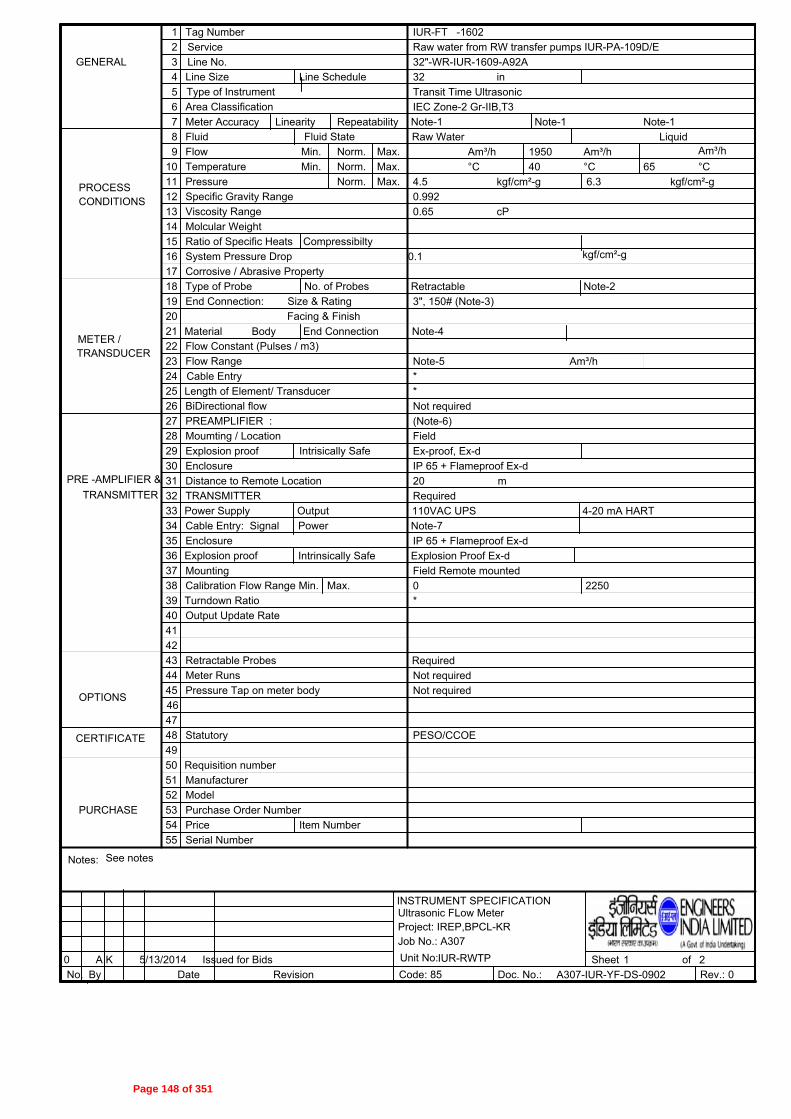
21
Am³/h Am³/h°C
kgf/cm²-g
Am³/h°C
kgf/cm²-g
1 Tag Number2 Service3 Line No.456789
10111213141516171819202122232425262728293031323334
GENERAL
Revision
3536
TRANSMITTER
373839404142434445464748
PURCHASE
INSTRUMENT SPECIFICATION
0 Sheet ofNo. By Date Doc. No.: Rev.: 0
Corrosive / Abrasive Property
End Connection: Size & RatingFacing & Finish
Line Size
Output Update Rate
Moumting / Location
Power
Type of Probe
Distance to Remote Location
Cable Entry: Signal
Area Classification
Line Schedule
Fluid
Molcular WeightRatio of Specific Heats
PREAMPLIFIER :
Calibration Flow Range Min.
Compressibilty
Flow Min. Norm.TemperaturePressure
Min.Norm.Norm.
Specific Gravity RangeViscosity Range
System Pressure Drop
PRE -AMPLIFIER &
PROCESSCONDITIONS
Explosion proof Intrisically Safe
BiDirectional flow
Enclosure
Output
Explosion proof
49505152535455
Notes:
ManufacturerModelPurchase Order NumberPriceSerial Number
Item Number
OPTIONS
Retractable Probes
Enclosure
Power Supply
Meter RunsPressure Tap on meter body
Statutory
Code: 855/13/2014
Max.
A K
Max.Max.Max.
Flow RangeFlow Constant (Pulses / m3)
Turndown Ratio
Issued for Bids
Type of Instrument
Fluid State
METER /TRANSDUCER
No. of Probes
Am³/hCable Entry
Meter Accuracy Linearity Repeatability
Material Body End Connection
Length of Element/ Transducer
TRANSMITTER
Intrinsically SafeMounting
CERTIFICATE
Requisition number
Ultrasonic FLow MeterProject: IREP,BPCL-KRJob No.: A307Unit No:
kgf/cm²-g
IUR-RWTP
32"-WR-IUR-1609-A92A32 in
See notes
A307-IUR-YF-DS-0902
IUR-FT -1602Raw water from RW transfer pumps IUR-PA-109D/E
0 2250
Raw Water1950
6.34.56540°C
Liquid
Note-4
Note-1
(Note-6)
Ex-proof, Ex-d
20
**
Required110VAC UPS
Note-5
Field
IP 65 + Flameproof Ex-d
Note-1
Required
3", 150# (Note-3)
Not required
IP 65 + Flameproof Ex-dExplosion Proof Ex-dField Remote mounted
Note-2
*
Retractable
cP0.65
4-20 mA HART
m
Note-7
Not requiredNot required
0.1
PESO/CCOE
0.992
Note-1IEC Zone-2 Gr-IIB,T3Transit Time Ultrasonic
Page 148 of 351

22
1. S.No. 7: Accuracy, linearity & repeatability shall be as per Standard Specification for Ultrasonic Flowmeters (6-52-0011).2. S.No. 18: Vendor shall provide two paths as a minimum. In case more paths are required to meet the accuracy with the recommended upstream and downsream straight lengths, the same shall be provied by vendor and indicated in the offer. Probe shall be insertion type.3. Bidder shall provide mounting details with the offer including orientation & size of probes & connections. 4. The probe / transducer material shall be SS316 as a minimum. 5. Vendor shall confirm the flowmeter range to cover the normal flow.6. Remote mounting type transmitter & associated electronics with intermediate cable shall be provided.7. S.No. 34: Refer sketch no. A307-000-16-51-0203.8. Bidder's scope shall include the supply of nozzles for mounting the probes. End connection size indicated in Sl.no. 19 is for connection of probeon the pipe nozzle. Material for 3" sch STD nozzle shall be ASTM A106 Gr. B and flange shall be ASTM A 105.9. Pipe thickness line (32"-WR-IUR-1609-A92A) shall be 12 mm.
0 A K 5/13/20140
INSTRUMENT SPECIFICATION
Ultrasonic Flowmeter
No. By Date Revision Code: Rev.:
IUR-FT -1602Tag Number :
Issued for Bids ofDwg. No.:85 A307-IUR-YF-DS-0902
Sheet
Page 149 of 351

GROUP H ULTRASONIC FLOWMETER
(FLARE - FOR UNITS IUF & IUS) (Qty - 2 Nos.)
Page 150 of 351

21
kg/h kg/h
°C
kgf/cm²-g
kg/h
°C
kgf/cm²-g
1 Tag Number
2 Service
3 Line No.
4
5
6
7
8
9
10
11
12
13
14
15
16
17
18
19
20
21
22
23
24
25
26
27
28
29
30
31
32
33
34
GENERAL
Revision
35
36
TRANSMITTER
37
38
39
40
41
42
43
44
45
46
47
48
PURCHASE
INSTRUMENT SPECIFICATION
A 5/8/2014
A Sheet of
No. By Date Doc. No.: Rev.: A
Corrosive / Abrasive Property
End Connection: Size & Rating
Facing & Finish
Line Size
Output Update Rate
Moumting / Location
Power
Type of Probe
Distance to Remote Location
Cable Entry: Signal
Area Classification
Line Schedule
Fluid
Molcular Weight
Ratio of Specific Heats
PREAMPLIFIER :
Calibration Flow Range Min.
Compressibilty
Flow Min. Norm.
Temperature
Pressure
Min.
Norm.
Norm.
Specific Gravity Range
Viscosity Range
System Pressure Drop
PRE -AMPLIFIER &
PROCESS
CONDITIONS
Explosion proof Intrisically Safe
BiDirectional flow
Enclosure
Output
Explosion proof
49
50
51
52
53
54
55
Notes:
Manufacturer
Model
Purchase Order Number
Price
Serial Number
Item Number
OPTIONS
Retractable Probes
Enclosure
Power Supply
Meter Runs
Pressure Tap on meter body
Statutory
Code: 85
11/11/2013
Max.
SKS
SG
Max.
Max.
Max.
Flow Range
Flow Constant (Pulses / m3)
Turndown Ratio
Issued With MR
Issued With MR
Type of Instrument
Fluid State
METER /
TRANSDUCER
No. of Probes
kg/h
Cable Entry
Meter Accuracy Linearity Repeatability
Material Body End Connection
Length of Element/ Transducer
TRANSMITTER
Intrinsically Safe
Mounting
CERTIFICATE
Requisition number
Ultrasonic FLow Meter
Project: IREP,BPCL-KR
Job No.: A307
Unit No:
kgf/cm²-g
IUF-Internal Fuel Oil / Fuel Gas System
18"-FL-IUF-1402-A11A
18 in STD
See notes
A307-IUF-YF-DS-0901
IUF-FT -1401
FLARE FROM IUF-V-113 TO OSBL FLARE
0 0
HC
100 65000
3.5
225°C
Gas/Vapor
Note-4
Note-1
Required (Note-6)
Ex-proof, Ex'd'
20
*
*
Required (Note-6)
110VAC UPS
Note-5
Field
IP 65 + Flameproof Ex'd'
0.9
Note-1
Required
RF 125AARH
3", 150# (Note-3)
Not required
IP 65 + Flameproof Ex'd'
Explosion Proof Ex'd'
1
19-50
Field Remote mounted
Note-2
*
Retractable
cP0.1
4-20 mA HART
m
Note-7
Not required
Not required
0.1
PESO/CCOE
Note-1
IEC Zone-1 Gr-IIB,T3
Transit Time Ultrasonic
Page 151 of 351

22
1. S.No. 7: Accuracy, linearity & repeatability shall be as per Standard Specification for Ultrasonic Flowmeters (6-52-0011)2. S.No. 18: Vendor shall provide two paths as a minimum. In case more paths are required to meet the accuracy at maximum flow with the recommended upstream and downstream straight lengths, the same shall be provided by vendor and indicated in the offer. Probe shall be insertion type.3. Bidder shall provide mounting details with the offer including orientation & size of probes & connections.4. The probe / transducer material shall be SS316 as a minimum. 5. Vendor shall select the flowmeter range such that the maximum flow specified is covered with the specified accuracy and the minimum flow is measured to the maximum extent possible.6. Remote mounting type transmitter, associated electronics & pre amplifier with intermediate cable shall be provided.7. S.No. 34: Refer sketch no. A307-000-16-51-02008. Bidder''s scope shall include the supply of nozzles for mounting the probes. End connection size indicated in Sl.no. 19 is for connection of probe on the pipe nozzle. Material for 3" sch STD nozzle shall be ASTM A106 Gr.B and flange shall be ASTM A105.9. Operating Pressure 0.5 - 1.5 Kg/cm2.10. Operating Temperature -45-20011. For pressure & temperature compensation, bidder shall provide pressure instrument (IUF-PT-1403) and temperature instruments (IUF-TE/TT-1401) as per the attached datasheets. Bidder shall select suitable ranges for the same.
A SKS 5/8/2014
A SG 11/11/2013
A
INSTRUMENT SPECIFICATION
Ultrasonic Flowmeter
No. By Date Revision Code: Rev.:
IUF-FT -1401Tag Number :
Issued With MR
Issued With MR of
Dwg. No.:85 A307-IUF-YF-DS-0901
Sheet
Page 152 of 351
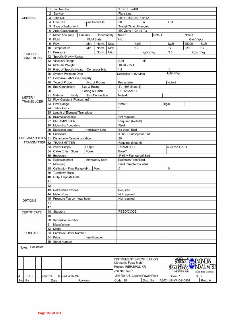
21
kg/h kg/h
°C
kgf/cm²-g
kg/h
°C
kgf/cm²-g
1 Tag Number
2 Service
3 Line No.
4
5
6
7
8
9
10
11
12
13
14
15
16
17
18
19
20
21
22
23
24
25
26
27
28
29
30
31
32
33
34
GENERAL
Revision
35
36
TRANSMITTER
37
38
39
40
41
42
43
44
45
46
47
48
PURCHASE
INSTRUMENT SPECIFICATION
A Sheet of
No. By Date Doc. No.: Rev.: A
Corrosive / Abrasive Property
End Connection: Size & Rating
Facing & Finish
Line Size
Output Update Rate
Moumting / Location
Power
Type of Probe
Distance to Remote Location
Cable Entry: Signal
Area Classification
Line Schedule
Fluid
Molcular Weight
Ratio of Specific Heats
PREAMPLIFIER :
Calibration Flow Range Min.
Compressibilty
Flow Min. Norm.
Temperature
Pressure
Min.
Norm.
Norm.
Specific Gravity Range
Viscosity Range
System Pressure Drop
PRE -AMPLIFIER &
PROCESS
CONDITIONS
Explosion proof Intrisically Safe
BiDirectional flow
Enclosure
Output
Explosion proof
49
50
51
52
53
54
55
Notes:
Manufacturer
Model
Purchase Order Number
Price
Serial Number
Item Number
OPTIONS
Retractable Probes
Enclosure
Power Supply
Meter Runs
Pressure Tap on meter body
Statutory
Code: 85
5/8/2014
Max.
SKS
Max.
Max.
Max.
Flow Range
Flow Constant (Pulses / m3)
Turndown Ratio
Issued With MR
Type of Instrument
Fluid State
METER /
TRANSDUCER
No. of Probes
kg/h
Cable Entry
Meter Accuracy Linearity Repeatability
Material Body End Connection
Length of Element/ Transducer
TRANSMITTER
Intrinsically Safe
Mounting
CERTIFICATE
Requisition number
Ultrasonic FLow Meter
Project: IREP,BPCL-KR
Job No.: A307
Unit No:
kgf/cm²-g
IUS-Captive Power Plant
20"-FL-IUS-2407-A11A
20 in STD
See notes
A307-IUS-YF-DS-0901
IUS-FT -2401
Flare Line
0 0
HC
65000
3.5
220°C
Gas/Vapor
Note-4
Note-1
Required (Note-6)
Ex-proof, Ex'd'
20
*
*
Required (Note-6)
110VAC UPS
Note-5
Field
IP 65 + Flameproof Ex'd'
1
Note-1
Required
RF 125AARH
3", 150# (Note-3)
Not required
IP 65 + Flameproof Ex'd'
Explosion Proof Ex'd'
1.3
18.28 - 35.1
Field Remote mounted
Note-2
*
Retractable
cP0.01
4-20 mA HART
m
Note-7
Not required
Not required
Negligible (0.02 Max)
PESO/CCOE
Note-1
IEC Zone-1 Gr-IIB,T3
Transit Time Ultrasonic
Page 153 of 351

22
1. S.No. 7: Accuracy, linearity & repeatability shall be as per Standard Specification for Ultrasonic Flowmeters (6-52-0011)2. S.No. 18: Vendor shall provide two paths as a minimum. In case more paths are required to meet the accuracy at maximum flow with the recommended upstream and downstream straight lengths, the same shall be provided by vendor and indicated in the offer. Probe shall be insertion type.3. Bidder shall provide mounting details with the offer including orientation & size of probes & connections.4. The probe / transducer material shall be SS316 as a minimum. 5. Vendor shall select the flowmeter range such that the maximum flow specified is covered with the specified accuracy and the minimum flow is measured to the maximum extent possible.6. Remote mounting type transmitter, associated electronics & pre amplifier with intermediate cable shall be provided.7. S.No. 34: Refer sketch no. A307-000-16-51-02008. Bidder''s scope shall include the supply of nozzles for mounting the probes. End connection size indicated in Sl.no. 19 is for connection of probe on the pipe nozzle. Material for 3" sch STD nozzle shall be ASTM A106 Gr.B and flange shall be ASTM A105.9. Operating Pressure 0.15 - 1 Kg/cm2.10. Operating Temperature -Amb11. For pressure & temperature compensation, bidder shall provide pressure instrument (IUS-PT-2401) and temperature instruments (IUS-TE/TT-2401) as per the attached datasheets. Bidder shall select suitable ranges for the same.
A SKS 5/8/2014
A
INSTRUMENT SPECIFICATION
Ultrasonic Flowmeter
No. By Date Revision Code: Rev.:
IUS-FT -2401Tag Number :
Issued With MR of
Dwg. No.:85 A307-IUS-YF-DS-0901
Sheet
Page 154 of 351

GROUP I ULTRASONIC FLOWMETER (FLARE - FOR UNIT - IFP)
(Qty - 2 Nos.)
Page 155 of 351

21
kg/h kg/h
°C
kgf/cm²-g
kg/h
°C
kgf/cm²-g
1 Tag Number
2 Service
3 Line No.
4
5
6
7
8
9
10
11
12
13
14
15
16
17
18
19
20
21
22
23
24
25
26
27
28
29
30
31
32
33
34
GENERAL
Revision
35
36
TRANSMITTER
37
38
39
40
41
42
43
44
45
46
47
48
PURCHASE
INSTRUMENT SPECIFICATION
A Sheet of
No. By Date Doc. No.: Rev.: A
Corrosive / Abrasive Property
End Connection: Size & Rating
Facing & Finish
Line Size
Output Update Rate
Moumting / Location
Power
Type of Probe
Distance to Remote Location
Cable Entry: Signal
Area Classification
Line Schedule
Fluid
Molcular Weight
Ratio of Specific Heats
PREAMPLIFIER :
Calibration Flow Range Min.
Compressibilty
Flow Min. Norm.
Temperature
Pressure
Min.
Norm.
Norm.
Specific Gravity Range
Viscosity Range
System Pressure Drop
PRE -AMPLIFIER &
PROCESS
CONDITIONS
Explosion proof Intrisically Safe
BiDirectional flow
Enclosure
Output
Explosion proof
49
50
51
52
53
54
55
Notes:
Manufacturer
Model
Purchase Order Number
Price
Serial Number
Item Number
OPTIONS
Retractable Probes
Enclosure
Power Supply
Meter Runs
Pressure Tap on meter body
Statutory
Code: 85
5/8/2014
Max.
SKS
Max.
Max.
Max.
Flow Range
Flow Constant (Pulses / m3)
Turndown Ratio
Issued With MR
Type of Instrument
Fluid State
METER /
TRANSDUCER
No. of Probes
kg/h
Cable Entry
Meter Accuracy Linearity Repeatability
Material Body End Connection
Length of Element/ Transducer
TRANSMITTER
Intrinsically Safe
Mounting
CERTIFICATE
Requisition number
Ultrasonic FLow Meter
Project: IREP,BPCL-KR
Job No.: A307
Unit No:
kgf/cm²-g
IFP-PRU
48"-FL-IFP-5902-A11A
48 in XS
See notes
A307-IFP-YF-DS-0901
IFP-FT -5901
HP FLARE FROM IFP-V-804 TO HP FLARE HEADER
0 0
HC
350 365000
7.5
214°C
Gas/Vapor
Note-4
Note-1
Required (Note-6)
Ex-proof, Ex'd'
20
*
*
Required (Note-6)
110VAC UPS
Note-5
Field
IP 65 + Flameproof Ex'd'
0.45-1
Note-1
Required
RF 125AARH
3", 150# (Note-3)
Not required
IP 65 + Flameproof Ex'd'
Explosion Proof Ex'd'
1.1 -1.4
20-120
Field Remote mounted
Note-2
*
Retractable
cP0.01
4-20 mA HART
m
Note-7
Not required
Not required
0.01
PESO/CCOE
Note-1
IEC Zone-1 Gr-IIC,T3
Transit Time Ultrasonic
Page 156 of 351

22
1. S.No. 7: Accuracy, linearity & repeatability shall be as per Standard Specification for Ultrasonic Flowmeters (6-52-0011)2. S.No. 18: Vendor shall provide two paths as a minimum. In case more paths are required to meet the accuracy at maximum flow with the recommended upstream and downstream straight lengths, the same shall be provided by vendor and indicated in the offer. Probe shall be insertion type.3. Bidder shall provide mounting details with the offer including orientation & size of probes & connections.4. The probe / transducer material shall be SS316 as a minimum. 5. Vendor shall select the flowmeter range such that the maximum flow specified is covered with the specified accuracy and the minimum flow is measured to the maximum extent possible.6. Remote mounting type transmitter, associated electronics & pre amplifier with intermediate cable shall be provided.7. S.No. 34: Refer sketch no. A307-000-16-51-02008. Bidder''s scope shall include the supply of nozzles for mounting the probes. End connection size indicated in Sl.no. 19 is for connection of probe on the pipe nozzle. Material for 3" sch STD nozzle shall be ASTM A106 Gr.B and flange shall be ASTM A105.9. Operating Pressure 0.1 - 5.5 Kg/cm2.10. Operating Temperature AMB- 75 degC.11. For pressure & temperature compensation, bidder shall provide pressure instrument (IFP-PT-5901) and temperature instruments (IFP-TE/TT-5901)as per the attached datasheets. Bidder shall select suitable ranges for the same. Pressure & Temperature Transmitters supplied shall be suitable for Electrical Area Classification IEC Zone-1 Gr-IIC,T3.
A SKS 5/8/2014
A
INSTRUMENT SPECIFICATION
Ultrasonic Flowmeter
No. By Date Revision Code: Rev.:
IFP-FT -5901Tag Number :
Issued With MR of
Dwg. No.:85 A307-IFP-YF-DS-0901
Sheet
Page 157 of 351

21
kg/h kg/h
°C
kgf/cm²-g
kg/h
°C
kgf/cm²-g
1 Tag Number
2 Service
3 Line No.
4
5
6
7
8
9
10
11
12
13
14
15
16
17
18
19
20
21
22
23
24
25
26
27
28
29
30
31
32
33
34
GENERAL
Revision
35
36
TRANSMITTER
37
38
39
40
41
42
43
44
45
46
47
48
PURCHASE
INSTRUMENT SPECIFICATION
A Sheet of
No. By Date Doc. No.: Rev.: A
Corrosive / Abrasive Property
End Connection: Size & Rating
Facing & Finish
Line Size
Output Update Rate
Moumting / Location
Power
Type of Probe
Distance to Remote Location
Cable Entry: Signal
Area Classification
Line Schedule
Fluid
Molcular Weight
Ratio of Specific Heats
PREAMPLIFIER :
Calibration Flow Range Min.
Compressibilty
Flow Min. Norm.
Temperature
Pressure
Min.
Norm.
Norm.
Specific Gravity Range
Viscosity Range
System Pressure Drop
PRE -AMPLIFIER &
PROCESS
CONDITIONS
Explosion proof Intrisically Safe
BiDirectional flow
Enclosure
Output
Explosion proof
49
50
51
52
53
54
55
Notes:
Manufacturer
Model
Purchase Order Number
Price
Serial Number
Item Number
OPTIONS
Retractable Probes
Enclosure
Power Supply
Meter Runs
Pressure Tap on meter body
Statutory
Code: 85
5/8/2014
Max.
SKS
Max.
Max.
Max.
Flow Range
Flow Constant (Pulses / m3)
Turndown Ratio
Issued With MR
Type of Instrument
Fluid State
METER /
TRANSDUCER
No. of Probes
kg/h
Cable Entry
Meter Accuracy Linearity Repeatability
Material Body End Connection
Length of Element/ Transducer
TRANSMITTER
Intrinsically Safe
Mounting
CERTIFICATE
Requisition number
Ultrasonic FLow Meter
Project: IREP,BPCL-KR
Job No.: A307
Unit No:
kgf/cm²-g
IFP-PRU
48"-FL-IFP-5904-A11A
48 in XS
See notes
A307-IFP-YF-DS-0902
IFP-FT -5902
LP FLARE FROM IFP-V-803 TO LP FLARE HEADER
0 0
HC
330 538000
3.5
200°C
Gas/Vapor
Note-4
Note-1
Required (Note-6)
Ex-proof, Ex'd'
20
*
*
Required (Note-6)
110VAC UPS
Note-5
Field
IP 65 + Flameproof Ex'd'
0.45-1
Note-1
Required
RF 125AARH
3", 150# (Note-3)
Not required
IP 65 + Flameproof Ex'd'
Explosion Proof Ex'd'
1.1 -1.4
20-120
Field Remote mounted
Note-2
*
Retractable
cP0.01
4-20 mA HART
m
Note-7
Not required
Not required
0.01
PESO/CCOE
Note-1
IEC Zone-1 Gr-IIC,T3
Transit Time Ultrasonic
Page 158 of 351
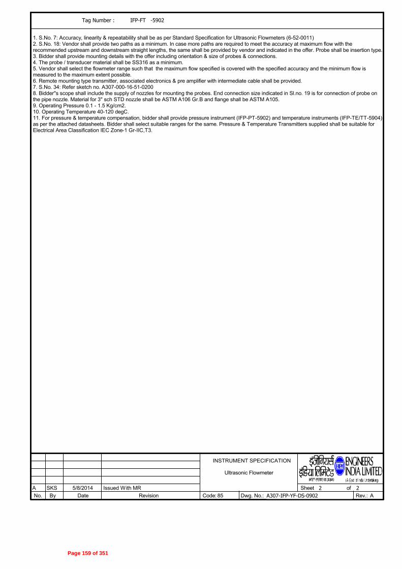
22
1. S.No. 7: Accuracy, linearity & repeatability shall be as per Standard Specification for Ultrasonic Flowmeters (6-52-0011)2. S.No. 18: Vendor shall provide two paths as a minimum. In case more paths are required to meet the accuracy at maximum flow with the recommended upstream and downstream straight lengths, the same shall be provided by vendor and indicated in the offer. Probe shall be insertion type.3. Bidder shall provide mounting details with the offer including orientation & size of probes & connections.4. The probe / transducer material shall be SS316 as a minimum. 5. Vendor shall select the flowmeter range such that the maximum flow specified is covered with the specified accuracy and the minimum flow is measured to the maximum extent possible.6. Remote mounting type transmitter, associated electronics & pre amplifier with intermediate cable shall be provided.7. S.No. 34: Refer sketch no. A307-000-16-51-02008. Bidder''s scope shall include the supply of nozzles for mounting the probes. End connection size indicated in Sl.no. 19 is for connection of probe on the pipe nozzle. Material for 3" sch STD nozzle shall be ASTM A106 Gr.B and flange shall be ASTM A105.9. Operating Pressure 0.1 - 1.5 Kg/cm2.10. Operating Temperature 40-120 degC.11. For pressure & temperature compensation, bidder shall provide pressure instrument (IFP-PT-5902) and temperature instruments (IFP-TE/TT-5904)as per the attached datasheets. Bidder shall select suitable ranges for the same. Pressure & Temperature Transmitters supplied shall be suitable for Electrical Area Classification IEC Zone-1 Gr-IIC,T3.
A SKS 5/8/2014
A
INSTRUMENT SPECIFICATION
Ultrasonic Flowmeter
No. By Date Revision Code: Rev.:
IFP-FT -5902Tag Number :
Issued With MR of
Dwg. No.:85 A307-IFP-YF-DS-0902
Sheet
Page 159 of 351

GROUP J ULTRASONIC FLOWMETER
(FLARE - FOR UNIT 00H) (Qty-1 No.)
Page 160 of 351

21
kg/h kg/h°C
kgf/cm²-g
kg/h°C
kgf/cm²-g
1 Tag Number2 Service3 Line No.456789
10111213141516171819202122232425262728293031323334
GENERAL
Revision
3536
TRANSMITTER
373839404142434445464748
PURCHASE
INSTRUMENT SPECIFICATION
0 Sheet ofNo. By Date Doc. No.: Rev.: 0
Corrosive / Abrasive Property
End Connection: Size & RatingFacing & Finish
Line Size
Output Update Rate
Moumting / Location
Power
Type of Probe
Distance to Remote Location
Cable Entry: Signal
Area Classification
Line Schedule
Fluid
Molcular WeightRatio of Specific Heats
PREAMPLIFIER :
Calibration Flow Range Min.
Compressibilty
Flow Min. Norm.TemperaturePressure
Min.Norm.Norm.
Specific Gravity RangeViscosity Range
System Pressure Drop
PRE -AMPLIFIER &
PROCESSCONDITIONS
Explosion proof Intrisically Safe
BiDirectional flow
Enclosure
Output
Explosion proof
49505152535455
Notes:
ManufacturerModelPurchase Order NumberPriceSerial Number
Item Number
OPTIONS
Retractable Probes
Enclosure
Power Supply
Meter RunsPressure Tap on meter body
Statutory
Code: 855/13/2014
Max.
A K
Max.Max.Max.
Flow RangeFlow Constant (Pulses / m3)
Turndown Ratio
ISSUED FOR BIDS
Type of Instrument
Fluid State
METER /TRANSDUCER
No. of Probes
kg/hCable Entry
Meter Accuracy Linearity Repeatability
Material Body End Connection
Length of Element/ Transducer
TRANSMITTER
Intrinsically SafeMounting
CERTIFICATE
Requisition number
Ultrasonic FLow MeterProject: IREP,BPCL-KRJob No.: A307Unit No:
kgf/cm²-g
00H-NHT
30"-FL-H-8804-A11A30 in STD
See notes
A307-00H-YF-DS-0901
00H-FT -8801HC Flare KOD H-V-183 to flare header
0 0kg/h kg/h
HC/ Nitrogen279357
3.5210191°C
Gas/Vapor
Note-4
Note-1
Required (Note-6)
Ex-proof, Ex-d
20
**
Required (Note-6)110VAC UPS
Note-5
Field
IP 65 + Flameproof Ex-d
Note-1
Required
RF 125AARH3", 150# (Note-3)
Not required
IP 65 + Flameproof Ex-dExplosion Proof Ex-dField Remote mounted
Note-2
*
Retractable
cP
4-20 mA HART
m
Note-7
Not requiredNot required
0.01
PESO/CCOE
Note-1IEC Zone-2 Gr-IIC,T6Transit Time Ultrasonic
Page 161 of 351

22
1. S.No. 7: Accuracy, linearity & repeatability shall be as per Standard Specification for Ultrasonic Flowmeters (6-52-0011).2. S.No. 18: Vendor shall provide two paths as a minimum. In case more paths are required to meet the accuracy at maximum flow with the recommended upstream and downstream straight lengths, the same shall be provied by vendor and indicated in the offer. Probe shall be insertion type.3. Bidder shall provide mounting details with the offer including orientation & size of probes & connections.4. The probe / transducer material shall be SS316 as a minimum. 5. Vendor shall select the flowmeter range such that the maximum flow specified is covered with the specified accuracy and minimum flow is measured to the maximum extent possible..6. Remote mounting type transmitter, associated electronics & pre amplifier with intermediate cable shall be provided.7. S.No. 34: Refer sketch no. A307-000-16-51-02008. Bidder's scope shall include the supply of nozzles for mounting the probes. End connection size indicated in Sl.no. 19 is for connection of probeon the pipe nozzle. Material for 3" sch STD nozzle shall be ASTM A106 Gr.B and flange shall be ASTM A105.9. Operating Pressure 0.1-1.5 Kg/cm2.10. For pressure & temperature compensation, bidder shall provide pressure instrument (00H-PT-8803) and temperature instruments (00H-TE/TT-8801) as per the attached datasheets. Bidder shall select suitable ranges for the same.11. Flow rate (Normal): (73.9-152) (Note-13)/ 180 Kg/hr (HOLD)12. Gas/ Vapour Properties: For HC :- MW- 81.2 (Note-13); Comp. factor: 0.88; Viscosity: 0.01cP; CP/CV: 1.08.For Nitrogen:- MW- 28; Comp. factor- 1; Viscosity: 0.01cP; CP/CV- 1.411.13. For normal fuel gas flow indicated MW range shall be 11.5-25.95.
0 A K 5/13/20140
INSTRUMENT SPECIFICATION
Ultrasonic Flowmeter
No. By Date Revision Code: Rev.:
00H-FT -8801Tag Number :
ISSUED FOR BIDS ofDwg. No.:85 A307-00H-YF-DS-0901
Sheet
Page 162 of 351
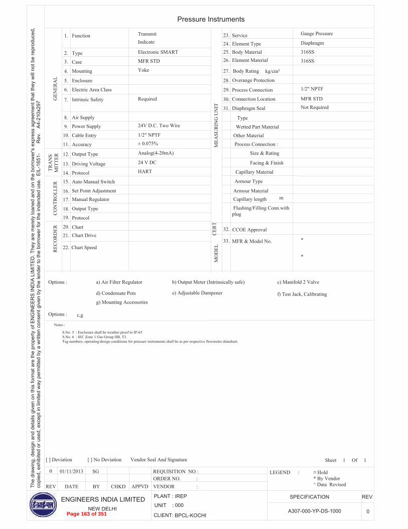
ENGINEERS INDIA LIMITEDNEW DELHI
UNIT :
CLIENT:
SPECIFICATION REV
A307-000-YP-DS-1000 0
Pressure Instruments
PLANT :
000
IREP
BPCL-KOCHI
The
draw
ing,
des
ign
and
deta
ils g
iven
on
this
form
at a
re th
e pr
oper
ty o
f EN
GIN
EE
RS
IND
IA L
IMIT
ED
. The
y ar
e m
erel
y lo
aned
and
on
the
borr
ower
's e
xpre
ss a
gree
men
t tha
t the
y w
ill n
ot b
e re
prod
uced
,co
pied
, exh
ibite
d or
use
d, e
xcep
t in
limite
d w
ay p
erm
itted
by
a w
ritte
n co
nsen
t giv
en b
y th
e le
nder
to th
e bo
rrow
er fo
r the
inde
nded
use
. E
IL-1
651-
Rev
. A
4-21
0x29
7
1
Page 163 of 351

0 SG
ENGINEERS INDIA LIMITEDNEW DELHI
UNIT :
CLIENT:
SPECIFICATION REV
A307-000-YT-DS-4000 0
Thermocouples and Thermowells
VENDOR : ORDER NO. :
REV APPVDCHKDBYDATE
01/11/2013
PLANT :
000
IREP
BPCL-KOCHI
[ ] Deviation [ ] No Deviation Vendor Seal And Signature
The
draw
ing,
des
ign
and
deta
ils g
iven
on
this
form
at a
re th
e pr
oper
ty o
f EN
GIN
EE
RS
IND
IA L
IMIT
ED
. The
y ar
e m
erel
y lo
aned
and
on
the
borr
ower
's e
xpre
ss a
gree
men
t tha
t the
y w
ill n
ot b
e re
prod
uced
,co
pied
, exh
ibite
d or
use
d, e
xcep
t in
limite
d w
ay p
erm
itted
by
a w
ritte
n co
nsen
t giv
en b
y th
e le
nder
to th
e bo
rrow
er fo
r the
inde
nded
use
. E
IL-1
651-
560
Rev
.1 A
4-21
0x29
7
REQUISITION NO : LEGEND : ¤ Hold * By Vendor ^ Data Revised
Sheet 1 Of 1
Scope of Supply
No. of Elements
Calibration
Construction
Junction
Nipple and Union
Packed Connector
Head Cover Type
No. of Entries
THER
MO
WEL
L
Enclosure
Thermowell
Construction
Process Connection
Instrument Connection
Options :
HEA
D
ELEM
ENT
MFR. and Model No.
Material
Cable Entry
a) Extra Nipple Extension b) Conformance on NACE
c) IBR Certification
Material
Terminals
O.D.
Material
Size
Material
As per std. 7-52-0036 Screwed Cap & Chain
IEC 60584-2
Duplex
Sheathed
SS 316
10
Enclosed & Ungrounded
Required
.5
Plated CS
No
Cast Aluminium
1/2" NPTF
Dual
Spring Loaded
IP65
Required as per std. 7-52-0035
SS 316
Tapered
1/2" NPTF
1 1/2" FL
*
mm
inchDrilled Bar Stock
Notes:1) Electrical area classification shall be IEC zone1, Gr. IIA/B, Temperature class T3 and the thermocouples shall be used in Intrinsically safe circuit.2) Head material is Cast Aluminium (Epoxy coated).3) Though sheath OD has been specified as 10 mm, the actual sheath OD shall be to suit the thermowell.4) Tag number, operating/design conditions for temperature elements shall be as per respective flowmeter tag.5) 'U' length for thermowell shall be considered as follows. Thermowell flange rating shall be minimum 300#.Line Size 4" - 6": 'U' Length 280 mmLine Size 8" - 18": 'U' Length 320 mmLine Size 20" - 34": 'U' Length 400 mmLine Size 36" & above: 'U' Length 450 mm
1.
3.
4.
5.
6.
7.
8.
9.
10.
11.
12.
13.
14.
15.
16.
17.
18.
19.
20.
d) CCOE Approval (if ex. T/c used)
Electrical AreaClassification
Note-1 2.
Page 164 of 351
Saurabh
Typewritten Text
Nozzle projection for thermowell shall be 200mm
Saurabh
Typewritten Text
Saurabh
Typewritten Text
Saurabh
Typewritten Text
Saurabh
Typewritten Text
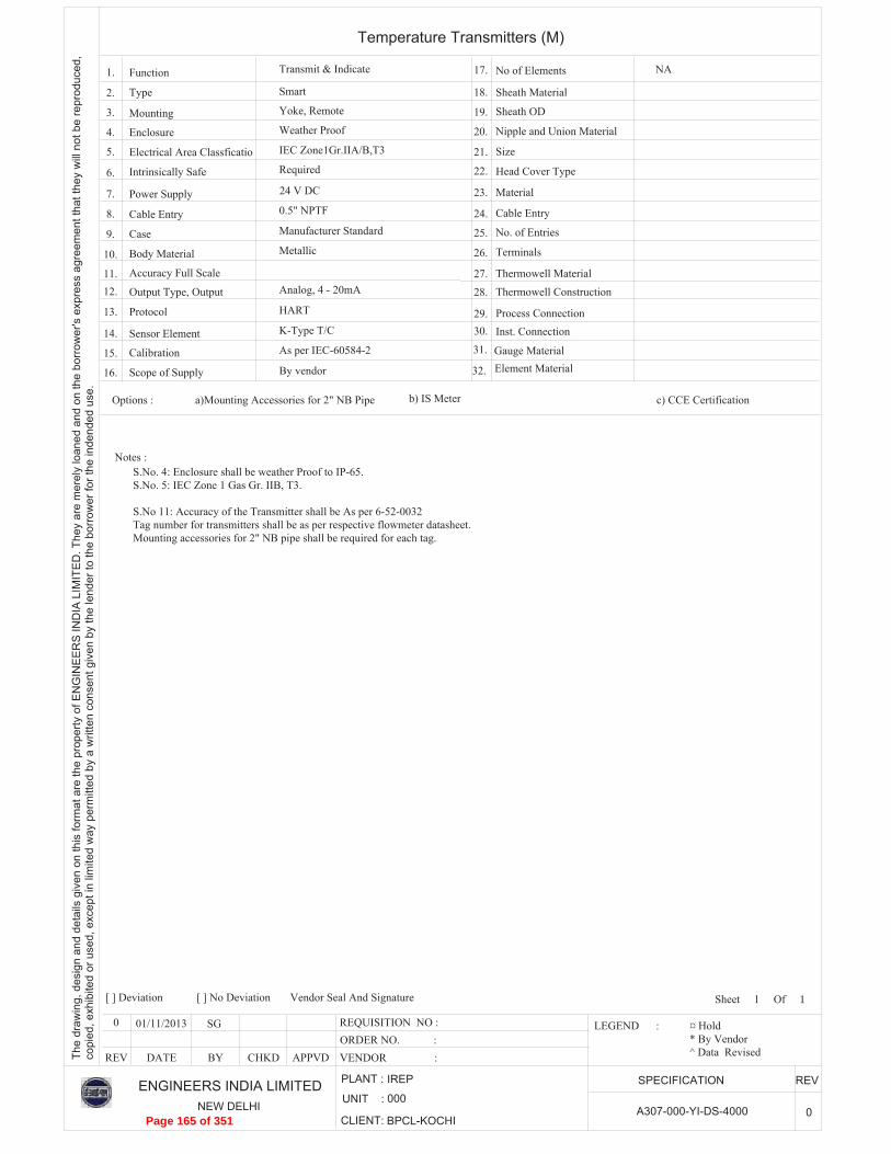
0 SG
ENGINEERS INDIA LIMITEDNEW DELHI
UNIT :
CLIENT:
SPECIFICATION REV
A307-000-YI-DS-4000 0
Temperature Transmitters (M)
VENDOR : ORDER NO. :
REV APPVDCHKDBYDATE
01/11/2013
PLANT :
000
IREP
BPCL-KOCHI
[ ] Deviation [ ] No Deviation Vendor Seal And Signature
The
draw
ing,
des
ign
and
deta
ils g
iven
on
this
form
at a
re th
e pr
oper
ty o
f EN
GIN
EE
RS
IND
IA L
IMIT
ED
. The
y ar
e m
erel
y lo
aned
and
on
the
borr
ower
's e
xpre
ss a
gree
men
t tha
t the
y w
ill n
ot b
e re
prod
uced
,co
pied
, exh
ibite
d or
use
d, e
xcep
t in
limite
d w
ay p
erm
itted
by
a w
ritte
n co
nsen
t giv
en b
y th
e le
nder
to th
e bo
rrow
er fo
r the
inde
nded
use
.
REQUISITION NO : LEGEND : ¤ Hold * By Vendor ^ Data Revised
Sheet 1 Of 1
K-Type T/C
Required
0.5" NPTF
IEC Zone1Gr.IIA/B,T3
NA
Weather Proof
Yoke, Remote
Analog, 4 - 20mA
Metallic
Smart
By vendor
24 V DC
Transmit & Indicate
HART
Manufacturer Standard
As per IEC-60584-2
Function
Type
Mounting
Enclosure
Electrical Area Classficatio
Intrinsically Safe
Power Supply
Cable Entry
Case
Body Material
Accuracy Full Scale
Output Type, Output
Protocol
Sensor Element
Calibration
Scope of Supply
Options :
No of Elements
Sheath Material
Sheath OD
Nipple and Union Material
Size
Head Cover Type
Material
Cable Entry
No. of Entries
Terminals
Thermowell Material
Thermowell Construction
Process ConnectionInst. Connection
Gauge Material
a)Mounting Accessories for 2" NB Pipe b) IS Meter c) CCE Certification
S.No. 4: Enclosure shall be weather Proof to IP-65.S.No. 5: IEC Zone 1 Gas Gr. IIB, T3.
S.No 11: Accuracy of the Transmitter shall be As per 6-52-0032Tag number for transmitters shall be as per respective flowmeter datasheet.Mounting accessories for 2" NB pipe shall be required for each tag.
Notes :
1.
2.
3.
4.
5.
6.
7.
8.
9.
10.
11.12.
13.
14.
15.
16.
17.
18.
19.
20.
21.
22.
23.
24.
25.
26.
27.28.
29.30.
31.
32. Element Material
Page 165 of 351

Page 166 of 351

Page 167 of 351
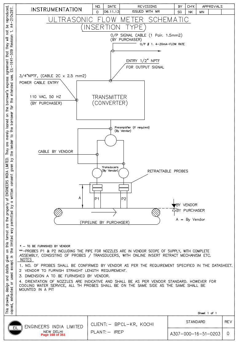
Page 168 of 351
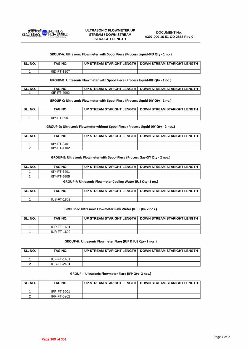
SL. NO. TAG NO. UP STREAM STARIGHT LENGTH DOWN STREAM STARIGHT LENGTH
1 0ID-FT-1207
SL. NO. TAG NO. UP STREAM STARIGHT LENGTH DOWN STREAM STARIGHT LENGTH1 0IF-FT-4902
SL. NO. TAG NO. UP STREAM STARIGHT LENGTH DOWN STREAM STARIGHT LENGTH
1 0IY-FT-3901
SL. NO. TAG NO. UP STREAM STARIGHT LENGTH DOWN STREAM STARIGHT LENGTH
1 0IY-FT-3401
2 0IY-FT-4102
SL. NO. TAG NO. UP STREAM STARIGHT LENGTH DOWN STREAM STARIGHT LENGTH
1 0IY-FT-5401
2 0IY-FT-5605
SL. NO. TAG NO. UP STREAM STARIGHT LENGTH DOWN STREAM STARIGHT LENGTH
1 IUS-FT-1802
SL. NO. TAG NO. UP STREAM STARIGHT LENGTH DOWN STREAM STARIGHT LENGTH
1 IUR-FT-1601
1 IUR-FT-1602
SL. NO. TAG NO. UP STREAM STARIGHT LENGTH DOWN STREAM STARIGHT LENGTH
1 IUF-FT-1401
2 IUS-FT-2401
SL. NO. TAG NO. UP STREAM STARIGHT LENGTH DOWN STREAM STARIGHT LENGTH
1 IFP-FT-5901
2 IFP-FT-5902
GROUP-C: Ultrasonic Flowmeter with Spool Piece (Process Liquid-0IY Qty - 1 no.)
GROUP-D: Ultrasonic Flowmeter without Spool Piece (Process Liquid-0IY Qty - 2 nos.)
GROUP-A: Ultrasonic Flowmeter with Spool Piece (Process Liquid-0ID Qty - 1 no.)
GROUP-B: Ultrasonic Flowmeter with Spool Piece (Process Liquid-0IF Qty - 1 no.)
ULTRASONIC FLOWMETER UP
STREAM / DOWN STREAM
STRAIGHT LENGTH
DOCUMENT No.
A307-000-16-51-OD-2853 Rev-0
GROUP-I: Ultrasonic Flowmeter Flare (IFP Qty- 2 nos.)
GROUP-G: Ultrasonic Flowmeter Raw Water (IUR Qty- 2 nos.)
GROUP-H: Ultrasonic Flowmeter Flare (IUF & IUS Qty- 2 nos.)
GROUP-E: Ultrasonic Flowmeter with Spool Piece (Process Gas-0IY Qty - 2 nos.)
GROUP-F: Ultrasonic Flowmeter Cooling Water (IUS Qty- 1 no.)
Page 1 of 2Page 169 of 351

ULTRASONIC FLOWMETER UP
STREAM / DOWN STREAM
STRAIGHT LENGTH
DOCUMENT No.
A307-000-16-51-OD-2853 Rev-0
SL. NO. TAG NO. UP STREAM STARIGHT LENGTH DOWN STREAM STARIGHT LENGTH
1 00H-FT-8801
GROUP-J: Ultrasonic Flowmeter Flare (00H Qty- 1 no.)
Page 2 of 2Page 170 of 351
ENGINEERS 5g2-jr INDIA LIMITED
I A Govt ofInela Undeftakogf
STANDARD SPECIFICATION FOR ULTRASONIC
FLOWMETER
STANDARD SPECIFICATION No.
6-52-0011 Rev. 0 Page 1 of 14
,-1,151, ,111,10,ffI
3w-d-•,,r4:11.rdw 4-011‘41c,<I 1~w
STANDARD SPECIFICATION FOR ULTRASONIC FLOW METER
0 27/11/2013 ISSUED AS STANDARD SPECIFICATION SM • RG P/ S r DM
Rev. No
Date Purpose Prepared Checked by by
Standards Standards Comm ittee Bureau Convener Chairman
Approved by
Format No. 8-00-0001-F2 Rev. 0 Copyright EIL — All rights reserved
Page 171 of 351

STANDARD SPECIFICATION FOR
ULTRASONIC FLOW METER
STANDARD SPECIFICATION No.
6-52-0011 Rev. 0 Page 2 of 14
Format No. 8-00-0001-F2 Rev. 0 Copyright EIL – All rights reserved
Abbreviations: AARH : Arithmetic Average Roughness Height NPT : National Pipe Thread NIST : National Institute of Standards and Technology
Instrumentation Standards Committee Convener: Ms. R. Priyamvada Members: Mr. Rajiv Gupta
Mr. S. Bhowal Mr. M. Nandi Ms. R. Shanthi Devi Mr. R.K. Gupta
Ms. N.P. Guha (Proj.)
Page 172 of 351

STANDARD SPECIFICATION ENGINEERS STANDARD SPECIFICATION FOR No. INDIA LIMITED
I IA Go, of Indfa Undertakingf ULTRASONIC FLOW METER 6-52-0011 Rev. 0 Page 3 of 14
CONTENTS
1.0 GENERAL 4
2.0 DESIGN AND CONSTRUCTION 7
3.0 NAMEPLATE 12
4.0 INSPECTION AND TESTING 13
5.0 SHIPPING 14
6.0 REJECTION 14
Copyright EIL — All rights reserved Format No. 8-00-0001-F2 Rev. 0
Page 173 of 351

STANDARD SPECIFICATION No.
6-52-0011 Rev. 0 Page 4 of 14
$'gLar 22-dg ,orc,,,DIJITCO/
ENGINEEFZS STANDARD SPECIFICATION FOR INDIA LIMITED IA GoN of Indo Unclertakng) ULTRASONIC FLOW METER
1.0 GENERAL
1.1 Scope
1.1.1 This specification, together with the data sheets covers the requirements for the design, materials, nameplate marking, inspection, testing and shipping of Ultrasonic Flow meters and their accessories.
1.1.2 The standards referred to herein and mentioned below shall be of the latest editions unless otherwise specified:
AGA American Gas Association, Gas measurement committee Report No. 8 Compressibility and Super-compressibility for Natural
Gas and other Hydrocarbon Gas Transmission Measurement
Report No. 9 Measurement of gas by Multipath Ultrasonic flow meters ReportNo.10 Speed of sound in Natural Gas & other Related
Hydrocarbon Gases
API American Petroleum Institute MPMS Manual of Petroleum Measurement Standards Chapter 1 Vocabulary Chapter 4 Proving Systems Chapter 5 Metering Chapter 5.8 Measurement of Liquid Hydrocarbons by Ultrasonic Flow
Meters using Transit Time Technology
ASME American Society of Mechanical Engineers B 1.20.1 Pipe Threads B 16.5 Steel Pipe Flanges and Flanged Fittings B 16.20 Ring-joint Gaskets and Grooves for Steel Pipe Flanges B 16.47-B Large Diameter Steel Flanges
EN European Standard
60947-5-6 Pulse generator requirements 10204 Inspection documents for metallic products
IS/IEC Indian Standards/International Electro-Technical Commission IS/IEC 60079 Electrical Apparatus for Explosive Gas Atmospheres. IS/IEC60529 Degree of Protection Provided by Enclosures (IP Code). IEC61000-4 Electronic compatibility for Industrial Process
Measurement and Control Equipment
ISO International Organisation for Standardisation 2186 Fluid Flow in Closed Conduits - Connections for Pressure
Signal Transmissions between Primary and Secondary Elements
5168 Measurement of Fluid Flow: Estimation of Uncertainty of Ultrasonic Flow meters
6551 Cabled transmission of electric and/or electronic pulse data 6569 Natural Gas - Rapid Analysis by Gas Chromatography 6976 Natural gas - Calculation of Calorific Value, Density and
Relative Density 10723 Natural gas — Performance evaluation for On-line
Analytical Systems 12765 Measurement of Fluid Flow in Closed Conduits —
Methods using Transit Time Ultrasonic Flow meters
OIML International Organisation of Legal Metrology R 117 Measurement systems for liquids other than water
Copyright EIL — All rights reserved Format No. 8-00-0001-F2 Rev. 0
Page 174 of 351

k5--112.1t4
g12:1[ 215t-eg
i. 21e, r, 1,1,~1
STANDARD SPECIFICATION No.
6-52-0011 Rev. 0 Page 5 of 14
CE@- ENGINEEFZS STANDARD SPECIFICATION FOR INDIA LIMITED IA Govt of Indo Untlertakng) ULTRASONIC FLOW METER
1.1.3 In the event of any conflict between this specification, data sheets, related standards, codes etc., the following order of priority shall govern:
a) Statutory Regu I at ions
b) Job Specifications/Data sheets
c) Standard specifications
d) Codes and Standards
1.1.4 In addition to compliance to purchaser's specification in totality, vendor's extent of responsibility includes the following:
a) Purchaser's data sheets indicate the minimum acceptable materials of construction for body, trim and accessories of the Ultrasonic flow meter. Alternative superior material of construction shall also be acceptable provided vendor assumes complete responsibility for proper selection of offered materials for their compatibility with the process fluid and its operating and design conditions specified in the data sheets.
b) Sizing of the Ultrasonic flow meter and its accessories.
c) Coordination and approvals from statutory authorities like weights and measures etc, wherever required.
1.1.5 A11 the relevant terminology used in Purchaser's data sheets and job specifications are as per AGA for Gas application and API MPMS for Liquid application.
1.2 Bids
1.2.1 Vendor's quotation shall be strictly as per the bidding instructions to vendor attached with the Material Requisition.
1.2.2 Whenever a detailed technical offer for each item is specifically indicated, vendor's quotation shall include the following:
a) Compliance to the specifications
b) A detailed specification sheet for each ultrasonic flow meter, which shall provide information, described as under. A11 the material specifications and units of measurement for various parts in the vendor's specification sheet shall be to the same standards as those indicated in the purchaser's data sheets.
i) Details regarding type, material of construction etc., for various parts of the Ultrasonic flow meter, meter runs, flow conditioner and its accessories.
ii) Meter capacity with recommended minimum and maximum flow rates at operating conditions within the specified performance requirements, transmitter output and calibrated range.
iii) All the design characteristics and performance characteristics including meter accuracy and repeatability.
iv) Specification and type of cabling required between the meter and its associated receiver instrument/flow computer including the maximum permissible cable length.
v) Hazardous area certification suitable for the area classification mentioned in the datasheet.
vi) Maximum pressure Loss through the meter and meter runs at maximum flow rate.
vii) Upstream and downstream straight pipe length requirement for installation.
c) Proven references for the offered model in line with clause 1.2.3 of this specification.
Format No. 8-00-0001-F2 Rev. 0
Copyright EIL — All rights reserved
Page 175 of 351

STANDARD SPECIFICATION 1/4511 ENGINEEFZS STANDARD SPECIFICATION FOR No. 21;j]s INDIA LIMITED
Govl of Indo Undertaking) ULTRASONIC FLOW METER 6-52-0011 Rev. 0 Page 6 of 14
d) Overall dimensions in millimetres of the Ultrasonic flow meter, meter runs and its accessories.
e) Type test certificate from accredited laboratory.
f) Certificate from regulatory authority for custody transfer application (whenever Custody Transfer application is specified in the data sheets).
g) A copy of approval from Local statutory authority, as applicable, such as Petroleum and Explosives Safety Organisation (PESO)/Chief Controller of Explosives (CCE) or Director General of Mine Safety ( DGMS) in India, for the electronic instruments installed in electrically hazardous area along with
i) Test certificate from recognised test house like Central Institute of Mining & Fuel research(CIMFR)/Electronics Regional Testing Laboratory(ERTL) etc. for flame proof enclosure and/or intrinsic safety, as specified in the datasheets, as per relevant Indian Standard for all Indian manufactured equipments or for items requiring DGMS approval.
ii) Certificate of conformity from agencies like Laboratorie Central Des Industries Electriques(LCIE), British Approval Service for Electrical Equipment in Flammable Atmospheres(Baseefa), Canadian Standards Association(CSA), Factory Mutual(FM), Underwriters laboratories(UL) etc. for compliance to ATEX directives or other equivalent standards for all equipment manufactured outside India.
h) Deviations on technical requirements shall not be entertained. In case vendor has any valid technical reason, they may include a list of deviations tag number wise, summing up all the deviations from the purchaser's data sheets and other technical specifications along with the technical reason for each of these deviations.
i) Catalogues in English giving detailed technical specifications; model decoding details and other information for the type of ultrasonic flow meter and its accessories covered in the bid.
1.2.3 All items, as offered, shall be field proven and should have completed trouble free satisfactory operation for a period of minimum 4000 hours on the bid due date in similar application with the process conditions similar to those as specified in the purchaser's datasheets. Items with prototype design or items not meeting provenness criteria specified above shall not be offered.
1.2.4 Vendor shall also quote for the following:
a) Two years' operational spares for Ultrasonic flow meter and its accessories covered in the bid.
b) Any special tools needed for maintenance work on the Ultrasonic flow meter and its accessories. Vendor must confirm in their offer if no special tools are needed for maintenance of the offered Ultrasonic flow meter.
c) Assistance in installation and commissioning of Ultrasonic flow meter, if required, as per job specifications.
d) Any Start-up and Commissioning spares, if required, as recommended by vendor.
1.3 Drawings and Data
1.3.1 Detailed drawings, data, catalogues and manuals required from the vendor are indicated by the Purchaser in vendor data requirement sheets. The required number of prints and soft copies should be despatched to the address mentioned, adhering to the time limits indicated.
1.3.2 Final documentation consisting of design data, installation manual, operational and maintenance manual etc., submitted by the vendor after placement of purchase order, shall include the following, as a minimum:
,awm c-frerg1,1”,ros,,)
Format No. 8-00-0001-F2 Rev. 0
Copyright EIL — All rights reserved
Page 176 of 351

ENGINEERS STANDARD SPECIFICATION FOR INDIA LIMITED 1A Govt of Incha Underlaking)
STANDARD SPECIFICATION No.
6-52-0011 Rev. 0 Page 7 of 14
$€Lar faW-g 7151 ULTRASONIC FLOW METER
a) Specification sheet for each Ultrasonic flow meter, Meter Run including flow conditioner, if required, Meter electronics and its accessories
b) Weight in kilograms of each Ultrasonic flow meter and its accessories, meter run with flow conditioners, if required, etc.
c) Certified drawings for each Ultrasonic flow meter, meter runs with flow conditioner, if required, etc., which shall provide dimensional details, internal construction details, material of construction etc.
d) Copy of type test certificates. e) Proving procedure f) Detailed wiring diagrams
g) Copy of test certificates for all tests in clause 4.0 of this specification h) Installation procedure with supports requirement. i) Calibration, maintenance procedure including replacement of its internal parts
wherever applicable j) Graphs of correction factors such as pressure, temperature, density, viscosity.
1.3.3 Vendor shall provide test certificates for all tests indicated in clause 4.0 of this specification. In addition, vendor shall also provide the certificate of compliance to purchaser's specification as per applicable clause of EN 10204.
2.0 DESIGN AND CONSTRUCTION
2.1 Flow meter Body and Trim
2.1.1 The Ultrasonic flow meter shall be based on transit time technology. The principle of operation used shall be simple in implementation and shall avoid analytical complexity associated with development of information, which is extraneous to the application.
2.1.2 The design used shall provide maximum reliability, maximum on-line performance and minimum maintenance. It shall be immune to other impurities in the fluid stream.
2.1.3 The flow meter transducers shall be energized by the integral electronics to transmit and
receive ultrasonic waves.
2.1.4 The meter design shall have the facility to remove /replace the transducers in situ under line operating condition. Failure or removal of one pair of transducers shall not cause the meter to lose all measurement function. Failure of any path shall generate an alarm identifying the affected path. Also transducers ports shall be designed in a way to reduce the possibility of liquid or solid accumulation.
2.1.5 It shall be possible to replace transducers without a change in meter performance. After replacement of transducers and a possible change of the associated software constants, the resulting shift in the meter's performance should not be more than the allowable repeatability of the meter.
2.1.6 The vendor shall comprehensively advise the impact of transducer failure on the performance and accuracy of the Ultrasonic flow meter.
2.1.7 Ultrasonic flow meters and the meter runs/flow conditioners shall be rated for the maximum design pressure as indicated in the data sheets.
2.1.8 Ultrasonic flow meter spool inside diameter (ID) shall meet the specified pipe ID and internal surface roughness shall be as per API standard.
2.1.9 The meter shall be suitable for horizontal & vertical mounting. However, the flow direction shall be clearly stamped or cast on the body.
2.1.10 End connections:
2.1.10.1 Spool piece type Ultrasonic flow meters shall have flanged end connections. Weld joints, if any, shall be of radiographic quality.
2.1.10.2 Unless otherwise mentioned, end connection details shall be as below:
a) Threaded end connections shall be to NPT as per ASME B 1.20.1
Format No. 8-00-0001-F2 Rev. 0
Copyright EIL — All rights reserved
Page 177 of 351

STANDARD SPECIFICATION
NDIA LIMIT ENGINEERS ED STANDARD SPECIFICATION FOR No. I IA Govt of Indo UnOeflaking) ULTRASONIC FLOW METER 6-52-0011 Rev. 0
Page 8 of 14
b) Flanged end connections shall be as per ASME B 16.5
c) Grooves of ring type joint flanges shall be octagonal as per ASME B 16.20 and groove finish shall be as follows:
63 AARH : 32 to 63 micro inch AARH
d) When Flanges are Raised Face (RF) type, the face finish shall be as per ASME B 16.5 and shall be as follows:
125 AARH : 125 to 250 micro inch AARH
2.1.11 The material of construction of Ultrasonic flow meter internals/wetted parts and body shall be as specified in the respective data sheets.
2.1.12 Meter Sizing:
2.1.12.1 A11 the calculations and units of measurement shall be in metric standard only.
2.1.12.2 Vendor shall furnish sizing calculations to justify the selection of Ultrasonic flow meters considering the density and viscosity of the fluid. Selected meter size shall ensure that flow meter operates within 85% of their standard range (not extended).
2.1.12.3 Overall pressure loss across the meter assembly including meter runs shall be within the permissible pressure loss specified in data sheet. Pressure drop calculation across the meter
shall be furnished.
2.1.12.4 Unless otherwise specified in the data sheets, vendor to ensure the velocity in the Ultrasonic flow meter and meter run shall not exceed maximum permissible velocity.
2.1.12.5 Vendor shall indicate the range of viscosities over which the measurement accuracy remains within limits.
2.2 Meters in Custody Transfer Applications
2.2.1.1 The design, construction and operation of Ultrasonic flow meters in Custody transfer applications shall conform to API standard (latest version) for Measurement of liquid Hydrocarbon by Ultrasonic flow meters using transit time technology and AGA Report 9 (latest version) for hydrocarbon Gas service
2.2.1.2 The average velocity of the fluid shall be measured along four acoustic paths as a minimum. Numerical calculation techniques shall then be used to compute the average axial flow velocity and volume flow rate at operating conditions through the meter.
2.2.1.3 Temperature and Pressure sensing devices shall be installed immediately downstream of the meter run to accurately represent the actual metering conditions and any calculation required for compensation of varying density.
2.2.1.4 Meter Runs:
2.2.1.4.1 Unless otherwise specified end connections for the upstream and downstream meter runs shall conform to this specification.
2.2.1.4.2 Flow Conditioners:
a) Type of flow conditioner (tube or vane type or Flow profiler etc.) shall be as recommended by vendor best suitable for the application. All Ultrasonic flow meters shall be provided with meter run and flow conditioner as per purchaser's datasheet. Minimum upstream and downstream run lengths shall be 10D and 5D respectively, where D is the inside diameter of the run.
b) The straightening element shall be made out of a thin walled tube or light gauge metal vane. However, the design shall be rugged enough to resist the forward thrust due to high flows. The element shall have smooth leading and trailing edges.
c) For tube type flow straightener, the length to diameter ratio of each tube shall be at least 10:1
Format No. 8-00-0001-F2 Rev. 0
Copyright EIL — All rights reserved
Page 178 of 351

STANDARD SPECIFICATION ENGINEERS STANDARD SPECIFICATION FOR No.
lafrdg INDIA LIMITED
tsufa olecor,a,foon■If in GoN of indfa Undertakmg) ULTRASONIC FLOW METER 6-52-0011 Rev. 0 Page 9 of 14
2.3 Meters in Process/Flare Applications
2.3.1 The ultrasonic flow meters shall be supplied in completely assembled condition with all the probes (sensor/transducer), nozzles for installation of these probes ready for installation on a pipeline or duly mounted on a spool piece as mentioned in the purchaser's datasheets.
2.3.2 The number of probes required for a particular application and probe configuration shall be decided by the vendor considering that measurement shall be taken across two acoustic paths as a minimum for process applications and single or more paths for flare applications. Vendor must accordingly supply single or multipath flow meter.
2.3.3 Whenever the sensor / receiver probes are insertion type:
a) The material of construction of all the wetted portions of probe shall be suitable for the specified process conditions.
b) The probes shall be inserted through flanged nozzles of suitable size to ensure insertion and removal of probes. Threaded nozzles for insertion shall not be acceptable.
c) It shall be possible to insert or retract the probes on-line without process interruption. Suitable retraction assembly shall be supplied for insertion and removal of probes on-line. In case of Flare meters, Vendor shall mandatorily provide full bore ball valve, for isolation, with each probe. The location of probes shall be selected to avoid fouling.
2.3.4 For high temperature application, suitable arrangement shall be provided to protect the sensor from high temperature. Any additional mounting accessory, if necessary shall be supplied by vendor.
2.3.5 Vendor to select the frequency of signal based on the application. Accordingly, vendor to select proper piezo-crystal probes meeting the specified requirements.
2.4 Meter Electronics
2.4.1 Ultrasonic flow meter's electronics system including power supplies, microcomputer, signal processing components and ultrasonic transducer excitation circuits, may be housed in one or more enclosures mounted Iocally or remotely to the meter and is referred to as the Signal Processing Unit (Transmitter). It shall be designed and installed to meet the specified hazardous area classification.
2.4.2 The transmitter/ signal processing unit shall be microprocessor-based electronics suitable for installation in the field under the ambient condition specified. Meter electronics shall be Weather proof to IP 65 and flameproof certified suitable to install in area classification. A11 field mounted items shall have enclosures suitable for the area classification indicated in purchaser's data sheets.
2.4.3 The transmitter/ signal processing shall have extensive diagnostic capability. Self-diagnostic feature should include monitoring the health of the transducers and signal quality. Meter parameters and factors set into the meter electronics shall be retained in non-volatile memory and shall be secured with password such that un-authorized changes are prohibited. Configuration software and firmware shall be provided.
2.4.4 For meter electronics, vendor shall ensure that the input/output signals and performance characteristics of individual instruments are compatible with each other.
2.4.5 The transmitters shall accept inputs from probes either directly or through pre-amplifier. The number of inputs shall be based on the number of paths selected for particular application.
2.4.6 The flow transmitter shall also accept inputs from pressure, temperature and/or density transmitters for accurate measurement at operating conditions (as applicable).
2.4.7 The cable entry sizes between the transmitter/ signal processing unit and pre- amplifier/transducers shall be decided by vendor. All interconnecting cables and the WP & flameproof cable glands to be supplied accordingly.
Format No. 8-00-0001-F2 Rev. 0
Copyright EIL — All rights reserved
Page 179 of 351

STANDARD SPECIFICATION ENGINEERS STANDARD SPECIFICATION FOR No.
22&-g INDIA LIMITED iA Govt of Indta Undertak,ngt ULTRASONIC FLOW METER 6-52-0011 Rev. 0
Page 10 of 14
2.4.8 Meter output signals from the meter electronics shall be without flying leads. No. of cable entries and their sizes for the output signals shall be as per purchaser's datasheets.
2.4.9 Meter electronics shall be capable of providing the following output signals (as applicable):
a) Individual 4-20 mA outputs for Mass flow rate (Kg/h), Volumetric flow rate (m3/h or Nm3/h), Pressure (Kg/cm2a), Temperature (°C), molecular weight, sound speed (m/s) as per the requirements mentioned in the purchaser's datasheets.
b) High-resolution dual pulse outputs to flow computers configurable for flow rate signals and shall be user selectable to be either same outputs or one signal dedicated to each direction of flow. The transmitters shall comply with the principles of ISO 6551 cabled transmission of electric and/or electronic pulse data. At least security Level B as defined by ISO 6551 shall be provided and the checking facility shall be of type P.
c) Digital discrete outputs for direction of flow, trouble alarm and output data validation.
d) RS-485/422 communication port with MODBUS protocol for communicating with the control room mounted flow computer for measured data, meter diagnostics, test and health data. Vendor shall supply the signal interconnection cables as per purchaser's datasheets for Pulse Outputs and RS 485 serial link (armored cables) including connectors at both ends against each tag for communication between flow meter in field and flow computers mounted on control panel located at respective control room.
2.4.10 Whenever smart transmitters or field bus based transmitters are mentioned in purchaser's datasheets, the following features must be ensured: a) It shall allow multi master (primary and secondary) for configuration, calibration,
diagnosis and maintenance. The primary could be the control system or host computer, and the secondary could be the hand held communicator.
b) It should be capable of implementing universal command.
2.4.11 In addition to the requirements specified above, field bus based transmitter, wherever specified in the purchaser's data Sheet, shall meet the following requirements: a) A11 instruments must satisfy the requirements of the field bus registration laboratory
with applicable checkmark like foundation field bus, profibusNutZerorganisation e.v (PNO), or as specified in the purchaser's data sheets.
b) A11 instruments shall have one analog input blocks, as a minimum. In addition, when specified the transmitter shall also have PID controller block.
c) A11 instruments must be interoperable and shall have valid interoperability test clearance like ITK latest version for foundation field bus or equivalent for profibus PA, as applicable.
d) The field bus instruments shall support peer-to-peer communication. e) A11 instruments shall be polarity insensitive. Also transmitter shall be LAS capable. f) The field bus instruments in hazardous area shall be certified as per entity concept
or shall be FISCO approved as per the requirements specified in the purchaser's specification.
g) A11 instruments shall support EDDL or FDT/DTM requirements, as specified in data sheets.
h) Internal Software shall be configured by the vendor including the following information.
- Serial Number - Device Tag (Tag No.) - Process Description
i) A11 instruments shall be capable of supporting incremental Device Descriptor (DD) for extra functionality and/or software revisions in Device Memory.
2.4.12 Meter electronics shall operate on 110/240 V AC ± 10°A, 50 Hz ± 3Hz UPS or 24 VDC and shall be protected from overload and from transients. Low power consumption is desired.
Format No. 8-00-0001-F2 Rev. 0 Copyright EIL — All rights reserved
ett2Chi2 ,151,A1-0,1
Page 180 of 351

Arr, 21"2"osro nol
STANDARD SPECIFICATION ENGINEERS STANDARD SPECIFICATION FOR No. INDIA LIMITED
IA Govt ol UndeOaking) ULTRASONIC FLOW METER 6-52-0011 Rev. 0 Page 11 of 14
Supply voltage fluctuation of ± 10 percent from the specified value and supply frequency fluctuation of ± 3 Hz from the specified value shall not affect the meter performance.
2.4.13 The design of electronic instruments shall be in compliance with the electromagnetic compatibility requirements as per IEC61000-4.
2.4.14 The meter transducers shall be intrinsically safe certified suitable for the specified area classification and weather proof to IP65 and vendor shall supply necessary isolating barriers between the transducers and preamplifier/transmitter. However the transducer/sensor housing can be flameproof (Ex d) certified suitable for the specified area classification instead of intrinsically safe.
2.4.15 The transmitter's enclosure housing the electrical parts shall be suitable for the area classification indicated in the purchaser's data sheets. Unless otherwise specified, the enclosure shall conform to the following standards:
Weather proof housing - IP 65 as per IS/IEC 60529 Flame proof housing - EX (d) as per IS/IEC 60079 Flameproof housing shall also be made weather proof.
2.5 Performance Requirements
Vendor shall meet the accuracy requirements mentioned herein, and indicate the same in the offer with sizing calculations and back-up documentation. The minimum no. of paths, as defined for each application, shall be ensured.
2.5.1 For Custody Transfer and Pipeline Applications:
a) Liquids a. Accuracy ±0.15% of reading b. Repeatability f0.02% of reading
b) Gases a. Accuracy ±0.3% of reading b. Repeatability ±0.1% of reading
2.5.2 For Process Applications:
a) Liquids a. Accuracy ±0.5% of reading b. Repeatability ±0.3% of reading
b) Gases a. Accuracy ±0.5% of reading b. Repeatability ±0.3% of reading
c) Flare a. Accuracy ±2-5% of reading b. Repeatability ±1% of reading
2.6 Certification and Flow Calibration of Ultrasonic Meters
2.6.1 Meters in Process/Flare Applications:
Each ultrasonic flow meter in process applications shall be flow calibrated at manufacturer's works for a minimum four points and test reports shall be furnished. For flow meters in Flare applications, test reports to check the functioning of the probes shall be furnished.
2.6.2 Meters in Custody Transfer and Pipeline Applications:
2.6.2.1 Liquid ultrasonic flow meters used for custody transfer application shall be certified by a suitable authority of the country of origin such as NMI, PTB etc, for use in custody transfer application. Gas Ultrasonic flow meters in custody transfer applications shall have calibration certificate duly signed by weights and measures authority such as NMI, PTB or other reputed National Standard laboratory of its country of origin such as Trans Canada Calibrations, (TCC) Canada ,Colorado Engineering Experiment Station Inc.(CEESI) USA, South West Research Inc. (SWRI) USA..
Format No. 8-00-0001-F2 Rev. 0
Copyright EIL — All rights reserved
Page 181 of 351

STANDARD SPECIFICATION ENGINEERS STANDARD SPECIFICATION FOR No.
$g-al$02-"dg INDIA LIMITED IA Govl of InOla UndeffAMI.9) ULTRASONIC FLOW METER 6-52-0011 Rev. 0
Page 12 of 14
2.6.2.2 Vendor shall furnish the regulations of the certifying authority considered by him for custody transfer approval. If other instruments of metering system are required to be certified as per the regulation the same shall be complied.
2.6.2.3 Each Ultrasonic flow meter in custody transfer application shall have calibration certificate, duly signed by weights and measure authority or authorised representative of accredited flow calibration laboratory or a NIST traceable flow Calibration labs of international repute.
2.6.2.4 The meter proving system to be used by vendor shall be traceable to international standards and vendor shall furnish certificate indicating the uncertainty of the Meter proving system used for meter flow calibration.
2.6.2.5 Each Liquid Ultrasonic flow meter shall be flow calibrated as follows:
a. Vendor shall calibrate each liquid Ultrasonic flow meter with water at his shop using preferably the mechanical displacement meter prover as detailed out in API MPMS. The proving conditions shall simulate the actual operating conditions as nearly as possible. A11 the precautions mentioned under paragraph 5.2 of ISA RP 31.1 shall be observed during proving.
b. Vendor shall carryout performance test and certify the meter in combination with its companion electronics. A recognized test facility with traceable reference measurements shall be used. Flow test data at six points covering the minimum to the maximum flow rate shall be obtained for ascertaining the meter linearity and repeatability within the specified limits and error curve shall be obtained. The testing medium shall be water. Flow calibration of each Ultrasonic flow meter shall include the associated upstream meter run with flow conditioner and downstream meter run being supplied with the meter
2.6.2.6 Each gas ultrasonic flow meter shall be flow calibrated as follows:
a. Each Gas Ultrasonic flow meter shall be "zero calibrated" ("dry calibrated") with nitrogen. Test results shall be furnished. In the dry calibration set up, the gas velocity observed on all the acoustic paths shall be zero. The speed of sound of the individual acoustic path in the dry calibration set up shall not exceed ±0.2% of the mean velocity of all the paths.
b. Vendor shall carry out performance test and certify the meter in combination with its companion electronics. A recognized test facility with traceable reference measurements shall be used. Flow test data at seven points with two point verification covering the minimum to the maximum flow rate, as recommended by AGA Report 9 (latest edition), shall be obtained for ascertaining the meter linearity and repeatability within the specified limits and error curve shall be obtained. Calibration of meter shall be done near operating pressure. Test medium shall be Natural Gas. Flow calibration of each Ultrasonic flow meter shall include the associated upstream meter run with flow conditioner and downstream meter run being supplied with the meter
c. Accuracy with wet flow calibration shall be demonstrated within ±0.3% for multi path type under the operating flow conditions. The meter proving system to be used by vendor shall be traceable to international standards and uncertainty of meter proving system shall be furnished. Gas metering system integration, testing, validation and including third party "wet calibrations" (only for the ultrasonic flow meters with its associated upstream / downstream meter runs) should be done in flow labs as detailed above.
d. Flow calibration shall be performed at pressure and flow rate close to the operating pressure and flow rate, depending upon the highest pressure and flow rate available with the calibration facility.
3.0 NAMEPLATE
3.1 Each Ultrasonic flow meter and its accessory shall have a SS nameplate attached firmly to it at a visible place, fumishing the following information:
a) Tag number as per purchaser's data sheet.
Format No. 8-00-0001-F2 Rev. 0
Copyright EIL — All rights reserved
Page 182 of 351

STANDARD SPECIFICATION k31 ENGINEERS STANDARD SPECIFICATION FOR No.
$g-ar 22—eg INDIA LIMITED .T7ar IA Go. of Inda Undertakn91 ULTRASONIC FLOW METER 6-52-0011 Rev. 0
Page 13 of 14
b) Manufacturers serial no. and model no.
c) Manufacturer's name/trade mark.
d) Nominal end connection size and rating in ASME B16.5 class.
e) Meter Body and Probe material.
f) Calibrated range & units of measurement of flow.
g) Area classification in which the equipment can be used.
h) Hazardous area certification number and marking.
4.0 INSPECTION AND TESTING
4.1 Unless otherwise specified, purchaser reserves the right to test and inspect all items at vendor' s works.
4.2 Supplier shall perform the usual standard tests to maintain quality control procedures. These test certificates shall be submitted for review before starting inspection by Purchaser. Supplier shall be responsible for testing and complete integration of the system. Detailed procedures of test and inspection shall be submitted by the supplier for purchaser's review and mutually agreed upon.
4.3 Vendor shall submit following test certificates and test reports for purchaser's review:
a) Material test certificates as per EN 10204 clause 3.1B for Ultrasonic flow meter and its accessories.
b) Certificates of radiography/X-ray for welded joints. Dye penetration test certificate shall be provided where radiography/X-ray is not possible.
a) Hydrostatic test report as per paragraph 4.4of this specification.
b) Certificate from statutory body for intrinsically safe, flameproof enclosure for meter electronics.
c) Type test reports for weatherproof meter electronics and transmitter housing.
d) Calibration report for each Ultrasonic flow meter over entire range.
e) Dimensional test reports for each Ultrasonic flow meter and its accessories.
f) For gas ultrasonic flow meters, charpy impact test on each heat of base material shall be conducted as per A370 for all pressure containing parts such as body, end flanges and welding ends as well as bolting material for pressure containing parts. Unless specified otherwise, the Charpy impact test shall be conducted at 0°C. The charpy impact test specimen shall be taken in the direction of principal grain flow and notched perpendicular to the original surface of plate or forging. The minimum average absorbed energy per set of three specimens shall be 27J with an individual minimum per specimen of 22J.
4.4 Hydrostatic Test
Each ultrasonic flow meter and its accessories shall be subjected to hydrostatic test. The hydrostatic test pressure shall be 1.5 times the maximum allowable working pressure.
4.5 Witness Inspection
All Ultrasonic flow meters and their accessories shall be offered for pre- despatch inspection for the following as a minimum:
a) Physical/ dimensional checks and workmanship.
b) Calibration, including establishing accuracy and repeatability over the entire range, on representative samples.
Format No. 8-00-0001-F2 Rev. 0 Copyright EIL — All rights reserved
Page 183 of 351

STANDARD SPECIFICATION
NDIA LIMIT ENGINEERS ED STANDARD SPECIFICATION FOR No. I IA Govl IrItha Unden.k,A9/ ULTRASONIC FLOW METER $g-a- Idf54-g
I.A7R cAA-o-rz.13,:rossu 6-52-0011 Rev. 0 Page 14 of 14
c) Review of all certificates and test reports as indicated in clause 4.3of this specification.
In the event of not witnessed by purchaser, all the tests shall anyway be completed by the vendor and documents for same shall be submitted for scrutiny.
5.0 SHIPPING
5.1 A11 threaded and flanged openings shall be suitably protected to prevent entry of foreign material.
5.2 The ultrasonic flow meter and accessories shall be packed separately.
6.0 REJECTION
6.1 Vendor shall prepare their offer strictly as per clause 1.2 of this specification and shall attach only those documents, which are specifically indicated in the material requisition.
6.2 Any offer not conforming to the above requirements, shall be summarily rejected.
Format No. 8-00-0001-F2 Rev. 0
Copyright EIL — All rights reserved
Page 184 of 351

aarre? ENGINEERS21t d INDIA LIMITED
ok GoN of inda UndoItaking)
STANDARD SPECIFICATIONFOR ELECTRONIC/PNEUMATIC
INSTRUMENTS
STANDARD SPECIFICATION No.6-52-0032 Rev. 4
Page 1 of 14
*cv)ercli:ictitil eicuti * firKNriv rct kiwi
STANDARD SPECIFICATION FORELECTRONIC/PNEUMATIC
INSTRUMENTS
4
3
12.03.12
15.02.07
Revised and Reissued as Standard Specification b§te
Revised and Reissued as Standard Specification AR
2 05.08.05 Revised and Reissued as Standard Specification KI
1 20.09.99 Revised and Reissued as Standard Specification PM
0 30 11 83 Issued as Standard Specification PVS
Rev. PreparedNo Date Purpose by
P/JMS DM
TGM HCJ VC
TGM PM VJN
RK BRS AS
TSN AKV AKStandards Standards
Checked Committee Bureauby Convenor Chairman
Approved by
Format No. 8-00-0001-F1 Rev. 0 Copyright EIL — All rights reserved
Page 185 of 351
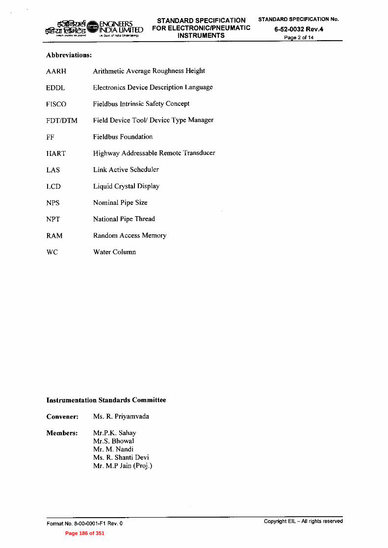
401 ei atENGINEERS STANDARD SPECIFICATION STANDARD SPECIFICATION No.groan facitegvie INDIA LIMITED FOR ELECTRONIC/PNEUMATIC 6-52-0032 Rev.4
''''eneww"wu .tea India Undetlaingl INSTRUMENTS Page 2 of 14
Abbreviations:
AARH Arithmetic Average Roughness Height
EDDL Electronics Device Description Language
FISCO Fieldbus Intrinsic Safety Concept
FDT/DTM Field Device Tool/ Device Type Manager
FF Fieldbus Foundation
HART Highway Addressable Remote Transducer
LAS Link Active Scheduler
LCD Liquid Crystal Display
NPS Nominal Pipe Size
NPT National Pipe Thread
RAM Random Access Memory
WC Water Column
Instrumentation Standards Committee
Convener: Ms. R. Priyamvada
Members: Mr.P.K. SahayMr.S. BhowalMr. M. NandiMs. R. Shanti DeviMr. M.P Jain (Proj.)
Format No. 8-00-0001-F1 Rev. 0 Copyright EIL — All rights reserved
Page 186 of 351

ate'Llealp ENGINEERS STANDARD SPECIFICATION STANDARD SPECIFICATION No.Wag WINDIA LIMITED FOR ELECTRONIC/PNEUMATIC 6-52-0032 Rev.4
(Men .FleTerFM1,19.i^ A Gort of India Undedaking) INSTRUMENTS Page 3 of 14
CONTENTS
1.0 GENERAL 4
2.0 DESIGN AND CONSTRUCTION 6
3.0 NAME PLATE 13
4.0 INSPECTION AND TESTING 13
5.0 SHIPPING 14
6.0 REJECTION 14
ANNEXURES:
ANNEXURE - 1: STUD - BOLTS AND NUTS MATERIAL REQUIREMENT
ANNEXURE - 2: GASKET MATERIAL REQUIREMENT
Format No. 8-00-0001-F1 Rev. 0 Copyright EIL — All rights reserved
Page 187 of 351

Oreael a ENGINEERS STANDARD SPECIFICATION STANDARD SPECIFICATION No.42mm:esINDIA LIMITED FOR ELECTRONIC/PNEUMATIC 6-52-0032 Rev.4
Govt of India undeptakingl INSTRUMENTS Page 4 of 14
1.0 GENERAL
1.1 Scope
1.1.1 This specification, together with the data sheets attached herewith describes the requirements
for the design, materials, nameplate marking, inspection, testing and shipping ofelectronic/pneumatic instruments.
1.1.2 The related standards referred to herein and mentioned below shall be of the latest editionprior to the date of the purchaser's enquiry:-
ASME American Society of Mechanical Engineers
1.20.1 Pipe Threads General Purpose (Inch)16.5 Pipe Flanges and Flanged Fittings16.20 Metallic Gaskets for Pipe Flanges,Ring Joint, Spiral wound
and Jacketed.
EN European Standards10204 Inspection Documents For Metallic Products
IS/IEC Indian Standards/ International Electrotechnical Commission
IS/IEC 60079 Electrical Apparatus for Explosive Gas Atmospheres.
IS/IEC 60529 Degree of Protection Provided by Enclosures (IP Code).
IEC 61000-4 Electromagnetic Compatibility (EMC) for Industrial
Process Measurement and Control EquipmentIEC 61158 Fieldbus Standard for use in Industrial Control System
IEC 61158-2 Physical Layer Specification and service definition for
FieldbusIEC 61508 Functional Safety of Electrical/Electronic/Programmable
Electronic Safety related Systems.IEC 61511 Functional safety instrumented system for the process
industry sectorIEC 61804 Function blocks (FB) for process control — Electronic
Device DescriptionIEC 61518 Mating dimensions between differential pressure (type)
measuring instruments and flanged-onshut-off devices upto 413 bar (41,3 MPa)
ISA International Society of Automation
S 7.3 Quality Standard for Instrument AirS 50.1 Compatibility of Analog Signals for Electronic Industrial
Process Instruments.
ITK Interoperability Test Kit (latest version)
1.1.3 In the event of any conflict between this standard specification, job specification/data sheets,statutory regulations, related standards, codes etc. the following order of priority shall govern:
Statutory Regulations
Job Specifications / Data Sheets
Standard Specification
Codes and Standards
1.1.4 In addition to compliance to purchaser's specifications in totality, vendor's extent ofresponsibility shall include the following:
a) Purchaser's data sheets specify the minimum acceptable material of construction ofbody, measuring element and accessories. Alternate superior material ofconstruction shall also be acceptable provided vendor assumes complete
Format No. 8-00-0001-F1 Rev. 0 Copyright EIL —All rights reserved
Page 188 of 351

051Przre?da ENGINEERS STANDARD SPECIFICATION STANDARD SPECIFICATION No.
51g7r teltaleuw INDIA UMITED FOR ELECTRONIC/PNEUMATIC 6-52-0032 Rev.4Go„ of India Undeltak.9) INSTRUMENTS Page 5 of 14
responsibility for the selected materials for their compatibility with the processfluid and its operating conditions.
b)
Selection of suitable sealant liquid for diaphragm seal instruments compatible withthe process fluid and its operating temperature.
1.2 Bids
1.2.1
Vendor's quotation shall be strictly as per the bidding instructions to the vendor attachedwith the material requisition.
1.2.2
Whenever a detailed technical offer is required, vendor's quotation shall include thefollowing:
Compliance to the specifications.Whenever the requirement of a detailed specification sheet for electronic/pneumaticinstruments is specifically indicated, a detailed specification sheet for each itemshall be furnished, which shall provide information regarding type, material ofconstruction, performance specification, model number etc. of the offeredelectronic / pneumatic instruments. The material specification and the units ofmeasurement for various parts in vendor's specification sheets shall be to the samestandards as those indicated in purchaser's data sheets.
c)
Proven references for each offered model number inline with clause 1.2.3 of thisspecification.
d)
A copy of approval from local statutory authority, as applicable such as Petroleum& Explosives Safety Organisation (PESO) / Chief Controller of Explosives (CCE),Nagpur or Director General of Mines Safety (DGMS) in India, for the electronicinstruments installed in electrically hazardous area along with:
Test certificate from recognised test house like Central Institute of Miningand Fuel Research (CIMFR) / Electronics Regional Testing Laboratory(ERTL) etc. for flameproof enclosure/intrinsic safety, as specified in the datasheet, as per relevant standard for all Indian manufactured equipments or foritems requiring Director General of Mines Safety DGMS approval.
Certificate of conformity from agencies like Laboratorie Central DesIndustries Electriques (LCIE), British Approval Service for ElectricalEquipment in Flammable Atmospheres (Baseefa), FactoryMutual (FM), Physikalisch-Technische Bundesanstalt (PTB) , CanadianStandards Association (CSA), Underwriters Laboratories (UL) etc. forcompliance to ATEX directives or other equivalent standards for allequipments manufactured outside India.
e)
Deviations on technical requirements shall not be entertained. In case vendor hasany valid technical reason, they must include a list of deviations tag number wise,summing up all the deviations from the purchaser's data sheets and other technicalspecifications along with the technical reasons for each of these deviations.
Catalogues giving detailed technical specifications, model decoding details andother related information for each type of electronic/pneumatic instruments coveredin the bid. Information shall include, but not limited to product certifications,dimensional drawings, Transient Protection, range limits, power supply, Currentdraw, vibration effect, power supply effect, Electromagnetic compatibility. ForField bus instruments, Field bus parameters like available standard functionblocks/Advanced function blocks and their execution time for each block, Devicetype, number of link objects, virtual communication Relationships, Basic andadvanced diagnostic features, transmitter failure mode, physical profile type etc.
1.2.3
All items, as offered, shall be field proven and should have completed trouble freesatisfactory operation for a period of minimum 4000 hours on the bid due date in the similar
Format No. 8-00-0001-F1 Rev. 0 Copyright EIL — All rights reserved
Page 189 of 351

Itilfraeg ENGINEERS STANDARD SPECIFICATION STANDARD SPECIFICATION No.
gent laYreu'IS INDIA LIMITED FOR ELECTRONIC/PNEUMATIC 6-52-0032 Rev.47412PrefZewenfrol Govl of India undenakm INSTRUMENTS Page 6 of 14
application with the process conditions similar to those as specified in the purchaser's datasheets. Items with proto-type design or items not meeting provenness criteria specifiedabove shall not be offered.
1.2.4 Wherever specified vendor must furnish certified values of failure rates, probability offailure on demand (PFD) and test intervals for offered items for Safety Integrity Level (SIL)analysis.
1.2.5 All documentation submitted by the vendor including their quotation, catalogues, drawings,installation, operation and maintenance manuals, etc shall be in English language only.
1.2.6 Vendor shall also quote for the following:Universal hand held configurator / terminal for the configuration and maintenanceof instruments with HART output.Field bus configurator with hardware and software for configuration andmaintenance of field bus devices and also to perform diagnostics and troubleshooting of fieldbus segments wherever specified.
Two-year operational spares for each model of instruments offered in the bid,which shall include sensor, electronic module, local indicator, o-ring/gasket set etc.based on vendor's recommendations.Any special tool other than those covered under 1.2.6 (a) and (b). In case anyspecial tools are needed for maintenance of offered instruments, vendor mustcertify in their offer.
1.3 Drawing and Data
1.3.1 Detailed drawings, data, catalogues and manuals required from the vendor are indicated bythe purchaser in vendor data requirement sheets. The required number of prints and softcopies should be dispatched to the address mentioned, adhering to the time limits indicated.
1.3.2 Final documentation consisting of design data, installation manual, operation andmaintenance manual, etc submitted by the vendor after placement of purchase order shallinclude the following, as a minimum;
Specification sheet for each electronic/pneumatic instrument and their accessories.
Certified drawing for each instrument, which shall provide dimensional detail,internal construction and part list, material of construction etc.
Calculations for integral orifice
Copy of type test certificates.
Copy of the test certificates of all the tests indicated in clause 4.0 of this specification.
Installation procedure for electronic/pneumatic instrument and its accessories.
Calibration, Configuration and Maintenance procedures including replacement ofits internal parts.
Device Descriptor (DD) Files for configuring the device parameters (Soft Copy)
i) Common File Format (CFF) files for integrating the device into the system (SoftCopy).
2.0 DESIGN AND CONSTRUCTION
2.1 General Requirements
2.1.1 The type and material of construction of electronic/pneumatic instruments shall be asspecified in the purchaser's data sheet.
Format No. 8-00-0001-F1 Rev. 0 Copyright EIL — All rights reserved
Page 190 of 351

a ENGINEERS STANDARD SPECIFICATION STANDARD SPECIFICATION No.ere, EvensvINDIA LIMITED FOR ELECTRONIC/PNEUMATIC 6-52-0032 Rev.4
IA Gort pi Inda Undeflaingl INSTRUMENTS Page 7 of 14
2.1.2 The range of instruments shall be selected by vendor based on the set range indicated in thepurchaser's data sheet. Where no set range is indicated, vendor may select the same as perthe following guidelines;
The set range shall be 1.1 times the maximum process value or 1.4 times theoperating process value whichever is higher rounded to the nearest ten.
The set range shall preferably be in the middle third of the selected instrumentrange.
2.1.3 Measuring element in vacuum service shall have under range protection down to fullvacuum, without undergoing a change in calibration or permanent set.
2.1.4 Unless otherwise specified, diaphragm seal instrument shall meet the following requirements;
Instruments shall have its diaphragm seal (flanged type) integral with theinstrument. In case wafer type diaphragm seal is provided, it shall be supplied withcompanion flange.When purchaser data sheets specify wafer seal type of instrument, vendor shallinclude supply of studs, nuts and gasket as per the materials specified in thepurchaser's data sheet. Refer Annexure — 1 attached with this specification for stud— bolts, nuts and gasket material requirement.
c) The sealant shall be an inert liquid, compatible with the process fluid and processtemperature indicated in the purchaser's data sheets. In general, sealant shall be;
DC 704 or equivalent for all diaphragm seal instruments except for oxygenand chlorine.
Flouro-lube or equivalent for all diaphragm seal instruments in oxygen andchlorine.
d) The requirement of spacer ring shall be as specified in purchaser's data sheet. Thematerial of construction of spacer ring shall be 316 Stainless Steel, as a minimumunless otherwise specified in the purchaser's data sheets.
e) The span of the offered model shall be selected to ensure zero elevation/zerosuppression equal to the head created by the fill fluid for the specified capillarylength in the data sheet.
2.1.5 Wherever purchaser data sheet specifies integral flow transmitter, vendor shall supplycomplete assembly consisting of integral orifice, upstream and downstream meter runs withend flanges, meeting the following requirements:
Three nos. of integral orifice plates shall be supplied i.e. one is installed and twoare spares.
Unless otherwise specified, material of construction shall be 316 Stainless Steel forintegral orifice and meter run with flanges.
2.1.6 The instrument enclosure shall be suitable for the area classification indicated in thepurchaser's data sheets. Unless otherwise specified, the enclosure shall meet the followingstandards;
Weatherproof housing IP-65 to IS/IEC-60529.
Flameproof housing Flameproof/ Ex (d) as per IS/IEC-60079
Flameproof housing shall also be made weatherproof.
2.1.7 Unless otherwise mentioned, end connection details shall be as below:-
Threaded end connections shall be to NPT as per ASME B 1.20.1.
Flanged end connections shall be as per ASME B 16.5.
Format No. 8-00-0001-F1 Rev. 0 Copyright EIL — All rights reserved
Page 191 of 351

1511=a-aelefalft.
ENGINEERS STANDARD SPECIFICATION STANDARD SPECIFICATION No.
INDIA LIMITED FOR ELECTRONIC/PNEUMATIC 6-52-0032 Rev.4IA GUN oundia undenson) INSTRUMENTS Page 8 of 14
Grooves of ring type joint flanges shall be octagonal as per ASME B16.20.
Flanged face finish shall be as per ANSI B 16.5. The face finish shall be asfollows:
125 AARH : 125 to 250 microinch AARH
63 AARH 32 to 63 microinch AARH
2.1.8 All electronic / pneumatic instruments in oxygen and chlorine service shall be thoroughlydegreased using reagents like trichloro-ethylene or carbon tetrachloride. End connectionshall be blinded / plugged after the degreasing process in order to avoid entrance of grease oroil particles.
2.1.9 Electronic Instruments
2.1.9.1 All instruments shall be of state-of-the-art technology and shall be in compliance with theelectromagnetic compatibility requirements specified in IEC-61000-4 standard.
2.1.9.2 Plug-in circuit boards shall be designed and manufactured such that reverse insertion orinsertion of the wrong card is prevented.
2.1.9.3 Electronic instruments shall generally operate on nominal voltage of 24 V DC and shall beprotected against short circuit and reverse voltage. Transmission and output signal shallgenerally be 4 to 20 mA DC for analog and smart transmitters. The display of integral outputmeter shall be in engineering units for pressure, differential pressure, flow & Temperatureand 100% linear for level.
2.1.9.4 Electronic transmitters with two-wire system shall be suitable for delivering rated current toan external loop resistance of at least 600ohm when powered with 24 V DC.
2.1.9.5 Terminals for electrical connections shall be clearly identified, and polarity shall bepermanently marked.
2.1.9.6 Peak to peak ripple and total noise level in the analog output signal shall not exceed 0.25%of the maximum signal.
2.1.9.7 Electrical cable entries shall have internal 'A" NPT threads.
2.1.9.8 Zero elevation/zero suppression shall be equal to minimum of 100% of the span of theoffered transmitter.
2.1.10 Pneumatic Instruments.
2.1.10.1 All pneumatic connections shall be 1/4" NPT, unless otherwise specified.
2.1.10.2 All threaded connections shall be internal, unless otherwise specified.
2.1.10.3 The process input connections and pneumatic output and air supply connections etc. shall bepermanently stamped on the body at a suitable place.
2.1.10.4 Unless otherwise specified, pneumatic instruments shall operate on air supply of 1.4 kg/cm2gand shall have transmission and output signal of 0.2 to 1.0 kg/cm2g.
2.1.10.5 Instrument air quality shall be as per ISA-S7.3 and shall be free from all corrosive,hazardous, flammable and toxic contaminants.
2.2 Transmitters
2.2.1 Pneumatic Transmitters
2.2.1.1 Pneumatic blind transmitters shall be of the force-balance type and pneumatic indicatingtransmitters of the motion balance type.
2.2.1.2 Transmitters shall have an accuracy of 0.5 % of span.
2.2.1.3 Transmitters shall be supplied with external zero and span adjustments.
2.2.2 Electronic Analog Transmitters
Format No. 8-00-0001-F1 Rev. 0 Copyright EIL — All rights reserved
Page 192 of 351

ENGINEERS STANDARD SPECIFICATION STANDARD SPECIFICATION No.
INDIA LIMITED FOR ELECTRONIC/PNEUMATIC 6-52-0032 Rev.4IA Govt of India undertism INSTRUMENTS Page 9 of 14
lafflzre?otia
2.2.2.1 Electronic transmitters shall be of the two-wire DC current regulating type. They shall beprovided with integral output indicator. When specified, field mounted external outputmeters shall be provided.
2.2.2.2 Electronic analog transmitters shall have an accuracy oft 0.25 % of span.
2.2.2.3 Transmitters shall be supplied with external zero and span adjustments. Flameprooftransmitters shall also have their calibration adjustment from outside, without any need toremove the cover.
2.2.2.4 Unless otherwise specified, the electronic transmitters shall be certified intrinsically safe.
2.2.3 Smart and Field bus based Transmitters
2.2.3.1 Smart and field bus based transmitters shall be two wire microprocessor based type. Theseshall have a non-volatile memory, storing, complete sensor characterisation andconfiguration data of the transmitter. All necessary signal conversions and output generationwith the required protocol shall be carried out in the transmitter electronics. Integral outputmeter with LCD display shall be provided for all transmitters.
2.2.3.2 Transmitter shall also run complete diagnostic subroutines and shall provide diagnosticalarm messages for sensor as well as transmitter healthiness. Field bus based transmitter inaddition shall have facility to detect plugged impulse lines, whenever specifically indicatedin purchaser's data sheets. In the event of detection failure, the output shall be driven to apredefined value, which shall be field configurable.
2.2.3.3 The transmitters with field bus connectivity shall have built in control algorithm likeproportional, proportional-integral and proportional-integral-differential.
2.2.3.4 Whenever specifically indicated in purchaser's data sheets, the meter electronics shall beprovided with in-built lightning and power supply surges. The transient protection shallmeet the requirements specified in IEC-61000-4.
2.2.3.5 The configurational data of the instruments shall be stored in a non-volatile memory suchthat this remains unchanged because of power fluctuations or power off condition. In casevendor standard instrument has battery backed RAM, vendor to ensure that battery drainalarm is provided as diagnostic maintenance message.
2.2.3.6 Accuracy of transmitters, smart as well as field bus based, shall be as follows:
Type of Transmitter Range of Transmitter Accuracy
Direct 760 mm WC and above Equal to or better than +0.075%
Direct Less than 760 mm WC Equal to or better than ±0.15%
Diaphragm seal 500 mm WC and above Equal to or better than ±0.25%
Diaphragm seal Less than 500 mm WC Equal to or better than ±0.5%
The accuracy is defined as the combined effect of repeatability, linearity and hysteresis.
2.2.3.7 The stability of the transmitters shall be equal to or better than ±0.1% of span for a period ofminimum 6 months, as a minimum.
2.2.3.8 Transmitter shall update the output at least 8 times a second unless otherwise specified.
2.2.3.9 Unless specified otherwise in purchaser's specification, transmitter response time shall be asfollows:
For transmitter range of 760 mm WC and above, the response time shall be equal toor better than 500 milliseconds.
For transmitter range below 760mm WC, the response shall be equal to or betterthan I second.
Copyright EIL — All rights reservedFormat No. 8-00-0001-F1 Rev. 0Page 193 of 351

STANDARD SPECIFICATION STANDARD SPECIFICATION No.FOR ELECTRONIC/PNEUMATIC 6-52-0032 Rev.4
INSTRUMENTS Page 10 of 14
The response time of the transmitter shall be considered as the sum of dead time and 63.2%step response time of the transmitter.
2.2.3.10 Unless specified otherwise, the over-range/static pressure protection of the transmitter shallbe as follows:
Range of Transmitter 0
OVERRANGE / STATIC PRESSURE (*)
Pressure TransmitterKg/Cm2
Differential Pressure Transmitter
Kg/Cm2
0 <®<250 mmWC 20 20
250 < 0 < 1000 mmWC 45 52
1000 < 0 < 5000mmWC
45 70
5000 < 0 < 10000mmWC
45 160
1 < ® < 10 Kg/cm2 52 160
10 < 0 < 100 Kg/cm2 160 210
® > 100 Kg/cm2 210 210
(*) However, if the overange/static pressure valve specified above is less than themaximum/design pressure of service conditions specified in the datasheets, offeredinstrument shall be suitable for the maximum/design pressure as per datasheet.
2.2.3.11 In the transmitter, the 'WRITE' option shall be protected through password.
2.2.3.12 Temperature transmitters shall meet the following requirements as a minimum:
Temperature transmitter shall be universal type and shall be able to accept inputfrom resistance temperature detector (RTD) or thermocouple (T/C) of any type andrange.Temperature transmitters shall be freely programmable i.e. element type and rangeshall be programmable without any change in hardware / software.
Temperature transmitter shall be remote mounted type, in general Head mountedtransmitters shall be supplied when specifically indicated in purchaser's datasheets.The accuracy of the temperature transmitter with RTD element shall be as follows:
For temperature range above 350° C, the accuracy shall be equal to or betterthan +0.075% of range.For temperature range with ranges between 350° C to 150° C, the accuracyshall be equal to or better than 10.15% of range.
For temperature range below 150° C, the accuracy shall be equal to or betterthan +0.25% of range.
e) The accuracy of temperature transmitter with cold junction compensation forThermocouple element shall be as follows;
For temperature above 350° C, accuracy shall be +0.25% of range.
For temperature between 150°C to 350°C. accuracy shall be ±0.5% of range.
For temperature below 150°C, accuracy shall be +0.75% of range.
Format No. 8-00-0001-F1 Rev. 0 Copyright EIL —All rights reserved
Page 194 of 351

satrazre?.211
ENGINEERS STANDARD SPECIFICATION STANDARD SPECIFICATION No.
INDIA LIMITED FOR ELECTRONIC/PNEUMATIC 6-52-0032 Rev.4Govt of India unaertaionci INSTRUMENTS Page 11 of 14
2.2.3.13 When HART protocol is specified, the following features must be ensured;
It shall allow multi masters (two for example, primary and secondary) forconfiguration, calibration, diagnostics and maintenance. The primary could be thecontrol system or host computer and the secondary could be the hand-heldcommunicator.It shall be capable of implementing universal commands from either of theselocations.
2.2.3.14 In addition to the requirements specified above, field bus based transmitter shall meet thefollowing requirements;
All instruments must satisfy the requirements of the field bus registrationlaboratory with applicable checkmark like foundation field bus, profibusNutZerorganisation e.v (PNO), or as specified in the purchaser's data sheets.
All instruments shall be polarity insensitive. Also transmitter shall be LAS capableand provided with line plugging detection, whenever specified in data sheet.
All instruments shall have one no. of Analog Input (AI) block and One no. ofProportional, Integration and Differential (PID) control block, as a minimum.
All instruments must be interoperable and shall have valid interoperability testclearance like ITK latest version for foundation field bus or equivalent for profibusPA, as applicable.
e) The field bus instruments shall support peer to peer communication.
The field bus instruments in hazardous area shall be certified as per entity conceptor shall be FISCO approved as per the requirements specified in the purchaser'sspecification.All instruments shall support EDDL or FDT/DTM requirements, as specified indata sheets.Internal Software shall be configured by the vendor including the followinginformation.
- Serial Number
Device Tag (Tag No.)
- Process Description
i) All instruments shall be capable of supporting incremental Device Descriptor (DD)for extra functionality and/or software revisions in Device Memory.
2.3 Receivers
2.3.1 Pneumatic/electrical cables shall be such that they permit the instrument internals to bedrawn from its normal mounting position without affecting operation. Pneumatic connectionpoints shall seal automatically upon disconnection.
2.3.2 Electronic receivers shall be suitable for standard voltage inputs of 0.25 to 1.25 V, 1 to 5 V,0 to 10 V dc. Any voltage receiver shall not alter the voltage drop across the conditioningresistor by more than ±0.1% of input range of maximum input voltage.
2.3.3 Recorder pens shall be easily replaceable.
2.3.4 Each recorder shall be supplied with chart-rolls and ink for six months continuous operation.
2.4 Controllers
2.4.1 Automatic control stations including dedicated cascade control stations shall have switchesto transfer control from automatic to manual mode and vice-versa. The transfer shall be
Format No. 8-00-0001-F1 Rev. 0 Copyright EIL — All rights reserved
Page 195 of 351

Iiiif®eENGINEERS STANDARD SPECIFICATION STANDARD SPECIFICATION No.
g Lear jalgeg NW INDIA LIMITED FOR ELECTRONIC/PNEUMATIC 6-52-0032 Rev.4- wow mein =AIM) (A GM AI Ma Undcriakingl INSTRUMENTS Page 12 of 14
procedure less and shall not produce any bump in the process under control during such atransfer, the output signal shall not change by more than I% of span.
2.4.2 Cascade control stations shall have a switch to select local or remote set point.
2.4.3 The control settings of the controller shall be readily adjustable from the front.
2.4.4 Controller action shall be easily reversible.
2.4.5 Pneumatic automatic controller shall be easily removable, without disturbing the manualcontrol mechanism.
2.4.6 Electronic controller shall be easily removable, with the aid of a service station.
2.4.7 Local mounted pneumatic controllers shall be supplied with gauges for air supply pressureand control signal. The gauges shall be integral with the instrument.
2.5 Accessories
2.5.1 Field Universal Communicator:
2.5.1.1 It shall be possible to perform routine configuration, calibration, display process variable,diagnostics etc. from a hand held portable communicator, which can be connected at anylocation in the transmitter loop. It shall be possible to perform all the above functions on-lineand the loop function shall remain unaffected.
2.5.1.2 There should be no interruption on the output while communicating with the transmitter.
2.5.1.3 Field communicator shall meet the following requirements:
Hand Held communicator shall be universal type and shall be compatible with allmake and models of HART transmitters and Smart positioners, with all engineeringcapability like calibration, diagnostics, configuration, inhibition of HART signal,etc. Similarly Field bus Hand Held communicator shall also be universal type andshall be suitable for all make and models of FF transmitters and Positioner.
It shall be possible to connect the communicator at any of the following locationsfor purpose of digital communication;
Marshalling cabinet serving the transmitter, in safe area.
Junction box serving the transmitter, in hazardous area.
iii) Directly at the transmitter, in hazardous area.
Plug-in type connections shall be provided with field communicator. Necessaryinterconnection accessories shall be supplied by the vendor.
Offered communicator shall be dust-proof, certified intrinsically safe and suitablefor outdoor location. Carrying case shall be supplied with each communicator.
When specified in data sheets, the software shall also be capable of configuringother makes of transmitters.
e) They shall be battery powered with replaceable and rechargeable batteries, suitablefor recharging with 240 V, 50 Hz . In case vendor's standard design does not makeuse of rechargeable batteries, then vendor to provide 2 sets of spare batteries.
2.5.2 Remote output meter
2.5.2.1 Remote output meter shall be electronic with LCD display. The display shall be in actualengineering units.
2.5.2.2 The indicator electronics shall be able to perform square root extraction for flowmeasurement
2.5.2.3 Offered indicators shall be certified Intrinsically safe/FISCO, when used in hazardous areaas specified in Data sheet.
Format No. 8-00-0001-F1 Rev. 0 Copyright EIL —All rights reserved
Page 196 of 351

lel MENGINEERS STANDARD SPECIFICATION STANDARD SPECIFICATION No.
Sig:ClItMegay INDIA UMITED FOR ELECTRONIC/PNEUMATIC 6-52-0032 Rev.4(A Geri oi kwila UndellaMingl INSTRUMENTS Page 13 of 14
2.5.2.4 This Field Bus based field indicator shall be 2 wire segment powered and shall be able toindicate minimum of 8 signals available in the fieldbus segment, selectively.
2.5.3 Yoke mounted instruments shall be supplied with universal mounting bracket , U-bolt andnuts suitable for mounting the instruments on a 50 mm (nominal bore) pipe stanchion(horizontal or vertical)
2.5.4 Air setAir set, where provided, shall be a combination air filter regulator set with 5-micron filtercartridge. It shall have a 50 mm diameter pressure gauge to indicate the regulated pressure.Each air set shall be supplied with mounting bracket and bolts with nuts for surface mounting.
2.5.5 Battery chargerBattery charger shall be supplied with all necessary accessories and shall be suitable for240V ±10%, 50Hz±3Hz, unless otherwise specified.
3.0 NAMEPLATE
3.1 Each flush panel mounted instrument shall have the following information identified in thefront:-
Tag number as per purchaser's data sheet.
Reading coefficient, if any
c) Pen colour, tag number-wise in the case of recorders.
Each flush panel mounted instrument shall have a back nameplate permanently fixed to it ata visible place reporting the following information:
Instrument tag number.
Manufacturer's serial number or model number.
c) Manufacturer's name/trade mark.
3.2 Surface mounted instruments shall be provided with only one nameplate.
Local mounted instruments shall have a stainless steel nameplate attached firmly to it at avisible place, furnishing the following information:
Tag number as per purchaser's data sheets.
Manufacturer's serial number and /or model number
Manufacturer's name/trade mark.
Body material.
Measuring element material.
Range of measurement.
j) Area classification in which the equipment can be used, this shall be to the same
code as per purchaser's data sheets.
4.0 INSPECTION AND TESTINGPurchaser reserves the right to inspect and witness testing all the items at the vendor's worksin line with the inspection test plan for electronic/pneumatic instruments and approvedquality documents. All these tests shall be completed by the vendor and test reports shall besubmitted to purchaser for scrutiny.
Format No. 8-00-0001-F1 Rev. 0 Copyright EIL — All rights reserved
Page 197 of 351

ISiMareqe ENGINEERS STANDARD SPECIFICATION STANDARD SPECIFICATION No.51g7ePegillir INDIA LIMITED FOR ELECTRONIC/PNEUMATIC 6-52-0032 Rev.4
(A Govt ■)0a Undenakingi INSTRUMENTS Page 14 of 14
5.0 SHIPPING
5.1 All threaded and flanged openings shall be suitably protected to prevent entry of foreignmaterial.
5.2 Instruments shall be supplied individually, in suitably sealed packing.
5.3 Proper care shall be taken in shipping instruments with diaphragm seals to ensure safety ofthe diaphragm seals, extensions, capillaries, where specified.
5.4 All pneumatic / electronic instruments in oxygen and chlorine service shall be separatelypacked along with a certificate indicating 'CERTIFIED FOR OXYGEN / CHLORINESERVICE', as applicable.
5.5 Proper care shall be taken in shipping instrument accessories clearly indicating theinstrument tag numbers.
6.0 REJECTION
6.1 Vendor shall prepare their offer strictly as per clause 1.2 of this specification and shall attachonly those documents and information, which are specifically indicated in the materialrequisition.
6.2 Any offer not conforming to the above requirements, shall be summarily rejected.
Format No. 8-00-0001-F1 Rev. 0 Copyright EIL - All rights reservedPage 198 of 351

OPtade ENGINEERSElPeg'10, INDIA UMITED
IA Goff of inam undertalonof
STUD-BOLTS AND NUTSMATERIAL REQUIREMENT
Annexure 1 10STANDARD SPECIFICATION NO.
6-52-0032 Rev. 4Page 1 of 1
Sr. No. Piping Classes Nut and Bolt Material
1 AIA, A2A, A5A, A6A, A7A, A8A, A9A,AIM, Al IA, A13A, AI4A, AI5A,AI9A, A20A, A32A, A33A, AIK, A6K,AIM, A1N, BIA, B2A, B5A, B6A, B9A,BI3A, B18A, B19A, B32A, BIK, B6K,BI8K, BIM, B3M, B5M, BIN, B6N,DIA, D2A, WA, D18A, DIK, DISK,DI8P, EIA, E2A, E5A, E5E, F5A
A-193 Gr. B7A-194 Gr. 2H
2 Al6A,B16A A-I93 Gr. B7MA-194 Gr. 2HM
3 MB, AID, A4F, A4G, BIB, BID, B5D,BIE, B3F, B4F, B4G, DIB, D2B, DID,D2D, D5D, D5E, F2D
AI-193 Gr. B16A-194 GR. 4
4 A2K, B2K, D2K A-320 Gr. B8 CL.2A-194 Gr. 8
5 A4A, AIH, B4A, B1H, D4A, DIH A-320 Gr. L7A-194 Gr. 4
6 A3Y A-307 Gr. BA-563 Gr. B
7 A3A, A3K, A3Y, A4Y, J3A A-307 Gr. BA-563 Gr. B
8 AIZ, A4Z, A5Y, J2A, .15A A-307 Gr. B (Gals)A-563 Gr. B (Gals)
9 B4K, B5K A-193 Gr. B8 MCIIA-194 Gr. 8 MA
10 A32Y A-193 Gr. B (Gaiv)A-194 Gr. 211 (Galv)
11 B3M, B4K, B5K, B5M A-453 Gr. 660 CL.AA-453 Gr. 660 CL.A
Format No. 8-00-0001-F1 Rev. 0 Copyrights EIL - All rights reserved
Page 199 of 351
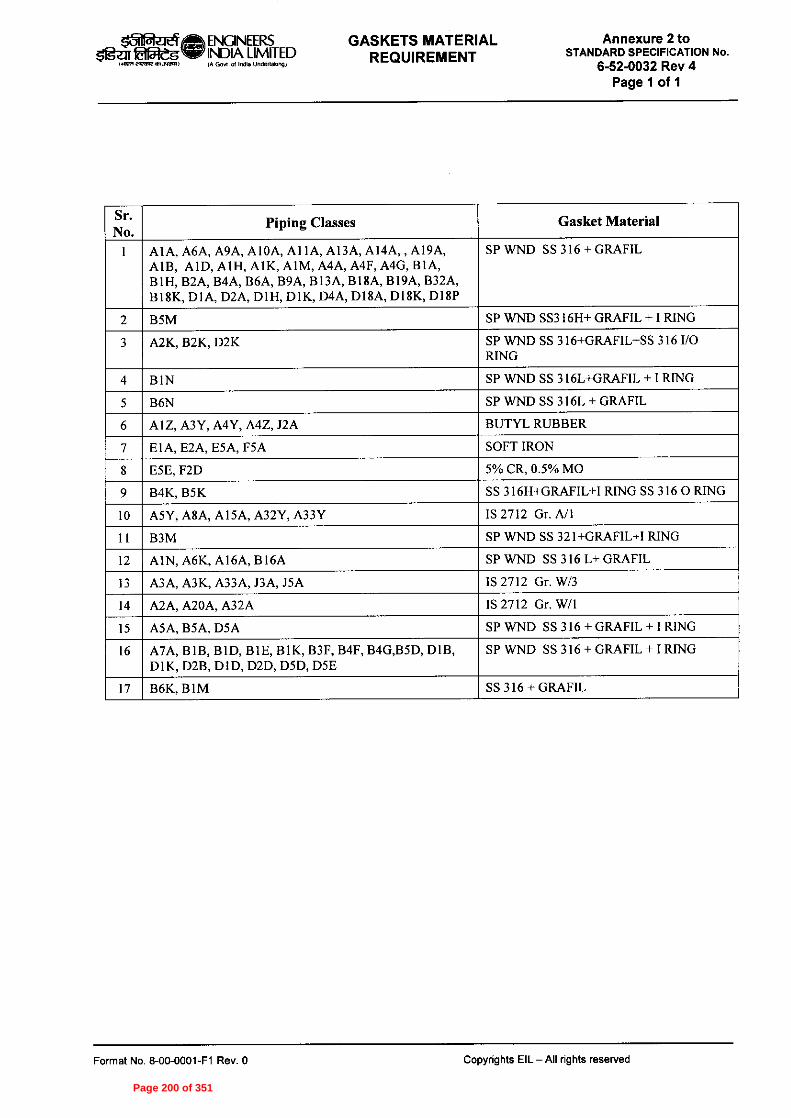
PRZTe? ENGINEERS GASKETS MATERIAL$1g7 efargi INDIA LIMITED REQUIREMENTIA Gov' of Ind. Udenda,)
Annexure 2 toSTANDARD SPECIFICATION No.
6-52-0032 Rev 4Page 1 of 1
Sr.No.
Piping Classes Gasket Material
1 AIA, A6A, A9A, AIOA, Al IA, A13A, AI4A, AI9A,AIB, AID, AIH, A1K, AIM, A4A, A4F, A4G, B1A,BIH, B2A, B4A, B6A, B9A, BI3A, B18A, BOA, B32A,BI8K, DIA, D2A, DIH, DIK, D4A, D18A, DISK, DISP
SP WND SS 316 + GRAFIL
2 B5M SP WND SS316H+ GRAFIL + I RING
3 A2K, B2K, D2K SP WND SS 316+GRAFIL+SS 316 I/ORING
4 BIN SP WND SS 3I6L+GRAFIL + I RING
5 B6N SP WND SS 316L + GRAFIL
6 Al Z, A3Y, A4Y, A4Z, J2A BUTYL RUBBER
7 E IA, E2A, E5A, F5A SOFT IRON
8 ESE, F2D 5% CR, 0.5% MO
9 B4K, B5K SS 316H+GRAFIL+I RING SS 316 0 RING
10 MY, A8A, AI5A, A32Y, A33Y IS 2712 Gr. A/I
I I B3M SP WND SS 321+GRAFIL+I RING
12 AIN, A6K, A16A, 1316A SP WND SS 316 L+ GRAFIL
13 A3A, A3K, A33A, J3A, J5A IS 2712 Gr. W/3
14 A2A, A20A, A32A IS 2712 Gr. W/I
15 A5A, B5A, D5A SP WND SS 316 + GRAFIL + I RING
16 A7A, BIB, BID, B1E, B1K, B3F, B4F, B4G,B5D, DIB,D1K, D2B, DID, D2D, D5D, D5E
SP WND SS 316 + GRAFIL + I RING
17 B6K, BIM SS 316 + GRAFIL
Format No. 8-00-0001-F1 Rev. 0 Copyrights EIL -All rights reserved
Page 200 of 351

Page 201 of 351

Page 202 of 351

Page 203 of 351

Page 204 of 351

Page 205 of 351

Page 206 of 351

Page 207 of 351

Page 208 of 351

Page 209 of 351

cZ 34 mm CHAIN
ct• 1/2"NPT r_
FOR CHAIN TERMINATION(ONLY FOR TEST THERMOWELL)
FULL PENETRATION WELD
45 mmPLUG WITH CHAIN
I VT FLANGE
FULL PENETRATION WELDNO WELD MATERIALPROJECTION BEYOND RF
ID 11 mmBORE TO BE CONCENTRIC
WITH 0.D. WITHIN 10% OFWALL THICKNESS
18 mm(1)
Oln-a-eifith ENGINEERSazit 'Meg Ter INDIA LIMITED THERMOWELL1.11271MORMMORI) IA Gm of India Underwonw
STANDARD No.
7-52-0035 Rev. 3Page 1 of 3
NOTES - 1. THIS STANDARD IS APPLICABLE FOR ;TEMPERATURE GAUGES, BEADED TEMPERATURE ELEMENTS AND DUPLEX TEMPERATURE ELEMENTS.THERMOWELL UPTO 1500 CLASS AS PER ASME OR EQUIVALENT.
TYPE OF FLANGE SHALL BE RTJ FOR RATING (AS PER ASME CLASS) > 600.DP TEST SHALL BE CARRIED OUT FOR ALL WELD JOINTS.
4. CHAIN AND PLUG SHALL BE APPLICABLE ONLY FOR TEST THERMOVVELLS.
3 21-03-12 REVISED & REISSUED ter
Manoj G4--v" DTh-'
M)RI5/J S 2 21-08-06 REVISED & REISSUED MN TGM PM VJN
Rev.No.
Copyright EIL - Al rights reservedFormat No. 8-00-0001-F4 Rev.O
Date Purpose Prepared Checkedby by
Stds. Committee Stds. BureauConvenor Chairman
Approved by
Page 210 of 351

CHAIN0 34 mm
q 1/2"NPT r_
FOR OW TERMINATION(ONLY FOR TE
NST THERMOWELL) 45 mm
00 I's 1.0z"
• Min•••
4!)
PLUG WITH CHAIN
1 1/7 FLANGE
ABMFULL PENETRATION WELDNO WELD MATERIALPROJECTION BEYOND RF
OD 21 mm
zID 7 mm
BORE TO BE CONCENTRICWRH O.D. WRMIN 10% OF
WALL THICKNESS
JO 16 mm
FULL PENETRATION WELD
6R
Rev.No. Date
Format No. 8-00-0001-F4 Rev.O
Prepared Checkedby by
Stds. Committee Stds. BureauConvenor Chairman
Approved by Copyright EIL - All rights reserved
Purpose
1511=4-a-eite, ENGINEERSDReg ie INDIA LIMITED THERMOWELL
MET MaRa51300,10 (A GOvl Of WM Undertgo001
STANDARD No.
7-52-0035 Rev. 3Page 2 of 3
NOTES - 1. THIS STANDARD IS APPLICABLE FOR ;SINGLE TEMPERATURE ELEMENT.THERMOWELL UPTO 1500 CLASS AS PER ASME OR EQUIVALENT.
TYPE OF FLANGE SHALL BE RTJ FOR RATING (AS PER ASME CLASS) > 600.DP TEST SHALL BE CARRIED OUT FOR ALL WELD JOINTS.
4. CHAIN AND PLUG SHALL BE APPLICABLE ONLY FOR TEST THERMOWELLS.2116,-,)3 21-03-12 REVISED & REISSUED rtm.
Cit SL MS phi 2 21-06-06 REVISED & REISSUED MN TOM PM VJN
Page 211 of 351

0 34 mm
45 mmWELD
FULL PENETRATION WELD
FULL PENETRATION WELDNO WELD MATERIALPROJECTION BEYOND RF
MACHINE TAPER TO BE CONCENTRIC1Nt T 11 INSIDE DIAMETER WITHIN 10%OF WALL THICKNESS
BORE TO BE CONCENTRICWITH O.D. WITHIN 10% OF
WALL THICKNESS
BAR STOCK
0 18 mm
2' FLANGE
R JMS
TGM PM VJNRev.No. Date
Format No. 8-00-0301-F4 Rev.O
Prepared Checkedby by
Stds. Committee Stds. BureauConvenor Chairman
Approved by Copyright EIL • AI rights reserved
Purpose
safteiela ENGINEERSau WaveINDIA LIMITED BUILT-UP THERMOWELL1.4.1
STANDARD No.
7-52-0035 Rev. 3Page 3 of 3
NOTES:-
DP TEST SHALL BE CARRIED OUT FOR ALL WELD JOINTS.TYPE OF FLANGE SHALL BE RTJ FOR RATING (AS PER ASME CLASS) >
3 21-03-12 REVISED & REISSUED e‘anoj2 21-08-08 REVISED & REISSUED MN
Page 212 of 351

JOB SPECIFICATION No.PIPING MATERIALA307-6-44-0005 Rev. CSPECIFICATION
Page 25 of 881
Client : BPCL 16/43Dept./Sect. :
Project : IREP
Location : KOCHI, KERALA Pipe Class : A11A Sheet 1 of 8
PIPE CLASS : A11A RATING : 150
BASE MATERIAL : CARBON STEEL
CORROSION ALLOWANCE : 3 MM
SPECIAL REQUIREMENT :
TEMPERATURE (Deg. C) AND PRESSURE ( Kg/Sq. cm g ) RATINGS
TEMP 20.03
-29
20.03
38
18.28
93
16.17
149
14.06
204
11.95
260
9.84
316
8.78
343
7.73
371
PRESS
SERVICE MILD SOUR FLARE (NON NACE) - REFER NOTE 34.
NOTES 5 FOR PERMANENT 'T' TYPE BW STRAINERS,REFER EIL'STD 7-44-0303 & 7-44-0304; AND FOR TEMPORARY
STRAINERS,REFER EIL'STD 7-44-0300; FOR SPACER AND BLIND REFER EIL'STD 7-44-0162. 7 FOR RESTRICTION ON USE OF BALL,PLUG & BUTTERFLY VALVES,REFER GENERAL NOTES.
32 CORROSION ALLOWANCE HAS BEEN ADJUSTED TO SELECT OPTIMUM SCH. REFER GENERAL NOTES TO PMS.
34 MAXIMUM HARDNESS IN WELD JOINTS SHALL BE LIMITED TO 200 BHN.
92 GATE VALVES OF SIZE 26" AND ABOVE SHALL BE IN ACCORDANCE WITH B-16.34/ BS-1414 AND FLANGE ENDS SHALL BE IN ACCORDANCE WITH ASME B16.47 SERIES B.
132 10% OF CORROSION ALLOWANCE HAS BEEN ADJUSTED TO SELECT OPTIMUM SCH / THICKNESS FOR SIZE 90".
151 NDT REQUIREMENT SHALL BE AS PER JOB SPECIFICATION A307-6-44-0016.
152 FIRST ISOLATION VALVE ON ALL FLOW, PRESSURE AND LEVEL TAPPINGS SHALL BE METAL TO METAL SEATED BALL VALVE.
161 BRANCH CONNECTION FOR SIZES 76", 80" AND 90" SHALL BE WITH HALF COUPLING FOR BRANCHES UP TO 1.5", PIPE TO PIPE WITH REINFORCEMENT PAD FOR 2"AND ABOVE BRANCHES
201 PIPE WALL THICKNESS IS CALCULATED BASED ON ACTUAL LINE DESIGN CONDITION [ 300 DEG. C & 7.5 KG/ CM2 G] SUBJECT TO MINIMUM OF 80% CLASS RATING.
SPECIAL NOTES
ITEM SIZE DESCRIPTION A.CODE MAINTAINENCE JOINTS
ALL FLANGED, TO BE KEPT MINIMUM
PIPE JOINTS 1.5" & BELOW SW COUPLING
2.0" & ABOVE BUTTWELDED
DRAINS ON LINES <= 1.5" REFER EILSTD 7-44-0350, DF3
ON LINES >= 2.0" AS PER P&ID OR 0.75". REFER EIL STD. 7-44-0351, D4
VENTS ON LINES <= 1.5" REFER EIL STD. 7-44-0350, VF3
ON LINES >= 2.0" AS PER P&ID OR 0.75". REFER EIL STD 7-44-0351, V4
TEMP.CONN 1.5" FLANGED. REFER EIL STD 7-44-0353
PRESS.CONN 0.75" SW NIPPLE WITH VALVE TO SPEC AS PER EIL STD 7-44-0354
Package : IPMCS
Report No. : 50 A11A Template No. 5-0000-0001-T2 Rev. Copyright EIL- All rights reserved
Page 213 of 351

JOB SPECIFICATION No.PIPING MATERIALA307-6-44-0005 Rev. CSPECIFICATION
Page 26 of 881
Client : BPCL 16/43Dept./Sect. :
Project : IREP
Location : KOCHI, KERALA Pipe Class : A11A Sheet 2 of 8
BR
AN
CH
PIP
E (
SIZ
E I
N I
NC
HE
S)
72.70. 68. 66. 64. 62. 60. 58. 56. 54. 52. 50. 48. 46. 44. 42. 40. 38. 36. 34. 32. 30. 28. 26. 24. 22. 20. 18. 16. 14. 12. 10. 8.0 6.0 5.0 4.0 3.5 3.0 2.5 2.0 1.5
1.25 1.0
0.75 0.5
T
T R
T R R
T R R R T R R R R
T R R R R R T R R R R R R
T R R R R R R R T R R R R R R R R
T R R R R R R R R R T R R R R R R R R R R
T R R R R R R R R R R R T R R R R R R R R R R R R
T R R R R R R R R R R R R R T R R R R R R R R R R R R R R
T R R R R R R R R R R R R R R R T R R R R R R R R R R R R R R R R
T R R R R R R R R R R R R R R R R R
T R R R R R R R R R R R R R R R R R R T R R R R R R R R R R R R R R R R R R R
T R R R R R R R R R R R R R R R R R R R R T P R R R R R R R R R R R R R R R R R R R R
T P P R R R R R R R R R R R R R R R R R R R R T P P P R R R R R R R R R R R R R R R R R R R R
T P P P P R R R R R R R R R R R R R R R R R R R R T P P P P P R R R R R R R R R R R R R R R R R R R R
T P P P P P P R R R R R R R R R R R R R R R R R R R R
T P P P P P P P R R R R R R R R R R R R R R R R R R R R
T P P P P P P P P R R R R R R R R R R R R R R R R R R R R T T H H H H H H H H H H H H H H H H H H H H H H H H H H H H
T T H H H H H H H H H H H H H H H H H H H H H H H H H H H H H T T T H H H H H H H H H H H H H H H H H H H H H H H H H H H H H
T T T T H H H H H H H H H H H H H H H H H H H H H H H H H H H H H
.500
.750
1.00
0
1.25
0
1.50
0
2.00
0
2.50
0
3.00
0
3.50
0
4.00
0
5.00
0
6.00
0
8.00
0
10.0
00
12.0
00
14.0
00
16.0
00
18.0
00
20.0
00
22.0
00
24.0
00
26.0
00
28.0
00
30.0
00
32.0
00
34.0
00
36.0
00
38.0
00
40.0
00
42.0
00
44.0
00
46.0
00
48.0
00
50.0
00
52.0
00
54.0
00
56.0
00
58.0
00
60.0
00
62.0
00
64.0
00
66.0
00
RUN PIPE (SIZE IN INCHES)
CODE DESCRIPTION
F SADDLE FUSED JT T TEES J THREADOLET
H H. COUPLING W WELDOLETS
P PIPE TO PIPE I INSTRUMENT TEE
R REINFORCED X Refer Notes
S SOCKOLETS L SWEEPOLET
Package : IPMCS
Report No. : 50 A11A Template No. 5-0000-0001-T2 Rev. Copyright EIL- All rights reserved
Page 214 of 351

JOB SPECIFICATION No.PIPING MATERIALA307-6-44-0005 Rev. CSPECIFICATION
Page 27 of 881
Client : BPCL Dept./Sect. : 16/43
Project : IREP
Location : KOCHI, KERALA Pipe Class : A11A Sheet 3 of 8
T
T R
R R
R R
R R
R R R R R R R R R R R R R R R R R R R R R R R R R R R R R R
R R R R R R R R R R R R R R R R
R R
R R
R R H H
H H H H H H
68.0
00
70.0
00
72.0
00
72. 70. 68. 66. 64. 62. 60. 58. 56. 54. 52. 50. 48. 46. 44. 42. 40. 38. 36. 34. 32. 30. 28. 26. 24. 22. 20. 18. 16. 14. 12. 10. 8.0 6.0 5.0 4.0 3.5 3.0 2.5 2.0 1.5 1.25 1.0 0.75 0.5
BR
AN
CH
PIP
E (SIZ
E IN
INC
HE
S)
Package : IPMCS
Report No. : 50 A11A Template No. 5-0000-0001-T2 Rev. Copyright EIL- All rights reserved
Page 215 of 351
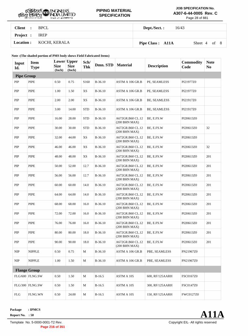
JOB SPECIFICATION No.PIPING MATERIALA307-6-44-0005 Rev. CSPECIFICATION
Page 28 of 881
Client : BPCL 16/43Dept./Sect. :
Project : IREP
Location : KOCHI, KERALA Pipe Class : A11A Sheet 4 of 8
Note :(The shaded portion of PMS body shows Field Fabricated Items)
Input Id.
Item Type
Lower Size (Inch)
Upper Size (Inch)
Sch/ Thk Dmn. STD Material Description
Commodity Code
Note No
Pipe Group PIP PIPE 0.50 0.75 S160 B-36.10 ASTM A 106 GR.B PE, SEAMLESS PI21977Z0
PIP PIPE 1.00 1.50 XS B-36.10 ASTM A 106 GR.B PE, SEAMLESS PI21977Z0
PIP PIPE 2.00 2.00 XS B-36.10 ASTM A 106 GR.B BE, SEAMLESS PI21917Z0
PIP PIPE 3.00 14.00 STD B-36.10 ASTM A 106 GR.B BE, SEAMLESS PI21917Z0
PIP PIPE 16.00 28.00 STD B-36.10 A672GR.B60 CL.12 (200 BHN MAX)
BE, E.FS.W PI2H613Z0
PIP PIPE 30.00 30.00 STD B-36.10 A672GR.B60 CL.12 (200 BHN MAX)
BE, E.FS.W PI2H613Z0 32
PIP PIPE 32.00 44.00 XS B-36.10 A672GR.B60 CL.12 (200 BHN MAX)
BE, E.FS.W PI2H613Z0
PIP PIPE 46.00 46.00 XS B-36.10 A672GR.B60 CL.12 (200 BHN MAX)
BE, E.FS.W PI2H613Z0 32
PIP PIPE 48.00 48.00 XS B-36.10 A672GR.B60 CL.12 (200 BHN MAX)
BE, E.FS.W PI2H613Z0 201
PIP PIPE 50.00 52.00 12.7 B-36.10 A672GR.B60 CL.12 (200 BHN MAX)
BE, E.FS.W PI2H613Z0 201
PIP PIPE 56.00 56.00 12.7 B-36.10 A672GR.B60 CL.12 (200 BHN MAX)
BE, E.FS.W PI2H613Z0 201
PIP PIPE 60.00 60.00 14.0 B-36.10 A672GR.B60 CL.12 (200 BHN MAX)
BE, E.FS.W PI2H613Z0 201
PIP PIPE 64.00 64.00 14.0 B-36.10 A672GR.B60 CL.12 (200 BHN MAX)
BE, E.FS.W PI2H613Z0 201
PIP PIPE 68.00 68.00 16.0 B-36.10 A672GR.B60 CL.12 (200 BHN MAX)
BE, E.FS.W PI2H613Z0 201
PIP PIPE 72.00 72.00 16.0 B-36.10 A672GR.B60 CL.12 (200 BHN MAX)
BE, E.FS.W PI2H613Z0 201
PIP PIPE 76.00 76.00 16.0 B-36.10 A672GR.B60 CL.12 (200 BHN MAX)
BE, E.FS.W PI2H613Z0 201
PIP PIPE 80.00 80.00 18.0 B-36.10 A672GR.B60 CL.12 (200 BHN MAX)
BE, E.FS.W PI2H613Z0 201
PIP PIPE 90.00 90.00 18.0 B-36.10 A672GR.B60 CL.12 (200 BHN MAX)
BE, E.FS.W PI2H613Z0 201
NIP NIPPLE 0.50 0.75 M B-36.10 ASTM A 106 GR.B PBE, SEAMLESS PN21967Z0
NIP NIPPLE 1.00 1.50 M B-36.10 ASTM A 106 GR.B PBE, SEAMLESS PN21967Z0
Flange Group FLG/600 FLNG.SW 0.50 1.50 M B-16.5 ASTM A 105 600, RF/125AARH FSC0167Z0
FLG/300 FLNG.SW 0.50 1.50 M B-16.5 ASTM A 105 300, RF/125AARH FSC0147Z0
FLG FLNG.WN 0.50 24.00 M B-16.5 ASTM A 105 150, RF/125AARH FWC0127Z0
Package : IPMCS
Report No. : 50 A11A Template No. 5-0000-0001-T2 Rev. Copyright EIL- All rights reserved
Page 216 of 351

JOB SPECIFICATION No.PIPING MATERIALA307-6-44-0005 Rev. CSPECIFICATION
Page 29 of 881
Client : BPCL 16/43Dept./Sect. :
Project : IREP
Location : KOCHI, KERALA Pipe Class : A11A Sheet 5 of 8
Note :(The shaded portion of PMS body shows Field Fabricated Items)
Input Id.
Item Type
Lower Size (Inch)
Upper Size (Inch)
Sch/ Thk Dmn. STD Material Description
Commodity Code
Note No
Flange Group FLG FLNG.WN 26.00 60.00 M B-16.47-B ASTM A 105 150, RF/125AARH FWB0127Z0
FLG/300 FLNG.WN 2.00 24.00 M B-16.5 ASTM A 105 300, RF/125AARH FWC0147Z0
FLG/600 FLNG.WN 2.00 24.00 M B-16.5 ASTM A 105 600, RF/125AARH FWC0167Z0
FLB FLNG.BLIND 0.50 24.00 B-16.5 ASTM A 105 150, RF/125AARH FBC0127Z0
FLB FLNG.BLIND 26.00 60.00 B-16.47-B ASTM A 105 150, RF/125AARH FBB0127Z0
FLB/300 FLNG.BLIND 6.00 6.00 B-16.5 ASTM A 105 300, RF/125AARH FBC0147Z0
FEF FLNG.FIG.8 0.50 8.00 ASMEB16.48
ASTM A 105 150, FF/125AARH FGK0121Z0
FEF SPCR&BLND 10.00 24.00 ASMEB16.48
ASTM A 105 150, FF/125AARH FCK0121Z0
FEF SPCR&BLND 26.00 60.00 EIL'STD ASTM A 516 GR.70 150, FF/125AARH FCE6321Z0
Fitting Group ELB90 ELBOW.90 0.50 0.75 B-16.11 ASTM A 105 SW, 6000 WA602D3Z0
ELB90 ELBOW.90 1.00 1.50 B-16.11 ASTM A 105 SW, 3000 WA602D2Z0
ELB90 ELBOW.90 2.00 14.00 M B-16.9 ASTM A 234 GR.WPB
BW, 1.5D WAG684Z10
ELB90 ELBOW.90 16.00 48.00 M B-16.9 ASTM A 234 GR.WPB-W
BW, 1.5D WAG754Z10
ELB90 ELBOW.90 50.00 90.00 M MNF'STD ASTM A 234 GR.WPB-W
BW, 1.5D WAN754Z10
ELB45 ELBOW.45 0.50 0.75 B-16.11 ASTM A 105 SW, 6000 WB602D3Z0
ELB45 ELBOW.45 1.00 1.50 B-16.11 ASTM A 105 SW, 3000 WB602D2Z0
ELB45 ELBOW.45 2.00 14.00 M B-16.9 ASTM A 234 GR.WPB
BW, 1.5D WBG684Z10
ELB45 ELBOW.45 16.00 48.00 M B-16.9 ASTM A 234 GR.WPB-W
BW, 1.5D WBG754Z10
ELB45 ELBOW.45 50.00 90.00 M MNF'STD ASTM A 234 GR.WPB-W
BW, 1.5D WBN754Z10
TEQ T.EQUAL 0.50 0.75 B-16.11 ASTM A 105 SW, 6000 WE602D3Z0
TEQ T.EQUAL 1.00 1.50 B-16.11 ASTM A 105 SW, 3000 WE602D2Z0
TEQ T.EQUAL 2.00 14.00 M B-16.9 ASTM A 234 GR.WPB
BW WEG684ZZ0
TEQ T.EQUAL 16.00 48.00 M B-16.9 ASTM A 234 GR.WPB-W
BW WEG754ZZ0
Package : IPMCS
Report No. : 50 A11A Template No. 5-0000-0001-T2 Rev. Copyright EIL- All rights reserved
Page 217 of 351

JOB SPECIFICATION No.PIPING MATERIALA307-6-44-0005 Rev. CSPECIFICATION
Page 30 of 881
Client : BPCL 16/43Dept./Sect. :
Project : IREP
Location : KOCHI, KERALA Pipe Class : A11A Sheet 6 of 8
Note :(The shaded portion of PMS body shows Field Fabricated Items)
Input Id.
Item Type
Lower Size (Inch)
Upper Size (Inch)
Sch/ Thk Dmn. STD Material Description
Commodity Code
Note No
Fitting Group TEQ T.EQUAL 50.00 90.00 M MNF'STD ASTM A 234
GR.WPB-W BW WEN754ZZ0
TRED T.RED 0.50 0.75 B-16.11 ASTM A 105 SW, 6000 WR602D3Z0
TRED T.RED 1.00 1.50 B-16.11 ASTM A 105 SW, 3000 WR602D2Z0
TRED T.RED 2.00 14.00 M, M B-16.9 ASTM A 234 GR.WPB
BW WRG684ZZ0
TRED T.RED 16.00 48.00 M, M B-16.9 ASTM A 234 GR.WPB-W
BW WRG754ZZ0
TRED T.RED 50.00 90.00 M, M MNF'STD ASTM A 234 GR.WPB-W
BW WRN754ZZ0
REDC REDUC.CONC 2.00 14.00 M, M B-16.9 ASTM A 234 GR.WPB
BW WUG684ZZ0
REDC REDUC.CONC 16.00 48.00 M, M B-16.9 ASTM A 234 GR.WPB-W
BW WUG754ZZ0
REDC REDUC.CONC 50.00 90.00 M, M MNF'STD ASTM A 234 GR.WPB-W
BW WUN754ZZ0
REDE REDUC.ECC 2.00 14.00 M, M B-16.9 ASTM A 234 GR.WPB
BW WVG684ZZ0
REDE REDUC.ECC 16.00 48.00 M, M B-16.9 ASTM A 234 GR.WPB-W
BW WVG754ZZ0
REDE REDUC.ECC 50.00 90.00 M, M MNF'STD ASTM A 234 GR.WPB-W
BW WVN754ZZ0
SWGC SWAGE.CONC 0.50 3.00 M, M BS-3799 ASTM A 105 PBE WNH026ZZ0
SWGE SWAGE.ECC 0.50 3.00 M, M BS-3799 ASTM A 105 PBE WPH026ZZ0
CAP CAP 0.50 0.75 B-16.11 ASTM A 105 SCRF, 6000 WF60283Z0
CAP CAP 1.00 1.50 B-16.11 ASTM A 105 SCRF, 3000 WF60282Z0
CAP CAP 2.00 48.00 M B-16.9 ASTM A 234 GR.WPB
BW WFG684ZZ0
CAP CAP 50.00 90.00 M MNF'STD ASTM A 234 GR.WPB
BW WFN684ZZ0
CPLF CPLNG.FULL 0.50 0.75 B-16.11 ASTM A 105 SW, 6000 WJ602D3Z0
CPLF CPLNG.FULL 1.00 1.50 B-16.11 ASTM A 105 SW, 3000 WJ602D2Z0
CPLH CPLNG.HALF 0.50 0.75 B-16.11 ASTM A 105 SW, 6000 WK602D3Z0
CPLH CPLNG.HALF 1.00 1.50 B-16.11 ASTM A 105 SW, 3000 WK602D2Z0
CPLL CPLNG.LH 0.50 0.75 B-16.11 ASTM A 105 SW, 6000 WL602D3Z0
Package : IPMCS
Report No. : 50 A11A Template No. 5-0000-0001-T2 Rev. Copyright EIL- All rights reserved
Page 218 of 351

JOB SPECIFICATION No.PIPING MATERIALA307-6-44-0005 Rev. CSPECIFICATION
Page 31 of 881
Client : BPCL 16/43Dept./Sect. :
Project : IREP
Location : KOCHI, KERALA Pipe Class : A11A Sheet 7 of 8
Note :(The shaded portion of PMS body shows Field Fabricated Items)
Input Id.
Item Type
Lower Size (Inch)
Upper Size (Inch)
Sch/ Thk Dmn. STD Material Description
Commodity Code
Note No
Fitting Group CPLL CPLNG.LH 1.00 1.50 B-16.11 ASTM A 105 SW, 3000 WL602D2Z0
CPLR CPLNG.RED 0.50 0.75 B-16.11 ASTM A 105 SW, 6000 WM602D3Z0
CPLR CPLNG.RED 1.00 1.50 B-16.11 ASTM A 105 SW, 3000 WM602D2Z0
Valves Group GAV VLV.GATE 0.25 1.50 API 602/ ISO
15761 BODY-ASTM A 105,TRIMSTELLITED,STEM13%CR.STEEL
SW, 800, 3000, B16.11, SHT NO.- 51001
51001ZZZ0
GAV VLV.GATE 2.00 42.00 API 600/ ISO 10434
BODY-ASTM A 216 GR.WCB,TRIM13% CR.STEEL
FLGD, 150, B-16.5, RF/125AARH, SHT NO.- 51301
51301ZZZ0 92
GLV VLV.GLOBE 0.25 1.50 BS EN ISO 15761
BODY-ASTM A 105,TRIMSTELLITED,STEM13%CR STEEL
SW, 800, 3000, B16.11, SHT NO.- 52001
52001ZZZ0
GLV VLV.GLOBE 2.00 16.00 BS-1873 BODY-ASTM A 216 GR.WCB,TRIM13% CR.STEEL
FLGD, 150, B-16.5, RF/125AARH, SHT NO.- 52301
52301ZZZ0
CHV VLV.CHECK 0.25 1.50 BS EN ISO 15761
BODY-ASTM A 105,TRIMSTELLITED
SW, 800, 3000, B16.11, SHT NO.- 53001
53001ZZZ0
CHV VLV.CHECK 2.00 24.00 BS 1868 BODY-ASTM A 216 GR.WCB,TRIM13% CR.STEEL
FLGD, 150, B-16.5, RF/125AARH, SHT NO.- 53301
53301ZZZ0
BLV VLV.BALL 0.50 16.00 BS EN ISO 17292
BODY-ASTM A 105 / A 216GR.WCB,TRIMBODY SEATRPTFE
FLGD, 150, B-16.5, RF/125AARH, SHT NO.- 54301
54301ZZZ0
BLV/2 VLV.BALL 2.00 8.00 BS EN ISO 17292
BODY- ASTM A 216GR.WCB,TRIM13% CR.STEEL
FLGD, 150, B-16.5, RF/125AARH, SHT NO.- 543AA
543AAZZZ0 152
BLV/1 VLV.BALL 0.50 1.50 BS EN ISO 17292
BODY-ASTM A 105,TRIMSTELLITED,STEM13% CR.STEEL
SW, 800, 3000, B16.11, SHT NO.540AA
540AAZZZ0 152
PLV VLV.PLUG 0.50 24.00 BS-5353 BODY-ASTM A 105 / A 216GR.WCB,TRIMPLUG-HARDENED
FLGD, 150, B-16.5, RF/125AARH, SHT NO.- 55301
55301ZZZ0
BFV VLV.BTRFLY 24.00 24.00 BS EN 593 BODY-ASTM A 216 GR.WCB,TRIM13% CR.STEEL
WAFL, 150, B-16.5, WAF/125AARH, SHT NO.- 56935
56935ZZZ0
BFV VLV.BTRFLY 26.00 60.00 BS EN 593 BODY-ASTM A 216 GR.WCB,TRIM13% CR.STEEL
FLGD, 150, B-16.47 B, RF/125AARH, SHT NO.- 56928
56928ZZZ0
Package : IPMCS
Report No. : 50 A11A Template No. 5-0000-0001-T2 Rev. Copyright EIL- All rights reserved
Page 219 of 351

JOB SPECIFICATION No.PIPING MATERIALA307-6-44-0005 Rev. CSPECIFICATION
Page 32 of 881
Client : BPCL 16/43Dept./Sect. :
Project : IREP
Location : KOCHI, KERALA Pipe Class : A11A Sheet 8 of 8
Note :(The shaded portion of PMS body shows Field Fabricated Items)
Input Id.
Item Type
Lower Size (Inch)
Upper Size (Inch)
Sch/ Thk Dmn. STD Material Description
Commodity Code
Note No
Bolt Group BOS BOLT.STUD 0.50 60.00 B-18.2 BOLT:A193 GR.B7,
NUT:A194 GR.2H BS40404Z0
Gasket Group GAS GASKET 0.50 24.00 B-16.20
ANSI B16.5 SP.WND SS316+GRAFIL
SPIRAL, 150 GK65072Z0
GAS GASKET 26.00 60.00 B-16.20ANSI B16.47B
SP.WND SS316+GRAFIL+ I RING
SPIRAL, 150 GK56272Z0
GAS/60 0
GASKET 0.50 24.00 B-16.20ANSI B16.5
SP.WND SS316+GRAFIL
SPIRAL, 600 GK65076Z0
GAS/30 0
GASKET 0.50 24.00 B-16.20ANSI B16.5
SP.WND SS316+GRAFIL
SPIRAL, 300 GK65074Z0
Trap/Strainer Group TSR STRNR.TEMP 1.50 24.00 EIL'STD B:A516GR.70;INT:S
S304 CONETYPE, 150,FF/125AARH
ST16831Z0
PSR STRNR.PERM 0.50 1.50 MNF'STD B:A105;INT:SS304 SW, Y-TYPE, 800 SP303D510
PSR STRNR.PERM 2.00 14.00 M EIL'STD B:A234GR.WPB;IN T:SS304
BW, T-TYPE SP13344Z0
PSR STRNR.PERM 16.00 24.00 M EIL'STD B:A234GR.WPBW;I NT:SS304
BW, T-TYPE SP13644Z0
Package : IPMCS
Report No. : 50 A11A Template No. 5-0000-0001-T2 Rev. Copyright EIL- All rights reserved
Page 220 of 351
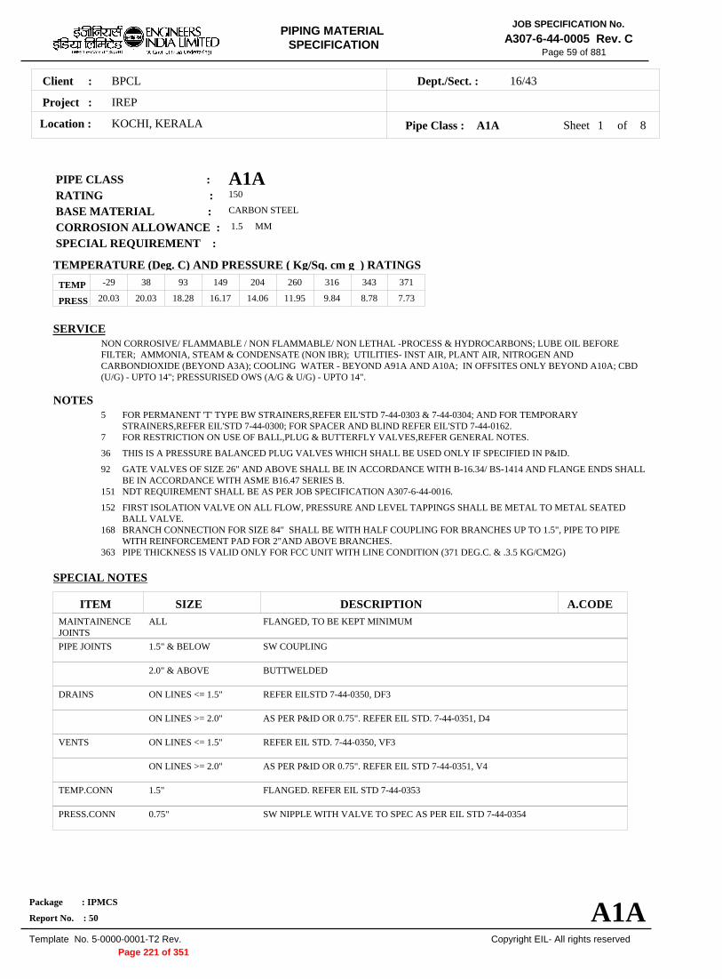
JOB SPECIFICATION No.PIPING MATERIALA307-6-44-0005 Rev. CSPECIFICATION
Page 59 of 881
Client : BPCL 16/43Dept./Sect. :
Project : IREP
Location : KOCHI, KERALA Pipe Class : A1A Sheet 1 of 8
PIPE CLASS : A1A RATING : 150
BASE MATERIAL : CARBON STEEL
CORROSION ALLOWANCE : 1.5 MM
SPECIAL REQUIREMENT :
TEMPERATURE (Deg. C) AND PRESSURE ( Kg/Sq. cm g ) RATINGS
TEMP 20.03
-29
20.03
38
18.28
93
16.17
149
14.06
204
11.95
260
9.84
316
8.78
343
7.73
371
PRESS
SERVICE NON CORROSIVE/ FLAMMABLE / NON FLAMMABLE/ NON LETHAL -PROCESS & HYDROCARBONS; LUBE OIL BEFORE FILTER; AMMONIA, STEAM & CONDENSATE (NON IBR); UTILITIES- INST AIR, PLANT AIR, NITROGEN AND CARBONDIOXIDE (BEYOND A3A); COOLING WATER - BEYOND A91A AND A10A; IN OFFSITES ONLY BEYOND A10A; CBD (U/G) - UPTO 14"; PRESSURISED OWS (A/G & U/G) - UPTO 14".
NOTES 5 FOR PERMANENT 'T' TYPE BW STRAINERS,REFER EIL'STD 7-44-0303 & 7-44-0304; AND FOR TEMPORARY
STRAINERS,REFER EIL'STD 7-44-0300; FOR SPACER AND BLIND REFER EIL'STD 7-44-0162. 7 FOR RESTRICTION ON USE OF BALL,PLUG & BUTTERFLY VALVES,REFER GENERAL NOTES.
36 THIS IS A PRESSURE BALANCED PLUG VALVES WHICH SHALL BE USED ONLY IF SPECIFIED IN P&ID.
92 GATE VALVES OF SIZE 26" AND ABOVE SHALL BE IN ACCORDANCE WITH B-16.34/ BS-1414 AND FLANGE ENDS SHALL BE IN ACCORDANCE WITH ASME B16.47 SERIES B.
151 NDT REQUIREMENT SHALL BE AS PER JOB SPECIFICATION A307-6-44-0016.
152 FIRST ISOLATION VALVE ON ALL FLOW, PRESSURE AND LEVEL TAPPINGS SHALL BE METAL TO METAL SEATED BALL VALVE.
168 BRANCH CONNECTION FOR SIZE 84" SHALL BE WITH HALF COUPLING FOR BRANCHES UP TO 1.5", PIPE TO PIPE WITH REINFORCEMENT PAD FOR 2"AND ABOVE BRANCHES.
363 PIPE THICKNESS IS VALID ONLY FOR FCC UNIT WITH LINE CONDITION (371 DEG.C. & .3.5 KG/CM2G)
SPECIAL NOTES
ITEM SIZE DESCRIPTION A.CODE MAINTAINENCE JOINTS
ALL FLANGED, TO BE KEPT MINIMUM
PIPE JOINTS 1.5" & BELOW SW COUPLING
2.0" & ABOVE BUTTWELDED
DRAINS ON LINES <= 1.5" REFER EILSTD 7-44-0350, DF3
ON LINES >= 2.0" AS PER P&ID OR 0.75". REFER EIL STD. 7-44-0351, D4
VENTS ON LINES <= 1.5" REFER EIL STD. 7-44-0350, VF3
ON LINES >= 2.0" AS PER P&ID OR 0.75". REFER EIL STD 7-44-0351, V4
TEMP.CONN 1.5" FLANGED. REFER EIL STD 7-44-0353
PRESS.CONN 0.75" SW NIPPLE WITH VALVE TO SPEC AS PER EIL STD 7-44-0354
Package : IPMCS
Report No. : 50 A1A Template No. 5-0000-0001-T2 Rev. Copyright EIL- All rights reserved
Page 221 of 351

JOB SPECIFICATION No.PIPING MATERIALA307-6-44-0005 Rev. CSPECIFICATION
Page 60 of 881
Client : BPCL 16/43Dept./Sect. :
Project : IREP
Location : KOCHI, KERALA Pipe Class : A1A Sheet 2 of 8
72.
T T R
T R R T R R R
T R R R R T R R R R R
T R R R R R R T R R R R R R R
T R R R R R R R R T R R R R R R R R R
T R R R R R R R R R R T R R R R R R R R R R R
T R R R R R R R R R R R R T R R R R R R R R R R R R R
T P R R R R R R R R R R R R R T P P R R R R R R R R R R R R R
T P P P R R R R R R R R R R R R R T P P P P R R R R R R R R R R R R R
T P P P P P R R R R R R R R R R R R R T P P P P P P R R R R R R R R R R R R R
T P P P P P P P R R R R R R R R R R R R R T P P P P P P P P R R R R R R R R R R R R R
T P P P P P P P P P R R R R R R R R R R R R R P
T P P P P P P P P P P R R R R R R R R R R R R R
T P P P P P P P P P P P R R R R R R R R R R R R R T T H H H H H H H H H H H H H H H H H H H H H H H H
T T H H H H H H H H H H H H H H H H H H H H H H H H H T T T H H H H H H H H H H H H H H H H H H H H H H H H H
T T T T H H H H H H H H H H H H H H H H H H H H H H H H H
.500
.750
1.00
0
1.25
0
1.50
0
2.00
0
2.50
0
3.00
0
3.50
0
4.00
0
5.00
0
6.00
0
8.00
0
10.0
00
12.0
00
14.0
00
16.0
00
18.0
00
20.0
00
22.0
00
24.0
00
26.0
00
28.0
00
30.0
00
32.0
00
34.0
00
36.0
00
38.0
00
40.0
00
42.0
00
44.0
00
46.0
00
48.0
00
72. 70. 70. 68. 68. 66. 66. 64. 64. 62. 62. 60. 60. 58. 58. 56. 56. 54. 54. 52. 52. 50. 50. 48. 48. 46. 46. 44. 44. 42. 42. 40. 40. 38. 38. 36. 36. 34. 34. 32. 32. 30. 30. 28. 28. 26. 26. 24. 24. 22. 22. 20. 20. 18. 18. 16. 16. 14. 14. 12. 12. 10. 10. 8.0 8.0 6.0 6.0 5.0 5.0 4.0 4.0 3.5 3.5 3.0 3.0 2.5 2.5 2.0 2.0 1.5 1.5
1.25 1.25 1.0 1.0
0.75 0.75 0.5 0.5
BR
AN
CH
PIP
E (
SIZ
E I
N I
NC
HE
S) B
RA
NC
H P
IPE
(SIZE
IN IN
CH
ES)
RUN PIPE (SIZE IN INCHES)
CODE DESCRIPTION
F SADDLE FUSED JT T TEES J THREADOLET
H H. COUPLING W WELDOLETS
P PIPE TO PIPE I INSTRUMENT TEE
R REINFORCED X Refer Notes
S SOCKOLETS L SWEEPOLET
Package : IPMCS
Report No. : 50 A1A Template No. 5-0000-0001-T2 Rev. Copyright EIL- All rights reserved
Page 222 of 351

JOB SPECIFICATION No.PIPING MATERIALA307-6-44-0005 Rev. CSPECIFICATION
Page 61 of 881
Client : BPCL 16/43Dept./Sect. :
Project : IREP
Location : KOCHI, KERALA Pipe Class : A1A Sheet 3 of 8
Note :(The shaded portion of PMS body shows Field Fabricated Items)
Input Id.
Item Type
Lower Size (Inch)
Upper Size (Inch)
Sch/ Thk Dmn. STD Material Description
Commodity Code
Note No
Pipe Group PIP PIPE 0.50 0.75 S160 B-36.10 ASTM A 106 GR.B PE, SEAMLESS PI21977Z0
PIP PIPE 1.00 1.50 XS B-36.10 ASTM A 106 GR.B PE, SEAMLESS PI21977Z0
PIP PIPE 2.00 2.00 XS B-36.10 ASTM A 106 GR.B BE, SEAMLESS PI21917Z0
PIP PIPE 3.00 14.00 STD B-36.10 ASTM A 106 GR.B BE, SEAMLESS PI21917Z0
PIP PIPE 16.00 36.00 STD B-36.10 ASTM A 672 GR.B60 CL.12
BE, E.FS.W PI2A813Z0
PIP PIPE 38.00 38.00 XS B-36.10 ASTM A 672 GR.B60 CL.12
BE, E.FS.W PI2A813Z0
PIP PIPE 40.00 48.00 XS B-36.10 ASTM A 672 GR.B60 CL.12
BE, E.FS.W PI2A813Z0
PIP PIPE 84.00 84.00 16.0 B-36.10 ASTM A 672 GR.B60 CL.12
BE, E.FS.W PI2A813Z0 363
NIP NIPPLE 0.50 0.75 M B-36.10 ASTM A 106 GR.B PBE, SEAMLESS PN21967Z0
NIP NIPPLE 1.00 1.50 M B-36.10 ASTM A 106 GR.B PBE, SEAMLESS PN21967Z0
Flange Group FLG/600 FLNG.SW 0.50 1.50 M B-16.5 ASTM A 105 600, RF/125AARH FSC0167Z0
FLG/300 FLNG.SW 0.50 1.50 M B-16.5 ASTM A 105 300, RF/125AARH FSC0147Z0
FLG FLNG.WN 0.50 20.00 M B-16.5 ASTM A 105 150, RF/125AARH FWC0127Z0
FLG FLNG.WN 22.00 22.00 M MSS-SP44 ASTM A 105 150, RF/125AARH FWH0127Z0
FLG FLNG.WN 24.00 24.00 M B-16.5 ASTM A 105 150, RF/125AARH FWC0127Z0
FLG FLNG.WN 26.00 48.00 M B-16.47-B ASTM A 105 150, RF/125AARH FWB0127Z0
FLG/150 0
FLNG.WN 0.50 24.00 M B-16.5 ASTM A 105 1500, RTJ/63AARH FWC0189Z0
FLG/900 FLNG.WN 3.00 24.00 M B-16.5 ASTM A 105 900, RTJ/63AARH FWC0179Z0
FLG/300 FLNG.WN 26.00 48.00 M B-16.47-B ASTM A 105 300, RF/125AARH FWB0147Z0
FLG/600 FLNG.WN 2.00 24.00 M B-16.5 ASTM A 105 600, RF/125AARH FWC0167Z0
FLG/300 FLNG.WN 2.00 24.00 M B-16.5 ASTM A 105 300, RF/125AARH FWC0147Z0
FLB FLNG.BLIND 0.50 24.00 B-16.5 ASTM A 105 150, RF/125AARH FBC0127Z0
FLB FLNG.BLIND 26.00 48.00 B-16.47-B ASTM A 105 150, RF/125AARH FBB0127Z0
Package : IPMCS
Report No. : 50 A1A Template No. 5-0000-0001-T2 Rev. Copyright EIL- All rights reserved
Page 223 of 351

JOB SPECIFICATION No.PIPING MATERIALA307-6-44-0005 Rev. CSPECIFICATION
Page 62 of 881
Client : BPCL 16/43Dept./Sect. :
Project : IREP
Location : KOCHI, KERALA Pipe Class : A1A Sheet 4 of 8
Note :(The shaded portion of PMS body shows Field Fabricated Items)
Input Id.
Item Type
Lower Size (Inch)
Upper Size (Inch)
Sch/ Thk Dmn. STD Material Description
Commodity Code
Note No
Flange Group FLB/900 FLNG.BLIND 3.00 24.00 B-16.5 ASTM A 105 900, RTJ/63AARH FBC0179Z0
FLB/600 FLNG.BLIND 0.50 24.00 B-16.5 ASTM A 105 600, RF/125AARH FBC0167Z0
FLB/300 FLNG.BLIND 0.50 24.00 B-16.5 ASTM A 105 300, RF/125AARH FBC0147Z0
FLB/150 0
FLNG.BLIND 0.50 24.00 B-16.5 ASTM A 105 1500, RTJ/63AARH FBC0189Z0
FEF FLNG.FIG.8 0.50 8.00 ASMEB16.48
ASTM A 105 150, FF/125AARH FGK0121Z0
FEF SPCR&BLND 10.00 24.00 ASMEB16.48
ASTM A 105 150, FF/125AARH FCK0121Z0
FEF SPCR&BLND 26.00 48.00 EIL'STD ASTM A 516 GR.70 150, FF/125AARH FCE6321Z0
Fitting Group ELB90 ELBOW.90 0.50 0.75 B-16.11 ASTM A 105 SW, 6000 WA602D3Z0
ELB90 ELBOW.90 1.00 1.50 B-16.11 ASTM A 105 SW, 3000 WA602D2Z0
ELB90 ELBOW.90 2.00 14.00 M B-16.9 ASTM A 234 GR.WPB
BW, 1.5D WAG684Z10
ELB90 ELBOW.90 16.00 48.00 M B-16.9 ASTM A 234 GR.WPB-W
BW, 1.5D WAG754Z10
ELB90 ELBOW.90 84.00 84.00 M MNF'STD ASTM A 234 GR.WPB-W
BW, 1.5D WAN754Z10
ELB90/1 ELBOW.90 18.00 18.00 M B-16.28 ASTM A 234 GR.WPB-W
BW, 1D WAA754Z20
ELB45 ELBOW.45 0.50 0.75 B-16.11 ASTM A 105 SW, 6000 WB602D3Z0
ELB45 ELBOW.45 1.00 1.50 B-16.11 ASTM A 105 SW, 3000 WB602D2Z0
ELB45 ELBOW.45 2.00 14.00 M B-16.9 ASTM A 234 GR.WPB
BW, 1.5D WBG684Z10
ELB45 ELBOW.45 16.00 48.00 M B-16.9 ASTM A 234 GR.WPB-W
BW, 1.5D WBG754Z10
ELB45 ELBOW.45 84.00 84.00 M MNF'STD ASTM A 234 GR.WPB-W
BW, 1.5D WBN754Z10
ELB45/1 ELBOW.45 18.00 18.00 M B-16.28 ASTM A 234 GR.WPB-W
BW, 1D WBA754Z20
TEQ T.EQUAL 0.50 0.75 B-16.11 ASTM A 105 SW, 6000 WE602D3Z0
TEQ T.EQUAL 1.00 1.50 B-16.11 ASTM A 105 SW, 3000 WE602D2Z0
TEQ T.EQUAL 2.00 14.00 M B-16.9 ASTM A 234 GR.WPB
BW WEG684ZZ0
TEQ T.EQUAL 16.00 48.00 M B-16.9 ASTM A 234 GR.WPB-W
BW WEG754ZZ0
Package : IPMCS
Report No. : 50 A1A Template No. 5-0000-0001-T2 Rev. Copyright EIL- All rights reserved
Page 224 of 351

JOB SPECIFICATION No.PIPING MATERIALA307-6-44-0005 Rev. CSPECIFICATION
Page 63 of 881
Client : BPCL 16/43Dept./Sect. :
Project : IREP
Location : KOCHI, KERALA Pipe Class : A1A Sheet 5 of 8
Note :(The shaded portion of PMS body shows Field Fabricated Items)
Input Id.
Item Type
Lower Size (Inch)
Upper Size (Inch)
Sch/ Thk Dmn. STD Material Description
Commodity Code
Note No
Fitting Group TEQ T.EQUAL 84.00 84.00 M MNF'STD ASTM A 234
GR.WPB-W BW WEN754ZZ0
TRED T.RED 0.50 0.75 B-16.11 ASTM A 105 SW, 6000 WR602D3Z0
TRED T.RED 1.00 1.50 B-16.11 ASTM A 105 SW, 3000 WR602D2Z0
TRED T.RED 2.00 14.00 M, M B-16.9 ASTM A 234 GR.WPB
BW WRG684ZZ0
TRED T.RED 16.00 48.00 M, M B-16.9 ASTM A 234 GR.WPB-W
BW WRG754ZZ0
TRED T.RED 84.00 84.00 M, M MNF'STD ASTM A 234 GR.WPB-W
BW WRN754ZZ0
REDC REDUC.CONC 2.00 14.00 M, M B-16.9 ASTM A 234 GR.WPB
BW WUG684ZZ0
REDC REDUC.CONC 16.00 48.00 M, M B-16.9 ASTM A 234 GR.WPB-W
BW WUG754ZZ0
REDC REDUC.CONC 84.00 84.00 M, M MNF'STD ASTM A 234 GR.WPB-W
BW WUN754ZZ0
REDE REDUC.ECC 2.00 14.00 M, M B-16.9 ASTM A 234 GR.WPB
BW WVG684ZZ0
REDE REDUC.ECC 16.00 48.00 M, M B-16.9 ASTM A 234 GR.WPB-W
BW WVG754ZZ0
REDE REDUC.ECC 84.00 84.00 M, M MNF'STD ASTM A 234 GR.WPB-W
BW WVN754ZZ0
SWGC SWAGE.CONC 0.50 3.00 M, M BS-3799 ASTM A 105 PBE WNH026ZZ0
SWGE SWAGE.ECC 0.50 3.00 M, M BS-3799 ASTM A 105 PBE WPH026ZZ0
CAP CAP 0.50 0.75 B-16.11 ASTM A 105 SCRF, 6000 WF60283Z0
CAP CAP 1.00 1.50 B-16.11 ASTM A 105 SCRF, 3000 WF60282Z0
CAP CAP 2.00 48.00 M B-16.9 ASTM A 234 GR.WPB
BW WFG684ZZ0
CAP CAP 84.00 84.00 M MNF'STD ASTM A 234 GR.WPB
BW WFN684ZZ0
PLG PLUG 0.50 0.75 B-16.11 ASTM A 105 SCRM, 6000 WH60293Z0
PLG PLUG 1.00 1.50 B-16.11 ASTM A 105 SCRM, 3000 WH60292Z0
CPLF CPLNG.FULL 0.50 0.75 B-16.11 ASTM A 105 SW, 6000 WJ602D3Z0
CPLF CPLNG.FULL 1.00 1.50 B-16.11 ASTM A 105 SW, 3000 WJ602D2Z0
CPLH CPLNG.HALF 0.50 0.75 B-16.11 ASTM A 105 SW, 6000 WK602D3Z0
Package : IPMCS
Report No. : 50 A1A Template No. 5-0000-0001-T2 Rev. Copyright EIL- All rights reserved
Page 225 of 351
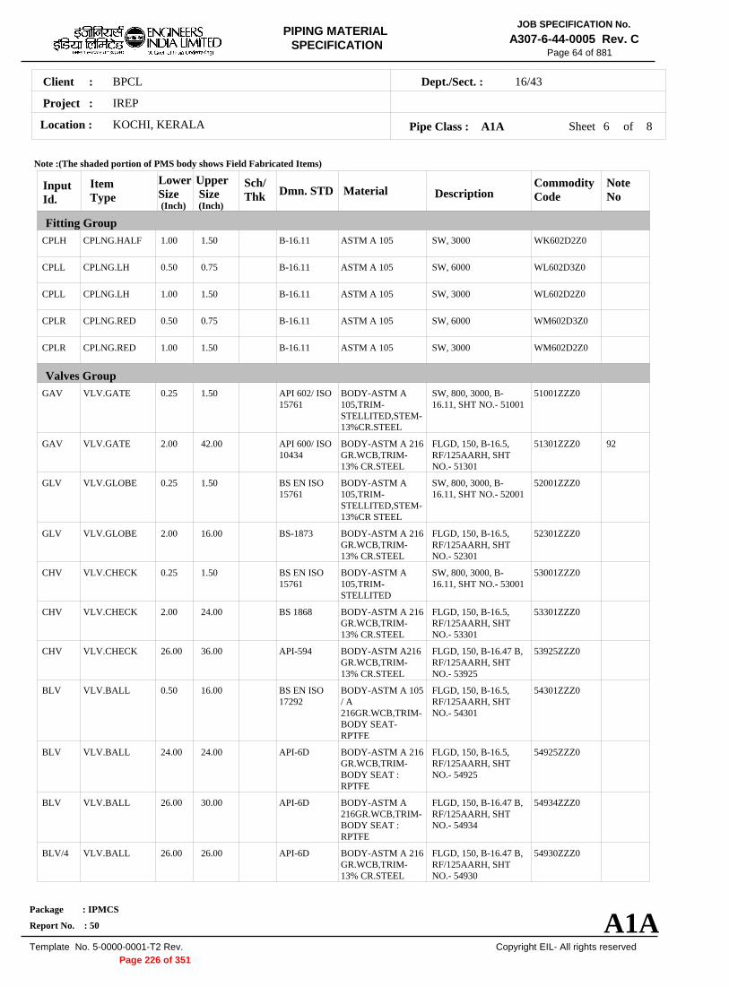
JOB SPECIFICATION No.PIPING MATERIALA307-6-44-0005 Rev. CSPECIFICATION
Page 64 of 881
Client : BPCL 16/43Dept./Sect. :
Project : IREP
Location : KOCHI, KERALA Pipe Class : A1A Sheet 6 of 8
Note :(The shaded portion of PMS body shows Field Fabricated Items)
Input Id.
Item Type
Lower Size (Inch)
Upper Size (Inch)
Sch/ Thk Dmn. STD Material Description
Commodity Code
Note No
Fitting Group CPLH CPLNG.HALF 1.00 1.50 B-16.11 ASTM A 105 SW, 3000 WK602D2Z0
CPLL CPLNG.LH 0.50 0.75 B-16.11 ASTM A 105 SW, 6000 WL602D3Z0
CPLL CPLNG.LH 1.00 1.50 B-16.11 ASTM A 105 SW, 3000 WL602D2Z0
CPLR CPLNG.RED 0.50 0.75 B-16.11 ASTM A 105 SW, 6000 WM602D3Z0
CPLR CPLNG.RED 1.00 1.50 B-16.11 ASTM A 105 SW, 3000 WM602D2Z0
Valves Group GAV VLV.GATE 0.25 1.50 API 602/ ISO
15761 BODY-ASTM A 105,TRIMSTELLITED,STEM13%CR.STEEL
SW, 800, 3000, B16.11, SHT NO.- 51001
51001ZZZ0
GAV VLV.GATE 2.00 42.00 API 600/ ISO 10434
BODY-ASTM A 216 GR.WCB,TRIM13% CR.STEEL
FLGD, 150, B-16.5, RF/125AARH, SHT NO.- 51301
51301ZZZ0 92
GLV VLV.GLOBE 0.25 1.50 BS EN ISO 15761
BODY-ASTM A 105,TRIMSTELLITED,STEM13%CR STEEL
SW, 800, 3000, B16.11, SHT NO.- 52001
52001ZZZ0
GLV VLV.GLOBE 2.00 16.00 BS-1873 BODY-ASTM A 216 GR.WCB,TRIM13% CR.STEEL
FLGD, 150, B-16.5, RF/125AARH, SHT NO.- 52301
52301ZZZ0
CHV VLV.CHECK 0.25 1.50 BS EN ISO 15761
BODY-ASTM A 105,TRIMSTELLITED
SW, 800, 3000, B16.11, SHT NO.- 53001
53001ZZZ0
CHV VLV.CHECK 2.00 24.00 BS 1868 BODY-ASTM A 216 GR.WCB,TRIM13% CR.STEEL
FLGD, 150, B-16.5, RF/125AARH, SHT NO.- 53301
53301ZZZ0
CHV VLV.CHECK 26.00 36.00 API-594 BODY-ASTM A216 GR.WCB,TRIM13% CR.STEEL
FLGD, 150, B-16.47 B, RF/125AARH, SHT NO.- 53925
53925ZZZ0
BLV VLV.BALL 0.50 16.00 BS EN ISO 17292
BODY-ASTM A 105 / A 216GR.WCB,TRIMBODY SEATRPTFE
FLGD, 150, B-16.5, RF/125AARH, SHT NO.- 54301
54301ZZZ0
BLV VLV.BALL 24.00 24.00 API-6D BODY-ASTM A 216 GR.WCB,TRIMBODY SEAT : RPTFE
FLGD, 150, B-16.5, RF/125AARH, SHT NO.- 54925
54925ZZZ0
BLV VLV.BALL 26.00 30.00 API-6D BODY-ASTM A 216GR.WCB,TRIMBODY SEAT : RPTFE
FLGD, 150, B-16.47 B, RF/125AARH, SHT NO.- 54934
54934ZZZ0
BLV/4 VLV.BALL 26.00 26.00 API-6D BODY-ASTM A 216 GR.WCB,TRIM13% CR.STEEL
FLGD, 150, B-16.47 B, RF/125AARH, SHT NO.- 54930
54930ZZZ0
Package : IPMCS
Report No. : 50 A1A Template No. 5-0000-0001-T2 Rev. Copyright EIL- All rights reserved
Page 226 of 351

JOB SPECIFICATION No.PIPING MATERIALA307-6-44-0005 Rev. CSPECIFICATION
Page 65 of 881
Client : BPCL 16/43Dept./Sect. :
Project : IREP
Location : KOCHI, KERALA Pipe Class : A1A Sheet 7 of 8
Note :(The shaded portion of PMS body shows Field Fabricated Items)
Input Id.
Item Type
Lower Size (Inch)
Upper Size (Inch)
Sch/ Thk Dmn. STD Material Description
Commodity Code
Note No
Valves Group BLV/3 VLV.BALL 12.00 16.00 BS EN ISO
17292 BODY-ASTM A 216 GR.WCB,TRIM13% CR.STEEL
FLGD, 150, B-16.5, RF/125AARH, SHT NO.- 54933
54933ZZZ0
BLV/2 VLV.BALL 2.00 8.00 BS EN ISO 17292
BODY- ASTM A 216GR.WCB,TRIM13% CR.STEEL
FLGD, 150, B-16.5, RF/125AARH, SHT NO.- 543AA
543AAZZZ0 152
BLV/1 VLV.BALL 0.50 1.50 BS EN ISO 17292
BODY-ASTM A 105,TRIMSTELLITED,STEM13% CR.STEEL
SW, 800, 3000, B16.11, SHT NO.540AA
540AAZZZ0 152
PLV VLV.PLUG 0.50 24.00 BS-5353 BODY-ASTM A 105 / A 216GR.WCB,TRIMPLUG-HARDENED
FLGD, 150, B-16.5, RF/125AARH, SHT NO.- 55301
55301ZZZ0
PLV/1 VLV.PLUG 0.50 36.00 BS-5353 BODY-ASTM A 105 / A 216GR.WCB,TRIMPLUG-HARDENED
FLGD, 150, B-16.5, RF/125AARH, SHT NO.- 55315
55315ZZZ0 36
BFV VLV.BTRFLY 3.00 24.00 BS EN 593 BODY-ASTM A 216 GR.WCB,TRIM13% CR.STEEL
WAFL, 150, B-16.5, WAF/125AARH, SHT NO.- 56301
56301ZZZ0
BFV VLV.BTRFLY 26.00 48.00 BS EN 593 BODY-ASTM A 216 GR.WCB,TRIM13% CR.STEEL
FLGD, 150, B-16.47 B, RF/125AARH, SHT NO.- 56315
56315ZZZ0
Bolt Group BOS BOLT.STUD 0.50 48.00 B-18.2 BOLT:A193 GR.B7,
NUT:A194 GR.2H BS40404Z0
Gasket Group GAS GASKET 0.50 20.00 B-16.20
ANSI B16.5 SP.WND SS316+GRAFIL
SPIRAL, 150 GK65072Z0
GAS GASKET 22.00 22.00 B-16.20MSS-SP-44
SP.WND SS316+GRAFIL
SPIRAL, 150 GK85072Z0
GAS GASKET 24.00 24.00 B-16.20ANSI B16.5
SP.WND SS316+GRAFIL
SPIRAL, 150 GK65072Z0
GAS GASKET 26.00 48.00 B-16.20ANSI B16.47B
SP.WND SS316+GRAFIL+ I RING
SPIRAL, 150 GK56272Z0
GAS/15 00
GASKET 0.50 24.00 B-16.20ANSI B16.5
SOFT IRON OCT-RING, 1500 GK67238Z0
GAS/30 0
GASKET 26.00 48.00 B-16.20ANSI B16.47B
SP.WND SS316+GRAFIL+ I RING
SPIRAL, 300 GK56274Z0
GAS/90 0
GASKET 3.00 24.00 B-16.20ANSI B16.5
SOFT IRON OCT-RING, 900 GK67237Z0
GAS/60 0
GASKET 0.50 24.00 B-16.20ANSI B16.5
SP.WND SS316+GRAFIL
SPIRAL, 600 GK65076Z0
GAS/30 0
GASKET 0.50 24.00 B-16.20ANSI B16.5
SP.WND SS316+GRAFIL
SPIRAL, 300 GK65074Z0
Package : IPMCS
Report No. : 50 A1A Template No. 5-0000-0001-T2 Rev. Copyright EIL- All rights reserved
Page 227 of 351

JOB SPECIFICATION No.PIPING MATERIALA307-6-44-0005 Rev. CSPECIFICATION
Page 66 of 881
Client : BPCL 16/43Dept./Sect. :
Project : IREP
Location : KOCHI, KERALA Pipe Class : A1A Sheet 8 of 8
Note :(The shaded portion of PMS body shows Field Fabricated Items)
Input Id.
Item Type
Lower Size (Inch)
Upper Size (Inch)
Sch/ Thk Dmn. STD Material Description
Commodity Code
Note No
Trap/Strainer Group TRP TRAP.STEAM 0.50 1.50 MNF'STD B:A105;T:13%CR;S:
SS304 FLGD, THRMDNMC, 150,RF/125AARH
TR3065530
TSR STRNR.TEMP 1.50 24.00 EIL'STD B:A516GR.70;INT:S S304
CONETYPE, 150,FF/125AARH
ST16831Z0
PSR STRNR.PERM 0.50 1.50 MNF'STD B:A105;INT:SS304 SW, Y-TYPE, 800 SP303D510
PSR STRNR.PERM 2.00 14.00 M EIL'STD B:A234GR.WPB;IN T:SS304
BW, T-TYPE SP13344Z0
PSR STRNR.PERM 16.00 24.00 M EIL'STD B:A234GR.WPBW;I NT:SS304
BW, T-TYPE SP13644Z0
PSR STRNR.PERM 26.00 30.00 M MNF'STD B:A234GR.WPBW;I NT:SS304
BW, T-TYPE SP33644Z0
Package : IPMCS
Report No. : 50 A1A Template No. 5-0000-0001-T2 Rev. Copyright EIL- All rights reserved
Page 228 of 351

JOB SPECIFICATION No.PIPING MATERIALA307-6-44-0005 Rev. CSPECIFICATION
Page 295 of 881
Client : BPCL 16/43Dept./Sect. :
Project : IREP
Location : KOCHI, KERALA Pipe Class : A91A Sheet 1 of 9
PIPE CLASS : A91A RATING : 150
BASE MATERIAL : CARBON STEEL
CORROSION ALLOWANCE : 1.5 MM
SPECIAL REQUIREMENT :
TEMPERATURE (Deg. C) AND PRESSURE ( Kg/Sq. cm g ) RATINGS
TEMP 7.6
0
7.6
38
7.6
50
7.6
65
PRESS
SERVICE CATEGORY 'D' FLUID-A/G & U/G COOLING WATER, U/G BEARING COOLING WATER RETURN, CONSTRUCTION WATER, PRESSURISED CRWS (A/G & U/G ) - UPTO 24".
NOTES 6 FOR FABRICATED REDUCERS,REFER EIL'STD 7-44-0485 & 7-44-0487. FOR MITRES, REFER EIL'STD 7-44-0033.
64 AWWA C207 CL.D FLANGES SHALL BE OF HUB TYPE.
65 FORGINGS ARE ACCEPTABLE IN LIEU OF PLATE MATERIAL FOR BLIND FLANGES AND SPACER & BLINDS.
77 FOR SIZES > 24", SPACER & BLIND SHALL BE DESIGNED BY THE MANUFACTURER AS PER ASME B31.3.
86 BUTTERFLY VALVES FOR THE SPEC ARE PN10 RATED WITH A MAXIMUM PRESSURE OF 10.2 KG/CM2G.
104 FOR PERMANENT AND TEMPORARY T-TYPE BW STRAINERS REFER EIL STD 7-44-0303 AND 7-44-0304
105 USE 5-PIECE 90 DEG. MITRE FOR SIZES FROM 16" TO 42" , 6-PIECE 90 DEG. MITRE FOR SIZES 44" TO 62" & 7-PIECE 90 DEG. MITRE FOR SIZES 64" TO 84". 45 DEG. MITRE SHALL REQUIRE ONE PIECE LESS.
106 FOR UNDERGROUND PIPING, PIPE WALL THICKNESSES ARE CALCULATED BASED ON SOIL PARAMETERS AND BURIAL DEPTH OF 600 MM TO 1500 MM FOR SIZES UPTO 30" AND 600MM TO 1200 MM FOR SIZES ABOVE 30".
151 NDT REQUIREMENT SHALL BE AS PER JOB SPECIFICATION A307-6-44-0016.
152 FIRST ISOLATION VALVE ON ALL FLOW, PRESSURE AND LEVEL TAPPINGS SHALL BE METAL TO METAL SEATED BALL VALVE.
197 BRANCH CONNECTION FOR SIZES ABOVE 72" SHALL BE WITH HALF COUPLING FOR BRANCHES UP TO 1.5", PIPE TO PIPE WITH REINFORCEMENT PAD FOR 2" AND ABOVE BRANCHES.
198 ASTM A 516 GR.70 MATERIAL IS ALSO ACCEPTABLE IN PLACE OF ASTM A 285 GR.C
199 BLIND FLANGES AND SPACER & BLINDS SPECIFIED TO MANUFACTURER'S STANDARD SHALL BE DESIGNED FOR 65 DEG.C AND 7.6 KG/CM2G TO SUIT 150#, FF, 125AARH, AWWA C207 CL.D FLANGES.
Package : IPMCS
Report No. : 50 A91A Template No. 5-0000-0001-T2 Rev. Copyright EIL- All rights reserved
Page 229 of 351

JOB SPECIFICATION No.PIPING MATERIALA307-6-44-0005 Rev. CSPECIFICATION
Page 296 of 881
Client : BPCL 16/43Dept./Sect. :
Project : IREP
Location : KOCHI, KERALA Pipe Class : A91A Sheet 2 of 9
SPECIAL NOTES
ITEM SIZE DESCRIPTION A.CODE MAINTAINENCE JOINTS
ALL FLANGED, TO BE KEPT MINIMUM
PIPE JOINTS 1.5" & BELOW SW COUPLING 3000 LBS.
2.0" & ABOVE BUTTWELDED
DRAINS ON LINES <= 1.5" REFER EILSTD 7-44-350, DF3
ON LINES >= 2.0" 0.75" OR AS PER P&ID. REFER EIL STD. 7-44-351, D4
VENTS ON LINES <= 1.5" REFER EIL STD. 7-44-350, VC1
ON LINES >= 2.0" 0.75" OR AS PER P&ID. REFER EIL STD 7-44-351, V3
TEMP.CONN 1.5" FLANGED. REFER EIL STD 7-44-353
PRESS.CONN 0.75" SW, SH HVY NIPPLE WITH VALVE TO SPEC AS PER EIL STD 7-44354
Package : IPMCS
Report No. : 50
Template No. 5-0000-0001-T2 Rev. Copyright EIL- All rights reserved Page 230 of 351

JOB SPECIFICATION No.PIPING MATERIALA307-6-44-0005 Rev. CSPECIFICATION
Page 297 of 881
Client : BPCL 16/43Dept./Sect. :
Project : IREP
Location : KOCHI, KERALA Pipe Class : A91A Sheet 3 of 9
BR
AN
CH
PIP
E (
SIZ
E I
N I
NC
HE
S)
72.70. 68. 66. 64. 62. 60. 58. 56. 54. 52. 50. 48. 46. 44. 42. 40. 38. 36. 34. 32. 30. 28. 26. 24. 22. 20. 18. 16. 14. 12. 10. 8.0 6.0 5.0 4.0 3.5 3.0 2.5 2.0 1.5
1.25 1.0
0.75 0.5
T T R
T R R T R R R
T R R R R T R R R R R
T R R R R R R T R R R R R R R
T R R R R R R R R T R R R R R R R R R
T R R R R R R R R R R T R R R R R R R R R R R
T R R R R R R R R R R R R T R R R R R R R R R R R R R
T R R R R R R R R R R R R R R T R R R R R R R R R R R R R R R
T R R R R R R R R R R R R R R R R T R R R R R R R R R R R R R R R R R
T R R R R R R R R R R R R R R R R R R T R R R R R R R R R R R R R R R R R R R
T R R R R R R R R R R R R R R R R R R R R T R R R R R R R R R R R R R R R R R R R R R
T R R R R R R R R R R R R R R R R R R R R R R T R R R R R R R R R R R R R R R R R R R R R R R
T R R R R R R R R R R R R R R R R R R R R R R R R T R R R R R R R R R R R R R R R R R R R R R R R R R
T R R R R R R R R R R R R R R R R R R R R R R R R R R T R R R R R R R R R R R R R R R R R R R R R R R R R R R
T R R R R R R R R R R R R R R R R R R R R R R R R R R R R T R R R R R R R R R R R R R R R R R R R R R R R R R R R R R
T R R R R R R R R R R R R R R R R R R R R R R R R R R R R R R
T P R R R R R R R R R R R R R R R R R R R R R R R R R R R R R R
T P P R R R R R R R R R R R R R R R R R R R R R R R R R R R R R R T T H H H H H H H H H H H H H H H H H H H H H H H H H H H H H H H H
H H H H H H H H H H H H H H H H H H H H H H H H H H H H H T T H H H H H H H H H H H H H H H H H H H H H H H H H H H H H H H H H
T T T H H H H H H H H H H H H H H H H H H H H H H H H H H H H H H H H H T T T T H H H H H H H H H H H H H H H H H H H H H H H H H H H H H H H H H
.500
.750
1.00
0
1.25
0
1.50
0
2.00
0
2.50
0
3.00
0
3.50
0
4.00
0
5.00
0
6.00
0
8.00
0
10.0
00
12.0
00
14.0
00
16.0
00
18.0
00
20.0
00
22.0
00
24.0
00
26.0
00
28.0
00
30.0
00
32.0
00
34.0
00
36.0
00
38.0
00
40.0
00
42.0
00
44.0
00
46.0
00
48.0
00
50.0
00
52.0
00
54.0
00
56.0
00
58.0
00
60.0
00
62.0
00
64.0
00
66.0
00
RUN PIPE (SIZE IN INCHES)
CODE DESCRIPTION
F SADDLE FUSED JT T TEES J THREADOLET
H H. COUPLING W WELDOLETS
P PIPE TO PIPE I INSTRUMENT TEE
R REINFORCED X Refer Notes
S SOCKOLETS L SWEEPOLET
Package : IPMCS
Report No. : 50 A91A Template No. 5-0000-0001-T2 Rev. Copyright EIL- All rights reserved
Page 231 of 351

JOB SPECIFICATION No.PIPING MATERIALA307-6-44-0005 Rev. CSPECIFICATION
Page 298 of 881
Client : BPCL Dept./Sect. : 16/43
Project : IREP
Location : KOCHI, KERALA Pipe Class : A91A Sheet 4 of 9
TT R
T R R R R R R R R R R R R R R R R R R R R R R R R R R R R R R R R R R R R R R R R R R R R R R R R R R R R R R R R R R R R R R R R R R R R
R R R R R R R R R R R R R R R R R R R R R R R R
R R R
R R R
R R R H H H H H H H H H H H H H H H
68.0
00
70.0
00
72.0
00
72. 70. 68. 66. 64. 62. 60. 58. 56. 54. 52. 50. 48. 46. 44. 42. 40. 38. 36. 34. 32. 30. 28. 26. 24. 22. 20. 18. 16. 14. 12. 10. 8.0 6.0 5.0 4.0 3.5 3.0 2.5 2.0 1.5 1.25 1.0 0.75 0.5
BR
AN
CH
PIP
E (SIZ
E IN
INC
HE
S)
Package : IPMCS
Report No. : 50 A91A Template No. 5-0000-0001-T2 Rev. Copyright EIL- All rights reserved
Page 232 of 351

JOB SPECIFICATION No.PIPING MATERIALA307-6-44-0005 Rev. CSPECIFICATION
Page 299 of 881
Client : BPCL 16/43Dept./Sect. :
Project : IREP
Location : KOCHI, KERALA Pipe Class : A91A Sheet 5 of 9
Note :(The shaded portion of PMS body shows Field Fabricated Items)
Input Id.
Item Type
Lower Size (Inch)
Upper Size (Inch)
Sch/ Thk Dmn. STD Material Description
Commodity Code
Note No
Pipe Group PIP PIPE 0.50 1.50 HVY IS-1239-I IS-1239 (BLACK) PE, C.WELDED PI6D471Z0
PIP PIPE 2.00 6.00 HVY IS-1239-I IS-1239 (BLACK) BE, C.WELDED PI6D411Z0
PIP PIPE 8.00 18.00 6.0 IS-3589 IS-3589 GR.330 BE, WELDED PI7D919Z0
PIP PIPE 20.00 26.00 8.0 IS-3589 IS-3589 GR.330 BE, WELDED PI7D919Z0
PIP PIPE 28.00 34.00 10.0 IS-3589 IS-3589 GR.330 BE, WELDED PI7D919Z0
PIP PIPE 36.00 44.00 12.0 IS-3589 IS-3589 GR.330 BE, WELDED PI7D919Z0
PIP PIPE 46.00 56.00 14.0 IS-3589 IS-3589 GR.330 BE, WELDED PI7D919Z0
PIP PIPE 60.00 68.00 16.0 IS-3589 IS-3589 GR.330 BE, WELDED PI7D919Z0
PIP PIPE 70.00 76.00 18.0 IS-3589 IS-3589 GR.330 BE, WELDED PI7D919Z0
PIP PIPE 80.00 82.00 19.0 IS-3589 IS-3589 GR.330 BE, WELDED PI7D919Z0
PIP PIPE 84.00 84.00 20.0 IS-3589 IS-3589 GR.330 BE, WELDED PI7D919Z0
NIP NIPPLE 0.50 1.50 M IS-1239-I IS-1239 (BLACK) PBE, C.WELDED PN6D461Z0
Flange Group FLG FLNG.SW 0.50 1.50 M B-16.5 ASTM A 105 150, RF/125AARH FSC0127Z0
FLG/600 FLNG.SW 0.50 1.50 M B-16.5 ASTM A 105 600, RF/125AARH FSC0167Z0
FLG/300 FLNG.SW 0.50 1.50 M B-16.5 ASTM A 105 300, RF/125AARH FSC0147Z0
FLG/300 FLNG.WN 28.00 28.00 M B-16.47-B ASTM A 105 300, RF/125AARH FWB0147Z0
FLG/600 FLNG.WN 2.00 24.00 M B-16.5 ASTM A 105 600, RF/125AARH FWC0167Z0
FLG/300 FLNG.WN 2.00 24.00 M B-16.5 ASTM A 105 300, RF/125AARH FWC0147Z0
FLG FLNG.SO 2.00 24.00 B-16.5 ASTM A 105 150, RF/125AARH FNC0127Z0
FLG FLNG.SO 26.00 84.00 AWWA-C207 CL.D
ASTM A 105 150, FF/125AARH FN40121Z0
FLB FLNG.BLIND 0.50 24.00 B-16.5 ASTM A 105 150, RF/125AARH FBC0127Z0
FLB FLNG.BLIND 26.00 54.00 AWWA-C207 CL.D
ASTM A 285 GR.C 150, FF/125AARH FB45321Z0
FLB FLNG.BLIND 56.00 56.00 MNF'STD ASTM A 285 GR.C 150, FF/125AARH FBG5321Z0
Package : IPMCS
Report No. : 50 A91A Template No. 5-0000-0001-T2 Rev. Copyright EIL- All rights reserved
Page 233 of 351

JOB SPECIFICATION No.PIPING MATERIALA307-6-44-0005 Rev. CSPECIFICATION
Page 300 of 881
Client : BPCL Dept./Sect. : 16/43
Project : IREP
Location : KOCHI, KERALA Pipe Class : A91A Sheet 6 of 9
Note :(The shaded portion of PMS body shows Field Fabricated Items)
Input Id.
Item Type
Lower Size
Upper Size
Sch/ Thk DescriptionMaterial
Commodity Code
Note No
Flange Group
Fitting Group
Dmn. STD (Inch) (Inch)
FLB
FLB
FEF
FEF
FEF
ELB90
ELB90
ELB90
ELB45
ELB45
ELB45
MIT90
MIT45
TEQ
TEQ
TEQ
TEQ
TRED
TRED
TRED
TRED
REDC
REDC
FLNG.BLIND
FLNG.BLIND
FLNG.FIG.8
SPCR&BLND
SPCR&BLND
ELBOW.90
ELBOW.90
ELBOW.90
ELBOW.45
ELBOW.45
ELBOW.45
MITRE.90
MITRE.45
T.EQUAL
T.EQUAL
T.EQUAL
T.EQUAL
T.RED
T.RED
T.RED
T.RED
REDUC.CONC
REDUC.CONC
60.00
74.00
0.50
10.00
26.00
0.50
2.00
8.00
0.50
2.00
8.00
16.00
16.00
0.50
2.00
8.00
56.00
0.50
2.00
8.00
56.00
2.00
8.00
72.00
84.00
8.00
24.00
84.00
1.50
6.00
14.00
1.50
6.00
14.00
84.00
84.00
1.50
6.00
48.00
56.00
1.50
6.00
48.00
56.00
6.00
14.00
STD
M
STD
M
M
M
STD
M
M
STD, STD
M, M
M, M
STD, STD
M, M
150, FF/125AARH
150, FF/125AARH
150, FF/125AARH
150, FF/125AARH
150, FF/125AARH
SW, 3000
BW, 1.5D
BW, 1.5D
SW, 3000
BW, 1.5D
BW, 1.5D
BW, 1.5D
BW, 1.5D
SW, 3000
BW
BW
BW
SW, 3000
BW
BW
BW
BW
BW
ASTM A 285 GR.C
ASTM A 285 GR.C
ASTM A 105
ASTM A 105
ASTM A 285 GR.C
ASTM A 105
ASTM A 234 GR.WPB
ASTM A 234 GR.WPB-W
ASTM A 105
ASTM A 234 GR.WPB
ASTM A 234 GR.WPB-W
IS-3589 GR.330
IS-3589 GR.330
ASTM A 105
ASTM A 234 GR.WPB
ASTM A 234 GR.WPB-W
ASTM A 234 GR.WPB-W
ASTM A 105
ASTM A 234 GR.WPB
ASTM A 234 GR.WPB-W
ASTM A 234 GR.WPB-W
ASTM A 234 GR.WPB
ASTM A 234 GR.WPB-W
FB45321Z0
FBG5321Z0
FGK0121Z0
FCK0121Z0
FCG5321Z0
WA602D2Z0
WAG684Z10
WAG754Z10
WB602D2Z0
WBG684Z10
WBG754Z10
WDKF141Z0
WGKF141Z0
WE602D2Z0
WEG684ZZ0
WEG754ZZ0
WEN754ZZ0
WR602D2Z0
WRG684ZZ0
WRG754ZZ0
WRN754ZZ0
WUG684ZZ0
WUG754ZZ0
AWWA-C207 CL.D
MNF'STD
ASMEB16.48
ASMEB16.48
MNF'STD
B-16.11
B-16.9
B-16.9
B-16.11
B-16.9
B-16.9
EIL'STD
EIL'STD
B-16.11
B-16.9
B-16.9
MNF'STD
B-16.11
B-16.9
B-16.9
MNF'STD
B-16.9
B-16.9
Package : IPMCS
Report No. : 50 A91A Template No. 5-0000-0001-T2 Rev. Copyright EIL- All rights reserved
Page 234 of 351

JOB SPECIFICATION No.PIPING MATERIALA307-6-44-0005 Rev. CSPECIFICATION
Page 301 of 881
Client : BPCL 16/43Dept./Sect. :
Project : IREP
Location : KOCHI, KERALA Pipe Class : A91A Sheet 7 of 9
Note :(The shaded portion of PMS body shows Field Fabricated Items)
Input Id.
Item Type
Lower Size (Inch)
Upper Size (Inch)
Sch/ Thk Dmn. STD Material Description
Commodity Code
Note No
Fitting Group REDC REDUC.CONC 16.00 84.00 M, M EIL'STD IS-3589 GR.330 BW WUKF14ZZ0
REDE REDUC.ECC 2.00 6.00 STD, STD
B-16.9 ASTM A 234 GR.WPB
BW WVG684ZZ0
REDE REDUC.ECC 8.00 14.00 M, M B-16.9 ASTM A 234 GR.WPB-W
BW WVG754ZZ0
REDE REDUC.ECC 16.00 84.00 M, M EIL'STD IS-3589 GR.330 BW WVKF14ZZ0
SWGC SWAGE.CONC 0.50 3.00 STD, STD
BS-3799 ASTM A 105 PBE WNH026ZZ0
SWGE SWAGE.ECC 0.50 3.00 STD, STD
BS-3799 ASTM A 105 PBE WPH026ZZ0
CAP CAP 0.50 1.50 B-16.11 ASTM A 105 SCRF, 3000 WF60282Z0
CAP CAP 2.00 6.00 STD B-16.9 ASTM A 234 GR.WPB
BW WFG684ZZ0
CAP CAP 8.00 48.00 M B-16.9 ASTM A 234 GR.WPB
BW WFG684ZZ0
CAP CAP 50.00 84.00 M ASME-VIII ASTM A 285 GR.C BW WF3J54ZZ0
PLG PLUG 0.50 1.50 B-16.11 ASTM A 105 SCRM, 3000 WH60292Z0
CPLF CPLNG.FULL 0.50 1.50 B-16.11 ASTM A 105 SW, 3000 WJ602D2Z0
CPLH CPLNG.HALF 0.50 1.50 B-16.11 ASTM A 105 SW, 3000 WK602D2Z0
CPLL CPLNG.LH 0.50 1.50 B-16.11 ASTM A 105 SW, 3000 WL602D2Z0
CPLR CPLNG.RED 0.50 1.50 B-16.11 ASTM A 105 SW, 3000 WM602D2Z0
UNN UNION 0.50 1.50 BS-3799 ASTM A 105 SW, 3000 WQH02D2Z0
Valves Group GAV VLV.GATE 0.25 1.50 API 602/ ISO
15761 BODY-ASTM A 105,TRIMSTELLITED,STEM13%CR.STEEL
SW, 800, 3000, B16.11, SHT NO.- 51001
51001ZZZ0
GAV VLV.GATE 2.00 24.00 API 600/ ISO 10434
BODY-ASTM A 216 GR.WCB,TRIM13% CR.STEEL
FLGD, 150, B-16.5, RF/125AARH, SHT NO.- 51321
51321ZZZ0
GLV VLV.GLOBE 0.25 1.50 BS EN ISO 15761
BODY-ASTM A 105,TRIMSTELLITED,STEM13%CR STEEL
SW, 800, 3000, B16.11, SHT NO.- 52001
52001ZZZ0
GLV VLV.GLOBE 2.00 16.00 BS-1873 BODY-ASTM A 216 GR.WCB,TRIM13% CR.STEEL
FLGD, 150, B-16.5, RF/125AARH, SHT NO.- 52321
52321ZZZ0
Package : IPMCS
Report No. : 50 A91A Template No. 5-0000-0001-T2 Rev. Copyright EIL- All rights reserved
Page 235 of 351
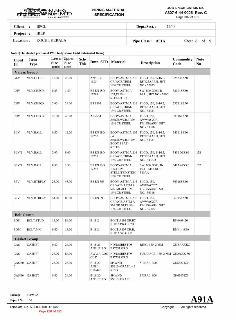
JOB SPECIFICATION No.PIPING MATERIALA307-6-44-0005 Rev. CSPECIFICATION
Page 302 of 881
Client : BPCL 16/43Dept./Sect. :
Project : IREP
Location : KOCHI, KERALA Pipe Class : A91A Sheet 8 of 9
Note :(The shaded portion of PMS body shows Field Fabricated Items)
Input Id.
Item Type
Lower Size (Inch)
Upper Size (Inch)
Sch/ Thk Dmn. STD Material Description
Commodity Code
Note No
Valves Group GLV VLV.GLOBE 18.00 20.00 ANSI-B
16.34 BODY-ASTM A 216 GR.WCB,TRIM13% CR.STEEL
FLGD, 150, B-16.5, RF/125AARH, SHT NO.- 52923
52923ZZZ0
CHV VLV.CHECK 0.25 1.50 BS EN ISO 15761
BODY-ASTM A 105,TRIMSTELLITED
SW, 800, 3000, B16.11, SHT NO.- 53001
53001ZZZ0
CHV VLV.CHECK 2.00 24.00 BS 1868 BODY-ASTM A 216 GR.WCB,TRIM13% CR.STEEL
FLGD, 150, B-16.5, RF/125AARH, SHT NO.- 53321
53321ZZZ0
CHV VLV.CHECK 26.00 48.00 API-594 BODY-ASTM A 216GR.WCB,TRIM13% CR.STEEL
FLGD, 150, AWWAC207, FF/125AARH, SHT NO.- 53316
53316ZZZ0
BLV VLV.BALL 0.50 16.00 BS EN ISO 17292
BODY-ASTM A 105 / A 216GR.WCB,TRIMBODY SEATRPTFE
FLGD, 150, B-16.5, RF/125AARH, SHT NO.- 54321
54321ZZZ0
BLV/2 VLV.BALL 2.00 8.00 BS EN ISO 17292
BODY-ASTM A 216 GR.WCB,TRIM13% CR.STEEL
FLGD, 150, B-16.5, RF/125AARH, SHT NO.- 543BD
543BDZZZ0 152
BLV/1 VLV.BALL 0.50 1.50 BS EN ISO 17292
BODY-ASTM A 105,TRIMSTELLITED,STEM13% CR.STEEL
SW, 800, 3000, B16.11, SHT NO.540AA
540AAZZZ0 152
BFV VLV.BTRFLY 26.00 48.00 BS EN 593 BODY-ASTM A 216 GR.WCB/ASTM A 516 GR.70,TRIM13% CR.STEEL
FLGD, 150, AWWAC207, FF/125AARH, SHT NO.- 56316
56316ZZZ0
BFV VLV.BTRFLY 54.00 80.00 BS EN 593 BODY-ASTM A 216 GR.WCB/ASTM A 516 GR.70,TRIM13% CR.STEEL
FLGD, 150, AWWAC207, FF/125AARH, SHT NO.- 56395
56395ZZZ0
Bolt Group BOS BOLT.STUD 18.00 84.00 B-18.2 BOLT:A193 GR.B7,
NUT:A194 GR.2H BS40404Z0
BOM BOLT.M/C 0.50 16.00 B-18.2 BOLT:A307 GR.B, NUT:A563 GR.B
BM41418Z0
Gasket Group GAS GASKET 0.50 24.00 B-16.21
ANSI B16.5 NONASBESTOS BS7531 GR X
RING, 150, 2 MM GKBAX52Z0
GAS GASKET 26.00 84.00 AWWA-C207 CL.D
NONASBESTOS BS7531 GR X
FULLFACE, 150, 2 MM GK2AX22Z0
GAS/30 0
GASKET 28.00 28.00 B-16.20ANSI B16.47B
SP.WND SS316+GRAFIL+ I RING
SPIRAL, 300 GK56274Z0
GAS/60 0
GASKET 0.50 24.00 B-16.20ANSI B16.5
SP.WND SS316+GRAFIL
SPIRAL, 600 GK65076Z0
Package : IPMCS
Report No. : 50 A91A Template No. 5-0000-0001-T2 Rev. Copyright EIL- All rights reserved
Page 236 of 351

JOB SPECIFICATION No.PIPING MATERIALA307-6-44-0005 Rev. CSPECIFICATION
Page 303 of 881
Client : BPCL 16/43Dept./Sect. :
Project : IREP
Location : KOCHI, KERALA Pipe Class : A91A Sheet 9 of 9
Note :(The shaded portion of PMS body shows Field Fabricated Items)
Input Id.
Item Type
Lower Size (Inch)
Upper Size (Inch)
Sch/ Thk Dmn. STD Material Description
Commodity Code
Note No
Gasket Group GAS/30 0
GASKET 0.50 24.00 B-16.20ANSI B16.5
SP.WND SS316+GRAFIL
SPIRAL, 300 GK65074Z0
Trap/Strainer Group PSR STRNR.PERM 0.50 1.50 MNF'STD B:A105;INT:SS304 SW, Y-TYPE, 800 SP303D510
PSR STRNR.PERM 2.00 6.00 STD EIL'STD B:A234GR.WPB;IN T:SS304
BW, T-TYPE SP13344Z0 104
PSR STRNR.PERM 8.00 24.00 M EIL'STD B:A234GR.WPBW;I NT:SS304
BW, T-TYPE SP13644Z0 104
PSR STRNR.PERM 26.00 54.00 M MNF'STD B:A234GR.WPBW;I NT:SS304
BW, T-TYPE SP33644Z0
Package : IPMCS
Report No. : 50 A91A Template No. 5-0000-0001-T2 Rev. Copyright EIL- All rights reserved
Page 237 of 351

JOB SPECIFICATION No.PIPING MATERIALA307-6-44-0005 Rev. CSPECIFICATION
Page 304 of 881
Client : BPCL 16/43Dept./Sect. :
Project : IREP
Location : KOCHI, KERALA Pipe Class : A92A Sheet 1 of 6
PIPE CLASS : A92A RATING : 150
BASE MATERIAL : CARBON STEEL
CORROSION ALLOWANCE : 3 MM
SPECIAL REQUIREMENT :
TEMPERATURE (Deg. C) AND PRESSURE ( Kg/Sq. cm g ) RATINGS
TEMP 15.6
0
15.6
38
15.6
50
15.6
65
PRESS
SERVICE RAW WATER / SERVICE WATER
NOTES 5 FOR PERMANENT 'T' TYPE BW STRAINERS,REFER EIL'STD 7-44-0303 & 7-44-0304; AND FOR TEMPORARY
STRAINERS,REFER EIL'STD 7-44-0300; FOR SPACER AND BLIND REFER EIL'STD 7-44-0162. 65 FORGINGS ARE ACCEPTABLE IN LIEU OF PLATE MATERIAL FOR BLIND FLANGES AND SPACER & BLINDS.
106 FOR UNDERGROUND PIPING, PIPE WALL THICKNESSES ARE CALCULATED BASED ON SOIL PARAMETERS AND BURIAL DEPTH OF 600 MM TO 1500 MM FOR SIZES UPTO 30" AND 600MM TO 1200 MM FOR SIZES ABOVE 30".
151 NDT REQUIREMENT SHALL BE AS PER JOB SPECIFICATION A307-6-44-0016.
152 FIRST ISOLATION VALVE ON ALL FLOW, PRESSURE AND LEVEL TAPPINGS SHALL BE METAL TO METAL SEATED BALL VALVE.
198 ASTM A 516 GR.70 MATERIAL IS ALSO ACCEPTABLE IN PLACE OF ASTM A 285 GR.C
SPECIAL NOTES
ITEM SIZE DESCRIPTION A.CODE MAINTAINENCE JOINTS
ALL FLANGED, TO BE KEPT MINIMUM
PIPE JOINTS 1.5" & BELOW SW COUPLING
2.0" & ABOVE BUTTWELDED
DRAINS ON LINES <= 1.5" REFER EILSTD 7-44-0350, DF3
ON LINES >= 2.0" AS PER P&ID OR 0.75". REFER EIL STD. 7-44-0351, D4
VENTS ON LINES <= 1.5" REFER EIL STD. 7-44-0350, VC1
ON LINES >= 2.0" AS PER P&ID OR 0.75". REFER EIL STD 7-44-0351, V1
TEMP.CONN 1.5" FLANGED. REFER EIL STD 7-44-0353
PRESS.CONN 0.75" SW NIPPLE WITH VALVE TO SPEC AS PER EIL STD 7-44-0354
Package : IPMCS
Report No. : 50 A92A Template No. 5-0000-0001-T2 Rev. Copyright EIL- All rights reserved
Page 238 of 351
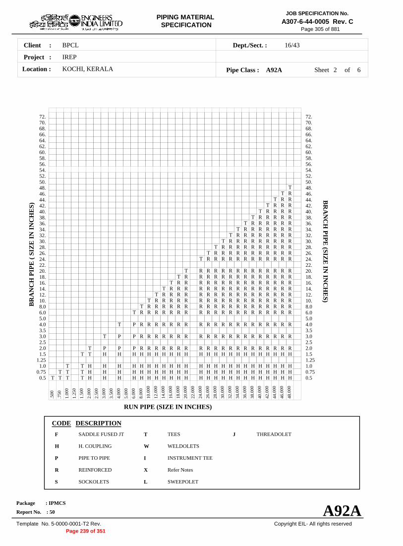
JOB SPECIFICATION No.PIPING MATERIALA307-6-44-0005 Rev. CSPECIFICATION
Page 305 of 881
Client : BPCL 16/43Dept./Sect. :
Project : IREP
Location : KOCHI, KERALA Pipe Class : A92A Sheet 2 of 6
72.
T T R
T R R T R R R
T R R R R T R R R R R
T R R R R R R T R R R R R R R
T R R R R R R R R T R R R R R R R R R
T R R R R R R R R R R T R R R R R R R R R R R
T R R R R R R R R R R R R
T R R R R R R R R R R R R R T R R R R R R R R R R R R R R
T R R R R R R R R R R R R R R R T R R R R R R R R R R R R R R R R
T R R R R R R R R R R R R R R R R R T R R R R R R R R R R R R R R R R R R
T R R R R R R R R R R R R R R R R R R R T R R R R R R R R R R R R R R R R R R R R
T P R R R R R R R R R R R R R R R R R R R R
T P P R R R R R R R R R R R R R R R R R R R R
T P P P R R R R R R R R R R R R R R R R R R R R T T H H H H H H H H H H H H H H H H H H H H H H H
T T H H H H H H H H H H H H H H H H H H H H H H H H T T T H H H H H H H H H H H H H H H H H H H H H H H H
T T T T H H H H H H H H H H H H H H H H H H H H H H H H
.500
.750
1.00
0
1.25
0
1.50
0
2.00
0
2.50
0
3.00
0
3.50
0
4.00
0
5.00
0
6.00
0
8.00
0
10.0
00
12.0
00
14.0
00
16.0
00
18.0
00
20.0
00
22.0
00
24.0
00
26.0
00
28.0
00
30.0
00
32.0
00
34.0
00
36.0
00
38.0
00
40.0
00
42.0
00
44.0
00
46.0
00
48.0
00
72. 70. 70. 68. 68. 66. 66. 64. 64. 62. 62. 60. 60. 58. 58. 56. 56. 54. 54. 52. 52. 50. 50. 48. 48. 46. 46. 44. 44. 42. 42. 40. 40. 38. 38. 36. 36. 34. 34. 32. 32. 30. 30. 28. 28. 26. 26. 24. 24. 22. 22. 20. 20. 18. 18. 16. 16. 14. 14. 12. 12. 10. 10. 8.0 8.0 6.0 6.0 5.0 5.0 4.0 4.0 3.5 3.5 3.0 3.0 2.5 2.5 2.0 2.0 1.5 1.5
1.25 1.25 1.0 1.0
0.75 0.75 0.5 0.5
BR
AN
CH
PIP
E (
SIZ
E I
N I
NC
HE
S) B
RA
NC
H P
IPE
(SIZE
IN IN
CH
ES)
RUN PIPE (SIZE IN INCHES)
CODE DESCRIPTION
F SADDLE FUSED JT T TEES J THREADOLET
H H. COUPLING W WELDOLETS
P PIPE TO PIPE I INSTRUMENT TEE
R REINFORCED X Refer Notes
S SOCKOLETS L SWEEPOLET
Package : IPMCS
Report No. : 50 A92A Template No. 5-0000-0001-T2 Rev. Copyright EIL- All rights reserved
Page 239 of 351

JOB SPECIFICATION No.PIPING MATERIALA307-6-44-0005 Rev. CSPECIFICATION
Page 306 of 881
Client : BPCL 16/43Dept./Sect. :
Project : IREP
Location : KOCHI, KERALA Pipe Class : A92A Sheet 3 of 6
Note :(The shaded portion of PMS body shows Field Fabricated Items)
Input Id.
Item Type
Lower Size (Inch)
Upper Size (Inch)
Sch/ Thk Dmn. STD Material Description
Commodity Code
Note No
Pipe Group PIP PIPE 0.50 0.75 S160 B-36.10 ASTM A 106 GR.B PE, SEAMLESS PI21977Z0
PIP PIPE 1.00 1.50 XS B-36.10 ASTM A 106 GR.B PE, SEAMLESS PI21977Z0
PIP PIPE 2.00 2.00 XS B-36.10 ASTM A 106 GR.B BE, SEAMLESS PI21917Z0
PIP PIPE 3.00 6.00 STD B-36.10 ASTM A 106 GR.B BE, SEAMLESS PI21917Z0
PIP PIPE 8.00 10.00 6.0 IS-3589 IS-3589 GR.410 BE, WELDED PI7E319Z0
PIP PIPE 12.00 20.00 8.0 IS-3589 IS-3589 GR.410 BE, WELDED PI7E319Z0
PIP PIPE 24.00 30.00 10.0 IS-3589 IS-3589 GR.410 BE, WELDED PI7E319Z0
PIP PIPE 32.00 36.00 12.0 IS-3589 IS-3589 GR.410 BE, WELDED PI7E319Z0
PIP PIPE 38.00 48.00 14.0 IS-3589 IS-3589 GR.410 BE, WELDED PI7E319Z0
NIP NIPPLE 0.50 0.75 M B-36.10 ASTM A 106 GR.B PBE, SEAMLESS PN21967Z0
NIP NIPPLE 1.00 1.50 M B-36.10 ASTM A 106 GR.B PBE, SEAMLESS PN21967Z0
Flange Group FLG FLNG.SW 0.50 1.50 M B-16.5 ASTM A 105 150, RF/125AARH FSC0127Z0
FLG/300 FLNG.SW 0.50 1.50 M B-16.5 ASTM A 105 300, RF/125AARH FSC0147Z0
FLG FLNG.WN 26.00 48.00 M B-16.47-B ASTM A 105 150, RF/125AARH FWB0127Z0
FLG/300 FLNG.WN 2.00 24.00 M B-16.5 ASTM A 105 300, RF/125AARH FWC0147Z0
FLG FLNG.SO 2.00 24.00 B-16.5 ASTM A 105 150, RF/125AARH FNC0127Z0
FLB FLNG.BLIND 0.50 24.00 B-16.5 ASTM A 105 150, RF/125AARH FBC0127Z0
FLB FLNG.BLIND 26.00 48.00 B-16.47-B ASTM A 285 GR.C 150, RF/125AARH FBB5327Z0
FEF FLNG.FIG.8 0.50 8.00 ASMEB16.48
ASTM A 105 150, FF/125AARH FGK0121Z0
FEF SPCR&BLND 10.00 24.00 ASMEB16.48
ASTM A 105 150, FF/125AARH FCK0121Z0
FEF SPCR&BLND 26.00 48.00 EIL'STD ASTM A 285 GR.C 150, FF/125AARH FCE5321Z0 107
Fitting Group ELB90 ELBOW.90 0.50 0.75 B-16.11 ASTM A 105 SW, 6000 WA602D3Z0
Package : IPMCS
Report No. : 50 A92A Template No. 5-0000-0001-T2 Rev. Copyright EIL- All rights reserved
Page 240 of 351

JOB SPECIFICATION No.PIPING MATERIALA307-6-44-0005 Rev. CSPECIFICATION
Page 307 of 881
Client : BPCL 16/43Dept./Sect. :
Project : IREP
Location : KOCHI, KERALA Pipe Class : A92A Sheet 4 of 6
Note :(The shaded portion of PMS body shows Field Fabricated Items)
Input Id.
Item Type
Lower Size (Inch)
Upper Size (Inch)
Sch/ Thk Dmn. STD Material Description
Commodity Code
Note No
Fitting Group ELB90 ELBOW.90 1.00 1.50 B-16.11 ASTM A 105 SW, 3000 WA602D2Z0
ELB90 ELBOW.90 2.00 6.00 M B-16.9 ASTM A 234 GR.WPB
BW, 1.5D WAG684Z10
ELB90 ELBOW.90 8.00 48.00 M B-16.9 ASTM A 234 GR.WPB-W
BW, 1.5D WAG754Z10
ELB45 ELBOW.45 0.50 0.75 B-16.11 ASTM A 105 SW, 6000 WB602D3Z0
ELB45 ELBOW.45 1.00 1.50 B-16.11 ASTM A 105 SW, 3000 WB602D2Z0
ELB45 ELBOW.45 2.00 6.00 M B-16.9 ASTM A 234 GR.WPB
BW, 1.5D WBG684Z10
ELB45 ELBOW.45 8.00 48.00 M B-16.9 ASTM A 234 GR.WPB-W
BW, 1.5D WBG754Z10
TEQ T.EQUAL 0.50 0.75 B-16.11 ASTM A 105 SW, 6000 WE602D3Z0
TEQ T.EQUAL 1.00 1.50 B-16.11 ASTM A 105 SW, 3000 WE602D2Z0
TEQ T.EQUAL 2.00 6.00 M B-16.9 ASTM A 234 GR.WPB
BW WEG684ZZ0
TEQ T.EQUAL 8.00 48.00 M B-16.9 ASTM A 234 GR.WPB-W
BW WEG754ZZ0
TRED T.RED 0.50 0.75 B-16.11 ASTM A 105 SW, 6000 WR602D3Z0
TRED T.RED 1.00 1.50 B-16.11 ASTM A 105 SW, 3000 WR602D2Z0
TRED T.RED 2.00 6.00 M, M B-16.9 ASTM A 234 GR.WPB
BW WRG684ZZ0
TRED T.RED 8.00 48.00 M, M B-16.9 ASTM A 234 GR.WPB-W
BW WRG754ZZ0
REDC REDUC.CONC 2.00 6.00 M, M B-16.9 ASTM A 234 GR.WPB
BW WUG684ZZ0
REDC REDUC.CONC 8.00 48.00 M, M B-16.9 ASTM A 234 GR.WPB-W
BW WUG754ZZ0
REDE REDUC.ECC 2.00 6.00 M, M B-16.9 ASTM A 234 GR.WPB
BW WVG684ZZ0
REDE REDUC.ECC 8.00 48.00 M, M B-16.9 ASTM A 234 GR.WPB-W
BW WVG754ZZ0
SWGC SWAGE.CONC 0.50 3.00 M, M BS-3799 ASTM A 105 PBE WNH026ZZ0
SWGE SWAGE.ECC 0.50 3.00 M, M BS-3799 ASTM A 105 PBE WPH026ZZ0
CAP CAP 0.50 0.75 B-16.11 ASTM A 105 SCRF, 6000 WF60283Z0
CAP CAP 1.00 1.50 B-16.11 ASTM A 105 SCRF, 3000 WF60282Z0
Package : IPMCS
Report No. : 50 A92A Template No. 5-0000-0001-T2 Rev. Copyright EIL- All rights reserved
Page 241 of 351

JOB SPECIFICATION No.PIPING MATERIALA307-6-44-0005 Rev. CSPECIFICATION
Page 308 of 881
Client : BPCL 16/43Dept./Sect. :
Project : IREP
Location : KOCHI, KERALA Pipe Class : A92A Sheet 5 of 6
Note :(The shaded portion of PMS body shows Field Fabricated Items)
Input Id.
Item Type
Lower Size (Inch)
Upper Size (Inch)
Sch/ Thk Dmn. STD Material Description
Commodity Code
Note No
Fitting Group CAP CAP 2.00 48.00 M B-16.9 ASTM A 234
GR.WPB BW WFG684ZZ0
CPLF CPLNG.FULL 0.50 0.75 B-16.11 ASTM A 105 SW, 6000 WJ602D3Z0
CPLF CPLNG.FULL 1.00 1.50 B-16.11 ASTM A 105 SW, 3000 WJ602D2Z0
CPLH CPLNG.HALF 0.50 0.75 B-16.11 ASTM A 105 SW, 6000 WK602D3Z0
CPLH CPLNG.HALF 1.00 1.50 B-16.11 ASTM A 105 SW, 3000 WK602D2Z0
CPLL CPLNG.LH 0.50 0.75 B-16.11 ASTM A 105 SW, 6000 WL602D3Z0
CPLL CPLNG.LH 1.00 1.50 B-16.11 ASTM A 105 SW, 3000 WL602D2Z0
CPLR CPLNG.RED 0.50 0.75 B-16.11 ASTM A 105 SW, 6000 WM602D3Z0
CPLR CPLNG.RED 1.00 1.50 B-16.11 ASTM A 105 SW, 3000 WM602D2Z0
Valves Group GAV VLV.GATE 0.25 1.50 API 602/ ISO
15761 BODY-ASTM A 105,TRIMSTELLITED,STEM13%CR.STEEL
SW, 800, 3000, B16.11, SHT NO.- 51001
51001ZZZ0
GAV VLV.GATE 2.00 24.00 API 600/ ISO 10434
BODY-ASTM A 216 GR.WCB,TRIM13% CR.STEEL
FLGD, 150, B-16.5, RF/125AARH, SHT NO.- 51321
51321ZZZ0
GLV VLV.GLOBE 0.25 1.50 BS EN ISO 15761
BODY-ASTM A 105,TRIMSTELLITED,STEM13%CR STEEL
SW, 800, 3000, B16.11, SHT NO.- 52001
52001ZZZ0
GLV VLV.GLOBE 2.00 16.00 BS-1873 BODY-ASTM A 216 GR.WCB,TRIM13% CR.STEEL
FLGD, 150, B-16.5, RF/125AARH, SHT NO.- 52321
52321ZZZ0
CHV VLV.CHECK 0.25 1.50 BS EN ISO 15761
BODY-ASTM A 105,TRIMSTELLITED
SW, 800, 3000, B16.11, SHT NO.- 53001
53001ZZZ0
CHV VLV.CHECK 2.00 24.00 BS 1868 BODY-ASTM A 216 GR.WCB,TRIM13% CR.STEEL
FLGD, 150, B-16.5, RF/125AARH, SHT NO.- 53321
53321ZZZ0
BLV/2 VLV.BALL 2.00 8.00 BS EN ISO 17292
BODY-ASTM A 216 GR.WCB,TRIM13% CR.STEEL
FLGD, 150, B-16.5, RF/125AARH, SHT NO.- 543BD
543BDZZZ0 152
BLV/1 VLV.BALL 0.50 1.50 BS EN ISO 17292
BODY-ASTM A 105,TRIMSTELLITED,STEM13% CR.STEEL
SW, 800, 3000, B16.11, SHT NO.540AA
540AAZZZ0 152
BFV VLV.BTRFLY 26.00 36.00 BS EN 593 BODY-ASTM A 216 GR.WCB,TRIM13% CR.STEEL
FLGD, 150, B-16.47 B, RF/125AARH, SHT NO.- 56310
56310ZZZ0
Package : IPMCS
Report No. : 50 A92A Template No. 5-0000-0001-T2 Rev. Copyright EIL- All rights reserved
Page 242 of 351

JOB SPECIFICATION No.PIPING MATERIALA307-6-44-0005 Rev. CSPECIFICATION
Page 309 of 881
Client : BPCL 16/43Dept./Sect. :
Project : IREP
Location : KOCHI, KERALA Pipe Class : A92A Sheet 6 of 6
Note :(The shaded portion of PMS body shows Field Fabricated Items)
Input Id.
Item Type
Lower Size (Inch)
Upper Size (Inch)
Sch/ Thk Dmn. STD Material Description
Commodity Code
Note No
Bolt Group BOS BOLT.STUD 0.50 48.00 B-18.2 BOLT:A193 GR.B7,
NUT:A194 GR.2H BS40404Z0
Gasket Group GAS GASKET 0.50 24.00 B-16.21
ANSI B16.5 NONASBESTOS BS7531 GR X
RING, 150, 2 MM GKBAX52Z0
GAS GASKET 26.00 48.00 B-16.21ANSI B16.47B
NONASBESTOS BS7531 GR X
RING, 150, 2 MM GKAAX52Z0
GAS/30 0
GASKET 0.50 24.00 B-16.21ANSI B16.5
NONASBESTOS BS7531 GR X
RING, 300, 2 MM GKBAX54Z0
Trap/Strainer Group TSR STRNR.TEMP 1.50 24.00 EIL'STD B:A285GR.C;INT:S
S304 CONETYPE, 150,RF/125AARH
ST14433Z0
PSR STRNR.PERM 0.50 1.50 MNF'STD B:A105;INT:SS304 SW, Y-TYPE, 800 SP303D510
PSR STRNR.PERM 2.00 6.00 M EIL'STD B:A234GR.WPB;IN T:SS304
BW, T-TYPE SP13344Z0
PSR STRNR.PERM 8.00 24.00 M EIL'STD B:A234GR.WPBW;I NT:SS304
BW, T-TYPE SP13644Z0
Package : IPMCS
Report No. : 50 A92A Template No. 5-0000-0001-T2 Rev. Copyright EIL- All rights reserved
Page 243 of 351

BPCLClient :
IREP
KOCHI, KERALALocation :
16/43Dept./Sect. :
Project :
PIPING MATERIAL SPECIFICATION
Copyright EIL- All rights reserved
JOB SPECIFICATION No.
A307-6-44-0005 Rev. C
Package : IPMCS
Report No. : 50
Template No. 5-0000-0001-T2 Rev.
Page 348 of 881
B1APIPE CLASS :300RATING :CARBON STEELBASE MATERIAL : 1.5CORROSION ALLOWANCE : SPECIAL REQUIREMENT :
MM
SERVICENON CORROSIVE PROCESS - FLAMMABLE / NON FLAMMABLE, NON LETHAL - HYDROCARBONS, AROMATICS,AMMONIA, SWEET GAS, FLUSHING OIL AND OTHER UTILITIES -MP CONDENSATE, INSTRUMENT AIR, PLANT AIR,NITROGEN, AMMONIA GAS ETC. ABOVE CLASS 'A1A'.
NOTES5
7
151
152
202
251
FOR PERMANENT 'T' TYPE BW STRAINERS,REFER EIL'STD 7-44-0303 & 7-44-0304; AND FOR TEMPORARYSTRAINERS,REFER EIL'STD 7-44-0300; FOR SPACER AND BLIND REFER EIL'STD 7-44-0162.FOR RESTRICTION ON USE OF BALL,PLUG & BUTTERFLY VALVES,REFER GENERAL NOTES.
NDT REQUIREMENT SHALL BE AS PER JOB SPECIFICATION A307-6-44-0016.
FIRST ISOLATION VALVE ON ALL FLOW, PRESSURE AND LEVEL TAPPINGS SHALL BE METAL TO METAL SEATEDBALL VALVE.PIPE WALL THICKNESS IS CALCULATED BASED ON ACTUAL LINE DESIGN CONDITION ( 178 DEG. C & 45 KG/ CM2 G ) .
PIPE WALL THICKNESS IS CALCULATED BASED ON ACTUAL LINE DESIGN CONDITION (FOR 30", AT 75 DEG. C & 32.7KG/ CM2 G , FOR 26", 28" & 32", AT 110 DEG. C & 27 KG/ CM2 G , FOR 36", AT 110 DEG. C &26.7 KG/ CM2 G AND FOR42", AT 110 DEG. C & 25.7 KG/ CM2 G ) SUBJECT TO MINIMUM OF 80% CLASS RATING
SPECIAL NOTES
ITEM SIZE DESCRIPTION A.CODEMAINTAINENCEJOINTS
PIPE JOINTS
DRAINS
VENTS
TEMP.CONN
PRESS.CONN
ALL
1.5" & BELOW
2.0" & ABOVE
ON LINES <= 1.5"
ON LINES >= 2.0"
ON LINES <= 1.5"
ON LINES >= 2.0"
1.5"
0.75"
FLANGED, TO BE KEPT MINIMUM
SW COUPLING
BUTTWELDED
REFER EILSTD 7-44-0350, DF3
AS PER P&ID OR 0.75". REFER EIL STD. 7-44-0351, D4
REFER EIL STD. 7-44-0350, VF3
AS PER P&ID OR 0.75". REFER EIL STD 7-44-0351, V4
FLANGED. REFER EIL STD 7-44-0353
SW NIPPLE WITH VALVE TO SPEC AS PER EIL STD 7-44-0354
TEMP
PRESS 52.02 52.02 47.8 46.05 44.64 42.53 40.07 38.66 37.26 35.5 28.82
-29 38 93 149 204 260 316 343 371 399 427
Sheet 1 of
TEMPERATURE (Deg. C) AND PRESSURE ( Kg/Sq. cm g ) RATINGS
Pipe Class : B1A
B1A
7
Page 244 of 351

BPCLClient :
IREP
KOCHI, KERALALocation :
16/43Dept./Sect. :
Project :
PIPING MATERIAL SPECIFICATION
Copyright EIL- All rights reserved
JOB SPECIFICATION No.
A307-6-44-0005 Rev. C
Package : IPMCS
Report No. : 50
Template No. 5-0000-0001-T2 Rev.
Page 349 of 881
Sheet 2 ofPipe Class : B1A
T T T T H H H H H H H H H H H H H H H H H H0.5T T T H H H H H H H H H H H H H H H H H H0.75
T T H H H H H H H H H H H H H H H H H H1.01.25
T T H H H H H H H H H H H H H H H H H1.5T P P R R R R R R R R R R R R R R R2.0
2.5T P R R R R R R R R R R R R R R R3.0
3.5T R R R R R R R R R R R R R R R4.0
5.0T R R R R R R R R R R R R R R6.0
T R R R R R R R R R R R R R8.0T R R R R R R R R R R R R10.
T R R R R R R R R R R R12.T R R R R R R R R R R14.
T R R R R R R R R R16.T R R R R R R R R18.
T R R R R R R R20.22.
T R R R R R R24.T R R R R R26.
T R R R R28.T R R R30.
T R R32.34.
T R36.38.40.
T42.44.46.48.50.52.54.56.58.60.62.64.66.68.70.72.
.500
.750
1.0
00
1.2
50
1.5
00
2.0
00
2.5
00
3.0
00
3.5
00
4.0
00
5.0
00
6.0
00
8.0
00
10.
000
12.
000
14.
000
16.
000
18.
000
20.
000
22.
000
24.
000
26.
000
28.
000
30.
000
32.
000
34.
000
36.
000
38.
000
40.
000
42.
000
BR
AN
CH
PIP
E (
SIZ
E I
N I
NC
HE
S)
0.50.751.01.251.52.02.53.03.54.05.06.08.010.12.14.16.18.20.22.24.26.28.30.32.34.36.38.40.42.44.46.48.50.52.54.56.58.60.62.64.66.68.70.72.
BR
AN
CH
PIP
E (SIZ
E IN
INC
HE
S)
RUN PIPE (SIZE IN INCHES)
CODE DESCRIPTION
F
H
P
R
S
T
W
I
X
L
JSADDLE FUSED JT
H. COUPLING
PIPE TO PIPE
REINFORCED
SOCKOLETS
TEES
WELDOLETS
INSTRUMENT TEE
Refer Notes
SWEEPOLET
THREADOLET
B1A
7
Page 245 of 351

BPCLClient :
IREP
KOCHI, KERALALocation :
16/43Dept./Sect. :
Project :
PIPING MATERIAL SPECIFICATION
Copyright EIL- All rights reserved
JOB SPECIFICATION No.
A307-6-44-0005 Rev. C
Package : IPMCS
Report No. : 50
Template No. 5-0000-0001-T2 Rev.
Page 350 of 881
Sheet 3 ofPipe Class : B1A
InputId.
Item Type
LowerSize
Upper Size
Sch/Thk DescriptionMaterial
CommodityCode
NoteNo
Pipe Group
Flange Group
Dmn. STD(Inch) (Inch)
PIP
PIP
PIP
PIP
PIP
PIP
PIP
PIP
PIP
PIP
PIP
PIP
PIP
NIP
NIP
FLG
FLG/600
FLG
FLG
FLG/900
FLG/1500
FLG/600
FLB
PIPE
PIPE
PIPE
PIPE
PIPE
PIPE
PIPE
PIPE
PIPE
PIPE
PIPE
PIPE
PIPE
NIPPLE
NIPPLE
FLNG.SW
FLNG.SW
FLNG.WN
FLNG.WN
FLNG.WN
FLNG.WN
FLNG.WN
FLNG.BLIND
0.50
1.00
2.00
3.00
16.00
20.00
24.00
26.00
28.00
30.00
32.00
36.00
42.00
0.50
1.00
0.50
0.50
2.00
26.00
6.00
6.00
2.00
0.50
0.75
1.50
2.00
14.00
18.00
20.00
24.00
26.00
28.00
30.00
32.00
36.00
42.00
0.75
1.50
1.50
1.50
24.00
42.00
6.00
6.00
24.00
24.00
S160
XS
XS
STD
XS
XS
14.0
XS
14.0
S30
S30
S40
20.0
M
M
M
M
M
M
M
M
M
PE, SEAMLESS
PE, SEAMLESS
BE, SEAMLESS
BE, SEAMLESS
BE, E.FS.W
BE, E.FS.W
BE, E.FS.W
BE, E.FS.W
BE, E.FS.W
BE, E.FS.W
BE, E.FS.W
BE, E.FS.W
BE, E.FS.W
PBE, SEAMLESS
PBE, SEAMLESS
300, RF/125AARH
600, RF/125AARH
300, RF/125AARH
300, RF/125AARH
900, RTJ/63AARH
1500, RTJ/63AARH
600, RF/125AARH
300, RF/125AARH
ASTM A 106 GR.B
ASTM A 106 GR.B
ASTM A 106 GR.B
ASTM A 106 GR.B
ASTM A 672GR.B60 CL.12
ASTM A 672GR.B60 CL.12
ASTM A 672GR.B60 CL.12
ASTM A 672GR.B60 CL.12
ASTM A 672GR.B60 CL.12
ASTM A 672GR.B60 CL.12
ASTM A 672GR.B60 CL.12
ASTM A 672GR.B60 CL.12
ASTM A 672GR.B60 CL.12
ASTM A 106 GR.B
ASTM A 106 GR.B
ASTM A 105
ASTM A 105
ASTM A 105
ASTM A 105
ASTM A 105
ASTM A 105
ASTM A 105
ASTM A 105
PI21977Z0
PI21977Z0
PI21917Z0
PI21917Z0
PI2A813Z0
PI2A813Z0
PI2A813Z0
PI2A813Z0
PI2A813Z0
PI2A813Z0
PI2A813Z0
PI2A813Z0
PI2A813Z0
PN21967Z0
PN21967Z0
FSC0147Z0
FSC0167Z0
FWC0147Z0
FWB0147Z0
FWC0179Z0
FWC0189Z0
FWC0167Z0
FBC0147Z0
202
251
251
251
251
251
251
B-36.10
B-36.10
B-36.10
B-36.10
B-36.10
B-36.10
B-36.10
B-36.10
B-36.10
B-36.10
B-36.10
B-36.10
B-36.10
B-36.10
B-36.10
B-16.5
B-16.5
B-16.5
B-16.47-B
B-16.5
B-16.5
B-16.5
B-16.5
Note :(The shaded portion of PMS body shows Field Fabricated Items)
B1A
7
Page 246 of 351

BPCLClient :
IREP
KOCHI, KERALALocation :
16/43Dept./Sect. :
Project :
PIPING MATERIAL SPECIFICATION
Copyright EIL- All rights reserved
JOB SPECIFICATION No.
A307-6-44-0005 Rev. C
Package : IPMCS
Report No. : 50
Template No. 5-0000-0001-T2 Rev.
Page 351 of 881
Sheet 4 ofPipe Class : B1A
InputId.
Item Type
LowerSize
Upper Size
Sch/Thk DescriptionMaterial
CommodityCode
NoteNo
Flange Group
Fitting Group
Dmn. STD(Inch) (Inch)
FLB
FLB/900
FEF
FEF
FEF
ELB90
ELB90
ELB90
ELB90
ELB90/1
ELB45
ELB45
ELB45
ELB45
ELB45/1
TEQ
TEQ
TEQ
TEQ
TRED
TRED
TRED
TRED
FLNG.BLIND
FLNG.BLIND
FLNG.FIG.8
SPCR&BLND
SPCR&BLND
ELBOW.90
ELBOW.90
ELBOW.90
ELBOW.90
ELBOW.90
ELBOW.45
ELBOW.45
ELBOW.45
ELBOW.45
ELBOW.45
T.EQUAL
T.EQUAL
T.EQUAL
T.EQUAL
T.RED
T.RED
T.RED
T.RED
26.00
6.00
0.50
10.00
26.00
0.50
1.00
2.00
16.00
18.00
0.50
1.00
2.00
16.00
18.00
0.50
1.00
2.00
16.00
0.50
1.00
2.00
16.00
42.00
6.00
8.00
24.00
42.00
0.75
1.50
14.00
42.00
18.00
0.75
1.50
14.00
42.00
18.00
0.75
1.50
14.00
42.00
0.75
1.50
14.00
42.00
M
M
M
M
M
M
M
M
M, M
M, M
300, RF/125AARH
900, RTJ/63AARH
300, FF/125AARH
300, FF/125AARH
300, FF/125AARH
SW, 6000
SW, 3000
BW, 1.5D
BW, 1.5D
BW, 1D
SW, 6000
SW, 3000
BW, 1.5D
BW, 1.5D
BW, 1D
SW, 6000
SW, 3000
BW
BW
SW, 6000
SW, 3000
BW
BW
ASTM A 105
ASTM A 105
ASTM A 105
ASTM A 105
ASTM A 516 GR.70
ASTM A 105
ASTM A 105
ASTM A 234GR.WPB
ASTM A 234GR.WPB-W
ASTM A 234GR.WPB-W
ASTM A 105
ASTM A 105
ASTM A 234GR.WPB
ASTM A 234GR.WPB-W
ASTM A 234GR.WPB-W
ASTM A 105
ASTM A 105
ASTM A 234GR.WPB
ASTM A 234GR.WPB-W
ASTM A 105
ASTM A 105
ASTM A 234GR.WPB
ASTM A 234GR.WPB-W
FBB0147Z0
FBC0179Z0
FGK0141Z0
FCK0141Z0
FCE6341Z0
WA602D3Z0
WA602D2Z0
WAG684Z10
WAG754Z10
WAA754Z20
WB602D3Z0
WB602D2Z0
WBG684Z10
WBG754Z10
WBA754Z20
WE602D3Z0
WE602D2Z0
WEG684ZZ0
WEG754ZZ0
WR602D3Z0
WR602D2Z0
WRG684ZZ0
WRG754ZZ0
B-16.47-B
B-16.5
ASME-B16.48
ASME-B16.48
EIL'STD
B-16.11
B-16.11
B-16.9
B-16.9
B-16.28
B-16.11
B-16.11
B-16.9
B-16.9
B-16.28
B-16.11
B-16.11
B-16.9
B-16.9
B-16.11
B-16.11
B-16.9
B-16.9
Note :(The shaded portion of PMS body shows Field Fabricated Items)
B1A
7
Page 247 of 351

BPCLClient :
IREP
KOCHI, KERALALocation :
16/43Dept./Sect. :
Project :
PIPING MATERIAL SPECIFICATION
Copyright EIL- All rights reserved
JOB SPECIFICATION No.
A307-6-44-0005 Rev. C
Package : IPMCS
Report No. : 50
Template No. 5-0000-0001-T2 Rev.
Page 352 of 881
Sheet 5 ofPipe Class : B1A
InputId.
Item Type
LowerSize
Upper Size
Sch/Thk DescriptionMaterial
CommodityCode
NoteNo
Fitting Group
Valves Group
Dmn. STD(Inch) (Inch)
REDC
REDC
REDE
REDE
SWGC
SWGE
CAP
CAP
CPLF
CPLF
CPLH
CPLH
CPLL
CPLL
CPLR
CPLR
GAV
GAV
GAV
GLV
REDUC.CONC
REDUC.CONC
REDUC.ECC
REDUC.ECC
SWAGE.CONC
SWAGE.ECC
CAP
CAP
CPLNG.FULL
CPLNG.FULL
CPLNG.HALF
CPLNG.HALF
CPLNG.LH
CPLNG.LH
CPLNG.RED
CPLNG.RED
VLV.GATE
VLV.GATE
VLV.GATE
VLV.GLOBE
2.00
16.00
2.00
16.00
0.50
0.50
0.50
2.00
0.50
1.00
0.50
1.00
0.50
1.00
0.50
1.00
0.25
2.00
26.00
0.25
14.00
42.00
14.00
42.00
3.00
3.00
0.75
42.00
0.75
1.50
0.75
1.50
0.75
1.50
0.75
1.50
1.50
24.00
36.00
1.50
M, M
M, M
M, M
M, M
M, M
M, M
M
BW
BW
BW
BW
PBE
PBE
SCRF, 6000
BW
SW, 6000
SW, 3000
SW, 6000
SW, 3000
SW, 6000
SW, 3000
SW, 6000
SW, 3000
SW, 800, 3000, B-16.11, SHT NO.- 51001
FLGD, 300, B-16.5,RF/125AARH, SHTNO.- 51401
FLGD, 300, B-16.47 B,RF/125AARH, SHTNO.- 51954
SW, 800, 3000, B-16.11, SHT NO.- 52001
ASTM A 234GR.WPB
ASTM A 234GR.WPB-W
ASTM A 234GR.WPB
ASTM A 234GR.WPB-W
ASTM A 105
ASTM A 105
ASTM A 105
ASTM A 234GR.WPB
ASTM A 105
ASTM A 105
ASTM A 105
ASTM A 105
ASTM A 105
ASTM A 105
ASTM A 105
ASTM A 105
BODY-ASTM A105,TRIM-STELLITED,STEM-13%CR.STEEL
BODY-ASTM A 216GR.WCB,TRIM-13% CR.STEEL
BODY-ASTM A 216GR.WCB,TRIM-13% CR.STEEL
BODY-ASTM A105,TRIM-STELLITED,STEM-13%CR STEEL
WUG684ZZ0
WUG754ZZ0
WVG684ZZ0
WVG754ZZ0
WNH026ZZ0
WPH026ZZ0
WF60283Z0
WFG684ZZ0
WJ602D3Z0
WJ602D2Z0
WK602D3Z0
WK602D2Z0
WL602D3Z0
WL602D2Z0
WM602D3Z0
WM602D2Z0
51001ZZZ0
51401ZZZ0
51954ZZZ0
52001ZZZ0
B-16.9
B-16.9
B-16.9
B-16.9
BS-3799
BS-3799
B-16.11
B-16.9
B-16.11
B-16.11
B-16.11
B-16.11
B-16.11
B-16.11
B-16.11
B-16.11
API 602/ ISO15761
API 600/ ISO10434
ANSI-B-16.34
BS EN ISO15761
Note :(The shaded portion of PMS body shows Field Fabricated Items)
B1A
7
Page 248 of 351
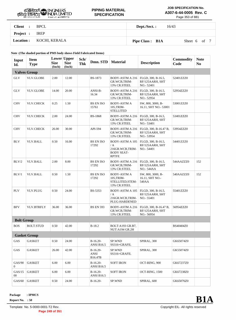
BPCLClient :
IREP
KOCHI, KERALALocation :
16/43Dept./Sect. :
Project :
PIPING MATERIAL SPECIFICATION
Copyright EIL- All rights reserved
JOB SPECIFICATION No.
A307-6-44-0005 Rev. C
Package : IPMCS
Report No. : 50
Template No. 5-0000-0001-T2 Rev.
Page 353 of 881
Sheet 6 ofPipe Class : B1A
InputId.
Item Type
LowerSize
Upper Size
Sch/Thk DescriptionMaterial
CommodityCode
NoteNo
Valves Group
Bolt Group
Gasket Group
Dmn. STD(Inch) (Inch)
GLV
GLV
CHV
CHV
CHV
BLV
BLV/2
BLV/1
PLV
BFV
BOS
GAS
GAS
GAS/900
GAS/1500
GAS/60
VLV.GLOBE
VLV.GLOBE
VLV.CHECK
VLV.CHECK
VLV.CHECK
VLV.BALL
VLV.BALL
VLV.BALL
VLV.PLUG
VLV.BTRFLY
BOLT.STUD
GASKET
GASKET
GASKET
GASKET
GASKET
2.00
14.00
0.25
2.00
26.00
0.50
2.00
0.50
0.50
36.00
0.50
0.50
26.00
6.00
6.00
0.50
12.00
20.00
1.50
24.00
30.00
16.00
8.00
1.50
24.00
36.00
42.00
24.00
42.00
6.00
6.00
24.00
FLGD, 300, B-16.5,RF/125AARH, SHTNO.- 52401
FLGD, 300, B-16.5,RF/125AARH, SHTNO.- 52954
SW, 800, 3000, B-16.11, SHT NO.- 53001
FLGD, 300, B-16.5,RF/125AARH, SHTNO.- 53401
FLGD, 300, B-16.47 B,RF/125AARH, SHTNO.- 53954
FLGD, 300, B-16.5,RF/125AARH, SHTNO.- 54401
FLGD, 300, B-16.5,RF/125AARH, SHTNO.- 544AA
SW, 800, 3000, B-16.11, SHT NO.-540AA
FLGD, 300, B-16.5,RF/125AARH, SHTNO.- 55401
FLGD, 300, B-16.47 B,RF/125AARH, SHTNO.- 56954
SPIRAL, 300
SPIRAL, 300
OCT-RING, 900
OCT-RING, 1500
SPIRAL, 600
BODY-ASTM A 216GR.WCB,TRIM-13% CR.STEEL
BODY-ASTM A 216GR.WCB,TRIM-13% CR.STEEL
BODY-ASTM A105,TRIM-STELLITED
BODY-ASTM A 216GR.WCB,TRIM-13% CR.STEEL
BODY-ASTM A 216GR.WCB,TRIM-13% CR.STEEL
BODY-ASTM A 105/ A216GR.WCB,TRIM-BODY SEAT-RPTFE
BODY-ASTM A 216GR.WCB,TRIM-13% CR.STEEL
BODY-ASTM A105,TRIM-STELLITED,STEM-13% CR.STEEL
BODY-ASTM A 105/ A216GR.WCB,TRIM-PLUG-HARDENED
BODY-ASTM A 216GR.WCB,TRIM-13% CR.STEEL
BOLT:A193 GR.B7,NUT:A194 GR.2H
SP.WNDSS316+GRAFIL
SP.WNDSS316+GRAFIL
SOFT IRON
SOFT IRON
SP.WND
52401ZZZ0
52954ZZZ0
53001ZZZ0
53401ZZZ0
53954ZZZ0
54401ZZZ0
544AAZZZ0
540AAZZZ0
55401ZZZ0
56954ZZZ0
BS40404Z0
GK65074Z0
GK55074Z0
GK67237Z0
GK67238Z0
GK65076Z0
152
152
BS-1873
ANSI-B-16.34
BS EN ISO15761
BS-1868
API-594
BS EN ISO17292
BS EN ISO17292
BS EN ISO17292
BS-5353
BS EN 593
B-18.2
B-16.20-ANSI B16.5
B-16.20-ANSIB16.47B
B-16.20-ANSI B16.5
B-16.20-ANSI B16.5
B-16.20-
Note :(The shaded portion of PMS body shows Field Fabricated Items)
B1A
7
Page 249 of 351
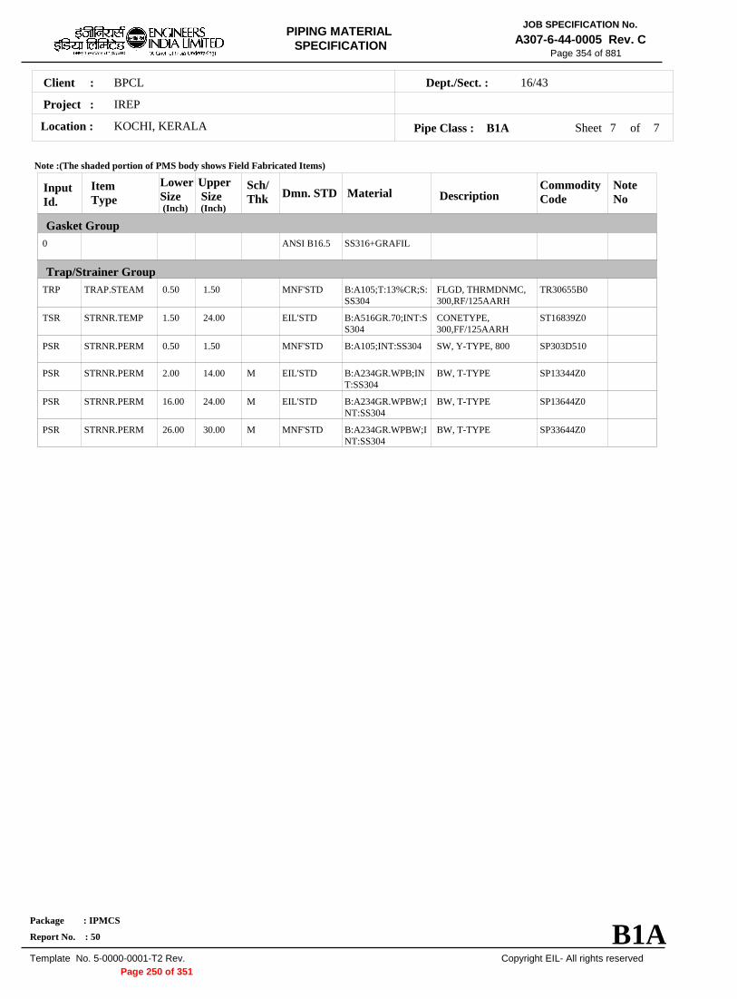
BPCLClient :
IREP
KOCHI, KERALALocation :
16/43Dept./Sect. :
Project :
PIPING MATERIAL SPECIFICATION
Copyright EIL- All rights reserved
JOB SPECIFICATION No.
A307-6-44-0005 Rev. C
Package : IPMCS
Report No. : 50
Template No. 5-0000-0001-T2 Rev.
Page 354 of 881
Sheet 7 of 7Pipe Class : B1A
InputId.
Item Type
LowerSize
Upper Size
Sch/Thk DescriptionMaterial
CommodityCode
NoteNo
Gasket Group
Trap/Strainer Group
Dmn. STD(Inch) (Inch)
0
TRP
TSR
PSR
PSR
PSR
PSR
TRAP.STEAM
STRNR.TEMP
STRNR.PERM
STRNR.PERM
STRNR.PERM
STRNR.PERM
0.50
1.50
0.50
2.00
16.00
26.00
1.50
24.00
1.50
14.00
24.00
30.00
M
M
M
FLGD, THRMDNMC,300,RF/125AARH
CONETYPE,300,FF/125AARH
SW, Y-TYPE, 800
BW, T-TYPE
BW, T-TYPE
BW, T-TYPE
SS316+GRAFIL
B:A105;T:13%CR;S:SS304
B:A516GR.70;INT:SS304
B:A105;INT:SS304
B:A234GR.WPB;INT:SS304
B:A234GR.WPBW;INT:SS304
B:A234GR.WPBW;INT:SS304
TR30655B0
ST16839Z0
SP303D510
SP13344Z0
SP13644Z0
SP33644Z0
ANSI B16.5
MNF'STD
EIL'STD
MNF'STD
EIL'STD
EIL'STD
MNF'STD
Note :(The shaded portion of PMS body shows Field Fabricated Items)
B1APage 250 of 351

BPCLClient :
IREP
KOCHI, KERALALocation :
16/43Dept./Sect. :
Project :
PIPING MATERIAL SPECIFICATION
Copyright EIL- All rights reserved
JOB SPECIFICATION No.
A307-6-44-0005 Rev. C
Package : IPMCS
Report No. : 50
Template No. 5-0000-0001-T2 Rev.
Page 600 of 881
B9APIPE CLASS :300RATING :CARBON STEELBASE MATERIAL : 3CORROSION ALLOWANCE : SPECIAL REQUIREMENT :
MM
SERVICEMILD TO MODERATE CORROSIVE PROCESS LIQUID, VAPOUR & GAS, FLAMMABLE/NON FLAMMABLE & NON LETHAL -HVGO,SLOP, DISTILLATE, RCO, DIESEL, KEROSENE,LVGO, VBTAR, TCTAR, ETC.
NOTES3
5
7
32
151
152
209
267
USE PIPE OF CLASS 22 INSTEAD OF CLASS 12 IF PIPE THICKNESS EXCEEDS 20.00 MM.
FOR PERMANENT 'T' TYPE BW STRAINERS,REFER EIL'STD 7-44-0303 & 7-44-0304; AND FOR TEMPORARYSTRAINERS,REFER EIL'STD 7-44-0300; FOR SPACER AND BLIND REFER EIL'STD 7-44-0162.FOR RESTRICTION ON USE OF BALL,PLUG & BUTTERFLY VALVES,REFER GENERAL NOTES.
CORROSION ALLOWANCE HAS BEEN ADJUSTED TO SELECT OPTIMUM SCH. REFER GENERAL NOTES TO PMS.
NDT REQUIREMENT SHALL BE AS PER JOB SPECIFICATION A307-6-44-0016.
FIRST ISOLATION VALVE ON ALL FLOW, PRESSURE AND LEVEL TAPPINGS SHALL BE METAL TO METAL SEATEDBALL VALVE.PIPE WALL THICKNESS IS CALCULATED BASED ON ACTUAL LINE DESIGN CONDITION [ 282 DEG. C & 16.7 KG/ CM2 G]SUBJECT TO MINIMUM OF 80% CLASS RATING.PIPE WALL THICKNESS IS CALCULATED BASED ON ACTUAL LINE DESIGN CONDITION [ 305 DEG. C & 24.6 KG/ CM2 G]SUBJECT TO MINIMUM OF 80% CLASS RATING.
SPECIAL NOTES
ITEM SIZE DESCRIPTION A.CODEMAINTAINENCEJOINTS
PIPE JOINTS
DRAINS
VENTS
TEMP.CONN
PRESS.CONN
ALL
1.5" & BELOW
2.0" & ABOVE
ON LINES <= 1.5"
ON LINES >= 2.0"
ON LINES <= 1.5"
ON LINES >= 2.0"
1.5"
0.75"
FLANGED, TO BE KEPT MINIMUM
SW COUPLING
BUTTWELDED
REFER EIL STD 7-44-0350, DF3
AS PER P&ID OR 0.75". REFER EIL STD. 7-44-0351, D4
REFER EIL STD. 7-44-0350, VF3
AS PER P&ID OR 0.75". REFER EIL STD 7-44-0351, V4
FLANGED. REFER EIL STD 7-44-0353
SW NIPPLE WITH VALVE TO SPEC AS PER EIL STD 7-44-0354
TEMP
PRESS 52.02 52.02 47.8 46.05 44.64 42.53 40.07 38.66 37.26 35.5 28.82
-29 38 93 149 204 260 316 343 371 399 427
Sheet 1 of
TEMPERATURE (Deg. C) AND PRESSURE ( Kg/Sq. cm g ) RATINGS
Pipe Class : B9A
B9A
6
Page 251 of 351

BPCLClient :
IREP
KOCHI, KERALALocation :
16/43Dept./Sect. :
Project :
PIPING MATERIAL SPECIFICATION
Copyright EIL- All rights reserved
JOB SPECIFICATION No.
A307-6-44-0005 Rev. C
Package : IPMCS
Report No. : 50
Template No. 5-0000-0001-T2 Rev.
Page 601 of 881
Sheet 2 ofPipe Class : B9A
T T T T H H H H H H H H H H H H0.5T T T H H H H H H H H H H H H0.75
T T H H H H H H H H H H H H1.01.25
T T H H H H H H H H H H H1.5T R R R R R R R R R R R2.0
2.5T R R R R R R R R R R3.0
3.5T R R R R R R R R R4.0
5.0T R R R R R R R R6.0
T R R R R R R R8.0T R R R R R R10.
T R R R R R12.T R R R R14.
T R R R16.T R R18.
T R20.22.
T24.26.28.30.32.34.36.38.40.42.44.46.48.50.52.54.56.58.60.62.64.66.68.70.72.
.500
.750
1.0
00
1.2
50
1.5
00
2.0
00
2.5
00
3.0
00
3.5
00
4.0
00
5.0
00
6.0
00
8.0
00
10.
000
12.
000
14.
000
16.
000
18.
000
20.
000
22.
000
24.
000
BR
AN
CH
PIP
E (
SIZ
E I
N I
NC
HE
S)
0.50.751.01.251.52.02.53.03.54.05.06.08.010.12.14.16.18.20.22.24.26.28.30.32.34.36.38.40.42.44.46.48.50.52.54.56.58.60.62.64.66.68.70.72.
BR
AN
CH
PIP
E (SIZ
E IN
INC
HE
S)
RUN PIPE (SIZE IN INCHES)
CODE DESCRIPTION
F
H
P
R
S
T
W
I
X
L
JSADDLE FUSED JT
H. COUPLING
PIPE TO PIPE
REINFORCED
SOCKOLETS
TEES
WELDOLETS
INSTRUMENT TEE
Refer Notes
SWEEPOLET
THREADOLET
B9A
6
Page 252 of 351

BPCLClient :
IREP
KOCHI, KERALALocation :
16/43Dept./Sect. :
Project :
PIPING MATERIAL SPECIFICATION
Copyright EIL- All rights reserved
JOB SPECIFICATION No.
A307-6-44-0005 Rev. C
Package : IPMCS
Report No. : 50
Template No. 5-0000-0001-T2 Rev.
Page 602 of 881
Sheet 3 ofPipe Class : B9A
InputId.
Item Type
LowerSize
Upper Size
Sch/Thk DescriptionMaterial
CommodityCode
NoteNo
Pipe Group
Flange Group
Fitting Group
Dmn. STD(Inch) (Inch)
PIP
PIP
PIP
PIP
PIP
PIP
PIP
PIP
PIP
NIP
NIP
FLG
FLG/600
FLG
FLG/900
FLG/150
FLG/600
FLB
FLB/600
FEF
FEF
ELB90
PIPE
PIPE
PIPE
PIPE
PIPE
PIPE
PIPE
PIPE
PIPE
NIPPLE
NIPPLE
FLNG.SW
FLNG.SW
FLNG.WN
FLNG.WN
FLNG.WN
FLNG.WN
FLNG.BLIND
FLNG.BLIND
FLNG.FIG.8
SPCR&BLND
ELBOW.90
0.50
1.00
2.00
3.00
12.00
16.00
18.00
20.00
24.00
0.50
1.00
0.50
0.50
2.00
6.00
2.00
2.00
0.50
0.50
0.50
10.00
0.50
0.75
1.50
2.00
10.00
14.00
16.00
18.00
20.00
24.00
0.75
1.50
1.50
1.50
24.00
6.00
24.00
24.00
24.00
24.00
8.00
24.00
0.75
S160
XS
XS
STD
XS
XS
XS
XS
14.0
M
M
M
M
M
M
M
M
PE, SEAMLESS
PE, SEAMLESS
BE, SEAMLESS
BE, SEAMLESS
BE, SEAMLESS
BE, E.FS.W
BE, E.FS.W
BE, E.FS.W
BE, E.FS.W
PBE, SEAMLESS
PBE, SEAMLESS
300, RF/125AARH
600, RF/125AARH
300, RF/125AARH
900, RTJ/63AARH
150, RF/125AARH
600, RF/125AARH
300, RF/125AARH
600, RF/125AARH
300, FF/125AARH
300, FF/125AARH
SW, 6000
ASTM A 106 GR.B
ASTM A 106 GR.B
ASTM A 106 GR.B
ASTM A 106 GR.B
ASTM A 106 GR.B
ASTM A 672GR.B60 CL.12
ASTM A 672GR.B60 CL.12
ASTM A 672GR.B60 CL.12
ASTM A 672GR.B60 CL.12
ASTM A 106 GR.B
ASTM A 106 GR.B
ASTM A 105
ASTM A 105
ASTM A 105
ASTM A 105
ASTM A 105
ASTM A 105
ASTM A 105
ASTM A 105
ASTM A 105
ASTM A 105
ASTM A 105
PI21977Z0
PI21977Z0
PI21917Z0
PI21917Z0
PI21917Z0
PI2A813Z0
PI2A813Z0
PI2A813Z0
PI2A813Z0
PN21967Z0
PN21967Z0
FSC0147Z0
FSC0167Z0
FWC0147Z0
FWC0179Z0
FWC0127Z0
FWC0167Z0
FBC0147Z0
FBC0167Z0
FGK0141Z0
FCK0141Z0
WA602D3Z0
32
209
267
B-36.10
B-36.10
B-36.10
B-36.10
B-36.10
B-36.10
B-36.10
B-36.10
B-36.10
B-36.10
B-36.10
B-16.5
B-16.5
B-16.5
B-16.5
B-16.5
B-16.5
B-16.5
B-16.5
ASME-B16.48
ASME-B16.48
B-16.11
Note :(The shaded portion of PMS body shows Field Fabricated Items)
B9A
6
Page 253 of 351

BPCLClient :
IREP
KOCHI, KERALALocation :
16/43Dept./Sect. :
Project :
PIPING MATERIAL SPECIFICATION
Copyright EIL- All rights reserved
JOB SPECIFICATION No.
A307-6-44-0005 Rev. C
Package : IPMCS
Report No. : 50
Template No. 5-0000-0001-T2 Rev.
Page 603 of 881
Sheet 4 ofPipe Class : B9A
InputId.
Item Type
LowerSize
Upper Size
Sch/Thk DescriptionMaterial
CommodityCode
NoteNo
Fitting Group
Dmn. STD(Inch) (Inch)
ELB90
ELB90
ELB90
ELB45
ELB45
ELB45
ELB45
TEQ
TEQ
TEQ
TEQ
TRED
TRED
TRED
TRED
REDC
REDC
REDE
REDE
SWGC
SWGE
CAP
CAP
ELBOW.90
ELBOW.90
ELBOW.90
ELBOW.45
ELBOW.45
ELBOW.45
ELBOW.45
T.EQUAL
T.EQUAL
T.EQUAL
T.EQUAL
T.RED
T.RED
T.RED
T.RED
REDUC.CONC
REDUC.CONC
REDUC.ECC
REDUC.ECC
SWAGE.CONC
SWAGE.ECC
CAP
CAP
1.00
2.00
16.00
0.50
1.00
2.00
16.00
0.50
1.00
2.00
16.00
0.50
1.00
2.00
16.00
2.00
16.00
2.00
16.00
0.50
0.50
0.50
2.00
1.50
14.00
24.00
0.75
1.50
14.00
24.00
0.75
1.50
14.00
24.00
0.75
1.50
14.00
24.00
14.00
24.00
14.00
24.00
3.00
3.00
0.75
24.00
M
M
M
M
M
M
M, M
M, M
M, M
M, M
M, M
M, M
M, M
M, M
M
SW, 3000
BW, 1.5D
BW, 1.5D
SW, 6000
SW, 3000
BW, 1.5D
BW, 1.5D
SW, 6000
SW, 3000
BW
BW
SW, 6000
SW, 3000
BW
BW
BW
BW
BW
BW
PBE
PBE
SCRF, 6000
BW
ASTM A 105
ASTM A 234GR.WPB
ASTM A 234GR.WPB-W
ASTM A 105
ASTM A 105
ASTM A 234GR.WPB
ASTM A 234GR.WPB-W
ASTM A 105
ASTM A 105
ASTM A 234GR.WPB
ASTM A 234GR.WPB-W
ASTM A 105
ASTM A 105
ASTM A 234GR.WPB
ASTM A 234GR.WPB-W
ASTM A 234GR.WPB
ASTM A 234GR.WPB-W
ASTM A 234GR.WPB
ASTM A 234GR.WPB-W
ASTM A 105
ASTM A 105
ASTM A 105
ASTM A 234GR.WPB
WA602D2Z0
WAG684Z10
WAG754Z10
WB602D3Z0
WB602D2Z0
WBG684Z10
WBG754Z10
WE602D3Z0
WE602D2Z0
WEG684ZZ0
WEG754ZZ0
WR602D3Z0
WR602D2Z0
WRG684ZZ0
WRG754ZZ0
WUG684ZZ0
WUG754ZZ0
WVG684ZZ0
WVG754ZZ0
WNH026ZZ0
WPH026ZZ0
WF60283Z0
WFG684ZZ0
B-16.11
B-16.9
B-16.9
B-16.11
B-16.11
B-16.9
B-16.9
B-16.11
B-16.11
B-16.9
B-16.9
B-16.11
B-16.11
B-16.9
B-16.9
B-16.9
B-16.9
B-16.9
B-16.9
BS-3799
BS-3799
B-16.11
B-16.9
Note :(The shaded portion of PMS body shows Field Fabricated Items)
B9A
6
Page 254 of 351

BPCLClient :
IREP
KOCHI, KERALALocation :
16/43Dept./Sect. :
Project :
PIPING MATERIAL SPECIFICATION
Copyright EIL- All rights reserved
JOB SPECIFICATION No.
A307-6-44-0005 Rev. C
Package : IPMCS
Report No. : 50
Template No. 5-0000-0001-T2 Rev.
Page 604 of 881
Sheet 5 ofPipe Class : B9A
InputId.
Item Type
LowerSize
Upper Size
Sch/Thk DescriptionMaterial
CommodityCode
NoteNo
Fitting Group
Valves Group
Dmn. STD(Inch) (Inch)
CPLF
CPLF
CPLH
CPLH
CPLL
CPLL
CPLR
CPLR
GAV
GAV
GLV
GLV
GLV
CHV
CHV
BLV
BLV/2
CPLNG.FULL
CPLNG.FULL
CPLNG.HALF
CPLNG.HALF
CPLNG.LH
CPLNG.LH
CPLNG.RED
CPLNG.RED
VLV.GATE
VLV.GATE
VLV.GLOBE
VLV.GLOBE
VLV.GLOBE
VLV.CHECK
VLV.CHECK
VLV.BALL
VLV.BALL
0.50
1.00
0.50
1.00
0.50
1.00
0.50
1.00
0.25
2.00
0.25
2.00
16.00
0.25
2.00
0.50
2.00
0.75
1.50
0.75
1.50
0.75
1.50
0.75
1.50
1.50
24.00
1.50
12.00
20.00
1.50
24.00
16.00
8.00
SW, 6000
SW, 3000
SW, 6000
SW, 3000
SW, 6000
SW, 3000
SW, 6000
SW, 3000
SW, 800, 3000, B-16.11, SHT NO.- 51001
FLGD, 300, B-16.5,RF/125AARH, SHTNO.- 51401
SW, 800, 3000, B-16.11, SHT NO.- 52001
FLGD, 300, B-16.5,RF/125AARH, SHTNO.- 52401
FLGD, 300, B-16.5,RF/125AARH, SHTNO.- 52954
SW, 800, 3000, B-16.11, SHT NO.- 53001
FLGD, 300, B-16.5,RF/125AARH, SHTNO.- 53401
FLGD, 300, B-16.5,RF/125AARH, SHTNO.- 54401
FLGD, 300, B-16.5,RF/125AARH, SHTNO.- 544AA
ASTM A 105
ASTM A 105
ASTM A 105
ASTM A 105
ASTM A 105
ASTM A 105
ASTM A 105
ASTM A 105
BODY-ASTM A105,TRIM-STELLITED,STEM-13%CR.STEEL
BODY-ASTM A 216GR.WCB,TRIM-13% CR.STEEL
BODY-ASTM A105,TRIM-STELLITED,STEM-13%CR STEEL
BODY-ASTM A 216GR.WCB,TRIM-13% CR.STEEL
BODY-ASTM A 216GR.WCB,TRIM-13% CR.STEEL
BODY-ASTM A105,TRIM-STELLITED
BODY-ASTM A 216GR.WCB,TRIM-13% CR.STEEL
BODY-ASTM A 105/ A216GR.WCB,TRIM-BODY SEAT-RPTFE
BODY-ASTM A 216GR.WCB,TRIM-13% CR.STEEL
WJ602D3Z0
WJ602D2Z0
WK602D3Z0
WK602D2Z0
WL602D3Z0
WL602D2Z0
WM602D3Z0
WM602D2Z0
51001ZZZ0
51401ZZZ0
52001ZZZ0
52401ZZZ0
52954ZZZ0
53001ZZZ0
53401ZZZ0
54401ZZZ0
544AAZZZ0 152
B-16.11
B-16.11
B-16.11
B-16.11
B-16.11
B-16.11
B-16.11
B-16.11
API 602/ ISO15761
API 600/ ISO10434
BS EN ISO15761
BS-1873
ANSI-B-16.34
BS EN ISO15761
BS-1868
BS EN ISO17292
BS EN ISO17292
Note :(The shaded portion of PMS body shows Field Fabricated Items)
B9A
6
Page 255 of 351

BPCLClient :
IREP
KOCHI, KERALALocation :
16/43Dept./Sect. :
Project :
PIPING MATERIAL SPECIFICATION
Copyright EIL- All rights reserved
JOB SPECIFICATION No.
A307-6-44-0005 Rev. C
Package : IPMCS
Report No. : 50
Template No. 5-0000-0001-T2 Rev.
Page 605 of 881
Sheet 6 of 6Pipe Class : B9A
InputId.
Item Type
LowerSize
Upper Size
Sch/Thk DescriptionMaterial
CommodityCode
NoteNo
Valves Group
Bolt Group
Gasket Group
Trap/Strainer Group
Dmn. STD(Inch) (Inch)
BLV/1
PLV
BOS
GAS
GAS/600
TSR
PSR
PSR
PSR
VLV.BALL
VLV.PLUG
BOLT.STUD
GASKET
GASKET
STRNR.TEMP
STRNR.PERM
STRNR.PERM
STRNR.PERM
0.50
0.50
0.50
0.50
0.50
1.50
0.50
2.00
16.00
1.50
24.00
24.00
24.00
24.00
24.00
1.50
14.00
24.00
M
M
SW, 800, 3000, B-16.11, SHT NO.-540AA
FLGD, 300, B-16.5,RF/125AARH, SHTNO.- 55401
SPIRAL, 300
SPIRAL, 600
CONETYPE,300,FF/125AARH
SW, Y-TYPE, 800
BW, T-TYPE
BW, T-TYPE
BODY-ASTM A105,TRIM-STELLITED,STEM-13% CR.STEEL
BODY-ASTM A 105/ A216GR.WCB,TRIM-PLUG-HARDENED
BOLT:A193 GR.B7,NUT:A194 GR.2H
SP.WNDSS316+GRAFIL
SP.WNDSS316+GRAFIL
B:A516GR.70;INT:SS304
B:A105;INT:SS304
B:A234GR.WPB;INT:SS304
B:A234GR.WPBW;INT:SS304
540AAZZZ0
55401ZZZ0
BS40404Z0
GK65074Z0
GK65076Z0
ST16839Z0
SP303D510
SP13344Z0
SP13644Z0
152BS EN ISO17292
BS-5353
B-18.2
B-16.20-ANSI B16.5
B-16.20-ANSI B16.5
EIL'STD
MNF'STD
EIL'STD
EIL'STD
Note :(The shaded portion of PMS body shows Field Fabricated Items)
B9APage 256 of 351

JOB SPECIFICATIONFOR NON DESTRUCTIVE
EXAMINATION REQUIREMENTS OF PIPING
JOB SPECIFICATION No.
A307-6-44-0016 Rev. 0
Page 1 of 20
0 31/12/2012 ISSUED AS JOB SPECIFICATION
NR
RP
RN
Rev. No
Date Purpose Prepared
by Checked
by
Approved by
Format No. 8-00-0001-F1 Rev. 0
ikbfiax ds v/oalkRed ijh{k.k dh vko';drkvksa gsrq ekud fofunsZ'k
JOB SPECIFICATION FOR NON DESTRUCTIVE EXAMINATION
REQUIREMENTS OF PIPING
PROJECT: INTEGRATED REFINERY EXPANSION PROJECT (IREP)
OWNER : BPCL-KR JOB NO. : A307
Page 257 of 351

JOB SPECIFICATIONFOR NON DESTRUCTIVE
EXAMINATION REQUIREMENTS OF PIPING
JOB SPECIFICATION No.
A307-6-44-0016 Rev. 0
Page 2 of 20
Format No. 8-00-0001-F1 Rev. 0 Copyright EIL – All rights reserved
Abbreviations: DP/LP : Dye/Liquid Penetrant MP : Magnetic Particle CS : Carbon Steel AS : Alloy Steel SS : Stainless Steel ASTM : American Society for Testing & Materials ASME : American Society of Mechanical Engineers IBR : Indian Boiler Regulations PMS: Piping Material Specification
CONTENTS
Page 258 of 351

JOB SPECIFICATIONFOR NON DESTRUCTIVE
EXAMINATION REQUIREMENTS OF PIPING
JOB SPECIFICATION No.
A307-6-44-0016 Rev. 0
Page 3 of 20
Format No. 8-00-0001-F1 Rev. 0 Copyright EIL – All rights reserved
S.NO TITLE PAGE NO. 1. GENERAL 4 2. VISUAL EXAMINATION 4 3. NON DESTRUCTIVE EXAMINATION 6 4. TABLE-I (with applicable Notes to Table-I) 7
Page 259 of 351

JOB SPECIFICATIONFOR NON DESTRUCTIVE
EXAMINATION REQUIREMENTS OF PIPING
JOB SPECIFICATION No.
A307-6-44-0016 Rev. 0
Page 4 of 20
Format No. 8-00-0001-F1 Rev. 0 Copyright EIL – All rights reserved
1.0 GENERAL 1.1 SCOPE
This specification covers the general requirements for non destructive examination of shop & field fabricated piping.
1.2 RELATED CODES & ENGINEERING STANDARDS
Referred codes / standards are as follows. Latest editions of the Codes/Standards referred to shall be followed.
a) ASME Boiler & Pressure Vessel Codes, Section V & VIII (Div.1) including
addenda.
b) ASME B31.3
c) ASME B16.5
d) ASME B16.34
e) Job Piping Material Specification, A307-6-44-0005
f) Welding Specification Charts for Piping Classes,IREP Project.
g) Standard Specification for Fabrication & Erection of Piping 6-44-0012
h) ASTM E10
i) Welding Specification for Fabrication of Piping, 6-77-0001
j) Design Guide for Radiography Requirements, 8-77-0010 k) Indian Boiler Regulations (IBR)
2. VISUAL EXAMINATION 2.1 Weld shall be visually inspected wherever accessible in accordance with the following
requirements: a) Internal misalignment 1.5 mm or less b) Cracks or lack of fusion not permitted
c) Incomplete penetration Depth shall not exceed the lesser of 0.8mm or 0.2 times thickness of thinner component joined by butt-weld. The total length of such imperfections
shall not exceed 38 mm in any 150 mm of weld length.
d) Surface porosity and not permitted
exposed slag inclusions (For nom. wall thickness 4.7 mm and less)
Page 260 of 351

JOB SPECIFICATIONFOR NON DESTRUCTIVE
EXAMINATION REQUIREMENTS OF PIPING
JOB SPECIFICATION No.
A307-6-44-0016 Rev. 0
Page 5 of 20
Format No. 8-00-0001-F1 Rev. 0 Copyright EIL – All rights reserved
e) Concave root surface For single sided welded joints, concavity of the root surface shall not reduce the total thickness
(Suck up) of joint, including reinforcement, to less than the thickness of the thinner of the components being joined.
f) Weld ripples irregularities 2.5 mm or less.
g) Lack of uniformity in bead 2.5 mm or less.
width
h) Lack of uniformity of leg 2.5 mm or less. length
i) Unevenness of bead 2.0 mm or less.
j) Weld undercutting 0.8 mm or 1/4 thickness of thinner components joined by butt weld, whichever is less. (shall be smooth finished)
k) Overlap 1.5 mm or less
l) Bead deflection 2.5 mm or less
m) External weld reinforcement and internal weld protrusion (when backing rings are not used) shall be fused with and shall merge smoothly into the component surfaces. The height of the lesser projection of external weld reinforcement or internal weld protrusion from the adjacent base material surface shall not exceed the following limits:
Wall thickness of thinner Weld reinforcement or internal weld protrusion
component joined by butt (mm) max weld (mm)
6.4 and under 1.6 Over 6.4 -12.7 3.2 Over 12.7 -25.4 4.0 Over 25.4 4.8
n) Throat thickness of fillet welds: Nominal thickness of the thinner component x 0.7 or more.
o) Flattening Flattening of a bend, as measured by difference between the nominal outside
diameter and minimum or maximum diameter at any cross section shall not exceed 5 % of the nominal outside diameter of pipe.
p) Reduction of wall thickness
Reduction of wall thickness of a bend, as measured by difference between the nominal thickness and minimum thickness shall not exceed 10 % of the nominal wall thickness of pipe.
Page 261 of 351

JOB SPECIFICATIONFOR NON DESTRUCTIVE
EXAMINATION REQUIREMENTS OF PIPING
JOB SPECIFICATION No.
A307-6-44-0016 Rev. 0
Page 6 of 20
Format No. 8-00-0001-F1 Rev. 0 Copyright EIL – All rights reserved
2.2 Welds having any of imperfections which exceed the limitations specified in various clauses of 2.1 shall be repaired by welding, grinding or overlaying etc. Number of times of repair welding for the same weld, however shall conform to applicable notes to Table 1- Note 6(b)b.5.
3. NON DESTRUCTIVE EXAMINATION 3.1 The type and extent of weld examination shall be in accordance with Table-1. All visual
and supplementary methods of girth weld examination shall be in accordance with ASME B31.3 & the requirements of this standard specification.
3.2 Welds between dissimilar materials shall be examined by method & to the extent required
for the material having the more stringent examination.
Page 262 of 351

JOB SPECIFICATIONFOR NON DESTRUCTIVE
EXAMINATION REQUIREMENTS OF PIPING
JOB SPECIFICATION No.
A307-6-44-0016 Rev. 0
Page 7 of 20
Format No. 8-00-0001-F1 Rev. 0 Copyright EIL – All rights reserved
4. TABLE-I (with applicable notes)
TABLE 1 : CLASS, TYPE & EXTENT OF WELD EXAMINATION
INSPECTION CLASS: I
INSPN. CLASS
SERVICE MATERIAL (NOTE 3)
P.NO. TEMP.DEG.C
PRESS. CLASS B16.5/ B16.34
APPLICABLEPIPING CLASS
TYPE OF EXAMINATION
TYPE OF WELD EXAMINED
GIRTH BUTT WELD
SOCKET WELD (NOTE 2)
ATTACH-MENT WELD
FAB. BRANCH WELD (NOTE 1)
FAB. WELDS OF MITRES /REDUC.
1 2 3 4 5 6 7 8 9 10 11 12 13
I CATEGORY 'D' FLUID SERVICE
CARBON STEEL
1 0 TO 186
150# UPTO 10.55 KG/CM2
A3A, A3Y, J2A, J3A, J5A, A4Y, A5Y, A91A, A92A, A93A, A94A
a) VISUAL b) LP (NOTE 4, 6, 9)
100% ---
100% ---
100% ---
100% 10%
100% 10%
AUSTENIC S.S.
8 - 29 TO 186
A3K
HDPE --- - 20 TO 50
A1Z, A4Z, A5Z.
CURPO NICKEL
34 - 29 TO 60
REMARKS FOR ABOVE TABLE :
1. LP TEST NOT APPLICABLE TO NON-METALLIC CLASSES. 2. MITRES & FABRICATED REDUCERS ARE PERMITTED ONLY IF SPECIFIED IN PMS.
Page 263 of 351

JOB SPECIFICATIONFOR NON DESTRUCTIVE
EXAMINATION REQUIREMENTS OF PIPING
JOB SPECIFICATION No.
A307-6-44-0016 Rev. 0
Page 8 of 20
Format No. 8-00-0001-F1 Rev. 0 Copyright EIL – All rights reserved
TABLE 1: CLASS, TYPE & EXTENT OF WELD EXAMINATION (CONTD.)
INSPECTION CLASS: II
INSPN. CLASS
SERVICE MATERIAL (NOTE 3)
P. NO.
TEMP. DEG.C
PRESS.CLASSB16.5/B16.34
APPLICABLEPIPING CLASS
TYPE OF EXAMINATION
TYPE OF WELD EXAMINED
GIRTH BUTT WELD
SOCKET WELD (NOTE 2)
ATTACH -MENT WELD
FAB. BRANCH WELD (NOTE 1)
FAB. WELDS OF MITRES/REDUC.
1 2 3 4 5 6 7 8 9 10 11 12 13
II a) ALL SERVICES COVERED UNDER INSPECTION CLASS-I, BUT, EXCEEDING CATAGORY 'D' PR./T EMP LIMITATIONS. b) ALL SERVICES OTHER THAN THOSE COVERED UNDER INSPECTION CLASS-I BUT NON-TOXIC, NOT SUBJECTED TO SEVERE CYCLIC CONDITIONS.
CARBON STEEL
1
- 29 TO 400
150#
A1A, A6A, A7A, A8A, A9A, A10A, A11A, A13A, A15A, A20A, A32A, A33Y, A75A.
a) VISUAL b) RADIOGRAPHY (NOTE 5,6) c) MP / LP (NOTE 4,6,10,11) d) HARDNESS
100% 10% --- NOTE 7
100% --- 10% NOTE 7
100% --- --- NOTE-7
100% --- 10% NOTE-7
100% 50% 50% NOTE-7
CARBON STEEL (IBR)
A2A.
REMARKS FOR ABOVE TABLE :
1. FOR A2A IBR SERVICE NOTE- 8 IS ALSO APPLICABLE. 2. FOR A33A & A33Y FIRE WATER SERVICE, NOTE-12 IS ALSO APPLICABLE.
3. EXTENT OF HARDNESS TEST FOR A11A IS 100%.. 3. MITRES & FABRICATED REDUCERS ARE PERMITTED ONLY IF SPECIFIED IN PMS.
Page 264 of 351

JOB SPECIFICATIONFOR NON DESTRUCTIVE
EXAMINATION REQUIREMENTS OF PIPING
JOB SPECIFICATION No.
A307-6-44-0016 Rev. 0
Page 9 of 20
Format No. 8-00-0001-F1 Rev. 0 Copyright EIL – All rights reserved
TABLE 1: CLASS, TYPE & EXTENT OF WELD EXAMINATION (CONTD.)
INSPECTION CLASS: III
REMARKS FOR ABOVE TABLE:
1. FOR IBR SERVICE B2A & D2A NOTE-8 IS ALSO APPLICABLE. 2. MITRES & FABRICATED REDUCERS ARE PERMITTED ONLY IF SPECIFIED IN PMS.
INSPN. CLASS
SERVICE MATERIAL (NOTE 3)
P. NO.
TEMP. DEG.C
PRESS.CLASSB16.5/ B16.34
APPLICABLE PIPING CLASS
TYPE OF EXAMINATION
TYPE OF WELD EXAMINED
GIRTH BUTT WELD
SOCKET WELD (NOTE 2)
ATTACH -MENT WELD
FAB. BRANCH WELDS (NOTE 1)
FAB. WELDS OF MITRES /REDUC.)
1 2 3 4 5 6 7 8 9 10 11 12 13
III a) TOXIC, NON-LETHAL & FLAMMABLE. b) FLAMMABLE / NON FLAMMABLE & TOXIC / NON-TOXIC; NOT SUBJECT TO SEVERE CYCLIC CONDITIONS.
CARBON STEEL
1 ABOVE - 29
150# ---
a) VISUAL b) RADIOGRAPHY (NOTE 5,6) c) LP / MP (NOTE 4,6,11) d) HARDNESS
100% 20% --- NOTE 7
100% --- 20% NOTE 7
100% --- --- NOTE 7
100% --- 20% NOTE 7
100% 100% --- NOTE 7
KILLED CARBON STEEL
- 45 TO 204
150# TO
600#
A4A, B4A, D4A.
ALL GENERAL SERVICES EXCEPT THOSE SUBJECT TO SEVERE CYCLIC CONDITIONS.
CARBON STEEL
1 - 29 TO 427
300# TO
600#
B1A, B6A, B9A, B13A, B15A, B32A, D1A, D9A.
CARBON STEEL (IBR)
B2A, D2A.
Page 265 of 351

JOB SPECIFICATIONFOR NON DESTRUCTIVE
EXAMINATION REQUIREMENTS OF PIPING
JOB SPECIFICATION No.
A307-6-44-0016 Rev. 0
Page 10 of 20
Format No. 8-00-0001-F1 Rev. 0 Copyright EIL – All rights reserved
TABLE 1: CLASS, TYPE & EXTENT OF WELD EXAMINATION (CONTD.)
INSPECTION CLASS: III (CONTD.)
INSPN. CLASS
SERVICE MATERIAL (NOTE 3)
P. NO.
TEMP. DEG.C
PRESS.CLASSB16.5/B16.34
APPLICABLE PIPING CLASS
TYPE OF EXAMINATION
TYPE OF WELD EXAMINED
GIRTH BUTT WELD
SOCKET WELD (NOTE 2)
ATTACH -MENT WELD
FAB. BRANCH WELDS (NOTE 1)
FAB. WELDS OF MITRES /REDUC.)
1 2 3 4 5 6 7 8 9 10 11 12 13
III
(CONTD)
ALL GENERAL SERVICES EXCEPT THOSE SUBJECT TO SEVERE CYCLIC CONDITIONS.
C - 0.5 Mo STEEL.
3
ABOVE -29
150# TO
600#
A1B, B1B, D1B.
a) VISUAL b) RADIOGRAPHY (NOTE 5,6) c) LP / MP (NOTE 4,6,11) d) HARDNESS
100% 20% --- NOTE 7
100% --- 20% NOTE 7
100% --- --- NOTE 7
100% --- 20% NOTE 7
100% 100% --- NOTE 7
0.5 Cr - 0.5 Mo STEEL
1 TO 2 Cr Mo. STEEL.
4 A1D, B1D, D1D
C - 0.5 Mo STEEL (IBR).
3 D2B
1 - 2 Cr Mo STEEL (IBR)
4 B2D, D2D
REMARKS FOR ABOVE TABLE :
1. FOR IBR SERVICE D2B & D2D NOTE- 8 IS ALSO APPLICABLE. 2. MITRES & FABRICATED REDUCERS ARE PERMITTED ONLY IF SPECIFIED IN PMS.
Page 266 of 351
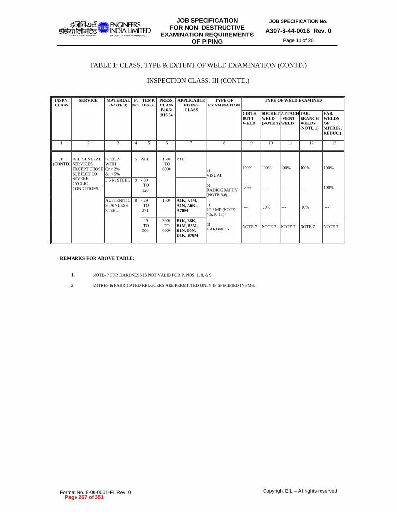
JOB SPECIFICATIONFOR NON DESTRUCTIVE
EXAMINATION REQUIREMENTS OF PIPING
JOB SPECIFICATION No.
A307-6-44-0016 Rev. 0
Page 11 of 20
Format No. 8-00-0001-F1 Rev. 0 Copyright EIL – All rights reserved
TABLE 1: CLASS, TYPE & EXTENT OF WELD EXAMINATION (CONTD.)
INSPECTION CLASS: III (CONTD.)
INSPN. CLASS
SERVICE MATERIAL (NOTE 3)
P. NO.
TEMP. DEG.C
PRESS.CLASSB16.5/ B16.34
APPLICABLE PIPING CLASS
TYPE OF EXAMINATION
TYPE OF WELD EXAMINED
GIRTH BUTT WELD
SOCKET WELD (NOTE 2)
ATTACH -MENT WELD
FAB. BRANCH WELDS (NOTE 1)
FAB. WELDS OF MITRES /REDUC.)
1 2 3 4 5 6 7 8 9 10 11 12 13
III
(CONTD)
ALL GENERAL SERVICES EXCEPT THOSE SUBJECT TO SEVERE CYCLIC CONDITIONS.
STEELS WITH Cr > 2% & < 5%
5
ALL
150# TO 600#
B1E
a) VISUAL b) RADIOGRAPHY (NOTE 5,6) c) LP / MP (NOTE 4,6,10,11) d) HARDNESS
100% 20% --- NOTE 7
100% --- 20% NOTE 7
100% --- --- NOTE 7
100% --- 20% NOTE 7
100% 100% --- NOTE 7
3.5 Ni STEEL 9 - 80 TO 120
AUSTENITIC STAINLESS STEEL
8 - 29 TO 371
150# A1K, A1M, A1N, A6K., A70M
- 29 TO 500
300# TO
600#
B1K, B6K, B1M, B3M, B1N, B6N, D1K, B70M
REMARKS FOR ABOVE TABLE:
1. NOTE- 7 FOR HARDNESS IS NOT VALID FOR P. NOS. 1, 8, & 9. 2. MITRES & FABRICATED REDUCERS ARE PERMITTED ONLY IF SPECIFIED IN PMS.
Page 267 of 351

JOB SPECIFICATIONFOR NON DESTRUCTIVE
EXAMINATION REQUIREMENTS OF PIPING
JOB SPECIFICATION No.
A307-6-44-0016 Rev. 0
Page 12 of 20
Format No. 8-00-0001-F1 Rev. 0 Copyright EIL – All rights reserved
TABLE 1: CLASS, TYPE & EXTENT OF WELD EXAMINATION (CONTD.)
INSPECTION CLASS: III (CONTD.)
INSPN. CLASS
SERVICE MATERIAL (NOTE 3)
P. NO.
TEMP.DEG.C
PRESS.CLASSB16.5/ B16.34
APPLICABLE PIPING CLASS
TYPE OF EXAMINATION
TYPE OF WELD EXAMINED
GIRTH BUTT WELD
SOCKET WELD (NOTE 2)
ATTACH -MENT WELD
FAB. BRANCH WELDS (NOTE 1)
FAB. WELDS OF MITRES /REDUC.)
1 2 3 4 5 6 7 8 9 10 11 12 13
III
(CONTD)
ALL GENERAL SERVICES EXCEPT THOSE SUBJECT TO SEVERE CYCLIC CONDITIONS.
ALUMINIUM & ALUMINIUM BASE ALLOY
21 TO 25
ALL
150#
a) VISUAL b) RADIOGRAPHY (NOTE 5,6) c) LP / MP (NOTE 4,6,10,11)
100% 20% ---
100% --- 20%
100% --- ---
100% --- 20%
100% 100% ---
COPPER & COPPER BASE ALLOY
31
ALUMINIUM BRONZE
35
OTHER NON FERROUS ALLOYS
---
Page 268 of 351

JOB SPECIFICATIONFOR NON DESTRUCTIVE
EXAMINATION REQUIREMENTS OF PIPING
JOB SPECIFICATION No.
A307-6-44-0016 Rev. 0
Page 13 of 20
Format No. 8-00-0001-F1 Rev. 0 Copyright EIL – All rights reserved
TABLE 1: CLASS, TYPE & EXTENT OF WELD EXAMINATION (CONTD.)
INSPECTION CLASS: IV
INSPN. CLASS
SERVICE MATERIAL (NOTE 3)
P. NO.
TEMP. DEG.C
PRESS.CLASSB16.5/B16.34
APPLICABLE PIPING CLASS
TYPE OF EXAMINATION
TYPE OF WELD EXAMINED
GIRTH BUTT WELD
SOCKET WELD (NOTE 2)
ATTACH -MENT WELD
FAB. BRANCH WELDS (NOTE 1)
FAB. WELDS OF MITRES /REDUC.)
1 2 3 4 5 6 7 8 9 10 11 12 13
IV
ALL SERVICES
CARBON STEEL
1
ALL
ABOVE 600#
E1A, F1A, E5A, E9A, F5A, F9A, G9A
a) VISUAL b) RADIOGRAPHY (NOTE 5,6) c) LP / MP (NOTE 4,6,10,11) d) HARDNESS
100% 100% --- NOTE 7
100% --- 100% NOTE 7
100% --- 10% NOTE 7
100% --- 100% NOTE 7
100% 100% --- NOTE 7
CARBON STEEL (IBR)
E2A, F2A.
REMARKS FOR ABOVE TABLE :
1. FOR IBR SERVICE E2A & F2A NOTE- 8 IS ALSO APPLICABLE. 2. EXTENT OF HARDNESS TEST FOR CLASSES E5A, F5A IS 10% .
3. MITRES & FABRICATED REDUCERS ARE PERMITTED ONLY IF SPECIFIED IN PMS.
Page 269 of 351

JOB SPECIFICATIONFOR NON DESTRUCTIVE
EXAMINATION REQUIREMENTS OF PIPING
JOB SPECIFICATION No.
A307-6-44-0016 Rev. 0
Page 14 of 20
Format No. 8-00-0001-F1 Rev. 0 Copyright EIL – All rights reserved
TABLE 1: CLASS, TYPE & EXTENT OF WELD EXAMINATION (CONTD.)
INSPECTION CLASS: IV (CONTD.)
INSPN. CLASS
SERVICE MATERIAL (NOTE 3)
P. NO.
TEMP. DEG.C
PRESS.CLASSB16.5/ B16.34
APPLICABLE PIPING CLASS
TYPE OF EXAMINATION
TYPE OF WELD EXAMINED
GIRTH BUTT WELD
SOCKET WELD (NOTE 2)
ATTACH -MENT WELD
FAB. BRANCHWELDS (NOTE 1)
FAB. WELDS OF MITRES /REDUC.)
1 2 3 4 5 6 7 8 9 10 11 12 13
IV
(CONTD)
ALL GENERAL SERVICES.
C - 0.5 Mo STEEL
3
ALL
ABOVE 600#
--
a) VISUAL b) RADIOGRAPHY (NOTE 5,6) c) LP / MP (NOTE 4,6,10,11) d) HARDNESS
100% 100% --- NOTE 7
100% --- 100% NOTE 7
100% --- 10% NOTE 7
100% --- 100% NOTE 7
100% 100% --- NOTE 7
5 Cr - 9 Cr Mo STEEL
5 150# TO 2500#
A3F, A4F, A4G, A72F, B23G, B26G, B3F, B4F, B4G, D26G, D3F, D4F, D4G, E4G
12 Cr (TYPE- 410 SS)/ CLAD
6 ALL B74M
KILLED CARBON STEEL
1 UPTO - 45
ABOVE 600#
--
1 TO 2 Cr STEEL (IBR)
4 ALL F2D, G22D
REMARKS FOR ABOVE TABLE :
1. FOR IBR SERVICE F2D NOTE- 8 IS ALSO APPLICABLE.. 2. MITRES & FABRICATED REDUCERS ARE PERMITTED ONLY IF SPECIFIED IN PMS.
Page 270 of 351

JOB SPECIFICATIONFOR NON DESTRUCTIVE
EXAMINATION REQUIREMENTS OF PIPING
JOB SPECIFICATION No.
A307-6-44-0016 Rev. 0
Page 15 of 20
Format No. 8-00-0001-F1 Rev. 0 Copyright EIL – All rights reserved
TABLE 1: CLASS, TYPE & EXTENT OF WELD EXAMINATION (CONTD.)
INSPECTION CLASS: IV (CONTD.)
INSPN. CLASS
SERVICE MATERIAL (NOTE 3)
P. NO.
TEMP. DEG.C
PRESS.CLASS B16.5/ B16.34
APPLICABLE PIPING CLASS
TYPE OF EXAMINATION
TYPE OF WELD EXAMINED
GIRTH BUTT WELD
SOCKET WELD (NOTE 2)
ATTACH -MENT WELD
FAB. BRANCH WELDS (NOTE 1)
FAB. WELDS OF MITRES /REDUC.)
1 2 3 4 5 6 7 8 9 10 11 12 13
IV
(CONTD)
SERVICES SUBJECT TO SEVERE CYCLIC CONDITIONS
CARBON STEEL & 0.5 TO 9 CR Mo STEEL
1, 3, 4, 5
ALL
ALL
--
a) VISUAL b) RADIOGRAPHY (NOTE 5,6) c) LP / MP (NOTE 4,6,10,11,13) d) HARDNESS
100% 100% --- NOTE 7
100% --- 100% NOTE 7
100% --- 10% NOTE 7
100% --- 100% NOTE 7
100% 100% --- NOTE 7
SPECIAL SERVICES (NACE, O, H, CAUSTIC)
A16A, B16A, D16A, A5A, B5A, D5A, B5D, D5D, D5E, E5E, D51A, A19A, B19A, D19A, E19A, F19A, A76A
SERVICES SUBJECT TO SEVERE CYCLIC CONDITIONS
12 CR STEEL (TYPE 410SS)
6 --
SERVICES SUBJECT TO SEVERE CYCLIC CONDITIONS.
3.5 NI STEEL
9 --
SPECIAL SERVICES (NACE, O, H, CAUSTIC)
--
SPECIAL SERVICES (NACE, O, H, CAUSTIC)
NI ALLOYS 41, 42, 43
--
ALL SERVICES
45 --
REMARKS FOR ABOVE TABLE:
1. NOTE-7 FOR HARDNESS IS NOT VALID FOR P.NO.9. 2. EXTENT OF HARDNESS TEST FOR CLASSES A5A, B5A & D5A IS 10% & FOR CLASSES A16A, B16A, A19A & B19A IT IS 100%..
3. MITRES & FABRICATED REDUCERS ARE PERMITTED ONLY IF SPECIFIED IN PMS.
Page 271 of 351

JOB SPECIFICATIONFOR NON DESTRUCTIVE
EXAMINATION REQUIREMENTS OF PIPING
JOB SPECIFICATION No.
A307-6-44-0016 Rev. 0
Page 16 of 20
Format No. 8-00-0001-F1 Rev. 0 Copyright EIL – All rights reserved
TABLE 1: CLASS, TYPE & EXTENT OF WELD EXAMINATION (CONTD.)
INSPECTION CLASS: IV (CONTD.)
INSPN. CLASS
SERVICE MATERIAL (NOTE 3)
P. NO.
TEMP. DEG.C
PRESS.CLASSB16.5/ B16.34
APPLICABLE PIPING CLASS
TYPE OF EXAMINATION
TYPE OF WELD EXAMINED
GIRTH BUTT WELD
SOCKET WELD (NOTE 2)
ATTACH -MENT WELD
FAB. BRANCHWELDS (NOTE 1)
FAB. WELDS OF MITRES /REDUC.)
1 2 3 4 5 6 7 8 9 10 11 12 13
IV
(CONTD)
SERVICES SUBJECT TO SEVERE CYCLIC CONDITIONS.
AUSTENITIC STAINLESS STEEL
8
ALL
ALL
--
a) VISUAL b) RADIOGRAPHY (NOTE 5,6) c) LP / MP (NOTE 4,6,10,11) d) HARDNESS
100% 100% -- NOTE 7
100% -- 100% NOTE 7
100% -- 10% NOTE 7
100% -- 100% NOTE 7
100% 100% -- NOTE 7
LOW TEMP. SERVICE
BELOW - 45
150# 300# & 600#
A2K, B2K, D2K
GENERAL SERVICES
ALL ABOVE 600#
F28M
HIGH TEMP. SERVICES
> 500 ALL B4K, B5K
NACE & SPECIAL SERVICES (O,H, ETC.)
ALL ALL B5M
REMARKS FOR ABOVE TABLE :
1. MITRES & FABRICATED REDUCERS ARE PERMITTED ONLY IF SPECIFIED IN PMS.
Page 272 of 351

JOB SPECIFICATIONFOR NON DESTRUCTIVE
EXAMINATION REQUIREMENTS OF PIPING
JOB SPECIFICATION No.
A307-6-44-0016 Rev. 0
Page 17 of 20
Format No. 8-00-0001-F1 Rev. 0 Copyright EIL – All rights reserved
Applicable Notes to Table-I 1. Branch welds shall consist of the welds between the pipe & reinforcing element (if any),
nozzles & reinforcing element and the pipe & nozzle under the reinforcing element. Reinforcing element to be interpreted as pads, saddles, weldolets, sockolets etc.
2. Seal welds of threaded joints shall be given the same examination as socket welds. 3. Unless specifically stated, all materials shall be for "Non-IBR" service. 4. Magnetic Particle & the Liquid Penetrant method of examination shall be in accordance
with Section V of the ASME Boiler and Pressure Vessel Code, Article VII and VI respectively. The entire area of the accessible finished weld surface shall be examined. Selected root runs, subject to a maximum of 10%, before finished weld, may also be examined, at the discretion of the engineer-in-charge.
a) Wherever MP / LP testing is specified, either MP or LP test may be used. But
wherever only MP test is specified, LP method of examination may be used only if MP examination is impracticable in the field as concurred by EIL site-in charge.
b) "Random 10%" of Liquid Penetrant / Magnetic Particle test shall mean testing, by
applicable test, one weld for each ten welds or less made by the same welding procedure or operator or both. Similarly "Random 20%" shall mean testing, by applicable test, one weld for each five welds or less made by the same welding procedure or operator or both.
c) When Liquid Penetrant examination is specified, the surface shall be free of
peened discontinuities. Abrasive blast cleaning shall be followed by light surface grinding prior to Liquid Penetrant examination.
d) Inspection shall be performed in the welds excluding those for which radiography
has been done.
e) Girth weld, branch weld, attachment weld & socket weld of 3-1/2% Ni steel shall be Liquid Penetrant tested only when welded with austenitic material where MP test has been specified.
5. Radiography:
a) "Random 10% or 20% radiography" shall mean examining not less than one from each 10 welds or less in case of "Random 10% radiography" or one from each five welds or less in case of "Random 20% radiography" made by the same welding procedure or welder or both. Irrespective of percentage, no. of welds to be radiographed shall be minimum 1. However first two welds made by each welder shall also be radiographed in case of "Random radiography". Welds selected for examination shall not include flange welds and shall be radiographed for their entire length. However, where it is impossible or impracticable to examine the entire weld length of field welds for either random or 100% radiography, and if the same impossibility is agreeable to EIL site-in- charge, then a single 120 deg. exposure of the weld length may be given a Magnetic Particle test or Liquid Penetrant test. However in such cases for ferro-magnetic materials, only MP test shall be acceptable for classes higher than 600#.
b) In-process examination shall not be substituted for any required radiographic
examination.
Page 273 of 351

JOB SPECIFICATIONFOR NON DESTRUCTIVE
EXAMINATION REQUIREMENTS OF PIPING
JOB SPECIFICATION No.
A307-6-44-0016 Rev. 0
Page 18 of 20
Format No. 8-00-0001-F1 Rev. 0 Copyright EIL – All rights reserved
c) Number of radiographs per one circumferential weld shall be as per ASME Sec.V Articles 2 and 22.
6. When radiography or other non destructive inspection is specified, acceptance criteria for
repairs or defects shall be as follows: a) In case of 100% examination, any unacceptable weld shall be repaired and
reinspected. b) If required random examination reveals a defect requiring repair, then: b.1 Two additional examinations of same type shall be made of the same kind
of item (if welded joint, then by the same welding procedure or operator or both).
b.2 If the group of items examined as required by b.1 above is acceptable, the
items requiring repair shall be repaired or replaced and reexamined as required and all items represented by this additional examination shall be accepted.
b.3 If any of the items examined as required by b.1 above reveals a defect
requiring repair, two further comparable items shall be examined for each defective item found by examination.
b.4 If all the items examined as required by b.3 are acceptable, the items
requiring repair shall be repaired or replaced and reexamined as required, and all items represented by this further examination shall be accepted.
b.5 Number of times repair welding could be done for the same weld before
acceptance shall be as follows:
Material No. of times repair welding is allowed C.S. upto 300 # 3 or less C.S. above 300 # 2 or less Killed steel 2 or less
Low alloy steel 2 or less Austenitic S.S. 2 or less 3.5 Ni steel 2 or less Al & Al base alloy 2 or less Cu & Cu base alloy 2 or less Others 2 or less
b.6 Welds not found acceptable for allowed number of times of repair as per b.5 above shall be replaced and reexamined.
Page 274 of 351

JOB SPECIFICATIONFOR NON DESTRUCTIVE
EXAMINATION REQUIREMENTS OF PIPING
JOB SPECIFICATION No.
A307-6-44-0016 Rev. 0
Page 19 of 20
Format No. 8-00-0001-F1 Rev. 0 Copyright EIL – All rights reserved
b.7 If any of the items examined as required by b.4 above reveals a defect requiring repair, all items represented by these examinations shall be either :
- repaired or replaced and reexamined as required. - fully examined and repaired or replaced as necessary, and
reexamined as necessary. 7. Hardness Test:
a) Hardness test shall be in accordance with ASTM specification E10. Hardness tests of the heat affected zone shall be made at a point as near as practicable to the edge of the weld. One test per weld shall be performed.
b) Hardness test where specifically called out in Table-I of this specification
or in PMS, shall be carried out irrespective of thickness and to the extent (%age) as mentioned therein.
c) All welds which are given heat treatment shall be hardness tested.
Hardness test shall be performed after final heat treatment.
d) A minimum of 10% of welds, hot bends, and hot formed components in each furnace heat treated batch and 100% of those which are locally heat treated shall be hardness tested.
e) Hardness test requirement not covered in this specification shall be as per
ASME B31.3.
f) The hardness limit applies to the weld and heat affected zone. Following hardness values shall be maintained:
Base Metal Group Maximum
Hardness (BHN/RC)
CS 238BHN/RC22
CS (NACE), Caustic, 200BHN
Amine, H2
Cr Upto 2% 225BHN
Cr 2.25%-10% 241BHN 18/8 SS (NACE) RC22
g) In case hardness values are mentioned in both Welding Specification Charts for Piping Classes, (6-77-0005) & table given in Note-7(f), the lower of the two values shall be applicable.
8. For IBR service lines, following IBR requirements shall apply in addition to the notes 4, 5, 6,
7, 12 and Table I. In case of conflict between above notes and these requirements, the more
Page 275 of 351

JOB SPECIFICATIONFOR NON DESTRUCTIVE
EXAMINATION REQUIREMENTS OF PIPING
JOB SPECIFICATION No.
A307-6-44-0016 Rev. 0
Page 20 of 20
Format No. 8-00-0001-F1 Rev. 0 Copyright EIL – All rights reserved
stringent ones shall apply. IBR piping shall be erected of IBR inspector approved material and construction procedure. Erected piping shall be hydrotested, inspected and approved by IBR inspector.
a) Piping over 102 mm (4") bore:
10% of welds made by each welder on a pipeline with a minimum of two welds per welder, selected at random, shall be subjected to radiography.
b) Piping 102 mm (4") bore and under, but not less than 38 mm (1-1/2") bore:
Two percent of welds made by each welder on a pipeline with a minimum of one weld per welder, selected at random, shall be subjected to radiography or may be cut for visual examination and tests.
c) Piping less than 38 mm (1.5") bore:
Special tests are not normally required but 2% of welds by each welder on a pipe line may be cut out from the pipeline for the visual examination and bend tests.
d) Retests:
If any test specimen is unsatisfactory, two further weld specimens for retests shall be selected from the production welds and subjected to tests. In the event of failure of any retest specimens, the production welds carried out by this welder subsequent to the previous test shall be given special consideration.
9. For fabricated fittings LP test shall be done on the final pass of welding only, in addition to
visual examination. 10. For mitres and fabricated reducers, LP / MP test shall be done on root pass in addition to
radiography applicable to circumferential joint of respective piping class. 11. For branch connections, LP/MP test shall be done on root pass and final pass. 12. 10% of the butt weld joints shall be radiographed, however, 50% of these butt weld joints
shall be field weld joints. 13. In addition to radiography, butt weld joints for A16A, B16A and D16A classes shall be wet
fluorescent magnetic particle tested. 14. For lined specs, testing (MP/LP/Radiography etc.) shall be performed before lining.
Page 276 of 351

01We?Sg7k1t5tr,
ENGINEERSINDIA LIMITEDA Got of India undertaking)
MATERIAL REQUIREMENTS FORCARBON STEEL COMPONENTS
USED IN SOUR SERVICE INPETROLEUM
REFINERY ENVIRONMENT
STANDARD SPECIFICATION No.6-79-0013 Rev. 1
Page 1 of 6
tirecrrt Rtoi it1 cimicitu i TrTK tirchiTRYITru trk A-r4 chick tack,' aNzgl
timul aTerw
MATERIAL REQUIREMENTS FORCARBON STEEL COMPONENTS USED
IN SOUR SERVICE INPETROLEUM REFINERY
ENVIRONMENTS
1 07.10.11 SPECIFICATION AR SG PPL DM0 07.10.04 ISSUED AS STANDARD SPECIFICATION GM VRK KKM SKG
Standards StandardsRev. Prepared Checked Committee BureauNo Date Purpose by by Convenor Chairman
Approved by
REVISED & REISSUED AS STANDARD
Format No. 8-00-0001-F1 Rev. 0 Copyright EIL — All rights reservedPage 277 of 351

In$jg",C1T 'Meg.
ENGINEERSINDIA LIMITEDIA Govl of India undertaking)
MATERIAL REQUIREMENTS FORCARBON STEEL COMPONENTS
USED IN SOUR SERVICE INPETROLEUM
REFINERY ENVIRONMENT
STANDARD SPECIFICATION No.6-79-0013 Rev. 1
Page 2 of 6
Abbreviations:
ANSI : American National Standards Institute
API : American Petroleum Institute
ASME : American Society of Mechanical Engineers
ASTM : American Society for Testing and Materials
ISO : International Organization for Standardization
NACE : National Association of Corrosion Engineers
SMMS Standards Committee:
Convener: Mr. PP Lahiri
Members: Mr. A AminMr. GS HegdeMr. R ChaudhuryMr. S GhosalMr. P SahaMr. R Nanda (Piping)Mr. AK Gupta (HMTD)Mr. S Mukherjee (Construction)Mr. R Muthulingam (Inspection)Mr. Raj Kishore (Pipeline)Mr. AR Purushottam (POSD)Mr. MP Jain (Projects)
Format No. 8-00-0001-F1 Rev. 0 Copyright EIL — All rights reserved
Page 278 of 351

1511*Zret:te ENGINEERSsig7 wegwINDIA LIMITEDIA earl of India Undenakurp)
MATERIAL REQUIREMENTS FORCARBON STEEL COMPONENTS
USED IN SOUR SERVICE INPETROLEUM
REFINERY ENVIRONMENT
STANDARD SPECIFICATION No.6-79-0013 Rev. 1
Page 3 of 6
CONTENTS
1.0 SCOPE 4
2.0 REFERENCED CODES/STANDARDS 4
3.0 GENERAL REQUIREMENTS 4
4.0 MATERIAL SPECIFICATION 5
5.0 PRODUCT SPECIFIC REQUIREMNTS 5
6.0 POST WELD HEAT TREATMENT (PWHT) AND HARDNESS REQUIREMENT 6
Format No. 8-00-0001-F1 Rev. 0 Copyright EIL — All rights reserved
Page 279 of 351

[email protected] INDIA LIMITED
IA Gan ol Intha undedakingl
MATERIAL REQUIREMENTS FORCARBON STEEL COMPONENTS
USED IN SOUR SERVICE INPETROLEUM
REFINERY ENVIRONMENT
STANDARD SPECIFICATION No.
6-79-0013 Rev. 1Page 4 of 6
1.0 SCOPE
1.1 In general, for refinery services, NACE Standard MR 0103 shall be applicable. For services
where HIC (Hydrogen Induced Cracking) resistant carbon steel is specifically mentioned inthe Process Documents, this specification shall be followed.
1.2 This specification lays down the requirements related to the chemical composition,manufacture, fabrication and testing requirements for carbon steel components intended to beused in sour service in petroleum refinery environments. These requirements are specified inorder to make the carbon steel component resistant to the various forms of material damage ina sour environment, such as Sulfide Stress Cracking (SSC), Hydrogen Induced Cracking(HIC), Stress Oriented Hydrogen Induced Cracking (SOHIC), Blistering etc. Theserequirements can be used for resisting Alkaline Stress Corrosion Cracking (ASCC) also. Thisspecification is applicable for corrosive petroleum refining facilities.
1.3 The service medium is defined as "Sour" when the service environment conforms to one ofthe following conditions, as defined in NACE Standard MR0103.
Service environments containing free water (in liquid phase) and:
>50 ppmw dissolved H 2 S in the free water.
Free water pH < 4 and some dissolved H 2S present.
Free water pH >7.6 and 20 ppmw dissolved hydrogen cyanide (HCN) in the water andsome dissolved H 2 S present.
>0.003 MPa absolute (0.05 psia) partial pressure H2S in the gas in processes with a gasphase.
2.0 REFERENCED CODES/STANDARDS
NACE MR 0103 ASTM A 694 ASTM A 770NACE RP 0472 ASTM A 216 ASTM A 370NACE Publication 8X194 & 8X294 ASTM A 106 ASTM A 578NACE TM 0284 API 5 L ASME SEC II PART CASTM A 20 API 6 A ASME SEC VIII-DIV.IASTM A 516 ASTM E 18 ASME SEC IXASTM A 105 ASTM E 45 ANSI B 16.34ASTM A 234 ASTM E 92 ANSI B 31.3
All ASTM Standard designations shall be applicable for corresponding ASME designationswhich would be read as ASME SA XXX instead of ASTM A XXX.
3.0 GENERAL REQUIREMENTS
3.1 The steel for sour service shall be manufactured by either basic oxygen or electric arc furnaceroute and shall be fully killed and fine grained.
3.2 Carbon steel shall not contain intentional additions of elements such as lead, selenium orsulphur to improve machinability.
3.3 Carbon steel shall be used in one of the following heat treatment conditions.
Format No. 8-00-0001-F1 Rev. 0 Copyright EIL —All rights reserved
Page 280 of 351
I5ilfaZre?at ENGINEERSs'gar Ea rew INDIA LIMITED
MATERIAL REQUIREMENTS FORCARBON STEEL COMPONENTS
USED IN SOUR SERVICE INPETROLEUM
REFINERY ENVIRONMENT
STANDARD SPECIFICATION No.
6-79-0013 Rev. 1
Page 5 of 6
Hot-rolled;Annealed;Normalised;Normalised and tempered;Normalised, austenitised, quenched and tempered;Austenitised, quenched and tempered.
3.4 All material after cold forming shall be thermally stress relieved to meet a hardnessrequirement of 200 BHN maximum.
3.5 All products shall be free of low temperature transformation microstructures such as bainitebands or islets of martensite.
4.0 MATERIAL SPECIFICATION
All items are required to conform to the chemical composition of the respective specificationas listed below.
Plate: SA-516 Gr.60
Pipe: SA-106 Gr. B or SA-333 Gr.1 or 6
Forgings: SA-105 or SA-350 Gr.LF1 or LF2 or SA-266 Class 1
Fittings: SA-234 Gr. WCB or SA-420 Gr.WPL6
Castings: SA-216 Gr. WCA, WCB or WCC or SA-352 Gr. LCA, LCB or LCC
Tubing: SA-179 or SA-214
5.0 PRODUCT SPECIFIC REQUIREMNTS
5.1 Plates and rolled products
All rolled products such as plates and sheets and fittings / pipes made of rolled products shallmeet the following specific requirements.
5.1.1 The steel shall be made through a clean steel making route and shall have minimum ofinclusions.
5.1.2 The sulphur level shall be restricted to 0.003 wt%.
5.1.3 The steel shall be calcium treated for inclusion morphology control and the Ca/S ratio shallbe in the range of 2 to 3. When sulphur content is less than 0.0015%, then Ca/S ratio is notapplicable and calcium can be present up to 50 ppm.
5.1.4 For plates including and above 25mm thick, through-thickness tensile testing shall be carriedout in accordance with ASTM A770, with minimum reduction in area being 35% asdetermined in accordance with ASTM A370, on one plate per heat.
5.1.5 No repair welding shall be permitted on plated.
Format No. 8-00-0001-F1 Rev. 0 Copyright EIL —All rights reserved
Page 281 of 351
tillaZleTeell ENGINEERSsigzir tatReglite INDIA LIMITED
IA Gent 01 Intha undeftakingi
MATERIAL REQUIREMENTS FORCARBON STEEL COMPONENTS
USED IN SOUR SERVICE INPETROLEUM
REFINERY ENVIRONMENT
STANDARD SPECIFICATION No.6-79-0013 Rev. 1
Page 6 of 6
5.1.6 When the fabrication of the components from the previously HIC tested plates involves noheavy wall thickness reduction or material flow, such as bending, spinning or welding, nofresh HIC test would be required on the final product. However, for fabrication of productswhere heavy reduction of thickness and heavy flow of material is encountered while formingsuch as like forging, extrusion or drawing, metallographic examination of the final productshall be required to be carried out to ensure absence of elongated inclusions.
5.1.7 The plates shall be procured only from pre-qualified manufacturers.
5.2 Pre-qualification criteria for vendors with prior experience track record
Vendors/manufacturers who have proven track record of supplying materials for sour serviceapplications in petroleum refineries to any of the reputed operating companies/EngineeringConsultants or Process Licensors such as UOP/ IFP/ EXXON/ BP/ CHEVRON/ IOCL/ HPCL/BPCL/ EIL will be considered as 'pre-qualified vendors/manufacturers', on production of therelevant Purchase Orders and test certificates, certified by a witnessing third party inspectionagency such as DNV/Lloyds/BV/ABSTECH/TUV/SGS/CEIL for the conformance of thematerials to the respective materials specification of the mentioned operators / engineeringconsultants. For pre-qualified vendors, Clause No.5.4 is not applicable.
5.3 Pre-qualification criteria for New Vendors with out track record
A vendor who has no track record of supplying sour service materials to any of the reputedengineering consultants/operators, as mentioned in Clause 5.2 above, shall be considered as anew vendor and shall be required to carry out HIC test as detailed out in Clause 5.4 for pre-qualification by any one of the reputed third party inspection agencies like Lloyds, BV, CEIL,DNV or TUV etc..
5.4 Hydrogen Induced Cracking (HIC) Test
The requirements for HIC test shall be as follows.
This test is required for vendor pre-qualification only.
This test shall be performed on a set of three specimens representing each productionbatch/heat of rolled products in accordance with NACE TM 0284 with the followingacceptance criteria:
Crack Length Ratio (CLR) 10.0%Crack Sensitivity Ratio (CSR) 1%
(iii) In case of failure of any one of the specimens, three more specimens from the sameproduct shall be retested and all the specimens shall meet the acceptance criteria. In caseof failure of any retest sample, the material shall be considered unacceptable.
6.0 POST WELD HEAT TREATMENT (PWHT) AND HARDNESS REQUIREMENT
All the weld joints, irrespective of thickness, shall be given a post weld heat treatment. Thetemperature range for PWHT shall be 595-650°C. Other aspects such as rate of heating,holding time etc. for PWHT shall be as per ASME Sec.VIII, Div.I /ANSI B31.3 requirements.The hardness of the weldment after PWHT shall be 200 BHN maximum.
Format No. 8-00-0001-F1 Rev. 0 Copyright EIL—All rights reserved
Page 282 of 351

JOB SPECIFICATION
FOR SURFACE PREPARATION
AND PROTECTIVE COATING
JOB SPECIFICATION No. A307-000-06-42-PLS-01
Rev.1 PAGE 1 OF 48
1 25-06-2013 COLOR CODE SCHEME INCORPORATED AS
PER CLIENT DHANANJAY SRIDHAR R.CHAUDHURY
0 18.04.2012 ISSUED AS JOB SPECIFICATION DIVYA SRIDHAR R CHAUDHURY
Rev. No
Date Purpose Prepared by Reviewed by Approved by
Format No. 8-00-0001-F1 Rev. 0 Copyright EIL – All rights reserved
JOB SPECIFICATION FOR
SURFACE PREPARATION AND
PROTECTIVE COATING
(NEW CONSTRUCTION)
CLIENT : BPCL – KR
PROJECT : IREP
JOB No. : A307
Page 283 of 351

JOB SPECIFICATION
FOR SURFACE PREPARATION
AND PROTECTIVE COATING
JOB SPECIFICATION No. A307-000-06-42-PLS-01
Rev.1 PAGE 2 OF 48
Format No. 8-00-0001-F1 Rev. 0 Copyright EIL – All rights reserved
Abbreviations:
AS : Alloy Steel
CS : Carbon Steel
DFT : Dry Film Thickness
DM : De-mineralized
GI : Galvanized Iron
ID : Internal Diameter
IRN : Inspection Release Note
LTCS : Low Temperature Carbon Steel
MS : Mild Steel
NB : Nominal Bore
OD : Outside Diameter
RCC : Reinforced Cement Concrete
SS : Stainless Steel
WFT : Wet Film Thickness
Page 284 of 351

JOB SPECIFICATION
FOR SURFACE PREPARATION
AND PROTECTIVE COATING
JOB SPECIFICATION No. A307-000-06-42-PLS-01
Rev.1 PAGE 3 OF 48
Format No. 8-00-0001-F1 Rev. 0 Copyright EIL – All rights reserved
CONTENTS
SL.
NO
DESCRIPTION PAGE
NO.
1.0 General…………………………………………………………………………………. 4
2.0 Scope…………………………………………………………………………………… 4
3.0 Reference Codes & Standards……………………………………………………….... 6
4.0 Equipment……………………………………………………………………………… 7
5.0 Surface Preparation, Shop Primer,Coating Application & Repair and Documentation.. 7
6.0 Paint Materials………………………………………………………………………….. 16
7.0 Coating Systems………………………………………………………………………... 21
8.0 Coating System for Gratings, Rolling & Stationery Ladders, Spiral Stairways and
Hand Rails in All Location……………………………………………………………...
23
9.0 Coating System for Offsite Area (Inland Plants)………………………………………. 24
10.0 Coating System For Unit Areas as well as DM, CPP, Cooling Tower of Inland Plants
and for All Areas (Unit, Offsite, DM, CPP, etc.) of Coastal Plants…………………….
25
11.0 Coating System for Effluent Treatment Plant (ETP)…………………………………... 27
12.0 External Coating Systems for Uninsulated Carbon Steel and Low Alloy Steel Storage
Tanks (For All Plant Locations, Coastal or Inland) - All Process Units & Off-Sites ….
28
13.0 Internal Coating Systems for Carbon Steel and Low Alloy Storage Tanks - All
Process Units & Off-Sites………………………………………………………………
30
14.0 Coating Systems for External Side of Underground Carbon Steel Plant Piping and
Underground Vessels…………………………………………………………………...
32
15.0 Coating Under Insulation (Coastal Or Inland Plants). All Units Areas & Off-Sites…… 33
16.0 Coating System for Carbon Steel Components of Coolers / Condensers (Internal
Protection) for Fresh Water Service…………………………………………………….
34
17.0 Coating System (Internal Protection) for Galvanized or Non Ferrous or Stainless
Steel/ Duplex Stainless Steel Components of Coolers/ Condensers for Fresh Water
Service…..........................................................................................................................
35
18.0 Storage………………………………………………………………………………….. 35
19.0 Paint colour code for piping and equipment ……...…………………………………… 35
20.0 Identification of Vessels, Piping etc……………………………………………………. 41
21.0 Painting for Civil Defence Requirements……………………………………………… 41
22.0 Quality Control, Inspection and Testing……………………………………………….. 42
23.0 Guarantee………………………………………………………………………………. 45
24.0 Qualification Criteria of Painting Contractor/Sub-Contractor…………………………. 45
25.0 Qualification/Acceptance Criteria for Paint Coating System…………………………... 45
26.0 Method of Sampling & Dispatch for Laboratory Testing……………………………… 48
Page 285 of 351

JOB SPECIFICATION
FOR SURFACE PREPARATION
AND PROTECTIVE COATING
JOB SPECIFICATION No. A307-000-06-42-PLS-01
Rev.1 PAGE 4 OF 48
Format No. 8-00-0001-F1 Rev. 0 Copyright EIL – All rights reserved
1.0 GENERAL
1.1 This technical specifications shall be applicable for the work covered by the contract, and
without prejudice to the provisions of various international codes of practice, standard
specifications etc. It is understood that contractor shall carry out the work in all respects with
the best quality of materials and workmanship and in accordance with the best engineering
practice and instructions of Engineer-In-Charge.
1.2 Wherever it is stated in the specification that a specific material is to be supplied or a specific
work is to be done, it shall be deemed that the same shall be supplied or carried out by the
contractor.
Any deviation from this standard without written deviation permit from appropriate
authority will result in rejection of job.
1.3 This specification covers the requirement for protective coating for new construction.
2.0 SCOPE
2.1 Scope of work covered in the specification shall include, without being limited to the
following.
2.1.1 This specification defines the requirements for surface preparation, selection and application
of primers and paints on external surfaces of equipment, vessels, machinery, piping, ducts,
steel structures, external & internal protection of storage tanks for all services and chimneys
if any. The items listed in the heading of tables of paint systems is indicative only, however,
the contractor is fully responsible for carrying out all the necessary painting, coating and
lining on external and internal surfaces as per the tender requirement.
2.2 Extent of Work
2.2.1 The following surfaces and materials shall require shop, pre-erection and field painting:
All uninsulated Carbon Steel & Alloy Steel equipments like vessels, Columns, storage
Tanks, Exchangers if any, parts of boilers etc.
All uninsulated carbon steel and low alloy plant and related piping, fittings and valves
(including painting of identification marks), furnace ducts and stacks.
All insulated parts of vessels, boilers, chimneys, stacks, piping and steam piping and if
any other insulated items present.
All items contained in a package unit as necessary.
All structural steel work, pipe, structural steel supports, walkways, handrails, ladders,
platforms etc.
Flare lines, external surfaces of MS chimney with or without refractory lining and
internal surfaces of MS chimney without refractory lining. (If present)
Page 286 of 351

JOB SPECIFICATION
FOR SURFACE PREPARATION
AND PROTECTIVE COATING
JOB SPECIFICATION No. A307-000-06-42-PLS-01
Rev.1 PAGE 5 OF 48
Format No. 8-00-0001-F1 Rev. 0 Copyright EIL – All rights reserved
Identification of colour bands on all piping as required including insulated aluminium
clad, galvanized, SS and nonferrous piping.
Identification lettering/ numbering on all painted surfaces of equipment/piping insulated
aluminium clad, galvanized, SS and non-ferrous piping.
Marking / identification signs on painted surfaces of equipment/piping including
hazardous service.
Supply of all primers, paints and all other materials required for painting (other than
Owner supplied materials)
Over insulation surface of equipments and pipes wherever required.
Painting under insulation for carbon steel, alloy steel and stainless steel as specified.
Painting of pre-erection/fabrication and Shop primer.
Repair work of damaged pre-erection/ fabrication and shop primer and weld joints in the
field/site before and after erection as required.
All CS Piping, equipments, storage tanks and internal surfaces of RCC tanks in ETP
plant.
Quality control, testing and inspection during all stages of work (surface preparation,
application of coating and testing of furnished coating).
2.2.2 The following surfaces and materials shall not require painting in general. However, if there
is any specific requirement by the owner, the same shall be painted as per the relevant
specifications:
a. Uninsulated austenitic stainless steel.
b. Plastic and/or plastic coated materials
c. Non-ferrous materials like aluminum, Cu-Ni alloy, galvanized steel.
2.3 Documents
2.3.1 The contractor shall perform the work in accordance with the following documents issued to
him for execution of work.
a. Bill of quantities for piping, equipment, machinery and structures etc.
b. Piping Line List.
c. Painting specifications including special civil defence requirements.
Page 287 of 351

JOB SPECIFICATION
FOR SURFACE PREPARATION
AND PROTECTIVE COATING
JOB SPECIFICATION No. A307-000-06-42-PLS-01
Rev.1 PAGE 6 OF 48
Format No. 8-00-0001-F1 Rev. 0 Copyright EIL – All rights reserved
2.4 Unless otherwise instructed, final paint coating (i.e., application of field primer,
wherever required, intermediate and top coats) on pre-erection/ shop primed
equipments shall be applied at site, only after all welding, testing on systems are
completed as well as after completion of steam purging wherever required .
2.5 Changes and deviations required for any specific job due to clients requirement or otherwise
shall be referred to EIL for deviation permit.
3.0 REFERENCE CODES & STANDARDS
3.1 Without prejudice to the provision of Clause 1.1 above and the detailed specifications of the
contract, latest editions of the following codes and standards are applicable for the work
covered by this contract.
IS-5 : Colour coding
RAL DUTCH : International Standard for colour shade (Dutch Standard)
IS-101 : Methods of test for ready mixed paints and enamels
IS-2379 : Indian Standard for Pipe line identification-colour code
ISO-12944 : Corrosion Protection of steel Structures by Protective Paint
System
ASTM-Vol 6.01&6.03 : American standard test methods for Paints and Coatings.
ANSI A 13.1 : Scheme for identification of piping systems: American
National Standards Institution
SSPC : Steel Structures Painting Council
3.2 Surface Preparation Standards
The latest editions of any of the following standards shall be followed for surface
preparation:
3.2.1 ISO 8501-1 / SIS-05 59 00: ISO standard for Preparation of steel substrates before
application of paints and related products. This standard contains photographs of the various
standards on four different degrees of rusted steel and as such is preferable for inspection
purpose by the Engineer-In-Charge.
3.2.2 Steel Structures Painting Council, U.S.A. (Surface Preparation Specifications (SSPC-SP).
3.2.3 National Association of Corrosion Engineers, U.S.A., (NACE).
3.2.4 Various International Standards equivalent to Swedish Standard for surface preparations are
given in Table-I.
3.3 The contractor shall arrange, at his own cost, to keep a set of latest edition of above standards
and codes at site.
3.4 The paint manufacturer's instructions shall be followed as far as practicable at all times for
best results. Particular attention shall be paid to the following:
a. Instructions for storage to avoid exposure as well as extremes of temperature.
Page 288 of 351

JOB SPECIFICATION
FOR SURFACE PREPARATION
AND PROTECTIVE COATING
JOB SPECIFICATION No. A307-000-06-42-PLS-01
Rev.1 PAGE 7 OF 48
Format No. 8-00-0001-F1 Rev. 0 Copyright EIL – All rights reserved
b. Surface preparation prior to painting shall be followed as per Table 8.0 to 16.0 of
this standard shall be followed.
c. Mixing and thinning.
d. Application of paints and recommended limit on time intervals in between coats.
4.0 EQUIPMENT
4.1 All tools, brushes, rollers, spray guns, blast material, hand power tools for cleaning and all
equipments, scaffolding materials, shot & grit blasting equipments & air compressors etc.
required to be used shall be suitable for the work and all in good order and shall be arranged
by the contractor at site and in sufficient quantity. The manufacturer’s test certificates / data
sheets for all the above items shall be reviewed by Engineer-in-charge at site before start of
work.
4.2 Mechanical mixer shall be used for paint mixing operations in case of two pack systems
except that the Engineer-In-Charge may allow the hand mixing of small quantities at his
discretion in case of specific requirement for touch up work only.
5.0 SURFACE PREPARATION, SHOP PRIMER COATING APPLICATION & REPAIR
AND DOCUMENTATION
5.1 General
5.1.1 In order to achieve the maximum durability, one or more of following methods of surface
preparation shall be followed, depending on condition of surface to be painted and as
instructed by Engineer-In-Charge. Adhesion of the paint film to surface depends largely on
the degree of cleanliness of the metal surface. Proper surface preparation contributes more to
the success of the paint protective system.
a. Abrasive blast cleaning
b. Mechanical or power tool cleaning
5.1.2 Mill scale, rust, rust scale and foreign matter shall be removed fully to ensure that a clean and
dry surface is obtained. Unless otherwise specified, surface preparation shall be done as per
provisions of relevant tables given elsewhere in this specification. The minimum acceptable
standard, in case of thermally sprayed metal coatings, in case of mechanical or power tool
cleaning it shall be St. 3 or equivalent. In case of blast cleaning it shall be Sa 2-1/2 as per
Swedish Standard SIS-055900 (latest edition) or SSPC-SP or ISO 8501-01.Blast cleaning
shall be Sa 3 as per Swedish Standard in case thermally sprayed metal coatings.
Before surface preparation by blast cleaning, the surface shall be degreased by aromatic
solvent to remove all grease, oil etc.
5.1.3 Irrespective of whether external or internal surface to be coated, blast cleaning shall not be
performed where dust can contaminate surfaces undergoing such cleaning or during humid
weather conditions having humidity exceed 85%. In case of internal coating of storage tanks,
dehumidifier shall be used, to control humidity level below 60%. Dehumidifier should
depress the dew point of air in the enclosed space, sufficient enough so as to maintain it 3⁰C
Page 289 of 351
JOB SPECIFICATION
FOR SURFACE PREPARATION
AND PROTECTIVE COATING
JOB SPECIFICATION No. A307-000-06-42-PLS-01
Rev.1 PAGE 8 OF 48
Format No. 8-00-0001-F1 Rev. 0 Copyright EIL – All rights reserved
below the metal substrate temperature during centre period of blasting and coating
application. During the interval time between application of primer coat and subsequent
intermediate and top coats or between blast cleaning completion and start of application of
primer coat, dehumidifier unit should be in continuous operation to ensure that no
condensation occurs on substrate.
Dehumidifier should be able to maintain grain drop (moisture removal) at the rate of 25
grains per pound of air per hour. Dehumidifier should have capacity of at least 2 air changes
per hour of the enclosed space. All necessary psychometric data should be collected by
contractor for the given site conditions before starting operation of dehumidifier to ensure
that desired values of dew point, moisture content in enclosed scope is achieved.
Dehumidification to be maintained round the clock for surface preparation and painting till
the total coating application is over.
Dehumidifier shall not be stopped under any condition till the entire blasted surface is primed
to the satisfaction of the technical representative of the paint manufacturer interested with
quality assurance for the work. In case the dehumidifier breaks down in middle of the job, the
same shall be replaced at the risk and the cost of the contractor and the entire unfinished
work shall be repeated.
5.1.4 The Engineer in-charge shall have the right to disallow usage of dehumidifier if the
performance is not meeting the specified requirements. Under such circumstances the
contractor shall remove the equipment and replace the same with another equipment to
provide satisfactory results without any additional cost to the owner.
5.1.5 Irrespective of the method of surface preparation, the first coat of primer must be applied by
airless spray/ air assisted conventional spray if recommended by the paint manufacturer on
dry surface. This should be done immediately and in any case within 4 hours of cleaning of
surface. However, at times of unfavorable weather conditions, the Engineer-In-Charge shall
have the liberty to control the time period, at his sole discretion and/or to insist on re-
cleaning, as may be required, before primer application is taken up. In general, during
unfavorable weather conditions, blasting and painting shall be avoided as far as practicable.
5.1.6 The external surface of R.C.C. chimney to be painted shall be dry and clean. Any loose
particle of sand, cement, aggregate etc. shall be removed by scrubbing with soft wire brush.
Acid etching with 10-15% HCL solution for about 15 minutes shall be carried and surface
must be thoroughly washed with water to remove acid & loose particles and then dried
completely before application of paint.
5.2 Procedure for Surface Preparation
5.2.1 Air Blast Cleaning with abrasives
The surfaces shall be blast cleaned using one of the abrasives like angular chilled cast iron or
steel grit, copper slag or Nickel slag, A12O3 particles at pressure of 7kg/cm2 at an appropriate
distance and angle depending of nozzle size maintaining constant velocity and pressure.
Chilled cast iron or steel shall be in the form of shot or grit of size in the range of G16 – G42
conforming to SSPC AB1 and S250 grade size of steel shots (maximum) to obtain a desired
surface profile of 35-50 microns trough to peak. For all other abrasives, size shall be in the
range of G16 – G24. The combination of steel grits and shots shall be normally in the ratio of
3:1. The quality of abrasives shall be free from contaminants and impurities and shall meet
Page 290 of 351

JOB SPECIFICATION
FOR SURFACE PREPARATION
AND PROTECTIVE COATING
JOB SPECIFICATION No. A307-000-06-42-PLS-01
Rev.1 PAGE 9 OF 48
Format No. 8-00-0001-F1 Rev. 0 Copyright EIL – All rights reserved
the requirements of SSPC AB1. Compressed air shall be free from moisture and oil. The
blasting nozzles should be venturi style with tungsten carbide or boron carbide as the
materials for liners. Nozzles orifice may vary from 3/16” to ¾”. On completion of blasting
operation, the blasted surface shall be clean and free from any scale or rust and must show a
grey white metallic luster. Primer/first coat of paint shall be applied within 4 hours of surface
preparation. Blast cleaning shall not be done outdoors in bad weather without adequate
protection or when there is dew on the metal, which is to be cleaned. Surface profile shall be
uniform to provide good key to the paint adhesion (i.e. 35 to 50 microns). If possible
vacuum collector shall be installed for collecting the abrasives and recycling.
5.2.2 Mechanical or Power Tool Cleaning
Power tool cleaning shall be done by mechanical striking tools, chipping hammers, grinding
wheels or rotating steel wire- brushes. Excessive burnish of surface shall be avoided as it can
reduce paint adhesion. On completion of cleaning, the detached rust mill scale etc. shall be
removed by clean rags and /or washed by water or steam and thoroughly dried with
compressed air jet before application of paint.
5.3 Non-Compatible Shop Coat Primer
For equipments on which application of total protective coating (Primer + Intermediate + top
coat) is carried out at shop, compatibility of finish coat with primer should be checked with
paint manufacturer. If the shop coat is in satisfactory condition showing no major defect upon
arrival at site, the shop coat shall not be removed.
5.4 Shop coated equipments (coated with Primer & finishing coat) should not be repainted unless
paint is damaged. Repair shall be carried out as per Table 7.2 of paint systems depending
upon compatibility of paint.
5.5 Shop primed equipment and surfaces will only be 'spot cleaned' in damaged areas by means
of power tool brush cleaning or hand tool cleaning and then spot primed before applying one
coat of field primer unless otherwise specified. If shop primer is not compatible with field
primer then shop coated primer should be completely removed before application of selected
paint system for particular environment.
5.6 For Package units/equipment, shop primer should be as per the paint system given in this
specification. However, manufacturer’s standard can be followed after review.
As mentioned in section 2.4, all coating application at field (field primer, intermediate and
top coat) on equipments, structures, piping, etc, shall be carried out only after its erection and
all welding, testing, steam purging (wherever carried out) have been completed.
5.7 Coating Procedure and Application
All paint coatings shall be applied by airless spray excepting at the following special
cases where application can be carried out by brush subject to suitability of the
application of the paint product by brush.
- Spot repair
- Stripe coating on edges
- Small bore parts not suitable for spray application.
Page 291 of 351

JOB SPECIFICATION
FOR SURFACE PREPARATION
AND PROTECTIVE COATING
JOB SPECIFICATION No. A307-000-06-42-PLS-01
Rev.1 PAGE 10 OF 48
Format No. 8-00-0001-F1 Rev. 0 Copyright EIL – All rights reserved
Irregular surfaces such as sharp edges, welds, small brackets, and interstices may stripe
coated to ensure specified DFT is achieved. Paint manufacturer recommendation
should be followed before deciding for brush application.
5.7.1 Surface shall not be coated in rain, wind or in environment where injurious airborne elements
exists, when the steel surface temperature is less than 5oF above dew point when the relative
humidity is greater than 85% or when the temperature is below 40oF and when the
ambient/substrate temp is below the paint manufacturer’s recommended temperature of
application and curing. De-humidifier equipment shall be used to control RH and Dew point.
The paint application shall not be done when the wind speed exceeds 20km per hour.
5.7.2 Blast cleaned surface shall be coated with one complete application of primer as soon as
practicable but in no case later than 4 hrs the same day.
5.7.3 To the maximum extent practicable, each coat of material shall be applied as a continuous
film uniform thickness free of probes. Any spots or areas missed in application shall be
recoated and permitted to dry before the next coat is applied. Applied paint should have the
desired wet film thickness.
5.7.4 Each coat shall be in proper state of cure or dryness before the application of succeeding
coat. Material shall be considered dry for recoating when an additional coat can be applied
without the development of any detrimental film irregularities, such as lifting or loss of
adhesion of the under coat. Manufacturer instruction shall be followed for inter coat interval.
5.7.5 When the successive coat of the same colour have been specified, alternate coat shall be
tinted, when practical, sufficiently to produce enough contrast to indicate complete coverage
of the surface. The tinting material shall be compatible with the material and not detrimental
to its service life and shall be recommended by the original paint manufacturer.
5.7.6 Airless spray application shall be in accordance with the following procedure: as per steel
structure paint Manual Vol.1 & Vol.2 by SSPC, USA, Air less spray relies on hydraulic
pressure rather than air atomization to produce the desired spray. An air compressor or
electric motor is sued to operate a pump to produce pressures of 1000 to 6000 psi. paint is
delivered to the spray gun at this pressure through a single hose within the gun, a single paint
stream is divided into separate streams, which are forced through a small orifice resulting in
automization of paint without the use of air. This results in more rapid coverage with less
over spray. Airless spray usually is faster, cleaner, more economical and easier to use than
conventional air spray.
Airless spray equipment is mounted on wheels, and paint is aspirated in a hose that sucks
paint from any container, including drums. The unit shall have in built agitator that keep the
paint uniformly mixed during the spraying. The unit shall consist of in built strainer. Usually
very small quantity of thinning is required before spray. In case of high build epoxy coating
(two pack). 30:1 pump ratio and 0.020-0.023” tip size will provide a good spray pattern.
Ideally fluid hoses should not be less than 3/8” ID and not longer than 50 ft to obtain
optimum results.
In case of gun choking, de-choking steps shall be followed immediately.
Page 292 of 351

JOB SPECIFICATION
FOR SURFACE PREPARATION
AND PROTECTIVE COATING
JOB SPECIFICATION No. A307-000-06-42-PLS-01
Rev.1 PAGE 11 OF 48
Format No. 8-00-0001-F1 Rev. 0 Copyright EIL – All rights reserved
5.7.7 Brush application of paint shall be in accordance with the following:
a. Brushes shall be of a style and quality that will enable proper application of paint.
b. Round or oval brushes are most suitable for rivets, bolts, irregular surface, and
rough or pitted steel. Wide flat brushes are suitable for large flat areas, but they
shall not have width over five inches.
c. Paint shall be applied into all corners.
d. Any runs or sags shall be brushed out.
e. There shall be a minimum of brush marks left in the applied paint.
f. Surfaces not accessible to brushes shall be painted by spray, doubers, or sheepkin.
5.7.8 For each coat the painter should know the WFT corresponding to the specified DFT and
standardize the paint application technique to achieve the desired WFT. This has to be
ensured in the qualification trial.
5.8 Drying of Coated Surfaces
5.8.1 No coat shall be applied until the preceding coat has dried. The material shall be considered
dry for re-coating when another coat can be applied without the development of any film
irregularities such as lifting or loss of adhesion of undercoats. Drying time of the applied coat
should not exceed maximum specified for it as a first coat; if it exceeds the paint material has
possibly deteriorated or maxing is faulty.
5.8.2 No paint shall be force dried under conditions which will cause chalking, wrinkling,
blistering formation of pores, or detrimentally affect the conditions of the paint.
5.8.3 No drier shall be added to paint on the job unless specifically called for in the manufacturer’s
specification for the paint.
5.8.4 Paint shall be protected from rain, condensation, contamination, snow and freezing until dry
to the fullest extent practicable.
5.9 Spot Repair of Damaged Primer
5.9.1 Where pre erection shop primer has been damaged at isolated localized spots during handling
and transportation, or after erection / welding, the repair of damaged coating of pre-erection /
pre-fabrication or shop primer shall be done as given below and as per the Table 7.2 of this
specification.
5.9.2 Repair of damaged inorganic zinc silicate pre-erection / pre-fabrication or shop primer
(F9) after erection / welding in the design temperature of -90oC to 400
oC and damaged
silicone aluminium (F-12) pre-erection / pre-fabrication or shop primer after erection /
welding for design temperature range of 401 – 550 °C.
Surface Preparation: Quickly remove the primer from damaged area by mechanical scraping
and emery paper conforming to SSPC-SP-3 to expose the white metal. Blast clean the
surface, if possible. Feather the primed surface over the intact adjacent surface surrounding
the damaged area by emery paper.
Page 293 of 351

JOB SPECIFICATION
FOR SURFACE PREPARATION
AND PROTECTIVE COATING
JOB SPECIFICATION No. A307-000-06-42-PLS-01
Rev.1 PAGE 12 OF 48
Format No. 8-00-0001-F1 Rev. 0 Copyright EIL – All rights reserved
Primer coating: One coat of F-9 shall be applied wherever damage was observed on pre-
erection / pre fabrication or shop primer of inorganic zinc silicate coating (F-9). Similarly
one coat of F-12 shall be applied wherever damage observed on pre-erection / pre-
fabrication shop primer of silicone aluminium (F-12).
5.9.3 Wherever if damaged areas are found extensive and spread over large areas, then entire pre-
erection / pre-fabrication or shop primer shall be removed by blasting to achieve SSPC-SP-
10 then entire blasted surface shall be primed again with F-9 or F-12 as applicable for the
intended design temp. (See note under table 7.2).
5.10 Paint Application
5.10.1 Shop priming/pre-erection priming with F9 or F12 shall be done only on blasted surface
(SSPC-SP-10)
5.10.2 Shop priming / pre-erection priming with F9 or F12 shall be done only with airless spray.
5.10.3 Assessment of Painting Requirement
The paint system to be applied for a specific job shall be arrived at sequentially as given
below:
- Identify the environment from area classification details and chose the appropriate table.
- Identify the design temperature from the technical documents
- Identify the specific field paint system and surface preparation requirement from the above
identified table and temperature range.
- Identify the shop priming requirement from Table 7.1 based on compatibility of the above
paint system.
- Identify the need of repair of shop primer and execute as per Table 7.2.
5.11 Documentation / Records
5.11.1 A written quality plan with procedure for qualification trials and for the actual work
including test and inspection plan & procedure for approval before start of work.
5.11.2 Daily progress report with details of weather conditions, particular of applications, no of
coats and type of materials applied, anomalies, progress of work versus program.
5.11.3 Results of measurement of temperatures relative humidity, surface profile, film thickness,
holiday detection, adhesion tests with signature of appropriate authority.
5.11.4 Particulars of surface preparation and paint application during trials and during the work.
5.11.5 Details of non-compliance, rejects and repairs.
5.11.6 Type of testing equipments and calibration.
Page 294 of 351

JOB SPECIFICATION
FOR SURFACE PREPARATION
AND PROTECTIVE COATING
JOB SPECIFICATION No. A307-000-06-42-PLS-01
Rev.1 PAGE 13 OF 48
Format No. 8-00-0001-F1 Rev. 0 Copyright EIL – All rights reserved
5.11.7 Code and batch numbers of paint materials used.
The coating applicator must maintain a job record consisting of all the information as per
5.11.2 -5.11.7 above as well as the approved procedure of work (5.11.1 above). The job
record consisting of information as required in accordance to 5.11.2 – 5.11.7 shall be entered
on daily basis and should be daily signed by Engineer-in-charge.
Page 295 of 351

JOB SPECIFICATION
FOR SURFACE PREPARATION
AND PROTECTIVE COATING
JOB SPECIFICATION No. A307-000-06-42-PLS-01
Rev.1 PAGE 14 OF 48
Format No. 8-00-0001-F1 Rev. 0 Copyright EIL – All rights reserved
TABLE-1 (FOR CLAUSE 5.0)
SURFACE PREPARATION STANDARDS
Sl.
No. DESCRIPTION
VARIOUS INTERNATIONAL
STANDARDS (EQUIVALENT) REMARKS
ISO 8501-1/
SIS-05 59 00
SSPC-SP,
USA
NACE,
USA
1
Manual or hand tool
cleaning
Removal of loose rust, loose
mill scale and loose paint,
chipping, scrapping,
standing and wire brushing.
Surface should have a faint
metallic sheen
ST.2
SSPC-SP-2
--
This method is
applied when the
surface is exposed to
normal atmospheric
conditions when
other methods cannot
be adopted and also
for spot cleaning
during maintenance
painting. 2
Mechanical or power tool
cleaning
Removal of loose rust loose
mill scale and loose paint to
degree specified by power
tool chipping, de-scaling,
sanding, wire brushing and
grinding, after removal of
dust, surface should have a
pronounced metallic sheen.
ST.3
SSPC-SP-3
--
3
Dry abrasive Blast cleaning
There are four common
grades of blast cleaning
3.1
White metal
Blast cleaning to white metal
cleanliness. Removal of all
visible rust. Mill scale, paint
& foreign matter 100%
cleanliness with desired
surface profile.
SA 3 SSPC-SP-5 NACE#1
Where extremely
clean surface can be
expected for prolong
life of paint system.
3.2
Near white metal
Blast cleaning to near white
metal cleanliness, until at
least 95% of each element of
surface area is free of all
visible residues with desired
surface profile. SA 2½ SSPC-SP-10 NACE#2
The minimum
requirement for
chemically resistant
paint systems such as
epoxy, vinyl,
polyurethane based
and inorganic zinc
silicate paints, also
for conventional paint
systems used under
fairly corrosive
conditions to obtain
desired life of paint
system.
Page 296 of 351

JOB SPECIFICATION
FOR SURFACE PREPARATION
AND PROTECTIVE COATING
JOB SPECIFICATION No. A307-000-06-42-PLS-01
Rev.1 PAGE 15 OF 48
Format No. 8-00-0001-F1 Rev. 0 Copyright EIL – All rights reserved
Sl.
No. DESCRIPTION
VARIOUS INTERNATIONAL
STANDARDS (EQUIVALENT) REMARKS
ISO 8501-1/
SIS-05 59 00
SSPC-SP,
USA
NACE,
USA
3.3
Commercial Blast
Blast cleaning until at least
two-third of each element of
surface area is free of all
visible residues with desired
surface profile.
SA 2 SSPC-SP-6 NO.3
For steel required to
be painted with
conventional paints
for exposure to
mildly corrosive
atmosphere for longer
life of the paint
systems.
3.4
Brush-off Blast
Blast cleaning to white metal
cleanliness, removal of all
visible rust, mill scale, paint
& foreign matter. Surface
profile is not so important
SA 1 SSPC-SP-7 NO.4
Page 297 of 351

JOB SPECIFICATION
FOR SURFACE PREPARATION
AND PROTECTIVE COATING
JOB SPECIFICATION No. A307-000-06-42-PLS-01
Rev.1 PAGE 16 OF 48
Format No. 8-00-0001-F1 Rev. 0 Copyright EIL – All rights reserved
6.0 PAINT MATERIALS
Paint manufacturers shall furnish the characteristics of all paints materials on original printed
literature, along with the test certificate for all specified characteristics given in this
specification. All the paint materials shall be of first quality and conform to the following
general characteristics as per the tables 6.1, 6.2, 6.3 and 6.4.
PAINT MATERIALS
TABLE No. 6.1 PRIMERS
Sl.
No.
DESCRIPTION P-2 P-4 P-6 P-7
1 Technical name
Chlorinated
rubber Zinc
Phosphate primer.
Etch
primer/wash
primer
Epoxy zinc
phosphate primer
ZINGA,
LOCKTITE or
ZRC
cold galvanizing
2 Type and composition
Single pack, air
drying chlorinated
rubber based
medium
plasticised with
unsaponifiable
plasticizer,
pigmented with
zinc phosphate.
Two pack
polyvinyl butyral
resin medium
cured with
phosphoric acid
solution
pigmented with
zinc tetroxy
chromate.
Two component
polyamine cured
epoxy resin
medium,
pigmented with
zinc phosphate.
One pack
Synthetic Resin
based zinc
galvanizing
containing min
92% of electrolytic
zinc dust of
99.95% purity.
3 Volume Solids % 40 ±3 10±1 50±1 37%
4
DFT (Dry Film
thickness) per coat in
microns
40-45 8-10 40-50 40-50µ
5 Theoritical covering
capacity in M2/coat/ litre
8-10 8-10 8-10 4m²/kg
6 Weight per litre in
kgs/litre 1.3±0.05 1.2±0.05 1.4±0.05 2.67 kg at 15
oC
7 Touch dry at 30
oC
(minimum) 30 minutes 2 hrs. After 30 min. 10 minutes
8 Hard dry at 30
oC
(maximum.) 8 hrs. 24 hrs. 8 hrs 24 hrs.
9 Overcoating interval Min.: 8 hrs Min: 4-6 hrs. Min.:8hrs. Min.:4 hrs
10 Pot life at 30
oC for two
component paints
Not
Applicable Not applicable 6 - 8 hrs. Unlimited
11 Temperature (Resistance
(minimum)
60 oC
Dry service
NA
Dry service
80oC
Dry service
50oC
Dry service
Page 298 of 351

JOB SPECIFICATION
FOR SURFACE PREPARATION
AND PROTECTIVE COATING
JOB SPECIFICATION No. A307-000-06-42-PLS-01
Rev.1 PAGE 17 OF 48
Format No. 8-00-0001-F1 Rev. 0 Copyright EIL – All rights reserved
PAINT MATERIALS
TABLE No. 6.2 FINISH PAINTS
Sl.
No DESCRIPTION F-2 F-3 F-6A/B F-6C F-7
1 Technical name
Acrylic
Polyurethane
finish paint
Chlorinated
rubber based
finish paint
Epoxy-High Build
coating
Solvent less
epoxy coating
High build coal
tar epoxy
coating.
2 Type and
composition
Two-pack
aliphatic
isocynate
cured acrylic
finish paint.
Single pack
plasticised
chlorinated
rubber based
medium with
chemical and
weather
resistant
pigments.
F-6A Two-pack
Aromatic amine
cured epoxy resin
medium suitably
pigmented.
F-6B: polyamide
cured epoxy resin
medium suitably
pigmented
Two pack,
cured with
Amine
Adduct;
catalyzed
epoxy resin
suitably
pigmented
Two pack
polyamide
cured epoxy
resin blended
with coaltar
medium,
suitably
pigmented
3 Volume Solids % 40 ± 3 38±2 60±3 99±1 65±3
4
DFT (Dry Film
thickness) per coat in
microns
30-40µ 30-40 100-125µ 200-500 100-125µ
5
Theoritical covering
capacity in
M2/coat/litre
11-15 11-15 5-6 2-3 5.2-6.5
6 Weight per liter in
kgs/litre 1.15±0.03 1.15±0.03 1.42±0.03 1.40±0.03 1.40±0.03
7 Touch dry at 30oC 30 minutes 30 minutes. 3 hrs. 3 hrs. 4 hrs.
8
Hard dry at 30oC
(max)
Full cure at 30oC (for
immersion/ high
temperature service)
8 hrs 8 hrs
16 hrs
5 days
16 hrs
48 hrs
5 days
9 Over-coating interval
at 30 oC
Min.12 hrs.
Min.:
Overnight
Min.: Overnight
Max.: 5 days
Min.: 8 hrs.
Max.: 48 hrs.
Min.: 24 hrs
Max.: 5 days.
10
Pot life (approx.) at
30oC for two
component paints
6-8 hrs.
Not
applicable 4-6 hrs 30 minutes 4-6 hrs.
11
Temperature
Resistance
(minimum)
80 oC
Dry service
min
60 oC
Immersion
service
80oC
Dry service
120oC(Dry
service),
50oC
(Immersion
service)
125oC
Immersion
service
Page 299 of 351

JOB SPECIFICATION
FOR SURFACE PREPARATION
AND PROTECTIVE COATING
JOB SPECIFICATION No. A307-000-06-42-PLS-01
Rev.1 PAGE 18 OF 48
Format No. 8-00-0001-F1 Rev. 0 Copyright EIL – All rights reserved
PAINT MATERIALS
TABLE No. 6.3 FINISH PAINTS
Sl.
No DESCRIPTION F-8 F-9 F-11 F-12
1 Technical name
Self priming type
surface tolerant
high build epoxy
coating (complete
rust control
coating).
Inorganic zinc
silicate coating
Heat resistant
synthetic medium
based two pack
Aluminium paint
suitable upto
250oC dry temp.
Heat resistant
silicone
Aluminium paint
suitable upto
500oC dry temp.
2 Type & composition
Two pack epoxy
resin based
suitable
pigmented and
capable of
adhering to
manually
prepared surface
and old coating.
A two pack air
drying self curing
solvent based
inorganic zinc
silicate coating with
minimum 80% zinc
content on dry film.
The final cure of
the dry film shall
pass the MEK rub
test.
Heat resistant
synthetic medium
based two pack
Aluminium paint
suitable upto
250oC.
Single pack
silicone resin
based medium
with Aluminium
flakes.
3 Volume Solids % 78±3 60±3 38±0.03 20±2
4
DFT (Dry Film
thickness) per coat in
microns
100-125 65-75µ 15-20µ 15-20µ
5
Theoritical covering
capacity in M2/coat/
litre
6.0-7.2 8-9 10-12 8-10
6 Weight per liter in
kgs/litre 1.41±0.03 2.3±0.03 0.95±0.03 1.00±0.03
7 Touch dry at 30
oC
(maximum) 3 hrs. 30 minutes. 3 hrs. 30 minutes.
8
Hard dry at 30oC
(maximum)
Full cure 30oC (for
immersion /high
temperature service)
24 hrs
5days
12
NA
12 hrs
NA
24 hrs
NA
9 Over-coating interval Min.: 10 hrs Min.: 12 hrs.at 20
oC
& 50 % RH Min. 24 hrs Min.: 24 hrs
10 Pot life at 30
oC for two
component paints 90 minutes. 4-6 hrs. Not applicable Not applicable
11 Temperature
Resistance (minimum)
80 oC
Dry service
400 oC
Dry service
250oC
Dry service
500oC
Dry service
Page 300 of 351

JOB SPECIFICATION
FOR SURFACE PREPARATION
AND PROTECTIVE COATING
JOB SPECIFICATION No. A307-000-06-42-PLS-01
Rev.1 PAGE 19 OF 48
Format No. 8-00-0001-F1 Rev. 0 Copyright EIL – All rights reserved
PAINT MATERIALS
TABLE No. 6.4 FINISH PAINTS
Sl.
No DESCRIPTION F-14 F-15 F-16 F-17
1 Technical name Polyamine cured
coal tar epoxy
Two-component
Epoxy phenolic
coating cured with
Polyamine adduct
hardner system
(primer +
intermediate coat
+ finish paint)
Ambient temperature
curing Poly Siloxane
coating/High build
cold applied inorganic
copolymer based
aluminium coating
suitable for under
insulation coating of
CS and SS piping for
high temperature
service.
Two component
solvent free type
high build epoxy
phenolic/novalac
epoxy phenolic
coating cured with
Polyamine adduct
hardner system
2 Type & composition
Specially
formulated
polyamine cured
coal tar epoxy
suitable for
application under
insulation
Two pack ambient
temperature curing
epoxy phenolic
coating system
suitable for
application under
insulation of
CS/SS piping
Amercoat 738 from
PPG Protective &
Marine Coatings or
Intertherm 751 CSA of
International (Akzo
Nobel). Note: 6
Two component
solvent free type
high build epoxy
phenolic/novalac
epoxy phenolic
coating cured with
Polyamine adduct
hardner system
3 Volume Solids % 70±3 70±3 60±2 98-100
4
DFT (Dry Film
thickness) per coat in
microns
100-125 75-100 75-100 125- 150
5
Theoritical covering
capacity in M2/coat/
litre
5-8 4-5 7.0- 9.0 6.5 - 8
6 Weight per liter in
kgs/litre (mix paint) 1.45±0.03 1.65±0.03 1.3 1.7
7 Touch dry at 30
oC
(maximum) 4 hrs 3 hrs 1 hr 2 hrs
8
Hard dry at 30oC
(maximum)
Full cure 30oC (for
immersion /high
temp. service)
24 hrs
168 hrs (7 days)
24 hrs
168 hrs (7 days)
16 hrs
-
24 hrs
168 hrs (7 days)
9 Over-coating interval Min. 6 hrs
Max.5 days
Min. 36 hrs
Max.21 days
Min.16 hrs
Max. Not applicable
Min. 16 hrs
Max.21 days
10
Pot life at 30oC for
two component
paints
4 hrs 4-6 hrs 1 hr 1 hr
11
Temperature
Resistance
-45oC to 125
oC
under insulation
And immersion
-45oC to 150
oC
under insulation &
immersion
(Note: 5)
a) upto 400 °C for C.
Steel & S. Steel for
Intertherm 751 CSA
b) upto 480 °C for C.
Steel & upto 600 °C
for S. Steel for
Amercoat 738
-45oC to 150
oC for
immersion service
Page 301 of 351
JOB SPECIFICATION
FOR SURFACE PREPARATION
AND PROTECTIVE COATING
JOB SPECIFICATION No. A307-000-06-42-PLS-01
Rev.1 PAGE 20 OF 48
Format No. 8-00-0001-F1 Rev. 0 Copyright EIL – All rights reserved
NOTES (for tables 6.1 to 6.4):
1. Covering capacity and DFT depends on method of application. Covering capacity
specified above are theoretical. Allowing the losses during application, min specified
DFT should be maintained.
2. All primers and finish coats should be cold cured and air drying unless otherwise
specified.
3. All paints shall be applied in accordance with manufacturer's instructions for surface
preparation, intervals, curing and application. The surface preparation, quality and
workmanship should be ensured. In case of conflict between this specification and
manufacturer’s recommendation, the same shall be clarified through EIL SMMS
department.
4. Technical data sheets for all paints shall be supplied at the time of submission of
quotations.
5. F-15: Two-component Epoxy phenolic coating cured with Polyamine adduct hardner
system (primer + intermediate coat + finish paint) suitable upto 225ºC (Intertherm 228
from M/s Akzo Nobel Coatings India Pvt Ltd. Bangalore). For all other companies, the
temperature resistance shall be a maximum of 150ºC.
6. F-16: Ambient temperature curing epoxy poly siloxane Coating or high build cold
applied inorganic co-polymer based aluminium coating.
Amercoat 738 from PPG Protective & Marine coatings. Mumbai, is suitable up to
480oC for CS surfaces and 600
oC for SS surfaces.
Intertherm 751 from Akzo Nobel Coatings India Pvt Ltd. Bangalore, Inorganic co-
polymer cold applied Aluminium spray coating is suitable upto 400oC of CS & SS
surfaces.
Page 302 of 351

JOB SPECIFICATION
FOR SURFACE PREPARATION
AND PROTECTIVE COATING
JOB SPECIFICATION No. A307-000-06-42-PLS-01
Rev.1 PAGE 21 OF 48
Format No. 8-00-0001-F1 Rev. 0 Copyright EIL – All rights reserved
7.0 COATING SYSTEMS
The coating system should be selected based on the Plant location as given below:
Classification based on Plant Location:
a) Plant located in Inland area (more than 50 km from coast);
Environment Classification – Industrial
- For offsite areas: Table 9.0 to be followed
- For all unit areas including DM, CPP and Cooling Tower: Table 10.0 to be
followed
b) Plant located on sea coast or within 50 km from sea coast;
Environment classification- Industrial marine
- For offsite area, as well as all unit area including DM, CPP, Cooling Tower:
Table 10.0 to be followed
c) For external surface of above ground tanks, table 12.0 to be followed for all
locations (Inland or coastal)
Notes:
1. Coating systems (Primers, Finish Paints etc.) based on Area
classification/environments/Applications are tabulated in Table 8.0 to Table 17.0
2. Primers & Finish paints covered in Tables 8.0 to 17.0 are listed in Table 7.1.
3. Repair of Pre-Erection/Pre-Fabrication & Shop priming after erection/ welding shall be
done as per Table 7.2.
Page 303 of 351
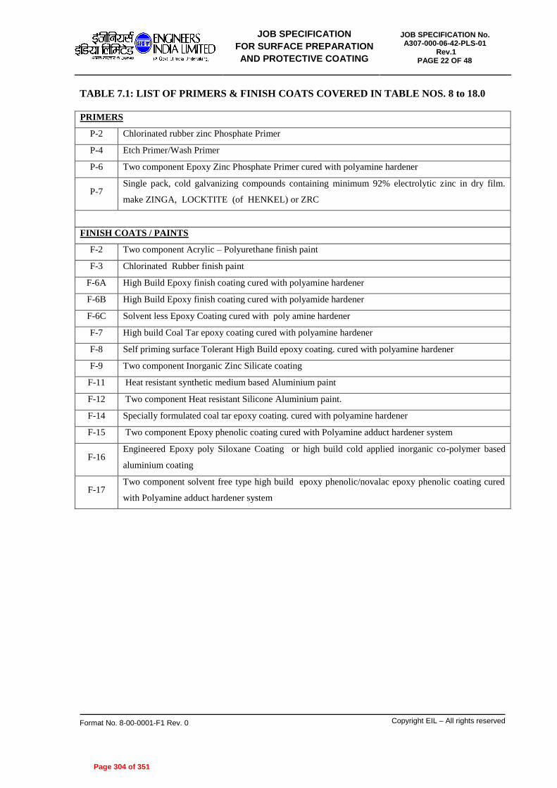
JOB SPECIFICATION
FOR SURFACE PREPARATION
AND PROTECTIVE COATING
JOB SPECIFICATION No. A307-000-06-42-PLS-01
Rev.1 PAGE 22 OF 48
Format No. 8-00-0001-F1 Rev. 0 Copyright EIL – All rights reserved
TABLE 7.1: LIST OF PRIMERS & FINISH COATS COVERED IN TABLE NOS. 8 to 18.0
PRIMERS
P-2 Chlorinated rubber zinc Phosphate Primer
P-4 Etch Primer/Wash Primer
P-6 Two component Epoxy Zinc Phosphate Primer cured with polyamine hardener
P-7 Single pack, cold galvanizing compounds containing minimum 92% electrolytic zinc in dry film.
make ZINGA, LOCKTITE (of HENKEL) or ZRC
FINISH COATS / PAINTS
F-2 Two component Acrylic – Polyurethane finish paint
F-3 Chlorinated Rubber finish paint
F-6A High Build Epoxy finish coating cured with polyamine hardener
F-6B High Build Epoxy finish coating cured with polyamide hardener
F-6C Solvent less Epoxy Coating cured with poly amine hardener
F-7 High build Coal Tar epoxy coating cured with polyamine hardener
F-8 Self priming surface Tolerant High Build epoxy coating. cured with polyamine hardener
F-9 Two component Inorganic Zinc Silicate coating
F-11 Heat resistant synthetic medium based Aluminium paint
F-12 Two component Heat resistant Silicone Aluminium paint.
F-14 Specially formulated coal tar epoxy coating. cured with polyamine hardener
F-15 Two component Epoxy phenolic coating cured with Polyamine adduct hardener system
F-16 Engineered Epoxy poly Siloxane Coating or high build cold applied inorganic co-polymer based
aluminium coating
F-17 Two component solvent free type high build epoxy phenolic/novalac epoxy phenolic coating cured
with Polyamine adduct hardener system
Page 304 of 351
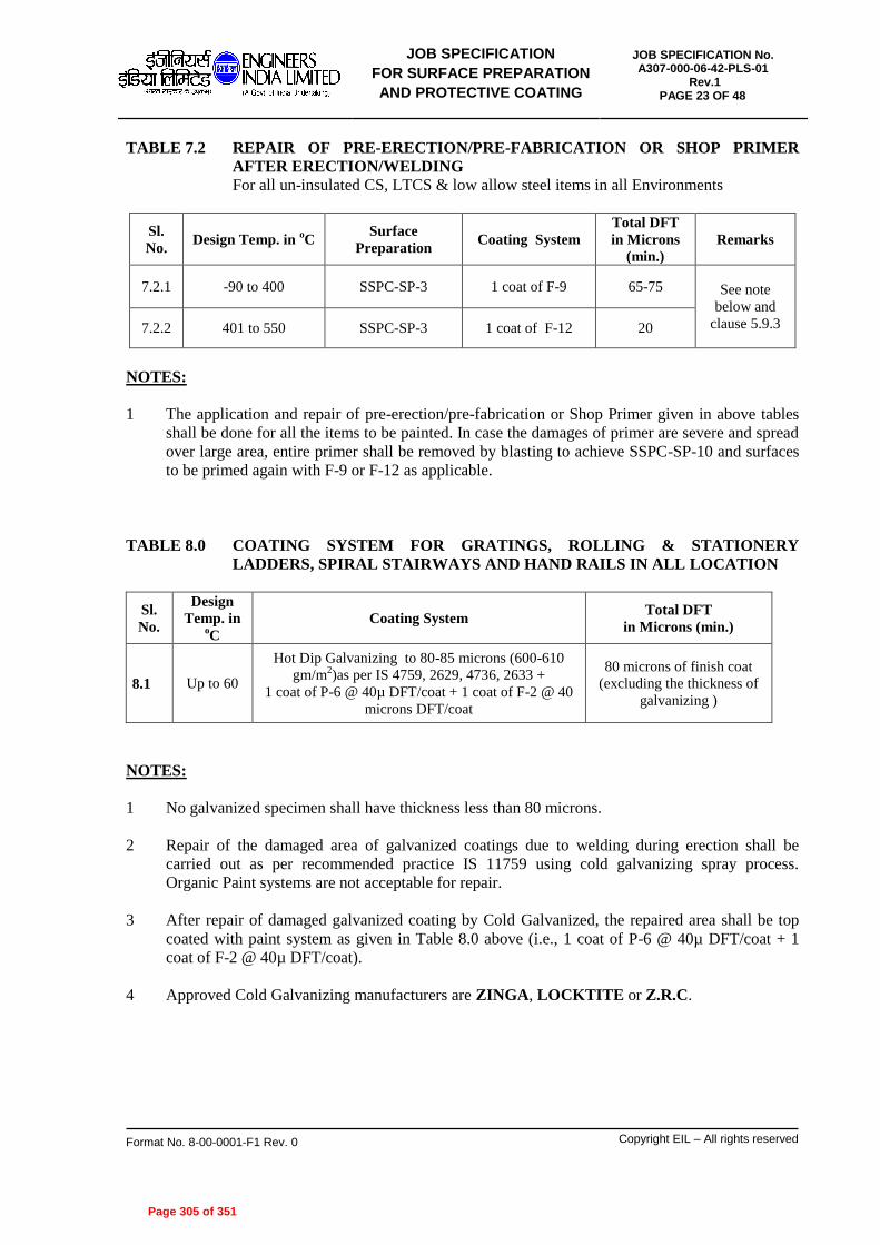
JOB SPECIFICATION
FOR SURFACE PREPARATION
AND PROTECTIVE COATING
JOB SPECIFICATION No. A307-000-06-42-PLS-01
Rev.1 PAGE 23 OF 48
Format No. 8-00-0001-F1 Rev. 0 Copyright EIL – All rights reserved
TABLE 7.2 REPAIR OF PRE-ERECTION/PRE-FABRICATION OR SHOP PRIMER
AFTER ERECTION/WELDING
For all un-insulated CS, LTCS & low allow steel items in all Environments
Sl.
No. Design Temp. in
oC
Surface
Preparation Coating System
Total DFT
in Microns
(min.)
Remarks
7.2.1 -90 to 400 SSPC-SP-3 1 coat of F-9 65-75 See note
below and
clause 5.9.3 7.2.2 401 to 550 SSPC-SP-3 1 coat of F-12 20
NOTES:
1 The application and repair of pre-erection/pre-fabrication or Shop Primer given in above tables
shall be done for all the items to be painted. In case the damages of primer are severe and spread
over large area, entire primer shall be removed by blasting to achieve SSPC-SP-10 and surfaces
to be primed again with F-9 or F-12 as applicable.
TABLE 8.0 COATING SYSTEM FOR GRATINGS, ROLLING & STATIONERY
LADDERS, SPIRAL STAIRWAYS AND HAND RAILS IN ALL LOCATION
Sl.
No.
Design
Temp. in oC
Coating System Total DFT
in Microns (min.)
8.1 Up to 60
Hot Dip Galvanizing to 80-85 microns (600-610
gm/m2)as per IS 4759, 2629, 4736, 2633 +
1 coat of P-6 @ 40µ DFT/coat + 1 coat of F-2 @ 40
microns DFT/coat
80 microns of finish coat
(excluding the thickness of
galvanizing )
NOTES:
1 No galvanized specimen shall have thickness less than 80 microns.
2 Repair of the damaged area of galvanized coatings due to welding during erection shall be
carried out as per recommended practice IS 11759 using cold galvanizing spray process.
Organic Paint systems are not acceptable for repair.
3 After repair of damaged galvanized coating by Cold Galvanized, the repaired area shall be top
coated with paint system as given in Table 8.0 above (i.e., 1 coat of P-6 @ 40µ DFT/coat + 1
coat of F-2 @ 40µ DFT/coat).
4 Approved Cold Galvanizing manufacturers are ZINGA, LOCKTITE or Z.R.C.
Page 305 of 351
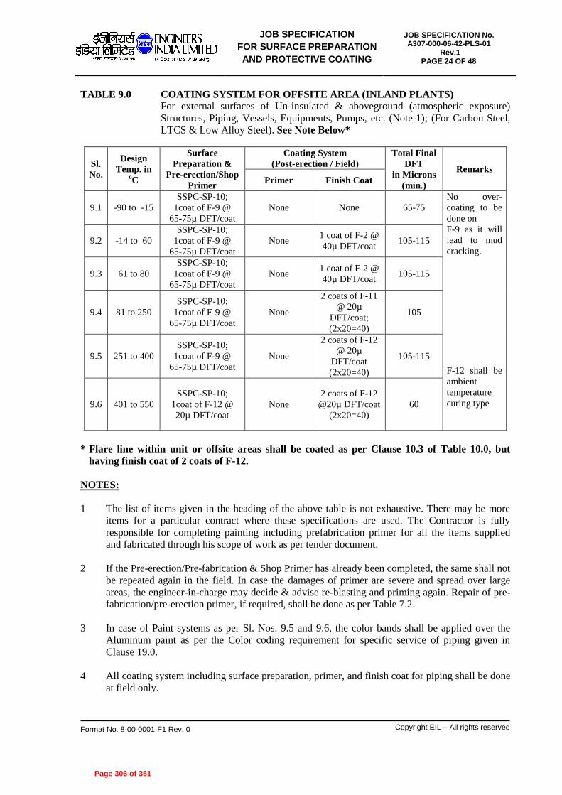
JOB SPECIFICATION
FOR SURFACE PREPARATION
AND PROTECTIVE COATING
JOB SPECIFICATION No. A307-000-06-42-PLS-01
Rev.1 PAGE 24 OF 48
Format No. 8-00-0001-F1 Rev. 0 Copyright EIL – All rights reserved
TABLE 9.0 COATING SYSTEM FOR OFFSITE AREA (INLAND PLANTS)
For external surfaces of Un-insulated & aboveground (atmospheric exposure)
Structures, Piping, Vessels, Equipments, Pumps, etc. (Note-1); (For Carbon Steel,
LTCS & Low Alloy Steel). See Note Below*
Sl.
No.
Design
Temp. in oC
Surface
Preparation &
Pre-erection/Shop
Primer
Coating System
(Post-erection / Field)
Total Final
DFT
in Microns
(min.)
Remarks
Primer Finish Coat
9.1 -90 to -15
SSPC-SP-10;
1coat of F-9 @
65-75µ DFT/coat
None None 65-75
No over-
coating to be
done on
F-9 as it will
lead to mud
cracking.
F-12 shall be
ambient
temperature
curing type
9.2 -14 to 60
SSPC-SP-10;
1coat of F-9 @
65-75µ DFT/coat
None 1 coat of F-2 @
40µ DFT/coat 105-115
9.3 61 to 80
SSPC-SP-10;
1coat of F-9 @
65-75µ DFT/coat
None 1 coat of F-2 @
40µ DFT/coat 105-115
9.4 81 to 250
SSPC-SP-10;
1coat of F-9 @
65-75µ DFT/coat
None
2 coats of F-11
@ 20µ
DFT/coat;
(2x20=40)
105
9.5 251 to 400
SSPC-SP-10;
1coat of F-9 @
65-75µ DFT/coat
None
2 coats of F-12
@ 20µ
DFT/coat
(2x20=40)
105-115
9.6 401 to 550
SSPC-SP-10;
1coat of F-12 @
20µ DFT/coat
None
2 coats of F-12
@20µ DFT/coat
(2x20=40)
60
* Flare line within unit or offsite areas shall be coated as per Clause 10.3 of Table 10.0, but
having finish coat of 2 coats of F-12.
NOTES:
1 The list of items given in the heading of the above table is not exhaustive. There may be more
items for a particular contract where these specifications are used. The Contractor is fully
responsible for completing painting including prefabrication primer for all the items supplied
and fabricated through his scope of work as per tender document.
2 If the Pre-erection/Pre-fabrication & Shop Primer has already been completed, the same shall not
be repeated again in the field. In case the damages of primer are severe and spread over large
areas, the engineer-in-charge may decide & advise re-blasting and priming again. Repair of pre-
fabrication/pre-erection primer, if required, shall be done as per Table 7.2.
3 In case of Paint systems as per Sl. Nos. 9.5 and 9.6, the color bands shall be applied over the
Aluminum paint as per the Color coding requirement for specific service of piping given in
Clause 19.0.
4 All coating system including surface preparation, primer, and finish coat for piping shall be done
at field only.
Page 306 of 351

JOB SPECIFICATION
FOR SURFACE PREPARATION
AND PROTECTIVE COATING
JOB SPECIFICATION No. A307-000-06-42-PLS-01
Rev.1 PAGE 25 OF 48
Format No. 8-00-0001-F1 Rev. 0 Copyright EIL – All rights reserved
TABLE 10.0 COATING SYSTEM FOR UNIT AREAS AS WELL AS DM, CPP,
COOLING TOWER OF INLAND PLANTS AND FOR ALL AREAS (UNIT,
OFFSITE, DM, CPP, etc.) OF COASTAL PLANTS
For external surfaces of un-insulated and above ground (atmospheric exposure)
structures, piping, vessels, equipments, external surface of MS chimney/stacks,
RCC chimney, internal surface of MS chimney without refractory lining, towers,
columns, pumps, compressors, blowers etc. of carbon steel, LTCS & low alloy
steels (note-1)
Sl.
No.
Design
Temp. in oC
Surface Preparation &
Pre-erection/Shop
Primer
Coating System
(Post-erection / Field)
Total DFT
in
Microns
(min.)
Remarks
Primer Finish Coat
10.1 -90 to -15
SSPC-SP-10;
1coat of F-9 @
65-75µ DFT/coat
None None 65-75
a) No over-
coating to be
done on
F-9 as it will
lead to mud
cracking.
b) F-12 shall
be ambient
temperature
curing type
c) Finish coat
including
primer
compatible
with finish
coat (i.e. field
primer) shall
be applied at
site only.
Finish
coating is not
permitted at
equipment
manufacture
shop.
10.2 -14 to 80
SSPC-SP-10;
1coat of F-9 @
65-75µ DFT/coat
1 coat of P-6
@ 40 µ
DFT/coat
2 coats of F-6A
@ 100 µ
DFT/coat + 1
coat of F-2 @
40µ DFT/coat;
(2x100 + 40=
240)
345-355
10.3 81 to 400
SSPC-SP-10;
1coat of F-9 @
65-75µ DFT/coat
None
2 coats of F-12
@ 20µ
DFT/coat
2x20=40
105-115
10.4 401 to 550
SSPC-SP-10;
1coat of F-12 @
20µ DFT/coat
None
2 coats of F-12
@ 20µ
DFT/coat;
(2x20=40)
60
NOTES:
1. The list of items given in the heading of the above table is not exhaustive. There may be more
items for a particular contract where these specifications are used. The Contractor is fully
responsible for completing painting including prefabrication primer for all the items supplied
and fabricated through his scope of work as per tender document.
2. If the Pre-erection/Pre-fabrication & Shop Primer has already been completed, the same shall not
be repeated again in the field. In case the damages of primer are severe and spread over large
Page 307 of 351

JOB SPECIFICATION
FOR SURFACE PREPARATION
AND PROTECTIVE COATING
JOB SPECIFICATION No. A307-000-06-42-PLS-01
Rev.1 PAGE 26 OF 48
Format No. 8-00-0001-F1 Rev. 0 Copyright EIL – All rights reserved
areas, the engineer-in-charge may decide & advise re-blasting and priming again. Repair of pre-
fabrication/pre-erection primer, if required, shall be done as per Table 7.2.
3. For external surface of MS chimney with or without refractory lining and for internal surface
without refractory lining, paint system as per 10.3 above shall be followed.
4. For external surface of RCC Chimney, 2 coats of F-6 @ 100µ DFT/coat to obtain total DFT of
200 µ shall be applied after proper surface preparation as per guidelines in 5.1.6.
5. In case of paint systems as per Sl. Nos. 10.3 and 10.4, the colour bands shall be applied over the
Aluminum paint as per the Color coding requirement for specific service of piping given in
Clause 19.0.
6. All coating system including surface preparation, primer, finish coat for piping shall be done at
site/field only.
Page 308 of 351
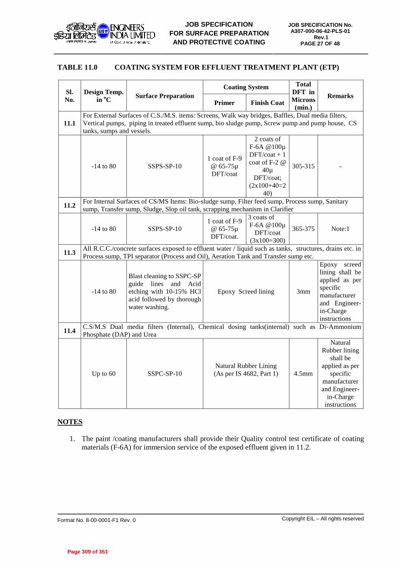
JOB SPECIFICATION
FOR SURFACE PREPARATION
AND PROTECTIVE COATING
JOB SPECIFICATION No. A307-000-06-42-PLS-01
Rev.1 PAGE 27 OF 48
Format No. 8-00-0001-F1 Rev. 0 Copyright EIL – All rights reserved
TABLE 11.0 COATING SYSTEM FOR EFFLUENT TREATMENT PLANT (ETP)
Sl.
No.
Design Temp.
in oC
Surface Preparation
Coating System Total
DFT in
Microns
(min.)
Remarks Primer Finish Coat
11.1
For External Surfaces of C.S./M.S. items: Screens, Walk way bridges, Baffles, Dual media filters,
Vertical pumps, piping in treated effluent sump, bio sludge pump, Screw pump and pump house, CS
tanks, sumps and vessels.
-14 to 80 SSPS-SP-10
1 coat of F-9
@ 65-75µ
DFT/coat
2 coats of
F-6A @100µ
DFT/coat + 1
coat of F-2 @
40µ
DFT/coat;
(2x100+40=2
40)
305-315 -
11.2 For Internal Surfaces of CS/MS Items: Bio-sludge sump, Filter feed sump, Process sump, Sanitary
sump, Transfer sump, Sludge, Slop oil tank, scrapping mechanism in Clarifier
-14 to 80 SSPS-SP-10
1 coat of F-9
@ 65-75µ
DFT/coat.
3 coats of
F-6A @100µ
DFT/coat
(3x100=300)
365-375 Note:1
11.3 All R.C.C./concrete surfaces exposed to effluent water / liquid such as tanks, structures, drains etc. in
Process sump, TPI separator (Process and Oil), Aeration Tank and Transfer sump etc.
-14 to 80
Blast cleaning to SSPC-SP
guide lines and Acid
etching with 10-15% HCl
acid followed by thorough
water washing.
Epoxy Screed lining 3mm
Epoxy screed
lining shall be
applied as per
specific
manufacturer
and Engineer-
in-Charge
instructions
11.4 C.S/M.S Dual media filters (Internal), Chemical dosing tanks(internal) such as Di-Ammonium
Phosphate (DAP) and Urea
Up to 60 SSPC-SP-10
Natural Rubber Lining
(As per IS 4682, Part 1)
4.5mm
Natural
Rubber lining
shall be
applied as per
specific
manufacturer
and Engineer-
in-Charge
instructions
NOTES
1. The paint /coating manufacturers shall provide their Quality control test certificate of coating
materials (F-6A) for immersion service of the exposed effluent given in 11.2.
Page 309 of 351

JOB SPECIFICATION
FOR SURFACE PREPARATION
AND PROTECTIVE COATING
JOB SPECIFICATION No. A307-000-06-42-PLS-01
Rev.1 PAGE 28 OF 48
Format No. 8-00-0001-F1 Rev. 0 Copyright EIL – All rights reserved
TABLE 12.0 EXTERNAL COATING SYSTEMS FOR UNINSULATED CARBON STEEL
AND LOW ALLOY STEEL STORAGE TANKS (For all plant locations, coastal
or inland)
All Process Units & Off-sites
Sl.
No.
Design Temp.
in oC
Surface
Preparation
(Field)
Coating system (Field)
(see note 1 below)
Total
DFT
in
Microns
(min.)
Remarks
Primer Finish Coat
12.1 All external surfaces of shell, wind girders, appurtenances, roof tops of all above ground tank including top
side of external and internal floating roof and associated external structural works.
12.1.1 -14 to 80 SSPC-SP-10
1coat of F-9 @ 65-75µ
DFT/coat + 1coat of P-6
@ 40µ DFT/ coat ;
2 coats of F-6A @
100µ DFT /coat + 1
coat of F-2 @ 40µ
DFT/ coat;
345-355
F-6 should
be suitable
for
occasional
water
immersion
12.1.2 81 to 150 SSPC-SP-10
1 coat of F-15 primer @
80µ DFT/ coat + 1 coat
of F-15 intermediate
coat @ 80µ DFT/coat ;
1 coat of F-15 finish
coat @80µ DFT/ coat +
1coat of F-2 @ 40µ
DFT/ coat;
280 -
12.1.3 151 to 500
SSPC-SP-10
1coat of F-9 @ 65-75µ
DFT/coat
2 coats of F-12 @20 µ
DFT/ coat
Or
1 coat of F-16 @ 50 µ
DFT / coat
105
or
115
-
12.2 External surfaces of bottom plate (soil side) for all storage tanks.
12.2.1 -14 to 80 SSPC-SP-10
1 coat of F-9 @
65-75µ DFT/ coat
3 coats of F-7@ 100µ
DFT/coat (3x100=300) 365-375
F-7 should
be suitable
for
immersion
service of
the
products
given
12.2.2 81 to 150 SSPC-SP-10
1 coat of F-15 primer @
80µ DFT/ coat + 1 coat
of F-15 intermediate
coat @ 80µ DFT/coat ;
(80+80=160)
1 coat of F-15 finish
coat @ 80µ DFT/ coat 240 -
12.2.3 151 to 550
SSPC-SP-10
1 coat of F-16 @ 125 µ
DFT /coat
1 coat of F-16 @ 125 µ
DFT /coat 250 -
12.3 For underside of the bottom plate (in case tank is not lifted during PWHT) (see Note 2c)
Page 310 of 351

JOB SPECIFICATION
FOR SURFACE PREPARATION
AND PROTECTIVE COATING
JOB SPECIFICATION No. A307-000-06-42-PLS-01
Rev.1 PAGE 29 OF 48
Format No. 8-00-0001-F1 Rev. 0 Copyright EIL – All rights reserved
12.3.1 -180 to 650
For CS
SSPC SP-6
Commercial
Blast 1 coat of inert polymeric
matrix coating @ 125 µ
2 coats of inert
polymeric matrix
coating @ 125 µ
350-400
Products
from
JOTUN or
HI-TEMP
coatings or
SK FORMULA
TIONS are
recommend
ed.
For SS
SSPC SP-1
with non-
chloride
solvent
NOTES
1. All paint coating application including primer for tankage shall be carried out at field after
erection and completion of all welding.
2. For underside of bottom plate :
a) Painting shall be carried out before laying of bottom plate for tanks with Non-Post Weld
Heat Treatment (PWHT).
b) For tanks with PWHT, painting shall be carried out after PWHT.
c) In case tank is not lifted during PWHT then painting shall be applied before laying of bottom
plate, clause no. 12.3.1 shall be followed.
Caution: PWHT temperature shall not exceed 650oC.
Page 311 of 351

JOB SPECIFICATION
FOR SURFACE PREPARATION
AND PROTECTIVE COATING
JOB SPECIFICATION No. A307-000-06-42-PLS-01
Rev.1 PAGE 30 OF 48
Format No. 8-00-0001-F1 Rev. 0 Copyright EIL – All rights reserved
TABLE 13.0 INTERNAL COATING SYSTEMS FOR CARBON STEEL AND LOW ALLOY
STORAGE TANKS
All Process Units & Off-sites
Sl.
No.
Design
Temp. in oC
Surface
Preparation
(Field)
Coating system (Field)
(see note 1 below)
Total
DFT
in
Microns
(min.)
Remarks
Primer Finish Coat
13.1
CRUDE OIL, ATF, TURPENTINE OIL, LUBRICATING OIL AND VEGETABLE OIL
Underside of floating roof, internal surface of cone roof, inside of bottom plate, Internal surfaces of Shell
- including wetted and free board height, oil side surfaces of deck plates, oil side surfaces of pontoons,
roof structures, structural steel, ladders and other CS internals
13.1.
1 -14 to 90 SSPC-SP-10
1 coat of F-15 primer @
80µ DFT/ coat
1 coat of F-15
intermediate coat @
80µ DFT/coat + 1 coat
of F-15 finish coat @
80µ DFT/ coat;
240-300 -
13.2
PETROLEUM PRODUCTS & INTERMEDIATES like LDO, HSD , GAS OIL, FEEDS of
FCC-PC, FCC-LCO, VGO-HDT, ISOM, DHDT, REFORMATE, DCU, NHT & GASOLINE,
NAPHTHA, ISOMERATE AND KEROSENE. Underside of Floating roofs, internal surface of cone roof, inside of bottom plate, internal surfaces of
Bare shell for full height, underside of floating roof, oil side surfaces of deck plates, oil side surfaces of
pontoons, support structures and ladders etc.
13.2.
1 -14 to 45 SSPC-SP-10
1 coat of F-9 @
75 µ DFT/coat - 75 Note 2
13.2.
2 46 to 90 SSPC-SP-10
1 coat of F-15 primer @
80µ DFT/ coat
1 coat of F-15
intermediate coat @
80µ DFT/coat + 1 coat
of F-15 finish coat @
80µ DFT/ coat;
240-300 -
13.3 POTABLE AND FIRE WATER
All internal surfaces, accessories and roof structures of Cone and Dome roof tanks
13.3.
1 -14 to 60 SSPC-SP-10
1 Coats of P-6 @
100 µ DFT/coat;
2 Coats of F-6A @
100µ DFT/ Coat;
(2x100=200)
300-350 Note-4
13.4 DE-MINERALIZED (DM) WATER
All internal surfaces, accessories and roof structures of Cone and Dome roof tanks
13.4.
1 -14 to 60 SSPC-SP-10
1 Coats of P-6 @
100µ DFT/coat;
2 coats of F-6C @
200µ DFT/ coat;
(2x200=400)
400-450 -
13.4.
2 61 to150 SSPC-SP-10
1 coat of F-15 primer @
80µ DFT/ coat
1 coat of F-15
intermediate coat @
80µ DFT/coat + 1 coat
of F-15 finish coat @
80µ DFT/ coat;
(80+80=160)
240-300 -
13.5 HYDROCHLORIC ACID (HCl) 10 %
All internal surfaces, accessories and roof structures of Cone and Dome roof tanks
13.5.
1 -14 to 60 SSPC-SP-10 None Natural Rubber Lining 4.5 mm -
Page 312 of 351

JOB SPECIFICATION
FOR SURFACE PREPARATION
AND PROTECTIVE COATING
JOB SPECIFICATION No. A307-000-06-42-PLS-01
Rev.1 PAGE 31 OF 48
Format No. 8-00-0001-F1 Rev. 0 Copyright EIL – All rights reserved
13.6 AGGRESSIVE SOLVENTS LIKE HEXANE, HEXENE, BENZENE, XYLENE AND TOLUENE
All internal surfaces, accessories and roof structures of Cone and Dome roof tanks
13.6.
1 -14 to 65 SSPC-SP-10
1 coat of F-9 @ 75µ
DFT/ coat --- 75 -
13.7 ETHYLENE GLYCOL (EG) TANKS
Internal shell-full height, bottom plate, underside of roof and all accessories
13.7.
1 All SSPC-SP-10 None
3 coats of vinyl
chloride co-polymer
AMERCOAT 23 @
75µ /Coat;
(3x75=225)
225 -
13.8 Inside pontoon and inside of double deck of all floating roofs
13.8.
1 -14 to 80 SSPC-SP-3
1 coat of F-8 @ 100µ
DFT/coat
1 coat of F-8 @ 100µ
DFT/coat 200 -
13.9 WET SLOPS, AMINE solutions, SOUR WATER , WATER DRAW OFF
All internal surfaces, accessories and roof structures of Cone and Dome roof tanks
13.9.
1 -14 to 90 SSPC-SP-10
1 coat of F-15 primer @
80µ DFT/ coat
1 coat of F-15
intermediate coat @
80µ DFT/coat + 1 coat
of F-15 finish coat @
80µ DFT/ coat;
(80+80=160)
240 -
13.10
VACUUM RESIDUE, FUEL OIL , DRY SLOP, BITUMEN AND OTHER HIGH TEMPERATURE
HYDROCARBON LIQUIDS
Underside of floating roof, internal surface of cone roof, bottom plate, inside of bare shell – including
wetted and non wetted surfaces, oil side surfaces of deck plates, oil side surfaces of pontoons, roof
structures, structural steel and ladders
13.10
.1 Up to 150
oC SSPC-SP-10
1 coat of F-17 primer
@ 125µ DFT/ coat
1 coat of F-17
intermediate coat @
125µ DFT/coat + 1 coat
of F-17 finish coat
@125µ DFT/ coat;
(125+125=250)
375 Note:3
13.11 ALKALIS UP TO 50 % CONCENTRATION
All internal surfaces, accessories and roof structures of Cone and Dome roof tanks
13.11
.1 Up to 60
oC SSPC-SP-10
1 coat of F-15 primer @
80µ DFT/ coat
2 Coats of F-6 A @
100µ DFT/coat;
(2x100=200)
280-100 -
NOTES
1. All paint coating application including primer shall be carried out after erection and completion
of all welding work at site.
2. F-6A should be suitable and resistant for immersion service for the respective Hydrocarbons.
3. This system can be used where maximum operating temperature is below 150oC and design
temperature is upto 200oC. Cases of operating temperature > 150
oC are not covered in this spec,
such cases shall be covered in the job specifications.
4 F-6 A shall be suitable for drinking water service and should have competent authority
certification.
Page 313 of 351

JOB SPECIFICATION
FOR SURFACE PREPARATION
AND PROTECTIVE COATING
JOB SPECIFICATION No. A307-000-06-42-PLS-01
Rev.1 PAGE 32 OF 48
Format No. 8-00-0001-F1 Rev. 0 Copyright EIL – All rights reserved
TABLE 14.0 COATING SYSTEMS FOR EXTERNAL SIDE OF UNDERGROUND
CARBON STEEL PLANT PIPING AND UNDERGROUND VESSELS
Sl.
No.
Design
Temp. in oC
Surface
Preparation
&
Shop Primer
Coating system (Field) Total Final
DFT
in Microns
(min.)
Remarks Surface
Preparation &
Primer
Finish Coat
14.1 Underground carbon steel plant piping
14.1.1 25 to 65 ---
SSPC-SP-10;
1 coat of synthetic
fast drying primer
25 @µ DFT/ coat
1 layer of coaltar tape
coating @ 2mm +1
coat of synthetic fast
drying primer 25 @µ
DFT/ coat + 1 layer of
coal tar tape coating @
2mm /layer as per
EIL Standard
Specification .No
6-79-0011
4 mm
The primer
DFT is not
measurable.
Reconciliation
primer shall
be done by
coverage of
maximum 10
sq.m/litre
14.2.1 66 to 150 ---
SSPC-SP-10;
1 coat of F-17
primer @ 125µ
DFT/ coat
1 coat of F-17
intermediate coat @
125µ DFT/coat + 1
coat of F-17 finish
coat @125µ DFT/ coat
375 -
14.2.2 151 to 400 ---
SSPC-SP-10;
1 coat of F-16
primer @ 125µ
DFT/ coat
1 coat of F-16 finish
coat @125µ DFT/ coat 250 -
14.3 External side of un-insulated underground storage vessels
14.3.1 -40 to 80
SSPC-SP-10;
1 coat of F-9
@
65-75µ DFT/
coat
--- 3 coats of F-7 @ 100µ
DFT/coat 365-375 -
14.3.2 81 to 150
SSPC-SP-10;
1 coat of F-17
primer @
125µ DFT/
coat
---
1 coat of F-17
intermediate coat @
125µ DFT/coat + 1
coat of F-17 finish
coat @125µ DFT/ coat
375 -
14.3.3 151 to 400
SSPC-SP-10;
1 coat of F-16
primer @
125µ DFT/
coat
--- 1 coat of F-16 finish
coat @125µ DFT/ coat 250 -
Page 314 of 351

JOB SPECIFICATION
FOR SURFACE PREPARATION
AND PROTECTIVE COATING
JOB SPECIFICATION No. A307-000-06-42-PLS-01
Rev.1 PAGE 33 OF 48
Format No. 8-00-0001-F1 Rev. 0 Copyright EIL – All rights reserved
TABLE 15.0 COATING UNDER INSULATION (COASTAL OR INLAND PLANTS). ALL
UNITS AREAS & OFF-SITES
For insulated Piping, Equipments, Storage vessels, tanks, Columns etc of Carbon
Steel, LTCS, Low Alloy Steel & Stainless Steels
Sl.
No.
Design
Temp. in oC
Surface
Preparation &
Pre-
erection/Shop
Primer
Coating System
(Post-erection / Field)
Total
Final
DFT
in
Microns
(min.)
Remarks Primer/
Intermediate Finish Coat
15.1 Carbon steel, LTCS and low Alloy steel Piping
15.1.1 -45 to 120
SSPC-SP-10;
1coat of F-15 @
75µ DFT/coat
1 coat of F-15 @
75µ DFT/coat
2 coats of F-15 @
75µ DFT/coat;
(2x75= 150)
225- 250 -
15.1.2 121-540
SSPC-SP-10;
1coat of F-12 @
20µ DFT/coat
None
2coat of F-12 @
20µ DFT/coat;
(2x20=40)
60 -
15.2 Carbon steel, LTCS and low Alloy steel - Storage vessels, Reactors, Columns & Equipments
15.2.1 -45 to 120
SSPC-SP-10;
1coat of F-15 @
75µ DFT/coat
1 coat of F-15 @
75µ DFT/coat
2 coats of F-15 @
75µ DFT/coat;
(2x75= 150)
300 -
15.2.2 121 to 400
SSPC-SP-10;
1 coat of F-9 @
65-75 µ DFT/coat
None
3 coats of F-12 @
20µ DFT/coat
OR
1 coat of F-16 @
60 µ DFT/coat
125-135 -
15.3 Stainless Steel (SS) including Alloy-20 piping (Note:2)
15.3.1 -180 to Zero
For CS
SSPC SP-6
Commercial Blast 1 coat of inert
polymeric matrix
coating @ 125 µ
2 coats of inert
polymeric matrix
coating @ 125 µ
350-400
Products from
JOTUN or HI-
TEMP coatings or
SK FORMULATIONS are recommended.
For SS
SSPC SP-1 with
non-chloride
solvent
15.3.2 0 to 125
SSPC-SP-10
(15-25µ surface
profile)
1 coat of F-15@
80 µ DFT/coat
1 coat of F-15
intermediate coat
@80 µ DFT/coat
1 coat of F-15
finish coat@ 80
µ DFT/coat;
240
If the piping &
equipments are
already erected
then surface shall
be prepared by
cleaning with
emery paper and
wash/flush with
chloride free DM
water followed by
wiping with
organic solvent
15.3.3 126 to 400
SSPC-SP-10
1 coat of F-16 @
125 µ DFT/coat
None 1 coat of F-16 @
125 µ DFT/coat 250
Not recommended
for operating
temperature
Page 315 of 351

JOB SPECIFICATION
FOR SURFACE PREPARATION
AND PROTECTIVE COATING
JOB SPECIFICATION No. A307-000-06-42-PLS-01
Rev.1 PAGE 34 OF 48
Format No. 8-00-0001-F1 Rev. 0 Copyright EIL – All rights reserved
15.3.4 401 to 600
SSPC SP-10;
1 coat of
Amercoat 738@
125 µ DFT/coat
None
1 coat of
Amercoat 738@
125 µ DFT/coat
250
between
60 – 120 °C
15.4 Coating system for Cyclic Service of Carbon Steel, LTCS, Low Alloy Steel & Stainless Steel
15.4.1 - 40 to 150
SSPC-SP-10
(15-25µ surface
profile)
1 coat of F-15 @
80 µ DFT/coat
1 coat of F-15
intermediate coat
@ 80µ DFT/coat
1 coat of F-15
finish coat @
80µ DFT/coat;
240
Apcothern EPN
200 of M/s Asian
Paints Ltd
OR
Equivalent
15.4.2 -180 to 650
For CS
SSPC SP-6
Commercial Blast 1 coat of inert
polymeric matrix
coating @ 125 µ
2 coats of inert
polymeric matrix
coating @ 125 µ
350-400
Products from
JOTUN or HI-
TEMP coatings or SK
FORMULATIONS are recommended.
For SS
SSPC SP-1 with
non-chloride
solvent
15.5 No painting is required for insulated Monel, Incoloy and Nickel lines.
NOTES
1. “Cyclic Service” is characterized by rapid temperature fluctuation.
2. The blast cleaning abrasives for SS and Alloy steel surfaces shall be Aluminium oxide
grits/shots or garnet.
3. In case of overlapping of temperature ranges as mentioned in 15.4.1 and 15.4.2, clause 15.4.1
shall be followed.
TABLE 16.0 COATING SYSTEM FOR CARBON STEEL COMPONENTS OF COOLERS /
CONDENSERS (INTERNAL PROTECTION) FOR FRESH WATER SERVICE
Fresh Water boxes, channels, partition plates, end covers and tube sheets etc.
Sl.
No.
Design
Temp. in oC
Surface Preparation
& Pre-erection/Shop
Primer
Coating System
(Post-erection / Field)
Total
Final DFT
in Microns
(min.)
Remarks
Primer Finish paint
16.1 Up to 80 oC SSPC-SP-10
1 coat of F-15
@ 80 microns
2 coats of F-15 @
80µ DFT/coat; 240 -
16.2 80 to 140 SSPC-SP-10 ---
1 coat of Glass
Fibre Reinforced
Novolac epoxy of
1.5 mm DFT
1500 -
Page 316 of 351
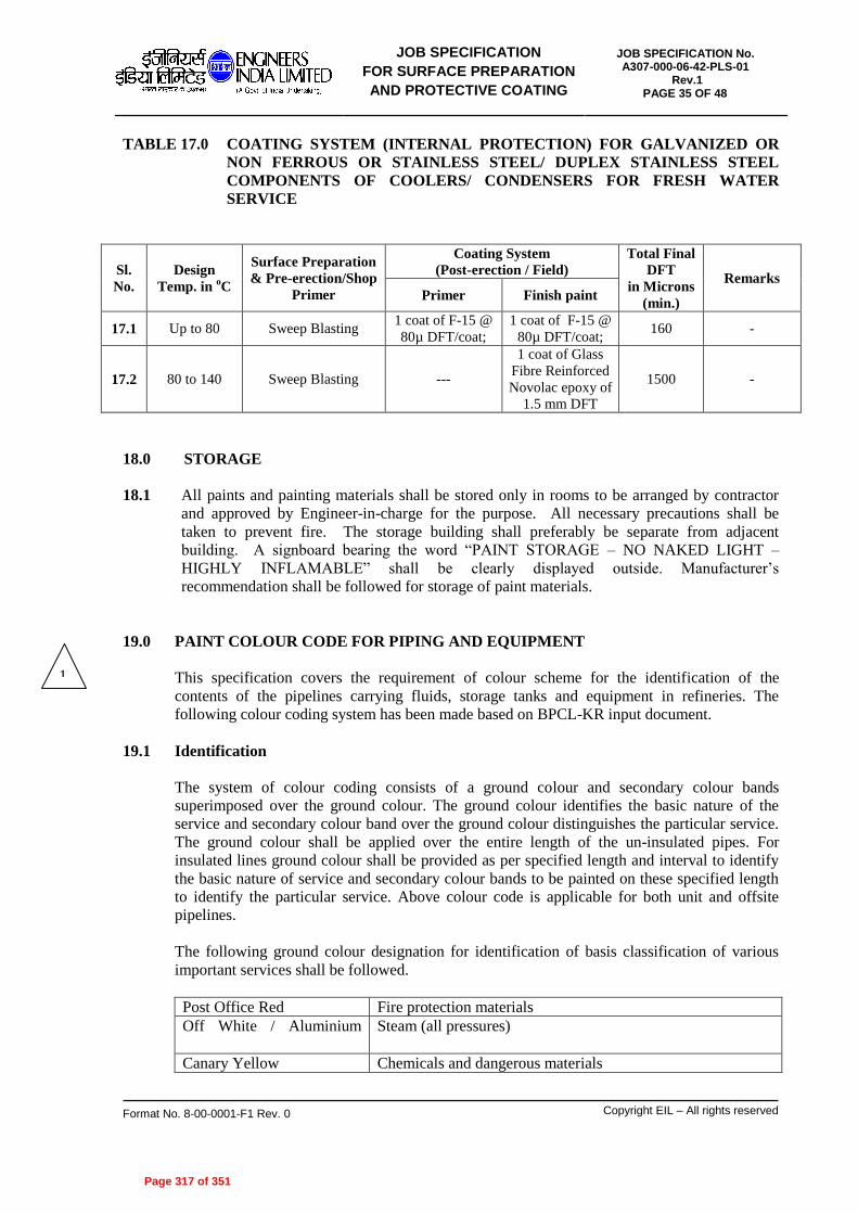
JOB SPECIFICATION
FOR SURFACE PREPARATION
AND PROTECTIVE COATING
JOB SPECIFICATION No. A307-000-06-42-PLS-01
Rev.1 PAGE 35 OF 48
Format No. 8-00-0001-F1 Rev. 0 Copyright EIL – All rights reserved
TABLE 17.0 COATING SYSTEM (INTERNAL PROTECTION) FOR GALVANIZED OR
NON FERROUS OR STAINLESS STEEL/ DUPLEX STAINLESS STEEL
COMPONENTS OF COOLERS/ CONDENSERS FOR FRESH WATER
SERVICE
Sl.
No.
Design
Temp. in oC
Surface Preparation
& Pre-erection/Shop
Primer
Coating System
(Post-erection / Field)
Total Final
DFT
in Microns
(min.)
Remarks
Primer Finish paint
17.1 Up to 80 Sweep Blasting 1 coat of F-15 @
80µ DFT/coat;
1 coat of F-15 @
80µ DFT/coat; 160 -
17.2 80 to 140 Sweep Blasting ---
1 coat of Glass
Fibre Reinforced
Novolac epoxy of
1.5 mm DFT
1500 -
18.0 STORAGE
18.1 All paints and painting materials shall be stored only in rooms to be arranged by contractor
and approved by Engineer-in-charge for the purpose. All necessary precautions shall be
taken to prevent fire. The storage building shall preferably be separate from adjacent
building. A signboard bearing the word “PAINT STORAGE – NO NAKED LIGHT –
HIGHLY INFLAMABLE” shall be clearly displayed outside. Manufacturer’s
recommendation shall be followed for storage of paint materials.
19.0 PAINT COLOUR CODE FOR PIPING AND EQUIPMENT
This specification covers the requirement of colour scheme for the identification of the
contents of the pipelines carrying fluids, storage tanks and equipment in refineries. The
following colour coding system has been made based on BPCL-KR input document.
19.1 Identification
The system of colour coding consists of a ground colour and secondary colour bands
superimposed over the ground colour. The ground colour identifies the basic nature of the
service and secondary colour band over the ground colour distinguishes the particular service.
The ground colour shall be applied over the entire length of the un-insulated pipes. For
insulated lines ground colour shall be provided as per specified length and interval to identify
the basic nature of service and secondary colour bands to be painted on these specified length
to identify the particular service. Above colour code is applicable for both unit and offsite
pipelines.
The following ground colour designation for identification of basis classification of various
important services shall be followed.
Post Office Red Fire protection materials
Off White / Aluminium
Steam (all pressures)
Canary Yellow Chemicals and dangerous materials
1
Page 317 of 351

JOB SPECIFICATION
FOR SURFACE PREPARATION
AND PROTECTIVE COATING
JOB SPECIFICATION No. A307-000-06-42-PLS-01
Rev.1 PAGE 36 OF 48
Format No. 8-00-0001-F1 Rev. 0 Copyright EIL – All rights reserved
Dark Admiralty Grey Crude oil, lube oil
Orange Volatile petroleum products (motor sprit and lighter)
Oxide red Non-Volatile petroleum products (kerosene and heavier,
including waxy distillates and diesel, gas oil)
Black Residual oils, still bottoms, slop oils and asphalts, fuel oil
Sky blue Water (all purities and temperatures)
Sea green Air and its components and Freon
Secondary colours: The narrow bands presenting the secondary colour which identifies the
specific service may be applied by painting or preferably by use of adhesive plastic tapes of
the specific colour.
19.2 Colour Bands and Identification Lettering
The following specifications of colour bands shall be followed for identifying the piping
contents, size and location of bands & letters. The bandwidth and size of letters in legends will
depend to some extent upon the pipe diameter. Either white or black letters are selected to
provide maximum contrast to the band colour. Bands usually are 100 mm wide and regardless
of band width, are spaced 50 mm apart when two bands are employed.
Colour bands and size of lettering for piping:
Outside diameter of pipe
or covering in mm
Width of colour bands in
mm
Size of legend Letters in
mm
19 to 32 200 13
38 to 51 200 19
64 to 150 300 32
200 to 250 600 64
Over 250 800 89
Contrast shall be provided between color field and legend for readability. Use of letters
standard style, in sizes, 1/2inch (13mm) and larger, is recommended. See above table for
specific size recommendations. For identification of materials in pipes of less than ¾ inch
(19mm) in diameter, and for valve and fitting identification, the use of permanently legible tag
is recommended.
In addition, ground colour as per specified length should be provided on insulated piping for
easy identification of nature of fluid, on which the colour bands should be painted for
identification of each service. The length of the ground colour should be 3 times the width of
normal bands or 2 meters, whichever is suitable depending on the length of the pipe.
Arrows shall be used to indicate direction of flow. Where flow can be in both directions,
arrows in both directions shall be displayed.
Positive identification of the contents of a piping system shall be by lettered legend, giving the
name of the contents in full or abbreviated form. Contents shall be identified by a legend with
sufficient additional details such as temperature, pressure, etc as are necessary to identify the
hazard. Legends shall be brief, informative, pointed and simple of greatest effectiveness.
Legends shall be applied close to valves or flanges and adjacent to changes in direction,
branches and where pipes pass through walls or floors, where it enters and emerges from road,
Page 318 of 351

JOB SPECIFICATION
FOR SURFACE PREPARATION
AND PROTECTIVE COATING
JOB SPECIFICATION No. A307-000-06-42-PLS-01
Rev.1 PAGE 37 OF 48
Format No. 8-00-0001-F1 Rev. 0 Copyright EIL – All rights reserved
culvert and walkway overpasses, unit battery limits and at every 50m intervals on straight pipe
runs sufficient for identification. Identification may be accomplished by stencilling, the use of
tape, or markers. In any situation, the number and location of identification markers shall be
based on the particular piping system.
The letters will be in black on pipes painted with light shade colours and white on pipes
painted with dark shade colours to give good contrast.
Only writing of service name shall be done on stainless steel lines. Precautions should be taken
while painting by using low chloride content painting to avoid any damage to the stainless
steel pipes. It is preferable to use adhesive plastic tapes to protect stainless steel pipes.
Visibility:
Attention shall be given to visibility with reference to pipe markings. Where pipelines are
located above or below the normal line of vision, the lettering shall be placed below or above
the horizontal centreline of the pipe.
Size of letters stencilled / written for equipment shall be as given below:
Column and vessel : 150
mm (Height)
Pump, compressor and other machinery : 50 mm (Height)
In addition, the contents of the pipe and/or direction of flow may be further indicated by
arrows and legend. If a hazard is involved it must be identified clearly by legend.
Colour bands: The location and size of bands, as recommended, when used, shall be
applied to the pipe.
- On both sides of the valves, tees and other fittings of importance.
- Where the pipe enters and emerges from walls and where it emerges from road &
walkway overpasses, unit battery limits.
- At uniform intervals along long sections of the pipe.
- Adjacent to tanks, vessels and pumps.
Colour band specification:
a) Bands at intervals of 50 meters for the long stretch of pipelines
b) Each pipe segment will have minimum one band indication, irrespective of length.
c) The bands shall also be displayed near walkways, both sides of culverts, tanks dykes,
tanks, vessels, suction and discharge of pumps / compressors, unit battery limit, near
valves of line, etc.
For alloy steel / stainless steel pipes and fittings in stores / fabrication yard, colour band
(Minimum ½” wide) should be applied along the complete length of pipe, bends / tees, side-
covered surface (on thickness) of flanges as well as valves as per the metallurgy.
Unusual or Extreme situations
When the piping layout creates or occurs in a limited area of inaccessibility or of extreme
complexity, such segments of layouts may require substitute techniques shall be limited to
such segments and shall not deviate from the concept of identification as defined above.
Page 319 of 351

JOB SPECIFICATION
FOR SURFACE PREPARATION
AND PROTECTIVE COATING
JOB SPECIFICATION No. A307-000-06-42-PLS-01
Rev.1 PAGE 38 OF 48
Format No. 8-00-0001-F1 Rev. 0 Copyright EIL – All rights reserved
The specification for application of the complete Piping identification colour code, including
base and bands colours, are presented in the below table.
Sl.
No. SERVICE GROUND COLOUR
FIRST COLOUR
BAND
SECOND
COLOUR BAND
I WATER
01 Drinking Water Sea Green French Blue Signal Red
02 DM Water Sea Green Gulf Red
03 Cooling Water Sea Green French Blue
04 Boiler Feed Water Sea Green Gulf Red
05 Steam Condensate Sea Green Light Brown
06 Raw Water Sea Green Oxide Red
07 Tempered Water Insulated With Green Band
08 Sour Water Sea Green Yellow
09 Stripped Water Sea Green Gulf Red
10 Fire Water Fire Red
11 Wash Water Sea Green Canary Yellow
12 ETP Treated water Sea Green Canary Yellow Canary Yellow
II STEAM
01 Very High Pressure Steam Aluminium To IS 2339 Signal Red
02 High Pressure Steam Aluminium To IS 2339 French Blue
03 Medium Pressure Steam Aluminium To IS 2339 Gulf Red
04 Low Pressure Steam Aluminium To IS 2339 Canary Yellow
05 Very Low Pressure Steam Aluminium To IS 2339 Grey
06 Low Medium Pressure Steam Aluminium To IS 2339 Light Brown
07 Condensate Aluminium To IS 2339 Grey Canary Yellow
III AIR/OTHER GASES
01 Process Air Sky Blue Signal Red
02 Plant Air Sky Blue Silver Grey
03 Instrument Air Sky Blue French Blue
04 Nitrogen Canary Yellow Black
05 Oxygen Canary Yellow White
06 Freon Canary Yellow Light Grey Dark Violet
07 Sweet Fuel Gas Canary Yellow Grey
08 Sour Fuel Gas Canary Yellow Grey Dark Violet
09 Acid Gas Orange Grey
10 H2S Canary Yellow French Blue
11 Hydrogen Canary Yellow Signal Red French Blue
IV CHEMICALS
01 Caustic Smoke Grey Light Orange
02 Chlorine Canary Yellow Dark Violet Light Orange
03 Ammonia Canary Yellow Dark Violet
04 Corrosion Inhibitor Yellow Aluminium
Page 320 of 351

JOB SPECIFICATION
FOR SURFACE PREPARATION
AND PROTECTIVE COATING
JOB SPECIFICATION No. A307-000-06-42-PLS-01
Rev.1 PAGE 39 OF 48
Format No. 8-00-0001-F1 Rev. 0 Copyright EIL – All rights reserved
05 Sulfolane Azure Blue Yellow
06 Mono Ethanol Amine Light Yellow Brown
07 Lean DEA Light Yellow Blue
08 Rich DEA Light Yellow Red
09 Lo-Cat Solution Canary Yellow Smoke Grey
10 Anti-Foam Light Yellow Grey
11 De-Mulsifier Light Yellow Black
12 DMDS Black Gulf Red
V HYDROCARBONS
01 LPG Dark Ad. Grey Brilliant Green Dark Violet
02 Naphtha Dark Ad. Grey Light brown Black
03 Benzene Dark Ad. Grey Canary Yellow
04 Toluene Orange Blue Green
05 Reformate Dark Ad. Grey Blue
06 LAN (Low Aromatic Naphtha) Dark Ad. Grey Brilliant Green
07 Mixed Aromatic Solvent Orange Brilliant Green
08 Motor Spirit (MS) Orange Blue
09 Heavy Naphtha Light Brown Brilliant Green Red
10 Kerosene Light Brown Brilliant Green Dark Violet
11 LGO (Light Gas Oil) Light Brown Brilliant Green
12 HGO (Heavy Gas Oil) Light Brown Brilliant Green
13 High Speed Diesel Light Brown Brilliant Green
14 ATF (Aviation Turbine Fuel) Light Blue White
15 VDO (Vacuum Diesel Oil) Light Brown Brilliant Green
16 VGO (Vacuum Gas Oil) Steel Grey Red
17 Slop Distillate Steel Grey Black Red
18 VR (Vacuum Residue) Steel Grey Black Green
19 Slop Steel Grey Black
20 Crude Oil Light Brown Yellow
21 Fuel Oil Steel Grey Yellow
22 Flushing Oil Light Brown Yellow
23 Flare Line Heat Resistant Aluminium
24 Reduced Crude Oil Steel Grey Black Signal Red
25 LCO (Light Cycle Oil) Light Brown Brilliant Green Yellow
26 HCO (Heavy Cycle Oil) Light Brown Brilliant Green Light Orange
27 CLO (Clarified Oil) Steel Grey Black French Blue
28 Propylene Dark Ad. Grey Signal Red Black
29 Reject Olefin Dark Ad. Grey Light Grey French Blue
30 Butane Dark Ad. Grey Signal Red Light Brown
31 Iso Butylene Dark Ad. Grey Brilliant Green Gulf Red
32 SBPS Dark Ad. Grey White Gulf Red
33 MTO Light Blue Green
34 Bitumen Dark Grey Signal Red Brilliant Green
35 HAN Dark Ad. Grey Brilliant Green
Page 321 of 351

JOB SPECIFICATION
FOR SURFACE PREPARATION
AND PROTECTIVE COATING
JOB SPECIFICATION No. A307-000-06-42-PLS-01
Rev.1 PAGE 40 OF 48
Format No. 8-00-0001-F1 Rev. 0 Copyright EIL – All rights reserved
36 Heavy Kerosene Light Blue Black
37 RLNG Canary Yellow Signal Red Light Brown
Sl. No. . SERVICE RECOMMENDED COLOUR CODE
VI INSULATED HYDROCARBON PIPING
01 IFO Supply 1 Black ground colour with 1 yellow band in centre
02 IFO Return 1 Black ground colour with 1 green band in centre
03 HPS 1 Black ground colour with 1 red band in centre
04 Bitumen 1 Black ground colour with 2 red band in centre
05 CLO 1 Black ground colour with 1 brown band in centre
06 VB Tar 1 Black ground colour with 2 brown band in centre
07 VR AM (Bitumen / VBU Feed) 1 Black ground colour with 1 blue band in centre
08 VR BH 1 Black ground colour with 2 blue band in centre
09 VAC Slop 1 Black ground colour with 1 white band in centre
10 Slop 1 Steel grey ground colour with 1 black band in centre
11 Crude Sweet 1 Light brown ground colour with 1 yellow band in centre
12 Crude Sour 1 Light brown ground colour with 1 orange band in centre
13 VGO / HCU Feed 1 Oxide red ground colour with 1 steel grey band in centre
14 OHCU Bottom / FCCU Feed 1 Oxide red ground colour with 2 steel grey band in centre
VII UNINSULATED EQUIPMENT, TANKS AND STRUCTURES
01 Heater Structure Dark Admiralty Grey
02 Heater Casing Heat Resisting Aluminium
03 Vessels & Columns Aluminium
04 Hydrogen Bullets Pink
05 LPG Vessels White (Reflective Paint)
06 SO2 Canary Yellow
07 Heat Exchangers Heat Resisting Aluminium
08 FO Tank & Hot Tanks Black
09 All Other Tanks Aluminium / Off White
10 Caustic / Amine / Acid Tanks Golden Yellow
11 Sour Water Sky Blue
12 Outer Surface In Boiler House Heat Resisting Aluminium
13 Compressors & Blowers Dark Admiralty Grey
14 Pumps Navy Blue
15 Motors & Switch Gear Bluish Green
16.1 Hand Railing - Hand Railing Middle Rail,
Toe Plate Signal Red
16.2 Hand Railing – Vertical Post Black
17.1 Ladder - Rungs Black
17.2 Ladder – Vertical & Cage Signal Red
Page 322 of 351

JOB SPECIFICATION
FOR SURFACE PREPARATION
AND PROTECTIVE COATING
JOB SPECIFICATION No. A307-000-06-42-PLS-01
Rev.1 PAGE 41 OF 48
Format No. 8-00-0001-F1 Rev. 0 Copyright EIL – All rights reserved
18 Load Lifting Equipment & Mono Rails Etc. Leaf Brown
19 Steel Structure Dark Admiralty Grey
19.3 PAINTING COLOUR CODE FOR STRUCTURAL STEEL
1. GANTRY GIRDER & MONORAIL DARK GREEN
2. GANTRY GIRDER & MONORAIL STOPPER SIGNAL RED
3. BUILDING STRUCTURAL STEEL COLUMNS, DARK ADMIRALITY
BRACKETS, BEAMS, BRACINGS, ROOF TRUSS, GREY
PURLINS, SIDEGIRTS, LOUVERS, STRINGERS
4. PIPE RACK STRUCTURE & TRESTLES DARK ADMIRALITY
GREY
5. CHEQUERED PLATE (BOTH FACES) BLACK
6. GRATING GALVANSIED
7. LADDER RUNGS – BLACK
VERTICALS & CAGE – RED
8. HAND RAILINGS
- HANDRAIL, MIDDLE RAIL, TOE PLATE SIGNAL RED
- VERTICAL POST BLACK
20.0 IDENTIFICATION OF VESSELS, PIPING ETC
20.1 Equipment number shall be stencilled in black or white on each vessel, column, equipment &
machinery (insulated or uninsulated) after painting. Line number in black or white shall be
stencilled on all the pipe lines of more than one location as directed by Engineer-In-Charge;
Size of letter printed shall be as below:
Column & Vessels - 150mm (high)
Pump, compressor & other machinery - 50mm (high)
Piping - 40-150 mm
20.2 Identification of Storage Tanks
The storage tanks shall be marked as detailed in the drawing.
21.0 PAINTING FOR CIVIL DEFENCE REQUIREMENTS
21.1 Following items shall be painted for camouflaging if required by the client.
a. All Columns
b. All tanks in Offsites
c. Large Vessels
Page 323 of 351

JOB SPECIFICATION
FOR SURFACE PREPARATION
AND PROTECTIVE COATING
JOB SPECIFICATION No. A307-000-06-42-PLS-01
Rev.1 PAGE 42 OF 48
Format No. 8-00-0001-F1 Rev. 0 Copyright EIL – All rights reserved
d. Spheres
21.2 Two coats of selected finishing paint as per defense requirement shall be applied in a
particular pattern as per 20.3 and as per the instructions of Engineer-In-Charge.
21.3 Method of Camouflaging
21.3.1 Disruptive painting for camouflaging shall be done in three colours in the ratio of 5:3:2 (all
matte finish).
Dark Green Light Green Dark Medium Brown
5 : 3 : 2
21.3.2 The patches should be asymmetrical and irregular.
21.3.3 The patches should be inclined at 30º to 60º to the horizontal.
21.3.4 The patches should be continuous where two surfaces meet at an angle.
21.3.5 The patches should not coincide with corners.
21.3.6 Slits and holes shall be painted in dark shades.
21.3.7 Width of patches should be 1 to 2 meters.
22.0 QUALITY CONTROL, INSPECTION AND TESTING
22.1 All painting materials including primers and thinners brought to site by contractor for
application shall be procured directly from manufactures as per specifications and shall be
accompanied by manufacturer's test certificates. Paint formulations without certificates are
not acceptable (see section 24.0).
22.2 The contractor must produce Test Certificate from Pre Qualified Paint Manufacturer for
various tests as detailed out in section 25.1 of this document, for each batch & for each
category of product. The Engineer-in-Charge shall have the right to test wet samples of paint
from each batch at random for verifying quality of paint supplied. Contractor shall arrange to
have such tests, when called for by Engineer-in-Charge, performed at his cost any one of the
independent laboratories listed in the 25.1 of this document.
Samples for the test will be drawn at random in presence Engineer-in-Charge or his
representations. Following tests to be carried out if called for by Engineer-in-Charge:
- Specific Gravity
- % solids by weight (% zinc content in case of inorganic or organic zinc primer)
- Drying time (touch dry & full curing)
- Adhesion
- Flexibility
- Hardness
- Storage stability (pot life)
Test methods for above tests shall be as per relevant ASTM or ISO Standard.
Page 324 of 351

JOB SPECIFICATION
FOR SURFACE PREPARATION
AND PROTECTIVE COATING
JOB SPECIFICATION No. A307-000-06-42-PLS-01
Rev.1 PAGE 43 OF 48
Format No. 8-00-0001-F1 Rev. 0 Copyright EIL – All rights reserved
22.3 The painting work shall be subject to inspection by Engineer-In-Charge at all times. In
particular, following stage-wise inspection will be performed and contractor shall offer the
work for inspection and approval of every stage before proceeding with the next stage. The
record of inspection shall be maintained in the registers. Stages of inspection are as follows:
(a) Surface preparation
(b) Primer application
(c) Each coat of paint
During surface preparation, following tests are to be carried out:
- Test for absence oil & grease after degreasing before blasting as per procedure given in
sec 6.7 of Annexure-I of this specification (specification for thermally sprayed
Aluminium Coating).
- Tests for surface finish of blasted surface shall be done by visual inspection using SSPC-
VIS1. Clear cellophane tape test as per ISO 8502-3 shall be used to confirm absence of
dust on blasted surface. Checks shall be done on each component atleast once per 200 m2
of blasted surface and minimum of 3 checks per shift.
- Test for presence of soluble salt as per method ISO 8502-9. Maximum allowable salt
content shall be considered 20 mg/m2 (2 mg/cm
2). Checks shall be done on each
component atleast once per 200 m2 of blasted surface and minimum of 3 checks per shift.
In case salt exceeds specified limit, the contaminated surface shall be cleaned by method
as per Annexure-C of IS 12944-4 (water cleaning). After cleaning surface shall be
retested for salt after drying.
- Blast profile measurement – This shall be done as described in sec 6.2 of Annexure-I of
this specification (Specification for thermally sprayed Aluminium).
- Test for blasting Media and Blasting air- this shall be done as described in sec 6.6 of
Annexure-I of this specification (Specification for thermally sprayed Aluminium).
In addition to above, record should include type of shop primer already applied on equipment
e.g. zinc silicate, or zinc rich epoxy, or zinc phosphate.
Any defect noticed during the various stages of inspection shall be rectified by the contractor
to the entire satisfaction of Engineer-In-Charge before proceeding further. Irrespective of the
inspection, repair and approval at intermediate stages of work, contractor shall be responsible
for making good any defects found during final inspection/guarantee period/defect liability
period as defined in general condition of contract. Dry film thickness (DFT) shall be checked
and recorded after application of each coat and extra coat of paint should be applied to make-
up the DFT specified without any extra cost to owner, the extra coat should have prior
approval of Engineer-in-charge.
22.4 Primer Application
After surface preparation, the primer should be applied to cover the crevices, corners, sharp
edges etc. in the presence of inspector nominated by Engineer-In-Charge.
22.5 The shades of successive coats should be slightly different in colour in order to ensure
application of individual coats, the thickness of each coat and complete coverage should be
checked as per provision of this specification. This should be approved by Engineer-In-
Charge before application of successive coats.
Page 325 of 351

JOB SPECIFICATION
FOR SURFACE PREPARATION
AND PROTECTIVE COATING
JOB SPECIFICATION No. A307-000-06-42-PLS-01
Rev.1 PAGE 44 OF 48
Format No. 8-00-0001-F1 Rev. 0 Copyright EIL – All rights reserved
22.6 The contractor shall provide standard thickness measurement instrument with appropriate
range(s) for measuring.
Dry film thickness of each coat, surface profile gauge for checking of surface profile in case
of sand blasting. Holiday detectors and pinhole detector and protector whenever required for
checking in case of immersion conditions.
22.7 Prior to application of paints on surfaces of chimneys, the thickness of the individual coat
shall be checked by application of each coat of same paint on M.S.test panel. The thickness of
paint on test panels shall be determined by using gauge such as 'Elkometer'. The thickness of
each coat shall be checked as per provision of this specification. This shall be approved by
Engineer-In-Charge before application of paints on surface of chimney.
22.8 At the discretion of Engineer-In-Charge, the paint manufacturer must provide the expert
technical service at site as and when required. This service should be free of cost and without
any obligation to the owner, as it would be in the interest of the manufacturer to ensure that
both surface preparation and application are carried out as per their recommendations. The
contractor is responsible to arrange the same.
22.9 Final inspection of finished coating shall consist of measurement of: 1) Paint dry film thickness (DFT),
2) Adhesion, and,
3) Holiday detection check as well as for finish and workmanship.
1) Coating DFT measurement shall be as per ISO 2808. Type II electromagnetic gauges
should be used for ferrous substrates. DFT gauge calibration, number of measurement
shall be as per SSPC-DA 2. Measured DFT shall be within + 10% of the dry film
thickness, specified in the specifications.
2) Adhesion of the primer to the steel substrate and intercoat adhesion of the subsequent
coat(s) after curing for at least a week after application of the topcoat shall be examined by
a knife test in accordance with ASTM D 6677. For the knife test, if the rating is better than
8, the adhesion is considered acceptable. The adhesion is destructive and tested areas shall
be repaired afterward using the spot repair procedure. Alternatively, the applicator may
perform the adhesion test on a steel coupon coated using the same surface preparation and
coating application procedure as the work piece. Adhesion testing shall be carried out for
each component at least once per 200 m2 (2000 ft
2) of coated surface.
3) Holiday testing shall be conducted in accordance with NACE SP 0188. For immersion
services, 100% of coated area shall be inspected for holidays. For atmospheric exposure,
10% of coated area which must include weld seams, corners and edges to be holiday
tested. Voltage at which test is to be carried out will depend upon DFT of coating being
tested and shall be as per NACE SP 0188. Any holiday is unacceptable and should be
marked and repaired immediately.
22.10 The contractor shall arrange for spot checking of paint materials for Specific gravity, glow
time (ford cup) and spreading rate.
22.11 Final Inspection of coating system
Page 326 of 351

JOB SPECIFICATION
FOR SURFACE PREPARATION
AND PROTECTIVE COATING
JOB SPECIFICATION No. A307-000-06-42-PLS-01
Rev.1 PAGE 45 OF 48
Format No. 8-00-0001-F1 Rev. 0 Copyright EIL – All rights reserved
A final inspection shall be conducted prior to the acceptance of the work. The coating
contractor and the facility owner shall both be present and they shall sign an agreed inspection
report. Such reports shall include:
General
- Names of the coating contractor and the responsible personnel
- Dates when work was performed
Coating Materials
- Information on coating materials being applied
- Condition of coating materials received
Environmental Conditions
- Weather and ambient conditions
- Coating periods
Surface Preparation
- Condition of surface before preparation
- Tools and methods used to prepare surface
- Condition of surface after preparation
Coating Application
- Equipment used
- Mixing procedure prior to application
- Coating application techniques used
Testing
- Type and calibration of inspection instruments used
- Type of quality control tests performed, and results
23.0 GUARANTEE
23.1 The contractor shall guarantee that the chemical and physical properties of paint materials used
are in accordance with the specifications contained herein/to be provided during execution of
work.
24.0 QUALIFICATION CRITERIA OF PAINTING CONTRACTOR/SUB-CONTRACTOR
Painting contractor who is awarded any job for EIL, Projects under this standard must have
necessary equipments, machinery, tools and tackles for surface preparation, paint application
and inspection. The contractor mush have qualified, trained and experienced surface
preparator, paint applicator, inspector and supervisors. The contractor supervisor, inspector,
surface preparator and paint applicator must be conversant with the standards referred in this
specification.
25.0 QUALIFICATION/ACCEPTANCE CRITERIA FOR PAINT COATING SYSTEM
25.1 Pre-Qualification of Paint Coating Manufacturer and his Products
Paint Coating manufacture meeting the following requirements shall be considered for supply
of their products. Contractor is advised to select coating manufacturer. Only after obtaining
Page 327 of 351

JOB SPECIFICATION
FOR SURFACE PREPARATION
AND PROTECTIVE COATING
JOB SPECIFICATION No. A307-000-06-42-PLS-01
Rev.1 PAGE 46 OF 48
Format No. 8-00-0001-F1 Rev. 0 Copyright EIL – All rights reserved
prequalification from EIL for the manufacturer based on following requirements. Even those
manufacturers, whose names are appearing elsewhere in the tender document, under the list of
“EIL’s Recommended or Approved Vendors”, will also be required to meet the following
prequalification requirements.
- Manufacturer should have been in continuous business of paint coating formulation and
manufacturer for at least past 5 years.
- Manufacturer should posses past experience of supplying his products to hydrocarbon
processing industry or offshore platforms in the past 5 years.
- Coating manufacturer should have supplied at least 10000 litre of an individual product
to hydrocarbon processing industry or offshore platform.
- The manufacturer’s manufacturing procedure & QA/QC system shall meet ISO 9001
requirements and preferably should posses ISO 14000 certificate.
- The Quality control set up should be manned by qualified paint technologists whose bio
data should be sent along with quality control organization chart.
- Pre-Qualification Testing:
Manufacturer should have got his products tested at least one time in last 3 years at a
reputed independent laboratory for the following test items. Test certificates which are
more than 3 years old will not be considered.
Test Test Method
Specific gravity ASTM D 1475
Dipping properties ASTM D 823
Film characteristics -
Solids content by weight ASTM D 2369
Drying time ASTM D 1640
Flexibility ASTM D 1737/ D 522
Hardness ASTM D 3363
Adhesion ASTM D 2197
Abrasion resistance ASTM D 968/ D 1044
DFT/coat As per SSPC guidelines
Storage Stability ASTM D 1849
Resistance to moisture vapour permeability for 2000 hrs ASTM D 2247
Cyclic Test for the duration of 4200 h (25 cycles a 168
hours)
ISO 7253, ASTM G53
% Zn in Dry film for Inorganic Zinc
Silicate primer
-
Page 328 of 351

JOB SPECIFICATION
FOR SURFACE PREPARATION
AND PROTECTIVE COATING
JOB SPECIFICATION No. A307-000-06-42-PLS-01
Rev.1 PAGE 47 OF 48
Format No. 8-00-0001-F1 Rev. 0 Copyright EIL – All rights reserved
Chemical Resistance test
- 10% & 40% NaOH (applicable only for F-6 & F-15)
- 10% H2SO4 (applicable only for F-6 & F-15)
- 10 % Nitric Acid test (applicable only for F-6 & F-15)
- Benzene / Toluene (applicable only for F-6 & F-15)
- Kerosene (applicable only for F-6 & F-15)
- Sea water (applicable only for F-6 & F-15)
- MIBK test (applicable only for F-6 & F-15)
ASTM D 543
Resistance to water using water immersion (applicable
only for F6-, F-7, F-8, F-14 & F-15)
ASTM D 870
Dry Heat Resistance test
(applicable only for F-9, F-6A/B, F-2, F-15, F-16,
polysiloxane, heat resistance Al silicone)
Thermal shock resistance test
(only for F-9, F-6, polysiloxane)
ASTM D2485 - 91
Each coating product to be qualified shall be identified by the following
1) An infrared scan (fingerprint), for Part A and B, each component as per ASTM
D 2621
2) Specific gravity of Base and curing agent (Ref. ISO 2811)
3) Ash content (ASTM D1650), volatile and non-volatile matters (ISO 3251) of each
component
The identification shall be carried out on the batch, which is used for the Pre-
qualification testing. Pre-qualification of the products shall be carried out at an
independent laboratory.
Test shall be carried out at any one of the following laboratories and tests to be witnessed &
certified by third party inspection agency (TUV, BV, DNV).
IICT, Hyderabad
HBTI, Kanpur
DMSRDE, Kanpur
BIS Laboratories
UICT, Matunga, Mumbai
RITES, Kolkata
PDIL, Sindri
NTH, Kolkata
Contractor shall furnish to EIL for approval/ acceptance of all necessary
documents/information including test certificates to prove that the paint manufacturers, from
whom he intends to procure paint products, meet the various requirements for fulfilling the
pre-qualification criteria as given under section 25.1 above. The paint manufacturer shall be
qualified and approved for supply after review/assessment of the submission made by the
contractor.
25.2 Information to be furnished during delivery of coating system:
Page 329 of 351

JOB SPECIFICATION
FOR SURFACE PREPARATION
AND PROTECTIVE COATING
JOB SPECIFICATION No. A307-000-06-42-PLS-01
Rev.1 PAGE 48 OF 48
Format No. 8-00-0001-F1 Rev. 0 Copyright EIL – All rights reserved
Contractor along with delivery of paint material has to furnish following information from
paint manufacturer to EIL for acceptance/approval of products.
a) Batch test certificates (Batch Testing)
Along with delivery to site of the paint products from pre-qualified coating manufacturer.
Contractor has to produce test certificate from paint manufacturer for each batch and for
each category of product for the following test items. Test to be witnessed & certified
by third party inspection agency. All test results must mention clearly the batch no. and
category of product tested. Tests to be conducted for following properties:
- Infrared scan for Part A and B, each component
- Specific Gravity
- % solids by weight (% zinc content in case of inorganic or organic zinc primer)
b) Product information sheet/ technical data sheet for each category of product.
26.0 METHOD OF SAMPLING & DISPATCH FOR LABORATORY TESTING (Pre-Qualification tests (sec. 25.1), Batch testing (sec. 25.2) and Inspection testing (sec.
22.0))
26.1 Samples of coating materials should be submitted to the Govt. laboratory in sealed containers
with batch no. and test certificate on regular format of manufacturer’s testing laboratory. The
sampling shall be certified and sealed by a certifying agency.
26.2 All test panels should be prepared by Govt. testing agency coloured photographs of test
panels should be taken before and after the test and should be enclosed along with test report.
Sample batch no. and manufacturer’s test certificate should be enclosed along with the
report. Test report must contain details of observation and rusting if any, as per the testing
code.
26.3 Manufacturers should intimate the company, details of sample submitted for testing, name of
Govt. testing agency, date, contact personnel of the govt. testing agency. At the end of the
test the manufacturer should submit the test reports to the company for approval.
26.4 Coating systems for panel test shall be decided after discussion with EIL.
Page 330 of 351

Page 331 of 351

Page 332 of 351

Page 333 of 351

Page 334 of 351

Page 335 of 351

Page 336 of 351

Page 337 of 351

Page 338 of 351

Page 339 of 351

Page 340 of 351

Page 341 of 351

Page 342 of 351

Page 343 of 351

Page 344 of 351

Page 345 of 351

Page 346 of 351

Page 347 of 351

Page 348 of 351

Page 349 of 351

Page 350 of 351

Page 351 of 351