SECTION – C - NPCIL e-Tenders
157
TPT/SUPPLY-1 SECTION – C TECHNICAL SPECIFICATIONS OF STORES
-
Upload
khangminh22 -
Category
Documents
-
view
4 -
download
0
Transcript of SECTION – C - NPCIL e-Tenders
TPT/SUPPLY-1
SECTION – C
TECHNICAL SPECIFICATIONS OF STORES
NUCLEAR POWER CORPORATION OF INDIA LIMITED (A Government of India Enterprise)
PROJECT – KAKRAPAR ATOMIC POWER STATION
Specification No: KAPS-1&2 / EMU/ 52310, 52410/ 2016/SPEC/ 001
TECHNICAL SPECIFICATION FOR
6.6 KV SWITCHGEAR FOR KAPS-2
REF. USI NO: 52310/52410
REVISION NO. : R0
DATE OF ISSUE : (MONTH/YEAR)
September, 2016
TOTAL NO. OF PAGES : (Including Cover Sheet)
156
PREPARED BY: SHADAB AHMAD, SO/D CHECKED BY: NIDHI SANGAM, SO/D(ED), HQ U.PETKAR, SE (EM) REVIEWED BY: P.BARIK, SME (E) S.K DESHMUKH, MS CONCURRED BY: S.K TIWARI, ACE(ED), HQ APPROVED BY: V.K.SHARMA, CS, KAPS-1&2 (NAME&DESIGNATION) (SIGNATURE) (DATE)
(Refer Revision Control Sheet for details of revisions)
File: KAPP-1&2-EMU-52310,52410-2016-SPEC-001
REVISION CONTROL SHEET
DOCUMENT TYPE: TECHNICAL SPECIFICATION
NO. : KAPP-1&2/EMU/52310, 52410/2016/SPEC/001
TITLE : TECHNICAL SPECIFICATION FOR 6.6KV SWITCHGEAR KAPS-2
REV. NO.
DATE
DESCRIPTIN OF REVISION
REVISED BY CHECKED BY
REVIEWED BY
APPROVED BY
NPCIL PROPRIETARY
This document contains confidential and protected information and that the same are the intellectual property of Nuclear Power Corporation of India Limited (NPCIL). No part of this document including notably any editorial elements, verbal and figurative marks and images included herein, shall be reproduced or transmitted or utilized or published or stored in any form or by any means now known or hereinafter invented, electronic, digital or mechanical, including photocopying, scanning, recording or by any information storage or retrieval system, without prior written permission from NPCIL, by any person or entity. Unauthorized use, disclosure or copying is strictly prohibited and may constitute unlawful act and can attract legal action.
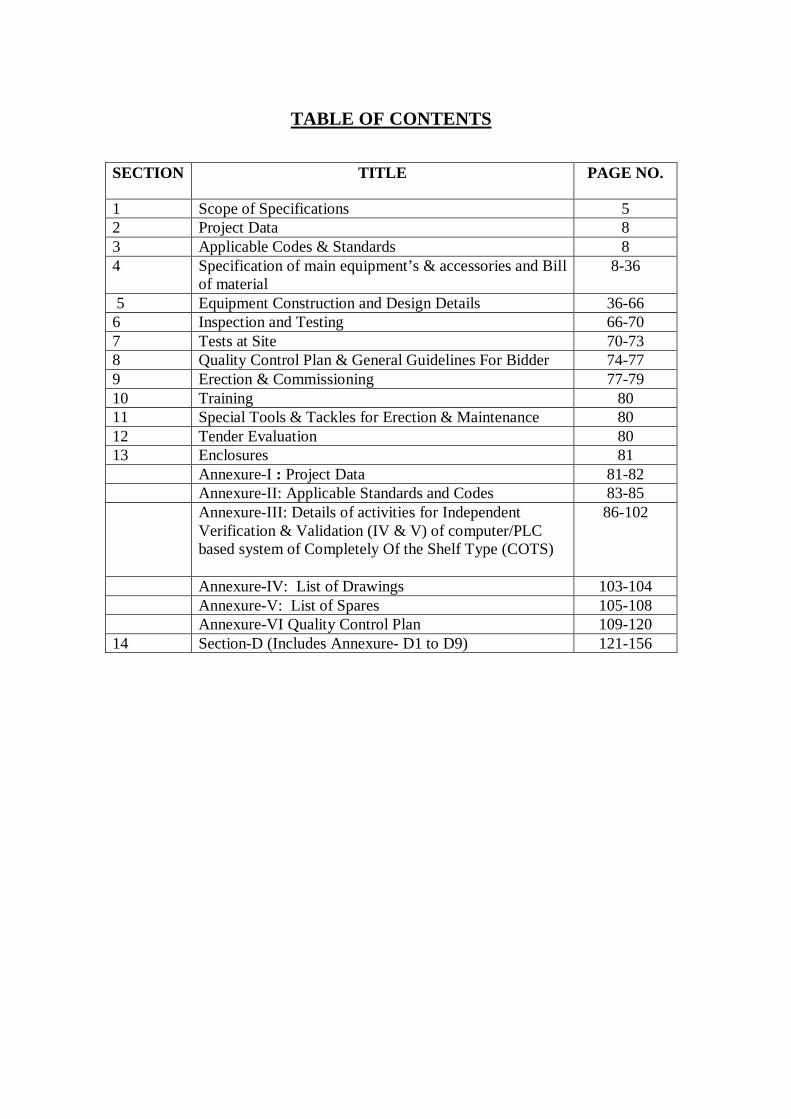
TABLE OF CONTENTS
SECTION TITLE PAGE NO.
1 Scope of Specifications 5 2 Project Data 8 3 Applicable Codes & Standards 8 4 Specification of main equipment’s & accessories and Bill
of material 8-36
5 Equipment Construction and Design Details 36-66 6 Inspection and Testing 66-70 7 Tests at Site 70-73 8 Quality Control Plan & General Guidelines For Bidder 74-77 9 Erection & Commissioning 77-79 10 Training 80 11 Special Tools & Tackles for Erection & Maintenance 80 12 Tender Evaluation 80 13 Enclosures 81 Annexure-I : Project Data 81-82 Annexure-II: Applicable Standards and Codes 83-85 Annexure-III: Details of activities for Independent
Verification & Validation (IV & V) of computer/PLC based system of Completely Of the Shelf Type (COTS)
86-102
Annexure-IV: List of Drawings 103-104 Annexure-V: List of Spares 105-108 Annexure-VI Quality Control Plan 109-120 14 Section-D (Includes Annexure- D1 to D9) 121-156
NUCLEAR POWER CORPORATION OF INDIA LIMITED KAKRAPAR ATOMIC POWER STATION-UNIT-1&2
TECHNICAL SPECIFICATION FOR 6.6KV SWITCHGEAR KAPS-2
Page No: 5 of 156
Rev. No : R-0
“Not for Unauthorized Publication / Presentation Outside NPCIL” KAPP-1&2/EMU/52310,52410/2016/SPEC/001 September, 2016
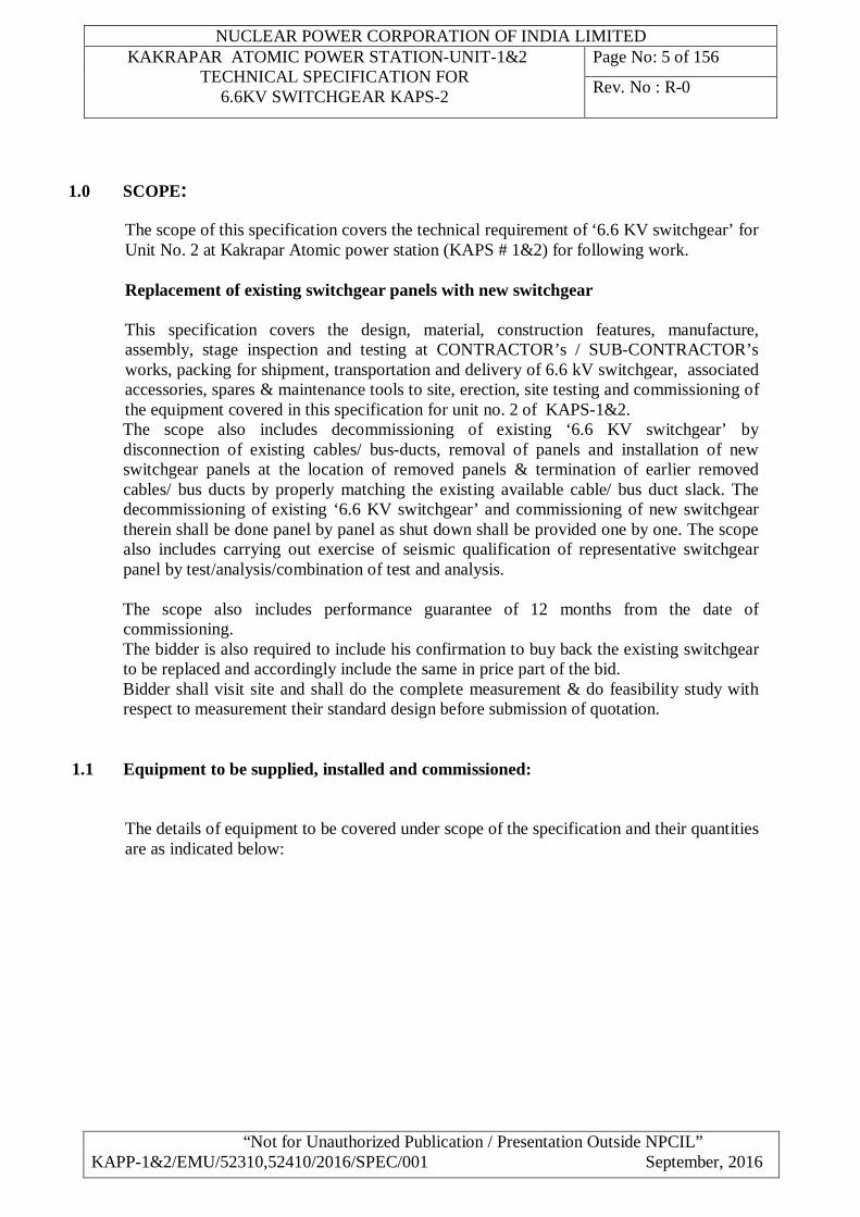
1.0 SCOPE:
The scope of this specification covers the technical requirement of ‘6.6 KV switchgear’ for Unit No. 2 at Kakrapar Atomic power station (KAPS # 1&2) for following work. Replacement of existing switchgear panels with new switchgear
This specification covers the design, material, construction features, manufacture,
assembly, stage inspection and testing at CONTRACTOR’s / SUB-CONTRACTOR’s works, packing for shipment, transportation and delivery of 6.6 kV switchgear, associated accessories, spares & maintenance tools to site, erection, site testing and commissioning of the equipment covered in this specification for unit no. 2 of KAPS-1&2.
The scope also includes decommissioning of existing ‘6.6 KV switchgear’ by disconnection of existing cables/ bus-ducts, removal of panels and installation of new switchgear panels at the location of removed panels & termination of earlier removed cables/ bus ducts by properly matching the existing available cable/ bus duct slack. The decommissioning of existing ‘6.6 KV switchgear’ and commissioning of new switchgear therein shall be done panel by panel as shut down shall be provided one by one. The scope also includes carrying out exercise of seismic qualification of representative switchgear panel by test/analysis/combination of test and analysis.
The scope also includes performance guarantee of 12 months from the date of
commissioning. The bidder is also required to include his confirmation to buy back the existing switchgear
to be replaced and accordingly include the same in price part of the bid. Bidder shall visit site and shall do the complete measurement & do feasibility study with
respect to measurement their standard design before submission of quotation.
1.1 Equipment to be supplied, installed and commissioned:
The details of equipment to be covered under scope of the specification and their quantities are as indicated below:

NUCLEAR POWER CORPORATION OF INDIA LIMITED KAKRAPAR ATOMIC POWER STATION-UNIT-1&2
TECHNICAL SPECIFICATION FOR 6.6KV SWITCHGEAR KAPS-2
Page No: 6 of 156
Rev. No : R-0
“Not for Unauthorized Publication / Presentation Outside NPCIL” KAPP-1&2/EMU/52310,52410/2016/SPEC/001 September, 2016
Sl. No.
Item Description Location El in mm
Quantity in Nos.
A. SWITCHGEAR: 6.6 kV Switchgear boards as listed below provided with number of panels and components complete with Vacuum Circuit Breakers (as per SLDs) with dual set of trip coils, protective relays, CTs, VTs, metering and all accessories as listed in the data sheets , schematics and drawings. The scope includes supply of dummy panels based on actual requirement depending on installation requirements & cubicle dimensions (to avoid interference from beams/columns), marshalling panels, relay panels etc.
i) Class IV Board 2-52410-BUS-A TB 01 ii) Class IV Board 2-52410-BUS-B TB 01 iii) Class IV Board 2-52410-BUS-C TB 01 iv) Class IV Board 2-52410-BUS-F TB 01 v) Class IV Board 2-52410-BUS-G TB 01 vi) Class IV Board 2-52410-BUS-H TB 01 vii) Class III Board 2-52310-BUS-D TB 01 viii) Class III Board 2-52310-BUS-E TB 01 ix) Class III Board 2-52310-BUS-I TB 01 x) Portable Evaluation station (Laptop)
along with communication cables - 1
xi) Control wiring within boards as above to complete the implementation of control scheme as per Control schematics and tender specification. This includes supply of control wiring and accessories.
As above As per Control Schematics and tender specification and as required to meet the requirements of the equipment offered.
xii) Dummy panels. (Price for dummy panels shall be included in the price for switchgear covered under item A (i) to (ix)
As required depending on the cubicle panel dimensions for installation. Bidder shall take note of the locations of columns and beams to assess the requirement of dummy panels.

NUCLEAR POWER CORPORATION OF INDIA LIMITED KAKRAPAR ATOMIC POWER STATION-UNIT-1&2
TECHNICAL SPECIFICATION FOR 6.6KV SWITCHGEAR KAPS-2
Page No: 7 of 156
Rev. No : R-0
“Not for Unauthorized Publication / Presentation Outside NPCIL” KAPP-1&2/EMU/52310,52410/2016/SPEC/001 September, 2016
Sl. No.
Item Description Location El in mm
Quantity in Nos.
xiii) Recommended spares required for one unit adequate for 3 years operation of switchgear.
- As per details mentioned in spares list…Annexure-v
xiv) Maintenance tools and tackles for 6.6 kV Class IV & III Switchgear as per Clouse 10.0
-
xv) Foundation base frames for switchgear boards covered above. Base frame height shall be match with existing panel’s base frame. It shall be ensured that finish floor level in front of switchgear would be suitable for smooth rack out of circuit breakers.
As indicated in pt. (i) to (ix) above.
As required for installation as per tender specification.
1.2 Unless otherwise specified, all accessories required for normal operation of equipment are
deemed to be considered as a part of the contractor’s scope of supply. Protection mentioned in this specification shall be complete in all respects. Auxiliary relays, timers, etc required to make the scheme complete shall be included in the scope. The details of desired interlocks in various schemes have been furnished in schemes and these are to be reflected in breaker control schematics. The scheme shall be designed and wired to meet requirement of relays covered in data sheets. The necessary redundancy and availability of required type of contact multiplication relays are deemed to be included in the scope of CONTRACTOR whether specifically brought out or not. The PURCHASER's decision regarding type and make of these relays will be communicated during drawings approval and shall be final and binding. Any cost implications due to this should be incorporated in the offer price for each feeder.
1.3 It is not the intent to specify completely here in all the details of design, engineering,
manufacture & construction of the equipment; however the equipment shall confirm in all respects to high standards of engineering, design & workmanship & be capable of performing continuously up to the vendors guarantees in a manner acceptable to the purchaser, who will interpret the meaning of drawing & specification and shall be entitled to reject any work or material which, in his judgment, is not in full accordance herewith.
1.4 Details of work involved & scope of material to be supplied by bidder has been included in
this specification to the maximum extent possible. However, it is advised that bidder or his representative visit site & assess the associated details himself before arriving at his offer.
1.5 The scope includes not only design, engineering and supply of all interfaces and
coordination for equipment covered under this specification but also with the existing equipment such as DC distribution boards and Synchronizing system etc which are not the part of this module and also with Protection panels for start-up transformers and unit auxiliary transformers, EDAS/SCADA etc which are not covered under the CONTRACT so as to ensure safe and satisfactory operation of the entire electrical system without any
NUCLEAR POWER CORPORATION OF INDIA LIMITED KAKRAPAR ATOMIC POWER STATION-UNIT-1&2
TECHNICAL SPECIFICATION FOR 6.6KV SWITCHGEAR KAPS-2
Page No: 8 of 156
Rev. No : R-0
“Not for Unauthorized Publication / Presentation Outside NPCIL” KAPP-1&2/EMU/52310,52410/2016/SPEC/001 September, 2016
constraints imposed due to lack of such integration. Details if any required from other systems will be provided by PURCHASER during detailed engineering.
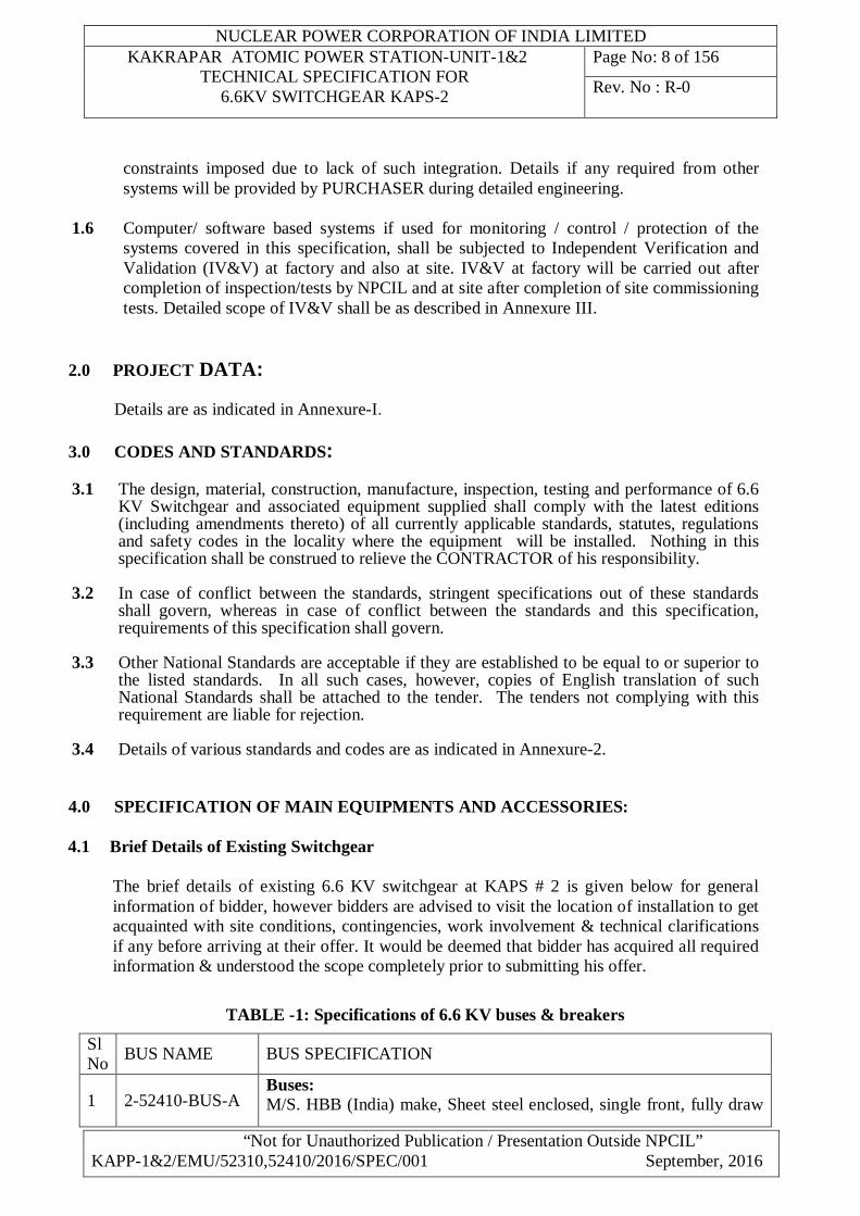
1.6 Computer/ software based systems if used for monitoring / control / protection of the
systems covered in this specification, shall be subjected to Independent Verification and Validation (IV&V) at factory and also at site. IV&V at factory will be carried out after completion of inspection/tests by NPCIL and at site after completion of site commissioning tests. Detailed scope of IV&V shall be as described in Annexure III.
2.0 PROJECT DATA: Details are as indicated in Annexure-I.
3.0 CODES AND STANDARDS:
3.1 The design, material, construction, manufacture, inspection, testing and performance of 6.6 KV Switchgear and associated equipment supplied shall comply with the latest editions (including amendments thereto) of all currently applicable standards, statutes, regulations and safety codes in the locality where the equipment will be installed. Nothing in this specification shall be construed to relieve the CONTRACTOR of his responsibility.
3.2 In case of conflict between the standards, stringent specifications out of these standards
shall govern, whereas in case of conflict between the standards and this specification, requirements of this specification shall govern.
3.3 Other National Standards are acceptable if they are established to be equal to or superior to
the listed standards. In all such cases, however, copies of English translation of such National Standards shall be attached to the tender. The tenders not complying with this requirement are liable for rejection.
3.4 Details of various standards and codes are as indicated in Annexure-2.
4.0 SPECIFICATION OF MAIN EQUIPMENTS AND ACCESSORIES:
4.1 Brief Details of Existing Switchgear
The brief details of existing 6.6 KV switchgear at KAPS # 2 is given below for general information of bidder, however bidders are advised to visit the location of installation to get acquainted with site conditions, contingencies, work involvement & technical clarifications if any before arriving at their offer. It would be deemed that bidder has acquired all required information & understood the scope completely prior to submitting his offer.
TABLE -1: Specifications of 6.6 KV buses & breakers
Sl No BUS NAME BUS SPECIFICATION
1 2-52410-BUS-A Buses: M/S. HBB (India) make, Sheet steel enclosed, single front, fully draw

NUCLEAR POWER CORPORATION OF INDIA LIMITED KAKRAPAR ATOMIC POWER STATION-UNIT-1&2
TECHNICAL SPECIFICATION FOR 6.6KV SWITCHGEAR KAPS-2
Page No: 9 of 156
Rev. No : R-0
“Not for Unauthorized Publication / Presentation Outside NPCIL” KAPP-1&2/EMU/52310,52410/2016/SPEC/001 September, 2016
2 2-52410-BUS-B out, cubicle type, Continuous rating : 2000 Amps, Rated/ maximum voltage: 6.6 KV/ 7.2 KV (non effectively earthed system), power frequency/impulse withstand voltage: 27 KV (rms) for 1 Min/ 60 KV peak, short time rating: 31.5 KA (350 MVA) for 1 sec., Min clearances : to withstand power frequency / impulse voltage successfully, Size of earth bus bar: 800 Sq. mm (aluminium), material of main buses: Copper, Bus rating: 630 A & 2000 A inside the cubicle, Size of bus bar: 70 mm diameter, 6 mm thick copper tube for 2000 A bus & 70 mm diameter, 3 mm thick copper tube for 630 A bus, Temperature rise over design ambient for rated current: Within limits as per IEC-298/ IEC-694 & 105 0 C for silver coated joints Breakers: M/S. HBB (India) make, Type: HB-12.12.25 (630 A) & HB-12.20.25 (2000 A), fully draw out type SF6 circuit breaker, Service voltage: 6.6 KV, 3 poles, duty cycle: O-3’-CO-3’-CO, rated symmetrical interrupting current: 31.5 KA (rms), making capacity: 80 KA, Total interruption time: 75 milliseconds, Total making time: 50 milliseconds, Operating mechanism: Spring charged, trip free with anti-pumping feature, No. of trip coil: one Current Transformers: Standard: IS-2705, Insulation level:27 KV (rms) for 1 Min power frequency / 60 KV (peak) impulse, Class of insulation: B, Short circuit withstand: 31.5 KA for 1 Sec Voltage Transformers: Insulation level:27 KV (rms) for 1 Min power frequency / 60 KV (peak) impulse, Rating: 100 VA class 0.5/0.3, Class of insulation: B, Voltage factor: Continuous: 1.2, For 8 Hours: 1.9
3 2-52410-BUS-C
4 2-52410-BUS-F
5 2-52410-BUS-G
6 2-52410-BUS-H
7 2-52310-BUS-D
8 2-52310-BUS-E
9 2-52310-BUS-I
TABLE -2: Details of breakers (Bus wise) Sl No
Bus Name No of Vertical sections
No of cubicles
Population of breakers
HB-12.12.25 HB-12.20.25 1 2-52410-BUS-A 08+02* 10 07 01 2 2-52410-BUS-B 09+01* 10 07 02 3 2-52410-BUS-C 02+01* 03 00 02 4 2-52410-BUS-F 08+02* 10 07 01 5 2-52410-BUS-G 09+01* 10 07 02 6 2-52410-BUS-H 02+01* 03 00 02 7 2-52310-BUS-D 08+02*+01**+01*** 12 08 00 8 2-52310-BUS-E 08+02*+01** 11 08 00 9 2-52310-BUS-I 03+02*+1** 06 03 00
NUCLEAR POWER CORPORATION OF INDIA LIMITED KAKRAPAR ATOMIC POWER STATION-UNIT-1&2
TECHNICAL SPECIFICATION FOR 6.6KV SWITCHGEAR KAPS-2
Page No: 10 of 156
Rev. No : R-0
“Not for Unauthorized Publication / Presentation Outside NPCIL” KAPP-1&2/EMU/52310,52410/2016/SPEC/001 September, 2016
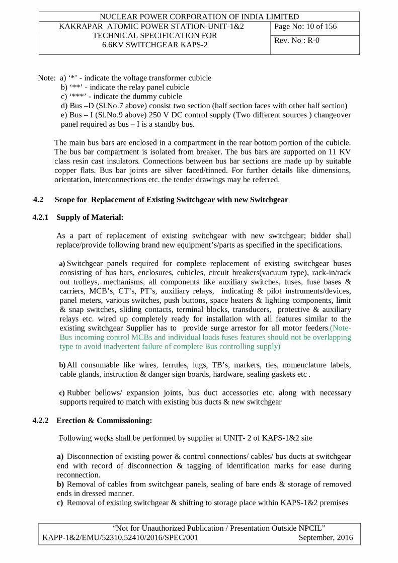
Note: a) ‘*’ - indicate the voltage transformer cubicle b) ‘**’ - indicate the relay panel cubicle c) ‘***’ - indicate the dummy cubicle d) Bus –D (Sl.No.7 above) consist two section (half section faces with other half section) e) Bus – I (Sl.No.9 above) 250 V DC control supply (Two different sources ) changeover panel required as bus – I is a standby bus.
The main bus bars are enclosed in a compartment in the rear bottom portion of the cubicle. The bus bar compartment is isolated from breaker. The bus bars are supported on 11 KV class resin cast insulators. Connections between bus bar sections are made up by suitable copper flats. Bus bar joints are silver faced/tinned. For further details like dimensions, orientation, interconnections etc. the tender drawings may be referred.
4.2 Scope for Replacement of Existing Switchgear with new Switchgear
4.2.1 Supply of Material:
As a part of replacement of existing switchgear with new switchgear; bidder shall replace/provide following brand new equipment’s/parts as specified in the specifications.
a) Switchgear panels required for complete replacement of existing switchgear buses consisting of bus bars, enclosures, cubicles, circuit breakers(vacuum type), rack-in/rack out trolleys, mechanisms, all components like auxiliary switches, fuses, fuse bases & carriers, MCB’s, CT’s, PT’s, auxiliary relays, indicating & pilot instruments/devices, panel meters, various switches, push buttons, space heaters & lighting components, limit & snap switches, sliding contacts, terminal blocks, transducers, protective & auxiliary relays etc. wired up completely ready for installation with all features similar to the existing switchgear Supplier has to provide surge arrestor for all motor feeders.(Note- Bus incoming control MCBs and individual loads fuses features should not be overlapping type to avoid inadvertent failure of complete Bus controlling supply)
b) All consumable like wires, ferrules, lugs, TB’s, markers, ties, nomenclature labels, cable glands, instruction & danger sign boards, hardware, sealing gaskets etc .
c) Rubber bellows/ expansion joints, bus duct accessories etc. along with necessary supports required to match with existing bus ducts & new switchgear
4.2.2 Erection & Commissioning:
Following works shall be performed by supplier at UNIT- 2 of KAPS-1&2 site
a) Disconnection of existing power & control connections/ cables/ bus ducts at switchgear end with record of disconnection & tagging of identification marks for ease during reconnection. b) Removal of cables from switchgear panels, sealing of bare ends & storage of removed ends in dressed manner. c) Removal of existing switchgear & shifting to storage place within KAPS-1&2 premises

NUCLEAR POWER CORPORATION OF INDIA LIMITED KAKRAPAR ATOMIC POWER STATION-UNIT-1&2
TECHNICAL SPECIFICATION FOR 6.6KV SWITCHGEAR KAPS-2
Page No: 11 of 156
Rev. No : R-0
“Not for Unauthorized Publication / Presentation Outside NPCIL” KAPP-1&2/EMU/52310,52410/2016/SPEC/001 September, 2016
d) Modification in existing mounting frames if necessary by means of drilling/ tapping/ welding/ grinding/ any other necessary operation e) Mounting of new base frames according to approved layout for new switchgear. f) Shifting the new material from place of storage to place of installation. g) Interior & exterior painting of base frames structures with approved procedure & shades h) Installation of new switchgear. i) Re glanding of earlier removed control/ power cables & laying the cable ends inside the switchgear after installation of glanded cable ends through gland holes & connections thereof j) Matching bus duct connections, modifications as necessary to match bus ducts & Bus duct connections k) Installation of gaskets, sealing of openings, alignment, lubrication of mechanism l) Thorough inspection, operability & functional checks, integrity checks/ testing/ inspection etc. m) Charging of the switchgear & commissioning of individual breakers n) Rectification of all the deficiencies observed during commissioning of switchgear o) Preparation & obtaining the approvals of work & test procedures, plans, inspection & quality control programs p) Documentation like IV&V of relays, maintaining log books, testing/ inspection records, man & material history, measurements, procedures, trainings, safety, security & administrative aspects with respect to switchgear erection & commissioning work.
4.3 Interchangeability
a) All identical equipment and corresponding parts including chassis of draw out modules of the same size shall be interchangeable without having to carry out any modifications for trouble free interchangeability. The draw out arrangements shall be designed such that normal dimensional variations are taken care of by self-aligning feature of the modules. b) Components and equipment that are not fully interchangeable are liable for rejection. Supplier shall replace all such equipment by fully interchangeable equipment at his cost. c) Typical control schematics indicating the control requirements together with the list of components/equipment required are detailed in the enclosed drawing in annexure-III. d) Physical size of compartment for each type of control and current rating shall be so chosen that all equipment can be housed in the compartment. No equipment/devices associated with any particular circuit shall be permitted to be mounted in any other circuit module.
4.4 6.6 kV Switchgear Data Sheet This section covers data sheets for new 6.6 kV switchgear and accessories
1.00 System Particulars
1.01 Nominal System Voltage 6.6 kV 1.02 Highest System Voltage 7.2 kV 1.03 Frequency 50 Hz
NUCLEAR POWER CORPORATION OF INDIA LIMITED KAKRAPAR ATOMIC POWER STATION-UNIT-1&2
TECHNICAL SPECIFICATION FOR 6.6KV SWITCHGEAR KAPS-2
Page No: 12 of 156
Rev. No : R-0
“Not for Unauthorized Publication / Presentation Outside NPCIL” KAPP-1&2/EMU/52310,52410/2016/SPEC/001 September, 2016
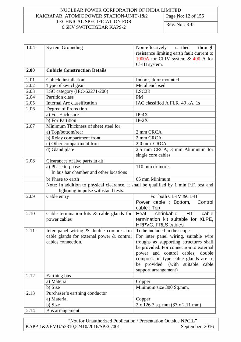
1.04 System Grounding Non-effectively earthed through resistance limiting earth fault current to 1000A for Cl-IV system & 400 A for Cl-III system.
2.00 Cubicle Construction Details
2.01 Cubicle installation Indoor, floor mounted. 2.02 Type of switchgear Metal enclosed 2.03 LSC category (IEC-62271-200) LSC2B 2.04 Partition class PM 2.05 Internal Arc classification IAC classified A FLR 40 kA, 1s 2.06 Degree of Protection
a) For Enclosure IP-4X b) For Partition IP-2X
2.07 Minimum Thickness of sheet steel for: a) Top/bottom/rear 2 mm CRCA b) Relay compartment front 2 mm CRCA c) Other compartment front 2.0 mm CRCA d) Gland plate 2.5 mm CRCA; 3 mm Aluminum for
single core cables 2.08 Clearances of live parts in air
a) Phase to phase In bus bar chamber and other locations
110 mm or more.
b) Phase to earth 65 mm Minimum Note: In addition to physical clearance, it shall be qualified by 1 min P.F. test and
lightning impulse withstand tests. 2.09 Cable entry For both CL-IV &CL-III
Power cable : Bottom, Control cable : Top
2.10 Cable termination kits & cable glands for power cables
Heat shrinkable HT cable termination kit suitable for XLPE, HRPVC, FRLS cables
2.11 Inter panel wiring & double compression cable glands for external power & control cables connection.
To be included in the scope. For inter panel wiring, suitable wire troughs as supporting structures shall be provided. For connection to external power and control cables, double compression type cable glands are to be provided. (with suitable cable support arrangement)
2.12 Earthing bus a) Material Copper b) Size Minimum size 300 Sq.mm.
2.13 Purchaser’s earthing conductor a) Material Copper b) Size 2 x 126.7 sq. mm (37 x 2.11 mm)
2.14 Bus arrangement
NUCLEAR POWER CORPORATION OF INDIA LIMITED KAKRAPAR ATOMIC POWER STATION-UNIT-1&2
TECHNICAL SPECIFICATION FOR 6.6KV SWITCHGEAR KAPS-2
Page No: 13 of 156
Rev. No : R-0
“Not for Unauthorized Publication / Presentation Outside NPCIL” KAPP-1&2/EMU/52310,52410/2016/SPEC/001 September, 2016
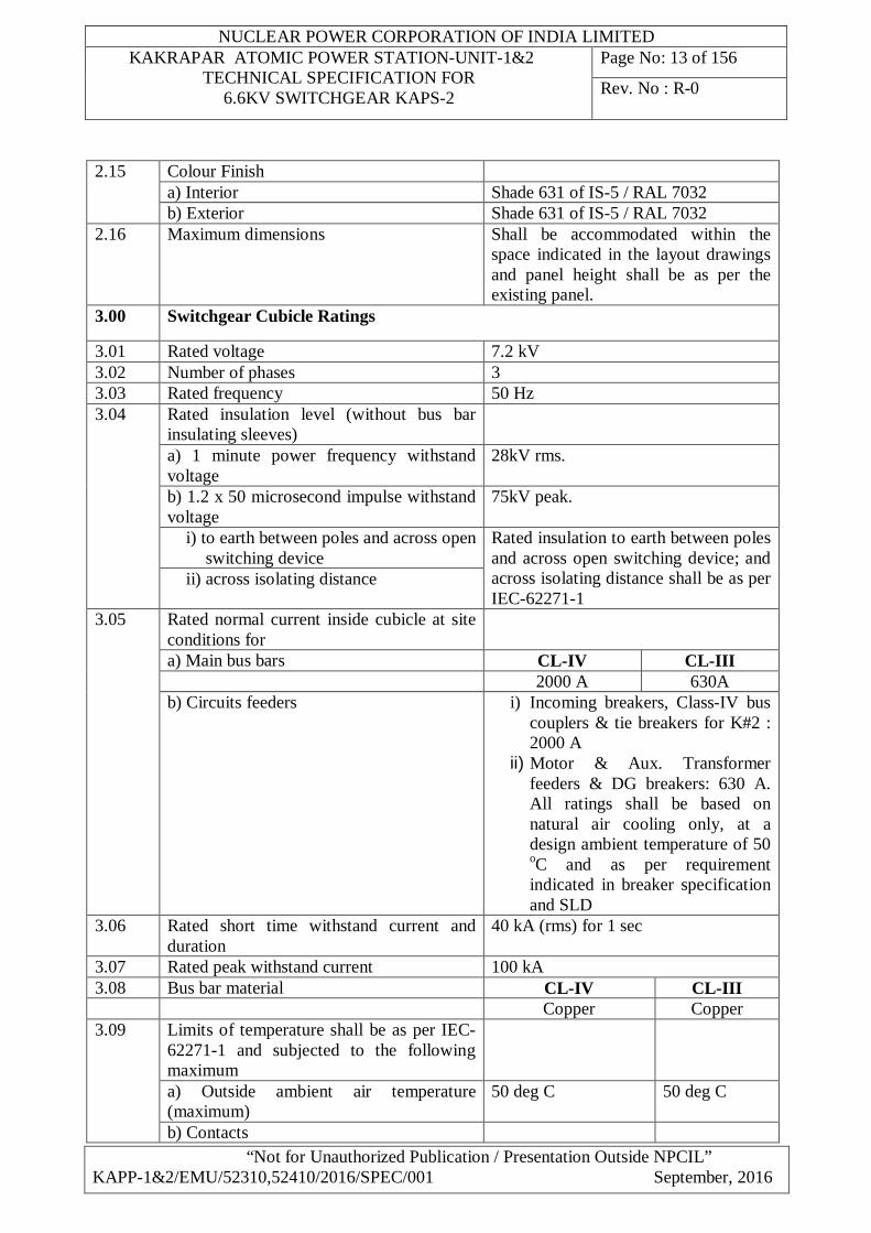
2.15 Colour Finish a) Interior Shade 631 of IS-5 / RAL 7032 b) Exterior Shade 631 of IS-5 / RAL 7032
2.16 Maximum dimensions Shall be accommodated within the space indicated in the layout drawings and panel height shall be as per the existing panel.
3.00 Switchgear Cubicle Ratings
3.01 Rated voltage 7.2 kV 3.02 Number of phases 3 3.03 Rated frequency 50 Hz 3.04 Rated insulation level (without bus bar
insulating sleeves)
a) 1 minute power frequency withstand voltage
28kV rms.
b) 1.2 x 50 microsecond impulse withstand voltage
75kV peak.
i) to earth between poles and across open switching device
Rated insulation to earth between poles and across open switching device; and across isolating distance shall be as per IEC-62271-1
ii) across isolating distance
3.05 Rated normal current inside cubicle at site conditions for
a) Main bus bars CL-IV CL-III 2000 A 630A b) Circuits feeders i) Incoming breakers, Class-IV bus
couplers & tie breakers for K#2 : 2000 A
ii) Motor & Aux. Transformer feeders & DG breakers: 630 A. All ratings shall be based on natural air cooling only, at a design ambient temperature of 50 oC and as per requirement indicated in breaker specification and SLD
3.06 Rated short time withstand current and duration
40 kA (rms) for 1 sec
3.07 Rated peak withstand current 100 kA 3.08 Bus bar material CL-IV CL-III Copper Copper 3.09 Limits of temperature shall be as per IEC-
62271-1 and subjected to the following maximum
a) Outside ambient air temperature (maximum)
50 deg C 50 deg C
b) Contacts
NUCLEAR POWER CORPORATION OF INDIA LIMITED KAKRAPAR ATOMIC POWER STATION-UNIT-1&2
TECHNICAL SPECIFICATION FOR 6.6KV SWITCHGEAR KAPS-2
Page No: 14 of 156
Rev. No : R-0
“Not for Unauthorized Publication / Presentation Outside NPCIL” KAPP-1&2/EMU/52310,52410/2016/SPEC/001 September, 2016
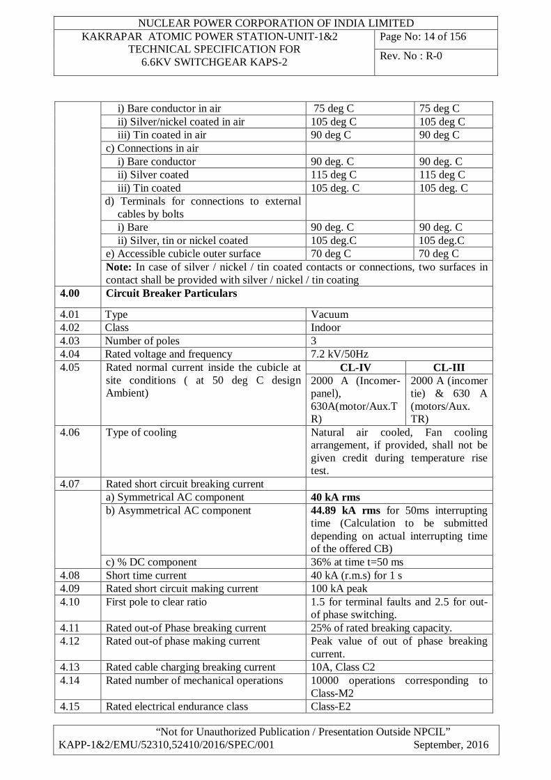
i) Bare conductor in air 75 deg C 75 deg C ii) Silver/nickel coated in air 105 deg C 105 deg C iii) Tin coated in air 90 deg C 90 deg C
c) Connections in air i) Bare conductor 90 deg. C 90 deg. C ii) Silver coated 115 deg C 115 deg C iii) Tin coated 105 deg. C 105 deg. C
d) Terminals for connections to external cables by bolts
i) Bare 90 deg. C 90 deg. C ii) Silver, tin or nickel coated 105 deg.C 105 deg.C
e) Accessible cubicle outer surface 70 deg C 70 deg C Note: In case of silver / nickel / tin coated contacts or connections, two surfaces in contact shall be provided with silver / nickel / tin coating
4.00 Circuit Breaker Particulars
4.01 Type Vacuum 4.02 Class Indoor 4.03 Number of poles 3 4.04 Rated voltage and frequency 7.2 kV/50Hz 4.05 Rated normal current inside the cubicle at
site conditions ( at 50 deg C design Ambient)
CL-IV CL-III 2000 A (Incomer-panel), 630A(motor/Aux.TR)
2000 A (incomer tie) & 630 A (motors/Aux. TR)
4.06 Type of cooling Natural air cooled, Fan cooling arrangement, if provided, shall not be given credit during temperature rise test.
4.07 Rated short circuit breaking current a) Symmetrical AC component 40 kA rms b) Asymmetrical AC component 44.89 kA rms for 50ms interrupting
time (Calculation to be submitted depending on actual interrupting time of the offered CB)
c) % DC component 36% at time t=50 ms 4.08 Short time current 40 kA (r.m.s) for 1 s 4.09 Rated short circuit making current 100 kA peak 4.10 First pole to clear ratio 1.5 for terminal faults and 2.5 for out-
of phase switching. 4.11 Rated out-of Phase breaking current 25% of rated breaking capacity. 4.12 Rated out-of phase making current Peak value of out of phase breaking
current. 4.13 Rated cable charging breaking current 10A, Class C2 4.14 Rated number of mechanical operations 10000 operations corresponding to
Class-M2 4.15 Rated electrical endurance class Class-E2
NUCLEAR POWER CORPORATION OF INDIA LIMITED KAKRAPAR ATOMIC POWER STATION-UNIT-1&2
TECHNICAL SPECIFICATION FOR 6.6KV SWITCHGEAR KAPS-2
Page No: 15 of 156
Rev. No : R-0
“Not for Unauthorized Publication / Presentation Outside NPCIL” KAPP-1&2/EMU/52310,52410/2016/SPEC/001 September, 2016
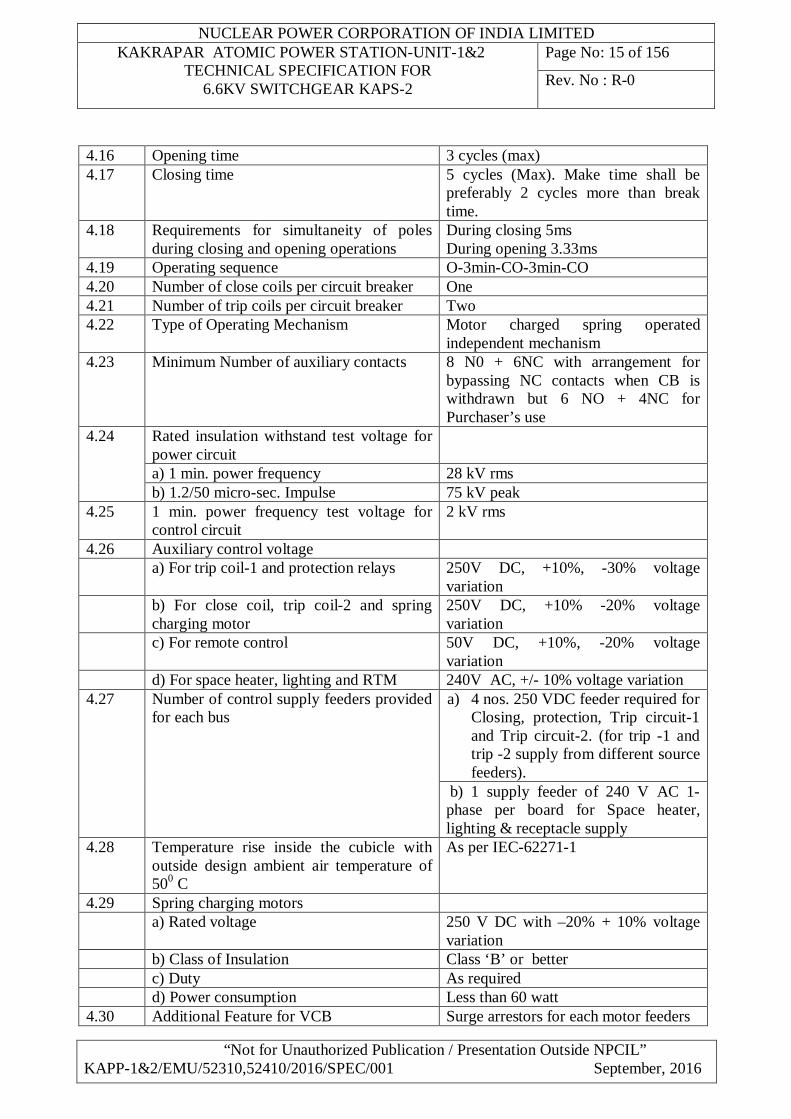
4.16 Opening time 3 cycles (max) 4.17 Closing time 5 cycles (Max). Make time shall be
preferably 2 cycles more than break time.
4.18 Requirements for simultaneity of poles during closing and opening operations
During closing 5ms During opening 3.33ms
4.19 Operating sequence O-3min-CO-3min-CO 4.20 Number of close coils per circuit breaker One 4.21 Number of trip coils per circuit breaker Two 4.22 Type of Operating Mechanism Motor charged spring operated
independent mechanism 4.23 Minimum Number of auxiliary contacts 8 N0 + 6NC with arrangement for
bypassing NC contacts when CB is withdrawn but 6 NO + 4NC for Purchaser’s use
4.24 Rated insulation withstand test voltage for power circuit
a) 1 min. power frequency 28 kV rms b) 1.2/50 micro-sec. Impulse 75 kV peak
4.25 1 min. power frequency test voltage for control circuit
2 kV rms
4.26 Auxiliary control voltage a) For trip coil-1 and protection relays 250V DC, +10%, -30% voltage
variation b) For close coil, trip coil-2 and spring
charging motor 250V DC, +10% -20% voltage variation
c) For remote control 50V DC, +10%, -20% voltage variation
d) For space heater, lighting and RTM 240V AC, +/- 10% voltage variation 4.27 Number of control supply feeders provided
for each bus a) 4 nos. 250 VDC feeder required for
Closing, protection, Trip circuit-1 and Trip circuit-2. (for trip -1 and trip -2 supply from different source feeders).
b) 1 supply feeder of 240 V AC 1-phase per board for Space heater, lighting & receptacle supply
4.28 Temperature rise inside the cubicle with outside design ambient air temperature of 500 C
As per IEC-62271-1
4.29 Spring charging motors a) Rated voltage 250 V DC with –20% + 10% voltage
variation b) Class of Insulation Class ‘B’ or better c) Duty As required d) Power consumption Less than 60 watt 4.30 Additional Feature for VCB Surge arrestors for each motor feeders
NUCLEAR POWER CORPORATION OF INDIA LIMITED KAKRAPAR ATOMIC POWER STATION-UNIT-1&2
TECHNICAL SPECIFICATION FOR 6.6KV SWITCHGEAR KAPS-2
Page No: 16 of 156
Rev. No : R-0
“Not for Unauthorized Publication / Presentation Outside NPCIL” KAPP-1&2/EMU/52310,52410/2016/SPEC/001 September, 2016
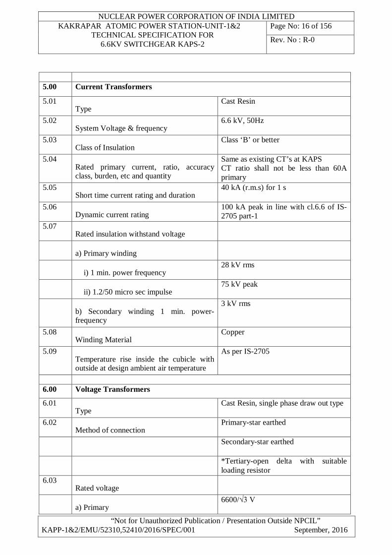
5.00 Current Transformers
5.01 Type
Cast Resin
5.02 System Voltage & frequency
6.6 kV, 50Hz
5.03 Class of Insulation
Class ‘B’ or better
5.04 Rated primary current, ratio, accuracy class, burden, etc and quantity
Same as existing CT’s at KAPS CT ratio shall not be less than 60A primary
5.05 Short time current rating and duration
40 kA (r.m.s) for 1 s
5.06 Dynamic current rating
100 kA peak in line with cl.6.6 of IS-2705 part-1
5.07 Rated insulation withstand voltage
a) Primary winding
i) 1 min. power frequency
28 kV rms
ii) 1.2/50 micro sec impulse
75 kV peak
b) Secondary winding 1 min. power-frequency
3 kV rms
5.08 Winding Material
Copper
5.09 Temperature rise inside the cubicle with outside at design ambient air temperature
As per IS-2705
6.00 Voltage Transformers
6.01 Type
Cast Resin, single phase draw out type
6.02 Method of connection
Primary-star earthed
Secondary-star earthed
*Tertiary-open delta with suitable loading resistor
6.03 Rated voltage
a) Primary
6600/√3 V
NUCLEAR POWER CORPORATION OF INDIA LIMITED KAKRAPAR ATOMIC POWER STATION-UNIT-1&2
TECHNICAL SPECIFICATION FOR 6.6KV SWITCHGEAR KAPS-2
Page No: 17 of 156
Rev. No : R-0
“Not for Unauthorized Publication / Presentation Outside NPCIL” KAPP-1&2/EMU/52310,52410/2016/SPEC/001 September, 2016
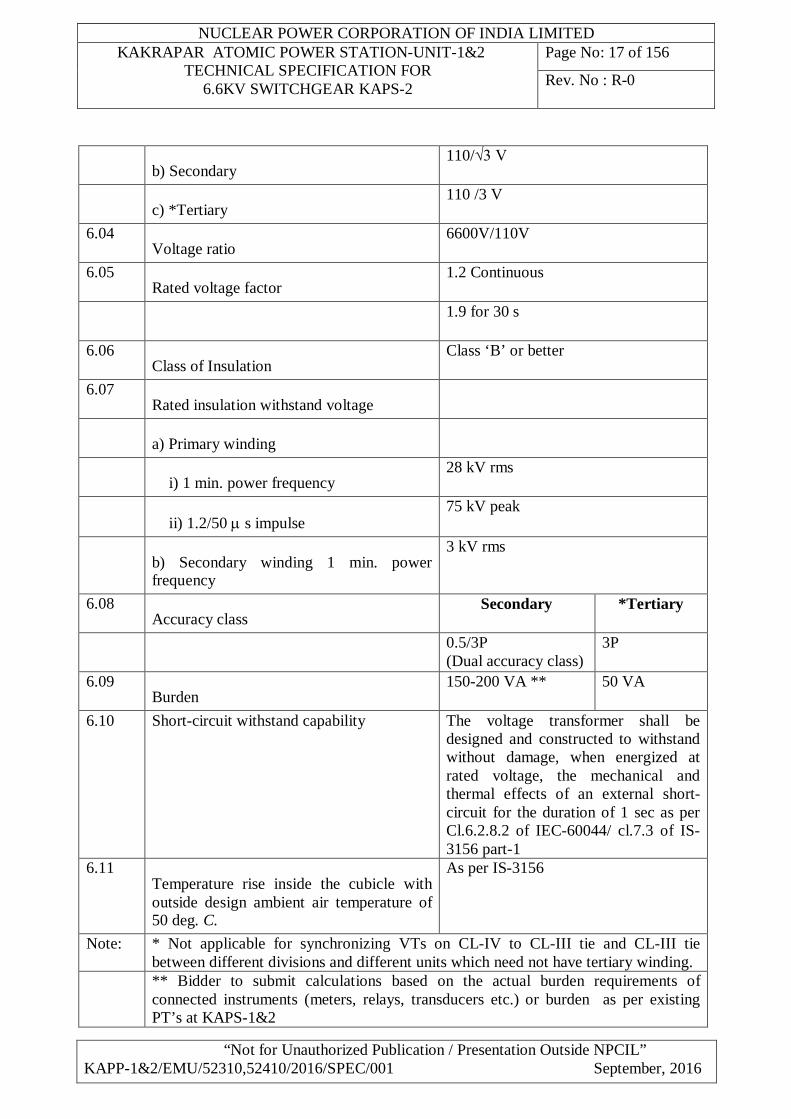
b) Secondary
110/√3 V
c) *Tertiary
110 /3 V
6.04 Voltage ratio
6600V/110V
6.05 Rated voltage factor
1.2 Continuous
1.9 for 30 s
6.06 Class of Insulation
Class ‘B’ or better
6.07 Rated insulation withstand voltage
a) Primary winding
i) 1 min. power frequency
28 kV rms
ii) 1.2/50 s impulse
75 kV peak
b) Secondary winding 1 min. power frequency
3 kV rms
6.08 Accuracy class
Secondary *Tertiary
0.5/3P (Dual accuracy class)
3P
6.09 Burden
150-200 VA ** 50 VA
6.10 Short-circuit withstand capability
The voltage transformer shall be designed and constructed to withstand without damage, when energized at rated voltage, the mechanical and thermal effects of an external short-circuit for the duration of 1 sec as per Cl.6.2.8.2 of IEC-60044/ cl.7.3 of IS-3156 part-1
6.11 Temperature rise inside the cubicle with outside design ambient air temperature of 50 deg. C.
As per IS-3156
Note: * Not applicable for synchronizing VTs on CL-IV to CL-III tie and CL-III tie between different divisions and different units which need not have tertiary winding.
** Bidder to submit calculations based on the actual burden requirements of connected instruments (meters, relays, transducers etc.) or burden as per existing PT’s at KAPS-1&2
NUCLEAR POWER CORPORATION OF INDIA LIMITED KAKRAPAR ATOMIC POWER STATION-UNIT-1&2
TECHNICAL SPECIFICATION FOR 6.6KV SWITCHGEAR KAPS-2
Page No: 18 of 156
Rev. No : R-0
“Not for Unauthorized Publication / Presentation Outside NPCIL” KAPP-1&2/EMU/52310,52410/2016/SPEC/001 September, 2016
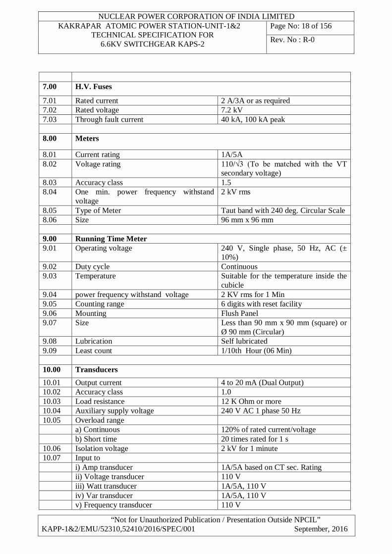
7.00 H.V. Fuses
7.01 Rated current 2 A/3A or as required 7.02 Rated voltage 7.2 kV 7.03 Through fault current 40 kA, 100 kA peak 8.00 Meters
8.01 Current rating 1A/5A 8.02 Voltage rating 110/√3 (To be matched with the VT
secondary voltage) 8.03 Accuracy class 1.5 8.04 One min. power frequency withstand
voltage 2 kV rms
8.05 Type of Meter Taut band with 240 deg. Circular Scale 8.06 Size 96 mm x 96 mm 9.00 Running Time Meter 9.01 Operating voltage 240 V, Single phase, 50 Hz, AC (±
10%) 9.02 Duty cycle Continuous 9.03
Temperature Suitable for the temperature inside the cubicle
9.04 power frequency withstand voltage 2 KV rms for 1 Min 9.05 Counting range 6 digits with reset facility 9.06 Mounting Flush Panel 9.07 Size Less than 90 mm x 90 mm (square) or
Ø 90 mm (Circular) 9.08 Lubrication Self lubricated 9.09 Least count 1/10th Hour (06 Min) 10.00 Transducers 10.01 Output current 4 to 20 mA (Dual Output) 10.02 Accuracy class 1.0 10.03 Load resistance 12 K Ohm or more 10.04 Auxiliary supply voltage 240 V AC 1 phase 50 Hz 10.05 Overload range a) Continuous 120% of rated current/voltage b) Short time 20 times rated for 1 s 10.06 Isolation voltage 2 kV for 1 minute 10.07 Input to i) Amp transducer 1A/5A based on CT sec. Rating ii) Voltage transducer 110 V iii) Watt transducer 1A/5A, 110 V iv) Var transducer 1A/5A, 110 V v) Frequency transducer 110 V
NUCLEAR POWER CORPORATION OF INDIA LIMITED KAKRAPAR ATOMIC POWER STATION-UNIT-1&2
TECHNICAL SPECIFICATION FOR 6.6KV SWITCHGEAR KAPS-2
Page No: 19 of 156
Rev. No : R-0
“Not for Unauthorized Publication / Presentation Outside NPCIL” KAPP-1&2/EMU/52310,52410/2016/SPEC/001 September, 2016
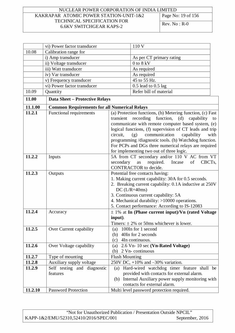
vi) Power factor transducer 110 V 10.08 Calibration range for i) Amp transducer As per CT primary rating ii) Voltage transducer 0 to 8 kV iii) Watt transducer As required iv) Var transducer As required v) Frequency transducer 45 to 55 Hz. vi) Power factor transducer 0.5 lead to 0.5 lag 10.09 Quantity Refer bill of material
11.00 Data Sheet – Protective Relays
11.1.00 Common Requirements for all Numerical Relays 11.2.1 Functional requirements (a) Protection functions, (b) Metering function, (c) Fast
transient recording function, (d) capability to communicate with remote computer based system, (e) logical functions, (f) supervision of CT leads and trip circuit, (g) communication capability with programming /diagnostic tools. (h) Watchdog function. For PCPs and DGs three numerical relays are required for implementing two out of three logic.
11.2.2 Inputs 5A from CT secondary and/or 110 V AC from VT secondary as required. Incase of CBCTs, CONTRACTOR to decide.
11.2.3 Outputs Potential free contacts having: 1. Making current capability: 30A for 0.5 seconds. 2. Breaking current capability: 0.1A inductive at 250V
DC (L/R=40ms) 3. Continuous current capability: 5A 4. Mechanical durability: >10000 operations. 5. Contact performance: According to IS-12083
11.2.4 Accuracy 1% at In (Phase current input)/Vn (rated Voltage input). Timers: 2% or 50ms whichever is lower.
11.2.5 Over Current capability (a) 100In for 1 second (b) 40In for 2 seconds (c) 4In continuous.
11.2.6 Over Voltage capability (a) 2.6 Vn- 10 sec (Vn-Rated Voltage) (b) 2 Vn- continuous
11.2.7 Type of mounting Flush Mounting 11.2.8 Auxiliary supply voltage 250V DC, +10% and –30% variation. 11.2.9 Self testing and diagnostic
features (a) Hard-wired watchdog timer feature shall be
provided with contacts for external alarm. (b) Internal Auxiliary power supply monitoring with
contacts for external alarm. 11.2.10 Password Protection Multi level password protection required.
NUCLEAR POWER CORPORATION OF INDIA LIMITED KAKRAPAR ATOMIC POWER STATION-UNIT-1&2
TECHNICAL SPECIFICATION FOR 6.6KV SWITCHGEAR KAPS-2
Page No: 20 of 156
Rev. No : R-0
“Not for Unauthorized Publication / Presentation Outside NPCIL” KAPP-1&2/EMU/52310,52410/2016/SPEC/001 September, 2016
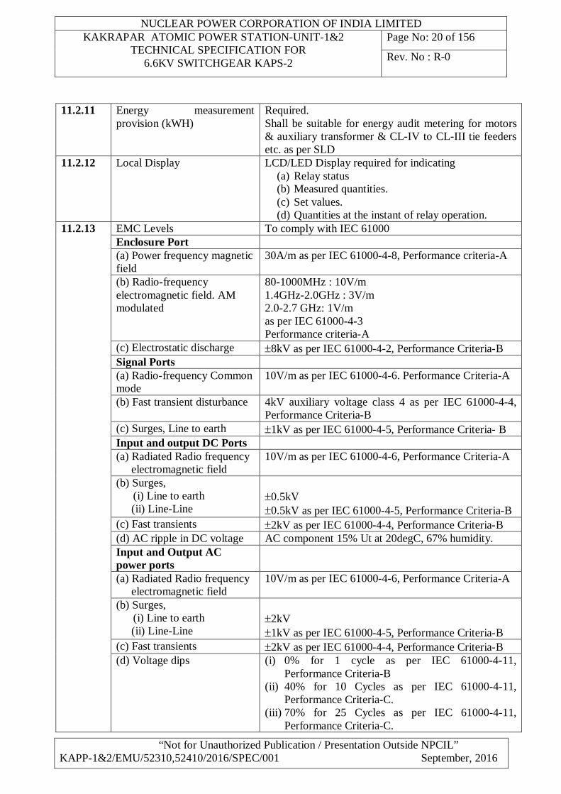
11.2.11 Energy measurement provision (kWH)
Required. Shall be suitable for energy audit metering for motors & auxiliary transformer & CL-IV to CL-III tie feeders etc. as per SLD
11.2.12 Local Display LCD/LED Display required for indicating (a) Relay status (b) Measured quantities. (c) Set values. (d) Quantities at the instant of relay operation.
11.2.13 EMC Levels To comply with IEC 61000 Enclosure Port (a) Power frequency magnetic field
30A/m as per IEC 61000-4-8, Performance criteria-A
(b) Radio-frequency electromagnetic field. AM modulated
80-1000MHz : 10V/m 1.4GHz-2.0GHz : 3V/m 2.0-2.7 GHz: 1V/m as per IEC 61000-4-3 Performance criteria-A
(c) Electrostatic discharge 8kV as per IEC 61000-4-2, Performance Criteria-B Signal Ports (a) Radio-frequency Common mode
10V/m as per IEC 61000-4-6. Performance Criteria-A
(b) Fast transient disturbance 4kV auxiliary voltage class 4 as per IEC 61000-4-4, Performance Criteria-B
(c) Surges, Line to earth 1kV as per IEC 61000-4-5, Performance Criteria- B Input and output DC Ports (a) Radiated Radio frequency
electromagnetic field 10V/m as per IEC 61000-4-6, Performance Criteria-A
(b) Surges, (i) Line to earth (ii) Line-Line
0.5kV 0.5kV as per IEC 61000-4-5, Performance Criteria-B
(c) Fast transients 2kV as per IEC 61000-4-4, Performance Criteria-B (d) AC ripple in DC voltage AC component 15% Ut at 20degC, 67% humidity. Input and Output AC power ports
(a) Radiated Radio frequency electromagnetic field
10V/m as per IEC 61000-4-6, Performance Criteria-A
(b) Surges, (i) Line to earth (ii) Line-Line
2kV 1kV as per IEC 61000-4-5, Performance Criteria-B
(c) Fast transients 2kV as per IEC 61000-4-4, Performance Criteria-B (d) Voltage dips (i) 0% for 1 cycle as per IEC 61000-4-11,
Performance Criteria-B (ii) 40% for 10 Cycles as per IEC 61000-4-11,
Performance Criteria-C. (iii) 70% for 25 Cycles as per IEC 61000-4-11,
Performance Criteria-C.

NUCLEAR POWER CORPORATION OF INDIA LIMITED KAKRAPAR ATOMIC POWER STATION-UNIT-1&2
TECHNICAL SPECIFICATION FOR 6.6KV SWITCHGEAR KAPS-2
Page No: 21 of 156
Rev. No : R-0
“Not for Unauthorized Publication / Presentation Outside NPCIL” KAPP-1&2/EMU/52310,52410/2016/SPEC/001 September, 2016
(e) Insulation Resistance 1000M (f) Climatic conditions (a) Operating temperature: 50C to 550C
(b) Storage temperature: 500C to 700C (c) Humidity: 93% RH at 400C (d) Vibration: Shall be qualified as per IEC-60255-
21-1 Test severity class-1 11.2.14 Degree of Protection provided
by relay enclosure IP 52 and IP20 for rear connections
11.2.15 Power off withstand 50ms 11.2.16 Vibration & Shock Vibration: Shall be qualified as per IEC-60255-21-1
Test severity class-2 11.2.0 Motor Protective Relay Particulars
11.2.1 Type Motor protection relay-Numerical Micom P 220 or equivalent with disturbance recording facility along with wave form
11.2.2 Number of poles 3 phase and earth fault elements.
11.2.3 Protective elements (i) Thermal overload protection (49) (ii) Instantaneous over current protection (50) (iii) Phase unbalance protection(46) (iv) Under current protection (37)* (v) 50LR Locked rotor. (vi) Instantaneous ground over current (50N)
11.2.4 The other features of relay shall be pre & post disturbance memory, event record logging, peak current records and supervisory functions for signal failure & self diagnostic features. The necessary software & hardware and interface for data download and analysis, relay setting (as required) shall also be part of relay supply.
11.2.5 Details of protective elements
i)
Thermal protection a) Setting range 20 % to 100% for alarm, 20% to 150% for trip in linear
steps of 10% or better. b) Relay
characteristics Shall match with motor thermal withstand characteristics; application check shall be made and submitted for approval
c) Time setting 25 s to 75 s for alarm, optional time delay 2 s to 30 s for trip
ii)
Instantaneous over current protection a) Current Setting
range 100% to 1200% In in linear steps
b) Operating time 0-100s in linear steps of 0.01s or better
iii)
Phase unbalance protection (46) a) Negative sequence
current Setting range
0.05 to 0.8 In in linear steps
b) Time setting 0.04 to 200 s iv) Locked rotor protection
NUCLEAR POWER CORPORATION OF INDIA LIMITED KAKRAPAR ATOMIC POWER STATION-UNIT-1&2
TECHNICAL SPECIFICATION FOR 6.6KV SWITCHGEAR KAPS-2
Page No: 22 of 156
Rev. No : R-0
“Not for Unauthorized Publication / Presentation Outside NPCIL” KAPP-1&2/EMU/52310,52410/2016/SPEC/001 September, 2016
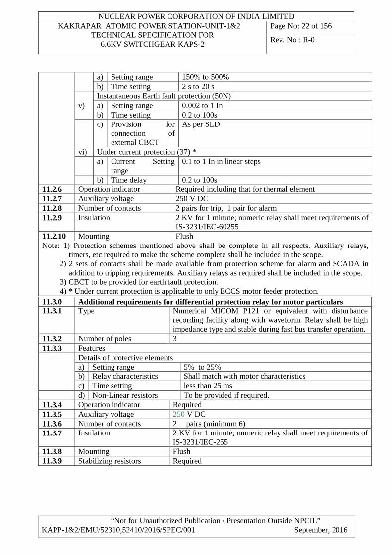
a) Setting range 150% to 500% b) Time setting 2 s to 20 s
v) Instantaneous Earth fault protection (50N) a) Setting range 0.002 to 1 In b) Time setting 0.2 to 100s
c) Provision for connection of external CBCT
As per SLD
vi) Under current protection (37) * a) Current Setting
range 0.1 to 1 In in linear steps
b) Time delay 0.2 to 100s 11.2.6 Operation indicator Required including that for thermal element 11.2.7 Auxiliary voltage 250 V DC 11.2.8 Number of contacts 2 pairs for trip, 1 pair for alarm 11.2.9 Insulation 2 KV for 1 minute; numeric relay shall meet requirements of
IS-3231/IEC-60255 11.2.10 Mounting Flush Note: 1) Protection schemes mentioned above shall be complete in all respects. Auxiliary relays,
timers, etc required to make the scheme complete shall be included in the scope. 2) 2 sets of contacts shall be made available from protection scheme for alarm and SCADA in
addition to tripping requirements. Auxiliary relays as required shall be included in the scope. 3) CBCT to be provided for earth fault protection. 4) * Under current protection is applicable to only ECCS motor feeder protection.
11.3.0 Additional requirements for differential protection relay for motor particulars 11.3.1 Type Numerical MICOM P121 or equivalent with disturbance
recording facility along with waveform. Relay shall be high impedance type and stable during fast bus transfer operation.
11.3.2 Number of poles 3 11.3.3 Features
Details of protective elements a) Setting range 5% to 25% b) Relay characteristics Shall match with motor characteristics c) Time setting less than 25 ms d) Non-Linear resistors To be provided if required.
11.3.4 Operation indicator Required 11.3.5 Auxiliary voltage 250 V DC 11.3.6 Number of contacts 2 pairs (minimum 6) 11.3.7 Insulation 2 KV for 1 minute; numeric relay shall meet requirements of
IS-3231/IEC-255 11.3.8 Mounting Flush 11.3.9 Stabilizing resistors Required
NUCLEAR POWER CORPORATION OF INDIA LIMITED KAKRAPAR ATOMIC POWER STATION-UNIT-1&2
TECHNICAL SPECIFICATION FOR 6.6KV SWITCHGEAR KAPS-2
Page No: 23 of 156
Rev. No : R-0
“Not for Unauthorized Publication / Presentation Outside NPCIL” KAPP-1&2/EMU/52310,52410/2016/SPEC/001 September, 2016
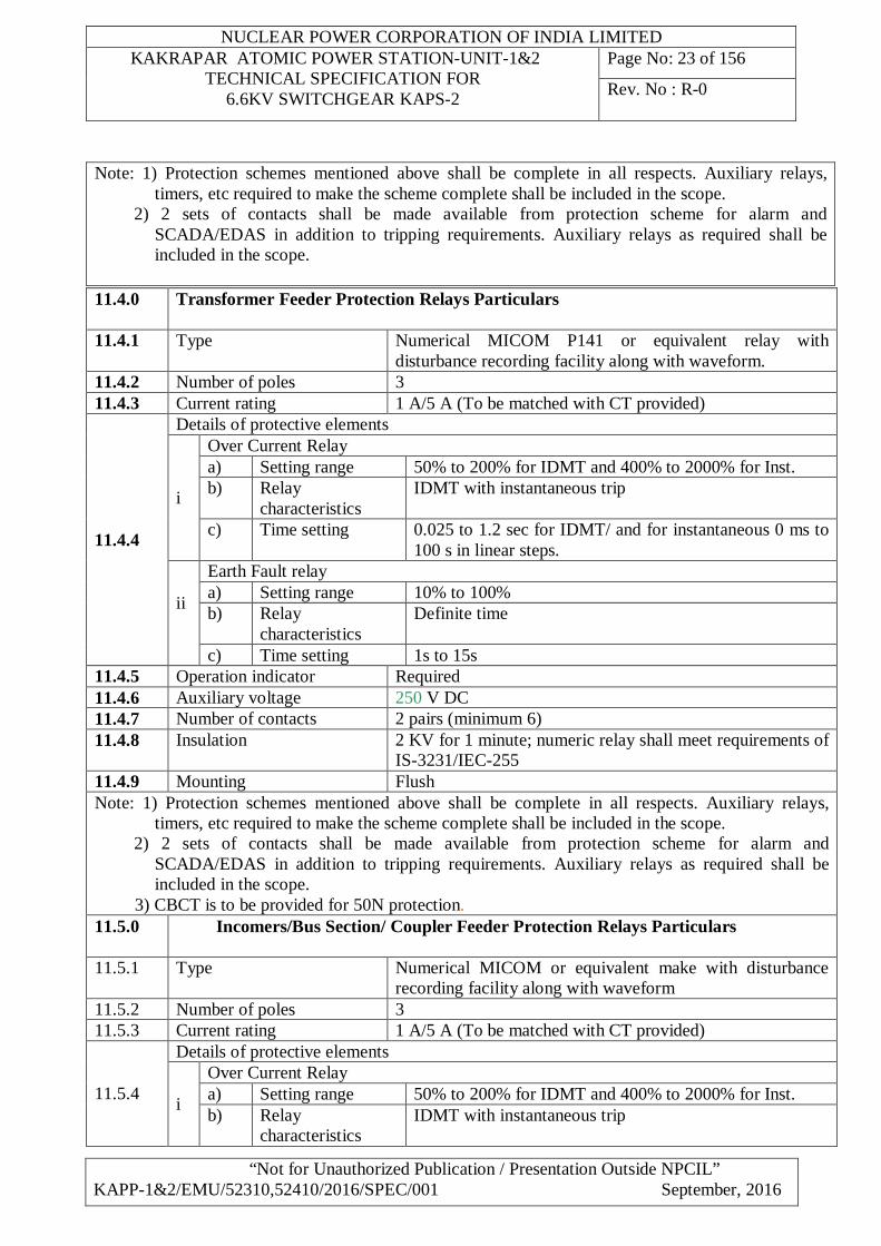
Note: 1) Protection schemes mentioned above shall be complete in all respects. Auxiliary relays, timers, etc required to make the scheme complete shall be included in the scope.
2) 2 sets of contacts shall be made available from protection scheme for alarm and SCADA/EDAS in addition to tripping requirements. Auxiliary relays as required shall be included in the scope.
11.4.0
Transformer Feeder Protection Relays Particulars
11.4.1 Type Numerical MICOM P141 or equivalent relay with disturbance recording facility along with waveform.
11.4.2 Number of poles 3 11.4.3 Current rating 1 A/5 A (To be matched with CT provided)
11.4.4
Details of protective elements
i
Over Current Relay a) Setting range 50% to 200% for IDMT and 400% to 2000% for Inst. b) Relay
characteristics IDMT with instantaneous trip
c) Time setting 0.025 to 1.2 sec for IDMT/ and for instantaneous 0 ms to 100 s in linear steps.
ii
Earth Fault relay a) Setting range 10% to 100% b) Relay
characteristics Definite time
c) Time setting 1s to 15s 11.4.5 Operation indicator Required 11.4.6 Auxiliary voltage 250 V DC 11.4.7 Number of contacts 2 pairs (minimum 6) 11.4.8 Insulation 2 KV for 1 minute; numeric relay shall meet requirements of
IS-3231/IEC-255 11.4.9 Mounting Flush Note: 1) Protection schemes mentioned above shall be complete in all respects. Auxiliary relays,
timers, etc required to make the scheme complete shall be included in the scope. 2) 2 sets of contacts shall be made available from protection scheme for alarm and
SCADA/EDAS in addition to tripping requirements. Auxiliary relays as required shall be included in the scope.
3) CBCT is to be provided for 50N protection. 11.5.0
Incomers/Bus Section/ Coupler Feeder Protection Relays Particulars
11.5.1 Type Numerical MICOM or equivalent make with disturbance
recording facility along with waveform 11.5.2 Number of poles 3 11.5.3 Current rating 1 A/5 A (To be matched with CT provided)
11.5.4
Details of protective elements
i
Over Current Relay a) Setting range 50% to 200% for IDMT and 400% to 2000% for Inst. b) Relay
characteristics IDMT with instantaneous trip
NUCLEAR POWER CORPORATION OF INDIA LIMITED KAKRAPAR ATOMIC POWER STATION-UNIT-1&2
TECHNICAL SPECIFICATION FOR 6.6KV SWITCHGEAR KAPS-2
Page No: 24 of 156
Rev. No : R-0
“Not for Unauthorized Publication / Presentation Outside NPCIL” KAPP-1&2/EMU/52310,52410/2016/SPEC/001 September, 2016
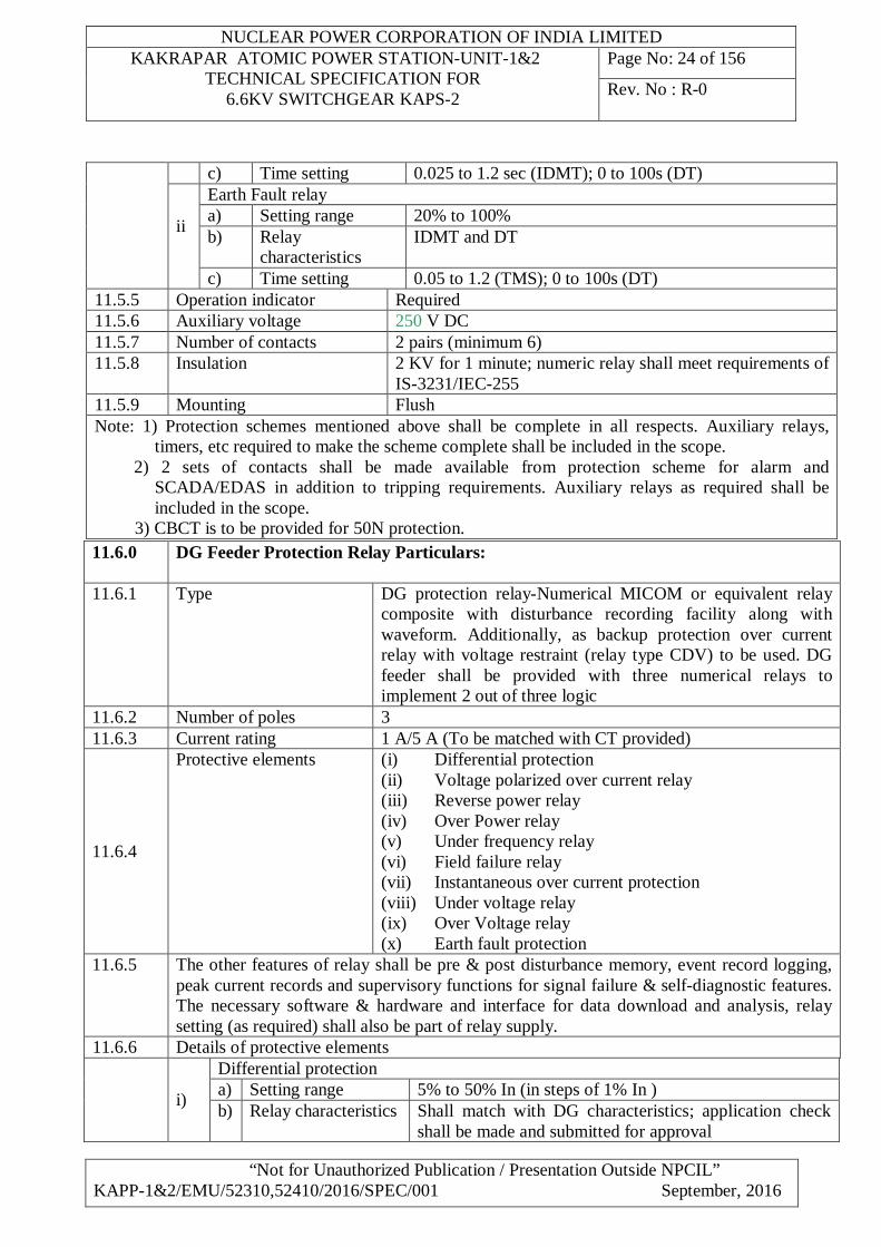
c) Time setting 0.025 to 1.2 sec (IDMT); 0 to 100s (DT)
ii
Earth Fault relay a) Setting range 20% to 100% b) Relay
characteristics IDMT and DT
c) Time setting 0.05 to 1.2 (TMS); 0 to 100s (DT) 11.5.5 Operation indicator Required 11.5.6 Auxiliary voltage 250 V DC 11.5.7 Number of contacts 2 pairs (minimum 6) 11.5.8 Insulation 2 KV for 1 minute; numeric relay shall meet requirements of
IS-3231/IEC-255 11.5.9 Mounting Flush Note: 1) Protection schemes mentioned above shall be complete in all respects. Auxiliary relays,
timers, etc required to make the scheme complete shall be included in the scope. 2) 2 sets of contacts shall be made available from protection scheme for alarm and
SCADA/EDAS in addition to tripping requirements. Auxiliary relays as required shall be included in the scope.
3) CBCT is to be provided for 50N protection.
11.6.0
DG Feeder Protection Relay Particulars:
11.6.1 Type DG protection relay-Numerical MICOM or equivalent relay composite with disturbance recording facility along with waveform. Additionally, as backup protection over current relay with voltage restraint (relay type CDV) to be used. DG feeder shall be provided with three numerical relays to implement 2 out of three logic
11.6.2 Number of poles 3 11.6.3 Current rating 1 A/5 A (To be matched with CT provided)
11.6.4
Protective elements (i) Differential protection (ii) Voltage polarized over current relay (iii) Reverse power relay (iv) Over Power relay (v) Under frequency relay (vi) Field failure relay (vii) Instantaneous over current protection (viii) Under voltage relay (ix) Over Voltage relay (x) Earth fault protection
11.6.5 The other features of relay shall be pre & post disturbance memory, event record logging, peak current records and supervisory functions for signal failure & self-diagnostic features. The necessary software & hardware and interface for data download and analysis, relay setting (as required) shall also be part of relay supply.
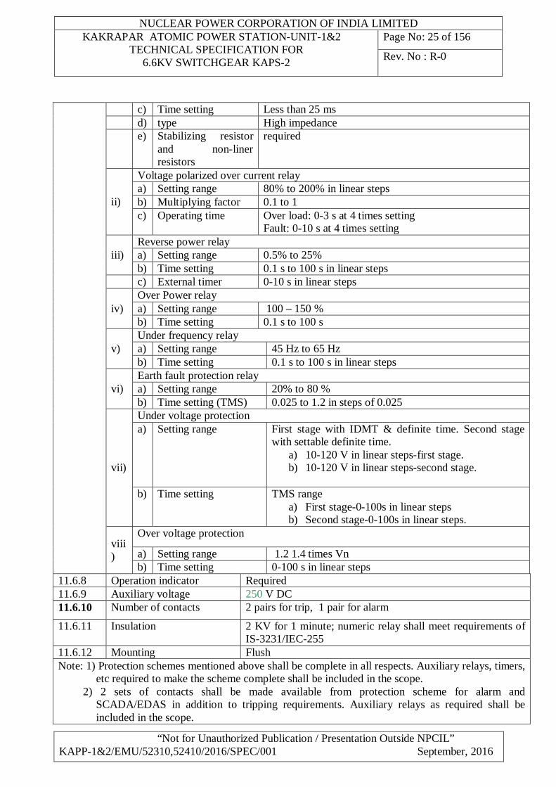
11 11.6.6 Details of protective elements
i)
Differential protection a) Setting range 5% to 50% In (in steps of 1% In ) b) Relay characteristics Shall match with DG characteristics; application check
shall be made and submitted for approval
NUCLEAR POWER CORPORATION OF INDIA LIMITED KAKRAPAR ATOMIC POWER STATION-UNIT-1&2
TECHNICAL SPECIFICATION FOR 6.6KV SWITCHGEAR KAPS-2
Page No: 25 of 156
Rev. No : R-0
“Not for Unauthorized Publication / Presentation Outside NPCIL” KAPP-1&2/EMU/52310,52410/2016/SPEC/001 September, 2016
c) Time setting Less than 25 ms d) type High impedance e) Stabilizing resistor
and non-liner resistors
required
ii)
Voltage polarized over current relay a) Setting range 80% to 200% in linear steps b) Multiplying factor 0.1 to 1 c) Operating time Over load: 0-3 s at 4 times setting
Fault: 0-10 s at 4 times setting
iii) Reverse power relay a) Setting range 0.5% to 25% b) Time setting 0.1 s to 100 s in linear steps
c) External timer 0-10 s in linear steps
iv) Over Power relay a) Setting range 100 – 150 % b) Time setting 0.1 s to 100 s
v) Under frequency relay a) Setting range 45 Hz to 65 Hz b) Time setting 0.1 s to 100 s in linear steps
vi) Earth fault protection relay a) Setting range 20% to 80 % b) Time setting (TMS) 0.025 to 1.2 in steps of 0.025
vii)
Under voltage protection a) Setting range First stage with IDMT & definite time. Second stage
with settable definite time. a) 10-120 V in linear steps-first stage. b) 10-120 V in linear steps-second stage.
b) Time setting TMS range
a) First stage-0-100s in linear steps b) Second stage-0-100s in linear steps.
viii)
Over voltage protection
a) Setting range 1.2 1.4 times Vn b) Time setting 0-100 s in linear steps
11.6.8 Operation indicator Required 11.6.9 Auxiliary voltage 250 V DC 11.6.10 Number of contacts 2 pairs for trip, 1 pair for alarm
11.6.11 Insulation 2 KV for 1 minute; numeric relay shall meet requirements of IS-3231/IEC-255
11.6.12 Mounting Flush Note: 1) Protection schemes mentioned above shall be complete in all respects. Auxiliary relays, timers,
etc required to make the scheme complete shall be included in the scope. 2) 2 sets of contacts shall be made available from protection scheme for alarm and
SCADA/EDAS in addition to tripping requirements. Auxiliary relays as required shall be included in the scope.
NUCLEAR POWER CORPORATION OF INDIA LIMITED KAKRAPAR ATOMIC POWER STATION-UNIT-1&2
TECHNICAL SPECIFICATION FOR 6.6KV SWITCHGEAR KAPS-2
Page No: 26 of 156
Rev. No : R-0
“Not for Unauthorized Publication / Presentation Outside NPCIL” KAPP-1&2/EMU/52310,52410/2016/SPEC/001 September, 2016
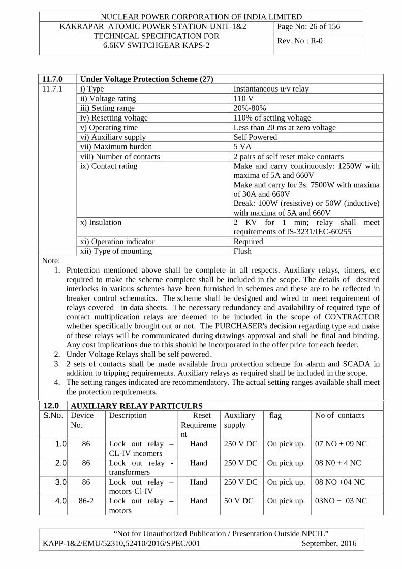
11.7.0 Under Voltage Protection Scheme (27) 11.7.1
i) Type Instantaneous u/v relay ii) Voltage rating 110 V iii) Setting range 20%-80% iv) Resetting voltage 110% of setting voltage v) Operating time Less than 20 ms at zero voltage vi) Auxiliary supply Self Powered vii) Maximum burden 5 VA viii) Number of contacts 2 pairs of self reset make contacts ix) Contact rating Make and carry continuously: 1250W with
maxima of 5A and 660V Make and carry for 3s: 7500W with maxima of 30A and 660V Break: 100W (resistive) or 50W (inductive) with maxima of 5A and 660V
x) Insulation 2 KV for 1 min; relay shall meet requirements of IS-3231/IEC-60255
xi) Operation indicator Required xii) Type of mounting Flush
Note: 1. Protection mentioned above shall be complete in all respects. Auxiliary relays, timers, etc
required to make the scheme complete shall be included in the scope. The details of desired interlocks in various schemes have been furnished in schemes and these are to be reflected in breaker control schematics. The scheme shall be designed and wired to meet requirement of relays covered in data sheets. The necessary redundancy and availability of required type of contact multiplication relays are deemed to be included in the scope of CONTRACTOR whether specifically brought out or not. The PURCHASER's decision regarding type and make of these relays will be communicated during drawings approval and shall be final and binding. Any cost implications due to this should be incorporated in the offer price for each feeder.
2. Under Voltage Relays shall be self powered. 3. 2 sets of contacts shall be made available from protection scheme for alarm and SCADA in
addition to tripping requirements. Auxiliary relays as required shall be included in the scope. 4. The setting ranges indicated are recommendatory. The actual setting ranges available shall meet
the protection requirements.
12.0 AUXILIARY RELAY PARTICULRS S.No. Device
No. Description Reset
Requirement
Auxiliary supply
flag No of contacts
1.0 86 Lock out relay –CL-IV incomers
Hand 250 V DC On pick up. 07 NO + 09 NC
2.0 86 Lock out relay -transformers
Hand 250 V DC On pick up. 08 N0 + 4 NC
3.0 86 Lock out relay – motors-Cl-IV
Hand 250 V DC On pick up. 08 NO +04 NC
4.0 86-2 Lock out relay –motors
Hand 50 V DC On pick up. 03NO + 03 NC
NUCLEAR POWER CORPORATION OF INDIA LIMITED KAKRAPAR ATOMIC POWER STATION-UNIT-1&2
TECHNICAL SPECIFICATION FOR 6.6KV SWITCHGEAR KAPS-2
Page No: 27 of 156
Rev. No : R-0
“Not for Unauthorized Publication / Presentation Outside NPCIL” KAPP-1&2/EMU/52310,52410/2016/SPEC/001 September, 2016
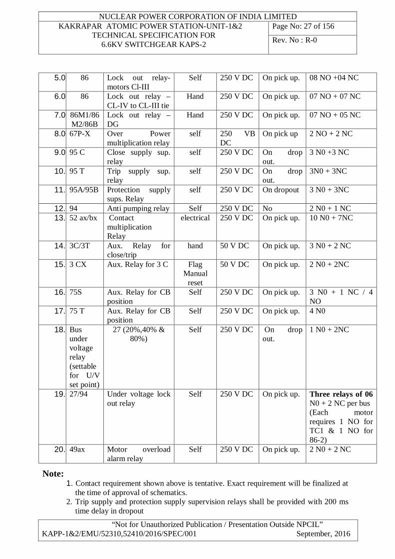
5.0 86 Lock out relay-motors Cl-III
Self 250 V DC On pick up. 08 NO +04 NC
6.0 86 Lock out relay –CL-IV to CL-III tie
Hand 250 V DC On pick up. 07 NO + 07 NC
7.0 86M1/86M2/86B
Lock out relay – DG
Hand 250 V DC On pick up. 07 NO + 05 NC
8.0 67P-X Over Power multiplication relay
self 250 VB DC
On pick up 2 NO + 2 NC
9.0 95 C Close supply sup. relay
self 250 V DC On drop out.
3 N0 +3 NC
10.095 T Trip supply sup. relay
self 250 V DC On drop out.
3N0 + 3NC
11.095A/95B Protection supply sups. Relay
self 250 V DC On dropout 3 N0 + 3NC
12.094 Anti pumping relay Self 250 V DC No 2 N0 + 1 NC 13.052 ax/bx Contact
multiplication Relay
electrical 250 V DC On pick up. 10 N0 + 7NC
14.03C/3T Aux. Relay for close/trip
hand 50 V DC On pick up. 3 N0 + 2 NC
15.03 CX Aux. Relay for 3 C Flag Manual
reset
50 V DC On pick up. 2 N0 + 2NC
16.075S Aux. Relay for CB position
Self 250 V DC On pick up. 3 N0 + 1 NC / 4 NO
17.075 T Aux. Relay for CB position
Self 250 V DC On pick up. 4 N0
18.0Bus under voltage relay (settable for U/V set point)
27 (20%,40% & 80%)
Self 250 V DC On drop out.
1 N0 + 2NC
19.027/94 Under voltage lock out relay
Self 250 V DC On pick up. Three relays of 06 N0 + 2 NC per bus (Each motor requires 1 NO for TC1 & 1 NO for 86-2)
20.049ax Motor overload alarm relay
Self 250 V DC On pick up. 2 N0 + 2 NC
Note: 1. Contact requirement shown above is tentative. Exact requirement will be finalized at
the time of approval of schematics. 2. Trip supply and protection supply supervision relays shall be provided with 200 ms
time delay in dropout
NUCLEAR POWER CORPORATION OF INDIA LIMITED KAKRAPAR ATOMIC POWER STATION-UNIT-1&2
TECHNICAL SPECIFICATION FOR 6.6KV SWITCHGEAR KAPS-2
Page No: 28 of 156
Rev. No : R-0
“Not for Unauthorized Publication / Presentation Outside NPCIL” KAPP-1&2/EMU/52310,52410/2016/SPEC/001 September, 2016
3. Close supply supervision relay shall be provided with 100 ms time delay drop out. 4. The relays shall be suitable for prolonged operation under auxiliary voltage variation
of (–) 15 % to (+) 10 % without affecting performance & life expectancy. The relays are expected to be remain at higher auxiliary voltage at about (+)10 % of rating for their entire service period
5. List of auxiliary relay is indicative only and does not cover all auxiliary relays. Timers and auxiliary relays are to be provided to meet all technical requirements of purchaser.
6. All auxiliary relay make should be of standard company.
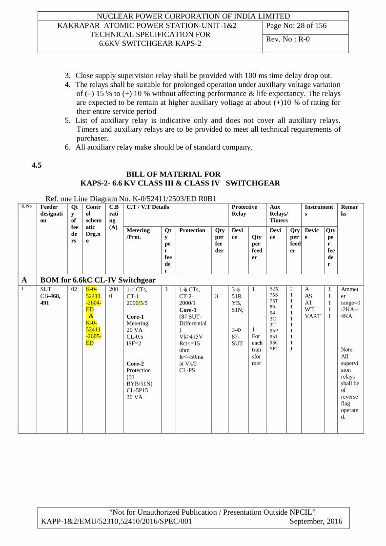
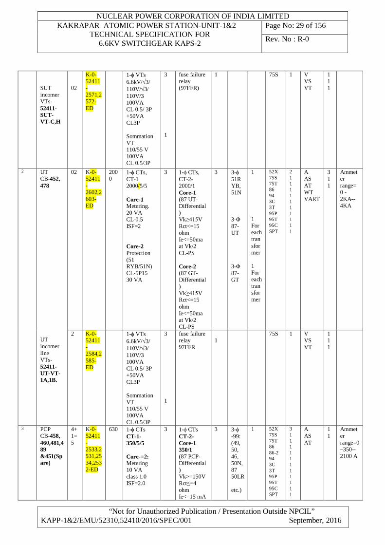
4.5 BILL OF MATERIAL FOR
KAPS-2- 6.6 KV CLASS III & CLASS IV SWITCHGEAR Ref. one Line Diagram No. K-0/52411/2503/ED R0B1
S. No Feeder designation
Qty of feeders
Control schematic Drg.no
C.B rating (A)
C.T / V.T Details Protective Relay
Aux Relays/ Timers
Instruments
Remarks
Metering /Prot.
Qty per feeder
Protection Qty per feeder
Device
Qty per feeder
Device
Qty per feeder
Device
Qty per feeder
A BOM for 6.6kC CL-IV Switchgear 1
SUT CB-468, 491
02 K-0-52411-2604-ED & K-0-52411-2605-ED
2000
1- CTs, CT-1 2000/5/5 Core-1 Metering. 20 VA CL-0.5 ISF=2 Core-2 Protection (51 RYB/51N) CL-5P15 30 VA
3
1- CTs, CT-2- 2000/1 Core-1 (87 SUT-Differential) Vk≥415V Rct<=15 ohm Ie<=50ma at Vk/2 CL-PS
3
3- 51RYB, 51N, 3-Φ 87-SUT
1 1 For each transformer
52X 75S 75T 86 94 3C 3T 95P 95T 95C SPT
2 1 1 1 1 1 1 1 1 1 1
A AS AT WT VART
1 1 1 1 1
Ammeter range=0 -2KA-- 4KA Note: All supervision relays shall be of reverse flag operated.
NUCLEAR POWER CORPORATION OF INDIA LIMITED KAKRAPAR ATOMIC POWER STATION-UNIT-1&2
TECHNICAL SPECIFICATION FOR 6.6KV SWITCHGEAR KAPS-2
Page No: 29 of 156
Rev. No : R-0
“Not for Unauthorized Publication / Presentation Outside NPCIL” KAPP-1&2/EMU/52310,52410/2016/SPEC/001 September, 2016
SUT incomer VTs-52411-SUT- VT-C,H
02
K-0-52411-2571,2572-ED
1- VTs 6.6kV/3/ 110V/3/ 110V/3 100VA CL 0.5/ 3P +50VA CL3P Sommation VT 110/55 V 100VA CL 0.5/3P
3 1
fuse failure relay (97FFR)
1 75S
1 V VS VT
1 1 1
2
UT CB-452, 478 UT incomer line VTs- 52411-UT-VT- 1A,1B.
02 K-0-52411-2602,2603-ED
2000
1- CTs, CT-1 2000/5/5 Core-1 Metering. 20 VA CL-0.5 ISF=2 Core-2 Protection (51 RYB/51N) CL-5P15 30 VA
3 1- CTs, CT-2- 2000/1 Core-1 (87 UT-Differential) Vk≥415V Rct<=15 ohm Ie<=50ma at Vk/2 CL-PS Core-2 (87 GT-Differential) Vk≥415V Rct<=15 ohm Ie<=50ma at Vk/2 CL-PS
3
3- 51RYB, 51N 3-Φ 87-UT 3-Φ 87-GT
1 1 For each transformer 1 For each transformer
52X 75S 75T 86 94 3C 3T 95P 95T 95C SPT
2 1 1 1 1 1 1 1 1 1 1
A AS AT WT VART
3 1 1
Ammeter range= 0 -2KA-- 4KA
2 K-0-52411-2584,2585-ED
1- VTs 6.6kV/3/ 110V/3/ 110V/3 100VA CL 0.5/ 3P +50VA CL3P Sommation VT 110/55 V 100VA CL 0.5/3P
3 1
fuse failure relay 97FFR
1
75S
1 V VS VT
1 1 1
3
PCP CB-458, 460,481,489 &451(Spare)
4+1=5
K-0-52411-2533,2531,2534,2532-ED
630 1- CTs CT-1-350/5/5 Core-=2: Metering 10 VA class 1.0 ISF=2.0
3
1- CTs CT-2- Core-1 350/1 (87 PCP-Differential) Vk>=150V Rct≤=4 ohm Ie<=15 mA
3
3- -99: (49, 50, 46, 50N, 87 50LR etc.)
1
52X 75S 75T 86 86-2 94 3C 3T 95P 95T 95C SPT
3 1 1 1 1 1 1 1 1 1 1 1
A AS AT
1 1
Ammeter range=0 –350--2100 A
NUCLEAR POWER CORPORATION OF INDIA LIMITED KAKRAPAR ATOMIC POWER STATION-UNIT-1&2
TECHNICAL SPECIFICATION FOR 6.6KV SWITCHGEAR KAPS-2
Page No: 30 of 156
Rev. No : R-0
“Not for Unauthorized Publication / Presentation Outside NPCIL” KAPP-1&2/EMU/52310,52410/2016/SPEC/001 September, 2016
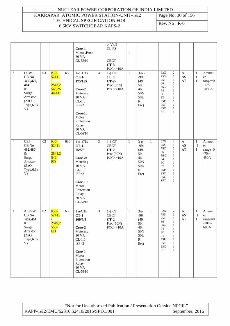
Core-1 Motor .Protr 30 VA CL-5P10
at Vk/2 CL-PS CBCT CT-3- POC<=10A
1
4
CCW CB No 456,479, 484 & Surge Arrestor (ZnO Type,6.6kV)
03 K-0-52411-2543,2545,2544-ED
630 1- CTs CT-1-175/155 Core-2 Metering 10 VA CL-1.0 ISF=2 Core-1: Motor Protection Relay. 30 VA CL-5P10
3 1- CT CBCT CT-2- Prot (50N) POC<=10A
1 3- --99: (49, 50, 46, 50N 50LR Etc)
1 52X 75S 75T 86 86-2 94 3C 3T 95P 95T 95C SPT
2 1 1 1 1 1 1 1 1 1 1 1
A AS AT
1 1 1
Ammeter range=0 -175-- 1050A
5
CEP CB No 462,487 & Surge Arrestor (ZnO Type,6.6kV)
02 K-0-52411-2541,2542-ED
630 1- CTs CT-1- 75/5/5 Core-2: Metering 10 VA CL-1.0 ISF=2 Core-1 : Motor Protection Relay. 30 VA CL-5P10
3 1- CT CBCT CT-2- Prot (50N) POC<=10A
1 3- -99: (49, 50, 46, 50N 50LR Etc)
1 52X 75S 75T 86 86-2 94 3C 3T 95P 95T 95C SPT
2 1 1 1 1 1 1 1 1 1 1 1
A AS AT
1 1 1
Ammeter range=0 -75-- 450A
6
ALPPW CB No. 457,464 & Surge Arrestor (ZnO Type,6.6kV)
02 K-0-52411-2549,2550-ED
630 1 -CTs CT-1 100/5/5 Core-2 Metering 10 VA CL-1.0 ISF=2 Core-1 Motor Protection Relay. 30 VA CL-5P10
3 1- CT CBCT CT-2- Prot (50N) POC<=10A
1 3- -99: (49, 50, 46, 50N 50LR Etc)
1 52X 75S 75T 86 86-2 94 3C 3T 95P 95T 95C SPT
2 1 1 1 1 1 1 1 1 1 1 1
A AS AT
1 1 1
Ammeter range=0 -100-- 600A
NUCLEAR POWER CORPORATION OF INDIA LIMITED KAKRAPAR ATOMIC POWER STATION-UNIT-1&2
TECHNICAL SPECIFICATION FOR 6.6KV SWITCHGEAR KAPS-2
Page No: 31 of 156
Rev. No : R-0
“Not for Unauthorized Publication / Presentation Outside NPCIL” KAPP-1&2/EMU/52310,52410/2016/SPEC/001 September, 2016
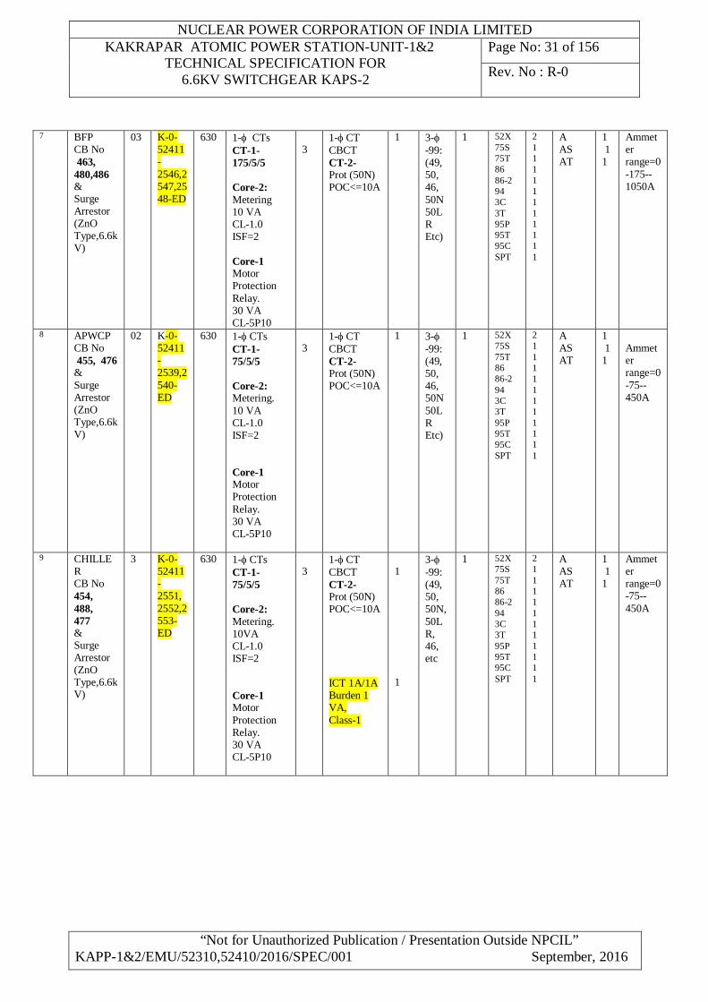
7
BFP CB No 463, 480,486 & Surge Arrestor (ZnO Type,6.6kV)
03 K-0-52411-2546,2547,2548-ED
630 1- CTs CT-1-175/5/5 Core-2: Metering 10 VA CL-1.0 ISF=2 Core-1 Motor Protection Relay. 30 VA CL-5P10
3
1- CT CBCT CT-2- Prot (50N) POC<=10A
1 3- -99: (49, 50, 46, 50N 50LR Etc)
1 52X 75S 75T 86 86-2 94 3C 3T 95P 95T 95C SPT
2 1 1 1 1 1 1 1 1 1 1 1
A AS AT
1 1 1
Ammeter range=0 -175-- 1050A
8
APWCP CB No 455, 476 & Surge Arrestor (ZnO Type,6.6kV)
02 K-0-52411-2539,2540-ED
630 1- CTs CT-1- 75/5/5 Core-2: Metering. 10 VA CL-1.0 ISF=2 Core-1 Motor Protection Relay. 30 VA CL-5P10
3
1- CT CBCT CT-2- Prot (50N) POC<=10A
1 3- -99: (49, 50, 46, 50N 50LR Etc)
1 52X 75S 75T 86 86-2 94 3C 3T 95P 95T 95C SPT
2 1 1 1 1 1 1 1 1 1 1 1
A AS AT
1 1 1
Ammeter range=0 -75-- 450A
9
CHILLER CB No 454, 488, 477 & Surge Arrestor (ZnO Type,6.6kV)
3 K-0-52411- 2551, 2552,2553-ED
630 1- CTs CT-1- 75/5/5 Core-2: Metering. 10VA CL-1.0 ISF=2 Core-1 Motor Protection Relay. 30 VA CL-5P10
3
1- CT CBCT CT-2- Prot (50N) POC<=10A ICT 1A/1A Burden 1 VA, Class-1
1 1
3- -99: (49, 50, 50N,50LR, 46, etc
1
52X 75S 75T 86 86-2 94 3C 3T 95P 95T 95C SPT
2 1 1 1 1 1 1 1 1 1 1 1
A AS AT
1 1 1
Ammeter range=0 -75-- 450A
NUCLEAR POWER CORPORATION OF INDIA LIMITED KAKRAPAR ATOMIC POWER STATION-UNIT-1&2
TECHNICAL SPECIFICATION FOR 6.6KV SWITCHGEAR KAPS-2
Page No: 32 of 156
Rev. No : R-0
“Not for Unauthorized Publication / Presentation Outside NPCIL” KAPP-1&2/EMU/52310,52410/2016/SPEC/001 September, 2016
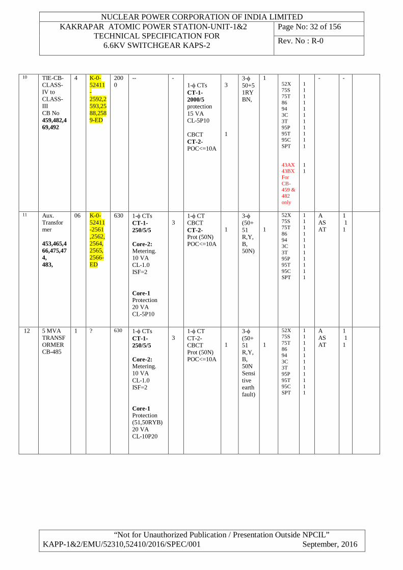
10 TIE-CB-CLASS-IV to CLASS-III CB No 459,482,469,492
4 K-0-52411-2592,2593,2588,2589-ED
2000
-- -
1- CTs CT-1- 2000/5 protection 15 VA CL-5P10 CBCT CT-2- POC<=10A
3 1
3- 50+51RYBN,
1 52X 75S 75T 86 94 3C 3T 95P 95T 95C SPT 43AX 43BX For CB-459 & 482 only
1 1 1 1 1 1 1 1 1 1 1 1 1
- -
11 Aux. Transformer 453,465,466,475,474, 483,
06 K-0-52411-2561 ,2562,2564, 2565, 2566-ED
630 1- CTs CT-1-250/5/5 Core-2: Metering. 10 VA CL-1.0 ISF=2 Core-1 Protection 20 VA CL-5P10
3
1- CT CBCT CT-2- Prot (50N) POC<=10A
1
3- (50+51 R,Y,B, 50N)
1
52X 75S 75T 86 94 3C 3T 95P 95T 95C SPT
1 1 1 1 1 1 1 1 1 1 1
A AS AT
1 1 1
12 5 MVA TRANSFORMER CB-485
1 ? 630 1- CTs CT-1-250/5/5 Core-2: Metering. 10 VA CL-1.0 ISF=2 Core-1 Protection (51,50RYB) 20 VA CL-10P20
3
1- CT CT-2- CBCT Prot (50N) POC<=10A
1
3- (50+51 R,Y,B, 50N Sensitive earth fault)
1
52X 75S 75T 86 94 3C 3T 95P 95T 95C SPT
1 1 1 1 1 1 1 1 1 1 1
A AS AT
1 1 1
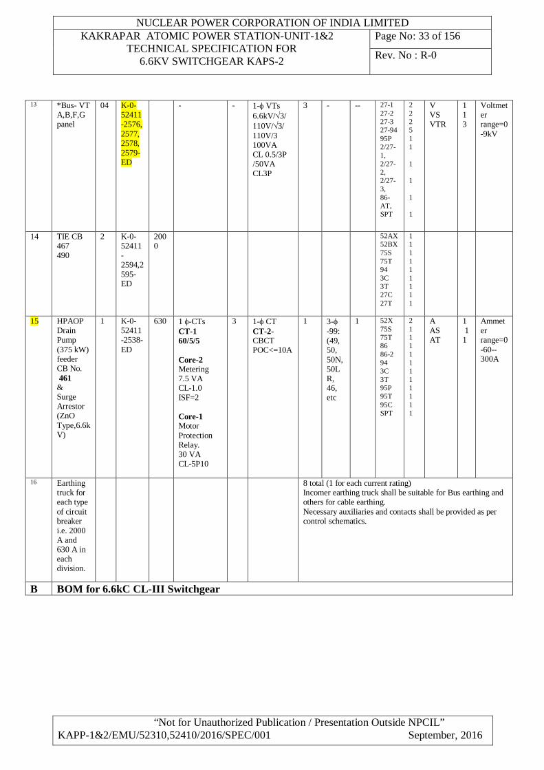
NUCLEAR POWER CORPORATION OF INDIA LIMITED KAKRAPAR ATOMIC POWER STATION-UNIT-1&2
TECHNICAL SPECIFICATION FOR 6.6KV SWITCHGEAR KAPS-2
Page No: 33 of 156
Rev. No : R-0
“Not for Unauthorized Publication / Presentation Outside NPCIL” KAPP-1&2/EMU/52310,52410/2016/SPEC/001 September, 2016
13 *Bus- VT A,B,F,G panel
04 K-0-52411-2576, 2577, 2578, 2579-ED
-
- 1- VTs 6.6kV/3/ 110V/3/ 110V/3 100VA CL 0.5/3P /50VA CL3P
3
- -- 27-1 27-2 27-3 27-94 95P 2/27-1, 2/27-2, 2/27-3, 86-AT, SPT
2 2 2 5 1 1 1 1 1 1
V VS VTR
1 1 3
Voltmeter range=0-9kV
14 TIE CB 467 490
2 K-0-52411-2594,2595-ED
2000
52AX 52BX 75S 75T 94 3C 3T 27C 27T
1 1 1 1 1 1 1 1 1
15 HPAOP Drain Pump (375 kW) feeder CB No. 461 & Surge Arrestor (ZnO Type,6.6kV)
1 K-0-52411-2538-ED
630 1 -CTs CT-1 60/5/5 Core-2 Metering 7.5 VA CL-1.0 ISF=2 Core-1 Motor Protection Relay. 30 VA CL-5P10
3 1- CT CT-2- CBCT POC<=10A
1 3- -99: (49, 50, 50N,50LR, 46, etc
1
52X 75S 75T 86 86-2 94 3C 3T 95P 95T 95C SPT
2 1 1 1 1 1 1 1 1 1 1 1
A AS AT
1 1 1
Ammeter range=0 -60-- 300A
16 Earthing truck for each type of circuit breaker i.e. 2000 A and 630 A in each division.
8 total (1 for each current rating) Incomer earthing truck shall be suitable for Bus earthing and others for cable earthing. Necessary auxiliaries and contacts shall be provided as per control schematics.
B BOM for 6.6kC CL-III Switchgear
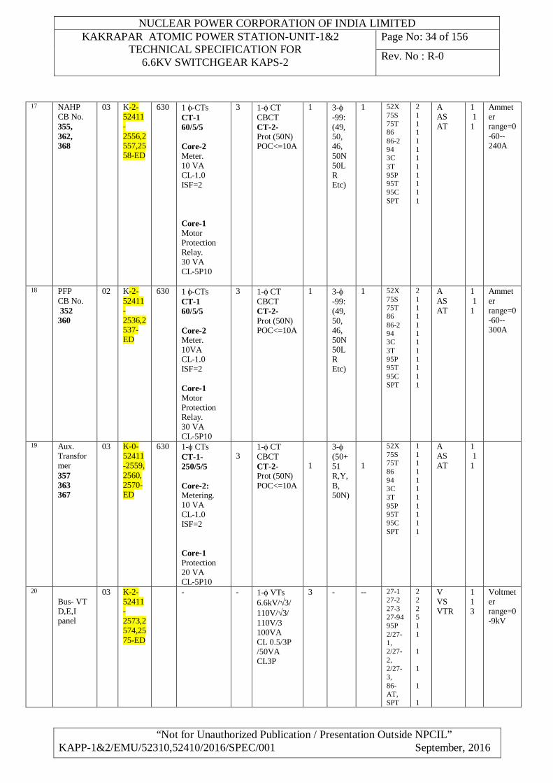
NUCLEAR POWER CORPORATION OF INDIA LIMITED KAKRAPAR ATOMIC POWER STATION-UNIT-1&2
TECHNICAL SPECIFICATION FOR 6.6KV SWITCHGEAR KAPS-2
Page No: 34 of 156
Rev. No : R-0
“Not for Unauthorized Publication / Presentation Outside NPCIL” KAPP-1&2/EMU/52310,52410/2016/SPEC/001 September, 2016
17 NAHP CB No. 355, 362, 368
03 K-2-52411-2556,2557,2558-ED
630 1 -CTs CT-1 60/5/5 Core-2 Meter. 10 VA CL-1.0 ISF=2 Core-1 Motor Protection Relay. 30 VA CL-5P10
3 1- CT CBCT CT-2- Prot (50N) POC<=10A
1 3- -99: (49, 50, 46, 50N 50LR Etc)
1 52X 75S 75T 86 86-2 94 3C 3T 95P 95T 95C SPT
2 1 1 1 1 1 1 1 1 1 1 1
A AS AT
1 1 1
Ammeter range=0 -60-- 240A
18 PFP CB No. 352 360
02 K-2-52411-2536,2537-ED
630 1 -CTs CT-1 60/5/5 Core-2 Meter. 10VA CL-1.0 ISF=2 Core-1 Motor Protection Relay. 30 VA CL-5P10
3 1- CT CBCT CT-2- Prot (50N) POC<=10A
1 3- -99: (49, 50, 46, 50N 50LR Etc)
1 52X 75S 75T 86 86-2 94 3C 3T 95P 95T 95C SPT
2 1 1 1 1 1 1 1 1 1 1 1
A AS AT
1 1 1
Ammeter range=0 -60-- 300A
19 Aux. Transformer 357 363 367
03 K-0-52411-2559, 2560, 2570-ED
630 1- CTs CT-1-250/5/5 Core-2: Metering. 10 VA CL-1.0 ISF=2 Core-1 Protection 20 VA CL-5P10
3
1- CT CBCT CT-2- Prot (50N) POC<=10A
1
3- (50+51 R,Y,B, 50N)
1
52X 75S 75T 86 94 3C 3T 95P 95T 95C SPT
1 1 1 1 1 1 1 1 1 1 1
A AS AT
1 1 1
20 Bus- VT D,E,I panel
03 K-2-52411-2573,2574,2575-ED
-
- 1- VTs 6.6kV/3/ 110V/3/ 110V/3 100VA CL 0.5/3P /50VA CL3P
3
- -- 27-1 27-2 27-3 27-94 95P 2/27-1, 2/27-2, 2/27-3, 86-AT, SPT
2 2 2 5 1 1 1 1 1 1
V VS VTR
1 1 3
Voltmeter range=0-9kV
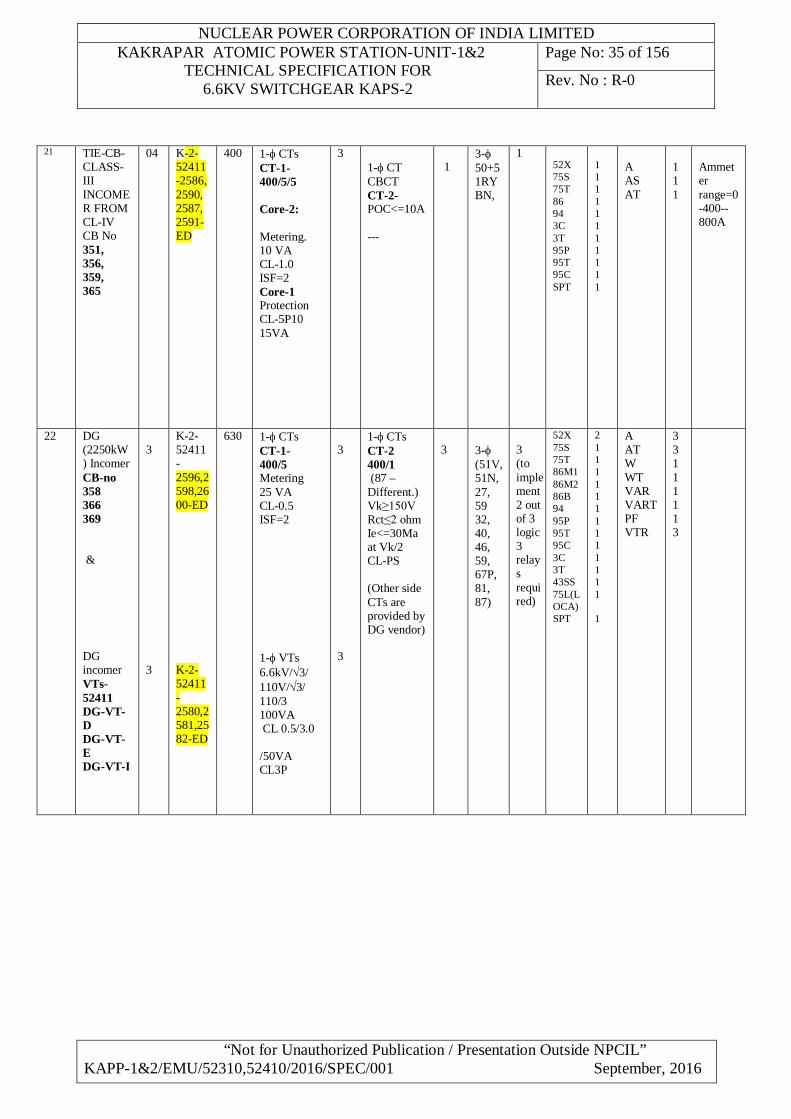
NUCLEAR POWER CORPORATION OF INDIA LIMITED KAKRAPAR ATOMIC POWER STATION-UNIT-1&2
TECHNICAL SPECIFICATION FOR 6.6KV SWITCHGEAR KAPS-2
Page No: 35 of 156
Rev. No : R-0
“Not for Unauthorized Publication / Presentation Outside NPCIL” KAPP-1&2/EMU/52310,52410/2016/SPEC/001 September, 2016
21 TIE-CB-CLASS-III INCOMER FROM CL-IV CB No 351, 356, 359, 365
04 K-2-52411-2586, 2590, 2587, 2591-ED
400 1- CTs CT-1-400/5/5 Core-2: Metering. 10 VA CL-1.0 ISF=2 Core-1 Protection CL-5P10 15VA
3
1- CT CBCT CT-2- POC<=10A ---
1
3- 50+51RYBN,
1 52X 75S 75T 86 94 3C 3T 95P 95T 95C SPT
1 1 1 1 1 1 1 1 1 1 1
A AS AT
1 1 1
Ammeter range=0 -400-- 800A
22 DG (2250kW) Incomer CB-no 358 366 369 & DG incomer VTs-52411 DG-VT-D DG-VT-E DG-VT-I
3 3
K-2-52411-2596,2598,2600-ED K-2-52411-2580,2581,2582-ED
630 1- CTs CT-1- 400/5 Metering 25 VA CL-0.5 ISF=2 1- VTs 6.6kV/3/ 110V/3/ 110/3 100VA CL 0.5/3.0 /50VA CL3P
3 3
1- CTs CT-2 400/1 (87 –Different.) Vk≥150V Rct≤2 ohm Ie<=30Ma at Vk/2 CL-PS (Other side CTs are provided by DG vendor)
3
3- (51V, 51N, 27, 59 32, 40, 46, 59, 67P, 81, 87)
3 (to implement 2 out of 3 logic 3 relays required)
52X 75S 75T 86M1 86M2 86B 94 95P 95T 95C 3C 3T 43SS 75L(LOCA) SPT
2 1 1 1 1 1 1 1 1 1 1 1 1 1 1
A AT W WT VAR VART PF VTR
3 3 1 1 1 1 1 3
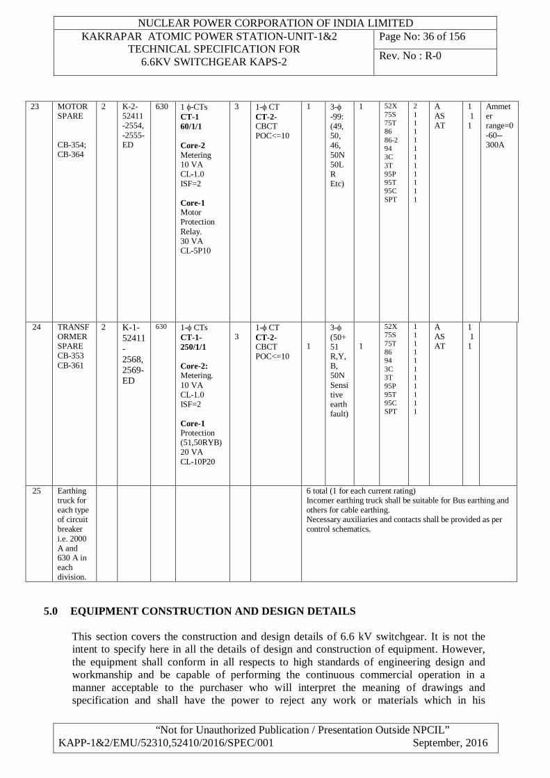
NUCLEAR POWER CORPORATION OF INDIA LIMITED KAKRAPAR ATOMIC POWER STATION-UNIT-1&2
TECHNICAL SPECIFICATION FOR 6.6KV SWITCHGEAR KAPS-2
Page No: 36 of 156
Rev. No : R-0
“Not for Unauthorized Publication / Presentation Outside NPCIL” KAPP-1&2/EMU/52310,52410/2016/SPEC/001 September, 2016
23 MOTOR SPARE CB-354; CB-364
2 K-2-52411-2554, -2555-ED
630 1 -CTs CT-1 60/1/1 Core-2 Metering 10 VA CL-1.0 ISF=2 Core-1 Motor Protection Relay. 30 VA CL-5P10
3 1- CT CT-2- CBCT POC<=10
1 3- -99: (49, 50, 46, 50N 50LR Etc)
1 52X 75S 75T 86 86-2 94 3C 3T 95P 95T 95C SPT
2 1 1 1 1 1 1 1 1 1 1 1
A AS AT
1 1 1
Ammeter range=0 -60-- 300A
24 TRANSFORMER SPARE CB-353 CB-361
2 K-1-52411-2568,2569-ED
630 1- CTs CT-1-250/1/1 Core-2: Metering. 10 VA CL-1.0 ISF=2 Core-1 Protection (51,50RYB) 20 VA CL-10P20
3
1- CT CT-2- CBCT POC<=10
1
3- (50+51 R,Y,B, 50N Sensitive earth fault)
1
52X 75S 75T 86 94 3C 3T 95P 95T 95C SPT
1 1 1 1 1 1 1 1 1 1 1
A AS AT
1 1 1
25 Earthing truck for each type of circuit breaker i.e. 2000 A and 630 A in each division.
6 total (1 for each current rating) Incomer earthing truck shall be suitable for Bus earthing and others for cable earthing. Necessary auxiliaries and contacts shall be provided as per control schematics.
5.0 EQUIPMENT CONSTRUCTION AND DESIGN DETAILS
This section covers the construction and design details of 6.6 kV switchgear. It is not the intent to specify here in all the details of design and construction of equipment. However, the equipment shall conform in all respects to high standards of engineering design and workmanship and be capable of performing the continuous commercial operation in a manner acceptable to the purchaser who will interpret the meaning of drawings and specification and shall have the power to reject any work or materials which in his
NUCLEAR POWER CORPORATION OF INDIA LIMITED KAKRAPAR ATOMIC POWER STATION-UNIT-1&2
TECHNICAL SPECIFICATION FOR 6.6KV SWITCHGEAR KAPS-2
Page No: 37 of 156
Rev. No : R-0
“Not for Unauthorized Publication / Presentation Outside NPCIL” KAPP-1&2/EMU/52310,52410/2016/SPEC/001 September, 2016
judgement are not in full accordance with the tender specifications and standard IEC 62271-200.
5.1 Constructional Features
The switchgear shall be designed with incorporating following constructional features.
5.1.1 Sheet steel , metal enclosed, indoor, floor mounted modular type. Switchgear panels shall be powder coated type. Switchgear shall conform to partition class LSC2B-PM of IEC 62271-200.
5.1.2 Made up of the requisite vertical sections. 5.1.3 Degree of protection of IP-4X as per IS: 12063-1987 5.1.4 Easily extendable on both sides by the addition of vertical sections after removing the end
covers. 5.1.5 Provided with a base frame made of structural steel channel section properly drilled for
mounting the Switchgear along with necessary mounting hardware. Hardware shall be zinc plated and passivated. The base frame shall be welded on floor EP’s. Foundation base frames shall be dispatched separately before delivery of the switchgear shall be provided with holes to match switchgear panel installation at site by bolting.
5.1.6 Provided with labels on the front and rear indicating the switchgear designation, duty, rating and individual CB designation. Each relay, instrument, switch, fuse and other devices shall be provided with separate labels.
5.1.7 Provided with cable entry facilities and removable MS gland plates of at least 3 mm thickness. Gland plates shall be of Aluminum Sheets of at least 4 mm thickness wherever single core power cables enter the cubicle
5.1.8 Having uniform height not more than existing switchgear height 5.1.9 Having single front and two tier execution (as in existing panels, the bottom tier for CB &
upper tier for instrumentation purpose), the switchgear shall incorporate operating devices only in the front of the cubicles
5.1.10 Provided with neoprene rubber gaskets all-round the perimeter of all covers and doors 5.1.11 Provided with bus bars running all along the length of the switchgear in a separate enclosure 5.1.12 Engineered so that CT’s are located in such a way that they can be easily approachable for
maintenance 5.1.13 Provided with Trolley mounted draw out type voltage transformers 5.1.14 Each vertical section shall be equipped with thermostatically controlled space heaters, which
may be located in the cable alley 5.1.15 Provided with sheet metal partition between two adjacent vertical sections running along
entire height of the switchgear except for the horizontal bus-bar compartment 5.1.16 Equipment associated with different circuits shall be housed in different compartments 5.1.17 The compartment shall be enclosed from all sides with the withdrawal units in position or
removed. The front of the compartment shall be provided with a door with concealed hinges.
5.1.18 Design shall be such that all live connections remain shrouded at all times & Insulating sheet with slots shall be provided wherever bus bar or breaker power connector extrusion is needed. These slots also shall be suitably shrouded with automatic shutter of insulating plate to prevent access to any part of live circuit when breaker trolley is in test & isolated position or breaker trolley is completely removed from compartment.
NUCLEAR POWER CORPORATION OF INDIA LIMITED KAKRAPAR ATOMIC POWER STATION-UNIT-1&2
TECHNICAL SPECIFICATION FOR 6.6KV SWITCHGEAR KAPS-2
Page No: 38 of 156
Rev. No : R-0
“Not for Unauthorized Publication / Presentation Outside NPCIL” KAPP-1&2/EMU/52310,52410/2016/SPEC/001 September, 2016
5.1.19 Control and selector switches, push buttons, indicating instruments and lamps, shall be mounted on the front doors of the respective compartments. Current transformers on circuit breaker controlled circuits shall be mounted on the fixed portion of the compartment. Current transformers shall not be directly mounted on the buses. All other equipment pertaining to a circuit shall be mounted on a withdrawal chassis.
5.1.20 The individual compartment doors shall be provided with suitable cutouts as necessary to permit operation of circuit breakers and circuit isolating switches from the front without having to open the door. Such cutouts shall be provided with spring-loaded gaskets for the purpose of dust and vermin proofing.
5.1.21 Suitable barriers shall be placed between circuit breakers and all control, protective and indication circuit equipment including instrument transformer. External cable connections shall be carried out in a separate cable compartment.
5.1.22 After isolation of the power and control connections of a circuit (i.e. in the maintenance position), it shall be possible to safely carry out maintenance in a compartment with the bus bars and adjacent circuits live.
5.1.23 The withdrawal chassis shall be provided with a plate cover on the side corresponding to the cable alley of the compartment, except for a slot to permit wiring connections. The withdrawal chassis shall move on suitable guides to facilitate easy withdrawal.
5.1.24 Cable alleys shall be provided with suitable hinged doors. It shall be possible to safely carry out maintenance work on cable connection to any one circuit with the bus bars and adjacent circuits live.
5.1.25 Rear of single front switchgear shall be provided with concealed type hinged doors with lockable handles.
5.1.26 All doors shall be provided with concealed type hinges and captive screws 5.1.27 The withdrawal chassis of the circuit breakers shall be of the fully draw out type facilitating
to draw out the withdrawal chassis without having to unscrew or unbolt any connections to the equipment mounted on the withdrawal chassis. Both power and control connections shall be of the plug-in or sliding type. The draw-out contacts shall be of copper/aluminum alloys with silver or tin plating and designed to safely withstand the specified full load and short circuit currents.
5.1.28 Switchgear shall be designed in such a way that all components/equipment operate satisfactorily without exceeding their respective maximum permissible rise in temperature under maximum ambient temperature conditions prevailing within the switchgear cubicle.
5.1.29 Metal clad switchgear board shall comprise of components, which are arranged in separate compartments with metal enclosures intended to be earthed.
5.1.30 The metal clad switchgear cubicle shall have separate compartments for the following components:
a) Main bus bars of each panel/cubicle. b) Main switching device/circuit breaker. c) Voltage transformers d) Cable box and current transformers/CBCTs. e) Metering and relaying devices associated with cubicle
5.1.31 Switchgear shall comprise of indoor metal clad, fully draw out type Vacuum/SF6 circuit
breakers as specified in the data sheets. 5.1.32 Switchgear shall be dust, moisture and vermin proof.
NUCLEAR POWER CORPORATION OF INDIA LIMITED KAKRAPAR ATOMIC POWER STATION-UNIT-1&2
TECHNICAL SPECIFICATION FOR 6.6KV SWITCHGEAR KAPS-2
Page No: 39 of 156
Rev. No : R-0
“Not for Unauthorized Publication / Presentation Outside NPCIL” KAPP-1&2/EMU/52310,52410/2016/SPEC/001 September, 2016
5.1.33 All doors, panels, removable covers shall be gasketed all around with neoprene gaskets. All louvers if provided shall have screens/perforated sheets. Vent openings if provided shall be covered with grills so arranged that hot gases or other material cannot be discharged through them in a manner that can injure the operating personnel. The screens and grills shall be made of galvanized iron perforated sheet.
5.1.34 Metal clad unit comprises of rigid welded structural frame enclosed completely by metal sheets, cold rolled, as per ANSI: C-37.20 (IEEE Std. 27). Sheet metal is smooth finished, leveled and free from flaws.
5.1.35 Switchgear design comprises of fully compartmental execution having separate vertical section for each circuit. Compartments with doors for access to operating mechanism are so arranged as not to expose high voltage circuit. Switchgear cubicles shall be provided with hinged doors on the front with in built locking facility.
5.1.36 Structure, buses and control wiring troughs shall be so designed and arranged to make future extensions easy.
5.1.37 Instruments, relays and control devices shall be mounted flush on the hinged door of the metering compartment located in the front portion of the cubicle. Panel door shall be supported by strong hinges and braced in such a manner which ensures freedom from sagging, bending and general distortion of panel or hinged parts.
5.1.38 Circuit breaker and voltage transformer carriages shall be fitted with positive guide so as to ensure proper alignment.
5.1.39 Switchgear cubicles are provided with bottom sheet metal removable plates, as specified in this specification. For single core cables, cubicles shall be fitted with removable plates of non-magnetic material at suitable locations for fixing cable glands.
5.1.40 The temperature of the air surrounding all the devices within enclosed assembly considered in conjunction with their rating and loading shall not cause these devices to operate outside their normal temperature range. The ambient temperature ranges are indicated in the data sheets (as per ANSI C 37.20).
5.1.41 The switchgear cubicle should provide sufficient support and physical protection to the equipment housed inside to enable the equipment to meet its essential performance requirements during and after the safe shutdown earthquake. (SSE). The SSE shall be as defined in IEEE STD.344.
5.1.42 To take care of the above, switchgear cubicle can be designed by providing sufficient rigidity so that no natural frequencies or resonance can exist at a frequency less than 33 Hz. This can be achieved by providing any or all of following:
i) Welded stiffeners at required intervals. ii) Diagonal braces to the base. iii) Thick plate for the skin.
Bidder shall specifically confirm the design of installation of breaker etc. To meet the above requirement in the offer. Special attention of the bidder is drawn to the fact that the equipment cannot be accepted unless switchgear and their equipment are qualified to meet the above by conducting relevant seismic tests at CPRI, Bangalore or any other facility/agency approved by NPC.
5.1.43 The Seismic response spectra for the above will be furnished to the bidders during the technical evaluation stage of the offer.
5.1.44 Backside cable compartment door/plate should be easily removable for regular basis parameter checks work (like IR value measurement).
NUCLEAR POWER CORPORATION OF INDIA LIMITED KAKRAPAR ATOMIC POWER STATION-UNIT-1&2
TECHNICAL SPECIFICATION FOR 6.6KV SWITCHGEAR KAPS-2
Page No: 40 of 156
Rev. No : R-0
“Not for Unauthorized Publication / Presentation Outside NPCIL” KAPP-1&2/EMU/52310,52410/2016/SPEC/001 September, 2016
5.2 Bus Bars
5.2.1 Switchgear shall be provided with three phase bus bars. Horizontal Bus bars shall be of
uniform cross section throughout the length of the switchgear. Both horizontal bus bars as well as vertical droppers shall be designed for thermal and dynamic withstand capacity for specified fault level (to be confirmed either by conducting short circuit test on panel or by producing type test like short circuit test on similar bus bar arrangement). The temperature at any point of bus bar under full load conditions for switchgear cubicle shall be limited to the specified values. Tap-off bus bar connections to potential transformer up to primary fuse should be designed to meet the specified short circuit conditions.
5.2.2 Bus bars shall be located in air-insulated enclosures and segregated from all other compartments of the cubicle. Direct access or accidental contact with bus bars and primary connections shall not be possible. To provide a seal between adjacent cubicles, bus bars shall be, preferably taken through seal-off bushings. The service continuity and design features of construction shall be such that it shall meet the class LSC2B-PM requirements of IS/IEC 62271-200. Bidder to substantiate class LSC-2B-PM features of construction by providing necessary details.
5.2.3 All bus bars shall be made of high conductivity electrical grade Copper. 5.2.4 Bus bars & all live connections shall be provided with at least 127 mm phase to phase &
76.2 mm phase to earth clearance. In the event, when it is not possible to maintain the specified clearance, the provided clearance shall be qualified by 27 KV power frequency HV test voltage for 1 minute and lighting impulse withstand tests, further subject to minimum clearance allowed by relevant standard.
5.2.5 Bus-bar chambers shall be compartmentalized. 5.2.6 Bus bars shall be adequately supported on insulators to withstand the dynamic stresses due
to the specified short circuit currents for the associated switchgear. The class of insulation of the bus-bar supports shall be adequate for continuous operation at the maximum temperature of the bus bars.
5.2.7 Minimum creepage distance of 127 mm shall be kept between live parts and earth. 5.2.8 Separate supports shall be provided for each phase of the bus bars. 5.2.9 Bus-bar joints shall be of brazing or bolted type. Bus bars shall be thoroughly cleaned at the
joint locations and suitable contact grease shall be applied just before making a joint. All bus-bar joints shall be silver-plated.
5.2.10 All joints should be easily accessible for inspection whenever necessary 5.2.11 Bus bars (horizontal and vertical) shall be provided with black matt epoxy coating.
However, no credit shall be taken for extra current carrying capacity due to black matt painting.
5.2.12 All insulators shall be non-hygroscopic with finished surface having appropriate class of insulation
5.2.13 Main and Tap off jumper bus bars shall be of copper conforming to the relevant standards specified in the data sheet. Edges of busbars shall be rounded.
5.2.14 All bus bar joints and bus tap joints shall be silver faced. Silver facing shall be provided on both the bus bars forming the joint. Plain and spring washers shall be provided to ensure good contacts at the joints and taps. Wherever aluminum to copper connections is required, suitable bimetallic connectors or clamps shall be used. For droppers and tap-off bus bars the current rating shall be at least equal to corresponding breaker rating irrespective of their load current.
NUCLEAR POWER CORPORATION OF INDIA LIMITED KAKRAPAR ATOMIC POWER STATION-UNIT-1&2
TECHNICAL SPECIFICATION FOR 6.6KV SWITCHGEAR KAPS-2
Page No: 41 of 156
Rev. No : R-0
“Not for Unauthorized Publication / Presentation Outside NPCIL” KAPP-1&2/EMU/52310,52410/2016/SPEC/001 September, 2016
5.2.15 Tap offs shall be adequately supported on insulators, to withstand dynamic stresses due to short circuit current specified in the data sheet. Bus bar support insulators shall conform to relevant standards specified in the data sheet.
5.2.16 Tap-off/jumper bus-bars inside the cubicle shall have a heat shrinkable insulating covering that by itself will withstand the maximum rated line to line voltage between the conductor and outside surface of the insulating covering for a period of one minute. Joints shall also be completely covered by a removable insulating material at the works. For joints (shrouded), which must be made in the field, insulating material shall be supplied and shall be provided by the supplier at site. Insulating material proposed to be used above shall be flame retardant in accordance with ANSI C37.20. Phase to phase, and phase to earth clearances in air of bus bars and live parts shall not be less than those specified in the data sheets. PVC sleeves or taping is not acceptable. Current ratings of bus bars as specified in data sheet shall be after taking into consideration the effect of insulating covering over the bus bars.
5.2.17 Performance characteristics specified for the bus-bars shall be obtained with bare bus bars.
5.3 Insulators
5.3.1 Bus support insulators shall be made from inter-changeable, high creep, high strength, wet-process, fine glazed porcelain. Alternatively good quality cast resin insulators may also be offered subject to approval of make and type by the PURCHASER.
5.3.2 Insulator shall be mounted so as to permit easy removal or replacement without dis-
assembly of the bus. The insulator mounting plate shall be designed for cantilever loading to withstand the force under short-circuit conditions.
5.3.3 The conductor shall be fastened on the insulator through fixed and slip joints so as to allow
conductor expansion or contraction without straining the insulator.
5.3.4 Space heaters shall be provided at suitable locations to avoid moisture condensation on them.
5.4 Circuit Breakers
5.4.1 Circuit Breakers shall be:
1. Circuit breakers shall be of vacuum type. These shall conform to relevant standards,
specified in the data sheets and shall be of horizontal draw-out type. Circuit breakers shall comprise of three separate identical single pole units operated through a common shaft by an operating mechanism.
2. Provided with shunt and / or series trip type as specified. 3. Provided with an operating mechanism of the type as specified above. 4. Provided with mechanically operated targets to show ‘open’, ‘closed’, ‘service’ and
‘test’ positions of the circuit Breaker &’spring charge status’ 5. The breaker control gears like spring charging motor, closing coil, trip coil,
solenoids, anti-pumping relays, auxiliary relays etc. shall be designed to operate satisfactorily under direct switching of their supply. These components also shall be
NUCLEAR POWER CORPORATION OF INDIA LIMITED KAKRAPAR ATOMIC POWER STATION-UNIT-1&2
TECHNICAL SPECIFICATION FOR 6.6KV SWITCHGEAR KAPS-2
Page No: 42 of 156
Rev. No : R-0
“Not for Unauthorized Publication / Presentation Outside NPCIL” KAPP-1&2/EMU/52310,52410/2016/SPEC/001 September, 2016
designed to operate satisfactorily under prolonged operation with their rated voltage variation in the range of (+)10 % to (-) 20 %
6. Provided with mechanical trip provision by means of extended trip lever extruded out of compartment door marked as ‘Emergency trip’ and marked with red color & shrouded suitably to prevent accidental operation
7. Provided with locking facilities in the ‘service’, test’ and `Isolated’ positions 8. In test position the breaker shall remain fully housed inside the compartment & it
shall be possible to operate the breaker with mechanical controls provided on breaker cubicle & with remote/ local electrical signals as the case may, without energizing the power circuit
9. Provided with 8 N0 + 6NC potential free auxiliary contacts with arrangement for bypassing NC contacts when CB is withdrawn with 6 NO + 4 NC contacts exclusively for Purchaser’s use rated for inductive breaking for 6 Amps at 240 V AC and 1 Amp at 250 V DC
10. Pilot indications provided on breaker compartment to indicate close/open, Test/service, Local/remote positions of the circuit breaker
11. Provided with electrical test facility to test the circuit breaker at test position 12. Breaker shall meet the all ratings like short time rating, continuous rating, dynamic
rating, make & break current rating, voltage rating, duty rating etc. as specified in the specification
13. Provided with four positions for breakers - `Service’, `Test’, Isolation’ and `maintenance’. The first three positions shall be achieved while the door of the breaker compartment is closed. In maintenance position, complete access shall be available for carrying out routine maintenance work without completely removing the breaker from the switchgear cubicle. Limit switches provided for indicating circuit Breaker positions shall have minimum 4 NO contacts.
5.4.2 Circuit breakers shall be provided with the following interlocks:
1. It shall not be possible to rack-in a closed circuit breaker or to draw-out a circuit
breaker in the closed position. 2. It shall not be possible to operate a circuit breaker unless it is in the fully plugged-in
or test or fully isolated position. 3. Circuit breaker closing and trip coils shall be rated for satisfactory operation on a
control supply system. Selection of trip supervision relay shall be such that trickle current through trip coil neither should deteriorate the coils/ circuit nor should initiate inadvertent operation of trip coil at entire control voltage variation span
4. Closing and trip coils shall operate satisfactorily under the following conditions of supply voltage variation:
Closing coils: 80% to 110% of rated voltage. Trip coils: 70% to 110% of rated voltage.
5.4.3 Following releases shall be provided for breakers wherever specified:
1. Shunt trip release through trip coil 2. Mechanical trip release on
When cubicle door is opened
NUCLEAR POWER CORPORATION OF INDIA LIMITED KAKRAPAR ATOMIC POWER STATION-UNIT-1&2
TECHNICAL SPECIFICATION FOR 6.6KV SWITCHGEAR KAPS-2
Page No: 43 of 156
Rev. No : R-0
“Not for Unauthorized Publication / Presentation Outside NPCIL” KAPP-1&2/EMU/52310,52410/2016/SPEC/001 September, 2016
When CB is at intermediate position (i.e. When it is not exactly in isolated or test or fully plugged in position or attempted to move from given position)
Emergency trip
3. The circuit breakers shall be qualified for its short circuit breaking and making capacity without the provision of releases.
4. Circuit breakers shall be of Vacuum type these shall conform to relevant standards, specified in the data sheets and shall be of horizontal draw-out type. Circuit breakers shall comprise of three separate identical single pole units operated through a common shaft by an operating mechanism.
5. Circuit breakers shall be suitable for the switching duty of the motors and other equipment whose capacity is furnished in the data sheet. Adequate provision shall be made on circuit breakers for motor switching to limit the over-voltage to 2.2 per unit rated peak line to earth voltage, safe for motor insulation. Availability of supporting test certificates to demonstrate capability of circuit breakers to break small inductive currents with switching over voltages limited as specified shall be furnished along with the technical portion of the offer and supporting test reports to demonstrate this capability shall be furnished during detailed engineering phase of the Contract..
6. The breakers controlling motors shall operate satisfactorily under following conditions:
a) Direct-on-line starting of motors whose ratings are indicated in data sheets.. b) The frequency of starts of motors shall be two successive starts from hot condition
OR two successive starts from cold condition followed by another start after 20 minutes.
c) Suitable surge arrestors shall be provided to restrict the over voltages during the switching of motors. The magnitude of voltage surges produced by the breakers during switching of any of motors connected to the bus taking in to account associated cable length, under any or all the operating conditions including no-load running and tripping under locked rotor conditions of the motor shall be indicated by the manufacturer and shall be subject to purchaser’s approval
7. Circuit breaker along with its operating mechanism shall be mounted on a wheeled
carriage moving on guides, designed to align correctly and allow easy movements. Isolating plugs and sockets for power as well as control circuits shall be of robust design and fully self-aligning. Plugs and sockets for power circuits shall be silver faced and shall be insulated with glass epoxy shrouds.
8. There shall be ‘Service’, ‘Test’ and ‘Fully’ withdrawn’ positions for the breaker/PT in cubicles. In ‘Test’ position the circuit breaker shall be capable of being tested for operation without energizing the power circuits; i.e. the control circuit shall remain undisturbed while the power circuit shall be disconnected. Separate limit switches each having minimum of 3 NO + 1 NC contacts shall be provided for ‘Service’, ‘Test’ positions of the circuit breakers. NC contact bypass arrangements shall be provided in CB “Withdrawn” position to ensure continuity of external circuit. These contacts shall be rated for 10A, 240V. AC and 0.5A inductive breaking at 250V DC.
9. Connection of the control circuit between the fixed portion of the cubicle and the breaker carriage shall be by means of a suitable plug and socket arrangement. The plug and socket shall be so designed that it shall be possible to insert the plug into the
NUCLEAR POWER CORPORATION OF INDIA LIMITED KAKRAPAR ATOMIC POWER STATION-UNIT-1&2
TECHNICAL SPECIFICATION FOR 6.6KV SWITCHGEAR KAPS-2
Page No: 44 of 156
Rev. No : R-0
“Not for Unauthorized Publication / Presentation Outside NPCIL” KAPP-1&2/EMU/52310,52410/2016/SPEC/001 September, 2016
socket in one position only, thereby eliminating the possibility of faulty insertion and wiring connections. The plug, after insertion, shall be secured in position by spring clamps, which need considerable force to operate. The length of the plug cord shall be such that the plug can be inserted into the socket only when the breaker is in the ‘Service’ and ‘Test’ positions but it shall be necessary to withdraw the plug from the socket before the breaker truck can be pulled-out to the ‘Fully withdrawn’ position.
5.4.4 Vacuum Circuit Breakers-
Vacuum circuit breakers shall be provided with the “contact wear indicator”, visible from the front of the equipment, without opening the cubicle door, allowing the operator to assess the conditions of the interrupters when the unit is in service. It shall be possible to isolate easily the vacuum interrupter unit from the breaker operating mechanism for mechanical testing of the interrupter to check for loss of vacuum.
The Vacuum breaker shall be complete with surge arrestors to provide protection to the equipment controlled by the breaker, especially motors, against switching surges.
5.4.5 Operating Mechanism-
1. Circuit breaker shall be ‘Motor wound spring Charging stored energy type’ provided with a power-operated mechanism.
2. The closing action of the circuit breaker shall charge the tripping spring ready for tripping.
3. The power required for spring charging mechanism motor shall be of low power consumption
4. Speed of closing of contacts shall be independent of the speed with which the handle is operated.
5. The stored energy mechanisms shall be provided with mechanical indicators to show the `charged’ and `discharged’ conditions of the spring.
6. Provision of closing and tripping the breaker mechanically. The provision shall be brought up to front panel of breaker suitably facilitated with arrangement similar to shrouded actuator of push button
7. Circuit breaker shall be power operated, by a motor charged spring operated mechanism. Main poles of the breakers shall operate simultaneously. The maximum difference between instants of contacts touching during closing shall not exceed half cycle of the rated frequency. There shall be no objectionable rebounce and the mechanism shall not require any critical adjustments. It shall be strong, rigid, positive and fast in operation.
8. Operating mechanism shall be anti-pumping electrically and mechanically under every method of closing (except during manual closing of a breaker for maintenance). Electrical anti-pumping feature shall be obtained by means of an auxiliary relay or in built contactor. Circuit breaker operating mechanism shall be mechanically and electrically trip free.
9. Mechanism shall be such that failure of any auxiliary spring shall not prevent tripping and will not cause tripping or closing operation of the power operated closing devices. When the circuit breaker is already closed, failure of any
NUCLEAR POWER CORPORATION OF INDIA LIMITED KAKRAPAR ATOMIC POWER STATION-UNIT-1&2
TECHNICAL SPECIFICATION FOR 6.6KV SWITCHGEAR KAPS-2
Page No: 45 of 156
Rev. No : R-0
“Not for Unauthorized Publication / Presentation Outside NPCIL” KAPP-1&2/EMU/52310,52410/2016/SPEC/001 September, 2016
auxiliary spring shall not cause damage to the circuit breaker or endanger the operator.
10. A mechanical indicator shall be provided to show the open and closed positions of the breaker. It shall be located in a position where it will be visible to the operator standing in front of the switchgear with cubicle closed.
11. The closing release shall operate correctly at all values of voltage between 80% and 110% of the rated voltage. The shunt trip shall operate correctly under all operating conditions of the circuit breaker up to the rated breaking capacity of the circuit breaker and all values of supply between 50% and 110% of rated voltage.
12. Mechanical trip shall be provided for the manual tripping of the breaker. The mechanical trip device shall be brought out to the front of the cubicle door; a lockable sliding flap shall be provided over the tripping device.
13. Working parts of the mechanism shall be of corrosion resisting material. Bearings, which require greasing, shall be equipped with pressure type grease fittings. Bearing pin, bolts, nuts and other parts shall be adequately pinned and locked to prevent loosening or changing alignments with the repeated operation of the breaker.
14. The operating mechanism, linkages and the linkages operating the CB aux. Switch shall be sturdy and proven design. It shall not require frequent adjustments at site. The operating mechanism shall not contain plastic material, which looses its properties due to ageing. PURCHASER will review the operating mechanism and provisions made to ensure long trouble free and reliable operation under site conditions. Circuit Breakers not meeting these criteria are liable for rejection.
15. Auxiliary contacts mounted on the fixed portion of the cubicles and directly operated from the breaker operating mechanism on each breaker having 8 NO and 6 NC potential – free contacts rated for 10 A 240 V. AC and 0.5 A inductive breaking 250 V. DC shall be provided. If required, auxiliary contacts shall be multiplied by using auxiliary relays. These contacts shall be in addition to those utilized in the control circuits of each breaker and shall be exclusively meant for the purchaser’s use in the external interlocks and controls.
16. Spring operated mechanism, shall be complete with motor, opening spring, closing spring with limit switch for automatic charging and all necessary accessories to make the mechanism a complete operating unit.
17. As long as power is available to the motor, a continuous sequence of closing and opening operations shall be possible. After failure of power supply to the motor, at least one open-close-open operation of the circuit breaker shall be possible.
18. Breaker operation shall be independent of the motor, which shall be used solely for compressing the closing spring.
19. Closing action of the circuit breaker shall energize the opening spring making it ready for tripping.
20. When the closing springs are discharged, after closing a breaker, closing springs shall be automatically charged for the next operations.
21. Motor shall be such that it requires only about 30 seconds with voltage at 80% of rated value, for fully charging the closing spring. Motor shall be rated for 250 V DC and shall operate satisfactorily at all values of voltage ranging 80% to 110% of the rated voltage. The degree of protection for the motor shall be IP 23 or better. The class of insulation shall be class-B or better.
NUCLEAR POWER CORPORATION OF INDIA LIMITED KAKRAPAR ATOMIC POWER STATION-UNIT-1&2
TECHNICAL SPECIFICATION FOR 6.6KV SWITCHGEAR KAPS-2
Page No: 46 of 156
Rev. No : R-0
“Not for Unauthorized Publication / Presentation Outside NPCIL” KAPP-1&2/EMU/52310,52410/2016/SPEC/001 September, 2016
22. Mechanical indicators to indicate charged and discharged condition of the spring shall be provided, without the need for opening the cubicle door.
23. Means shall be provided to slowly open and close the breaker manually for maintenance purpose when the operating power is not available.
24. Circuit breakers provided with stored energy operating mechanism shall be provided with the following interlocks. i) The circuit breaker shall not close unless the spring is fully charged. ii) Shocks, vibrations or failure of springs shall neither operate the breaker nor
prevent intended tripping of the breaker. 25. Power operating mechanism shall be provided with the following additional
features:
i) Closing of the circuit breaker shall automatically initiate recharging of the spring to get ready for next closing stroke.
ii) The motor shall get mechanically decoupled as soon as the emergency manual-charging handle is coupled. Also the spring charging motor electrical supply shall get isolated as soon as the emergency manual-charging handle is coupled. This shall be demonstrated by actual checking in factory.
iii) The circuit breaker mechanism shall make one complete closing operation once the control switch has been operated and the first device in the control scheme has responded even through the control switch is released before the closing operation is complete (provided there is no counter trip impulse)
iv) Closing controls shall be so arranged that only one closing operation of the circuit breaker shall result from each close initiating impulse, even if the breaker trips while the initiating device is held in the `close’ position. An anti-pumping relay shall be provided on the circuit breaker chassis for this purpose, in addition to the mechanical anti-pumping feature incorporated in the breaker.
v) All circuit breakers shall be provided with operation counter having no provision of reset to register the number of operations.
vi) Circuit breakers shall be provided with two trip coils. vii) Operating mechanism shall normally be operated by ‘Remote electrical
control when the breaker is in ‘Service position’. Shunt trip coils shall perform electrical tripping. Electrical tripping shall be made for local electrical control when the breaker is in ‘Test’ position by control switch on the switchgear cubicle door. Also, ‘Local/Remote’ selector switch ,lockable in both ‘Local’ & “Remote” positions with facility to withdraw key in both positions, shall be provided on cubicle door. ‘Red’ and ‘Green’ indicating lamps shall be provided on cubicle door to indicate the breaker close and open positions. Separate indicating lamps on cubicle door shall indicate breaker ‘Service’, ‘Test’ and ‘withdrawn’ positions, in case mechanical indication of ‘Service’, ‘Test’ and ‘withdrawn’ positions is not available on cubicle door.
viii) The mechanical trip and close devices shall be provided on the breakers in addition to the above. The mechanical trip will be used as an emergency trip and shall be accessible without opening the cubicle door.
ix) Circuit breaker shall be provided with anti-pumping and trip free mechanism.
NUCLEAR POWER CORPORATION OF INDIA LIMITED KAKRAPAR ATOMIC POWER STATION-UNIT-1&2
TECHNICAL SPECIFICATION FOR 6.6KV SWITCHGEAR KAPS-2
Page No: 47 of 156
Rev. No : R-0
“Not for Unauthorized Publication / Presentation Outside NPCIL” KAPP-1&2/EMU/52310,52410/2016/SPEC/001 September, 2016
5.5 Safety interlocks and features:
Switchgear shall be provided with following interlocks:
5.5.1 Operating mechanism shall normally be operated by remote electrical control when the
breaker is in ‘Service position’. Shunt trip coils shall perform electrical tripping. Electrical tripping shall be made for local electrical control when the breaker is in ‘Test’ position by control switch on the switchgear cubicle door. Also, ‘Local/Remote’ selector switch lockable in ‘Local’ position shall be provided on cubicle door. ‘Red’ and ‘Green’ indicating lamps shall be provided on cubicle door to indicate the breaker close and open positions. Separate indicating lamps on cubicle door shall indicate breaker ‘Service’, ‘Test’ and ‘withdrawn’ positions, in case mechanical indication of ‘Service’, ‘Test’ and ‘withdrawn’ positions is not available on cubicle door.
5.5.2 The mechanical trip and close devices shall be provided on the breakers in addition to the above. The mechanical trip will be used as an emergency trip and shall be accessible without opening the cubicle door. Attempted withdrawal of the closed circuit breaker shall not be possible
5.5.3 Operation of a circuit breaker shall not be possible unless it is fully in service position, withdrawn to test position or fully drawn out. It shall not be possible to close electrically the circuit breaker in service position, without completing the auxiliary circuits between the fixed and moving portion.
5.5.4 Compartment door of a breaker shall not open unless the associated breaker is in open position.
5.5.5 Means shall be provided for positively holding the removable elements in place in the housing when it is in connected position, test position of disconnected position with the door closed.
5.5.6 All the circuit breakers are equipped with stored energy mechanism; these shall be designed to prevent the release of the stored energy unless the mechanism is fully charged. A suitable device may be provided which prevents the withdrawal of the circuit breaker until the closing mechanism is blocked.
5.5.7 Circuit breaker cubicles shall be provided with safety shutters operated automatically by the movement of the circuit breaker carriage, to cover the stationary isolated contacts when the breaker is withdrawn to test position or fully withdrawn position. Padlocking facilities shall be provided for locking the shutters positively in the closed position. It shall, however, be possible to open the shutters intentionally against spring pressure for testing purpose. High voltage warning plate shall be provided on the shutter
5.5.8 All the circuit breaker cubicles of the same type and rating shall be physically and electrically interchangeable. Removable elements not of same type and rating shall not be interchangeable.
5.5.9 The circuit breaker carriage shall be earthed before the main circuit breaker controls are plugged in the stationary contacts, i.e. before the control circuit is completed. Positive earthing of circuit breaker carriage shall be maintained in the connected position.
5.5.10 Caution nameplate, “Caution Live Terminals” shall be provided at all points where the terminals are likely to remain live.
5.5.11 The closing and tripping circuits of each cubicle will be interlocked electrically with the purchaser’s equipment to be specified later and the manufacturer shall arrange for the necessary terminals and wiring as per the approved schemes.
NUCLEAR POWER CORPORATION OF INDIA LIMITED KAKRAPAR ATOMIC POWER STATION-UNIT-1&2
TECHNICAL SPECIFICATION FOR 6.6KV SWITCHGEAR KAPS-2
Page No: 48 of 156
Rev. No : R-0
“Not for Unauthorized Publication / Presentation Outside NPCIL” KAPP-1&2/EMU/52310,52410/2016/SPEC/001 September, 2016
5.5.12 Bus bar and cable earthing trucks shall be provided for switchgear cubicles. Each Incomer cubicle shall be provided with bus bar earthing facility and each outgoing feeder shall be provided with cable earthing facility. The earthing trucks shall have provision of pre-sensing contact, which gives alarm and indication to prevent earthing of live bus. Also provision shall be made to block the movement of earthing truck in case the bus or cable concerned is live.
5.5.13 The draw out arrangement shall be rugged, simple and maintenance free or requiring minimum maintenance and easy to operate. The drawing mechanism shall be designed in a manner that it shall provide smooth operation and without alignment problems over service period. CONTRACTOR shall furnish details of arrangement in the offer for design review by PURCHASER. The offer is liable to be rejected if mechanism and design features are found not to be user friendly.
5.6 Auxiliary Component Requirements
5.6.1 Air break Switches:
1. Air break switches shall be of the heavy duty, group operated, load break, fault-make complying with the requirements of IS: 4064.
2. The switches shall be capable of withstanding the thermal stresses for one second caused by short circuit current of value equal to the let-through current of the associated fuse.
3. The switches shall be capable of withstanding the mechanical stress caused by the peak short circuit current of value equal to the cut-off current of the associated fuse
4. The rating of the switch shall be so chosen as to get complete Protection by the associated O/L relay and/or fuse during all the normal and abnormal operating conditions such as full load, over-load locked-rotor, short circuit etc.
5. Continuous current rating of switches shall be so chosen that there is approximately 20% margin over the circuit rating under ambient temperature conditions specified.
5.6.2 Fuses:
1. All fuses shall be of the HRC cartridge type. Control circuit fuses shall be of the plug-in type. Fuses shall be provided with visible indication to show that they have operated.
2. Fuse ratings chosen by Bidder for application in various circuits shall be subject to Purchaser’s approval.
3. Fuses shall preferably be mounted on molded plastic carriers, which are mounted on the fuse bases. It shall be possible to mount fuses on carriers.
4. Wherever it is not possible to mount fuses on carriers, fuses shall be directly mounted on plug-in type of bases covered with insulated shroud. In such cases an insulated fuse-pulling handle shall be provided for each size of fuse for each switchboard.
5. It shall be possible to change fuses with the control circuit alive, without danger of contact with live metal.
6. Current Vs time characteristics of fuses shall be furnished after placement of order.
5.6.3 Miniature Circuit Breakers:
NUCLEAR POWER CORPORATION OF INDIA LIMITED KAKRAPAR ATOMIC POWER STATION-UNIT-1&2
TECHNICAL SPECIFICATION FOR 6.6KV SWITCHGEAR KAPS-2
Page No: 49 of 156
Rev. No : R-0
“Not for Unauthorized Publication / Presentation Outside NPCIL” KAPP-1&2/EMU/52310,52410/2016/SPEC/001 September, 2016
The MCB’s shall conform to IS: 8828 and shall be provided with the following features:
1. Inverse-time-current tripping characteristics under sustained overload with Instantaneous tripping on short circuit. The MCB’s shall trip instantaneously at 8 times the rated current.
2. Operating mechanism shall be quick-break and trip-free type provided with Mechanical position indicator & shrouded terminals. It shall be possible to provide a changeover type auxiliary contact rated for 240 V AC, 5A, if required.
3. The voltage ratings of MCB’s shall be 250 Volts +/-10% AC/DC for single pole MCB, 415 Volts AC for double & triple pole MCB’s.
4. MCB’s shall be suitable for both flush and surface mounting. 5. For multi pole MCB’s, common trip bar shall be provided for simultaneous tripping of
all poles. 6. The MCB’s shall be provided with an inscription window. The vendor shall provide
removable labels (indelible) on the same. MCB’s on VT secondary circuit shall be provided with 1 No + 1 NC auxiliary contact.
5.6.4 Instrument Transformers:
1. The current transformers and voltage transformers shall conform to the requirements stipulated in relevant standards and specified in the data sheets. The ratings of the instrument transformers specified in the data sheets are only approximate. It shall be the responsibility of the manufacturer to ensure that the specified ratings are adequate for the relays and meters furnished by him taking into consideration the lead resistance for the remote connected equipment. In case the specified ratings are not adequate, the manufacturer shall offer instrument transformers of adequate ratings.
2. The CT’s and VT’s shall be of cast resin type and shall be able to withstand the thermal and mechanical stresses resulting from the maximum short circuit and momentary currents. They should be fire retardant.
3. CTs shall have polarity marks indelibly marked on each transformer and at the associated terminal block.
4. Current Transformers shall be of the dry type with minimum Class-B insulation
5. Current transformer shall have a short time withstand rating equal to the short time withstand rating of the associated switchgear for one second
6. The vendor shall co-ordinate the current transformers burden with the requirements of relays, instruments and loads associated with that particular current transformer
7. Test links shall be provided in both secondary leads of the CT’s to easily carry out current and phase angle measurement tests.
8. All current transformers including CTs used, if any, for thermal overload relay shall be earthed through a separate earth link on the terminal block to permit easy measurement of the current transformer insulation resistance.
9. Voltage Transformers shall be of dry type, with minimum Class-B insulation
10. All voltage transformers are dual purpose of minimum 50 VA and dual accuracy; Class 1.0/3 P for metering and protection respectively. Voltage transformers shall have an
NUCLEAR POWER CORPORATION OF INDIA LIMITED KAKRAPAR ATOMIC POWER STATION-UNIT-1&2
TECHNICAL SPECIFICATION FOR 6.6KV SWITCHGEAR KAPS-2
Page No: 50 of 156
Rev. No : R-0
“Not for Unauthorized Publication / Presentation Outside NPCIL” KAPP-1&2/EMU/52310,52410/2016/SPEC/001 September, 2016
over voltage factor 1.2 continuous & 1.9 for 8 hours. Voltage transformers shall be complete with suitable rated primary fuses, secondary and tertiary MCB’s. Primary fuses shall have a rupturing capacity equal to the rupturing capacity rating of the associated switchgear. Separate fuses shall be provided for protection and metering circuits.
11. It shall be possible to replace voltage transformers without having to de-energies the main bus bars.
12. Middle phase terminals of voltage transformer secondary and tertiary windings shall be connected to earth through an earth link. Fuses shall not be provided on this link.
13. CBCT shall be provided as per relevant specifications for providing separate 50N protection. CBCT burden matching with new relay for operation of the relay at set current is to be ensured by the supplier. CBCT shall be epoxy resin cast and shall have copper winding.
14. VTs shall be of drawout type. They shall be of the Single-phase type and shall be housed in separate cubicles. VTs shall be protected on their primary side by current limiting fuse with it’s interrupting rating corresponding to the circuit breaker rating. VTs shall be protected on their secondary side by a MCB. Provision shall be made such that primary fuses can be handled only in deenergised position.
15. Voltage transformers shall be provided with means for disconnecting them from the primary circuit before access can be obtained to either the transformer or its primary fuse. Provision shall be made for disconnecting and grounding the secondary circuits while disconnecting the primary circuit. Provision shall be made for momentarily grounding the primary of the voltage transformer during the disconnecting operation.
5.6.5 Indicating Instruments and Meters:
1. All electrical indicating instruments shall be circular with 240 degrees scale (taut band type). They shall be suitable for flush mounting on vertical panels.
2. Instrument dial shall be white with black numerals and lettering. Knife edge pointers and parallax free dial shall be provided.
3. Instruments shall conform to IS: 1248 and shall have accuracy class of1.5 or better. 4. Ammeters shall withstand 120% of the rated current continuously and 10 times the
rated current for 0.5 sec. without any loss of accuracy. Voltmeters shall withstand 120% of the rated voltage continuously and twice the rated voltage for 0.5 sec. without any loss of accuracy.
5.6.6 Indicating Lamps/modules:
1. Indicating lamps/modules shall be LED modular type with low watt consumption. 2. Indication lamps/modules shall be provided with transparent lens covers of colors
`Red’, `Green’, Blue, White, Yellow and `Amber’ as specified in Control wiring diagrams. Lamps and lenses shall be easily replaceable from the front.
3. Dual LED screw type indicating lamps shall be provided with rear terminal connectors. LED shall be of the same color as that of the lamp covers.
4. The wattage of the lamps shall be as follows:
NUCLEAR POWER CORPORATION OF INDIA LIMITED KAKRAPAR ATOMIC POWER STATION-UNIT-1&2
TECHNICAL SPECIFICATION FOR 6.6KV SWITCHGEAR KAPS-2
Page No: 51 of 156
Rev. No : R-0
“Not for Unauthorized Publication / Presentation Outside NPCIL” KAPP-1&2/EMU/52310,52410/2016/SPEC/001 September, 2016
i) 250V - 5 to 10 W - ii) 110 V - 5 to 10 W iii) 50 V - 5 to 10 W -
5. LED indicating lamps shall be with suitable low voltage glow protection. and should
glow above 50% of specified voltage.
5.6.7 Push Buttons:
1. All push buttons shall be of 29.5/ 30 mm diameter with shrouded actuator to prevent accidental operation. The color code of push button actuator shall be as per standard practices of color code of electrical accessories. Unless otherwise required/ specified the contact element shall consist at least 1 NO + 1 NC contacts. The push button shall be such that it shall facilitate to add additional contact elements if required.
2. All push buttons shall be of momentary contact type with rear terminal connections. They shall be provided with integral inscription plates engraved with their functions.
3. All push buttons shall have two NO and two NC contacts. The contact faces shall be with rivets of pure silver. The contacts shall be able to make and carry 5 A at 250 V DC and shall be capable of breaking 1A inductive load at 250 V DC.
5.6.8 Space Heaters:
1. Suitable for operation on a single phase 250 V AC supply controlled via single pole and
neutral (SP&N) MCB/ toggle switch, fuses & thermostat to isolate/ regulate or to maintain switchgear interior temperature 5 0C above the ambient temperature automatically & if required manually.
2. Strip type space heaters, if required, of adequate capacity shall be provided inside each
compartment of the panel. Space heaters shall be rated for 240 V, 1 phase, 50 Hz supply. They shall be provided with thermostatic control. Heaters inside the panel shall not be mounted close to the wiring or any panel mounted equipment. Also, accidental contact with heaters by operators shall not be possible. Heaters shall be complete with isolating switches, HRC fuse on phase and link on the neutral of the heater supply.
5.7 Protective Relays:
5.7.1 Protections relays as mentioned below can be of numerical type with following general specifications
1. Numerical relays to be built with minimum 16 bit with reasonable clock frequency to
meet the response requirement of relay. 2. Numerical relays shall be provided with (a) Required Protection functions, (b) metering
functions for (i) Current, (ii) Voltage, (iii) kWh and (iv) kVARh, (c) facilities for fast transient recording functions for all the analog inputs to the relay, (d) facilities for CT secondary circuit and trip circuit supervision, (e) programmable logic outputs (f) facilities for software uploading/down loading/ fault diagnostics, time tagging, time
NUCLEAR POWER CORPORATION OF INDIA LIMITED KAKRAPAR ATOMIC POWER STATION-UNIT-1&2
TECHNICAL SPECIFICATION FOR 6.6KV SWITCHGEAR KAPS-2
Page No: 52 of 156
Rev. No : R-0
“Not for Unauthorized Publication / Presentation Outside NPCIL” KAPP-1&2/EMU/52310,52410/2016/SPEC/001 September, 2016
synchronisation with external clock, multi level pass word protection security and (g) Watchdog facility.
3. It shall be possible to adjust pre-fault and post-fault recording times. Trip circuit
supervision for one of the trip coil circuits shall be provided by this relay. 4. Numerical relay shall have energy metering facility. The sampling (per cycle) rate of
CT inputs and digital input shall be adequate to process the inputs with required accuracy. The system shall use non-volatile memories and shall not require any loading of software after it is inspected at factory works. The response time for instantaneous type protections shall not be more than 30 m sec. Time delayed and IDMT protections shall be suitable for range specified. Deviations, if any, shall be brought out clearly in the offer.
5. Necessary provisions shall be made in the relay so that the configuration can be changed at site, if required.
6. Ports shall be provided to connect the PC (MMI/Programming) and SCADA/EDAS In addition, the relay facia shall have LCD/LED displays with functional keys to program the relay for relay setting and configuration. Communication protocol shall conform to IEC-61850 Std.
7. The bidder shall indicate clearly in their offer, the various protections for which the multi-function numerical relays are offered. Bidders shall also confirm the arrangement and specification of CTs in the enclosed single line diagram. Any deviation in this respect shall be brought clearly in their offer. Rating of digital output shall be suitable for energizing /de-energizing tripping relays offered.
8. The relay shall be suitable for accepting minute pulses or hour pulses from station master clock.
9. The programming of the relay shall be easily implemental at site and shall not require special programming knowledge by the relay setting engineer.
10. One portable evaluation station (PCs) for numerical relays shall be supplied. Analysis software and operating software and other software required for various functions shall be included in the scope of supply. Communication cables, connectors and printers shall also be supplied with Evaluation Stations. PCs and printers and the associated equipment shall be supplied with Evaluation Stations. PCs, Printers and the associated equipment shall be suitable for 240 V single phase AC supply. Bidders shall indicate the no. of PCs and their configurations.
11. Numerical relays shall have display screen in front enabling operator to select suitable online display of parameter like currents, thermal state, sequence currents etc.
12. Numerical relays shall comply with EMC levels as defined in IEC 61000-6-5: EMC immunity of apparatus in power generating stations and high voltage substations and electromagnetic compatibility criteria as per IEC-60255. In addition relays shall also be qualified for climatic conditions as per applicable IEC standards.
13. After placement of order, before finalisation of relay, CONTRACTOR shall provide the simplified algorithms and formulae used in the relay software for effective understanding of the relay operation.
5.7.2 Specific requirements of various numerical relays are as follows:
NUCLEAR POWER CORPORATION OF INDIA LIMITED KAKRAPAR ATOMIC POWER STATION-UNIT-1&2
TECHNICAL SPECIFICATION FOR 6.6KV SWITCHGEAR KAPS-2
Page No: 53 of 156
Rev. No : R-0
“Not for Unauthorized Publication / Presentation Outside NPCIL” KAPP-1&2/EMU/52310,52410/2016/SPEC/001 September, 2016
1. Motor protection relay
Motor protection relay shall be designed for motor protection, supervision and monitoring. It shall be programmable to adjust characteristics as per motor characteristics in hot and cold conditions and also the starting duty specified for motors. All three phases inputs and if specified, CBCT input shall be taken to the relay and processed.
The relay shall not prevent two successive restarts of the motor coupled to driven equipment in both hot and cold conditions and a third restart after 20 minutes. All motor protection functions such as thermal overload, short circuit, locked rotor, unbalance, earth fault etc. shall be provided. Under current function or loss of load detection shall also be provided. Relay shall be capable of accepting speed switch input.
Transmitter recording of motor starting current and fault current shall be possible. It should be possible to adjust pre-fault and post-fault recording times. Trip circuit supervision for two trip coil shall be provided by using this relay. CT circuit supervision/monitoring of CT circuit shall be provided. The following minimum information shall be transferred to SCADA/EDAS by IEC 870 protocol/potential free contacts.
a) Relay trip b) Relay in-operative c) Trip circuit open
2. Over-current Relay
Over current relay with thermal overload, three phase over current, earth fault, etc. as per single line diagram shall be provided for incomers transformers and tie feeders. Disturbance recorder shall be provided. Fault recording function shall be available with adjustable pre and post fault times. Trip circuit supervision for one trip coil shall be provided by this relay. CT circuit supervision/monitoring of continuity of CT circuit shall be provided. The following minimum information shall be transferred to SCADA/EDAS by IEC 1470 protocol/ potential free contacts.
a) Relay trip b) Relay in-operative c) Trip circuit open
3. Differential protection for PCP motor feeders
Numerical relay for differential protection of PCP motors shall be provided for unit protection of the motors. The relay shall have features as detailed in data sheets and shall cover all three phases. Bidder shall be provided three independent relays (each of the relay shall have three phase differential protection feature for motor differential) for implementing the 2 out of three logic.
NUCLEAR POWER CORPORATION OF INDIA LIMITED KAKRAPAR ATOMIC POWER STATION-UNIT-1&2
TECHNICAL SPECIFICATION FOR 6.6KV SWITCHGEAR KAPS-2
Page No: 54 of 156
Rev. No : R-0
“Not for Unauthorized Publication / Presentation Outside NPCIL” KAPP-1&2/EMU/52310,52410/2016/SPEC/001 September, 2016
4. DG Protection
DG shall have protections as given in single line diagram and data sheet of this specification and same shall be generated using three independent numerical relays for generator protection (for implementing 2 out of 3 logics). One of the relays shall have three phase differential protection feature for generator differential protection. Three phase Voltage restrained over current protection (51V) and Ground IDMT over current (51N) relay shall be of different type/make. Output contacts from three numerical relays shall be programmed such that independent outputs for (a) differential protection, (b) 51V and 51N protections, (c) reverse power protection, loss of excitation and (d) over power, under frequency and over frequency functions are made available to energise corresponding lockout relays.
5.7.3 All hand reset protection relays shall be mounted on the door of metering and relay compartment of the cubicle.
5.7.4 All relays and timers shall confirm to the requirements as specified in the data sheets and
schematics.
5.7.5 All relays shall conform to the requirements of IS:3231 or equivalent. All protective relays and relays having flag indication and manual resetting relays shall be suitable for flush mounting with only flanges projecting on the front with connections from the rear. All other relays can be projection mounted. Relays shall be dust tight and have transparent covers removable from the front.
5.7.6 It is the responsibility of CONTRACTOR to select the relays properly whose characteristics
shall match with the equipment characteristics and also to obtain proper discrimination. Calculations for relay settings shall be submitted for Purchaser’s approval.
5.7.7 All protective relays shall be in draw out cases with built in test facilities. Necessary test
plugs shall be supplied loose and shall be included in CONTRACTOR’S scope of supply. Test blocks and switches shall be located immediately below each relay for testing.
5.7.8 All protective relays shall be provided with at least three pairs of potential free normally
open (NO) output contacts. Protective relays, auxiliary relays and timers shall have pairs of contacts as specified in respective data sheets/schematic drawings. Relay cases shall have adequate number of terminals for making potential free connections to the relay coils and contacts including spare contacts. Relay case size shall be so chosen as not to introduce any limitations on the use of available contacts of the relay due to inadequacy of terminals.
5.7.9 All protective relays and timers shall be provided with externally hand reset, positive action
operation indicators. Inscriptions on the operation indicators shall be subject to PURCHASER’S approval.
5.7.10 Relays and timers shall be of electromagnetic type or static type.
NUCLEAR POWER CORPORATION OF INDIA LIMITED KAKRAPAR ATOMIC POWER STATION-UNIT-1&2
TECHNICAL SPECIFICATION FOR 6.6KV SWITCHGEAR KAPS-2
Page No: 55 of 156
Rev. No : R-0
“Not for Unauthorized Publication / Presentation Outside NPCIL” KAPP-1&2/EMU/52310,52410/2016/SPEC/001 September, 2016
5.7.11 All relays shall be self-reset type unless otherwise specified as electrical/hand reset type in the respective data sheet/schematic drawing.
5.7.12 All lock out relays shall be hand reset type. Operation indicator required as per existing
scheme.
5.7.13 Provision shall be made for easy isolation of contacts of each relay from the trip circuits for the purpose of testing and maintenance.
5.7.14 Auxiliary seal in units provided on the protective relays shall be shunt reinforcement type.
5.7.15 Relay contacts shall be silver faced with spring action and shall be free of contact bounce.
The main relay or the seal in relay contacts shall be rated as follows:
Description Rating of Contacts
a) To make and carry for 1.0 sec > 10 A DC, for voltage upto 300 V
b) To make and carry continuously 5.0 A DC for voltage upto 300 V
c) To break (resistive current) 130 Watts at 300 V DC
d) (Inductive current) VDC with L/R < =40 ms 50Watts at 300
5.7.16 The essential spare contacts of protective relays, auxiliary relays, timers etc. as shown in the control schematics shall be wired to the terminal block in the cubicle.
5.7.17 The TENDERER shall note that the relays mounted on the cubicle have to withstand the forces likely to be generated under seismic condition at relay location without malfunctioning. Hence the relays have to be qualified for the maximum forces likely to be experienced.
5.7.18 All relays shall be suitable for continuous operation for ambient temperature at the location of mounting e.g. relays located in breaker cubicle etc.
5.8 Auxiliary Relays & Timers:
5.8.1 All relays shall conform to the requirements of IS: 3231 or equivalent. Relays shall be suitable for semi-flush mounting with only flanges projecting on the front with connection form the rear. Relays shall be rectangular in shape and shall have dust tight, transparent covers removable from the front. Relay cases shall be painted with dull black or eggshell black enamel paint.
5.8.2 All protective relays shall be in draw-out cases with built-in test facilities. Necessary test plugs shall be supplied loose and shall be included in vendor’s scope of supply. Test blocks and switches shall be located immediately below each relay for testing. Unless otherwise specified, all auxiliary relays and timers may be supplied in draw out cases or of Plug IN type.
5.8.3 All A.C. relays shall be suitable for operation at 50 Hz A.C. Voltage operated relays shall be suitable for 110 Volts VT secondary. Current operated relays shall be suitable for CT secondary as specified. D.C. voltages auxiliary relays and timers shall be designed for D.C.
NUCLEAR POWER CORPORATION OF INDIA LIMITED KAKRAPAR ATOMIC POWER STATION-UNIT-1&2
TECHNICAL SPECIFICATION FOR 6.6KV SWITCHGEAR KAPS-2
Page No: 56 of 156
Rev. No : R-0
“Not for Unauthorized Publication / Presentation Outside NPCIL” KAPP-1&2/EMU/52310,52410/2016/SPEC/001 September, 2016
voltages specified and shall operate satisfactorily ranging from 80% to 110% of rated voltage. Voltage operated relays shall have adequate thermal capacity for continuous operation.
5.8.4 All protective relays shall be provided with at least two pairs of potential free output contacts (2 NO + 2 NC) or as specified. Auxiliary relays and timers shall have pairs of contacts as specified. Contacts shall be silver faced with spring action. Relay cases shall have adequate number of terminals for making potential free connections to the relay coils and contacts including spare contacts. Relay case size shall be so chosen as not to introduce any limitations on the use of available contacts of the relay due to inadequacy of terminals. Paralleling of contacts, if any, shall be done at the terminals on the casing of the relay.
5.8.5 All protective relays shall be provided with externally hand reset, positive action operation indicators. Inscriptions on the operation indicators shall be subject to Purchaser’s approval.
5.8.6 Timers shall be of the electro-magnetic or static type. Short time delays in terms of milli seconds may be obtained by shading with copper ring on auxiliary relays and in such cases it shall be ensured that the continuous rating of the relay is not affected by the shading arrangement. Time delay in terms of milli-seconds obtained by external capacitor resistor combination is not preferred and shall be avoided to the extent possible.
5.8.7 No control relay, which shall trip the power circuit breaker when the relay is de-energized, shall be employed in the circuits.
5.8.8 All relays shall be self reset type unless otherwise specified. 5.8.9 Provision shall be made for easy isolation of trip circuits of each relay for the purpose of
testing and maintenance. 5.8.10 All relays shall withstand a test voltage of 2.5 KV, 50 Hz, RMS voltage for one second. 5.8.11 Auxiliary seal-in units provided on the protective relays shall preferably be shunt
reinforcement type. If series relays are used, the following shall be strictly ensured. 5.8.12 The operating time of the series seal-in unit shall be sufficiently shorter than the trip coil or
trip relay in series with which it operates to ensure positive operation of the flag indication of the relay.
5.8.13 Seal-in unit shall obtain adequate current for operation when one or more relays operate simultaneously.
5.8.14 Impedance of the seal-in unit shall be small enough to permit satisfactory operation of the trip coils or trip relays when the D.C. supply voltage is at lower tolerance range.
5.8.15 Series seal-in units shall have taps; operated for 0.2 amp and the other rated for 2.0 amps. The ratings of the taps shall be as follows:
Description 2 amps Tap 0.2 Amps Tap a) Carry for tripping duty 30 A D.C 5 A D.C b) Carry continuously 3.0A D.C 0.3A D.C c) Maximum target operating current 2.0 A D.C 0.2A D.C d) Internal Resistance 0.15 Ohms 0.15 ohms.
5.8.16 The main relay or the seal-in-relay contacts shall be rated as follows
Description
For 0.3 sec. for voltage up to 300 V DC 2A series Seal-in unit
0.2A series Seal-in unit
Other type of Seal-in unit
a) To make and carry 30A D.C. 5 A D.C 30A.D.C.
NUCLEAR POWER CORPORATION OF INDIA LIMITED KAKRAPAR ATOMIC POWER STATION-UNIT-1&2
TECHNICAL SPECIFICATION FOR 6.6KV SWITCHGEAR KAPS-2
Page No: 57 of 156
Rev. No : R-0
“Not for Unauthorized Publication / Presentation Outside NPCIL” KAPP-1&2/EMU/52310,52410/2016/SPEC/001 September, 2016
b) To break (resistive current) 0.33A at 300 VDC c) To break (Inductive current) 0.16A at 300 V.D.C
5.9 Control Switches:
5.9.1 Control and instrument switches shall be of rotary type provided with etch-on plates cleanly
marked to show the operating position and suitable for semi flush mounting with only the switch front plate and operating handle projecting out. The connections shall be made from the back. The contact assembly at the back of the switch shall be enclosed in dust tight removable covers. The access to the contacts shall be from the back by the removal of the cover.
5.9.2 The selection of the operating handles for the different types of switches shall be as follows:
i) Breaker control switches : Pistol grip, black ii) Selector switches : Oval or knob, black
5.9.3 Circuit breaker control switch shall be of 3-position spring return to normal type. It shall
have external red, green and amber indicating lamps. Red/green lamps shall give ON/OFF indication. Amber lamp shall be used for indicating trip circuit fault. The control springs shall be strong and robust enough to prevent inadvertent operation due to light touch. Indicator to indicate last operation of the switch shall be provided.
5.9.4 Instrument selector switches shall be of the stay put type. Ammeter selector switches shall
have make before break type contacts.
5.9.5 Lockable type of switches, which can be locked in local position, shall be provided for local/remote selector switches.
5.9.6 Contacts of the switches shall be spring assisted and contact faces shall be with rivets of
pure silver. Spring shall not be used as a current carrying part. The contact combinations and their operation shall be as specified in the respective data sheets.
5.9.7 The contact rating of the switches shall be as follows:
Description Contact rating in Amps at 250 V DC 110 V DC 50 VDC 240 V AC
a) Make and carry continuously 5 10 10 10 b) Make and carry for 0.5 sec. 30 30 30 30 c) Break resistive load 3 7 20 7 d) Break inductive load with L/R 40 ms 2 5 16 7
5.10 Transducers:
5.10.1 Output shall be protected against external & terminal short circuits. When auxiliary supply is absent to the transducer, transducer output shall be zero. It shall be 4 MA DC when aux. supply to transducer is available together with no signal from input parameter. From 4 MA onwards output of the transducer shall be linearly proportional with input parameter and
NUCLEAR POWER CORPORATION OF INDIA LIMITED KAKRAPAR ATOMIC POWER STATION-UNIT-1&2
TECHNICAL SPECIFICATION FOR 6.6KV SWITCHGEAR KAPS-2
Page No: 58 of 156
Rev. No : R-0
“Not for Unauthorized Publication / Presentation Outside NPCIL” KAPP-1&2/EMU/52310,52410/2016/SPEC/001 September, 2016
shall be independent of load across output of transducer. The maximum output of transducer shall be 20 MA DC at maximum rated signal of input device. Transducers shall be tested in accordance with IEC. Minimum requirement shall be for checking accuracy, power, frequency, IR, ripple content, regulation etc. in output.
5.10.2 Transducers shall be manufactured as per IEC-60688. 5.10.3 Transducers shall be suitable for 1A/5A based on CT secondary rating. 5.10.4 Galvanic isolation shall be provided between the input and output of the transducer. 5.10.5 DC output of the transducer shall be linearly proportionate and independent of load. Output
shall be protected against external and terminal short circuits. 5.10.6 Transducers shall be suitable for external load resistance of 750 ohms. 5.10.7 Power/P.F. transducer, if required, shall be suitable for 3 ph, 3-wire balanced/unbalanced
load. 5.10.8 P.F. transducer, if required, shall be suitable for the measurement of both lagging/leading
P.F 5.10.9 Transducers shall be tested in accordance with IEC. Minimum requirement shall be for
checking accuracy, high voltage withstand, IR, ripple content in output. 5.10.10 All transducers shall be dual output type.
5.11 Running Time Meter (RTM):
All motor circuits shall be provided with a totalizer device to record the duration of time for which the motor was ON. The totalizer shall be provided with six (6) digit counters to read in hours and shall have the facility for resetting in order to bring the reading to zero. It shall be totally enclosed and suitable for flush panel mounting. It shall be suitable for the power supply as indicated in the data sheets.
5.12 Terminal Blocks:
5.12.1 Terminal blocks for power and CT circuits shall be of the 650 V grade stud type,
comprising finely threaded pairs of brass studs of at-least 6 mm diameter, links between each pair of studs, washers, nuts and locknuts. The studs shall be securely locked within the mounting base to prevent their turning. Insulated barriers shall be provided between adjacent terminals. Terminals blocks for control circuits shall be stud type or of Elmex type. Terminals for circuits with voltage exceeding 125 V shall be shrouded. Terminal blocks shall be grouped depending on circuit voltage. Different voltage groups of terminal blocks shall be segregated.
5.12.2 Terminal blocks shall be adequately rated to carry the current of the associated circuit. Minimum rating of the terminal block is 10A.
5.12.3 Provision shall be made to insert terminal labels between two successive insulating barriers.
5.12.4 Terminals shall be numbered for identification and grouped according to function. Engraved white-on-black labels shall be provided on the terminal blocks, describing the function of the circuit.
5.12.5 Where duplication of a terminal block is necessary, it may be achieved by solid bonding links.
5.12.6 Terminal blocks for CT secondary lead wires shall be provided with shorting and disconnecting/ earthing facilities.
NUCLEAR POWER CORPORATION OF INDIA LIMITED KAKRAPAR ATOMIC POWER STATION-UNIT-1&2
TECHNICAL SPECIFICATION FOR 6.6KV SWITCHGEAR KAPS-2
Page No: 59 of 156
Rev. No : R-0
“Not for Unauthorized Publication / Presentation Outside NPCIL” KAPP-1&2/EMU/52310,52410/2016/SPEC/001 September, 2016
5.12.7 Terminal blocks shall be arranged with at-least 100 mm clearances between two sets of terminal blocks.
5.12.8 Control terminals for external connections shall be suitable for terminating at least two conductors each of 2.5 sq. mm size.
5.12.9 All terminal blocks shall be mounted in accessible place for maintenance; on each stud of T.B., not more than two wires shall be connected.
5.12.10 At least 20% spare terminals shall be provided on each terminal block.
5.13 General Requirements
5.13.1 Cable Terminations:
1. Bidder shall assess the requirements of power and control cable glands in each module from the description of the modules given in the specification. In existing design, power cable have bottom entries in panel and control cables have top entries. For getting data of number and size of control cable, supplier may visit site. Bidder shall make a liberal provision of space for cable glanding & termination. The number and sizes of power cable glands to be provided shall be stated in the bid. If, during course of detailed engineering of the switchgear, it is found necessary to provide more glands or glands of higher size than the quantity/sizes envisaged by vendor, he shall provide the same with no extra cost to Purchaser. Supply of cable glands is also included in Supplier’s scope.
2. The supplier shall disconnect & remove all the existing incoming & outgoing feeder cables from the existing switchgear panels & re-terminate all cables after installation of new switchgear panel. In doing so, supplier shall match with the available cable slack in the existing panels.
3. All cable cores shall be adequately supported at regular intervals inside the cable alleys by means of suitable, PVC lined clamps, up-to the respective terminal blocks. Necessary crimping type of tinned-copper lugs for connecting the individual cores to the respective terminals shall be provided.
4. Power and control cables entries to the switchgear cubicles shall be as per the existing switchgear.
5. Connecting leads of adequate size with terminal clamps and all fixing accessories for connecting cable box terminals to switchgear equipment terminals shall be included.
6. Necessary position shall be made in the cable box to support and clamp the cables. 7. Necessary clamps are included in the supplier’s scope.
5.13.2 Internal Wiring:
1. Wiring inside the switchgear shall be carried out with 1100/650 V Grade, PVC
insulated, FRLS, stranded copper conductor flexible wires. Minimum size of conductor shall be 4 sq. mm for power circuits, 2.5 Sq. mm for 250 V DC & CT circuits & 1.5 sq. mm for remaining circuits
2. Engraved wiring core identification ferrules, marked to correspond with the finally approved wiring diagrams shall be fitted to each wire. Ferrules shall tight fit on wires & shall not fall when wire is removed. Ferrules shall be of yellow/ white color with black lettering. All wiring shall be done using solder less crimping type, tinned copper lugs of appropriate capacity. Insulated tight fitting sleeves shall be provided on barrel
NUCLEAR POWER CORPORATION OF INDIA LIMITED KAKRAPAR ATOMIC POWER STATION-UNIT-1&2
TECHNICAL SPECIFICATION FOR 6.6KV SWITCHGEAR KAPS-2
Page No: 60 of 156
Rev. No : R-0
“Not for Unauthorized Publication / Presentation Outside NPCIL” KAPP-1&2/EMU/52310,52410/2016/SPEC/001 September, 2016
of lugs. Sleeves colors shall be correspond to wire color. All wiring shall be neatly bunched & cleated without affecting the access to the components mounted within the panel/ cubicle. Wires forming part of a tripping circuit shall be provided with an additional red ferrules marked `T’.
3. Each circuit of control wiring shall be with distinguished color code as stated below.
i) CT/PT wiring: Red, Yellow, Blue for corresponding phase and Black for neutral.
ii) 240 V AC: Phase – Red White, Neutral – Black iii) 250 V DC & remaining wiring: Grey iv)50 V DC wiring - Brown v) Earthing connections: Green
4. Spare auxiliary contacts of all equipment forming part of the switchgear shall be wired
up to the terminal blocks. 5. Spare and unassigned modules shall be complete with internal wiring. 6. The terminals for different voltages shall be suitably segregated and adequately spaced
for external cable connections. 7. Existing standard terminal no. for interconnection of external and internal wiring shall
be maintained.
5.13.3 Cubicle Wiring & Termination:
A) Cubicle wiring
1. Cubicle shall be completely wired internally and ready for purchaser’s external cable connections at the terminal blocks. When cubicles are arranged to be mounted adjacent to each other, all inter cubicle wiring and connections between cubicles shall be furnished by the supplier. In case the cubicles are supplied in shipping sections the entire required cubicle wiring (including wiring between switchgear panels) at site shall be done by the supplier by deputing his personnel with the required material for this purpose.
2. Schematic diagram of control and protection scheme shall be as per drawings enclosed. These drawings illustrate approximate scope of control and protective equipment, and their wiring for each type of cubicle. Final control and protective schemes will be finalized at the time of approval of manufacturer’s drawing. Manufacturer shall prepare and wire the control and protective equipment as per the purchaser’s final scheme.
3. Separate schematics for individual feeders (irrespective of feeders of the same type), internal & inter cubicle wiring diagrams and external cable connection diagram for each cubicle shall be furnished by the manufacturer. The external connection drawings shall indicate all external connections to be made by the purchaser to the respective cubicles from the purchaser’s remote equipment. The purchaser will furnish necessary data for these remote connections during the approval of drawings.
4. The motor space heater rating is expected to be a maximum of 5 KW. The breaker auxiliary contacts, which are required in motor space heating circuit, shall be suitable to make, break and carry continuously corresponding current. In case the breaker auxiliary contact rating is inadequate, suitable auxiliary contactor shall be provided for each motor feeder.
NUCLEAR POWER CORPORATION OF INDIA LIMITED KAKRAPAR ATOMIC POWER STATION-UNIT-1&2
TECHNICAL SPECIFICATION FOR 6.6KV SWITCHGEAR KAPS-2
Page No: 61 of 156
Rev. No : R-0
“Not for Unauthorized Publication / Presentation Outside NPCIL” KAPP-1&2/EMU/52310,52410/2016/SPEC/001 September, 2016
5. The control, protection, space heater and lighting supplies and their numbers are indicated in the data sheets. These supplies in individual cubicles shall be made through a switch and fuse unit of adequate rating. The manufacturer shall ensure proper co-ordination between fuses on sub circuits with the fuses at the main supply points.
6. All internal wiring shall be carried out with 650 V grade FR HR PVC insulated, single core, stranded copper conductor wires. The sizes of the stranded copper conductor used for panel wiring shall be as follows:
a) All control circuits except CT circuits 1.5 sq mm per lead
b) CT circuit 2.5 sq mm per lead
c) Main control supplies (close, trip & protection supply bus) 10 sq mm
d) Space heater main supply 10 sq mm
e) Individual cubicle control supply and Space heater/lighting supply
2.5 sq mm
7. Flexible wires shall be used for the wiring of devices mounted on moving parts such as
swinging panel doors. Colored wires shall be used based on circuit voltages as given below:
Circuit voltage Color of wire
250 V DC Grey
50 V DC Brown
CT circuit R-phase Red
CT circuit Y-phase Yellow
CT circuit B-phase Blue
240 V AC phase White
All neutrals Black
All earthing Green
8. Wire terminations shall be made with solder less crimping type of tinned copper lugs, which firmly grip the conductor and insulation. Insulated sleeves shall be provided at all the wire terminations. Engraved core identification plastic ferrules, marked to correspond with panel wiring diagram shall be fitted at both ends of each wire. Ferrules shall fit tightly on the wires and shall not fall off when the wire is disconnected from the terminal blocks. The wire numbers shown on the wiring diagram shall be in accordance with IS-375. All wires directly connected to the trip circuit of the breaker shall be distinguished by the addition of a red colored unlettered ferrule.
9. Longitudinal troughs extending through the full length of the panels shall be provided for inter panel wiring. Inter connections to adjacent panels shall be brought out to a separate set of terminal blocks located near the slots or holes meant for taking the interconnecting wires. Arrangements shall permit easy interconnections to the adjacent
NUCLEAR POWER CORPORATION OF INDIA LIMITED KAKRAPAR ATOMIC POWER STATION-UNIT-1&2
TECHNICAL SPECIFICATION FOR 6.6KV SWITCHGEAR KAPS-2
Page No: 62 of 156
Rev. No : R-0
“Not for Unauthorized Publication / Presentation Outside NPCIL” KAPP-1&2/EMU/52310,52410/2016/SPEC/001 September, 2016
panels at site and wires for this purpose shall be provided by the manufacturer looped and bunched properly inside the panels. Wire troughs shall be made of self-extinguishing material.
B) Control cable Termination 1. Terminal blocks shall be stud type terminals of 650V grade, 10 A rated and one piece
molded. They shall be complete with insulated barriers, washers, nuts, lock-nuts and identification strips, except for the incoming control and space heater supplies. For these suitably rated terminal blocks shall be provided subject to the purchaser’s approval. Markings on the terminal strips shall correspond to wire numbers on the wiring diagrams. Terminal block shall be manufactured from fire retardant and self-extinguishing material .
2. Terminal blocks for CT and VT secondary leads shall be provided with test links and isolating facilities. CT secondary leads shall also be provided with short- circuiting and earthing facilities.
3. At least 20% spare terminals shall be provided on each terminal block of individual cubicle.
4. Spare contacts of all equipment shall be wired to the terminal blocks. 5. A terminal shall have not more than one incoming and one outgoing wire termination.
Terminal interconnections shall be through internal shorting strips. 6. There shall be a minimum clearance of 250mm between the first row of terminal blocks
and the associated cable gland plate. Also the clearance between two rows of terminal blocks shall be a minimum of 100 mm.
7. Terminal blocks shall be segregated based on their voltage ratings. Colored terminals shall be used for various circuits for easy identification and ease of maintenance. For CT/PT circuits brown colored terminal blocks shall be used. For 250 V DC, 50V DC circuits colors of terminals shall be chosen to match the color of the wires.
5.13.4 Interior Lighting and Receptacle:
1. Each panel shall be provided with a lighting fixture rated for 240 V, 1 phase, 50 Hz supply for the interior illumination of the panel during maintenance. The fixture shall be complete with a switch fuse unit and the respective panel door limit switch shall control the switching of the fixture.
2. Each panel shall be provided with a 240 V, 1 phase, 50 Hz, 15A, 3 pin, and industrial type receptacles with switch. The receptacle with switch shall be mounted inside the panel at a convenient location.
5.13.5 Labels:
1. All front mounted equipment and equipment mounted inside the panels, shall be
provided with individual labels with equipment designation engraved. The labels shall be mounted directly below the respective equipment. Also the panel shall be provided at the top with a label engraved with panel designation.
2. All front mounted equipment shall also be provided at the rear with individual labels engraved with tag numbers corresponding to the ones shown in the panel internal wiring
NUCLEAR POWER CORPORATION OF INDIA LIMITED KAKRAPAR ATOMIC POWER STATION-UNIT-1&2
TECHNICAL SPECIFICATION FOR 6.6KV SWITCHGEAR KAPS-2
Page No: 63 of 156
Rev. No : R-0
“Not for Unauthorized Publication / Presentation Outside NPCIL” KAPP-1&2/EMU/52310,52410/2016/SPEC/001 September, 2016
to facilitate easy tracing of the wiring. These labels mounted directly by the side of the respective equipment, shall not be hidden by the equipment wiring.
3. Labels shall be made of anodised aluminium or stainless steel. Labels shall have white letters on dark blue background. Labels shall be fitted using proper fasteners. Use of adhesives is not acceptable.
5.13.6 Earthing:
1. An earthing bus shall be provided and extended throughout the length of the existing switchgears. It has been bolted/ brazed to the framework of each cubicle and each breaker-earthing bar.
2. The earth bus shall be of sufficient cross section to carry the fault currents as specified in data sheet for one second without exceeding the maximum the allowable temperature.The current density in earth bus shall be limited to 200A/mm2 as given in IEC 62271-200.
3. Suitable clamp type terminals at each end of the earth bus external to each board shall be provided to suit the size of the purchaser’s earthing conductor as indicating in the data sheet.
4. All non-current carrying metal work of the switch board shall be effectively bonded to the earth bus.
5. Bolted joints, splices, taps etc. to the earth bus shall be made with at least two bolts. 6. Hinged doors shall be earthed through flexible earthing braid. 7. Positive earthing of the circuit breaker frame shall be maintained when it is in the
connected position and in all other positions while the auxiliary circuits are not totally disconnected.
8. The circuit breaker frame/carriage shall be earthed before the main circuit breaker contacts/control circuit contacts are plugged in the associated stationary contacts.
9. All metallic cases of relays, instruments and other cubicle mounted equipment shall be connected to the earth bus by independent copper wires of size not less than 2.5 mm2. The color code for the earthing wire shall be green. Earthing wire shall be connected on terminals with suitable clamp connector; soldering will not be permitted.
10. Looping of earth connections, which would result in loss of earth connection to other devices when the loop is broken, shall not be permitted. However, looping of earth connection between equipment to provide alternate path to the earth bus shall be allowed.
11. VT and CT secondary neutral or common lead shall be earthed at the terminal block and at one point. Such an earthing shall be made through links so that it may be removed from one group without disturbing the continuity of the earthing system for other groups.
5.13.7 Circuit/ Bus bar Earthing Facility:
1. It shall be possible to connect each circuit or the set of 3 phase bus bars of the switchgear to earth, either through earthing switches or through an earthing truck.
2. Earthing switches shall be mechanically interlocked with the associated breakers to prevent earthing of live circuit or bus bars. The earthing switch shall be capable of carrying the making current.
3. In case the earthing facility comprises of earthing trucks to be inserted in place of circuit breakers, separate earthing trucks shall be supplied for each type/size of the
NUCLEAR POWER CORPORATION OF INDIA LIMITED KAKRAPAR ATOMIC POWER STATION-UNIT-1&2
TECHNICAL SPECIFICATION FOR 6.6KV SWITCHGEAR KAPS-2
Page No: 64 of 156
Rev. No : R-0
“Not for Unauthorized Publication / Presentation Outside NPCIL” KAPP-1&2/EMU/52310,52410/2016/SPEC/001 September, 2016
breaker. Provisions shall be made to ensure that it is not possible to insert earthing truck into live line connection.
4. The earthing facilities proposed to be provided by the manufacturer shall be clearly detailed in this bid and shall be subject to purchaser’s approval.
5.13.8 Surface Treatment & painting:
1. All sheet steel work shall be phosphated in accordance with the following procedure and in accordance with IS: 6005 “Code of Practice for phosphating Iron and Steel”. Seven tank processes shall be followed as per relevant standard
2. Oil, grease & dirt shall be thoroughly removed by emulsion cleaning. 3. Rust and scale shall be removed by pickling with dilute acid clean water followed by
final rinsing with dilute dichromate solution and oven drying. 4. The phosphate coating shall be sealed by the application of two coats of ready mixed,
stoving type zinc chromate primer. The first coat may be “Flash dried” while the second coat shall be stoved.
5. After application of the primer, two coats of finishing synthetic enamel paint shall be applied, each coat followed by stoving.
6. Each coat of primer and finishing paint shall be of a slightly different shade to enable inspection of the painting.
7. The final finished thickness of paint film on steel shall not be less than 50 microns and shall not be more than 80 microns.
8. Finished painted surface of panels shall present an aesthetically pleasing appearance free from dents and uneven surface.
9. Panels not complying with the foregoing requirements are liable to be rejected. 10. A small quantity of finishing paint shall be supplied for minor touching up required at
site after the installation of the panels. The color of the finish paint shall be aircraft grey to shade 693 of IS-5 on exterior of the panel and semi-gloss white on interior of the panel.
11. Switchgear panels shall be powder coated type.
5.14 AC and DC Control Power supplies And Their Distribution
5.14.1 Each cubicle shall be provided with the necessary arrangement for receiving, distributing and isolating of DC and AC supplies along with MCBs for various control, signaling, lighting and space heater circuits. The incoming circuits and sub circuits shall be separately provided with switch or MCB units. Selection of the main and sub circuit MCB ratings shall be such as to ensure selective clearance of sub circuit faults. Only primary side of PTs is to be protected through fuses with ratings as indicated in SLDs.
5.14.2 All fuses shall be of HRC cartridge type conforming to applicable standards mounted on plug in type fuse bases or as required in case of VT primary fuses. All accessible live connections to the fuse bases shall be adequately shrouded. Fuses shall have operation indicators for indicating blown fuse condition. Fuse carrier base shall have imprints of the fuse rating.
5.14.3 MCBs used in VT secondary circuits shall have minimum 2 NO auxiliary contacts for blocking the trip circuits of voltage dependent protection and annunciation. Actual requirements are shown in respective control schematic drawings.
NUCLEAR POWER CORPORATION OF INDIA LIMITED KAKRAPAR ATOMIC POWER STATION-UNIT-1&2
TECHNICAL SPECIFICATION FOR 6.6KV SWITCHGEAR KAPS-2
Page No: 65 of 156
Rev. No : R-0
“Not for Unauthorized Publication / Presentation Outside NPCIL” KAPP-1&2/EMU/52310,52410/2016/SPEC/001 September, 2016
5.15 Spare Parts:
The bidder shall quote for adequate spare parts of switchgear for five years of trouble free operations with unit rates. The bidder may quote for all components required for switchgear as well as for tools and associated equipments required for the maintenance of breakers and relays and recommend the quantities required for five years of trouble free operation.
5.16 Design and Engineering Review
5.16.1 The CONTRACTOR shall carry out sizing calculations of CTs and VTs submit the same to
the PURCHASER.
5.16.2 The CONTRACTOR shall carry out relay setting calculations for specific loads, AC and DC power supplies in order to maintain proper coordination and shall prepare documentation including relay setting charts and detailed calculations. ETAP software may be used to prepare the same and it shall be handed over along with hard and soft copies of documents for future use.
5.16.3 The CONTRACTOR shall review the dimensional constraints with respect to the actual site
layout, location of beams and requirement of dummy panels and space/ height restrictions due to doors/beams etc and consider the same.
5.16.4 The CONTRACTOR shall carry out analysis for sizing of surge arrestors for outgoing
feeders and submit the same for review. Transient analysis of motor switching shall cover complete range of motors together with associated cable lengths and shall be performed to find out transient over voltages developed during different switching operations of VCB and to verify adequacy of surge arrestors provided.
5.16.5 The CONTRACTOR shall submit reliability data such as failure data, MTBF, MTTR for
relays used.
5.16.6 The scope of engineering also includes review and coordination for all interfaces with external systems not covered in this tender such as PURCHASER’s Isolated Phase Bus duct (IPBD), Start-up and Unit auxiliary transformers, civil foundations for the Bus duct, operations from Main Control Room (MCR), EDAS/SCADA system, protection panels, billing and metering panels, disturbance recorders etc so as to ensure that all switchgear covered under this tender are capable of operating as specified under site conditions in association with all other equipment/services provided by PURCHASER. CONTRACTOR shall make available to PURCHASER all required technical inputs and details for ensuring effective interface of systems provided for switchgear with external systems engineered by others. CONTRACTOR shall also provide all required information and participate in discussions as and when required for interface related issues.
5.16.7 The scope of engineering also includes review and coordination for all interfaces with
external systems associated with switchgear covered in this tender such as auxiliary transformers, synchronizing scheme, EMTR scheme, 415V switchgear DC distribution, cabling, grounding etc so as to ensure that switchgear covered under this tender are capable
NUCLEAR POWER CORPORATION OF INDIA LIMITED KAKRAPAR ATOMIC POWER STATION-UNIT-1&2
TECHNICAL SPECIFICATION FOR 6.6KV SWITCHGEAR KAPS-2
Page No: 66 of 156
Rev. No : R-0
“Not for Unauthorized Publication / Presentation Outside NPCIL” KAPP-1&2/EMU/52310,52410/2016/SPEC/001 September, 2016
of operating safe and securely under site conditions in association with all other equipment/services.
5.16.8 In case of numerical relays used in Cl-III systems, independent verification and validation
(IV&V) shall be performed. The scope includes preparation and submission of all necessary documentation and performance of tests at factory after the relays are inspected and cleared by quality surveillance and also at site. Details of the scope of work are indicated in Annexure-III.
5.16.9 EM compatibility of the switchgear assembly shall be as per IEC 61000-6-5 which deals
with EMC of apparatus in power generating stations and high voltage substations shall be complied with.
6.0 INSPECTION AND TESTING
a) The inspections by NPC shall be carried out as per approved QAP. b) The following type/routing tests shall be conducted in the presence of purchaser as per
latest standards.
6.1 General:
6.1.1 The tests at Works shall include electrical and mechanical tests in accordance with the appropriate clauses of Statutory Regulation, relevant Codes and Standards and in addition any test called for by the PURCHASER or his representative to ensure that the equipment being supplied fulfills the requirements of the specification. The CONTRACTOR shall carry out all the shop tests and inspections specified in the following clauses in addition to those normally carried out by him. For equipment not covered by any code or specifically mentioned in this specification, the tests are to be agreed with the PURCHASER. If considered necessary by the PURCHASER or his representative, multipart assemblies shall be fully erected and tested in the works prior to packing and dispatch to the site.
6.1.2 All the equipments offered should have been successfully type tested as per the relevant
standards, amended up to date. In case the equipment of the type and design offered has already been typed tested, bidder shall furnish type test reports before proceeding with manufacture. Type tests must not have been conducted earlier than five years from the date of opening of bids. In case the type tests were conducted earlier than five years, such type tests shall be repeated by the successful bidder free of cost before commencement of supply. The undertaking to this effect shall be furnished along with the offer without which the offer shall be liable for rejection. As a part of technical offer, bidder shall include a tabulation detailing various type tests on each type of equipment along with applicable type test certificate number, details of the equipment subjected to type test, place of testing, severity levels and final results.
6.1.3 The purchaser reserves the right to demand repetition of some or all the type tests in the
presence of his representative. For this purpose the bidder shall quote unit rates for carrying out each type test. If there are changes in the components or in the design/type already type tested and the design/type offered against this specification, the purchaser
NUCLEAR POWER CORPORATION OF INDIA LIMITED KAKRAPAR ATOMIC POWER STATION-UNIT-1&2
TECHNICAL SPECIFICATION FOR 6.6KV SWITCHGEAR KAPS-2
Page No: 67 of 156
Rev. No : R-0
“Not for Unauthorized Publication / Presentation Outside NPCIL” KAPP-1&2/EMU/52310,52410/2016/SPEC/001 September, 2016
reserves the right to demand repetition of tests without any extra cost before commencement of supply. The bidder shall bring out in his offer all such changes made in components, materials, design etc. as the case may be and likely effects of such changes on type qualification.
6.2 Routine Tests: for 6.6kV switchgear
6.2.1 All routine tests shall be carried out on all equipment as per latest IEC standards. Routine
tests shall be conducted on the fully assembled switchgear cubicles in the presence of Purchaser’s representative.
6.2.2 The routine tests to be carried out by the CONTRACTOR shall include but not be limited
to the tests listed below.
6.2.3 Visual inspection, dimensional checks, verification of bill of material and wiring as per approved schematics for all feeders and continuity and polarity tests on all coils and circuits.
6.2.4 Mechanical operation tests on circuit breakers, switches, auxiliary electrical and manual devices etc.
6.2.5 Interchangeability of removable elements i.e. circuit breaker, etc. 6.2.6 Electrical control, interlock and sequential operation tests. 6.2.7 Verification against direct contact with main circuit and safe accessibility to control and
auxiliary equipment parts liable to be touched during normal operation shall be checked. 6.2.8 Dry Power frequency voltage withstand tests and insulation resistance tests on the main
circuit, control and auxiliary circuits. 6.2.9 Functional tests on all equipment. 6.2.10 Measurement of the resistances of the Main circuit. (Milli volt drop test across the breaker
contacts and between terminals). 6.2.11 Type test certificates of bought out items like circuit breakers, CTs, VTs, relays, auto
transfer equipment, meters, transducers, bus bar sleeves, switches etc., shall be furnished after the placement of order and routine test certificates shall be presented during inspection of corresponding switchgear assemblies. The details of tests on individual components are given in the enclosed QAP.
6.3 Type Tests: for 6.6kV switchgear
6.3.1 Tests to verify the insulation level of the switchgear 6.3.2 Test to prove the temperature rise of any part of the equipment and measurement of the
resistance of circuits. 6.3.3 Tests to prove the capability of the main and earthing circuits to be subjected to the rated
peak and rated short–time withstand currents. 6.3.4 Tests to prove the making and breaking capacity of the included switching devices. 6.3.5 Motor switching over voltage test for VCB as per standards 6.3.6 Tests to prove satisfactory operation of the included switching devices and removable
parts.
NUCLEAR POWER CORPORATION OF INDIA LIMITED KAKRAPAR ATOMIC POWER STATION-UNIT-1&2
TECHNICAL SPECIFICATION FOR 6.6KV SWITCHGEAR KAPS-2
Page No: 68 of 156
Rev. No : R-0
“Not for Unauthorized Publication / Presentation Outside NPCIL” KAPP-1&2/EMU/52310,52410/2016/SPEC/001 September, 2016
6.3.7 Tests to verify the protection of persons against access to hazardous parts and the protection of the equipment against solid foreign objects.
6.3.8 Tests to verify the protection of persons against dangerous electric effects. 6.3.9 Tests to assess the effects of arcing due to internal faults. 6.3.10 Electromagnetic Emission tests on representative auxiliary and control circuits. 6.3.11 Electromagnetic immunity tests on representative auxiliary and control circuit. 6.3.12 Type test report for the following tests for all numerical relays covered under this
specification shall be submitted for the PURCHASER’s approval. I. Dielectric Withstand Tests (IEC 60255-5)
II. High Voltage Impulse Test (IEC 60255-5) III. DC supply interruption (IEC 60255-11) IV. AC Ripple on DC supply (IEC 60255-11) V. AC Voltage Dips and Short Interruptions (IEC 61000-4-11)
VI. High Frequency Disturbance (IEC 60255-22-1) VII. Fast Transient Disturbance(IEC 60255-22-4)
VIII. Electrostatic Discharge (IEC 60255-22-2) IX. Surge Immunity (IEC 61000-4-5) X. Radio Frequency Electromagnetic Field Compatibility Test (IEC 60255-22-2)
XI. Atmospheric Environment Tests - Temperature (IEC 60255-6) and Humidity (IEC 60068-2-3)
XII. Mechanical Stress Tests -Vibration (IEC 60255-21-1) -Shock (IEC 60255-21-2) -Seismic Vibration (IEC 60255-21-3).
6.4 Type and routine test certificates shall be submitted for tests conducted as per relevant standards for insulators and seal off bushings.
6.5 Test Certificates
Routine and type test certificates including test records, performance curves, etc. shall be supplied according to the distribution schedule. All the tests shall be carried out in accordance with the provisions of this contract.
6.6 Special Tests:
6.6.1 CONTRACTOR shall indicate in his price bid charges for performance of following tests, especially for the PURCHASER. 1. Temperature rise tests on a typical Class-III switchgear assembly of panels (consisting
of one panel of each type) and bus bars used 2. Temperature rise test on a typical Class-IV switchgear assembly of panels (consisting
of one panel of each type) and bus bars used
NUCLEAR POWER CORPORATION OF INDIA LIMITED KAKRAPAR ATOMIC POWER STATION-UNIT-1&2
TECHNICAL SPECIFICATION FOR 6.6KV SWITCHGEAR KAPS-2
Page No: 69 of 156
Rev. No : R-0
“Not for Unauthorized Publication / Presentation Outside NPCIL” KAPP-1&2/EMU/52310,52410/2016/SPEC/001 September, 2016
3. Seismic qualification of Cl-III switchboard assembly generally as per IEEE- 344 and as per approved test procedures for specified seismic acceleration shall be performed This may involve performance of seismic tests on representative components and panels of PURCHASER's choice with all components mounted on the cubicle and qualification of complete switchboard by analysis. Equipment used for seismic qualification shall not be supplied for use in class-III switchboards. However, after the seismic tests, if the condition of the equipment is same as before the tests and after obtaining PURCHASER’s permission, it can be supplied as part of some of the class-IV switchboards.
6.7 Seismic Qualification of Switchgear
6.7.1 Seismic qualification of switchgear by analytical analysis :
The complete switchgear along with all accessories, base frames & interconnections shall
be designed for specified seismic requirement. The applicable floor response spectra shall be given to successful bidder. The seismic qualification shall be carried out either by combination of analysis and testing of active components or by full-fledged shake table test as the case may be. The modifications in design that may emerge from analysis or test shall be carried out by supplier at no extra cost to purchaser.
6.7.2 Seismic qualification of switchgear by testing:
One randomly selected representative vertical section of switchgear in ‘completely ready to use form’ (i.e. assembled fully with all accessories like breakers, trolleys, base frame, bus bar, vertical droppers, meters, indications, shutters, selector switches & other associated components which shall supposed to be part of subject vertical section) shall be tested as per procedure approved by NPC.The test shall be carried out either at CPRI,Banglore or any other test facility approved by NPC. The test procedure shall be submitted by vendor for the approval of purchaser. The format of test procedure shall be given to successful bidder.
The engineering of seismic qualification by analytical analysis & qualification of switchgear by testing at approved laboratory, to & fro transportation of associated specimens & accessories to test laboratory from suppliers premises or from KAPS site as the case may be, coordination of seismic test, preparation of test procedure & obtaining the purchasers approvals, loading/unloading, octroi & taxations, insurance, submission of bank guarantee & other incidental expanses shall be in the scope of supplier.
6.7.3 Brief procedure for seismic qualification test:
1. The test specimen (i.e. vertical section of switchgear to be seismically tested) shall be
subjected to IR measurement, HV test & physical inspection prior to keep on shake table for seismic test.
2. The test specimen shall be fixed on shake table along with base frame in similar way in which it shall be erected at site
3. During the seismic tests, the circuit breaker shall be kept closed & placed on a fixed load of the value of approximately 2 % of the rated load at 415 V, 3 phase, 50 Hz power
NUCLEAR POWER CORPORATION OF INDIA LIMITED KAKRAPAR ATOMIC POWER STATION-UNIT-1&2
TECHNICAL SPECIFICATION FOR 6.6KV SWITCHGEAR KAPS-2
Page No: 70 of 156
Rev. No : R-0
“Not for Unauthorized Publication / Presentation Outside NPCIL” KAPP-1&2/EMU/52310,52410/2016/SPEC/001 September, 2016
supply. All auxiliary supplies like 250 V DC, 240 V AC, 50 V DC etc. shall be kept extended & terminated at appropriate TB’s of specimen. Monitoring of current and voltage shall be done throughout the testing. No fluctuations & circuit interruptions in voltage or current should occur during testing.
4. The test specimen shall be subjected to the specified test response spectrum (TRS) considering a margin of 10% over FRS (Floor response Spectra). There shall be 5 OBE tests followed by 1 SSE test. The number of tests in each direction shall be such that all conditions as per IEEE 344 are satisfied.
5. The specimen shall be considered qualified if there is no degradation of the test result parameters, no deformity or breakage or damage is observed together with the condition at 6.1.3.c is satisfied.
6. The suppliers having already seismically qualified design for their switchgear may produce documentary evidences & certification from expertise agency that the switchgear being supplied is tested for the seismic response spectra’s higher than the response spectra’s of KAPS & that no repeat testing is necessary & switchgear is fully seismically qualified for using at KAPS.
7.0 TESTS AT SITE:
The following tests shall be conducted at site on 6.6 kV switchgears, Bus ducts and accessories per standards specified. These are however not intended to form a comprehensive commissioning check list as it shall be the CONTRACTOR’S responsibility to draw up and carry out such a program duly approved by the PURCHASER. Typical checks to be carried out at site are listed below & CONTRACTOR shall arrange for necessary equipment for carry out these tests at site.
7.1 Switchgear
7.1.1 Preliminary checks:
1. Check nameplate details of every associated equipment according to specification and
verification of bill of materials. 2. Check for physical damage. 3. Check tightness of all bolts, clamps and connecting terminals. 4. Check cleanliness. 5. Check cleanliness of insulators & bushings. 6. Check earthing. 7. Check heaters provided. 8. Alignment and leveling 9. Verification of welding as per the approved drawings and the quality of welding. 10. Verification of proper power and control cable glanding and termination and provision
of proper supports for power and control cables. 11. Verification of switchgear assembly as per the specifications and approved drawings.
7.1.2 Commissioning checks:
1. Switch developments.

NUCLEAR POWER CORPORATION OF INDIA LIMITED KAKRAPAR ATOMIC POWER STATION-UNIT-1&2
TECHNICAL SPECIFICATION FOR 6.6KV SWITCHGEAR KAPS-2
Page No: 71 of 156
Rev. No : R-0
“Not for Unauthorized Publication / Presentation Outside NPCIL” KAPP-1&2/EMU/52310,52410/2016/SPEC/001 September, 2016
2. Each wire shall be traced by continuity tests and it should be made sure that the wiring is as per relevant drawings. All interconnections between panels/equipment shall be similarly checked.
3. All the wires should be meggered to earth. 4. Megger between bus bars and bus bars to earth. HV test on high voltage circuits at 80%
voltage. 5. Checks on relays 6. Checks on meters and transducers 7. Checks on CTs 8. Checks on VTs 9. Settings of relay, other alarm, tripping devices and interlocks as per scheme. 10. Functional checking of all control circuit – e.g. closing, tripping, control,
interlock, supervision and alarm circuits including proper functioning of the component equipment.
11. Measurement of milli volt drop across bus bar joints.
7.2 Circuit Breakers
Before taking in to service by the PURCHASER, all circuit breakers shall be verified for proper operation and correctness of settings/adjustments of operating mechanism etc as is normally carried out at the factory. For this purpose, CONTRACTOR shall avail the services of qualified technicians from the original equipment manufacturer (OEM). In the presence of this technician(s) from the OEM, CONTRACTOR shall demonstrate successful operation (Close-Open) of each circuit breaker for 25 times and 10 times rack-in and rack-out operations from the switchgear cubicle. During the above sequence of operations, no adjustments shall be made and the breaker operating times shall be within the guaranteed limits
7.2.1 Preliminary checks:
1. Check name plate details according to specification. 2. Check for physical damage. 3. Check tightness of all bolts, clamps and connecting terminals. 4. Check earth connections. 5. Check cleanliness of insulators and bushings. 6. Check all moving parts are properly lubricated. 7. Specific checks recommended by the contractor.
7.2.2 Commissioning checks:
1. Check alignment of breaker trucks for free movement inside the cubicle, check correct
operation of shutters. Check for interchangeability of CB trucks and PT trucks. 2. Slow-closing/opening operation, if provided. 3. Check control wiring for correctness of connections, continuity and IR values. 4. Manual operation of breakers. 5. Proper closing/opening operation manually and electrically. 6. Breaker closing and tripping time and speed measurement. 7. Trip free and anti-pumping operation.
NUCLEAR POWER CORPORATION OF INDIA LIMITED KAKRAPAR ATOMIC POWER STATION-UNIT-1&2
TECHNICAL SPECIFICATION FOR 6.6KV SWITCHGEAR KAPS-2
Page No: 72 of 156
Rev. No : R-0
“Not for Unauthorized Publication / Presentation Outside NPCIL” KAPP-1&2/EMU/52310,52410/2016/SPEC/001 September, 2016
8. IR values, resistance and minimum pick up voltage of coils. 9. Contact resistance. 10. Check electrical and mechanical interlocks provided as per approved schematics. 11. Checks on spring charging motor correct operation of limit switches and time of
charging. 12. All functional checks as per approved schematics. 13. Simultaneous closing of 3 poles, duty cycles test, Vacuum pressure test . Any other
recommended by CONTRACTOR. 14. HV Test at 80% voltage. 15. IR value check for power circuit. 16. Measurement of mill volt drop across breaker terminals and across cubicle terminals
(Including fixed and moving contact assemblies of the cubicle).
7.3 Current Transformers
7.3.1 Preliminary checks:
1. Check nameplate details according to specification. 2. Check for physical damage. 3. Check tightness of all bolts, clamps and connecting terminals. 4. Check earth connections.
7.3.2 Commissioning checks:
1. Megger between windings and winding terminals to body. 2. HV test. 3. Polarity test. 4. Spare CT cores, if any, to be shorted and earthed. 5. Ratio test. 6. Magnetization characteristics. 7. Secondary winding resistance.
7.4 Voltage Transformers
All Voltage transformers shall be subjected to the following tests.
7.4.1 Preliminary checks:
1. Check nameplate details according to specification.
2. Check for physical damage.
3. Check cleanliness
4. Check tightness of all bolts, clamps and connecting terminals.
NUCLEAR POWER CORPORATION OF INDIA LIMITED KAKRAPAR ATOMIC POWER STATION-UNIT-1&2
TECHNICAL SPECIFICATION FOR 6.6KV SWITCHGEAR KAPS-2
Page No: 73 of 156
Rev. No : R-0
“Not for Unauthorized Publication / Presentation Outside NPCIL” KAPP-1&2/EMU/52310,52410/2016/SPEC/001 September, 2016
5. Check earth connections.
7.4.2 Commissioning checks
1. Insulation resistance test.
2. Polarity test.
3. Ratio test on all cores.
4. Line connections as per approved drawings.
5. HV test at reduced voltage.
7.5 Meters and Transducers:
7.6.1 Preliminary checks:
1. Check name plate details according to specification. 2. Check for physical damage.
7.6.2 Commissioning checks:
1. Check calibration by comparing it with a standard meter. 2. Megger all insulated portions. 3. Check CT and VT connections with particular reference to their polarities for power
type meters.
7.6 Relays:
7.6.1 Preliminary checks:
1. Check name plate details according to specification. 2. Check for physical damage.
7.6.2 Commissioning checks:
1. Check internal wiring. 2. Megger all terminals to body. 3. Megger AC to DC terminals. 4. Check operating characteristics by secondary injection. 5. Check minimum pick up voltage on DC coils. 6. Check operation of electrical/mechanical targets. 7. Relay settings. 8. Check CT and VT connection with particular reference to their polarities for directional
relays.
NUCLEAR POWER CORPORATION OF INDIA LIMITED KAKRAPAR ATOMIC POWER STATION-UNIT-1&2
TECHNICAL SPECIFICATION FOR 6.6KV SWITCHGEAR KAPS-2
Page No: 74 of 156
Rev. No : R-0
“Not for Unauthorized Publication / Presentation Outside NPCIL” KAPP-1&2/EMU/52310,52410/2016/SPEC/001 September, 2016
9. Verify all functions of the relay as per the requirements specified, in particular- configuration, settings, watchdog function, measuring, supervision, transient recording function, relay fault diagnostics etc.
10. Independent Verification and Validation Tests based on documents detailed in Annexure-III.
8.0 QUALITY CONTROL PLAN & GENERAL GUIDELINES FOR BIDDER:
8.1 Quality Control Plan
8.1.1 On award of the Contract, the CONTRACTOR shall prepare Quality Control Plan (QCP) identifying the various stages of manufacture; quality checks performed at each stage and the Customer hold points. The document shall also furnish details of method of checking, inspection and acceptance standards/values and get the approval of PURCHASER or his representative before proceeding with manufacturing. However, PURCHASER or his representative shall have the right to review the inspection reports, quality checks and results of Contractor’s in house inspection department which are not Customer hold points and the CONTRACTOR shall comply with the remarks made by PURCHASER or his representative on such reviews with regards to further testing, rectification or rejection etc. A typical QCP is enclosed as annexure-IV for general guideline and the requirements of this QCP shall be included in the QCP to be submitted after placement of order.
8.1.2 The CONTRACTOR shall submit a detailed quality assurance manual to ensure that the equipment and service under the scope of this contract, whether manufactured or performed within his works or at his SUB-Contractor’s works or at Purchaser’s site or at any other place of work are in accordance with the specified requirements. The quality assurance manual shall cover the aspects as indicated in various standard specifications.
8.1.3 The quality assurance manual shall provide:
a) Organization chart of quality assurance department b) Qualification and experience details of the personnel of quality assurance department c) In-house quality control plan d) Procedures and standards adopted for designing, manufacturing, inspection and testing e) Facilities available for inspection and testing including NDT f) Quality checkpoints indicating the customer hold points normally adopted by him for
such checkpoints starting from raw material. Procurement till final tests to be conducted and accepted at shop and site.
g) Mock-up test procedures. h) Defect rectification or deviation acceptance procedure with regard to approval by design
department, by PURCHASER, by quality assurance department and by collaborators including the information flow scheme up to erection and commissioning department wherever applicable
i) On-line statistical quality control methods adopted to prevent defects in mass-produced items
j) Administrative procedures for corrective action
NUCLEAR POWER CORPORATION OF INDIA LIMITED KAKRAPAR ATOMIC POWER STATION-UNIT-1&2
TECHNICAL SPECIFICATION FOR 6.6KV SWITCHGEAR KAPS-2
Page No: 75 of 156
Rev. No : R-0
“Not for Unauthorized Publication / Presentation Outside NPCIL” KAPP-1&2/EMU/52310,52410/2016/SPEC/001 September, 2016
8.1.4 The PURCHASER and/or his duly authorized representative shall have at all reasonable
times access to the Contractor’s premises or works and shall have the power, at all reasonable times to inspect and examine the materials and workmanship during manufacture and if part of the equipment is being manufactured or assembled on other premises or works, the CONTRACTOR shall obtain for the PURCHASER and/or his duly authorized representative, necessary permission to inspect as if the equipment were manufactured or assembled on the Contractor’s own premises or works.
8.1.5 The PURCHASER or his representative shall have the right to inspect any machinery, material, structures, equipment or workmanship furnished or used by the CONTRACTOR and may reject any which is defective or unsuitable for the use and purpose intended, or which is not in accordance with the intent of the contract. The CONTRACTOR, upon demand by the PURCHASER or his representative, shall remedy or replace at the Contractor’s expense such defective or unsuitable items of the plant, or the PURCHASER may, at the expense of the CONTRACTOR, remedy or replace such defective or unsuitable items of the plant.
8.1.6 The PURCHASER or his representative shall at all working hours have access to all parts of the Contractor’s and his SUB-Contractor’s factory where the items of the plant are being prepared, and shall be provided with all reasonable inspection facilities by the CONTRACTOR. The inspection facilities shall include all necessary tools, instruments, equipment and qualified operators to facilitate inspection. The CONTRACTOR shall make a set of latest prints of the relevant approved drawings available to the PURCHASER or his representative for reference during inspection.
8.1.7 For the purpose of this clause, inter-works orders are to be treated as sub-orders. It is
obligatory on the CONTRACTOR that he advises his SUB-CONTRACTOR of the pertinent clauses in this specification when ordering bought-out equipment or materials. In particular, the CONTRACTOR is to advise each SUB-CONTRACTOR that he is required to supply design calculations, drawings, inspection reports and test certificates strictly in accordance with this specification and technical information for inclusion in the instruction manual as specified.
8.1.8 The CONTRACTOR shall offer test reports on incoming material inspection for
verification by the Purchaser’s representative.
8.1.9 The CONTRACTOR is to provide test pieces on random basis as required by the Purchaser’s representative to enable him to determine the quality of material supplied under this contract. If any test piece fails to comply with the requirements, the Purchaser’s representative may reject the whole material represented by the test piece. The PURCHASER or his representative shall have the right to select particular test piece of his choice from the lot in case of sample testing. In case the results are found to be not satisfactory the Purchaser’s representative shall have the right to test more number of pieces or each piece additionally from the lot for testing or reject whole lot
8.2 General Guidelines for Bidder:
NUCLEAR POWER CORPORATION OF INDIA LIMITED KAKRAPAR ATOMIC POWER STATION-UNIT-1&2
TECHNICAL SPECIFICATION FOR 6.6KV SWITCHGEAR KAPS-2
Page No: 76 of 156
Rev. No : R-0
“Not for Unauthorized Publication / Presentation Outside NPCIL” KAPP-1&2/EMU/52310,52410/2016/SPEC/001 September, 2016
8.2.1 For all major equipment, the CONTRACTOR shall provide appropriate structural steel members for mounting various handling devices, which are necessary for the dismantling and re assembly of equipment components during erection and maintenance.
8.2.2 The TENDERER shall indicate and include in his scope of supply all the necessary tools and tackles required for erection, maintenance and servicing of the equipment and components. The PURCHASER reserves the right to exclude any of the above items from the TENDERER's scope of supply and effect price adjustments on the basis of the unit rates quoted by the TENDERER. Maintenance tools and tackles supplied shall be new and unused. The dispatch of tools, tackles and lifting devices shall be synchronized with the dispatch of the related system/equipment.
8.2.3 The CONTRACTOR shall supply all tools and tackles clearly marked with its size and/or
purpose. They shall not be used for erection purpose.
8.2.4 Each set of tools and tackles shall be suitably arranged in fitted boxes of mild steel construction. The number of boxes being determined in relation to the layout of the plant in question. The taps, stocks and dies shall be kept in approved mild steel boxes with compartments for individual items. If the weight of any box and its contents is such that it cannot be conveniently carried it shall be supplied on steer able rubber tyred wheels.
8.2.5 Each toolbox shall be fitted with a lock and two keys and shall be painted navy blue and clearly marked in white letters, with the name of the system/equipment for which the tools and tackles are intended
8.2.6 The tools and tackles with the appropriate boxes are to be handed over to the PURCHASER at the time of issue of the taking over certificate.
8.2.7 All prices quoted by the TENDERER shall be firm. Unit prices quoted by the TENDERER shall be binding on him and shall be used for determining the final Contract Price.
8.2.8 Deviations from the Specification, if acceptable to the PRUCHASER, in so far as practicable, will be converted to a rupee value and added to the tender price to compensate for the deviation from this specification. In determining the rupee value of the deviation, the PURCHASER will use parameters consistent with those specified in the documents and specifications and other information as necessary and available to the PURCHASER.
8.2.9 If identical breakers and accessories were type tested within the last five years, the same
may be acceptable with type test certificates. If the same were not tested in the last five years, additional charges for type testing shall be included in the price bid. Irrespective or, whether type tests certificates are available or not, CONTRACOTR shall quote unit prices.
8.2.10 For all major equipment, the CONTRACTOR shall provide appropriate structural steel
member for mounting various handling devices, which are necessary for the dismantling and reassembly of equipment components during erection and maintenance.
8.2.11 The TENDERER shall indicate and include in his scope of supply all the necessary tools
and tackles required for erection, maintenance and servicing of the equipment and components. The PURCHASER reserves the right to exclude any of the above items from the TENDERER’S scope of supply and effect price adjustments on the basis of the unit
NUCLEAR POWER CORPORATION OF INDIA LIMITED KAKRAPAR ATOMIC POWER STATION-UNIT-1&2
TECHNICAL SPECIFICATION FOR 6.6KV SWITCHGEAR KAPS-2
Page No: 77 of 156
Rev. No : R-0
“Not for Unauthorized Publication / Presentation Outside NPCIL” KAPP-1&2/EMU/52310,52410/2016/SPEC/001 September, 2016
rates quoted by the TENDERER. Maintenance tools and tackles supplied shall be new and unused. The dispatch of tools, tackles and lifting devices shall be synchronized with the dispatch of the related system/equipment.
8.2.12 The CONTRACTOR shall supply all tools and tackles clearly marked with its size and/or
purpose. They shall not be used for erection purpose.
8.2.13 Each set of tools and tackles shall be suitably arranged in fitted boxes of mild steel
construction. The number of boxes being determined in relation of the layout of the plant in question. The taps, stocks and dies shall be kept in approved mild steel boxes with compartments for individual items. If the weight of any box and its contests is such that it cannot be conveniently carried it shall be supplied on steerable rubber tyred sheets.
8.2.14 Each tools box shall be fitted with a lock and two keys and shall be painted navy blue and clearly marked in white letters, with the name of the system/equipment for which the tools and tackles are intended.
8.2.15 The tools and tackles with the appropriate boxes are to be handed over to the
PURCHASER at the time of issue of the taking over certificate.
9.0 ERECTION AND COMMISSIONING
9.1 General Requirements
9.1.1 The erection and commissioning of Load center shall comply with all applicable statutes, regulations, Indian Electricity Rules, Safety Codes and applicable standards in the locality where the equipment will be installed. Nothing in the specification shall be considered to relieve the contactor of the responsibility.
9.1.2 Contractor shall provide insurance coverage for all the material for the time required for transportation, storage, erection and commissioning of the equipment against damages, theft, fire etc. Repair or replacement of items which are damaged during transportation and storage shall be arranged immediately by the contactor so that installation and commissioning schedule is not affected. All claims insurance shall be processed by the contactor under intimation to the purchaser.
9.1.3 Contractor shall submit following documents for approval before commencing erection of the equipment
a) Detailed procedure for erection of various equipment and foundation details b) Erection schedule. c) Details of proposed manpower to be deployed. d) List of commissioning checks, tests and procedure e) Procedure for qualification of welder and welding procedure.
9.1.4 Contractor shall arrange to transport the equipment from the place of storage to the place of
installation. Handling facilities if available at site will be provided by the purchaser on a
NUCLEAR POWER CORPORATION OF INDIA LIMITED KAKRAPAR ATOMIC POWER STATION-UNIT-1&2
TECHNICAL SPECIFICATION FOR 6.6KV SWITCHGEAR KAPS-2
Page No: 78 of 156
Rev. No : R-0
“Not for Unauthorized Publication / Presentation Outside NPCIL” KAPP-1&2/EMU/52310,52410/2016/SPEC/001 September, 2016
chargeable basis at the rates prevailing at that time. Cubicles shall be laid in accordance with the approved drawings.
9.1.5 Erection shall also include leveling, alignment and mounting of the Switchgear panels, mechanical interconnections between different sections, inter-panel wiring if required, connection between existing Switchgear buses and the panels supplied and any modifications required to ensure satisfactory installation and operation.
9.1.6 Before commencement of commissioning, a list of commissioning check and procedures to be followed shall be submitted for approval. Commissioning checks shall be carried out in accordance with the list of commissioning checks and procedures approved by the purchaser.
9.1.7 Termination of purchaser’s external power and control-cables is also included in the Contractor’s scope of erection and commissioning.
9.1.8 Purchaser’s site engineers shall have access to inspect erection, commissioning procedure being followed by contractor and contractor shall provide all necessary instrument required for inspection when informed by the purchaser’s inspector about non-conformance of erection/commissioning procedure, standards, tolerances etc. as the case may be, due to contractor’s mistakes during erection/ commissioning, the contractor shall rectify the same to the full satisfaction of the purchaser.
9.1.9 Contractor shall touch-up the cubicles by painting after erection/commissioning of the
equipment.
9.1.10 Space for storage of equipment will be provided by the purchaser.
9.1.11 Electric power supply of 415 V, 3 phase, 4 wire, 50 z for the purpose of erection and commissioning will be made available by the purchaser free of cost.
9.1.12 Cranes, trucks and other handling facilities if made available by the purchaser may be on
chargeable basis, as per the utility practice.
9.1.13 All tools, tackles, testing equipment etc shall be in contactor’s scope.
9.1.14 Purchaser shall be at all times have an access to check the progress of work. Contactor shall proceed to the next stage only after obtaining clearance from the purchaser.
9.2 Safety & Security:
9.2.1 Contactor shall be responsible for safety of the equipment at all time during the period of
contract.
9.2.2 Contactor shall ensure safety of crew employed for erection/ commissioning by providing workmen with adequate protective gear as required, by employing skilled and trained labor for this kind of jobs, by enforcing safety norms to the followed by his workmen.
9.2.3 The contractor shall abide by all safety rules and regulations stipulated by the project safety
officer.
NUCLEAR POWER CORPORATION OF INDIA LIMITED KAKRAPAR ATOMIC POWER STATION-UNIT-1&2
TECHNICAL SPECIFICATION FOR 6.6KV SWITCHGEAR KAPS-2
Page No: 79 of 156
Rev. No : R-0
“Not for Unauthorized Publication / Presentation Outside NPCIL” KAPP-1&2/EMU/52310,52410/2016/SPEC/001 September, 2016
9.2.4 All Security measures as advised by the Plant authority shall be followed strictly. Entry Permit, Token Pass etc. shall be obtained by the contractor from concerned Plant Authority as per the rules
9.3 Housekeeping:
The contractor shall ensure proper housekeeping of the work area while the work is in progress and, upon completion of the job shall clean and dispose of all surplus materials, rubbish and temporary works of whatsoever nature and kind as directed by the purchaser and leave the work site clean and tidy.
9.4 Inspection of site
The contractor or his representative shall be deemed to have inspected the site and surroundings before submitting his tender. The contractor shall follow at site all security rules in force. The contractor shall follow all the central and state government Rules/Acts applicable for the work and also maintain necessary records stipulated in these Rules/Acts.
Before commencement of the job, contractor shall provide detailed schedule for the completion of the jobs indicating target for the completion of major events, manpower requirements during various stages of erection, commissioning.
9.5 Accommodation and Medical Facilities
The Contactor shall arrange for accommodations, medical and other requirements on his own. However, subject to availability hostel accommodation may be provided to contactor’s personnel of supervisor grade or above on chargeable basis.
9.6 Installation of Switchgear
Erection and commissioning work for Switchgear will be done one by one in phase manner. Unless first switchgear is not commissioned in full; work on second switchgear may not be allowed. Supplier shall co-ordinate his erection & commissioning work according to site schedule & requirement in consultation with engineer in charge of work. The supplier in his bid shall indicate tentative time required/ schedule of work for erection & commissioning of one switchgear bus in all respect.
9.7 Free Issue Item
No free issue items will be issued to supplier either during manufacturer or erection & commissioning. However necessitated switchgear assemblies from existing switchgear may be issued to bidder & permitted to take out from station premises against submission of following documents for conducting engineering of seismic test by bidder.
a) Bank guarantee of appropriate value having suitable validity b) Analytical seismic qualification of retrofitted switchgear c) The consent of test laboratory for conducting seismic testing along with schedule of test d) Transit insurance for the material being taken out
NUCLEAR POWER CORPORATION OF INDIA LIMITED KAKRAPAR ATOMIC POWER STATION-UNIT-1&2
TECHNICAL SPECIFICATION FOR 6.6KV SWITCHGEAR KAPS-2
Page No: 80 of 156
Rev. No : R-0
“Not for Unauthorized Publication / Presentation Outside NPCIL” KAPP-1&2/EMU/52310,52410/2016/SPEC/001 September, 2016
e) Approved seismic test procedure from SA & S department, NPCIL, Mumbai
10.0 TRAINING Bidder at no extra cost shall provide the training for at least two engineer, two supervisor & eight technicians of purchaser on operation & maintenance aspects of new circuit breakers/ switchgear at manufacturing works of bidder in two batches. The duration, contents of training shall be subject to approval of purchaser.
11.0 FOLLOWING TOOLS AND TACKLES SHALL BE SUPPLIED 1.0 Earthing trucks suitable for each rating of circuit breaker and cubicle for earthing of bus
side or feeder side.
2.0 Tools, fixtures etc required for carrying out adjustments to breaker truck so as to ensure proper insertion and withdrawal from the cubicle.
3.0 Tools and tackles required for making all periodic adjustments at site on circuit breaker operating mechanism.
4.0 Transducer and its attachments required for measuring the travel of circuit breaker contacts at site.
5.0 All necessary software, hardware and laptop computer required for loading and reading the setting of protection relays and analyzing, down loading transient and steady state stored data from the protection relays, fault diagnosis of protection relays etc.
6.0 As a part of training and supply of tools and tackles, the CONTRACTOR shall provide on site training and documentation to PURCHASER’s personnel in proper use of tools so as to derive complete benefit from the use of above tools.
12.0 TENDER EVALUATION: As per SCC
NUCLEAR POWER CORPORATION OF INDIA LIMITED KAKRAPAR ATOMIC POWER STATION-UNIT-1&2
TECHNICAL SPECIFICATION FOR 6.6KV SWITCHGEAR KAPS-2
Page No: 81 of 156
Rev. No : R-0
“Not for Unauthorized Publication / Presentation Outside NPCIL” KAPP-1&2/EMU/52310,52410/2016/SPEC/001 September, 2016
ANNEXURE-1
PROJECT DATA FOR KAPS 1.1 PURCHASER : NUCLEAR POWER CORPORATION (A Govt. of India Enterprise) 1.2 PROJECT : Kakrapar Atomic Power Station 1.3 LOCATION : Kakrapar (approx. 87 KM from Surat) 1.4 ELEVATION : 51 Meters above MSL
1.5 CLIMATIC CONDITION AT SITE: The climate is tropical with high humidity and heavy Rainfall
1.6 RELATIVE HUMIDITY: 80% peak, 60% average
1.7 AMBIENT AIR TEMPERATURE: Minimum : 4 degree C
Maximum: 45 degree C 1.8 STATION POWER SUPPLY :
a) 415V, 3 phase, 50 HZ A.C. Solid grounded b) 240 V, single phase, 50 Hz A.C. c) 250V, D.C. ungrounded (voltage from 187 V to 235 V) d) 50 V, D.C. ungrounded (Voltage from 39 V to 53 V) e) 6.6kV, 3 phase,50 HZ A.C.
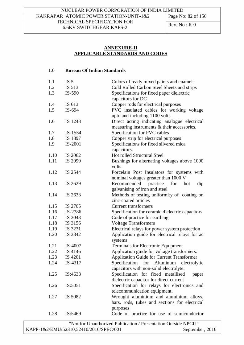
NUCLEAR POWER CORPORATION OF INDIA LIMITED KAKRAPAR ATOMIC POWER STATION-UNIT-1&2
TECHNICAL SPECIFICATION FOR 6.6KV SWITCHGEAR KAPS-2
Page No: 82 of 156
Rev. No : R-0
“Not for Unauthorized Publication / Presentation Outside NPCIL” KAPP-1&2/EMU/52310,52410/2016/SPEC/001 September, 2016
ANNEXURE-II APPLICABLE STANDARDS AND CODES
1.0 Bureau Of Indian Standards
1.1 IS 5 Colors of ready mixed paints and enamels 1.2 IS 513 Cold Rolled Carbon Steel Sheets and strips 1.3 IS-590 Specifications for fixed paper dielectric
capacitors for DC 1.4 IS 613 Copper rods for electrical purposes 1.5 IS-694 PVC insulated cables for working voltage
upto and including 1100 volts 1.6 IS 1248 Direct acting indicating analogue electrical
measuring instruments & their accessories. 1.7 IS-1554 Specification for PVC cables 1.8 IS 1897 Copper strip for electrical purposes 1.9 IS-2001 Specifications for fixed silvered mica
capacitors. 1.10 IS 2062 Hot rolled Structural Steel 1.11 IS 2099 Bushings for alternating voltages above 1000
volts. 1.12 IS 2544 Porcelain Post Insulators for systems with
nominal voltages greater than 1000 V 1.13 IS 2629 Recommended practice for hot dip
galvanising of iron and steel 1.14 IS 2633 Methods of testing uniformity of coating on
zinc-coated articles 1.15 IS 2705 Current transformers 1.16 IS-2786 Specification for ceramic dielectric capacitors 1.17 IS 3043 Code of practice for earthing 1.18 IS 3156 Voltage Transformers 1.19 IS 3231 Electrical relays for power system protection 1.20 IS 3842 Application guide for electrical relays for ac
systems 1.21 IS-4007 Terminals for Electronic Equipment 1.22 IS 4146 Application guide for voltage transformers. 1.23 IS 4201 Application Guide for Current Transformer 1.24 IS-4317 Specification for Aluminum electrolytic
capacitors with non-solid electrolyte. 1.25 IS:4633 Specification for fixed metallised paper
dielectric capacitor for direct current 1.26 IS:5051 Specification for relays for electronics and
telecommunication equipment. 1.27 IS 5082 Wrought aluminium and aluminium alloys,
bars, rods, tubes and sections for electrical purposes
1.28 IS:5469 Code of practice for use of semiconductor
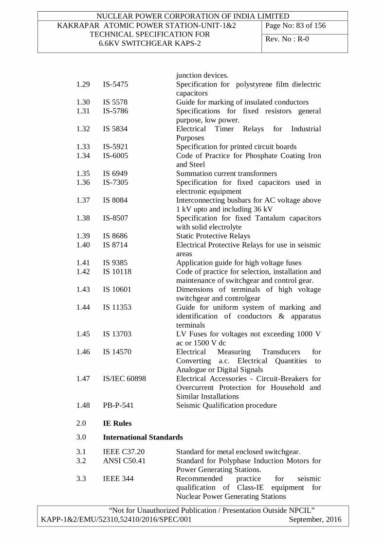
NUCLEAR POWER CORPORATION OF INDIA LIMITED KAKRAPAR ATOMIC POWER STATION-UNIT-1&2
TECHNICAL SPECIFICATION FOR 6.6KV SWITCHGEAR KAPS-2
Page No: 83 of 156
Rev. No : R-0
“Not for Unauthorized Publication / Presentation Outside NPCIL” KAPP-1&2/EMU/52310,52410/2016/SPEC/001 September, 2016
junction devices. 1.29 IS-5475 Specification for polystyrene film dielectric
capacitors 1.30 IS 5578 Guide for marking of insulated conductors 1.31 IS-5786 Specifications for fixed resistors general
purpose, low power. 1.32 IS 5834 Electrical Timer Relays for Industrial
Purposes 1.33 IS-5921 Specification for printed circuit boards 1.34 IS-6005 Code of Practice for Phosphate Coating Iron
and Steel 1.35 IS 6949 Summation current transformers 1.36 IS-7305 Specification for fixed capacitors used in
electronic equipment 1.37 IS 8084 Interconnecting busbars for AC voltage above
1 kV upto and including 36 kV 1.38 IS-8507 Specification for fixed Tantalum capacitors
with solid electrolyte 1.39 IS 8686 Static Protective Relays 1.40 IS 8714 Electrical Protective Relays for use in seismic
areas 1.41 IS 9385 Application guide for high voltage fuses 1.42 IS 10118 Code of practice for selection, installation and
maintenance of switchgear and control gear. 1.43 IS 10601 Dimensions of terminals of high voltage
switchgear and controlgear 1.44 IS 11353 Guide for uniform system of marking and
identification of conductors & apparatus terminals
1.45 IS 13703 LV Fuses for voltages not exceeding 1000 V ac or 1500 V dc
1.46 IS 14570 Electrical Measuring Transducers for Converting a.c. Electrical Quantities to Analogue or Digital Signals
1.47 IS/IEC 60898 Electrical Accessories - Circuit-Breakers for Overcurrent Protection for Household and Similar Installations
1.48 PB-P-541 Seismic Qualification procedure
2.0 IE Rules
3.0 International Standards
3.1 IEEE C37.20 Standard for metal enclosed switchgear. 3.2 ANSI C50.41 Standard for Polyphase Induction Motors for
Power Generating Stations. 3.3 IEEE 344 Recommended practice for seismic
qualification of Class-IE equipment for Nuclear Power Generating Stations
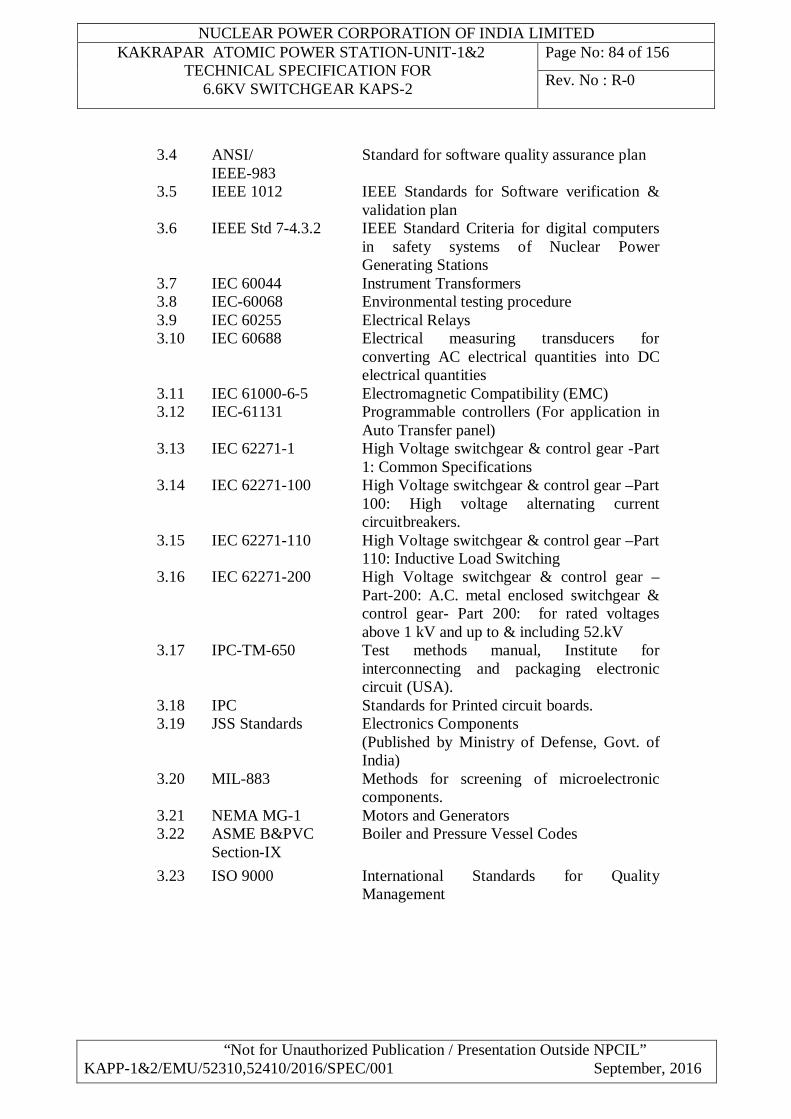
NUCLEAR POWER CORPORATION OF INDIA LIMITED KAKRAPAR ATOMIC POWER STATION-UNIT-1&2
TECHNICAL SPECIFICATION FOR 6.6KV SWITCHGEAR KAPS-2
Page No: 84 of 156
Rev. No : R-0
“Not for Unauthorized Publication / Presentation Outside NPCIL” KAPP-1&2/EMU/52310,52410/2016/SPEC/001 September, 2016
3.4 ANSI/ IEEE-983
Standard for software quality assurance plan
3.5 IEEE 1012 IEEE Standards for Software verification & validation plan
3.6 IEEE Std 7-4.3.2 IEEE Standard Criteria for digital computers in safety systems of Nuclear Power Generating Stations
3.7 IEC 60044 Instrument Transformers 3.8 IEC-60068 Environmental testing procedure 3.9 IEC 60255 Electrical Relays 3.10 IEC 60688 Electrical measuring transducers for
converting AC electrical quantities into DC electrical quantities
3.11 IEC 61000-6-5 Electromagnetic Compatibility (EMC) 3.12 IEC-61131 Programmable controllers (For application in
Auto Transfer panel) 3.13 IEC 62271-1 High Voltage switchgear & control gear -Part
1: Common Specifications 3.14 IEC 62271-100 High Voltage switchgear & control gear –Part
100: High voltage alternating current circuitbreakers.
3.15 IEC 62271-110 High Voltage switchgear & control gear –Part 110: Inductive Load Switching
3.16 IEC 62271-200 High Voltage switchgear & control gear –Part-200: A.C. metal enclosed switchgear & control gear- Part 200: for rated voltages above 1 kV and up to & including 52.kV
3.17 IPC-TM-650 Test methods manual, Institute for interconnecting and packaging electronic circuit (USA).
3.18 IPC Standards for Printed circuit boards. 3.19 JSS Standards Electronics Components
(Published by Ministry of Defense, Govt. of India)
3.20 MIL-883 Methods for screening of microelectronic components.
3.21 NEMA MG-1 Motors and Generators 3.22 ASME B&PVC
Section-IX Boiler and Pressure Vessel Codes
3.23 ISO 9000 International Standards for Quality Management
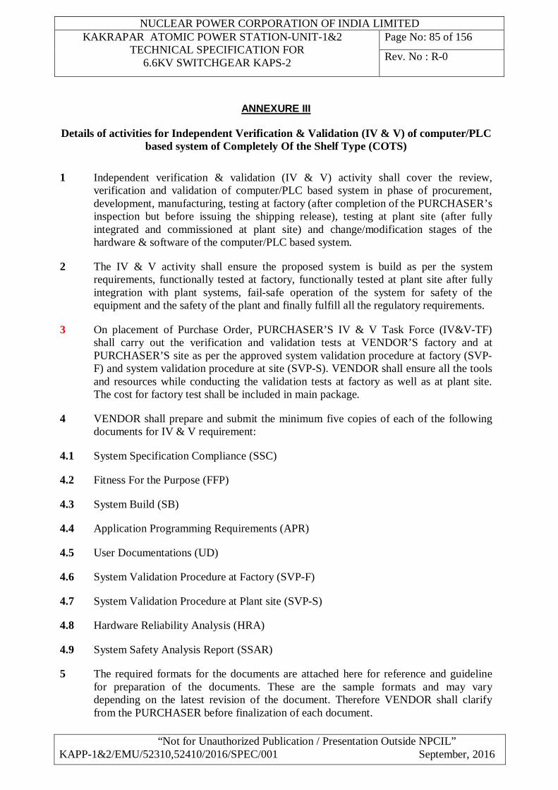
NUCLEAR POWER CORPORATION OF INDIA LIMITED KAKRAPAR ATOMIC POWER STATION-UNIT-1&2
TECHNICAL SPECIFICATION FOR 6.6KV SWITCHGEAR KAPS-2
Page No: 85 of 156
Rev. No : R-0
“Not for Unauthorized Publication / Presentation Outside NPCIL” KAPP-1&2/EMU/52310,52410/2016/SPEC/001 September, 2016
ANNEXURE III
Details of activities for Independent Verification & Validation (IV & V) of computer/PLC based system of Completely Of the Shelf Type (COTS)
1 Independent verification & validation (IV & V) activity shall cover the review,
verification and validation of computer/PLC based system in phase of procurement, development, manufacturing, testing at factory (after completion of the PURCHASER’s inspection but before issuing the shipping release), testing at plant site (after fully integrated and commissioned at plant site) and change/modification stages of the hardware & software of the computer/PLC based system.
2 The IV & V activity shall ensure the proposed system is build as per the system requirements, functionally tested at factory, functionally tested at plant site after fully integration with plant systems, fail-safe operation of the system for safety of the equipment and the safety of the plant and finally fulfill all the regulatory requirements.
3 On placement of Purchase Order, PURCHASER’S IV & V Task Force (IV&V-TF) shall carry out the verification and validation tests at VENDOR’S factory and at PURCHASER’S site as per the approved system validation procedure at factory (SVP-F) and system validation procedure at site (SVP-S). VENDOR shall ensure all the tools and resources while conducting the validation tests at factory as well as at plant site. The cost for factory test shall be included in main package.
4 VENDOR shall prepare and submit the minimum five copies of each of the following documents for IV & V requirement:
4.1 System Specification Compliance (SSC)
4.2 Fitness For the Purpose (FFP)
4.3 System Build (SB)
4.4 Application Programming Requirements (APR)
4.5 User Documentations (UD)
4.6 System Validation Procedure at Factory (SVP-F)
4.7 System Validation Procedure at Plant site (SVP-S)
4.8 Hardware Reliability Analysis (HRA)
4.9 System Safety Analysis Report (SSAR)
5 The required formats for the documents are attached here for reference and guideline for preparation of the documents. These are the sample formats and may vary depending on the latest revision of the document. Therefore VENDOR shall clarify from the PURCHASER before finalization of each document.
NUCLEAR POWER CORPORATION OF INDIA LIMITED KAKRAPAR ATOMIC POWER STATION-UNIT-1&2
TECHNICAL SPECIFICATION FOR 6.6KV SWITCHGEAR KAPS-2
Page No: 86 of 156
Rev. No : R-0
“Not for Unauthorized Publication / Presentation Outside NPCIL” KAPP-1&2/EMU/52310,52410/2016/SPEC/001 September, 2016
6 VENDOR shall ensure that the entire document shall be correct, consistence and complete with required information about the system.
7 Typical examples indicating formats and contents of different types of documents under IV&V.
7.1 Format for System Specification Compliance (SSC) 7.1.1 Introduction 7.1.1.1 Purpose
To establish that (a) one to one compliance between the technical specifications given by the PURCHASER and the technical specifications given by the CONTRACTOR/supplier and (b) to record any deviation (addition/deletion) from the original technical specifications
7.1.1.2 Scope Describe the scope of this document
7.1.1.3 Definitions, Abbreviations and Notions Describe various definitions, abbreviations and notations as applicable to this document.
7.1.1.4 References Provide reference to applicable documents, standards, codes, and guidelines etc. that need to be referred to for information.
7.1.1.5 Overview Provide a brief overview of the contents of the document.
7.1.2 Technical Specifications given by NPCIL in TSD (here the extract/copy of the Technical Specifications shall be used)
7.1.2.1 System hardware configuration 7.1.2.2 System software requirements 7.1.2.3 Other requirements as per SR 7.1.2.4 Data Sheets/checklist/compliance list requirements 7.1.3 Technical Specifications offered by Vendor
(here copy of the Technical Specifications offered by the vendor shall be pasted)
7.1.3.1 Description of the system hardware configuration 7.1.3.2 Description of the system software configuration/packages 7.1.3.3 Other requirements as per SR 7.1.3.4 Data Sheets/checklist and any additional feature of the
proposed system
7.1.4 Compliance report as submitted by vendor 7.1.5 Approved deviation reports, if any (Copy shall be enclosed) 7.1.6 List of Annexures 7.1.6.1 Guaranteed technical particulars for the offered system by
Vendor
7.1.6.2 Bill of the material to be delivered 7.1.6.3 Simplified /block/context diagram of the proposed system. 7.1.6.4 Copy of the purchase order (un-priced) 7.1.7 Conclusion

NUCLEAR POWER CORPORATION OF INDIA LIMITED KAKRAPAR ATOMIC POWER STATION-UNIT-1&2
TECHNICAL SPECIFICATION FOR 6.6KV SWITCHGEAR KAPS-2
Page No: 87 of 156
Rev. No : R-0
“Not for Unauthorized Publication / Presentation Outside NPCIL” KAPP-1&2/EMU/52310,52410/2016/SPEC/001 September, 2016
7.2 Format for Fitness For Purpose document (FFP) 7.2.1 Introduction 7.2.2 Purpose
To establish that (a) The COTS product/system has been developed, inspected and tested in accordance with the governing standards and (b) The product is suitable for the kind of application envisaged
7.2.3 Scope Describe the scope of this document
7.2.4 Definitions, Abbreviations and Notations Describe various definitions, abbreviations and notations as applicable to this document.
7.2.5 References and Applicable Documents Provide reference to applicable documents, standards, codes, and guidelines etc. that need to be referred to for information.
7.2.6 Overview Provide a brief overview of the contents of the document. 7.2.7 Manufacturer
Experience in the field ISO 9000 (or other) quality system certification Hardware Process Description of design process Description of manufacturing process Standards followed Certification Software Process SEI CMM level qualification? Standards followed in design/coding/testing of software (IEEE?) Software Quality Assurance standard (IEEE 730.1/ IEC 60880 /ISO 9000-3) Configuration Management standard (IEEE etc.)
7.2.9 Product Model / Version no. Compliance to standards (IEC etc.) Certifications available (UL, CE etc.) Test/Verification/Validation reports available Years in manufacture and field operation Same model, same version no. Same model, earlier version Earlier model Number of installations Total number of installations In similar applications (area/criticality) (give sample list) Field experience (Errors reported, versions released, known faults) Reliability Documentation available
7.2.10 Maintenance support from the manufacturer (after sale) 7.2.11 Conclusion
NUCLEAR POWER CORPORATION OF INDIA LIMITED KAKRAPAR ATOMIC POWER STATION-UNIT-1&2
TECHNICAL SPECIFICATION FOR 6.6KV SWITCHGEAR KAPS-2
Page No: 88 of 156
Rev. No : R-0
“Not for Unauthorized Publication / Presentation Outside NPCIL” KAPP-1&2/EMU/52310,52410/2016/SPEC/001 September, 2016
7.3 Format for the Application Programming Requirements (Typical for the PLC software)
7.3.1 Introduction 7.3.2 Purpose: 7.3.3 Scope 7.3.4 Definitions, Abbreviations and Notions 7.3.5 References 7.3.6 Overview 7.3.7 Brief overview of PLC hardware 7.3.8 Application Programming Requirements 7.3.9 Description of logic scheme (as described in the SR) 7.3.10 Block Logic Diagram (BLD) (it shall be enclosed) 7.3.11 List of Man Machine Interfaces/operator interfaces 7.3.12 List of Field Input and output 7.3.13 Software Variable 7.3.14 List of the event/messages printout through ASCII module 7.3.15 Brief description of the Software programming Tool to be deployed 7.3.16 Steps for running Software programming Tools 7.3.17 Brief description of the Application Software to be deployed
I/O map and Software Variable for Application Software 7.3.18 Memory allocation for Application Software 7.3.19 Description of Sections in a Segment of application software 7.3.20 Effect PLC hardware and software failure 7.3.21 Logging of Alarms 7.3.22 Miscellaneous Terminology 7.3.23 Scan Time / Response Time 7.3.24 Accuracy 7.3.25 Resolution 7.3.26 Segment Scheduler 7.3.27 Traceability requirements between SR and APR 7.3.28 List of the Annexure 7.3.29 Block Logic Diagram 7.3.30 Ladder Logic/Functional Block Logic Diagram 7.3.31 List of field Input and Output 7.3.32 PLC block/context diagram 7.3.33 Conclusion 7.4 Format for System Build document (SB) 7.4.1. Introduction 7.4.1.1 Purpose
To provide the information about the hardware package, software package and integration of the hardware & software components to build the final system as per the system requirements.
7.4.1.2 Scope Describe the scope of this document
7.4.1.3 Definitions, Abbreviations and Notations
NUCLEAR POWER CORPORATION OF INDIA LIMITED KAKRAPAR ATOMIC POWER STATION-UNIT-1&2
TECHNICAL SPECIFICATION FOR 6.6KV SWITCHGEAR KAPS-2
Page No: 89 of 156
Rev. No : R-0
“Not for Unauthorized Publication / Presentation Outside NPCIL” KAPP-1&2/EMU/52310,52410/2016/SPEC/001 September, 2016
Describe various definitions, abbreviations and notations as applicable to this document. 7.4.1.4 References and Applicable Documents
Provide reference to applicable documents, standards, codes, and guidelines etc. that need to be referred to for information.
7.4.1.5 Overview Provide a brief overview of the contents of the document. 7.4.2. System Decomposition
List all the Subsystems that the system is composed of, enclosed the diagram. 7.4.3. Subsystem n 3.n.1 Hardware Package Build 3.n.1.1 List of items this package is composed of 3.n.1.2 Unique Ids 3.n.1.3 Hardware Environment Description Provide embedded software version, Jumper
settings, switch settings, software settings, and cable connectivity 3.n.1.4 Integration Procedures / drawings 3.n.2 Software Package Build 3.n.2.1 List of sub-packages 3.n.2.2 Unique Ids/Version Nos. 3.n.2.3 Media Details (Floppies/CDs/Tapes/EPROM's) 3.n.2.4 Relevant Disk / Memory maps 3.n.2.5 Hardware Environment Description Describe the Processor type, Memory ports,
hard disk space, etc. 3.n.2.6 Software Environment Description Describe OS version and services settings,
Compiler version; compile time options, library versions, and environment variables.
3.n.2.7 Integration Procedures 7.4.4 System hardware and software integration for System Build
Integration drawings Integration procedure
System Start up and Shutdown Procedure Bill of the material List of the Annexure Conclusion
7.5 Document Format for User Documentation (UD) 7.5.1. Introduction 7.5.1.1 Purpose Provide the purpose of preparing this document 7.5.1.2 Scope
Describe the scope of this document 7.5.1.3 Definitions, Abbreviations and Notations
Describe various definitions, abbreviations and notations as applicable to this document.
NUCLEAR POWER CORPORATION OF INDIA LIMITED KAKRAPAR ATOMIC POWER STATION-UNIT-1&2
TECHNICAL SPECIFICATION FOR 6.6KV SWITCHGEAR KAPS-2
Page No: 90 of 156
Rev. No : R-0
“Not for Unauthorized Publication / Presentation Outside NPCIL” KAPP-1&2/EMU/52310,52410/2016/SPEC/001 September, 2016
7.5.1.4 References and Applicable Documents Provide reference to applicable documents, standards, codes, and guidelines etc. that need to be referred to for information.
7.5.1.5 Overview Provide a brief overview of the contents of the document. 7.5.1.6 Description of the manuals with ID details
Describe the list of system manuals with ID (List of End documents) and the contents of the document. This should include the GA drawings, Configuration drawings etc. The list of the documents shall be attached here with for completeness of the UD documents. This document shall cover the followings Information
7.5.2 Information for Installation of the system.
This shall include the installation drawing, and detail for the system. 7.5.3 Information for Commissioning of the system.
Refer WDs, SB configuration drawing BOM. Write the procedure for sequence of steps to be followed. Set up environment such as IP addresses, switch settings etc.
7.5.4 Information for Operation of the system.
Write the details on start-up, normal operation procedure, shutdown procedure, and various modes of operation, usage details to cover. Various functions, test utilities, tools available
7.5.5 Information for Maintenance of the system.
Describe possible failures and its symptoms, possible known cause of the failures, describe the fault tree analysis and trouble-shooting procedure for the above. This shall include the procedure to bring up the system after troubleshooting. Cover test programme, diagnostics for checking healthiness, etc
7.5.6 List of the Annexure 7.5.7 Conclusion 7.6 Format for System Validation Procedure at Factory (SVP-F)
7.6.1. Introduction 7.6.1.1 Purpose Provide the purpose of preparing this document 7.6.1.2 Scope Describe the scope of this document 7.6.1.3 Definitions, Abbreviations and Notations
Describe various definitions, abbreviations and notations as applicable to this document.
7.6.1.4 References and Applicable Documents Provide reference to applicable documents, standards, codes, and guidelines etc. that need to be referred to for information.
7.6.1.5 Overview
NUCLEAR POWER CORPORATION OF INDIA LIMITED KAKRAPAR ATOMIC POWER STATION-UNIT-1&2
TECHNICAL SPECIFICATION FOR 6.6KV SWITCHGEAR KAPS-2
Page No: 91 of 156
Rev. No : R-0
“Not for Unauthorized Publication / Presentation Outside NPCIL” KAPP-1&2/EMU/52310,52410/2016/SPEC/001 September, 2016
Provide a brief overview of the contents of the document. 7.6.2. Test Team Details
Give the requirement of the test team members, their roles and responsibilities for carrying out the System Validation test at factory and specified the expected test duration under following heads Test Team Members Test team members Role and Responsibilities Test Duration
7.6.3. Infrastructure and resource requirements Give the infrastructure and resources requirements for the system validation under the following heads.
Infrastructure requirement Resources requirements QA inspection test procedure and test reports Vendor’s QA test reports Copy of the purchase orders with bill of the material Test certificates by third party/principal suppliers Standard Test Setup with diagram Manpower Requirement
7.6.4 System Validation Test Plan
The system validation tests should be carried out as per following plan 7.6.4.1 Confirmation of System Build (SB) 7.6.4.2 Confirmation of the User Documentation 7.6.4.3 Hardware validation Test on AC-PLC Panel 7.6.4.4 Verification of QA and vender test reports 7.6.4.5 Simulation and testing of all the inputs and outputs 7.6.4.6 Off line verification of the software logics 7.6.4.7 Software validation test on the software logics 7.6.5 System Validation Test Procedure 7.6.5.1 Confirmation of System under test for System Build
Confirm that the system H/W and S/W is built according to the System Build document under the following heads.
7.6.5.2 Confirmation of System Hardware All the hardware modules shall be listed out with type number, ID number, make etc General hardware at panel level Panel wise hardware Modules
7.6.5.3 Confirmation of the System Software
All the software modules shall be listed out with the name, version, license (if applicable), location and size etc. Operating System software with service packs System software with services packs. Application software development tools/software manager (complete sets).
NUCLEAR POWER CORPORATION OF INDIA LIMITED KAKRAPAR ATOMIC POWER STATION-UNIT-1&2
TECHNICAL SPECIFICATION FOR 6.6KV SWITCHGEAR KAPS-2
Page No: 92 of 156
Rev. No : R-0
“Not for Unauthorized Publication / Presentation Outside NPCIL” KAPP-1&2/EMU/52310,52410/2016/SPEC/001 September, 2016
Application software. List of the firmware deployed Anti-virus software, if any Any other relevant software
7.6.5.4 Confirmation of the system Integration with hardware and software 7.6.5.5 Confirmation for User Documentation for system under test
Verify the list of the documents and content of each document as per the UD. This shall include the descriptions in the user documents as implemented in the system. Ex: Operating procedures, modes, command options, error messages, help, utilities, etc.
7.6.5.6 Verification of QA and vender test reports
Verify all the QA test reports and type test reports on the system. Also verify the vendors internal test reports and test reports on the bought out items.
7.6.5.7 System Hardware Validation Test (Hardware performance test)
Activity shall cover system hardware test cases by simulating the failure of the hardware. This shall include the test cases, its procedure and expected test results. This shall be prepared in line of system requirement and its expected performance in case of the failure (Including the single component failure for fail safe mode operation)
7.6.5.8 System Software Validation Tests
This shall cover the system software test cases by simulating the input for open loops as well as closed loops using the test tools like automatic functional testers, simulators, TDR etc. The software access control and self-diagnostics shall also be tested. This included the following heads:
Verification of application s/w with software logic requirements (BLD) Offline validation of the application s/w on workstation (simulation mode) Verification of all the inputs and outputs by simulation on screen Validation of the software database Validation of the software timers/counters for its setting & its accuracy Validation of the software security access control Validation of the system self-diagnostics features in case of faults. Validation of the memory allocation for application s/w and available free memory. Validation of the critical parameters (System dependent) Validation of Application Software by simulation for open & close loops Validation of Application Software by simulation in test/fail safe modes Validation of Application Software by simulation for interfaces (COIS, Printers, SCADA etc)
7.6.5.9 List of Annexure
NUCLEAR POWER CORPORATION OF INDIA LIMITED KAKRAPAR ATOMIC POWER STATION-UNIT-1&2
TECHNICAL SPECIFICATION FOR 6.6KV SWITCHGEAR KAPS-2
Page No: 93 of 156
Rev. No : R-0
“Not for Unauthorized Publication / Presentation Outside NPCIL” KAPP-1&2/EMU/52310,52410/2016/SPEC/001 September, 2016
This shall includes the test set up diagram, system context diagram, procedure for testing of system software logics (for all inputs and outputs), List of Inputs and corresponding variable name used in s/w, List of Outputs and corresponding variable name used in s/w etc.
7.6.5.10 Traceability requirements 7.6.5.10.1 Forward Traceability
Generate a cross-reference of all requirements mentioned in System Requirements to various packages to confirm that all system requirements have been included Requirements cross-reference matrix is preferable.
7.6.5.10.2Backward Traceability Generate a cross-reference of all requirement mentioned in this document to those listed in System Requirements. If some requirements have been added to facilitate system architectural design these should be also listed. Requirements cross-reference matrix is preferable.
7.6.5.11Conclusion 7.7 Format for System Validation Procedure at Site (SVP-S) 7.7.1. Introduction 7.7.1.1 Purpose Provide the purpose of preparing this document 7.7.1.2 Scope Describe the scope of this document 7.7.1.3 Definitions, Abbreviations and Notations
Describe various definitions, abbreviations and notations as applicable to this document.
7.7.1.4 References and Applicable Documents Provide reference to applicable documents, standards, codes, and guidelines etc. that need to be referred to for information.
7.7.1.5 Overview Provide a brief overview of the contents of the document. 7.7.2. Test Team Details
Give the requirement of the test team members, their roles and responsibilities for carrying out the System Validation test at plant site and specified the expected test duration under following heads Test Team Members Test team members Role and Responsibilities Test Duration
7.7.3. Infrastructure and resource requirements Give the infrastructure and resources requirements for the system validation under the following heads. Infrastructure requirement Resources requirements Commissioning test procedure Commissioning test reports Standard Test Setup Manpower Requirement
NUCLEAR POWER CORPORATION OF INDIA LIMITED KAKRAPAR ATOMIC POWER STATION-UNIT-1&2
TECHNICAL SPECIFICATION FOR 6.6KV SWITCHGEAR KAPS-2
Page No: 94 of 156
Rev. No : R-0
“Not for Unauthorized Publication / Presentation Outside NPCIL” KAPP-1&2/EMU/52310,52410/2016/SPEC/001 September, 2016
Necessary clearances from Shift Charge Engineer/Control room 7.7.4. System Validation Test Plan
The system validation test shall be carried out as per the following plan: 7.7.4.1 Verification of the approved Commissioning Procedure and Commissioning Report.
Verification of remedial action for deficiency, if any, noted during system validation tests at factory Confirmation for System Build for system under test Confirmation of the system Integration with plant systems. Confirmation Hardware validation test on integrated panel Software Validation tests on integrated penal Functional testing of man machine interfaces and other computer base subsystem Functional testing of logic schemes for all possible test cases.
7.7.5.0 System Validation Test Procedure
This shall cover the system hardware and software test cases by actuating the actual field inputs and observe the field outputs this includes the performance of the hardware, execution the software logics/programme, signal processing, response time audio-visual alarms at LCP and in MCR, event recording, Interface with other computer base systems, synchronization with master clock, testing of the self diagnostic features, software access control, etc. This included the following heads:
7.7.5.1 Verification of the approved Commissioning Procedure and Commissioning Report
The approved commissioning procedure and commissioning report shall be verified for the under test
7.7.5.2 Verification of remedial action for deficiency, if any, noted during system validation
tests at factory Verify that all the deficiencies are rectified as per the recommendation of the SVTR at factory. Any modification in hardware/software is to be revalidated at plant site.
7.7.5.3 Confirmation for System Build for the system under test
Confirm that the system H/W and S/W is built according to the System Build document and it is installed, integrated with the plant systems under the following heads.
7.7.5.3.1 Confirmation of System Hardware
Panel wise hardware Modules General hardware at panel level Plant Interface with panel/hardware modules
7.7.5.3.2 Confirmation of the System Software
Operating System software with service pack, licensing System software with services packs. Application software development tools/software manager. Application software.
NUCLEAR POWER CORPORATION OF INDIA LIMITED KAKRAPAR ATOMIC POWER STATION-UNIT-1&2
TECHNICAL SPECIFICATION FOR 6.6KV SWITCHGEAR KAPS-2
Page No: 95 of 156
Rev. No : R-0
“Not for Unauthorized Publication / Presentation Outside NPCIL” KAPP-1&2/EMU/52310,52410/2016/SPEC/001 September, 2016
System firmware, if any Antivirus software, if any Any other related software loaded in the system
7.7.5.3.3 Confirmation of the system Integration with plant systems 7.7.5.3.4 Confirmation hardware validation test on integrated panel
Hardware performance tests (sample test) System self-diagnostics features in case of faults. Redundancy/failure test
7.7.6 Software Validation tests on integrated penal Validation of the software logics (sample basis) Validation of the software security access control and creation of the users based on the site requirements Verification of allocated memory and available free memory for software
7.7.7 Functional testing of man machine interfaces and other computer base subsystem
Testing of all the Field Inputs by actuating from the field and observing in the software program on the screen of the programming unit. Testing of all the Field outputs by actuating from the software of the programming unit and observing in the field Functional testing of window annunciation provided on LCP and MCR panel. Functional testing of Hand Switches and lamp indications provided on LCP and MCR Panel. Functional testing of window annunciation, meters, switches provided on LCP and MCR Panel. Functional testing of MCC interface. Functional testing of SCADA interface. Functional testing of event message printing with time and date stamping Functional testing of system synchronization with Master Clock
7.7.8 Functional testing of logic schemes for all possible test cases.
The functional testing of the logic scheme shall be carried out as per the test cases given in the Annexure-….
7.7.9 Validation of the software timers/counters for its setting based on the field response time.
Based on the field requirements the setting of software timer may be changed .the same shall be recoded during validation test at site.
Transfer of the application software from RAM to UV-EPROM after final testing After final testing of all the test case and satisfactorily operation of the system under test the application software shall be transferred from RAM to UV-EPROM using EPROM programmer and associated software. Also take the back up on HDD as well as on the CD for the future reloading /reference.
NUCLEAR POWER CORPORATION OF INDIA LIMITED KAKRAPAR ATOMIC POWER STATION-UNIT-1&2
TECHNICAL SPECIFICATION FOR 6.6KV SWITCHGEAR KAPS-2
Page No: 96 of 156
Rev. No : R-0
“Not for Unauthorized Publication / Presentation Outside NPCIL” KAPP-1&2/EMU/52310,52410/2016/SPEC/001 September, 2016
7.7.10 List of Annexure This shall includes the following: Test set up diagram, System context diagram with plant interfaces, List of the test cases for the functional testing of the logic scheme, List of field inputs & outputs with its types (Digital/Analogue) and state (NO/NC),
7.7.11 Traceability Requirement 7.7.11.1 Forward Traceability
Generate a cross-reference of all requirements mentioned in System Requirements to various packages to confirm that all system requirements have been included Requirements cross-reference matrix is preferable.
7.7.11.2 Backward Traceability Generate a cross-reference of all requirement mentioned in this document to those listed in System Requirements. If some requirements have been added to facilitate system architectural design these should be also listed. Requirements cross-reference matrix is preferable
7.8 Hardware Reliability Analysis (HRA) 7.8.1 Introduction 7.8.1.1 Purpose
Provide the purpose of preparing this document 7.8.1.2 Scope
Describe the scope of this document 7.8.1.3Definitions, Abbreviations and Notations
Describe various definitions, abbreviations and notations as applicable to this document.
7.8.1.4 References and Applicable Documents
Provide reference to applicable documents, standards, codes, and guidelines etc. that need to be referred to for information.
7.8.1.5 Overview of the system
Describe the context of the system vis-à-vis the plant and its architecture to the level of modules/subsystems whose failures are being considered subsequently
7.8.2 System Description
NUCLEAR POWER CORPORATION OF INDIA LIMITED KAKRAPAR ATOMIC POWER STATION-UNIT-1&2
TECHNICAL SPECIFICATION FOR 6.6KV SWITCHGEAR KAPS-2
Page No: 97 of 156
Rev. No : R-0
“Not for Unauthorized Publication / Presentation Outside NPCIL” KAPP-1&2/EMU/52310,52410/2016/SPEC/001 September, 2016
Provide the description of the system, hardware details of its modules/subsystems, interfaces, functionality of each module, series & redundancy relationships as well as functional interdependence between modules along with necessary context diagrams under following heads
7.8.2.1 Introduction
7.8.2.2 System Functional description
7.8.2.3 System hardware configuration
7.8.2.4 System input & output details
7.8.2.5 System schematics
7.8.3 System Analysis Provide the details of the modules considered/not considered for analysis and logic/rationale for the same. Also provide the details of methods and tools, types of failure with justifications, values of the failure rates with the source details under the following minimum heads
7.8.3.1 Scope/coverage
7.8.3.2 Boundary conditions & Assumptions
7.8.3.3 Values MTBF & MTTR for hardware modules
7.8.3.4 Values of failure rates
7.8.3.5 Failure criteria
7.8.4 Results of Analysis Provide the Fault Tree diagram & derived failure frequencies
7.8.4.1 Domain cut set
7.8.4.2 Fault tree diagram
7.8.5 Traceability 7.8.5.1 Forward traceability
7.8.5.2 Backward traceability
7.8.6 List of the Annexure Enclosed the Annexure as required in the document
7.8.7 Conclusion 7.9 System Safety Analysis Report (SSAR) 7.9.1. Introduction 7.9.1.1 Purpose Provide the purpose of preparing this document
NUCLEAR POWER CORPORATION OF INDIA LIMITED KAKRAPAR ATOMIC POWER STATION-UNIT-1&2
TECHNICAL SPECIFICATION FOR 6.6KV SWITCHGEAR KAPS-2
Page No: 98 of 156
Rev. No : R-0
“Not for Unauthorized Publication / Presentation Outside NPCIL” KAPP-1&2/EMU/52310,52410/2016/SPEC/001 September, 2016
7.9.1.2 Scope
Describe the scope of this document 7.9.1.3 Definitions, Abbreviations and Notations
Describe various definitions, abbreviations and notations as applicable to this document. 7..9.1.4References and Applicable Documents
Provide reference to applicable documents, standards, codes, and guidelines etc. that need to be referred to for information.
7.9.1.5 Overview of the system
Describe the context of the system vis-à-vis the plant and its architecture to the level of modules/subsystems whose failures are being considered subsequently
7.9.2 System Architecture
Describe the system architecture in terms of decomposition into sub-systems (if any) with connectivity and the inputs and outputs connected to each sub-system
7.9.3 System Interfaces
Describe the interfaces of each subsystem with the plant as well as with other sub-systems 9.n.1. Interface of subsystem n with Plant 9.n.1.1. Inputs This section should list the description of the inputs 9.n.1.2. Outputs This section should list the description of the outputs 9.n.2. Interface with other subsystems This section should list the connectivity of the sub-system with other sub-systems 9.n.3. Interface with other systems
This section should list the connectivity of the sub-system with other systems 9.n.4 Interfaces with power supplies This section should list the connectivity of the sub-system with power supplies and power sources.
7.9.4 Effect of System Failures on Plant Safety
Consequence of a Single module / subsystem failure including power supplies and power sources and connectivity with other subsystems on the plant safety Module / subsystem n Failure
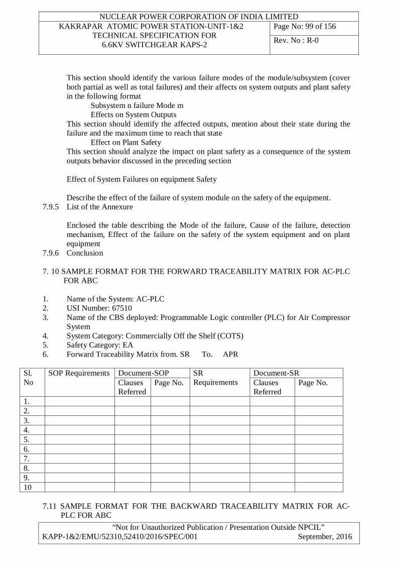
NUCLEAR POWER CORPORATION OF INDIA LIMITED KAKRAPAR ATOMIC POWER STATION-UNIT-1&2
TECHNICAL SPECIFICATION FOR 6.6KV SWITCHGEAR KAPS-2
Page No: 99 of 156
Rev. No : R-0
“Not for Unauthorized Publication / Presentation Outside NPCIL” KAPP-1&2/EMU/52310,52410/2016/SPEC/001 September, 2016
This section should identify the various failure modes of the module/subsystem (cover both partial as well as total failures) and their affects on system outputs and plant safety in the following format Subsystem n failure Mode m Effects on System Outputs This section should identify the affected outputs, mention about their state during the failure and the maximum time to reach that state Effect on Plant Safety This section should analyze the impact on plant safety as a consequence of the system outputs behavior discussed in the preceding section
Effect of System Failures on equipment Safety
Describe the effect of the failure of system module on the safety of the equipment.
7.9.5 List of the Annexure
Enclosed the table describing the Mode of the failure, Cause of the failure, detection mechanism, Effect of the failure on the safety of the system equipment and on plant equipment
7.9.6 Conclusion 7. 10 SAMPLE FORMAT FOR THE FORWARD TRACEABILITY MATRIX FOR AC-PLC
FOR ABC 1. Name of the System: AC-PLC 2. USI Number: 67510 3. Name of the CBS deployed: Programmable Logic controller (PLC) for Air Compressor
System 4. System Category: Commercially Off the Shelf (COTS) 5. Safety Category: EA 6. Forward Traceability Matrix from. SR To. APR
Sl. No
SOP Requirements Document-SOP SR Requirements
Document-SR Clauses Referred
Page No. Clauses Referred
Page No.
1. 2. 3. 4. 5. 6. 7. 8. 9. 10
7.11 SAMPLE FORMAT FOR THE BACKWARD TRACEABILITY MATRIX FOR AC-
PLC FOR ABC
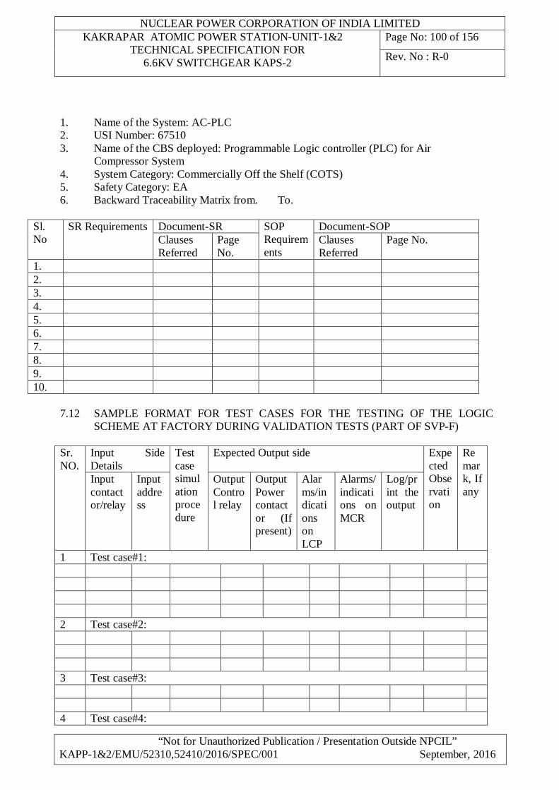
NUCLEAR POWER CORPORATION OF INDIA LIMITED KAKRAPAR ATOMIC POWER STATION-UNIT-1&2
TECHNICAL SPECIFICATION FOR 6.6KV SWITCHGEAR KAPS-2
Page No: 100 of 156
Rev. No : R-0
“Not for Unauthorized Publication / Presentation Outside NPCIL” KAPP-1&2/EMU/52310,52410/2016/SPEC/001 September, 2016
1. Name of the System: AC-PLC 2. USI Number: 67510 3. Name of the CBS deployed: Programmable Logic controller (PLC) for Air Compressor System 4. System Category: Commercially Off the Shelf (COTS) 5. Safety Category: EA 6. Backward Traceability Matrix from. To.
Sl. No
SR Requirements Document-SR SOP Requirements
Document-SOP Clauses Referred
Page No.
Clauses Referred
Page No.
1. 2. 3. 4. 5. 6. 7. 8. 9. 10.
7.12 SAMPLE FORMAT FOR TEST CASES FOR THE TESTING OF THE LOGIC
SCHEME AT FACTORY DURING VALIDATION TESTS (PART OF SVP-F) Sr. NO.
Input Side Details
Test case simulation procedure
Expected Output side Expected Observation
Remark, If any
Input contactor/relay
Input address
Output Control relay
Output Power contactor (If present)
Alarms/indications on LCP
Alarms/indications on MCR
Log/print the output
1 Test case#1: 2 Test case#2: 3 Test case#3: 4 Test case#4:
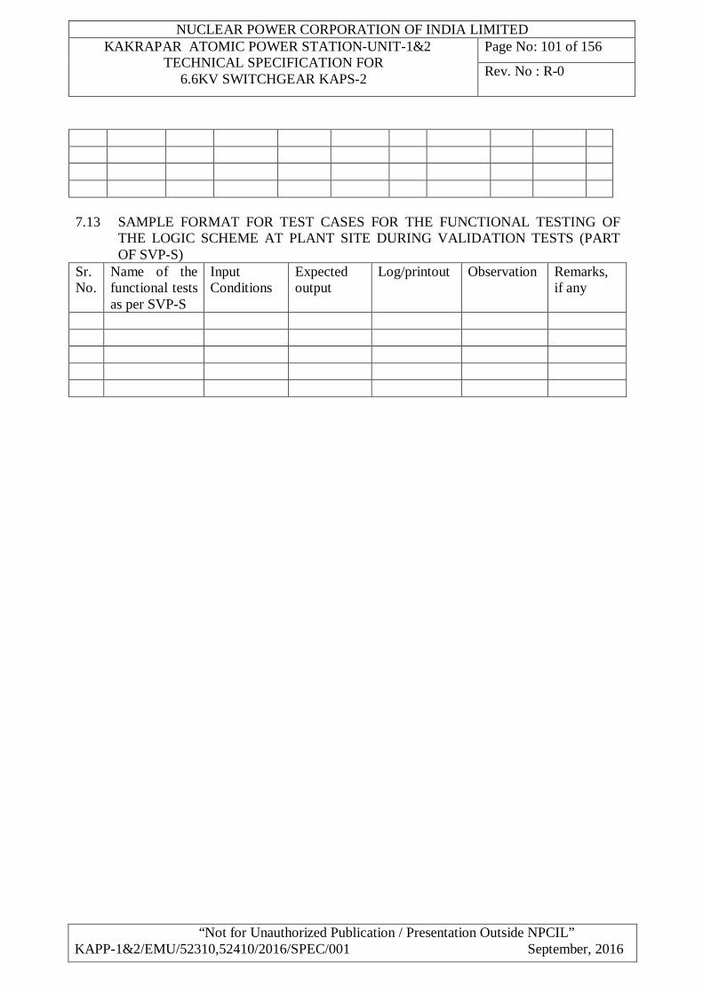
NUCLEAR POWER CORPORATION OF INDIA LIMITED KAKRAPAR ATOMIC POWER STATION-UNIT-1&2
TECHNICAL SPECIFICATION FOR 6.6KV SWITCHGEAR KAPS-2
Page No: 101 of 156
Rev. No : R-0
“Not for Unauthorized Publication / Presentation Outside NPCIL” KAPP-1&2/EMU/52310,52410/2016/SPEC/001 September, 2016
7.13 SAMPLE FORMAT FOR TEST CASES FOR THE FUNCTIONAL TESTING OF
THE LOGIC SCHEME AT PLANT SITE DURING VALIDATION TESTS (PART OF SVP-S)
Sr. No.
Name of the functional tests as per SVP-S
Input Conditions
Expected output
Log/printout Observation Remarks, if any
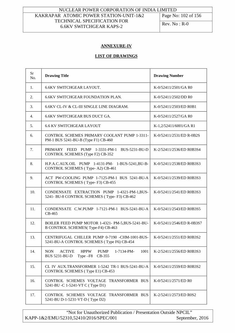
NUCLEAR POWER CORPORATION OF INDIA LIMITED KAKRAPAR ATOMIC POWER STATION-UNIT-1&2
TECHNICAL SPECIFICATION FOR 6.6KV SWITCHGEAR KAPS-2
Page No: 102 of 156
Rev. No : R-0
“Not for Unauthorized Publication / Presentation Outside NPCIL” KAPP-1&2/EMU/52310,52410/2016/SPEC/001 September, 2016
ANNEXURE-IV
LIST OF DRAWINGS
Sr No. Drawing Title Drawing Number
1. 6.6KV SWITCHGEAR LAYOUT. K-0/52411/2501/GA R0
2. 6.6KV SWITCHGEAR FOUNDATION PLAN. K-0/52411/2502/DD R0
3. 6.6KV CL-IV & CL-III SINGLE LINE DIAGRAM. K-0/52411/2503/ED R0B1
4. 6.6KV SWITCHGEAR BUS DUCT GA. K-0/52411/2527/GA R0
5. 6.6 KV SWITCHGEAR LAYOUT K-1,2/52411/6001/GA R1
6. CONTROL SCHEMES PRIMARY COOLANT PUMP 1-3311-PM-1 BUS 5241-BU-B (Type F1) CB-460
K-0/52411/2531/ED R-0B2S
7. PRIMARY FEED PUMP 1-3331-PM-1 BUS-5231-BU-D CONTROL SCHEMES (Type F2) CB-352
K-2/52411/2536/ED R0B3S4
8. H.P.A.C.AUX.OIL PUMP 1-4131-PM- 1-BUS-5241,BU-B- CONTROL SCHEMES ( Type- A2) CB-461
K-0/52411/2538/ED R0B3S3
9. ACT PW-COOLING PUMP 1-7125-PM-1 BUS 5241-BU-A CONTROL SCHEMES ( Type- F3) CB-455
K-0/52411/2539/ED R0B3S3
10. CONDENSATE EXTRACTION PUMP 1-4321-PM-1,BUS-5241- BU-8 CONTROL SCHEMES ( Type- F3) CB-462
K-0/52411/2541/ED R0B3S3
11. CONDENSATE C.W.PUMP 1-7121-PM-1 BUS-5241-BU-A CB-465
K-0/52411/2543/ED R0B3S5
12. BOILER FEED PUMP MOTOR 1-4321- PM-5,BUS-5241-BU-B CONTROL SCHEMES( Type-F4) CB-463
K-0/52411/2546/ED R-0B3S7
13. CENTRIFUGAL CHILLER PUMP 0-7190 -CHM-1001-BUS- 5241-BU-A CONTROL SCHEMES ( Type F6) CB-454
K-0/52411/2551/ED R0B3S2
14. NON ACTIVE HPPW PUMP 1-7134-PM- 1001 BUS 5231-BU-D Type –F8 CB-355
K-2/52411/2556/ED R0B3S3
15. CL IV AUX.TRANSFORMER 1-5242 TR-1 BUS-5241-BU-A CONTROL SCHEMES ( Type E1) CB-453
K-0/52411/2559/ED R0B3S2
16. CONTROL SCHEMES VOLTAGE TRANSFORMER BUS 5241-BU -C 1-5241-VT C ( Type D1)
K-0/52411/2571/ED R0
17. CONTROL SCHEMES VOLTAGE TRANSFORMER BUS 5241-BU D-1-5231-VT-D ( Type D2)
K-2/52411/2573/ED R0S2
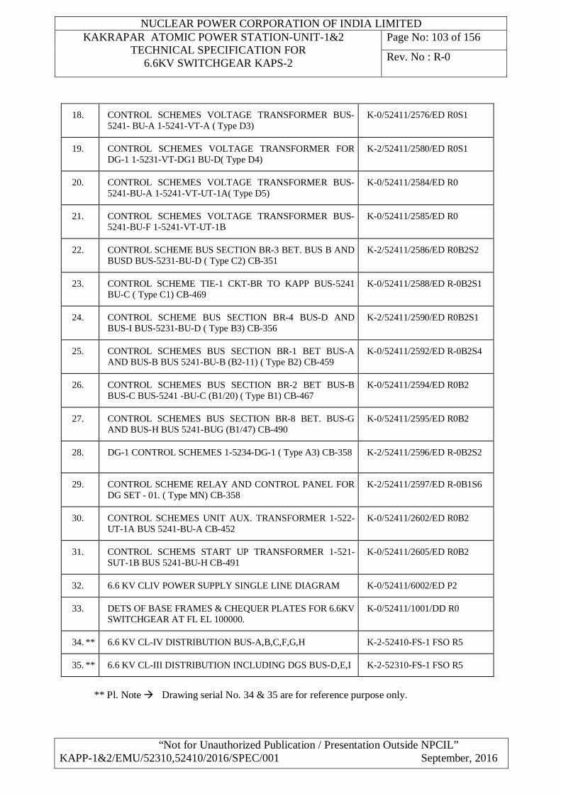
NUCLEAR POWER CORPORATION OF INDIA LIMITED KAKRAPAR ATOMIC POWER STATION-UNIT-1&2
TECHNICAL SPECIFICATION FOR 6.6KV SWITCHGEAR KAPS-2
Page No: 103 of 156
Rev. No : R-0
“Not for Unauthorized Publication / Presentation Outside NPCIL” KAPP-1&2/EMU/52310,52410/2016/SPEC/001 September, 2016
18. CONTROL SCHEMES VOLTAGE TRANSFORMER BUS-5241- BU-A 1-5241-VT-A ( Type D3)
K-0/52411/2576/ED R0S1
19. CONTROL SCHEMES VOLTAGE TRANSFORMER FOR DG-1 1-5231-VT-DG1 BU-D( Type D4)
K-2/52411/2580/ED R0S1
20. CONTROL SCHEMES VOLTAGE TRANSFORMER BUS-5241-BU-A 1-5241-VT-UT-1A( Type D5)
K-0/52411/2584/ED R0
21. CONTROL SCHEMES VOLTAGE TRANSFORMER BUS-5241-BU-F 1-5241-VT-UT-1B
K-0/52411/2585/ED R0
22. CONTROL SCHEME BUS SECTION BR-3 BET. BUS B AND BUSD BUS-5231-BU-D ( Type C2) CB-351
K-2/52411/2586/ED R0B2S2
23. CONTROL SCHEME TIE-1 CKT-BR TO KAPP BUS-5241 BU-C ( Type C1) CB-469
K-0/52411/2588/ED R-0B2S1
24. CONTROL SCHEME BUS SECTION BR-4 BUS-D AND BUS-I BUS-5231-BU-D ( Type B3) CB-356
K-2/52411/2590/ED R0B2S1
25. CONTROL SCHEMES BUS SECTION BR-1 BET BUS-A AND BUS-B BUS 5241-BU-B (B2-11) ( Type B2) CB-459
K-0/52411/2592/ED R-0B2S4
26. CONTROL SCHEMES BUS SECTION BR-2 BET BUS-B BUS-C BUS-5241 -BU-C (B1/20) ( Type B1) CB-467
K-0/52411/2594/ED R0B2
27. CONTROL SCHEMES BUS SECTION BR-8 BET. BUS-G AND BUS-H BUS 5241-BUG (B1/47) CB-490
K-0/52411/2595/ED R0B2
28. DG-1 CONTROL SCHEMES 1-5234-DG-1 ( Type A3) CB-358 K-2/52411/2596/ED R-0B2S2
29. CONTROL SCHEME RELAY AND CONTROL PANEL FOR DG SET - 01. ( Type MN) CB-358
K-2/52411/2597/ED R-0B1S6
30. CONTROL SCHEMES UNIT AUX. TRANSFORMER 1-522-UT-1A BUS 5241-BU-A CB-452
K-0/52411/2602/ED R0B2
31. CONTROL SCHEMS START UP TRANSFORMER 1-521-SUT-1B BUS 5241-BU-H CB-491
K-0/52411/2605/ED R0B2
32. 6.6 KV CLIV POWER SUPPLY SINGLE LINE DIAGRAM K-0/52411/6002/ED P2
33. DETS OF BASE FRAMES & CHEQUER PLATES FOR 6.6KV SWITCHGEAR AT FL EL 100000.
K-0/52411/1001/DD R0
34. ** 6.6 KV CL-IV DISTRIBUTION BUS-A,B,C,F,G,H K-2-52410-FS-1 FSO R5
35. ** 6.6 KV CL-III DISTRIBUTION INCLUDING DGS BUS-D,E,I K-2-52310-FS-1 FSO R5
** Pl. Note Drawing serial No. 34 & 35 are for reference purpose only.
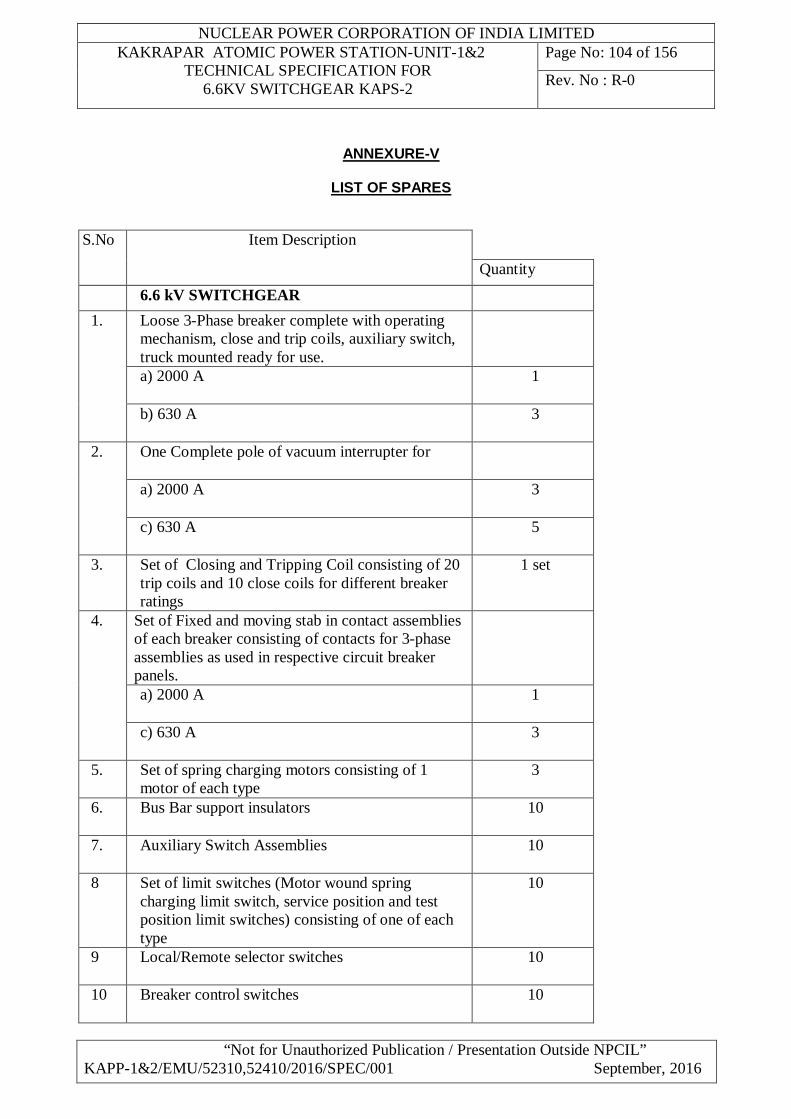
NUCLEAR POWER CORPORATION OF INDIA LIMITED KAKRAPAR ATOMIC POWER STATION-UNIT-1&2
TECHNICAL SPECIFICATION FOR 6.6KV SWITCHGEAR KAPS-2
Page No: 104 of 156
Rev. No : R-0
“Not for Unauthorized Publication / Presentation Outside NPCIL” KAPP-1&2/EMU/52310,52410/2016/SPEC/001 September, 2016
ANNEXURE-V
LIST OF SPARES
S.No Item Description
Quantity 6.6 kV SWITCHGEAR
1. Loose 3-Phase breaker complete with operating mechanism, close and trip coils, auxiliary switch, truck mounted ready for use.
a) 2000 A 1
b) 630 A 3
2. One Complete pole of vacuum interrupter for
a) 2000 A 3
c) 630 A 5
3. Set of Closing and Tripping Coil consisting of 20 trip coils and 10 close coils for different breaker ratings
1 set
4. Set of Fixed and moving stab in contact assemblies of each breaker consisting of contacts for 3-phase assemblies as used in respective circuit breaker panels.
a) 2000 A 1
c) 630 A 3
5. Set of spring charging motors consisting of 1 motor of each type
3
6. Bus Bar support insulators 10
7. Auxiliary Switch Assemblies 10
8 Set of limit switches (Motor wound spring charging limit switch, service position and test position limit switches) consisting of one of each type
10
9 Local/Remote selector switches 10
10 Breaker control switches 10
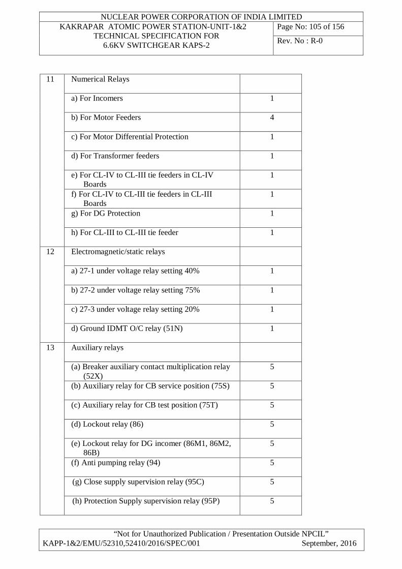
NUCLEAR POWER CORPORATION OF INDIA LIMITED KAKRAPAR ATOMIC POWER STATION-UNIT-1&2
TECHNICAL SPECIFICATION FOR 6.6KV SWITCHGEAR KAPS-2
Page No: 105 of 156
Rev. No : R-0
“Not for Unauthorized Publication / Presentation Outside NPCIL” KAPP-1&2/EMU/52310,52410/2016/SPEC/001 September, 2016
11 Numerical Relays
a) For Incomers 1
b) For Motor Feeders 4
c) For Motor Differential Protection 1
d) For Transformer feeders 1
e) For CL-IV to CL-III tie feeders in CL-IV Boards
1
f) For CL-IV to CL-III tie feeders in CL-III Boards
1
g) For DG Protection 1
h) For CL-III to CL-III tie feeder 1
12
Electromagnetic/static relays
a) 27-1 under voltage relay setting 40% 1
b) 27-2 under voltage relay setting 75% 1
c) 27-3 under voltage relay setting 20% 1
d) Ground IDMT O/C relay (51N) 1
13 Auxiliary relays
(a) Breaker auxiliary contact multiplication relay (52X)
5
(b) Auxiliary relay for CB service position (75S)
5
(c) Auxiliary relay for CB test position (75T)
5
(d) Lockout relay (86) 5
(e) Lockout relay for DG incomer (86M1, 86M2, 86B)
5
(f) Anti pumping relay (94) 5
(g) Close supply supervision relay (95C)
5
(h) Protection Supply supervision relay (95P) 5
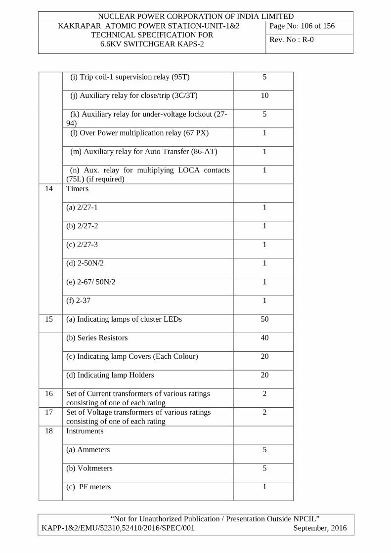
NUCLEAR POWER CORPORATION OF INDIA LIMITED KAKRAPAR ATOMIC POWER STATION-UNIT-1&2
TECHNICAL SPECIFICATION FOR 6.6KV SWITCHGEAR KAPS-2
Page No: 106 of 156
Rev. No : R-0
“Not for Unauthorized Publication / Presentation Outside NPCIL” KAPP-1&2/EMU/52310,52410/2016/SPEC/001 September, 2016
(i) Trip coil-1 supervision relay (95T) 5
(j) Auxiliary relay for close/trip (3C/3T) 10
(k) Auxiliary relay for under-voltage lockout (27-94)
5
(l) Over Power multiplication relay (67 PX) 1
(m) Auxiliary relay for Auto Transfer (86-AT) 1
(n) Aux. relay for multiplying LOCA contacts (75L) (if required)
1
14 Timers
(a) 2/27-1 1
(b) 2/27-2 1
(c) 2/27-3 1
(d) 2-50N/2 1
(e) 2-67/ 50N/2 1
(f) 2-37 1
15 (a) Indicating lamps of cluster LEDs 50
(b) Series Resistors 40
(c) Indicating lamp Covers (Each Colour) 20
(d) Indicating lamp Holders 20
16 Set of Current transformers of various ratings consisting of one of each rating
2
17 Set of Voltage transformers of various ratings consisting of one of each rating
2
18 Instruments
(a) Ammeters 5
(b) Voltmeters 5
(c) PF meters 1
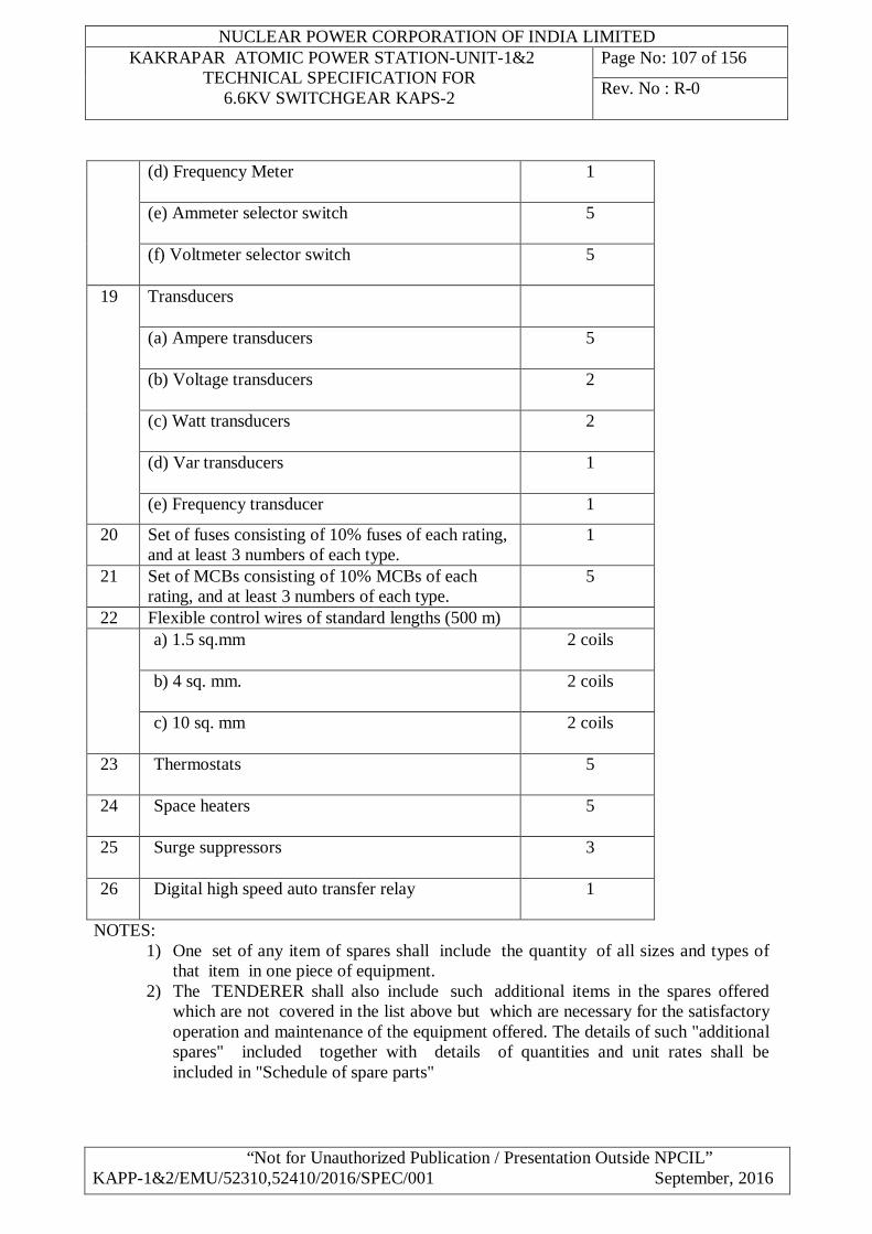
NUCLEAR POWER CORPORATION OF INDIA LIMITED KAKRAPAR ATOMIC POWER STATION-UNIT-1&2
TECHNICAL SPECIFICATION FOR 6.6KV SWITCHGEAR KAPS-2
Page No: 107 of 156
Rev. No : R-0
“Not for Unauthorized Publication / Presentation Outside NPCIL” KAPP-1&2/EMU/52310,52410/2016/SPEC/001 September, 2016
(d) Frequency Meter 1
(e) Ammeter selector switch 5
(f) Voltmeter selector switch 5
19
Transducers
(a) Ampere transducers 5
(b) Voltage transducers 2
(c) Watt transducers 2
(d) Var transducers 1
(e) Frequency transducer 1
20 Set of fuses consisting of 10% fuses of each rating, and at least 3 numbers of each type.
1
21 Set of MCBs consisting of 10% MCBs of each rating, and at least 3 numbers of each type.
5
22 Flexible control wires of standard lengths (500 m) a) 1.5 sq.mm
2 coils
b) 4 sq. mm. 2 coils
c) 10 sq. mm 2 coils
23 Thermostats 5
24 Space heaters 5
25 Surge suppressors 3
26 Digital high speed auto transfer relay 1
NOTES: 1) One set of any item of spares shall include the quantity of all sizes and types of
that item in one piece of equipment. 2) The TENDERER shall also include such additional items in the spares offered
which are not covered in the list above but which are necessary for the satisfactory operation and maintenance of the equipment offered. The details of such "additional spares" included together with details of quantities and unit rates shall be included in "Schedule of spare parts"
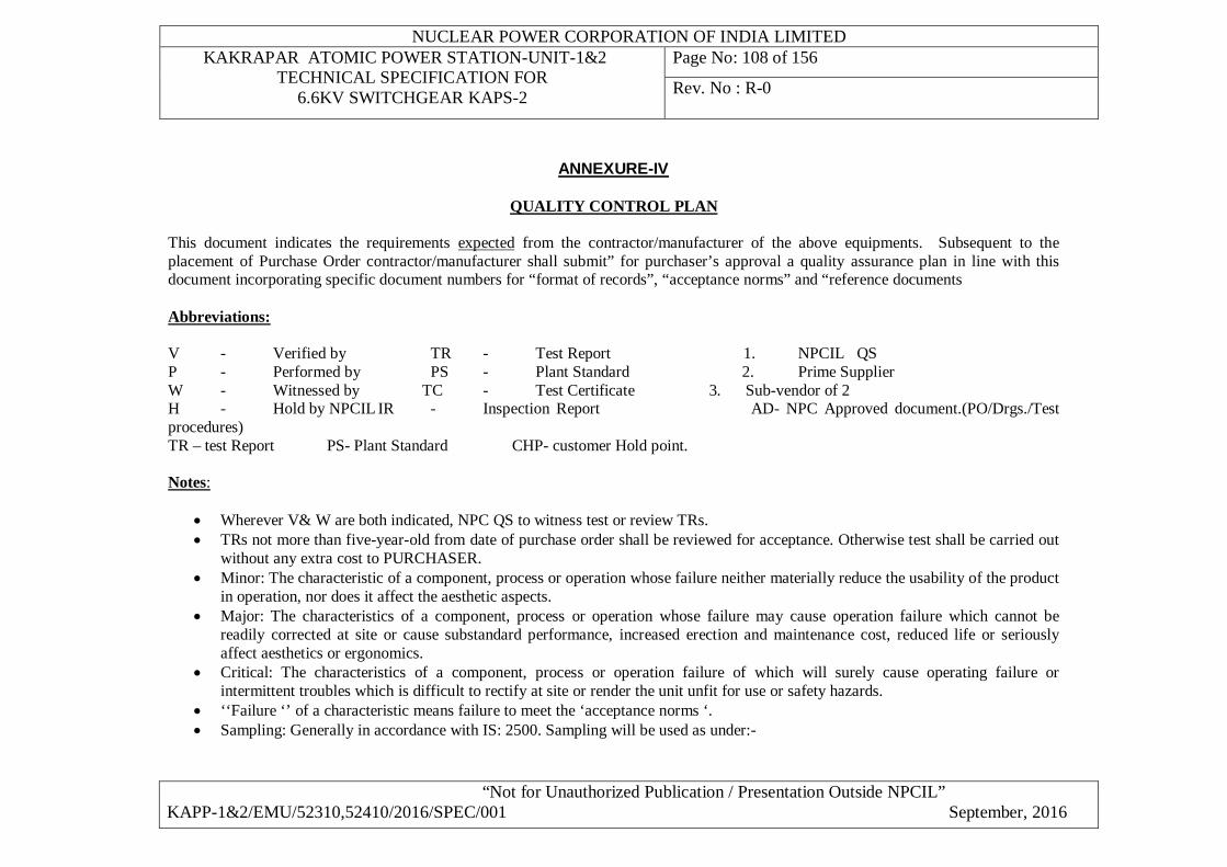
NUCLEAR POWER CORPORATION OF INDIA LIMITED KAKRAPAR ATOMIC POWER STATION-UNIT-1&2
TECHNICAL SPECIFICATION FOR 6.6KV SWITCHGEAR KAPS-2
Page No: 108 of 156
Rev. No : R-0
“Not for Unauthorized Publication / Presentation Outside NPCIL” KAPP-1&2/EMU/52310,52410/2016/SPEC/001 September, 2016
ANNEXURE-IV
QUALITY CONTROL PLAN This document indicates the requirements expected from the contractor/manufacturer of the above equipments. Subsequent to the placement of Purchase Order contractor/manufacturer shall submit” for purchaser’s approval a quality assurance plan in line with this document incorporating specific document numbers for “format of records”, “acceptance norms” and “reference documents Abbreviations: V - Verified by TR - Test Report 1. NPCIL QS P - Performed by PS - Plant Standard 2. Prime Supplier W - Witnessed by TC - Test Certificate 3. Sub-vendor of 2 H - Hold by NPCIL IR - Inspection Report AD- NPC Approved document.(PO/Drgs./Test procedures) TR – test Report PS- Plant Standard CHP- customer Hold point. Notes:
Wherever V& W are both indicated, NPC QS to witness test or review TRs. TRs not more than five-year-old from date of purchase order shall be reviewed for acceptance. Otherwise test shall be carried out
without any extra cost to PURCHASER. Minor: The characteristic of a component, process or operation whose failure neither materially reduce the usability of the product
in operation, nor does it affect the aesthetic aspects. Major: The characteristics of a component, process or operation whose failure may cause operation failure which cannot be
readily corrected at site or cause substandard performance, increased erection and maintenance cost, reduced life or seriously affect aesthetics or ergonomics.
Critical: The characteristics of a component, process or operation failure of which will surely cause operating failure or intermittent troubles which is difficult to rectify at site or render the unit unfit for use or safety hazards.
‘‘Failure ‘’ of a characteristic means failure to meet the ‘acceptance norms ‘. Sampling: Generally in accordance with IS: 2500. Sampling will be used as under:-
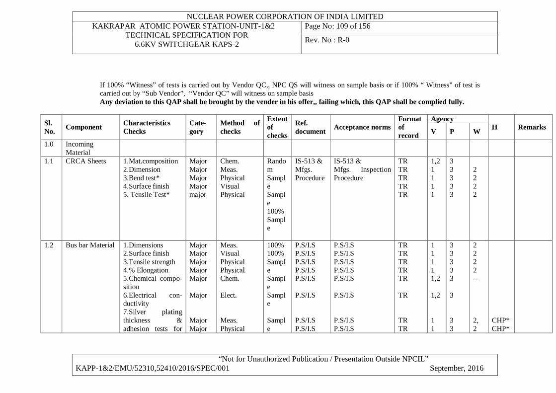
NUCLEAR POWER CORPORATION OF INDIA LIMITED KAKRAPAR ATOMIC POWER STATION-UNIT-1&2
TECHNICAL SPECIFICATION FOR 6.6KV SWITCHGEAR KAPS-2
Page No: 109 of 156
Rev. No : R-0
“Not for Unauthorized Publication / Presentation Outside NPCIL” KAPP-1&2/EMU/52310,52410/2016/SPEC/001 September, 2016
If 100% “Witness” of tests is carried out by Vendor QC,, NPC QS will witness on sample basis or if 100% “ Witness" of test is carried out by “Sub Vendor”, “Vendor QC” will witness on sample basis Any deviation to this QAP shall be brought by the vender in his offer,, failing which, this QAP shall be complied fully.
Sl. No. Component Characteristics
Checks Cate-gory
Method of checks
Extent of checks
Ref. document Acceptance norms
Format of record
Agency H Remarks V P W
1.0 Incoming Material
1.1 CRCA Sheets 1.Mat.composition 2.Dimension 3.Bend test* 4.Surface finish 5. Tensile Test*
Major Major Major Major major
Chem. Meas. Physical Visual Physical
Random Sample Sample 100% Sample
IS-513 & Mfgs. Procedure
IS-513 & Mfgs. Inspection Procedure
TR TR TR TR TR
1,2 1 1 1 1
3 3 3 3 3
2 2 2 2
1.2 Bus bar Material 1.Dimensions 2.Surface finish 3.Tensile strength 4.% Elongation 5.Chemical compo-sition 6.Electrical con-ductivity 7.Silver plating thickness & adhesion tests for
Major Major Major Major Major Major Major Major
Meas. Visual Physical Physical Chem. Elect. Meas. Physical
100% 100% Sample Sample Sample Sample
P.S/I.S P.S/I.S P.S/I.S P.S/I.S P.S/I.S P.S/I.S P.S/I.S P.S/I.S
P.S/I.S P.S/I.S P.S/I.S P.S/I.S P.S/I.S P.S/I.S P.S/I.S P.S/I.S
TR TR TR TR TR TR TR TR
1 1 1 1 1,2 1,2 1 1
3 3 3 3 3 3 3 3
2 2 2 2 -- 2, 2
CHP* CHP*
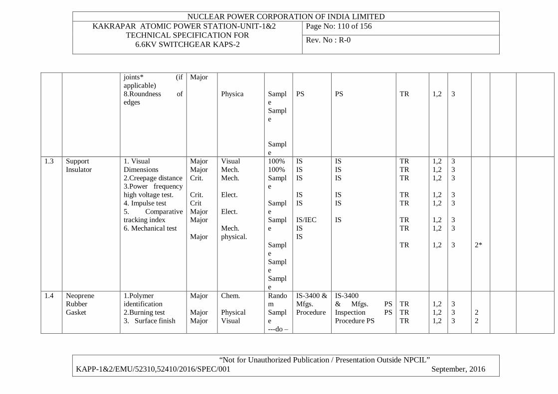
NUCLEAR POWER CORPORATION OF INDIA LIMITED KAKRAPAR ATOMIC POWER STATION-UNIT-1&2
TECHNICAL SPECIFICATION FOR 6.6KV SWITCHGEAR KAPS-2
Page No: 110 of 156
Rev. No : R-0
“Not for Unauthorized Publication / Presentation Outside NPCIL” KAPP-1&2/EMU/52310,52410/2016/SPEC/001 September, 2016
joints* (if applicable) 8.Roundness of edges
Major Physica
Sample Sample Sample
PS
PS
TR
1,2
3
1.3 Support Insulator
1. Visual Dimensions 2.Creepage distance 3.Power frequency high voltage test. 4. Impulse test 5. Comparative tracking index 6. Mechanical test
Major Major Crit. Crit. Crit MajorMajor Major
Visual Mech. Mech. Elect. Elect. Mech. physical.
100% 100% Sample Sample Sample Sample Sample Sample
IS IS IS IS IS IS/IEC IS IS
IS IS IS IS IS IS
TR TR TR TR TR TR TR TR
1,2 1,2 1,2 1,2 1,2 1,2 1,2 1,2
3 3 3 3 3 3 3 3
2*
1.4
Neoprene Rubber Gasket
1.Polymer identification 2.Burning test 3. Surface finish
Major Major Major
Chem. Physical Visual
Random Sample ---do –
IS-3400 & Mfgs. Procedure
IS-3400 & Mfgs. PS Inspection PS Procedure PS
TR TR TR
1,2 1,2 1,2
3 3 3
2 2
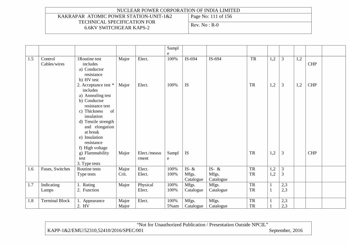
NUCLEAR POWER CORPORATION OF INDIA LIMITED KAKRAPAR ATOMIC POWER STATION-UNIT-1&2
TECHNICAL SPECIFICATION FOR 6.6KV SWITCHGEAR KAPS-2
Page No: 111 of 156
Rev. No : R-0
“Not for Unauthorized Publication / Presentation Outside NPCIL” KAPP-1&2/EMU/52310,52410/2016/SPEC/001 September, 2016
Sample
1.5
Control Cables/wires
1Routine test includes
a) Conductor resistance
b) HV test 2. Acceptance test *
includes a) Annealing test b) Conductor
resistance test c) Thickness of
insulation d) Tensile strength
and elongation at break
e) Insulation resistance
f) High voltage g) Flammability test
3. Type tests
Major Major Major
Elect. Elect. Elect./measurment
100% 100% Sample
IS-694 IS IS
IS-694
TR TR TR
1,2 1,2 1,2
3 3 3
1,2 1,2
CHP CHP CHP
1.6 Fuses, Switches Routine tests Type tests
Major Crit.
Elect. Elect.
100% 100%
IS- & Mfgs. Catalogue
IS- & Mfgs. Catalogue
TR TR
1,2 1,2
3 3
1.7 Indicating Lamps
1. Rating 2. Function
Major Physical Elect.
100% 100%
Mfgs. Catalogue
Mfgs. Catalogue
TR TR
1 1
2,3 2,3
1.8 Terminal Block 1. Appearance 2. HV
Major Major
Elect. 100% 5%am
Mfgs. Catalogue
Mfgs. Catalogue
TR TR
1 1
2,3 2,3
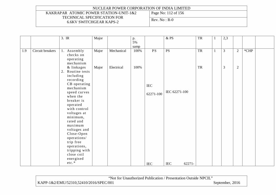
NUCLEAR POWER CORPORATION OF INDIA LIMITED KAKRAPAR ATOMIC POWER STATION-UNIT-1&2
TECHNICAL SPECIFICATION FOR 6.6KV SWITCHGEAR KAPS-2
Page No: 112 of 156
Rev. No : R-0
“Not for Unauthorized Publication / Presentation Outside NPCIL” KAPP-1&2/EMU/52310,52410/2016/SPEC/001 September, 2016
3. IR Major p. 5% samp
& PS TR 1 2,3
1.9 Circuit breakers 1. Assembly checks on operating mechanism & linkages
2. Rout ine tests including recording CB operating mechanism speed curves when the breaker is operated with control voltages at minimum, rated and maximum voltages and Close-Open operations/ tr ip free operations, tr ipping with close coil energised etc.*
Major Major
Mechanical Electrical
100%
100%
PS
IEC
62271-100
IEC
PS
IEC 62271-100
IEC 62271-
TR TR
1
3 3
2 2
*CHP
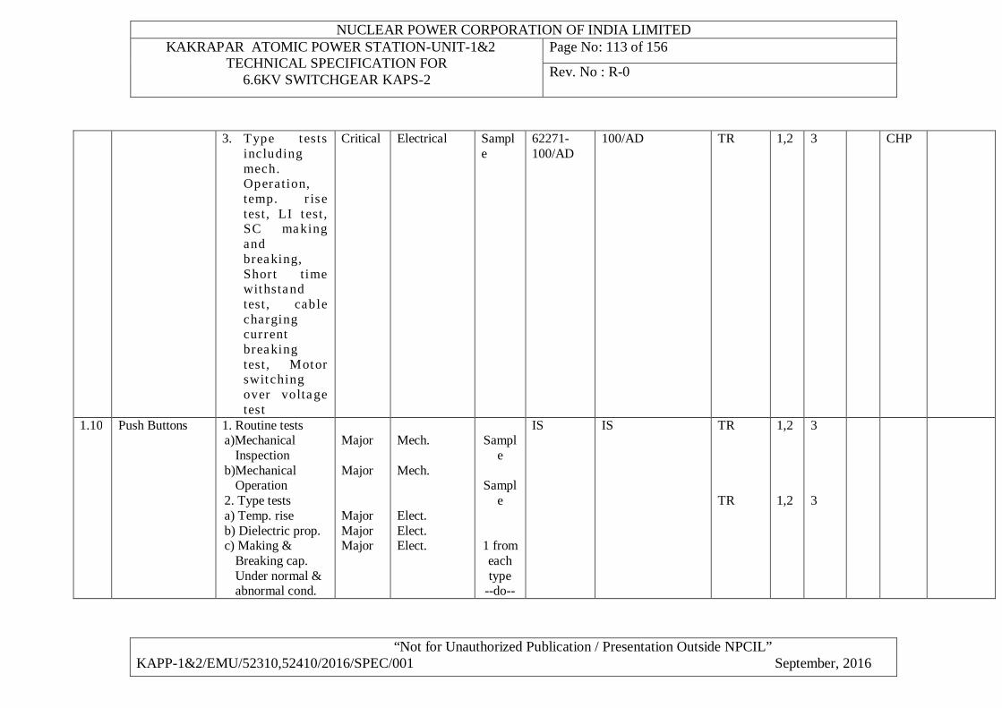
NUCLEAR POWER CORPORATION OF INDIA LIMITED KAKRAPAR ATOMIC POWER STATION-UNIT-1&2
TECHNICAL SPECIFICATION FOR 6.6KV SWITCHGEAR KAPS-2
Page No: 113 of 156
Rev. No : R-0
“Not for Unauthorized Publication / Presentation Outside NPCIL” KAPP-1&2/EMU/52310,52410/2016/SPEC/001 September, 2016
3. Type tests including mech. Operation, temp. r ise test , LI t est , SC making and breaking, Short t ime withstand test , cable charging current breaking test , Motor switching over voltage test
Critical Electrical Sample
62271-100/AD
100/AD TR 1,2 3 CHP
1.10 Push Buttons 1. Routine tests a)Mechanical
Inspection b)Mechanical
Operation 2. Type tests a) Temp. rise b) Dielectric prop. c) Making &
Breaking cap. Under normal & abnormal cond.
Major Major Major Major Major
Mech. Mech. Elect. Elect. Elect.
Sampl
e
Sample
1 from each type
--do--
IS IS TR TR
1,2 1,2
3 3
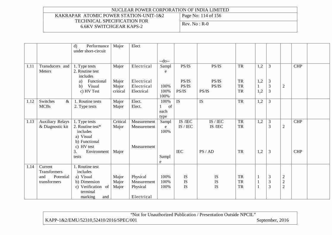
NUCLEAR POWER CORPORATION OF INDIA LIMITED KAKRAPAR ATOMIC POWER STATION-UNIT-1&2
TECHNICAL SPECIFICATION FOR 6.6KV SWITCHGEAR KAPS-2
Page No: 114 of 156
Rev. No : R-0
“Not for Unauthorized Publication / Presentation Outside NPCIL” KAPP-1&2/EMU/52310,52410/2016/SPEC/001 September, 2016
d) Performance under short-circuit
Major Elect
--do-- 1.11 Transducers and
Meters
1. Type tests 2. Routine test
includes a) Functional b) Visual
c) HV Test
Major Major Major critical
Electr ical Electr ical Electr ical Electrical
Sample
100% 100%
100%
PS/IS
PS/IS PS/IS
PS/IS
PS/IS
PS/IS PS/IS
PS/IS
TR TR TR TR
1,2 1,2 1 1,2
3 3 3 3
2
CHP
1.12 Switches & MCBs
1. Routine tests 2. Type tests
Major Major
Elect. Elect.
100% 1 of each type
IS IS TR 1,2 3
1.13 Auxiliary Relays & Diagnostic kit
1. Type tests 2. Routine test*
includes a) Visual b) Functional c) HV test
3. Environment tests
Critical Major Major
Measurement Measurement Measurement
Sample
100%
Sample
IS /IEC IS / IEC
IEC
IS / IEC IS /IEC
PS / AD
TR TR TR
1,2 1,2
3 3 3
2
CHP CHP
1.14 Current Transformers and Potential transformers
1. Routine test includes
a) Visual b) Dimension c) Verification of
terminal marking and
Major Major Major
Physical Measurement Physical Electr ical
100% 100% 100%
IS IS IS
IS IS IS
TR TR TR
1 1 1
3 3 3
2 2 2
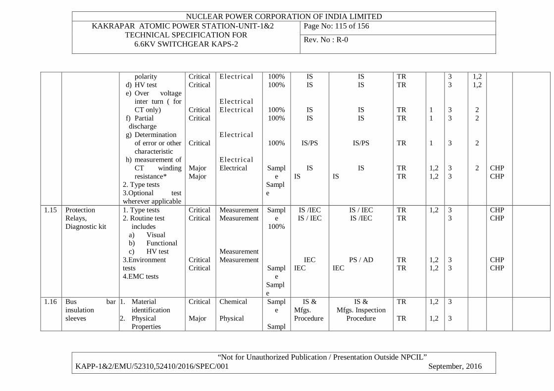
NUCLEAR POWER CORPORATION OF INDIA LIMITED KAKRAPAR ATOMIC POWER STATION-UNIT-1&2
TECHNICAL SPECIFICATION FOR 6.6KV SWITCHGEAR KAPS-2
Page No: 115 of 156
Rev. No : R-0
“Not for Unauthorized Publication / Presentation Outside NPCIL” KAPP-1&2/EMU/52310,52410/2016/SPEC/001 September, 2016
polarity d) HV test e) Over voltage
inter turn ( for CT only)
f) Partial discharge
g) Determination of error or other characteristic
h) measurement of CT winding resistance*
2. Type tests 3.Optional test wherever applicable
Critical Critical Critical Critical Critical Major Major
Electr ical Electr ical Electr ical Electr ical Electr ical Electrical
100% 100%
100% 100%
100%
Sample
Sample
IS IS
IS IS
IS/PS
IS IS
IS IS
IS IS
IS/PS
IS IS
TR TR TR TR TR TR TR
1 1 1 1,2 1,2
3 3 3 3 3 3 3
1,2 1,2
2 2 2 2
CHP CHP
1.15 Protection Relays, Diagnostic kit
1. Type tests 2. Routine test
includes a) Visual b) Functional c) HV test
3.Environment tests 4.EMC tests
Critical Critical Critical Critical
Measurement Measurement Measurement Measurement
Sample
100%
Sample
Sample
IS /IEC IS / IEC
IEC IEC
IS / IEC IS /IEC
PS / AD IEC
TR TR TR TR
1,2 1,2 1,2
3 3 3 3
CHP CHP CHP CHP
1.16 Bus bar insulation sleeves
1. Material identification
2. Physical Properties
Critical Major
Chemical Physical
Sample
Sampl
IS & Mfgs. Procedure
IS & Mfgs. Inspection
Procedure
TR TR
1,2 1,2
3 3
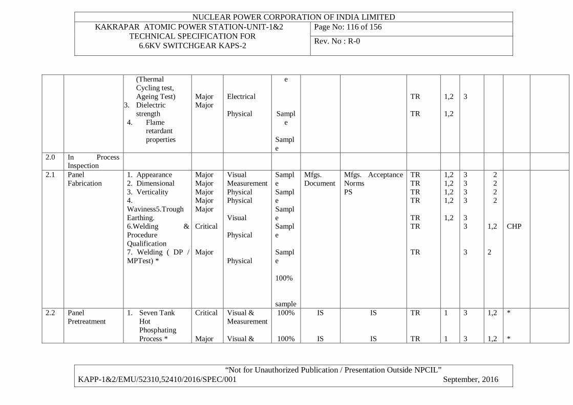
NUCLEAR POWER CORPORATION OF INDIA LIMITED KAKRAPAR ATOMIC POWER STATION-UNIT-1&2
TECHNICAL SPECIFICATION FOR 6.6KV SWITCHGEAR KAPS-2
Page No: 116 of 156
Rev. No : R-0
“Not for Unauthorized Publication / Presentation Outside NPCIL” KAPP-1&2/EMU/52310,52410/2016/SPEC/001 September, 2016
(Thermal Cycling test, Ageing Test)
3. Dielectric strength
4. Flame retardant properties
Major Major
Electrical Physical
e
Sample
Sample
TR TR
1,2 1,2
3
2.0 In Process Inspection
2.1 Panel Fabrication
1. Appearance 2. Dimensional 3. Verticality 4. Waviness5.Trough Earthing. 6.Welding & Procedure Qualification 7. Welding ( DP / MPTest) *
Major Major Major Major Major Critical Major
Visual Measurement Physical Physical Visual Physical Physical
Sample Sample Sample Sample Sample 100% sample
Mfgs. Document
Mfgs. Acceptance Norms PS
TR TR TR TR TR TR TR
1,2 1,2 1,2 1,2 1,2
3 3 3 3 3 3 3
2 2 2 2 1,2 2
CHP
2.2 Panel Pretreatment
1. Seven Tank Hot Phosphating Process *
Critical Major
Visual & Measurement Visual &
100%
100%
IS
IS
IS
IS
TR TR
1 1
3 3
1,2 1,2
* *
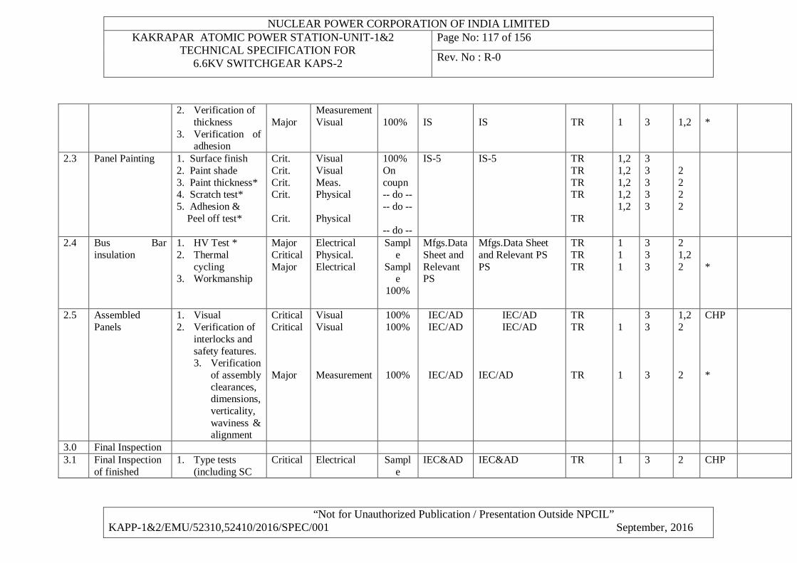
NUCLEAR POWER CORPORATION OF INDIA LIMITED KAKRAPAR ATOMIC POWER STATION-UNIT-1&2
TECHNICAL SPECIFICATION FOR 6.6KV SWITCHGEAR KAPS-2
Page No: 117 of 156
Rev. No : R-0
“Not for Unauthorized Publication / Presentation Outside NPCIL” KAPP-1&2/EMU/52310,52410/2016/SPEC/001 September, 2016
2. Verification of thickness
3. Verification of adhesion
Major
Measurement Visual
100%
IS
IS
TR
1
3
1,2
*
2.3
Panel Painting
1. Surface finish 2. Paint shade 3. Paint thickness* 4. Scratch test* 5. Adhesion & Peel off test*
Crit. Crit. Crit. Crit. Crit.
Visual Visual Meas. Physical Physical
100% On coupn -- do -- -- do -- -- do --
IS-5
IS-5
TR TR TR TR TR
1,2 1,2 1,2 1,2 1,2
3 3 3 3 3
2 2 2 2
2.4 Bus Bar insulation
1. HV Test * 2. Thermal
cycling 3. Workmanship
Major Critical Major
Electrical Physical. Electrical
Sample
Sample
100%
Mfgs.Data Sheet and Relevant PS
Mfgs.Data Sheet and Relevant PS PS
TR TR TR
1 1 1
3 3 3
2 1,2 2
*
2.5 Assembled Panels
1. Visual 2. Verification of
interlocks and safety features. 3. Verification
of assembly clearances, dimensions,verticality,waviness & alignment
Critical Critical Major
Visual Visual Measurement
100% 100%
100%
IEC/AD IEC/AD
IEC/AD
IEC/AD IEC/AD
IEC/AD
TR TR TR
1 1
3 3 3
1,2 2 2
CHP *
3.0 Final Inspection 3.1 Final Inspection
of finished 1. Type tests
(including SC Critical
Electrical
Sample
IEC&AD
IEC&AD
TR
1
3
2
CHP
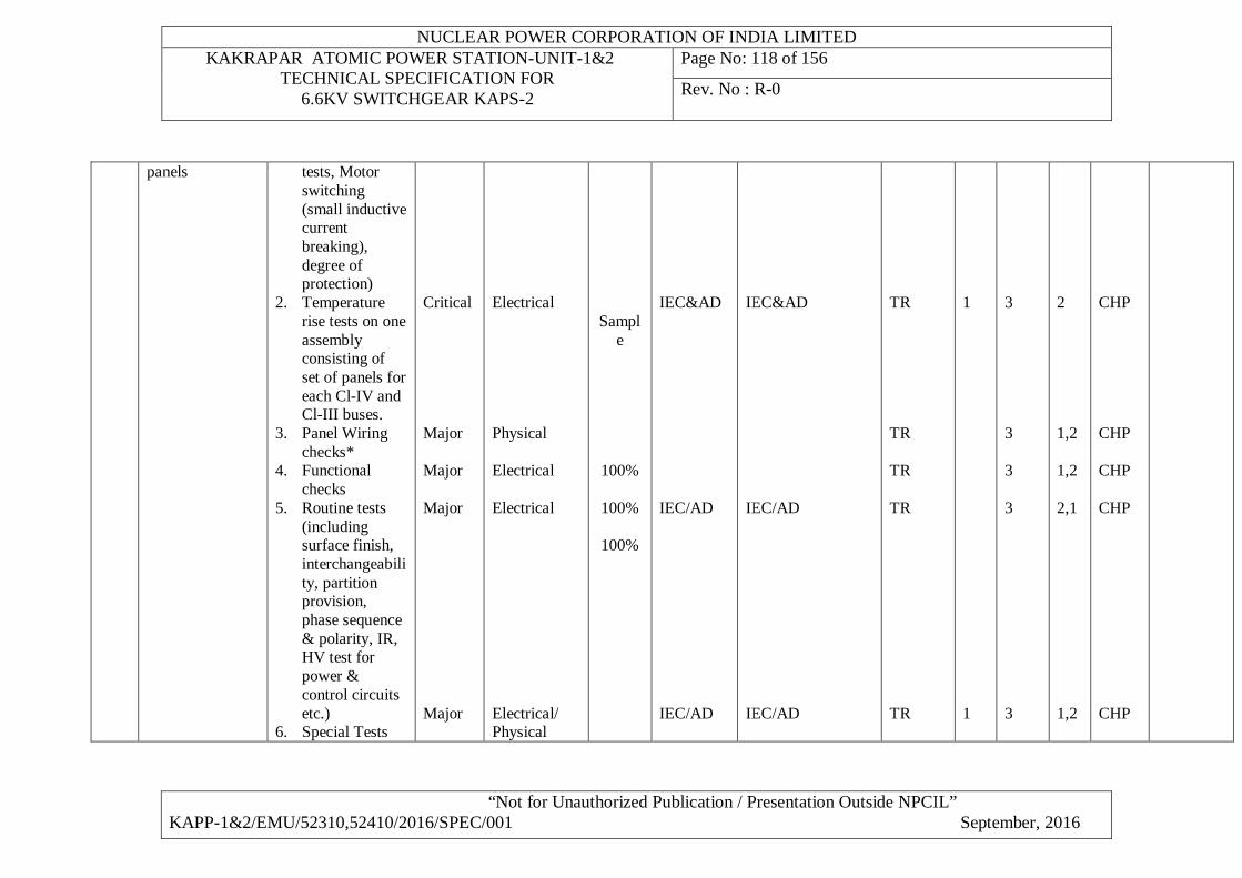
NUCLEAR POWER CORPORATION OF INDIA LIMITED KAKRAPAR ATOMIC POWER STATION-UNIT-1&2
TECHNICAL SPECIFICATION FOR 6.6KV SWITCHGEAR KAPS-2
Page No: 118 of 156
Rev. No : R-0
“Not for Unauthorized Publication / Presentation Outside NPCIL” KAPP-1&2/EMU/52310,52410/2016/SPEC/001 September, 2016
panels
tests, Motor switching (small inductive current breaking), degree of protection)
2. Temperature rise tests on one assembly consisting of set of panels for each Cl-IV and Cl-III buses.
3. Panel Wiring checks*
4. Functional checks
5. Routine tests (including surface finish, interchangeability, partition provision, phase sequence & polarity, IR, HV test for power & control circuits etc.)
6. Special Tests
Critical Major Major Major Major
Electrical Physical Electrical Electrical Electrical/ Physical
Sample
100%
100%
100%
IEC&AD IEC/AD IEC/AD
IEC&AD IEC/AD IEC/AD
TR TR TR TR TR
1 1
3 3 3 3 3
2 1,2 1,2 2,1 1,2
CHP CHP CHP CHP CHP
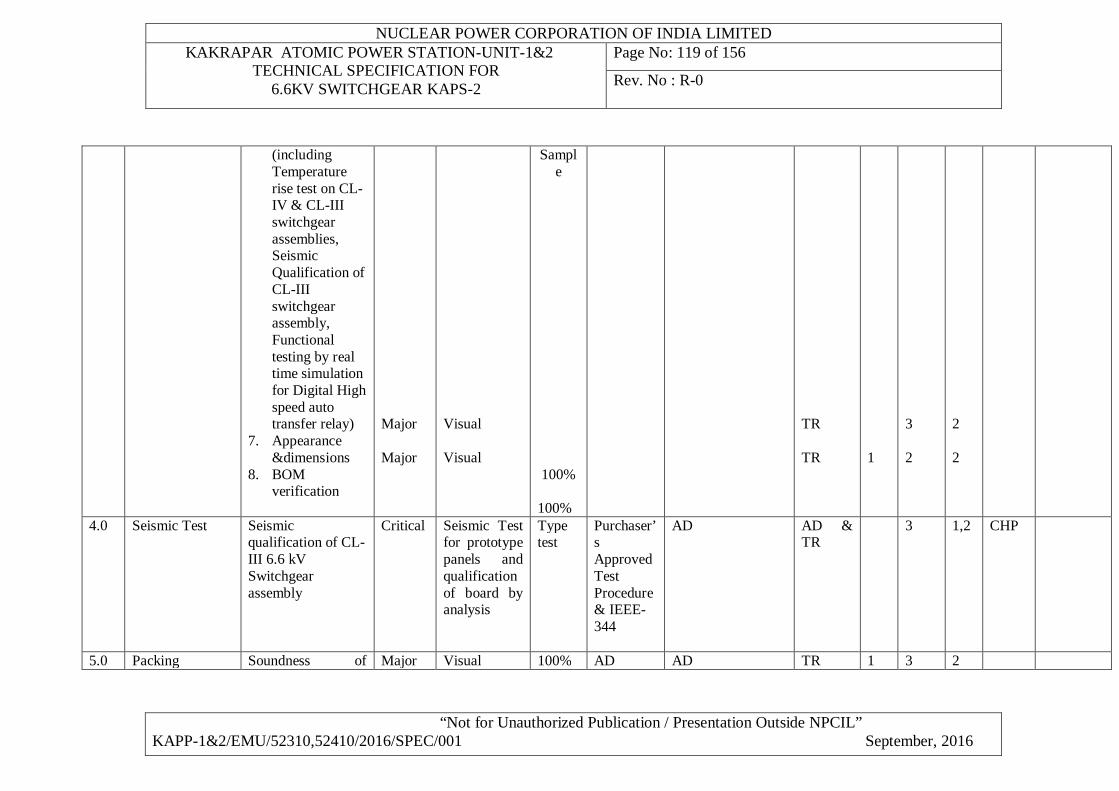
NUCLEAR POWER CORPORATION OF INDIA LIMITED KAKRAPAR ATOMIC POWER STATION-UNIT-1&2
TECHNICAL SPECIFICATION FOR 6.6KV SWITCHGEAR KAPS-2
Page No: 119 of 156
Rev. No : R-0
“Not for Unauthorized Publication / Presentation Outside NPCIL” KAPP-1&2/EMU/52310,52410/2016/SPEC/001 September, 2016
(including Temperature rise test on CL-IV & CL-III switchgear assemblies, Seismic Qualification of CL-III switchgear assembly, Functional testing by real time simulation for Digital High speed auto transfer relay)
7. Appearance &dimensions
8. BOM verification
Major Major
Visual Visual
Sample
100%
100%
TR TR
1
3 2
2 2
4.0 Seismic Test Seismic qualification of CL-III 6.6 kV Switchgear assembly
Critical Seismic Test for prototype panels and qualification of board by analysis
Type test
Purchaser’s Approved Test Procedure & IEEE-344
AD AD & TR
3 1,2 CHP
5.0 Packing Soundness of Major Visual 100% AD AD TR 1 3 2
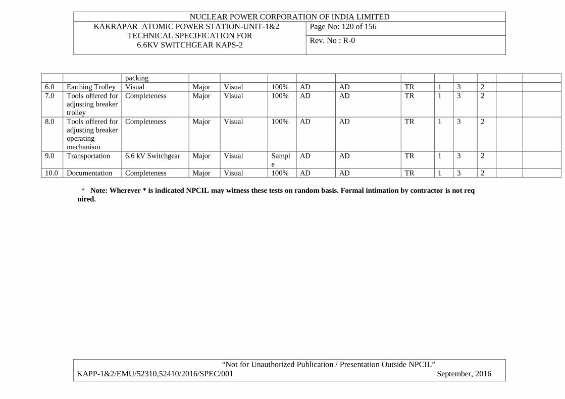
NUCLEAR POWER CORPORATION OF INDIA LIMITED KAKRAPAR ATOMIC POWER STATION-UNIT-1&2
TECHNICAL SPECIFICATION FOR 6.6KV SWITCHGEAR KAPS-2
Page No: 120 of 156
Rev. No : R-0
“Not for Unauthorized Publication / Presentation Outside NPCIL” KAPP-1&2/EMU/52310,52410/2016/SPEC/001 September, 2016
packing 6.0 Earthing Trolley Visual Major Visual 100% AD AD TR 1 3 2 7.0 Tools offered for
adjusting breaker trolley
Completeness Major Visual 100% AD AD TR 1 3 2
8.0 Tools offered for adjusting breaker operating mechanism
Completeness Major Visual 100% AD AD TR 1 3 2
9.0 Transportation 6.6 kV Switchgear Major Visual Sample
AD AD TR 1 3 2
10.0 Documentation Completeness Major Visual 100% AD AD TR 1 3 2 * Note: Wherever * is indicated NPCIL may witness these tests on random basis. Formal intimation by contractor is not req uired.
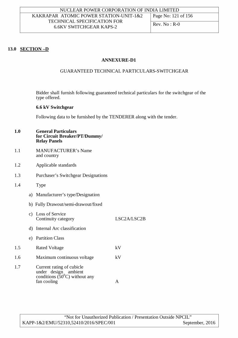
NUCLEAR POWER CORPORATION OF INDIA LIMITED KAKRAPAR ATOMIC POWER STATION-UNIT-1&2
TECHNICAL SPECIFICATION FOR 6.6KV SWITCHGEAR KAPS-2
Page No: 121 of 156
Rev. No : R-0
“Not for Unauthorized Publication / Presentation Outside NPCIL” KAPP-1&2/EMU/52310,52410/2016/SPEC/001 September, 2016
13.0 SECTION –D
ANNEXURE-D1 GUARANTEED TECHNICAL PARTICULARS-SWITCHGEAR
Bidder shall furnish following guaranteed technical particulars for the switchgear of the type offered.
6.6 kV Switchgear
Following data to be furnished by the TENDERER along with the tender. 1.0 General Particulars for Circuit Breaker/PT/Dummy/ Relay Panels 1.1 MANUFACTURER’s Name and country 1.2 Applicable standards 1.3 Purchaser’s Switchgear Designations 1.4 Type
a) Manufacturer’s type/Designation b) Fully Drawout/semi-drawout/fixed c) Loss of Service Continuity category LSC2A/LSC2B
d) Internal Arc classification
e) Partition Class
1.5 Rated Voltage kV 1.6 Maximum continuous voltage kV 1.7 Current rating of cubicle under design ambient conditions (500C) without any fan cooling A
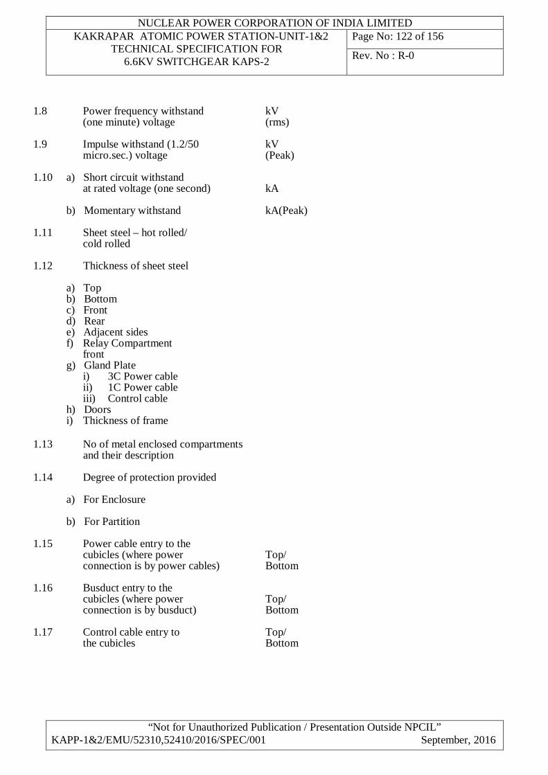
NUCLEAR POWER CORPORATION OF INDIA LIMITED KAKRAPAR ATOMIC POWER STATION-UNIT-1&2
TECHNICAL SPECIFICATION FOR 6.6KV SWITCHGEAR KAPS-2
Page No: 122 of 156
Rev. No : R-0
“Not for Unauthorized Publication / Presentation Outside NPCIL” KAPP-1&2/EMU/52310,52410/2016/SPEC/001 September, 2016
1.8 Power frequency withstand kV (one minute) voltage (rms) 1.9 Impulse withstand (1.2/50 kV micro.sec.) voltage (Peak) 1.10 a) Short circuit withstand at rated voltage (one second) kA b) Momentary withstand kA(Peak) 1.11 Sheet steel – hot rolled/ cold rolled 1.12 Thickness of sheet steel
a) Top b) Bottom c) Front d) Rear e) Adjacent sides f) Relay Compartment front g) Gland Plate i) 3C Power cable ii) 1C Power cable iii) Control cable h) Doors i) Thickness of frame
1.13 No of metal enclosed compartments and their description 1.14 Degree of protection provided
a) For Enclosure b) For Partition
1.15 Power cable entry to the cubicles (where power Top/ connection is by power cables) Bottom 1.16 Busduct entry to the cubicles (where power Top/ connection is by busduct) Bottom 1.17 Control cable entry to Top/ the cubicles Bottom
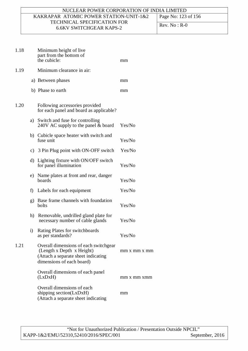
NUCLEAR POWER CORPORATION OF INDIA LIMITED KAKRAPAR ATOMIC POWER STATION-UNIT-1&2
TECHNICAL SPECIFICATION FOR 6.6KV SWITCHGEAR KAPS-2
Page No: 123 of 156
Rev. No : R-0
“Not for Unauthorized Publication / Presentation Outside NPCIL” KAPP-1&2/EMU/52310,52410/2016/SPEC/001 September, 2016
1.18 Minimum height of live part from the bottom of the cubicle: mm 1.19 Minimum clearance in air:
a) Between phases mm b) Phase to earth mm
1.20 Following accessories provided for each panel and board as applicable?
a) Switch and fuse for controlling 240V AC supply to the panel & board Yes/No b) Cubicle space heater with switch and fuse unit Yes/No c) 3 Pin Plug point with ON-OFF switch Yes/No d) Lighting fixture with ON/OFF switch for panel illumination Yes/No e) Name plates at front and rear, danger boards Yes/No f) Labels for each equipment Yes/No g) Base frame channels with foundation bolts Yes/No h) Removable, undrilled gland plate for necessary number of cable glands Yes/No
i) Rating Plates for switchboards as per standards? Yes/No
1.21 Overall dimensions of each switchgear (Length x Depth x Height) mm x mm x mm (Attach a separate sheet indicating dimensions of each board)
Overall dimensions of each panel (LxDxH) mm x mm xmm Overall dimensions of each shipping section(LxDxH) mm (Attach a separate sheet indicating
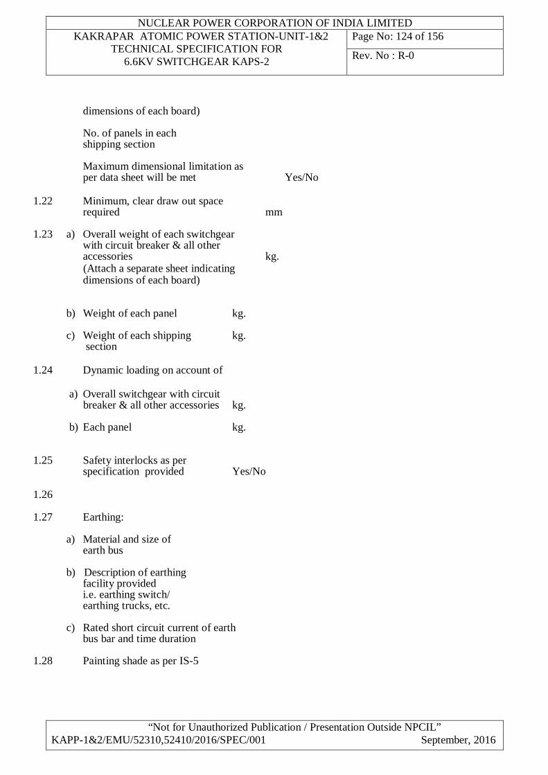
NUCLEAR POWER CORPORATION OF INDIA LIMITED KAKRAPAR ATOMIC POWER STATION-UNIT-1&2
TECHNICAL SPECIFICATION FOR 6.6KV SWITCHGEAR KAPS-2
Page No: 124 of 156
Rev. No : R-0
“Not for Unauthorized Publication / Presentation Outside NPCIL” KAPP-1&2/EMU/52310,52410/2016/SPEC/001 September, 2016
dimensions of each board)
No. of panels in each shipping section Maximum dimensional limitation as per data sheet will be met Yes/No 1.22 Minimum, clear draw out space required mm 1.23 a) Overall weight of each switchgear with circuit breaker & all other accessories kg. (Attach a separate sheet indicating dimensions of each board)
b) Weight of each panel kg. c) Weight of each shipping kg. section
1.24 Dynamic loading on account of
a) Overall switchgear with circuit breaker & all other accessories kg. b) Each panel kg.
1.25 Safety interlocks as per specification provided Yes/No 1.26 1.27 Earthing:
a) Material and size of earth bus b) Description of earthing facility provided i.e. earthing switch/ earthing trucks, etc.
c) Rated short circuit current of earth bus bar and time duration
1.28 Painting shade as per IS-5
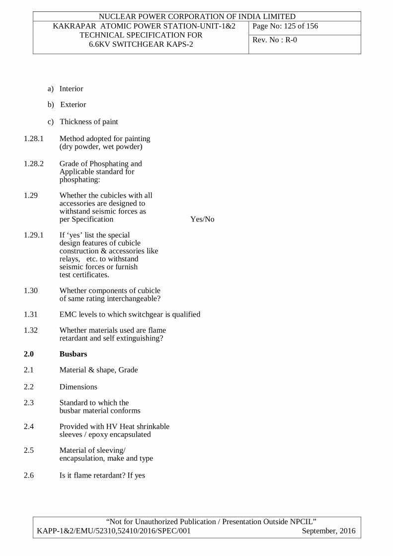
NUCLEAR POWER CORPORATION OF INDIA LIMITED KAKRAPAR ATOMIC POWER STATION-UNIT-1&2
TECHNICAL SPECIFICATION FOR 6.6KV SWITCHGEAR KAPS-2
Page No: 125 of 156
Rev. No : R-0
“Not for Unauthorized Publication / Presentation Outside NPCIL” KAPP-1&2/EMU/52310,52410/2016/SPEC/001 September, 2016
a) Interior b) Exterior c) Thickness of paint
1.28.1 Method adopted for painting (dry powder, wet powder) 1.28.2 Grade of Phosphating and Applicable standard for phosphating: 1.29 Whether the cubicles with all accessories are designed to withstand seismic forces as per Specification Yes/No 1.29.1 If ‘yes’ list the special design features of cubicle construction & accessories like relays, etc. to withstand seismic forces or furnish test certificates. 1.30 Whether components of cubicle
of same rating interchangeable?
1.31 EMC levels to which switchgear is qualified
1.32 Whether materials used are flame retardant and self extinguishing?
2.0 Busbars 2.1 Material & shape, Grade 2.2 Dimensions 2.3 Standard to which the busbar material conforms 2.4 Provided with HV Heat shrinkable sleeves / epoxy encapsulated 2.5 Material of sleeving/ encapsulation, make and type 2.6 Is it flame retardant? If yes
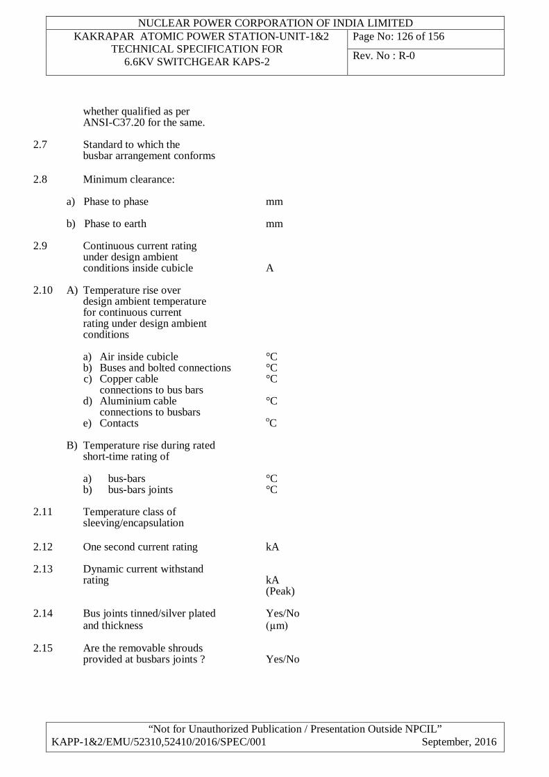
NUCLEAR POWER CORPORATION OF INDIA LIMITED KAKRAPAR ATOMIC POWER STATION-UNIT-1&2
TECHNICAL SPECIFICATION FOR 6.6KV SWITCHGEAR KAPS-2
Page No: 126 of 156
Rev. No : R-0
“Not for Unauthorized Publication / Presentation Outside NPCIL” KAPP-1&2/EMU/52310,52410/2016/SPEC/001 September, 2016
whether qualified as per ANSI-C37.20 for the same. 2.7 Standard to which the busbar arrangement conforms 2.8 Minimum clearance: a) Phase to phase mm b) Phase to earth mm 2.9 Continuous current rating under design ambient conditions inside cubicle A 2.10 A) Temperature rise over design ambient temperature for continuous current rating under design ambient conditions
a) Air inside cubicle °C b) Buses and bolted connections °C c) Copper cable °C connections to bus bars d) Aluminium cable °C connections to busbars e) Contacts oC
B) Temperature rise during rated short-time rating of
a) bus-bars °C b) bus-bars joints °C 2.11 Temperature class of sleeving/encapsulation 2.12 One second current rating kA 2.13 Dynamic current withstand rating kA (Peak) 2.14 Bus joints tinned/silver plated Yes/No and thickness (µm) 2.15 Are the removable shrouds provided at busbars joints ? Yes/No
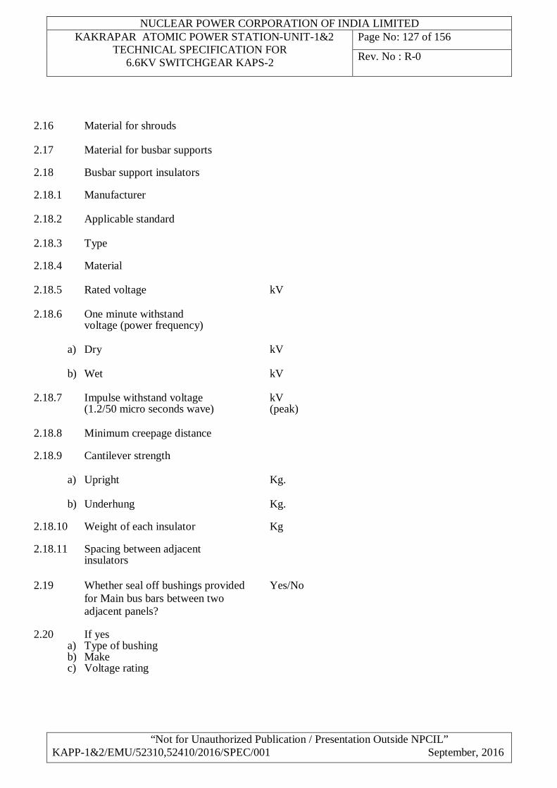
NUCLEAR POWER CORPORATION OF INDIA LIMITED KAKRAPAR ATOMIC POWER STATION-UNIT-1&2
TECHNICAL SPECIFICATION FOR 6.6KV SWITCHGEAR KAPS-2
Page No: 127 of 156
Rev. No : R-0
“Not for Unauthorized Publication / Presentation Outside NPCIL” KAPP-1&2/EMU/52310,52410/2016/SPEC/001 September, 2016
2.16 Material for shrouds 2.17 Material for busbar supports 2.18 Busbar support insulators 2.18.1 Manufacturer 2.18.2 Applicable standard 2.18.3 Type 2.18.4 Material 2.18.5 Rated voltage kV 2.18.6 One minute withstand voltage (power frequency)
a) Dry kV
b) Wet kV 2.18.7 Impulse withstand voltage kV (1.2/50 micro seconds wave) (peak) 2.18.8 Minimum creepage distance 2.18.9 Cantilever strength
a) Upright Kg.
b) Underhung Kg. 2.18.10 Weight of each insulator Kg 2.18.11 Spacing between adjacent insulators 2.19 Whether seal off bushings provided Yes/No for Main bus bars between two adjacent panels? 2.20 If yes
a) Type of bushing b) Make c) Voltage rating
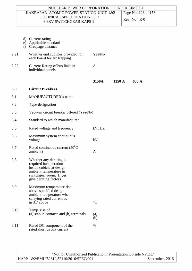
NUCLEAR POWER CORPORATION OF INDIA LIMITED KAKRAPAR ATOMIC POWER STATION-UNIT-1&2
TECHNICAL SPECIFICATION FOR 6.6KV SWITCHGEAR KAPS-2
Page No: 128 of 156
Rev. No : R-0
“Not for Unauthorized Publication / Presentation Outside NPCIL” KAPP-1&2/EMU/52310,52410/2016/SPEC/001 September, 2016
d) Current rating e) Applicable standard f) Creepage distance
2.21 Whether end cubicles provided for Yes/No each board for arc trapping
2.22 Current Rating of bus links in A individual panels
3150A 1250 A 630 A 3.0 Circuit Breakers 3.1 MANUFACTURER’s name 3.2 Type designation 3.3 Vacuum circuit breaker offered (Yes/No) 3.4 Standard to which manufactured 3.5 Rated voltage and frequency kV, Hz. 3.6 Maximum system continuous voltage kV 3.7 Rated continuous current (500C ambient) A 3.8 Whether any derating is required for operation inside cubicle at design ambient temperature in switchgear room. If yes, give derating factors. 3.9 Maximum temperature rise above specified design ambient temperature when carrying rated current as in 3.7 above °C 3.10 Temp. rise of (a) stab in contacts and (b) terminals. (a) (b) 3.11 Rated DC component of the % rated short circuit current
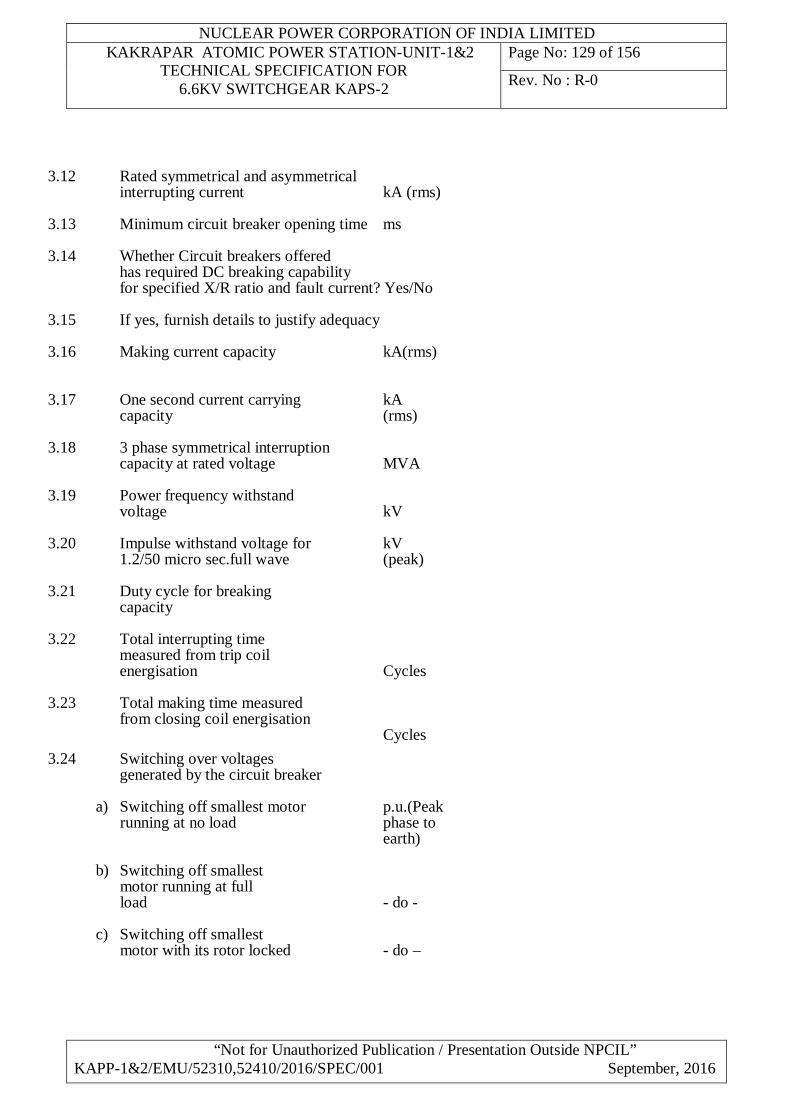
NUCLEAR POWER CORPORATION OF INDIA LIMITED KAKRAPAR ATOMIC POWER STATION-UNIT-1&2
TECHNICAL SPECIFICATION FOR 6.6KV SWITCHGEAR KAPS-2
Page No: 129 of 156
Rev. No : R-0
“Not for Unauthorized Publication / Presentation Outside NPCIL” KAPP-1&2/EMU/52310,52410/2016/SPEC/001 September, 2016
3.12 Rated symmetrical and asymmetrical
interrupting current kA (rms) 3.13 Minimum circuit breaker opening time ms
3.14 Whether Circuit breakers offered has required DC breaking capability
for specified X/R ratio and fault current? Yes/No
3.15 If yes, furnish details to justify adequacy 3.16 Making current capacity kA(rms) 3.17 One second current carrying kA capacity (rms) 3.18 3 phase symmetrical interruption capacity at rated voltage MVA 3.19 Power frequency withstand voltage kV 3.20 Impulse withstand voltage for kV 1.2/50 micro sec.full wave (peak) 3.21 Duty cycle for breaking capacity 3.22 Total interrupting time measured from trip coil energisation Cycles 3.23 Total making time measured from closing coil energisation Cycles 3.24 Switching over voltages generated by the circuit breaker
a) Switching off smallest motor p.u.(Peak running at no load phase to earth) b) Switching off smallest motor running at full load - do - c) Switching off smallest motor with its rotor locked - do –
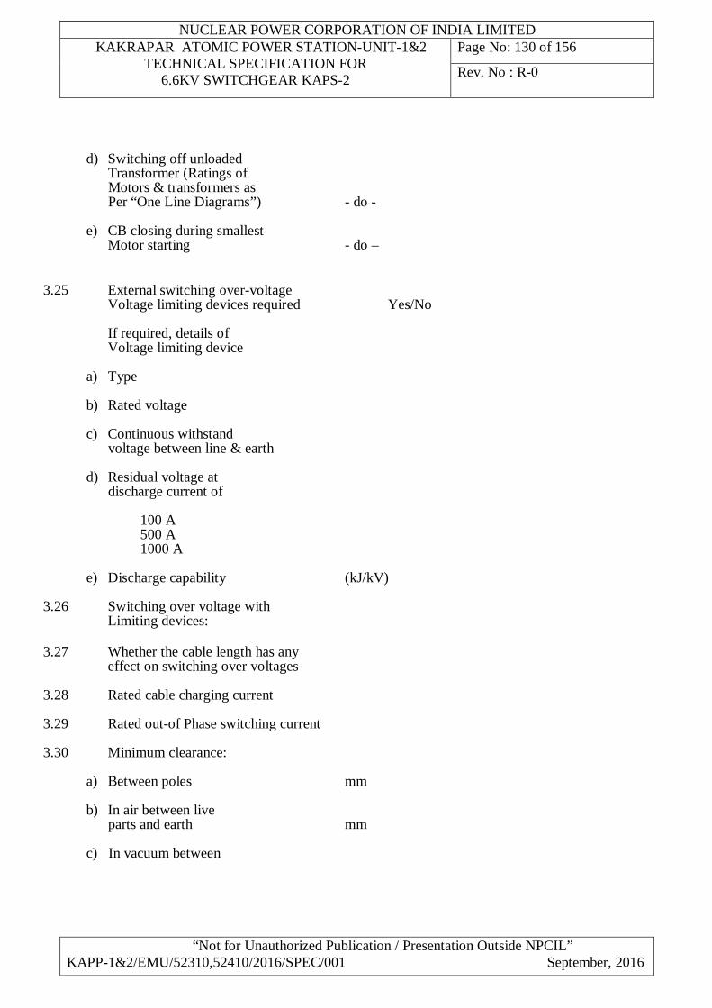
NUCLEAR POWER CORPORATION OF INDIA LIMITED KAKRAPAR ATOMIC POWER STATION-UNIT-1&2
TECHNICAL SPECIFICATION FOR 6.6KV SWITCHGEAR KAPS-2
Page No: 130 of 156
Rev. No : R-0
“Not for Unauthorized Publication / Presentation Outside NPCIL” KAPP-1&2/EMU/52310,52410/2016/SPEC/001 September, 2016
d) Switching off unloaded Transformer (Ratings of Motors & transformers as Per “One Line Diagrams”) - do - e) CB closing during smallest Motor starting - do –
3.25 External switching over-voltage Voltage limiting devices required Yes/No If required, details of Voltage limiting device
a) Type b) Rated voltage c) Continuous withstand voltage between line & earth d) Residual voltage at discharge current of 100 A
500 A 1000 A
e) Discharge capability (kJ/kV) 3.26 Switching over voltage with Limiting devices: 3.27 Whether the cable length has any effect on switching over voltages 3.28 Rated cable charging current 3.29 Rated out-of Phase switching current 3.30 Minimum clearance:
a) Between poles mm b) In air between live parts and earth mm c) In vacuum between
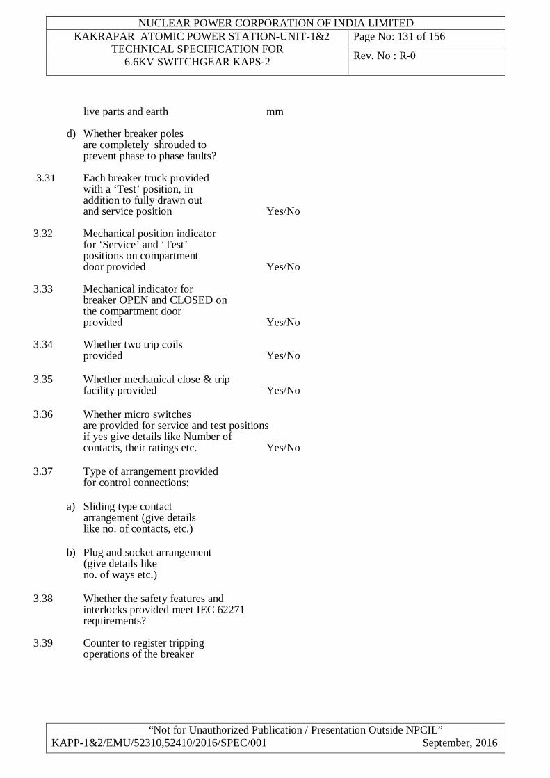
NUCLEAR POWER CORPORATION OF INDIA LIMITED KAKRAPAR ATOMIC POWER STATION-UNIT-1&2
TECHNICAL SPECIFICATION FOR 6.6KV SWITCHGEAR KAPS-2
Page No: 131 of 156
Rev. No : R-0
“Not for Unauthorized Publication / Presentation Outside NPCIL” KAPP-1&2/EMU/52310,52410/2016/SPEC/001 September, 2016
live parts and earth mm
d) Whether breaker poles are completely shrouded to prevent phase to phase faults?
3.31 Each breaker truck provided
with a ‘Test’ position, in addition to fully drawn out and service position Yes/No 3.32 Mechanical position indicator for ‘Service’ and ‘Test’ positions on compartment door provided Yes/No 3.33 Mechanical indicator for breaker OPEN and CLOSED on the compartment door provided Yes/No 3.34 Whether two trip coils provided Yes/No 3.35 Whether mechanical close & trip
facility provided Yes/No 3.36 Whether micro switches are provided for service and test positions if yes give details like Number of contacts, their ratings etc. Yes/No 3.37 Type of arrangement provided for control connections:
a) Sliding type contact arrangement (give details like no. of contacts, etc.) b) Plug and socket arrangement (give details like no. of ways etc.)
3.38 Whether the safety features and
interlocks provided meet IEC 62271 requirements? 3.39 Counter to register tripping operations of the breaker
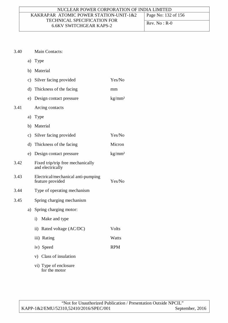
NUCLEAR POWER CORPORATION OF INDIA LIMITED KAKRAPAR ATOMIC POWER STATION-UNIT-1&2
TECHNICAL SPECIFICATION FOR 6.6KV SWITCHGEAR KAPS-2
Page No: 132 of 156
Rev. No : R-0
“Not for Unauthorized Publication / Presentation Outside NPCIL” KAPP-1&2/EMU/52310,52410/2016/SPEC/001 September, 2016
3.40 Main Contacts:
a) Type b) Material c) Silver facing provided Yes/No d) Thickness of the facing mm e) Design contact pressure kg/mm²
3.41 Arcing contacts
a) Type b) Material c) Silver facing provided Yes/No d) Thickness of the facing Micron e) Design contact pressure kg/mm²
3.42 Fixed trip/trip free mechanically and electrically 3.43 Electrical/mechanical anti-pumping feature provided Yes/No 3.44 Type of operating mechanism 3.45 Spring charging mechanism
a) Spring charging motor:
i) Make and type ii) Rated voltage (AC/DC) Volts iii) Rating Watts iv) Speed RPM
v) Class of insulation
vi) Type of enclosure for the motor
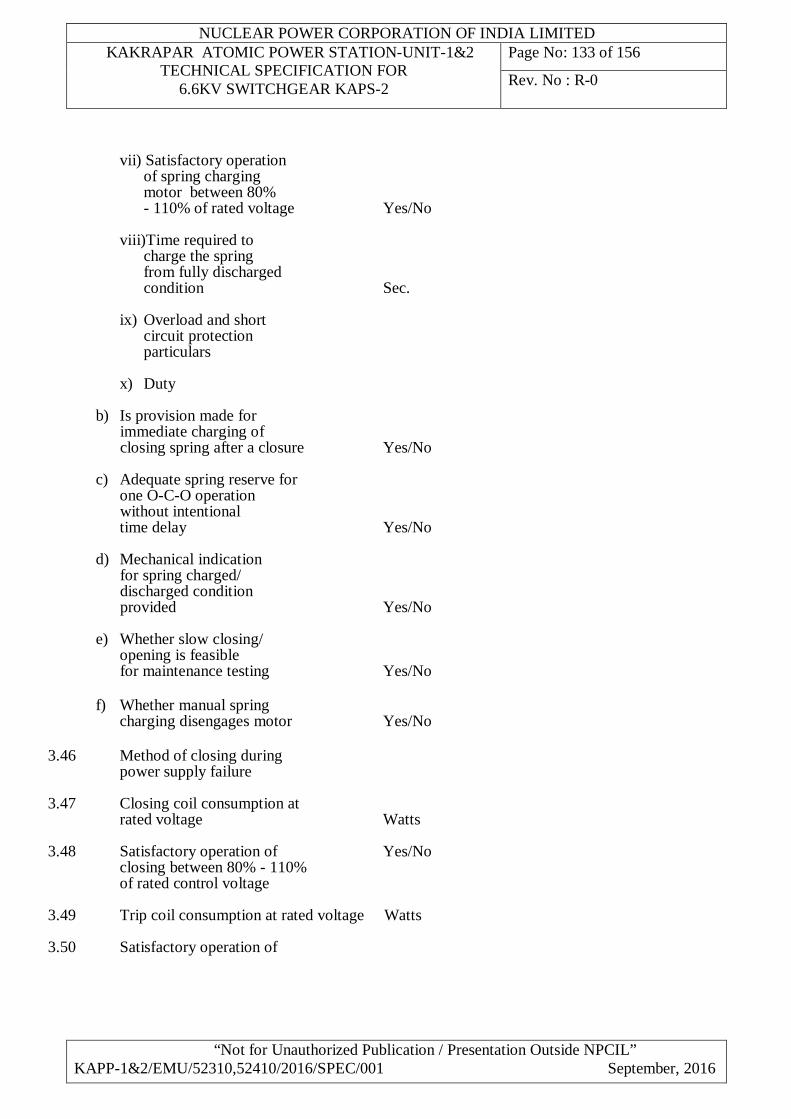
NUCLEAR POWER CORPORATION OF INDIA LIMITED KAKRAPAR ATOMIC POWER STATION-UNIT-1&2
TECHNICAL SPECIFICATION FOR 6.6KV SWITCHGEAR KAPS-2
Page No: 133 of 156
Rev. No : R-0
“Not for Unauthorized Publication / Presentation Outside NPCIL” KAPP-1&2/EMU/52310,52410/2016/SPEC/001 September, 2016
vii) Satisfactory operation of spring charging motor between 80% - 110% of rated voltage Yes/No viii)Time required to charge the spring from fully discharged condition Sec.
ix) Overload and short circuit protection particulars x) Duty
b) Is provision made for immediate charging of closing spring after a closure Yes/No c) Adequate spring reserve for one O-C-O operation without intentional time delay Yes/No d) Mechanical indication for spring charged/ discharged condition provided Yes/No e) Whether slow closing/ opening is feasible for maintenance testing Yes/No f) Whether manual spring charging disengages motor Yes/No
3.46 Method of closing during power supply failure 3.47 Closing coil consumption at rated voltage Watts 3.48 Satisfactory operation of Yes/No closing between 80% - 110% of rated control voltage 3.49 Trip coil consumption at rated voltage Watts 3.50 Satisfactory operation of
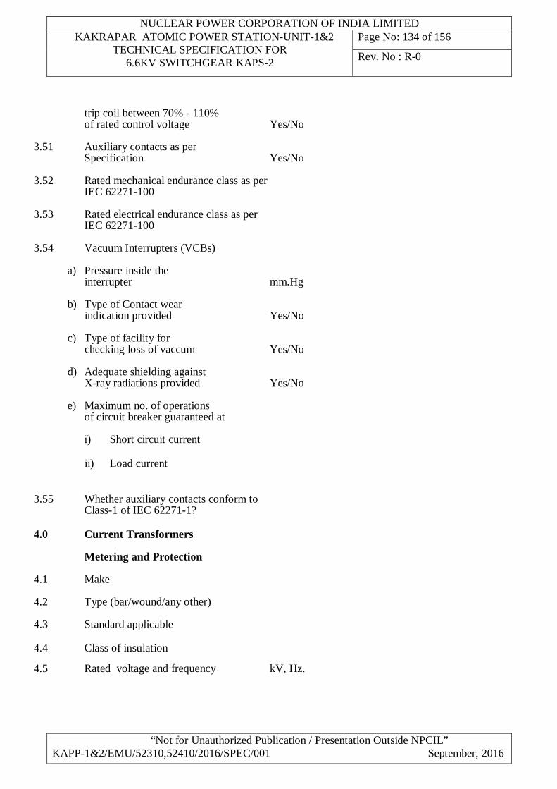
NUCLEAR POWER CORPORATION OF INDIA LIMITED KAKRAPAR ATOMIC POWER STATION-UNIT-1&2
TECHNICAL SPECIFICATION FOR 6.6KV SWITCHGEAR KAPS-2
Page No: 134 of 156
Rev. No : R-0
“Not for Unauthorized Publication / Presentation Outside NPCIL” KAPP-1&2/EMU/52310,52410/2016/SPEC/001 September, 2016
trip coil between 70% - 110% of rated control voltage Yes/No 3.51 Auxiliary contacts as per Specification Yes/No 3.52 Rated mechanical endurance class as per
IEC 62271-100
3.53 Rated electrical endurance class as per IEC 62271-100
3.54 Vacuum Interrupters (VCBs)
a) Pressure inside the interrupter mm.Hg b) Type of Contact wear indication provided Yes/No c) Type of facility for checking loss of vaccum Yes/No d) Adequate shielding against X-ray radiations provided Yes/No e) Maximum no. of operations of circuit breaker guaranteed at i) Short circuit current ii) Load current
3.55 Whether auxiliary contacts conform to Class-1 of IEC 62271-1?
4.0 Current Transformers Metering and Protection 4.1 Make 4.2 Type (bar/wound/any other) 4.3 Standard applicable 4.4 Class of insulation
4.5 Rated voltage and frequency kV, Hz.
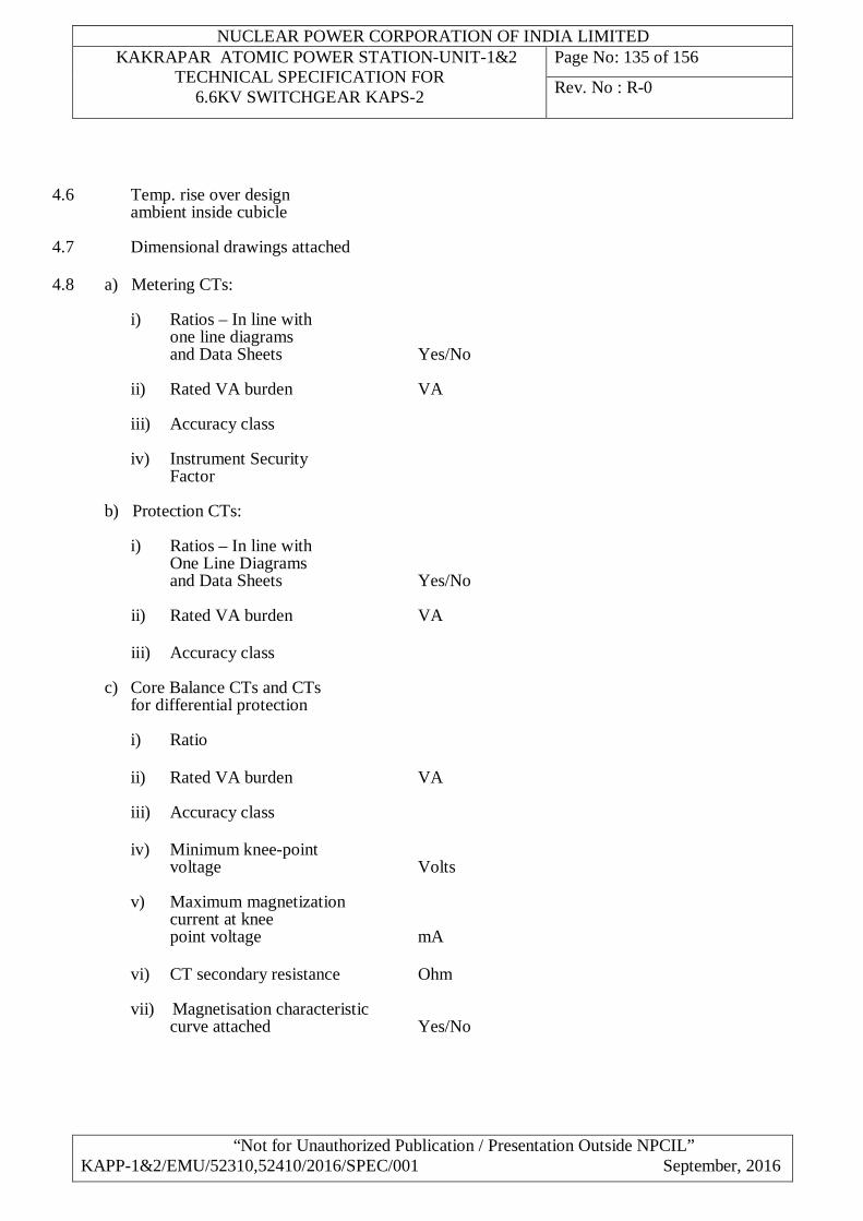
NUCLEAR POWER CORPORATION OF INDIA LIMITED KAKRAPAR ATOMIC POWER STATION-UNIT-1&2
TECHNICAL SPECIFICATION FOR 6.6KV SWITCHGEAR KAPS-2
Page No: 135 of 156
Rev. No : R-0
“Not for Unauthorized Publication / Presentation Outside NPCIL” KAPP-1&2/EMU/52310,52410/2016/SPEC/001 September, 2016
4.6 Temp. rise over design ambient inside cubicle 4.7 Dimensional drawings attached 4.8 a) Metering CTs:
i) Ratios – In line with one line diagrams and Data Sheets Yes/No ii) Rated VA burden VA
iii) Accuracy class
iv) Instrument Security Factor
b) Protection CTs:
i) Ratios – In line with One Line Diagrams and Data Sheets Yes/No ii) Rated VA burden VA iii) Accuracy class c) Core Balance CTs and CTs for differential protection
i) Ratio
ii) Rated VA burden VA
iii) Accuracy class
iv) Minimum knee-point voltage Volts
v) Maximum magnetization current at knee point voltage mA vi) CT secondary resistance Ohm vii) Magnetisation characteristic curve attached Yes/No

NUCLEAR POWER CORPORATION OF INDIA LIMITED KAKRAPAR ATOMIC POWER STATION-UNIT-1&2
TECHNICAL SPECIFICATION FOR 6.6KV SWITCHGEAR KAPS-2
Page No: 136 of 156
Rev. No : R-0
“Not for Unauthorized Publication / Presentation Outside NPCIL” KAPP-1&2/EMU/52310,52410/2016/SPEC/001 September, 2016
4.9 Short time current and kA duration Sec. 4.10 Dynamic rating kA (Peak) 4.11 Power frequency withstand test voltage kV 4.12 1.2/50 micro sec. withstand test voltage kV (Peak) 5.0 Voltage Transformers 5.1 Make 5.2 Type 5.3 Standard Applicable 5.4 Type and class of insulation 5.5 Ratio 5.6 Connections Primary : Secondary : 5.7 Rated output burden (Single Phase) VA 5.8 Rated accuracy 5.9 Power frequency withstand voltage for one minute kV 5.10 1.2/50 micro second impulse kV withstand voltage (peak) 5.11 Rated voltage factor: a) Continuous b) 8 hours 5.12 Temperature rise at specified voltage, frequency and highest rated output C
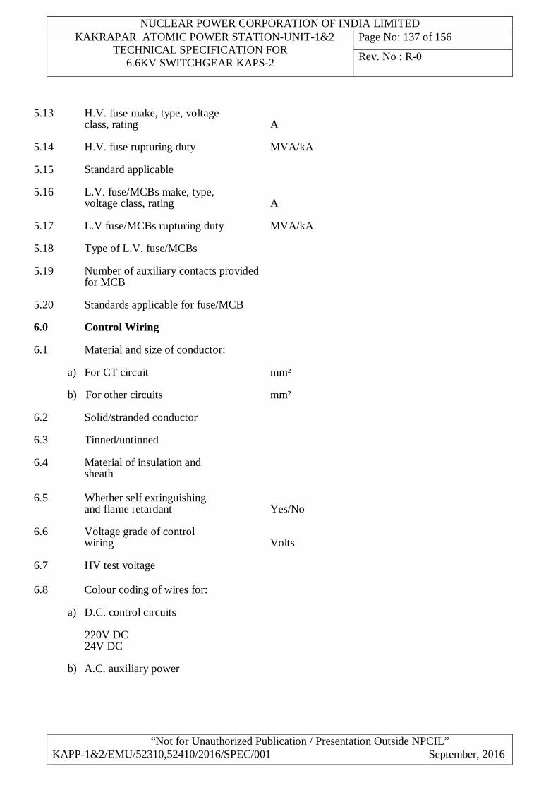
NUCLEAR POWER CORPORATION OF INDIA LIMITED KAKRAPAR ATOMIC POWER STATION-UNIT-1&2
TECHNICAL SPECIFICATION FOR 6.6KV SWITCHGEAR KAPS-2
Page No: 137 of 156
Rev. No : R-0
“Not for Unauthorized Publication / Presentation Outside NPCIL” KAPP-1&2/EMU/52310,52410/2016/SPEC/001 September, 2016
5.13 H.V. fuse make, type, voltage class, rating A 5.14 H.V. fuse rupturing duty MVA/kA 5.15 Standard applicable 5.16 L.V. fuse/MCBs make, type, voltage class, rating A 5.17 L.V fuse/MCBs rupturing duty MVA/kA 5.18 Type of L.V. fuse/MCBs
5.19 Number of auxiliary contacts provided for MCB 5.20 Standards applicable for fuse/MCB 6.0 Control Wiring 6.1 Material and size of conductor:
a) For CT circuit mm² b) For other circuits mm²
6.2 Solid/stranded conductor 6.3 Tinned/untinned 6.4 Material of insulation and sheath 6.5 Whether self extinguishing and flame retardant Yes/No 6.6 Voltage grade of control wiring Volts 6.7 HV test voltage 6.8 Colour coding of wires for:
a) D.C. control circuits 220V DC 24V DC b) A.C. auxiliary power
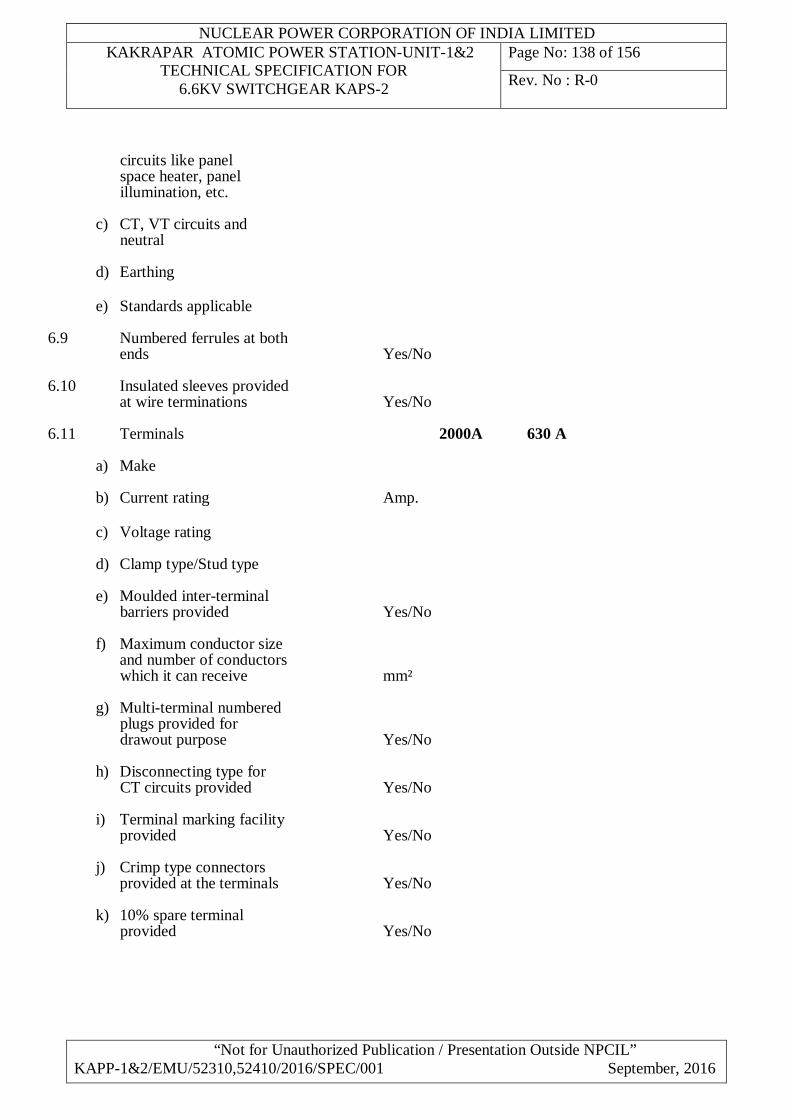
NUCLEAR POWER CORPORATION OF INDIA LIMITED KAKRAPAR ATOMIC POWER STATION-UNIT-1&2
TECHNICAL SPECIFICATION FOR 6.6KV SWITCHGEAR KAPS-2
Page No: 138 of 156
Rev. No : R-0
“Not for Unauthorized Publication / Presentation Outside NPCIL” KAPP-1&2/EMU/52310,52410/2016/SPEC/001 September, 2016
circuits like panel space heater, panel illumination, etc.
c) CT, VT circuits and neutral d) Earthing e) Standards applicable
6.9 Numbered ferrules at both ends Yes/No 6.10 Insulated sleeves provided at wire terminations Yes/No 6.11 Terminals 2000A 630 A
a) Make b) Current rating Amp. c) Voltage rating d) Clamp type/Stud type e) Moulded inter-terminal barriers provided Yes/No f) Maximum conductor size and number of conductors which it can receive mm² g) Multi-terminal numbered plugs provided for drawout purpose Yes/No
h) Disconnecting type for CT circuits provided Yes/No i) Terminal marking facility provided Yes/No j) Crimp type connectors provided at the terminals Yes/No k) 10% spare terminal provided Yes/No
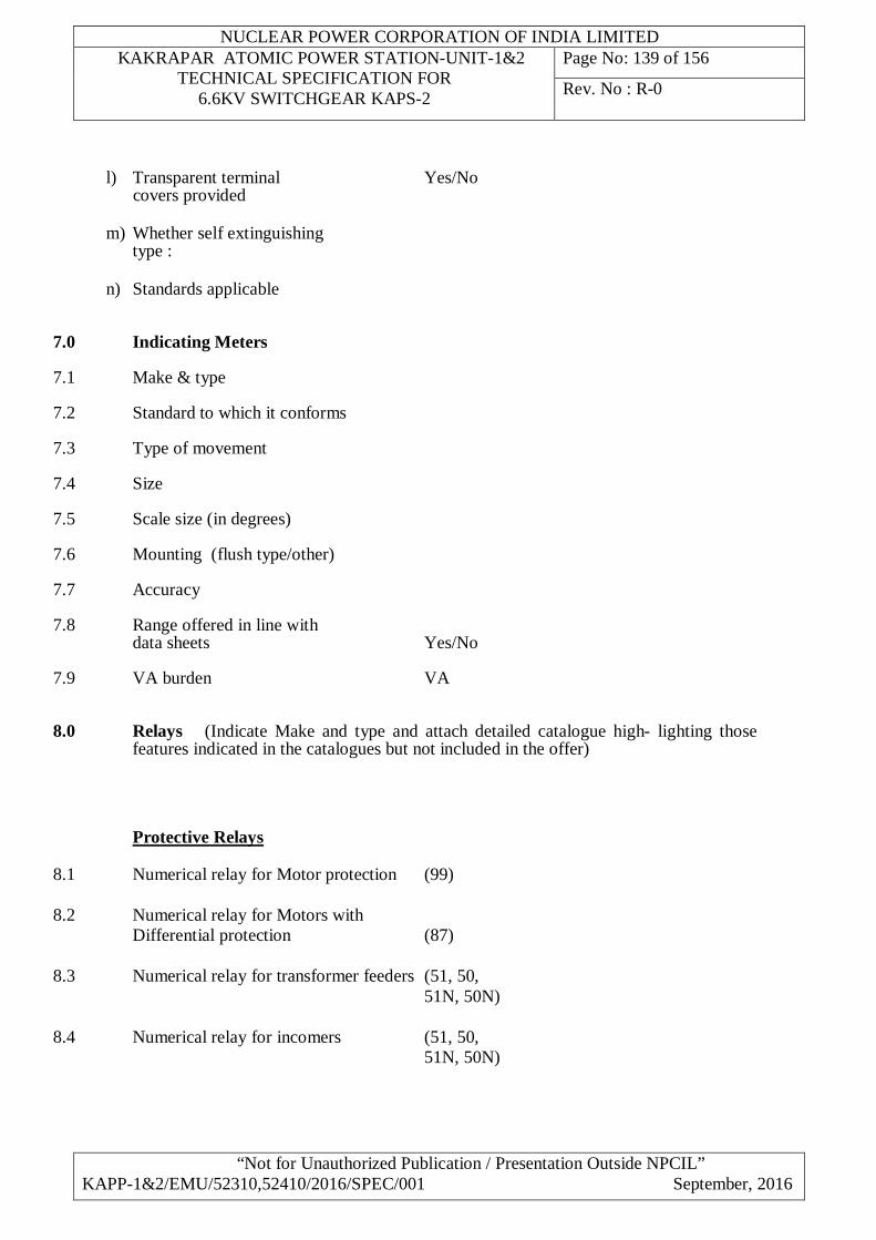
NUCLEAR POWER CORPORATION OF INDIA LIMITED KAKRAPAR ATOMIC POWER STATION-UNIT-1&2
TECHNICAL SPECIFICATION FOR 6.6KV SWITCHGEAR KAPS-2
Page No: 139 of 156
Rev. No : R-0
“Not for Unauthorized Publication / Presentation Outside NPCIL” KAPP-1&2/EMU/52310,52410/2016/SPEC/001 September, 2016
l) Transparent terminal Yes/No covers provided m) Whether self extinguishing type : n) Standards applicable
7.0 Indicating Meters 7.1 Make & type 7.2 Standard to which it conforms 7.3 Type of movement 7.4 Size 7.5 Scale size (in degrees) 7.6 Mounting (flush type/other) 7.7 Accuracy 7.8 Range offered in line with data sheets Yes/No 7.9 VA burden VA 8.0 Relays (Indicate Make and type and attach detailed catalogue high- lighting those
features indicated in the catalogues but not included in the offer)
Protective Relays 8.1 Numerical relay for Motor protection (99) 8.2 Numerical relay for Motors with Differential protection (87) 8.3 Numerical relay for transformer feeders (51, 50, 51N, 50N) 8.4 Numerical relay for incomers (51, 50, 51N, 50N)
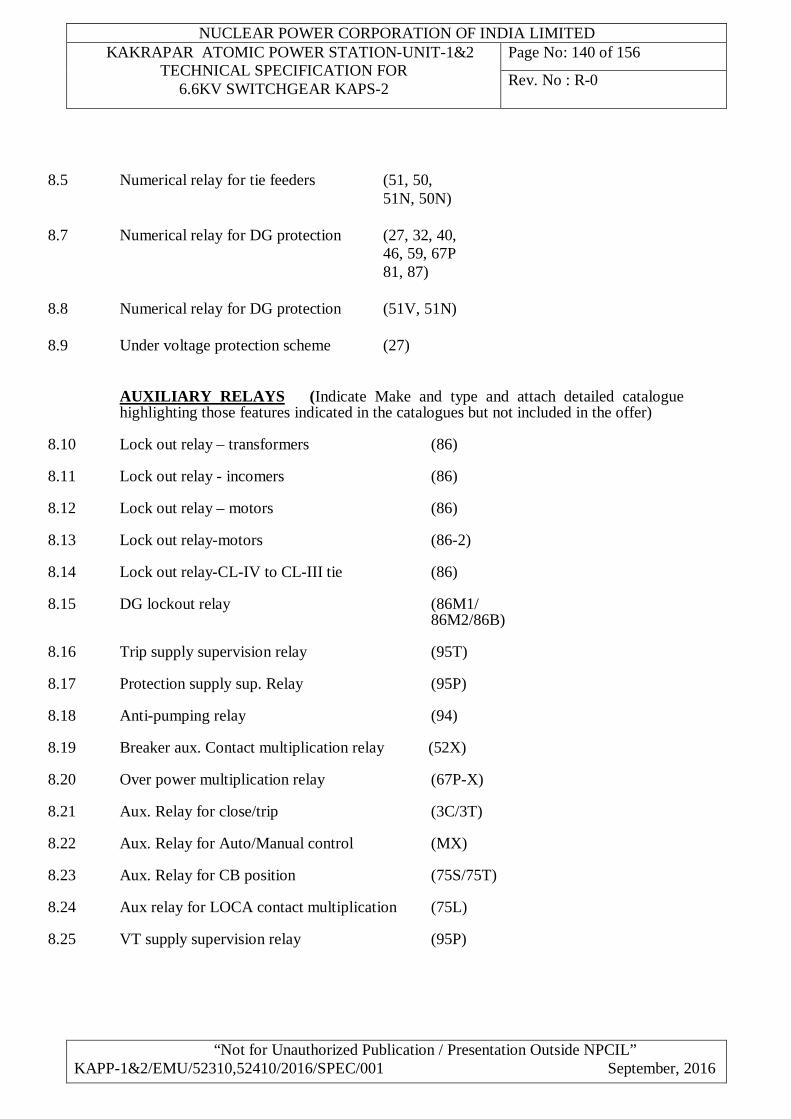
NUCLEAR POWER CORPORATION OF INDIA LIMITED KAKRAPAR ATOMIC POWER STATION-UNIT-1&2
TECHNICAL SPECIFICATION FOR 6.6KV SWITCHGEAR KAPS-2
Page No: 140 of 156
Rev. No : R-0
“Not for Unauthorized Publication / Presentation Outside NPCIL” KAPP-1&2/EMU/52310,52410/2016/SPEC/001 September, 2016
8.5 Numerical relay for tie feeders (51, 50, 51N, 50N) 8.7 Numerical relay for DG protection (27, 32, 40, 46, 59, 67P 81, 87)
8.8 Numerical relay for DG protection (51V, 51N) 8.9 Under voltage protection scheme (27) AUXILIARY RELAYS (Indicate Make and type and attach detailed catalogue
highlighting those features indicated in the catalogues but not included in the offer) 8.10 Lock out relay – transformers (86) 8.11 Lock out relay - incomers (86) 8.12 Lock out relay – motors (86) 8.13 Lock out relay-motors (86-2) 8.14 Lock out relay-CL-IV to CL-III tie (86) 8.15 DG lockout relay (86M1/ 86M2/86B) 8.16 Trip supply supervision relay (95T) 8.17 Protection supply sup. Relay (95P) 8.18 Anti-pumping relay (94) 8.19 Breaker aux. Contact multiplication relay (52X) 8.20 Over power multiplication relay (67P-X) 8.21 Aux. Relay for close/trip (3C/3T) 8.22 Aux. Relay for Auto/Manual control (MX) 8.23 Aux. Relay for CB position (75S/75T) 8.24 Aux relay for LOCA contact multiplication (75L) 8.25 VT supply supervision relay (95P)
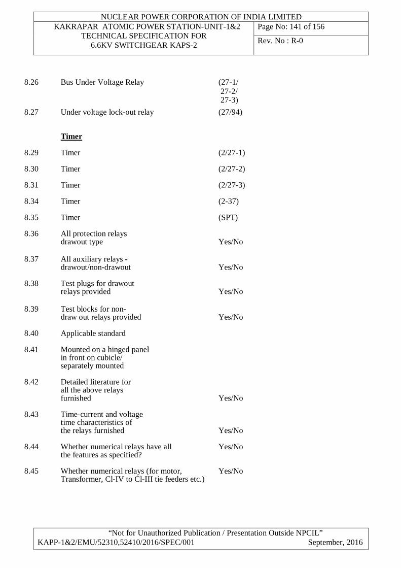
NUCLEAR POWER CORPORATION OF INDIA LIMITED KAKRAPAR ATOMIC POWER STATION-UNIT-1&2
TECHNICAL SPECIFICATION FOR 6.6KV SWITCHGEAR KAPS-2
Page No: 141 of 156
Rev. No : R-0
“Not for Unauthorized Publication / Presentation Outside NPCIL” KAPP-1&2/EMU/52310,52410/2016/SPEC/001 September, 2016
8.26 Bus Under Voltage Relay (27-1/ 27-2/ 27-3) 8.27 Under voltage lock-out relay (27/94) Timer 8.29 Timer (2/27-1) 8.30 Timer (2/27-2) 8.31 Timer (2/27-3) 8.34 Timer (2-37) 8.35 Timer (SPT) 8.36 All protection relays drawout type Yes/No 8.37 All auxiliary relays - drawout/non-drawout Yes/No 8.38 Test plugs for drawout relays provided Yes/No 8.39 Test blocks for non- draw out relays provided Yes/No 8.40 Applicable standard 8.41 Mounted on a hinged panel in front on cubicle/ separately mounted 8.42 Detailed literature for all the above relays furnished Yes/No 8.43 Time-current and voltage time characteristics of the relays furnished Yes/No 8.44 Whether numerical relays have all Yes/No the features as specified?
8.45 Whether numerical relays (for motor, Yes/No Transformer, Cl-IV to Cl-III tie feeders etc.)
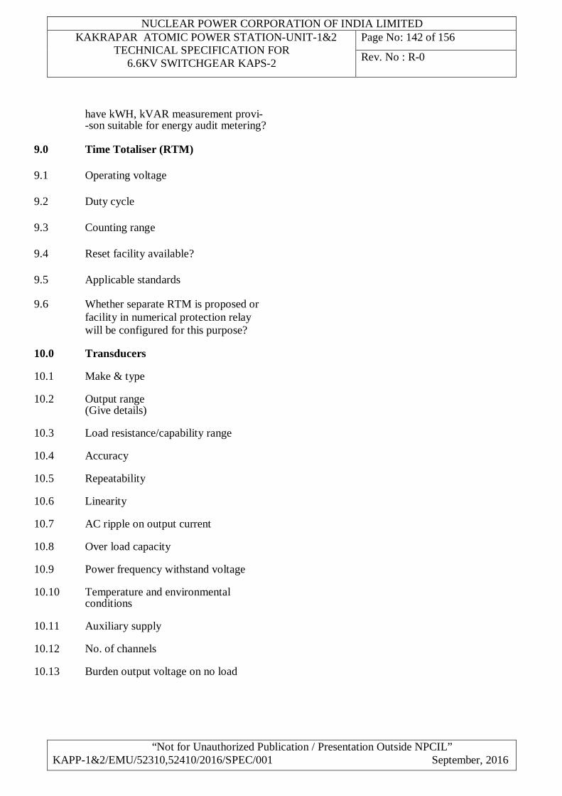
NUCLEAR POWER CORPORATION OF INDIA LIMITED KAKRAPAR ATOMIC POWER STATION-UNIT-1&2
TECHNICAL SPECIFICATION FOR 6.6KV SWITCHGEAR KAPS-2
Page No: 142 of 156
Rev. No : R-0
“Not for Unauthorized Publication / Presentation Outside NPCIL” KAPP-1&2/EMU/52310,52410/2016/SPEC/001 September, 2016
have kWH, kVAR measurement provi- -son suitable for energy audit metering? 9.0 Time Totaliser (RTM) 9.1 Operating voltage 9.2 Duty cycle 9.3 Counting range 9.4 Reset facility available? 9.5 Applicable standards
9.6 Whether separate RTM is proposed or facility in numerical protection relay will be configured for this purpose?
10.0 Transducers
10.1 Make & type 10.2 Output range (Give details) 10.3 Load resistance/capability range 10.4 Accuracy 10.5 Repeatability 10.6 Linearity 10.7 AC ripple on output current 10.8 Over load capacity 10.9 Power frequency withstand voltage 10.10 Temperature and environmental conditions 10.11 Auxiliary supply 10.12 No. of channels 10.13 Burden output voltage on no load
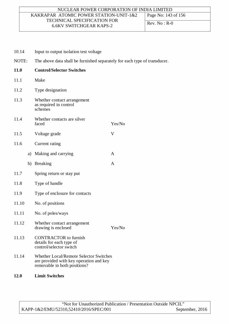
NUCLEAR POWER CORPORATION OF INDIA LIMITED KAKRAPAR ATOMIC POWER STATION-UNIT-1&2
TECHNICAL SPECIFICATION FOR 6.6KV SWITCHGEAR KAPS-2
Page No: 143 of 156
Rev. No : R-0
“Not for Unauthorized Publication / Presentation Outside NPCIL” KAPP-1&2/EMU/52310,52410/2016/SPEC/001 September, 2016
10.14 Input to output isolation test voltage NOTE: The above data shall be furnished separately for each type of transducer. 11.0 Control/Selector Switches 11.1 Make 11.2 Type designation 11.3 Whether contact arrangement as required in control schemes 11.4 Whether contacts are silver faced Yes/No 11.5 Voltage grade V 11.6 Current rating
a) Making and carrying A b) Breaking A
11.7 Spring return or stay put 11.8 Type of handle 11.9 Type of enclosure for contacts 11.10 No. of positions 11.11 No. of poles/ways 11.12 Whether contact arrangement drawing is enclosed Yes/No 11.13 CONTRACTOR to furnish details for each type of control/selector switch
11.14 Whether Local/Remote Selector Switches are provided with key operation and key removable in both positions? 12.0 Limit Switches
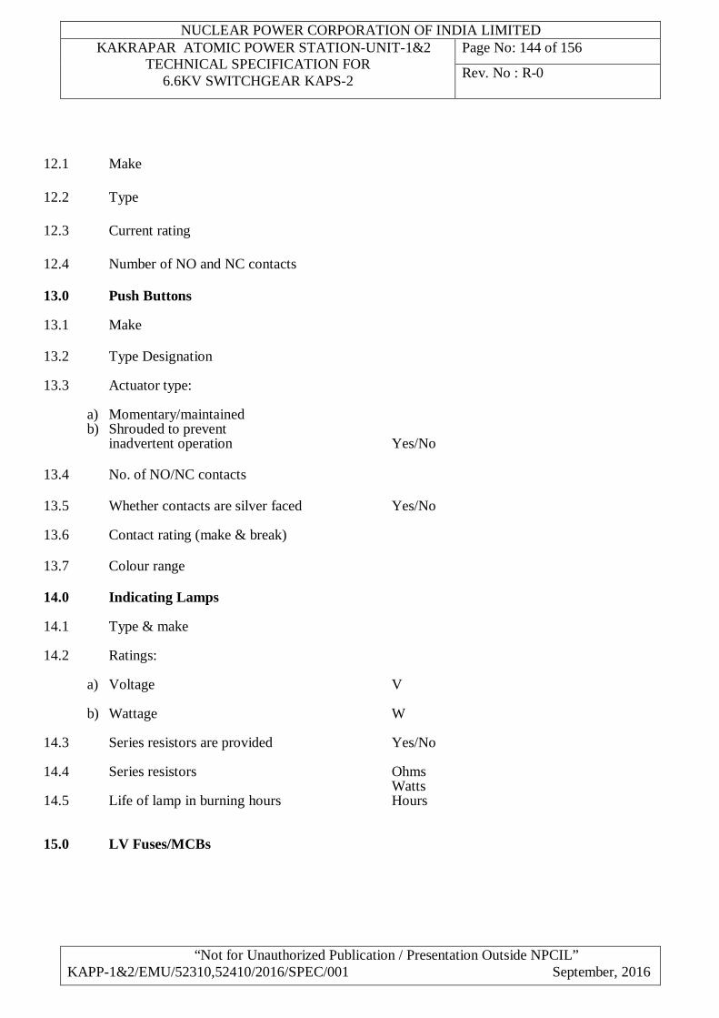
NUCLEAR POWER CORPORATION OF INDIA LIMITED KAKRAPAR ATOMIC POWER STATION-UNIT-1&2
TECHNICAL SPECIFICATION FOR 6.6KV SWITCHGEAR KAPS-2
Page No: 144 of 156
Rev. No : R-0
“Not for Unauthorized Publication / Presentation Outside NPCIL” KAPP-1&2/EMU/52310,52410/2016/SPEC/001 September, 2016
12.1 Make 12.2 Type 12.3 Current rating 12.4 Number of NO and NC contacts 13.0 Push Buttons 13.1 Make 13.2 Type Designation 13.3 Actuator type:
a) Momentary/maintained b) Shrouded to prevent inadvertent operation Yes/No
13.4 No. of NO/NC contacts 13.5 Whether contacts are silver faced Yes/No 13.6 Contact rating (make & break) 13.7 Colour range 14.0 Indicating Lamps 14.1 Type & make 14.2 Ratings:
a) Voltage V b) Wattage W
14.3 Series resistors are provided Yes/No 14.4 Series resistors Ohms Watts 14.5 Life of lamp in burning hours Hours
15.0 LV Fuses/MCBs
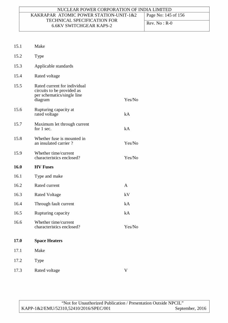
NUCLEAR POWER CORPORATION OF INDIA LIMITED KAKRAPAR ATOMIC POWER STATION-UNIT-1&2
TECHNICAL SPECIFICATION FOR 6.6KV SWITCHGEAR KAPS-2
Page No: 145 of 156
Rev. No : R-0
“Not for Unauthorized Publication / Presentation Outside NPCIL” KAPP-1&2/EMU/52310,52410/2016/SPEC/001 September, 2016
15.1 Make 15.2 Type 15.3 Applicable standards 15.4 Rated voltage 15.5 Rated current for individual circuits to be provided as per schematics/single line diagram Yes/No 15.6 Rupturing capacity at rated voltage kA 15.7 Maximum let through current for 1 sec. kA 15.8 Whether fuse is mounted in an insulated carrier ? Yes/No 15.9 Whether time/current characteristics enclosed? Yes/No 16.0 HV Fuses 16.1 Type and make 16.2 Rated current A 16.3 Rated Voltage kV 16.4 Through fault current kA 16.5 Rupturing capacity kA 16.6 Whether time/current characteristics enclosed? Yes/No 17.0 Space Heaters 17.1 Make 17.2 Type 17.3 Rated voltage V
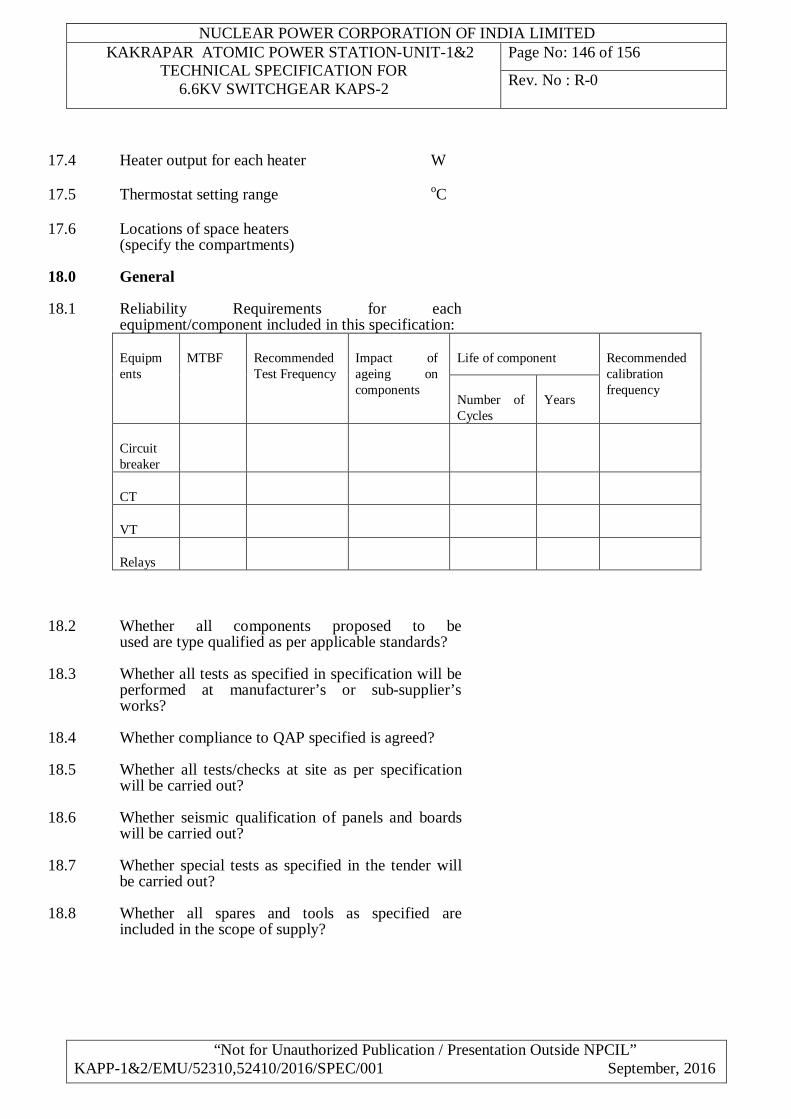
NUCLEAR POWER CORPORATION OF INDIA LIMITED KAKRAPAR ATOMIC POWER STATION-UNIT-1&2
TECHNICAL SPECIFICATION FOR 6.6KV SWITCHGEAR KAPS-2
Page No: 146 of 156
Rev. No : R-0
“Not for Unauthorized Publication / Presentation Outside NPCIL” KAPP-1&2/EMU/52310,52410/2016/SPEC/001 September, 2016
17.4 Heater output for each heater W 17.5 Thermostat setting range oC 17.6 Locations of space heaters (specify the compartments) 18.0 General
18.1 Reliability Requirements for each equipment/component included in this specification:
Equipments
MTBF Recommended Test Frequency
Impact of ageing on components
Life of component Recommended calibration frequency
Number of Cycles
Years
Circuit breaker
CT
VT
Relays
18.2 Whether all components proposed to be used are type qualified as per applicable standards?
18.3 Whether all tests as specified in specification will be performed at manufacturer’s or sub-supplier’s works?
18.4 Whether compliance to QAP specified is agreed?
18.5 Whether all tests/checks at site as per specification will be carried out?
18.6 Whether seismic qualification of panels and boards will be carried out?
18.7 Whether special tests as specified in the tender will be carried out?
18.8 Whether all spares and tools as specified are included in the scope of supply?
NUCLEAR POWER CORPORATION OF INDIA LIMITED KAKRAPAR ATOMIC POWER STATION-UNIT-1&2
TECHNICAL SPECIFICATION FOR 6.6KV SWITCHGEAR KAPS-2
Page No: 147 of 156
Rev. No : R-0
“Not for Unauthorized Publication / Presentation Outside NPCIL” KAPP-1&2/EMU/52310,52410/2016/SPEC/001 September, 2016
18.9 Whether the components/equipment meets the EMC immunity levels specified in IEC 61000-6-5.
18.10 Whether all components are suitable for the ambient conditions specified and qualified in accordance with IEC 60068 standards?
NUCLEAR POWER CORPORATION OF INDIA LIMITED KAKRAPAR ATOMIC POWER STATION-UNIT-1&2
TECHNICAL SPECIFICATION FOR 6.6KV SWITCHGEAR KAPS-2
Page No: 148 of 156
Rev. No : R-0
“Not for Unauthorized Publication / Presentation Outside NPCIL” KAPP-1&2/EMU/52310,52410/2016/SPEC/001 September, 2016
ANNEXURE-D2
SCHEDULE OF PROPOSED EQUIPMENT MANUFACTURER’S GENERAL PARTICULARS
The TENDERER shall furnish here the following general particulars:
1.0 Name of the TENDERER/ MANUFACTURER :
2.0 Address of the MANUFACTURER :
3.0 Telegraphic and telex addresses of the MANUFACTURER :
4.0 Name and designation of the Officer of the
MANUFACTURER / to whom all reference shall be made for expeditious technical co-ordination :
5.0 If equipment is manufactured in foreign collaboration
please furnish necessary details :
6.0 Place of manufacture & assembly : 7.0 Whether service facilities available, if so details :
8.0 Whether sufficient spares are available in stock :
SIGNATURE ------------------ DESIGNATION ------------------ COMPANY ------------------
DATE ------------------ SEAL OF COMPANY
NUCLEAR POWER CORPORATION OF INDIA LIMITED KAKRAPAR ATOMIC POWER STATION-UNIT-1&2
TECHNICAL SPECIFICATION FOR 6.6KV SWITCHGEAR KAPS-2
Page No: 149 of 156
Rev. No : R-0
“Not for Unauthorized Publication / Presentation Outside NPCIL” KAPP-1&2/EMU/52310,52410/2016/SPEC/001 September, 2016
ANNEXURE-D3 SCHEDULE OF MANUFACTURER’S EXPERIENCE
The TENDERER / MANUFACTURER shall furnish here, a list of all similar jobs executed by him to whom a reference may be made by the PURCHASER in case the PURCHASER considers such a reference necessary.
Sr. No.
Description Of work Including Qty. of Items
Work Order Or P.O. No. & Date
Value Of work
Delivery Date as Per P.O.
Actual Date of Delivery
Contact Address Of Purchaser
SIGNATURE _________________ DESIGNATION _________________ COMPANY _________________ DATE _________________ SEAL OF COMPANY

NUCLEAR POWER CORPORATION OF INDIA LIMITED KAKRAPAR ATOMIC POWER STATION-UNIT-1&2
TECHNICAL SPECIFICATION FOR 6.6KV SWITCHGEAR KAPS-2
Page No: 150 of 156
Rev. No : R-0
“Not for Unauthorized Publication / Presentation Outside NPCIL” KAPP-1&2/EMU/52310,52410/2016/SPEC/001 September, 2016
ANNEXURE-D4
DRAWINGS TO BE SUBMITTED ALONGWITH THE TENDER
As part of the proposal the TENDERER shall furnish the following for preliminary study:
a) Detailed literature/catalogues for all equipment being offered under this contract (Switchgear, breakers, numerical relays etc)
b) Arrangement showing proposed arrangement of switchgear panels and switchboards for each bus.
c) Dimensional drawings showing front side and plan views outline dimensions, floor/wall/structure fixing arrangements, earthing terminals and weights.
d) Any other drawings necessary for the correct and complete understanding of the proposal.
NOTE All drawings and data shall be annotated in English. SIGNATURE _________________ DESIGNATION _________________ COMPANY _________________ DATE _________________ SEAL OF COMPANY
NUCLEAR POWER CORPORATION OF INDIA LIMITED KAKRAPAR ATOMIC POWER STATION-UNIT-1&2
TECHNICAL SPECIFICATION FOR 6.6KV SWITCHGEAR KAPS-2
Page No: 151 of 156
Rev. No : R-0
“Not for Unauthorized Publication / Presentation Outside NPCIL” KAPP-1&2/EMU/52310,52410/2016/SPEC/001 September, 2016
ANNEXURE-D5
PERFORMANCE DATA INCLUDING PERFORMANCE CURVES ETC TO BE SUBMITTED ALONG WITH THE TENDER
As a part of technical offer, the Tenderer shall enclose the following data, curves etc. Detailed type test certificates shall not be attached:
1) Tabulation indicating list of type tests performed on the type of equipment offered (Details of tests performed on equipment which are not offered against this tender shall not be indicated), Reference standards, severity levels to which they have been tested, date of testing, place of testing, results.
2) Modifications, if any carried out to the type tested equipment.
3) Tabulation indicating list of type tests carried out on Circuit breakers and numerical relays shall also be indicated on above lines.
SIGNATURE _________________ DESIGNATION _________________ COMPANY _________________ DATE _________________ SEAL OF COMPANY
NUCLEAR POWER CORPORATION OF INDIA LIMITED KAKRAPAR ATOMIC POWER STATION-UNIT-1&2
TECHNICAL SPECIFICATION FOR 6.6KV SWITCHGEAR KAPS-2
Page No: 152 of 156
Rev. No : R-0
“Not for Unauthorized Publication / Presentation Outside NPCIL” KAPP-1&2/EMU/52310,52410/2016/SPEC/001 September, 2016
ANNEXURE-D6
SCHEDULE FOR SUBMISSION OF DRAWINGS, DATA, INSTRUCTION MANUALS, TEST
REPORTS ETC.
1.0 Drawings/Documents
The CONTRACTOR shall furnish all drawings for switchgear within the time indicated, after the issue of letter of intent. The time schedule given below is indicative, however the actual schedule shall be drawn up by the Contractor in consultation with the Purchaser for meeting the delivery schedules.
1.1 Engineering schedule indicating a list of all drawings, documents, data, performance curves, test certificates, manuals, quality assurance plan, etc. to be submitted by the CONTRACTOR together with dates of submission and category of approval i.e. for approval or for reference.
1 month
1.2 General arrangement including layout, plan, front elevation, rear and side elevation, inside views and view showing mounting arrangement
2 months
1.3 Foundation details drawing showing loading details, feeder wise schematic diagrams, wiring diagrams for relays and auto transfer equipment, catalogues and application guides for each component/devices mounted on the panels
3 months
1.4 Itemised Bill of Material listing all devices mounted and also otherwise furnished indicating the make, type, ratings, duty class, applicable standards, MANUFACTURER’S catalogue numbers, quantity and special notes, if any.
3 months
1.5 Quality assurance plan and test procedures 2 months
1.6 Seismic qualification procedure 2 months
1.7 Type test certificates for all type tested equipment which are to be accepted based on type test certificates
2 months
1.8 Feeder wise Wiring diagrams 6 months
1.9 Inter panel wiring details 6 months

NUCLEAR POWER CORPORATION OF INDIA LIMITED KAKRAPAR ATOMIC POWER STATION-UNIT-1&2
TECHNICAL SPECIFICATION FOR 6.6KV SWITCHGEAR KAPS-2
Page No: 153 of 156
Rev. No : R-0
“Not for Unauthorized Publication / Presentation Outside NPCIL” KAPP-1&2/EMU/52310,52410/2016/SPEC/001 September, 2016
1.10 Detailed documents required for engineering review 2 months
1.11 Any other drawings/documents considered necessary
2.0 Test Certificates, Instruction manuals, end documents etc
For all items offered Within 1 month of despatch
SIGNATURE ______________ DESIGNATION______________ COMPANY ______________ DATE ______________ SEAL OF COMPANY
NUCLEAR POWER CORPORATION OF INDIA LIMITED KAKRAPAR ATOMIC POWER STATION-UNIT-1&2
TECHNICAL SPECIFICATION FOR 6.6KV SWITCHGEAR KAPS-2
Page No: 154 of 156
Rev. No : R-0
“Not for Unauthorized Publication / Presentation Outside NPCIL” KAPP-1&2/EMU/52310,52410/2016/SPEC/001 September, 2016
ANNEXURE-D7
SCHEDULE OF PERFORMANCE GUARANTEE
The TENDERER shall furnish performance guarantee in respect of the following:
1.0 All equipment/accessories supplied shall conform to the requirements listed in this specification as well as the requirements of all applicable standards. Not meeting any of these requirements will result in rejection of the equipment/accessories.
SIGNATURE ________________ DESIGNATION ________________ COMPANY ________________ DATE ________________ SEAL OF COMPANY
NUCLEAR POWER CORPORATION OF INDIA LIMITED KAKRAPAR ATOMIC POWER STATION-UNIT-1&2
TECHNICAL SPECIFICATION FOR 6.6KV SWITCHGEAR KAPS-2
Page No: 155 of 156
Rev. No : R-0
“Not for Unauthorized Publication / Presentation Outside NPCIL” KAPP-1&2/EMU/52310,52410/2016/SPEC/001 September, 2016
ANNEXURE-D8
SCHEDULE OF DEVIATIONS FROM TECHNICAL SPECIFICATION All deviations from the technical specification shall be filled in by the
TENDERER clause by clause in this schedule.
Section Clause No Deviation
The TENDERER hereby certifies that the above mentioned are the only
deviations from the technical specification of the enquiry. SIGNATURE ________________ DESIGNATION ________________ COMPANY ________________ DATE ________________ SEAL OF COMPANY
NUCLEAR POWER CORPORATION OF INDIA LIMITED KAKRAPAR ATOMIC POWER STATION-UNIT-1&2
TECHNICAL SPECIFICATION FOR 6.6KV SWITCHGEAR KAPS-2
Page No: 156 of 156
Rev. No : R-0
“Not for Unauthorized Publication / Presentation Outside NPCIL” KAPP-1&2/EMU/52310,52410/2016/SPEC/001 September, 2016
ANNEXURE-D9
SCHEDULE OF PERSONNEL FOR ERECTION, TESTING & COMMISSIONING
The Tenderer shall indicate below the number and category of personnel required for erection, start-up and performance testing and commissioning.
Category Erection Testing & Commissioning Number Number Expatriate Personnel
Local Recruitment
Expatriate Personnel
Local Recruitment
The Tenderer shall also indicate here those section of works or items for which specialist services on site are required. SIGNATURE _____________ DESIGNATION _____________ COMPANY _____________ DATE _____________ SEAL OF COMPANY