NUCLEAR POWER CORPORATION OF INDIA LTD - NPCIL e ...
68
-
Upload
khangminh22 -
Category
Documents
-
view
5 -
download
0
Transcript of NUCLEAR POWER CORPORATION OF INDIA LTD - NPCIL e ...


REVISION CONTROL SHEET
DOCUMENT TYPE : ENGINEERING SPECIFICATION
NO.: PP-E-00061, Rev. No.-0
TITLE: TECHNICAL SPECIFICATION FOR
FIRE ALARM SYSTEM, CCTV & COMMUNICATION SYSTEMS of OESC
REV. NO.
&
DATE
DESCRIPTION
OF
REVISION
REVISED
BY
NAME &
SIGNATURE
CHECKED BY
NAME &
SIGNATURE
REVIEWED BY
NAME &
SIGNATURE
APPROVED BY
NAME &
SIGNATURE

NPCIL PROPRIETARY
This document contains confidential and protected information and that the same are the
intellectual property of Nuclear Power Corporation of India Limited (NPCIL). No part of
this document including notably any editorial elements, verbal and figurative marks and
images included herein, shall be reproduced or transmitted or utilized or published or
stored in any form or by any means now known or hereinafter invented, electronic, digital
or mechanical, including photocopying, scanning, recording or by any information storage
or retrieval system, without prior written permission from NPCIL, by any person or entity.
Unauthorized use, disclosure or copying is strictly prohibited and may constitute unlawful
act and can attract legal action.

NUCLEAR POWER CORPORATION OF INDIA LTD
TECHNICAL SPECIFICATION ON FIRE ALARM SYSTEM, CCTV
& COMMUNICATION SYSTEMS OF OESC
PAGE NO. : 4 of 69
REV. NO. 0
60167/PP-E-00061 MAY-2017
NOT FOR UNAUTHORISED PUBLICATION/PRESENTATION OUTSIDE NPCIL
1.0 SCOPE
An On-site Emergency support Centre (OESC) for site emergency is suitably
located at the site for use of directing emergency handling operations and co-
ordination with off-site emergency response, so that control room staff is not
distracted from performing control room operations.One OESC at each NPPs site
is envisaged to cater to the requirements of all NPP units located at that site. OESC
design is standard for all sites, therefore, this specification is applicable for Indian
PHWRs.
This specification covers the requirements for design, engineering, manufacture,
testing, supply, delivery to site, testing at site, installation, commissioning at site,
training to site personnel, documentation requirement and guarantee of Fire alarm
system, CCTV& communication systems for OESC of Indian PHWRs.
This document serves as the basis for carrying out the following jobs by the
supplier of the Fire alarm system, CCTV& communication systems for OESC:
a) Preparation of drawings like GA, BM, schematic diagrams, wiring diagrams &
nameplate details etc.
b) Procurement of various sensors, cameras, field modules, modules and panels.
c) Procurement of associated peripherals, cables, glands, conduits and its accessories.
d) Mounting and wiring of sensors, cameras, field modules, servers and panels in
consoles.
e) Inspection and tests to meet the requirements of NPCIL set forth in this
specification.
f) Supply of test equipment.
g) Supply of 10 % of PCBs and Modules, components as spares.
h) Laying of various types of cables in rigid G.I conduit in indoor areas & inside
cable trenches and rigid hume pipes in outdoor areas for connecting various types
of sensors with JBs.
i) Installation of sensors/ cameras/ field modules in the field.
j) Termination of cables & glands at JB’s, Panels, sensors and other field modules.
k) Carrying out modifications in the system matching with final design drawings if
any at site.
l) Training to design and site personnel at NPCIL’s site on maintenance and
operational aspects.
m) Installation, commissioning and support after commissioning for at least 2 years.
n) It is expected that vendor shall meet all the requirements given in this
specification. In case of any difference between requirements given in this
specification and the specification of the equipment offered by the bidder, the same
must be clearly indicated in the bid.

NUCLEAR POWER CORPORATION OF INDIA LTD
TECHNICAL SPECIFICATION ON FIRE ALARM SYSTEM, CCTV
& COMMUNICATION SYSTEMS OF OESC
PAGE NO. : 5 of 69
REV. NO. 0
60167/PP-E-00061 MAY-2017
NOT FOR UNAUTHORISED PUBLICATION/PRESENTATION OUTSIDE NPCIL
2.0 CONTENTS
Requirements of this specification are presented under the following section
headings:
Description Section
Definitions, Abbreviations & Notations 3
Applicable standards, specifications and drawings 4
Materials, Process & workmanship 5
General Function and Description 6
Design requirements 7
Inspection, Tests and Reports 8
Indicative Quality Assurance Plans 9
Packing and Shipment 10
Warranty/Guarantee requirements 11
Bill of quantities Annexure-I
Questionnaire to the bidders Annexure-II
Quality Assurance Plan (Sample) Annexure-III
3.0 DEFINITIONS, ABBREVIATIONS & NOTATIONS
3.1 Definitions
Channel (Instrumentation)
An arrangement of interconnected components within a system that initiates output(s).
Common Cause Failure
The failure of a number of devices or components to perform their functions, as a result
of a single specific event or cause.

NUCLEAR POWER CORPORATION OF INDIA LTD
TECHNICAL SPECIFICATION ON FIRE ALARM SYSTEM, CCTV
& COMMUNICATION SYSTEMS OF OESC
PAGE NO. : 6 of 69
REV. NO. 0
60167/PP-E-00061 MAY-2017
NOT FOR UNAUTHORISED PUBLICATION/PRESENTATION OUTSIDE NPCIL
Diversity
The presence of two or more different components or systems to perform an identified
function, where the different components or systems have different attributes, so as to
reduce the possibility of common cause failure.
Fail Safe Design A concept in which, if a system or a component fails, then plant/component/system will
pass into a safe state without the requirement to initiate any operator action.
Functional Isolation
Prevention of influences from the mode of operation or failure of one circuit or system on
another.
Independence
The ability of equipment, channel or a system to perform its function irrespective of the
normal or abnormal functioning of any other equipment, channel or system. Independence
is achieved by functional isolation and physical separation.
Physical Separation
A means of ensuring independence of equipment through separation by geometry
(distance, orientation etc.), appropriate barriers or a combination of both.
Redundancy
Provision of alternative structures, systems, components of identical attributes, so that
anyone can perform the required function, regardless of the state of operation or failure of
the other.
Reliability
The probability that a structure, system, component or facility will perform its intended
(specified) function satisfactorily for a specified period under specified conditions.
Quality Assurance
Planned and systematic actions necessary to provide adequate confidence that an item or
a facility will perform satisfactorily in service as per design specifications.
System Safety Analysis Analysis, of design of computer based systems, consisting of Confirmation of Safety
Function implementation, Failure Analysis, CCF analysis.
Software Quality
The composite characteristics of software that determine the degree to which the software
in use will meet the expectations of the user.
Single Failure
A random failure, which results in the loss of capability of a component to perform its
intended safety function. Consequential failures resulting from a single random
occurrence are considered to be part of the single failure.

NUCLEAR POWER CORPORATION OF INDIA LTD
TECHNICAL SPECIFICATION ON FIRE ALARM SYSTEM, CCTV
& COMMUNICATION SYSTEMS OF OESC
PAGE NO. : 7 of 69
REV. NO. 0
60167/PP-E-00061 MAY-2017
NOT FOR UNAUTHORISED PUBLICATION/PRESENTATION OUTSIDE NPCIL
3.2 Abbreviations The following abbreviations are used in this specification:
AC Alternating Current
AVI Audio Video Interleave
AWG American wire gauge
BOQ Bill Of Quantities
BM Bill of Material
CBS Computer based system
CCTV Closed Circuit Television System
CCF Common cause Failure
CD Compact Disc
C&I Control & Instrumentation
CIF Common Intermediate Format
CMOS Complementary Metal Oxide Semiconductor
CPU Central Processing Unit
CRCA Cold Rolled Close Annealed
CS Communication System
CO Common Office
DC Direct Current
DND Do Not Disturb
DVMS Digital Video Management System
EMI Electro Magnetic Interference.
EMC Electromagnetic Compatibility
EPR Ethylene Propylene Rubber
EPABX Electronic Private Automatic Branch Exchange
ETP Equipment Test Procedure.
FAS Fire alarm system
FO Fibre optic
FPS Frames per second
GA General Arrangement
GI Galvanized Iron
GSM Global System for Mobile communication
GU General Unit.
GUI Graphic User Interface
HD High-definition
HMI Human Machine Interface
HV High Voltage
IEEE Institute Of Electrical And Electronic Engineers
IEC International Electro-technical Commission
I/O Input/ Output
I/P Input
IP Ingress Protection
IPS In-plane switching
IR Insulation Resistance
IS Indian standard

NUCLEAR POWER CORPORATION OF INDIA LTD
TECHNICAL SPECIFICATION ON FIRE ALARM SYSTEM, CCTV
& COMMUNICATION SYSTEMS OF OESC
PAGE NO. : 8 of 69
REV. NO. 0
60167/PP-E-00061 MAY-2017
NOT FOR UNAUTHORISED PUBLICATION/PRESENTATION OUTSIDE NPCIL
ISDN Integrated Services Digital Network
JB Junction Box
LAN Local Area network
LCD Liquid Crystal Display
LED Light Emitting Diode
LIU Light Interfacing Unit
LHLS Low Halogen Low smoke
MCB Miniaturized Circuit Breaker
MCR Main Control Room
MDF Main Distribution Frame
NINS Not Important to Nuclear Safety
NPCIL Nuclear Power Corporation Of India Limited
NPP Nuclear Power Plant
OC Operator Console
OESC On-Site Emergency Support Centre
ONVIF Open Network Video Interface Forum
O&M Operation & Maintenance
OS Operating system
PAL Phase Alternating Line
PC Personal Computer
PCB Printed Circuit Board
PCM Pulse Code Modulation
PO Purchase Order
PTZ Pan tilt and zoom
PTFE Poly Tetra Fluoro Ethylene
PHWR Pressurized Heavy water reactor
PSTN Public Switched Telephone Network
QAP Quality Assurance Plan
RAM Random Access Memory
RAID Redundant Array of Independent Disks
RFI Radio Frequency Interference.
RH Relative Humidity
SAN Storage Area Network
SATA Serial AT Attachment
SWG Standard Wire Gauge
TB Terminal Block
UPS Uninterruptable Power Supply.
UDP User Datagram Protocol
UL Underwriters Laboratories
USI Universal Subject Index
USB Universal Serial Bus
VA Video Analytics
VoIP Voice over Internet Protocol
VGA Video Graphics Adapter
VMD Video Motion Detection
VSAT Very Small Aperture Terminal

NUCLEAR POWER CORPORATION OF INDIA LTD
TECHNICAL SPECIFICATION ON FIRE ALARM SYSTEM, CCTV
& COMMUNICATION SYSTEMS OF OESC
PAGE NO. : 9 of 69
REV. NO. 0
60167/PP-E-00061 MAY-2017
NOT FOR UNAUTHORISED PUBLICATION/PRESENTATION OUTSIDE NPCIL
WAN Wide Area Network
WD Wiring Diagram
4.0 APPLICABLE SPECIFICATIONS AND DRAWINGS
4.1 NPCIL specifications
1. PC-E-709: NPCIL Engineering standard on Instrumentation & control system
grounding.
2. PC-E-234: NPCIL Technical specification for EPR insulated LHLS Sheathed
unarmored cables.
3. PC-E-240:NPCIL Technical specification for EPR Insulated LHLS Sheathed
armoured Control Cables
Note:
In the event that certain requirements of the above specifications conflict with the
requirements of this specification, the latter shall govern.
The standards, specification / data sheets of all major items, including the bought out
items, required for manufacture of the system shall be submitted by the supplier within
one month of the receipt of this specification and on acceptance of the same by the
Purchaser, they shall form part of requirements of this specification.
4.2 Drawings
The methodology of the system will be explained in this document. It is the responsibility
of the supplier to work out the complete design and prepare detailed drawings and submit
the same along with his offer. The drawings pertaining to fabrication, engineering and
installation can be sought by purchaser while evaluating vendor offer. All the drawings &
documents prepared by successful bidder will become the property of the purchaser and
he shall not disclose the details to any person/ agency without the written approval of
purchaser.
5.0 MATERIALS, PROCESSAND WORKMANSHIP
5.1 Materials and Process
Materials, process and standard parts that are required for the fulfillment of this
specification, shall be of very good quality and in accordance with the high grade practice
pertinent to the manufacture of this type of equipment. Suitable care shall be taken in
design, procurement & manufacture of the equipment.
All electrical & electronic components used shall be standard components readily
available in the market from multiple vendors. The components shall be in the list of
current products and recommended by the manufacturer for current design.

NUCLEAR POWER CORPORATION OF INDIA LTD
TECHNICAL SPECIFICATION ON FIRE ALARM SYSTEM, CCTV
& COMMUNICATION SYSTEMS OF OESC
PAGE NO. : 10 of 69
REV. NO. 0
60167/PP-E-00061 MAY-2017
NOT FOR UNAUTHORISED PUBLICATION/PRESENTATION OUTSIDE NPCIL
The supplier shall submit the qualification procedure adopted for the procurement of the
electrical and electronic components used in the system and obtain the approval of the
Purchaser.
5.2 Workmanship
The workmanship shall be in accordance with the high grade practice to ensure
satisfactory operation and service life of 40 years in accordance with the provisions of this
specification. The units mounted in the control panels, shall be modular in design with
adequate test points for easy maintenance and troubleshooting purpose.
5.3 Practices
The components shall be sufficiently de-rated for long life and component arrangement
shall allow proper heat dissipation avoiding hot spots.
Adequate test point shall be provided for trouble shooting purpose. The supplier shall
provide detailed documentation on system software and application software for long term
maintenance of software.
6.0 GENERAL FUNCTION & DESCRIPTION
6.1 General Description
OESC is an important place which provides information for effective and safe handling
of the accident scenario arising out of BDBA in Nuclear Power Plants.
The functions of OESC is to provide the operator with a place from where the status of
essential plant equipment can be monitored. Also the required manual actions can be
initiated safely for maintaining the decay heat removal process. This facility shall be
available for a minimum period of 7 days, during and after the severe accident conditions.
6.2 General Function
Design, engineering, manufacture, inspection, testing at works, installation,
commissioning and testing at site, shall confirm to relevant IS, IEC and IEEE standards.
The performance expected as per the specifications shall be applied for reference ambient
temperature as per latest edition of relevant standard.
a) The Supplier & Manufacturer of equipment shall have experienced staff available for
planning, engineering, commissioning and maintaining the system.
b) Other documents required along with the offer are;

NUCLEAR POWER CORPORATION OF INDIA LTD
TECHNICAL SPECIFICATION ON FIRE ALARM SYSTEM, CCTV
& COMMUNICATION SYSTEMS OF OESC
PAGE NO. : 11 of 69
REV. NO. 0
60167/PP-E-00061 MAY-2017
NOT FOR UNAUTHORISED PUBLICATION/PRESENTATION OUTSIDE NPCIL
i. system write up, system block diagram, technical data sheets, brochures, approval
certificates and installation, commissioning and maintenance guidelines of the
offered system.
ii. A point to point compliance with respect to all the points of this specification
indicating details of deviations if any. In case deviations require modifications
in the bill of quantities (BOQ) given in the Annexure-1, the BOQ shall be
updated with the justification & approval of the Purchaser shall be obtained.
c) The Purchaser or his designated representative shall have the right to conduct quality
surveillance of the proposed equipment on the manufacturer’s and/or his sub-
contractor premises.
d) Drawings dealing with overall dimensions, cutouts, general layouts, controls, field
wiring diagrams etc shall be sent for purchaser’s approval before manufacture.
6.3 General requirements
The equipment shall preferably be procured from reputed manufacturers. The
systems/equipment under this specification are classified as NINS.
6.3.1 Environmental requirements
The sensors & detectors shall be suitable for continuous operation & storage at the ambient
conditions as specified below:
Climatic conditions
Normal Operating condition:
Normal Temperature: 8 to 45 °C, R.H. up to 90% Non-condensing or as specifically
mentioned against an equipment.
Occasional Operating / Storage condition
Storage Temperature: -10 to 55 °C, R.H. up to 95% Non-condensing or as specifically
mentioned against an equipment.
6.3.2 Seismic conditions
The systems mentioned in this specification are classified as non-seismic.
6.3.3 EMI/RFI conditions
The FAS and CCTV cameras shall be EMI/EMC compliant as per relevant IEC /
Equivalent standards.
NUCLEAR POWER CORPORATION OF INDIA LTD
TECHNICAL SPECIFICATION ON FIRE ALARM SYSTEM, CCTV
& COMMUNICATION SYSTEMS OF OESC
PAGE NO. : 12 of 69
REV. NO. 0
60167/PP-E-00061 MAY-2017
NOT FOR UNAUTHORISED PUBLICATION/PRESENTATION OUTSIDE NPCIL
6.3.4 Input Power Supply to the Equipment
1. Single phase, 230 V AC from an UPS is provided to supply all the instrumentation
loads in the OESC, i.e. Server, Laptops, different computer accessories, CCTV
cameras, Communication equipment, Fire alarm system etc.. The UPS is not in the
scope of supply of this specification but in specification no PP-E-00053 .
2. AC to DC Converter required if any for CCTV shall be mounted in the field near the
equipment inside a general unit.
3. Supplier shall make arrangements to test the system functioning under steady state &
transient variations.
4. The systems under this specification shall perform satisfactorily at specified upper and
lower limits of output power supply of the UPS and withstand other transient
parameters of the UPS.
6.3.5 Grounding
Station Grounding
Each instrument or device having an electrical grounding terminal shall be connected thru’
insulated wire to a common ground bus provided in the respective Panel as per NPCIL
Engineering Standard PC-E-709.
Signal Grounding
Zero reference points of signal circuits shall be connected to insulated wire through
shortest length to station grounding system.
6.3.6 Terminations
Terminal blocks shall be of polyamide (nylon 6.6). Fire rating shall be VO as per UL-94.
Current bar shall be copper alloy. Standard terminal strips with sufficient strength to
withstand subsequent maintenance shall be used for termination of field wires. For
interconnection between various sub-units as well as for external field connections, the
terminals shall be properly identified. Terminals to be used for signal and power supply
connections to the instruments/components shall be screw type, suitable for taking
conductor up to 4 sq. mm. The external connections terminals shall be segregated from
the internal inter- unit connection terminals. AC & DC voltage terminals shall be suitably
segregated. The terminals carrying voltage of 120 volts and above shall be provided with
suitable protective covers so as to prevent any danger to personnel due to inadvertent
contact with the same. Cable to cable connectors shall be provided for all the 230 VAC
loads, between the instrument and the terminal block. Wire termination shall be carried
out with care. The correct torque as recommended by the terminal block manufacturer
shall be applied by torque limiting screw drivers, which shall be checked by a suitable
standard at frequent intervals. 10% spare terminals shall be provided in each terminal strip.

NUCLEAR POWER CORPORATION OF INDIA LTD
TECHNICAL SPECIFICATION ON FIRE ALARM SYSTEM, CCTV
& COMMUNICATION SYSTEMS OF OESC
PAGE NO. : 13 of 69
REV. NO. 0
60167/PP-E-00061 MAY-2017
NOT FOR UNAUTHORISED PUBLICATION/PRESENTATION OUTSIDE NPCIL
Wiring of equipment/components:
All connections to instruments or switches where screw posts are provided shall have
crimped lug or equivalent connector fixed on the wires.
The contractors shall connect all instruments/components with sufficient looped slack to
permit the withdrawal of the instrument/component from behind or beneath the console
for maintenance, test or alteration. The wires to any one component/instrument shall be
neatly cleated together.
Wires shall be identified with double termination identity sleeves showing the two
terminations of the wire. Such sleeves should be provided at both ends of the wire.
Identification shall be marked in such a manner that it may be read easily from positions
normally used when the equipment is being serviced.
The color of the sleeves shall be selected as per the main plant guidelines.
Wiring Channels, Cable dressing and Terminal Block supports:
PVC material wiring channels with cover shall be provided in each panel for routing of
wires of cables and Teflon wires. Wiring channels with cover shall be provided such that
all the wires can be routed in these wiring channels only and can be dressed and securely
supported by lacing to form a tight bunch of wires.
Cable Entry:
All cables will enter and leave from bottom of the Panels. The cables will run through the
cable trenches provided on the floor of the OESC Conference room. Cables are generally
twisted pair types. No cable diameters will exceed 50mm. Contractor shall devise to take
the cables thru glands provided at the bottom of the panel and run suitably inside to the
terminal strips.
The supplier shall carry out all inter module wiring inside the Panel and termination
between terminals and units/modules. The supplier shall supply the required cables and
connectors. All cables and connectors required for interconnection shall be done in the
factory. The supplier shall supply mating connectors for all equipment/devices.
6.3.7 Painting
The structural steel and GU’s shall be painted with baked enamel paints or powder coated
according to procedures approved by the Purchaser. The finish color shade shall be as per
light Grey (RAL-7035) from outside and inside.
For painting of GU’s, Supplier shall prepare the detailed painting procedure as per
Annexure-B of PC-E-00053, and get it approved from NPCIL.
6.3.8 Safety Requirements
All Systems listed in this specification are classified as NINS.

NUCLEAR POWER CORPORATION OF INDIA LTD
TECHNICAL SPECIFICATION ON FIRE ALARM SYSTEM, CCTV
& COMMUNICATION SYSTEMS OF OESC
PAGE NO. : 14 of 69
REV. NO. 0
60167/PP-E-00061 MAY-2017
NOT FOR UNAUTHORISED PUBLICATION/PRESENTATION OUTSIDE NPCIL
6.3.9 Security Requirements
Owing to the nature of the business of the purchaser, all software, subsystems / packages
shall have inherent in-built security features including password logging, encryption etc.,
apart from password protection, if any.
A high level of security shall be achieved through the use of passwords. The system shall
have user classification such as super user (administrator), superior and operators etc. The
super user/ administrator shall have access to all menus, and other users to selected menus.
6.3.10 Self-diagnostics Requirements
The system shall have extensive on line & off line self-diagnostic features. Self-diagnostic
shall be provided for modules, cards/bins, CPU modules, Server PC, software modules,
LAN links/devices, sensors and other links.
In case of any fault or disturbance, appropriate messages on server PC display and/or
indications shall be provided. The failure mode of modules shall be well defined .All
failures within systems shall be logged.
6.3.11 On-line Testability Requirements
The on line diagnostics shall continuously monitor the correct functioning of all the field
sensors, modules, cards, healthiness of LAN/loop wiring, etc. and the control panel shall
report all the troubles for quick and easy rectification.
6.3.12 Off-line Testability Requirements
Off line diagnostics shall help in finding the faulty module in the equipment. These shall
also be used for testing any device/ sensor/ module before it is installed.
6.3.13 Hardware Maintainability
The diagnostics shall quickly identify and indicate the hardware associated with fault. The
hardware shall be modular and easily replaceable. Module shall be easily accessible. All
hardware modules and its location shall be identifiable. All PCBs shall be provided with
replaceable jumpers/switch pack so that same can be easily reconfigured.
For easy maintenance the equipment in OESC such as server, network switches, etc. shall
preferably be procured from the same or compatible manufacturer. The OESC sub-units
shall be modular in nature. It shall be possible to identify and replace the faulty module in
the equipment.
6.3.14 Software Maintainability
All the application/embedded software shall be documented and supplied.

NUCLEAR POWER CORPORATION OF INDIA LTD
TECHNICAL SPECIFICATION ON FIRE ALARM SYSTEM, CCTV
& COMMUNICATION SYSTEMS OF OESC
PAGE NO. : 15 of 69
REV. NO. 0
60167/PP-E-00061 MAY-2017
NOT FOR UNAUTHORISED PUBLICATION/PRESENTATION OUTSIDE NPCIL
6.3.15 Physical& Layout Requirements
a) The control panel shall be designed with standard bins/modules to facilitate easy
maintenance and system expansion.
b) The PC’s& monitors of CCTV shall be housed in a console. The supplier shall
ensure all necessary equipment can be housed inside the console, if not it shall be
clearly specified in the quotation. The supply of console is in the scope of this
specification.
c) Console GA drawing shall be submitted to meet the requirements mentioned in
section 7.7.3
6.3.16 Training Requirements
The supplier shall provide training to purchaser's four engineers regarding operation and
maintenance of the system at their works. The boarding/lodging and travel costs of
purchaser’s engineers for the same will be borne by the purchaser. Supplier shall provide
all facilities and documents for training.
For efficient operation and maintenance of System at plant site, training shall also be
imparted to site engineers during testing, installation and commissioning at site on
1) Installation, commissioning operation and maintenance aspects
2) Design aspects, system architecture design of software and hardware.
3) Functional operation of software and hardware.
4) Interpretation of various diagnostics of software& hardware.
5) Trouble shooting
Vendor shall provide training manuals before the start of the training. The training
program shall emphasize on all relevant CBS Human interface.
7.0 DESIGN REQUIREMENTS
The system requirements for OESC shall be as follows:-
I) FIRE ALARM SYSTEM
II) CCTV Surveillance (CCTVS) (IP based)
III) EPABX
IV) SATELLITE TELEPHONE SYSTEM
V) VIDEO CONFERENCING SYSTEM
VI) INTERNET LEASE LINE
Refer Annexure-I for Bill of Quantities.
The details of the sub systems are given below:-

NUCLEAR POWER CORPORATION OF INDIA LTD
TECHNICAL SPECIFICATION ON FIRE ALARM SYSTEM, CCTV
& COMMUNICATION SYSTEMS OF OESC
PAGE NO. : 16 of 69
REV. NO. 0
60167/PP-E-00061 MAY-2017
NOT FOR UNAUTHORISED PUBLICATION/PRESENTATION OUTSIDE NPCIL
7.1 Fire alarm System (FAS)
7.1.1 General
Fire alarm system for Onsite Emergency Support Center (OESC) is meant for fire
annunciation and tripping of ventilation equipment. All the detectors, other equipment and
control and indicating equipment proposed by bidder shall be as per requirements
mentioned in this section.
7.1.2 Description
Fire alarm system (FAS) shall be provided for detecting fire in its incipient stages in the
fire prone areas of the Onsite Emergency Support Center, to give an audio visual
annunciation, to give potential free output relay contacts for tripping of ventilation system
exhaust fans on detection of fire in the specific areas.
The FAS control and indicating equipment shall be wall mounted type and shall be located
in the Decision Support System (DSS) /FA room at the entrance of OESC.
Intelligent Fire Alarm System shall be used. The fire detectors employed shall be
intelligent i.e. these detectors shall have all the necessary firm-ware built in to detect and
annunciate a fire condition. Intelligent detectors are those detectors that have all the
necessary data and software in them to decide the fire condition on their own. Each sensor
in an intelligent system shall have an inbuilt microprocessor with unique software. These
fire detectors shall have the ability to discriminate between transient non-fire conditions
and a genuine fire state. Analog addressable type detectors as compared to intelligent type
do not have the software of fire detection loaded in them. Instead they send the data about
smoke density / temperature as the case may be to the control panel. The control and
indicating equipment analyses this data with the software & threshold set for the detector
to annunciate an alarm/fault indication. Bidders shall clearly understand this
requirement and shall not offer analog addressable detectors as intelligent detectors.
The detection of fire shall be done by means of multi-criteria (optical & thermal only)
detectors configured as optical or thermal only or as combined detector, strategically
located throughout the area to be protected in cross zoning mode. Multi criteria (Smoke
cum heat) detectors shall be of intelligent type. The FAS control and indicating equipment
shall also display the description of the location where fire has been detected. The control
and indicating equipment shall have feature to connect detectors in cross-zone mode
through system software. The cross zoning feature shall also be ensured by having
redundant detectors connected to two different loop cards. It shall be possible to define
any two or more detectors of the panel in cross zone mode for reconfirmation of fire and
actuation of relay contact output for operation of ventilation system fans etc. The output
in such cases shall be actuated only when any two detectors defined in the cross zone go
into alarm. However, the control and indicating equipment shall report all the detectors in
alarm.

NUCLEAR POWER CORPORATION OF INDIA LTD
TECHNICAL SPECIFICATION ON FIRE ALARM SYSTEM, CCTV
& COMMUNICATION SYSTEMS OF OESC
PAGE NO. : 17 of 69
REV. NO. 0
60167/PP-E-00061 MAY-2017
NOT FOR UNAUTHORISED PUBLICATION/PRESENTATION OUTSIDE NPCIL
7.1.3 Fire detectors
It shall be possible to connect the following types of intelligent fire detectors to the fire
alarm control panels:
i. Multi-criteria smoke detectors
ii. Manual call points
General Requirements of Detectors
i) Reverse polarity or fault in the field wiring shall not damage the detector.
Detectors shall have inbuilt short circuit isolator.
ii) The visual (alarm) response of a detector (by an LED) shall be clearly visible from
the outside by a steady/ flashing light of sufficient brightness.
iii) The alarm indication shall be repeatable to a repeat response indicator through a
simple 2-wire connection.
iv) The detector shall be designed for fast and simple cleaning method in lab or on
site without need of specialized tools.
v) The detector shall be suitable for connection to the control and indicating
equipment via a fully supervised two-wire circuit (class B wiring) or a two-wire
loop circuit (class A wiring). Both methods shall be possible.
vi) The detector shall be suitable for wall/ column/ ceiling mounting.
vii) The detectors shall be approved by at least one of reputed organizations such as.
1) VdS - Verband der Sachversicherer, Germany.
2) AFNOR - Association Francaise De Normalisation France.
3) L.P.C.B. - Loss Prevention Council, Great Britain.
The relevant certificates for the same shall be furnished.
viii) Operating voltage for the detectors shall be 12/ 24 V DC nominal.
ix) The operating condition for detectors & accessories are as follows:
Temperature: 5 degree C to 50 degree C
Relative Humidity up to 95% (Non- condensing)
x) In general, single pair, 1.5 sq mm, Copper conductor LHLS sheathed EPR
insulated cable in GI conduit will be used for all inter-detector wiring. The bidder
shall confirm that the system offered would work satisfactorily with the above
cable. Supply of field cables is in the scope of the bidder. The maximum detector
loop length using this cable shall be clearly specified by the bidder in his quotation.
The required quantity of all types of cables, conduits and other accessories shall
also be in the vendor scope.
xi) The detector address setting shall be by means of soft addressing or dip switches
or decade switches, or suitable punched cards.
xii) It shall be possible to install and un-install detectors mounted at a height of 7
meters from the floor with installation tool. Suitable installation tool shall be
supplied.
xiii) The manufacturing date of fire detectors & other field modules shall be less than
two years from the date of dispatch to site. Shelf life shall be specified for each
type of detector.

NUCLEAR POWER CORPORATION OF INDIA LTD
TECHNICAL SPECIFICATION ON FIRE ALARM SYSTEM, CCTV
& COMMUNICATION SYSTEMS OF OESC
PAGE NO. : 18 of 69
REV. NO. 0
60167/PP-E-00061 MAY-2017
NOT FOR UNAUTHORISED PUBLICATION/PRESENTATION OUTSIDE NPCIL
7.1.3.1Multi-criteria Smoke Detectors [S.D. (M)]
1) The detector shall incorporate, at least, two separate sensing elements, a photoelectric
smoke sensing chamber using the optical scatter principle and thermal detection using
a thermistor. Any other sensing element apart from the above if used is not acceptable
to the purchaser. It shall be possible to configure the detector to work in any of the
modes such as only photoelectric type or only thermal type or combined type. If any
one of the sensing elements fails, the control and indicating equipment shall display
this status accordingly.
2) The detector shall be microprocessor controlled intelligent multi-sensor.
3) The detector shall respond quickly to smoke from all combustion materials such as
PVC, teflon, charcoal, wood, cloth, nylon, paper, rubber, acrylic, thermocol, Mylar,
Paints, lubricating oil, insulating oil etc.
7.1.3.2 Manual Call Point [MCP]
1) Manual Call Points (MCP) shall be addressable and comprise of a push button placed
in a suitable metallic enclosure with a glass/ fibre front.
2) Replacement of glass/ fibre cover shall be simple & easy.
3) A built-in alarm indicator lamp shall be provided.
4) Suitable earth stud shall be provided.
5) It shall be suitable for column/wall/pedestal mounting. Suitable mounting accessories
shall be supplied along with the MCP.
6) Terminals provided shall be capable of accepting 1.5mm2 conductor size.
7) It shall be possible to connect the manual call point to the standard 4-wire/ 2 wire
detection line.
7.1.3.3 Plug in Bases
1) Plug in bases shall be compatible with multi-criteria detector.
2) It shall be possible to insert and remove detectors by a single push twist movement.
3) The base shall have locking feature to prevent loosening of detector on its own.
4) Installation & removal of detector located at height (up to 7 m from floor) shall be
possible with the help of detector removal tool, which shall also be supplied.
5) The base shall be equipped with field terminals capable of securing field wire sizes
up-to 1.5mm2.

NUCLEAR POWER CORPORATION OF INDIA LTD
TECHNICAL SPECIFICATION ON FIRE ALARM SYSTEM, CCTV
& COMMUNICATION SYSTEMS OF OESC
PAGE NO. : 19 of 69
REV. NO. 0
60167/PP-E-00061 MAY-2017
NOT FOR UNAUTHORISED PUBLICATION/PRESENTATION OUTSIDE NPCIL
7.1.3.4 Four-Way Mounting Boxes for Bases of detectors:
1) It shall be possible to mount fire detector base on the 4-way mounting box. It shall be
of square type design of size 150x 150 x 60 mm for fire detectors & MCPs.
2) The 4-way mounting box shall be fabricated from cold rolled sheet steel of 16 SWG
and shall be powder coated in post office red colour.
3) The 4-way mounting box shall have provision of knock out holes from four sides for
cable termination.
4) A stud for grounding of cable shield shall be provided on the mounting box.
7.1.3.5 Fixtures for smoke Detectors:
At certain locations, the smoke detectors will be required to be mounted at a height of 1
to 3 meters below the ceiling. For this suitable fixtures are to be fabricated and supplied.
Two types of fixtures (Type A &Type B) are required.
1) Type A fixture shall be made of a 75mm MS Channel /GI pipe of dia 75mm of length
between 1 meter to 3 meter and having a base plate welded at one end of the
channel/pipe. The base plate of approximate size 100mm x 100mm x 6mm. The
fixture is fixed to ceiling by screws through the base-plate. The channel/pipe is
vertical. At the lower end, these is another base plate of size 150mm x 150mm x 6mm
on which a 4 way GI box is to be fixed with screws.
2) Type B fixture shall be same as Type A fixture except that Type B fixture shall be
installed horizontally on the sidewall.
7.1.3 FAS control and indicating equipment
The FAS control and indicating equipment shall have provision to connect to two detector
loops and be configurable for a minimum of 25 zones. Each zone shall provide a minimum
of 4 potential free contacts. This feature may be achieved through loop powered relay
modules interfaced with user output relays to increase the number of contacts &obtain the
desired rating of contact for each zone. The relays/ the associated field modules shall be
at required locations inside a pull box, wired in the detector loop and shall be configurable
from control panel. Provision shall be made to provide alarm indication in FAS control
and indicating equipment regarding failure of these relay modules. Each relay shall
provide four nos. of potential free changeover, output contacts with rating of 2A, 240V
AC and 5A, 24 V DC.
The configuration database of the FAS control and indicating equipment shall be
achievable through the keypad on the control and indicating equipment or through simple
software loaded on to a laptop. This software shall also be supplied. For this the FAS
control and indicating equipment shall have facility to be connect to the laptop. For this
the required number of compatible cards in control and indicating equipment shall be
provided. The bidder shall clearly specify the networking scheme and limitations, if any.

NUCLEAR POWER CORPORATION OF INDIA LTD
TECHNICAL SPECIFICATION ON FIRE ALARM SYSTEM, CCTV
& COMMUNICATION SYSTEMS OF OESC
PAGE NO. : 20 of 69
REV. NO. 0
60167/PP-E-00061 MAY-2017
NOT FOR UNAUTHORISED PUBLICATION/PRESENTATION OUTSIDE NPCIL
One no. of 230 V A.C. power supply feeder from UPS will be provided to the FAS control
panel.
Two potential free relay change-over contacts one each for common fire and common
fault conditions shall be provided in the FAS control panel. These contacts will be used
for window annunciation in the main plant control room located at 1.5Km distance from
OESC. Existing FO Ethernet LAN network between the two will be used for this purpose,
however the vendor shall supply the interface modules which can convert this potential
free relay change over contacts into IP and reconvert back for window annunciation in the
main plant control room. Any other instrument or module necessary for the satisfactory
operation of the same shall be provided by the vendor. The contact rating required for
window annunciation is 0.5A, 48V DC. These contacts shall go back to normal state only
after the initiating event is rectified and reset at the control panel.
The following are the other requirements for FAS control and indicating equipment.
1. The control and indicating equipment shall accept and process inputs from intelligent
type of detectors and field modules or manual call points.
2. The operating condition for control and indicating equipment are as follows:
Temperature: 5 degree C to 50 degree C
Relative Humidity up to 95% (Non- condensing)
3. The control and indicating equipment shall be supplied & equipped with 2
addressable loops.
4. The control and indicating equipment shall be equipped with an LCD display, key
pad , switches and LED indications for MMI.
5. For reliable fire detection the fire detectors in a room shall be connected into two
different loops. These two loops are in turn shall be connected to different loops in
the control and indicating equipment so that loss of one loop will not affect the fire
detection capability for the area.
6. There shall be provision for both Class-A and B type wiring for detector loops.
However, class A wiring shall be adopted for detector looping.
7. All the detection line circuits shall be monitored against open circuit, short circuit
and ground faults. If malfunction occurs in any detection line, the control and
indicating equipment shall indicate a trouble condition for that detection line. In
addition, the following criteria shall also be met:
8. Fault in one detection line shall not affect the functioning of other detection lines.
9. A single open circuit shall not inhibit the detection capability of a detection circuit;
the remaining circuit should still remain functional.
10. A short circuit shall not inhibit the detection capability of a detection circuit.
11. A single Ground fault shall not inhibit the detection capability of a detection line.
12. The control and indicating equipment shall pinpoint the location of troubles/ fault for
easy maintenance.
13. The loop length capabilities for class-A wiring in addressable detectors shall be 2000
meters with a single pair 1.5 mm2 copper conductor. Any limiting factor in terms of
cable length, cable resistance, cable capacitance or any other parameter shall be
clearly specified by the bidder in his quotation.
14. Each loop circuit shall have capacity to handle hundred or more detectors/ interface
modules of all types. However, max no. of detectors/ field modules connected per
loop shall be limited to 60.

NUCLEAR POWER CORPORATION OF INDIA LTD
TECHNICAL SPECIFICATION ON FIRE ALARM SYSTEM, CCTV
& COMMUNICATION SYSTEMS OF OESC
PAGE NO. : 21 of 69
REV. NO. 0
60167/PP-E-00061 MAY-2017
NOT FOR UNAUTHORISED PUBLICATION/PRESENTATION OUTSIDE NPCIL
15. The operating power for the detection devices shall be supplied through the regular
two-wire loop.
16. Each addressable line module shall have its own microprocessor-based circuit,
working independently from the central processor board located in the control panel.
17. The control and indicating equipment shall also maintain a historical log of at least
500 events.
7.1.4 Safe Test Devices
Suitable safe test devices allowing testing of detectors at a height of 7m from floor (with
collapsible type of concentric rods) shall be supplied for all type of detectors.
Detector Removal/Installation Tool
i) Installation & removal of detector located at height shall be possible from a distance
with the help of detector removal tool.
ii) On line detector removal tool by the help of which detectors can be exchanged from
the floor also shall be supplied.
iii) The detector removal tool arm length shall be at least 5meters and the length shall
be achievable by three or four pieces.
7.1.5Approvals
The control and indicating equipment shall be approved by at least one of reputed
organizations such as.
4) VdS - Verband der Sachversicherer, Germany.
5) AFNOR - Association Francaise De Normalisation France.
6) L.P.C.B. - Loss Prevention Council, Great Britain.
The relevant certificates for the same shall be furnished.
7.2 CCTV System
The CCTV System shall be IP based CCTV System.
The objective is to provide high degree of electronic surveillance system and to have
recorded images of all cameras to be stored, at least, for 1 month in the system.
7.2.1 CCTV System shall consist of the following:-
a) Auto dome color cameras, with pan, tilt and zoom facility and fixed focus color
cameras installed at various locations for general surveillance of outdoor areas.
b) Digital Video Management (DVMS) System along with monitors, servers , client
machines and storage for managing, viewing and recording of videos from these
cameras.
7.2.2 Other requirements of CCTV System shall be as follows:-

NUCLEAR POWER CORPORATION OF INDIA LTD
TECHNICAL SPECIFICATION ON FIRE ALARM SYSTEM, CCTV
& COMMUNICATION SYSTEMS OF OESC
PAGE NO. : 22 of 69
REV. NO. 0
60167/PP-E-00061 MAY-2017
NOT FOR UNAUTHORISED PUBLICATION/PRESENTATION OUTSIDE NPCIL
1. It shall be possible to display any camera output on the monitor/ the monitor in the
client PC in OESC and on at the Plant control room. Such operation shall be
performed by the keyboard/mouse connected with PC as well as from a keyboard
connected in system/PC.
2. It shall be possible for operators at OESC and at the Plant control room to select and
control any cameras in a random sequence and view the video on monitor. It shall be
possible for the operator to view the videos of cameras in a predetermined sequence
which shall be programmable at site.
3. The System shall also display the camera identification number, location of the
camera, time and date.
4. The cameras & its accessories such as GUs / mounts etc. which will be used in outdoor
areas shall be capable of withstanding the weather conditions normally associated with
outdoor areas. The cameras or its housings shall not get corroded. Supplier shall
confirm the same.
7.2.3 Digital Video Management (DVMS) System
The capacity of system shall be of 50 cameras. All the cameras shall, be connected on a
common LAN using FO LAN network with layer2/3 network switch.
There shall be at least 1 no. of servers one for recording with one client PC including its
monitor at OESC, and one client PC including its monitor per each twin unit station.
Purchaser may decide to keep the server at a different location. The bidder shall configure
the required amount of servers to meet the functional requirement. The software used in
the DVMS shall be compatible with the CCTV equipment chosen. System shall also
maintain the centralised primary management, configuration and user database. Vendor
may provide additional server for the same if offered system does not allow loading these
functionalities on same server. All the machines used for above functionalities shall be off
the shelf 19” rack mount servers from reputed manufacturers and the proposed solution
shall not require proprietary computer, server and network or storage hardware.
System Components shall typically be:
a) Servers and workstations
b) RAID 5 Storage
c) Software
d) Network switches
1 The DVMS system shall be based on the latest software programming technology
2 DVMS should allow making a graphical representation of the site.
3 Software should allow the changing of cameras configuration etc.
4 The DVMS shall be able to support all cameras at up to 25 frames per second and
1080p resolution while maintaining less than 70% load on the Server for live
viewing.

NUCLEAR POWER CORPORATION OF INDIA LTD
TECHNICAL SPECIFICATION ON FIRE ALARM SYSTEM, CCTV
& COMMUNICATION SYSTEMS OF OESC
PAGE NO. : 23 of 69
REV. NO. 0
60167/PP-E-00061 MAY-2017
NOT FOR UNAUTHORISED PUBLICATION/PRESENTATION OUTSIDE NPCIL
5 The DVMS video storage shall be capable of storing video at 720presolution for a
minimum period of 1 month available for on line access. The recorded video shall
be based on video motion with a predefined selectable pre-alarm and post alarm
period of up to 2 minutes.
6 Storage system shall be of Direct Attached Storage (DAS) systems/ Network
Attached Storage (NAS) systems and/ or Storage Area Network (SAN) Systems.
7 All storage redundancy and mirroring capabilities shall be to perform these
functions.
8 The DVMS shall be able to configure the cameras to transmit in Two H.264streams.
All of these cameras shall allow configuring one at 1080p for live video@ 25FPSand
720p for recording @ 25FPS.
9 Each Camera shall provide independent settings per stream.
10 The DVMS shall be expandable to switch and control minimum 50 cameras in
single/ multiple central configuration management and user database. All the related
software licenses shall be the part of the offered system.
11 The system shall allow the recording, live monitoring, playback of archived video
audio and data simultaneously
12 The DVMS shall provide file export tool to export the native video format with all
video protections (e.g. watermark, encryption) and the ability to play this video on
a standard computer.
13 The native file format video player shall show the status of the video authentication
as available with the original file format.
14 The IP Based DVMS shall provide file export tool for export of single frames of
video in J-PEG and BMP file formats and for export of motion video files in AVI
file format for transport and playback on computers utilizing a Windows
environment.
Server Software
1. Vendor shall consider additional servers for maintaining system administration
database.
2. The DVMS shall be provided with at least 3 concurrent system administration
licenses and 10 client stations so that system administration and viewing can be
distributed depending on the sub division of the surveillance areas.
3. Server shall maintain a catalog of settings for all the client, servers, and IP cameras
in the system.
4. Server software shall enable the client to dynamically create connections between
cameras and workstations and view live or recorded video on the digital monitors
(audio, video, serial ports and digital I/Os)
5. Server software shall provide the client seamless operation of all cameras and
workstations available in the system regardless of the actual connection to different
archive servers.
6. Offered software shall use standard servers for all the processing and shall not need
any proprietary server hardware. System needing such proprietary servers will not
be accepted in any conditions.

NUCLEAR POWER CORPORATION OF INDIA LTD
TECHNICAL SPECIFICATION ON FIRE ALARM SYSTEM, CCTV
& COMMUNICATION SYSTEMS OF OESC
PAGE NO. : 24 of 69
REV. NO. 0
60167/PP-E-00061 MAY-2017
NOT FOR UNAUTHORISED PUBLICATION/PRESENTATION OUTSIDE NPCIL
7. Software shall be open to accept ONVIF IP cameras. Totally closed software which
cannot accept any other makes camera or encoder is not acceptable in any
circumstances.
8. Vendor will be asked to provide the list of compatible makes and models which can
be integrated in the offered system, failing to provide the information the offer may
be rejected.
9. To provide an advanced and reliable system the Server and Client machines shall
have latest version of operating system. Client Software’s shall be capable of
accessing DVMS system.
10. System shall allow to create the reports for a)Alarm Report b)Camera configuration
report c) User logon/ logoff report d) Server health report e) Equipment failure report
f) Incident report etc..
11. Software shall allow creation of camera sequences. It shall be possible to set
different dwell time for each camera within the sequence. It shall also allow sending
the PTZ cameras to specific presets during their turn in sequence. It shall allow same
camera appearing multiple times in the same sequence.
12. Software shall allow taking the backup of the configuration database and restoring
the same if required.
13. Software shall allow easy and user friendly menus for camera configurations.
14. Software shall provide totally configurable user privileges with independent user
rights.
Client Software
1. Client shall consist of the relevant software licenses. All the client licenses shall
work on concurrent basis and shall not be restricted to be used with specific
workstation..
2. Client applications shall provide an authentication mechanism, which verifies the
validity of the user through system directory.
3. Client shall perform the following applications simultaneously without interfering
with any of the Archive Server operations (Recording, Alarms, etc.)
a. Live display of cameras
b. Live display of camera sequences, panoramic camera views
c. Playback of archived video
d. PTZ control
e. Display and control of Maps
f. Alarm management
The above features shall be assignable for each client.
4. Client applications shall support IP Multicast (UDP) and Unicast (UDP) video
streaming as required depending on the network capabilities.
5. Client application shall provide different Video display layouts which shall include
Full screen, Quad, 2x3, 3x3, 3x4, 4x4, etc.
6. Client application shall be able to control the playback with play, pause, forward,
and speed buttons.
7. Client application shall allow operators to add bookmarks with description to live or
recorded clips of video.

NUCLEAR POWER CORPORATION OF INDIA LTD
TECHNICAL SPECIFICATION ON FIRE ALARM SYSTEM, CCTV
& COMMUNICATION SYSTEMS OF OESC
PAGE NO. : 25 of 69
REV. NO. 0
60167/PP-E-00061 MAY-2017
NOT FOR UNAUTHORISED PUBLICATION/PRESENTATION OUTSIDE NPCIL
8. Client application shall provide drag and drop facility for selection of any content
on the tile.
9. Client application shall support Graphical Site Representation (Maps) functionality,
where digital maps are used to represent the physical location of cameras and other
devices throughout facility. It shall allow the selection of any camera for display
from the map
10. Client application shall support the procedure functionality, where procedures can
be triggered to appear during a certain alarm/event and can be used to provide
detailed written or verbal instructions to the operator regarding the actions to be
taken.
11. Client application with Standard scroll mouse shall be able to move the camera by
merely clicking on the extremes of the picture in all directions and zoom function
by scroll button to avoid the use of joystick keyboard but maintain the easiness of
the control.
12. Client application shall provide management and control over the system using a
standard PC mouse, keyboard and be able to control pan-tilt-zoom presets of the
PTZ camera.
13. Software shall provide utility to play multiple exported clips simultaneously. It shall
also provide the ability to play multiple clips in time sync with each other to
understand the sequence of events took place during the emergency situations.
Suggested Hardware
1 Configuration for Server with storage (For Recording): Quantity to be decided by
bidder (minimum-1 No)
The computer server shall be of 19" rack mounting type.
The server shall be of the most recent computer technology.
Intel Xeon based processor, minimum 2.8 GHz, 12M Cache, 1333MHz
OS- Windows Server Latest Edition with SQL database
2 x 160 GB (Dual mirrored) Hard Drive for OS and External RAID5 configured
storage array for video storage.
Dual Integrated 10/100/1000 Ethernet NIC
Dual/Redundant power supply
Standard video display adapter
2. Direct Attached Storage/NAS/ASN
SATA hot-pluggable hard drives of required quantity and capacity to meet
storage requirements.
LED indications for System status, Power, Split mode, Activity, Drive indicator
per drive, fan fault, SAS ports etc.
Configured with RAID5. Support for RAID levels 0, 1, 5
3. Configuration of Server Video management & Database: Quantity to be decided
by bidder (Minimum- 1 No)
The server shall be of 19" rack mounting type.
The server shall be of the most recent computer technology
Intel Xeon based processor, minimum 2.8 GHz, 12M Cache, 1333MHz

NUCLEAR POWER CORPORATION OF INDIA LTD
TECHNICAL SPECIFICATION ON FIRE ALARM SYSTEM, CCTV
& COMMUNICATION SYSTEMS OF OESC
PAGE NO. : 26 of 69
REV. NO. 0
60167/PP-E-00061 MAY-2017
NOT FOR UNAUTHORISED PUBLICATION/PRESENTATION OUTSIDE NPCIL
OS- Windows Server Latest Edition with SQL database
2 x 160 GB (Dual mirrored) Hard Drive for OS and External RAID5 configured
storage array for database.
Dual Network Interface Card - 100/1000 MB
Dual/Redundant power supply
Standard video display adapter
3. Configuration for Client Workstation
The client shall be of the most recent computer technology
Intel Xeon based processor, minimum 2.8 GHz, 8GB DDR4 RAM
WINDOWS Latest Edition operating system
Min. one TB SATA Hard Drive
Network Interface Card - 10/100/1000 MB
Video Card –Graphics Card to support two nos. of multiplexed Monitors
Mandatory requirements for 42" High Resolution LED Display unit composite
Video Input is as follows:
Sl. No. FEATURE REQUIRED PARAMETERS
1 Screen Size 42"diagonal as applicable
2 Resolution(H/V) 1920 X 1080 Pixels
3 Progressive Scan Yes
5 Color System PAL
6 Video In D-Sub 15 pin (female X2)
7 Displayable Colors Max 29 billion equivalent colors for darker part
8 Contrast Ratio Max. 10,000:1
9 Sub Pixel Control Yes
10 Video Noise Reduction Yes
11 HDMI Input 2
12 Composite Video Input AV1/2/3/4 RCA phono type (3 rear, 1 front)
13 S-Video Input AV1/4 Mini DIN 4-pin (1 rear, 1 front)
14 Monitor Out RCA type (1 rear)
15 Power Supply AC 240 V+ 10%, 50/60Hz
Typical configuration for the servers and client workstation along with monitors has
been specified in this section. The vendor shall provide the required computers for
the DVMS client and servers. These computers shall be of the most current state of
the art technology available at the time of supply and as minimum shall be better
than the minimum requirements specified above meeting the technical & functional

NUCLEAR POWER CORPORATION OF INDIA LTD
TECHNICAL SPECIFICATION ON FIRE ALARM SYSTEM, CCTV
& COMMUNICATION SYSTEMS OF OESC
PAGE NO. : 27 of 69
REV. NO. 0
60167/PP-E-00061 MAY-2017
NOT FOR UNAUTHORISED PUBLICATION/PRESENTATION OUTSIDE NPCIL
requirements. However, the configuration shall not be susceptible to single failure
i.e. redundancy shall be provided with bump less transfer in case of failure of one
server.
7.2.4 CCTV Cameras
Requirements for Color IP based High resolution PTZ Speed dome cameras for
Outdoor are as follows:
SL.
No. FEATURE REQUIRED PARAMETERS
1. Type PTZ type Day & Night high speed Camera
2. Environmental IP66 rated and NEMA 4X
3. Approvals UL & CE Listed
4. Imaging Device Progressive Scan based CMOS 1/2.8” or 1/3" Sensor
5. Compression
H.264
The camera should be able to provide at least two,
individually configurable streams in H.264 one at
1080p for live video and 720p for recording
6. Image Frame Rate 1920 × 1080 p at 25 fps
7. Zoom Optical 20X or more Digital 10x or more, motorized
zoom lense.
8. Focus distance/Lens Autofocus auto iris; clear view from min distance 10
meters to max distance 300 meters
9. Resolution 1920 × 1080 p resolution in 25fps
10. Sensitivity Colour 0.3 lux at 30 IRE, B/W 0.01lux at 30 IRE
11. IRIS Auto/Manual
12. Back light control On/Off
13. Signal to Noise Ratio > 50 dB
14. White Balance Auto
15. Color to B/W
conversion
Programmable as per the illumination condition/time.
IR Cut filter
16. Network 10/100 base-T for LAN/WAN
17. ONVIF Should be ONVIF compiled.
18. Pan Movement 0o to 360o Continuous
19. Tilt Movement -15 deg to +90 deg or better

NUCLEAR POWER CORPORATION OF INDIA LTD
TECHNICAL SPECIFICATION ON FIRE ALARM SYSTEM, CCTV
& COMMUNICATION SYSTEMS OF OESC
PAGE NO. : 28 of 69
REV. NO. 0
60167/PP-E-00061 MAY-2017
NOT FOR UNAUTHORISED PUBLICATION/PRESENTATION OUTSIDE NPCIL
20. Preset 64 or more Programmable
21. Power Supply 230V AC
22. Self-temperature
control
Through built in Heater and fans Auto Manual
controlled
23. Operating temperature 0-50oC or better
24. Relative humidity Up to 90% RH (non- condensing)
Other requirements include: Vandal resistant enclosure & bubble capable of mounting
on camera pole & two potential free alarm contacts and one relay out.
Requirements for Color IP based High resolution Fixed Cameras for Outdoor are
as follows:
SL. No. FEATURE REQUIRED PARAMETERS
1 Type Fixed Day &Night Camera
2 Environmental IP66 rated along with housing
3 Approvals UL & CE Listed
4 Self-temperature
control
Through built-in Heater and fans. Auto /Manual
controlled.
5 Imaging Device
Progressive Scan based CMOS 1/2.8” or 1/3"
Sensor
6 Compression
H.264
The camera should be able to provide at least two,
individually configurable streams in H.264 one at
1080p for live video and 720p for recording
7 Image Frame
Rate 1920 × 1080 p resolution in 25fps
8 Focus
distance/Lens
Vari-focal Coverage distance from 5 meter to up to
60 meters.
9 Capability
Mount C/CS type lenses
10 IRIS System Auto/Manual
11 Resolution 1920 × 1080 p resolution in 25fps
12 Min
Illumination
Camera should be able to produce color image <= 0.3
Lux and b/w images <= 0.01 lux or better
13 ONVIF Should be ONVIF compiled.
14 Signal to Noise
Ratio >50dB

NUCLEAR POWER CORPORATION OF INDIA LTD
TECHNICAL SPECIFICATION ON FIRE ALARM SYSTEM, CCTV
& COMMUNICATION SYSTEMS OF OESC
PAGE NO. : 29 of 69
REV. NO. 0
60167/PP-E-00061 MAY-2017
NOT FOR UNAUTHORISED PUBLICATION/PRESENTATION OUTSIDE NPCIL
15 Back light
control On/Off
14 Auto White
Balance Auto
15 Color to B/W
conversion Programmable as per the illumination condition/time.
16 Power Supply 230V AC
17 Network 10/100 base-T for LAN/WAN
18 Operating
temperature 0-50oC or better
20 Relative
humidity Up to 90% RH (non- condensing)
Other requirements include: capable of mounting on camera pole/ wall and at least one
potential free alarm contact. Suitable cooling case shall also be supplied for outdoor
cameras, if required.
Vendor shall clearly specify the lens proposed for fixed cameras. However, they shall be
of vari-focal type with sufficient range to meet functional requirements. Analog cameras
with encoders alone will not be accepted.
Mandatory requirements for Outdoor housing camera lens assembly with heater /
blower / sunshield / 4 PIN 240V AC are as follows:
SL.
No.
FEATURE REQUIRED PARAMETERS
1 Camera Housing IP66, NEMA-4x
2 Rear connector type Compatible for power input and LAN Ethernet
output
3 Operating
temperature
(with fixed lens)
External: -40oC to +50oC
4 Power Supply 230V AC
5 Accessories Heater, blower & sunshield
Cameras shall be suitable for mounting on poles. Required accessories shall be quoted &
supplied.

NUCLEAR POWER CORPORATION OF INDIA LTD
TECHNICAL SPECIFICATION ON FIRE ALARM SYSTEM, CCTV
& COMMUNICATION SYSTEMS OF OESC
PAGE NO. : 30 of 69
REV. NO. 0
60167/PP-E-00061 MAY-2017
NOT FOR UNAUTHORISED PUBLICATION/PRESENTATION OUTSIDE NPCIL
7.3 EPABX
7.3.1 Scope
1. Supply of all the items as per technical specifications and as per bill of materials
indicated in the BOQ
2. Programming of extensions, BSNL trunk lines, GSM trunk group for integrating with
Site’s EPABX’s, Creation of trunk groups for BSNL class of service grouping, PRI
integration with Level DID, Voice mail service, Operator console programming, Class
of service activation for each extension, CLI activation, Name for each extension and
other features activation as indicated in the EAPBX specification
3. Integration of Internal wiring MDF to EPABX MDF with required interface cables
7.3.2 Electronic Private Automatic Branch Exchange (EPABX)
Sr No Description of item Specifications
1. System architecture and
switching Technology
1) PCM/TDM, 2) IP, 3) level
switching, 4)ATM
Any one of the above
2. Equipped capacity
a Analog telephone line ports 60 ports
b Digital telephone line ports 8 ports
c Central Office(CO) line ports
with loop resistance of 1600
ohms
12 ports
d Primary Rate Interface(PRI)
port
1 no
e DISA(Direct Inward System
Access)
2 ports with messaging facility
f Voice messaging Voice mail facility
3. Interface ports for
programming and maintenance
with PC
USB port, RS 232C port
4. External paging ports Two nos.
5. Music on hold Two nos. (1 Internal and 1 external)
6. System features
a Class of service Minimum 8 groups
b Trunk groups Minimum 8 groups
c Extension number digits 1-4
d Conference 3 parties including caller or better
e Mode DTMF
f Calling Line Identification Internal and external calls on extensions
g Call park Required
h Call forwarding Required
i Delayed ringing Required
j Flexible numbering plan Required

NUCLEAR POWER CORPORATION OF INDIA LTD
TECHNICAL SPECIFICATION ON FIRE ALARM SYSTEM, CCTV
& COMMUNICATION SYSTEMS OF OESC
PAGE NO. : 31 of 69
REV. NO. 0
60167/PP-E-00061 MAY-2017
NOT FOR UNAUTHORISED PUBLICATION/PRESENTATION OUTSIDE NPCIL
k Extension lock for external and
internal calls
Required
l Hotline Required
m Echo cancellation Required
n DISA(Direct Inward System
Access)
Required
o Hunting group Required
p Remote extension lock Required
q Abbreviated dialing Required
r Automatic call back on Busy
trunk/bundle/network link
Required
s Automatic call back on
free/busy extension
Required
t Intercept routing Busy, DND, No answer
v Call queuing Required
7. Integration
a Qsig protocol support Seamless integration with other EPABX
which supports QSig
b ISDN compatibility and
features
CLIP, DID, MSN, Call forward, Automatic
ISDN setting on BRI
c E1, PRI and BRI Required
d IP with IP Gateway Seamless integration with other EPABX
which support IP
e CTI(CSTA/TAPI) Computer Telephony integration for PC
console operations
f DECT Compatibility Required
g VOIP Required
9. Telephone support Analog, Digital and IP
10. Power supply
unit(internal/external) with 4
hours battery backup for
EPABX operation and
charging the battery
230 V AC, as per clause no.6.3.4.
11 Connecting cables from
EPABX to MDF as required
Factory built cable with connectors (min
10 m distance between EPABX and MDF)
7.3.3 DSS (Direct Selection system) console and Digital telephone instrument)
The DSS unit will have minimum 60 station selection buttons with indication and shall
have capability to integrate with Digital Key telephone instrument for Direct station
Selection for extensions and CO lines. The button numbers shall be assigned as per
requirement. The unit shall not be powered from external sources and it shall be integrated
with EPABX.

NUCLEAR POWER CORPORATION OF INDIA LTD
TECHNICAL SPECIFICATION ON FIRE ALARM SYSTEM, CCTV
& COMMUNICATION SYSTEMS OF OESC
PAGE NO. : 32 of 69
REV. NO. 0
60167/PP-E-00061 MAY-2017
NOT FOR UNAUTHORISED PUBLICATION/PRESENTATION OUTSIDE NPCIL
The DSS Digital console instrument shall be connected to digital telephone instrument
and the telephone instrument shall have following minimum features.
1. Digital duplex speakerphone
2. 24-Programmable/function Keys
3. 3-Line Back-lit LCD Display and 24 characters
4. Digital duplex speakerphone
5. USB Connection/interface
6. Ringer lamp
7. Ringer Volume switch
8. Soft keys- 4 nos. for features
9. Navigation key – 1 no
10. Add on key module for Direct Selection System (DSS) console
11. Head set socket for operator
12. Bluetooth module interface (option)
13. Personal speed dial – 10 nos.
14. It should have independent buttons for Navigator key (jog dial), Flash, hold, speaker
phone, redial, transfer, intercom, autodial, auto answer, conference DND, pause,
Message, enter, cancel etc.
7.3.4 Digital key telephone instrument
The following are the desired requirements of Digital key telephone instrument
1. LCD display shall be one line x 16 characters for Caller ID, Time and Date.
2. Digital duplex speakerphone hands free with speaker volume control/ hand set
volume control.
3. UP/Down Key
4. Digital XDP port
5. Off hook monitor/announcement
6. Personal Speed Dial-10 nos. and Call Log-10 nos.
7. 8 function keys
8. Ringer Volume
9. It should have independent buttons for Flash, hold, speaker phone, redial, transfer,
intercom, autodial, auto answer, Conference, FWD/DND, Pause and message, etc.
7.3.5 Caller ID Telephone instrument
1. Caller ID display with backlight
2. Incoming/outgoing calls memory
3. Two Way Speakerphone with 2 Level Volume adjustable
4. Both wall mountable and desktop type
5. Redial & Auto redial button
6. Flash button
7. Memory dialing

NUCLEAR POWER CORPORATION OF INDIA LTD
TECHNICAL SPECIFICATION ON FIRE ALARM SYSTEM, CCTV
& COMMUNICATION SYSTEMS OF OESC
PAGE NO. : 33 of 69
REV. NO. 0
60167/PP-E-00061 MAY-2017
NOT FOR UNAUTHORISED PUBLICATION/PRESENTATION OUTSIDE NPCIL
7.3.6 Four channel Interlinking hardware GSM Fixed terminal
GSM FCT units shall be installed and commissioned with a capacity of 4 channels(1 x 4
or 2 x 2) each for interlinking with the EPABX for direct dialing from both the sides. It
shall have features like Dual band operation, Routing of incoming GSM calls on
POTS(FXS) ports, Automatic number translation for flexible numbering plan, Automatic
call distribution for First free & Round robin, Calling control for releasing the port when
the call gets terminated from GSM channel, Support for Caller ID, SLT port with RJ 11
connector, etc. It shall work on 230 V AC, capable of accepting input 240 V AC as per
clause no.6.3.4 through External Adaptor..
7.3.8 Main Distribution Box (MDB) with krone modules
Main distribution box 150+150 pair shall be fabricated out of 16 gauge CRCA sheet steel
and it should be powder coated. The MDF box shall house with 100 pair SS frames- 1 nos
and 10 pair Krone disconnection type (KRONE-LSA-PLUS) modules- 30 nos.
Krone terminal connectors shall be connection type krone make only. The telephone
cables, jumper/drop wires are to be terminated at these krone terminals using standard
insertion krone tools as per manufacturer’s recommendations. All necessary accessories
shall be provided for these connectors. This box shall have a detachable front cover or
door with hinges with flat gasket. It shall have self-locking facility. It shall have provision
to install on the wall with knockouts for routing telephone cables.
7.4 Portable hand held satellite telephone systems
Portable hand held satellite telephone systems provide an independent communication
system in addition existing communication channels between Headquarters and OESC.
These systems shall provide high reliability and independent communication by utilizing
satellite bandwidth.
7.4.1 Scope
(i) Supply
(ii) Installation
(iii) Commissioning
(iv) Arranging bandwidth, licenses for satellite communication as necessary
(v) Training.
System interconnectivity:
Any Terminal to any Terminal
Any Terminal to any lines in any PSTN
PSTN to any Terminal
NUCLEAR POWER CORPORATION OF INDIA LTD
TECHNICAL SPECIFICATION ON FIRE ALARM SYSTEM, CCTV
& COMMUNICATION SYSTEMS OF OESC
PAGE NO. : 34 of 69
REV. NO. 0
60167/PP-E-00061 MAY-2017
NOT FOR UNAUTHORISED PUBLICATION/PRESENTATION OUTSIDE NPCIL
7.4.2 Portable hand held satellite telephone system
Sr.
No.
Description of parameter Specifications
1 Voice communication Two way
2 Integration with EPABX With POTS port or Central office
(CO) line
3
Connectivity Any Terminal to any Terminal
Any Terminal to any lines in any
PSTN
PSTN to any Terminal
4 Detachable Antenna Optional
5 Transmit frequency band 2670-2690MHz (typical)
6 Receive frequency band 2560-2590MHz (typical)
7 Antenna Gain 2.5 dBi
8 Antenna beam width ± 45 deg
9 EIRP 0dBW
10 G/T -25dB/K minimum
11 Harmonics Lower than -40dB
12 Channel access scheme
Forward signaling scheme
Return signaling scheme
SCPC-DAMA
TDM
ALOHA
13 Modulation QPSK
14 Channel transmission rate 2.7 Kbps with voice compression
rate at 2.4 Kbps
15 Error correction
Rate-1/2 (Convolution coding)
16 Scrambler Polynomial
17 Power supply Battery operated with
charging facility with 230 V
AC, as per clause no.6.3.4
18 Power consumption
Talk time
Standby time
: 2hrs
: 12 hrs
19 Environment conditions:
Operating temperature
Humidity
0º to +50º C
95% at 40º C, non-condensing
20 Size
< 1.3 Kg

NUCLEAR POWER CORPORATION OF INDIA LTD
TECHNICAL SPECIFICATION ON FIRE ALARM SYSTEM, CCTV
& COMMUNICATION SYSTEMS OF OESC
PAGE NO. : 35 of 69
REV. NO. 0
60167/PP-E-00061 MAY-2017
NOT FOR UNAUTHORISED PUBLICATION/PRESENTATION OUTSIDE NPCIL
7.5 IP and ISDN-based Full HD Video Conferencing System
7.5.1 Scope
This part covers Supply, Installation and Commissioning of and Full HD Video
Conferencing (VC) System at OESC which will be connected to NPCIL’s various
sites through VSAT network, 10 Mbps MPLS Leased Lines network and Internet
leased Lines. The supplier shall supply the equipment including installation and
commissioning the equipment with the technical specifications given in this
specification.
7.5.2 Network Topology and requirement
1. NPCIL is having its headquarters at Anushakti Nagar, Mumbai and has its sites at
11 locations across the country. Presently, NPCIL is having a VSAT network
operating on INSAT-3C in extended C-band with mesh connect topology and 2
Mbps Leased Line network from BSNL.
2. Apart from normal Video Conferencing, NPCIL has a requirement for sharing of
MS-Office applications like MS-Word, MS-Power Point Presentations, MS-Excel,
etc during video calls simultaneously. PowerPoint Presentation shall be operable
from Touch Panel.
3. NPCIL has Full HD Video Conferencing of Make: Polycom, HDX7000 at 11 sites
and HDX8000 with Eagle Eye Director (1 no) systems with multi party capability.
The bidder shall propose MCU for full compatibility and interoperability with the
above systems. Also it shall integrate with other VC manufacturer’s equipment
seamlessly.
7.5.3 General requirements
1. All equipment shall operate on 230 V AC, as per clause no.6.3.4.
2. The equipment shall operate satisfactorily at Operating Temperature between10°
to 40° Centigrade.
3. All the equipment shall support English language.
4. The solution should be hardware-based. Software-based solutions are not
acceptable.
7.5.4 Video Conferencing Unit
1. Video Conferencing should be equipped with IP - 4 Mbps connectivity and shall
establish VC for 4 (Four) or above parties including the host with continuous
presence of all parties. It shall have option for up-gradation for 2 Mbps PRI or 512
Kbps BRI in future.
2. Protection against network interruptions in point-to-point and multi-point calls
with automatic down-speeding and Packet loss recovery technology
3. The system shall be supplied with HD camera of 1080p

NUCLEAR POWER CORPORATION OF INDIA LTD
TECHNICAL SPECIFICATION ON FIRE ALARM SYSTEM, CCTV
& COMMUNICATION SYSTEMS OF OESC
PAGE NO. : 36 of 69
REV. NO. 0
60167/PP-E-00061 MAY-2017
NOT FOR UNAUTHORISED PUBLICATION/PRESENTATION OUTSIDE NPCIL
4. Real presence touch: Sleek Touch Control Panel of colour Display size of IPS
LCD panel 10.1” with LED backlighting or above: Touch Control Panel should
work as a graphical interface for initiating Video Conferences, Capacitive type
touch screen, Support for Power Over Ethernet (PoE), Highly intuitive on-screen
menu for dialling, directory, camera controls, content sharing and administrative
functions with integrated with the Codec. Resolution shall be 1280 x 800. It shall
have mechanical locking arrangement. Aspect ratio shall be 16 x 10. Viewing
angle shall be better than 175º. It shall have self-positioning angle for 30º and 65º.
5. It should have dual monitor support to simultaneously display full screen video
and presentations.
6. Cameras should be Full HD 1920x1080p with 12x optical zoom and Auto Focus
as per specifications given in the table below
7. It should have built-in capability for Video, Voice and sharing of MS-Office
applications like MS-Word, MS-PowerPoint presentations, MS-Excel etc. with
desktop / laptop computer integration during video calls simultaneously. This will
ensure easy collaboration of data during audio and video conference
8. VC Codec, Cameras, Touch panel and Microphones should be from same
manufacturer.
Elaborated specifications as detailed in the following table are required.
Table-1
Sr.
No. Description Requirements
I CODEC
1. System capacity (equipped) and
type 4 party (3 remote + 1 host) or above Video
conferencing
Multi party license
Rack mountable
Full HD codec
1-year firmware update support required
2. Video Standards H.261, H.263, H.264,H.264 High Profile
Support for people + content using standards
based H.239
3. Inputs (Video/Audio/Data)
Video
1xHD input for connecting main HD camera
1x HDMI 1.3
1 x VGA
Audio
Microphone input port (suitable for 4 Mic
arrays)

NUCLEAR POWER CORPORATION OF INDIA LTD
TECHNICAL SPECIFICATION ON FIRE ALARM SYSTEM, CCTV
& COMMUNICATION SYSTEMS OF OESC
PAGE NO. : 37 of 69
REV. NO. 0
60167/PP-E-00061 MAY-2017
NOT FOR UNAUTHORISED PUBLICATION/PRESENTATION OUTSIDE NPCIL
1x HDCI
1X HDMI
1x 3.5mm stereo line in
4. Outputs (Video/Audio) Video
2 x HDMI 1.3
Audio
1xHDMI
1x 3.5mm stereo line out
5 Bandwidth Usage Point-to-Point @ 6Mbps
Total bandwidth supported should be 6 Mbps
It should give Standard Definition for
Multiparty call.
6 Network Interface
10Mbps /100Mbps /1 Gbps auto NIC (RJ-45)
H.323 at 6 Mbps
Lost packet recovery
7 Camera
½.33" CMOS, 1920x1080 (1080p)
12x optical zoom,
Auto Focus
Up to 85 degree or better
Up to 36 degree or better
Pan should be +100 to -100 degrees
Must have tilt range of +20 to -30 degrees
Min Illumination : 50 Lux
Focal length – f=3.76 – 37.6 mm
8 Video Resolution HD720p 60 from 832 kbps, HD1080p 30 from
1024 kbps, HD1080p 60 from 1740 kbps.
4SIF/CIF 30, 4SIF/CIF 60, SIF, CIF, QCIF
9 Content Resolution
Input: HD1080p,WSXGA, SXGA, HD720p,
XGA, SVGA
Output: WSXGA, SXGA, HD and XGA
10 Audio Standard
Stereo sound
22kHz crystal clear audio
14 kHz bandwidth with G.722.1 Annex C
7 kHz bandwidth with G.722, G.722.1
3.4 kHz bandwidth with G.711, G.728,
G.729A
Automatic Gain Control, Automatic Noise
Suppression
Keyboard noise reduction
Audio Error Concealment
Instant Adaptation Echo Cancellation
11 Other Standards H.224/H.281, H.323 Annex Q, H.225, H.245,
H.241, H.239, H.243, H.460, BFCP (RFC 4562)

NUCLEAR POWER CORPORATION OF INDIA LTD
TECHNICAL SPECIFICATION ON FIRE ALARM SYSTEM, CCTV
& COMMUNICATION SYSTEMS OF OESC
PAGE NO. : 38 of 69
REV. NO. 0
60167/PP-E-00061 MAY-2017
NOT FOR UNAUTHORISED PUBLICATION/PRESENTATION OUTSIDE NPCIL
12 Security
Media encryption AES 128 and AES 256
System Management by web interface,
SNMP
Authenticated access to admin and web
interface
Local account password
Network intrusion detection system
13 Other Features Support audio with content using People +
Content (H.239)
14 IP capability Shall be configured on IPV4 and it should be
ready for IPV6 in future
15 Microphones Group microphone array should be supplied
16 Touch Control System
High Definition Video Conferencing system
should be supplied with Touch Control Panel
Touch Control Panel should work as a
graphical interface Touch Screen device for
users to initiate Video Conferences
7-inch or higher colour LCD Touch Screen
Power Over Ethernet (PoE) adopter
Highly intuitive on-screen menu should
include - dialling, directory, camera controls,
content sharing and administrative functions
It should have dedicated Home and Back
buttons
Content sharing should be possible via direct
USB connection to the Touch Control or DVI
connection direct to the video codec
It should have minimum two USB 2.0 hi-
speed ports; one can be used for showing
content (.ppt and .pdf file formats) and
another for software updates
Supplied with a detachable stand mount with
an optimized viewing angle
User Settings screen of the Touch Control
should be used to configure brightness and
volume, allowing far-end Camera Control,
automatically answering or muting incoming
calls, and powering off the Touch Control
Administrative Screen of the Touch Panel
should be used to perform software updates
and configure LAN properties and security
properties on the Touch Control.
Touch Panel should be supplied with Power
Adaptor

NUCLEAR POWER CORPORATION OF INDIA LTD
TECHNICAL SPECIFICATION ON FIRE ALARM SYSTEM, CCTV
& COMMUNICATION SYSTEMS OF OESC
PAGE NO. : 39 of 69
REV. NO. 0
60167/PP-E-00061 MAY-2017
NOT FOR UNAUTHORISED PUBLICATION/PRESENTATION OUTSIDE NPCIL
7.5.5 65” Full Hi-Definition Edge-LED Backlit LCD Display:
One no. of Display Unit (65” or above) shall be supplied and installed at OESC
with integration to VC system. The connecting cables with accessories shall be
supplied and installed in VC room. The Display Unit should be of the following
minimum specifications:
Sr.
No.
Description Specifications
I DISPLAY
1 Panel Type VA Panel / E-LED
2 Screen Size (Diagonal) 65 inch Diagonal
3 Aspect Ratio 16:9
4 Effective Display Area (W x H) 56 x 31 inches (approx.)
5 Number of Pixels (H x V) 1920 x 1080 pixels
6 Viewing Angle (H/V) 176º / 176º
7 Panel Brightness 350 cd/m.sq
8 Response Time (G-to-G) 6.5 ms ( G to G)
9 Contrast Ratio 5000:1
II CONNECTION TERMINALS
1 HDMI In HDMI Type -A
2 Video In Mini jack (M3)
3 DVI-D In/ Audio In (L/R) DVI-D 24 pin x/ mini stereo jack
4 PC In / Audio In Mini D-Sub 15 pin x mini stereo jack
5 USB Type a
III Control
1 Serial D-Sub 9 pin RS 232 C
2 LAN RJ45 100 Mbps
3 IR In/out Mini jack
IV Audio
1 Audio out Stereo mini jack
2 Built in speaker 10 W + 10 W
V POWER Power Supply 230 V AC, as per clause no.6.3.4
VI Additional features
1 Screen saver with Auto power off feature
2 Wall-mounted stand shall be supplied along with the Display Unit.
3 Power Cord, Remote Control with Batteries
7.6 Equipment required for Internet Leased line
7.6.1 Scope
This specification is for Firewall and accessories required for Internet Leased line
connectivity at OESC.

NUCLEAR POWER CORPORATION OF INDIA LTD
TECHNICAL SPECIFICATION ON FIRE ALARM SYSTEM, CCTV
& COMMUNICATION SYSTEMS OF OESC
PAGE NO. : 40 of 69
REV. NO. 0
60167/PP-E-00061 MAY-2017
NOT FOR UNAUTHORISED PUBLICATION/PRESENTATION OUTSIDE NPCIL
The Integrated secure firewall shall have multiple comprehensive security functions in a
single unit with network firewalling, network intrusion detection/prevention (IDS/IPS),
gateway antivirus (AV), gateway anti-spam, VPN, content filtering, load balancing, data
loss prevention, and on-appliance reporting.
The secure firewall rules shall be configured as per information security policy of NPCIL
which will be informed during installation. The Internet leased line connectivity will be
established through 10 Mbps Internet platform and liaison with BSNL will be done by the
NPCIL. The requirement of features, technical specifications are detailed below:
7.6.2 Integrated Secure firewall features:
1. Routing and bridge mode facility in Firewall with stateful packet inspection.
2. Anti-malware protection with firewall functions with control of Web applications.
3. Anti-virus with a) stream based antivirus engine, b) Automatic signature updates,
c) SSL(HTTPS)inspection support, e) blocking various viruses, f) HTTP, FTP,
SMTP, POP3 and IMAP4 protocol support, g) No file size limitation, etc.
4. Antispam with a) Transparent mail interception, b) configurable POP3 and SMTP
ports, c) IP reputation filter, d) Recurrent pattern detection, e) Spam tag support,
f) Statistics report, g) Blacklist and white list support etc.
5. Content filtering – Social media, malicious websites, URL, Blacklist /white list
support, Block cookies/ActiveX/Java applets, etc.
6. Intrusion detection and protection in Routing and transparent (bridge) mode with
a) Signature-based and behavior-based scanning, b) Automatic signature updates,
c) customizable protection profile, d) Customized signatures supported and e)
SSL (HTTPS) inspection support.
7. Next-generation application intelligence and SSL inspection i.e. to block threats
that are hidden in SSL encrypted connections and facilitates with deeper policy
enforcement.
8. Shall have Dual WAN for internet facility management with failover with USB or
Broadband.
9. High availability VPN for VPN deployments, supporting advanced GRE over
IPSec technology, to deploy two IPSec VPN tunnels for active-active VPN load
balancing or active-passive failover.
10. Logging/Monitoring feature with a) Comprehensive local logging, b) Syslog (to
up to 4 servers), c) Email alerts (to up to 2 servers), d) Real-time traffic monitoring
and e) Built-in daily report with vantage Report.
11. Shall support a) User-aware policy enforcement, b) SIP/H.323 NAT traversal, c)
ALG support for customized ports, d) Protocol anomaly detection and protection,
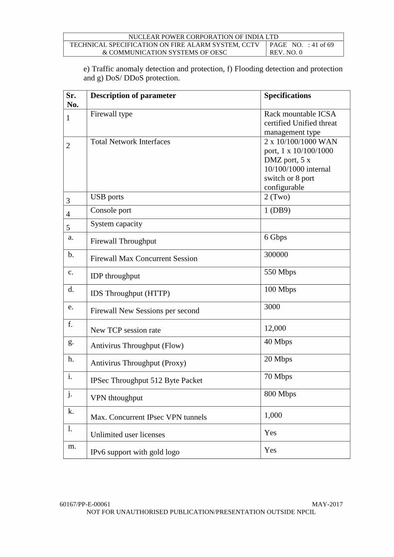
NUCLEAR POWER CORPORATION OF INDIA LTD
TECHNICAL SPECIFICATION ON FIRE ALARM SYSTEM, CCTV
& COMMUNICATION SYSTEMS OF OESC
PAGE NO. : 41 of 69
REV. NO. 0
60167/PP-E-00061 MAY-2017
NOT FOR UNAUTHORISED PUBLICATION/PRESENTATION OUTSIDE NPCIL
e) Traffic anomaly detection and protection, f) Flooding detection and protection
and g) DoS/ DDoS protection.
Sr.
No.
Description of parameter Specifications
1 Firewall type Rack mountable ICSA
certified Unified threat
management type
2 Total Network Interfaces 2 x 10/100/1000 WAN
port, 1 x 10/100/1000
DMZ port, 5 x
10/100/1000 internal
switch or 8 port
configurable
3 USB ports 2 (Two)
4 Console port 1 (DB9)
5 System capacity
a. Firewall Throughput
6 Gbps
b. Firewall Max Concurrent Session
300000
c. IDP throughput
550 Mbps
d. IDS Throughput (HTTP)
100 Mbps
e. Firewall New Sessions per second
3000
f. New TCP session rate 12,000
g. Antivirus Throughput (Flow)
40 Mbps
h. Antivirus Throughput (Proxy)
20 Mbps
i. IPSec Throughput 512 Byte Packet
70 Mbps
j. VPN thtoughput
800 Mbps
k. Max. Concurrent IPsec VPN tunnels 1,000
l. Unlimited user licenses Yes
m. IPv6 support with gold logo Yes

NUCLEAR POWER CORPORATION OF INDIA LTD
TECHNICAL SPECIFICATION ON FIRE ALARM SYSTEM, CCTV
& COMMUNICATION SYSTEMS OF OESC
PAGE NO. : 42 of 69
REV. NO. 0
60167/PP-E-00061 MAY-2017
NOT FOR UNAUTHORISED PUBLICATION/PRESENTATION OUTSIDE NPCIL
6 Networking features
a. Routing mode, bridge mode and hybrid mode
b. Ethernet and PPPoE
c. NAT and PAT
d. VLAN tagging (802.1Q)
e. Policy-based routing (user-aware)
f. Policy-based NAT (SNAT)
g. Dynamic routing (RIPv1/v2 and OSPF)
h. DHCP client/server/relay
i. Dynamic DNS support
j. WAN trunk for more than 2 ports
k. Per host session limit
l. Guaranteed bandwidth
m. Maximum bandwidth
n. Priority-bandwidth utilization
o. Bandwidth limit per user
p. Bandwidth limit per IP
Required
7 Authentication
a. Local user database
b. Microsoft Windows Active Directory
integration
c. External LDAP/RADIUS user database
d. XAUTH, IKEv2 with EAP VPN authentication
e. Web-based authentication
f. Forced user authentication (transparent
authentication)
g. IP-MAC address binding
h. SSO (Single Sign-On) support
Required
8 System Management
a. Role-based administration
b. Multiple administrator logins
c. Multi-lingual Web GUI (HTTPS and HTTP)
d. Command line interface (console, Web
console, SSH and telnet)
e. SNMP v2c (MIB-II)
f. System configuration rollback
g. Firmware upgrade via FTP, FTP-TLS and Web
GUI
h. Dual firmware images
Required

NUCLEAR POWER CORPORATION OF INDIA LTD
TECHNICAL SPECIFICATION ON FIRE ALARM SYSTEM, CCTV
& COMMUNICATION SYSTEMS OF OESC
PAGE NO. : 43 of 69
REV. NO. 0
60167/PP-E-00061 MAY-2017
NOT FOR UNAUTHORISED PUBLICATION/PRESENTATION OUTSIDE NPCIL
9 Logging and Monitoring
a) Comprehensive local logging
b) Syslog (to up to 4 servers)
c) Email alerts (to up to 2 servers)
d) Real-time traffic monitoring
e) Built-in daily report
f) Advanced reporting with Vantage Report
Required
10 Online support with one year subscription for
Content filter, IDP, Antivirus and Anti-Spam Required
6.6.2 Router technical specifications
Sr.
No.
Description of
parameter
Specifications
1 Configuration Equipped with
a) Onboard 3 nos. of 100/1000 Mbps ports
b) 4 WAN interface slots (3 Gigabit Ethernet
1 SFP)
c) Performance of Min 75 Mbps
2 Architecture Modular single box
19’ rack mountable
Equipped with integrated Hardware based
encryption
Shall support
a) 1 Internal Modules slots
b) 2 External USB 3.0 slots
c) 1 high density network module
d) out of band management access via USB
port / Aux. Port
e) single software image containing all of the
feature sets which can be activated with a
software license
3 RAM and Flash System Memory 1G (equipped) DDR2 ECC
future expandable to 2 GB
Flash RAM 256 MB(Equipped) expandable up
8GB
4 Network support Voice, Data, Video and IP Telephony
5 Security General Shall support
a) Time-Based Access Lists Using Time
Ranges (ACL)
b) advanced application inspection and
control
c) functionality to protect the route processor
from unnecessary or malicious levels of
traffic, including DoS attacks

NUCLEAR POWER CORPORATION OF INDIA LTD
TECHNICAL SPECIFICATION ON FIRE ALARM SYSTEM, CCTV
& COMMUNICATION SYSTEMS OF OESC
PAGE NO. : 44 of 69
REV. NO. 0
60167/PP-E-00061 MAY-2017
NOT FOR UNAUTHORISED PUBLICATION/PRESENTATION OUTSIDE NPCIL
d) Authentication, Authorization, and
Accounting (AAA)
e) Hot Standby Router Protocol or equivalent
f) HSRP for IPv6
6 Firewall, VPN &IPS Shall support
a) Advanced Firewall, VRF-aware Firewall
& SSLVPN Capability
b) IPSec, GRE, 3DES, AESetc
c) Onboard hardware VPN acceleration
d) GRE-based IPsec VPN
e) IPv6 IOS Firewall FTP Application
Support
7 Management Shall support
a) SNMPv1, v2 & v3, SNMP over IPv6, SSH
v1 & v2
b) TACACS+ & RADIUS
c) Mechanisms for measuring service-level
indicators, including delay, jitter, and
availability
d) Mechanism to monitor network
performance between two or more routers
e) Mechanism to monitor network
performance for SLA monitoring
f) Event management capability
g) Identification of flows by looking at the IP
address, Ports, Protocol & Type of Service
h) Onboard automation for fault detection,
troubleshooting, and recovering
8 Protocols Shall support
a) IPv4/IPv6 Dual Stack
b) Static routes as well as Dynamic Routes
like OSPF, EIGRP, BGP,PBR etc.
c) Multicast Internet Group Management
Protocol IGMPv2, IGMPv3, PIM SM,
SSM, DVMRP, ECMP MBGP etc.
d) MPLS Layer 2 & Layer 3 VPN
e) Ethernet in the First Mile (IEEE802.3ah)
f) Class Based Ethernet CoS Matching &
Marking (802.1p & ISL CoS)
g) Selection of the best path for each
application based upon reachability
h) Selection of the best path for each
application based upon delay, loss, jitter,
MOS etc
9 Approvals UL & TUV, UL60950 & EN60950, EN55022
class A, EN55024, FCC class A, VCCI class A,

NUCLEAR POWER CORPORATION OF INDIA LTD
TECHNICAL SPECIFICATION ON FIRE ALARM SYSTEM, CCTV
& COMMUNICATION SYSTEMS OF OESC
PAGE NO. : 45 of 69
REV. NO. 0
60167/PP-E-00061 MAY-2017
NOT FOR UNAUTHORISED PUBLICATION/PRESENTATION OUTSIDE NPCIL
AS/NZS CISPR22 class A and CE &RoHS
Compliant
10 Hardware and general Operating voltage- 230 V AC, as per clause
no.6.3.4
b. Temp operating: 10º C to 40º C
c. Relative Humidity: 10 to 85%
11 Real time clock It shall support real time clock for accurate time
stamp such as logging, debugging, and digital
certificates
12 Security device manager Web based device management tool embedded
within the router for software access remotely
13 Software Latest IOS software version as per WEB site of
OEM or version released for India
The S/W shall support Bandwidth management
and Security features
7.7 Miscellaneous items
7.7.1 JB's AND GU's
JB's and General Units (GU's)(for housing any field module of CCTV cameras such as
Power Supply unit, outdoor network switch, MDF, etc.) shall meet requirements as
specified in TABLE-1 below. In addition, for GU's size may vary depending upon the
enclosures. For GU's and JBs in built mechanical locks shall be provided. GU's shall be
suitable for wall mounting type and the degree of protection provided by enclosures shall
be IP-65 as per IS-13947 for all GUs except MDF.
TABLE-1
S. No. DESCRIPTION SPECIFICATION
GENERAL
1 Type IP-65 Metal Junction Box
2 Dimension As per requirement.
3 Quantity As per BOQ.
4 Material of
Construction
Cold Rolled sheet steel Hot dip galvanized of
Thickness1.6mm
5 Mounting Plate As per requirement.
6 Door Solid hinged front door with cam locking
arrangement
7 Door Gasket Synthetic Neoprene Rubber
8 Cable Glands As per requirement.
9 Mounting
Arrangement
Suitable for Wall, Column, Structure etc.
10
Colour
Exterior and Interior
LIGHT GREY SHADE RAL7035

NUCLEAR POWER CORPORATION OF INDIA LTD
TECHNICAL SPECIFICATION ON FIRE ALARM SYSTEM, CCTV
& COMMUNICATION SYSTEMS OF OESC
PAGE NO. : 46 of 69
REV. NO. 0
60167/PP-E-00061 MAY-2017
NOT FOR UNAUTHORISED PUBLICATION/PRESENTATION OUTSIDE NPCIL
Paint Thickness of min. 25 microns and one base
coating + 2 finish coating of anti-corrosive epoxy.
11 Gland Plate Removable gland Plate of 2mm thick made of Cold
Rolled sheet steel
12 Mounting Bracket
MOC
Carbon Steel
Environmental
13 Protection class IP 65 as per IS: 13947 Part-1
Options
14
Terminal Blocks
30 [tentative- will be decided during detail
engineering] nos, screw type, 4 sq.mm. Terminal
Identification number shall be provided on the
center. Insulating material for terminal casing,
endplate & end clamp shall be Polyamide -6.6V0
grade Current bar (conducting part) material: Sn-
Cu 58 plated with 4-8 micron thickness of tin/Cu-
Ni alloy
15 Shield Bus Bar Tinned copper shield bus bar with16 nos. of M6
holes suitable for 2.5sq.mm. cable size:5mm(thick)
x12mm(wide) x 210mm(long)
16 TB Mounting
Channel
35 mm. standard, galvanized Mounting channels
are interconnected through 1.5 sq.mm. green cable
and connected to shield bus bar
17 Earthing Stud M6,on both sides
18 Hinges Made of stainless steel
19 Name Plate
Laser printed SS Name Plate, Tag nos need to be
Provided by customer
Dimension: 100mm(length) x 25mm(width) x
1.6mm(thick) Character height shall be
minimum12.7mm
20
Nut, Bolt &Washer
4 nos. Nuts of M10 embedded to facilitate
mounting (welded to the box)
4 nos., M10 x 20 bolts & washer with each JB
All nuts, bolts and washers are made of cadmium
plated carbon steel
Tests & Checks
21 HV Test (Routine
Test) for terminal
block
HV Test Voltage: 1.5 KV
22
IR Test (Routine Test)
for terminal block
Test Voltage 500VDC for 1 minute between
terminals and mounting connection.
There should not be considerable drop in insulation
resistance before and after the HV test (shall be

NUCLEAR POWER CORPORATION OF INDIA LTD
TECHNICAL SPECIFICATION ON FIRE ALARM SYSTEM, CCTV
& COMMUNICATION SYSTEMS OF OESC
PAGE NO. : 47 of 69
REV. NO. 0
60167/PP-E-00061 MAY-2017
NOT FOR UNAUTHORISED PUBLICATION/PRESENTATION OUTSIDE NPCIL
>100MΩ)
23 Dimensional check
(Routine Test)
As per drawing
24
Test Reports for
review
Chalk powder test report (This is the type test,
hence a test report from recognized test lab shall be
submitted. No witness of this is possible)
Hardness test report on painting (Type Test)
Stripping test report on painting (Type Test)
Flexibility & Adhesion test report on painting
(Type Test)
Type test and routine test report of terminal block.
7.7.2 Fixtures for outdoor cameras
Suitable fixtures for installation of outdoor cameras shall be fabricated & supplied. Each
camera shall be installed on a fixture fixed on the ground such that it is at an elevation of
four meter from the floor level. For this the length of the fixture shall be 6 meter out of
which 1.5meter shall be below ground and 4.5 meter shall be above ground. The fixture
shall be rigid and the arrangement shall not cause vibrations in it due to wind etc. and shall
last for operational life of 20 years. The fixture can be fabricated from 4mm thick MS
sheet rolled in the form of a tube of 104mm (ID) with suitable base. The fixtures shall be
designed accordingly (i.e. size of MS plate, thick bases & tube depth inside the ground &
above floor level etc.). Some of these fixtures shall have provision for anchoring since it
may not be possible to fix it by digging a pit. The bidder may submit the design of these
fixtures along with the offer. Fixture must have provision of routing the camera cables
(integrated cable management) and suitable arrangement must be made on the fixtures to
install the camera.
7.7.3 Consoles
Console shall accommodate the following:
1. Two nos. of 22 inch monitor for PC and a PC with keyboards
2. One nos. of 42 inch video monitor and other items required for display & viewing
videos.
3. Server PC s as required.
Minimum requirements for console are:
1. Name plate as required by the purchaser.
2. Necessary gland plate for cable entry shall be provided in the console.
3. Mounting of all instruments / components supplied by the purchaser, wiring them and
providing any accessories such as cleats, straps at site during commissioning.

NUCLEAR POWER CORPORATION OF INDIA LTD
TECHNICAL SPECIFICATION ON FIRE ALARM SYSTEM, CCTV
& COMMUNICATION SYSTEMS OF OESC
PAGE NO. : 48 of 69
REV. NO. 0
60167/PP-E-00061 MAY-2017
NOT FOR UNAUTHORISED PUBLICATION/PRESENTATION OUTSIDE NPCIL
4. Necessary arrangements for the mounting of the PCs, converters/switches & other
hardware shall be made inside the console.

NUCLEAR POWER CORPORATION OF INDIA LTD
TECHNICAL SPECIFICATION ON FIRE ALARM SYSTEM, CCTV
& COMMUNICATION SYSTEMS OF OESC
PAGE NO. : 49 of 69
REV. NO. 0
60167/PP-E-00061 MAY-2017
NOT FOR UNAUTHORISED PUBLICATION/PRESENTATION OUTSIDE NPCIL
Fig-1. Typical general arrangement of console.
7.7.4 Network switches
S. No. Specifications
1. Edge / Distribution switch (Managed-Switch)
Layer-3, rack mountable switches, 24 Nos. of 100/1000 SFP ports with 8 nos.
10/100/1000 Mbps combo ports, RPS- rack power supply- 1 nos., 8 Nos. 1000
Mbps LX modules along with rack for housing the switch.
2. Outdoor industrial grade (managed switch) with power supply, layer 2
comprising of 10/100 Mbps 7 ports, one 10/100/1000 Mbps port and SFP ports
2 Nos., 2 nos. of 1000 LX modules along with rack for housing the switch.
Switch along with its modules and power supply shall withstand temperature of
650C.
3. Patch cords SC to SC
4. Patch cords LC to SC
5. Patch cords LC to LC
6. LIU 24 ports –SC, single mode
7. LIU 12 ports-SC, single mode
8. Pigtails-SC
9. Pigtails-LC
10. CAT-6 Connectors
11. Intelligent management center- Network management software loaded on a
PC for 100 node license.

NUCLEAR POWER CORPORATION OF INDIA LTD
TECHNICAL SPECIFICATION ON FIRE ALARM SYSTEM, CCTV
& COMMUNICATION SYSTEMS OF OESC
PAGE NO. : 50 of 69
REV. NO. 0
60167/PP-E-00061 MAY-2017
NOT FOR UNAUTHORISED PUBLICATION/PRESENTATION OUTSIDE NPCIL
Supplier shall get the model approved by the purchaser, for all items.
7.7.5 Name Plate/Tagging modules
Complete name plates designation for each instrument/component is shown on the
equipment arrangement drawing of each panel. The name plate on the panel/OC shall have
a minimum life of the panel. Name plates shall be black with white characters. Basic
material, type of characters, size of characters and depth of engraving shall be subject to
purchaser’s approval. The name plate shall be fixed with blackened pan head screws or
with the use of suitable adhesive depending on the size of the name plates. In case of
adhesive fixing, it shall be ensured that the adhesive will have sufficient bonding strength
and also it is possible to remove the fixed name plate for replacement or deletion by
applying white petrol at the joint without causing damage to painting on the panel. Care
shall be taken to ensure that name plates are located in an orderly manner with proper
spacing from the equipment to maintain the aesthetic look.
7.8 Cables, glands, conduits & accessories
The supplier shall carry out all inter module wiring inside the panel and termination
between panel terminals and units/modules and all the cabling and termination required
between panels and between panel & field devices. All the cables proposed & quoted by
the bidder for meeting the functional requirements of each of the subsystem shall be LHLS
sheathed cables. The insulation & conductor size shall be so chosen that it meets the
functional requirement. It is preferred if conductor size of 1.5 sq.mm and EPR insulation
is chosen for signal cables, provided it meets the functional requirements. The multi-pair
cables if used for signal transmission shall be twisted, individually and overall shielded
cable. The cables used for power supply can be cored cables ( i.e untwisted). The
conductor sizes to be used shall be 1.5 Sq.mm. Supply of nickel plated double
compression brass cable glands complying to BIS standards and all required accessories
are in the scope of this specification.
In general armored cables are to be used for outdoor areas and un-armored cables for
indoor areas. In outdoor areas the cables are to be laid in underground conduits. These
conduits/ pipes are to be supplied by the vender. The conduits shall meet the BIS
requirements. The vendor shall supply the required cables and any other general purpose
cables as required for meeting the system requirements. These cables shall comply with
the requirement specified in the NPCIL technical specification No.PC-E-234/240 for EPR
insulated LHLS sheathed unarmored/ armored cables. Suitable termite proof compound
shall be added in the sheath of the cable. However, testing for termite proof is not required.
The connectors shall also be supplied for this purpose (internal wiring).All the field cable
entries to the panel/console shall be from the bottom. Supplier shall supply mating
connectors for all equipment/devices. The internal wiring at the panels if carried-out by
loose wires shall be by PTFE wires (Teflon wires) of 18 AWG.

NUCLEAR POWER CORPORATION OF INDIA LTD
TECHNICAL SPECIFICATION ON FIRE ALARM SYSTEM, CCTV
& COMMUNICATION SYSTEMS OF OESC
PAGE NO. : 51 of 69
REV. NO. 0
60167/PP-E-00061 MAY-2017
NOT FOR UNAUTHORISED PUBLICATION/PRESENTATION OUTSIDE NPCIL
7.8.1 CAT 6 Cable
4 Pair, unshielded twisted pair CAT-6 shall meet EIA/TIA 568-B.2-1 Category 6
specification, UL 444 test and shall meet CM and CMR ratings suitable for 100 base-TX
Ethernet data network. The quantity shall be supplied in 350 meters in single length boxes
and shall comply to the following specifications:
Sr.
No.
Description Requirement
1 Conductor: 24 AWG Annealed bare solid copper
CAT-6 UTP Cable
2 Frequency: 100 Mhz
3 Attenuation( Min. at 100 Mhz): 22 db
4 Characteristic impedance: 100 ohms +/- 15%
5 Outer Sheath Material LSZH
It shall Support for Fast Ethernet and Gigabit Ethernet IEEE 802.3/5/12, Voice, ISDN,
and broadband.
7.8.2 Fiber Optic cable
The fiber optic cables, used for network connectivity of CCTV & FAS located at
the main plant to OESC shall have the following requirements.
S.
No.
Parameter Requirements
1 Cable Type Single Mode (9 / 125 μm)
2 Applicable Standard IEC 60794 and ITU.T - G. 652D
3 Number of Fibers in the cable 12 Fibers
4 Installation Temperature -20 Deg C to +70 Deg C
5 Operating Temperature -20 Deg C to +70 Deg C
6 Storage Temperature -20 Deg C to +70 Deg C
7 Attenuation at 1310 nm < 0.38 dB/km
8 Attenuation at 1550 nm < 0.30 dB/km
9 PMDq <=0.2 ps /√km
10 Tube Details Multi Tube Construction (Loose Tube)
with thixotropic jelly
11 Number of Loose Tubes Multi Tube Design, 4 Fiber Per Tube
12 Central Strength Member FRP Central Aramid strength member
13 Loose Tube Material PBTP with Thixotropic Jelly Filling
14 Type of Fiber / Diameter Single Mode (9 / 125 μ M)
15 Inner Sheath Material / Thickness /
Colour
LSZH / 1.5 mm Nominal / Black
16 Armor Details Corrugated, chromium / polymer
coated steel tape

NUCLEAR POWER CORPORATION OF INDIA LTD
TECHNICAL SPECIFICATION ON FIRE ALARM SYSTEM, CCTV
& COMMUNICATION SYSTEMS OF OESC
PAGE NO. : 52 of 69
REV. NO. 0
60167/PP-E-00061 MAY-2017
NOT FOR UNAUTHORISED PUBLICATION/PRESENTATION OUTSIDE NPCIL
17 Rip Cords Required
18 Outer Sheath Material / Thickness /
Colour
LSZH / 1.5 mm Nominal / Black
19 Bending Radius during Installation
(Short Term)
20D
20 Bending Radius after Installation
(Long Term)
10D
21 Maximum Tensile Strength 2670 N
22 Crush Resistance 4000 N / 100 x100 mm
23 Impact Strength 50 Nm
7.8.3 LAN
Redundant network scheme shall be used for data communication required for these
systems. A 12 core single mode cable fibre optic on a LAN is to be used for this.
The communication between the nodes with transport layer protocol of TCP-IP or UDP
or other standard protocols. There shall be a standard application layer protocol to be
developed so that it shall be possible to exchange all information. Transfer of data for
control application or for annunciation can be through LAN.
The network shall have the following minimum features in addition to requirements
specified under CCTVS:
a. The network shall have guaranteed access under all operating conditions.
b. The bandwidth shall be sufficient to meet the responses of the system even during data
inrush for the plant under the worst case scenario with alarm bursts. It shall be possible
to upgrade network capacity.
c. The design shall be such as to minimize interruption of signals. It shall ensure that a
single failure anywhere in the media shall cause no more than a single message to be
disrupted and that message shall automatically be retransmitted. In case of failure of
one network the changeover to the redundant network shall be automatic and
completely bump less and the same shall be suitably alarmed /logged.
d. Any failure or physical removal of any node connected to the data highway shall not
result in loss of any communication function to and from any other node.
e. Software shall monitor the healthiness of redundant networks continuously. Built-in
diagnostics shall be provided for easy fault detection. Network Diagnostic software as
a minimum shall include the following:
Monitoring of the network medium including the traffic

NUCLEAR POWER CORPORATION OF INDIA LTD
TECHNICAL SPECIFICATION ON FIRE ALARM SYSTEM, CCTV
& COMMUNICATION SYSTEMS OF OESC
PAGE NO. : 53 of 69
REV. NO. 0
60167/PP-E-00061 MAY-2017
NOT FOR UNAUTHORISED PUBLICATION/PRESENTATION OUTSIDE NPCIL
Monitoring of the communication through the network for timing and protocol.
Communication error detection and correction facility shall be provided at all
levels of communication.
Maintenance of communication in the presence of faulty nodes and
addition/deletion of nodes etc.
Failure of the communication between Equipment shall lead to driving the
parameters exchanged through that network to pre-determined/fail-safe state.
f. The network shall be secured and protected against virus attack.
g. The design and installation of the data highways shall take care of the environmental
conditions and hazardous area classification as applicable to similar services.
h. All network components of LAN and Human Machine Interface system shall be
compatible to the LAN without degrading LAN performance.
i. Isolation shall be provided at both transmitting and receiving ends and redundant link
shall be provided wherever applicable.
NOTE: The bidder shall clearly specify & quote for any additional equipment/ cable/
modules as per the required quantities in order to meet the functional requirements
of the system. In case it is noticed that some material (equipment/module/ software
etc.) not offered/quoted initially, but is required for complete functionality then such
material shall be offered along with spares at no extra cost to purchaser.
7.9 Spares
The spares to be supplied under the contract unless otherwise specified shall be on the
following basis:
a. Items for which spares to be supplied are identified in BOQ.
b. 10% of hardware items like connectors, switches, etc. used on the equipment with
at least one of each type.
A list of spares proposed to be supplied by the supplier on the above basis shall be
submitted by the supplier to NPCIL for approval. Any item not listed initially in the
offer, but is found out to be required for the functioning of the system shall be
supplied along with spare at no extra cost.
Afterwards the vendor can supply the spares which are backward compatible with the
supplied system. The vendor shall also suggest the actions that can be taken to address
the issues of up-gradation and backward compatibility of spares NPCIL has the option to
order these spares.

NUCLEAR POWER CORPORATION OF INDIA LTD
TECHNICAL SPECIFICATION ON FIRE ALARM SYSTEM, CCTV
& COMMUNICATION SYSTEMS OF OESC
PAGE NO. : 54 of 69
REV. NO. 0
60167/PP-E-00061 MAY-2017
NOT FOR UNAUTHORISED PUBLICATION/PRESENTATION OUTSIDE NPCIL
8.0 INSPECTION TESTS & REPORTS
8.1 General
The purchaser or his authorised representative shall have access to the supplier’s
premises at all reasonable times to the extent necessary to assess compliance with
the provisions of this specification.
The equipment shall be carefully examined to determine their conformance with
reference to material and workmanship, finish, marking, dimensions and to assess
its conformance with other requirements stated or reasonably implied and not
covered by any specific test.
All the constituent units of equipment supplied to the provisions of this specification
shall be subjected to visual, dimensional and functional inspection and testing as per
approved QAP to the satisfaction of purchaser.
8.2 Tests at the Factory
i) The supplier shall subject all the electrical and electronic components to inward
inspection to check their conformance with the relevant specification and standard
prior to assembly and wiring as per QAP.
ii) Inspection of fabricated items such as GU’s, JB’s etc. shall be carried out to ensure
conformity with the relevant fabrication drawings.
iii) Electrical wiring shall be inspected and continuity checked to ensure conformity
with the relevant wiring diagrams.
iv) The assembled panel shall be inspected to ensure that they conform to the relevant
drawings.
v) All the electric & electronic modules shall be tested to ensure proper functioning
of all controls, outputs as per relevant specifications.
Noise Immunity Test [EMI/EMC]: The vendor shall supply relevant certificates/ reports
from international test agencies certifying compliance to EMI/EMC requirement as per
IEC /EN-54 /UL standard for FAS and CCTV cameras only.
Test plan and test data have to be prepared and made available prior to conducting
acceptance testing, on a mutually agreed basis. Test procedures including test cases and
expected correct results in terms of quality, messages, reports etc., shall be carried out.
Appropriate tools and methodologies commensurate with the technology shall be suitably
deployed to demonstrate the functionality.

NUCLEAR POWER CORPORATION OF INDIA LTD
TECHNICAL SPECIFICATION ON FIRE ALARM SYSTEM, CCTV
& COMMUNICATION SYSTEMS OF OESC
PAGE NO. : 55 of 69
REV. NO. 0
60167/PP-E-00061 MAY-2017
NOT FOR UNAUTHORISED PUBLICATION/PRESENTATION OUTSIDE NPCIL
7.2 Environmental Test
Climatic Tests: The vendor shall supply relevant certificates/ reports from international
test agencies certifying compliance to Climatic Tests requirement as per IEC /EN-54 /UL
standard for FAS and CCTV cameras only.
7.3 Functional Test
Functional tests shall be carried out as per approved test procedures for all subsystems
listed in this specification. For general purpose items such as JB's, cables tests as specified
in the relevant referred specification/QAP shall be carried out as applicable.
The equipment shall be completely wired and interconnected with field cable simulated
as applicable and the necessary software and basic servers/ workstations for the purpose
of functional tests in accordance with this specification. This test will be carried out sub
system wise. For this purpose at least two sets of equipment of each subsystem shall be
interconnected & the complete operation sequence checked. For this the supplier shall
submit a detailed system functional test procedure to the purchaser for his approval prior
to this test.
During the functional test following are some of the tests that shall be simulated.
Mains supply fail
Single fault.
Multiple faults.
Diagnostic features & HMI provisions shall be verified for various operating modes.
all the operational logics, indications, annunciations, displays & recording to meet
system design intent.
Alarm functions shall be simulated & verified.
7.4 Test Reports
Copies of the inspection and test reports, signed by authorised representative of the
supplier shall be submitted to Purchaser.
8.6 Operation & Maintenance Manual
The Supplier shall prepare manufactured system operating and maintenance manual and
offer one copy of the draft manual for purchaser’s review & comments which shall be
taken care in the revised version of the manual.
The manual shall include the following:
a) System technical description
The system technical description shall be given in detail with reference to drawings. The
working of all modules / units shall be described. The system description shall be specific

NUCLEAR POWER CORPORATION OF INDIA LTD
TECHNICAL SPECIFICATION ON FIRE ALARM SYSTEM, CCTV
& COMMUNICATION SYSTEMS OF OESC
PAGE NO. : 56 of 69
REV. NO. 0
60167/PP-E-00061 MAY-2017
NOT FOR UNAUTHORISED PUBLICATION/PRESENTATION OUTSIDE NPCIL
to the equipment furnished and not of a general nature. It shall consists of data of the
equipment, adjustment, calibrations, complete instructions of installation, commissioning,
working & operation of the equipment, parts catalogues and data sheets and drawings.
The instructions for assembly and installation shall show the identification part number of
the dismantled apparatus or equipment.
b) Operating Instruction
The system operation instructions shall be descriptive and in detail. Step by step operating
instructions shall be given for operation of the system. Various adjustments, calibrations
shall be clearly defined and mentioned.
c) Maintenance instructions
Trouble shooting methods, routine and periodic maintenance, test equipment to be used,
test points with test voltages and pattern/wave shapes shall be covered.
d) Commissioning instructions
Sequence of steps to be followed for commissioning of the system/ sub-system, hardware
& software settings such as jumper/switch settings, communication port configuration, IP
address schemes for networking etc. shall be covered.
e) Manufacturer catalogues for the equipment/components procured from other sources.
Ten copies of the manufacturers operating and maintenance manual and one softcopy in
CD (word & PDF) shall be supplied to the purchaser.
8.7 Inspection History Document
The supplier shall supply 5 copies of “Inspection History Document” to purchaser prior
to dispatch of material to site. The History Document shall consist of following:-
1) P. O. Copy
2) Specification, Approved QAP
3) NPCIL approved test procedures, test reports and test certificates
4) Minutes of meeting and Design Concession Request if any.
5) Shipping reference, Certificate of Compliance
6) Any other P.O. related documentation
8.8 Inspection at Site
After obtaining shipping release from purchaser's authorised representative, equipment
shall be packed properly and transported to the site. As this process may cause some
damage to the equipment, they shall be checked and inspected for physical damage and
quantity.

NUCLEAR POWER CORPORATION OF INDIA LTD
TECHNICAL SPECIFICATION ON FIRE ALARM SYSTEM, CCTV
& COMMUNICATION SYSTEMS OF OESC
PAGE NO. : 57 of 69
REV. NO. 0
60167/PP-E-00061 MAY-2017
NOT FOR UNAUTHORISED PUBLICATION/PRESENTATION OUTSIDE NPCIL
8.9Installation & Commissioning
Drawings under relevant USI issued by purchaser are to be refereed for installation of
equipment. The cable terminations on panels/ Consoles and JBs shall be done as per the
Wiring Diagrams (WD) and Terminal List (TL) issued by purchaser. Only the field
termination shall be carried out at site. All intra panel terminations shall be carried out by
the supplier in his premises prior to shipment based on the WDs and TLs issued by the
purchaser. If for any reason, the panels are shipped without intra panel wiring being
carried out, the same shall be carried out while installation of field equipment/ sensors is
being carried out as per drawing. A copy of relevant drawings such as GA, WDs & TLs
of the panels, consoles and other equipment shall be submitted to purchaser.
Responsibility of implementation of this procedure lies with supplier of equipment. He
shall coordinate with the supplier of engineer in-charge at site, and follow his instructions
while executing this job.
Personnel engaged in the installation & commissioning work at site will have to follow
the security procedures controlling entry and movement. During commissioning at
Purchaser’s premises, supplier or his representative will have to ensure that all safety
regulations (both industrial safety and radiological safety) in force are strictly followed.
In such matters, Purchaser’s instructions wherever given will be binding.
The supplier shall be responsible for the commissioning at site of all the electronics
equipment covered in this specification. The supplier shall ensure that trained and
qualified personnel are involved during commissioning of the systems. The supplier shall
have to depute one engineer along with a technician to site for a minimum period of 30
days at the time of system commissioning.
Following checks are to be carried out prior to commissioning:
i) Components mounted on all the panels, detectors/ sensors, fixtures, CCTV cameras,
EPABX telephones and other equipment in OESC etc. shall be checked as per applicable
general arrangement (GA) drawings.
ii) Tagging details shall be verified with applicable documents.
iii) Panels/enclosure grounding is checked for their rigid support, proper continuity to
ground and cable glands.
iv) Cable terminations at panels, JBs & detectors are checked as per Terminal Lists (TLs).
v) The wiring for panels/JBs & instruments shall be checked as per Wiring Diagrams
(WDs).
vi) Address setting, alignment and functional checking of sensors/ cameras/ telephones.
vii) Alarm functions shall be simulated & verified.
The equipment shall be commissioned as per the commissioning procedure and
Instruction manuals (MI). The Commissioning job involves
Checking of wiring
Over all system commissioning.
Generation of commissioning documents
Handing over of the system to O&M personnel after successful test run.

NUCLEAR POWER CORPORATION OF INDIA LTD
TECHNICAL SPECIFICATION ON FIRE ALARM SYSTEM, CCTV
& COMMUNICATION SYSTEMS OF OESC
PAGE NO. : 58 of 69
REV. NO. 0
60167/PP-E-00061 MAY-2017
NOT FOR UNAUTHORISED PUBLICATION/PRESENTATION OUTSIDE NPCIL
8.10 Test run
The test run shall be at least for one month, during which the reliable operation of the
system has to be established. Test run will continue till the requirement of specifications
is achieved. During this test run the supplier shall be responsible for the maintenance and
repair of the equipment and training of the operation. After successful completion of the
commissioning and test run the system shall be handed over to the operation staff.
9.0 INDICATIVE QUALITY ASSURANCE PLANS
All the system drawings such as general arrangement, overall dimensions, cut-out
dimension drawings, schematics, elementary wiring diagram, details and bill of material
terminal loops etc. along with drawings list shall be submitted to the Purchaser for
approval prior to fabrication.
Supplier shall provide their detailed Quality Assurance Plan (Q.A.P.) mentioning the steps
they follow to ensure quality of the product for items fabricated at their works and for
bought out items. The Q.A.P. shall be prepared to ensure that all the tests on
components/equipment of the system and final assembled system are included for quality
assurance. The same has to be submitted for purchaser's approval and approved Q.A.P.
shall be followed to ensure the quality of the product. A typical Quality Assurance Plan is
given for reference as Annexure-II.
The Equipment Test Procedure (E.T.P.) in detail covering all the functional requirements
of this specification shall be prepared mentioning the step-wise inspection and test
procedures. The test procedure also shall be submitted to the purchaser for approval prior
to the commencement of testing.
The Supplier shall also submit one set of as built drawings in reproducible format in soft
(Auto-cad version in addition to PDF) form in CDs to the purchaser.
10.0 PACKING AND SHIPMENT
The supplier shall arrange packing of the instruments as per IRCA regulations in respect
of consignments sent by rail. In respect of dispatches by road, the supplier shall arrange
such packing as would safeguard the consignment against all rigors of road transport. All
accessories and components shall be packed in packages limited to the sizes and weights
that are admissible under the prevailing rail and road limitations. The instruments shall
be so packed and protected as not to suffer deterioration, damage or breakage and shall be
protected to prevent entrance of dirt and moisture during transit and storage. Each
package shall be properly labeled and tagged indicating the type of quality of material it
contains its dimensions, weight as well as the order number (Requisition No.). All
hardware, spares, etc. shall be specially packed and clearly marked indicating the intended
use. After receipt of material at site and during installation & commissioning if it is found
out that the equipment/ sensor/ module has suffered damage due to transfer or storage on
account of improper packing or while transfer from stores, the supplier shall replace such
equipment/ modules/ sensors at no extra cost to purchaser.

NUCLEAR POWER CORPORATION OF INDIA LTD
TECHNICAL SPECIFICATION ON FIRE ALARM SYSTEM, CCTV
& COMMUNICATION SYSTEMS OF OESC
PAGE NO. : 59 of 69
REV. NO. 0
60167/PP-E-00061 MAY-2017
NOT FOR UNAUTHORISED PUBLICATION/PRESENTATION OUTSIDE NPCIL
Each package shall be marked with “fragile and electronic item, handle with care”. The
packages shall be clearly and legibly marked with suitable permanent manner with the
following information.
a) Description of item and its serial number.
b) USI number.
c) The Purchase Order No.
d) The number of pieces in the shipment.
In addition, the name and addresses of supplier and consignee shall be marked.
Identification
Proper identification i.e. name of the system, model, sr. no., tag number & manufacturers
name shall be provided on the console. A nameplate for the console shall be provided on
top of panel. The character height shall be such that, it can be easily readable from a
distance of two meters. The exact engraving details will be given at the time of detailed
engineering.
11.0 GUARANTEE
The Equipment shall be guaranteed against defects arising due to design, fault, material,
workmanship, poor packing, and damage during transportation, handling, storage etc. and
for trouble free operation for a period of one year from the date of satisfactory
commissioning of the system. During this period all the faulty units shall be
replaced/repaired free of cost at site by the supplier.
Subsequent to one year guarantee, two year after sales support including maintenance,
bug-fixation of the application software shall be provided by the supplier.

Annexure- I
Bill of Material Fire Alarm System
Distribution and destination of quantities of indent items: S. No.
Item Description Total qty.
UOM Qty. for NAPS
Qty. for KAPS
Qty. for RAPS
Qty. for KGS
Qty. for TAPS
Qty. for MAPS
1 Installation, termination & Commissioning of fire alarm system for OESC building.
1 LS 1 0 0 0 0 0
2 Intelligent Multi-Criteria Detectors 480 Nos. 80 80 80 80 80 80
3 Spare Intelligent Multi-Criteria detectors 48 Nos. 8 8 8 8 8 8
4 Intelligent Manual Call Point 54 Nos. 9 9 9 9 9 9
5 Intelligent Zone Monitoring Unit 18 Nos. 3 3 3 3 3 3
6 Interface Module For converting contact Input To IP
30 Nos. 5 5 5 5 5 5
7 Loop Powered Relay Modules With 4 C/O contacts
60 Nos. 10 10 10 10 10 10
8 Interposing relays 240 Nos. 40 40 40 40 40 40
9 4-Way GI Mounting Box 600 Nos. 100 100 100 100 100 100
10 Fixtures for smoke detector 180 Nos. 30 30 30 30 30 30
11 FAS control and indicating equipment having 2 loops complete with its own power supply, loop cards and other required modules.
6 Nos. 1 1 1 1 1 1
12 Spare modules/cards of FAS control panel having 1 number each type of module/card used in the control panel.
6 Set 1 1 1 1 1 1
13 Fire detector removal tool kit with 5 m collapsible / concentric rod.
12 Set 2 2 2 2 2 2
14 Fire Detector testing tool kit 12 Set 2 2 2 2 2 2

S. No.
Item Description Total qty.
UOM Qty. for NAPS
Qty. for KAPS
Qty. for RAPS
Qty. for KGS
Qty. for TAPS
Qty. for MAPS
15 Aerosol Gas Cans 180 Nos. 30 30 30 30 30 30 16 1 Pair 1.5 Sq.mm EPR insulated, low halogen
low smoke sheathed, overall shielded cable. 12 KM 2 2 2 2 2 2
17 Supply of 25 mm rigid hot dipped G.I. conduit including accessories viz. elbows, inspection bends, couplers, check nuts, fasteners, gaskets, lead rawal-plugs, saddles, spacers etc.
12 KM 2 2 2 2 2 2
18 Supply of nickel plated double compression brass cable glands (NPT Or Metric Straight Thread) for cables being supplied against Item No. 16 Above.
600 Nos. 100 100 100 100 100 100
19 GU for housing Interposing relays 6 Nos. 1 1 1 1 1 1 20 Supervision for Installation & commissioning of
FAS in OESC building at 5 NPCIL sites (KAPS near Surat, RAPS near Kota, KGS near Karwar, MAPS near Chennai, TAPS Near Mumbai) and test run for another one month after Installation and commissioning. Minimum one Engineer and one Supervisor (having through knowledge of the supplied system and shall be well competent to integrate and operate the system as per design intent and specifications) shall be deputed for supervision during installation and commissioning and test run for another one month.
5 Nos. 0 1 1 1 1 1
NAPS Narora Atomic Power Station, Narora, Dist. Bulandshahr (U.P)-203389 KAPS Kakarapar Atomic Power Station, Kakrapar Gujrat RAPS Rajasthan Atomic Power Station, Rawatbhata via- Kota, (Rajasthan) KGS Kaiga Generating Station, Kaiga (Karnataka) TAPS Tarapur Atomic Power Station, Tarapur Maharashtra) MAPS Madras Atomic Power Station, Kalpakkam, Tamilnadu.
The above Table gives the tentative BOQ, the bidder shall quote for any other items(s) required for proper functioning of the system which is/are not listed above. Any item not listed initially in the offer, but found to be required later for the functioning of the system, shall be supplied along with spare at no extra cost.

NUCLEAR POWER CORPORATION OF INDIA LTD
TECHNICAL SPECIFICATION ON FIRE ALARM SYSTEM, CCTV
& COMMUNICATION SYSTEMS OF OESC
PAGE NO. : 65 of 69
REV. NO. 0
60167/PP-E-00061 MAY-2017
NOT FOR UNAUTHORISED PUBLICATION/PRESENTATION OUTSIDE NPCIL
ANNEXURE - II
Questionnaire to the bidders
Sr.
No
.
Specification’s
Point no.
Technical requirement Remark
Bidder may
provide additional
information.
1. Scope Bidder is ready to give undertaking for
design, construction, manufacture,
assembly, inspection, testing, packing,
forwarding, and delivery to site,
handling and storage of equipment at
site, testing at site, installation
&commissioning at site,
documentation requirement including
guarantee for equipment.
2. Applicable
Standards &
Specifications
Bidder is aware of the requirements of
Equipment applicable standards/
specifications.
(Give details for
deviations, if any)
3. Applicable
NPCIL
Specifications
Whether Bidder has taken care of
environmental requirements,
grounding & shielding requirements in
the system offered.
(Give details for
deviations, if any)
4. Material process
& workmanship
Bidder is ready to adhere to strict
NPCIL’s QA requirements on
Inspection, Terminations, mounting,
painting & workmanship.
(Give details for
deviations, if any)
5. Material &
processes
Whether bidder has understood the
NPCIL QA policies?
6. Environmental &
Operating
Conditions
Whether Equipment offered is rated for
continuous operation at ambient
conditions as stated in the Technical
specification?
7. Manufactures
drawing.
Whether bidder has enclosed system
write up along with block diagram,
GA’s a point-to-point compliance with
respect to all the points of this
specification, highlighted deviations
etc. & attached these along with
quotation?
8. System
Requirement
Whether the Bidder has provided
panel/ Console, functional
requirements, performance
requirements, priorities & controls as
per technical specification?
Give details in case
of any deviations.

NUCLEAR POWER CORPORATION OF INDIA LTD
TECHNICAL SPECIFICATION ON FIRE ALARM SYSTEM, CCTV
& COMMUNICATION SYSTEMS OF OESC
PAGE NO. : 66 of 69
REV. NO. 0
60167/PP-E-00061 MAY-2017
NOT FOR UNAUTHORISED PUBLICATION/PRESENTATION OUTSIDE NPCIL
9. System
Requirement
Whether the Bidder has understood the
technical requirements of subsystems?
Give details in case
of any deviations
10. Documentation Is the bidder agreeable to provide
documentation as given below:
A) Preparation of Quality Assurance
plan.
B) Equipment Test procedure
C) Preparation of Test Reports
D) Preparation of Drawings
General Arrangement [GA] & Bill
of Material [BM], Detail Drawings
[DD], I/O Schedule, Wiring
Diagram [WD] in NPCIL format
and Reproducible etc.
E) Preparation of operation &
maintenance manual.
F) History docket.
Give details in case
of any deviations.
11. Inspection, Tests
& Reports
Whether the Bidder has understood the
testing requirements?
Give details in case
of any deviations.
12. Identification Whether the Bidder is agreeable for
packaging & shipment as per Technical
Specification.
Give details in case
of any deviations.

NUCLEAR POWER CORPORATION OF INDIA LTD
TECHNICAL SPECIFICATION ON FIRE ALARM SYSTEM, CCTV & COMMUNICATION
SYSTEMS OF OESC
PAGE : 67 of 69
REV. NO. : 0
60167/PP-E-00061 MAY-2017
NOT FOR UNAUTHORISED PUBLICATION/PRESENTATION OUTSIDE NPCIL
ANNEXURE - III
SAMPLE QUALITY ASSURANCE PLAN (QAP)
Sl.
No
1
Components
2
Characteristics
3
Type of
Check
4
Classific
ation
5
Quantum of
Check
6
Reference
Document
7
Acceptance
Norms
8
Format of
Records
9
AGENCY REMARKS
11
P W
10
V
1.0 INWARD INSPECTION Mechanical hardware
1.1 a) Raw material a. Physical
properties
b. Chemical
Composition
test
Visual
Examination
Sheet
thickness
Dimensions
Chemical
MA
MA
Sample
10% of lot
Sample
IS-513-1986
Approved
Drawings &
manufacturer’
s Data Sheet
As per IS-228
IS-513-1986
Approved
Drawings &
manufacturer’s
Data Sheet
Test Report
Test
certificate
Test Report
3
3
2
2
1
1
1.2 b) Consoles, 6
Mtr tower,
mounts, JB's,
GU's etc.
c) Nuts, screws,
washers,
studs, etc.
1. Acceptance
test
2. Routine test
3. Visual test
4. Dimensional
5. Alignment
1. Acceptance
test
2. Visual test
Visual
Visual
MA
MA
Sample
Sample
Approved
Drawings &
manufacturer’
s Data Sheet
Approved
Drawings &
manufacturer’s
Data Sheet
IQC Record 2
2
2
3
1
1
1
2
Verification
of internal
procedures
by Purchaser
1.3 Pre-treatment and
painting of
mechanical parts
1. Surface test
2. Paint film
thickness
3. Colour
4. Scratch test
5. Adhesion
Visual
Measurement
Shade card
Mechanical
Mechanical
MA 100%
Sample
100%
Sample
Sample
Specifications
as per
manufacturing
drawing
Specifications
as per
manufacturing
drawing
IQC Record 2 2 1

NUCLEAR POWER CORPORATION OF INDIA LTD
TECHNICAL SPECIFICATION ON FIRE ALARM SYSTEM, CCTV & COMMUNICATION
SYSTEMS OF OESC
PAGE : 68 of 69
REV. NO. : 0
60167/PP-E-00061 MAY-2017
NOT FOR UNAUTHORISED PUBLICATION/PRESENTATION OUTSIDE NPCIL
ANNEXURE – III (Cont’d.)
SAMPLE QUALITY ASSURANCE PLAN (QAP)
Sl.
No
1
Components
2
Characteristics
3
Type of Check
4
Classifi
cation
5
Quantum
of Check
6
Reference
Document
7
Acceptance
Norms
8
Format of
Records
9
AGENCY REMARKS
11
P W
10
V
1.4 Assembly of
mechanical
hardware
1. Visual
2. Dimension
3. Marking
4. Workmanship
5. Finish
Visual
Measurement
Visual
Visual
Visual
MA
MA
MA
MA
MA
100%
100%
100%
100%
100%
Applicable
manufacturing
drawings
Applicable
manufacturing
drawings
IQC records 2 2 1
3.0 FINAL INSPECTION OF ASSEMBLED UNITS (detectors, sensors, CCTV, telephones, communication equipment etc. sub system wise)
3.1 Routine and
acceptance
test
i) Completeness
ii) A.C. Power
supply units
iii) Functional
Physical, overall
dimension GA,
BM
i) A.C.
Variation
ii) Line & load
regulation,
riffle
iii) AC ON/OFF
All functions &
diagnostics
MA
MA
MA
MA
MA
100%
As per
approved
test
procedur
e
--do--
--do--
--do--
Specs &
approved
Manufacturer’s
drawing.
As per
approved test
procedure
--do--
--do--
--do--
As per specs &
approved
Manufacturer’s
drawing.
As per
approved test
procedure
--do--
--do--
--do--
IQC Records
IQC Records
IQC Records
IQC Records
IQC Records
2
2
2
2
2
2
2
1
1
2
1
1
1
1
1
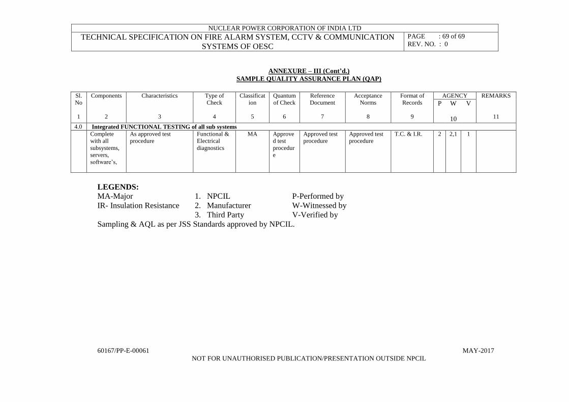
NUCLEAR POWER CORPORATION OF INDIA LTD
TECHNICAL SPECIFICATION ON FIRE ALARM SYSTEM, CCTV & COMMUNICATION
SYSTEMS OF OESC
PAGE : 69 of 69
REV. NO. : 0
60167/PP-E-00061 MAY-2017
NOT FOR UNAUTHORISED PUBLICATION/PRESENTATION OUTSIDE NPCIL
ANNEXURE – III (Cont’d.)
SAMPLE QUALITY ASSURANCE PLAN (QAP)
Sl.
No
1
Components
2
Characteristics
3
Type of
Check
4
Classificat
ion
5
Quantum
of Check
6
Reference
Document
7
Acceptance
Norms
8
Format of
Records
9
AGENCY REMARKS
11
P W
10
V
4.0 Integrated FUNCTIONAL TESTING of all sub systems
Complete
with all
subsystems,
servers,
software’s,
As approved test
procedure
Functional &
Electrical
diagnostics
MA Approve
d test
procedur
e
Approved test
procedure
Approved test
procedure
T.C. & I.R. 2 2,1 1
LEGENDS:
MA-Major 1. NPCIL P-Performed by
IR- Insulation Resistance 2. Manufacturer W-Witnessed by
3. Third Party V-Verified by
Sampling & AQL as per JSS Standards approved by NPCIL.

Annexure-IV of PP-E-00061
The information listed below shall be treated as part of tender specifications PP-E-00061. For clear interpretation/understanding of clauses/information of PP-E-00061, the contents of this annexure should also be taken into account as the case may be. In case of discrepancy, the contents of this annexure (Annexure-IV of PP-E-00061) shall supersede.
1. The bidder has to supply all the items of indent in totality. Partial supply of the indent items (item-wise) is not allowed.
2. The bidder has to complete installation, termination and commissioning at only one site i.e. NAPS Narora (U.P.) as mentioned in the indent.
3. The bidder has to provide supervision during installation and commissioning at remaining five NPCIL sites as mentioned in the indent.
4. The installation and commissioning of the system at NAPS, Narora (U.P.) shall be subject to readiness of the site for the same. The successful bidder shall be informed one month in advance regarding date of commencement of installation and commissioning job.
5. The quantities of item serial number 2 to 19 of the indent are for 6 (Six) NPCIL sites namely NAPS, KAPS, RAPS, KGS, TAPS and MAPS. The distribution of quantities of indent items among 6 NPCIL sites has been mentioned in Annexure-I of PP-E-00061. The bidder shall ensure to supply the quantities of the indent items as mentioned in Annexure-I of PP-E-00061 to above mentioned NPCIL sites.
6. The policy for Public procurement for MSE will not be applicable for this tender.
7. Price bid against each item shall be inclusive for the tests (if any) in accordance with item- 8 of PP-E-00061.
8. The information regarding fire alarm system layout drawing with detector cabling scheme will be provided at the time of installation & commissioning, which is required to be done only at one site i.e. NAPS Narora.
9. As per tender specifications PP-E-00061, the system is non-seismic; hence seismic test is not required.
10. The scope of this tender is limited to fire alarm system only. The bidder has to quote as per tender specifications PP-E-00061 related to fire alarm system only.
11. The tender specifications are generic in nature. The bidder has to quote meeting the requirement as per PP-E-00061.
12. The IV & V of the Fire Alarm System is not required.
13. The specification PC-E-00053 for painting of structural steel and GUs shall be provided to successful bidder if required.
14. Quantities of spares shall be as per BOM (Annexure-I of Technical specification PP-E-00061.
15. For Fire Detectors to be installed in the system, following Environmental condition shall be considered: Temperature: 5 Degree C to 50 degree C, Relative Humidity upto 95% (Non condensing)
16. For FAS control & Indicating Equipments,following Environmental condition shall be considered: Temperature: 5 Degree C to 50 degree C, Relative Humidity upto 95% (Non condensing)
17. The dimensions of fixture given in Bill of Quantity (BOQ) are explained on page no. 19 of 69 of technical specification PP-E-00061.
18. The requirement at all the 6 units of NPCIL namely NAPS, KAPS, RAPS, KGS, TAPS, MAPS against this tender, is only for Fire Detection/alarm System.
19. The cable shall be laid on wall/ceiling using conduits during installation and commissioning of the system only at one site i.e. NAPS Narora.
20. There is no requirement for laying of underground cable in this Tender.