NATIONAL THERMAL POWER CORPORATION LTD. BHARAT ...
323
NATIONAL THERMAL POWER CORPORATION LTD. NABINAGAR SUPER THERMAL POWER PROJECT STAGE – II (3X660 MW) TECHNICAL SPECIFICATION FOR AGITATORS OF FGD SLURRY TANKS SPECIFICATION NO.: PE- TS- 457- 571- 18000-A003 BHARAT HEAVY ELECTRICALS LTD POWER SECTOR PROJECT ENGINEERING MANAGEMENT NOIDA Page 1 of 323 11/24/21 560979/2021/PS-PEM-MAX 6
-
Upload
khangminh22 -
Category
Documents
-
view
1 -
download
0
Transcript of NATIONAL THERMAL POWER CORPORATION LTD. BHARAT ...

NATIONAL THERMAL POWER CORPORATION LTD.
NABINAGAR SUPER THERMAL POWER PROJECT STAGE – II (3X660 MW)
TECHNICAL SPECIFICATION FOR
AGITATORS OF FGD SLURRY TANKS
SPECIFICATION NO.: PE- TS- 457- 571- 18000-A003
BHARAT HEAVY ELECTRICALS LTD POWER SECTOR
PROJECT ENGINEERING MANAGEMENT NOIDA
Page 1 of 323 11/24/21
560979/2021/PS-PEM-MAX6
TITLE: NABINAGAR SUPER THERMAL POWER
PROJECT (3x660MW) TECHNICAL SPECIFICATION
FOR AGITATORS OF FGD SLURRY TANKS
SPECIFICATION No: PE-TS-457-571- 18000-A003SECTION – I & II REV. 00 DATE: SHEET : 1 OF 1
CONTENTS
SECTION – I TITLE Page No.
Sub-Section-A INTENT OF SPECIFICATION 3 Sub-Section-B PROJECT INFORMATION WITH WIND AND SEISMIC DESIGN CRITERIA 7 Sub-Section-C TECHNICAL SPECIFICATIONS
Sub Section-C1 SPECIFIC TECHNICAL REQUIREMENT– MECHANICAL 39 Sub Section-C2 CUSTOMER SPECIFICATION 60
C2 - A PROJECT SPECIFIC GENERAL REQUIREMENTS INCLUDING:
GENERAL TECHNICAL REQUIREMENT QUALITY ASSURANCE FUNCTIONAL GUARANTEES C2 - B PAINTING SPECIFICATION
Sub Section-C3 TECHNICAL SPECIFICATION (ELECTRICAL PORTION) 223 Sub Section-D ANNEXURE-I LIST OF MAKES OF SUB-VENDOR ITEMS 266
ANNEXURE-II MANDATORY SPARE LIST 275 ANNEXURE-III SIZING CALCULATION , SELECTION PARAMETER FOR
ALL TANKS (SLURRY & WATER) 278
ANNEXURE-IV MASTER DRAWING LIST WITH SCHEDULE OF SUBMISSION
292
ANNEXURE-V SEA-WORTHY PACKING 296
SECTION – II
SUB SECTIONS TITLE Page No. Annexure-1 LIST OF DOCUMENTS TO BE SUBMITTED WITH BID 308 Annexure-2 COMPLIANCE CUM CONFIRMATION CERTIFICATE 309 Annexure-3 PRE BID CLARIFICATION SCHEDULE 311 Annexure-4 DEVIATION SHEET (COST OF WITHDRAWAL) 312 Annexure-5 ELECTRICAL LOAD DATA 313 Annexure-6 LIST OF MAKES OF SUB VENDOR ITEMS 314 Annexure-7 LIST OF TOOLS & TACKLES 315 Annexure-8 AGITATOR SCHEDULE 316 Annexure-9 LIST OF COMMISSIONING SPARES 318
Annexure-10 ATTACHMENT 3K 319 Annexure-11 GUARANTEED POWER CONSUMPTION FORMAT 323
Page 2 of 323 11/24/21
560979/2021/PS-PEM-MAX7
TITLE: NABINAGAR SUPER THERMAL POWER
PROJECT (3x660MW) TECHNICAL SPECIFICATION
FOR AGITATORS OF FGD SLURRY TANKS
SPECIFICATION No: PE-TS-457-571-18000-A003 SECTION-I, SUB-SECTION-A REV. 00 DATE: SHEET : 1 OF 1
INTENT OF SPECIFICATION
Page 3 of 323 11/24/21
560979/2021/PS-PEM-MAX8

TITLE: NABINAGAR SUPER THERMAL POWER
PROJECT (3x660MW) TECHNICAL SPECIFICATION
FOR AGITATORS OF FGD SLURRY TANKS
SPECIFICATION No: PE-TS-457-571-18000-A003 SECTION-I, SUB-SECTION-A REV. 00 DATE: NOV 2021 SHEET : 1 OF 3
1.0 SCOPE OF ENQUIRY/ INTENT OF SPECIFICATION 1.1 The specification covers Supply part, Services part and Mandatory spares comprising of
design (i.e. Preparation and submission of drawing /documents including “As Built” drawings and O&M manuals), engineering, manufacture, fabrication, assembly, inspection / testing at vendor's & sub-vendor’s works, painting, maintenance tools & tackles, fill of lubricants & consumables till handing over, mandatory spares along with spares for erection, start-up and commissioning, forwarding, proper packing, shipment and delivery at site, assembly AND services part covers supervision services for erection & commissioning (Supervision by OEM), trial run at site and carrying out Performance guarantee tests at site, training of customer/ client O&M staff covering all aspects of the Agitator including Operation & Maintenance, Troubleshooting etc., training of customer at manufacturer’s works (3 persons for 2 days including lodging and boarding) & handover in flawless condition of the package to the customer complete with all accessories for the total scope defined as per BHEL NIT & tender technical specification, amendment & agreements till placement of order for Flue Gas Desulphurization (FGD) plant of 3x660 MW NABINAGAR STPP, Aurangabad, Bihar, M/s Nabinagar power generating company private limited (NPGCL), a Joint Venture between Govt. of Bihar and NTPC Ltd. The following points may be noted.
a. Agitators are part of various slurry tanks, details of which are given in Technical Information of Agitators.
b. Bidder shall assume full unit responsibility for the entire equipment assembly and make all possible efforts to comply strictly with the requirements of this specification and other specifications/attachments to inquiry/order.
c. The Bidder shall offer only proven design which meets the Provenness /Pre-qualification requirement of NTPC. Necessary document evidences as per Attachment-3K for qualification shall be submitted along with the bid. If bidder doesn’t meet the specified provenness criteria, their offer will be rejected.
1.2 The contractor shall be responsible for providing all material, equipment & services, which
are required to fulfil the intent of ensuring operability, maintainability, reliability and complete safety of the complete work covered under this specification, irrespective of whether it has been specifically listed herein or not. Omission of specific reference to any component / accessory necessary for proper performance of the equipment shall not relieve them of the responsibility of providing such facilities to complete the supply, erection and commissioning, performance and guarantee/demonstration testing of Agitators for FGD Slurry Tanks .
1.3 It is not the intent to specify herein all the details of design and manufacture. However, the
equipment / system shall conform in all respects to high standards of design, engineering and workmanship and shall be capable of performing the required duties in a manner acceptable to purchaser who will interpret the meaning of drawings and specifications and shall be entitled to reject any work or material which in his judgement is not in full accordance herewith.
1.4 The extent of supply under the contract includes all items shown in the drawings,
notwithstanding the fact that such items may have been omitted from the specification or
Page 4 of 323 11/24/21
560979/2021/PS-PEM-MAX9

TITLE: NABINAGAR SUPER THERMAL POWER
PROJECT (3x660MW) TECHNICAL SPECIFICATION
FOR AGITATORS OF FGD SLURRY TANKS
SPECIFICATION No: PE-TS-457-571-18000-A003 SECTION-I, SUB-SECTION-A REV. 00 DATE: NOV 2021 SHEET : 2 OF 3
schedules. Similarly, the extent of supply also includes all items mentioned in the specification and /or schedules, notwithstanding the fact that such items may have been omitted in the drawing. Similarly, the extent of supply also includes all items required for completion of the system for its safe, efficient, reliable and trouble free operation.
1.5 Items though not specifically mentioned but needed to make the system complete as
stipulated under these specifications are also to be furnished unless otherwise specifically excluded.
1.6 The general terms and conditions, instructions to tenderer and other attachment referred
to elsewhere are hereby made part of the tender specifications. The equipment / material and works covered by this specification is subject to compliance to all the attachments referred in the specification. The tenderer shall be responsible for adherence to all requirements stipulated herein.
1.7 While all efforts have been made to make the specification requirement complete &
unambiguous, it shall be bidders’ responsibility to ask for missing information, ensure completeness of specification, to bring out any contradictory / conflicting requirement in different sections of the specification and within a section itself to the notice of BHEL and to seek any clarification on specification requirement in the format enclosed under Sec.-III of the specification within 10 days of receipt of tender documents. In absence of any such clarifications, in case of any contradictory requirement, the more stringent requirement as per interpretation of Purchaser/Customer shall prevail and shall be complied by the bidder without any commercial implication on account of the same. Further in case of any missing information in the specification not brought out by the prospective bidders as part of pre-bid clarification, the same shall be furnished by Purchaser/ Customer as and when brought to their notice either by the bidder or by purchaser/ customer themselves. However, such requirements shall be binding on the successful bidder without any commercial & delivery implication.
1.8 Deviations, if any, should be very clearly brought out clause by clause along with cost of
withdrawal in the enclosed schedule (in Section -III); otherwise, it will be presumed that the vendor's offer is strictly in line with NIT specification. If no cost of withdrawal is given against the deviation, it will be presumed that deviation can be withdrawn without any cost to BHEL/it’s customer.
1.9 In the event of any conflict between the requirements of two clauses of this specification &
requirements of different codes/standards and between respective clauses of sub-section C & sub-section D, more stringent clause as per the interpretation of the owner shall apply.
1.10 In case all above requirements are not complied with, the offer may be considered as
incomplete and would become liable for rejection. 1.11 Unless specified otherwise, all through the specification, the word contractor shall have
same meaning as successful bidder/vendor and Customer/Purchaser/Employer will mean BHEL and/or Customer as interpreted by BHEL in the relevant context. Please refer GCC/SCC for better clarity.
1.12 The equipment covered under this specification shall not be dispatched unless the same
have been finally inspected, accepted and dispatch release issued by BHEL/Customer.
Page 5 of 323 11/24/21
560979/2021/PS-PEM-MAX10

TITLE: NABINAGAR SUPER THERMAL POWER
PROJECT (3x660MW) TECHNICAL SPECIFICATION
FOR AGITATORS OF FGD SLURRY TANKS
SPECIFICATION No: PE-TS-457-571-18000-A003 SECTION-I, SUB-SECTION-A REV. 00 DATE: NOV 2021 SHEET : 3 OF 3
1.13 BHEL’s Customer’s representative shall be given full access to the shop in which the
equipment’s are being manufactured or tested and all test records shall be made available to him.
1.14 Various codes and standards to be used shall be as indicated in various parts of the
specification. In case bidder uses any standard other than those indicated in the specification, the onus of establishing equivalence of the same with the specified standards will rest with the bidder and acceptance of the same shall be sole prerogative of customer. The bidder will also arrange for BHEL a copy of the standards in ENGLISH language. The cost of such service will be deemed to have been included by the bidder in the total cost of the package. BHEL will not entertain any additional cost on account of the same.
1.15 All text/ numeric in the document / drawings to be generated by the successful bidder will
be in English language only. 1.16 The bidder’s offer shall not carry any sections like clarification, interpretations and /or
assumptions. Note:
a) Bidder to note that BHEL reserves the right for drawing/document submission through web based Document Management System. Bidder would be provided access to the DMS for drawing/document approval and adequate training for the same. Detailed methodology would be finalized during the kick-off meeting. Bidder to ensure following at their end.
• Internet explorer version – Minimum Internet Explorer 7. • Internet speed – 2 mbps (Minimum preferred). • Pop ups from our external DMS IP (124.124.36.198) should not be blocked. • Vendor’s internal proxy setting should not block DMS application’s link (http://dmsserver. bhelpem.com/Wrench%20Web%20Access/Login.aspx.).
Page 6 of 323 11/24/21
560979/2021/PS-PEM-MAX11

TITLE: NABINAGAR SUPER THERMAL POWER
PROJECT (3x660MW) TECHNICAL SPECIFICATION
FOR AGITATORS OF FGD SLURRY TANKS
SPECIFICATION No: PE-TS-457-571-18000-A003 SECTION-I, SUB-SECTION-B REV. 00 DATE:NOV 2021 SHEET : 1 OF 1
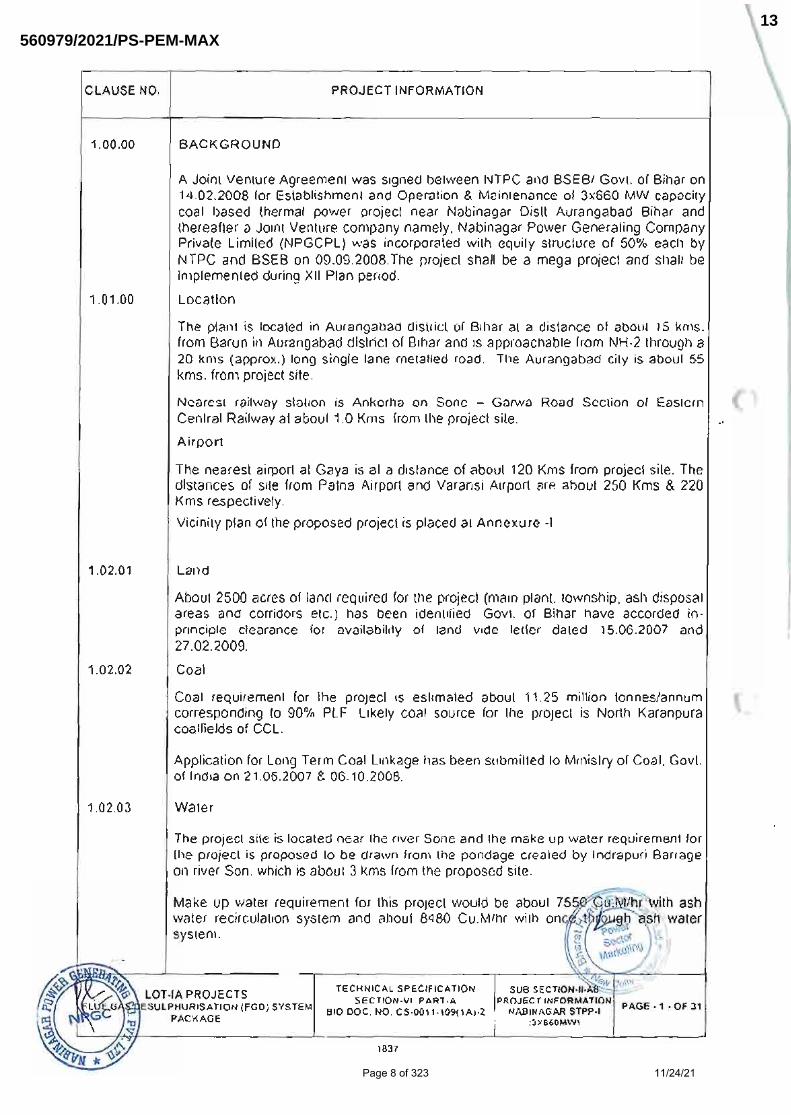
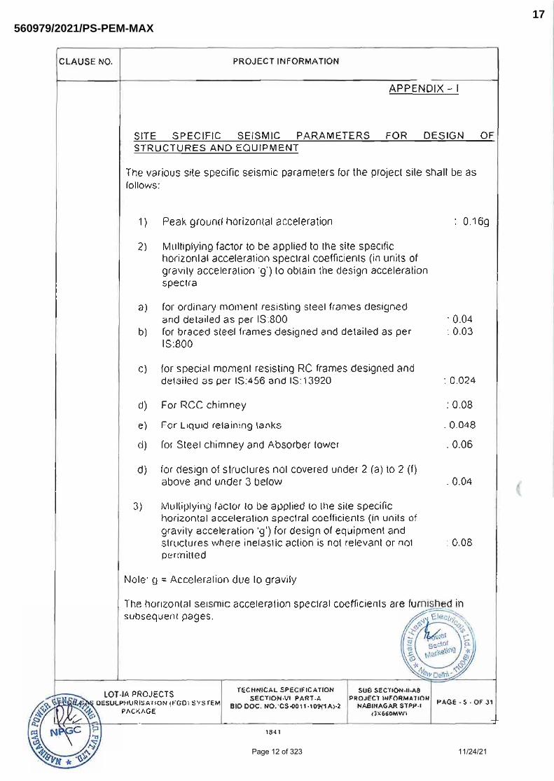
PROJECT INFORMATION WITH WIND AND SEISMIC DESIGN CRITERIA
Page 7 of 323 11/24/21
560979/2021/PS-PEM-MAX12
Page 8 of 323 11/24/21
560979/2021/PS-PEM-MAX13

Page 9 of 323 11/24/21
560979/2021/PS-PEM-MAX14

Page 10 of 323 11/24/21
560979/2021/PS-PEM-MAX15

Page 11 of 323 11/24/21
560979/2021/PS-PEM-MAX16
Page 12 of 323 11/24/21
560979/2021/PS-PEM-MAX17

Page 13 of 323 11/24/21
560979/2021/PS-PEM-MAX18

Page 14 of 323 11/24/21
560979/2021/PS-PEM-MAX19

Page 15 of 323 11/24/21
560979/2021/PS-PEM-MAX20

Page 16 of 323 11/24/21
560979/2021/PS-PEM-MAX21

Page 17 of 323 11/24/21
560979/2021/PS-PEM-MAX22
3062805
Line

Page 18 of 323 11/24/21
560979/2021/PS-PEM-MAX23
3062805
Line

Page 19 of 323 11/24/21
560979/2021/PS-PEM-MAX24
3062805
Line

Page 20 of 323 11/24/21
560979/2021/PS-PEM-MAX25
3062805
Line

Page 21 of 323 11/24/21
560979/2021/PS-PEM-MAX26
3062805
Line
3062805
Line

Page 22 of 323 11/24/21
560979/2021/PS-PEM-MAX27
3062805
Line

Page 23 of 323 11/24/21
560979/2021/PS-PEM-MAX28
3062805
Line

Page 24 of 323 11/24/21
560979/2021/PS-PEM-MAX29
3062805
Line

Page 25 of 323 11/24/21
560979/2021/PS-PEM-MAX30
3062805
Line

Page 26 of 323 11/24/21
560979/2021/PS-PEM-MAX31
3062805
Line

Page 27 of 323 11/24/21
560979/2021/PS-PEM-MAX32
3062805
Line

Page 28 of 323 11/24/21
560979/2021/PS-PEM-MAX33
3062805
Line

Page 29 of 323 11/24/21
560979/2021/PS-PEM-MAX34
Page 30 of 323 11/24/21
560979/2021/PS-PEM-MAX35

Page 31 of 323 11/24/21
560979/2021/PS-PEM-MAX36

Page 32 of 323 11/24/21
560979/2021/PS-PEM-MAX37
3062805
Line

Page 33 of 323 11/24/21
560979/2021/PS-PEM-MAX38
3062805
Line

Page 34 of 323 11/24/21
560979/2021/PS-PEM-MAX39
3062805
Line

Page 35 of 323 11/24/21
560979/2021/PS-PEM-MAX40
3062805
Line

Page 36 of 323 11/24/21
560979/2021/PS-PEM-MAX41
3062805
Line

Page 37 of 323 11/24/21
560979/2021/PS-PEM-MAX42
3062805
Line

Page 38 of 323 11/24/21
560979/2021/PS-PEM-MAX43
3062805
Line

TITLE: NABINAGAR SUPER THERMAL POWER
PROJECT (3x660MW) TECHNICAL SPECIFICATION
FOR AGITATORS OF FGD SLURRY TANKS
SPECIFICATION No: PE-TS-457-571-18000-A003 SECTION-I, SUB-SECTION-C REV. 00 DATE: SHEET : 1 OF 1
SPECIFIC TECHNICAL REQUIREMENT-MECHANICAL
Page 39 of 323 11/24/21
560979/2021/PS-PEM-MAX44

TITLE: NABINAGAR SUPER THERMAL POWER
PROJECT (3x660MW) TECHNICAL SPECIFICATION
FOR AGITATORS OF FGD SLURRY TANKS
SPECIFICATION No: PE-TS-457-571-18000-A003 SECTION-C, SUB-SECTION-C1 REV. 00 DATE: SHEET : 1 OF 20
1.0. APPLICABLE CODES & REGULATIONS The design and materials shall conform to the requirements of applicable codes and regulations of the latest edition. The design, manufacture, installation and testing of the Agitator shall follow the latest applicable Indian/International (AISI / ASME/EN/Japanese) Standards.
Bidder shall supply the equipment in accordance with relevant regulations, codes and standards specified in the specification. If required by relevant regulations, codes and standards specified in the specification, Successful Bidder shall assist BHEL to obtain approval against the equipment, documents and drawings by Indian authorities.
2.0. PROVENNESS CRITERIA/Pre-QUALIFICAITON REQUIREMENT The Bidders are required to meet the Qualification Requirement (PQR) for Agitators as per Proven-ness Criteria & shall submit the credentials as called in the tender document. Bidder shall submit the Annexure to qualification requirement (Attachment-3k). Only OEMs qualifying as per the Qualification requirement shall be considered for placement of order.
3.0. TECHNICAL INFROMATION 3.1 AGITATOR DETAILS:
For agitators refer “Agitator Schedule” in Section-II, Annexure-8 of the specification.
3.2 MATERIAL OF CONSTRUCTION
Sl. No. Material of construction
Horizontal agitators (side entry) Vertical Agitators ( Top entry)
i. Impeller blade Alloy 926 or better material Alloy 926 or better material
ii.
Impeller Hub Alloy 926 or better material Alloy 926 or better material (or) Carbon steel with 6mm thick Bromo/Chloro Butyl Rubber Lining (as per Proven practice)
iii. Shaft Alloy 926 or better material CS with Rubber Lining (min 6 mm thk Chloro/bromo butyl Rubber)
iv. Fasteners in wetted parts Alloy 926 or better material Alloy 926 or better material
v. Fasteners in Non Wetted GI fastener (40 μ plated) /
SS GI fastener (40 μ plated) / SS
vi. Mounting base Alloy 926/SMO254 (Wetted parts)
Carbon Steel
vii. Tank Nozzle (for inserting agitator) with Flange
Not applicable (in BHEL scope)
Not applicable (in BHEL scope)
viii.
Flush pipe for Start up with flange
FRP or Alloy 926 or Alloy 59 (Material has to be selected based on flush velocity)
Not applicable
ix.
Tank nozzle with flange (for Flush Pipe)
(i)For absorber agitator Carbon Steel with 2mm C276 lining inside the pipe and on the flange face (ii)For other tanks -Carbon Steel
Not applicable
x. Agitator Support Leg Carbon Steel Not applicable
Page 40 of 323 11/24/21
560979/2021/PS-PEM-MAX45

TITLE: NABINAGAR SUPER THERMAL POWER
PROJECT (3x660MW) TECHNICAL SPECIFICATION
FOR AGITATORS OF FGD SLURRY TANKS
SPECIFICATION No: PE-TS-457-571-18000-A003 SECTION-C, SUB-SECTION-C1 REV. 00 DATE: SHEET : 2 OF 20
3.3 POWER SUPPLY DETAILS:
3.4 AGITATOR ARRANGEMENT For arrangement of Agitators please refer “SIZING CALCULATION, SELECTION PARAMETER FOR ALL TANKS” under Annexure-III, Sub-Section-D, Section-I. Auxiliary Absorber Tank Agitators will operate continuously when Limestone / Gypsum Slurry is evacuated from Absorber for any Absorber maintenance work. Other Slurry Tanks and sumps Agitators will operate continuously for FGD system operation.
4 SCOPE OF SUPPLY & SERVICES The bidder shall assume sole responsibility for the design, fabrication, testing, surface preparation & painting, packing, transportation and performance of the specified equipment with accessories, and shall ensure that the equipment with accessories are in conformance with this specification, as well as other documents which form part of the Purchase Order/Contract.
Various inspections by the BHEL/NTPC shall not relieve the Bidder in any way of his obligation to maintain an adequate test, inspection, and documentation program of his own, and shall not relieve the Bidder of any other obligation under this specification. Furthermore, any inadvertent overlook of deviations from some requirements of this specification by the buyer shall not constitute a waiver of these requirements, or of the Bidder's obligation to correct the condition when it is discovered, or of any other obligation under this specification. This specification only states the lowest technical requirement, neither specifying all technical details, nor referring the pertaining code and standard fully. It is the Bidder's responsibility to ensure that the complete delivery complies with all relevant codes, standards and specifications. The Bidder is obliged to supply relevant drawings and documentation to the buyer. All to be in English language and metric system, if not otherwise agreed in writing.
Scope for the bidders shall include Design, Manufacturing, Supply, and Supervision of Erection & Commissioning by OEM.
1. POWER SUPPLY
The following voltage levels shall apply: 3 phase, 6.6 kV AC ,50 Hz Voltage for motors rated 175 kW and
upto 1500 kW and for power distribution within the plant.
3 phase, 415 V, AC , 50 Hz Standard voltage for power supplies to electric power consumers and motors Above 0.2 KW and upto 175 kW.
1 phase 240V AC / 3 phase 415 V AC, 50 Hz
Standard voltage for power supplies to electric power consumers and motors Upto 0.2 kW.
1. All equipments at 415V voltage level shall be suitable for voltage variation of ±10% and rated frequency of 50 Hz with a variation of + 3% to -5%, and 10 % (absolute sum) combined variation of voltage and frequency unless specifically brought out in the specification.
2. Bidder shall design and supply the equipment suitable for satisfactory operation under above mentioned power supply condition.
3. For further details refer electrical specification under Section-I, Sub-Section-C3.
Page 41 of 323 11/24/21
560979/2021/PS-PEM-MAX46

TITLE: NABINAGAR SUPER THERMAL POWER
PROJECT (3x660MW) TECHNICAL SPECIFICATION
FOR AGITATORS OF FGD SLURRY TANKS
SPECIFICATION No: PE-TS-457-571-18000-A003 SECTION-C, SUB-SECTION-C1 REV. 00 DATE: SHEET : 3 OF 20
Design: Broadly includes basic engineering, detail engineering, preparation and submission of engineering drawings/calculations/datasheets/quality assurance documents/field quality plans, storage instructions, commissioning procedures, Erection & assembly Drawings, operation & maintenance manuals, performance guarantee test procedures and assisting BHEL in obtaining time bound approval from customer.
Supply: The scope includes the following:
Includes manufacturing/fabrication, shop floor testing, stage inspections, final inspections, painting & packing.
Mandatory spares as defined as Section-I, Sub-Section-D, Annexure-II.
Recommended spare parts list to be furnished (is not part of scope of supply)
Any special tools & tackles required for the entire equipment to disassemble assemble or maintain the units.
Start-up & Commissioning Spares
First fill of consumables
Services: Services to be provided by the bidder:
Detailed Erection and commissioning procedure shall be submitted by successful bidder for carrying out the erection and commissioning at site by BHEL.
Supervision for Erection & Commissioning, trial run at site by OEM.
Performance guarantee tests at site & handover in flawless condition of the package to the customer
Training of customer/ client O&M staff covering all aspects of the Agitators - Operation & Maintenance, Trouble-shooting etc. at site
Training of customer at manufacturer’s works (3 persons for 2 days including lodging and boarding)
Visits shall be planned by BHEL site team and prior intimation shall be sent to supplier for visit to site for supervision services. Bidder shall be informed at least 10 days in advance for the requirement of visit at site. Visiting team shall consist of one or two expert of bidder (OEM) as deemed necessary by them.
The scope of supply for AGITATORS shall include but not limited to the following:
A) For Horizontal (Side Entry) Agitators:
Sl. No
Scope
1. AGITATOR complete with i. AGITATOR Blades
ii. AGITATOR Shafts iii. Coupling arrangement (Flexible) iv. Single Mechanical Seals v. Shaft Sleeve
vi. Lanterns/ Stools ( Bearing Housing), Safety Guard vii. Bearings
viii. Agitator Mounting Flanges with gaskets and fasteners ix. Drive Motor(IE3) with gearbox arrangement x. Supporting arrangement including tie rods, gusset plates etc. of Side Entry Agitator on the
tank Wall. Vessel Nozzle and mating flange for supporting on the tank wall, gaskets and
Page 42 of 323 11/24/21
560979/2021/PS-PEM-MAX47

TITLE: NABINAGAR SUPER THERMAL POWER
PROJECT (3x660MW) TECHNICAL SPECIFICATION
FOR AGITATORS OF FGD SLURRY TANKS
SPECIFICATION No: PE-TS-457-571-18000-A003 SECTION-C, SUB-SECTION-C1 REV. 00 DATE: SHEET : 4 OF 20
Sl. No
Scope
fasteners. xi. VOID.
xii. Foundation plate with foundation bolts, vessel nozzle xiii. Painting and Rust Prevention during shipment and construction xiv. Packing and transportation xv. Supervision of Erection & commissioning at site by OEM.
xvi. Special tools & tackles as applicable xvii. Start-up spares, Spare parts for commissioning & erection, Mandatory Spares: As per
Project Specific Requirement xviii. Installation, operation and maintenance manuals xix. Any other items required for completeness of the equipment except the items covered in
the exclusions.
B) For Vertical (Top Entry) Agitators:
Sl. No
Scope
1. AGITATOR complete with i. AGITATOR Blades
ii. AGITATOR Shafts iii. Coupling arrangement (Flexible) iv. Gland Packing, Seals, O Rings, Glands v. Shaft Sleeve
vi. Lanterns/ Stools ( Bearing Housing), Safety Guard vii. Bearings
viii. AGITATOR Mounting Flanges with gaskets and fasteners ix. Drive Motor(IE3) with gearbox arrangement x. Mating Flange for Supporting on Slurry Tank Roof
xi. Shims xii. Painting and Rust Prevention during shipment and construction
xiii. Packing and transportation xiv. Supervision of Erection & commissioning at site by OEM. xv. Special tools & tackles as applicable
xvi. Start-up spares, Spare parts for commissioning & erection, Mandatory Spares: As per Project Specific Requirement
xvii. Installation, operation and maintenance manuals xviii. Any other items required for completeness of the equipment except the items covered
in the exclusions. The quantity, location of the agitators has been included in the agitator schedule (Section-II, Annexure-8). 4.1 TECHNICAL REQUIREMENTS I Agitators shall be supplied in tanks and vessels to prevent caking and settlement of particles
out of the slurry, e.g. in the limestone slurry tank, Auxiliary Absorbent tank, and sumps etc.
II
All agitators shall be designed for continuous operation unless otherwise specified. The design of the agitators shall be of proven type. BHEL, during detail engineering reserves the right to ask for CFD (Computational Fluid Dynamics) analysis to accurately determine equipment requirements. Successful Bidder shall provide the same without any additional
Page 43 of 323 11/24/21
560979/2021/PS-PEM-MAX48

TITLE: NABINAGAR SUPER THERMAL POWER
PROJECT (3x660MW) TECHNICAL SPECIFICATION
FOR AGITATORS OF FGD SLURRY TANKS
SPECIFICATION No: PE-TS-457-571-18000-A003 SECTION-C, SUB-SECTION-C1 REV. 00 DATE: SHEET : 5 OF 20
price implication.
III
Standard type agitators with suitable characteristics shall be used wherever practical. The agitators shall be complete with motor, gearbox, agitator shaft, coupling, safety guards, mechanical seal (for side entry agitators), impeller, support legs, agitator mounting flange including bolts nuts and gasket etc.
IV All agitator parts and accessories in contact with the stirred fluid shall be constructed of materials specifically designed for the conditions and nature of the stirred fluid and be resistant to erosion and corrosion.
V
The material for the shaft (which is continuously in contact with slurry) and agitator blades of the Auxiliary Absorbent Tank Agitators shall be made with Alloy 926 or better material. For Agitators in other tanks, agitator blades shall be made with Alloy 926 or better material and shaft can be rubber lined (minimum 6 mm thick Chlorobutyl Rubber). This does not release the bidder of the responsibility for selecting the correct materials.
VI
Each agitator and its associated equipment shall be arranged in such a manner as to permit easy access for operation, maintenance and agitator removal without interrupting plant operation. It shall be possible to remove the sealing devices of the side mounted agitators without having to drain completely the slurry inside the tank.
VII -VOID- VIII
Lifting lugs and eyes and other special tackle shall be provided as necessary to permit easy handling of the agitators and their components.
IX Static and dynamic (as far as applicable) balancing of all agitators shall be carried out after assembly. Any deviation to this requirement is subject to customer approval during detailed engineering based on applicable codes and standards to be furnished by the bidders.
X
All agitator parts and components shall be designed and calculated for fatigue life, considering maximum bending loads, induced by fluctuating hydraulic forces and torsional loads, based on the installed motor power. For side entry agitators the alternating bending moment resulting from impeller and shaft weight has to be considered additionally.
XI All exposed moving parts shall be covered by guards.
XII
The shape of the impeller blades of side entry agitator’s/top entry agitators shall be designed to avoid wear on the impellers which will affect the agitator performance as specified for a minimum period of 2 years of continuous operation under design conditions for the range of slurry specified in the specification. In order to avoid excessive wear impeller tip speeds must not exceed 12 m/s.
XIII Belt drives (if applied for side entry agitators) shall be properly designed to provide a minimum lifetime of 2 years under design conditions
XIV It shall be noted that all Agitators are meant for keeping the solid particles in suspended mode in liquid with “Full Off-Bottom Suspension” of solid particles to 98% of liquid column to virtually “Uniform Solid Concentration”. No chemical reaction will take place.
XV
Maintaining a uniform concentration over the 95% of liquid column. Absolute sweeping of solid particle from tank bottom is a must for all Agitators. If speed is required to be increased to guarantee the above requirements; the same can be increased by vendor. Bidder's machines that consume less power will be in an advantageous position.
XVI It is to be noted that in continuous process any deposit at tank bottom is the loss of material which are not getting converted as per process. Hence, total loss of material by sedimentation is a loss to FGD Process & determines the “In efficiency of the Agitator”.
XVII Vendor should ensure nil settlement; utilization of solid material shall be a guaranteed parameter and will be assessed in percentage (%) term to net wet of solid mass of inflow or out flow. This is one of the guarantee parameter.
XVIII Agitator and its driver shall perform on the test stand at shop and on the Agitator’s permanent location at site within vibration limit. The vibration of combined unit will be the responsibility of Agitator manufacturer. Agitator manufacturer is to ensure that Site
Page 44 of 323 11/24/21
560979/2021/PS-PEM-MAX49

TITLE: NABINAGAR SUPER THERMAL POWER
PROJECT (3x660MW) TECHNICAL SPECIFICATION
FOR AGITATORS OF FGD SLURRY TANKS
SPECIFICATION No: PE-TS-457-571-18000-A003 SECTION-C, SUB-SECTION-C1 REV. 00 DATE: SHEET : 6 OF 20
performance of vibration is one of the “Acceptance Criteria” of the equipment. Please note that vibration at test stand can only be taken as “for information”.
XIX
Every Tank will have a pump whose suction line shall be connected to tank. These pumps are to operate continuously at the lowest operating level which is decided by Process requirement. Hence, the minimum operating level of liquid in every tank for every Agitator is a must to assess the combined operation of Agitator as well as that of pump alone. The Tank water level is indicated in “SECTION-II Annexure-8”. Any minor change in liquid level required by Agitator supplier will be accommodated only if it is acceptable to the pump supplier.
XX
Agitator must have low-pitch propeller with low solidity ratio and Power Number. The Maximum Input Power at motor terminal shall be considered as a guaranteed parameter under “Schedule of Guaranteed Parameters” in “SECTION-II Annexure-10-Schedule of Guarantees”- and the same shall be calculated for maximum liquid level in tank. A calculation of power specifying the hydraulic power of Agitator, Seal loss, Gear box and Motor internal loss must be submitted along with the offer. A characteristics curve showing power versus liquid level should be submitted from the lowest liquid level, required for Agitator to maximum liquid level in the tank. Motor should be selected based on the highest power demand with a 10%margin at maximum liquid level, taking into account frequency variation.
XXI
The agitator shall be suitably designed for mounting and operation in purchaser’s tank whose details are given under sizing calculation of tanks, annexed with the enquiry specification (SECTION-I, SUB-SECTION-D, Annexure-III). The bidder shall review and seek clarifications, if any on Tank sizing document.
XXII In case Bidder provides a Vertical Agitator with hub design, the same has to be of Alloy 926 or better material. Impeller hub material has to be Alloy 926 or better material.
XXIII
Unless otherwise specified, for small diameter impeller, it shall be possible to remove complete agitator assembly without dismantling through the opening provided on the tank/sump, and for large diameter impeller, the blade shall be of removable construction for ease of removal. Bidder shall also provide the headroom required for taking out the agitator as above.
XXIV Any instruments provided shall be Profibus Compatible.
XXV Bidder shall provide the design and arrangement of baffle plates in circular tanks. Baffle plates are in BHEL scope.
XXVI
Bidder shall provide proper dowelling between motor and base plate, gear box and mounting tool/base plate, for ease of assembly of agitator unit. Tapered dowell shall be provided.
XXVII
Vendor shall provide suitable arrangement for supporting the agitator shaft with impellers during removal of gear-box for maintenance and details of such arrangements shall be furnished.
4.2 CONSTRUCTIONAL FEATURES A) BLADE AND HUB OF PROPELLER I) The blades of the agitators shall be of Alloy 926 or better material.
II) The Blade design of the Agitator to be of most efficient design in order to offer least power consumption. The Agitator power consumption is part of the guarantee parameters.
III)
Although Agitator will have substantial low speed because of reduction Gear Box, hydraulic unbalance at impeller can cause severe vibration, hence it is mandatory that rotating assembly shall be dynamically balanced to its rated speed. Any deviation to this requirement is subject to customer approval during detailed engineering based on applicable codes and standards to be furnished by the bidders.
IV) Impeller should be dynamically balanced to Gr: G16: ISO-1940 after rubber lining of shaft. B) SEAL
Page 45 of 323 11/24/21
560979/2021/PS-PEM-MAX50

TITLE: NABINAGAR SUPER THERMAL POWER
PROJECT (3x660MW) TECHNICAL SPECIFICATION
FOR AGITATORS OF FGD SLURRY TANKS
SPECIFICATION No: PE-TS-457-571-18000-A003 SECTION-C, SUB-SECTION-C1 REV. 00 DATE: SHEET : 7 OF 20
1 Horizontal / Side Entry Agitators:
I. Agitators should be provided with Single Stage mechanical seal. The mechanical seal should be as per ISO-21049 / API 682.
II. The Mechanical Seals shall be so arranged that repacking or fitting of replacement seals can be carried out with the minimum of disruption to plant operation.
III. Design the mechanical seals chamber to have sufficient room to lubricate and get seal face cool with its own slurry.
IV. -VOID-
V. All mechanical seals, regardless of type or arrangement, shall be of the cartridge design. Hook sleeve cartridge should not be used.
VI. -VOID- VII. Requirement of flushing water, its quantity, and pressure to be indicated in data sheet.
VIII. Zero leakage is the intension of this specification. However, quantity of leakage, if it is unavoidable, it should have a provision of collecting / or discharging back to the tank.
IX. Mechanical seals shall be fitted and installed in the Agitator before shipment and shall be clean. Mechanical seals shall be plugged with screw for shipping.
X
Intention of the specification is not to specify Type of Seal, Seal design, Spring configuration, Seal configuration, Balanced or Unbalance type etc. Agitator manufacturer to decide the same along with seal manufacturer, the best seal that is suitable for the offered Agitator
XI Seal life has to be guaranteed, taking into consideration all its components for 25000 hrs. If the seals fail before the completion of guaranteed period, the same should be replaced free of cost by the bidder.
XII The sub-vendor of the seal shall be approved by customer during contract execution. 2 Vertical Agitators for Other Slurry Tanks & Drain Pit Tanks
I
Agitator shall be supplied with stuffing box or any proven equivalent or superior sealing type. Construction of Gland Packing shaft seal system shall be as per the below fig:
II
Agitator shall be supplied with stuffing box or any proven equivalent or superior sealing type. For type of sealing to be provided for various Agitators please refer Agitator schedule. Mechanical and hydraulic conditions in the seal chamber, required to maintain a stable film at seal face, including temperature, pressure and flow, shall be jointly established by Agitator manufacturer and seal manufacturer, and shall be noted in data sheet submitted in
Page 46 of 323 11/24/21
560979/2021/PS-PEM-MAX51

TITLE: NABINAGAR SUPER THERMAL POWER
PROJECT (3x660MW) TECHNICAL SPECIFICATION
FOR AGITATORS OF FGD SLURRY TANKS
SPECIFICATION No: PE-TS-457-571-18000-A003 SECTION-C, SUB-SECTION-C1 REV. 00 DATE: SHEET : 8 OF 20
tender. If mechanical seal is offered by bidder, the mechanical seal should be as per ISO-21049 / API 682.
C) SHAFT
I.
MOC of Shaft shall be as per Clause no.3.2 & “Agitator Schedule”, Section-II, Annexure-8. Use of dissimilar material at flange joint shall be avoided to eliminate any crevice corrosion. Spacing of the shaft joint should not be more than 3.0 m for easy assembly if it is more than 40kg. If welding is used for joining two tubes, welding joint must be 100% radio graphed. If split shaft is proposed for larger tanks , shaft flange at the joining interface has to be rubber lined at manufacturer’s works and necessary fasteners have to be provided.
D) BEARING & BEARING HOUSING IN GEAR BOX
I Bearing shall be of rolling type radial and thrust bearing (FAG/SKF/Timken make only) as required. Thrust bearing shall be sized for continuous operation under all specified condition.
II
Thrust bearing shall provide full load capability if the Agitator’s normal direction of rotation is reversed. Up-thrust and Down-thrust load must be taken into account in sizing bearing. Life of the every anti-friction bearing, used in the bearing housing as per manufacturer’s design, should have L10 of 25000 hr (minimum).
III
Bearing housing should be grease/oil lubricated. If bearing is oil lubricated, constant–level sight-feed oiler of 100cc size or bigger capacity is to be provided. Bearing housing should have oil drain, constant oil level indicator. A provision of one (1) number G1/2” thread (ISO-228, Part-1)port is required for remote control of temperature of bearing housing oil bath through RTD.
IV If bearing housing requires cooling water, volume and pressure of cooling water is to be indicated in Technical Data Sheet.
V Lubricating oil will be the responsibility of Gear Box manufacturer. Hence, manufacturer has to make arrangement of first fill of oil at installation and at commissioning stage. Quantity of oil and its grade is to be indicated in Drawing and Operation Manual.
E) MATERIALS
I Agitator components designated as “Full Compliance Material” shall meet the requirements of the industry specification as listed for the material in the table as well as in the specification in the respective section.
II A detail quality plan is to be submitted along with offer for all items marked “Full Compliance Material”.
III Final acceptance of the quality plan will be approved by ultimate user during detailed engineering without any commercial implication. QAP should be as per the best practice followed internationally to avoid any conflict of interest.
F) DRIVER (MOTOR)
I Driver shall be sized to meet all specified operating conditions including bearing housing , seal, external gear box and coupling loss( if any).
II Motor shall be able to accelerate to speed at reduced voltage and frequency as specified in “Site Power Supply Condition” as per Clause: 3.3.
III It should meet the electrical specification (SECTION-I, SUBSECTION-C3). G) GEAR BOX
I.
Gear box should be vertical flange mounted solid shaft type (Vertical Agitators), reducing speed type, specially designed for the requirement of Slurry mixing and to be manufactured by the Agitator supplier. Complete up-thrust and down-thrust, developed by Agitator shall be taken by thrust bearing housing of Gear Box. An auxiliary slow drive provision shall be provided in the Gear Box so that slurry is always kept in dynamic condition to avoid settling of slurry at bottom, in the event
Page 47 of 323 11/24/21
560979/2021/PS-PEM-MAX52

TITLE: NABINAGAR SUPER THERMAL POWER
PROJECT (3x660MW) TECHNICAL SPECIFICATION
FOR AGITATORS OF FGD SLURRY TANKS
SPECIFICATION No: PE-TS-457-571-18000-A003 SECTION-C, SUB-SECTION-C1 REV. 00 DATE: SHEET : 9 OF 20
of Agitator is not operating at its rated speed. Rating of Gear box shall be at least 1.5 times the rated torque of Agitator. Gear box details are subject to customer approval during detailed engineering without any commercial implications.
II. The reduction unit shall be procured from a reputed manufacturer and shall confirm to BS: 721 (latest edition)/AGMA/Equivalent specifications. The sub-vendor of the gear-box shall be approved by customer during contract execution.
III. Gear drives shall have splash type oil lubrication. If oil pumps are used, they shall be removable for maintenance without disturbing the motor or drive housing.
IV. The gear reduction unit shall always be provided with an oil drain, a breather and oil level gauge. The lubrication to be designed keeping in view that the temperature within the bearing should not exceed 85 Deg. C.
V. -VOID-
VI. The bidder shall provide an easily accessible oil level gauge and a dipstick that will indicate oil level under standstill and operating conditions.
H) COUPLING & COUPLING GUARD
I. Coupling and coupling guard should be supplied between driver and driven equipment.
II. Coupling should be designed taking into consideration adequate service factor.
III. Design rating of the coupling (excluding service factor) should be indicated in data sheet.
IV. Coupling must be having locking screw so that it does not slide over shaft in due course operation.
V.
Vertical Agitators - Coupling between Motor and Gear Box, if applicable, shall be Spacer-type flexible coupling, made of Cast Iron. Spacer shall be of sufficient length so than Motor and Gear Box shall be able to run independently at no-load condition by detaching the respective coupling.
VI.
It is desirable that for servicing of seal, coupling half should not be removed. Coupling should be dynamically balanced to Gr: G6.3, ISO-1940. Any deviation to this requirement is subject to customer approval during detailed engineering based on applicable codes and standards to be furnished by the bidders.
VII. Removable coupling guard shall conform to the requirements of all applicable national, industrial or statutory regulations.
I) PLATE AND FASTENING BOLTS
I.
Base plate shall be interpreted as the component of Agitator assembly through which the whole load will be transmitted to the Sole Plate/Nozzle over which the equipment will be mounted. The Base plate shall be fabricated with mild steel of structural quality (UTS=42N/sq mm minimum) with anti-corrosive paint of sufficient dry-film thickness.
II. Base plate must have provision of leveling on its intended mounting place. Nozzle is not in the scope of supply of Agitator manufacturer. It should be noted that Nozzle will be rubber lined to prevent any leakage of corrosive gases
III.
Alignment between Gear Head Shaft and Agitator shaft shall be within the permissible limit of Gear Box. Similarly, misalignment between Motor shaft and Gear Box Shaft shall be within 0.050 micron (radial) and 2 degree (angular) or better as per requirement of Motor and Gear Box
IV.
Base plate with desired number of hole shall be provided by the bidder, will be machined on one side. Base Plate shall be welded to the structure after leveling, as recommended by Agitator manufacturer and rubber lining is completed before placing the equipment in its
Page 48 of 323 11/24/21
560979/2021/PS-PEM-MAX53

TITLE: NABINAGAR SUPER THERMAL POWER
PROJECT (3x660MW) TECHNICAL SPECIFICATION
FOR AGITATORS OF FGD SLURRY TANKS
SPECIFICATION No: PE-TS-457-571-18000-A003 SECTION-C, SUB-SECTION-C1 REV. 00 DATE: SHEET : 10 OF 20
desired location. J) OTHER COMPONENTS
I All fasteners used in wetted condition must be of Alloy 926 or better material so that even if it comes in contact with liquid by swelling of rubber, thread remains unaffected. Raw material of fastener must undergo Inter-granular Corrosion test as per ISO-3651, Part-1 for Nitric Acid test.
II Mounting flange dimensions shall be as per ASME B16.5 up to 600 Nb, ASME B 16.47 for more than 600 NB.
III
Rubber Lining (As Applicable) a) Rubber lined surfaces shall utilize 6 mm nominal thickness chlorobutyl rubber. b) Areas of high wear (e.g. leading edges on impeller blades) shall have an additional
6 mm of rubber for abrasion protection. c) No field-applied linings are permitted except for file patch kits.
K) GENERAL REQUIREMENT OF SIDE ENTRY AGITATORS: I. All Agitators shall be designed for continuous operation.
II. The Material of Construction (MOC) of Agitators shall be Alloy 926 or better material as per Cl. No. 3.2 & “Agitator Schedule” ”, Section-II, Annexure-8.
III. It should be of Flange mounted type.
IV.
Nozzle size, on which Agitator shall be mounted, shall have enough opening to Insert rotating assembly from side. Bidder shall inform the required nozzle size. Further the mating flange shall be in the scope of the bidder.
V. The Bidder to consider Gypsum Sedimentation during stoppage of Agitator.
VI.
The following information to be provided along with the bid: a) Impeller Diameter b) Impeller Speed c) Agitator Pumping Capacity ( m^3/min) d) Volume per Agitator:
L) GENERAL REQUIREMENT OF TOP ENTRY AGITATORS IN OTHER SLURRY TANKS & DRAIN PITS:
I. All Agitators shall be designed for continuous operation.
II. The Material of Construction (MOC) of Agitators: Agitator blades shall be made with Alloy 926 or better material & Agitator shaft can be rubber lined as per Clause No.3.2 & “Agitator Schedule” , Section-II, Annexure-8.
III. It should be roof mounted.
IV.
Agitators shall be vertical mounted type and shall be driven by motor with reducing speed gear box of rigid type, solid shaft coupling between gear box and agitator and flexible coupling of spacer type between Motor and Gear Box. Both Gear Box and Motor should be vertically/horizontally flange mounted type with a common frame of the whole equipment. The entire thrust load of agitator should be transmitted to the thrust bearing of Gear box.
V. Nozzle size, on which Agitator shall be mounted, shall have enough opening to Insert rotating assembly from top. Bidder shall inform the required nozzle size. Further the mating flange shall be in the scope of the bidder.
VI. Cable entry to the Motor terminal box should preferably be from top when motor is vertically mounted at its position and it should be easily accessible.
VII. Impeller should be dynamically balanced to Gr: G16: ISO-1940 after rubber lining of shaft.
VIII In case Bidder provides a Vertical Agitator with hub design the same has to be of Alloy 926 or better material
IX Operation speed of the Agitator motor shall be at least 25% below the first critical speed. X -VOID-
Page 49 of 323 11/24/21
560979/2021/PS-PEM-MAX54

TITLE: NABINAGAR SUPER THERMAL POWER
PROJECT (3x660MW) TECHNICAL SPECIFICATION
FOR AGITATORS OF FGD SLURRY TANKS
SPECIFICATION No: PE-TS-457-571-18000-A003 SECTION-C, SUB-SECTION-C1 REV. 00 DATE: SHEET : 11 OF 20
XI -VOID- 4.3 MOTOR
All AC motor shall be Squirrel cage induction motor and, shall be suitable for direct –on-line starting. Rating of the motor should of Type S1 (Continuously rated) as per ISO-60034, Part-1. Rating of motor must be selected with minimum margin (as per the below table) above the maximum load demand of the driven equipment under entire operating range including voltage and frequency variation: Agitator Rated BKW Motor Margin <22KW 125% of Agitator Rated BKW 22KW-55KW 115% of Agitator Rated BKW >55KW 110% of Agitator Rated BKW
It should meet the electrical specification (SECTION-I, SUBSECTION-C3). 5 GENERAL REQUIREMENTS
1 Metric unit shall be used in the drawings and in the any displays on the equipment’s. Special attention should be taken that the unit of pressure shall be in dual scales of kPa and kg/cm2(G). For instance the pressure gauges should have dual unit’s indication.
2 Descriptions in the drawings, in the documents, and in the displays shall be in English
3 All rotating parts such as coupling shall be covered with suitable protective guards. Guards shall be easily removable type.
4 The equipment shall be designed to withstand the corrosive and moist environment in which these are proposed to operate.
5 Noise level produced by any rotating equipment individually or collectively shall not exceed 85 dB measured at a distance of 1.0 meters from the source in any direction and 1.5m above operating floor.
6 The overall vibration level shall be as per ISO 10816. 7 Suitable drain connections shall be provided. 8 The equipment shall be suitable for stable operation continuously.
9
Corrosion allowance: Corrosion allowance for entire equipment shall be in accordance with latest applicable Indian / International standard. Carbon steel shaft shall have a corrosion allowance of 6mm on its diameter. On other non-pressure carbon steel parts a corrosion of 3mm shall be considered on each surface.
10 Unless otherwise specified , flanges shall be in accordance with ANSI B16.5 Class 150
11
Name plate: All equipment shall be provided with nameplates indicating the item number and service name. Name plates shall be of 304 Stainless steel plate and placed at a readily visible location. Nameplate of main equipment shall have enough information, which will be confirmed during engineering phase. Stainless steel nameplates for all instruments and valves shall be provided.
12 Rotation arrows shall be cast in or attached with stainless steel plate on each item of rotation equipment at a readily visible location.
13
Unless otherwise specified, all equipment items where the weight exceeds 15 kg shall be provided with suitable lifting lugs, ears or ring bolts or tapped holes for lifting rings. Minimum shock factor for lifting lugs shall be minimum 2.0. The position of lifting lugs and reference dimension shall be shown on GA and/or outline drawings. NDT shall be conducted for lifting lugs. When any spreader bars are required for lifting and laydown, the bidder shall provide spreader bar with equipment.
14 Skid Mount/Transportation: Equipment shall be fabricated as skid mount design as much as practical to minimize erection at the site.
15 If the driver/driven equipment train is in the resonance condition or any vibration problems occur, the bidder shall solve the problems in a timely manner.
16 Bidder shall provide the necessary gaskets.
Page 50 of 323 11/24/21
560979/2021/PS-PEM-MAX55

TITLE: NABINAGAR SUPER THERMAL POWER
PROJECT (3x660MW) TECHNICAL SPECIFICATION
FOR AGITATORS OF FGD SLURRY TANKS
SPECIFICATION No: PE-TS-457-571-18000-A003 SECTION-C, SUB-SECTION-C1 REV. 00 DATE: SHEET : 12 OF 20
17 All the surfaces of the carbon steel should be rust prevented before shipment for the period of at least 12 months for storage and construction.
18 Bidder to provide capacity of hoist required for material handling and the details of heaviest component to be handled. Bidder shall provide a typical arrangement/drawing of the handling arrangement.
19 The list of all Bought out items with makes and country of origin to be mentioned along with offer to be submitted.
20
Cost towards the participation in discussions/meetings, providing technical assistance during technical discussions/meetings with customer for approval of drawing/documents etc. TA/DA, boarding and lodging to attend these meetings shall be borne by the bidder and shall be inclusive in supply portion.
21
Material of construction for all equipment/components shall be subject to customer/ BHEL approval during detail engineering. Accordingly bidder shall consider MOC for all equipment/component (complying tender specifications), as per best engineering practice, global standard and global references, in case no MOC is available in specs.
22
Bidder to provide sub vendor list and Bidder shall strictly adhere to customer approved vendor list (reference list is included in SUB-SECTION-D, Annexure-I). In case bidder proposes an additional vendor for an item or vendor approval is required for any new item, acceptance shall be subject to approval by customer/ BHEL before placing order and bidder shall submit relevant documents to take up with customer for approval. Bidder shall submit relevant documents as per Sub-Supplier Questionnaire provided in referred Annexure .
23
It shall be the complete responsibility of the successful bidder to obtain “Sub Vendor Approval” from BHEL / customer for all equipment’s & components. Any delay in sub vendor’s approval should not affect the project schedule. If any of the sub vendors does not have the approval of customer/ BHEL, the same may be replaced with another customer/BHEL approved sub-vendor only, without any price implications to BHEL.
24
The modalities of inspection (Stage, Final, In-process) shall be finalized during detail engineering after submission of quality assurance plan (QAP). It shall be reviewed by the end customer and BHEL. Bidder shall follow the procedures of inspection as per the approved QAP. Bidder has to submit the following documents along with inspection call and if any other documents required as per approved QAP. - Raw material inspection certificate - Internal test reports - Statutory certificates as required. - All inspection & testing shall be carried out based on the following documents: a. Relevant Standards b. Specifications c. Approved drawings d. Data Sheets e. Calibration certificate for all the measuring instruments
25 During detail engineering, bidder to strictly adhere to BHEL drawing formats, document numbering, quality plan & FQP formats
26 The identification and numbering of equipment, systems, items, etc. of supply, as well as of all documents and drawings shall be in accordance with reference Designation System for Power Plants - KKS system.
27 Complete detail engineering drawings, calculations, selection of components etc. shall be reviewed & subject to approval of BHEL/end customer during detail engineering
28 Bidder shall furnish necessary inputs & drawings of all equipment in editable Auto CAD/ MS-Word /Excel format.
29 During detail engineering, successful bidder shall ensure flow of drawings/documents as per schedule. Any comments from BHEL/end customer should be addressed timely by the
Page 51 of 323 11/24/21
560979/2021/PS-PEM-MAX56

TITLE: NABINAGAR SUPER THERMAL POWER
PROJECT (3x660MW) TECHNICAL SPECIFICATION
FOR AGITATORS OF FGD SLURRY TANKS
SPECIFICATION No: PE-TS-457-571-18000-A003 SECTION-C, SUB-SECTION-C1 REV. 00 DATE: SHEET : 13 OF 20
bidder.
30 Bidder to note above mentioned points not exhaustive and any work /items required for completing the smooth operation and ensuring satisfactory running of the machines till final hand over to the end user shall also be in the scope of the bidder.
31
Bidder shall provide design support to assist the Purchaser in efficiently integrating the furnished equipment. Design support specifically includes:
Bidder shall verify/ validate the number and location of agitators to keep material in suspension.
Static and dynamic loading information and requirements for agitator support design (applicable for top & side type)
32 Any other item required to meet the stipulations mentioned in GTR , GCC and SCC and relevant to Agitator package unless specifically excluded from scope of supply.
6 PACKING AND FORWARDING
1
Proper packing to be ensured. Indigenous Supply: Agitator & sub system assembly shall be wrapped in polythene bags & packed in a strong rigid wooden crate. Rain water should not enter into the Agitator internals during storage in the outer yard of power plant. Further the packing shall be done in line with requirements mentioned in point no. 2 to 20 of this section. Imported Supply: All imported supply should be packed as per Sea worthy packing standards as per Sub-Section D, Annexure-V. All imported items should have Sea worthy packing. Liberal packing materials and struts shall be provided to arrest rolling and to protect from transit damages.
2
Equipment and process materials shall be packed and semi-knocked down, to the extent possible, to facilitate handling and storage and to protect bearings and other machine surfaces from oxidation. Each container, box, crate or bundle shall be reinforced with steel strapping in such a manner that breaking of one strap will not cause complete failure of packaging. The packing shall be of best standard to withstand rough handling and to provide suitable protection from tropical weather while in transit and while awaiting erection at the site.
3
Equipment and materials in wooden cases or crates shall be properly cushioned to withstand the abuse of handling, transportation and storage. Packing shall include preservatives suitable to tropical conditions. All machine surfaces and bearings shall be coated with oxidation preventive compounds. All parts subject to damage when in contact with water shall be coated with suitable grease and wrapped in heavy asphalt or tar impregnated paper.
4 Crates and packing material used for shipping will become the property of end customer.
5
Packaging or shipping units shall be designed within the limitations of the unloading facilities of the receiving ports and the ship which will be used. It shall be the bidder’s responsibility to investigate these limitations and to provide suitable packaging and shipping to permit transportation to site.
6
Packing (tare) shall be part of the equipment cost and shall not be subject to return. The packing should ensure integrity and cohesiveness of each delivery batch of equipment during transportation. In case of equipment assemblies and unit’s delivery in the packing of glass, plastics or paper the specification of packing with the material and weight characteristics are to be indicated.
7
Each package should have the following inscriptions and signs stenciled with an indelible ink, legibly and clearly: a. Destination b. Package Number c. Gross and Net Weight
Page 52 of 323 11/24/21
560979/2021/PS-PEM-MAX57

TITLE: NABINAGAR SUPER THERMAL POWER
PROJECT (3x660MW) TECHNICAL SPECIFICATION
FOR AGITATORS OF FGD SLURRY TANKS
SPECIFICATION No: PE-TS-457-571-18000-A003 SECTION-C, SUB-SECTION-C1 REV. 00 DATE: SHEET : 14 OF 20
d. Dimensions e. Lifting places f. Handling marks and the following delivery marking
8
Each package or shipping units shall be clearly marked or stenciled on at least two sides as per the dispatch instruction givens during the contract. In addition, each package or shipping unit shall have the symbol painted in red on at least two sides of the package, covering one fourth of the area of the side.
9
Each part of the equipment which is to be shipped as a separate piece or smaller parts packed within the same case shall be legibly marked to show the unit of which it is part, and match marked to show its relative position in the unit, to facilitate assembly in the field. Unit marks and match marks shall be made with steel stamps and with paint.
10
Each case shall contain a packing list showing the detailed contents of the package. When any technical documents are supplied together with the shipment of materials no single package shall contain more than one set of such documents. Shipping papers shall clearly indicate in which packages the technical documents are contained.
11 The case number shall be written in the form of a fraction, the numerator of which is the serial number of the case and the denominator the total number of case in which a complete unit of equipment is packed.
12 Wherever necessary besides usual inscriptions the cases shall bear special indication such as “Top”, “Do not turn over”, “Care” , “Keep Dry” etc. as well as indication of the center of gravity (with red vertical lines) and places for attaching slings (with chain marks)
13
Marking for Safe handling: To ensure safe handling, packing case shall be marked to show the following: a. Upright position b. Sling position and center of Gravity position c. Storage category d. Fragile components ( to be marked properly with a clear warning for safe handling)
14
Each crate or package is to contain a packing list in a waterproof envelope. All items are to be clearly marked for easy identification against the packing List. All cases, packages etc. are to be clearly marked on the outside to indicate the total weight where the weight is bearing and the correct position of the slings are to bear an identification mark relating them to the appropriate shipping documents. All stencil marks on the outside of cases are either to be made in waterproof material or protected by shellac or varnish to prevent obliteration in transit.
15
The packing slip shall contain the following information: - Customer name, Name of the equipment, Purchase Order number with Date, Address of the delivery site, Name and Address of the Sender, Serial Number of Agitator, and BHEL item Code, Gross Weight and Net weight of Supplied items.
16
Prior to transport from manufacturer’s work to destination, components of the unit shall be completely cleaned to remove any foreign particles. Flange faces and other machined surfaces shall be protected by an easily removable rust preventive coating followed by suitable wrapping.
17 All necessary painting, corrosion protection & preservation measures shall be taken as specified in painting schedule. Supplier shall consider the coastal environment zone which is defined as “very severe” during final finishing/shipping.
18
Successful bidder shall furnish the detail packing /shipment box details with information like packing box size, type of packing, weight of each consignment, sequence no. of dispatch, no. of consignment for each deliverable item against each billing break up units/ billable blocks. Without these details the BBU shall not be approved during detail engineering.
19 All items/equipment shall be dispatched in properly packed condition (i.e. no item shall be dispatched in loose condition such that it becomes difficult to store/identify its location at
Page 53 of 323 11/24/21
560979/2021/PS-PEM-MAX58

TITLE: NABINAGAR SUPER THERMAL POWER
PROJECT (3x660MW) TECHNICAL SPECIFICATION
FOR AGITATORS OF FGD SLURRY TANKS
SPECIFICATION No: PE-TS-457-571-18000-A003 SECTION-C, SUB-SECTION-C1 REV. 00 DATE: SHEET : 15 OF 20
site at a later stage).
20
Cases which cannot be marked as above shall have metal tags with the necessary markings on them. The metal tags shall be securely attached to the packages with strong steel binding wire. Each piece, Skid, Case or package shipped separately shall be labelled or tagged properly.
7 SUPERVISION OF ERECTION, TESTING AND COMMISSIONING
1
The erection of Agitators will be done by owner as per Erection Manual and check List to be provided by the bidder during detail engineering. However, the bidder shall make visit as per enquiry/PO for the supervision of erection, pre-commissioning & post- commissioning check-up, start-up, testing and trial runs of all the items covered under the scope of supply & Services.
2 The bidder will be informed well in advance for the visit. 3 -VOID-
4 Price comparison for evaluating the lowest bid will be considered for all main supply, supervision of E&C charges and mandatory spares price all together along with the loading on account of guarantee power consumption (as applicable).
5
Scope of Supervision by OEM for Erection & commissioning: Tentatively following visits shall be planned by site team which shall be as follows: -
Three visits (for all agitators) of 20 days each for supervision of erection, pre-commissioning & post- commissioning check-up, start-up, testing and trial runs of all the items covered under the scope of supply & Services.
Two visits of 10 days each (for all agitators) for performance demonstrations and handing over of system.
Any additional visit as per requirement of BHEL site office during erection of equipment.
6 Any other service required for making the installation complete in all respect within battery limits and for satisfactory erection & commissioning of the system shall be in bidder’s scope.
8 EXCLUSION
The following work associated with the Agitators will be by others: a. Access, Walkways, platforms and ladders b. Handling equipment (hoist) along with the handling arrangement. However,
bidder shall provide the details of the same to BHEL. c. Baffle plates d. Installation, however, supervision of erection and commissioning shall be in
bidder’s scope 9 INSPECTION AND TESTING
1 The General inspection requirements to be considered are as below:
2 Bidder shall furnish written copies of shop production, fabrication and quality test procedures and drawings to be used on the Agitators for review by BHEL/end customer prior to manufacture.
3 The Bidder shall furnish performance test procedure along with standard. The test procedure will be reviewed and approved by the BHEL/customer.
4 Since there is no standard for “Acceptance Test Procedure” for Agitator, Agitator manufacturer is to submit a test procedure and Quality Plan, clearly indicating that equipment will meet the desired parameter.
5 Power consumption at motor terminal and vibration of equipment will be conducted at site. Vendor to indicate other material tests that are to be conducted as per their practice in their Quality plan.
Page 54 of 323 11/24/21
560979/2021/PS-PEM-MAX59

TITLE: NABINAGAR SUPER THERMAL POWER
PROJECT (3x660MW) TECHNICAL SPECIFICATION
FOR AGITATORS OF FGD SLURRY TANKS
SPECIFICATION No: PE-TS-457-571-18000-A003 SECTION-C, SUB-SECTION-C1 REV. 00 DATE: SHEET : 16 OF 20
6
No liquid should enter the tube through any flange joint. “O”-ring used in the flange joint will deteriorate at a highly chlorinated and acidic environment of medium at a maximum operating temperature unless right quality of rubber is used. Hydrostatic testing of tube assembly is required at a pressure of twice that of maximum liquid column in any tank or 30m whichever is higher. The hydro test duration will be for a minimum of 1 hr to check sweating of any flange. Hydrostatic test is meant in part for a check of equipment joint at new condition only. It is cannot be considered as a guarantee of functional objective of rubber used.
7
Mechanical Run Test (in air) Each Agitator unit shall be given a 4-hour mechanical run test in air at vendor's shop. Agitator unit shall be mounted in the same manner as it will operate in the field. During this test the record shall be made of: a) Shaft run out at free end. b) Dynamic shaft deflection adjacent to the mechanical seal/packing/vapor seal. c) Gearbox oil temperature and temperature of bearing housing in stool. The temperature of the gear box oil shall not exceed ambient plus 40 Deg. C and that of bearing housing shall not exceed from room temperature plus 20 Deg. C after temperatures have stabilized. d) Bearing Housing vibration checks shall be carried out. Maximum acceptable vibration velocity shall be 6 mm/sec. e) Noise level shall be checked and shall be within the specified limits mentioned in the specification. f) Agitator shaft RPM and motor RPM. g) Check of satisfactory operation of shut off and retracting arrangement. Please also refer sl no 9 below.
8
Mechanical Run Test (in water) Each agitator unit shall be given a load test in water at the vendor's shop. The duration of this test shall be 4 hours unless agreed otherwise between the Purchaser and the vendor. The following parameters shall be recorded during the test: a) Dynamic shaft deflection adjacent to the mechanical seal/packing/vapor seal. b) Gear box bearing oil temperature and temperature of bearing housing in stool. The temperature of gear box oil shall not exceed ambient plus 40°C and that of bearing housing shall not exceed room temperature plus 20°C after the temperatures have stabilized. c) Bearing housing vibrations. Maximum acceptable vibration velocity is 6 mm/sec. d) Noise levels shall be checked and shall be within the specified limits mentioned in the specification. e) Electrical power input to the motor. f) Agitator shaft RPM and motor RPM. g) Check of satisfactory operation of shut off and retracting arrangement. As a part of the Quality Assurance Plan, where possible as per facility available at bidder’s work, bidder may demonstrate the power consumption also of each agitator at shop with the available fluid along with relevant calculation to establish the correlation with the slurry used for the project, apart from necessarily demonstrating power requirement at site. Please also refer sl no 9 below.
9
In case of any constraints in carrying out shop tests indicated at S.No. 7 & 8 above, the Mechanical run tests for agitators shall be carried out with air/water at shop along with other test requirement in line with the QAP to be approved by customer during detail engineering.
9A Acceptance Test (at Site) After the agitator has been installed at site and is ready for test, vendor shall depute his representative to supervise the site acceptance test
Page 55 of 323 11/24/21
560979/2021/PS-PEM-MAX60

TITLE: NABINAGAR SUPER THERMAL POWER
PROJECT (3x660MW) TECHNICAL SPECIFICATION
FOR AGITATORS OF FGD SLURRY TANKS
SPECIFICATION No: PE-TS-457-571-18000-A003 SECTION-C, SUB-SECTION-C1 REV. 00 DATE: SHEET : 17 OF 20
10 DYNAMICS 10.1 CRITICAL SPEED
10.1.1 Operation speed of the Agitator motor shall be at least 25% below the first critical speed
10.1.2
Additional to the requirement of the critical speed of Agitator, as specified above. Agitator manufacturer is to analyze the torsional critical speed of combined system of Agitator, Gear Box and Motor to establish there is a separation margin of minimum 20% between the torsional critical speed (dry/wet) and any operating speed.
10.2 VIBRATION SEVERITY
10.2.1 During performance test, unfiltered vibration measurements shall be made with running of Agitator in Air. Measurement shall be taken on the Gear Box thrust bearing housings as well in motor top.
10.2.2
Guaranteed Site vibration of the equipment on its own pedestal, at commissioning with normal level of liquid and with maximum liquid at respective tank, Vibration limit at site will be as per ISO-10816 and 1.5-2.3mm/sec even if Motor rating falls below 15kw. Any deviation to this requirement is subject to customer approval during detailed engineering based on applicable codes and standards to be furnished by the bidders
10.2.3 Vibration measurements of bearing housing shall be made in root mean square (RMS) velocity.
10.2.4 Vibration levels measured on the non-rotating parts shall not exceed the zone limit “B” as defined in ISO 10816 at steady conditions and shall not exceed the zone limit “C” as defined in ISO 10816 at transient conditions.
11 For surfaces with rubber lining, welding shall be visually inspected to verify the absence of rough area and unacceptable transition between surfaces which prevent the adequate adherence of rubber. The acceptance criteria shall be as per latest standard.
12 For surfaces with rubber lining, degree of cleaning shall be visually checked before the application of the coating. There must be no area with oxidation, dirt or partially or generalized corrosion defects.
13 Test certificates shall be issued for each lot of raw material used in the coating, corresponding to specific weight and traction resistance.
14 For surfaces with rubber lining, adherence test shall be conducted on production samples. Adherence test shall be conducted on the actual surface through hammering. In order to verify the absence of air packets (or) surface without adherence.
15 For surfaces with rubber lining, Coating thickness shall be checked at 100%. A High voltage porosity test will be conducted on 100 % of the coated surface.
16 Out of all Agitators One Number of each type will be inspected at the Bidder’s works before dispatch or where the test facilities are available.
17 The Bidder shall conduct performance test for the remaining Agitators and submit the reports.
18 Contract shaft mechanical seals shall be used during shop tests, unless the seal design is unsuitable for the shop-test condition, if applicable.
19 Agitators shall not be released for shipment, until shop tests data and performance tests curves have been approved by Owner.
20 Bidder should furnish performance guarantee as per applicable guarantee for the design, manufacture, material and safe operation of the equipment’s.
21 Bidder to arrange all calibrated gauges, Instruments during inspection.
22 Mechanical running and the performance test shall be carried out. Bidder to arrange Motor of same / higher rating for the shop test and inspection.
23 All testing requirement/certificates shall be in line with QAP to be approved by customer during detailed engineering.
10 PAINTING
Page 56 of 323 11/24/21
560979/2021/PS-PEM-MAX61
TITLE: NABINAGAR SUPER THERMAL POWER
PROJECT (3x660MW) TECHNICAL SPECIFICATION
FOR AGITATORS OF FGD SLURRY TANKS
SPECIFICATION No: PE-TS-457-571-18000-A003 SECTION-C, SUB-SECTION-C1 REV. 00 DATE: SHEET : 18 OF 20
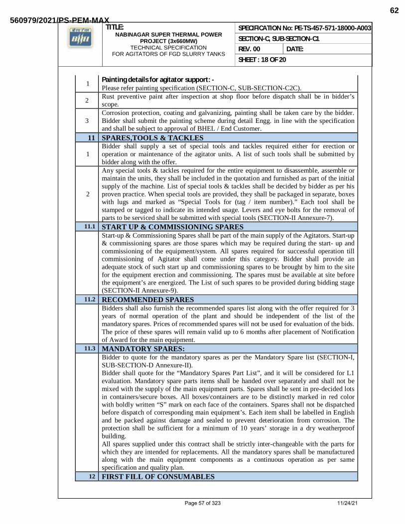
1 Painting details for agitator support: - Please refer painting specification (SECTION-C, SUB-SECTION-C2C).
2 Rust preventive paint after inspection at shop floor before dispatch shall be in bidder’s scope.
3 Corrosion protection, coating and galvanizing, painting shall be taken care by the bidder. Bidder shall submit the painting scheme during detail Engg. in line with the specification and shall be subject to approval of BHEL / End Customer.
11 SPARES,TOOLS & TACKLES
1 Bidder shall supply a set of special tools and tackles required either for erection or operation or maintenance of the agitator units. A list of such tools shall be submitted by bidder along with the offer.
2
Any special tools & tackles required for the entire equipment to disassemble, assemble or maintain the units, they shall be included in the quotation and furnished as part of the initial supply of the machine. List of special tools & tackles shall be decided by bidder as per his proven practice. When special tools are provided, they shall be packaged in separate, boxes with lugs and marked as “Special Tools for (tag / item number).” Each tool shall be stamped or tagged to indicate its intended usage. Levers and eye bolts for the removal of parts to be serviced shall be submitted with special tools (SECTION-II Annexure-7).
11.1 START UP & COMMISSIONING SPARES
Start-up & Commissioning Spares shall be part of the main supply of the Agitators. Start-up & commissioning spares are those spares which may be required during the start- up and commissioning of the equipment/system. All spares required for successful operation till commissioning of Agitator shall come under this category. Bidder shall provide an adequate stock of such start up and commissioning spares to be brought by him to the site for the equipment erection and commissioning. The spares must be available at site before the equipment’s are energized. The List of such spares to be provided during bidding stage (SECTION-II Annexure-9).
11.2 RECOMMENDED SPARES
Bidders shall also furnish the recommended spares list along with the offer required for 3 years of normal operation of the plant and should be independent of the list of the mandatory spares. Prices of recommended spares will not be used for evaluation of the bids. The price of these spares will remain valid up to 6 months after placement of Notification of Award for the main equipment.
11.3 MANDATORY SPARES:
Bidder to quote for the mandatory spares as per the Mandatory Spare list (SECTION-I, SUB-SECTION-D Annexure-II). Bidder shall quote for the “Mandatory Spares Part List”, and it will be considered for L1 evaluation. Mandatory spare parts items shall be handed over separately and shall not be mixed with the supply of the main equipment parts. Spares shall be sent in pre-decided lots in containers/secure boxes. All boxes/containers are to be distinctly marked in red color with boldly written “S” mark on each face of the containers. Spares shall not be dispatched before dispatch of corresponding main equipment’s. Each item shall be labelled in English and be packed against damage and sealed to prevent deterioration from corrosion. The protection shall be sufficient for a minimum of 10 years’ storage in a dry weatherproof building. All spares supplied under this contract shall be strictly inter-changeable with the parts for which they are intended for replacements. All the mandatory spares shall be manufactured along with the main equipment components as a continuous operation as per same specification and quality plan.
12 FIRST FILL OF CONSUMABLES
Page 57 of 323 11/24/21
560979/2021/PS-PEM-MAX62

TITLE: NABINAGAR SUPER THERMAL POWER
PROJECT (3x660MW) TECHNICAL SPECIFICATION
FOR AGITATORS OF FGD SLURRY TANKS
SPECIFICATION No: PE-TS-457-571-18000-A003 SECTION-C, SUB-SECTION-C1 REV. 00 DATE: SHEET : 19 OF 20
I
Bidder’s scope shall include supply and filling of all chemicals, lubricants, grease, filters and consumable items for operation up to commissioning including top up requirements. All lubricants proposed for the plant operation shall be suitable for all operating and environmental conditions that will be met on site consistent with good maintenance procedures as instructed in the maintenance manuals.
II
Bidder shall also supply a quantity not less than 10% of the full charge of each variety of lubricants, servo fluids, gases, chemicals etc. (as applicable) used which is expected to be utilized during the first year of operation. This additional quantity shall be supplied in separate containers.
III
Detailed specifications for the lubricating oil, grease, gases, servo fluids, control fluids, chemicals including items qualities and quantities required per month of the plant operation for the end customer/BHEL’s approval herein shall be furnished within 2 months of placement of Order. On completion of erection, complete list of bearings/equipment giving their location and identification marks shall be furnished to BHEL along with lubrication requirements. All types of chemicals, consumables, lubricants and grease shall be readily obtainable locally and the number of different types shall be kept to a minimum. For each type and grade of lubricant recommended, bidder shall list at least three equivalent lubricants manufactured by alternative companies.
13 BID EVALUATION CRITERIA FOR POWER CONSUMPTION:
1. POWER GUARANTEE Bidder to specify the total guaranteed power per Agitators operating at the rated capacity in their offer.
2. BID EVALUATION CRITERIA FOR POWER CONSUMPTION: Refer Annexure 12 of Section-II.
14 LIQUIDATED DAMAGES FOR POWER CONSUMPTION Refer Annexure 12 of Section-II.
15 PERFORMANCE GUARANTEE
All performance tests for Agitators shall be carried out in accordance with any latest international codes/standards. Bidder shall furnish Performance guarantee for the design, manufacture, material, safe and trouble-free operation of the Agitators and its accessories The Bidder shall ensure a design of the equipment to achieve an average target availability of 98% for 120 days and average target availability of 95% for 1 year. Noise level ≤85 dB (A) at 1m horizontal distance from equipment/enclosures and 1.5m above operating floor is to be guaranteed. Vibration levels measured on the non-rotating parts shall not exceed the zone limit “B” as defined in ISO 10816 at steady conditions and shall not exceed the zone limit “C” as defined in ISO 10816 at transient conditions. Acceptance tests to be carried out as per the procedure defined by the bidder which shall be submitted for BHEL/ end customer approval. In the event that the performance test is unsuccessful, bidder shall take necessary remedial action at his cost and the performance test shall be repeated. For additional details of performance guarantee please refer clause no. 2.00.00 of NTPC specification Section-VI, Part-A, Sub-section-VI, Functional Guarantee and Liquidated
Page 58 of 323 11/24/21
560979/2021/PS-PEM-MAX63

TITLE: NABINAGAR SUPER THERMAL POWER
PROJECT (3x660MW) TECHNICAL SPECIFICATION
FOR AGITATORS OF FGD SLURRY TANKS
SPECIFICATION No: PE-TS-457-571-18000-A003 SECTION-C, SUB-SECTION-C1 REV. 00 DATE: SHEET : 20 OF 20
damages. 16 DOCUMENTATION A DOCUMENTS TO BE SUBMITTED ALONG WITH THE OFFER
The Bidder shall submit all documents, drawings, diagrams and all such information, which are necessary to fully understand the offer for techno – commercial Offer. Vendors are requested to comply with above in all respect. List of such documents have been indicated in (SECTION-II Annexure-1).
B DOCUMENTS TO BE SUBMITTED AFTER AWARD OF CONTRACT
The Successful bidder shall submit necessary data, documents and drawings for review, approval as specified in this specification. Drawings that are reviewed by the end customer/ BHEL, will be returned to bidder with a transmittal letter with any comments and / or questions marked on the drawings or noted in the letter. All comments and questions must be resolved before a resubmission of drawings / documents. If the design has not developed enough to resolve some of the comments or questions, bidder shall place a “hold” on those items or areas of design. End customer/ BHEL reserves the right to return drawings unprocessed to bidder if there exists any evidence that bidder has not acknowledged all comments and questions. All necessary GA drawings, sections, sub-assembly drawings, specifications of main and sub components and necessary set of operation & maintenance manual as asked by end customer must be furnished by bidder in soft and hard copy forms. For all documents softcopy format shall be searchable pdf, however in addition all drawings, diagrams shall be supplied in ACAD or other editable format and all lists in Excel format. Further break up of technical documents will be discussed during finalization of the purchase contract. All documents in hard and soft form are to be submitted in the English language. Electronic Copies shall be submitted in primary original data format (e.g. DOC, XLS, DWG) as well as in a printable non-proprietary document format (e.g. PDF). Especially P&IDs shall be submitted as DWG files and PDF files. Bidder to ensure submission of hard copies as per end customer requirement for all engineering drg/doc and for all subsequent revisions along with a soft copy through email to concerned project team. The list of such drawing/documents have been indicated in (SECTION-I, SUB-SECTION-D Annexure-IV).
17 LIST OF REFERENCE DRAWINGS BY BHEL I The document specified in Annexure-III, Sub-Section-D of Section-I are being provided
along with the tender specification for estimation and calculation purpose of the bidder.
Page 59 of 323 11/24/21
560979/2021/PS-PEM-MAX64

TITLE: NABINAGAR SUPER THERMAL POWER
PROJECT (3x660MW) TECHNICAL SPECIFICATION
FOR AGITATORS OF FGD SLURRY TANKS
SPECIFICATION No: PE-TS-457-571-18000-A003 SECTION-I, SUB-SECTION-C2 REV. 00 DATE: SHEET : 1 OF 1
CUSTOMER SPECIFICATION
Page 60 of 323 11/24/21
560979/2021/PS-PEM-MAX65

Page 61 of 323 11/24/21
560979/2021/PS-PEM-MAX66
2211238
Line

Page 62 of 323 11/24/21
560979/2021/PS-PEM-MAX67

TITLE: NABINAGAR SUPER THERMAL POWER
PROJECT (3x660MW) TECHNICAL SPECIFICATION
FOR AGITATORS OF FGD SLURRY TANKS
SPECIFICATION No: PE-TS-457-571-18000-A003 SECTION-I, SUB-SECTION-C2-A REV. 00 DATE: NOV 2021 SHEET : 1 OF 1
CUSTOMER SPECIFICATION: PROJECT SPECIFIC GENERAL REQUIREMENTS
Page 63 of 323 11/24/21
560979/2021/PS-PEM-MAX68

Page 64 of 323 11/24/21
560979/2021/PS-PEM-MAX69

Page 65 of 323 11/24/21
560979/2021/PS-PEM-MAX70

Page 66 of 323 11/24/21
560979/2021/PS-PEM-MAX71

Page 67 of 323 11/24/21
560979/2021/PS-PEM-MAX72

Page 68 of 323 11/24/21
560979/2021/PS-PEM-MAX73

Page 69 of 323 11/24/21
560979/2021/PS-PEM-MAX74

Page 70 of 323 11/24/21
560979/2021/PS-PEM-MAX75

Page 71 of 323 11/24/21
560979/2021/PS-PEM-MAX76

Page 72 of 323 11/24/21
560979/2021/PS-PEM-MAX77

Page 73 of 323 11/24/21
560979/2021/PS-PEM-MAX78

Page 74 of 323 11/24/21
560979/2021/PS-PEM-MAX79
3062805
Line
3062805
Line
3062805
Line
3062805
Line
3062805
Line
3062805
Line

Page 75 of 323 11/24/21
560979/2021/PS-PEM-MAX80
3062805
Line
3062805
Line

Page 76 of 323 11/24/21
560979/2021/PS-PEM-MAX81
3062805
Line
3062805
Line

Page 77 of 323 11/24/21
560979/2021/PS-PEM-MAX82

Page 78 of 323 11/24/21
560979/2021/PS-PEM-MAX83

Page 79 of 323 11/24/21
560979/2021/PS-PEM-MAX84

Page 80 of 323 11/24/21
560979/2021/PS-PEM-MAX85

Page 81 of 323 11/24/21
560979/2021/PS-PEM-MAX86

Page 82 of 323 11/24/21
560979/2021/PS-PEM-MAX87

Page 83 of 323 11/24/21
560979/2021/PS-PEM-MAX88

Page 84 of 323 11/24/21
560979/2021/PS-PEM-MAX89

Page 85 of 323 11/24/21
560979/2021/PS-PEM-MAX90

Page 86 of 323 11/24/21
560979/2021/PS-PEM-MAX91

Page 87 of 323 11/24/21
560979/2021/PS-PEM-MAX92

Page 88 of 323 11/24/21
560979/2021/PS-PEM-MAX93

Page 89 of 323 11/24/21
560979/2021/PS-PEM-MAX94

Page 90 of 323 11/24/21
560979/2021/PS-PEM-MAX95

Page 91 of 323 11/24/21
560979/2021/PS-PEM-MAX96

Page 92 of 323 11/24/21
560979/2021/PS-PEM-MAX97

Page 93 of 323 11/24/21
560979/2021/PS-PEM-MAX98

Page 94 of 323 11/24/21
560979/2021/PS-PEM-MAX99

Page 95 of 323 11/24/21
560979/2021/PS-PEM-MAX100
Page 96 of 323 11/24/21
560979/2021/PS-PEM-MAX101

Page 97 of 323 11/24/21
560979/2021/PS-PEM-MAX102

Page 98 of 323 11/24/21
560979/2021/PS-PEM-MAX103

Page 99 of 323 11/24/21
560979/2021/PS-PEM-MAX104

Page 100 of 323 11/24/21
560979/2021/PS-PEM-MAX105

Page 101 of 323 11/24/21
560979/2021/PS-PEM-MAX106

Page 102 of 323 11/24/21
560979/2021/PS-PEM-MAX107

Page 103 of 323 11/24/21
560979/2021/PS-PEM-MAX108

Page 104 of 323 11/24/21
560979/2021/PS-PEM-MAX109

Page 105 of 323 11/24/21
560979/2021/PS-PEM-MAX110

Page 106 of 323 11/24/21
560979/2021/PS-PEM-MAX111

Page 107 of 323 11/24/21
560979/2021/PS-PEM-MAX112

Page 108 of 323 11/24/21
560979/2021/PS-PEM-MAX113
3062805
Line
3062805
Line
3062805
Line
3062805
Line
3062805
Line
3062805
Line
3062805
Line

Page 109 of 323 11/24/21
560979/2021/PS-PEM-MAX114
3062805
Line
3062805
Line
3062805
Line

Page 110 of 323 11/24/21
560979/2021/PS-PEM-MAX115

Page 111 of 323 11/24/21
560979/2021/PS-PEM-MAX116

Page 112 of 323 11/24/21
560979/2021/PS-PEM-MAX117

Page 113 of 323 11/24/21
560979/2021/PS-PEM-MAX118

Page 114 of 323 11/24/21
560979/2021/PS-PEM-MAX119

Page 115 of 323 11/24/21
560979/2021/PS-PEM-MAX120

Page 116 of 323 11/24/21
560979/2021/PS-PEM-MAX121

Page 117 of 323 11/24/21
560979/2021/PS-PEM-MAX122

Page 118 of 323 11/24/21
560979/2021/PS-PEM-MAX123

Page 119 of 323 11/24/21
560979/2021/PS-PEM-MAX124

Page 120 of 323 11/24/21
560979/2021/PS-PEM-MAX125

Page 121 of 323 11/24/21
560979/2021/PS-PEM-MAX126

Page 122 of 323 11/24/21
560979/2021/PS-PEM-MAX127

Page 123 of 323 11/24/21
560979/2021/PS-PEM-MAX128

Page 124 of 323 11/24/21
560979/2021/PS-PEM-MAX129

Page 125 of 323 11/24/21
560979/2021/PS-PEM-MAX130

Page 126 of 323 11/24/21
560979/2021/PS-PEM-MAX131
Page 127 of 323 11/24/21
560979/2021/PS-PEM-MAX132

Page 128 of 323 11/24/21
560979/2021/PS-PEM-MAX133

Page 129 of 323 11/24/21
560979/2021/PS-PEM-MAX134

Page 130 of 323 11/24/21
560979/2021/PS-PEM-MAX135

Page 131 of 323 11/24/21
560979/2021/PS-PEM-MAX136

Page 132 of 323 11/24/21
560979/2021/PS-PEM-MAX137

Page 133 of 323 11/24/21
560979/2021/PS-PEM-MAX138

Page 134 of 323 11/24/21
560979/2021/PS-PEM-MAX139

Page 135 of 323 11/24/21
560979/2021/PS-PEM-MAX140

Page 136 of 323 11/24/21
560979/2021/PS-PEM-MAX141

Page 137 of 323 11/24/21
560979/2021/PS-PEM-MAX142

Page 138 of 323 11/24/21
560979/2021/PS-PEM-MAX143

Page 139 of 323 11/24/21
560979/2021/PS-PEM-MAX144

Page 140 of 323 11/24/21
560979/2021/PS-PEM-MAX145

Page 141 of 323 11/24/21
560979/2021/PS-PEM-MAX146

Page 142 of 323 11/24/21
560979/2021/PS-PEM-MAX147
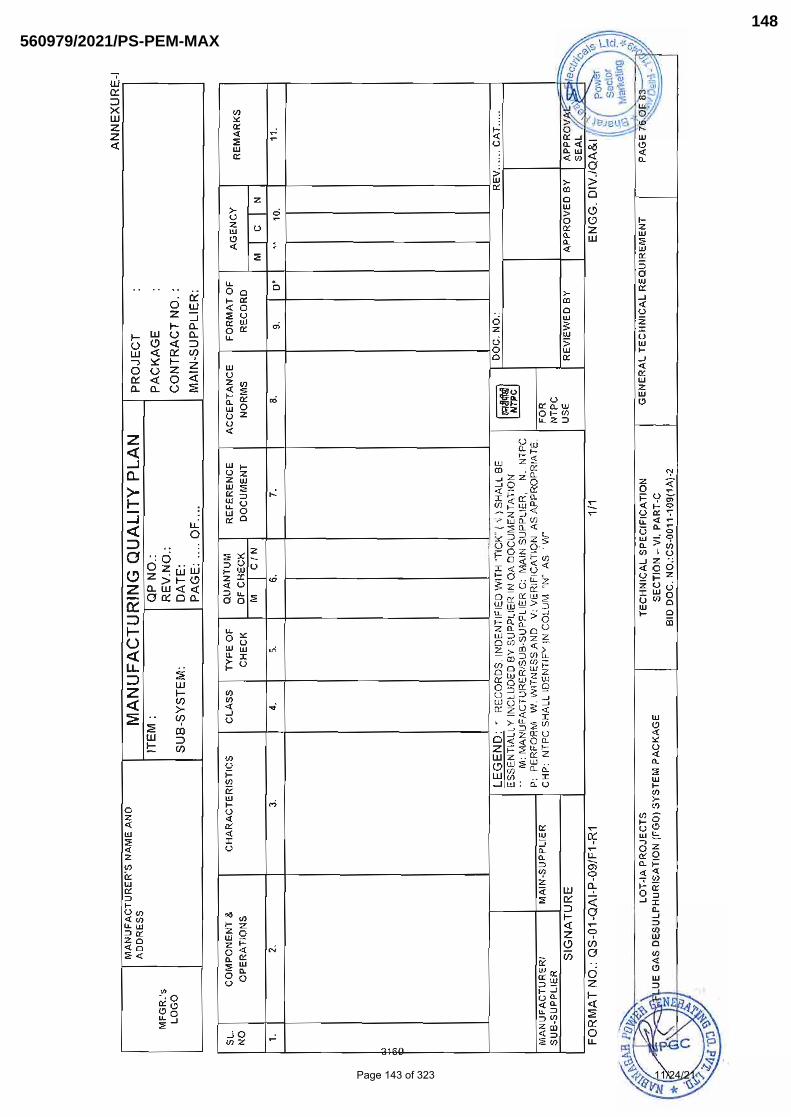
Page 143 of 323 11/24/21
560979/2021/PS-PEM-MAX148
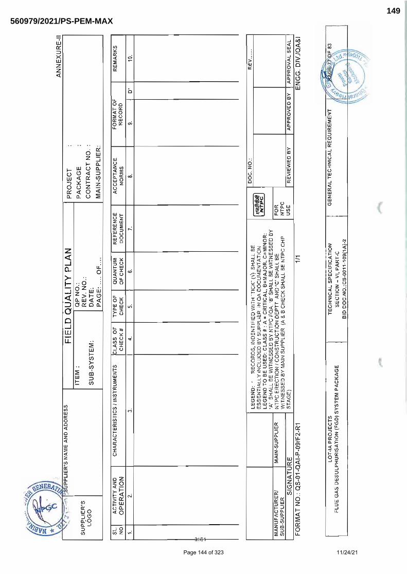
Page 144 of 323 11/24/21
560979/2021/PS-PEM-MAX149

Page 145 of 323 11/24/21
560979/2021/PS-PEM-MAX150

Page 146 of 323 11/24/21
560979/2021/PS-PEM-MAX151

Page 147 of 323 11/24/21
560979/2021/PS-PEM-MAX152

Page 148 of 323 11/24/21
560979/2021/PS-PEM-MAX153

Page 149 of 323 11/24/21
560979/2021/PS-PEM-MAX154

Page 150 of 323 11/24/21
560979/2021/PS-PEM-MAX155

TITLE: NABINAGAR SUPER THERMAL POWER
PROJECT (3x660MW) TECHNICAL SPECIFICATION
FOR AGITATORS OF FGD SLURRY TANKS
SPECIFICATION No: PE-TS-457-571- 8000-A003 SECTION-I, SUB-SECTION-C2-A REV. 00 DATE: SHEET : 1 OF 1
PROJECT SPECIFIC GENERAL REQUIREMENTS INCLUDING: QUALITY ASSURANCE
Page 151 of 323 11/24/21
560979/2021/PS-PEM-MAX156

Page 152 of 323 11/24/21
560979/2021/PS-PEM-MAX157

CLAUSE NO. QUALITY ASSURANCE
MOUDA STPP-II (2x660MW) / SOLAPUR STPP (2 x 660MW) / NABINAGAR STPP (3x 660MW) /
MEJA TPP-I (2 x 660MW) / RAGHUNATHPUR TPP PHASE-II (2 x660MW)
STEAM GENERATOR PACKAGE
TECHNICAL SPECIFICATION SECTION-VI
BID DOC NO.: CS-9575/ 9571/ 0370/ 0360/ 9586-102(R)-2
PART-B SUB-SECTION-VII:QM3 POWER CYCLE PIPING
PAGE 4 OF 4
Table -1
Valve size NB in mm
ANSI Class upto 300
ANSI Class above 300 upto 600
ANSI Class above 600 below 900
ANSI Class 900 & above & below 4500
Less than 50
Visual Visual Visual MPI
50 & above but below100
Visual Visual MPI MPI & RT (on 10%of valves on 100% area)
100 & above but less than 300
Visual MPI MPI & RT (on 10% of valves on change of section & weld ends)
MPI & RT (on 100% area)
300 and above
MPI MPI MPI & RT (on change of sections & weld ends)
MPI, RT on100% area)
NOTE: For body and bonnet forgings UT with MPI may be adopted in place of RT for austenitic steel MPI may be replaced by LPI.
1.06.00 Metallic expansion Joint (if applicable)
(a) Hydraulic pressure test shall be carried out on each pipe and expansion bellow.
(b) Longitudinal butt weld on bellow shall be subjected to suitable NDT examination before forming, and after forming MPE / DP test shall be carried out.
(c) All welds shall be subjected to 100% magnetic particle/dye pentrant check and butt welds shall be subjected to 100% radiographic testing.
(d) All the bellows subjected to vacuum service shall be subjected to vacuum test.
(e) The bellows shall be subjected to movement test to establish suitability to perform satisfactorily in site conditions. During this test spring rate shall also be measured.
(f) Life cycle test, meridional yield rupture test and squirm test to be carried out on a prototype/expansion bellow as per Sec.D clause 3.2 of standards of Expansion joint Manufacturer Association (EJMA). In case these tests have already been accepted by NTPC on a prototype expansion bellow, as defined in Sec. D Clause 3.2 of Expansion Joints Manufacturers Association (EJMA) test reports may be furnished by manufacturer for consideration and approval of Employer.
1.07.00 CHEMICAL DOSING SYSTEM (HP/LP/OXYGENATED)
(a) Pumps of chemical dosing system shall be performance tested as per relevant international codes.
(b) In case of diaphragm type of pumps, the life cycle test shall be done on pumps. If this test is already conducted for same model in earlier projects of NTPC, then TCs for same shall be reviewed.
(c) Dosing skid shall be subjected to leakage test and functional test.
(d) Oxygen cylinders shall be as per relevant standard meeting statutory requirements.
Page 153 of 323 11/24/21
560979/2021/PS-PEM-MAX158

Agitator inspection requirement-Please note that attached QP is indicative only. Stage inspection and Quantum of check may vary during final approval by customer (NTPC).
Page 154 of 323 11/24/21
560979/2021/PS-PEM-MAX159

Page 155 of 323 11/24/21
560979/2021/PS-PEM-MAX160

QUALITY REQUIREMENT ���������������� ���� ��� ��������������������������� ������������������� �� ������������� !"#$ !"#�%&'�����(%&��� ����(%&��)�������������������*���������������������� ����� ���������+�&����(%&��,��������������&����������������-�������������-�(%&�*��&�� ������������������&�� �����������������������.�����������*�������� �������������������-��������������������-������������������ ������(%&��*���������������&��������/�&������������� ������� ��-�������������������.������*�&�������� �������� ������������ ����������������� ����������� � -�������������������������*������������'��� ��-��������������-����������� ���������� ����-�����0�'� �����������-�������#� ����� �����)��1���2)3�������������� ����������������� ������� ���������������������������*�4������� ����-���� �� !"#������ ����������� ���������������� ��.������ ������������������������������ �����������'� ������)�����-������������ �-��� !"#5 ���������������*��
(d) In case of order placed on foreign vendors, vendor has to finalize Inspection agency at their own cost and carry out inspection as per the approved Quality plan . Further, the list of third party insection agencies (as applicable) shall be provided by BHEL during detail engineering.Vendor has to furnish BHEL the inspection reports and other documents required as per approved Quality plan duly signed by the Inspection Agency after their witness for BHEL's review and acceptance.
Page 156 of 323 11/24/21
560979/2021/PS-PEM-MAX161

Page 157 of 323 11/24/21
560979/2021/PS-PEM-MAX162

Page 158 of 323 11/24/21
560979/2021/PS-PEM-MAX163

Page 159 of 323 11/24/21
560979/2021/PS-PEM-MAX164

TITLE: NABINAGAR SUPER THERMAL POWER
PROJECT (3x660MW) TECHNICAL SPECIFICATION
FOR AGITATORS OF FGD SLURRY TANKS
SPECIFICATION No: PE-TS-457-571-18000-A003 SECTION-C, SUB-SECTION-C2-A REV. 00 DATE: SHEET : 1 OF 1
CUSTOMER SPECIFICATION: FUNCTIONAL GUARANTEES
Page 160 of 323 11/24/21
560979/2021/PS-PEM-MAX165

Page 161 of 323 11/24/21
560979/2021/PS-PEM-MAX166

Page 162 of 323 11/24/21
560979/2021/PS-PEM-MAX167

Page 163 of 323 11/24/21
560979/2021/PS-PEM-MAX168

Page 164 of 323 11/24/21
560979/2021/PS-PEM-MAX169
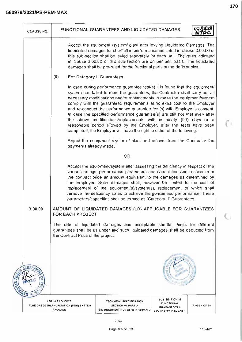
Page 165 of 323 11/24/21
560979/2021/PS-PEM-MAX170

Page 166 of 323 11/24/21
560979/2021/PS-PEM-MAX171
2211238
Line

Page 167 of 323 11/24/21
560979/2021/PS-PEM-MAX172
2211238
Line

Page 168 of 323 11/24/21
560979/2021/PS-PEM-MAX173
2211238
Line

Page 169 of 323 11/24/21
560979/2021/PS-PEM-MAX174
2211238
Line

Page 170 of 323 11/24/21
560979/2021/PS-PEM-MAX175
2211238
Line
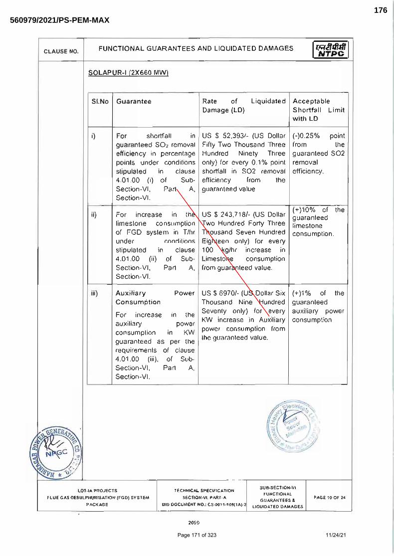
Page 171 of 323 11/24/21
560979/2021/PS-PEM-MAX176
2211238
Line

Page 172 of 323 11/24/21
560979/2021/PS-PEM-MAX177
2211238
Line

Page 173 of 323 11/24/21
560979/2021/PS-PEM-MAX178

Page 174 of 323 11/24/21
560979/2021/PS-PEM-MAX179
2211238
Line

Page 175 of 323 11/24/21
560979/2021/PS-PEM-MAX180
2211238
Line

Page 176 of 323 11/24/21
560979/2021/PS-PEM-MAX181
2211238
Line

Page 177 of 323 11/24/21
560979/2021/PS-PEM-MAX182
3062805
Line

Page 178 of 323 11/24/21
560979/2021/PS-PEM-MAX183
3062805
Line

Page 179 of 323 11/24/21
560979/2021/PS-PEM-MAX184
3062805
Line

Page 180 of 323 11/24/21
560979/2021/PS-PEM-MAX185
3062805
Line
3062805
Line
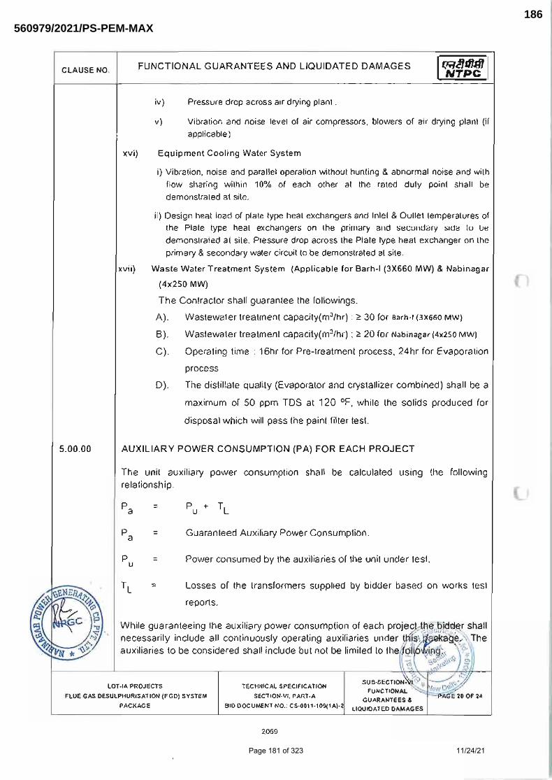
Page 181 of 323 11/24/21
560979/2021/PS-PEM-MAX186
3062805
Line

Page 182 of 323 11/24/21
560979/2021/PS-PEM-MAX187

Page 183 of 323 11/24/21
560979/2021/PS-PEM-MAX188

Page 184 of 323 11/24/21
560979/2021/PS-PEM-MAX189

Page 185 of 323 11/24/21
560979/2021/PS-PEM-MAX190

TITLE: NABINAGAR SUPER THERMAL POWER
PROJECT (3x660MW) TECHNICAL SPECIFICATION
FOR AGITATORS OF FGD SLURRY TANKS
SPECIFICATION No: PE-TS-457-571-18000-A003 SECTION-I, SUB-SECTION-C2-B REV. 00 DATE: SHEET : 1 OF 1
CUSTOMER SPECIFICATION: PAINTING SPECIFICATION
Page 186 of 323 11/24/21
560979/2021/PS-PEM-MAX191

CLAUSE NO.
TECHNICAL REQUIREMENTS
MOUDA STPP-II (2x660MW) / SOLAPUR STPP (2 x 660MW) / NABINAGAR STPP (3x 660MW) /
MEJA TPP-I (2 x 660MW) / RAGHUNATHPUR TPP PHASE-II (2 x660MW)
STEAM GENERATOR PACKAGE
TECHNICAL SPECIFICATION SECTION-VI
BID DOC NO.: CS-9575/ 9571/ 0370/ 0360/ 9586-102-2
PART-B SUB-SECTION-II:M3
POWER CYCLE PIPING SYSTEM & LPP
Page 25 of 54
for the above test shall also be furnished by the Contractor. Any defect noticed during the testing shall be rectified and the unit shall be retested by the Contractor.
13.06.00 The hydraulic test shall be considered successful only on certification to that effect
by the concerned inspecting authority as per the provision of the IBR and the Project Manager.
14.00.00 SPECIFICATION FOR SURFACE PREPARATION & PAINTING
14.01.00 Surface preparation methods and paint/primer materials shall be of the type specified herein. If the contractor desires to use any paint/primer materials other than that specified, specific approval shall be obtained by the contractor in writing from the employer for using the substitute material.
14.02.00 All paints shall be delivered to job site in manufacturers sealed containers. Each container shall be labeled by the manufacturer with the manufacturer’s name, type of paint, batch number and color.
14.03.00 Unless specified otherwise, paint shall not be applied to surfaces of insulation, surfaces of stainless steel/nickel/ copper/brass/ monel/ aluminum/ hastelloy/lead/ galvanized steel items, valve stem, pump rods, shafts, gauges, bearing and contact surfaces, lined or clad surfaces.
14.04.00 All pipelines shall be Colour coded for identification as per the NTPC Colour-coding scheme, which will be furnished to the contractor during detailed engineering..
14.05.00 SURFACE PREPARATION
14.05.01 All surfaces to be painted shall be thoroughly cleaned of oil, grease and other foreign matter. Surfaces shall be free of moisture and contamination from chemicals and solvents.
14.05.02 The following surface schemes are envisaged here. Depending upon requirement any one or a combination of these schemes may be used for surface preparation before application of primer.
SP1 Solvent cleaning
SP2 Application of rust converter (Ruskil or equivalent grade)
SP3 Power tool cleaning
SP4 Shot blasting (shot blasting shall be used as surface preparation method for hot worked pipes prior to application of primer)
SP4* Shot blast cleaning/ abrasive blast cleaning to SA21/2 (near white metal) 35-50 microns
SP5 Phosphating
SP6 Emery sheet cleaning/Manual wire brush cleaning.
Page 187 of 323 11/24/21
560979/2021/PS-PEM-MAX192
2211238
Text Box
PAINTING SPECIFICATION TO BE FOLLOWED BY BIDDERS FOR AGITATORS

CLAUSE NO.
TECHNICAL REQUIREMENTS
MOUDA STPP-II (2x660MW) / SOLAPUR STPP (2 x 660MW) / NABINAGAR STPP (3x 660MW) /
MEJA TPP-I (2 x 660MW) / RAGHUNATHPUR TPP PHASE-II (2 x660MW)
STEAM GENERATOR PACKAGE
TECHNICAL SPECIFICATION SECTION-VI
BID DOC NO.: CS-9575/ 9571/ 0370/ 0360/ 9586-102-2
PART-B SUB-SECTION-II:M3
POWER CYCLE PIPING SYSTEM & LPP
Page 26 of 54
14.06.00 APPLICATION OF PRIMER/PAINT
14.06.01 The paint/primer manufacturer’s instructions covering thinning, mixing, method of application, handling and drying time shall be strictly followed and considered as part of this specification. The Dry film thickness (DFT) of primer/paint shall be as specified herein.
14.06.02 Surfaces prepared as per the surface preparation scheme indicated herein shall be applied with primer paint within 6 hours after preparation of surfaces.
14.06.03 Where primer coat has been applied in the shop, the primer coat shall be carefully examined, cleaned and spot primed with one coat of the primer before applying intermediate and finish coats. When the primer coat has not been applied in the shop, primer coat shall be applied by brushing, rolling or spraying on the same day as the surface is prepared. Primer coat shall be applied prior to intermediate and finish coats.
14.06.04 Steel surfaces that will be concealed by building walls shall be primed and finish painted before the floor is erected. Tops of structural steel members that will be covered by grating shall be primed and finish painted before the grating is permanently secured.
14.06.05 Following are the Primer/painting schemes envisaged herein:
PS3 - Zinc Chrome Primer (Alkyd base) by brush/Spray to IS104.
PS3* - Zinc Chrome primer (Alkyd base) by dip coat.
PS4 - Synthetic Enamel (long oil alkyd) to IS2932.
PS5 - Red oxide zinc phosphate to IS-12744.
PS9 - Aluminum paint to IS 2339.
PS9* - Heat resistant Aluminum paint to IS-13183 Gr.-I (for temperature 400 oC - 600 oC) , IS-13183 Gr.-II (for temperature 200oC - 400oC) and IS-13183 Gr.-III (for temperature upto 200 oC)
PS13 - Rust preventive fluid by spray, dip or brush.
PS14 - weldable primer-Deoxaluminate or equivalent.
PS16 - High Build Epoxy CDC mastic `15’ .
PS17 - Aliphatic Acrylic Polyurethane CDE134 ,%V=40.0(min.)
PS18 - Epoxy based TiO2 pigmented coat
PS19 - Epoxy based Zinc phosphate primer (92% zinc in dry film (min.), %VS=35.0(min.).
PS20 - Epoxy based finish paint.
14.06.06 All weld edge preparation for site welding shall be applied with one coat of weldable primer.
14.06.07 For internal protection of pipes/tubes, VCI pellets shall be used at both ends after sponge testing and ends capped. VCI pellets shall not be used for SS components and composite assemblies.
Page 188 of 323 11/24/21
560979/2021/PS-PEM-MAX193

CLAUSE NO.
TECHNICAL REQUIREMENTS
MOUDA STPP-II (2x660MW) / SOLAPUR STPP (2 x 660MW) / NABINAGAR STPP (3x 660MW) / MEJA TPP-I (2 x 660MW) /
RAGHUNATHPUR TPP PHASE-II (2 x660MW) STEAM GENERATOR PACKAGE
TECHNICAL SPECIFICATION SECTION-VI
BID DOC NO.: CS-9575/ 9571/ 0370/ 0360/ 9586-102-2
PART-B SUB-SECTION-II:M3
PCP & LPP Page 27 of 54
14.07.00 Primer/Painting Schedule
Primer Coat Intermediate Coat Finish Coats Sl.No
Description Surface Preparation System Coat Min. DFT /
coat (Microns)
System Coat Min. DFT/ Coat (Microns)
System Coat Min. DFT/ Coat (Microns)
Total Min. Painting DFT (Microns)
Colour Shade
1. All insulated Pipings, fittings/ components, Pipe clamps, Vessels/Tanks, Equipments etc.
SP3/SP4 PS 9* 1 20 - - - PS9* 1 20 40
Design temperature <60 oC
SP3/SP4 PS 5 1 20 - - - PS 4
3 $
35 $
155 $
Design temperature 60 oC-200 oC
SP3/SP4 PS 9* 1 20 PS 9* 1 20 40
2. All uninsulated Piping, fittings/ components, Pipe clamps, Vessels/Tanks, Equipments etc.
Design temperature > 200 oC
SP3/SP4 PS9* 1 20 - - - PS9* 1 20 40
3 Constant Load Hanger (CLH), Variable Load Hanger (VLH) and other supports
SP4* PS19 1 40 - - - PS17
1
30
70
Valves 4. Cast /Forged
Design temperature <60oC
SP1/SP2/SP3
PS9
1 20 PS9 1 100 PS 9 1 20 40
As per NTPC Colour shade/ coding scheme
Page 189 of 323 11/24/21
560979/2021/PS-PEM-MAX194

CLAUSE NO.
TECHNICAL REQUIREMENTS
MOUDA STPP-II (2x660MW) / SOLAPUR STPP (2 x 660MW) / NABINAGAR STPP (3x 660MW) / MEJA TPP-I (2 x 660MW) /
RAGHUNATHPUR TPP PHASE-II (2 x660MW) STEAM GENERATOR PACKAGE
TECHNICAL SPECIFICATION SECTION-VI
BID DOC NO.: CS-9575/ 9571/ 0370/ 0360/ 9586-102-2
PART-B SUB-SECTION-II:M3
PCP & LPP Page 28 of 54
Design temperature 60 oC-200 oC
SP1/SP2/SP3
PS9* 1 20 -
- - PS9* 1 20 40
Design temperature > 200 oC
SP1/SP2/SP3
PS9* 1 20 PS9* 1 20 40
Outside TG building and in SG envelope
SP4* Inorganic Ethyl Zinc Silicate
1 75 PS18 1 75 a))Epoxy coat b)Final coat of paint PS17
2 1
35 30
250
5. All Structural Steel components
Within TG building
SP4* -do- 1 35 PS18 1 35 a))Epoxy coat b)Final coat of paint PS17
2 1
25 30
150
6. Weld Edges SP6 (Hand cleaning by wire brushing)
PS13 (Weldable primer)
1 25 - - - - - - -
$ The first 2 finished coats (total min.DFT of 70 microns) shall be done at shop and the 3rd finish coat (min.DFT 35 Microns) shall be applied at site.
15.00.00 Testing Requirements:
The detailed testing requirements for power cycle piping and its components are given in the subsection for Quality Assurance(QA) .The requirements pertaining to testing given in this subsection if in variance with that given in QA subsection, then the more stringent of the two shall be followed.
Page 190 of 323 11/24/21
560979/2021/PS-PEM-MAX195

RANIPET
Bharat Heavy Electricals Limited Boiler Auxiliaries Plant
Ranipet – 632 406
BHEL DOC NO. PS: NN FGD: : G609
REVISION NO. 02
DATE 06.12.2019
PS- NABINAGAR 3X660 MW – FGD PACKAGE REV. 02 DATE 06.12.2019 Page 1 of 32
Prepared By Reviewed & Approved By
Rajamanickam M Dy.Manager/QA
K.C. Gandhi Parimalam DGM/QA
NABINAGAR FGD PACKAGE
PAINTING SCHEME for FGD SYSTEM, BOOSTER FAN& GATES& DAMPERS
NTPC CONTRACT NO: CS-0370-109-(1A) -2-FC -NOA-0059
NTPC DRG NO: 0370-109-PVM-H-001
BHEL RANIPET Customer No(s).: G609-G611
Digitally signedby P SChowdhuryDate: 2019.12.2009:50:32 ISTReason: CAT ILocation:NTPCEOC
Signature Not Verified
Page 191 of 323 11/24/21
560979/2021/PS-PEM-MAX196
6074979
Text Box
Note: 1) For PGMAs of Agitator and and its sub-components shall be the same as that of similar items provided in the list. For Example, for motor, gear box, coupling etc. which are applicable for agitators PGMA-FW 212 & FW 701 are to be followed. 2) Painting : Painting details in the specification are minimum requirement. Painting shall be as per customer approved schedule to be submitted by successful bidder during detail engineering.

Sl No
SURFACE LOCATION PGMA SURFACE
PREPARATION
PRIMER FINISH TOTAL DFT IN
(µm
min.) PAINT
DFT (µm
min.)
PAINT DFT (µm
min.)
PS- NABINAGAR 3X660 MW – FGD PACKAGE REV. 02 DATE 06.12.2019 Page 2 of 32
RECORD OF REVISION
REV NO DATE DETAILS OF REVISION
00 25.10.2019 Original Issue - First Submission
01
18.11.2019
NTPC comments: BHEL has got approved painting schedule for other projects with same spec which may please be endorsed. BHEL reply: We wish to submit that we have got approved painting scheme for other projects with same spec but the PGMAs will vary from one project to another depending upon the size and scope. Hence we request you to kindly consider and approve the painting scheme developed for this project. NTPC comments: Please include Painting Schedule for Limestone & Gypsum Handling System equipment.
BHEL reply: We wish to submit that this painting scheme is intended only for Ranipet scope of supply. The scope of the items referred
in the comments are given by ISG group. Painting scheme for ISG scope of supply will be submitted separately by them as their PGMAs are different and paint selection will be different based on the intricacies of their product. Also FGD is a system supplied by seven units
of BHEL similair to SG and TG package. Therefore, we request you to kindly consider and approve this painting scheme for Ranipet
scope of supply.
02
06.12.2019
NTPC comments: no electrical items like motors, switchgear etc.,are covered in this document??? where are they covered? BHEL reply: This painting scheme covers painting for manufacturing items, Electrical items like motors, switchgears etc are bought out items and the painting is covered in the respective drawings itself which are submitted to NTPC for approval. Painting as per NTPC specification is given in the drawings. This is the practice which is followed for SG and TG packages as well. We request you to kindly approve the document.
NTPC comments: will there be as many documents as the no of units of BHEL? BHEL reply: Other than BAP, Ranipet, separate paining schedule will only be submitted by ISG as the manufacturing items are available for them. Other units cover the painting in the drawing itself which will be submitted to NTPC for approval as they deal with bought out items more. We request you to kindly approve the painting schedule.
Page 192 of 323 11/24/21
560979/2021/PS-PEM-MAX197

Sl No
SURFACE LOCATION PGMA SURFACE
PREPARATION
PRIMER FINISH TOTAL DFT IN
(µm
min.) PAINT
DFT (µm
min.)
PAINT DFT (µm
min.)
PS- NABINAGAR 3X660 MW – FGD PACKAGE REV. 02 DATE 06.12.2019 Page 3 of 32
1. FANS
1 Axial Fan tool & fixtures
(Clause 20.03.00 of Part- C Section VI)
55 000
Power Tool
Cleaning to st3 (SSPC-SP3)
Red Oxide Zinc Phosphate Primer
to IS: 12744 (Two coats)
60 Synthetic Enamel to IS 2932
Shade: Grey white RAL 9002 (Two coats)
40 100
2 Booster Fan foundation material
55 081 Temporary rust preventive fluid application as per PRQA 523 DFT- 20µ
All Threaded and other surfaces of foundation bolt and its materials shall be coated with temporary rust preventive fluid. During execution of civil works the dried film of coating will be removed using Organic
Solvents.
3 Booster Fan Handrails & Insert
(Clause 31.06.00 of Sec.VI, Part-B, Subsection- IV-D)
55 082 Blast cleaning to Sa 2½/ Acid
pickling
Hand rails, Gratings- Hot dip galvanizing to 610gms/sq.m (minimum) and to a coating thickness of 87µm (min).
4 Booster Fan Handrails & Insert- Structural items
other than the above
(Clause 31.03.00 of Sec.VI, Part-B, Subsection- IV-D)
55 082 Blast cleaning to Sa 2½ (Near
white metal) with
surface profile 40-60µm conforming
to ISO 8501-1
Primer: One coat of Two component moisture curing zinc
(ethyl) silicate primer coat (Min
80% metallic zinc content in dry film, solid by volume minimum
60% ±2). Zinc dust composition and properties shall be as per
Type II as per ASTM D520-00 DFT- 70µ
Intermediate: One coat of Two component polyamide cured
epoxy with MIO content (containing lamellar MIO Min
30% on pigment, solid by
volume min. 80%±2) DFT- 100µ
70
100
Finish: Two coats of two pack aliphatic isocyanate
cured acrylic polyurethane
paint to IS 13213 solid by volume min.55%±2)
DFT- 35µ/ coat Shade: Grey white,
RAL 9002 With gloss retention (SSPC
paint spec no.36, ASTM
D4587, D2244, D523 of level 2 after min. 1000 hrs
exposure, gloss less than 30 and colour change less than
2.0Δ E)
70
240
5 Axial booster cooling/ seal fan
(Clause 1.04.00 of Part- A Section VI)
55 084 Blast cleaning to Sa 2½
Primer: Two coats of Epoxy resin based Epoxy Zinc
phosphate primer to IS 13238
DFT- 50µ/coat
100
Finish: One coat of Epoxy based finish paint to IS
14209; DFT- 75µ
75
300
Page 193 of 323 11/24/21
560979/2021/PS-PEM-MAX198

Sl No
SURFACE LOCATION PGMA SURFACE
PREPARATION
PRIMER FINISH TOTAL DFT IN
(µm
min.) PAINT
DFT (µm
min.)
PAINT DFT (µm
min.)
PS- NABINAGAR 3X660 MW – FGD PACKAGE REV. 02 DATE 06.12.2019 Page 4 of 32
Intermediate: One coat of Two component epoxy based
intermediate paint pigmented
with MIO/Tio2 DFT- 100µ
100
Finish: One coat of acrylic aliphatic polyurethane paint
to IS 13213
DFT-25µ Shade: Grey White, RAL9002
25
6 Booster fan canopy for motor
(Clause 1.04.00 of Part- A Section VI)
55 089 Blast cleaning to Sa 2½
Primer: Two coats of Epoxy resin based Epoxy Zinc
phosphate primer to IS 13238 DFT- 50µ/coat
Intermediate: One coat of Two
component epoxy based
intermediate paint pigmented with MIO/Tio2
DFT- 100µ
100
100
Finish: One coat of Epoxy based finish paint to IS
14209; DFT- 75µ
Finish: One coat of acrylic
aliphatic polyurethane paint
to IS 13213 DFT-25µ
Shade: Grey White, RAL9002
75
25
300
7 Axial booster fan rotor
(Clause 20.03.00 of Part- C Section VI)
55 287 Power Tool
Cleaning to St3 (SSPC-SP3)
Two coats of Epoxy based Zinc
phosphate primer (Two pack system) to IS 13238;
DFT- 30µ/coat
60 NIL -- 60
8 Axial booster fan stator
(Clause 20.03.00 of Part- C Section VI)
55 587 Power Tool Cleaning to St3
(SSPC-SP3)
Red Oxide Zinc Phosphate Primer to IS: 12744 (Two coats)
60 Synthetic Enamel to IS 2932 Shade: Grey white
RAL 9002 (Two coats)
40 100
9 Axial booster fan coupling
(Clause 1.04.00 of Part- A Section VI)
55 880 Blast cleaning to
Sa 2½
Primer: Two coats of Epoxy
resin based Epoxy Zinc phosphate primer to IS 13238
DFT- 50µ/coat
Intermediate: One coat of Two
component epoxy based intermediate paint pigmented
with MIO/Tio2 DFT- 100µ
100
100
Finish: One coat of Epoxy
based finish paint to IS 14209; DFT- 75µ
Finish: One coat of acrylic
aliphatic polyurethane paint to IS 13213
DFT-25µ Shade: Grey White, RAL9002
75
25
300
Page 194 of 323 11/24/21
560979/2021/PS-PEM-MAX199

Sl No
SURFACE LOCATION PGMA SURFACE
PREPARATION
PRIMER FINISH TOTAL DFT IN
(µm
min.) PAINT
DFT (µm
min.)
PAINT DFT (µm
min.)
PS- NABINAGAR 3X660 MW – FGD PACKAGE REV. 02 DATE 06.12.2019 Page 5 of 32
10 Booster fan LOS with lubricant
(Clause 1.04.00 of Part- A Section VI)
55 980
Blast cleaning to Sa 2½
Primer: Two coats of Epoxy resin based Epoxy Zinc
phosphate primer to IS 13238
DFT- 50µ/coat
Intermediate: One coat of Two component epoxy based
intermediate paint pigmented
with MIO/Tio2 DFT- 100µ
100
100
Finish: One coat of Epoxy based finish paint to IS
14209; DFT- 75µ
Finish: One coat of acrylic aliphatic polyurethane paint
to IS 13213
DFT-25µ Shade: Grey White, RAL9002
75
25
300
11 Booster fan actuator
(Clause 1.04.00 of Part- A Section VI)
55 983 Blast cleaning to
Sa 2½
Primer: Two coats of Epoxy
resin based Epoxy Zinc
phosphate primer to IS 13238 DFT- 50µ/coat
Intermediate: One coat of Two
component epoxy based
intermediate paint pigmented with MIO/Tio2
DFT- 100µ
100
100
Finish: One coat of Epoxy
based finish paint to IS
14209; DFT- 75µ
Finish: One coat of acrylic
aliphatic polyurethane paint
to IS 13213 DFT-25µ
Shade: Grey White, RAL9002
75
25
300
Page 195 of 323 11/24/21
560979/2021/PS-PEM-MAX200

Sl No
SURFACE LOCATION PGMA SURFACE
PREPARATION
PRIMER FINISH TOTAL DFT IN
(µm
min.) PAINT
DFT (µm
min.)
PAINT DFT (µm
min.)
PS- NABINAGAR 3X660 MW – FGD PACKAGE REV. 02 DATE 06.12.2019 Page 6 of 32
2. FGD SYSTEM
1 Slurry recirculation pump
System
(Referred from cl. 7.05.00 of Section-VI, Part-B,
Sub section-I-M5)
FW 212 Power Tool
Cleaning to St3 (SSPC-SP3)
Primer: Red Oxide Zinc Phosphate
Primer to IS: 12744 (Two coats)
Intermediate: One coat of Synthetic Enamel intermediate
coat to IS 2932; DFT- 50µ
60
50
Two coats of Synthetic
Enamel to IS 2932, DFT- 50µ/ coat
Shade: Light blue RAL 5012
100 210
2 Absorber System Internals – Structural items
(Clause 1.04.00 of Part- A Section VI)
FW 213 Blast cleaning to Sa 2½
Primer: Two coats of Epoxy resin based Epoxy Zinc phosphate
primer to IS 13238 DFT- 50µ/coat
Intermediate: One coat of Two component epoxy based
intermediate paint pigmented with MIO/Tio2
DFT- 100µ
100
100
Finish: One coat of Epoxy based finish paint to IS
14209; DFT- 75µ
Finish: One coat of acrylic aliphatic polyurethane paint
to IS 13213 DFT-25µ
Shade: Grey White, RAL9002
75
25
300
3 Mist eliminator and
accessories, Absorber baffle grating support, Mist
eliminator support&
Absorber Spray pipe support - Structural items
(Clause 1.04.00 of Part- A Section VI)
FW 215
FW 216 FW 217
FW 218
Blast cleaning to
Sa 2½
Primer: Two coats of Epoxy resin
based Epoxy Zinc phosphate primer to IS 13238
DFT- 50µ/coat
Intermediate: One coat of Two
component epoxy based intermediate paint pigmented with
MIO/Tio2
DFT- 100µ
100
100
Finish: One coat of Epoxy
based finish paint to IS 14209; DFT- 75µ
Finish: One coat of acrylic
aliphatic polyurethane paint to IS 13213
DFT-25µ
Shade: Grey White, RAL9002
75
25
300
4 Absorber System- Base
(Clause 31.03.00 of Sec.VI, Part-B, Subsection- IV-D)
FW 219 Blast cleaning to Sa 2½ (Near
white metal)
with surface profile 40-60µm
Primer: One coat of Two component moisture curing zinc
(ethyl) silicate primer coat (Min
80% metallic zinc content in dry film, solid by volume minimum
60% ±2). Zinc dust composition
70
Finish: Two coats of two pack aliphatic isocyanate
cured acrylic polyurethane
paint to IS 13213 solid by volume min.55%±2)
DFT- 35µ/ coat
70
240
Page 196 of 323 11/24/21
560979/2021/PS-PEM-MAX201

Sl No
SURFACE LOCATION PGMA SURFACE
PREPARATION
PRIMER FINISH TOTAL DFT IN
(µm
min.) PAINT
DFT (µm
min.)
PAINT DFT (µm
min.)
PS- NABINAGAR 3X660 MW – FGD PACKAGE REV. 02 DATE 06.12.2019 Page 7 of 32
conforming to ISO 8501-1
and properties shall be as per Type II as per ASTM D520-00
DFT- 70µ
Intermediate: One coat of Two
component polyamide cured epoxy with MIO content (containing
lamellar MIO Min 30% on pigment,
solid by volume min. 80%±2) DFT- 100µ
100
Shade: Grey white, RAL 9002
With gloss retention (SSPC
paint spec no.36, ASTM D4587, D2244, D523 of level
2 after min. 1000 hrs exposure, gloss less than 30
and colour change less than
2.0Δ E)
5 Absorber system structures,
Absorber shear plate, Duct
supports, Structures for RC pump house& Hook up duct
structure
(Clause 31.03.00 of Sec.VI, Part-B, Subsection- IV-D)
FW 220
FW 231
FW 232 FW 233
FW 234 FW 236
FW 238
Blast cleaning to
Sa 2½ (Near
white metal) with surface
profile 40-60µm conforming to
ISO 8501-1
Primer: One coat of Two
component moisture curing zinc
(ethyl) silicate primer coat (Min 80% metallic zinc content in dry
film, solid by volume minimum 60% ±2). Zinc dust composition
and properties shall be as per
Type II as per ASTM D520-00 DFT- 70µ
Intermediate: One coat of Two
component polyamide cured epoxy with MIO content (containing
lamellar MIO Min 30% on pigment,
solid by volume min. 80%±2) DFT- 100µ
70
100
Finish: Two coats of two
pack aliphatic isocyanate
cured acrylic polyurethane paint to IS 13213 solid by
volume min.55%±2) DFT- 35µ/ coat
Shade: Grey white,
RAL 9002 With gloss retention (SSPC
paint spec no.36, ASTM D4587, D2244, D523 of level
2 after min. 1000 hrs exposure, gloss less than 30
and colour change less than
2.0Δ E)
70
240
6 Absorber system casing
bottom- Outside surfaces
(Clause 31.03.00 of Sec.VI, Part-B, Subsection- IV-D)
FW 221 Blast cleaning to
Sa 2½ (Near white metal)
with surface profile 40-60µm
conforming to
ISO 8501-1
Primer: One coat of Two
component moisture curing zinc (ethyl) silicate primer coat (Min
80% metallic zinc content in dry film, solid by volume minimum
60% ±2). Zinc dust composition
and properties shall be as per Type II as per ASTM D520-00
DFT- 70µ
70
Finish: Two coats of two
pack aliphatic isocyanate cured acrylic polyurethane
paint to IS 13213 solid by volume min.55%±2)
DFT- 35µ/ coat
Shade: Grey white, RAL 9002
With gloss retention (SSPC paint spec no.36, ASTM
70
240
Page 197 of 323 11/24/21
560979/2021/PS-PEM-MAX202

Sl No
SURFACE LOCATION PGMA SURFACE
PREPARATION
PRIMER FINISH TOTAL DFT IN
(µm
min.) PAINT
DFT (µm
min.)
PAINT DFT (µm
min.)
PS- NABINAGAR 3X660 MW – FGD PACKAGE REV. 02 DATE 06.12.2019 Page 8 of 32
Inside surfaces are of C276 cladded sheets, hence no
paint is envisaged.
Intermediate: One coat of Two component polyamide cured epoxy
with MIO content (containing
lamellar MIO Min 30% on pigment, solid by volume min. 80%±2)
DFT- 100µ
100
D4587, D2244, D523 of level 2 after min. 1000 hrs
exposure, gloss less than 30
and colour change less than 2.0Δ E)
7 Absorber system casing top- Outside surfaces
(Clause 31.03.00 of Sec.VI, Part-B, Subsection- IV-D)
Inside surfaces are of C276 cladded sheets, hence no
paint is envisaged.
FW 222 Blast cleaning to Sa 2½ (Near
white metal) with surface
profile 40-60µm conforming to
ISO 8501-1
Primer: One coat of Two component moisture curing zinc
(ethyl) silicate primer coat (Min 80% metallic zinc content in dry
film, solid by volume minimum 60% ±2). Zinc dust composition
and properties shall be as per
Type II as per ASTM D520-00 DFT- 70µ
Intermediate: One coat of Two
component polyamide cured epoxy
with MIO content (containing lamellar MIO Min 30% on pigment,
solid by volume min. 80%±2) DFT- 100µ
70
100
Finish: Two coats of two pack aliphatic isocyanate
cured acrylic polyurethane paint to IS 13213 solid by
volume min.55%±2) DFT- 35µ/ coat
Shade: Grey white,
RAL 9002 With gloss retention (SSPC
paint spec no.36, ASTM D4587, D2244, D523 of level
2 after min. 1000 hrs
exposure, gloss less than 30 and colour change less than
2.0Δ E)
70
240
8 Absorber system accessories
(Clause 20.03.00 of Part- C Section VI)
FW 223 Power Tool
Cleaning to St3 (SSPC-SP3)
Red Oxide Zinc Phosphate Primer
to IS: 12744 (Two coats)
60 Synthetic Enamel to IS 2932
Shade: Grey white RAL 9002 (Two coats)
40 100
9 Emergency Quench water
tank- Outside surfaces
(Clause 31.03.00 of Sec.VI, Part-B, Subsection- IV-D)
FW 226 Blast cleaning to
Sa 2½ (Near white metal)
with surface profile 40-60µm
conforming to
ISO 8501-1
Primer: One coat of Two
component moisture curing zinc (ethyl) silicate primer coat (Min
80% metallic zinc content in dry film, solid by volume minimum
60% ±2). Zinc dust composition
and properties shall be as per Type II as per ASTM D520-00
DFT- 70µ
70
Finish: Two coats of two
pack aliphatic isocyanate cured acrylic polyurethane
paint to IS 13213 solid by volume min.55%±2)
DFT- 35µ/ coat
Shade: Grey white, RAL 9002
70
240
Page 198 of 323 11/24/21
560979/2021/PS-PEM-MAX203

Sl No
SURFACE LOCATION PGMA SURFACE
PREPARATION
PRIMER FINISH TOTAL DFT IN
(µm
min.) PAINT
DFT (µm
min.)
PAINT DFT (µm
min.)
PS- NABINAGAR 3X660 MW – FGD PACKAGE REV. 02 DATE 06.12.2019 Page 9 of 32
Intermediate: One coat of Two
component polyamide cured epoxy
with MIO content (containing lamellar MIO Min 30% on pigment,
solid by volume min. 80%±2) DFT- 100µ
100
With gloss retention (SSPC paint spec no.36, ASTM
D4587, D2244, D523 of level
2 after min. 1000 hrs exposure, gloss less than 30
and colour change less than 2.0Δ E)
10 Emergency Quench water
tank- Inside surfaces
FW 226 Blast cleaning to
Sa 2½ (Near white metal)
with surface profile 35-50µm
Primer: Two coats of Red Oxide Zinc phosphate primer, DFT-30µ/coat; Total-60µ (Primer is only envisaged as lining is given in inside surfaces of the tank)
11 Emergency quench system,
Handling Equipment RC pump
(Clause 20.03.00 of Part- C Section VI)
FW 227
FW 249
Power Tool
Cleaning to St3 (SSPC-SP3)
Red Oxide Zinc Phosphate Primer
to IS: 12744 (Two coats)
60 Synthetic Enamel to IS 2932
Shade: Grey white RAL 9002 (Two coats)
60 120
12 Air oxidation system,
Viewing ports (Without glass)
(Clause 20.03.00 of Part- C Section VI)
FW 230
FW 239
Power Tool
Cleaning to St3 (SSPC-SP3)
Red Oxide Zinc Phosphate Primer
to IS: 12744 (Two coats)
60 Synthetic Enamel to IS 2932
Shade: Grey white RAL 9002 (Two coats)
40 100
13 Absorber W/D interface, W/D wash system, Slurry
distribution system, Oxidation Air distribution
system
(Clause 1.04.00 of Part- A Section VI)
FW 228 FW 229
FW 243 FW 244
Blast cleaning to Sa 2½
Primer: Two coats of Epoxy resin based Epoxy Zinc phosphate
primer to IS 13238 DFT- 50µ/coat
Intermediate: One coat of Two component epoxy based
intermediate paint pigmented with MIO/Tio2
DFT- 100µ
100
100
Finish: One coat of Epoxy based finish paint to IS
14209; DFT- 75µ
Finish: One coat of acrylic aliphatic polyurethane paint
to IS 13213 DFT-25µ
Shade: Grey White, RAL9002
75
25
300
Page 199 of 323 11/24/21
560979/2021/PS-PEM-MAX204

Sl No
SURFACE LOCATION PGMA SURFACE
PREPARATION
PRIMER FINISH TOTAL DFT IN
(µm
min.) PAINT
DFT (µm
min.)
PAINT DFT (µm
min.)
PS- NABINAGAR 3X660 MW – FGD PACKAGE REV. 02 DATE 06.12.2019 Page 10 of 32
14 Expansion joint
between
bypass
(Clause 20.03.00 of
Part- C Section VI)
Flue gas swept
surface
FW 251
Power Tool Cleaning to
St3 (SSPC-SP3)
Red Oxide Zinc Phosphate Primer to IS: 12744 (two coats)
60 -- -- 60
Insulated surfaces
Power Tool Cleaning to
St3 (SSPC-SP3)
HR Aluminium paint to IS 13183 Gr.II (upto 400 deg C)
40 NIL -- 40
15 Expansion
joint
(Clause 20.03.00 of
Part- C Section VI)
Flue gas
swept surface
FW 252
Power Tool
Cleaning to St3 (SSPC-SP3)
Red Oxide Zinc Phosphate Primer
to IS: 12744 (Two coats)
60 NIL -- 60
Insulated
surfaces
Power Tool
Cleaning to
St3 (SSPC-SP3)
HR Aluminium paint to IS 13183
Gr.II (upto 400 deg C)
40 NIL -- 40
16 Ducts
between bypass duct
inlet& booster fan
(Clause 20.03.00 of
Part- C Section VI)
Flue gas
swept surface
FW 255
Power Tool
Cleaning to St3 (SSPC-SP3)
Red Oxide Zinc Phosphate Primer
to IS: 12744 (Two coats)
60 NIL -- 60
Insulated
surfaces
Power Tool
Cleaning to
St3 (SSPC-SP3)
HR Aluminium paint to IS 13183
Gr.II (upto 400 deg C)
40 NIL -- 40
17 Ducts between
Booster fan& Absorber
(Clause 20.03.00 of
Part- C Section VI)
Flue gas swept
surface
FW 256
Power Tool Cleaning to
St3 (SSPC-SP3)
Red Oxide Zinc Phosphate Primer to IS: 12744 (Two coats)
60 NIL -- 60
Insulated
surfaces
Power Tool
Cleaning to St3 (SSPC-SP3)
HR Aluminium paint to IS 13183
Gr.II (upto 400 deg C)
40 NIL -- 40
Page 200 of 323 11/24/21
560979/2021/PS-PEM-MAX205

Sl No
SURFACE LOCATION PGMA SURFACE
PREPARATION
PRIMER FINISH TOTAL DFT IN
(µm
min.) PAINT
DFT (µm
min.)
PAINT DFT (µm
min.)
PS- NABINAGAR 3X660 MW – FGD PACKAGE REV. 02 DATE 06.12.2019 Page 11 of 32
18 Ducts between
Absorber&
Stack
(Clause 20.03.00 of
Part- C Section VI)
Flue gas swept
surface
FW 257
Power Tool Cleaning to
St3 (SSPC-SP3)
Red Oxide Zinc Phosphate Primer to IS: 12744 (Two coats)
60 NIL -- 60
Insulated
surfaces
Power Tool
Cleaning to
St3 (SSPC-SP3)
HR Aluminium paint to IS 13183
Gr.II (upto 400 deg C)
40 NIL -- 40
19 Duct structure between
bypass duct& Booster fan
(Clause 31.03.00 of Sec.VI, Part-B, Subsection- IV-D)
FW 260
Blast cleaning to
Sa 2½ (Near
white metal) with surface
profile 40-60µm conforming to
ISO 8501-1
Primer: One coat of Two
component moisture curing zinc
(ethyl) silicate primer coat (Min 80% metallic zinc content in dry
film, solid by volume minimum 60% ±2). Zinc dust composition
and properties shall be as per
Type II as per ASTM D520-00 DFT- 70µ
Intermediate: One coat of Two
component polyamide cured epoxy with MIO content (containing
lamellar MIO Min 30% on pigment,
solid by volume min. 80%±2) DFT- 100µ
70
100
Finish: Two coats of two
pack aliphatic isocyanate
cured acrylic polyurethane paint to IS 13213 solid by
volume min.55%±2) DFT- 35µ/ coat
Shade: Grey white,
RAL 9002 With gloss retention (SSPC
paint spec no.36, ASTM D4587, D2244, D523 of level
2 after min. 1000 hrs exposure, gloss less than 30
and colour change less than
2.0Δ E)
70
240
20 Duct structure between
Booster fan& Absorber
(Clause 31.03.00 of Sec.VI, Part-B, Subsection- IV-D)
FW 261
Blast cleaning to
Sa 2½ (Near white metal)
with surface profile 40-60µm
conforming to
ISO 8501-1
Primer: One coat of Two
component moisture curing zinc (ethyl) silicate primer coat (Min
80% metallic zinc content in dry film, solid by volume minimum
60% ±2). Zinc dust composition
and properties shall be as per Type II as per ASTM D520-00
DFT- 70µ
Intermediate: One coat of Two component polyamide cured epoxy
70
100
Finish: Two coats of two
pack aliphatic isocyanate cured acrylic polyurethane
paint to IS 13213 solid by volume min.55%±2)
DFT- 35µ/ coat
Shade: Grey white, RAL 9002
With gloss retention (SSPC paint spec no.36, ASTM
D4587, D2244, D523 of level 2 after min. 1000 hrs
70
240
Page 201 of 323 11/24/21
560979/2021/PS-PEM-MAX206

Sl No
SURFACE LOCATION PGMA SURFACE
PREPARATION
PRIMER FINISH TOTAL DFT IN
(µm
min.) PAINT
DFT (µm
min.)
PAINT DFT (µm
min.)
PS- NABINAGAR 3X660 MW – FGD PACKAGE REV. 02 DATE 06.12.2019 Page 12 of 32
with MIO content (containing lamellar MIO Min 30% on pigment,
solid by volume min. 80%±2)
DFT- 100µ
exposure, gloss less than 30 and colour change less than
2.0Δ E)
21 Duct structure between
Absorber & Stack
(Clause 31.03.00 of Sec.VI, Part-B, Subsection- IV-D)
FW 262
Blast cleaning to
Sa 2½ (Near white metal)
with surface profile 40-60µm
conforming to
ISO 8501-1
Primer: One coat of Two
component moisture curing zinc (ethyl) silicate primer coat (Min
80% metallic zinc content in dry film, solid by volume minimum
60% ±2). Zinc dust composition
and properties shall be as per Type II as per ASTM D520-00
DFT- 70µ
Intermediate: One coat of Two
component polyamide cured epoxy with MIO content (containing
lamellar MIO Min 30% on pigment, solid by volume min. 80%±2)
DFT- 100µ
70
100
Finish: Two coats of two
pack aliphatic isocyanate cured acrylic polyurethane
paint to IS 13213 solid by volume min.55%±2)
DFT- 35µ/ coat
Shade: Grey white, RAL 9002
With gloss retention (SSPC paint spec no.36, ASTM
D4587, D2244, D523 of level
2 after min. 1000 hrs exposure, gloss less than 30
and colour change less than 2.0Δ E)
70
240
Page 202 of 323 11/24/21
560979/2021/PS-PEM-MAX207

Sl No
SURFACE LOCATION PGMA SURFACE
PREPARATION
PRIMER FINISH TOTAL DFT IN
(µm
min.) PAINT
DFT (µm
min.)
PAINT DFT (µm
min.)
PS- NABINAGAR 3X660 MW – FGD PACKAGE REV. 02 DATE 06.12.2019 Page 13 of 32
22 Foundation material for
duct structures, Absorber, Elevator, RC pump shed,
tanks, Silo Structure, pipe racks
FW 280
FW 281 FW 282
FW 283 FW 740
FW 760
FW 762 FW 763
Temporary rust preventive fluid application as per PRQA 523
DFT- 20µ All Threaded and other surfaces of foundation bolt and its materials shall be coated with temporary rust
preventive fluid. During execution of civil works the dried film of coating will be removed using Organic Solvents.
23 Structures for Emergency
Quench water tank Structures for Elevator
(Clause 31.03.00 of Sec.VI, Part-B, Subsection- IV-D)
FW 285
FW 292
Blast cleaning to
Sa 2½ (Near white metal) with
surface profile 40-60µm conforming
to ISO 8501-1
Primer: One coat of Two
component moisture curing zinc (ethyl) silicate primer coat (Min
80% metallic zinc content in dry film, solid by volume minimum
60% ±2). Zinc dust composition and properties shall be as per
Type II as per ASTM D520-00
DFT- 70µ
Intermediate: One coat of Two component polyamide cured
epoxy with MIO content
(containing lamellar MIO Min 30% on pigment, solid by volume min.
80%±2) DFT- 100µ
70
100
Finish: Two coats of
two pack aliphatic isocyanate cured acrylic
polyurethane paint to IS 13213 solid by
volume min.55%±2) DFT- 35µ/ coat
Shade: Grey white,
RAL 9002 With gloss retention
(SSPC paint spec no.36, ASTM D4587, D2244,
D523 of level 2 after
min. 1000 hrs exposure, gloss less
than 30 and colour change less than
2.0Δ E)
70
240
24 Elevator and accessories
(Clause 20.03.00 of Part- C Section VI)
FW 293 FW 716
Power Tool Cleaning to st3
(SSPC-SP3
Red Oxide Zinc Phosphate Primer to IS: 12744 (Two coats)
60 Synthetic Enamel to IS 2932 Shade: Grey
white RAL 9002 (Two coats)
60 120
Page 203 of 323 11/24/21
560979/2021/PS-PEM-MAX208

Sl No
SURFACE LOCATION PGMA SURFACE
PREPARATION
PRIMER FINISH TOTAL DFT IN
(µm
min.) PAINT
DFT (µm
min.)
PAINT DFT (µm
min.)
PS- NABINAGAR 3X660 MW – FGD PACKAGE REV. 02 DATE 06.12.2019 Page 14 of 32
25 Structures for booster fan
handling
(Clause 31.03.00 of Sec.VI, Part-B,
Subsection- IV-D)
FW 310 Blast cleaning to
Sa 2½ (Near white metal)
with surface profile 40-60µm
conforming to ISO 8501-1
Primer: One coat of Two component
moisture curing zinc (ethyl) silicate primer coat (Min 80% metallic zinc
content in dry film, solid by volume minimum 60% ±2). Zinc dust
composition and properties shall be as per Type II as per ASTM D520-00
DFT- 70µ
Intermediate: One coat of Two
component polyamide cured epoxy with MIO content (containing
lamellar MIO Min 30% on pigment,
solid by volume min. 80%±2) DFT- 100µ
70
100
Finish: Two coats of two
pack aliphatic isocyanate cured acrylic polyurethane
paint to IS 13213 solid by volume min.55%±2)
DFT- 35µ/ coat Shade: Grey white,
RAL 9002
With gloss retention (SSPC paint spec no.36, ASTM
D4587, D2244, D523 of level 2 after min. 1000 hrs
exposure, gloss less than
30 and colour change less than 2.0Δ E)
70
240
26 Galleries and railings for Stairs, Absorber, Dampers,
Ducts, Tanks
(Clause 31.06.00 of Sec.VI, Part-B,
Subsection- IV-D)
FW 237
FW 610
FW 612 FW 613
FW 722
Blast cleaning to Sa 2½/ Acid
pickling
Hand rails, Gratings- Hot dip galvanizing to 610gms/sq.m (minimum) and to a coating thickness of 87µm (minimum)
27 Galleries and railings for Stairs, Absorber, Dampers,
Ducts, Tanks – Structures
other than the above
(Clause 31.03.00 of Sec.VI, Part-B,
Subsection- IV-D)
FW 237
FW 610 FW 612
FW 613 FW 722
Blast cleaning to Sa 2½ (Near
white metal)
with surface profile 40-60µm
conforming to ISO 8501-1
Primer: One coat of Two component moisture curing zinc (ethyl) silicate
primer coat (Min 80% metallic zinc
content in dry film, solid by volume minimum 60% ±2). Zinc dust
composition and properties shall be as per Type II as per ASTM D520-00
DFT- 70µ
70
Finish: Two coats of two pack aliphatic isocyanate
cured acrylic polyurethane
paint to IS 13213 solid by volume min.55%±2)
DFT- 35µ/ coat Shade: Grey white,
RAL 9002
70
240
Page 204 of 323 11/24/21
560979/2021/PS-PEM-MAX209

Sl No
SURFACE LOCATION PGMA SURFACE
PREPARATION
PRIMER FINISH TOTAL DFT IN
(µm
min.) PAINT
DFT (µm
min.)
PAINT DFT (µm
min.)
PS- NABINAGAR 3X660 MW – FGD PACKAGE REV. 02 DATE 06.12.2019 Page 15 of 32
Intermediate: One coat of Two
component polyamide cured epoxy
with MIO content (containing lamellar MIO Min 30% on pigment,
solid by volume min. 80%±2) DFT- 100µ
100
With gloss retention (SSPC paint spec no.36, ASTM
D4587, D2244, D523 of
level 2 after min. 1000 hrs exposure, gloss less than
30 and colour change less than 2.0Δ E)
28 Slurry pumps &
accessories, Water pumps
(Referred from cl. 7.05.00 of Section-VI, Part-B,
Sub section-I-M5)
FW 701
FW 702
Power Tool
Cleaning to St3 (SSPC-SP3)
Primer: Red Oxide Zinc Phosphate
Primer to IS: 12744 (Two coats)
Intermediate: One coat of Synthetic Enamel intermediate coat to IS
2932; DFT- 50µ
60
50
Two coats of Synthetic
Enamel to IS 2932, DFT- 50µ/ coat
Shade: Light blue RAL 5012
100 210
29 Monorail for hoist & cranes
(Clause 31.03.00 of Sec.VI, Part-B,
Subsection- IV-D)
FW 710 Blast cleaning to Sa 2½ (Near
white metal)
with surface profile 40-60µm
conforming to ISO 8501-1
Primer: One coat of Two component moisture curing zinc (ethyl) silicate
primer coat (Min 80% metallic zinc
content in dry film, solid by volume minimum 60% ±2). Zinc dust
composition and properties shall be as per Type II as per ASTM D520-00
DFT- 70µ
Intermediate: One coat of Two
component polyamide cured epoxy with MIO content (containing
lamellar MIO Min 30% on pigment, solid by volume min. 80%±2)
DFT- 100µ
70
100
Finish: Two coats of two pack aliphatic isocyanate
cured acrylic polyurethane
paint to IS 13213 solid by volume min.55%±2)
DFT- 35µ/ coat Shade: Grey white,
RAL 9002 With gloss retention (SSPC
paint spec no.36, ASTM
D4587, D2244, D523 of level 2 after min. 1000 hrs
exposure, gloss less than 30 and colour change less
than 2.0Δ E)
70
240
30 Handling Equipment- Hoists& Man hole door
(Clause 20.03.00 of Part- C Section VI)
FW 713 FW 714
FW 717
Power Tool Cleaning to st3
(SSPC-SP3
Red Oxide Zinc Phosphate Primer to IS: 12744 (Two coats)
Idler roller shall be applied with two
coats of 70 microns at shop
70 Synthetic Enamel to IS 2932 Shade: Grey white
RAL 9002 (Two coats)
60 130
31 Agitator support
Clause 31.03.00 of Sec.VI, Part-B, Subsection- IV-D)
FW 721 Blast cleaning to Sa 2½ (Near
white metal)
with surface
Primer: One coat of Two component moisture curing zinc (ethyl) silicate
primer coat (Min 80% metallic zinc
content in dry film, solid by volume
70
Finish: Two coats of two pack aliphatic isocyanate
cured acrylic polyurethane
70
240
Page 205 of 323 11/24/21
560979/2021/PS-PEM-MAX210

Sl No
SURFACE LOCATION PGMA SURFACE
PREPARATION
PRIMER FINISH TOTAL DFT IN
(µm
min.) PAINT
DFT (µm
min.)
PAINT DFT (µm
min.)
PS- NABINAGAR 3X660 MW – FGD PACKAGE REV. 02 DATE 06.12.2019 Page 16 of 32
profile 40-60µm conforming to
ISO 8501-1
minimum 60% ±2). Zinc dust composition and properties shall be
as per Type II as per ASTM D520-00
DFT- 70µ
Intermediate: One coat of Two component polyamide cured epoxy
with MIO content (containing
lamellar MIO Min 30% on pigment, solid by volume min. 80%±2)
DFT- 100µ
100
paint to IS 13213 solid by volume min.55%±2)
DFT- 35µ/ coat
Shade: Grey white, RAL 9002
With gloss retention (SSPC paint spec no.36, ASTM
D4587, D2244, D523 of
level 2 after min. 1000 hrs exposure, gloss less than
30 and colour change less than 2.0Δ E)
32 Limestone silo structures
Clause 31.03.00 of Sec.VI, Part-B, Subsection- IV-D)
FW 730 Blast cleaning to
Sa 2½ (Near white metal)
with surface profile 40-60µm
conforming to
ISO 8501-1
Primer: One coat of Two component
moisture curing zinc (ethyl) silicate primer coat (Min 80% metallic zinc
content in dry film, solid by volume minimum 60% ±2). Zinc dust
composition and properties shall be
as per Type II as per ASTM D520-00 DFT- 70µ
Intermediate: One coat of Two
component polyamide cured epoxy with MIO content (containing
lamellar MIO Min 30% on pigment,
solid by volume min. 80%±2) DFT- 100µ
70
100
Finish: Two coats of two
pack aliphatic isocyanate cured acrylic polyurethane
paint to IS 13213 solid by volume min.55%±2)
DFT- 35µ/ coat
Shade: Grey white, RAL 9002
With gloss retention (SSPC paint spec no.36, ASTM
D4587, D2244, D523 of level 2 after min. 1000 hrs
exposure, gloss less than
30 and colour change less than 2.0Δ E)
70
240
33 Limestone Silo- Outside surfaces
Clause 31.03.00 of Sec.VI, Part-B, Subsection- IV-D)
FW 731 Blast cleaning to Sa 2½ (Near
white metal) with surface
profile 40-60µm
conforming to ISO 8501-1
Primer: One coat of Two component moisture curing zinc (ethyl) silicate
primer coat (Min 80% metallic zinc content in dry film, solid by volume
minimum 60% ±2). Zinc dust
composition and properties shall be as per Type II as per ASTM D520-00
DFT- 70µ
70
Finish: Two coats of two pack aliphatic isocyanate
cured acrylic polyurethane paint to IS 13213 solid by
volume min.55%±2)
DFT- 35µ/ coat Shade: Grey white,
RAL 9002
70
240
Page 206 of 323 11/24/21
560979/2021/PS-PEM-MAX211

Sl No
SURFACE LOCATION PGMA SURFACE
PREPARATION
PRIMER FINISH TOTAL DFT IN
(µm
min.) PAINT
DFT (µm
min.)
PAINT DFT (µm
min.)
PS- NABINAGAR 3X660 MW – FGD PACKAGE REV. 02 DATE 06.12.2019 Page 17 of 32
Intermediate: One coat of Two component polyamide cured epoxy
with MIO content (containing
lamellar MIO Min 30% on pigment, solid by volume min. 80%±2)
DFT- 100µ
100
With gloss retention (SSPC paint spec no.36, ASTM
D4587, D2244, D523 of
level 2 after min. 1000 hrs exposure, gloss less than
30 and colour change less than 2.0Δ E)
34 Lime stone Silo- Inside
surfaces (Conical portion)
FW 731 Blast cleaning to
Sa 2½ (Near white metal)
with surface profile 35-50µm
conforming to
ISO 8501-1
Primer: Two coats of Red Oxide Zinc phosphate primer to IS: 12744
(SS lining is inside the Limestone silo
conical portion, hence primer is only
envisaged; SS lining will be done at shops itself)
60 NIL -- 60
35 Lime stone Silo- Inside
surfaces (Cylindrical portion)
FW 731 Blast cleaning to
Sa 2½ (Near white metal)
with surface
profile 40-60µm conforming to
ISO 8501-1
Primer Coat: One coat of two component moisture curing Inorganic Ethyl Zinc Silicate Primer to IS 14946,
(Solid by volume- 60% (min)), (Metallic zinc content 80% (min))
DFT = 70 µm per coat (min.) Zinc dust composition shall be Type-II as
per ASTM D520-00
70 -- -- 70
36 Air cannon silo, Bag filter
& Fan assy, Nozzles& Flanges
(Clause 20.03.00 of Part- C Section VI)
FW 723
FW 724 FW 725
Power Tool
Cleaning to St3 (SSPC-SP3)
Red Oxide Zinc Phosphate Primer to
IS: 12744 (Two coats)
60 Synthetic Enamel to IS
2932 Shade: Grey white RAL 9002 (Two coats)
40 100
37 Limestone silo approach platform, Platform for Pipe
racks& Sub pipe racks
(Clause 31.06.00 of Sec.VI, Part-B,
Subsection- IV-D)
FW 733 FW 766
FW 767
Blast cleaning to Sa 2½/ Acid
pickling
Hand rails, Ladders, Gratings- Hot dip galvanizing to 610gms/sq. m (minimum) and to a coating thickness of 87µm (minimum)
Page 207 of 323 11/24/21
560979/2021/PS-PEM-MAX212

Sl No
SURFACE LOCATION PGMA SURFACE
PREPARATION
PRIMER FINISH TOTAL DFT IN
(µm
min.) PAINT
DFT (µm
min.)
PAINT DFT (µm
min.)
PS- NABINAGAR 3X660 MW – FGD PACKAGE REV. 02 DATE 06.12.2019 Page 18 of 32
38 Limestone silo approach platform, Pipe racks, Sub
pipe racks platform-
Structures other than the above
(Clause 31.03.00 of Sec.VI, Part-B,
Subsection- IV-D)
FW 733 FW 766
FW 767
Blast cleaning to Sa 2½ (Near
white metal)
with surface profile 40-60µm
conforming to ISO 8501-1
Primer: One coat of Two component moisture curing zinc (ethyl) silicate
primer coat (Min 80% metallic zinc
content in dry film, solid by volume minimum 60% ±2). Zinc dust
composition and properties shall be as per Type II as per ASTM D520-00
DFT- 70µ
Intermediate: One coat of Two
component polyamide cured epoxy with MIO content (containing
lamellar MIO Min 30% on pigment, solid by volume min. 80%±2)
DFT- 100µ
70
100
Finish: Two coats of two pack aliphatic isocyanate
cured acrylic polyurethane
paint to IS 13213 solid by volume min.55%±2)
DFT- 35µ/ coat Shade: Grey white,
RAL 9002
With gloss retention (SSPC paint spec no.36, ASTM
D4587, D2244, D523 of level 2 after min. 1000 hrs
exposure, gloss less than 30 and colour change less
than 2.0Δ E)
70
240
39 Limestone Mill – Outside surfaces
(Clause 1.04.00 of Part- A Section VI)
FW 735 Blast cleaning to Sa 2½
Primer: Two coats of Epoxy resin based Epoxy Zinc phosphate primer
to IS 13238
DFT- 50µ/coat
Intermediate: One coat of Two component epoxy based
intermediate paint pigmented with MIO/Tio2
DFT- 100µ
100
100
Finish: One coat of Epoxy based finish paint to IS
14209; DFT- 75µ
Finish: One coat of acrylic aliphatic polyurethane paint
to IS 13213 DFT-25µ
Shade: Grey White,
RAL9002
75
25
300
40 Lime stone mill- Inside
surfaces
FW 735 Blast cleaning to
Sa 2½ (Near
white metal) with surface
profile 40-60µm conforming to
ISO 8501-1
Primer Coat: One coat of two component moisture curing Inorganic Ethyl Zinc Silicate Primer to IS 14946,
(Solid by volume- 60% (min)), (Metallic zinc content 80% (min))
DFT = 70 µm per coat (min.) Zinc dust composition shall be Type-II as
per ASTM D520-00
70 -- -- 70
Page 208 of 323 11/24/21
560979/2021/PS-PEM-MAX213

Sl No
SURFACE LOCATION PGMA SURFACE
PREPARATION
PRIMER FINISH TOTAL DFT IN
(µm
min.) PAINT
DFT (µm
min.)
PAINT DFT (µm
min.)
PS- NABINAGAR 3X660 MW – FGD PACKAGE REV. 02 DATE 06.12.2019 Page 19 of 32
41 Gypsum belt filter and accessories
Structural items
(Clause 1.04.00 of Part- A Section VI)
FW 738 Blast cleaning to Sa 2½
Primer: Two coats of Epoxy resin based Epoxy Zinc phosphate primer
to IS 13238
DFT- 50µ/coat
Intermediate: One coat of Two component epoxy based
intermediate paint pigmented with
MIO/Tio2 DFT- 100µ
100
100
Finish: One coat of Epoxy based finish paint to IS
14209; DFT- 75µ
Finish: One coat of acrylic aliphatic polyurethane paint
to IS 13213
DFT-25µ Shade: Grey White,
RAL9002
75
25
300
42 Lime stone slurry storage
tank, Auxiliary absorber tank, Filtrate tank,
Wastage water tank, Hydro cyclone waste water
tank, Neutralization tank,
Process Water tank, Belt filter washing tank,
Primary hydro cyclone feed tank, Clarified water
tank Outside surfaces
(Clause 31.03.00 of Sec.VI, Part-B,
Subsection- IV-D)
FW 742
FW 743 FW 744
FW 745 FW 747
FW 748
FW 785 FW 786
FW 800 FW 802
Blast cleaning to
Sa 2½ (Near white metal)
with surface profile 40-60µm
conforming to
ISO 8501-1
Primer: One coat of Two component
moisture curing zinc (ethyl) silicate primer coat (Min 80% metallic zinc
content in dry film, solid by volume minimum 60% ±2). Zinc dust
composition and properties shall be
as per Type II as per ASTM D520-00 DFT- 70µ
Intermediate: One coat of Two
component polyamide cured epoxy with MIO content (containing
lamellar MIO Min 30% on pigment,
solid by volume min. 80%±2) DFT- 100µ
70
100
Finish: Two coats of two
pack aliphatic isocyanate cured acrylic polyurethane
paint to IS 13213 solid by volume min.55%±2)
DFT- 35µ/ coat
Shade: Grey white, RAL 9002
With gloss retention (SSPC paint spec no.36, ASTM
D4587, D2244, D523 of level 2 after min. 1000 hrs
exposure, gloss less than
30 and colour change less than 2.0Δ E)
70
240
43 Lime stone slurry storage
tank, Auxiliary absorber
tank, Filtrate tank, Wastage water tank,
Hydrocyclone waste water tank, Neutralization tank,
FW 742
FW 743
FW 744 FW 745
FW 747 FW 748
FW 749
Blast cleaning to
Sa 2½ (Near
white metal) with surface
profile 35-50µm
Red Oxide Zinc Phosphate Primer to
IS: 12744 (Two coats)
(Liner is inside the tank, hence primer is only envisaged; Protection
till erection only)
60 NIL -- 60
Page 209 of 323 11/24/21
560979/2021/PS-PEM-MAX214

Sl No
SURFACE LOCATION PGMA SURFACE
PREPARATION
PRIMER FINISH TOTAL DFT IN
(µm
min.) PAINT
DFT (µm
min.)
PAINT DFT (µm
min.)
PS- NABINAGAR 3X660 MW – FGD PACKAGE REV. 02 DATE 06.12.2019 Page 20 of 32
Process Water tank, Belt filter washing tank,
Primary Hydrocyclone feed
tank, Clarified water tank, Tank internal structure
Inside surfaces
FW 800 FW 802
44 Process water pipe accessories, Cooling pipe
accessories
(Referred from cl. 7.05.00 of Section-VI, Part-B,
Sub section-I-M5)
FW 751 FW 752
Power Tool Cleaning to
St3 (SSPC-SP3)
Primer: Red Oxide Zinc Phosphate Primer to IS: 12744 (Two coats)
Intermediate: One coat of Synthetic Enamel intermediate
coat to IS 2932; DFT- 50µ
60
50
Two coats of Synthetic Enamel to IS 2932,
DFT- 50µ/ coat
Shade: Grey white RAL 9002
Identification Tag: Sea Green Shade no:
217 as per IS 5
100 210
45 Slurry pipe accessories
(Referred from cl. 7.05.00 of Section-VI, Part-B,
Sub section-I-M5)
FW 753 Power Tool Cleaning to
St3 (SSPC-SP3)
Primer: Red Oxide Zinc Phosphate Primer to IS: 12744 (Two coats)
Intermediate: One coat of
Synthetic Enamel intermediate
coat to IS 2932; DFT- 50µ
60
50
Two coats of Synthetic Enamel to IS 2932,
DFT- 50µ/ coat Shade: Grey white
RAL 9002
Identification Tag: Sea Green Shade no: 217 as
per IS 5
100 210
46 Service Air pipe accessories
(Referred from cl. 10.00 .00 of Section-VI, Part-B,
Sub section-I-M3)
FW 754 Power Tool Cleaning to
St3 (SSPC-SP3)
Red Oxide Zinc Phosphate Primer to IS: 12744 (Two coat)
60 Synthetic Enamel to IS 2932 Shade: Grey white
RAL 9002 (Two coats)- 30µ/ coat
Identification Tag: Sky Blue Shade no: 101 as per IS 5
60 120
47 Instrument air pipe
accessories
(Referred from cl. 10.00 .00 of Section-VI, Part-B,
Sub section-I-M3)
FW 755 Power Tool
Cleaning to St3 (SSPC-SP3)
Red Oxide Zinc Phosphate Primer
to IS: 12744 (Two coat)
60 Synthetic Enamel to IS
2932 Shade: Grey white RAL 9002 (Two coats)-
30µ/ coat
60 120
Page 210 of 323 11/24/21
560979/2021/PS-PEM-MAX215

Sl No
SURFACE LOCATION PGMA SURFACE
PREPARATION
PRIMER FINISH TOTAL DFT IN
(µm
min.) PAINT
DFT (µm
min.)
PAINT DFT (µm
min.)
PS- NABINAGAR 3X660 MW – FGD PACKAGE REV. 02 DATE 06.12.2019 Page 21 of 32
Identification Tag: Sky Blue Shade no: 101 as per IS 5
48 All valves (Temp <95 deg C)
(Clause 20.03.00 of Part- C Section VI)
FW 815 to
FW 851
Power Tool Cleaning to
St3 (SSPC-SP3)
Red Oxide Zinc Phosphate Primer to IS: 12744 (Two coats)
60 Synthetic Enamel to IS 2932 Shade: Grey white
RAL 9002 (Two coats)-
30µ/ coat
60 120
49 Structure for Pipe racks, Sub pipe racks
Trestle for pipe racks, Structures inside Gypsum
dewatering building & Ball mill building
(Clause 31.03.00 of Sec.VI, Part-B,
Subsection- IV-D)
FW 761 FW 765
FW 768 FW 769
FW 787
Blast cleaning to Sa 2½ (Near
white metal) with surface
profile 40-60µm conforming to
ISO 8501-1
Primer: One coat of Two component moisture curing zinc
(ethyl) silicate primer coat (Min 80% metallic zinc content in dry
film, solid by volume minimum 60% ±2). Zinc dust composition
and properties shall be as per
Type II as per ASTM D520-00 DFT- 70µ
Intermediate: One coat of Two
component polyamide cured
epoxy with MIO content (containing lamellar MIO Min 30%
on pigment, solid by volume min. 80%±2)
DFT- 100µ
70
100
Finish: Two coats of two pack aliphatic isocyanate
cured acrylic polyurethane paint to IS 13213 solid by
volume min.55%±2) DFT- 35µ/ coat
Shade: Grey white,
RAL 9002 With gloss retention (SSPC
paint spec no.36, ASTM D4587, D2244, D523 of
level 2 after min. 1000 hrs
exposure, gloss less than 30 and colour change less
than 2.0Δ E)
70
240
50 Supports for cable trays, Air receivers,
commissioning& Mandatory spares, Tools &
tackles
(Clause 20.03.00 of Part- C Section VI)
FW 779 FW 798
FW 988 FW 996
Power Tool Cleaning to
St3 (SSPC-SP3)
Red Oxide Zinc Phosphate Primer to IS: 12744 (Two coats)
60 Synthetic Enamel to IS 2932 Shade: Grey white
RAL 9002 (Two coats)
40 100
Page 211 of 323 11/24/21
560979/2021/PS-PEM-MAX216

Sl No
SURFACE LOCATION PGMA SURFACE
PREPARATION
PRIMER FINISH TOTAL DFT IN
(µm
min.) PAINT
DFT (µm
min.)
PAINT DFT (µm
min.)
PS- NABINAGAR 3X660 MW – FGD PACKAGE REV. 02 DATE 06.12.2019 Page 22 of 32
3. GATES & DAMPERS 01 Gates & Dampers
> 95⁰ C Insulated
Surfaces& Uninsulated
surfaces
57 540 57 550
57 583
Power Tool Cleaning to
St3 (SSPC-SP3)
HR Aluminium paint to IS 13183 Gr.II (upto 400 deg C)
40 -- -- 40
02 Seal air piping
57 141 Power Tool
Cleaning to St3 (SSPC-SP3)
Red Oxide Zinc Phosphate
Primer to IS: 12744 (Two coat)
60 Synthetic Enamel to IS
2932 Shade: Grey white
RAL 9002 (Two coats)-
30µ/ coat Identification Tag: Sky
Blue Shade no: 101 as per IS 5
60 120
03 Blower with Motor
Knife Gate valve Mounting bracket
Mandatory spares
57 491
57 497 57 209
Power Tool
Cleaning to St3 (SSPC-SP3)
Red Oxide Zinc Phosphate
Primer to IS: 12744 (Two coats)
60 Synthetic Enamel to IS
2932 Shade: Grey white
RAL 9002 (Two coats)
40 100
04 Ladder, Cage for Ladder
Toe Guard Plate Floor Grill, Hand
Rails, Hand Rail Post
Clause 31.06.00 of Sec.VI, Part-B,
Subsection- IV-D
57 466
57 566 Blast cleaning to
Sa 2½/ Acid Pickling
Hot Dip Galvanizing to 610 gm per sq. Meter (minimum) and to a coating thickness of 87
µm (minimum)
05 Other Structural Items-
Other than sl.no. 3 of above
(Clause 31.03.00 of Sec.VI, Part-B,
Subsection- IV-D)
57 466
57 566
Blast cleaning to
Sa 2½ (Near white metal) with
surface profile 40-
60µm conforming to ISO 8501-1
Primer: One coat of Two
component moisture curing zinc (ethyl) silicate primer coat (Min
80% metallic zinc content in dry
film, solid by volume minimum 60% ±2). Zinc dust composition
70
Finish: Two coats of two
pack aliphatic isocyanate cured acrylic
polyurethane paint to IS
13213 solid by volume min.55%±2)
DFT- 35µ/ coat
70
240
Page 212 of 323 11/24/21
560979/2021/PS-PEM-MAX217

Sl No
SURFACE LOCATION PGMA SURFACE
PREPARATION
PRIMER FINISH TOTAL DFT IN
(µm
min.) PAINT
DFT (µm
min.)
PAINT DFT (µm
min.)
PS- NABINAGAR 3X660 MW – FGD PACKAGE REV. 02 DATE 06.12.2019 Page 23 of 32
and properties shall be as per Type II as per ASTM D520-00
DFT- 70µ
Intermediate: One coat of Two
component polyamide cured epoxy with MIO content
(containing lamellar MIO Min
30% on pigment, solid by volume min. 80%±2)
DFT- 100µ
100
Shade: Grey white, RAL 9002
With gloss retention
(SSPC paint spec no.36, ASTM D4587, D2244,
D523 of level 2 after min. 1000 hrs exposure,
gloss less than 30 and
colour change less than 2.0Δ E)
Page 213 of 323 11/24/21
560979/2021/PS-PEM-MAX218

Sl No
SURFACE LOCATION PGMA SURFACE
PREPARATION
PRIMER FINISH TOTAL DFT IN
(µm
min.) PAINT
DFT (µm
min.)
PAINT DFT (µm
min.)
PS- NABINAGAR 3X660 MW – FGD PACKAGE REV. 02 DATE 06.12.2019 Page 24 of 32
4. PAINTING OF DAMAGED AREAS
Areas where paint has deteriorated badly by erosion and areas where the paint film has lost its adhesion property and
where the steel has got rusted appreciably - these areas are to be repainted as per the following procedure:
SL NO
SURFACE LOCATION SURFACE PREPARATION PRIMER, INTERMEDIATE & FINISH
1 Paint damaged Components falling under Sl.no. 04,05,06,09,10,11 of
Fans, Sl no.02,03,04, 05,06,07, 09,
13,19,20,21,23,25,27, 29, 31,32 33,38,39,41,42, 49 of FGD and Sl no. 5
of GAD.
Hand/ Power Tool cleaning to Bare metal to minimum 6 inches
peripheral area adjoining to
damaged area
Primer: Epoxy Zinc rich primer to IS 14589, DFT-70µ (If Metal surface exposed) followed by intermediate &
finish coat as per respective scheme
If primer is intact- Intermediate & finish as per respective scheme
2 Paint damaged components failing under other Sl.nos of Fans, FGD& GAD
Power Tool Cleaning to Bare metal
Primer and Finish : As given in respective scheme
Page 214 of 323 11/24/21
560979/2021/PS-PEM-MAX219

Sl No
SURFACE LOCATION PGMA SURFACE
PREPARATION
PRIMER FINISH TOTAL DFT IN
(µm
min.) PAINT
DFT (µm
min.)
PAINT DFT (µm
min.)
PS- NABINAGAR 3X660 MW – FGD PACKAGE REV. 02 DATE 06.12.2019 Page 25 of 32
GENERAL NOTES
1. No painting is required for Galvanized, non-ferrous & stainless steel items, except as indicated above.
2. Machined items are to be applied with coat of temporary rust preventive oil
3. PGMAs covered in sub-supplier (ie., Purchased) items viz., Agitator/ slide bearing and other sub-delivery components etc., are not indicated in the
above list. However, the Painting Schedule for all items supplied by all sub-suppliers and BOI under the scope of BHEL shall be same as for main
equipment covered in this document.
4. In sub-assy, wherever plates / sheets of thickness less than or equal to 5mm and rods are used, very minor items like clamps, small items etc -
Power Tool or Hand Tool Cleaning to SSPC - SP 3 / SP 2 shall be followed and painting under Sl no:01 of Fans shall be followed.
5. Ground shade/colour of finish paints and identification tag/band for equipments, fans, piping, pipe services, supporting structures and other
components is followed as per NTPC doc no: QS-01-DIV-W-4 at site.
6. All components covered under different PGMAs are to be painted. Incase any component is left out, the same shall deemed to be included under the
relevant section.
7. All threaded and other surfaces of foundation bolts and its materials, insulation pins, Anchor channels, Sleeves shall be coated with temporary rust
preventive fluid and during execution of civil works; the dried film of coating shall be removed using organic solvents.
8. Painting requirement for all electrical equipment shall be as per the details identified in specification for the respective equipment.
9. All steel structures shall be provided with painting as given in the specification. Further, painting system shall also meet the requirements of
corrosivity category C3 (durability high) as per ISO 12944.
10. Finish coat to be applied after an interval of min 10 hrs and within 6 months (after completion of intermediate coat).
11. Primer coat on steel shall be applied in shop immediately after blast cleaning by airless spray technique.
12. For the portion of steel surfaces embedded in concrete, the surface shall be prepared by Manual cleaning and provided with Primer coat of
Chlorinated Rubber based Zinc Phosphate Primer of Minimum 50 Micron DFT.
Page 215 of 323 11/24/21
560979/2021/PS-PEM-MAX220

Sl No
SURFACE LOCATION PGMA SURFACE
PREPARATION
PRIMER FINISH TOTAL DFT IN
(µm
min.) PAINT
DFT (µm
min.)
PAINT DFT (µm
min.)
PS- NABINAGAR 3X660 MW – FGD PACKAGE REV. 02 DATE 06.12.2019 Page 26 of 32
PAINTING SCHEME- DETAILS OF PROCUREMENT & APPLICATION PROCESSES
SL
NO
TYPE OF PAINT SPECIFICATION
OF PAINT
NO OF
PACK
VOLUME OF
SOLIDS
(% Min)
MODE OF
APPLICATION
MIN. OVER
COATING
INTERVAL (hours)
SHADE
01 Epoxy Zinc
phosphate primer
IS 13238 2 40 Spray 24 Grey
02 Zinc Ethyl silicate
primer (% Zn on dry
film= 80 (min))
IS 14946 2 60 Airless Spray only
At Shop
24 Grey
03 Epoxy High solid-
Polyamide cured Epoxy based MIO
pigmented
intermediate coat
-- 2 80 Airless Spray only
At Shop
16 Brown
04 Aliphatic isocyanate
acrylic polyurethane
paint
IS 13213 2 55 Spray
At Shop
16 Corresponding
shade no
05 Heat resistant
aluminium paint
IS 13183 Grade II 1 -- Brush/ Spray 24 --
06 Long oil alkyd Synthetic enamel
finish paint
IS 2932 1 35 Brush/ Spray 12 Corresponding shade no
07 Synthetic Enamel Intermediate coat
IS 2932 1 40 Brush/ Spray 12 --
08 Red oxide Zinc phosphate primer
IS 12744 1 -- Brush/ spray 12 --
Page 216 of 323 11/24/21
560979/2021/PS-PEM-MAX221

Sl No
SURFACE LOCATION PGMA SURFACE
PREPARATION
PRIMER FINISH TOTAL DFT IN
(µm
min.) PAINT
DFT (µm
min.)
PAINT DFT (µm
min.)
PS- NABINAGAR 3X660 MW – FGD PACKAGE REV. 02 DATE 06.12.2019 Page 27 of 32
PGMA DETAILS
SNO PGMA PGMA DESCRIPTION PGMA DETAILS
01 FW 212 Slurry recirculation pump system RC Pumps incl Shaft seal Common Base Plate Coupling and Guard Gear Box Expansion Bellow Anchor Bolts & Fasteners Special Tools
02 FW 219 Absorber system base Absorber tank bottom plate
03 FW 220 Absorber system structures Absorber tank structure Absorber tower structure Spray headers structure
04 FW 221 Absorber system casing bottom Absorber tank wall casing- bottom
05 FW 222 Absorber system casing top Absorber Tank wall casing –Top Mist Eliminator supports Spray pipe supports Internal Beam Shim plates in Absorber area Internal Struts
06 FW 223 Absorber system accessories Nozzles and flanges
Inspection doors & Man holes Viewing ports Antifoam dosing equipment Suction strainers- FRP
07 FW 226 Emergency Quench water tank Base Plate & its supports Roof, Shell
08 FW 227 Emergency Quench System Emergency Quenching Spray Pipe Nozzle for Emergency Pipe Fasteners Gaskets
09 FW 230 Air oxidation System Oxidation Blowers Common Base Plate
Coupling and Guard Anchor Bolts & Fasteners Expansion Bellow Suction & Discharge Silencers Acoustic Enclosure Water Injection cooling system
Page 217 of 323 11/24/21
560979/2021/PS-PEM-MAX222

Sl No
SURFACE LOCATION PGMA SURFACE
PREPARATION
PRIMER FINISH TOTAL DFT IN
(µm
min.) PAINT
DFT (µm
min.)
PAINT DFT (µm
min.)
PS- NABINAGAR 3X660 MW – FGD PACKAGE REV. 02 DATE 06.12.2019 Page 28 of 32
Pipe, Valves & Instruments Special Tools
SNO PGMA PGMA DESCRIPTION PGMA DETAILS
10 FW 244 Oxidation air distribution System Pipe & Fittings Flanges Pipe Hanger, Bottom Elbow, Bottom sliding supports
11 FW 251 Expansion joint between bypass Expansion joints Seal Plates & Fasteners
12 FW 252 Expansion joint between scrubbers Fabric & its fixing fasteners Sleeves & Flanges Gaskets
13 FW 255 Ducts between bypass duct inlet & booster fan
Plates & Stiffeners Guide Vanes
14 FW 256 Ducts between Booster fan & Absorber
Plates & Stiffeners Guide Vanes
15 FW 257 Ducts between Absorber & stack Plates & Stiffeners Guide Vanes
16 FW 260 Duct structure between bypass duct& Booster fan
Duct Supports Gusset Plate Divider plate Internal Struts Support bearings
17 FW 261 FW 262
Duct structure between booster fan& absorber & Absorber and Stack
Duct Supports Gusset Plate Divider plate Internal Struts Support bearings
18 FW 292 Structures for Elevator Columns Seal Plate Bracings Enclosure (Purlin& sheeting)
19 FW 293 Elevator and accessories Base Frame Buffer Spring Mast Section Cage Control Panel & AC Mandatory Spares
Page 218 of 323 11/24/21
560979/2021/PS-PEM-MAX223

Sl No
SURFACE LOCATION PGMA SURFACE
PREPARATION
PRIMER FINISH TOTAL DFT IN
(µm
min.) PAINT
DFT (µm
min.)
PAINT DFT (µm
min.)
PS- NABINAGAR 3X660 MW – FGD PACKAGE REV. 02 DATE 06.12.2019 Page 29 of 32
SNO PGMA PGMA DESCRIPTION PGMA DETAILS
20 FW 310 Structures for booster fan handling Columns Beams Bracings Seal plate
21 FW 610 FW 722
Galleries & railings for Scrubbers, Tank
Stairs Handrail Step treads Floor grills Ladders Foundation bolts Fasteners
22 FW 701 Slurry pumps & accessories Slurry Pumps incl Shaft seal Common Base Plate Coupling and Guard Belt & Pulley Expansion Bellow Anchor Bolts & Fasteners Motor & accessories Sump Pumps incl Shaft seal Common Base Plate Coupling and Guard
Belt & Pulley Anchor Bolts & Fasteners Motor & accessories
23 FW 710 Monorail for hoist& cranes Insert Plate Stiffener plate Monorail beam
24 FW 721 Agitator support Channels & Beams
25 FW 730 Limestone silo structures Columns Beams Bracings Seal plate Angles, channels
Page 219 of 323 11/24/21
560979/2021/PS-PEM-MAX224

Sl No
SURFACE LOCATION PGMA SURFACE
PREPARATION
PRIMER FINISH TOTAL DFT IN
(µm
min.) PAINT
DFT (µm
min.)
PAINT DFT (µm
min.)
PS- NABINAGAR 3X660 MW – FGD PACKAGE REV. 02 DATE 06.12.2019 Page 30 of 32
SNO PGMA PGMA DESCRIPTION PGMA DETAILS
26 FW 731 Limestone silo Base plate & its supports Shell, Roof
27 FW 723 FW 724 FW 725
Air cannon Bag filter
Nozzles & flanges
Bag filter Air cannon bin activator Nozzles & Flanges
28 FW 733 Limestone silo approach platforms Stairs Handrail Step treads
Floor grills Ladders Foundation bolts Fasteners
29 FW 734 Limestone mill Wet ball mill Hydro cyclone- Mill area Mill circuit pump Mill separator tank with Agitator
30 FW 742 Lime stone slurry storage tank Base plate & its supports Shell, Roof
31 FW 743 Auxiliary Absorber tank Base plate & its supports Shell, Roof
32 FW 744 Filtrate tank Base plate & its supports Shell, Roof
33 FW 745 Wastage water tank Base plate & its supports Shell, Roof
34 FW 747 Hydro cyclone waste water tank Base plate & its supports Shell, Roof
35 FW 748 FW 785 FW 786
Process Water tank Belt filter washing tank
Primary Hydro cyclone feed tank
Base plate & its supports Shell, Roof
36 FW 751 FW 752
Process water pipe accessories Cooling water pipe accessories
CS/FRP Pipes & Fittings Sight Glass R Orifice
Gaskets & Fasteners
37 FW 753 Slurry pipe accessories CSRL/FRP Pipes & Fittings Strainer (Cone) Expansion Joint-Rubber R Orifice Gaskets & Fasteners
Page 220 of 323 11/24/21
560979/2021/PS-PEM-MAX225

Sl No
SURFACE LOCATION PGMA SURFACE
PREPARATION
PRIMER FINISH TOTAL DFT IN
(µm
min.) PAINT
DFT (µm
min.)
PAINT DFT (µm
min.)
PS- NABINAGAR 3X660 MW – FGD PACKAGE REV. 02 DATE 06.12.2019 Page 31 of 32
SNO PGMA PGMA DESCRIPTION PGMA DETAILS
38 FW 754 Service air pipe accessories GI Pipes & Fittings Flexible Hose Expansion Joint (Metallic) Hose connector R Orifice Gaskets & Fasteners
39 FW 755 Instrument air pipe accessories SS Pipes & Fittings Strainer(Y Type) Gaskets & Fasteners
40 FW 815 to FW 851 Valves and fittings Globe valves Ball Valves Butterfly Valves Diaphragm Valves Gate Valves CheckValves Pinch Valves Knife Gate Valves Control Valves Relief Valves
41 FW 761 FW 765
Structures for Pipe racks Structures for Sub pipe racks
Bracings Columns
42 FW 280 FW 281 FW 282 FW 283 FW 740 FW 760 FW 763
Foundation material for duct structure
Foundation material for absorber Foundation material for Tanks
Foundation material for Pipe racks Foundation material for Elevator Foundation material for RC pump
shed
Foundation bolts Template
43 FW 766 Platforms for Pipe rack Stairs Handrail Step treads Floor grills
Ladders Foundation bolts Fasteners
44 FW 768 FW 769
Trestle for Main & sub Pipe racks Truss Beams, Supports for all Pipes
45 FW 779 Supports for cable tray Double Sup Channel & Base plates Single Sup Channel & Base plates
Page 221 of 323 11/24/21
560979/2021/PS-PEM-MAX226

Sl No
SURFACE LOCATION PGMA SURFACE
PREPARATION
PRIMER FINISH TOTAL DFT IN
(µm
min.) PAINT
DFT (µm
min.)
PAINT DFT (µm
min.)
PS- NABINAGAR 3X660 MW – FGD PACKAGE REV. 02 DATE 06.12.2019 Page 32 of 32
Cantilever Arm Fasteners & clamps Brackets
46 FW 996 Tools Erection , commissioning, special tools
SNO PGMA PGMA DESCRIPTION PGMA DETAILS
47 FW 798 Air receivers Instrument Air receivers Any Instruments/Valves
48 FW 800 Clarified water tank Base plate & its supports Shell, Roof
49 FW 802 Neutralization tank & accessories Base plate & its supports
Shell, Roof
50 FW 988 FW 997 FW 999
Commissioning spares & Mandatory spares
Startup & commissioning spares Mandatory spares
Page 222 of 323 11/24/21
560979/2021/PS-PEM-MAX227

TITLE: NABINAGAR SUPER THERMAL POWER
PROJECT (3x660MW) TECHNICAL SPECIFICATION
FOR AGITATORS OF FGD SLURRY TANKS
SPECIFICATION No: PE-TS-457-571-18000-A003 SECTION-I, SUB-SECTION-C3 REV. 01 DATE: NOV 2021 SHEET : 1 OF 1
TECHNICAL SPECIFICATION OF AGITATORS (ELECTRICAL PORTION)
Page 223 of 323 11/24/21
560979/2021/PS-PEM-MAX228

TITLE : ELECTRICAL EQUIPMENT SPECIFICATION
FOR AGITATOR
3X800 MW PVUNL PATRATU TPP PHASE-1
SPECIFICATION NO.
VOLUME NO. : II-BSECTION :
REV NO. 00 : DATE : 09.01.2020SHEET : 1 OF 3
`
TECHNICAL SPECIFICATION
FOR
AGITATOR
(ELECTRICAL PORTION)
Page 224 of 323 11/24/21
560979/2021/PS-PEM-MAX229
3062554
Text Box
3X660 MW NPGCPL NABINAGAR FGD
2211238
Text Box
TITLE: NABINAGAR SUPER THERMAL POWER PROJECT (3x660MW) TECHNICAL SPECIFICATION FOR AGITATORS OF FGD SLURRY TANKS
2211238
Text Box

TITLE : ELECTRICAL EQUIPMENT SPECIFICATION
FORLUBE OIL PUMP
3X800 MW PVUNL PATRATU TPP PHASE-1
SPECIFICATION NO.
VOLUME NO. : II-BSECTION :
REV NO. 00 : DATE : 09.01.2020SHEET : 2 OF 3
1.0 EQUIPMENT & SERVICES TO BE PROVIDED BY BIDDER:
a) Services and equipment as per “Electrical Scope between BHEL and Vendor”.
b) Any item/work either supply of equipment or erection material which have not
been specifically mentioned but are necessary to complete the work for trouble free
and efficient operation of the plant shall be deemed to be included within the scope
of this specification. The same shall be provided by the bidder without any extra
charge.
c) Supply of mandatory spares as specified in the specifications of mechanical
equipments.
d) Electrical load requirement for AGITATOR.
e) All equipment shall be suitable for the power supply fault levels and other climatic
conditions mentioned in the enclosed project information.
f) Bidder to furnish list of makes for each equipment at contract stage, which shall be
subject to customer/BHEL approval without any commercial and delivery
implications to BHEL
g) Various drawings, data sheets as per required format, Quality plans, calculations,
test reports, test certificates, operation and maintenance manuals etc shall be
furnished as specified at contract stage. All documents shall be subject to
customer/BHEL approval without any commercial implication to BHEL.
h) Motor shall meet minimum requirement of motor specification.
i) Vendor to clearly indicate equipment locations and local routing lengths in their
cable listing furnished to BHEL.
j) Cable BOQ worked out based on routing of cable listing provided by the vendor
for “ both end equipment in vendor’s scope”shall be binding to the vendor with
+10 % margin to take care of slight variation in routing length & wastages.
2.0 EQUIPMENT & SERVICES TO BE PROVIDED BY PURCHASER FOR
ELECTRICAL & TERMINAL POINTS:
Refer “Electrical Scope between BHEL and Vendor”.
3.0 DOCUMENTS TO BE SUBMITTED ALONG WITH BID
3.1 The electrical specification without any deviation from the technical/quality assurance
requirements stipulated shall be deemed to be complied by the bidder in case bidder
furnishes the overall compliance of package technical specification in the form of
AGITATOR
Page 225 of 323 11/24/21
560979/2021/PS-PEM-MAX230
3062554
Text Box
3X660 MW NPGCPL NABINAGAR FGD
3062554
Text Box
SEP. 2020
2211238
Text Box
TITLE: NABINAGAR SUPER THERMAL POWER PROJECT (3x660MW) TECHNICAL SPECIFICATION FOR AGITATORS OF FGD SLURRY TANKS
2211238
Text Box

TITLE : ELECTRICAL EQUIPMENT SPECIFICATION
FORLUBE OIL PUMP
3X800 MW PVUNL PATRATU TPP PHASE-1
SPECIFICATION NO.
VOLUME NO. : II-BSECTION :
REV NO. 00 : DATE : 09.01.2020SHEET : 3 OF 3
compliance certificate/No deviation certificate.
3.2 No technical submittal such as copies of data sheets, drawings, write-up, quality plans,
type test certificates, technical literature, etc, is required during tender stage. Any such
submission even if made, shall not be considered as part of offer.
4.0 List of enclosures :
a) Electrical scope between BHEL & vendor
b) Customer (NTPC) specification for Motors
c) Customer ( NTPC) specification for cable lugs and glands
d) Quality plan for motors & NTPC quality assurance
e) Datasheet A & C (Annexure- I)
f) Sub vendor List for Motors & other Electrical items ( Annexure-II)
g) Electrical Load data format (Annexure –III)
h) BHEL cable listing format (Annexure –IV)
AGITATOR
Page 226 of 323 11/24/21
560979/2021/PS-PEM-MAX231
3062554
Text Box
3X660 MW NPGCPL NABINAGAR FGD
3062554
Text Box
f) Electrical Load data format (Annexure –II)
3062554
Text Box
g) BHEL cable listing format (Annexure –III)
3062554
Text Box
3062554
Text Box
SEP. 2020
2211238
Text Box
TITLE: NABINAGAR SUPER THERMAL POWER PROJECT (3x660MW) TECHNICAL SPECIFICATION FOR AGITATORS OF FGD SLURRY TANKS
2211238
Text Box

REV: 0 DATE: 17.03.2015 STANDARD ELECTRICAL SCOPE BETWEEN BHEL AND VENDOR (FOR EPC PROJECTS)
PACKAGE: AGITATOR (Supply Package)
PROJECT: 3X800 MW PATRATU TPS
S.NO DETAILS SCOPE SUPPLY SCOPE E&C REMARKS
1 415 V MCC BHEL BHEL 415 V AC (3 PHASE 4 WIRE) supply shall be provided by BHEL based on load data provided by vendor at contract stage for all equipment supplied by vendor as part of contract. Any other voltage level (AC/DC) required will be derived by the vendor.
2 Local Push Button Station ( for motors) BHEL BHEL Located near the motors.
3 Power cables, control cables and screened control cables
BHEL BHEL
Incoming cable from BHEL supplied MCC will be informed by BHEL. Vendor shall provide lugs & glands accordingly.
4 Cable trays, accessories & cable trays supporting system BHEL BHEL 5 Cable glands and lugs for equipments supplied by Vendor Vendor BHEL 1. Double compression Ni-Cr plated brass cable glands
2. Solder less crimping type heavy duty tinned copper lugs for power and control cables.
6 Conduit and conduit accessories for cabling between equipments supplied by vendor
BHEL BHEL
7 Equipment grounding & lightning protection BHEL BHEL
8 Below grade grounding BHEL BHEL 9 LT Motors with base plate and foundation hardware Vendor BHEL Makes shall be subject to BHEL approval at contract stage.
10 Mandatory spares Vendor - Vendor to quote as per specification. 11 Recommended O & M spares Vendor - As per specification 12 Any other equipment/material/service required for
completeness of system but not specified above (to ensure trouble free and efficient operation of the system).
Vendor BHEL
13 Electrical equipment GA drawing Vendor - For necessary interface review.
NOTES:
1. Make of all electrical equipments/items supplied shall be reputed make & shall be subject to approval of BHEL after award of contract. 2. All QPs shall be subject to approval of BHEL after award of contract without any commercial implication.
Page 227 of 323 11/24/21
560979/2021/PS-PEM-MAX232
3062554
Text Box
3X660 MW NPGCPL NABINAGAR FGD
2211238
Text Box

Page 228 of 323 11/24/21
560979/2021/PS-PEM-MAX233

Page 229 of 323 11/24/21
560979/2021/PS-PEM-MAX234

Page 230 of 323 11/24/21
560979/2021/PS-PEM-MAX235

Page 231 of 323 11/24/21
560979/2021/PS-PEM-MAX236

Page 232 of 323 11/24/21
560979/2021/PS-PEM-MAX237

Page 233 of 323 11/24/21
560979/2021/PS-PEM-MAX238
6190456
Line

Page 234 of 323 11/24/21
560979/2021/PS-PEM-MAX239
6190456
Line

Page 235 of 323 11/24/21
560979/2021/PS-PEM-MAX240
6190456
Line

Page 236 of 323 11/24/21
560979/2021/PS-PEM-MAX241

Page 237 of 323 11/24/21
560979/2021/PS-PEM-MAX242

Page 238 of 323 11/24/21
560979/2021/PS-PEM-MAX243
3062554
Rectangle
3062554
Line

TITLE : GENERAL TECHNICAL REQUIREMENTs
FOR
LV MOTORS
SPECIFICATION NO. PE-SS-999-506-E101 VOLUME NO. : II-B
REV NO. : 00 DATE : 29/08/2005SHEET : 1 OF 1
GENERAL TECHNICAL REQUIREMENTS
FOR
LV MOTORS
SPECIFICATION NO.: PE-SS-999-506-E101 Rev 00
Page 239 of 323 11/24/21
560979/2021/PS-PEM-MAX244

TITLE : GENERAL TECHNICAL REQUIREMENTs
FOR
LV MOTORS
SPECIFICATION NO. PE-SS-999-506-E101 VOLUME NO. : II-B SECTION : D REV NO. : 00 DATE : 29/08/2005SHEET : 1 OF 4
1.0 INTENT OF SPECIFIATION
The specification covers the design, materials, constructional features, manufacture, inspection and testing at manufacturer’s work, and packing of Low voltage (LV) squirrel cage induction motors along with all accessories for driving auxiliaries in thermal power station.
Motors having a voltage rating of below 1000V are referred to as low voltage (LV) motors. 2.0 CODES AND STANDARDS Motors shall fully comply with latest edition, including all amendments and revision, of following
codes and standards: IS:325 Three phase Induction motors IS : 900 Code of practice for installation and maintenance of induction motors IS: 996 Single phase small AC and universal motors IS: 4722 Rotating Electrical machines IS: 4691 Degree of Protection provided by enclosures for rotating electrical machines IS: 4728 Terminal marking and direction of rotation rotating electrical machines IS: 1231 Dimensions of three phase foot mounted induction motors IS: 8789 Values of performance characteristics for three phase induction motors IS: 13555 Guide for selection and application of 3-phase A.C. induction motors for
different types of driven equipment IS: 2148 Flame proof enclosures for electrical appliance IS: 5571 Guide for selection of electrical equipment for hazardous areas IS: 12824 Type of duty and classes of rating assigned IS: 12802 Temperature rise measurement for rotating electrical machnines IS: 12065 Permissible limits of noise level for rotating electrical machines IS: 12075 Mechanical vibration of rotating electrical machines In case of imported motors, motors as per IEC-34 shall also be acceptable.
3.0 DESIGN REQUIREMENTS 3.1 Motors and accessories shall be designed to operate satisfactorily under conditions specified in data
sheet-A and Project Information, including voltage & frequency variation of supply system as defined in Data sheet-A
3.2 Motors shall be continuously rated at the design ambient temperature specified in Data Sheet-A and
other site conditions specified under Project Information Motor ratings shall have at least a 15% margin over the continuous maximum demand of the driven equipment, under entire operating range including voltage & frequency variation specified above.
3.3 Starting Requirements 3.3.1 Motor characteristics such as speed, starting torque, break away torque and starting time shall be
properly co-ordinated with the requirements of driven equipment. The accelerating torque at any speed with the minimum starting voltage shall be at least 10% higher than that of the driven equipment.
3.3.2 Motors shall be capable of starting and accelerating the load with direct on line starting without
exceeding acceptable winding temperature.
Page 240 of 323 11/24/21
560979/2021/PS-PEM-MAX245

TITLE : GENERAL TECHNICAL REQUIREMENTs
FOR
LV MOTORS
SPECIFICATION NO. PE-SS-999-506-E101 VOLUME NO. : II-B SECTION : D REV NO. : 00 DATE : 29/08/2005SHEET : 2 OF 4
The limiting value of voltage at rated frequency under which a motor will successfully start and
accelerate to rated speed with load shall be taken to be a constant value as per Data Sheet - A during the starting period of motors.
3.3.3 The following frequency of starts shall apply
i) Two starts in succession with the motor being initially at a temperature not exceeding the rated load temperature.
ii) Three equally spread starts in an hour the motor being initially at a temperature not exceeding
the rated load operating temperature. (not to be repeated in the second successive hour)
iii) Motors for coal conveyor and coal crusher application shall be suitable for three consecutive hot starts followed by one hour interval with maximum twenty starts per day and shall be suitable for mimimum 20,000 starts during the life time of the motor
3.4 Running Requirements 3.4.1 Motors shall run satisfactorily at a supply voltage of 75% of rated voltage for 5 minutes with full load
without injurious heating to the motor. 3.4.2 Motor shall not stall due to voltage dip in the system causing momentary drop in voltage upto 70% of
the rated voltage for duration of 2 secs. 3.5 Stress During bus Transfer 3.5.1 Motors shall withstand the voltage, heavy inrush transient current, mechanical and torque stress
developed due to the application of 150% of the rated voltage for at least 1 sec. caused due to vector difference between the motor residual voltage and the incoming supply voltage during occasional auto bus transfer.
3.5.2 Motor and driven equipment shafts shall be adequately sized to satisfactorily withstand transient
torque under above condition. 3.6 Maximum noise level measured at distance of 1.0 metres from the outline of motor shall not exceed
the values specified in IS 12065. 3.7 The max. vibration velocity or double amplitude of motors vibration as measured at motor bearings
shall be within the limits specified in IS: 12075. 4.0 CONSTRUCTIONAL FEATURES 4.1 Indoor motors shall conform to degree of protection IP: 54 as per IS: 4691. Outdoor or semi-indoor
motors shall conform to degree of protection IP: 55 as per IS: 4691and shall be of weather-proof construction. Outdoor motors shall be installed under a suitable canopy
4.2 Motors upto 160KW shall have Totally Enclosed Fan Cooled (TEFC) enclosures, the method of
cooling conforming to IC-0141 or IC-0151 of IS: 6362.
Motors rated above 160 KW shall be Closed Air Circuit Air (CACA) cooled 4.3 Motors shall be designed with cooling fans suitable for both directions of rotation.
Page 241 of 323 11/24/21
560979/2021/PS-PEM-MAX246

TITLE : GENERAL TECHNICAL REQUIREMENTs
FOR
LV MOTORS
SPECIFICATION NO. PE-SS-999-506-E101 VOLUME NO. : II-B SECTION : D REV NO. : 00 DATE : 29/08/2005SHEET : 3 OF 4
4.4. Motors shall not be provided with any electric or pneumatic operated external fan for cooling the
motors. 4.5 Frames shall be designed to avoid collection of moisture and all enclosures shall be provided with
facility for drainage at the lowest point. 4.6 In case Class ‘F’ insulation is provided for LV motors, temperature rise shall be limited to the limits
applicable to Class ‘B’ insulation. In case of continuous operation at extreme voltage limits the temperature limits specified in table-1 of IS:325 shall not exceed by more than 10°C.
4.7 Terminals and Terminal Boxes 4.7.1 Terminals, terminal leads, terminal boxes, windings tails and associated equipment shall be suitable
for connection to a supply system having a short circuit level, specified in the Data Sheet-A. Unless otherwise stated in Data Sheet-A, motors of rating 110 kW and above will be controlled by
circuit breaker and below 110 kW by switch fuse-contactor. The terminal box of motors shall be designed for the fault current mentioned in data sheet “A”.
4.7.2 unless otherwise specified or approved, phase terminal boxes of horizontal motors shall be positioned
on the left hand side of the motor when viewed from the non-driving end. 4.7.3 Connections shall be such that when the supply leads R, Y & B are connected to motor terminals A B
& C or U, V & W respectively, motor shall rotate in an anticlockwise direction when viewed from the non-driving end. Where such motors require clockwise rotation, the supply leads R, Y, B will be connected to motor terminals A, C, B or U W & V respectively.
4.7.4 Permanently attached diagram and instruction plate made preferably of stainless steel shall be
mounted inside terminal box cover giving the connection diagram for the desired direction of rotation and reverse rotation.
4.7.5 Motor terminals and terminal leads shall be fully insulated with no bar live parts. Adequate space
shall be available inside the terminal box so that no difficulty is encountered for terminating the cable specified in Data Sheet-A.
4.7.6 Degree of protection for terminal boxes shall be IP 55 as per IS 4691. 4.7.7 Separate terminal boxes shall be provided for space heaters.. If this is not possible in case of LV
motors, the space heater terminals shall be adequately segregated from the main terminals in the main terminal box. Detachable gland plates with double compression brass glands shall be provided in terminal boxes.
4.7.8. Phase terminal boxes shall be suitable for 360 degree of rotation in steps of 90 degree for LV motors. 4.7.9 Cable glands and cable lugs as per cable sizes specified in Data Sheet-A shall be included. Cable lugs
shall be of tinned Copper, crimping type. 4.8 Two separate earthing terminals suitable for connecting G.I. or MS strip grounding conductor of size
given in Data Sheet-A shall be provided on opposite sides of motor frame. Each terminal box shall have a grounding terminal.
4.9 General Page 242 of 323 11/24/21
560979/2021/PS-PEM-MAX247

TITLE : GENERAL TECHNICAL REQUIREMENTs
FOR
LV MOTORS
SPECIFICATION NO. PE-SS-999-506-E101 VOLUME NO. : II-B SECTION : D REV NO. : 00 DATE : 29/08/2005SHEET : 4 OF 4
4.9.1 Motors provided for similar drives shall be interchangeable. 4.9.2 Suitable foundation bolts are to be supplied alongwith the motors. 4.9.3 Motors shall be provided with eye bolts, or other means to facilitate safe lifting if the weight is 20Kgs.
and above. 4.9.4 Necessary fitments and accessories shall be provided on motors in accordance with the latest Indian
Electricity rules 1956. 4.9.5 All motors rated above 30 kW shall be provided with space heaters to maintain the motor internal air
temperature above the dew point. Unless otherwise specified, space heaters shall be suitable for a supply of 240V AC, single phase, 50 Hz.
4.9.6 Name plate with all particulars as per IS: 325 shall be provided 4.9.7 Unless otherwise specified, the colour of finish shall be grey to Shade No. 631 and 632 as per IS:5 for
motors installed indoor and outdoor respectively. The paint shall be epoxy based and shall be suitable for withstanding specified site conditions.
5.0 INSPECTION AND TESTING 5.1 All materials, components and equipments covered under this specification shall be procured,
manufactured, as per the BHEL standard quality plan No. PED-506-00-Q-006/0 and PED-506-00-Q-007/2 enclosed with this specification and which shall be complied.
5.2 LV motors of type-tested design shall be provided. Valid type test reports not more than 5 year shall
be furnished. In the absence of these, type tests shall have to be conducted by manufacturer without any commercial implication to purchaser.
5.3 All motors shall be subjected to routine tests as per IS: 325 and as per BHEL standard quality plan. 5.4 Motors shall also be subjected to additional tests, if any, as mentioned in Data Sheet A. 6.0 DRAWINGS TO BE SUBMITTED AFTER AWARD OF CONTRACT a) OGA drawing showing the position of terminal boxes, earthing connections etc. b) Arrangement drawing of terminal boxes. c) Characteristic curves: (To be given for motor above 55 kW unless otherwise specified in Data Sheet). i) Current vs. time at rated voltage and minimum starting voltage. ii) Speed vs. time at rated voltage and minimum starting voltage.
iii) Torque vs. speed at rated voltage and minimum voltage. For the motors with solid coupling the above curves i), ii), iii) to be furnished for the motors coupled with driven equipment. In case motor is coupled with mechanical equipment by fluid coupling, the above curves shall be furnished with and without coupling.
iv) Thermal withstand curve under hot and cold conditions at rated voltage and max. permissible voltage.
Page 243 of 323 11/24/21
560979/2021/PS-PEM-MAX248

Page 244 of 323 11/24/21
560979/2021/PS-PEM-MAX249
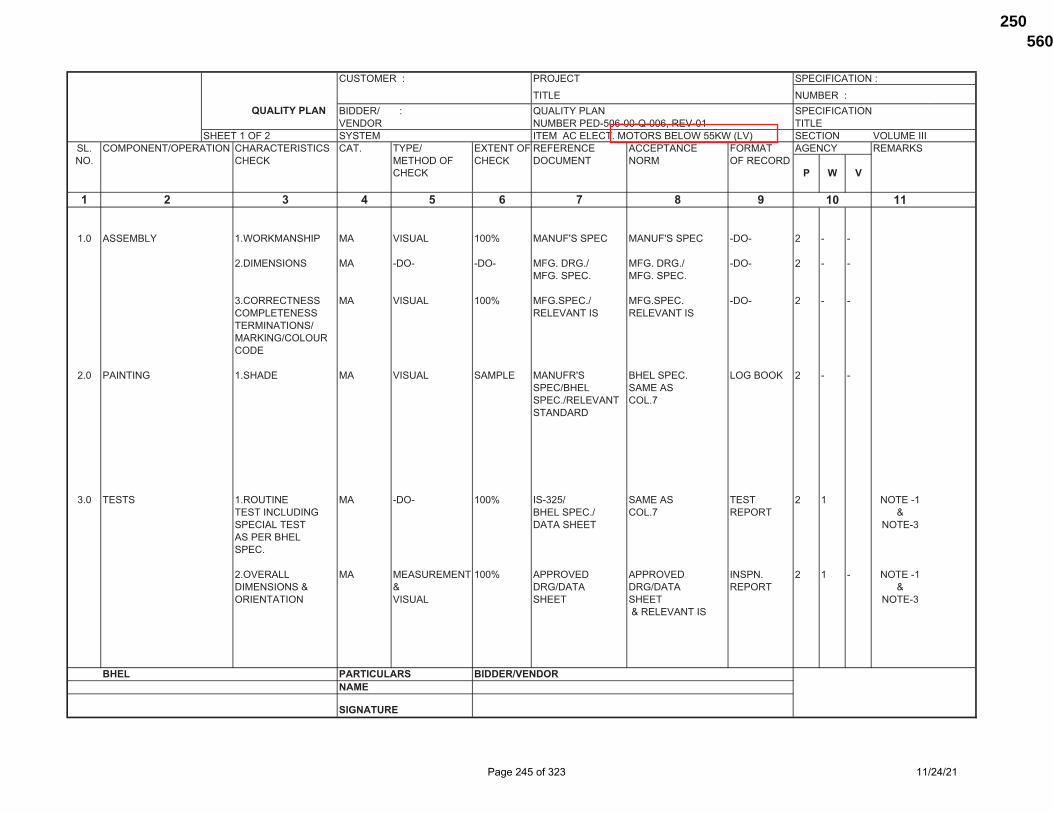
�������� �� �������� ������
�������������������������� ������� ����������� ������������������ ��������������������������� �����
��������! ������ �����������#���������$��*$;��< ������� �����������# ������������������ ������������� ���# ����� �=������ ������� ���������� ����� �>���� ���*���# ����* �������� ����* �������� ��� ������
����* �
� � � � � � � � �� ��
�#� �������� �#$�*������� �� ������ ���? �����@����� �����@����� ���� ! � �
!#���������� �� ���� ���� ��>#�>#� ��>#�>#� ���� ! � ���>#����# ��>#����#
Q#��������� �� ������ ���? ��>#����#� ��>#����# ���� ! � ������������� ��������� �����������������������*��>����������
!#� �������> �#����� �� ������ ������ �����@� ��������# ��>���* ! � ���������� ����������#�������� ���#Z�������
Q#� ����� �#������ �� ���� ���? ���Q!�� ������ ���� ! � ������������������> ��������#� ���#Z ���� [����������� ��������� �����Q������������#
!#������ �� �������������? ������� ������� �����# ! � � ����������������[ [ �>����� �>����� ���� [���������� ������ ����� ����� �����Q
[���������
���� ���������� ������� �������!�
��"������
��������������
#
Page 245 of 323 11/24/21
560979/2021/PS-PEM-MAX250

�������� �� ����������������������������� ����� ������
������� ����������� ������������������� ��������������������������� ������
�����!��! ������ �����������#���������$��*$;��< ������� �����������# ������������������ ������������� ���# ����� �=������ ������� ���������� ����� �>���� ���*���# ����* �������� ����* �������� ��� ������
����* �
� � � � � � � � �� ��
Q#��������� �� ������ ���? ���Q!�[ ���Q!�[ �����# ! � �������� ��������� ��������� ����
������
� ����������������?��������������������������#��$�������������$�������������������������������#����������>��������������������>�������
! $������������������������������������;�<������������������������������>����#Q ���=�������������������������������>�����#�*$��������������������������������������������������#
�\]\^_`{|}�^`~\���|^�]\^��
�#������������!#�����;��������������<Q#���������;�$�������������������������<
�#�����$#$�������#�����
���� ���������� ������� �������!���"���������� �����@�������������������
��������������
#
Page 246 of 323 11/24/21
560979/2021/PS-PEM-MAX251

�������� �� ��� ������������������� ������
�������������������������� ������� ����������� ������������������� ��������������������Z�����Q �����
��������� ������ ������������#�������*$[�����;��[��< ������� �����������# ������������������ ������������ ���# ����� �=������ ������� ���������� ����� �>���� ���*���# ����* �������� ����* �������� ��� ������
����* �
� � � � � � � � ���#� �$�������[���>�����
������
�#� ������������������ �#������ �� ������ ���? � ������ ��>���* Q � ����������������� ��������� ����*��
���*��$����������
!#���������� �� ���������� ������ ����@� ����@� ���� Q � ��>#����� �>#�����
Q#�������� �� ����#���� ���� ���� ���� ������# Q � !����;��� ��������<
�#! ���$��� �#������ �� ������ ���? ������ ���� Q � ���������� ���*�����
�����������#
!#������ �� ������ ������� ����@� ������� �������� Q � ! ���������������� �>#����� �������# ��[��> ��*��>�������
���* ����*������������
�#Q ������> �#������ �� ������ ���? ������ ��>���* Q � !��������� ���*��
���$��������#
!#����#[ �� ����[���� ��������# ����@� ������� �������@� Q � ! ������#����������#���# ���� �>#����� ��� �� �������
Q#���������� �� ���������� ���? �����@� �����@� ��>���* Q � !�># �>#
�#� �����[������ �#��*�������� �� ������ ���? ����@� ����@� ��>���* Q � !���������[ ���������� �>#����� �>#���������
���� ���������� ������� �������!���"���������� �����@�������������������
# ��
Page 247 of 323 11/24/21
560979/2021/PS-PEM-MAX252

�������� �� ��� ������������������� ������
�������������������������� ������� ����������� ������������������� ��������������������Z�����Q �����
�����!��� ������ ������������#�������*$[�����;��[��< ������� �����������# ������������������ ������������ ���# ����� �=������ ������� ���������� ����� �>���� ���*���# ����* �������� ����* �������� ��� ������
����* �
� � � � � � � � ��
�#� ����� �#������ �� ������ ���? � ������ ���� Q � � �����@��������;��>��������< ����# ������ ���������������������
������� ����������
!#����#[ �� ����#[ ��������# ��>#�># ������� �������@� Q � !�������� �������� ����� ����# �� ���������� ����� ��������
�������
Q#���������� �� ���������� ���? ���� �����@� ��>���* Q � !�>#
�#������� � �� ���� ������Q�� �����@� ���� Q ! � �����������[���$� ����# �����
��������#
�#� ������������������� �#��*�[ �� ������ ���� �����@� �����@� ���� Q � !���������������*�� ����> �>#����# �>#����#��������������>���������������#���������������@�
!#�������� �� ���� ���� � ������#����>�� ���� Q � !����# �����������
�������������
Q#���������� �� ���������� ������ �����@� �����@� ���� Q � !;$����� �>#�����# �>#�����#����������<
�#���������� �� ���� ���? ���� ���� ����# Q � !���������� ����
���� ���������� ������� �������!���"���������� �����@�������������������
��#
Page 248 of 323 11/24/21
560979/2021/PS-PEM-MAX253

�������� �� ��� ������������������� ������
�������������������������� ������� ����������� ������������������� ��������������������Z�����Q �����
�����Q��� ������ ������������#�������*$[�����;��[��< ������� �����������# ������������������ ������������ ���# ����� �=������ ������� ���������� ����� �>���� ���*���# ����* �������� ����* �������� ��� ������
����* �
� � � � � � � � ��
�#Z �������������> �#������ �� ������ ���? � �������� �����# Q � !����������*��������� ����#���# ������� ����������>������������������������#
!#����������������� �� ���� ������ �����@� �����@� ��>���* Q � !
����# ����# �����������@�
��
�#� ������������> �#������ �� ������ ���? � �������� ��>���* Q � �;�������< ����# �������
;���������<
!#���������� �� ���������� ������ �����@� �����@� ���� Q � ! �����������������������>��� �>## �># ���������������*�������>�� ��������������
���������>��Q#���������� �� �����#[���� ���� �����@� ������� �������@� Q � !����� ����� ����#� �� ��
���������
�#� ��������� �#������ �� ������ ���? � ������ ��>���* Q� � !������� ������
�������
!#�����#����[ �� �����#[ ������� ���������� ���������� �������� Q � !����#��� ����#���� ��� ��� ��[
���� ���� �����@��������� �������� �����#
�����
���� ���������� ������� �������!���"���������� �����@�������������������
����������������������������������*��������������������������;��?������<�����$�*�������������������������������������������#
��#
Page 249 of 323 11/24/21
560979/2021/PS-PEM-MAX254

�������� �� ��� ������������������� ������
�������������������������� ������� ����������� ������������������� ��������������������Z�����Q �����
��������� ������ ������������#�������*$[�����;��[��< ������� �����������# ������������������ ������������ ���# ����� �=������ ������� ���������� ����� �>���� ���*���# ����* �������� ����* �������� ��� ������
����* �
� � � � � � � � ��
Q#���������� �� ���������� ���� ���� ���� �|]�||� Q � !
�#�� �����>� �#��*�[���� �� ������ ���?����@��>#�����������������
����@��>#�����������������
���� Q � !
!#���������� �� ���������� ������ �������� �������� ���� Q � !����� ����������>
�����@�������>���
Q#������ �� ������ ���? � ������ ���� Q � !������ ������
�������
�#�� ������> �#������ �� ������ ���? � ���� ���� Q � �;$���������������< ����#
!#���������� �� ���������� ������ �����@� �����@� ���� Q � ��> �>
Q#����#$���� �� �����#���� ���� �����@� �����@� ���� Q � !
������������� ����#���������# ����#���������#
�#���� �� ���� ���? ���� ���� ���� Q � !
�#�! ��������[>��*��� �#��������� �� ������ ���? �����@� �����@� ���� Q � �>��*�� �>������ �>#������#
!#������ �� ������ ���? � ������ ���� Q � �����# ������
�������
Q#���������� �� ���������� ������ �����@� �����@� ���� Q � ��> �>
���� ���������� ������� �������!���"���������� �����@�������������������
��#
Page 250 of 323 11/24/21
560979/2021/PS-PEM-MAX255

�������� �� ��� ������������������� ������
�������������������������� ������� ����������� ������������������� ��������������������Z�����Q �����
��������� ������ ������������#�������*$[�����;��[��< ������� �����������# ������������������ ������������ ���# ����� �=������ ������� ���������� ����� �>���� ���*���# ����* �������� ����* �������� ��� ������
����* �
� � � � � � � � ��
!#� ��������
!#� ���������$�����> �#$�*������� �� ������ ���? ���� >��������� ��>���* Q�! ! �;����������������� [��������������<
!#���������� �� ���������� ���� �����@� �����@� ���� ! � ��> �>
!#! ��������> �#������ �� ������ ���? ���� >��������� ��>���* ! � �
!#���������� �� ���������� ���� �����@� �����@� ���� ! � ��> �>
Q#����������� �� �� ���� ������� �����@� ���� ! � ����$� ����#� ����#�
��������� ��������#�
!#Q �������> �#������ �� ������ ���? ����@� ���� ��>���* ! � ���������� ��������� ����#
����#� ������������� ���#Z�����
!#���������*���� �� ���������� ������ ���� ���� ���� ! � �;��������[ ��������������������<
Q#����� �� ������ ���� ���� ���� �|]�||� ! � �
�#�������� �� ���� ���� ���� ���� �|]�||� ! � �������>[��������
���� ���������� ������� �������!���"���������� �����@�������������������
��#
Page 251 of 323 11/24/21
560979/2021/PS-PEM-MAX256

�������� �� ��� ������������������� ������
�������������������������� ������� ����������� ������������������� ��������������������Z�����Q �����
��������� ������ ������������#�������*$[�����;��[��< ������� �����������# ������������������ ������������ ���# ����� �=������ ������� ���������� ����� �>���� ���*���# ����* �������� ����* �������� ��� ������
����* �
� � � � � � � � ��
!#� ���������*��> �#������������ �� ���������� ������ �����@� �����@� �|]�||� ! � �����# ����#
!#���������� �� ���������� ���? ���� ���� �|]�||� ! � �[��>������>
Q#�������[ �� �����#���� ���� ���� ���� �|]�||� ! �� ��������
!#� $�����> �#������������ � ������ ���? �����@� �����@� �|]�||� ! � �����#����� ����#���������# ����#
!#����������� � ���� ���� ���� ���� �|]�||� ! � �
Q#������ � �����#���� ���� ���� ���� �|]�||� ! � �
�#��������� � ���� ���� ���� ���� �|]�||� ! � �
�#������� � ���� ���� ���� ���� �|]�||� ! � �����������
�#��>�$��� � ���� ���� ���� ���� �|]�||� ! � � �������������������#���������
!#� ����>������ �#���������� �� ���#���� ��������> ���� ���� �|]�||� ! � �
!#����# �� ������ ���������� ���� ���� �|]�||� ! � ������� ����*������
Q#��#������ �� ���� ���� ���� ���� �|]�||� ! � � ������������>����
���� ���������� ������� �������!���"���������� �����@�������������������
��#
;���������!�$��������<�����?�����������
Page 252 of 323 11/24/21
560979/2021/PS-PEM-MAX257

�������� �� ��� ������������������� ������
�������������������������� ������� ����������� ������������������� ��������������������Z�����Q �����
�����Z��� ������ ������������#�������*$[�����;��[��< ������� �����������# ������������������ ������������ ���# ����� �=������ ������� ���������� ����� �>���� ���*���# ����* �������� ����* �������� ��� ������
����* �
� � � � � � � � ��
�#������� �� ���� ���� ���� ���� �|]�||� ! � �
!#Z ������������� �#����������� �� ������ ���? ���� ���� �|]�||� ! � ��������� [�����������
!#� �����>����������� �#������������ � ���� ���� ���� ���� �|]�||� ! � � ����
!#��������� � ���������� ���� ���� ���� �|]�||� ! �[��
Q#�� �� �����#���� ���� ���� ���� �|]�||� ! �
!#� ����������� �#������� � ���#������� ���� ��>����#� ��>#�$># �|]�||� ! � ����������������������� ��������� ������� ��������
!#��������� � �����# ���� ��>#����# ��>#����# �|]�||� ! ������ ;>�$��������> ����<
!#�� �������� �#���>����� �� ����# ���� ���� ���� �|]�||� ! � �
!#$�*������� �� ������ ���� ���� ���� �|]�||� ! � �
Q#�=������� �� ����# ���� ���� ���� �|]�||� ! � �
�#���������� �� ���� ���� ��>#�>#� ��>#�>� �|]�||� ! � ���>����# ���������
�#���������� �� ������ ���? ��>����# ��>����# �|]�||� ! � ������������� ��������� �����������������������*��>����������
�#������[����� �� ������ ���? ��>����# ��>����# �|]�||� ! �������������># ��������� ���������
���� ���������� ������� �������!���"���������� �����@�������������������
��#
Page 253 of 323 11/24/21
560979/2021/PS-PEM-MAX258

�������� �� ��� ������������������� ������
�������������������������� ������� ����������� ������������������� ��������������������Z�����Q �����
��������� ������ ������������#�������*$[�����;��[��< ������� �����������# ������������������ ������������ ���# ����� �=������ ������� ���������� ����� �>���� ���*���# ����* �������� ����* �������� ��� ������
����* �
� � � � � � � � ��
Q#� ����� �#��������� �� �����#���� ����������� ���Q!�� ���Q!�� ���� ! �� � ���������������> ��������#� ��������#� ����������� ��������� ��������������������������#
!#������ �� ���� ���? ���� ���� ���� ! �� � ������!�������������>�����������������������#
Q#��������[ �� ���� ���? ����!�Z�[ ����!�Z�[ ���� ! �� � ������!���������� ����!��� ����!���
�#������ �� ���������� ���? ������� ������� �����# ! � ����������� [������ �>����� �>����� ����������������� ����� �����[
���������
�#��>���� �� �����#[ ������� ��������� ��������# �� ! � ���������� ����#���� ���� �������
������#������������ �� ���� ���? ���� ���� ���� ! �� � ������!�������������[���
Z#������������ �� ���� ���? ���� ���� ���� ! �� � ������!�����������������������
�#��������� �� ������ ���? ���Q!�[ ���Q!�[ �����# ! �� � ������!������� ��������� ��������� ����
�#�=������� �� �=������� ������ ���Q��! ���Q��! �� ! � ���������� ��������� ����!Q� ����!Q�����;�� ���� ����!�� ����!�����������<
��#����������� �� ������[ ������ ��������# ��������# �� ! �� � �������>������������*���� ���������� [���� [���� �������������������[������ ����*����� ����� ����� �>����
������!
���� ���������� ������� �������!���"���������� �����@�������������������
�����������������������������������Q
�����������������������������������Q
��#
Page 254 of 323 11/24/21
560979/2021/PS-PEM-MAX259

�������� �� ��� ������������������� ������
�������������������������� ������� ����������� ������������������� ��������������������Z�����Q �����
��������� ������ ������������#�������*$[�����;��[��< ������� �����������# ������������������ ������������ ���# ����� �=������ ������� ���������� ����� �>���� ���*���# ����* �������� ����* �������� ��� ������
����* �
� � � � � � � � ��
������
� ��������>������������������������$��������>��������������������#
! ����������������?��������������������������#��$�������������$�������������������������������#����������>��������������������>�������#
Q ���������������������������������������������������������>�����������������������������������������������������������������#
� $������������������������������������>����;�<������������������������������>����#
�\]\^_`{|}�^`~\���|^�]\^��
�#������������!#�����;��������������<Q#���������;�$�������������������������<
�#�����$#$�������#�����
���� ���������� ������� �������!���"���������� �����@�������������������
��#
Page 255 of 323 11/24/21
560979/2021/PS-PEM-MAX260

Page 256 of 323 11/24/21
560979/2021/PS-PEM-MAX261

Page 257 of 323 11/24/21
560979/2021/PS-PEM-MAX262

TITLE
LV MOTORS
DATA SHEET-A
3X660 MW NABINAGAR-I FGD
SPECIFICATION NO. VOLUME II B SECTION D REV NO. DATE:22.01.2020 SHEET 1 OF 2
ANNEXURE-III
1.0 Design ambient temperature : 50 oC 2.0 Maximum acceptable kW rating of LV motor : 200KW * 3.0 Installation (Indoors/ Outdoors) : As required
4.0 Details of supply system a) Rated voltage (with variation) : 415V 10% b) Rated frequency (with variation) : 50 Hz + 3 % to - 5% c) Combined voltage & freq. variation : 10% (sum of absolute values) d) System fault level at rated voltage : 50 kA for 1 sec
e) Short time rating for terminal boxes o 110 kW and above (Breaker : 50 KA for 0.25 sec.
Controlled) o Below 110 kW (Contactor : 50 KA protected by HRC fuse
Controlled) f) LV System grounding : Solidly 5.0 Winding & Insulation : Class F with temp rise limited to class B 6.0 Minimum voltage for starting : 85% for motor ratings below 110kW
(As percentage of rated voltage) 80% for motor ratings from 110kW to 200kW.
7.0 Power cables data : Shall be given during detailed engg. 8.0 Earth Conductor Size & Material : Shall be given during detailed engg. 9.0 Space heater supply (for motors >=30kw) : 240 V, 1ɸ, 50 Hz 10.0 Rating up to which Single phase motor : Acceptable below 0.2 kW 11.0 Locked rotor current
a) Limit as percentage of FLC : As per IS 12615
12.0 Makes : BHEL/ Customer approval (Package owner to take care) 13.0 Paint shade : Blue (RAL 5012) – Corrosion proof 14.0 Degree Of protection for motor/ terminal box : Degree of protection for various
enclosures as per IEC60034-05 shall be as follows:-
i) Indoor motors - IP 54 ii) Outdoor motors - IP 55 iii) Cable box-indoor area - IP 54 iv) Cable Box-Outdoor area - IP 55
* LT motors of continuous duty shall be energy efficient IE3 class conforming to IS-12615 15.0 TESTING REQUIREMENTS: IN LINE WITH SPECIFICATION
Page 258 of 323 11/24/21
560979/2021/PS-PEM-MAX263
3062554
Text Box
ANNEXURE-I

CLAUSE NO.
Bidder’s Name ………………………..
DE-1B LT MOTORS
A. GENERAL
5. Manufacturer & Country of origin. (Shall be as per approved QA make)
6. Equipment driven by motor
7. Motor type
8. Quantity
B. DESIGN AND PERFORMANCE DATA
18. Frame size
19. Type of duty
20. Type of enclosure /Method of cooling/ Degree of
21. Applicable standard to which motor generally
22. Efficiency class as per IS 12615
23. (a)Whether motor is flame proof Yes/No
(b)If yes, the gas group to which it conforms as per IS:2148
24. Type of mounting
25. Direction of rotation as viewed from DE END
26. Standard continuous rating at 40 deg.C. ambient temp. as per Indian Standard (KW)
27. Derated rating for specified normal condition i.e. 50 deg. C ambient temperature (KW)
28. Maximum continuous load demand of driven
29. Rated Voltage (volts)
30. Permissible variation of :
a. Voltage (Volts)
b. Frequency (Hz)
c. Combined voltage and frequency
31. Rated speed at rated voltage and
32. At rated Voltage and frequency:
a. Full load current
ATTACHMENT-12 TO LOT 1A PROJECTS
SECTION-VII FLUE GAS DESULPHURISATION (FGD)
TECHNICAL DATA SHEETS SYSTEM PACKAGE
BID DOC. NO. : CS-00111-109(1A)-2
PART-F CHAPTER-II
PAGE 13 OF 17 MODULE-II
SUB-SECTION:DE1 MOTORS
Page 259 of 323 11/24/21
560979/2021/PS-PEM-MAX264
3062554
Text Box
DATA SHEET-C

CLAUSE NO.
Bidder’s Name ………………………..
b. No load current
33. Power Factor at
a. 100% load
b. NO load
c. Starting.
34. Efficiency at rated voltage and frequrecy,
a.100% load
b. 75% load
c. 50% load
35. Starting current (amps) at
a. 100 % voltage
b. 85% voltage
c. 80% voltage
36. Minimum permissible starting Voltage (Volts)
37. Starting time with minimum permissible voltage
a. Without driven equipment coupled
b. With driven equipment coupled
38. Safe stall time with 100% and 110% of rated
a. From hot condition
b. From cold condition
39. Torques :
a. Starting torque at min. permissible voltage(kg-
b. Pull up torque at rated voltage.
c. Pull out torque
d. Min accelerating torque (kg.m) available
e.Rated torque (kg.m)
40. Stator winding resistance per phase (ohms at 20
41. GD2 value of motors
ATTACHMENT-12 TO LOT 1A PROJECTS
SECTION-VII FLUE GAS DESULPHURISATION (FGD)
TECHNICAL DATA SHEETS SYSTEM PACKAGE
BID DOC. NO. : CS-00111-109(1A)-2
PART-F CHAPTER-II
PAGE 14 OF 17 MODULE-II
SUB-SECTION:DE1 MOTORS
Page 260 of 323 11/24/21
560979/2021/PS-PEM-MAX265

CLAUSE NO.
Bidder’s Name ………………………..
42. No of permissible successive starts when motor is in hot condition
43. Locked Rotor KVA Input
44. Locked Rotor KVA/KW
45. Vibration limit :Velocity (mm/s)
46. Noise level limit (dBA)
C. CONSTRUCTIONAL FEATURES
1. Stator winding insulation
a. Class & Type
b. Winding Insulation Process c. Tropicalised (Yes/No)
d. Temperature rise over specified maximum ambient temperature of 50 deg C
e. Method of temperature measurement
f. Stator winding connection 2. Main Terminal Box
a. Type
b. Location(viewed from NDE side)
c. Entry of cables(bottom/side)
d. Recommended cable size(To be matched with cable size envisaged by owner)
e. Fault level (MVA),Fault level duration(sec)
f. Cable glands & lugs details (shall be suitable for
3. Type of DE/NDE Bearing
4. Motor Paint shade
5. Weight of
a. Motor stator (KG)
b. Motor Rotor (KG)
c. Total weight (KG)
ATTACHMENT-12 TO LOT 1A PROJECTS
SECTION-VII FLUE GAS DESULPHURISATION (FGD)
TECHNICAL DATA SHEETS SYSTEM PACKAGE
BID DOC. NO. : CS-00111-109(1A)-2
PART-F CHAPTER-II
PAGE 15 OF 17 MODULE-II
SUB-SECTION:DE1 MOTORS
Page 261 of 323 11/24/21
560979/2021/PS-PEM-MAX266

CLAUSE NO.
Bidder’s Name ………………………..
D. List of accessories.
1. 3 Space Heaters (Applicable for 30 KW & above motor) (Nos./Power in watts/supply voltage)
2. Terminal Box for Space Heater (Yes/No)
3. Speed switch (Yes/No)
4. Insulation of bearing (Yes/No)
5. Noise reducer(Yes/No)
6. Grounding pads
i) No and size on motor body
ii) Nos on terminal Box
7. Vibration pads
i) Nos and size
ii) Location
8. Any other fitments
E. List of curves.
1. Torque speed characteristic of the motor
2. Thermal withstand characteristic
3. Starting. current Vs. Time
4. Starting. current Vs speed
5. P.F. and Effi. Vs Load
F. Additional Data to be filled for each rating of DC Motor
1. Rated armature voltage (Volt)
2. Rated field excitation (Amp)
3. Permissible % variation in voltage
4. Minimum Permissible Starting voltage (volt)
5. At rated voltage
i)Full load Armature current.(Amp)
ATTACHMENT-12 TO LOT 1A PROJECTS
SECTION-VII FLUE GAS DESULPHURISATION (FGD)
TECHNICAL DATA SHEETS SYSTEM PACKAGE
BID DOC. NO. : CS-00111-109(1A)-2
PART-F CHAPTER-II
PAGE 16 OF 17 MODULE-II
SUB-SECTION:DE1 MOTORS
Page 262 of 323 11/24/21
560979/2021/PS-PEM-MAX267

CLAUSE NO.
Bidder’s Name ………………………..
ii)Full load Field current (Amp)
iii)No load Armature current (Amp)
6. Full load Field current (Amp)
7. No load Aramature current (Amp)
8. Minimum permissible field current(Amp) to avoid
i) Maximum permissible voltage
ii) Rated voltage
iii) Minimum Permissible Voltage
9. Resistance (indicative Values) in ohm
i)Armature winding(Arm + IP + Series) at 25
ii) Field Winding at 25 deg. C
10.. Inductance (indicative values)
i) Armature winding
ii) Field winding
11 Value of trimmer resistance (ohm) to be connected in series with the shunt field to
i) 220 V DC
ii) 250 V DC
iii) 187 V DC
12 Value of the external resistance (ohm)required to be connected in series with armature during starting only
13 Technical data sheet for external resistance box
14 GA drawing of motor
15 Starting time calculation
16 Starter resistance design calculation
17 Electrical connection diagram of motor
ATTACHMENT-12 TO LOT 1A PROJECTS
SECTION-VII FLUE GAS DESULPHURISATION (FGD)
TECHNICAL DATA SHEETS SYSTEM PACKAGE
BID DOC. NO. : CS-00111-109(1A)-2
PART-F CHAPTER-II
PAGE 17 OF 17 MODULE-II
SUB-SECTION:DE1 MOTORS
Page 263 of 323 11/24/21
560979/2021/PS-PEM-MAX268

LOAD TITLE
RATING (KW / A)
UN
IT (
U)/
ST
N (
S) Nos.
VO
LT
AG
E C
OD
E*
FE
ED
ER
CO
DE
**
EM
ER
. L
OA
D (
Y)
CO
NT
.(C
)/ IN
TT
.(I)
ST
AR
TIN
G T
IME
>
5 S
EC
(Y
)
LOCATION BOARD
NO.
CABLE
BL
OC
K C
AB
LE
D
RG
. No
.
CONTROL
CODE
REMARKS
LOAD No.
VERIFICATION FROM MOTOR
DATASHEET (Y/N)
KKS NO
NAME PLATE
MAX. CONT.
DEMAND (MCR)
RU
NN
ING
ST
AN
DB
Y
SIZE CODE
NOs
1 2 3 4 5 6 7 8 9 10 11 12 13 14 15 16 17 18 19 20 21
NOTES: 1. COLUMN 1 TO 12 & 18 SHALL BE FILLED BY THE REQUISITIONER (ORIGINATING AGENCY); REMAINING COLUMNS ARE TO BE FILLED UP BY PEM (ELECTRICAL)/ CUSTOMER
2. ABBREVIATIONS : * VOLTAGE CODE (7):- (ac) A=11 KV, B=6.6 KV, C=3.3 KV, D=415 V, E=240 V (1 PH), F=110 V (cc): G=220 V, H=110 V, J=48 V, K=+24V, L=-24 V
: ** FEEDER CODE (8):- U=UNIDIRECTIONAL STARTER, B=BI-DIRECTIONAL STARTER, S=SUPPLY FEEDER, D=SUPPLY FEEDER (CONTACTER CONTROLLED)
LOAD DATA
(ELECTRICAL)
JOB NO. 436 ORIGINATING AGENCY PEM (ELECTRICAL) PROJECT TITLE 3X660 MW NABINAGAR-I FGD NAME DATA FILLED UP ON
SYSTEM GYPSUM DEWATERING
SYSTEM SIGN.
DATA ENTERED ON
DEPTT. / SECTION MAX SHEET 1 OF 1 REV. 00 DE’S SIGN. & DATE
ANNEXURE-II
Page 264 of 323 11/24/21
560979/2021/PS-PEM-MAX269
3062554
Text Box
AGITATOR
3062554
Text Box
457

CABLE SCHEDULE FORMAT ANNEXURE III
UNITCABLENO FROM TO PURPOSE
CABLE SCOPE (BHEL PEM/ VENDOR) REMARKS CABLESIZE PATHCABLENO
TENTATIVE CABLE LENGTH
Page 265 of 323 11/24/21
560979/2021/PS-PEM-MAX270

TITLE: NABINAGAR SUPER THERMAL POWER
PROJECT (3x660MW) TECHNICAL SPECIFICATION
FOR AGITATORS OF FGD SLURRY TANKS
SPECIFICATION No: PE-TS-457-571-18000-A003 SECTION-I, SUB-SECTION-D REV. 00 DATE: SHEET : 1 OF 1
LIST OF MAKES OF SUB‐VENDOR ITEMS
Page 266 of 323 11/24/21
560979/2021/PS-PEM-MAX271

TITLE: NABINAGAR SUPER THERMAL POWER
PROJECT (3x660MW) TECHNICAL SPECIFICATION
FOR AGITATORS OF FGD SLURRY TANKS
SPECIFICATION No: PE-TS-457-571-18000-A003 SECTION-I, Sub Section-D REV. 00 DATE: SHEET : 1
Sl.no. Item Category of Inspection
Sub-vendor Place Remarks
1. PAINT III ASIAN PAINT III BERGER III KANSAI NEROLAC III JOTUN III SHALIMAR III JENSON & NICHOLSON
(I) LTD
III CDC CARBOLINE (I) LTD. III ADDISON PAINTS LTD III GRAND POLYCOAT
NOTES: INSPECTION CATEGORIZATION CAT I: INSPECTION BY OWNER, BHEL/BHEL NOMINATED TPIA & VENDOR. MDCC WILL BE ISSUED BASED ON INSPECTION REPORT IN LINE ITH APPROVED QAP. CAT II: INSPECTION BY BHEL/BHEL NOMINATED TPIA & VENDOR. MDCC WILL BE ISSUED BASED ON INSPECTION REPORT IN LINE ITH APPROVED QAP. CAT III: MDCC WILL BE ISSUSED BASED COC & MTC ISSUSD BY VENDOR AND VERIFICATION BY BHEL / OWNER IN LINE WITH APPROVED QAP/CHECK LIST
The list of all bought out items like gearbox, coupling, bearings etc. with makes and country of origin and contact details of the manufacturers to be mentioned along with offer to be submitted in the format attached in Section II, Annexure-6 as information to BHEL.
Acceptance of makes shall be subject to BHEL/ End customer acceptance during the detailed engineering without cost and delivery implication to BHEL.
Bidder has to submit the sub-vendor questionnaire (attached herewith) along with necessary credentials in case the proposed sub-vendor is not as per the list provided.
The complete list will be necessarily submitted within one month of placement of LOI to ensure
timely placement of order for BOIs. Bidder to assess the capability of their proposed sub‐vendors in terms of preparation of drawings, calculations, documents, quality assurance, supply of material etc. as per project schedule before placing the order on them.
Page 267 of 323 11/24/21
560979/2021/PS-PEM-MAX272

IND
ICA
TIV
E S
UB
VE
ND
OR
LIS
T
NTPC
DOC
NO
PACK
AGE:
,�,ait
l RE
VISIO
N NO
DA
TE
�
SI Ite
m
QP/
ACCE
PTAB
LE SU
PPLIE
R AS
PER
DAT
ABAS
E PLA
CE O
F MAN
UFACT
URIN
G AP
PROV
AL
:E -�
No.
lnsp
. ST
A :S ,
Ca
t. n
MBE
KU
MAR
DHUB
I A
'-. -
KALI
KU
MBA
KONA
M
'-.A
� ...
AMPS
JA
MSH
EDPU
R �
A.I
A.
ADAK
HOW
RAH
I
AT
BENG
AL T
OO
LSKO
LKAT
A ,� �
A V
V N
MFG
VV
NAG
AR ,.........
,
A Uo
to 1
50 N
B Di
a TK
IIHY
DERA
BAD/
�UN
E'
A PR
O M
ACBA
NGAL
OR
E, ... '-
.I
A L
& T-
EWL
KANC
Hl?�
UR',4;M
-A
ROLL
WEL
LHI
NDW:R
lJla.
I
A IN
DIAN
A CO
NVEY
ORS
PLIN
E '-.
'V'
A 9
PIPE
S FO
R ID
LERS
IS 9
295
MAI
N CO
NT. A
PPRD
SO
URCE
S�,
-SU
BJEC
T TO
VAL
ID B
IS L
ICEN
CE
10
BEAR
ING
S FO
R ID
LERS
M
AIN
CONT
. APP
RD S
OUR
CES
� H
OSlJ
Ei,.
N 11
PU
LLEY
S EL
ECO
N ..... "/PN
�G
AR
A PR
O M
AC
'
B&,G
ALO
RE
A M
BE
.............. , K
UM
ARD
HU
BI
A BE
NGAL
TO
OLS
�
--
KOLK
ATA
A TN
S H
EAV
Y 1
�
CHEN
NAI
A KA
LI
•"
i
TH
IRUB
UVAN
AM
A TK
II '"
HY
DERA
BAD
/PLIN
E A
L &
T-EW
L a.
. .............. ,
KA
NCHE
EPUR
AM
A V
VN
MFG
-''-.
.....
V
V N
AGAR
A
Upto
800
NB
Dia
R K
INDI.J..
Sl'RIE
S'
NEW
DEL
HI
A UP
TO
800
MM
DIA
RO
LL.W
ELL'-.
HI
NDUP
UR
A IN
Dl�
NVE
YORS
PLI
NE
A 12
R
UBB
ER L
AGG
ING
FO
R PU
LLEY
S R
ISHI
Thle'U
ST R
I ES
SONE
PAT
A � W
AHE..
mlRU
KO
LKAT
A A
-� S
UDBlt
P RU
BBER
V
V N
AGAR
A
DSE!
l:51P
RUB
BER
KOLK
ATA
A
-� �
CORI
RUB
BER
CHEN
NAI
A PR
ADEE
P RU
BBER
CH
AKUL
A A
PRES
IDEN
CY R
UBBE
R KO
LKAT
A A
,,---
THEJ
O E
NGG
CH
ENNA
I A
CENT
URY
RUBB
ER
KOLK
ATA
A 13
BE
ARIN
G F
OR
PULL
EYS
'T
MAI
N CO
NT. A
PPRD
SO
URCE
S 14
HE
LICA
L G
EARB
OX
SHAN
TI G
EARS
CO
IMBA
TORE
A
Uoto
size
560
EL
ECO
N V
V N
AGAR
A
SIEM
ENS
(FLE
NDER
) KH
ARAG
PUR
A PR
EMIU
M T
RAN
MIS
SIO
N LT
D PU
NE/F
ALTA
A
Up to
size
710
I 45
0
Page
5 o
f 18
Page 268 of 323 11/24/21
560979/2021/PS-PEM-MAX273
2211238
Line

IND
ICA
TIV
E S
UB
VE
ND
OR
LIS
T
NTPC
DOC
NO
PACK
AGE:
,�,ait
l RE
VISIO
N NO
DA
TE
,;
SI Ite
m
QP/
ACCE
PTAB
LE SU
PPLIE
R AS
PER
DAT
ABAS
E PLA
CE O
F MAN
UFACT
URIN
G AP
PROV
AL :,
No
. ln
sp.
STA :
S ,
Cat.
n
SIEM
ENS
(FLE
NDER
) G
ERM
ANY
A'-.
-NE
W A
LLEN
BURY
WO
RKS
KOLK
ATA
'-.A
� ...
15
PLAN
ETAR
Y G
EARB
OX
ELEC
ON
VV
NAG
AR
�A.I
SIEM
ENS
(FLE
NDER
) G
ERM
ANY
I
AT
MO
VENT
AS
GER
MAN
Y ,� �
A BR
EVIN
I IT
ALY
,.........,
A SE
W E
URO
DRI
VE G
MBH
& C
O.
GER
MAN
Y I
' A
16
FLUI
D C
OUP
LING
(SCO
OP
AND
FL
UIDO
MAT
DE
W AS
,...,,,.
""""'
A Sc
oop
type
upt
o SC
-133
0 TR
ACTI
ON
TYPE
) PT
L AU
RANi3
�D '
A SC
OOP T
YPE U
PTO
PST 1
150
ELEC
ON
v �"'
A Sc
oop t
ype u
pto
mode
l ESC
760.
� ,�
--
v
�
VOIT
H .,
i
HYDE
RABA
D A
SCO
OP T
YPE U
PTO
SV
NL 1
33
0
17
GEA
RED
CO
UPLI
NG
MAI
N CO
NTRA
CTO
,�
DSO
URCE
S 18
FL
EXIB
LE C
OUP
LING
S M
AIN
CONT
� ��
PRO
VED
SOUR
CES,i
19
FL
AP G
ATE,
R&P
GAT
E AN
D R
OD
TK
II "
�
PLI
NE
A G
ATE*
M
ININ
.G &
MA
'l:ERI
AL H
AND
LING
KO
LKAT
A A
UNIT
1:.1 J""'
·LC:i..
HN
OM
AC
PLINE
A
M&E
i .,
-KU
MAR
DHU
BI
A �
PREP.
E�
HOW
RAH
A .....
, lsl
MTal
KO
LKAT
A A
_,
EEECO
N V
V NA
GAR
A
20
VENT
ILAT
ION
SYST
EM
��
)
MAI
N CO
NTRA
CTO
R AP
PRO
VED
FAN
FRO
M N
TPC
APPR
OVE
D S
OUR
CES
SOUR
CES
21
VENT
ILAT
ION
FANS
__
, v
M
ARAT
HON
ELEC
TRIC
MO
TOR(
I) KO
LKAT
AA
�-
LTD
D
UVE N
T BA
NGAL
ORE
A
S K
SYST
EM
SONI
PAT
A AL
MO
NARD
CH
ENNA
I A
TCF
NAD
I CH
ENNA
I A
HOW
DEN
SO
L YVE
NT
CHEN
NAI
A
Page
6 o
f 18
Page 269 of 323 11/24/21
560979/2021/PS-PEM-MAX274
2211238
Line

Page 270 of 323 11/24/21
560979/2021/PS-PEM-MAX275
2211238
Line

Doc
No
:
Rev
No
:D
ate
:14
.06.
2019
Page
: Sub-
supp
lier
Det
ails
su
bmis
sion
sc
h
Rem
ark
Sl N
o IT
EM D
ESC
RIPT
ION
QP
/ In
sp.
Cat
.Q
P N
o:
QP
Sub.
Sc
h.
QP
appr
oval
Sc
h.
Sub-
Supp
lier
appr
oval
st
atus
/ ca
tego
ry
Proj
ect
ELEC
TRIC
AL
ITEM
S
Pack
age
:IN
DIC
ATI
VE
VEN
DO
R L
IST
FOR
ITEM
S R
EQU
IRIN
G Q
UA
LITY
PLA
N A
ND
SU
B-V
END
OR
APP
RO
VA
LSu
pplie
r
: C
ontr
act N
o.:
Prop
osed
sub
-sup
plie
rPl
ace
CG
LA
hmed
naga
rA
MA
RATH
ON
KO
LKA
TAA
SIEM
ENS
MU
MBA
IA
JYO
TI
BARO
DA
A
BHA
RAT
BIJL
EEN
AV
I MU
MBA
IA
Upt
o 69
0 V
, 500
KW
for I
nver
ter D
uty
& u
pto
415V
, 200
KW
for N
on-In
vert
er D
uty
ABB
FARI
DA
BAD
AU
PTO
55K
WA
BBBA
NG
ALO
REA
55K
W –
200
KW
NG
EFBA
NG
ALO
REA
UPT
O 1
5KW
KEC
BAN
GA
LORE
AK
ECH
UBL
IA
UPT
O 9
0KW
LHP
SOLA
PUR
AU
PTO
120
KW
PETL
AU
RAN
GA
BAD
AM
otor
to b
e su
pplie
d fr
om N
TPC
app
rove
d so
urce
sPB
LV
V N
AG
AR
AIN
TERN
AL
CO
MBU
STIO
NA
uran
gaba
dA
NEW
ALL
ENBU
RRY
WO
RKS
Kol
kata
AA
BBV
AD
OD
ARA
AU
pto
6.6k
V, 2
500k
W &
11k
V, 2
000k
WM
ARA
THO
NK
OLK
ATA
AU
pto
11kV
,160
0kW
CG
L(D
5 In
dust
rial
Are
a)M
AN
DID
EEP
AU
pto
6.6k
V,1
650k
W &
11k
V, 1
350k
WC
GL(
Plot
9)
MA
ND
IDEE
PA
Upt
o 11
kV,
4MW
BHEL
BHO
PAL
AW
EG H
OSU
RA
Upt
oo 1
1kV
, 700
0kW
SIEM
ENS
THA
NE
AU
pto
690
V, 5
00 K
WK
ECBA
NG
ALO
REA
3.3
kV, 2
40 k
W
JYO
TI
VA
DO
DA
RAA
Upt
o 6.
6kV
,225
0kW
ABB
BAN
GA
LORE
AU
pto
690V
, 250
KW
MA
RATH
ON
ELE
CTR
IC M
OTO
RSK
OLK
ATA
AU
pto
690V
, 100
KW
BHA
RAT
BIJL
EEN
AV
I MU
MBA
IA
UPT
O 6
90V
, 500
KW
SI
EMEN
STH
AN
EA
Upt
o 69
0 V
, 500
KW
6V
FD M
otor
5H
T M
OTO
R
3L
T (4
15 V
) Mot
ors
GEA
RED
MO
TOR
4
INDIC
ATIVE VENDOR LIST
INDIC
ATIVE VENDOR LIST
A
INDIC
ATIVE VENDOR LIST
A A
INDIC
ATIVE VENDOR LIST
A A
INDIC
ATIVE VENDOR LIST
A A
INDIC
ATIVE VENDOR LIST
A
INDIC
ATIVE VENDOR LIST
INDIC
ATIVE VENDOR LIST
INDIC
ATIVE VENDOR LIST
INDIC
ATIVE VENDOR LIST
INDIC
ATIVE VENDOR LIST
INDIC
ATIVE VENDOR LIST
INDIC
ATIVE VENDOR LIST
INDIC
ATIVE VENDOR LIST
A
INDIC
ATIVE VENDOR LIST
A
INDIC
ATIVE VENDOR LIST
INDIC
ATIVE VENDOR LIST
INDIC
ATIVE VENDOR LIST
INDIC
ATIVE VENDOR LIST
INDIC
ATIVE VENDOR LIST
INDIC
ATIVE VENDOR LIST
AU
RAN
GA
BAD
INDIC
ATIVE VENDOR LIST
AU
RAN
GA
BAD
INDIC
ATIVE VENDOR LIST
VV
NA
GA
R
INDIC
ATIVE VENDOR LIST
VV
NA
GA
R
INDIC
ATIVE VENDOR LIST
INTE
RNA
L C
OM
BUST
ION
Aur
anga
bad
INDIC
ATIVE VENDOR LIST
INTE
RNA
L C
OM
BUST
ION
Aur
anga
bad
INDIC
ATIVE VENDOR LIST
NEW
ALL
ENBU
RRY
WO
RKS
Kol
kata
INDIC
ATIVE VENDOR LIST
NEW
ALL
ENBU
RRY
WO
RKS
Kol
kata
INDIC
ATIVE VENDOR LIST
INDIC
ATIVE VENDOR LIST
VA
DO
DA
RA
INDIC
ATIVE VENDOR LIST
VA
DO
DA
RA
INDIC
ATIVE VENDOR LIST
INDIC
ATIVE VENDOR LIST
KO
LKA
TA
INDIC
ATIVE VENDOR LIST
KO
LKA
TA
INDIC
ATIVE VENDOR LIST
INDIC
ATIVE VENDOR LIST
MA
ND
IDEE
P
INDIC
ATIVE VENDOR LIST
MA
ND
IDEE
P
INDIC
ATIVE VENDOR LIST
INDIC
ATIVE VENDOR LIST
MA
ND
IDEE
P
INDIC
ATIVE VENDOR LIST
MA
ND
IDEE
P
INDIC
ATIVE VENDOR LIST
INDIC
ATIVE VENDOR LIST
INDIC
ATIVE VENDOR LIST
INDIC
ATIVE VENDOR LIST
INDIC
ATIVE VENDOR LIST
INDIC
ATIVE VENDOR LIST
INDIC
ATIVE VENDOR LIST
INDIC
ATIVE VENDOR LIST
INDIC
ATIVE VENDOR LIST
INDIC
ATIVE VENDOR LIST
INDIC
ATIVE VENDOR LIST
INDIC
ATIVE VENDOR LIST
INDIC
ATIVE VENDOR LIST
INDIC
ATIVE VENDOR LIST
INDIC
ATIVE VENDOR LIST
INDIC
ATIVE VENDOR LIST
INDIC
ATIVE VENDOR LIST
INDIC
ATIVE VENDOR LIST
INDIC
ATIVE VENDOR LIST
INDIC
ATIVE VENDOR LIST
INDIC
ATIVE VENDOR LIST
MA
RATH
ON
ELE
CTR
IC M
OTO
RSK
OLK
ATA
INDIC
ATIVE VENDOR LIST
MA
RATH
ON
ELE
CTR
IC M
OTO
RSK
OLK
ATA
INDIC
ATIVE VENDOR LIST
BHA
RAT
BIJL
EE
INDIC
ATIVE VENDOR LIST
BHA
RAT
BIJL
EESI
EMEN
S
INDIC
ATIVE VENDOR LIST
SIEM
ENS
INDIC
ATIVE VENDOR LIST
INDIC
ATIVE VENDOR LIST
INDIC
ATIVE VENDOR LIST
INDIC
ATIVE VENDOR LIST
INDIC
ATIVE VENDOR LIST
INDIC
ATIVE VENDOR LIST
INDIC
ATIVE VENDOR LIST
INDIC
ATIVE VENDOR LIST
INDIC
ATIVE VENDOR LIST
INDIC
ATIVE VENDOR LIST
Page 271 of 323 11/24/21
560979/2021/PS-PEM-MAX276
2211238
Line

TITLE: PATRATU STPP FGD PACKAGE
TECHNICAL SPECIFICATION FOR AGITATORS
SPECIFICATION No: PE-TS-434-571-18000-A001
SECTION-I, Sub Section-D
REV. 00 DATE: DEC 2019
SHEET : 2
ANNEXURE-A
The list of all bought out items like gearbox, coupling, bearings etc. with makes and country of
origin and contact details of the manufacturers to be mentioned along with offer to be submitted in the format attached in section II Annexure-6 as an information to BHEL.
Bidder has to submit the sub-vendor questionnaire (attached herewith) along with necessary credentials in case the proposed sub-vendor is not as per the list provided.
Acceptance of makes shall be subject to BHEL/ End customer acceptance during the detailed engineering without cost and delivery implication to BHEL.
Page 272 of 323 11/24/21
560979/2021/PS-PEM-MAX277
3062805
Text Box
3x660 MW NABIBAGAR TPP
3062805
Text Box
DATE: SEP. 2020
3062805
Text Box
PE-TS-457-571-18000-A001
2211238
Line
2211238
Text Box
TITLE: NABINAGAR SUPER THERMAL POWER PROJECT (3x660MW) TECHNICAL SPECIFICATION FOR AGITATORS OF FGD SLURRY TANKS
2211238
Text Box
SPECIFICATION No: PE-TS-457-571-18000-A001
2211238
Text Box
DATE : NOV 2020

CORPORATE QUALITY ASSURANCE
SUB-VENDOR QUESTIONNAIRE
Format No. : QS-01-QAI-P-04/F2-R2 1/2 Engg. div./QA&I
i. Item/Scope of Sub-contracting
ii. Address of the registered office
Details of Contact Person
(Name, Designation, Mobile, Email)
iii. Name and Address of the proposed Sub-vendor’s works
where item is being manufactured
Details of Contact Person:
(Name, Designation, Mobile, Email)
iv. Annual Production Capacity for proposed item/scope of
sub-contracting
v. Annual production for last 3 years for proposed item/scope
of sub-contracting
vi. Details of proposed works
1. Year of establishment of present works
2. Year of commencement of manufacturing at above works
3. Details of change in Works address in past (if any)
4. Total Area
Covered Area
5. Factory Registration Certificate Details attached at Annexure – F2.1
6. Design/ Research & development set-up
(No. of manpower, their qualification, machines & tools
employed etc.)
Applicable / Not applicable if manufacturing is as
per Main Contractor/purchaser design)
Details attached at Annexure – F2.2
(if applicable)
7. Overall organization Chart with Manpower Details
(Design/Manufacturing/Quality etc)
Details attached at Annexure – F2.3
8. After sales service set up in India, in case of foreign sub-
vendor
(Location, Contact Person, Contact details etc.)
Applicable / Not applicable
Details attached at Annexure – F2.4
9. Manufacturing process execution plan with flow chart
indicating various stages of manufacturing from raw
material to finished product including outsourced process,
if any
Details attached at Annexure – F2.5
Page 273 of 323 11/24/21
560979/2021/PS-PEM-MAX278

CORPORATE QUALITY ASSURANCE
SUB-VENDOR QUESTIONNAIRE
Format No. : QS-01-QAI-P-04/F2-R2 2/2 Engg. div./QA&I
10. Quality Control exercised during receipt of raw
material/BOI, in-process , Final Testing, packing
Details attached at Annexure – F2.6
11. Manufacturing facilities (List of machines, special process facilities, material handling etc.)
Details attached at Annexure – F2.7
12. Testing facilities
(List of testing equipment)
Details attached at Annexure – F2.8
13. If manufacturing process involves fabrication then- Applicable / Not applicable
Details attached at Annexure – F2.9
(if applicable)
List of qualified Welders
List of qualified NDT personnel with area of specialization
14. List of out-sourced manufacturing processes with Sub-
Vendors’ names & addresses
Applicable / Not applicable
Details attached at Annexure. –F2.10
(if applicable)
15. Supply reference list including recent supplies Details attached at Annexure – F2.11
(as per format given below) Project/ package
Customer Name
Supplied Item (Type/Rating/Model /Capacity/Size etc)
PO ref no/date Supplied Quantity Date of Supply
16. Product satisfactory performance feedback
letter/certificates/End User Feedback
Attached at annexure - F2.12
17. Summary of Type Test Report (Type Test Details, Report
No, Agency, Date of testing) for the proposed product
(similar or higher rating)
Note:- Reports need not to be submitted
Applicable / Not applicable
Details attached at Annexure – F2.13
(if applicable)
18. Statutory / mandatory certification for the proposed
product
Applicable / Not applicable
Details attached at Annexure – F2.14
(if applicable)
19. Copy of ISO 9001 certificate
(if available)
Attached at Annexure – F2.15
20. Product technical catalogues for proposed item (if
available)
Details attached at Annexure – F2.16
Name: Desig: Sign: Date:
Company’s Seal/Stamp:-
Page 274 of 323 11/24/21
560979/2021/PS-PEM-MAX279

TITLE: NABINAGAR SUPER THERMAL POWER
PROJECT (3x660MW) TECHNICAL SPECIFICATION
FOR AGITATORS OF FGD SLURRY TANKS
SPECIFICATION No: PE-TS-457-571-18000-A003 SECTION-I Sub Section-D REV. 00 DATE: SHEET : 1 OF 1
ANNEXURE-II
MANDATORY SPARE LIST
Page 275 of 323 11/24/21
560979/2021/PS-PEM-MAX280

SPECIFICATION NO. :PE-TS-457-571-18000-A003
ANNEXURE‐II
Sl. No. PARTICULARSUnit /Quantity( Nos./SET/%)
1.06.00 AGITATORS
A AUXILIARY ABSORBENT TANK AGITATOR
1 Impeller Assembly 2 no. of each type and size
2 Bearing Assembly 2 no. of each type and size
3 Motor 1 no. of each type
4 Belt and Pulley (If applicable) 2 no. of each type and size
5 Gear Box Assembly (If Applicable) 1 no. of each type and size
6 Agitators shaft assembly 2 no. of each type and size
7 Shaft seal 2 no. of each type and size
8 Complete Agitator Assembly 1 no. of each type and size
B1 LIMESTONE SLURRY STORAGE TANK AGITATORS
1 Impeller Assembly 1 no. of each type
2 Bearing Assembly 1 no. of each type
3 Motor 1 no. of each type
4 Belt and Pulley (If applicable) 2 no. of each type
5 Gear Box Assembly (If Applicable) 1 no. of each type
6 Agitators shaft assembly 2 no. of each type and size
7 Complete Agitator Assembly 1 no. of each type and size
B2 PRIMARY HYDRO-CYCLONE FEED TANK AGITATOR
1 Impeller Assembly 1 no. of each type
2 Bearing Assembly 1 no. of each type
3 Motor 1 no. of each type
4 Belt and Pulley (If applicable) 2 no. of each type
5 Gear Box Assembly (If Applicable) 1 no. of each type
6 Agitators shaft assembly 2 no. of each type and size
7 Complete Agitator Assembly 1 no. of each type and size
B3 SECONDARY HYDROCYCLONE FEED TANK AGITATOR
1 Impeller Assembly 1 no. of each type
2 Bearing Assembly 1 no. of each type
3 Motor 1 no. of each type
4 Belt and Pulley (If applicable) 2 no. of each type
5 Gear Box Assembly (If Applicable) 1 no. of each type
6 Agitators shaft assembly 2 no. of each type and size
7 Complete Agitator Assembly 1 no. of each type and size
B4 FILTRATE WATER TANK AGITATOR
1 Impeller Assembly 1 no. of each type
2 Bearing Assembly 1 no. of each type
3 Motor 1 no. of each type
4 Belt and Pulley (If applicable) 2 no. of each type
5 Gear Box Assembly (If Applicable) 1 no. of each type
6 Agitators shaft assembly 2 no. of each type and size
7 Complete Agitator Assembly 1 no. of each type and size
B5 WASTE WATER TANK AGITATOR
1 Impeller Assembly 1 no. of each type
2 Bearing Assembly 1 no. of each type
3 Motor 1 no. of each type
4 Belt and Pulley (If applicable) 2 no. of each type
5 Gear Box Assembly (If Applicable) 1 no. of each type
6 Agitators shaft assembly 2 no. of each type and size
7 Complete Agitator Assembly 1 no. of each type and size
NABINAGAR SUPER THERMAL POWER PROJECT (3x660MW)TECHNICAL SPECIFICATION
FOR AGITATORS OF FGD SLURRY TANKS
MANDATORY SPARE LIST
Page 276 of 323 11/24/21
560979/2021/PS-PEM-MAX281

SPECIFICATION NO. :PE-TS-457-571-18000-A003
ANNEXURE‐II
Sl. No. PARTICULARSUnit /Quantity( Nos./SET/%)
NABINAGAR SUPER THERMAL POWER PROJECT (3x660MW)TECHNICAL SPECIFICATION
FOR AGITATORS OF FGD SLURRY TANKS
MANDATORY SPARE LIST
B6 AGITATOR FOR DRAIN PIT ( FOR ABSROBER AREA, GYPSEM AREA AND LIMESTONE AREA)
1 Impeller Assembly 1 no. of each type and size
2 Bearing Assembly 1 no. of each type and size
3 Motor 1 no. of each type and size / rating
4 Belt and Pulley (If applicable) 2 no. of each type and size
5 Gear Box Assembly (If Applicable) 1 no. of each type and size
6 Agitators shaft assembly 2 no. of each type and size
7 Complete Agitator Assembly 1 no. of each type and size
10)The Contractor shall warrant that all spares supplied will be new and in accordance with the Contract Documents and will be free from defects in design, material and workmanship.
5) Mandatory spares shall not be dispatched before dispatch of corresponding main equipment. Pls. refer NIT for delivery schedule. The spares shall be treated and packed for a long storage under the climatic condition prevailing at site.6) All spares supplied under this contract shall be strictly interchangeable with parts for which they are intended for replacements. These spares should include all mounted accessories like components, boards, add or items, fitting, connectors etc. and be complete in all respects so that the replacement of the main items by these spares does not require any additional item. The vendors must conform the pair to pair compatibility of each electrical spares modules with the modules supplied in the original package. All electronic modules should be pre-set and/or pre-programmed for ready use at site. Alternatively, suitable instruction sheet indicating the details of required PCB jumper position, BCD which is setting, EPROM/PROM listing etc should be packed along with each module. Also a caution mark sign should be put on all such module which needs pre-setting/pre-programming before putting them in to service. The spare shall be treated and properly packed for long term storage.
7) Each spare shall be clearly marked and labelled on the outside of the packing with its description. When more than one spare part is packed in single case, a general description of the contents shall be shown on the outside of such case and a detailed list enclosed. All cases, containers and other packages must be suitably marked and numbered for the purpose of identification.8) Set for the particular equipment, would include all components required to replace the item, for example a set of bearing shall include all hardware normally required while replacing the bearings. It is further intended that the assembly / sub-assembly which have different orientation (like left hand or right hand, top or bottom), different direction of rotation or mirror image positioning or any other reasons which result in maintaining two different sets of the spares to be used for the subject assembly / sub-assembly, these shall be considered as different types of assembly/sub-assembly.9)All the spares shall be manufactured along with the main equipment components as a continuous operation as per same specification and quality plan.
Note:
4) Any item which is quoted as “not applicable” in the above list and is found to be “applicable” at a later date shall be supplied by the bidder without any commercial implications. The Bidder shall note that if there in any change/ variation in equipment/ system during detail engineering which causes any change/ variation in the essential spares quantity, the same shall be supplied without any commercial implications. The price indicated for the mandatory spares shall be considered for the purpose of evaluation.
1)One set means 100% complete replacement of the particular component/equipment, as mentioned i.e., Set for the particular equipment, would include all components required to replace the item. For example, a set of bearing shall include all hardware normally required while replacing the bearings. It is further, intended that the assembly / sub‐assembly which have different orientation (like left hand or right hand, top or bottom), different direction of rotation or mirror image positioning or any other reasons which result in maintaining two different sets of the spares to be used for the subject assembly / sub‐assembly, these shall be considered as different types of assembly/sub‐assembly.2) Wherever the quantities have been indicated for each type, size, thickness, material, radius, range etc. these shall cover all the items supplied and installed.3) In case spares indicated in the list are not applicable to the particular design offered by the bidder, the bidder should offer spares applicable to offered design with quantities generally in line with the approach followed in the above list.
11) Any cell left blank in the unpriced schedule shall be teated as "Quoted"12) Bidder to provide mandatory spares as asked above for each type of tank separately ,even in case type & size of tank of agitator is similar.
Page 277 of 323 11/24/21
560979/2021/PS-PEM-MAX282

TITLE: NABINAGAR SUPER THERMAL POWER
PROJECT (3x660MW) TECHNICAL SPECIFICATION
FOR AGITATORS OF FGD SLURRY TANKS
SPECIFICATION No: PE-TS-457-571-18000-A003 SECTION-I Sub Section-D REV. 01 DATE: SHEET : 1 OF 1
ANNEXURE-III INPUT DRAWINGS (GAD OF TANKS)
Page 278 of 323 11/24/21
560979/2021/PS-PEM-MAX283

1. Gas condition for Tank Sizing:
S.No. Gas Condition Feature
1 VWO FGD Design Point
2. Tank Sizing Basis
Tank size is decided as per the following
LL Pump LL level m
L LL + 0.2 m
H - Effective height m
HH - H + 0.2 m
Top - HH + 0.5 m (If tank Ht. <10m)
-HH + 0.8 m (If tank Ht. >10m)
Effective volume = 3.14 / 4 x -L)
Hold volume = 3.14 / 4 x
H/D ratio = 1-1.2
M
Top
D
H
L LL
HH
Page 279 of 323 11/24/21
560979/2021/PS-PEM-MAX284

S.No
Item No Service Design Spec
Process Parameter
Design Basis
1 00HTM 03
BB001
Filtrate
water
Tank
5000 mm D X
5300mm H
Quantity = 1
no (Common
for all units)
Process
Capacity
127.3 m3/h (Stream No: <402> x 5 absorber units)
Retention
Time
0.5 Hr
Required
volume
127.3 m3/h x 0.5 hr =63.65 m3
Tank Level is designated as follows
Top 5.3
HH 4.8
H 4.6
L 1.2*
LL 1.0*
Circular Tank Effective volume = 5 -1.2) m
= 66.76 m3>63.65 m3
Hold Volume = 5.0 4.8 m
= 94.25 m3
*L and LL level is finalized by vendor s information of filtrate water pump and agitator.
HH=4.8 m
L=1.2 m LL=1.0 m
5.0 mD
M
5.3 m H=4.6 m
Page 280 of 323 11/24/21
560979/2021/PS-PEM-MAX285

S.No Item No Service Design Spec
Process Parameter
Design Basis
2 00HTM00
BB001
Primary
Hydro
cyclone
feed Tank
6500 mm D x
7050 mm H
Quantity = 1
no.
(Common
for all units)
Process
Capacity
159.208 m3/h
(Stream No: <201> x 5 absorber
units)
Retention
Time
1 Hour
Required
volume
159.2 m3/h x 1 hr
= 159.2 m3
Tank Level is designated as
follows
Top 7.05
HH 6.55
H 6.35
L 1.2*
LL 1.0*
Circular Tank Effective volume = 6.5 6.35-1.2)m
= 170.89 m3 > 159.2 m3
Hold Volume = 6.5 6.55 m
=217.34 m3
*L and LL level is finalized by vendor s information of Waste water hydro cyclone feed pump
and agitator.
HH = 6.55 m
L = 1.2 m LL =1.0 m
M
7.05
6.5 mD
H =6.35
Page 281 of 323 11/24/21
560979/2021/PS-PEM-MAX286

S.No Item No Service Design Spec
Process Parameter
Design Basis
3 00HTM04
BB001
Secondary
Hydro
cyclone
feed Tank
5500 mm D
X 6050mm H
Quantity = 1
no.
(Common
for all units)
Process
Capacity
91.94 m3/h
(Stream No: <202> x 5 absorber
units)
Retention
Time
1 Hour
Required
volume
91.94 m3/h x 1 hr
= 91.94 m3
Tank Level is designated as
follows
Top 6.05
HH 5.55
H 5.35
L 1.2*
LL 1.0*
Circular Tank Effective volume = 5.5 -1.2)
m = 98.6 m3>91.94 m3
Hold Volume = 5.5 5.55 m
= 131.8 m3
*L and LL level is finalized by vendor s information of Waste water hydro cyclone feed pump
and agitator.
HH = 5.55 m
L = 1.2 m LL =1.0 m
M
6.05
5.5 mD
H =5.35 m
Page 282 of 323 11/24/21
560979/2021/PS-PEM-MAX287

S.No
Item No
Service Design Spec
Process Parameter
Design Basis
4 00HTM
05BB0
01
Waste
water
storage
Tank
8000 mmD X
9600 mmH
Quantity = 1
no.
Process
Capacity
44.07 m3/h (Stream No: <205> x 5
Absorber units)
Retention
Time
8.0 Hours
Required
volume
44.07 m3/h x 8.0 hr
= 352.6 m3
Tank Level is designated as follows
Top 9.6
HH 9.1
H 8.9
L 1.2*
LL 1.0*
Circular Tank Effective volume = 8.0 8.9-1.2) m
= 387 m3 > 352.6 m3
Hold Volume = 8.0 9.1 m
= 457.4 m3
*L and LL level is finalized by vendor s information of Waste water pump and agitator.
HH = 9.1 m
L = 1.2 m LL =1.0 m
M
9.6 m
8.0 mD
H =8.9 m
Page 283 of 323 11/24/21
560979/2021/PS-PEM-MAX288

S.No
Item No Service Design Spec Process Parameter
Design Basis
5 00HTK0
3BB001/
002
Lime
stone
slurry
storage
Tank
13000 mmD
X 13450mmH
Quantity = 2
no. (1W+1S)
(Common for
all units)
Process
Capacity
for each
tank
a) Limestone required = 27.437 TPH
(Stream No: <501> x 5 Units)
b) 20% (w/w) Limestone slurry
= 27.437 TPH / 20% mass flow rate
= 137.185 TPH
c) 20%(w/w) Limestone slurry density
= 1.130 t/m3
d) 20% (w/w) Limestone slurry
= 137.185 TPH / 1.130 volume flow rate
= 121.403 m3/hr
Retention
Time
12.0 hr
Required
volume
121.403 m3/h x 12 hr = 1456.84 m3
Tank Level is designated as follows
Top 13.45
HH 12.65
H 12.45
L 1.2*
LL 1.0*
Circular Tank Effective volume = 13.0 2.45-1.2) m
= 1493.24 m3 > 1456.84 m3
Hold Volume = 13.0 m 2.65 m
= 1679.1 m3
*L and LL level is finalized by vendor s information of Limestone slurry Feed pump and agitator.
M
13.45 m
13.0 mD
H =12.45
L = 1.2 m LL =1.0 m
HH =12.65
Page 284 of 323 11/24/21
560979/2021/PS-PEM-MAX289

S.No
Item No Service Design Spec Process Parameter
Design Basis
6 00HTK0
0BB001
Auxiliary
Absorbent
Tank
12000mmD x
12900mmH
Quantity = 1
no (Common
for all units)
Process
Capacity
Absorber Tank Volume = 1330.56 m3
(with 20% margin)
(500MW Absorber tank Size
22.4mX9.9mX5.0m= 1108.8 m3
20 % margin =1108.8 X 1.2=1330.56 m3 )
Retention
Time
Batch Operation
Required
volume
1330.56 m3
` Tank Level is designated to be empty
during normal operation. Therefore the
volume from bottom to H is considered
as effective volume of tank.
Top 12.9
HH 12.1
H 11.9
L 1.2*
LL 1.0*
Circular Tank Effective volume = 12.0 1.9 m
= 1345.8 m3 > 1330.56 m3
Hold Volume = 12.0 2.1 m
= 1368.5 m3
*L and LL level is finalized by vendor s information of Auxiliary Absorbent tank pump and agitator.
M
12.9 m
12.0 mD
H =11.9 m
HH =12.1 m
Page 285 of 323 11/24/21
560979/2021/PS-PEM-MAX290

S.No
Item No Service Design Spec Process Parameter
Design Basis
7 10/50HTT
00BB001
Absorber
Area
Drain
Sump
4000mmW X
4000mmL X
4000mmH
Quantity = 5
nos. for five
absorber
Units
Process
Capacity
for each
Sump
25 m3
Retention
Time
Batch Operation
Required
volume
25 m3
Tank Level is designated as follows
Top 4.0
HH 3.5
H 3.3
L 1.6*
LL 1.4*
Rectangular Tank Effective volume = 4.0 m x 4.0 m x (3.3-1.6) m
= 27.2 m3 >25 m3
Hold Volume = 4.0 m x 4.0 m x 3.5 m = 56 m3
*L and LL level is finalized by vendor s information of Sump pump and agitator.
M
4.0 m D
4.0 mW
H=3.3 m
L= 1.6 m LL=1.4 m
HH=3.5 m
Page 286 of 323 11/24/21
560979/2021/PS-PEM-MAX291

S.No
Item No Service Design Spec
Process Parameter
Design Basis
8 00HTT01
BB001
Gypsum
Area
Drain
Sump
4000mmW
X 4000mmL
X 4000mmH
Quantity = 1
no.
(Common
for all units)
Process
Capacity
25 m3
Retention
Time
Batch Operation
Required
volume
25 m3
Tank Level is designated as follows
Top 4.0
HH 3.5
H 3.3
L 1.6*
LL 1.4*
Rectangular Tank Effective volume = 4.0 m x 4.0 m x (3.3-1.6) m
= 27.2 m3 >25 m3
Hold Volume = 4.0 m x 4.0 m x 3.5 m = 56 m3
*L and LL level is finalized by vendor s information of Sump pump and agitator.
4.0 m D
4.0 mW
H=3.3 m
L= 1.6 m LL=1.4 m
HH=3.5 m
M
Page 287 of 323 11/24/21
560979/2021/PS-PEM-MAX292

S.No
Item No Service Design Spec
Process Parameter
Design Basis
9 00HTT02
BB001
Lime
Stone
Area
Drain
Sump
4000mmW
X 4000mmL
X 4000mmH
Quantity = 1
no.(Commo
n for all
units)
Process
Capacity
25 m3
Retention
Time
Batch Operation
Required
volume
25 m3
Tank Level is designated as follows
Top 4.0
HH 3.5
H 3.3
L 1.6*
LL 1.4*
Rectangular Tank Effective volume = 4.0 m x 4.0 m x (3.3-1.6) m
= 27.2 m3 >25 m3
Hold Volume = 4.0 m x 4.0 m x 3.5 m = 56 m3
*L and LL level is finalized by vendor s information of Sump pump and agitator.
4.0 m D
4.0 mW
H=3.3 m
L= 1.6 m LL=1.4 m
HH=3.5 m
M
Page 288 of 323 11/24/21
560979/2021/PS-PEM-MAX293

S.No
Item No Service Design Spec
Process Parameter
Design Basis
10 00HTQ0
0BB001/
002
Process
Water
Tank
6500 mmD X
7100 mmH
Quantity = 2
nos.
(common for
all the units)
Process
Capacity
568.335 m3/h
(<801> + <802> + <803> + <804> +
<805>/2 + <806>) x 5 units)
Retention
Time
0.25 hr
Required
volume
568.335 m3/h x 0.25 hr
= 142.1 m3
Tank Level is designated as follows
Top 7.1
HH 6.6
H 6.4
L 1.5
LL 1.3*
Effective volume = 6.5 6.4-1.5) m
= 162.6 m3>142.1 m3
Hold Volume = 6.5 6 m
= 219 m3
* LL level will be finalized by vendor s information of Process water pump.
HH=6.6 m
L=1.5 m LL=1.3 m
6.5 mD
7.1 m
H=6.4 m
Page 289 of 323 11/24/21
560979/2021/PS-PEM-MAX294

S.No
Item No Service Design Spec Process Parameter
Design Basis
11 00HTQ0
1BB001/
002
Cake wash
(Clarified
water) Tank
3500 mmD X
3850 mmH
Quantity = 2
nos.
Process
Capacity
for each
tank
16.995 m3/h
stream no. (<805>/2 for 5
absorbers).
Retention
Time
1hr
Required
volume
16.995 m3/h x 1hr = 16.995 m3
Tank Level is designated as follows
Top 3.85
HH 3.35
H 3.15
L 1.2
LL 1.0*
Effective volume = 3.5 3.15-1.2) m
=18.76 m3 > 16.995 m3
Hold Volume = 3.5 35 m
= 32.23 m3
*LL level is finalized by vendor s information of Cake wash tank pump.
3.85
3.5 mD
H=3.15
L= 1.2 m LL=1.0 m
HH=3.35
Page 290 of 323 11/24/21
560979/2021/PS-PEM-MAX295

S. No
Item No Service Design Spec Process Parameter
Design Basis
12 00HTM01B
B001/002
Belt Filter
Wash
Tank
3500 mmD X
3850 mmH
Quantity = 2
nos.
Process
Capacity
for each
tank
16.995 m3/h
stream no. (<805>/2 for 5
absorbers).
Retention
Time
1hr
Required
volume
16.995 m3/h x 1hr = 16.995 m3
Tank Level is designated as follows
Top 3.85
HH 3.35
H 3.15
L 1.2
LL 1.0*
Effective volume = 3.5 3.15-1.2) m
=18.76 m3 > 16.991 m3
Hold Volume = 3.5 35 m
= 32.23 m3
*LL level is finalized by vendor s information of belt filter wash tank pump.
Reference Documents Mass Flow Balance - 4200-109-RPT-PVM-W-035
3.85
3.5 mD
H=3.15
L= 1.2 m LL=1.0 m
HH=3.35
Page 291 of 323 11/24/21
560979/2021/PS-PEM-MAX296

TITLE: NABINAGAR SUPER THERMAL POWER
PROJECT (3x660MW) TECHNICAL SPECIFICATION
FOR AGITATORS OF FGD SLURRY TANKS
SPECIFICATION No: PE-TS-457-571-18000-A003 SECTION-I, SUB-SECTION- D REV. 01 DATE: SHEET : 1 OF 1
ANNEXURE-IV
MASTER DRAWING LIST WITH SCHEDULE OF SUBMISSION
Page 292 of 323 11/24/21
560979/2021/PS-PEM-MAX297

TITLE: NABINAGAR SUPER THERMAL POWER PROJECT (3x660MW)
TECHNICAL SPECIFICATION FOR AGITATORS OF FGD SLURRY TANKS
SPEC. NO.: PE-TS-457-571-18000-A003 SECTION-I, SUB-SECTION- D, ANNEXURE-IV REV. NO.: 00 DATE:
SHEET : 1 OF 3
DRAWINGS/ DOCUMENTS REQUIRED DURING DETAIL ENGINEERING
The successful bidder shall submit the following drawings / documents during detail engineering for approval / information / reference (as the case may be): -
Sl. No.
BHEL Drawing / Document No. Title Schedule Date Drawing
Classification
1 PE-V0-457-571-A001 GA drawing, Exploded view, sectional view with Material of construction, mechanical seal , gearbox for all Agitator models
2 weeks from LOI Primary
2 PE-V0-457-571-A002 Data sheet for all Agitator 2 weeks from LOI Primary
3 PE-V0-457-571-A003 Agitator Performance curve of all Agitators 2 weeks from LOI Primary
4 PE-V0-457-571-A004 Electrical motor GA drawing & Data sheet and performance curves of all motors 2 weeks from LOI
Primary
5 PE-V0-457-571-A005 Quality plan & Inspection and Test Procedure 2 weeks from LOI Primary
6 PE-V0-457-571-A006 Agitator and Motor Sizing Calculation 2 weeks from LOI Primary
7 PE-V0-457-571-A007 O&M Manual for Agitator 4 weeks from LOI Secondary
8 PE-V0-457-571-A008 Utility Consumption 4 weeks from LOI Secondary
9 PE-V0-457-571-A009 Foundation Data including Anchor plan 4 weeks from LOI Secondary
10 PE-V0-457-571-A010 Lubricating oil list 4 weeks from LOI Secondary
11 PE-V0-457-571-A011 Special tools list, Start-up & Commissioning Spares 4 weeks from LOI Secondary
12 PE-V0-457-571-A012 Installation and assembly procedure including Pre Commissioning Check List 4 weeks from LOI Secondary
Page 293 of 323 11/24/21
560979/2021/PS-PEM-MAX298

TITLE: NABINAGAR SUPER THERMAL POWER PROJECT (3x660MW)
TECHNICAL SPECIFICATION FOR AGITATORS OF FGD SLURRY TANKS
SPEC. NO.: PE-TS-457-571-18000-A003 SECTION-I, SUB-SECTION- D, ANNEXURE-IV REV. NO.: 00 DATE:
SHEET : 2 OF 3
NOTE: Drwg/ Document shall be uploaded by the successful bidder on WRENCH /DMS.Procedure for the same will be informed after award of contract.
1.The above drawing list is tentative and shall be finalized with the successful bidder after placement of order. While some of the drawings indicated
above may not be applicable, some additional drawings may also be required based on scope of work.
2. Drawings shall be prepared in Auto-Cad latest edition. Required no. of hard and soft copies (editable) of the drawings shall be furnished as per
requirement specified elsewhere in the specification.
3. Only manual calculation with authentic supporting literature (e.g. extracts of hand Book/ standard/codes) shall be acceptable. All design calculations
and drawings shall be in SI system only.
4. All the drawings and documents including general arrangement drawing, data sheet, calculation etc. to be furnished to the customer during detailed
engineering stage shall include / indicate the following details for clarity w.r.t. Inspection, construction, erection and maintenance etc.:
a) All drawings and documents shall indicate the list of all reference drawings including General Arrangement.
b) All drawings shall include / show plan, elevation, side view, cross-section, skin section, blow-up view; all major self-manufactured and bought out items
shall be labeled and included in BOQ / BOM in tabular form.
c) Painting schedule shall also be made as a part of general arrangement drawing of each equipment / items indicating at least 3 trade names.
d) All the drawings required to be furnished to customer during detailed engineering stage shall include technical parameters, details of paints and
lubrication, hardness and BOQ / BOM in tabular form indicating all major components including bought out items and their quantity, material of
construction indicating its applicable code / standard, weight, make etc.
e) Void.
f) Drawings and documents not covered above but required to check safety of machines/ system, shall be submitted during detailed engineering stage
without any commercial implication.
g) All drawings shall include "B.O.M" and indicate quantity, material of construction, make along with IS/BS No., Technical parameters, dimensions,
hardness, machining symbol and tolerance, requirement of radiography and hydraulic tests, painting details, elevation, side view, plan, skin section and
blow-up view for clarity.
h) All drawings shall be prepared as per BHEL's title block and shall bear BHEL's drawing No. Documents marked for submission to BHEL’s Customer shall
Page 294 of 323 11/24/21
560979/2021/PS-PEM-MAX299

TITLE: NABINAGAR SUPER THERMAL POWER PROJECT (3x660MW)
TECHNICAL SPECIFICATION FOR AGITATORS OF FGD SLURRY TANKS
SPEC. NO.: PE-TS-457-571-18000-A003 SECTION-I, SUB-SECTION- D, ANNEXURE-IV REV. NO.: 00 DATE:
SHEET : 3 OF 3
also bear BHEL's Customer’s drawing No.
i) Schedule of drawings submissions, comment incorporations & approval shall be as stipulated in the specifications. The successful bidder shall depute his
design personnel to BHEL’s/ Customer’s/ Consultant’s office for across the table resolution of issues and to get documents approved in the stipulated
time.
j) Bidder to follow the following the drawing submission schedule:
k) 1st submission of drawings from date of LOI as per the submission schedule.
l) Every revised submission incorporating comments – within 7 days.
m) Bidder to submit revised drawings complete in all respects incorporating all comments.
o) The primary drawings are to be considered as the basic engineering drawings.
Any incomplete drawing submitted shall be treated as non-submission with delays attributable to bidder’s account. For any clarification/ discussion
required to complete the drawings, the bidder shall depute his personal to BHEL for across the table discussions/ finalizations/ submissions of drawings.
SIGNATURE:___________________
COMPANY SEAL NAME : ___________________
DESIGNATION: __________________
COMPANY: _____________________
Page 295 of 323 11/24/21
560979/2021/PS-PEM-MAX300

TITLE: NABINAGAR SUPER THERMAL POWER
PROJECT (3x660MW) TECHNICAL SPECIFICATION
FOR AGITATORS OF FGD SLURRY TANKS
SPECIFICATION No: PE-TS-457-571-18000-A003 SECTION-I, SUB-SECTION- D REV. 00 DATE: SHEET : 1 OF 1
ANNEXURE-V
SEA-WORTHY PACKING PROCEDURE
Page 296 of 323 11/24/21
560979/2021/PS-PEM-MAX301

SEAWORTHY PACKING (PACKING INSTRUCTIONS FOR GENERAL COMPONENTS / ASSEMBLIES / EQUIPMENT)
1 GENERAL
This standard lays down packing instructions for seaworthy packing of Components /Assemblies/ Equipment to be dispatched against Customer's contracts, for which there are no special instructions issued by the Engineering Departments.
The Components/Assemblies need to be packed suitably to avoid physical damage & corrosion during transit for storage. For specific applications the concerned engineering department shall issue a product standard. Reference of this standard, must appear in the Shipping list/Packing List.
2 SCOPE
This procedure gives minimum guidelines for seaworthy packing to be complied with for packing of Components /Assemblies / Equipment. This packing shall be suitable for different handling operations and for the adverse conditions during transportation and during indoor / outdoor storage for periods more than one year.
3 CROSS REFERRED SPECIFICATION
– Multi-layered cross laminated plastic film : AA51420 – Packing Wood : AA51401 – Silica gel : AA55619 – Thermocole : AA51416 – Packing slip holders : AA7240901 – Corrugated Fibre Board : AA51414 – Rubber sheet : AA59001 – VCI paper : AA51406 – High quality full glossy out door finishing paint : AA56126 – Polyethylene air bubble film : IS 12787 – Structural steel - standard quality (plates, sections, strips flats & bars) : AA10108 – International Standards For Phytosanitary Measures No. 15 : ISPM-15:2009
4 WOOD SPECIFICATION FOR PACKING
The wood shall conform to specification AA51401.
For export packing wood in addition to the above the following has to be met:
The standard requires the use of debarked wood in the construction of compliant wood packaging material. Debarked wood is defined in the ISPM 5.
5 TYPE OF PACKING
The following 5 types of packings have been standardized for packing of General Components /Assemblies.
Page 297 of 323 11/24/21
560979/2021/PS-PEM-MAX302
3060713
Rectangle
3060713
Rectangle

– ‘OP’ - Open Type – ‘PP’ - Partially Packed – ‘CP’ - Crate Packing - Components/Equipment requiring physical protection – ‘CQ’ - Case Packing - Small medium Components/ Assemblies/ Equipment which require corrosion &
physical protection – ‘CR’ - Case Packing - Electrical Components/Assemblies which require special packing viz. Water
Proof, Shock Proof, etc.
6 DESCRIPTION OF TYPES OF PACKING
The various types of packing, as standardized above, are described below.
6.1 ‘OP’ - Open Type In case, of components which are not affected by water & dust & do not require special protection &, are generally not machined, shall be sent as open packages. However these components may be sent in crates, wherever necessary.
6.2 ‘PP’ - Partially Packed Components which need special protection, at selected portions only, shall be dispatched partially packed. Machined surfaces should not be allowed to come directly in contact with the wood. Such surfaces after application of TRP should be protected with Multi-layered cross laminated plastic film to AA51420.
6.3 ‘CP’ - Crate Packing – General Assemblies/Components which need only physical protection from the point of view of handling shall be dispatched duly packed in crates.
6.4 ‘CQ’ - Case Packing - Machined Components/Assemblies/Equipment a) Small & Medium sized components/assemblies/equipment due to size/weight & to avoid handling,
and pilferage, problems shall be packed in Case/Containers. b) Wherever required adequate quantity of silica gel to AA55619 or VCI Powder/ Tablets, packed in thin
muslin cloth cotton bags shall be suitably placed. c) Small machines/components of less weight shall be provided with suitable cushioning. Wood
Wool/Expanded Polyethylene Foam Sheet, if used, shall be sandwiched between polyethylene sheets and sealed.
d) The components inside the case shall be entirely covered with Multi-layered cross laminated plastic film to AA51420, where-ever required.
6.5 ‘CR’ - Case Packing - Electrical & Electronic Components/Assemblies Delicate components likely to be damaged e.g. Gauges, Instruments etc. are to be wrapped in waxed paper or polyethylene air bubble film and packed in cartons.
a) Adequate quantity of Silica gel to AA55619 packed in cotton bags, of 100 grams each are to be suitably placed in the cartons. The cartons shall be entirely covered with Multi-layered cross laminated plastic film to AA51420, before being packed in the cases.
b) VCI Powder/Tablets can be used as an alternative to Silica Gel to AA55619. c) Empty space in the cartons shall be filled with small chips of Expanded Polystyrene (Thermocole),
Wood Wool etc. Polyethylene air bubble film shall conform to IS 12787/AA51420 Expanded polystyrene (Thermocole) shall conform to AA51416.
d) The cartons shall be manufactured from corrugated Fibre Board, meeting requirements of AA51414. 6.6 Special Packing Components requiring special packing (as per customer/contractual/ engineering requirements) not included in this specification shall be covered by product standards.
Page 298 of 323 11/24/21
560979/2021/PS-PEM-MAX303
3060713
Rectangle
3060713
Rectangle
3060713
Rectangle
3060713
Rectangle

7 PREPARATION OF PACKING CASE
1) Cases and crates with gross weight up to 1,000 kgs. shall be provided with bottom cleats of min. 40 mm thicknesses to ensure clearance for handling by forklift. Cases and crates exceeding gross weight of 1,000 kgs. shall be provided with skid runners, number and size according to weight of package.
2) The base of the case shall be made of wooden batons for planks giving necessary reinforcement, such that the bottom of the equipment is at a height of 100 to 200 mm from the ground level depending upon size & weight of equipment. However for packing cases of smaller size equipment can be at a height of 40 mm from the ground level.
3) In case of 'CR1 - Packing Viz. Electrical & Electronic components for instruments/assemblies, a rubber sheet, Self-expanded polyethene foam sheet, preferably 10 mm thick, shall be fixed on to the base to act as cushioning to the equipment.
4) The four sides, shall be lined, from inside with multi-layered cross-laminated polyethylene sheet of 90GSM as per AA51420 and tacked at suitable places. Whenever specified the top cover will have a layer of multi-layered cross laminated polyethylene sheet of 90 GSM over the cover. This should project about 100 - 250mm on all sides. It is preferable to have a single piece of the above Multi-layered cross laminated polyethylene sheet fixed on the four sides. In case jointing is unavoidable, it should be done by overlapping of approximately 100mm.
5) Place the Components/cartons with corrosion inhibitors duly applied wherever necessary for place suitably, thin muslin cloths bags containing 100 grams (approx.) of activated Blue Silica Gel to AA55619, wherever necessary. Alternatively VCI Powder or Tablet may be used.
6) In case, depression is formed, at the top, after the equipment is lowered, provide ply board/wooden batons.
7) Cover the whole equipment with polyethylene sheet of at least 100 micron thickness, on all sides preferably by a single piece.
8) For indoor panels/equipment, provide suitable packing batons with covering of Thermocole/expanded soft polyethylene foam/polyethylene air bubble film wrapped with suitable cords, to avoid cutting of the polyethylene sheet so that finished surface is not damaged.
9) Empty space in the box shall be filled with adequate cushioning material e.g. Thermocole Chips, Wood Wool etc. to avoid movement for shocks. Alternatively put wooden blocks/batons wherever necessary.
10) The inner side of the top cover shall be lined with polyethylene sheet, of at least 11) 100 micron thickness, which shall project approximately 25 to 150 mm depending upon the size of
the case on all sides of the top cover shall be provided below the top cover. This projection, after nailing the top cover, shall be folded over, on the sides of the crates & tacked, to, prevent ingress of water from the top.
12) For specific requirement of packing the cases are to be provided with Tongue and Groove joints.
8 STEEL CONTAINERS
Steel containers for packing can be used in case of repeated supplies of the same equipment. Empty steel containers are to be returned back from customer's end and to be reused for the next supplies.
The containers are to be made of structural steel as per AA10108 with proper reinforcement with I, C and T Sections.
Following precautions are to be taken during packing:
– Put the Components/Assemblies/Equipment in the steel container properly. Cover the Components/Assemblies/Equipment with polythene.
– To arrest the movement in the steel container necessary wooden Blocks/Batons may be put. – Put cover on steel, container and Bolt Properly.
Page 299 of 323 11/24/21
560979/2021/PS-PEM-MAX304
3060713
Rectangle

9 SEALED PACKING
Components sub-assemblies and assemblies sensitive to climatic conditions shall be packed seal tight. All the openings of the sensitive components, sub-assemblies and assemblies shall be blanketed to prevent the ingress of dust and moisture.
The components sub-assemblies and assemblies are completely covered with 2 layers of polyethylene sheet. All sharp corners and edges are to be protected by rubber mats to prevent the polyethylene sheet from damage. Top surface of the case shall be free from dents to prevent rain water pockets.
10 SLING PLATE
Sling plate shall be provided to prevent damage to the packing box during lifting. Size of the sling plate shall be selected depending upon the net weight of the consignment.
11 PACKING SLIP HOLDERS
Two nos. steel packing slip holders, specification no. AA7240901 containing the packing list, sealed in thick polyethylene film, shall be fixed one inside and the other outside the packing box.
12 Volatile Corrosion Inhibitor (VCI) Paper
a) Un-protected surfaces of steel and cast iron components, tools bearing, shaft seals etc. are covered with VCI paper. VCI paper has been impregnated with corrosion inhibitors which by evaporation and chemical conversion protect metals in an enclosed area against corrosion.
b) 7 m3 VCI paper is necessary for 1 m3 of packed item approximately as per AA51406. Application Limitation: VCI paper shall not be used for components made of aluminium, aluminium alloys as well as Zinc, copper, brass, cadmium and silver.
VCI powder is sprinkled inside the piping components ends shall be protected with end cover as specified in plant standards, drawings.
13 Moisture Absorber
Silica gel is used for this purpose to protect the contents over sufficiently long time from corrosion. At the time of use, silica gel should be so dried that its colour becomes dark blue. These shall be filled in small cotton bags. Before sealing the equipment, the silica gel bags should be kept inside the polyethylene film cover at different locations. The quantity of silica gel should not be less than 1.0 kg per cubic metre volume of the packing box
Page 300 of 323 11/24/21
560979/2021/PS-PEM-MAX305
3060713
Rectangle
3060713
Rectangle

14 GENERAL PRECAUTIONS
a) While fixing nails during packing, necessary care shall be taken to ensure that materials used for protection inside the case e.g. paper, polyethylene sheet, coir etc. do not get damaged.
b) Sling protection brackets to be provided on cases wherever required. c) It shall be ensured that all stencil marks external, front & rear sides of the casing shall be of water
proof Material to prevent obliteration in transit. d) The various caution signs shall be marked with stencil on both sides of the packing box. e) Do not pack any other Mechanical items with this case (do not use any other non-permitted
packing materials). THE FOLLOWING DETAILS ARE TO BE MARKED ON THE PACKING CASES.
a) Address of consignee. b) Purchase Order No./ SO No/WO No. c) Description of item or title of packing list. d) Case identification Number/ Packing List No. e) Net Weight. f) Gross Weight. g) Dimensions of box h) Marking showing upright position. i) Marking showing sling position. j) Marking showing umbrella (i.e. for machines/components to be stored under covered storage. k) Loading and unloading precautions
Page 301 of 323 11/24/21
560979/2021/PS-PEM-MAX306

Figure 1
CENTER OF GRAVITY
Figure 2
Page 302 of 323 11/24/21
560979/2021/PS-PEM-MAX307

Table 1
Black and Red Marking Ink to IS: 1234 "Ink, Stencil, Oil Base, For Marking Porous Surfaces" or duplicating ink stencilling, oil base for marking porous surfaces.
All cases containing fragile items are to be stencilled with red marking and stencilling paint/ink.
"HANDLE WITH CARE", "FRAGILE DO NOT TURN OVER".
Besides the caution signs the product information shall be stencilled of letters with 13mm to 50mm height.
In case of consignment consists of more than one package, each package shall carry its Package No. as given in shipping list. All caution signs shall be stencilled in higher quality full glossy out door finishing paint red in colour (AA56126). All other markings shall be carried out in black enamel (AA56126).
Caution signs & other markings shall be stencilled on both the end shooks & the side shooks. Caution sign (for slinging) shall be stencilled only on side shooks at the appropriate place.
Note: In case the size of package is small for using the stencils, then hand written letters/figures shall be allowed.
Page 303 of 323 11/24/21
560979/2021/PS-PEM-MAX308

15 PROCEDURE FOR HANDLING OF COMPONENTS
The purpose of this procedure is to protect the quality of the components/equipment while handling in various stages of manufacturing packing & despatching.
15.1 Adequate care shall be taken in handling the material, and components to avoid damage during receipts, storage issue manufacture & despatch operations.
15.2 Appropriate material handling equipment like fork lifters, cranes etc. Shall be used where needed.
15.3 Lifting by crane and transportation by trolley of critical items and large components like rotors castings etc. Shall be done carefully.
15.4 For critical items, where specified, special handling fixtures shall be used for lifting. 15.5 Slings and shackles used for lifting the components/equipment shall be checked for fitness and
suitability before use. 15.6 Slings used on machined surfaces shall be suitably padded. No slings shall be used on journal
surfaces. 15.7 Precision machined components like blades, catches, rollers etc. Shall be lifted using suitable
wooden pallets. 15.8 HANDLING OF COMPONENTS ON RECEIPT/DESPATCH: Before loading/unloading a packing case from the carrier look for the following shipping instructions painted on the packing case.
– The markings showing the upright position. – The markings showing the sling position – Markings showing the fragile contents. – Other required markings as per Clause No. 12 15.8.1 Appropriate cranes and slings should be used for different components/ cases. Slings should
normally make an angle as minimum as possible (width wise) but in no case more than 15º. 15.8.2 Handling and lifting should be done without jerks or impacts. 15.8.3 Immediately after receipt of the goods, the packing should be examined all-round for any sign
of damage. If necessary, lift the cover or a number of boards of the case so as to make the contents visible. In the event of sealed packing being used the plastic sheeting should not be damaged. It is imperative that the packing material is restored in original condition after the inspection.
15.8.4 On receipt of the equipment it should be checked with the shipping list and missing or damage if any should be reported immediately. It is important to arrange for immediate examination to determine the extent of the damage, the cause of the damage and where applicable the person or persons responsible for the damage. According to general practice when transporting by railway or by road vehicle the carrier concerned should be immediately called upon (within specified periods) for jointly establishing a statement of the damage. This is essential as a basis for a subsequent claim and possible damage report to the insurance company.
15.8.5 Protective coating applied on machined surfaces should not be disturbed. The plastic covering should be put back carefully so that it prevents ingress of dust and moisture. Some packing may have vapour phase inhibitor (VPI) paper enclosed inside the packing cases. This should be restored to its original place as far as possible.
15.8.6 Silica gel and such other chemicals kept in the box as desiccants and indicators should also be left in the box itself.
16 GI SHEET
The packing cases are covered with GI sheet on outside for sides and top; inside for bottom as per the Figure-3 (GI sheet covering is applicable for all closed type of wooden packing).
Page 304 of 323 11/24/21
560979/2021/PS-PEM-MAX309

17 Treatment of Wood & Application and use of the mark
For seaworthy export packing, treatment of wood has to be carried out as below subject to BHEL Engg & QC approval.
As per customer requirement for export packing, wood to be treated as applicable should be done as per International Standards for Phytosanitary Measures ISPM: 15 to control the growth stages viz. egg to adult of structural insects (beetles, borers, bugs, fleas, flies, lice, moths, roaches, termites) and other pests (mice, rats, spiders) etc. in stored products.
The specified marks applied to wood packaging material treated in accordance with ISPM 15 must conform to the requirements described in Annex 2 of ISPM 15.
17.1 Heat treatment using a conventional steam or dry kiln heat chamber (treatment code for the mark: HT)
When using conventional heat chamber technology, the fundamental requirement is to achieve a minimum temperature of 56 °C for a minimum duration of 30 continuous minutes throughout the entire profile of the wood (including its core).
This temperature can be measured by inserting temperature sensors in the core of the wood. Alternatively, when using kiln-drying heat chambers or other heat treatment chambers, treatment schedules may be developed based on a series of test treatments during which the core temperature of the wood at various locations inside the heat chamber has been measured and correlated with chamber air temperature, taking into account the moisture content of the wood and other substantial parameters (such as species and thickness of the wood, air flow rate and humidity). The test series must demonstrate that a minimum temperature of 56 °C is maintained for a minimum duration of 30 continuous minutes throughout the entire profile of the wood.
Treatment schedules should be specified or approved by the National Plant Protection Organisation (NPPO). Treatment providers should be approved by the NPPO.
17.2 Heat treatment using dielectric heating (treatment code for the mark: DH) Where dielectric heating is used (e.g. microwave), wood packaging material composed of wood not exceeding 20 cm when measured across the smallest dimension of the piece or the stack must be heated to achieve a minimum temperature of 60 °C for 1 continuous minute throughout the entire profile of the wood (including its surface). The prescribed temperature must be reached within 30 minutes from the start of the treatment.
Treatment schedules should be specified or approved by the NPPO.
17.3 Methyl bromide treatment (treatment code for the mark: MB) Wood packaging material containing a piece of wood exceeding 20 cm in cross-section at its smallest dimension must not be treated with methyl bromide.
The fumigation of wood packaging material with methyl bromide must be in accordance with a schedule specified or approved by the NPPO (National Plant Protection Organisation) that achieves the minimum concentration-time product (CT) over 24 hours at the temperature and final residual concentration specified in Table 1. This CT must be achieved throughout the profile of the wood, including its core, although the concentrations would be measured in the ambient atmosphere. The minimum temperature of the wood and its surrounding atmosphere must not be less than 10 °C and the minimum exposure time must not be less than 24 hours. Monitoring of gas concentrations must be carried out at a minimum at 2, 4 and 24 hours from the beginning of the treatment. In the case of longer exposure times and weaker concentrations, additional measurement of the gas concentrations should be recorded at the end of fumigation.
If the CT is not achieved over 24 hours, corrective action needs to be taken to ensure the CT is reached; for example, the treatment is restarted or the treatment time extended for a maximum of 2 hours without adding more methyl bromide to achieve the required CT (see the footnote to Table 2).
Page 305 of 323 11/24/21
560979/2021/PS-PEM-MAX310

Table 2 – Minimum CT over 24 hours for wood packaging material fumigated with methyl bromide
Temperature (°C) CT (g∙h/m3) over 24 h Minimum final concentration (g/m3) after 24 h#
21.0 or above 650 24
16.0 – 20.9 800 28
10.0 – 15.9 900 32
# In circumstances when the minimum final concentration is not achieved after 24 hours, a deviation in the concentration of ~5% is permitted provided additional treatment time is added to the end of the treatment to achieve the prescribed CT.
One example of a schedule that may be used for achieving the specified requirements is shown in Table 3.
Table 3 – Example of a treatment schedule that achieves the minimum required CT for wood packaging material treated with methyl bromide (initial doses may need to be higher in conditions of high sorption or leakage)
Temperature (°C) Dosage (g/m3)
Minimum concentration (g/m3) at:
2 h 4 h 24 h
21.0 or above 48 36 31 24
16.0 – 20.9 56 42 36 28
10.0 – 15.9 64 48 42 32
Treatment providers should be approved by the NPPO.
17.4 Marking The specified marks applied to wood packaging material treated in accordance with ISPM 15 must conform to the requirements described in ISPM 15.
18 PROVISION FOR INSPECTION
This clause is applicable only where contractual requirement of customer is there. For other packings this is not applicable.
Each transportable packing’s shall have provision for inspection by customer authority etc. during transport from origin of dispatched till destination. This inspection may require opening of the package and subsequently closing it again. For this purpose suitable designed opening with bolted cover shall be provided. Such an opening shall be clearly marked as “OPENING” with clear instruction for opening & closing written on this cover. For large consignment the size of the opening shall be suitable to facilitate entry of personnel.
Page 306 of 323 11/24/21
560979/2021/PS-PEM-MAX311

Figure 3
Page 307 of 323 11/24/21
560979/2021/PS-PEM-MAX312

TITLE: NABINAGAR SUPER THERMAL POWER
PROJECT (3x660MW) TECHNICAL SPECIFICATION
FOR AGITATORS OF FGD SLURRY TANKS
SPECIFICATION No: PE-TS-457-571-18000-A003 SECTION : II ANNEXURE-1 REV: 00 DATE: SHEET 1 OF 1
1.1
P
BIDDER SHOULD SUBMIT THE SIGNED AND STAMPED COPY OF THE FOLLOWING DOCUMENTS: Document for Evaluation:
1. Compliance cum confirmation certificate (Refer Annexure-2 of section-II).
2. Pre-bid clarification, if any, as per format given under Section‐II (Annexure-3)
3. Amendment to specification, if any, issued by BHEL dully signed and stamped.
4. Deviation schedule as per format given under Section‐II (Annexure-4), in case of any deviations by bidder.
5. Documents for meeting the Pre-Qualification Requirement (3K format has to be submitted along with supporting documents as given under Annexure-11, section-II).
6. List of special tools and tackles (Refer Annexure-7 of section-II).
7. Dully filled Guaranteed power consumption format (In the format attached with the price schedule) declaring guaranteed power consumption value in KW along with the Technical offer. Bid with GPC more than 129.6 KW will not be considered for evaluation.
Document for Reference:
1. Agitator Schedule filled up by the bidder (Refer Annexure-8 of section-II).
2. GA drawing, Exploded view with Material of construction, total weight of all Agitators models offered.
3. Agitator Motor Sizing Calculation.
4. Electrical Load data filled up by the bidder (Refer Annexure-5 of section-II).
5. Test arrangement at shop 5. Product catalogue for offered agitators
Details mentioned under reference documents are subject finalization during detail engineering meeting requirements mentioned in various parts of the specification.
Page 308 of 323 11/24/21
560979/2021/PS-PEM-MAX313

TITLE: NABINAGAR SUPER THERMAL POWER
PROJECT (3x660MW) TECHNICAL SPECIFICATION
FOR AGITATORS OF FGD SLURRY TANKS
SPECIFICATION No:PE-TS-457-571-18000-A003 SECTION : II ANNEXURE-2 REV. NO. 00 SHEET: 1 OF 2
COMPLIANCE CUM CONFIRMATION CERTIFICATE
The bidder shall confirm compliance with following by signing / stamping this compliance certificate (every sheet) and furnish same with the offer.
a) The scope of supply, technical details, construction features, design parameters etc. shall be as per technical specification & there are no exclusions, other than those mentioned under “exclusion and those resolved as per ‘Schedule of Deviations’, with regard to same.
b) There are no other deviations w.r.t. specifications other than those furnished in the
‘Schedule of Deviations’. Any other deviation, stated or implied, taken elsewhere in the offer stands withdrawn unless specifically brought out in the ‘Schedule of Deviations’
c) Bidder shall submit QP in the event of order based on the guidelines given in the
specification & QP enclosed therein. QP will be subject to BHEL / CUSTOMER approval & customer hold points for inspection / testing shall be marked in the QP at the contract stage. Inspection / testing shall be witnessed as per same apart from review of various test certificates/ Inspection records etc. This is within the contracted price without any extra implications to BHEL after award of the contract.
d) All drawings/ data-sheets / calculations etc. submitted along with the offer shall not be
taken cognizance off. e) The offered materials shall be either equivalent or superior to those specified in the
specification & shall meet the specified / intended duty requirements. In case the material specified in the specifications is not compatible for intended duty requirements then same shall be resolved by the bidder with BHEL during the pre-bid discussions, otherwise BHEL / Customer’s decision shall be binding on the bidder whenever the deficiency is pointed out.
For components where materials are not specified, same shall be suitable for intended duty, all materials shall be subject to approval in the event of order.
f) The commissioning spares shall be supplied on ‘As Required Basis’ & prices for same
included in the base price itself. g) All sub vendors shall be subject to BHEL / CUSTOMER approval in the event of order.
h) Guarantee for plant/equipment shall be as per relevant clause of GCC / SCC / Other
Commercial Terms & Conditions
i) In the event of order, all the material required for completing the job at site shall be supplied by the bidder within the ordered price even if the same are additional to approved billing break up, approved drawing or approved Bill of quantities within the scope of work as tender specification. This clause will apply in case during site commissioning, additional requirements emerges due to customer and / or consultant’s comments. No extra claims shall be put on this account
Page 309 of 323 11/24/21
560979/2021/PS-PEM-MAX314

TITLE: NABINAGAR SUPER THERMAL POWER
PROJECT (3x660MW) TECHNICAL SPECIFICATION
FOR AGITATORS OF FGD SLURRY TANKS
SPECIFICATION No:PE-TS-457-571-18000-A003 SECTION : II ANNEXURE-2 REV. NO. 00 SHEET: 2 OF 2
j) Schedule of drawings submissions, comment incorporations & approval shall be as
stipulated in the specifications. The successful bidder shall depute his design personnel to BHEL’s / Customer’s / Consultant’s office for across the table resolution of issues and to get documents approved in the stipulated time.
k) As built drawings shall be submitted as and when required during the project execution.
l) The bidder has not tempered with this compliance cum confirmation certificate and if at
any stage any tempering in the signed copy of this document is noticed then same shall be treated as breach of contract and suitable actions shall be taken against the bidder.
m) Successful bidder shall furnish detailed erection manual for each of the equipment
supplied under this contract at least 3 months before the scheduled erection of the concerned equipment / component or along with supply of concerned equipment / component whichever is earlier.
n) Document approval by customer under Approval category or information category shall
not absolve the vendor of their contractual obligations of completing the work as per specification requirement. Any deviation from specified requirement shall be reported by the vendor in writing and require written approval. Unless any change in specified requirement has been brought out by the vendor during detail engineering in writing while submitting the document to customer for approval, approved document (with implicit deviation) will not be cited as a reason for not following the specification requirement.
o) In case vendor submits revised drawing after approval of the corresponding drawing, any
delay in approval of revised drawing shall be to vendor’s account and shall not be used as a reason for extension in contract completion.
Page 310 of 323 11/24/21
560979/2021/PS-PEM-MAX315

SPECIFICATION NO. PE-TS-457-571-18000-A003
NABINAGAR STPP 3X 660MW SECTION-II ANNEXURE-3
TECHNICAL SPECIFICATION FOR AGITATORS FGD SLURRY TANKS REV: 00 Date: SHEET: 1 OF 1
PRE-BID CLARIFICATION SCHEDULE
S.No. Section/Clause/ Page No.
Statement of the referred clause
Pre-bid Query BHEL Reply
SIGNATURE:___________________ NAME : ___________________ DESIGNATION:__________________ COMPANY: _____________________ DATE:__________________________
COMPANY SEAL
Page 311 of 323 11/24/21
560979/2021/PS-PEM-MAX316

TITLE: NABINAGAR SUPER THERMAL POWER
PROJECT (3x660MW) TECHNICAL SPECIFICATION
FOR AGITATORS OF FGD SLURRY TANKS
SPECIFICATION NO. PE-TS-457-571-18000-A003SECTION-II ANNEXURE-4 REV: 00
1.1
P
ANNEXURE-4
SCHEDULE OF TECHNICAL DEVIATION
(PLEASE REFER GCC FOR THE FORMAT OF DEVIATION
SCHEDULE)
Page 312 of 323 11/24/21
560979/2021/PS-PEM-MAX317

LOAD TITLE
RATING (KW / A)
UNIT
(U)/S
TN (S
) Nos.
VOLT
AGE
CODE
* FE
EDER
CO
DE*
* EM
ER. L
OAD
(Y)
CON
T.(C
)/ IN
TT.(I
)
STAR
TIN
G T
IME
>5 S
EC (Y
)
LOCATION BOARD NO.
CABLE
BLO
CK C
AB
LE
DRG
. No.
CONTROL CODE REMARKS LOAD No. NAME
PLATE
MAX. CONT.
DEMAND (MCR)
RUN
NIN
G
STAN
DBY
SIZE CODE NOs
1 2 3 4 5 6 7 8 9 10 11 12 13 14 15 16 17 18 19
NOTES: 1. COLUMN 1 TO 12 & 18 SHALL BE FILLED BY THE REQUISITIONER (ORIGINATING AGENCY); REMAINING COLUMNS ARE TO BE FILLED UP BY PEM (ELECTRICAL)/ CUSTOMER 2. ABBREVIATIONS : * VOLTAGE CODE (7):- (ac) A=11 KV, B=6.6 KV, C=3.3 KV, D=415 V, E=240 V (1 PH), F=110 V (cc): G=220 V, H=110 V, J=48 V, K=+24V, L=-24 V
: ** FEEDER CODE (8):- U=UNIDIRECTIONAL STARTER, B=BI-DIRECTIONAL STARTER, S=SUPPLY FEEDER, D=SUPPLY FEEDER (CONTACTER CONTROLLED)
ANNEXURE-5 LOAD DATA
(ELECTRICAL)
JOB NO. 457 ORIGINATING AGENCY PEM (ELECTRICAL) PROJECT TITLE 3x660MW NABINAGAR STPP NAME DATA FILLED UP ON SYSTEM AGITATOR SIGN. DATA ENTERED ON DEPTT. / SECTION MAUX SHEET 1 OF 1 REV. 00 DE’S SIGN. & DATE
ANNEXURE-IV Filtrate Water Tank Agitator 1 0 C
Secondary Waste Water Hydro- cyclone Feed Tank Agitator 1 0 C
Waste Water Tank Agitator 1 0 C
Limestone Slurry Storage Tank Agitator 2 0 C
Absorber Area Drain Sump Agitator-1 1 0 C
Absorber Area Drain Sump Agitator-2 1 0 C
Absorber Area Drain Sump Agitator-3 1 0 C
Auxiliary Absorbent Tank Agitator 3 0 C
Gypsum Area Drain Sump Agitator 1 0 C
Limestone Area Drain Sump Agitator 1 0 C
Page 313 of 323 11/24/21
560979/2021/PS-PEM-MAX318
TITLE: NABINAGAR SUPER THERMAL POWER
PROJECT (3x660MW) TECHNICAL SPECIFICATION
FOR AGITATORS OF FGD SLURRY TANKS
SPECIFICATION NO. PE-TS-457-571-18000-A003 SECTION : II ANNEXURE : 6 REV 00
SHEET 1 OF 1
1.1
P
LIST OF MAKES OF ITEMS
S.N. ITEM NAME MANUFACTURER LOCATION
Page 314 of 323 11/24/21
560979/2021/PS-PEM-MAX319
TITLE: NABINAGAR SUPER THERMAL POWER
PROJECT (3x660MW) TECHNICAL SPECIFICATION
FOR AGITATORS OF FGD SLURRY TANKS
SPECIFICATION NO. PE-TS-457-571-18000-A003SECTION : II ANNEXURE-7 REV 00 DATE:
SHEET: 1 OF 1
1.1
P
LIST OF SPECIAL TOOLS AND TACKLES Bidder shall supply a set of special tools and tackles required either for erection or operation or maintenance of the agitator units. A list of such tools and tackles shall be submitted along with the offer in the format below. Sl.no. Description of item Quantity In case bidder indicates that no special tools and tackles are required but the same is found applicable during detailed engineering the same shall be supplied by the bidder without any commercial and delivery implications.
SIGNATURE:___________________
NAME : ___________________
DESIGNATION:__________________
COMPANY: _____________________
DATE:__________________________ COMPANY SEAL
Page 315 of 323 11/24/21
560979/2021/PS-PEM-MAX320

Sl.no. Description
Prim
ary
Hydr
ocyc
lone
feed
ta
nk A
gita
tor
Filtr
ate
wat
er ta
nk
Agita
tor
Seco
ndar
y Hy
droc
yclo
ne
feed
tank
Agi
tato
r
Was
te w
ater
Tan
k Ag
itato
r
Lim
esto
ne S
lurr
y St
orag
e ta
nk A
gita
tor
Auxi
liary
Abs
orbe
nt T
ank
Agita
tor
Abso
rber
Are
a Dr
ain
Pit
Agita
tor
Gyps
um D
ewat
erin
g Ar
ea
Drai
n Pi
ts A
gita
tor
Ball
Mill
Are
a Dr
ain
Pit
Agita
tor
1 Agitator Sl No. 1 2 3 4 5 6 7 8 9
2 TypeVertical Type – (Center Mounted)
Vertical Type – (Center Mounted)
Vertical Type – (Center Mounted)
Vertical Type – (Center Mounted)
Vertical Type – (Center Mounted)
Marine Propeller –Horizontal Type (Side Entry),
Vertical Type – (Center Mounted)
Vertical Type – (Center Mounted)
Vertical Type – (Center Mounted)
3 Medium to be handled Gypsum slurry Gypsum slurry Gypsum slurry Gypsum slurry Limestone slurry Gypsum slurry Gypsum slurry Gypsum slurry Limestone slurry
4 Seal Type Not required Not required Not required Not required Not required Mechanical Seal (Flushless) Not required Not required Not required
5 Duty Continuous Continuous Continuous Continuous Continuous Continuous Continuous Continuous Continuous
6 Agitator Location Outdoor Outdoor Outdoor Outdoor Outdoor Outdoor Outdoor Outdoor Outdoor
7 Operation Continuous Continuous Continuous Continuous ContinuousIntermittent Whenever FGD is under maintenance
Intermittent Intermittent Intermittent
8 Tank details
a) Tank Shape Vertical cylindrical Vertical cylindrical Vertical cylindrical Vertical cylindrical Vertical cylindrical Vertical cylindrical Rectangular Rectangular Rectangular
b) Tank namePrimary Hydrocyclone feed tank
Filtrate water tankSecondary Hydrocyclone feed tank
Waste water TankLimestone Slurry Storage tank
Auxiliary Absorbent TankAbsorber Area Drain Pit
Gypsum Dewatering Area Drain Pits
Ball Mill Area Drain Pit
c) Capacity of Slurry (in m3) 270.0 135.4 161.0 288.6 2090.0 1595.0 56.0 56.0 56.0
Dimension (in m)
d) Diameter 7.0 5.5 6.0 7.0 13.5 12.5 - - -
e) Length - - - - - - 4 4 4
f) Breadth - - - - - - 4 4 4
g) Height 7.5 6.2 6.2 8.0 15.4 13.8 4 4 4
9 MOC of Agitator10 Quantity of Agitator per tank 1 1 1 1 1 3 (Refer note-2) 1 1 1
11 Total quantity of agitators (for four units) 1 1 1 1 2 3 (Refer note-2) 3 1 1
12 Slurry Analysis
a) Slurry to be handled Gypsum slurry Gypsum slurry Gypsum slurry Gypsum slurry Limestone slurry Gypsum slurry Gypsum slurry Gypsum slurry Limestone slurry
b) Maximum solid particle size 200 mesh (75 µ) 200 mesh (75 µ) 200 mesh (75 µ) 200 mesh (75 µ) 200 mesh (75 µ) 200 mesh (75 µ) 6-7 mm 6-7 mm 6-7 mm
c) Normal solid particle size, d50 325 mesh (43 µ) 325 mesh (43 µ) 325 mesh (43 µ) 325 mesh (43 µ) 325 mesh (43 µ) 325 mesh (43 µ) 6-7 mm 6-7 mm 6-7 mm
d) Solid to be handledgypsum along with Limestone & other impurities
gypsum along with Limestone & other impurities
gypsum along with Limestone & other impurities
gypsum along with Limestone & other impurities
Limestone + impurities
gypsum along with Limestone & other impurities
gypsum along with Limestone & other impurities
gypsum along with Limestone & other impurities
Limestone + impurities
e) Chloride concentration max 30000 ppm max 30000 ppm max 30000 ppm max 30000 ppm max 1000 ppm max 30000 ppm max 30000 ppm max 30000 ppm max 1000 ppm
f) Hardness of particle 5-7 mho scale 5-7 mho scale 5-7 mho scale 5-7 mho scale 5-7 mho scale 5-7 mho scale 5-7 mho scale 5-7 mho scale 5-7 mho scale
g) Slurry concentration, wt% 30 wt% 11% 16.60% 3% 30 wt% 30% 25% 25% 30 wt%
h) Sp. Gravity of slurry 1.216 1.069 1.112 1.023 1.215 1.216 1.216 1.216 1.216
i) Sp. Gravity of Lime Stone & Gypsum 2.32(avg) 2.32(avg) 2.32(avg) 2.32(avg) 2.32(avg) 2.32(avg) 2.32(avg) 2.32(avg) 2.32(avg)
j) Viscosity of Slurry 10 cP 4 cP 4 cP 3 cP 30 cP 10 cP 10 cP 10 cP 30 cP
k) pH 4 to 8 4 to 8 4 to 8 4 to 8 5 to 8 4 to 8 4 to 8 4 to 8 5 to 8
l) SiO2 Content 4 to 6 g/l 4 to 6 g/l 4 to 6 g/l 4 to 6 g/l 4 to 6 g/l 4 to 6 g/l 4 to 6 g/l 4 to 6 g/l 4 to 6 g/l
m) TemperatureNormal -63 deg C;Design-70 deg C.
Normal -59 deg C;Design-70 deg C.
Normal -63 deg C;Design-70 deg C.
Normal -45 deg C;Design-55 deg C.
Normal -63 deg C;Design-70 deg C.
Normal -63deg C;Design-70 deg C.
Normal -63 deg C;Design-70 deg C.
Normal -63 deg C;Design-70 deg C.
Normal -63 deg C;Design-70 deg C.
13 Motor
a) Total Power consumed To be filled by bidder To be filled by bidderTo be filled by bidder
To be filled by bidderTo be filled by bidder
To be filled by bidderTo be filled by bidder
To be filled by bidder To be filled by bidder
b) Motor Rating To be filled by bidder To be filled by bidderTo be filled by bidder
To be filled by bidderTo be filled by bidder
To be filled by bidderTo be filled by bidder
To be filled by bidder To be filled by bidder
c) Motor Explosion Proof Class Non-Flame Proof Non-Flame Proof Non-Flame Proof Non-Flame Proof Non-Flame Proof Non-Flame Proof Non-Flame Proof Non-Flame Proof Non-Flame Proof
d) Motor Protection Class IP-55/ Outdoor IP-55/ Outdoor IP-55/ Outdoor IP-55/ Outdoor IP-55/ Outdoor IP-55/ Outdoor IP-55/ Outdoor IP-55/ Outdoor IP-55/ Outdoor
e) Motor Efficiency Class IE-3 IE-3 IE-3 IE-3 IE-3 IE-3 IE-3 IE-3 IE-3
14 Various Tank Levels
a) Minimum Liquid level (m) 1.0 1.2 1.0 1.0 1.0 1.0 1.4 1.4 1.4b) Normal Liquid level (m) 6.8 5.5 5.5 7.3 11.4 12.8 3.3 3.3 3.3c) Maximum Liquid Level (m) 7 5.7 5.7 7.5 14.6 13 3.5 3.5 3.515 Impeller
a) Type of impeller To be filled by bidder To be filled by bidderTo be filled by bidder
To be filled by bidderTo be filled by bidder
To be filled by bidderTo be filled by bidder
To be filled by bidder To be filled by bidder
b) No. of impeller stages per agitator - 1 1 1 2 2 1 1 1
c) Impeller diameter To be filled by bidder To be filled by bidderTo be filled by bidder
To be filled by bidderTo be filled by bidder
To be filled by bidderTo be filled by bidder
To be filled by bidder To be filled by bidder
d) Impeller tip speed ( Refer S.N. 19 c) To be filled by bidder To be filled by bidderTo be filled by bidder
To be filled by bidderTo be filled by bidder
To be filled by bidderTo be filled by bidder
To be filled by bidder To be filled by bidder
e) Operating speed To be filled by bidder To be filled by bidderTo be filled by bidder
To be filled by bidderTo be filled by bidder
To be filled by bidderTo be filled by bidder
To be filled by bidder To be filled by bidder
f) Agitator Pumping Capacity To be filled by bidder To be filled by bidderTo be filled by bidder
To be filled by bidderTo be filled by bidder
To be filled by bidderTo be filled by bidder
To be filled by bidder To be filled by bidder
g) Volume/Agitator To be filled by bidder To be filled by bidderTo be filled by bidder
To be filled by bidderTo be filled by bidder
To be filled by bidderTo be filled by bidder
To be filled by bidder To be filled by bidder
h) Power Number for Agitator To be filled by bidder To be filled by bidderTo be filled by bidder
To be filled by bidderTo be filled by bidder
To be filled by bidderTo be filled by bidder
To be filled by bidder To be filled by bidder
15 Baffle Plates (not in bidder's scope)
a) No. & size of baffle plates To be filled by bidder To be filled by bidderTo be filled by bidder
To be filled by bidderTo be filled by bidder
To be filled by bidderTo be filled by bidder
To be filled by bidder To be filled by bidder
c) Thickness of baffle plates (mm) To be filled by bidder To be filled by bidderTo be filled by bidder
To be filled by bidderTo be filled by bidder
To be filled by bidderTo be filled by bidder
To be filled by bidder To be filled by bidder
d) Distance from Bottom of the tank To be filled by bidder To be filled by bidderTo be filled by bidder
To be filled by bidderTo be filled by bidder
To be filled by bidderTo be filled by bidder
To be filled by bidder To be filled by bidder
16 Nozzle (not in bidder's scope)
a) Size of the nozzle on which agitator frame is mounted
To be filled by bidder To be filled by bidderTo be filled by bidder
To be filled by bidderTo be filled by bidder
To be filled by bidder NA NA NA
17 Loads
a) Static Load To be filled by bidder To be filled by bidderTo be filled by bidder
To be filled by bidderTo be filled by bidder
To be filled by bidderTo be filled by bidder
To be filled by bidder To be filled by bidder
b) Dynamic load To be filled by bidder To be filled by bidderTo be filled by bidder
To be filled by bidderTo be filled by bidder
To be filled by bidderTo be filled by bidder
To be filled by bidder To be filled by bidder
c) Torsional Moment (Nm) To be filled by bidder To be filled by bidderTo be filled by bidder
To be filled by bidderTo be filled by bidder
To be filled by bidderTo be filled by bidder
To be filled by bidder To be filled by bidder
d) Bending Moment (Nm) To be filled by bidder To be filled by bidderTo be filled by bidder
To be filled by bidderTo be filled by bidder
To be filled by bidderTo be filled by bidder
To be filled by bidder To be filled by bidder
18Power loading for Auxiliary power consumption
Not applicable Applicable Applicable Applicable Applicable Applicable Not applicable Not applicable Not applicable
AGITATOR SCHEDULE (To be sumbmitted with the offer by Bidder) , 3x660 MW NABINAGAR TPP
Refer Clause no 3.2, Material of construction in SECTION-I, SUB SECTION-C1 of Specific technical requirement (Mechanical)
Page 316 of 323 11/24/21
560979/2021/PS-PEM-MAX321
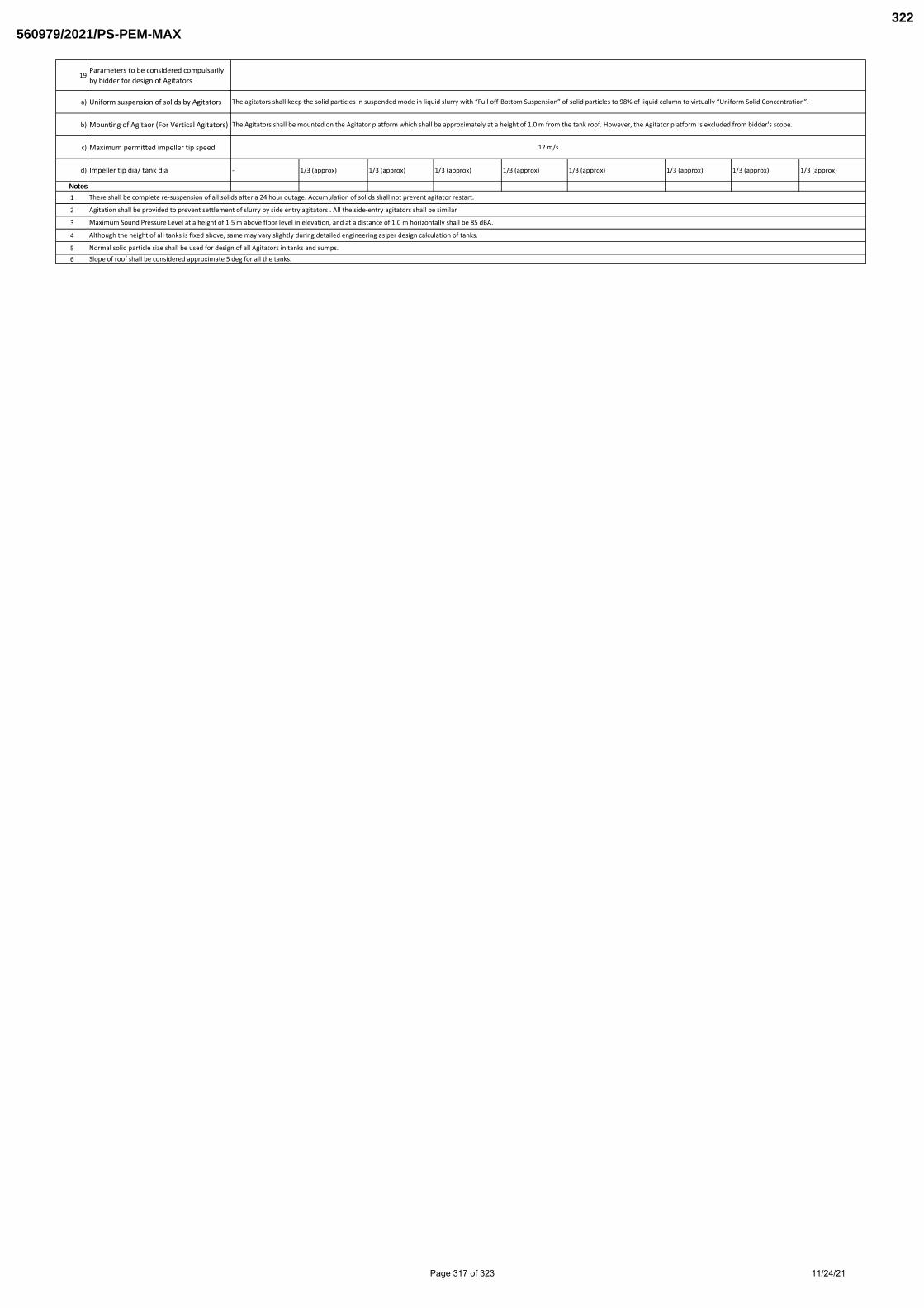
19Parameters to be considered compulsarily by bidder for design of Agitators
a) Uniform suspension of solids by Agitators
b) Mounting of Agitaor (For Vertical Agitators)
c) Maximum permitted impeller tip speed
d) Impeller tip dia/ tank dia - 1/3 (approx) 1/3 (approx) 1/3 (approx) 1/3 (approx) 1/3 (approx) 1/3 (approx) 1/3 (approx) 1/3 (approx)
Notes1
2
3
4
56
There shall be complete re-suspension of all solids after a 24 hour outage. Accumulation of solids shall not prevent agitator restart.
Agitation shall be provided to prevent settlement of slurry by side entry agitators . All the side-entry agitators shall be similar
The agitators shall keep the solid particles in suspended mode in liquid slurry with “Full off-Bottom Suspension” of solid particles to 98% of liquid column to virtually “Uniform Solid Concentration”.
The Agitators shall be mounted on the Agitator platform which shall be approximately at a height of 1.0 m from the tank roof. However, the Agitator platform is excluded from bidder's scope.
12 m/s
Slope of roof shall be considered approximate 5 deg for all the tanks.Normal solid particle size shall be used for design of all Agitators in tanks and sumps.
Although the height of all tanks is fixed above, same may vary slightly during detailed engineering as per design calculation of tanks.
Maximum Sound Pressure Level at a height of 1.5 m above floor level in elevation, and at a distance of 1.0 m horizontally shall be 85 dBA.
Page 317 of 323 11/24/21
560979/2021/PS-PEM-MAX322

Sl.no Description Qty. Unit
Total (Rs)
NOTE -
4X210MW + 3X500MW KAHALGAON STPP AGITATOR PACKAGELIST OF COMMISSIONING SPARES
Break up price for COMMISSIONING SPARES
Bidder shall furnish unit price of commissioning spares in above format alongwith the Bid. Any part even though not mentioned in list furnished but required at later date shall be supplied free of cost.
TITLE: NABINAGAR SUPER THERMAL POWER PROJECT (3x660MW)
TECHNICAL SPECIFICATION FOR AGITATORS OF FGD SLURRY TANKS
Page 318 of 323 11/24/21
560979/2021/PS-PEM-MAX323

Page 319 of 323 11/24/21
560979/2021/PS-PEM-MAX324
6074979
Text Box
THE FORMAT TO BE FILLED SEPARATELY FOR BOTH HORIZONTAL AND VERTICAL AGITATOR.
6202969
Text Box
ANNEXURE-2
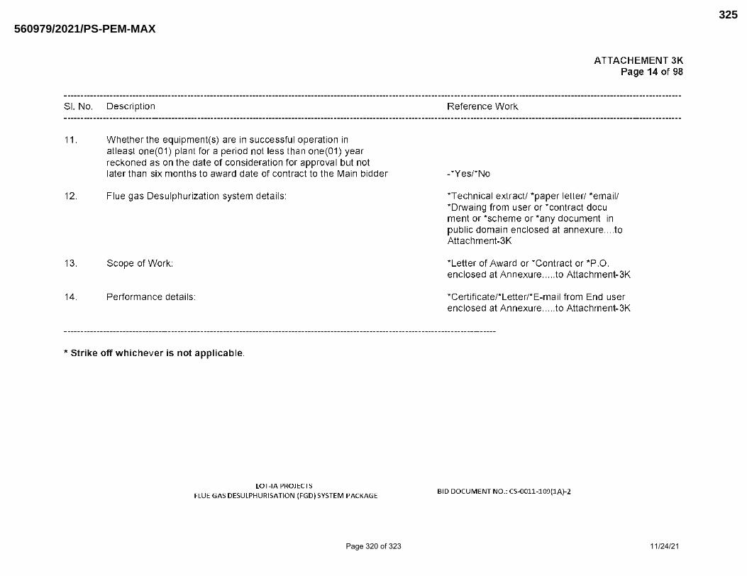
Page 320 of 323 11/24/21
560979/2021/PS-PEM-MAX325

Page 321 of 323 11/24/21
560979/2021/PS-PEM-MAX326

Page 322 of 323 11/24/21
560979/2021/PS-PEM-MAX327

Rev-00, Date: NOV 2021
Sl.No. Description / Item Working Standby Power Consumption (KW) (at motor input terminal)
Duty Factor Power Consumption (KW)
1 2 3 4 5 6 7 = 3 x 5 x 6
A) Limestone slurry storage tank agitataor 2 0 To be filled by Bidder 1 To be filled by Bidder
B) Primary hydro-cyclone feed tank agitator 1 0 To be filled by Bidder 1 To be filled by Bidder
C) Secondary hydrocyclone feed tank agitator 1 0 To be filled by Bidder 1 To be filled by Bidder
D) Filtrate water Tank Agitator 1 0 To be filled by Bidder 1 To be filled by Bidder
E) Waste Water Tank Agitator 1 0 To be filled by Bidder 1 To be filled by Bidder
F) To be filled by Bidder
1
2
3
Power consumption (KW) of motors shall be measured at motor input terminals when the system operating at the rated capacity.Total Estimated Power Consumption Figure for the above mentioned Agitators is considered as 129.6 KW which is to be treated as base power. Declared Guaranteed Power Consumption in this Format duly signed and stamped shall be submitted along with technical bid. Total GPC given by the bidder shall not exceed 129.6 kW failing which offer of bidder will not be considered for evaluation.
Total power ( @ S.No. F above) and not individual power quoted by bidder shall be termed as 'Guaranteed Power consumption' (GPC) and bidder shall be liable to demonstrate compliance to GPC value during PG test/ Demonstration test at site. If the actual power consumption exceeds 129.6 kW , liquidated damages shall be payable by the successful bidder at the rate of USD 2484/- per KW excess power consumption over 129.6 kW. Such liquidated damages may be recovered by the BHEL by deduction from the contract price or by enforcing the contract performance guarantee or in any other manner deemed fit by the BHEL. Acceptable short fall limit for GPC WITH LD will be (+1%) of base power (129.6 kW).
NABINAGAR STPP FGD (3x660 MW)ANNEXURE-V: GUARANTEED POWER CONSUMPTION FORMAT
Technical Specification No. PE-TS-457-571-18000-A003
Total Guaranteed power (KW)Notes
Page 323 of 323 11/24/21
560979/2021/PS-PEM-MAX328