
The Tata Power Company Limited Invites Tenders through E ...
559
(Corporate Contracts Department) The Tata Power Company Limited, 2nd Floor, Sahar Receiving Station Sahar Airport Road, Andheri East, Mumbai-400059 The Tata Power Company Limited Invites Tenders through E-Tender (Two-Part Bidding Process) from eligible and interested bidders for the following packages: - A. Summary of the tendered packages: Sr. No. Description Tender Reference no. Bid Guarantee Fee / EMD (₹) Tender Fee (₹) Last date and time for Payment of Tender Participation Fee 1. Supply and Installation of MV Switchgear at kolshet CC21AK008 500,000 1,000 29 th May 2021; 15:00 Hrs B. Procedure for Participation Interested bidders to submit Tender Participation Fee and Authorization Letter before Last date and time as indicated above, after which detailed RFQ shall be shared through Tata Power e-Tender system (Ariba): 1. Non-Refundable Tender Participation Fee, as indicated in table above, to be submitted in the form of- Direct deposit in the following bank account and submit the receipt along with a covering letter clearly indicating the Tender Reference number – Beneficiary Name – The Tata Power Co. Ltd. Bank Name – HDFC Bank Ltd. Branch Name – Fort Branch, Mumbai Address – Maneckji Wadia Building, Nanik Motwani Marg, Fort, Mumbai 400023. Branch Code – 60 Bank & Branch Code – 400240015 Account No – 00600110000763 Account type – CC IFSC Code – HDFC0000060
-
Upload
khangminh22 -
Category
Documents
-
view
1 -
download
0
Transcript of The Tata Power Company Limited Invites Tenders through E ...

(Corporate Contracts Department) The Tata Power Company Limited, 2nd Floor, Sahar Receiving Station
Sahar Airport Road, Andheri East, Mumbai-400059
The Tata Power Company Limited Invites Tenders through E-Tender (Two-Part Bidding Process) from eligible and interested bidders for the following packages: -
A. Summary of the tendered packages:
Sr. No.
Description Tender
Reference no.
Bid Guarantee Fee / EMD
(₹)
Tender Fee (₹)
Last date and time for Payment of Tender Participation Fee
1.
Supply and Installation
of MV Switchgear at
kolshet CC21AK008 500,000 1,000
29th May 2021; 15:00 Hrs
B. Procedure for Participation
Interested bidders to submit Tender Participation Fee and Authorization Letter before Last date and time as indicated above, after which detailed RFQ shall be shared through Tata Power e-Tender system (Ariba):
1. Non-Refundable Tender Participation Fee, as indicated in table above, to be submitted in the form of-
Direct deposit in the following bank account and submit the receipt along with a covering letter clearly indicating the Tender Reference number –
Beneficiary Name – The Tata Power Co. Ltd.
Bank Name – HDFC Bank Ltd.
Branch Name – Fort Branch, Mumbai
Address – Maneckji Wadia Building, Nanik Motwani Marg, Fort, Mumbai 400023.
Branch Code – 60
Bank & Branch Code – 400240015
Account No – 00600110000763
Account type – CC
IFSC Code – HDFC0000060

2. Bidders to submit duly signed and stamped letter on Bidder's letterhead indicating
a. Tender Enquiry number
b. Name of authorized person
c. Contact number
d. e-mail id
e. Details of submission of Tender Participation Fee
Package Owner- Mr. Abrar Khan ([email protected])
Please share above documents/details with package owner, with copy to Mr. P N Ramesh Kumar ([email protected]), before Last date for Payment of Tender Participation Fee.
Please note all future correspondence regarding the tender, bid submission, bid submission date extension, Pre-bid query etc will be only through Tata Power e-Tender system (Ariba). User manual to guide the bidders to submit the bid through e-Tender system (Ariba) is also enclosed.
No e-mail or verbal correspondence will be responded. All communication will be done strictly with the bidder who have complied with above steps to participate in the Tender.
Also it may be strictly noted that once date of “Last date and time for Payment of Tender Participation Fee” is lapsed no Bidder will be sent link from Tata Power e-Tender System (Ariba). Without this link vendor will not be able to participate in the tender. Any last moment request to participate in tender will not be entertained.
Any payment of Tender Participation Fee / EMD by Bidder who have not done the pre-requisite within stipulated timeline will not be refunded

Tender Documents

The Tata Power Company Ltd
OPEN TENDER NOTIFICATION
Tender Reference: CC21AK008
Document Date:19 May 2021
Property of Tata Power – Not to be reproduced without prior written permission of Tata Power
Page | 1
OPEN TENDER NOTIFICATION
FOR
Supply and Installation of MV Switchgear at Kolshet Receiving Station.
Tender Enquiry No.: CC21AK008 Due Date for Bid Submission: 16th June 2021 [15:00 Hrs.]
The Tata Power Company Limited
Mumbai, Maharashtra

The Tata Power Company Ltd
OPEN TENDER NOTIFICATION
Tender Reference: CC21AK008
Document Date:19 May 2021
Property of Tata Power – Not to be reproduced without prior written permission of Tata Power
Page | 2
CONTENTS OF THE ENQUIRY
Following Documents Form Part of Tender Enquiry:
Section no Description
A Tender Document
Event Information
Evaluation Criteria
Submission of Bid Documents
Bid Opening & Evaluation process
Award Decision
Order of Preference/Contradiction
Post Award Contract Administration
Ethics
Annexures
Annexure I – Schedule of Items
Annexure II – Pre-Qualification Requirement
Annexure III – Query/Clarification/Deviation Format
Annexure IV – E-Auction Undertaking
Annexure V – Checklist of documents to be submitted with Bid
B Technical Specifications/work Scope & SLA
C GCC, SCC ,Format for Bank Guarantees ,CSM
D Tata Power Standard Policies- Health and Safety Policy, Environment Policy, sustainability
Policy

The Tata Power Company Ltd
OPEN TENDER NOTIFICATION
Tender Reference: CC21AK008
Document Date:19 May 2021
Property of Tata Power – Not to be reproduced without prior written permission of Tata Power
Page | 3
Section A : Tender Document
1. Event Information
1.1 Scope of Work
Open Tenders are invited through e-Tender (Two-Part Bidding Process) from eligible and interested
bidders for the following package, required for Mumbai Transmission: -
Sr. No.
Description Tender Reference
no.
Bid Guarantee Fee / EMD
(₹)
Tender Fee (₹)
Last date and time for Payment of Tender Participation Fee
1.
Supply and Installation
of MV Switchgear at
kolshet
CC21AK008 5,00,000 1,000
29th May 2021;
15:00 Hrs
1.2 Calendar of Events
(a)
Date by which Interested and Eligible
Bidder to pay Tender Fee and confirm
Participation
29th May 2021; 15:00 Hours
(b)
Last Date of receipt of pre-bid queries, if
any. (in editable QCD Format-Annexure-
III)
5th June 2021; 15:00 Hours*
(c) Date of Posting Consolidated replies to
all the pre-bid queries as received 9th June 2021*
(d) Last date and time of receipt of Bids 16th June 2021; 15:00 Hours*
Note:- * These date and time are as planned and tentative. In case of change the same shall be
intimated to Authorized Person of Interested Bidder through E-Tender System.
Please note post submission of Bids relevant communication will be done with Authorized Person of
Interested Bidder through E-Tender System
1.3 Mandatory documents required along with the Bid
1.3.1 Bid Guarantee Fee (EMD) of requisite value and validity. PLEASE NOTE THAT BID GUARANTEE
ONLY IN FORM OF BANK GUARANTEE WILL BE ACCEPTED in given format.
1.3.2 Requisite Documents to ascertain fulfilling of Technical and Commercial Pre-Qualification
Requirement as detailed in Tender Enquiry.
1.3.3 Technical Submission including Drawings, Type Test details etc as detailed in Technical
Specification.
1.3.4 Required Commercial Submission as detailed in Tender Document

The Tata Power Company Ltd
OPEN TENDER NOTIFICATION
Tender Reference: CC21AK008
Document Date:19 May 2021
Property of Tata Power – Not to be reproduced without prior written permission of Tata Power
Page | 4
1.3.5 Technical and Commercial Clarification and Deviations as per the format attached in the
Tender Enquiry
1.3.6 Proper authorization letter to sign the tender and participate in Tata Power E-Tender system
on the behalf of bidder.
Please note that in absence of any of the above documents, the bid submitted by a bidder shall be
liable for rejection.
Also please note that whenever editable format are shared it is requested that data be filled in
relevant cells. No formatting or addition / deletion of rows / columns to be done. Wherever editable
Excel submission are requested the file should be free from references, macros etc.
1.4 Deviation from Tender
Normally, the deviations to tender terms are not admissible and the bids with deviation are liable for
rejection. Hence, the bidders are advised to refrain from taking any deviations on this Tender. Still in
case of any deviations, all such deviations shall be set out by the Bidders, clause by clause in the
‘Annexure III – Query/clarification/Deviation Format’ and same shall be submitted as a part of the
Technical Bid.
1.5 Right of Acceptance/Rejection
1.5.1 Bids are liable for rejection in absence of following:-
1.5.2 Mandatory Documents as listed in 1.3 above
1.5.3 Price Bid as per the Price Schedule mentioned in Tender Document
1.5.4 Receipt of Bid and Response to queries within the due date and time
Tata Power reserves the right to accept/reject any or all the bids without assigning any reason thereof.
1.6 Qualification Criteria
Please refer attached Annexure-II
1.7 Pre-Bid Queries
Pre-Bid Queries if any has to be sent through message in E-Tender System. Pre-Bid Query has to be
sent only in the Query / Clarification / Deviation (QCD) Format. Technical Pre-Bid Query and
Commercial Pre-Bid Query have to be submitted in Separate Editable Excel File in Prescribed Format.
Pre-Bid Queries sent in any other format or send through any other communication channel will not
be accepted and answered. Pre-Bid Query have to be sent in the stipulated timeline as defined in the
Tender Document. No Pre-Bid Query will be accepted after the due time and date as specified as "Last
Date of receipt of pre-bid queries, if any"
1.8 Marketing Integrity
We have a fair and competitive marketplace. The rules for bidders are outlined in the General
Condition of Contracts and other parts of Tender Documents. Bidders must agree to these rules prior
to participating. In addition to other remedies available, Tata Power reserves the right to exclude a
bidder from participating in future markets due to the bidder’s violation of any of the rules or
obligations contained in the General Condition of Contracts or other part of the Tender Documents. A
bidder who violates the marketplace rules or engages in behavior that disrupts the fair execution of
the marketplace, may result in restriction of a bidder from further participation in the marketplace for

The Tata Power Company Ltd
OPEN TENDER NOTIFICATION
Tender Reference: CC21AK008
Document Date:19 May 2021
Property of Tata Power – Not to be reproduced without prior written permission of Tata Power
Page | 5
a length of time, depending upon the seriousness of the violation. Examples of violations include, but
are not limited to:
Failure to honor prices submitted to the marketplace
Breach of terms as published in TENDER
Submit irrelevant documents or frequently cases of missing documents as part of
compliance to Qualifying, Technical or Commercial Requirements causing unnecessary delay
in Tender Evaluation
1.9 Supplier Confidentiality
All information contained in this tender is confidential and shall not be disclosed, published or
advertised in any manner without written authorization from Tata Power. This includes all bidding
information submitted to Tata Power. All tender documents remain the property of Tata Power and
all suppliers are required to return these documents to Tata Power upon request. Suppliers who do
not honor these confidentiality provisions will be excluded from participating in future bidding events.
2. Evaluation Criteria
The bids will be evaluated technically on the compliance to tender terms and conditions.
The bids will be evaluated commercially on the overall all-inclusive lowest cost as calculated
in Schedule of Items (Annexure-I). Tata Power however, reserves right to split the order line
item wise and/or quantity wise among more than one Bidder. Hence all bidders are advised
to quote their most competitive rates against each line item.
Bidder has to mandatorily quote against each item of, Schedule of Items (Annexure-I). Failing
to do so, Tata Power may reject the bids.
NOTE: In case of a new bidder not registered with Tata Power, factory inspection and evaluation shall
be carried out to ascertain bidder’s manufacturing capability and quality procedures. However Tata
Power reserves the right to carry out factory inspection and evaluation for any bidder prior to technical
qualification. In case a bidder is found as Disqualified in the factory evaluation, their bid shall not be
evaluated any further and shall be summarily rejected. The decision of Tata Power shall be final and
binding on the bidder in this regard.
Price Variation Clause:
The prices shall remain firm during the entire contract period.
3. Submission of Bid Documents
3.1 Bid Submission
Bidders are requested to submit their offer in line with this Tender document. Bids shall be submitted
in 3 (three) parts:
FIRST PART: “EMD – BANK GUARANTEE” of Value detailed in 1.1 valid for 180 days from the due date
of bid submission in the form of Bank Guarantee favoring ‘The Tata Power Company Limited’. The
EMD has to be strictly in the format as mentioned in Tender Document, failing which it shall not be
accepted by Tata Power and the bid as submitted shall be liable for rejection.

The Tata Power Company Ltd
OPEN TENDER NOTIFICATION
Tender Reference: CC21AK008
Document Date:19 May 2021
Property of Tata Power – Not to be reproduced without prior written permission of Tata Power
Page | 6
Note : BG of 180 days and further claim period of 180 days is needed. In case the same cannot be
issued by your bank then BG valid for 365 days can be provided.
Note : At times bidders have sought Tata Power bank details which is needed by them to make BG.
Hence the same is reproduced below. These details are only provided to facilitate making of BG if
needed
Tata Power’s Bank Details for submitting EMD BG:
Bank Name & Address – ICICI Bank, 163 HT Marg,
Backbay Reclamation, Churchgate, Mumbai 400 020.
A/c no. - 000451000293
IFSC Code – ICIC0000393
The hard copy of EMD in a sealed envelope should be sent on address mentioned in Tender document.
First Part has to be submitted in Sealed Envelope.
SECOND PART: “TECHNICAL / UN-PRICED COMMERCIAL BID” shall contain the following documents:
a) Documentary evidence in support of Technical, Commercial qualifying criteria
b) Technical literature/GTP/Type test report/Details of Qualified Manpower Available/ Testing
Facility available etc. (complete in all respect as desired and detailed in Technical Specification and
Technical Requirement Section)
c) Duly filled Technical and Commercial Deviation Sheets
d) Duly filled formats like Authorization affidavit form
e) Unpriced Commercial Bid
The technical / un-priced commercial bid shall be properly indexed and is to be submitted in Soft
Copy though E-Tender system of Tata Power. Hard Copy of Technical Bids need not be submitted.
SAFETY BID needs to be submitted along with the technical bid. The format of the safety bid is
attached as Annexure.
Second Part has to be submitted through E-Tender System Only
THIRD PART: “PRICE BID” shall contain only the price details and strictly in Price Bid format along with
explicit break up of basic prices and applicable GST. Basic price should include packaging forwarding,
freight, transit insurance and any other cost envisaged by the bidder.
FOR BIDS INVITED THROUGH E-TENDER SYSTEM (TECHNICAL AND UN-PRICED COMMERCIAL BID) :
In response to advertisement Bidder has to provide details of person authorized to Bid on behalf of
the Bidder. An e-mail will be generated by E-Tender System and the authorized person can download
the Tender Documents from the system.
SECOND and THIRD PART of the Bid have to be submitted in E-Tender System.
Bidders have to mandatorily submit SECOND PART (Technical and Un-priced commercial Bid) only
through E-Tender system of Tata Power. Bids submitted through any other form/ route shall not be
admissible.

The Tata Power Company Ltd
OPEN TENDER NOTIFICATION
Tender Reference: CC21AK008
Document Date:19 May 2021
Property of Tata Power – Not to be reproduced without prior written permission of Tata Power
Page | 7
SIGNING OF BID DOCUMENTS:
The bid must contain the name, residence and place of business of the person or persons making the
bid and must be signed and sealed by the Bidder with his usual signature. The names of all persons
signing should also be typed or printed below the signature.
The Bid being submitted must be signed by a person holding a Power of Attorney authorizing him to
do so, certified copies of which shall be enclosed.
The Bid submitted on behalf of companies registered with the Indian Companies Act, for the time
being in force, shall be signed by persons duly authorized to submit the Bid on behalf of the Company
and shall be accompanied by certified true copies of the resolutions, extracts of Articles of Association,
special or general Power of Attorney etc. to show clearly the title, authority and designation of persons
signing the Bid on behalf of the Company. Satisfactory evidence of authority of the person signing on
behalf of the Bidder shall be furnished with the bid.
A bid by a person who affixes to his signature the word ‘President’, ‘Managing Director’, ‘Secretary’,
‘Agent’ or other designation without disclosing his principal will be rejected.
The Bidder’s name stated on the Proposal shall be the exact legal name of the firm.
3.2 Contact Information
Please note all correspondence regarding the tender, bid submission, bid submission date extension,
Pre-bid query etc will happen only through Tata Power E-Tender system (Ariba).
No e-mail or verbal correspondence will be responded. All communication will be done strictly with
the bidder who have done the above step to participate in the Tender.
Communication Details:
Package Owner
Name : Mr. Abrar Khan
Contact Number: 9029009468
E-maid ID : [email protected]
Escalation Matrix
Group Head Contracts – T&D
Name: Mr. P N Rameshkumar
E-Mail ID: [email protected]
Bidders are strictly advised to communicate with Package Owner through Tata Power E-tender
System (Ariba) only. They need to pay Tender Participation Fee and receive the Ariba log-in. Above
escalation details are for reference purpose only.

The Tata Power Company Ltd
OPEN TENDER NOTIFICATION
Tender Reference: CC21AK008
Document Date:19 May 2021
Property of Tata Power – Not to be reproduced without prior written permission of Tata Power
Page | 8
3.3 Bid Prices
Bidders shall quote for the entire Scope of Supply/ work with a break up of prices for individual items
and Taxes & duties. The bidder shall complete the appropriate Price Schedules included herein, stating
the Unit Price for each item & total price with taxes, duties & freight up to destination at various sites
of Tata Power. The all-inclusive prices offered shall be inclusive of all costs as well as Duties, Taxes and
Levies paid or payable during the execution of the supply work, breakup of price constituents.
The quantity break up shown else-where other than Price Schedule is tentative. The bidder shall
ascertain himself regarding material required for completeness of the entire work. Any items not
indicated in the price schedule but which are required to complete the job as per the Technical
Specifications/ Scope of Work/ SLA mentioned in the tender, shall be deemed to be included in prices
quoted.
3.4 Bid Currencies
Prices shall be quoted in Indian Rupees Only. It also may be noted that the denomination of Purchase
Order / Outline Agreement / Rate Contract and associated Payment to Successful Bidder shall also be
in Indian Rupees Only. In case Bidder intends to import any equipment, part etc and supply to Tata
Power then all liability and costs related to import will rest with the Bidder. All statutory compliances,
payments, expenditure etc related to importing of equipment will be responsibility of the bidder.
3.5 Period of Validity of Bids
Bids shall remain valid for 180 days from the due date of submission of the bid.
Notwithstanding clause above, Tata Power may solicit the Bidder’s consent to an extension of the
Period of Bid Validity. The request and responses thereto shall be made in writing.
3.6 Alternative Bids
Bidders shall submit Bids, which comply with the Bidding documents. Alternative bids will not be
considered. The attention of Bidders is drawn to the provisions regarding the rejection of Bids in the
terms and conditions, which are not substantially responsive to the requirements of the bidding
documents.
3.7 Modifications and Withdrawal of Bids
The bidder is not allowed to modify or withdraw its bid after the Bid’s submission. The EMD as
submitted along with the bid shall be liable for forfeiture in such event.
3.8 Earnest Money Deposit (EMD)
The bidder shall furnish, as part of its bid, an EMD amounting as specified in the tender. The EMD is
required to protect the Tata Power against the risk of bidder’s conduct which would warrant
forfeiture.
The EMD shall be in following form:
Bank Guarantee valid for 180 days after due date of submission.

The Tata Power Company Ltd
OPEN TENDER NOTIFICATION
Tender Reference: CC21AK008
Document Date:19 May 2021
Property of Tata Power – Not to be reproduced without prior written permission of Tata Power
Page | 9
The EMD shall be forfeited in case of:
a) The bidder withdraws its bid during the period of specified bid validity.
Or
b) In case of a successful bidder, if the Bidder, within 15 days, does not
i) accept the purchase order, or
ii) furnish the required Contract Performance Bank Guarantee (CPBG)
Original Bank Guarantee submitted as EMD shall be returned only after completion of award
process for unsuccessful bidders and issue of Contract Performance Bank Guarantee (CPBG) for
successful bidder.
4. Bid Opening & Evaluation process
4.1 Process to be confidential
Information relating to the examination, clarification, evaluation and comparison of Bids and
recommendations for the award of a contract shall not be disclosed to Bidders or any other persons
not officially concerned with such process. Any effort by a Bidder to influence Tata Powers processing
of Bids or award decisions may result in the rejection of the Bidder's Bid.
4.2 Technical Bid Opening
Bids will be opened internally by Tata Power. Technical bid must not contain any cost information
whatsoever.
First the envelope marked “EMD” will be opened. Bids without EMD of required amount/ validity in
prescribed format, shall be rejected.
Next, the technical bid of the bidders who have furnished the requisite EMD will be opened in E-Tender
system.
4.3 Preliminary Examination of Bids/Responsiveness
Tata Power will examine the Bids to determine whether they are complete, whether any
computational errors have been made, whether required sureties have been furnished, whether the
documents have been properly signed, and whether the Bids are generally in order. Tata Power may
ask for submission of original documents in order to verify the documents submitted in support of
qualification criteria.
Prior to the detailed evaluation, Tata Power will determine the substantial responsiveness of each Bid
to the Bidding Documents including production capability and acceptable quality of the Goods offered.
A substantially responsive Bid is one, which conforms to all the terms and conditions of the Bidding
Documents without material deviation.
Bid determined as not substantially responsive will be rejected by the Tata Power and/or the Tata
Power and may not subsequently be made responsive by the Bidder by correction of the non-
conformity.
The Tata Power Company Ltd
OPEN TENDER NOTIFICATION
Tender Reference: CC21AK008
Document Date:19 May 2021
Property of Tata Power – Not to be reproduced without prior written permission of Tata Power
Page | 10
4.4 Techno Commercial Clarifications
Bidders need to ensure that the bids submitted by them are complete in all respects. To assist in the
examination, evaluation and comparison of Bids, Tata Power may, at its discretion, ask the Bidder for
a clarification on its Bid for any deviations with respect to the Tata Power specifications and attempt
will be made to bring all bids on a common footing. All responses to requests for clarification shall be
in writing and no change in the price or substance of the Bid shall be sought, offered or permitted
owing to any clarifications sought by Tata Power.
4.5 Price Bid Opening
Price Bid of only Technically and / or Safety Qualified Bidders shall be considered and open internally
by TPC. Bidders will get mail intimation from Tata Power E-Tender system (Ariba) when their Price Bids
are opened. The EMD of the bidder withdrawing or substantially altering his offer at any stage after
the technical bid opening will be forfeited at the sole discretion of TPC without any further
correspondence in this regard.
Arithmetical errors will be rectified on the following basis: If there is a discrepancy between the unit
price and the total price per item that is obtained by multiplying the unit price and quantity, the unit
price shall prevail and the total price per item will be corrected. If there is a discrepancy between the
Total Amount and the sum of the total price per item, the sum of the total price per item shall prevail
and the Total Amount will be corrected.
4.6 Reverse Auction and Price Matching Option
Tata Power reserves the right to conduct the reverse auction AND / OR Manual Negotiations for the
products/ services being asked for in the tender. Only Technical Qualified Bids will be allowed to
participate in e-auction. Date and time of e-auction will be intimated through E-Tender system to
Authorized Person of Interested Bidder.
For case where more than one bidders have to be awarded (including Rate Contract / Outline
Agreement) Price Matching Option will be exercised. Volume of job allocated to original competitive
bidder will be more than bidder who is chosen through Price Matching Option. Tata Power decision
regarding work sharing shall be final and no explanation OR clarification shall be given regarding the
same.
5.0 Award Decision
Tata Power will award the contract to the successful bidder whose bid has been determined to be the
lowest-evaluated responsive bid as per the Evaluation Criterion mentioned at Clause 2.0. The Cost for
the said calculation shall be taken as the all-inclusive cost quoted by bidder in Priced Bid Format
subject to any corrections required in line with Clause 4.3 above. The decision to place purchase
order/Outline Agreement/ Rate Contact solely depends on Tata Power on the cost competitiveness
across multiple lots, quality, delivery and bidder’s capacity, in addition to other factors that Tata Power
may deem relevant.
Tata Power reserves all the rights to award the contract to one or more bidders so as to meet the
delivery requirement or nullify the award decision without assigning any reason thereof.
In case any supplier is found unsatisfactory during the delivery process, the award will be cancelled
and Tata Power reserves the right to award other suppliers who are found fit.

The Tata Power Company Ltd
OPEN TENDER NOTIFICATION
Tender Reference: CC21AK008
Document Date:19 May 2021
Property of Tata Power – Not to be reproduced without prior written permission of Tata Power
Page | 11
6.0 Order of Preference/Contradiction:
In case of contradiction in any part of various documents in tender, following shall prevail in order of
preference:
1. Outline Agreement/Purchase Order (with Commercial conditions)
2. Special Terms and conditions (if applicable)
3. General Terms and conditions
4. Technical Specifications
In case there is a discrepancy in the BOQ mentioned in tender (to the extent modified through
subsequent Corrigendum, if any) and the bid submitted by any bidder, the description as
mentioned in the tender (to the extent modified through subsequent Corrigendum, if any) shall
prevail.
7.0 Ethics
Tata Power is an ethical organization and as a policy Tata Power lays emphasis on ethical practices
across its entire domain. Bidder should ensure that they should abide by all the ethical norms and in
no form either directly or indirectly be involved in unethical practice.
Tata Power work practices are governed by the Tata Code of Conduct. Bidder is request to refer Tata
Code of Conduct Clause in General Terms and Conditions.
8.0 General Condition of Contract and Special Condition of Contracts
Any condition not mentioned above shall be applicable as per General Terms and Conditions and
Special Condition of Contracts attached along with this tender.
The Tata Power Company Ltd
OPEN TENDER NOTIFICATION
Tender Reference: CC21AK008
Document Date:19 May 2021
Property of Tata Power – Not to be reproduced without prior written permission of Tata Power
Page | 12
ANNEXURE I
Schedule for Items
Attached Separately with Tender Document
NOTE:
The bids will be evaluated commercially on the overall lowest cost for each line item.
The unit price with GST in column “Total”, is landed price.
The bidders are advised to quote prices strictly in the above format. Failing to do so, bids are liable
for rejection.
The bidder must fill each and every column of the above format. Mentioning “extra/inclusive” in
any of the column may lead for rejection of the price bid.
No cutting/ overwriting in the prices is permissible.

The Tata Power Company Ltd
OPEN TENDER NOTIFICATION
Tender Reference: CC21AK008
Document Date:19 May 2021
Property of Tata Power – Not to be reproduced without prior written permission of Tata Power
Page | 13
ANNEXURE II
Pre-Qualification Requirement
SNo
Parameter
Tata Power Requirement
Documents To be submitted by Bidder to ascertain
meeting of Pre-qualification
requirement
1
Infrastructure
Bidder must be an OEM of HT Switchgear
with manufacturing facility / assembly
in India.
Self-undertaking to be submitted in this regard . TATA Power
reserves the right to inspect the said manufacturing
facility as a proof of compliance to this parameter.
2
Supply and Experience
Bidder shall have supplied 5000 quantity of
HT Switchgear in last 5 years. Out
of this 1000 quantity of HT
Switchgear shall be in satisfactory
service for last 2 years.
Indian Subsidiaries of global
companies having plant in India are
also eligible to bid if the qualification
requirements stated above are met
independently or in combination with the
parent company. Declaration from parent
company needs to be submitted.
Supply List & Performance Certificates from the utilities / clients
Self-undertaking to be submitted in this regard . TATA
Power reserves the right to inspect the said
manufacturing facility as a proof of compliance to this
parameter.
3
Type Test
The bidder shall submit Type test reports
obtained from NABU International
Accredited Lab for the equipment /
material offered. The type tests should
have been conducted on the
equipment / material of the same
design.
The type tests should have been
conducted within 5 years prior to the
date of bid opening. Time period for type
test can be extended by another 5
years as a special case, if there is no
change in design / material of
construction (MOC).
In case the type test reports furnished
are not for the quoted equipment /
material but for the equipment /
material with higher voltage class
and/or different capacity, then type test
shall be carried out for the offered
equipment
/ material from NABL / International
Accredited Lab without any cost
implication to the owner and the Type
Test reports shall be submitted before
despatch of the equipment / material.
Type Test Repo rt.
Undertaking that there is no change in design / material of
construction (MOC) if Type Test Report older than 5 years
but less than 1O years prior to date of bid opening has to be
considered (if applicable)
Undertaking that type test shall be carried out for the
offered equipment / material from NABL / International
Accredited Lab without any cost implication to the owner and
the Type Test reports shall be submitted before dispatch of
the equipment / material, in case type test reports furnished
are not for the quoted equipment / material but for the
equipment / material with higher voltage class and/or
different capacity, (if applicable)

The Tata Power Company Ltd
OPEN TENDER NOTIFICATION
Tender Reference: CC21AK008
Document Date:19 May 2021
Property of Tata Power – Not to be reproduced without prior written permission of Tata Power
Page | 14
4
Commercial Capability
Average Annual turnover of the bidder for last three years shall not be less than Rs ….. 3.75 Crs
Copy of audited Balance Sheet and P&L Account to be
submitted in this regard.
5
Installation &
Commissioning for
same equipment
In case the package involves installation &
commissioning of the equipment /
material, then the bidder shall have
the following experience:
a) He should have successfullycompleted
one single order of value Rs 2 Crs
of similar work in last three years) OR
b) He should have successfully
completed two single orders of value
Rs 1.25 Cr of similar work in last
three
years) OR c) He should have successfully
completed
three single orders of value Rs1 Cr of similar work in last three years).
Performance Certificates from the utilities / clients

The Tata Power Company Ltd
OPEN TENDER NOTIFICATION
Tender Reference: CC21AK008
Document Date:19 May 2021
Property of Tata Power – Not to be reproduced without prior written permission of Tata Power
Page | 15
ANNEXURE III
Query / Clarification / Deviation Format
Please note that Editable Soft Copy of Query / Clarification / Deviation
Format will be shared through E-Tender System for Participating Bidders
Pre-Bid Queries if any has to be sent through message in E-Tender System. Pre-Bid Query has to be
sent only in the Format prescribed below. Technical Pre-Bid Query and Commercial Pre-Bid Query
have to be submitted in Separate Editable Excel File in Prescribed Format. Pre-Bid Queries sent in
any other format or send through any other communication channel will not be accepted and
answered
Format for Query / Clarification / Deviation (QCD)
Tender No
Package Name
Bidder :
Sr. No.
Detailed Reference to concerned
Document . Please specify
Document No / Clause No /
Page No
Description as per
Bid Document
Query /
Clarification /
Deviation
Tata Power Response
1 2 3 4 5

The Tata Power Company Ltd
OPEN TENDER NOTIFICATION
Tender Reference: CC21AK008
Document Date:19 May 2021
Property of Tata Power – Not to be reproduced without prior written permission of Tata Power
Page | 16
Annexure IV
Acceptance Form for Participation In Reverse Auction Event
(To be signed and stamped by the bidder)
In a bid to make our entire procurement process more fair and transparent, Tata Power intends to use
the reverse auctions through E-Tender system as an integral part of the entire tendering process. All
the bidders who are found as technically qualified based on the tender requirements shall be eligible
to participate in the reverse auction event.
The following terms and conditions are deemed as accepted by the bidder on participation in the
bid event:
1. Tata Power shall log-in to the authorized representative of the bidder.
2. Tata Power will make every effort to make the bid process transparent. However, the award
decision including sharing of work would be final and binding on the supplier.
3. The bidder agrees to non-disclosure of trade information regarding the purchase, identity of Tata
Power, bid process, bid technology, bid documentation and bid details.
4. The bidder is advised to understand the auto bid process to safeguard themselves against any
possibility of non-participation in the auction event.
5. In case of bidding through Internet medium, bidders are further advised to ensure availability of
the entire infrastructure as required at their end to participate in the auction event. Inability to
bid due to telephone line glitch, internet response issues, software or hardware hangs, power
failure or any other reason shall not be the responsibility of Tata Power.
6. Tata Power has sole discretion to extend or restart the auction event in case of any glitches in
infrastructure observed which has restricted the bidders to submit the bids to ensure fair &
transparent competitive bidding. In case of an auction event is restarted, the best bid as already
available in the system shall become the start price for the new auction.
7. In case the bidder fails to participate in the auction event due any reason whatsoever, it shall be
presumed that the bidder has no further discounts to offer and the initial bid as submitted by the
bidder as a part of the tender shall be considered as the bidder’s final no regret offer. Any offline
price bids received from a bidder in lieu of non-participation in the auction event shall be out-
rightly rejected by Tata Power.
8. The bidder shall be prepared with competitive price quotes on the day of the bidding event.
9. The prices as quoted by the bidder during the auction event shall be inclusive of all the applicable
taxes, duties and levies and shall be FOR at Tata Power site.
10. The prices submitted by a bidder during the auction event shall be binding on the bidder.
11. No requests for time extension of the auction event shall be considered by Tata Power.
12. Detailed price split of E-auction price will be submitted within 24 hours from completion of E-
auction. If not submitted, the original price bids of the bidders shall be reduced on pro-rata basis
against each line item based on the final all inclusive prices offered during conclusion of the
auction event for arriving at Contract amount.
Signature & Seal of the Bidder

The Tata Power Company Ltd
OPEN TENDER NOTIFICATION
Tender Reference: CC21AK008
Document Date:19 May 2021
Property of Tata Power – Not to be reproduced without prior written permission of Tata Power
Page | 17
ANNEXURE V
Checklist of all the documents to be submitted with the Bid
Bidder has to mandatorily fill in the checklist mentioned below:-
S. No. Documents attached Yes / No /
Not Applicable
1 EMD of required value (Original BG to be forwarded on given address
and scan copy to be attached with bids)
2 Duly filled PQR with supporting documents (Annexure II)
3 Sheet of commercial/ technical deviation if any (Annexure III)
4 e-Auction undertaking (Annexure IV)
5 Price bid as per schedule for items (Annexure-I)
6 Signed copy of this RFQ as an unconditional acceptance

A 33kV AIS System
1.0 Supply of 33 kV, 2500A, 31.5 kA, 3s indoor metal-clad
switchgear Panel ( as per SLD and spec.) along with
BCPUs(with conformal coating) , MFMs and 33kV Capacitor
Voltage indicator for cable charge indication and earth switch
interlock(electrical and mechanical), Floor bushing, gas duct.
Bidder shall provide mater-trip relays ABB make only and type
are as follows:
a.RXMS1: for Incomer, bus-coupler and out-going feeder
b.RXMVB2: for Station transformers and cap bank bay
Set
1.1 Incomers Nos. 2 2
1.2 Bus coupler Nos. 1 1
1.3 Outgoings Nos. 6 6
1.4 Station transformers Nos. 3 3
1.5 Spare Outgoing feeders Nos. 0 0
1.6 Capacitor bank Nos. 1 1
1.7 Bus PT-3 PH Set 2 2
1.8 Bus SA-3 PH Set 2 2
2.0 Mandatory Spares for 33kV AIS Lot 1 1
3.0 Recommended Spares for 33kV AIS Lot 1 1
4.0 Separate common control panel with control switches and
indicating LEDs. Bidder to consider 2.5 sq.mm, 12C, copper ,
Amoured, FRLS cable, ST2 type cable. Bidder to consider 80
mtr. length for per bay and 80mtrs of cable trays along with
acessories.Additionally Bidder to furnish unit rate for cables and
the billing for the cable and Trays will be done at actuals.
Lot
1 1
5.0 Unit rate for 2.5 sq.mm, 12C, copper , Amoured, FRLS cable,
ST2 type control cable
Mtr- Unit Rate
6.0 Unit rate for 300mm Cable trays Mtr - Unit Rate
7.0 Arc flash system set 1
8.0 High Impedance Bur bar protection scheme as per spec. for
2no. Zones
set1
9.0 Additional numerical relay (to be mounted on SWGR) for all
Station transformers (3 nos) for HV protection as per SLD
Nos.3
10.0 Optional price for motorised rack-in & rack out mechanism for all
feeders
set13
11.0 Optional price for motorised earth switch for all ougoing feeder
B 33kV AIS Sub-Station Automation ( Please refer the
technical specification for more details)
Set
1.1 Pre-wired Redundant Gateway Panel
Mounting: To be supplied with prewired panel with IP54 class (Rittal
or equivalent), bottom side cable entry, size : 2300 mm x 800 mm x
800 mm, having swing frame and both side opening with accessories.
Set
1 1
Total QuantityShort Description Unit Total (All
Inclusive)
Unit
Rate
Total Supply Total (All
Inclusive)
GST% GST
Supply Services
ANNEXURE - 1
Item Quantity GST% Unit
Rate
Total Services GST

Total QuantityShort Description Unit Total (All
Inclusive)
Unit
Rate
Total Supply Total (All
Inclusive)
GST% GSTItem Quantity GST% Unit
Rate
Total Services GST
1.2 Managed L3 Ethernet Switch for Station level
Communication
Communication Ports: 24 PORT L3 W/100/1000 MBPS,
Combination of FO & Copper Ports
Mounting Arrangement: To be mounted in Gateway panel
Qty: 2 nos.
Set
1 1
1.3 Managed L2 Ethernet Switches for BCPU, Misc RTU
Communication & for Gateway Integration
Mounting Arrangement: To be mounted in Dummy panels /
Separate Network Panel
Qty: Nos. of Switches, Nos. of FO & Copper ports in each
switch will be based on Relay quantity & Relay port with 20%
spare FO and CU ports on each switch. However, minimum qty
shall be 4 nos.
Set
1 1
1.4Communication Cable:
4P X 0.36 Sq.mm (Reputed Make) unarmoured multistrand pair
and overall shielded for serial communication
mtrs
100 100
1.5 Communication Cable:
4P X 0.36 Sq.mm (Reputed Make) armoured multistrand pair
and overall shielded for serial communication
mtrs
900 900
1.6 Armoured CAT6 UTP Cable mtrs 1000 1000
1.7 Un-Armoured CAT6 UTP Cable mtrs 305 305
1.8 Armoured Fibre Optic Cable for SCADA 8 core, MM/SM mtrs 1000 1000
1.9 GPS Receiver ,Clock with Time, Date and Frequency
Display Unit with dual antenna, Surge protector and cables
Mounting Arrangement : GPS Receiver to be mounted in
Gateway Panel
Power Supply: Redundant 48 V DC
Remote display Mounting : Time, Date and Frequency Display
Unit on a wall in C/R or R/R
Set
1 1
1.10 Configuration Laptop (one with protection software)
Hardware: Laptop with latest processor, 500 GB HDD, 8 GB
RAM, DVD RW, 4 USB Ports, 15" Display with 1 no. serial to
USB converter
Power Supply: 230 V DC
Microsoft Windows compatible with latest version of
configuration software, latest Microsoft Office License pack,
Antivirus Quick heal Total Security with three-year subscription,
Configuration & maintenance software tools, Diagnostic tools.
Logic building Application of SCU,BCU,RTU and Process Bus
related Configurations
Set
2 2
1.11 Temperature & Humidity Transmitter and integration with
gateway on RS485 Modbus RTU
Nos.2 2
1.12 Networking accessories like LIU, patch panel (for each Ethernet
switch), patch chords (Fibre optic, UTP) of suitable length,
Conduits for all non-armoured cables, I/O boxes with Quad face
plate, RJ45 connectors etc.
Lot
1 1
1.13 Multi-Function Meter (SATEC 130EH+) for all Bays including
Bus PTs
Nos.15 15
1.14 Mandatory Spares as per Specification Set 1 1
C Installation, Integration and Commissioning of SAS System LS

Total QuantityShort Description Unit Total (All
Inclusive)
Unit
Rate
Total Supply Total (All
Inclusive)
GST% GSTItem Quantity GST% Unit
Rate
Total Services GST
1.1
Installation, Integration and Commissioning of SAS System
a) Engineering
b) Installation and commissioning of all supplied items
c) Cable termination, continuity check of all communication
cables
d) All BCPU, MFM looping and Integration with Proposed
Gateway
e) Preparation of ICS and Signal List
f) Configuration and Testing of IED's, BCPUs, Gateway etc.
g) Time Synchronization of BCPUs with Gateway, DRCA, IEDs
with GPS Receiver
h) Integrated testing with purchasers existing Unified SCADA
System
i) I/O testing, Pre- SAT testing of Hardware and Software
functionality
j) Integrated FAT & SAT for Hardware and Software
k) Submission of as-built drawing in AutoCAD and PDF Format
LS
1 1
1.2 Warranty for Supplied Hardware & Software inclusive of patch
management and software upgradation for the period of 5 Years
1.3 Services of M/s Kalkitech for Configuration, integration with both
local DRCA System of the respective station & Centralised
DRCA system at 110kV Kolshet RSS
d Training
1.1 Training Mandays at Site Manday - 5
1.2 Training Mandays at Vendors Works Manday - 5
Notes Total -Supply Total-Services
Quantities indicated are Indicative only and shall vary based on
site conditions and layout. The rates shall be fixed. Contractor
has to provide a separate list with rate and cost separately and
give total price for complete Electrical works. Items not listed
but required for completing the works shall be done by the
contractor without any additional payments.
Supply: Rates for Supply shall include all taxes, Duties,
levies,Packing and forwarding, Transport to site,Transit
insurance, unloading, safe storage.
Grand-Total
(All Inclusive)
0
Installation: Rates for installation shall include all taxes.Handling,
Storage, movement to site,assembly,
alignment,cleaning,installation, testing and commissioning
including labour, tools, tackles, consumables, complete.

SECTION B- TECHNICAL SPECIFICATIONS

Technical Specifications (Annexure to Tender Documents)

TE/SP/0001/FY22 Rev: A Date:02.04.2021
The Tata Power Company Ltd Replacement of MV Switchgear at Kolshet RSS
THE TATA POWER COMPANY LIMITED
NOTICE INVITING TENDER FOR
MV Switchgear at Kolshet RSS (SPECIFICATION NO – TE/SP/0001/FY22)
Tata Power
Engineering T&D
Revision Date Revision History Approvals
Prepared by
(Name & sign)
Checked by (Name &
sign)
Approved by
(Name & sign)
A 02.04.2021 MRP/SV SV/DAJ/RSM AM
10.05.2021

TE/SP/0001/FY22 Rev: A Date:02.04.2021
The Tata Power Company Ltd
Contents
New 22kV MV Switchgear at Kolshet
VOLUME II
COVER PAGE
SECTION A DESCRIPTION
A SPECIFICATION
A1 INTENT OF SPECIFICATION
A2 PROJECT INFORMATION
A3 SCOPE OF WORK
A4 TERMINAL POINTS
A5 EXCLUSIONS
A6 CODES AND STANDARDS
A7 BIDDER’S QUALIFICATION REQUIREMENT
A8 PROJECT SCHEDULE / MILESTONES
A9 SUBMISSIONS BY BIDDERS
A10 DETAILED TECHNICAL SPECIFICATION
A11 LAYOUT REQUIREMENT
A12 QUALITY REQUIREMENT
A13 PERFORMANCE REQUIREMENTS
A14 MAINTAINANCE REQUIREMENTS
A15 TOOLS TACKLES FOR ERECTION AND COMMISSIONING
A16 SPARES
SECTION B TECHNICAL SPECIFICATION & DATA SHEETS
B.2.3-A MV SWITCHGEAR
B.2.3-B AUTOMATION SPECIFICATION
B.2.3-C MV, LV POWER AND CONTROL CABLE
B.2.3-D CABLE CARRIER SYSTEM
B.2.3-E GENERAL REQUIREMENTS OF QUALITY ASSURANCE AND INSPECTION
SECTION C SCHEDULES
C1 Schedule of Quantities & Prices (including services)
C2 Time Schedule for the project
C3 Schedule of Deviations from Technical Specifications
C4 Schedule of Deviations from General & Special conditions of contract
C5 Schedule of Drawings/ Document submission
C6 Schedule of Mandatory Spares
C7 Schedule of special erection, maintenance tools & tackles
C8 Schedule of places of tests & inspection
C9 Schedule of Recommended Spares (to be listed by bidders)

TE/SP/0001/FY22 Rev: A Date:02.04.2021
The Tata Power Company Ltd
Contents
New 22kV MV Switchgear at Kolshet
Sr. NO DESCRIPTION
SECTION D ANNEXURES
1 Annexure-1: Single line diagram
2 Annexure-2: Room layout drawing

The Tata Power Company Ltd. Engineering T&D
TE/SP/0001/FY22 Rev: A Date:02.04.2021
The Tata Power Company Ltd
Section-A Page 4 of 22
Replacement of MV Switchgear at Kolshet RSS
VOLUME - II
SECTION - A
PROJECT SPECIFICATIONS

The Tata Power Company Ltd. Engineering T&D
TE/SP/0001/FY22 Rev: A Date:02.04.2021
The Tata Power Company Ltd
Section-A Page 5 of 22
Replacement of MV Switchgear at Kolshet RSS
A.1 INTENT OF SPECIFICATION:
This specification covers replacement of existing 22 kV MV switchgear with a new
33kV class switchgear at Kolshet RSS. This switchgear will operate at 22kV voltage
level. The replacement is being carried out to enhance human safety and availability.
The existing 22kV out-door air insulated switchyard at Kolshet RSS required
conversion with Indoor 22kV AIS in view of uprating existing 30MVA source supply
transformers to 90MVA.
New 22kV switchgear will consist of 2 nos. incomers, 1 no. bus coupler, 6 nos. outgoing
feeders, 3 nos. Station transformers, 1 no. Capacitor feeders.
Scope includes engineering, procurement, installation, commissioning & testing of new
system.
A.2 PROJECT INFORMATION & DESIGN SYSTEM PARAMETERS:
A.2.1 Project Information:
Plant location detail is mentioned below:
1. Owner The TATA Power Company Ltd.
2. Location of the plant
In and around Mumbai, India Kolshet receiving station, Altitude: 54 metres above sea level.
3. Nearest Rail head Thane
4. Transport Road/Rail
5. Plant Elevation 176.0 m
6. Climatic conditions
7.
6.1 Temperatures:
a) Max. Daily mean 40oC
b) Min. Daily mean 20.7oC
c) Design temp. for Instrumentation & Control / electrical equipment
50.0oC
d) Minimum ambient air temp.
10 deg.C

The Tata Power Company Ltd. Engineering T&D
TE/SP/0001/FY22 Rev: A Date:02.04.2021
The Tata Power Company Ltd
Section-A Page 6 of 22
Replacement of MV Switchgear at Kolshet RSS
8. e) Climatic conditions
Atmosphere is generally hot, humid and is conducive to pollution, rust and fungus growth. It is laden with salt sprays, chemical fumes, steam and dust. Relative humidity is over 95% during four months in a year when about 5000 mm rainfall takes place.
9. Rainfall
10.
(a) Annual average 1391.3 mm
(b) Maximum per day of 24 hrs.
214.1 mm
(c) Period June to September
11. Seismic conditions
12.
a) Zone : Zone III b) Co-efficient : 0.04 c) Importance factor (I): 2.5 for electrical Equipment, 1.5 for others
13. Auxiliary Supply
14.
a) Power devices: 415V, 3 Phase, 4 wire, 50 Hz AC System (voltage variation + 10%, frequency variation + 3%, ambient variation + 10%). b) Light fixtures and: 240 V, 1 phase, 50 Hz AC System. Space heaters c) Control devices: 220 V / 110 V, 2 wire, ungrounded DC System. (As specified for each station) d) Communications: 48 V DC + VE grounded e) SCADA: 48 V DC ungrounded f) Instrumentation: 24 V DC
15. Earthing High Impedance grounded system.
16. Tropicalisation
a) The equipment shall be given tropical and fungicidal treatment in view of the above mentioned climatic conditions. b) Tropical protection shall conform to BS: CP 1014 entitled “Protection of Electrical Power Equipment against climatic condition.”
Effectively earth
The Tata Power Company Ltd. Engineering T&D
TE/SP/0001/FY22 Rev: A Date:02.04.2021
The Tata Power Company Ltd
Section-A Page 7 of 22
Replacement of MV Switchgear at Kolshet RSS
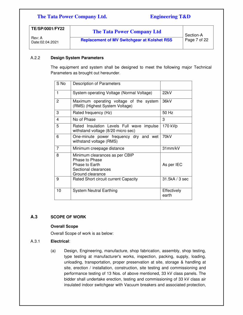
A.2.2 Design System Parameters
The equipment and system shall be designed to meet the following major Technical
Parameters as brought out hereunder.
S No Description of Parameters
1 System operating Voltage (Normal Voltage) 22kV
2 Maximum operating voltage of the system (RMS) (Highest System Voltage)
36kV
3 Rated frequency (Hz) 50 Hz
4 No of Phase 3
5 Rated Insulation Levels Full wave impulse withstand voltage (8/20 micro sec)
170 kVp
6 One-minute power frequency dry and wet withstand voltage (RMS)
70kV
7 Minimum creepage distance 31mm/kV
8 Minimum clearances as per CBIP Phase to Phase Phase to Earth Sectional clearances Ground clearance
As per IEC
9 Rated Short circuit current Capacity 31.5kA / 3 sec
10 System Neutral Earthing Effectively earth
A.3 SCOPE OF WORK Overall Scope
Overall Scope of work is as below:
A.3.1 Electrical: (a) Design, Engineering, manufacture, shop fabrication, assembly, shop testing,
type testing at manufacturer's works, inspection, packing, supply, loading,
unloading, transportation, proper preservation at site, storage & handling at
site, erection / installation, construction, site testing and commissioning and
performance testing of 13 Nos. of above mentioned, 33 kV class panels. The
bidder shall undertake erection, testing and commissioning of 33 kV class air
insulated indoor switchgear with Vacuum breakers and associated protection,

The Tata Power Company Ltd. Engineering T&D
TE/SP/0001/FY22 Rev: A Date:02.04.2021
The Tata Power Company Ltd
Section-A Page 8 of 22
Replacement of MV Switchgear at Kolshet RSS
control and metering, in the location and dimensions 15Mtr (Length) X 4Mtr
(Depth). New panels shall be fit in assigned dimensions.
(b) Design, Engineering, manufacture, shop fabrication, assembly, shop testing,
type testing at manufacturer's works, inspection, packing, supply, loading,
unloading, transportation, proper preservation at site, storage & handling at
site, erection / installation, construction, site testing and commissioning and
performance testing of remote control panel used for closing & tripping of the
circuit breakers. This panel is separate standalone panel other than switchgear
consist of ON and OFF TNC switches and indication lamps. This panel shall be
kept away, may be in another room from the switchgear panels.
(c) All associated LV power and control cabling, laying and termination required
for successful testing and commissioning shall be included in the Bidder's
scope.
(d) Integration of existing metering panels with new 22kV AIS is in bidder scope of
work. Bidder to extend all required input for metering panel from new 22kV AIS.
All required accessories for integration is in bidder scope of work.
(e) The bidder must confirm the technical and operational support for 25 years for
equipment being procured under this requirement.
(f) Following are the mandatory requirements for the bidder.
• Bidder must visit site before submission of the bid.
• The new switchgear shall fit in the assigned switchgear area.
• The protection, control, monitoring and metering philosophy shall be as
per specification and SLD attached (Refer annexure-1).
• Bay control and protection unit and multi-function meter for each bay shall
be
integrated with proposed gateway as per B.2.3-B
• Bidder shall organize stage inspection as required and approved by
owner.
• The switchgear offered shall be suitable for the switching applications
such as transformer feeders rating, Incomers, line feeders and Capacitor
Banks.
A.3.2 Automation:
Please refer section B.2.3-B for scope of work and specification for Automation part.

The Tata Power Company Ltd. Engineering T&D
TE/SP/0001/FY22 Rev: A Date:02.04.2021
The Tata Power Company Ltd
Section-A Page 9 of 22
Replacement of MV Switchgear at Kolshet RSS
A.3.2.1 Feeder rating:
PANEL NO
TYPE OF FDR BKR RATING FEEDER NAME
1. Incomer Breaker 2500A Incomer-1
2. Incomer Breaker 2500A Incomer-2
3. Bus coupler 2500A Bus coupler
4. Station Transformer-1 1250A Station Transformer-1
5. Station Transformer-2 1250A Station Transformer-2
6. Station Transformer-3 1250A Station Transformer-3
7. Out-going 1250A Pokhran-1
8. Out-going 1250A
Thana-1
9. Out-going 1250A
KMKB-1
10. Out-going 1250A
Pokhran-2
11. Out-going 1250A
Thana-2
12. Out-going 1250A
KMKB-2
13. Capacitor Feeder -1 1250A
Capacitor Bank -1
3.1.1. Statutory approvals: Obtaining statutory approvals for switchboard installations is in bidder scope of work.
3.1.2. Bidder shall visit site to understand the detailed scope of work before bid submission.

The Tata Power Company Ltd. Engineering T&D
TE/SP/0001/FY22 Rev: A Date:02.04.2021
The Tata Power Company Ltd
Section-A Page 10 of 22
Replacement of MV Switchgear at Kolshet RSS
Details of equipment:
1.1.1 MV(33 kV class) AIR INSULATED INDOOR SWITCHGEAR:
1.1.1.1 The switchgear boards shall have a single front, single tier, fully compartmentalized,
metal enclosed construction complying with clause No. 3.102 of IEC 62271-200,
comprising of a row of free-standing floor mounted panels. The Service Class
Continuity of Switchgears shall be LSC 2B-PM (as per IEC 622771-200).
1.1.1.2 HT switchgear of adequate rating consisting of two incomers and one bus coupler
which shall cater to all the HT/ LT loads of FGD system. This switchgear shall be
installed in assigned location and dimensions 15Mtr (Length) X 4Mtr (Depth).
1.1.1.3 The Circuit Breakers/Bus VTs shall be mounted on withdraw able trucks which shall
roll out horizontally from service position to isolated position.
1.1.1.4 The short-time fault withstand rating for of the switchgears shall be 31.5kA (RMS) for
three second.
1.1.1.5 The Switchgear shall have an Internal Arc Classification of lAC FLR 31.5kA for 1 sec.
The Circuit Breakers shall be of Vacuum type.
1.1.1.6 MV AIS incomer, bus-bar, Tie feeders and Bus coupler shall be sized as per 2500A
switchgear ratings.
1.1.1.7 Bus bar shall be of copper.
1.1.1.8 90MVA, 110kV/22kV transformer secondary will be connected to new 22kV
switchgear.
1.1.1.9 Rating of panels shall be as follows:
Sr.No. Feeder Description Rating Quantity
a. 22 kV Incomer breaker 2500 A 2 No b. 22 kV Bus-coupler 2500 A 1 No
c. 22 kV Outgoing breaker 1250 A 6 No d. 22 kV Cap bank breaker 1250 A 1 No
e. 22 kV Station Transformer breaker 1250 A 3 No
1.1.1.10 Extension of bus shall be possible on both the side of the switchgear.
1.1.1.11 For cable termination floor bushing shall be considered.
1.1.1.12 Bus bar shall be sleeved type.
1.1.1.13 Switchgear Bus, CT, PT compartment should have adequate access and space to
carry out maintenance.
1.1.1.14 Bidder shall consider motorized rack-in and rack-out mechanism for all Breakers:
MV switchgear panel shall be Internal Arc tested for 31.5 kA for 1 sec. with full exhaust
duct.Each of feeder shall have motorised arrangement which is part of circuit breaker

The Tata Power Company Ltd. Engineering T&D
TE/SP/0001/FY22 Rev: A Date:02.04.2021
The Tata Power Company Ltd
Section-A Page 11 of 22
Replacement of MV Switchgear at Kolshet RSS
that it enables to rack-in and rack-out of circuit breaker through motorised operation
locally and remotely.
Motorized racking, the basic design of the equipment shall incorporate features even
beyond the motorization, such as:
• Bidirectional interlocks between electric and manual operations, to prevent any conflict
between manual and electrical actions.
• Signalization of a "manual" status, for any remote operator to understand why he
cannot perform motorized racking
• When considering withdrawable circuit breakers, it is mandatory to prevent a
racking/rack-out operation if the breaker is closed. Generating an opening order before
any racking attempt, as illustrated above, may be insufficient as the contacts of the
breaker may remain closed due to some default. If the closed position of the breaker,
either in service or in test position, actually prevents from attempting the racking
operation, the information available (attempt forbidden, and circuit breaker closed)
shall be clear enough for an easy interpretation of the situation.
In addition to this scheme for motorised operation will be discussed and finalized during
detailed engineering.
• Remote rack-in and rack -out RCP shall be possible from remote control panel(RCP).
Bidder shall consider required switches in RCP panel also.
1.1.1.15 Bidder to supply following system along with switchgear:
a. Arc-flash system
b. Remote control panel: This is separate standalone panel other than switchgear
consist of ON and OFF TNC switches and indication lamps. This panel shall be
kept away, may be in another room from the switchgear panels
c. Temperature scanner system
d. Earth switch shall be with motorised operation with following technical
requirement:
• Rated for carrying continuous load current with a short-time withstand fault current rating (Ik)
• Can carry rated load current (Ir)
• Can with-stand rated short ckt. current (Ip) i.e. 31.5kA for 3 sec.
• Used with circuit breaker
In the case of main circuits, racking-in and racking-out circuit-breakers, switch-
disconnectors or contactors must only be possible when they are in the open
position. Their operation must only be possible when they are in the connected,
isolated, withdrawn, test or earthing positions, but never in intermediate
positions.

The Tata Power Company Ltd. Engineering T&D
TE/SP/0001/FY22 Rev: A Date:02.04.2021
The Tata Power Company Ltd
Section-A Page 12 of 22
Replacement of MV Switchgear at Kolshet RSS
Vice versa, the interlock must prevent the auxiliary circuits from disconnecting
when the circuit-breaker is closed in the service position Make sure that
disconnectors operate in the conditions for which they were designed. This
means that the disconnector may only operate when the associated circuit-
breaker is open.
CVD contact interlock shall be considered for operation of earth switch.
1.1.2 LV POWER, INSTRUMENTATION AND CONTROL CABLES
All associated LV power and control cabling, laying and termination required for
successful testing and commissioning shall be included in the Bidder's scope.
Following interconnection is in bidder scope of work from new 22kV AIS to:
a. new remote-control panel
b. metering panel
c. upstream source beaker
d. Station transformer
e. Field equipment
f. Scada, RTU panel
g. Capacitor bank
However, bidder to carry out study for all existing system and shall include any
additional cable (including cable required for integration with existing system) required
for successful commissioning of new switchgear. Supply, laying and commissioning of
cables and cable carrier system is in bidder scope of work.
1.1.3 D.C. SYSTEMS:
Bidder to design and supply all new 22kV panels in line with existing auxiliary control
supply system and philosophy.
1.1.4 EARTHING SYSTEM
Connection of new earthing grid to nearby earthing grid with two connections is in
Bidder scope of work.
1.1.5 INTEGRATION OF METERING SYSTEM
Existing multifunction meters of all feeders are integrated with SCADA.

The Tata Power Company Ltd. Engineering T&D
TE/SP/0001/FY22 Rev: A Date:02.04.2021
The Tata Power Company Ltd
Section-A Page 13 of 22
Replacement of MV Switchgear at Kolshet RSS
All metering CT core and PT core shall be extended to existing ABT and revenue
metering system as per Tata Power requirement.
1.1.6 CONTROL PHYLOSOPHY:
All bays shall be controlled from new remote-control panel (RCP) located in control
room as well as from SCADA. Bidder to study and design new switchgear to retain
similar philosophy for control and monitoring.
1.1.7 CURRENT TRANSFORMER DETAILS AND PROTECTION PURPOSE:
Bidder to consider following No. of CT and ratio as per feeder Type:
1.1.7.1 CT ratio for 22kV Incomer-1 and 2:
(a) Core-1:3000-2000/1, Protection (Class-PS), kVp=>600V, Rct>16Ω-11 Ω,
Iex<=30mA at 3000A, Vk/2 (For Trafo. Differential Main-1 protection-87M1)
(b) Core-2: 3000-2000/1A, CL-5P20,20VA (For 50, 50N, 51, 51N,67,95,86, LBBU)
+ (For Trafo. Differential Main-2 protection-87M2)
(c) Core-3: 2000-3000A/1A, Metering (Class-0.2), 20VA (For Metering)
(d) Core-4: 3000-2000/1, Protection (Class-PS), kVp=>600V, Rct>16Ω-11 Ω,
Iex<=30mA at 3000A, Vk/2 ( Bus-bar protection-87BB)
1.1.7.2 CT ratio for 22kV Bus-coupler:
(e) Core-1:3000-2000/1, Class-0.2, 20VA, Isf<5
(f) Core-2:3000-2000/1, Protection (Class-PS), kVp=>600V, Rct>16Ω-11 Ω,
Iex<=30mA at 3000A, Vk/4 (Bus-bar protection-87BB)
(g) Core-1: 3000-2000/1A, CL-5P20,20VA (For 50, 50N, 51, 51N,67,95,86, LBBU)
(h) Core-2: 3000-2000/1, Protection (Class-PS), kVp=>600V, Rct>16Ω-11 Ω,
Iex<=30mA at 3000A, Vk/4 ( Bus-bar protection-87BB)
1.1.7.3 CT ratio for 22kV Outgoing feeder (Pokharan-1 and 2, Thane-1 and 2, KMKB-1
AND 2):
(a) Core-1: 400-800/1, Metering (Class-0.2), 20 VA (For Metering)
(b) Core-2: 400-800-1200/1, Protection (5P20), 20VA (For 50, 50N, 51, 51N)
(c) Core-3:3000-2000/1, Protection (Class-PS), kVp=>600V, Rct>16Ω-11 Ω,
Iex<=30mA at 3000A, Vk/2 (Bus-bar protection-87BB)

The Tata Power Company Ltd. Engineering T&D
TE/SP/0001/FY22 Rev: A Date:02.04.2021
The Tata Power Company Ltd
Section-A Page 14 of 22
Replacement of MV Switchgear at Kolshet RSS
1.1.7.4 Service Station Transforme-1,2 and 3:
(a) Core-1: 400-800/1, Metering (Class-0.2), 20 VA (For Metering)
(a) Core-2: 400-800-1200/1, Protection (5P20), 20VA (For 50, 50N, 51, 51N)
(b) Core-3:3000-2000/1, Protection (Class-PS), kVp=>600V, Rct>16Ω-11 Ω,
Iex<=30mA at 3000A, Vk/2 (Bus-bar protection-87BB)
1.1.7.5 Capacitor Bank-1:
(b) Core-1: 400-800/1, Metering (Class-0.2), 20 VA (For Metering)
(c) Core-2: 400-800-1200/1, Protection (5P20), 20VA (For 50, 50N, 51, 51N,
67,67N)
(d) Core-3:3000-2000/1, Protection (Class-PS), kVp=>600V, Rct>16Ω-11 Ω,
Iex<=30mA at 3000A, Vk/2 (Bus-bar protection-87BB)
1.1.7.6 All incomers, bus coupler and outgoing feeders shall have master trip relay type
RXMS1 (heavy duty type)
1.1.7.7 Station Transformer and Capacitor bank bays shall have master trip relay type
RXMVB2
1.1.7.8 Flag relay type RXSF or RXME18 type aux relays shall be provided for station
transformer feeders for alarm and trip for devices such as buchholz, WTI, OTI, OSR,
MOG, PRD etc.
1.1.7.9 Bidder to consider lock-out relay for under frequency load shedding (UFLS)
requirement alongwith wiring to each feeder. 2-self reset L/O (RXMH2) and UFLS
wiring with UFLS In/Out switch on one of Dummy Panel shall be provided. Also
bidder to make provision cut out for Micom P923 relay. Micom P923 relay relay
will be free issue.Control cable from existing load shedding relay to new panel is in
bidder scope of work.
1.1.7.10 Bus Differential protection
A. RBS and auto-restoration scheme:
Bidder to supply and commission RBS scheme and auto-restoration scheme for this
project with approved configuration and philosophy from Tata Power. Design,
engineering, supply and successful commissioning of RBS scheme is in bidder scope
of work. Please refer annexure-5 and 6 for tentative RBS scheme and auto-restoration
scheme in standard specification
Bidder Relay for bus bar differential shall be of following make:

The Tata Power Company Ltd. Engineering T&D
TE/SP/0001/FY22 Rev: A Date:02.04.2021
The Tata Power Company Ltd
Section-A Page 15 of 22
Replacement of MV Switchgear at Kolshet RSS
Siemens
Alstom/Schneider
ABB
B. High Impedance bus fault protection 87HZ BB
In addition, bidder to consider High impedance bus-fault scheme. Technical requirement for 22kV busbar with 2 bus system. The scheme shall be mounted on the Switchgear panels itself but separately for Bus section-1 & 2.
High
impedance
bus fault
protection
Zone-1 IED-1: High impedance bus fault
protection + CT supervision alarm & blocking
Zone-2 IED-2: High impedance bus fault
protection + CT supervision alarm & blocking
IED-3: Blind zone protection (*To be
provided only if blind zone exists in SLD)
Total 03 nos of
IEDs shall be
supplied. IEDs
shall have
dedicated high
impedance
protection
function in relay.
Number of BI /
BO = 16/16
B.1 In high impedance bus fault protection panel, links for phase wise CT summation with
phase wise protection shall be achieved.
B.2 The operating time of the IED at 2 times of the pick-up setting shall not be greater than
15 milli seconds.
B.3 The relay shall remain stable for external fault conditions and shall not operate on
transients. CT saturation due to internal faults and external faults shall not affect the
performance of the scheme.
B.4 The IED shall be capable of sensing phased wise bus fault with pickup current ranging
from 5% to 100% of rated secondary current.
B.5 For Zone-1 & Zone-2, dedicated relays shall be used. Apart from busfault relay, one
blind zone protection relay shall also be provided for protecting unprotected zone
between bus section breaker and CT.
B.6 The high impedance busfault protection shall be provided with phase wise variable
stabilizing resistor and protective metrosil surge protection arrangement. The rating of
stabilizing resistor shall be calculated based on CT details and station fault level with
safety factor of 2.
B.7 Bidder shall submit the stabilizing resistor and surge protection rating calculations for
Tata Powers approval during detail engineering.
B.8 The IED shall have internal functionality for supervision of open / short / saturated /
abnormal CT and shall block the bus fault protection upon sensing it. The CT
supervision alarm for the same shall be provided.
B.9 Number of lockouts – Zone wise enough number of high speed (<5ms) latch type
lockouts with suitable NO/NC contacts shall be provided. For each feeder at least 4NO

The Tata Power Company Ltd. Engineering T&D
TE/SP/0001/FY22 Rev: A Date:02.04.2021
The Tata Power Company Ltd
Section-A Page 16 of 22
Replacement of MV Switchgear at Kolshet RSS
& 1 NC contact shall be considered. Lockout supervision shall be provided for each of
the bus fault lockouts.
1.9.7 Potential transformer details:
Bidder to consider following bus PT details:
PTR: 22000/√3/110/√3/110/√3
Cores: two core secondary: one metering class- 0.2 and one protection class-3P
1.9.8 Surge arrestor:
Suitable Surge arrestor protection to be designed for installation on the bus to suppress
the surges generated during switching on each bus-section.
A.3.3 Civil work:
Required civil work is excluded from bidder’s scope.
A.4 TERMINAL POINTS
The terminal points of the supply for AIS equipment are:
Electrical:
(a) Incomer MV cable terminals
(b) Outgoing feeder MV cable terminals
(c) Panel Earthing Terminals. Existing risers to be reused. Connection to existing
risers is in bidder’s scope.
(d) The accessories required for interconnection between existing and new AIS
bus section.
(e) Floor bushings and jumpers for connection to MV power cables.
(f) Any connection exposed to atmosphere shall be supplied with blanking plates.
(g) The terminal points of all accessories with wiring shall include marshalling of
all terminals of all protection devices, devices for remote indications.
A.5 EXCLUSIONS
a. Civil work is excluded from bidder scope of work.
b. MV power cable

The Tata Power Company Ltd. Engineering T&D
TE/SP/0001/FY22 Rev: A Date:02.04.2021
The Tata Power Company Ltd
Section-A Page 17 of 22
Replacement of MV Switchgear at Kolshet RSS
A.6 CODES AND STANDARDS:
A.6.1 The works covered by the specification shall be designed, engineered, manufactured,
built, tested and commissioned in accordance with the Acts, Rules, Laws and
Regulations of India.
A.6.2 The equipment to be furnished under this specification shall conform to latest issue
with all amendments (as on the date of bid opening) of standard specified in Volume
II, Section - B, unless specifically mentioned in the specification.
A.6.3 The Bidder shall note that standards mentioned in the specification are not mutually
exclusive or complete in themselves but intended to complement each other.
A.6.4 The Bidder shall also note that list of standards presented in this specification is not
complete. Whenever necessary the list of standards shall be considered in conjunction
with specific IS, IEC.
A.6.5 When the specific requirements stipulated in the specifications exceed or differ than
those required by the applicable standards, the stipulation of the specification shall
take precedence.
A.6.6 Other internationally accepted standards which ensure equivalent or better
performance than that specified in the standards specified in individual sections for
various equipment’s may be accepted, however the salient points of difference shall
be clearly brought out in additional information schedule, along with English language
version of such standard. The equipment conforming to standards other than specified
in the individual sections for various equipment’s shall be subject to Owner’s approval.
A.6.7 The Bidder shall clearly indicate in his bid the specific standards in accordance with
which the works will be carried out.
A.6.8 Bidder shall supply assembled and pre-wired panels, ready to install to save the time.
A.7 BIDDER’S QUALIFICATION REQUIREMENTS
As per standard specifications.
A.8 PROJECT SCHEDULE / MILESTONES The complete scope should be completed as per project requirement from effective
date of contract. Bidder shall submit with the bid, detailed Project Schedule covering
Major milestone and activities.
The project schedule is as follows.
Milestone Target Prebid meeting One week from Enquiry Date

The Tata Power Company Ltd. Engineering T&D
TE/SP/0001/FY22 Rev: A Date:02.04.2021
The Tata Power Company Ltd
Section-A Page 18 of 22
Replacement of MV Switchgear at Kolshet RSS
Post bid meeting 10 days from bid submission Drawing submission 15 days from PO Inspection of equipment Inspection call shall be raised one week in
advance Completion of installation As per site requirement PG test (site acceptance test) As per site requirement Handover to Tata Power after commissioning
As per site requirement
The tentative execution schedule is as follows.
SWITCHBOARD NO. of PANELS EXECUTION PLAN
22kV Switchgear 13 OCT-21
A.9 SUBMISSIONS BY BIDDERS
A.9.1 GENERAL DOCUMENTS for all System
A.9.1.1 Bidder shall submit the following information along with the Technical Bid. a. Acknowledgement of Bid receipt by duly signing all the pages of the bid
documents.
b. Bid Guarantee in the format enclosed.
c. Site visit attendance certificate duly acknowledged by Owner or Owners
representative.
d. Organization Chart
e. List of Projects executed with Reference List.
f. Guaranteed schedule of all the material to be supplied duly filled in with all
technical parameters etc.
g. Testing Facility
h. All Schedules along with the deviations.
i. Data Sheets duly filled with the data.
j. Duly signed un-priced copy of price schedule along with technical bid.
k. Project Schedule to be prepared and submitted by the bidder along with the bid
documents
l. Supporting documents for bid qualification criteria
m. Systems write up.
n. Signed and stamped copy of project specification.
o. Erection methodology.
A.9.1.2 After Award of Contract: a. Master Document list (MDL) will be finalized along with the bidder to cover the
whole project which should cover the following but not limited to.

The Tata Power Company Ltd. Engineering T&D
TE/SP/0001/FY22 Rev: A Date:02.04.2021
The Tata Power Company Ltd
Section-A Page 19 of 22
Replacement of MV Switchgear at Kolshet RSS
b. Technical data sheets of all equipment's covered under this specification.
c. GA drawings of all equipment's.
d. Layout drawings of each system
e. Civil detail drawings and design calculation
f. Inter-connecting cable schedule
g. Hydraulic calculation of system if applicable.
h. Quality Assurance Plan (QAP), Manufacturing Quality Plan (MQP), Field
Quality plan (FQP), Inspection categorization plan (ICP)
i. Bidder to submit Operation and maintenance manual (5 copies)
j. Bidder shall submit all the demanded in the individual.
A.10 DETAILED SPECIFICATION:
Bidder to comply with section-A and section-B for Standard Specifications for each
equipment for this project.
A.11 LAYOUT REQUIREMNETS
A.11.1 REQUIREMENT OF ELECTRICAL SYSTEM
A.11.1.1 General
a. Station layout of the station shall be used, and bidder shall try to fit the new
switchgear in the available location without much alterations.
b. The layout shall be decided with due consideration to statutory safety
requirements, ease of erection and maintenance etc. Safety clearances shall
be maintained in accordance with the Central Electricity Authority (Measures
relating to Safety and Electricity Supply) Regulations as and when these are
notified by the Authority. Reference document for clearances shall be clearly
mentioned in the relevant drawings.
c. The clearances shall be adequate for moving portable equipment for
maintenance and maneuvering personnel for carrying out maintenance.
A.11.1.2 Electrical Panels
a. Distance between any electrical panel and wall shall be more than 750 mm.
b. A clear space of 1500 mm shall be available in front of an electrical panel for
O & M requirements. In case the panel is a duplex panel 1500 mm of clear
space shall be available both in front and back of the panel.

The Tata Power Company Ltd. Engineering T&D
TE/SP/0001/FY22 Rev: A Date:02.04.2021
The Tata Power Company Ltd
Section-A Page 20 of 22
Replacement of MV Switchgear at Kolshet RSS
A.12 QUALITY REQUIREMENTS To ensure that the equipment and services under the scope of this Contract whether
manufactured or performed within the Bidders Works or at his Sub-contractor’s
premises or at the Owner’s site or at any other place of Work are in accordance with
the specifications, the Bidder shall adopt suitable quality assurance program to control
such activities at all points necessary.
Reference specification and Volume II, of Section – B.
A.13 PERFORMANCE REQUIREMENTS
Bidder to comply with performance requirement as per standard specifications.
Bidder to also comply with following requirements:
A.13.1 INSPECTION, TESTING AND INSPECTION CERTIFICATE
A.13.2 Shop and site inspections shall be carried out as per Owner approved Manufacturing
Quality Plans (MQP) and Field Quality Plans (FQP).
A.13.3 Bidder to note that integrated testing of switchgear along with protection and
monitoring equipment shall be carried out at the same time at one place.
A.13.4 Minimum Testing and inspection requirements are defined in attached Standard
Quality Plans (SQP & SFP) of Tata Power with respective specifications. Successful
bidder to prepare MQP and FQP in-line of these documents and submit for Owner
approval post award of contract.
A.13.5 Inspection & QA process is defined in General Quality Assurance and Inspection
chapter of Section-B.
A.13.6 PRE-COMMISSIONING AND COMMISSIONING TESTS
A.13.7 PRE-COMMISSIONING TESTS
A.13.7.1 On completion of erection of the equipment and before charging, each item of the
equipment shall be thoroughly cleaned and then inspected jointly by the Owner and
the Contractor for correctness and completeness of installations per field quality plan,
Bidder to depute a independent quality engineer for checking the installation as per
field quality plan and acceptability for charging, leading to initial pre-commissioning
tests at Site. The list of pre- commissioning tests to be performed are given in
The Tata Power Company Ltd. Engineering T&D
TE/SP/0001/FY22 Rev: A Date:02.04.2021
The Tata Power Company Ltd
Section-A Page 21 of 22
Replacement of MV Switchgear at Kolshet RSS
respective chapters and shall be included in the Contractor’s Quality Assurance
program
A.13.7.2 Inspection and testing shall be carried out to ensure that the material and equipment
has been installed as required and/ or recommended by the equipment manufacturer
and as per the latest relevant Indian Standards Specifications, codes, Indian Electricity
Rules, requirement of Electrical Inspector and any other authorities having jurisdiction.
The installation must pass all inspection and will subject to the approval of the Owner,
Electrical Inspector.
A.13.7.3 The Owner reserves the right to witness all tests and he shall be notified two weeks
before tests are to take place. Owner reserves the right to approve all test results
before circuits or equipment is energized for the first time. All results of the tests shall
be recorded on test data sheet. Test report shall include for each test, the date of
performance and name of the person in charge of the test.
A.13.7.4 Before starting the tests, a visual inspection of the material and equipment is to be
made to determine that all components are installed as per drawing and in a neat and
workman like manner and that in general, the equipment is ready for testing.
A.13.8 COMMISSIONING TESTS
A.13.8.1 The available instrumentation and control equipment will be used during such tests
and the bidder shall calibrate all such measuring equipment and devices as far as
practicable.
A.13.8.2 Any special equipment, tools and tackles required for the successful completion of the
Commissioning Tests shall be provided by the Contractor, free of cost.
A.13.8.3 The specific tests requirements on equipment have been brought out in the Quality
Plan.
A.13.8.4 The Contractor shall be responsible for obtaining statutory clearances from the
concerned authorities for commissioning the equipment and the switchyard.
A.14 MAINTAINANCE REQUIREMENTS
As per Standard Specifications provided in Section-B
A.15 TOOLS AND TACKLES FOR ERECTION AND COMMISSIONING
A.15.1 As per Standard Specifications provided in Section-B
A.15.2 The Contractor shall supply with the equipment one complete set of all special tools
and tackles for the erection, assembly, dis-assembly and maintenance of the
equipment. However, these tools and tackles shall be separately, packed and brought
on to Site.
The Tata Power Company Ltd. Engineering T&D
TE/SP/0001/FY22 Rev: A Date:02.04.2021
The Tata Power Company Ltd
Section-A Page 22 of 22
Replacement of MV Switchgear at Kolshet RSS
A.15.3 The work shall be performed using tools designed and approved for the purpose.
A.15.4 The contractor shall be responsible for arranging all tools and tackles, instruments, etc.
that are required for erection, testing and commissioning of the equipment and
materials.
A.15.5 A complete set of tools and tackles, which are required for carrying out routine and
normal maintenance, shall be furnished along with the Tender in the Bidding
Schedules. The price of tools and plants shall not be considered for evaluation.
A.16 SPARES
Bidder needs to include competitive price for mandatory spare parts against mentioned
in the section-B, standard specification.
Bidder shall also include list of spares with quantities as recommended by him required
for Five years trouble free operation of switchgear.
---------x---------

The Tata Power Company Ltd. Engineering (T&D)
TE/SP/0001/FY22 Rev: A
Date:02.04.2021
The Tata Power Company Ltd
Section - B
Replacement of MV Switchgear at Kolshet RSS
SECTION - B
MV SWITCHGEAR
SPECIFICATION

THE TATA POWER COMPANY LIMITED
STANDARD
TECHNICAL SPECIFICATION
FOR
MEDIUM VOLTAGE AIR INSULATED SWITCHGEAR(TRANSMISSION)
(DOCUMENT NO - ENGG/ ELECT/STD-SPEC/2018/48)
Tata Power
Engineering T&D
Revision Date Revision History Prepared by Checked by
Approved by
A 15.01.2018 Preliminary for comments
MRP DAJ AM
B 25.09.2018 Revised with incorporation of comments from QAIT
MRP DAJ AM
C 17.03.2021 Revised with incorporation of RBS scheme and auto re-storation and safety points
MRP DAJ AM

The Tata Power Company Ltd. Engineering T&D
ENGG/ELECT/STD-SPEC/2018/48 Rev: C Date: 17.03.2021
Technical Specification
Page 2 of 60 MV AIR INSULATED
SWITCHGEAR(TRANSMISSION)
Contents
Sr. No. Description Page no.
1.0 Introduction 3
2.0 Approved Vendor List and Qualifying Requirements 3
2.1 Approved Vendor List 3
2.2 Qualifying Requirements 4
3.0 System Description and Scope 6
4.0 Codes & Standards 9
5.0 Design Requirements 10
6.0 Layout Requirements for the Equipment / System 48
7.0 Operational & Maintenance Requirements
7.1 Operational Requirements 49
7.2 Maintenance Requirements 49
8.0 Technical Parameters of Equipment (incl. Data Sheet) 50
9.0 Quality Requirements, Inspection and Testing (incl. SQP & SFP) 56
10.0 Performance Requirements 57
11.0 Mandatory Spares and Special Tools & Tackles
11.1 Mandatory Spares 59
11.2 Special Tools & Tackles 59
12.0 Data Submission by Bidder
12.1 Along with Bid 59
12.2 After Award of Contract 59
13.0
Annexures:
a. Annexure-1:- PQR MV AIS
b. Annexure-2- SQP for M V Switchgear
c. Annexure-3- Standard FQP AIS
d. Annexure-4-Typical SLD
e. Annexure-5-_Auto Restoration scheme
f. Annexure-6-_RBS scheme
60

The Tata Power Company Ltd. Engineering T&D
ENGG/ELECT/STD-SPEC/2018/48 Rev: C Date: 17.03.2021
Technical Specification
Page 3 of 60 MV AIR INSULATED
SWITCHGEAR(TRANSMISSION)
1. INTRODUCTION
This specification covers requirement of 11kV/22kV/33kV Air Insulated Switchgear required
for providing 11kV/22kV/33kV feeder supply to distribution system. The design,
manufacture, testing at the VENDOR's and/or his SUB-VENDOR's works; supply, transport
to site, installation and commissioning of 11kV/22kV/33kV AIR INSULATED
SWITCHGEAR (Referred as 11kV/22kV/33kV AIS) including protection relay, multifunction
meter, and associated accessories, as specified herein.
2. APPROVED VENDOR LIST & BIDDER’S QUALIFICATION REQUIREMENTS
2.1 APPROVED VENDOR LIST :
For all other equipment, bidder to supply as per preferred vendor list mentioned in table
below Items supplied of different make other than specified above, is not encouraged
however if bidder wishes to offer some other make, shall require prior approval from Owner
during bidding stage as per the Bidders Qualifying requirements as given below.
Product / Material description
Manufacturer Name Factory Location
MV CT/PT (cast resin) Pragati Electricals Thane.
Huphen Electromech Nashik
Huphen Fabricator Nashik
Schneider Pune
CGL Nasik
Gemini Chennai
Instrans Engg & Mfg. Pvt. Ltd Bangalore
Electrical Control & Systems Vadodara
Indicating Meters (Digital type)
Automatic Electric Mumbai
Toshniwal Mumbai
Rishab instruments Mumbai
Secure Meters Udaypur
Indicating meter (Analog type)
Automatic Electric. Mumbai Toshniwal. Mumbai
Secure Meters. Udaipur Meco Mumbai Meco Instruments. Mumbai
Power Meters (Assembly of Panel)
Enercon Systems Pvt. Ltd Banglore
Alacrity Electronics Limited Chennai
Yantra Electronics & Electricals (I) Ltd
Pune

The Tata Power Company Ltd. Engineering T&D
ENGG/ELECT/STD-SPEC/2018/48 Rev: C Date: 17.03.2021
Technical Specification
Page 4 of 60 MV AIR INSULATED
SWITCHGEAR(TRANSMISSION)
Central Electricals & Electronics Pvt. Ltd
Mumbai
Emcon Instruments Pvt. Ltd Chennai
M. B. Control & Systems Pvt. Ltd (Dealer of satec, Isael)
New Delhi
Revenue Meters (KWH/TVM)
Secure Udaipur
L&T Mysore Interposing Relays (For Command Output To MCC)
H&B Bangalore
Jyoti Pune
National Ireland
OEN Bangalore
MCCB / MPCB/contactors
GE Power Bangalore
ABB Nasik
L&T Ahemadabad
Siemens Goa
Schneider Kolkata
LT Fuses (HRC) L&T Mumbai
GE Pune
ABB Banglore
Schneider Banglore
1.1kV Power Cables & LT Power Cables
KEC International Vadodara
Universal Cables Limited Satna, MP
Finolex Pune
Torrent Nadiad
Nicco Corporation Limited Kolkata
Ravin Cables Pune
Reliance Engineers Bangalore
Cords Cable Industries Ltd. New Delhi
Thermo Cables Jadcherla, Hyderbad
Gemscab Industries Rewadi
Control Cables KEC International Vadodara
Universal Cables Limited Satna, MP
Finolex Pune
Torrent Nadiad
Nicco Corporation Limited Kolkata
Ravin Cables Pune
Reliance Engineers Bangalore
Thermo Cables Jadcherla, Hyderbad
Cords Cable Industries Ltd New Delhi
Gemscab Industries Rewadi

The Tata Power Company Ltd. Engineering T&D
ENGG/ELECT/STD-SPEC/2018/48 Rev: C Date: 17.03.2021
Technical Specification
Page 5 of 60 MV AIR INSULATED
SWITCHGEAR(TRANSMISSION)
Instrumentation Cables Reliance Engineers Bangalore
Associated Cables Chiplun, MH
Uday Pyro cables Pune
Cosmotec Communication Products Pvt. Ltd. (for Belden make)
Mumbai
Lapp Bangalore
Thermo Cables Jadcherla, Hyderbad
Cords Cables Industries Ltd. Bhiwadi, RJ
Numerical relays/BCPU/IED
GE Chennai
ABB
Siemens
Terminal blocks Connect well Mumbai
Elemex Vadodara
Capacitive voltage indicator
George Jordan
ECS
Kries
Surge arrestor Pfisterer
Euromould
ABB
Bushings ECS
CGL
ABB
Annunciator MINILEC
ALAN PROTON
Aux Relays ABB
Lamps / LED Siemens / ABB / TECHNIC
Items supplied of different make other than specified above, is not encouraged however if
bidder wishes to offer some other make, shall require prior approval from Owner during
bidding stage as per the Bidders Qualifying requirements as given below.
2.2 BIDDER’S QUALIFYING REQUIREMENTS
2.2.1 Please refer Annexure-1 for PQR requirement.
2.2.2 All equipment / systems offered should have been successfully type tested, as per IEC or
equivalent relevant standards, at any of the internationally / nationally accredited
laboratories. The type test certificate of the equipment shall not be more than 5 years old
as on the scheduled date of bid opening. Time period for type test may be extended by
another 5 years as a special case, if there is no change in design / material of construction
(MOC).
2.2.3 All equipment / systems offered should have been successfully type tested, as per IEC or
equivalent relevant standards, at any of the internationally / nationally accredited

The Tata Power Company Ltd. Engineering T&D
ENGG/ELECT/STD-SPEC/2018/48 Rev: C Date: 17.03.2021
Technical Specification
Page 6 of 60 MV AIR INSULATED
SWITCHGEAR(TRANSMISSION)
laboratories. The type test certificate of the equipment shall not be more than 5 years old
as on the scheduled date of bid opening. Time period for type test may be extended by
another 5 years as a special case, if there is no change in design / material of construction
(MOC).
2.2.4 All equipment / systems offered should have been successfully type tested, as per IEC or
equivalent relevant standards, at any of the internationally / nationally accredited
laboratories. The type test certificate of the equipment shall not be more than 5 years old
as on the scheduled date of bid opening. Time period for type test may be extended by
another 5 years as a special case, if there is no change in design / material of construction
(MOC).
2.2.5 General Qualifying Requirements
2.2.5.1 Acceptance of Owner's preferred list of vendor / sub vendor / OEM, which will be shared
as part of Technical Specifications. However, if Bidder introduces additional vendor/sub
vendor the same will be evaluated separately. This vendor/sub vendor evaluation /
assessment shall inter-alia include (i) document verification; (ii) Bidders work /
manufacturing facilities visit (iii) manufacturing capacity, details of works executed, works
in hand, anticipated in future and the balance capacity available for present scope of
works; (iv) details of plant and machinery, manufacturing and testing facilities, manpower
and financial resources; (v) details of quality systems in place; (vi) past experience and
performance; (vii) customer feedback; (viii) response to complaint.
2.2.5.2 Bidder must agree for handing over, to Owner, all project related drawings in AutoCAD
format only. The pdf versions of above drawings shall be submitted through Wrench for
formal approval process.
2.2.5.3 ‘As built” drawings to be provided in Autocad.
2.2.5.4 Acceptance of minimum quality requirements defined in technical specifications.
3. SYSTEM DESCRIPTION AND SCOPE
The scope covers design, manufacture, testing at the VENDOR's and/or his SUB-
VENDOR's works; supply, transport to site, installation and commissioning of
11kV/22kV/33kV AIR INSULATED SWITCHGEAR (Referred as 11kV/22kV/33kV AIS)
including protection relay, multifunction meter, and associated accessories, as specified
herein.
Also, the VENDOR shall undertake erection and site testing of 11kV/22kV/33kV Air
Insulated metal clad Switchgear and accessories, including the associated main bus bars
and cable termination assemblies and associated platforms, supports and internal wiring
etc.

The Tata Power Company Ltd. Engineering T&D
ENGG/ELECT/STD-SPEC/2018/48 Rev: C Date: 17.03.2021
Technical Specification
Page 7 of 60 MV AIR INSULATED
SWITCHGEAR(TRANSMISSION)
The intent of this specification is to provide the work enumerated to be fully complete
in every detail for the function designated. It is hereby required that the BIDDER, in
accepting the contract, agrees to furnish all apparatus, appliances, material not herein
specifically mentioned or included, but which may be found necessary to complete, perfect
or test any portion of the apparatus or equipment herein specified in a substantial manner,
and in compliance with the requirements implied in this specification and without extra
cost to the PURCHASER.
It is not the intent to specify completely herein, all details of design and construction
of the equipment. However, the equipment shall conform in all respects to high
standards of engineering design and workmanship and can perform in continuous
commercial operation up to the VENDOR's guarantees in a manner acceptable to the
purchaser, who will interpret the meaning of drawings and specifications and shall be
entitled to reject any work / material which in his judgement is not in full accordance
therewith.
Whether called for specifically or not, all accessories required for normal operation
of equipment are deemed to be a part of VENDOR's scope of supply.
3.1 Design, manufacture, supply of Hardware and Software.
3.2 Installation, testing & commissioning of the RELAY/IED including integration with SCADA
System through Gateway on IEC60870-5-104 and performance as specified in the
document.
3.3 Integration of the RELAY/IED with Purchaser’s Fault Disturbance Data Collection &
Analysis System and Remote Relay Parameterisation System from the Layer 2 switch.
3.4 Supply shall also include Software license, communication protocol licenses and
necessary communication cables & interfaces for communication between bidder’s
supplied gateway.
3.5 Bidder shall consider and supply the Universal tools (IEC61850) for configuration,
parameterization, maintenance and troubleshooting of offered IEDs and System.
3.6 Networking accessories such as Switches, internal Cables, CAT6 UTP cables, Fibre Optic
Cables, Fibre Optic Transceivers (FOTEs) if required, LIUs, Patch Cords, Patch panels,
RJ45 Connectors, I/O boxes, etc. All switches & FOTEs shall be of industrial grade and
of preferred make as mentioned in the Table-1.
3.7 BCPU for each 11kV/22kV/33kV feeder shall be mounted on respective Local Control
panel (switchgear panel) along with multifunction meters.
3.8 Cable supply, laying and termination for powering up and networking of the supplied
equipment also for MFM and connectivity to the Masters (within the premises).
3.9 Installation and commissioning of Prewired Gateway panel.
3.10 SATEC make PM130 EH+ Multifunction meters shall be mounted on respective
switchgear panels for all 11kV/22kV/33kV feeders. Separate MFM shall also be
considered for each Bus section voltages (11kV/22kV/33kV). These MFMs shall
communicate directly to proposed gateway on MODBUS (RTU) protocol.

The Tata Power Company Ltd. Engineering T&D
ENGG/ELECT/STD-SPEC/2018/48 Rev: C Date: 17.03.2021
Technical Specification
Page 8 of 60 MV AIR INSULATED
SWITCHGEAR(TRANSMISSION)
3.11 MFM shall indicate power flow as _+ve when it is flowing into the bus & vice versa. CT
routing through MFMs shall be done accordingly. (SATEC meter it shall be taken from
bottom to top, with CT neutral formation towards the feeder).
3.12 Supply, delivery, installation & integration of Temperature & humidity sensor along with
accessories. Cables for integration of the sensors with Gateway shall be on Modbus.
3.13 Integrated Testing of the system at Bidder’s works (FAT) before dispatch of the system to
the site along with switchgear, protection system and automation system.
3.14 Development of system database, protection schemes, interlock logic and integration with
SCADA systems etc. is in the scope of the Bidder.
3.15 Site Acceptance Test to the Purchaser’s satisfaction with the completion of the following:
3.15.1 Integration of all the RELAY/IED, MFMs as per the specifications.
3.15.2 Testing of the field equipment through RELAY/IED, MFM from the Purchaser’s SCADA
Systems.
3.15.3 Demonstration of system response as specified.
3.16 Submission of technical documentation related to design, installation, testing, operation &
maintenance of the equipment and submission of Test Reports, job progress reports etc.
in hard copies (4 sets) and soft copies (2 sets, preferably in PDF) for Purchaser’s approval
and record. Final as-built documents shall be submitted in hard copies, PDF as well as in
auto CAD format also.
3.17 Maintenance of the system during warranty period as specified. Providing software
upgrades and modifications during warranty period.
3.18 Training of Purchaser’s personnel.
3.19 Common spares for all supplied power supply modules, power supply distribution
modules, Diode-oring-unit, BCPU, I/O modules including interface modules and prefab
cables & connectors, spare gateway with OS for 5 years and to ensure MTTR not more
than one hour for the failed part restoration.
3.20 Any necessary power conversion shall be Bidder’s responsibility for powering up the
supplied equipment. So required convertors/inverters shall be supplied, installed &
commissioned by the bidder.
3.21 Submission of qualifying documents for product compliance to the IS & IEC standards and
the bids in the desired format.
3.22 Bidder shall submit the architecture of the proposed system with BOM mentioning the
quantity, make, model and software matrix.
3.23 Bids shall be complete with dimensioned drawings, descriptive literature, all necessary
particulars and the required schedules. Incomplete Bids will be rejected.
It is not the intent of this specification to specify completely herein, all details of design &
construction of Sub-Station Automation. However, the equipment shall conform in all
respects to high standards of engineering, design & workmanship. It is the responsibility
of the bidder to provide all necessary hardware, software and necessary resources to
commission the system as required by Purchaser and to their satisfaction.

The Tata Power Company Ltd. Engineering T&D
ENGG/ELECT/STD-SPEC/2018/48 Rev: C Date: 17.03.2021
Technical Specification
Page 9 of 60 MV AIR INSULATED
SWITCHGEAR(TRANSMISSION)
4 CODES AND STANDARDS
The equipment covered by this specification shall unless otherwise stated, be designed,
manufactured and tested in accordance with latest editions of the following
standards/IEC and shall conform to the regulations of local statutory authorities.
4.1 IS 2705/ IEC 60044-1: Current Transformers
4.2 IS 3156/ IEC 60044-2: Voltage Transformers
4.3 IS 3427/ IEC 62271 -200: HV switchgear and control gear-AC Metal Enclosed switchgear
and Control gear for voltages above 1kV and up to and including 52kV.
4.4 IS 694-1990 : PVC insulated cables for working voltage up to and including 1100V
4.5 IS 2629-1985 : Recommended practice for Hot Dip Galvanizing of Iron &Steel
4.6 IS 2633-1986 : Tests for uniformity of zinc coating
4.7 IS 5578-1984 : Guide for marking of insulated conductors
4.8 IS 11353-1985: Guide for uniform system of marking and identification of conductors and
apparatus terminals.
4.9 IEC 60060 : Bushings for Alternating Voltage above 1000V
4.10 IEC 60137 : Electrical relays - Single input energizing quantity measuring relays
4.11 IEC 60255 -3: Bushings for Alternating Voltage above 1000V with dependent or
independent time.
4.12 IEC 60255-2: Measuring relays and protection equipment-Part-27 Product safety
requirement.
4.13 IEC 60265-1: High voltage switches - Part 1: Switches for rated voltages above 1 kV and
less than 52 kV
4.14 IEC 60282-1: High voltage fuses
4.15 IEC 60529: Degrees of protection provided by enclosures (IP Code)
4.16 IEC 60694/62271-1: Common specifications for high voltage switchgear and control gear
standards
4.17 IEC 60947: Low voltage switchgear and control gear
4.18 IEC 61010-1: Safety requirement for electrical equipment for measurement and
4.19 Laboratory use.
4.20 IEC 61233: High Voltage alternating current Circuit Breaker- Inductive Load
4.21 Switching.
4.22 IEC 62052-11: Electricity metering equipment (a.c.) - General requirements, tests and test
Conditions.
4.23 IEC 62053-22: Static meters for active energy (Class 0.2 Sand 0.5 S).
4.24 IEC62271-102: HV switchgear and control gear-Alternating current disconnectors and
earthing switches.
4.25 IEC 62271 -100: High voltage alternating current circuit breakers.
4.26 IEC 61634: High Voltage Switchgear and Control gear use and handling of SF6 in High
Voltage Switchgear and Control Gear.

The Tata Power Company Ltd. Engineering T&D
ENGG/ELECT/STD-SPEC/2018/48 Rev: C Date: 17.03.2021
Technical Specification
Page 10 of 60 MV AIR INSULATED
SWITCHGEAR(TRANSMISSION)
4.27 IEC 694: Common clauses for medium voltage switchgear
4.28 IEC 298 / IS 3427: Medium voltage switchgear in metallic enclosure
4.29 IEC 62271 / IS13338: Medium voltage AC circuit breakers
4.30 IEC 265: Medium voltage switches
4.31 IEC 129: AC disconnections & earthing switches
4.32 IEC 801 : Control and monitoring
4.33 IEC 529 / IS 2147: Degree of protection
4.34 IEC 255 : Protection Relays
4.35 IEC 282-1: High voltage fuses
5 DESIGN REQUIREMENTS
Switchgear shall be of metal-clad design and of draw out type and generally in line with
the single line diagram enclosed. The bidders shall quote panel/board wise prices for the
equipment described in Schedule of quantities.
5.1 DESIGN CRITERIA FOR MV SWITCHGEARS
5.1.1. Sizing Criteria
The Sizing criteria for MV Switchgears shall be the short time fault withstand levels,
impulse withstand levels, Continuous Current rating for the MV Switchboards and
Modules.
5.1.2. Sizing For fault Conditions
The switchgear shall be supplied as follows:-
(a) Minimum symmetrical short-circuit current breaking capacity as specified in data
sheet or as per project requirement for MV switchgear or as per calculations,
whichever is higher shall be provided,
(b) Breaker rating shall be selected based on IEC 62271.
(c) Asymmetrical S.C current breaking capacity of the breaker shall consider the higher
time constant for decay of current in the vicinity of power generating stations and the
breaker offered shall be suitable for the same
(d) Calculations for arriving at the time constant at this plant shall be furnished to justify
breaker selection in accordance with IEC-62271.
(e) CT selection for protection:

The Tata Power Company Ltd. Engineering T&D
ENGG/ELECT/STD-SPEC/2018/48 Rev: C Date: 17.03.2021
Technical Specification
Page 11 of 60 MV AIR INSULATED
SWITCHGEAR(TRANSMISSION)
This shall be based on calculations. It is observed that some bus and CB are short
time rated for 3sec /1 sec and such rating is also applicable for CTs and relays
associated. All the relays shall be designed with appropriate IP protection class (
dust proof) and shall work satisfactory in thermal power plants (with coal dust
environment). Most of the relays are short-time rated for 70In or 100In with max
secondary amps indicated for 1 sec. The vendor shall select the CT tap, ratio, burden
etc based on continuous ratings, short time rating, setting range, sensitivity of
protection involved. However, for outgoing feeders vendor shall decide the time
based on calculations to be submitted or as per project requirement.
5.1.3. Sizing For fault Conditions
Fault Level shall be the basic selection Criteria for MV switchgears. Typical Fault ratings
are as detailed under Technical parameters (sub-section-II-E1).
5.1.4. Sizing For Load Current Duty
5.1.4.1 The sizing Criteria for a Typical MV Switchboard shall be determined by the size of the
transformer feeding the board. As a design Philosophy the Board continuous Current
shall be selected as (1.1) * (Full load current at rated voltage on the Transformer's
secondary) at 50 deg. C Ambient.
5.1.4.2 11kV/22kV/33kV supply system shall be designed for supplying power to MV drives at
11kV/22kV/33kV level. Each of the switchgear shall have two incomers and bus sections.
Each bus section and transformer is rated for 100 % capacity, so that incoming cable fault
etc. does not necessitate complete outage of entire switchgear. Interconnection between
transformer and 11kV/22kV/33kV Switchgear shall be by bus ducts/cable (project
requirement).
5.1.4.3 To have interchange ability of breakers, breaker rating shall be standard and limited to
two types / current ratings.
5.1.5. Design of Outgoing feeders:
The various outgoing feeders shall be Feeders for Motors, Auxiliary Transformers, Tie
feeders and Supply feeders. While sizing the outgoing feeder the rating is calculated
based on the following:
Transformer feeder: Transformer KVAI primary [Voltage* 1.732] *1.1 (at least)
Tie feeder: As per system requirement
lncomer feeders: Generally same as the Board rating
Bus Couplers: Same as lncomer Feeder rating.

The Tata Power Company Ltd. Engineering T&D
ENGG/ELECT/STD-SPEC/2018/48 Rev: C Date: 17.03.2021
Technical Specification
Page 12 of 60 MV AIR INSULATED
SWITCHGEAR(TRANSMISSION)
5.1.6. Plant control cable Interconnections
5.1.6.1 Standard control cable sizes shall preferably be 3CX1.5, 5CX1.5, 7CX1.5 & 10CX1.5 mm²
5.1.6.2 Cable size for motor space heater application shall be 2CX2.5 mm²
5.1.6.3 Current Transformer secondary wiring shall with four cores of 4 sq.mm or 6 sq.mm. size
5.1.6.4 Core identification shall be using core color for up to 5-core cable and core number for
cable with more cores
5.1.6.5 Separate control cables shall be used for current transformers.
5.1.6.6 Separate control cables shall be laid for EPB (Emergency/Local Push Button) status from
EPB to Switchgear for the Switchgear and PLC/DCS.
5.2 GENERAL TECHNICAL REQUIREMENTS :
5.2.1 Switchgear Panel
5.2.1.1 The switchgear boards shall have a single front, single tier, fully compartmentalized, metal
enclosed construction complying with IEC 62271-200, comprising of a row of free standing
floor mounted panels.
Metal enclosed cubicles shall be divided in the following compartments
a) Bus-bar compartment
b) Circuit breaker compartment
c) Cable compartment
d) LV/Metering compartment
e) Instrument transformer compartment
5.2.1.2 All compartments of the switchgear i.e. bus compartment, breaker compartment, cable
compartment and LV compartment shall have isolation. Also, all major and critical
components shall be easily accessible for maintenance purposes. Bidder to ensure the
availability of compartmentalization between main bus side and feeder side especially for
dummy adaptor panels for arresting the fire spread.
5.2.1.3 The adjacent panels shall be completely separated by steel/ aluzinc sheets except in
busbar compartments where insulated barriers shall be provided to segregate adjacent
panels. The Service Class Continuity of Switchgears shall be LSC 2B-PM (as per
IS/IEC 62271-200).However, manufacturer's standard switchgear designs without inter
panel barriers in busbar compartment may also be considered with adequate clearances
as per applicable standard. Alternate material instead of Polycarbonate material shall be
provided as phase barrier in the switchgear.
5.2.1.4 The circuit breakers , contactors and bus VTs shall be mounted on withdrawable trucks
which shall roll out horizontally from service position to isolated position. For complete
withdrawal from the panel, the truck shall rollout on the floor or shall roll out on telescopic
rails. In case the later arrangement is offered, suitable trolley shall be provided by the
Contractor for withdrawal and insertion of the truck from and into the panel. The number

The Tata Power Company Ltd. Engineering T&D
ENGG/ELECT/STD-SPEC/2018/48 Rev: C Date: 17.03.2021
Technical Specification
Page 13 of 60 MV AIR INSULATED
SWITCHGEAR(TRANSMISSION)
of trolleys to be provided shall be as specified. Testing of the breaker shall be possible in
Isolated position by keeping the control plug connected.
5.2.1.5 The trucks shall have distinct SERVICE and ISOLATED positions. It shall be possible to
close the breaker compartment door in isolated position also, so that the switchgear retains
its specified degree of protection. Circuit Breaker rack-in and rack-out from Service to Test,
Test to Isolated position, or vice-versa shall be possible only in the compartment door
closed condition.
5.2.1.6 The switchgear assembly shall be dust, moisture, rodent and vermin proof, with the truck
in any position SERVICE, ISOLATED or removed, and all doors and covers closed. All
doors, removable covers and glass windows shall have gaskets all round with synthetic
rubber or neoprene gaskets.
5.2.1.7 The VT/relay compartments shall have degree of protection not less than IP 5X in
accordance with IS/IEC 60947. However, remaining compartments can have a degree of
protection of IP 4X. All louvers, if provided, shall have very fine brass or Gl mesh screen.
Tight fitting gourmet I gaskets are to be provided at all openings in relay compartment.
Numerical Relays shall be fully Flush mounted on the switchgear panels at a suitable
height.
5.2.1.8 The Switchgear shall have an Internal Arc Classification of lAC FLR as per standard and
fault level as per project requirement. The switchgear construction shall be such that the
operating personnel are not endangered by breaker operation and internal explosions,
and the front of the panels shall be specially designed to withstand these. Gas duct to
be provided to vent arc flash & hot gases away from operator. Pressure relief device shall
be provided in each high voltage compartment of a panel, so that in case of a fault in a
compartment, the gases produced are safely vented out, thereby minimizing the possibility
of its spreading to other compartments and panels. The pressure relief device shall
not however reduce the degree of protection of panels under normal working conditions.
To demonstrate that the pressure relief device operates satisfactorily the Contractor shall
submit the type test report in line with IEC 62271-200 Annex- A. Wherever louvers
are provided, the construction of louvers shall be such that the lAC requirements are
satisfied. Further, viewing glass windows shall have the same strength as that of
enclosure against internal Arc.
5.2.1.9 Explosion vents to be provided over bus bar chamber and other chambers where ever
there is possibility of explosions. This shall not cause deterioration to operational easi
ness, not at the cost of safety.
5.2.1.10 To demonstrate that the pressure relief device operates satisfactorily the Contractor shall
submit the type test report in line with IEC 62271-200 Annex- A. Wherever louvers
are provided, the construction of louvers shall be such that the lAC requirements
are satisfied. Further, viewing glass windows shall have the same strength as that of
enclosure against internal Arc.

The Tata Power Company Ltd. Engineering T&D
ENGG/ELECT/STD-SPEC/2018/48 Rev: C Date: 17.03.2021
Technical Specification
Page 14 of 60 MV AIR INSULATED
SWITCHGEAR(TRANSMISSION)
5.2.1.11 The manufacturer should provide toughened glass of on inspection window. The
toughened glass should either be glued with industrial adhesive or fastened tightly with
proper technique. Sliding of glass in a metal bracket shall not be accepted.
5.2.1.12 Enclosure shall be constructed with rolled steel/ aluzinc sections. The doors and covers
shall be constructed from cold rolled steel sheets of 2.0 mm or higher thickness. Gland
plates shall be 2.5 mm thick made out of hot rolled or cold rolled steel sheets and for
non-magnetic material it shall be 3.0 mm.
5.2.1.13 The switchgear shall be cooled by natural air flow.
5.2.1.14 Total height of the switchgear panels shall not exceed 2600 mm. The height of
switches, pushbuttons and other hand operated devices shall not exceed 1800 mm and
shall not be less than 700 mm.
5.2.1.15 Necessary guide channels shall be provided in the breaker compartments for proper
alignment of plug and socket contacts when truck is being moved to SERVICE
position. A crank or lever arrangement shall preferably be provided for smooth and
positive movement of truck between Service and Isolated positions.
5.2.1.16 Safety shutters complying with IEC 62271-200 shall be provided to cover up the fixed high
voltage contacts on busbar and cable sides when the truck is moved to ISOLATED
position. The shutters shall move automatically, through a linkage with the movement of
the truck. Preferably it shall however, be possible to open the shutters of busbar side and
cable side individually against spring pressure for testing purpose after defeating the
interlock with truck movement deliberately. In case, insulating shutters are provided,
these shall meet the requirements of IEC 62271-200 and necessary tests as per IEC
62271-200 Clause 5.103.3.3 shall be carried out. A clearly visible warning label "Isolate
elsewhere before earthing" shall be provided on the shutters of incoming and tie
connections which could be energised from other end.
5.2.1.17 Switchgear construction shall have a bushing or other sealing arrangement between
the circuit breaker compartment and the busbar/cable compartments, so that there is no
air communication around the isolating contacts in the shutter area with the truck in service
position.
5.2.1.18 The breaker and the auxiliary compartments provided on the front side shall have strong
hinged doors. Busbar and cabling compartments provided on the rear side shall have
separate bolted covers with self-retaining bolts for easy maintenance and safety. Breaker
compartment doors shall have locking facility and shall be provided with single shot latch
type handle. Suitable interlock shall be provided, which will ensure that breaker is OFF
before opening the bolted covers /back doors. For lncomer / Tie panels suitable interlock
shall be provided to prevent opening of any compartment doors which has any of the
MV (33kV/22kV/11kV) equipment, in case the incoming supply is ON.
5.2.1.19 In the Service position, the truck shall be so secured that it is not displaced by short circuit
forces. Busbars, jumpers and other components of the switchgear shall also be properly
supported to withstand all possible short circuit forces corresponding to the short circuit
rating specified.

The Tata Power Company Ltd. Engineering T&D
ENGG/ELECT/STD-SPEC/2018/48 Rev: C Date: 17.03.2021
Technical Specification
Page 15 of 60 MV AIR INSULATED
SWITCHGEAR(TRANSMISSION)
5.2.1.20 Suitable base frames made out of steel channels shall be supplied along with
necessary anchor bolts and other hardware, for mounting of the switchgear panels. These
shall be dispatched in advance so that they may be installed and leveled when the flooring
is being done, welding of base frame to the insert plates as per approved installation
drawings shall be in Bidders scope.
5.2.1.21 The switchboard shall have the facility of extension on both sides. Adopter panels and
dummy panels required to meet the various busbar arrangements, cable/busduct
termination and layouts shall be included in Bidders scope of work.
5.2.1.22 All similar component including breaker shall be interchangeable and shall be of same
type and rating for easy maintenance and low spare inventory.
5.2.1.23 The 11kV/22/33 kV switchgears where BCPUs are used , bidder shall provide separate
standalone set of remote control panels(RCP) with TNC switches for open operations of
Breaker manually along with lamp indication ( in the vent of emergency SCADA failure -
remote operation not possible) . This control panel will be located in room away from
switchgear.
5.2.1.24 Supply, erection and commissioning of control cabling between RCP panel and AIS panels
is in bidder scope of work.
5.2.1.25 RCP panel shall be with MIMC diagram.
5.2.1.26 For motorized earth switch operation from Remote required switches shall be provided in
RCP panel.
5.2.2 Circuit Breakers
5.2.2.1 The circuit breakers shall be of Vacuum type. They shall comprise of three separate,
identical single pole interrupting units, operated through a common shaft by a sturdy
operating mechanism.
5.2.2.2 Outgoing breakers shall be suitable for switching transformers and motors at any load.
They shall be capable of being used for frequent direct-on-line starting of squirrel cage
induction motors. Surge arrestor shall be provided for each motor feeder.
5.2.2.3 Circuit breaker shall be restrike free, stored energy operated and trip free type. Motor
wound closing spring charging shall only be acceptable. An anti-pumping relay shall be
provided for each breaker, even if it has built-in mechanical anti-pumping features. An
arrangement of two breakers in parallel to meet a specified current rating shall not be
acceptable.
5.2.2.4 During closing, main poles shall not rebound objectionably and mechanism shall not
require adjustments. Necessary dampers shall be provided to withstand the impact at the
end of opening stroke. Slow closing facility shall preferably be provided for checking
and adjustment of arc chutes, contact wear/tear and poles when the breaker is completely
withdrawn and isolated.
5.2.2.5 Plug and socket isolating Contacts for main power circuit shall be silver plated, of self-
aligning type, of robust design and capable of withstanding the specified short circuit

The Tata Power Company Ltd. Engineering T&D
ENGG/ELECT/STD-SPEC/2018/48 Rev: C Date: 17.03.2021
Technical Specification
Page 16 of 60 MV AIR INSULATED
SWITCHGEAR(TRANSMISSION)
currents. They shall preferably be shrouded with an insulating material. Plug and socket
contacts for auxiliary circuits shall also be silver plated, sturdy and of self-aligning type
having a high degree of reliability. Thickness of silver plating shall not be less than 10
microns.
5.2.2.6 All working part of the mechanism shall be of corrosion resisting material. Bearings which
require greasing shall be equipped with pressure type grease fittings. Bearing pins,
bolts, nuts and other parts shall be adequately secured and locked to prevent loosening or
change in adjustment due to repeated operation of the breaker and the mechanism.
5.2.2.7 The operating mechanism shall be such that failure of any auxiliary spring shall not prevent
tripping and shall not lead to closing or tripping of circuit breaker. Failure of any auxiliary
spring shall also not cause damage to the circuit breaker or endanger the operator.
5.2.2.8 Mechanical indicators shall be provided on the breaker trucks to indicate OPEN I CLOSED
conditions of the circuit breaker, and CHARGED/ DISCHARGED conditions of the closing
spring. An operation counter shall also be provided. These shall be visible without opening
the breaker compartment door.
5.2.2.9 No sliding contact to be used contact to be used in control circuit.
5.2.2.10 The rated control supply voltage shall be as mentioned elsewhere under Technical
parameters. The closing coil and spring charging motor shall operate satisfactorily at all
values of control supply voltage between 187V-242V or 93.5V-121 V DC. The shunt trip
coil shall operate satisfactorily under all operating conditions of the circuit breaker up to its
rated short circuit breaking current at all values of control supply voltage between 154-
242V DC 177 V-121 V DC. The trip coil shall be so designed that it does not get energized
when its healthiness is monitored by two indicating lamps (Red) and one trip coil
supervision relay. Electronic trip coil is not acceptable. Complete trip circuit supervision
along with trip coil shall be provided.
5.2.2.11 The time taken for charging of closing spring shall not exceed 30 seconds. The spring
charging shall take place automatically preferably after a closing operation. Breaker
operation shall be independent of the spring charging motor which shall only charge the
closing spring. Opening spring shall get charged automatically during closing operation.
As long as power supply is available to the charging motor a continuous sequence of
closing and opening operations shall be possible. One open-close- open operation of the
circuit breaker shall be possible after failure of power supply to the motor. Spring charging
motors shall be capable of starting and charging the closing spring twice in quick
succession without exceeding acceptable winding temperature when the control supply
voltage is anywhere between 187V-242V9I 3.5V-121 V DC. The initial temperature shall
be as prevalent in the switchgear panel during full load operation with 50 deg. C ambient
air temperature. The motor shall be provided with short circuit protection.
5.2.2.12 Breaker ON, OFF indications are to be provided both front and back side of the breaker
compartment.

The Tata Power Company Ltd. Engineering T&D
ENGG/ELECT/STD-SPEC/2018/48 Rev: C Date: 17.03.2021
Technical Specification
Page 17 of 60 MV AIR INSULATED
SWITCHGEAR(TRANSMISSION)
5.2.2.13 Motor windings shall be provided with class E insulation or better. The insulation shall be
given tropical and fungicidal treatment for successful operation of the motor in a hot, humid
and tropical climate.
5.2.2.14 Circuit breaker shall be provided with inter pole barriers of insulating materials. The use of
inflammable materials like Hylam shall not be acceptable. Alternate material instead of
Polycarbonate material shall be provided as phase barrier in the switchgear.
5.2.2.15 The VCB shall be tested for E2 M2 C2 class of operation
5.2.2.16 Bidder shall ensure that the vacuum breaker switching is suitable for all existing motor
feeders, transformer feeders and incomers. Protective gear such as surge protection or
surge suppression circuit to be provided by the bidder/manufacturer if required. Bidder to
study and consider accordingly.
5.2.2.17 It is preferred that spring charging handle is integral part of the VCB. It should not be a
separate entity. If this design is not available, the manufacturer should provide 1 spring
charging handle per panel vertical.
5.2.2.18 Capacitor breakers shall be suitable for the following operating conditions
a) Voltage Rating
The breaker shall operate satisfactorily at 33kV continuously for controlling
10/20/30 MVAR capacitor banks.
b) Interrupting Rating
The circuit breaker shall interrupt short circuit currents (not exceeding 40 kA at
33kV) occurring on the capacitor side.
c) Momentary Current Rating
The circuit breaker shall have sufficient momentary current rating to adequately
withstand both system short circuit current for faults at its terminals and inrush
currents associated with energizing the capacitor bank.
d) Frequency of Operation
The mechanical and electrical design of the breaker shall be such that the breaker
will withstand repetitive switching operations.
e) The circuit breaker shall withstand inrush currents due to energizing of a 20 MVAR
bank with another 20 MVAR capacitor bank already in service on the associated
bus. The breaker shall be capable of making a maximum capacitor inrush current
of 8.5 kA at a maximum inrush frequency of 2000 Hz.
f) The capacitor circuit breaker shall be restrike free when switching off a capacitive
current of up to 700 Amps. Should there be a reignition under the above condition,
it shall not lead to restrike.
5.2.2.19 Circuit breaker performance for switching of inductive load such as shunt reactor, shall be
as per requirements of standard IEC 62271-110 – High voltage switchgear and control
gear for inductive load switching.

The Tata Power Company Ltd. Engineering T&D
ENGG/ELECT/STD-SPEC/2018/48 Rev: C Date: 17.03.2021
Technical Specification
Page 18 of 60 MV AIR INSULATED
SWITCHGEAR(TRANSMISSION)
5.2.3 Surge Arrestor:
5.2.3.1 Surge suppressors shall be provided on all motor feeders. Surge Arrestor The surge
arrestors shall be provided for all motor feeders and shall be metal oxide, gapless type
generally in accordance with IEC 60099-4 and suitable for indoor duty.
5.2.3.2 These shall be mounted within the switchgear cubicle between line and earth, preferably
in the cable compartment.
5.2.3.3 Surge arrestor selected shall be suitable for non-effectively earthed system and rating
shall be in such a way that the value of steep fronted switching over voltage generated
at the switchgear terminals shall be limited to the requirements of switchgear.
5.2.4 Control and Interlocks:
5.2.4.1 The circuit breaker will normally be controlled from remote control panels (PLC/DCS)
(via Numerical Relays) through closing and shunt trip coils. The local control console of
the relay flush mounted on the switchgear would normally be used only for testing of circuit
breaker in isolated position. Provision for closing & tripping of the circuit breaker shall be
possible locally from laptop/ relay HMI through serial port shall be possible to facilitate
commissioning activities.
5.2.4.2 The basic control scheme shall be developed as per the schematic logics in the relay.
The schematics shall be developed in soft inside the relay.
5.2.4.3 Process signal shall be initiated from PLC or DCS, all closing interlock shall be configured
in the numerical relays which will give ready status to PLC for closing
5.2.4.4 Facilities shall be provided for mechanical tripping of the breaker/ contactor and for
manual charging of the stored energy mechanism for a complete duty cycle, in an
emergency in closed door condition.
5.2.4.5 Each panel shall have two separate limit switches, one for the Service position and the
other for isolated position. Each of these limit switches shall have at least four (4) contacts
which shall close in the respective positions.
5.2.4.6 Auxiliary Contacts of breaker may be mounted in the fixed portion or in the withdrawable
truck as per the standard practice of the manufacturer, and shall be directly operated by
the breaker operating mechanism. At least 12 NO + 12 NC direct auxiliary contacts shall
be provided in breaker. Contact multiplication through auxiliary relays can be provided for
additional contacts however such auxiliary relays shall be of latched type. All the incomers
& bus couplers (wherever Breaker is available) shall have bi-stable relays for contact
multiplication purpose.
5.2.4.7 Auxiliary contacts mounted in the fixed portion shall not be operable by the operating
mechanism, once the truck is withdrawn from the service position, but remain in the
position corresponding to breaker open position. Auxiliary contacts mounted on the truck
portion, and dedicated for PLC/DCS use shall be wired out in series with a contact
denoting breaker service position. With truck withdrawn, the auxiliary contacts shall be
operable by hand for testing.

The Tata Power Company Ltd. Engineering T&D
ENGG/ELECT/STD-SPEC/2018/48 Rev: C Date: 17.03.2021
Technical Specification
Page 19 of 60 MV AIR INSULATED
SWITCHGEAR(TRANSMISSION)
5.2.4.8 The contacts of all limit switches and all breaker auxiliary contacts located on truck portion
and fixed portion shall be silver plated, rated to make, carry and break 1.0A 240V DC
(Inductive)/10A 240V AC. Contacts of control plug and socket shall be capable of carrying
the above current continuously.
5.2.4.9 Movement of truck between SERVICE and ISOLATED positions shall be mechanically
prevented when the breaker/contactor is closed. An attempt to withdraw a closed breaker
shall not trip it.
5.2.4.10 Closing of the breaker shall be possible only when truck is either in ISOLATED or in
SERVICE position and shall not be possible when truck is in between. Further, closing
shall be possible only when the auxiliary circuits to breaker/contactor truck have been
connected up, and closing spring is fully charged.
5.2.4.11 It shall be possible to easily insert breaker of one typical rating into any one of the panels
meant for same rating but at the same time shall be prevented from inserting it into panels
meant for a different type or rating.
5.2.4.12 Indications shall be provided in the relay console flush mounted on the panel front as
brought out in the specification elsewhere. It shall be possible to easily make out whether
the truck in SERVICE OR ISOLATED POSITION even when the compartment door is
closed.
5.2.4.13 Lock out and tagout(LOTO) arrangement shall be provided for each feeder. LOTO shall
prevent mechanical as well electrical operation of disconnectors, earth switch & breaker.
5.2.5 Busbars and Insulators
5.2.5.1 All busbar and jumper connections shall be of high conductivity copper alloy. They shall
be adequately supported on insulators to withstand electrical and mechanical stresses due
to specified short circuit currents.
5.2.5.2 Busbar cross-section shall be uniform throughout the length of switchgear. Busbars and
other high voltage connection shall be sufficiently corona free at maximum working
voltage.
5.2.5.3 Contact surfaces at all joints shall be silver plated or properly cleaned and non-oxide
grease applied to ensure an efficient and trouble free connection. All bolted joints shall
have necessary plain and spring washers. All connection hardware shall have high
corrosion resistance. Bimetallic connectors or any other technically proven method shall
be used for copper connections.
5.2.5.4 Busbar insulators shall be of arc and track resistant, high strength, non-hygroscopic, non-
combustible type and shall be suitable to withstand stresses due to over-voltages, and
short circuit current. Busbar shall be supported on the insulators such that the conductor
expansion and contraction are allowed without straining the insulators. In case of organic
insulator partial discharge shall be limited to 100 pico coulomb at rated voltage x 1.1 /Ѵ3.
Use of insulators and barriers of in-flammable material such as Hylam shall not be

The Tata Power Company Ltd. Engineering T&D
ENGG/ELECT/STD-SPEC/2018/48 Rev: C Date: 17.03.2021
Technical Specification
Page 20 of 60 MV AIR INSULATED
SWITCHGEAR(TRANSMISSION)
accepted. Alternate material instead of Polycarbonate material shall be provided as phase
barrier in the switchgear.
5.2.5.5 The Contractor shall furnish calculation establishing adequacy of busbar sizes for the
specified continuous and short time current ratings.
5.2.5.6 All busbars shall be color coded.
5.2.5.7 The temperature of the busbar and all other equipment, when carrying the rated current
continuously shall be limited as per the stipulations of relevant Indian Standards, duly
considering the specified ambient temperature (50 deg. C). The temperature rise of the
horizontal and vertical busbars when carrying the rated current shall in no case exceed
55 deg. C for silver plated joints and 40 deg. C for all other type of joints. The temperature
rise at the switchgear terminals intended for external cable termination shall not exceed
40 deg. C. Further the switchgear parts handled by the operator shall not exceed a rise
of 5 deg. C .The temperature rise of the accessible parts/external enclosure expected to
be touched in normal operation shall not exceed 20 deg. C.
5.2.5.8 Bus bar rating with only natural cooling, without any forced cooling shall be clearly
mentioned.
5.2.5.9 Power bus bars shall be insulated and provided with shrouds at all bus bar joints.
5.2.5.10 Floor bushing for cable connection:
All bushings shall conform to the requirements of latest revision of IS:3347and other
relevant standards. Bushings must be well processed, homogneous and free from cavities
and other flaws. Glazing must be uniform in colour and free from blisters, burns and other
defects. The bushing rods & and nuts shall be made of brass m material 12 mm diameter..
The tests as per IS 2099 and IS 7321 shall be conducted on the bushings. The Bushings
can be of porecelain/epoxy material. Polymer Insulator bushings conforming to relevant
IEC can also be used. For 33 KV, 36 KV class bushings shall be used and for 11KV and
6.6kV class bushing. Dimensions of bushings of the voltage class shall conform to the
standards specified . Arcing horns shall be provided on HV bushings. Lightning Impulse
voltage of H.V bushing shall be 170 KVP and short duration Power frequency voltage shall
be 28 KV (RMS). The minimum creepage distance of 33KV bushings should be 31mm/kV.
The Bushings shall be of reputed make. The Bushing manufacturer shall have credential
of supply of Bushings and have testing facility for bushing. The minimum phase to phase
and phase to earth clearance in air in case of outdoor type bushing shall be as follows:
Voltage Clearance
Phase to
Phase
Phase to Earth
33kV 350 mm. 320 mm.
11kV 255 mm 140 mm.
The Lightning Impulse Voltage level and Arcing Horn Gap shall be as follows:
Voltage Lightning Impulse
Voltage Level

The Tata Power Company Ltd. Engineering T&D
ENGG/ELECT/STD-SPEC/2018/48 Rev: C Date: 17.03.2021
Technical Specification
Page 21 of 60 MV AIR INSULATED
SWITCHGEAR(TRANSMISSION)
33 KV 170 KVP
11 KV 95 KVP
5.2.6 Earthing and Earthing Devices
5.2.6.1 A copper earthing bus shall be provided at the bottom and shall extend throughout the
length of each switch board. It shall be bolted/ welded to the framework of each panel and
each breaker earthing contact bar.
5.2.6.2 The earth bus shall have sufficient cross section to carry the momentary short-circuit and
short time fault currents to earth as indicated under switchgear parameters without
exceeding the allowable temperature rise.
5.2.6.3 Suitable arrangement shall be provided at each end of the earth bus for bolting to earthing
conductors. All joint splices to the earth bus shall be made through at least two bolts and
taps by proper lug and bolt connection.
5.2.6.4 All non-current carrying metal work of the switchboard shall be effectively bonded to the
earth bus. Electrical continuity of the whole switchgear enclosure frame work and the truck
shall be maintained even after painting.
5.2.6.5 The truck and breaker frame shall get earthed while the truck is being inserted in the panel
and positive earthing of the truck and breaker frame shall be maintained in all positions
i.e. SERVICE and ISOLATED as well as throughout the intermediate travel. The truck
shall also get and remain earthed when the control plug is connected irrespective of its
position.
5.2.6.6 All metallic cases of relays, instruments and other panel mounted equipment shall be
connected to earth by independent stranded copper wires of size not less than 2.5 sq.
mm. Insulation colour code of earthing wires shall be green. Earthing wires shall be
connected to terminals with suitable clamp connectors and soldering shall not be
acceptable. Looping of earth connections which would result in loss of earth
connection to other devices, when a device is removed is not acceptable. However,
looping of earth connections between equipment to provide alternative paths of earth bus
is acceptable.
5.2.6.7 VT and CT secondary neutral point earthing shall be at one place only on the terminal
block. Such earthing shall be made through links so that earthing of one secondary circuit
may be removed without disturbing the earthing of other circuits.
5.2.6.8 Separate earthing trucks shall be provided by the Contractor for maintenance work. These
trucks shall be suitable for earthing the switchgear busbars as well as outgoing/ incoming
cables or busducts. The trucks shall have a voltage transformer and an interlock to
prevent earthing of any live connection. The earthing trucks shall in addition have a
visual and audible annunciation to warn the operator against earthing of live connections.
5.2.6.9 As an alternative to separate earthing trucks the Contractor may also offer built-in
earthing facilities for the busbars and outgoing/ incoming connections, in case such

The Tata Power Company Ltd. Engineering T&D
ENGG/ELECT/STD-SPEC/2018/48 Rev: C Date: 17.03.2021
Technical Specification
Page 22 of 60 MV AIR INSULATED
SWITCHGEAR(TRANSMISSION)
facilities are available in their standard proven switchgear design. The inbuilt earthing
switches shall have provision for short circuiting and earthing a circuit intended to be
earthed. These switches shall be quick make type, independent of the action of the
operator and shall be operable from the front of the switchgear panel. These switches
shall have facility for padlocking in the earthed condition.
5.2.6.10 Separate earthing connection shall be provided which will directly connect to the earth bus
with adequate size of CU or GI strip for following equipment:
a) PTs primary neutral
b) LA's
c) BCPUs
d) Individual compartments LV, CB, BB & CABLE compartments
5.2.6.11 Earthing wires in the LV cubicles shall have exclusive ferrules for identifications.
5.2.6.12 PT Primary neutral grounding shall be firmly grounded and should not be through sliding
contact.
5.2.6.13 Location of earth switch shall be after the CT such that shall not create bus fault if the
feeder is back-charged.
5.2.7 Interlocks shall be provided to prevent:
5.2.7.1 Closing of the earthing switch if the associated circuit breaker truck is in Service position.
5.2.7.2 Insertion of the breaker truck to Service position if earthing switch is in closed position.
5.2.7.3 Closing of the earth switch on a live connection. Three (3) nos. voltage capacitive dividers
shall be provided on each phase of the section intended for earthing and three (3) nos.
"RED" neon lamps connected to these on the panel front for visual indication.
5.2.7.4 Energizing an earthed Section.
Complete details of arrangement offered shall be included in the bid, describing the safety
features and interlocks.
5.2.7.5 The earthing device (truck/ switch) shall have the short circuit withstand capability equal
to that of associated switchgear panel. 4 NO + 4 NC of auxiliary contacts of the earthing
device shall be provided for interlocking purpose.
5.2.7.6 All hinged doors shall be earthed through flexible earthing braid.
5.2.7.7 Cable live indicator shall be provided on each feeder. Cable live indicator shall be following
features:
a) Voltage present indication shall be self-powered and independent of aux. supply.
b) Suitable for Aux. supply of 0-250V DC system (with center tap grounding)
c) Provision shall be available for measurement of secondary voltages, which shall
be used for phasing in measurements.
d) Secondary voltages shall be minimum of 10V wrt to gnd at service voltage of AIS.
e) It shall have 2 relay output contacts for remote indication & interlocking.
f) TEST mode to check the healthiness of indication & contacts.

The Tata Power Company Ltd. Engineering T&D
ENGG/ELECT/STD-SPEC/2018/48 Rev: C Date: 17.03.2021
Technical Specification
Page 23 of 60 MV AIR INSULATED
SWITCHGEAR(TRANSMISSION)
Indicator shall follow the matrix :
5.2.7.8 Interlocking mechanism shall be provided between cable compartment and breaker to
ensure a) back side panel can’t be opened unless the breaker is OFF and isolated
condition. B) Breaker shall not go in service unless the back-side cable box cover is closed
and locked. Cable charged/live indication shall be provided on cable compartment door
on back side also.
5.2.7.9 While operation of Earth switch CVD contact shall be wired out to check feeder live
condition.
5.2.7.10 For Capacitor feeder, Castle Key is required in cable compartment which will be possible
to remove in earth switch closed condition only.
5.2.7.11 Castle Key is required in cable compartment which will be possible to remove when earth
switch in switch closed condition only and cable is not back charged.
5.2.7.12 DC fail alarm through relay will not distinguish between failure of Panel of Panel DC &
relay failure. Hence, both should be hard wired for SCADA annunciation.
5.2.7.13 Relay Binary Output carrying SCADA Close command should be connected after
Local/Remote switch and before Closing Interlocks. It should not bypass any Closing
Interlock
5.2.7.14 Flag relay type RXSF or RXME18 type aux relays shall be provided for station transformer
feeders for alarm and trip for devices such as buchholz, WTI, OTI, OSR, MOG, PRD etc
5.2.7.15 Lock out relay details to be checked:
• For Capacitor bank and station transformer: Manual set reset type
• For Incomer, Bus-coupler, Outgoing feeder: self-reset type
5.2.7.16 Lock out relay should operate both Trip Coils instead of only one Trip Coil of Circuit
breaker. Bidder shall provide mater-trip relays ABB make only and type are as follows:
a. RXMS1: for Incomer, bus-coupler and out-going feeder
b. RXMVB2: for Station transformer
5.2.7.17 Separate MCB to be provided for relay in all bays without any tapping through relay MCB.
(Even if CB/ISO DC is made OFF during bay maint. Relay should remain live/online due
to RBS requirement.)
5.2.7.18 Transformer troubles like Buchholz, Winding temperature, Oil temperature & Pressure
Relief Device trips shall be wired to separate binary inputs of the relay and shall be
configured to issue trip command to the breaker.
Condition AUX SUPPLY
PRESENT
HT SUPPLY
PRESENT
RELAY
1
RELAY
2
FINAL
OUTPUT
1 NO NO NO NO NO
2 YES NO NC NC NC
3 YES YES NC NO NO
4 NO YES NO NO NO

The Tata Power Company Ltd. Engineering T&D
ENGG/ELECT/STD-SPEC/2018/48 Rev: C Date: 17.03.2021
Technical Specification
Page 24 of 60 MV AIR INSULATED
SWITCHGEAR(TRANSMISSION)
5.2.7.19 Alarm contacts of the above transformer troubles shall be wired to separate binary inputs
of the relay for communication to HMII DDCMIS.
5.2.7.20 Isolator panel shall also have separate BCPU.
5.2.8 Switches/MCBs
5.2.8.1 AC ckt, DC ckt, Motor ckt, CVD, BCPU and numerical relays shall have separate MCBs
having add on contact for supervision.
5.2.8.2 Switches/MCBs shall be hand operated, air break, heavy duty, quick make, quick break
type conforming to applicable IEC standards.
5.2.8.3 It shall be the responsibility of the VENDOR to fully coordinate the overload and short
circuit tripping of the MCBs with the downstream MCBs provide satisfactory discrimination.
5.2.8.4 A single throw isolating switches for complete isolation of the DC control circuits shall be
provided.
5.2.8.5 Segregation of indication & binary input circuit in beaker control scheme shall be available.
5.2.9 Painting
All sheet steel work shall be pretreated, in tanks, in accordance with IS: 6005. Degreasing
shall be done by alkaline cleaning. Rust and scales shall be removed by pickling with acid.
After pickling, the parts shall be washed in running water. Then these shall be rinsed
in slightly alkaline hot water and dried. The phosphate surfaces shall be rinsed and
passivated. After passivation, Electrostatic Powder Coating shall be used. Powder should
meet requirements of IS 13871 (Powder costing specification). Finishing paint shade for
complete panels excluding end covers shall be RAL7032 . The paint thickness shall not
be less than 100 microns. Finished parts shall be suitably packed and wrapped with
protective covering to protect the finished surfaces from scratches, grease, dirt and
oil spots during testing, transportation, handling and erection.
5.2.10 Instrument Transformers
5.2.10.1 All single-section switchboards shall be provided with two numbers of separate bus VT
panels complete with all accessories.
5.2.10.2 Open Delta winding with damping resistor shall be provided in VTs to avoid ferro-
resonance to be thought off.
5.2.10.3 All current and voltage transformers shall be completely encapsulated cast resin
insulated type, suitable for continuous operation at the ambient temperature prevailing
inside the switchgear enclosure, when the switchboard is operating at its rated load and
the outside ambient temperature is 50 deg. C. The class of insulation shall be E or better.
5.2.10.4 All instrument transformers shall withstand the power frequency and impulse test voltage
specified for the switchgear assembly. The current transformer shall further have the
dynamic and short time ratings at least equal to those specified for the associated
switchgear and shall safely withstand the thermal and mechanical stress produced by

The Tata Power Company Ltd. Engineering T&D
ENGG/ELECT/STD-SPEC/2018/48 Rev: C Date: 17.03.2021
Technical Specification
Page 25 of 60 MV AIR INSULATED
SWITCHGEAR(TRANSMISSION)
maximum fault currents specified when mounted inside the switchgear for circuit breaker
modules. However, current transformer mounted in fuse backed contactor module shall
have the dynamic and short time rating compatible with the let through current of the fuses.
5.2.10.5 All instrument transformers shall have clear indelible polarity markings. All secondary
terminals shall be wired to separate terminals on an accessible terminal block.
5.2.10.6 Current transformers may be multi or single core and shall be located in the cable
termination compartment. All voltage transformers shall be single phase type. The bus
VTs shall be housed in a separate panel on a truck so as to be fully withdrawable.
5.2.10.7 Core balance CTs (CBCT) shall be provided on outgoing motor and transformer feeders
having CT ratio more than 50/1A. These CBCTs shall be mounted inside the switchgear
panel. The window size of CBCTs shall be based on the overall diameter of the cables, to
be finalised during detailed engineering. The CBCT shall be of circular window type.
5.2.10.8 All voltage transformers shall have suitable MCB with supervision on secondary sides. PT
used for cable back charging indication should not have primary fuse. All voltage
transformers shall be designed and manufactured for 0.8 Tesla operating point on 8-H
curve. VT shall be fully insulated type (i.e. double pole construction and neutral side fully
insulated to rated BIL). VT shall be manufactured without any joint in secondary winding.
5.2.10.9 PT Secondary Protection, MCB with monitoring contact shall be located immediately after
secondary terminals.
5.2.10.10 In Bus PT panel Bus charged indications, R, Y, B Lamps shall be provided in prominent
locations on the MCC.
5.2.10.11 Bus PT wiring is to be extended to all the panels for integration with relay and EM.
5.2.10.12 CT & PT partial discharge ( PD) test to be confirmed by OEM & supporting documents to
be made available to Tata Power along with all other documents for FAT . Also the resin
composition with details specification shall be provide.
5.2.11 Control Supply and Space Heater Supply
5.2.11.1 Bus PT Panel shall house the control & space heater supply distribution system and
other LV equipment common for the board.
5.2.11.2 Each switchboard section shall be provided with two (2) Nos. of 220V DC supply feeders
for the control supply with auto changeover scheme located in Bus-coupler LV
compartment.
5.2.11.3 Contractor shall provide one 240Vsingle phase to neutral AC supply feeder per
switchboard/Switchboard section for space heater supply. Contractor shall provide
necessary switch and fuse to receive, isolate and distribute to each panel.
5.2.11.4 Power Supply to Numerical Relay shall be an independent circuit with MCB tapped from
the panel DC supply. Exact scheme for segregation of switchgear & numerical relay
DC supplies shall be finalized during detailed engineering.
5.2.11.5 Each sub circuit shall have separate MCB. MCB size shall be to achieve selective
clearance between main circuit and sub circuit in case of fault. Potential circuits for
protection and metering shall also be protected by separate fuse.

The Tata Power Company Ltd. Engineering T&D
ENGG/ELECT/STD-SPEC/2018/48 Rev: C Date: 17.03.2021
Technical Specification
Page 26 of 60 MV AIR INSULATED
SWITCHGEAR(TRANSMISSION)
5.2.12 Space Heater
5.2.12.1 For motor space heater supply, one breaker normally closed (NC) auxiliary contact of
each motor feeder shall be wired out in series of switch fuse upto terminals block in the
respective panels of switch boards. The motor space heater supply shall be taken from
Panel space heater supply given to switch board. For OAF module the space heater circuit
& its components shall be rated for min. 16A.
5.2.12.2 A 240V single phase 50Hz AC plug point shall be provided in the interior of each cubicle
with ON-OFF switch for connection of hand lamp.
5.2.12.3 Strip type space heaters of adequate capacity shall be provided inside each cabinet
including LV & cable compartments. Heaters shall be complete with rotary type ON-OFF
switch, HRC fust on phase or a single-pole MCB with overload and short circuit protection,
link on the neutral and a thermostat to cut off the heaters at 45 Deg.C. The heaters shall
be suitable for connecting to 240V, 1 phase, 50 Hz supply. Shrouds shall be provided
wherever required to prevent direct accidental contact with heaters. Heaters shall be
provided with suitable cover to prevent accidental contact during maintenance. Ammeter
to be provided on SWGR for indicating locally the current through the space heater.
5.2.12.4 Space heater with thermostat shall be provided in cable compartment and LV cubicle
5.2.13 Terminal Blocks
5.2.13.1 Terminal blocks shall be 1100V grade, 10Amps rated, made up of unbreakable polyamide
grade of highest system voltage level. The terminals shall be either screw type or screw-
less (spring loaded) /cage clamp type with lugs. Marking on terminal strips shall
correspond to the terminal numbering in wiring diagrams. All metal parts shall be of non-
ferrous material. In case of screw type terminals the screw shall be captive, preferably
with screw locking design.
5.2.13.2 Terminal blocks for CT and VT secondary leads shall be of stud type, made up of
unbreakable polyamide 6.6 grade. They shall be provided with links to facilitate testing,
isolation star/ delta formation and earthing. Terminal blocks for CT secondary shall have
the short circuiting facility. The terminals for remote ammeter connection etc. shall also
be disconnecting type only. All metal parts shall be of non-ferrous material. Screws shall
be captive.
5.2.13.3 At least 10% spare terminals for external connections shall be provided on each panel
and these spare terminals shall be uniformly distributed on all terminal blocks. Space for
adding another 10% spare terminals shall also be available in each panel.
5.2.13.4 There shall be minimum clearances of 250 mm between the terminal blocks and the cable
gland plate and 150 mm between two rows of terminal blocks.
5.2.13.5 All panel wring for external connections shall terminate on separate terminal blocks which
shall be suitable for connecting two (2) stranded copper conductors of 2.5 sq. mm on each

The Tata Power Company Ltd. Engineering T&D
ENGG/ELECT/STD-SPEC/2018/48 Rev: C Date: 17.03.2021
Technical Specification
Page 27 of 60 MV AIR INSULATED
SWITCHGEAR(TRANSMISSION)
side, or alternatively, the terminal blocks shall have the possibility of double shorting
space to facilitate looping.
5.2.13.6 All the terminal blocks in the LV compartment shall be of disconnecting type links and
mounted in such a way that the links drop by gravity. 20% spare terminals to be provided
by bidder.
5.2.14 Switchgear Wiring
5.2.14.1 All Switchgear panels shall be supplied completely wired internally upto the terminal block
ready to receive external cabling. All inter cubicle wiring and connections between panels
of same switchboard including all bus wiring for AC and DC supplies shall be provided /
done by the Bidder.
5.2.14.2 All internal wiring shall be carried out with 1100 V grade, single core, 1.5 sq. mm. stranded
copper wires having minimum of seven strands per conductor and color coded, PVC
insulation. CT circuits shall be wired with 4sq.mm./6 sq.mm. wires which otherwise are
similar to the above. Extra flexible wires shall be used for wiring between fixed and moving
parts such as hinged doors.
5.2.14.3 All wiring shall be properly supported neatly arranged, readily accessible and securely
connected to equipment, terminals and terminal blocks. Wiring troughs or gutters be used
for this purpose.
5.2.14.4 Inter-panel wiring for distribution of space heater supply shall be done with copper wires
of adequate cross-section to carry the total current of all panel as well as motor space
heaters
5.2.14.5 Internal wire terminals shall be made with solderless crimping type tinned copper lugs
which shall firmly grip the conductor. Insulation sleeves shall be provided over the
exposed parts of lugs.
5.2.14.6 Printed single tube ferrules marked to correspond with panel wiring diagram shall be fitted
at both ends of each wire. The wire identification marking shall be in accordance with IS:
375. Red Ferrules shall be provided on trip circuit wiring.
5.2.14.7 Interconnection to adjacent panels shall be brought out to a separate set of terminal blocks
located near the slots or holes, meant for the interconnecting wires. Arrangement shall
permit neat layout and easy interconnections to adjacent panels at site and wires for this
purpose shall be provided by Contractor looped and bunched properly inside the panels.
5.2.14.8 Contractor shall be fully responsible for the completeness and correctness of the internal
wiring and for the proper functioning of the connected equipment.
5.2.14.9 All panel internal wiring shall be top from TB and all field wiring shall be from bottom side
of TBs.
5.2.14.10 Bidder shall submit wiring table along with as-built drawing.
5.2.14.11 The Contractor shall provide the necessary clamps wiring troughs etc. for all wiring inside
the switchgear enclosed including the Contractor's power and control cables.

The Tata Power Company Ltd. Engineering T&D
ENGG/ELECT/STD-SPEC/2018/48 Rev: C Date: 17.03.2021
Technical Specification
Page 28 of 60 MV AIR INSULATED
SWITCHGEAR(TRANSMISSION)
5.2.14.12 In the LV cubicle exclusive inter-panel passage or compartments shall be provided for
running the inter-panel wires. The passage shall be divided into two compartments, one
for control wiring and the other for SCADA wiring.
5.2.14.13 Shielding shall be provided for AC control cables (CT, PT & AC) to avoid induced voltage
in DC circuits.
5.2.15 Power Cable Termination
5.2.15.1 Cable termination compartment shall receive stranded copper conductor, XLPE insulated,
shielded, armored/ unarmored, PVC jacketed, single core/ three core, unearthed/earthed
grade power cable(s).
5.2.15.2 A minimum clearance of about 600 mm shall be kept between the cable lug bottom ends
and gland plates for stress cone formation for XLPE cables. Interphase clearance in the
cable termination compartment shall be adequate to meet electrical and mechanical
requirement besides facilitating easy connections and disconnection of cables.
Dimensional drawing of cable connection compartment showing the location of lug,
glands, CTs, gland plates etc. and the electrical clearances available shall be submitted
for owner's approval during detail engineering.
5.2.15.3 Cable termination compartment shall have provision for termination of power cables of
sizes as indicated during detailed engineering with removable undrilled gland plates. For
all single core cables gland plates shall be of nonmagnetic material. Cable entry shall be
from bottom/top. Cable entry will be finalized during detailed engineering.
5.2.16 Name Plates and Labels
5.2.16.1 Each switch board shall have a name plate for its identification. All enclosure mounted
equipment hall be provided with individual engraved name plates for clear equipment
identification. All panels shall be identified on front as well as backside by large engraved
name plates giving the distinct feeder description along with panel numbers. Back side
name plates shall be fixed in panel frame and not on the rear removable cover.
5.2.16.2 Name plate shall be of non-rusting metal or 3-ply lamicoid with white engraved letterings,
on black background. Letter size shall be of at least 10 mm height.
5.2.16.3 Suitable stenciled paint mark shall be provided for identification of all equipment, located
inside the enclosure, as well as for door mounted equipment, from the back side in addition
to plastic sticker labels, if provided. These labels shall be located directly by the side of
the respective equipment, shall be clearly visible and shall not be hidden by equipment
wiring. Labels shall have device number as mentioned in wiring drawings. Type of labels
and fixing of labels shall be such that they are not likely to peel off / fall off during prolonged
use.
5.2.17 NUMERICAL RELAYS
5.2.17.1 General requirements

The Tata Power Company Ltd. Engineering T&D
ENGG/ELECT/STD-SPEC/2018/48 Rev: C Date: 17.03.2021
Technical Specification
Page 29 of 60 MV AIR INSULATED
SWITCHGEAR(TRANSMISSION)
a) All Numerical relays shall be of types, proven for the application satisfying
requirements specified elsewhere and shall be subject to Employer's approval.
Numerical Relays shall have appropriate setting ranges, accuracy, resetting ratio,
transient overreach and other characteristics to provide required sensitivity to
the satisfaction of the owner.
b) All relays shall be with conformal coating to prevent tracking due to dust and
moisture ingress.
c) All numerical relays shall be rated for control supply voltage as mentioned
elsewhere under system parameters and shall be capable of satisfactory
continuous operation between 80-120% of the rated voltage. Making, carrying
and breaking current ratings of their contacts shall be adequate for the circuits
in which they are used. Contacts for breaker close and trip commands shall be
so rated as to be used directly used in the closing and tripping circuits of breaker
without the need of any interposing/ master trip relays. Threshold voltage for binary
inputs shall be suitably selected to ensure avoidance of mal operation due to stray
voltages and typically shall be more than 70% of the rated control supply voltage.
d) One minute power frequency withstand test voltage for all numerical relays shall at
least be 2kV (rms).
e) All lEOs shall have freely programmable optically isolated binary inputs (BI) and
potential free binary output (BO) contacts, the minimum quantity of which is as
follows.
i. Motor feeder- 10 Bl + 8 BO
ii. Transformer feeder- 12 Bl + 6 BO
iii. lncomer, Bus-coupler, Tie feeder- 14BI + 8 BO
Pick up voltage for BI shall be 50% to 80% of rated voltage.
The above quantities are only indicative and shall be finalized during detailed
engineering.
f) Failure of a control supply and de-energization of a relay shall not initiate any circuit
breaker operation.
g) Disturbance Record waveforms, event records & alarms shall be stored in
Non-volatile memory and failure of control supply shall not result in deletion of any
of these data.
h) All the numerical relays shall have communications on two ports, local front
port for communication to laptop and one RJ45 port on IEC 61850.
i) All Numerical relays shall have features for electrical measurements including
voltage, current, power (active & reactive), frequency, power-factor and energy
parameters.
j) Relays shall have event recording feature, recording of abnormalities and
operating parameters with time stamping.
k) Master trip (86) and non-86 trips shall be software configurable to output contacts
and no separate master trip relay shall be used.

The Tata Power Company Ltd. Engineering T&D
ENGG/ELECT/STD-SPEC/2018/48 Rev: C Date: 17.03.2021
Technical Specification
Page 30 of 60 MV AIR INSULATED
SWITCHGEAR(TRANSMISSION)
l) All numerical relays shall have provision of both current (CT) and voltage (VT)
inputs. Relays shall be suitable for both 5A / 1A CT input.
m) All CT terminals on the relays shall be of fixed type suitable for connection of ring-
type lugs to avoid any hazard due to loose connection leading to CT open-circuit.
In no circumstances Plug In type connectors shall be used for CT/VT connections.
n) All numerical relays shall have key pad I keys to allow relay setting from relay
front. Pre- programmed or programmable key for Master trip (86) reset shall be
provided on the relay front. Relay to be self or hand reset shall be software
selectable. Manual resetting shall be possible from remote.
o) Relays shall have suitable output contact for circuit breaker failure protection
(CBFP).
p) Relays shall have self-diagnostic feature with continuous self-check for power
failure, program routines, memory and main CPU failures and a separate
output contact for indication of any failure.
q) Relays shall have at least two sets or groups of two different sets of adaptable
settings. Relays shall have multiple IEC/ANSII user-programmable characteristics.
r) Design of the relay must be immune to any kind of electromagnetic interference.
Vendor to submit all related type test reports for the offered model along with the
offer.
s) Relay shall have circuit breaker monitoring features.
All cards/hardware of numerical relays shall be suitable for operation in Harsh
Environmental conditions with respect to high temperature, humidity & dust.
5.2.18 Protection Requirements:
5.2.18.1 The specifications provide for Design, Engineering, Supply, Installation, Testing,
Commissioning and integration of Bay Control and Protection Units (BCPU) for each 33
KV switchgear bay. The Bidder shall supply the interoperable system which shall be able
to Control & Monitor the 33 KV Switchgear. These BCPUs shall communicate to proposed
Gateway on IEC 61850 protocol. The gateway will in turn communicate to the redundant
SCADA systems for control, monitoring & protection functions on IEC60870-5-104.
5.2.18.2 The scope of work shall include but not be limited to the following:
5.2.18.3 Design, manufacture, supply of Hardware and Software.
5.2.18.4 Installation, testing & commissioning of the BCPUs+ IEDs including integration with
SCADA
5.2.18.5 System through Gateway on IEC60870-5-104 and performance as specified in the
document.
5.2.18.6 BCPU and IED for each 33 KV feeder shall be mounted on respective Local Control panel
(switchgear panel) along with multifunction meters. Failure of BCPU/IED shall be

The Tata Power Company Ltd. Engineering T&D
ENGG/ELECT/STD-SPEC/2018/48 Rev: C Date: 17.03.2021
Technical Specification
Page 31 of 60 MV AIR INSULATED
SWITCHGEAR(TRANSMISSION)
connected for alarm through its IRF contact to local as well as SCADA system. Cable
supply, laying and termination for powering up and networking of the supplied equipment
also for MFM and connectivity to the Masters (within the premises).
5.2.18.7 Installation and commissioning of Prewired Gateway panel.
5.2.18.8 SATEC make PM130 EH+ Multifunction meters shall be mounted on respective
switchgear panels for all 33 KV feeders. Separate MFM shall also be considered for each
Bus section voltages (33 KV) (one per voltage transformer). These MFMs shall
communicate directly to proposed gateway on MODBUS (RTU) protocol.
5.2.18.9 Integrated Testing of the system at Bidder’s works before dispatch of the system to the
site (FAT) along with switchgear, protection system and automation system.
5.2.18.10 Submission of technical documentation related to design, installation, testing, operation &
maintenance of the equipment and submission of Test Reports, job progress reports etc.
in hard copies (4 sets) and soft copies (2 sets, preferably in PDF) for Owner’s approval
and record.
5.2.18.11 Maintenance of the system during warranty period as specified. Providing software
upgrades and modifications during warranty period.
5.2.18.12 Training of Owner’s personnel.
5.2.18.13 Common spares for all supplied power supply modules, power supply distribution
modules, Diode-oring-unit, BCPU, I/O modules including interface modules and prefab
cables & connectors, spare gateway with OS for 5 years and to ensure MTTR not more
than one hour for the failed part restoration.
5.2.18.14 Any necessary power conversion shall be Bidder’s responsibility for powering up the
supplied equipment. So required convertors/inverters shall be supplied, installed &
commissioned by the bidder.
5.2.18.15 Submission of qualifying documents for product compliance to the IS & IEC standards and
the bids in the desired format.
5.2.18.16 Bidder shall submit the architecture of the proposed system with BOM mentioning the
quantity, make, model and software matrix.
5.2.18.17 Bids shall be complete with dimensioned drawings, descriptive literature, all necessary
particulars and the required schedules. Incomplete Bids will be rejected.
It is not the intent of this specification to specify completely herein, all details of design &
construction of Sub-Station Automation. However, the equipment shall conform in all
respects to high standards of engineering, design & workmanship. It is the responsibility
of the bidder to provide all necessary hardware, software and necessary resources to
commission the system as required by Owner and to their satisfaction.
5.2.18.18 Particulars of Bay Control Protection Units (BCPU) and Numerical O/C & E/F relay (IED)
It is proposed to use BCPU and one IED for 33KV AIS to be installed in LCP Panel of GIS.
5.2.18.19 Bay Control Protection Units shall be micro-processor based and have Protection,
monitoring, metering and control functions in the same unit.
The Tata Power Company Ltd. Engineering T&D
ENGG/ELECT/STD-SPEC/2018/48 Rev: C Date: 17.03.2021
Technical Specification
Page 32 of 60 MV AIR INSULATED
SWITCHGEAR(TRANSMISSION)
5.2.18.20 Bay control and protection units are to be considered with 2 no’s of fibre optic port at the
rear end for SAS networking and RS485 port at rear end for future use. 1 No. Serial USB
or 1 No. RJ45 Ethernet port shall be provided for local configuration of the IED.
5.2.18.21 The numerical protection system offered i.e. BCPU & IED shall have at least three years
proven field experience. Bidder shall submit the protection schemes implemented by them
in other projects (elsewhere) along with the proposal using BCPUs on IEC61850 and
GOOSE messaging.
5.2.18.22 All numerical relay along with CT open circuit supervision having following characteristics
a. Tripping Time (in m Secs) < 80 ms
b. Voltage operated CT secondary wiring Supervisory feature in main/ discrete Relay
c. Setting Range of CT secondary wiring supervisory feature (in main/ discrete relay)
d. Adjustable time for CT secondary wiring supervision feature (in main/ discrete
relay) (in Secs)
e. Max Tripping time (in m Secs) of relay to be mentioned
5.2.18.23 Blind zone protection provided for the fault between bus section breaker and CT. Discrete
numerical relay for the blind zone protection feature to be provided.
5.2.18.24 High Speed Tripping Relays to be provided.
5.2.18.25 Lockout coil supervision and DC Supply supervision relays for each panel to be provided.
In case of Distribution Transformer (HV on 33kV) is fed from 33kV AIS, the separate BCPU
for Transformer differential protection should be considered with all the flag relays.
5.2.18.26 CT shorting scheme for each bay bus fault CT core using set reset (c RXMB4 type) relay
5.2.18.27 All the above auxiliary relays shall be of ABB make.
5.2.18.28 Design Standards:
The BCPUs shall be multifunctional, designed in accordance with applicable
International Electro-technical Commission (IEC), Institute of Electrical and Electronics
Engineer (IEEE), American National Standards Institute (ANSI), and National
Equipment Manufacturers association (NEMA) standards, unless otherwise specified in
this Technical specification. In all cases the provisions of the latest edition or revision
of the applicable standards in effect shall apply.
5.2.18.29 Binary inputs / outputs: Typical Input/Outputs requirement
Digital Inp (DI) Digital Input Digital Ou ( (DO) Digital Output Analog Inp Analog Input (AI)
BCPU 32 16 0
5.2.18.30 BCPU shall offer Binary input processing (Single point, Double points, Multiple points,
system input and logic input), all acquired and time stamped at 1 msec accuracy.
5.2.18.31 The auxiliary voltage for the Opto-coupler shall be 220 V/110V DC.
5.2.18.32 The characteristic of the contact outputs per signal / command shall be adjustable via
software:Latched/ Non latched /Time delayed reset

The Tata Power Company Ltd. Engineering T&D
ENGG/ELECT/STD-SPEC/2018/48 Rev: C Date: 17.03.2021
Technical Specification
Page 33 of 60 MV AIR INSULATED
SWITCHGEAR(TRANSMISSION)
5.2.18.33 The Digital Output contacts of BCPUs and IEDs shall be rated to drive the Close / Open
coils of Circuit Breakers / Isolators / Earth Switches. The contacts shall have the rating
110V/220V DC, 16 A. In addition to the digital output contact, bidder shall provide
droppable type of terminal blocks for output contacts.
5.2.18.34 Specific Requirement of BCPU and IED (numerical O/C & E/F relay)
Sl. No. Description Specification
1.0 System Frequency 50 Hz
2.0 Rated current 5A / 1A
3.0 Auxiliary Voltage 220/110 V DC
4.0 Timing Accuracy 1 ms or better
5.0 Sampling Rate Relay shall have DR with selectable sampling frequency.
The max. time shall be 20 sec.
6.0 Sequential Events &
Recorder memory Latest 1000 entries shall be stored
7.0 Environment
Shall be suitable for continuous operation over a
temperature range of -20oC to +65oC in accordance with
IEC 60255-6.
8.0 Ingress Protection IP 54
9.0 Protection functions for
BCPU
POL & EF with Hiset1,Hiset2, IDMT
Breaker failure
Trip Circuit supervision
Min. two protection Group settings
Breaker monitoring feature, for monitoring breaker aux
contact for timing, trip coil current trace and contact wear
& tearby ∑I2t. Travel transducer to be provided to monitor
operating speed.
Directional over current feature
Under voltage & Over voltage

The Tata Power Company Ltd. Engineering T&D
ENGG/ELECT/STD-SPEC/2018/48 Rev: C Date: 17.03.2021
Technical Specification
Page 34 of 60 MV AIR INSULATED
SWITCHGEAR(TRANSMISSION)
10.0
Additional separate
protection for Capacitor Bank
bay
Neutral unbalance relay and Neutral Displacement relay
11.0 Software tools
A user friendly engineering and disturbance handling tool
shall be available.
Configuration of all input and output logical signals and
binary inputs, Analog Inputs and relay outputs for all
built-in functions and signals shall be possible both locally
and remotely.
It shall be possible for remote parameterisation.
It shall be possible to access the BCPUs remotely from the
Centralised Monitoring system for configuration &
maintenance activity. The bay control shall have
multilevel passwords to safeguard bay control, logic,
and automation settings.
User friendly on-line monitoring facility of real time data
shall be provided to maintenance engineer for monitoring
/analysing the real time status of the process, program
logic from the engineering station (Configuration tool
Laptop).
12.0 Spare BCPUs 3 nos. To be provided
13.0
Protection Schemes
using IEC61850
with GOOSE messaging
Bus bar protection to be implemented by reverse
interlocking scheme using GOOSE messaging
through BCPUs.
15.0 Communication (BCPU)
Front: 1 No. Ethernet / USB for BCPU Configuration
Rear:
a) 2 nos. Fibre optic ports for SCADA communication

The Tata Power Company Ltd. Engineering T&D
ENGG/ELECT/STD-SPEC/2018/48 Rev: C Date: 17.03.2021
Technical Specification
Page 35 of 60 MV AIR INSULATED
SWITCHGEAR(TRANSMISSION)
b) 1 No. RS 485
5.2.18.35 Protections: Relay Types & Protections
A. 33 kV AIS Panel:
• 33 kV Incomer BCPU: (50/51 + 50/51N + 67/67N + LBB (50Z))
• 33 kV Bus coupler BCPU: (50/51 + 50/51N + 67/67N)
• 33 kV Outgoing BCPU for feeder application: (50/51 + 50/51N)
• 33 kV Outgoing BCPU for Capacitor Bank application: (50/51 + 50/51N + 50 NUB
+ 49 + 27 + 59 + 59R )
• 33 kV Outgoing BCPU for Reactor Application (two IEDs)
IED 1: (87L + 24 + 27 + 59)
IED 2: (50/51 + 50/51N + 49)
• 33 kV Outgoing BCPU for Station Transformer Application: (50/51 + 50/51N)
• 33 kV Bus bar Protection: A high Impedance Differential Protection and Reverse
Blocking scheme using IEC 61850 Protocol.
B. Brief description of the protection functions:
1. 33 kV Incomer will be provided with Directional / Non-directional Protection & LBBU
protection.
2. 33 kV Buscoupler will be provided Directional / Non-direction Protection.
3. 33 kV Outgoing feeders / stations transformer will have Non-directional protection.
4. A Composite Numerical relay will be provided for 33 kV Capacitor Bank which
includes Overcurrent, NUB, Thermal Overload, Undervoltage & Overvoltage,
Residual Overvoltage Protection.
5. 33 kV Reactor will be provided with Differential, over-fluxing, under voltage and
Overvoltage Protection.
6. High Impedance Busbar Protection and Reverse Blocking Scheme will be provided
as a Busbar Protection.
C. Numerical Directional Overcurrent & Earth Fault Protection (67 and 67N)
7. Incomer and Buscoupler IED shall have Directional Phase and Earth fault
protection.
8. Earth Fault protection shall be based on internal derived open delta voltage.

The Tata Power Company Ltd. Engineering T&D
ENGG/ELECT/STD-SPEC/2018/48 Rev: C Date: 17.03.2021
Technical Specification
Page 36 of 60 MV AIR INSULATED
SWITCHGEAR(TRANSMISSION)
3 The 67 & 67N protection shall have a setting range of 5 to 200%.
4 The relay shall have all IEC/ANSI Characteristics.
5 The relay shall also include a high set instantaneous over-current unit with a
continuously adjustable setting range of 10-2000% of rated current.
D. LBBU Protection (50Z) on Incomer breaker
1. LBB protection shall be part of main BCPU. The operation of LBB feature shall be
based on external initiation only.
2 LBB shall be initiated by Busbar operation, LT O/C operation and Transformer L/O
operation and shall give trip signal to Transformer L/O and Busbar L/O.
3 The relay shall be three phase having an operating time less than 20 mS. The
setting range shall be 5 to 200% of rated current. A time delay with a continuously
adjustable setting of 0.0 to 1 sec shall be provided
4 The relay shall have a continuous thermal withstand capacity to carry four times
rated current irrespective of the setting.
5 IN/OUT facility shall be provided for making the LBB operative / in-operative. It
should be possible to make the protection IN/OUT through SCADA Command.
E. Numerical Non-Directional Over-current & Earth Fault Protection (50/51, 50/51N)
1. Three phase Numerical (IDMT) over-current relay and numerical (IDMT) earth fault
relays shall be provided for phase over-current and earth fault protection.
2. It shall have a setting range of 5 to 200%.
3. The relay shall have all standard IEC/ANSI characteristics.
4. The relay shall also include a high set instantaneous over-current unit with a
continuously adjustable setting range of 10-2000% of rated current.
F. Numerical Differential Protection for Reactor / Transformer (87)
1. Transformer/Reactor shall be provided differential Protection with facility of 2nd and
5th harmonic restraint, cross-blocking, CT saturation detection, un-restraint hi-set
differential protection.
2. The Differential Pick shall be in the range of 1 % to 200 % of the CT rated current
G. Overfluxing Protection (24)
1. Over fluxing protection shall be provided for Reactor.
2. The Protection shall be provided in two stages -
H. Thermal Overload Protection (49) – Only for cap Bank feeder
The Tata Power Company Ltd. Engineering T&D
ENGG/ELECT/STD-SPEC/2018/48 Rev: C Date: 17.03.2021
Technical Specification
Page 37 of 60 MV AIR INSULATED
SWITCHGEAR(TRANSMISSION)
1. Thermal Overload protection shall work on the thermal curve
2. The function shall have setting range from 10 % to 200 % of the CT Rated current.
3. The relay shall have all IEC/ANSI Characteristics.
I. Neutral Unbalance Protection (50NUB) – Only for cap Bank feeder
1. The BCPU shall have provision to measure a sensitive current.
2. 50 NUB shall have setting range from 5% to 200 % of the CT Rated current.
J. Residual Overvoltage Protection (59R) – Only for cap Bank feeder
1. The BCPU shall have provision to measure a residual voltage.
2. 59R shall have setting range from 5% to 100 % of the VT Secondary voltage.
K. Under Voltage and Over voltage (27 & 59) – Only for cap Bank and Reactor
feeder
1. The BCPU shall have both the functionality – Under voltage and Overvoltage.
2. Both 27 & 59 operation shall be selectable – 1 out of 3 or 3 out 3 etc
3. The setting range shall be from 10% to 200 % of the VT Secondary voltage.
4. Auto cut-in/ cut-out of capacitor bank through relay shall be possible
L. Numerical Bus Fault Protection – High Impedance busbar protection
M. RBS and auto-restoration scheme:
Bidder to supply and commission RBS scheme and auto-restoration scheme for this
project with approved configuration and philosophy from Tata Power. Design, engineering,
supply and successful commissioning of RBS scheme is in bidder scope of work. Please
refer annexure-5 and 6 for tentative RBS scheme and auto-restoration scheme in standard
specification
Bidder Relay for bus bar differential shall be of following make:
Siemens
Alstom/Schneider
ABB
RBS shall comply with following scheme:
• The offered numerical IEDs shall be capable of user configurable RBS & Auto
restoration schemes based on IEC61850. The relay shall have sufficient number

The Tata Power Company Ltd. Engineering T&D
ENGG/ELECT/STD-SPEC/2018/48 Rev: C Date: 17.03.2021
Technical Specification
Page 38 of 60 MV AIR INSULATED
SWITCHGEAR(TRANSMISSION)
of logic gates, volatile / non-volatile flip flops, Long/Short timers etc. required for
scheme completion.
• Bidder shall configure IEC61850 based Reverse Blocking Scheme (Annexure-xxx)
and Auto Restoration Scheme (Annexure-xxx) in all IEDs of switchgear as per
logics given in respective Annexures.
• Bidder shall configure 100% logics with IEC61850 mapping and get it approved
from Tata Power before FAT. The FAT request will be accepted only if relay
configuration with RBS & ARS scheme approved by Tata Power. 4. Bidder shall
demonstrate 100% simulation of these logics during FAT.
N. High Impedance bus fault protection 87HZ BB:
In addition, bidder to consider High impedance bus-fault scheme. Technical requirement
for 22kV busbar with 2 bus system.
In addition, bidder to
consider High
impedance bus-fault
scheme. Technical
requirement for 22kV
busbar with 2 bus
system. High
impedance bus fault
protection
Zone-1 IED-1: High impedance
bus fault protection + CT
supervision alarm & blocking
Zone-2 IED-2: High impedance
bus fault protection + CT
supervision alarm & blocking
IED-3: Blind zone protection (*To
be provided only if blind zone
exists in SLD)
Total 03 nos of
IEDs shall be
supplied. IEDs
shall have
dedicated high
impedance
protection
function in relay.
Number of BI /
BO = 16/16
1. In high impedance bus fault protection panel, links for phase wise CT summation
with phase wise protection shall be achieved.
2. The operating time of the IED at 2 times of the pick-up setting shall not be greater
than 15 milli seconds.
3. The relay shall remain stable for external fault conditions and shall not operate on
transients. CT saturation due to internal faults and external faults shall not affect
the performance of the scheme.
4. The IED shall be capable of sensing phased wise bus fault with pickup current
ranging from 5% to 100% of rated secondary current.
5. For Zone-1 & Zone-2, dedicated relays shall be used. Apart from busfault relay,
one blind zone protection relay shall also be provided for protecting unprotected
zone between bus section breaker and CT.
6. The high impedance busfault protection shall be provided with phase wise variable
stabilizing resistor and protective metrosil surge protection arrangement. The rating

The Tata Power Company Ltd. Engineering T&D
ENGG/ELECT/STD-SPEC/2018/48 Rev: C Date: 17.03.2021
Technical Specification
Page 39 of 60 MV AIR INSULATED
SWITCHGEAR(TRANSMISSION)
of stabilizing resistor shall be calculated based on CT details and station fault level
with safety factor of 2.
7. Bidder shall submit the stabilizing resistor and surge protection rating calculations
for Tata Powers approval during detail engineering.
8. The IED shall have internal functionality for supervision of open / short / saturated
/ abnormal CT and shall block the bus fault protection upon sensing it. The CT
supervision alarm for the same shall be provided.
9. Number of lockouts – Zone wise enough number of high speed (<5ms) latch type
lockouts with suitable NO/NC contacts shall be provided. For each feeder at least
4NO & 1 NC contact shall be considered. Lockout supervision shall be provided
for each of the bus fault lockouts.
O. Transformer trouble trips for station transformers
Transformer troubles like Buchholz, Winding temperature, Oil temperature & Pressure
Relief Device trips shall be wired to separate binary inputs of the relay and shall be
configured to issue trip command to the breaker.
Transformer trouble Alarm for station transformers
Alarm contacts of the above transformer troubles shall be wired to separate binary inputs
of the relay for communication to HMII DDCMIS.
P. Supervision of Auxiliary DC Supplies:
Supervision scheme shall be provided to supervise of all auxiliary DC supplies and the
Scheme shall initiate annunciation on DC supply failure.
Q. General Relays
Tripping Relays (86)
High speed tripping relays shall be provided for trip functions of various protection schemes.
The operating time of the relay shall not be more than 20 mS. The pick-up value of the relay
shall be in the range of 50 to 60% of rated voltage. Healthiness of the tripping relays shall
be supervised by suitable tripping relay supervision relay. It shall be static type. Wherever
reset type relays are prescribed these should be provided with a local and remote reset
facility. There should be an illuminated RESET pushbutton for local indication.
Trip Circuit Supervision Relays (95)
Relays for pre-closing and post-closing breaker trip coil supervision shall be provided for
all circuit breakers. One (1) relay shall be provided for each trip coil and they shall be
connected at the end of tripping loop. Action of the relay shall be annunciated. The relays

The Tata Power Company Ltd. Engineering T&D
ENGG/ELECT/STD-SPEC/2018/48 Rev: C Date: 17.03.2021
Technical Specification
Page 40 of 60 MV AIR INSULATED
SWITCHGEAR(TRANSMISSION)
shall have an inherent limit in time delay of 300 to 400 mS to prevent operation due to
transients. The relay shall operate satisfactorily for 80 to 110% of rated supply voltage. It
shall be static type.
DC Supply Supervision (80)
DC supply of each protection and alarm scheme shall be monitored by no volt relays. The
relay on operation shall give annunciation.
R. Other Protections and Control features
a) Control of breakers shall be carried out from PLC DCS through hardwired
control commands in the form of 24V DC signal. Preferably, binary input of all
relays shall be configurable to accept 24V DC signals directly from DDCMIS and
no separate coupling relays shall be provided.
b) Trip circuit supervision shall be provided for all feeders to monitor the circuit
breaker trip circuit both in pre-trip and post-trip conditions.
c) Schematics requiring auxiliary relays/ timers for protection function shall be a
part of numerical relay. The number of auxiliary relay and timer functions shall be
as required for the application. Timer functions shall be configurable for on & off
delays as per requirement.
d) The numerical relay shall be able to provide supervisory functions such as
trip circuit monitoring, circuit breaker status monitoring, VT and CT supervision.
e) The numerical processor shall be capable of measuring and storing values of a
wide range of quantities, all events, faults and disturbance recordings with a
time stamping using the internal real time clock. Battery backup for real time clock
in the event of power supply failure shall be provided.
f) At least 200 time tagged events/ records shall be stored with time stamping.
Details of at least 5 previous faults including the type of protection operated,
operating time, all currents & voltages and time of fault.
g) Diagnostics Automatic testing, power on diagnostics with continuous monitoring
to ensure high degree of reliability shall be shall be provided. The results of the
self-reset functions shall be stored in battery back memory. Test features
such as examination of input quantities, status of digital inputs and relay outputs
shall be shall be available on the user interface Sequence of events shall have
1ms resolution at device level. Measurement accuracy shall be 1 % for rated RMS
Current and voltage
h) It shall be possible to carryout open/ close operation of breakers from a laptop by
interfacing from the relay front port during initial commissioning.
i) 4-20mA analog output (current signal) for use- in PLC DCS shall be provided in all
breakers. This may be provided as analog output from the Numerical relay or may

The Tata Power Company Ltd. Engineering T&D
ENGG/ELECT/STD-SPEC/2018/48 Rev: C Date: 17.03.2021
Technical Specification
Page 41 of 60 MV AIR INSULATED
SWITCHGEAR(TRANSMISSION)
be generated using a suitable CT & Current transducer. In case analog output is
not available in the relay, the same may be achieved using external 110 device
of same make complying with the requirement stated elsewhere in this
specification. In addition, any other requirement of digital & analog signals for
process controls shall be taken care.
5.2.19 Accessories
5.2.19.1 Position Indicator: A mechanical position indicating device shall be provided for each
isolator/earthing switch which shall be clearly visible from ground.
5.2.19.2 Name Plate: A weather-proof and corrosion-proof name plate shall be provided on each
isolator, earthing switch and operating devices etc. The name plates shall conform to
applicable standards.
5.2.19.3 14 window flush mounted annunciator shall be provided by bidder.
5.2.20 Control and Monitoring:
5.2.20.1 The system shall incorporate the control, monitoring and protection functions specified,
self-monitoring, signaling and testing facilities, measuring as well as memory functions,
event recording and evaluation of disturbance records.
5.2.20.2 RELAY/IED shall have facility of inclusion of supervision of mA input signals from
transducers.
5.2.20.3 The RELAY/IED shall accept direct CT / PT inputs and provide the following minimum
analog parameters at 0.2 class accuracy
a. Phase & Neutral Currents
b. Phase Voltages
c. Active & Reactive Power
d. Active & Reactive Energy (Import & Export)
e. Power Factor
f. Frequency
g. Demand
5.2.20.4 Raise and lower operation of OLTC taps of transformer, Control of protection relay systems
in or out of service shall be available through Bay controller IED.
5.2.20.5 The operation shall depend on the conditions of other functions, such as interlocking,
synchrocheck (if any), etc.
5.2.20.6 Relay Configuration shall be part of Approved drawing. Display Configuration, Control
configuration shall be part of approved drawing.
5.2.20.7 The analog values acquired/calculated in bay control/protection/Energy meter unit shall
also be displayed locally on the BCPU HMI and in the SCADA Systems. The abnormal
values must be discarded if BCPU’s are used for analog measurements. The analog
values shall be updated every 1 second.

The Tata Power Company Ltd. Engineering T&D
ENGG/ELECT/STD-SPEC/2018/48 Rev: C Date: 17.03.2021
Technical Specification
Page 42 of 60 MV AIR INSULATED
SWITCHGEAR(TRANSMISSION)
5.2.20.8 Level of Operation with control rights along with sequence of operation to be clearly
mentioned (Password Protection).
5.2.20.9 The commands are always to be executed in two stages: selection of the object and
command for operation under all mode of operation except emergency operation. Final
execution shall take place only when selection and command are actuated.
5.2.20.10 Command execution timer (user configurable) must be available for each digital output. If
the control action is not completed within a specified time, the command shall get
cancelled.
5.2.20.11 Particulars of Bay Control Protection Units (BCPU) and Numerical O/C & E/F relay (IED)
a) It is proposed to use BCPU and one IED for 33KV AIS to be installed in LCP Panel
of AIS. Bay Control Protection Units shall be micro-processor based and have
Protection, monitoring, metering and control functions in the same unit.
b) Bay control and protection units are to be considered with 2 no’s of fibre optic port
at the rear end for SAS networking and RS485 port at rear end for future use. 1 No.
Serial USB or 1 No. RJ45 Ethernet port shall be provided for local configuration of
the IED.
c) The numerical protection system offered i.e. BCPU & IED shall have at least three
years proven field experience. Bidder shall submit the protection schemes
implemented by them in other projects (elsewhere) along with the proposal using
BCPUs on IEC61850 and GOOSE messaging.
d) Bus fault scheme with dedicated CTs should be provided and shall be mounted on
the switchgear itself, which shall have the following
e) High impedance bus fault scheme is in the bidder’s scope. Bidder shall consider
bus fault scheme for each bus section including CT shorting scheme for each bay
bus fault CT core using set reset (Bi-stable RXMB4 type) relay and CT open circuit
supervision detection and blocking scheme. The CT supervision relay shall be
sensitive enough to detect current of around 5 mA.
f) Bus fault tripping relays 2 nos with sufficient number of contacts shall be provided.
Also Bus fault scheme IN/OUT switch suitable for operation from remote shall be
provided
g) Bus fault scheme shall be mounted on one of the SWGR panels such as Bus coupler
/ bus riser/ bus PT panel / dummy panel.
The relay details shall be provided as tabulated below
Numerical High speed high impedance Bus Differential relay:
Following High Impedance bus bar Relay types are acceptable
h) 7SJ80X / 7SJ6X(with sensitive earth fault)- Siemens make
i) DADN- Easun Reyrolle make along with CT open circuit supervision having following
characteristics
• Tripping Time (in m Secs) < 80 ms
• Setting Range of Bus Differential Relay
The Tata Power Company Ltd. Engineering T&D
ENGG/ELECT/STD-SPEC/2018/48 Rev: C Date: 17.03.2021
Technical Specification
Page 43 of 60 MV AIR INSULATED
SWITCHGEAR(TRANSMISSION)
• Voltage operated CT secondary wiring Supervisory feature in main/
discrete Relay
• Setting Range of CT secondary wiring supervisory feature (in main/ discrete
relay)
• Adjustable time for CT secondary wiring supervision feature (in main/
discrete relay) (in Secs)
• Max Tripping time (in m Secs) of relay to be mentioned
• Blind zone protection provided for the fault between bus section breaker
and CT. Discrete numerical relay for the blind zone protection feature to be
provided
• High Speed Tripping Relays to be provided.
• Lockout coil supervision and DC Supply supervision relays for each panel
to be provided.
• In case of Distribution Transformer (HV on 33kV) is fed from 33kV AIS, the
separate BCPU for Transformer differential protection should be considered
with all the flag relays.
• CT shorting scheme for each bay bus fault CT core using set reset (Bi-
stable RXMB4 type) relay
• All the above auxiliary relays shall be of ABB make.
j) Design Standards:
The BCPUs shall be multifunctional, designed in accordance with applicable
International Electro-technical Commission (IEC), Institute of Electrical and
Electronics Engineer (IEEE), American National Standards Institute (ANSI), and
National Equipment Manufacturers association (NEMA) standards, unless
otherwise specified in this Technical specification. In all cases the provisions of the
latest edition or revision of the applicable standards in effect shall apply.
k) BCPU shall offer Binary input processing (Single point, Double points, Multiple
points, system input and logic input), all acquired and time stamped at 1 msec
accuracy.
l) The auxiliary voltage for the Opto-coupler shall be 220 V/110V DC.
m) The characteristic of the contact outputs per signal / command shall be adjustable
via software:
n) Latched/ Non-latched /Time delayed reset
The Digital Output contacts of BCPUs and IEDs shall be rated to drive the Close /
Open coils of Circuit Breakers / Isolators / Earth Switches. The contacts shall have
the rating 110V/220V DC, 16 A. In addition to the digital output contact, bidder shall
provide droppable type of terminal blocks for output contacts.
5.2.20.12 Power Supply:
a) Power supply modules from 48 to 250 V DC +/- 20 % shall be available.

The Tata Power Company Ltd. Engineering T&D
ENGG/ELECT/STD-SPEC/2018/48 Rev: C Date: 17.03.2021
Technical Specification
Page 44 of 60 MV AIR INSULATED
SWITCHGEAR(TRANSMISSION)
b) A redundant power supply module shall be available for the Gateway unit.
5.2.20.13 Time Synchronization:
a) GPS time synchronization module with GPS receiver used for time synchronization
shall be available.
b) Time synchronization interface: The unit shall be capable to synchronize the
internal RTC via communication ports on IEEE 1588, SNTP and through direct
IRIG-B port through GPS clock.
c) Timing Accuracy: The bay control shall time-tag event reports to an absolute
accuracy of 10 IJs or better Bay controls at different system locations shall have
the same absolute minimum timing accuracy.
5.2.20.14 Facility for breaker close/open operation:
Facility to operate the breaker using TNC switch on the SWGR when in test/service mode
with Local / Remote switch on local shall be provided. Remote control using Local remote
switch on Remote through the SCADA system shall be provided. This is a mandatory
requirement for the safety of the operating personnel.
5.2.20.15 Emergency Operation:
It shall be possible to open the selected Circuit Breaker with OFF push buttons even during
the outage of BCPU (BCPU out of service for maintenance purpose).
5.2.20.16 Reliability & Cooling:
The Unit shall have high reliability in operation and shall not use cooling fans. The unit
shall have vermin proof enclosure and shall insulate electronics, internal components and
electronics from external environment to avoid failures due to dust, humidity, fungus etc.
5.2.20.17 Expansion in future:
Offered system shall be suitable for extension in future for additional bays. During such
requirement, all the drawings and configurations shall be designed in such a manner that
its extension shall be easily performed by the Purchaser. During such event, normal
operation of the existing substation shall be unaffected and system shall not require a
shutdown. The Vendor shall provide all necessary hardware and software tools along with
source codes to perform addition of bays in future and complete integration with
Purchaser’s SCADA System. These hardware and software tools shall be able to configure
IED, add additional analogue variable, digital I/Os, modify interlocking logics etc. for
additional bays/equipment which shall be added in future.
5.2.20.18 IED parameter setting:

The Tata Power Company Ltd. Engineering T&D
ENGG/ELECT/STD-SPEC/2018/48 Rev: C Date: 17.03.2021
Technical Specification
Page 45 of 60 MV AIR INSULATED
SWITCHGEAR(TRANSMISSION)
a) It shall be possible to access all protection and control (logic) IEDs for reading the
parameters (settings) from the Purchaser’s SCADA System or from a Central
remote monitoring computer. The setting of parameters or the activation of
parameter sets shall only be allowed after entering a password.
b) Level Wise enabling of settings with User Rights shall be incorporated as per the
Password protection.
5.2.20.19 Test Function:
a) Vendor to provide the detailed test procedure for testing the BCPU functionalities
using IEC61850, GOOSE messaging and protection scheme
implemented/proposed. Vendor to ensure availability of the required hardware and
software to test the above at the time of FAT and SAT.
b) The protection system shall support a test mode where it shall be possible to set
or reset binary input signals, signaling and tripping contacts individually or in
groups.
c) All output relay contacts can be blocked via a setting and configuration program.
Using the test function, it shall be possible to set or reset signaling and tripping
contacts individually.
d) A test sequencer for the local bay protection functions shall be part of the user
interface programme. Virtual current, voltage and binary signals shall be
programmable in a minimum of six different sequences to verify the correct
operation of the respective functions and settings in the respective bay unit.
e) Vendor shall provide predefined saved cases for test sequence, during
commissioning and for routine maintenance.
5.2.20.20 Miscellaneous Accessories:
a) Heater: Each switchgear cubicle shall be equipped with heaters to prevent
moisture condensation within the enclosure and shall be complete with switch-fuse
unit for power supply. Heaters and switch-fuse units shall be suitable for continuous
operation on 240V, 1 phase, 50 Hz. AC supply. Heaters shall be provided with
suitable cover to prevent accidental contact during maintenance. Ammeter to be
provided on SWGR for indicating locally the current through the space heater and
provision to be made to make this current indication available on SCADA.
b) Plug Point: A 240V, 1 phase, 50Hz AC plug point shall be provided in the interior
of each cubicle with an on-off switch for connection of hand lamps.
5.2.21 HMI (Front Display):
5.2.21.1 The intuitive user interface and the various communication interfaces allow easy control
and monitoring of the switchgear units, simple and comprehensive setting as well as
access to readings of extensive recordings.

The Tata Power Company Ltd. Engineering T&D
ENGG/ELECT/STD-SPEC/2018/48 Rev: C Date: 17.03.2021
Technical Specification
Page 46 of 60 MV AIR INSULATED
SWITCHGEAR(TRANSMISSION)
5.2.21.2 It shall be possible to equip the BCPU with a large HMI for local control, visualization of
single line diagrams with analog, alarms and overview of service status (Breakers and
Isolators).
5.2.21.3 The graphical display shall be easily configured by means of symbol library.
5.2.21.4 The HMI shall include LEDs for status indication and at least 15 configurable LEDs for
alarm indication.
5.2.21.5 The front display shall be able to work in harsh environment, and temperature upto 70°C.
Vendor to deliver the HMI display, which shall not blacken out after in use of the BCPU life
time.
5.2.22 Communication Ports:
5.2.22.1 A galvanic isolated front port shall be available for connection of a personal computer for
configuration.
5.2.22.2 2 nos. Electrical RS485 ports for Energy meter and other BCPU (if any).
5.2.22.3 Fiber optic ports of 2 nos for IN and OUT, for fault tolerant fibre-optic ring.
5.2.22.4 2 Nos. IP ports.
5.2.23 Protocols:
5.2.23.1 IEC 61850-8-1, IEC60870-5-104 communication protocol shall be available. The BCPU
shall meet the IEC 61850 standard in every respect. Interoperability and interchangeability
and with other manufacture’s RELAY/IED and tools will be preferred.
5.2.23.2 Data exchange is to be realized using IEC 61850 protocol with a redundant managed
switched Ethernet communication infrastructure.
5.2.23.3 All the RELAY/IED must be fully IEC 61850 compliant and must have the following
features.
a. Have peer-to-peer communication using GOOSE messages (IEC 61850)
b. For interlocking/ protection schemes.
c. Shall be interoperable with third party IEC 61850 compliant devices
d. Shall generate XML file for integration/engineering with vendor independent
SCADA systems.
e. Shall be directly connected to the fibre optic ring and communicating on IEC 61850
without the use of any gateways.
5.2.23.4 IEC61850 GOOSE messaging shall be used to transmit BIs data on the fibre optic LAN to
reflex automation/protection schemes.
5.2.24 arc-flash protection:
The Tata Power Company Ltd. Engineering T&D
ENGG/ELECT/STD-SPEC/2018/48 Rev: C Date: 17.03.2021
Technical Specification
Page 47 of 60 MV AIR INSULATED
SWITCHGEAR(TRANSMISSION)
5.2.24.1 Arc fault protection shall be employed for the fast clearance of arcing faults on busbars
and within metal clad switchgear and associated cable boxes caused by human errors
during maintenance or insulation breakdown during operation etc.
5.2.24.2 The lens sensors shall be placed in the busbar compartment, the breaker compartment,
and the cable compartment of the metal-clad cubicle.
5.2.24.3 Numerical protection relays shall be equipped with arc-flash protection option. In practice
this means sensor inputs to which the arc flash sensors can directly be connected.
5.2.24.4 Complete system shall be type tested.
5.2.25 Temperature monitoring system:
5.2.25.1 Monitoring systems provide on-line continuous insight into the condition of the equipment.
5.2.25.2 High voltage switchgear monitoring system monitors a various values of the switchgear
apparatuses: circuit breakers, disconnectors, earthing switches and instrument
transformers, bus-bar joints and cable compartment.
5.2.25.3 Wireless passive sensor systems provide real-time continuous monitoring via direct
connection to critical measurement points.
5.2.25.4 The IntelliSAW wireless temperature monitoring system shall consists of three main
components: the passive wireless temperature sensors (not requiring any power supply),
the reader and the network connecting all the readers together with asset management
infrastructure.
5.2.25.5 Continuous (24 x 7) temperature monitoring, any abnormalities of loose connections or
abnormal temperature rise can be detected at early stage
5.2.25.6 Complete system shall be type tested.
6 LAYOUT REQUIREMENTS FOR THE EQUIPMENT / SYSTEM
Please ensure the total depth of the panel shall not be more than 2800MM. If required the
bus fault CT core to be mounted on floor bushing.
The entire switchgear shall be tropicalised. The sheet steel shall be pre-treated by seven
tank process before painting.
6.1 It is expected that Vendor shall visit the respective site where the new 11kV/22kV/33kV
switchgear is to be installed and get familiar with the existing arrangement and scope of
works. Any alteration/ change in the scope arising out of not visiting the sites will not be
accepted while finalizing the contract. Following are the contact details
6.2 Switchgear shall be supplied along with base frame made of 100mm x 50mm channels.
The base frame will be fixed on to Purchaser's foundation or flooring and switchgear will
be bolted to the base frame by Purchaser.
6.3 Suitable provision for the top and bottom entry for control cables shall be provided.

The Tata Power Company Ltd. Engineering T&D
ENGG/ELECT/STD-SPEC/2018/48 Rev: C Date: 17.03.2021
Technical Specification
Page 48 of 60 MV AIR INSULATED
SWITCHGEAR(TRANSMISSION)
6.4 Proper inspection window shall be provided on the breaker cubicle to confirm adequate
contact penetration of all moving and fixed contacts of breaker i.e. top and bottom moving
and fixed contacts of all three phases.
6.5 Dummy Panels shall be provided by the manufacturer between two SWGR panels to
match the existing cable openings on the floor so that after alignment, no gaps shall occur
between the panels and it shall be completely vermin proof. Panels shall be aligned in the
factory for inspection by customer.
6.6 All the control cables from customer's premises to LV compartment shall be terminated
from bottom of the terminal blocks irrespective of the cable entry. Top side of the terminal
blocks shall be used for internal wiring.
7 OPERATIONAL AND MAINTENACE REQUIRMENT
7.1 OPERATIONAL REQUIRMENT
The following devices shall be provided:
7.1.1 Spring charging mechanism shall be provided with an adjustable timer with 3 No + 1 NC
contacts for alarm and indication for Local/Remote in case of failure of spring not charged
in specified time.
7.1.2 It is preferred that an alarm unit is provided to indicate any abnormal condition e.g. spring
not fully discharged etc.
Note: In case these devices do not form a standard part of the breaker, they shall be
quoted as optional features.
7.1.3 Additional requirements for Vacuum circuit Breakers :
It shall be possible to quickly isolate mechanically the interrupter unit of a vacuum circuit
breaker from the breaker operating mechanism for checking loss of vacuum inside the
interrupter. Vacuum circuit breaker shall be provided with a suitable metal shield for
protecting the testing/maintenance system from X-ray radiation emitted during high voltage
testing of interrupter unit.
7.2 MAINTENANCE REQUIRMENT
Requirements for Switchgears
7.2.1 A device to indicate cumulative current interruption carried out by the respective pole and
to indicate maintenance/ replacement.
7.2.2 Vendor shall submit delivery schedule for each package. On finalization of contract, vendor
shall submit detailed bar chart for retrofitting at each site and each job depending upon
which owner will confirm the schedule of outages to the vendor.

The Tata Power Company Ltd. Engineering T&D
ENGG/ELECT/STD-SPEC/2018/48 Rev: C Date: 17.03.2021
Technical Specification
Page 49 of 60 MV AIR INSULATED
SWITCHGEAR(TRANSMISSION)
7.2.3 Vendor shall submit site specific drawings (in hard as well as in soft format) for the new
switchgear panel including site modifications for approval. He will also be responsible for
submitting final “As built” drawing in soft and hard form.
7.2.4 In case, installation & commissioning/ retrofitting work will be carried out sub-contractor of
the vendor, approval must be obtained from TPC for subcontracting the work and the same
shall be indicated in the offer. In the above event, vendor shall depute their full time
qualified and skilled engineer to supervise the work at each site from commencement to
completion of all work to the entire satisfaction.
7.2.5 The completion period shall be guaranteed. The satisfactory completion of retrofitting work
in the agreed time shall be the responsibility of the vendor. In the event of not able to
complete the contract or any part thereof for any reason whatsoever, TPC will make
alternative arrangements to complete the work at vendor’s cost, risk and responsibility.
7.2.6 All tools, tackles, consumables, hardware materials, etc. as required to complete the work
shall be in the vendor’s scope.
7.2.7 All the handling and transportation of tools, fittings, workmen, etc. shall be in the vendor’s
scope.
7.2.8 Joint measurements and certification of work: The work done shall be certified by our
authorized Engineer with attested joint measurements and completion of the job.
7.2.9 Guarantee of installation, retrofitting and workmanship
Installation and retrofitting shall be guaranteed for a period of 12 months from the date of
commissioning. All the work done shall confirm to good quality and good engineering
practices. Any subsequent failure attributable to poor designing, workmanship shall be
rectified free of charge and promptly by the vendor to the satisfaction of Tata Power.
7.2.10 Record of tests: Wherever necessary, vendor shall maintain and submit the record of all
checks/ tests done and the readings obtained as required for the job.
8 TECHNICAL PARAMETERS OF EQUIPMENT (INCL. DATA SHEET)
8.1 Technical Parameters:
8.1.1 33 KV SWITCHGEAR
Sr. No.
Description Unit Client specification
Bidders specifications
1.0 Manufacturer’s name * 2.0 Applicable standard. IEC60298/IEC62271-
100/200
3.0 Nominal system voltage, phase & frequency
V 33kV,3 phase, 50 Hz
4.0 System neutral earthing considered
Solidly earth
5.0 Maximum system voltage V 36kV

The Tata Power Company Ltd. Engineering T&D
ENGG/ELECT/STD-SPEC/2018/48 Rev: C Date: 17.03.2021
Technical Specification
Page 50 of 60 MV AIR INSULATED
SWITCHGEAR(TRANSMISSION)
Sr. No.
Description Unit Client specification
Bidders specifications
6.0 1) One minute power frequency withstand voltage 2) 1.2/50 µS impulse withstand voltage
kV rms kV peak
1) 70kV
2) 170kV
8.0 Short circuit withstand capability a) Short time for 3 sec b) Dynamic rating
kA rms kA peak
As per project requirement
9.0 Reference ambient temperature Deg. C Refer point no. 3 (Particular of the system)
10.0 Continuous current rating under site reference ambient condition
A As per project/ source supply rating
11.0 Maximum temperature of Bus Bars, dropper, connectors & contacts at continuous current rating under site reference ambient temperature
Deg C 90 deg. C for non-silver-plated joints 105 deg. C for silver plated joints
12.0 Material of bus bars considered Copper
13.0
Busbar support insulator KV 36
14.0 Busbar joints / connections Silver faced
15.0 Busbar rating (with natural cooling only)
A As per project/ source supply rating
16.0 Short circuit current rating and duration
RMS 25kA for 3 sec./
31.5kA for 3 sec/
40kA for 3 sec./
As per project requirement
17.0 Cable entry Bottom/Top
18.0 Thickness of sheet steel enclosures/ doors.
Cold Rolled mm 2.5 Hot rolled mm 2.5
19.0 Degree of protection VT/relay compartment: IP52
Other Compartments: IP42
20.0 Shade of paints: RAL 7032
21.0 Earthing bus bar size & material considered
50 x10 mm (min) copper/As per system requirement
22.0 Clearance in air of live parts a) phase to phase b) phase to earth
Phase to phase: 351mm
Phase to earth : 222 mm

The Tata Power Company Ltd. Engineering T&D
ENGG/ELECT/STD-SPEC/2018/48 Rev: C Date: 17.03.2021
Technical Specification
Page 51 of 60 MV AIR INSULATED
SWITCHGEAR(TRANSMISSION)
Sr. No.
Description Unit Client specification
Bidders specifications
3.0 Circuit breaker a) Type b) Rated operating duty c) Rated current at site
reference ambient temp. d) Rated breaking current e) Rated making current f) Short time current withstand
capacity for 3 sec duration
g) Asymmetrical breaking current (1) AC component (2) DC component
h) operating time (1) Opening time (2) Closing time
g) Closing and opening coil particulars. j) Switching over voltage factor
A KA rms KA peak KA rms KA rms kA Cycles Cycles
Vacuum O-3min-CO-3min-CO As per project info. 40 Min. 100 Min. 40 Min. 40 Min. as per IEC – 62271 <60 ms <75 ms * 2.2
24.0 Trip free operating mechanism type
Motor charged spring (manual trip & close facility to be provided)
25.0 Auxiliary control voltage for trip, close, annunciation and spring charging.
110 V DC (+/- 15 %) or 220V DC (+/- 15%)
26.0
Auxiliary control voltage for space heater, DC failure annunciation, motor winding / space heaters, lighting etc
230V AC, 1-Ph, 2 wire, 50 Hz
28.0 Details of CTs 1. Type 2. Ratio 3. Burden 4. Accuracy class 5. Knee point voltage 6. Magnetizing current at Vk/2 7. Secondary resistance 8. Class of insulation
(CT’s shall be cast resin, bar primary, Class E)

The Tata Power Company Ltd. Engineering T&D
ENGG/ELECT/STD-SPEC/2018/48 Rev: C Date: 17.03.2021
Technical Specification
Page 52 of 60 MV AIR INSULATED
SWITCHGEAR(TRANSMISSION)
Sr. No.
Description Unit Client specification
Bidders specifications
9. Short time & dynamic current rating 10. Applicable standard 11. No. of cores
29.0 Details of VTs 1. Type, Ratio, Burden 2. Accuracy class 3. Magnetizing characteristic 4. Method of connection 5. Class of insulation 6. Rated voltage factor ( continuous & 8 hours) 7. Applicable standard 8. No. of cores
(Over voltage factor shall be 1.2 continuous, 1.9 for 8 hrs.)
31.0 Particulars of HV current limiting fuses 1. Rated current 2. Voltage class 3. Symmetrical interrupting rating 4. Applicable standard
A KV KA rms
By Bidder 33 25kA/31.5kA/40kA/ As per project requirement *
32.0 Particulars of meters * 33.0 Particulars of relays * 34.0 Particular of spring charging
motors *
35.0 Panels construction details * 36.0 Type test reports To be submitted along with
BID.
37.0 Delivery period
8.1.2 11KV SWITCHGEAR
Sr.No. Description Requirement By Bidder
1 SWITCHGEAR PANEL
1.1 Architecture Vacuum Insulated Metal Clad
1.2 No. of Phases Three
1.3 Rated Voltage 12 kV
1.4 Service Voltage 11 kV
1.5 Rated Frequency 50 Hz
1.6 Rated Lightning Impulse withstand
voltage
75 kVp

The Tata Power Company Ltd. Engineering T&D
ENGG/ELECT/STD-SPEC/2018/48 Rev: C Date: 17.03.2021
Technical Specification
Page 53 of 60 MV AIR INSULATED
SWITCHGEAR(TRANSMISSION)
1.7 One Minute Power Frequency
Withstand Voltage
28 kV rms
1.8 Rated short time withstand current 25kA for 3 sec./
31.5kA for 3 sec/
40kA for 3 sec./
As per project requirement
1.9 Peak withstand current rating 62.5 kA peak/
78.75kA peak/
100kA peak/
1.1 Normal service condition Indoor
1.11 Internal arc Protection IAC-A FLR
as per IEC 62271-200, Shall
withstand 25 kA for 1 sec.
IAC-A FLR as per IEC 62271-
200, Shall withstand 25
kA/31.5kA/40kA for 1 sec.
1.12 Degree of Protection VT/relay compartment: IP52
Other Compartments: IP42
2 BUS BAR
2.1 Type Extensible on both sides
2.2 Bus bar continuous rated current As per project requirement
2.3 Bus bar material Copper with Silver Coated
contacts
2.4 Rated short time withstand current 25kA for 3 sec./
31.5kA for 3 sec./
40kA for 3 sec./
As per project requirement
2.5 Max. permissible temperature
rated normal current
The maximum permissible
current temperature for bus bar
shall be as per IEC
3 CIRCUIT BREAKER
3.1 Application /Class Indoor
3.2 Type of circuit Vacuum (VCB)
3.3 No. of poles
3.4 Rated Voltage 12 kV rms
3.5 Rated Insulation Level 11 KV
3.6 Lighting impulse 75 kV peak
3.7 One-minute power frequency
withstand
28 kV rms
3.8 Rated frequency 50 Hz
3.9 Rated normal current As per project requirement

The Tata Power Company Ltd. Engineering T&D
ENGG/ELECT/STD-SPEC/2018/48 Rev: C Date: 17.03.2021
Technical Specification
Page 54 of 60 MV AIR INSULATED
SWITCHGEAR(TRANSMISSION)
3.1 Rated operating sequence O-t-CO-T-CO (t=0.3sec, T= 3
min.)
3.11 Max. Spring Charging Time of Motor 10 sec.
3.12 Max. Power consumption of Trip &
close coils
200 W
3.13 Rated load breaking current (sym) 25 kA rms/31.5kA for 3 sec./
40kA for 3 sec./ As per project
requirement
3.14 Rated short circuit withstand current 25 kA rms/31.5kA for 3 sec./
40kA for 3 sec./ As per project
requirement
3.14 Rated short circuit making current 62.5 kA peak/
78.75kA peak/
100kA peak/
4 OPERATING AUXILIARY
VOLTAGES
4.1 For Protection relays 230V DC
4.2 For Ant condensation Heaters 230V AC
4.3 Spring Charging Motor (Universal
Motor)
230V AC
4.4 No. of spare auxiliary contacts with
wring
8NO + 8 NC
5 VOLTAGE TRANSFORMER
5.1 Location Access from Front side of the
panel and VT shall be for
incomer side
5.2 Type Plug In type, Dual ratio
5.3 Ratio 11kV/√3 / 110/√3 -110/√3
5.4 Core Details: Accuracy class,
Burden
Core-I: 0.2 Class, 30VA
Core-II: Class 3P, 30VA
Details of VTs 1. Type, Ratio, Burden 2. Accuracy class 3. Magnetizing characteristic 4. Method of connection 5. Class of insulation 6. Rated voltage factor (
continuous & 8 hours) 7. Applicable standard 8. No. of cores
(Over voltage factor shall be 1.2
continuous, 1.9 for 8 hrs.)
6 CURRENT TRANSFORMER
6.1 For Metering and Protection

The Tata Power Company Ltd. Engineering T&D
ENGG/ELECT/STD-SPEC/2018/48 Rev: C Date: 17.03.2021
Technical Specification
Page 55 of 60 MV AIR INSULATED
SWITCHGEAR(TRANSMISSION)
6.1.1 Ratio As per SLD
6.1.2 Core Details: Accuracy class,
Burden
Core-I: 0.2 Class, 10VA, Isf <5
Core-II: Class 5P20, 10VA
6.2 For Differential Protection
6.2.1 Ratio As per SLD
6.2.2 Core Details: Accuracy class,
Burden
Core-III: Class 5P20, 10VA
6.2.3 Details of CTs 1. Type 2. Ratio 3. Burden 4. Accuracy class 5. Knee point voltage 6. Magnetizing current at Vk/2 7. Secondary resistance 8. Class of insulation 9. Short time & dynamic current rating 10. Applicable standard 11. No. of cores
(CT’s shall be cast resin, bar primary, Class E)
8.2 PROTECTION AND CONTROL REQUIREMENTS
8.2.1 BCPU:
SN. Description Specification
1 Approved vendors SIEMENS/ ABB/ SCHNEIDER/ ALSTOM
2 System Frequency 50 Hz
3 Rated current 5A
4 Auxiliary Voltage 110V/220V DC (confirm while bidding)
5 Timing Accuracy 10 μs or better
6 Sampling Rate Disturbance events shall be recorded up to 2 seconds at 8 kHz
sampling rate and 5 seconds at 1 kHz sampling rate.
7 Sequential Events Latest 1000 entries shall be stored
8 Environment Shall be suitable for continuous operation over a temperature range of
-20°C to +65°C in accordance with IEC 60255-6.
9 Ingress Protection IP 54
10
Protection
functions
for BCPU
POL & EF with Hiset1,Hiset2, IDMT
Breaker failure
Trip Circuit supervision
Min. two protection Group settings

The Tata Power Company Ltd. Engineering T&D
ENGG/ELECT/STD-SPEC/2018/48 Rev: C Date: 17.03.2021
Technical Specification
Page 56 of 60 MV AIR INSULATED
SWITCHGEAR(TRANSMISSION)
Breaker monitoring feature, for monitoring breaker aux
contact for timing, trip coil current trace and contact wear & tear by ∑I2t
Directional over current feature
Under voltage & Over voltage
11 Software tools
A user-friendly engineering and disturbance handling tool shall be
available.
Configuration of all input and output logical signals and binary inputs,
Analog Inputs and relay outputs for all built-in functions and signals
shall be possible both locally and remotely.
It shall be possible to retrieve/download the disturbance records and
parameterization of all RELAY/IED through Gateway/Master.
It shall be possible to access the RELAY/IED remotely from the Master
Station for configuration / maintenance activity. The bay control shall
have multilevel passwords to safeguard bay control, logic, and
automation settings.
User friendly on-line monitoring facility of real time data shall be
provided to maintenance engineer for monitoring/analyzing the real-
time status of the process, program logic from the engineering station
(Configuration tool – Laptop).
9 QUALITY REQUIREMENTS, INSPECTION & TESTING (INCL. SQP & SFP)
9.1 To ensure that a well-engineered and contractually compliant system is produced, vendor
shall adhere Tata Power’s standard quality plan for the preparation of all contract
deliverables, which includes hardware, software and documentation. The plan shall
provide for early detection of actual or potential deficiencies, timely and effective corrective
action, and a method of tracking all such deficiencies.
SQP: TPQAIT-QAXX-00-EX-SQP-072
TPQAIT: TPQAIT-QAXX-00-EX-FQP-121-Rev.0
9.2 Vendor shall submit temperature rise type test reports for breaker carried out along with
the breaker panel. In case of retrofitting, Vendor shall extrapolate the temperature rise and
submit the temperature rise for the panel in which breaker will be retrofitted. The same
shall be submitted for each rating of breaker.
10 PERFORMANCE REQUIREMENTS

The Tata Power Company Ltd. Engineering T&D
ENGG/ELECT/STD-SPEC/2018/48 Rev: C Date: 17.03.2021
Technical Specification
Page 57 of 60 MV AIR INSULATED
SWITCHGEAR(TRANSMISSION)
10.1 The Vendor shall submit a test specification for factory acceptance test (FAT) and
commissioning tests of the system for approval. The purpose is to ensure that the Vendor
has interpreted the specified requirements correctly and that the FAT includes checking to
the degree required by the user. The general philosophy shall be to deliver a system to
site only after it has been thoroughly tested and its specified performance has been
verified, as far as site conditions can be simulated in a test lab.
10.2 During FAT the entire System including complete control and protection system to be
supplied under present scope shall be tested for complete functionality configuration and
performance in factory itself. The extensive testing shall be carried out during FAT. The
purpose of Factory Acceptance Testing is to ensure trouble free installation at site. No
major configuration setting of system is envisaged at site.
10.3 If the complete system consists of parts from various suppliers or some parts are already
installed at site, the FAT shall be limited to sub-system tests. In such a case, the Vendor
can use their SCADA System for testing the functionality as per the Purchaser’s
requirement. Similarly, the complete system test will be performed on site together with
the site acceptance test (SAT). Prior to release for shipment of the equipment the
Purchaser or his representative will witness Factory Acceptance Test (FAT) in which the
system is checked against the specifications.
10.4 The FAT shall include testing of all the hardware and software modules.
10.5 Spare modules and spare channels also will be tested in FAT.
10.6 Bidder shall arrange all the simulation facilities that will be required in FAT & SAT.
10.7 Vendor shall submit FAT procedure 2 weeks before commencement of FAT for
purchaser’s approval.
10.8 Vendor shall incorporate all FAT comments prior to dispatch. After Vendor confirms that
all changes have been incorporated, Purchaser’s Office will issue Dispatch Clearance.
10.9 The Test Reports as well as Test Certificates of OEM, third party, Vendor shall be
submitted for approval / verification.
10.10 FAT and Dispatch Clearance by the Purchaser shall not relieve the Vendor from complete
responsibility for the total system and its performance subsequently.
10.11 Diagnostic tools shall be demonstrated.
10.12 The system shall be kept ON continuously without interruptions for at least 72 hours during
the FAT.
10.13 Tests requiring advanced Laboratory facilities that may not be available at site shall be
conducted during FAT.
10.14 Training at Vendor’s Works shall precede FAT and shall include troubleshooting and
advanced testing techniques.

The Tata Power Company Ltd. Engineering T&D
ENGG/ELECT/STD-SPEC/2018/48 Rev: C Date: 17.03.2021
Technical Specification
Page 58 of 60 MV AIR INSULATED
SWITCHGEAR(TRANSMISSION)
10.15 Local transport for Purchaser’s representatives from the place of stay to Vendor’s works
shall be arranged by the vendor. Vendor shall make available all necessary documentation
& office facilities for Purchaser’s representatives. Specialists of sub-vendors shall be
present for FAT.
10.16 Local transport for Purchaser’s representatives from the place of stay to Vendor’s works
shall be arranged by the vendor. Vendor shall make available all necessary documentation
& office facilities for Purchaser’s representatives. Specialists of sub-vendors shall be
present for FAT. Training at Vendor’s Works shall precede FAT and shall include
troubleshooting and advanced testing techniques.
10.17 Receipt at site, Handling & Storage and Insurance
10.18 The Purchaser shall provide necessary storage space for the system on receipt at site.
10.19 All Insurance including but not restricted to transit, storage, and installation and
commissioning till the acceptance of the complete system shall be the responsibility of the
Vendor.
10.20 Installation
Installation of the complete system is under Bidder’s scope. Installation work shall be
scheduled and carried out in co-ordination with Purchaser’s representatives. All related
drawings, installation manuals and recommended practices shall be submitted in advance
for Purchaser’s approval. Installation shall be certified by the Vendor’s representative.
11 SPARES AND SPECIAL TOOLS & TACKLES
11.1 MANDATORY SPARES
Bidder needs to include competitive price for Mandatory Spare parts against the specified
list and schedules.
List of Mandatory Spares:
Sr. No. Description Quantity
1. Voltage transformer 3 (1 set) of each type
2. Current transformers of each type 3 (1 set) of each type

The Tata Power Company Ltd. Engineering T&D
ENGG/ELECT/STD-SPEC/2018/48 Rev: C Date: 17.03.2021
Technical Specification
Page 59 of 60 MV AIR INSULATED
SWITCHGEAR(TRANSMISSION)
3. Trip Coil 4 nos.
4. Closing Coil 4 nos.
5. CB Spring charging motor 2 nos.
6. Auxiliary switch (aux. switch assembly, limit
position switch, local remote selector switch,
breaker control switch, other switches)
1 set
7. Disconnector motor 1 no. of each type
8. Bursting disc / pressure relief plate complete as
applicable 2 nos. of each type
9. Capacitive voltage indicator 1 set
10. Complete breaker set each type for I/C, Tie & O/G
feeders 1 set
11. Vacuum bottles for each type of breaker 1 set
12. Protection as well as auxiliary relays each type 1 set
13. Transducer for each type 1 set
14. Breaker components spare each type 1 set
15. Panel meter each type 1 set
16. bus bar support insulators 1 set
17. push buttons 1 set
18. indicating lamps 1 set
19. HV fuse each rating 1 set
20. MCB's each rating 1 set
21. power and aux contactors each type and rating 1 set
22. CT/ VT fuse blocks 1 set
23. Rack in mechanism 1 set
11.2 SPECIAL TOOLS & TACKLES
BIDDER shall give details of various tools, with price, required for maintenance for trouble
free operation thereof.
12 DATA SUBMISSION BY BIDDER
12.1 ALONG WITH BID:
12.1.1 Datasheets
12.1.2 General Arrangement, Plan & Section
12.1.3 Type Test Reports as Per attached SQP

The Tata Power Company Ltd. Engineering T&D
ENGG/ELECT/STD-SPEC/2018/48 Rev: C Date: 17.03.2021
Technical Specification
Page 60 of 60 MV AIR INSULATED
SWITCHGEAR(TRANSMISSION)
12.2 AFTER AWARD OF CONTRACT
12.2.1 Guaranteed Technical Particulars
12.2.2 General Arrangement, Plan & Section
12.2.3 SLD, Schematics, BOQ
12.2.4 QAP-MQP
12.2.5 Test Plan
12.2.6 Wiring table along with as-built drawing
12.2.7 Cable interconnecting schedule
13 ANNEXURES
13.1 Annexure-1:- PQR MV AIS
13.2 Annexure-2- SQP for M V Switchgear
13.3 Annexure-3- Standard FQP AIS
13.4 Annexure-4-Typical SLD
13.5 Annexure-5-_Auto Restoration scheme
13.6 Annexure-6-_RBS scheme

S No Parameter Tata Power RequirementDocuments To be submitted by Bidder to ascetrain meeting of
Pre-qualification requirement
1 Infrastructure
Bidder must be an OEM of HT Switchgear
with manufacturing facility / assembly in
India.
Self-undertaking to be submitted in this regard. TATA Power
reserves the right to inspect the said manufacturing facility as a
proof of compliance to this parameter.
2 Supply and Experience
Bidder shall have supplied 5000 quantity of
HT Switchgear in last 5 years. Out of this
1000 quantity of HT Switchgear shall be in
satisfactory service for last 2 years.
Indian Subsidiaries of global companies
having plant in India are also eligible to bid if
the qualification requirements stated above
are met independently or in combination with
the parent company. Declaration from parent
company needs to be submitted.
Supply List & Performance Certificates from the utilities / clients
Self-undertaking to be submitted in this regard. TATA Power
reserves the right to inspect the said manufacturing facility as a
proof of compliance to this parameter.
3 Type Test
The bidder shall submit Type test reports
obtained from NABL/ International Accredited
Lab for the equipment / material offered. The
type tests should have been conducted on
the equipment / material of the same design.
The type tests should have been conducted
within 5 years prior to the date of bid opening.
Time period for type test can be extended by
another 5 years as a special case, if there is
no change in design / material of construction
(MOC).
In case the type test reports furnished are not
for the quoted equipment / material but for
the equipment / material with higher voltage
class and/or different capacity, then type test
shall be carried out for the offered equipment
/ material from NABL / International
Accredited Lab without any cost implication to
the owner and the Type Test reports shall be
submitted before despatch of the equipment /
material.
Type Test Report.
Undertaking that there is no change in design / material of
construction (MOC) if Type Test Report older than 5 years but less
than 10 years prior to date of bid opening has to be considered (if
applicable)
Undertaking that type test shall be carried out for the offered
equipment / material from NABL / International Accredited Lab
without any cost implication to the owner and the Type Test reports
shall be submitted before despatch of the equipment / material, in
case type test reports furnished are not for the quoted equipment /
material but for the equipment / material with higher voltage class
and/or different capacity, (if applicable)
Installation &
Commissioning for same
equipment
In case the package involves installation &
commissioning of the equipment / material,
then the bidder shall have the following
experience:
a) He should have successfully completed
one single order of value ..... (80% of
estimated value of similar work in last three
years) OR
b) He should have successfully completed
two single orders of value ..... (50% of
estimated value of similar work in last three
years) OR
c) He should have successfully completed
three single orders of value ..... (40% of
estimated value of similar work in last three
years).
Performance Certificates from the utilities / clients
Sheet 45 of 48
Bidders Preqiualification Requirement (HT Switchgear) - Distribution
4
Annexure-1:PQR MV switchgear

Annexure-2- SQP for M V Switchgear
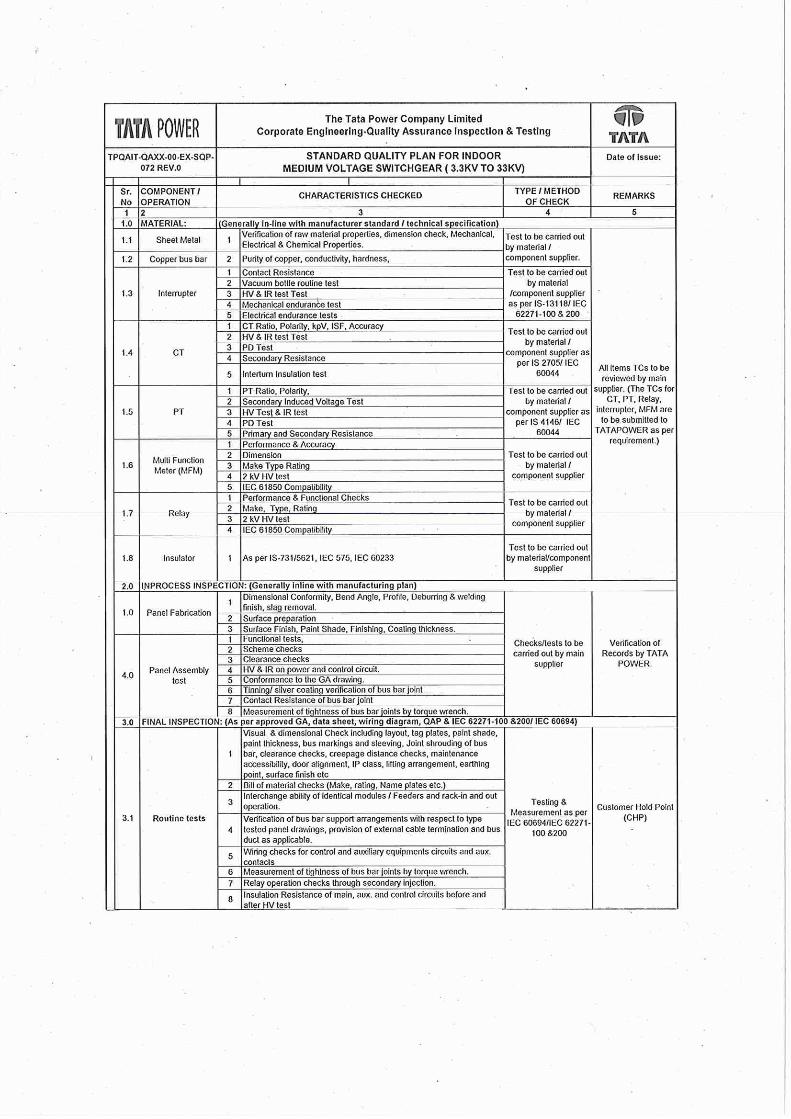


Annexure-3- Standard FQP AIS


Annexure-4-HTSWGRA4-Transmission-SLD

AUTO CHANGEOVER SCHEME FOR MV AUTO CHANGEOVER SCHEME FOR MV AUTO CHANGEOVER SCHEME FOR MV AUTO CHANGEOVER SCHEME FOR MV
SWITCHGEARSSWITCHGEARSSWITCHGEARSSWITCHGEARS
1
Annexure-5-_Auto Restoration

Conditions for auto changeover
LV bus shutdown due to
Transformer HV side bus fault
Transformer devices (WTI / OTI / Buchholz / PRD etc) trip
Transformer trip due to transformer winding fault, termination failure or HV/LV cable fault
Tripping due to mal operation of transformer protection system
× Tripping due to sneak circuits
× Tripping due to human errors
× Stuck OG or incomer breaker condition
× LBBU operation on incomer
× Bus fault trip due to actual fault in bus
2

3
Note:
1. Green colored cells shall be hard wired to LV incomer relay.
2. LV 86 of transformer CRP shall be wired.
3. Trip Shall be sent to all breaker on bus section including incomers.
3-ph UV on
LV Bus-1
2 sec
pickup
Inc-1
Fusefail
Inc-1 PT
MCB OFF
Bus-1
Comm Fail
OR NOT
LV 86
Operated
A
N
DBus-2
Voltage
Healthy
Changeover Initiation
from Inc-1
Trip Initiation to all
breakers on Bus
Section-1
LOGIC IN INCOMER-1 RELAY
OR
HV 96
Operated Trip LV INC
BKR
LV INC CB
OPEN
Block C/O
from BS bkr
NOT

4
Note: Auto changeover will automatically get blocked after LBB & RBS operation. Same shall be taken IN service
through IN/OUT Function key OR SCADA based on system requirement.
Incomer-1 RBS / LBB
Optd
Auto Changeover OUT
from SCADA
O
R Block Changeover
Scheme
SET
RESET
Auto Changeover IN
from SCADA
Bus Section BKR
OC/EF/RBS Operated
LOGIC IN BUS SECTION BKR RELAY
Incomer-2 RBS / LBB
Optd
Bus-1 Undervoltage
after 2 sec timer
Bus-2 Undervoltage
after 2 sec timer
AND

5
OG breaker in REMOTE
& IN SERVICE
Earth Switch Open
100ms HOLD
OG breaker Closed
AND
Trip Initiation to all
breakers on Bus
Section-1 SH.3
LOGIC IN OG FEEDER RELAY
TRIP OG on BS-1 by
Auto Changeover
SET
RESET
TRIP OG on BS-1 by
Auto Changeover SH.5
OG CLOSED Feedback
Individual OG on BS-1
Closing Permissive
Block Changeover
Scheme SH.04
O
R
Incomer-2 overload**
Note: ** For changeover on BS-2, Incomer-1 overload shall be taken. OLTS
ALARM shall give hard wired input to incomer relay. The signal shall be
converted into goose for sending to individual OG feeders

6
OG breaker Closed
Earth Switch Closed
AND
OR
Common Permissive
from each BKR of BS-1
Note:
1) Clouded portion shall be configured for only those switchgears where earthing of feeder is through breaker.
OG-1 breaker Open
LOGIC IN INDIVIDUAL RELAY
OG-2 breaker Open
OG-X breaker Open on
BS-1
AND
Incomer-1 BKR Open

7
Changeover Initiation
from Inc-1 SH.3
Changeover Initiation
from Inc-2 SH.4
Block
Changeover
scheme SH.4
AND
NOT
AND
O
R
Close Bus Section
breaker
Common Permissive
from all BKR of BS-1
SH.6
Common Permissive
from all BKR of BS-2
SH.6
^Pulse
50 sec
Close Initiation to all
OG of BS-1
Close Initiation to all
OG of BS-2
^Pulse
50 sec
Note:
1. ^Pulse timer which shall hold the output for 50 sec shall be used.
2. ^^ 100ms pulse timer shall wipe out incoming command
LOGIC IN BUS SECTION BREAKER RELAY
AND
BS BKR CLOSED
FEEDBACK
ANDBS BKR CLOSED
FEEDBACK
AND
BS BKR IN REMOTE
& IN SERVICE
Block
Changeover
scheme SH.4NOT
BS BKR BOTH SIDE
ISOLATORS CLOSED
^^100ms
Pulse

8
PU
TD- 3s
PU
TD- 6s
PU
TD = (X+3s)
CLS OG1 form
Changeover
CLS OG2 form
Changeover
CLS OG-X form
Changeover
Pulse 100ms
Pulse 100ms
Pulse 100ms
OG-1 Pickup on
OC / EF
Close Initiation to all
OG of BS-1 SH.7
^Pulse
60s NOT
AND
Note:
1) ^Pulse timer which shall hold the output for 60 sec shall be used.
2) Closing initiation shall not be subscribed for cap bank and reactor feeders
Individual OG Closing
Permissive SH.5
LOGIC IN INDIVIDUAL FEEDER RELAY

TATA POWER BKC 22 KV GIS REVERSE
INTERLCOKING SCHEME
Annexure-6-_RBS

TRF-2TRF-1
OG feeder-2OG feeder-1
Bus-1 Bus-2
FWD
REV
REV REV

OG-1 signal Send
&Send Block to I/C-1
RBS
150 ms Timer
PHLPTOC1 (51)
PHHPTOC1 (50-1)
EFLPTOC1 (51N)
EFHPTOC1 (50N-1)
PHLPTOC1 (51)
PHHPTOC1 (50-1)
EFLPTOC1 (51N)
EFHPTOC1 (50N-1)
PICK UP
TRIP
TRIP OWN BREAKER
Send Block to B/C
Rev functional stage
Note::: RBS: Reverse Blocking stage
For blocking send, GOOSE IN is not required.

Note::: RBS: Reverse Blocking stage
OR
Inc-1 RBS stage 50-1
trip
BC 1-2 REV stage
67N-2 trip
Direct trip OG-1 feeder
OG-1 signal receive
Bs 1-2 REV stage 67-
2 trip
Inc-1 RBS stage 50N-1
trip

Outgoing-2 signal Send
&Send Block to I/C-2
RBS
150 ms Timer
PHLPTOC1 (51)
PHHPTOC1 (50-1)
EFLPTOC1 (51N)
EFHPTOC1 (50N-1)
PHLPTOC1 (51)
PHHPTOC1 (50-1)
EFLPTOC1 (51N)
EFHPTOC1 (50N-1)
PICK UP
TRIP
TRIP OWN BREAKER
Send Block to B/C
FWD function Stage
For blocking send, GOOSE IN is not required.

Note::: RBS: Reverse Blocking stage
OR
Inc-2 RBS stage 50-1
trip
BC 1-2 FWD stage
67N-2 trip
Direct trip OG-2 feeder
OG-2 signal receive
Bs 1-2 FWD stage
67-2 trip
Inc-2 RBS stage 50N-1
trip

Bus Section-1-2 Signal Send
&Send Block to I/C-2
RBS
150 ms Timer
PHLPTOC1 (51)
PHHPTOC1 (50-1)
EFLPTOC1 (51N)
EFHPTOC1 (50N-1)
PICK UP
TRIP
DPHHPDOC1 (67-2) REV DIR
DEFHPDEF1 (67N-2) REV DIR
BUS SECTION PT FUSE FAIL
For blocking send, GOOSE IN is not required.

Bus Section-1-2 Signal Send
&Send Block to I/C-1
RBS
150 ms Timer
PHLPTOC1 (51)
PHHPTOC1 (50-1)
EFLPTOC1 (51N)
EFHPTOC1 (50N-1)
PICK UP
TRIP
DPHHPDOC1 (67-2) FWD DIR
DEFHPDEF1 (67N-2) FWD DIR
BUS SECTION PT FUSE FAIL
For blocking send, GOOSE IN is not required.

Bus Section-1-2 Signal Receive
Block signal from
OG-Feeder of BS -1
Block BS 1-2
REV stage
BS 1-2 Logic
OR
BC panel GOOSE OUT
Block BS 1-2
FWD stage
BS 1-2 Logic
OR
BC panel GOOSE OUT
DPHHPDOC1 (67-2) FWD DIR
DEFHPDEF1 (67N-2) FWD DIR
DPHHPDOC1 (67-2) REV DIR
DEFHPDEF1 (67N-2) REV DIR
Block signal from
OG-Feeder of BS -2
Block signal from
Inc-1 REV stage
Block signal from
Inc-2 REV stage

Tripping of OG breaker after operation of reverse blocking based busfault protection
Trip send to all
BS -1 OG
feeders
BS 1 Tripping
OR
Trip send to all
BS-2 OG
feeders
BS 2 Tripping
OR
BS 1-2 REV stage
BS 1-2 FWD stage
DPHHPDOC1 (67-2) FWD DIR
DEFHPDEF1 (67N-2) FWD DIR
DPHHPDOC1 (67-2) REV DIR
DEFHPDEF1 (67N-2) REV DIR
PHIPTOC1 (RBS)
EFIPTOC1 (RBS)
PHIPTOC1 (RBS)
EFIPTOC1 (RBS)
IC-1 RBS Stage
IC-2 RBS Stage
TRIP
TRIP
TRIP
TRIP
TRIP OWN BREAKER
+ TRIP BS 1-2 BREAKER
TRIP OWN BREAKER
+ TRIP IC-1 BREAKER
TRIP OWN BREAKER
+ TRIP IC-2 BREAKER
TRIP OWN BREAKER
+ TRIP BS 1-2 BREAKER

Bus Section-1 Blocking Receive
Block IC-1 RBS
Stage
Incomer-1 Logic
OR
INCOMER-1
GOOSE OUT
Block IC-2 RBS
Stage
Incomer-2 logic
OR
PHIPTOC1 (RBS)
EFIPTOC1 (RBS)
PHIPTOC1 (RBS)
EFIPTOC1 (RBS)
Block signal from
OG-Feeder of BS -1
Block signal from BC
(FWD)
Block signal from
OG-Feeder of BS -2
Block signal from BC
(REV)
INCOMER-2
GOOSE OUT
Block signal from
Inc-1 (REV) pickup
Block signal from
Inc-2 (REV) pickup

Inc-1 REV 67-2 Pickup
Block Tripping of BC 1-2 REV
67-2, 67N-2 stage
Inc-1 signal send
&
OR
150 ms Timer
Inc-1 51 Trip
Inc-1 51N Trip
Inc-1 50-2 Trip
Inc-1 50N-2 Trip
Inc-1 50-1 Trip
Inc-1 50N-1 Trip
ORInc-1 REV 67N-2 Pickup
Inc-1 RBS stage 50-1
Trip i] Send trip to OG-1
Ii] Send Trip to BC 1-2ORInc-1 RBS stage 50N-1
Trip
Inc-1 PT Fuse Fail
Inc-1 CB Fail

Inc-2 REV 67-2 Pickup
Block Tripping of BC 1-2 FWD
67-1, 67N-1 stage
Inc-2 signal send
&
OR
150 ms Timer
Inc-2 51 Trip
Inc-2 51N Trip
Inc-2 50-2 Trip
Inc-2 50N-2 Trip
Inc-2 50-1 Trip
Inc-2 50N-1 Trip
ORInc-2 REV 67N-2 Pickup
Inc-2 RBS stage 50-1
Trip i] Send trip to OG-2
Ii] Send Trip to BC 1-2ORInc-2 RBS stage 50N-1
Trip
Inc-2 PT Fuse Fail
Inc-2 CB Fail
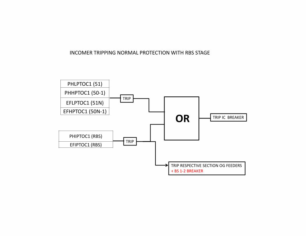
PHLPTOC1 (51)
PHHPTOC1 (50-1)
EFLPTOC1 (51N)
EFHPTOC1 (50N-1)
TRIP
TRIP IC BREAKER
INCOMER TRIPPING NORMAL PROTECTION WITH RBS STAGE
PHIPTOC1 (RBS)
EFIPTOC1 (RBS)TRIP
OR
TRIP RESPECTIVE SECTION OG FEEDERS
+ BS 1-2 BREAKER

The Tata Power Company Ltd. Corporate Engineering
Job No./ SR/148/18 Rev: 0 Date:23/03/2018
STUDY REPORT Page 6 of 8
IEC61850 based Bus bar protection Scheme Proposed Setting Philosophy
Form No: ENG-FM-27 R3 dated 27.12.17
&
"# &!
"#$% !'!'() *
Note: Proposed pickup are kept above the maximum pickup on outgoing feeders i.e. for Phase fault – 1200 Amp & for Earth fault- 600 Amp.
b. Configuration Modification It is recommended to modify the bus coupler configuration, In Block sending to incomer logic is modified as shown below.
Fig:1] Typical Station Layout

The Tata Power Company Ltd. Corporate Engineering
Job No./ SR/148/18 Rev: 0 Date:23/03/2018
STUDY REPORT Page 7 of 8
IEC61850 based Bus bar protection Scheme Proposed Setting Philosophy
Form No: ENG-FM-27 R3 dated 27.12.17
Logic-1 Own Forward stage bus fault blocking logic
Logic-2 Modified Block send logic when Own Forward stage is Blocked / Picked Up

The Tata Power Company Ltd. Corporate Engineering
Job No./ SR/148/18 Rev: 0 Date:23/03/2018
STUDY REPORT Page 8 of 8
IEC61850 based Bus bar protection Scheme Proposed Setting Philosophy
Form No: ENG-FM-27 R3 dated 27.12.17
Logic-3 Own Reverse stage bus fault blocking logic
Logic-4 Modified Block send logic when Own Reverse stage is Blocked / Picked Up

THE TATA POWER COMPANY LIMITED
STANDARD SPECIFICATION
FOR
MV, LV POWER AND CONTROL CABLE
(DOCUMENT NO - ENGG/ ELEC/STD-SPEC/2017/31)
Tata Power
Engineering T&D
Rev.
No
R0
Date
11-10-2017
Revision History
Final Specifications
Prepared
By
PSA
Checked
By
AAB
Approved By
AM
R1 27-08-2018 Information about time
gradient of fault feed
modified
PSA AAB AM
R2 20-12-2019 List of drawings and
format updated
PSA SVD RS
B 13-04-2020 PQR updated PSA SVD RS

The Tata Power Company Ltd. Engineering T&D
ENGG/ELEC/STD-SPEC/2017/31 Rev: B Date: 13.04.2020
Standard Specification
Page 2 of 20 MV, LV POWER AND CONTROL CABLE
Contents
Sr. No. Description Page no.
1.0 Introduction 3
2.0 Bidder Qualifying Requirements
3.0 System Description and Scope 5
4.0 Codes & Standards 6
5.0 Design Requirements 7
6.0 Layout Requirements for the Equipment / System 13
7.0 Operational & Maintenance Requirements 13
7.1 Operational Requirements 13
7.2 Maintenance Requirements 13
7.3 Safety Requirements 13
8.0 Technical Parameters of Equipment (incl. Data Sheet) 14
9.0 Quality Requirements, Inspection and Testing (incl. SQP & SFP) 19
10.0 Performance Requirements 19
11.0 Mandatory Spares and Special Tools & Tackles 19
11.1 Start Up Spares 19
11.2 Mandatory Spares 20
11.3 Recommended Spares 20
11.4 Special Tools & Tackles 20
12.0 Data Submission by Bidder 20
12.1 Along with Bid 20
12.2 After Award of Contract 20
13.0 Annexures 20

The Tata Power Company Ltd. Engineering T&D
ENGG/ELEC/STD-SPEC/2017/31 Rev: B Date: 13.04.2020
Standard Specification
Page 3 of 20 MV, LV POWER AND CONTROL CABLE
1. INTRODUCTION :
The document covers the specific requirements for complete design, detailed
engineering, manufacture, supply, inspection & testing at Bidder's work, packing,
transportation, loading and unloading, delivery to site, storage at site, handling at site,
erection, testing, commissioning, performance testing and handing over of MV, LV
Power and Control cable.
All equipment, system and services covered under this specification shall comply with
all current applicable statutory regulations and safety codes in the locality where the
equipment is proposed to be installed. The equipment and systems shall also conform
to the latest version of applicable codes and standards on the date of offer made by the
Bidder unless otherwise indicated. Nothing in this specification shall be construed to
relieve the Bidder of this responsibility
2. BIDDER’S QUALIFICATION REQUIREMENTS
2.1. Bidder must be an OEM of LT Power and Control cables with manufacturing in India
2.2. The Bidder shall have supplied at least 50 kms of LT Power and control cable of similar
size and rating to any major utilities/SEB for last 5 years as on date of bid submission.
Out of which at least 10 kms of LT Power and control cables shall be in successful
operation for more than two (2) years as on date of bid submission.
Indian Subsidiaries of global companies having plant in India are also eligible to bid if the
qualification requirements stated above are met independently or in combination with the
parent company. Declaration from parent company needs to be submitted.
2.3. The bidder shall submit Type test reports obtained from NABL/ International Accredited
Lab for the equipment / material offered. The type tests should have been conducted on
the equipment / material of the same design.The type tests should have been conducted
within 5 years prior to the date of bid opening. Time period for type test can be extended
by another 5 years as a special case, if there is no change in design / material of
construction (MOC). In case the type test reports furnished are not for the quoted
equipment / material but for the equipment / material with higher voltage class and/or
different capacity, then type test shall be carried out for the offered equipment / material
from NABL / International Accredited Lab without any cost implication to the owner and
the Type Test reports shall be submitted before despatch of the equipment / material.
2.4. In case the package involves installation & commissioning of the equipment / material,
then the bidder shall have the following experience:
a) He should have successfully completed one single order of value ..... (80% of estimated
value of similar work in last three years) OR

The Tata Power Company Ltd. Engineering T&D
ENGG/ELEC/STD-SPEC/2017/31 Rev: B Date: 13.04.2020
Standard Specification
Page 4 of 20 MV, LV POWER AND CONTROL CABLE
b) He should have successfully completed two single orders of value ..... (50% of
estimated value of similar work in last three years) OR
c) He should have successfully completed three single orders of value ..... (40% of
estimated value of similar work in last three years).
3. SYSTEM DESCRIPTION AND SCOPE:
Scope includes Design, manufacture, testing at manufacturer's works, packing,
forwarding, supply and unloading at site/store, erection and commissioning of Cables
along with Necessary number of termination kit, jointing kit, trefoil clamps, cable glands
and lugs etc as specified in Section A.
4. CODES AND STANDARDS
Given below are the acceptable code and standards. The Bidder shall take Owners
approval for use of other codes & standards
Sr.
no.
Applicable
standard
Description
1. IS:1554 (Part-I) PVC insulated (heavy duty) electric cables for working
2. IS:1554 (Part-II) PVC insulated (heavy duty) electric cables for working
voltage from 3.3kV upto and including 11kV.
3. IS:7098 (Part-II) XLPE insulated PVC sheathed cables for working voltages
from 3.3 kV upto and including 33kV.
4. IS:3961 Recommended current ratings for cables.
5. IS:8130 Conductors for insulated electric cables and flexible cords.
6. IS:5831 PVC insulation and sheath of electric cables.
7. IS:2982 Copper conductor in insulated cables and cords.
8. IS:3975 Mild steel wires, strips and tapes for armouring cables
9. IS:5609 Specification for low frequency wires and cables with PVC
insulation and PVC Sheath.
10. IS:6380 Spec. of elastomeric insulation of sheath of electric cables
11. IS:434(I and II) Specification for rubber insulation cables
12. IEC:540 The methods for insulations and sheaths of electric cables
and cords (elastomeric and thermoplastic compounds).
13. IEC:230 Impulse tests on cables and their accessories.
14. IEC:60 High voltage test techniques.
15. IEC:287 Calculations of the continuous current rating of cables (100%
load factor)
16. IEC:288 Nominal cross-sectional area and composition of conductor
of insulated cables

The Tata Power Company Ltd. Engineering T&D
ENGG/ELEC/STD-SPEC/2017/31 Rev: B Date: 13.04.2020
Standard Specification
Page 5 of 20 MV, LV POWER AND CONTROL CABLE
17. IEC:502 Extruded solid dielectric insulated power cables for rated
voltages from 1.00 kV upto 30 kV.
18. NEMA-WC-5 Thermoplastic insulated wires and cables for transmission
and distribution of electrical energy.
19. IEEE:383 Standard for type test for class IE electric cables, filled splices
and connections for nuclear power generation stations
20. IEC: 332-1 Test on electric cables under fire conditions
21. IEC-754-I Test method for acid gas generation
22. IEC-331 Fire resisting characteristics of electric cables
5. DESIGN REQUIREMENTS
5.1 This section covers the detailed requirements regarding design, supply, installation and
commissioning of 33kV, 11kV, 6.6 kV and 1.1kV cables required for substation. The
design, manufacture and performance of equipment shall comply with all currently
applicable statues, regulations and safety codes in the locality where the equipment will
be installed. Nothing in this specification shall be construed to relieve the BIDDER of this
responsibility.
5.2 The equipment shall conform to the latest edition of applicable standards. In case of
conflict between applicable standards and this specification, this specification shall govern.
5.3 All the cables feeding switchboards from transformers shall be sized based on transformer
rating and considering the maximum negative voltage variations envisaged in the
specifications. All the cables and bus ducts feeding transformers shall be sized based on
current ratings of transformer at the minimum voltage tap of the transformer. All other
cables shall be sized based on the load demand under most onerous conditions.
5.4 Cables shall be selected to so as to limit maximum voltage drop at equipment
terminals during normal operation and starting conditions well within permissible
values. Cables shall be de-rated for the site ambient and ground temperatures,
grouping and soil resistivity and cable laying configuration.
5.5 All HT cables shall be of unearthed grade. The bidder shall furnish detailed cable
selection/sizing criteria for Employer's approval.
5.6 Cable calculation and sizing shall be done for cable installation . It shall be in accordance
with IEEE std-399-1997 and IEC-60287-2-2. EPC contractor shall submit all sizing
calculations to Owner for review and approval before procurement.
5.7 There should not be any joint in the run of cable.

The Tata Power Company Ltd. Engineering T&D
ENGG/ELEC/STD-SPEC/2017/31 Rev: B Date: 13.04.2020
Standard Specification
Page 6 of 20 MV, LV POWER AND CONTROL CABLE
5.8 Specific requirement:
5.7.1 MV cables:
5.7.1.1 The cable shall comply with the technical parameters of the specification and latest version
of IS.
5.7.1.2 Aluminium stranded compacted circular, grade H4, class 2 as per IS 8130
5.7.1.3 Conductors shall be screened by extruded semi-conducting compound and XLPE
insulated.
5.7.1.4 Cores shall be screened by extruded semi-conducting compound in combination with
non-magnetic metallic tape.
5.7.1.5 Helically applied single layer of copper tape.
5.7.1.6 Provided with inner sheath of extruded black PVC compound type ST-2.
5.7.1.7 Aluminium armouring in the form of round wire followed by a binder tape
5.7.1.8 Extruded FRLS PVC compound type ST-2 outer sheath.
5.7.1.9 The insulation over the individual conductor core will be colour coded.
5.7.1.10 The construction, performance and testing of cables shall comply with IS 7098 Part II
for HT cables.
5.7.1.11 Core identification shall be by printed numerals
5.7.1.12 Oxygen index shall be minimum 29 when tested at 27+2 degC as per ASTMD- 2863
5.7.1.13 The temperature index value shall be minimum 230 degC at oxygen index of 21 when
tested as per NES 715.
5.7.1.14 Cable maximum pulling force shall be 70kN/ Sq.mm for copper conductor, unless
specified by cable manufacturer.
5.7.1.15 Bending radii shall be 15 X D, where D will be overall diameter of cable.
5.7.1.16 All single core cable shall be supported with non-magnetic plate or member, while
crossing floor or room.
5.7.2 L T Power Cables
LT Power cables for the 415V AC, 240V AC system and 220V DC system are single core
/ Multi core 1100V earthed H4 grade with stranded aluminium/copper conductor, extruded
cross-linked polyethylene (XLPE) insulated, core identification by colour coding, extruded
PVC (Type –ST 2) inner sheathed, armoured, aluminum wire armour for single core cables
and galvanized steel wire for multi core cables and extruded PVC (Type ST-2) outer
sheathed with FRLS properties, generally conforming to IS: 7098 (Part 1).
Upto 16 sq.mm cables, Copper conductor shall be used and above 16 sq.mm cables,
Aluminium conductor shall be used for LT power cables. For DC all cables shall be of
Copper conductor irrespective of its size. The cables used for DC system are of single
core type. Only single core cables will be used between batteries / battery chargers and

The Tata Power Company Ltd. Engineering T&D
ENGG/ELEC/STD-SPEC/2017/31 Rev: B Date: 13.04.2020
Standard Specification
Page 7 of 20 MV, LV POWER AND CONTROL CABLE
main distribution boards to eliminate the possibility of positive to negative faults in the
cables.
5.7.3 Control Cables
Control cables shall be 1100 V grade, multi core, minimum 1.5 sq. mm cross section, PVC
insulated, stranded copper conductor having minimum 7 strands, extruded PVC inner
sheathed, galvanised steel wire armoured, over all sheathed, outer sheath (ST-2) made
of FRLS PVC compound. The cables shall conform to IS-1554 (Part-I) 1988 / IEC-60502
(1998) & IEC-60502 – amendment –1 999 in all other respects.
In situations where accuracy of measurement or voltage drop in control circuit warrants,
higher cross sections as required shall be used.
The minimum size of the stranded copper conductor used for panel wiring shall be as
follows:
All circuits except CT & PT circuits : 1.5 mm2 per lead.
CT & PT Circuits inside panel : 4/6 mm2 per lead.
CT Circuits outside panel : 4 mm2 per lead
DC circuit within panel : 1.5 mm2 per lead
DC circuit outside panel : 2.5 mm2 per lead
5.9 FIRE RETARDANT LOW SMOKE (FRLS PVC)
a. FRLS PVC compound used for outer sheath shall meet the following performance
requirements: The critical oxygen index value shall be minimum 29 when tested at
27+ 2 Deg.C. as per ASTM-D-2863-77 and the temperature index value shall be
minimum 230 Deg.C. at oxygen index of 21 when tested as per NES-715.
b. The maximum total acid gas generation as determined by titration method shall be
less than 20% by weight when tested as per IEC-60754-1 (1994).
c. The smoke generation under fire shall have maximum smoke density rating of 60%
when tested as per ASTM-D-2843-77.
d. Cables supplied against this specification may be exposed to Ultra-Violet (UV)
radiation from the sunlight, humidity, atmospheric pollution and water either during
storage in open stockyard with covers on cable reels removed or when laid in
ladder type cable trays installed out door without cable tray covers. Under
environment conditions, any reduction in mechanical property i.e., tensile strength
and ultimate elongation of outer sheath material of cable shall not cause reduction
in expected life of cable. More over the material shall meet the following test
requirements.

The Tata Power Company Ltd. Engineering T&D
ENGG/ELEC/STD-SPEC/2017/31 Rev: B Date: 13.04.2020
Standard Specification
Page 8 of 20 MV, LV POWER AND CONTROL CABLE
e. The cables shall pass the hydrolytic stability and ultraviolet tests as per DIN 53387.
The retention values of tensile strength and ultimate elongation after the tests shall
be minimum 60% of tensile strength and ultimate elongation before test.
f. The cables shall pass the ultra violet tests as per DIN: 53387. The same shall be
conducted at an independent laboratory like CPRI/ERDA.
g. The finished cable shall pass the flammability test as per IEC 60332-1 (1994) and
IEEE.383. In addition, it shall also pass flammability test as per class F3 of
Swedish Standard SS-424-14-75 (1978).
h. The cables shall conform to applicable IS standard in all other respects.
i. The FRLS PVC compound used for outer sheath shall also be resistant to
termite, fungus and rodent attacks.
j. The bidder shall submit along with the bid the results of tests carried out on the
sheath material and finished cable to conform compliance to the requirements of
FRLS properties specified above.
k. The cables shall be suitable for continuous operation and satisfactory performance
for the following power supply conditions.
Variation in supply voltage ± 10% for MV cables
Variation in supply voltage (+) 10% & (-) 15% for LV cables Variation in supply
frequency ±5%.
Combined voltage and frequency variation 10%.
5.10 Cable Terminations
All 6.6 kV, 11kV and 33kV termination kits shall be of heat shrinkable type and suitable for
XLPE insulation.
All 1100V termination for XLPE/PVC power cables and control cables shall be by crimping
type tinned copper / aluminium lugs. Cable termination will be done with suitable double
compression type brass cable glands.
5.11 Cable Joints
Cable joints shall be avoided to the extent possible. If joints are unavoidable due to circuit
length, in excess of permissible maximum drum length, they shall be heat shrinkable type
having a short circuit withstands capacity of 40 kA for 1 sec. for MV cables and 50kA for 1
sec. for 1100V grade cables.
5.12 For Design /Sizing Cables:
5.11.1 The following data shall be used as the basis input data for sizing and selection of cable

The Tata Power Company Ltd. Engineering T&D
ENGG/ELEC/STD-SPEC/2017/31 Rev: B Date: 13.04.2020
Standard Specification
Page 9 of 20 MV, LV POWER AND CONTROL CABLE
a. Design ambient temperature: 50 deg.c
b. Fault current for MV systems: 40 KA for 1 sec. for 33KV/22 kV system
c. 40 kA for 1 sec. for 11KV/6.6 kV system
d. Fault current for 415 systems: 50 KA for 1 sec.
e. Fault current for 220V system: 20KA
f. Main protection fault clearing time for cables to the feeders protected by breakers:
1.0 sec for Incomers, tie feeders, transformer feeders and 0.25 sec for motor feeders
respectively
5.11.2 Design Considerations: Power Cables
5.11.2.1 In general, Power Cables are sized to satisfy the following criteria:
a. Power cables will carry the full load current of the circuit continuously under site
conditions considering the various derating factors like ambient air temperature,
grouping, method of laying etc.
b. Power cables will withstand the fault current of the circuit for the duration not less than
the maximum time taken by the primary protective system to isolate the fault.
c. For cables to 415V motors and feeders protected by fuses, the cross section will be
chosen according to the cut-off current of the fuse and it’s fusing time.
d. Maximum voltage drop limits under steady state and voltage dip during starting.
e. Voltage dip at motor terminals during starting of motors will be limited to 15% of the
rated voltage for LT motors and 20% HT motors.
5.11.2.2 The normal current ratings for the feeders are considered as under:
a. Transformer feeders:
Current ratings corresponding to MVA rating of the transformer.
b. 415V Supply feeders
i. Cable size of each incomer of MCC & PDB shall be selected such that the incomer
can take full MVA rating of source transformer. Cable size for incomer of MLDB shall
be selected on the basis of current rating corresponding to lighting transformer and
voltage drop. Also additional voltage drop due to cable resistance and reactance for
entire cable length shall be considered for cable sizing.
ii. For power feeders voltage drop shall be considered on normal rated current of the
feeder.
iii. Power factor for 415V supply feeders are considered as below:
iv. Cos = 0.8
c. 415V Motor feeders:
i. Normal current rating for motor feeder is taken as the full load current corresponding
to the motor rating. For voltage dip consideration, the starting current is taken as 6
times the full load current. (+20% tolerance will be applied as per IS 323). Also

The Tata Power Company Ltd. Engineering T&D
ENGG/ELEC/STD-SPEC/2017/31 Rev: B Date: 13.04.2020
Standard Specification
Page 10 of 20 MV, LV POWER AND CONTROL CABLE
additional voltage drop due to cable resistance and reactance for entire cable length
shall be considered for cable sizing.
ii. Power factor and efficiency for 415V motors under steady state conditions are
considered as below:
iii. Cos = 0.8
iv. Efficiency = 0.85
v. During motor starting conditions, the power factor shall be considered as 0.2
vi. For Cable between transformers and respective switchgear transformer full load
regulation voltage shall be considered for the voltage drop calculation.
5.11.3 Design consideration: Control Cables
Current transformers leads shall be checked for the lead burden vis-a-vis the current
transformer VA capacity and 4 mm2 cables shall be used for connection of CT to loads. In
case 4 mm2 conductors impose unacceptable high burden on CTs, conductor of higher
cross section shall be used.
Voltage transformer leads shall be checked for voltage drop, which shall be limited to within
1% for all cases other than tariff metering. For tariff metering the voltage drop shall be
limited to 0.2%. In case the voltage drop with 4 mm2 Cu conductors exceed this value,
higher conductor sizes shall be used.
5.11.4 The cable shall be suitable for installation in a tropical monsoon area having a hot humid
climate. The reference ambient temperature to be considered for the purpose of this
specification is 50 deg. C. The derating factor for the various conditions of installation
including the following shall be considered while choosing the conductor size and
calculations shall be submitted for purchaser’s approval: a) Maximum ambient air
temperature. b) Maximum ground temperature c) Depth of laying wherever applicable d)
Grouping of cables .
5.11.5 The allowable voltage drop at terminal of the connected equipment shall be maximum
2.5% at full load while choosing the conductor size and calculations shall be submitted for
purchaser’s approval. In case of squirrel cage induction motors, the cable size shall be so
chosen that the motor terminal voltage does not fall below 85% of the rated voltage, at the
time of starting.
5.11.6 The maximum continuous conductor temperature and the maximum allowable conductor
temperature during short circuit are to be taken as 70 deg. C and 160 deg. C respectively
in case of PVC insulated cables and 90 deg .C and 230 deg. C respectively in case of
XLPE insulated cables.

The Tata Power Company Ltd. Engineering T&D
ENGG/ELEC/STD-SPEC/2017/31 Rev: B Date: 13.04.2020
Standard Specification
Page 11 of 20 MV, LV POWER AND CONTROL CABLE
5.11.7 For 415V power cables of size above 35 mm2 , XLPE insulated cables shall also be
acceptable.
5.11.8 The minimum size of all 33kV,11kV grade power cables and 415V power cables
connected to circuit breakers shall be chosen taking into account the following factors: a)
Fault level due to system contribution. b) Fault contribution of running motors. c) Expected
time up to which motor contribution persists. d) Maximum time for fault clearance (i.e.
operating time of the backup protection relays plus the time of operation of the circuit
breakers). e) Full load current of the circuit. vi) The cables shall be capable of continuous
satisfactory operation under a power supply system frequency variation of (±) 5%, voltage
variation of (±) 10% and combined frequency and voltage variation of 10% (absolute sum).
6. LAYOUT REQUIREMENTS FOR THE EQUIPMENT / SYSTEM
6.1 Cable shall be laid through trenches/ ducts/ cable trays or shall be buried as per cable
layout drawings to be prepared by the bidder and approved by Owner during detailed
engineering.
6.2 Bidder shall maintain necessary clearances as per statutory and safety requirements as
applicable.
6.3 Fire Barriers to be provided wherever applicable
7 OPERATIONAL AND MAINTENACE REQUIRMENT
7.1 OPERATIONAL REQUIRMENT
Equipment shall give continuous service under specified site conditions.
7.2 MAINTENACE REQUIRMENT
7.2.1 O& M manuals for the installation, operation and maintenance of Cables shall be furnished
at least three months before despatch of equipment.
7.2.2 The manual shall contain minimum following details: a) General description of equipment.
b) Approved Technical Data Sheet c) Salient constructional features. d) Technical leaflets
of fittings/ important parts. e) All drawings. f) Type and routine test certificates. g)
Instructions to be followed on receipt of equipment at site & for storage. i) Erection
procedures and checks. j) Pre-commissioning checks. k) Commissioning procedures. l)
Withdrawal arrangement/ material handling instructions. m) Operation instructions. n)
Maintenance instructions. o) Trouble-shooting. p) Safety instructions.

The Tata Power Company Ltd. Engineering T&D
ENGG/ELEC/STD-SPEC/2017/31 Rev: B Date: 13.04.2020
Standard Specification
Page 12 of 20 MV, LV POWER AND CONTROL CABLE
7.3 SAFETY REQUIREMENTS
7.3.1 All Power and Control cables shall be FRLS type only
8 TECHNICAL PARAMETERS OF EQUIPMENT
Data sheet: A: MV Power cable
Description Specification
requirement
To be filled
by Bidder
Name of the manufacturer
Cable type XLPE
Applicable Standard IS 7098/P2/85
Size Suitable size
Voltage grade As applicable
No. of cores 1C and 3C
Permissible voltage and frequency
variation for satisfactory operation
±10%
Max. Rated conductor temp. 90 deg.C
Max. Allowable conductor temp. during
short ckt.
230 Deg.C
Max. allowable conductor temp. during
overload
130 Deg.C
Conductor
Material Aluminium confirming
IS:8130/84
Shape Compact Stranded
circular
Cross sectional area Suitable size
Min. no. of wires By bidder
Conductor screen
material semi conducting XLPE
nominal thcikness By Bidder
Insulation
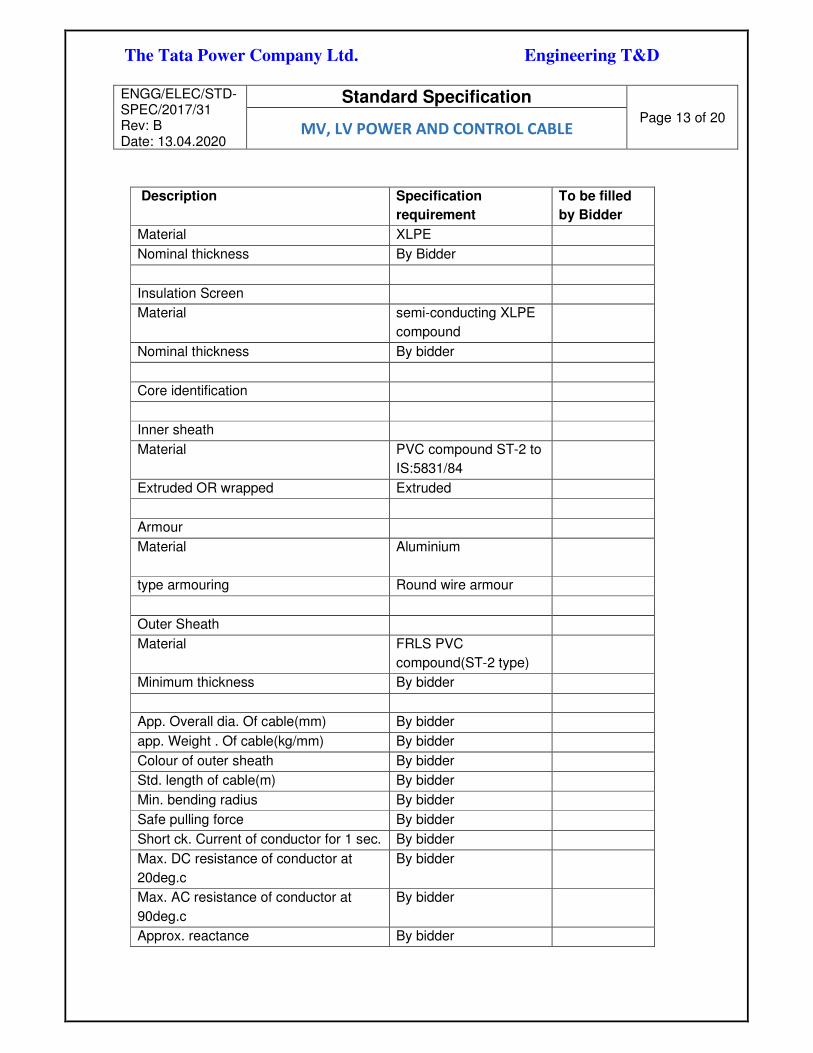
The Tata Power Company Ltd. Engineering T&D
ENGG/ELEC/STD-SPEC/2017/31 Rev: B Date: 13.04.2020
Standard Specification
Page 13 of 20 MV, LV POWER AND CONTROL CABLE
Description Specification
requirement
To be filled
by Bidder
Material XLPE
Nominal thickness By Bidder
Insulation Screen
Material semi-conducting XLPE
compound
Nominal thickness By bidder
Core identification
Inner sheath
Material PVC compound ST-2 to
IS:5831/84
Extruded OR wrapped Extruded
Armour
Material Aluminium
type armouring Round wire armour
Outer Sheath
Material FRLS PVC
compound(ST-2 type)
Minimum thickness By bidder
App. Overall dia. Of cable(mm) By bidder
app. Weight . Of cable(kg/mm) By bidder
Colour of outer sheath By bidder
Std. length of cable(m) By bidder
Min. bending radius By bidder
Safe pulling force By bidder
Short ck. Current of conductor for 1 sec. By bidder
Max. DC resistance of conductor at
20deg.c
By bidder
Max. AC resistance of conductor at
90deg.c
By bidder
Approx. reactance By bidder

The Tata Power Company Ltd. Engineering T&D
ENGG/ELEC/STD-SPEC/2017/31 Rev: B Date: 13.04.2020
Standard Specification
Page 14 of 20 MV, LV POWER AND CONTROL CABLE
Description Specification
requirement
To be filled
by Bidder
Approx. capacitance By bidder
FRLS properties By bidder
Data sheet: B: LT Power cable
The 1.1KV grade Power Cables will comply with the particulars indicated below.
Sl.
No. Description Unit
Specification
Requirements BY BIDDER
1.0 Name of the
Manufacturer
2.0 General Requirements
2.1 Voltage Grade kV 1.1
2.2 No. of Cores 1, 2 , 3 & 4
2.3 Conductor Material
H4 Grade Aluminium
for above 16 Sq mm
/copper for below 16
Sq mm
2.4 Design Ambient
Temperature o C 50
3.0 Specific Requirements
3.1 Conductor
(stranded/solid) Stranded
3.2 Form-
circular/segmented
3.3 Insulation Extruded XLPE
3.4 Inner Sheath Extruded PVC
Compound (ST-2)
3.5 Armour
Aluminium wire for
single core cables and
Galvanized Steel wire
for multicore cables.

The Tata Power Company Ltd. Engineering T&D
ENGG/ELEC/STD-SPEC/2017/31 Rev: B Date: 13.04.2020
Standard Specification
Page 15 of 20 MV, LV POWER AND CONTROL CABLE
Sl.
No. Description Unit
Specification
Requirements BY BIDDER
3.6 Outer Sheath Extruded FRLS PVC
Compound (ST-2)
3.7
Incremental running
lengths and all details
as specified in IS-7098
(Part-1) are marked on
cable sheath at every
1m interval
Required
3.8 Category for Flame
Retardance Test Category- A
4.0 Cable drums
4.1
Length of cables in
zcable drum and
tolerance
ms
4.2 Type of end sealing
4.3 Marking on cable drums
as per IS-7098 (Part-1) Required
Data sheet: C: Control cable
The 1.1KV grade Control Cables will comply with the particulars indicated below
Sl.
No.
Description Unit Specification Requirements BY BIDDER
1.0
Name of the Manufacturer
a. 2
.
General Requirements
b. 2
.
Voltage Grade kV 1.1
c. 2
.
3
Conductor Material Annealed, high conductivity,
copper conductor, nominal
cross sectional area 2.5/4
sq.mm (having 7/11 strands of
0.67 mm dia)

The Tata Power Company Ltd. Engineering T&D
ENGG/ELEC/STD-SPEC/2017/31 Rev: B Date: 13.04.2020
Standard Specification
Page 16 of 20 MV, LV POWER AND CONTROL CABLE
Sl.
No.
Description Unit Specification Requirements BY BIDDER
d. 2
.Design Ambient
Temperature
o C 50
e. 4Nominal Diameter mm *
f. 4Overall Diameter mm *
g. 4
.
4
Conductor
(stranded/solid)
Stranded
h. 4
.
5
Insulation Extruded PVC Compound type C
i. 4
.
6
Inner Sheath Extruded PVC type ST-2
j. 4
.
7
Outer Sheath Extruded black FRLS PVC
compound type ST-2
k. 4
.
8
Identification of cores Colour coded upto 5 cores and
cable with more than 5 cores
will have printed numerals
l. 4
.
9
Incremental running
lengths and all details as
specified in IS-1554 (Part-
1) are marked on cable
sheath at every 1m
interval
Required
m. 4
.
1
Category for Flame
Retardance Test
Category- A
n. 5Cable drums
o. 5
.Length of cables in cable
drum and tolerance
*
p. 5
.Weight of cable drum
without cables
*
q. 5
.Weight of cable drum with
cables
*
r. 5Type of end sealing *

The Tata Power Company Ltd. Engineering T&D
ENGG/ELEC/STD-SPEC/2017/31 Rev: B Date: 13.04.2020
Standard Specification
Page 17 of 20 MV, LV POWER AND CONTROL CABLE
Sl.
No.
Description Unit Specification Requirements BY BIDDER
s. 5
.
5
Marking on cable drums
as per IS-1554 (Part-1)
Required
9 QUALITY REQUIREMENTS, INSPECTION & TESTING (INCL. SQP & SFP)
9.1 The Quality Control Plan shall list and define in sequential order all process control
activities, inspection and tests proposed to be performed on the equipment/material
starting from component procurement and from testing stages to product dispatch. The
Quality Control Plan shall indicate and identify the applicable standards, detailed
description with diagram the procedure, acceptance criteria, extent of check and record
to be generated. This QAP shall be submitted by bidder and approved by Owner.
9.2 All erection and installation activities shall be performed in line of approved FQP by Owner.
9.3 All test routine test, performance test, special tests and acceptance test as per the relevant
standards specified in this specification and approved MQP shall be carried out on each
cable. Minimum shop testing requirements are specified in the attached Standard Quality
Plans. All applicable Type test report shall be submitted with the bid and shall not be older
than 5 years.
Standard SQP and SFP are as follows:
(Standard Quality plan) SQP document no.: TPQAIT-QAXX-00-EX-SQP-113: SQP for LV
cable
(Standard Quality plan) SQP document no.: TPQAIT-QAXX-00-EX-SQP-138: SQP for MV
cable
(Standard Field Quality plan) SFP document number: TPQAIT-QAXX-00-EX- FQP-161:
FQP for cable installation
10 PERFORMANCE REQUIREMENTS
10.1 The cable shall be suitable for installation in a tropical monsoon area having a hot humid
climate. The reference ambient temperature to be considered for the purpose of this
specification is 50 deg. C.
10.2 Cables shall be capable of carrying continuous load current under a power supply system
frequency variation of (±) 5%, voltage variation of (±) 10% and combined frequency and
voltage variation of 10% within specified limits of temperature rise.
11 SPARES AND SPECIAL TOOLS & TACKLES

The Tata Power Company Ltd. Engineering T&D
ENGG/ELEC/STD-SPEC/2017/31 Rev: B Date: 13.04.2020
Standard Specification
Page 18 of 20 MV, LV POWER AND CONTROL CABLE
The spares supplied shall be strictly interchangeable with parts for which they are intended
for replacement.
The spares shall be treated and packed for long storage (minimum 5 years) under the
climatic conditions prevailing at the site.
The start-up spares shall be delivered at the site well in time before the start-up and
commissioning of the plant.
11.1 Start-Up Spares
The start-up spares are those spares which will be required during start-up and
commissioning of the equipment/systems, and until Final Take Over. It is the responsibility
of the bidder to supply all the necessary spares as required until the equipment/systems
are handed over to the Owner. An adequate stock of start-up spares shall be available at
the site such that the start-up and commissioning of the equipment/systems, performance
testing and handing over the equipment/systems to the Owner will be carried out without
hindrance and delay. All start-up spares which remain unused after the taking over the
sub-station shall remain the property of the Owner. The Bidder shall furnish the Schedule
of Start-up Spares.
11.2 Essential Spares
Essential spares are those considered necessary by the owner for first three (5) years of
normal sub-station operation. A list of such spares has been listed in the below mentioned
table and the same shall be included in bidder’s scope. When a particular item of spares
is indicated as `percentage', it shall be considered as percentage of total number of that
item of spares in the single equipment/system, unless specified otherwise and the fraction
shall be rounded-off to the next higher whole number. Whenever the item of spares has
been indicated as `set' the same shall mean the supply for a single equipment/system.
One set of spares for the particular equipment shall mean the total quantities of that
particular spares for a single equipment e.g., `set' of Server, set of Gateway, shall include
HMI, keyboard, mouse etc. The `set’ shall however include all components required to
replace that item of spares. The Owner reserves the right to buy any of the essential spare
parts as considered necessary.
In case during start-up and commissioning certain essential spares are used up, the same
shall be replaced within one (1) month without any commercial implications.
VENDOR shall furnish details for all essential spares as per the approved vendor
document list.
11.3 Recommended Spares

The Tata Power Company Ltd. Engineering T&D
ENGG/ELEC/STD-SPEC/2017/31 Rev: B Date: 13.04.2020
Standard Specification
Page 19 of 20 MV, LV POWER AND CONTROL CABLE
In addition to the spares mentioned above, the Bidder shall also furnish in his bid a list of
recommended spares with unit prices. The Owner reserves the right to buy any of the
recommended spare parts as considered necessary by him. The prices of recommended
spares shall be consistent with those of start-up/essential spares. Purchase of these spare
parts will be covered by a separate order or an amendment to the contract.
The Bidder shall provide a list of recommended spares for a period of five years from the
date of Site Acceptance Test (SAT) and confirm that the shelf-life of these spares is such
as to last for at least 7 years from the date of SAT.
The Bidder shall provide the MTBF of various components, sub-assemblies, assemblies
etc. (recommended as spares) and the relationship between MTBF and spare quantities
recommended.
The Bidder shall submit the product life cycle details of the all hardware offered under this
RFP.
The table below indicate the minimum requirement of the owner, bidder to include the
spares, which are not part of this table, but required for maintenance and upkeep of the
system.
11.4 SPECIAL TOOLS & TACKLES
11.4.1 Commissioning spares are those, which may be required during commissioning of the
equipment. Bidder to furnish list of commissioning spares (price deemed to be included
in the total bid price) along with technical offer.
11.4.2 The bidder shall supply with the equipment, one unused complete set of all special
tools & tackles required for the erection, assembly, disassembly and proper
maintenance of the equipment. A list of such tools & tackles (price deemed to be
included in the total bid price) shall be submitted by the bidder along with the offer.
12 DATA SUBMISSION BY BIDDER:
12.1 ALONGWITH BID
Following drawings and documents shall be prepared based on Owner specifications and
statutory requirements and shall be submitted with the bid:
12.1.1 Completely filled in Technical Particulars
12.1.2 General description of the equipment and all components including brochures.
12.1.3 General arrangement
12.1.4 Bill of material
12.1.5 Experience List

The Tata Power Company Ltd. Engineering T&D
ENGG/ELEC/STD-SPEC/2017/31 Rev: B Date: 13.04.2020
Standard Specification
Page 20 of 20 MV, LV POWER AND CONTROL CABLE
12.1.6 Type test certificates
12.2 AFTER AWARD OF CONTRACT
Sr. No Descriptions For
Approval
For Review
Information
Final
submission
1. Technical parameters √ √
2. Cross section Drawing √ √
3. Installation Instruction √ √
4. Transport / Shipping dimension drawing √
5. QA & QC Plan √ √ √
6. Test Certificates √ √ √
13 ANNEXURES :
13.1 Annexure-1: (Standard Quality plan) SQP document no.: TPQAIT-QAXX-00-EX-SQP-
113: SQP for LV cable
13.2 Annexure- 2: (Standard Quality plan) SQP document no.: TPQAIT-QAXX-00-EX-SQP-
138: SQP for MV cable
13.3 Annexure-3: (Standard Field Quality plan) SFP document number: TPQAIT-QAXX-00-
EX- FQP-161: FQP for cable installation


THE TATA POWER COMPANY LIMITED
STANDARD
TECHNICAL SPECIFICATION
FOR
CABLE CARRIER SYSTEM
(DOCUMENT NO - ENGG/ ELEC/STD-SPEC/2017/28)
Tata Power
Engineering T&D
Rev. No
R0
Date
11-10-2017
Revision History
Final Specifications
Prepared By
PSA
Checked By
AAB
Approved By
AM
R1 20-11-2019 List of drawings and
format updated
PSA SVD RS
R2 06-04-2020 PQR updated PSA SVD AM

The Tata Power Company Ltd. Engineering T&D
ENGG/ELEC/STD-SPEC/2017/28 Rev: 2 Date: 06.04.2020
Technical Specification
Page 2 of 18 CABLE CARRIER SYSTEM
Contents
Sr. No. Description Page no.
1.0 Introduction 3
2.0 Bidder Qualifying Requirements
2.1 Qualifying Requirements 4
3.0 System Description and Scope 6
4.0 Codes & Standards 7
5.0 Design Requirements 8
6.0 Layout Requirements for the Equipment / System 13
7.0 Safety Requirements 13
8.0 Operational & Maintenance Requirements 13
8.1 Operational Requirements 14
8.2 Maintenance Requirements 14
9.0 Technical Parameters of Equipment (incl. Data Sheet) 15
10.0 Quality Requirements, Inspection and Testing (incl. SQP & SFP) 16
11.0 Performance Requirements 17
12.0 Mandatory Spares and Special Tools & Tackles 17
12.1 Start up spares 17
12.2 Mandatory Spares 17
12.3 Recommended Spares 17
12.4 Special Tools & Tackles 17
13.0 Data Submission by Bidder 18
13.1 Along with Bid 18
13.2 After Award of Contract 18
14.0 Annexures 18

The Tata Power Company Ltd. Engineering T&D
ENGG/ELEC/STD-SPEC/2017/28 Rev: 2 Date: 06.04.2020
Technical Specification
Page 3 of 18 CABLE CARRIER SYSTEM
1. INTRODUCTION :
The document covers the specific requirements for complete design, detailed
engineering, manufacture, supply, inspection & testing at Bidder's work, packing,
transportation, loading and unloading, delivery to site, storage at site, handling at site,
erection, testing, commissioning, performance testing and handing over of Cable Carrier
System.
All equipment, system and services covered under this specification shall comply with
all current applicable statutory regulations and safety codes in the locality where the
equipment is proposed to be installed. The equipment and systems shall also conform
to the latest version of applicable codes and standards on the date of offer made by the
Bidder unless otherwise indicated. Nothing in this specification shall be construed to
relieve the Bidder of this responsibility
2. APPROVED VENDOR LIST & BIDDER’S QUALIFICATION REQUIREMENTS
2.1 QUALIFICATION REQUIREMENTS
1.1.1. Bidder must be an OEM of Cable carrier system with manufacturing in India
1.1.2. The Bidder shall have supplied at least 10 no’s of Cable carrier systems for Power plant
or Receiving stations of any of the major utilities/SEB for last 5 years as on date of bid
submission. Out of which at least 5 no’s shall be in successful operation for more than two
(2) years as on date of bid submission.
Indian Subsidiaries of global companies having plant in India are also eligible to bid if the
qualification requirements stated above are met independently or in combination with the
parent company. Declaration from parent company needs to be submitted.
1.1.3. The bidder shall submit Type test reports obtained from NABL/ International Accredited
Lab for the equipment / material offered. The type tests should have been conducted on
the equipment / material of the same design. The type tests should have been conducted
within 5 years prior to the date of bid opening. Time period for type test can be extended
by another 5 years as a special case, if there is no change in design / material of
construction (MOC). In case the type test reports furnished are not for the quoted
equipment / material but for the equipment / material with higher voltage class and/or
different capacity, then type test shall be carried out for the offered equipment / material
from NABL / International Accredited Lab without any cost implication to the owner and
the Type Test reports shall be submitted before despatch of the equipment / material.
1.1.4. In case the package involves installation & commissioning of the equipment / material,
then the bidder shall have the following experience:

The Tata Power Company Ltd. Engineering T&D
ENGG/ELEC/STD-SPEC/2017/28 Rev: 2 Date: 06.04.2020
Technical Specification
Page 4 of 18 CABLE CARRIER SYSTEM
a) He should have successfully completed one single order of value ..... (80% of estimated
value of similar work in last three years) OR
b) He should have successfully completed two single orders of value ..... (50% of
estimated value of similar work in last three years) OR
c) He should have successfully completed three single orders of value ..... (40% of
estimated value of similar work in last three years).
2 SYSTEM DESCRIPTION AND SCOPE:
Design, manufacture, testing at manufacturer's works, packing, forwarding, supply and
unloading at site/store, erection and commissioning of cable carrier system.
This pat covers specific requirements of the cable carrying system:
3.1 Section – I - Cable Tray Mountings Requirements
3.2 Section – II - Cable Trays - Construction Requirements
3.3 Section – III - Cable Trays - Installation Requirements
3.4 Section – IV - Cable Installation Requirements
3.5 Section – V - Conduit Installation Requirements
4. CODES AND STANDARDS
Given below are the acceptable code and standards. The Bidder shall take Owners
approval for use of other codes & standards
Sr. no. Brief Title Ref. No. of Standard
1. Code of practice for fire safety of bldgs. IS: 1646
2. Guide for safety procedures and practices in
electrical work
IS:5216
3. Accessories for rigid steel conduits IS:3837
4. Fittings for rigid steel conduits IS:2667
5. Fittings for rigid non-metallic conduits IS:3419
6. Adaptors for flexible steel conduits IS:4649
7. Code of practice for structural steel IS:800
8. Code of practice for installation and
maintenance of power cables up to and
including 33 kV rating.
IS:1255
9. Electrical wiring installation (system voltage
not exceeding 650 V).
IS:732

The Tata Power Company Ltd. Engineering T&D
ENGG/ELEC/STD-SPEC/2017/28 Rev: 2 Date: 06.04.2020
Technical Specification
Page 5 of 18 CABLE CARRIER SYSTEM
10. Structural steel (Standard Quality). IS 226
11.
Code of practice for use of metal arc welding
for general construction in mild steel.
IS:316
12. Hexagonal bolts, nuts and screws. IS:1363
13. Electroplated coatings of cadmium on iron and
steel.
IS:1572
14. Code of practice for hot dip galvanizing for iron
and steel.
IS:2629
15. Method of testing uniformity of coating on zinc
coated articles.
IS:2633
16. Indian Electricity Act.
5. DESIGN REQUIREMENTS :
a. For cable laying in outdoor areas it is proposed to use trenches (Cable laying shall
be through cable trays), cable duct banks and overhead cable racks. Direct burial of
cable will be avoided as far as possible.
b. For cable laying in indoor areas, it is proposed to use cable trenches (Cable laying
shall be through cable trays), duct banks, conduits, cable trays.
c. Cables from switchgear, PMCCs and control panels will be routed on prefabricated
ladder type galvanized steel cable trays supported on site fabricated tray supports
inside station and ancillary buildings. Separate cable trays will be used for power,
and control and instrumentation cables.
d. Cable trays and tray supporting structures in chemically corrosive areas like battery
rooms and water treatment plant will be mild steel painted trays finished with
chlorinated rubber based paint / epoxy paint.
e. Duct bank using Hume pipe/ GI pipe shall be used for road crossing.
f. Perforated cable trays shall be considered for control and instrumentation cables.
g. All cable trays will be earthed at minimum two places by GS flats to plant earthing
system. The distances between the earthing points will not exceed 10 meters.
h. Separate trays shall be provided for HV Power/LV Power (AC&DC)/Control &
Instrumentation cables. HV cable shall be laid in topmost tray, then LV cable and
control and instrumentation cables to be laid in bottom most trays.
i. In case of buried cables, armoured cables (with aluminium wire/strip armour for
single core cables and galvanised steel wire/strip armour for multi-core cables) will
be used.
5.1 SECTION – I : CABLE TRAY MOUNTINGS REQUIREMENTS

The Tata Power Company Ltd. Engineering T&D
ENGG/ELEC/STD-SPEC/2017/28 Rev: 2 Date: 06.04.2020
Technical Specification
Page 6 of 18 CABLE CARRIER SYSTEM
Unless otherwise specifically mentioned on the relevant layout drawings, all cable tray
mounting works shall be carried out as per following:
5.1.1. Cable tray mounting arrangement shall be as per layout drawings prepared by the
contractor and approved by owner.
5.1.2. Assembly of cable tray mounting structure shall be fabricated, supplied, erected and
painted by the electrical contractor.
5.1.3. Plate inserts for cable tray mounting structure will be provided by civil contractor in floor
slabs at 1000 mm spacing. Cable tray mounting structure shall be welded to the plate
inserts or to steel structural beams/members. Welding of cable tray mounting structure to
steel structural beams/members shall be done with prior approval of owner.
5.1.4. Wherever embedded plates or steel structural beams/members are not available for
welding the cable tray mounting structure, electrical contractor shall supply the M.S. plate
and fix it to floor slab by four anchor fasteners of minimum 16 mm dia. with holding power
of at least 5000 kg.
5.1.5. Spacing between cable tray mounting structures shall be 1000 mm for horizontal straight
run of cable trays unless otherwise noted.
5.1.6. Loading on a horizontal support arm shall not exceed 120kg / metre run of cable/ tray.
5.1.7. Width of the horizontal arms of the mounting structures shall be same as the tray widths
required in the cable layout drawings plus length required for welding to the vertical
supports except where shown otherwise in the layout drawings.
5.1.8. The length of the vertical supporting members for horizontal cable tray runs shall be to suit
the number of cable tray tiers indicated in the cable tray layout drawings.
5.1.9. Spacing between horizontal support arms of vertical cable tray runs shall be 600 mm
unless otherwise specified.
5.1.10. Cable trays shall be welded to tray mounting supports.
5.1.11. All welds for cable tray mounting steel structure shall be as indicated in cable tray mounting
arrangement drawings.
5.1.12. Minimum clearance between top most tray tier and structural member/ceiling shall be 300
mm.
5.1.13. Minimum vertical clearance below the bottom of the lowest cable tray tier & any structural
member shall be 200 mm and 300 mm in case of process pipe lines.
5.1.14. All structural steel supplied by the contractor and exposed surfaces of embedded steel for
cable tray mountings shall be painted as follows unless otherwise noted:
5.1.1.1 For indoor installations: One shop coat of red oxide zinc chromate primer (site coat for
exposed surfaces of embedded steel) and two site coats of aluminium alkyd paint.
5.1.1.2 For outdoor installations: Painting with a two pack epoxy coating.
5.1.1.3 For installations in corrosive atmospheres both indoors and outdoors. Same as per (b)
above.

The Tata Power Company Ltd. Engineering T&D
ENGG/ELEC/STD-SPEC/2017/28 Rev: 2 Date: 06.04.2020
Technical Specification
Page 7 of 18 CABLE CARRIER SYSTEM
5.1.1.4 Where any cuts or holes are made or painted surfaces are damaged or welding is done
on finished steel work, these shall be touched up with paints specified above.
5.2 SECTION – II : CABLE TRAYS - CONSTRUCTION REQUIREMENTS
5.2.1 Cable trays of ladder and perforated types and the associated accessories such as
coupler plates, tees, elbows etc., shall be fabricated from 14 gauge (2.0 mm thick) mild
steel sheets. Cable tray covers shall be fabricated from 16 gauge perforated (1.60 mm
thick) M.S. sheets.
5.2.2 All cable trays will be galvanised and cable tray supporting structures will be fabricated
from standard galvanised steel sections and will be touched up with cold galvanisation
paint. Cable trays and tray supporting structures in chemically corrosive areas like battery
rooms and water treatment plant will be with mild steel painted trays finished with
chlorinated rubber based paint / epoxy paint.
5.2.3 The cable trays shall be supplied in standard lengths of 2500 mm and clear inside widths
of trays shall be as follows:
a. Perforated type trays : 150, 300, 450 and 600 mm.
b. Ladder type trays : 300, 450, 600 and 750 mm.
5.2.4 Cable trays, accessories and covers shall be either galvanised or made of aluminium as
specifically mentioned in the layout drawings.
5.2.5 For use in corrosive atmospheres both indoors and outdoors, the cable trays, accessories
and covers shall be as per note no. 1.3 above.
5.2.6 The spacing of rungs for ladder type of trays shall be 250 mm unless otherwise noted.
5.2.7 All finished cable trays and accessories shall be free from sharp edges, corners, burrs and
unevenness.
5.2.8 Depth of cable tray shall be 100 mm minimum
5.3 SECTION – III : CABLE TRAYS - INSTALLATION REQUIREMENTS
5.3.1 Cable trays shall be installed generally at the elevations shown in respective cable tray
layout drawings. If any major modifications in the drawings are envisaged in the field,
these shall be carried out after getting approval from owner. It shall be the responsibility
of the electrical contractor to mark up all the field modifications on the latest issues of the
drawings and return two copies of all such “ as constructed ” drawings to consultants
design office for updating the relevant tracings.
5.3.2 When cable trays are used in trenches and tunnels, the carrier structure for mounting the
trays shall be supplied and installed as per applicable standards.
5.3.3 The type and size of tray to be used shall be as mentioned in the individual layout
drawings.

The Tata Power Company Ltd. Engineering T&D
ENGG/ELEC/STD-SPEC/2017/28 Rev: 2 Date: 06.04.2020
Technical Specification
Page 8 of 18 CABLE CARRIER SYSTEM
5.3.4 The maximum size of cable tray when used in trenches and tunnels shall be of 600 mm
width.
5.3.5 Cable trays shall be welded to the mounting/carrier structures.
5.3.6 Vertical trays (raceways) and all outdoor cable trays shall be provided with removable 16
guage GI sheet covers.
5.3.7 Each continuous laid out length of cable tray shall be earthed at minimum two places by
M.S. flats of minimum size 25x3 mm (unless otherwise noted) to the purchaser’s earthing
system.
5.3.8 The following shall be checked before laying the cables on trays.
5.3.8.1 Check for proper painting and identification nos. of the trays.
5.3.8.2 Check for continuity of cable trays over the entire route.
5.3.8.3 Check that all sharp corners, burrs and waste materials have been removed from the tray.
5.3.8.4 Obtain clearances from piping contractor / engineer that no piping will be taken in the way
of cable trays.
5.3.8.5 Check for earth continuity & earth connection of cable trays.
5.3.9 Cable tray installation work shall comply with all currently applicable statutes, regulations
and safety codes in the locality/country where the installation is to be carried out.
5.4 SECTION – IV : CABLE INSTALLATION REQUIREMENTS
5.4.1 Installation of cables upto and including 33 kV grade shall be as follows:
5.4.1.1 Electrical installation work shall comply with all currently applicable statutes, regulations
and safety codes in the locality/country where the installation is to be carried out.
5.4.1.2 Installation of cables shall be carried out generally as per IS:1255 or relevant applicable
standards and as per the instructions mentioned in project drawings.
5.4.1.3 Installation of cables shall include unloading, storing, laying, fixing, jointing, termination
and all other work necessary for completing the job. Supply of glands and lugs whenever
specified, together with other necessary materials for jointing and termination shall also
be included in contractor's scope.
5.4.1.4 Cables shall be installed in trenches, trays, racks, tunnels, conduits, duct banks or directly
buried. The cable layouts drawings shall be prepared by contractor and approved by
owner.
5.4.1.5 Cables to each circuit shall be laid in one continuous length to the extent possible.
5.4.2 OUTDOOR CABLE INSTALLATION
5.4.2.1 Directly buried cables shall be laid as per applicable latest standards and cable markers
shall be provided. At least, one cable marker shall be provided if the length of the buried
cable is less than 15 metres. Buried single core cables laid in trefoil formation shall be tied
by plastic tapes or 3 mm dia. nylon cord every 750 mm.

The Tata Power Company Ltd. Engineering T&D
ENGG/ELEC/STD-SPEC/2017/28 Rev: 2 Date: 06.04.2020
Technical Specification
Page 9 of 18 CABLE CARRIER SYSTEM
a. Joints in directly buried cables shall be identified by joint markers at each joint
location. In each outdoor cable run greater than 60 metres, some extra cable
length shall be kept at a suitable point to enable a straight through joint to be made,
should the cable develop fault at a later date.
b. Where cables cross roads and water/oil/gas/ sewage pipes, the cables shall be
laid in hume or steel pipes. For road crossings, the pipe for the cable shall be
buried at not less than 1000 mm depth unless otherwise noted in the drawings.
Hume pipes shall be preferred to steel pipes from the point of view of corrosion.
c. Control cables and small power cables in trenches, tunnels and racks shall be run
in ladder type cable trays (maximum tray width 600 mm) supported on trench/
tunnel/rack carrier arms. The cables shall be tied to tray rungs by means of 3 mm
dia. Nylon cord or cable ties at an interval not exceeding 5000 mm and also at
bends.
d. For good sealing arrangement at entry points, suitable pipe sleeves, adequate in
number and of adequate sizes shall be provided in building walls/slabs for passage
of cables into a building from cable trays/racks/cable trenches located outside the
buildings. Details of sleeves and exact locations of such entry points will be
available on relevant project drawings.
5.4.3 CABLES IN TRAYS / ON RACKS
5.4.3.1 Different voltage grade cables shall be laid in separate trays when trays are arranged in
tiers. H.V. cables shall be laid in top trays and cables of subsequent voltage grade in lower
tier of trays.
5.4.3.2 The HV power cables of 33kV, 11kV and above shall be laid in trays/on racks as follows:
a. In single layer only without exception.
b. 3 core cables shall be laid in touching formation.
c. Single core cables shall be laid in tre-foil groups with a spacing equal to diameter of
the cable between edges of the trefoils.
d. Cables in trefoil groups of the same circuit shall be laid as indicated below so as to
ensure balanced current distribution:
Y Y Y Y
R B B R R B B R and so on.
(1) (2) (3) (4)
5.4.3.3 1100V grade power cables of 120 mm2 size and above shall normally be laid in single
layer in trays/on racks. In exceptional cases, these may be laid in double layer, if shown
on the drawings or with the permission of the purchaser.

The Tata Power Company Ltd. Engineering T&D
ENGG/ELEC/STD-SPEC/2017/28 Rev: 2 Date: 06.04.2020
Technical Specification
Page 10 of 18 CABLE CARRIER SYSTEM
5.4.3.4 1100V grade power cables below 120 mm2 may be run in double layers in case of space
restrictions.
5.4.3.5 Control and instrumentation cables can be laid upto a maximum of three layers in each
tray/rack.
5.4.3.6 Single core power cables for 3 phase AC circuits laid in trays/racks/ trenches in tre-foil
groups shall be held in trefoil clamps placed at an interval not exceeding 3 metres. The
tre-foil groups of cables shall be additionally tied by means of 3 mm dia. Nylon cord or
cable ties as follows:
a. At an interval not exceeding 1 metre when laid in cable trays/racks.
b. At an interval not exceeding 750 mm when laid in trenches without cable trays.
5.4.3.7 Cables in vertical raceways shall be clamped by saddle type cleats to the horizontal slotted
angles. Cleats shall be fabricated from 3 mm aluminium strip at site by the electrical
contractor to suit cable groups.
5.4.4 BENDING RADII FOR CABLES
5.4.4.1 The bending radii for various types of cables shall not be less than those specified below,
unless specifically approved by the purchaser / manufacturer:
Type and voltage grade of cable Minimum bending radius
Single core Multi core
a) PVC & XLPE insulated upto 1.1kV. 15D 12D
b) PVC & XLPE insulated above 1.1 kV & upto 11 kV 15D 15D
c) XLPE insulated above 11 kV. 20D 15D
d) XLPE insulated 132 kV. 25D -
-- where " D " is the overall diameter of cable.
(for other types of cables, recommendations of manufacturers shall be followed.)
5.4.4.2 The above values may be reduced to the extent of 70% when making only one bend such
as in the case of installing an end termination.
5.4.5 TERMINATIONS, CLAMPING & MISCELLANEOUS DETAILS
5.4.5.1 Cable entry to motors, push button stations and other electrical devices shall be from the
bottom as far as possible or from the sides. Top entry shall be avoided particularly for
outdoor equipment.
5.4.5.2 Identification tags made from aluminium sheet shall be attached to each end of each cable
by means of GI binding. Tags shall be additionally put at an interval of 30 metres on long
runs of cables and in pull boxes.

The Tata Power Company Ltd. Engineering T&D
ENGG/ELEC/STD-SPEC/2017/28 Rev: 2 Date: 06.04.2020
Technical Specification
Page 11 of 18 CABLE CARRIER SYSTEM
5.4.5.3 All cable terminations shall be solder-less crimping type. Whenever lugs are required to
be supplied, adequate size pre-insulated crimping lugs of approved make shall be used
by the contractor. The crimping tools shall be adequate for the lug sizes.
5.4.5.4 Saddle type clamps shall be provided to suit number of cables to be clamped at a
particular location shall be used for clamping cables running along walls, ceilings,
structures etc. The interval between adjacent clamps shall be as shown on the relevant
enclosed drawings.
5.4.5.5 Metallic/ Fibre Cleats when required for supporting vertical runs of one or more single core
cables per phase, such as near transformer cable boxes, and shall be painted with two
coats of fire retarding paint of approved quality.
5.4.6 EARTHING
5.4.6.1 Metallic sheaths, screens and armour of all multicore cables shall be earthed at both
equipment and switchgear end.
5.4.6.2 Sheath and armour of single core power cables shall be earthed at switchgear end only.
If specifically indicated in project specification/drawings, for long lengths of cables,
multiple earthing may have to be adopted to safeguard against the presence of standing
voltages under normal as well as under fault conditions.
5.4.6.3 Earthing of CT and PT neutral lead shall be done at one end only, as indicated in
respective control wiring drawings.
5.5 SECTION – V: CONDUIT INSTALLATION REQUIREMENTS
5.5.1 Conduits are diagrammatically shown on the project drawings and locating dimensions
will be indicated only for embedded conduits. Minor changes if required shall be made in
the field after obtaining prior approval of the purchaser. All such changes shall be clearly
marked-up by the contractor on relevant drawings and forwarded to consultant's design
office for finalisation.
5.5.2 Civil works such as embedding conduits/pipes in concrete/masonry and construction of
duct banks shall be normally excluded from electrical contractor's scope. However, if the
same is to be done by the electrical contractor, it shall be carried out as per the
instructions/notes on relevant project drawings, BOQ of installation specification and as
per the notes given here.
a. All conduits to be embedded in concrete shall be inspected to ensure continuity
and accuracy of placement before concrete is poured.
5.5.3 Conduits embedded in concrete floor shall have a minimum 50 mm concrete cover.
5.5.4 All embedded pipes/conduits, sleeves, long radii bends etc. shall have at least 50 mm
long threaded extension beyond the embedded part for extension of the same or for
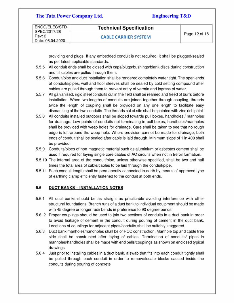
The Tata Power Company Ltd. Engineering T&D
ENGG/ELEC/STD-SPEC/2017/28 Rev: 2 Date: 06.04.2020
Technical Specification
Page 12 of 18 CABLE CARRIER SYSTEM
providing end plugs. If any embedded conduit is not required, it shall be plugged/sealed
as per latest applicable standards.
5.5.5 All conduit ends shall be closed with caps/plugs/bushings/blank discs during construction
and till cables are pulled through them.
5.5.6 Conduit/pipe and duct installation shall be rendered completely water tight. The open ends
of conduits/pipes, wall and floor sleeves shall be sealed by cold setting compound after
cables are pulled through them to prevent entry of vermin and ingress of water.
5.5.7 All galvanised, rigid steel conduits cut in the field shall be reamed and freed of burrs before
installation. When two lengths of conduits are joined together through coupling, threads
twice the length of coupling shall be provided on any one length to facilitate easy
dismantling of the two conduits. The threads cut at site shall be painted with zinc rich paint.
5.5.8 All conduits installed outdoors shall be sloped towards pull boxes, handholes / manholes
for drainage. Low points of conduits not terminating in pull boxes, handholes/manholes
shall be provided with weep holes for drainage. Care shall be taken to see that no rough
edge is left around the weep hole. Where provision cannot be made for drainage, both
ends of conduit shall be sealed after cable is laid through. Minimum slope of 1 in 400 shall
be provided.
5.5.9 Conduits/pipes of non-magnetic material such as aluminium or asbestos cement shall be
used if required for laying single core cables of AC circuits when not in trefoil formation.
5.5.10 The internal area of the conduit/pipe, unless otherwise specified, shall be two and half
times the total area of cable/cables to be laid through the conduit/pipe.
5.5.11 Each conduit length shall be permanently connected to earth by means of approved type
of earthing clamp efficiently fastened to the conduit at both ends.
5.6 DUCT BANKS – INSTALLATION NOTES
5.6.1 All duct banks should be as straight as practicable avoiding interference with other
structural foundations. Branch runs of a duct bank to individual equipment should be made
with 45 degree or longer radii bends in preference to 90 degree bends.
5.6..2 Proper couplings should be used to join two sections of conduits in a duct bank in order
to avoid leakage of cement in the conduit during pouring of cement in the duct bank.
Locations of couplings for adjacent pipes/conduits shall be suitably staggered.
5.6.3 Duct bank manholes/handholes shall be of RCC construction. Manhole top and cable free
side shall be constructed after laying of cables. Termination of conduits/ pipes in
manholes/handholes shall be made with end bells/couplings as shown on enclosed typical
drawings.
5.6.4 Just prior to installing cables in a duct bank, a swab that fits into each conduit tightly shall
be pulled through each conduit in order to remove/locate blocks caused inside the
conduits during pouring of concrete

The Tata Power Company Ltd. Engineering T&D
ENGG/ELEC/STD-SPEC/2017/28 Rev: 2 Date: 06.04.2020
Technical Specification
Page 13 of 18 CABLE CARRIER SYSTEM
6 LAYOUT REQUIREMENTS FOR THE EQUIPMENT / SYSTEM
6.1 Cable tray layout shall be as per the specification given in the preceding sections.
6.2 Cable carrier system and cable installation shall be carried out as per the cable layout
drawings approved by the owner.
7 SAFETY REQUIREMENTS
Cable trays shall be earthed at every 10 m at minimum two places by M.S. flats of minimum
size 25x3 mm (unless otherwise specified) to the purchaser’s earthing system.
8 OPERATIONAL AND MAINTENACE REQUIRMENT
8.1 OPERATIONAL REQUIRMENT
The cable carrier system shall be designed considering the following:
8.1.1 Facility for easy laying of cables.
8.1.2 Access to maintenance.
8.1.3 Neat and aesthetic appearance.
8.1.4 Safety of equipment & personnel.
8.1.5 Drainage system for oil and water
7.2 MAINTENACE REQUIRMENT
8.1.6 Identification labels as per cable layout drawings shall be provided on each cable
tray. Also cable tags shall be provided on each cable.
8.1.7 The allocation of cables to cable trays shall be done considering future
requirement.
8 TECHNICAL PARAMETERS OF EQUIPMENT
Cable tray:
Sr.no. Description Tata Power
Requirement Bidder specification
1. Name of the Manufacturer

The Tata Power Company Ltd. Engineering T&D
ENGG/ELEC/STD-SPEC/2017/28 Rev: 2 Date: 06.04.2020
Technical Specification
Page 14 of 18 CABLE CARRIER SYSTEM
9 QUALITY REQUIREMENTS, INSPECTION & TESTING (INCL. SQP & SFP)
9.1 The Quality Control Plan shall list and define in sequential order all process control
activities, inspection and tests proposed to be performed on the equipment/material
starting from component procurement and from testing stages to product dispatch. The
Quality Control Plan shall indicate and identify the applicable standards, detailed
description with diagram the procedure, acceptance criteria, extent of check and record
to be generated. This QAP shall be submitted by bidder and approved by Tata Power co.
Ltd.
9.2 All erection and installation activities shall be performed in line of approved FQP by Tata
Power.
2. Place of the manufacture
3. Material M.S. Sheet confirming to
IS: 1079 of
4. Type of tray Ladder and perforated
5. Length of cable tray 2500MM
6. Thickness of cable tray 2.0MM
7. Width of cable tray As per BOQ
8. Finish Hot dip galvanised as per
IS 2629 and IS 4759
9. Tolerance As per IS 1852
10. Galvanisation Uniformity of
zinc coating
As per IS 2633
11. Average zinc coating thickness Minimum 87 Microns
12. Purity of zinc Confirming to ISIS 209
13. Coupler plate and hardware As per project
requirement

The Tata Power Company Ltd. Engineering T&D
ENGG/ELEC/STD-SPEC/2017/28 Rev: 2 Date: 06.04.2020
Technical Specification
Page 15 of 18 CABLE CARRIER SYSTEM
9.3 All test routine test, performance test, special tests and acceptance test as per the relevant
standards specified in this specification and approved MQP shall be carried out . Minimum
shop testing requirements are specified in the attached Standard Quality Plans. All
applicable Type test report shall be submitted with the bid and shall not be older than 5
years.
Pl refer following standard quality plan and field quality plan:
Standard Quality plan FOR CABLE TRAY: TPQAIT-QAXX-00-EX-SQP-123-REV0
Field Quality plan FOR CABLE INSTALLATION: TPQAIT-QAXX-00-EX-FQP-161-REV0
Field Quality plan FOR CABLE TRAY: TPQAIT-QAXX-00-EX-FQP-130-REV0
10 PERFORMANCE REQUIREMENTS
10.1 Cable carrier system shall be designed to suitably withstand the static loading of all cables
and accessories.
10.2 Cable carrier system shall be designed so that adequate cooling shall be available for
cables to carry full load current without exceeding specified temperature rise limits.
11 SPARES AND SPECIAL TOOLS & TACKLES
11.1 MANDATORY SPARES ( NA for this package)
The spares supplied shall be strictly interchangeable with parts for which they are intended
for replacement.
The spares shall be treated and packed for long storage (minimum 5 years) under the
climatic conditions prevailing at the site.
The start-up spares shall be delivered at the site well in time before the start-up and
commissioning of the plant.
11.1.1 Start-Up Spares
The start-up spares are those spares which will be required during start-up and
commissioning of the equipment/systems, and until Final Take Over. It is the responsibility
of the bidder to supply all the necessary spares as required until the equipment/systems
are handed over to the Owner. An adequate stock of start-up spares shall be available at
the site such that the start-up and commissioning of the equipment/systems, performance
testing and handing over the equipment/systems to the Owner will be carried out without
hindrance and delay. All start-up spares which remain unused after the taking over the
sub-station shall remain the property of the Owner. The Bidder shall furnish the Schedule
of Start-up Spares.
11.1.2 Essential Spares

The Tata Power Company Ltd. Engineering T&D
ENGG/ELEC/STD-SPEC/2017/28 Rev: 2 Date: 06.04.2020
Technical Specification
Page 16 of 18 CABLE CARRIER SYSTEM
Essential spares are those considered necessary by the owner for first three (5) years of
normal sub-station operation. A list of such spares has been listed in the below mentioned
table and the same shall be included in bidder’s scope. When a particular item of spares
is indicated as `percentage', it shall be considered as percentage of total number of that
item of spares in the single equipment/system, unless specified otherwise and the fraction
shall be rounded-off to the next higher whole number. Whenever the item of spares has
been indicated as `set' the same shall mean the supply for a single equipment/system.
One set of spares for the particular equipment shall mean the total quantities of that
particular spares for a single equipment e.g., `set' of Server, set of Gateway, shall include
HMI, keyboard, mouse etc. The `set’ shall however include all components required to
replace that item of spares. The Owner reserves the right to buy any of the essential spare
parts as considered necessary.
In case during start-up and commissioning certain essential spares are used up, the same
shall be replaced within one (1) month without any commercial implications.
VENDOR shall furnish details for all essential spares as per the approved vendor
document list.
11.1.3 Recommended Spares
In addition to the spares mentioned above, the Bidder shall also furnish in his bid a list of
recommended spares with unit prices. The Owner reserves the right to buy any of the
recommended spare parts as considered necessary by him. The prices of recommended
spares shall be consistent with those of start-up/essential spares. Purchase of these spare
parts will be covered by a separate order or an amendment to the contract.
The Bidder shall provide a list of recommended spares for a period of five years from the
date of Site Acceptance Test (SAT) and confirm that the shelf-life of these spares is such
as to last for at least 7 years from the date of SAT.
The Bidder shall provide the MTBF of various components, sub-assemblies, assemblies
etc. (recommended as spares) and the relationship between MTBF and spare quantities
recommended.
The Bidder shall submit the product life cycle details of the all hardware offered under this
RFP.
The table below indicate the minimum requirement of the owner, bidder to include the
spares, which are not part of this table, but required for maintenance and upkeep of the
system
11.2 SPECIAL TOOLS & TACKLES
NA

The Tata Power Company Ltd. Engineering T&D
ENGG/ELEC/STD-SPEC/2017/28 Rev: 2 Date: 06.04.2020
Technical Specification
Page 17 of 18 CABLE CARRIER SYSTEM
12 DATA SUBMISSION BY BIDDER:
12.1 ALONGWITH BID
Following drawings and documents shall be prepared based on Tata Power specifications
and statutory requirements and shall be submitted with the bid:
Bidder shall submit following Data sheets / information along with the Technical Bid.
12.1.1 Guaranteed Technical Parameters (GTP) (in attached Excel format – Excel soft file to be
sent with Technical Bid) & in PDF
12.1.2 Quality Assurance Plan
12.1.3 General Arrangement Drawing
12.1.4 Confirmation on technical support for next 25 years.
12.1.5 Schedule of Technical Deviations
12.1.6 Project Schedule / Manufacturing & Delivery schedule
12.1.7 Valid Type Test Reports (Should not be older than 5 years of same design)
12.2 AFTER AWARD OF CONTRACT
Sr.
No. List of Drawings & Documents
Approval (A) /
Information (I)
Submission Format
ACAD Pdf
1 Overall cable Tray Layout
A Yes Yes
2
Cable Tray Section drawings with all
details
A Yes Yes
3 Guaranteed Technical Parameters
A Yes

The Tata Power Company Ltd. Engineering T&D
ENGG/ELEC/STD-SPEC/2017/28 Rev: 2 Date: 06.04.2020
Technical Specification
Page 18 of 18 CABLE CARRIER SYSTEM
4 Manufacturing Quality Plan
A Yes
5 Field Quality plan A Yes
13 ANNEXURES:
Annexure-1: Standard Quality plan FOR CABLE TRAY: TPQAIT-QAXX-00-EX-SQP-123-
REV0
Annexure-2: Field Quality plan FOR CABLE INSTALLATION: TPQAIT-QAXX-00-EX-
FQP-161-REV0
Annexure-3: Field Quality plan FOR CABLE TRAY: TPQAIT-QAXX-00-EX-FQP-130-
REV0
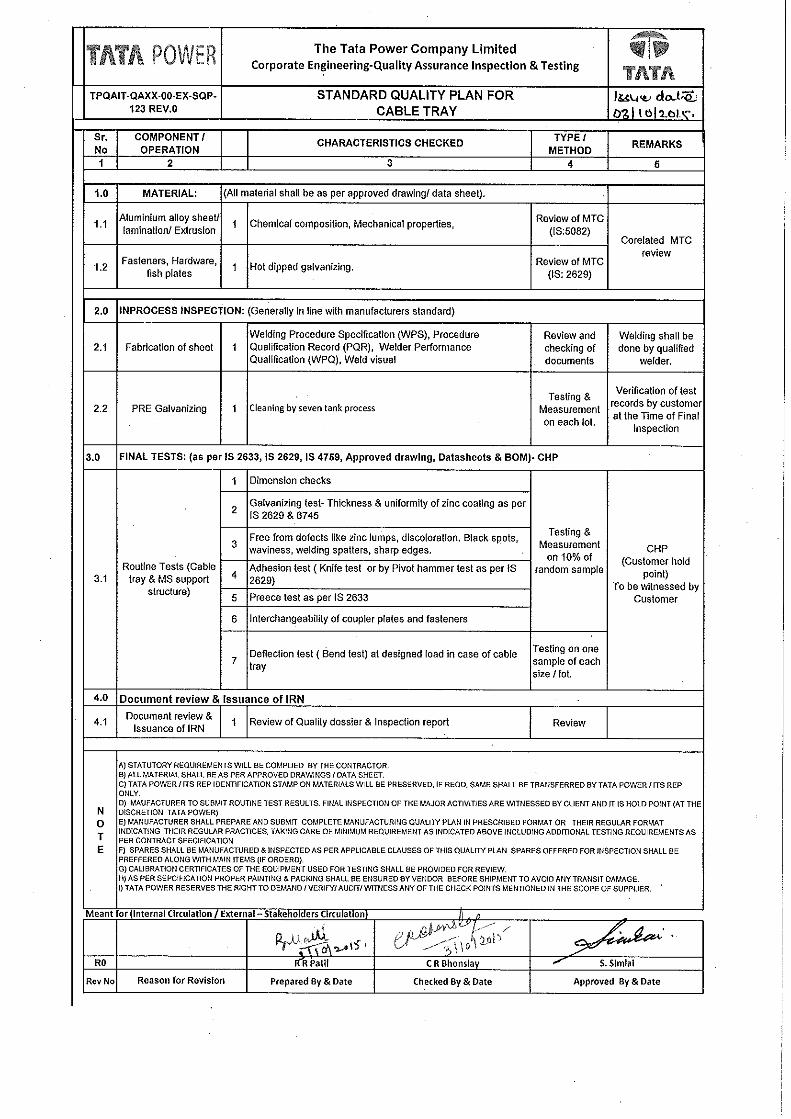
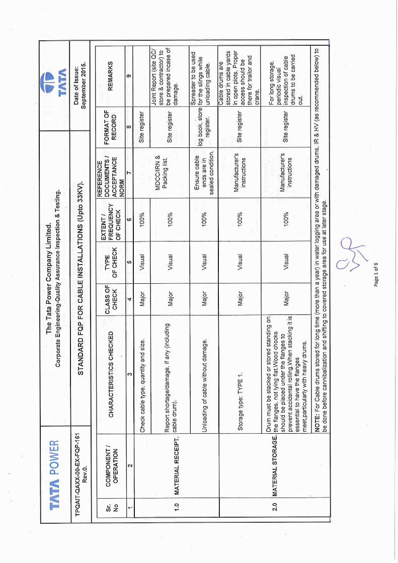


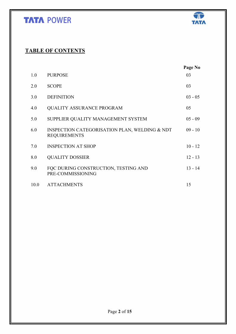
Page 2 of 15
TABLE OF CONTENTS Page No
1.0 PURPOSE
03
2.0 SCOPE
03
3.0 DEFINITION
03 - 05
4.0 QUALITY ASSURANCE PROGRAM
05
5.0 SUPPLIER QUALITY MANAGEMENT SYSTEM
05 - 09
6.0
INSPECTION CATEGORISATION PLAN, WELDING & NDT REQUIREMENTS
09 - 10
7.0 INSPECTION AT SHOP
10 - 12
8.0 QUALITY DOSSIER
12 - 13
9.0 FQC DURING CONSTRUCTION, TESTING AND PRE-COMMISSIONING
13 - 14
10.0 ATTACHMENTS
15

Page 3 of 15
1.0 PURPOSE
Purpose of these requirements is to provide uniform general requirements for implementation of Quality Management System for projects being executed by OWNER.
2.0 SCOPE
2.1 Scope of these requirement covers pre-requisites of the Bidder’s/ Supplier’s/ Contractor’s Quality Management System (QMS) applicable for all phases of contract execution including design, procurement, manufacture, testing, erection and commissioning, applicable other services and further to establish specific factors for which control shall be carried and put into continuing operation by the Bidder/ Supplier /Contractor to ensure that all supplies and services comply with the contract requirements.
2.2 The required/specified reliability & other characteristics of quality should initially be “designed in” and then “built in”. It is emphasized that satisfactory product and system performance can be achieved only through strict control of all design, manufacturing and erection/installation processes as well as test and inspection.
2.3 During bid stage itself, BIDDER shall submit requisite documents to demonstrate that as a
supplier/ contractor they have well defined and implemented QMS. They shall also establish that their QMS is taking care of their sub-supplier/agencies, and continually improve its effectiveness in accordance with the requirements of their QMS as per ISO 9001, or any other quality standard.
BIDDER shall submit a project specific organization chart defining the permanent positions responsible for QMS accompanied by a brief description of each position’s function and responsibility.
3.0 DEFINITION
OWNER Tata Power or its subsidiaries/ JV partners.
Bidder An organization/ agency, who propose to submit their offer against RFQ/enquiry floated by OWNER. Only successful bidder will be converted to supplier/ contractor on award of contract by OWNER.
Supplier / Contractor An organization referred as Supplier/ contractor, who execute the contract awarded by Contracts department of OWNER. It also covers the Agency involved in execution of site/ field activities or provides services (as a contractor) when awarded by Contracts department of OWNER. A Supplier can also be a manufacturer for part of supply for his in-house products.
Sub-Supplier/ Sub-vendor An organization, who manufactures, supplies the system or equipment or item and provides
services to the supplier. It also covers manufacturer who manufactures and supplies the equipment or its components or items to the sub-suppliers to complete the system supply. It

Page 4 of 15
should also cover the agencies which also support execution of main supplier by providing qualified manpower/ services.
Third Party Inspection Agency (TPIA)
An third party organization or any neutral agency mutually agreed, deputed for conducting inspection or quality surveillance activities on case to case basic.
Inspection Agency (IA) An organization or any agency deputed by OWNER for conducting inspection or quality surveillance activities on behalf of OWNER on case to case basic.
Inspection Categorization Plan (ICP)
This document shall categorize the Quality Plan and Inspection scope of all equipment/ items in the package. This will also include the schedule for submission and approval of all Quality related documents.
Standard Quality Plan (SQP)/ Standard Field Quality Plan (SFP) SQP shall comprise of minimum basic requirements of all tests/checks to be carried out during manufacturing to meet/ conform technical requirement. SQP may be in the form of Inspection & Test Plan (ITP)/ Technical Specification as part of Bid Document.
Similarly SFP shall comprise of minimum basic requirements of all field tests/checks to be carried out during execution of the project.
Manufacturing Quality Plan (MQP)
MQP shall comprise of all tests/ checks indicated in standard Quality Plan (SQP) and tech specifications. It shall also include any additional quality checks/ tests required as per discussions (pre & post bid) to be followed during manufacturing of particular item/ equipment.
Field Quality Plan (FQP)
FQP shall detail out the activities and steps to be performed at project site and shall be followed from receipt of material to pre-commissioning stage. FQP shall be prepared by contractor and to be submitted to OWNER at post award stage of contract for owner's approval.
Hold Point/ Customer hold point (CHP)
A check point for an activity mentioned in approved MQP/ FQP, which requires inspection/ verification, and acceptance by the OWNER or its representative for this stage before any further work is permitted. Supplier shall not process beyond a CHP without written acceptance & clearance of that activity by OWNER in writing
Witness Point
A check point for an activity mentioned in the approved MQP/ FQP, which will be witnessed by OWNER or its representative. Supplier will obtain consent from OWNER to proceed for further work, in case OWNER or its representative is not able to attend the activity within notification period.

Page 5 of 15
Review / Verification Point A check point for an activity mentioned in the approved MQP/ FQP that requires review of document/ test record by OWNER or its representative performed by the Supplier for acceptance.
Test Report Record Such reports / record are document prepared by Supplier/ Sub-Supplier for test/ check conducted indicating details / types of test including test results, relevant codes etc.
Inspection Report (IRT) Such report which covers details of all the checks / activities carried out as per approved MQP. It also covers details of the observations and NCRs during those checks / inspection.
Inspection Release Note (IRN) IRN is a document issued on standard format after successful quality checks/inspection and confirming to compliances of all observations and NCs if any).
Non Conformity Report (NCR)/ Quality Correction Action Report (QCAR) It is a report on deviation/ non-compliance with respect to the requirements laid down in the PO/ Technical Specification, MQP, Codes & standards. NCR shall be applicable during inspection at Shop as well during site Audits and QCAR shall be applicable for site inspection / surveillance.
4.0 QUALITY ASSURANCE PROGRAMME
To ensure that the equipment and services under the scope of contract whether manufactured or performed within the Bidder/ Supplier /Contractor’s works or at his sub-vendor’s premises or at site or at any other place of work are in accordance with the specifications, the Bidder/ Supplier/ Contractor shall adopt suitable project specific QMS based on his organization’s Quality Management System, regular practice, statutory requirements and as specified for this specific contract and submit the same for approval of OWNER, to control such activities at all points, as necessary. Such program shall be outlined by the Bidder/ Supplier/ contractor. Any deviation with respect to all above requirements (as specified in SQP, SFP, Technical specification as minimum quality requirements) shall be brought out clearly in the bid stage by bidder.
5.0 SUPPLIER QUALITY MANAGEMENT SYSTEM (QMS)
5.1 All materials, components and equipment covered under the contract including bought outs shall be procured, manufactured and tested at all the stages, as per a comprehensive Quality Assurance Programme. It is the Bidder/ Supplier / Contractor’s responsibility to draw up and implement such program duly approved by the OWNER.
5.2 All items/equipment in the scope of the contract shall be classified into categories according to the criticality or other attributes of items/ equipment. A detailed proposal addressing vendor approvals and quality control of all such items/ equipment shall be proposed to OWNER for approval.
5.3 The detailed quality plans for shop manufactured items and for field activities including civil works (if applicable) shall be drawn up by the Bidder/ Supplier / Contractor separately.

Page 6 of 15
All shop quality plans and field quality plans shall be submitted to OWNER for approval prior to start of manufacturing activities and site activities respectively.
5.4 Manufacturing quality plans shall detail out various tests/ inspections to be carried out as per the requirement of the specification, standards mentioned therein, quality practices and procedures followed by Supplier’s/ his sub vendor’s quality control department. MQP shall be prepared by manufacturer and submitted through supplier post award stage of contract for owner's approval. OWNER approved MQP to be referred during manufacturing & shop inspection. Typical format of Manufacturing Quality Plan is enclosed as Exhibit A.
5.5 Field quality plans shall detail out for all equipment, the quality practices and procedures etc. to be followed by the execution agency, during various stages of site activities right from receipt of materials/ equipment at site to commissioning stage covering receipt, storage, erection & pre-commissioning tests. It shall comprise of all tests / checks indicated in SFP & Technical Specification including any additional quality checks / tests required as per discussions (pre & post bid). It shall also take care of minimum basic requirement of OEM/manufacturer (as the execution agency may not be part of OEM/manufacturer). OWNER approved FQP is to be referred during execution of work. FQP shall have 5 stages: Receipt, Storage, Pre-erection/ pre fabrication, Erection/ Execution and pre commissioning checks with categorization of checks as Critical (Cr), Major (Mj) and Minor (Mn). Typical format of Field Quality Plan is enclosed as Exhibit B.
5.6 In these approved manufacturing and field quality plans, OWNER shall identify “Customer Hold Points” & “Witness Points”. “Customer Hold Points” are test/checks which shall be carried out in presence of the OWNER’s Engineer or its authorized representative and beyond which the work shall not proceed without consent of OWNER/ its authorized representative in writing. “Witness Points” are tests/checks which shall be carried out in presence of the OWNER’s Engineer or its authorized representative but the work can proceed to next operation/ stage in case OWNER’s Engineer doesn't attend on the mutually agreed date. The above procedure shall be applicable to the Bidder/ Supplier / Contractor’s bought out equipment/ items also.
5.7 All the critical & major items shall be procured from the sub-vendors approved by OWNER by supplier/vendor/contractor. Detailed list of such sub-vendors offered by supplier/vendor/contractor shall be submitted not later than 7 days after the LOI/ Placement of order whichever is earlier and shall be frozen within 15 days of submission. Request for additional sub-vendors shall not be entertained from the Bidder/ Supplier / Contractor after the sub-vendor list is finalized and frozen. Only in case of Force Majure Condition, Supplier/ contractor shall establish such condition and propose new/ alternative source. Contractor / supplier shall provide requisite documents for consideration of OWNER. OWNER has right to accept/ reject based on review of details. If required, physical assessment shall be made before conveying such decision. Delays arising out of such exercises shall be entirely to the account of Supplier/ Contractor and shall not relieve him from any obligation, duty or responsibility under the contract. For intended manufacturer/ sub-vendors/ sub-suppliers, details to be submitted are indicated below:
i. Rating, Range / type etc. of equipment/ item for proposed approval. ii. Organisational structure including QA/QC inspection dept with man power & qualification
details. iii. In house design / R&D capability. iv. List of sub-vendors for critical/ major bought out items.

Page 7 of 15
v. In-coming material inspection plan and Manufacturing Quality Plan. vi. In house manufacturing facilities, including process flows.
vii. In house Testing facilities (including Type testing). viii. Experience (Past Track Record) list for last 3 yrs for similar product.
ix. Performance certificates issued by other customers. x. Certification of/ by reputed agencies (ISO/ ASME/ CE/ UL/API/ etc) & also approval
certificates from other customers etc. xi. Quality Manual.
xii. Assessment report by contractor/ supplier and their own experience. 5.8 Non Conformance Report (NCR) / Quality Correction Action Report (QCAR)
Wherever the non-conformity is found during inspection either by Supplier or OWNER or its representatives, NCR / QCAR shall be issued in prescribed format. Manufacturer /Supplier shall indicate the Correction / CAPA and submit these NCRs/QCARs to OWNER or its representative for their review & resolution. Till such time identified item/ equipment will be kept under quarantine. Upon satisfactory completion of the rectification work, final acceptance of the item/equipment shall be documented on the NCR/QCAR format. Supplier has to close all NCR / QCAR in systematic & time bound manner including all corrective and preventive actions. Job shall progress only after effective resolution of NCR / QCAR.
Note: If OWNER observes that any material or equipment is unacceptable with respect to potential safety, reliability, interchangeability or workmanship, OWNER shall issue a non-conformance report NCR / QCAR in this regard to the Supplier/ Contractor. Such NCR/QCAR shall be dealt as above.
5.9 No material shall be dispatched from the Bidder’s/ Supplier’s/ Contractor’s /manufacturer’s works before the dispatch instruction is given in writing by the owner. subsequent to pre-dispatch inspection including verification of records of all previous tests/ inspections by OWNER/ authorized representative. Any such item/material dispatched by party without clearance from OWNER shall be at suppliers risk & cost only. No IRN/ dispatch clearance shall be issued for the same as post facto.
5.10 OWNER or its nominated representative reserves the right to carry out quality audit/ quality surveillance of the systems and procedures of the Bidder/ Supplier/ Contractor’s or their sub-vendor’s Quality Management System and control activities without prior intimation. The Bidder/ Supplier/ Contractor shall provide all necessary assistance to OWNER or its nominated representative to carry out such audit/ surveillance.
5.11 The Bidder/ Supplier/ Contractor shall be responsible for providing, controlling, calibrating, and maintaining the 'measuring & test equipment' required by them for demonstrating compliance of supplies within contract requirements at shop and at site. All the measuring instruments shall be calibrated at periodic intervals determined by Bidder/ Supplier/ Contractor/ sub-vendor on the basis of his suitability, purpose and usage as per the system adopted by him for calibration of such measuring and test equipment. However, in no case, shall the interval between successive calibrations be more than 12 months. All measuring and test instruments shall have valid calibration certificates and calibration data shall be made available to OWNER or its nominated representative on demand.

Page 8 of 15
5.12 Quality surveillance/ approval of the results of the tests and inspection shall not, however, prejudice the right of the OWNER to reject the equipment if it does not comply with the specification when erected or does not give complete satisfaction in service and the above shall in no way limit the liabilities and responsibilities of the Bidder/ Supplier / Contractor in ensuring complete conformance of the materials/ equipment supplied to relevant specification, standard, data sheets, drawings etc.
5.13 For all spares and replacement items, the quality requirements as agreed for the main equipment supply shall be applicable. Inspection of all mandatory spares and commissioning spares shall be in line with the approved MQP of respective equipment/ item.Interchangeability Certificate shall also be part of quality records for all spares. 5.14 Statutory Inspection Supplier to ensure that Equipment/ items which fall under statutory requirements of
country where the equipment will be installed, shall be inspected by statutory authority like IBR etc. In case of imported items, statutory inspection will be carried out by the agency as nominated by Statutory Authority or Statutory authority of the country of origin. Original certificates endorsed by statutory authorities shall be submitted to project manager as identified in the contract.
Such items shall also be offered to OWNER for inspection irrespective of country of origin.
5.15 Failure to Pass Tests
If any item/ equipment fail to pass any test, the Bidder/ Supplier shall rectify or replace the same and, unless OWNER agrees to dispense with repetition of the test, shall repeat the test following a further notice. The cost and expense of any such retest shall be fully borne by the Bidder/ Supplier only.
5.16 Major repair/rectification procedures to be adopted to make the job acceptable shall be subject to the approval of the OWNER/ its authorized representative.
5.17 All tests shall be carried out to the satisfaction of the OWNER/ its authorized
representative either in their presence or as agreed by OWNER. All reports/ protocols, site and shop inspection reports shall be developed specific to the requirements of the project which is acceptable to OWNER. The same shall be applicable to erection testing and pre-commissioning reports and protocols also.
Only tested, inspected and accepted (by owner) material as listed in PO / ICP shall be
dispatched to project site. Any diversion of such accepted material without any prior approval shall be considered as deviation/ breach of contract and a minimum penalty of 5 times the cost of inspection will be levied.
5.18 Approval of any concession shall be the prerogative of the OWNER and approval of
concession for a particular case shall not be set as a precedent.

Page 9 of 15
5.19 All the equipment shall be of proven design and type tested. Valid type test reports shall be furnished to engineering for review and acceptance prior to offering equipment for inspection.
5.20 All documents/ reports/ records shall be issued either in English language or bilingual with English.
6.0 INSPECTION CATEGORIZATION PLAN, WELDING & NDT REQUIREMENT
6.1 Inspection Categorization Plan (ICP) This document shall be prepared by supplier and to be submitted to OWNER for approval in attached standard format for all package items within 15 days of award of contract. The schedule shall be prepared considering that all MQP should be approved at-least 15 days prior to start of any manufacturing activity and FQP with related procedures shall be finalized at least 15 days prior to dispatch schedule/ site mobilization. ICP, MQP, FQP and related procedures shall form part of Master Drawing List (MDL) All the items/equipment in the scope of the contract shall be classified into categories (A/ B/ C) according to the criticality or other attributes of items / equipment. A detailed proposal addressing vendor approvals and quality control of all such items /equipment shall be proposed to OWNER by the Supplier/ Contractor for approval. Category “A”: Manufacturing Quality Plan (MQP) shall be approved by TATA POWER. Stage &/ or Final Inspection including document review by EPC Contractor and TATA POWER (or its appointed Inspection Agency) as per approved MQP. Category “B”: Manufacturing Quality Plan (MQP) shall be approved by Tata Power. Stage &/ or Final Inspection including document review by EPC contractor or Tata Power (in case no EPC Contractor) as per approved MQP. Inspection report of EPC contractor/ Supplier with supporting documents review by Tata Power. Category “C”: Supplier shall carry out inspection as per their regular practice/ standard manufacturing quality plan. Supplier shall submit test report and COC to EPC Contractor/ Tata Power for approval/acceptance. COC shall be in standard format of Tata Power.
6.2 Welding & Non-Destructive Testing (applicable for shop as well project site)
6.2.1 Bidder / Supplier/ Contractor shall submit the following documents in requisite copies for
review and approval of OWNER/ its authorized representative at least FOUR weeks prior to commencing fabrication/ manufacturing and finalize before start of job. All such submissions shall be made in ENGLISH language only.
i. Welding procedures together with the relevant procedure qualification records. ii. Non-destructive testing procedures.
iii. Heat treatment procedures. iv. Any other special procedure (as applicable) proposed to be used during project execution
Welding procedures and welders’ qualifications in accordance with the latest revision of ASME Boiler & Pressure Vessels Code, Section IX, (structural welding as per AWS D1.1)

Page 10 of 15
or equivalent standard covering all essential & non- essential variables shall be acceptable to OWNER.
6.2.2 Only qualified welders shall be deployed. Welders shall be qualified as per approved WPS in presence of OWNER/ its authorized representative. Electrode/ welding rod used at project site shall be of owners approved. Supplier/ Contractor shall take prior approval.
6.2.3 Weld repair procedures are subject to approval of the OWNER. No welding is permitted on C.I. Castings. OWNER reserves the right to examine and witness acceptance tests, prior to and following weld repairs and subsequent post weld heat treatment, mechanical tests etc, at the material manufacturer/ Supplier works.
6.2.4 Should any of these welds prove to be defective on inspection, the number of welds to be tested in that system shall be twice that of originally selected. Should any of the second incremental welds prove to be defective, then 100 % of the welds in that system/ group shall be tested.
6.2.5 NDT operators shall be qualified in accordance with an agreed nationally accredited scheme such as the Personnel Certification in Non-destructive testing (PCN) scheme and shall be certified to level II or higher of that system.
6.2.6 Plate thickness ≥ 32mm (for structure), Plate thickness ≥ 25mm (for pressure vessel),
Forging / Bar dia. ≥40mm (finished) shall be UT tested. 7.0 INSPECTION AT SHOP 7.1 Inspection Scope
The scope of inspection shall be as per Witness/ Hold Point as defined in approved MQP/ SQP. Supplier has to ensure that all applicable and agreed approved Drawings, Data Sheet etc. are available for any inspection and equipment used for measurement are calibrated. Supplier shall intimate all such cases in advance (as inspection rolling plan) and also through inspection call as per contract agreement.
7.2 Inspection Coordination
Supplier has to identify single point contact for coordination of the entire inspection activities on behalf of Supplier/ sub-supplier. Supplier to ensure that monthly and 3 monthly rolling inspection plan are prepared and submitted in advance to OWNER by 1st
working day of each month for effective inspection coordination. 7.3 Inspection Request 7.3.1 Depending upon the stages of inspection as agreed in manufacturing quality plan, supplier
to send Inspection Requests (in OWNER standard format & through system) to OWNER Project Manager for inspection activities to be attended at supplier’s / sub-supplier’s premises. Supplier to submit all relevant approved reference documents (MQP, Drawings/ Data Sheet etc.) along with inspection request. Supplier has to give sufficient advance notice, as defined below for inspection of any stage. The date of receipt of inspection call by OWNER will hold good.
7.3.2 The minimum advance notice period for inspection shall be given below:

Page 11 of 15
i. Inspection within INDIA : 7 Days ii. Overseas (Outside India) Inspection : 30 Days
Supplier to strictly adhere the above mentioned minimum advance notice period. 7.3.3 Supplier shall plan the inspection visits required in a manner so as to achieve maximum
inspection stages attended with minimum possible inspection visits/ time where-in more than one external inspection agencies are involved for single inspection activity, inspection by all agencies may be done concurrently.
7.4 Inspection Methodology
7.4.1 Suppliers shall ensure internal inspection before offering inspection to OWNER or its representative. Internal test certificates and previous stage inspection reports to be made available during inspection.
7.4.2 During inspection, Supplier to produce copies of the latest revision of the approved MQP along with drawings, Data Sheet, Standard and accepted type test reports as indicated in approved MQP / agreement to ensure that the inspection is carried out as per the latest revision and approved documents. If required, Supplier to arrange the necessary codes and standards for reference purposes. In case inspection cannot be completed or undertaken due to reasons such as non-readiness of material, back up documents, false inspection call etc. then such reason shall be recorded in Inspection Report. If Supplier fails to offer the item / equipment for inspection as per the agreed date, he is liable to pay for the time and expenses for the abortive visit of the OWNER or its representative.
7.4.3 All inspection related documents i.e. mill test reports, Supplier inspection/ tests reports, all
inspection/ tests carried out including other records such as stress relieving charts, radiographic reports and other non-destructive testing records in accordance with provision of contract shall be submitted in original form. All such reports shall be duly endorsed/ certified by the main supplier.
7.4.4 Results of Tests and copies of Inspection Report, Test reports, original material test
certificates (MTCs), calculations, performance curves etc. shall be promptly made available to the OWNER or its appointed representative by the Supplier, in accordance with this document and shall form part of the subsequent Manufacturers Test Record Book in accordance with the requirements of this document.
7.4.5 Supplier to ensure that all the materials are properly identified/ coded to confirm traceability and correlation purposes.
7.4.6 Supplier shall take special care including packing to protect the final painting and finish product (equipment / item) during handling, transportation, storage and execution stage so that there is no damage occur. In case of any such damage, joint inspection to be carried out at site and necessary action to be taken.
7.4.7 Supplier to ensure finish product is properly identified after completion of inspection and are suitably recorded in Inspection Report by inspection engineer.

Page 12 of 15
7.5 Inspection Report & Clearance 7.5.1 Inspection Report (IRT)
All inspection visits by OWNER or its appointed agency shall be supported by an inspection report as per the standard format (sample enclosed). Any shortcoming observed w.r.t. approved MQP/ Drawing/ Data Sheet / specification etc. shall be recorded as NCR. IRT shall have detail references of all such NCRs. All such inspection report / NCR shall be jointly signed by supplier and Inspection Engineer. IRT shall be issued to all concern including Supplier and Sub-supplier/ Manufacturer.
7.5.2 Inspection Release Note (IRN)
IRN shall be issued only after satisfactory completion of Inspection by OWNER as defined below IRN shall be issued by Tata Power (QA&I dept) thru system in the standard format as closure of particular inspection. IRN for Category 'A' item (as defined in ICP) shall be issued only after ensuring inspected Equipment / Item meets the requirements of the applicable documents and all NCs have been closed to the satisfaction of Owner. IRN shall be issued in the standard format as closure of particular inspection. Similarly for Category 'B' items (as defined in ICP) IRN shall be issued after review of inspection report, compliance report and required applicable documents as per approved MQP & Closure of NCs if any are verified and accepted to the satisfaction of Tata Power. For Category 'C' items (as defined in ICP), IRN shall be issued after review of original manufacturer test certificates, Certificate of Conformance (CoC) from supplier/contractor in Tata Power standard format and required applicable documents as per MQP approved by main supplier / as per their standard procedure are verified and accepted
7.6 Material Dispatch Clearance Certificate (MDCC) Supplier shall obtain dispatch clearance (MDCC) from Project / Plant based on IRN prior to dispatch of any billable material / equipment/ item from manufacturer place to our project site / plant. One set of Quality Dossier (hard copy) for which MDCC has been issued, shall be sent to project site along with material / equipment/ item. MDCC is not required for material / equipment/ item/ Part supply which are dispatched from one sub-supplier works to another sub-supplier/ supplier works for further assembly and testing (to make it billable). However, clearance in the form of Inspection Report (IRT) is needed in this regard.
8.0 QUALITY DOSSIER (FOR SUPPLY PORTION) [Package wise]
Supplier shall compile and submit all stage and final inspection reports as per approved MQP, duly reviewed and endorsed by inspection engineer for reference and records of OWNER. Documents shall be submitted with-in 4 weeks of issuance of final MDCC Dossier shall consist of following documents, as minimum:
i. Index Sheet ii. Approved bill of material of package.

Page 13 of 15
iii. All Approved documents (MQP, Drawings & Data Sheet etc.) iv. MDCC, IRN & IRT along with all closed NCR of all items. v. Factory Acceptance Test (FAT) reports.
vi. Raw material and bought out item MTC’s vii. Test Reports corresponding to IRT & MQP.
viii. Supplier internal inspection reports as per MQP. ix. Copy of Statutory and IBR certificates as applicable.
Note: 1. Each package compilation shall be done on the basis of unit wise and common systems. 2. Each volume/ dossier shall be spiral/ hard bounded. Each sheet of dossier to have running
numbers. 3. One hard copy (in addition to the dossier dispatch with material / equipment/ item) and 2
Soft copies of documents to be submitted as final dossier.
9.0 FQC DURING CONSTRUCTION AND PRE-COMMISSIONING. 9.1 Supplier Quality Management System is applicable for field activities also and for his
further sub agencies deputed at project / plant. Refer clause no: 5.0 (applicable part). Supplier/ Contractor shall deploy sufficient no of QA/ QC persons to take care of daily activities as per agreed/ approved Quality documents. Some of such activities are detailed below. Also QA/ QC head shall regularly co-ordinate with OWNERs FQC team.
9.2 Raising of inspection calls on regular basis for various activities as indicated in approved
FQP/ other document, carrying out inspection activities along with OWNER's execution / FQC department and maintaining the records duly signed by all concerned.
9.3 Various inspection/ quality assurance procedures/ methods at different stages of erection and
pre-commissioning will be as per OWNERs approved field quality plans/ codes/ IBR and other statutory provisions and as per OWNER’s engineer’s instructions.
9.4 Preparation of quality assurance log sheets and protocols, welding logs, NDE and post weld
heat treatment records, testing & calibration records and other quality assurance documentation as per OWNER’s engineer’s instructions is within the scope of work/ specification. These records shall be submitted to OWNER for approval from time to time.
9.5 A daily logbook of all measurements and testing/ calibration should be maintained by contractor on the job inspection details for various equipment.
9.6 All the workers of contractor / sub contractor/it's agencies shall carry identity cards as per
the Performa prescribed by OWNER. Only workers duly authorized by OWNER shall be engaged on the work.
9.7 Contractor shall provide all the measuring and monitoring devices (MMD) required for completion of the work satisfactorily. These MMDs shall be calibrated & conform to job requirement in respect of measurement range, accuracy level & any other specification.

Page 14 of 15
9.8 Re-work necessitated on account of use of invalid MMD shall be entirely to the contractor’s account. Contractor shall be responsible to take all corrective actions, including resource augmentation if any, as specified by OWNER to make-up for the loss of time.
OWNER's FQC team / QAI representative will have the right to carry out Surveillance
Audit of supplier/contractor and their agencies including their store without any prior intimation.
9.9 Regular Internal audit shall be conducted by supplier/ contractor QA/QC team of their
agencies and their other dept. Such audit reports shall be made available whenever ask for by OWNER FQC team. OWNERs FQC/ QA&I have the right to carryout 2nd party audit of supplier/ contractor and their agencies as per predefined Audit schedule.
In course of work OWNER may counter/ finally check the measurements with their own
MMDs. Contractor shall render all assistance in conduct of such counter check/ final measurements.
9.10 Communication
Direct, formal communication between the SUPPLIER’s field QC and OWNER’s field QC representative is mandatory. All inspection activities as per field quality plan shall be intimated to OWNER in the form of Request for Inspection (RFI) at least 24 hrs. in advance with intimation to OWNER execution group. Whenever any major issues / deviations related to design or fabrications are noticed, the same shall be immediately informed to OWNER's field QC by supplier’s field QC/ Supplier Project Head. On completion of above activity, joint inspection reports/ protocol shall be made and circulated to concern agencies. Any part of work at the site shall not be covered up or made inaccessible without the OWNER Representative's prior approval in the form of joint protocol or otherwise.
SUPPLIER/ Contractor’s in-progress inspection reports, log book, follow up/ punch out sheets; records of all DT & NDT etc. shall be made available to OWNER field QC during the course of the work. At the end of the work, SUPPLIER/ Contractor’s standard inspection reports, check off sheets, radiographs, master copy of loop diagrams, electrical testing data sheets, etc. shall be handed over to OWNER in an organized and agreed format. SUPPLIER/ Contractor shall verify that all of the required documentation of the equipment has been received and placed in the equipment files. The SUPPLIER/ Contractor is responsible for obtaining any outstanding documentation from his sub-supplier/ agencies.
9.11 Dealing with open Punch Points NCR/QCAR:
All open points in the form of observations, non-conformities (NCR, QCAR etc.) that are not responded / closed in time as well as, those were not put up by supplier/ Contractor for resolution/ agreement to OWNER, the same will be considered as violation of contractual obligations and will be dealt suitably during closure of contract. Penalty clauses (if any) shall be applicable as per contract.
Supplier/ Contractor’s Performance rating will be impacted as per prevailing policy of OWNER in this regard.
Page 15 of 15
10.0 ATTACHMENT
1. Exhibit A – MQP Format 2. Exhibit B – FQP Format 3. Exhibit C – Shop Inspection Request Format 4. Exhibit D – ICP Format 5. Exhibit E – IRN Format 6. Exhibit F – Suggested MDCC Format 7. Exhibit G – RFI Format (For Site Inspection Request) 8. Exhibit H – NCR Format 9. Exhibit I – QCAR Format 10. Exhibit J – Weekly Progress Report format


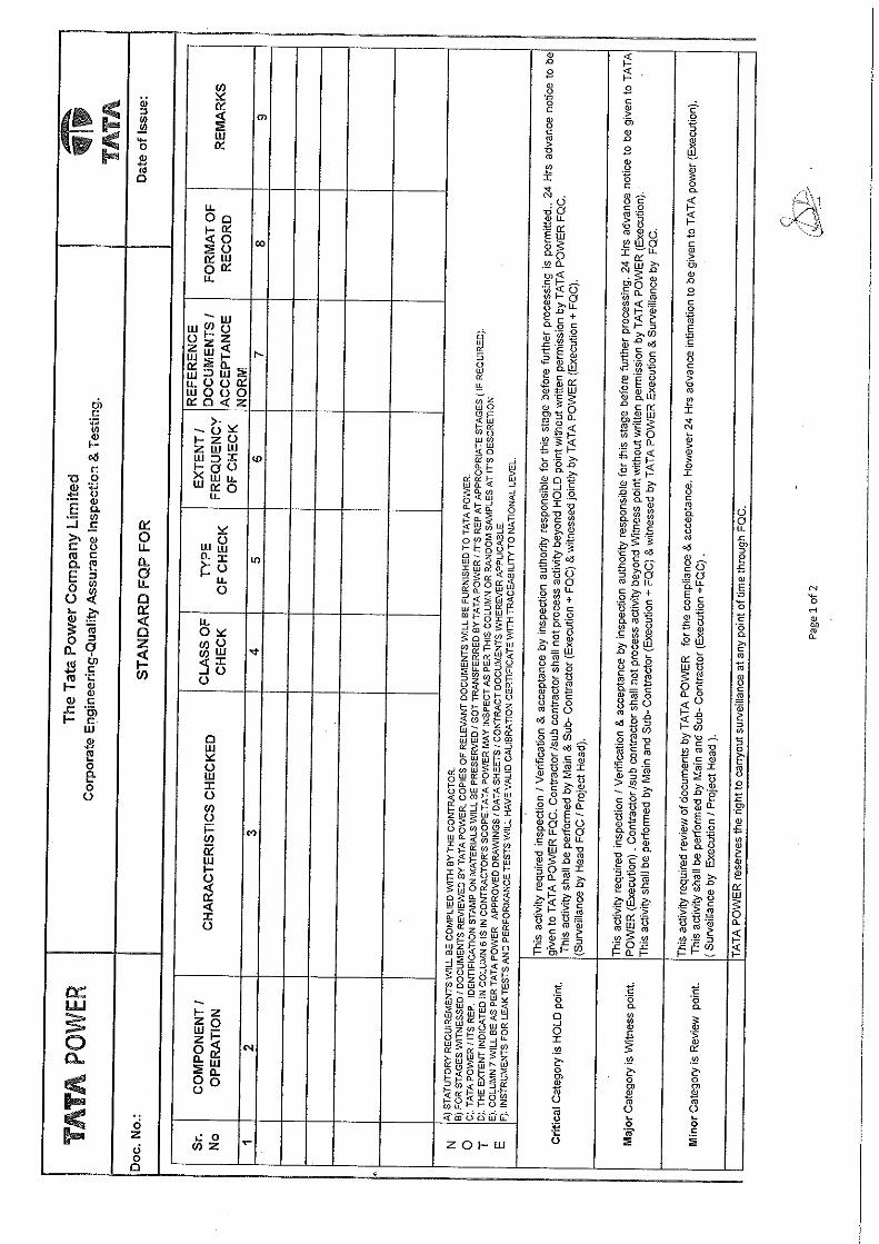


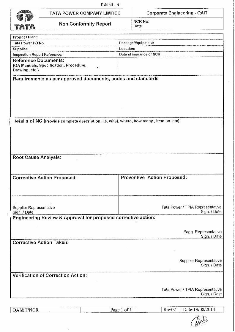


The Tata Power Company Ltd. Engineering T&D
TE00xx/xxx/21 Rev: R0 Date:12/03/2021
Specification for Substation Automation System Page 1 of 66
22kV Switchgear at Kolshet RSS
SECTION B
CHAPTER - B2.3-B
TECHNICAL SPECIFICATION
FOR
“Sub-station Automation System”
Rev. No
Date Revision History Prepared By Checked
By Approved
By
R0 24-03-2021 Final release VS RSM BSP

The Tata Power Company Ltd. Engineering T&D
TE00xx/xxx/21 Rev: R0 Date:12/03/2021
Specification for Substation Automation System Page 2 of 66
22kV Switchgear at Kolshet RSS
Contents
Sr. No. Description Page no.
1.0 Introduction 3
2.0 Approved Vendor List and Qualifying Requirements
2.1 Approved Vendor List 3
2.2 Bidder Qualifying Requirements 3
3.0 System Description and Scope 4
4.0 Codes & Standards 9
5.0 Design Requirements 11
6.0 Layout Requirements for the Equipment / System 12
7.0 Operational, Maintenance and Training Requirements
7.1 Operational Requirements 14
7.2 Maintenance Requirements 14
7.3 Training Requirements 16
8.0 Technical Parameters of Equipment (incl. Data Sheet) 32
9.0 Quality Requirements, Inspection and Testing (incl. SQP & SFP) 33
10.0 Performance Requirements 38
11.0 Spares and Special Tools & Tackles 39
12.0 Data Submission by Bidder
12.1 Along with Bid 41
12.2 After Award of Contract 48
13.0
Annexures
Annexure – I List of Preferred Vendor 51
Annexure – II Indicative Bill of Material 53
Annexure – III Reference Input / Output List 54
Annexure – IV Standard Quality Plan (Separately attached ) 66

The Tata Power Company Ltd. Engineering T&D
TE00xx/xxx/21 Rev: R0 Date:12/03/2021
Specification for Substation Automation System Page 3 of 66
22kV Switchgear at Kolshet RSS
1.0 INTRODUCTION
Tata Power Company Limited (Tata Power) hereinafter called the "OWNER" or "PURCHASER",
proposes augmentation work at various Receiving Station (RSS) as mentioned in the RFP.
Bidder shall refer the entire project specifications to understand the execution methodology and
interface equipment specification for the complete scope of work of this project. Bidder shall
offer the Substation Automation System (SAS) Supply & Services accordingly.
The document covers the specific requirements for complete design, detailed engineering,
installation, Integrated testing and commissioning of Substation Automation System as per
following
a. Substation Automation System for 22kV System at Kolshet RSS.
b. Integration of Auxiliaries and other systems (if any) mentioned in the RFP.
All equipment, system and services covered under this specification shall comply with all current
applicable statutory regulations and safety codes in the locality where the equipment is
proposed to be installed. The equipment and systems shall also conform to the latest version
of applicable codes and standards on the date of offer made by the Bidder, unless otherwise
indicated. Nothing in this specification shall be construed to relieve the Bidder of this
responsibility
2.0 BIDDER’S QUALIFICATION REQUIREMENTS & APPROVED VENDOR LIST
2.1 Approved Vendor List for Purchaser
Following Automation System Manufacturers are approved for supply and installation of Sub-
Station Automation System.
a. M/s Siemens India Limited
b. M/s ABB India Limited
c. M/s GE (T&D) India Limited
Purchasers preferred list of vendor / sub vendor / OEM (Refer Annexure-I List of Preferred
Equipment’s), which is shared as part of Technical Specifications and the same should be
adhered by the bidder.
2.2 Bidder’s Qualifying Requirement
Bidder must meet all following qualifying criteria for Substation Automation Systems:
a. The bidder should have supplied minimum 20 nos. Protection, Automation and Communication
systems for 110 kV and above sub-stations with at least 10,000 Input-Output Points (of Gateways)
for each project. The system supplied should have been in satisfactory commercial operation for
a minimum period of 05 years as on scheduled date of the bid opening. Bidder shall offer latest
software on open architecture and should have supplied these at least for 5 projects in last 2
years. Protection and Sub-Station Automation must be from the same OEMs.

The Tata Power Company Ltd. Engineering T&D
TE00xx/xxx/21 Rev: R0 Date:12/03/2021
Specification for Substation Automation System Page 4 of 66
22kV Switchgear at Kolshet RSS
b. Indian Subsidiaries of global companies having plant in India are also eligible to bid if the
qualification requirements stated above are met independently or in combination with the parent
company. Declaration from parent company needs to be submitted.
c. Bidder must be OEM of protection relays, Sub-station Automation and Communication system,
having manufacturing and testing facility in India.
d. The bidder shall submit Type test reports obtained from NABL/ International Accredited Lab for
the equipment / material offered. The type tests should have been conducted on the equipment /
material of the same design. The type tests should have been conducted within 5 years prior to
the date of bid opening. Time period for type test may be extended by another 5 years as a
special case, if there is no change in design / material of construction (MOC).
e. In case the type test reports furnished are not for the quoted equipment / material but for the
equipment / material with higher voltage class and/or different capacity, then type test shall be
carried out for the offered equipment / material from NABL / International Accredited Lab without
any cost implication to the owner and the Type Test reports shall be submitted before despatch
of the equipment / material.
f. EPC Experience (if applicable), In case the package involves installation & commissioning of the
equipment / material, then the bidder shall have the following experience:
a) He should have successfully completed one single order of value XXX INR (80% of estimated
value of similar work in last three years) OR
b) He should have successfully completed two single orders of value XXX INR (50% of estimated
value of similar work in last three years) OR
c) He should have successfully completed three single orders of value XXX INR (40% of
estimated value of similar work in last three years).
3.0 SYSTEM DESCRIPTION AND SCOPE
The scope of work shall include but not be limited to the following:
3.1 The BIDDER shall consider scope for design, engineering, manufacture, procure, inspect/test
at manufacturers works; deliver to the site, do erection, installation and testing, commission
and hand over of a complete Substation Automation System (SAS) based on IEC61850
standards along with all its components and auxiliaries as described in sections below,
integrations with other existing / third party systems etc. including integration of Protection
IEDs, condition monitoring devices with Gateway to Purchaser's SCADA Systems on IEC104
protocol.
The scope of SAS includes, in minimum, the following:
a. Station Gateway
b. Ethernet Switches

The Tata Power Company Ltd. Engineering T&D
TE00xx/xxx/21 Rev: R0 Date:12/03/2021
Specification for Substation Automation System Page 5 of 66
22kV Switchgear at Kolshet RSS
c. Networking accessories viz. panel for SAS, LIU, 4 Port I/O boxes with Quad face plates with
accessories, RJ45 connectors, Patch panels with cable guard/messenger, FO & CAT6 patch
chords, FO & CAT6 armoured & unarmoured cables, RS485 armoured & unarmoured
communication cables etc.
d. Redundant Gateway system with Layer-3 Switches for SAS
e. System management Software’s and tools
f. Other components and accessories, hardware, software and firmware, to interconnect and
integrate the above items into a common fully functional system.
g. Spares
3.2 The offered SAS system/solution shall be from single OEM and the entire automation products
shall be from the same OEM family/ same SAS product series. Bidder cannot offer multiple
product from Same OEM/multiple vendor to meet the design requirement.
3.3 The BCPU proposed for 33 kV system shall be mounted on the GIS Switchgear and shall be
integrated to the existing/proposed SAS redundant Gateway's on IEC 61850. The BCPU shall
have redundant built-in Fiber Optic port.
3.4 In case of RTU based Gateway, The Gateway shall have dedicated redundant processors for
Upstream communication(IEC104) & redundant processor for downstream communication
(IEC61850) for each Bus-section . Bidder has to convert the hardware & port in the BOM to
meet the same functionality in case of IPC Gateway.
3.5 Redundant communication network switches to be used for redundant Gateway system, each
redundant communication network shall be capable of handling the entire 22kV/33kV system
communication traffic.
3.6 Bidder shall consider Ethernet switches, Cables, Termination boxes, Patch cords and other
networking accessories accordingly in their scope. Bidder shall consider the communication
equipment either in the protection panel or in a separate network Panel (2200x800x800mm).
The same shall be finalized during detailed engineering.
3.7 Protection relays will be time synchronized with new GPS receiver as mentioned in the BOM.
3.8 Bidder to note that PRP/HSR communication architecture will be finalized during detailed
engineering. Bidder to submit the technical offer accordingly.
3.9 The gateway configurations (Own and Third-Party Gateway) shall be done in such a way that
the system shall report to four independent redundant masters (Unified SCADA, Emergency
Control Center, Nodal SCADA, Quality Assurance System) on IEC60870-5-104.
3.10 Multifunction meter shall be installed on the switchgear panel with necessary CT, PT and
communication wiring, termination and power supply through MCB’s. Integration of
multifunction meter on Modbus protocol to redundant Gateway. Bidder to consider separate
MFM for Bus PTs, these MFM shall be mounted along with Bus-coupler bay BCPUs.

The Tata Power Company Ltd. Engineering T&D
TE00xx/xxx/21 Rev: R0 Date:12/03/2021
Specification for Substation Automation System Page 6 of 66
22kV Switchgear at Kolshet RSS
3.11 Power supply arrangement for the individual BCPU, RTU Racks, Gateways, DI, DO, AI & MFM
shall be through separate MCBs.
3.12 Scope of Protection IEDs (BCPU) integration includes all networking accessories and
communication cables supply, laying & looping of the devices to the respective Gateways.
Depending on the Bus-sections and GIS panel layouts the BCPUs shall be integrated through
independent L2 switches for reliability & redundancy.
3.13 Bidder to ensure adequate space in the GIS (shall consider dummy panel) to mount the
communication accessories including network switches and power supply arrangement for
integration of BCPUs and MFM with redundant Gateway.
3.14 It is proposed that the bidder shall visit each site before bidding. Bidder is responsible for
studying the existing automation and communication system at each location (under
consideration) of TATA power and offer technical solution accordingly. Any additional
hardware, software and services required will have to be considered by the bidder in Scope of
supply and services. In case, any additional hardware, software and services are required
during detailed engineering and execution, it is bidder’s responsibility to meet all such
requirement at no additional cost to purchaser.
3.15 Switches/LIU shall be distributed Bus-section wise as per the approved Single line diagram
and GIS layout. A separate switch panel shall be considered for mounting of the networking
accessories in case of space constraint in the switchgear or non-availability of dummy Panels.
The switch panels shall be adjoined at either side of the 33 kV Switchgear as per final GIS
layout. Bidder to submit the communication architecture accordingly with all required
communication and functional redundancy, number of switches and other communication
accessories for purchaser’s review and approval.
3.16 Integration of proposed BCPUs with existing Disturbance Record Collector Cum Analyzer
(DRCA) systems at Station level as well as Purchaser's centralized DR system. The technical
scope includes Auto DR, Relay parameterization, configuration management, fault record
collection & analysis.
3.17 All necessary hardware, software or any other item required and not covered in the RFQ &
BOM for successful commissioning of the Sub-Station Automation system; shall be arranged
and supplied by the Bidder as a part of the scope adhering to the quality norms as per the
direction and the satisfaction of the Purchaser.
3.18 Bidder shall consider Services from DRCA OEMs for configuration, testing & integration at local
& Central system.
Sl.no Station Name DRCA Make & Model
1 Kolshet Kalkitech & Syn3000& RAS

The Tata Power Company Ltd. Engineering T&D
TE00xx/xxx/21 Rev: R0 Date:12/03/2021
Specification for Substation Automation System Page 7 of 66
22kV Switchgear at Kolshet RSS
Table-1
3.19 All terminal blocks (output contact from Aux.relay) shall be mounted vertically, links when
dropped should isolate the control circuit and the field cables will be connected at the bottom
of the terminal block. Bidder shall consider the suitable size of Cable Trough (Both vertical &
horizontal) and routing accordingly. The Cable trough should have minimum 50% free space
to cater the field cables.
3.20 It is bidder responsibility to design the panels and propose to Purchaser considering all
maintenance aspects viz. free access to the equipment, removal during repair/failure, Field
wiring/cabling. Also, Bidder should also take care the Equipment wiring, routing of cable, wiring
from equipment to Terminal blocks etc. with enough length and appropriate lugs & appropriate
labels for equipment & Cable identification.
3.21 Bidder shall ensure the Segregation of network (VLANS) with proper configuration, inbound
and outbound network filtering on all the interfaces. Separate network shall be established for
each function defined in the specification and including protection System.
3.22 Bidder shall provide all the necessary cables, termination kits and accessories for
commissioning of Sub-Station Automation system. Cable supply, laying and termination for
powering up and networking of the supplied equipment’s and connectivity to the Masters (within
the premises).
3.23 All FO/CAT6 cables for inter and intra panel shall be armored/unarmored for integration of
IEDs.
3.24 All Inter panel wiring shall be through cable conduit. All FO patch cords shall be ruggedized.
3.25 Bidder shall submit single Signal list (I/O list) and ICS for Substation Automation for the entire
station. The ICS shall include details of either ends terminal numbers, cable type, cable size
etc.
3.26 Bidder shall consider and supply the Universal IEC61850 configuration tools for configuration,
parameterization, maintenance and troubleshooting of offered IEDs and gateway.
3.27 All software supplied shall be licensed and shall be in the name of the Owner. Bidder should
offer the latest software & Firmware of the SAS products including 3rd party products which is
tested and proven. Bidder shall provide all documentation in soft/ hard form about licensing
information for each software supplied (OS, application software’s of IED, other Application
software’s, configuration, diagnostics, simulation & testing tools).
3.28 Bidder to submit the architecture drawing and indicative bill of material along with the offer.
3.29 Demonstration / Testing of the fully configured system at Bidder’s works before dispatch of the
system at site (FAT). The factory inspection shall be integrated FAT of protection, automation
and communication system of automation at a common workplace. FAT will be conducted as
per the FAT procedure document to be submitted by the bidder during detailed engineering
and approved by Owner after review.

The Tata Power Company Ltd. Engineering T&D
TE00xx/xxx/21 Rev: R0 Date:12/03/2021
Specification for Substation Automation System Page 8 of 66
22kV Switchgear at Kolshet RSS
3.30 Installation, testing & commissioning of the system including integration and configuration with
Purchaser’s existing systems, sub-vendors’ systems & other systems and performance.
3.31 Submission of technical documentation related to design, construction/as built, testing,
operation & maintenance of the equipment and submission of Test Reports, job progress
reports etc. in hard copies (4 sets) and soft copies (3 sets, in PDF & AutoCAD).
3.32 Bidder to consider recommended and mandatory spares for all supplied items as mentioned in
the separate section.
3.33 Development of system database, schemes and interlock logic etc. in BCPU & SAS system at
bidder's works/at site is in the scope of the bidder.
3.34 IRF of each BCPU will hardwired to the existing Misc RTU. The IRF signals shall be aggregated
either in dummy panels/Bus-riser panels & further taken as a hardwired to existing Misc RTU
Panel. IRF signals for SAS devices in Gateway panel to be wired & bought on terminal blocks
inside Gateway & MISC RTU panels being considered.
3.35 Site Acceptance Test (SAT) to the Purchaser’s satisfaction (as per the SAT document
submitted by the bidder during detailed engineering and approved by the owner after review)
with the completion of the following, in minimum:
a. Testing of the proposed Sub-Station Automation System from the Purchaser’s SCADA
systems.
b. Demonstration of system response
c. Integration of all supplied equipment under the contract.
3.36 Supply of recommended and mandatory spares for all supplied items as mentioned in the
separate section.
3.37 Bidder shall provide 5 years of warranty for the supplied Substation Automation products
including the 3rd party items viz. Ethernet Switches, Convertors, GPS system etc., Bidder shall
consider the scope for warranty as specified in the specifications & share the warranty details
including third party items as specified above
3.38 Maintenance of the system during warranty period and post warranty maintenance as
specified. Providing software upgrades and modifications.
3.39 Any interoperability issues/integration issues arising during commissioning and during warranty
period, bidder shall undertake to resolve them within 2 months (maximum) period without any
cost implication to the Purchaser. In case the issue persists more than 2months, Purchaser
shall have right to take any action (either alternate technical solution suggested by Purchaser
or Commercial implications) on the vendor.
3.40 Indicative I/O list, Bill of material and Data sheets attached in this specification are only as a
reference for bid purposes. Details provided in these documents are minimum requirement of

The Tata Power Company Ltd. Engineering T&D
TE00xx/xxx/21 Rev: R0 Date:12/03/2021
Specification for Substation Automation System Page 9 of 66
22kV Switchgear at Kolshet RSS
the purchaser. It is the responsibility of the bidder to meet the functional requirement as
specified in the specification.
3.41 Unless specified otherwise, Bidder shall consider the products of quality, industrial grade &
reputed make with replacement warranty, spares availability & maintenance support as per this
specification document which applies for all SAS items.
Bidder shall note that, it is not the intent of this specification to specify completely
herein, all details of design & construction of Sub-Station Automation system. However,
the bidder shall include and supply the required material and resource at any stage of
the project for successful and complete commissioning of the system.
4.0 CODES AND STANDARDS
The design, manufacture and performance of the Sub Station Automation System shall comply
with all the requirements of the latest editions of international codes and standards applicable.
Nothing in this specification shall be construed to relieve the Bidder of this responsibility.
Emissions Standards
1 EN55011 (CISPR 11) ISM RF Equipment – Electromagnetic Disturbance
Characteristics
2 60255-25 Electromagnetic emission tests for measuring
relays and protection equipment
3 61000-3-2:2000 EMC-Limits for harmonic current Emissions.
4 61000-3-3:1994+2001
EMC Limits-Limitations in voltage changes, voltage
fluctuations and flicker in public low-voltage supply
systems.
Immunity Standards
1
61000-4-2 1995-01
60255-22-2
IEEE C37.90.3
Electrostatic discharge (ESD) immunity test
2
61000-4-3 1998-11,
60255-22-3
IEEE C37.90.2 (10V/m)
Radiated, radio-frequency electromagnetic field
immunity test
3
61000-4-4 1995-01,
60255-22-4, IEEE
C37.90.1
Electrical fast transient/burst immunity test
4 61000-4-5 1995-02 Surge immunity test
5 61000-4-6 1996-03 Immunity to conducted disturbances, induced by
radio-frequency fields

The Tata Power Company Ltd. Engineering T&D
TE00xx/xxx/21 Rev: R0 Date:12/03/2021
Specification for Substation Automation System Page 10 of 66
22kV Switchgear at Kolshet RSS
6 60255-22-6 Electrical fast transient/burst immunity test
7 61000-4-81993-06 Immunity to power frequency magnetic fields
8 61000-4-12 Oscillatory waves immunity test
9 1995-05, 60255-22-1,
IEEE C37.90.1 (Damped Oscillatory and Ring wave)
Safety
1 61010-1 Harmonized Safety Standard
2 60255-5 2000-12 Insulation coordination for measuring relays and
protection equipment- Requirements and tests
Power Supply Standards
1 61000-4-11 1994-06 AC Power supply interruptions
2 61000-4-16 1998-01 Immunity to conducted, common mode
disturbances.
3 61000-4-17 Ripple on D.C. power supply
4 61000-4-29+2000-08,
60255-11
Voltage dips, short interruptions & voltage
variations on D.C. input power port immunity test
Environmental Standards
1 60068-2-1 1994-05 Environmental Testing Cold
2 600068-2-2 1974 Environmental Testing Dry Heat
3 60068-2-6 1995-03
60255-21-1
Environmental Testing Vibration tests (sinusoidal)
4 60068-2-27 1987 Environmental Testing Shock
5 60068-2-29 1987 Environmental Testing Bump
6 60068-2-30 1980 Environmental Damp Heat cyclic (12+12 hour cycle)
7 60068-2-31 1969 Environmental Testing Drop and Topple
8 60255-21-2 Shock and bump tests
Communication Standards
1 61850-3
IEEE 802.3 CSMA/CD
Substation Comm. Standard access method and
physical layer specifications
Cyber Security Standards
1. IEC62351 Security in Automation Systems

The Tata Power Company Ltd. Engineering T&D
TE00xx/xxx/21 Rev: R0 Date:12/03/2021
Specification for Substation Automation System Page 11 of 66
22kV Switchgear at Kolshet RSS
2. IEC 62443
Cybersecurity standards are multi-industry
standards listing cybersecurity protection methods
and techniques
3 Standards NCIIPC, CERT-IN Guidelines, IS027001
The proposed automation system shall be multifunctional, designed in accordance with
applicable International Electro-technical Commission (IEC), Institute of Electrical and
Electronics Engineer (IEEE), American National Standards Institute (ANSI), and National
Equipment Manufacturers association (NEMA) standards, unless otherwise specified in this
Technical specification. In all cases the provisions of the latest edition or revision of the
applicable standards in effect shall apply.
5.0 DESIGN REQUIREMENTS
5.1 The Substation Automation System shall be designed such that it facilitates both local and
remote monitoring with priority for remote monitoring. The Substation automation system shall
enable complete unmanning of the sub-station and allow for complete remote monitoring and
control from Purchaser’s Power System Control Center (PSCC)
5.2 The Automation system design shall be based on distributed architecture with central
monitoring and control in line with existing Unified SCADA and SAS implemented across
Purchasers sites.
5.3 The systems shall be State-of the art system; based on IEC61850 standards for operation under
electrical conditions present in high-voltage substations.
5.4 All SAS components supplied as a part of this specification shall be industrial grade suitable for
24x7 operations and equipment shall be selected accordingly by the bidder.
5.5 Bidder should offer the latest software, firmware of the equipment including 3rd party products
which are tested, proven and in service.
5.6 The offered product shall comply to all open protocols such as IEC 61850, C37.94 ( Tele-
protection), etc. and compatible with all other OEM's products. Any interoperability issues
arising during commissioning and during guaranty period, bidder shall undertake to resolve
them within 2 months (maximum) period.
5.7 The Bidder shall follow the latest engineering practices & ensure compatibility requirements,
continuity of equipment supply and the safety of the personals. All required safety interlocks
and fail-safe logics shall be incorporated in the system wherever required.
5.8 Redundancy shall be ensured in terms of processor, ports and path of communication to ensure
reliability & availability. There shall be no single point of failure in the system until specify as
non-redundant in the specification .

The Tata Power Company Ltd. Engineering T&D
TE00xx/xxx/21 Rev: R0 Date:12/03/2021
Specification for Substation Automation System Page 12 of 66
22kV Switchgear at Kolshet RSS
5.9 All substation automation system shall be designed with ungrounded 48VDC redundant power
supply. However, Using of AC-DC Converter (UPS to 48VDC) and or DC-DC Converter (Station
Aux to 48VDC) or direct 48V DC shall be finalized during detailed engineering.
5.10 All Automation Panels shall be provided with redundant Diode OR-ing units or other scheme
which meets functional & O&M requirements and DC-DC converters (Shall be finalized during
detailed engineering).
5.11 All protection and automation system shall be time synced and shall have the same reference
time i.e. from the station GPS. The station GPS shall have multiple SNTP/ NTP ports to
synchronize the systems.
5.12 The system shall be designed such that maintenance, modification or extension of components
shall not cause a shutdown of the whole system.
5.13 The system shall be self-healing without human interventions. Self-monitoring of components,
modules and communication shall be incorporated to increase the availability and the reliability
of the equipment and minimize maintenance.
5.14 The systems shall be modular in nature and shall be capable for expansion to meet future
requirement.
5.15 The substation automation system shall be designed and implemented using the best Cyber
Security practices. The system shall provide in minimum the following features viz.
Authentication, Authorization, Audit Trails, Network segregation, backups, ports hardening,
virus/malwares/ransomware prevention, intrusion prevention and detection.
5.16 All Automation Panels will have Louvers & Fan arrangement (min.2 nos). The Panel shall be
either front Swing frame or front fixed and the rear side shall be double door type. The Panel IP
class shall be IP55.The Panel shade shall be Siemens Grey (RAL 7032).
5.17 22kV/33kV system
a. Each Switchgear will have Bay control & protection unit (BCPU) and shall be integrated to
22kV/33kV Gateway on IEC 61850 protocol.
b. Physically independent redundant communication networks shall be considered Bus-section
wise. Adequate switches at BCPU end along with panels/mounting arrangements shall be
considered
c. All these independent networks shall be connected to the switches in the Gateway panel.
d. The Gateway shall have separate ports for communication to the Automation WAN (Station L3
switches).
e. The Gateway configurations shall be done in such a way that the system shall report to four
independent redundant masters (Unified SCADA, Emergency Control Center, Nodal SCADA,
Quality Assurance System) on IEC60870-5-104 Protocol.

The Tata Power Company Ltd. Engineering T&D
TE00xx/xxx/21 Rev: R0 Date:12/03/2021
Specification for Substation Automation System Page 13 of 66
22kV Switchgear at Kolshet RSS
f. All DI signals shall be terminated in knife edge type TBs CKT4U or equivalent. For DO signals
stud type droppable links (CBT4U or equivalent) shall be used.
5.18 Disturbance Recorder Collector and Analysis system (DRCA)
a. All BCPUs shall integrate to existing DRCA system through the Bay level switches/Network
Panel.
b. The Station DRCA shall become part of the Centralized DRCA system to enable automatic
downloading of DR files and remote parameterization.
5.19 Safety in Design:
a. All IED viz. RTU, BCU, BCPUs,Gateway shall have Select before execute for equipment control,
Single command execution at a given time for equipment control
b. All required safety interlocks and fail-safe logics shall be incorporated in the system wherever
required.
c. Feedback of the equipment before and after control, in absence of equipment status feedback,
controls are blocked
d. Control Command time out in case of long ideal state. All Control commands shall de-energised
in case of re-booting the RTU/BCU/Gateway.
e. Disconnected Terminal blocks for safety isolation, Control command links shall be vertically
mounted, Series contacts used in Aux. relays for equipment Control.
f. Ensuring Breaking mechanism (Fuse, MCB) in all equipment Schematic in case of abnormal
conditions.
g. Opto-coupler isolation for all DI/DO/AI cards
h. Selection of Panel with appropriate IP Class – (e.g. IP54 (dust-proof with rodent protection))
i. All materials used in the enclosures including cable insulation or sheathing, wire troughs,
terminal blocks, and enclosure trim shall be made of flame-retardant material and shall not
produce toxic gasses under fire conditions.
j. Equipment’s should comply to Cybersecurity aspects required under SAS.
6.0 LAYOUT REQUIREMENTS
6.1 All systems shall be installed based on the approved equipment layout and plot plan.
7.0 OPERATIONAL AND MAINTENANCE REQUIRMENT
7.1 OPERATIONAL REQUIREMENTS
a. The system shall be user-friendly and suitable for remote operations and control from
existing/new Unified SCADA system.

The Tata Power Company Ltd. Engineering T&D
TE00xx/xxx/21 Rev: R0 Date:12/03/2021
Specification for Substation Automation System Page 14 of 66
22kV Switchgear at Kolshet RSS
b. Any failure or disturbance in the substation shall be annunciate to PSCC via the SCADA system
as per Tata Power’s operation philosophy.
c. The system shall facilitate safe and secure operations of all the equipment.
d. Wherever local and remote operations are possible, selector button shall be made available both
in local as well as remote. The selection of local/remote mode of operation shall be reported to
the SCADA system.
e. Proper Rating of MCB, Power supply Units, Converters etc, to be selected. Appropriate &
suitable lugs, wires and terminal blocks to be selected during design of Panel & Equipment.
f. Opto-coupler isolation for all DI/DO/AI cards along with LED indication for each input & Output
7.2 MAINTENANCE REQUIREMENTS
a. Bidder shall provide facilities for carrying out online and offline maintenance of the components
supplied as a part of the system. In general, this should include adequate testing equipment,
tools, safety devices and other accessories. Bidder shall provide the details in their bid.
b. Bidder should provide Maintenance strategy of the product being offered so as to schedule
appropriate timeline for maintenance. maintenance along with comprehensive checklist
depicting checkpoints for software & hardware maintenance inclusive of third party products
offered along with SAS solution.
Warranty :
a. Bidder shall warrant that the equipment including software, hardware, firmware and associated
documentation are free of defects in material and workmanship and from defects or faults in
design, in so far as the equipment fails to meet the requirements of this technical specification,
bidder to adhere to the warranty of 60 months from the date of final acceptance by the Tata
Power after completion of 30 days trouble free operation.
b. With respect to defects in equipment part, Bidder’s liability is to make good either by repairing or
replacing the faulty equipment (prefers a replacement by Purchaser). It is the responsibility of
the Bidder to replace the faulty equipment in warranty within 7 working days. In case any
failure of equipment which affects operations, Bidder shall arrange for stop gap/interim
hardware/equipment arrangement to Purchaser’s operational requirement till the defective
material is getting repaired/replaced.
c. After replacement of the faulty equipment, the purchaser shall return parts that are defective to
the Bidder. The Bidder shall cover the cost associated with the shipping of defective or failed
items during warranty period. The new equipment, parts shall be delivered to the purchasers
facility CIF (Cost, Insurance, and Freight) free of charge.
d. During the warranty period, the bidder shall upgrade the firmware of the modules with the latest
available. This activity shall be carried out free of cost at site as and when the patches are

The Tata Power Company Ltd. Engineering T&D
TE00xx/xxx/21 Rev: R0 Date:12/03/2021
Specification for Substation Automation System Page 15 of 66
22kV Switchgear at Kolshet RSS
released. Sample testing for the operation of devices and associated equipment shall be carried
out after the Up gradation of any software upon agreed by the purchaser.
e. With respect to software, the Purchaser will notify the problem to the Bidder, including a detailed
description of the deficiency and associated condition. Bidder shall guide the purchaser for
corrective action. If the same is not resolved, the Bidder shall depute his personnel to attend the
same within 24 hours from the time of reporting the problem. The system Bidder shall be fully
responsible to resolve hardware and software deficiency reported by the purchaser.
f. With respect to third-party software and consumable parts supplied, the Bidder shall make
reasonable effort to obtain the best warranties possible from the sub-Vendor thereof and
assign to the purchaser any such warranties to the extent that such warranties may be
assigned to the purchaser.
g. Bidder may consider longer warranties than included in these specifications.
h. Bidder shall extend all warranties / guarantees to the purchaser, provided by sub- Vendors, of
duration longer than that in this specification.
Upgrades & Modifications
a. Bidder shall continuously keep the Owner informed of all Software and Hardware upgrades as
& when these are released through advisories/ mails.
b. Bidder shall supply upgrades of all installed software (both own and third party) for a period of
five years from the date of system acceptance without any commercial implication.
c. Bidder shall rectify all design defects and software bugs at no extra cost for a period of 5 years
from the date of system acceptance
d. Bidder shall provide lifetime support (15 years) for the system, even if no upgrades are
implemented.
e. The Product life cycle and support for the offered system shall be for 15years. Bidder to maintain
all the product spares & expertise support during the period of product lifecycle which can be
availed by Tata Power as per the requirement.
f. In case of product obsolescence , Bidder to inform/give advance notice to Tata power at least 24
months before the declaration of the product. In case the obsolescence falls during warranty
period. Bidder to maintain the system spares & support for next 10years from the date of product
obsolescence.
g. The system referred to above includes Bidder’s own as well as third party components.
h. Bidder shall port the supplied software onto upgraded hardware (as per Bidder’s standard
offerings) without additional Software License Fees.
Support Services

The Tata Power Company Ltd. Engineering T&D
TE00xx/xxx/21 Rev: R0 Date:12/03/2021
Specification for Substation Automation System Page 16 of 66
22kV Switchgear at Kolshet RSS
i. Bidder shall have support service Centre in India to cater after sales services. Technical support
facilities including qualified manpower, testing tools, instruments and integration facilities
available within India
7.3 TRAINING REQUIREMENT
a. Bidder shall provide training to the Purchaser’s personnel on the configuration, operation and
maintenance of the system supplied including configuration related to Cybersecurity aspects &
Non-OEM equipment/3rd Party equipment. The training shall cover development, integration,
installation and commissioning of both software & hardware components of the system.
b. Bidder to consider minimum 30 man-days training for Purchaser's personnel for automation
systems.
c. The Bidder shall provide Classroom as well as hands-on training on the system. All required
training materials such as system catalogues, test instruments, demo equipment, and simulation
jigs, etc. shall be provided by the Bidder. The training shall equip the Purchaser’s engineers for
installation, commissioning, operation and post-warranty maintenance of hardware, software
(Operating System, Administration and Applications), protocols and all third-party systems viz.
Ethernet switches and converters etc.,
d. All clauses related to Transport, Lodging & Boarding, Local transport for Owner's personnel etc.
shall be as per the terms and condition defined in the GCC/Section-A.
e. Factory training shall be immediately prior to FAT. Site Training shall be prior to commissioning
on a mutually convenient schedule.
f. Bidder shall indicate their Training facilities including test tools and simulation facilities. Bidder
shall provide the training calendar & details of topics considered for the equipment offered.
g. General requirements relating to the training are specified below:
i. Personnel who speak understandable English and who are experienced in instruction shall
conduct training courses.
ii. Bidder shall provide all necessary training material. Each trainee shall receive individual copies
of the technical manuals and pertinent documents.
iii. The Purchaser shall be permitted to video tape all training classes.
iv. Class materials, including documents sent before the training classes and class handouts, shall
become the Purchaser’s property. The Purchaser may copy this material for in-house training
and use only.
v. Training sessions shall accommodate the number of candidates as per the contract.
8.0 TECHNICAL PARAMETERS OF EQUIPMENT INCLUDING DATA SHEET
8.1 Bay Control and Protection Unit (BCPU)

The Tata Power Company Ltd. Engineering T&D
TE00xx/xxx/21 Rev: R0 Date:12/03/2021
Specification for Substation Automation System Page 17 of 66
22kV Switchgear at Kolshet RSS
Please refer GIS/Switchgear specification for the details of Bay Control and Protection Unit
(BCPU)
8.2 Gateway
Gateway is envisaged for data acquisition, protocol conversion and integration with control centres
to carry out remote operation and control of the Substation. A state-of-art microprocessor based
industrial gateway designed for the electrical process environment in a decentralized manner shall
be considered. The gateway shall guarantee high availability and ensure safe and secure
operations of all substation equipment.
The Gateway shall be multifunctional, designed in accordance with applicable International
Electro-technical Commission (IEC), Institute of Electrical and Electronics Engineer (IEEE),
American National Standards Institute (ANSI), and National Equipment Manufacturers association
(NEMA) standards, unless otherwise specified in this Technical specification. In all cases the
provisions of the latest edition or revision of the applicable standards in effect shall apply.
Gateways shall be redundant to provide a reliable system for acquisition of required information
from the RTUs, BCUs, BCPUs, Numerical relays, Multifunction meters, condition monitoring
devices and other communicable devices.
The gateway shall be capable of seamlessly integrating to the existing Unified SCADA system.
The gateway integration shall follow all the integration and configuration practices followed in the
Unified SCADA system.
All functional capability described herein shall be provided by the bidder even if a function is not
initially implemented. As a minimum, the gateway shall be capable of performing the following
functions:
1) The Gateway shall be based on a decentralized architecture with function-oriented, distributed
intelligence.
2) RTU based Gateway is preferable over PC based Gateway.
3) The proposed gateway can be of the same family of BCU/RTU or Embedded, industrial grade
system with high availability & reliability. Gateway hardware shall be easily scalable to integrate
IEDs in future on open protocols.
4) The Gateway shall be redundant in hot standby mode with auto changeover.
5) Gateway shall have vast protocol conversion capability, adaptable for customization and
additional protocols and Multi master communication capability.
6) The Gateway shall support a wide range of protocols including IEC61850 (server/client), IEC104
(Master/Slave), IEC103, Modbus - RTU, Modbus - TCP/IP (Master/Slave).
7) The Gateway shall have min 10,000 I/O tags and shall support integration of at least 120 IEDs on
IEC61850 and at least 75 IEDs on serial protocols. Bidder to consider the hardware such as Serial
Ports, Communication processors, Converters etc., in the Gateway accordingly.

The Tata Power Company Ltd. Engineering T&D
TE00xx/xxx/21 Rev: R0 Date:12/03/2021
Specification for Substation Automation System Page 18 of 66
22kV Switchgear at Kolshet RSS
8) The proposed Gateway shall have the capability to support simultaneous communications with
four independent remote master (redundant) stations on IEC104 Protocol.
9) Gateway to the Purchaser’s SCADA Systems shall allow scanning & control of all defined points
(Physical/Pseudo points) within the substation independently to each of the SCADA systems.
Proposed system shall simultaneously respond to independent scans & commands from
Purchaser's SCADA Systems. Proposed system shall support the use of a different
communication data exchange rate (bits per second), scanning cycle, and/or communication
protocol for each remote control center. Also, each control center’s data scan and control
commands may be different for different data points within the proposed system's database.
10) The Gateway shall have Server grade Operating System (OS) – in case of Industrial PC Gateway
with Industrial Grade SSD hard disk. Bidder to supply Gateway software tested on the offered
server grade OS in all respect. The Industrial grade machine shall support SNMP protocol for
health monitoring of the hardware.
11) The Gateway shall 19” Rack mounted Sliding Monitor & KVM switch installed in the Gateway
Panel.
12) Disturbance and fault record collection and management
13) IEC61131 based programming logic
14) Time sync based on IEEE1588 V2/, SNTP, Protocol specific synchronization (IEC 104 etc.)
15) Device management using SNMP/Web server, File Upload / Download Support, Remote
configuration etc.
16) Gateway shall be capable of acquiring 32-bit analog and accumulator data from Multi-function
meters, numerical relays on MODBUS/IEC60870-5-103.
17) Gateway communication protocol shall be configured to report analog & Status changes by
exception to master stations. However, Gateway shall support periodic reporting of analog data
and periodicity shall be configurable from 1 sec to 1 hour. Digital status shall have higher priority
than the analog data. In addition, analog values shall also be reported to Master station by
exception on violation of a defined threshold limit.
18) The XML based Substation Configuration Description Language (SCL) of IEC 61850 configuration
interfaces shall allow information to be shared between the various configuration tools, reducing
the overall engineering time.
19) The Gateway shall support programming language (Functional Block) with arithmetic & logical
functions to incorporate Interlock Logic for SCADA Controls. Bidder to ensure supply of necessary
hardware and software to achieve the functionality.
20) User friendly on-line health and data monitoring facility shall be provided to maintenance engineer
for monitoring/analyzing the real time status of the process, program logic from the engineering
station (Configuration tool – Laptop).

The Tata Power Company Ltd. Engineering T&D
TE00xx/xxx/21 Rev: R0 Date:12/03/2021
Specification for Substation Automation System Page 19 of 66
22kV Switchgear at Kolshet RSS
21) The Master Station user shall be able to perform a virtual connection through gateway with any
RTU/BCU/IED, provided by the communication protocol functionality, to support the information
transfer from and to the RTU/BCU/IEDs. For example, the Master Station shall gather on-demand
IED data; visualize IED configuration parameters. On the other hand, the Master Station shall be
able to download to the RU/BCU/IEDs configuration parameters, code changes, etc.
22) The system shall comprise of features namely failsafe control (i.e. check-before-execute,
selection timeout etc.), Interlock and Sequential Logic Control system, Sequence of Event
Recording (SER) system, Interfacing with third party IEDs (e.g. Multifunction Meters, condition
monitoring equipment etc.), interfacing with third party computer system, Integration of data as
per time base (e.g. 15 minutes integration of energy data per feeder), direct GPS clock
connectivity, through IEEE1588/SNTP server or through the Master (main and standby mode) for
time synchronization. Gateway shall support redundant time synchronization inputs.
23) In case of power supply failure, auto start-up and restoration of the Gateway shall be possible
without manual intervention.
24) Remote database downloading and uploading of Gateway from master station shall be provided.
25) In case of Industrial server-based Gateway, necessary CD/DVD RW shall be available for loading
the OS & Gateway software.
26) It shall be possible to increase the number of communication ports in the Gateway by addition of
cards, if required in future. The Gateway shall support the use of a different communication data
exchange rate and scanning cycle on each port and different database for each master station.
27) Internal battery backup to hold data in SOE buffer with time & date.
28) The proposed Gateway shall be KEMA Certified or by equivalent certification body.
29) Separate set of communication modules shall be used for communicating to slave IEDs and to
Purchaser’s FEP/Master Systems.
30) It shall be capable to perform all functions for entire substation including future requirements.
Processor & RAM shall be selected in such a manner that during normal operation not more than
30% capacity of processing & memory are used.
31) Gateway shall communicate to MCC, BCC, ECC, Nodal & QAS SCADA system through
IEC60870-5-104 protocol. Interoperability profile shall be as per ALSTOM E-terra platform and
OSI monarch.
32) It shall be the bidder’s responsibility to integrate his offered system with Purchaser’s existing
SCADA systems for exchange of desired data.
33) Continuous self-supervision function with self-diagnostic feature shall be included.
34) Communication
Ports

The Tata Power Company Ltd. Engineering T&D
TE00xx/xxx/21 Rev: R0 Date:12/03/2021
Specification for Substation Automation System Page 20 of 66
22kV Switchgear at Kolshet RSS
a. Redundant IP ports for simultaneous communication with min 4 independent redundant Masters
using IEC60870-5-104 protocol.
b. Inbuilt Redundant IP ports for simultaneous communication with IEDs (IEC61850).
c. Inbuilt Redundant IP ports for simultaneous communication with BCUs & RTUs (IEC61850).
d. 2 nos. RS485/RS 232 electrical ports (Configurable)
e. 8 nos. RS 485 electrical ports
Protocols
a. The communication protocol for gateway to Master Control Center must be IEC 60870-5-104.
b. IEC 61850 and IEC 60870-5-103, MODBUS (Serial and TCP/IP) communication protocol for IEDs.
The Gateway shall meet the IEC 61850 standard in every respect and interoperability with other
manufactures IEDs and tools shall be verified.
c. IEC 60870-5-104 (Master & Slave) for BCU,RTU integration.
d. Time synchronization using SNTP/IEEE1588 V2
e. Master and slave licenses shall be considered for all the above-mentioned protocols.
f. Should generate XML file for integration/engineering with vendor Independent SCADA systems
g. Gateway shall be PRP compliant for communication redundancy.
h. SNMP (v1, v2c and v3 )for Health monitoring of the Hardware.
35) Algorithm and Logic
a. The Gateway shall be based on advanced and proven algorithms and an easy and efficient
upgrade of the Gateway functionality shall be possible.
b. The Gateway shall support interlocking via station bus or process bus.
c. The Gateway shall facilitate user defined logic functions such as automatic control sequences by
means of available logic elements. For example, with one command perform a safe change of the
connection of a selected line from one bus-bar to another bus-bar in double bus-bar switchgear.
d. Command is always to be given in two stages: selection of the object and command for operation
under all mode of operation. Final execution shall take place only when selection and command
are actuated (Select-before-execute).
e. It shall also be possible to interconnect and derive input and output signals, logic functions, using
built-In functions, complex voltage and currents, additional logics (AND-gates, OR gates and
timers).
f. A delay/integrator shall allow the pick-up and reset of binary signals of IEDs to be delayed before
being displayed or used to control other functions.
36) Self-Supervision

The Tata Power Company Ltd. Engineering T&D
TE00xx/xxx/21 Rev: R0 Date:12/03/2021
Specification for Substation Automation System Page 21 of 66
22kV Switchgear at Kolshet RSS
a. The Gateway shall have extensive self-supervision including all functional module and
communication channel.
b. The Gateway shall have LEDs for healthiness / error indication
c. Gateway shall have the facility to generate and download the log files for maintenance and
troubleshooting.
d. Each Gateway shall be independent from each other and its functioning shall not be affected by
any fault occurring in any of the equipment of the station.
e. Command execution timer (configurable) must be available for each control level point. If the
control action is not completed within a specified time, the command should get cancelled (Run
Time Command cancellation). The timer for this command time-out feature shall also be
configurable.
f. In case of restoration of communication links, power supply after failure, the software along with
hardware shall be capable of automatically synchronizing with the remaining system without any
manual intervention.
g. It shall be possible to re-boot the Gateway through the LAN/WAN from a remote location.
37) Disturbance & Event Recording pertaining to Gateway
a. An event recorder that can handle up to 5000 time tagged events shall be included. Events shall
be stored in non-volatile memory.
b. The Gateway shall have an internal clock with the stability of minimum 10 ppm or better. The
Gateway time shall be set from time synchronization messages received from GPS clock or
Master station. SOE time resolution shall be 1ms or better.
c. The Gateway shall maintain a clock and shall time-stamp the digital status data. Any digital input
data in the Gateway shall be assignable as an SOE point. Each time a SOE status indication point
changes the state, the Gateway shall time-tag the change and store in SOE buffer within the
Gateway. SOE shall be transferred to Master Station through gateway as per IEC 60870-5-104
protocol.
d. It shall be possible to retrieve the recorded event on the Purchaser’s SCADA system.
38) Power Supply
a. Redundant Power supply module of 48 V DC +/- 20 % shall be available. Bidder may consider the
redundant DC-DC (110/220 V DC ~ 48 V DC) converter and add-on NO contact on each MCB's.
Provision of two 110/220 V DC feeder shall be made available by the Purchaser from the DCDB.
Same shall be finalized during detailed engineering.
b. The Gateway shall have adequate protection against reversed polarity, over current and under
voltage conditions.
39) Time Synchronization

The Tata Power Company Ltd. Engineering T&D
TE00xx/xxx/21 Rev: R0 Date:12/03/2021
Specification for Substation Automation System Page 22 of 66
22kV Switchgear at Kolshet RSS
a. Gateway time synchronization shall be through GPS clock via communication ports on IEEE 1588
/ NTP or direct IRIG-B port through GPS clock. Gateway in turn shall be capable of
synchronizing all the slave IEDs
b. Timing Accuracy: The Gateway shall time-tag event reports to an absolute accuracy of 10 μs or
better.
c. Gateway shall generate an alarm if it gets drifted or loose the synchronization signal.
d. In absence of direct synchronization signal from GPS receiver, the Gateway shall be synchronized
through Master/FEP.
e. Gateway shall have min 2(two) options for Time synchronization with priority provision.
40) Environment requirements, Reliability & Cooling
a. The Unit shall have high reliability in operation and shall not use cooling fans. The unit shall have
vermin proof enclosure and shall insulate electronics, internal components and electronics from
external environment in order to avoid failures due to dust, humidity, fungus etc.
b. The Gateway panel shall be installed in switchyard RTU room or control room buildings with no
temperature or humidity control. The Gateways shall be capable of operating in ambient
temperature from 0 to +65 degree C with rate of temperature change of 20 degree C/hour and
relative humidity 95%, non-condensing.
41) Expansion in future
Offered system shall be suitable for extension in future for additional RTUs, BCUs & other IEDs.
During such requirement, all the drawings and configurations shall be designed in such a manner
that its extension shall be easily performed by the Purchaser. During such event, normal operation
of the existing substation shall be unaffected, and system shall not require a shutdown. The
Bidder shall provide all necessary hardware and complete set of software tools along with
source codes to perform addition of bays in future and complete integration with
Purchaser’s SCADA System. These hardware and software tools shall be able to configure IED,
add additional analogue variable, digital I/Os, modify interlocking logics etc. for additional
bays/equipment which shall be added in future.
42) Engineering Functions
a. A tool for user friendly engineering and disturbance handling shall be available.
b. Configuration of all input and output logical, communication interfaces and other built-in functions
and signals shall be possible both locally and remotely from the Master Station for configuration
& maintenance activity.
c. The Gateway shall have multilevel passwords to safeguard control, logic, and automation settings.
d. For IEC 61850 compliance, the Gateway shall be test certified by KEMA or equivalent.
e. The device shall have PICS, MICS & TICS & PIXIT files.

The Tata Power Company Ltd. Engineering T&D
TE00xx/xxx/21 Rev: R0 Date:12/03/2021
Specification for Substation Automation System Page 23 of 66
22kV Switchgear at Kolshet RSS
43) Gateway Functionalities
a. Data acquisition
The Industrial grade system shall provide the ability to display data via workstations, and to store
data in appropriate logs. The computer systems shall provide the ability to display and log any data
value in the system via any of the system devices. This requirement includes the following types of
data:
i. Telemetered data received from BCUs/RTUs and other computer systems
ii. Calculated data
iii. Manually entered data
b. Sequence of Event Processing
Sequence-of-events (SOE) data shall be collected by the industrial grade systems for subsequent
review by relevant user personnel. The SOE data shall be time-oriented listings of status change
events collected from RTU/IEDs. The time difference between events shall be resolved within one
millisecond.
c. Event & Alarm Processing
The alarm and event list shall contain alarm and events that are important for the control and
monitoring of the substation.
The alarm list shall consist of a summary display of the present alarm situation. Each alarm shall be
reported on one line that contains:
i. The date and time of the alarm
ii. The name of the alarming object
iii. A descriptive text
iv. The acknowledgement state
v. User-Authority Levels
The access rights shall be defined by passwords assigned during the log-in procedure. Only the
system administrator shall be able to add/remove users and change access rights. Atleast following
access rights shall be possible:
a) Display only
b) Normal Operation
c) System Administration
d) Engineering / Configuration
d. Test Function

The Tata Power Company Ltd. Engineering T&D
TE00xx/xxx/21 Rev: R0 Date:12/03/2021
Specification for Substation Automation System Page 24 of 66
22kV Switchgear at Kolshet RSS
i. Vendor to provide the detailed test procedure for testing the Gateway functionalities using IEC61850,
GOOSE messaging and protection scheme Implemented/proposed. Vendor to ensure the required
hardware and software to test the above at the time of FAT and SAT.
ii. The protection system shall support a test mode where it shall be possible to set or reset binary Input
signals, signalling and tripping contacts individually or in groups.
iii. All output relay contacts can be blocked via a setting and configuration program.
iv. Using the test function, it shall be possible to set or reset signalling and tripping contacts individually.
v. A test sequencer for the local bay protection functions shall be part of the user Interface
program. Virtual current, voltage and binary signals shall be programmable in a minimum of six
different sequences to verify the correct operation of the respective functions and settings in the
respective bay unit.
vi. It shall be possible to run these test sequences and simulations during normal operation, i.e.
without affecting the station protection system in service. Re-use of saved test sequences shall
be supported.
44) Cybersecurity
a) Secure access- Level Wise enabling of settings with User Rights should be incorporated with
Password protection in the Gateway. Each User shall have his/her own User Id & Passwords.
b) User Credentials to access Gateway shall be authenticated through Purchaser’s Active directory
Server.
c) All actions/modifications/deletions shall be logged in the Gateway. These logs shall be pushed to
Purchaser’s Central Asset Management system/SOC.
d) It shall be possible to access the Gateway through a web browser (Https Support) anywhere from
the LAN for configuration, diagnosis, monitoring, file upload & download, simulation and log
retrieval by using appropriate user account management viz. Role based access control &
password complexity
e) The Gateway should also supports Authentication and Authorization of individual users, Security
logging.
f) Gateway shall be NERC-CIP/NIST 7628, IEC62351 and IEEE 1686 compliant.
g) Gateway shall be enabled with System hardening viz. disabling/removal of unused ports and
services.
8.3 Layer 2 Industrial Grade Managed Switch
The switch shall be of industrial grade type designed for continuous operation.
a. Switch shall have combination of RJ45 / Fiber ports of 100/1000 Mbps with 20% spare ports of
each type.
b. Switch shall be 19-inch rack mountable.

The Tata Power Company Ltd. Engineering T&D
TE00xx/xxx/21 Rev: R0 Date:12/03/2021
Specification for Substation Automation System Page 25 of 66
22kV Switchgear at Kolshet RSS
c. Switch shall support IEEE802 series for VLAN, RSTP, MSTP and Suitable for ring configuration
etc.
d. Switch shall be IEC 61850 EMC and operating conditions for Power Substations Complaints.
e. Switch shall be IEEE 1613 Environmental Standard for Electric Power Substations complaint.
f. Switch shall have design for minimum Heat generation and high MTBF (minimum time between
failure)
g. Switch shall Support Simple plug and play operation - automatic learning, negotiation, and
crossover detection
h. Switch shall Support Quality of Service (802.1p) for real-time traffic
i. Switch shall Support SNTP time synchronization (client and server) & IEEE 1588 PTP V2
(Precision Time Protocol) for precise time synchronization of networks
j. Switch shall Support Industrial automation features (e.g. Modbus, Ethernet/IP and PROFINET
protocols for transparent data transmission)
k. Switch shall be suitable for PRP/HSR configuration and devices.
l. Switch shall Support Management Tools like:
m. Web-based, Telnet & Command Line Interface (CLI) for quickly configuring major managed
functions
n. SNMPv1/v2c/v3 for different levels of network management
i. Remote Monitoring (RMON)
ii. Rich set of diagnostics with logging and alarms
o. LAYER 2 features
i. The Switch should support Layer 2 switch ports with Secure VTP or similar protocols to reduce
administrative burden of configuring VLANs on multiple switches in turn eliminating the
configuration errors & troubleshooting in secure manner.
ii. The Switch should support Rapid Spanning Tree Protocol & Multiple Spanning Tree Protocol.
iii. The Switch shall have IEEE compliance for 802.1Q VLAN, 801.2p, 802.1d STP, 802.3ad (Port
aggregation), 802.1w RSTP, 802.1s MSTP, 802.3ad LACP, IEEE 802.1ab Link Layer Discovery
Protocol.
iv. The switch should have support for Port mirroring
v. The Switch should be able to discover the neighbouring device of the same vendor giving the
details about the platform, IP Address, Link connected through etc, thus helping in troubleshooting
connectivity problems or equivalent

The Tata Power Company Ltd. Engineering T&D
TE00xx/xxx/21 Rev: R0 Date:12/03/2021
Specification for Substation Automation System Page 26 of 66
22kV Switchgear at Kolshet RSS
vi. The Switch should support a mechanism to prevent edge devices not in the network
administrator's control from becoming Spanning Tree Protocol root nodes
p. Management features
i. The Switch should support SNMP v2c, V3
ii. The Switch should support Configurable SNMP traps
iii. The Switch should support Logging to syslog with time stamp
iv. The Switch should support NTP support.
v. Full environmental monitoring of PSUs, fans, temperature and internal voltages, with SNMP traps
to alert network managers in case of any failure
q. Power supply
i. Switch shall Support Redundant Power supply of 48V/ 110V / 220V DC.
ii. Power supply voltage level shall be selected during detailed engineering
r. Environmental
i. The switches should have IEEE 802.3az Energy efficient Ethernet and ROHS compliance
ii. Switch should be capable of operating under normal room temperature without the requirement
of Air conditioning.
8.4 Layer 3 Industrial Grade Managed Switch
a. Generic Requirements
i. The Switch should have 24-port module of 10/100/1000T Gigabit with a minimum of 4 no’s
combo/dedicated ports of 1 G SFP having DOM functionality.
ii. The switch should have the provision for adding 2 nos. 10G ports at a later date while retaining
the remaining 2 nos. 1G SFP ports.
iii. It should support Active-Active Clustering, VSS or equivalent technology for high availability and
quick resiliency.
b. LAYER 2 features
i. The Switch should support Layer 2 switch ports with Secure VTP or similar protocols to reduce
administrative burden of configuring VLANs on multiple switches in turn eliminating the
configuration errors & troubleshooting in secure manner.
ii. The Switch should support Rapid Spanning Tree Protocol & Multiple Spanning Tree Protocol.
iii. The Switch shall have IEEE compliance for 802.1Q VLAN, 801.2p, 802.1d STP, 802.3ad (Port
aggregation), 802.1w RSTP, 802.1s MSTP, 802.3ad LACP, IEEE 802.1ab Link Layer Discovery
Protocol.
iv. The switch should have support for Port mirroring

The Tata Power Company Ltd. Engineering T&D
TE00xx/xxx/21 Rev: R0 Date:12/03/2021
Specification for Substation Automation System Page 27 of 66
22kV Switchgear at Kolshet RSS
v. The Switch should be able to discover the neighbouring device of the same vendor giving the
details about the platform, IP Address, Link connected through etc, thus helping in troubleshooting
connectivity problems or equivalent
vi. The Switch should support a mechanism to prevent edge devices not in the network
administrator's control from becoming Spanning Tree Protocol root nodes
c. LAYER 3 features
i. The Switch should support basic Routing-Static IP routing, RIP v1/v2, RIPng and policy based
routing.
ii. The Switch should support hardware enabled advance IP routing protocols OSPF, OSPFv3,
BGPv4, PIMSM, PIM-DM, PIM-SSM etc.
iii. The switch should support at least 500 routing table entries.
iv. The Switch should support VRRP, LACP & Non-blocking L3 switching

The Tata Power Company Ltd. Engineering T&D
TE00xx/xxx/21 Rev: R0 Date:12/03/2021
Specification for Substation Automation System Page 28 of 66
22kV Switchgear at Kolshet RSS
d. Virtual Switching Support
i. The Switch should support combining of two separate physical switches in a single logical unit
ii. The Virtual switch system should be responsible for the control plane of both the switches
iii. The Virtual switch data planes of both the physical switches should be active
iv. The virtual switching links between the 2 High Available switches should be min of 20Gbps
bandwidth with no single point of failure, all the required modules / other related cards should be
proposed from day one.
v. The switch should support In-Service OS upgrade mechanism with a minimal disruption of traffic
through upgrade process.
vi. The failover should be transparent to other networking devices
vii. It Should support configuration roll back for quick correction of wrong configurations
e. IPv6
The switch should support IPV6 in hardware without the addition of special modules to achieve
that forwarding & the Switch PPS performance should not degrade for IPv6 packets
f. Quality of Service
i. The Switch should support Per-port -per-VLAN policies, Distributed policing (up to 4 K polices),
Egress/Ingress policing, Diff Serv QoS on all ports, minimum four queues per port in hardware.
ii. The Switch should support Congestion Avoidance: WTD or WRED, multiple Queue Thresholds or
equivalent technology.
iii. The Switch should support Strict-Priority Queue (protects mission-critical, delay-sensitive traffic),
Weighted Round Robin (WRR), Priority queuing, Weighted Random Early Detection (WRED),
Tail-drop thresholds or equivalent technology.
iv. The switch should support Traffic policing, Traffic shaping, Traffic marking and classification
v. The switch should support IEEE802.1p CoS and DSCP based traffic marking
vi. The switch should support Cross stack QoS
g. Security features
i. The Switch should support IEEE 802.1x
ii. The Switch should support at least 500 ACL
iii. The Switch should support VLAN ACLs, Router ACLs, port based ACLs
iv. The Switch should support TACACS+/RADIUS
v. The Switch should support Shall have SSHv1, SSHv2, SNMPv1, SNMPv2, SNMPv3, Web Based
GUI, Telnet and NTP support

The Tata Power Company Ltd. Engineering T&D
TE00xx/xxx/21 Rev: R0 Date:12/03/2021
Specification for Substation Automation System Page 29 of 66
22kV Switchgear at Kolshet RSS
vi. The Switch should support Management Access Filter (Access Policies) & Port level access-lists
vii. The Switch should support Dynamic ARP inspection
viii. The Switch should support IP Source guard
ix. The Switch should support MAC binding
x. The Switch should support Per-port storm control
xi. The Switch should support Secure admin access over SSH
xii. The Switch should support IEEE 802.1x
xiii. The Switch should support Security encryptions
xiv. The Switch should support Private VLANs
xv. The Switch should support a mechanism to prevent a malicious user from spoofing or taking over
another user’s IP address by creating a binding table between client’s IP and MAC address, port,
and VLAN
h. Management features
i. The Switch should support SNMP v2c, V3
ii. The Switch should support Configurable SNMP traps
iii. The Switch should support Logging to syslog with time stamp
iv. The Switch should support NTP support.
v. Full environmental monitoring of PSUs, fans, temperature and internal voltages, with SNMP traps
to alert network managers in case of any failure
i. Power supply
i. Redundant 48 VDC power supply module
ii. Provision for connecting redundant power supply option should be available.
j. Environmental
i. The switches should have IEEE 802.3az Energy efficient Ethernet and ROHS compliance
ii. Switch should be capable of operating under normal room temperature without the requirement of
Air conditioning.
8.5 GPS Receiver
GPS based time facility, using Universal Time Coordination (UTC) source, shall be provided for
time synchronization of Sub-Station Automation System at various Receiving Stations. The time
receiver shall include an offset adjustment to get the local time. It shall have propagation delay
compensation to provide an overall accuracy of +/- 1.5 microseconds. The GPS system shall have
dual 10/100/1000Mbps LAN interface along with other interfaces. The time receiver shall detect the

The Tata Power Company Ltd. Engineering T&D
TE00xx/xxx/21 Rev: R0 Date:12/03/2021
Specification for Substation Automation System Page 30 of 66
22kV Switchgear at Kolshet RSS
loss of signal from the UTC source, which shall be suitably indicated and reported to purchaser’s
SCADA system. Upon loss of signal, the time facility shall revert to its internal time base. The
internal time base shall have a stability of 2 PPM or better. The GPS system shall include digital
displays for time and date in the format DDD:HH:MM:SS (the hour display shall be in 00 to 23 hour
format) GPS system shall also be used to drive separate time, day, date and frequency indicators
which shall be wall mounted type. The display for time shall be in the 24-hour, HH:MM:SS:SSS
format. The display for the day & date shall be xxx format (MON through SUN) & DD:MM:YYYY,
frequency XX.XXX respectively. Bidder shall provide wall mounted type digital display units for time,
day, date & frequency indication. The frequency shall be derived from 230V AC supply. Each digit
on the time, day and frequency indicators shall be at least 7.5 cm in height and shall be bright
enough for adequate visibility in the control room from a distance of 15 meters. The offered GPS
clock shall also provide at least one 2 MHz (75 ohm interface confirming to ITU-T G.703)
synchronization interface to meet the time synchronization requirement of the communication
system. This interface shall confirm to the requirements specified in ITU-T G.811 for accuracy, jitter,
wander etc.
Technical requirements: The system shall include GPS antenna, GPS receiver, signal processing
unit, comparator, signal conditioning units, power supplies, lighting arrestor with batteries, standard
antennae cable with additional 50m length, etc. The frequency & Time display Units shall be wall
mounted in the control room. Bidder to indicate the battery back-up time provided.
The system shall be capable of providing time synchronizing signals in the following formats
a. RS 232 / 485
b. IRIG-B (AM 1 KHz SIGNAL)
c. IEEE 1588 V2, NTP, SNTP
The system shall have the minimum following features supported:
a. Any single failure shall not lead to loss of partial/full functionality.
b. The system shall be based on Global Positioning System (GPS) reference.
c. The System shall receive the synchronizing signals from remote satellite and after suitable
conversions and conditioning shall provide time signals for synchronization of RTU, BCU, BCPUs,
Numerical Relays, DRCA and Fault Disturbance Recorder systems.
d. Electronic earthing for the supplied system to the nearest grounding box/earth pit shall be included
in the scope.
e. The Master Clock shall be configured as Real Time Clock with display of time in 24 hrs format and
date and shall drive slave clocks.
f. All cabling between the Bidder supplied equipment shall be in Bidder scope.
g. Any Servers (e.g. NTP/SNTP server) shall be included in the scope
h. Bidder shall offer time synchronization using Serial and IP based ports.

The Tata Power Company Ltd. Engineering T&D
TE00xx/xxx/21 Rev: R0 Date:12/03/2021
Specification for Substation Automation System Page 31 of 66
22kV Switchgear at Kolshet RSS
i. The system shall be suitable for continuous operation under the specified site conditions.
j. The master clock shall have the facility to be programmed from a Web-interface that can be
accessed through any typical web browser such as Microsoft Internet explorer.
k. Technical features of the Master Clock System shall be as follows:
l. GPS Receiver
• Type : Microcontroller based where applicable
• Tracking : GPS-L1, C/A code, 12 channels, accuracy < 1 microsecond
• Redundant : Fully redundant
• Output : Minimum 4 nos. independent NTP/SNTP outputs for 4 independent IP network configuration, Serial & Potential free Contacts (1PPS, 1PPM, 1PPH), ports and contacts as per BOM.
• Operating Temp : 0 to 50 Deg C, (-30 to +80 Deg C for GPS Antenna)
• Display : Backlit LCD, Functions – showing local date & time, Position – latitude, longitude, altitude, Receiver & Clock status, deviation & Event time.
• Time format : 24 hours format
• Time Reference : Oven Controlled Crystal Oscillator with stability of 1PPM
• Front Keypad : For Configuration and status monitoring
• Mounting : Standard 19” Rack mountable
• Alarm : Potential free contacts and displays for system failure, GPS signal lost , Any critical alarms to meet the time sync monitoring.
• Back up signals : On loss of GPS signal, GPS receiver shall continue to send out time synchronization pulses based on own clock
• Signal conditioner : Suitable for all type of protocols specified.
• Power Supplies : Redundant DC Power Supply
• Amplifier : To be included as required
m. GPS Antenna
• Type : Helical & Redundant
• Noise : Less than 1 dB
• Tracking method : Code / Carrier tracking
• Output data : NEMA 0183 format
• Output rate : Continuous
• Mounting : Fixed Outdoor (sky view), wall / floor mounted,
• Lightening Arrestor : Required

The Tata Power Company Ltd. Engineering T&D
TE00xx/xxx/21 Rev: R0 Date:12/03/2021
Specification for Substation Automation System Page 32 of 66
22kV Switchgear at Kolshet RSS
• Antenna Cable : Low loss cable, length as per site requirement (min 50 metres)
• Weather Condition : All Seasons
n. Slave Clocks
• Display : Time, Day & Date Display: HOUR, MINUTE & SECONDS in 24 Hrs format & DATE, MONTH, YEAR
: Frequency: XX.XXX Hz format
• Display size : 100 mm 7 segment Red LED
• Input : Ethernet/RS 485 from Comparator unit Clock
• Power Supply : 90-260 V AC/DC
• Interface with : Ethernet / Multi Core copper cable (Multi Drop System)
GPS Receiver
• Slave Updation : Every second
• Environment : a) Temperature : 0-50 Deg C
• b) RH: 0-90% non-condensing
• Mounting : Wall Mountable
8.6 Networking Accessories
a. Ruggedized Fiber Patch cords for SAS
Multimode patch cords of suitable length shall be supplied which would be compatible to the end
devices and LIUs. The FO patch cords shall be ruggedized and the patch cord color shall be
Orange.
b. LIUs- SAS
LIUs which are part of the SAS shall be rack mounted type and shall be installed in network switch
panels (L2 switches) as per the configuration diagram. The LIUs type for SAS shall be Multi-mode
and the connectors type shall be of ST/LC type(preferably). LIUs shall include all the accessories
for terminating the cable such as pigtail, splice holder, coupler etc. All cores of the fiber cable shall
be terminated on the LIU. LIU shall be rodent proof.
c. Patch Panel - SAS
The Patch panel shall have 24Port with RJ45 Connectors (Jack field) with cable support. All
structured UTP armoured cabling shall be terminated through patch panels before connects to
Ethernet switch/end equipment.
d. I/O Box- SAS
All the structured CAT6 cabling on the device side shall be terminated on I/O boxes. The IO box
shall have QUAD face plate with 4 RJ45 connectors, Back covers and mounting screws.
e. UTP Patch cords (CAT6) - SAS

The Tata Power Company Ltd. Engineering T&D
TE00xx/xxx/21 Rev: R0 Date:12/03/2021
Specification for Substation Automation System Page 33 of 66
22kV Switchgear at Kolshet RSS
Prefabricated (factory crimped) CAT6 UTP Patch cords for intra panel connection/within panel
from equipment to equipment.
8.7 Multifunction Meter
Bidder to consider Multifunction meter for each bay, which shall be mounted on the switchboard
along with BCPUs. These meters shall be integrated to Gateway on MODBUS (Serial) protocol.
Separate MFM shall be considered for Bus PTs (Bus Voltages).
In case these meters are required to put in daisy chain, no more than ten MFM shall be considered
in each loop.
Also, integration through Modbus TCP/IP with Gateway shall be explored during detailed
engineering.
8.8 Engineering Station (Laptop)
Engineering LAPTOP shall be industrial grade LAPTOP system loaded with software for Gateway
configuration, diagnosis, simulation, Logic development (Ladder Logic Programming) in Gateway.
Also, shall be loaded with configuration and management software of RTUs, BCUs & DRCA on IEC
61850 LAN.
i. A tool for user friendly engineering and disturbance handling shall be available.
ii. Configuration of all input and output logical, communication interfaces and other built-in functions
and signals shall be possible both locally and remotely from the Master Station for configuration &
maintenance activity.
iii. Configuration application shall have multilevel passwords to safeguard control, logic, and
automation settings.
iv. Data collection, data modelling, configuration and parameter setting
v. Engineering of process information for automation and control centre systems
vi. Engineering of process information for automation of non-bidder systems and their individual
parameters.
vii. User friendly on-line monitoring facility of real time data shall be provided to maintenance engineer
for monitoring/analysing the real time status of the process, program logic from the engineering
station.
a. Configuration Application
i. SCL Tool shall be used to model the (IEDs) as stipulated in the standard IEC61850. SCL Tool shall
be capable of generating the configuration files for any IEC61850 compliance IED.
ii. The main functions that the application shall perform are:
a. Read and edit any type of configuration file compliant with the defined restrictions by the schema
of the SCL language.

The Tata Power Company Ltd. Engineering T&D
TE00xx/xxx/21 Rev: R0 Date:12/03/2021
Specification for Substation Automation System Page 34 of 66
22kV Switchgear at Kolshet RSS
b. Model devices from the libraries of Logical Nodes (LNs), Common Data Class (CDCs) and
Common Data Attributes (CDAs) defined in the norm.
c. Generation of the modelling and SCL configuration files for devices IEC61850.
d. Capacity to manage projects with several devices, generating the files for the configured devices.
e. Visualization and edition of the components of the standard library of the norm. This can be
customized with user additions or generate custom libraries for specific projects.
f. Export files of data templates (Data Type Templates) that can be reused to model new devices.
This avoids the need to create all these sections in new models.
g. Compatible with IEC 61980-6 Ed:1, Ed:2, and other associated models like IEC 61850-7-410, IEC
61850-7-420
h. Create SCD / SSD / SED / ICD / IID SCL Files
i. Import & Export of SCD / SSD / SED / ICD / IID / CID SCL Files
j. Facilitate enhanced management of SCL files and its validation
k. Wizard for handling major process and work flow
• SLD Wizard: to draw and add Substation Configurations to the Project
• IED Configuration Wizard: to add and edit IED Configurations to the project
• SCD Wizard: to add external SCDs /SEDs to the Project
l. Library Support
• SLD library support for reusing substation drawings in multiple projects
• Data model library as per IEC 61850-6 Ed:1 and Ed:2
• Flexible design that enable user to create & edit data model library

The Tata Power Company Ltd. Engineering T&D
TE00xx/xxx/21 Rev: R0 Date:12/03/2021
Specification for Substation Automation System Page 35 of 66
22kV Switchgear at Kolshet RSS
8.9 Panel and other Accessories
a. All Automation Panels shall be front Swing / front fixed type and rear side shall be double door.
All the panels shall be of IP54 class and industrial grade.
b. Bidder shall submit the GA drawing considering the clearance between the equipment, easy
access and removal during failure/repair, maintenance and aesthetic requirements and submit
the drawings along with bill of material for purchaser’s review.
c. Panel shall have Louvers (min.2nos) & Fan (Min.2nos) arrangement for ventilation. Bidder shall
guarantee the satisfactory functioning of the system hardware mounted in the panels even in the
event of failure of air-conditioning.
d. Proper size Cable trough (Width, length) shall be provided in the panel after reviewing the number
of cables to be terminated in the panel.
e. Enough space (for easy termination, for easy viewing of cable tags) shall be provided between
the terminal channels and cable trough.
f. Control panel shall be suitable for bottom cable entry.
g. Interconnection between panels shall be by prefabricated cables with proper conduit.
h. All Source terminal blocks shall be droppable ( or equivalent) and the terminals shall be distributed
functionally in the panel.
i. Panel door locks shall have the common key.
j. Acrylic glass sheet shall be provided, wherever the power cables & terminations are exposed and
prone to be fatal.
k. Electrostatic strap shall be fitted with each panel.
l. Sheet Metal Work
The panel frame shall be fabricated using suitable mild steel structural sections or pressed and
shaped cold rolled sheet steel of thickness not less than 2.5 mm.
Frames shall be enclosed by cold rolled sheet steel of thickness not less than 2 mm, smoothly
finished, levelled and free from flaws. Stiffeners shall be provided wherever necessary. The
Panels shall be provided with MS Base Channel of 75 x 50 mm
All panel edges and door edges shall be reinforced against distortion by rolling, bidding or by the
addition of welded reinforcement member.
Cut-Outs shall be true in shape and devoid of sharp edges.
The complete structure shall be rigid, self- supporting, free from vibration, twists and bends.
m. Constructional Features

The Tata Power Company Ltd. Engineering T&D
TE00xx/xxx/21 Rev: R0 Date:12/03/2021
Specification for Substation Automation System Page 36 of 66
22kV Switchgear at Kolshet RSS
SAS cabinet shall be indoor type, floor mounted, with total dimension (2315 (H) x 800 (W) x 800
(D)) and front swing frame or front fixed and rear double door . Front glass door with 19” rack
arrangement.
The panel dimension shall be 2200 (H)x800(W)x800mm(D),100 mm(H) plinth and Anti-vibration
pad of 15 mm (H) thickness should be provided.
The panel shall be -
i. Of the metal enclosed indoor, floor mounted.
o Preferred make of Automation Panels – Rittal make only.
ii. Made up of the requisite vertical sections.
iii. dust, moisture and vermin proof construction
iv. It shall have lifting i-bolts for hooks of good capacity and even distributed lifting. Test certificates
shall be available for the lifting bolts.
v. Suitable to provide a degree of protection of not less than IP 54 as per IS: 2147.
vi. It is the responsibility of the bidder to ensure that the equipment specified and such unspecified
complementary equipment required for completeness of the SAS design shall be properly
accommodated in the panel, in such a way that the maintenance, identification, isolation of any
component or circuit shall be easy. Equipment shall be mounted such that removal and
replacement can be carried out individually without affecting the services of the adjacent devices.
No price increase at a later date on this account shall be allowed.
vii. Of self-cooled design with adequate louvers on sides. The louvers shall have screens and filters
on inner side of panel. The screens shall be of fine wire mesh made of brass or GI wire.
viii. Provided with labels on the front and rear indicating the panel designation.
ix. Proper provision has to be provided for the entry of FO cables and Ethernet cables at the bottom.
AC & DC incoming cable entry provision should also be there.
x. Provided with pocket on rear door for keeping A4 size copy of panel drawings.
xi. Provided with 4 nos. of lifting hooks.
xii. Provided with neoprene gaskets all-round the perimeter of covers, gland plates, removable covers
and doors.
xiii. 150 sq.mm copper earth bar has to be provided for equipment earthing.
xiv. All sheet steel work shall be degreased, pickled, phosphated and then applied with two coats of
zinc chromate primer and two coats of finishing synthetic enamel paint, both inside and outside.
The paint shade shall be Siemens Grey (RAL 7032/RAL7035). The final finished thickness of paint
film on steel shall not be less than 100 microns and shall not be more than 150 microns.

The Tata Power Company Ltd. Engineering T&D
TE00xx/xxx/21 Rev: R0 Date:12/03/2021
Specification for Substation Automation System Page 37 of 66
22kV Switchgear at Kolshet RSS
xv. For every distribution of AC and DC circuits MCB’s has to be provided. These MCB’s has to be
rated according to the load on the distributed circuit.
xvi. Each RTU/Gateway, Switch panels shall be provided with 20% spare terminals.
xvii. If I/O interface boards are used for field input connection proper isolation facility shall be provided.
Preferably disconnecting type of terminal blocks shall be used for all inputs.
xviii. Interconnection between panels shall be by prefabricated cables.
xix. Terminal blocks shall be having provision for isolation, with full-depth insulating barriers made
from moulded self-extinguishing material. Terminal blocks shall be appropriately sized and rated
for the electrical capacity of the circuit and wire used. No more than two wires shall be connected
to any terminal. Required number of TBs shall be provided for common shield termination for each
cable.
xx. All materials used in the enclosures including cable insulation or sheathing, wire troughs, terminal
blocks, and enclosure trim shall be made up of flame retardant material and shall not produce
toxic gasses under fire conditions
xxi. Proper lighting arrangement shall be made on both sides of the panel if both sides of the panels
are used.
xxii. Space heater with thermostat shall be provided in the panel to maintain the required temperature
& are to be placed at such location so as to not interfere with the field cabling thereby avoiding
heating of the field cables at entry point.
xxiii. Disconnecting type terminal blocks shall be used for AC & DC sources and for all Digital Outputs
from relay coil for SCADA command.
xxiv. Enough space (for easy termination, for easy viewing of cable tags) shall be provided between
the terminal channels and cable trough.
xxv. Terminals shall be distributed functionally in the panel.
xxvi. The panel shall also have a document pocket.
xxvii. Horizontal and vertical Grounding bus shall be provided in the panel. Green colored wires shall
be used for grounding purpose. Cable gland plate fitted on the bottom of the panel shall be
connected to earthing of the Panel/Station through a flexible braided copper conductor rigidly.
n. Cabinet Internal Wiring
SAS cabinet shall be wired with all the DC distribution wiring and AC wiring for the Illumination
and fans. Following sizes of wires shall be
Colour Codes
DC wiring 1.5 sq.mm Red/ Black/Grey
AC wiring 1.5 sq.mm Blue/Yellow

The Tata Power Company Ltd. Engineering T&D
TE00xx/xxx/21 Rev: R0 Date:12/03/2021
Specification for Substation Automation System Page 38 of 66
22kV Switchgear at Kolshet RSS
Earthing 2-2.5 sq.mm Green
Engraved identification ferrules marked to correspond with the wiring diagram shall be fitted at both
ends of each wire. These ferrules shall fit tightly on the wires and should not fall off when the wire is
removed. The wires should be terminated on terminal blocks using soldering crimping type of tinned
copper lugs. Insulated sleeves shall be neatly punched and cleaned without affecting access to
equipment mounted within the cabinet. Wiring troughs shall be provided for cable routing inside the
cabinet. One piece moulded, 650 V grade terminal blocks complete with insulated barriers, screws,
identification strips shall be used. Terminals links shall be of Elmex or Connect well make. Terminals
for power connections shall be adequately rated for the circuit current and the rating of other terminal
blocks for central indication etc. shall not be less than 15 amps. At least twenty percent spare terminal
blocks shall be provided. All the terminal blocks should be provided with proper identification strips.
Terminal blocks shall be provided with transparent acrylic covers.
All internal wiring shall be securely supported, neatly arranged, readily accessible and connected
to equipment terminals and terminal blocks. Cable ways & troughs shall be used for this purpose.
Wire termination shall be made with solder less crimping type and tinned copper lugs, which firmly
grip the conductor. Insulated sleeves shall be provided at all the wire terminations. Engraved core
identification plastic ferrules marked to correspond with panel wiring diagram shall be fitted at both
ends of each wire. Ferrules shall fit tightly on the wire and shall not fall off when the wire is
disconnected from terminal blocks.
o. Labels
All equipment’s shall be provided with individual labels with equipment designation engraved. Also
the control cabinet shall be provided on the front with a label engraved with designation of the
cabinet as furnished by PURCHASER. Labels shall be made up of non-rusting metal or 3 ply
lamicoid. Labels shall have white letters on black or dark blue background. Sizes of labels and
lettering are subject to PURCHASER's approval.
Manufacturer’s label should be provided at the rear door, which should mention the project ref,
substation, P.O ref, circuit details, drawing ref.
p. Earthing Terminals
Control cabinet shall be provided with two separate earthing terminals suitable to receive
PURCHASER's earthing conductors of size specified.
Positive connection between all the frames of equipment mounted in the switchboard and earth
bus bar shall be provided by using insulated copper wire/bars bus bars of cross section equal to
that of the bus bar or equal to half the size of circuit load current carrying conductor, whichever is
smaller.
All equipment shall be connected to the earth busbar using 1100/650V grade PVC insulated 2.5
sq.mm stranded tinned copper earthing conductor.

The Tata Power Company Ltd. Engineering T&D
TE00xx/xxx/21 Rev: R0 Date:12/03/2021
Specification for Substation Automation System Page 39 of 66
22kV Switchgear at Kolshet RSS
All hinged doors shall be positively connected to the earthing bus terminals, with the help of
braided copper conductors of adequate size.
An electrostatic discharge arrangement shall be provided in each panel so as to discharge human
body before he handles the equipment inside the panels.
DATA SHEETS – SUB-STATION AUTOMATION Refer annexure E2- 3B Automation Technical Requirement of Automation
• Pre-wired RTU Panel
• Layer-2 Switch
• Networking Accessories ( Refer the Technical specification)

The Tata Power Company Ltd. Engineering T&D
TE00xx/xxx/21 Rev: R0 Date:12/03/2021
Specification for Substation Automation System Page 40 of 66
22kV Switchgear at Kolshet RSS
9.0 QUALITY REQUIREMENTS, INSPECTION, TESTING
9.1 Quality Assurance
To ensure that a well-engineered and contractually compliant system is produced, vendor shall
adhere to a quality assurance program for the preparation of all contract deliverables, which
includes hardware, software and documentation. The program shall provide for early detection of
actual or potential deficiencies, timely and effective corrective action, and a method of tracking all
such deficiencies. Bidder shall submit the following information along with the Technical Bid and
project specific document after award of contract. Quality Assurance Plan (QAP), Manufacturing
Quality Plan (MQP), Field Quality Plan (FQP)
9.2 Factory Acceptance Test (FAT)
The Vendor shall submit a test specification for factory acceptance test (FAT) and commissioning
tests of the Substation Automation System for approval. For the individual bay level, and Misc
cum Protection level BCUs applicable type test certificates shall be submitted. The manufacturing
phase of the SAS shall be concluded by the factory acceptance test (FAT).The purpose is to
ensure that the Vendor has interpreted the specified requirements correctly and that the FAT
includes checking to the degree required by the user. The general philosophy shall be to deliver
a system to site only after it has been thoroughly tested and its specified performance has been
verified, as far as site conditions can be simulated in a test lab. During FAT the entire System
including complete control and protection system to be supplied under present scope shall be
tested for complete functionality and configuration in factory itself. The extensive testing shall be
carried out during FAT. The purpose of Factory Acceptance Testing is to ensure trouble free
installation at site. No major configuration setting of system is envisaged at site.
9.3 Integrated Testing
The integrated system tests include Protection & Automation shall be performed as detailed in
subsequent clauses as per following configuration:
Bay BCU / BCPU’s, Gateway, Protection cum Miscellaneous RTU, Station HMI, DR work station,
two switches along with all IEDs for the GPS Receiver and clock. Vendor should arrange complete
Hardware & software as per the approved architecture under this RFP for the integrated FAT.
All other components for complete sub-station as detailed in section project shall be simulated as
needed.
9.4 Hardware Integration Tests
The hardware integration test shall be performed on the specified systems to be used for Factory
tests when the hardware has been installed in the factory. The operation of each item shall be
verified as an integral part of system. Applicable hardware diagnostics shall be used to verify that
each hardware component is completely operational and assembled into a configuration capable
of supporting software integration and factory testing of the system. The equipment expansion
capability shall also be verified during the hardware integration tests.

The Tata Power Company Ltd. Engineering T&D
TE00xx/xxx/21 Rev: R0 Date:12/03/2021
Specification for Substation Automation System Page 41 of 66
22kV Switchgear at Kolshet RSS
9.5 Integrated System Tests
Integrated system tests shall verify the stability of the hardware and the software. During the tests
all functions shall run concurrently, and all equipment shall operate properly. The integrated
system test shall ensure the SAS is free of improper interactions between software and hardware
while the system is operating as a whole.
If the complete system consists of parts from various suppliers or some parts are already installed
at site, the FAT shall be limited to sub-system tests. In such a case, the Vendor can use their
SCADA System for testing the functionality as per the Users requirement. Otherwise the complete
system test shall be performed on site together with the site acceptance test (SAT).
i. Prior to release for shipment of the equipment the Purchaser or his representative shall witness
Factory Acceptance Test (FAT) in which the system is checked against the specifications.
ii. The FAT shall include testing of all the hardware and software modules.
iii. Spare modules and spare channels also shall be tested in FAT.
iv. Bidder shall indicate all the simulation facilities that shall be used in FAT.
v. Vendor shall submit FAT procedure 2 weeks before commencement of FAT for purchaser’s
approval.
vi. Vendor shall incorporate all FAT comments prior to despatch. After Vendor confirms that all
changes have been incorporated, Purchaser’s Office shall issue Despatch Clearance.
vii. The Test Reports as well as Test Certificates of OEM, third party, Vendor shall be submitted for
approval / verification.
viii. Tests shall include demonstration of System Responses and Loading (CPU, Memory &
Communication Bus) including worst-case scenario and expandability of the system.
ix. FAT and Despatch Clearance by the Purchaser shall not relieve the Vendor from complete
responsibility for the total system and its performance subsequently.
x. Redundancy, Backup & Restoration functions shall be tested.
xi. Diagnostic tools shall be demonstrated.
xii. The system shall be kept ON continuously without interruptions for at least 72 hours during the
FAT.
xiii. Tests requiring advanced Laboratory facilities that may not be available at site shall be conducted
during FAT.
xiv. Travel, Boarding & Lodging expenses for the Purchaser’s representatives for FAT shall be borne
by the Purchaser, Local transport for Purchaser’s representatives from the place of stay to
Vendor’s works shall be arranged by the vendor. Vendor shall make available all necessary
documentation & office facilities for Purchaser’s representatives. Specialists of sub-vendors shall

The Tata Power Company Ltd. Engineering T&D
TE00xx/xxx/21 Rev: R0 Date:12/03/2021
Specification for Substation Automation System Page 42 of 66
22kV Switchgear at Kolshet RSS
be present for FAT. Training at Vendor’s Works shall precede FAT and shall include
troubleshooting and advanced testing techniques.
xv. Deficiency Reporting
• In case of failures, deficiency reports shall be written for hardware, software, functional
performance & documentation deficiencies. The deficiency reporting procedure includes methods
to ensure that deficiencies are identified, documented & corrected. The documentation shall
include a unique identifier for tracking as well as a detailed description of the deficiency. A
deficiency status summary shall be included from time to time in the project progress reports, &
up to date deficiency reports shall be made available to the purchaser on demand.
• When a test fails, a separate deficiency report shall be written for each problem that prevented the
successful completion of the test. Deficiencies shall be classified by their severity as follows:
i. Fatal - Priority A
ii. Major - Priority B
iii. Minor - Priority C
iv. Documentation - Priority D
• The presence of fatal discrepancies, such as the complete failure of the system, shall be acted
upon immediately and may, at the discretion of the purchaser, be cause for suspension of the
tests. A retest shall be agreed which may include all or part of the test procedures. All other
discrepancies shall be corrected and re-tested without suspending the entire test. The purchaser
shall have the right to request that other hardware and software modules that may be impacted by
the correction be re-tested.
9.6 Commissioning
i. The commissioning of the system (hardware and software) including Site Acceptance Test and
one month Trouble-free Operation shall be the responsibility of vendor. Development and
customization of all software components shall be in Bidder’s scope.
ii. Adequate number of competent engineers (Hardware & Software) as approved by Purchaser shall
be posted at site during the entire period of installation & commissioning. In addition telecom
specialists shall be deputed to site for establishing communication systems.
iii. Daily site work shall be planned and executed as per due approvals from Purchaser’s
representative.
iv. Vendor shall submit detailed site organization chart of Personnel for Purchaser’s approval.
Purchaser reserves the right to review the same. Vendor’s commissioning engineers shall also
train purchaser’s engineers during commissioning apart from scheduled Training.
v. The responsibility for Installation, Commissioning, Performance Guarantee and Warranty shall
remain with the vendor.

The Tata Power Company Ltd. Engineering T&D
TE00xx/xxx/21 Rev: R0 Date:12/03/2021
Specification for Substation Automation System Page 43 of 66
22kV Switchgear at Kolshet RSS
vi. The vendor shall furnish procedures, protocols and time schedules for commissioning and
Acceptance Test activities.
vii. All tools (both hardware and software), test instruments, simulation jigs, documents, programming
equipment etc. required for Installation, Testing & Commissioning are in the scope of bidder.
viii. All passwords, access keys etc. are the property of the Purchaser and shall be handed over to the
Purchaser.
ix. All Inter-Operability Tables for interfacing to other systems shall be supplied.
x. Principal’s representatives including specialists shall participate at site for supervision &
certification of commissioning and Acceptance Tests.
9.7 Site Acceptance Test (SAT)
i. SAT shall cover all equipment and functions as specified for the complete system (all hardware &
software) and connectivity with Purchaser’s system. As such SAT shall cover all the tests listed in
FAT along with site-specific tests including interconnections with field equipment and other
systems. Apart from testing and commissioning, SAT shall include one month of continuous
trouble-free operation of the complete system without major intervention. In case of interruptions,
one month trial shall be restarted after attending to the problem.
ii. IEDs used for protection, control, etc.; the redundant inter-bay bus (and associated
communications hardware/software), the redundant station bus (and associated communications
hardware/software), the time synchronization system (redundant GPS receivers) and the
local/station HMI are to be considered as SAS components, and shall undergo commissioning
requirements as part of the SAT.
iii. Vendor shall furnish, advance SAT protocols and list of vendor’s instruments for site testing. Tests
shall include demonstration of loading & expandability of the system.
iv. SAT shall be performed after the system has been installed, the final software has been loaded in
each subsystem, all I/Os and functionality checked, system has been running and all
commissioning checks have been completed successfully.
v. Unstructured tests shall be employed as necessary, to verify overall system operation under field
conditions.
9.8 Test Procedures
Test Procedures (for FAT, Commissioning and SAT) shall be prepared by the vendor to test the
specified functional and performance requirements of the system which shall include but not be
limited to the following:

The Tata Power Company Ltd. Engineering T&D
TE00xx/xxx/21 Rev: R0 Date:12/03/2021
Specification for Substation Automation System Page 44 of 66
22kV Switchgear at Kolshet RSS
a. System Hardware Tests
• Visual Test:
Verification that the system includes all required equipment and is properly configured. This
includes a visual inspection for proper workmanship and labelling, including cables and
connectors.
• Verification of Upgrade and Expansion Capabilities:
Inspection and verification, to the extent possible, that provision to upgrade and expand the
system are furnished as required by the contract.
• Hardware Diagnostic Test:
The hardware diagnostic test consists of individual test of all system hardware. These tests
consist of running standard hardware diagnostic programs, plus special diagnostic programs used
by vendor where appropriate.
b. System Functional Tests
The purpose of the system functional tests is to rigorously exercise all functions and to verify the
correct functional operation of all hardware and software. The system functional tests shall
include, but not be limited to, the following tests. The Purchaser shall also be able to perform
other tests not specifically mentioned.
• Verification of proper data acquisition & control from the BCUs, BCPUs and RTUs.
• Verification of proper data acquisition from the Energy Meters
• Verification of proper data acquisition & control from Purchaser’s external systems.
• Verification of proper data acquisition & control from third party systems.
• Verification of the proper response of the system to include
Loss / Restoration of BCUs, BCPUs and RTUs
Loss / Restoration of Input Power
Loss / Restoration of Communication System
• Verification of System Redundancy including fail-over procedures and restart.
• Verification of all development and maintenance capabilities Including:
• Database Generation and Maintenance
• Back-up and Restoration functions of all systems.
c. Cybersecurity Test
• Configuration/Settings related to cybersecurity features in SAS products, BCPUs & 3rd party
systems viz. Switches etc.,
The Tata Power Company Ltd. Engineering T&D
TE00xx/xxx/21 Rev: R0 Date:12/03/2021
Specification for Substation Automation System Page 45 of 66
22kV Switchgear at Kolshet RSS
• Product compliance w.r.t Cyber security standards
9.9 System Performance Tests
The system performance tests shall verify that the performance requirements are met for the
system as specified in the purchaser’s technical specification. For example, performance testing
shall include the verification of data acquisition performance etc.
9.10 System Availability Test
To ensure that the system software is error-free and that the hardware system is reliable, thirty
(30) days continuous run of the system shall be performed after the successful completion of
system functional tests and system performance tests. The system configuration shall be as per
the final system configuration.
This test shall be considered successful if no critical function is lost and no hardware or software
failure occurs within a consecutive 30 days period. Any minor or major hardware deficiencies shall
be removed prior to starting the test.
During this test, the system shall be exercised a manner, which approximates an operational
environment. No software patches, modifications, or changes shall be allowed to bypass failed
modules during this test. If a module affecting a critical function fails. The failed module shall be
replaced, and portions of the system functional tests affected by the change shall be repeated
and the system availability test shall be re-run in totality.
10.0 PERFORMANCE REQUIREMENTS
10.1 System Performance Standards
The system shall meet performance as per the IEC & IS standards required to maintain real-time
monitoring and control of the network.
10.2 System Response
The system shall meet the following response and resource utilization requirements:
a. The system functions and associated databases shall be capable of accommodating at least a
50% increase in the delivered capacity without requiring regeneration, recompilation, or any
processing other than definition of the database by Tata Power.
b. All Digital Inputs shall be reported with a resolution of 1 msec.
c. All Digital Inputs shall have individual channel reporting
d. The system shall report correct Time Stamping when all process inputs scanning & processing is
in progress & all the data is transmitted over Data Bus every sec.
e. The worst loading condition shall include the following tasks:
• All processor inputs scanning and processing is in progress and all the data is transmitted over
the main data bus every sec.

The Tata Power Company Ltd. Engineering T&D
TE00xx/xxx/21 Rev: R0 Date:12/03/2021
Specification for Substation Automation System Page 46 of 66
22kV Switchgear at Kolshet RSS
• All controls in operation.
• Control / information request is initiated from all terminals.
10.3 System Utilization
Name Utilization Comments
Main Memory 30%
50%
Normal Loading
Peak Loading
Processor Utilization
Application processor
Communication processor
30%
50%
30%
50%
Normal Loading
Peak Loading
Normal Loading
Peak Loading
Local Area Networks 40%
60%
Normal Loading
Peak Loading
11.0 SPARES AND SPECIAL TOOLS AND TACKLES
The spares supplied shall be strictly interchangeable with parts for which they are intended for
replacement.
The spares shall be treated and packed for long storage (minimum 5 years) under the climatic
conditions prevailing at the site.
The start-up spares shall be delivered at the site well in time before the start-up and
commissioning of the plant.
11.1 Start-Up Spares
The start-up spares are those spares which will be required during start-up and commissioning
of the equipment/systems, and until Final Take Over. It is the responsibility of the bidder to supply
all the necessary spares as required until the equipment/systems are handed over to the Owner.
An adequate stock of start-up spares shall be available at the site such that the start-up and
commissioning of the equipment/systems, performance testing and handing over the
equipment/systems to the Owner will be carried out without hindrance and delay. All start-up
spares which remain unused after the taking over the sub-station shall remain the property of the
Owner. The Bidder shall furnish the Schedule of Start-up Spares.
11.2 Mandatory Spares
Essential spares are those considered necessary by the owner for first three (5) years of normal
sub-station operation. A list of such spares has been listed in the below mentioned table and the
same shall be included in bidder’s scope. When a particular item of spares is indicated as
`percentage’, it shall be considered as percentage of total number of that item of spares in the
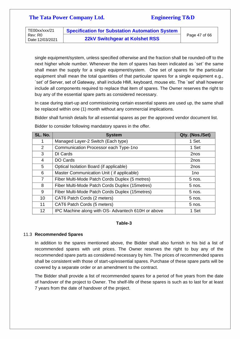
The Tata Power Company Ltd. Engineering T&D
TE00xx/xxx/21 Rev: R0 Date:12/03/2021
Specification for Substation Automation System Page 47 of 66
22kV Switchgear at Kolshet RSS
single equipment/system, unless specified otherwise and the fraction shall be rounded-off to the
next higher whole number. Whenever the item of spares has been indicated as `set’ the same
shall mean the supply for a single equipment/system. One set of spares for the particular
equipment shall mean the total quantities of that particular spares for a single equipment e.g.,
`set’ of Server, set of Gateway, shall include HMI, keyboard, mouse etc. The `set’ shall however
include all components required to replace that item of spares. The Owner reserves the right to
buy any of the essential spare parts as considered necessary.
In case during start-up and commissioning certain essential spares are used up, the same shall
be replaced within one (1) month without any commercial implications.
Bidder shall furnish details for all essential spares as per the approved vendor document list.
Bidder to consider following mandatory spares in the offer.
SL. No. System Qty. (Nos./Set)
1 Managed Layer-2 Switch (Each type) 1 Set.
2 Communication Processor each Type-1no 1 Set
3 DI Cards 2nos
4 DO Cards 2nos
5 Optical Isolation Board (if applicable) 2nos
6 Master Communication Unit ( if applicable) 1no
7 Fiber Multi-Mode Patch Cords Duplex (5 metres) 5 nos.
8 Fiber Multi-Mode Patch Cords Duplex (15metres) 5 nos.
9 Fiber Multi-Mode Patch Cords Duplex (15metres) 5 nos.
10 CAT6 Patch Cords (2 meters) 5 nos.
11 CAT6 Patch Cords (5 meters) 5 nos.
12 IPC Machine along with OS- Advantech 610H or above 1 Set
Table-3
11.3 Recommended Spares
In addition to the spares mentioned above, the Bidder shall also furnish in his bid a list of
recommended spares with unit prices. The Owner reserves the right to buy any of the
recommended spare parts as considered necessary by him. The prices of recommended spares
shall be consistent with those of start-up/essential spares. Purchase of these spare parts will be
covered by a separate order or an amendment to the contract.
The Bidder shall provide a list of recommended spares for a period of five years from the date
of handover of the project to Owner. The shelf-life of these spares is such as to last for at least
7 years from the date of handover of the project.

The Tata Power Company Ltd. Engineering T&D
TE00xx/xxx/21 Rev: R0 Date:12/03/2021
Specification for Substation Automation System Page 48 of 66
22kV Switchgear at Kolshet RSS
The Bidder shall provide the MTBF of various components, sub-assemblies, assemblies etc.
(recommended as spares) and the relationship between MTBF and spare quantities
recommended.
The Bidder shall submit the product life cycle details of the all hardware offered under this RFP.
The table above indicate the minimum requirement of the owner, bidder to include the spares,
which are not part of this table, but required for maintenance and upkeep of the system
11.4 Special Tools & Tackles
Bidder to consider and supply special tools and tackles required for erection, commissioning and
maintenance of the offered system. After commissioning of the system all tools and tackles shall
be handed over to Owner's Project/Maintenance team.
All tools (both hardware and software), test instruments, simulation jigs, documents,
programming equipment etc. required for Installation, Testing & Commissioning are in the scope
of bidder.
All configuration cables and other specialized testing passive devices to be provided with the
supply of material.
12.0 DATA SUBMISSION BY BIDDER
Following Documents must be submitted along with the bid.
Bids are liable to be rejected if following minimum documents are not submitted along
with the bid.
a. Deviation if any from specification strictly following the prescribed format.
b. Compliance to the approved vendor list
c. List of major relevant experiences of the Principal, Collaborator and the Product respectively.
d. Technical support facilities including qualified man-power, testing tools and instruments and
integration facilities available within India.
e. Technical data sheet of critical equipment
f. System architecture drawing.
g. Compliance to data sheets covered in the specification.
h. Product life cycle document for all supplied equipment.
i. Quality Assurance Plan (QAP), Manufacturing Quality Plan (MQP), Field Quality Plan (FQP)
j. Type test certificates of the offered equipment
k. Confirmation on lifetime, spares, manufacturing, onsite & Offsite technical support of the
supplied equipment for the period of 15 years.

The Tata Power Company Ltd. Engineering T&D
TE00xx/xxx/21 Rev: R0 Date:12/03/2021
Specification for Substation Automation System Page 49 of 66
22kV Switchgear at Kolshet RSS
l. The Bidder shall furnish the following drawings/documents during detailed engineering within 2
month from date of PO Placement Bidder to submit all datasheets, detailed GTP of the proposed
BOM items during detailed engineering for the approval and finalization by Owner.
m. System Architecture Drawing. This drawing should show in detail of the following:
i. Network connections
ii. Protocol used
iii. Type of interconnecting cable
iv. All IED’s, workstations, gateways, network switches, meters etc. which are part of the SAS.
n. Panel GA and Complete wiring diagram
o. Functional Design Specification document
p. Step by Step test procedures for Factory Acceptance Test (FAT) and Site Acceptance Test (SAT)
q. SCADA I/O List with protocol details along with addresses
r. Interconnection Schedule (ICS) for Automation
s. Hardware, Software and Application manuals for all the equipment supplied including that of
Third parties.
t. All Software Licenses (both own & third party), key for Hardware Locks
u. All interoperability tables
v. Guaranteed technical parameters & Guaranteed availability and reliability
w. Calculation for power supply dimensioning
x. Bill of Material listing equipment designation, make, type ratings, etc. of all the equipment's
supplied
y. Logic Diagram (Hardware & Software)
z. Operator’s Manual
aa. Complete documentation of implemented protocols between various elements
bb. IP addressing chart for all the IED’s, Gateways, Workstations, network switches which are
connected to the network
cc. Diagnostic and performance evaluation software and hardware tools
dd. Details of software (Operating systems, application software, engineering tools, communication
systems management software, license details, I/O distribution protocol-wise etc.) for SAS
computer equipment (including PCs, Station HMI equipment and configuration laptop
computers) and loadable in CD/DVD ROM

The Tata Power Company Ltd. Engineering T&D
TE00xx/xxx/21 Rev: R0 Date:12/03/2021
Specification for Substation Automation System Page 50 of 66
22kV Switchgear at Kolshet RSS
ee. All SAS related drawings in both AutoCAD & Pdf format only. However, the pdf versions of above
drawings shall be submitted through wrench for formal approval process. All AutoCAD drawings
of the entire project shall be submitted through Secondary Media viz. USB Storage disk.
ff. Bidder shall agree to comply with minimum quality requirements and Contractor Safety Code of
Conduct, defined in bid documents.
gg. Other documents as may be required / applicable during detailed engineering
hh. All drawings and data shall be annotated in English.
ii. Bidder shall furnish six (6) hardcopies and 3 soft copies on reliable media of all drawings,
manuals (Administration, Operation & Maintenance, Troubleshooting and Installation), Technical
catalogues, Test Certificates and Acceptance Test Reports.
jj. Two copies of the internal test report, FAT and SAT documents with test protocol formats shall
be submitted for approval at least 4 weeks before Factory Acceptance Test. Two copies of SAT
protocol shall be submitted for approval at least two weeks before Site Acceptance Test.
kk. Bidder shall also furnish Original plus one copy of all System Software (OS, Application and
tools) along with delivery. Bidder shall submit two copies of all the configuration, application,
display, database backup of all equipment on reliable secondary media.
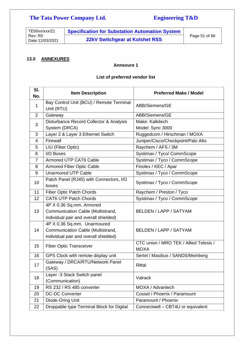
The Tata Power Company Ltd. Engineering T&D
TE00xx/xxx/21 Rev: R0 Date:12/03/2021
Specification for Substation Automation System Page 51 of 66
22kV Switchgear at Kolshet RSS
13.0 ANNEXURES
Annexure 1
List of preferred vendor list
Sl.
No. Item Description Preferred Make / Model
1 Bay Control Unit (BCU) / Remote Terminal
Unit (RTU) ABB/Siemens/GE
2 Gateway ABB/Siemens/GE
3 Disturbance Record Collector & Analysis
System (DRCA)
Make: Kalkitech
Model: Sync 3000
3 Layer 2 & Layer 3 Ethernet Switch Ruggedcom / Hirschman / MOXA
4 Firewall Juniper/Cisco/Checkpoint/Palo Alto
5 LIU (Fiber Optic) Raychem / AFS / 3M
6 I/O Boxes Systimax / Tyco/ CommScope
7 Armored UTP CAT6 Cable Systimax / Tyco / CommScope
8 Armored Fiber Optic Cable Finolex / KEC / Apar
9 Unarmored UTP Cable Systimax / Tyco / CommScope
10 Patch Panel (RJ45) with Connectors, I/O
boxes Systimax / Tyco / CommScope
11 Fiber Optic Patch Chords Raychem / Preston / Tyco
12 CAT6 UTP Patch Chords Systimax / Tyco / CommScope
13
4P X 0.36 Sq.mm. Armored
Communication Cable (Multistrand,
individual pair and overall shielded)
BELDEN / LAPP / SATYAM
14
4P X 0.36 Sq.mm. Unarmoured
Communication Cable (Multistrand,
individual pair and overall shielded)
BELDEN / LAPP / SATYAM
15 Fiber Optic Transceiver CTC union / MRO TEK / Allied Telesis /
MOXA
16 GPS Clock with remote display unit Sertel / Masibus / SANDS/Meinberg
17 Gateway / DRCA/RTU/Network Panel
(SAS) Rittal
18 Layer -3 Stack Switch panel
(Communication) Valrack
19 RS 232 / RS 485 converter MOXA / Advantech
20 DC-DC Converter Cossel / Phoenix / Paramount
21 Diode-Oring Unit Paramount / Phoenix
22 Droppable type Terminal Block for Digital Connectwell – CBT4U or equivalent

The Tata Power Company Ltd. Engineering T&D
TE00xx/xxx/21 Rev: R0 Date:12/03/2021
Specification for Substation Automation System Page 52 of 66
22kV Switchgear at Kolshet RSS
Output, CT & PT.
23 Disconnecting type (Knife edge) Terminal
Block for Digital Input Connectwell - CKT4U or equivalent
24
Auxiliary Relays – BCU
Breaker
Isolator & other Digital Inputs
Make – OMRON
MM4XP-D
MM2XP-D
25 Auxiliary Relays - Miscellaneous RTU OMRON
26 Multifunction Meter Make – SATEC
Model – PM130EH+
27 Rack Mounted Sliding monitor with
keyboard & Touch pad. Make – ATEN
28 Voltage Transducers Make – RISHABH
29 Modbus TCP/IP converter Moxa, Advantech
30 Configuration Laptop HP/DELL/Lenovo
31 Temperature & Humidity Sensor Make & Model : KIMO & C-310

The Tata Power Company Ltd. Engineering T&D
TE00xx/xxx/21 Rev: R0 Date:12/03/2021
Specification for Substation Automation System Page 53 of 66
22kV Switchgear at Kolshet RSS
ANNEXURE – II
Indicative Bill of Material- Sub-Station Automation
(Bidder shall refer the equipment technical specification for more details and offer the solutions
accordingly)
Refer the attached Indicative Automation BOM annexure separately
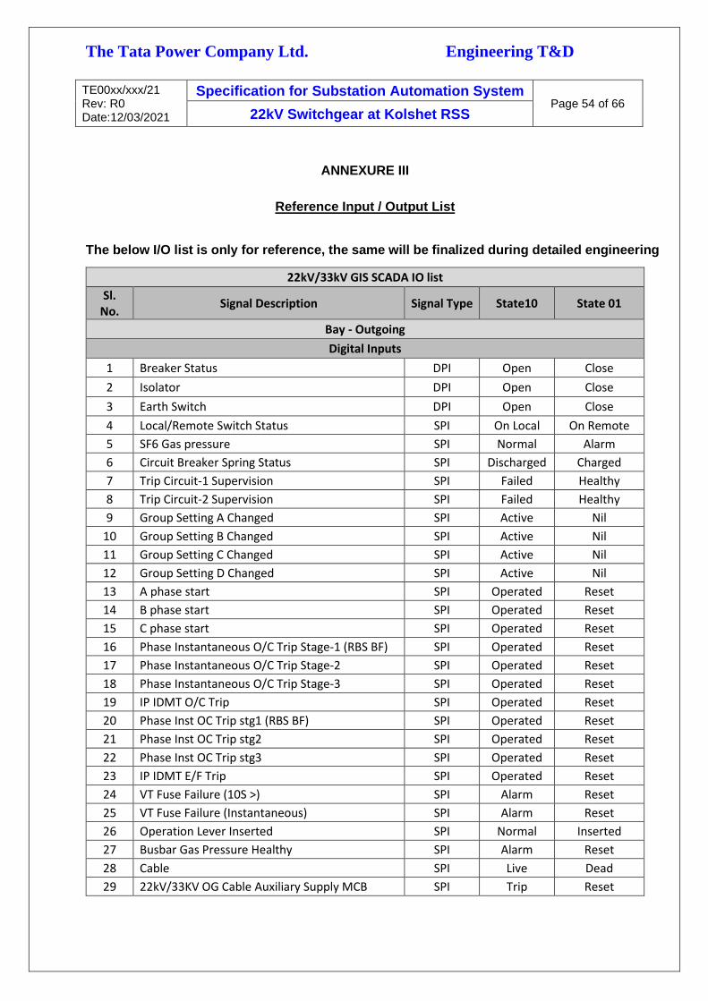
The Tata Power Company Ltd. Engineering T&D
TE00xx/xxx/21 Rev: R0 Date:12/03/2021
Specification for Substation Automation System Page 54 of 66
22kV Switchgear at Kolshet RSS
ANNEXURE III
Reference Input / Output List
The below I/O list is only for reference, the same will be finalized during detailed engineering
22kV/33kV GIS SCADA IO list
Sl. No.
Signal Description Signal Type State10 State 01
Bay - Outgoing
Digital Inputs
1 Breaker Status DPI Open Close
2 Isolator DPI Open Close
3 Earth Switch DPI Open Close
4 Local/Remote Switch Status SPI On Local On Remote
5 SF6 Gas pressure SPI Normal Alarm
6 Circuit Breaker Spring Status SPI Discharged Charged
7 Trip Circuit-1 Supervision SPI Failed Healthy
8 Trip Circuit-2 Supervision SPI Failed Healthy
9 Group Setting A Changed SPI Active Nil
10 Group Setting B Changed SPI Active Nil
11 Group Setting C Changed SPI Active Nil
12 Group Setting D Changed SPI Active Nil
13 A phase start SPI Operated Reset
14 B phase start SPI Operated Reset
15 C phase start SPI Operated Reset
16 Phase Instantaneous O/C Trip Stage-1 (RBS BF) SPI Operated Reset
17 Phase Instantaneous O/C Trip Stage-2 SPI Operated Reset
18 Phase Instantaneous O/C Trip Stage-3 SPI Operated Reset
19 IP IDMT O/C Trip SPI Operated Reset
20 Phase Inst OC Trip stg1 (RBS BF) SPI Operated Reset
21 Phase Inst OC Trip stg2 SPI Operated Reset
22 Phase Inst OC Trip stg3 SPI Operated Reset
23 IP IDMT E/F Trip SPI Operated Reset
24 VT Fuse Failure (10S >) SPI Alarm Reset
25 VT Fuse Failure (Instantaneous) SPI Alarm Reset
26 Operation Lever Inserted SPI Normal Inserted
27 Busbar Gas Pressure Healthy SPI Alarm Reset
28 Cable SPI Live Dead
29 22kV/33KV OG Cable Auxiliary Supply MCB SPI Trip Reset

The Tata Power Company Ltd. Engineering T&D
TE00xx/xxx/21 Rev: R0 Date:12/03/2021
Specification for Substation Automation System Page 55 of 66
22kV Switchgear at Kolshet RSS
30 Block to IC-1 & BC 1-2A SPI Send Reset
31 Trip from IC-1 SPI Received Reset
32 Trip from BC-1-2A SPI Received Reset
33 Fault Current If A Phase Analog Value Nil
34 Fault Current If B Phase Analog Value Nil
35 Fault Current If C Phase Analog Value Nil
36 Fault Current If N Analog Value Nil
37 Fault Duration Analog Value Nil
38 I Square t Analog Value Nil
39 Breaker Contact Wear out SPI Operated Nil
40 Time Sync SPI Sync Not Sync
Digital Output (Control Command)
1 Breaker Status DCO Open Close
2 Isolator DCO Open Close
3 Earth Switch DCO Open Close
4 Group Setting A SCO In Service Out of Service
5 Group Setting B SCO In Service Out of Service
6 Group Setting C SCO In Service Out of Service
7 Group Setting D SCO In Service Out of Service
Bay – Out Going with BUS PT
Digital Inputs
1 Breaker Status DPI Open Close
2 Isolator DPI Open Close
3 Earth Switch DPI Open Close
4 Bus-PT Isolator DPI Open Close
5 Earth Switch Bus-PT DPI Open Close
6 Local/Remote Switch Status SPI On Local On Remote
7 SF6 Gas pressure SPI Normal Alarm
8 CB Spring Charge SPI Discharged Charged
9 Trip Circuit-1 Supervision SPI Failed Healthy
10 Trip Circuit-2 Supervision SPI Failed Healthy
11 Group A Setting Status SPI Active Nil
12 Group B Setting Status SPI Active Nil
13 Group C Setting Status SPI Active Nil
14 Group D Setting Status SPI Active Nil
15 A phase start SPI Operated Reset
16 B phase start SPI Operated Reset
17 C phase start SPI Operated Reset
16 Phase Inst OC Trip stg1 (RBS BF) SPI Operated Reset

The Tata Power Company Ltd. Engineering T&D
TE00xx/xxx/21 Rev: R0 Date:12/03/2021
Specification for Substation Automation System Page 56 of 66
22kV Switchgear at Kolshet RSS
17 Phase Inst OC Trip stg2 SPI Operated Reset
18 Phase Inst OC Trip stg3 SPI Operated Reset
19 IP IDMT OC Trip SPI Operated Reset
20 Phase Inst OC Trip stg1 (RBS BF) SPI Operated Reset
21 Phase Inst OC Trip stg2 SPI Operated Reset
22 Phase Inst OC Trip stg3 SPI Operated Reset
23 IP IDMT E/F Trip SPI Operated Reset
26 VT Fuse Failure (10S >) SPI Alarm Reset
27 VT Fuse Failure (Instantaneous) SPI Alarm Reset
28 Operation Lever Inserted SPI Normal Inserted
29 Busbar Gas Pressure Healthy SPI Alarm Reset
30 cable SPI Live Dead
31 22kV/33KV OG Cable Aux Supply MCB SPI Trip Reset
32 Block to IC-1 & BC 1-2A SPI Send Reset
33 Trip from IC-1 SPI Received Reset
34 Trip from BC-1-2A SPI Received Reset
35 BUS-1 PT Selected SPI Selected -
36 BUS-2 PT Selected SPI Selected -
37 Fault Current If A Phase Analog Value Nil
38 Fault Current If B Phase Analog Value Nil
39 Fault Current If C Phase Analog Value Nil
40 Fault Current If N Phase Analog Value Nil
41 Fault Duration Analog Value Nil
42 I Square t Analog Value Nil
43 Breaker Contact wear out SPI Operated Nil
Digital Output (Control Command)
1 Breaker Status DCO Open Close
2 Isolator DCO Open Close
3 Earth Switch DCO Open Close
4 Group Setting A SCO In Service Out of Service
5 Group Setting B SCO In Service Out of Service
6 Group Setting C SCO In Service Out of Service
7 Group Setting D SCO In Service Out of Service
Bay - Capacitor Bank
Digital Inputs
1 Breaker Status DPI Open Close
2 Isolator DPI Open Close
3 Earth Switch DPI Open Close
4 Local/Remote Switch Status SPI On Local On Remote
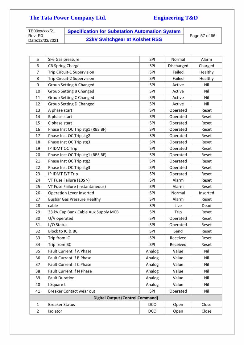
The Tata Power Company Ltd. Engineering T&D
TE00xx/xxx/21 Rev: R0 Date:12/03/2021
Specification for Substation Automation System Page 57 of 66
22kV Switchgear at Kolshet RSS
5 SF6 Gas pressure SPI Normal Alarm
6 CB Spring Charge SPI Discharged Charged
7 Trip Circuit-1 Supervision SPI Failed Healthy
8 Trip Circuit-2 Supervision SPI Failed Healthy
9 Group Setting A Changed SPI Active Nil
10 Group Setting B Changed SPI Active Nil
11 Group Setting C Changed SPI Active Nil
12 Group Setting D Changed SPI Active Nil
13 A phase start SPI Operated Reset
14 B phase start SPI Operated Reset
15 C phase start SPI Operated Reset
16 Phase Inst OC Trip stg1 (RBS BF) SPI Operated Reset
17 Phase Inst OC Trip stg2 SPI Operated Reset
18 Phase Inst OC Trip stg3 SPI Operated Reset
19 IP IDMT OC Trip SPI Operated Reset
20 Phase Inst OC Trip stg1 (RBS BF) SPI Operated Reset
21 Phase Inst OC Trip stg2 SPI Operated Reset
22 Phase Inst OC Trip stg3 SPI Operated Reset
23 IP IDMT E/F Trip SPI Operated Reset
24 VT Fuse Failure (10S >) SPI Alarm Reset
25 VT Fuse Failure (Instantaneous) SPI Alarm Reset
26 Operation Lever Inserted SPI Normal Inserted
27 Busbar Gas Pressure Healthy SPI Alarm Reset
28 cable SPI Live Dead
29 33 kV Cap Bank Cable Aux Supply MCB SPI Trip Reset
30 U/V operated SPI Operated Reset
31 L/O Status SPI Operated Reset
32 Block to IC & BC SPI Send Reset
33 Trip from IC SPI Received Reset
34 Trip from BC SPI Received Reset
35 Fault Current If A Phase Analog Value Nil
36 Fault Current If B Phase Analog Value Nil
37 Fault Current If C Phase Analog Value Nil
38 Fault Current If N Phase Analog Value Nil
39 Fault Duration Analog Value Nil
40 I Square t Analog Value Nil
41 Breaker Contact wear out SPI Operated Nil
Digital Output (Control Command)
1 Breaker Status DCO Open Close
2 Isolator DCO Open Close

The Tata Power Company Ltd. Engineering T&D
TE00xx/xxx/21 Rev: R0 Date:12/03/2021
Specification for Substation Automation System Page 58 of 66
22kV Switchgear at Kolshet RSS
3 Earth Switch DCO Open Close
4 Group A Setting Command SCO In Service Out of Service
5 Group B Setting Command SCO In Service Out of Service
6 Group C Setting Command SCO In Service Out of Service
7 Group D Setting Command SCO In Service Out of Service
8 L/O Reset Command SCO Reset -
Bay - Reactor
Digital Inputs
1 Breaker Status DPI Open Close
2 Isolator DPI Open Close
3 Earth Switch DPI Open Close
4 Local/Remote Switch Status SPI On Local On Remote
5 SF6 Gas pressure SPI Normal Alarm
6 CB Spring SPI Discharged Charged
7 Trip Circuit-1 Supervision SPI Failed Healthy
8 Trip Circuit-2 Supervision SPI Failed Healthy
9 Group A Setting Status SPI Active Nil
10 Group B Setting Status SPI Active Nil
11 Group C Setting Status SPI Active Nil
12 Group D Setting Status SPI Active Nil
13 A phase start SPI Operated Reset
14 B phase start SPI Operated Reset
15 C phase start SPI Operated Reset
16 Phase Inst OC Trip stg1 (RBS BF) SPI Operated Reset
17 Phase Inst OC Trip stg2 SPI Operated Reset
18 Phase Inst OC Trip stg3 SPI Operated Reset
19 IP IDMT OC Trip SPI Operated Reset
20 Phase Inst OC Trip stg1 (RBS BF) SPI Operated Reset
21 Phase Inst OC Trip stg2 SPI Operated Reset
22 Phase Inst OC Trip stg3 SPI Operated Reset
23 IP IDMT E/F Trip SPI Operated Reset
24 Operation Lever Inserted SPI Normal Inserted
25 Busbar Gas Pressure Healthy SPI Alarm Reset
26 Cable SPI Live Dead
27 22kV/33KV Reactor Cable Aux Supply MCB SPI Trip Reset
28 L/O Relay SPI Operated Reset
29 Differential Protection Stage 1 SPI Operated Reset
30 Differential Protection Stage 2 SPI Operated Reset
31 Block to IC & BC SPI Send Reset
32 Trip from IC SPI Received Reset

The Tata Power Company Ltd. Engineering T&D
TE00xx/xxx/21 Rev: R0 Date:12/03/2021
Specification for Substation Automation System Page 59 of 66
22kV Switchgear at Kolshet RSS
33 Trip from BC SPI Received Reset
34 Fault Current If A Phase Analog Value Nil
35 Fault Current If B Phase Analog Value Nil
36 Fault Current If C Phase Analog Value Nil
37 Fault Current If N Phase Analog Value Nil
38 Fault Duration Analog Value Nil
39 I Square t Analog Value Nil
40 Breaker Contact wear out SPI Operated Nil
Digital Output (Control Command)
1 Breaker Status DCO Open Close
2 Isolator DCO Open Close
3 Earth Switch DCO Open Close
4 Group A Setting Command SCO In Service Out of Service
5 Group B Setting Command SCO In Service Out of Service
6 Group C Setting Command SCO In Service Out of Service
7 Group D Setting Command SCO In Service Out of Service
8 L/O Reset Command SCO Reset -
Bay - Incomer
Digital Inputs
1 Breaker Status DPI Open Close
2 Isolator DPI Open Close
3 Earth Switch DPI Open Close
4 Local/Remote Switch SPI On Local On Remote
5 SF6 Gas pressure SPI Normal Alarm
6 CB Spring SPI Discharged Charged
7 Trip Circuit-1 Supervision SPI Failed Healthy
8 Trip Circuit-2 Supervision SPI Failed Healthy
9 Group A Setting Status SPI Active Nil
10 Group B Setting Status SPI Active Nil
11 Group C Setting Status SPI Active Nil
12 Group D Setting Status SPI Active Nil
13 A phase start SPI Operated Reset
14 B phase start SPI Operated Reset
15 C phase start SPI Operated Reset
16 Phase Inst OC Trip stg1 (RBS BF) SPI Operated Reset
17 Phase Inst OC Trip stg2 SPI Operated Reset
18 Phase Inst OC Trip stg3 SPI Operated Reset
19 IP IDMT OC Trip SPI Operated Reset
20 Phase Inst OC Trip stg1 (RBS BF) SPI Operated Reset

The Tata Power Company Ltd. Engineering T&D
TE00xx/xxx/21 Rev: R0 Date:12/03/2021
Specification for Substation Automation System Page 60 of 66
22kV Switchgear at Kolshet RSS
21 Phase Inst OC Trip stg2 SPI Operated Reset
22 Phase Inst OC Trip stg3 SPI Operated Reset
23 IP IDMT E/F Trip SPI Operated Reset
24 VT Fuse Failure (10S >) SPI Alarm Reset
25 VT Fuse Failure (Instantaneous) SPI Alarm Reset
26 Operation Lever SPI Normal Inserted
27 Busbar Gas Pressure Healthy SPI Alarm Reset
28 Cable SPI Live Dead
29 33 kV Incomer Cable Aux Supply MCB SPI Trip Reset
30 33 kV INC1 GOOSE Message Activity SPI Disable Enable
31 Overload Trimming Scheme SPI Operated Reset
32 LBBU Protection Trip SPI Operated Reset
33 LBBU Protection Initiated SPI Operated Reset
34 LBBU Out of service SPI In Service Out of service
35 Bus Fault Stage I> BLOCKED SPI Received Reset
36 Bus Fault Stage IE> BLOCKED SPI Received Reset
37 Block to Bus Coupler 1-2A Reverse Trip on own REV P/U
SPI Send Reset
38 Block from Bus Coupler 1-2A FWD P/U SPI Received Reset
39 Block from Own Reverse Stage SPI Active Reset
40 Trip from BC REV Trip SPI Received Reset
41 Trip to BC & O.G feeder of Bus section-1 SPI Operated Reset
42 Bus Fault Stage Trip SPI Operated Reset
43 Bus 1 Communication Fail SPI Healthy Failed
44 Fault Current If A Phase Analog Value Nil
45 Fault Current If B Phase Analog Value Nil
46 Fault Current If C Phase Analog Value Nil
47 Fault Current If N Phase Analog Value Nil
48 Fault Duration Analog Value Nil
49 I Square t Analog Value Nil
50 Breaker Contact wear out SPI Operated Nil
51 Time Sync SPI Sync Not Sync
Digital Output (Control Command)
1 Breaker Status DCO Open Close
2 Isolator DCO Open Close
3 Earth Switch DCO Open Close
4 Group A Setting Command SCO In Service Out of Service
5 Group B Setting Command SCO In Service Out of Service
6 Group C Setting Command SCO In Service Out of Service

The Tata Power Company Ltd. Engineering T&D
TE00xx/xxx/21 Rev: R0 Date:12/03/2021
Specification for Substation Automation System Page 61 of 66
22kV Switchgear at Kolshet RSS
7 Group D Setting Command SCO In Service Out of Service
8 OLTS Relay DCO IN OUT
Bay - Bus Coupler
Digital Inputs
1 Breaker Status DPI Open Close
2 Isolator DPI Open Close
3 Earth Switch DPI Open Close
4 Isolator ( Bus Riser) DPI Open Close
5 Earth Switch ( Bus Riser) DPI Open Close
6 Local/Remote Switch Status SPI On Local On Remote
7 SF6 Gas pressure SPI Normal Alarm
8 CB Spring Charge SPI Discharged Charged
9 Trip Circuit-1 Supervision SPI Failed Healthy
10 Trip Circuit-2 Supervision SPI Failed Healthy
11 Group A Setting Status SPI Active Nil
12 Group B Setting Status SPI Active Nil
13 Group C Setting Status SPI Active Nil
14 Group D Setting Status SPI Active Nil
15 A phase start SPI Operated Reset
16 B phase start SPI Operated Reset
17 C phase start SPI Operated Reset
16 Phase Inst OC Trip stg1 (RBS BF) SPI Operated Reset
17 Phase Inst OC Trip stg2 SPI Operated Reset
18 Phase Inst OC Trip stg3 SPI Operated Reset
19 IP IDMT OC Trip SPI Operated Reset
20 Phase Inst OC Trip stg1 (RBS BF) SPI Operated Reset
21 Phase Inst OC Trip stg2 SPI Operated Reset
22 Phase Inst OC Trip stg3 SPI Operated Reset
23 IP IDMT E/F Trip SPI Operated Reset
26 VT Fuse Failure(10S >) SPI Alarm Reset
27 VT Fuse Failure (Instantaneous) SPI Alarm Reset
28 Operation Lever Inserted SPI Normal Inserted
29 Busbar Gas Pressure Healthy SPI Alarm Reset
30 Cable SPI Live Dead
31 22kV/33KV BC Cable Aux Supply MCB SPI Trip Reset
32 GOOSE Messaging activity SPI Disable Enable
33 BC1 NON-DIR Phase Inst OC Trip stg1 SPI Operated Reset
34 BC1 NON-DIR Phase Inst OC Trip stg2 SPI Operated Reset
35 BC1 NON-DIR Phase Inst OC Trip stg3 SPI Operated Reset
36 BC1 NON-DIR IP IDMT OC Trip SPI Operated Reset

The Tata Power Company Ltd. Engineering T&D
TE00xx/xxx/21 Rev: R0 Date:12/03/2021
Specification for Substation Automation System Page 62 of 66
22kV Switchgear at Kolshet RSS
37 BC1 NON-DIR E/F Inst Trip stg1 SPI Operated Reset
38 BC1 NON-DIR E/F Inst Trip stg2 SPI Operated Reset
39 BC1 NON-DIR E/F Inst Trip stg3 SPI Operated Reset
40 BC1 NON-DIR IEP IDMT OC Trip SPI Operated Reset
41 Block from BS-1 OG SPI Received Reset
42 Block from BS-1 I/C Rev P/U SPI Received Reset
43 Block From BC2A-2B FWD P/U SPI Received Reset
44 Trip from BS-1 I/C SPI Received Reset
45 Block to BS-1 I/C for BC FWD P/U SPI SEND Reset
46 Block to BS-2 I/C and BC2A-2B REV Trip SPI SEND Reset
47 Trip to BS-1 IC/Outgoings Bus 1 SPI Operated Reset
48 Trip to BS-2A IC/Outgoings Bus 2A SPI Operated Reset
49 Bus Fault Forward Stage Trip Block SPI Active Reset
50 Bus Fault Forward Stage Trip SPI Operated Reset
51 Block from BS-2A Outgoing SPI Received Reset
52 Block from BS-2A IC Rev P/U SPI Received Reset
53 Trip from BS-2A I/C SPI Received Reset
54 Trip from BC-2A-2B REV Trip SPI Received Reset
55 Bus Fault REVERSE Stage Trip Block SPI Active Reset
56 Bus Fault REVERSE Stage Trip SPI Operated Reset
57 Forward Directional Element Start SPI Operated Reset
58 Reverse Directional Element Start SPI Operated Reset
59 Bus 1 Communication Fail SPI Healthy Failed
60 Bus 2A Communication Fail SPI Healthy Failed
61 Fault Current If A Phase Analog Value Nil
62 Fault Current If B Phase Analog Value Nil
63 Fault Current If C Phase Analog Value Nil
64 Fault Current If N Phase Analog Value Nil
65 Fault Duration Analog Value Nil
66 I Square t Analog Value Nil
67 Breaker Contact wear out SPI Operated Nil
68 Time Sync SPI Sync Not Sync
Digital Output(Control Command)
1 Breaker Status DCO Open Close
2 Isolator DCO Open Close
3 Earth Switch DCO Open Close
4 Group A Setting Command SCO In Service Out of Service
5 Group B Setting Command SCO In Service Out of Service
6 Group C Setting Command SCO In Service Out of Service

The Tata Power Company Ltd. Engineering T&D
TE00xx/xxx/21 Rev: R0 Date:12/03/2021
Specification for Substation Automation System Page 63 of 66
22kV Switchgear at Kolshet RSS
7 Group D Setting Command SCO In Service Out of Service
8 Isolator ( Bus Riser) DCO Open Close
9 Earth Switch ( Bus Riser) DCO Open Close
Bay - Distribution Transformer / Station Transformer
Digital Inputs
1 Breaker Status DPI Open Close
2 Isolator DPI Open Close
3 Earth Switch DPI Open Close
4 Local/Remote Switch Status SPI On Local On Remote
5 SF6 Gas pressure SPI Normal Alarm
6 CB Spring Charge SPI Discharged Charged
7 Trip Circuit-1 Supervision SPI Failed Healthy
8 Trip Circuit-2 Supervision SPI Failed Healthy
9 Group A Setting Status SPI Active Nil
10 Group B Setting Status SPI Active Nil
11 Group C Setting Status SPI Active Nil
12 Group D Setting Status SPI Active Nil
13 A phase start SPI Operated Reset
14 B phase start SPI Operated Reset
15 C phase start SPI Operated Reset
16 Phase Inst OC Trip stg1 (RBS BF) SPI Operated Reset
17 Phase Inst OC Trip stg2 SPI Operated Reset
18 Phase Inst OC Trip stg3 SPI Operated Reset
19 IP IDMT OC Trip SPI Operated Reset
20 Phase Inst OC Trip stg1 (RBS BF) SPI Operated Reset
21 Phase Inst OC Trip stg2 SPI Operated Reset
22 Phase Inst OC Trip stg3 SPI Operated Reset
23 IP IDMT E/F Trip SPI Operated Reset
24 VT Fuse Failure (10S >) SPI Alarm Reset
25 VT Fuse Failure (Instantaneous) SPI Alarm Reset
26 Operation Lever Inserted SPI Normal Inserted
27 Busbar Gas Pressure Healthy SPI Alarm Reset
28 cable SPI Live Dead
29 22kV/33KV OG Cable Aux Supply MCB SPI Trip Reset
30 Block to IC-1 & BC 1-2A SPI Send Reset
31 Trip from IC-1 SPI Received Reset
32 Trip from BC-1-2A SPI Received Reset
33 Fault Current If A Phase Analog Value Nil
34 Fault Current If B Phase Analog Value Nil
35 Fault Current If C Phase Analog Value Nil

The Tata Power Company Ltd. Engineering T&D
TE00xx/xxx/21 Rev: R0 Date:12/03/2021
Specification for Substation Automation System Page 64 of 66
22kV Switchgear at Kolshet RSS
36 Fault Current If N Analog Value Nil
37 Fault Duration Analog Value Nil
38 I Square t Analog Value Nil
39 Breaker Contact wear out SPI Alarm Normal
40 Diff A Phase Trip SPI Trip Reset
41 Diff B Phase Trip SPI Trip Reset
42 Diff C Phase Trip SPI Trip Reset
43 Diff Fault Current If A Ph Analog Value Nil
44 Diff Fault Current If B Ph Analog Value Nil
45 Diff Fault Current If C Ph Analog Value Nil
47 OTI TRIP SPI Trip Reset
48 WTI TRIP SPI Trip Reset
49 OSR TRIP SPI Trip Reset
50 IE>TRIP INST-EF Trip. SPI Trip Reset
51 IEP TRIP-IDMT-EF-Trip SPI Trip Reset
53 Neutral Fault Current Analog Value Nil
54 OTI/MOG(OLTC)/BUCH ALARM SPI Alarm Reset
55 WTI/MOG(MAIN)/PRV(MAIN) SPI Alarm Reset
56 BUCH TRIP SPI Operated Nil
57 Time Sync SPI Sync Not Sync
Digital Output (Control Command)
1 Breaker Status DCO Open Close
2 Isolator DCO Open Close
3 Earth Switch DCO Open Close
4 Group A Setting Command SCO In Service Out of Service
5 Group B Setting Command SCO In Service Out of Service
6 Group C Setting Command SCO In Service Out of Service
7 Group D Setting Command SCO In Service Out of Service
System Event list (Hardwired)
Sl. No.
Description Signal Type
State Table
State10 State 01
1 (Voltage level) (Bus section Number) BCPU IRF Status SPI Failed Healthy
List of Parameters from Multi-Function Meter
Sl. No.
Parameter Description Parameter Type
1 R-Phase Current Analog
2 Y-Phase Current Analog
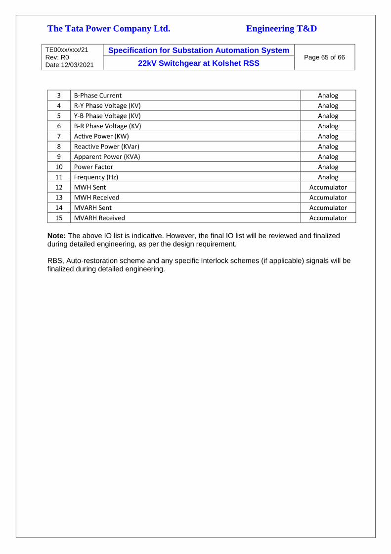
The Tata Power Company Ltd. Engineering T&D
TE00xx/xxx/21 Rev: R0 Date:12/03/2021
Specification for Substation Automation System Page 65 of 66
22kV Switchgear at Kolshet RSS
3 B-Phase Current Analog
4 R-Y Phase Voltage (KV) Analog
5 Y-B Phase Voltage (KV) Analog
6 B-R Phase Voltage (KV) Analog
7 Active Power (KW) Analog
8 Reactive Power (KVar) Analog
9 Apparent Power (KVA) Analog
10 Power Factor Analog
11 Frequency (Hz) Analog
12 MWH Sent Accumulator
13 MWH Received Accumulator
14 MVARH Sent Accumulator
15 MVARH Received Accumulator
Note: The above IO list is indicative. However, the final IO list will be reviewed and finalized during detailed engineering, as per the design requirement. RBS, Auto-restoration scheme and any specific Interlock schemes (if applicable) signals will be finalized during detailed engineering.

The Tata Power Company Ltd. Engineering T&D
TE00xx/xxx/21 Rev: R0 Date:12/03/2021
Specification for Substation Automation System Page 66 of 66
22kV Switchgear at Kolshet RSS
Annexure – IV
Standard Quality Plan
Attached Separately
END

THE TATA POWER COMPANY LIMITED DATA SHEET FOR : Gateway (G/W) 22kV Kolshet RSS
SL. NO. TECHNICAL PARTICULARS TATA POWER REQUIREMENT BIDDER RESPONSE
1 Gateway RTU Family (Preferably ) or IPC
2 Make
3 Model
4 Operating System for IPC Lastest WINDOWS Server tested & proven with Gateway Software.
5 I/O handling & IEDs Integration > 10,000 physical tags / Gateway
IEDs integration
On IEC61850 - > 120 IEDs
On IEC103, MODBUS - > 75 IEDs
7 Gateway Hardware
RTU based-modular, it shall be of same family of BCU and RTU (Preferbly)
Or
Embedded System – Industrial Grade Hardware Certified by KEMA with Industrial SSD
hard disk & Rack Mounted Sliding Monitor
Communication with minimum 4 independent Redundant SCADA masters
simultaneously on different networks
Communication with BCU/RTU on IEC61850 /IEC104 Protocol.
Communication with Station IEDs on IEC61850 and other open IP protocols
Communication with IEDs on serial protocol i.e. IEC60870-5-103, MODBUS etc.
7.3 Status LEDs on all module – for fault indication Required, Mandatory
7.4 Module replacement in Gateway Hot-Swappable module
7.5 Battery Backup / Flash-PROM backup Required
Ports Requirement
For Main & Standby SCADA System/Gateway InterfacingRedundant IP ports (100/1000 MBPS TCP/IP) for communicating to four redundant
masters on different IP address simultaneously using IEC60870-5-104 protocol
For IEDs (BCU, RTU, MFM, Relays), Time synchronization Redundant IP Ports for simultaneous communication with IEDs on IEC61850
Min 2 nos. RS232 electrical ports, RJ45 type,
Min 8 nos. RS-485 Ports with RJ45 Type
For structuring (Configuration) system (separate port) USB / Ethernet
7.7 CD/DVD RW for loading OS & Application Software Required, Mandatory for IPC based System
Device redundancy - back-up device automatically (in case of Embedded System). In
case of RTU family CPU, Communication & Power Supply redundancy
Switch over from active device in case of failure
Upstream redundancy - parallel communication channels to send / receive
simultaneous data upstream to control center
Downstream redundancy - parallel communication channels to send / receive
simultaneous data to downstream IEDs( Redundant Communication Processor to be
considered for each Bus section incase of RTU based Gateway)
High performance priority based algorithm for switchover management
9 Gateway Software
9.1XML based Substation Configuration description Language
(SCL) for IEC 61850 configurationRequired
9.2 Protocol Support
9.2.1 Main & Standby SCADA System IEC 60870–5–104 (Master & Slave protocol), SNMP
7.2Communication with similar systems on same/different
protocols, same/different Addressing
Gateway (G/W)
6
Shall be capable of integrating all the station IEDs, on different protocols with
Electrical/FO interface, Bidder to consider appropriate interfaces for 120 nos. of IEDs on
IP and 75 nos. of Serial
7.1 Hardware
7.6
Gateway shall support expandability of RS232/RS485 ports by
adding only communication module, in case more ports are
required to integrate station IEDs
8 Redundancy support features
Sheet 1 of 3

THE TATA POWER COMPANY LIMITED DATA SHEET FOR : Gateway (G/W) 22kV Kolshet RSS
SL. NO. TECHNICAL PARTICULARS TATA POWER REQUIREMENT BIDDER RESPONSE
Gateway (G/W)
9.2.2 BCU / IED / Relays / RTUsIEC 61850, IEC 60870–5–103, IEC60870-5-104 (Master and Slave), MODBUS (Serial,
TCP/IP), SNMP
9.2.3 Time synchronization between IEDs, Gateway and Master On IEEE1588 / SNTP, Gateway shall be capable of synchronizing slave IEDs on open
protocol
9.2.4 Time Synchronization Priority Provision Min.2 Options, Provision for Manually setting the prirority
9.2.5 Communication Compliance PRP, HSR
Min 5000 (shall be user configurable)
SOE Retention – 1 month
9.4 Manual Status Points Required
9.5 Manual Analog Points Required
9.6 Calculated Analog Points Unlimited
9.7 Calculated Digital Points Unlimited
9.8 Check-Before-Execute Scheme for control Mandatory
9.9 SCSMs Supported – SCSM : IEC61850.8.1 (MMS) Required
9.10Generic Substation event Model – Goose Publisher /
SubscriberRequired
9.11 Data Modeling IEC61850 Logical Nodes Ed.2
Buffered Report Control Block (BRCB)
Unbuffered Report Control Block (URCB)
Direct Control, Enhanced Direct Control
SBO Control, Enhanced SBO Control
9.14 File Transfer Via MMS and FTP
Support of Mathematical Function
Arithmetic functions
Logical functions
Trigonometric functions,
Differential & Integration functions
Timer, Counter etc.
Configuration shall be possible both locally and remotely
Configuration Software and Maintenance Tools – SCL,
Diagnostic tools, Master & IED Simulator tool, Maintenance
tools
Configuration application for database and process control
program development - Interlock logic and Calculation
functionality
Allow configuration of the Gateway with different versions of
the Configuration Tool
ICD file generation shall be possible from the proposed
Configuration Tool
Gateway shall have the provision to identify and configure the
IP of the BCUs, RTUs and other IEDs
Gateway shall have multilevel passwords
NERC-CIP security Compliant
IEC62351 support
SSL VPN with AES, DES or 3 DES encryptions
Bidder to confirm Cyber security measures as indicated in the Specification
Response Time
9.3 SOE List
9.12 Reporting Schemes
9.13 Commands
9.15 Required, Mandatory
9.16
Required
10 Cyber Security Feature
Sheet 2 of 3

THE TATA POWER COMPANY LIMITED DATA SHEET FOR : Gateway (G/W) 22kV Kolshet RSS
SL. NO. TECHNICAL PARTICULARS TATA POWER REQUIREMENT BIDDER RESPONSE
Gateway (G/W)
Digital Input 1 msec or better
Analog 1 sec or better
Digital Output <1 sec or better
Time stamping at Gateway level, I/O level, IED level Required
Monitoring & Management
Disturbance and fault record Collection and Management Required
Transparent / Tunneling support for remote configuration and
disturbance collection of IEDs
Master station user shall be able to perform a virtual
connection through Gateway with any RTU/BCU/IED
IED management using SNMP / Web server, File upload /
Download, Remote ConfigurationRequired
Capable of acquiring 32 bit Analog & Accumulator data from
MFMRequired, Mandatory
Required
11
Sheet 3 of 3

The Tata Power Company Limited DATA SHEET FOR : GPS Receiver 22kV AIS at Kolshet
SL. NO. TECHNICAL PARTICULARS TATA POWER REQUIREMENT BIDDER RESPONSE
1 Make
2 Model
3 Network support
Multiple LAN network topology
Multiple IEEE1588 V2 /PTP & SNTP ports supporting different IP networks (as per the
specification)
4 Tracking
GPS-L1, C/A code (1575.42 MHz),
Minimum 12 channel (tracks up to 12 satellites) or more
Minimum Accuracy 1 microsecond or better
Code/Carrier tracking
5 Front Keypad
For Configuration of Local time offset, Output code select, Backlight control, Out-of-lock
time, Auto-Survey, Position, Event input, Antenna delay, Programmable Pulse setup, Off or
Zero delay, Serial and IP port configuration.
6Redundant High Interference GPS
Antenna and mounting adapter kitRequired, Mandatory
7 IEEE1588 V2,NTP,SNTP Server Mandatory
8 Mounting Type19” Rack Mountable, Size : 2 U, Chassis: Rack Chassis w/sliding Rapid/Versa Rails and Cable
management Arm, with all other mounting accessories
LED Indicators : Power, Watchdog, GPS Locked, Event, GPS Sata
LCD display for: 4-rows x 40-character backlit LCD, Functions- showing local date and time,
Position: latitude, longitude, altitude, Receiver and clock status, Deviation, Event time.
TCP/IP
Min 4 Nos. independent SNTP Ports for Station Bus & Minimum 4 Ports for Process Bus on
IEEE1588 V2
GPS Clock shall have suitable format / software for IEEE1588 / NTP / SNTP to broadcast the
time on TCP/IP network to all devices
IP address of the GPS shall be user configurable
Pulse
4 Nos. Potential free contact (minimum pulse duration 50 msec).
The pulse output shall be user configurable to provide pulse rates of 1 PPS, 1 PPM, 1 PPH,
accuracy < 1 micro-second with GPS locked contacts suitable for 220 V DC, 100 mA
Serial
2 Nos. RS 232C serial port for configuration and synchronous time string broadcast, capable
of giving time in format to suit various applications such as UNIX / LINUX / Windows server,
simultaneously. 1200 – 19200 baud, 7 or 8 data bits, 1 or 2 stop bits; Even / Odd / No Parity
Potential Free Contacts for Alarms
Dry and isolated alarm contacts for GPS Sync Lost, Power Failure, Watchdog and 1 spare
(Configurable)
IRIG-B
GPS Receiver with Frequency, Time & Date Display
9 LED Indicators and LCD Display
10 Outputs
Sheet 1 of 3
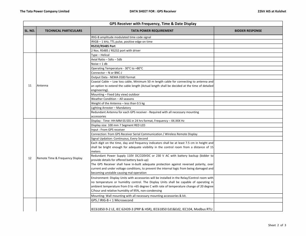
The Tata Power Company Limited DATA SHEET FOR : GPS Receiver 22kV AIS at Kolshet
SL. NO. TECHNICAL PARTICULARS TATA POWER REQUIREMENT BIDDER RESPONSE
GPS Receiver with Frequency, Time & Date Display
IRIG-B amplitude modulated time code signal
IRIGB – 1 kHz, TTL pulse, positive edge on time
RS232/RS485 Port
2 Nos. RS485 / RS232 port with driver
Type – Helical
Axial Ratio – 5dts – 5db
Noise < 1 db
Operating Temperature - 30°C to +80°C
Connector – N or BNC-J
Output Data - NEMA 0183 format
Coaxial Cable – Low loss cable, Minimum 50 m length cable for connecting to antenna and
an option to extend the cable length (Actual length shall be decided at the time of detailed
engineering).
Mounting – Fixed (sky view) outdoor
Weather Condition – All seasons
Weight of the Antenna – less than 0.5 kg
Lighting Arrester – Mandatory
Redundant Antenna for each GPS receiver - Required with all necessary mounting
accessories
Display : Time: HH:MM:SS:SSS in 24 hrs format, Frequency – XX.XXX Hz
Display size: 100 mm 7 Segment RED LED
Input : From GPS receiver
Connection: from GPS Receiver Serial Communication / Wireless Remote Display
Signal Updation: Continuous, Every Second
Each digit on the time, day and frequency indicators shall be at least 7.5 cm in height and
shall be bright enough for adequate visibility in the control room from a distance of 15
meters
Redundant Power Supply 110V DC/220VDC or 230 V AC with battery backup (bidder to
provide details for offered battery back-up)
The GPS Receiver shall have in-built adequate protection against reversed polarity, over
current and under voltage conditions, to prevent the internal logic from being damaged and
becoming unstable causing mal-operation
Environment: Display Units with accessories will be installed in the Relay/Control room with
no temperature or humidity control. The Display Units shall be capable of operating in
ambient temperature from 0 to +65 degree C with rate of temperature change of 20 degree
C/hour and relative humidity of 95%, non-condensing
Mounting: Wall mounting with all necessary mounting accessories & kit.
GPS / IRIG-B < 1 Microsecond
IEC61850-9-2 LE, IEC 62439-3 (PRP & HSR), IEC61850 Ed1&Ed2, IEC104, Modbus RTU
12 Remote Time & Frequency Display
13 Expected Accuracy
11 Antenna
Sheet 2 of 3

The Tata Power Company Limited DATA SHEET FOR : GPS Receiver 22kV AIS at Kolshet
SL. NO. TECHNICAL PARTICULARS TATA POWER REQUIREMENT BIDDER RESPONSE
GPS Receiver with Frequency, Time & Date Display
NTP, SNTP:
WAN < 10 msec
LAN < 1 msec
IEEE 1588 : < 10 microseconds or better
14 Remote Monitoring SNMP v1,v2,v3 for Monitoring from Remote
15 Cybersecurity NERC CIP, IEC62443 standard
15.1 Syslog reporting Yes,Mandatory
15.2 Management Shall be Managed from Remote throgun secured Access
16 Conformal Coated Yes,Mandatory
17 IP class IP64
18 Power Supply
Redundant Power supply module of 48V DC.
The Equipment shall have adequate protection against reversed polarity, over
current and under voltage conditions, to prevent the internal logic from being
damaged and becoming unstable causing mal-operation
19 Electronic Earthing Provision of electronic earthing to the nearest grounding box/earth pit
20 Environment
GPS Receiver with accessories will be installed in the Gateway Panel with no
temperature or humidity control. The GPS Receiver shall be capable of operating in
ambient temperature from 0 to +65 degree C with rate of temperature change of 20
degree C/hour and relative humidity of 95%, non-condensing
Offset Adjustment
Propogation Delay Compensation to achieve overall accuracy of < +/- 1.5
microseconds
Internal time base stability < 1 PPM or better
Web-Interface for Configuration
Amplifier to be included if required
13 Expected Accuracy
21 Other Required Features
Sheet 3 of 3

The Tata Power Company Limited DATA SHEET FOR : Layer 2 Managed Switch 22kV AIS at Kolshet
SL. NO. TECHNICAL PARTICULARS TATA POWER REQUIREMENT BIDDER RESPONSE
1 Make
2 Model
3 Type of Switch Industrial Grade, 19" Rackmountable
4 No. of Ports per switch Minimum 24
4.1 No. of Copper ports (10/100 mbps) As per Bidder's Proposed Architecture
4.2 No. of Fiber Ports (100/1000 mbps) As per Bidder's Proposed Architecture
4.3 SFPs to be considered for fiber ports Required, Mandatory
4.4 Copper Ports 2nos Minimum & Mandatory
5 Compliance
5.1
Shall support 802.1Q VLAN, 801.2p, 802.1d STP, 802.3ad (Port
aggregation), 802.1w RSTP, 802.1s MSTP, 802.3ad LACP, IEEE
802.1ab Link Layer Discovery Protocol and also suitable for Ring
Configuration
Required
5.2 IEEE 1613 compliance Mandatory
5.3 IEC 61850 Compliance Mandatory
5.4 IEC 62439-3 Mandatory
5.5 QAS (802.1p) Mandatory
6 Time Synchronization SNTP, IEEE1588 V2
7 Suitable for PRP/HSR architecture Mandatory, As per proposed Architecture
Automatic Learning, Ngotiation, and Crossover Detection
Support Industrial Automation Protocols i.e. IEC61850, MODBUS, Ethernet/IP
etc.
Shall support Layer 2 switch ports with Secure VTP or similar protocols to
reduce administrative burden for VLANs Configuration
Shall support both Rapid Spanning Tree Protocol (RSTP) & Multiple Spanning
Tree Protocol (MSTP)
Port Mirroring
Discover the neighboring device, giving the details about the platform, IP
Address, Link connected through etc.
Shall support to prevent edge devices not in the network administrator's control
from becoming STP root nodes
Shall support configuratble SNMP traps
Syslog Reporting, Mandatory
Web-based, Telnet & Command Line Interface (CLI) for quickly configuring
major managed functions
SNMPv1/v2c/v3 for different levels of network management
Remote Monitoring (RMON)
Rich set of diagnostics with logging and alarms
10 Auxiliary Power Supply
Redundant Power supply module of 48V DC or 110 / 220 V DC +/- 20 % shall be
available ( Based on the Architecture proposal).
The Switch shall have in-built adequate protection against reversed polarity,
over current and under voltage conditions, to prevent the internal logic from
being damaged and becoming unstable causing mal-operation
11
Health Monitoring of Hardware such as Ethernet ports, Power
supply cards & Communication links and internal voltages through
SNMP to Gateway
Mandatory
9 Management Tools support
Managed Layer - 2 Switch
Other Required Features8
Sheet 1 of 1

The Tata Power Company Limited DATA SHEET FOR : Layer 3 Managed Switch 22kV AIS at Kolshet
SL. NO. TECHNICAL PARTICULARS TATA POWER REQUIREMENT BIDDER RESPONSE
1 Make
2 Model
3 No. of Ports 24
3.1 No. of copper Ports (10/1000 mbps) 16 Minimum
3.2 No. of Fiber Ports (100/1000 mbps) 8 Minimum
3.3 PRP & HSR Support Mandotary
Non-Blocking L3 switching
Static IP routing
Dynamic Routing Protocols – RIP, RIP v1/v2, RIPng OSPF (Day 1) and BGP
(scalable)
VRRP
LACP
Shall support IP v6 in hardware without any additional module
IGMP, multicast routing (scalable)
Policy based routing
LACP
OSPF routes – min 500 table entries
MAC address table size min 4K
Shall support Layer 2 switch ports with Secure VTP or similar protocols to
reduce administrative burden for VLANs Configuration
Port aggregation using IEE 802.3
Shall support 802.1Q VLAN, 801.2p, 802.1d STP, 802.3ad (Port aggregation),
802.1w RSTP, 802.1s MSTP, 802.3ad LACP, IEEE 802.1ab Link Layer Discovery
Protocol and also suitable for Ring Configuration
Port Mirroring
Discover the neighboring device, giving the details about the platform, IP
Address, Link connected through etc.
Shall support to prevent edge devices not in the network administrator's
control from becoming STP root nodes
Automatic Learning, Ngotiation, and Crossover Detection
Common Virtual Switch control plane for both switches
Common Virtual Switch Active Data plane for both switches
VRRP, VSS, Stacking or equivalent HA solution
Min 20 Gbps bandwidth on the high availability link between switches
Switches shall support Ring resiliency protocols (RPR / EPSR) to ensure sub 50
ms convergence
Per port egress queues
Priority queuing
Custom queuing
Traffic policing
6 Virtual Switching Features
7 QOS Features
4 Layer 3 features
5 Layer 2 features
Managed Layer - 3 Switch (SAS)

The Tata Power Company Limited DATA SHEET FOR : Layer 3 Managed Switch 22kV AIS at Kolshet
Traffic shaping
Traffic marking and classification
Congestion avoidance using WTD or WRED
Cross stack QOS
Port level access list
Dynamic ARP inspection
IP score guard
MAC binding
Per port storm control
Secure admin access over SSH
Admin access restrictions
IEEE 802.1x
AAA using RADIUS / TRACS+
Security encryptions
Private VLANs
SNMP v2c, V3
Configurable SNMP traps
Logging to Syslog with time stamp
NTP support
10 Power Supply
Redundant Power supply module of 48V DC.
The Equipment shall have adequate protection against reversed polarity,
over current and under voltage conditions, to prevent the internal logic from
being damaged and becoming unstable causing mal-operation
11 Environment
Switch with accessories will be installed in the Gateway with no temperature
or humidity control. The equipment shall be capable of operating in ambient
temperature from 0 to +65 degree C with rate of temperature change of 20
degree C/hour and relative humidity of 95%, non-condensing
12
Health Monitoring of Hardware such as Ethernet
ports, Power supply cards & Communication links
through SNMP
Protocol shall be SNMP
Management features
Security features
9
8
7 QOS Features

The Tata Power Company Limited DATA SHEET FOR : Multi-Function Meter 22kV AIS at Kolshet
SL. NO. TECHNICAL PARTICULARS TATA POWER REQUIREMENT BIDDER RESPONSE
1 Make
2 Model
3 Accuracy Class Class 0.2S / 0.5S (IEC62053-11 and IEC62053-22)
4 Sampling rate 128 Samples/Cycle for true RMS measurement
Voltage Input 0 to 690 V L-L, 400 V L-N
Voltage Burden < 0.15 VA
PT Ratio 1.0 - 6500
Primary Value of PT Shall be programmable
Range of Reading 1 - 999000 V
Current Input 1 A / 5A selectable from the front display
CT Burden < 0.1 VA per phase
CT range 0.1% to 200%
Current over range5A CT = 15A RMS continuous, 250A for 1 Sec
1A CT = 3A RMS continuous, 50A for 1 Sec
Range of Reading 0-60000 Amp
Primary Value of CT Shall be programmable
7 Power Factor 0.5 (lag) to 1.0 (unity) and 1.0 (unity) to 0.5 (lead)
8 Accuracy kW / kWH 0.5 S as per IEC62053:22
9 Real time & Average parameters Required
10 Four Quadrant measurement Required
11 LED Load Bar Indication Optional
12 Self-Diagnostic LED Required
13 Real time clock Required
14 Min./Max of parameters Required
15 THD Required
16 Individual Harmonics upto 39th Required
17 Real time waveform monitoring Standard software to monitor real-time waveform
18 Communication Port Min 1 no. RS 485 port
19 Isolation Galvanic
20 Communication protocols MODBUS RTU, ASCII, selectable at site
21 User defined registers Preferred
22 Energy pulse LED for calibration test Required
23 Relay output Optional
24 Auxiliary Power Supply
Universal Power Supply with 85V to 265 V AC and 88 -290 V DC
The MFM shall have in-built adequate protection against reversed
polarity, over current and under voltage conditions, to prevent the
internal logic from being damaged and becoming unstable causing
mal-operation
Multi- Function Meter (MFM)
5
6
Sheet 1 of 2

The Tata Power Company Limited DATA SHEET FOR : Multi-Function Meter 22kV AIS at Kolshet
25 Environment
MFM will be installed on the LCP Panel / Relay / Control room
with no temperature or humidity control. The MFM shall be
capable of operating in ambient temperature from 0 to +65
degree C with rate of temperature change of 20 degree C/hour
and relative humidity of 95%, non-condensing
26 Mounting Panel cutout 92 mm x 92 mm, flush mounting
The meter should allow the user to configure the registers for the
electrical parameters.
Unit should be fully programmable in the field and also remote
configuration including PT/CT ratios and should have adequate
protection for authorization for changes.
28 Parameters to be monitored and reported:Volt, Amp, Cos (Phi), kWatt, kvar, kVA, HZ, MWH Import & Export,
MVARH Import & Export.
27 Programming features
Sheet 2 of 2

The Tata Power Company Limited DATA SHEET FOR : Engineering Station (Laptop) 22kV AIS at Kolshet
SL. NO. TECHNICAL PARTICULARS TATA POWER REQUIREMENT BIDDER RESPONSE
1 Make
2 Model
3 HardwareLaptop with latest processor, 64 bit, 500 GB HDD, 8 GB RAM, DVD RW, 4 USB Ports, 15” Display with 1 no.
serial to USB converter
Microsoft Windows & Office License
Antivirus software
BCU, Gateway Configuration Software
IEC61850 Configuration Tool
RTU/BCU/GW, Master Simulation & Protocol Analyzer Software
5 Accessories Wireless Mouse & Laptop Bag
6 Auxiliary Power Supply 230V AC
Engineering Station (Laptop)
4 Software
Sheet 1 of 1

The Tata Power Company Limited DATA SHEET FOR : Temperature & Humidity Sensor 22kV AIS at Kolshet
SL. NO. TECHNICAL PARTICULARS TATA POWER REQUIREMENT BIDDER RESPONSE
1 Make
2 Model
-40.0 to + 85 °C (Temperature)
0.0 to 100.0% RH (RH)
-40.0 to + 65 °C (Temperature)
0.0 to 100.0% RH (RH)
5 Temperature Accuracy +/- 0.1 °C
6 RH Accuracy +/- 0.1 % RH @ 24 °C
7Long term stability for humidity
sensor< 1% RH / Year
8 Local Display 4 Digit (min), red, Seven Segment Display, Independent displays for T & % RH, Visible at least from 15 mtrs.
9 Output for Temperature & % RH Isolated 4 wire / 3 wire RS 485 electrical port with MODBUS RTU protocol
10 Min / Max Load V-signal ≥ 1Kohms/V, mA-signal ≤ 500 ohms
11 Front Keyboard Required for programming and calibration (if applicable)
Enclosure (Size) Robust Industrial Housing, Suitable for Internal and External use
Additional Enclosure for Outdoor
ApplicationTransmitter shall be mounted in the industrial grade weather proof Box
13 Mounting Arrangement Wall mounted, with necessary mounting arrangement for internal and external use
14 Protection Necessary protection shall be provided for the sensors
15 Protection Rating IP 65
16 Data Logging Optional
17 Self-Diagnostic LED Required
18 Power Supply
Universal Power Supply with 85V to 265 V AC or 88 -290 V DC +/- 10%
The Sensor shall have in-built adequate protection against reversed polarity, over current and under voltage
conditions, to prevent the internal logic from being damaged and becoming unstable causing mal-operation
19 EnvironmentSensor will be installed in the Switchyard/GIS, Switchgear rooms,Battery Room, Control & Relay room etc.
where no temperature or humidity control is available.
12
Temperature & Humidity Sensor
3 Operating Range
4 Measuring Range
Sheet 1 of 1


The Tata Power Company Ltd. Engineering (T&D)
TE/SP/0001/FY22 Rev: A Date:02.04.2021
The Tata Power Company Ltd
Section - C Page 1 of 1
Replacement of MV Switchgear at Kolshet RSS
SECTION - C
SCHEDULES
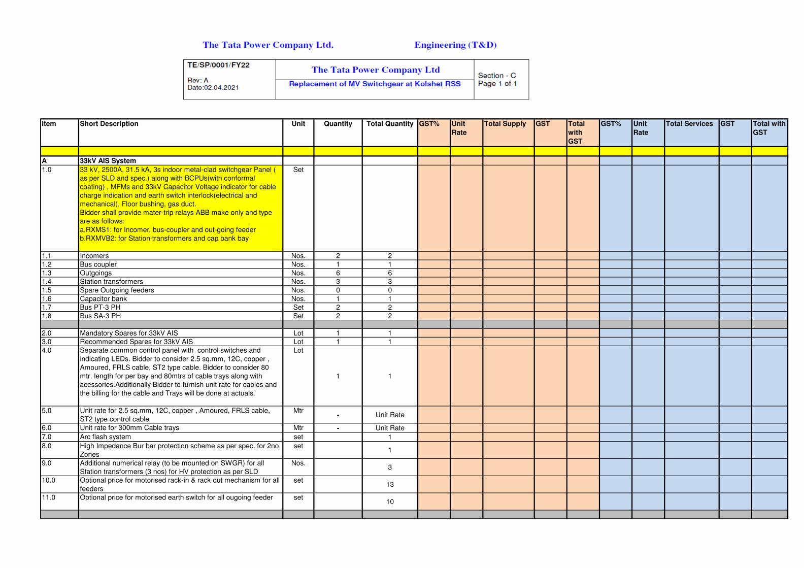
A 33kV AIS System
1.0 33 kV, 2500A, 31.5 kA, 3s indoor metal-clad switchgear Panel (
as per SLD and spec.) along with BCPUs(with conformal
coating) , MFMs and 33kV Capacitor Voltage indicator for cable
charge indication and earth switch interlock(electrical and
mechanical), Floor bushing, gas duct.
Bidder shall provide mater-trip relays ABB make only and type
are as follows:
a.RXMS1: for Incomer, bus-coupler and out-going feeder
b.RXMVB2: for Station transformers and cap bank bay
Set
1.1 Incomers Nos. 2 2
1.2 Bus coupler Nos. 1 1
1.3 Outgoings Nos. 6 6
1.4 Station transformers Nos. 3 3
1.5 Spare Outgoing feeders Nos. 0 0
1.6 Capacitor bank Nos. 1 1
1.7 Bus PT-3 PH Set 2 2
1.8 Bus SA-3 PH Set 2 2
2.0 Mandatory Spares for 33kV AIS Lot 1 1
3.0 Recommended Spares for 33kV AIS Lot 1 1
4.0 Separate common control panel with control switches and
indicating LEDs. Bidder to consider 2.5 sq.mm, 12C, copper ,
Amoured, FRLS cable, ST2 type cable. Bidder to consider 80
mtr. length for per bay and 80mtrs of cable trays along with
acessories.Additionally Bidder to furnish unit rate for cables and
the billing for the cable and Trays will be done at actuals.
Lot
1 1
5.0 Unit rate for 2.5 sq.mm, 12C, copper , Amoured, FRLS cable,
ST2 type control cable
Mtr- Unit Rate
6.0 Unit rate for 300mm Cable trays Mtr - Unit Rate
7.0 Arc flash system set 1
8.0 High Impedance Bur bar protection scheme as per spec. for 2no.
Zones
set1
9.0 Additional numerical relay (to be mounted on SWGR) for all
Station transformers (3 nos) for HV protection as per SLD
Nos.3
10.0 Optional price for motorised rack-in & rack out mechanism for all
feeders
set13
11.0 Optional price for motorised earth switch for all ougoing feeder set10
Item Quantity GST% Unit
Rate
Total Services GSTTotal
with
GST
Unit
Rate
Total Supply Total with
GST
GST% GSTTotal QuantityShort Description Unit
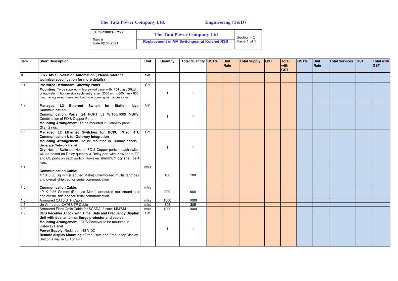
Item Quantity GST% Unit
Rate
Total Services GSTTotal
with
GST
Unit
Rate
Total Supply Total with
GST
GST% GSTTotal QuantityShort Description Unit
B 33kV AIS Sub-Station Automation ( Please refer the
technical specification for more details)
Set
1.1 Pre-wired Redundant Gateway Panel
Mounting: To be supplied with prewired panel with IP54 class (Rittal
or equivalent), bottom side cable entry, size : 2300 mm x 800 mm x 800
mm, having swing frame and both side opening with accessories.
Set
1 1
1.2 Managed L3 Ethernet Switch for Station level
Communication
Communication Ports: 24 PORT L3 W/100/1000 MBPS,
Combination of FO & Copper Ports
Mounting Arrangement: To be mounted in Gateway panel
Qty: 2 nos.
Set
1 1
1.3 Managed L2 Ethernet Switches for BCPU, Misc RTU
Communication & for Gateway Integration
Mounting Arrangement: To be mounted in Dummy panels /
Separate Network Panel
Qty: Nos. of Switches, Nos. of FO & Copper ports in each switch
will be based on Relay quantity & Relay port with 20% spare FO
and CU ports on each switch. However, minimum qty shall be 4
nos.
Set
1 1
1.4Communication Cable:
4P X 0.36 Sq.mm (Reputed Make) unarmoured multistrand pair
and overall shielded for serial communication
mtrs
100 100
1.5 Communication Cable:
4P X 0.36 Sq.mm (Reputed Make) armoured multistrand pair
and overall shielded for serial communication
mtrs
900 900
1.6 Armoured CAT6 UTP Cable mtrs 1000 1000
1.7 Un-Armoured CAT6 UTP Cable mtrs 305 305
1.8 Armoured Fibre Optic Cable for SCADA 8 core, MM/SM mtrs 1000 1000
1.9 GPS Receiver ,Clock with Time, Date and Frequency Display
Unit with dual antenna, Surge protector and cables
Mounting Arrangement : GPS Receiver to be mounted in
Gateway Panel
Power Supply: Redundant 48 V DC
Remote display Mounting : Time, Date and Frequency Display
Unit on a wall in C/R or R/R
Set
1 1

Item Quantity GST% Unit
Rate
Total Services GSTTotal
with
GST
Unit
Rate
Total Supply Total with
GST
GST% GSTTotal QuantityShort Description Unit
1.10 Configuration Laptop (one with protection software)
Hardware: Laptop with latest processor, 500 GB HDD, 8 GB
RAM, DVD RW, 4 USB Ports, 15" Display with 1 no. serial to
USB converter
Power Supply: 230 V DC
Microsoft Windows compatible with latest version of
configuration software, latest Microsoft Office License pack,
Antivirus Quick heal Total Security with three-year subscription,
Configuration & maintenance software tools, Diagnostic tools.
Logic building Application of SCU,BCU,RTU and Process Bus
related Configurations
Set
2 2
1.11 Temperature & Humidity Transmitter and integration with
gateway on RS485 Modbus RTU
Nos.2 2
1.12 Networking accessories like LIU, patch panel (for each Ethernet
switch), patch chords (Fibre optic, UTP) of suitable length,
Conduits for all non-armoured cables, I/O boxes with Quad face
plate, RJ45 connectors etc.
Lot
1 1
1.13 Multi-Function Meter (SATEC 130EH+) for all Bays including Bus
PTs
Nos.15 15
1.14 Mandatory Spares as per Specification Set 1 1
C Installation, Integration and Commissioning of SAS System LS
1.1
Installation, Integration and Commissioning of SAS System
a) Engineering
b) Installation and commissioning of all supplied items
c) Cable termination, continuity check of all communication
cables
d) All BCPU, MFM looping and Integration with Proposed
Gateway
e) Preparation of ICS and Signal List
f) Configuration and Testing of IED's, BCPUs, Gateway etc.
g) Time Synchronization of BCPUs with Gateway, DRCA, IEDs
with GPS Receiver
h) Integrated testing with purchasers existing Unified SCADA
System
i) I/O testing, Pre- SAT testing of Hardware and Software
functionality
j) Integrated FAT & SAT for Hardware and Software
k) Submission of as-built drawing in AutoCAD and PDF Format
LS
1 1

Item Quantity GST% Unit
Rate
Total Services GSTTotal
with
GST
Unit
Rate
Total Supply Total with
GST
GST% GSTTotal QuantityShort Description Unit
1.2 Warranty for Supplied Hardware & Software inclusive of patch
management and software upgradation for the period of 5 Years
1.3 Services of M/s Kalkitech for Configuration, integration with both
local DRCA System of the respective station & Centralised
DRCA system at 110kV Kolshet RSS
d Training
1.1 Training Mandays at Site Manday - 5
1.2 Training Mandays at Vendors Works Manday - 5
Notes
Quantities indicated are Indicative only and shall vary based on
site conditions and layout. The rates shall be fixed. Contractor
has to provide a separate list with rate and cost separately and
give total price for complete Electrical works. Items not listed
but required for completing the works shall be done by the
contractor without any additional payments.
Supply: Rates for Supply shall include all taxes, Duties,
levies,Packing and forwarding, Transport to site,Transit
insurance, unloading, safe storage.
Installation: Rates for installation shall include all taxes.Handling,
Storage, movement to site,assembly,
alignment,cleaning,installation, testing and commissioning
including labour, tools, tackles, consumables, complete.

TE/SP/0001/FY22 Rev: A Date:02.04.2021
The Tata Power Company Ltd Section - A Page 1 of 9
Replacement of MV Switchgear at Kolshet RSS
C2- PROJECT TIME SCHEDULE
Seal of the Company Signature
Designation
Note: The bidder shall indicate schedule of milestones and also attach/furnish a detailed bar chart identifying customer inputs.

The Tata Power Company Ltd. Corporate Engineering
TE/SP/0001/FY22 Rev: A Date:02.04.2021
The Tata Power Company Ltd
Section-A Page 2 of 9
Replacement of MV Switchgear at Kolshet RSS
C3- SCHEDULE OF DEVIATIONS FROM TECHNICAL SPECIFICATIONS
All deviations from this specification, shall be set out by the Bidders, indicating clause no and page in this schedule. Unless specifically mentioned in this schedule, the tender shall be deemed to conform to the purchaser’s specifications: Sr. No. Clause No. Details of deviation with justifications -------- --------------- --------------------------- We confirm that there are no deviations apart from those detailed above. Seal of the Company Signature
Designation

The Tata Power Company Ltd. Corporate Engineering
TE/SP/0001/FY22 Rev: A Date:02.04.2021
The Tata Power Company Ltd
Section-A Page 3 of 9
Replacement of MV Switchgear at Kolshet RSS
C4- SCHEDULE OF DEVIATIONS FROM GENERAL & SPECIAL CONDITIONS OF
CONTRACT All deviations from this specification, shall be set out by the Bidders, indicating clause no and page in this schedule. Unless specifically mentioned in this schedule, the tender shall be deemed to conform to the purchaser’s specifications:
Sr. No. Clause No. Details of deviation with justifications -------- --------------- --------------------------- We confirm that there are no deviations apart from those detailed above. Seal of the Company
Signature
Designation
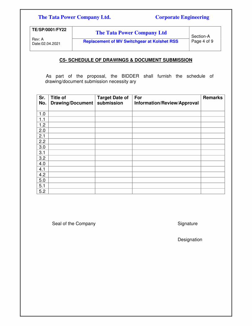
The Tata Power Company Ltd. Corporate Engineering
TE/SP/0001/FY22 Rev: A Date:02.04.2021
The Tata Power Company Ltd
Section-A Page 4 of 9
Replacement of MV Switchgear at Kolshet RSS
C5- SCHEDULE OF DRAWINGS & DOCUMENT SUBMISSION
As part of the proposal, the BIDDER shall furnish the schedule of
drawing/document submission necessity ary Sr. No.
Title of Drawing/Document
Target Date of submission
For Information/Review/Approval
Remarks
1.0
1.1 1.2 2.0 2.1 2.2 3.0 3.1
3.2 4.0 4.1 4.2 5.0 5.1
5.2
Seal of the Company Signature Designation

The Tata Power Company Ltd. Corporate Engineering
TE/SP/0001/FY22 Rev: A Date:02.04.2021
The Tata Power Company Ltd
Section-A Page 5 of 9
Replacement of MV Switchgear at Kolshet RSS
C6- SCHEDULE OF MANDATORY SPARES
As part of the proposal, the BIDDER shall indicate below the list of recommended spares for three years of trouble free operation of the equipment/system offered by him. Sr. No.
Description of spare
Quantity recommended per unit of equipment
Unit price Total price Delivery period from date of LOI
Remarks
Seal of the Company Signature Designation

The Tata Power Company Ltd. Corporate Engineering
TE/SP/0001/FY22 Rev: A Date:02.04.2021
The Tata Power Company Ltd
Section-A Page 6 of 9
Replacement of MV Switchgear at Kolshet RSS
C7 - SCHEDULE OF SPECIAL ERECTION/MAINTENANCE TOOLS & TACKLES As part of the proposal, the BIDDER shall indicate below, the list of erection/maintenance tools & tackles offered by him. Sr. No.
Description of spare
Quantity recommended per unit of equipment
Unit price
Total price
Delivery period from date of LOI
Remarks
Seal of the Company Signature Designation

The Tata Power Company Ltd. Corporate Engineering
TE/SP/0001/FY22 Rev: A Date:02.04.2021
The Tata Power Company Ltd
Section-A Page 7 of 9
Replacement of MV Switchgear at Kolshet RSS
C8 - SCHEDULE OF PLACES OF MANUFACTURE, TESTS AND INSPECTION
For major equipment / systems, the Bidder shall indicate the name of the Manufacturer / SUB CONTRACTOR and place of test and inspection. ITEM OF EQUIPMENT
Manufacturer / SUBCONTRACTOR
PLACE OF TESTING & INSPECTION
Seal of the Company Signature Designation

The Tata Power Company Ltd. Corporate Engineering
TE/SP/0001/FY22 Rev: A Date:02.04.2021
The Tata Power Company Ltd
Section-A Page 8 of 9
Replacement of MV Switchgear at Kolshet RSS
C9- SCHEDULE OF RECOMMENDED SPARES
As part of the proposal, the BIDDER shall indicate below the list of recommended spares for three years of trouble free operation of the equipment/system offered by him. Sr. No.
Equipment tag no.
Description of spare
Material of construction
Part no
Quantity recommended per unit of equipment
Unit price
Total price
Delivery period from date of LOI
Remarks
Seal of the Company Signature Designation

The Tata Power Company Ltd. Corporate Engineering
TE/SP/0001/FY22 Rev: A Date:02.04.2021
The Tata Power Company Ltd
Section-A Page 9 of 9
Replacement of MV Switchgear at Kolshet RSS
DRAWINGS AND DOCUMENTS
D1 TENDER PURPOSE D2 AFTER AWARD OF CONTRACT
WRENCH system to be followed for submission of drawings & documents


Annexure-2: Room layout drawing

SECTION C- GCC & SCC

GCC-Supply (Annexure to Tender Documents)

The Tata Power Company Limited General Terms and Conditions‐ Indigenous Supply Rev. BPS‐In‐02
Rev. date: 25 July 2017 Page 1 of 8
The Tata Power Company Limited is hereunder referred to as the “Purchaser” or “Company”. The person, firm or company selling the goods, the subject of this purchase order is referred to as “Vendor” or “Contractor”. The subject of this purchase order is hereinafter referred to as the “Material(s)”or “Goods”.
The Contract shall mean the contract as derived from the following:
1. Purchase Order (with ‘Commercial Notes’ and Annexures to the Purchase Order referred thereon)
2. Technical Specifications. 3. General Terms & Conditions
The documents including all reference document (s) and Annexures forming the Contract are to be read together as a whole and are to be taken as mutually explanatory. 1. Price:
Unless otherwise specifically stipulated, the price shall be firm and shall not be subject to escalation for any reason till the validity of this Contract.
Unless otherwise specifically stipulated, the price shall be inclusive of road/ rail worthy water-proof packing & forwarding charges up to effecting delivery at FOT/ FOR despatch point, GST and shall also be inclusive of inland freight, terminal taxes and entry taxes as leviable on the transportation or entry of goods into any local area limits pursuant to the Contact.
2. Taxes and Duties:
2.1 The Contract Price shall be inclusive of all taxes, duties, including but not limited to GST or any local taxes, levies imposed by State/Central/Local governments
2.2 Taxes as mentioned in the Contract Price or Price Schedule shall be paid to the contractor subject to the Contractor complying with all the statutory requirements and furnishing the relevant documents including error free invoices containing detailed break-up of the taxes
2.3 However the payment of GST or local levies shall
be restricted to the total amount as indicated in the price schedule.
2.4 Any duties, levies or taxes not mentioned in
Contract Price or Price Schedule but applicable as per any statute (s) shall be deemed to be
included in the Contract price and shall be to the account of the Contractor.
2.5 Any statutory variation in duties, levies or taxes if applicable and specified in this Contract till the scheduled date for supply of Goods and limited to direct invoices of the Contractor shall be to the account of Purchaser. The Contractor shall have the obligation to provide the necessary documentary evidence / supporting by way of gazetted notifications etc. to prove the change in such levies or taxes between the due date of submission of the Bid and the scheduled date of supply of goods to claim the difference.
2.6 The Contractor shall pass on to the Purchaser all the benefits of either reduction in tax rates, exemptions, concessions, rebate, set off, credits etc. or introduction of new tax rates exemptions, concessions, rebate, set off, credits etc. pertaining to all taxes, duties, imposts, fees and levies in respect of the supplies of Goods or performance of obligations under the contract. This would specifically include reduction of tax rates as a result of statutory changes or judicial rulings.
2.7 Any other taxes, levies and duties not mentioned in Contract Price or Price Schedule but applicable as per any statute (s) or introduction (omission) of new taxes, levies and duties shall be deemed to be included in the Contract Price and shall be to the account of the Contractor.
2.8 For facilitating availment of a credit, set-off,
rebate, drawback or like benefit available to the Purchaser, the Contractor will facilitate the Purchaser by providing the necessary documentary and/or procedural support. In any process of assessment or re-assessment, of taxes payable by the Purchaser. Wherever expressly agreed the purchaser would provide the statutory form ‘C’ to the seller for availing the concessional rate of Central sales tax.
2.9 The Contractor shall bear and pay all the costs,
liabilities, levies, interest, penalties in respect of non-compliances of any legal requirements as per various statutory provisions. The contractor shall keep the owner indemnified at all times from any tax liability, interest, penalties or assessments that may be imposed by the statutory authorities for non-compliances or non-observation of any statutory requirements by the Contractor.
2.10 Purchaser shall pay the invoices to the Vendor after necessary deductions as prescribed under the applicable law, income – tax or other

The Tata Power Company Limited General Terms and Conditions‐ Indigenous Supply Rev. BPS‐In‐02
Rev. date: 25 July 2017 Page 2 of 8
deductions under the State Tax laws as may be applicable to the Contract.
3 Packing details:
Packing details: The material must be packed in suitable packing to suit the mode of transport and to ensure its safe receipt at point of delivery. Any damage to material noticed at the time of delivery at site, due to improper packing or any other reason whatsoever shall be the responsibility of the Vendor. Such damaged goods shall be replaced within 14 days from intimation from the Purchaser.
4 Transportation and Unloading at Site:
The Vendor shall deliver the Material(s) at site/ Stores as per the delivery address specified in the Purchase order. The unloading at delivery shall be organised by the Purchaser unless otherwise specified. The receipt of the material/ equipment is subject to inspection and rejection if Material(s) is found unsatisfactory or any of the clauses under this purchase order are violated.
5 Insurance: Unless otherwise specified, Purchaser will be
responsible to obtain transit insurance for the Material(s). The Vendor shall intimate the Order Manager (as mentioned in the Purchase Order) along with Invoice, packing list, the Railway Receipt/Truck or Lorry Receipt etc. immediately after the consignment is booked, at the e-mail id mentioned in the Purchase order.
6 Payment Terms:
100% payment shall be made within 60 days from the receipt and acceptance of the material at the Consignee Stores/ Site/ Location as per the Contractual terms and conditions herein.
7 Bills and invoice:
The tax invoices should contain the details to comply with the GST Law. The supplier shall:
i) Furnish (electronically) and communicate to the Owner, the details of Goods or Services supplied by the 10th of the month succeeding the said tax period,
ii) Upon discovery of any discrepancy, rectify it and shall pay the tax and interest thereof,
iii) Furnish the returns (electronically), for the inward and outward supplies of
Goods and/or Services, before the specified dates as per the GST Law,
iv) Communicate the tax paid, credits etc. as and when credited.
v) The Invoice should clearly state the description of the goods, quantity, sale price, tax %, and tax amount;
vi) The Invoice should be signed by an Authorized Signatory.
Bills/Invoices in the name of The Tata Power Company Ltd. with packing lists in triplicate shall be forwarded along with the equipment. Contractor to furnish GST Registration no. in all invoices as well as Purchaser’s (Tata Power’s) GST no.
8 Transfer of Title and risk:
The transfer of property and risk of Material(s) shall be deemed to take place as follows: a. For delivery F.O.R. or F.O.T. despatch
point: Transfer of property on handing over the Material(s) to the carrier against receipt of clean Railway Receipt/Truck or Lorry Receipt and such receipt having been handed over to Purchaser. However, the risk of loss shall pass to the Purchaser on delivery of goods at the specified destination.
b. In case the Material(s) are procured by the Vendor from sub-vendors on receipt of duly endorsed documents of title to the goods.
9 Contract Performance Bank Guarantee (In
case applicable):
9.1 The Vendor shall within 15 days of issue of this Purchase Order furnish an unconditional irrevocable bank guarantee duly stamped and strictly as per the prescribed format of the Purchaser from any nationalized bank or any scheduled bank having a branch in Mumbai and approved by the Purchaser for a sum equivalent to 10% of the Total value of Order valid for a period not less than 6 months from the expiry of the Warranty period.
9.2 Irrespective of the performance demonstrated as part of the Factory Acceptance Tests Take-over tests / Performance Tests etc, the Purchaser may call for re-validation of performance of the system during the performance guarantee period by conducting fresh performance tests if in its opinion, the

The Tata Power Company Limited General Terms and Conditions‐ Indigenous Supply Rev. BPS‐In‐02
Rev. date: 25 July 2017 Page 3 of 8
system is not able to deliver the designed performances based on its operational performance results. If the equipment fails to prove the performance during such performance tests, the Purchaser may allow the Vendor to either rectify the system by addition / modification of equipment etc at the Vendor’s costs & risk to restore the performance levels. Failure to rectify the system to achieve the designed performance levels may result in imposition of penalties including revocation of the Performance Bank Guarantee and forfeiture of the entire amount under the Performance Guarantee.
9.3 In case the Vendor fails to furnish the requisite Bank Guarantee as stipulated above, then the Company shall have the option to terminate the contract besides other contractual remedies.
10 Price reduction:
10.1 The Vendor agrees that time of supply of Material(s) is of prime importance. If the Vendor fails to supply Material(s) before the respective scheduled / fixed date for supply. Company may without prejudice to any other right or remedy available to the Company: - 10.1.1 Recover from the Vendor ascertained
and agreed, genuine pre-estimate liquidated damages, and not by way of penalty, a sum equivalent to 1% (of total value of order) per week or part thereof for each week’s delay, beyond the scheduled supply date each subject to maximum of 10% of the total order value, even though the Company may accept delay in supply after the expiry of the scheduled supply date. The Company may, at its discretion, set off the aforesaid amounts from any other amounts owed by the Company to the Vendor or recover such amounts in other manner as may be permissible under applicable laws.
10.1.2 Arrange to get supply from elsewhere on account and at the sole risk of the Vendor, such decision of the Company being final and binding on the Vendor; or
10.1.3 Terminate the contract or a portion of supply of the supply work thereof, and if so desired, arrange for the supply in default by the Vendor to be attained from elsewhere at the sole risks and costs of the Vendor.
10.2 Liquidated damages for performance shortfall (if applicable) shall be specified in the Technical Specifications.
10.3 The Liquidated Damages referred in this clause 10 may be recovered by the Company from the Vendor as set off against any monies owed by the Company to the Vendor or in any other manner permissible under applicable laws.
11 Warranties:
11.1 Materials and Workmanship: Vendor shall fully warrant that all the stores, equipment and component supplied under the order shall be new and of first class quality according to the specifications and shall be free from defects (even concealed fault, deficiency in design, materials and workmanship).
11.2 Should any defects be noticed in design, material and/or workmanship within 12 months after the Material(s) or any portion thereof as the case may be have been commissioned or for 24 months from the date of delivery, whichever period concludes earlier. Purchaser shall inform Vendor and Vendor shall immediately on receipt of such intimation, depute their personnel within 7 days to investigate the causes of defects and arrange rectification/ replacement/modification of the defective equipment at site, without any cost to Purchaser within a reasonable period. If the Vendor fails to take proper corrective action to repair/replace defects satisfactorily within a reasonable period, Purchaser shall be free to take such corrective action as may be deemed necessary at Vendor’s risk and cost after giving notice to the Vendor, including arranging supply of the Goods from elsewhere at the sole risk and cost of the Vendor.
11.3 In case defects are of such nature that equipment shall have to be taken to Vendor’s work for rectification etc., Vendor shall take the equipment at his costs after giving necessary undertaking or security as may be required by Purchaser. After repair Vendor shall deliver the equipment at site on freight paid basis. Any taxes applicable in relation to this repair shall be to the Vendor’s account. All risks in transit to and fro shall be borne by the Vendor.
11.4 Equipment or spare parts thereof replaced shall have further warranty for a period of 12 months from the date of acceptance.
12 Quality, Testing, inspection, installation:
12.1 All Material(s) supplied under this Contract
shall be new and unused.

The Tata Power Company Limited General Terms and Conditions‐ Indigenous Supply Rev. BPS‐In‐02
Rev. date: 25 July 2017 Page 4 of 8
12.2 Wherever a specific Quality Assurance Plan is provided with the Request for Quotation (RFQ) or agreed as part of the commercial/ technical discussions, the same shall be binding on the Vendor.
12.3 The material shall be inspected a. At consignee end by Purchaser.
b. At factory premise of the Vendor/ sub-
vendor by Purchaser or third party duly nominated by Purchaser. The Vendor shall extend all necessary co-operation to Purchaser/ third party inspector carrying out the inspection. The Inspector(s) shall have the right to carry out the inspection or testing, which will include inspection and testing of the raw materials at manufacturers shop, at fabricators shop and at the time of actual despatch before and/or after completion of packing.
12.4 The Vendor will inform Purchaser at least eight (8) days in advance of the exact place, date and time of tendering the Material(s) for required inspection and provide free access to the Inspector(s) during normal working hours at Vendor’s or his/ its sub-Suppliers works, and place at the disposal of the Inspector(s) all useful means for undertaking the Inspection, checking the results of tests performed, marking the Material(s), getting additional tests conducted and final stamping of the Material(s).
12.5 Even if the inspection and tests are fully carried out, the Vendor shall not be absolved from its responsibilities to ensure that the Material(s), raw materials, components and other inputs are supplied strictly to conform and comply with all the requirements of the Contract at all stages, whether during manufacture and fabrication, or at the time of Delivery as on arrival at site and after its erection or start up or consumption, and during the defect liability period. The inspections and tests are merely intended to prima facie satisfy Purchaser that the Material(s) and the parts and components comply with the requirements of the Contract.
12.6 All costs associated with the inspection shall be included in cost of Material(s).
12.7 Original material test certificate/ performance test certificate/ fitment certificate/ test reports etc. relevant/ applicable as per the
specifications/ standards shall be dispatched along with the material supply failing which the material may be rejected.
13 Rejection:
13.1 Rejected goods shall be removed and replaced within 14 days of the date of communication of rejection.
13.2 Claim in respect of breakage/shortages in any cases shall be referred on the Vendor within ninety (90) days from the date of receipt of Goods by the Purchaser which shall be replaced/made good by the Vendor at his own cost. All risk of loss or damage to the material shall be upon the Vendor till it is delivered to the purchaser/consignee.
14 General Indemnity:
The Vendor shall indemnify and keep the Purchaser indemnified from and against any and all claims, costs, liabilities (financial), litigations, compensations, judgments, expenses or damages (including attorney's fees and other related expenses) arising out of any breach or alleged breach of any of the conditions of this Contract, performance of the obligations hereunder, or any representation or misrepresentation made by the Vendor or any third party with regard to the subject of this Contract.
15 Indemnity against IPR:
The equipment, system, drawings, and other materials that shall be supplied against the order will become the Purchaser’s property. Without limitation of any liability of whatsoever nature, the Purchaser shall be indemnified and kept indemnified against any claim for infringement or breach of any of the statues, rules & regulations by the use of or sale of any article or material supplied by the Vendor. The indemnity shall include any infringement of patent, trade mark, design, copyright or other property rights whether in Country of Origin, or elsewhere resulting from the Vendor’s design, manufacture, use, supply or re-supply & would also cover use or sale of any article or material supplied by the Vendor to the Purchaser under the Purchase Order. The Indemnity shall cover any claim/action taken by a third party either directly against the Purchaser or any claim/action made against the Vendor & where under the Purchaser is made liable. The

The Tata Power Company Limited General Terms and Conditions‐ Indigenous Supply Rev. BPS‐In‐02
Rev. date: 25 July 2017 Page 5 of 8
Indemnity shall be for losses, damages, and costs including litigation costs, attorney fees etc incurred by the Purchaser in relation to the Purchase Order.
16 Latent Defects Liability period (if applicable): Notwithstanding the inspections, acceptance tests, quality checks etc carried out by the Vendor and witnessed/accepted by the Purchaser, the Vendor shall further warrant the equipment for any latent defects in its design, material or workmanship against the specifications set forth and shall make good any such defects by way of repair or replacement of the part or whole of the defective product at its own cost & risks as and when such latent defects are observed and intimated by the Purchaser and intimated to the Vendor within 36 months of completion of warranty period.
17 Force Majeure:
17.1 In the event of either party being rendered unable by force majeure to perform any obligation required to be performed by it under this Contract the relative obligation of the party affected by such force majeure shall, after notice under this articles be suspended for the period during which such cause lasts. The term ‘Force Majeure’ as employed herein shall mean acts of God, wars (declared or undeclared), riots or civil commotion, fire, floods, and acts and regulations of the Government of India or State Government or any of the statutory agencies. Both the party shall pay to the other party, the amount payable upon the date of the occurrence of such force majeure.
17.2 Upon the occurrence of such cause and upon its termination, the party alleging that it has been rendered unable as aforesaid, thereby shall notify the other party in writing immediately but not later than twenty four (24) hours of the alleged beginning and ending thereof giving full particulars and satisfactory evidence in support of the claims.
17.3 During the period, the obligations of the parties are suspended by force majeure, the contractor shall not be entitled to payment of any rate.
17.4 In the event of the force majeure conditions continuing or reasonably expected to continue for a period more than thirty (30) days, Purchaser shall have the option of terminating the contract by giving seven (7) days notice thereof to the contractor.
18 Variation: Except for any provisions in this Purchase Order, any change /modification to the terms and conditions of this Order can be issued only by Purchaser or with the prior written approval from Purchaser.
19 Termination
19.1 The Contract shall be deemed to be terminated on completion of delivery of Material(s)
19.2 Termination of Default by Vendor: Purchaser may terminate the contract at any
time if the Vendor fails to carry out any of his obligations including timely delivery under this Contract. Prior to termination, the Vendor shall be advised in writing of the causes of unsatisfactory performance to be improved upon 15 days of the receipt of notice. In case, if the Vendor fails to bring about the improvement to the satisfaction of the Purchaser, then the order shall be terminated.
19.3 Without prejudice to the rights and remedies
available to Purchaser, Purchaser may terminate the Contract or part thereof with immediate effect with written notice to the Vendor if,: 19.3.1 The Vendor becomes bankrupt or goes
into liquidation. 19.3.2 The Vendor makes a general
assignment for the benefit of creditors. 19.3.3 A receiver is appointed for any
substantial property owned by the Vendor.
19.3.4 The Vendor has misrepresented to Purchaser, acting on which misrepresentation Purchaser has placed the Purchase Order on the Vendor.
The Vendor/ Contractor shall not be entitled to
any further payment under the Contract if the Contract is terminated. If the order is terminated under clause 19.2 and 19.3, the Vendor shall not be entitled to any further payment, except that, if Purchaser completes the supply of Material(s) and the costs of completion are less than the Total Order value, the Purchaser shall pay Vendor an amount properly allocable to supply of Material(s) fully performed by Vendor prior to termination for which payment was not made to Vendor. In case, the cost of completion of Material(s) exceed the total Order value, the additional cost incurred by Purchaser for such completion shall be paid by the Vendor.

The Tata Power Company Limited General Terms and Conditions‐ Indigenous Supply Rev. BPS‐In‐02
Rev. date: 25 July 2017 Page 6 of 8
19.4 Purchaser shall be entitled to terminate the Contract at it’s convenience, at any time by giving thirty (30) Days prior notice to the Contractor. Such notice of termination shall specify that termination is for Companies convenience and the date upon which such termination becomes effective. Upon receipt of such notice, the Contractor shall proceed as follows: 19.4.1 cease all further work, except for such
work as may be necessary and instructed by the Company/ Company’s representative for the purpose of protecting those parts of the supplies already manufactured;
19.4.2 stop all further sub-contracting or purchasing activity, and terminate Sub-contracts;
19.4.3 handover all Documents, equipment, materials and spares relating to the supply of goods prepared by the Contractor or procured from other sources up to the date of termination for which the Contractor has received payment equivalent to the value thereof; and
19.4.4 handover those parts of the supplies manufactured by the Contractor up to the date of termination.
Upon termination pursuant to clause 19.4, the Vendor shall be entitled to be paid the full value on the Material(s) delivered in accordance with the Contract.
19.5 The Contractor shall not be released from any of his obligations or liabilities accrued under the Contract on termination. For the avoidance of doubt, the termination of the Contract in accordance with this clause shall neither relieve the Contractor of his accrued obligations for Warranty or his accrued liability to pay (liquidated) damages for Delay nor shall entitle him to reduce the value of Performance Security.
20 Sub letting and assignment: The contractor shall not without prior consent in writing of the Purchaser, sublet, transfer or assign the contract or any part thereof or interest therein or benefit or advantage thereof in any manner whatsoever, provided nevertheless that any such consent shall not relieve the contractor from any obligation, duty or responsibility under the contract.
21 Dispute Resolution:
Dispute or differences arising out or relating to this Order shall be resolved amicably by the parties. Failing such amicable resolution of dispute / differences either party may refer the matter to arbitration of a Sole Arbitrator to be appointed jointly by both the parties. The award of the Arbitrator shall be final, binding and conclusive on the parties. The venue for arbitration shall be Mumbai. The Arbitration proceedings will be governed and regulated by the provisions of Indian Arbitration and Conciliation Act, 1996 as amended from time to time and the rules framed there under.
22 Governing laws
This Contract shall be construed in accordance with and governed by the Laws of India without giving effect to any principle of conflict of law.
23 Jurisdiction This Contract and the transaction contemplated herein shall be subject to the exclusive jurisdiction of the competent Courts in Mumbai only.
24 Limitation of Liability
Notwithstanding anything contained in the Contract, the Contractor’s aggregate liability under this Contract shall be limited 100% of the Total order value. This shall however, exclude liability arising pursuant to clause 2.8- tax indemnity, clause 14- General Indemnity, clause 15- Indemnity against IPR, clause 25 – Confidentiality and liabilities arising due to wilful misconduct, gross negligence, third party claims and corrupt acts attributable to the Vendor.
25 Confidentiality:
The Vendor shall use the Confidential Information of the Purchaser only in furtherance of this Contract and shall not transfer or otherwise disclose the Confidential Information to any third party. The Vendor shall (i) give access to such Confidential Information solely to those employees with a need to have access thereto; and (ii) take the same security precautions to protect against disclosure or unauthorized use of such Confidential Information that the party takes with its own confidential information but, in no

The Tata Power Company Limited General Terms and Conditions‐ Indigenous Supply Rev. BPS‐In‐02
Rev. date: 25 July 2017 Page 7 of 8
event, shall a party apply less than a reasonable standard of care to prevent such disclosure or unauthorized use.
26 Consequential Damages:
Unless otherwise specified, neither Party shall be responsible for and nor shall be liable to the other Party for indirect/consequential losses and damages suffered by such Party including for loss of use, loss of profit whether such liability or claims are based upon any negligence on the part of the other Party or its employees in connection with the performance of the Purchase Order.
27 New Legislation (The Micro, Small and Medium Enterprise Development Act 2006)
a. This Act has been enacted and made effective from 2nd October 2006. The Interest on Delayed Payments to Small Scale and Ancillary Industrial Undertaking Act, 1993 is repealed.
b. Vendor is requested to inform the purchaser if vendor fall under The Micro, Small and Medium Enterprises Development Act, 2006 legislation and provide the purchaser, registration number and date to enable purchaser to take necessary care. The vendors are also requested to mention the same on their invoice / bill.
28 Relation between parties:
The Purchase Order shall be entered into on a principal-to-principal basis only. The Purchase order shall not be construed as a partnership or an association of persons. There is no agent and principal relationship between the parties. Each party shall be responsible for its own conduct. The Vendor shall ensure at all times that all the work carried out under this contract either by its own person or through any of its sub-Vendors shall be always done under its own direct supervision.
29 Environment / ISO 14001 Certification: The Vendor to confirm whether their organization is ISO 14001 certified. If not, the Vendor must certify that the handling, use and disposal of their product / by-products conform to practices consistent with sound environmental management and local statutes. The Vendor shall ensure that all the wastes are disposed in environmental friendly way with strict compliance to applicable laws including
adherence to MoEF guidelines with respect to disposal of batteries, lead waste, copper cables, ash, waste oil, e-waste etc which shall be disposed through MoEF approved parties only. The Vendor shall also be responsible to collect and recycle all the e-waste generated at the end of the product life cycle at its own costs and risks as per the MoEF guidelines/ orders.
30 Tata Code of Conduct
The Purchaser abides by the Tata Code of Conduct in all its dealing with stake holders and the same shall be binding on the Purchaser and the Vendor for dealings under this Purchase Order. A copy of the Tata Code of Conduct is available at our website: http://www.tatapower.com/aboutus/code-of-conduct.aspx. The Vendor is requested to bring any concerns regarding this to the notice of our Chief Ethics Officer on the e-mail ID: [email protected].
31 Responsible Supply Chain Management: The Purchaser is committed for a cleaner environment and respect of Human rights through its Responsible Supply Chain Management policy. The Vendor is required to comply with all the environment & Human rights related laws, including emission norms, Labour and environmental regulations. The Purchaser encourages its Vendors/ Contractors/ Business partners to pay more attention to green design, green supply, green production, green logistics and green packaging in performing their business obligations.
The Vendor is required to abide by the Tata Power Corporate Environment policy, Energy Conservation and Corporate Sustainability Policy.
A copy of the Responsible Supply Chain Management Policy along with Environment policy, Energy Conservation policy, Sustainability policy, Health & Safety policy and Human Rights policy is available at website: http://www.tatapower.com/sustainability/policies.aspx. Vendor/Bidder is required to completely fill the attached “Supplier Sustainability Questionnaire” in support of their Green Supply Chain Management initiatives and submit the same with their offer.

The Tata Power Company Limited General Terms and Conditions‐ Indigenous Supply Rev. BPS‐In‐02
Rev. date: 25 July 2017 Page 8 of 8
The Owner recognizes that diversity in the workplace positively impacts business. The Owner is committed to help people from SC/ST background either by helping them to become entrepreneurs or by engaging workforce from SC/ST community under the contracts agreed herein. To encourage engaging SC/ST community, the owner may consider on the merit to incentivize the Contractor by paying additional 1% of the service contract portion if the number of SC/ST workforce engaged in the contract exceeds 30% of the total deployed strength and 2%, if the strength goes beyond 50%. While the Contractor will assist the workforce so engaged to become self-reliant in meeting the work expectation, the Owner may also volunteer its training resources to the extent possible to improve their employability. The Contractor shall maintain the proper documentation of such category of the workforce engaged and the owner may consider to pay the incentive after its verification.
The Owner may also consider extending price preference of 5% in the bid evaluation for an order value up to Rs.50 Lacs, provided the company is owned by a person from SC/ST community having minimum 50% holding in the company.
32 Vendor rating
You are requested to ensure compliance to the terms of the individual orders with regards to timely delivery, provision of all applicable documents / challans / test certificate, quality of the material etc. Your performance with respect to the said factors will be taken into consideration for future business.
33 Vendor Feedback:
33.1 In this dealing Vendors feedback is important for the purchaser to improve its processes. If vendor have to report any grievance, problem or require any clarification, information, vendor is requested to contact purchaser at email ID: [email protected]
33.2 Vendor is requested to ensure compliance to the terms of the individual orders with regards to timely delivery, provision of all applicable documents / challans / test certificate, quality of the material etc. Vendor performance with
respect to the said factors will be taken into consideration for future business.
34 Non-Waiver: Failure of Purchaser or its representatives to insist upon adherence to any of the terms or conditions incorporated in the Contract or failure or delay to exercise any right or remedies herein or by law accruing, or failure to promptly notify the Vendor in the event of breach or the acceptance of or the payment of any Material(s) hereunder or approval of any design or Material(s) shall not release the Vendor and shall not be deemed a waiver of any right of Purchaser to insist upon the strict performance thereof or of any of its rights or remedies as to any such Material(s) regardless of when the Material(s) are shipped, received or accepted not shall any purported oral modification or revisions of the Contract by Purchaser or its representative(s) act as waiver of the terms hereof.
35 Repeat Order:
Purchaser may place the repeat order for 100% of ordered quantities within a span of 6 months from the date of issue of this Purchase Order & Vendor shall execute it at same rates, terms and conditions.
36 Severability
If any provision of this Contract is invalid, unenforceable or prohibited by law, this Contract shall be considered divisible as to such provision and such provision shall be inoperative and shall not be part of the consideration moving from any Party hereto to the others, and the remainder of this Contract shall be valid, binding and of like effect as though such provision was not included herein.

The Tata Power Company Limited General Terms and Conditions‐ Service Rev. BPS‐Ser‐04
Rev. date: 25 Jul 2017 Page 1 of 10
The Tata Power Company Limited is hereunder referred to as the “Owner” or “Company”. The person, firm or company offering the services, the subject of this order is referred to as “Contractor”. The subject of this order is hereinafter referred to as the “Work”. “Sub-Contractor” means any person named in the Contract as a Sub-contractor, sub-vendor, manufacturer or supplier for a part of the Works or any person to whom a part of the Works has been subcontracted and the legal successors in title to such Person, but not any assignee of such Person. The Contract shall mean the contract as derived from the following:
1. Work Order (with ‘Commercial Notes’ and Annexures to the Work Order referred thereon)
2. Scope of Work. 3. General Terms & Conditions - Service
The documents including all reference document (s) and Annexures forming the Contract are to be read together as a whole and are to be taken as mutually explanatory, provided however, in the event of any inconsistency or discrepancy between the aforementioned documents, the order of precedence in interpretation of the documents shall be as set out above. For the avoidance of doubt, it is clarified that the terms set forth in the Work Order (with ‘Commercial Notes’ and Annexures to the Work Order referred thereon) shall take precedence over the terms set out in the Scope of Work, which shall in turn take precedence of the terms set out in the General Terms & Conditions – Service. 1. Contractor’s obligation:
1.1 Contractor warrants that it is a competent,
qualified and experienced contractor, equipped, organised and financed to perform and complete the services in the operating area in an efficient and professional manner and capable of meeting all the requirements of the Contract.
1.2 The Contractor has the overall responsibility of
executing the contract, conducting Planning, Job Scheduling, Maintenance Planning, Maintenance Job Scheduling, executing the Work and maintenance jobs as per the Scope of work & schedule.
1.3 Except to the extent that it may be legally or
physically impossible or create a hazard to safety, the Contractor shall comply with the Owner’s representative(s) instructions and directions on all matters relating to the Work.
1.4 Contractor shall at all times have full responsibility for control of the Equipment and for the direction and supervision of operations being carried out under the Contract.
1.5 In the performance of the Work, Contractor shall
be and act as an independent Contractor fully responsible and accountable for the proper execution of its responsibilities, obligations and
liabilities under this Contract and for its own acts and the acts of its Sub-Contractors and the Personnel. Owner’s supervision, examination or inspection of the (performance of the) Work or omission to carry out the same shall not be construed in any manner whatsoever as relieving Contractor from its responsibilities, obligations or liabilities under this Contract.
1.6 Contractor shall submit list of tools & tackles
with details of make, year of manufacturing, valid certification to the Project Manager/ User for their approval.
Project Manager may during the execution of project inspect & verify that the tools & tackles are as per the qualification requirements approved by him and will have right to seek replacements in case of any discrepancies. The Contractor shall always comply with such directives.
1.7 Contractor shall engage Tata Power Skill Development Institute (TPSDI) certified labour force at the site for execution of the job. Requirement & fees for TPSDI certification shall be as per Company Policy.
1.8 Contractor shall take full responsibility for the protection and security of Owner’s materials and equipment while such materials and equipment are temporarily stored in Contractor's facility or otherwise in Contractor's custody.
1.9 All notices, instructions, information, and other
communications given by the Contractor to Owner under the Contract shall be given to the Order Manager/ Owner’s representative, except as otherwise provided for in this Contract.
1.10 The Contractor shall make its own arrangements
for movement of personnel and equipment, within and outside the sites / units / offices at the various locations covered by the Contract.
1.11 The Contractor shall acquire in its name all
permits, approvals, and/or licenses from all local, state, or national government and other statutory authorities and/or public service undertakings that are necessary for the performance of the Contract.
1.12 Neither the Contractor nor its personnel shall
during the term of this Contract, engage in any business or professional activities in India/abroad which would conflict with the activities assigned to them under this Contract.
2. Service Warranties:
Contractor warrants that all services performed for or on behalf of Owner will be performed in a competent,

The Tata Power Company Limited General Terms and Conditions‐ Service Rev. BPS‐Ser‐04
Rev. date: 25 Jul 2017 Page 2 of 10
workmanlike manner and shall be free from faults and defects. Said warranties shall be in addition to any warranties of additional scope given by Contractor to Owner. None of said warranties and no other implied or express warranties shall be deemed is claimed or excluded unless evidenced by a change notice or revision issued and signed by Owner's authorized representative.
3. Compliance of Local Laws: Contractor shall be responsible and shall comply with the provision of all the Statutory Acts Applicable. Special attention of the Contractor is drawn towards the compliance of provision of the following statues: (along with the latest amendments/additions, as applicable):
a) The Child Labour (Prohibition and Regulation) ACT, 1986.
b) The Contract Labour (Regulation and Abolition) ACT, 1970.
c) The Employee's Pension Scheme, 1995.
d) The Employee's Provident Funds and miscellaneous provisions Act, 1952.
e) The Employees State Insurance Act, 1948.
f) The Equal Remuneration Act, 1976. g) The Industrial Disputes Act, 1947. h) The Maternity Benefit Act, 1961. i) The Minimum Wages Act, 1948. j) The Payment of Bonus Act, 1965 k) The Payment of Gratuity Act, 1972. l) The Payment of Wages Act, 1936. m) The Shops & Establishment Act,
1954. n) The Workmen's Compensation Act,
1923. o) The Employer's Liability Act, 1938. p) and any other applicable statutory
act Site Specific requirements shall be as Annexure at I. The compliance to these Site Specific requirements shall not absolve the Contractor of its obligation to comply with the Owner’s Contractor Safety Management Policy. 4. Owner’s Obligation: 4.1 The order manager (As specified in the
‘Commercial Notes’) shall have the authority to represent Owner on all day-to-day matters relating to the Contract or arising from the Contract. All notices, instructions, orders, certificates, approvals, and all other communications under the Contract shall be given by the order manager, except as otherwise provided for in this Contract. The order manager may appoint the Engineer-In-Charges for different areas for monitoring the work progress, inspections and signing of bills.
4.2 Owner shall ensure the availability of site access, all information and/or data to be arranged/ supplied by Owner to the Contractor for execution of the Work . The terms on which the Contractor shall be allowed access to the site shall be specified by the Owner prior to commencement of the execution of the Work and thereafter shall be governed in accordance with such policies as the Owner may provide in writing to the Contractor from time to time.
5. Contractor’s/ Sub-contractor’s employees: 5.1 The Contractor shall engage appropriately
qualified persons to provide the services with the prior approval of Owner. Owner may withhold such approval for any reason whatsoever.
5.2 The Contractor hereby represents and warrants that:
i) the personnel are duly qualified, and are, and will remain, sufficiently qualified, careful, skilful, diligent and efficient to provide the services to Owner; and
ii) the Services will be rendered carefully, skilfully, diligently and efficiently, and to the professional standard reasonably expected by Owner of a contractor qualified and experienced in providing services substantially the same as the Services.
5.3 The Contractor must ensure that the
Contractor’s personnel conduct themselves in a proper manner and comply with the procedures and all policies, regulations and directives of Owner including any occupational, health and safety policies and the relevant prevailing laws and regulations in the Country of operations and specifically in the area where Work is being executed.
5.4 Owner may inform the Contractor to
immediately remove Contractor’s personnel from the relevant premises in the event of misconduct or incompetence on the part of the Personnel. The Contractor shall at all times remain liable for all acts and/or omissions of its Personnel.
5.5 It is made clear that no relationship of Owner
and employee is created between Owner and the Contractor’s resident engineers, employees and no claim for employment of any such personnel shall be tenable or entertained.
6. Title of Property: 6.1 Unless otherwise provided in this order or
agreed to in writing, property of every description including but not limited to all tooling, tools, equipment and material furnished or made available to Contractor, title to which is

The Tata Power Company Limited General Terms and Conditions‐ Service Rev. BPS‐Ser‐04
Rev. date: 25 Jul 2017 Page 3 of 10
in Owner, and any replacement thereof shall be and remain the property of Owner. Such property other than material shall not be modified without the written consent of Owner. Such property shall be plainly marked or otherwise adequately identified by Contractor as being owned by Owner and shall be safely stored separately and apart from Contractor's property.
6.2 Contractor shall not use such property except for performance of work hereunder or as authorized in writing by Owner. Such property while in Contractor's possession or control shall be listed in writing and kept in good condition, shall be held at Contractor's risk, and shall be kept insured by Contractor, at its expense, in an amount equal to the replacement cost with loss payable to Owner. To the extent such property is not material consumed in the performance of this order, it shall be subject to inspection and removal by Owner and Owner shall have the right of entry for such purposes without any additional liability whatsoever to Contractor. As and when directed by Owner, Contractor shall disclose the location of such property, prepare it for shipment and ship it to Owner in as good condition as originally received by Contractor, reasonable wear and tear excepted.
7. Work Completion schedule:
Contractor shall plan and execute the Work in accordance with a detailed schedule mutually agreed upon by the Parties (Owner and Contractor).
8. Contract Price and Payment: 8.1 The Contract Price shall be a firm & fixed
Contract Value for the Work inclusive of all the taxes, levies & duties and shall remain firm till the validity of this contract.
8.2 Unless Specifically stated elsewhere in the contract, the Contractor is solely liable for payment of , and warrants that it will pay, or ensure the payment of all taxes imposed, assessment made in relation to the Work.
8.3 An amount as stated in the table below shall be
retained towards Contractor's safety performance against every RA bill:
Contract Value Retention Amount
(%)
Upto Rs. 10 lakhs 2.5
Above Rs. 10 lakhs and below Rs. 50 lakhs
2
Above 50 lakhs and upto Rs. 10 Crores
1.5
Above Rs. 10 Crores 1
The above mentioned safety retention shall be over and above any other retentions/ deferred payments as may have been specifically agreed in the Contract.
8.4 For Contract Price Rs. 1 crores or above and Contract Completion Schedule 12 months or more, the above safety retention will be released half yearly against the Safety Performance Score (methodology for evaluation enumerated in the Safety Terms & Conditions attached as Appendix to this General Terms & Condition) which will be evaluated by the Order Manager every month. For all other contracts, the above said safety retention shall be released along with the final settlement only at the end of the contract period.
8.5 The Owner shall have the right to stop any work which in its opinion is not meeting the safety standards/ guidelines of the Owner and good engineering practice. The Contractor shall not be eligible for and shall not be granted any extension in Completion Schedule due to such stoppage of work by the Owner.
8.6 The above retention towards safety shall not absolve the Contractor of its liabilities including statutory liabilities towards safety violations, injury or death (whether by accident or otherwise). An amount between Rs. 5 to 50 lakhs as deemed appropriate by Owner's appointed Committee for incident investigation and/ or as determined by statutory authorities (whichever higher), will be payable by the Contractor in case of such severe incidents of injury leading to loss of property or partial/ permanent disablement (e.g. loss of limb/s, vision etc.) or death.
8.7 Notwithstanding anything else stated in the Contract, the Contract shall be liable for termination without any notice and without recourse to Owner in case of three (3) or more severe safety violations. There shall be no termination fees/ compensation payable to Contractor for such termination.
8.8 In case the Contractor achieves 100% on the Safety Performance Score, the Contractor shall be awarded a discretionary bonus of 1% of invoiced value subject to a maximum of Rs. 50 lakhs towards Safety Performance.
8.9 Payment shall be released within 60 days of submission of error free invoice with supporting documents duly certified by the Order Manager/ Engineer-in-Charge after deducting taxes at source as prescribed under the applicable law, income – tax or other deductions under the state value added tax laws . If such payment release

The Tata Power Company Limited General Terms and Conditions‐ Service Rev. BPS‐Ser‐04
Rev. date: 25 Jul 2017 Page 4 of 10
day falls on a holiday of Owner, payment will be released on the next working day. Against deduction of statutory taxes, tax deduction certificates where ever applicable shall be issued as per the applicable provisions of the statute. The Order Manager may recover any amount wrongly paid in excess in any previous bills certified by him.
8.10 Mode of Payment: All payments shall be made direct to the Contractor or his authorized representative in the shape of RTGS or Electronics Transfer method, on certification of the Order Manager/Engineer-in-Charge and on compliance of contractual terms & conditions.
9. Taxes and Duties:
9.1 The Contract Price shall be inclusive of all taxes,
duties, including but not limited to Customs duty, GST or any local taxes, levies imposed by State/Central/Local governments.
9.2 Taxes as mentioned in the Contract Price or Price Schedule shall be paid to the contractor subject to the Contractor complying with all the statutory requirements and furnishing the relevant documents including error free invoices containing detailed break up of the taxes.
9.3 The tax invoices should contain the details to comply with the GST Law. The supplier shall:
i) Furnish (electronically) and communicate to the Owner, the details of Goods or Services supplied by the 10th of the month succeeding the said tax period,
ii) Upon discovery of any discrepancy, rectify it and shall pay the tax and interest thereof,
iii) Furnish the returns (electronically), for the inward and outward supplies of Goods and/or Services, before the specified dates as per the GST Law,
iv) Communicate the tax paid, credits etc. as and when credited.
v) The Invoice should clearly state the description of the goods, quantity, sale price, tax %, and tax amount;
vi) The Invoice should be signed by an Authorized Signatory.
Bills/Invoices in the name of The Tata Power Company Ltd. with packing lists in triplicate shall be forwarded along with the equipment. Contractor to furnish GST Registration no. in all invoices as well as Purchaser’s (Tata Power’s) GST no.
9.4 However the payment of tax shall be restricted to
the total amount as indicated in the price schedule.
9.5 Any statutory variation in duties, levies or taxes if applicable and specified in this Contract till the scheduled date for completion of Work and limited to direct invoices of the Contractor shall be to the account of Owner. The Contractor shall have the obligation to provide the necessary documentary evidence / supporting by way of gazetted notifications etc. to prove the change in such levies or taxes between the due date of submission of the Bid and the scheduled date of completion of work to claim the difference.
9.6 The Contractor shall pass on to the Owner all
the benefits of either reduction in tax rates, exemptions, concessions, rebate, set off, credits etc. or introduction of new tax rates exemptions, concessions, rebate, set off, credits etc. pertaining to all taxes, duties, imposts, fees and levies in respect of the supplies of Goods or performance of obligations under the contract. This would specifically include reduction of tax rates as a result of statutory changes or judicial rulings.
9.7 Any other taxes, levies and duties not mentioned in Contract Price or Price Schedule but applicable as per any statute (s) or introduction (omission) of new taxes, levies and duties shall be deemed to be included in the Contract Price and shall be to the account of the Contractor.
9.8 For facilitating availment of a credit, set-off, rebate, drawback or like benefit available to the Owner, the Contractor will facilitate the Owner by providing the necessary documentary and/or procedural support. In any process of assessment or re-assessment, of taxes payable by the Owner,
9.9 The Contractor shall bear and pay all the costs, liabilities, levies, interest, penalties in respect of non-compliances of any legal requirements as per various statutory provisions. The contractor shall keep the owner indemnified at all times from any tax liability, interest, penalties or assessments that may be imposed by the statutory authorities for non-compliances or non-observation of any statutory requirements by the Contractor.
9.10 All formalities required under statutes, for availing any concessions under relevant tax laws shall be adhered to by the Contractor.
9.11 Deduction at source: Recovery at source towards income tax calculated at the rate prescribed from time to time under the Income Tax Act 1961 and other relevant sections of Income Tax Act shall be made from the bills of the Contractor and the amount so recovered shall be

The Tata Power Company Limited General Terms and Conditions‐ Service Rev. BPS‐Ser‐04
Rev. date: 25 Jul 2017 Page 5 of 10
deposited with the Income Tax Department. Necessary TDS certificate to this effect will be issued to the Contractor in the prescribed pro-forma.
9.12 If any other taxes / duties / cess etc are to be recovered at source as per government regulations / Legislation from time to time, the same shall be recovered from the bills payable to the Contractor. Necessary receipt to this effect will be issued to the Contractor in this regard as per the applicable legislation.
10. Contract Performance Guarantees (If
applicable) The Contractor shall within 15 days of issuance of this Order/Contract furnish an unconditional irrevocable bank guarantee duly stamped, strictly as per the prescribed format of Owner from any nationalized bank or any scheduled bank having a branch in Mumbai and approved by the Owner for a sum equivalent to 10% of the Total Contract Price valid for the Contract Period and with a claim period of not less than 6 months from the completion of Contract Period. The issuing bank should be advised to send a direct confirmation of issue of bank guarantee to Owner. In case the Contractor fails to furnish the requisite Bank Guarantee as stipulated above, then the Owner shall have the option to cancel the Contract besides other contractual remedies. 11. Price Reduction: 11.1 In case the Contractor fails to deliver the
service/ Complete the work as per the agreed Completion Schedule including intermediate milestones (if applicable), the Owner shall recover from Contractor, as ascertained and agreed Liquidated Damages, and not by way of penalty, a sum equivalent to 1% of the Contract Value per week of delay. The Liquidated Damages referred above may be recovered by the Owner as set off against any amounts payable by the Owner to the Contractor or in any other manner in accordance with applicable laws.
11.2 The overall cap on liquidated damages shall be limited to 10% of the Contract Price.
12. Insurance 12.1 The Contractor agrees to indemnify and protect
Owner against all liability, claims or demands for injuries or damages to any person or property growing out of the performance of this order/ Contract.
12.2 The Contractor further agrees to furnish evidence of insurance showing that Contractor has and will maintain adequate insurance coverage during the life of this Contract/ order in the opinion of Owner, including but not
limited to comprehensive general liability insurance. Such evidence of insurance must set forth the name of the insurer, policy number, expiration date, and limits of liability. Compliance by Contractor with insurance requirements does not in any way affect Contractor's indemnification of Owner under Indemnification clause
13. Indemnification: The Contractor shall indemnify, save harmless and defend the Owner and keep the Owner indemnified from and against any and all claims, costs, liabilities (financial), litigations, compensations, judgments, expenses or damages (including attorney's fees and other related expenses) arising out of any breach or alleged breach of any of the conditions of this Contract including compliance to statutory laws of provisioned under clause 3, performance of the obligations hereunder, or any representation or misrepresentation made by the Contractor or by any third party in respect of death or bodily injury or in respect to loss or damage to any property with regard to the subject of this Contract.
14. Indemnity against IPR: The equipment, system, drawings, and other materials that shall be supplied against the Contract will become the Owner’s property. Without limitation of any liability of whatsoever nature, the Owner shall be indemnified and kept indemnified against any claim for infringement or breach of any of the statues, rules & regulations by the use of or sale of any article or material supplied by the Contractor. The indemnity shall include any infringement of patent, trade mark, design, copyright or other property rights whether in Country of Origin, or elsewhere resulting from the Contractor’s design, manufacture, use, supply or re-supply & would also cover use or sale of any article or material supplied by the Contractor to the Owner under the Contract. The Indemnity shall cover any claim/action taken by a third party either directly against the Owner or any claim/action made against the Contractor & where under the Purchaser is made liable. The Indemnity shall be for losses, damages, and costs including litigation costs, attorney fees etc incurred by the Owner in relation to the Contract. 15. Free Issue Material: Wherever contracts envisage supply of Free Issue Material (FIM) by the Owner to the contractor for fabrication/ use in service performance, such Free Issue Material shall be safeguarded by an insurance policy to be provided by the Contractor at his own cost for the full value of such materials and the insurance policy shall cover the following risks specifically and shall be valid for six months beyond the Contract Validity date : RISKS TO BE COVERED: Any loss or damage to the Owner’s materials due to fire, theft, riot, burglary,

The Tata Power Company Limited General Terms and Conditions‐ Service Rev. BPS‐Ser‐04
Rev. date: 25 Jul 2017 Page 6 of 10
strike, civil commotion, terrorist act, natural calamities etc. and any loss or damage arising out of any other causes such as other materials falling on Owner’ s materials. The amount for which insurance policy is to be furnished shall be indicated in the respective Contract. Free Issue material (FIM) will be issued to the Contractor only after receipt of the Insurance Policy from the Contractor. The contractor shall arrange collection of the FIM from the Owner’s premises and safe transportation of the same to his premises at his risk and cost. Notwithstanding the insurance cover taken out by the Contractor as above, the Contractor shall indemnify the Owner and keep the Owner indemnified to the extent of the value of free issue materials to be issued till such time the entire contract is executed and proper account for the free issue materials is rendered and the left over/surplus and scrap items are returned to the Owner. The contractor shall not utilize the Owner’s free issue materials for any job other than the one contracted out in this case and also not indulge in any act, commission or negligence which will cause/result in any loss/damage to the Owner and in which case, the Contractor shall be liable to the Owner to pay compensation to the full extent of damage/loss. The Contractor, shall be responsible for the safety of the free issue materials after these are received by them and all through the period during which the materials remain in their possession/control/custody. The Free issue materials on receipt at the Contractor’s works shall be inspected by them for ensuring safe and correct receipt of the material. The contractor shall report the discrepancies, if any, to the Owner within 5 days from the date of receipt of the material. The contractor shall take all necessary precautions against any loss, deterioration, damage or destruction of the FIMs from whatever cause arising while the said materials remain in their possession/custody or control. The free issue materials shall be inspected periodically at regular intervals by the Contractor for ensuring safe preservation and storage, the Contractor, shall also not mix up the materials in question with any other goods and shall render true and proper account of the materials actually used and return balance remaining unused material on hand and scrap along with the final product and if it is not possible within a period of one month from the date of delivery of the final product/ completion of Service covered by this Contract. The Contractor shall also indemnify the Owner to compensate the difference in cost between the actual cost of the free issue material lost/damaged and the claim settled to the Owner by the insurance company. 16. Relation between parties:
The Contract shall be entered into on a principal-to-principal basis only. The Contract shall not be construed as a partnership or an association of persons. There is no agent and principal relationship between the parties. Each party shall be responsible for its own conduct. The Contractor shall ensure at all times that all the work carried out under this contract
either by its own person or through any of its sub-Vendors shall be always done under its own direct supervision. 17. Safety: Contractor shall comply with all legal and statutory provisions including all rules and regulations pertaining to Safety, Health and the Environment and will be responsible for all legal liabilities arising due to any of their acts or of their personnel. The Contractor shall comply with the Owner's Contractor Safety Policy and Safety Terms and Conditions. Any misconduct and/ or violation with respect to the Owner’s Contractor Safety Policy and Safety Terms and Conditions or any other legal and statutory provisions pertaining to Safety, Health and Environment shall be dealt with as per the Safety Terms and Conditions. Prior to commencement of any work at site Contractor shall submit an undertaking in writing to adhere to and comply with all the provisions of Owner's Contractor Safety Code of Conduct. The Contractor shall have a valid ISO 14001/ OHSAS certification. In absence of the same, the Contractor shall obtain the same within 6 months from the date of the Effective Date of Contract. 18. Suspension of Work Owner may instruct Contractor at any time to suspend performance of the Work or any part thereof with a notice of 7 days for whatever reason. Provided Contractor is not in default under this Contract subject to Articles 1 and 5 inclusive, the Contractor shall be paid a mutually agreed fee, if any, necessarily incurred by Contractor as a direct consequence thereof of suspension and the Project Completion Schedule may be revised accordingly. Without prejudice to any other rights Owner may have under this Contract or at law if Contractor is in default under this Contract, Owner may instruct Contractor to suspend performance of the Work or any part thereof by giving 7 days notice till such default has been corrected to the satisfaction of Owner. Also Liquidated Damages in accordance with Clause 11 shall continue to be applicable during such period until the default is cured. The costs incurred by the Contractor for such correction shall be to the Contractor’s account, and furthermore no payment shall become due to the Contractor. Any cost incurred due to non - performance of the Contractor by the Owner shall be charged to the Contractor. 19. Change Management: Owner shall have the right at any time to order any change in the Work in accordance with the following procedure. Contractor shall furnish to Owner upon request as soon as reasonably possible but no later

The Tata Power Company Limited General Terms and Conditions‐ Service Rev. BPS‐Ser‐04
Rev. date: 25 Jul 2017 Page 7 of 10
than five (5) days following the request, a written statement specifying:
(a) the increase or decrease, as the case may be, in the costs of the Work which will result from a change in the Work as requested by Owner,
(b) any effect such change in the Work may have on any other provision of this Contract originating from either parties, and
(c) such other details as Owner may require.
Any change in costs shall be reasonably related to the proportional change in the Work and any other costs incurred by Contractor. If Owner agrees to Contractor’s statement Owner shall notify Contractor thereof in writing in the form of a change order, whereupon the change in the Work shall be incorporated in the Work and immediately implemented. In the event that the change relates to a reduction in Work, the work in question shall not be undertaken pending the issue of an appropriate Change Order.
20. Governing Laws This Contract shall be construed in accordance with and governed by the Laws of India without giving effect to any principle of conflict of law. 21. Jurisdiction
This Contract and the transaction contemplated herein shall be subject to the exclusive jurisdiction of the competent Courts in Mumbai only.
22. Dispute settlement:
Dispute or differences arising out or relating to this Order shall be resolved amicably by the parties. Failing such amicable resolution of dispute / differences either party may refer the matter to arbitration of a Sole Arbitrator to be appointed jointly by both the parties. The award of the Arbitrator shall be final, binding and conclusive on the parties. The venue for arbitration shall be Mumbai. The Arbitration proceedings will be governed and regulated by the provisions of Indian Arbitration and Conciliation Act, 1996 as amended from time to time and the rules framed there under. 23. Force majeure: 23.1 In the event of either party being rendered
unable by force majeure to perform any obligation required to be performed by it under this Contract the relative obligation of the party affected by such force majeure shall, after notice under this articles be suspended for the period during which such cause lasts. The term ‘Force Majeure’ as employed herein shall mean acts of God, wars (declared or undeclared), riots or civil commotion, fire, floods, and acts and regulations of the Government of India or State Government or any of the statutory agencies. Both the party
shall pay to the other party, the amount payable upon the date of the occurrence of such force majeure.
23.2 Upon the occurrence of such cause and upon its termination, the party alleging that it has been rendered unable as aforesaid, thereby shall notify the other party in writing immediately but not later than twenty four (24) hours of the alleged beginning and ending thereof giving full particulars and satisfactory evidence in support of the claims.
23.3 During the period, the obligations of the parties
are suspended by force majeure; the contractor shall not be entitled to payment of any rate.
23.4 In the event of the force majeure conditions
continuing or reasonably expected to continue for a period more than thirty (30) days, Owner shall have the option of terminating the contract by giving seven (7) days notice thereof to the contractor.
24. Sub letting and Assignment The contractor shall not, without prior consent in writing of the Owner, sublet, transfer or assign the contract or any part thereof or interest therein or benefit or advantage thereof in any manner whatsoever, provided nevertheless that any such consent shall not relieve the contractor from any obligation, duty or responsibility under the contract.
25. Limitation of Liability:
Notwithstanding anything contained in the Contract, the Contractor’s aggregate liability under this Contract shall be limited 100% of the Total Contract value. This shall exclude liability arising pursuant to clause 3- Compliance to Local Laws, clause 9.10, clause 14- Indemnity against IPR, clause 13- Indemnity, clause 26 – Confidentiality, liability arising due to loss of or damage to the Free Issue Material (FIM) issued by Owner to Contractor for completion of the Work and liability arising due to wilful misconduct, gross negligence, third party claims and corrupt acts attributable to the Contractor. 26. Confidentiality: The Contractor shall use the Confidential Information of the Owner only in furtherance of this Contract and shall not transfer or otherwise disclose the Confidential Information to any third party. The Contractor shall (i) give access to such Confidential Information solely to those employees with a need to have access thereto; and (ii) take the same security precautions to protect against disclosure or unauthorized use of such Confidential Information that the party takes with its own confidential information but, in no event, shall a party apply less than a reasonable standard of care to prevent such disclosure or unauthorized use.

The Tata Power Company Limited General Terms and Conditions‐ Service Rev. BPS‐Ser‐04
Rev. date: 25 Jul 2017 Page 8 of 10
27. Termination: 27.1 The Contract shall be deemed to be terminated
on completion of the Contract period.
27.2 Termination of default by Contractor: Owner may terminate the contract at any time if
the Contractor fails to carry out any of his obligations under this Contract. Prior to termination, the Contractor shall be advised in writing of the causes of unsatisfactory performance to be improved upon 15 days of the receipt of notice. In case, if the Contractor fails to bring about the improvement to the satisfaction of the Owner, then the Contract shall be terminated.
27.3 Without prejudice to the rights and remedies
available to Owner, Owner may terminate the Contract or part thereof with immediate effect with written notice to the Contractor if,: 27.3.1 The Contractor becomes bankrupt or
goes into liquidation. 27.3.2 The Contractor makes a general
assignment for the benefit of creditors. 27.3.3 A receiver is appointed for any
substantial property owned by the Contractor.
27.3.4 The Contractor is in breach of any representation or warranty made to the Owner by the Contractor.
The Contractor shall not be entitled to any
further payment under the Contract if the Contract is terminated. If the order is terminated under clause 27.2 and 27.3, the Contractor shall not be entitled to any further payment, except that, if Owner completes the Work and the costs of completion are less than the Contract Price, the Owner shall pay Contractor an amount properly allocable to services fully performed by Contractor prior to termination for which payment was not made to Contractor. In case, the cost of completion of Work exceeds the Contract Price, the additional cost incurred by Owner for such completion shall be paid by the Contractor.
27.4 Owner shall be entitled to terminate the
Contract at it’s convenience, at any time by giving thirty (30) Days prior notice to the Contractor. Such notice of termination shall specify that termination is for Companies convenience and the date upon which such termination becomes effective. Upon receipt of such notice, the Contractor shall proceed as follows: 27.4.1 cease all further work, except for such
work as may be necessary and instructed by the Owner/ Owner’s representative for the purpose of preserving and protecting Work already in progress and protect
materials, facilities and equipment on the Work Site or in transit;
27.4.2 stop all further sub-contracting or purchasing activity, and terminate Sub-contracts;
27.4.3 handover all Documents, equipment, materials and spares relating to the portion of Work already executed by the Contractor or procured from other sources up to the date of termination for which the Contractor has received payment equivalent to the value thereof; and
27.4.4 handover those parts of the supplies manufactured/ work executed by the Contractor up to the date of termination.
Upon termination pursuant to clause 27.4, the Contractor shall be entitled to be paid (a) all sums properly due to the Contractor under the Contract up to the date of termination; and (b) any direct and substantiated charges already incurred or committed for cancellation of the procurement of third party goods or services which were to have been supplied by the Contractor in connection with this Contract provided that the Contractor shall use its best endeavours to minimise such charges
25.5 The Contractor shall not be released from any of his obligations or liabilities accrued under the Contract on termination. For the avoidance of doubt, the termination of the Contract in accordance with this clause shall neither relieve the Contractor of his accrued obligations for Warranty or his accrued liability to pay (liquidated) damages for Delay nor shall entitle him to reduce the value of Performance Security.
28. Consequential Damages: Unless otherwise specified, neither Party shall be responsible for and nor shall be liable to the other Party for indirect/consequential losses and damages suffered by such Party including for loss of use, loss of profit whether such liability or claims are based upon any negligence on the part of the other Party or its employees in connection with the performance of the Contract.
29. Environment / ISO 14001 Certification:
The Contractor to confirm whether their organization is ISO 14001 certified. If not, the Contractor must certify that the handling, use and disposal of their product / by-products conform to practices consistent with sound environmental management and local statutes. The Contractor shall ensure that all the wastes are disposed in environmental friendly way with strict compliance to applicable laws including adherence to MoEF guidelines with respect to disposal of batteries, lead waste, copper cables, ash, waste oil, e-waste etc which shall be disposed through MoEF approved

The Tata Power Company Limited General Terms and Conditions‐ Service Rev. BPS‐Ser‐04
Rev. date: 25 Jul 2017 Page 9 of 10
parties only. The Contractor shall also be responsible to collect and recycle all the e-waste generated at the end of the product life cycle at its own costs and risks as per the MoEF guidelines/ orders. 30. Non-Exclusive Agreement
This Contract is non-exclusive and Owner reserves the right to engage other contractors to perform similar or identical work. Contractor shall accord such other contractors adequate opportunity to carry out their contracts and shall accomplish the Work in co-operation with those contractors and with Owner, in accordance with such instructions as may be issued by the Owner from time to time.
31. Severability
In the event that any of the provisions, or portions or applications thereof, of this Contract are held to be unenforceable or invalid by any court or arbitration panel of competent jurisdiction, Contractor and Owner shall negotiate an equitable adjustment to the provisions of the Contract with a view towards effecting the purpose of the Contract and the validity and enforceability of the remaining provisions, or portions or applications thereof, shall not be affected thereby. 32. Housekeeping & Removal of scrap:
The Contractor shall be responsible for keeping the areas of his work at site, neat and tidy throughout the period of his work. All excess material/ spares/ consumables taken by Contractor, as well as the scrapped items and wooden logs/ crates/ planks shall be returned, from time to time, to the Stores, and transported/ unloaded by Contractor’s personnel at the place shown by Order Manager/Engineer-in charge.
The Contractor shall so arrange that all the scrap generated during the progress of his work, is separated into two categories, viz.
i) Saleable scrap like steel, copper or other metals, etc., and,
ii) Others, which have nil or negligible resale value, like insulation material, jute, debris, etc. (or as directed by the Order Manager/Engineer-in charge).
The saleable scrap shall be shifted to and unloaded at a central place as per directions of the Stores-in charge, while the other scraps shall be shifted to other locations as per directions from Order Manager/ Engineer-in Charge, or as per terms of the order.
The Contractor shall arrange to remove the scrap on regular basis, or even on daily basis, depending upon the requirement, to keep the area around his work-place neat and tidy. In case, it is observed that the
Contractor is not carrying out regular cleaning of his areas of work, or, is not returning the excess materials/ scrap, etc., to the Stores, Owner reserves the right to arrange the same through other sources, and back-charge the Contractor the cost of doing so, along-with overheads, by deducting the amount from Contractor’s bills.
Contractor’s final bill will be cleared by Owner only after confirming that proper clearing of his areas of work has been completed by the Contractor, and same is certified by the Order Manager/ Engineer in-charge
33. Tata Code of Conduct
The Owner abides by the Tata Code of Conduct in all its dealing with stake holders and the same shall be binding on the Owner and the Contractor for dealings under this Order/ Contract. A copy of the Tata Code of Conduct is available at our website: http://www.tatapower.com/aboutus/code-of-conduct.aspx. The Contractor is requested to bring any concerns regarding this to the notice of our Chief Ethics Officer on the e-mail ID: [email protected]. 34. Responsible Supply Chain Management: The Owner is committed for a cleaner environment and respect of Human rights through its Responsible Supply Chain Management policy. The Contractor is required to comply with all the environment & Human rights related laws, including emission norms, Labour and environmental regulations. The Owner encourages its Vendors/ Contractors/ Business partners to pay more attention to green design, green supply, green production, green logistics and green packaging in performing their business obligations.
The Contractor is required to abide by the Tata Power Corporate Environment policy, Energy Conservation and Corporate Sustainability Policy.
A copy of the Responsible Supply Chain Policy along with Environment policy, Energy Conservation policy, Sustainability policy, Health & Safety policy and Human Rights policy is available at website: http://www.tatapower.com/sustainability/policies.aspx. Contractor/Bidder is required to completely fill the attached “Supplier Sustainability Questionnaire” in support of their Green Supply Chain Management initiatives and submit the same with their offer. The Owner recognizes that diversity in the workplace positively impacts business. The Owner is committed to help people from SC/ST background either by helping them to become entrepreneurs or by engaging workforce from SC/ST community under the contracts agreed herein. To encourage engaging SC/ST community, the owner may consider on the merit to incentivize the Contractor by paying additional 1% of

The Tata Power Company Limited General Terms and Conditions‐ Service Rev. BPS‐Ser‐04
Rev. date: 25 Jul 2017 Page 10 of 10
the service contract portion if the number of SC/ST workforce engaged in the contract exceeds 30% of the total deployed strength and 2%, if the strength goes beyond 50%. While the Contractor will assist the workforce so engaged to become self-reliant in meeting the work expectation, the Owner may also volunteer its training resources to the extent possible to improve their employability. The Contractor shall maintain the proper documentation of such category of the workforce engaged and the owner may consider to pay the incentive after its verification.
The Owner may also consider extending price preference of 5% in the bid evaluation for an order value up to Rs.50 Lacs, provided the company is owned by a person from SC/ST community having minimum 50% holding in the company. 35. Vendor rating:
You are requested to ensure compliance to the terms of the individual orders with regards to timely delivery, provision of all applicable documents / challans / test certificate, quality of the material etc. Your performance with respect to the said factors will be taken into consideration for future business.
36. Vendor Feedback:
34.1 In this dealing Vendors feedback is important for the purchaser to improve its processes. If Contractor have to report any grievance, problem or require any clarification, information, Contractor is requested to contact purchaser at email ID: [email protected]
34.2 Contractor is requested to ensure compliance to the terms of the individual orders with regards to timely delivery, provision of all applicable documents / challans / test certificate, quality of the material etc. Contractor performance with respect to the said factors will be taken into consideration for future business.
37. Non-Waiver:
Failure of Owner or its representatives to insist upon adherence to any of the terms or conditions incorporated in the Contract or failure or delay to exercise any right or remedies herein or by law accruing, or failure to promptly notify the Contractor in the event of breach or the acceptance of or the payment of any Material(s) hereunder or approval of any design or Material(s) shall not release the Contractor and shall not be deemed a waiver of any right of Owner to insist upon the strict performance thereof or of any of its rights or remedies as to any
such Material(s) regardless of when the Material(s) are shipped, received or accepted not shall any purported oral modification or revisions of the Contract by Owner or its representative(s) act as waiver of the terms hereof.

Special Terms and Conditions
Item No D.2
1. The information contained in this Tender Document or subsequently provided to Bidder,
whether verbally or in documentary or any other form by or on behalf of The Tata Power Company Limited herein referred to as Tata Power, or any of its employees, is provided to Bidder on the terms and conditions set out in this Tender Document and such other terms and conditions subject to which such information is provided.
2. Tata Power also does not accept any liability of any nature whether resulting from negligence
or otherwise however caused arising from reliance of any Bidder upon the statements contained in this Tender Document.
3. Tata Power, and its employees make no representation or warranty and shall have no liability
to any person including any Bidder under any law, statute, rules or regulations or tort, principles of restitution or unjust enrichment or otherwise for any loss, damages, cost or expense which may arise from or be incurred or suffered on account of anything contained in this Tender Document or otherwise, including the accuracy, adequacy, correctness, reliability or completeness of the Tender Enquiry and any assessment, assumption, statement or information contained therein or deemed to form part of this Tender Document or arising in any way in this Selection Process.
4. Tata Power may in its absolute discretion, but without being under any obligation to do so, update, amend or supplement the information, assessment or assumption contained in this Tender Document.
5. Though adequate care taken while issuing this Tender Document, Bidder should satisfy
himself for completeness of the document in all respects. Intimation of any discrepancy should be given to Tata Power Concerned Person immediately. If no intimation received by this office within 3 days from the date of issue of the Tender Document, then Tata Power shall consider that the document received by the Bidder is complete and to the satisfaction of the Bidder in all respects.
6. Tata Power reserves the right to change any or all of the provisions of this Tender Document
before date of submission. Such changes, if any, would be intimated to Authorized Person of Interested Bidder through E-Tender System only.
7. The issue of this Tender Document does not imply that Tata Power is bound to select a Bidder
or to appoint the Selected Bidder, as the case may be, for the Contract and Tata Power reserves the right to reject all or any of the Proposals without assigning any reasons and or making any correspondence on this account whatsoever.
8. Bidder shall bear all costs associated with or relating to the preparation and submission of its
Proposal including but not limited to preparation, copying, postage, delivery fees, expenses

associated with any demonstrations or presentations which may be required by Tata Power or any other costs incurred in connection with or relating to its Proposal. All such costs and expenses will remain with the Bidder and Tata Power shall not be liable in any manner whatsoever for the same or for any other costs or other expenses incurred by an Bidder in preparation or submission of the Proposal, regardless of the conduct or outcome of the Selection Process.
Any Bidder wishing to undertake site visits for familiarization with site conditions, may do so. All costs towards site visits, conference and submission of documents shall be borne by the Bidder themselves.
9. No claim shall be entertained on account of disruption of internet services being used by bidders. Bidders are advised to upload their bids well in advance to avoid last minute technical snag.
10. The decision of Tata Power Management regarding the opening of offers, evaluation and acceptance of the offer shall be final and binding on all the Bidders.
11. Tata Power reserves the right to extend the date of uploads/opening of tenders without
assigning any reason thereof, and also reserves the right to distribute the work among more than one bidder.
12. Tata Power reserves the right to accept or reject any offer, and to annul the offer process and
reject all offers at any time prior to award of Offer, without thereby incurring any liability to the affected Bidder or any obligation to inform the affected Bidder of the grounds for the Tata Power decision.
13. Tata Power reserves the right to invite open or limited tenders and when tenderers are called
to accept a tender in whole or in part or reject any tender or all tenders without assigning any reasons for such action.
14. The authority for the acceptance of the tender will rest with the Tata Power. It shall be
obligatory on the said authority to accept the most suitable bid or any other bid and no Bidder shall demand neither any explanation for the cause of rejection of his / their tender nor Tata Power undertake to assign reasons for declining to consider or reject any particular tender or tenders.
15. Local Conditions: It will be imperative on each Bidder to fully acquaint himself with all the local
conditions and factors which would have any effect on the performance of the contract. Tata
Power shall not entertain any request for clarifications from the tenderer regarding such local
conditions. No request for the change of price, of time schedule of completion of work on
account of any local conditions or factor shall be entertained after the offer is accepted by
Tata Power.

16. The intending bidder will be deemed to have satisfied himself by actual inspection of the site
and locality of the works, that all conditions liable to be encountered during the execution of
the works are taken into account and that rates he enters in the tender papers are adequate
and all inclusive, for the completion of works to the entire satisfaction of Tata Power.
17. Bidder who is Black listed / Banned / Debarred as on originally scheduled date of this bid
opening or whose Agreement / Work order has been terminated on account of performance, or a bidder against whom there is adverse report about its performance under an existing contract or a bidders performance security has been forfeited by any company/organization for non-performance at any time shall not be eligible, within 5 (five) years of originally scheduled date of this bid opening by any State / Central Govt. / Govt. Undertaking / Public sector Undertaking in India for similar type of work, will not be eligible for participating in this tender. The Bidder should submit an affidavit on Letter Head (Format F1) as a proof in this regard.
18. The bidder should provide detailed information on any litigation or arbitration arising out of
contracts completed or under execution by it over the last five years. A consistent history of awards involving litigation against the Bidder may result in rejection of Bid.
19. Conditional and incomplete tenders shall not be accepted. Bid must be in conformity with
schedules / formats of this tender.
20. At any stage if it is found that bidder
a. have submitted false document for the purpose of qualifying in the tender or non-execution of project as per contract,
b. Have not provided relevant details (for example litigation history etc) action as per Law will be taken and the pending payment, Bank Guarantee, EMD, Security amount of the bidder will be forfeited by Tata Power at any stage of execution. Also Bidder will be Blacklisted for future Tenders by Tata Power.
21. Issuance of Tender document does not construe that Bidder will be qualified for award of work.
22. Tata Power reserves the right to verify all statements, information and documents, Submitted by the Bidder in response to Tender Document. Any such verification or the lack of such verification by Tata Power to undertake such verification shall not relieve the Bidder of its obligations or liabilities hereunder nor will it affect any rights of Tata Power there under.
--- XXX ---

FORMAT OF EMD – Bid Guarantee BG Note: a) Format shall be followed in toto b) Claim period of six months must be kept. In case of Bank is not ready to give BG for six months and claim period of six months EMD BG valid of one year to be given c) The guarantee to be accompanied by the covering letter from the bank confirming the signatories to the guarantee on the Bank’s letter head. ------------------------------------------------------------------------------------------------------------ The Tata Power Co Ltd 34,Sant Tukaram Road Carnac Bunder, Mumbai 400 009
Whereas (Name of the Contractor ), a Company incorporated under the Indian Companies Act
1956, having its Registered office at ______________________________, (hereinafter called
the “BIDDER”) has in response to your Invitation to Bid against Enquiry No.
_____________dated _________, for (name of work), offered to supply and/or execute the
works as contained in Employers letter dated ____________.
AND WHEREAS BIDDER is required to furnish to you a Bank Guarantee for the sum of
Rs.__________/-(Rupees ____ only) as Earnest Money against Bidder's offer as aforesaid.
AND WHEREAS we, (name of the bank) having our Registered Office at __________and
Branch office at _____________________, have at the request of Bidder, agreed to give you
this Guarantee as hereinafter contained.
NOW THEREFORE, in lieu of earnest money deposit, we, the undersigned, hereby
covenant that the aforesaid Bid of the BIDDER shall remain open for acceptance by you
during the period of validity as mentioned in the Bid Document or any extension thereof as
requested by you and if Bidder shall for any reason back out, whether expressly or impliedly,
from this said Bid during the period of its validity or any extension thereof as aforesaid, we
hereby guarantee to you the payment of the sum of Rs._________/-(Rupees ____ only) on
demand and without demur and notwithstanding the existence of any dispute between you
and the BIDDER in this regard and we hereby further agree as follows:
(a) You shall have the right to file/make a claim on us under the Guarantee for a further
period of six months from the said date of expiry.
(b) That this guarantee shall not be revoked during its currency without your written express
consent.
(c) That you may without affecting this guarantee grant time or other indulgence to or
negotiate further with BIDDER in regard to the conditions contained in the said Bid
document and thereby modify these conditions or add thereto any further conditions as
may be mutually agreed upon between you and BIDDER.
(d) That the guarantee hereinbefore contained shall not be affected by any change in the
constitution of our Bank or in the constitution of BIDDER.

(e) That any account settled between you and BIDDER shall be conclusive evidence
against us of the amount due hereunder and shall not be questioned by us.
(f) That this guarantee commences from the date hereof and shall remain in force till
BIDDER, if his Bid is accepted by you, furnishes the Contract Performance Guarantee
as required under the said specifications and executes formal Contract Agreement as
therein provided or till ____Days (__days) from the date of submission of the Bid by the
BIDDER i.e. (expiry date), whichever is earlier.
(g) That the expression, BIDDER and Bank, and OWNER herein used shall, unless such an
interpretation is repugnant to the subject or context, include their respective successors
and assignees.
(h) Notwithstanding anything herein contained, our liability under this guarantee is
limited to Rs.__________/-(Rupees _______only) and the Guarantee will remain in
force upto and including and shall be extended from time to time for such period or
periods as may be desired by you. Unless a demand or claim under this Guarantee
is received by us in writing within six months from (expiry date ), i.e. on or before
(claim period date), we shall be discharged from all liabilities under this guarantee
thereafter.
(i) Any claim/extension under the guarantee can be lodgeable at issuing outstation
bank or at Mumbai branch and claim will also be payable at Mumbai Branch. (To be
confirmed by Mumbai Branch by a letter to that effect)
(j) Liability against this Bank Guarantee will be discharged only after issue of
Discharge Letter by Tata Power
Notwithstanding anything contained hereinabove :
a) Our liability under this Bank Guarantee shall not exceed Rs._______/-(Rupees
_________ only).
b) This Bank Guarantee shall be valid upto ------------ 200.
c) Our Liability to make payment shall arise and we are liable to pay the guaranteed
amount or any part there of under this Bank Guarantee only and only if you serve
upon us a written claim or demand on or before ---------- 200.
(k) For any correspondence in relation to extension / invocation / discharge of bank
guarantee contact us at Tel No.___________________and Bank branch email id
__________
Dated at .................... , this ................. day of ...................2020 .
Bank Contact Details:
BG Issuing Person Name:
Contact Number:
e-mail Id.


FORMAT OF PERFORMANCE BANK GUARANTEE Note: a) Format shall be followed in toto b) Claim period of six months must be kept up c) The guarantee to be accompanied by the covering letter from the bank confirming the signatories to the guarantee on the Bank’s letter head. ------------------------------------------------------------------------------------------------------------ The Tata Power Co Ltd 34,Sant Tukaram Road Carnac Bunder, Mumbai 400 009 Our Letter of Guarantee No.................... Contract/Purchase Order No.....................dated............... 1.0 You have entered into a Contract No.................... with...............................
..................................................(hereinafter referred to as " the Vendor” ) for the supply and delivery of ..................................................... (hereinafter referred t o as "the said equipment") for the price and on the terms and conditions contained in the said contract.
2.0 In accordance with the terms of the said contract, “ the Vendor” has
agreed to furnish you with an irrevocable and unconditional bank guarantee in a form and from a bank acceptable to you as security for the due performance by “ the Vendor” of all his contractual obligations under the said contract in an amount equal to 10% (ten percent) of the total value of the contract to be valid from the date of contract and up to 12 months from the date of satisfactory commissioning of the said equipment into service or 18 months from the date of delivery whichever is earlier.
3.0 In consideration thereof, we, .............................. hereby irrevocably and
unconditionally guarantee to pay to you on demand and without demur and without reference to “ the Vendor” such amount or amounts not exceeding the sum of Rs............................(Rupees ................................................ only) being 10% (ten percent) of the total value of the contract on receipt of your intimating that “ the Vendor” has not fulfilled his contractual obligations. You shall be the sole judge for such non-fulfilment and “ the Vendor” shall have no right to question such judgement.
PBG 1/2

4.0 You shall have the right to file/make your claim on us under the guarantee
for a further period of six months from the said date of expiry. 5.0 This guarantee shall not be revoked without your express consent and shall
not be affected by your granting time or any other indulgence to “ the Vendor”, which shall include but not be limited to, postponement from time to time of the exercise of any powers vested in you or any right which you may have against “ the Vendor” and to exercise the same in any manner at any time and either to enforce or forbear to enforce any covenant contained or implied in the said contract or any other course or remedy or security available to you, and our Bank shall not be released from its obligations under this guarantee by your exercising any of your rights with reference to matters aforesaid or any of them or by reasons of any other act or forbearance or other acts of omission or commission on your part or any other indulgence shown by you or by any other matter or thing whatsoever which under the law would, but for this provision, have the effect of relieving our bank from its obligation under this guarantee.
6.0 We also agree that you shall be entitled at your option to enforce this
guarantee against our bank as a principal debtor, in the first instance, notwithstanding any other security or guarantee that you may have in relation to “ the Vendor” 's liabilities in respect of the premises.
7.0 This guarantee shall not be affected by any change in the constitution of our
Bank or “ the Vendor” or for any other reason whatsoever. 8.0 Any claim/extension under the guarantee can be lodged at issuing
outstation branch or at Mumbai branch and also become payable at our issuing outstation bank or at the Mumbai branch as per confirmatory letter/letters of the concerned bank branches as attached. (This Confirmatory letter is to be obtained from Mumbai Branch by the vendor and submitted along with the Performance Bank Guarantee and is applicable for PBG submitted from Banks located outside Mumbai).
9.0 Notwithstanding anything herein contained, our liability under this
guarantee is limited to Rs.................... (Rupees .............. .............................. only ) and the guarantee will remain in force up to and including ..................(Date) and shall be extended from time to time for such period or periods as may be desired by “ the Vendor” .
10.0 Unless a demand or claim under this guarantee is received by us in writing
within six months from .................... (expiry date) i.e. on or before ......................(claim period end date) we shall be discharged from all liabilities under this guarantee thereafter.
11.0 For any correspondence in relation to extension / invocation / discharge of
bank guarantee contact us at Tel No.___________________and Bank branch email id___________
Dated at .................... , this ................. day of ...................2020 .

PBG 2/2

The Tata Power Company Ltd
Contractor’s Safety Code of Conduct
Document No. TPSMS/GSP/CSM/015 REV 05
Date of Issue: 30/07/2020
Confidential & Proprietary – The Tata Power Company Limited
Contractor’s Safety Code of Conduct
Reason for Change Prepared By Checked By Approved by
Revision to accommodate
Existing changes in org structure and to
simplify the procedure
Rajesh Sharma (Head-Safety Generation)
Suresh Khetwani (Chief - Safety & Environment)
Monish Kumar (Chief -Corporate Contract)
V. V. Namjoshi
(Chief Generations)

The Tata Power Company Ltd
Contractor’s Safety Code of Conduct
Document No. TPSMS/GSP/CSM/015 REV 05
Date of Issue: 30/07/2020
Confidential & Proprietary – The Tata Power Company Limited
Page 2 of 36
INDEX
1. Objective ...................................................................................... 3
2. Scope ................................................. Error! Bookmark not defined.
3. Definitions .................................................................................... 3
3.1. Order Manager: ......................................................................................................................... 3
3.2. Site Safety Management Plan .................................................................................................... 3 3.3. Contractor .................................................................................................................................. 3 3.4. Emergency: ................................................................................................................................ 3 3.5. Expert Service jobs: ................................................................................................................... 3
3.6. Head of the Division: ................................................................................................................ 4 3.7. Category A Vendor: Vendor ..................................................................................................... 4 3.8. Category B Vendor: ................................................................................................................... 4
3.9. Category C Vendor: ................................................................................................................... 4
3.10. Category D Vendor: ................................................................................................................. 4 3.11. High Risk Jobs ........................................................................................................................... 4 3.12. Medium Risk Jobs: . .................................................................................................................. 4
3.13. Low Risk Jobs:. ......................................................................................................................... 4 3.14. Long Duration Jobs: .................................................................................................................. 4
3.15. High Value Jobs: ....................................................................................................................... 4
4. Responsibilities ............................................................................. 5
4.1 Order Manager .......................................................................................................................... 5 4.2 Contractor .................................................................................................................................. 5
4.3 Safety Concurrence Group ........................................................................................................ 5
5. Procedure: ......................................... Error! Bookmark not defined.
Appendix 1: Process Flow Chart for Vendor Registration .................................................................... 7
Appendix 2: CSM-F-1 Safety Category Qualification form ................................................................. 9
Appendix 3: Safety Terms and Conditions ......................................................................................... 10
Appendix 4: CSM- F-3- Safety Performance Evaluation Criteria ...................................................... 10
Appendix 5: CSM- F-4 Safety Violation Penalty Criteria .................................................................. 12
Appendix 6: Process Flow Chart for issuing RFQ and PO ................................................................. 16
Appendix 7: CSM-F-7 Safety Competency Form (Template) ............................................................ 17
Appendix 8: CSM-F-8 PPE requirements ........................................................................................... 19
Appendix 9: CSM- F-10 Site Safety Management Plan / Method Statement ..................................... 20
Appendix 10: Process Flow Chart for Safety Performance Evaluation .............................................. 25
Appendix 11: CSM- F-11 Safety Performance Score ......................................................................... 26
Appendix 12: CSM-F-5 Safety Potential Evaluation Criteria for Vendor Registration ...................... 28
Appendix 13: CSM-F-9 Safety Bid Evaluation Criteria. .................................................................... 31
Appendix 14: CSM-F-11.1 CFSA Format .......................................................................................... 34
Appendix 15: Indicative List of High-Risk Jobs ................................................................................. 35
The Tata Power Company Ltd
Contractor’s Safety Code of Conduct
Document No. TPSMS/GSP/CSM/015 REV 05
Date of Issue: 30/07/2020
Confidential & Proprietary – The Tata Power Company Limited
Page 3 of 36
1. Objective
The Tata Power engages contractor workforce to execute, run and maintain various operating sites and facilities across locations for various business verticals including Generation, Transmission, Distribution and Renewable. The activities range from project execution, operation, maintenance to facilities management.
The management of contractor safety represents a significant challenge for management. Tata Power has a responsibility to ensure that contractors are provided with enough information and support to enable them to conduct their roles safely and without endangering health and safety of their own workforce or that of our staff.
To ensure reduction in reportable injuries and achieve goal of zero accidents, first edition of contractor safety code of conduct was launched successfully in the year 2014. Since last four years after the launch of CSCC, Tata Power could achieve the objective of reduction in reportable injuries and fatalities.
Over the period, as the system was being matured, a need was felt to make second revision of the CSCC process. Objective of second revision is improve existing CSCC system and make it user friendly.
2. Scope: This procedure applies to all operating and project sites of The Tata Power Company
Ltd and Group companies including new businesses like EV charging, Home Automation etc.
3. Definitions 3.1. Order Manager: Order Manager is the Tata Power representative, who has the
ownership of the given job.
3.2. Site Safety Management Plan: It is the safety plan agreed between Contractor and Tata Power. It will contain the entire job specific safety requirement and will be signed by the contractor.
3.3. Contractor: An individual or a company that provides services to Tata Power under a signed contract.
3.4. Emergency: a serious, unexpected or dangerous situation requiring immediate action, which may result in loss of revenue/property, business discontinuity. In case of Emergency*, services may be procured by selecting the qualified vendor based on the vendor category without the safety bid evaluation. It must be approved by MB level and above.
3.5. Expert Service jobs: Jobs which needs expert services of contractor which does not
involve direct exposure to the potential risk or work which involves only

The Tata Power Company Ltd
Contractor’s Safety Code of Conduct
Document No. TPSMS/GSP/CSM/015 REV 05
Date of Issue: 30/07/2020
Confidential & Proprietary – The Tata Power Company Limited
Page 4 of 36
supervisory work such as expert for turbine overhaul, expert for boiler overhaul,
expert for pump and motor, expert for compressor overhaul.
3.6. Head of the Division: Business in charge of the division who is overall custodian of
the generating station or transmission division or distribution division.
3.7. Category A Vendor: Vendor eligible to carry out Very High & High risk (as per Tata
Power Hazard Identification and Risk Analysis Procedure) and /or Long-Term
Contract related to operation and maintenance (O&M) of plant. Vendors must
fulfil the requirement specified for Category A in Appendix 12-CSMF-5 of this
document.
3.8. Category B Vendor: Vendors eligible to carry out technical jobs, that are classified under Medium /low risk. Vendors must fulfil the requirement specified for Category B in Appendix 12-CSMF-5 of this document.
3.9. Category C Vendor: Vendors eligible for to carry out low or very low risk administrative and office jobs. For this he must fulfil the requirement specified for Category C in Appendix 12-CSMF-5 of this document.
3.10. Category D Vendor: All Consultants, Medical Practitioners or vendors taking job from Tata Power and working from their own premises (e.g. motor rewinding at
vendor’s shop floor, equipment sent for repair to vendor’s works etc.) are classified as Category D Vendor
3.11. High Risk Jobs: A Job or its activities are considered as Very High or High Risk
when Order manager apply the “Tata Power Hazard Identification and Risk
Analysis” procedure and found safety risk associated with are under Very High or
High category. Indicative lists of jobs are given in appendix 15 of this document.
3.12. Medium Risk Jobs: Jobs or its activities are considered as medium risk when Order
manager apply “Tata Power Hazard Identification and Risk Analysis” procedure
and found the same as Medium Risk.
3.13. Low Risk Jobs: Any job or its activities are considered as Low or Very low risk while
Order manager, calculate it by applying “Tata Power Hazard Identification and Risk
Analysis” procedure and found it under Low or Very Low category.
3.14. Long Duration Jobs: When the duration of job is 12 months or more, it is
considered as Long duration job
3.15. High Value Jobs: When the value of the job contract is Rs. One Crore or more it will
be considered as High value job.

The Tata Power Company Ltd
Contractor’s Safety Code of Conduct
Document No. TPSMS/GSP/CSM/015 REV 05
Date of Issue: 30/07/2020
Confidential & Proprietary – The Tata Power Company Limited
Page 5 of 36
4. Responsibilities
4.1 Order Manager: Order Manager is the Tata Power representative, who is responsible for:
4.1.1 Finalizing the Site Safety Management Plan along with Contractor, Safety Concurrences
Group, Divisional Safety Head and Expert (External or Internal) if required.
4.1.2 Supervise and ensure work is carried out as per the Site Safety Management Plan
including agreed Risk Assessment (HIRA/JSA) and Method Statement.
4.1.3 Conduct audit and evaluate Safety Performance of contractor.
4.1.4 Ensure contractors adhere to all statutory provisions.
4.1.5 In case any deviation is needed in agreed safety management plan or in CSCC process
for execution of job, Management of Change procedure will be applicable, and
approval may be obtained from divisional head /Cluster head.
4.2 Contractor: The person, entity or organisation who is executing the job for Tata Power
under a contractual agreement and will be responsible for the following
4.2.1 To follow all Tata Power Critical Safety Procedure, Rules and guidelines given in Safety
Terms and Conditions
4.2.2 Undertake job as per Site Safety Management Plan CSM-F10 and method statements agreed with Tata Power.
4.2.3 Raise any concerns with regard to their work and its safety with the Tata Power Order Manager.
4.2.4 Report all injuries, near misses, unsafe acts/conditions, and occurrences to the Tata Power Order Manager immediately.
4.2.5 Ensure that all sub-contractors follow the Tata Power Safety Procedure and agreed Site Safety Management Plan CSM-F10.
4.2.6 To follow all statutory requirements as per the laws of the land. 4.2.7 All vendors applying for A category jobs or submitting quote for high risk jobs shall
obtain certificates of ISO 9001, ISO14001 and ISO45001 before submitting quote for high risk Jobs.
4.3 Safety Concurrence Group: It is Cross Functional Team constituted by Corporate Safety
Team, which will have representatives from Execution department, Divisional safety and
Corporate / Divisional contracts. SCG will be responsible for the following
4.3.1 Assessment of Safety Potential of new vendor before registration as per CSM-F1-Safety Category Qualification Form.
4.3.2 Safety Evaluation of the bids as per evaluation format CSM-F-9 Safety Bid Evaluation Criteria
4.3.3 Finalization of the Site Safety Management Plan CSM-F-10 submitted by the contractor.

The Tata Power Company Ltd
Contractor’s Safety Code of Conduct
Document No. TPSMS/GSP/CSM/015 REV 05
Date of Issue: 30/07/2020
Confidential & Proprietary – The Tata Power Company Limited
Page 6 of 36
4.3.4 Corporate Safety Team / Cluster Safety Head will be part of SCG during Safety Bid Evaluation for following types of jobs 4.3.4.1 High-Risk jobs to be carried out in Annual Overhaul / Major Shutdowns and Outages. 4.3.4.2 Capex jobs of High-Risk Category
5.1 Vendor Registration
For Vendor Registration, Corporate Contract will issue following documents for evaluation of
contractor’s safety capability
1) CSM-F1 –Safety Category Qualification Form
2) Safety Terms and Conditions
The document Safety Terms and Conditions provides the information about Tata Power safety System to the contractor. Contractor will submit the CSM-F1- Safety Category Qualification Form with all relevant details and documents to Vendor Registration Initiator, which will in turn forward it to Safety Concurrence Group (SCG) for evaluation. The SCG will evaluate the details submitted by the contractor based on a predetermined criteria CSM-F-5 Safety Potential Evaluation Criteria for Vendor Registration and will determine the category (Category A/B/C/D) for which the contractor will be registered. As mentioned in the above criteria, a site visit may also be organized by SCG prior to registration under Category A and B. In case, the contractor does not qualify the safety criteria, the contractor will not be registered. However, he may apply afresh for registration after 6 months. Please refer Appendix 1: Process Flow Chart for Vendor Registration.
5.2 Bid evaluation
At the time of placing the Purchase Requisition (PR), Order Manager is required to declare the risk involved in the of the job (i.e. High Risk / Medium Risk / Low Risk jobs, based on the RPN in HIRA. If the Job is “High Risk” or “Long Duration”, then RFQ will be attached with following documents:
1) CSM-F7- Blank Safety Competency Form
2) CSM-F8 PPE requirements
3) Safety Terms and Conditions
4) Job Specific Safety Requirement (Educational and Professional Qualification, Skill &
Experience Manpower, Tools and Tackles (e.g. man lifter, use of drone, use & availability
of rescue kit), Work Methodology etc.)
Otherwise the RFQ will be attached only with Safety Terms and Conditions. Long term and low
value jobs (see definition) are exempted from the CSCC process.

The Tata Power Company Ltd
Contractor’s Safety Code of Conduct
Document No. TPSMS/GSP/CSM/015 REV 05
Date of Issue: 30/07/2020
Confidential & Proprietary – The Tata Power Company Limited
Page 7 of 36
Corporate Contracts will collect duly filledCSM-F7 Safety Competency Form along with the bid. All other stakeholders will also put their efforts to get all relevant safety data during meeting / discussions with the vendor. SCG will evaluate the document as per the CSM-F9 Safety bid evaluation criteria. If any specific condition related to Contract is required to convey to contractor, Site safety team will attach the same as Annexure for specific conditions of job and submit it to contract team along with safety bid evaluation form. Commercial bid of contractor will be considered for evaluation by contract team only if contractor is qualified in safety bid. Site Safety Management Plan, defining the complete procedure of executing the job at site will be signed by the contractor and SCG after mutual agreement. CC will attach a copy of site safety Management Plan and any specific condition of contract along with PO to the successful bidder. Please refer Appendix 6: Process Flow Chart for issuing RFQ and PO
significant health and safety risk associated with it.
5.3 Safety Performance Evaluation
During the time of job execution, regular site inspection will be carried out by the Tata Power officials and violations will be dealt as per CSM–F4 Safety Violation Penalty Criteria. Apart from this, monthly safety performance of the contractor will be evaluated based on the predetermined criteria as per CSM-F11 safety Performance Score and monthly score will be maintained by the Order Manager. Certain percentage of each running bill will be retained as Safety Retention amount and will be released on the basis of Safety Performance Score at certain intervals as defined in CSM- F-3- Safety Performance Evaluation Criteria. Please refer Appendix 10: Process Flow Chart for Safety Performance Evaluation. Percentage of retention amount is mentioned in safety terms and conditions.
Appendix 1: Process Flow Chart for Vendor Registration

The Tata Power Company Ltd
Contractor’s Safety Code of Conduct
Document No. TPSMS/GSP/CSM/015 REV 05
Date of Issue: 30/07/2020
Confidential & Proprietary – The Tata Power Company Limited
Page 8 of 36
Vendor eligible to get register in the applied
category?
Start
Vendor registration form along with necessary documents will be uploaded by “Requester” to register in MDG. Requester has to mention category (A/B/C/D) under
which they want to register the vendor.
SCG evaluates the vendors as per the defined criteria (Separate evaluation criteria for Category A/B/C/D vendors).
YES
NO
Vendor is registered under applied category.
Vendor not to be registered
Stop

The Tata Power Company Ltd
Contractor’s Safety Code of Conduct
Document No. TPSMS/GSP/CSM/015 REV 05
Date of Issue: 30/07/2020
Confidential & Proprietary – The Tata Power Company Limited
Page 9 of 36
Appendix 2: CSM-F-1 Safety Category Qualification form
1. “Safety Category Qualification Form” is part of vendor registration form. It needs to be filled by the
contractor at the time of Registration and should submitted to Requester / order manager with all
relevant documents.
2. The same will be evaluated by Safety Concurrence Group of the Division (SCG) as per the criteria given
in CSM-F-5.
3. Information provided by contractor will be verified during site visit.
Safety Category Qualification Form Please Consider my application for
Category A Vendor: Vendor eligible to carry out Very High- and High-risk O&M jobs
Category B Vendor: Vendors eligible to carry out technical jobs, classified as Medium / low risk
Category C Vendor: Vendors eligible for to carry out low or very low risk administrative and office jobs
Category D vendor: All Consultants, Medical Practitioners or vendors taking job from Tata Power and
working from their own premises.
Name of the Vendor:
Sr. No Safety Information Remarks Attachment
1
Certified for i. OHSAS 18001/ ISO 45001, ii. ISO: 14001 iii. ISO: 9001
(ISO certificates to be issued from reputed accreditation agencies specified by Tata Power)
i. Y/ N ii. Y/ N iii. Y/ N
Attach copy of the certification
2 Safety Statistics for Last Three (3) Years - LTIFR - LTISR
Yes/No
Year 1
(Last FY) Year
2 Year
3
LTIFR
LTISR
3 Do you have Safety Policy? Yes/No Attach copy of the safety policy.
4 Do you have Safety training process? Yes/No Attach safety training process.
5 Do you have Safety organization structure e.g. Safety Officers and Safety Committees?
Yes/No Attach copy of the safety organization structure.
6 Name and address of sites where work is in progress or worked earlier
Yes/No Site details to be attached for inspection by Officials.
Signature :
Name and Designation :
Stamp of Organization :

The Tata Power Company Ltd
Contractor’s Safety Code of Conduct
Document No. TPSMS/GSP/CSM/015 REV 05
Date of Issue: 30/07/2020
Confidential & Proprietary – The Tata Power Company Limited
Page 10 of 36
Appendix 3: Safety Terms and Conditions Please refer the attached document Safety Terms and Conditions.
Appendix 4: CSM- F-3- Safety Performance Evaluation Criteria 1. A certain percentage of the bill value will be retained against every running bill as safety performance retention. The amount will be released with the last invoice or every six-month based on Safety Performance Score of contractors. The retention amount will be calculated based on contract value as below.
Contract Value Retention Amount (%)
Up to 10 Lakhs 2.5
10 – 50 lakhs 2
0.5 to 10 Cr 1.5
>10 Cr 1
2. The evaluation criteria include Lead Indicators such as CFSA (Contractor Field safety Audit) score, percentage of workers trained in TPSDI, inspection of critical equipment. Lag indicators such as Fatalities, LWDC and man days lost. 3. The retention amount saved will go to a separate Safety Improvement Fund. 4. For the contract value of more than Rs 1 Cr or contract duration more than 12 months, the retention amount shall be released half yearly based on safety performance. For all remaining contracts, the retention amount will be released with the final bill. 5. Long term jobs with low value (Less than Rs. 1 Cr.) are exempted from the safety retention. Invoice of these type of jobs can be cleared without safety retention. 6. In case of job stoppage due to safety violations / unsafe observations at the site, no time extension shall be given to the contractor, if such delays are attributable to contractor. 7. In case of fatality, limb loss or loss of property, vendor must pay for liability, legal, statutory and additional mutually agreed settlement charges imposed by the appointed committee. This charge is over and above the retention amount. 8. The committee will finalize an amount between 5 -50 lakhs based on factors such as advise by statutory authorities, contract value and impact of accident etc. 9. Safety performance bonus 1% (limiting to 50 lakhs) of the invoice value will be considered at the end of the job if the contractual safety performance score 100%. 10. During the progress of the work, concerned Supervisor/Engineer will visit and inspect the work site regularly and evaluate the safety performance of the contractor based on matrix attached herewith and apply the Consequence management policy as applicable. 11. Order Manager, divisional chief and SBU head have the authority to terminate the contract in case of three consecutive serious violations.

The Tata Power Company Ltd
Contractor’s Safety Code of Conduct
Document No. TPSMS/GSP/CSM/015 REV 05
Date of Issue: 30/07/2020
Confidential & Proprietary – The Tata Power Company Limited
Page 11 of 36
Safety Performance Evaluation report- CSM-F-3
Lead Indicators Unit Of
measurement Target weight age
1 % of Employee certified in TPSDI/Authorized agency
% 50% 10
2 CFSA score (Annexure 6.1)
Average Severity of Violations
1.49 20
3
Monthly inspection completed by contractor for Critical Equipment, lifting Tools & Tackles and hand tools used at site as per Tata Power Checklist
% 80 5
4
Revalidation of Condition of tools, tackles and equipment by Order Manger.
% 100 15
Lag Indicators
1 Number of Fatalities No. 0 30
2 Number of Lost workday case (LWDC)
No. 0 10
3 Man-days Lost No. 0 10

The Tata Power Company Ltd
Contractor’s Safety Code of Conduct
Document No. TPSMS/GSP/CSM/015 REV 05
Date of Issue: 30/07/2020
Confidential & Proprietary – The Tata Power Company Limited
Page 12 of 36
Appendix 5: CSM- F-4 Safety Violation Penalty Criteria Penalty shall be imposed on the contractors under the following circumstances for breaching the contractual agreements:
Sr No Description of violation Severity Penalty /
1. Working without Permit 5 5000/-
2. Untrained (TPSDI) worker on high-risk jobs. 5 5000/-
3. Unhygienic/Bad condition of PPE 2 250/-
4. Not following Tata Power Procedure & Standard 4 2000/-
5. Unsafe Act/Condition of Severity 4 4 2000/-
6. Unsafe Act/Condition of Severity 5 5 5000/-
7. No Earthling of Electrical equipment 5 5000/-
8. Damaged welding cable 5 5000/
9. Violation of Positive Isolation Procedure (LOTO Not followed) 5 5000/
10. ELCB of more than 30 mA/ELCB not working 5 5000/
11. On/Off switch of welding m/c not working 5 5000/
12. Electric cable tied with metal wire 5 5000/
13. Leakage found DA hose / cylinder 5 5000/
14. Use of LPG 5 5000/
15. Use of IC engine based Three-wheeler at the work site. 5 5000/
16. Starting the job without Toolbox Talk 5 5000/
17. Spatter falling on DA hose / Gas-line/ pathways / Equipment 5 5000/
18. No safety latch in crane hook 5 5000/
19. Load raised or swung over people or occupied areas of buildings 5 5000/
20. Persons standing in swing area of construction equipment. 5 5000/
21. Using damaged slings. 5 5000/
22. Unstable scaffolding/nonstandard Scaffolding in use 5 5000/
23. Handrails and mid-rails are missing 5 5000/
24. Safety Harness not anchored with lifeline/fixed structure 5 5000/
25. Fall arrestor not provided/ Not being used. 5 5000/
26. Double lifeline not used for working at height 5 5000/
27. No rubber mat in Electrical Distribution (DB) room 4 2000/-
28. Water found accumulated in Electrical Distribution room/near welding machine.
4 2000/
29. Inserting electric cables into socket, without using plug. 4 2000/
30. Use of damaged electrical cable/two core cables. 4 2000/
31. Inflammable material found in Distribution Room / welding areas.
4 2000/

The Tata Power Company Ltd
Contractor’s Safety Code of Conduct
Document No. TPSMS/GSP/CSM/015 REV 05
Date of Issue: 30/07/2020
Confidential & Proprietary – The Tata Power Company Limited
Page 13 of 36
32. Loose material falling into excavated pit 4 2000/
33. Water logging into excavated pit /trenches 4 2000/
34. No / inadequate Barricade 4 2000/
35. Undercut / cave-in found on sides of excavated pits 4 2000/
36. Grinding wheel/ Coupling/ Piling winch/other rotating parts without guard
4 2000/
37. The HMV/Mobile Crane operator does not have a valid HMV driving license.
4 2000/
38. The loading area is not leveled properly. 4 2000/
39. Ladder not anchored at top 4 2000/
40. Opening found in working platform of scaffolding/floor 4 2000/
41. Inadequate illumination at the working area 4 2000/
42. Loose material lying on Gantry, platform 4 2000/
43. Cleaning with Compressed Air. 3 500/-
44. Gas Cylinders using without cap. 3 500/
45. Gas Cylinders stored without securing 3 500/
46. Bringing inside any other chemicals, apart from approved by Safety dept.
3 500/
47. Using drum for sitting or accessing height. 3 500/
48. Misusing emergency facilities like fire hydrant line/ hose box/ spray system/ eye wash etc.
3 500/
49. No provision of Safety net where falling materials or tools may occurs
3 500/
50. Taking electrical supply from non-designated outlet (other than socket).
3 500/
51. Restricted gangways due to unwanted materials. 3 500/
52. Not reporting incident. 3 500/
53. Entering into restricted area like switch yard/ hazardous storage 3 500/
54. Work without supervision 3 500/
55. Parking of vehicle without applying wheel choke at right front-front and left rear-rear wheels other than passenger cars.
3 500/
56. Heavy Vehicle without helper or co-driver. 3 500/
57. Not wearing florescent safety jacket at site. 3 500/
58. People travelling in load body of vehicle. 3 500/
59. Parking of vehicles at non designated area. 3 500/
60. Shifting heavy materials without guide ropes. 3 500/
61. Using other than 24V lamp inside the confined space/Use of other than 24V lamps.
3 500/
62. Angular loading/ lifting with Crane or hoist. 3 500/
63. By passing the limit switch/ Safety Interlock. 3 500/
64. Housekeeping activities on road without proper barricade. 3 500/
65. Trying to board or alit from running vehicle. 3 500/

The Tata Power Company Ltd
Contractor’s Safety Code of Conduct
Document No. TPSMS/GSP/CSM/015 REV 05
Date of Issue: 30/07/2020
Confidential & Proprietary – The Tata Power Company Limited
Page 14 of 36
66. Cylinder Valves of Gas cylinders not closed when not in use. 3 500/
67. Flash-back arrester not used. 3 500/
68. Hand Trolley wheel found damaged. 3 500/
69. Guy ropes of required length on both sides of object are not used during movement with load.
3 5/ 00/
70. Scotch block/wedge not provided, when the vehicle is parked. 3 500/
71. Suitable Trolley not provided to hold the cylinders. 3 500/
72. Locked First Aid box 3 500/
73. Caution boards, danger signs (luminescent /red) along with emergency contact number are not found displayed.
3 500/
74. Person found jumping barricading tape 3 500/
75. Stacking of pipes, pile casing, drums without chock blocks/wedges
3 500/
76. The terrain on which Heavy Equipment/Machinery moves is not reasonably hard.
3 500/
77. Without Safety Helmet at working sites 4 250/-
78. Without Crash Helmet (on bikes) 4 500/-
79. Without Full body double lanyard Safety Harness (for work at height)
5 5000/-
80. Without Hand gloves - Material Handling, Welding, Cutting, 4 100/-
81. Without Safety goggles/ face shield - Welding/Cutting /Grinding 5 5000/-
82. Handling Chemical without PVC Apron 5 5000/-
83. Smoking in prohibited area (Closed Go-downs, Storage of flammable material, Storage of Gas cylinders)
5 1000/-
84. Sleeping at Workplace 3 100/-
85. Driving beyond speed limit 3 1000/-
86. Seat Belt While Driving (for front seat passengers and driver) 3 500/-
87. Driving without license 4 1000/-
88. Heavy Commercial vehicles without reverse horn 3 500/-
89. Nonfunctional Head light/ taillight and side indicators 3 100/-
90. Using Mobile Phone During Driving 5 5000/-
91. Poor visibility of registration number/ without registration number
3 100/-
92. Broken/ without Side view mirror 3 100/-
93. Over speeding above specified limit 3 500/-
94. Broken/ Without Pressure gauge on Oxygen/ LPG / Acetylene cylinder.
3 500/-
95. Without Flash back arrestor on Industrial Acetylene & Oxygen cylinders.
5 5000/-
96. Spillage of hazardous material/chemicals during transportation 4 2000/-

The Tata Power Company Ltd
Contractor’s Safety Code of Conduct
Document No. TPSMS/GSP/CSM/015 REV 05
Date of Issue: 30/07/2020
Confidential & Proprietary – The Tata Power Company Limited
Page 15 of 36
97. Electrical equipment without Earthing/ ELCB/ Double Insulation Cable.
5 5000/-
98. Lifting Tools & Tackles used without/ expired Test Certificates. 5 5000/-
99. Housekeeping repeatedly not maintained
100. • First Time 3 Warning
101. • Second Time 4 1000/-
102. • Third Time 5 5000/-
103. Serious Violation of House Keeping (after 1st or 2nd warning to be decided by Project Manager depending on the severity)
5 Rs.10000/- and above
104. Repeat Violation of same nature 5
5 X Penalty for Violation
105. Appointment of subcontractor without his Safety Bid Evaluation and/or without the permission of engineer in charge or Order manager.
5 5% of Contract Value

The Tata Power Company Ltd
Contractor’s Safety Code of Conduct
Document No. TPSMS/GSP/CSM/015 REV 05
Date of Issue: 30/07/2020
Confidential & Proprietary – The Tata Power Company Limited
Page 16 of 36
Appendix 6: Process Flow Chart for issuing RFQ and PO
At the time of raising PR, Order Manager will decide the type of job (High Risk /Low Risk
Start
CC will evaluate commercial bids of only safety qualified bidders
CC to attach copy of Site Safety Management Plan and Annexure A with the PO
Stop
CC will attach following 1) Safety Terms and Conditions
YES
Is the Job High Risk?
NO
Safety Bid Document will be attached by CC along with the RFQ. Safety Bid Document 1) Safety Competency Assessment Form 2) PPE requirements 3) Safety Terms and Conditions
YES
SCG will carry out safety bid evaluation assessment, conduct site visits if required and submit evaluation result to CC.
Is the job duration
≥12 month?

The Tata Power Company Ltd
Contractor’s Safety Code of Conduct
Document No. TPSMS/GSP/CSM/015 REV 05
Date of Issue: 30/07/2020
Confidential & Proprietary – The Tata Power Company Limited
Page 17 of 36
Appendix 7: CSM-F-7 Safety Competency Form (Template) Name of the Vendor/Bidder : - Name of the Sub Vendor (If job is given to Sub Vendor) : - Description of the Job : - Request for Quotation (RFQ) No. :-
Vendor/Bidder to mandatorily provide the below safety competency related information. 1. Proposed Manpower Deployment Schedule : -
2. List of Tools, Tackles, Machines and Equipment: -
Bidder/ Vendor to provide the list of tools, tackles, equipment to be used during the job / project execution. Bidder/Vendor to ensure that all the lifting tools and tackles, pressure vessels are duly certified by the competent person authorised by the Chief Inspector of Factories of the respective state prior to start of the job
Month 1 Month 2 … Month n
Project Manager
Site-In-Charge (Site Manager)
Shift-in-Charge
Safety Officers
Supervisors
Technicians
a………………
b……………….
Highly Skilled Workmen
a………………
b……………….
Skilled Workmen
Semi-Skilled Workmen
Unskilled Workmen
Total Manpower
Proposed Numbers against each category
month-wise
Category of Manpower Deployed Minimum Qualification &
Experience
Instructions to Bidder to fill:
1. Bidder to provide the overall site manpower deployment schedule as above.
2. Bidder to indicate (through colour code mentioned below ) their direct and sub-contracted employees
Direct bidder employee
Partly Direct / Partly sub-contracted
Sub-Contracted
3. Against each of the category, bidder to indicate the minimum qualification and experience of the proposed manpower.
4. Rows can be added to also identify other specialised manpower e.g. specific details to be included for high risk activities operators
5. Columns can be extended to the actual duration of Site activities.
6. Bidder to note that if operations is in shifts, then Shift-in-charge / safety officers are required for each shift of operation.

The Tata Power Company Ltd
Contractor’s Safety Code of Conduct
Document No. TPSMS/GSP/CSM/015 REV 05
Date of Issue: 30/07/2020
Confidential & Proprietary – The Tata Power Company Limited
Page 18 of 36
3. Safety Records: Bidder to provide the details of fatalities and lost workday cases (LWDC), occurred in last three years (data to be provided for the last completed FY and preceding 2 years).
Description Safety Data for Last 3 Years
Year 1 (Last FY) Year 2 Year 3
20__ - __ 20__ - __ 20__ - __
Fatalities (Nos.)
Lost Workday Cases (Nos.)
In case of no fatalities, LWDC during any year, the form may be filled stating NIL against the respective year. Bidders are encouraged to also submit the RCA / incident investigation reports and the learning's implemented out of the above reported incidents 4. Job Safety Plan/ Method Statement: Bidder to provide / enclose a detailed Site/Job Safety Plan along with a Method statement detailing the execution philosophy (how the bidder intends to execute the Job/Project), identifying all key activities which are required to be performed by the contractor at Site. Bidder to also list down all high-risk activities and provide the Hazard Identification and Risk Assessment (HIRA) for all such high-risk activities involved in the site work. (Use Method Statement template attached as annexure A and sample as attachment B) 5. Management System Certification: -
Sr. Certification Yes / No If Yes, Year of Certification
If No, Target date for Certification
1. ISO 9001
2. ISO 14001
3. OSHAS 18001 / ISO 45001
4. Any other (please specify………….)
Note: Please attach certificates to support above. In case not accredited for above but applied for, application letters may be attached.
Sr. No. Description of Tools / Tackles Capacity / Rating Quantity Make Remarks
1
2
3
4
5
6
7
…

The Tata Power Company Ltd
Contractor’s Safety Code of Conduct
Document No. TPSMS/GSP/CSM/015 REV 05
Date of Issue: 30/07/2020
Confidential & Proprietary – The Tata Power Company Limited
Page 19 of 36
Appendix 8: CSM-F-8 PPE requirements The Contractor shall ensure that the following PPE of Approved standards shall be available
at all time and shall be used by his employees with no exception whatsoever.
1 All contractor’s employees at site Safety Florescent Jacket (orange color), Safety helmet & safety shoes with Composite or steel toe cap
2 Workers mixing asphalt, cement, lime / concrete
Safety goggle & protective Hand gloves and footwear, Nose mask.
3 Welders / Grinders Welding screen/goggles, safety shoes, leather hand gloves, aprons, leg guard
4 Stone breaker Protective goggle, hearing protection, anti-vibration hand gloves and Protective clothing.
5 Electricians Rubber hand gloves & Electrical resistant shoes.
6 Workers engaged in insulation using glass wool etc.
Respiratory mask & leather Hand gloves, goggles.
Workers engaged in coal handling plant, ash handling plant and working in high dust area.
Dust mask, Hand gloves, protective goggles.
7 Workers working at a height of 1.8 Meter or above.
Double lanyard full body harness, fall arrestor and safety net made of reinforced nylon fiber ropes firmly supported with steel structures
• PPE shall be conforming to BIS/DGMS/DIN specifications, in good condition and shall be
comfortable to his employees, when used.

The Tata Power Company Ltd
Contractor’s Safety Code of Conduct
Document No. TPSMS/GSP/CSM/015 REV 05
Date of Issue: 30/07/2020
Confidential & Proprietary – The Tata Power Company Limited
Page 20 of 36
Appendix 9: CSM- F-10 Site Safety Management Plan / Method Statement
Site Safety Plan / Method Statement (Template)
This Method Statement describes the specific safe working methods which will be used to carry out the described work. It gives details of work procedure with control measures to counter health and safety issues related to this work. The listed content of this Method Statement can be changed/modified subjected to job scope / specifications, but task specific method statement once finalized & approved, that should not be modified during work execution without permission from the approving authority.
Project/Job Name
Scope of work: -
Drawing References: -
Detail of Sub contractors involved: -
Method Statement Prepared By: - Designation: - (e.g. Site Manager)
Signature
Date
1.0 Introduction (Describe purpose of the work, give details of type and scope of work being carried out);
2.0 Location of Work (Give site address and precise location on site where work is to be carried out. )
3.0 Safety Document /Specific Approval Required (Details of any safety documents or specific approval i.e. Client specific approval required to undertake the work)

The Tata Power Company Ltd
Contractor’s Safety Code of Conduct
Document No. TPSMS/GSP/CSM/015 REV 05
Date of Issue: 30/07/2020
Confidential & Proprietary – The Tata Power Company Limited
Page 21 of 36
5.0 Role & Responsibilities of Personnel/Parties Involved in activities: -Clearly define role and responsibilities of all personnel involved in activity i.e. Site management staff including subcontractors’ parties- Main contractor Project/Site Manager, Sub Contractor Site Manager, Project Engineer, Safety officer, Competent Supervisory Staff)
6.0 Working/Activity Description: - It is important that all operatives should have clear idea of those operational sequences and responsible supervisor must verify their competency prior to their engagement in operation.
6.1 Pre-Working Checks
6.2 Resources (Equipment, tools including manpower) Details i.e. Equipment and Tools, specific operational
equipment, test kits, lifting resources, Details of materials to be used in operation, including any reference to COSHH assessments in case of use of any chemicals, Details of the manpower allocated to the task, e.g. titles, qualifications, competences, direct manpower, contractors. Details of plant, tools and equipment to be used for the work, including the availability of relevant statutory documents, checks or inspections etc. Details of fencing, barriers, cones, chains, dangers notices, warning signs etc.

The Tata Power Company Ltd
Contractor’s Safety Code of Conduct
Document No. TPSMS/GSP/CSM/015 REV 05
Date of Issue: 30/07/2020
Confidential & Proprietary – The Tata Power Company Limited
Page 22 of 36
Tools required for work:
Sr.No Tools /Equipment /Machine UOM Required Qty. Remark
1
2
3
4
5
6
7
8
9
10
6.4 Operational Sequence of work: - Full description of the work, setting out the methodology in a sequential manner, including any reference to any identified operational restraints. Also refer here sec. 5.0 responsibilities part for every step of work sequence).
Sr.No Activity Details of job
sequence Risk Involved
Control Checks
1. 1.
2.
3
4
5.
6.7 Final Checks & restoration of work area after completion of work :- Those checks to be carried out by responsible supervisor in witness of his line hierarchy by use of specific checklist of certain operational checks and once those completed satisfactory, PTW (if applicable) to be closed and isolation arrangements to be restored by removing barricades/cautionary tags.

The Tata Power Company Ltd
Contractor’s Safety Code of Conduct
Document No. TPSMS/GSP/CSM/015 REV 05
Date of Issue: 30/07/2020
Confidential & Proprietary – The Tata Power Company Limited
Page 23 of 36
7.0 Task Specific Hazards: - Refer to Task Specific Risk Assessment and attach in appendix Attachment: - Specific Risk Assessment In addition, please provide below control measures in risk assessment (as applicable).
7.0 Emergency Provisions: -Relevant operational possibility of a programme in the case
of emergency situation i.e. electrical supply restoration. In addition emergency response
provisions i.e. first aiders, fire fighting, and first aid arrangements, nearest onsite/offsite
emergency response also to be considered during emergency planning.
Fall Protection Measures: (Where Work at height cannot be avoided)
Control Measures for Electrical Hazards
Others Hazard if any (please provide details)
Hazardous Substances to be used in job : (Attach MSDS if required)
Yes /No Yes /No Yes /No Yes /No Yes /No Yes /No Yes /No

The Tata Power Company Ltd
Contractor’s Safety Code of Conduct
Document No. TPSMS/GSP/CSM/015 REV 05
Date of Issue: 30/07/2020
Confidential & Proprietary – The Tata Power Company Limited
Page 24 of 36
8.0 "5S issues" / Waste Disposal/ Housekeeping and Environmental issues: -Details waste
disposal processes and or housekeeping activities, Details of environmental impacts and
control measures.
9.0 Personal Protective Equipment (PPE):- (Tick on PPE requirements for the task/Job
10.0 First Aid facilities and Nearby Hospitals Details
11.0 Occupational Health, Fitness and COVID-19 related Preparedness:
1. Please give a brief writeup / methodology of your organization planned to avoid impact of the COVID-19 pandemic at Tata Power working site.
2. Please give brief details of occupational health and hygiene related interventions planned by your organisation to ensure good health and fitness of workforce at Tata Power site.

The Tata Power Company Ltd
Contractor’s Safety Code of Conduct
Document No. TPSMS/GSP/CSM/015 REV 05
Date of Issue: 30/07/2020
Confidential & Proprietary – The Tata Power Company Limited
Page 25 of 36
Appendix 10: Process Flow Chart for Safety Performance Evaluation
Start
Safety Performance Score will be assessed every month and records will be uploaded/maintained by "Order Manager" in SAP / CSM- F-
11 Safety Performance Score sheet
A certain % of each running bill will be retained as Safety Retention amount as per Safety Terms and Conditions
Is the average Score (at the end
of Contract) =100%?
Yes
Release the Safety retention amount + 1 % of bill amount
as bonus
No
Release complete retention amount
Stop
Is the average Score (at the end of Contract) ≥95
%?
Is the average Score (at the end
of Contract) between
40 -94 %?
No
Retention amount to be
released on pro rata basis.
Vendor not to be
considered for further
jobs
No
Yes Yes

The Tata Power Company Ltd
Contractor’s Safety Code of Conduct
Document No. TPSMS/GSP/CSM/015 REV 05
Date of Issue: 30/07/2020
Confidential & Proprietary – The Tata Power Company Limited
Page 26 of 36
Appendix 11: CSM- F-11 Safety Performance Score
Sr.No
Parameter Unit of Measurement
Target Weight
age Actual Performance
Actual Score
Lead Indicator
1 % of Employee certified in TPSDI/Authorized agency
Number 50% 10
2 CFSA score (Annexure 6.1) Average Severity of Violations
1.49 20
3
Monthly inspection completed for Critical Equipment, lifting Tools & Tackles and hand tools used at site
Number 80% 10
4 Condition of critical tools, tackles and equipment
Number 100% 10
Lag Indicator
1 Number of Fatalities No 0 30
2 Number of Lost workday case (LWDC) (reportable)
No 0 10
3 Man-days Lost Man-days 0 10
Final Score
Invoice Value
Amount to be released

The Tata Power Company Ltd
Contractor’s Safety Code of Conduct
Document No. TPSMS/GSP/CSM/015 REV 05
Date of Issue: 30/07/2020
Confidential & Proprietary – The Tata Power Company Limited
Page 27 of 36
Safety Performance Evaluation Criteria
Lead Indicators
Target
% of Employee certified in TPSDI/Authorized agency
50% 100% Less than 100%
Score
10 5
Target
CFSA score <=1.49 1.5 to 2.5
2.51 to 3.5
>=3.51
Score 20 15 10 0
Target
Monthly inspection completed for Critical Equipment, lifting Tools & Tackles and hand tools used at site
>=80% 79 to 50% <50%
Score 10 7 0
Target
Condition of critical tools, tackles and equipment
100% <100%
Score 10 0
Lag Indicators
Number of Fatalities 0 >0
Score 30 0
Number of LWDC (reportable) 0 >0
Score 10 0
Number of man days lost 0 1 to 5 >5
Score 10 5 0

The Tata Power Company Ltd
Contractor’s Safety Code of Conduct
Document No. TPSMS/GSP/CSM/015 REV 05
Date of Issue: 30/07/2020
Confidential & Proprietary – The Tata Power Company Limited
Page 28 of 36
Appendix 12: CSM-F-5 Safety Potential Evaluation Criteria for Vendor Registration
At the time of vendor registration, vendor will be registered under 3 categories
1) Category A- Vendors eligible to carry out High risk Jobs 2) Category B- Vendors eligible to carry out technical jobs that are low risk 3) Category C- Vendors eligible to carry out administrative and office jobs 4) Category D- Outsourced Jobs / Consultants /Medical Practitioners / Suppliers etc
For vendors to be registered under Category A, a safety potential evaluation will be carried out based on following parameters.
Sr. No Description
Remarks Weight age (%)
Actual Score
1 Does the contractor have a valid ISO 45001/ OHSAS 18001/ Certification?
30
2 During site visit check for safety adequacy at site
30
Annexure -12.1
3 Check the Safety statistics of Contractor
10
Annexure -12.2
4 Check the Safety orientation & training process of Contractor
15
Annexure 12.3
5 Check the organizational structure for safety professionals & engineers / supervisors.
10
Annexure -12.4
6 Certified/skilled workers as a percentage of overall workforce
5
Total 100
Evaluation Criteria for Category B
Sr. No Description
Remarks Weight age (%)
Actual Score
1 Does the contractor have a valid ISO 9001 certification?
30
2 During site visit check for safety adequacy at site
30
Annexure -12.1
3 Check the Safety statistics of Contractor
10
Annexure -12.2

The Tata Power Company Ltd
Contractor’s Safety Code of Conduct
Document No. TPSMS/GSP/CSM/015 REV 05
Date of Issue: 30/07/2020
Confidential & Proprietary – The Tata Power Company Limited
Page 29 of 36
4 Check the Safety orientation & training process of Contractor
15
Annexure -12.3
5 Check the organizational structure for safety professionals & engineers / supervisors.
10
Annexure -12.4
6 Certified/skilled workers as a percentage of overall workforce
5
Total 100
Evaluation Criteria for Category C
Sr. No Description
Remarks Weight age (%)
Actual Score
1 Does the contractor have a valid ISO 9001 certification?
40
2 Check the Safety statistics of Contractor
40
Annexure -12.2
3 Check the Safety orientation & training process of Contractor
20
Annexure -12.3
Total 100
Annexure 12.1: Evaluation Criteria for Category D: Category D does not require any evaluation as it is for outsourced job outside the Tata Power company premise.
Annexure 12.2

The Tata Power Company Ltd
Contractor’s Safety Code of Conduct
Document No. TPSMS/GSP/CSM/015 REV 05
Date of Issue: 30/07/2020
Confidential & Proprietary – The Tata Power Company Limited
Page 30 of 36
Annexure 12.3
Annexure 12.4

The Tata Power Company Ltd
Contractor’s Safety Code of Conduct
Document No. TPSMS/GSP/CSM/015 REV 05
Date of Issue: 30/07/2020
Confidential & Proprietary – The Tata Power Company Limited
Page 31 of 36
Appendix 13: CSM-F-9 Safety Bid Evaluation Criteria. The User has to select whether the job is high risk/ long duration at time of raising the PR.
1) The decision whether job is “high risk “or not has to be made by order manager on the
basis of Risk involved (Risk Priority Number in HIRA) of the Jobs. An indicative list of high-risk jobs is attached as annexure
2) If a technical job is of low risk with estimated duration of the contract is 1 year or more the job should be treated as “long duration”.
3) All Safety bids will be evaluated by Safety Concurrence Group. Structure of SCG will be declared by Corporate safety. Corporate safety team will audit bid evaluation process of a few selected jobs and Quality of evaluated safety Bids.
4) Records of jobs sent by for Safety Bid evaluation shall be maintained by Corporate Contract team in existing tracing sheet along with other jobs.
5) For Safety Bid Evaluation will be based on following parameters.
Minimum Requirement Weight age (%)
Score Obtained
Manpower
Safety Officer (1 per 500 workers)
Qualification- Officer shall possess Advance Diploma In Industrial Safety by state technical board. Experience- Minimum 1-year experience in relevant field as mentioned in the job in PR.
5
Safety Supervisor (1 per work site up to max. 50 workers)
Qualification- Supervisor shall possess ITI/ Diploma in relevant field. Experience- Minimum 2-year experience in relevant field as mentioned in the job in PR. Training – Trained and certified by TPSDI or equivalent institute in relevant safety procedures. Note: On request of the contractor/Users -TPDSI should vet & certify the skilled & experienced
5

The Tata Power Company Ltd
Contractor’s Safety Code of Conduct
Document No. TPSMS/GSP/CSM/015 REV 05
Date of Issue: 30/07/2020
Confidential & Proprietary – The Tata Power Company Limited
Page 32 of 36
Technician if Technical Qualification is not adequate.
Technician (Skilled workers as electrician, rigger, fitter, welder, cable jointer, line men etc)
Experience- Minimum 2 year experience in relevant field as mentioned in the job in PR. Training – Trained and certified by TPSDI or equivalent institute in relevant safety procedures.
5
Tools & Tackles
Equipment / Machines/ Tools & Tackles(lifting and shifting tools)
The list of Equipment /Machines / Tools and tackles to be used for job to be submitted by the contractor. Evaluation of the list will be carried out based on
1) Suitability as per the relevant job 2) Make and age of the tools from
authorized agencies defined by the user.
3) Certification by the competent authority of respective state.
30
Safety Records
Safety Records Safety Records for last 3 years (as per vendor or as per our knowledge) –Recommendation?
15
Safety Plan
HIRA/Contract Job Safety Plan
Adequacy of HIRA and Job Safety Plan with respect to relevant job. More weight age will be given to vendor for using mechanized work and advanced tools and equipment
20
Accredited Bodies
certificate
ISO-9001
ISO-9001
2
ISO-14001
ISO-14001
3
OHSAS 18001 ISO 45000
OHSAS 18001/ISO 45000
15
Total Score
6) Vendor entitled to carry out the job only when qualified for the safety evaluation as
follows:

The Tata Power Company Ltd
Contractor’s Safety Code of Conduct
Document No. TPSMS/GSP/CSM/015 REV 05
Date of Issue: 30/07/2020
Confidential & Proprietary – The Tata Power Company Limited
Page 33 of 36
Contractor is qualified in safety bid only if his total score is more than 70% in all
category 1 jobs such as high risk/long duration.
7) The Corporate Contract has to ensure that the vendor provides the filled “Safety
Competency Form” along with the quotation.
8) Corporate Contract will forward the Safety Competency Form received from the
contractor to the Safety Concurrence Group for evaluation.
9) In case SCG wants to visit the site, the Safety Competency will be based on evaluation at
the time of site visit Annexure 13.1
Annexure -13.1:
Checklist to be used: During site visit to check the adequacy Safety systems.
Observation Score* (1-5)
1 Check the adequacy of safety policy and Safety Management system of the contractor.
2 Does the contractor have written down safety procedures?
3 Check the records of Near miss, unsafe act, unsafe conditions and incidents.
4 Check the organization setup to implement the safety systems at site (safety officer, safety supervisor)
5 Check whether safety meeting and toolbox talk carried out regularly and records maintained or not.
6 Is the process of incident investigation adequate or not?
7 Verify incident reporting and recording system
8 Check the usage of equipment/tools and tackles.
9 Check for housekeeping at site
10 Check the use of PPEs and general behavior of workforce towards safety
Total Score
Site Visit Score Score*- rating on the scale of 1-5 to be given based on the observations on site. Score of 1 is the lowest and core of 5 is the highest.

The Tata Power Company Ltd
Contractor’s Safety Code of Conduct
Document No. TPSMS/GSP/CSM/015 REV 05
Date of Issue: 30/07/2020
Confidential & Proprietary – The Tata Power Company Limited
Page 34 of 36
Appendix 14: CSM-F-11.1 CFSA Format
CONTRACTOR FIELD SAFETY AUDIT
Project Name :
Date:
Description of Severity rating: Audit Team:
1 = Untidy area, minor issues, sets poor example
2 = Restricted access, unacceptable trash, disorderly
3 = Rule or procedure violation, potential injury
4 = Unsafe condition, serious injury potential
5 = Immediate serious injury potential, stop activity immediately and correct
Audit Time: 10:00hrs -11:30 hrs
Weather: cloudy
Description
Responsible Number Personnel Observed
Violations Remarks Leading Indicators
Engi
nee
r
Co
ntr
acto
rs
Go
od
Cit
ize
ns
Vio
lato
rs
Nu
mb
er
of
Vio
lati
on
s
Seve
rity
Vio
lati
on
s x
Seve
rity
4 &
5
PP
E
Un
safe
Act
Un
safe
Co
nd
itio
n
Area
1
Sub Totals 0 0 0 0 0 0 0 0 0
% of Observed People Working Safely
Number of Violations
Average Severity of Violations
Number of Severity 4 & 5 Violations
% of 4 & 5 Violations
Approximate Number of Workers
Observed
Number of People on Site
% of Workers Observed

The Tata Power Company Ltd
Contractor’s Safety Code of Conduct
Document No. TPSMS/GSP/CSM/015 REV 05
Date of Issue: 30/07/2020
Confidential & Proprietary – The Tata Power Company Limited
Page 35 of 36
Appendix 15: Indicative List of High-Risk Jobs To access the exhaustive list of High-risk jobs, please refer the following documents
1) High Risk Jobs- Generation 2) High Risk Jobs- T&D 3) High Risk Jobs- Renewable
Indicative List of High-Risk Jobs -Generation Cluster Sl. No. Jobs
1 Demolition / Painting of Chimney
2 Survey Sounding Jobs in Sea
3 Dredging at Coal Birth Jetty
4 Maintenance / Testing and Replacement of Extra High Voltage (132 KV etc.) Switchyard equipment
5 Maintenance of EOT Cranes
6 Deep excavation (5 feet or more) near existing buildings /Structure s
7 Working inside confined spaces (entry through manhole)
8 Operation Maintenance of elevators
9 Working on Live control Circuits for identification of faults
10 Cable laying and termination Jobs
Indicative List of High-Risk Jobs - T&D Cluster Sl. No. Jobs
1 Transmission Line Tower Erection on columns, near live lines, In congested areas, In creeks, In the Sea
2 Conductor Stringing on Tower Using Tensioner & Puller in the area such as Line Crossing, Near Live lines, Congested Areas, Road Crossing, Bridge Crossing, Railway line Crossing, In creeks ,In the Sea
3 Cable Pulling by Using winch Machine in City and Rural Areas
4 Hot Washing of HT and Extra HT lines, Towers and switchyards equipment
5 Installation of Lifts
6 Installation of EOT Cranes
7 Tower Dismantling
8 Working on H Frame /Pole mounted Transformers
9 Excavation in operational Area heaving power cables in receiving station
10 Identification and spiking of cable / disconnection of cables from poles

The Tata Power Company Ltd
Contractor’s Safety Code of Conduct
Document No. TPSMS/GSP/CSM/015 REV 05
Date of Issue: 30/07/2020
Confidential & Proprietary – The Tata Power Company Limited
Page 36 of 36
Indicative List of High-Risk Jobs - Renewable Cluster Sl. No. Jobs
1 Working on Electrical Panels
2 Hi Potting of Equipment
3 Battery commissioning and maintenance
4 Working on the nasal of Wind Turbine
5 Working on live electrical switchyard, material Handling and Equipment installation
6 Roof Top Solar Panels Installation and maintenance
7 Working in live Electrical Switchyard, Material Handling, equipment installation
8 All maintenance activities that requires climbing on Towers /Structures / Transformer/ GODs
9 Loading and Unloading of Solar Panels on trucks
10 Structural Repair /Dismantling work at height.

Note: Uncontrolled once printed Page 1 of 24
The Tata Power Company Ltd
Document Title
Heavy Equipment Movement Safety Procedure
Document Ref No. TPSMS/CSP/HEMS/005 Rev 01 Date of Issue: 01/01/2016
Heavy Equipment Movement Safety Procedure
Rev No. Reason for Revision
Prepared By Checked By Approval by
Rev 00 First release R&P Subcommittee D Kamath Vijay Chourey
Rev 01 Standardization of procedure
Arnav Mukherjee
(Head - EMD & IMD Haldia)
Navendra Singh
(Group Head – P &
CB; Corp Safety.)
Vijay Chourey
(Chief – Corp Safety)

Note: Uncontrolled once printed Page 2 of 24
The Tata Power Company Ltd
Document Title
Heavy Equipment Movement Safety Procedure
Document Ref No. TPSMS/CSP/HEMS/005 Rev 01 Date of Issue: 01/01/2016
Contents
Section Description Page No.
1.0 OBJECTIVE 3
2.0 SCOPE 3
3.0 EXPECTED RESULTS 3
4.0 ACCOUNTABILITY & RESPONSIBILTIY 3
5.0 GLOSSARY/ DEFINITIONS 3
6.0 PROCEDURES 6
7.0 RECORDS 14
8.0 TRAINING & COMMUNICATION 11
9.0 VERIFICATION 15
10.0 EXCEPTION 15
11.0 REFERENCES 15
12.0 REVIEW 16
13.0 ATTACHMENTS/APPENDIX 16
- Annexure 1- Critical lift best practice for overhead crane
equipment.
17
- Annexure 2- Overhead Crane pre-operational checklist
(TPSMS/CSP/HEMS/005/FORM001)
19
- Annexure 3- Crane Periodic inspection report format –
Mechanical Items (TPSMS/CSP/HEMS/005/FORM002)
21
- Annexure 4- Overhead crane Periodic inspection report
format – Electrical Items (TPSMS/CSP/HEMS/005/FORM003)
23

Note: Uncontrolled once printed Page 3 of 24
The Tata Power Company Ltd
Document Title
Heavy Equipment Movement Safety Procedure
Document Ref No. TPSMS/CSP/HEMS/005 Rev 01 Date of Issue: 01/01/2016
1. OBJECTIVE:
Objective of this procedure is to cover the safe practices required for heavy equipment lifting and movement. This procedure is developed to establish mandatory requirements for practices to protect personnel from hazards associated with heave equipment movement activities.
2. SCOPE: This procedure applies to all operating plants and project sites of Tata Power Group companies.
3. EXPECTED RESULTS: 3.1. Manage jobs related to Heavy Equipment movement being done safely. 3.2. Control of incidents related to Heavy Equipment movements. 3.3. Compliance to Regulatory requirements related to Heavy Equipment Movement.
4. ACCOUNTABILITY & RESPONSIBILITY:
4.1. ACCOUNTABILITY: Concerned Division’s Heads/Assets Custodian. 4.2. RESPONSIBILITY: Concerned Engineer/s
5. GLOSSARY/ DEFINITIONS:
Approver: Location Manager in charge of plant/dept. Authorized shall be as Per the
permit to work procedure.
Attachment description - List type of slings; belts, wire ropes, chains, shackles etc. to
be used to attach the load, if required make a simple sketch under lift description.
Anti-two-blocking device - a device that, when activated, disengages all crane
functions whose movement can cause two-blocking.
Abnormal operating conditions—Environmental conditions that are unfavorable,
Harmful, or detrimental to the operation of a mobile crane (e.g., excessively high or low
ambient temperatures, exposure to weather, corrosive fumes, dust-laden or
Moisture-laden atmospheres, and hazardous locations).
Competent Person - One who, by possession of a recognized degree,
certificate, or professional standing and certified by government authority.
Critical lift—A lift using an Mobile crane where, because of the characteristics and
properties or travel path of the load, a hoist failure or loss of control of the load could
result in a serious personal injury, serious environmental incident, serious process
safety incident, or significant disruption to operations.
Capacity loading - It will be calculated by dividing the total weight with the safe
workload at lift radius. It shall not exceed 85%. For capacity loading above 85% a lifting
plan is required. No capacity loading above 100% shall be allowed, equal to 90% of
load test. If Safe Load Indicator is not installed the capacity loading shall not exceed
60%; if above a lifting plan is required. For lifting personnel the capacity loading must
be below 50%.

Note: Uncontrolled once printed Page 4 of 24
The Tata Power Company Ltd
Document Title
Heavy Equipment Movement Safety Procedure
Document Ref No. TPSMS/CSP/HEMS/005 Rev 01 Date of Issue: 01/01/2016
Eccentric Load - Load center of gravity does not correspond to the geometrical center,
e.g. an unevenly loaded container. In case of eccentric load for heavy loads, say above
2 T, center of gravity should be calculated and lifting points defined accordingly. For
light loads the most practical is to determine the center of gravity by trial and error
without lifting the load completely off the ground.
Hazard Identification & Risk Assessment - Hazard Identification & Risk Assessment
is to identify and evaluate the hazards, Risk and put controls measures for safe
execution of activities.
Hazard - Source or situation with potential for harm, something that can cause body
injury / occupational illness, damage company property.
HIRA - Hazard Identification and Risk Assessment
Intended load = Dead load + Live load + wind load + Dynamic load.
Job - A piece of physical work defined by time or other limits and that has a clear start
and end point.
JSA - Job Safety Analysis
Job Safety Analysis: Job safety analysis (JSA) is a procedure which helps integrate
accepted safety and health principles and practices into a particular task or job. In a
JSA, for each basic step of the job, it is to identify potential hazards and to recommend
the safest way to do the job.
LEL - Lower Explosive Limit
LOTO - Lock Out Tag out
Load - Weight of load can be from equipment data sheet, marking on packing, marking
on pipe spool, calculation (add 15% allowance for inaccuracies) or weighing. Guessing
the weight of the load is not allowed. Crane user shall maintain record of how the
weight was derived until the lift is successfully completed.
Length x Width x Height (LxWxH) - Is required for bigger equipment for deciding
lifting radius and lifting height. For bigger surface, say above 25 m2, also wind loads
need to be considered. For small pipe spools, valves etc. this data is not required.
Lift Radius - Maximum horizontal distance between the point at which the center of
crane rotation meets the ground and the vertical centerline passing through the load
lifting attachment.
Lift Height - The height above the setting of the crane that the load must be lifted to.
To derive at the boom height the length of hook, slings and load must be added as well
as some free space above any equipment the load will be slew over.
Non Routine Job / Task: Where an SOP / SMP is not available or the conditions of
the SOP / SMP have changed
PPE - Personal Protective Equipment
PTW - Permit to Work
Periodic Inspection - Detailed safety and maintenance inspection performed by
a qualified person to verify compliance with the provisions of legal requirements.

Note: Uncontrolled once printed Page 5 of 24
The Tata Power Company Ltd
Document Title
Heavy Equipment Movement Safety Procedure
Document Ref No. TPSMS/CSP/HEMS/005 Rev 01 Date of Issue: 01/01/2016
Risk - The likelihood (probability) which can lead to potential negative consequences.
Risk Assessment - A systematic and structured process whereby hazards present in
a workplace, or arising from workplace activity, are identified, risks assessed /
evaluated, and decisions prioritized in order to reduce risks to acceptable levels.
Rated load (capacity) - the maximum load designated by the manufacturer for which
an individual hoisting system component is designed and built.
Shall - Mandatory requirement
Should - Optional requirement
SHE - Safety, Health and Environment
Severity - The level of consequence / harm of an event that could occur due to
exposure to the hazard present.
SWL - Safe working load
Safe Workload at lift radius - Will be derived from the selected Crane Load Chart for
the calculated lift radius and boom length. Adjustment shall be done in relation to valid
load test and only 85% of the load test value shall be considered as safe workload.
SLI - Safe Load Indicator, it is a system which cut-off all the unsafe crane operations if
overloaded and anti two blocking comply.
Safe access route - to the place for the crane set up shall be checked with SS or SFE.
Ensure that ground can carry the load of the crane. If soil is soaked with water the
loading capability is significantly reduced. Check for underground cables and pipes as
well as vicinity to any above ground obstructions like fire hydrants, firewater valves and
pits. Ensure that trailer bringing the load also has a safe access, not blocked by the
intended set up of the crane.
Standard lift - If load to be lifted weighs less than 15 ton, it is a standard lift. The crane
user is required to complete “Mobile Crane Planning & Risk Assessment Checklist”.
Two-blocking - The condition in which the lower load block or hook assembly
comes in contact with the upper load block or boom point sheave assembly.
(Condition under which the load block or load suspended from the hook becomes
jammed against the crane structure preventing further winding up of the hoist drum).
Total weight - It is the sum of the weight of the load and weight of hook block, slings
and attachment.
Task / Activity - A sequence of steps taken to conduct a job. A task is a sub element
of a Job.
Weight of hook block, slings and attachments shall be derived from crane load
chart and tables for slings.

Note: Uncontrolled once printed Page 6 of 24
The Tata Power Company Ltd
Document Title
Heavy Equipment Movement Safety Procedure
Document Ref No. TPSMS/CSP/HEMS/005 Rev 01 Date of Issue: 01/01/2016
6. PROCEDURES: 6.1. Manual hoisting systems: This section describes the safety features for all new
and existing manually powered chain hoists and lever-operated hoists.
6.1.1. New Manual Hoisting Systems Installation: All new manual hoisting systems
shall meet the following mandatory requirements:
6.1.1.1. Rated Load - The rated load shall be marked on each hoist or lifting device
and on the trolley if the hoist is hook-mounted (i.e. easily detached). These
markings shall be clearly legible from the operating floor.
6.1.1.2. Load Test – The initial load test of manual hoisting systems will be 1.5 times
the rated load. All subsequent tests of new hoisting systems and hoists with
modified or altered load-suspension parts shall be load-tested before being
placed in normal service. The load test shall not be less than 100 percent or
more than 125 percent of the rated load unless recommended by the
manufacturer or a competent person or regulatory requirements.
6.1.1.3. Overload Limiting Devices - Chain hoists and lever-operated hoists used for
overhead lifting or drifting of loads shall be equipped with automatic overload
devices to prevent lifting over capacity loads. The overload limiting device
shall not exceed load test limit of the hoist’s capacity. Lever-operated hoists
shall have either a slip clutch overload limiting device or an overload-sensing
lever handle.
6.1.1.4. Load brakes - Chain hoists and lever-operated hoists used for overhead lifting
or drifting shall be equipped with an independent mechanical load brake to
control the lowering of the load and to stop and hold a rated load. For lever-
operated hoists, simple ratchet-and-pawl type brakes shall not be used for
hoisting applications because of the risk of sudden or uncontrolled load drop if
the ratchet-and-pawl mechanism fails.
6.1.1.5. Trolley Safety lugs/rail sweeps - Where hoists are mounted on trolleys, the
trolley shall be equipped with safety lugs/rail sweeps, which protect against
load drop in the event of wheel axle failure.
6.1.1.6. Roller chain and wire rope hoists - Roller chain hoists and wire rope lever-
operated hoists shall not be used in overhead hoisting systems.
6.1.2. Existing manual hoisting systems, installation
6.1.2.1. With the exception of overload-limiting devices, all existing manual hoisting
systems shall meet all mandatory requirements for new systems. Existing
hand-operated chain hoists not equipped with an overload-limiting device shall
only be used under the following conditions:
6.1.2.1.1. The hoist shall be used under strict administrative controls that prohibit the
hoist from being placed in any over-capacity condition.

Note: Uncontrolled once printed Page 7 of 24
The Tata Power Company Ltd
Document Title
Heavy Equipment Movement Safety Procedure
Document Ref No. TPSMS/CSP/HEMS/005 Rev 01 Date of Issue: 01/01/2016
6.1.2.1.2. The hoist shall be labeled with a permanent tag to indicate the absence of an
overload-limiting device.
6.1.2.1.3. The hoist shall not be used to conduct a critical lift.
6.2. Electrical and Air Powered Overhead Hoists and Cranes:
This section describes safety features for all new and existing, overhead-
supported, Powered hoists.
6.2.1. New electrical and air-powered hoisting Systems Installation
6.2.1.1. All new electric and air-powered hoist and crane installations must meet the
following mandatory requirements. For precise movement and control two
speed hoists shall be used.
6.2.1.2. Rated load: The rated load shall be marked on each hoist or lifting device
and on the trolley if the hoist is hook-mounted (i.e., easily detached).These
markings shall be clearly legible from the operating floor and markings shall
be on both sides for top-running cranes.
6.2.1.3. Load test: All new hoisting systems and hoists and cranes with modified or
altered load-suspension parts shall be load tested. The initial load test of
electric or air powered hoisting systems will be 1.5 times the rated load. All
subsequent load tests shall not be less than 100 percent or more than 125
percent of the rated load unless otherwise recommended by the hoist
manufacturer or a competent person or regulatory authorities.
6.2.1.4. Overload limiting device: Powered hoists shall be equipped with an
overload-limiting device to prevent the hoist from lifting over-capacity loads.
The overload limiting device shall not exceed the test load limit of the hoist’s
rated load for electric/electronic load cell or mechanical devices. For air-
powered hoists, this mandatory requirement for an overload-limiting device
can be satisfied if the hoist is equipped with an air motor that shall not
exceed of the rated load at standard operating pressure.
6.2.1.5. Dual braking system: Powered hoists shall be equipped with dual braking
systems. All hoists must be equipped with a primary brake. A second
braking system shall be one of the following:
6.2.1.6. An independent mechanical load brake that controls the lowering of the load
and stops and holds a rated load if the primary brake fails;
6.2.1.7. Self-locking worm gear (40:1 ratio), which acts as an additional braking
system because the self-locking worm feature acts as a holding brake.
6.2.1.8. Trolley safety lugs/rail sweeps: Trolleys and crane end trucks shall be
equipped with safety lugs/rail sweeps to prevent the load from dropping if
the trolley or end truck wheel axle fails.
6.2.1.9. Roller chain: Roller chain hoists shall not be used for overhead hoisting
systems.
Note: Uncontrolled once printed Page 8 of 24
The Tata Power Company Ltd
Document Title
Heavy Equipment Movement Safety Procedure
Document Ref No. TPSMS/CSP/HEMS/005 Rev 01 Date of Issue: 01/01/2016
6.2.1.10. “Dead man” controls: All powered hoists and cranes shall be equipped with
“dead man”- style controls that, when released, return to the off position and
stop powered motion.
6.2.1.11. Clearly marked control station device: All pushbuttons shall have clear,
legible markings to indicate all control station equipment functions.
6.2.1.12. Upper final limit device: All wire rope hoists shall have an upper final limit
device to stop the upward hoisting motion beyond safe limits. For electric
powered wire rope hoists, this upper final limit device is typically a weight or
paddle upper limit switch. This switch shall be connected to open the
mainline contactor in the motor feed circuit. A reset button must bypass the
limit switch contact to provide the means of re-closing the contactor. This
reset button shall immobilize the upward motion and allow the load to be
safely lowered. It is preferred that the reset button be located in the control
enclosure.
6.2.1.13. Over-travel protection: All chain hoists shall be designed and constructed so
that the load hook shall not exceed the upper limit of travel.
6.2.1.14. Geared limit device: All powered wire rope and chain hoists shall be
equipped with geared limit devices that prevent over travel while either
raising or lowering the hook or load.
6.2.1.15. If an air-powered chain-hoist is equipped with physical chain stops that
prevent chain over travel and a load-limiting device, then geared limit
devices are not required. A permanent tag indicating the absence of a
geared limit device shall be attached to any hoist without geared limit
devices.
6.2.1.16. Trolley and crane bridge travel limit devices: Motorized trolleys and
motorized crane bridges shall be equipped with travel limit devices to stop
travel motion before the trolley or bridge strikes the end stops.
6.2.1.17. Mainline contactor: Electric powered hoists and cranes shall be equipped
with a magnetically operated mainline contactor that interrupts power to all
motors and is energized from the pendant pushbutton station. Momentary
pressure on the Push button shall de-energize the mainline contactor.
6.2.1.18. Electrical grounding conductor: Electric hoists shall have a dedicated
electrical grounding conductor in the electrification and control system to
positively ground or earth all equipment.
6.2.2. Existing electric and air-powered hoisting systems, installation
6.2.2.1. All existing electric and air-powered hoist and crane installations must meet
either the mandatory requirements for new installations.

Note: Uncontrolled once printed Page 9 of 24
The Tata Power Company Ltd
Document Title
Heavy Equipment Movement Safety Procedure
Document Ref No. TPSMS/CSP/HEMS/005 Rev 01 Date of Issue: 01/01/2016
6.2.2.2. If an electric chain hoist has a defective or damaged mainline contactor or if
an electric powered hoist has a defective or damaged geared limit device or
if any.
6.2.2.3. hoist does not have operable dual brakes (e.g. one brake is defective or
damaged), then the following steps must be done:
6.2.2.4. Operator or Field Engineer must notify the Site/Project Manager of the
abnormal condition immediately.
6.2.2.5. The damaged or deficient hoist or crane shall not be used. The damaged or
deficient hoist or crane must be repaired and verified by field engineer.
6.2.2.6. Mainline contactor (chain hoists) administrative controls – All existing electric
chain hoists without slip clutch overload protection shall be retrofitted with a
mainline contactor circuit. All electric chain hoists with slip clutch overload
protection, but without a mainline contactor, shall be equipped with a
permanent tag indicating the absence of the mainline contactor.
6.2.2.7. Any electric chain hoist with slip clutch overload protection, but without a
magnetic mainline contactor circuit, shall have an electric powered manual
disconnect switch that is within sight of the hoist and accessible to the
operator.
6.2.2.8. Administrative controls shall be employed to help ensure that the operator
knows the location of the manual disconnect switch.
6.2.2.9. Mainline Contactor: Electric powered hoists and cranes shall be equipped
with a magnetically operated mainline contactor that interrupts power to all
motors and is energized from the pendant pushbutton station. Momentary
pressure on the Push button shall de-energize the mainline contactor.
6.2.2.10. Geared limit device administrative controls - All electric powered hoists
without geared limit devices shall employ administrative controls to help
ensure that the upper final limit device or over travel protection is not used as
a routine upper travel limit. A permanent tag indicating the absence of a
geared limit device shall be attached to the hoist.
6.2.2.11. Dual brake deficiency - All hoists without an approved secondary braking
system shall employ administrative controls to prevent the hoists from being
used in critical lifts in which an uncontrolled load drop could cause a serious
injury or incident. These hoists shall be equipped with a permanent tag
indicating the absence of a secondary braking system. The administrative
procedures are meant to keep personnel away from the load during hoisting
operations and prevent the hoist from being used for critical lifts.
6.3. Overhead Hoisting Monorails Installation:
Important safety features for overhead hoisting monorails include the
following:

Note: Uncontrolled once printed Page 10 of 24
The Tata Power Company Ltd
Document Title
Heavy Equipment Movement Safety Procedure
Document Ref No. TPSMS/CSP/HEMS/005 Rev 01 Date of Issue: 01/01/2016
6.3.1. Monorail end stops - All monorails shall have permanent end stops
provided at the extremes of hoisting equipment travel.
6.3.2. Switches, turnarounds, lift sections, and other monorail track ends shall be
provided with automatic safety stops to prevent trolleys from rolling off open
ends.
6.3.3. Where a section of track must be opened to allow for the closing of fire
doors, automatic track openers shall be provided. These devices must be so
constructed that the closing of the door (i.e., manually or because of a fusible
link’s parting) opens the track and allows the door to close tightly. Track
safety stops shall be automatically placed and retracted as the track is
opened and closed.
6.3.4. Monorail extension modification - Whenever a monorail is extended, it shall
be designed to carry the design load of the original system. The track
sections must be compatible to help ensure that the trolleys do not slip off
the different track sections.
6.3.5. Rated load markings - The rated load shall be marked on the monorail, and
the markings shall be clearly legible from the operating floor. For lifting lugs
that support hoisting equipment, the rated load shall be marked on the lug or
in close proximity to it and shall be clearly legible from the operating floor.
6.3.6. Load test - All new monorails and recently modified or altered monorails shall
be load-tested before being placed in normal service. The initial load test of
the monorail will be 1.5 times the rated load. All subsequent load tests shall
not be less than 100 percent or not more than 125 percent of the rated load
unless recommended by the manufacturer or a qualified person.
6.3.7. The load test must be in line with the requirements of the statutory agency.
6.3.8. Multiple hoists on a single monorail - If multiple hoists are used on a single
monorail, the sum of the hoist capacities should not exceed the marked
monorail rated load. Where this is impractical, strict administrative control
and proper hoist operating instructions shall be provided to prevent
overloading of the monorail.
6.4. Inspection:
6.4.1. Initial inspection: Prior to initial use, all new, reinstalled, altered, or modified
overhead hoisting systems shall be inspected by the Competent person to
verify compliance with the applicable provisions of this standard. Records of
inspections shall be maintained.
6.4.2. Inspection procedure for overhead hoisting systems: The inspection
frequency for overhead hoisting systems in regular service is divided into two
general classifications based on the service frequency of the hoist or crane.

Note: Uncontrolled once printed Page 11 of 24
The Tata Power Company Ltd
Document Title
Heavy Equipment Movement Safety Procedure
Document Ref No. TPSMS/CSP/HEMS/005 Rev 01 Date of Issue: 01/01/2016
The service frequency affects the nature of the critical components of the
hoisting system and the degree of their exposure to wear, deterioration, or
malfunction.
6.4.3. Inspections shall be done by the operator at prior to use every day.
6.4.4. Inspections shall be done by competent person every year as per legal
requirements.
6.4.5. Preventive Maintenance: A preventive maintenance program shall be
established and based on the equipment manufacturer. Dated records
should be kept. Replacement parts shall be, at least, equal to the original
manufacturer’s specifications.
6.4.6. Maintenance procedure: Before adjustments and repairs are started on a
hoisting system, the following precautions shall be taken:
6.4.6.1. If a load is attached to the hoisting system, it shall be removed.
6.4.6.2. If the hoisting system is electrical- or air-powered, all controllers shall be
placed in the “off” position.
6.4.6.3. If the hoisting system is electrical- or air-powered, a lockout/tag out
procedure shall be performed.
6.4.6.4. Any crane or monorail carrier shall be moved to a location in which it
causes the least interference with other cranes or carriers on the system
and operations in the area.
6.4.6.5. Effective warning signs and barriers shall be used where the maintenance
work creates a hazardous area on the floor below the hoisting system.
6.4.6.6. Where other cranes or carriers are in operation on the same runways or
monorail track, rail stops or a signal person shall be provided to prevent
contact with the idle equipment.
6.4.6.7. Where runways are adjacent to the crane runway of the crane being
repaired, and the center runway or center repair platform, or both
becomes a work area that is not protected by wire mesh or other suitable
protection, or if any hazard from the adjacent operations exists, the
adjacent runway must also be restricted.
6.4.6.8. When cranes must operate on adjacent runways and through the
restricted area, a signal person shall be provided.
6.4.6.9. All cranes shall come to a full stop prior to entering the restricted area and
then are permitted to proceed through this area on a signal from the signal
person.
6.4.6.10. If the hoist is suspended from a trolley, provisions should be taken to
prevent movement of the trolley.
6.4.6.11. After adjustments and repairs have been completed and before the hoist
is restored to normal operation, the following steps shall be taken:
a. Guards shall be reinstalled.

Note: Uncontrolled once printed Page 12 of 24
The Tata Power Company Ltd
Document Title
Heavy Equipment Movement Safety Procedure
Document Ref No. TPSMS/CSP/HEMS/005 Rev 01 Date of Issue: 01/01/2016
b. Safety devices shall be reactivated.
c. Parts that have been replaced and loose material shall be removed.
d. Maintenance tools (including hand tools) and equipment shall be
removed.
e. Warning signs and barriers, when used, shall be removed.
f. Warning signs and barriers, when used, shall be placed and removed
only by designated persons.
6.5. Operation:
6.5.1. Operators of overhead hoisting systems: Hoisting systems shall be operated
only by the following personnel:
a. Qualified operators,
b. Maintenance and test personnel, when hoist system operation is
performed as part of their duties and they are qualified operators,
c. Inspectors of hoisting systems who are qualified operators.
6.5.2. Operators shall attend formal training or instructions on the operation of the
specific hoisting device or crane. Attendance shall be recorded. Operators
shall be required to pass a practical operating examination. The practical
operating examination must include actual operation of the specific
hoisting device or crane in the presence of an experienced supervisor or
qualified person who will verify the competence of the operator under
examination. Successful “pass” of the examination shall be recorded.
Failure requires repeat training and re- examination until “passing” mark is
obtained.
6.5.3. Qualifications shall be limited to the specific type of equipment for which the
operator was examined and passed. If an operator has not operated a
specific type of equipment in the previous 12 months, he or she shall be re-
qualified.
6.5.4. Before operating a hoisting system
6.5.4.1. The operator shall be familiar with all operating controls including remote
control unit of the hoisting system and be instructed in the operation(s) to be
performed. Instructions shall include, as applicable, the warnings on the
hoist, the hoisting practices listed in this section, and the operation
instructions portion of the manufacturer’s manual.
6.5.4.2. If adjustments or repairs are appropriate or any defects are known, the
operator shall report this promptly to the designated person.
6.5.4.3. The following restrictions shall be observed:
6.5.4.3.1. The operator shall not operate a hoisting system that bears an out- of-
order or “do not operate” sign.

Note: Uncontrolled once printed Page 13 of 24
The Tata Power Company Ltd
Document Title
Heavy Equipment Movement Safety Procedure
Document Ref No. TPSMS/CSP/HEMS/005 Rev 01 Date of Issue: 01/01/2016
6.5.4.3.2. The operator shall not adjust or repair a hoisting system unless qualified
to perform maintenance on it. Only a qualified maintenance person from
OEM (Original Equipment Manufacturer) shall perform repairs to a
hoisting or crane system.
6.5.4.3.3. The chain or rope shall not be used as a ground for welding.
6.5.4.3.4. A welding electrode shall not be touched to the chain or rope.
6.5.4.3.5. Hand-chain-operated hoists shall only be operated with hand power with
no more than one operator operating each hand chain.
6.5.4.3.6. Manually operated lever hoists shall not be operated with an extension on
the handle.
6.5.5. Applying the load: The following mandatory requirements shall be in effect
when the load is applied:
6.5.5.1. The hoist rope or chain shall not be wrapped around the load.
6.5.5.2. The load shall be attached to the load hook by suitable means.
6.5.5.3. The sling or other device shall be properly seated in the base (i.e., bowl or
saddle) of the hook. The hook latch shall not be allowed to support any
part of the load.
6.5.5.4. The load shall not be applied to the point of the hook.
6.5.5.5. Before moving the load, the operator shall ascertain that chains or wire
rope are not kinked or twisted or that multiple part chains or ropes are not
twisted about each other.
6.5.5.6. The hoist shall not be operated unless the rope or chain is seated properly
on the drum, sheaves, or sprockets.
6.5.5.7. Hoisting systems shall not be operated unless the hoist unit is centered
over the load, except when authorized by a qualified person who has
determined that the components of the hoist and its mounting would not
be overstressed. If a load that is not centered under the hoist unit is to be
picked up, precautions shall be taken to control the swing of the load when
it is picked clear of its supports.
6.5.5.8. The operator shall not pick up a load in excess of the rated load for any of
the individual hoisting system components (hoist, trolley, monorail, crane,
lifting lug). A hoist overload-limiting device shall not be used to measure
the maximum load to be lifted.
6.5.5.9. Specific attention should be given to balancing of the load and hitching or
slinging to prevent slipping of the load.
6.5.6. Moving the load: The following mandatory requirements shall be observed
when moving a load.

Note: Uncontrolled once printed Page 14 of 24
The Tata Power Company Ltd
Document Title
Heavy Equipment Movement Safety Procedure
Document Ref No. TPSMS/CSP/HEMS/005 Rev 01 Date of Issue: 01/01/2016
6.5.6.1. The operator shall not engage in any activity that diverts the operator’s
attention while operating the hoist. The operator shall be focused only on
proper lifting operation.
6.5.6.2. The operator shall respond to signals from the designated person only.
6.5.6.3. However, the operator shall obey a stop signal at all times, no matter who
gives it.
6.5.6.4. The operator shall not lift or lower a load with the hoist until the operator
and all other personnel are clear of the load.
6.5.6.5. The operator shall be very clear about the path of the load to be travelled
.Any obstruction in the path shall be identified and removed before starting
movement of the load
6.5.6.6. The operator shall determine that there is adequate clearance between the
load and hoisting system and all obstacles before moving or rotating the
load.
6.5.6.7. The operator shall inch powered hoists slowly into engagement with a load.
The operator should minimize inching and avoid quick reversals of
direction.
6.5.6.8. A load shall not be lifted more than a few inches until it is well balanced in
the sling or lifting device.
6.5.6.9. The place where the load is going to park should be checked for its
levelness and strength in order to avoid imbalance while parking either in
the vehicle or ground.
6.5.6.10. Each time a load approaching rated load is handled, the operator shall
check hoist brake action by lifting the load clear of supports and continuing
only after verifying that the brake system is operating properly.
6.5.6.11. On rope hoists, the load shall not be lowered below the point where less
than two wraps of rope remain on each anchorage point of the hoist drum,
unless a lower limit device is provided. In this case, no less than one wrap
should remain on each anchorage point of the hoist drum.
6.5.6.12. The operator shall not carry loads over people at any time.
6.5.6.13. Personnel shall not be carried on the hook or the load at any time.
6.5.6.14. The operator shall avoid swinging the load or load hook when traveling the
hoist.
6.5.6.15. On trolley mounted hoists contact between trolleys or between trolleys and
stops should be avoided.
6.5.6.16. The operator shall not use the upper (or lower, if provided) limit device(s)
as a normal means of stopping the hoist. These are emergency devices
only.
6.5.7. Parking the load:
6.5.7.1. The operator shall not leave a suspended load unattended.

Note: Uncontrolled once printed Page 15 of 24
The Tata Power Company Ltd
Document Title
Heavy Equipment Movement Safety Procedure
Document Ref No. TPSMS/CSP/HEMS/005 Rev 01 Date of Issue: 01/01/2016
6.5.7.2. The load block should be positioned above head level for storage when not
in use.
6.5.7.3. Care shall be exercised when removing a sling from under a landed and
blocked load. The person who is removing the sling shall protect himself
with appropriate PPE and position himself to avoid being struck or pinched
by the sling.
6.5.8. Limitations on Lifts: Lifts in excess of the rated load shall not to be
performed at any time.
6.5.9. Critical lifts: Every critical lift shall have a completed critical lift plan.
Critical lift best practice for overhead crane equipment is attached in
Annexure - 1.
7. Records:
7.1. Daily/Periodic Hoist/Monorail Inspection Forms (TPSMS/CSP/HEMS/005/FORM001,
002 & 003) - Retention - One (1) years
7.2. Annual Checklist / Form filled by competent person as per Factory Act - Retention
– Three (3) years
8. Training & Communication:
8.1. Training of Heavy Equipment Movement Safety procedure shall be carried out to
cover for following-
a) Operator b) Rigger & Signalman
8.2. Initial Communication to be done through Corporate Communication, Email and subsequently shall be made available at safety portal at Sangam.
9. VERIFICATION
9.1. Verification of implementation shall be done during Heavy Equipment Movement Safety procedure audit, field safety visit and site inspections.
10. Exceptions: Any Exception to this procedure shall only be done as per Document Control .Procedure (TPSMS/GSP/DC/014).
11. REFERENCES
Indian Factory Act 1948 and State Factory Rules
Permit-To-Work Procedure : (TPSMS/CSP/PTW/008)
Job Safety Analysis (JSA) Procedure : (TPSMS/CSP/JSA/009)
Hazard Identification & Risk Assessment (HIRA) Procedure : (TPSMS/GSP/HIRA/005)
Lockout/Tag out Standard and Procedure : (TPSMS/CSP/LOTO/001)
American Society of Mechanical Engineers (ASME) B30.2-2001, Overhead and Gantry Cranes—Top Running Bridge, Single or Multiple Girder, Top Running Trolley Hoist
ASME B30.11-1998, Monorails and Underhung Cranes
ASME B30.16-1998, Overhead Hoists (Underhung)

Note: Uncontrolled once printed Page 16 of 24
The Tata Power Company Ltd
Document Title
Heavy Equipment Movement Safety Procedure
Document Ref No. TPSMS/CSP/HEMS/005 Rev 01 Date of Issue: 01/01/2016
ASME B30.17-1999, Overhead and Gantry Cranes (Top Running Bridge, Single Girder, Under hung Hoist)
ASME B30.21-1999, Manually Lever-Operated Hoists
12. Review: Review of this procedure shall be done as and when but not later than once in every three (03) years. Typical Factors like Changes in legislation, Review of Incident Reports, Inspection & Audit findings, Feedback from users, Recommendations in Incident investigation reports may be inputs for the review and revision of the procedure.
13. ATTACHMENTS/APPENDIX : 13.1. Annexure 1- Critical lift best practice for overhead crane equipment. 13.2. Annexure 2- Overhead Crane pre-operational checklist
(TPSMS/CSP/HEMS/005/FORM001) 13.3. Annexure 3- Crane Periodic inspection report format – Mechanical Items
(TPSMS/CSP/HEMS/005/FORM002) 13.4. Annexure 4- Overhead crane Periodic inspection report format – Electrical Items
(TPSMS/CSP/HEMS/005/FORM003)

Note: Uncontrolled once printed Page 17 of 24
The Tata Power Company Ltd
Document Title
Heavy Equipment Movement Safety Procedure
Document Ref No. TPSMS/CSP/HEMS/005 Rev 01 Date of Issue: 01/01/2016
Annexure – 1
Critical Lift best Practice for Overhead Crane Equipment
Purpose The purpose of this best practice is to provide guidance to help ensure safe lifting of loads over critical equipment. References Heavy Equipment Movement Principles Live service lines and process equipment are vulnerable to damage if suspended loads are dropped on them. Use of proper hoisting equipment, and correct rigging and lifting practices to maintain control of the hoisted load will ensure the load is not dropped. Definitions Critical lift - a critical lift is a lift where a load suspended from an overhead lifting device travels over live equipment containing high hazard process and the potential exists to cause a release of the process and/or significant downtime, if the load were to become uncontrollable and drop. Competent person - one by way of training and/or experience, is knowledgeable of applicable standards, is capable of identifying workplace hazards relating to the specific operation, is designated by the employer, and has the authority to take appropriate actions. Designated person - one selected or assigned by the employer or employer’s representative as being competent to perform specific duties. Frequent inspection - visual examinations of hoisting equipment by the operator or other designated person with records not required. Periodic inspection - visual inspection of hoisting equipment by a designated person who makes records of external conditions to provide the basis for a continuing evaluation. High hazardous process – any process that falls within the definition of HHP (High Hazard Process) as defined in TATA POWER Safety manual. Equipment requirements Manual and powered hoisting units must be in compliance with all requirements of TATA POWER Standard for new hoisting equipment. The exceptions allowable for existing equipment are not allowable for hoisting equipment performing critical lifts.

Note: Uncontrolled once printed Page 18 of 24
The Tata Power Company Ltd
Document Title
Heavy Equipment Movement Safety Procedure
Document Ref No. TPSMS/CSP/HEMS/005 Rev 01 Date of Issue: 01/01/2016
If the powered and manual hoisting equipment does not meet all the requirements for new hoisting equipment (Tata Power Standard for Heavy Equipment Movement), then the live equipment which the hoisted load will be traveled over shall be protected with adequate dunnage to protect the live equipment against a dropped load. One of the most important requirements for both powered and manual overhead hoisting equipment is a back up load brake to hold the load in case of failure of the primary brake. On manual hoists the ability of the hoist operator to stop and hold the load using the hand chain serves as the second back up braking means, if the primary brake were to fail. Equipment inspection All hoisting equipment including the rigging hardware must have a thorough visual and functional inspection by a competent person immediately before the critical lift. In addition, prior to the critical lift, a competent person must ensure the periodic inspection is up to date and all discrepancies have been corrected. This inspection should comply with the periodic inspection procedures as indicated in the “Maintenance Inspection Procedures for Rigging and Hoisting Equipment “. Critical lift plan A written, dated and signed critical lift plan should be prepared by the lead designated person responsible and doing the work. The critical lift plan shall be reviewed and signed by all those directly involved in making the lift, and those potentially affected, including those required to secure the plant should a hoisted load fall and cause a process disruption. If the lifting plan is required to go beyond the end of the shift, the designated person responsible for the lift must coordinate with the new shift workers to make sure the conditions are understood and have not changed. If the conditions have changed, a new critical lift plan should be provided. It is recommended that the “Overhead Hoisting Equipment Critical Lift Plan document be use to document the critical lift. Operator qualifications Floor operated cranes – Operators of floor operated top running and under hung cranes, shall have passed a practical operating examination, specific to the crane being operated. Hoists – Operator must be familiar with all operating controls and be instructed in the operation(s) to be performed. Procedures All site, corporate, and plant procedures must be followed for the critical lift.

Note: Uncontrolled once printed Page 19 of 24
The Tata Power Company Ltd
Document Title
Heavy Equipment Movement Safety Procedure
Document Ref No. TPSMS/CSP/HEMS/005 Rev 01 Date of Issue: 01/01/2016

Note: Uncontrolled once printed Page 20 of 24
The Tata Power Company Ltd
Document Title
Heavy Equipment Movement Safety Procedure
Document Ref No. TPSMS/CSP/HEMS/005 Rev 01 Date of Issue: 01/01/2016

Note: Uncontrolled once printed Page 21 of 24
The Tata Power Company Ltd
Document Title
Heavy Equipment Movement Safety Procedure
Document Ref No. TPSMS/CSP/HEMS/005 Rev 01 Date of Issue: 01/01/2016

Note: Uncontrolled once printed Page 22 of 24
The Tata Power Company Ltd
Document Title
Heavy Equipment Movement Safety Procedure
Document Ref No. TPSMS/CSP/HEMS/005 Rev 01 Date of Issue: 01/01/2016

Note: Uncontrolled once printed Page 23 of 24
The Tata Power Company Ltd
Document Title
Heavy Equipment Movement Safety Procedure
Document Ref No. TPSMS/CSP/HEMS/005 Rev 01 Date of Issue: 01/01/2016

Note: Uncontrolled once printed Page 24 of 24
The Tata Power Company Ltd
Document Title
Heavy Equipment Movement Safety Procedure
Document Ref No. TPSMS/CSP/HEMS/005 Rev 01 Date of Issue: 01/01/2016

Note: Uncontrolled once printed Page 1 of 27
The Tata Power Company Ltd
Document Title: Mobile Crane Safety Procedure
Document Ref No. TPSMS/CSP/MCS/006 Rev 01
Date of Issue: 01/01/2016
Mobile Crane Safety Procedure
Rev
No.
Reason for
Revision Prepared By Checked By Approval by
Rev 00 First release R&P Sub Committee D Kamath Vijay Chourey
Rev 01 Standardization of
procedure
Sambit Kumar Sahoo
(Group Head (Mechanical) -
Core Technology)
Navendra Singh
(Group Head – P & CB;
Corp Safety.)
Vijay Chourey
(Chief – Corp Safety)

Note: Uncontrolled once printed Page 2 of 27
The Tata Power Company Ltd
Document Title: Mobile Crane Safety Procedure
Document Ref No. TPSMS/CSP/MCS/006 Rev 01
Date of Issue: 01/01/2016
Contents
Section Description Page No.
1.0 OBJECTIVE 3
2.0 SCOPE 3
3.0 EXPECTED RESULTS 3
4.0 ACCOUNTABILITY & RESPONSIBILTIY 3
5.0 GLOSSARY/ DEFINITIONS 5
6.0 PROCEDURES 8
7.0 RECORDS 16
8.0 TRAINING & COMMUNICATION 16
9.0 VERIFICATION 16
10.0 EXCEPTIONS 16
11.0 REFERENCES 16
12.0 REVIEW 17
13.0 ATTACHMENTS/APPENDIX 17
- Annexure 1: Daily/Periodic Mobile Crane Check List
(TPSMS/CSP/MCS/006/FORM/001) 18
- Annexure 2: Timber Pads required under Outriggers-
Examples 19
- Annexure 3: Checks & Maintenance for Crane rope &
hook 21
- Annexure 4: Mobile Crane Planning & Risk Assessment
Guidelines 24
Annexure 5:Signage for Height Restriction (Example Illustration)
26
Annexure 6: Load chart for Mobile Crane -90 Ton, Boom length 11-50 M (Typical)
27

Note: Uncontrolled once printed Page 3 of 27
The Tata Power Company Ltd
Document Title: Mobile Crane Safety Procedure
Document Ref No. TPSMS/CSP/MCS/006 Rev 01
Date of Issue: 01/01/2016
1. OBJECTIVE:
Objective of this procedure is to provide minimum requirements for safe operation of mobile
cranes and to establish mandatory requirements and practices to protect personnel &
property from hazards associated with mobile crane related jobs.
2. SCOPE:
This procedure applies to all operating and project sites of Tata Power Group companies.
3. EXPECTED RESULTS:
3.1. Manage jobs related to Mobile Crane safely.
3.2. Control of incidents related to Mobile Crane operation.
3.3. Compliance to Regulatory requirements related to Mobile Crane & Lifting tools.
4. ACCOUNTABILITY & RESPONSIBILITY:
4.1. ACCOUNTABILITY: Concerned Division’s Heads/Assets Custodian.
4.2. RESPONSIBILITY:
4.2.1. Lift Engineer/ Supervisor:
4.2.1.1. Shall check suitability of crane referring Load chart & raise the request in
prescribed format including all details. Load Chart will be provided by the crane
supplier / contractor (Refer Annexure -6 for load Chart).
4.2.1.2. Completion of mandatory requirements such as vehicle entry permit, Risk
assessment.
4.2.1.3. Use tested lifting tool-tackles of appropriate capacity (sling / synthetic belt / D-
shackle / tailing hook etc.)
4.2.1.4. Shall prepare Lifting plan for all critical lifts.
4.2.1.5. Ensure Area/ground preparation will be done wherever required. It will be done
with consultation of SBU/Site - Civil Engineer if crane is required to position on
soft soil.(For supporting crane outriggers sufficient wooden blocks/thick metal
sheets will be placed on soft soil)
4.2.1.6. Ensure tool box talk of all movements & rigging operations.
4.2.1.7. He shall discuss rigging plan with rigger, signal man & crane operator for safe
execution of job.
4.2.1.8. Ensure operating locations are far enough away from shoring, excavations,
trenches, buried utilities, foundations, etc. to eliminate the risk of collapse.
4.2.2. Signalman & Riggers:
4.2.2.1. Shall follow procedure to use mobile crane, best rigging practice for safe
operation of crane.
4.2.2.2. Shall use only lifting tools which are tested & of appropriate capacity.
4.2.2.3. Rigging foreman/signal man shall identify himself by wearing reflective jacket.
4.2.3. Crane Operators responsibilities:
4.2.3.1. Check ground condition & position the crane.

Note: Uncontrolled once printed Page 4 of 27
The Tata Power Company Ltd
Document Title: Mobile Crane Safety Procedure
Document Ref No. TPSMS/CSP/MCS/006 Rev 01
Date of Issue: 01/01/2016
4.2.3.2. Crane Operator shall check all interlock & safety devices are in working
condition. He will inform his supervisor & concern plant engineer if anyone is not
in working condition. (i.e. Anti two blocking, Safe Load Indicator)
4.2.3.3. The operator must understand its functions and limitations as well as its
particular operating characteristics.
4.2.3.4. Having a thorough knowledge of the information contained in the crane's
operating manual.
4.2.3.5. Familiar with the crane's load chart (Refer Annexure -6 for load Chart). The
operator must understand the correct meaning of all notes and warnings and be
able to calculate or determine the crane's actual net capacity for every possible
configuration of the machine.
4.2.3.6. Inspecting and maintaining the crane regularly as prescribed by both the owner
and manufacturer.
4.2.3.7. Informing the owner of any problems, needed maintenance, or necessary
repairs to the machine. This should be done in writing, preferably in the
machine's logbook or inspection report.
4.2.3.8. Recording in the log or report the details of all inspections, maintenance, and
other work done on the crane while in the field.
4.2.3.9. Supervising and training the apprentice if one is present.
4.2.3.10. Being aware of any site conditions that could affect the crane operation. Be
particularly cautious around power lines. The operator must refuse to operate if
the crane, hoist rope, or load will come closer to a power line than the
absolute limit of approach specified in law.
4.2.3.11. Checking that the site is adequately prepared for the crane.
4.2.3.12. Reviewing the planned operation and requirements with the site supervision.
4.2.3.13. Finding out the load and rigging weight and determining where the load is to be
placed. Although the operator is not responsible for determining the weight of the
load, if the operator lifts it without checking the weight with site supervision, then
the operator becomes fully responsible for the lift and any consequences that
result.
4.2.3.14. Checking the load chart to ensure that the crane has sufficient net lifting capacity
for every lift (Refer Annexure -6 for load Chart).
4.2.3.15. Selecting (from the range diagram) the best boom, jib, and crane configuration to
suit the load, site and lift conditions.
4.2.3.16. Assembling, setting up and rigging the crane properly.
4.2.3.17. Following the manufacturer's operating instructions in accordance with the
load chart.
4.2.3.18. Considering all factors that might reduce crane lift capacity and adjusting the
load weight to suit. This will include such factors as weather conditions and
ground conditions.

Note: Uncontrolled once printed Page 5 of 27
The Tata Power Company Ltd
Document Title: Mobile Crane Safety Procedure
Document Ref No. TPSMS/CSP/MCS/006 Rev 01
Date of Issue: 01/01/2016
4.2.3.19. Knowing basics of rigging procedures and ensuring that they are applied (this is
possible only when the load is visible to the operator).
4.2.3.20. Maintaining communication with signalman & riggers.
4.2.3.21. Operating mobile crane in a smooth, controlled, and safe manner.
4.2.3.22. Shutting down and securing the machine properly when it is unattended.
4.2.3.23. Exercising the right to refuse to operate the crane if there is cause to suspect the
lift might be unsafe.
4.2.3.24. Holding Vehicle Fitness Certificate / copy of valid license / safety card document.
4.2.3.25. Equipment handing checklist should available with operator prior to lift if the load
above two MT.
4.2.3.26. Conduct functional tests prior to using the equipment.
4.2.3.27. At the beginning of each operator's shift, the upper limit switch (anti-two-block) of
each hoist shall be tried out under no load. Extreme care shall be exercised; the
block protection shall be kept in line.
4.2.3.28. While any employee is touching the load or hook, there shall be no hoisting,
lowering, or traveling.
5. GLOSSARY/ DEFINITIONS:
Attachment description - List type of slings; belts, wire ropes, chains, shackles etc. to be
used to attach the load, if required make a simple sketch under lift description.
Anti-two-blocking device - a device that, when activated, disengages all crane
functions whose movement can cause two-blocking.
Abnormal operating conditions—Environmental conditions that are unfavorable,
Harmful, or detrimental to the operation of a mobile crane (e.g., excessively high or low
ambient temperatures, exposure to weather, corrosive fumes, dust-laden or
Moisture-laden atmospheres, and hazardous locations).
Approver: Location Manager in charge of plant/dept. Authorized shall be as per the permit
to work procedure.
Competent person - one who is capable of identifying existing and predictable
deficiencies in mobile cranes and boom trucks.
Critical lift—A lift using an Mobile crane where, because of the characteristics and
properties or travel path of the load, a hoist failure or loss of control of the load could result
in a serious personal injury, serious environmental incident, serious process safety incident,
or significant disruption to operations. Critical Lift shall contain one or more of following
criteria –
a. Tandem Lift (use of two or more cranes simultaneously)
b. Capacity utilization of crane exceeding over 85%.
c. lifting of man using crane boom
d. Travel path crossing over process plant/process pipelines
e. Cost of load exceeding one Million Rupees.

Note: Uncontrolled once printed Page 6 of 27
The Tata Power Company Ltd
Document Title: Mobile Crane Safety Procedure
Document Ref No. TPSMS/CSP/MCS/006 Rev 01
Date of Issue: 01/01/2016
Capacity loading - It will be calculated by dividing the total weight with the safe workload
at lift radius. It shall not exceed 85% of mobile crane. For capacity loading above 85% a
lifting plan is required. No capacity loading above 100% shall be allowed, equal to 90% of
load test. If Safe Load Indicator is not installed the capacity loading shall not exceed 60%; if
above a lifting plan is required. For lifting personnel the capacity loading must be below
50%.
Emergency operations - operations that include fire, power line contact, loss of stability, or
control malfunction.
Eccentric Load - Load center of gravity does not correspond to the geometrical center,
e.g. an unevenly loaded container. In case of eccentric load for heavy loads, say above 2
Tons, center of gravity should be calculated and lifting points defined accordingly. For light
loads the most practical is to determine the center of gravity by trial and error without lifting
the load completely off the ground.
Ground for crane set up safe - Can the ground support the point load from outriggers or
crawlers? Ground loading capability must be established. Underground cables and pipes
exposed to the load of the crane shall be identified and if required protected by spreading
the load by e.g. applying spreaders under the outriggers. Experiences at site and
elsewhere have shown that paved areas are not necessarily having the loading capability
as per design.
Hazard Identification & Risk Assessment: Hazard Identification & Risk Assessment is to
identify and evaluate the hazards, Risk and put controls measures for safe execution of
activities.
Hazard: Source or situation with potential for harm, something that can cause body injury /
occupational illness, damage company property.
HIRA: Hazard Identification and Risk Assessment
JSA: Job Safety Analysis
Job: A piece of physical work defined by time or other limits and that has a clear start and
end point.
Job Safety Analysis: Job safety analysis (JSA) is a procedure which helps integrate
accepted safety and health principles and practices into a particular task or job. In a JSA,
for each basic step of the job, it is to identify potential hazards and to recommend the
safest way to do the job.
LEL: Lower explosive limit
LOTO: Lock out Tag out
Load: Weight of load can be from equipment data sheet, marking on packing, marking on
pipe spool, calculation (add 15% allowance for inaccuracies) or weighing. Guessing the
weight of the load is not allowed. Crane user shall maintain record of how the weight was
derived until the lift is successfully completed.
Length x Width x Height (LxWxH): Is required for bigger equipment for deciding lifting
radius and lifting height. For bigger surface, say above 25 m2, also wind loads need to be
considered. For small pipe spools, valves etc. this data is not required.

Note: Uncontrolled once printed Page 7 of 27
The Tata Power Company Ltd
Document Title: Mobile Crane Safety Procedure
Document Ref No. TPSMS/CSP/MCS/006 Rev 01
Date of Issue: 01/01/2016
Lift Radius: Maximum horizontal distance between the point at which the center of crane
rotation meets the ground and the vertical centerline passing through the load lifting
attachment.
Lift Height: The height above the setting of the crane that the load must be lifted to. To
derive at the boom height the length of hook, slings and load must be added as well as
some free space above any equipment the load will be slew over.
Mobile Crane: A Crane that is self-propelled. This includes crawler cranes, wheel-mounted
cranes, Hydra and any variations thereof. Overhead cranes, gantry cranes, side boom
tractors, trolley boom cranes, and cranes with a rated capacity of one ton or less
are specifically excluded and relevant Standard Operating Procedure (SOP) for the same
may be followed.
Non Routine Job / Task: Where an SOP / SMP is not available or the conditions of the
SOP / SMP have changed
PPE: Personal Protective Equipment
PTW: Permit to Work
Periodic Inspection: Detailed safety and maintenance inspection performed by a qualified
person to verify compliance with the provisions of legal requirements.
Risk: The likelihood (probability) which can lead to potential negative consequences.
Risk Assessment: A systematic and structured process whereby hazards present in a
workplace, or arising from workplace activity, are identified, risks assessed / evaluated, and
decisions prioritized in order to reduce risks to acceptable levels.
Safe Access Route: To the place for the crane set up shall be checked with SS or SFE.
Ensure that ground can carry the load of the crane. If soil is soaked with water the loading
capability is significantly reduced. Check for underground cables and pipes as well as
vicinity to any above ground obstructions like fire hydrants, firewater valves and pits.
Ensure that trailer bringing the load also has a safe access, not blocked by the intended set
up of the crane.
Safe Workload at lift radius: Will be derived from the selected Crane Load Chart for the
calculated lift radius and boom length (Refer Annexure -6 for load Chart). Adjustment shall
be done in relation to valid load test and only 85% of the load test value shall be considered
as safe workload.
Shall: Mandatory requirement
Should: Optional requirement
Severity: The level of consequence / harm of an event that could occur due to exposure to
the hazard present
SWL: Safe working load
SLI: Safe Load Indicator, it is a system which cut-off all the unsafe crane operations if
overloaded and anti two blocking comply.
SHE: Safety, Health and Environment
Standard lift - If load to be lifted weighs less than 15 ton, it is a standard lift. The crane
user is required to complete “Mobile Crane Planning & Risk Assessment Checklist”.

Note: Uncontrolled once printed Page 8 of 27
The Tata Power Company Ltd
Document Title: Mobile Crane Safety Procedure
Document Ref No. TPSMS/CSP/MCS/006 Rev 01
Date of Issue: 01/01/2016
Two-blocking: The condition in which the lower load block or hook assembly
comes in contact with the upper load block or boom point sheave assembly. (Condition
under which the load block or load suspended from the hook becomes jammed
against the crane structure preventing further winding up of the hoist drum)
Total weight - It is the sum of the weight of the load and weight of hook block, slings and
attachment.
Task / Activity: A sequence of steps taken to conduct a job. A task is a sub element of a
Job.
Weight of hook block, slings and attachments shall be derived from crane load chart
and tables for slings (Refer Annexure -6 for load Chart).
6. PROCEDURES:
6.1. GENERAL PRECAUTIONS :Observe the following precautions when operating a mobile
crane:
6.1.1 Do not leave a crane unattended even for a short time, unless all loads have
been removed, lowered to the ground or the engine shut down and brakes
applied.
6.1.2 Do not operate a crane beyond 35 KMPH wind speed that may put the load or
personnel at risk. Always use the cranes load rating charts for guidance, these
have wind and weather factors built into them.
6.1.3 Faulty slings shall be tagged for destruction with an “Out of Service” Tag and
returned to store as scrap material.
6.1.4 Discard any wire rope used on a crane, when the visible number of broken wires
in any length of rope diameter exceeds 5% of the total number of wires in the
wire rope.
6.1.5 Check that there are no loose objects on a load that could fall during lifting.
6.1.6 All mobile cranes fitted with outriggers shall have the outriggers during lifting
operation.
6.1.7 No slewing of these cranes is to take place unless outriggers are fully extended
and in place.
6.1.8 Do not use the crane to drag the load along the ground, this may result in severe
overloading.
6.1.9 The work area, equivalent to that of the extended jib, should be barricaded to
ensure un-authorized personnel do not enter the area.
6.1.10 A signalman shall walk alongside a load using tag lines attached to the load,
slung from a crane while the load is being transported form one area to another.
6.1.11 Use tag lines to prevent loads from turning or swaying while the crane is in
motion of lifting a load.
6.1.12 Avoid sudden braking and fast hoisting, luffing and slewing.
6.1.13 Do not under any circumstances, use a crane to lift a load over personnel, or
allow anyone to ride the load.

Note: Uncontrolled once printed Page 9 of 27
The Tata Power Company Ltd
Document Title: Mobile Crane Safety Procedure
Document Ref No. TPSMS/CSP/MCS/006 Rev 01
Date of Issue: 01/01/2016
6.1.14 Keep personnel well clear of the suspended loads.
6.1.15 The crane shall only be operated minimum 6 M away from live electrical lines or
away from safe arching zone whichever is higher.
6.2. PLANT AREA PRECAUTIONS:
6.2.1. Do not operate a crane over live process equipment. If such an operation is
unavoidable, Risk Assessment shall be prepared with specific scope for working
over live process equipment and the risk assessment will include a lift assessment
from experienced crane supervisors/operators that operate the hired machines, a
Work Permit must be obtained from the area responsible.
6.2.2. When cranes enter into plant areas there is always a chance of the crane being
an ignition source and as such will be required to have all necessary permits and
certification relating to access criteria as well as a gas test carried out were
applicable.
6.2.3. Where people not involved in the lifting operation but could otherwise come into
the area steps to prevent that from happening will be required, barriers shall be
provided at ground and all levels to prevent this occurring. Appropriate warning
signs shall be displayed on the barriers.
6.2.4. All communication devices shall be rated to prevent ignition sources, if working in
a plant that has hazardous areas with an ignition risk.
6.3. PRECAUTIONS WHEN OPERATING NEAR LIVE ELECTRICAL LINES:
6.3.1. All electrical lines shall be treated as live unless the crane operator has received,
from the electricity distributor or transmission line operator, documentary evidence
that the conductors have been positively de-energized, isolated and earthed.
Where such documentary evidence has been made available, it shall state the
date and time frame of isolation and any special conditions and precautions.
6.3.2. The crane shall only be operated minimum 6 M away from live electrical lines or
away from safe arching zone whichever is higher.
6.4. AERIAL CONDUCTOR (OVERHEAD POWERLINE) CONTACT PRECAUTIONS:
If the crane or load contacts live electrical line, concerned department/agency shall
be immediately notified of the situation and, until assistance is received, a competent
person shall remain in a prominent position to warn of the danger of electrocution.
In such an event the crane operator should act as follows:
6.4.1. Remain inside the cabin or on the crane.
6.4.2. Warn all other personnel to keep away from the crane and not to touch any part
of the crane, rope or load.
6.4.3. Without anyone approaching the crane, operate the crane in such a manner to
break contact, where possible.
6.4.4. When unable to move or disentangle the crane from the aerial conductors,
remain inside the cabin or on the crane and take no further action until it is
confirmed that conditions are safe.
Note: Uncontrolled once printed Page 10 of 27
The Tata Power Company Ltd
Document Title: Mobile Crane Safety Procedure
Document Ref No. TPSMS/CSP/MCS/006 Rev 01
Date of Issue: 01/01/2016
6.4.5. When it is essential to leave the cabin or crane because of fire or some other
reason then, to avoid being electrocuted, jump clear as far away from the crane as
possible and avoid touching the crane and the ground at the same time. When
moving away from the crane, shuffle or hop slowly across the affected area to
avoid a simultaneous contact with areas of high potential difference
6.5. Inspection of Mobile Crane: There are three levels of crane inspections used at sites.
These inspections are conducted by three categories of inspectors. In addition to the
mandatory requirements and advisory guidance covered below. Sites should be aware
that local regulations may impose additional mandatory inspection requirements
beyond those listed in this standard.
6.5.1. Inspection Prior to use on sites (Internal) :
6.5.1.1. Mobile cranes shall be inspected by Operator prior to use on sites.
6.5.1.2. A checklist shall be used to document the inspection. (Annexure - 1)
6.5.1.3. The inspection shall cover the general condition of the crane and the
availability of required safety equipment in accordance with manufacturer’s
recommendations and site requirements.
6.5.1.4. If a mobile crane is removed from a site and then returned, it shall
be re-inspected before it is used again on the site.
6.5.2. Frequent Inspection (Internal: daily and monthly – Annexure- 1 )
6.5.2.1. Mobile crane operators shall inspect all controls and safety devices
including safe travel limit alarms & fill daily checklist before beginning of
work in each shift.
6.5.2.2. Crane operator’s inspection shall be documented and records maintained.
6.5.2.3. Crane operator shall inspect mobile cranes at least once in a month
following the same inspection methodology used in the prior-to-use
inspection as per Annexure - 1.
6.5.3. Periodic Inspection (External):
6.5.3.1. Mobile crane equipment shall receive periodic inspection by a
competent person (third party) at least annually.
6.5.3.2. This competent person may be supplied by an independent agency.
6.5.3.3. For company-owned mobile cranes, the annual inspection records shall be
available on site.
6.5.3.4. For equipment owned, leased, or rented by a contractor, the periodic
inspection record shall be reviewed prior to use.
6.5.3.5. Cranes that remain on site and are idle for more than one month
shall receive a prior-to-use inspection by Operator before being
returned to service.
6.5.3.6. Cranes that are idle for more than six months shall receive a periodic
inspection by a competent person before being returned to service.
6.6. Maintenance, Repairs and Modifications:
Note: Uncontrolled once printed Page 11 of 27
The Tata Power Company Ltd
Document Title: Mobile Crane Safety Procedure
Document Ref No. TPSMS/CSP/MCS/006 Rev 01
Date of Issue: 01/01/2016
6.6.1. All maintenance and repairs shall be in accordance with manufacturer’s
Recommendations.
6.6.2. Preventive maintenance of crane shall be done as per manufacturer’s
Recommendations.
6.6.3. All minor repair requirement shall fulfilled at the earliest if found while daily check.
6.6.4. For all major repair/maintenance use detailed SOPs which are made based on
manufacturer’s Recommendations.
6.6.5. Modifications or major repair affecting capacity or safe operation shall have the
manufacturer’s written approval.
6.6.6. Records of maintenance, repairs, and modifications shall be maintained.
6.6.7. After major repairs/modification the crane shall be thoroughly examined and
tested to its maximum capacity and re-certified by competent person.
6.7. Rope Safety & Replacement:
6.7.1. Rope must be secured to drum.
6.7.2. No less than three wraps of rope shall remain on the drum when the hook is in its
extreme low position.
6.7.3. Rope end shall be anchored by a clamp securely attached to the drum, or by a
socket arrangement approved by the crane or rope manufacturer.
6.7.4. Rope clips attached with U-bolts shall have the U-bolts on the dead or short end
of the rope.
6.7.5. Spacing and number of all types of clips shall be in accordance with the clip
manufacturer's recommendation or relevant Indian standard.
6.7.6. Clips shall be drop-forged steel in all sizes manufactured commercially. When a
newly installed rope has been in operation for an hour, all nuts on the clip bolts
shall be retightened
6.7.7. Replacement rope shall be the same size, grade, and construction as the original
rope furnished by the crane manufacturer, unless otherwise recommended by a
wire rope manufacturer due to actual working condition requirements with test
certificate.
6.8. Crane Operations
6.8.1. General Safety Instructions:
6.8.1.1. During hoisting, sudden acceleration or deceleration of the moving load
shall not to be permitted.
6.8.1.2. When hoisting, make sure the load does not come in contact with any
obstructions primarily electrical. While operating the crane, it should be
ensured that the high tension power line is dead/ safe working distance
maintained as per voltage level.
6.8.1.3. Cranes should not be used for side pulls. Only freely suspended load may
be side pulled.

Note: Uncontrolled once printed Page 12 of 27
The Tata Power Company Ltd
Document Title: Mobile Crane Safety Procedure
Document Ref No. TPSMS/CSP/MCS/006 Rev 01
Date of Issue: 01/01/2016
6.8.1.4. At all times the operator must avoid carrying loads over people. Positive
barricading with display board shall be provided around the crane &
unauthorized entry shall be restricted inside barricading.
6.8.1.5. The load must not be lowered below the point where less than three full
wraps of rope remain on the hoisting drum.
6.8.1.6. Make sure hook have safety latch. The load is well balanced. Avoid tip
loading, and loading on hook latch.
6.8.1.7. Never lift the load over the rated capacity (refer load chart only to decide
Safe Working Load)
6.8.1.8. Do not operate with kinked, twisted or damaged rope
6.8.1.9. Never leave the suspended load unattended. If it is required because of any
failure, high wind condition or specific requirement by plant, additional
support under all four outriggers shall be applied. Support below the
suspended load also to be provided if possible.
6.8.1.10. Holding brakes on hoists shall be applied automatically when power is
removed
6.8.1.11. A drag brake (a brake which provides retarding force without external
control) may be applied to hold the trolley in a desired position on the bridge
and to eliminate creep with the power off
6.8.1.12. If a load is supported by more than one part of rope, the tension in the parts
shall be equalized.
6.8.1.13. Hooks shall meet the manufacturer's recommendations and shall not be
over loaded. Hook testing shall be carried out every year with annual
inspection of crane.
6.8.1.14. Sufficient barricading around crane shall be made to protect people working
near mobile crane before slewing operation check clearance for counter
weight.
6.8.1.15. Crane operator should strictly follow the instructions/signals given by site
supervisor on job.
6.8.1.16. Special permission to be obtained from site in-charge after considering
following guidelines for travelling with suspended load
Load may need to be secured during travel
Swing lock and/or other interlocks may need to be engaged
Consider routes of travel and ground conditions
Additional signalperson assistance needed
Speed limit restriction shall be mentioned in Job Safety Analysis (JSA)
6.8.2. Stability function of load charts:
6.8.2.1. Dynamic factors caused by the crane motion and the load (e.g. for boom
movement, application of brakes, swaying of the load) and wind effects on
the load and boom.

Note: Uncontrolled once printed Page 13 of 27
The Tata Power Company Ltd
Document Title: Mobile Crane Safety Procedure
Document Ref No. TPSMS/CSP/MCS/006 Rev 01
Date of Issue: 01/01/2016
6.8.2.2. Mobile cranes requires that the stability factor of mobile cranes shall be
based on 75% of tipping for stationary mode, and 66.6% for pick-and-carry
mode.
6.8.2.3. Strong winds impose additional loads on a crane and affect the crane’s
stability. Maximum permissible wind speed of 36 km/hour shall be for
mobile crane operation.
6.8.3. Ground conditions and crane support
6.8.3.1. Where the ground is compact the distance of any part of the crane support
timbers from the excavation should be at least equal to the depth of the
excavation (1:1 rule).For example, for a three meter deep trench in compact
ground, the outrigger timbers or pads should be a horizontal distance of at
least three meters away from the closest edge of the trench wall.
6.8.3.2. Where the ground is loose or backfilled the distance of any part of the crane
support timbers from the excavation should be at least twice the depth of the
excavation (2:1 rule). For example, for a three meter deep trench in backfilled
ground, the outrigger timbers or pads should be a horizontal distance of at
least six meters away from the closest face of the trench wall.
6.8.4. Timbers pads under outriggers of crane:
6.8.4.1. Size of timber pads required under outriggers should be chosen as per
sample example calculation mentioned Annexure –2.
6.8.5. Loading capacity of crane
6.8.5.1. Capacity loading will be calculated by dividing the total weight with the
safe workload at lift radius. It shall not exceed 85%. For capacity loading
above 85% a lifting plan is required. No capacity loading above 100% shall
be allowed, equal to 90% of load test.
6.8.5.2. If Safe Load Indicator is not installed the capacity loading shall not exceed
60%; if above a lifting plan is required.
6.8.5.3. Lifting of personnel shall not be allowed using mobile crane.
6.8.6. Multi Crane Lift Considerations (Safety measures for multiple crane lifts):
6.8.6.1. Lifting a load with two or more cranes requires greater attention to planning
and supervision, because the effects of the relative motion between the
cranes may create additional loadings on the cranes, the load and the lifting
gear in place. Where possible, avoid hoisting a load with more than one
crane. However, where it is necessary to lift a load using more than one
crane, the following steps should be taken:
6.8.6.1.1. A person certificated to work as an intermediate rigger should be in
overall control of the lift.
6.8.6.1.2. Make an accurate assessment of:
a. The share of the load which is to be carried by each crane;
b. How the load sharing is to be proportioned; and
c. How the proportioning is to be maintained.

Note: Uncontrolled once printed Page 14 of 27
The Tata Power Company Ltd
Document Title: Mobile Crane Safety Procedure
Document Ref No. TPSMS/CSP/MCS/006 Rev 01
Date of Issue: 01/01/2016
6.8.6.2. Lifting plan shall be made by Lift engineer/Supervisor for critical lifts. The
following factors are to be considered when planning for critical lifts:
a. Mass of the load;
b. Position of the center of gravity;
c. Mass of the lifting gear;
d. Safe working capacity of the lifting gear; and
e. Synchronization of crane motions.
6.8.6.2.1. Make sure the instructions to each crane operator and other persons
involved are clear, and rehearse the operation wherever possible.
6.8.6.2.2. Use cranes of equal capacity and similar characteristics, where
practicable.
6.8.6.2.3. Make sure that both cranes are aligned in the same direction when using
non slewing type cranes in the pick-and-carry mode.
6.8.6.2.4. Tandem lifts are not to be undertaken unless all cranes are fitted with a
load indicator. Where multiple hoisting operations are carried out, the
following minimum capacity requirements for each crane will apply:
(i) For two (2) cranes—20% greater than the calculated share of the load;
(ii) For three (3) cranes—33% greater than the calculated share of the
load;
(iii) For four (4) or more cranes—50% greater than the calculated share of
the load.
6.8.6.3. If it is not possible to comply with the minimum capacity requirements
stated above, then the Lifting engineer must check and certify the lifting
plan.
6.8.7. Rigging Safety Tips:
a. Determine the weight of the load. Do not guess.
b. Determine the proper size for certified slings and components.
c. Do not use manila rope for rigging
d. Do not use slings, eye bolts, shackles, or hooks that have been cut, welded,
or brazed.
e. Use two guy ropes (one on top & two at the bottom) to avoid swing during lift.
f. Determine the center of gravity and balance the load before moving it
g. Initially lift the load only a few inches to test the rigging and balance
h. Loads should be well secured.
i. Slings should be adequate to the task. Slings should be un-kinked and load
balanced and secured.
j. No sudden stops.
k. No loose items on load or crane before lift.
l. Bumping into runway stops is prohibited.
m. Rigger should have knowledge of rigging plan, slings & belt fixing methods.
n. Hoist line must be vertical prior to the lift (remove slack in the hoist slowly).
Note: Uncontrolled once printed Page 15 of 27
The Tata Power Company Ltd
Document Title: Mobile Crane Safety Procedure
Document Ref No. TPSMS/CSP/MCS/006 Rev 01
Date of Issue: 01/01/2016
6.8.8. Handling the Load:
6.8.8.1. Size of load - The crane shall not be loaded beyond its rated load except for
test purposes as provided in the Rated Load Test section.
6.8.8.1.1. All routes which pass through overhead pipe rack, cable trays etc.
should be marked with clear vertical height (headroom). This clear vertical
height should be considered in planning stage of movement of oversize
load and heavy equipment etc. (refer annexure-5).
6.8.8.1.2. In case of oversize load, it shall be ensured that overall
walkway/route from where load shall move/pass is greater than the size
of load and lifting equipment considering its width and height (WXH).
6.8.8.2. Attaching the load
a. The hoist chain or hoist rope shall be free from kinks or twists and shall not
be wrapped around the load.
b. The load shall be attached to the load block hook by means of slings or
other approved devices
c. Care shall be taken to make certain that the sling clears all obstacles
d. Care shall be taken to ensure that hook lock is in healthy condition & also
the slings resting on hook to be tied by a rope to prevent the slings from
coming out of the hook.
6.8.8.3. Moving the load:
a. The load shall be well secured and properly balanced in the slings on lifting
device before it is lifted more than a few inches
b. Before starting to hoist, the following conditions shall be noted:
c. Hoist rope shall not be kinked
d. Multiple part lines shall not be twisted around each other
e. The hook shall be brought over the load in such a manner as to prevent
swinging
6.8.8.4. Care During hoisting:
a. There is no sudden acceleration or deceleration of the moving load
b. The load does not contact any obstructions.
c. While any employee is touching the load or hook, there shall be no
hoisting, lowering, or traveling.
d. Operators shall avoid carrying loads over people.
e. The operator shall test the brakes each time a load is approaching the
rated load handled. The brakes shall be tested by raising the load a few
inches and applying the brakes
f. The load shall not be lowered below the point where less than two full
wraps of rope remain on the hoisting drum.
g. The supervisor shall ensure that the operator does not leave his position
at the controls while the load is suspended.

Note: Uncontrolled once printed Page 16 of 27
The Tata Power Company Ltd
Document Title: Mobile Crane Safety Procedure
Document Ref No. TPSMS/CSP/MCS/006 Rev 01
Date of Issue: 01/01/2016
h. when the load or hook approaches near or over persons, the warning
signal should be sounded
i. Control excess swing by providing guy ropes (one on top & two at the
bottom) from opposite side of load.
j. The hoist limit switch which controls the upper limit of travel of the load
block shall never be used as an operating control
6.8.8.5. Common Hazards Associated with Mobile Crane: Assessment of hazards
shall be made before movement & use of mobile crane. Examples of hazards to
be considered include the following:
a. Electrocution, principally due to proximity of crane boom to overhead/ nearby power lines & underground cables.
b. Ground condition, soft soil, nearby trench etc. c. The presence and activity of other people and equipment in the vicinity of
the work. d. Toppling of crane, caused by instability or overloading
e. Being struck by swinging, lifting, lowering or falling load. (Due to failure of slings, D-shackles, crane rope, other lifting tool-tackles or mechanical/hydraulic system of crane.)
f. Low illumination g. Wrong signaling h. Noise i. Smoke. j. Heavy wind.
7. Records:
7.1. Daily/Periodic Mobile Crane Check list (TPSMS/CSP/MCS/006/FORM/001) –Retention –
12 Months
7.2. Annual Checklist/Form filled by competent person as per Factory Act – retention – three
years.
8. Training & Communication:
8.1. Training of this procedure shall be covered as per Safety Training need identified
across divisions.
8.2. Initial Communication to be done through Corporate Communication, Email and
subsequently shall be made available at safety portal at Sangam.
9. VERIFICATION
9.1. Verification of implementation shall be done during Mobile crane procedure audit, field
safety visit and site inspections.
10. Exceptions: Any Exception to this procedure shall only be done as per Document Control
.Procedure (TPSMS/GSP/DC/014).
11. REFERENCES
Indian Factory Act 1948 and State Factory Rules
Permit-To-Work Procedure
Job Safety Analysis (JSA) Procedure

Note: Uncontrolled once printed Page 17 of 27
The Tata Power Company Ltd
Document Title: Mobile Crane Safety Procedure
Document Ref No. TPSMS/CSP/MCS/006 Rev 01
Date of Issue: 01/01/2016
Hazard Identification & Risk Assessment (HIRA) Procedure
Heavy Equipment Movement Safety Procedure
12. Review: Review of this procedure shall be done as and when but not later than once in
every three (03) years. Typical Factors like Changes in legislation, Review of Incident
Reports, Inspection & Audit findings, Feedback from users, Recommendations in Incident
investigation reports may be inputs for the review and revision of the procedure.
13. ATTACHMENTS/APPENDIX :
Refer Sample formats as Annexures attached in next page of this document:
Annexure 1: Daily/Periodic Mobile Crane Check list (TPSMS/CSP/MCS/006/FORM/001)
Annexure 2: Timber pads required under Outriggers- Examples
Annexure 3: Checks & Maintenance for Crane rope & hook
Annexure 4: Mobile Crane Planning & Risk Assessment guidelines
Annexure 5: Signage for Height Restriction (Example Illustration)
Annexure 6: Load chart for Mobile Crane -90 Ton, Boom length 11-50 M (Typical)

Note: Uncontrolled once printed Page 18 of 27
The Tata Power Company Ltd
Document Title: Mobile Crane Safety Procedure
Document Ref No. TPSMS/CSP/MCS/006 Rev 01
Date of Issue: 01/01/2016
TPSMS/CSP/MCS/006/FORM/001 Annexure-1
Mobile Crane Daily Check List
Operator: Company:
Crane type: Model:
Location: Unit no.:
Date: Shift:
1 – Pre Start-up Walk-around Status
OK NO
3 – Start-up Status
OK NO Cab – glass/doors/2nd exit Instrumentation – warning
lights/gauges
Steps/ladder – secure/clean Oil pressure
Wheels & tires – rims/lug nuts/tire
condition/ inflation
Air (brake) pressure
Boom – angle indicator/jib/condition Coolant temperature
Main/auxiliary hoist(s) –
hook/attachment/block/sheaves/wire rope
Battery charge rate/level
Hydraulics –
cylinders/hosing/pins/fittings/fluid level
Fuel level
Turntable – ring & pinion condition Noises – engine sounds normal
Engine – fluids/belts/hoses/leaks/debris Lights
Battery/batteries – secure/electrolyte
level/ connections clean & tight
Horn
Counterweight – secure/condition Accessories – wipers/heater/fan/radio
Drum(s) – condition/line spooled properly LMI – functions/calibrated properly
Air (brake) tanks – condition/water
drained/ petcock closed
House lock-pin – disengaged (as
applicable)
Outriggers/stabilizers – condition/leaks Other:
Lights/strobes – condition
Warning decals – in place/ condition/
legible
2 – Interior Cab Checks Status
OK NO
4 - Function Checks Status
OK NO Housekeeping Boom – lift/lower/extend/retract Fire extinguisher Hoist(s) – raise/lower Manufacturer’s operating manual Turntable swing Log book Outriggers/stabilizers Inspection Certificate Steering External Certification Transmission – gear & direction
selector
Load charts/range diagrams Brakes Level indicator Other: Seat belt
Comments
Operator Name & Sign:

Note: Uncontrolled once printed Page 19 of 27
The Tata Power Company Ltd
Document Title: Mobile Crane Safety Procedure
Document Ref No. TPSMS/CSP/MCS/006 Rev 01
Date of Issue: 01/01/2016
Annexure - 2 (Page 1 of 2)
Timber pads required under Outriggers- Examples
Sample Example 1 – for a 40 MT crane
A mobile crane is to be set up on its outriggers on asphalt or dry clay/sand. The
crane has a total mass of 32 tonnes and is to lift a 21.65-tonne load—21.65 tonnes is the
maximum the crane can lift in the stability range of the load chart at 6 mtr radius. The lift plan
requires the load to be slewed above each outrigger foot. Calculate the minimum required area
of the timbers to be placed under each outrigger when lifting directly above an outrigger foot.
Lifted load (L) = 21.65 tonnes
Total crane mass (CM) = 32 tonnes
Maximum allowable ground pressure (PMAX) for Asphalt/dry sand/clay = 20 tonnes per m2
area = 0.65 x (CM + L ) / PMAX
area = 0.65 x (32 tonnes + 21.65 tonnes) / 20 tonnes per m2
area = 22.75 tonnes / 20 tonnes per m2
area = 1.74 m2
Dimensions of outrigger timbers: √1.74 m2 = 1.32 m
Therefore, length x width of timbers required = 1320 mm x 1320 mm.
Sample Example 2 - for 30 Mt crane
A mobile crane is to be set up on its outriggers on asphalt or dry clay/sand. The
crane has a total mass of 29 tonnes and is to lift a 15-tonne load—15 tonnes is
the maximum the crane can lift in the stability range of the load chart at 6 mtr radius. The lift
plan requires the load to be slewed above each outrigger foot. Calculate the minimum required
area of the timbers to be placed under each outrigger when lifting directly above an outrigger
foot.
Lifted load (L) = 15 tonnes
Total crane mass (CM) = 29 tonnes
Maximum allowable ground pressure (PMAX) ) for Asphalt/dry sand/clay = 20 tonnes per m2
area = 0.65 x (CM + L ) / PMAX
area = 0.65 x (29 tonnes + 15 tonnes) / 20 tonnes per m2
area = 22.75 tonnes / 20 tonnes per m2
area = 1.43 m2
Dimensions of outrigger timbers: √1.43 m2 = 1.2 m
Therefore, length x width of timbers required = 1200 mm x 1200 mm.
Sample Example 3 - for 125 Mt crane AMK-125
A mobile crane is to be set up on its outriggers on asphalt or dry clay/sand. The crane has a
total mass of 86 tonnes and is to lift a 68-tonne load - 68 tonnes is the maximum the crane can
lift in the stability range of the load chart at 6 mtr radius. The lift plan requires the load to be

Note: Uncontrolled once printed Page 20 of 27
The Tata Power Company Ltd
Document Title: Mobile Crane Safety Procedure
Document Ref No. TPSMS/CSP/MCS/006 Rev 01
Date of Issue: 01/01/2016
Annexure - 2 (Page 2 of 2)
slewed above each outrigger foot. Calculate the minimum required area of the timbers to be
placed under each outrigger when lifting directly above an outrigger foot.
Lifted load (L) = 86 tonnes
Total crane mass (CM) = 68 tonnes
Maximum allowable ground pressure (PMAX) ) for Asphalt/dry sand/clay = 20 tonnes per m2
area = 0.65 x (CM + L ) / PMAX
area = 0.65 x (86 tonnes + 68 tonnes) / 20 tonnes per m2
area = 100 tonnes / 20 tonnes per m2
area = 5.00 m2
Dimensions of outrigger timbers: √5.00 m2 = 2.23 m
Therefore, length x width of timbers required = 2230 mm x 2230 mm.
Maximum permissible ground pressure is shown for reference in below table.

Note: Uncontrolled once printed Page 21 of 27
The Tata Power Company Ltd
Document Title: Mobile Crane Safety Procedure
Document Ref No. TPSMS/CSP/MCS/006 Rev 01
Date of Issue: 01/01/2016
Annexure - 3 (Page 1 of 3)
Checks & Maintenance for Crane rope & hook

Note: Uncontrolled once printed Page 22 of 27
The Tata Power Company Ltd
Document Title: Mobile Crane Safety Procedure
Document Ref No. TPSMS/CSP/MCS/006 Rev 01
Date of Issue: 01/01/2016
Annexure - 3 (Page 2 of 3)
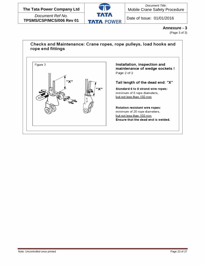
Note: Uncontrolled once printed Page 23 of 27
The Tata Power Company Ltd
Document Title: Mobile Crane Safety Procedure
Document Ref No. TPSMS/CSP/MCS/006 Rev 01
Date of Issue: 01/01/2016
Annexure - 3 (Page 3 of 3)

Note: Uncontrolled once printed Page 24 of 27
The Tata Power Company Ltd
Document Title: Mobile Crane Safety Procedure
Document Ref No. TPSMS/CSP/MCS/006 Rev 01
Date of Issue: 01/01/2016
Annexure – 4 (Page 1 of 2)
Mobile Crane Planning & Risk Assessment Guidelines
These checks should be done for each new set up even if the same crane is deployed in
different set ups.
Does lift radius and boom length check with the planned: With the crane set up
measure the lift radius and check the boom length required. For hydraulic cranes the
boom length can be read on the SLI and the lift radius measured checked against the
SLI reading for lift radius. For crawler cranes boom length is fixed and can be taken
from the load chart using the relevant configuration. If lift radius or/and boom length is
bigger than planned, the capacity loading must be recalculated to check that the loading
still is within prescribed limit; 85% for cranes with SLI, 60% for cranes without SLI or for
crane used for lifting personnel.
Are outriggers fully extended, placed on load spreaders and crane leveled: Check
that all 4 outriggers are fully extended to the marking on each of the outriggers. It is not
allowed to proceed with the lift if any of the outriggers cannot fully be extended. If
possible always use the spreaders provided with the crane under the outriggers. Is the
crane leveled as per spirit level installed in the crane? If the crane will move free on
wheels (hydras) or on crawler with the load suspended ensure it will stay leveled.
Are out riggers set on solid ground free from water logging/soaking and on safe
distance from any excavation, storm-water channel, pit, trench etc.: Do not allow
the crane setting on ground with water logging or soil soaked with water as the ground
loading capability might be much lower than expected. The distance of any outrigger to
an excavation, storm-water channel, pit (not RCC pit), trench must at least be equal to
the depth of the cavity. Outriggers should not be placed above storm-water culverts
without spreading the load.
crane boom: When crane boom, fully extended, is pointed towards the overhead line
the distance must be at least 6 meters away from the line. If required the line must be
made dead and permit given by authorized electrical person.
Is crane slewing/movement free from any obstruction with at least 0.6 m: Check
that the crane can slew with the prescribed safety margin of 0.6 m, if not possible
barricade the area to stop personnel access.
Is the crane free of any oil leakage: When walking around the crane check for any oil
leakage from the hydraulic system especially on the outriggers.
Is weather condition safe for lift: High wind speed will have a significant impact on
loads with high wind areas, say above 25 m2. The wind might cause the lift line to get
out of plumb and cause the crane to topple. If wind speed is above 35 km/hr or 19.4
knots the lift shall be stopped. For lift of personnel the wind speed limit is 14 knots. Call
MFS, ext. 11191, to get actual wind speed. Do not permit the lift if visibility is limited by
e.g.heavy rain or fog. Avoid lift during not daylight hours. Do not lift during thunderstorm.

Note: Uncontrolled once printed Page 25 of 27
The Tata Power Company Ltd
Document Title: Mobile Crane Safety Procedure
Document Ref No. TPSMS/CSP/MCS/006 Rev 01
Date of Issue: 01/01/2016
Annexure – 4 (Page 2 of 2)
Are slings marked with safe load, valid color-coding and without any visual
damage. Is capacity loading below 50%: All slings, belts, shackles shall be visual
inspected for wear and tear, cuts before any lift. No damage shall be accepted. The
load on slings/belts shackles should not exceed 50% of the marked safe load. When
lifting plan available higher sling loading is acceptable. Account for sling angles when
more than one sling is used. A sling angle of 60 degree towards the load will increase
the load in the sling with 15%, 45 degree with 41% and 30 degree with 100%. Slings
used for lifting personnel shall only be loaded to 20%.
Are slings protected from sharp edges on the load: A couple of incidences at site
have happened when sharp edges have cut through the belts and caused the load to
drop. Ensure that the slings are protected by e.g. fitting wooden beams between load
and slings.
Is angle between sling and load more than 60 degree: A small angle will cause high
load on the sling and load, see above. If possible keep the angle above 60 degree and
the extra load will be limited to 15%.
Are shackles used if more than 2 slings are attached to the hook: To avoid undue
load on the slings from each other, the slings shall be connected to the hook by help of
shackles if more than 2 slings are used.
Is the load free from adhesion: Ensure that the load is free from adhesion by e.g. use
of a jack. If it is not possible to conclude that the load is free, e.g. during dismantling
operation, add 100% to the load and check capacity loading.
Are lifting lugs free from visual defects: Visual inspect lifting lugs for any defects.
Is load center of gravity known: For eccentric load with unknown center of gravity
always determine center of gravity by trial and error without lifting the load completely
off the ground.
Is lift line plumb: It is not allowed to use the crane for dragging the load as this could
cause the crane to topple. The lift line shall hang vertical free from any obstruction
above the center of gravity of the load.
Is the lift area free from any other conflicting activities: During the lift other activities
in the direct vicinity and especially under the load must temporarily be stopped. A crane
operation is a hot job and no draining of hydrocarbon shall be allowed in the vicinity as
long as the crane engine is running.
Is signaler in high visibility vest: Ensure that the person signaling to the crane
operator is in high visibility vest.
Is lift area barricaded? Are the slinger and signaler clear of the lifted load by use
of guide ropes: This is the ultimate precaution for all lifts. No person shall be allowed
under suspended load. If it is not practical to barricade the area other means to keep
people away must be used.

Note: Uncontrolled once printed Page 26 of 27
The Tata Power Company Ltd
Document Title: Mobile Crane Safety Procedure
Document Ref No. TPSMS/CSP/MCS/006 Rev 01
Date of Issue: 01/01/2016
Annexure- 5
Signage for Height and Width Restriction (Example Illustration)

Note: Uncontrolled once printed Page 27 of 27
The Tata Power Company Ltd
Document Title: Mobile Crane Safety Procedure
Document Ref No. TPSMS/CSP/MCS/006 Rev 01
Date of Issue: 01/01/2016
Annexure- 6
Load chart for Mobile Crane -90 Ton, Boom length 11-50 M (Typical)

Note: Uncontrolled once printed Page 1 of 23
The Tata Power Company Ltd
Document Title
Permit-To-Work Procedure
Document Ref No.
TPSMS/CSP/PTW/008 Rev 02 Date of Issue: 16/01/2017
Permit-To-Work (PTW) Procedure
Rev No.
Reason for Revision Prepared By Checked By Approval by
Rev 00 First Release - - -
Rev 01 Standardization of
Procedure
Sunil Bartakke
(Head-Biogas &
Lavasa Project)
Navendra Singh
(Group Head – P &
CB; Corp Safety.)
Vijay Chourey
(Chief – Corp
Safety)
Rev 02
Alignment With SAP's Permit-To-Work
(PTW)Management Process
Sudhir Kumar (Corporate
Safety)
Navendra Singh
(Head – Operation
Safety; Corp
Safety.)
Vijay Chourey
(Chief – Corp
Safety)

Note: Uncontrolled once printed Page 2 of 23
The Tata Power Company Ltd
Document Title
Permit-To-Work Procedure
Document Ref No.
TPSMS/CSP/PTW/008 Rev 02 Date of Issue: 16/01/2017
Contents
Section Description Page No.
1.0 OBJECTIVES 3
2.0 SCOPE 3
3.0 EXPECTED RESULTS 3
4.0 ACCOUNTIBILITY & RESPONSIBILITY 3
5.0 GLOSSARY / DEFINITION 6
6.0 PROCEDURE 7
7.0 RECORDS 14
8.0 TRAINING & COMMUNICATION 14
9.0 VERIFICATION 14
10.0 EXCEPTION 14
11.0 REFERANCES 14
12.0 REVIEW 15
13.0 ATTACHMENTS/APPENDIX 15
- Annexure-1 : Permit- To-Work (PTW) - Status Sequence 16
- Annexure-2 : Permit -To-Work (PTW) Issuance Process 18
- Annexure-2 : Sheet 2 - Permit-To-Work (PTW) Return Process 19
- Annexure-3 : SAP Permit-To-Work (PTW) Process Flow
(Tabular Form)
20
- Annexure-4 : SAP Standard Report 21
- Annexure-5 : Permit-To-Work (PTW) Revalidation
(TPSMS/CSP/PTW/008/FORM/001)
22
- Annexure -6 Tool-Box-Talk (TBT) TPSMS/CSP/PTW/008/FORM/
002.
23
Note: Uncontrolled once printed Page 3 of 23
The Tata Power Company Ltd
Document Title
Permit-To-Work Procedure
Document Ref No.
TPSMS/CSP/PTW/008 Rev 02 Date of Issue: 16/01/2017
1. OBJECTIVE:
To provide a standardized & uniform procedure for obtaining authorization to perform jobs require special consideration to ensure the safety of personnel, and protection of facilities by using a safe system of work and clear understanding between the working agencies / departments involved. 2. SCOPE:
This procedure applies to all operating and project sites of Tata Power Group
companies.
3. EXPECTED RESULTS:
3.1. Manage jobs being done under Permit-To-Work (PTW) safely.
3.2. Control of incidents in Jobs related to Permit-To-Work (PTW).
3.3. Compliance to Regulatory requirements related to Permit-To-Work.
4. ACCOUNTABILITY & RESPONSIBILITY:
4.1 ACCOUNTABILITY: Concerned Division’s Heads / SBU Heads / Assets Custodian.
4.2 RESPONSIBILITY: Working department, Contractors.
4.2.1 SBU Head / Assets Custodian:
Implement and manage the PTW system and provide necessary resources of expertise in its application.
Implement, apply, monitor and audit the Permit-To-Work System within the respective area.
Delegate various levels of authority in accordance with needs, subject to appropriate training and competency.
Oversee training programs for Permit Acceptors, Permit Issuers, Permit Approvers, Area Operators and Gas Testers as applicable.
Ensure that those who are appointed as Permit Acceptors, Permit Issuers, Approvers and Area Operators are certified and competent to undertake the role.
Ensure updated list persons certified and competent for PTW are available. Preferably list to be displayed at conspicuous location.
Ensure regular audit of PTW process as a whole.
Receive feedback from the users of the PTW system.
4.2.2 Permit Creator / Initiator / Applicant / Acceptor
The permit creator / initiator / acceptor / Applicant is a person who initiate the PTW and after its approval he accept it for performing the job. He / She shall be responsible for executing the entire job in full compliance with the PTW requirements. His/her responsibilities include the following:

Note: Uncontrolled once printed Page 4 of 23
The Tata Power Company Ltd
Document Title
Permit-To-Work Procedure
Document Ref No.
TPSMS/CSP/PTW/008 Rev 02 Date of Issue: 16/01/2017
Understand the potential hazards involve in the job.
Ensuring that LOTO is performed at all points as applicable before the commencement of the job.
Understand how the hazards are controlled.
Know the emergency situations likely to occur in the job / area and actions to be taken including evacuation procedure.
Ensure that the Permit Holder understands all the hazards and controls, explaining them to the workers, and ensure that the controls are maintained throughout the execution of job.
Inform all people who may be directly / indirectly affected by the job.
Know the status of the job at all times, till its completion.
Transfer duties formally as and when required. Know how to mitigate a possible incident, safe closure of job at such time, rescue of
men and material, arrange / administer medical aid if required. Knowledge of first aid and its administration. Is aware of the on-site emergency plan. Lead and take care of his group at times of emergencies.
Permit Creator / Initiator / Applicant / Acceptor is typically maintenance engineer or equivalent, however terminology of this designation may vary based upon hierarchy/ organization chart.
4.2.3 Permit Issuer / Issuing Authority (Control Room Engineer) The Permit Issuer shall be responsible for review the information provided and amend if required. The Permit Issuer shall be responsible for the following:
Confirm that all hazards associated with the job have been identified, assessed, managed and all relevant parties have provided their inputs and agree with the precautions.
Ensure that the PTW contains scope of the job and the documented controls mentioned are adequate to ensure that the job can be completed safely.
Ensure that all necessary supporting PTWs / Certificates / Checklist / JSA / drawings are attached or referred to in the PTW.
Ensure that the Permit Acceptor knows the exact location and scope of the job, all the hazards that may be present and all the precautions and controls that must be taken and maintained during execution of the job.
Confirm that all operational preparations, including process clearance and isolations, de-energizing and de-pressurizing have been completed.
Lock out and Tag out (LOTO) shall be performed as per Tata Power LOTO procedure (TPSMS/CSP/LOTO/001) and isolation shall be done as per Standard Operating Procedure.
Confirm that the job site is safe for the job to proceed. Specify on the PTW any additional precautions that need to be taken during the job.

Note: Uncontrolled once printed Page 5 of 23
The Tata Power Company Ltd
Document Title
Permit-To-Work Procedure
Document Ref No.
TPSMS/CSP/PTW/008 Rev 02 Date of Issue: 16/01/2017
Identify any conflicts between the proposed job and other jobs in the area, and if necessary, cross-reference necessary controls in all such PTWs.
Inform all persons who may be affected by the job. Know the status of the job at all times till it's completion, Ensure shift handover includes all ongoing or suspended PTWs with the upcoming
Permit issuer.
Permit Issuer / Issuing Authority is typically Control Room Engineer or equivalent, however terminology of this designation may vary based upon hierarchy/ organization chart.
4.2.4 Permit Approver: Shift Incharge shall be a Permit Approver. The Permit Approver
shall be responsible for ensuring that the hazards have been evaluated, adequate controls are provided and precautions are specified in the PTW. He/she is responsible for the following:
Know the hazards including potential hazards and confirming that all hazards associated with the job have been identified, assessed and managed and all relevant agencies / Departments have provided their inputs and agreed with the precautions.
Know how to control and manage hazards involve in the job.
Verify that the job area is safe to commence and carryout job, including checking that representative atmospheric sampling results are within the acceptable limits.
Ensure that the PTW contains scope of the job and the documented controls mentioned are adequate to ensure that the job can be completed safely.
Ensure that all necessary supporting PTWs / Certificates / Checklist / JSA / drawings are attached or referred to in the PTW.
Confirm that the Permit Holder has been explained the exact location of the job, all the hazards & risks that may be present and all the precautions and controls are taken care of.
Confirm that all operational preparations, including process clearance, isolations, de-energizing and de-pressuring etc. have been completed.
Approve the PTW.
Permit Approver is typically Shift In- Charge or equivalent, however terminology of this designation may vary based upon hierarchy/ organization chart.
4.2.5 Permit Holder - Person who is supervising the working party at the site and
executing the job.
The Permit Holder shall be responsible for commencing and completing the authorized job while fully complying with all the requirements as mentioned in PTW. His / Her responsibilities include the following:
Know and understand the potential hazards involved in the job.
Know and understand how the hazards are controlled.
Know the right kind of PPEs required, ensure correct use and compliance thereof.

Note: Uncontrolled once printed Page 6 of 23
The Tata Power Company Ltd
Document Title
Permit-To-Work Procedure
Document Ref No.
TPSMS/CSP/PTW/008 Rev 02 Date of Issue: 16/01/2017
Know the emergency situations likely to occur in the job / area and actions to be taken including evacuating the area.
Deliver the Tool-Box-Talk (TBT) to the workers involved prior to commence the job and record the same.
4.2.5 Individuals working within the PTW system should ensure that:
• Received and understood safety instructions during TBT on the particular job and they understand the hazards and the precautions taken or to be taken.
• Shall not start any job without valid PTW and TBT.
• In case of stop work, the site and any equipment they are using is left in a safe condition
• If in any doubt or if circumstances change, they must stop work and consult with their supervisor / Permit holder.
5 GLOSSARY/ DEFINITIONS:
PTW - Permit-To- Work
Permit-To-Work (PTW) system: A PTW system is a formal written system used to control and execute certain types of jobs safely, which are identified as potentially hazardous. It is also a means of communication between different departments, plant supervisors, operators, agencies etc.
Permit Creator / Initiator / Applicant / Acceptor: The Permit Creator / Initiator / Acceptor / Applicant is a person who initiate the PTW and after its approval he accept it for performing the job. He / She shall be responsible for executing the entire job in full compliance with the PTW requirements. Permit Creator / Initiator / Applicant / Acceptor is typically maintenance engineer or equivalent, however terminology of this designation may vary based upon hierarchy/ organization chart.
Permit Issuer / Issuing Authority (Control room engineer): The Permit Issuer shall be responsible for review the information provided and amend if required. Permit Issuer / Issuing Authority is typically Control Room Engineer or equivalent, however terminology of this designation may vary based upon hierarchy/ organization chart. Permit Approver: Shift Incharge shall be a Permit Approver. The Permit Approver
shall be responsible for ensuring that the hazards have been evaluated, adequate
controls are provided and precautions are specified in the PTW. Permit Approver is
typically Shift In- Charge or equivalent, however terminology of this designation may
vary based upon hierarchy/ organization chart.
Permit Holder: Person who is supervising the working party at the site and executing the
job. The Permit Holder shall be responsible for commencing and completing the authorized
job while fully complying with all the requirements as mentioned in PTW.
Job Safety Analysis: Job safety analysis (JSA) is a procedure which helps integrate
accepted safety and health principles and practices into a particular task or job. In a

Note: Uncontrolled once printed Page 7 of 23
The Tata Power Company Ltd
Document Title
Permit-To-Work Procedure
Document Ref No.
TPSMS/CSP/PTW/008 Rev 02 Date of Issue: 16/01/2017
JSA, for each basic step of the job, it is to identify potential hazards and to recommend
the safest way to do the job.
6 PROCEDURES:
6.1 Applicability:
Valid Permit-To-Work (PTW) and approve Job Safety Analysis (JSA) shall be taken for all
jobs other than approved exception list. Exception list shall be prepared at each division
and shall be approved by division chief.
The Plant / installation which is completely under the supervision / custody of External party
/ contractor; as a principle employer, company has to ensure the PTW system must be in
place. Such PTW system those are from external party / contractors shall be approved by
concerned division chief.
6.2 Preparation
6.2.1 Co-ordination: It is important to ensure that job requiring PTW, shall be planned
and coordinated in order to avoid risks caused by simultaneous activities.
6.2.2 Planning : Careful planning of job requiring a PTW shall take place to ensure:
• Appropriate approval for the job.
• All persons in charge of areas which may be affected are made aware and hence take precautions against possible interaction with other work activity
• Sufficient time to identify all potential hazards, implement precautions and prepare
the worksite. One suggested technique of achieving this is a Job Safety Analysis.
6.2.3 Job safety Analysis (JSA): Job safety Analysis (JSA) shall be done directly into the
system or alternatively it can be done externally and uploaded in the system.
6.2.4 Types of Permit-To-Work (PTW): The types of work for which PTW systems shall
be applied include maintenance and repair, inspection, testing, construction,
dismantling, modification and cleaning.
The types of Permit-To-Work (PTW) as per SAP-EHS include:
- General Permit
- Confined Space Entry Permit
- Electrical Permit
- Excavation Permit
- Hot Permit
- Lifting and slinging Permit
- Project Nature Permit
- Radiography Permit
- Working at Height Permit

Note: Uncontrolled once printed Page 8 of 23
The Tata Power Company Ltd
Document Title
Permit-To-Work Procedure
Document Ref No.
TPSMS/CSP/PTW/008 Rev 02 Date of Issue: 16/01/2017
6.2.5 Cross Reference: The objective of cross reference is to ensure that no interaction
takes place between work activities which might endanger the safety of personnel or the
installation. The PTW issuer shall, by knowledge of work going on in his area of
responsibility, be aware of potential interaction when issuing multiple PTWs for the same
piece of equipment or system, or where there may be potential conflict with adjacent work
activities.
Such situations should be minimized by careful planning and suitable precautions which
should include an appropriate method of cross referencing the different tasks.
It may be that the interacting activities are covered by separate PTW issuers, in such cases
close co-ordination shall be necessary.
6.2.6: Process Flow of Permit-To-Work (PTW) in SAP:
NO
Yes
PTW Preparation
(Maintenance Engineer)
Approval of PTW (Concerned Head)
Refer to Control Room Engineer
for LOTO (Shift In charge)
LOTO applied
(Control Room Engineer)
PTW approved
(Shift In charge)
SAP Notification (By Operation Dept.)
Allotment to Maintenance Engineer (By Concerned Head)
Self-Approval (Maintenance Engineer)
Is it high
risk Job?
Safety Approval (Safety Head)
PTW Acceptor
(Maintenance Engineer)
PTW Holder
(Supervisor)
Tool-Box-Talk (TBT)
& Job Execution
Site Restoration
& PTW Closure
(Supervisor)
PTW Clear (By Shift In charge)

Note: Uncontrolled once printed Page 9 of 23
The Tata Power Company Ltd
Document Title
Permit-To-Work Procedure
Document Ref No.
TPSMS/CSP/PTW/008 Rev 02 Date of Issue: 16/01/2017
For all high risk jobs and Project nature Job, it is mandatory to take approval to
safety while processing the PTW.
If the job is high risk in nature then concerned Head has to change the status to High Risk Job (HRJB) while assigning the Notification to Person responsible. Only concerned Head is authorized to set the User Status LRJB & HRJB. Permit initiator while preparing permits can still change job as high risk even if Concern head has marked it as low risk. If the Notification Status is “High Risk Job”, system will not allow to delete the concerned Head & Safety Approvals in all types of PTW. If User tries to delete the Approvals, System will show error message. Concerned Safety Advisor shall check the adequacy of control measures defined in PTW and JSA for all such high risk jobs. He may further recommend additional control measures before grant of approval. At PTW clearing stage s/he is responsible to give their inputs in JSA & PTW and during this s/he may not visit site, however subsequently during site visit s/he shall check deployment of control measures. Line management is wholly responsible for the implementation of JSA & PTW at site which has been cleared by safety. Tool box talk (TBT) shall be done prior to start of each job and to be recorded as per Annexure -6 Tool-Box-Talk (TBT) TPSMS/CSP/PTW/008/FORM/ 002. PTW shall be displayed at site or alternatively it should be made available at site. Permit Holder shall remain present at site during entire period of job. 6.2.7 Extension of Permit-To-Work (PTW): In order that effective control is maintained in
changing circumstances there shall be a limit on the life of a permit. Depending on
the job, extension of all PTW other Project Nature Permit shall be up to 7 days.
Maximum extension in case of project nature permit may be upto 30 days. It shall be
necessary to intimate about the extension of PTW to all concerns involved. All
concerns shall maintain all existing controls measures in place as mentioned in
PTW & JSA.
6.2.8 Tagging: An essential ingredient of any safe system of work is the method and
integrity of the isolation procedure. The isolation principle to be adapted, prior to carry
out maintenance or repair, will be determined by a number of factors e.g. potential for
pressure, dangerous substances, lack of oxygen, moving machinery etc. It is beyond
the scope of this document to provided guidance on the isolation required for each
potential hazards, please refer Standard operating procedure of each equipments and
Tata Power LOTO procedure - TPSMS/CSP/LOTO/001. In case isolations are required,
Note: Uncontrolled once printed Page 10 of 23
The Tata Power Company Ltd
Document Title
Permit-To-Work Procedure
Document Ref No.
TPSMS/CSP/PTW/008 Rev 02 Date of Issue: 16/01/2017
the Issuing Authority will maintain the required isolations. Electrical team will be involved
in this step if electrical isolations are required.
The following additional points should be considered within the isolation procedures:
• Complex isolations should be planned and recorded on a working drawing. This
should be discussed between the Permit Issuer and Permit Acceptor to ensure all
isolation points are clearly understood and agreed. The marked up drawing should
be readily available to all concerned. Consideration should be given to attaching a
copy to the PTW.
• It is essential that the isolation standard is commensurate with the type of job being
carried out, plant operating conditions and other local influences.
• Isolation procedures should include all energy sources, i.e. mechanical, electrical,
hydraulic pressure etc.
• The tag or key number should be recorded on the PTW form or on a separate form
which should in turn be cross referenced and attached to the PTW form.
• isolation should only be applied and removed on instruction from the person issuing
the PTW
• If more than one task is to be carried out on part of a plant or piece of equipment,
there is a risk that on completion of one of the tasks the isolations are removed and
the equipment is put back into service. Controls should be in place to prevent
premature de-isolation where dual tasks are involved
• if the work is not able to be completed within the shift the site should be checked by
both the Permit Acceptor and the Permit Issuer to ensure it is left in a safe condition
and equipment cannot be reinstated until all job shall be properly completed
• If the PTW is suspended, the status of the job site should be left on display in a
suitable location e.g. Control Room, and the isolation padlock keys kept in a secure
place to ensure no unauthorized access.
All persons authorized to carry out isolations should be assessed for their competence prior
to appointment i.e. they should
• Be suitably qualified
• Have experience on the plant/equipment
• Have received specific instructions on the plant, methods of isolation etc.
• Be able to demonstrate their knowledge by examination.
Their areas of responsibility shall be made quite clear.
6.2.9 Gas Testing: PTW preparation may involve a consideration of the likely presence of flammable or toxic gases, or oxygen deficiency/enrichment, at the worksite.

Note: Uncontrolled once printed Page 11 of 23
The Tata Power Company Ltd
Document Title
Permit-To-Work Procedure
Document Ref No.
TPSMS/CSP/PTW/008 Rev 02 Date of Issue: 16/01/2017
Where such a consideration is necessary then gas testing shall be undertaken.
Persons involved in gas testing shall be adequately trained in the use of gas testing equipment, and in the interpretation of results.
The responsibility of what to test for, where to take samples, and the minimum number of samples to take should lie with the Permit Issuer. Gas testing shall be done as close to the commencement of work as possible. Results of any gas testing shall be recorded and timed, as per Tata Power confined space entry procedure (TPSMS/CSP/CSE/003- Annexure 05/form No TPSMS/CSP/CSE/003/FORM/003). In case ambient parameters changes beyond acceptable levels during the work, the PTW shall be suspended. 6.2.10 Signatures: Once PTW approved, auto generated mail shall go to Permit
Initiator to execute the job as requested in PTW. Signature of Permit Holder and respective field operation engineer (area / equipment owner) shall be taken on initial issue of PTW and thereafter for revalidation on each day/shift as applicable.
6.3 Process
6.3.1 Display of Permit-To-Work (PTW): It is important that permits shall be displayed so the persons who need to be aware of them, or to refer to them, are able to do so.
Copies should normally be distributed/displayed as follows:
• At the worksite. Where this is not practicable (e.g. at an exposed location), the Permit Acceptor of the job should retain the copy, having ensured that the working party members are familiar with its content and control measures.
• At the main control / co-ordination room, where these should be displayed in a systematic arrangement.
6.3.2 Revalidation: Permit-To-Work (PTW) should be revalidated in order that the Permit Issuer can satisfy himself that the conditions under which the PTW was originally issued remain unchanged to allow work to continue. Revalidation shall be done on next day before start of the same job as per
Annexure 5 Permit-To-Work (PTW) Revalidation (TPSMS/CSP/PTW/008/FORM/001). It can be revalidated upto 7 days only except project nature permit. For project nature permit revalidation may be done upto 30 days. The maximum validity of the permits is defined and revalidation beyond this period are not allowed. In such cases, the PTW is closed and a new PTW shall be issued.
6.3.3 Suspension: In the event of any of the following circumstances occurring during the
course of an activity under permit, the Permit Holder must refer back to the Permit Issuer
(through Permit Acceptor) on the appropriate course of action:

Note: Uncontrolled once printed Page 12 of 23
The Tata Power Company Ltd
Document Title
Permit-To-Work Procedure
Document Ref No.
TPSMS/CSP/PTW/008 Rev 02 Date of Issue: 16/01/2017
The specified equipment or tools to be used not being available.
Any changes in the type and nature of work.
Occurrence of any condition / situation during the progress of the work that was not
anticipated.
Any change in the process condition or the surrounding. (E.g. unexpected release of
gas from a nearby tank).
An emergency in the area.
Any change in the weather condition.
6.3.4 Shift Hand-overs: Shift changeovers can be one of the most vulnerable times for the
PTW system. The failure to pass on information or the correct information has been
shown to be the cause of many accidents. There is sufficient overlap to allow proper
review and discussion of the status of all Permit-To-Work.
Written means of communicating information can be by:
• PTW Log Book
• PTW Files
• Display Boards
• Computer Screen/Print Out
Or a combination of any of the above. Whichever arrangements are adopted, the shift handover arrangement shall be monitored regularly to ensure its continued effectiveness.
6.3.5 Action in an Emergency / break down situation: During emergencies, when working party is not able to generate notification, PM order and hence PTW; in such situation control room will use WCT6 and WCT7 to create safety tag number for the outage. However, maintenance engineer will have to generate - notification, PM order, PTW subsequently and attach safety tag (by using WCLE & WCD transaction) number. No safety norms to be violated and standard SOP to be followed. For more details please refer "SAP – PM Training Manuals (Use of WCT6 & WCT7 - Guidelines Emergency Outages) available at Sangam web page at following path -
Saarthi > Project Saarthi > Training > Module > Plant Maintenance (PM) > 2. PM Processes - Others> 06. Creating Safety Tags (WCT6 & WCT&) without PTW-Emergency Outages.
6.3.6 Monitoring: The monitoring of the PTW shall be during entire span of job execution by Permit Holder.

Note: Uncontrolled once printed Page 13 of 23
The Tata Power Company Ltd
Document Title
Permit-To-Work Procedure
Document Ref No.
TPSMS/CSP/PTW/008 Rev 02 Date of Issue: 16/01/2017
6.3.7 Trial Required After Maintenance Work: If trial of equipment is required to be taken after the maintenance work is completed, the temporary un-tagging cycle is initiated. (Refer Tata Power LOTO procedure (TPSMS/CSP/LOTO/001 Rev 01) 6.5 Temporary Removal of Lockout/Tag out Devices)
Process is initiated by authorized person by activating the button “Untag temporarily” in the
work clearance document, and system status is updated as BTUG - Untag temporarily.
(Annexure-1 Permit- To-Work (PTW) - Status Sequence)
Tags are removed from the field and system is restored to original condition. After the tags
are removed and the system condition is restored the authorized person activates a button
in the work clearance document “Temporarily untagged” and the system status is up-dated
as ETUG – Temporarily Untagged.
Trial is taken for the system and after successful completion of the trial, the authorized
person activates the button “Tagged” in the Work Clearance document and system status
is updated as ETG – Tagged.
If trial is unsuccessful then Maintenance team (Permit Initiator) have two options based on
the scenario.
If work can be done to rectify the problem, then the isolations of the field equipments will be
done again using the temporary untagging cycle as explained above. Temporary untagging
cycle will be repeated using the same tags and field equipments will be isolated. Work will
be executed in the equipment and further trial will be taken.
However, if work cannot be executed again and a scope change in work is required then the PTW shall be closed. Untagging of the field equipments will be done and work clearance document shall be closed. Scope change in work shall be handled by creating a sub order through Work Order Management and new PTW will be created.
6.4 Completion
6.4.1 Work Completion: When the maintenance work is completed then maintenance
person indicates in the work order system that work is completed by activating Work
Completed Button on order header and the System Status is updated to WOCO –
Work completed.
Order operations are confirmed and order is updated with a system status as CNF –
Confirmed.

Note: Uncontrolled once printed Page 14 of 23
The Tata Power Company Ltd
Document Title
Permit-To-Work Procedure
Document Ref No.
TPSMS/CSP/PTW/008 Rev 02 Date of Issue: 16/01/2017
6.4.2 Closing of Permit-To-Work (PTW): After the Work is completed the Permit-To-
Work (PTW) is surrendered and the PTW is closed and the System Status is updated as
CLSD – Closed.
The system provides a facility to automatically set CLSD status on the Permit-To-Work
(PTW) when Maintenance order gets WOCO status.
6.4.3 Un-Tagging Process: After the Permit-To-Work (PTW) is surrendered then un-tagging process is initiated by activating the button “Untag” in the Work clearance document and the System status is up-dated as BUG – Untag. System is restored to original condition as per the un-tagging conditions in the Work Clearance document and tags are removed from the field equipment and with proper housekeeping of job site. Authorized person will activate the button “Untagged” in the Work Clearance Document and
the system status is updated as EUG – Untagged.
6.4.4 Closing the work Clearance Documents: After untagging of the isolation the Work
Clearance Document is closed and the system status is updated as CLSD – Closed.
6.4.5 Closing of Maintenance Order: After the PTW is closed, the order is technically
completed and the system status is set to TECO – Technically Completed. The
order cost is then settled by the finance section to the respective cost center and
order is business completed and system status is up-dated as CLSD - Completed.
6.4.6 Housekeeping: Housekeeping shall be ensured before the start of job as well as
after the completion / cancellation of job. Permit-To-Work (PTW) shall be closed only
after restoration of housekeeping of the Job site.
7 Records:
7.3 Filled Permit-To-Work (PTW) – Retention Period - One year Filled Permit-To-Work (PTW) Revalidation (TPSMS/CSP/PTW/008/FORM/001) -– Retention Period - One year Record of Tool-Box-Talk (TBT) TPSMS/CSP/PTW/008/FORM/ 002 – Retention Period - One year
8 TRAINING & COMMUNICATION
8.1 Training of Permit-To-Work procedure shall be carried out to cover for following-
(i) Permit Issuer,
(ii) Permit acceptor,

Note: Uncontrolled once printed Page 15 of 23
The Tata Power Company Ltd
Document Title
Permit-To-Work Procedure
Document Ref No.
TPSMS/CSP/PTW/008 Rev 02 Date of Issue: 16/01/2017
(iii) Permit Holder,
(iv) Permit approver.
List of trained and competent person in PTW as a Permit Issuer, acceptor, holder &
approval shall be displayed at conspicuous location.
8.2 Initial Communication to be done through Corporate Communication, Email and
subsequently shall be made available at safety portal at Sangam
9 VERIFICATION
Verification of implementation shall be done during Permit-To-Work (PTW) procedure audit,
field safety visit and site inspections.
10 EXCEPTION: Any Exception to this procedure shall only be done as per Document
Control .Procedure (TPSMS/GSP/DC/014).
11 REFERENCES
EPM 04.01.02 - Safe Working Procedures
Indian Factory Act 1948 and State Factory Rules (As amended)
SAP PM Work Permit Management Process - PM_Work_Permit_Management_04
Excavation Safety (Shoring and Sloping) Procedure - TPSMS/CSP/EXS/002
Tata Power LOTO Procedure - TPSMS/CSP/LOTO/001
Tata Power Job Safety Analysis (JSA) Procedure - TPSMS/CSP/JSA/009
Tata Power Hazard Identification & Risk Assessment (HIRA) Procedure - TPSMS/GSP/HIRA/005
Tata Power Confined Space Entry Procedure - TPSMS/CSP/CSE/003
Tata Power Work At Height Procedure - TPSMS/CSP/WAH/004
12 REVIEW: Review of this procedure shall be done as and when but not later than once
in every three (03) years. Typical Factors like Changes in legislation, Review of
Incident Reports, Inspection & Audit findings, Feedback from users,
Recommendations in Incident investigation reports may be inputs for the review and
revision of the procedure.
13 ANNEXURES:
Annexure-1: Permit- To-Work (PTW) - Status Sequence
Annexure-2: Sheet 1 - Permit -To-Work (PTW) Issuance Process
Sheet 2 - Permit-To-Work (PTW) Return Process
Annexure - 3: SAP Permit-To-Work (PTW) Process Flow (Tabular Form)

Note: Uncontrolled once printed Page 16 of 23
The Tata Power Company Ltd
Document Title
Permit-To-Work Procedure
Document Ref No.
TPSMS/CSP/PTW/008 Rev 02 Date of Issue: 16/01/2017
Annexure -4: SAP Standard Report
Annexure-5: Permit-To-Work (PTW) Revalidation
(TPSMS/CSP/PTW/008/FORM/001)
Annexure-6: Tool-Box-Talk (TBT) TPSMS/CSP/PTW/008/FORM/ 002
Annexure -1
Permit- To-Work (PTW) - Status Sequence
During the process of the isolations, execution and completion of work, the system status of Header and Item level gets up-dated based on the processing phase. The processing phase could be as follows –
- Tagging Phase
- Un-tagging phase
- Temporary Un-tagging Phase
System Status
Description Remarks
CRTE Created When the Work Clearance Document is created the system status is set to CRTE – Created.
PREP Prepared After review of the Work Clearance Document Header and Item data the WCD system status is set to PREP – Prepared. This will allow for the approval and Tagging process.
CHNG Change WCD status PREP is revoked.
CLSD Closed After the items are untagged the WCD status is set to CLSD – Closed and the WCD is completed in the system.
ITG Initial Tagging Condition
WCD items system status is set to ITG – Initial Tagging Condition when the WCD is set to Prepared condition. The items cannot be deleted from the WCD document after ITG status is set to the items.
PROC Processing When the Tagging process is initiated System status is set to Processing.
BTG Begin Tagging WCD items system status is set to BTG- Begin Tagging status when tagging process is initiated by activating the “TAG” button.
PTAG Print Tag WCD items status is set to “PTAG” status when tag printing button is activated for printing the Tags from the system
ETG End of Tagging
WCD items system status is set to “ETG” - Tagged status when “Tagged” button is activated after the items are physically isolated and tags are placed on the isolated items.
INAC Inactivated WCD item status is set to INAC- Inactivated status if WCD item is not relevant and items already have system status ITG.

Note: Uncontrolled once printed Page 17 of 23
The Tata Power Company Ltd
Document Title
Permit-To-Work Procedure
Document Ref No.
TPSMS/CSP/PTW/008 Rev 02 Date of Issue: 16/01/2017
BTUG Begin Temporary Untagging
WCD items status is set to “BTUG” status when “Untag Temporarily” button is activated for Trial purposes.
ETUG End of Temporary Tagging
WCD items status is set to “ETUG” status when “Temporarily Untagged” button is activated after conditions are restored for trial purposes.
TEST TEST Cycle Permit trial cycle in progress
PTST Print Test Tag WCD items get “PTST” status when tag printing button is activated for printing the Tags from the system for test cycle.
UNT Untaggable WCD items get UNT – Untaggable status to indicate items can be untagged.
BUG Begin Untagging
WCD items get “BUG” untag status when “Untag” button is activated to begin Untagging Process
EUG End of Untagging
WCD items are set to “ETG” Untagged status when “Untagged” button is activated.

Note: Uncontrolled once printed Page 18 of 23
The Tata Power Company Ltd
Document Title
Permit-To-Work Procedure
Document Ref No.
TPSMS/CSP/PTW/008 Rev 02 Date of Issue: 16/01/2017
Annexure-2
Sheet 1
Permit -To-Work (PTW) Issuance Process

Note: Uncontrolled once printed Page 19 of 23
The Tata Power Company Ltd
Document Title
Permit-To-Work Procedure
Document Ref No.
TPSMS/CSP/PTW/008 Rev 02 Date of Issue: 16/01/2017
Annexure- 2
Sheet 2 Permit-To-Work (PTW) Return Process

Note: Uncontrolled once printed Page 20 of 23
The Tata Power Company Ltd
Document Title
Permit-To-Work Procedure
Document Ref No.
TPSMS/CSP/PTW/008 Rev 02 Date of Issue: 16/01/2017
Annexure- 3 SAP Permit-To-Work (PTW) Process Flow (Tabular Form)
Work Step #
Work Step Description SAP T-code/Out of SAP/Other
Permit Issuance Process
1 Create Work permit in maintenance order IW31/IW32
2 Identify affected departments & types of work permit required for the job like PTW (Hot Work Permit, Confined Space)
IW32/IPMD
3 Attach JSA/HIRA if required
4 Prepare the work Permit & inform operations for approvals.
WCLE
5 Can maintenance of equipment be done? (YES:7 NO:6)
Manual
6 Reject the work Permit Document with comment and Email alert to all the concerned Dept
WCLE
7 Approve Permit WCLE
8 Are other maintenance dept involved? (YES:9 NO:12)
Manual
9 Notify relevant departments Workflow
10 Preparedness is ensured Manual
11 Confirm preparedness WCLE
12 Print Permit Document & TAGS WCLE
13 Carry out Isolations at site/LOTO & inform the concerned to activate the work Permit
Manual
14 Safety tags are assigned Manual
15 Activate Work Permit/Tagging WCLE
16 Email alert to person who created the order Workflow
Permit Return Process
1 Job is executed in field Manual
2 Clear WCD and LOTO WCLE
3 Is Equipment trail required (YES 4, NO 10) Manual
4 Take Operating Permit
5 Trail Taken Manual
6 Record Results
7 Is Trail is OK (YES 10 NO 8)
8 Create new WCD/Safety Tags WCLE

Note: Uncontrolled once printed Page 21 of 23
The Tata Power Company Ltd
Document Title
Permit-To-Work Procedure
Document Ref No.
TPSMS/CSP/PTW/008 Rev 02 Date of Issue: 16/01/2017
9 Carry Out LOTO Manual
10 All permits are returned & Work Permit is closed/Untagging
WCLE
11 Email alert will be sent to Shift In Charge/Section Head for breakdown Main for Equipment Category A and B
Manual
Annexure- 4
SAP Standard Report
Report title Transaction code ( SAP GUI)
Comment
List Work Approvals IP16 A list of all work approvals will be displayed with respective status such as ‘created’, ‘closed’, etc.
List Work Clearance Applications
WCL6 A list of all work clearance applications will be displayed
List maintenance orders
IW39 A list of all selected maintenance orders is displayed.
Equipment list IH08 An equipment list with general data and more information.
List of Work Clearance Document templates
WCL2 A list of all work clearance document templates will be displayed

Note: Uncontrolled once printed Page 22 of 23
The Tata Power Company Ltd
Document Title
Permit-To-Work Procedure
Document Ref No.
TPSMS/CSP/PTW/008 Rev 02 Date of Issue: 16/01/2017
TPSMS/CSP/PTW/008/FORM/001 Annexure- 5
Permit-To-Work (PTW) Revalidation
Details: Day 2 Day 3 Day 4 Day 5 Day 6 Day 7
Date:
Time: From
Time :To
Signature & Name of Permit Issuer
Signature & Name of Permit Accepter / Holder
Signature & Name of Area Operator (if applicable)

Note: Uncontrolled once printed Page 23 of 23
The Tata Power Company Ltd
Document Title
Permit-To-Work Procedure
Document Ref No.
TPSMS/CSP/PTW/008 Rev 02 Date of Issue: 16/01/2017
TPSMS/CSP/PTW/008/FORM/002 Annexure- 6
Tool-Box-Talk (TBT) Record Tool-Box-Talk (TBT) Date : Location/Venue : Permit-To-Work (PTW) No. : Time : Tool Box Talk conducted by : Name of the Contractor / dept. : Name of the Contractor’s Supervisor : Number of Workmen Present :
COMMON POINTS TO BE DISCUSSED
STATUS Brief Discussion on Job to be performed
Use of proper PPEs
Use of proper Tools
Barriers & Signs
Emergency Vehicle & First Aid Box
Enquiry of Health Status
SN. Name of the Workmen Gate Pass No. Sign
1
2
3
4
5
6
7
8
9
10
11
12
13
14

Note: Uncontrolled once printed Page 24 of 23
The Tata Power Company Ltd
Document Title
Permit-To-Work Procedure
Document Ref No.
TPSMS/CSP/PTW/008 Rev 02 Date of Issue: 16/01/2017
15
Sign & Name of Tool-Box-Talk (TBT) conducted by:

Note: Uncontrolled once printed Page 1 of 7
The Tata Power Company Ltd
Document Title
Job Safety Analysis (JSA) Procedure
Document Ref No:
TPSMS/CSP/JSA/009 Rev 01 Date of Issue: 01/01/2016
JOB SAFETY ANALYSIS (JSA) PROCEDURE
Rev No. Reason for Revision Prepared By Checked By Approval by
Rev 00 Initial Release Navendra Singh Sanjay Kale Shrinivas Katti
Rev 01 To implement Tata Power JSA
Standard
Navendra Singh
(Group Head – P &
CB; Corp Safety.)
Rajesh Sharma
(Head – Crop.
Safety Operation)
Vijay Chourey
(Chief – Corp Safety)

Note: Uncontrolled once printed Page 2 of 7
The Tata Power Company Ltd
Document Title
Job Safety Analysis (JSA) Procedure
Document Ref No:
TPSMS/CSP/JSA/009 Rev 01 Date of Issue: 01/01/2016
Contents
Section Description Page No.
1.0 OBJECTIVE 3
2.0 SCOPE 3
3.0 EXPECTED RESULTS 3
4.0 ACCOUNTABILITY & RESPONSIBILTIY 3
5.0 GLOSSARY/ DEFINITIONS 4
6.0 PROCEDURES 4
7.0 RECORDS 5
8.0 TRAINING & COMMUNICATION 5
9.0 VERIFICATION 6
10.0 EXEMPTION 6
11.0 REFERENCES 6
12.0 REVIEW 6
13.0 ATTACHMENTS/APPENDIX 6
- Annexure – 1: Sample Format for Job Safety Analysis (JSA) -
TPSMS/CSP/JSA/009/FORM/001
7

Note: Uncontrolled once printed Page 3 of 7
The Tata Power Company Ltd
Document Title
Job Safety Analysis (JSA) Procedure
Document Ref No:
TPSMS/CSP/JSA/009 Rev 01 Date of Issue: 01/01/2016
1. OBJECTIVE: Objective of this procedure is to have a task/job based risk assessment
process in place that identifies, evaluates and controls the risks associated with work
activities, and as a result, prevents those involved in the task or those potentially affected
by the task, from being harmed.
2. SCOPE: This procedure applies to all operating and project sites of Tata Power Group
companies. A JSA (Job Safety Analysis) Shall be carried out:
2.1. When new / different people will be undertaking the job for which an SOP / SMP is
available
2.2. When a non-routine task is to be undertaken
2.3. When Job to be executed under Permit-To-Work (PTW)
2.4. When deviations, due to some specific reasons, are required for Standard Operating
procedure (SOP) / SMP (Standard Maintenance Procedure)
2.5. Whenever a job with a Standard Operating procedure (SOP) / SMP (Standard
Maintenance Procedure) is being undertaken in circumstances where the conditions
of the job are changed with respect to the SOP/SMP. e.g. A welder working in his
fabrication area will be covered by a SOP with HIRA already carried out, however, if
the welding is being done on the site at a height or a confined space or in an area
which may interfere with other jobs we need to conduct a JSA and use this in
conjunction with the HIRA (Hazard Identification Risk Assessment) for the welding
activity.
3. EXPECTED RESULTS:
3.1. Manage Non routine jobs being done under permit-to-work safe.
3.2. Manage Routine jobs being done under SOP/SMP.
3.3. Control of incidents related to Routine & Non routine Jobs.
3.4. Compliance to Regulatory requirements to make work place safety
4. ACCOUNTABILITY & RESPONSIBILITY:
4.1. ACCOUNTABILITY: Concerned Division’s Heads / Assets Custodian.
4.2. RESPONSIBILITY: Concerned Engineer

Note: Uncontrolled once printed Page 4 of 7
The Tata Power Company Ltd
Document Title
Job Safety Analysis (JSA) Procedure
Document Ref No:
TPSMS/CSP/JSA/009 Rev 01 Date of Issue: 01/01/2016
5. GLOSSARY/ DEFINITIONS:
Hazard Identification & Risk Assessment: Hazard Identification & Risk Assessment is
to identify and evaluate the hazards, Risk and put controls measures for safe execution of
activities.
Hazard: Source or situation with potential for harm, something that can cause body injury
/ occupational illness, damage company property.
Job: A piece of physical work defined by time or other limits and that has a clear start and
end point
Job Safety Analysis: Job safety analysis (JSA) is a procedure which helps integrate
accepted safety and health principles and practices into a particular task or job. In a JSA,
for each basic step of the job, it is to identify potential hazards and to recommend the
safest way to do the job.
Non Routine Job / Task: Where an SOP / SMP is not available or the conditions of the
SOP / SMP have changed
Risk Assessment: A systematic and structured process whereby hazards present in a
workplace, or arising from workplace activity, are identified, risks assessed
Risk: The likelihood (probability) which can lead to potential negative consequences.
Severity: The level of consequence / harm of an event that could occur due to exposure
to the hazard present
SOP: Standard Operating Procedure
SMP: Standard Maintenance Procedure
Shall: Mandatory requirement
Should: Optional requirement
Task / Activity: A sequence of steps taken to conduct a job. A task is a sub element of
a Job.
6. PROCEDURES
6.1. The following criteria shall be used in determining whether HIRA or JSA will be
required. Following illustrations may be useful to understand between selection of
HIRA and JSA.
6.1.1. HIRA is activity specific like use of OXY-Acetylene Set for cutting.
6.1.2. JSA is Job specific like cutting of steam tubes using OXY-Acetylene set in the
boiler
6.1.3. HIRA is Quantitative while JSA is Qualitative
6.1.4. HIRA primarily contain hazard & control measures specific to tools &
equipment’s and methodology to be used for the activity.
6.1.5. JSA contain hazards and control measure including to activity and site
conditions where job to be accomplished.

Note: Uncontrolled once printed Page 5 of 7
The Tata Power Company Ltd
Document Title
Job Safety Analysis (JSA) Procedure
Document Ref No:
TPSMS/CSP/JSA/009 Rev 01 Date of Issue: 01/01/2016
6.2. For methodology and details about HIRA refer Tata Power Hazard Identification &
Risk Assessment (HIRA) Procedure (TPSMS/GSP/HIRA/005).
6.3. Job Safety Analysis (JSA) involves the following:
6.3.1. Determining the scope of the job and listing the steps in the job.
6.3.2. Identifying possible hazards in the job.
6.3.3. Determining who and/or what is at potential risk
6.3.4. Describing the recommended safe way to do the job in order to prevent
incidents and injuries.
6.3.5. Anticipating what might go wrong and devising back-up controls.
6.4. This will help to:
6.4.1. Identify and address hazards.
6.4.2. Prevent incidents and injuries.
6.4.3. Get organized to do the job right and more efficiently.
6.4.4. Create procedures that can be used by everyone.
6.4.5. Get people in the habit of working safely.
6.5. Key Steps: The Job Safety Analysis consists of the following 6 steps:
Step 1: Describe the job and the sequence of job steps
Step 2: Identification of the potential hazards of each step
Step 3: Determine who and/or what is at potential risk
Step 4: Description of the recommended safe job procedure
Step 5: Identification of what might go wrong
Step 6: Identification of back up controls
JSA should be done using SAP-EHS Modules. Alternatively it can be done using
above 6 steps and format given in the Annexure 1.
6.6. Team Composition: The JSA is generally carried out by a team comprising;
6.6.1. Person/Team who do the work
6.6.2. Person supervising the job
6.6.3. Person with safety knowledge
6.6.4. Person (Specialist/Consultant) with technical knowledge
6.6.5. The number of team members will depend on and vary with the complexity of
the job.
7. RECORDS :
7.1. Job safety analysis (JSA) (TPSMS/CSP/JSA/009/FORM/001)- Retention 12 Months
8. TRAINING & COMMUNICATION
8.1. Training of procedure shall be covered along with Permit-To-Work (PTW) procedure
as Safety Training Needs identified.

Note: Uncontrolled once printed Page 6 of 7
The Tata Power Company Ltd
Document Title
Job Safety Analysis (JSA) Procedure
Document Ref No:
TPSMS/CSP/JSA/009 Rev 01 Date of Issue: 01/01/2016
8.2. Initial Communication to be done through Corporate Communication, Email and
subsequently shall be made available at safety portal at Sangam.
9. VERIFICATION
9.1. Verification of implementation shall be done during Permit-To-Work (PTW) audit, field
safety visit and site inspections.
10. EXCEPTION: Any exception to this procedure Any Exception to this procedure shall only
be done as per Document Control .Procedure (TPSMS/GSP/DC/014).
11. REFERENCES
Tata Group Job Safety Analysis (JSA) Standard
Tata Power Permit-To-Work (PTW) procedure (TPSMS/CSP/PTW/008)
Tata Power Hazard Identification & Risk Assessment (HIRA) Procedure
(TPSMS/GSP/HIRA/005)
12. REVIEW: Review of this procedure shall be done as and when but not later than once in
every three (03) years. Typical Factors like Changes in legislation, Review of Incident
Reports, Inspection & Audit findings, Feedback from users, Recommendations in Incident
investigation reports may be inputs for the review and revision of the procedure.
13. ATTACHMENTS/APPENDIX :
13.1. Annexure – 1: Sample Format for Job Safety Analysis (JSA)
(TPSMS/CSP/JSA/009/FORM/001)

Note: Uncontrolled once printed Page 7 of 7
The Tata Power Company Ltd
Document Title
Job Safety Analysis (JSA) Procedure
Document Ref No:
TPSMS/CSP/JSA/009 Rev 01 Date of Issue: 01/01/2016
Annexure - 1
TPSMS/CSP/JSA/009/FORM/001
All above activities, Hazards, Controls have been explained to M/S _____________________________
and are required to be followed by M/s _____________________________________.

The Tata Power Company Ltd
Document Title Electrical Safety Procedure
Document Ref No. TPSMS/CSP/ELEC/010 Rev 01
Date of Issue: 01/01/2016
Note: Uncontrolled once printed Page 1 of 33
ELECTRICAL SAFETY PROCEDURE
Rev No. Reason for Revision Prepared By Checked By Approval by
Rev 00 Initial Release Ali Mohammed
Zulphekari Navendra Singh Shrinivas Katti
Rev 01 To align with Tata Group
Safety Standard
Ali Mohammed Zulphekari
(Team Lead - QA,I&T)
Navendra Singh
(Group Head – P &
CB; Corp Safety.)
Vijay Chourey
(Chief – Corp Safety)

The Tata Power Company Ltd
Document Title Electrical Safety Procedure
Document Ref No. TPSMS/CSP/ELEC/010 Rev 01
Date of Issue: 01/01/2016
Note: Uncontrolled once printed Page 2 of 33
Contents
Section Description Page No.
1.0 OBJECTIVE 3
2.0 SCOPE 3
3.0 EXPECTED RESULTS 3
4.0 ACCOUNTABILITY & RESPONSIBILTIY 3
5.0 GLOSSARY/ DEFINITIONS 3
6.0 PROCEDURE 4
7.0 RECORDS 21
8.0 TRAINING & COMMUNICATION 21
9.0 VERIFICATION 21
10.0 EXCEPTION 21
11.0 REFERENCES 21
12.0 REVIEW 22
13.0 ATTACHMENTS/APPENDIX 22
- Annexure-1:Safety Check List for HV Testing :
TPSMS/CSP/ELEC/010/FORM/001 23
- Annexure-2:Safety Check List for Transformer Testing :
TPSMS/CSP/ELEC/010/FORM/002 24
- Annexure-3:Safety Check List for Transformer Bushing Testing :
TPSMS/CSP/ELEC/010/FORM/003 25
- Annexure-4:Safety Check List for CT/CVT/PT Testing:
TPSMS/CSP/ELEC/010/FORM/004 26
- Annexure-5:Safety Check List for Capacitor Testing:
TPSMS/CSP/ELEC/010/FORM/005 27
- Annexure-6: Check List for Generator Testing:
TPSMS/CSP/ELEC/010/FORM/006 28
- Annexure-7:Safety Check List for Switch Gear Testing :
TPSMS/CSP/ELEC/010/FORM/007 29
- Annexure-8: Check List for Relay Testing:
TPSMS/CSP/ELEC/010/FORM/008 30
- Annexure-9: Check List for Handling Test Instruments
TPSMS/CSP/ELEC/010/FORM/009 31
- Annexure-10: Check List General For Testing Activity
TPSMS/CSP/ELEC/010/FORM/010 32
- Annexure-11: Checklist for Power Supply Used for Testing :
TPSMS/CSP/ELEC/010/FORM/011 33

The Tata Power Company Ltd
Document Title Electrical Safety Procedure
Document Ref No. TPSMS/CSP/ELEC/010 Rev 01
Date of Issue: 01/01/2016
Note: Uncontrolled once printed Page 3 of 33
1. OBJECTIVE:
The objective of these procedure is to specify minimum mandatory requirements and
advisory guidance for identifying and controlling hazards to ensure ‘Zero Harm’ with
regard to operation maintenance and testing of electrical equipment. The established
documentation for the elimination and control of hazards is henceforth referred to as
Electrical Safety Procedure.
2. SCOPE:
Applicable to Tata Power (Operating and Project sites) which cover but not limited to
plant premises, switchyards, substations, offices etc.
3. EXPECTED RESULTS:
3.1. Manage activities/jobs associated with electrical hazards safely.
3.2. Control of incidents related to electrical shock and hazards.
3.3. Compliance to Regulatory requirements to make work place safe.
4. ACCOUNTABILITY & RESPONSIBILITY:
ACCOUNTABILITY: Concerned Division’s Heads / Assets Custodian
RESPONSIBILITY: Concerned Permit-To-Work Approver/Receiver
LINE MANAGEMENT IN SBU’S AND SITES HAS THE RESPONSIBILITY TO
IMPLEMENT THIS STANDARD
5. GLOSSARY/ DEFINITIONS:
ELCB: Earth Leakage Circuit Breaker
ELV: Extra Low Voltage (< 50V AC and < 120V DC)
HIRA: Hazard Identification and Risk Assessment
JSA: Job Safety Analysis
LOTO: Lock Out Tag Out
PPE: Personal Protective Equipment
PTW: Permit to Work

The Tata Power Company Ltd
Document Title Electrical Safety Procedure
Document Ref No. TPSMS/CSP/ELEC/010 Rev 01
Date of Issue: 01/01/2016
Note: Uncontrolled once printed Page 4 of 33
Shall: Mandatory requirement
Should: Optional requirement
TBT : Test Before Touch
Work Permit - The written or printed document that is issued to control working in
operational area/ in vicinity of electrical equipments.
Work supervisor - A person who is authorized; to verify that all conditions for working
have been met, to define ongoing precautions to maintain safe working conditions
during the work, to authorize the work to occur, and to cancel the permit allowing the
work; also known as proprietor, work group supervisor, or authorizing person.
6.0 PROCEDURES
6.1 ESSENTIALS
6.1.1 Personnel (both Company employees and Contractors) shall be competent to
carry out electrical work and shall possess Tata approved government authorized
competency certificate for work at working voltage levels.
6.1.2 Employees/contractors working on/near electrical equipment shall be trained in
emergency response/first aid.
6.1.3 Prior to carrying out any activity related to operation, maintenance or testing of
electrical equipment, it shall be ensured that there is an appropriate Job Safety
Analysis (JSA) supported with Hazard Identification and Risk assessment (HIRA)
done and recorded.
6.1.4 Fire and explosion hazards associated with electrical equipment shall be
assessed and managed.
6.1.5 Permit to Work (PTW) - TPSMS/CSP/PTW/008, and Lock Out Tag Out (LOTO) -
TPSMS/CSP/LOTO/001 Procedures to be followed.
6.1.6 All electrical work shall be done in compliance to Standard Operating Procedure
(SOP)/ Standard Maintenance Procedure (SMP).
6.1.7 Checklist should be made available and filled up copies recorded.
6.1.8 Isolation and subsequent confirmation test shall be carried out to verify absence
of voltage.

The Tata Power Company Ltd
Document Title Electrical Safety Procedure
Document Ref No. TPSMS/CSP/ELEC/010 Rev 01
Date of Issue: 01/01/2016
Note: Uncontrolled once printed Page 5 of 33
6.1.9 Authorized Work Area cordoning off by barricading tape/Hard barricades shall be
done prior to maintenance/testing.
6.1.10 Proper illumination shall be provided if the work has to be continued during
dark hours. If any hand lamp is to be used it should be of voltage level equal to
or less than 24V AC.
6.1.10 Hazard/flashing lights shall be installed if the work involves HV testing at 1 kV
and above.
6.1.14 The room in which work is being carried out should have adequate ventilation
system and emergency exit points. Adequate communication systems should be
made available.
6.1.15 While working in the vicinity of live equipment the Engineer to whom PTW has
been issued shall give proper information to PSCC and instructions to Staff
carrying out work.
6.1.16 Appropriate PPE and adequate safety apparel like arc suits shall be worn.
6.1.17 Certified and insulated tools shall be used while performing electrical work.
After completion of work the Removed material shall be stored / shipped to safe
location.
6.1.18 After completion of work Permit Issuer shall physically check and ensure that the
following are cleared before closing of PTW.
a. Grounds
b. Tools
c. Spares
d. Personnel
e. Debris
f. Scrap
6.1.20 All Electrical equipment, spares and tools should be inspected and maintained at
regular intervals as per proper approved schedule.

The Tata Power Company Ltd
Document Title Electrical Safety Procedure
Document Ref No. TPSMS/CSP/ELEC/010 Rev 01
Date of Issue: 01/01/2016
Note: Uncontrolled once printed Page 6 of 33
6.2 COMPLIANCE TO WORK PROCEDURES
6.2.5 Persons who work near electrical equipment and are potentially exposed to
electrical hazards, shall be made fully aware of the hazards and should be
suitably trained on how to work safely. All the work procedures should aim at
minimizing exposure to electrical hazards to an acceptable level on the basis of
HIRA.
6.2.6 Energy isolation shall be done before carrying out work on electrical equipment
as per Lock out Tag out (LOTO) procedure.
6.3 WORKING ON OR NEAR ELECTRICALLY ENERGIZED EQUIPMENT
6.3.1 Work on or near any live conductor shall be carried out only in case of
exceptions, after a thorough HIRA has been carried out.
6.3.2 When working on or near energized electrical equipment it shall be ensured that
no other work should be performed within the prohibited approach boundary.
(Work in switchyard, multi circuit tower with other lines charged)
6.3.3 Permission to work on such locations requires authorization from a senior
authorized person/Engineer in charge (as per company standard/procedure)
regardless of the PPE used or design of equipment. Appropriate control
measures and suitable precautions (including the provision of suitable PPE) have
been taken.
6.3.4 Energised Equipment may include working on both Extra Low Voltage (ELV)
systems (<50 AC or < 120 DC) and non ELV systems
6.3.5 Testing which calls for Voltage injection is allowed within the prohibited approach
boundary provided proper test equipments and PPE are used and the personnel
are competent and qualified.
Recommended PPE: Helmet, voltage rated hand gloves, safety shoes, safety
goggle with face shield, FR (Flame Resistant) coat, gas mask, acid resistant
aprons.

The Tata Power Company Ltd
Document Title Electrical Safety Procedure
Document Ref No. TPSMS/CSP/ELEC/010 Rev 01
Date of Issue: 01/01/2016
Note: Uncontrolled once printed Page 7 of 33
6. 4 TESTING FOR ABSENCE OF VOLTAGE
6. 4.1 All circuits are considered energized until verified dead by testing it with
appropriate instruments such as non-range selectable voltage indicators
(Common DC/AC range voltmeter while verifying whether LV circuits are de-
energised)
6. 4.2 All MV Cable Compartments of switchgears shall have back charge indicators.
These back charge indicators shall be checked for no voltage before accessing
the cable compartment. The healthiness of these back charge indicators must be
monitored as per Standard Operating Procedure (SOP)/ Standard Maintenance
Procedure (SMP).
6. 4.4 Ensure metallic segregation of Bus side (source) and Cable side (load)
Compartment before entering any compartment for maintenance testing
inspection. Metallic segregation shall be ensured between cable side (load)
compartments.
6. 4.5 Ensure that all test instruments or equipment used are designed and certified to
meet the requirements and are rated in all aspects for the category of the task to
be performed.
6. 4.6 Practice of “Test Before Touch” (TBT) and performance of positive confirmatory
test of the instrument before every use should be followed. Insulation healthiness
level of test instrument should be confirmed before using them as it is likely to be
in contact with a live 220 kV line. Insulation should be physically checked for
cleanliness, dryness and free of cracks/breakages. Always store such
instruments in protected cases.
6. 4.7 Recommended PPE: Helmet, Shoes, voltage rated hand gloves, safety shoes,
safety goggles with face shield and Flame Resistant coat.
6. 5 DISMANTLLING OF ELECTRICAL RACEWAYS AND CABLES
6.5.1 The identification, cutting, and removal of electrical raceways and cables often
involve a high level of risk in determining that cables are not damaged while
removed cable trays and that in case of cable removal the correct cable is
removed.

The Tata Power Company Ltd
Document Title Electrical Safety Procedure
Document Ref No. TPSMS/CSP/ELEC/010 Rev 01
Date of Issue: 01/01/2016
Note: Uncontrolled once printed Page 8 of 33
6.5.2 The cable left behind after removal of cable tray must be adequately supported
and protected from damage by adjacent equipment, moving parts, UV rays, hot
pipe lines, etc.
6.5.3 Maintain proper labelling and identification of cables at both ends to avoid the
error of mistaken identity (Refer Lockout Tag Out Procedure).
6.5.4 Test for the absence of voltage at the source and destination ends of each cable.
Follow live cable identification procedures and positively identify each cable
before it is cut.
6.5.5 Ensure all protection and isolation system are working.
6.5.6 A good practise would be to positively identify other cables in the vicinity.
6. 6 RELOCATION OF EQUIPMENT
6.6.1 Before relocation of equipment / electrical systems from one place to another a
formal risk assessment should be carried out.
6.6.2 When equipment / electrical system are relocated to a new place it shall be
ensured that it will work in a safe manner.
6.6.3 Alternate power supply should be made available during relocation work
wherever applicable/possible. This will improve availability and reduce pressure
of time constraint while carrying out replacement job.
6. 7 EXCAVATIONS AND DRILLING IN WALLS
6.7.1 Ensure that the electrical lines, conduits, and cables in the area of work activity
are identified before performing excavation and drilling of floors, roofs, walls.
6.7.2 Up-to-date maps / drawings/electronic tracers systems may be used for locating
underground / concealed cables
6.7.3 GIS system may be referred to wherever it is available.
6.7.4 Prior to excavation and penetration, it shall be ensured that there is an
appropriate Job Safety Analysis (JSA), Permit to Work (PTW) and Lock Out Tag
Out (LOTO) compliance supported with Hazard Identification and Risk
Assessment (HIRA).

The Tata Power Company Ltd
Document Title Electrical Safety Procedure
Document Ref No. TPSMS/CSP/ELEC/010 Rev 01
Date of Issue: 01/01/2016
Note: Uncontrolled once printed Page 9 of 33
6.8 MANAGEMENT OF ELECTRICAL HAZARDS
6.8.1 SHOCK HAZARD
The following technologies should be adopted to complement the overall shock
protection program and to minimize the risk of shock:
a. Voltage-rated gloves shall be worn wherever a shock hazard is present.
b. Proper design, installation, and maintenance of equipment earthing which is
critical to managing shock hazards shall be ensured.
c. Installation of RCCB (Residual Current Circuit Breakers)/ELCBs (Earth Leakage
Circuit Breaker) shall be carried out based on the company’s standards /
procedures. Periodic test of RCCB/ELCB should be carried out.
d. Battery-powered tools instead of AC power driven tools to be used wherever
possible.
e. Reduced-voltage equipment
f. Double-insulated equipment
g. Shrouding and barriers
h. Insulated or voltage-rated tools
i. Voltage-rated PPE (e.g., gloves or helmets)
j. Insulated mats for floors
k. Insulated, flexible barriers for exposed equipment parts
l. Identification of multiple voltage sources inside cabinets
m. Segregated voltages to prevent accidental contact where multiple voltage
sources exist in one unit, terminal blocks, marshalling boxes,
n. Finger-safe terminals to prevent finger contact
o. Prohibited approach boundary limit for circuit parts and conductors shall be
crossed only by a qualified and competent person under the written authorization
from management.
6.8.2 ARC / FLASHOVER HAZARDS
Arcing faults in electrical equipment are multi-energy events (i.e., involving heat,
blast, light, and sound) that generally produce high levels of energy release in a
short-duration.

The Tata Power Company Ltd
Document Title Electrical Safety Procedure
Document Ref No. TPSMS/CSP/ELEC/010 Rev 01
Date of Issue: 01/01/2016
Note: Uncontrolled once printed Page 10 of 33
a. It takes place due to phase to phase and phase to earth fault conditions. It may
cause heavy flashover which may result in severe injury to employees in the
close vicinity.
b. Tata Power shall clearly specify the level of Incident Energy above which the
recommended PPE’s (such as cool coat, face shield with goggles, safety shoes,
hand gloves and insulated electrical hand tools) are to be used.
c. Areas where dangers of Arc/Flashover hazards can occur should be identified.
d. There should be warning boards wherever use of ARC SUIT is mandatory.
e. This phenomenon can occur at low voltage levels as well.
Areas where dangers of Arc/flashover hazards can occur should be identified.
There should be warning boards wherever use of ARC SUIT is mandatory.
6.8.3 STATIC ELECTRICITY HAZARDS
a. Static electricity hazards, including lightning can be a source of ignition, and
injuries. It can result in shock to personnel and damage to equipment directly. It
may also lead to fires.
b. Some operations (e.g. handling or transporting liquids, solids, or gases in
portable containers or piping systems) generate static electricity hazards.
c. Certain maintenance activities (e.g. steam cleaning, industrial vacuuming, and
sandblasting), generate static electricity hazards.
d. Ensure proper earthing and bonding of earthing conductors to equipment and
structures to prevent generation of static electricity.
e. Each site shall be equipped with adequate lightning arrestors (Refer to local
standards / regulations for guidance).
6.8.4 FIRE AND EXPLOSION HAZARDS
Assess and manage the risk of explosion hazards associated with electrical
equipment .e.g. Hydrogen filled generators. These should include, but are not
limited to:-

The Tata Power Company Ltd
Document Title Electrical Safety Procedure
Document Ref No. TPSMS/CSP/ELEC/010 Rev 01
Date of Issue: 01/01/2016
Note: Uncontrolled once printed Page 11 of 33
a. Provision and maintenance of drawings and documents describing the limits of
the hazardous area and its classification.
b. Selection and procurement of electrical and non-electrical equipment appropriate
for the area classification (refer note below).
c. Maintenance of the mechanical integrity of the installation, including grounding
and bonding.
d. Promptly arresting the leakage of combustible gases and liquid and avoid
accumulation of combustible waste.
e. No hot work to be carried out without “HOT WORK PERMIT”
f. In the absence of Work Permit System in that particular site, a system should be
put in place to ensure that hot work is conducted in a safe and secure manner
6.8.5 FLAMMABLE AND TOXIC GAS HAZARDS
a. Assess and manage the risk of hazards associated with handling flammable and
toxic gases. These include Cl2, SF6, H2, N2, CO2, Furnace Exhaust gases,
(while working in ESPs, Chlorination Plant, Chimney, Boilers)
b. Promptly arresting the leakage of combustible gases and liquid and avoid
accumulation of combustible waste.
c. Warning signs shall be put up with instruction for emergencies.
d. No hot work to be carried out near flammable gases.
Note: Entry into these areas by electrician may be required for installation of
lighting purposes.
6.8.6 MECHANICAL ENERGIZED SPRING HAZARDS
a. Assess and manage the risk of hazards associated with Mechanically Charged
Springs.
b. Ensure all springs are discharged before maintenance activity is carried out.
c. When work to carried out in vicinity of charged springs adequate knowledge of
the hazards associated should be possessed. Ensure that either the springs are
discharged or they are in locked in position.

The Tata Power Company Ltd
Document Title Electrical Safety Procedure
Document Ref No. TPSMS/CSP/ELEC/010 Rev 01
Date of Issue: 01/01/2016
Note: Uncontrolled once printed Page 12 of 33
6.8.7 PRESSURIZED GAS CYLINDER HAZARDS
a. Assess and manage the risk of explosion hazards associated with Pressurized
Gas Cylinders.
b. Follow Tata Power Safety Procedures for Handling and Storage of Pressurized
Gas Cylinders.
c. Empty Cylinders should be clearly identified.
d. All Cylinders should be stored vertically.
6.8.8 BATTERY ACID HANDLING HAZARDS
6.8.8.1 Storage of Acid Cans/Containers
a. Acid cans should be clearly labelled with danger sign.
b. Emergency Contact Numbers should be clearly printed.
c. Board with Instructions for actions to be taken in case of emergency should be
put up at entrance to storage area.
d. It should be fool proof against mistakenly being taken to be water.
e. Acid containers should be stored away from reach of general public.
f. Adequate ventilation should be provided.
g. Availability of fire fighting equipment should be ensured.
h. Provision of eye wash and shower should be ensured.
i. Containers should be durable and UV proof
j. Do not bring naked flame in vicinity of storage area
k. Never pour water into concentrated acid for preparation of dilute acid.
l. Acid should be handled by approved personnel
m. Necessary PPE should be used before handling Battery Acid.
n. Instrument used for measuring specific gravity should be calibrated.
6.9 PERMIT TO WORK (PTW), LOCK OUT TAG OUT (LOTO), HAZARD
IDENTIFICATION AND RISK ASSESSMENT (HIRA)
6.9.1 Documented “Permit to Work (PTW) System” shall be implemented with total
compliance to LOTO.

The Tata Power Company Ltd
Document Title Electrical Safety Procedure
Document Ref No. TPSMS/CSP/ELEC/010 Rev 01
Date of Issue: 01/01/2016
Note: Uncontrolled once printed Page 13 of 33
6.9.2 Concept of test before touch should be followed by everyone working with
electrical systems.
6.9.3 Control circuit isolation is not considered safe for electrical working.
6.9.4 Power circuit of all voltage levels shall be isolated, locked and tagged. Keep in
mind that 415V power circuit are equally hazardous especially in case it is fed
directly from transformer output.
6.9.5 Permit for working on energized circuits shall be supported by HIRA and it shall
be discussed with the working team for developing an understanding of involved
hazards and precautionary measures.
6.9.6 After checking absence of voltage by neon tester of appropriate voltage rating,
the discharging of residual charge from the cables, capacitors, transformers and
other equipment by short circuiting and earthing should be done before touching
un-insulated portion of the equipment.
6.10 TEMPORARY WIRING
6.10.1 Temporary wiring shall be done with all safety systems, ELCBs, warning signs,
in place and in working condition.
6.10.2 Knowledge of source isolation points shall be known to the working personnel.
6.10.3 Wiring for temporary supply shall be done with proper plug and socket
arrangement.
6.10.4 Proper earthing should be applied to all equipment and tools used.
6.10.5 Temporary wiring will be allowed only in the following cases:
a. Construction, remodelling, demolition of buildings and / or structures.
Maintenance, repair of equipment
b. Emergencies, testing activities, experiments and developmental work
c. Temporary wiring shall be removed immediately upon completion of
construction, or the purpose for which it was installed
6.10.6 Special precautions should be taken in case of temporary wiring installation. The
precautions taken shall provide a level of safety equivalent to or greater than
that provided by fixed / permanent wiring.

The Tata Power Company Ltd
Document Title Electrical Safety Procedure
Document Ref No. TPSMS/CSP/ELEC/010 Rev 01
Date of Issue: 01/01/2016
Note: Uncontrolled once printed Page 14 of 33
6.11 EARTHING
6.11.1 All extraneous metal parts of an electrical installation and adjacent metal work
shall be connected to earth.
6.11.2 The design of the earth system shall take into account the protection of life from
raised voltages on external parts and the correct operation of the electrical
protection systems.
6.11.3 Dual earthing should be provided.
6.11.4 Appropriate means shall be used to test the integrity of earthing systems
periodically.
6.11.5 The design of the system should consider the requirement to test wherever
possible.
6.13.6 Proper symbols and colour codes should be used for earthing system.
6.13.7 Earthing System should be theft proof. In case of theft it should be replaced
immediately.
6.14 OVERHEAD LINES
6.14.1 Work in areas where overhead lines are present should be monitored carefully. A
formal risk assessment / Job Safety Analysis shall be carried out and adequate
precautions taken before such work is permitted.
6.14.2 Adequate precautions should be taken while using long length equipment and
tackles in these areas.
6.14.3 Reduction in clearances should be considered while working in vicinity of HV
lines.
6.14.4 Personnel working in these areas should be aware of Induction Voltages present.
6.14.5 Personnel should be alert to fault occurring on adjacent lines.
Working at height Procedure shall be followed.
6.15 OTHER ASPECTS
6.15.1 Access to high tension areas and vital installations shall be controlled.
6.15.2 Access control should be maintained for Capacitor Bank Cages

The Tata Power Company Ltd
Document Title Electrical Safety Procedure
Document Ref No. TPSMS/CSP/ELEC/010 Rev 01
Date of Issue: 01/01/2016
Note: Uncontrolled once printed Page 15 of 33
6.15.3 Appropriate signage shall be displayed in hazardous areas and on equipment as
per statutory requirements.
6.16 SAFETY PRECAUTIONS WHILE CARRYING OUT TESTING OF EQUIPMENT
RELAYS INSTRUMENTS
a. Instruction Manuals of equipment shall be studied before carrying out any
activity.
b. LOTO system will be used for de-energizing stored energy.
c. Working at Heights Standards shall be referred wherever appropriate.
d. While working in switchyard one must be aware of levels of induction voltages
and its dangers to personnel and test equipment.
e. Umbrellas and metallic ladders shall NOT be used in the switchyard.
f. Transportation in switchyard shall be done considering safe clearances.
g. While working with SF6 environmental precautions shall be strictly followed.
h. Other standards wherever applicable shall be adhered to.
6.17.1 SAFETY PRECAUTIONS DURING HIGH VOLTAGE TESTING
a. Before Hi-pot of any equipment get confirmation of the test voltage to be applied.
b. Before Hi-pot flashing light and alarm system should be made available.
c. Before Hi-pot of any equipment, conduct the leakage current trial trip test of the
test set by grounding the equipment under test.
d. Discharge all equipment by proper discharge rod after every Hi-pot test.
e. Ensure proper duration of discharge
f. While doing Hi-Pot ensure that IR shall be taken before and after test.
g. Ensure minimum value of IR is met before Hi-Pot test.
h. While doing Hi-Pot ensure proper cordoning of the area under test
i. Testing engineer should maintain safe distance from high voltage by locating
control unit outside cordoned area
j. After every test before discharging, isolate 230 V AC power supply by physically
removing three pin plug from socket.

The Tata Power Company Ltd
Document Title Electrical Safety Procedure
Document Ref No. TPSMS/CSP/ELEC/010 Rev 01
Date of Issue: 01/01/2016
Note: Uncontrolled once printed Page 16 of 33
k. Discharge after DC Hi-Pot should be very slow, gradual and will consume more
time.
l. Ensure proper identification and connection of phase and neutral of variac for
input to the kit.
m. Ensure firm connection of leads so that they do not break fall while the test is in
progress
6.17.2 SAFETY PRECAUTIONS WHILE TESTING TRANSFORMER
a. While doing magnetic balance test from LV side, ensure that the HV side is not
shorted and clearances for induced HV voltages are taken care of. The area
should be well cordoned-off to prevent anybody from coming close to the
equipment which may include connected switchgear.
b. While doing magnetic balance (without variac) with one shot direct voltage
application, ensure proper ELCB protection on supply side to take care of
inadvertent shorting on secondary side or fault in transformer.
c. While arranging for silica gel replacement ensure Buchholz relay trip and PRD trip
is taken care of.
d. Before clearing transformer for charging confirm that the transformer neutral has
been earthed.
e. Before clearing transformer for charging ensure that unused transformer CT cores
are shorted and grounded in its marshalling boxes.
f. No transformer should be cleared for charging without all device trials.
g. Ensure proper and safe discharge of transformer after every HV test (e.g. IR, HV
tan delta, etc.)
h. Ensure firm connection of leads so that they do not break and fall while the test is
in progress
i. Do not touch any exposed leads for making connections without insulated rubber
hand gloves.
j. Winding Resistance: After discharge of winding by test set, Switch off test supply.
While changing the lead connection for different phase measurement, ensure
supply plug is disconnected in addition to the above. Additionally, a banana

The Tata Power Company Ltd
Document Title Electrical Safety Procedure
Document Ref No. TPSMS/CSP/ELEC/010 Rev 01
Date of Issue: 01/01/2016
Note: Uncontrolled once printed Page 17 of 33
shorting across terminal of transformer or test set may be used to ensure complete
discharge.
k. TTR / Voltage Ratio / Vector Group Test: Test should be done by injecting voltage
on HV side
l. Buchholz trials to be conducted by draining oil. Ensure all the related isolating
valves are opened after the test and proper venting is done.
m. WTI / OTI Maximum Temp Indicator should be noted before the test and should be
set to same value after the test. During this test ensure that All fans and pumps are
ready for operation.
6.17.3 SAFETY PRECAUTIONS WHILE TESTING TRANSFORMER BUSHING
a. Test tap is normally rated up to 1 kV and should be grounded in service condition.
During HV tan delta, the connection to test tap point should be made firmly so that
the leads do not come out while test is in progress.
b. Ensure proper connection of HV lead to the bushing HV cylinder. Connection to
conductor coming out of bushing need not always be connected firmly to bushing
cylinder in case through put bushing.
c. Ensure proper grounding and protection from moisture ingress of the test tap after
completion of the test.
6.17.4 SAFETY PRECAUTIONS WHILE TESTING CT / CVT / PT
a. Test tap is normally rated up to 1 kV and should be grounded in service condition.
During HV tan delta, the connection to test tap point should be made firmly so that the
leads do not come out while test is in progress.
b. Ensure proper grounding and protection from moisture ingress of the test tap after
completion of the test.
c. While doing primary injection ensure LBBU, B/F and Transformer differential relay are
properly identified and blocked if necessary.
d. While bypassing i.e. connecting measuring instrument across CT links and dropping
them for current measurements, ensure continuity of current measuring circuit. There
should be no fuse in that measuring circuit.

The Tata Power Company Ltd
Document Title Electrical Safety Procedure
Document Ref No. TPSMS/CSP/ELEC/010 Rev 01
Date of Issue: 01/01/2016
Note: Uncontrolled once printed Page 18 of 33
e. After raising CT link by two screw driver method only, ensure current in the test
measurement circuit for which the link was dropped has gone to zero.
f. Do not short secondary of CVT/PT
g. While doing CVT/PT secondary voltage injection ensure the HV side is not shorted
and that it is cordoned off and protected.
h. Do not leave any CT secondary open circuit
i. There should be only one ground in each core / winding of CT/CVT/PT secondary
circuit.
j. Follow the instructions of HV Test Kit while doing secondary induced voltage testing
on PT.
6.17.5 SAFETY PRECAUTIONS WHILE TESTING CAPACITOR BANK
a. While entering Capacitor bank cage ensure that it is fully discharged.
b. Do not reclose capacitor bank breaker immediately after tripping.
c. Ensure Discharge Timer in Protection circuit for the above.
d. One must be aware of the corrosive and dangers of the electrolyte in the capacitor
e. Ensure proper Voltage and KVAr rating of the capacitor being commissioned
/replaced.
6.17.6 SAFETY PRECAUTIONS WHILE TESTING GENERATOR
a. While entering GT/UAT/Generator HV side bus duct, etc. ensure that the generator is
at standstill and not on turning gear. Ensure primary drive is isolated.
b. Ensure to disconnect space heater supply during work. If space heater is to be kept
in service this condition should be clearly highlighted. Space heater terminals should
be adequately covered to prevent personnel coming in contact to live terminals.
Precaution against contact with hot surface of space heater should also be taken.
c. Ensure that Generator is not taken on turning gear when testing in Generator Bus
duct is in progress.
d. Ensure proper sound protection for ears while working in vicinity of running generators
e. While doing generator shaft voltage measurements ensure proper safety.

The Tata Power Company Ltd
Document Title Electrical Safety Procedure
Document Ref No. TPSMS/CSP/ELEC/010 Rev 01
Date of Issue: 01/01/2016
Note: Uncontrolled once printed Page 19 of 33
f. In case of Hydrogen filled generators follow the laid down procedures as Hydrogen
gas is highly explosive.
g. Ensure decoupling of generator from primary mover where ever possible. The
isolation valves to the turbine should be closed.
6.17.7 SAFETY PRECAUTIONS WHILE TESTING MOTOR
a. Ensure that the motor is at standstill and not on turning gear. Even after standstill
ensure the windings are discharged before testing.
b. It should be decoupled from load. The motor should not drive the load and vice versa
the load should not rotate the motor during testing.
c. Ensure to disconnect space heater supply during work. If space heater is to be kept
in service this condition should be clearly highlighted.
d. Space heater terminals should be adequately covered to prevent personnel coming in
contact to live terminals.
e. Precaution against contact with hot surface of space heater should also be taken.
f. Ensure that Motor is not taken on turning gear when testing.
g. Ensure proper sound protection for ears while working in vicinity of running motors
h. While disconnecting motor make sure to note down cable connections to prevent
reverse rotation. One should ensure correct rotation of motor before coupling to load
after overhaul or testing. Wrong direction of rotation may cause severe damage.
6.17.8 SAFETY PRECAUTIONS WHILE TESTING SWITCHGEAR
a. Ensure all entry points and doors are closed and vermin proof before clearing
equipment.
b. Especially for outdoor equipment ensure proper monsoon, water ingress protection.
c. During Testing, do NOT put hands in moving parts of breaker mechanism
d. While entering cubicle for CT or PT connection, ensure metal clad isolation between
live bus bar compartment & cable compartment of feeders, incomers etc.
e. IR of Vacuum bottle must be done with X-Ray exposure shield.

The Tata Power Company Ltd
Document Title Electrical Safety Procedure
Document Ref No. TPSMS/CSP/ELEC/010 Rev 01
Date of Issue: 01/01/2016
Note: Uncontrolled once printed Page 20 of 33
6.17.9 SAFETY PRECAUTIONS WHILE TESTING RELAY
a. While doing carrier trials ensure that it is not used for direct trip as a special case.
b. During testing ensure isolation of relay binary outputs accounted for. There should be
no Remote, Bus Coupler, Lock Out tripping (other than the feeder which is being
tested) connected.
c. Confirm B/F, Differential Stability, Shinkle test while taking new equipment in service.
d. Test charge equipment with B/F, LBBU kept inoperative. These should be taken into
service after spill current measurements.
e. Ensure safety ground in CT and PT secondary circuits.
f. Ensure DC on while carrying out changeover before release so the juice is available
for changeover relays.
6.17.10 SAFETY PRECAUTIONS WHILE USING TEST INSTRUMENT
a. Ensure proper grounding of test instruments especially while working in High
Voltage areas
b. Ensure proper grounding of equipment under test before test lead connections
c. Ensure all grounds are removed after completion of all tests.
d. Do final Maintenance IR measurement before charging the equipment.
e. Use of Dimmerstat should be done keeping in mind that both phase and neutral
may have high voltages with respect to ground.
f. Dimmerstat body should be earthed properly before it is used.
g. Before HV tan delta measurement at high voltage do one reading at low voltage to
ensure healthiness of circuit.
h. Keep all test instruments in cool place/shaded area for protection against heat.
i. Ensure field calibration of instrument if required, e.g. leads of SFRA test set.
6.17.11 GENERAL SAFETY PRECAUTIONS WHILE TESTING
a. Cross check if any doubt about test results or variations in test results.
b. Wherever working with high pressure vessels/ cylinders person must be aware of
the dangers.

The Tata Power Company Ltd
Document Title Electrical Safety Procedure
Document Ref No. TPSMS/CSP/ELEC/010 Rev 01
Date of Issue: 01/01/2016
Note: Uncontrolled once printed Page 21 of 33
c. Wherever working with corrosive liquids like battery acid, cleaning liquids, alcohol all
precautions and emergency procedures are understood.
6.17.12 SAFETY PRECAUTIONS FOR POWER SUPPLY USED FOR TESTING
a. Ensure ELCB.
b. Test ELCB.
c. Ensure 3 pin plugs for 1 phase supply.
d. Ensure proper earthing of the earth point in the supply system.
e. Ensure healthiness and firmness of Phase Neutral and Earthing wire connections.
f. Measure the supply voltage.
g. Ensure adequate rating of supply point so that ELCB / MCB do not trip during test.
h. Ensure proper phase sequence in case of three phase supply.
i. Ensure adequately rated cables and hardware.
7.0 RECORDS :
All Check Lists as annexed with this procedure. Records to be kept minimum
three years.
8.0 TRAINING & COMMUNICATION
8.1 Training of procedure shall be covered as part of electrical safety Training.
8.2 Initial Communication to be done through Corporate Communication, Email and
subsequently shall be made available at safety portal at Sangam.
9.0 VERIFICATION
9.1 Verification of implementation shall be done during safety audit, field safety visit
and site inspections.
10.0 EXCEPTION: Any Exception to this procedure shall only be done as per Document
Control .Procedure (TPSMS/GSP/DOC/014).

The Tata Power Company Ltd
Document Title Electrical Safety Procedure
Document Ref No. TPSMS/CSP/ELEC/010 Rev 01
Date of Issue: 01/01/2016
Note: Uncontrolled once printed Page 22 of 33
11.0 REFERENCES
11.1 Tata Group Job Safety Analysis (JSA) Procedure - TPSMS/CSP/JSA/009
11.2 Tata Power Permit-To-Work (PTW) Procedure - TPSMS/CSP/PTW/008
12.0 REVIEW: Review of this procedure shall be done as and when but not later than
once in every three (03) years. Typical Factors like Changes in legislation, Review of
Incident Reports, Inspection & Audit findings, Feedback from users, Recommendations
in Incident investigation reports may be inputs for the review and revision of the
procedure.
13.0 ATTACHMENTS/APPENDIX :
SAFETY CHECK LIST FOR TESTING ACTIVITIES: In addition to checklist given
below each division shall prepare its own equipment specific checklist. PTW acceptor
(usually the O&M engineer in the particular shift) and testing engineer shall fill the
checklist before carrying out any testing activity and keep signed copy for record. The
check list is valid only once for the duration of the caution/release/operation order. List
of Annexure enclosed in this procedures:
13.1 Annexure-1:Safety Check List for HV Testing :
TPSMS/CSP/ELEC/010/FORM/001
13.2 Annexure-2:Safety Check List for Transformer Testing :
TPSMS/CSP/ELEC/010/FORM/002
13.3 Annexure-3:Safety Check List for Transformer Bushing Testing :
TPSMS/CSP/ELEC/010/FORM/003
13.4 Annexure-4:Safety Check List for CT/CVT/PT Testing:
13.5 TPSMS/CSP/ELEC/010/FORM/004
13.6 Annexure-5:Safety Check List for Capacitor Testing:
TPSMS/CSP/ELEC/010/FORM/005
13.7 Annexure-6: Check List for Generator Testing:
TPSMS/CSP/ELEC/010/FORM/006
13.8 Annexure-7:Safety Check List for Switch Gear Testing :
TPSMS/CSP/ELEC/010/FORM/007
13.9 Annexure-8: Check List for Relay Testing:
TPSMS/CSP/ELEC/010/FORM/008
13.10 Annexure-9: Check List for Handling Test Instruments
TPSMS/CSP/ELEC/010/FORM/009
13.11 Annexure-10: Check List General For Testing Activity
TPSMS/CSP/ELEC/010/FORM/010
13.12 Annexure-11: Checklist for Power Supply Used for Testing:
TPSMS/CSP/ELEC/010/FORM/011

The Tata Power Company Ltd
Document Title Electrical Safety Procedure
Document Ref No. TPSMS/CSP/ELEC/010 Rev 01
Date of Issue: 01/01/2016
Note: Uncontrolled once printed Page 23 of 33
Annexure- 1 TPSMS/CSP/ELEC/010/FORM/001
SAFETY CHECK LIST FOR HV TESTING
DATE OF TESTING:--------------------
1 Hi-Pot Test Voltage to be applied available ____ kV
2 Cordoning of the area under test done Yes
3 IR before Hi Pot test > 10 Mohm (>minimum value).
Yes
4 Proper identification and connection of phase and neutral of variac for input to the kit.
Yes
5 Flashing light, alarm system working. Yes
6 Testing engineer at safe distance from high voltage by locating control unit outside cordoned area
Yes
7 Ensure firm connection of leads so that they do not break fall while the test is in progress
Done
8 Leak trip test of Hi-pot set Done
9 After Hi-Pot test before discharging, isolate 230 V AC power supply by physically removing three pin plug from socket.
Done
10 Equipment discharged for sufficient duration by proper discharge rod after Hi-pot test.
Yes
11 Discharge after DC Hi-Pot should be very slow, gradual and will consume more time.
Yes
Remarks (If any) :
Prepared & Checked By (Name & Signature) :
Reviewed By (Name & Signature) :

The Tata Power Company Ltd
Document Title Electrical Safety Procedure
Document Ref No. TPSMS/CSP/ELEC/010 Rev 01
Date of Issue: 01/01/2016
Note: Uncontrolled once printed Page 24 of 33
Annexure- 2
TPSMS/CSP/ELEC/010/FORM/002
SAFETY CHECK LIST FOR TRANSFORMER TESTING
DATE OF TESTING:--------------------
1 Magnetic Balance Test: While doing magnetic balance test from LV side the area should be well cordoned off to
prevent anybody from coming close to the equipment which may include connected switchgear.
Done
2 Magnetic Balance Test: While doing magnetic balance test from LV side, ensure that the HV side is not shorted and
clearances for induced HV voltages are taken care of.
Done
3 While doing magnetic balance (without variac) with one
shot i.e. direct full voltage application, proper ELCB protection on supply side available to take care of inadvertent shorting or fault on secondary side of
transformer.
Yes
4 Transformer neutral has been earthed after test. Done
5 CT cores are shorted and grounded in its marshalling boxes.
Done
6 Device trial alarm and trip done. Yes
7 Proper and safe discharge of transformer after every HV
test (e.g. IR, HV tandelta, etc) done.
Yes
8 Firm connection of test leads so that they do not break
and fall while the test is in progress
Done
9 Put on Rubber hand gloves before test lead connection. Yes
10 Winding Resistance: After discharge of winding by test set, Switch off test supply. While changing the lead
connection for different phase measurement, ensure supply plug is disconnected in addition to the above.
Additionally, a banana shorting across terminal of transformer or test set may be used to ensure complete discharge.
11 TTR / Voltage Ratio / Vector Group Test: Test should be done by injecting voltage on HV side
Yes
12 Buchholz trials to be conducted by draining oil. Yes
13 After Buchholz trials all the related isolating valves are opened and proper venting is done.
Yes
14 WTI / OTI Maximum Temp Indicator noted before the test. Yes
15 WTI / OTI test all fans and pumps are ready for operation
The fans are either covered or nobody is near the fan. Pump suction and discharge lines are lined up
Yes
16 WTI / OTI Maximum Temp Indicator reset after the test. Yes
Prepared & Checked By (Name & Signature) :
Reviewed By (Name & Signature) :
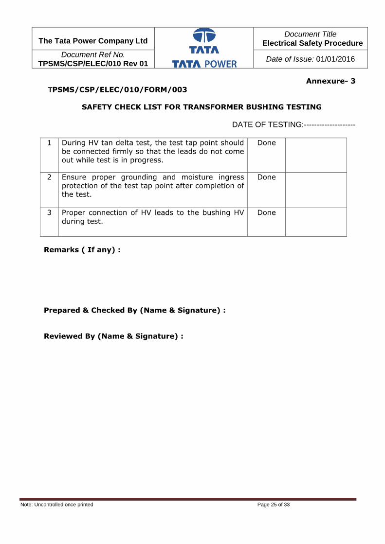
The Tata Power Company Ltd
Document Title Electrical Safety Procedure
Document Ref No. TPSMS/CSP/ELEC/010 Rev 01
Date of Issue: 01/01/2016
Note: Uncontrolled once printed Page 25 of 33
Annexure- 3 TPSMS/CSP/ELEC/010/FORM/003
SAFETY CHECK LIST FOR TRANSFORMER BUSHING TESTING
DATE OF TESTING:--------------------
1 During HV tan delta test, the test tap point should
be connected firmly so that the leads do not come out while test is in progress.
Done
2 Ensure proper grounding and moisture ingress protection of the test tap point after completion of the test.
Done
3 Proper connection of HV leads to the bushing HV
during test.
Done
Remarks ( If any) :
Prepared & Checked By (Name & Signature) :
Reviewed By (Name & Signature) :

The Tata Power Company Ltd
Document Title Electrical Safety Procedure
Document Ref No. TPSMS/CSP/ELEC/010 Rev 01
Date of Issue: 01/01/2016
Note: Uncontrolled once printed Page 26 of 33
Annexure- 4
TPSMS/CSP/ELEC/010/FORM/004
SAFETY CHECK LIST FOR CT/CVT/PT TESTING
DATE OF TESTING:--------------------
1 Secondary of CVT/PT kept open and grounded at one point.
Yes
2 Secondary of CT kept shorted and grounded at one point.
Yes
3 Before primary injection LBBU, B/F and Transformer differential relay are properly identified and blocked if necessary.
Yes
4 There should be no fuses in the meters used for
current measurements on CT secondary circuits. Yes
5 While dropping CT links for current measurements
ensure continuity of current measuring circuit. Yes
6
After raising CT link by two screw driver methods
only, current in the meter across the link has gone to zero before removing the meter.
Yes
7 While doing CVT/PT secondary voltage injection ensure the HV side is not shorted and that it is cordoned off and protected.
Yes
8
There should be only one ground in each core /
winding of CT/CVT, PT circuit. IR of secondary circuit after removing single ground > 2Mohm
Yes
9 Follow the instructions of HV Test while doing
secondary induced voltage testing on PT. Yes
Remarks ( If any) :
Prepared & Checked By (Name & Signature) :
Reviewed By (Name & Signature) :

The Tata Power Company Ltd
Document Title Electrical Safety Procedure
Document Ref No. TPSMS/CSP/ELEC/010 Rev 01
Date of Issue: 01/01/2016
Note: Uncontrolled once printed Page 27 of 33
Annexure- 5
TPSMS/CSP/ELEC/010/FORM/005
SAFETY CHECK LIST FOR CAPACITOR TESTING
DATE OF TESTING:--------------------
1 While entering Capacitor bank cage ensure that it is fully discharged.
Yes
2 Do not reclose capacitor bank breaker immediately
after tripping. Yes
3 Ensure Discharge Timer in Protection circuit for the
above. Yes
4 One must be aware of the corrosive and dangers of
the electrolyte in the capacitor Yes
5 Ensure proper Voltage and KVAr rating of the capacitor being commissioned /replaced.
Yes
Remarks ( If any) :
Prepared & Checked By (Name & Signature) :
Reviewed By (Name & Signature) :

The Tata Power Company Ltd
Document Title Electrical Safety Procedure
Document Ref No. TPSMS/CSP/ELEC/010 Rev 01
Date of Issue: 01/01/2016
Note: Uncontrolled once printed Page 28 of 33
Annexure- 6
TPSMS/CSP/ELEC/010/FORM/006
SAFETY CHECK LIST FOR GENERATOR TESTING
DATE OF TESTING:--------------------
1 While entering GT/UAT/Generator HV side bus duct, etc.
ensure that the generator is at standstill and not on turning gear.
Yes
2 Ensure that Generator is not taken on turning gear when
testing in Generator Bus duct is in progress.
Yes
3 Ensure proper sound protection for ears while working in vicinity of running generators
Yes
4 While doing generator shaft voltage measurements
ensure proper safety.
Yes
Remarks ( If any) :
Prepared & Checked By (Name & Signature) :
Reviewed By (Name & Signature) :

The Tata Power Company Ltd
Document Title Electrical Safety Procedure
Document Ref No. TPSMS/CSP/ELEC/010 Rev 01
Date of Issue: 01/01/2016
Note: Uncontrolled once printed Page 29 of 33
Annexure- 7
TPSMS/CSP/ELEC/010/FORM/007
SAFETY CHECK LIST FOR SWITCHGEAR TESTING
DATE OF TESTING:--------------------
1 Ensure all entry points and doors are closed and vermin proof before clearing equipment.
Yes
2 Especially for outdoor equipment ensure proper monsoon, water ingress protection.
Yes
3 During Testing, do not put hands in moving parts of breaker mechanism
OK
4 While entering cubicle for CT or PT connection, ensure metal clad isolation between live bus bar compartment & cable
compartment of feeders, incomers etc.
Yes
5 IR of Vacuum bottle must be done with X-Ray exposure
shield.
Yes
6 DC clearance and AC clearance are adequate (of different
criteria?)
Yes/NO
Remarks ( If any) :
Prepared & Checked By (Name & Signature) :
Reviewed By (Name & Signature) :

The Tata Power Company Ltd
Document Title Electrical Safety Procedure
Document Ref No. TPSMS/CSP/ELEC/010 Rev 01
Date of Issue: 01/01/2016
Note: Uncontrolled once printed Page 30 of 33
Annexure- 8
TPSMS/CSP/ELEC/010/FORM/008
SAFETY CHECK LIST FOR RELAY TESTING
DATE OF TESTING:--------------------
1 Direct Trip links if any kept dropped during carrier
trials Yes
2
During testing ensure isolation of relay binary outputs accounted for. There should be no Remote,
Bus Coupler, Lock Out tripping (other than the feeder which is being tested) connected.
Yes
3 Confirm B/F Stability while taking new equipment in service.
Yes
4 Confirm Differential Stability test while taking new equipment in service.
Yes
5 Confirm Shinkle test while taking new equipment in service.
Yes
6 B/F, LBBU trip links kept inoperative for test charging and/or taking equipment on load service
Yes
7 B/F, LBBU normalized after making spill current
measurements. Yes
8 DC and Positive to Trip circuits IR taken. Yes
9 CT and PT secondary circuits IR taken. Yes
10 Ensure safety ground in CT and PT secondary circuits.
Yes
11 Ensure DC on while carrying out changeover before release so the juice is available for changeover
relays.
Yes
Remarks (If any):
Prepared & Checked By (Name & Signature):
Reviewed By (Name & Signature):
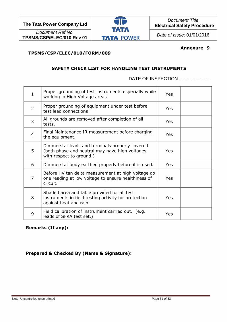
The Tata Power Company Ltd
Document Title Electrical Safety Procedure
Document Ref No. TPSMS/CSP/ELEC/010 Rev 01
Date of Issue: 01/01/2016
Note: Uncontrolled once printed Page 31 of 33
Annexure- 9
TPSMS/CSP/ELEC/010/FORM/009
SAFETY CHECK LIST FOR HANDLING TEST INSTRUMENTS
DATE OF INSPECTION:--------------------
1 Proper grounding of test instruments especially while working in High Voltage areas
Yes
2 Proper grounding of equipment under test before test lead connections
Yes
3 All grounds are removed after completion of all tests.
Yes
4 Final Maintenance IR measurement before charging
the equipment. Yes
5 Dimmerstat leads and terminals properly covered (both phase and neutral may have high voltages
with respect to ground.)
Yes
6 Dimmerstat body earthed properly before it is used. Yes
7 Before HV tan delta measurement at high voltage do one reading at low voltage to ensure healthiness of
circuit.
Yes
8 Shaded area and table provided for all test instruments in field testing activity for protection
against heat and rain.
Yes
9 Field calibration of instrument carried out. (e.g. leads of SFRA test set.)
Yes
Remarks (If any):
Prepared & Checked By (Name & Signature):

The Tata Power Company Ltd
Document Title Electrical Safety Procedure
Document Ref No. TPSMS/CSP/ELEC/010 Rev 01
Date of Issue: 01/01/2016
Note: Uncontrolled once printed Page 32 of 33
Annexure- 10
TPSMS/CSP/ELEC/010/FORM/010
SAFETY CHECK LIST GENERAL FOR TESTING ACTIVITY
DATE OF INSPECTION:--------------------
1 Cross check if any doubt about test results or
variations in test results.
Yes
2 Wherever working with high pressure vessels/
cylinders person must be aware of the dangers.
Yes
3 Wherever working with corrosive liquids like battery
acid, cleaning liquids, alcohol all precautions and emergency procedures are understood.
Yes
Remarks ( If any) :
Prepared & Checked By (Name & Signature) :
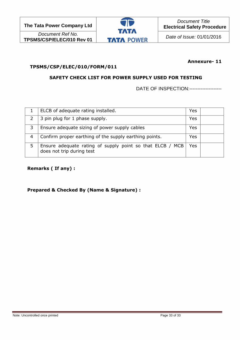
The Tata Power Company Ltd
Document Title Electrical Safety Procedure
Document Ref No. TPSMS/CSP/ELEC/010 Rev 01
Date of Issue: 01/01/2016
Note: Uncontrolled once printed Page 33 of 33
Annexure- 11
TPSMS/CSP/ELEC/010/FORM/011
SAFETY CHECK LIST FOR POWER SUPPLY USED FOR TESTING
DATE OF INSPECTION:--------------------
1 ELCB of adequate rating installed. Yes
2 3 pin plug for 1 phase supply. Yes
3 Ensure adequate sizing of power supply cables Yes
4 Confirm proper earthing of the supply earthing points. Yes
5 Ensure adequate rating of supply point so that ELCB / MCB does not trip during test
Yes
Remarks ( If any) :
Prepared & Checked By (Name & Signature) :

Uncontrolled copy once printed Page 1
The Tata Power Company Ltd
Document Title: Earth Leakage Circuit Breaker
(ELCB) Testing Procedure
Document No: TPSMS/GSP/ELCB/016 REV 01
Date of Issue: 05/11/2015
EARTH LEAKAGE CIRCUIT BREAKER (ELCB) TESTING PROCEDURE
Rev No.
Reason for Revision Revised By Checked By Approval by
R0 On the basis of incident
Investigation report Ravindra Panchal
Navendra Singh
V K Chourey
R1 To add SOP of ELCB
Testing Ravindra Panchal
Navendra Singh
V K Chourey

Uncontrolled copy once printed Page 2
The Tata Power Company Ltd
Document Title: Earth Leakage Circuit Breaker
(ELCB) Testing Procedure
Document No: TPSMS/GSP/ELCB/016 REV 01
Date of Issue: 05/11/2015
Content
Section Description Page No.
1.0 OBJECTIVE 3
2.0 SCOPE 3
3.0 EXPECTED RESULTS 3
4.0 ACCOUNTABILITY & RESPONSIBILTIY 3
5.0 GLOSSARY/ DEFINITIONS 3-4
6.0 PROCEDURE 4
7.0 RECORDS 5
8.0 TRAINING & COMMUNICATION 5
9.0 VERIFICATION 5
10.0 EXEMPTION 5
11.0 REFERENCES 5
12.0 REVIEW 5
13.0 ATTACHMENTS/APPENDIX 6-11

Uncontrolled copy once printed Page 3
The Tata Power Company Ltd
Document Title: Earth Leakage Circuit Breaker
(ELCB) Testing Procedure
Document No: TPSMS/GSP/ELCB/016 REV 01
Date of Issue: 05/11/2015
1. OBJECTIVE:
The objective of this procedure is to define the minimum requirements for testing of
Earth Leakage Circuit Breaker (ELCB).
2. SCOPE:
This procedure applies to all operating & Project sites of TATA Power Group
Companies.
3. EXPECTED RESULTS:
3.1. Manage activities/jobs associated with ELCB safely.
3.2. Control of incidents related to failure of ELCB.
3.3. Compliance to Regulatory requirements to make work place safety
4. ACCOUNTABILITY & RESPONSIBILITY:
4.1. ACCOUNTABILITY: Concerned Division’s Heads / Assets Custodian
4.2. RESPONSIBILITY: Concerned Engineer.
5. GLOSSARY/ DEFINITIONS:
Shall: mandatory requirement
Should: Optional requirement
Earth Leakage Circuit Breaker (ELCB): An Earth Leakage Circuit Breaker (ELCB)
is a safety device used in electrical installations with high earth impedance to
prevent shock. It detects small stray voltages/differential current and interrupts the
circuit if a dangerous voltage is detected. ELCB is also known as RCCB.
RCCB: Residual Current Circuit Breaker
JSA: Job Safety Analysis
LOTO: Lock Out Tag Out
PPE: Personal Protective Equipment
PTW: Permit To Work
Work Permit - The written or printed document that is issued to control working in
operational area/ in vicinity of electrical equipments.

Uncontrolled copy once printed Page 4
The Tata Power Company Ltd
Document Title: Earth Leakage Circuit Breaker
(ELCB) Testing Procedure
Document No: TPSMS/GSP/ELCB/016 REV 01
Date of Issue: 05/11/2015
Work supervisor - A person who is authorized; to verify that all conditions for
working have been met, to define ongoing precautions to maintain safe working
conditions during the work, to authorize the work to occur, and to cancel the permit
allowing the work; also known as proprietor, work group supervisor, or authorizing
person.
Licensed Electrician : PWD Electrical license Holder.
6. PROCEDURES :
Power system protection plays important role for the safety of humans and electrical
equipment in Plants and buildings. Earth leakage circuit breaker (ELCB) is an
important protection device especially for plants, houses, buildings and Portable
Electrical Equipment. The ELCB’s spring trap will trip to isolate the fault from the
system when line to ground fault occurs. So the healthy condition of the ELCB is
very important for safety of human beings and protection of the system.
6.1. Any power supply provided for the use of portable electrical tools shall be given
through portable power supply board fitted with ELCB of 30 miliAmp rating.
6.2. If tripping timing exceeds more than 50 Miliseconds at 30 MiliAmp then ELCB
shall be replaced immediately.
6.3. The power supply cable shall be free of any joints.
6.4. Testing Schedule: Following testing schedule shall be followed for ELCBs.-
6.4.1. All fixed type ELCBs installed on switchboards shall be tested Half yearly
with the help of ELCB tester as per attached SOP (Appendix C) by the
licensed Electrician & record shall be maintained as per attached
Appendix A.
6.4.2. All ELCBs installed on portable switchboards, switchboard installed at
Temporary sheds, and outside areas (outside buildings) shall be tested
quarterly with the help of ELCB tester as per attached SOP (Appendix C)
by the licensed Electrician.
6.4.3. Before starting any work ELCB provided / installed for that Electrical
Circuit to be tested by pressing Push Button provided on ELCB to confirm
ELCB is tripping mechanically.

Uncontrolled copy once printed Page 5
The Tata Power Company Ltd
Document Title: Earth Leakage Circuit Breaker
(ELCB) Testing Procedure
Document No: TPSMS/GSP/ELCB/016 REV 01
Date of Issue: 05/11/2015
6.4.4. Defective ELCB shall be replaced immediately with new ELCB.
6.4.5. The ELCB testing & failure record shall be maintained in format given in
appendix - B.
7. RECORDS :
7.1 ELCB Testing record to be maintained as per Format for minimum three (03)
years as per attached appendix A.
7.2 ELCB failure record to be maintained as per Format for minimum three (03)
years as per attached Appendix B.
8. TRAINING & COMMUNICATION
8.1. Training of ELCB procedure shall be covered along with Electrical safety
Training.
8.2. Initial Communication to be done through Corporate Communication, Email
and subsequently this procedure shall be made available at safety portal at
Sangam.
9. VERIFICATION
9.1. Verification of implementation of ELCB Testing shall be done during Safety
Audit, Field Safety visit and inspections.
10. EXCEPTION :
Any Exception to this procedure shall only be done as per section 6.3 of Document
Control .Procedure (TPSMS/GSP/DC/014/REV01).
11. REFERENCES
11.1. Electrical safety procedure.
11.2. Indian Electricity act and Rules
11.3. IS : 12640: 2008
12. REVIEW
Review of this procedure shall be done as and when but not later than once in every
three (03) years. Typical Factors like Changes in legislation, Review of Incident
Reports, Inspection & Audit findings, Feedback from users, Recommendations in

Uncontrolled copy once printed Page 6
The Tata Power Company Ltd
Document Title: Earth Leakage Circuit Breaker
(ELCB) Testing Procedure
Document No: TPSMS/GSP/ELCB/016 REV 01
Date of Issue: 05/11/2015
Incident investigation reports may be inputs for the review and revision of the
procedure.
13. ATTACHMENTS/APPENDIX :
Appendix-A - Format for ELCB Testing
Appendix-B - Format for ELCB Failure record
Appendix-C- SOP For Testing ELCB
Appendix-D- Photographs of ELCB Tester.

Uncontrolled copy once printed Page 7
The Tata Power Company Ltd
Document Title: Earth Leakage Circuit Breaker
(ELCB) Testing Procedure
Document No: TPSMS/GSP/ELCB/016 REV 01
Date of Issue: 05/11/2015
ELCB/016/FORM/01 Appendix-A
Format for ELCB Testing
Date Sr. No. of ELCB
Location Type & Make
of ELCB
Rating in mA
Trip Time in
Seconds
Remarks Name & Sign.

Uncontrolled copy once printed Page 8
The Tata Power Company Ltd
Document Title: Earth Leakage Circuit Breaker
(ELCB) Testing Procedure
Document No: TPSMS/GSP/ELCB/016 REV 01
Date of Issue: 05/11/2015
ELCB/016/FORM/02 Appendix-B
Format for ELCB Failure record
Date Sr. No. of
ELCB
Location Type & Make
of ELCB
Rating in mA
Defect ( Mechanical / Electrical)
Remarks Name & Sign.
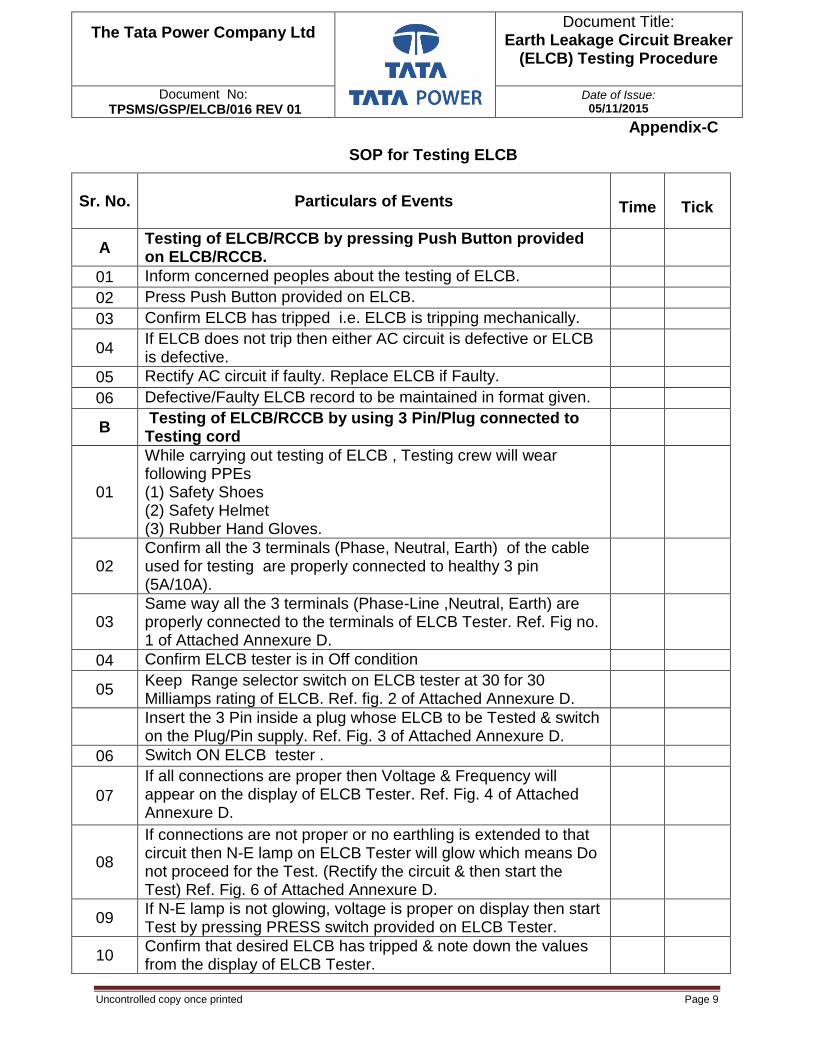
Uncontrolled copy once printed Page 9
The Tata Power Company Ltd
Document Title: Earth Leakage Circuit Breaker
(ELCB) Testing Procedure
Document No: TPSMS/GSP/ELCB/016 REV 01
Date of Issue: 05/11/2015
Appendix-C
SOP for Testing ELCB
Sr. No.
Particulars of Events
Time Tick
A Testing of ELCB/RCCB by pressing Push Button provided on ELCB/RCCB.
01 Inform concerned peoples about the testing of ELCB.
02 Press Push Button provided on ELCB.
03 Confirm ELCB has tripped i.e. ELCB is tripping mechanically.
04 If ELCB does not trip then either AC circuit is defective or ELCB is defective.
05 Rectify AC circuit if faulty. Replace ELCB if Faulty.
06 Defective/Faulty ELCB record to be maintained in format given.
B Testing of ELCB/RCCB by using 3 Pin/Plug connected to Testing cord
01
While carrying out testing of ELCB , Testing crew will wear following PPEs (1) Safety Shoes (2) Safety Helmet (3) Rubber Hand Gloves.
02 Confirm all the 3 terminals (Phase, Neutral, Earth) of the cable used for testing are properly connected to healthy 3 pin (5A/10A).
03 Same way all the 3 terminals (Phase-Line ,Neutral, Earth) are properly connected to the terminals of ELCB Tester. Ref. Fig no. 1 of Attached Annexure D.
04 Confirm ELCB tester is in Off condition
05 Keep Range selector switch on ELCB tester at 30 for 30 Milliamps rating of ELCB. Ref. fig. 2 of Attached Annexure D.
Insert the 3 Pin inside a plug whose ELCB to be Tested & switch on the Plug/Pin supply. Ref. Fig. 3 of Attached Annexure D.
06 Switch ON ELCB tester .
07
If all connections are proper then Voltage & Frequency will appear on the display of ELCB Tester. Ref. Fig. 4 of Attached Annexure D.
08
If connections are not proper or no earthling is extended to that circuit then N-E lamp on ELCB Tester will glow which means Do not proceed for the Test. (Rectify the circuit & then start the Test) Ref. Fig. 6 of Attached Annexure D.
09 If N-E lamp is not glowing, voltage is proper on display then start Test by pressing PRESS switch provided on ELCB Tester.
10 Confirm that desired ELCB has tripped & note down the values from the display of ELCB Tester.

Uncontrolled copy once printed Page 10
The Tata Power Company Ltd
Document Title: Earth Leakage Circuit Breaker
(ELCB) Testing Procedure
Document No: TPSMS/GSP/ELCB/016 REV 01
Date of Issue: 05/11/2015
Sr. No.
Particulars of Events
Time Tick
11 Tripping timing of ELCB should be 30Miliseconds
12 If tripping timing exceeds more than 50 Miliseconds at 30 MiliAmp then ELCB shall be replaced immediately.
13 Defective/Faulty ELCB record to be maintained in format given. Frequent failure analysis to be done.
C Testing of ELCB/RCCB by using Testing cord (No 3 Pin connected to Testing cord)
01
While carrying out testing of ELCB, Testing crew will wear following PPEs (1) Safety Shoes (2) Safety Helmet (3) Rubber Hand Gloves.
02 Confirm ELCB tester is in Off condition
03 Confirm all the 3 terminals (Phase-Line, Neutral, and Earth) of the cord used for testing are properly connected to ELCB Tester.
04 In case of 3 Phase ELCB there are 4 points (Holes access to 3 phases & Neutral) on ELCB i.e. R,Y,B,N.
05
For Testing R phase, insert phase-Line cord coming from ELCB tester inside R phase of ELCB, Neutral to N point of ELCB & Earth to Earth point nearby. Ref. Fig. 5 of Attached Annexure D.
06 Switch ON ELCB tester.
07 If all connections are proper then Voltage & Frequency will appear on the display of ELCB Tester.
08
If connections are not proper or no earthling is extended to that circuit then N-E lamp on ELCB Tester will glow which means Do not proceed for the Test. (Rectify the circuit & then start the Test)
09 If N-E lamp is not glowing, voltage is proper on display then start Test by pressing PRESS switch provided on ELCB Tester.
10 Confirm that desired ELCB has tripped & note down the values from the display of ELCB Tester.
11 Tripping timing of ELCB should be 30 Miliseconds
12 If tripping timing exceeds more than 50 Miliseconds at 30 MiliAmp then ELCB shall be replaced immediately.
13 Defective/Faulty ELCB record to be maintained in format given. Frequent failure analysis to be done.
14 Same way test to be conducted for other Phases.

Uncontrolled copy once printed Page 11
The Tata Power Company Ltd
Document Title: Earth Leakage Circuit Breaker
(ELCB) Testing Procedure
Document No: TPSMS/GSP/ELCB/016 REV 01
Date of Issue: 05/11/2015
Appendix-D
Photographs of ELCB Tester
Fig. 1 Fig 2
Fig. 3 Fig. 4
Fig. 5 Fig 6

1
HHHaaazzzaaarrrddd IIIdddeeennntttiiifffiiicccaaatttiiiooonnn aaannnddd RRRiiissskkk AAAsssssseeessssssmmmeeennnttt
(((HHHIIIRRRAAA)))

2
Document Control Details
Document Issue
Issue Date
* Compiled By Document Owner
Approved by
1st Corp Rules & Procedures -committee
V.Srinavasan
Mr. V.K.Chourey
Chairman Corp R&P Committee
Document Revision No.
Revision Date Document No.
R-00 Nil
User Notes: - Corp Rules and procedure Team at Tata Power, is the custodian of this document and is responsible for the Administration and Authorization of this Procedure. Rules and procedure Site Team is responsible for confirming the accuracy and integrity of content and proposed changes to the Procedure.
Controlled copy of the current version of this document is held at TATA POWER, on Sangam portal under safety. Any printed / electronic copy of this document is uncontrolled. It is recommended that users verify that the version being used by them is the current version by referring to the controlled version
* Compiled By -
Location Team Members
Trombay V.Srinivasan
Trombay M.P.Mhatre
Trombay Z.H.Mulani

3
Table of Contents 1.1 Introduction. 1.2 Purpose. 1.3 Scope. 1.4 Controlling document. 1.5 Review and Improvement. 1.6 Terminology. 1.7 Roles and Responsibility. 1.8 Procedure for Hazard Identification and Risk assessment and Control. 1.9 Records.

4
1.1 Introduction Hazard Identification and Risk Assessment (HIRA) The objective of hazard identification is to identify and evaluate the hazards and the unintended events, which could cause an accident. The first task usually is to identify & the hazards that are inherent to the process and/or plant and then focus on the evaluation of the events, which could be associated with hazards. In hazard identification and Quantification of probability of occurrence it is assumed that the plant will perform as designed in the absence of unintended events (component and material failures, human errors, external event, process unknown), which may affect the plant/process behaviour. The primary objective of this process is to provide assurance that new OH&S risks are not introduced or the existing risk profile is not increased without appropriate mitigation. Managing the OH&S impact of changes requires a structured risk evaluation and management framework in accordance with Tata Power HSE Risk Evaluation and management procedures. This shall include, but not be limited to, the development of formal and approved OH&S policies, plans, procedures and standards. However, in the normal course of Tata Power operations there will be a need to update or revise these to reflect changes in operations and/or organisation. Therefore, robust procedures for managing OH&S in changes are essential in order that suitable and sufficient risk controls are maintained and that standards remain up-to-date. 1.2 Purpose: To define guidelines for Hazard identification, Risk assessment and determination of controls. 1.3 Scope: This procedure describes specific techniques to prevent human and property losses in the operation and management of process plant. The overall methodology presented in this procedure allows systematic identification of hazards as well as quantification of the risks associated with the operation of process plants. Applied with due expertise and rigour the prescribed methodology can help the user understand the relative levels of hazards and risk potential in an installation. This aids the selection and prioritization of necessary strategies for accident prevention and limiting their consequences. Therefore, the procedure can be used for improving plant safety performance as well as to reduce human and property losses. Risk analysis is a process that consists of a number of sequential steps as follows: 1.4 Controlling Documents This document is a specification under Tata Power Document management system. 1.5 Review and Improvement This specification shall be reviewed, as a minimum, every 3 years. However, Changes to the current version may be made in less than 3 years as required. Users are encouraged to participate in the ongoing improvement of this document by providing constructive feedback to the document custodian.

5
1.6 Terminology: For the purpose of this procedure, the following technical terms used are interpreted and understood as given below. 1.6.1 Accident - A specific unplanned event or sequence of events that has undesirable consequences. 1.6.2 Basic Event - A fault tree event that is sufficiently basic that no “further development is necessary. 1.6.3 Consequence - A measure of the expected effects of an incident. 1.6.4 Explosion- A sudden release of energy characterized by accompaniment of a blast wave. 1.6.5 External Event - An event caused by a natural hazard (earthquake, flood, etc) or man-induced events (aircraft crash, -sabotage, etc). 1.6.6 Fire- A process of combustion characterized by heat or smoke or flame or any combination of these. 1.6.7 Frequency - The number of occurrences of an event per unit of time. 1.6.8 Hazard - A characteristic of the system/plant process that represents a potential for an accident causing damage to people, property or the environment. 1.6.9 .Initiating Event - The first event in an event sequence. 1.6.10 Mitigation System - Equipment and/or procedures designed to respond to an accident event sequence by interfering with accident propagation and/or reducing the accident consequence. 1.6.11 Probability - An expression for the likelihood of occurrence of an event or an event sequence during an interval of time or the likelihood of the success or failure of an event on test or on demand. 1.6.12 Risk - A measure of potential economic loss or human injury in terms of the probability of the loss or injury occurring and the magnitude of the loss or injury if it occurs. 1.6.13 Top Event - The unwanted event or incident at the top of a fault tree that is traced downward to more basic failures using logic gates to determine its causes and likelihood.

6
1.6.14 Worst Case Consequence - A conservative (high) estimate of the consequences of the most severe accident identified. 1.6.15 : Hazard Identification — Identifying sources of process accidents involving release of hazardous material in the atmosphere and the various -ways (that is scenarios) they could occur. 1.6.16:Consequence Assessment — Estimating the probable zone of impact of accidents as well as the scale and/or probability of damages with respect to human beings and plant equipment and other structures. 1.7: Roles and Responsibility: Respective Section heads / HODs (Unless otherwise specified). 1.8: Procedure for Hazard Identification and Risk assessment and Control. 1.8.1 The Tata Power Company has established, implemented and maintained a
procedure for the ongoing Hazard identification, risk assessment and determination of necessary risk controls. The Procedure for Hazard identification and Risk assessment is defined below.
Procedure for HIRA:
Sl. No.
Activity details / Procedure Responsibility
1 The sequence / flow chart of Hazard identification and Risk assessment is as follows. Classify the work activities Identify the Hazards Determine Risks Determine existing control measures Assess the Risk considering the probable failures in the existing risk control measures (i.e., Effectiveness of existing risk control measures) Decide whether the risk is tolerable Decide the Risk control Plan.
---------------
2 Classification of work activities: Department Heads in association with the core team member shall list out routine and non-routine activities, activities of all personnel having access to the workplace (including Contractors and Visitors) in the respective department. and gather the following information wherever possible, for each work activity. Tasks being carried out; their duration and frequency. Location/s where the work is carried out. Who normally carries out the tasks. Others who may be affected by the work (e.g. visitors,
contractors, the public) Training, that personnel have received about the tasks.
HODs/ Section Heads

7
Work permit system for the job Size, shape, surface character of and weight of materials
that might be handled. Utility services such as compressed air/steam. Substances used or encountered during the work Physical form of substances used and recommendations as
per MSDS. Legal and other requirements. Records of accident/s and incident/s and analysis Communications from employees and other interested
parties. Work place monitoring data. Control measures believed to be in place. Safety committee reports Note: Any interested party can request concerned department heads and he/she shall fill up the risk assessment format and the Department Head shall evaluate the same.
3 Identify hazards and determine risks. Hazard identification and risk assessment to be pro-active rather than reactive. The broad categories of hazards are: a) Mechanical (Example: Fall / slip due to slippery floor,
Exposure to moving / rotating parts of machine etc) b) Electrical (Example: Electric shocks / electrocution) c) Substances (Example: Direct contact with acids /
chemicals). d) Fire and explosion. e) Radiation (Example: Exposure to X-rays etc) f) Toxic release (Example: Leakage of chlorine, ammonia etc) g) Natural calamities.(Earth quake, Floods, h) Severe wind storm, lightening etc) i) Biological hazards (Example: Sources of biological
hazards include bacteria, viruses, insects, plants, birds, animals, and humans. These sources can cause a variety of health effects ranging from skin irritation and allergies to infections (e.g., tuberculosis, AIDS), cancer and so on.
HODs/ Section Heads
4 The following three questions enable hazard identification.
a) Is there a source of harm? b) Who (or what) could be harmed? c) How could harm occur?
HODs/ Section Heads
5 While identifying the hazards and determining the risks, the following factors shall be considered. Human behavior, capabilities and other human factors. Hazards originating outside the workplace capable of
adversely affecting the health and safety of personnel under the control of the organization within the
HODs/ Section Heads

8
workplace. Hazards created in the vicinity of the workplace by work
related activities under the control of the organization. Infrastructure, equipment and materials at the workplace,
whether provided by the organization or others. Changes or proposed changes in the organization, it’s
activities and materials. Modification to the OH&S Management system including
temporary changes. Applicable legal obligations relating to risk assessment
and implementation of necessary controls. Design of workplace, processes installations, machinery
/ equipment, operating procedures and work organization, including their adaptation to human capabilities.
6 After identifying the hazards and determination of risks, carrying out risk assessment and classify the risks based on the risk priority number (RPN).
HODs/ Section Heads
7 Hazard identification and Risk assessment shall be reviewed at least once in 6 months to keep this information up-to-date.
HODs/ Section Heads
8 However, Hazard identification and Risk assessment shall be reviewed before implementing changes to the activity / process / equipment / existing risk control measures. Review of Risk assessment shall be carried out during the following situations. During changes from normal operation, new or modified
process/ installation, changes in raw materials, chemicals etc,
During expansion, contraction, restructuring New or modified legislation. New information/inputs from interested parties
Note : Care should be taken to ensure that risk level is not increased due to the introduction of change/ modification to the existing activities, materials , equipments, processes, risk control measures
HODs/ Section Heads
9 The significant OH&S Risks identified by all departments are reviewed in the Management Review Meeting to identify the OH&S objectives of the organization. In addition to this, the individual departments may identify OH&S objectives in a proactive manner.
HODs
10 Hierarchy of Risk Control measures: While determining risk controls or considering changes to existing controls, consideration shall be given to reducing the risks according to the following hierarchy:
ELIMINATE (REMOVE) / SUBSTITUTION ENGINEERING CONTROLS
HODs

9
SIGNAGE / WARNINGS and / or ADMINISTRATIVE CONTROLS.
PERSONAL PROTECTIVE EQUIPMENTS (PPEs - Last resort).
Examples: a. Eliminate / Substitution (If practicable, Eliminate the
hazards altogether, or combat the risk at source….. For example Use a safe substance instead of dangerous one).
b. Engineering Controls If elimination or Substitution is not
possible, try to reduce the risk through engineering controls such as Usage of low voltage electrical appliance, remote operation from enclosure. Other examples for Engineering controls are: (Machine guarding, Proper platforms, Acoustic enclosures, automation instead of manual operations)
c. Administrative controls (Work permit systems,
Barricading, Limited access, providing training, display of signages etc).
d. PPEs If hazard cannot be avoided, protect yourself
(Example: Helmets, Safety belts, Goggles, Nose masks, shields, Hand gloves, Gum boots, Safety shoes, Aprons etc).
1.8.2 RISK ASSESSMENT: A. QUALITATIVE ASSESSMENT OF RISKS:
a) LC – Legal Concern: The hazard or risk is addressed by applicable legal requirements such as Factories Act / State factory rules or Indian electricity rules etc.
b) IPC – Interested Party Concern: The hazard / Risk having a concern
expressed by Employees, Neighbors, local residents. (Note: The head of the department conducts the risk assessment for any complaint received by any employee or interested party and if he feels that the risk is intolerable then the same is considered as interested party concern and the risk is treated as intolerable. Proper control measures are taken for the to reduce the risk)

10
c) BC – Business Concern : Any hazard and Risk which will result in: Fatal accidents / severe damage to human health and safety. Damage to property resulting in loss of Production. Huge financial implications.
d) E – Potential Emergency situations which result in loss or damage to humans / property / environment.( Emergency : Any situation, arising out of major fire, gas leak, explosion, toxic release, flooding which is likely to go out of control and requires controlling by a pre determined team. The situation may result in injury/ill health to group of employees and/or general public and/or, property damage which require mitigation of losses.
B. Any Hazard / risk which is associated with a Legal Concern (LC), Interested Party Concern (IPC), Business Concern (BC) and Potential Emergency situations (E) are considered as Significant Risks by default.
The following Qualitative Risk Assessment matrix will be used across Tata Power for maintaining consistency.
Pro
bab
ilit
y
Very high Almost certain, it
will occur >80% in any time frame
High Expected to occur
10 % to 80 % chance in time
frame
Medium It could occur less than up to 10 % chance in time
frame
Low Not expected to
occur less than .1 % in time frame
Very Low Almost certain it will occur greater than .01% chance
in time frame
Very Low Low Medium High Very High
1 2 3 4 5
Consequence Severity Increases
Co
nse
qu
ence
s in
var
iou
s
reg
imes
People (Health and Safety)
No Health / Injury risk
Fir4st aid cases or
slight health
problem
Lost time injury or potential health
problem
Partial disability or major health
problem
Total disability / fatality (s)
server healthy problem

11
Environmental Negligible effect
confined to in plant
grounds / environment
Minor effects
neighbours adjacent to
plant complain
Localise rerelease
makes local TV
coverage / news paper
Major release make
national TV
coverage / news paper
Massive damage makes
international TV
coverage / new paper
Product or Service Quality
Some product or
service fails to meet
standards
Several costumer complain verbally
Several customer complain in writing
Important / major
customer cancelled
orders
Loss of substantial
marked share due problem
Assess or finance loss
Slight damage is Up to Rs 10,000
Noticeable damage between
Rs 10,000 to 1 Lakh
Large damage 1 Lakh to 10
Lakhs
Major damage 10 Lakhs
to 100 Lakhs
Severe damage
more than 1 Crore
Reputation (Local, National, or International
Slight to moderate
impact
Loss of community reputation
Loss of state
reputation
Loss of national
reparation
Loss of international reputation

1
PPE MANDATE

2
Document Control Details
Document Issue Issue Date * Compiled By Document
Owner Approved by
1st 26/04/11 Corp Rules & Procedures -committee
V Srinivasan V K Chourey
Document Revision No. Revision Date Document No.
R-00 Nil CS-PGL-015
User Notes: - Corp Rules and procedure Team at Tata Power, is the custodian of this document and is responsible for the Administration and Authorization of this Policy. Rules and procedure Site Team is responsible for confirming the accuracy and integrity of content and proposed changes to the requirement of PPE
Controlled copy of the current version of this document is held at TATA POWER, on Sangam portal under safety. Any printed / electronic copy of this document is uncontrolled. It is recommended that users verify that the version being used by them is the current version by referring to the controlled version
* Compiled By -
Location Team Members
Trombay Mr V Srinivasan
Trombay Mr P M Naik
Engineering dept Mr A S Kakirde
Trombay Mr C G H Aranha

3
Scope: The scope of this policy shall be applicable for any work related to TATA POWER. The PPE’s must be of good quality and appropriate to their work as per relevant IS codes. Selection of PPE’s to be done based on IS / equivalent spec, manufacturer’s recommendation and feedback from users. A record of the PPE’s identified and chosen for the task, the manufacturers’ instructions for the cleaning and storage also to be kept for reference.
POLICY ON MANDATORY USE OF PPE IN COMPANY PREMISES.
(To be followed by all Visitors, Contractors and Tata Power Employees.)
A. General: With the objective of ensuring personal safety and uphold safe practices of the
highest order; The Tata Power Company Limited enforces the following policy for all persons, who enter the company premises, operating plants or project sites. Violations of the policy shall call for action as per “The Consequence Management policy” of the company, in force at that time. The entire premises shall be subdivided into areas depending on the PPE mandate applicable to that area and these areas shall be demarcated with required number of entrances. All the entrants to the Tata Power premises, except for the categories (a) and (b) in section D as mentioned below, shall also strictly ensure not to wear loose clothing in the operations / project sites.
B. Division of the premises: For the purpose of this policy the entire premises shall be divided as:- 1. Office area, including Canteen, Restrooms, Changing rooms etc; 2. Internal and peripheral roads not within plant battery limits; open spaces (like safe
assembly areas, parking lots, gardens etc.). 3. Plant areas including roads within the battery limits.

4
C. A few examples of the PPE requirements are given below (Not an exhaustive list)
Sr. No Area PPE required
1 Plant Area - TG deck feed cycle, boiler fan area etc
Safety Shoes, Helmet, hand gloves, ear plugs / muffs and goggles.
2 Materials and Fuel Area Safety Shoes, Hand Gloves, Helmets, goggles
3 Parking lots, open areas, peripheral and internal roads and safe assembly areas.
Safety Shoes
4 Plant Area - Chemical handling Safety Shoes, Helmet, hand gloves, canister type mask with suitable filters, goggles, face shield and any other job specific PPE
D. Mandate for different Categories of entrants: a) For office staff: The office staff can be in their usual outfit. The office staff shall normally enter the premises from the authorized main gate. They shall walk to, or take a shuttle bus to travel to the office building by the shortest route, using the PPE free walk way. No PPE mandate shall be applicable for these walk ways. In case required to go out to any other area, except the safe assembly area at times of emergency, they shall obey the PPE mandate for that area.
2… b) Vendors, visitors stakeholders and others, supposed to have some work in the office building only: As in (a) above. c) Technical staff: This includes operation, maintenance staff and all those regularly required to enter the plant premises as a part of their routine job. They shall carry with them all the PPEs required for that particular area / job and use the same judiciously. d) External experts: Those who are not conditioned and acquainted with our safety policies shall be accompanied by the authorized representative of the originating department. Experts coming for long assignment, when conditioned and acquainted with our safety policies, can work without being accompanied by a Tata Power representative. The originating department engineer calling the external expert for work in the company premises shall be responsible for conditioning and acquainting the external experts with our safety policies as well as job specific PPE requirements.

5
The PPE mandate applicable for different areas in their control will be decided by the Plant / SBU head. The mandate shall be clearly, prominently and distinctly displayed at all the entrances to the areas within the premises in bold sign boards so as to catch unfailing attention of any entrant to the area as far as possible. As far as possible the boards shall be similar in size, shape at all the locations of the company to maintain identity. SBU head may make some site specific changes, if so required. Certain areas where the company employees, particularly those who are in O&M wish to take rest or relax must be condoned off as ‘No PPE” area and be suitably covered, well ventilated and out of any apparent danger of the type that the PPEs can prevent. Once the employee is out of this area, he must again put on his PPEs as required.
******************************************************

6

Projects Access Control Philosophy
1
A. Background:
The Apex Safety Committee (ASC) during its meeting on 02.06.2011, made a strong recommendation
to improve Access control in project sites for safety (Ref.: 12.01.04). A Special Task force was formed
to analyze and suggest practical solutions.
The Task force had a special brainstorming session on 17.06.2011, debated various practical options
and has finally come out with the following philosophy.
B. Objectives:
To classify project personnel under broader categories based on the safety critical jobs in which they
are involved; identify the helmet stickers for each category for ease of identification and control.
To divide the project areas into various zones in order to install physical barricades (fence etc) and
influence proper access control;
C. Categories of project personnel involved in safety critical jobs:
S.N Categories of personnel involved in Top 8 Safety
critical jobs
Authorization by Prerequisites for authorization
1 Personnel working at height Head-Mech Head-Civil
Medical report
General safety induction
Working at height training and Test (includes knowledge of precautions, care for self, fellow colleagues, PPE for safe working at height)
2 Scaffolding erectors Head-Mech Medical report
General safety induction
Scaffolding erector training
3 Riggers & Signal men Head-Mech Medical report
General safety induction
Safe rigging and signal practices
4 Heavy Equipment Operators (including cranes, JCBs, Hydras, Shovel loaders, and winch operators)
Head-Mech Medical report
Driving license
General safety induction
Material handling
Safe rigging and signal practices
5 Electricians Head-Elect General safety induction
Govt. Electrical license (as applicable)
Electrical safety training
6 Welders and gas cutters Head-Mech General safety induction
Welding and gas cutting safety
7 Gang leaders Concerned HODs General safety induction
Supervision for safety course
Job Safety Analysis (JSA)
Permit to work (PTW)

Projects Access Control Philosophy
2
Electrical safety training
Gas cylinders safety
Safety inspection and auditing
8 Personnel working for deep excavation
Head-Civil Medical report
General safety induction
Excavation Safety Training
Confined Space Entry Training
D. Method of Control to prohibit unauthorized engagement in safety critical jobs:
The distinct helmet stickers will be issued as per the below samples to control unauthorized
personnel being deployed in safety critical jobs.

Projects Access Control Philosophy
3
Employee No:
Co. Name:
Authorized By:
Date:
Employee No:Co. Name:Authorized By:
Date:

Projects Access Control Philosophy
4
Employee No:
Co. Name:
Authorized By:
Date:
Employee No:
Co. Name:
Category:
Authorized By:
Date:

Projects Access Control Philosophy
5
Employee No:
Co. Name:
Category (LV/HV) :
Authorized By:
Date:
Employee No:
Co. Name
Authorized By:
Date:

Projects Access Control Philosophy
6
Employee No:
Co. Name
Authorized By:
Date:
Employee No:
Co. Name:
Authorized By:
Date:

Projects Access Control Philosophy
7
Employee No:
Co. Name:
Authorized By:
Date:
E. Project Zonal classification:
S.N Zones Color Stickers
1 Boiler & ESP Violet
2 Turbine Generator (TG) Blue
3 Balance of Plant (BOP) Green
4 Chimney Yellow
5 Switch yard Orange
6 Internal Coal Handling System (ICHS) Red
7 Administrative Offices NIL
F. Method of control to prohibit unauthorized entry into sensitive areas:
Different color stickers will be affixed on helmet to indicate the area(s) for which an individual is
authorized to work.

SECTION D- TATA POWER STANDARD POLICIES


For Reference- User Manual e-Bidding & Auction (Ariba)

CONFIDENTIAL 1
Supplier Manual anSwering
to
e-bidding
Version 1.2 Company Confidential DEC - 2020

CONFIDENTIAL 2
INDEX
1 ACCESSING ARIBA SOURCING ........................................................................................................................ 3
2 VENDOR SCREEN...................................................................................................................................................4
2.1.1 Review and Approve “Prerequisites” ..................................................................................................................5
2.1.2 Select Items or Lots ..............................................................................................................................................6
2.1.3 Entering Your Prebid ..........................................................................................................................................6
2.1.4.1 How to submit a price...........................................................................................................................................................9
3 COMMUNICATING WITH TATA POWER BUYER DURING E-BIDDING..............................................7
4 ARIBA TRAINING AND ARIBA SUPPORT ……...........................................................................................8
5 SUPPLIER FREQUENTLY ASKED QUESTION ...........................................................................................11

CONFIDENTIAL 3
1- Accessing Ariba Sourcing Step 1: You will get an invitation to your email from Ariba System. Keep this email, it contains your login Information and a direct link to Ariba. Step 2: Click “Click Here” to access the Ariba Web Site.
Step 3: Supplier has to click on "Continue"
Step 4: The registration process only takes a few moments, with a simple one-page registration Define your password and secret question. Click “OK”

CONFIDENTIAL 4
Step 5: If it’s the first time you are invited to use UPM Ariba, you’ll need to accept the “Participant Terms”. Select “I accept the terms of this agreement”. Click “Submit”.
2 Vendor Screen - Submitting Your Answers / Proposal
2.1.1 If vendor goes through mail invitation then directly Screen 3.1.1 will appear, but if If you have used Ariba before and have already accessed an event for the buyer-specific account with your current log in ID, click the Login button to continue. Log in with your Ariba username and password in order to participate in the event OR you have to follow the following steps. Step 1 - Log on supplier.ariba.com
Step 2 - Put your USER ID and Password in following screen

CONFIDENTIAL 5
Step 3 - Go to “Ariba Proposals & Questionnaire”.
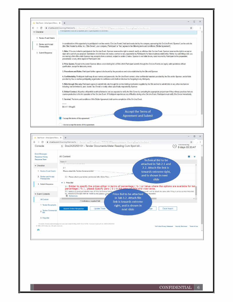
CONFIDENTIAL 6

CONFIDENTIAL 7
3 Communicating with Tata Power Buyer during e- bidding Step 1: Click “Compose Message”.
Step 2: Compose Your Message and click “Send”.
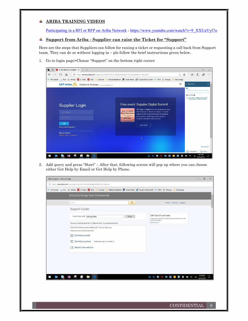
CONFIDENTIAL 8
ARIBA TRAINING VIDEOS Participating in a RFI or RFP on Ariba Network - https://www.youtube.com/watch?v=9_XXUaVyI7o
Support from Ariba - Supplier can raise the Ticket for “Support”
Here are the steps that Suppliers can follow for raising a ticket or requesting a call back from Support team. They can do so without logging in – pls follow the brief instructions given below.
1. Go to login page>Choose “Support” on the bottom right corner
2. Add query and press “Start” – After that, following screen will pop up where you can choose either Get Help by Email or Get Help by Phone.

CONFIDENTIAL 9
3. Choose phone and add following basic details and you will get call back
If not by phone, they can ask for a response/support by email.
xxxxxxxxxxxxxxxxxxxxxxxxxxxxxxxxxxxxxxxxxxxxxxxxxxxxxxxxxxxxxxxxxxxxxxxxxxxxxxxxxxxxxxxxxxxxxxxxxxxxxxxxxxxxxxxx
Supplier- Frequently aSked queStionS
If I registered on my buyer's Ariba Sourcing site in the past, do I need to register again?
Answer- Yes. Although you have registered on your buyer's Ariba Sourcing site in the past, registering on the Ariba Commerce Cloud is required. The registration process only takes a few moments, with a simple one-page registration. Registering on the Ariba Commerce Cloud gives you access to all your buyer relationships with one username and password.
What is the Ariba Commerce Cloud?
Answer: - The Ariba Commerce Cloud is your entry point to all of your seller solutions. Rather than managing log in information for multiple buyers' sites, you will have one log in and one account. This means fewer passwords to remember, easier user maintenance for your company, and a unified profile for your organization.
Do I need to add Product and Service Categories during registration?
Answer:-Yes; this is a required field. Product and Service Categories classify what your company sells, and the system uses this information to match potential business opportunities with your products and services. Click Add Product and Service Categories to select one or more categories from the list of options. During registration, you only need to choose one category, preferably related to the event you are joining. You can add, refine, or remove categories any time after the registration process.
Do I need to add ship-to or service locations during registration?
Answer: - Yes; this is a required field. Ship-to or Service locations inform buyers where your company sells its products or provides its services, and the system uses this information to match potential business opportunities with your products and services.

CONFIDENTIAL 10
Click Add Ship-to or Service Locations to select one or more sales territories from a list. You can add, refine, or remove ship-to or service locations any time after the registration process.
Additional Information: - D-U-N-S is a registered trademark of Dun & Bradstreet or its subsidiaries in the United States and other countries.
What is the difference between the Email and Username fields in my profile?
Answer: - The Email field represents the email address where you wish to receive email notifications. The Username field is the identifier that you use to access your account. The Username field must be in email format, but you do not have to use a valid email address. Note: Leave the This is my username box checked if you want your email address to be the same as your username.
How do I participate in my buyer's event using an email invitation?
Answer: - Use the Click here link in the email notification to access the sourcing event.
While buyers might customize the email content you receive, all email invitations contain a link to access the event.
Depending on your previous experience with Ariba solutions, do one of the following to access the event after you click the link:
If you are new user, click Continue on the welcome page. You continue to register an Ariba account to link with your buyer and participate in the event.
If you have used Ariba before and have already accessed an event for the buyer-specific account with your current log in ID, click the Login button to continue. Log in with your Ariba username and password in order to participate in the event.
If you already have an existing Ariba Network, Ariba Discovery, or Ariba Sourcing supplier account, but you have not accessed any events for the inviting buyer's site, use the Click here if you already have an Ariba Commerce Cloud, Ariba Discovery or Ariba Network account link. After clicking the link, log in with your existing account to move your information to your buyer's site.
Additional Information:- Registering an Ariba account provides you with a consolidated view of all your customer relationships. With this one profile, you can view business opportunities, participate in sourcing events, participate in contract negotiations, and manage orders, catalogs, and invoices.
Why doesn't the link in the email invitation to participate in a sourcing event work?
Answer:-If you cannot click the link, or the link does not open the log in page, highlight and copy the Uniform Resource Locator (URL), and then paste the URL into your web browser.
Can my company have multiple accounts?
Answer:-Your Company can have multiple Ariba accounts, depending on your business needs. For example, if your company has several locations around the world, you might want a separate account for each region.

CONFIDENTIAL 11
Most companies choose to have one account with multiple customer relationships, which provides a centralized location to maintain their company profile information and all of their customer relationships.
How do I complete registration if my username already exists?
Answer: - This message means that you already have an Ariba Network, Ariba Discovery, or Ariba Sourcing supplier account registered under username you entered. You can either register ua new account by creating a new username, or access one of the following sites to request a password reset for the registered username:
Ariba Network (This login page is used for all Ariba Network, Ariba Sourcing, or Ariba Contracts suppliers).
Ariba Discovery login page
To reset your password, click the Having trouble logging in? Link on the Login page.
Nothing happens when I click Forgot Username and enter my email address
Issue: - Nothing happens when I click the Forgot Username link and enter my email address. Cause: - After you submit your request to retrieve your username, the Ariba Network sends an email notification with usernames that match the email address you submitted. Some possible reasons why you may not receive this username retrieval email notification:
The email address on your account does not match the email address you entered when submitting the request.
Your buyer-specific account was deactivated before you could move it to the Ariba Commerce Cloud. Generally, that means you probably have not participated in an event with that buyer for a while.
Solution: - To ensure you receive this email notification: Make sure you type the email address configured within your account.
If your buyer-specific account has been deactivated, contact your buyer to determine how to proceed.
Where is my password reset email?
Answer: - After you submit your request for a password reset, Ariba sends instructions to the email address associated with your account. If you didn't receive a password reset email, check the following scenarios to troubleshoot.
The username you entered is in the wrong format, or it isn't associated with the email address you are checking.
Keep in mind, your username is in the format of a full email address, but it can be associated with any email address you entered previously.
Your username is also case-sensitive. To confirm that you are using the correct username and format, return to the Ariba login page,
and click the Having trouble logging in? link (Forgot Username if you're working in Ariba Discovery).
o Choose I forgot my username, and click Continue. o Enter the email address associated with your account, and click Submit.

CONFIDENTIAL 12
o You will receive an email that lists the exact format of the username associated with the email you entered.
You entered the correct username, but you still didn't receive the password reset email notification.
This can occur if the configured email address is different from the account you are checking. You might have multiple accounts for your company, so make sure you are attempting to
access the correct account.
Your email configuration or company's security settings might also prevent you from receiving the password reset email. To find out, check your junk mail folder or email filter settings to verify that automated emails from Ariba are not blocked from your email account.
Why do I get this message on the SAP Ariba Login page: "The username and password pair you entered was not found"?
Answer: - You entered an incorrect Username or Password. You might receive this message if you entered a previous Username or Password. Remember that your Username has the format of an email address, and both the Username and Password are case sensitive. Click the Having trouble logging in? Link on the Login page if you don't remember your log in information.