2 (Employers Requirements & Technical Specifications for ...
222
1 Name of Work - Designing, Providing, Constructing and commissioning modernized and fully automated package/modular Sewage Treatment Plants based on MBR technology along Oshiwara/ Walbhat river on Design Build Operate (DBO), along with 15 years of Operation and Maintenance and Providing and laying of sewer network, provision of Interceptors for diversion of DWF, construction of service road, and road side drains on either banks of Oshiwara/ Walbhat River for interception & diversion works of sewage. Name of Project - Rejuvenation and Beautification of Oshiwara/Walbhat River Project Consultant : Tandon Urban Solutions Pvt. Ltd. Volume – 2 (Employers Requirements & Technical Specifications for Civil Works) Website-portal.mcgm.gov.in/tenders Office of Chief Engineer (SWD) Engineering Hub Building, Dr E Moses Road, Worli Naka, Worli Mumbai – 400 018.
-
Upload
khangminh22 -
Category
Documents
-
view
2 -
download
0
Transcript of 2 (Employers Requirements & Technical Specifications for ...

1
Name of Work - Designing, Providing, Constructing and commissioning
modernized and fully automated package/modular Sewage Treatment Plants
based on MBR technology along Oshiwara/ Walbhat river on Design Build
Operate (DBO), along with 15 years of Operation and Maintenance and
Providing and laying of sewer network, provision of Interceptors for diversion
of DWF, construction of service road, and road side drains on either banks of
Oshiwara/ Walbhat River for interception & diversion works of sewage.
Name of Project - Rejuvenation and Beautification of
Oshiwara/Walbhat River
Project Consultant : Tandon Urban Solutions Pvt. Ltd.
Volume – 2
(Employers Requirements & Technical Specifications for
Civil Works)
Website-portal.mcgm.gov.in/tenders
Office of Chief Engineer (SWD)
Engineering Hub Building,
Dr E Moses Road,
Worli Naka, Worli
Mumbai – 400 018.

2
GENERAL CIVIL
SPECIFICATION

3
Contents
GENERAL CIVIL SPECIFICATION ..................................................................................... 14
1 List of Important Indian Standards ................................................................................... 14
1.1 Temporary Fencing and Hoarding ............................................................................ 25
1.1.1 Removal of Debris ............................................................................................. 25
1.1.2 Tests ................................................................................................................... 26
2 EARTHWORK AND EXCAVATION ............................................................................ 27
2.1 General ...................................................................................................................... 27
2.2 Clearing ..................................................................................................................... 27
2.3 Cofferdams ................................................................................................................ 27
2.3.1 General Description ........................................................................................... 27
2.3.2 Submittal Drawings ........................................................................................... 28
2.3.3 Materials ............................................................................................................ 28
2.3.4 Construction ....................................................................................................... 28
2.3.5 Removing Cofferdams ....................................................................................... 29
2.4 Excavation ................................................................................................................. 29
2.4.1 Classification of Earthwork ............................................................................... 30
2.4.2 Excavation Side Slopes ...................................................................................... 30
2.4.3 Undercutting of Adjacent Works ....................................................................... 30
2.4.4 Stripping Loose Rock: ....................................................................................... 31
2.4.5 Excess excavation to be made good................................................................... 31
2.4.6 Lead.................................................................................................................... 31
2.4.7 Trench Excavation ............................................................................................. 31
2.4.8 Sheeting Shoring and Bracing ........................................................................... 32
2.4.9 Trenchless Excavation ....................................................................................... 35
2.5 Backfilling and Filling .............................................................................................. 37
2.5.1 Materials ............................................................................................................ 37
2.5.2 Execution ........................................................................................................... 37
2.5.3 Site Filling .......................................................................................................... 38
2.5.4 Backfill around Structures ................................................................................. 39
2.5.5 Filling Beneath Plinths and Floors ..................................................................... 40
2.5.6 Trench Backfilling ............................................................................................. 41
2.5.7 Site Grading ....................................................................................................... 42

4
2.5.8 Clean Up ............................................................................................................ 42
2.5.9 Disposal of Excavated Material ......................................................................... 42
2.6 Excavation Dewatering ............................................................................................. 42
2.6.1 General ............................................................................................................... 42
2.6.2 Components of Dewatering Systems ................................................................. 43
2.6.3 Maintenance of Existing Water Table ............................................................... 44
2.6.4 Protection of Existing facilities .......................................................................... 44
2.6.5 Drainage ............................................................................................................. 44
2.6.6 Removal ............................................................................................................. 44
2.7 Ground improvement by vertical drains.................................................................... 44
2.7.1 General ............................................................................................................... 44
2.7.2 Qualifications of Specialist Contractors ............................................................ 45
2.7.3 Working Platform .............................................................................................. 45
2.7.4 Vertical Drains ................................................................................................... 45
2.7.5 Earthwork materials ........................................................................................... 49
2.7.6 Instrumentation of Ground Improvement Area ................................................. 50
2.7.7 Site Records and Reports ................................................................................... 55
3 PLAIN AND REINFORCED CEMENT CONCRETE WORKS .................................... 56
3.1 General ...................................................................................................................... 56
3.2 Materials .................................................................................................................... 56
3.3 Samples and Tests ..................................................................................................... 60
3.4 Storing of Materials ................................................................................................... 60
3.5 Concrete .................................................................................................................... 60
3.5.1 General ............................................................................................................... 60
3.5.2 Design Mix Concrete ......................................................................................... 61
3.5.3 Batching and Mixing of Concrete ...................................................................... 65
3.5.4 Nominal Mix Concrete ...................................................................................... 65
3.6 Formwork .................................................................................................................. 65
3.7 Reinforcement Workmanship ................................................................................... 68
3.8 Tolerances ................................................................................................................. 68
3.8.1 Tolerances for R.C. Buildings ........................................................................... 68
3.9 3Preparation Prior to Concrete Placement ................................................................ 71
3.10 Transporting, Placing and Compacting Concrete ..................................................... 71

5
3.11 Mass Concrete Works ............................................................................................... 72
3.12 Curing ........................................................................................................................ 72
3.13 Construction Joints and Keys .................................................................................... 73
3.14 Foundation Bedding .................................................................................................. 73
3.15 Finishes...................................................................................................................... 74
3.15.1 General ............................................................................................................... 74
3.15.2 Surface Finish Type F1 (IS 457) ........................................................................ 74
3.15.3 Surface Finish Type F2 (IS 457) ........................................................................ 74
3.15.4 Surface Finish Type F3 (IS 457) ........................................................................ 74
3.15.5 Unformed Surfaces (IS 457) .............................................................................. 74
3.15.6 Integral Cement Finish on Concrete Floor......................................................... 75
3.16 Repair and Replacement of Unsatisfactory Concrete ............................................... 75
3.17 Vacuum Dewatering of Slabs .................................................................................... 75
3.18 Hot Weather Requirements ....................................................................................... 75
3.19 Liquid Retaining Structures ...................................................................................... 76
3.20 Testing Concrete Structures for Leakage .................................................................. 76
3.21 Optional Tests ........................................................................................................... 77
3.22 Grouting .................................................................................................................... 77
3.22.1 Standard Grout ................................................................................................... 77
3.22.2 Non-Shrink Grout .............................................................................................. 78
3.22.3 Inspection ........................................................................................................... 78
3.22.4 Clean-Up ............................................................................................................ 78
3.22.5 Acceptance Criteria ............................................................................................ 78
3.22.6 Water stops......................................................................................................... 79
3.22.7 Workmanship ..................................................................................................... 80
3.23 Preformed Fillers and Joint Sealing Compound ....................................................... 80
3.23.1 Materials ............................................................................................................ 80
3.23.2 Workmanship ..................................................................................................... 82
3.23.3 Concreting Records ............................................................................................ 83
3.23.4 Renovation Work ............................................................................................... 83
4 STRUCTURAL STEEL WORKS.................................................................................... 84
4.1 Steel Materials ........................................................................................................... 84
4.2 Fabrication ................................................................................................................. 84

6
4.2.1 General ............................................................................................................... 84
4.2.2 Connections........................................................................................................ 84
4.2.3 Straightening ...................................................................................................... 85
4.2.4 Welding .............................................................................................................. 85
4.3 Tolerances ................................................................................................................. 86
4.4 End Milling ............................................................................................................... 86
4.5 Inspection .................................................................................................................. 86
4.5.1 General ............................................................................................................... 86
4.5.2 Material Testing ................................................................................................. 86
4.5.3 Tests on Welds ................................................................................................... 87
4.6 Drilling Holes for other works .................................................................................. 87
4.7 Marking of Members ................................................................................................. 88
4.7.1 Errors.................................................................................................................. 88
4.8 Site Operations .......................................................................................................... 88
4.9 Acceptance of Steel, its Handling and Storage ......................................................... 89
4.10 Anchor Bolts and Foundations .................................................................................. 89
4.11 Assembly and connections ........................................................................................ 89
4.12 Erection ..................................................................................................................... 90
4.13 Inspection .................................................................................................................. 91
4.14 Tolerances ................................................................................................................. 91
4.14.1 Surface Treatment .............................................................................................. 91
4.14.2 Materials ............................................................................................................ 91
4.15 Galvanising of Structural Steel ................................................................................. 92
4.15.1 Galvanising Plant ............................................................................................... 92
4.15.2 Workmanship ..................................................................................................... 93
5 PLANT ROADS AND DRAINS ..................................................................................... 94
5.1 Road Construction ..................................................................................................... 94
5.2 Materials .................................................................................................................... 94
5.2.1 General ............................................................................................................... 94
5.2.2 Soling Stone ....................................................................................................... 94
5.2.3 Stone Aggregate/Metal ...................................................................................... 94
5.2.4 Screenings for Water Bound Macadam ............................................................. 96
5.2.5 Binding Material ................................................................................................ 96

7
5.2.6 Murum/Kankar/Gravel/Sand .............................................................................. 97
5.2.7 Bituminous Materials ......................................................................................... 97
5.3 Earth work ................................................................................................................. 97
5.3.1 Earthwork in Excavation.................................................................................... 97
5.3.2 Earthwork in Embankment ................................................................................ 97
5.4 Preparation of Subgrade ............................................................................................ 98
5.5 Sub-base .................................................................................................................... 99
5.5.1 General ............................................................................................................... 99
5.5.2 Spreading and Rolling........................................................................................ 99
5.5.3 Application of Screening ................................................................................... 99
5.5.4 Sprinkling and Grouting .................................................................................. 100
5.6 Base course - Waterbound Macadam Course ......................................................... 100
5.6.1 Preparation of Base .......................................................................................... 100
5.6.2 Spreading Coarse Aggregate............................................................................ 100
5.6.3 Rolling.............................................................................................................. 100
5.6.4 Application of Blindage ................................................................................... 101
5.6.5 Sprinkling and Grouting .................................................................................. 101
5.6.6 Setting and Drying ........................................................................................... 102
5.7 Seal Coat ................................................................................................................. 102
5.7.1 Materials .......................................................................................................... 102
5.7.2 Preparation of Base .......................................................................................... 103
5.7.3 Construction of Type A Seal Coat ................................................................... 103
5.7.4 Rolling.............................................................................................................. 103
5.7.5 Construction of Type B Seal Coat ................................................................... 103
5.8 Quality Control ........................................................................................................ 104
5.8.1 General ............................................................................................................. 104
5.8.2 Permitted Tolerances ....................................................................................... 104
5.8.3 Tests ................................................................................................................. 107
5.8.4 Slab Culvert ..................................................................................................... 110
5.8.5 Pipe Drains ....................................................................................................... 111
6 GENERAL BUILDING WORKS .................................................................................. 114
6.1 Brickwork ................................................................................................................ 114
6.1.1 Materials: ......................................................................................................... 114

8
6.1.2 Workmanship ................................................................................................... 115
6.1.3 Half Brick Work .............................................................................................. 117
6.2 Un-Coursed Random Rubble Masonry, in Foundation, Plinth and Superstructure 117
6.2.1 Materials .......................................................................................................... 117
6.2.2 Workmanship ................................................................................................... 118
6.3 Coursed Rubble Masonry (First Sort) for Superstructure ....................................... 119
6.4 Concrete Block Masonry ......................................................................................... 119
6.4.1 Materials .......................................................................................................... 119
6.4.2 Workmanship ................................................................................................... 121
6.5 Damp - Proof Course............................................................................................... 122
6.6 Miscellaneous Inserts, Bolts etc. ............................................................................. 123
6.7 Woodwork in Doors, Windows, Ventilators and Partitions .................................... 123
6.7.1 Materials .......................................................................................................... 123
6.7.2 Workmanship ................................................................................................... 124
6.7.3 Deleted ............................................................................................................. 125
6.7.4 Aluminum Doors, Windows, Ventilators and Partitions ................................. 125
6.7.5 Steel Rolling Shutters ...................................................................................... 127
6.7.6 Rubble Sub-Base .............................................................................................. 128
6.7.7 Base Concrete .................................................................................................. 129
6.7.8 Terrazzo and Plain Cement Tiling Work ......................................................... 129
6.7.9 In-Situ Terrazzo Work ..................................................................................... 131
6.7.10 Shahabad / Tandur/ Kota Stone Slab work/granite .......................................... 132
6.7.11 Vitrified Porcelain Tiles ................................................................................... 133
6.7.12 Carborundum Tile Finish ................................................................................. 134
6.7.13 Glazed Tile Finish ............................................................................................ 135
6.7.14 In-Situ Cement Concrete Floor Topping ......................................................... 136
6.7.15 In-Situ Granolithic Concrete Floor Topping .................................................... 137
6.7.16 Floor Hardener Topping .................................................................................. 137
6.7.17 PVC Sheet/Tile Flooring.................................................................................. 138
6.7.18 Acid Resisting Brick/Tiling Work ................................................................... 140
6.7.19 Heavy Duty Abrasion Resistant Flooring ........................................................ 141
6.8 Epoxy Lining Work ................................................................................................. 141
6.8.1 Materials .......................................................................................................... 141

9
6.8.2 Workmanship ................................................................................................... 142
6.9 Polyurea Coating ..................................................................................................... 142
6.9.1 General ............................................................................................................. 142
6.9.2 Technical properties ......................................................................................... 142
6.9.3 Application Methodology ................................................................................ 143
6.10 Mineral Based Surface Coating............................................................................... 143
6.10.1 General ............................................................................................................. 143
6.10.2 Application Methodology ................................................................................ 144
6.11 Water-Proofing ........................................................................................................ 144
6.11.1 General ............................................................................................................. 144
6.11.2 Modified Bituminous Membrane Water Proofing ........................................... 144
6.11.3 Waterproofing of Roofs with Lime Concrete .................................................. 145
6.11.4 Waterproofing of Roofs/Terraces etc............................................................... 147
6.12 Cement Plastering Work ......................................................................................... 149
6.13 Cement Pointing ...................................................................................................... 150
6.13.1 Materials .......................................................................................................... 150
6.13.2 Workmanship ................................................................................................... 150
6.14 Metal Lath and Wire Fabric .................................................................................... 151
6.14.1 Materials .......................................................................................................... 151
6.14.2 Workmanship ................................................................................................... 151
6.15 Water-Proofing Admixtures .................................................................................... 151
6.15.1 Wall Care Putty ................................................................................................ 152
6.16 Painting of Concrete, Masonry and Plastered Surfaces .......................................... 153
6.16.1 General ............................................................................................................. 154
6.16.2 Surfaces Not to be Painted ............................................................................... 154
6.16.3 Materials .......................................................................................................... 154
6.16.4 Service Conditions and Applicable Systems Non-Architectural ..................... 155
6.16.5 Coating Schedule ............................................................................................. 159
6.16.6 Painting and Coatings – Architectural ............................................................. 160
6.16.7 Workmanship ................................................................................................... 161
6.17 Flashing ................................................................................................................... 163
6.17.1 Materials .......................................................................................................... 163
6.17.2 Workmanship ................................................................................................... 163

10
6.18 Thermal Insulation for Ceiling ................................................................................ 164
6.18.1 “Thermocole” Boards ...................................................................................... 164
6.18.2 Fibre Glass Boards ........................................................................................... 164
6.19 Plaster of Paris Board False Ceiling/ Gypsum Boards ............................................ 164
6.19.1 Plaster of Paris Boards ..................................................................................... 164
6.19.2 Timber Frame Work ........................................................................................ 165
6.19.3 Metal Frame Work ........................................................................................... 165
6.20 Construction ............................................................................................................ 165
6.21 Finishing .................................................................................................................. 167
6.22 Fire Stopping ........................................................................................................... 167
6.23 Concrete Roof ......................................................................................................... 167
6.24 False or Cavity Floor ............................................................................................... 167
6.24.1 Frame Work ..................................................................................................... 167
6.24.2 Floor Panels ..................................................................................................... 168
6.24.3 Imposed Loading ............................................................................................. 168
6.24.4 Finish................................................................................................................ 169
6.24.5 Drawings .......................................................................................................... 169
6.25 Fire Proof Doors ...................................................................................................... 169
6.25.1 Accessories ...................................................................................................... 169
7 WATER SUPPLY AND SANITARY WORKS ............................................................ 172
7.1 Sanitary Installation................................................................................................. 172
7.1.1 Western type WC ............................................................................................. 172
7.1.2 Urinals .............................................................................................................. 172
7.1.3 Wash Basins ..................................................................................................... 172
7.1.4 Pipes, Valves and Thrust blocks ...................................................................... 173
7.1.5 Stop Cock and Bib Cock .................................................................................. 178
7.1.6 Soak Pit ............................................................................................................ 178
7.1.7 Manholes / Inspection chambers ...................................................................... 178
7.1.8 Septic Tank ...................................................................................................... 181
7.1.9 Miscellaneous .................................................................................................. 181
8 PIPELINES, PIPE-WORK AND FITTINGS ................................................................ 183
8.1 Materials for Pipelines ............................................................................................ 183
8.2 Ductile Iron Pipes and Fittings ................................................................................ 183

11
8.2.1 Pipes and Fittings ............................................................................................. 183
8.3 JOINTS.................................................................................................................... 184
8.4 Reinforced Cement Concrete Pipes......................................................................... 186
8.4.1 Design .............................................................................................................. 186
8.5 Steel Cylinder Pipes and Specials ........................................................................... 189
8.5.1 Design .............................................................................................................. 189
8.5.2 Manufacturing .................................................................................................. 189
8.6 Cast Iron Pipes ........................................................................................................ 192
8.6.1 Manufacturing .................................................................................................. 192
8.6.2 General ............................................................................................................. 192
8.6.3 Materials .......................................................................................................... 193
8.6.4 Dimensions ...................................................................................................... 193
8.6.5 Workmanship and Finish ................................................................................. 193
8.6.6 Coating ............................................................................................................. 193
8.6.7 Marking ............................................................................................................ 194
8.6.8 Jointing ............................................................................................................. 194
8.6.9 Flanged Pipes ................................................................................................... 194
8.6.10 Cleaning of Pipes and Fittings ......................................................................... 194
8.6.11 Unplasticised PVC Pipes and Fittings ............................................................. 195
8.7 Polyethylene Pipes .................................................................................................. 195
8.7.1 Rubber Hosing ................................................................................................. 195
8.7.2 Copper Tubes and Fittings ............................................................................... 195
8.7.3 Flanged Joints .................................................................................................. 195
8.7.4 Gaskets and Joint Rings ................................................................................... 196
8.7.5 Flexible Couplings and Flange Adaptors ......................................................... 196
8.8 Storage and Shipment.............................................................................................. 196
8.8.1 Protection of Pipes and Fittings for Shipment ................................................. 196
8.8.2 Inspection of Pipes and Fittings ....................................................................... 198
8.8.3 Built-in Pipe-work and other Plant .................................................................. 198
8.8.4 Pipe-laying ....................................................................................................... 198
8.9 Laying...................................................................................................................... 199
8.9.1 Excavation........................................................................................................ 199
8.9.2 Dewatering ....................................................................................................... 201

12
8.9.3 Special Foundation in Poor Soil ...................................................................... 201
8.9.4 Wooden Shoring .............................................................................................. 201
8.9.5 Steel Plate Shoring ........................................................................................... 201
8.9.6 Laying of Pipes and Fittings/Specials .............................................................. 202
8.9.7 Thrust Blocks ................................................................................................... 203
8.9.8 Jointing ............................................................................................................. 203
8.9.9 Testing and Commissioning ............................................................................ 204
8.9.10 Backfilling........................................................................................................ 204
8.9.11 Reinstatement of Road/Footpath...................................................................... 204
8.9.12 Clearing of Site ................................................................................................ 204
9 MISCELLANEOUS ....................................................................................................... 205
9.1 Tests ........................................................................................................................ 205
9.2 Hand Railing and Rungs ......................................................................................... 211
9.2.1 Stainless Steel Hand Railings .......................................................................... 211
9.2.2 Rungs ............................................................................................................... 211
9.3 Landscaping ............................................................................................................ 211
9.3.1 Clearance of Large Trees, Structures etc. ........................................................ 211
9.3.2 Removal of Top Soil ........................................................................................ 211
9.3.3 Grading ............................................................................................................ 212
9.3.4 Grassing and Landscaping ............................................................................... 212
9.3.5 Fencing ............................................................................................................. 213
9.3.6 Barbed Wire ..................................................................................................... 213
9.3.7 Chain Link ....................................................................................................... 214
9.3.8 Fixing of the Chain Link Fencing to Mild Steel/Reinforced Concrete Post .... 214
9.3.9 Mild Steel Crimp net Gate ............................................................................... 214
9.4 Anchor Bolts ........................................................................................................... 214
9.4.1 Materials .......................................................................................................... 214
9.4.2 Execution ......................................................................................................... 215
9.5 Anti Termite Treatment and Pesticides ................................................................... 216
9.5.1 General ............................................................................................................. 216
9.5.2 Products............................................................................................................ 216
9.5.3 Delivery, Storage and Handling ....................................................................... 217
9.5.4 Site Preparation ................................................................................................ 217

13
9.5.5 Application ....................................................................................................... 218
9.5.6 Safety Requirements ........................................................................................ 219
9.6 Inspections ............................................................................................................... 220
9.7 Buried Utilities ........................................................................................................ 221
9.7.1 Marker Tape for Buried Services ..................................................................... 221
9.7.2 CONTROL CABLE BELOW Route Marker Posts......................................... 221
9.7.3 Cable Duct Systems ......................................................................................... 221
14
GENERAL CIVIL SPECIFICATION
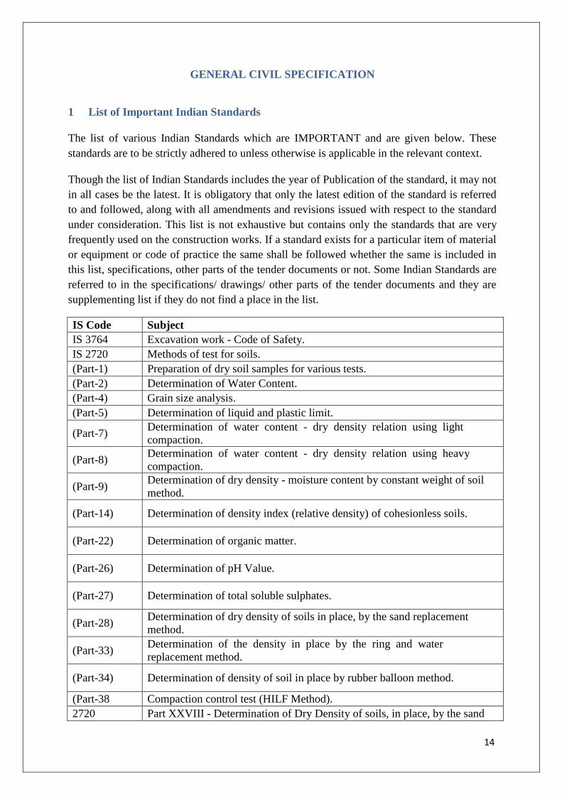
1 List of Important Indian Standards
The list of various Indian Standards which are IMPORTANT and are given below. These
standards are to be strictly adhered to unless otherwise is applicable in the relevant context.
Though the list of Indian Standards includes the year of Publication of the standard, it may not
in all cases be the latest. It is obligatory that only the latest edition of the standard is referred
to and followed, along with all amendments and revisions issued with respect to the standard
under consideration. This list is not exhaustive but contains only the standards that are very
frequently used on the construction works. If a standard exists for a particular item of material
or equipment or code of practice the same shall be followed whether the same is included in
this list, specifications, other parts of the tender documents or not. Some Indian Standards are
referred to in the specifications/ drawings/ other parts of the tender documents and they are
supplementing list if they do not find a place in the list.
IS Code Subject
IS 3764 Excavation work - Code of Safety.
IS 2720 Methods of test for soils.
(Part-1) Preparation of dry soil samples for various tests.
(Part-2) Determination of Water Content.
(Part-4) Grain size analysis.
(Part-5) Determination of liquid and plastic limit.
(Part-7) Determination of water content - dry density relation using light
compaction.
(Part-8) Determination of water content - dry density relation using heavy
compaction.
(Part-9) Determination of dry density - moisture content by constant weight of soil
method.
(Part-14) Determination of density index (relative density) of cohesionless soils.
(Part-22) Determination of organic matter.
(Part-26) Determination of pH Value.
(Part-27) Determination of total soluble sulphates.
(Part-28) Determination of dry density of soils in place, by the sand replacement
method.
(Part-33) Determination of the density in place by the ring and water
replacement method.
(Part-34) Determination of density of soil in place by rubber balloon method.
(Part-38 Compaction control test (HILF Method).
2720 Part XXVIII - Determination of Dry Density of soils, in place, by the sand

15
IS Code Subject
replacement method
2720 Part XXIX - Determination of Dry Density of soils, in Place, by the core
cutter method
6313 n 1981 Code of Practice for Anti Termite Measure in Buildings
Materials
IS: 269 Specification for 33 Grade Ordinary Portland Cement.
IS: 455 Specification for Portland Slag Cement.
IS: 1489 Specification for Portland Pozzolana Cement (Part 1and2).
IS: 8112 Specification for 43 Grade Ordinary Portland Cement.
IS: 12269 Specification for 53 Grade Ordinary Portland Cement.
IS: 12330 Specification for Sulphate Resisting Portland Cement.
IS: 383 Specification for Coarse and Fine Aggregates from Natural Sources for
Concrete
IS: 432 Specification for Mild Steel and Medium (Tensile Steel Bars and Hard
Drawn Steel) Wires for Concrete Reinforcement (Part 1 and 2)
IS: 1786 Specification for High Strength Deformed Steel Bars and Wires for Concrete
Reinforcement
IS: 1566 Specification for Hard Drawn Steel Wire Fabric for Concrete
Reinforcement
IS: 9103 Specification for Admixtures for Concrete
IS: 2645 Specification for Integral Cement Water Proofing Compounds
IS: 4990 Specification for Plywood for Concrete Shuttering Work
IS: 12089 Specification for Granulated Slag for the Manufacture of Portland Slag
Cement
Material Testing
IS: 4031 Methods of physical Tests for Hydraulic Cement (Parts 1 to 15)
IS: 4032 Method for Chemical Analysis of Hydraulic Cement
IS: 650 Specification for Standard Sand for Testing of Cement
IS: 2430 Methods for Sampling of Aggregates for Concrete
IS: 2386 Methods of Test for Aggregates for Concrete (Parts 1 to 8)
IS: 3025 Methods of Sampling and Test (physical and chemical) for Water Used in
Industry
IS: 6925 Methods of Test for Determination of Water Soluble Chlorides in
Concrete Admixture
Material storage
IS: 4082 Recommendations on Stacking and Storing of Construction Materials at Site

16
IS Code Subject
Concrete mix design
IS: 10262 Recommended Guidelines for Concrete Mix Design
Concrete testing
IS.1199 Method of Sampling and Analysis of Concrete
IS: 516 Method of Test for Strength of Concrete
IS: 9013 Method of Making, Curing and Determining Compressive Strength of
Accelerated Cured Concrete Test Specimens
IS: 8142 Method of Test for Determining Setting Time of Concrete by
Penetration Resistance
IS: 9284 Method of Test for Abrasion Resistance of Concrete
IS: 2770 Methods of Testing Bond in Reinforced Concrete
Equipment
IS: 1791 Specification for Batch Type Concrete Mixers
IS: 2438 Specification for Roller Pan Mixer
IS: 4925 Specification for Concrete Batching and Mixing Plant
IS: 5892 Specification for Concrete Transit Mixer and Agitator
IS: 7242 Specification for Concrete Spreaders
IS: 2505 General Requirements for Concrete Vibrators: Immersion Type.
IS: 2506 General Requirements for Screed Board Concrete Vibrators
IS: 2514 Specification for Concrete Vibrating Tables
IS: 3366 Specification for Pan Vibrators
IS: 4656 Specification for Form Vibrators for Concrete
IS: 11993 Code of Practice for Use of Screed Board Concrete Vibrators
IS: 7251 Specification for Concrete Finishers
IS: 2722 Specification for Portable Swing Weigh Batchers for Concrete (single and
double bucket type)
IS: 2750 Specification for Steel Scaffoldings
Codes of Practice
IS: 456 Code of Practice for Plain and Reinforced Concrete
IS: 457 Code of Practice for General Construction of Plain and Reinforced Concrete
for Dams and Other Massive Structures
IS: 3370 Code of Practice for Concrete Structures for Storage of Liquids (Parts 1 to 4)
IS: 3935 Code of Practice for Composite Construction
IS: 2204 Code of Practice for Construction of Reinforced Concrete Shell Roof
IS: 2210 Criteria for the Design of Reinforced Concrete Shell Structures and Folded
Plates

17
IS Code Subject
IS: 2502 Code of Practice for Bending and Fixing of Bars for Concrete
Reinforcement
IS: 5525 Recommendation for Detailing of Reinforcement in Reinforced Concrete
Works
IS: 2751 Code of Practice for Welding of Mild Steel Plain and Deformed Bars Used
for Reinforced Concrete Construction
IS: 9417 Specification for Welding Cold Worked Bars for Reinforced Concrete
Construction
IS: 3558 Code of Practice for Use of Immersion Vibrators for Consolidating Concrete
IS: 3414 Code of Practice for Design and Installation of Joints in Buildings
IS: 4326 Code of Practice for Earthquake Resistant Design and Construction of
Building
IS: 4014 Code of Practice for Steel Tubular Scaffolding (Parts 1 and 2)
IS: 2571 Code of Practice for Laying In Situ Cement Concrete Flooring
IS: 7861 Code of Practice for Extreme Weather Concreting: Part 1
Recommended Practice for Hot Weather Concreting.
IS: 875 Code of Practice for Design Loads (other than earthquake) for Building
Structures (Parts 1 to 5)
IS: 2502 Code of Practice for Bending and Fixing of Bars for Concrete
Reinforcement
IS: 2974 Code of Practice for Design and Construction of Machine Foundations (Parts
1 to 4)
IS: 1893 Criteria for Earthquake Resistant Design of Structures
Construction Safety
IS: 3696 Safety Code for Scaffolds and Ladders. (Parts 1 and 2)
IS: 7969 Safety Code for Handling and Storage of Building Materials.
IS: 8989 Safety Code for Erection of Concrete Framed Structures.
IS Code Description
IS : 808 Dimensions for Hot Rolled Steel sections
IS : 814 Covered Electrodes for Manual Metal Arc Welding of Carbon and Carbon
Maganese Steel
IS : 817 Code of practice for training and testing of metal arc welders
IS : 800 Code of Practice for General Construction in Steel
IS : 801 Code of Practice for Use of Cold Formed Light Gauge Steel Structural
Members in General Building Construction
IS : 806 Code of Practice for Use of Steel Tubes in General Building
Construction
IS : 7205 Safety Code for Erection of Structural Steel Work
IS : 7215 Tolerances for Fabrication of Steel Structures
IS : 4000 High Strength Bolts in Steel Structure – Code of Practice
AISC Specifications for Design, Fabrication and Erection of Buildings
IS : 1161 Steel Tubes for structural purposes
IS: 102 Ready Mixed paint, Brushing, Red Lead, Non-setting, Priming.
IS: 110 Ready Mixed paint, brushing, grey filler for enamels for use over primers.
IS: 117 Ready Mixed paint, Brushing, Finishing, Exterior Semigloss for general

18
IS Code Subject
purposes, to Indian Standard colours.
IS: 158 Ready Mixed paint, Brushing, Bituminous, Black, Lead free, Acid,
Alkali and heat resisting.
IS: 159 Ready Mixed paint, Brushing, Acid resisting for protection against acid
fumes, colour as required.
IS: 341 Black Japan, Types A, B and C
IS: 2339 Aluminium paint for general purposes, in Dual container
IS: 2932 Specification for enamel, synthetic, exterior, type 1, (a) undercoating, (b)
finishing
IS: 2933 Specification for enamel, exterior, type 2, (a) undercoating, (b) finishing
IS: 3613 Acceptable tests for wire flux combination for submerged arc welding
IS: 5905 Sprayed aluminium and zinc coatings on Iron and Steel.
IS: 6005 Code of practice for phosphating of Iron and Steel.
IS: 9862 Specification for ready mixed paint, brushing, bituminous, black, lead free,
acid, alkali, water and chlorine resisting.
IS: 13183 Aluminium paint, Heat resistant.
SIS-05-5900 (Swedish Standard)
IS : 1239 Mild steel tubes, tubulars and other Wrought steel fittings
Part 1 – Mild steel tubes
Part 2 – Mild steel tubulars and other wrought steel pipe fittings
IS : 1363
(Parts 1 to 3)
Hexagon Head Bolts, Screws and Nuts of product Grade C (Size range M5
to M64)
IS : 1367
(All parts) Technical Supply Conditions for Threaded Fasteners
IS : 1852 Rolling and Cutting Tolerances for Hot Rolled Steel Products
IS : 1977 Structural Steel (Ordinary Quality)
IS : 2062 Steel for General Structural Purposes
IS : 2074 Ready Mixed Paint, Air drying, Red Oxide Zinc Chrome and Priming
IS : 3502 Steel Chequered Plate
IS : 3757 High Strength Structural Bolts
IS : 5369 General Requirements for Plain Washers and Lock Washers
IS : 5372 Taper Washers for Channels
IS : 5374 Taper Washer for 1 Beams
IS : 6610 Heavy Washers for Steel Structures
IS : 7318 Approval tests for welders when welding procedure approval is not required
(Part 1 and 2)
IS : 8500 Structural Steel-microalloyed (medium and high strength qualities)
IS : 803 Code of practice for design, fabrication and erection of vertical mild steel
cylindrical welded storage tanks
IS : 816 Code of Practice for use of Metal Arc Welding for General
construction in Mild Steel
IS : 822 Code of Procedure for Inspection of Welds
IS : 1182 Recommended Practice for Radiographic examination of Fusion –Welded

19
IS Code Subject
Butt Joints in Steel Plates
IS : 1200 Method of Measurement in Building Civil Works
IS : 1477 Code of Practice for Painting of (Parts 1and2) Ferrous Metals in
Buildings
IS : 2595 Code of Practice for Radiographic Testing
IS : 3658 Code of Practice for Liquid Penetrant Flaw Detection
IS : 5334 Code of Practice for Magnetic Particle Flaw Detection of Welds
IS : 9595 Recommendations for Metal Arc Welding of Carbon and Carbon
Manganese Steel
IS: 73 Specification for Paving Bitumen
IS: 215 Specification for Road Tar
IS: 217 Specification for Cutback Bitumen
IS: 454 Specification for Digboi type Cutback Bitumen
IS: 460 Specification for Test sieves
IS: 1077 Common burnt clay building bricks - Specification
IS: 1124 Method of test for determination of water absorption, apparent specific
gravity and porosity of building stones
IS: 1195 Specification for Bitumen Mastic for Flooring
IS: 1196 Code of Practice for Laying Bitumen Mastic Flooring
IS: 1834 Specification for Hot Applied Sealing Compounds for Joints in
Concrete
IS: 2386
(Parts 1 to 8) Methods of test for aggregates for concrete
IS: 2720
(Part 5) Method of Test for Soils Determination of Liquid and plastic limit
IS: 6241 Method of test for determination of stripping value of road aggregat
IRC: 16 Specification for priming of Base Course with Bituminous Primers
IRC: 17 Tentative specification for Single Coat Bituminous Surface Dressing
IRC: 19 Standard specifications and code of practice for water bound macadam
IRC: 29 Specification for bituminous concrete (Asphaltic Concrete) for road
pavement
IS: 110 Ready mixed paint, brushing, grey filler, for enamels for use over primers
IS: 269 Specification for 33 grade ordinary Portland cement
IS: 278 Galvanized Steel Barbed wire for fencing
IS: 280 Specification for mild steel wire for general engineering purposes
IS: 287 Recommendations for maximum permissible moisture content of timber
used for different purposes
IS : 304 High Tensile Brass Ingots and Castings.
IS: 337 Varnish, finishing interior
IS: 348 French polish
IS: 383 Specification for coarse and fine aggregates from natural sources for
concrete
IS: 412 Expanded metal steel sheets for general purposes
IS: 419 Specification for putty for use on window frames
IS: 428 Distemper, oil emulsion, colour as required

20
IS Code Subject
IS: 459 Specification for unreinforced corrugated and semi-corrugated
asbestos cement sheets
IS: 702 Specification for industrial bitumen
IS: 710 Specification for marine plywood
IS: 712 Specification for building limes
IS: 730 Specification for hook bolts for corrugated sheet roofing
IS: 733 Wrought aluminum and aluminum alloys, bars, rods and sections for
general engineering purposes
IS: 737 Wrought aluminum and aluminum alloy sheet and strip
IS: 777 Glazed earthenware tiles
IS: 781 Cast copoer allow screw down bib taps and stop valves for water services
IS: 1003 Specification for timber paneled and glazed shutters (Parts 1 and 2)
IS: 1038 Specification for steel doors, windows and ventilators
IS: 1068 Elctroplated coating of Nickel plus Chromium and copper Plus Nickel Plus
Chromium
IS: 1077 Specification for common burnt clay building bricks
IS: 1081 Code of practice for fixing and glazing of metal (steel and aluminum) doors,
windows and ventilators
IS: 1124 Method of test for determination of water absorption, apparent specific
gravity and porosity of natural building stones
IS: 1237 Specification for cement concrete flooring tiles
IS: 1322 Bitumen felts for water proofing and damp proofing
IS: 1346 Code of practice for water proofing of roofs with bitumen felts
IS: 1361 Specification for steel windows for industrial buildings
IS: 1397 Specification for Kraft paper
IS: 1398 Specification for packing paper, waterproof, bitumen laminated
IS: 1443 Code of practice for laying and finishing of cement concrete flooring tiles
IS: 1477 Code of practice for painting of ferrous metals in buildings (Parts 1 and 2)
IS: 1542 Specification for sand for plaster
IS: 1580 Specification for bituminous compounds for water-proofing and caulking
purposes
IS: 1597 Code of practice for construction of stone masonry : Part 1 Rubble stone
masonry
IS: 1659 Specification for block boards
IS: 1661 Code of practice for application of cement and cement-lime plaster finishes
IS: 1786 High Strength deformed steel bars and wires for high strength
deformed steel bars and wires for concrete reinforcement
IS: 1834 Specification for hot applied sealing compound for joint in concrete
IS: 1838
Specification for preformed fillers for expansion joint in concrete
pavements and structures (non extruding and resilient type) : Part 1 Bitumen
impregnated fibre
IS: 1948 Specification for aluminium doors, windows and ventilators
IS: 1949 Specification for aluminium windows for industrial buildings
IS: 2074 Ready mixed paint, air drying, red oxide- zinc chrome, priming
IS: 2098 Asbestos cement building boards

21
IS Code Subject
IS: 2114 Code of practice for laying in-situ terrazzo floor finish
IS: 2116 Specification for sand for masonry mortars
IS: 2185 Specification for concrete masonry units (Parts 1,2 and 3)
IS: 2202 Specification for wooden flush door shutters (Solid core type) : Parts 1 and 2
IS: 2212 Code of practice for brickwork
IS: 2250 Code of practice for preparation and use of masonry mortars
IS: 2338 Code of practice for finishing of wood and wood based materials (Parts 1
and 2)
IS: 2339 Aluminium paint for general purposes, in dual container
IS: 2394 Code of practice for application of lime plaster finish
IS: 2395 Code of practice for painting concrete, masonry and plaster surfaces (Parts 1
and 2)
IS: 2402 Code of practice for external rendered finishes
IS: 1397 Specification for kraft paper
IS: 1398 Specification for packing paper, waterproof, bitumen laminated
IS: 1443 Code of practice for laying and finishing of cement concrete flooring tiles
IS: 1477 Code of practice for painting of ferrous metals in buildings (Parts 1 and 2)
IS: 1542 Specification for sand for plaster
IS: 1580 Specification for bituminous compounds for water-proofing and caulking
purposes
IS: 1597 Code of practice for construction of stone masonry : Part 1 Rubble stone
masonry
IS: 1659 Specification for block boards
IS: 1661 Code of practice for application of cement and cement-lime plaster finishes
IS: 1834 Specification for hot applied sealing compound for joint in concrete
IS: 1838
Specification for preformed fillers for expansion joint in concrete
pavements and structures (non extruding and resilient type) : Part 1 Bitumen
impregnated fiber
IS: 1948 Specification for aluminum doors, windows and ventilators
IS: 1949 Specification for aluminum windows for industrial buildings
IS: 2074 Ready mixed paint, air drying, red oxide- zinc chrome, priming
IS: 2098 Asbestos cement building boards
IS: 2114 Code of practice for laying in-situ terrazzo floor finish
IS: 2116 Specification for sand for masonry mortars
IS: 2185 Specification for concrete masonry units (Parts 1,2 and 3)
IS: 2202 Specification for wooden flush door shutters (Solid core type) : Parts 1 and 2
IS: 2212 Code of practice for brickwork
IS: 2250 Code of practice for preparation and use of masonry mortars
IS: 2338 Code of practice for finishing of wood and wood based materials (Parts 1
and 2)
IS: 2339 Aluminum paint for general purposes, in dual container
IS: 2394 Code of practice for application of lime plaster finish
IS: 2395 Code of practice for painting concrete, masonry and plaster surfaces (Parts 1
and 2)
IS: 2402 Code of practice for external rendered finishes

22
IS Code Subject
IS: 2571 Code of practice for laying in-situ cement concrete flooring
IS: 2572 Code of practice for construction of hollow concrete block masonry
IS: 2645 Specification of integral cement waterproofing compounds
IS: 2690 Specification for burnt clay flat terracing tiles : Part 1 Machine made
IS: 2691 Specification for burnt clay facing bricks
IS: 2750 Specification for steel scaffoldings
IS: 2835 Flat transparent sheet glass
IS: 2932 Specification for enamel, synthetic, exterior type (a) undercoating, (b)
finishing
IS: 3007 Code of practice for laying of asbestos cement sheets - corrugated and (Part
1 and 2) semi-corrugated sheets
IS: 3036 Code of practice for laying lime concrete for a water-proofed roof finish
IS: 3067 Code of practice of general design details and preparatory work for damp-
proofing and water- proofing of buildings
IS: 3068 Specification for broken brick (burnt clay) coarse aggregates for use in lime
concrete
IS: 3384 Specification for bitumen primer for use in water-proofing and damp-
proofing
IS: 3461 Specification for PVC-asbestos floor tiles
IS: 3462 Specification for un-backed flexible PVC flooring
IS: 3495 Method of test for burnt clay building bricks: Part 1 to 4
IS: 3536 Specification for ready mixed paint, brushing, wood primer, pink
IS: 3564 Specification for door closers (hydraulically regulated)
IS: 3614
(Part 1)
Specification for fire checks doors : Part –I Plate metal covered and rolling
type
IS: 3614
(Part – 2)
Specification for metallic and non-metallic fire check doors : Part-2
Resistance test and performance criteria
IS: 3696 Safety code of scaffolds and ladders (Parts 1 and 2)
IS: 3935 Code of practice for composite construction
IS: 4020 Methods of test for wooden flush door : Type test
IS: 4021 Specification for timber door, window and ventilator frames
IS: 4351 Specification for steel door frames
IS: 4443 Code of practice for use of resin type chemical resistant mortars
IS: 4457 Specification for ceramic unglazed vitreous acid resisting tile
IS: 4631 Code of practice for laying epoxy resin floor toppings
IS: 4832 Specification for chemical resistant mortars (Part II)
IS: 4860 Specification for acid resistant bricks
IS: 4948 Specification for welded steel wire fabric for general use
IS: 5318 Code of practice for laying of flexible PVC sheet and tile flooring
IS: 5410 Cement paint, colour as required
IS: 5411 Specification for plastic emulsion paint (Parts 1 and 2)
IS: 5437 Wired and figured glass
IS: 5491 Code of practice for laying of in-situ granolithic concrete floor topping
IS: 6041 Code of practice construction of autoclaved cellular concrete block masonry

23
IS Code Subject
IS: 6042 Code of practice for construction of light weight concrete block
masonry
IS: 6248 Specification for metal rolling shutters and rolling grilles
IS: 7193 Specification for glass fibre base coal tar pitch and bitumen felts
IS: 7452 Specification for hot rolled steel sections for doors, windows and
ventilators
IS: 8042 Specification for white portland cement
IS: 8543 Methods of testing plastics
IS: 8869 Specification for washers for corrugated sheet roofing
IS: 9197 Specification for epoxy resin, hardeners and epoxy resin composites for floor
topping
IS: 9862 Specification for ready mixed paint, brushing, bituminous, black, lead-free,
acid, alkali, water and chlorine resisting
IS: 10005 SI units and recommendations for the use of their multiples and of certain
other units.
IS: 12200 Code of practice for provision of water stops at transverse contraction joints
in masonry and concrete dams
BS :476
(Part–20)
Methods for determination of the fire resistance of elements of
construction (General Principles)
BS:476
(Part–21)
Methods for determination of the fire resistance of load bearing
elements of construction
BS:476
(Part 22)
Methods for determination of the fire resistance of non-load bearing
elements of Construction
Part – IV National Building code of India
IS : 210 Specification for grey iron castings
IS : 269 Specification for ordinary and low heat portland cement
IS : 383 Specification for coarse and fine aggregates from natural sources for
concrete
IS : 432 Specification for mild steel and medium tensile steel bars and hard drawn
steel wire for concrete reinforcement
IS : 456 Code of Practice for plain and reinforced concrete
IS : 458 Concrete Pipes (with and without reinforcement).
IS : 516 Methods of tests for strength of concrete
IS : 554 Dimensions for pipe threads where pressure tight joints are required on the
threads.
IS : 651 Salt glazed stoneware pipes and fittings.
IS : 774 Flushing Cisterns for water closets and urinals (valveless siphonic type)
IS : 775 Cast iron brackets and supports for wash basins and sinks.
IS : 781 Sand-cast brass screw-down bib taps and stop taps for water services.
IS : 783 Code of practice for laying of concrete pipes.
IS : 1068 Electroplated coatings of nickel and chromium of iron and steel.
IS : 1077 Specification for common burnt clay building bricks
IS : 1172 Code of practice for basic requirements for water supply, drainage and
sanitation
IS : 1786 Specification for high strength deformed steel bars and wires for
concrete reinforcement

24
IS Code Subject
IS : 1239 Mild steel tubes (Part I) and mild steel tubulars and other wrought steel pipe
fittings (Part II)
IS : 1536 Centrifugally cast (spun) iron pressure pipes for water, gas and sewage.
IS : 1626 Asbestos cement building pipes, gutters and fittings (spigot and socket
types).
IS : 1703 Copper Alloy float valves (horizontal plunger type) for water supply
purposes.
IS : 1726 Cast iron manhole covers and frames.
IS : 1729 Sand cast iron spigot and socket soil, waste and ventilating pipes, fittings and
accessories.
IS : 1742 Code of practice for buildings drainage
IS : 2065 Code of practice for water supply in Buildings
IS : 2116 Specification for sand for masonry mortars
IS : 2212 Code of practice for brickwork
IS : 2250 Code of practice for preparation and use of masonry mortars
IS : 2326 Automatic flushing cisterns for urinals
IS : 2470 Code of practice for design and construction of septic tanks (Parts I and II)
IS : 2556 Vitreous sanitary appliances (Part I to Part XV)
IS : 2963 Specification for copper alloy waste fittings for wash basins and sinks
IS : 3006 Specification for chemically resistant glazed stoneware pipes and
fittings
IS : 3025 Method for sampling and test (Physical and chemical) for water and waste
water (Parts 1 to 44)
IS : 3311 Waste plug and its accessories for sinks and wash basins
IS : 5455 Specification for cast iron steps for manholes
IS : 4127 Code of Practice for laying of glazed stoneware pipes
IS : 3495 Methods of tests of burnt clay building bricks
IS : 4111 Code of practice for ancillary structures in sewerage system manholes
IS : 5382 Specification for rubber sealing rings for gas mains, water mains and sewers
IS : 5329 Code of practice for sanitary pipe work above ground for buildings
IS : 5434 Non-ferrous alloy bottle traps for marine use
IS : 210 Specification for grey iron casting
IS : 290 Specification for coal tar black paint
IS : 318 Specification for leaded tin bronze ingots and castings
IS : 456 Code of practice for plain and reinforced concrete
IS : 458 Specification for pre cast concrete pipes (with and without
reinforcement)
IS : 516 Method of test for strength of concrete
IS : 638 Specification for sheet rubber jointing and rubber insertion jointing
IS : 783 Code of practice for laying of concrete pipes
IS : 816 Code of practice for use of metal arc welding for general construction in
mild steel
IS : 1367 Technical supply conditions for threaded steel fasteners
IS : 1387 General requirements for the supply of metallurgical materials
IS : 1500 Method for Brinell hardness test for metallic materials

25
IS Code Subject
IS : 1536 Specification for centrifugally cast (spun) iron pressure pipes for water,
gas and sewage
IS : 1537 Specification for vertically cast iron pressure pipes for water, gas and sewage
IS : 1538 Specification for cast iron fittings for pressure pipes for water, gas and
sewage
IS : 1916 Specification for steel cylinder pipes with concrete lining and coating
IS : 2078 Method for tensile testing of grey cast iron
IS : 3597 Method of tests for concrete pipes
IS : 3658 Code of practice for liquid penetrant flow detection
IS : 5382 Specification for rubber sealing rings for gas mains, water mains and sewers
IS : 5504 Specification for spiral welded pipes
IS : 6587 Specification for spun hemp yarn
IS : 7322 Specification for specials for steel cylinder reinforced concrete pipes
IS: 8329 Specification for centrifugally cast (spun) ductile iron pressure pipes for
water, gas and sewage
IS: 9523 Specification for ductile iron fittings for pressure pipes for water, gas and
sewage
IS: 11906 Recommendations for cement mortar lining for cast iron, mild steel and
ductile iron pipes and fittings for transportation of water
IS: 12820
Specification for dimensional requirements of rubber gaskets for
mechanical joints and push-on joints for use with cast iron pipes and fittings
for carrying water, gas and sewage
IS : 3114 Code of practice for laying of cast iron pipes
IS : 3764 Excavation work - Code of Safety
IS : 4127 Code of practice for laying of glazed stoneware pipes
IS : 5822 Code of practice for laying of electrically welded steel pipes for water
supply.
IS : 6530 Code of practice for laying of asbestos cement pressure pipes.
IS: 13620 Code of practice for Fusion bonded epoxy coated reinforcing bars
1.1 Temporary Fencing and Hoarding
The Contractor shall erect a fence around the perimeter of the safe working area required for
demolition and shall demonstrate to the Employer’s Representative that the extent of this area
fulfils safety requirements.
The Contractor shall provide hoarding as required and to the satisfaction of the Employer’s
Representative, to protect all those who may be affected by those works.
1.1.1 Removal of Debris
Any serviceable material obtained during dismantling or demolition shall be separated out and
stacked properly. All unserviceable materials shall be disposed of from the site and the site
left in a neat and orderly condition, to the satisfaction of the Employer’s Representative and in
accordance with prevailing regulations.
26
1.1.2 Tests
Tests as specified and other tests for specialized works or important structures and as required
by the Employer’s Representative shall be carried out as specified and/or in accordance with
the relevant IS. In case of non-IS materials, it shall be the responsibility of the Contractor to
establish the conformity of material with relevant IS and this specification by carrying out
necessary tests. The mandatory tests shall include, but are not limited to, tests mentioned in
this Volume.

27
2 EARTHWORK AND EXCAVATION
2.1 General
The Contractor shall furnish all tools, plant, instruments, qualified supervisory personnel,
labour, materials, any temporary works, consumables, any and everything necessary, whether
or not such items are specifically stated herein for completion of the work in accordance with
the Employer’s Requirements.
The Contractor shall survey the site before excavation and set out all lines and establish levels
for various works such as grading, basement, foundations, plinth filling, roads, drains, cable
trenches, pipelines etc. Such survey shall be carried out by taking accurate cross sections of
the area perpendicular to established reference/grid lines at 8m intervals or nearer, if
necessary, based on ground profile and thereafter properly recorded.
In case of excavations adjacent to existing structures, care should be taken to avoid
damage/settlement to existing structure in consultation with Engineer’s representative.
Excavated material should be stored as directed so as to provide necessary access for
functioning of existing structures.as per client’s requirements.
The excavation shall be carried out to correct lines and levels. This shall also include, where
required, proper shoring to maintain excavations and also the furnishing, erecting and
maintaining of substantial barricades around excavated areas and warning lamps at night.
Excavated material shall be dumped in regular heaps, bunds, riprap with regular slopes within
the lead specified and leveling the same so as to provide natural drainage. Rock/soil excavated
shall be stacked properly as approved by the Employer’s Representative. As a rule, all softer
material shall be laid along the center of heaps, the harder and more weather resisting
materials forming the casing on the sides and the top. Rock shall be stacked separately.
Topsoil shall be stock piled separately for later re-use.
2.2 Clearing
The area to be excavated/ filled shall be cleared of fences, trees, plants, logs, stumps, bush,
vegetation, rubbish, slush, etc. and other objectionable matter. If any roots or stumps of trees
are encountered during excavation, they shall also be removed. The material so removed shall
be disposed off as approved by the Employer’s Representative. Where earthfill is intended,
the area shall be stripped of all loose/ soft patches, top soil containing objectionable matter/
materials before fill commences.
2.3 Cofferdams
2.3.1 General Description
This work consists of designing, constructing, maintaining, dewatering, removing, and
disposing of cofferdams, which are necessary for constructing substructures and for protecting
personnel and adjacent structures, roadbeds, tracks, channels, slopes, or other property (public
or private) whether on or off the Rights-of-Way from water, caving soil, and other dangers.

28
2.3.2 Submittal Drawings
The Employer’s Representative may require the Contractor to submit drawings of proposed
cofferdams for review. If this is required, the Contractor shall not start work until the
Employer’s Representative completes the review. The review will not relieve the Contractor
of the responsibility for providing an adequate and safe cofferdam.
2.3.3 Materials
Materials used in cofferdam construction may be of any type suitable for the design
requirements and for the particular dam being constructed, subject to approval from
Employer’s Representative. Earth, sand bags, or dams constructed using excavated materials
may be considered for cofferdam construction.
2.3.4 Construction
Designing Cofferdams
Cofferdams shall be structurally adequate to withstand external and internal forces including
the following:
1. Forces and pressures from an excavation depth of not less than 6m
2. Forces and pressures from surcharge loads from adjacent structures, roadbeds, tracks,
slopes, and equipment.
Design the cofferdam to meet these conditions:
Cofferdams shall permit placing pumping equipment.
Cofferdams shall permit driving piling between braces.
Cofferdams shall be watertight to permit the construction of substructure.
Dewatering Cofferdams without Seal Concrete
The Employer’s Representative shall decide, if the Contractor has used all reasonable
methods to provide watertight cofferdams. If it is not possible to dewater the enclosures, and
the Employer’s Representative shall decide that the Contractor has not used all reasonable
methods to provide watertight cofferdams, the Employer’s Representative may permit the
Contractor to place Seal Concrete at the Contractor’s expense instead of trying further
dewatering methods without a seal.
Dewatering Cofferdams with Seal Concrete
If all reasonable methods to provide a dewaterable enclosure have been used and the Engineer
determines that seal concrete is necessary the contractor shall place the concrete. When using
seal concrete, the contractor shall dewater the cofferdam no earlier than 24 hours after the
concrete is placed unless the Engineer determines that a longer period is necessary.

29
2.3.5 Removing Cofferdams
Unless otherwise specified, the contractor shall completely remove all cofferdam material and
dispose it off as directed by the Employer’s Representative.
2.4 Excavation
Excavations shall be prepared with shallow side slopes to minimize the risk of slope failure.
Where this is not possible and the depth exceeds 0.6m, then the trench slopes must be
stabilized. Prior to man entry into the excavation, the Contractor must ensure the excavation is
stable. Further checks should be made following periods of rainfall, or where, excessive
loadings occur within close proximity to the excavation.
No excavated material shall be placed, even temporarily, nearer than three meters to the outer
edge of an excavation.
The removal of obstructions that would interfere with the proper execution and completion of
the work shall conform to the correct lines and grades or be limited generally to 60 cm beyond
the outer limit of the structure. It shall be the Contractor’s responsibility to provide all
required pumping, ditching, or other approved measures for the removal or exclusion of water
from excavations.
The Contractor shall notify the Employer’s Representative before any ground is disturbed and
shall conduct a ground level survey. The ground levels shall be taken at 1 to 3 meters intervals
in uniformly sloping ground and at closer distances where local mounds, pits or undulations
occur. The ground levels shall be recorded in field books and plotted on plans, which shall be
signed by the Contractor and the Employer’s Representative, before the earthwork
commences. When excavating to the required levels for the foundation of any structure or to
the required limits for the face of any structure abutting undisturbed ground, the Contractor
shall not excavate the last 150 mm until immediately before commencing the constructional
work.
The excavations shall be carried out systematically. No under-pining or undercutting will be
allowed. The bottom and sides of excavation shall be dressed to proper levels, slopes, steps,
cambers etc by removing high spots and filling and thoroughly compacted as necessary.
The width of excavations shall generally be of the width of the leveling course (PCC) and
depth as required by the design and according to availability of the desired bearing capacity of
soil below. The minimum depth of foundations for all structures, equipment, buildings and
frame foundations and load bearing walls shall be 1.50 m below average final ground level,
whether the foundation is in soil or in murum. For any excavation, if taken below the required
depth and level, the Contractor shall fill such over-cut to the specified level with 1:2:4 cement
concrete.
The Contractor shall provide adequate ventilation and efficient apparatus to keep all
excavation trenches, tunnels and heading structures, sewers and manholes free from all
noxious gases and he shall take precautions to ascertain that they are in a safe condition
before allowing workmen to proceed. After the excavation is completed, the Contractor shall

30
notify the Employer’s Representative to that effect and no further work shall be taken up until
the Employer’s Representative has approved the depth and dimensions and also the nature of
the foundation material. Levels and measurements of the excavation shall also be recorded
prior to taking up any further work.
2.4.1 Classification of Earthwork
The earthwork shall be classified under the following main categories:
1. All types of soils, murum, boulders.
2. Soft rock.
3. Hard rock.
2.4.1.1. All types of Soils, Murrum, Boulders
This includes earth, murrum, top deposits of agricultural soil, reclaimed soil, clay, sand or any
combination thereof and soft and hard murrum, shingle etc. which is loose enough to be
removed with spades, shovels and pick axes. Boulders of not more than 0.03 m3 in volume
found during the course of excavation shall also fall under this classification.
2.4.1.2. Excavation in Soft Rock
This shall include all materials which are rock or hard conglomerate, all decomposed
weathered rock, highly fissured rock, old masonry, boulders bigger than 0.03 m3 in volume
but not bigger than 0.5 m3 and other varieties of soft rock which can be removed only with
pick axes, crow bars, wedges and hammers with some difficulty.
2.4.1.3. Excavation in Hard Rock
This rock, occurring in masses, boulders having approximate volume of more than 0.5 m3
plain or reinforced cement concrete, which can best be removed by chiselling and wedging.
The excavation of hard rock shall be done by chiseling and wedging or any other agreed
method. Blasting shall not be allowed on this project.
All the excavated hard rock obtained shall be stacked properly and neatly by the Contractor as
approved by the Employer’s Representative.
2.4.2 Excavation Side Slopes
Loose soil or boulders shall be removed from the sides of the trenches before workmen shall
be allowed into the excavation and the trench sides shall be stabilized with screening or other
methods approved by the Employer’s Representative.
2.4.3 Undercutting of Adjacent Works
In no case shall the Contractor undercut the foundations of adjacent facilities. Should such a
situation be envisaged or develop the Contractor shall provide protection measures as
necessary to ensure the safety of the adjacent facility. The Employer’s Representative shall be
given every opportunity to review the methods adopted by the Contractor and where he

31
requires, Contractor shall satisfy the Employer’s Representative of the adequacy of the
methods employed.
2.4.4 Stripping Loose Rock:
All loose boulders, partially detached rocks and other loose material, which might move
there-with not directly in the excavation, but so close to the area to be excavated, as to be
liable, in the opinion of Employer’s Representative, to fall or otherwise endanger the
workmen, equipment, or the work shall be stripped off and removed from the area of the
excavation. The method used shall be such as not to render unstable or unsafe the portion,
which was originally sound and safe.
Any material not requiring removal in order to complete the permanent works, but which, in
the opinion of Employer’s Representative, is likely to become loose or unstable later, shall
also, be promptly and satisfactorily removed.
2.4.5 Excess excavation to be made good
The contractor, at his own expense, shall, if directed, remove from the Site all excess material
resulting from excess excavation and shall make good the same with class of concrete as
specified under 11.2.4.
2.4.6 Lead
Lead for deposition of the excavated materials should be in accordance with the regulatory
requirements. . For the purpose of measurement of lead, the area to be excavated or filled or
area in, which excavated material is to be deposited / disposed off shall be divided into
suitable blocks and for each of the blocks, the distance between centerlines shall be taken as
the lead which shall be measured by the shortest straight line route on plan and not the actual
route taken by contractor. No extra compensation is admissible on the grounds that the lead
including that for borrowed material had to be transported over marshy or kaccha land route.
2.4.7 Trench Excavation
The Contractor shall not keep trenches open for unduly long periods, creating public hazards,
such that laying and jointing of pipes can reasonably be expected to be completed and the
trench refilled not later than three days after excavation of the trench, except by special
permission of the Employer’s Representative. Loose soil or boulders shall be removed from
the sides of the trenches before workmen shall be allowed into the excavation and the trench
sides shall be stabilized with screening or other methods approved by the Employer’s
Representative.
Excavation for pipe trenches in hard rock shall be carried out so that the clearance between
the pipe, when laid in position and the sides and trench bottom shall be kept to the minimum
limits necessary to provide for the thickness of bedding and surround to the pipe.
The minimum width of trenches measured at the crown of the pipe shall permit adequate
working space. The trenches may be widened at sockets and other structures as may be
necessary.

32
Care should be taken to avoid excessive trench widths and thereby increasing the load on the
pipes. Where this is the case the Contractor shall provide either special bedding or stronger
pipes.
2.4.7.1. Over-excavation of Trench Bottoms
1. All pipeline trenches shall be excavated to a depth of 150 mm below the bottom of the
outside of the pipe and backfilled with the appropriate bedding.
2. All excavation below the required level shall be refilled with compacted cement
concrete of minimum grade 1:2:4..
2.4.8 Sheeting Shoring and Bracing
2.4.8.1.General
Description
The Contractor shall supply and install piling, diaphragm walls, bracing, underpinning
shoring and dewatering systems to adequately protect existing buildings and facilities and to
maintain the excavations required for the construction of facilities.
The Contractor shall be solely responsible for the adequacy of the piling, diaphragm walls,
bracing and shoring on the site to maintain safety and prevent damage to existing buildings,
facilities, excavation and new construction. The configuration of the proposed shoring and
bracing shall be approved by the Employer’s Representative. To obtain the approval of the
Employer’s Representative, the Contractor shall, if so required, provide drawings of the
proposed sheeting and bracing including sheeting sizes, waling, rakers, anchor systems, struts,
earth anchors, anchor piles, tie rods and other components pertinent to the effectiveness and
adequacy of the shoring and bracing.
2.4.8.2. Existing Conditions
Soils
Any information provided by the Employer relating to boring logs and soil tests carried out
are supplied in good faith. Any conclusions drawn from them, however, shall be the
responsibility of the Contractor. Where slopes steeper than the natural angle of repose or other
conditions inconsistent with the safety of personnel required to work within an excavated area
are encountered such excavations shall be sheeted or shored as may be needed to provide
adequate safety. The Contractor’s attention is specially drawn to the necessity for a thorough
study of the site and soil conditions, groundwater levels and other relevant factors,
particularly in the case of any wet wells, incoming sewer connections and force mains at great
depths, before deciding on the necessity or otherwise of sheeting, shoring and bracing and if
provided, the adequacy of same.
Obstructions

33
Prior to driving sheeting etc, the Contractor shall locate existing facilities in service, if any,
and avoid sections that may interfere with such. If such avoidance is not possible the
Contractor shall relocate the facility or arrange for its relocation as required to clear the
interference. Any action proposed in such circumstances shall be subject to the prior approval
of the Employer’s Representative.
2.4.8.3. Products and Materials
Steel Pilling and Shoring
Steel sheet piles shall conform to the requirements of IS 2314 and the steel for walls, struts
braces and tie rods shall comply with IS 226. Any materials to be incorporated into the
permanent works shall be new.
Piles shall be of the types and sizes indicated in the approved shop drawings or as specified
herein and shall be of a design that provides continuous interlocking throughout their entire
lengths. Standard handling holes shall generally be provided located approximately 100 mm
below the top of each pile.
Timber Shoring
Where the Contractor elects to use timber shoring for trench and structure excavations he
shall provide details of the shoring he proposes to adopt, taking into consideration the nature
and condition of the soil to be excavated and the depths to which the excavations are to be
carried. The quality and strength of the timber and the cross-sectional details and spacing of
the shoring, walling and struts together with the calculations, where required or requested by
the Employer’s Representative, demonstrating the structural adequacy of the proposed shoring
and timbering shall be included in the submittals.
Approval of the submittals shall however not relieve the Contractor in any way from his sole
responsibility for the stability of the works and the safety of the employees engaged on the
work and of the general public.
Dimensions
Piles and ancillary structural members shall be as shown on the approved shop drawings. All
procedures shall be subject to the approval of the Employer’s Representative approval.
2.4.8.4. Execution
General
Piling shall be accurately located and driven to the required depths, plumb and true to line
with each pile interlocking with the adjacent pile throughout its entire length. Frames,
temporary walls templates, guide-frames and bracing as are necessary shall be installed to
guide and support the sheet piling in the correct position and alignment.

34
The choice of specific construction procedure appropriate for any works or phase thereof shall
be the Contractor’s responsibility. The procedure adopted shall meet the requirement of the
works and specific procedures adopted such as construction methods, shoring, sheet piling,
bracing, dewatering etc are at the option of the Contractor. He shall however submit to the
Employer’s Representative a detailed construction procedure prior to commencement of
work.
Driving
Piling shall be driven by approved methods in such a manner as not to subject the piles to
damage and to ensure interlocking throughout the length of each pile.
Pile hammers shall be of the size and type needed to achieve the required penetration with the
minimum damage to the piles. Hammers shall be maintained in a proper alignment with the
piles during driving by use of suitable leads or guides. A protective driving cap of approved
design shall be used, as required, to minimize the damage to tops of piles. Unless otherwise
approved by the Employer’s Representative, pile driving shall be done without jetting.
The piles shall be driven plumb and if the sheet piling goes progressively out of plumb,
corrective steps shall be taken. If necessary, the piles shall be withdrawn and re-driven so that
no part of any pile is more than 75 mm from the design location of the alignment on
completion of the work.
Piling shall be driven in stages. No sheet, or pair of piles if driven in pairs, shall be driven
more than one-third of its length before the adjacent sheet pile is set. Piling that is damaged or
driven without interlocking shall be withdrawn and re-placed. The Employer’s Representative
is empowered to order withdrawal if he has reasonable grounds to suspect damage. Any
encroachment of piles upon concrete piles shall be sufficient grounds for withdrawal and
replacement.
If obstructions are encountered during driving, the piles in question shall be driven at least to
the specified refusal driving resistance after adjacent piles have been set and driven. However,
the number of sheet piles permitted to be driven short of the required depths shall be limited
in the field by the Employer’s Representative and if so approved, the Contractor shall remove
obstructions encountered by whatever means necessary.
Splices
Splices shall be avoided if practicable, but where unavoidable shall be designed to develop the
full strength of the piling. Drawings of the proposed splices shall be approved prior to
execution. Extreme care shall be exercised to align the spliced sections so that the axis of the
pile will be straight and that the interlocks of the piles shall form a straight, smooth and
continuous groove.
Driving Resistance

35
Steam, air or diesel hammers shall be provided with a rated energy not less than the hammer
manufacturer’s recommendation for the total weight of pile and the type of subsurface
material to be encountered. The Employer’s Representative may require the Contractor to
change the hammer in use to obtain the required minimum penetration. Piling shall be driven
to such depth as required to provide the degree of protection needed.
Stressing Rods
All tie rods shall be stressed to minimum of 10 percent of their design load. The Contractor
shall submit to the Employer’s Representative for his approval the proposed procedure for
pre-stressing tie rods.
2.4.9 Trenchless Excavation
2.4.9.1.General
The Contractor shall submit his proposals for excavating and constructing sewers and
pipelines in tunnel and obtain the approval of the Employer’s Representative before any work
may commence.
The Contractor shall be responsible for the security of any timbering or other temporary
tunnel supports. The Contractor shall submit for approval full details of the support and
timbering he proposes to use. The excavation for the tunnel shall be of sufficient size for the
proper execution of the construction work, all timbering must be driven and fixed in close
contact with the ground to be supported.
Unless otherwise approved by the Employer’s Representative, the tunnel shall be closed
timbered and the timber shall be left in place on completion of the work. During excavation,
securely fixed running boards shall be provided to the floor of the tunnel. On completion and
after the formation has been cleaned and dried out, a concrete sealing coat shall be provided.
The tunnel shall be driven complete between access points before the permanent work may
commence and the work shall at all times, be carried out as quickly as possible so that the
excavation remains open for the shortest possible time.
The working face of the tunnel excavation shall be supported as necessary and shall be fixed
up at the end of each point when continuous working is not in progress or whenever required
by the Employer’s Representative. When work is in progress, proper access ladders shall be
fixed and maintained at the tunnel access points and the tunnel lit by electricity of not more
than 110 volts. Lamps shall be provided at not more than 9 m intervals and no flame or other
naked light shall be used. Proper and adequate ventilation fans and ducts must be provided,
maintained and operated at all times.
2.4.9.2. Method for Trenchless Excavation

36
General
The Contractor is required to take full cognizance of the physical site condition and available
working space and select his method with due regard to the same in addition to other
requirements for the method proposed.
There is a high likelihood of heavy seepage of water into the excavation.
If required, the Contractor may use sleeve pipes of a bigger diameter than necessary and lay
the carrier pipe inside the sleeve pipe at the required grade and alignment.
The Contractor shall take into account the existing manholes to which the proposed pipeline is
to be connected and take every precaution to avoid damage to the manholes and any existing
sewers.
Where a connection is to be made to a functioning trunk sewer, the Contractor shall take all
necessary steps for plugging the sewer and diverting the flows and restoration of the same
after completion of the work.
Jacking and Receiving Shafts
The Contractor shall take due cognisance of the available working space and provide jacking
and receiving shafts at appropriate locations so not to cause any harm or danger to adjoining
structures, as well as to not occupy additional space.
The Contractor must shore the sides of shafts securely as approved by the Employer’s
Representative.
Jacking/Boring/Ramming
The jacking pipe and or carrier pipe should be of suitable length joined by properly designed
leak proof joints as required for the method adopted by the Contractor. The jacking pipe may
be provided with arrangements for circulating bentonite solution for stabilization of the
surrounding ground.
The grade and alignment of jacking shall be periodically checked by suitable instruments after
jacking of individual units and correct grade and level will have to be ensured. If the jacking
pipe is other than the carrier pipe, the annular space shall be grouted with 1:3 cement sand
grout.
Tolerance
The pipes shall be installed in place, true to line and level. The maximum tolerance allowable
in the displacement of the centerline of the laid pipe from the design centerline is 50 mm per
30 metres in the horizontal plane and 50 mm per 100 metres in the vertical plane. There shall
be no back fall at any point.
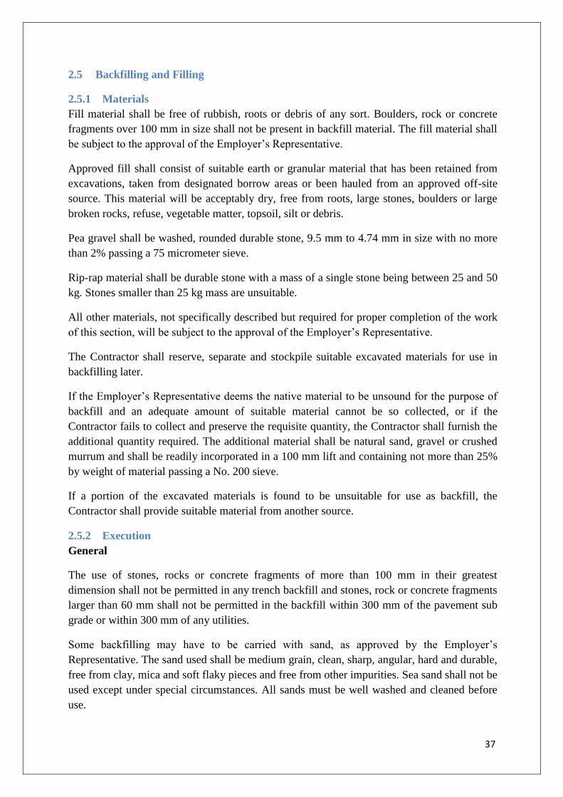
37
2.5 Backfilling and Filling
2.5.1 Materials
Fill material shall be free of rubbish, roots or debris of any sort. Boulders, rock or concrete
fragments over 100 mm in size shall not be present in backfill material. The fill material shall
be subject to the approval of the Employer’s Representative.
Approved fill shall consist of suitable earth or granular material that has been retained from
excavations, taken from designated borrow areas or been hauled from an approved off-site
source. This material will be acceptably dry, free from roots, large stones, boulders or large
broken rocks, refuse, vegetable matter, topsoil, silt or debris.
Pea gravel shall be washed, rounded durable stone, 9.5 mm to 4.74 mm in size with no more
than 2% passing a 75 micrometer sieve.
Rip-rap material shall be durable stone with a mass of a single stone being between 25 and 50
kg. Stones smaller than 25 kg mass are unsuitable.
All other materials, not specifically described but required for proper completion of the work
of this section, will be subject to the approval of the Employer’s Representative.
The Contractor shall reserve, separate and stockpile suitable excavated materials for use in
backfilling later.
If the Employer’s Representative deems the native material to be unsound for the purpose of
backfill and an adequate amount of suitable material cannot be so collected, or if the
Contractor fails to collect and preserve the requisite quantity, the Contractor shall furnish the
additional quantity required. The additional material shall be natural sand, gravel or crushed
murrum and shall be readily incorporated in a 100 mm lift and containing not more than 25%
by weight of material passing a No. 200 sieve.
If a portion of the excavated materials is found to be unsuitable for use as backfill, the
Contractor shall provide suitable material from another source.
2.5.2 Execution
General
The use of stones, rocks or concrete fragments of more than 100 mm in their greatest
dimension shall not be permitted in any trench backfill and stones, rock or concrete fragments
larger than 60 mm shall not be permitted in the backfill within 300 mm of the pavement sub
grade or within 300 mm of any utilities.
Some backfilling may have to be carried with sand, as approved by the Employer’s
Representative. The sand used shall be medium grain, clean, sharp, angular, hard and durable,
free from clay, mica and soft flaky pieces and free from other impurities. Sea sand shall not be
used except under special circumstances. All sands must be well washed and cleaned before
use.

38
Sand fill shall be kept flooded with water for 24 hours to ensure maximum consolidation. The
surface of the consolidated sand shall be dressed to the required level or slope. Construction
of floors or other structures on sand fill shall not be started until the Employer’s
Representative has approved the fill. Backfilling work shall be suspended at any time when
satisfactory compaction results cannot be obtained due to rain, or other adverse conditions in
the field. The surfaces of any fill shall be maintained with a slope at all times to provide
proper surface drainage.
Materials shall be compacted in maximum 300 mm layers and shall be of the proper moisture
content before compacting to facilitate obtaining the required compaction.
Temporary planking and formwork etc, shall be removed as backfilling progresses to avoid
the formation of voids.
Excavated foundations shall be inspected and approved by the Employer’s Representative
before proceeding with further work, including placing of any mudmat, reinforcing steel etc.
Complete final grading at grassed or seeded areas shall be to within 50 mm.
The Contractor shall repair damage and correct deficiencies that may result from the
settlement of backfilled areas.
Foundation Bedding
Unless otherwise specified, new concrete foundation floors and base slabs shall be
constructed on a suitably prepared formation of 150 mm PCCof minimum grade 1:2:4.
Bedding material, except for clear crushed stone, shall be compacted by mechanical means at
optimum moisture content to a value of 98% standard Proctor maximum dry density (SPD).
2.5.3 Site Filling
Sand fill
Sand fill shall be deposited to bring the grade level to the desired elevation after compaction
of fill.
Sand fill shall be carried out in one of the following methods as specified. Sand fill shall be
compacted where so specified, by 12 ton vibrating rollers as indicated elsewhere in the
Employer’s Requirements. The fill material shall be compacted to the specified density,
where so specified.
If the density of fill or use of rollers for compaction is not specified, Contractor shall ensure
necessary compaction by the passage of trucks, carrying the fill material over the deposited
fill in such a way that the entire fill area is covered. This sand fill will be subject to approval
by the Employer’s Representative. Contractor shall ensure that every layer is thus compacted
before the succeeding layers are deposited. Each layer shall not exceed 200mm in thickness.

39
Compaction of sand fill by flooding the area shall be carried out where so specified. In this
case, Contractor shall ensure that the fill material is not washed away. This work shall be
carried out as directed by Employer’s Representative.
Soil fill
Approved soil fill consisting of ordinary soil, murum, soil containing gravel, shingle, etc.
shall be deposited in layers not exceeding 200mm. Contractor shall ensure that all clods of
earth are broken down to a size not larger than 100mm.
Where density of fill or use of rollers is not specified the fill shall be carried out as specified.
Where specified, the required density to fill shall be obtained by proper compaction.
2.5.4 Backfill around Structures
Backfill under this item shall be considered as all replaced excavation or new embankments
adjacent to structures. No backfill shall be placed against any structural elements until they
have been approved by the Employer’s Representative. Backfilling shall be done as soon as
practicable after the required conditions are satisfied. Backfill against waterproofed surfaces
shall be carefully placed to avoid any damage to the waterproofing material.
The scope of work for filling and backfilling shall include filling for all the buildings covered
under the contract.
Mechanical tampers or other approved compactors shall be used to compact all backfill and
embankments within 1.2m of a structure and heavy compaction equipment beyond 1.2m of
this area. The backfill shall be placed in 200 mm un-compacted depth lifts.
Backfilling shall only be carries out after the concrete or masonry has fully set and shall be
done in such a way as not to cause under-thrust on any part of the structure.
All timber shoring and formwork left in excavations shall be removed after use and waste
materials shall be cleared out from the excavation.
All the space between foundation masonry or concrete and the sides of excavations shall be
backfilled to the original surface level with approved materials in layers not exceeding 300
mm in thickness, watered and well consolidated by means of rammers to at least 90% of the
consolidation obtainable at optimum moisture content (Proctor density). Flooding with water
for consolidation will not be allowed.
Areas inaccessible to mechanical equipment such as areas adjacent to walls and columns etc
shall be tamped by hand rammer or by hand held power rammers to the required density.
Tests to establish proper consolidation as required will be carried out by the Contractor. Two
tests per 50 m2 will be taken to ascertain the proper consolidation.

40
Unless otherwise specified or approved by the Employer’s Representative, the period of time
after which the Contractor may place backfill against or on top of any cast-in-place structures
is greater than or equal to the time periods as shown in the table below:
Operation
Location
Against Sides of
Structures
On top of
Structures
Placement of loose
backfill 5 days 21 days
Compaction of backfill 7 days 28 days
The Contractor shall observe any special backfilling requirements or materials, such as those
for sub- drains and perimeter drain filters and insulation/expansion material where required.
Where walls are waterproofed on the exterior, or where insulation/expansion material has
been placed, backfill shall be placed by hand to prevent damage to the waterproofing
membrane. Should any damage to waterproofing occur, such areas shall be re-excavated and
the membrane or coatings repaired or replaced to the satisfaction of the Employer’s
Representative.
Where fill is required on both sides of a wall, foundation or culvert, it shall be deposited layer
by layer at each side alternately.
2.5.5 Filling Beneath Plinths and Floors
Construction of floors or other structures on fill shall not be started until the Employer’s
Representative has inspected and approved the fill. Suitable fill material shall be placed in 15
cm layers, each layer being well watered and consolidated by approved hand or mechanical
tampers or other suitable means to achieve the required density.
Gravel if required to be filled under floors, shall be single washed gravel of approved quality
and of size varying from 12 mm to 20 mm it shall be uniformly blinded with approved type of
soil and/or sand to obtain full compaction. Gravel shall be placed in 15 cm layers and shall be
well watered and rammed entirely to the satisfaction of the Employer’s Representative.
Slab Base (Rubble Hard Core)
The rubble shall be of the best variety of black trap/granite/basalt or other approved stone
available locally. The stone shall be hard, durable, free from defects and of the required size
and shall be approved by the Employer’s Representative before incorporation in the work.
The stone used for the work shall be broken rubble of fairly regular shape and free from
weathered, soft or decayed pieces.
Workmanship
The bed on which rubble soling is to be laid shall be cleared of all loose materials, levelled,
watered and compacted and approved by the Employer’s Representative before laying the
rubble soling. Cable or pipe trenches shall be completed before the soling is started.

41
Over the prepared surface, the stone shall be set as closely as possible and well packed and
firmly set. The stones shall be of full height and shall be laid so as to have their bases of the
largest area resting on the sub-grade. Soling shall be laid in one layer of 230 mm or 150 mm
or other specified thickness and no stones shall be less than 230 mm or 150 mm depth or
specified thickness of soling with a tolerance of 25 m.
After packing the stones properly in position, the interstices between them shall be carefully
filled with quarry spoils or stone chips, to obtain a hard, compact surface.
The entire surface shall be examined for any protrusions and the same shall be knocked off by
a hammer and all interstices shall be filled with approved murum. Excess murum over the
surfaces shall be removed. The surfaces shall then be watered and consolidated with
mechanical or sufficiently heavy wooden tampers and log-rammers, as approved by the
Employer’s Representative, to give the required slope or level and density of sub-base. After
compaction, the surface shall present a clean look.
Adequate care shall be taken by the contractor while laying and compacting the rubble soling
to see that concrete surfaces in contact with soling are not damaged.
2.5.6 Trench Backfilling
Backfilling over pipes shall not take place until after the pipes have been successfully tested
except for bracing purposes.
Trench backfilling shall start at the top of the pipe or conduit bedding. All materials below
this elevation are considered as bedding.
Filling in trenches for pipes and drains shall be commenced as soon as the joints of pipes and
drains have been tested and passed.
The bedding between the bottom of the trench and up to a level of 300 mm above the top of
the pipe shall consist of granular material or murum. The maximum size of coarse material or
stone shall not exceed 20 mm.
The bedding shall be placed in layers not exceeding 150 mm watered and consolidated, taking
care that no damage is caused to the pipe. Placing the bedding around thin-walled pipes shall
receive special consideration.
The backfill materials shall be suitable excavated material, gravel, crushed stone or murrum
or sand, free from any boulders and lumps of hard earth larger than 100 mm in size. Backfill
material shall be spread evenly in 225 mm horizontal layers, brought to approximately the
optimum moisture content and then tamped or rolled until 95 percent of the maximum dry
density is achieved as determined by the standard proctor Test as per IS 2720 (Part VII) or a
higher value if one is required in particular circumstances.
Backfill for cast-in-place piping, appurtenances or structures such as manholes shall start at
the sub- grade for the structure. Backfill shall be brought up simultaneously and equally on all
sides of the structure.

42
Care shall be exercised during backfill operations to prevent damage or dislodging of the
pipes or conduits. Any damage or dislodging of pipes or conduits shall be repaired to the
satisfaction of the Employer’s Representative.
2.5.7 Site Grading
Generally site grading shall include the grading of un-surfaced areas to the final landscape
profile with due allowance for topsoil and turfing or as approved by the Employer’s
Representative. The grading shall ensure that the ground profile slopes away from the
structures and does not create ponding.
The site grading shall be subject to the approved by the Employer’s Representative before any
landscaping is commenced.
Fill for site grading shall be placed in 300 mm layers and compacted to 90% SPD. Imported
fill material shall be used if there is insufficient excavated material on the site. Ditches and
swales shall include trim, grade and slope ditches and swales, to the satisfaction of the
Employer’s Representative.
2.5.8 Clean Up
Upon completion of the work in this section, all rubbish and debris shall be removed from the
site. All construction equipment and implements shall be removed and the entire area shall be
left in a neat, clean and acceptable condition.
2.5.9 Disposal of Excavated Material
All materials arising from cleaning and grubbing operations shall be the property of the
Owner and shall be disposed of by the Contractor as directed by the Employer’s
representative.
Trunks and stumps of trees shall be cleaned of limbs and roots and stacked. Also boulders,
stones and other materials usable in construction shall be stacked as directed by the
Employer’s representative. Stacking stumps, boulders, stones etc., shall be done at specified
spots with all lifts and up to a lead of 1000 m.
All products of clearing and grubbing, which, in the opinion of the Employer’s representative,
cannot be used or auctioned, shall be cleared away from the site in a manner as directed by the
Employer’s representative. Care shall be taken to see that unsuitable waste materials are
disposed off in such a manner that there is no likelihood of these getting mixed up with the
materials meant for construction.
2.6 Excavation Dewatering
2.6.1 General
Continuous operation of dewatering systems shall be required to complete all portions of the
works where dewatering is necessary to prevent inflow and collection of surface water or
groundwater, or accumulation of water due to leakage, flow from water/sewers/storm water
pipeline/structures or to protect adjacent properties or constructions from damage resulting
from a rise or fall in groundwater levels.

43
Dewatering systems shall effectively intercept and remove water from the strata and thus
enable the excavations to be kept dry when necessary.
The Contractors shall provide and operate all pumps, engines and machinery necessary to
keep excavations clear of water. The pumping shall be continued until after the execution of
any portion of the work and continued afterwards as necessary.
Where ground water is encountered or anticipated, the Contractor shall provide sufficient
pumps to handle the ingress of water and shall provide, and maintain in working order,
standby pumping units to be available and employed in the event of mechanical failure. The
Contractor shall also arrange for night and day management and operation of the pumps as
necessary to ensure that at all times and weather the works may proceed.
The Contractor shall furnish for the Employer’s Representative review, the proposed
drawings and method statements giving the intended plan for dewatering and re- charging
operations. These should include locations and capacities of dewatering wells, well point,
pumps, sumps, collection and discharge lines, standby units, recharge system (if any), water
disposal methods, monitoring and settlement, measuring equipment and data collection.
2.6.2 Components of Dewatering Systems
Units of standard manufacture and in good working order shall be used. Unserviceable
equipment shall be removed from the site. Major items of equipment for which spare parts are
not available from local suppliers shall not be used. Adequate arrangements shall be made for
the provision of under drain systems below grade slabs to give relief from hydrostatic
pressure during construction activities.
2.6.3. Execution
Preparation
Coordination: The dewatering installation shall be laid out and installed outside the limits of
the permanent works, without interfering with access or other activities.
Barricades, Shelters and Safety: Vital sections of the works shall be protected from accidental
damage and barricades and suitable prominent signs shall be provided to indicate and where
necessary, isolate hazardous areas.
Performance
Dewatering arrangements shall be adequate to enable underground and below-grade work to
be performed in the dry except where sections of the work have been specified to be done in
the wet. Dewatering shall, wherever required or approved, be continuous from
commencement to completion, including placing and compaction of back-fill.
When and where approved by the Employer’s Representative, the Contractor shall provide an
approved monitoring system to measure groundwater levels and settlement.

44
2.6.3 Maintenance of Existing Water Table
Where deep pits and heavy, continuous dewatering have to be maintained for long periods in
developed areas, the possible effects of groundwater depletion beyond the range of usual
fluctuations shall be given due consideration before commencement. Special methods shall be
adopted, as necessary, to avoid such dangers. Any observations or complaints of subsidence
in the vicinity shall be promptly brought to the notice of the Employer’s Representative and
corrective measures adopted immediately.
2.6.4 Protection of Existing facilities
Adequate standby units and spares shall be provided by the Contractor to ensure uninterrupted
dewatering. Where any sloped excavation potentially endangers any existing facilities or
structures, the Contractor shall provide shoring, sheeting and bracing to the satisfaction of the
Employer’s Representative.
2.6.5 Drainage
During the entire course of operations at any site, the Contractor shall provide and maintain
an effective drainage system to prevent inundation of the site. The effluent from the drainage
system shall be disposed of as approved by the Employer’s Representative.
Grading in the vicinity of excavations shall be such as to exclude rain/surface water from
draining into the excavations. The excavation shall be kept clear of rain or such other water by
suitably pumping out.
Care shall be taken to ensure that the water is discharged sufficiently away from existing
foundations to keep it free from nuisance to other works.
2.6.6 Removal
When no longer needed for dewatering or control operations, the equipment used for such
purposes shall be removed from the site. This shall be done after monitoring and settlement
measuring operations, if any, are completed and the removal of the equipment is approved.
Any underground components such as well-points may be abandoned in place only to the
extent of the approval of the Employer’s Representative. The Contractor shall not allow any
accumulation of water either from the discharge of their dewatering pumps or their water
connections on the site. If an accumulation is unavoidable, it shall be treated with insecticides
to the satisfaction of the Employer’s Representative.
2.7 Ground improvement by vertical drains
2.7.1 General
Ground treatment works may be necessary to improve founding conditions for structures or
areas of the site where piling is not required, but where the subsoil is predicted to undergo
unacceptable consolidation settlement under loading. Installation of vertical drains in
combination with surcharging is considered to be a suitable solution. Specific requirements
for this ground improvement method are presented below. Use of alternative ground
improvement methods may only be made with the prior approval of the Employer’s
Representative.

45
The Contractor shall carry out the detailed design of any ground improvement works in
accordance with the Contract Conditions and Employer’s Requirements, and shall determine
the degree of ground improvement, optimum arrangement of vertical wick drains, and
surcharging requirements in order to sufficiently improve the ground conditions. Additionally,
an instrumentation program shall be developed to demonstrate achievement of the required
improvement.
At least 21 days before the Contractor intends to commence instrumentation installation ahead
of the ground treatment works on the Site, the Contractor shall submit for the Employer’s
Representative’s approval a Method Statement containing full details of his proposed ground
improvement and monitoring works. No ground improvement or monitoring works shall
commence on the Site until the Employer’s Representative ‘s approval to the Contractor’s
proposal has been received.
Notwithstanding, the requirements outlined in this section, the ground improvement design
shall be entirely the Contractor’s responsibility.
2.7.2 Qualifications of Specialist Contractors
It is envisaged that the ground improvement works and the instrumentation monitoring works
will be conducted by Subcontractors. The ground improvement Contractor and the
instrumentation Contractor shall be experienced in installation work comparable to that
proposed. The Contractor shall submit the Sub-Contractor’s experience records to the
Employer’s Representative for approval as part of the ground improvement works Method
Statement.
2.7.3 Working Platform
The Contractor shall provide and maintain a working platform of suitable material capable of
supporting the placement equipment to allow proper installation of the drains, and subsequent
placement of surcharge material.
The working platform material is not to be compacted to a degree that would preclude cone
penetration testing or preclude band drains to be installed.
The Contractor shall be responsible for ensuring there is suitable drainage so as to prevent
ponding of water over the working platform.
2.7.4 Vertical Drains
2.7.4.1. Approved Products
Wick drains shall be Mebradrain MD 7007 vertical prefabricated wick drains or similar
accepted by the Employer’s Representative.
2.7.4.2. General
The drain shall be sufficiently flexible to cope with the anticipated settlement of the soil while
maintaining continuity and without offering any significant support to the ground. The drain

46
material shall be inert and the drain shall retain its properties throughout the required period
of consolidation.
The drain shall be flexible, capable of being wound without damage on a drum of 300 mm
minimum diameter, and strong enough so as not to break tear or lose its drainage properties
during installation.
The drain shall offer the minimum resistance to the passage of water from the surrounding
soil without loss of fines from that soil.
The drain shall be capable of transmitting water along its length without significant resistance
to flow and shall retain its required discharge capacity at the maximum required working
depth.
Vertical drains shall be installed through the full depth of Marine Clay, and shall be cut off at
the level of the working platform.
2.7.4.3. Tolerances
All drains shall be located within 100 mm of their proposed plan position.
The drains shall not deviate by more than 1 in 50 from the vertical. If required in order to
achieve acceptable verticality the Contractor shall locally level the working platform prior to
drain installation.
2.7.4.4. Core
The core shall be a continuous plastic material with grooved channels, a pattern of protruding
studs, or mesh-type materials fabricated to promote drainage along the axis of the vertical
drain.
2.7.4.5. Jacket
The jacket shall:
be a synthetic, non-woven geotextile capable of resisting all bending, punching and
tensile forces imposed during installation;
not crack, peel or otherwise become damaged during installation;
be sufficiently rigid when embedded to withstand lateral earth pressures and to ensure
vertical flow capacity through the core; an
allow free passage of pore water to the core without passage of soil material or piping.
The Contractor shall provide independent test data proving the jacket material
conforms to the following requirements:

47
Requirement
Test Specification Minimum Value
Grab Tensile ASTM D 4632 355 N
Trapezoidal Tear ASTM D 4533 110 N
Puncture Strength ASTM D 4833 220 N
Burst Strength ODOT TM 814 900 kPa
Permeability ASTM D 4491 0.05 mm/s
Pore size, O95 ASDM D4751 90m (maximum)
2.7.4.6. Assembled Drain
The assembled drain shall:
be resistant against wet rot, mildew, bacterial action, insects, salts, acids, alkalis, solvents
and any other significant ingredients in the groundwater;
be band-shaped with an aspect ratio (width divided by thickness) not exceeding 50
have a minimum tensile strength of 2kN; and
have a minimum equivalent diameter of 50 mm (2 inches) using the following definition
of equivalent diameter:
dW = diameter of a circular drain equivalent to the band shaped drain a = width of the band
shaped drain
b = thickness of the band shaped drain
2.7.4.7.Splicing
Wick drain material may be spliced by stapling to ensure structural and hydraulic continuity
of the drain. The jacket and core shall be overlapped a minimum of 150 mm at the splice.
Splicing shall only be permitted at the beginning and end of a manufacturer’s roll of band
drain material. A maximum of one splice per drain installed is permitted.
2.7.4.8.Shipment, Transportation and Storage
The transportation, site storage and handling of prefabricated drains shall be in accordance
with the manufacturer’s instructions. The drain shall be protected from harmful substances
and environments, including sunlight, mud, dirt, dust and debris. Each shipment of drain
materials shall be accompanied by the manufacturer's Quality Control Certificate.
Each shipment of drain materials shall be identifiable with labels or tags that include the
manufacturer's name, lot or control number, individual roll number and date of manufacturer.

48
2.7.4.9.Equipment Requirements
The installation equipment and its operation shall be such as to minimize disturbance of the
treated ground.
Drains shall be installed using a mandrel or sleeve that:
has a maximum cross-sectional area of 6400 mm2;
is sufficiently stiff to prevent wobble or deflection during use;
protects the drain material from tears, cuts and abrasion during installation; and
has an anchor shoe or similar arrangement at the bottom to prevent soil from
entering the drain during its installation, and to anchor the drain tip at the required depth at
the time of withdrawal. Anchors shall conform to the dimensions of the mandrel or sleeve.
Where used, the anchor shoe shall be of the minimum size capable of holding the drain in
place at the required depth as the mandrel is withdrawn.
2.7.4.10. Instrumentation
Equipment instrumentation shall be provided to allow continuous monitoring and recording of
data throughout the wick drain installation process.
As a minimum, the following shall be recorded versus level:
Top and bottom levels of each drain;
ground level at installation;
Verticality; and
Installation driving force against level.
The Contractor shall provide details of the proposed installation and instrumentation
equipment and plant to the Employer’s Representative for acceptance in the Method
Statement. Reporting of the installation process shall be in accordance with Clause 10.10.
2.7.4.11.Pre-drilling
Where pre-drilling is required to enable the Contractor’s placement apparatus to penetrate the
ground, the pre-drilling unit shall be capable of pre-drilling the ground for the placement
apparatus so that the latter may place the drain to the specified depth without damaging either
the drain or the drain installation equipment.
The Contractor may use augering or alternative methods accepted by the Employer’s
Representative to loosen the soil and remove any obstruction material before installing wick
drains. Such predrilling shall not penetrate more than 0.6 meters into the underlying
compressible soil.
If augering, the minimum outside diameter of the auger shall be equal to the largest horizontal
dimension of the mandrel, sleeve, shoe or anchor, whichever is greatest. The maximum
outside diameter of the auger shall not be more than 75 mm greater than the minimum outside
diameter.

49
2.7.4.12.Water
The use of water to assist in the drain installation process shall be subject to the approval of
the Employer’s Representative. Where used, the water used for drain installation purposes
shall not have a deleterious effect on the performance of the drainage system. 0.6
2.7.4.13.Drainage
The Contractor shall ensure that water is free to drain away from the tops of the vertical
drains, by means of providing a drainage layer or similar, to the approval of the Employer’s
Representative. The Contractor shall also provide a means by which the drained water shall
then be drained or channeled away, and this means shall designed to prevent pooling of water
on the Site.
2.7.4.14.Surcharging
Materials
Any materials used as part of the surcharging shall be subject to the acceptance of the
Employer’s Representative. Materials Data sheets for each material shall be submitted to the
Employer’s Representative for acceptance in the Contractor’s Method Statement.
Fill materials for the surcharge material shall conform with the general Earthworks
Specification and the additional requirement.
Equipment requirements
The installation equipment and its operation shall be such as to minimize disturbance of the
treated ground.
The Contractor shall provide details of the proposed surcharging equipment and plant to the
Employer’s Representative for acceptance in the Method Statement.
Records
Reporting of the installation process shall be in accordance.
2.7.5 Earthwork materials
Fill materials shall comply and be placed and compacted in accordance with the requirements
of the UK Highways Agency Specification for Highway Works, Series 600, Earthworks. The
types of materials that are acceptable for general fill, drainage and for surcharging the various
areas of the site are set out on the Contract Drawings. The frequency and type of testing of the
materials shall comply with the requirements in the table below. This testing regime is in
addition to requirements outlined in the Earthwork Specification:

50
Test Frequency of Testing
Optimum mc (2.5 kg
rammer/vibrating hammer
method)
One set of six tests for each class or
sub-class of material and each source
of material.
Field dry density, bulk density
and moisture content 1 per 5000m
3
The use of in-situ nuclear density testing shall only be used following calibration by sand
replacement testing and acceptance by the Employer’s Representative. Where there is
uncertainty over the in-situ density results from a nuclear density meter, sand replacement
testing shall be undertaken.
2.7.6 Instrumentation of Ground Improvement Area
General
Large ground movements are anticipated as a result of surcharging. Following vertical drain
installation, settlement plates and vibrating wire piezometers shall be installed to record the
ground movements and pore pressures associated with the subsequent loading and
surcharging.
The objectives of monitoring are:
To determine any existing background movements;
To verify the design assumptions;
To record the ground movements generated as a result of surcharge loading. In particular
to record the development of settlement with time; and
To record the pore pressures in the Marine Clay to assist in the assessment of the progress
of the dissipation of these pore pressures with time.
Settlement Plates
The surface monitoring system shall comprise Settlement Monitoring Plates to be read
manually.
The plates are to be installed close to initial surface and shall have a riser pipe. Connections to
the plate are to be extended as filling operations take place. Settlement shall be calculated by
precise levelling of the top of the riser pipe.
Installation of the settlement plates shall be as follows:
Excavate a pit 300 mm deep with a level bottom.
Place the plate in the pit with one section of riser 1 m in length attached.
Ensure the plate has full bearing and the riser pipe is plumb before proceeding.

51
A 150 mm diameter PVC pipe shall be placed around the riser pipe and the plate
backfilled in maximum of 300 mm layers.
Settlement plate riser pipes shall be capable of extension, vertically, in screw-fit 1 m sections
to suit backfilling operations. The extension pipes should be screwed in securely before being
backfilled. The surrounding PVC sleeve shall be extended at the same time.
The plates and risers shall be installed at locations so as not to interfere with the vertical
drains, and shall be installed before any filling to raise ground levels has been undertaken.
Plates shall be installed at a density of 1 plate/0.5 hectare.
Vibrating Wire Piezometers
The following clause relates to vibrating wire piezometers. The Contractor may propose an
alternative type of piezometer installation, but the use of this alternative shall be subject to the
approval of the Employer’s Representative.
The piezometers shall be installed at 10 No. locations, and are to be located between five and
ten meters from respective settlement plates. The pressure sensing devices should be installed
at approximately mid depth of the Marine Clay. The precise locations and depths shall be to
the approval of the Employer’s Representative. The pressure sensing device shall consist of
an electrical transducer/transmitter. The transducer is to be absolute reading. The zero and
stability of the pressure sensing device shall be not greater than 0.1 per cent per annum in the
operating environment.
Interfacing and recording equipment shall be compatible with this requirement. The
instruments shall be suitable for measuring a range of -10m to +50m head of water.
The instrument and associated equipment shall include the following primary components:
Piezometer filters shall consist of a porous ceramic or other suitable element not less than
100 mm long with a diameter not less than 40 mm. The piezometer tips shall be of the
high air entry resistance type with an average pore diameter of one micron, have an air
entry value of approximately 1 atmosphere and a permeability of the order of 2 x 10⁻⁸
m/sec;
Instrument cabinet readout equipment shall consist of transducer readout systems. Each
system shall include a terminal panel and transducer unit to be read by a common
portable digital readout unit. The combined accuracy of instrument and readout device
shall be within +/- 1.0% of the true pressure. The instrument shall be capable of
measuring pressures up to 15 bars;
Leads from the piezometers shall terminate in remote terminal boxes to which a portable
remote readout unit can be attached;
Cabling shall be to the acceptance of the Employer’s Representative, and shall be durable
and suitable for the proposed locations. Cabling shall be supplied in lengths such that
jointing is reduced to a minimum;
The tip of each piezometer shall be air free and the porous stone of the tip shall be fully
saturated by submergence in clean de-aired water for a period of at least 24 hours prior to

52
installation. Complete de-airing of the porous stone shall be confirmed by periodic
weighing;
All piezometers shall be tested before installation by submergence at a series of depths
appropriate to the anticipated pressure range of operation in still clean water to verify the
calibration and accuracy of the instrument;
Each piezometer shall be installed in a 100 mm diameter borehole. The complete
installation shall be carried out as soon as practicable after drilling, so as to minimise the
amount of deterioration or alteration of the ground at the location of the piezometer tip;
Drilling to the required depth shall be carried out using percussive or rotary wash
methods, but without the use of air-flush or drilling mud in the vicinity of the tip position.
Casings, if used to maintain the hole open, shall be withdrawn carefully so as not to
damage the instruments or cables, and concurrently with the progress of the backfilling;
The hole shall then be flushed clean and partly filled with clean water, and a minimum of
250 mm depth of medium sand placed at the base by flushing using clean water and a
tremie pipe. The piezometer tip shall be lowered using placing rods onto the sand, and
more sand added by flushing through a tremie pipe to surround and cover the instrument
to a minimum depth of 250 mm;
Prior to installation of the sand filter surround, the borehole shall be flushed with clean
water.
The sand filter surround to the porous element shall consist of uniformly graded clean
sand in the size range 500-1200 microns. A sample of the proposed sand shall be
submitted to the Employer’s Representative for acceptance prior to the installation of any
of the piezometers. The sand shall be carefully placed using a tremie tube and clean water
in such a way as to minimise air entry into the sand;
The sand filter shall be raised to the required level and the piezometer tip lowered into
position and centralised. Piezometer readings shall be taken and the borehole water level
dipped at 2m intervals as the instrument is lowered down the borehole. Confirmation of
the correct operation of the piezometer shall be obtained prior to proceeding with the
installation. The remaining sand shall then be termed into position. Placing of the seal
above the filter shall not be commenced until measurements to the upper surface show
that the correct level has been reached and that all of the sand has settled. The final
elevation of this sand and the volume of sand placed shall be recorded; and
A 1 metre bentonite seal shall be placed above the sand filter. Bentonite mixed with
sufficient clean water to form a cohesive paste shall be formed into balls of size 10-15
mm. These balls shall be placed in the hole and tamped with a suitable shaped tamper to
form a homogeneous seal without voids between adjacent balls. The top level of the seal
and the volume of bentonite placed shall be recorded
The borehole shall be grouted to the top of the hole, to the final excavation level or next
instrument location. The levels of all interfaces and the volumes of material placed shall
be recorded. Temporary borehole casing shall be withdrawn in stages as the backfilling
proceeds. The stiffness of grout should be similar to the in-situ material
Accurate records of the depths of the piezometers, sand surrounds and seals shall be kept,
and readings shall be recorded at each stage of the installation.

53
Records shall be kept of all calibration certificates. Copies of all certification shall be
held on site.
All instruments, including readout boxes and data loggers, shall be maintained in a
satisfactory working order for the duration of the monitoring programme.
General Provisions
All equipment and installation accessories shall be securely stored prior to installation where
they will not suffer physical damage or damage arising from excessive moisture, extremes of
temperature or any adverse conditions.
All instruments and measuring devices shall be manufactured by companies with proven
experience in the field of geotechnical or survey instrumentation, as appropriate. All
materials, designs and construction shall be of the highest quality to provide robust, corrosion
and vibration resistant instruments. All instrumentation shall have a satisfactory proven
working life and be new at the time of installation/contract commencement. The accuracy and
dependability of the equipment shall not be significantly affected by changes in temperature,
humidity, stray currents or contaminants that may be encountered.
The Contractor shall install and test the instrumentation in accordance with the
manufacturer’s instructions and the Quality Assurance requirements. Testing shall be
undertaken as necessary to ensure satisfactory functioning of the instrumentation at each stage
of the installation. Instrumentation found to be malfunctioning at any time shall be replaced at
the earliest opportunity, but in any case no later than 48 hours from the time of the fault being
identified.
All instruments shall be operated in accordance with the manufacturer’s instructions.
All instruments and settlement markers shall be protected by high visibility stakes or similar
measures to protect them from damage by construction vehicles. The main construction plant
shall not be operated within 3m of the instruments. The fill immediately around the
instruments shall be compacted by a hand-operated plate compactor to avoid damage to the
instruments.
Instrumentation Reading and Records
A logical reference system for all the instrumentation equipment shall be established prior to
installation, so that records for any particular location can easily be recovered for
interpretation or review.
The instrumentation Contractor should satisfy himself that suitable provisions have been
made for instrument installation, prior to commencement of installations.
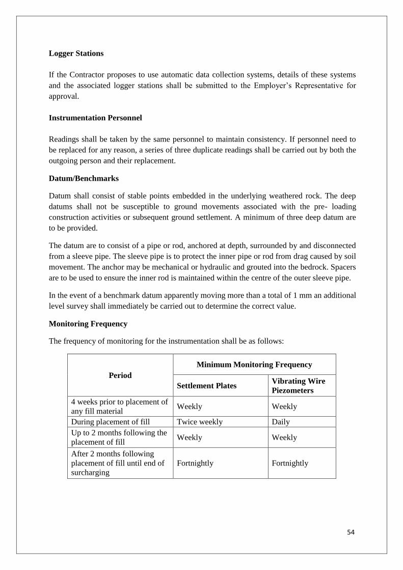
54
Logger Stations
If the Contractor proposes to use automatic data collection systems, details of these systems
and the associated logger stations shall be submitted to the Employer’s Representative for
approval.
Instrumentation Personnel
Readings shall be taken by the same personnel to maintain consistency. If personnel need to
be replaced for any reason, a series of three duplicate readings shall be carried out by both the
outgoing person and their replacement.
Datum/Benchmarks
Datum shall consist of stable points embedded in the underlying weathered rock. The deep
datums shall not be susceptible to ground movements associated with the pre- loading
construction activities or subsequent ground settlement. A minimum of three deep datum are
to be provided.
The datum are to consist of a pipe or rod, anchored at depth, surrounded by and disconnected
from a sleeve pipe. The sleeve pipe is to protect the inner pipe or rod from drag caused by soil
movement. The anchor may be mechanical or hydraulic and grouted into the bedrock. Spacers
are to be used to ensure the inner rod is maintained within the centre of the outer sleeve pipe.
In the event of a benchmark datum apparently moving more than a total of 1 mm an additional
level survey shall immediately be carried out to determine the correct value.
Monitoring Frequency
The frequency of monitoring for the instrumentation shall be as follows:
Period
Minimum Monitoring Frequency
Settlement Plates Vibrating Wire
Piezometers
4 weeks prior to placement of
any fill material Weekly Weekly
During placement of fill Twice weekly Daily
Up to 2 months following the
placement of fill Weekly Weekly
After 2 months following
placement of fill until end of
surcharging
Fortnightly Fortnightly

55
2.7.7 Site Records and Reports
All site records and reports shall comply with the following requirements whether submitted
electronically or in hardcopy.
The Contractor shall keep daily records of the improvement work and associated monitoring
carried out and shall submit a copy of these records to the Employer’s Representative within
two working days.
During the monitoring period the records shall show:
Day, month, year, time of the beginning and end of the work shift; names of all workers
(associated with each item of plant); and a summary of equipment used during the shift;
Time of beginning and completion of each drain installed during the work shift;
Coordinates, top and bottom level, depth, unique reference number and installation
information for each drain;
Coordinates, levels and records of materials used sufficient to fully record surcharging
operations;
Obstructions encountered;
Summary of any unproductive time, including start and end time, duration, and reason;
Number and type of test carried out
Details of changes to fill level, including surcharging;
Results of all field tests;
Readings from installed instruments, including the raw data in spreadsheet form, but also
including graphs and plots of the data to clearly demonstrate filling level, settlement and
pore pressure development with time
Site conditions that may affect the results.
On completion of the surcharge period the Contractor shall produce a factual report compiling
the record information detailed above as well as detailing the following:
A drawing of the As-built location of all instrumentation points;
A drawing of the As-built levels of the settlement plates;
Borehole logs detailing the piezometer installations;
A summary of the raw settlement data in spreadsheet form
A summary of the raw piezometer data in spreadsheet form;
A summary of all the interpreted instrumentation data including the final graphs and plots
showing the full history of filling, settlement and pore pressure development and
dissipation;
Calibration certificates; and
Earthworks materials test results.

56
3 PLAIN AND REINFORCED CEMENT CONCRETE WORKS
3.1 General
The Employer’s Representative shall have the right at all times to inspect all operations
including the sources of materials, procurement, layout and storage of materials, the concrete
batching and mixing equipment and the quality control system. Such an inspection shall be
arranged and the Employer’s Representative’s approval obtained, prior to starting of concrete
work. This shall, however, not relieve the Contractor of any of his responsibilities. All
materials which do not conform to the Employer’s Requirements shall be rejected.
Materials shall be selected so that they satisfy the design requirements of strength,
serviceability, safety, durability and finish with due regards to the functional requirements and
the environmental conditions to which the structure will be subjected. Materials complying
with codes/standards shall generally be used. Other materials may be used after approval of
the Employer’s Representative and after establishing their performance suitability based on
previous data, experience or tests.
3.2 Materials
1. Cement:
i. The Contractor shall procure minimum 43/53 grade cement, unless otherwise stated
separately confirming to IS specifications, ordinary Portland cement, as required in the
work, only from reputed manufacturers such as L&T Ultra-tech, ACC, Gujarat
Ambuja, Cement Corporation of India, etc. of having a cement production capacity of
one million tones per annum or more, and as approved by Employer, Ministry of
Industry, Government of India and holding license to use IS certification mark for
their product, whose name shall be got approved from the Employer. Supply of
cement shall be taken either in silos or in 50 kg. bags bearing manufacturer’s name
and IS marking. Samples of cement arranged by the Contractor will be taken by the
Engineer and got tested in accordance with provisions of relevant IS codes. Cost of
such tests shall be borne by the Contractor including taking sample and obtaining test
result. In case test results indicate that the cement arranged by contractor does not
conform to be relevant IS. codes, the same stand rejected and shall be removed from
the site by the Contractor at his own cost within one week from the time of written
order from the Employer.
ii. The cement shall be brought at site in bulk supply of approximately 50 tonnes from
the manufacturer direct, or as decided and approved by the Employer, as the case may
be.
iii. The cement Go-down of sufficient capacity shall be constructed by the contractor and
at all time it shall have a stock of minimum of 2000 bags. The contractor shall
facilitate the inspection of the cement Go-down by the Engineer at any time. Storage
of cement shall be as per IS specification.
iv. Cement brought at site and cement remaining unused after completion of work shall
not be removed from site without written permission of the Employer.
57
Ground Granulated Blast Furnace Slag
Ground granulated blast furnace slag obtained by grinding granulated blast furnace slag
conforming to IS 12089 may be used as part replacement of ordinary Portland cement.
2. Aggregates (General)
Aggregate in general designates both fine and coarse inert materials used in the manufacture
of concrete.
Fine aggregate is aggregate most of which passes through 4.75 mm IS sieve.
Coarse aggregate is aggregate most of which is retained on 4.75 mm IS sieve.
Aggregate shall comply with requirement of IS 383. As far as possible preference shall be
given to machine broken and graded aggregate.
All fine and coarse aggregates proposed for use in the work shall be subject to the Employer’s
Representative’s approval and after specific materials have been accepted, the source of
supply of such materials shall not be changed without prior approval of the Employer’s
Representative.
Aggregate shall, except as noted above, consist of natural sand, crushed stone and gravel from
a source known to produce satisfactory aggregate for concrete and shall be chemically inert,
strong, hard, durable against weathering, of limited porosity and free from deleterious
materials that may cause corrosion to the reinforcement or may impair the strength and/or
durability of the concrete. The grading of aggregates shall be such as to produce a dense
concrete of specified strength and consistency that will work readily into position without
segregation and shall be based on the mix design and preliminary test on concrete specified.
a) Fine Aggregate
Fine aggregate except as noted above and for other than light weight concrete shall consist of
natural or crushed sand conforming to IS 383. The sand shall be clean, sharp, hard, strong and
durable and shall be free from dust, vegetable substances, adherent coating, clay, loam, alkali,
organic matter, mica, salt or other deleterious substances which can be injurious to the setting
qualities, strength or durability of the concrete.
b) Machine Made Sand
Machine made sand will be acceptable, provided the constituent rock composition is sound,
hard, dense, non-organic, uncoated and durable against weathering. Machine made sand shall
be accepted provided grading and fine particle limits conform to IS 383.
c) Screening and Washing
Sand shall be prepared for use by such screening or washing or both, as necessary, to remove
all objectionable foreign matter while separating the sand grains to the required size fractions.
Sand with a silt content of more than 3 percent will not be used unless the same is washed and
silt content is brought within 3% by weight.

58
d) Coarse Aggregate
Coarse aggregate for concrete, except as noted above and for other than light weight concrete,
shall conform to IS 383. This shall consist of natural or crushed stone and gravel and shall be
clean and free from elongated, flaky or laminated pieces, adhering coatings, clay lumps, coal
residue, clinkers, sag, alkali, mica, organic matter or other deleterious matter.
e) Screening and Washing
Crushed rock shall be screened and/or washed for the removal of dirt or dust coating, if so
required by the Employer’s Representative.
f) Grading
Coarse aggregates shall be either single size or graded. The grading shall be within the limits
on the table below. The aggregate pieces shall be angular in shape and shall have granular or
crystalline surfaces.
Friable, flaky and laminated pieces, mica and shale, if present, shall be only in such quantities
that will not, in the opinion of Employer’s Representative, affect adversely the strength and/or
durability of concrete.
The maximum size of coarse aggregate shall be the maximum size specified, but in no case
greater than 1/4 of the minimum thickness of the member, provided that the concrete can be
placed without difficulty to surround all reinforcement thoroughly and fill the corners of form.
Cobbles above 160 mm and up to any reasonable size can be used in plain mass concrete
work of large dimensions up to a maximum limit of 20% by volume of concrete when
specifically approved by the Employer’s Representative.
3. Water
Water used for both mixing and curing shall conform to IS: 456. Potable waters are generally
satisfactory. Water containing any excess of acid, alkali, sugar or salt shall not be used. Water
shall be tested in the laboratory approved by the Employer’s Representative.
4. Steel Reinforcement
i Steel for reinforcement shall be high yield strength deformed bars having corrosion
resistant characteristics. The steel shall be either Tiscon – CRS of grade Fe 500 or
SAIL’s HCR – Rebars Gr M of grade Fe 500 or Vizag Steel’s A1 – Rebars of grade Fe
500 or equivalent or Fe 500 epoxy coating having similar compositions and shall have
mechanical properties as per IS 1786. The reinforcement supplied shall have the
following Chemical Properties:
Carbon % max :0.250
Sulphur % max :0.040
Phosphorus % max :0.040
S + P % max :0.075
Copper % min :0.400

59
ii The steel reinforcement, shall be brought to the site in bulk supply of 10 tonnes or more
or as decided by the Employer’s Representative from manufacturer. For small or
occasional quantities of TOR steel reinforcement bars less than 10 MT, the Employer’s
Representative may authorize the contractor to purchase the same from authorized
dealers of the approved manufacturers. The contractor shall have to obtain and furnish
test certificates to the Employer’s Representative in respect of all supplies of steel
brought by him to the site of work. Samples shall also be taken and got tested by the
Employer’s Representative as per the provisions in this regard in relevant IS codes. Cost
of such tests shall be borne by the contractor. In case the test results indicate that the
steel arranged by the contractor does not conform to IS codes, the same shall stand
rejected and shall be removed from the site of work by the Contractor at his cost within
a week’s time after written orders from the Employer’s representative.
iii The steel reinforcement shall be stored by the contractor at site of work in such a way as
to prevent distortion and corrosion. Bars of different sizes and lengths shall be stored
separately
iv For checking nominal mass, tensile strength, band test, re-band-test etc. specimen of
sufficient length shall be cut from each size of the bar at random at frequency not less
than that specified below :-
Size of Bar For consignment below
100 tonnes
For consignment
over 100 tonnes
Under 10 mm dia. One sample for each 25
tonnes or part thereof
One sample for
each 40 tonnes or
part thereof.
10 mm to 16 mm dia One sample for each 35
tonnes or part thereof
One sample for
each 45 tonnes or
part thereof.
Over 16 mm dia. One sample for each 45
tonnes or part thereof.
One sample for
each 50 tonnes or
part thereof.
v Steel brought to site and steel remaining unused shall not be removed from site written
permission of the Employer’s Representative.
5. Admixtures
Accelerating, retarding, water-reducing and air entraining admixtures shall conform to IS:
9103 and integral water proofing admixtures to IS: 2645.
Admixtures may be used in concrete as per manufacturer's instructions only with the approval
of the Employer’s Representative. An admixture's suitability and effectiveness shall be
verified by trial mixes with the other materials used in the works. If two or more admixtures
are to be used simultaneously in the same concrete mix, their interaction shall be checked and
trial mixes done to ensure their compatibility. There should also be no increase in risk of
corrosion of the reinforcement or other embedment.

60
Calcium chloride shall not be used for accelerating setting of the cement for any concrete
containing reinforcement or embedded steel parts. When calcium chloride is permitted such as
in mass concrete works, it shall be dissolved in water and added to the mixing water by an
amount not exceeding 1.5 percent of the weight of the cement in each batch of concrete. The
designed concrete mix shall be corrected accordingly.
3.3 Samples and Tests
All materials used for the works shall be tested before use.
Manufacturer's test certificate shall be furnished for each batch of cement and when directed
by the Engineer, samples shall also be tested by the Contractor in a laboratory approved by
the Employer’s Representative.
Sampling and testing shall be as per IS 2386 under the supervision of the Employer’s
Representative. Water to be used shall be tested to comply with requirements of IS: 456.
The Contractor shall furnish manufacturer's test certificates and technical literature for any
admixture proposed for use. If directed, the admixture shall be tested at the laboratory
approved by Employers Representative.
3.4 Storing of Materials
All materials shall be stored in a manner so as to prevent its deterioration and contamination
which would preclude its use in the works. Requirements of IS: 4082 shall be complied with.
Each size of coarse and fine aggregates shall be stacked separately and shall be protected from
leaves and contamination with foreign material. The stacks shall be on hard, clean, free
draining bases, draining away from the concrete mixing area.
The Contractor shall make his own arrangements for storing water at site in tanks to prevent
contamination.
3.5 Concrete
3.5.1 General
The grades of concrete and maximum aggregate size for various types of structures shall be as
given as below:
Sr. No. Structure Minimum Grade of
Concrete
Max.
Aggregate Size
1 All liquid retaining structures M35 20mm
(a) for foundation raft M35 20mm
(b) for walls, columns, floor beams,
circular floor slab. M35 20mm
(c) for columns, beams, slabs of
Superstructure M35 20mm
(d) Dome Slab M35 20mm

61
Sr. No. Structure Minimum Grade of
Concrete
Max.
Aggregate Size
2 Foundation, columns, beams, slabs etc
in Buildings M30 20mm
3 Anchor blocks on pipeline, base slab
of storm water drains M30 40mm
4 Pipeline encasement, grade slab,
ramps, SW drain coping etc. M20 20mm
3.5.2 Design Mix Concrete
For Design Mix Concrete, the mix shall be designed using any of the four methods given in
Hand book on Concrete Mixes SP23 published by Bureau of Indian Standards, to provide the
grade of concrete having the required workability and characteristic strength not less than
appropriate values given in IS: 456. The design mix shall in addition be such that it is
cohesive and does not segregate and should result in a dense and durable concrete and also
capable of giving the finish as specified. For liquid retaining structures, the mix shall also
result in water tight concrete. The Contractor shall exercise great care while designing the
concrete mix and executing the works to achieve the desired result.
Contractor shall get the design mix approved from any of the institutes designated by the
Employer’s representative. The minimum cement content for Design Mix Concrete shall be as
given below;
Minimum cement content and maximum free water cement ratio
Grade of Concrete
Minimum Cement Content
in Kg/ m3 of Concrete (for
20mm downgraded
aggregates)
MaximumFree
water cement
Ratio
M20 315 0.45
M25 360 0.45
M30 400 0.45
M35 430 0.45
M40 470 0.4
M45 500 0.4
M50 525 0.4
The minimum cement content stipulated above shall be adopted irrespective of whether the
Contractor achieves the desired strength with less quantity of cement. Where the quantity of
cement required is higher than that specified above to achieve desired strength based on an
approved mix design, higher quantity of cement shall be used.

62
The Contractor shall submit details of the source of all material and the proposed quantities of
each ingredient per cubic meter of fully compacted concrete. The Contractor shall then make
trial mixes for each class of concrete using the same Contractor’s Equipment and the same
materials as are proposed for the Permanent Works. The Contractor shall give 24 hours notice
of such trials to enable the Employer’s Representative to attend. For each trial mix, three
separate and consecutive batches of concrete shall be made by the Contractor and the
specimens shall be tested at 7 days and 28 days (9 specimens at 7 days and 9 specimens at 28
days). For 7 days test the acceptance criteria shall be 70% of the corresponding target mean
strength.
The Contractor shall not commence concreting in the Permanent Works until details of trial
mixes and test results for each class of concrete have been submitted to and approved by the
Engineer.
Durability test of concrete such as water permeability (as per IS 3085), water absorption (BS
1881-122:1983) and rapid chloride penetration test (as per ASTM C1202-2012) should be
done on concrete during trial mix. Chloride permeability should be moderate as per ASTM
C1202.
Only good washed sand confirming to IS specifications shall be used for concrete and
masonry work.
A trial mix design will be approved by the Employer’s Representative with respect to strength
if the average compressive strength of the nine specimens each at 7 days and 28 days is more
than the specified target mean strength appropriate to the grade of concrete. Acceptance
criteria of cubes shall be as per Table 11 of 23456-2000. Percolation test shall be conducted
with trial mix in laboratory.
For concrete of Grade M20 and over, the Contractor shall cast two sample wall panels 48
hours apart. Each shall be cast in two equal lifts to form a wall panel having one horizontal
construction joint formed in the manner proposed by the Contractor for the Works. The top
surface of the second lift shall have a Type U3 finish as per IS 457. The panels shall not be
touched up after stripping. The panels shall be 300 mm thick and 1.5 m long by 1.5 m high.
The Contractor shall not commence concreting in the Permanent Works until the test panels
have been approved by Employer’s Representative.
The Contractor shall not alter the approved mix proportions nor the approved source of supply
of any of the ingredients without having previously obtained the approval of the Employer’s
Representative.
During production, the Employer’s Representative may require trial mixes to be made before
a substantial change is made in the materials or in the proportions of the materials to be used.
It shall be the Contractor's sole responsibility to carry out the mix designs. He shall furnish to
the Employer’s Representative at least 30 days before concreting operations, a statement of
proportions proposed to be used for the various concrete mixes and the strength results

63
obtained. The strength requirements of the concrete mixes ascertained on 150 mm cubes as
per IS: 516 shall comply with the requirements of IS: 456 as follows;
Grade of Concrete
Minimum Compressive
Strength (N/ mm2 at 7
days)
Specified
Characteristic
Compressive Strength
(N/ mm2 at 28 days)
M 15 10 15
M 20 13.5 20
M 25 17 25
M 30 20 30
M 35 23.5 35
M 40 27 40
3.5.2.1.Standard Deviation
The standard Deviation for each grade of concrete shall be calculated separately.
Standard Deviation Based on Test Results
Number of test results - The total number of test results required to constitute anacceptable
record for calculation of standard deviation shall be not less than 30.
Attempts should be made to obtain the 30 test results, as early as possible, when a mix is used
for the first time.
Standard deviation to be brought up to date - The calculation of the standarddeviation
shall be brought up to date after every change of mix design and at least once a month.
Determination of standard deviation:
Concrete of each grade shall be analyzed separately to determine its standard deviation.
The standard deviation of concrete of a given grade shall be calculated using the
following formula from the results of individual tests of concrete of that grade obtained
as specified for test strength of sample:
Estimated standard deviation S = /(n-1)
Where = Deviation of the individual test strength from the average strength of a
sample and n = Number of sample test results
When significant changes are made in the production of concrete (for example
changes in the materials used, mix design, equipments or technical control), the
Standard deviation value shall be separately calculated for such batches of concrete.
Where sufficient test results for a particular grade of concrete are not available, the value of
standard deviation given in the table below may be assumed for a design of mix in the first
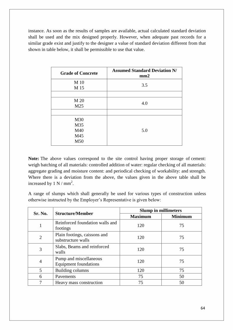
64
instance. As soon as the results of samples are available, actual calculated standard deviation
shall be used and the mix designed properly. However, when adequate past records for a
similar grade exist and justify to the designer a value of standard deviation different from that
shown in table below, it shall be permissible to use that value.
Grade of Concrete Assumed Standard Deviation N/
mm2
M 10
M 15 3.5
M 20
M25 4.0
M30
M35
M40
M45
M50
5.0
Note: The above values correspond to the site control having proper storage of cement:
weigh batching of all materials: controlled addition of water: regular checking of all materials:
aggregate grading and moisture content: and periodical checking of workability: and strength.
Where there is a deviation from the above, the values given in the above table shall be
increased by 1 N / mm2.
A range of slumps which shall generally be used for various types of construction unless
otherwise instructed by the Employer’s Representative is given below:
Sr. No. Structure/Member Slump in millimeters
Maximum Minimum
1 Reinforced foundation walls and
footings 120 75
2 Plain footings, caissons and
substructure walls 120 75
3 Slabs, Beams and reinforced
walls 120 75
4 Pump and miscellaneous
Equipment foundations 120 75
5 Building columns 120 75
6 Pavements 75 50
7 Heavy mass construction 75 50

65
Note:
- All concrete for liquid retaining structures shall have a minimum slump value of 75 mm
and maximum of 120 mm.
3.5.3 Batching and Mixing of Concrete
The Contractor shall abide by the decision of the Employer’s Representative about the choice
to either have a batching and mixing plant at site or source ready mix concrete from approved
external manufacturing unit or use mechanical and concrete mixers for concreting works.
The mixing of concrete shall be strictly carried out in an approved type of batching and
mixing plant for concrete. Ready Mix Concrete as per IS 4926-1976 shall be used for which
Concrete Batching Plant shall be provided at site, if the Employer’s representative has opted
for the same. The Concrete Batching Plant shall be fully computerized. The Concrete
Batching Plant shall have a Capacity of 30 Cum/Hr. Minimums Four Transit Mixers shall be
provided with Concrete Pumps along with line pumps for ready mix concrete. Fully equipped
Quality Assurance Laboratory shall be provided and following tests shall be done:
Equipment Tests
Calibration of Electronic Load Cell (Weigh Batcher)
Calibration of Water Meter.
Calibration of Admixture Dispenser
Calibration of Cube Testing Machine.
For small concreting works less than 10 m3 in a single day, mechanical concrete mixers may
be used. The entire batch shall be discharged before recharging. Mixing periods shall be
measured from the time when all of the solid materials are in the mixing drum, provided that
all of the mixing water shall be introduced before one fourth of the mixing time has elapsed.
The mixing time in no case shall be less than two minutes. The mixer speed shall not be less
than 14 nor more than 20 revolutions per minute. Mixing shall be continued until there is a
uniform distribution of the materials and the mass is uniform in colour and consistency. Hand
mixing of concrete shall not be permitted at all.
3.5.4 Nominal Mix Concrete
Mix design and preliminary tests are not necessary for Nominal Mix Concrete. However
works tests shall be carried out as per IS: 456. Proportions for Nominal Mix Concrete and w/c
ratio may be adopted as per Table 3 of IS: 456. However it will be the Contractor's sole
responsibility to adopt appropriate nominal mix proportions to yield the specified strength.
Based on the adopted nominal mixes, aggregates shall be measured by volume. However
cement shall be by weight only.
3.6 Formwork
Formwork shall be all inclusive and shall consist of but not be limited to shores, bracings,
sides of footings, walls, beams and columns, bottom of slabs etc. including ties, anchors,
hangers, inserts, false work, wedges etc. The design and engineering of the formwork as well

66
as its fabrication shall be the responsibility of the Contractor. However, if so desired by the
Employer’s Representative, the drawings and calculations for the design of the formwork
shall be submitted to the Employer’s Representative for approval.
Formwork shall be designed to fulfill the following requirements:
a) Sufficiently rigid and tight to prevent loss of grout or mortar from the concrete at all stages
and appropriate to the methods of placing and compacting.
b) Made of suitable materials.
c) Capable of providing concrete of the correct shape and surface finish within the specified
tolerance limits.
d) Capable of withstanding without deflection the worst combination of self weight,
reinforcement and concrete weight, all loads and dynamic effects arising from construction
and compacting activities, wind and weather forces.
e) Capable of easily striking without shock, disturbance or damage to the concrete
f) Soffit forms capable of imparting a camber if required.
g) Soffit forms and supports capable of being left in position if required.
h) Capable of being cleaned and/or coated if necessary immediately prior to casting the
concrete; design temporary openings where necessary for these purposes and to facilitate
the preparation of construction joints.
The formwork may be of plywood, steel, plastic or concrete depending upon the type of finish
specified. Sliding forms and slip form may be used with the approval of the Employer’s
Representative. Joints between formwork and formwork and between formwork and
structures shall be sufficiently tight to prevent loss of slurry from concrete, using seals if
necessary.
The faces of formwork coming in contact with concrete shall be cleaned and two coats of
approved mould oil applied before fixing reinforcement. All rubbish, particularly chippings,
shavings, sawdust, wire pieces dust etc. shall be removed from the interior of the forms before
the concrete is placed. Where directed, cleaning of forms shall be done by blasting with a jet
of compressed air.
Forms intended for reuse shall be treated with care. Forms that have deteriorated shall not be
used. Before reuse, all forms shall be thoroughly scraped, cleaned, nails removed, holes
suitably plugged, joints repaired and warped lumber replaced to the satisfaction of the
Employer’s Representative. The Contractor shall equip himself with enough shuttering to
allow for wastage so as to complete the job in time.

67
Permanent formwork shall be checked for its durability and compatibility with adjoining
concrete before it is used in the structure. It shall be properly anchored to the concrete.
Wire ties passing through beams, columns and walls shall not be allowed. In their place bolts
passing through sleeves shall be used. Formwork spacers left in situ shall not impair the
desired appearance or durability of the structure by causing spalling, rust staining or allowing
the passage of moisture.
For liquid retaining structures, sleeves shall not be provided for through bolts nor shall
through bolts be removed if provided. In the latter case, non-removable through bolts with
plastic cones shall be provided and the bolts shall be cut at 25 mm depth from the surface and
the conical cavity made good with non-shrink grout just after striking the formwork.
All corners and angles exposed in the finished structure shall have chamfers or fillets of 20
mm x 20 mm size, unless otherwise stated on the drawings or elsewhere.
Forms for substructure may be omitted when, in the opinion of the Employer’s
Representative, the open excavation is firm enough (in hard non-porous soils) to act as a form.
Such excavations shall be larger, as approved by the Employer’s Representative, than that
required as per drawing to compensate for irregularities in excavation. The Contractor shall
provide adequate props carried down to a firm bearing without overloading any of the
structures.
The shuttering for beams and slabs shall be so erected that the side shuttering of beams can be
removed without disturbing the bottom shuttering. If the shuttering for a column is erected for
the full height of the column, one side shall be built up in sections as placing of concrete
proceeds or windows left for placing concrete from the side to limit the drop of concrete to
1.0m or as approved by the Employer’s Representative. The Contractor shall temporarily and
securely fix items to be cast (embedment / inserts) in a manner that will not hinder the striking
of forms or permit loss of grout.
Formwork showing excessive distortion, during any stage of construction, shall be
repositioned and strengthened. Placed concrete affected by faulty formwork, shall be entirely
removed and formwork corrected prior to placement of new concrete.
3.6.1. Formwork Striking Time
The striking time for formwork shall be determined based on the following requirements:
Development of adequate concrete strength;
Permissible deflection at time of striking form work;
Curing procedure employed - its efficiency and effectiveness;
Subsequent surface treatment to be done;
Prevention of thermal cracking at re-entrant angles;
Ambient temperatures; and

68
Aggressiveness of the environment (unless immediate adequate steps are taken to prevent
damage to the concrete)
Under normal circumstances (generally where temperatures are above 20oC), forms may be
struck after expiry of the time period given in IS: 456 unless approved otherwise by the
Employer’s Representative. For Portland Pozzolana/slag cement the stripping time shall be
suitably modified as approved by the Employer’s Representative. It is the Contractor's
responsibility to ensure that forms are not struck until the concrete has developed sufficient
strength to support itself, does not undergo excessive deformation and resist surface damage
and any stresses arising during the construction period.
3.7 Reinforcement Workmanship
Reinforcing bars supplied bent or in coils shall be straightened cold without damage. No
bending shall be done when ambient temperature is below 5oC. Local warming may be
permitted if steel is kept below 100oC.
All bars shall be accurately bent gradually and according to the sizes and shapes shown on the
drawings/ schedules to be prepared by the Contractor.
Re-bending or straightening incorrectly bent bars shall not be done without the approval of
the Employer’s Representative.
Reinforcement shall be accurately fixed and maintained firmly in the correct position by the
use of blocks, spacers, chairs, binding wire etc. to prevent displacement during placing and
compaction of concrete. The tied in place reinforcement shall be approved by the Employer’s
Representative prior to concrete placement. Spacers shall be of such materials and designs as
will be durable, not lead to corrosion of the reinforcement and not cause spalling of the
concrete cover.
Binding wire shall be 16 gauge soft annealed wire. Ends of the binding wire shall be bent
away from the concrete surface and in no case encroach into the concrete cover.
3.8 Tolerances
3.8.1 Tolerances for R.C. Buildings
(a) Variation from the Plumb
In the lines and surfaces of columns, piers, walls and in arises 5 mm per 2.5 m or 25 mm,
whichever is less.
For exposed corner columns and other conspicuous lines
In any bay or 5 m maximum - 5 mm
In 10 m or more - 10 mm
(b) Variation from the level or from the grades indicated on the drawings In slab soffits,
ceilings, beam soffits, and in arises

69
In 2.5 m - 5 mm
In any bay or 5 m maximum - 10 mm
In 10 m or more - 15 mm
For exposed lintels, sills, parapets, horizontal grooves and other conspicuous lines:
In any bay or 5 m maximum - 5 mm
In 10 m or more - 10 mm
(c) Variation of the linear building lines from established position in plan and related
position of columns, wall and partitions:
In any bay or 5 m maximum - 10 mm
In 10 m or more - 20 mm
(d) (Variation in cross-sectional dimensions of columns and beams and in the thickness of
slabs and walls:
Minus - 5 mm
Plus - 10 mm
(e) Variation in case of footings Variation in dimension in plan
Minus – 5 mm
Plus - 10 mm
Misplacement or eccentricity
2% of footing width in the direction of misplacement but not more than 50 mm
Reduction in thickness
Minus-5% of specified thickness subject to amaximum of 50 mm
(f) ariation in steps In a flight of stairs
Rise - 3 mm
Tread - 5 mm
In consecutive steps
Rise - 1.5 mm
Tread - 3.0 mm
(g) Tolerances in other structures
Variation of the construction linear outline from established position in plan In 5 m 10
mm

70
In 10 m or more 15 mm
Variations of dimensions to individual structure features from established positions In 20
m or more 25 mm
In buried construction 50 mm
Variation from plumb, from specified batter or from curved surfaces of all structures
In 2.5 m - 10 mm
In 5 m - 15 mm
In 10 m or more 25 mm
In buried construction - Twice the above amounts
Variation from level or grade indicated on drawings in slab, beams, soffits, horizontal
grooves and visible arises.
In 2.5 m - 5 mm
In 7.5 m or more - 10 mm
In buried construction - Twice the above amounts
Variation in cross-sectional dimensions of columns, beams, buttresses, piers
and similar members
Minus - 5 mm
Plus - 10 mm
(h) Footing for columns, piers, walls, buttresses and similar members
Variation of dimension in plan
Minus - 10 mm
Plus - 50 mm
Misplacement or eccentricity
2% footing width in the direction of misplacement but not more than 50 mm
Reduction in thickness
5% of specified thickness subject to a maximum of 50 mm.
(i) Tolerance in fixing anchor bolts:
Anchor bolts without sleeves - 1.5 mm in plan

71
Anchor bolts with sleeves - 5.0 mm in elevation
For bolts up to and including 28 mm dia - 5 mm in all directions
For bolts 32 mm dia and above - 3 mm in all directions
Embedded parts - 5 mm in all directions
3.9 Preparation Prior to Concrete Placement
Before concrete is actually placed in position, the inside of the formwork shall be cleaned and
mould oil applied, inserts and reinforcement shall be correctly positioned and securely held,
necessary openings, pockets, etc. provided.
All arrangements-formwork, equipment and proposed procedure, shall be approved by the
Employer’s Representative.
3.10 Transporting, Placing and Compacting Concrete
Concrete shall be transported from the mixing plant to the formwork with minimum time
lapse by methods that shall maintain the required workability and will prevent segregation,
loss of any ingredients or ingress of foreign matter or water.
In all cases concrete shall be deposited as nearly as practicable directly in its final position. To
avoid segregation, concrete shall not be rehandled or caused to flow. For locations where
direct placement is not possible and in narrow forms the Contractor shall provide suitable
drops and "Elephant Trunks". Concrete shall not be dropped from a height of more than 1.0m.
Concrete shall not be placed in flowing water. Under water, concrete shall be placed in
position by tremies or by pipeline from the mixer and shall never be allowed to fall freely
through the water.
While placing concrete the Contractor shall proceed as specified below and also ensure the
following:
Continuously between construction joints and pre- determined abutments
Without disturbance to forms or reinforcement
Without disturbance to pipes, ducts, fixings and the like to be cast in; ensure that such
items are securely fixed. Ensure that concrete cannot enter open ends of pipes and
conduits etc.
Without dropping in a manner that could cause segregation or shock.
In deep pours only when the concrete and formwork designed for this purpose and by
using suitable chutes or pipes
Do not place if the workability is such that full compaction cannot be achieved.
Without disturbing the unsupported sides of excavations; prevent contamination of
concrete with earth. Provide sheeting if necessary. In supported excavations, withdraw the
linings progressively as concrete is placed.
If placed directly onto hardcore or any other porous material, dampen the surface to
reduce loss of water from the concrete

72
Ensure that there is no damage or displacement to sheet membranes
Record the time and location of placing structural concrete.
Concrete shall normally be compacted in its final position within thirty minutes of leaving the
mixer. Concrete shall be compacted during placing with approved vibrating equipment
without causing segregation until it forms a solid mass free from voids thoroughly worked
around reinforcement and embedded fixtures and into all corners of the formwork. Immersion
vibrators for compaction of concrete shall be electrically operated and vibrator needles shall
be of 60 mm size only. Immersion vibrators shall be inserted vertically at points not more than
450 mm apart and withdrawn slowly till air bubbles cease to come to the surface, leaving no
voids. When placing concrete in layers advancing horizontally, care shall be taken to ensure
adequate vibration, blending and melding of the concrete between successive layers. Vibrators
shall not be allowed to come in contact with reinforcement, formwork and finished surfaces
after start of initial set.
Concrete may be conveyed and placed by mechanically operated equipment after getting the
complete procedure approved by the Employer’s Representative. The slump shall be held to
the minimum necessary for conveying concrete by this method. When concrete is to be
pumped, the concrete mix shall be specially designed to suit pumping. Care shall be taken to
avoid stoppages in work once pumping has started.
Except when placing with slip forms, each placement of concrete in multiple lift work, shall
be allowed to set for at least 24 hours after the final set of concrete before the start of
subsequent placement. Placing shall stop when concrete reaches the top of the opening in
walls or bottom surface of slab, in slab and beam construction, and it shall be resumed before
concrete takes initial set but not until it has had time to settle as approved by the Employer’s
Representative. Concrete shall be protected against damage until final acceptance.
3.11 Mass Concrete Works
Sequence of pouring for mass concrete works shall be as approved by the Employer’s
Representative. The Contractor shall exercise great care to prevent shrinkage cracks and shall
monitor the temperature of the placed concrete if directed.
3.12 Curing
Curing and protection shall start immediately after the compaction of the concrete to protect it
from:
Premature drying out, particularly by solar radiation and wind;
Leaching out by rain and flowing water;
Rapid cooling during the first few days after placing;
High internal thermal gradients;
Low temperature or frost;
Vibration and impact which may disrupt the concrete and interfere with its bond to the
reinforcement.

73
All concrete, unless approved otherwise by the Employer’s Representative, shall be cured by
use of continuous sprays or ponded water or continuously saturated coverings of sacking,
canvas, hessian or other absorbent material for the period of complete hydration with a
minimum of 7 days. The quality of curing water shall be the same as that used for mixing.
Where a curing membrane is approved to be used by the Employer’s Representative, the same
shall be of a non-wax base and shall not impair the concrete finish in any manner. The curing
compound to be used shall be approved by the Employer’s Representative before use and
shall be applied with spraying equipment capable of a smooth, even textured coat.
Curing may also be done by covering the surface with an impermeable material such as
polyethylene, which shall be well sealed and fastened.
3.13 Construction Joints and Keys
Construction joints will be as shown on the drawing or as approved by the Employer’s
Representative. Concrete shall be placed without interruption until completion of work
between construction joints. If stopping of concreting becomes unavoidable anywhere, a
properly formed construction joint shall be made with the approval of the Employer’s
Representative.
Dowels for concrete work, not likely to be taken up in the near future, shall be coated with
cement slurry and encased in lean concrete as indicated on the drawings or as approved by the
Employer’s Representative
As soon as the exposed concrete has sufficiently hardened, the surface of the joint shall be
water jetted or brushed with a stiff brush to expose the larger aggregate without being
disturbed. Alternatively, if the preparation is not satisfactory, or proper joint preparation is not
possible due to inclement weather, the Contractor shall thoroughly remove the laitance of
hardened concrete by mechanical chipping after seven days of concrete work at his own cost.
Before placing fresh concrete against a construction joint all loose material shall be removed
and the surface sluiced with water until it is perfectly clean, thereafter all ponded water should
be removed.
When concreting is to be resumed on a surface which has not fully hardened, all laitance shall
be removed by wire brushing, the surface wetted, free water removed and a coat of cement
slurry applied. On this, a layer of concrete not exceeding 150 mm thickness shall be placed
and well rammed against the old work. Thereafter work shall proceed in the normal way.
3.14 Foundation Bedding
All earth surfaces upon which or against which concrete is to be placed, shall be well
compacted and free from standing water, mud or debris. The surfaces of absorptive soils shall
be moistened.
Concrete shall not be deposited on large sloping rock surfaces. The rock shall be cut to form
rough steps or benches by picking, barring or wedging. The rock surface shall be kept wet for
2 to 4 hours before concreting.

74
3.15 Finishes
3.15.1 General
The formwork for concrete works shall be such as to give the finish as specified. The
Contractor shall make good any unavoidable defects as approved consistent with the type of
concrete and finish specified; defects due to bad workmanship (e.g. damaged or misaligned
forms, defective or poorly compacted concrete) will not be accepted. The Contractor shall
construct the formwork using the correct materials and to meet the requirements of the design
and to produce finished concrete to required dimensions, plumbs, planes and finishes and
architectural requirement.
3.15.2 Surface Finish Type F1 (IS 457)
The main requirement is that of dense, well compacted concrete. No treatment is required
except repair of defective areas, filling all form tie holes and cleaning up of loose or adhering
debris. For surfaces below grade which will receive waterproofing treatment the concrete
shall be free of surface irregularities which would interfere with proper and effective
application of waterproofing material specified for use.
3.15.3 Surface Finish Type F2 (IS 457)
The appearance shall be that of a smooth dense, well- compacted concrete showing the slight
marks of well fitted shuttering joints. The Contractor shall make good any blemishes.
3.15.4 Surface Finish Type F3 (IS 457)
This finish shall give an appearance of smooth, dense, well-compacted concrete with no
shutter marks, stain free and with no discolouration, blemishes, arises, air holes etc. Only
lined or coated plywood with very tight joints shall be used to achieve this finish. The panel
size shall be uniform and as large as practicable. Any minor blemishes that might occur shall
be made good by the Contractor.
3.15.5 Unformed Surfaces (IS 457)
Finishes to unformed surfaces of concrete shall be classified as U1, U2, and U3, ‘spaded or
bonded concrete’. Where the class of finish is not specified the concrete shall be finished to
Class U1.
Class U1 finish is the first stage for Class U2 and U3 finishes and for a bonded concrete
surface. Class U1 finish shall be a levelled and screeded, uniform plain or ridged finish which
(unless it is being converted to Class U2, U3, or bonded concrete) shall not be disturbed in
any way after the initial set and during the period of curing, surplus concrete being struck off
immediately after compaction.
Where a bonded concrete surface is specified, the laitance shall be removed from the Class
U1 finished surface and the aggregate exposed while the concrete is still green.
A spaded finish shall be a surface free from voids and brought to a reasonably uniform
appearance by the use of shovels as it is placed in the Works.

75
Class U2 finish shall be a wood float finish. Floating shall be done after the initial set of the
concrete has taken place and the surface has hardened sufficiently. The concrete shall be
worked no more than is necessary to produce a uniform surface free from screed marks.
Class U3 finish shall be a hard smooth steel-troweled finish. Troweling shall not commence
until the moisture film has disappeared and the concrete has hardened sufficiently to prevent
excess laitance from being worked into the surface. The surfaces shall be troweled under firm
pressure and left free from trowel marks.
The addition of dry cement, mortar or water shall not be permitted during any of the above
operations.
3.15.6 Integral Cement Finish on Concrete Floor
The floor slabs of all the units with floor slope steeper than 1:12 shall be finished with 50mm
thick M20 Grade screed concrete with neat finish at top surface.
3.16 Repair and Replacement of Unsatisfactory Concrete
Immediately after the shuttering is removed, all the defective areas such as honey-combed
surfaces, rough patches, holes left by form bolts etc. will be inspected by the Employer’s
Representative who may permit patching of the defective areas or reject the concrete work.
All through holes for shuttering shall be filled for full depth and neatly plugged flush with
surface. Rejected concrete shall be removed and replaced by the Contractor at no additional
cost to the Employer. For patching of defective areas all loose materials shall be removed and
the surface shall be prepared as approved by the Employer’s Representative.
Bonding between hardened and fresh concrete shall be done either by placing cement mortar
or by applying epoxy. The decision of the Employer’s Representative as to the method of
repairs to be adopted shall be final and binding on the Contractor. The surface shall be
saturated with water for 24 hours before patching is done with 1:5 cement sand mortar. The
use of epoxy for bonding fresh concrete shall be carried out as approved by the Employer’s
Representative.
All the form bolt repairs and delayed repairs shall be carried out using a proportion of white
cement in repair mix to the approval of the Employer’s Representative so as to match the
colour of the surrounding area.
3.17 Vacuum Dewatering of Slabs
Where specified, floor slabs, either grade or suspended, shall be finished by vacuum
dewatering including all operations such as poker vibration, surface vibration, vacuum
processing, floating and trowelling as per equipment manufacturers recommendation. The
equipment to be used shall be subject to the Employer’s Representative's approval.
3.18 Hot Weather Requirements
Concreting during hot weather shall be carried out as per IS: 7861 (Part I).

76
Adequate provisions shall be made to lower concrete temperatures which shall not exceed 40o
C at the time of placement of fresh concrete. Where directed by the Employer’s
Representative, the Contractor shall spray non-wax based curing compound on unformed
concrete surfaces.
3.19 Liquid Retaining Structures
All liquid containing / conveying structures shall be designed for the following conditions:
a. The Contractor shall take special care for concrete for liquid retaining structures,
underground structures and those others specifically called for to guarantee the finish and
water tightness.
b. The minimum level of surface finish for liquid retaining structures shall be Type F2 (IS
457). All such structures shall be hydro-tested.
c. The Contractor shall make all arrangements for hydro-testing of structure such as
temporary bulk heads, pressure gauges, pumps, pipe lines etc.
d. The Contractor shall also make all temporary arrangements that may have to be made to
ensure stability of the structures during construction.
Any leakage that may occur during the hydro-test or subsequently during the defects liability
period or the period for which the structure is guaranteed shall be effectively stopped either by
cement/epoxy pressure grouting, gunniting or such other methods as may be approved by the
Employer’s Representative. All such rectification shall be done by the Contractor to the entire
satisfaction of the Employer/Employer’s Representative.
3.20 Testing Concrete Structures for Leakage
Water testing of concrete structures shall be done with potable water. Hydro-static test for
water tightness shall be done at top level of structure or soffit of cover slab, as may be
directed by the Employer’s Representative. This test shall be carried out preferably in dry
season in accordance with the procedure given below:
The water tightness test shall be carried out when the structure is ready for filling. Before the
filling operation is started, the structure shall be jointly inspected by the Employer’s
Representative and the Contractor’s Representative and the condition of surfaces of wall,
contraction and expansion joints shall be noted and it shall be ensured that jointing material
filled in the joints is in position and all openings are closed. The filling of the structure then
shall be carried out gradually at the rate not exceeding 30 mm rise in water level per hour and
shall preferably extend over a period of 72 hours. Records of leakages starting at different
level of water in the structure, if any, shall be kept. The structure once filled shall be allowed
to remain filled for a period of seven days before any readings of drop in water level are
recorded. The level of the water shall be recorded again at subsequent interval of 24 hours
over a period of seven days. Backfilling shall be withheld till the structure is tested.
The total drop in surface level of a period of seven days shall be taken as indication of the
water tightness of the tank, which for all practical purpose, shall not exceed 40 mm. If the
structure does not satisfy the conditions of the test and a daily drop in water level is found, the

77
period of test may be extended for a further period of seven days and if the specified limit is
then reached the structure may be considered as satisfactory. The Employer’s Representative
shall decide on the actual permissible nature of the drop in the surface level, taking into
account whether the structures are open or closed and the corresponding effect it has on
evaporation losses.
In case of structures whose external faces are exposed, such as elevated tanks, the
requirements of the test shall be deemed to be satisfied if the external faces show no sign of
leakage or sweating and remain completely dry during the period of observation of seven days
after allowing a seven day period for absorption after filling with water.
Each compartment/segment of the structure shall be tested individually and then all together.
For structures such as pipes, tunnels etc. the hydrostatic test shall be carried out by filling with
water, after curing as specified, and subjecting to the specified test pressure for specified
period. If during this period the loss of water does not exceed the equivalent of the specified
rate, the structure shall be considered to have successfully passed the test.
3.21 Optional Tests
If the Employer’s Representative feels that the materials i.e. cement, sand, coarse aggregates,
reinforcement and water are not in accordance with the Employer’s Requirements or if
specified concrete strengths are not obtained, he may order tests to be carried out on these
materials in laboratory, to be approved by the Employer’s Representative, as per relevant IS
Codes.
In the event of any work being suspected of faulty material or workmanship requiring its
removal or if the works cubes do not give the stipulated strengths, the Employer’s
Representative reserves the right to order the Contractor to take out cores and conduct tests on
them or do ultrasonic testing or load testing of structure, etc. The Employer’s Representative
also reserves the right to ask the Contractor to dismantle and re-do such unacceptable work, at
no cost to the Employer.
3.22 Grouting
3.22.1 Standard Grout
The proportion of Standard Grout shall be such as to produce a flowable mixture consistent
with minimum water content and shrinkage. Surfaces to be grouted shall be thoroughly
roughened and cleaned. All structural steel elements to be grouted, shall be cleaned of oil,
grease, dirt etc. The use of hot, strong caustic solution for this purpose will be permitted. Prior
to grouting, the hardened concrete shall be saturated with water and just before grouting,
water in all pockets shall be removed. Grouting once started shall be done quickly and
continuously. Variation in grout mixes and procedures shall be permitted if approved by the
Employer’s Representative. The grout proportions shall be limited as follows:

78
Sr. No. Use Grout Thickness Mix Proportions W/C Ratio
(max)
A Fluid mix Under 25mm
One part Portland
Cement to one part
sand
0.44
B General Mix
25mm and over
but less than
50mm
One part Portland
Cement to 2 parts of
sand
0.53
C Stiff mix 50mm and over
One part Portland
Cement to 3 parts of
sand
0.53
3.22.2 Non-Shrink Grout
Non –shrink grout where required as instructed by the Employer’s Representative, shall be
provided in strict accordance with the manufacturer’s instructions / specifications on the
drawings.
3.22.3 Inspection
All materials, workmanship and finished construction shall be subject to continuous
inspection and approval of Employer’s Representative. Materials rejected by Employer’s
Representative shall be expressly removed from site and shall be replaced by Contractor
immediately.
3.22.4 Clean-Up
Upon the completion of concrete work, all forms, equipment, construction tools, protective
coverings and any debris, scraps of wood, etc. resulting from the work shall be removed and
the premises left clean.
3.22.5 Acceptance Criteria
Any concrete work shall satisfy the requirements given below individually and collectively
for it to be acceptable.
Properties of constituent materials;
Characteristic compressive strength;
Specified mix proportions;
Minimum cement content;
Maximum free-water/cement ratio;
Workability;
Temperature of fresh concrete;
Density of fully compacted concrete;
Cover to embeded steel;
Curing;
Tolerances in dimensions;
Tolerances in levels;

79
Durability;
Surface finishes;
Special requirements such as;
Water tightness
Resistance to aggressive chemicals
Resistance to freezing and thawing
Very high strength
Improved fire resistance
Wear resistance
Resistance to early thermal cracking
The Employer’s Representative's decision as to the acceptability or otherwise of any concrete
work shall be final and binding on the Contractor. For work not accepted, the Employer’s
Representative may review and decide whether remedial measures are feasible so as to render
the work acceptable. The Employer’s Representative will in that case direct the Contractor to
undertake and execute the remedial measures. These shall be expeditiously and effectively
implemented by the Contractor. Nothing extra shall become payable to the Contractor by the
Employer for executing the remedial measures.
3.22.6 Water stops
Waterstops shall be provided as per IS 3370. The material for the PVC water stops shall be a
plastic compound with the basic resin of polyvinyl chloride and additional resins, plasticizers,
inhibitors, which satisfies the performance characteristics specified below as per relevant IS
codes. Testing shall be in accordance with IS: 8543.
Tensile strength : 11.6 N/mm2 minimum
Ultimate elongation : 300% minimum
Tear resistance : 4.9 N/mm2 minimum
Stiffness in flexure : 2.46 N/mm2 minimum
Accelerated extraction
i. Tensile strength : 10.50 N/mm2 minimum
ii. Ultimate elongation : 250% minimum
Effect of Alkali : 7 days
i) Weight increase : 0.10% maximum
ii) Weight decrease : 0.10% maximum
iii) Hardness change : ± 5 points

80
Effect of Alkali : 28 days
i) Weight increase : 0.40% maximum
ii) Weight decrease : 0.30% maximum
iii) Dimension change : ±1%
PVC water stops shall be either of the bar type, serrated with centre bulb and end grips for use
within the concrete elements or of the surface (kicker) type for external use. For floors only
surface type water bars (PVC) shall be used.
PVC water stops shall be of approved manufacture. Samples and the test certificate shall be
got approved by the Employer’s Representative before procurement for incorporation in the
works.
3.22.7 Workmanship
Water stops shall be cleaned before placing them in position. Oil or grease shall be removed
thoroughly using water and suitable detergents.
Water stops shall be procured in long lengths as manufactured to avoid joints as far as
possible. Standard L or T type of intersection pieces shall be procured for use depending on
their requirement. Any non-standard junctions shall be made by cutting the pieces to profile
for jointing. Lapping of water stops shall not be permitted. All jointing shall be of fusion
welded type as per manufacturer's instructions.
Water stops shall be placed at the correct location/level and suitably supported at intervals
with the reinforcement to ensure that it does not deviate from its intended position during
concreting and vibrating. Care shall also be taken to ensure that no honey-combing occurs
because of the serrations/end grips, by placing concrete with smaller size aggregates in this
region. Projecting portions of the water stops embedded in concrete shall be thoroughly
cleaned of all mortar/ concrete coating before resuming further concreting operations. The
projecting waterstop shall also be suitably supported at intervals with the reinforcement to
maintain its intended position during concreting so as to ensure that it does not bend leading
to formation of pockets. In addition, smaller size aggregates shall be used for concreting in
this region also.
3.23 Preformed Fillers and Joint Sealing Compound
3.23.1 Materials
Preformed filler for expansion/isolation joints shall be non-extruding and resilient type of
bitumen impregnated fibres conforming to IS: 1838 (Part I).
Bitumen coat to concrete/masonry surfaces for fixing the preformed bitumen filler strip shall
conform to IS: 702. Bitumen primer shall conform to IS: 3384.
Sealants shall be of the following types:

81
Sealant Type A
Sealant Type A shall be a gun grade, non-slumping compound suitable for sealing horizontal,
vertical and soffit joints in water retaining structures. It shall be a UK WFBS listed (B.S.
6920: Part 2) material approved for unrestricted use in contact with potable water to the full
exposure condition of 15000 mm2/l, and shall not support bacterial growth.
It shall be stable and shall have a low water absorption and good adhesion to concrete.
Hardness (Shore A) : > 12
Transverse Movement Accommodation : + or-15%
Sealant Type B
Sealant type shall be a gun grade compound, suitable for sealing vertical movement and
construction joints in concrete structures. It shall be flexible, resistant to aging, physical
damage and weathering and shall have good adhesion to concrete.
Hardness (Shore A) : > 12
Transverse Movement Accommodation : + or-12.5%
Sealant Type C
Sealant type C shall be similar to Type B above. In addition it shall have been designed for
sealing movement and construction joints in hydraulic and water retaining structures and shall
be suitable for use in contact with potable water.
Hardness (Shore A) : > 20
Transverse Movement Accommodation : + or -12.5%
Sealant Type D
Sealant Type D shall be a pourable compound suitable for sealing horizontal movement and
construction joints in concrete structures. It shall be flexible, resistant to aging, physical
damage and weathering and shall have good adhesion to concrete.
Hardness (Shore A) : > 9
Transverse Movement Accommodation : + or -12.5%
Sealant Type E
Sealant Type E shall be a cold pouring compound complying with BS 5212, suitable for
sealing movement and construction joints in concrete paved areas. It shall be resistant to fuels,
oils and hydraulic fluids. It shall be tough, abrasion-resistant and shall not decompose in
strong sunlight.

82
Hardness (Shore A) : > 12
Transverse Movement Accommodation : + or -12.5%
The hardness value specified in the above summaries is the Shore A Durometer value at 14
days at 25 degree C and 50% RH. The specified transverse movement values are based on
joints having a width to depth ratio of 1.5: 1.
The Contractor may use the above sealants or ones meeting equivalent or higher
specifications.
3.23.2 Workmanship
The thickness of the preformed bitumen impregnated filler shall be 25mm for expansion joints
and 50mm for isolation joints around foundation supporting rotatory equipments. Contractor
shall procure the strips of the desired thickness and width in lengths as manufactured.
Assembly of small pieces/thicknesses of strips to make up the specified size shall not be
permitted.
The concrete/masonry surface shall be cleaned free from dust and any loose particles. When
the surface is dry, one coat of industrial blown type bitumen of grade 85/25 conforming to IS:
702 shall be applied hot by brushing at the rate of 1.20 kg/sq.m. When the bitumen is still hot
the preformed bitumen filler shall be pressed and held in position till it completely adheres.
The surface of the filler against which further concreting/masonry work is to be done shall
similarly be applied with one coat of hot bitumen at the rate of 1.20 kg/sq.m.
Sealing compound shall be heated to a pouring consistency for enabling it to run molten in a
uniform manner into the joint. Before pouring the sealing compound, the vertical faces of the
concrete joint shall be applied hot with a coat of bitumen primer conforming to IS: 3384 in
order to improve the adhesive quality of the sealing compound.
Expansion joints between beams/slabs shall be provided with 100mm wide x 4mm thick mild
steel plate at the soffit of RCC beams/slabs to support and prevent the preformed joint filler
from dislodging. This plate shall be welded to an edge angle of ISA 50 x 50 x 6mm provided
at the bottom corner, adjacent to the expansion joint of one of the beams/slabs, by intermittent
fillet welding. Steel surfaces shall be provided with 2 coats of red oxide zinc chrome primer
and 3 coats of synthetic enamel paint finish.
The Contractor shall construct recesses at all joints and on both faces of the concrete work
except on the underside of ground slabs. The recesses shall be accurately formed to the lines
and dimensions shown on the Drawings or as agreed with the Employer’s Representative.
The Contractor shall prepare the surfaces of the recess and shall supply a joint sealer and fill
or caulk the recess completely with it.

83
Joint sealing shall not be commenced without the approval of the Employer’s Representative.
In reservoir joints the sealer shall be poured after completion of the water tightness test, to the
satisfaction of the Employer’s Representative.
All joint sealers shall be from an approved manufacturer. The Contractor shall supply the
manufacturer’s test certificates for each consignment of each type of joint sealant delivered to
the Site and shall if requested supply to the Employer’s Representative sufficient samples of
each type and consignment for confirmatory tests to be carried out in accordance with the
appropriate test procedure.
Sealants shall be installed in strict accordance with the manufacturer’s instructions. De-
bonding strip shall be used in conjunction with the sealers as indicated on the Drawings. The
de-bonding strip shall be compatible with the joint sealer and shall be resistant to attach from
the primer used to bond the sealer to the concrete.
Poly-sulphide and polyurethane sealants shall not abut bitumen sealers. Surfaces to receive
Poly-sulphide and polyurethane sealants shall be kept free from bituminous paints. All
sealants shall be appropriate for the prevailing climatic conditions. Bituminous sealants shall
comply with the BS 2499 for Type A1. Poly-sulphide sealants shall comply with IS 12118.
3.23.3 Concreting Records
A written record of the concrete works shall be made each day by the Contractor and kept
available for inspection by the Employer’s Representative. The diary shall contain notes and
records of:
1. The names of the Contractor’s Engineer who are responsible for the different phases of
the concrete work and also the names of their assistants.
2. The temperatures of air, water, cement, aggregates, together with the air humidity and
type of weather.
3. Deliveries to the Site of concrete materials (quantity, brand of concrete, etc
4. Inspections carried out, tests performed, etc. and their results.
5. Times of commencement and completion of different parts of the concrete works and
times of erection and striking of forms
3.23.4 Renovation Work
In case of renovation work for bonding new concrete with old concrete suitable bonding agent
like epoxy from reputed manufacturers approved by Employers Representative shall be used.
The composition of bonding agent, method of cleaning of old concrete surface as well as
application method should be as per manufacturer’s recommendations. Manufacturer should
have sufficient documentation to prove utility of his bonding agent as per relevant standards.
Method of storage, shelf life of bonding agent etc to be as per manufacturer’s
recommendation with supporting documentation.

84
4 STRUCTURAL STEEL WORKS
4.1 Steel Materials
Corrosion allowance of 2 mm shall be taken in case of M.S. Plates for gasholders etc., over
and above the minimum thickness of 6 mm or design thickness of plates. All materials used
shall be new, unused and free from defects.
Steel conforming to IS: 1977 shall be used only for the following:
Fe310-0(St 32-0) : For general purposes such as door/window frames, grills, steel
gates, handrails, fence posts, tee bars and other non-structural
use.
Fe410-0(St 42-0) : For structures not subjected to dynamic loading other than wind
loads such as :
Platform roofs, foot over bridges, building, factory sheds etc.
Fe10-0(St 42-0) : Grade steel shall not be used
a) If welding is to be employed for fabrication
b) If site is in severe earthquake zone
c) If plastic theory of design is used
4.2 Fabrication
4.2.1 General
All workmanship and finish shall be of the best quality and shall conform to the best approved
method of fabrication. All materials shall be finished straight and shall be machined/ground
smooth true and square where so specified. All holes and edges shall be free of burrs.
Shearing and chipping shall be neatly and accurately done and all portions of work exposed to
view shall be neatly finished. Unless otherwise approved by the Employer’s Representative,
reference may be made to relevant IS codes for providing standard fabrication tolerance.
Material at the shops shall be kept clean and protected from weather.
4.2.2 Connections
Shop/field connections shall be as per approved fabrication drawings.
In case of bolted connections, taper washers or flat washers or spring washers shall be used
with bolts as necessary. The length of the bolt shall be such that at least one thread of the bolt
projects beyond the nut.
85
In all cases where bearing is critical, the unthreaded portion of bolt shall bear on the members
assembled. A washer of adequate thickness may be provided to exclude the threads from the
bearing thickness, if a longer grip bolt has to be used for this purpose.
All connections and splices shall be designed for full strength of members or loads. Column
splices shall be designed for the full tensile strength of the minimum cross section at the
splice.
All bolts, nuts, washers, electrodes, screws etc., shall be supplied/brought to site 10% in
excess of the requirement in each category and size. Rates shall cover the cost of this extra
quantity.
All members likely to collect rain water shall have drain holes provided.
4.2.3 Straightening
All materials, shall be straight and, if necessary, before being worked shall be straightened
and/or flattened by pressure and shall be free from twists. Heating or forging shall not be
resorted to without the prior approval of the Employer’s Representative in writing.
4.2.4 Welding
Welding procedure shall be submitted to the Employer’s Representative for approval.
Welding shall be entrusted to qualified and experienced welders who shall be tested
periodically and graded as per IS 817, IS: 7310 (Part 1) and IS : 7318 (Part 1).
Approval of the welding procedure by the Employer’s Representative shall not relieve the
Contractor of his responsibility for correct and sound welding without undue distortion in the
finished structure.
No welding shall be done when the surface of the members is wet nor during periods of high
wind.
Each layer of a multiple layer weld except root and surfaces runs may be moderately peened
with light blows from a blunt tool. Care shall be exercised to prevent scaling or flaking of
weld and base metal from overpeening.
No welding shall be done on base metal at a temperature below –5 Deg.C. Base metal shall be
preheated to the temperature as per relevant IS codes.
Electrodes other than low-hydrogen electrodes shall not be permitted for thicknesses of 32
mm and above.
All welds shall be inspected for flaws by any of the methods described in relevant IS Code.
The method adopted shall be agreed with the Employer’s Representative.
The correction of defective welds shall be carried out without damaging the parent metal in a
manner approved by the Employer’s Representative. When a crack in the weld is removed,

86
magnetic particle inspection or any other equally positive means approved by the Employer’s
Representative shall be used to ensure that the whole of the crack and material up to 25 mm
beyond each end of the crack has been removed. The cost of all such tests and operations
incidental to correction shall be borne by the Contractor.
4.3 Tolerances
The dimensional and weight tolerances for rolled shapes shall be in accordance with IS: 1852
for indigenous steel and equivalent applicable codes for imported steel. The tolerances for
fabrication of structural steel shall be as per IS: 7215.
Cutting, punching, drilling, welding and fabrication tolerances shall be generally as per
relevant IS codes.
4.4 End Milling
Where compression joints are specified to be designed for bearing, the bearing surfaces shall
be milled true and square to ensure proper bearing and alignment.
4.5 Inspection
4.5.1 General
The Contractor shall give due notice to the Employer’s Representative in advance of the
works being made ready for inspection. All rejected material shall be promptly removed from
the shop and replaced with new material for the Employer’s Representative’s inspection. The
fact that certain material has been accepted at the Contractor’s shop shall not invalidate final
rejection at site by the Employer’s Representative if it fails to conform to the requirements of
these specifications, fails to be in proper condition or has fabrication inaccuracies which
prevent proper assembly nor shall it invalidate any claim which the Employer may make
because of defective or unsatisfactory materials and/or workmanship.
No materials shall be painted or despatched to site without inspection and approval by the
Employer’s Representative unless such inspection is waived in writing by the Employer’s
Representative.
The Contractor shall provide all the testing and inspection services and facilities for shop
work except where otherwise specified.
For fabrication work carried out in the field the same standard of supervision and quality
control shall be maintained as in shop fabricated work. Inspection and testing shall be
conducted in a manner satisfactory to the Employer’s Representative.
Inspection and tests on structural steel members shall be as set forth below.
4.5.2 Material Testing
If mill test reports are not available for any steel materials the same shall be tested by the
Contractor to the Employer’s Representative’s satisfaction to demonstrate conformity with the
relevant specification.

87
4.5.3 Tests on Welds
Magnetic Particle Test
Where welds are examined by magnetic particle testing, such testing shall be carried out in
accordance with relevant IS codes. If heat treatment is performed, the completed weld shall be
examined after the heat treatment. All defects shall be repaired and retested. Magnetic particle
tests shall be carried out using alternating current. Direct current may be used with the
permission of the Employer’s Representative.
Liquid Penetrant Inspection
In the case of welds examined by Liquid Penetrant Inspection, such tests shall be carried out
in accordance with relevant IS Code. All defects shown shall be repaired and rechecked.
Radiographic Inspection
All full strength butt welds shall be radiographed in accordance with the recommended
practice for radiographic testing as per relevant IS code.
Dimensions, Workmanship and Cleanliness
Members shall be inspected at all stages of fabrication and assembly to verify that
dimensions, tolerances, alignment, surface finish and painting are in accordance with the
requirements shown in the Contractor’s approved fabrication drawings.
Test Failure
In the event of failure of any member to satisfy inspection or test requirement, the Contractor
shall notify the Employer’s Representative. The Contractor must obtain permission from the
Employer’s Representative before any repair `is undertaken. The quality control procedures to
be followed to ensure satisfactory repair shall be subject to approval by the Employer’s
Representative.
The Employer’s Representative has the right to specify additional testing as he deems
necessary, and the additional cost of such testing shall be borne by the Employer, only in case
of successful testing.
The Contractor shall maintain records of all inspection and testing which shall be made
available to the Employer’s Representative.
4.6 Drilling Holes for other works
As a part of this Contract, holes in members required for installing equipment or steel
furnished by other manufacturers or other contractors shall be drilled by the Contractor at no
extra cost of the Employer. The information for such extra holes will be supplied by the
Employer/Employer's Representative.
88
4.7 Marking of Members
After checking and inspection, all members shall be marked for identification during erection.
This mark shall correspond to distinguishing marks on approved erection drawings and shall
be legibly painted and stamped on it.
4.7.1 Errors
Any error in shop fabrication which prevents proper assembling and fitting up of parts in the
field by moderate use of drift pins or moderate amount of reaming will be classified by the
Employer’s Representative as defective workmanship. Where the Employer’s Representative
rejects such material for defective workmanship, the same shall be replaced by materials and
workmanship conforming to these Employer’s Requirements by the Contractor, at no cost to
the Employer.
4.8 Site Operations
The Contractor shall complete all preliminary works at site well before the arrival of
structural steel, such as establishment of a well-equipped and adequately staffed site office,
stores, unloading gantry, unloading and pre-assembly yard, labour quarters if any, electrical
and water connections, electrical winches, derricks, cranes, compressors, all tools and tackles,
rivet guns, welding sets, torque wrenches, spud wrenches, staging, etc., as well as experienced
erection and supervisory personnel as part of this contract and any other work that may be
necessary so as to start erection immediately after the arrival of the first batch of steel on site.
The Contractor shall furnish at his own expense, the necessary non-inflammable staging and
hoisting materials or equipment required for the erection work and shall remove and take
them away after completion of the job. The Contractor shall also provide necessary
passageways, fences, safety belts, helmets, lights and other fittings to the satisfaction of the
Employer’s Representative and to meet the rules of local authorities and for protection to his
men and materials. A licensed electrician shall be kept on the job for the entire duration of the
work to maintain the Contractor’s electrical equipment and connections.
The Contractor shall protect all existing plant, structures, piping, conduits, equipment and
facilities against damage during erection. Any damage caused by Contractor shall be rectified
entirely at his cost, to the satisfaction of the Employer’s Representative. If work has to be
carried out adjacent to existing switch yards or electrical installations which are live, the
Contractor must ensure suitable safety precautions in consultation with Employer’s
Representative.
If a portion of the work of the project area cannot be made available to the Contractor for his
activities due to operations being carried out by other agencies, he shall suitably modify his
sequence of operations so as to continue work without interruption. The Contractor shall work
in co-ordination with other agencies working on the project site and plan his work suitably so
as not to hinder the progress of construction at site.

89
4.9 Acceptance of Steel, its Handling and Storage
The Contractor shall carefully check the steel to be erected at the time of acceptance. Any
fabrication defects observed should be brought to the notice of the Employer’s
Representative.
No dragging of steel shall be permitted. All steel shall be stored 300mm above ground on
suitable packing to avoid damage. It shall be stored in the order required for erection, with
erection marks visible. All storage areas shall be prepared and maintained by the Contractor.
Steel shall not be stored in the vicinity of areas where excavation or grading will be done and,
if so stored temporarily, this shall be removed by the Contractor well before such excavation
and/or grading commences to a safe distance to avoid burial under debris.
Scratched or abraded steel shall be given a coat of primer in accordance with these
Employer’s Requirements for protection after unloading and handling prior to erection. All
milled and machined surfaces shall be properly protected from rust/corrosion by suitable
coating and also from damage.
4.10 Anchor Bolts and Foundations
The Contractor shall carefully check the location and layout of anchor bolts embedded in
foundations constructed, to ensure that the structures can be properly erected as shown on the
drawings. Any discrepancy in the anchor bolts/foundation shall be reported to the Employer’s
Representative.
Levelling of column bases to the required elevation may be done either by providing shims or
three nuts on the upper threaded portion of the anchor bolt. All shim stock required for
keeping the specified thickness of grout and in connection with erection of structures on
foundations, crane brackets or at any other locations shall be of good M.S. plates and shall be
supplied by the Contractor at his cost.
A certain amount of cleaning of foundations and preparing the area is considered normal and
shall be carried out by the Contractor at no extra cost.
Where beams bear in pockets or on walls, bearing plates shall be set and levelled as part of the
work. All grouting under column base plates or beam bearing plates will be carried out by the
Contractor.
4.11 Assembly and connections
Field connections may be effected either by riveting, bolting, welding or by use of high
strength friction grip bolts as shown on the design and erection drawings.
All field connection work shall be carried as per the drawings prepared by the Contractor. All
bolts, nuts, washers, rivets, electrodes required for field connections shall be supplied by the
Contractor.
All assembling shall be carried on a level platform.

90
Drifts shall be used only for drawing the work to proper position and must not be used to such
an extent as to damage the holes. Size of drifts larger than the normal diameter of hole shall
not be used. Any damaged holes or burrs must be rectified to the satisfaction of the
Employer’s Representative.
Corrections of minor misfits and reasonable amount of reaming and cutting of excess stock
from rivets shall be considered as a part of erection. Any error in the shop, which prevents
proper fit on a moderate amount of reaming and slight chipping or cutting, shall be
immediately reported to the Employer’s Representative.
4.12 Erection
All structural steel shall be erected as shown on the drawings prepared by the Contractor.
Proper size steel cable slings, etc., shall be used for hoisting. Guys shall not be anchored to
existing structures, foundations, etc., unless so permitted by the Employer’s Representative in
writing. Care shall be taken to see that ropes in use are always in good condition.
Steel columns in the basement, if any, are to be lowered and erected carefully with the help of
a crane and/or derrick without damaging the basement walls or floor.
Structural steel frames shall be erected plumb and true. Frames shall be lifted at points such
that they are not liable to buckle and deform. Trusses shall be lifted only at node points. In the
case of trusses, roof girders, all of the purlins and wind bracing shall be placed simultaneously
and the columns shall be erected truly plumb on screed bars over the pedestals. All steel
columns and beams shall be checked for plumb and level individually before and after
connections are made. Temporary bracings shall be introduced wherever necessary to take
care of all loads to which the structure may be subjected, including erection equipment and
the operation thereof. Such bracings shall be left in place as long as may be required for safety
and stability.
Chequered plates shall be fixed to supporting members by tack welding or by countersunk
bolts as shown/specified in relevant drawings and/or as approved by the Employer’s
Representative. The edges shall be made smooth and no burrs or jagged ends shall be left.
While splicing, care should be taken so that there is continuity in pattern between the two
portions. Care should also be taken to avoid distortion of the plate while welding. The
erection of chequered plates shall include:
(a) Welding of stiffening angles/vertical stiffening ribs
(b) Cutting to size and making holes to required shape wherever necessary to allow service
piping and/or cables to pass through
(c) Splicing as shown in relevant drawing
(d) Smoothening of edge
(e) Fixing of chequered plates by tack welding or by countersunk bolt
(f) Providing lifting hooks for ease of lifting.
As erection progresses, the work shall be securely bolted to take care of all dead load, wind,
seismic and erection stresses.

91
No riveting or welding or final bolting shall be done until the structure has been properly
aligned and approved by the Employer’s Representative. No cutting, heating or enlarging of
the holes shall be carried out without the prior written approval of the Employer’s
Representative.
Test certificates shall be furnished by the Contractor.
4.13 Inspection
The Employer’s Representative shall have free access to all parts of the job during erection
and all erection shall be subjected to his approval. In case of faulty erection, all dismantling
and re-erection required will be at the Contractor’s cost. No paint shall be applied to rivet
heads or field welds or bolts until these have been approved by the Employer’s
Representative.
4.14 Tolerances
Tolerances mentioned in the relevant codes of practice shall be achieved after the entire
structure or part thereof is in line, level and plumb.
4.14.1 Surface Treatment
All the surfaces of steel work to be painted shall be thoroughly cleaned of all loose mill scale,
rust, grease, dirt and other foreign matter. The workmanship shall generally conform to the
requirements of IS 1477- Part I.
Oil and grease removal shall be carried out either by solvent cleaning or by using alkali type
degreasing agents. The procedure for cleaning shall be as per manufacturer’s instructions.
Loose mill scale, loose rust and loose paint shall be removed by wire brushing, scrapping,
chipping, rubbing with abrasive paper or steel wool. This method shall not be employed when
the surface has firmly adhering mill scale. After hand tool cleaning, the surface shall be
rubbed with sand paper so as to ensure that no loose material exists and the surfaces shall be
dusted off.
4.14.2 Materials
Primer paint
Anti-corrosive primers shall be either lead based or lead free types. Red lead primer shall
conform to IS 102 and red oxide zinc chrome primer shall conform to IS 2074.
All the materials shall be of the best quality from an approved manufacturer. The Contractor
shall obtain prior approval of the Employer’s Representative for the brand of manufacture and
the colour/shade prior to procurement for usage in the works.
Primer and finish paints shall be compatible with each other to avoid cracking and wrinkling.
and shall be from the same manufacturer for each painting system.
Workmanship
The type and the number of coats of the primer paint and finish paint shall be as specified.

92
Painting shall be carried out only on thoroughly dry surfaces.
No painting shall be done in frosty/foggy weather or when the humidity is high enough to
cause condensation on the surface to be painted. Paint shall not be applied when the
temperature of the surface to be painted is at 5deg.C or lower.
Primers shall adhere to the surface firmly and offer a key to the subsequent coats.
Workmanship shall generally conform to requirements specified in IS: 1477-Part II.
It is essential to ensure that immediately after preparation of the surfaces, the first coat of
primer paint shall be applied by brushing and working it well to ensure a continuous film.
After the first coat becomes hard dry a second coat of primer shall be applied by brushing.
The dry film thickness of each coat of primer shall be not less than 25 microns.
Application of finishing paints shall be carried out within the shortest possible time interval
after primer since the primer coats are too thin to give adequate corrosion protection of the
steel surface over a long duration.
Painting shall be carried out either by brushing or by spraying. The Contractor shall procure
the appropriate quality of paint for this purpose as recommended by the manufacturer.
After the second coat of primer is hard dry, the entire surface shall be wet rubbed cutting
down to a smooth uniform surface. When the surface becomes dry, the undercoat of paint of
optimum thickness shall be applied by brushing/spraying with minimum of brush marks. The
coat shall be allowed to hard-dry. The under coat shall then be wet rubbed cutting down to a
smooth finish, taking adequate care to ensure that at no place the undercoat is completely
removed. The surface shall then be allowed to dry.
The first finishing coat of paint shall be applied by brushing or by spraying and allowed to
hard-dry. The gloss from the entire surface shall then be gently removed and the surface
dusted off. The second finishing coat shall then be applied by brushing or by spraying.
At least 24 hours shall elapse between the applications of successive coats. Each coat shall
vary slightly in shade and shall be approved by the Employer’s Representative, prior to
applying the next coat.
Minimum dry film thickness of each coat of finish paint of synthetic enamel shall be 25
microns. Minimum dry film thickness of other finish paints shall be as specified in the
respective item of work.
4.15 Galvanising of Structural Steel
4.15.1 Galvanising Plant
Prior approval shall be obtained from Employer / Employer’s Representative if galvanising is
proposed to be carried out outside Contractor’s plant.

93
4.15.2 Workmanship
After all shop work is complete, all structural materials shall be punched with the erection
mark and be hot-dip galvanised. Before galvanising, the steel shall be thoroughly cleaned of
any paint, grease, rust, acid or alkali or such other foreign matters as are likely to interfere
with the galvanising process or with the quality and durability of the zinc coating. Pickling
shall be very carefully done and shall be proper.
The weight of the zinc coating shall be at least 0.610 kg/sq.m unless specified otherwise. Stub
members and members for grillage type footing shall have heavier zinc coating not less than
0.80 kg/m2.
The galvanised surface shall consist of a continuous and uniformly thick coating of zinc,
firmly adhering to the surface of steel. The finished surface shall be clean and smooth, and
shall be free from defects like discoloured patches, bare spots, unevenness of coating, spelter
which is loosely attached to the steel, globules, spikes, etc. The finish shall be as per IS: 2633
unless specified otherwise.
All galvanised members shall be treated with Sodium dichromate solution or an approved
equivalent after galvanising, so as to prevent white storage stains.
Galvanising of each member shall be carried out in one complete immersion. Double dipping
shall not be permitted. However, in case of members over 7.5 m long, the Contractor shall
take prior approval of Employer’s Representative for double dipping. When the steel section
is removed from the galvanising kettle, excess spelter shall be removed by ‘bumping’.
Wherever galvanised bolts, nuts locknuts, washers, accessories etc. are specified, they shall be
hot-dip galvanised. Spring washers shall be electro-galvanised. Excess spelter from bolts,
nuts, etc. shall be removed by centrifugal spinning. Rechasing of bolt threads after
galvanising shall not be permitted. Nuts, however, may be tapped, but not to cause
appreciable rocking of the nuts on the bolts. Readily available GI nuts, bolts and washers
conforming to galvanising requirements may also be used.
Defects in certain members indicating presence of impurities in the galvanising bath in
quantities larger than that permitted by the specifications, or lack of quality control in any
manner in the galvanizing plant, shall render the entire production in the relevant shift liable
to rejection.
Contractor shall ensure that galvanizing is not damaged in transit. In the event of occurrence
of any damages Contractor shall at his own cost adopt scraping and re-galvanizing the
member to satisfy the specific requirements.

94
5 PLANT ROADS AND DRAINS
5.1 Road Construction
Road shall consist of the following:
(a) Well compacted sub-grade layer.
(b) Providing and laying sub-base of Granular Sub Base (GSB) 250mm thick as per MCGM
road department specification.
(c) Providing and laying base course wet mix Macadam (WMM) 200mm thick as per
MCGM road department specification.
(d) Providing 50 mm asphalt Macadam + 40 mm asphalt concrete/mastic asphalt or cement
concrete road.
5.2 Materials
5.2.1 General
All materials shall be obtained from local sources and shall be subject to Employer’s
Representative's approval prior to use.
5.2.2 Soling Stone
It shall be clean, sound, dense, hard, tough, durable stone of uniform quality free from
unsound material, cracks, decay and weathering. Water absorption shall not be more than 5
percent. The stone shall be in the smallest dimension equal to thickness of the soling course
specified with a tolerance of 25 mm. Soling stone shall be sufficiently flat bedded. The height
of the soling stone shall be equal to the specified thickness of soling. The length and breadth
shall not exceed twice the specified thickness.
5.2.3 Stone Aggregate/Metal
Coarse aggregate, stone chippings shall consist of natural or crushed stone, clean, hard, tough,
durable and free from excess of flat, elongated, soft and disintegrated particles, dirt, salt,
alkali, vegetable matter, adherent coatings, organic and other objectionable matter, and shall
conform to the physical requirements given in Tables 17.1 or 17.2 hereunder, as applicable.
Aggregate for bituminous wearing courses shall in addition have good hydrophobic properties
i.e. capacity of retaining the film of bituminous material applied to the stone in all weather
conditions and especially in wet conditions. Basalt, dolerite are good in this respect; granite,
quartzite are comparatively poor.
Physical Requirements of Coarse Aggregate for Water Bound Macadam (Sub Base/ Base
Course)
Sl. No. Test Requirements Test Method
1 Los Angeles Abrasion
Value*
Or
Aggregate Impact Value*
50 percent
(max.)
40 percent
(max.)
IS: 2386 (Part – IV)
IS: 2386 (Part – IV)
Or
IS: 5640***

95
2 Flakiness Index ** 15 percent
(max.)
IS: 2386 (Part I)
(*) Aggregate may satisfy requirements of either of two tests.
(**) Requirements of flakiness index shall be enforced only in case of crushed broken
stone.
(***) Aggregates like brick, metal, kankar, laterite etc., which get softened in presence
of water shall be tested for impact value under wet conditions in accordance with IS: 5640.
Physical Requirements of Aggregates for Bituminous Wearing Course
Sl. No. Test Requirements Test Method
1
Los Angeles Abrasion
Value*
or
Aggregate Impact Value*
40 percent (max.)
30 percent (max.)
IS: 2386 (Part – IV)
IS: 2386 (Part – IV)
2 Flakiness Index ** 35 percent (max.) IS: 2386 (Part I)
3 Stripping Value 25 percent (max.) IS: 6241
4 Water Absorption 2 percent (max.) IS: 2386 (Part-III)
Soundness
5 Loss with Sodium Sulphate
– 5 cycles 12 percent (max.) IS: 2386 (Part-V)
Loss with Magnesium
Sulphate – 5 cycles 18 percent (max.)
(*) Aggregate may satisfy requirements of either of two tests (**) Requirement of
flakiness index shall be enforced only in case of crushed broken stone
The coarse aggregate for water bound Macadam shall conform to one of the gradings given in
Table-17.3 below:
Grading Requirements of Coarse Aggregates For Water Bound Macadam
Grading No. Size Range Sieve
Designation
Percent by Weight
Passing the Sieve
1 90mm to 45mm
125 mm 100
90 mm 90-100
63 mm 25-60
40 mm 0-15
22.4 mm 0-5
2 63mm to 45mm
90 mm 100
63 mm 90-100
53 mm 25-75
45 mm 0-15

96
Grading No. Size Range Sieve
Designation
Percent by Weight
Passing the Sieve
22.4 mm 0-5
3 53mm to 22.4 mm
63 mm 100
53 mm 95-100
45 mm 65-90
22.4 mm 0-10
11.2 mm 0-5
5.2.4 Screenings for Water Bound Macadam
Screenings to fill voids in the coarse aggregate shall consist of the same materials as the
coarse aggregate. However, where permitted, predominantly non-plastic material such as
murum or gravel (other than river borne material) may be used for this purpose provided
liquid limit and plasticity index of such material is below 20 and 6 respectively and fraction
passing 75 micron sieve does not exceed 10 percent.
Screenings shall conform to the gradings set forth in Table – 17.4. Screenings of Type-A in
Table-17.4 shall be used with coarse aggregate of grading 1 in Table – 17.3. Screenings of
Type A or B, as approved, shall be used with coarse aggregates of grading 2. Type-B
screenings shall be used with coarse aggregates of grading 3. Grading for Screenings
Grading No. Size Range Sieve
Designation
Percent by
Weight Passing
the Sieve
A 12.5 mm
12.5 mm 100
17.0 mm 90-100
4.75 mm 10- 30
150 micron 0-8
10 Mm 100
B 10 mm 4.75 mm 85-100
150 micron 10-30
The use of screening shall be omitted in the case of soft aggregates such as brick metal,
kankar, laterites etc. as they are likely to get crushed to a certain extent under rollers.
5.2.5 Binding Material
Binding material shall comprise of a suitable material, approved by Employer’s
Representative, have plasticity index value of less than 6 as determined in accordance with IS
: 2720 (Part - V)
Application of binding material may not be necessary, when the screenings used are of
crushable type such as murum or gravel.

97
5.2.6 Murum/Kankar/Gravel/Sand
Murum shall contain low plasticity binder material mixed with hard granular particles such as
sand and/or gravel. Murum shall be sound and hard of a quality not affected by weather, to be
screened at the quarry and free from all impurities. Large lumps shall all be broken at the
quarry and murum delivered at site must pass in every direction through a 63 mm ring.
Murum shall not contain more than 5% to 8% of fines passing a 75 micron sieve.
Gravel shall be composed of large, coarse, silicious grains, sharp and gritty to the touch,
thoroughly free from dirt, organic and deleterious matter. It shall be hard, tough, dense and
shall not contain particles bigger than 12 mm and more than 10 percent silt.
Sand used for blinding the bituminous road surface, shall be coarse, sharp, gritty, clean,
granular material. Only material passing through 4.75 mm sieve and retained on 75 micron
sieve shall be used.
5.2.7 Bituminous Materials
Bituminous materials shall conform to IS : 73, IS : 215, IS : 217 or IS : 454 as applicable and
be of the grade specified.
5.3 Earth work
5.3.1 Earthwork in Excavation
In general the excavation shall be in accordance to Employer’s Requirements specified
elsewhere.
Profiles of road excavation shall be laid at 50 m intervals to conform to the required
alignment, sections, grades and side slopes and the lines of cuts shall be clearly marked.
Contractor shall on no account excavate beyond the slopes or below the specified grade unless
so approved by the Employer’s Representative in writing. If excavation is done below the
specified level or outside the section the Contractor shall be required to fill up with approved
materials, in layers of 150 to 200 mm, watered and compacted as specified for the subgrade.
The excavation shall be finished neatly, smoothly and evenly to the correct lines, grades,
sections and side slopes as shown in the drawings or approved by Employer’s Representative.
5.3.2 Earthwork in Embankment
The embankment shall be formed of earth obtained from approved source.
The ground over which embankment is to be formed shall be cleared of all brushwood, loose
stones, vegetation, bushes, stumps, and all other objectionable matter and materials so
removed shall be burnt off or disposed off as approved by Employer’s Representative. The
cost of this clearing, burning and disposal shall be included in the unit rates quoted for
embankment construction.
Profiles of embankment shall be set up with stout poles to mark the centre and edges of the
formation with the top levels of formation clearly marked by paint or cut and the slopes with

98
strings and pegs at every 10 metres on straight portions. Toe line may be marked with pick
marks.
Before placing any embankment material the top 150 mm of soil strata receiving it shall be
scarified and watered and compacted with one pass of 8-10T roller.
Embankment material shall be placed in successive horizontal layers of 200 mm depth
extending to the full width of the embankment including the slopes at the level of the
particular layer and 300 mm more on both sides to allow compaction of the full specified
section. Before placing the next layer the surface of the underlayer shall be moistured and
scarified with pick axes or spades to provide a satisfactory bond with the next layer. The extra
loose stuff at the edges shall be trimmed later after completion of the bank work leaving the
correct section fully compacted.
When boulders, broken stones and similar hard materials are mixed up with the embankment
materials care shall be taken to see that they are distributed uniformly into the bank and that
no hollows are left near them. No stone or hard material shall project above the top of any
layer. Each layer of embankment shall be watered, leveled, and compacted as specified before
the succeeding layer is placed. The surface of the embankment shall at all times during
construction be maintained at such a cross fall as will shed water and prevent ponding.
If the bank materials contains less than the optimum moisture, water shall be added to the
loose layers of the embankment to bring the moisture uniformly up to requirement. If the
material contains more than the required moisture it shall be allowed to dry until the moisture
is reduced to the required extent.
The moistured/dried loose layers shall be compacted with a power roller of 10 to 12 tonnes.
The roller shall pass at least twice over the same area, once in the forward move and the
second time in backward move.
To allow for subsequent settlement the finished level of the embankment shall be kept higher
than the specified level by one centimetre for every metre of the height of the bank.
Embankment shall be finished and dressed smooth and even to conform to the alignment,
levels, cross sections, and dimensions shown on drawings with due allowance for shrinkage.
Any damage caused by rain, or due to any other reason shall be made good in the finishing
operation.
5.4 Preparation of Subgrade
In general Earthwork in subgrade shall conform to Employer’s Requirements specified
elsewhere.
Immediately prior to the laying of the soling the subgrade shall be cleaned of all foreign
substances, vegetation etc. Any ruts or soft yielding patches that appear shall be corrected and
the subgrade dressed off parallel to the finished profile. The camber of subgrade shall
conform in shape to that of the finished road surface. Camber boards shall be used to get the
required section.

99
The prepared subgrade shall be lightly sprinkled with water, if necessary, and rolled with
power roller of not less than 10 tonnes, till the soil is evenly compacted to 95% of maximum
laboratory dry density as per IS 2720 (Part 8) with 2% variation in optimum moisture content.
Roller shall pass minimum 5 runs on the subgrade. Rolling shall commence at the edges and
progress towards the centre longitudinally. Each pass of the roller shall uniformly overlap not
less than one third of the track made in the preceding pass. Any undulations in the surface that
develop due to rolling shall be made good with approved earth and subgrade rerolled.
5.5 Sub-base
5.5.1 General
The sub-base shall not be constructed on a wet subgrade.
The width of the sub-base course shall be 150 mm more on either side than that of the water
bound macadam wearing course. The finished thickness of the sub-base course shall be 250
mm.
5.5.2 Spreading and Rolling
The metal shall be spread uniformly and evenly upon the prepared base. The spreading shall
be done from stock piles along the side of the roadway. In no case shall be the aggregates be
dumped in heaps directly on the surface prepared to receive the metal nor shall hauling over
uncompacted or partially compacted base be permitted. The surface of the aggregate shall be
carefully checked, with templates and all high or low spots remedied by removing or adding
aggregate as may be required. No segregation of large or fine particles shall be allowed and
the coarse aggregates as spread shall be of uniform gradations with no pockets of fine
material.
Immediately following the spreading of the metal rolling shall be started with wheeled power
rollers of 10 – 12 tonnes capacity or tandem or vibratory rollers of approved type. Rolling
shall begin from the edges gradually progressing towards the centre. First the edge/edges shall
be firmly compacted with roller running forward and backward. The roller shall then move
inwards parallel to the centreline of the road, in successive passes uniformly lapping
preceding tracks by at least one half width.
Rolling shall be continued until the road metal has been thoroughly keyed and forward
movement of stones ahead of the roller is no longer visible. Slight sprinkling of water may be
done if necessary.
5.5.3 Application of Screening
After the metal has been thoroughly keyed and set by rolling, screening to completely fill the
interstices shall be applied gradually over the surface. These shall not be damp or wet at the
time of application. Dry rolling shall be done while the screening is being spread so that
vibrations of the roller cause them to settle in the voids. The screenings shall not be dumped
in piles but be spread uniformly by spreading motion of hand shovels.
The dry rolling shall be accompanied by brooming with hand brooms, wire brushes or both. In
no case shall the screenings be applied so fast and thick as to form cakes or ridges on the

100
surface in such a manner as would prevent, filling of voids or prevent the direct bearing of the
roller on the metal. These operations shall continue until no more screenings can be forced
into the voids in the metal.
5.5.4 Sprinkling and Grouting
After completing screening, the surface shall be copiously sprinkled with water, swept and
rolled. Hand brooms shall be used to sweep the screening into voids and to distribute them
evenly. The sprinkling, sweeping and rolling operations shall be continued with additional
screenings applied as necessary, until the coarse aggregate has become well bonded and
firmly set in its full depth and a grout has been formed of the screenings. Care shall be taken
to see that the underlying layers do not get damaged due to the addition of excessive
quantities of water during construction. After the first layer of the sub-base has fully set, to
the satisfaction of the Employer’s Representative, the second layer shall be laid. The
constructional operation for the second layer will be the same as that specified herein for the
first.
5.6 Base course - Waterbound Macadam Course
5.6.1 Preparation of Base
The base to receive the waterbound macadam course shall be prepared to the specified grade
and camber and made free of dust and other extraneous material. Any ruts or soft yielding
places shall be corrected in an approved manner and rolled until firm.
5.6.2 Spreading Coarse Aggregate
The coarse aggregates conforming to the Employer’s Requirements shall be spread uniformly
upon the prepared base.
The spreading shall be done from stockpiles along the side of the roadway or directly from
vehicles. In no case shall the aggregate be dumped in heaps directly on the surface prepared to
receive the aggregate nor shall hauling over uncompacted or partially compacted base be
permitted.
The surface of the aggregates spread shall be carefully checked with templates and all high or
low spots remedied by removing or adding aggregate as may be required. No segregation of
large or fine particles shall be allowed and the coarse aggregate as spread shall be of uniform
gradation with no pockets of fine material.
The coarse aggregate shall not normally be spread over more than 3 days in advance of the
subsequent construction operations.
5.6.3 Rolling
Immediately following the spreading of the coarse aggregate, rolling shall be started with
three wheeled power rollers of 10 to 12 tonne capacity or tandem or vibratory rollers of
approved types. The weight of the roller shall depend upon the type of aggregate and shall be
approved by the Employer’s Representative.

101
Except on superelevated portions where the rolling shall proceed from inner edge to the outer,
rolling shall begin from the edges gradually progressing towards the centre. First the
edge/edges shall be compacted with roller running forward and backward. The roller shall
then move inwards parallel to the centre line of the road, in successive passes uniformly
lapping the preceding tracks by at least one half width.
Rolling shall be discontinued when the aggregates are partially compacted with sufficient
void space in them to permit application of blindage. During rolling slight sprinkling of water
may be done if necessary. Rolling shall not be done when the subgrade is soft or yielding or
when it causes a wave-like motion in the subgrade or base course.
The rolled surface shall be checked transversely and longitudinally with templates and any
irregularities corrected by loosening the surface, adding or removing necessary amounts of
aggregate and re-rolling until the entire surface conforms to the desired camber and grade. In
no case shall the use of blindage be permitted to make up depressions.
5.6.4 Application of Blindage
After the coarse aggregate has been rolled, blindage conforming to Employer’s Requirements
to completely fill the interstices shall be gradually applied over the surface. These shall not be
damp or wet at the time of application. Dry rolling shall be done while the blindage is being
spread so that vibrations of the roller cause them to settle into the voids of the coarse
aggregate. The blindage shall not be dumped in piles but be spread uniformly in successive
thin layers either by the spreading motion of hand shovels or by mechanical spreaders or
directly from trucks. Trucks operating for spreading the blindage shall be so driven as not to
disturb the coarse aggregate.
The blindage shall be applied at a slow and uniform rate (in three or more applications) so as
to ensure filling of all voids. The rate of spreading blindage shall not be less than 3.00 cu.m or
more than 4.50 cu.m per 100 sq.m. This shall be accompanied by dry rolling and brooming
with mechanical brooms, hand brooms or both. In no case shall the blindage be applied so fast
and thick as to form cakes or ridges on the surface in such a manner as would prevent filling
of voids or prevent the direct bearing of the roller on the coarse aggregate. The operations
shall continue until no more blindage can be forced into the voids of the coarse aggregate.
The spreading, rolling and brooming of blindage shall be carried out in only such lengths of
the road which could be completed within one day's operation.
5.6.5 Sprinkling and Grouting
After the blindage have been applied, the surface shall be copiously sprinkled with water,
swept and rolled. Hand brooms shall be used to sweep the wet blindage into voids and to
distribute them evenly. The sprinkling, sweeping and rolling operations shall be continued
with additional blindage applied as necessary until the coarse aggregate had been thoroughly
keyed, well-bonded and firmly set in its full depth and a grout has been formed of blindage.
Care shall be taken to see that the base or subgrade does not get damaged due to the addition
of excessive quantities of water during construction.

102
5.6.6 Setting and Drying
After the final compaction of water bound macadam course, the road shall be allowed to dry
overnight. Next morning hungry spots shall be filled with blindage as directed, lightly
sprinkled with water if necessary and rolled. No traffic shall be allowed on the road until the
macadam has set. The Employer’s Representative shall have the discretion to stop hauling
traffic from using the completed water bound macadam course if in his opinion it would cause
damage to the surface.
Should the subgrade at any time become soft or churned up with the sub-base metal, or the
water bound macadam course, the Contractor shall without additional compensation remove
the mixture from the affected portion, reshape and compact the subgrade and replace the
removed section in accordance with the foregoing requirements.
5.7 Seal Coat
This work shall consist of application of a seal coat sealing the voids in a bituminous surface
laid to the specified levels, grade and camber. Seal coat shall be either of the two types below:
Type A : Liquid seal coat comprising of an application of a layer of bituminous binder
followed by a cover of stone chippings.
Type B : Premixed seal coat comprising of a thin application of fine aggregate premixed with
bituminous binder.
5.7.1 Materials
Binder
This shall be 30/40, 60/70 or 80/100 grade straight run bitumen conforming to IS: 73. The
actual grade of bitumen to be used shall be approved by the Employer’s Representative,
appropriate to the region, traffic, rainfall and other environmental conditions. The quantity of
binder to be utilized shall be 9.8 kg and 6.8 kg per 10 m2 of area for Type A and Type B seal
coat respectively.
Stone Chippings for Type A Seal Coat
These shall consist of angular fragments of clean, hard, tough and durable rock of uniform
quality throughout. They should be free of elongated or flaky pieces, soft or disintegrated
stone, vegetable or other deleterious matter. Stone chippings shall be of 10 mm size defined as
100 percent passing through 12.5 mm sieve and retained on 2.36 mm sieve. The quantity used
for spreading shall be 0.09 m3 per 10 m
2.
Fine Aggregate for Type B Seal Coat
The fine aggregate shall be sand or fine grit and shall consist of clean, hard, durable, uncoated
dry particles and shall be free from dust, soft or flaky material organic matter or other
deleterious substances. The aggregate shall pass 1.7 mm sieve and be retained on 180 micron
sieve. The quantity used for premixing shall be 0.06 m3 per 10 m
2 area.

103
5.7.2 Preparation of Base
The seal coat shall be applied immediately after the laying of bituminous course which is
required to be sealed. Before application of seal coat materials the surface shall be cleaned
free of any dust or other extraneous matter.
5.7.3 Construction of Type A Seal Coat
Application of Binder
Binder shall be heated in boilers to 163 deg. C to 171 deg. C, maintained at the temperature
and sprayed on the dry surface in a uniform manner with the help of mechanical sprayers.
Excessive deposits of binder caused by stopping or starting of the sprayer through leakage or
any other reason shall be suitably corrected before the stone chippings are spread.
Application of Stone Chipping
Immediately after the application of the binder, stone chippings in a dry and clean state shall
be spread uniformly on the complete surface. If necessary the surface shall be broomed to
ensure uniform spread of chippings. The surface shall be checked by means of a camber board
laid across the road and a 3 metre straight edge laid parallel to the centre line of the road and
undulations if any shall be corrected by addition or removal of blindage.
5.7.4 Rolling
Immediately after the application of the material, the entire surface shall be rolled with a 8 to
10 tonne smooth wheeled roller. While rolling is in progress additional material shall be
spread by hand in whatever quantities required making up irregularities. Rolling shall
continue until all material is firmly bedded in the binder and presents a uniform closed
surface. Generally five to six passes shall be made for thorough compaction of the surface or
as approved by the Employer’s Representative. Along kerbs, manholes and at all places not
accessible to roller, thorough compaction shall be secured by means of steel rammers or hand
rollers. Traffic shall be allowed after 24 hours. After a period of seven days, surplus grit shall
be swept and collected and shall be used for binding the spots where bleeding occurs.
5.7.5 Construction of Type B Seal Coat
Preparation of Mix and Laying
The aggregate shall be surface dry and contain not more than 2 percent moisture before use,
and shall be heated to 155 deg. C - 163 deg. C and then loaded into the drum mixer according
to the capacity of the mixing drum in the proportion specified. The binder shall be heated to
149 deg. C to 177 deg. C in boilers and maintained at that temperature. At no time shall the
difference in temperature between the aggregate and binder exceed 14 deg. C. The heated
binder shall be drawn from the boiler into a suitable container or in a bucket gauged to show
the weight of bitumen in it. The mix shall be immediately transported from the mixing plant
to the point of use and spread uniformly on the bituminous surface to be sealed.

104
Rolling
As soon as sufficient length has been covered with the premixed material, the surface shall be
rolled with 8 to 10 tonne smooth wheeled power rollers. Rolling shall be continued till the
premixed material completely seals the voids in bituminous course and a smooth uniform
surface is obtained.
Opening to traffic
Traffic may be allowed soon after final rolling when, the premixed material has cooled down
to the surrounding temperature.
5.8 Quality Control
5.8.1 General
All materials incorporated and all works performed shall be strictly in conformity with the
Employer’s Requirements. All works shall conform to the lines, grades, cross sections and
dimensions shown on the drawings or as approved by the Employer’s Representative subject
to the permitted tolerances described hereinafter. The Contractor shall be fully responsible for
the quality of the work in the entire construction within the Contract. He shall, therefore, have
his own independent and adequate set-up for ensuring the same.
The Contractor shall carry out quality control tests on the materials and work to the frequency
specified. In the absence of clear indications about method and/or frequency of tests for any
item, the approval of the Employer’s Representative shall be obtained and he shall provide
necessary co-operation and assistance in obtaining the samples for test and carrying out the
field test as required by the Employer’s Representative from time to time. This may include
provision of Labour, attendance, assistance in packing and despatching and any other
assistance considered necessary in connection with the test.
For the work of embankment, subgrade and construction of subsequent layer of same or other
material over the finished layer shall be done after obtaining approval from the Employer’s
Representative. Similar approval from the Employer’s Representative shall be obtained in
respect of all other items of works prior to proceeding with the next stage of construction.
The Contractor shall carry out modification in the procedure of work, if found necessary, as
approved by the Employer’s Representative during inspection. Works falling short of quality
shall be rectified by the Contractor as approved by the Employer’s Representative.
5.8.2 Permitted Tolerances
5.8.2.1.Horizontal Alignments
Horizontal alignments shall be reckoned with respect to the centre line of the carraigeway as
shown on the drawings. The edges of the carriageway as constructed shall be correct within a
tolerance of ±25 mm therefrom. The corresponding tolerance for edges of the roadway and
lower layers of pavement shall be ±40 mm.
105
5.8.2.2.Longitudinal Profile
The levels of the subgrade and different pavement courses as constructed shall not vary from
those calculated with reference to the longitudinal and cross- profile of the road shown on the
drawings or as approved by the Employer’s Representative beyond the tolerances mentioned
below:
Subgrade ± 15 mm
Sub-base ± 20 mm
Base Course ± 15 mm
Wearing Course ± 10 mm
Provided, however, that the negative tolerance for wearing course shall not be permitted in
conjunction with the positive tolerance for base course if the thickness of the former is
thereby reduced by more than 6 mm.
5.8.2.3.Surface Regularity
The surface regularity of completed subgrade, sub-bases, base courses and wearing surfaces
in the longitudinal and transverse directions shall be within the tolerances indicated in Table
17.7.
The longitudinal profile shall be checked with a 3 metre long straight edge, at the middle of
each traffic lane along a line parallel to the centre line of the road. The transverse profile shall
be checked with a set of three camber boards at intervals of 10 metres.
5.8.2.4. Rectification
Where the surface irregularity of subgrade and the various courses fall outside the specified
tolerances, the Contractor shall be liable to rectify these in the manner described below and to
the satisfaction of the Employer’s Representative.
i) Subgrade
Where the surface is high, it shall be trimmed and suitably compacted. Where the same is low,
the deficiency shall be corrected by adding fresh material. The degree of compaction and the
type of material to be used shall conform norms as specified.
ii) Water Bound Macadam
Where the surface is high or low, the top 75 mm shall be scarified, reshaped with added
material as necessary and recompacted. The area treated at a place shall not be less than 5
metres long and 2 metres wide.
iii) Bituminous Constructions
For bituminous construction other than wearing course, where the surface is low, the
deficiency shall be corrected by adding fresh material and recompacting to Employer’s

106
Requirements. Where the surface is high, the full depth of the layer shall be removed and
replaced with fresh material and compacted to Employer’s Requirements.
For wearing course, where the surface is high or low, the full depth of the layer shall be
removed and replaced with fresh material and compacted to Employer’s Requirements. In all
cases where the removal and replacement of a bituminous layer is involved, the area treated
shall not be less than 5 metre long and not less than 1 lane wide.
Permitted Tolerance of Surface Regularity for Subgrade and Pavement Courses
Sl.N
o.
Type of
Construction
Longitudinal profile with 3 Cross profile metre straight edge
Maximum
permissible
undulation mm
Maximum number of
undulations permitted in any
300 metres length exceeding :
mm
Maximum
permissible
variation from
specified profile
under camber
template : mm
18 12 10 6
1 2 3 4 5 6 7 8
1 Earthen subgrade 24 30 - - - 15
2
Granular/Lime/Ce
ment/stabilised
subbase
15 - 30 - - 12
3
Water Bound
Macadam with
over size metal
(45-90 mm size)
15 - 30 - - 12
4
Water Bound
Macadam with
normal size metal
(22.4-53 mm and
45-63 mm size)
12 - - 30 - 8
5 Bituminous
concrete 8 - - - 10
1 4
Notes :
1. These are for machine laid surfaces. If laid manually due to unavoidable reasons,
tolerance up to 50 percent above these values in this column may be permitted at the
discretion of the Employer’s Representative. However, this relaxation does not apply to
the values of maximum undulation for longitudinal and cross profiles mentioned in
columns 3 and 8 on the table.
2. Surface evenness requirements in respect of both the longitudinal and cross profiles
should be simultaneously satisfied.

107
5.8.3 Tests
5.8.3.1.General
For ensuring the requisite quality of construction, the materials and works shall be subjected
to quality control tests, as described hereinafter. The testing frequencies set forth are the
desirable minimum and the Employer’s Representative shall have the full authority to
increase the frequencies of tests as he may deem necessary to satisfy himself that the materials
and works comply with the appropriate Employer’s Requirements.
Test procedures for the various quality control tests are indicated in the respective Sections of
these Employer’s Requirements or for certain tests within this Section. Where no specific
testing procedure is mentioned, the tests shall be carried out as per the prevalent accepted
engineering practice to the approval of the Employer’s Representative.
5.8.3.2.Tests on Earthwork for Embankment and Subgrade Construction
Borrow material
(i) Sand content [IS: 2720(Part IV)]
1-2 tests per 8000 cu. metres of soil
(ii) Plasticity Test [IS: 2720(Part V)]
(iii) Density Test [[IS: 2720(Part VII)].
(iv) Deleterious Content Test [IS: 2720(PartXXVII)] As and when required by the
Employer’s Representative.
(v) Moisture Content Test [IS: 2720(Part II)]
(vi) CBR Test on materials to be incorporated in the subgrade on soaked/unsoaked samples
[[IS: 2720(part XVI)]
One test for every 3000 m3 at least or closer as and when required by the Employer’s
Representative.
5.8.3.3.Compaction control
Control shall be exercised by taking at least one measurement of density for each 1000 m2 of
compacted area, or closer as required to yield the minimum number of test results for
evaluation a days work on statistical basis. The determination of density shall be in
accordance with IS: 2720 (part XXVIII). Tests locations shall be chosen only through random
sampling techniques. Control shall not be based on the result of any one test but on the mean
value of a set of 5-10 density determinations. The number of tests in one tests in one set of
measurements shall be 5 as long as it is felt that sufficient control over borrow material and
the method of compaction is being exercised. If considerable variations are observed between
individual density results, the minimum number of tests in one set of measurement shall be
increased to 17. The acceptance of work shall be subject to the condition that the mean dry
density equals or exceeds the specified density and the standard deviation for any set of
results is below 0.08 gm/cc.

108
However, for earthwork in shoulders (earthern) and in top 500 mm portion of the
embankment below the subgrade, at least one density measurement shall be taken for every 50
m2 of the compacted area provided further `that the number of tests in each set of
measurements shall be at least 17. In other respects, the control shall be similar to that
described earlier.
5.8.3.4.Tests on Sub-bases and Bases (Excluding bitumen bound bases)
The tests and their frequencies for the different types of bases and sub-base shall be as given
in following Table. The evaluation of density results for compaction control shall be on lines
similar to those set out
Control Tests and Their Frequencies for Sub-Bases and Bases (Excluding Bitumen Bound
Bases)
Sr.No. Types of
Construction
Test Frequency
1. Granular sub-base i) Gradation
ii) Atterbergs limit
iii) Moisture content prior
to compaction
iv) Density of compacted layer
v) Deleterious constituents
vi) C.B.R
One test per 200 m3
One test per 200 m3
One test per 250 m2
One test per 500 m2
As required
As required
2. Lime/Cement
Stabilised
i) Purity of lime (for lime-soil
stabilization
ii) Lime/Cement content
iii) Degree of pulverisation
iv) CBR test on a set of 3
specimens
v) Moisture content prior to
compaction
vi) Density of compacted layer
vii) Deleterious constituents
One test for each
consignment subject to
a minimum of one test
per 5 tonnes of lime.
Regularly, through
procedural checks.
Periodically as
considered necessary.
As required
One test per 250 m3.
One test per 500 m2
As required
3. Water Bound
Macadam
i) Aggregate Impact Value
ii) Grading
iii) Flakiness Index
iv) Atterbergs limits of
One test per 200m3 of
aggregate
One test per 100 m3 of
aggregate
One test per 200 m3 of
aggregate
One test per 25 m3 of

109
Sr.No. Types of
Construction
Test Frequency
binding
material.
binding material
5.8.3.5. Tests on Bituminous Constructions
The tests and their frequencies for the different types of bituminous works shall be as given in
following Table hereunder.
Control Tests and Their Frequency for Bituminous Works
Sr.No. Types of
Construction
Test Frequency
1. Prime Coat/Tack
Coat
i) Quality of binder
ii) Binder temperature for a
application
iii) Rate of spread of binder
As Required
At regular close intervals
Two tests per day
2. Seal Coat/Surface
Dressing
i) Quality of binder
ii) Aggregate Impact Value
iii) Flakiness Index
iv) Stripping value of
aggregates
iv) Water absorption of
aggregates
vi) Grading of aggregates
vii) Temperature of binder of
application
viii) Rate of spread of materials
As required
One test per 50 m3 of
aggregate
One test per 50 m3 of
aggregate
Initially, one set of 8
representative specimens
for each source of supply.
Subsequently when
warranted by changes in
the quality of aggregate
One test per 25 m3 of
aggregate
At regular close intervals
One test per 500 m3
of aggregate
3. Bituminous Concrete i) Quality of binder
ii) Aggregate impact value,
As required
One test per 50-100m3

110
Sr.No. Types of
Construction
Test Frequency
flakiness index and
stripping value of
aggregates
iii) Mix-grading
iv) Control of temperature of
binder in boiler, aggregate
in the dryer and mix at the
time of laying and rolling
v) Stability of mix (vide
ASTM:D-1559)
vi) Binder content and gradation
in the mix (Binder
content test vide ASTM:D-
2172)
vii) Rate of spread of mixed
material
viii) Density of compacted layer
of aggregate
One set of test on
individual constituents
and mixed aggregates
from the dryer for each
100 tonnes of mix
subject to a maximum
of two sets perplant per
day.
At regular close interval.
For each 100 tonnes of
mix produced, a set of
three Marshall specimens
to be prepared and tested
for stability, flow value
density, and void content,
subject to a minimum of
two sets
being tested per plant per
day.
One test for each 100
tonnes of mix subject to a
minimum of two tests
per day per plant.
Regular control through
checks on the weight of
mixed material and layer
thickness.
One test per 500 m3 area
5.8.4 Slab Culvert
Slab culverts shall be constructed at specified locations of the existing cross drainage works
as directed by the Employer’s Representative. The Concrete works specifications for
construction of RC slab and the rubble masonry specifications for the supporting rubble walls
shall be followed as per Employer’s Requirements described elsewhere.
5.8.4.1.Bitumen at Location of Contact
The Bitumen to be used on the top of the bed concrete at the location of contact of RCC slab
above in two coats, shall be straight run bitumen of specified grade.

111
5.8.4.2.Graded Gravel Free Draining Backfill
On each side of the uncoursed rubble walls supporting the slab culvert a free draining backfill
of thickness 200 mm shall be provided. The material for this backfill shall be granular
consisting of sound, tough, durable particles of crushed or uncrushed gravel, crushed stone or
brickbats which will not become powdery under loads and in contact with water. The material
shall be free from soft, thin, elongated or laminated pieces and vegetable or other deleterious
substances. It shall be graded and shall meet the grading requirements given in following
Table hereunder.
Sieve Designation Percent Passing by Weight
10 mm 100
4.75 mm 30-65
425 microns 5-30
150 microns 0-10
5.8.4.3.Weep Holes
Weep holes as shown on the drawings or as directed by the Employer’s Representative shall
be provided in the masonry to drain water from the backfilling. Weep holes shall be of
asbestos cement pipes conforming to IS 6908 in rubble walls with necessary M10 concrete
cushioning, 75 mm thick. They shall extend through the full width of the masonry at spacing
of 1.5 m c/c and with slope of about 1 vertical to 20 horizontal (or as shown on the drawings)
towards the draining face.
5.8.5 Pipe Drains
Wherever required, pipe drains shall be provided for cross drainage purposes. The sequence
of construction shall be as follows:
i) Laying of sand/shingle bedding on the original ground,
ii) Laying of PCC of M10 grade,
iii) Laying of concrete pipes of NP3 class as per IS 458,
iv) Constructing embankment above in compacted murrum, laying of the sub-base and
Waterbound Macadam as specified herein above.
The details of above works as directed by Employer’s Representative shall be followed.
5.8.5.1.Materials for Pipe Drains
All materials used in the construction of pipe drains shall conform to Employer’s
Requirements.
RCC pipes class NP3 shall conform to IS 458 and shall be ISI marked.

112
Each consignment of cement concrete pipes shall be inspected, tested if necessary, and
approved by Employer’s Representative at the place of manufacture or at site before their
incorporation in the Works.
5.8.5.2.Excavation for pipes
The foundation bed for pipe drain shall be executed true to the lines and grades shown on the
drawings or as directed by the Employer’s Representative. The pipes shall be placed in
shallow excavation of the natural ground in open trenches cut in the existing embankment,
taken down to levels as shown in the drawings. Where trenching is involved, its width on
either side of pipe shall not be less than 150 mm nor more than one third the diameter of pipe.
The sides of the trench shall be as nearly vertical as possible.
When during excavation, the material encountered is soft, spongy or other unstable soil,
unless other special construction methods are called for as indicated on drawings, such
unsuitable material shall be removed up to a depth of 600 mm or as directed by the
Employer’s Representative. Before placing any backfill material, exposed surface of the soft
soil shall be lightly compacted with one pass of 0.5 T roller. On the lightly compacted surface,
coarse sand and shingle shall be spread in two successive layers of 300 mm and each layer
shall be compacted by rolling with a min.0.5 T roller and with a minimum of 10 passes each,
both in longitudinal and transverse directions.
When bed rock or boulder strata are encountered, excavation shall be taken down at least 200
mm below bottom level of pipe as directed by Employer’s Representative and space filled
with approved sand and shingle and thoroughly compacted to provide adequate support for
the pipes.
Trenches shall be kept free from water until the pipes are installed and the joints have been
hardened.
5.8.5.3.Bedding for pipe
The bedding surface shall provide a firm foundation of uniform density throughout the length
of the pipe drain and shall conform to the specified level and grade.
The pipe shall be bedded in a cradle of concrete having a mix not leaner than M-10. The pipes
shall be laid on the concrete bedding before the concrete has set.
5.8.5.4.Laying of pipes
No pipe shall be placed in position until the foundations have been approved by Employer’s
Representative. When pipes are to be laid adjacent to each other, they shall be separated by a
distance at least equal to or greater than half the diameter of pipe subject to a minimum of 450
mm.
The laying of pipes on the prepared concrete foundation shall start from the outlet and
proceed towards the inlet and be completed to the specified lines and grades. The pipes shall
be fitted and matched so that when laid they form a drain with a smooth uniform invert.

113
Any pipe found defective or damaged during laying shall be removed at the cost of the
Contractor.
5.8.5.5.Jointing
All the joints shall be made with care so that their interior face is smooth and consistent with
the interior surface of the pipes. The ends of the pipes should be so shaped as to form a self-
centering joint with jointing space 13 mm wide. The jointing space shall be filled with cement
mortar (1 cement to 2 sand) mixed sufficiently dry to remain in position when forced with a
trowel or rammer. Care shall be taken to fill all voids and excess mortar shall be removed.
After finishing, the joints shall be kept covered and damp for at least four days.
5.8.5.6.Back filling
Trenches shall be backfilled with selected materials as per Employer’s Requirements given in
this part. Backfilling up to 0.3 metre above the top of pipe shall be carefully done and murrum
shall be thoroughly consolidated under the haunches of the pipe.
5.8.5.7. Concrete Encasement
Concrete encasement shall be provided at places wherever directed by the Employer’s
Representative and as per relevant drawing.

114
6 GENERAL BUILDING WORKS
6.1 Brickwork
6.1.1 Materials:
Bricks used in the works shall conform to the requirements laid down in IS: 1077.
The nominal size of the modular brick shall be 200mm x 100mm x 100mm with the
permissible tolerances over the actual size of 190mm x 90mm x 90mm as per IS: 1077. Clay
engineering bricks shall comply with the requirements of IS: 2180. Samples of the proposed
bricks to be used shall be submitted to the Employer’s Representative for his approval. The
nominal thickness of one brick and half brick walls using modular bricks shall be considered
as 200 mm and 100 mm respectively. In the event of use of traditional bricks of nominal size
230mm x 115mm x 75mm with tolerance up to ±3 mm in each dimension, one brick and half
brick walls shall be considered as 230 mm and 115 mm respectively. Bricks shall be class
designation 35 of size 22.5 x 11.1 x 7 cm. Permissible tolerance on dimensions shall not be
more than (+/-) 8%. The minimum crushing strength shall not be less than 35 kg/cm2 and
water absorption shall not be more than 25% by weight.
Bricks shall be sound, hard, homogenous in texture, well burnt in kiln without being vitrified,
hand/machine molded, deep red, cherry or copper colored, of regular shape and size and shall
have sharp and square edges with smooth rectangular faces. The bricks shall be free from
pores, cracks, flaws and nodules of free lime. Hand molded bricks shall be moulded with a
frog and those made by extrusion process may not be provided with a frog. Bricks shall give a
clear ringing sound when struck and shall have a minimum crushing strength of 7.5N/sq.mm
unless otherwise specified in the Items of work prepared by the Contractor and approved by
the employer’s representative.
The average water absorption shall not be more than 20 percent by weight up to class 12.5
and 15 percent by weight for higher classes. Bricks which do not conform to this requirement
shall be rejected. Over or under burnt bricks are not acceptable for use in the works.
Sample bricks shall be submitted to the Employer’s Representative for approval and bricks
supplied shall conform to approved samples. If demanded by Employer’s Representative,
brick samples shall be got tested as per IS: 3495 by Contractor. Bricks rejected by Employer’s
Representative shall be removed from the site of works within 24 hours.
Mortar for brick masonry shall consist of cement and coarse sand and shall be prepared as per
IS: 2250. Mix shall be in the proportion of 1:4 for brickwork of thickness one brick or above
and 1:3 for brickwork of thickness half brick or below, unless otherwise specified in the
respective items of work prepared by the Contractor and approved by the employer’s
representative. Sand for masonry mortar shall conform to IS: 2116. The sand shall be free
from clay, shale, loam, alkali and organic matter and shall be of sound, hard, clean and
durable particles. Sand shall be as approved by Employer’s Representative. If so directed by
the Employer’s Representative, sand shall be screened and washed till it satisfies the limits of
deleterious materials.

115
For preparing cement mortar, the ingredients shall first be mixed thoroughly in dry condition.
Water shall then be added and mixing continued to give a uniform mix of required
consistency. Mixing shall be done thoroughly in a mechanical mixer, unless hand mixing is
specifically permitted by the Employer’s Representative. The mortar thus mixed shall be used
as soon as possible, preferably within 30 minutes from the time water is added to cement. In
case, the mortar has stiffened due to evaporation of water, this may be re-tempered by adding
water as required to restore consistency, but this will be permitted only up to 30 minutes from
the time of initial mixing of water to cement. Any mortar, which is partially set, shall be
rejected and shall be removed forthwith from the site. Droppings of mortar shall not be re-
used under any circumstances.
Mortar shall be prepared and tested as per IS 2250. Mixing of cement mortar shall be done in
a mechanical mixer.
The Contractor shall arrange for test on mortar samples if so directed by the Employer’s
Representative.
6.1.2 Workmanship
Workmanship of brick work shall conform to IS: 2212. All bricks shall be thoroughly soaked
in clean water for at least one hour immediately before being laid. The cement mortar for
brick masonry work shall be as specified in the respective item of work in the schedule and as
approved by the employer’s representative.
Brickwork 200mm / 230mm thick and over shall be laid in English Bond unless otherwise
specified. 100mm/115mm thick brickwork shall be laid with stretchers. For laying bricks, a
layer of mortar shall be spread over the full width of suitable length of the lower course. Each
brick shall be slightly pressed into the mortar and shoved into final position, so as to embed
the brick fully in mortar. Only full size bricks shall be used for the works and cut bricks
utilised only to make up required wall length or for bonding. Bricks shall be laid with frogs
uppermost.
All brickwork shall be plumb, square and true to dimensions shown. Vertical joints in
alternate courses shall come directly one over the other and be in line. Horizontal courses
shall be levelled. The thickness of brick courses shall be kept uniform. In case of one brick
thick or half brick thick wall, at least one face should be kept smooth and plane, even if the
other is slightly rough due to variation in size of bricks. For walls of thickness greater than
one brick both faces shall be kept smooth and plane. All interconnected brickwork shall be
carried out at nearly one level so that there is uniform distribution of pressure on the
supporting structure and no portion of the work shall be left more than one course lower than
the adjacent work. Where this is not possible, the work shall be raked back according to bond
(and not saw toothed) at an angle not exceeding 45 deg. But in no case the level difference
between adjoining walls shall exceed one meter. Brick work shall not be raised more than one
meter per day.

116
Bricks shall be so laid that all joints are well filled with mortar. The thickness of joints shall
not be less than 6 mm and not more than 10 mm. The face joints shall be raked to a minimum
depth of 10mm/15mm by raking tools during the progress of work when the mortar is still
green, so as to provide a proper key for the plastering/ pointing respectively to be done later.
When plastering or pointing is not required to be done, the joints shall be uniform in thickness
and be struck flush and finished at the time of laying. The face of brickwork shall be cleaned
daily and all mortar droppings removed. The surface of each course shall be thoroughly
cleaned of all dirt before another course is laid on top.
During inclement weather conditions, newly built brick masonry works shall be protected by
tarpaulin or other suitable covering to prevent mortar being washed away by rain.
Brickwork shall be kept constantly moist on all the faces for at least seven days after 24 hrs of
laying. The arrangement for curing shall be got approved from the Employer’s
Representative. Double scaffolding having two sets of vertical supports shall be provided to
facilitate execution of the masonry works. The scaffolding shall be designed adequately
considering all the dead, live and possible impact loads to ensure safety of the workmen, in
accordance with the requirements stipulated in IS: 2750 and IS: 3696 (Part I). Scaffolding
shall be properly maintained during the entire period of construction. Single scaffolding shall
not be used on important works and will be permitted only in certain cases as decided by the
Employer’s Representative. Where single scaffolding is adopted, only minimum number of
holes, by omitting a header shall be left in the masonry for supporting horizontal scaffolding
poles. All holes in the masonry shall be carefully made good before plastering/pointing.
In the event of usage of traditional bricks of size 230 mm x 115mm x 75mm, the courses at
the top of the plinth and sills as well as at the top of the wall just below the roof/floor slabs
and at the top of the parapet shall be laid with bricks on edge.
All brickwork shall be built tightly against columns, floor slabs or other structural members.
To overcome the possibility of development of cracks in the brick masonry following
measures shall be adopted.
For resting RCC slabs, the bearing surface of masonry wall shall be finished on top with 12
mm thick cement mortar 1:3 and provided with 2 layers of Kraft paper Grade 1 as per IS:
1397 or 2 layers of 50 micron thick polyethylene sheets.
RCC/ steel beams resting on masonry wall shall be provided with reinforced concrete bed
blocks of 50 mm thickness, projecting 50mm on either sides of the beam, duly finished on top
with 2 layers of Kraft paper Grade 1 as per IS: 1397 or 2 layers of 50 micron thick
polyethylene sheets.
Steel wire fabric shall be provided at the junction of brick masonry and concrete before taking
up plastering work.
Bricks for partition walls shall be stacked adjacent to the structural member to pre-deflect the
structural member before the wall is taken up for execution. Further, the top most course of

117
half or full brick walls abutting against either a de-shuttered slab or beam shall be built only
after any proposed masonry wall above the structural member is executed to cater for the
deflection of the structural element.
Reinforced cement concrete transoms and mullions of dimensions, as indicated in the
construction Drawings, to be prepared by the Contractor, are generally required to be
provided in the half brick partition walls.
Where the drawings prepared by the Contractor indicate that structural steel sections are to be
encased in brickwork, the brickwork masonry shall be built closely against the steel section,
ensuring a minimum of 20mm thick cement-sand mortar 1:4 over all the steel surfaces. Steel
sections partly embedded in brickwork shall be provided with bituminous protective coating
to the surfaces at the point of entry into the brick masonry.
Facing bricks of the type specified conforming to IS:2691 shall be laid in the positions
indicated on the Drawings prepared by the Contractor and all facing brickwork shall be well
bonded to the backing bricks/RCC surfaces. The level of execution of the facing brickwork
shall at any time be lower by at least 600 mm below the level of the backing brickwork.
Facing bricks shall be laid over 10 mm thick backing of cement mortar. The mortar mix,
thickness of joint and the type of pointing to be carried out shall be as specified in the item of
works prepared by the Contractor and approved by the employer’s representative. The pattern
of laying the bricks shall be as specifically indicated in the Drawings prepared by the
Contractor and as approved by the Employer’ Representative.
For facing brickwork, double scaffolding shall be used.
Faced works shall be kept clean and free from damage, discoloration etc., at all times.
6.1.3 Half Brick Work
Materials and workmanship for a half brick or brick on edge partition wall shall be as
specified above. The wall shall be stiffened by RCC stiffeners 115 mm wide x 80 mm thick to
the full length of the wall and shall be provided with two 6 mm diameter mild steel bars or as
otherwise approved by the Employer’s Representative. These bars shall be securely anchored
at their end where the partition ends. The free ends of the reinforcement shall be keyed into
the mortar of the main brickwork to which the half brickwork is joined. Overlaps in
reinforcement, if any, shall not be less than 30 cm.
6.2 Un-Coursed Random Rubble Masonry, in Foundation, Plinth and Superstructure
6.2.1 Materials
Stones for the works shall be of the specified variety which are hard, durable, fine grained and
uniform in colour (for superstructure work) free from veins, flaws and other defects. Quality
and work shall conform to the requirements specified in IS: 1597 (Part-I). The percentage of
water absorption shall not exceed 5 percent as per test conducted in accordance with IS: 1124.
The Contractor shall supply sample stones to the Employer’s Representative for approval.
Stones shall be laid with its grains horizontal so that the load transmitted is always

118
perpendicular to the natural bed. Cement-sand mortar for stone masonry works shall be in the
proportion of 1:6. Materials and preparation of mortar shall be as specified in relevant IS
Code.
6.2.2 Workmanship
For all Works below ground level the masonry shall be random rubble uncoursed with
ordinary quarry dressed stones for the hearting and selected quarry dressed stones for the
facing.
For all works above ground level and in superstructure the masonry shall be random rubble
uncoursed, well-bonded, faced with hammer dressed stones with squared quoins at corners.
The bushings on the face shall not be more than 40 mm on an exposed face and on the face to
be plastered it shall not project by more than 12 mm nor shall it have depressions more than
10 mm from the average wall surface.
Face stones shall extend back sufficiently and bond well with the masonry. The depth of stone
from the face of the wall inwards shall not be less than the height or breadth at the face. The
length of the stone shall not exceed three times the height and the breadth on base shall not be
greater than three-fourths the thickness of wall nor less than 150 mm. The height of stone may
be up to a maximum of 300 mm. Face stones or hearting stones shall not be less than 150 mm
in any direction.
Chips and spalls shall be used wherever necessary to avoid thick mortar joints and to ensure
that no hollow spaces are left in the masonry. The use of chips and spalls in the hearting shall
not exceed 20 percent of the quantity of stone masonry. Spalls and chips shall not be used on
the face of the wall and below hearting stones to bring them to the level of face stones.
The maximum thickness of joints shall not exceed 20 mm. All joints shall be completely filled
with mortar. When plastering or pointing is not required to be done, the joints shall be struck
flush and finished as the work proceeds. Otherwise, the joints shall be raked to a minimum
depth of 20 mm by a raking tool during the progress of the work while the mortar is still
green.
Through or bond stones shall be provided in walls up to 600 mm thick and in case of walls
above 600 mm thickness, a set of two or more bond stones overlapping each other by at least
150 mm shall be provided in a line from face to back. In case of highly absorbent types of
stones (porous lime stone and sand stone, etc.) the bond stone shall extend about two-thirds
into the wall and a set of two or more bond stones overlapping each other by at least 150 mm
shall be provided. Each bond stone or a set of bond stones shall be provided for every 0.5 m2
of wall surface.
All stones shall be sufficiently wetted before laying to prevent absorption of water from the
mortar. All connected walls in a structure shall be normally raised uniformly and regularly.
However if any part of the masonry is required to be left behind, the wall shall be raked back
(and not saw toothed) at an angle not exceeding 45deg. Masonry work shall not be raised by
more than one meter per day.

119
Green work shall be protected from rain by suitable covering. Masonry work shall be kept
constantly moist on all the faces for a minimum period of seven days for proper curing of the
joints.
6.3 Coursed Rubble Masonry (First Sort) for Superstructure
All Courses shall be laid truly horizontal and shall be of the same height in any course. The
height of course shall not be less than 150 mm and not more than 300 mm. The width of stone
shall not be less than its height.
Face stones shall tail into the work for not less than their height and at least1/3rd the number
of stones shall tail into the work for a length not less than twice their height but not more than
three-fourths the thickness of the wall whichever is smaller. These should be laid as headers
and stretchers alternately to break joints by at least75 mm.
The face stones shall be squared on all joints and beds; the bed joints being hammer or chisel
dressed true and square for at least 80 mm back from the face and the side joints for at least40
mm. The face of the stone shall be hammer dressed so that the bushing shall not be more than
40 mm on an exposed face and 10 mm on a face to be plastered. No portion of the dressed
surface shall show a depth of gap more than 6 mm from a straight edge placed on it. The
remaining unexposed portion of the stone shall not project beyond the surface of bed and side
joints.
No spalls or pinnings shall be allowed on the face. All bed joints shall be horizontal and side
joints shall be vertical and no joints shall be more than 10 mm in thickness. When plastering
or pointing is not required to be done, the joints shall be struck flush and finished as the work
proceeds. Otherwise, the joints shall be raked to a minimum depth of 20 mm by a raking tool,
during the progress of the work while the mortar is still green.
Hearting shall consist of flat bedded stones carefully laid on their proper beds and solidly
bedded in mortar. The use of chips shall be restricted to the filling of interstices between the
adjacent stones in hearting and these shall not exceed 10 percent of the quantity of the stone
masonry. Care shall be taken so that no hollow spaces are left anywhere in the masonry.
Through or bond stones shall be provided at 1.5 m to 1.8m apart clear in every course but
staggered at alternate courses.
The quoins which shall be of the same height as the course in which they occur, shall not be
less than 450 mm in any direction. Quoin stones shall be laid as stretchers and headers
alternately. They shall be laid square on their beds, which shall be rough chisel dressed to a
depth of at least 100 mm from the face. These stones shall have minimum uniform chisel
drafts of 25mm width at four edges, all the edges being in the same plane.
6.4 Concrete Block Masonry
6.4.1 Materials
Masonry units of hollow and solid concrete blocks shall conform to the requirements of IS:
2185 (Part I).

120
Masonry units of hollow and solid light-weight concrete blocks shall conform to the
requirements of IS: 2185 (Part 3).
Masonry units of autoclaved cellular concrete blocks shall conform to the requirements of IS:
2185 (Part 3).
The height of the concrete masonry units shall not exceed either its length or six times its
width.
The nominal dimensions of concrete block shall be as under.
Length 400, 500 or 600 mm
Height 100 or 200 mm
Width 100 to 300 mm in 50 mm increments
Half blocks shall be in lengths of 200, 250 or 300mm to correspond to the full length blocks.
Actual dimensions shall be 10mm short of the nominal dimensions. The maximum variation
in the length of the units shall not be more than ±5 mm and maximum variation in height or
width of the units shall not be more than ± 3mm.
Concrete blocks shall be either hollow blocks with open or closed cavities or solid blocks.
Concrete blocks shall be sound, free of cracks, chipping or other defects, which impair the
strength or performance of the construction. Surface texture shall as specified. The faces of
the units shall be flat and rectangular, opposite faces shall be parallel and all arises shall be
square. The bedding surfaces shall be at right angles to the faces of the block. The concrete
mix for the hollow and solid concrete blocks/light weight concrete blocks shall not be richer
than one part of cement to six parts of combined aggregates by volume.
Concrete blocks shall be of approved manufacture, which satisfy the limitations in the values
of water absorption, drying shrinkage and moisture movement, as specified for the type of
block as per relevant IS code. Contractor shall furnish the test certificates and also supply the
samples for the approval of Employer’s Representative.
Minimum crushing strength of the solid blocks shall be 40 Kg/ cm2 28 days after curing. The
type of the bond to be adopted will be decided by the Employer’s Representative but vertical
joints shall be staggered. The size of the blocks shall be 390 x 190 x 140 mm and 390 x 190 x
100 mm.
Concrete blocks, whether made on or off site shall be manufactured to the shapes, sizes and
finishes as approved by the Employer’s Representative and shall comply with the
requirements of IS: 2185. Concrete for blocks shall be made generally in accordance with Part
17 except that the combined aggregate shall have a fineness modulus lying between 3.6 and 4
and shall conform with the following grading:

121
IS Sieve Percentage passing by weight
12.5 mm 100
10 mm >85
4.75 microns >60
300 microns >10
Concrete for blocks shall be minimum Class M-20. Hand mixing shall not be permitted.
When ordered by the Employer’s Representative, sample blocks from any batch shall be
tested as specified in IS: 2185.
The Contractor shall submit full details of his proposed manufacturing arrangements to the
Employer’s Representative for his approval before making any blocks for use in the works
and shall submit such samples as may be needed to demonstrate the quality of the finished
product. Production of blocks shall be of equal standard to the approved sample blocks.
The blocks shall be cured for at least for 14 days before incorporation in the work. The
cement mortar for concrete blocks masonry shall be 1:4 and joints shall not be more than 10
mm thick. Finished blocks shall be neatly stacked for storage on a firm dry support and shall
be covered to protect them from dirt, sun and rain. Damaged blocks shall not be used in the
works.
6.4.2 Workmanship
The type of the concrete block, thickness, and grade based on the compressive strength for use
in load bearing and/or non-load bearing walls shall be as specified. The minimum nominal
thickness of non- load bearing internal walls shall be 100mm. The minimum nominal
thickness of external panel walls in framed construction shall be 200mm.
The workmanship shall generally conform to the requirements of IS: 2572 for concrete block
masonry, IS: 6042 for light weight concrete block masonry and IS: 6041 for autoclaved
cellular concrete block masonry works.
From considerations of durability, generally concrete block masonry shall be used in
superstructure works above the damp-proof course level.
Concrete blocks shall be embedded with a mortar which is relatively weaker than the mix of
the blocks in order to avoid the formation of cracks. Cement mortar of proportion 1:6 shall be
used for the works.
The thickness of both horizontal and vertical joints shall be 10mm. The first course shall be
laid with greater care, ensuring that it is properly aligned, levelled and plumb since this will
facilitate in laying succeeding courses to obtain a straight and truly vertical wall. For the
horizontal (bedding) joint, mortar shall be spread over the entire top surface of the block

122
including front and rear shells as well as the webs to a uniform layer of 10mm. For vertical
joints, the mortar shall be applied on the vertical edges of the front and rear shels of the
blocks. The mortar may be applied either to the unit already placed on the wall or on the
edges of the succeeding unit when it is standing vertically and then placing it horizontally,
well pressed against the previously laid unit to produce a compacted vertical joint. In case of
two cell blocks with slight depression on the vertical sides these shall also be filled up with
mortar to secure greater lateral rigidity. To assure satisfactory bond, mortar shall not be
spread too far ahead of actual laying of the block as the mortar will stiffen and lose its
plasticity Mortar while hardening shrinks slightly and thus pulls away from the edges of the
block. The mortar shall be pressed against the units with a jointing tool after it has stiffened to
effect intimate contact between the mortar and the unit to obtain a weather tight joint. The
mortar shall be raked to a depth of 10mm as each course is laid to ensure good bond for the
plaster.
Dimensional stability of hollow concrete blocks is greatly affected by variations of moisture
content in the units. Only well dried blocks should be used for the construction. Blocks with
moisture content more than 25% of maximum water absorption permissible shall not be used.
The blocks should not be wetted before or during laying in the walls. Blocks should be laid
dry except slightly moistening their surfaces on which mortar is to be applied to obviate
absorption of water from the mortar.
As per the design requirements and to effectively control cracks in the masonry, RCC bound
beams/studs, joint reinforcement shall be provided at suitable locations. Joint reinforcement
shall be fabricated either from mild steel wires conforming to IS: 280 or welded wire
fabric/high strength deformed basis.
For jambs of doors, windows and openings, should concrete blocks shall be provided. If
hollow units are used, the hollows shall be filled with concrete of mix 1:3:6. Hold fasts of
doors/windows should be arranged so that they occur at block course level.
At intersection of walls, the courses shall laid up at the same time with a true masonry bond
between at least50% of the concrete blocks.
Curing of the mortar joints shall be carried out for at least 7 days. The walls should only be
lightly moistened and shall not be allowed to become excessively wet. Double scaffolding
shall be adopted for execution of block masonry work.
Cutting of the units shall be restricted to a minimum. All horizontal and vertical dimensions
shall be in respectively, adopting modular co-ordination for walls, opening locations for
doors, windows etc.
Concrete blocks shall be stored at site suitably to avoid any contact with moisture from the
ground and covered to protect against wetting.
6.5 Damp - Proof Course
The surface to receive a damp proof course shall be cleaned and carefully swept to remove all
dust, laitance etc and shall be approved by the Employer’s Representative. Damp proof

123
courses shall be cement concrete. An approved waterproofing compound at 3%by weight of
cement or as otherwise approved by the manufacturer shall be mixed into the cement mortar
for this concrete. The damp proof course shall be laid to the full width of the wall and the
edges shall be straight, even and truly vertical. Wooden forms shall be used to obtain good
edges. No masonry work shall be commenced onto a freshly laid damp proof course until it
has cured for 48 hours but the curing of cement concrete shall be continued along with the
masonry work. Specifications for cement, sand, aggregate and water shall be as described for
concrete works.
The concrete of ground floors shall be laid in two layers. The top of the lower layer of
concrete shall be painted with two coats of A-90 grade bitumen (conforming to IS: 1580)
applied at the rate of 1.5 kg/m2. The top surface of the lower layer shall be finished smooth
while laying the concrete so that the bitumen can be applied uniformly. The bitumen shall be
applied after the concrete has set and is sufficiently hard. Bitumen felt conforming to IS: 1322
shall be sandwiched in the sub-floor laid in two layers.
6.6 Miscellaneous Inserts, Bolts etc.
All the miscellaneous inserts such as bolts, pipes, plate embedments etc., shall be accurately
installed in the building works at the correct location and levels, all as detailed in the
construction Drawings to be prepared by the Contractor and as approved by the Employer’s
representative. Contractor shall prepare and use templates for this purpose, if so directed by
the Employer’s Representative. In the event, of any of the inserts are improperly installed,
Contractor shall make necessary arrangements to remove and reinstall at the correct
locations/levels, all as directed by the Employer’s Representative.
6.7 Woodwork in Doors, Windows, Ventilators and Partitions
6.7.1 Materials
Timber to be used shall be first class Teak wood as per IS: 4021. Timber shall be of the best
quality and well seasoned by a suitable process before being planed to the required sizes. The
maximum permissible moisture content shall be from 10 to 16 percent for timber 50mm and
above in thickness and 8 to 14 percent of timber less than 50mm in thickness for different
regions of the country as stipulated in IS : 287. Timber shall be close grained, of uniform
colour and free from decay, fungal growth, boxed heart, pitch pockets or streaks on the
exposed edges, borer holes, splits and cracks.
Flush door shutters of the solid core type with plywood face panels shall conform to IS: 2202
(Part 1) and with particle board/hard board face panels shall conform to IS: 2202 (Part 2).
Transparent sheet glass shall conform to the requirements of IS: 2835. Wired and figured
glass shall be as per IS: 5437.
All hardware for fittings and fixtures shall be of the best quality from approved
manufacturers.

124
6.7.2 Workmanship
The workmanship and finish of wood work in doors, windows, ventilators and partitions shall
be of a very high order. Contractor shall ensure that work is executed in a professional manner
by skilled carpenters for good appearance, efficient and smooth operation of the shutters.
All works shall be executed as per the detailed Drawings prepared by the Contractor and/or as
directed by the Employer’s Representative.
All members of the door, window, and ventilator shall be straight without any warp or bow
and shall have smooth well planned faces. The right angle shall be checked from the inside
surfaces of the respective members of the frame. Frames shall have mortice and tenon joints
which shall be treated with an approved adhesive and provided with metal or wood pins. The
vertical members of the door frame shall project 50 mm below the finished floor level. The
finished dimension of frames shall be rebated on the solid for keying with the plaster and for
receiving the shutters. The depth of rebate for housing the shutter shall be 15 mm. The size of
the frames shall be as specified in the respective items of work prepared by the Contractor and
approved by the employer’s representative. The workmanship shall generally conform to the
requirements specified in IS: 4021.
The face of the frames abutting the masonry or concrete shall be provided with a coat of coal
tar. Three hold fasts using 25 mm x 6 mm mild steel flats 225 mm long with split ends shall
be fixed on each side of door and window frames, one at the center and the other two at 300
mm from the top and bottom of the frame. For window and ventilator frames less than 1 m in
height, two hold fasts on each side shall be fixed at quarter points.
Timber panelled shutters for doors, windows and ventilators shall be constructed in the form
of framework of stiles and rails with panel insertion. The panels shall be fixed by either
providing grooves in the stiles and rails or by beading. Glazing bars shall be as detailed in the
drawings prepared by the Contractor. The stiles and rails shall be joined by mortice and tenon
joints at right angles. All members of the shutter shall be straight without any warp or bow
and shall have smooth, well planed faces at right angles to each other. The right angle for the
shutter shall be checked by measuring the diagonals and the difference shall not be more than
+ or- 3 mm. Timber panels made from more than one piece shall be jointed with a continuous
tongued and grooved joint, glued together and reinforced with metal dowels. The
workmanship shall generally conform to the requirements specified in IS: 1003 (Parts 1 and
2). The thickness of the shutter, width/thickness of the stiles/rails/panel type shall be as
specified. Marine plywood panels conforming to IS: 710 shall be used for doors where
specified.
Details of the wooden flush door shutters, solid core type with specific requirement of the
thickness, core, face panels, viewing glazed panel, venetian louvre opening, teak wood lipping
etc. shall be as specified. Panels of shutter shall be of marine plywood conforming to IS: 710.
Flush door shutters shall be from reputed manufacturers and Contractor shall submit test
results as per IS: 4020, if so desired by the Employer’s Representative

125
Glazing of door, window, ventilator and partitions shall be with either flat transparent sheet
glass, wired or figured glass. Transparent sheet glass shall be of 'B' quality as per IS: 2835.
The thickness and type of glazing to be provided shall be as specified.
The material of the fittings and fixtures either of chromium plated steel, cast brass, copper
oxidized or anodized aluminum shall be as specified. The number, size and type of the fittings
and fixtures shall be as specified.
Wood work shall not be provided with the finishes of painting/varnishing etc. unless it has
been approved by the Employer’s Representative. The type of finish and the number of coats
shall be as stipulated in the respective items of work prepared by the Contractor and approved
by the employer’s representative.
Wooden hand railing and architraves shall be of the size and shape with the fixing
arrangement as indicated in the drawings prepared by the Contractor and approved by the
employer’s representative.
The framework of the partitions with mullions and transoms shall be with the sections of
dimensions as specified. Panels of double/single glazing/plywood shall be fixed as per details
specified. Partitions shall be fixed rigidly between the floor and structural columns/beams
including provision of necessary shims for wedging etc. Finished work shall be of rigid
construction, erected truly plumb to the lines and levels, at locations as per the construction
drawings prepared by the Contractor and approved by the employer’s representative.
Any carpentry work which shows defects due to inadequate seasoning of the timber or bad
workmanship shall be removed and replaced by Contractor with work as per Employer’s
requirements.
6.7.3 Deleted
6.7.4 Aluminum Doors, Windows, Ventilators and Partitions
6.7.4.1.Materials
Transparent sheet glass shall conform to the requirements of IS: 2835. Wired and figured
glass shall be as per IS: 5437. Aluminum alloy for extruded sections for the above work shall
correspond to IS 733 and 737 specifications or any further revision thereof (extruded sections
shall conform to IS Designation HE 9- WP. Hollow sections shall conform to IS Designation
HV9-WP) and shall be anodized before incorporating in the work. Anodic coating shall
conform to IS: 1868.
The frame-work, stiles, mullions, beadings, transoms and handles etc shall be of aluminum
anodized sections. The sections shall be structurally suitable to withstand all loads the
members have to sustain. Counter sunk screws, nuts, bolts, washers, rivets and other
miscellaneous fastenings devices shall be of approved cadmium plated brass or stainless steel.

126
Each door leaf shall be prepared to receive glazed panels ofminimum 3mm thickness. Glazing
shall be done with neoprene dry set glazing gasket (of best quality and approved make) with
snap-in-beveled white anodized matt finish aluminum metal glazing stops inside and outside.
All doors shall have off- set pivots, double action (1800 minimum swing) floor springs with
oil check boxes of approved manufacture. All doors shall have 4 lever concealed brass body
mortise lock with concealed flush cadmium plated brass tower bolts provided at suitable
locations. All doors shall have push plates.
All entrances shall be without thresholds. All aluminum surfaces in contact with masonry or
concrete shall be given a thick coat of bitumastic paint. After fabrication, aluminum sections
shall be protected from construction hazards that may damage their appearance or finish. All
exposed surfaces of aluminum entrance doors shall be protected by masking tape during trans-
shipment and erection. All sections and hardware shall have anodic film and cover a
minimum thickness of 0.015 mm.
Hardware of fittings and fixtures shall be of the best quality from approved manufacturers.
6.7.4.2.Workmanship
All aluminum doors, windows, ventilators, and partitions shall be of the type and size as
specified. The doors, windows, ventilators shall conform to the requirements of IS: 1948.
Aluminum windows shall conform to IS: 1949, if so specified.
All aluminum units shall be supplied with anodized finish. The minimum anodic film
thickness shall be 0.015 mm.
Doors, windows and ventilators shall be of an approved manufacture. Fabrication of the units
shall be with the extruded sections, cut to correct lengths, mitered and welded at the corners to
a true right angle conforming to the requirements of IS: 1948. Tolerance in overall dimensions
shall be within ± 1.5mm. The frames and shutters shall be free from warp or buckle and shall
be square and truly plane. Punching of holes, slots and other provisions to install fittings or
fixtures later shall be made at the correct locations, as per the requirements.
Aluminum swing type doors, aluminum sliding windows, partitions shall be as specified.
IS: 1948 and IS: 1949 referred to incorporates the sizes, shapes, thicknesses and weight per
running meter of extruded sections for the various components of the units. However, new
sizes, shapes, thicknesses with modifications to suit snap-fit glazing clips etc. are being
continuously being added by various leading manufacturers of extruded sections, which are
available in the market. As such, the sections of the various components of the unit proposed
by the Contractor, will be reviewed by the Employer’s Representative and will be accepted
only if they are equal to or marginally more than that given in the codes/as specified.
The framework of the partitions with mullions and transoms shall be with anodized aluminum
box sections. Anodized aluminum box sections shall be in-filled with timber of class 3 (silver
oak or any other equivalent) as per IS: 4021. Panels of double/single glazing/plywood shall be
fixed as per details indicated in the drawings to be prepared by the Contractor and as

127
approved by the employer’s representative. Partitions shall be fixed rigidly between the floor
and the structural columns/beams including provision of necessary shims for wedging etc.
Finished work shall be of rigid construction, erected truly plumb to the lines and levels, at
locations as per the construction drawings to be prepared by the Contractor and as approved
by the employer’s representative.
Specific provisions as stipulated for steel doors, windows, ventilators under clause 18.9.2
shall be applicable for this item work. Glazing beads shall be of the snap-fit type suitable for
the thickness of glazing proposed as indicated in the items of works prepared by the
Contractor and as approved by the employer’s representative. A layer of clear transparent
lacquer shall be applied on aluminum sections to protect them from damage during
installation. This lacquer coating shall be removed after the installation is completed.
6.7.5 Steel Rolling Shutters
Rolling shutters shall be of an approved manufacture, conforming to the requirements
specified in IS: 6248.
The type of rolling shutter shall be self coiling type (manual) for clear areas up to 12m2, gear
operated type (mechanical) for clear areas up to 35 sq.m and electrically operated type for
areas up to 50 m2. Mechanical type of rolling shutters shall be suitable for operation from
both inside and outside with the crank handle or chain gear operating mechanism duly
considering the size of wall/column. Electrical type of rolling shutter shall also be provided
with a facility for emergency mechanical operation.
The spring shall be of best quality and shall be manufactured from tested tensile spring steel
wire or strip of adequate strength to balance the shutter in all positions. The spring, shaft etc
shall be supported on strong mild steel or malleable cast iron brackets. Both the side guides
and bottom rails shall be jointless and of single piece of pressed steel of minimum 16 gauge
thickness. The top cover of the shaft, spring etc shall be of the same materials as that of lath.
The reduction gear arrangement operated by the mechanical device shall be of the best quality
and shall be easy in operation.
Rolling shutters shall be supplied duly considering the type, specified clear width/height of
the opening and the location of fixing as indicated in the drawings prepared by the Contractor
and as approved by the employer’s representative.
Shutters shall be built up of interlocking laths 75 mm width between rolling centres formed
from cold rolled steel strips. The thickness of the steel strip shall not be less than 0.90 mm for
shutters up to 3.50m width and not less than 1.20 mm for shutters above 3.50 m width. Each
lath section shall be continuous single piece without any welded joint.
The guide channels out of mild steel sheets of thickness not less than 3.15 mm shall be of
either rolled, pressed or built up construction. The channel shall be of size as stipulated in IS:
6248 for various clear widths of the shutters.

128
Hood covers shall be of mild steel sheets not less than 0.90 mm thick and of approved shape.
Rolling shutters shall be provided with a central hasp and staple safety device in addition to
one pair of lever locks and sliding locks at the ends.
All component parts of the steel rolling shutter (excepting springs and insides of guide
channels) shall be provided with one coat of zinc chrome primer conformity to IS: 2074 at the
shop before supply. These surfaces shall be given an additional coat of primer after erection at
the site along with the number of coats and type of finish paint as specified in the respective
items of works prepared by the Contractor and as approved by the employer’s representative.
In case of galvanised rolling shutter, the lath sections, guides, lock plate, bracket plates,
suspension shaft and the hood cover shall be hot dip galvanized with a zinc coating containing
not less than 97.5 percent pure zinc. The weight of the zinc coating shall be at least
610gms/sq.m.
Guide channels shall be installed truly plumb at the specified location. Bracket plate shall be
rigidly fixed with necessary bolts and holdfasts. Workmanship of erection shall ensure
strength and rigidity of rolling shutter for trouble free and smooth operation.
6.7.6 Rubble Sub-Base
6.7.6.1. Materials
Stones used for rubble packing under floors on grade, foundations etc., shall be clean, hard,
durable rock free from veins, flaws, laminations, weathering and other defects. Stones shall
generally conform to the requirements stipulated in IS: 1597 (Part I).
Stones shall be as regular as can be obtained from quarries. Stones shall be of height equal to
the thickness of the packing proposed with a tolerance of + or - 10 mm. Stones shall not have
a base area less than 250 sq cm nor more than 500 cm2, and the smallest dimension of any
stone shall not be less than half the largest dimension. The quality and size of stones shall be
subject to the approval of the Employer’s Representative.
6.7.6.2.Workmanship
Stones shall be hand packed carefully and laid with their largest base downwards resting flat
on the prepared sub-grade and with their height equal to the thickness of the packing. Stones
shall be laid breaking joints and in close contact with each other. All interstices between the
stones shall be wedged-in by small stones of suitable size, well driven in by crow bars and
hammers to ensure tight packing and complete filling-in of the interstices. The wedging shall
be carried out simultaneously with the placing in position of rubble packing and shall not lag
behind. After this, any interstices between the smaller wedged stones shall be infilled with
clean hard sand by brooming so as to fill the joints completely.
The laid rubble packing shall be sprinkled with water and compacted by using suitable
rammers.

129
6.7.7 Base Concrete
The thickness and grade of concrete and reinforcement shall be as specified in items of works
prepared by the contractor and as approved by the Employer’s Representative.
Before placing the blinding concrete, the sub-base of rubble packing shall be properly wetted
and rammed. Concrete for the base shall then be deposited between the forms, thoroughly
tamped and the surface finished level with the top edges of the forms. Two or three hours
after the concrete has been laid in position, the surface shall be roughened using steel wire
brush to remove any scum or laitance and swept clean so that the coarse aggregates are
exposed. The surface of the base concrete shall be left rough to provide adequate bond for the
floor finish to be provided later.
6.7.8 Terrazzo and Plain Cement Tiling Work
6.7.8.1.Materials
Terrazzo tiles and cement tiles shall generally conform in all respects to standards stipulated
in IS: 1237. Tiles shall be of the best quality manufactured adopting hydraulic pressure of not
less than 14N/mm2. The type, quality, size, thickness colour etc, of the tiles for
flooring/dado/skirting shall be as specified.
The aggregates for terrazzo topping shall consist of marble chips which are hard, sound and
dense. Cement to be used shall be either Ordinary Portland Cement or white cement with or
without colouring pigment. The binder mix shall be with 3 parts of cement to 1 part of marble
powder by weight. The proportion of cement shall be inclusive of any pigments. For every
one part of cement-marble powder binder mix, the proportion of aggregates shall be 1.75 parts
by volume, if the chips are between 1mm to 6mm and 1.50 parts by volume if the chips are
between 6mm to 25mm.
The minimum thickness of wearing layer of terrazzo tiles shall be 5mm for tiles with chips of
size varying from 1mm up to 6mm or from 1mm up to 12mm. This shall be 6mm for tiles
with chips varying from 1mm up to 25mm. The minimum thickness of wearing layer of
cement/coloured cement tiles shall be 5mm. This shall be 6mm for heavy duty tiles. Pigment
used in the wearing layer shall not exceed 10 percent of the weight of cement used in the mix.
6.7.8.2.Workmanship
Laying and finishing of tiles shall conform to the requirements of workmanship stipulated in
IS:1443.
Tiling work shall be commenced only after the door and window frames are fixed and
plastering of the walls/ ceiling is completed. Wall plastering shall not be carried out up to
about 50mm above the level of proposed skirting/dado.
The base concrete shall be finished to a reasonably plane surface about 40 to 45mm below the
level of finished floor. Before the tiling work is taken up, the base concrete or structural slab

130
shall be cleaned of all loose materials, mortar droppings, dirt, laitance etc. using steel wire
brush and well wetted without allowing any water pools on the surface.
A layer of 25mm average thickness of cement mortar consisting of one part of cement to 6
parts of sand shall be provided as bedding for the tiles over the base concrete. The thickness
of bedding mortar shall not be less than 10mm at any place. The quantity of water to be added
for the mortar shall be just adequate to obtain the workability for laying. Sand for the mortar
shall conform to IS: 2116 and shall have minimum fineness modulus of 1.5. The surface shall
be left rough to provide a good bond for the tiles. The bedding shall be allowed to harden for
a day before laying of the tiles.
Neat cement slurry using 4.4 kg of cement per m2 of floor area shall be spread over the
hardened mortar bedding over such an area at a time as would accommodate about 20 tiles.
Tiles shall be fixed in this slurry one after the other, each tile being gently tapped with a
wooden mallet till it is properly bedded and in level with the adjoining tiles. The joints shall
be in straight lines and shall normally be 1.5mm wide. On completion of laying of the tiles in
a room, all the joints shall be cleaned and washed fairly deep with a stiff broom/wire brush to
a minimum depth of 5mm. The day after the tiles have been laid, the joints shall be filled with
cement grout of the same shade as the colour of the matrix of the tile. For this purpose white
cement or grey cement with or without pigments shall be used. The flooring should be kept
moist and left undisturbed for 7 days for the bedding/joints to set properly. Heavy traffic shall
not be allowed on the floor for at least 14 days after fixing of the tiles.
About a week after laying the tiles, each and every tile shall be lightly tapped with a small
wooden mallet to find out if it gives a hollow sound; if it does, such tiles along with any other
cracked or broken tiles shall be removed and replaced with new tiles to proper line and level.
The same procedure shall be followed again after grinding the tiles and all damaged tiles
replaced, properly jointed and finished to match. For the purpose of ensuring that such
replaced tiles match with those laid earlier, it is necessary that the Contractor shall procure
sufficient quantity of extra tiles to meet this contingency.
Wherever a full tile cannot be provided, tiles shall be cut to size and fixed. Floor tiles
adjoining the wall shall go about 10mm under the plaster, skirting or dado.
Tile skirting and dado work shall be executed only after laying tiles on the floor. For dado and
skirting work, the vertical wall surface shall be thoroughly cleaned and wetted. Thereafter it
shall be evenly and uniformly covered with 10mm thick backing of 1:4 cement sand mortar.
For this work the tiles as obtained from the factory shall be of the size required and practically
full polished. The back of each tile to be fixed shall be covered with a thin layer of neat
cement paste and the tile shall then be gently tapped against the wall with a wooden mallet.
Fixing shall be done from the bottom of the wall upwards. The joints shall be in straight lines
and shall normally be 1.5mm wide. Any difference in the thickness of the tiles shall be evened
out in the backing mortar or cement paste so that the tile faces are in conformity and truly
plumb. Tiles for use at the corners shall be suitably cut with bevelled edges to obtain a neat

131
and true joint. After the work has set, hand polishing with Carborundum stones shall be done
so that the surface matches with the floor finish.
Wall plastering of the strip left out above the level of skirting/dado shall be taken up after the
tiles are fixed. Chequered terrazzo tiles for flooring and for stair treads shall be delivered to
site after the first machine grinding.
Machine grinding and polishing shall be commenced only after a lapse of 14 days of laying.
The sequence and three numbers of machine grinding operations, usage of the type of
Carborundum stones, filling up of pin holes, watering etc. shall be carried out all as specified
in IS: 1443.
Tiles shall be laid to the levels specified. Where large areas are to be tiled the level of the
central portion shall be kept 10mm higher than that at the walls to overcome optical illusion
of a depression in the central portion. Localised deviation of ±3mm in any 3m length is
acceptable in a nominally flat floor.
6.7.9 In-Situ Terrazzo Work
6.7.9.1.Materials
Cement shall first be mixed with the marble powder in dry state. The mix thus obtained shall
be mixed with the aggregates in the specified proportions. Care shall be taken not to get the
materials into a heap, which results in the coarsest chips falling to the edges and cement
working to the centre at the bottom. Materials shall be kept, as far as possible, in an even layer
during mixing. After the materials have been thoroughly mixed in the dry state, water shall be
added, just adequate to obtain plastic consistency for the desired workability for laying. The
mix shall be used in the works within 30 minutes of the addition of water to the cement.
6.7.9.2.Workmanship
The thickness, type, quality, size and colour of chips etc. for the in-situ terrazzo finish for
flooring/dado/ skirting shall be as specified in the respective items of works prepared by the
Contractor. Laying and finishing of in-situ work shall conform to the requirements of
workmanship stipulated in IS: 2114.
In-situ terrazzo finish shall be laid over hardened concrete base. The finish layer consists of
an under layer and terrazzo topping. The under layer shall be of cement concrete of mix 1:2:4
using 10mm downgraded coarse aggregates. The combined thickness of under layer and
topping shall not be less than 30 mm for flooring and 20mm for dado/skirting work.
The minimum thickness of topping shall be 6mm if chips used are between 1mm to 4mm,
9mm if chips are between 4mm to 7mm and 12mm if chips are between 7mm to 10mm. If
chips larger than 10mm size are used, the minimum thickness shall be one and one third the
maximum size of chips.

132
Both the under layer and later the topping shall be divided into panels not exceeding 2 sq.m
for laying so as to reduce the possibility of development of cracks. The longer dimension of
any panel shall not exceed 2m. Dividing strips shall be used to separate the panels. When the
dividing strips are not provided, the bays shall be laid alternately, allowing an interval of at
least 24 hours between laying adjacent bays.
Dividing strips shall be either of aluminum, brass or other material as indicated in the items of
works prepared by the Contractor. Aluminum strips should have a protective coating of
bitumen. The thickness of the strips shall be not less than 1.5mm and width not less than
25mm for flooring work.
Concrete base shall be finished to a reasonably plane surface to a level below the finished
floor elevation equal to the specified thickness of terrazzo finish. Before spreading the under
layer, the base concrete surface shall be cleaned of all loose materials, mortar droppings, dirt,
laitance etc. and well wetted without allowing any water pools on the surface. Dividing strips
or screed strips, if dividing strips are not provided shall be fixed on the base and levelled to
the correct height to suit the thickness of the finish. Just before spreading the under layer the
surface shall be smeared with cement slurry at 2.75 Kg/sq.m. Over this slurry, the under layer
shall be spread and levelled with a screeding board. The top surface shall be left rough to
provide a good bond for the terrazzo topping.
Terrazzo topping shall be laid while the under layer is still plastic and normally between 18 to
24 hours after the under layer is laid. Cement slurry of the same colour as the topping shall be
brushed on the surface immediately before laying is commenced. The terrazzo mix shall be
laid to a uniform thickness and compacted thoroughly by tamping and with a minimum of
troweling. Straight edge and steel floats shall be used to bring the surface true to the required
level in such a manner that the maximum amount of marble chips come up and spread
uniformly all over the surface.
The surface shall be left dry for air-curing for a period of 12 to 18 hours. Thereafter it shall be
cured by allowing water to stand in pools for a period of not less than 4 days.
Machine grinding and polishing shall be commenced only after a lapse of 7 days from the
time of completion of laying. The sequence and four numbers of machine grinding operations,
usage of the type of carborundum stones, filling up of pinholes, wet curing, watering etc shall
be carried out all as specified in IS: 2114.
6.7.10 Shahabad / Tandur/ Kota Stone Slab work/granite
6.7.10.1.Materials
The slabs shall be of approved selected quality, hard, sound, dense and homogenous in
texture, free from cracks, decay, weathering and flaws. The percentage of water absorption
shall not exceed 5 percent as per test conducted in accordance with IS: 1124.

133
The slabs shall be hand or machine cut to the required thickness. Tolerance in thickness for
dimensions of tile more than 100mm shall be ±5mm. This shall be ±2mm on dimensions less
than 100mm.
Slabs shall be supplied to the specified size with machine cut edges or fine chisel dressed to
the full depth. All angles and edges of the slabs shall be true and square, free from any
chipping giving a plane surface. Slabs shall have the top surface machine polished (first
grinding) before being brought to site. The slabs shall be washed clean before laying.
6.7.10.2.Workmanship
The type, size, thickness and colour/shade etc. of the slabs for flooring/dado/skirting shall be
as specified in the respective items of works prepared by the Contractor and as approved by
the Employer’s Representative.
The thickness of the slabs for dado/skiting work shall not be more than 25mm. Slabs shall be
so placed that the back surface is at a distance of 12mm. If necessary, slabs shall be held in
position temporarily by suitable method. After checking for verticality, the gap shall be filled
and packed with cement sand mortar of proportion 1:3. After the mortar has acquired
sufficient strength, the temporary arrangement holding the slab shall be removed.
First grinding with coarse grade carborundum shall not be done and cement slurry with or
without pigment shall not be applied before polishing.
6.7.11 Vitrified Porcelain Tiles
Vitrified polished porcelain floor tiles shall be of 1st quality. These vitrified tiles are classified
under group B1a of the international standard for ceramic tiles ISO: 13006. Tiles shall be
hard, dense, impervious and frost resistant. Water absorption of tiles shall be less than 0.5%
and flexural strength (Modulus of Rupture) shall be more than 35 N/Sqmm. Vitrified polished
porcelain floor tiles shall be provided of sizes, colour, shades, texture and designs as indicated
and if size not indicated it shall be 600mm X 600mm / 605mm X 605mm. The thickness shall
be as specified by the manufacturer but not less than 8mm.
Heavy duty vitrified unpolished porcelain floor tiles for exterior use shall be of 1st quality.
Heavy duty vitrified tiles shall be acid and alkali resistant, weather proof, antiskid and
abrasion resistant as per international standard for ceramic tiles ISO :13006 and EN 176
requirement. These tiles shall comply with the following requirements:
(a) Water absorption<2%
(b) Flexible Strength >35 N/Sqmm
(c) Moh’s Hardness>6
(d) Abrasion resistance <204mm.

134
Heavy duty vitrified tiles shall be of sizes, colour, texture and designs as indicated but size if
not indicated it shall be of 300mm X 300mm. The thickness shall be as specified by the
manufacturer.
6.7.11.1.Bedding
The screed bed for laying vitrified porcelain tiles shall be of cement and sand mortar as
indicated. Bedding over which the tiles shall be laid shall not be less than 100mm at any
place.
6.7.11.2.Laying
Base concrete or RCC slab shall be cleaned and wetted. The bedding shall then be laid evenly
over the surface, tamped and corrected to desire. Levels and allowed to harden enough to
offer a rigid cushion to tiles. Before laying the tiles, tiles shall be washed and then applied
fine cement slurry on back of the tile insure full and proper bedding. Tiles shall then be placed
on bedding, each tile being gently tapped with rubber hammer in position till it is properly
bedded and level and line with adjoining tiles. Use of spacers is recommended for uniformity
in joints and better finish. Remove the residual cement or jointing material immediately by a
sponge. After 24 hours when the tiles are properly set and cured, fill the joint gaps with joint
filler paste in spaces between the tiles with the help of rubber trowel. Clean the tiles surface
immediately with the help of wet sponge.
Vitrified porcelain tiles can be laid in flooring over base concrete or RCC slab directly by
using suitable chemical adhesive as per manufacturer’s instructions if so indicated.
6.7.12 Carborundum Tile Finish
6.7.12.1.Materials
Carborundum tiles shall generally conform in all respects to the standards stipulated in IS:
1237 for heavy duty tiles. Tiles shall be of the best quality manufactured adopting hydraulic
pressure of not less than 14 N/mm2.
The topping shall be uniform and of thickness not less than 6mm. The quantity of
carborundum grit shall be not less than 1.35 kg/sq.m used with cement with or without
pigment. The carborundum grit shall pass through 1.18mm mesh and shall be retained on 0.60
mm mesh.
6.7.12.2.Workmanship
Requirements as detailed for terrazzo/cement tile finish under clause 8.7.14.2 shall be
applicable for carborundum tile flooring.

135
6.7.13 Glazed Tile Finish
6.7.13.1.Materials
Glazed earthenware tiles shall conform to the requirements of IS: 777. Tiles shall be of the
best quality from an approved manufacturer. The tiles shall be flat, true to shape and free from
flaws such as crazing, blisters, pinholes, specks or welts. Edges and underside of the tiles shall
be free from glaze and shall have ribs or indentations for a better anchorage with the bedding
mortar. Dimensional tolerances shall be as specified in IS: 777.
6.7.13.2.Workmanship
The total thickness of glazed tile finish including the bedding mortar shall be 20 mm in
flooring/dado/skirting. The minimum thickness of bedding mortar shall be 12mm for flooring
and 10mm for dado/skirting work.
The bedding mortar shall consist of 1 part of cement to 3 parts of sand mixed with just
sufficient water to obtain proper consistency for laying. Sand for the mortar shall conform to
IS: 2116 and shall have minimum fineness modulus of 1.5.
Tiles shall be soaked in water for about 10 minutes just before laying. Where full size tiles
cannot be fixed, tiles shall be cut to the required size using special cutting device and the
edges rubbed smooth to ensure straight and true joints.
Coloured tiles with or without designs shall be uniform and shall be preferably procured from
the same batch of manufacture to avoid any differences in the shade.
Tiles for the flooring shall be laid over hardened concrete base. The surface of the concrete
base shall be cleaned of all loose materials, mortar droppings etc well wetted without allowing
any water pools on the surface. The bedding mortar shall then be laid evenly over the surface,
tamped to the desired level and allowed to harden for a day. The top surface shall be left
rough to provide a good bond for the tiles. For skirting and dado work, the backing mortar
shall be roughened using a wire brush.
Neat cement slurry using 3.3 kg cement per m2 of floor area shall be spread over the hardened
mortar bed over such an area as would accommodate about 20 tiles. Tiles shall be fixed in this
slurry one after the other, each tile being gently tapped with a wooden mallet till it is properly
bedded and in level with the adjoining tiles. For skirting and dado work, the back of the tiles
shall be smeared with cement slurry for setting on the backing mortar. Fixing of tiles shall be
done from the bottom of the wall upwards. The joints shall be in perfect straight lines and as
thin as possible but shall not be more than 1mm wide. The surface shall be checked frequently
to ensure correct level/required slope. Floor tiles near the walls shall enter skirting/dado to a
minimum depth of 10mm. Tiles shall not sound hollow when tapped.

136
All the joints shall be cleaned of grey cement with wire brush to a depth of at least 3mm and
all dust, loose mortar etc. shall be removed. White cement with or without pigment shall then
be used for flush pointing the joints. Curing shall then be carried out for a minimum period of
7 days for the bedding and joints to set properly. The surface shall then be cleaned using a
suitable detergent, fully washed and wiped dry. Specials consisting of coves, internal and
external angles, cornices, beads and their corner pieces shall be of thickness not less than the
tiles with which they are used.
6.7.14 In-Situ Cement Concrete Floor Topping
6.7.14.1.Materials
The mix proportion for the in-situ concrete floor topping shall be 1:2.5:3.5 (one part cement:
two and half parts sand: three and half parts coarse aggregates) by volume unless otherwise
specified.
The aggregates shall conform for the requirements of IS: 383.
Coarse aggregates shall have high hardness surface texture and shall consist of crushed rock
of granite, basalt, trap or quartzite. The aggregate crushing valve shall not exceed 30 percent.
The grading of the aggregates of size 12.5mm and below shall be as per IS: 2571. Grading of
the sand shall be within the limits indicated in IS: 2571.
6.7.14.2.Workmanship
The thickness of the floor topping shall be as specified in the items of work prepared by the
Contractor. The minimum thickness of the floor topping shall be 25mm.
Preparation of base concrete/structural slab before laying the topping shall be as per tender
specifications. The surface shall be rough to provide adequate bond for the topping.
Mixing of concrete shall be done thoroughly in a mechanical mixer unless hand mixing is
specifically permitted by the Employer’s Representative. The concrete shall be as stiff as
possible and the amount of water added shall be the minimum necessary to give just sufficient
plasticity for laying and compacting. The mix shall be used in the work within 30 minutes of
the addition of water for its preparation.
Floor finish shall be laid in suitable panels to reduce the risk of cracking. No dimension of a
panel shall exceed 2 meters and the length of a panel shall not exceed one and a half times its
breadth. Topping shall be laid in alternate panels, the intermediate panels being cast after a
gap of at least one day. Construction joints shall be plain vertical butt joints.
Screed strips shall be fixed dividing the area into suitable panels. Immediately before
depositing the concrete topping, neat cement slurry at 2.75 kg/m2 of area shall be thoroughly
brushed into the prepared surface. Topping shall then be laid, very thoroughly tamped, struck
off level and floated with wooden float. The surface shall then be tested with a straight edge
and mason's spirit level to detect any inequalities and these shall be made good immediately.

137
Finishing of the surface by troweling shall be spread over a period of one to six hours
depending upon the temperature and atmospheric conditions. The surface shall be trowelled 3
times at intervals so as to produce a smooth uniform and hard surface. Immediately after
laying, the first trowelling just sufficient to give a level surface shall be carried out avoiding
excessive trowelling at this stage. The surface shall be re- trowelled after sometime to close
any pores and to scrap off excess water or laitance, which shall not be trowelled back into the
topping. Final trowelling shall be done well before the concrete has become too hard but at a
time when considerable pressure is required to make any impression on the surface.
Sprinkling of dry cement or cement-sand mixture for absorbing moisture shall not be
permitted.
Immediately after the surface is finished, it shall be protected suitably from rapid drying due
to wind/ sunlight. After the surface has hardened sufficiently to prevent any damage to it, the
topping shall be kept continuously moist for a minimum period of 10 days.
It is preferable to lay the topping on hardened base concrete, as against being laid
monolithically with a lesser thickness, since proper levels and slopes with close surface
tolerances is achievable in practice, owing to its greater thickness. Further, as this would be
laid after all other building operations are over, there will be no risk of any damages or
discoloration to the floor finishes which are difficult to repair satisfactorily.
6.7.15 In-Situ Granolithic Concrete Floor Topping
The Requirements of materials and workmanship shall be all as for in-situ cement concrete
floor topping except that the mix proportion of the concrete shall be 1:1:2
(cement:sand:coarse aggregates) by volume.
The minimum thickness of granolithic floor topping on hardened concrete base shall be
40mm.
6.7.16 Floor Hardener Topping
Floor hardener topping shall be provided either, as integrally finished over the structural
slab/grade slab or laid monolithically with the concrete/granolithic floor finish on top of
hardened concrete base.
Floor hardener of the metallic or non-metallic type suitable for the performance of normal /
medium/ heavy duty function of the floor, the quantum of ingredients and the thickness of
topping shall be as specified in the respective items of work prepared by the Contractor and as
approved by the Employer’s Representative.
For monolithic application with the floor finish/slab the thickness of the layer shall be 15mm.
The topping shall be laid within 2 to 3 hours after concrete is laid when it is still plastic but
stiffened enough for the workmen to tread over it by placing planks. The surface of the
concrete layer shall be kept rough for providing adequate bond for the topping. Laitance shall
be removed before placing the topping. The topping shall be screeded and thoroughly
compacted to the finished level. Trowelling to a smooth finish shall be carried out as per

138
clause 8.7.19.2. After the surface has hardened sufficiently, it shall be kept continuously moist
for at least10 days.
The procedure for mixing the floor hardener topping shall be as per manufacturer's
instructions. Surface shall be prevented from any damages due to subsequent building
operations by covering with 75 mm thick layer of sand.
6.7.17 PVC Sheet/Tile Flooring
6.7.17.1.Materials
PVC floor covering shall be of either unbacked homogeneous flexible type in the form of
sheets/tiles conforming to IS: 3462 or homogeneous PVC asbestos tiles conforming to IS:
3461.
The surface of the sheets/tiles shall be free from any physical defects such as pores, blisters,
cracks etc. which affects the appearance and serviceability. Tiles/ sheets shall meet with the
tolerance limits in dimensions specified in the IS. Contractor shall submit the test certificates,
if so desired by the Employer’s Representative.
Each tile/sheet shall be legibly and indelibly marked with the name of the manufacturer or his
trade mark, IS certificate mark, and batch number.
The preferred thickness of PVC tiles for normal floor covering shall be 1.5, 2.0, 2.5, 3.0 or
4.0mm The thickness of PVC sheets shall be measured with a micrometer or a dial gauge
graduated to 0.02 mm. The micrometer shall have flat bearing surfaces of at least 6.5 mm
diameter at both contact points. For sheets and rolls the thickness of the specimen shall be
measured at twenty scattered points. The width of flooring sheets and rolling in continuous
length shall be 1000, 1500 and 2000 mm. When supplied in rolls the length of the rolls shall
not be less than 10 metres. Each tile shall be measured for length and width at the three
quarter point in each direction.
Tolerances
(a) In Thickness: (+/-) 0.15 mm
(b) In Width: as under:
(i) 300 mm square tiles (+/-) 0.2 mm
(ii) 600 mm square tiles (+/-) 0.4 mm
(iii) 900 mm square tiles (+/-) 0.6 mm
(iv) Sheets and rolls (+/-) 0.1 per cent
Rubber based adhesives may be used for fixing PVC flooring over concrete, wood and metal
floors. PVA based adhesives may be used for concrete and wooden sub floors only. PVA
based adhesives are not suitable for metallic surfaces or for locations where there is the likely
spillage of water. The adhesive to be used for laying the PVC flooring shall be rubber based
and of the make as recommended and approved by the manufacturer of PVC sheets/tiles.

139
The type, size, colour, plain or mottled and the pattern shall be as specified in the respective
items of work prepared by the Contractor and as approved by the Employer’s Representative.
6.7.17.2.Workmanship
PVC Floor covering shall be provided over an underbed of cement concrete floor finish over
the base concrete or structural slab. It is essential that the sub-floor and the underbed are
perfectly dry before laying the PVC flooring. This shall be ensured by methods of testing as
stipulated in Appendix-A of IS: 5318.
The surface of the underbed shall have trowelled finish without any irregularities which
creates poor adhesion. Surface shall be free of oil or grease and thoroughly cleaned of all dust,
dirt and wiped with a dry cloth.
PVC sheets/tiles shall be brought to the temperature of the area in which they are to be laid by
stacking in a suitable manner within or near the laying area for a period of about 24 hours.
Where air-conditioning is installed, the flooring shall not be laid on the underbed until the
A/C units have been in operation for at least7 days. During this period, the temperature range
shall be between 20deg.C and 30deg.C and this shall be maintained during the laying
operations and also for 48 hours thereafter.
Layout of the PVC flooring shall be marked with guidelines on the underbed and PVC
tiles/sheets shall be first laid for trial, without using the adhesive, according to the layout.
The adhesive shall be applied by using a notched trowel to the surface of the underbed and to
the backside of PVC sheets/tiles. When the adhesive has set sufficiently for laying, it will be
tacky to the touch, which generally takes about 30 minutes. The time period need be carefully
monitored since a longer interval will affect the adhesive properties. Adhesive shall be
uniformly spread over only as much surface area at one time, which can be covered with PVC
flooring within the stipulated time.
PVC sheet shall be carefully taken and placed in position from one end onwards slowly so
that the air will be completely squeezed out between the sheet and the background surface and
no air pockets are formed. It shall then be pressed with a suitable roller to develop proper
contact. The next sheet shall be laid edge to edge with the sheet already laid, so that there is
minimum gap between joints. The alignment shall be checked after each row of sheet is
completed and trimmed if considered necessary.
Tiles shall be laid in the same manner as sheets and preferably, commencing from the centre
of the area. Tiles should be lowered in position and pressed firmly on to the adhesive with
minimum gap between the joints. Tiles shall not be slided on the surface. Tiles shall be rolled
with a light wooden roller of about 5kg to ensure full contact with the underlay. Work should
be constantly checked to ensure that all four edges of adjacent tiles meet accurately.
Any excess adhesive, which may squeeze up between sheets/tiles shall be wiped off
immediately with a wet cloth. Suitable solvents shall be used to remove hardened adhesive.
140
A minimum period of 24 hours shall be given after laying for the development of proper bond
of the adhesive. When the flooring is thus completed, it shall be cleaned with a wet cloth
soaked in warm soap solution.
Metallic edge strips shall be used to protect the edges of PVC sheets/tiles which are exposed
as in doorways/ stair treads.
Hot sealing of joints between adjacent PVC sheet flooring to prevent creeping of water
through the joints shall be carried out, using special equipment as per manufacturer's
instructions.
6.7.18 Acid Resisting Brick/Tiling Work
6.7.18.1.Materials
The ceramic unglazed vitreous acid resisting tiles shall conform to the requirements of IS:
4457.
Acid resistant bricks shall conform to the requirements of IS: 4860.
The finished tile/brick when fractured shall appear fine grained in texture, dense and
homogeneous. Tile/brick shall be sound, true to shape, flat, free from flaws and any
manufacturing defects affecting their utility. Tolerance in dimensions shall be within the
limits specified in the respective IS.
The tiles/bricks shall be bedded and jointed using chemical resistant mortar of the resin type
conforming to IS: 4832 (Part II). Method of usage shall generally be as per the requirements
of IS: 4443.
6.7.18.2.Workmanship
The resin shall have viscosity for readily mixing with the filler by manual methods. The filler
shall have graded particles which permit joint thickness of 1.5 mm.
The base concrete surface shall be free from dirt and thoroughly dried. The surface shall be
applied with a coat of bitumen primer conforming to IS: 3384. The primed surface shall then
be applied with a uniform coat of bitumen conforming to IS: 1580. Tiles or bricks shall be
laid directly without the application of bitumen, if epoxy or polyester resin is used for the
mortar.
Just adequate quantity of mortar, which can be applied, within the pot life as specified by the
manufacturer shall be prepared at one time for bedding and jointing. Rigid PVC/Stainless
steel/chromium plated tools shall be used for mixing and laying.
For laying the floor 6 to 8 mm thick mortar shall be spread on the back of the tile/brick. Two
adjacent sides of the tile/brick shall be smeared with 4 to 6 mm thick mortar. Tile/brick shall
be pressed into the bed and pushed against the floor and with the adjacent tile/ brick, until the
joint in each case is 2 to 3 mm thick. Excess mortar shall then be trimmed off and allowed to
harden fully. Similar procedure shall be adopted for the work on walls by pressing the

141
tile/brick against the prepared wall surfaces and only one course shall be laid at a time until
the initial setting period.
The mortar joints shall be cured for a minimum period of 72 hours with 20 to 25%
hydrochloric acid or 30 to 40% sulphuric acid. After acid curing, the joints shall be washed
with water and allowed to thoroughly dry. The joints shall then be filled with mortar to make
them smooth and plane. Acid curing is not required to be carried out if epoxy or polyester
resin is used for the mortar.
Resin mortars are normally self-curing. The area tiled shall not be put to use before 48 hours
in case epoxy, polyester and furane type of resin is used for the mortar. If phenolic or
cashewnut shell liquid resin is used for the mortar, the area tiled shall not be put to use for 7 to
28 days respectively, without heat treatment. This period shall be 2 to 6 days respectively, if
heat treatment is given with infra red lamp.
6.7.19 Heavy Duty Abrasion Resistant Flooring
The type, quality, size, thickness, colour, etc., of the tile for flooring and skirting work shall
be of the best quality approved by the Employer’s Representative. For this purpose, the
Contractor shall provide the Employer’s Representative with necessary samples for this
selection. Tiles shall be hardwearing, resistant to impact, resistant to abrasion, free from
slipperiness and also resistant to attack by water, oils and greases.
6.8 Epoxy Lining Work
6.8.1 Materials
The epoxy resin and hardener formulation for laying of joint-less lining work in floors and
walls of concrete tanks/trenches etc shall be as per the requirements of IS: 9197.The epoxy
composition shall have the chemical resistance to withstand the following conditions of
exposure:
Hydrochloric acid up to 30% concentration
Sodium hydroxide up to 50% concentration
Liquid temperature up to 60deg.C
Ultraviolet radiation
Alternate wetting and drying
Sand shall conform to grading zone III or IV of IS: 383.
The hardener shall be of the liquid type such as Aliphatic Amine or an Aliphatic/Aromatic
Amine Adduct for the epoxy resin. The hardener shall react with epoxy resin at normal
ambient temperature. Contractor shall furnish test certificates for satisfying the requirements
of the epoxy formulation if so directed by the Employer’s Representative.

142
6.8.2 Workmanship
The minimum thickness of epoxy lining shall be 4 mm. It is essential that the concrete
elements are adequately designed to ensure that water is excluded to permeate to the surface,
over which the epoxy lining is proposed.
The epoxy lining shall be of the trowel type to facilitate execution of the required thickness
for satisfactory performance.
The concrete surfaces over which epoxy lining is to be provided shall be thoroughly cleaned
of oil or grease by suitable solvents, wire brushed to remove any dirt/dust and laitance. The
surfaces shall then be washed with dilute hydrochloric acid and rinsed thoroughly with plenty
of water or dilute ammonia solution. The surfaces shall then be allowed to dry. It is essential
to ensure that the surfaces are perfectly dry before the commencement of epoxy application.
Just adequate quantity of epoxy resin, which can be applied within the pot life as specified by
the manufacturer shall be prepared at one time for laying and jointing.
Rigid PVC/stainless steel/chromium plated tools shall be used for laying. Trowelling shall be
carried out to obtain uniformly the specified thickness of lining.
Lining shall be allowed to set without disturbance for a minimum period of 24 hours. The
facility shall be put to use only after a minimum period of 7 days of laying of the lining.
6.9 Polyurea Coating
6.9.1 General
All segmental lining pieces shall be coated internally using Polymer urea (Polyurea) coat of
suitable approved makes conforming to the relevant ASTM/BIS standards and the technical
properties stated therein.
Application methodology shall be as per the manufacturer’s specifications or as approved by
Employer
The internal or external concrete surfaces where ever required to be coated shall be coated
with the Polyurea coating to a minimum 1.5mm thickness. The protective coating shall be
Polyurea, a 100% solids, flexible, two components, rapid curing, pure Polyurea coating
system providing high corrosion, abrasion and thermal shock resistance.
6.9.2 Technical properties
The Polyurea coating shall meet the following technical properties:
1 Solids by volume 100%
2 Density at 25deg C 1.01 g/ml sprayed film
3 Tensile Strength ASTM D-412 19 Mpa
4 Tear Strength ASTM D624C 90 +/- 4 (N/mm)
5 Elongation ASTM D412 >300%
6 Shore –D ASTM D2240 46
7 Abrasion (1kg, H22 wheels) ASTM D4060 0.4 mg/1000 cycles

143
8 Abrasion (1kg, CS17 wheels) DIN En ISO 5470 10 mg/1000 cycles
9 Abrasion (1kg, H22 wheels) ASTM D4060 36mg/1000 cycles
10 Service temperature -30deg C +/- 135deg C
11 Modulus 100/200/300 % D412
>9/13/16 Mpa (Nmmsq)
ASTM
The Contractor shall submit test certification from the manufacturers for approval by the
Engineer.
6.9.3 Application Methodology
The Polyurea coating shall only be applied to the required concrete surfaces after completion
of casting & placing the concrete and after the relevant section of the structure has been
cleared of construction materials and plant.
The Contractor shall grout any bolt holes in the RCC works using a freshly prepared non-
shrink cement and fine aggregate paste.
The Contractor shall then prepare the concrete surface by pressure washing and cleaning to
ensure a good bond between the coating and the substrate.
Upon completion of the preparation works the Contractor shall seal off the section of structure
and install dehumidifiers to reduce the relative humidity at the surface to 75% or less when
measured with a hygrometer to BS 8201 Appendix A, for the duration of the application
process and in accordance with supplier guidance.
6.10 Mineral Based Surface Coating
6.10.1 General
Where specified concrete surfaces shall be coated internally using a mineral based Surface
Protection system of suitable approved make conforming to the relevant ASTM/BIS/DIN
standards and the technical properties stated therein.
Application methodology shall be as per the manufacturer’s specifications or as approved by
Employer
The internal or external concrete surfaces where ever required to be coated shall be coated
with the Mineral Based coating to a minimum 6 mm thickness. The system at minimum 6mm
thickness should be composed of a Mineral Powder Component & Liquid Additive providing
resistance to extreme pH from 4 to 14 (e.g. Sewage), abrasion (caused by water or mechanical
abrasion during desilting and maintenance), salt and sulphate attack (e.g. sea or groundwater)
and Biogenic Sulphuric Acid Concrete Corrosion (H2S Attack).
The Mineral Based coating shall meet the following technical properties:
1 Grain Size < 1.5 mm
2 Fresh Mortar Density Approx 2 Kg/L
3 Compressive Strength > 55 N/SqMM

144
4 Flexural Strength > 8 N/SqMM
5 Bond Strength, ASTM D4541 > 1.5 N/SqMM
6 Sulphate Resistance, DIN 4030 No Damage
7 Abrasion Resistance (Taber CS17
Wheel), ASTM D 4060 < 400 mg
8 Shrinkage <0.6 mm/m
9 Minimum Layer Thickness 6 mm
10 Maximum Layer Thickness 10 mm
11 Salt Spray Test, ASTM B117 Passes
12 Water Absorption under Pressure Nil
13 Resistance to pH 4 to 14, DIN 4030 No Damage
The Contractor shall submit test certification from the manufacturers for approval by the
Engineer.
6.10.2 Application Methodology
The Mineral Based coating shall only be applied to the required concrete surfaces after
completion of casting & placing the concrete and after the relevant section of the structure has
been cleared of construction materials and plant.
The Contractor shall grout any boltholes in the RCC works using a freshly prepared non-
shrink cement and fine aggregate paste.
The Contractor shall then prepare the concrete surface by pressure washing and cleaning to
ensure a good bond between the coating and the substrate. Use of bond-coat may be required
with certain substrates, especially on inclined surfaces. Manufacturer’s recommendations to
be followed.
Application can be by Trowel or Spray machine. It may be applied in one or several layers as
per Manufacturers requirement.
6.11 Water-Proofing
6.11.1 General
The work shall include waterproofing for the building roofs, terraces, toilets, floor slabs,
walls, planters, chajjas, sills and any other areas and at any other locations and situations as
directed by the Employer’s Representative. The waterproofing treatment shall be carried out
on top of lime concrete (brick bat coba) laid to slope on roof surfaces. The brick bat coba shall
be covered as specified below. The work shall be carried out by an experienced specialist
Sub-Contractor who shall be appointed only after prior approval of the Employer’s
Representative.
6.11.2 Modified Bituminous Membrane Water Proofing
Modified Bituminous Membrane shall be a proprietary product from an approved experienced
manufacturer comprising bitumen and a core reinforcement material with protective film
layers. “SUPER THERMOLAY” 4 mm thick weighing 4 Kg/sqm, manufactured using APP

145
Polymer modified bitumen with a central core of non-woven polyester reinforcement (200
gms/ m2) and with top and bottom layers of thermofusible film (top layer could also be sand
finished) made by STP Limited in collaboration with Bitumat Company Limited and
“PLYFLEX” of Bitumat Company Limited, Saudi Arabia, supplied by STP Limited are
examples of acceptable materials. Other materials of equivalent specification may be
provided, all subject to the approval of the Employer’s Representative.
The work shall include waterproofing for the reservoir roof slabs and any other areas as
directed by the Employer’s Representative. The waterproofing treatment shall be applied as
follows :
The top surface of slab shall be cleaned off dirt by air blower
A layer of cold applied bituminous primer at 0.20 kg/sqm shall be applied
A coat of blown bitumen 85/125 shall be applied at the rate of 1.45 kg/sqm
A roll of modified bituminous membrane shall be unrolled over the primed surface and
completely bonded to the substrate by pressing down evenly for the full width of the roll
using a wooden roller. Torching shall be done where recommended by the manufacturer
and where directed by the Employer’s Representative as the unrolling progresses.
The side overlaps shall be 100 mm whereas end overlaps shall be minimum 150 mm; both
shall be bonded and sealed by flame torching. Care shall be taken that membrane is lapped
with treatment along the vertical surface and roof gutter treatment for at least 500 mm. The
membrane shall be properly overlapped / terminated at all openings, rainwater downtakes etc.,
to ensure that such junctions do not become source of leakage.
A layer of 40 mm thick M15 grade screed with 10 mm downgraded aggregate shall be
provided over membrane and finished smooth with wooden float.
This work shall be carried out by an experienced specialist Contractor who shall be appointed
only after prior approval of the Employer’s Representative.
6.11.3 Waterproofing of Roofs with Lime Concrete
Broken brick coarse aggregates prepared from well/over burnt bricks shall be well graded
having a maximum size of 25mm and shall generally conform to IS: 3068.
Lime shall be class C lime (fat lime) or factory made hydrated lime conforming to IS: 712.
Lime concrete shall be prepared by thoroughly mixing the brick aggregates inclusive of brick
dust obtained during breaking with the slaked lime in the proportions of 2 1/2 (two and a half)
parts of brick aggregates to 1 part of slaked lime by volume. Water shall be added just
adequate to obtain the desired workability for laying. Washing soap and alum shall be
dissolved in the water to be used. The quantity of these materials required per cum of lime
concrete shall be 12kg of washing soap and 4kg of alum. Brick aggregates shall be soaked
thoroughly in water for a period of not less than six hours before use in the concrete mix.
Lime concrete shall be used in the works within 24 hours after mixing.

146
The roof surface over which the water-proof treatment is to be carried out shall be cleaned of
all foreign matter by wire brushing, dusting and made thoroughly dry. Preparation of surfaces
shall be as stipulated in IS: 3067.
The slope of the finished waterproofing treatment shall be not less than 1 in 60 for efficient
drainage. This shall be achieved either wholly in the lime concrete layer.
The average thickness of lime concrete, slope and the finish on top of machine made burnt
clay flat terracing tiles conforming to IS: 2690 (part I) shall be as specified in the items of
work to be prepared by the Contractor. Cement concrete flooring tiles in lieu of clay terracing
tiles shall be provided if so specified in the items of work prepared by the Contractor, duly
considering the traffic the terrace will be subjected to.
The minimum compacted thickness of lime concrete layer shall be 75mm and average
thickness shall not be less than 100mm. In case, the thickness is more than 100mm, it shall be
laid in layers not exceeding 100mm to 125mm.
Laying of lime concrete shall be commenced from a corner of the roof and proceeded
diagonally towards centre and other sides duly considering the slopes specified for effectively
draining the rain-water towards the downtake points.
Lime concrete fillet for a minimum height of 150mm shall be provided all along the junction
of the roof surface with the brick masonry wall/parapet/column projections. These shall then
be finished on top with provision of clay terracing tiles/cement concrete tiles.
After the lime concrete is laid it shall be initially rammed with a rammer weighing not more
than 2 Kg and the finish brought to the required evenness and slope. Alternatively, bamboo
strips may be used for the initial ramming. Further consolidation shall be done using wooden
THAPIES with rounded edges. The beating will normally have to be carried on for at least
seven days until the THAPI makes no impression on the surface and rebounds readily from it
when struck. Special care shall be taken to properly compact the lime concrete at its junction
with parapet walls or column projections.
During compaction by hand-beating, the surface shall be sprinkled liberally with lime water
(1 part of lime putty and 3 to 4 parts of water) and a small proportion of sugar solution for
obtaining improved water-proofing quality of the lime concrete. On completion of beating,
the mortar that comes on the top shall be smoothened with a trowel or float, if necessary, with
the addition of sugar solution and lime putty. The sugar solution may be prepared in any one
of the following ways as directed by the Employer’s Representative.
By mixing about 3 Kg of Jaggery and 1.5 Kg of BAEL fruit to 100 litres of water.
By mixing about 600 gm of KADUKAI (the dry nuts shall be broken to small pieces and
allowed to soak in water), 200 gm of jaggery and 40 litres of water for 10 m2 of work. This
solution shall be brewed for about 12 to 24 hours and the resulting liquor decanted and
used for the work.

147
The lime concrete after compaction shall be cured for a minimum period of seven days or
until it hardens by covering with a thin layer of straw or hessian which shall be kept wet
continuously. Machine made flat terracing tiles shall be of the size and thickness as specified.
Tiles shall be soaked in water for at least one hour before laying. Bedding for the tiles shall be
12mm thick in cement mortar 1:3. Tiles shall be laid, open jointed with 4 to 6 mm wide joints,
flat on the mortar and lightly pressed and set to plane surface true to slope, using a trowel and
wooden straight edge. They shall be laid with their longitudinal lines of joints truly parallel
and generally at right angles to the direction of run-off gradient. Transverse joints in alternate
rows shall come directly in line with each other. Transverse joints in adjacent courses shall
break joints by at least50 mm The joints shall be completely filled and flush pointed with
cement mortar 1:2 mixed with water proofing compound as per manufacturer's instructions.
Curing shall be carried out for a minimum period of seven days.
Finishing on top with cement concrete tiles or in-situ cement concrete floor topping shall be
carried out in similar fashion as described for clay tiles in above paragraph. Tiles to be used
shall be supplied after the first machine grinding of the surface.
6.11.4 Waterproofing of Roofs/Terraces etc
Water proofing of Horizontal Surfaces
The waterproofing shall be applied as follows :
A coat of Blown Bitumen 85/25 shall be applied at the rate of 1.45 kg/km2
A roll of Modified Bituminous Membrane shall be unrolled over the primed surface and
completely bonded to the substrate by pressing down evenly for the full width of the roll
using a wooden roller. Torching shall be done, where recommended by the manufacturer and
where directed by the Engineer-in-Charge, as the unrolling progresses.
The side overlaps shall be minimum 100 mm whereas the end overlaps shall be minimum 150
mm; both shall be bonded and sealed by flame torching.
Care shall be taken that the membrane is lapped with the treatment along the vertical surface
and roof gutter treatment for at least 500 mm.
The membrane shall be properly overlapped/terminated at all openings, rainwater downtakes
etc. to ensure that such junctions do not become sources of leakage. Top of membrane finally
shall be painted with antiglouse reflective paint.
China Mosaic Waterproofing
General
This type of waterproofing shall consist of setting in thick cement slurry selected colour/white
broken glazed tile pieces of approved make and size over 20 mm thick bedding of 1:4 cement
mortar with approved waterproofing agent, to the required slope and level, over brick bat coba
and finishing with neat cement and cleaning to the required degree of fineness and evenness.

148
The surface of brick bat coba shall be thoroughly cleaned of dust, dirt and loose particles
removed and adequately watered. A thick coat of cement slurry of honey like consistency
shall be sprayed on the base before the lime mortar screening of specified thickness is laid.
Laying
Over the prepared surface of brick bat coba, a layer of cement mortar, 20 mm thick or as
specified, shall be laid and cement slurry of consistency of honey, shall be spread over it
using cement at a rate of not less than 0.01 m3 per 10 m
2. While the bed is fresh, broken
pieces of 6 mm thick selected white/colour glazed tiles not less than 25 mm and not more than
50 mm in any direction shall be set closely by hand at random. The glazed tile pieces shall be
soaked in water before setting in position. The glazed surfaces shall be kept exposed and
pressed with a wooden mallet.
Over the glazed tile pieces, a neat cement slurry, using cement not less than 0.01 m3 per 10 m
2
shall be spread and the surface brushed in and lightly rolled with wooden roller, taking care
that no air pocket is left between brick bat coba and china mosaic flooring.
The top surfaces shall be cleaned with saw dust and cotton waste. Finally the surface shall be
cleaned with weak acid solution to remove cement marks over the glazed tile pieces.
The finished work shall be cured for at least 7 days. Care shall be taken to ensure that cement
in joints does not get dissolved due to acid washing. At corners and junctions with parapets,
the waterproofing course shall be rounded off with cement mortar.
Waterproofing of Vertical Surfaces at Roof Level and Gutters
The Water proofing shall be applied as described in (a) above. Modified Bituminous
membrane shall be unrolled and bonded to the substrate after applying a coat of bitumen and
by pressing down evenly for the full width of the roll. Light torching shall be done to ensure
complete bonding.
The membrane shall be overlapped with treatment for the horizontal surface by at least 500
mm. The membrane shall be taken up to a pre-cut chase anchored and sealed.
Khurras and Rainwater Down Pipes
Down pipes shall be isolated from RCC work with 6 mm polyethylene foam fixed with
adhesive (Araldite) and sealed with silicone sealant prior to laying membrane. A water
proofing flashing composed of one layer of Hessian based self-finished felt Type 3 Grade 1
and two layers of aluminium foil of 0.075 mm thickness shall be provided. This flashing shall
be carried into the down take pipes for at least 150 mm and sealed with hot bitumen. The
Contractor shall closely coordinate the work with the agency providing and fixing the
rainwater down take pipes.
The treated area (flat and horizontal only) shall be tested by allowed water to stand on the
treated areas to a depth of 150 mm for a minimum period of 72 hours.
149
The treated area (flat and horizontal) shall have continuous slope towards the rainwater outlets
and no water shall pond anywhere on the surface.
6.12 Cement Plastering Work
Neeru Finish
Wherever required, the surface render shall be finished smooth with good quality lime neeru
class ëCí conforming to revised IS 712-1984. The lime shall be tested in an approved testing
laboratory for the chemical analysis of the lime and test certificate submitted regarding
suitability of lime for plaster work. Neeru shall be prepared at site out of best quality pure fat
lime slaked at site with fresh water and slaked in accordance with the relevant IS code. The
slaked and sifted lime shall be reduced to a fine paste by grinding 150 turns in a mortar mill.
Sufficient quantity, which can be used within 10 days only shall be prepared at a time.
Chopped hessian or jute fibre in the required quantity may also be added to neeru and
properly ground to pure paste.
An entire unobstructed area shall be plastered in one operation. Neeru shall be applied to the
prepared and partially set but somewhat plastic surface with a steel trowel to a thickness
slightly exceeding 1.5 mm and rubbed down to 1.5 mm. It shall be polished to a smooth and
even finish working from top to bottom for at least 3 days. All corners shall be truly brought
to the desired lines and levels in the base plaster and the thickness of neeru shall not exceed
1.5 mm at these locations
Moistening shall be commenced as soon as the plaster has hardened sufficiently and is not
susceptible to damage. The surfaces shall be kept sprinkled with water for 7 days to prevent
excessive evaporation. On the sunny or wind-ward sides of buildings in hot dry weather,
matting or gunny bags shall be hung over on the outside of the plaster and kept wet. If blow
holes are observed in neeru plaster at any time during the contract period and during the
defect liability period, the Contractor shall rectify the defective plaster work including the
redoing of the whitewashing/colour washing/distempering work etc as the case may be.
Terol Finish of Terraco
Wherever required, the surface render shall be finished smooth with a 0.5 to 3 mm thick coat
of Terol of Terraco as per manufacturerís specification. It shall be ensured that the surface to
be covered is free of loose particles, dust, dirt, grease, oil and paint. Terol shall be applied on
top of finished coat of plaster which should be levelled without any scratch/key marks.
Adequate care should be taken that the first coat is levelled well to enable the thin layer Terol
plaster to give a smooth finish, substrata/sub base should be moistened with water prior to the
application of the Terol.
Mixing
Put water into a clean empty drum. Add Terol start stirring with paddle. Gradually add water
and Terol alternatively in the required proportion to get desired creamy consistency,
convenient for application and stir continuously and ensure that no lumps remain. Terol

150
should not be allowed to stand without stirring for longer than 60 minutes. In normal
condition Terol shall stand for 5 minutes then stirred and used. Where rapid drying conditions
are prevalent, Terol shall be mixed 20 minutes before using.
Application
Terol shall be sprayed or hand applied and smoothened with a steel float. Smooth finishing
shall be achieved with wooden float or trowel when Terol has set. The float should be
moistened during the smoothening operation.
Curing the surface shall be carried out after 24 hours of application for at least 4 days using
light water spray.
Wherever required, the surfaces shall be finished smooth with approved quality plaster of
Paris (PoP). PoP shall be mixed in water for hydration at site. A quantity which can be used
within half an hour only shall be prepared at a time.
PoP shall be applied immediately after the under coat of cement plaster has set. An entire
unobstructed area shall be finished in one operation. PoP shall be applied on top of the
finished coat of plaster which shall be flat and smooth without any scratch/key marks to the
prepared and partially set. It shall be ensured that the surface to be covered is free of loose
particles, dust, dirt, grease, oil and paint. PoP shall be applied with steel trowel to a thickness
slightly exceeding 2 mm and rubbed down to 2 mm. PoP shall be polished to a silk smooth
and even finish working from top to bottom. All corners shall be truly brought to the desired
lines and levels in the base plaster along and the thickness of PoP shall not exceed 2 mm, at
these locations.
6.13 Cement Pointing
6.13.1 Materials
The cement mortar for pointing shall be in the proportion of 1:3 (one part of cement to three
parts of fine sand). Sand shall conform to IS: 1542 and shall be free from clay, shale, loam,
alkali and organic matter and shall be of sound, hard, clean and durable particles. Sand shall
be approved by Employer’s. Representative and if so directed it shall be washed/screened to
meet specification requirements.
6.13.2 Workmanship
Where pointing of joints in masonry work is specified, the joints shall be raked at least
15mm/20mm deep in brick/stone masonry respectively as the work proceeds when the mortar
is still green.
Any dust/dirt in the raked joints shall be brushed out clean and the joints shall be washed with
water. The joints shall be damp at the time of pointing. Mortar shall be filled into joints and
well pressed with special steel trowels. The joints shall not be disturbed after it has once
begun to set. The joints of the pointed work shall be neat. The lines shall be regular and
uniform in breadth and the joints shall be raised, flat, sunk or 'V' as may be specified in the
respective items of work. No false joints shall be allowed.

151
The work shall be kept moist for at least7 days after the pointing is completed. Whenever
coloured pointing has to be done, the colouring pigment of the colour required shall be added
to cement in such proportions as recommended by the manufacturer and as approved by the
Employer’s Representative.
6.14 Metal Lath and Wire Fabric
6.14.1 Materials
Welded steel wire fabric shall conform to IS : 4948.
Expanded metal shall conform to IS : 412.
Galvanised wire mesh shall be of approved quality.
6.14.2 Workmanship
The type and details of the steel material to be used for metal lath plastering work and at the
junctions of brick masonry/concrete before wall plastering shall be as specified in the
respective items of work.
For metal lath plastering work, the weight of steel material shall be not less than 1.6 kg/sq.m.
Steel material for use at the junction of brick masonry/concrete shall have the mesh
dimensions not greater than 50 mm.
Steel material shall be obtained in maximum lengths as manufactured to restrict joints to the
minimum. Overlap at the joints shall be minimum 25 mm which shall be securely tied with
wires of diameter not less than 1.25 mm at spacings not more than 100 mm for lath plastering
work. Nailing to wall shall be at spacings not exceeding 200 mm. The material shall be
straightened, cut and bent to shape if required for fixing as per the details indicated in the
drawings. Types
Raised and Cut Pointing: Raised and cut pointing shall project from the wall facing with its
edges cut parallel to have a uniformly raised band about 6 mm raised and width 10 mm or
as otherwise approved.
Flush Pointing: The mortar pressed into the joints shall be finished off flush and level with
the edges of bricks, tiles or stones to give a smooth appearance. The edges shall be neatly
trimmed with a trowel and straight edges.
Ruled Pointing: The joints shall be initially formed as for flush pointing and then while the
mortar is still green, a groove of shape and size as approved shall be formed by running a
forming tool straight along the centre line of the joints. This operation shall be continued
until a smooth and hard surface is obtained. The vertical joints shall also be finished in a
similar way. All vertical lines shall make true right angles at their junctions with horizontal
lines and shall not project beyond the same.
6.15 Water-Proofing Admixtures
Water-proofing admixture shall conform to the requirements of IS: 2645 and shall be of
approved manufacture. The admixture shall not contain calcium chloride. The quantity of the

152
admixture to be used for the works and method of mixing etc. shall be as per manufacturer's
instructions and as directed by the Employer’s Representative.
6.15.1 Wall Care Putty
General
Wall care putty shall consist of white cement, high quality polymers and special chemicals
and mineral fillers and shall be formulated to make it suitable to apply even on damp surfaces.
Wall care putty shall be suitable for application to both interior and exterior plastered surfaces
and have a water resistant base coating to provide a fine flat and protective base for the
surfaces to be painted.
Wall care putty shall have superior water resisting properties to prevent paint from flaking
even if the walls are damp and it shall fill-up fine pores in walls and ceilings to get the smooth
and dry surface. Wall care putty shall have better properties in terms of water- resistance,
adhesive strength and durability compared to the ordinary putties. The putty shall provide a
breathable surface and allow any trapped moisture to move out keeping the wall dry and
clean.
Material
Wall care putty shall be in dry free flowing powder form. The putty shall conform to the
International standards (viz. HDB-Singapore Standards with Water-resistant properties). The
putty shall be procured in the form of fine or coarse (matt) finish.
Preparation of Surfaces
Surfaces should be clean of loose particles, dirt, grease and traces of foreign material. Sand
papering or chipping shall be done if so required. Loose plastered areas/defective materials
shall be removed and the surface re-plastered and cracks filled. Uneven ceiling/wall surfaces
shall be made even by re-plastering. Surfaces should be pre-wetted prior to application to
provide a strong bond with substrate.
Mixing
12 to 16 litres of clean water shall be required for a bag of 40 kg of wall care putty. Required
quantity of putty (which is required to be used at a time) shall be added to the water in right
proportion. (considering pot life of the mix is 60 minutes).
The mix shall be stirred continuously by using an electric mixer or by hand to obtain a
homogeneous lump-free paste.
The paste shall be allowed to stand for about 10 minutes for the additives to dissolve. The
paste shall be re-mixed again for about 2 minutes.
This mix should be used within 60 minutes.

153
Application
The plastered surface shall be dampened with clean water and excess water shall be allowed
to be drained off.
Using a steel trowel/blade, the above mix shall be applied to a thickness of about 1 2 mm then
the surface shall be levelled and smoothed. This first coat shall be cured lightly after it dries.
The second coat shall be applied after the first coat is fully dried and set. The second coat
shall be cured lightly for two days.
Over plastered / coarse putty substrate, fine wall care putty of about 1 to 1.5 mm thickness
shall be applied and a steel trowel used to smooth the surface. The finished surface of wall
care putty shall not require any further dressing.
The thickness of each coat should not exceed 1.5 mm and total wall putty thickness should not
exceed 3 mm
If necessary, coarse wall care putty of about 6 to 10 mm thickness shall be applied to remove
the undulations and level the surface. More coats of coarse putty shall be applied to cover up
undulations, only after approval of the Employer’s Representative.
Coverage of wall care putty depends upon surface quality, however, approximate coverage for
2 2 Application of primer before painting is not necessary over the surfaces finished with wall
care putty.
Specification:
Specification of wall care putty for smooth finish
Property
As per HDB (Housing
Development Board),
Singapore
Test method
Dry Adhesion >=0.8 N/mm2 EN 1015-12
Wet Adhesion >=0.3 N/mm2 Chinese Std.
1. Tensile Adhesion Strength (N/sqmm2)
@ 28 Days >0.8 N/mm
2 EN-1348
2.Compressive Strength (N/mm2) @ 28
Days 7-12 N/mm
2 EN 1015-11
3.Setting Time (Minutes) - Initial and
Final <360 <500 EN 196
4.Water Absorption Coefficient Kg/m2. <=0.13 for W2 / EN 1015-18
H1/2 <=0.26 for W1
5. Water Capillary Absorption (ML) @
24 Hrs. Karsten Tube
6. Water Retentivity % >=95% EN 1015-8
7. PH Alkaline
6.16 Painting of Concrete, Masonry and Plastered Surfaces

154
6.16.1 General
Surfaces to be Painted
The following, in general, are the surfaces to be painted.
1. All exposed piping and other metal surfaces, interior and exterior.
2. All submerged metal surfaces.
3. All Structural and Miscellaneous steel, including tanks.
4. Exterior, above ground concrete and brick masonry as specified and shown on the
drawings.
5. The interior of structures as specified and shown on the drawings.
Equipment furnished with and without factory finished surface except as specified hereafter.
6. Door woodwork and architectural trim work.
6.16.2 Surfaces Not to be Painted
Unless otherwise approved by the Employer’s Representative, the following surfaces shall in
general not be painted.
1. Concrete surfaces subject to pedestrian traffic
2. Plastic surfaces, except for colour code labelling.
3. Non-ferrous metals (galvanised metal shall not be considered as a non-ferrous metal in
this context).
4. Mechanical equipment and electrical equipment with approved factory finishes.
5. Non-ferrous piping
6. Chain link fencing
6.16.3 Materials
Oil bound distemper shall conform to IS: 428. The primer shall be alkali resistant primer of
the same manufacture as that of the distemper.
Cement paint shall conform to IS: 5410. The primer shall be a thinned coat of cement paint.
Lead free acid, alkali and chlorine resisting paint shall conform to IS: 9862.
White wash shall be made from good quality fat lime conforming to IS : 712. It shall be
slaked at site and mixed with water in the proportion of 5 liters of water to 1 kg of unslaked
lime stirred well to make a thin cream. This shall be allowed to stand for a minimum period of
one day and strained through a clean coarse cloth. Four kg of gum dissolved in hot water shall
be added to each cu.m of cream. 1.30 kg of sodium chloride dissolved in hot water shall then
be added per 10 kg of lime used for the white wash to be ready for application.
Colour wash shall be made by addition of a suitable quantity of mineral pigment, not affected
by lime, to the prepared white wash to obtain the shade/tint as approved by the Employer’s
Representative.

155
All the materials shall be of the best quality from an approved manufacturer. Contractor shall
obtain prior approval of the Employer’s Representative for the brand of manufacture and the
colour/shade. All materials shall be brought to the site of works in sealed containers.
6.16.4 Service Conditions and Applicable Systems Non-Architectural
1. General
This clause refers to the painting of items other than items of mechanical and electrical plant
and equipment.
The painting systems specified herein have been chosen with regard to the different service
conditions and shall not be changed except with the explicit permission of the Employer’s
Representative. All paint materials shall be first quality products of the required type and
composition. Trade names, where given; are only meant to clarify the quality required and are
not meant to be restrictive in any other sense. Products of other reputed manufacturers
complying with the following requirements shall be eligible for use.
2. Service Condition A
Service condition A includes ferrous metals other than stainless steel, subject to corrosive
moisture or atmosphere and condensation.
Surface preparation shall be carried out so that all metal surfaces are field sand blasted to near
white metal blast cleaned quality. Weld surfaces, edges and sharp corners shall be ground to a
curve and all weld splatter removed.
A near-white metal blast cleaned surface finish is defined as a surface with a grey- white,
uniform metallic colour, slightly roughened to form a suitable anchor pattern for coatings. The
surface, when viewed without magnification, shall be free of all oil, grease, dirt, visible mill
scale, rust, corrosion products, oxides, paint or any other foreign matter.
Coat Description Thickness
Primer
Zinc rich epoxy primer, equal or superior
to Apcodur CP 686 of Asian paints or
Epilux 4 zinc rich primer
50 microns
Intermediate Universal type primer, same as above
acceptable 50 microns
Finish Epoxy enamel, equal or superior to
Apcodur CF 697 or Epilux 4 High Build. 100 microns
Total Minimum Thickness 200 microns
A minimum of 12 hours shall elapse prior to the application of additional coats to the prime
coat. A minimum of 2 hours shall elapse prior to the application of the intermediate coat and a
minimum of 2 hours for the finish coat.
3. Service Condition B
Service condition B includes ferrous and other metals other than stainless steel, not subject to
chemical attack, normal indoor and outdoor exposure, except as specified for buildings.

156
Surface preparation shall be carried out so that all surfaces shall be free of dirt, dust, grease
and other foreign matter before coating. Surfaces shall be cleaned to brush- off blast cleaning
quality and weld surfaces and rough edges shall be ground and weld splatter removed.
Coatings shall include the following:
Coat Description Thickness
Primer Zinc rich epoxy primer, equal or superior
to Apcodur CP 686 of Asian paints or
Epilux 4 zinc rich primer
50 microns
Intermediate Universal type primer, same as above
acceptable
50 microns
Finish Epoxy enamel, equal or superior to
ìApcodur CF 697î or ìEpilux 4 High
Build
100 microns
Total Minimum Thickness 200 microns
Coatings shall be applied in strict accordance with the manufacturer’s recommendations. All
sharp edges, nuts bolts and other items difficult to coat shall receive a brush-applied coat of
the specified coating prior to application of each coat.
Coat Description Thickness
Primer
Zinc rich epoxy primer, equal or superior to
Apcodur CP-686 or Epilux 4 zinc rich primer
in 2 coats aggregating 75 microns.
75 microns
Intermediate Coal tar epoxy polyamine coating equal or
superior to Apcodur CF 651 or Epiliux 5
Adequate coats to
aggregate dryfilm
Finish As intermediate thickness 400 microns
Total Minimum Thickness 475 microns
4. Service Condition C
Service condition C includes ferrous metals and other metals other than stainless steel wholly
or intermittently submerged in water or corrosive liquid. Surface Preparation shall be carried
out so that all metal surfaces shall be field sand blasted to near white metal blast cleaned
quality. Weld surfaces, edges and sharp corners shall be ground to a curve and all weld
splatter removed and welds neutralized with thinner.
Coatings shall include;
Coatings shall be applied in strict conformance with the manufacturer’s recommendations. All
sharp edges, nuts, bolts and other items difficult to coat shall receive a brush-applied coat of
the specified coating prior to application of each coat.

157
5. Service Condition D
Service condition D includes concrete surfaces subject to intermittent submergence including
the entire interior surfaces of wet wells and manholes.
Coat Description Thickness
Primer Not required
Intermediate
andFinish
Coats
Coal tar epoxy polyamine coating equal or superior to
Apcodur CF 651 or Epilux 5 adequate number of coats
to give total dry film thickness 400 microns
Total Minimum Thickness 400 microns
6. Service Condition E
Service condition E includes exterior or interior concrete surfaces exposed to view, not
subject to immersion and designated for painting and not covered under architectural painting.
Surface preparation shall be carried out so that all surfaces shall be free of dust, grease and
other foreign matter before coating. Cracks and voids shall be repaired or filled with suitable
material compatible with the paint used.
Coat Description Thickness
1st Coat Equal or superior to Snowcem, or
Durocem
224 microns
Intermediate
Coat
Best quality plastic em ulsion paint
available dry film thickness of not less
than 38 microns.
38 microns
Finish Coat As above 38 microns
Total Minimum Thickness 400 microns
Coatings shall include:
Time between coats -The filler coat may be recoated in 12 hours, the finish coat if dry for a
recoat in 2 hours.
A minimum of 12 hours shall elapse prior to the application of additional coats to the filler
coat, a minimum of 2 hours shall elapse prior to the application of the finish coat.
7. Service Condition F
Service condition F includes interior and exterior metal not painted under service conditions
A, B and C, but designated for painting. Surface preparation shall be:
1. Ferrous Metals - Prepare surface as for Service Condition B.
2. Non-Ferrous Metals - Wash surfaces with solvent thinner

158
Coatings for Ferrous Metals shall include:
Coat Description Thickness
Primer
Red lead primer, equal or superior to
Bisow Synthetic Red Lead Primer 50 microns
Intermediate
Exterior synthetic enamel equal or
superior to Apcolite or Luxol 50 microns
Finish As intermediate 50 microns
Total Minimum Thickness 150 microns
Coatings for Non-Ferrous Metals shall include:
Coat Description Thickness
Primer A wash primer equal or superior to
Apconil WP-636 or Bison Wash Primer 10 microns
Intermediate
and Finish
As for ferrous metals above, adequate
coats to give 140 microns 140 microns
Total Minimum Thickness 150 microns
8. Service Condition G
Service Condition G includes plastic pipes, coating for purpose of colour coding and label-
stencilling. Coatings to be used for this category shall be certified by pipe manufacturer and to
be completely acceptable and non-injurious to pipe.
Surface preparation shall be to lightly sand the pipe and wipe with a solvent to degrease and
clean surface.
Coating shall include two coats of paint approved by the Employer’s Representative and
certified by pipe manufacturer as non-injurious to the pipe, of total dry thickness not less than
150 microns.
Application shall be in strict accordance with manufacturer’s recommendations.
9. Service Condition H
Service condition H includes interior and exterior wood. Unless already properly hand-
sanded, surface preparation shall include sandpaper smooth by hand and clean off dust. Neatly
fill nail holes, cracks and depressions with approved filler, coloured to match the wood. When
dry, sandpaper smooth and flush.
Coatings shall include:
Coat Description Thickness
Primer White or pink primer equal or superior to
Parrot Wood Primer or Woodrite n/a
Intermediate Synthetic enamel coating equal or
superior to Apcolite or Luxol High Gloss 50 microns

159
Finish As intermediate 50 microns
Total Minimum Thickness 100 microns
6.16.5 Coating Schedule
The following list specifies the coating system required for each item. The list shall not be
construed as complete, list of all surfaces to be coated but as a guide as to the coating systems
applicable.
Where reference is made to ferrous metal in this schedule it does not include stainless steel
and galvanized iron pipes. Coatings and finishes for architectural work and items are given
separately on the drawings.
Description Service Condition
General
Exposed ferrous metal A
Exposed plastic pipe G
Galvanized metals to be painted F
Designated Interior concrete walls E
Designated Exterior concrete walls E
Submerged ferrous metals C
All non-submerged structural steel and miscellaneous
metals B
(Unless A is specified)
Interior of surge tanks D
Screenings and wet well Area
Structure above floor level A
Screenings hopper A
Interior of wet wells and all Screen Chambers D
Walls and roof slabs of all channels D
Exposed ferrous metals A
Pump Rooms
Exposed ferrous metals A

160
6.16.6 Painting and Coatings – Architectural
General
The painting and coatings required for architectural work including doors windows and trim
work. The systems required for different items and service conditions are given below.
Service Condition I
Service condition I includes un-plastered interior or exterior concrete surfaces designated for
painting shall conform to requirements of service condition E.
Service Condition J
Service Condition J includes interior plastered brickwork and concrete surface or concrete
block work. All concrete block surfaces to be painted shall be filled with putty of a
composition approved by the manufacturer of the paint to be used. Service condition K
includes five alternative specifications
Alternative 1 is for synthetic enamel paint and is specified below:
1. Surface preparation shall be that all surfaces shall be free of dirt, dust, grease and other
foreign matter before coating. Cracks and voids shall be repaired with a suitable
compound compatible with the paint to be used.
2. Coating shall include:
Coat Description Thickness
Primer Cement primer, equal or superior to Decoprime or
Bison cement primer solvent or water thin-able. Total dry film
thickness not less
than 75 microns Intermediate
Synthetic enamel paint with matt finish equal or
superior to Apcoliteor a Luxol synthetic enamel
paint
Finish As intermediate
Total Minimum Thickness 75 microns
3. Each coat shall be completely dry before subsequent coat is applied
Alternative 2 is for emulsion paint and shall be as specified below:
1. Surface preparation: As for Alternative 1.
2. Coatings: Three coats of an emulsion paint equal or superior to Pentalite Emulsion Paint
A 383 line or Luxol Silk Acrylic Emulsion. Total dry thickness should not be less than
190 microns.
3. Application: as for Alternative 1 and conforming to requirements of the manufacturer.

161
Alternative 3 is for an approved brand of oil-bound distemper or vinyl wall paint.
Surfacepreparation, application and minimum dry thickness shall be as for Alternative 1. The
paint shall be of a quality acceptable to the Employer’s Representative and shall have been
used extensively under similar circumstances satisfactorily.
Alternative 4 is for an approved brand of water-bound distemper such as Castle Dry
Distemper.Surface preparation, application and minimum dry thickness shall be as for
Alternative 1. The minimum dry film thickness shall be 100 microns, obtained by applying an
adequate number of coats.
Alternative 5 is for colour wash of approved tint. The surface shall be prepared as
forAlternatives 1 and an adequate number of coats of an approved tint of colour wash shall be
applied in accordance with the best current practice to ensure a minimum dry film thickness
of 100 microns.
Service Condition K
Service Condition K is for exterior plastered brickwork and concrete surfaces or concrete
block work and is specified below:
1. Surface Preparation - The preparation of surface shall be as for Service Condition E.
2. Coatings - Shall be the same as for Service Condition E
3. Application - Shall be as recommended by the paint manufacturer.
Service Condition L
Service Condition L is for the woodwork of doors and windows and is as for Service
Condition H unless woodwork is to be varnished or French polished. Where varnishing is
specified, the varnish used shall be the best quality copal varnish mixed with turpentine if
required and applied in three even coats. French polishing, if specified, shall be in accordance
with the requirements of I.S 348 French polish.
6.16.7 Workmanship
Contractor shall obtain the approval of the Employer’s Representative regarding the readiness
of the surfaces to receive the specified finish, before commencing the work on painting.
Painting of new surfaces shall be deferred as much as possible to allow for thorough drying of
the sub-strata.
The surfaces to be treated shall be prepared by thoroughly brushing them free from dirt,
mortar droppings and any loose foreign materials. Surfaces shall be free from oil, grease and
efflorescence. Efflorescence shall be removed only by dry brushing of the growth. Cracks
shall be filled with Gypsum. Workmanship of painting shall generally conform to IS: 2395.
Surfaces of doors, windows etc. shall be protected suitably to prevent paint finishes from
splashing on them.

162
6.16.7.1.White Wash
The prepared surfaces shall be wetted and the finish applied by brushing. The operation for
each coat shall consist of a stroke of the brush first given horizontally from the right and the
other from the left and similarly, the subsequent stroke from bottom upwards and the other
from top downwards, before the first coat dries. Each coat shall be allowed to dry before the
next coat is applied. Minimum of 2 coats shall be applied unless otherwise specified. The dry
surface shall present a uniform finish without any brush marks.
6.16.7.2.Colour Wash
Colour wash shall be applied in the same way as for white wash. A minimum of 2 coats shall
be applied unless otherwise specified. The surface shall present a smooth and uniform finish
without any streaks. The finished dry surface shall not show any signs of peeling/powdery and
come off readily on the hand when rubbed.
6.16.7.3.Cement Paint
The prepared surfaces shall be wetted to control surface suction and to provide moisture to aid
in proper curing of the paint. Cement paint shall be applied with a brush with stiff bristles.
The primer coat shall be a thinned coat of cement paint. The quantity of thinner shall be as per
manufacturer's instructions. The coats shall be vigorously scrubbed to work the paint into any
voids for providing a continuous paint film free from pinholes for effective water proofing in
addition to decoration. Cement paint shall be brushed in uniform thickness and the covering
capacity for two coats on plastered surfaces shall be 3 to 4 kg/sq.m. A minimum of 2 coats of
the same colour shall be applied. At least24 hours shall be left after the first coat to become
sufficiently hard before the second coat is applied. The painted surfaces shall be thoroughly
cured by sprinkling with water using a fog spray at least 2 to 3 times a day. Curing shall
commence after about 12 hours when the paint hardens. Curing shall be continued for at
least2 days after the application of final coat. The operations for brushing each coat shall be as
detailed above.
6.16.7.4.Oil bound Distemper
The prepared surfaces shall be dry and provided with one coat of alkali resistant primer by
brushing. The surface shall be finished uniformly without leaving any brush marks and
allowed to dry for at least48 hours. A minimum of two coats of oil bound distemper shall be
applied, unless otherwise specified. The first coat shall be of a lighter tint. At least24 hours
shall be left after the first coat to become completely dry before the application of the second
coat. Broad, stiff, double bristled distemper brushes shall be used for the work. The operations
for brushing each coat shall be as detailed above.
6.16.7.5.Acid, Alkali Resisting Paint
A minimum of 2 coats of acid/alkali resisting paint shall be applied over the prepared dry
surfaces by brushing. Primer coat shall be as per manufacturer's instructions.

163
6.16.7.6.Plastic Emulsion Paint
The prepared surface shall be dry and provided with one coat of primer which shall be a
thinned coat of emulsion paint. The quantity of thinner shall be as per manufacturer's
instructions. The paint shall be laid on evenly and smoothly by means of crossing and laying
off. The crossing and laying off consists of covering the area with paint, brushing the surface
hard for the first time over and then brushing alternately in opposite directions two or three
times and then finally brushing lightly in a direction at right angles. In this process, no brush
marks shall be left after the laying off is finished. The full process of crossing and laying off
constitutes one coat. The next coat shall be applied only after the first coat has dried and
sufficiently become hard which normally takes about 2 to 3 hours. A minimum of 2 finishing
coats of the same colour shall be applied unless otherwise specified. Paint may also be applied
using rollers. The surface on finishing shall present a flat velvety smooth finish and uniform
in shade without any patches.
6.16.7.7.Acrylic Emulsion Paint
Acrylic emulsion paint shall be applied in the same way as for plastic emulsion paint. A
minimum of 2 finishing coats over one coat of primer shall be provided unless otherwise
specified.
6.17 Flashing
6.17.1 Materials
Anodised Aluminium sheets shall be 1.00mm thick with anodic film thickness of 0.025
mm.
Galvanised mild steel sheets shall be 1.00mm thick with zinc coating of 800 gms/m2.
Bitumen felt shall be either Hessian base self finished bitumen felt Type-3 Grade I
conforming to IS: 1322 or glass fibre base self finished felt Type-2 Grade 1 conforming to
IS: 7193.
6.17.2 Workmanship
The type of the flashing and method of fixing shall be as specified.
Flashing shall be of the correct shape and size as indicated in the construction drawings to be
prepared by the Contractor and they shall be properly fixed to ensure their effectiveness.
Flashing shall be of long lengths so as to provide minimum number of joints. The minimum
overlap at joints shall be 100mm.
Fixing of the flashing shall be either by bolting with bitumen washers or by tucking into the
groove 75 mm wide x 65 mm deep in masonry/concrete alongwith with cement mortar 1:4
filletting as indicated in the drawings to be prepared by the Contractor. Curing of the mortar
shall be carried out for a minimum period of 4 days.
Bitumen felt flashing of the type as specified shall be provided with 2 coats of bituminous
paint at the rate of 0.10 litre/sq.m after the installation.

164
6.18 Thermal Insulation for Ceiling
Thermal insulation shall be “Thermocole” TF type or similar approved or Resin bonded fibre
glass boards.
6.18.1 “Thermocole” Boards
Soffit of R.C.Slab shall be thoroughly cleaned with wire brush and 85/25 industrial grade hot
bitumen conforming to IS: 702 shall be applied uniformly over the surface at the rate of 1.5
kg/m2.
Thermocole boards (T.F. variety) of 50mm thickness shall be stuck by means of the same
grade of hot bitumen. The boards shall be further secured with screws, washers and plugs.
The joints of the boards shall be sealed with bitumen.
6.18.2 Fibre Glass Boards
Timber pegs 50mm x 50mm x 50mm shall be fixed to the slab at 600mm centres with 6mm x
65mm long wood screws. 20 gauge G.I. lacing wire shall be tied to the pegs.
‘Crown’ 200 fibreglass boards 50mm thick shall be stuck to the pegs with CPRX compound
or any other suitable adhesive and be held in posiiton by the 20 gauge G.I. lacing wires.
The insulation boards shall be covered with 20mm – 24 gauge hexagonal G.I. chicken wire
mesh, nailed to the timber pegs and 30 gauge aluminium sheets shall be fixed over the
chicken wiremesh with 50mm overlap and secured to the timer pegs by screws.
If the insulation is specified to rest on top of the false ceiling, it shall be properly installed and
anchored to the framework. In case additional battens are required for proper installation,
Contractor shall include its cost in the rate for insulation.
6.19 Plaster of Paris Board False Ceiling/ Gypsum Boards
6.19.1 Plaster of Paris Boards
The plaster of paris boards to be used in the false ceiling shall be of an approved manufacture
or manufactured at site by methods and materials approved by Employer’s Representative.
The plaster of paris shall be of the calcium-sulphate hemi-hydrate variety and shall contain
not less than 35 percent sulphur trioxide and other requirements as per IS: 2547 (Part I)
However, its fineness shall be such that the residue, after drying, and sieving on I.S. sieve
designation 3.35mm for 5 minutes shall not be more than 1 percent by weight. Initial setting
time shall not be less than 13 minutes. The average compressive strength of plaster
determined by testing 5 cm cubes 24 hours after removal from moulds and drying in an oven
at 40 Deg. C till the weight of the cubes is constant, shall not be less than 84 kg per sq.cm.
The plaster of paris boards reinforced with hessian cloth or coir shall be prepared in suitable
sizes as shown on the drawings or as directed by Employer’s Representative. Wooden forms
of height equal to the thickness of boards shall be placed on truly level and smooth surface
such as a glass sheet. The edges of the boards shall be truly square. The glass sheet or surface
on which form is kept and the form sides shall be given a thin coat of non-staining oil to

165
facilitate the easy removal of the board. Plaster of paris shall be evenly spread into the form
up to about half the depth and hessian cloth or coir shall be pressed over the plaster of paris
layer. The weight of hessian cloth or coir in the board shall be 250 gm per sq.m. The ends of
the hessian/coir reinforcement shall be turned over at all edges to form a double layer for a
width of 50mm. The hessian cloth shall be of an open web texture so as to allow the plaster
below and above to intermix with each other and form an integral board. The form shall then
be filled with plaster of paris which shall be uniform pressed and then wire cut to an even and
smooth surface. The board shall then be allowed to set initially for an hour or so and then
removed from the form and allowed to dry and harden for about a week. The board after
drying and hardening shall give a ringing sound when struck. The boards shall be true and
exact to shape and size and the exposed face shall be truly plane and smooth.
The size of boards shall generally be 600mm x 600 mm x 12 mm thick. Boards shall be kept
dry in transit and stored flat in a clean dry place and shall not be exposed to moisture. The
boards shall always be carried on edges.
6.19.2 Timber Frame Work
Timber for frame work of false ceiling grid and hangers shall be of good quality and well
seasoned. It shall have uniform colour, reasonably straight and close grains and shall be free
from knots, cracks and sapwood. It shall be treated with approved anti-termite preservative as
directed by the Employer’s Representative. Extreme care shall be taken so that the
preservative treatment does not stain the ceiling boards. In case metal hangers are used, these
shall be M.S. flats or bars, having two coats of red oxide zinc chromate paint primer, as
shown on drawings or as approved by Employer’s Representative.
6.19.3 Metal Frame Work
The metal frame work may be made of sections of light metal, such as anodised aluminium,
mild steel or as shown on the drawings. The shape of cross-section shall be such as to
facilitate proper suspension and proper fixing of the ceiling boards covering them and shall be
structurally sound and rigid.
6.20 Construction
Contractor shall ensure that the frame to support the ceiling is designed for structural strength
and the sizes, weight and strength of ceiling boards to be fixed and other loads due to live
load, air-conditioning ducts, grills, electrical wiring and lighting fixtures, thermal insulation,
etc. as shown on the drawings. Contractor shall also submit a detailed drawing to show the
grid work, sizes of grid members, method of suspension, position of openings for air-
conditioning and lighting, access doors, etc.
Structural design of timber member for the frame shall be in accordance with IS: 883, and
metal sections shall be of appropriate size and thickness and shall be of approved
manufacture, all as approved by Employer’s Representative.
The false ceiling grid work shall be carried out as per the approved drawings or as directed by
Employer’s Representative. In case of timber grid work, the grid work shall consist of teak
wood runners of minimum size 60mm deep x 40mm wide along one direction at 1.2m centre

166
to centre and secondary runners of size 50mm deep x 40 mm wide at 60mm centre to centre
perpendicular to the main runners.
The timber grid work shall be suspended with the help of wooden hangers or metal hangers at
1.2m centre to centre in both the directions. Wooden hangers shall be adopted for flat R.C.
roof slab structures whereas metal hangers for flat R.C. roof or structural steel floors / tresses.
Metal hangers shall be fabricated from mild steel / galvanised flats of 35mm x 6mm size or
bars of 10mm dia. Threaded at the lower end and anchored securely in the roof concrete or
welded to inserts provided on the underside of slabs, beams etc. All M.S. hangers shall be
given two coats of red oxide zinc chromate paint primer. In case the roof work is of A.C.
sheeting supported on purlins and trusses, hangers shall be suspended from roof steel work.
The arrangement of metal hangers shall be such that the level of false ceiling can be adjusted
during fixing of the ceiling frame work. The ceiling frame work shall be secured to hangers
by means of washers and nuts. The ends of main runners shall preferably be embedded into
the masonry work.
The metal frame work when it is anodised aluminium false ceiling grid system shall consist of
aluminium main member of special T-Profile of 38mm x 38mm x 1.5mm thick, interlocking
with each other to form frames of various sizes, 600mm x 600 mm or as shown on the
drawing. The main members shall be suspended from the roof structures by means of steel
hangers as described for timber frame work and supported at the walls by means of anodised
aluminium wall angles.
In the case of timber frame work, all the edges of the plaster of paris board shall be fixed to
frame members by means of counter sunk and rustless screws of 2.74 mm size, 40mm long at
a spacing of 100mm to 150 mm c/c and 12mm from the edge of the board. Holes for screws
shall be drilled and screws slightly countersunk into the boards. The boards shall be fixed to
wooden framework with a joint clearance of about 3mm. The joints shall always be in perfect
line and plane.
In case of aluminium grid system, boards shall be just placed into the frames formed by the
main `T’ members and the cross members fitted with the clips for locking boards. Contractor
shall take utmost care so as not to force the boards in position and a slight gap shall be
provided so as not to make a tight joint. The boards shall be cut with a saw, if required, to any
shape and size.
As the work of false ceiling may be inter-connected with the work of air-conditioning ducts
and lighting, Contractor shall fully co-operate with the other agencies entrusted with the
above work, who may be working simultaneously . Contractor shall provide necessary
openings in the false ceiling work for air-conditioning, lighting and other fixtures. Additional
framing, if required, for the above opening shall also be provided at no extra cost to
Employer. Removable or hinged type inspection or access trap doors shall be provided at
locations specified by Employer’s Representative.

167
6.21 Finishing
It is essential that false ceiling work should be firm and in perfect line and level and all boards
free from distortion, bulge, and other defects. All defective boards and other material shall be
removed from site immediately and replaced, and ceiling restored to original finish to the
satisfaction of Employer’s Representative.
The workmanship shall be of highest order and all joinery work for timber work shall be in
the best workmanship manner. The joints for aluminium frame work shall be of inter-locking
type so that when the cross member is in place, it cannot be lifted out.
The countersunk heads of screws and all joints shall be filled with plaster of paris and finished
smooth. After filling the joints, a thick skin of the finishing material shall be spread about
50mm wide on either side of the joint and on to it shall be trowelled dry a reinforcing scrim
cloth about 10mm wide. If metal scrim is used, a stiffer plaster will be necessary to enable the
trowelling of the scrim down to the board.
6.22 Fire Stopping
In case of fire protective ceilings, fire resisting barriers at suitable intervals shall be provided.
These shall completely close the gap between the false ceiling and soffit of the structural slab.
The material of the barrier shall be as indicated by Employer’s Representative (Reference
may be made to the British Standards Institutions CP 290: Code of Practice for suspended
ceiling and lining of dry construction using metal fixing system, `for guidance).
6.23 Concrete Roof
The reinforced concrete roofs shall be made waterproof by application of an approved roof
polythene / bitumen membrane / brick bat coba. The finished roof surface shall have adequate
slope to drain quickly the rain water to R.W down take inlet points.
All roof floors shall have minimum 1100 mm height solid concrete block parapet wall where
access is provided and shall have minimum 300 mm height solid concrete block parapet wall
where access is not provided
For roofing drainage, cast iron or uPVC rainwater down takes with C.I. bell mouth or uPVC
bend and C.I. or uPVC grating at top shall be provided. For roof areas up to 40 sq m
minimum two nos. 100 mm diameter down take pipes shall be provided. For every additional
area of 40 sq m or part thereof, at least one no. 100 mm dia. down take pipe shall be provided.
Top surfaces of chajjas and canopies shall be made waterproof by providing a screed layer of
adequate slope or application of an approved roof membrane and sloped to drain the rain
water.
6.24 False or Cavity Floor
6.24.1 Frame Work
The false floor shall consist of a framework of suitable structural member designed to carry
the loads specified. This frame work shall be supported on suitably designed stools placed at
600mm centre to centre in both directions. The stools shall consist of a mild steel base plate

168
with a mild steel stud having adjustable lock nut and coupling at the centre and another mild
steel plate at top serving as a prophead. The above framework shall be suitably designed to
accommodate 35mm thick, 600mm square panels. The base plate shall be fixed to the
reinforced concrete floor with an approved adhesive compound or with 4 Nos. 6mm diameter
anchor fastners. Bedding of 1:2 or richer cement sand mortar shall be provided locally under
the base plates of stools to provide a level surface.
The prophead shall be provided with mild steel lugs welded on top and each placed
perpendicular to the other for proper positioning and supporting the main and cross members.
The stools shall be capable of adjustment to accommodate concrete floor level irregularities
up to plus or minus 15mm. The framing members shall be completely removable and shall
remain in position without screwing or bolting to the propheads. All steel framework
including steel stools shall be given a coat of zinc chromate primer and two coats of enamel
paint of approved colour and shade.
6.24.2 Floor Panels
The floor panels shall be made of 600mm x 600mm x 35 mm thick medium density
unveneered/ non-prelaminated teak wood particle boards having a density of not more than
800 kg/cu.m bonded with boiling water proof phenol formaldehyde synthetic resin and shall
be of fire resistant, termite resistant and moisture proof quality, generally conforming to IS:
3087-specification for wood particle boards (Medium Density )for general purposes. The
thermal conductivity of the boards shall not exceed 0.12 kCal/hr/m2/deg./C/m.
The panel size given above may be suitably modified near electrical panel/equipment and also
to suit room dimensions with panel size not more than 600mm under any circumstances.
Exposed 2-mm thick vinyl edging shall be provided on all edges of individual panels. Each
panel shall be given a coat or primer and two coats of approved fire resistant paint from
underside.
The particle boards shall be faced with 600mm x 600 mm x 2mm thick approved make
flooring tiles conforming to IS: 3462 – “Specification for unbacked flexible PVC flooring”
and of approved colour and shade. The completed panel shall be completely removable and
shall remain in position without screwing or bolting to the on the inner side with stickers for
easy identification and reassembly whenever required.
Suitable backing material shall be provided on the underside of the particle board to prevent
warping and / or to cater to specified loading. Suitable removable covers shall be provided to
serve as outlets for the cables.
6.24.3 Imposed Loading
The finished floor shall be capable of supporting a uniformly distributed loads of 500 to 1000
Kg/m2 of floor area as specified in data sheet. A point load of 450 Kg on 600 mm
2 on any part
of the panel or a line load of 725 kg on 100mm strip across the panel length shall not result in
a deflection greater than 2.5mm.

169
6.24.4 Finish
The finished floor shall be true to lines and levels and present a neat flush surface.
6.24.5 Drawings
Contractor shall prepare and submit a layout drawing for false floor giving all details
including supporting system for approval. If so called for, Contractor shall also submit his
calculations for the supporting system with all relevant data assumed, to the Employer’s
Representative for his approval. Work shall be carried out on approved drawings only.
6.25 Fire Proof Doors
The design of fire proof doors and the materials to be used in their fabrication have to be such
that they shall be capable of providing the effective barrier to the spread of fire. The materials,
fabrication and erection of fire proof doors shall confirm to IS: 3614 (Part – I) . The fire proof
doors shall be obtained from an approved manufacturer. Specific approval for such purchase
shall be obtained before hand. Sample approval shall also be obtained from testing authority
as per the standard IS : 3614 (Part – 2) for the specified degree of fire rating in hours. All fire
proof doors shall have specified sizes and confirm to the description in the respective items of
work.
Fire proof door shutters shall be of zinc coated weldable steel (confirming to BS:6687) or
stainless steel (conforming to IS: 304) sheet (18G minimum) fixed in a frame work of rolled
channel. The shutter shall consist of an insulating material like mineral wool in required
thickness to satisfy the specified fire rating. Normally the thickness of door shutter shall not
be less than 35mm for two hour fire rating and 46 mm for four hour fire rating.
The shutter with the required insulating material shall be mounted on angle iron frame or the
special made frame from zinc coated (16G minimum) weldable steel sheet. The shutter shall
be fixed to frame by means of suitable hinges and shall have a three way latching system. All
the doors shall be provided with a coat of primer and one coat of synthetic enamel paint to
attain the specified fire rating. All other accessories like hinges, door lock, hold fasts, etc.
shall be provided as approved by the Employer’s Representative. All these accessories shall
be compatible with the material used for door and shutter.
6.25.1 Accessories
All doors, windows, rolling shutters shall have lintels above. Chajja protection to lintels on
external walls shall be such as to prevent the rain water splashing into the building. Chajja
projection of minimum 750 mm for rolling shutters, 600 mm for doors and windows shall be
provided to prevent the rain water splashing into the building. Chajja shall be projected 150
mm on either sides from size of doors/windows/rolling shutters.
All windows and ventilators shall have 25 mm thick Kota stone sills bedded in cement mortar
(1:3).
All doors and windows shall be painted with two coats of synthetic enamel paint over a
priming coat (ready mixed Zinc Chromate Yellow primer of approved brand and
manufacturer conforming to I.S.: 127-106, 341 and 340).

170
All doors, windows and ventilators shall be made of aluminum conforming to latest version of
IS: 1948. All fixtures for doors, windows and ventilators shall also be of aluminum.
Aluminum grills shall be provided in all the windows. Doors shall be in two panel and both
panels shall be glazed/unglazed. Minimum weight of aluminum doors and windows shall be
as follows
Single Glazed Window: (Weights indicated shall be aluminum)
Openable
Outer Frame : Weight 0.70 kg/Rmt
Shutter Frame : Weight 0.97 kg/Rmt
Intermediate Mullion : Weight 0.97 kg/Rmt
Beading : Weight 0.31 kg/Rmt
Fixing Louvers windows/ventilators
Outer Frame : Weight 0.46 kg/Rmt
Double Glazed Window
Outer Frame : Weight 0.72 kg/Rmt
Shutter Frame : Weight 0.97 kg/Rmt
Intermediate Mullion : Weight 0.98 kg/Rmt
Beading : Weight 0.31 kg/Rmt
Sliding Windows
Bottom and Top Frame : Weight 0.70 kg/m
Shutter Frame : Weight 0.42 kg/m
Interlocking Section : Weight 0.47 kg/m
Aluminum Door
Outer Frame : Weight 2.508 kg/Rmt
Shutter Frame : Weight 2.508 kg/Rmt
Bottom Stile : Weight 2.508 kg/Rmt
Glazing shall be 5.5 mm thick glass.
Openings of the windows and ventilators shall be minimum 25% of the external wall area.

171
Ventilator shall be provided where height of floor is more than 3m.
All windows and ventilators shall have wire mesh. Frame of doors, windows and ventilators
shall be of aluminium of standard rolled section. Doors, Windows and Ventilators shall be of
size as per schedule to be submitted by the Contractor for approval of Engineer. The
minimum size shall be as per below:
Door of opening size 1.2m x 2.1m
Door of opening size 0.75m x 2.1m for toilets Glazed windows of minimum size 1.2m x 1.2m
Ventilators of minimum size 0.6m x 0.6m
Rolling shutters shall be made of 80 x 1.25 mm MS laths. Rolling shutter shall be of
minimum size 5.0m wide x 5.0m high. Rolling shutter shall be provided in MCC cum panel
room, chlorine tonner shed, at entry and exit of the pump house for access to pumps, motors,
valves, panels and as wherever required.

172
7 WATER SUPPLY AND SANITARY WORKS
7.1 Sanitary Installation
The work shall be carried out complying in all respects with any specific requirements of the
local body in whose jurisdiction the work is situated, and as approved by the Employer’s
Representative.
Any damage caused to the building, or to installations therein, either due to negligence on the
part of the Contractor, or due to actual requirements of the work, shall be made good and the
building or the installation shall be restored to its original condition by the Contractor.
All sanitary and plumbing work shall be carried out by licensed plumbers with the contractor.
All sanitary appliances including sanitary fittings, fixtures, toilet requisites shall be of size,
and design as approved by the Employer’s Representative.
All white glazed porcelain fixtures, such as wash basin, sink drain board, water closet pan,
urinal, `P' trap etc. shall have hard durable white glazed finish. They shall be free from cracks
and other glazing defects. No chipped porcelain fixtures shall be used.
Joints between iron and earthenware pipes shall be made perfectly air and water tight by
caulking with neat cement mortar.
7.1.1 Western type WC
Each toilet block shall also have, Western Type, Water Closet of approved quality and of
approved make, as per approval of Employer’s Representative. Western type water closet
shall be one piece toilet in ceramic material. The flush tank and the bowl body shall be fused
together. The water closet shall be complete with heavy duty seat and cover made from Urea
Formaldehyde. The water closet shall be floor mounted and shall be fitted with ‘S’ trap.
Height of the water closet shall be 500 to 550 mm. and it shall withstand a minimum load of
400kg before breaking.
7.1.2 Urinals
Urinals shall be white glazed flat back type of approved make and of size minimum 430 mm x
260mm x 350mm conforming to IS 2556. High level automatic CI flushing cistern of 10 liter
capacity as per IS 2326 with necessary CI brackets, GI pipes for water connection from
cistern to urinals, stop tap, waste pipe up to CI waste shaft etc. shall be provided.
7.1.3 Wash Basins
Wash basins shall be of white glazed earthenware conforming to IS 2556 of approved make
and of size minimum 560 mm x 410 mm or as approved by the Employer’s Representative.
The wash basins shall be provided with water supply GI pipe, chromium plated tap, stop cock,
CP bottle trap, GI waste water pipe and all necessary accessories and fittings.
7.1.4. Sinks
Sinks shall be of white glazed earthenware conforming to IS 2556 of approved make and of
size 450 mm x 300 mm x 150 mm or as approved by the Employer’s Representative. The sink

173
shall be provided with CP tap, water supply GI pipe, non-ferrous waste fitting, waste plug and
necessary accessories and fittings.
7.1.4.1. uPVC Pipes for Rain Water Pipes, Soil Waste and Vent Pipes and
Fittings
The specification covers requirements for plain and socket end unplasticized polyvinyl
chloride (UPVC) pipes for use for soil and waste discharge system inside buildings ventilating
and rain water applications. All UPVC pipes and fittings shall conform to IS: 13592 (Type-A
for rain water pipes and Type-B for soil pipes). Pipes shall be fixed to the wall by W.I. or
M.S. holder bat clamps, unless projecting ears with fixing holes are provided at socket end of
pipe. The clamps shall be fixed to the walls by embedding their hooks in cement concrete
blocks (1:2:4) 10 cm x 10 cm making necessary holes in the walls at proper places. All holes
and breakages shall be made good. The clamps shall be kept 25 mm clear of the finished face
of the walls to facilitate cleaning and painting of pipes.
7.1.4 Pipes, Valves and Thrust blocks
7.1.5.1.Poly propylene pipes
Three layer PP-R (Poly propylene Random copolymer) pipes SDR 7.4, PN-16, U V stabilized
and anti - microbial fusion welded, having thermal stability for hot and cold water supply
shall be used. The fittings shall include all PP – R plain and brass threaded polypropylene
random fittings.
7.1.5.2.HDPE Pipes
HDPE Pipes of class PE – 80, PN – 4 and SDR – 19 HDPE shall be used. All pipes shall be
ISI marked, manufactured as per IS 14333 – 1996 (Amended up to date). The pipes shall be
procured only after approval of the manufacturer by the Engineer.
All the tests as specified in relevant IS code shall be performed by the contractor at the
manufacturer’s place in presence of Engineer’s representative and/ or by third Party inspector.
The contractor / firm shall submit the name of manufacturers of HDPE pipes from whom he is
going to procure the pipes for verification of his ISI mark and previous experience in the field
of manufacturing of pipes. The bedding below the pipeline shall be provided as per approved
pipe bedding drawings. The backfilling shall be done only after inspection of joints by the
Engineer is completed and approval given.
The HDPE Pipe manufacturer shall submit test certificates for raw material used for each lot
of HDPE Pipes duly supported by purchaser invoices at the time of supply/inspection.
Employer reserves the right to inspect the Pipe Manufacturing unit if required to evaluate the
capability and quality assurance before approving the make of pipes.
1. The Color of the HDPE pipe shall be black,
2. No reworked material to be used.

174
3. The pipes shall be supplied in straight lengths of minimum 6m.
4. The internal diameter, wall thickness, length and other dimensions of pipes shall be
5. as per IS: 14333.
The manufacturer should provide the test certificates for the tests conducted for each lot of
pipes dispatched. The acceptance tests can be performed in the in-house laboratory of the pipe
manufacturer. The Employer will depute his representative who will check and approve each
lot of the pipes manufactured before they leave the factory after ensuring that they are
meeting the required specifications.
Jointing of HDPE Pipes
Jointing between HDPE pipes and specials shall be done as per IS: 7634 part II. Method of
jointing between the pipes to pipes and pipes to specials shall be with butt fusion welding
using semi automatic, hydraulically operated, superior quality butt fusion machines which
will ensure good quality butt fusion welding of HDPE pipes.
Installation and testing
The HDPE Pipes shall be laid in accordance with the latest IS 7634 Part-2. The pipe shall be
laid over 150 mm thick sand bedding. After installation, the pipe shall be provided all around
with 150 mm sand cover and then backfilled with the excavated material up to the formation
level.
7.1.5.3.Valve Chambers
Valve chambers of adequate of adequate size to accommodate valves shall be constructed as
per the site condition. The construction shall be similar to that for Inspection Chambers except
for benching for the drain pipes. Suitable hand railing on wall of the wall chamber shall be
provided.
7.1.5.4.Ductile Iron Pipes and Fittings
All Ductile iron pipes shall be class K-9 conforming to IS: 8329. All Ductile iron fittings shall
conform to IS: 9523.
Socket and Spigot type shall consist of elastomeric rubber ring gasket for forming an integral
joint between pipes or pipe and fitting shall conform to IS: 12820. Flanged Joints, wherever
specified in the drawings, shall conform to IS: 8329.
All pipes and fittings shall be internally lined with sulphate resistant cement mortar in
accordance with ISO 4179/IS: 11906. Sulphate resistant Cement mortar lining shall be applied
at the factory in accordance with the above mentioned standards. Pipe linings shall be
inspected and any damage or defective areas shall be made good to the satisfaction of the
Engineer.
On completion of the work, the contractor shall remove any oil stains or paint spots, leaving
the pipes and fittings in a clean and acceptable condition.

175
7.1.5.5.Reinforced Cement Concrete Pipes
RCC pipes shall be in accordance with the relevant clauses of IS: 458. The pipes shall be with
Socket and Spigot ends. The pipes shall be lined with 3mm thick PE lining.
7.1.5.6.Built-in Pipe-work and other Plant
The pipes and other Plant in water retaining structures shall, wherever possible, be built in as
the work on the structure proceeds. The Contractor shall ensure that delivery of the requisite
pipe work and other Plant is in accordance with the requirements of the construction program.
Where a pipe subject to thrust passes through a concrete structure or where an external seal is
required, a puddle flange shall be used. The puddle flange dimensions shall conform to BS:
4504. The puddle flange shall be fixed to the collor pipe through welding only and shall not
be drilled. The puddle flange and collor arrangement shall be fixed at right angle to the RCC
wall during casting of the wall. The exterior of the pipe shall be cement washed
symmetrically about the puddle flange by the manufacturer for a length at least equivalent to
the thickness of the wall through which it passes.
The Contractor shall be responsible through every stage of the Works for checking the
correctness of the setting of built-in Plant and shall satisfy himself they are positioned in
accordance with his approved drawings.
7.1.5.7.Thrust Blocks
Thrust blocks shall be designed and installed wherever there is a change in the direction/size
of the pipe line or the pressure line diagram, or when the pipe line ends at a dead end. If
required, thrust blocks shall be constructed at valve location also.
The contractor shall prepare design and drawings of the thrust block and get it approved by
Engineer. The minimum grade of concrete for construction of thrust block shall be M-25.
For slopes up to 30 degree good well drained soil carefully tamped in layers of 100 mm under
and over the pipe, right up to the top of trench will not require anchoring.
For steeper slopes, one out of every three pipes shall be held by straps fastened to vertical
supports anchored in concrete.
7.1.5.8.Stoneware pipes and fittings
All pipes with spigot and socket ends shall conform to IS.651/3006 and shall be of grade `A'.
These shall be sound, free from visible defects such as fine cracks or hair cracks. The glaze of
the pipes shall be free from crazing. The pipes shall give a sharp clear note when struck with a
light hammer.
The following information shall be clearly marked on each pipe and fitting:
(a) Internal diameter;
(b) Grade;

176
(c) Date of manufacture;
(d) Name of manufacturer or his registered trade-mark or both. All pipes and fittings
shall have ISI mark.
Jointing of glazed stone ware (GSW) pipes and fittings shall be done as per the requirements
of the following Employer’s Requirements and the relevant IS. After jointing, extraneous
material if any, shall be removed from the inside of the pipes and fittings and the newly made
joints shall be thoroughly cured. In case, rubber sealing rings are used for jointing, these shall
conform to IS: 5382.
7.1.5.9.Spigot and Socket Joint (Cement Joint)
The spigot of each pipe shall be slipped home well into the socket of the pipe previously laid
and adjusted in the correct position. In each joint, spun yarn soaked in neat cement slurry or
tarred gasket shall be passed around the joint and inserted in it by means of a caulking tool.
More skeins of yarn or gasket shall be added if necessary and shall be well caulked. Yarn or
gasket so rammed shall not occupy more than one- fourth of the depth or socket.
Cement mortar (1:1) shall be slightly moistened and carefully inserted by hand into the
remaining space of the joint after caulking of yarn or gasket. The mortar shall than be caulked
into the joint with a caulking tool. More cement mortar shall be added until the space of joint
has been completely filled with tightly caulked mortar. The joint shall then be finished off
neatly outside the socket at an angle of 45˚.
The cement mortar joints shall be cured at least for seven days before testing.
The approximate quantities of cement required for each joint for certain common sizes of
pipes are give below for guidance :
Nominal diameter of pipe (mm) Cement (kg)
150 1.5
200 2.0
250 2.5
300 3.25
350 4.5
400 5.5
450 6.5

177
7.1.5.10. Spigot and Socket Joint (Rubber Ring Joint)
The pipe with the rubber ring accurately positioned on the spigot shall be pushed well home
into the socket of the previously laid pipe by means of uniformly applied pressure with the aid
of a jack or similar appliance. The rubber rings conforming to IS : 5382 shall be used, and the
manufacturer's instructions shall be deemed to form a part of this Employer’s Requirements.
The rubber rings shall be lubricated before making the joint and the lubricant shall be soft
soap water or an approved lubricant supplied by the manufacturer.
7.1.5.11.Cleaning of Pipes
As soon as a stretch of GSW pipes has been laid complete from manhole to manhole or for a
length as approved by the Employer’s Representative, the Contractor shall run through the
pipes both backward and forward a double disc or solid or closed cylinder 50 mm less in
diameter than the internal diameter of pipes. The open end of an incomplete stretch of
pipeline shall be securely closed as approved by the Employer’s Representative to prevent
entry of mud or silt etc.
If as a result of the removal of any obstruction the Employer’s Representative considers that
damage may have been caused to the pipe lines, he shall be entitled to order the length to be
tested immediately. Should such a test prove unsatisfactory the Contractor shall repair the
pipeline and carry out such further tests as are required by the Employer’s Representative.
It shall also be ascertained by the Contractor that each length from manhole to manhole or the
length as approved by the Employer’s Representative is absolutely clear and without any
obstruction by means of visual examination of the interior of the pipeline suitably illuminated
by projected sunlight or otherwise.
7.1.5.12.Testing at Work Site
After laying and jointing of GSW pipes is completed the pipe line shall be tested as per the
following Employer’s Requirements and as approved by the Employer’s Representative. All
equipment for testing at work site shall be supplied and erected by the Contractor. Potable
water for testing of pipeline shall be arranged by him. Damage during testing shall be the
Contractor's responsibility and shall be rectified by him to the full satisfaction of the
Employer’s Representative. Water used for test shall be removed from pipes and not released
to the excavated trenches.
After the joints have thoroughly set and have been checked by the Employer’s Representative
and before backfilling the trenches, the entire section of the sewer or storm water drain shall
be proved by the Contractor to be water tight. Before commencing the hydraulic test, the
pipelines shall be filled with water and maintained full for 24 hours by adding water, if
necessary, under a head of 0.6 m of water. The test shall be carried out by suitably plugging
the low end of the drain and the ends of connections, if any, and filling the system with water.
A knuckle bend shall be temporarily jointed at the top end and a sufficient length of vertical
pipe jointed to it so as to provide the required test head; or the top end may be plugged with a
connection to a hose ending in a funnel which could be raised or lowered till the required head

178
is obtained and fixed suitably for observation. The pipeline shall be subjected to a test
pressure of at least 2.5 m head of water at the highest point of the section under test. The
leakage tolerance of two litres per centimeter of diameter per kilometer may be allowed
during a period of 10 minutes. Any leakage including excessive sweating which causes a drop
in the test water level will be visible and the defective part of the work should be removed and
made good.
If any damage is caused to the pipeline during the execution of work or while cleaning/testing
the pipeline as specified, the Contractor shall be held responsible for the same and shall
replace the damaged pipeline and re-test the same without any extra claim to the full
satisfaction of the Employer’s Representative.
Water for testing of pipeline shall be arranged by the Contractor.
7.1.5 Stop Cock and Bib Cock
Stopcocks and Bibcock’s shall be of brass heavy class, chromium plated and of approved
manufacture and pattern complying with IS 781. They shall be of specified size and of the
screw down type. The cocks shall open in anticlockwise direction and chromium plating shall
be in accordance with IS: 1068.
7.1.6 Soak Pit
Soak pit shall be constructed at the location specified by the Employer’s Representative.
Earthwork excavation shall be carried out to the exact dimensions. Brick masonry lining with
open joints shall be constructed in the pit up to 150 mm below the outlet pipeline. Brick
masonry in cement mortar 1:6 shall be constructed above this level up to ground. Well burnt
brick aggregates of nominal size 40 mm to 80 mm and coarse sand shall be filled within the
chamber. Construction of pit lining and filling of the brick ballast shall progress
simultaneously.
7.1.7 Manholes / Inspection chambers
7.1.8.1.Location
Manholes / Inspection chambers shall be constructed at places approved by the Employer’s
Representative.
7.1.8.2.Excavation
Excavation, shoring, dewatering etc. for the pits of manholes / Inspection chambers, laying of
pipes and fittings/specials shall be done in accordance with Employer’s Requirements.
7.1.8.3.Bed Concrete
The bed concrete for manholes/ Inspection chambers shall be in accordance with Employer’s
Requirements.

179
7.1.8.4.Bricks
Bricks used for construction of manholes / Inspection chambers shall conform to the relevant
Indian Standards. They shall be sound, hard, homogeneous in texture, well burnt in kiln
without being vitrified, table moulded, deep red, cherry or copper coloured, of regular shape
and size and shall have sharp and square and parallel faces. The bricks shall be free from
pores, chips, flaws or humps of any kind. Bricks containing unground particles and/or which
absorb water more than 1/6th of their weight when soaked in water for twenty-four hours shall
be rejected. Over-burnt or under-burnt bricks shall be liable to rejection. The bricks shall give
a clear ringing sound when struck and shall have a minimum crushing strength of 75
kg/sq.cm. unless otherwise noted in drawings. The class and quality requirements of bricks
shall be as laid down in IS: 1077.
The size of the brick shall be 23.0 x 11.5 x 7.5 cm. unless otherwise specified; but tolerance
up to 3 mm in each direction shall be permitted. Only full size brick shall be used for masonry
work. Brick bats shall be used only with the permission of Employer’s Representative to
make up required wall length or for bonding. Sample bricks shall be submitted to the
Employer’s Representative for approval and bricks supplied shall conform to approved
samples. If required by the Employer’s Representative, brick sample shall be tested as per IS :
3495 by Contractor. Bricks rejected by the Employer’s Representative shall be removed from
the Site within 24 hours.
7.1.8.5.Cement Mortar
Mortar for brick masonry shall be prepared as per IS: 2250. Sand for masonary mortar shall
confirm to IS: 2116 Manholes / Inspection chambers shall be constructed in brick masonry
with cement mortar (1:2) unless otherwise specified. Gauge boxes for sand shall be of such
dimensions that one bag containing 50 kg. of cement forms one unit. The sand shall be free
from clay, shale, loam, alkali and organic matter and shall be of sound, hard, clean and
durable particles. Sand shall be as approved by the Employer’s Representative. If required by
the Employer’s Representative sand shall be thoroughly washed till it is free of any
contamination.
For preparing cement mortar, the ingredients shall first be mixed thoroughly in dry conditions.
Water shall then be added and mixing continued to give a uniform mix of required
consistency. Cement mortar shall be used within 25 minutes of mixing. Mortar left unused in
the specified period shall be rejected.
The Contractor shall arrange for tests on mortar samples if so required by Employer’s
Representative. Retempering of mortar shall not be permitted.
7.1.8.6.Brick Masonry
All bricks shall be thoroughly soaked in clean water for at least one hour immediately before
being laid. Brick work 230 mm thick and over shall be laid in English Bond unless otherwise
specified. 115 mm thick brick work shall be laid with stretchers. For laying bricks, a layer of
mortar shall be spread over the full width of suitable length of the lower course. Each brick

180
shall be pressed into the mortar and shoved into final position so as to embed the brick fully in
mortar. Bricks shall be laid with frogs uppermost.
All brickwork shall be plumb and square unless otherwise shown on drawing and true to
dimensions shown. Vertical joints in alternate courses shall come directly one over the other
and be in line. Horizontal courses shall be levelled. The thickness of brick courses shall be
kept uniform. For walls of thickness greater than 230 mm both faces shall be kept in vertical
planes unless otherwise specified. All interconnected brickwork shall be carried out at nearly
one level (so that there is uniform distribution of pressure on the supporting structure) and no
portion of the work shall be left more than one course lower than the adjacent work. Where
this is not possible, the work shall be raked back according to bond (and not saw toothed) at
an angle not exceeding 45 degrees. But in no case the level difference between adjoining
walls shall exceed 1.25 m. Workmanship shall conform to IS: 2212.
Brick shall be so laid that all joints are well filled with mortar. The thickness of joints shall
not be less than 6 mm and not more than 10 mm. The face joints shall be raked to a minimum
depth of 12 mm by raking tools daily during the progress of work when the mortar is still
green, so as to provide a proper key for the plastering to be done. When plastering is not
required to be done, the joints shall be uniform in thickness and be struck flush and finished at
the time of laying. The face of brickwork shall be cleaned daily and all mortar droppings
removed. The surface of each course shall be thoroughly cleaned of all dirt before another
course is laid on top. If mortar in the lower courses has begun to set, the joints shall be raked
out to a depth of 12 mm before another course is laid.
7.1.8.7.Cement Plaster
All joints in masonry shall be raked to a depth of 12 mm with hooked tool made for the
purpose when the mortar is still green and in any case within 48 hours of its laying. The
surface to be rendered shall be washed with fresh clean water free from all dirt, loose
material, grease etc. and thoroughly wetted for 6 hours before plastering work is commenced.
Concrete surfaces to be rendered will however be kept dry. The wall should not be too wet but
only damp at the time of plastering. The damping shall be uniform to get uniform bond
between the plaster and the wall.
Cement shall be mixed thoroughly in dry condition and then just enough water added to
obtain a workable consistency. The quality of water, sand and cement shall be as per relevant
I.S. The mortar thus mixed shall be used immediately and in no case shall the mortar be
allowed to remain for more than 25 minutes after mixing with water.
Curing of plaster shall be started as soon as the applied plaster has hardened enough so as not
to be damaged. Curing shall be done by continuously applying water in a fine spray and shall
be carried out for at least 7 days.
Plastering shall be carried out on both faces of brick masonry in cement mortar (1:2) and 20
mm thick unless otherwise specified.
181
Plastering work shall be carried out in two layers, the first layer being 14 mm thick and the
second layer being 6 mm thick. The first layer shall be dashed against the prepared surface
with a trowel to obtain an even surface. The second layer shall then be applied and finished
leaving an even and uniform surface, trowel finished unless otherwise approved by the
Employer’s Representative.
7.1.8.8. Cement Concrete Channel
The channel for the manhole shall be constructed in cement concrete of M15 grade. Both
sides of the channel shall be taken up to the level of the crown of the outgoing sewer. They
shall be benched up in concrete and rendered in cement mortar (1:1) of 20 mm thickness and
formed to a slope of 1 in 12 towards the channel.
7.1.8.9.Pipe Entering or Leaving Manhole / Inspection Chamber
Whenever a pipe enters or leaves a manhole / inspection chamber, bricks on edge must be cut
to a proper form and laid around the upper end of the pipe so as to form an arch. All around
the pipes, there shall be a joint of cement mortar (1:2) 13 mm thick between it and the bricks.
7.1.8.10.Foot Rest
Cast Iron where the depth of the invert exceeds 1.20M below the surface of the ground, cast –
iron steps weighing not less than 5.44 kg and of approved pattern shall be built at every four
courses or 40 cm intervals in concrete manhole with such additional hand iron as may be
necessary for safety. The first step shall be provided at 0.45M
Orange colour safety foot rests shall be provided of minimum 6mm thick plastic encapsulated
as per IS 10910 on 12mm dia steel bar conforming to IS 1786 having minimum cross section
as 23mm x 25mm and over all minimum length 263mm and width as 165mm with minimum
112 mm space between protruded legs having 2mm tread on top surface by ribbing or
chequering besides necessary and adequate anchoring projections on tail length on 138 mm as
per standard drawing and suitable to withstand the bend test and chemical resistance test as
per specifications and having manufacturer’s permanent identification mark to be visible even
after fixing including fixing in manholes with 30x20x15cm cement concrete block 1:3:6 with
stone aggregate 20mm nominal size) complete.
7.1.8 Septic Tank
The sewer line shall be connected to a septic tank of adequate capacity and design including
necessary soak pit. All the works involved, such as excavation, refilling, accessories, fittings,
vent pipe, cowl cap etc as specified and directed shall be carried out.
7.1.9 Miscellaneous
If any damage is caused to the other services such as water supply pipeline, sewer, cable, etc.
during the construction of manholes and erection of vent shafts, the Contractor shall be held
responsible for the same and shall replace the damaged services to the full satisfaction of the
Employer’s Representative.

182
The interior of manholes shall be cleared of all debris after construction and before testing the
same for water tightness by the Contractor.

183
8 PIPELINES, PIPE-WORK AND FITTINGS
8.1 Materials for Pipelines
Each pipeline shall be constructed in a material compatible with the fluid conveyed through
that pipeline, i.e. the materials used in the pipes which are or can be in contact with the
untreated or treated water, shall not contain any matter which could impart taste or odour or
toxicity or otherwise be harmful to health or adversely affect the water conveyed. Nor shall
any pipe be adversely affected by the fluid being conveyed through that pipe.
Pipework and valve materials for the following duties shall be as follows or equivalent to the
approval of the Employer’s Representative:
Pipework and Valve Materials
Application /
Location Material
Chlorine:
Drum connections Cadmium plated 70/30 copper nickel CN 107, BS 2871 : Part 1:
Chlorine gas or
liquid flanged or welded carbon steel, CAF flanged joints
Chlorine gas lines
below atmospheric
pressure
polyvinylidene fluoride (PVDF) with solvent welded or flanged
joints
Chlorine solution
Class E UPVC in concrete covered ducts outside building.
Inside building and in exposed areas, rubber lined carbon
steel
Valves shall be globe type with forged steel bodies, monel
spindles, stainless steel seats and PTFE gland packing or carbon
steel, monel plug, PTFE sleeved plug
Service water steel, ductile iron or PVC-U.
Sewage Ductile Iron, RCC, Steel Cylinder Reinforced Concrete
8.2 Ductile Iron Pipes and Fittings
8.2.1 Pipes and Fittings
All pipes rubber rings and fittings shall be ISI marked.
a.General
Ductile iron pressure pipes and fittings shall be Class K9 unless otherwise shown on the
drawings and shall comply with IS 8329 and IS 9523. All fittings shall be socketed unless
specified otherwise.
b.Materials

184
The materials used in the manufacture of pipes and fittings shall comply with IS 8329 and IS
9523.
c.Tests
Tests on pipes and fittings shall be carried out in accordance with IS 8329 and IS 9523.
The Employer’s Representative shall be permitted free access to the place of manufacture for
the purpose of examining and witnessing the testing of pipes and fittings.
8.3 JOINTS
a. Spigot and Socket Joints
These shall have sockets which are integral with the pipe and incorporate an elastomeric
rubber ring gasket conforming to IS 12820.
b.Flanged Joints
These shall comply with dimensions and drilling details in IS 8329 for PN 10 flanges. All
flanged joints between steel and ductile iron pipework shall be electrically isolated joints.
These shall have isolation gaskets between the flanges, isolation sleeves around all bolts and
isolation washers under all bolt heads and nuts. All materials shall be supplied by a specialist
manufacturer and be to the approval of the Employer’s Representative.
Cement Mortar Lining
All pipes and fittings shall be internally lined with cement mortar in accordance with ISO
4179/IS: 11906. Cement mortar lining shall be applied at the factory in conformance with the
above mentioned standards. No admixtures in the mortar shall be used without the approval of
the Employer’s Representative.
Pipe linings shall be inspected on site and any damage or defective areas shall be made good
to the satisfaction of the Employer’s Representative.
Lining shall be uniform in thickness all along the pipe. The minimum thickness of factory
applied cement mortar lining shall be 3 mm for DN 300 mm pipe ; 5 mm for DN 350 to 600
mm pipe ; and 6mm for DN 800 mm pipes.
Coatings
a. General
Ductile iron pipes and fittings shall be zinc coated with a bitumen over coating, all in
accordance with the following Specifications. Buried pipes and fittings shall also have a site
or factory applied polythene sleeving. Coating shall not be applied to pipe and fittings unless
its surface is clean, dry and free from rust. Pipe coatings shall be inspected on site and any
damage or defective areas made good to the satisfaction of the Employer’s Representative.

185
b. Zinc Coating
Zinc coating shall comply with ISO 8179 and shall be applied as a spray coating. The mass of
sprayed metal shall not be less than 130 g/m2 as described in Clause 5.2 of ISO 8179.
c. Bitumen Coating
Bitumen coating shall be of normal thickness 75 microns unless otherwise specified. It shall
be a cold applied compound complying with the requirements of BS 3416 Type II, suitable
for tropical climates, factory applied in accordance with the manufacturer's instructions.
Damaged areas of coating shall be repainted on site after removing any remaining loose
coating and wire brushing any rusted areas of pipe.
d. Polythene Sleeving
Where polythene sleeving is specified to be applied in addition to bitumen coating it shall
comply with ISO 8180. Site applied sleeving shall be stored under cover, out of direct
sunlight, and its exposure to sunlight shall be kept to a minimum. Pipes having a factory
applied sleeving must be stored in the same conditions. Joints in the sleeving shall be properly
overlapped and taped in accordance with Manufacturer's instructions to provide in continuous
sleeving.
e. Epoxy painting
Unless otherwise specified, pipes and fittings above ground level shall be epoxy painted.
All exposed pipes and fittings shall be painted externally with zinc rich epoxy primer and
epoxy paint. Both shop and site application is to be done by airless spray equipment. Paints of
reputed make and approved by Employer’s Representative shall be used. Thinning or heating
of paints will not be permitted except with specific approval from Employer’s Representative
and in accordance with manufacturer’s instructions.
Each lot of primer and paint used by Contractor shall be accompanied by certified copies of
the test results on hardness, impact and heat resistance and resistance to corrosion carried out
by manufacturers in accordance with relevant Indian or International standards.
Surface preparation shall be in accordance with manufacturer’s instructions, but as a
minimum the pipes shall be abrasive blast cleaned to BS 7079 Grade Sa 2.5 or equivalent to
achieve surface roughness profile of 40 – 50 microns. The primer shall be applied within 2
hours of surface preparation, before flash rusting can occur. Two coats of Zinc rich epoxy
primer shall be applied by spray equipment on the pipes and fittings.
The priming coat shall be uniform in thickness and free from floods, runs, sags, drips, and
bare spots. Any bare spots or defects shall be recoated with an additional application of the
primer. All defects shall be rectified as per the instructions of the Employer’s Representative.

186
Though the priming coats become touch dry in 10 to 15 minutes, the finishing coats with
epoxy paints shall be applied after allowing the film to cure at least for 48 hours. The final dry
film thickness shall be a minimum of 300 microns. This may be achieved by applying in 2 to
4 coats.
On completion of the work, the contractor shall remove any oil stains or paint spots, leaving
the pipes and fittings in a clean and acceptable condition.
8.4 Reinforced Cement Concrete Pipes
8.4.1 Design
Design of RCC pipes including reinforcement details and the ends of pipes shall be in
accordance with the relevant clauses of IS: 458. All pipes rubber rings and fittings shall be ISI
marked.
8.4.2. Manufacturing
General
The method of manufacture shall be such that the form and the dimensions of the finished
pipes are accurate within the limits specified in relevant clause of IS: 458. The surfaces and
edges of the pipes shall be well defined and true, and their ends shall be square with the
longitudinal axis. The ends of the pipes shall be further reinforced by an extra ring of
reinforcement to avoid breakage during transportation.
The RCC pipes and collars/rubber rings shall be systematically checked for any
manufacturing defects by experienced supervisors so as to maintain a high standard of quality.
The Employer’s Representative shall at all reasonable times have free access to the place
where the pipes and collars/rubber rings are manufactured for the purpose of examining and
testing the pipes and collars/ rubber rings and of witnessing the test and manufacturing.
All tests specified either in this Employer’s Requirements or in the relevant Indian standards
shall be performed by the supplier/contractor at his own cost and in presence of the
Employer’s Representative if desired. For this, sufficient notice before testing of the pipes and
fittings shall be given to the Employer’s Representative. If the test is found unsatisfactory, the
Employer’s Representative may reject any or all pipes of that lot.
Materials
Cement
Sulphate resisting cement used for the manufacture of RCC pipes and collars shall conform to
relevant IS codes. The use of pozzolana as an admixture to Portland cement shall not be
permitted.

187
Aggregates
Aggregates used for the manufacture of RCC pipes and collars shall conform to IS: 383. The
maximum size of aggregate should not exceed one third the thickness of the pipe or 20mm,
whichever is smaller.
Mixing and Curing Water
Water shall be clean, colourless and free from objectionable quantities of organic matter,
alkali, acid, salts, or other impurities that might reduce the strength, durability or other
desirable qualities of concrete and mortar.
Reinforcement
Reinforcement used for the manufacture of the RCC pipes and collars shall be mild steel
Grade I or medium tensile steel bars conforming to IS: 432 (Part-1) or hard-drawn steel wire
conforming to IS: 432 (part-2). Reinforcement cages for pipes and collars shall be as per
relevant requirement of IS: 458.
Concrete
Concrete used for the manufacture of RCC pipes and collars shall conform to IS: 456. The
minimum cement content and minimum compressive strength of concrete shall be as per
relevant requirements of IS: 458. Compressive strength tests shall be conducted on 15 cm
cubes in accordance with the relevant requirements of IS: 456 and IS: 516.
8.4.2.1.Curing
Pipes manufactured in compliance with IS: 458 shall be either water cured or steam cured in
accordance with the relevant requirements of IS: 458.
8.4.2.2. Dimensions
The internal diameter, wall thickness and length of barrel and collar of pipes, reinforcement
(longitudinal and spiral), type of ends and minimum clear cover to reinforcement and strength
test requirements shall be as per the relevant clauses / tables of IS: 458 for different classes of
pipes.
The tolerances regarding overall length, internal diameter of pipes or sockets and barrel wall
thickness shall be as per relevant clause of IS: 458.
Workmanship and Finish
Pipes shall be straight and free from cracks except that craze cracks may be permitted. The
ends of the pipes shall be square with their longitudinal axis so that when placed in a straight
line in the trench no opening between ends in contact shall exceed 3 mm in pipes up to
600mm diameter (inclusive), and 6 mm in pipes larger than 600 mm diameter.

188
The outside and inside surfaces of the pipes shall be smooth, dense and hard, and shall not be
coated with cement wash or other preparation unless otherwise agreed to between the
Employer’s Representative and the manufacturer or supplier.
The pipes shall be free from defects resulting from imperfect grading of the aggregate, mixing
or moulding.
The pipes shall be free from local dents or bulges greater than 3 mm in depth and extending
over a length in any direction greater than twice the thickness of barrel.
The deviation from straight in any pipe throughout its effective length, tested by means of
rigid straight edge parallel to the longitudinal axis of the pipe shall not exceed, for all
diameters 3 mm for every meter run.
8.4.2.3.Marking
The following information shall be clearly marked on each pipe:
i) Internal diameter of pipe
ii) Class of pipe
iii) Date of manufacture and
iv) Name of manufacturer or his registered trade-mark or both.
8.4.2.4. Jointing
General
Jointing of RCC pipes shall be done as per the requirements of following Employer’s
Requirements and as per the relevant IS. After jointing, extraneous material, if any, shall be
removed from the inside of the pipe and the newly made joints shall be thoroughly cured. In
case, rubber sealing rings are used for jointing, these shall conform to IS: 5382.
Collar Joint (Rigid)
After laying the RCC pipes at proper alignment and gradient their abutting faces shall be
coated with hot bitumen in liquid condition by means of a brush. The wedge-shaped groove in
the end of the pipe shall then be filled with a tarred gasket in one length for each joint. The
collar shall then be slipped over the end of the pipe and the next pipe butted well against the
tarred gasket by suitable appliances approved by the Employer’s Representative so as to
thoroughly compress the tarred gasket into the grooves, care being taken that the concentricity
of the pipes and levels are not disturbed during this operation. The collar shall then be place
symmetrically over the end of the two pipes and the space between the inside of the collar and
the outside of the pipe filled with a mixture of cement and sand, tempered with just sufficient
water to have a consistency of the semi-dry conditions, well packed and thoroughly rammed
with caulking tools. The joints shall be finished off with a fillet sloping at 450 to the side of
the pipe. The finished joints shall be protected and cured thoroughly as directed by the
Employer’s Representative. Any plastic solution or cement mortar that may have been

189
squeezed into the inside of the pipe shall be removed so as to leave the inside of the pipe
perfectly clean.
Spigot and Socket Joint (Flexible)
The RCC pipe with the rubber ring accurately positioned on the spigot shall be pushed well
home into the socket of the previously laid pipe by means of uniformly applied pressure with
the aid of a jack or similar appliance. The RCC pipes shall be of spigot and socket type and
rubber rings shall be used, and the manufacturers instructions shall be deemed to form a part
of these Employer’s Requirements. The rubber rings shall be lubricated before making the
joint and the lubricant shall be soft soap water or an approved lubricant supplied by the
manufacturer.
Cleaning of Pipes
As soon as a stretch of RCC pipes has been laid complete from manhole to manhole or for a
stretch as directed by the Employer’s Representative, Contractor shall run through the pipes
both backwards and forwards a double disc or solid or closed cylinder 75 mm less in diameter
than the internal diameter of pipes. The open end of an incomplete stretch of pipe line shall be
securely closed as may be directed by the Employer’s Representative to prevent entry of mud
or silt etc.
If as a result of the removal of any obstructions the Employer’s Representative considers that
damages may have been caused to the pipe lines, he shall be entitled to order the stretch to be
tested immediately. Should such test prove unsatisfactory, contractor shall amend the work
and carry out such further tests as are required by the Employer’s Representative.
It shall also be ascertained by contractor that each stretch from manhole to manhole or the
stretch as directed by Employer’s Representative is absolutely clear and without any
obstruction
by means of visual examination of the interior of the pipe line suitably enlightened by
projected sunlight or otherwise.
8.5 Steel Cylinder Pipes and Specials
8.5.1 Design
In general the design of steel cylinder pipes with cement mortar lining and concrete coating
shall conform to clause 8 of IS 1916. In addition to above, in case of buried pipe line, the pipe
shall also be designed for the earth load and traffic load.
8.5.2 Manufacturing
8.5.2.1.General
Steel cylinder pipes and specials with concrete lining and coating shall be systematically
checked for any manufacturing defects by experienced supervisors and a very high standard
of quality shall be maintained. The pipes and specials shall be inspected and defects noticed,
if any, such as protrusions, grooves, dents, notches, etc. shall be rectified, if agreed to by the

190
Employer’s Representative. Care shall be taken that the resulting wall thickness does not
become less than the minimum specified. If the wall thickness become less than the minimum
specified, as per Table 1 of IS: 1916, the damaged portion should be cut out as cylinder and
replaced by an undamaged piece of pipe at no extra cost to the Employer’s Representative.
The Employer’s Representative shall at all reasonable times have free access to the place
where the pipes and specials are manufactured for the purpose of examining and testing the
pipes and specials and for witnessing the test and manufacturing.
All tests specified either in this Employer’s Requirement or in the relevant Indian Standards
shall be performed by Supplier/Contractor at his own cost and in presence of the Employer’s
Representative, if desired. For this sufficient notice before testing of the pipes and specials
shall be given to the Employer’s Representative.
If the test is found unsatisfactory, the Employer’s Representative may reject any or all pipes
and specials of that lot. The decision of the Employer’s Representative in this matter shall be
final and binding on the Contractor.
8.5.2.2.Materials
All material shall conform to IS codes.
8.5.2.3.Manufacturing Process
Steel cylinder pipes with concrete lining and coating shall be manufactured as per Clause
No.9 of IS: 1916 and specials shall be manufactured as per Clause 7 of IS: 7322. In case of
spiral welded pipes, they shall be manufactured as per Clause 3 of IS: 5504. Internal lining
shall be to the full length of the pipes and specials. However, external coating shall be done
leaving about 100 mm length of the pipes and specials from their ends. The internal lining and
external coating to pipes and specials shall be done at factory. Before lining/coating by
concrete/mortar the surface of pipes and specials shall be thoroughly cleaned. In the event that
loose mill scale, tuberculation, or an accumulation of dirt, debris, oil or grease is present, it
shall be removed from the surface by hand, by machine or both and given a coating of neat
cement slurry.
8.5.2.4. Dimensions
The clear cover to the reinforcement whether steel cylinder or cage shall be not less than 9
mm for lining of pipe/special and 12 mm for coating of the pipe/special.
The permissible tolerance for diameter and length of pipe shall be as per Clause 4 of IS: 1916,
whereas for diameter, arm length and angular deviation of specials the tolerance limit shall be
as per Clause 6 of IS: 7322.
8.5.2.5. Workmanship and Finish
Workmanship and finish of pipe shall conform to Clause 4 of IS: 1916.

191
8.5.2.6.Marking
The following information shall be clearly marked on each pipe and special:
Internal diameter
Class of pipe and special with its serial number
Date of manufacture and
Name of manufacturer or his registered trade mark or both
8.5.2.7. Jointing
General
Jointing of steel cylinder pipes and specials with concrete lining and coating be done as per
the relevant IS. After jointing, extraneous material if any, shall be removed from the inside of
the pipe and special. The welding of joints for pipes and specials at work sites shall comply
with 816. Electrodes used for welding shall comply with IS: 814.
Butt Welded Joint
After pipes and specials are laid in the trench, the faces of pipes/specials shall first be tack-
welded alternately at one or more diametrically opposite pairs of points. After completing
tack welding, full welding shall be carried out in suitable runs following a sequence of
welding portions of segments diametrically opposite. After jointing the exposed surface of the
steel cylinder of pipes and specials shall be coated with M20 cement concrete of sufficient
thickness so as to make it flush with the adjoining both inner and outer faces of pipes and
specials. The gap in the internal lining at the joints shall be filled with cement mortar (1:2) for
pipes and specials larger than 600 mm diameter. The lining/coating shall be done after the
field test in the section has been successfully completed.
Lap Welded Joint with Slip-in-ends
In the case of pipes with plain or slip-in-ends, swaged end of the steel cylinder may be formed
by heating one of its ends and expanding it or rolling it out to the required shape. The
minimum depth and maximum clearance between the swaged end and the plain end of pipes
for field welding shall be provided as directed by the Employer’s Representative. Lap welding
shall be done from the external face at the junction of pipe and socket. After jointing the
exposed surface of the steel cylinder of pipes and specials shall be coated with M20 cement
concrete of sufficient thickness so as to make it flush with the adjoining both inner and outer
faces of pipes and specials. The gap in the internal lining at the joints shall be filled with
cement mortar (1:2) for pipes and specials larger than 600 mm diameter. The lining/coating
shall be done after the field test in the section has been successfully completed.

192
8.5.2.8. Flanged Joints
The flanges for steel cylinder pipes and specials shall be as per Fig.5 of IS: 7322. Flanges
shall be provided at the end of pipes or specials where valves, blank flanges etc. have to be
introduced or flanged joints for the pipes are specified. The flanges shall have necessary bolt
holes drilled. It might be necessary for contractor to follow the instructions and specifications
given by the valve manufacturer. All bolts, nuts and packing material required for flanged
joints shall be provided by the Contractor. Bolts and nuts shall conform to IS: 1367 whereas
rubber gasket of required thickness shall conform to IS: 638.
8.5.2.9.Cleaning of pipes and specials
Contractor shall ascertain that each stretch of pipeline is absolutely clear and without any
obstruction by means of visual examination of the interior of pipeline suitably lighted by
projected sunlight or otherwise. The open end of an incomplete stretch of pipeline shall be
securely closed as may be directed by the Employer’s Representative to prevent entry of mud
or silt etc.
If as a result of the removal of any obstructions the Employer’s Representative considers that
damages may have been caused to the pipeline, he shall be entitled to order the stretch to be
tested immediately. Should such test prove unsatisfactory, contractor shall amend the work
and carry out such further tests as are required by the Employer’s Representative.
8.6 Cast Iron Pipes
8.6.1 Manufacturing
All pipes rubber rings and fittings shall be ISI marked.
8.6.2 General
C.I. pipes and fittings shall be systematically checked for any manufacturing defects by
experienced supervisors and a very high standard of quality shall be maintained.
Employer’s Representative shall at all reasonable times have free access to the place where
the pipes and fittings are manufactured for the purpose of examining and testing the pipes and
fittings and for witnessing the test and manufacturing.
All tests specified either in this Employer’s Requirements or in the relevant Indian Standards
shall be performed by the supplier/contractor at his own cost and in presence of the
Employer’s Representative if desired. For this, sufficient notice before testing of the pipes and
fittings shall be given to the Employer’s Representative.
If the test is found unsatisfactory, the Employer’s Representative may reject any or all pipes
and fittings of that lot. The decision of the Employer’s Representative in this matter shall be
final and binding of the Contractor and not subject to any arbitration or appeal.

193
8.6.3 Materials
The general requirements relating to the supply of material shall be as per IS: 1387. The
material for pipes and fittings shall be of good quality cast iron conforming to IS: 210 (Grade
-FG 200).
8.6.4 Dimensions
The internal diameter, thickness and length of barrel, dimensions of pipes and fittings shall be
as per the relevant tables of IS: 1536/1537/1538 for pipes and fittings.
The tolerances for pipes and fittings regarding dimensions and deviations from straight line in
case of pipes shall be as per relevant IS codes.
The standard weight of uncoated pipes and fittings and the permissible tolerance shall be as
per relevant IS codes.
8.6.5 Workmanship and Finish
The pipes and fittings shall be stripped, with all precautions necessary to avoid warping or
shrinking defects. The pipes and fittings shall be free from defects, other than any
unavoidable surface imperfections which result from the method of manufacture and which
do not affect the use of the pipes in the opinion of Employer’s Representative.
The pipes and fittings shall be such that they could be cut, drilled or machined and may be
accepted provided the hardness of the external unmachined surface does not exceed 230 HBS.
In the case of spigot and socket pipes and fittings for lead joints, the socket shall be without
the centering ring.
In the case of flanged pipes the flanges shall be at the right angles to the axis of the pipe and
machined on face. The bolt holes shall be drilled and located symmetrically off the centre
line. The bolt hole circle shall be concentric with the bore and bolt holes equally spaced. The
flanges shall be integrally cast with the pipes and fittings and the two flanges of the pipe shall
be correctly aligned.
8.6.6 Coating
Coating shall not be applied to any pipe and fitting unless its surface is clean, dry and free
from rust. All pipes and fittings shall be coated externally and internally with the same
material, by dipping in a tar or suitable base bath. The pipe and fitting may be either preheated
before dipping or the bath may be uniformly heated. The coating material shall set rapidly
with good adherence and shall not scale off. In all instances where the coating material has a
tar or similar base, it shall be smooth and tenacious and hard enough not to flow when
exposed to a temperature of 65o C, but not so brittle at a temperature of 0
0C as to chip off
when scribed lightly with a penknife. In case of pipes and fittings which are imperfectly
coated or where the coating does not set or conform to the required quality, the coating shall
be removed and the pipes and fittings recoated.

194
In case the pipes are to be used for conveying potable water, the inside coating shall not
contain any constituent soluble in such water or any ingredient which could impart any taste
or odour whatsoever to the potable water after disinfection and suitable washing of the mains.
8.6.7 Marking
Each pipe and fitting shall have cast, stamped or indelibly painted on it the following
appropriate marks:
The nominal diameter
Class reference
Mass of pipe
Date of manufacture and
Manufacturer's name, initials or identification mark.
Marking shall be done as per relevant IS code.
8.6.8 Jointing
General
Jointing of CI pipes and fittings shall be done as per the following Employer’s Requirements
and as per the relevant IS. After jointing, extraneous material, if any, shall be removed from
the inside of the pipe. In case, rubber sealing rings are used for jointing, these shall conform
to IS: 5382.
Tyton joints
In jointing cast iron spigot and socket pipes and fittings with tyton flexible joints the
contractor shall take into account the manufacture's recommendations as to the methods and
equipment to be used in assembling the joints. In particular the contractor shall ensure that the
spigot end of the pipe to be jointed is smooth and has been properly chamfered, that the
rubber ring as per IS: 5382, is correctly positioned in line, before the joint is made. The rubber
rings and any recommended lubricant shall be obtained only through the pipe supplier or as
otherwise directed by Employer’s Representative.
8.6.9 Flanged Pipes
The gaskets used between flanges of pipes shall be compressed fibre board or
natural/synthetic rubber conforming to IS: 638, of thickness between 1.5 to 3 mm. The fibre
board shall be impregnated with chemically neutral mineral oil and shall have a smooth and
hard surface. Its weight per square metre shall be not less than 112 g/mm thickness.
Each bolt should be tightened a little at a time taking care to tighten diametrically opposite
bolts alternately. The practice of fully tightening the bolts one after another is highly
undesirable. The bolts shall be of mild steel unless otherwise specified.
8.6.10 Cleaning of Pipes and Fittings
The Contractor shall ascertain that each stretch of pipeline is absolutely clear and without any
obstruction by means of visual examination of the interior of pipeline suitably lighted by
projected sunlight or otherwise. The open end of an incomplete stretch of pipeline shall be

195
securely closed as may be directed by the Employer’s Representative to prevent entry of mud
or silt etc.
If as a result of the removal of any obstructions the Employer’s Representative considers that
damages may have been caused to the pipeline, he shall be entitled to order the stretch to be
tested immediately. Should such test prove unsatisfactory, contractor shall amend the work
and carry out such further tests as are required by the Employer’s Representative.
8.6.11 Unplasticised PVC Pipes and Fittings
Unplasticised polyvinyl chloride pipes, fittings and specials shall be to BS 3505 for potable
water and BS 4346: Part 1 for fittings. All pipes and fittings shall be ISI marked.
The pipes shall be of the spigot and socket type with approved gasket type flexible joint. The
rubber gaskets shall be to BS 2494, Class C.
Where PVC pipes, fittings and specials are to be connected to cast iron, stainless steel or steel
pipes, ‘Viking Johnson’ type flange adaptors or stepped couplings shall be used.
8.7 Polyethylene Pipes
Polyethylene pipes shall comply with BS 1973 or BS 6437 as appropriate.
8.7.1 Rubber Hosing
Rubber hosing shall conform to BS 5119, Type 2. It shall be capable of handling chlorine and
sulphur dioxide solutions at a working pressure of 12 bar.
8.7.2 Copper Tubes and Fittings
Copper tubing and fittings for work above ground level shall comply with BS 2871 and BS
864 : Part 2 respectively and be jointed with capillary joints. For underground location the
copper pipe shall be to BS 2871 : Part 1.
8.7.3 Flanged Joints
All flanges shall comply with BS 4504: Part 1 and BS 4772. The nominal pressure rating for
particular flanges shall be at least equal to the highest pressure rating of the pipes or fittings to
which they are attached, but with a minimum nominal pressure of PN 10. All flanges shall be
provided with all necessary nuts, bolts, washers and gaskets. In general, valves shall have
flanged body ends.
All flanged joints which are buried or in chambers shall be protected with Densomastic and
Densotape wrapping, applied in accordance with the manufacturer's instructions.
Flanges shall be installed on the pipes in the factory and field welding of flanges shall only be
allowed with the approval of the Employer’s Representative.
Where pipework outside pumping stations and surge vessel chambers is cathodically
protected, an insulated flange shall be incorporated at the first flange inside the structure.
These flanges shall be tested to ensure that electrical insulation is achieved.

196
8.7.4 Gaskets and Joint Rings
Joint rings shall be manufactured to conform with BS 2494 and shall be of chloroprene rubber
or other approved synthetic material suitable for temperatures up to 80oC.
Gaskets may be inside the bolt circle type and shall comply with BS 4865 : Part 1.
Alternatively the gasket shall be to the full diameter of the flange, drilled to suit the
appropriate bolt provisions.
Chloroprene rubber with a hardness of 71 to 80 IRHD shall be used.
Joints shall be made in accordance with manufacturer's instructions or as specified herein.
Until immediately required for incorporation in a joint, each rubber ring or gasket shall be
stored in the dark, free from the deleterious effects of heat or cold, and kept flat so as to
prevent any part of the rubber being in tension.
Only lubricants recommended by the manufacturer shall be used in connection with rubber
rings and these lubricants shall not contain any soluble constituent, shall be suitable for the
climatic conditions at the Site and shall contain an approved bactericide.
After cleaning, the flanges the gaskets shall be fitted smoothly to the flange and the joint
made by tightening the nuts to finger pressure first. Thereafter the final tightening of the nuts
shall be made by gradually and evenly tightening bolts in diametrically opposite positions
using standard spanners.
Graphite grease shall be applied to the threads of bolts before joints are made.
8.7.5 Flexible Couplings and Flange Adaptors
Flexible couplings and flange adaptors shall be of the Viking Johnson or similar approved
pattern and be assembled in accordance with the manufacturer's instructions and protected, if
buried or in chambers with Densomastic and Densotape wrapping applied in accordance with
the manufacturers' instructions. Flexible joints shall be harnessed or tied where necessary.
8.8 Storage and Shipment
8.8.1 Protection of Pipes and Fittings for Shipment
Except where otherwise specified all items shall have received their complete protective
coatings before dispatch from the manufacturer's works and shall be additionally protected by
approved means for the period of transit, storage and erection, against corrosion and
accidental damage.
For the protection of pipe linings and in particular for protecting cement mortar linings from
drying out, protective metal or timber discs shall be fitted over the ends of pipes and fittings.
Similar timber protective discs shall be attached to all flanges of pipes and fittings, by means
of bolts specifically provided for the purpose and which shall be discarded when the item is

197
incorporated in the Works. The sleeves and flanges of flexible joints shall be wired together in
suitable bundles.
8.8.1.1.Storage of Pipeline Materials
Pipes and fittings shall be stored raised off the ground, and shall be carefully supported,
cushioned and wedged. Pipes shall not rest directly on one another and shall not be stacked
more than four pipes high or two pipes high in the case of pipes of 500 mm diameter or over.
Special care shall be taken to ensure that flexible pipes are cradled and supported in a manner
that prevents any distortion of the pipes.
Couplings and joints (and all components thereof) and other similar items shall be stored in
dry conditions, raised from the ground in sheds or covered areas.
Storage areas shall be carefully set out to facilitate unloading, and checking of materials with
different consignments stacked or stored separately with identification marks clearly visible.
Where items to be stored have a limited shelf life or require special storage arrangements, the
method of storage shall be to the approval of the Employer’s Representative and in
accordance with the manufacturer's instructions.
All pipes and fittings supplied as spares shall have end covers which are proof against the
entry of sand and vermin. Mortar lined pipes and fittings shall have end covers which form a
complete seal, provision being made to accommodate the effects of temperature changes.
Pipes and fittings supplied as spares shall have a temporary white external finish and shall be
stored sheltered from the direct rays of the sun.
End covers and protection shall not be removed until incorporation of the pipes and fittings
into the Works.
8.8.1.2.Transportation of Pipes and Fittings
Any vehicle on which pipes are transported shall have a body of such length that the pipes do
not overhang. Large pipes shall be placed on cradles and the loads properly secured during
transit. The pipes shall be handled in accordance with the manufacturer's recommendations.
Approved slings shall be used and all hooks and dogs and other metal devices shall be well
padded. Hooks engaged on the inner wall surface at pipe ends shall not be used. Steadying
ropes shall be employed. The positions of lifting slings shall ensure that stresses and tendency
towards deformation in the pipes are kept at a minimum.
Pipe handling equipment shall be maintained in good repair and any equipment which in the
opinion of the Employer’s Representative may cause damage to the pipes shall be discarded.
Under no circumstances shall pipes be dropped, be allowed to strike one other, be rolled
freely or dragged along the ground.

198
8.8.2 Inspection of Pipes and Fittings
Before incorporating into the Works each pipe shall be brushed out and carefully examined
for soundless. Damaged pipes which in the opinion of the Employer’s Representative cannot
be satisfactorily repaired, shall be rejected and removed from Site.
Damage to pipe coatings or linings shall be repaired to the satisfaction of the Employer’s
Representative.
8.8.3 Built-in Pipe-work and other Plant
The pipes and other Plant in water retaining structures shall, wherever possible, be built in as
the work on the structure proceeds. The Contractor shall ensure that delivery of the requisite
pipework and other Plant is in accordance with the requirements of the programme.
Where a pipe subject to thrust passes through a concrete structure or where an external seal is
required, a puddle flange shall be used. The puddle flange dimensions shall be to BS 4504 but
shall be undrilled. The exterior of the pipe shall be cement washed symmetrically about the
puddle flange by the manufacturer for a length at least equivalent to the thickness of the wall
through which it passes.
The Contractor shall be responsible through every stage of the Works for checking the
correctness of the setting of built-in Plant and shall satisfy himself they are positioned in
accordance with his approved drawings.
8.8.4 Pipe-laying
8.8.4.1.Carting and Handling
Pipes and fittings /specials shall be transported from the factory to the work sites at places
along the alignment of pipeline as directed by the Employer’s Representative. Contractor shall
be responsible for the safety of pipes and fittings/specials in transit, loading/unloading. Every
care shall be exercised in handling pipes and fittings/specials to avoid damage.
While unloading, the pipes and fittings/specials shall not be thrown down from the truck on to
hard surfaces. They should be unloaded on timber skids with steadying ropes or by any other
approved means. Padding shall be provided between coated pipes, fittings/specials and timber
skids to avoid damage to the coating. Suitable gaps between pipes should be left at intervals in
order to permit access from one side to other. In case of spigot socket pipes, care should be
taken regarding orientation of pipes while unloading.
As far as possible, pipes shall be unloaded on one side of the trench only. The pipes shall be
checked for any visible damage (such as broken edges, cracking or spalling of pipe) while
unloading and shall be sorted out for reclamation. Any pipe which shows sufficient damage to
preclude it from being used shall be discarded. Dragging of pipes and fittings/specials along
concrete and similar pavement with hard surfaces shall be prohibited.

199
8.8.4.2.Storage
Each stack of pipes shall contain only pipes of same class and size, with consignment or batch
number marked on it with particulars of suppliers wherever possible. Storage shall be done on
firm level and clean ground and wedges shall be provided at the bottom layer to keep the
stack stable. The stack shall be in pyramid shape or the pipes laid lengthwise and crosswise in
alternate layers. The pyramid stack shall be made for smaller diameter pipes for conserving
space in storing them. The height of the stock shall not exceed 1.5 m.
Fittings/Specials shall be stacked under cover and separated from pipes.
Rubber rings shall be stored in a clean, cool store away from windows, boiler, electrical
equipment and petrol, oils or other chemicals. Particularly in the field where the rubber rings
are being used it is desirable that they are not left out on the ground in the sun or overnight
under heavy frost or snow conditions.
8.9 Laying
8.9.1 Excavation
Before excavating the trench the alignment of pipeline shall be approved by the Employer’s
Representative. The excavation of trenches and pits for manholes/ chambers shall be carried
out in accordance with the Employer’s Requirements described elsewhere and shall be done
such that it does not get far ahead of the laying operation as approved by the Employer’s
Representative.
To protect persons from injury and to avoid damage to property, adequate barricades,
construction signs, red lanterns and guards as required shall be placed and maintained during
the progress of the construction work and until it is safe for the traffic to use the roadways.
The relevant Indian Standards and the rules and regulations of local authorities in regards to
safety provisions shall be observed.
Suitable fencing shall be provided along the sides of trenches and pits. The posts of fencing
shall be of timber securely fixed in the ground not more than 3 m apart and they shall not be
less than 75 mm in diameter or less than 1.2m above surface of the ground. There shall be two
rails, one near the top of the post and the other about 450mm above the ground and each shall
be from 50mm to 70mm in diameter and sufficiently long to run from post to post to which
they shall be bound with strong rope. The method of projecting rails beyond the post and
tying them together where they meet will not be allowed on any account. All along the edges
of the excavation trenches a bank of earth about 1.2 m high shall be formed where required by
the Employer’s Representative for further protection.
The road metal and also the rubble packing shall first be stripped off for the whole width of
the trench/pit and separately deposited in such place or places as may be determined by the
Employer’s Representative.
During excavation, large stones and rubble shall be separated and removed from the
excavated soil and stacked separately. The material from excavation shall be deposited on

200
either side of the trench leaving adequate clear distance from the edges of the trench and pit,
or as may be necessary to prevent the sides of the trench pit to slip or fall, or at such a
distance and in such a manner as to avoid covering fire hydrants, sluice valves, manholes and
covers etc. and so as to avoid abutting the wall or structure or causing inconvenience to the
public and other service organizations or otherwise as the Employer’s Representative may
direct.
Contractor shall take into account additional excavation if any as the Employer’s
Representative may require in order to locate the position of water pipes, drains, sewers etc.
or any other works which may be met with, in or about the excavation of trenches/pits while
considering the rates for excavation. Such service lines if met with during excavation shall be
properly maintained by Contractor, by means of shoring, strutting, planking over, padding or
otherwise as the Employer’s Representative may direct, and shall be protected by the
Contractor from damage during the progress of the work. All precautions shall be taken
during excavation and laying operations to guard against possible damage to any existing
structure /pipe line of water, gas, sewage etc.
Utmost care shall be taken to see that the width of the trench at the top of pipe is not more
than the minimum requirement. In case additional width is required it shall be provided only
in the top portion from the ground level up to 300 mm above the top of pipe. If any extra
width is provided in the area below this portion, Contractor shall have to provide remedial
measures in the form of lime concrete or rubble masonry otherwise at the discretion and to the
satisfaction of the Employer’s Representative. If rock is met with, it shall be removed to 15
cm below the bottom of pipes and fittings/specials and the space resulting shall be refilled
with granular materials and properly consolidated. Bottom of trenches/pits shall be saturated
with water well rammed wherever the Employer’s Representative may consider it necessary
to do so.
Wherever a socket or collar of pipe or fitting/ special occurs, a grip is to be cut in the bottom
of the trench or concrete bed to a depth of at least 75 mm below the bed of the pipe so that the
pipe may have a fair bearing on its shaft and does not rest upon its socket. Such grip shall be
of sufficient size in every respect to admit the hand all around the socket in order to make the
joint, and the grip shall be maintained clear until the joint has been approved by the
Employer’s Representative.
When welding is to be carried out with the pipes and specials in the trench, additional
excavation of not more than 60cm in depth and 90 cm in length shall be made at joints in
order to facilitate welding.
The excess excavated material shall be carried away from site of works to a place up to a
distance as directed by the Employer’s Representative. This shall be done immediately so as
not to cause any inconvenience to the public or traffic. If the instructions from Employer’s
Representative are not implemented within seven days from the date of instructions to cart the
materials and to clear the site, the same shall be carried out by the Employer’s Representative
and any claim or dispute shall not be entertained in this respect.

201
8.9.2 Dewatering
During the excavation, if subsoil water is met with Contractor shall provide necessary
equipment and labourers for dewatering the trenches. The Contractor shall also make
necessary arrangement for the disposal of drained water to nearby storm water drain or in a pit
if allowed by the Employer’s Representative. In no case the water shall be allowed to spread
over the adjoining area. Before discharging this water into public sewer/drain, the Contractor
shall take necessary permission from the local authorities.
8.9.3 Special Foundation in Poor Soil
Where the bottom of the trench and subgrade is found to consist of material which is unstable
to such a degree that in the opinion of the Employer’s Representative, it cannot be removed
and replaced with an approved material thoroughly compacted in place to support the pipe
properly, a suitable foundation for the pipes, consisting of piling, timbers or other materials,
in accordance with relevant drawings to be prepared by the Contractor and as instructed by
the Employer’s Representative shall be constructed.
8.9.4 Wooden Shoring
Contractor shall suitably design polling boards, waling and struts to meet different soil
conditions that might be encountered in excavating trenches/pits. The horizontal and vertical
spacing of struts shall be such that not only the sides of trenches shall be prevented from
collapse but also easy lowering of pipe in trenches shall be ensured without creating undue
obstructions for the excavation of the work. Any inconvenience and/or delay that might be
caused in lowering pipes in trenches as a result of adopting improper spacing of struts by
Contractor shall be his sole responsibility. No part of shoring shall at any time be removed by
Contractor without obtaining permission from the Employer’s Representative. While taking
out shoring planks the hollows of any form must simultaneously be filled in with soft earth
well rammed with rammers and with water.
The Employer’s Representative may order portions of shoring to be left in the trenches /pits at
such places, where it is found absolutely necessary to do so to avoid any damage which may
be caused to buildings, cables, gas mains, water mains, sewers etc. in close proximity of the
excavation, by pulling out the shoring from the excavations. The Contractor shall not claim,
on any reason whatsoever, for the shoring which may have been left in by him at his own
discretion.
8.9.5 Steel Plate Shoring
Where the subsoil conditions are expected to be of a soft and unstable character in trench/pit
excavation, the normal method of timbering may prove insufficient to avoid subsidence of the
adjoining road surfaces and other services. In such circumstances, the Contractor will be
required to use steel trench sheeting or sheet piling adequately supported by timber struts,
waling etc., as per the instructions, manner and method directed by the Employer’s
Representative. Contractor shall supply pitch, drive and subsequently remove trench sheeting
or piling in accordance with other items of the Employer’s Requirements.

202
8.9.6. Boning Staves and Sight Rails
In laying the pipes and fittings/ specials the centre for each manhole / chamber or pipeline
shall be marked by a peg. Contractor shall dig holes for and set up two posts (about 100 x 100
x 1800 mm) at each manhole/chamber or junction of pipelines at nearly equal distance from
the peg and at sufficient distances to be well clear of all intended excavation, so arranged that
a sight rail when fixed at a certain level against the post shall cross the centre line of the
manhole/chamber or pipe lines. The sight rail shall not in any case be more than 30 m apart,
intermediate rails shall be put up if directed by the Employer’s Representative.
Boning staves of 75 mm x 50 mm size shall be prepared by Contractor in various lengths,
each length being of a certain whole number of metres and with a fixed tee head and fixed
intermediate cross pieces, each about 300 mm long. The top-edge of the cross piece must be
fixed below the top-edge of the tee-head at a distance equal to the outside diameter of the pipe
or the thickness of the concrete bed to be laid as the case may be. The top of cross pieces shall
indicate different levels such as excavation for pipe line, top of concrete bed, top of the pipe
etc. as the case may be.
The sight rail of size 250 mm x 40 mm shall be screwed with the top edge resting against the
level marks. The centreline of the pipe shall be marked on the rail and this mark shall denote
also the meeting point of the centrelines of any converging pipes. A line drawn from the top
edge of one rail to the top edge of the next rail shall be vertically parallel with the bed of the
pipe, and the depth of the bed of pipe at any intermediate point may be determined by letting
down the selected boning staff until the tee head comes in the line of sight from rail to rail.
The post and rails shall be perfectly square and planed smooth on all sides and edges. The
rails shall be painted white on both sides, and the tee-heads and cross-piece of the boning
staves shall be painted black.
For the pipes converging to a manhole/chamber at various levels, there shall be a rail fixed for
every different level. When a rail comes within 0.60 m of the surface of the ground, a higher
sight-rail shall be fixed for use with the rail over the next point.
The posts and rails shall in no case be removed until the trench is excavated, the pipes are laid
and the Employer’s Representative gives permission to proceed with the backfilling.
8.9.6 Laying of Pipes and Fittings/Specials
All precautions shall be taken during excavation and laying operations to guard against
possible damage to any existing structure/pipeline of water, gas, sewage etc. All pipes, fittings
/ specials shall be laid under the expert supervision of the pipe manufacturer. After excavation
of trenches, pipes shall not be lowered unless the dimensions of trenches and bedding work
for pipes at the bottom of the trenches are approved and measured by Employer /Employer’s
Representative. Pipes and fittings/specials shall be carefully lowered in the trenches.
Special arrangements such as cranes, tripods with chain pulley block for lowering the pipes
and fittings/specials shall be made by Contractor. In no case pipes and fittings/specials shall
be dropped. Slings of canvas or equally non-abrasive material of suitable width or special

203
attachment to fit the ends of pipes and fittings/specials shall be used to lift and lower the
coated pipes and fittings/specials.
The pipes and fittings /specials shall be inspected for defects and be rung with a light hammer
preferably while suspended to detect cracks. If doubt persists, further confirmation shall be
done by pouring a little kerosene/dye on the inside of the pipe at the suspected spot. No sign
of kerosene/dye should appear on the outside surface. Pipes and fittings/specials damaged
during lowering or aligning shall be rejected by the Employer’s Representative.
All the pipes are to be laid perfectly true both in alignment and to gradient specified. In case
of spigot and socket pipe the socket end of the pipe shall face upstream, except when the
pipeline runs uphill in which case the socket ends should face the upgrade. The laying of
pipes shall always proceed upgrade of a slope. After placing a pipe in the trench, the spigot
end shall be centred in the socket and the pipe forced home and aligned to required gradient.
The pipes shall be secured in place with approved backfill material tamped under it except at
the socket.
Pipes and fittings/specials which do not allow a sufficient and uniform space for joints shall
be removed and replaced with pipes and fittings/specials of proper dimensions to ensure such
uniform space. Precautions shall be taken to prevent dirt from entering the jointing space. At
times when pipe laying is not in progress, the open ends of pipe shall be closed by a
watertight plug or other means approved by the Employer’s Representative. During the period
that the plug is on, the Contractor shall take proper precautions against floating of the pipe
owing to entry of water into the trench.
Wherever it is necessary to deflect pipe from a straight line, either in the vertical or horizontal
plane, to avoid obstructions or where long radius curves are permitted the deflection allowed
at joints shall not exceed 2 ½0. In case of pipes, with joint to be made with loose collars, the
collars shall be slipped on before the next pipe is laid. The pipes shall be laid such that the
marking on pipes appears at the top of the pipes.
The cutting of pipe for inserting valves, fittings, or specials shall be done in a neat and
workman like manner without damage to the pipe so as to leave a smooth end at right angles
to the axis of the pipe. For this purpose, pipe cutting machine shall be used.
8.9.7 Thrust Blocks
Thrust blocks shall be provided, to counteract hydraulic thrust, at places wherever directed by
the Employer’s Representative. All thrust blocks shall be cast against the excavated face and
constructed in minimum M15 grade concrete with surface reinforcement as per codal
provision.
8.9.8 Jointing
Jointing for pipes and fittings/specials shall be done in accordance with the relevant
Employer’s Requirements depending upon the type of pipes being used.

204
8.9.9 Testing and Commissioning
Testing and commissioning of pipes shall be done in accordance with the relevant Employer's
Requirements.
8.9.10 Backfilling
Trenches shall be backfilled with approved selected excavated material only after the
successful testing of the pipeline. The tamping around the pipe shall be done by hand or other
hand-operated mechanical means. The water content of the soil shall be as near the optimum
moisture content as possible. Filling of the trench shall be carried out simultaneously on both
sides of the pipe in such a manner that unequal pressure does not occur. Backfilling shall be
done in layers not exceeding 30 cm. Each layer shall be consolidated by watering, ramming,
care bring taken to avoid damage to the pipeline. In case of the mild steel pipes/specials, the
spiders provided during assembly and welding shall be retained until the trench is refilled and
consolidated. Where timbers are placed under the pipeline to aid alignment, these timbers
shall be removed before backfilling.
8.9.11 Reinstatement of Road/Footpath
Reinstatement of road/footpath shall be done as per the requirements of local authorities and
the Employer’s Requirements after completion of work.
8.9.12 Clearing of Site
All surplus materials, and all tools and temporary structures shall be removed from the site as
directed by the Employer’s Representative and the construction site left clean to the
satisfaction of the Employer’s Representative.

205
9 MISCELLANEOUS
9.1 Tests
Material Test Field/Lab Test procedure
Minimum quantity of
material / Work for
carrying out the test
Frequency of testing
Water for
construction
purposes
Ph value, Limits of Acidity,
Limits of Alkalinity,
Percentage of solids,
Chlorides, Suspended matter,
Lab IS 3025 Water from each
source
Before commencement of work and
thereafter:
Mandatory Once in one year from
each source;
Reinforced
Cement
Concrete
a) slump test Field IS 1199
a) 20 cu.m. for slabs,
beams and connected
columns.
b) 5 Cu.m in case of
columns
a) 20 cu.m. Part there of or more
frequently as required by the
Employer’s Representative.
b) Every 5 Cu.m.
b) cube test Lab IS 516
a) 20 cu.m. In slab,
beams,and connected
columns.
b) 5 Cu.m in columns
a) Every 20 cum of a day's
concreting (Ref. as per frequency of
sampling).
b) Every 5 cum.
Ready mixed
Concrete (IS-
4926) cement
Cube test` Lab
IS 516 and as per
para 6.3.2 of IS-
4926-2003
50 cum
One for every 50cum of production
or every 50 batches, whichever is
the greater frequency

206
Lime Chemical and physical
properties of lime Lab
IS 6932 (part 1 to
x) 5 M.T.
10 M.T. or part there of as decided
by the Employer’s Representative
Note: for all other small items and where RCC done in a day is less than 5 cum, test may be carriedout as required by Employer’s Representative.
Mortars
Material Test Field/Lab Test procedure Minimum
quantity of
material / Work
for carrying out
the test
Frequency of testing
Sand
Bulking of Sand Field 20 CU.M Every 20 cu.m or part there of
or more frequently as decided
by Employer’s Representative Silt Content Field IS 383 20 CU.M
Particle Size and
Distribution
Field/Lab as per the
requirements
of the Employer’s
Rep.
IS 383 40 CU.M Every 40 cu.m or part there of
or more frequently as decided
by Employer’s Representative
Organic Impurities Field DO 20 CU.M Every 20 cu.m or part there of
or more frequently as decided
by Employer’s Representative
Chloride and Sulphate
Content tests
Field Optional 1 per 3 months
Cement

207
Material Test Field/Lab Test procedure Minimum
quantity of
material / Work
for carrying out
the test
Frequency of testing
Fineness (m2/kg) IS 4031 (Part-II) Each fresh lot Every 50 MT or part thereof
Normal Consistency IS 4031 (Part-IV)
Setting time (minutes)
a) Initial
b) Final Soundness
IS 4031 (Part-IV)
a)Le-Chat expansion
(mm)
b) Auto clave(%)
IS 4031 (Part-III)
Compressive strength
(Mpa)
a) 72+/-1 hr
b) 168+/-2hr
IS 4031 (Part-VI)
Stone Aggregate
a) Percentage of soft or
Particle size distribution
General visual inspection/Lab test where
required by
One test for each
source
One test for each source Every
40 cum. Or part thereof and:
Field/Lab - 10 cu.m
Once in three months for each source for coarse and fine aggregates required in RCC works, for
a minimum quantity - 10 cum for coarse aggregate and 40 cum for fine aggregate.
a) Estimation of organic
impurities
Field/Lab IS 2386 Part II 10 cu. M as above
b) Specific Gravity Field

208
Material Test Field/Lab Test procedure Minimum
quantity of
material / Work
for carrying out
the test
Frequency of testing
c) Bulk Density
Aggregate
crushing strength
Aggregate
Timber Moisture Field (moisture meter) Lab, 1 cum Every 1 cum or
Doors
Flush Door End immersion test Knife
test Adhesion test
Lab IS 2202 part I and II 26 doors If the
cost of
fittings exceeds
Rs. 20,000/-
As per sampling and testing as
instructed by the ER
Aluminium door
or window
fittings
Thickness of anodic
coating
Lab IS 5523 Rs. 20,000/- or part thereof as
required by the ER
Bricks Testing of bricks brick
tiles for dimensions
Compressive strength
Water absorption
Efflorescence
Lab IS 3495 Part I to IV No of bricks to be
selected and
bricks lot
Permissible defective bricks in
the sample
2.222916667 1
32:10001- 2
50:35001- 50000 3
20: for every 1
50000 or part
If < 2000, As per
decision of the
ER

209
Material Test Field/Lab Test procedure Minimum
quantity of
material / Work
for carrying out
the test
Frequency of testing
Steel for RCC
Physical Tests Lab/Field < 100 tonnes > 100 tonnes
Tensile Strength IS 608 Dia < 10
mm 1 sample per
25 tonnes or part
thereof Dia is >10
mm < 16 mm: 1
1 sample per 35
tonnes or
part thereof.
Dia
>16 mm 1
sample per 45
tonnes
Dia < 10 mm 1
sample per 40
tonnes or part
thereof
Dia is >10 mm <16
mm: 1
1 sample per 45
tonnes or part
thereof.
Dia >16 mm 1
sample per 50
tonnes
Retest IS 1786
Rebound Test IS 1786
Nominal Mass IS 1786
Bend Test IS 1599
Elongation Test IS 1786
Proof Test IS 1786
Chemical Tests IS 786
Carbon
Sulphur
Phosphorus
Phosphorus and
Soil Core Test
OMC Proctor Density IS 12175 2 per 50 sqm As per para 1.10 and 1.11 of IS
Tiles
Mosaic Tiles IS 13801 Para 14.6 5000 tiles and
more for each
manufacturer and
thereafter for
every 10000 tiles
or

210
Material Test Field/Lab Test procedure Minimum
quantity of
material / Work
for carrying out
the test
Frequency of testing
Ceramic Tiles 3000 tiles and
more for each
manufacturer and
thereafterf or
every 3000 tiles
or part

211
9.2 Hand Railing and Rungs
9.2.1 Stainless Steel Hand Railings
Hand railing and vertical posts shall be made from stainless steel pipes and fittings. The
design of the railing shall be approved by the Engineer to whom the Contractor shall submit
manufacturer's drawings showing positions of vertical posts, and joint details and all fixing
details. Fabrication shall not start until these drawings have approved by the Engineer.
Hand railing and vertical posts fabricated from stainless steel pipes and fittings shall conform
to the following requirements.
The height of the top railing shall be 1200 mm above finished floor level unless otherwise
shown. The lower railing shall 600 mm above finished floor and toe guard of minimum 75
mm height and 6mm thickness shall be provided on the floor. Subject to the Engineer's
approval these and other leading dimensions may be varied slightly to suit manufacturer's
standard products.
Unless otherwise shown, handrails and vertical posts shall be made of stainless steel
tubes (grade 304, Schedule 40) of 50 mm nominal bore horizontal and 50 mm nominal
bore vertical and fittings such as Tees, Bends, Crossed etc. of heavy class.
In general the vertical posts shall be spaced at 1.2 metre c/c and shall be built into the
concrete or bolted to the SS plate embedded in concrete.
9.2.2 Rungs
Rungs shall be provided in all manholes/inspection chambers/pumping stations over 0.6 mm
in depth and shall be of cast iron conforming to IS:5455. These rungs shall be fixed staggered
in two vertical runs, 300 mm apart horizontally and 300 mm c/c vertically. The top rung shall
be 450 mm below the manhole/inspection chamber cover and the lowest not more than 300
mm above the benching. The rungs shall be of moulded FRP of minimum size 150 mm by
200 mm..
9.3 Landscaping
9.3.1 Clearance of Large Trees, Structures etc.
Clearance of large trees and structures shall include the removal of large trees, stumps and
structures or parts thereof lying within the site of the works as demarcated at the site.
9.3.2 Removal of Top Soil
All shrubs, vegetation and other plants shall be removed and cleared from the site and
disposed of. Topsoil shall be carefully stripped and stored at a suitable location on the site,
separate from other excavated material. Excess topsoil and topsoil unsuitable for landscaping
and grassing shall be removed from the site and disposed of.
All debris and material unsuitable for re-use at the site shall be excavated to a depth of 30 cm
shall be removed from the site.

212
9.3.3 Grading
Areas of exposed soil shall be graded, landscaped and planted to produce a neat and attractive
environment not subject to ponding.
Where required, areas shall be refilled to correct grade with selected suitable excavated
material from the site, or suitable material imported to the site. The quality and compaction of
such fill or embankments shall be in accordance with the requirements of Employer.
Backfilling and compaction shall be suitable for the final requirements at the given location.
As a minimum, backfilling shall include compacted hardcore to 300 mm below grade level
and granular fill or topsoil to grade as appropriate.
The Contractor shall, where necessary, refill and compact any existing pits, wells, existing
dry-wells or other areas where the levels are below the general finished grade.
9.3.4 Grassing and Landscaping
9.3.4.1.Landscaping:
In addition to topsoiling, landscaping includes the supply, installation, laying-out and
stocking of flower beds and rockeries, planting of trees and shrubs and for the seeding
or turfing of lawns.
All parts of the site not covered by buildings or paving shall, as soon as practicable after
the completion of the earthworks, be covered with topsoil and sown with grass, all as
specified hereafter.
9.3.4.2.Top Soiling:
As far as practicable topsoil shall be obtained from material generated from excavations
and separately stored in temporary spoil tips as approved.
If, in the Employer’s Representative’s opinion the Contractor cannot reasonably obtain
sufficient topsoil of acceptable quality in this way, the Contractor shall if so approved
by the Employer’s Representative provide extra material from an approved source off
the site.
Topsoil shall be evenly spread and trimmed over embankments and other areas to
appropriate slopes and grades. The depth after spreading and trimming shall be 300.
mm, measured perpendicular to the surface. All clods and lumps shall be broken up and
any rubbish large stones, roofs and weeds shall be removed.
9.3.4.3.Grassing:
Areas to be grassed and which have been covered with 300 mm of topsoil shall be sown
with an approved species of grass seed suitable for local conditions.
The Contractor shall be responsible for maintaining all landscaped areas including
grassed areas, flower beds, rockeries, trees and shrubs in good condition throughout the
Contract including all watering, rolling, fertilizing, weeding, cutting and re-sowing as
necessary.

213
9.3.5 Fencing
9.3.5.1.Mild Steel Posts and Struts
Mild steel posts and struts shall be free from rust, scale, cracks, twists and other defects
and shall be fabricated to the required shape and size out of the suitably sized sections.
The posts and struts shall have split ends for proper fixing and shall be embedded in
cement concrete of mix 1:3:6. The exposed surfaces of the posts and struts shall be
painted with two coats of synthetic enamel paint of approved make and shade over a
coat of approved primer.
9.3.5.2.Reinforced Concrete Posts and Struts
Reinforced concrete posts and struts shall be of a standard size and be cast in suitable
bases in cement concrete 1:2:4 mix and shall have appropriate reinforcement and
dimensions. The posts and struts shall be free from honeycombing, cracks and other
defects.
After casting, the posts/struts shall be cured for a minimum period of 7 days without
being moved. After 7 days curing the posts/struts shall be moved to a levelled area and
stacked for 14 days of further curing. After 21 days of curing, the posts/struts may be
transported for fixing in position.
9.3.5.3.Spacing of the Posts and Struts
Posts shall be installed at 3 m. centres unless otherwise specified or as approved by the
Employer’s Representative, to suit the dimensions of the area to be fenced. Every 10th
post, last but one end posts, corner posts and posts where the level of fencing changes in
steps and end post when the fencing changes its direction shall be strutted on both sides,
or as approved by the Employer’s Representative. End posts where barbed wire fencing
is discontinued shall be strutted on one side only.
9.3.5.4.Fixing of Mild Steel/Reinforced Concrete Posts and Struts
Pits of size 45 x 45 x 45 cm. deep, shall first be excavated centrally in the direction of
the proposed fencing work, true to line and level to receive the posts. For struts, the pits
shall be excavated to receive a minimum of 15 cm concrete cover at any point to suit its
inclination.
The pits shall be filled with a 15 cm layer of cement concrete of 1:2:4 mix. The posts
and struts shall then be placed in the pits to the required height above ground level and
held true to line, plumb and position by providing adequate temporary supports and then
filled with cement concrete so that the posts are embedded. The concrete in foundation
shall be watered for at least seven days to ensure proper curing.
9.3.6 Barbed Wire
Barbed wire shall conform to IS 278 1978.

214
9.3.7 Chain Link
The chain link shall be plastic coated galvanised mild steel of approved manufacture and
colour and of appropriate size, gauge etc. The base materials of the wire shall be of good
commercial quality mild steel. The wire shall be circular in section, free from rust, scale, cuts,
welds and other defects and shall be uniformly galvanised.
9.3.8 Fixing of the Chain Link Fencing to Mild Steel/Reinforced Concrete Post
The chain link fencing shall be fixed first to the end post with the approved GI U type clamps
threaded at both ends and GI nuts, bolts and washers and with a 6 mm diameter full height
galvanized anchor bar. After fixing the chain link at the end post, it shall be stretched tightly
and fixed to the next posts sequentially using the clamps and bars etc leaving 50 mm ground
clearance, if soil, or 20 mm if surfaced. At points of change in the level of the fencing, the
necessary links shall be adjusted suitably as per the manufacturer’s recommendations.
9.3.9 Mild Steel Crimp net Gate
All steel work, pipe frame work and crimp net shall be galvanized and of suitable sizes and
sections and shall conform to relevant IS specifications. The crimp net shall be minimum 25 x
25 mm x 8 g unless otherwise stated and of approved manufacturer.
For each leaf of the gate, the crimp net shall be welded to an internal angle iron frame of
suitable size. The iron frame shall then be fixed to the 50 mm dia seamless pipe outer frame of
by means of 65 mm long angle iron lugs welded together. Suitable cleats for the locking
arrangement shall be welded at a convenient height. Both the leaves of the gates shall be fitted
with suitable hinges provided on the galvanized mild steel channel posts. The side post shall
be welded with mild steel plates 250 x 150 x 5 mm at the bottom. These posts shall be
properly embedded in cement concrete foundations of suitable sizes and be allowed to set
properly. All the assembly shall be properly erected correct to line, level, plumb and allow
easy and proper movement of the gates.
The steel parts shall be thoroughly cleaned and painted with red oxide primer of
approved make and shade. Final painting with two coats of synthetic enamel paints of
approved shade and make shall be carried out to the approval of the Employer’s
Representative.
9.4 Anchor Bolts
9.4.1 Materials
Anchor bolt materials shall be as specified in the table below.
Anchor Bolt Materials
Material Specification
Steel bolts ASTM A307, Grade A
Fabricated steel bolts ASTM A36
Stainless steel bolts, nuts, washers ASTM A320,Type 304/316 as required

215
Anchor bolts for equipment frames and foundations shall be designed in accordance with the
project seismic zone requirements.
Anchor bolt holes in equipment support frames shall not exceed the bolt diameters by more
than 25 percent, up to a limiting maximum over sizing of 6 mm. Minimum anchor bolt
diameter shall be 12 mm. Anchor bolts for equipment mounting and vibration isolation
systems shall be provided as required.
Tapered washers shall be provided where the mating surface is not square with the nut.
Expansion, wedge or adhesive anchors set in holes drilled in the concrete after the concrete is
placed will not be permitted in substitution for anchor bolts except where otherwise specified.
Upset threads are not acceptable.
The following information shall be provided for all bolt systems not cast-in-place:
1. Data indicating load capacities.
2. Chemical resistance
3. Temperature limitations
4. Installation instructions
5. Evaluation report for expansion and wedge type anchors.
9.4.2 Execution
General
i) Fieldwork, including cutting and threading, shall not be permitted on galvanized items.
Dissimilar metals shall be protected from galvanic corrosion by means pressure tapes,
coating or isolators, grouting of anchor bolts with non epoxy grouts as required.
Cast-In Place Anchor Bolts
Anchor bolts to be embedded in concrete shall be placed accurately and held in correct
position while the concrete is placed or, if specified, recesses or blackouts shall be formed in
the concrete and the metalwork shall be grouted in place in accordance with Part 17. The
surface of metalwork in contact with concrete shall be thoroughly cleaned.
After anchor bolts have been embedded, their threads shall be protected by greasing and
placing the nuts.
Adhesive Anchor Bolts
1. Use of adhesive or capsule anchors shall be subject to the following conditions;
2. Use shall be limited to locations where exposure, on an intermittent or continuous basis,
to acid concentrations higher than 10 percent, chlorine or to machine or diesel oils, is
extremely unlikely.
3. Use shall be limited to applications where exposure to fire or exposure to concrete or rod
temperature above 1200F is extremely unlikely. Overhead applications (such as pipe
supports) shall not be allowed because of the above concerns

216
4. Approval from the Employer’s Representative for specific application and from the
supplier of equipment to be anchored, if applicable.
5. Anchors shall be threaded or deformed for the full length of embedment and shall be free
of rust, scale, grease and oils.
6. Embedment depth shall be as per manufacturer’s recommendations. Adhesive capsules of
different diameters may be used to obtain proper volume of the embedment, but no more
than two capsules per anchor may be used. When installing different diameter capsules in
the same hole, the larger diameter capsule shall be installed first. No extension or
protrusion of the capsule from the hole is acceptable.
7. All installation recommendations by the anchor system manufacture shall be followed
carefully.
8. Holes shall have rough surfaces.
9. Holes shall be cleaned with compressed air and be free of dust or water prior to
installation.
10. Anchor shall be left undisturbed and unloaded for the adhesive curing period.
11. Concrete temperature (not air temperature) shall be compatible with curing requirements
of the adhesives.
9.5 Anti Termite Treatment and Pesticides
9.5.1 General
Anti-termite treatment shall be applied to structures during the early stages of construction in
the foundation trenches for columns, plinth beams, pile caps, brick walls, service trenches, lift
pits, steps, ramps, in the top surfaces of plinth filling, at junction of walls and floor, in
expansion joints etc in stages as detailed in this specification. Unless otherwise stipulated, the
anti-termite treatment will be carried out as per IS6313 (part II) 1981 and/or as per direction
of the Employer’s Representative. Soil treatment shall be applied during the construction
stages of the sub-structure up to plinth level.
9.5.2 Products
Pesticide and/or termiticide emulsions, recommended by the Indian Pest Control Association
(IPCA) and approved by the Employer’s Representative, shall be used uniformly over the area
to be treated. The Contractor shall comply with the requirements on Contractor’s licensing,
certification and record keeping.
The Contractor shall submit certification for the chemicals purchased and obtain verification
that the containers of the chemicals are sealed from the Employer’s Representative before
preparing the emulsion for the treatment.
The pesticide shall be dispersed uniformly in the soil and to the required strength to form an
effective chemical barrier.
Roadways, Pathways and Hard Standings
A comprehensive network of roadways shall be provided the around treatment plant to link in
with the existing road network and permit access to the plant for necessary maintenance,

217
delivery of consumables and personnel access. All internal roads shall be of Asphalt
pavement of minimum 6 metres wide comprising of bituminous concrete as the top most layer
to be followed by dense mix macadam as the second layer and wet mix macadam as the third
layer with subgrade as the bottom most layer depending on soil conditions excluding
shoulders and drains. Vehicular access shall be provided for all Plant structures and buildings.
All roads shall be provided with drainage and shall be constructed to prevent standing water.
Paved pedestrian access ways shall be constructed to provide a network of logical routes
interlinking plant areas. Damage to any existing roads on account of their use by the
Contractor shall be made good to the satisfaction of the Engineer.
Hard standing areas with shading facility shall be provided to permit the parking of vehicles
involved in the delivery of consumables from blocking site roadways during unloading or
loading. The road system shall be designed such that vehicles involved in the delivery of
consumables can follow a continuous route through the works and out again.
9.5.3 Delivery, Storage and Handling
Pesticides shall be delivered to the site in sealed and labelled containers in good condition as
supplied by the manufacturer or formulator. The pesticides shall be stored, handled and used
in accordance with manufacturer’s instructions. Labels shall bear evidence of registration as
per the IS or appropriate regulations.
9.5.4 Site Preparation
In order to ensure uniform distribution of the chemical emulsion and to assist penetration, the
following site preparation shall be carried out:
1. Remove all felled trees, stumps, logs or roots from the site.
2. Remove any concrete formwork, levelling pegs, timber off-cuts and other builder’s debris
from the area to be treated.
3. If the soil to be treated is sandy or porous, preliminary moistening will be required to fill
capillary spaces in the soil to prevent the loss of emulsion through piping or excessive
percolation.
4. In the event of water logging of foundation, the water shall be pumped out before
application of the chemical emulsion and it should be applied only when the soil is
absorbent.
5. On clays and other heavy soils where penetration is likely to be slow and on sloping sites,
where the treating solution is likely to run-off, the surface of the soil should be scarified to
a minimum depth of 75 mm.
6. All sub-floor levelling and grading shall be completed, all cuttings, trenches and
excavations shall be completed with backfilling in place. If this is not done, supplementary
treatments shall be carried out to complete the barrier.
At the time of application, the soil shall have sufficiently low moisture content to allow
uniform distribution of the treatment solution throughout the soil. Application of the

218
chemicals shall not be made during or immediately following heavy rains or when conditions
may cause runoff and create an environmental hazard.
9.5.5 Application
The Contractor shall apply termiticide to the soil material which will be covered by or lie
immediately adjacent to the buildings and structures to provide a protective barrier against
subterranean termites.
The termiticide shall be applied as a coarse spray and in such manner as to provide uniform
distribution onto the soil surface. This treatment shall be applied prior to placement of a
vapour barrier or waterproof membrane and prior to concrete pouring. Where treated soil or
fill material is not to be covered with a vapour barrier or waterproof membrane, the
Contractor shall exercise adequate precautions to prevent its disturbance.
The chemical emulsion will be applied uniformly by sprayers at the prescribed rates as
detailed below in all the stages of the treatment.
Treatment in Foundation Trenches
In case of normal wall load bearing structures, column pits, wall trenches and basements, the
treatment shall be at 5 l/m2 of surface area of the bottom and sides to a height of at least 300
mm. After the foundation work, the sides shall be treated at 7.5 l/m2 of vertical surface of
substructure on each side. After the earth filling is completed, treatment shall be by rodding
the earth at 150 mm centres close to the wall surface and spraying the chemical at a rate of 7.5
l/m2.
In the case of framed structures, the treatment shall start at a depth of 500 mm below ground
level. From this depth the backfill around the columns, beams and RCC basement walls shall
be treated at a rate of 7.5 l/m2 for the vertical surface and at 5 l/m2 for horizontal surfaces at
the bottom of trenches/pits.
Treatment on Top Surfaces of Plinth Filling
The top surface of filled earth within plinth walls shall be treated with chemical emulsion at
the rate of 5 l/m2 of the surface area before sub-base to floor is laid. If filled earth has been
well rammed and the surface does not allow the emulsion to seep through, holes up to 50 to
75 mm deep at 150 mm centres both ways shall be made with crow bars on the surface to
facilitate saturation of the soil with the emulsion.
Treatment at Junction of Walls and Floors
Special care shall be taken to establish continuity of the vertical chemical barrier on the inner
wall surfaces from the finished ground level (or from level where the treatment has stopped)
up to the level of the filled earth surface. To achieved this, a small channel 30 x 30 mm shall
be made at all the junctions of wall/column with the floor (before laying sub- grade) and rod
holes made in the channel up to the finished ground level at 150 mm spacings and the iron rod
moved backward and forward to break the earth and the chemical emulsion shall be poured

219
along the channel at 7.5 l/ l/m2 of the vertical wall/column surfaces to soak the soil right up to
the bottom. The soil shall be tamped back into place after this operation.
Treatment for Expansion Joints
The soil beneath expansion joints shall be supplemented by treating through the expansion
joint after sub-grade has been laid at the rate of 2 l/m length of expansion joint.
Precautions during Treatment
Utmost care shall be taken to ensure that the chemical barrier is complete and continuous.
Each part of the area shall receive the prescribed dosage of chemical emulsion.
The treatment should not be carried out when it is raining or when the soil is wet with rain or
sub-soil water.
The Contractor shall ensure that these chemicals do not enter water supply systems or potable
water supplies or aquifers and that they do not endanger plants and animals. The Contractor
shall notify the Employer’s Representative at least 48 hours prior to the beginning of
treatment and perform any formulating, mixing and application.
Once formed, the treated soil barrier shall not be disturbed. If treated soil barriers are
disturbed, immediate steps shall be taken to restore the continuity and completeness of the
barrier system.
If soil or fill material has been disturbed after treatment, the Contractor shall provide further
treatment before placement of slabs or other covering structures. Treatment of the soil on the
exterior sides of foundation walls, grade beams and similar structures shall be coordinated
with final grading and planting operations to avoid disturbance of the treated barriers by such
operations.
9.5.6 Safety Requirements
The manufacturer’s warnings and precautions in the handling and use of materials and the
manufacturer’s method of application shall be followed by the Contractor. Where the
manufacturer’s method differs from this document then the Contractor shall submit his
method statement to the Employer’s Representative for approval.
The Contractor shall formulate, treat and dispose of termiticides and their containers in
accordance with the manufacturer’s instructions. The Contractor shall draw water for
formulating only from sites as approved by the Employer’s Representative and fit the filling
hose with a backflow preventer meeting local plumbing codes or standards. The filling
operation shall be under the direct and continuous observation of a Contractor’s representative
to prevent overflow. Pesticides and related materials shall be kept secure under lock and key
when unattended. Proper protective clothing and equipment shall be worn and used during all
phases of termiticide application. Used pesticide containers shall be disposed of in accordance
with guidelines and to the satisfaction of the Employer’s Representative.

220
All the chemicals are poisonous and hazardous to health. These chemicals can have an
adverse effect upon health when absorbed through the skin, inhaled as vapours or spray mist
or swallowed. Persons handling or using these chemicals shall be instructed of these dangers
and advised that absorption through the skin is the most likely source of accidental poisoning
and cautioned to observe carefully, as a minimum, the safety precautions given in this
document and as recommended by the supplier, particularly when handling these chemicals in
the form of concentrates.
These chemicals are usually brought to the site in the form of emulsifiable concentrates. The
containers shall be clearly labelled and kept securely closed.
Particular care shall be taken to prevent skin contact with concentrates. Prolonged exposure to
dilute emulsions shall also be avoided. Workers shall wear clean clothing and wash
thoroughly with soap and water especially before eating and smoking. In the event of severe
contamination, clothing shall be removed at once and the skin washed with soap and water. If
chemicals splash into the eyes they shall be flushed with plenty of soap and water and
immediate medical attention sought.
The concentrates are oil solutions and present a fire hazard owing to the use of petroleum
solvents. There shall be no naked flames in the proximity during mixing.
Care should be taken in the application of chemicals/soil-toxicants to ensure that they are not
allowed to contaminate wells or springs.
9.6 Inspections
For the duration of the Contract, following the treatment, the Contractor shall perform annual
inspections of all buildings treated.
If during the inspections, or at any other time, live subterranean termite infestation or
subterranean termite damage is discovered and the soil and building conditions have not been
altered in the interim, the Contractor shall:
1 Excavate the soil and perform other treatment as may be necessary for elimination of
subterranean termite infestation;
2 Repair damage caused by termite infestation; an
3 Re-inspect the building approximately 180 days after the additional treatment.
In the event of a reappearance of termites within the building area due to defective materials
or workmanship or due to any other reason, the Contractor will carry out the necessary post
construction treatment to keep the entire area free from termites once again.
The Contractor shall maintain a Pest Management Maintenance Record, identifying target
pest, type of operation, brand name and manufacturer of pesticide, formulation, concentration
or rate of application used and submit copies of records when requested by the Employer’s
Representative.

221
9.7 Buried Utilities
9.7.1 Marker Tape for Buried Services
Marker tape shall be placed above all buried services. Marker tape shall be placed at a suitable
depth below existing road surfaces so that future resurfacing works do not adversely affect the
marker tape. In open ground the marker tape shall be installed within the trench at a depth of
300 mm.
The marker tape laid above buried services shall be colour coded as detailed in the table
below and shall be 500 mm wide and 0.1 mm nominal thickness coloured polythene, boldly
printed throughout its entire length with the word CAUTION and words to identify the
particular service.
Type of service Tape
Colour
Service identification
wording
Pipe carrying potable water Blue WATER MAIN BELOW
Pipe carrying wastewater, effluent or sludge of
any type Green WASTE PIPE BELOW
Fuel oil or gas pipe Orange FUEL MAIN BELOW
Electricity or earthing cable Yellow ELECTRIC CABLE
BELOW
Instrumentation, telephone or telemetry cable Red
9.7.2 CONTROL CABLE BELOW Route Marker Posts
In order to leave permanent indication of the routes and depths of pressure pipelines and
cables where they are below ground, marker posts with aluminum indicator plates shall be
provided.
The marker posts shall be set up as soon as practicable after trench excavations have been
refilled.
Marker posts shall be provided at changes in direction of the main or cable and at field
boundaries and elsewhere as may be necessary, indicating the diameter and depth of the main
or cable below giving the ground level.
9.7.3 Cable Duct Systems
Cable ducts external to buildings and structures shall be provided wherever cables pass under
roads and as otherwise called for in the Contract.
The internal diameter of each cable duct shall not less than both 100 mm and 1.6 times the
overall diameter of the largest cable to be installed in it.
Draw pits shall be provided in appropriate locations to facilitate the installation and removal
of cables. The plan dimensions of each draw pit shall be not less than:
1. 600 x 600 mm if personnel entry will not be necessary

222
2. 900 x 900 mm if personnel entry will be required or if the depth of the draw pit exceeds
1,000 mm
Larger plan dimensions shall be adopted, as appropriate, where large diameter cables are to be
installed in the cable ducts.
Every cable duct shall be of a proprietary type with spigot and socket connections between
successive ducts.
The minimum depth of cover for ducts shall be 500 mm. Ducts passing under roads or
hardstanding shall be haunched in at least 100 mm of concrete.
Both ends of every cable duct shall be sealed after installation and a draw-rope shall be
provided in the duct.