
Guidelines for the technical specifications and procurement of ...
48
Guidelines for the technical specifications and procurement of agricultural hand tools FAO 13/12/2001
-
Upload
khangminh22 -
Category
Documents
-
view
1 -
download
0
Transcript of Guidelines for the technical specifications and procurement of ...

Guidelines for the technical specifications and procurement of agricultural hand tools
FAO 13/12/2001

Hand Tools: Last updated by AGSE on 13/12/2001 Page 2 of 48
ACKNOWLEDGEMENTS Several sources have been used in the preparation of this guideline and these are listed in the References. In particular we wish to acknowledge the use of text and diagrams from the 1981 ILO publication “Guide to tools and equipment for labour based road construction” and the related 1981 Intermediate Technology Publication by Armstrong, “ Better Tools for the Job. Specifications for Hand Tools and Equipment”. Another important source has been the 1992 Intermediate Technology Publication, “Tools for Agriculture. A guide to appropriate equipment for smallholder farmers”. We also wish to acknowledge the photographs supplied by Ralph Martindale & Company Ltd.
PREFACE This guideline is designed to assist in the preparation of technical specifications and the procurement of agricultural hand tools for emergency and development projects. It is primarily intended for use by FAO head office and field staff, agricultural and industrial extension officers and NGOs, companies bidding for tenders in this field, manufacturers and organisations carrying out the testing and acceptance procedures. The specifications for hand tools given in this guide are more detailed than those used by FAO in the past. This has been done to ensure that good quality tools are purchased for FAO projects, while allowing them to be purchased from companies within developing economies in order to facilitate development within these countries.

Hand Tools: Last updated by AGSE on 13/12/2001 Page 3 of 48
CONTENTS ACKNOWLEDGEMENTS...............................................................................................................2 PREFACE...........................................................................................................................................2 1 SELECTION AND PROCUREMENT OF TOOLS ................................................................4
1.1 Selection of Hand Tools..........................................................................................................4 1.2 Specifications of Tools ...........................................................................................................6 1.3 Sourcing of Tools...................................................................................................................6 1.4 Tool Procurement, Inspection and Stores ...............................................................................7
2 TECHNICAL SPECIFICATIONS FOR AGRICULTURAL TOOLS..................................9 2.1 Hoes ........................................................................................................................................9 2.2 Pickaxes and Mattocks..........................................................................................................12 2.3 Spades, Shovels and Forks....................................................................................................14 2.4 Sickles ...................................................................................................................................18 2.5 Reaping Hooks and Scythes..................................................................................................20 2.6 Axes ......................................................................................................................................23 2.7 Miscellaneous Items: Grass Slasher, Garden Rake, Watering Can, Bucket, Wheel Barrow, Crowbar, Bow Saw .........................................................................................................................26
3 TECHNICAL SPECIFICATIONS FOR MAINTENANCE EQUIPMENT FOR HAND TOOLS ..............................................................................................................................................32
3.1 Sharpening Stones.................................................................................................................33 3.2 Whetstone .............................................................................................................................33
4 REFERENCES ..........................................................................................................................34 5 BIBLIOGRAPHY OF BOOKS ON HAND TOOLS .............................................................34 ANNEX 1: EXAMPLE OF STANDARD SPECIFICATION SHEET FOR HAND TOOLS..35 ANNEX 2: MATERIALS................................................................................................................37 ANNEX 3: TOOLS INSPECTION AND TESTING PROCEDURES........................................41 ANNEX 4: FIELD QUESTIONNAIRE ON COMMON HAND TOOLS USED IN ................45

Hand Tools: Last updated by AGSE on 13/12/2001 Page 4 of 48
1 SELECTION AND PROCUREMENT OF TOOLS
This guideline is designed to assist in the preparation of technical specifications of agricultural hand tools and in their procurement. The selection of tools and their procurement process is initially outlined, followed by a detailed outline of technical specifications of the most commonly used hand tools. The procurement process outlined includes a very brief overview of the sourcing of tools, the tendering and bidding process, and testing and acceptance procedures. Further details are given in Annex 3 on testing procedures and sampling rates. There are numerous hand tools and strong national and regional preferences for particular types of tools, shapes of heads and handles. Only the most popular ones will be detailed here. However, where there are strong regional preferences for a particular type or shape of tool, the details of these should be collected and potential suppliers identified early in the project preparation stage. Selected workshop equipment such as files and sharpening tools, considered useful as part of the tool kit in helping to maintain agricultural tools in optimum working conditions, are also described. The specifications drawn up here are heavily based on ILO (1981) and Armstrong (1981), and were developed in Kenya during the implementation of the Rural Access Roads Programme. In turn, these specifications were based on British Standards and Indian Standards. The specifications given in this guideline, generally use the lowest range of either of the British or Indian specifications and the highest range of either. That is, the specifications given in this guideline are slightly broader than either the British or Indian standards. Currently many of the tools commercially available in Africa and Asia still do not fully meet the broader specifications given in this guideline, and those that do are often relatively costly. Hence, a technical assessment of whether to accept tools offered in bids will be made taking into account both the costs and the extent of any deviations from the specifications requested. Once a bid has been accepted then the specifications listed in that bid will automatically be the specifications mutually agreed to between the purchaser and the supplier. Should the tests, either on or prior to deliver of the goods, indicate that the tools have not met the original specifications requested, nor the specifications agreed to in the bid, then either the goods will be rejected or financial penalties will be imposed on the supplier by withholding part of the payment. Suppliers of goods should therefore know exactly what they are offering. If they are not the manufacturers of the goods themselves then they may need to have the tools rigorously tested themselves. Alternatively, they may need to ensure that the manufacturer is part of a recognised quality certification or accreditation scheme. They would also need to ensure that they have a legally binding arrangement with the manufacture to supply the goods according to specification agreed to. Some further aspects of this are discussed in Sections 1.3 and 1.4.
1.1 SELECTION OF HAND TOOLS When selecting tools for farming operations it is important to consider the whole farming environment and farming system, and the tools and equipment that the farming households already possess. FAO Agricultural Services Bulletin No. 84 – “Agricultural engineering in development: selection of mechanisation inputs”, covers this area in detail and it is desirable to refer to this document prior to drawing up project proposals involving agricultural tools and equipment. Only a very brief overview is given here.

Hand Tools: Last updated by AGSE on 13/12/2001 Page 5 of 48
Within the context of the farming system, some of the essential considerations for the selection of tools and equipment are the following:
Function Power and energy requirements Work rates Cost and life Service requirements Cultural aspects
Some details are given below of the typical work rates of the main hand tools and it is particularly important that these work rates are considered in detail when selecting the number of tools required for each farming household and the area to be cultivated. The number of farm labourers and the number of tools and their work rates largely determine the area that can be cultivated and the timeliness of operations. Work rates (indicative only, due to the variability of local conditions and crops):
a. Hoes: Land preparation: 300 hrs/ha/person Planting: 80 hrs/ha/person Weeding 140 hrs/ha/person, down to 65 hrs/ha/person for 3rd weeding
b. Sickles: Harvesting rate (sorghum): 210 hrs/tonne/person. Weeding is a particularly time consuming task and is frequently the main limiting factor on the area that can be cultivated when farmers are restricted to using hand tools. Using lighter weeding hoes with longer handles for this operation, rather than digging hoes, can significantly reduce the time required for weeding and the drudgery involved. In resource poor farming households, as digging hoes are worn down with use they become used as weeding hoes and this is an optimum use of limited financial resources, even if not of energy resources. If hoes specifically designed for weeding, such as push/pull hoes, tined hoes, or wheeled hoes are used locally, or have been shown to be locally acceptable and financially viable, then substantial savings in time and improved productivity can be achieved. There are a number of cultural and gender aspects associated with the use of hoes and some of these are discussed in FAO’s 1998 publication ‘Agricultural Implements Used by Women Farmers in Africa’. It is also important that tools for the harvesting component of crop production are considered. As is pointed out in ITP (1992), “in developing countries, up to 40% of the total labour required to grow a crop is expended in the harvesting and threshing operations. At peak harvest periods labour shortages can occur – even in regions that normally have surplus labour..” Knives, sickles, scythes and reaping hooks are used. The latter two are not commonly used in Africa, but can substantially reduce the harvesting time for some crops. For example, the use of scythes rather than sickles in harvesting wheat can reduce the time required by a factor of three or four. However, substantial skill is required in their use, and hence training would be required if they are introduced into areas in which they are not commonly used. A large range of tools shapes exist and only a limited range is shown in this booklet. Further designs and shapes can be obtained from the brochures of the main manufacturers and from other reference materials, some of which are listed in the Bibliography. For specification purposes these can be photocopied and sent to FAO where a specification can be drawn around them. For

Hand Tools: Last updated by AGSE on 13/12/2001 Page 6 of 48
emergency projects, tools should generally be limited to the conventional tools used in the local area. When formulating projects which involve the purchase and supply of tools and equipment it is important to provide the appropriate background information in the proposals. This includes, the description of the farming system that the tools are to be used in, the area per farming household, labour availability and existing tool resources, and the key aspects outlined above.
1.2 SPECIFICATIONS OF TOOLS Once the type and quantity of hand tools have been identified, then for international procurement the following basic specifications are required:
a. Basic form, dimensions and weight of the tools b. Materials specifications c. Heat treatment and hardness d. Construction details e. Marking f. Preservative treatment g. Strength test
Field experts will normally only be required to specify (a) above and the remainder of the specifications will generally be made by the procurement services at FAO. This latter information is included in this guideline, but can be skipped by field staff if necessary. Information received from the field through the completed questionnaires in Annexe 4 will be used to update the region specific information for tools. Some tools are always specified with handles, such as machetes, sickles and axes, and others, such as hoes, will depend on the ability of the recipients to make their own handles. The latter case is usually determined by whether the tools and resources are available locally to make acceptable handles. If acceptable handles can be made locally then limited, project resources may profitably be used in another area or aspect of the project. However, it is important to note that a very large proportion of the problems encountered with hand tools arise from the use of handles made from cheap unseasoned softwood, coupled with poor manufacturing quality. Breakage, loose tool heads, and unsatisfactory grips are typical problems, leading to poor productivity and possibly injury to the operator. Suitable hardwoods are widely available and seasoning can be carried out naturally if kilns are not in use. Adequate manufacturing ability is also usually available within the country either by machine or by manual methods in rural areas. The cost increase for a specified handle as compared with a cheap one is usually modest, and no other single step can return such high dividends in terms of cost effectiveness and productivity as the manufacture of tool handles to specification from seasoned hardwood. Finally, it needs to be emphasised that the manufacture of axe handles and fitting them to the axe heads is a job for experienced specialists.
1.3 SOURCING OF TOOLS In order to promote industrial development in the country and region where the tools are being supplied it is desirable to source the tools from manufacturers within the country or at least from neighbouring countries. To do this, field staff should identify the main local manufacturers capable of producing tools to the specifications required and in sufficient quantities to satisfy the order, or

Hand Tools: Last updated by AGSE on 13/12/2001 Page 7 of 48
their representatives or dealers. This information should then be passed on to the procurement services for them to be included in the bidding process. It needs to be emphasised that the quality and reliability of supply of tools to the farmers should not be compromised by local purchasing and that penalty clauses would be included in the procurement process. The manufacturer should therefore not only be capable of manufacturing acceptable tools within the specified time but, either they or their dealer, should also be capable of implementing competent bidding, administrative and delivery procedures. Local manufacturers can promote themselves as being suitable companies to be included in the tendering process by the following main steps:
Belonging to a quality certification or accreditation scheme implemented by a national or regional testing institute, by regularly having their products independently and randomly selected and tested. Where suitable standards have not been developed for the whole tool or implement then at least the material of the blade, handle and their fitting, and the effect of heat treatment in the case of steel, can be tested, using international procedures or those described in this guide and in ILO (1981).
Being accredited to a general quality scheme such as ISO 9000/1/2. See http://www.iso.ch/iso/en/ISOOnline.frontpage
Having effective and documented stock control systems in operation. Maintaining records of successfully fulfilling large orders for tools in the past.
These certificates can then be used in establishing credibility during the tendering process and also be used by them for marketing and export promotion in general. They should be renewed on a regular basis. However, the lack of quality certificates should not be seen as an automatic bar to being considered, as testing facilities are not universally accessible.
1.4 TOOL PROCUREMENT, INSPECTION AND STORES Standard FAO tendering and bidding procedures are followed. Only selected companies are invited to bid and hence it is important that field staff identify local manufacturers or their dealers, as outlined in Section 1.3, and provide this information to FAO. It is also important that companies register their general interest to supply tools by contacting FAO and supporting this with information on their ability and previous history of supplying large orders and their certification status. In the past, a number of companies that have submitted bids have been disqualified simply for not completing the bidding process as required. Furthermore, some dealers simply copy the tool specifications that they are being asked to bid for from the tender documents without ensuring that they can supply them, and then when their tools fail to meet the specifications they are heavily penalised. This has also resulted in significant delays to the implementation of these critical projects. The following main procedures should be adhered to:
a. The bid document must specify exactly what is being offered and it must be possible for those evaluating the bids to verify from the documents alone that what is being offered either meets all the requirements specified in the tender document, or the extent to which they do not. This applies to the tool specifications, the packaging and delivery to the required destinations within the stipulated time and any other requirements specified.
b. Some minor deviations from the initial tool specifications may be acceptable, but these must be fully stated in the bid document. If after technical evaluation the bid is accepted, then

Hand Tools: Last updated by AGSE on 13/12/2001 Page 8 of 48
these specifications offered by the supplier in their bid, become the agreed specifications of the goods.
c. Deviations from the time and place of delivery can not be accepted and should not be included in the tender documents, as these documents will be automatically rejected. Any discussions on these issues must be entered into prior to placing the bids.
d. The country of origin and the name and address of the manufacturer of each tool type must be specified in the bid documents. Copies of the documents supporting any claims that the manufacturer has certified status (see Section 1.3) should be included with the bid.
e. The potential suppliers must ensure that they are capable of fully satisfying all that they offer in their bid documents.
Prior to acceptance and payment for the tools, they need to be inspected for compliance with the original specifications agreed to by FAO and the supplier. Some of these tests require laboratory facilities and should be carried out by independent and competent inspection organisations. These tests should preferably be carried out prior to the delivery of the goods to the project sites with sufficient time allowed for the possible rejection of the entire shipment of tools and their replacement with acceptable ones. The parameters to be checked and the sampling rate to be used must be established at the time of appointment of the inspecting organisation and these must be fully detailed in the inspection reports. Ideally, all of the specifications made should be checked, see Standard Specification Sheet in Annex 1, however, the tests to be carried out will generally depend on the following: a. Tools to be tested. b. Testing facilities available to the selected certification organisation. c. Cost of the testing, largely determine by the tests to be carried out and the sample size. d. Handling and transport cost involved with the testing, which favours local testing. e. Funds available for testing.
Further details on these aspects are given in Annex 3. It is essential that these certificates would stand up to close scrutiny in a court of law should there be a failure to meet the specifications and the penalties imposed on the supplier are legally contested. For this reason, it is also important that the samples tested are retained so that they can be retested should the test results be challenged. The inspection organisation should be accredited to the International Standards Association (ISO), or to the International Federation of Inspection Agencies (IFIA) or equivalent. Wherever possible standards authorities within the country from which the tools are being purchased should be used to build up capacity within the recipient country and these should be encouraged to affiliate to the ISO. Where these agencies have acceptable testing facilities and competencies, but do not yet have IFIA membership or equivalent, then sub sampling could be carried out with a few samples being checked by an accredited organisation in a second country to ensure independence. Prior to the receipt of goods, adequate storage and protection facilities should be prepared together with a recording system for the receipt and distribution of the goods.

Hand Tools: Last updated by AGSE on 13/12/2001 Page 9 of 48
2 TECHNICAL SPECIFICATIONS FOR AGRICULTURAL TOOLS
The specifications of the most commonly used agricultural tools are outlined in this section. Further information on metals and their heat treatment is given in Annex 2. This information is provided to give a better understanding of metals, but this is not essential for the preparation of the specifications. An example of a completed standard specification sheet, based on a hoe, is shown in Annex 1. As a minimum, field staff should specify the quantity, type, weight and dimensions for each of the tools required for projects, preferably accompanied with a dimensional drawing. This information will then be included into the tender documents, with the term “approximate” qualified to mean +/- 10%. In their bids, suppliers will be requested to specify the exact dimensions and weight offered. The information given in this section should be adequate to complete this form for each tool. It will be noted that the example given in Annex 1 was made by copying the entire section on hoes and deleting the information not required for the specific hoe chosen, and adding in the details given in the previous paragraph.
2.1 HOES The shapes, sizes and weights of hoes depend on their main use and vary from country to country. For primary tillage, heavy blades and short, thick handles are required. These are also usually used for weeding, particularly when they are worn down and become lighter. However, for weeding lighter hoes with broader blades and longer handles, which allow the operator to stand upright and achieve higher workrates are generally preferred. Other push/pull hoes allow even higher workrates for weeding. See Section 1.2 for further discussion on these aspects.
Figure: 1
2.1.1 Description The blades are attached to the handles by means of either a spike (tang), eye, or sunken eye. The most commonly used hoes are illustrated in Figure 1. Some definitions and descriptions are given below:
Spike (tang): The spike is usually tapered and ridged to retain its firm fitting when driven into the bulbous end of the shaft.
Eye and Sunken Eye: These may be specified to be either round or oval and both should be tapered. With the sunken eye hoe, the eye is partially surrounded by the blade.

Hand Tools: Last updated by AGSE on 13/12/2001 Page 10 of 48
Rise: The rise is the distance between the blade tip and a line at right angles to the shaft, when measured parallel to the shaft. For digging hoes this should generally be less than 55 mm, so that the blade is almost at right angles to the shaft, to promote penetration on impact. For pull type weeding hoes the rise should be large to promote penetration when being pulled.
Front of blade: Side facing the operator when in use. The table below outlines some of the major types of hoes in terms of their approximate dimensions and weight, and their means of attachment to the handle. Type, Weight and Dimensional Specifications:
Type
Fitting to handle
Dimensions L* x W (mm)
Blade Weight
(kg)
Handle Length (mm)
Heavy/Digging hoes: Dished rectangular Dished rectangular curved blade Rectangular blade
Eye
Tang/spikeEye Sunken
235 x 280 300 x 200 230 x 180
2.2 1.6 1.1
900 900 900
Light/Weeding hoes: Rounded blade Rectangular blade Three prong blade
Eye
Tang/spikeEye
180 x 335 215 x 185 190 x 110
1.1 0.8 0.7
1200 1200 1200
Planting hoes: Rectangular blade
Eye
185 x 125
0.7
700
* Length from top of blade to cutting edge, excluding eye/tang. Thickness of material around the eye to range from a minimum of 10 mm at widest point to a minimum of 5 mm at narrowest.
2.1.2 Manufacturing Blade: The steel for agricultural hoes shall be a medium to high carbon steel within the specified range given below. Material Specification (Steel): Constituent Specified Range % Carbon 0.4 – 0.65 Manganese 0.5 – 0.8 Silicon 0.35 max. Phosphorous 0.06 max. Sulfur 0.06 max.
Handle: The handle shall be made of a suitable hardwood with a specific gravity of 0.66 to 0.80 after seasoning to not more than 20% moisture content. Heat Treatment and Hardness Specifications: After the forging has been normalised, the lower part of the blade adjacent to the cutting edge shall be hardened and tempered to give the following conditions:
Area immediately adjacent to eye: Rockwell C 25/30.

Hand Tools: Last updated by AGSE on 13/12/2001 Page 11 of 48
Hardness within 50 mm of the cutting edge: Rockwell C 40/46. This hardened zone shall not extend more than half way towards the tang or eye and shall gradually decrease to the normalised zone around the eye.
Construction: Blade: The forging must be symmetrical and free from flaws. All fins and flashes must be dressed off. The eye must be smooth internally, uniformly tapered, and must lie centrally in the forging. Spikes should also should be uniformly tapered, lie centrally in the forging, and be of a rectangular cross-section to ensure good retention in handles. The cutting edge must be ground sharp, preferably with an included angle of 18 to 23° and shall be ground on the front side of the blade, i.e. the side facing the operator. For digging hoes, the rise of the blade shall be small (preferably less than 55 mm) so that the blade is almost at right angle to the handle to give maximum penetration on impact. For pull type hoes the rise should be large. Handle: The handle must be completed to a smooth finish.
Marking: The forging should be clearly and indelibly marked with the following:
a. Manufacturers name and/or trademark. b. The nominal weight or size of the head. c. The pattern number.
Preservative Treatment: The heads to be varnished or painted all over and the handles to be oiled, waxed or varnished. If they are to be shipped over the sea, then they should also be greased or individually wrapped in a rust protecting covering. They should also be packed in a strong cardboard box for shipment.
2.1.3 Strength Testing: In addition to meeting the above specifications, the tools shall also meet the following strength tests. If the tools are to be supplied without handles, then at least five separate handles should be supplied for testing purposes. Figure 1a. Hoes Bending Test: With a standard hardwood handle fitted and the tool clamped as shown in Figure 1 (Strength Test), a load of 45 kg shall be gradually applied by suspension at the handle end and maintained for 2 minutes. On removal of the load, the tool shall show no signs of damage to the
Hand Tools: Last updated by AGSE on 13/12/2001 Page 12 of 48
head or loosening of the handle, nor shall there be any permanent set in excess of 25 mm measured at the end of the handle. Impact Test: With a handle fitted the implement shall be dropped four times by gravity a minimum height of 600 mm onto a rigidly supported 25 mm mild steel plate, so that the working edge strikes squarely. There shall be no damage to the head or cutting edge, or loosening of the handle.
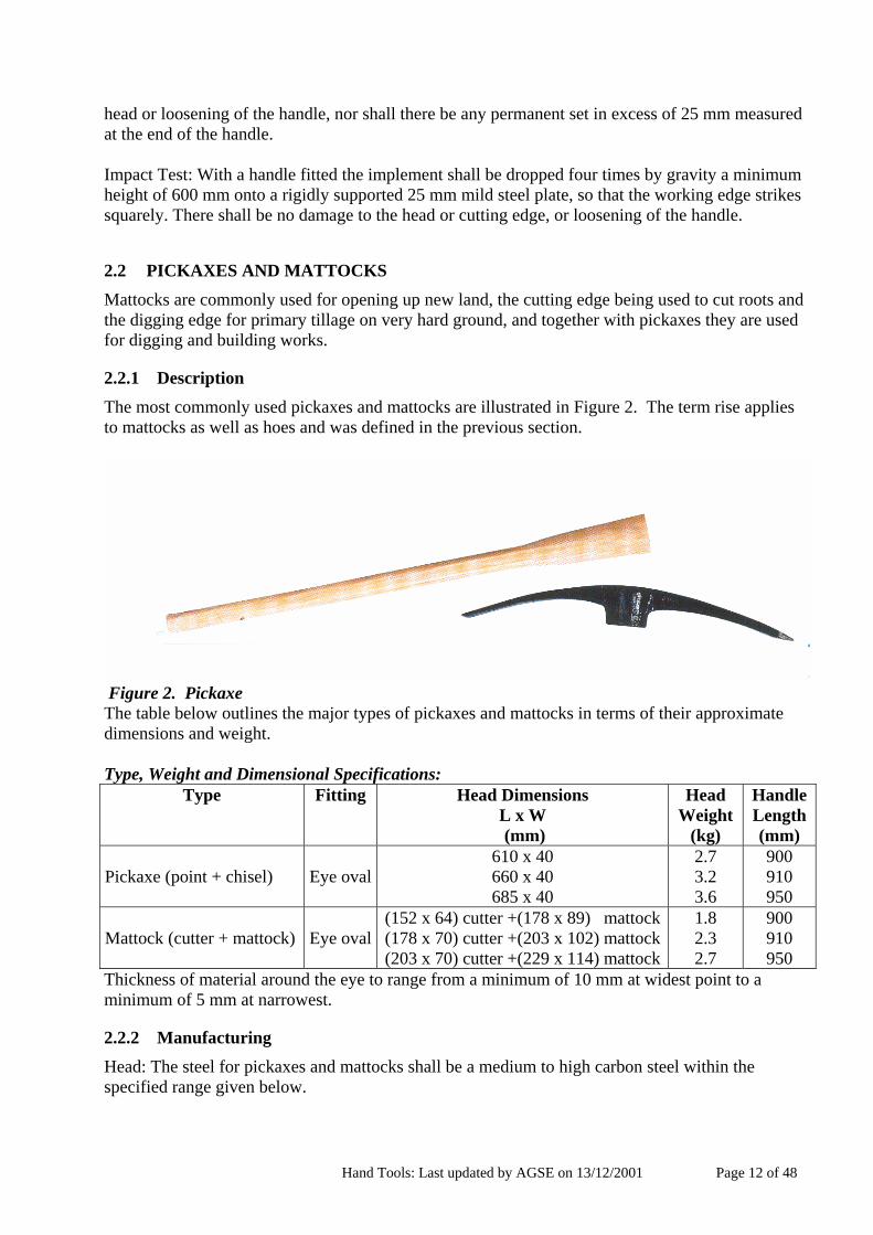
2.2 PICKAXES AND MATTOCKS Mattocks are commonly used for opening up new land, the cutting edge being used to cut roots and the digging edge for primary tillage on very hard ground, and together with pickaxes they are used for digging and building works.
2.2.1 Description The most commonly used pickaxes and mattocks are illustrated in Figure 2. The term rise applies to mattocks as well as hoes and was defined in the previous section.
Figure 2. Pickaxe The table below outlines the major types of pickaxes and mattocks in terms of their approximate dimensions and weight. Type, Weight and Dimensional Specifications:
Type Fitting Head Dimensions L x W (mm)
Head Weight
(kg)
Handle Length(mm)
Pickaxe (point + chisel)
Eye oval
610 x 40 660 x 40 685 x 40
2.7 3.2 3.6
900 910 950
Mattock (cutter + mattock)
Eye oval
(152 x 64) cutter +(178 x 89) mattock (178 x 70) cutter +(203 x 102) mattock (203 x 70) cutter +(229 x 114) mattock
1.8 2.3 2.7
900 910 950
Thickness of material around the eye to range from a minimum of 10 mm at widest point to a minimum of 5 mm at narrowest.
2.2.2 Manufacturing
Head: The steel for pickaxes and mattocks shall be a medium to high carbon steel within the specified range given below.

Hand Tools: Last updated by AGSE on 13/12/2001 Page 13 of 48
Material Specification (Steel): Constituent Specified Range % Carbon 0.4 – 0.65 Manganese 0.5 – 0.8 Silicon 0.35 max Phosphorous 0.06 max Sulfur 0.06 max
Handle: The handle shall be made of a suitable hardwood with a specific gravity of 0.66 to 0.80 after seasoning to not more than 20% moisture content. Heat Treatment and Hardness Specifications: After the forging has been normalised, the lower part of the blade adjacent to the cutting edge shall be hardened and tempered to give the following conditions:
Area immediately adjacent to eye: Rockwell C 25/30. Hardness within 50 mm of the cutting edge: Rockwell C 46/54. This hardened zone shall not
extend more than half way towards the eye and shall gradually decrease to the normalised zone around the eye.
Construction: Head: The forging must be symmetrical and free from flaws. All fins and flashes must be dressed off. The eye must be oval shaped, smooth internally, uniformly tapered, and must lie centrally in the forging. The cutting edge of the mattock must be ground sharp, preferably with an included angle of 18 to 23° and should be ground on the front side of the blade, i.e. the side facing the operator. The cutter end must be ground sharp on both faces. The rise of the mattock blade shall be small (preferably less than 75mm) to give maximum penetration on impact. Handle: The handle must be completed to a smooth finish.
Marking: The forging should be clearly and indelibly marked with the following:
a. Manufacturers name and/or trademark. b. The nominal weight or size of the head. c. The pattern number.
Preservative Treatment: The heads to be varnished or painted all over and the handles to be oiled, waxed or varnished. If they are to be shipped over the sea, then they should also be greased or individually wrapped in a rust protecting covering. They should also be packed in a strong cardboard box for shipment.
2.2.3 Strength Testing: In addition to meeting the above specifications, the tools shall also meet the following strength tests. If the tools are to be supplied without handles, then at least five separate handles should be supplied for testing purposes.

Hand Tools: Last updated by AGSE on 13/12/2001 Page 14 of 48
Figure: 2a Bending Test: With a standard hardwood handle fitted and the tool clamped as shown in Figure 2a. (Strength Test), a load of 45 kg shall be gradually applied by suspension at the handle end and maintained for 2 minutes. On removal of the load, the tool shall show no signs of damage to the head or loosening of the handle, nor shall there be any permanent set in excess of 25 mm measured at the end of the handle. Impact Test: With a handle fitted the implement shall be dropped four times by gravity a minimum height of 600 mm onto a rigidly supported 25 mm mild steel plate, so that the working edge strikes squarely. There shall be no damage to the head or cutting edge, or loosening of the handle.
2.3 SPADES, SHOVELS AND FORKS Spades are primarily digging implements whereas shovels are used to move loose or unconsolidated materials over short distances. Forks are used both for gardening and for moving loosely packed materials like manure or hay. A wide range of shapes and sizes are available depending on their main use, see ITP (1992).
2.3.1 Description Spades, shovels and forks have many common features in that their parts and the methods used to attach the heads to the handles are similar. Some definitions are given below:
Socket attachment: Cylindrical collar into which the handle is fitted and secured by screws, nails or rivets.
Strapped attachment: Two tapered ferrule straps, often extending out of a collar, between which the shaft is fitted and secured by screws or rivets. Usually the most durable of the attachments.
Blade Lift: The vertical distance of the blade tip to the floor when laid down on its back on a flat surface.
Blade Dish: The maximum vertical distance between two parallel planes encompassing the blade, and specified as either lateral or longitudinal curvature.
Crank: The maximum distance of the handle to the floor when laid down on its back on a flat surface.
Spades are designed mainly as digging tools. The blade is normally stronger than that of a shovel and has less of a lift. The top of the blade is normally bent over so that it can be forced into the ground with the foot. The need for stout footwear can be reduced, if the spade is given a tread at the top part of the blade. A broad slotted piece of wood fitted onto the top of the blade is more suitable for bare-foot labour.
Hand Tools: Last updated by AGSE on 13/12/2001 Page 15 of 48
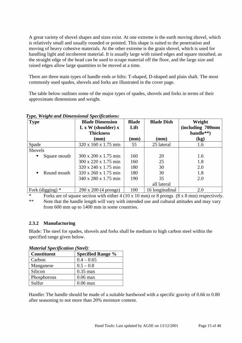
A great variety of shovel shapes and sizes exist. At one extreme is the earth moving shovel, which is relatively small and usually rounded or pointed. This shape is suited to the penetration and moving of heavy cohesive materials. At the other extreme is the grain shovel, which is used for handling light and incoherent material. It is usually large with raised edges and square mouthed, as the straight edge of the head can be used to scrape material off the floor, and the large size and raised edges allow large quantities to be moved at a time. There are three main types of handle ends or hilts: T-shaped, D-shaped and plain shaft. The most commonly used spades, shovels and forks are illustrated in the cover page. The table below outlines some of the major types of spades, shovels and forks in terms of their approximate dimensions and weight.
Type, Weight and Dimensional Specifications:
Type Blade Dimension L x W (shoulder) x
Thickness (mm)
Blade Lift
(mm)
Blade Dish
(mm)
Weight (including 700mm
handle**) (kg)
Spade 320 x 160 x 1.75 min 55 25 lateral 1.6 Shovels
Square mouth
Round mouth
300 x 200 x 1.75 min 300 x 220 x 1.75 min 320 x 240 x 1.75 min 320 x 260 x 1.75 min 340 x 280 x 1.75 min
160 160 180 180 190
20 25 30 30 35
all lateral
1.6 1.8 2.0 1.8 2.0
Fork (digging) * 290 x 200 (4 prongs) 100 16 longitudinal 2.0 * Forks are of square section with either 4 (10 x 10 mm) or 8 prongs (8 x 8 mm) respectively. ** Note that the handle length will vary with intended use and cultural attitudes and may vary from 600 mm up to 1400 mm in some countries.
2.3.2 Manufacturing Blade: The steel for spades, shovels and forks shall be medium to high carbon steel within the specified range given below. Material Specification (Steel): Constituent Specified Range % Carbon 0.4 – 0.65 Manganese 0.5 – 0.8 Silicon 0.35 max Phosphorous 0.06 max Sulfur 0.06 max
Handle: The handle should be made of a suitable hardwood with a specific gravity of 0.66 to 0.80 after seasoning to not more than 20% moisture content.

Hand Tools: Last updated by AGSE on 13/12/2001 Page 16 of 48
Heat Treatment and Hardness Specifications: After the forging has been normalised, the lower part of the blade adjacent to the digging edge shall be hardened and tempered to give the following conditions:
Area immediately adjacent to the socket: Rockwell C 22/30. Hardness within 50 mm of the blade tips: Rockwell C 39/48. This hardened zone shall
gradually decrease to the normalised zone around the socket. Construction: Blade: The blade and socket of the spade, or the prongs and socket of the fork, should be made from one piece of steel, free from cracks or other defects. Handle: The handle must be completed to a smooth finish and the hilt to be a wooden T, or metal or wooden Y with a wooden grip. For some purposes, especially hay forks, the hilt may be plain. Marking: The forging should be clearly and indelibly marked with the following:
a. Manufacturers name and/or trademark. b. The nominal weight or size of the head. c. The pattern number.
Preservative Treatment: The heads to be varnished or painted all over and the handles to be oiled, waxed or varnished. If they are to be shipped over the sea, then they should also be greased or individually wrapped in a rust protecting covering. They should also be packed in a strong cardboard box for shipment.
2.3.3 Strength Testing: In addition to meeting the above specifications, the tools shall also meet the following strength tests. If the tools are to be supplied without handles, then at least five separate handles should be supplied for testing purposes. Figure 3. Spades, shovels and forks Bending Test: With a standard hardwood handle fitted and the tool clamped as shown in Figure 3 (Strength Test), a load of 50 kg shall be gradually applied by suspension from the grip and maintained for 2 minutes. On removal of the load, the tool shall show no signs of damage or loosening of any component part, nor shall there be any permanent set in excess of 25 mm when measured at the grip. Bending Test: For trenching forks, in addition to (a), the tips of any two adjacent prongs are brought together for 1 minute and shall not show sign of permanent set or damage.

Hand Tools: Last updated by AGSE on 13/12/2001 Page 17 of 48
Machetes Machetes, or pangas, are used for general purpose heavy cutting work, including bush clearance and harvesting.
2.3.4 Description Machetes come in a broad range of shapes and sizes depending on their prime uses and the most commonly used ones are illustrated in Figure 4. Figure 4. Machetes The table below outlines some of the major types of machetes in terms of their approximate dimensions and weight. Type, Weight and Dimensional Specifications: Type Dimensions of Blade
L x W min (mm)
Dimensions of Blade Thickness
(mm)
Blade Weight
(g)
Handle Length (mm)
Cutlass Straight edge General purpose knife
510 x 50 405 x 50 150 x 20
2.5 min 2.5 min 2.5 min
630 400 150
160 160 160
2.3.5 Manufacturing Blade: The steel for machetes shall be a high carbon steel within the specified range given below.
Hand Tools: Last updated by AGSE on 13/12/2001 Page 18 of 48
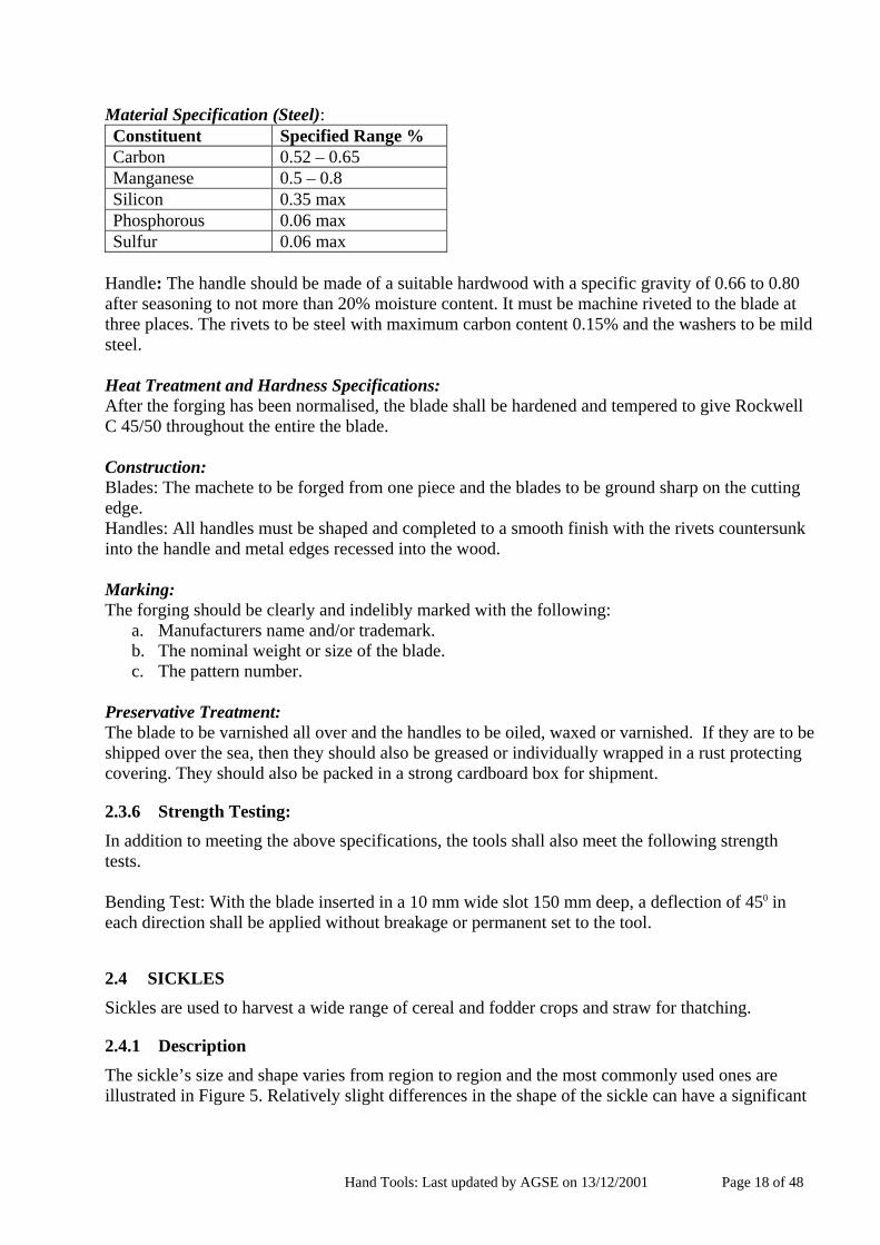
Material Specification (Steel): Constituent Specified Range % Carbon 0.52 – 0.65 Manganese 0.5 – 0.8 Silicon 0.35 max Phosphorous 0.06 max Sulfur 0.06 max
Handle: The handle should be made of a suitable hardwood with a specific gravity of 0.66 to 0.80 after seasoning to not more than 20% moisture content. It must be machine riveted to the blade at three places. The rivets to be steel with maximum carbon content 0.15% and the washers to be mild steel. Heat Treatment and Hardness Specifications: After the forging has been normalised, the blade shall be hardened and tempered to give Rockwell C 45/50 throughout the entire the blade. Construction: Blades: The machete to be forged from one piece and the blades to be ground sharp on the cutting edge. Handles: All handles must be shaped and completed to a smooth finish with the rivets countersunk into the handle and metal edges recessed into the wood. Marking: The forging should be clearly and indelibly marked with the following:
a. Manufacturers name and/or trademark. b. The nominal weight or size of the blade. c. The pattern number.
Preservative Treatment: The blade to be varnished all over and the handles to be oiled, waxed or varnished. If they are to be shipped over the sea, then they should also be greased or individually wrapped in a rust protecting covering. They should also be packed in a strong cardboard box for shipment.
2.3.6 Strength Testing:
In addition to meeting the above specifications, the tools shall also meet the following strength tests. Bending Test: With the blade inserted in a 10 mm wide slot 150 mm deep, a deflection of 450 in each direction shall be applied without breakage or permanent set to the tool.
2.4 SICKLES Sickles are used to harvest a wide range of cereal and fodder crops and straw for thatching.
2.4.1 Description The sickle’s size and shape varies from region to region and the most commonly used ones are illustrated in Figure 5. Relatively slight differences in the shape of the sickle can have a significant

Hand Tools: Last updated by AGSE on 13/12/2001 Page 19 of 48
impact on its acceptability by farmers. They either have smooth internal cutting edges to cut green vegetation, or serrated edges to cut dry vegetation. Figure 5. Sickle The table below outlines some of the major types of sickles in terms of their approximate dimensions and weight. Type, Weight and Dimensional Specifications: Type Dimensions of Blade
L x W
(mm)
Dimensions of BladeThickness on back
edge (mm)
Weight (including
handle) (g)
Handle Length
(mm)
Serrated edge Smooth/plain edge
405 x 20 min 305 x 20 min
3 min 3 min
250 200
150 150
2.4.2 Manufacturing
Blade: The steel for sickles shall be a high carbon steel within the specified range given below. Material Specification (Steel): Constituent Specified Range % Carbon 0.5 – 0.65 Manganese 0.5 – 0.8 Silicon 0.35 max Phosphorous 0.06 max Sulfur 0.06 max
Handle: The handle should be made of a suitable hardwood with a specific gravity of 0.66 to 0.80 after seasoning to not more than 20% moisture content.

Hand Tools: Last updated by AGSE on 13/12/2001 Page 20 of 48
Heat Treatment and Hardness Specifications: After forging, the blade should be normalised and then hardened and tempered to give Rockwell C 45/50 along the whole length of the blade. Construction: Blades: Both plain and serrated edges to be ground sharp. Handles: The blades should be firmly fixed to handles in a way that does not allow the blade to rotate loosely or slip off after sustained use. Either countersunk rivets or screws can be used, or the tang from the blade should run through the whole length of the handle and emerge at the other end of the handle and be bent backwards, to ensure that the handle cannot be pulled off the blade. It is important that this is done in such as way that the protruding metal is not exposed to the operators hand. If the bent tang does not also prevent the handle from rotating then the handle should be positively located onto the blade by countersunk rivet or screw. Marking: The forging should be clearly and indelibly marked with the following:
a. Manufacturers name and/or trademark. b. The nominal weight or size of the blade. c. The pattern number.
Preservative Treatment: The blade to be varnished all over and the handles to be oiled, waxed or varnished. If they are to be shipped over the sea, then they should also be greased or individually wrapped in a rust protecting covering. They should also be packed in a strong cardboard box for shipment.
2.4.3 Strength Testing: In addition to meeting the above specifications, the tools shall also meet the following strength tests. Bending Test: With the handle clamped horizontally and with the blade also in a horizontal plane, a load of 10 kg shall be gradually applied to the blade tip and maintained for 2 minutes. The blade shall then be turned over and the test repeated until a total of four tests has been carried out. On final removal of the load, the tool shall show no signs of damage to the head or loosening of the handle, nor shall there be any permanent set in excess of 5 mm measured at the end of the blade. [Note: This is a newly suggested test and needs to be physically checked].
2.5 REAPING HOOKS AND SCYTHES
Reaping hooks and scythes are used for harvesting cereal and fodder crops and although not as commonly used as sickles, they offer higher work rates. As scythes require substantial skill to use, they should not be introduced into areas in which they are not common without a training component. Generally, scythes can only be used on flat surfaces with few stones.
2.5.1 Description
Scythes are have long curved blades sharpened along one edge and connected to a long shaft with two handles. Reaping hooks are a compromise between a sickle and a scythe, with the blade connected to the shaft with one handle at the end. With both of these implements, the crop or fodder is not held while being cut. Two main types of blades are used and these are described below:

Hand Tools: Last updated by AGSE on 13/12/2001 Page 21 of 48
Hammered blades: Blades that are sharpened with a hammer and small anvil to draw out the cutting edge. They are said to be less liable to breakage and less fatiguing to use as they are also lighter.
Ground blades: Blades that are sharpened on a grindstone. These blades are thicker and heavier than hammered blades. The sharpening of both types is finished off with a whetstone.
Scythes and reaping hooks come in a broad range of shapes and sizes and the most commonly used ones are illustrated in Figure 6. Figure 6. Reaping Hooks and Scythes The table below outlines some of the major types of scythes and reaping hooks in terms of their approximate dimensions and weight and shaft length. Type, Weight and Dimensional Specifications:
Type Dimensions of Blade L x W at shaft end
(mm)
Dimensions of Blade Thickness (back edge)
(mm)
Blade Weight
(kg)
Shaft Length(mm)
Scythe: Cereal, fodder and grass Brush
700 to 1000 x 70 400 to 500 x 50
5 5
3.0 2.2
1200 1000
Reaping Hook: 220 5 1.3 620
2.5.2 Manufacturing Blade: The steel for scythes and reaping hooks shall be a medium carbon steel for ‘hammered blades’ and a high carbon steel for ‘ground blades’, within the specified range given below.

Hand Tools: Last updated by AGSE on 13/12/2001 Page 22 of 48
Material Specification (Steel): Constituent Specified Range % Carbon 0.4 – 0.65 Manganese 0.5 – 0.8 Silicon 0.35 max Phosphorous 0.06 max Sulfur 0.06 max
Handle: The shaft can either be made of a suitable hardwood with a specific gravity of 0.66 to 0.80 after seasoning to not more than 20% moisture content, or of light tubular steel. Heat Treatment and Hardness Specifications: After forging, the blade should be normalised and then hardened and tempered to give Rockwell C 45/50 along the whole length of blade for a ground blade and Rockwell C 17/22 for a hammered blade. Construction: Blades: Edges to be ground sharp after forging on the lower surface, so that the blade is not drawn towards the ground by the cutting action. Handles: Scythes: For shafts, a hardwood that can be bent during manufacture is required. They should be sanded and surface treated. Those made of metal must be coated with anti-rust protection and varnished. The length of the shaft and the position of the handle are usually determined by the height of the operator. The middle handle should be up to the waist of the operator while the top grip should be up to the nose height. The blades should be firmly fixed to the shaft in a way that does not allow the blade to rotate or slip after sustained use. Reaping Hooks: The handle of wood is fixed to the end of the shaft made of wood or tubular steel. They should be sanded and surface treated. The blades should be firmly fixed to the shaft in a way that does not allow the blade to rotate or slip after sustained use. Marking: The forging should be clearly and indelibly marked with the following:
a. Manufacturers name and/or trademark. b. The nominal weight or size of the blade. c. The pattern number.
Preservative Treatment: The blade to be varnished all over and the handles to be oiled, waxed or varnished. If they are to be shipped over the sea, then they should also be greased or individually wrapped in a rust protecting covering. They should also be packed in a strong cardboard box for shipment. Maintenance: As the blades have to be regularly sharpened during use to be effective, a tool kit that includes a hammer and small anvil for hammered blades, and a grindstone for ground blades, together with a whetstone for both types, should be included with the package. Blades should be sharpened on the lower surface, so that the blade is not drawn towards the ground by the cutting action.
2.5.3 Strength Testing: In addition to meeting the above specifications, the tools shall also meet the following strength tests.

Hand Tools: Last updated by AGSE on 13/12/2001 Page 23 of 48
Bending Test: With the shaft clamped into a vertical position, a load of 10 kg shall be gradually applied to the blade by suspension, at one third of the length of the blade from the tip, and maintained for 2 minutes. On removal of the load, the tool shall show no signs of damage to the head or loosening of the handle, nor shall there be any permanent set in excess of 10 mm measured at the end of the blade tip. This test will be repeated with the shaft and blade horizontal. [Note: This is a newly suggested test and needs to be physically checked].
2.6 AXES Axes may be used for bush clearance and the cutting of wood for the manufacture of handles for other agricultural tools, or for fuel, etc.
2.6.1 Description The most commonly used axes are illustrated in Figure 7.
Figure 7. Axes The table below outlines some of the major types of axes in terms of their approximate dimensions and weight. Type, Weight and Dimensional Specifications: Type Blade Dimensions
L x W cut x Eye max. dia. (mm)
Head Weight
(kg)
Handle Length (mm)
Asymmetrical axe
200 x 120 x 65 210 x 130 x 65 220 x 145 x 65
1.8 2.3 2.7
800 800 900
2.6.2 Manufacturing Head: For an axe to be effective and retain its edge, high-grade chrome manganese steel shall be used within the specified range given below. Material Specification (Steel): Constituent Specified Range % Carbon 0.55 – 0.9 Manganese 0.5 – 0.8 Chromium 0.45 minimum Silicon 0.35 max Phosphorous 0.05 max Sulfur 0.05 max

Hand Tools: Last updated by AGSE on 13/12/2001 Page 24 of 48
Handle: The handle should be made of a suitable hardwood with a specific gravity of 0.66 to 0.80 after seasoning to not more than 20% moisture content. Heat Treatment and Hardness Specifications: After the forging has been normalised the forging shall be hardened and tempered to produce Rockwell C 25/30 at the eye, increasing to Rockwell C 48/56 up to 50 mm from the cutting edge and to the full depth of the blade. Construction: Head: The forging must be symmetrical and free from flaws. All fins and flashes must be dressed off. The elliptical eye must be smooth internally, uniformly tapered and must lie centrally within the forging. The walls of the eye must be sufficiently thick to withstand normal working stresses. They should be a minimum of 3 mm for axe heads of less than about 1.7 kg and a minimum of 5 mm for heads in excess of 3.0 kg. The cutting edge must be ground sharp. Handle: The handle must be shaped and completed to a smooth finish. They may be fitted with softwood wedges or by chemical adhesive bonding. It should be noted that the fitting of the handles is a specialised operation. Marking: The forging should be clearly and indelibly marked with the following:
a. Manufacturers name and/or trademark. b. The nominal weight or size of the head. c. The pattern number.
Preservative Treatment: The head to be bright finished all over and the head and handle to be oiled, waxed or varnished. If they are to be shipped over the sea, then they should also be greased or individually wrapped in a rust protecting covering. They should also be packed in a strong cardboard box for shipment. Maintenance: The axe should be supplied with a toolkit for sharpening consisting of a flat file and whetstone.
2.6.3 Strength Testing: In addition to meeting the above specifications, the tools shall also meet the following strength tests. Figure: 7a Axes
Hand Tools: Last updated by AGSE on 13/12/2001 Page 25 of 48
Bending Test: With a standard hardwood handle fitted and the tool clamped as shown in Figure 7 (Strength Test), a load of 45 kg shall be gradually applied by suspension at end of the handle and maintained for 2 minutes. On removal of the load the tool shall show no signs of damage to the head or loosening of the handle, nor shall there be any permanent set in excess of 25 mm measured at the end of the handle end. Impact Test: The tool shall withstand a minimum of twenty very heavy blows across the grain of a hardwood without damage to the cutting edge or loosening of the handle.

Hand Tools: Last updated by AGSE on 13/12/2001 Page 26 of 48
2.7 MISCELLANEOUS ITEMS: GRASS SLASHER, GARDEN RAKE, WATERING CAN, BUCKET, WHEEL BARROW, CROWBAR, BOW SAW
A more detailed description and list of specifications have not been drawn up for the following items, either due to their simplicity or complexity. For certification purposes they should be tested for visual, dimensional, material composition, and marking criteria to the same level as the previously listed items. Where no specific strength tests have been established for these items particular attention should be paid to the quality of their manufacture.
2.7.1 Grass Slasher The Grass Slasher shall conform to the following specifications: Type, Weight and Dimensional Specifications: Bar 1.0 metre long x 50 mm wide x 3 mm thick, (tolerance of +/- 5%). Material Specification: Blade: The steel shall be a high carbon steel within the specified range given below. Constituent Specified Range % Carbon 0.3 – 0.65 Manganese 0.5 – 0.8 Silicon 0.35 max. Phosphorous 0.06 max. Sulfur 0.06 max.
Handle: The handle shall be made of a suitable hardwood with a specific gravity of 0.66 to 0.80 after seasoning to not more than 20% moisture content. Heat Treatment and Hardness Specifications: Hardness of at least Rockwell C 22. Construction: Blade: Bottom 200 mm cranked and sharpened on both sides on the bottom edge. Handle: Riveted to top of the metal bar with a minimum of two countersunk rivets and the handle overlapping the steel bar and completed to a smooth finish.
Figure: 8 Grass Slasher

Hand Tools: Last updated by AGSE on 13/12/2001 Page 27 of 48
Marking: The forging should be clearly and indelibly marked with the following: Manufacturers name and/or trademark. Preservative Treatment: The blades to be varnished all over and the handles to be oiled, waxed or varnished. If they are to be shipped over the sea, then they should also be greased or individually wrapped in a rust protecting covering. They should also be packed in a strong cardboard box for shipment. Strength Testing: In addition to meeting the above specifications, the tools shall also meet the following strength tests. Bending Test: With the blade inserted in a 10 mm wide slot 150 mm deep, a deflection of 450 in each direction shall be applied without breakage or permanent set to the tool.
2.7.2 Garden Rake The Garden Rake shall conform to the following specifications: Type, Weight and Dimensional Specifications: Width of 350 to 450 mm, 10 to 16 teeth each 75 to 100 mm long, and weight without handle should be between 0.7 to 1.0 kg. Material Specification: The socket, head and teeth shall ideally be forged from a single piece of carbon steel within the specified range given below. Alternatively, the socket may be made of a lower carbon steel, but of at least 0.2% Carbon, and riveted or welded onto the head. Constituent Specified Range % Carbon 0.3 – 0.5 Manganese 0.5 – 0.8 Silicon 0.35 max. Phosphorous 0.06 max. Sulfur 0.06 max.
Handle: The handle shall be made of a suitable hardwood with a specific gravity of 0.66 to 0.80 after seasoning to not more than 20% moisture content. Heat Treatment and Hardness Specifications: The head and teeth will have a hardness of at least Rockwell C 22. Construction: Head and Teeth: Teeth may be curved or straight, with 10 to 16 teeth and each tooth between 75 to 100 mm long. The distance between teeth should be approximately 30 mm. Handle: The handle should be approximately 1500 mm long. Marking: The forging should be clearly and indelibly marked with the following: Manufacturers name and/or trademark. Preservative Treatment: The blades to be varnished all over and the handles to be oiled, waxed or varnished. If they are to be shipped over the sea, then they should also be greased or individually wrapped in a rust protecting covering. They should also be packed in a strong cardboard box for shipment.

Hand Tools: Last updated by AGSE on 13/12/2001 Page 28 of 48
Strength Testing: In addition to meeting the above specifications, the tools shall also meet the following strength tests: Bending Test: With a standard hardwood handle fitted and the teeth fully clamped in a vice, a load of 10 kg shall be gradually applied to the handle by suspension 1 m from the head and maintained for 2 minutes. On removal of the load the tool shall show no signs of damage to the head or loosening of the handle, nor shall there be any permanent set in excess of 25 mm measured 1 m from the head on the handle. [Note: This is a newly suggested test and needs to be physically checked.
2.7.3 Watering Can The Watering Can shall conform to the following specifications: Type, Weight and Dimensional Specifications: Capacity of 10 to 12 litre, preferably with nominal calibration marks of water level at 1 litre intervals for use with chemical applications. Material Specification: Body of galvanised steel sheet of 0.5 mm minimum. Alternatively, a robust body of plastic that is ultra-violet and heat resistant may be used. Construction: The watering can shall be constructed to be robust and durable. If galvanised sheet is used then lock seams and rolled edges shall be constructed. The watering spout shall be stayed to the body for strength and tapered to connect to a well fitting watering rose. The top and side handles shall be manufactured to a thickness that is comfortable carry. Marking: The cans should be clearly and indelibly marked with the following: Manufacturers name and/or trademark. Preservative Treatment: They should be packed in a strong cardboard box for shipment. Strength Testing: In addition to meeting the above specifications, the tools shall also meet the following strength tests: Impact Test: With a very loosely packed bag of sand weighing 5 kg placed within the watering can, the can shall be held horizontally with the spout facing downward, and dropped four times from a height of 400 mm, measured from the tip of the spout. This test shall then be repeated with the can being dropped twice each onto the top and back handles, with the 400 mm height being measured from the handles. Following these eight drops there shall be no permanent set in excess of 25 mm measured at the tip of the spout, nor shall there be any leaks when the can is filled with water. [Note: This is a newly suggested test and needs to be physically checked].
2.7.4 Bucket
The Bucket shall conform to the following specifications: Type, Weight and Dimensional Specifications: Capacity of 12 to 15 litres.

Hand Tools: Last updated by AGSE on 13/12/2001 Page 29 of 48
Material Specification: Body of galvanised steel sheet of 0.5 mm minimum. Alternatively, a robust body of plastic that is ultra-violet and heat resistant may be used. Construction: The bucket shall be constructed to be robust and durable. If galvanised sheet is used then lock seams and rolled edges shall be constructed. The handles shall be manufactured to a thickness that is comfortable to carry, preferably zinc coated round iron bar with plastic or wooden sheath. Marking: The bucket should be clearly and indelibly marked with the following: Manufacturers name and/or trademark. Preservative Treatment: They should be packed in a strong cardboard box for shipment. Strength Testing: In addition to meeting the above specifications, the tools shall also meet the following strength tests: Impact Test: With a very loosely packed bag of sand weighing 5 kg placed within the watering can, the can shall be held horizontally with the spout facing downward, and dropped four times from a height of 400 mm, measured from the bottom of the bucket. This test shall then be repeated with the bucket being dropped twice each onto opposite sides , with the 400 mm height being measured from thelowest point. Following these eight drops there shall be no permanent set in excess of 25 mm, nor shall there be any leaks when the bucket is filled with water.
2.7.5 Wheel Barrow The Wheel Barrow shall conform to the following specifications: Type, Weight and Dimensional Specifications: Struck capacity of 70 to 85 litre, (capacity when loaded level with rim of tray). Distance from end of handle to axle of 1225 mm minimum, and from end of handle to crossbracing of 600 mm to allow operator to walk freely. Axle to have a diameter of 25 mm minimum. Solid rubber tyre of 350 to 400 mm outside diameter, and 75 to 100 mm wide. Material Specification: Frame and handles: Tubular mild carbon steel of diameter 30 mm minimum, thickness of 1.6 mm minimum. Tray: Galvanised or mild steel sheet of 1.3 mm thickness minimum. Bearings: Ball or roller bearings, grey cast iron bushes or nylon/molybdenum disulphide bushes. Construction: The wheel barrow shall be constructed to be robust and durable. The rim of the tray to be rolled over a mild steel bar of at least 8 mm diameter. Clearance between the wheel and the body to be a minimum of 50 mm. The legs/rests should be cross braced for strength and heals should be welded onto them. Marking: The wheelbarrow should be clearly and indelibly marked with the following: Manufacturers name and/or trademark. Preservative Treatment: Metallic parts to be painted with anti-rust protection, if not galvanised.
Hand Tools: Last updated by AGSE on 13/12/2001 Page 30 of 48
2.7.6 Crowbar The Crowbar should conform to the following specifications: Type, Weight and Dimensional Specifications: Round section bar 30 mm diameter (tolerance +/- 5%), length 1600 to 1800 mm, and weight 8 to 10 kg. Material Specification: The crowbar shall be forged from a single piece of carbon steel within the specified range given below. Constituent Specified Range % Carbon 0.5 – 0.65 Manganese 0.5 – 0.8 Silicon 0.35 max. Phosphorous 0.06 max. Sulfur 0.06 max.
Heat Treatment and Hardness Specifications: After the forging has been normalised the crowbar shall be hardened and tempered to give Rockwell C 45/50 throughout the entire the bar. Construction: The end 100 mm of the bar shall be shaped to a chisel form at one end and a four flat point at the other. Marking: The forging should be clearly and indelibly marked with the following: Manufacturers name and/or trademark. Preservative Treatment: The bar to be varnished or painted all over.
2.7.7 Bow Saw The Bow Saw should conform to the following specifications: Type, Weight and Dimensional Specifications: Bow Saw to hold standard length blades. Blades must be commercially available, made of a high carbon alloy steel of standard length (762 or 914 mm) and width (20 to 25 mm). Type of blade to be specified depends on types of wood involved:
Peg teeth, which are evenly, spaced row V shaped. Each tooth is normally filed on both edges so that it cuts in both directions.
Gullet teeth, which has a gullet between the cutting teeth to get rid of the sawdust and prevent jamming of the saw.
Each saw should be supplied with about 10 spare blades. Material Specification: Tubular steel frame in the form of a bow made from mild steel. Blades made of a high carbon alloy steel of standard length. Heat Treatment and Hardness Specifications: No heat treatment for frame. Construction: Quick release lever at one end of the frame to allow rapid mounting of blade.

Hand Tools: Last updated by AGSE on 13/12/2001 Page 31 of 48
Marking: The forging should be clearly and indelibly marked with the following: Manufacturers name and/or trademark. Preservative Treatment: The frame to be varnished or painted all over.

Hand Tools: Last updated by AGSE on 13/12/2001 Page 32 of 48
3 TECHNICAL SPECIFICATIONS FOR MAINTENANCE EQUIPMENT FOR HAND TOOLS
For agricultural handtools to be used effectively and efficiently they need to be kept in good working order. The main tools used for the maintenance of hand tools are metal files and filing stones and details of these are given in this section. Initial sharpening is carried out using files and then sharpening stones and for the precision sharpening of scythes and axes the surface is then honed using whetstones. Files For the sharpening of digging and cutting tools flat files are used and for sharpening saw teeth, small triangular files are used. Type, Weight and Dimensional Specifications: For sharpening machetes, sickles, scythes and axes:
Combination flat file with handle. Point to shoulder: 152 or 203 mm. One side: double or second cut and other side: single or smooth cut. Square edge.
For sharpening saws:
Taper saw file: Point to shoulder: 152 mm. File of equilateral triangular section parallel for two thirds of the body length and then tapering towards the point. Sides and edges: single cut and point left uncut.
Material Specification: The files shall be forged from a single piece of carbon steel within the specified range given below. Constituent Specified Range % Carbon 1.1 min Manganese 0.45 max Silicon 0.35 max Phosphorous 0.06 max Sulfur 0.06 max
Figure: 9
Figure:10

Hand Tools: Last updated by AGSE on 13/12/2001 Page 33 of 48
Handle: The handle should be made of a suitable hardwood with a specific gravity of 0.66 to 0.80 after seasoning to not more than 20% moisture content. Heat Treatment and Hardness Specifications: After the forging has been normalised it shall be hardened and tempered to produce Rockwell C 56 minimum. Construction: The teeth shall be uniform and regular over the whole of the cut surfaces and the uncut edges of the file shall be smooth and free from burrs or defects of any kind. The handle should be approximately 100 mm long and completed to a smooth finish. Marking: The forging should be clearly and indelibly marked with the following: Manufacturers name and/or trademark. Preservative Treatment: The handle to be varnished. If they are to be shipped over the sea, then they should also be greased or individually wrapped in a rust protecting covering. They should also be packed in a strong cardboard box for shipment.
3.1 SHARPENING STONES These stones are used for sharpening scythes, sickles and machete blades. Sharpening stones should conform to the following specifications:
The general purpose sharpening stone should have a length of roughly 355 mm, including the handle.
The material should be silicon carbide.
3.2 WHETSTONE These stones are used for the final sharpening process for scythes, sickles and machete blades. Whetstones should conform to the following specifications:
They should be oval shaped with roughly the following main dimensions: Length, 100 mm x Width, 25 mm x Thickness, 12.5 mm.
They should be oil filled ultra fine natural grit stones.

Hand Tools: Last updated by AGSE on 13/12/2001 Page 34 of 48
4 REFERENCES
Armstrong, W. 1981. Better Tools for the Job. Specifications for Hand Tools and Equipment. Intermediate Technology Publications, London, U.K. FAO, 1998. Agricultural Implements Used by Women Farmers in Africa. FAO, IFAD, Japan ILO, 1981. Guide to tools and equipment for labour based road construction, ILO/UN publication. ITP, 1992. Tools for Agriculture. A guide to appropriate equipment for smallholder farmers. Intermediate Technology Publications, London, U.K.
5 BIBLIOGRAPHY OF BOOKS ON HAND TOOLS
BSI, 1966. Metric Standards for engineering, B.S. handbook No.18, British Standards Institution. IFAD, ? Tendering documents for agricultural hand tools, IFAD loan document No. 93, Mozambique. ILO, 1988. Fabrication artisanale d'outils manuels pour l'agriculture, ILO / UN doc 15. Moeller, O. 1997. Farmers’ Tools. Farmesa. FAO, SIDA. Pandya, A. C. 1981. Farm hand tools for transmigration areas, UNDP/ FAO project. Peatfield, A. E. 1972. Mechanical Engineering, Hand tools Volume I, publisher? Rollason, E.C. 1975. Metallurgy for Engineers, ELBS series.

Hand Tools: Last updated by AGSE on 13/12/2001 Page 35 of 48
ANNEX 1: EXAMPLE OF STANDARD SPECIFICATION SHEET FOR HAND TOOLS See beginning of Section 2 for further details on the preparation of this standard specification. --------------------------------------------------------------------------------------------------------------- PROJECT NUMBER:............................ TENDER NUMBER:.......................... ITEM: HOES WITH HANDLES QUANTITY: 5000 PCS A. DESCRIPTION The means of attachment of the blade to the handle, and the approximate (+/- 10%) dimensions and weight, are outlined in the table below. Suppliers should specify the exact dimensions and weight offered in their bids. Type, Weight and Dimensional Specifications:
Type
Fitting to handle
Dimensions L* x W (mm)
Blade Weight
(kg)
Handle Length (mm)
Heavy/Digging hoe: Dished rectangular
Eye
235 x 280
2.2
900
* Length from top of blade to cutting edge, excluding eye/tang. Thickness of material around the eye to range from a minimum of 10 mm at widest point to a minimum of 5 mm at narrowest. B. MANUFACTURING Blade: The steel for agricultural hoes shall be a medium to high carbon steel within the specified range given below. Material Specification (Steel): Constituent Specified Range % Carbon 0.4 – 0.65 Manganese 0.5 – 0.8 Silicon 0.35 max. Phosphorous 0.06 max. Sulfur 0.06 max.
Handle: The handle shall be made of a suitable hardwood with a specific gravity of 0.66 to 0.80 after seasoning to not more than 20% moisture content. Heat Treatment and Hardness Specifications: After the forging has been normalised, the lower part of the blade adjacent to the cutting edge shall be hardened and tempered to give the following conditions:
Area immediately adjacent to eye: Rockwell C 25/30.

Hand Tools: Last updated by AGSE on 13/12/2001 Page 36 of 48
Hardness within 50 mm of the cutting edge: Rockwell C 40/46. This hardened zone shall not extend more than half way towards the tang or eye and shall gradually decrease to the normalised zone around the eye.
Construction: Blade: The forging must be symmetrical and free from flaws. All fins and flashes must be dressed off. The eye must be smooth internally, uniformly tapered, and must lie centrally in the forging. The cutting edge must be ground sharp, preferably with an included angle of 18 to 23°, and should be ground on the front side of the blade, i.e. the side facing the operator. The rise of the blade shall be small (preferably less than 55 mm) so that the blade is almost at right angle to the handle to give maximum penetration on impact. Handle: The handle must be completed to a smooth finish.
Marking: The forging should be clearly and indelibly marked with the following:
a. Manufacturers name and/or trademark required. b. The nominal weight or size of the head. c. The pattern number.
Preservative Treatment: The heads to be varnished or painted all over and the handles to be oiled, waxed or varnished. If they are to be shipped over the sea, then they should also be greased or individually wrapped in a rust protecting covering. They should also be packed in a strong cardboard box for shipment. C. STRENGTH TESTING: In addition to meeting the above specifications, the tools shall also meet the following strength tests. Bending Test: With a standard hardwood handle fitted and the tool clamped as shown in Figure 1 (Strength Test), a load of 45 kg shall be gradually applied by suspension at the handle end and maintained for 2 minutes. On removal of the load, the tool shall show no signs of damage to the head or loosening of the handle, nor shall there be any permanent set in excess of 25 mm measured at the end of the handle. Impact Test: With a handle fitted the implement shall be dropped four times by gravity a minimum height of 600 mm onto a rigidly supported 25 mm mild steel plate, so that the working edge strikes squarely. There shall be no damage to the cutting edge or loosening of the handle.

Hand Tools: Last updated by AGSE on 13/12/2001 Page 37 of 48
ANNEX 2: MATERIALS The main materials used in the fabrication of agricultural hand tools and workshop equipment are steel and its alloys for the tool head or blade, and wood and plastics used for handles. Steel is made by alloying carbon (C) with iron. As the carbon content is increased the hardness and strength of steel increases, however, its ductility is reduced. This increase in brittleness with increasing carbon content imposes limits on the amount of carbon that can be added. As the carbon content is increased, the susceptibility of the metal to hardening when rapidly cooled from elevated temperatures is also increased. This is due to various microstructures obtained by different heat-treatments. Steel can be roughly divided into three categories: mild, medium and high carbon steel. The carbon content varies according to size, shape and duty for various tools and equipment. Table A1 illustrates briefly the various compositions and items and or processes pertaining to such categories. Table A1: Categories of carbon steel and their uses Category % of Carbon Items Mild carbon steel
0.15 to 0.25%
Drop forging for agricultural hand tools, such as sockets or straps of shovels, etc. Section steel for joists, channels and angles Boiler plate and stamping purposes
0.25 to 0.5 Forging and general structural engineering purposes, etc 0.30 to 0.4 Shafts, high tensile tubes, etc
Medium carbon steel
0.40 to 0.5 Shafts, rotors, gears and agricultural tools such as hoes, spades, forks, machetes, sickles, and axes.
0.5 to 0.6 Agricultural hand tools such as hoes, pickaxes, mattocks, machetes, sickles and axes.
0.55 to 0.65 Railway rails, laminated springs for vehicles, hammers for rivets, etc
0.65 to 0.75 Saw mandrels, drills, and hammers, hot sets, keys, torsion bars, etc
0.75 to 0.85 Laminated springs, small forging dies, shear blades, cold sets, etc
0.85 to 0.95 Small cold chisels, punches, shear blades, etc
High carbon steel
1.10 to 1.40 Gauges, drills, woodworking tools, files, etc Steel also contains small quantities of impurities such as phosphorus (P), sulphur (S) and silicon (Si), and other elements such as manganese (Mn) and alloying elements such as chromium (Cr) and Nickel (Ni) to enhance the performance of the metal. A. STANDARDS FOR STEEL MATERIALS For any mechanical design, the most important properties are given below:
a. Tensile strength which represents the material’s resistance to being pulled apart. It is usually expressed at 0.2% of permanent elongation.
b. Ductility indicates how much a material is deformed when it is stretched and is expressed as a reduction in area. It represents the ability of the material to accommodate deformation

Hand Tools: Last updated by AGSE on 13/12/2001 Page 38 of 48
without failure. Material with higher ductility implies its greater ability to resist impact loads.
c. Hardness: With some tools, it is important that parts of the head are hardened to resist wear and compressive stresses whilst other parts are left in their naturally tough condition to absorb tensile forces. This can be measured by determining the hardness values. The most widely employed standard methods are Brinell, Vickers and Rockwell tests. Each value has its own merits and weaknesses. Brinell is generally not reliable for very hard metals, while Vickers is more precise and complex. The “Rockwell” which is the commonly utilised method is particularly useful for rapid routine tests on finished products will be briefly described.
The property of hardness in metals largely determines its resistance to scratching, wear, penetration, machining and ability to cut. Rockwell measurement consists of either a steel ball loaded with 100kg (Scale B), or a diamond cone having an angle of 1200 loaded with 150-kg (Scale C). The penetrator is first loaded with a minor load of 10 kg to take out any slack in the machine and the indicator, for measuring the depth set to zero. A major load is applied and after its removal, the dial gauge records the depth of the impression in terms of Rockwell numbers often abbreviated as HRC. Table A2. Relationship between Rockwell, Brinell and Vickers ( kg/ mm2)
Hardness measuring system
Scale
Rockwell HRC 15 20 25 30 35 40 45 50 55 60 Brinell HB30 195 218 247 279 317 363 417 479 555 663*Vickers 205* 230 260 294 334 382 439 504 584 698
*Asterisks indicate approximate values. Lower range for Rockwell (0 to 20) is generally not used. For specific data on materials prior to designing, one may refer to the following standards:
• American Iron and Steel Institute (AISI) • American National Standards Institute (ANSI) • American Society for Testing Metals (ASTM) • British Standards Institution (BSI) • Deutsche Industry Norm (DIN) • International Standards Institution (ISO) • Japanese Standards Association (JIS)
While these standards provide useful and precise data to the experienced design engineer, for newcomers in the steel industry sector, they represent a hurdle as each country maintains its own coding system. Consequently, it is difficult to compare the relative strength and composition of steel from different manufacturing countries. An attempt is made in Table 3, to provide a few well known Standards of steel with similar chemical composition and mechanical properties.
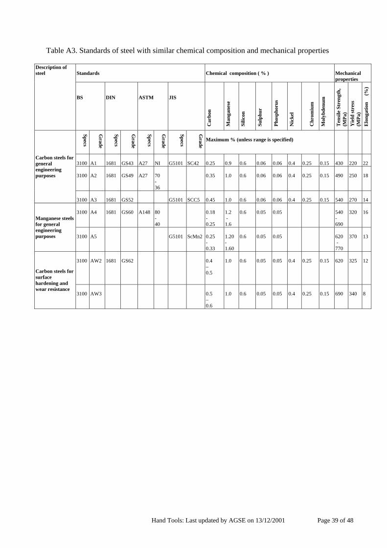
Hand Tools: Last updated by AGSE on 13/12/2001 Page 39 of 48
Table A3. Standards of steel with similar chemical composition and mechanical properties
Standards
Chemical composition ( % )
Mechanical properties
Description of steel
BS
DIN
ASTM
JIS
Car
bon
Man
gane
se
Silic
on
Sulp
hur
Phos
phor
us
Nic
kel
Chr
omiu
m
Mol
ybde
num
T
ensi
le S
tren
gth,
(M
Pa)
Yie
ld st
ress
(M
Pa)
Elo
ngat
ion
(%
)
Specs
Grade
Specs
Grade
Specs
Grade
Specs
Grade
Maximum % (unless range is specified)
3100
A1
1681
GS43
A27
NI
G5101
SC42
0.25
0.9
0.6
0.06
0.06
0.4
0.25
0.15
430
220
22
3100
A2
1681
GS49
A27
70 - 36
0.35
1.0
0.6
0.06
0.06
0.4
0.25
0.15
490
250
18
Carbon steels for general engineering purposes
3100
A3
1681
GS52
G5101
SCC5
0.45
1.0
0.6
0.06
0.06
0.4
0.25
0.15
540
270
14
3100
A4
1681
GS60
A148
80 - 40
0.18 - 0.25
1.2 - 1.6
0.6
0.05
0.05
540 - 690
320
16
Manganese steels for general engineering purposes
3100
A5
G5101
ScMn2
0.25 - 0.33
1.20 - 1.60
0.6
0.05
0.05
620 - 770
370
13
3100
AW2
1681
GS62
0.4 – 0.5
1.0
0.6
0.05
0.05
0.4
0.25
0.15
620
325
12
Carbon steels for surface hardening and wear resistance
3100 AW3
0.5 – 0.6
1.0
0.6
0.05
0.05
0.4
0.25
0.15
690
340
8

Hand Tools: Last updated by AGSE on 13/12/2001 Page 40 of 48
B. HEAT TREATMENT OF STEEL Heat treatment is an operation involving the heating of the solid metal to specific temperatures, followed by cooling at suitable rates in order to obtain certain physical properties, which are associated with changes in the nature, form, size and distribution of the micro-constituents. The basic forms of heat treatment are outlined below. Annealing is a common heat treatment that softens the steel and relieve internal stresses by some previous treatment (forging & uneven cooling). The steel part is heated to around 800°C which is the critical temperature and then cooled slowly in air. Prolonged annealing induces greater ductility at the expenses of strength. On the other hand, the purpose of hardening is to provide better wear for parts subjected to friction. It requires bringing the part to the critical temperature, followed by fast cooling (Table 4). Case hardening is a specific process in which up to only 0.2 cm depth of hard surface is sought. The part is heated to nearly 800 °C and then exposed to carbon atmosphere or carbon particles. After the carbon diffuses into the metal to the required depth, the part is cooled, then reheated to 200 to 500°C, and quenched. Tempering is a heating procedure in which the steel’s temperature is raised to around 200 to 550°C, then quenched in order to retain some hardness and at the same time to restore some ductility back to the part. Table 4. Average annealing and hardening temperatures
Carbon, % 0.1 0.2 0.3 0.5 0.7 0.9 to 1.3 Temperature, °C 910 860 830 810 770 760

Hand Tools: Last updated by AGSE on 13/12/2001 Page 41 of 48
ANNEX 3: TOOLS INSPECTION AND TESTING PROCEDURES This Annex provides information on the acceptance testing of tools to determine whether they meet the specifications agreed to between the purchaser and supplier, and complements that given in Section 1.4. A brief outline of the tests to be carried out as well as of the sampling rate and procedures is given and these are based closely on ILO (1981). It is essential that all tests to be carried out by inspection agencies be specified prior to the appointment of the agency. This includes the test procedures, the sampling rate and sampling procedures. A. Acceptance Tests Acceptance tests simply determine whether or not a tool meets a particular specification. The more comprehensive the tests, the more expensive and difficult they are to administer, but the more confident the customer can be of the purchase. For this reason, methods are described that progress from the simplest visual checks of the entire tool to those requiring more skill or laboratory equipment. All the specifications that these tests are designed to check have been detailed in Section 2. The strength tests for each category of implement have also been given as part of the specifications in Section 2. 1. Visual: Wooden material and production defects For wooden handles of striking tools, inspection should be particularly rigorous. Wood used for tool handles should be straight grained with grain running parallel to the handle. Any serious deviation in the grain pattern should be examined for possible hair cracks and marked with a soft pencil for scrutiny during and after the bending test. There should not be any decay (rot), centre heart (pith), borer holes and cracks or splits resulting from incorrect seasoning. Discoloration of wood is not acceptable, unless it is a known characteristic of the species and does not affect the strength of the handle. All wooden parts must be free of machine chips or sharp edges resulting from the production process. The simplest test is to run the hand over the surface and any rough parts are unacceptable. The head and the cutting edge must be in correct alignment with the handle. The head and any attachment must be fixed firmly to the handle. 2. Visual: Metal material and production defects There should be no cracks, seams, scales, blowholes or discoloration, particularly on the sharpened or polished edges that might indicate defects in the original material or in its subsequent treatment. All sharp edges other than the cutting edge should have been removed. Particular attention should be given to any bolts or rivets, which should be countersunk on handles, the joint between head and handle, and any parts where the hands grip or slide when using the tool. Any rough edges likely to cause discomfort or injury to the hands are unacceptable. 3. Visual: Treatment The metal part must be painted, varnished or lacquered as specified and there should be no evidence of rust, while wooden parts must be oiled, waxed or varnished. 4. Visual: Manufacturers identification

Hand Tools: Last updated by AGSE on 13/12/2001 Page 42 of 48
Each tool should be plainly marked with some ready means of identifying the source, such as the manufacturer's name or trademark. This will enable both satisfactory and unsatisfactory field performances to be reported. 5. Weights and dimensions It is comparatively simple to check if sample tools comply with specified weights and dimensions allowing for any tolerances on the nominal values. With axe, hoe, pickaxe and mattock, particular attention should be paid to ensuring that the eye is central in the head and wall thickness is not less than the minimum specified. Any irregularities in the shape of the eye should not be permitted, as it requires considerable skill to obtain a secure handle fixing in a poorly shaped eye. 6. Physical properties tests These can be verified through a number of tests, namely: Impact, Bending, Crack and Hardness tests. The specific tests for each tool are described in Section 2. Impact test: Various forms of impact tests are carried out on the cutting edges or working faces of axes, crowbars, hoes, pickaxes and mattocks. Either the entire tool assembly is dropped onto a supported hardwood or metal surface a specified number of times from a given height, or the working edge/face is struck with a metal bar or hammer, or the tool is used to strike a supported hardwood or metal surface. The usual test stipulation is that there should be no sign of damage in the form of cracks or deformation or loosening of the component part, after the tests have been performed a specified number of times. Bending: This test is carried out on assembled axes, hoes, pickaxes, mattocks, shovels, spades and forks. The implements are clamped at the blade end and a specified load is gradually applied at the handle for a predetermined time. The usual test stipulation is that there are no visible signs of damage or loosening of any component part nor should there be any permanent set or bending, in excess of a specified maximum. This relatively simple test provides a useful check on the overall quality, without necessarily pinpointing the particular defect in cases of failure. Ringing: The head is suspended through the eye on a cord or wire, and struck on the working faces with the ball pein of a 100 g hammer. Sound heads will give a clear metallic ring. Cracks: There are various non-destructive methods of determining fine cracks. The simplest one is using fluorescence, which consist of dipping the materials in a solution of fluorescent dye, which fills any cracks. The surplus liquid is then removed from the component after drying and is examined under ultra-violet light. Cracks are shown up vividly by the fluorescence. Hardness test: The most accurate method of checking on the effectiveness of heat treatment of tool heads is to determine their hardness. The Rockwell method described in Annex 2 is particularly useful for rapid routine tests on finished products. Many tools are heat treated to achieve different hardness ratings over their surface, for example, hoes are heat treated to achieve a very hard and wear resistant cutting edge and a softer and more ductile state around the eye. It is therefore essential that hardness tests on tools are done at specified points on the tool and that these are specified in the testing procedure and test reports. Ideally four tests should be carried out on each head; one at the eye, and then 1/3 and 2/3 of the distance between the eye and cutting edge and then the fourth near the cutting edge.
Hand Tools: Last updated by AGSE on 13/12/2001 Page 43 of 48
7. Material composition tests These tests require specialist facilities and are normally carried out by specialist chemical or metallurgical laboratories, although large and well equipped engineering works would also have these facilities. The simplest way to carry these tests out is by using an atomic absorption spectrometer. From the specifications, the elements required to be analysed are simply programmed in and a readout of all the elements is given in a few seconds. The capital cost of the equipment required is high, however the operating costs are minimal and for common elements the costs are not dependent on the number of elements tested for. B. Sampling Rates and Acceptance Numbers If large numbers of tools are being purchased it is generally impractical to inspect them all, so some form of sampling will be necessary. A sampling scheme should specify the number to be selected, the process of selection, and the consequences if a proportion of the sampled items fail the given tests. 1. Sample size Sample sizes are not generally laid down in national tool specifications, this being left to the discretion of the purchaser. Certain general principles have been established in acceptance testing:
For a given lot size being purchased, the larger the sample the more confidence that can be attached to the results of any tests.
The larger the lot being purchased the smaller in percentage terms the sample need be for reliable conclusions to be drawn.
The more difficult or costly the testing procedure the smaller the sample sizes that are practicable.
Tools from new manufacturers should be inspected more rigorously than those that have proved the quality of their products.
2. Selection process The sampling process should ensure that the results are free from bias. Generally, a combination of a stratified and a random process is used. Stratified in that samples are taken from each shipment or batch and then randomly from each batch. If sampling requires that 100 tools be inspected from a batch of 1500, then simply inspect every 15th tool, i.e. batch size divided by sample size. 3. Acceptance numbers Not all tests are of equal importance. The more crucial to the performance of a tool is the characteristic being tested the fewer the test failures that can be tolerated among the sampled items, or perhaps no failures at all. While a minor proportion of variations from specification in the dimensions, weight or finish of tools might be overlooked, almost no deviations ought to be allowed for the stipulated hardness or impact test results on the faces of striking tools (axes, pickaxes, mattock, hoes, etc) as the safety of the operators would be compromised. As already pointed out, no irregularities in the shape or dimensions of the eye for striking tools should be permitted.

Hand Tools: Last updated by AGSE on 13/12/2001 Page 44 of 48
The maximum permissible number of items in a sample which are permitted to fail the test, without the entire lot from which the samples have been taken being rejected, is referred to as the Acceptance Number. [Note: The sampling rates and acceptance numbers still need to be finalised. Also note that if the sampling rates given below were accepted by FAO that they would substantially increase the current costs of testing. Note that these sampling and acceptance rates need to be based on both a sound statistical basis as well as take account of the costs of sampling]. The following sampling rates and acceptance numbers for hand tools are recommended:
Weight, Dimensions, Visual *
Hardness & Strength Material Composition Moisture Content (Handles)
Lot Size Sample
Size Acceptance Number **
Sample Size
Acceptance Number
Sample Size
Acceptance Number
Sample Size
Acceptance Number
20 – 70 15 1 5 0 2 0 10 1 71 – 180 20 2 7 0 3 0 15 2 181 – 360 25 2 8 0 4 0 20 2 361 – 600 30 3 9 0 5 0 25 3 601 – 1500 40 3 10 0 5 0 30 4
* For Visual checks particular note should be taken of the specifications given under the heading Construction in the specifications. ** Acceptance Number – Maximum permissible number of defectives in respect of given requirement [Note: The table above is based on ILO (1981), which in turn is based on BS standards. This only goes up to a lot size of 1500, whereas some FAO purchases go up to 20,000. This table therefore needs to be extended and a first step is laid out below. The range need to be extended and adjusted for larger quantities and sample size quoted by Armstrong as 0.4 % and 0.2% for dimensions and harness may be used to be build on, as more information becomes available.

Hand Tools: Last updated by AGSE on 13/12/2001 Page 45 of 48
ANNEX 4: FIELD QUESTIONNAIRE ON COMMON HAND TOOLS USED IN Field and extension officers, as well as general users of the guideline are invited to fill in the following questionnaire, and add to it, on the range of hand tools commonly used in their country or region. This information will be used to make this guide more comprehensive and more representative of a wider range of regions. AGRICULTURAL HAND TOOLS COUNTRY: ............................... Region, main farming systems, average annual rainfall (mm), etc. ......................................................................................... .............................................................................................................................................................. .............................................................................................................................................................. For all tools please specify their main uses, as we wish to relate these uses to the weights and shapes of the tools used for distinctly different operations. Also, please specify all the dimensions used and preferably use kg and mm. 1. HOES Type, Weight and Dimensional Specifications: Type Fitting to
handle Dimensions
L* x W (mm)
Blade Weight
(kg)
Handle Length(mm)
Heavy/Digging hoes:
Light/Weeding hoes:
Planting hoes:
* Length from top of blade to cutting edge, excluding eye/tang. Notes on each, including their main uses and where the fitting to the handle is an eye specify whether it is circular or oval and the dimensions: Circular: diameter...... Oval: length...... x width...... a. b. Any other types, such as wheeled hoes? Attach drawings and/or sketches.

Hand Tools: Last updated by AGSE on 13/12/2001 Page 46 of 48
2. PICKAXES AND MATTOCKS Type, Weight and Dimensional Specifications: Type Fitting Head Dimensions
L x W (mm)
Head Weight
(kg)
Handle Length(mm)
Pickaxe (point + chisel)
Mattock (cutter + mattock)
( ) cutter +( ) mattock
Notes on each, including their main uses, and specify the fitting of the handle to the head: Oval: length...... x width...... or Circular: diameter..... a. b. Any other types, such as wheeled hoes? Attach drawings and/or sketches. 3. SPADES, SHOVELS AND FORKS
Type Blade Dimension
L x W (shoulder) x Thickness
(mm)
Blade Lift
(mm)
Blade Dish
(mm)
Weight (including 700mm
handle**) (kg)
Spade
Shovels Square mouth
Round mouth
Fork (digging) *
* Specify number and size of prongs. Include notes on each, including their main uses, and specify the fitting of the handle to the head: a. b. Attach drawings and/or sketches.

Hand Tools: Last updated by AGSE on 13/12/2001 Page 47 of 48
4. MACHETES Type, Weight and Dimensional Specifications: Type Dimensions of Blade
L x W (mm)
Dimensions of Blade Thickness
(mm)
Blade Weight
(g)
Handle Length (mm)
Include notes on each, including their main uses and specify the fitting of the handle to the blade: a. b. Attach drawings and/or sketches. 5. SICKLES Type, Weight and Dimensional Specifications: Type Dimensions of Blade
L x W
(mm)
Dimensions of BladeThickness on back
edge (mm)
Weight (including
handle) (g)
Handle Length
(mm)
Include notes on each, including their main uses and specify the fitting of the handle to the blade: a. b. Attach drawings and/or sketches. 6. REAPING HOOKS AND SCYTHES Type, Weight and Dimensional Specifications:
Type Dimensions of Blade L x W at shaft end
(mm)
Dimensions of Blade Thickness (back edge)
(mm)
Blade Weight
(kg)
Shaft Length(mm)
Scythe:
Reaping Hook:

Hand Tools: Last updated by AGSE on 13/12/2001 Page 48 of 48
Include notes on each, including their main uses and specify the fitting of the handle to the blade: a. b. Attach drawings and/or sketches 7. AXES Type, Weight and Dimensional Specifications: Type Blade Dimensions
L x W cut x Eye max. dia. (mm)
Head Weight
(kg)
Handle Length (mm)
Include notes on each, including their main uses and specify the fitting of the handle to the blade: a. b. Attach drawings and/or sketches 7. Rakes
Type, Weight and Dimensional Specifications: Type Head Dimension
W (shoulder) (mm)
Number and shape
of teeth
Length of teeth (mm)
Weight
(kg)
Handle length (mm)
Include notes on each, including their main uses and specify the fitting of the handle to the blade: a. b. Attach drawings and/or sketches 8. ADDITIONAL COMMONLY USED AGRICULTURAL TOOLS