TECHNICAL SPECIFICATIONS - UNDP | Procurement Notices
657
TECHNICAL SPECIFICATIONS RENOVATION OF MIRYATA SOCIAL DEVELOPMENT CENTER BOYADJIAN Masterspecs ‐ Project: UNDP Social and Local Development‐
-
Upload
khangminh22 -
Category
Documents
-
view
0 -
download
0
Transcript of TECHNICAL SPECIFICATIONS - UNDP | Procurement Notices

TECHNICAL SPECIFICATIONS
RENOVATION OF MIRYATA
SOCIAL DEVELOPMENT CENTER
BOYADJIAN Masterspecs ‐ Project: UNDP Social and Local Development‐

Tender Documents-Specifications Division 01 General Requirements
BOYADJIAN Masterspecs - Project: UNDP Social and Local Development-
SECTION 01100 - SUMMARY
PART 1 - GENERAL
1.1 RELATED DOCUMENTS
A. Drawings and general provisions of the Contract, including General and Supplementary Conditions and other Division 1 Specification Sections, apply to this Section.
1.2 WORK COVERED BY CONTRACT DOCUMENTS
A. Project Identification: The “ Renovation of Miryata Social Develpment Center” project comprises the construction, completion and maintenance during the defects liability period of retaining walls and bridges located in Miryata, North Lebanon.
B. Scope of Works consist of the construction, completion and maintenance during the defects
liability period of the retaining walls.
1. The Work includes structural, architectural, mechanical and electrical engineering disciplines as defined in the drawings.
1.3 CONTRACT
A. Project will be constructed under the conditions of contract stated in the tender documents.
1. Name of Contract: “Renovation of Miryata Social Develpment Center”.
1.4 SPECIFICATION FORMATS AND CONVENTIONS
A. Specification Format: The Specifications are organized into Divisions and Sections using the 16-division format and CSI/CSC's "MasterFormat" numbering system.
1. Section Identification: The Specifications use section numbers and titles to help
cross-referencing in the Contract Documents. Sections in the Project Manual are in numeric sequence; however, the sequence is incomplete. Consult the table of contents at the beginning of the Project Manual to determine numbers and names of sections in the Contract Documents.
B. Specification Content: The Specifications use certain conventions for the style of language
and the intended meaning of certain terms, words, and phrases when used in particular situations. These conventions are as follows:
1. Abbreviated Language: Language used in the Specifications and other Contract
Documents is abbreviated. Words and meanings shall be interpreted as appropriate. Words implied, but not stated, shall be inferred as the sense requires. Singular words shall be interpreted as plural, and plural words shall be interpreted as singular where applicable as the context of the Contract Documents indicates.
2. Imperative mood and streamlined language are generally used in the Specifications. Requirements expressed in the imperative mood are to be performed by Contractor. Occasionally, the indicative or subjunctive mood may be used in the Section Text for

Tender Documents-Specifications Division 01 General Requirements
BOYADJIAN Masterspecs - Project: UNDP Social and Local Development-
clarity to describe responsibilities that must be fulfilled indirectly by Contractor or by others when so noted.
a. The words "shall," "shall be," or "shall comply with," depending on the
context, are implied where a colon (:) is used within a sentence or phrase.
PART 2 - PRODUCTS (Not Used)
PART 3 - EXECUTION (Not Used)
END OF SECTION 01100

Tender Documents-Specifications Division 01 General Requirements
BOYADJIAN Masterspecs - Project: UNDP Social and Local Development-
SECTION 01140 - WORK RESTRICTIONS
PART 1 - GENERAL
1.1 RELATED DOCUMENTS
A. Drawings and general provisions of the Contract, including General and Supplementary Conditions and other Division 1 Specification Sections, apply to this Section.
1.2 USE OF PREMISES
A. Use of Site: Limit use of premises to work in areas indicated. Do not disturb portions of site beyond areas in which the Work is indicated.
1. Limits: Confine constructions operations to area indicated on drawings. 2. Owner Occupancy: Allow for Owner occupancy of site. 3. Driveways and Entrances: Keep driveways and entrances serving premises clear and
available to Owner, Owner's employees, and emergency vehicles at all times. Do not use these areas for parking or storage of materials.
a. Schedule deliveries to minimize use of driveways and entrances. b. Schedule deliveries to minimize space and time requirements for storage of
materials and equipment on-site.
1.3 OCCUPANCY REQUIREMENTS
A. Partial Owner Occupancy: Owner reserves the right to occupy and to place and install equipment in completed areas of building, before Substantial Completion, provided such occupancy does not interfere with completion of the Work. Such placement of equipment and partial occupancy shall not constitute acceptance of the total Work.
1. Engineer will prepare a Certificate of Substantial Completion for each specific
portion of the Work to be occupied before Owner occupancy. 2. Obtain a Certificate of Occupancy from authorities having jurisdiction before Owner
occupancy. 3. Before partial Owner occupancy, mechanical and electrical systems shall be fully
operational, and required tests and inspections shall be successfully completed. On occupancy, Owner will provide, operate, and maintain mechanical and electrical systems serving occupied portions of building, works or facilities.
4. On occupancy, Owner will assume responsibility for maintenance and custodial service for occupied portions of building, works or facilities.
PART 2 - PRODUCTS (Not Used)
PART 3 - EXECUTION (Not Used)
END OF SECTION 01140

Tender Documents-Specifications Division 01 General Requirements
BOYADJIAN Masterspecs - Project: UNDP Social and Local Development-
SECTION 01310 - PROJECT MANAGEMENT AND COORDINATION
PART 1 - GENERAL
1.1 RELATED DOCUMENTS
A. Drawings and general provisions of the Contract, including General and Supplementary Conditions and other Division 1 Specification Sections, apply to this Section.
1.2 SUMMARY
A. This Section includes administrative provisions for coordinating construction operations on
Project including, but not limited to, the following:
1. General project coordination procedures. 2. Conservation. 3. Coordination Drawings. 4. Administrative and supervisory personnel. 5. Project meetings.
B. Related Sections: The following Sections contain requirements that relate to this Section:
1. Division 1 Section "Construction Progress Documentation" for preparing and submitting the Contractor's Construction Schedule.
2. Division 1 Section "Execution Requirements" for procedures for coordinating general installation and field-engineering services, including establishment of benchmarks and control points.
3. Division 1 Section "Closeout Procedures" for coordinating Contract closeout. 1.3 SUBMITTALS
A. Coordination Drawings: Prepare Coordination Drawings if limited space availability
necessitates maximum utilization of space for efficient installation of different components or if coordination is required for installation of products and materials fabricated by separate entities.
1. Indicate relationship of components shown on separate Shop Drawings. 2. Indicate required installation sequences.
B. Staff Names: Within the bid documents (at tender stage), submit a list of principal staff
assignments, including superintendent and other personnel in attendance at Project site. Identify individuals and their duties and responsibilities; list addresses and telephone numbers, including home and office telephone numbers. Provide names, addresses, and telephone numbers of individuals assigned as standbys in the absence of individuals assigned to Project.
1. Post copies of list in Project meeting room, in temporary field office, and by each
temporary telephone. 1.4 ADMINISTRATIVE AND SUPERVISORY PERSONNEL

Tender Documents-Specifications Division 01 General Requirements
BOYADJIAN Masterspecs - Project: UNDP Social and Local Development-
A. General: In addition to Project superintendent, provide other administrative and supervisory personnel as required for proper performance of the Work.
1.5 PROJECT MEETINGS
A. General: Schedule and conduct meetings and conferences at Project site, unless otherwise
indicated.
1. Attendees: Inform participants and others involved, and individuals whose presence is required, of date and time of each meeting. Notify Owner and Engineer of scheduled meeting dates and times.
2. Agenda: Prepare the meeting agenda. Distribute the agenda to all invited attendees. 3. Minutes: Record significant discussions and agreements achieved. Distribute the
meeting minutes to everyone concerned, including Owner and Engineer, within 3 days of the meeting.
B. Preconstruction Conference: Schedule a preconstruction conference before starting
construction, at a time convenient to Owner Construction Manager and Engineer, but no later than 14 days after execution of the Agreement. Hold the conference at Project site or another convenient location. Conduct the meeting to review responsibilities and personnel assignments.
1. Attendees: Authorized representatives of Owner, Construction Manager Engineer,
and their consultants; Contractor and its superintendent; major subcontractors; manufacturers; suppliers; and other concerned parties shall attend the conference. All participants at the conference shall be familiar with Project and authorized to conclude matters relating to the Work.
2. Agenda: Discuss items of significance that could affect progress, including the following:
a. Tentative construction schedule. b. Phasing. c. Critical work sequencing. d. Designation of responsible personnel. e. Procedures for processing field decisions and Change Orders. f. Procedures for processing Applications for Payment. g. Distribution of the Contract Documents. h. Submittal procedures. i. Preparation of Record Documents. j. Use of the premises. k. Responsibility for temporary facilities and controls. l. Parking availability. m. Office, work, and storage areas. n. Equipment deliveries and priorities. o. First aid. p. Security. q. Progress cleaning. r. Working hours.
C. Pre-installation Conferences: Conduct a pre-installation conference at Project site before
each construction activity that requires coordination with other construction.
1. Attendees: Installer and representatives of manufacturers and fabricators involved in or affected by the installation and its coordination or integration with other materials and installations that have preceded or will follow, shall attend the meeting. Advise Engineer and Construction Manager of scheduled meeting dates.

Tender Documents-Specifications Division 01 General Requirements
BOYADJIAN Masterspecs - Project: UNDP Social and Local Development-
2. Agenda: Review progress of other construction activities and preparations for the particular activity under consideration, including requirements for the following:
a. Contract Documents. b. Options. c. Related Change Orders. d. Purchases. e. Deliveries. f. Submittals. g. Review of mockups. h. Possible conflicts. i. Compatibility problems. j. Time schedules. k. Weather limitations. l. Manufacturer's written recommendations. m. Warranty requirements. n. Compatibility of materials. o. Acceptability of substrates. p. Temporary facilities and controls. q. Space and access limitations. r. Regulations of authorities having jurisdiction. s. Testing and inspecting requirements. t. Required performance results. u. Protection of construction and personnel.
3. Record significant conference discussions, agreements, and disagreements. 4. Do not proceed with installation if the conference cannot be successfully concluded.
Initiate whatever actions are necessary to resolve impediments to performance of the Work and reconvene the conference at earliest feasible date.
D. Progress Meetings: Conduct progress meetings as per progress requirements.
1. Attendees: In addition to representatives of Owner Construction Manager and
Engineer, each contractor, subcontractor, supplier, and other entity concerned with current progress or involved in planning, coordination, or performance of future activities shall be represented at these meetings. All participants at the conference shall be familiar with Project and authorized to conclude matters relating to the Work.
2. Agenda: Review and correct or approve minutes of previous progress meeting. Review other items of significance that could affect progress. Include topics for discussion as appropriate to status of Project.
a. Contractor's Construction Schedule: Review progress since the last meeting.
Determine whether each activity is on time, ahead of schedule, or behind schedule, in relation to Contractor's Construction Schedule. Determine how construction behind schedule will be expedited; secure commitments from parties involved to do so. Discuss whether schedule revisions are required to ensure that current and subsequent activities will be completed within the Contract Time.
b. Review present and future needs of each entity present, including the following:
1) Interface requirements. 2) Sequence of operations. 3) Status of submittals. 4) Deliveries. 5) Off-site fabrication. 6) Access. 7) Site utilization.

Tender Documents-Specifications Division 01 General Requirements
BOYADJIAN Masterspecs - Project: UNDP Social and Local Development-
8) Temporary facilities and controls. 9) Work hours. 10) Hazards and risks. 11) Progress cleaning. 12) Quality and work standards. 13) Change Orders. 14) Documentation of information for payment requests.
3. Reporting: Distribute minutes of the meeting to each party present and to parties who
should have been present. Include a brief summary, in narrative form, of progress since the previous meeting and report.
a. Schedule Updating: Revise Contractor's Construction Schedule after each
progress meeting where revisions to the schedule have been made or recognized. Issue revised schedule concurrently with the report of each meeting.
PART 2 - PRODUCTS (Not Used)
PART 3 - EXECUTION (Not Used)
END OF SECTION 01310

Tender Documents-Specifications Division 01 General Requirements
BOYADJIAN Masterspecs - Project: UNDP Social and Local Development-
SECTION 01320 - CONSTRUCTION PROGRESS DOCUMENTATION
PART 1 - GENERAL
1.1 RELATED DOCUMENTS
A. Drawings and general provisions of the Contract, including General and Supplementary Conditions and other Division 1 Specification Sections, apply to this Section.
1.2 SUMMARY
A. This Section includes administrative and procedural requirements for documenting the progress of construction during performance of the Work, including the following:
1. Contractor's Construction Schedule. 2. Submittals Schedule. 4. Material location reports. 5. Field condition reports. 6. Special reports. 7. Construction photographs.
B. Related Sections include the following:
1. Division 1 Section "Project Management and Coordination" for submitting and distributing meeting and conference minutes.
2. Division 1 Section "Submittal Procedures" for submitting schedules and reports. 3. Division 1 Section "Quality Requirements" for submitting a schedule of tests and
inspections. 4. Division 1 Section "Closeout Procedures" for submitting photographic negatives as
Project Record Documents at Project closeout.
1.3 DEFINITIONS
A. Activity: A discrete part of a project that can be identified for planning, scheduling, monitoring, and controlling the construction project. Activities included in a construction schedule consume time and resources.
1. Critical activities are activities on the critical path. They must start and finish on the
planned early start and finish times. 2. Predecessor activity is an activity that must be completed before a given activity can
be started.
B. CPM: Critical path method, which is a method of planning and scheduling a construction project where activities are arranged based on activity relationships. Network calculations determine when activities can be performed and the critical path of Project.
C. Critical Path: The longest continuous chain of activities through the network schedule that
establishes the minimum overall Project duration and contains no float.
D. Event: The starting or ending point of an activity.

Tender Documents-Specifications Division 01 General Requirements
BOYADJIAN Masterspecs - Project: UNDP Social and Local Development-
E. Float: The measure of leeway in starting and completing an activity.
1. Float time belongs to Owner. 2. Free float is the amount of time an activity can be delayed without adversely affecting
the early start of the following activity. 3. Total float is the measure of leeway in starting or completing an activity without
adversely affecting the planned Project completion date.
F. Fragnet: A partial or fragmentary network that breaks down activities into smaller activities for greater detail.
G. Major Area: A story of construction, a separate building, or a similar significant
construction element.
H. Milestone: A key or critical point in time for reference or measurement.
I. Network Diagram: A graphic diagram of a network schedule, showing activities and activity relationships.
1.4 SUBMITTALS
A. Qualification Data: For firms and persons specified in "Quality Assurance" Article demonstrate their capabilities and experience. Include lists of completed projects with project names and addresses, names and addresses of engineers and owners, and other information specified.
B. Submittals Schedule: Submit three copies of schedule. Arrange the following information
in a tabular format:
1. Scheduled date for first submittal. 2. Specification Section number and title. 3. Submittal category (action or informational). 4. Name of subcontractor. 5. Description of the Work covered. 6. Scheduled date for Engineer's final release or approval.
C. Contractor's Construction Schedule: Submit two printed copies of initial schedule, one a
reproducible print and one a blue- or black-line print, large enough to show entire schedule for entire construction period.
1. Submit an electronic copy of schedule, using software indicated, on a CD labeled
to comply with requirements for submittals. Include type of schedule (Initial or Updated) and date on label.
D. CPM Reports: Concurrent with CPM schedule, submit three printed copies of each of the
following computer-generated reports. Format for each activity in reports shall contain

Tender Documents-Specifications Division 01 General Requirements
BOYADJIAN Masterspecs - Project: UNDP Social and Local Development-
activity number, activity description, original duration, remaining duration, early start date, early finish date, late start date, late finish date, and total float.
1. Activity Report: List of all activities sorted by activity number and then early start
date, or actual start date if known. 2. Logic Report: List of preceding and succeeding activities for all activities, sorted in
ascending order by activity number and then early start date, or actual start date if known.
3. Total Float Report: List of all activities sorted in ascending order of total float. 4. Earnings Report: Compilation of Contractor's total earnings from the Notice to
Proceed until most recent Application for Payment.
E. Construction Photographs: Submit two prints of each photographic view within seven days of taking photographs.
1. Format: 8-by-10-inch (203-by-254-mm) smooth-surface matte prints on single-
weight commercial-grade stock, mounted on linen or card stock to allow a 1-inch- (25-mm-) wide margin and enclosed back to back in clear plastic sleeves that are punched for standard 3-ring binder.
2. Identification: On back of each print, provide an applied label or rubber-stamped impression with the following information:
a. Name of Project. b. Name and address of photographer. c. Name of Engineer d. Name of Contractor. e. Date photograph was taken. f. Description of vantage point, indicating location, direction (by compass point),
and elevation or story of construction.
3. Negatives: Submit a complete set of photographic negatives in protective envelopes with each submittal of prints as a Project Record Document. Identify date photographs were taken.
F. Material Location Reports: Submit two copies at weekly intervals.
G. Field Condition Reports: Submit two copies at time of discovery of differing conditions.
H. Special Reports: Submit two copies at time of unusual event.
1.5 QUALITY ASSURANCE
A. Scheduling Consultant Qualifications: An experienced specialist in CPM scheduling and
reporting.
B. Photographer Qualifications: An individual of established reputation who has been regularly engaged as a professional photographer for not less than three years.
C. Prescheduling Conference: Conduct conference at Project site to comply with requirements
in Division 1 Section "Project Management and Coordination." Review methods and procedures related to the Preliminary Construction Schedule and Contractor's Construction Schedule, including, but not limited to, the following:

Tender Documents-Specifications Division 01 General Requirements
BOYADJIAN Masterspecs - Project: UNDP Social and Local Development-
1. Review software limitations and content and format for reports. 2. Verify availability of qualified personnel needed to develop and update schedule. 3. Discuss constraints, including phasing work stages area separations interim
milestones and partial Owner occupancy. 4. Review delivery dates for Owner-furnished products. 5. Review schedule for work of Owner's separate contracts. 6. Review time required for review of submittals and resubmittals. 7. Review requirements for tests and inspections by independent testing and inspecting
agencies. 8. Review time required for completion and startup procedures. 9. Review and finalize list of construction activities to be included in schedule. 10. Review submittal requirements and procedures. 11. Review procedures for updating schedule.
1.6 COORDINATION
A. Coordinate preparation and processing of schedules and reports with performance of
construction activities and with scheduling and reporting of separate contractors.
B. Coordinate Contractor's Construction Schedule with the Schedule of Values, list of subcontracts, Submittals Schedule, progress reports, payment requests, and other required schedules and reports.
1. Secure time commitments for performing critical elements of the Work from parties
involved. 2. Coordinate each construction activity in the network with other activities and
schedule them in proper sequence.
C. Auxiliary Services: Cooperate with photographer and provide auxiliary services requested, including access to Project site and use of temporary facilities including temporary lighting.
PART 2 - PRODUCTS
2.1 SUBMITTALS SCHEDULE
A. Preparation: Submit a schedule of submittals, arranged in chronological order by dates
required by construction schedule. Include time required for review, resubmittal, ordering, manufacturing, fabrication, and delivery when establishing dates.
1. Coordinate Submittals Schedule with list of subcontracts, the Schedule of Values, and
Contractor's Construction Schedule. 2. Initial Submittal: Submit concurrently with preliminary bar-chart schedule
preliminary network diagram. Include submittals required during the first 60 days of construction. List those required to maintain orderly progress of the Work and those required early because of long lead time for manufacture or fabrication.
a. At Contractor's option, show submittals on the Preliminary Construction
Schedule, instead of tabulating them separately.
3. Final Submittal: Submit concurrently with the first complete submittal of Contractor's Construction Schedule.

Tender Documents-Specifications Division 01 General Requirements
BOYADJIAN Masterspecs - Project: UNDP Social and Local Development-
2.2 CONTRACTOR'S CONSTRUCTION SCHEDULE, GENERAL
A. Procedures: Comply with procedures contained in AGC's "Construction Planning &
Scheduling."
B. Time Frame: Extend schedule from date established for the Notice to Proceed to date of Substantial Completion
1. Contract completion date shall not be changed by submission of a schedule that
shows an early completion date, unless specifically authorized by Change Order.
C. Activities: Treat each story or separate area as a separate numbered activity for each principal element of the Work. Comply with the following:
1. Activity Duration: Define activities so no activity is longer than 20 (Twenty) days,
unless specifically allowed by Engineer. 2. Procurement Activities: Include procurement process activities for long lead items
and major items, requiring a cycle of more than 60 days, as separate activities in schedule. Procurement cycle activities include, but are not limited to, submittals, approvals, purchasing, fabrication, and delivery.
3. Submittal Review Time: Include review and resubmittal times indicated in Division 1 Section "Submittal Procedures" in schedule. Coordinate submittal review times in Contractor's Construction Schedule with Submittals Schedule.
4. Startup and Testing Time: Include not less than 3 days for startup and testing. 5. Substantial Completion: Indicate completion in advance of date established for
Substantial Completion, and allow time for Engineer's and Construction Manager's administrative procedures necessary for certification of Substantial Completion.
D. Constraints: Include constraints and work restrictions indicated in the Contract Documents
and as follows in schedule, and show how the sequence of the Work is affected.
1. Phasing: Arrange list of activities on schedule by phase. 2. Products Ordered in Advance: Include a separate activity for each product. Include
delivery date indicated in Division 1 Section "Summary." Delivery dates indicated stipulate the earliest possible delivery date.
3. Owner-Furnished Products: Include a separate activity for each product. Include delivery date indicated in Division 1 Section "Summary." Delivery dates indicated stipulate the earliest possible delivery date.
4. Work Restrictions: Show the effect of the following items on the schedule:
a. Coordination with existing construction. b. Limitations of continued occupancies. c. Uninterruptible services. d. Partial occupancy before Substantial Completion. e. Use of premises restrictions. f. Provisions for future construction. g. Seasonal variations. h. Environmental control.
5. Work Stages: Indicate important stages of construction for each major portion of the
Work, including, but not limited to, the following:
a. Subcontract awards. b. Submittals. c. Purchases.

Tender Documents-Specifications Division 01 General Requirements
BOYADJIAN Masterspecs - Project: UNDP Social and Local Development-
d. Mockups. e. Fabrication. f. Sample testing. g. Deliveries. h. Installation. i. Tests and inspections. j. Adjusting. k. Curing. l. Startup and placement into final use and operation.
6. Area Separations: Identify each major area of construction for each major portion of
the Work. Indicate where each construction activity within a major area must be sequenced or integrated with other construction activities to provide for the following:
a. Structural completion. b. Permanent space enclosure. c. Completion of mechanical installation. d. Completion of electrical installation. e. Substantial Completion.
E. Milestones: Include milestones indicated in the Contract Documents in schedule, including,
but not limited to, the Notice to Proceed, interim milestones indicated, Substantial Completion, and Final Completion.
F. Cost Correlation: At the head of schedule, provide a cost correlation line, indicating
planned and actual costs. On the line, show dollar volume of the Work performed as of dates used for preparation of payment requests.
1. Refer to Division 1 Section "Payment Procedures" for cost reporting and payment
procedures.
G. Contract Modifications: For each proposed contract modification and concurrent with its submission, prepare a time-impact analysis using fragnets to demonstrate the effect of the proposed change on the overall project schedule.
H. Computer Software: Prepare schedules using a program that has been developed
specifically to manage construction schedules.
1. Primavera (Original Copy) latest version (at year of installation).
2. Microsoft Project (Original Copy) latest version (at year of installation).
2.4 CONTRACTOR'S CONSTRUCTION SCHEDULE (GANTT CHART)
A. Gantt-Chart Schedule: Submit a comprehensive, fully developed, horizontal Gantt-chart- type, Contractor's Construction Schedule within 30 days of date established for the Notice to Proceed. Base schedule on the Preliminary Construction Schedule and whatever updating and feedback was received since the start of Project.
B. Preparation: Indicate each significant construction activity separately. Identify first
workday of each week with a continuous vertical line.
1. For construction activities that require 3 months or longer to complete, indicate an estimated completion percentage in 10 percent increments within time bar.

Tender Documents-Specifications Division 01 General Requirements
BOYADJIAN Masterspecs - Project: UNDP Social and Local Development-
2.5 CONTRACTOR'S CONSTRUCTION SCHEDULE (CPM SCHEDULE)
A. General: Prepare network diagrams using AON (activity-on-node) format.
B. CPM Schedule: Prepare Contractor's Construction Schedule using a CPM network analysis diagram.
1. Develop network diagram in sufficient time to submit CPM schedule so it can be
accepted. 2. Conduct educational workshops to train and inform key Project personnel, including
subcontractors' personnel, in proper methods of providing data and using CPM schedule information.
3. Establish procedures for monitoring and updating CPM schedule and for reporting progress. Coordinate procedures with progress meeting and payment request dates.
4. Use "one workday" as the unit of time.
C. CPM Schedule Preparation: Prepare a list of all activities required to complete the Work. Using the preliminary network diagram, prepare a skeleton network to identify probable critical paths.
1. Activities: Indicate the estimated time duration, sequence requirements, and
relationship of each activity in relation to other activities. Include estimated time frames for the following activities:
a. Preparation and processing of submittals. b. Purchase of materials. c. Delivery. d. Fabrication. e. Installation.
2. Processing: Process data to produce output data or a computer-drawn, time-scaled
network. Revise data, reorganize activity sequences, and reproduce as often as necessary to produce the CPM schedule within the limitations of the Contract Time.
3. Format: Mark the critical path. Locate the critical path near center of network; locate paths with most float near the edges.

Tender Documents-Specifications Division 01 General Requirements
BOYADJIAN Masterspecs - Project: UNDP Social and Local Development-
a. Subnetworks on separate sheets are permissible for activities clearly off the
critical path.
D. Schedule Updating: Concurrent with making revisions to schedule, prepare tabulated reports showing the following:
1. Identification of activities that have changed. 2. Changes in early and late start dates. 3. Changes in early and late finish dates. 4. Changes in activity durations in workdays. 5. Changes in the critical path. 6. Changes in total float or slack time. 7. Changes in the Contract Time.
E. Value Summaries: Prepare two cumulative value lists, sorted by finish dates.
1. In first list, tabulate activity number, early finish date, dollar value, and cumulative
dollar value. 2. In second list, tabulate activity number, late finish date, dollar value, and cumulative
dollar value. 3. In subsequent issues of both lists, substitute actual finish dates for activities
completed as of list date. 4. Prepare list for ease of comparison with payment requests; coordinate timing with
progress meetings.
a. In both value summary lists, tabulate "actual percent complete" and "cumulative value completed" with total at bottom.
b. Submit value summary printouts one week before each regularly scheduled progress meeting.
PART 3 - EXECUTION
3.1 CONTRACTOR'S CONSTRUCTION SCHEDULE
A. Contractor's Construction Schedule Updating: At monthly intervals, update schedule to reflect actual construction progress and activities. Issue schedule one week before each regularly scheduled progress meeting.

Tender Documents-Specifications Division 01 General Requirements
BOYADJIAN Masterspecs - Project: UNDP Social and Local Development-
1. Revise schedule immediately after each meeting or other activity where revisions
have been recognized or made. Issue updated schedule concurrently with the report of each such meeting.
2. Include a report with updated schedule that indicates every change, including, but not limited to, changes in logic, durations, actual starts and finishes, and activity durations.
3. As the Work progresses, indicate Actual Completion percentage for each activity.
B. Distribution: Distribute copies of approved schedule to Engineer, Owner, separate contractors, testing and inspecting agencies, and other parties identified by Contractor with a need-to-know schedule responsibility.
1. Post copies in Project meeting rooms and temporary field offices. 2. When revisions are made, distribute updated schedules to the same parties and post in
the same locations. Delete parties from distribution when they have completed their assigned portion of the Work and are no longer involved in performance of construction activities.
3.2 CONSTRUCTION PHOTOGRAPHS
A. Contractor shall submit soft and hard copy of all photographs taken for the project.
B. Date: Unless otherwise indicated, date and time shall be included on each photograph as it is being taken so date and time are integral to photograph.
C. Preconstruction Photographs: Before starting construction, take four color photographs of
Project site and surrounding properties from different vantage points, as directed by Engineer. Show existing conditions adjacent to property.
D. Periodic Construction Photographs: Take four color photographs monthly, coinciding with
cutoff date associated with each Application for Payment. Photographer shall select vantage points to best show status of construction and progress since last photographs were taken.
1. Field Office Prints: Retain one set of prints of periodic photographs in field office at
Project site, available at all times for reference. Identify photographs the same as for those submitted to Engineer.
E. Final Completion Construction Photographs: Take eight color photographs after date of
Substantial Completion for submission as Project Record Documents. Engineer will direct photographer for desired vantage points.
END OF SECTION 01320

Tender Documents-Specifications Division 01 General Requirements
BOYADJIAN Masterspecs - Project: UNDP Social and Local Development-
SECTION 01330 - SUBMITTAL PROCEDURES
PART 1 - GENERAL
1.1 RELATED DOCUMENTS
A. Drawings and general provisions of the Contract, including General and Supplementary Conditions and other Division 1 Specification Sections, apply to this Section.
1.2 SUMMARY
A. This Section includes administrative and procedural requirements for submitting Shop Drawings, Product Data, Samples, and other miscellaneous submittals.
B. Related Sections include the following:
1. Division 1 Section "Project Management and Coordination" for submitting Coordination Drawings.
2. Division 1 Section "Construction Progress Documentation" for submitting schedules and reports, including Contractor's Construction Schedule and the Submittals Schedule and construction photographs.
3. Division 1 Section "Quality Requirements" for submitting test and inspection reports and Delegated-Design Submittals and for erecting mockups.
4. Division 1 Section "Closeout Procedures" for submitting warranties Project Record Documents and operation and maintenance manuals.
1.3 DEFINITIONS
A. Action Submittals: Written and graphic information that requires Engineer's responsive action.
B. Informational Submittals: Written information that does not require Engineer's approval.
Submittals may be rejected for not complying with requirements.
1.4 SUBMITTAL PROCEDURES
A. General: Electronic copies (.pdf only) of Drawings of the Contract Drawings will be provided by Engineer for Contractor's use in preparing submittals.
B. Contractor shall submit soft and hard copies of shop drawings which shall be prepared based
on the NCS format. Number of copies shall be 3 hard copies and 1 soft copy for each drawing.
C. All submitted shop drawings shall have at least a 40% enhancement or additional details
then that of the Architect’s / Engineer’s, reflecting types of material already submitted for approval and approved by the Architect / Engineer and reflecting all necessary equipment if any or else the submitted shop drawing shall not be considered as complete.
D. Coordination: Coordinate preparation and processing of submittals with performance of
construction activities.

Tender Documents-Specifications Division 01 General Requirements
BOYADJIAN Masterspecs - Project: UNDP Social and Local Development-
1. Coordinate each submittal with fabrication, purchasing, testing, delivery, other submittals, and related activities that require sequential activity.
2. Coordinate transmittal of different types of submittals for related parts of the Work so processing will not be delayed because of need to review submittals concurrently for coordination.
a. Engineer reserves the right to withhold action on a submittal requiring
coordination with other submittals until related submittals are received.
E. Submittals Schedule: Comply with requirements in Division 1 Section "Construction Progress Documentation" for list of submittals and time requirements for scheduled performance of related construction activities.
F. Processing Time: Allow enough time for submittal review, including time for resubmittals,
as follows. Time for review shall commence on Engineer's receipt of submittal.
1. Initial Review: Allow up to 21 days for initial review of each submittal. Allow additional time if processing must be delayed to permit coordination with subsequent submittals. Engineer will advise Contractor when a submittal being processed must be delayed for coordination.
2. Concurrent Review: Where concurrent review of submittals by Engineer's consultants, Owner, or other parties is required, allow up to 28 days for initial review of each submittal.
3. If intermediate submittal is necessary, process it in same manner as initial submittal. 4. Allow up to 21 days for processing each resubmittal. 5. No extension of the Contract Time will be authorized because of failure to transmit
submittals enough in advance of the Work to permit processing.
G. Identification: Place a permanent label or title block on each submittal for identification.
1. Indicate name of firm or entity that prepared each submittal on label or title block. 2. Provide a space approximately 4 by 5 inches (100 by 125 mm) on label or beside title
block to record Contractor's review and approval markings and action taken by Engineer.
3. Include the following information on label for processing and recording action taken:
a. Project name. b. Date. c. Name and address of Engineer. d. Name and address of Contractor. e. Name and address of subcontractor. f. Name and address of supplier. g. Name of manufacturer. h. Unique identifier, including revision number. i. Number and title of appropriate Specification Section. j. Drawing number and detail references, as appropriate. k. Other necessary identification.
H. Deviations: Highlight, encircle, or otherwise identify deviations from the Contract
Documents on submittals.
I. Additional Copies: Unless additional copies are required for final submittal, and unless Engineer observes noncompliance with provisions of the Contract Documents, initial submittal may serve as final submittal.

Tender Documents-Specifications Division 01 General Requirements
BOYADJIAN Masterspecs - Project: UNDP Social and Local Development-
1. Submit one copy of submittal to concurrent reviewer in addition to specified number of copies to Engineer.
2. Additional copies submitted for maintenance manuals will not be marked with action taken and will be returned.
J. Transmittal: Package each submittal individually and appropriately for transmittal and
handling. Transmit each submittal using a transmittal form. Engineer will return submittals, without review, received from sources other than Contractor.
1. On an attached separate sheet, prepared on Contractor's letterhead, record relevant
information, requests for data, revisions other than those requested by Engineer on previous submittals, and deviations from requirements of the Contract Documents, including minor variations and limitations. Include the same label information as the related submittal.
2. Include Contractor's certification stating that information submitted complies with requirements of the Contract Documents.
3. Transmittal Form: Before the commencement of any works on the site, submit a form for the Engineer for his review and approval.
4. Transmittal Form: Provide locations on form for the following information:
a. Project name. b. Date. c. Destination (To:). d. Source (From:). e. Names of subcontractor, manufacturer, and supplier. f. Category and type of submittal. g. Submittal purpose and description. h. Submittal and transmittal distribution record. i. Remarks. j. Signature of transmitter.
K. Distribution: Furnish copies of final submittals to manufacturers, subcontractors, suppliers,
fabricators, installers, authorities having jurisdiction, and others as necessary for performance of construction activities. Show distribution on transmittal forms.
L. Use for Construction: Use only final submittals with mark indicating action taken by
Engineer in connection with construction.
PART 2 - PRODUCTS
2.1 ACTION SUBMITTALS
A. General: Prepare and submit Action Submittals required by individual Specification Sections. 1. Number of Copies: Submit copies of each submittal, as follows, unless otherwise
indicated:
a. Initial Submittal: Submit a preliminary single copy of each submittal where selection of options, color, pattern, texture, or similar characteristics is required. Engineer, will return submittal with options selected.
b. Final Submittal: Submit three copies, unless copies are required for operation and maintenance manuals. Submit five copies where copies are required for operation and maintenance manuals. Engineer will retain two copies;
Tender Documents-Specifications Division 01 General Requirements
BOYADJIAN Masterspecs - Project: UNDP Social and Local Development-
remainder will be returned. Mark up and retain one returned copy as a Project Record Document.
B. Product Data: Collect information into a single submittal for each element of construction
and type of product or equipment.
1. If information must be specially prepared for submittal because standard printed data are not suitable for use, submit as Shop Drawings, not as Product Data.
2. Mark each copy of each submittal to show which products and options are applicable. 3. Include the following information, as applicable:
a. Manufacturer's written recommendations. b. Manufacturer's product specifications. c. Manufacturer's installation instructions. d. Standard color charts. e. Manufacturer's catalog cuts. f. Wiring diagrams showing factory-installed wiring. g. Printed performance curves. h. Operational range diagrams. i. Mill reports. j. Standard product operating and maintenance manuals. k. Compliance with recognized trade association standards. l. Compliance with recognized testing agency standards. m. Application of testing agency labels and seals. n. Notation of coordination requirements.
C. Shop Drawings: Prepare Project-specific information, drawn accurately to scale. Do not
base Shop Drawings on reproductions of the Contract Documents or standard printed data.
1. Preparation: Include the following information, as applicable:
a. Dimensions. b. Identification of products. c. Fabrication and installation drawings. d. Roughing-in and setting diagrams. e. Wiring diagrams showing field-installed wiring, including power, signal, and
control wiring. f. Shopwork manufacturing instructions. g. Templates and patterns. h. Schedules. i. Design calculations. j. Compliance with specified standards. k. Notation of coordination requirements. l. Notation of dimensions established by field measurement.
2. Wiring Diagrams: Differentiate between manufacturer-installed and field-installed
wiring. 3. Sheet Size: Except for templates, patterns, and similar full-size drawings, submit
Shop Drawings on sheets at least 8-1/2 by 11 inches (215 by 280 mm) but no larger than 30 by 40 inches (750 by 1000 mm).
4. Number of Copies: Submit three black-line prints of each submittal, unless prints are required for operation and maintenance manuals. Submit five prints where prints are required for operation and maintenance manuals. Engineer will retain two

Tender Documents-Specifications Division 01 General Requirements
BOYADJIAN Masterspecs - Project: UNDP Social and Local Development-
prints; remainder will be returned. Mark up and retain one returned print as a Project Record Drawing.
D. Coordination Drawings: Comply with requirements in Division 1 Section "Project
Management and Coordination."
E. Samples: Prepare physical units of materials or products, including the following:
1. Comply with requirements in Division 1 Section "Quality Requirements" for mockups.
2. Samples for Initial Selection: Submit manufacturer's color charts consisting of units or sections of units showing the full range of colors, textures, and patterns available.
3. Samples for Verification: Submit full-size units or Samples of size indicated, prepared from the same material to be used for the Work, cured and finished in manner specified, and physically identical with the product proposed for use, and that show full range of color and texture variations expected. Samples include, but are not limited to, the following: partial sections of manufactured or fabricated components; small cuts or containers of materials; complete units of repetitively used materials; swatches showing color, texture, and pattern; color range sets; and components used for independent testing and inspection.
4. Preparation: Mount, display, or package Samples in manner specified to facilitate review of qualities indicated. Prepare Samples to match Engineer's sample where so indicated. Attach label on unexposed side that includes the following:
a. Generic description of Sample. b. Product name or name of manufacturer. c. Sample source.
5. Additional Information: On an attached separate sheet, prepared on Contractor's
letterhead, provide the following:
a. Size limitations. b. Compliance with recognized standards. c. Availability. d. Delivery time.
6. Submit Samples for review of kind, color, pattern, and texture for a final check of
these characteristics with other elements and for a comparison of these characteristics between final submittal and actual component as delivered and installed.
a. If variation in color, pattern, texture, or other characteristic is inherent in the
product represented by a Sample, submit at least three sets of paired units that show approximate limits of the variations.
b. Refer to individual Specification Sections for requirements for Samples that illustrate workmanship, fabrication techniques, details of assembly, connections, operation, and similar construction characteristics.
7. Number of Samples for Initial Selection: Submit one full set of available choices
where color, pattern, texture, or similar characteristics are required to be selected from manufacturer's product line. Engineer will return submittal with options selected.
8. Number of Samples for Verification: Submit one set of Samples. Engineer will retain approved Sample sets; remainder will be returned. Mark up and retain one returned Sample set as a Project Record Sample.
Tender Documents-Specifications Division 01 General Requirements
BOYADJIAN Masterspecs - Project: UNDP Social and Local Development-
a. Submit a single Sample where assembly details, workmanship, fabrication techniques, connections, operation, and other similar characteristics are to be demonstrated.
9. Disposition: Maintain sets of approved Samples at Project site, available for quality-
control comparisons throughout the course of construction activity. Sample sets may be used to determine final acceptance of construction associated with each set.
a. Samples that may be incorporated into the Work are indicated in individual
Specification Sections. Such Samples must be in an undamaged condition at time of use.
b. Samples not incorporated into the Work, or otherwise designated as Owner's property, are the property of Contractor.
F. Subcontract List: Prepare a written summary identifying individuals or firms proposed for
each portion of the Work, including those who are to furnish products or equipment fabricated to a special design. Include the following information in tabular form:
1. Name, address, and telephone number of entity performing subcontract or supplying
products. 2. Number and title of related Specification Section(s) covered by subcontract. 3. Drawing number and detail references, as appropriate, covered by subcontract.
2.2 INFORMATIONAL SUBMITTALS
A. General: Prepare and submit Informational Submittals required by other Specification Sections.
1. Number of Copies: Submit two copies of each submittal, unless otherwise indicated.
Engineer will not return copies. 2. Certificates and Certifications: Provide a notarized statement that includes signature
of entity responsible for preparing certification. Certificates and certifications shall be signed by an officer or other individual authorized to sign documents on behalf of that entity.
3. Test and Inspection Reports: Comply with requirements in Division 1 Section "Quality Requirements."
B. Contractor's Construction Schedule: Comply with requirements in Division 1 Section
"Construction Progress Documentation."
C. Qualification Data: Prepare written information that demonstrates capabilities and experience of firm or person. Include lists of completed projects with project names and addresses, names and addresses of engineers and owners, and other information specified.
D. Product Certificates: Prepare written statements on manufacturer's letterhead certifying that
product complies with requirements.
E. Welding Certificates: Prepare written certification that welding procedures and personnel comply with requirements. Submit record of Welding Procedure Specification (WPS) and Procedure Qualification Record (PQR) on AWS forms. Include names of firms and personnel certified.

Tender Documents-Specifications Division 01 General Requirements
BOYADJIAN Masterspecs - Project: UNDP Social and Local Development-
F. Installer Certificates: Prepare written statements on manufacturer's letterhead certifying that Installer complies with requirements and, where required, is authorized for this specific Project.
G. Manufacturer Certificates: Prepare written statements on manufacturer's letterhead
certifying that manufacturer complies with requirements. Include evidence of manufacturing experience where required.
H. Material Certificates: Prepare written statements on manufacturer's letterhead certifying
that material complies with requirements.
I. Material Test Reports: Prepare reports written by a qualified testing agency, on testing agency's standard form, indicating and interpreting test results of material for compliance with requirements.
J. Preconstruction Test Reports: Prepare reports written by a qualified testing agency, on
testing agency's standard form, indicating and interpreting results of tests performed before installation of product, for compliance with performance requirements.
K. Compatibility Test Reports: Prepare reports written by a qualified testing agency, on testing
agency's standard form, indicating and interpreting results of compatibility tests performed before installation of product. Include written recommendations for primers and substrate preparation needed for adhesion.
L. Field Test Reports: Prepare reports written by a qualified testing agency, on testing
agency's standard form, indicating and interpreting results of field tests performed either during installation of product or after product is installed in its final location, for compliance with requirements.
M. Product Test Reports: Prepare written reports indicating current product produced by
manufacturer complies with requirements. Base reports on evaluation of tests performed by manufacturer and witnessed by a qualified testing agency, or on comprehensive tests performed by a qualified testing agency.
N. Research/Evaluation Reports: Prepare written evidence, from a model code organization
acceptable to authorities having jurisdiction, that product complies with building code in effect for Project. Include the following information:
1. Name of evaluation organization. 2. Date of evaluation. 3. Time period when report is in effect. 4. Product and manufacturers' names. 5. Description of product. 6. Test procedures and results. 7. Limitations of use.
O. Maintenance Data: Prepare written and graphic instructions and procedures for operation
and normal maintenance of products and equipment. Comply with requirements in Division 1 Section "Closeout Procedures, Operation and Maintenance Data."
P. Manufacturer's Instructions: Prepare written or published information that documents
manufacturer's recommendations, guidelines, and procedures for installing or operating a product or equipment. Include name of product and name, address, and telephone number of manufacturer. Include the following, as applicable:
1. Preparation of substrates. 2. Required substrate tolerances.

Tender Documents-Specifications Division 01 General Requirements
BOYADJIAN Masterspecs - Project: UNDP Social and Local Development-
3. Sequence of installation or erection. 4. Required installation tolerances. 5. Required adjustments. 6. Recommendations for cleaning and protection.
Q. Manufacturer's Field Reports: Prepare written information documenting factory-authorized
service representative's tests and inspections. Include the following, as applicable:
1. Name, address, and telephone number of factory-authorized service representative making report.
2. Statement on condition of substrates and their acceptability for installation of product. 3. Statement that products at Project site comply with requirements. 4. Summary of installation procedures being followed, whether they comply with
requirements and, if not, what corrective action was taken. 5. Results of operational and other tests and a statement of whether observed
performance complies with requirements. 6. Statement whether conditions, products, and installation will affect warranty. 7. Other required items indicated in individual Specification Sections.
R. Insurance Certificates and Bonds: Prepare written information indicating current status of
insurance or bonding coverage. Include name of entity covered by insurance or bond, limits of coverage, amounts of deductibles, if any, and term of the coverage.
S. Construction Photographs: Comply with requirements in Division 1 Section "Construction
Progress Documentation, Photographic Documentation."
T. Monthly Progress Report: Report shall include the following: 1. Schedule of planning with updates and current situation at the date of report
preparation. 2. Updated Cashflow. 3. Submittals log. 4. Construction Progress Photographs 5. Daily Reports 6. Variation Orders. 7. Payment Certificates. 8. List of problems faced on site.
PART 3 - EXECUTION
3.1 CONTRACTOR'S REVIEW
A. Review each submittal and check for compliance with the Contract Documents. Note
corrections and field dimensions. Mark with approval stamp before submitting to Engineer.
B. Approval Stamp: Stamp each submittal with a uniform, approval stamp. Include Project name and location, submittal number, Specification Section title and number, name of reviewer, date of Contractor's approval, and statement certifying that submittal has been reviewed, checked, and approved for compliance with the Contract Documents.
3.2 ENGINEER'S ACTION
A. General: Engineer will not review submittals that do not bear Contractor's approval stamp
and will return them without action.

Tender Documents-Specifications Division 01 General Requirements
BOYADJIAN Masterspecs - Project: UNDP Social and Local Development-
B. Action Submittals: Engineer will review each submittal, make marks to indicate corrections or modifications required, and return it. Engineer will stamp each submittal with an action stamp and will mark stamp appropriately to indicate action taken, as follows:
1. Approved
2. Approved as Noted
3. Revise Resubmit 4. Rejected – Resubmit
C. Informational Submittals: Engineer will review each submittal and will not return it, or will
reject and return it if it does not comply with requirements. Engineer will forward each submittal to appropriate party.
D. Submittals not required by the Contract Documents will not be reviewed and may be
discarded. END OF SECTION 01330

Tender Documents-Specifications Division 01 General Requirements
BOYADJIAN Masterspecs - Project: UNDP Social and Local Development-
SECTION 01400 - QUALITY REQUIREMENTS
PART 1 - GENERAL
1.1 RELATED DOCUMENTS
A. Drawings and general provisions of the Contract, including General and Supplementary Conditions and other Division 1 Specification Sections, apply to this Section.
1.2 SUMMARY
A. This Section includes administrative and procedural requirements for quality assurance and quality control.
B. Testing and inspecting services are required to verify compliance with requirements
specified or indicated. These services do not relieve Contractor of responsibility for compliance with the Contract Document requirements.
1. Specific quality-control requirements for individual construction activities are
specified in the Sections that specify those activities. Requirements in those Sections may also cover production of standard products.
2. Specified tests, inspections, and related actions do not limit Contractor's quality- control procedures that facilitate compliance with the Contract Document requirements.
3. Requirements for Contractor to provide quality-control services required by Engineer, Owner, or authorities having jurisdiction are not limited by provisions of this Section.
C. Related Sections include the following:
1. Division 1 Section "Allowances" for testing and inspecting allowances. 2. Division 1 Section "Construction Progress Documentation" for developing a schedule
of required tests and inspections. 3. Division 1 Section "Cutting and Patching" for repair and restoration of construction
disturbed by testing and inspecting activities. 4. Divisions 2 through 16 Sections for specific test and inspection requirements.
1.3 DEFINITIONS
A. Quality-Assurance Services: Activities, actions, and procedures performed before and during execution of the Work to guard against defects and deficiencies and ensure that proposed construction complies with requirements.
B. Quality-Control Services: Tests, inspections, procedures, and related actions during and
after execution of the Work to evaluate that completed construction complies with requirements. Services do not include contract enforcement activities performed by Engineer.
C. Mockups: Full-size, physical example assemblies to illustrate finishes and materials.
Mockups are used to verify selections made under Sample submittals, to demonstrate aesthetic effects and, where indicated, qualities of materials and execution, and to review

Tender Documents-Specifications Division 01 General Requirements
BOYADJIAN Masterspecs - Project: UNDP Social and Local Development-
construction, coordination, testing, or operation; they are not Samples. Mockups establish the standard by which the Work will be assessed.
D. Testing Agency: An entity engaged to perform specific tests, inspections, or both. Testing
laboratory shall mean the same as testing agency.
1.4 DELEGATED DESIGN
A. Performance and Design Criteria: Where professional design services or certifications by a design professional are specifically required of Contractor by the Contract Documents, provide products and systems complying with specific performance and design criteria indicated.
1. If criteria indicated are not sufficient to perform services or certification required,
submit a written request for additional information to Engineer.
1.5 SUBMITTALS
A. Qualification Data: For testing agencies specified in "Quality Assurance" Article to demonstrate their capabilities and experience. Include proof of qualifications in the form of a recent report on the inspection of the testing agency by a recognized authority.
B. Delegated-Design Submittal: In addition to Shop Drawings, Product Data, and other
required submittals, submit a statement, signed and sealed by the responsible design professional, for each product and system specifically assigned to Contractor to be designed or certified by a design professional, indicating that the products and systems are in compliance with performance and design criteria indicated. Include list of codes, loads, and other factors used in performing these services.
C. Schedule of Tests and Inspections: Prepare in tabular form and include the following:
1. Specification Section number and title. 2. Description of test and inspection. 3. Identification of applicable standards. 4. Identification of test and inspection methods. 5. Number of tests and inspections required. 6. Time schedule or time span for tests and inspections. 7. Entity responsible for performing tests and inspections. 8. Requirements for obtaining samples. 9. Unique characteristics of each quality-control service.
D. Reports: Prepare and submit certified written reports that include the following:
1. Date of issue. 2. Project title and number. 3. Name, address, and telephone number of testing agency. 4. Dates and locations of samples and tests or inspections. 5. Names of individuals making tests and inspections. 6. Description of the Work and test and inspection method. 7. Identification of product and Specification Section. 8. Complete test or inspection data. 9. Test and inspection results and an interpretation of test results. 10. Ambient conditions at time of sample taking and testing and inspecting.

Tender Documents-Specifications Division 01 General Requirements
BOYADJIAN Masterspecs - Project: UNDP Social and Local Development-
11. Comments or professional opinion on whether tested or inspected Work complies
with the Contract Document requirements. 12. Name and signature of laboratory inspector. 13. Recommendations on retesting and reinspecting.
E. Permits, Licenses, and Certificates: For Owner's records, submit copies of permits, licenses,
certifications, inspection reports, releases, jurisdictional settlements, notices, receipts for fee payments, judgments, correspondence, records, and similar documents, established for compliance with standards and regulations bearing on performance of the Work.
1.6 QUALITY ASSURANCE
A. Fabricator Qualifications: A firm experienced in producing products similar to those
indicated for this Project and with a record of successful in-service performance, as well as sufficient production capacity to produce required units.
B. Factory-Authorized Service Representative Qualifications: An authorized representative of
manufacturer who is trained and approved by manufacturer to inspect installation of manufacturer's products that are similar in material, design, and extent to those indicated for this Project.
C. Installer Qualifications: A firm or individual experienced in installing, erecting, or
assembling work similar in material, design, and extent to that indicated for this Project, whose work has resulted in construction with a record of successful in-service performance.
D. Manufacturer Qualifications: A firm experienced in manufacturing products or systems
similar to those indicated for this Project and with a record of successful in-service performance.
E. Professional Engineer Qualifications: A professional engineer who is legally qualified to
practice in jurisdiction where Project is located and who is experienced in providing engineering services of the kind indicated. Engineering services are defined as those performed for installations of the system, assembly, or product that are similar to those indicated for this Project in material, design, and extent.
F. Specialists: Certain sections of the Specifications require that specific construction
activities shall be performed by entities who are recognized experts in those operations. Specialists shall satisfy qualification requirements indicated and shall be engaged for the activities indicated.
1. Requirement for specialists shall not supersede building codes and similar regulations
governing the Work, nor interfere with local trade-union jurisdictional settlements and similar conventions.
G. Testing Agency Qualifications: An agency with the experience and capability to conduct
testing and inspecting indicated, as documented by ASTM E 548, and that specializes in types of tests and inspections to be performed. (Provide Kite Mark Label for products under the British Standards BS, and UL label for product under the American Standards.)
H. Preconstruction Testing: Testing agency shall perform preconstruction testing for
compliance with specified requirements for performance and test methods.
1. Contractor responsibilities include the following:

Tender Documents-Specifications Division 01 General Requirements
BOYADJIAN Masterspecs - Project: UNDP Social and Local Development-
a. Provide test specimens and assemblies representative of proposed materials
and construction. Provide sizes and configurations of assemblies to adequately demonstrate capability of product to comply with performance requirements.
b. Submit specimens in a timely manner with sufficient time for testing and analyzing results to prevent delaying the Work.
c. Fabricate and install test assemblies using installers who will perform the same tasks for Project.
d. When testing is complete, remove assemblies; do not reuse materials on Project.
2. Testing Agency Responsibilities: Submit a certified written report of each test,
inspection, and similar quality-assurance service to Engineer, with copy to Contractor. Interpret tests and inspections and state in each report whether tested and inspected work complies with or deviates from the Contract Documents.
I. Mockups: Before installing portions of the Work requiring mockups, build mockups for
each form of construction and finish required to comply with the following requirements, using materials indicated for the completed Work:
1. Build mockups in location and of size indicated or, if not indicated, as directed by
Engineer. 2. Notify Engineer 4 days in advance of dates and times when mockups will be
constructed. 3. Demonstrate the proposed range of aesthetic effects and workmanship. 4. Obtain Engineer's approval of mockups before starting work, fabrication, or
construction. 5. Maintain mockups during construction in an undisturbed condition as a standard for
judging the completed Work. 6. Demolish and remove mockups when directed, unless otherwise indicated.
1.7 QUALITY CONTROL
A. Owner Responsibilities: Where quality-control services are indicated as Owner's responsibility, Owner will engage a qualified testing agency to perform these services.
1. Owner will furnish Contractor with names, addresses, and telephone numbers of
testing agencies engaged and a description of the types of testing and inspecting they are engaged to perform.
2. Payment for these services will be made from testing and inspecting allowances. 3. Costs for retesting and reinspecting construction that replaces or is necessitated by
work that failed to comply with the Contract Documents will be charged to Contractor, and the Contract Sum.
B. Contractor Responsibilities: Unless otherwise indicated, provide quality-control services
specified and required by authorities having jurisdiction.
1. Where services are indicated as Contractor's responsibility, engage a qualified testing agency to perform these quality-control services.
a. Contractor shall not employ the same entity engaged by Owner, unless agreed
to in writing by Owner.

Tender Documents-Specifications Division 01 General Requirements
BOYADJIAN Masterspecs - Project: UNDP Social and Local Development-
2. Notify testing agencies at least 24 hours in advance of time when Work that requires
testing or inspecting will be performed. 3. Where quality-control services are indicated as Contractor's responsibility, submit a
certified written report, in duplicate, of each quality-control service. 4. Testing and inspecting requested by Contractor and not required by the Contract
Documents are Contractor's responsibility. 5. Submit additional copies of each written report directly to authorities having
jurisdiction, when they so direct.
C. Special Tests and Inspections: Contractor will engage a testing agency to conduct special tests and inspections required by authorities having jurisdiction.
1. Testing agency will notify Engineer and Contractor promptly of irregularities and
deficiencies observed in the Work during performance of its services. 2. Testing agency will submit a certified written report of each test, inspection, and
similar quality-control service to Engineer with copy to Contractor and to authorities having jurisdiction.
3. Testing agency will submit a final report of special tests and inspections at Substantial Completion, which includes a list of unresolved deficiencies.
4. Testing agency will interpret tests and inspections and state in each report whether tested and inspected work complies with or deviates from the Contract Documents.
5. Testing agency will retest and reinspect corrected work.
D. Manufacturer's Field Services: Where indicated, engage a factory-authorized service representative to inspect field-assembled components and equipment installation, including service connections. Report results in writing.
E. Retesting/Reinspecting: Regardless of whether original tests or inspections were
Contractor's responsibility, provide quality-control services, including retesting and reinspecting, for construction that revised or replaced Work that failed to comply with requirements established by the Contract Documents.
F. Testing Agency Responsibilities: Cooperate with Engineer and Contractor in performance
of duties. Provide qualified personnel to perform required tests and inspections.
1. Notify Engineer and Contractor promptly of irregularities or deficiencies observed in the Work during performance of its services.
2. Interpret tests and inspections and state in each report whether tested and inspected work complies with or deviates from requirements.
3. Submit a certified written report, in duplicate, of each test, inspection, and similar quality-control service through Contractor.
4. Do not release, revoke, alter, or increase requirements of the Contract Documents or approve or accept any portion of the Work.
5. Do not perform any duties of Contractor.
G. Associated Services: Cooperate with agencies performing required tests, inspections, and similar quality-control services, and provide reasonable auxiliary services as requested. Notify agency sufficiently in advance of operations to permit assignment of personnel. Provide the following:
1. Access to the Work. 2. Incidental labor and facilities necessary to facilitate tests and inspections. 3. Adequate quantities of representative samples of materials that require testing and
inspecting. Assist agency in obtaining samples. 4. Facilities for storage and field-curing of test samples.

Tender Documents-Specifications Division 01 General Requirements
BOYADJIAN Masterspecs - Project: UNDP Social and Local Development-
5. Delivery of samples to testing agencies. 6. Preliminary design mix proposed for use for material mixes that require control by
testing agency. 7. Security and protection for samples and for testing and inspecting equipment at
Project site.
H. Coordination: Coordinate sequence of activities to accommodate required quality-assurance and quality-control services with a minimum of delay and to avoid necessity of removing and replacing construction to accommodate testing and inspecting.
1. Schedule times for tests, inspections, obtaining samples, and similar activities.
I. Schedule of Tests and Inspections: Prepare a schedule of tests, inspections, and similar
quality-control services required by the Contract Documents. Submit schedule within 30 days of date established for the Notice to Proceed.
1. Distribution: Distribute schedule to Owner, Engineer, testing agencies, and each
party involved in performance of portions of the Work where tests and inspections are required.
PART 2 - PRODUCTS (Not Used)
PART 3 - EXECUTION
3.1 ACCEPTABLE TESTING AGENCIES
A. UL (Underwriters Laboratories), Warnock Hersey, Kite Mark or other agencies approved by the UNDP Engineer.
3.2 REPAIR AND PROTECTION
A. General: On completion of testing, inspecting, sample taking, and similar services, repair
damaged construction and restore substrates and finishes.
1. Provide materials and comply with installation requirements specified in other Sections of these Specifications. Restore patched areas and extend restoration into adjoining areas in a manner that eliminates evidence of patching.
2. Comply with the Contract Document requirements for Division 1 Section "Cutting and Patching."
B. Protect construction exposed by or for quality-control service activities.
C. Repair and protection are Contractor's responsibility, regardless of the assignment of
responsibility for quality-control services.
END OF SECTION 01400

Tender Documents-Specifications Division 01 General Requirements
BOYADJIAN Masterspecs - Project: UNDP Social and Local Development-
SECTION 01600 - PRODUCT REQUIREMENTS
PART 1 - GENERAL
1.1 RELATED DOCUMENTS
A. Drawings and general provisions of the Contract, including General and Supplementary Conditions and other Division 1 Specification Sections, apply to this Section.
1.2 SUMMARY
A. This Section includes the following administrative and procedural requirements: selection of products for use in Project; product delivery, storage, and handling; manufacturers' standard warranties on products; special warranties; product substitutions; and comparable products.
B. Related Sections include the following:
1. Division 1 Section "References" for applicable industry standards for products specified.
2. Division 1 Section "Closeout Procedures" for submitting warranties for contract closeout.
3. Divisions 2 through 16 Sections for specific requirements for warranties on products and installations specified to be warranted.
1.3 DEFINITIONS
A. Products: Items purchased for incorporating into the Work, whether purchased for Project or taken from previously purchased stock. The term "product" includes the terms "material," "equipment," "system," and terms of similar intent.
1. Named Products: Items identified by manufacturer's product name, including make
or model number or other designation, shown or listed in manufacturer's published product literature, that is current as of date of the Contract Documents.
2. New Products: Items that have not previously been incorporated into another project or facility, except that products consisting of recycled-content materials are allowed, unless explicitly stated otherwise. Products salvaged or recycled from other projects are not considered new products.
3. Comparable Product: Product that is demonstrated and approved through submittal process, or where indicated as a product substitution, to have the indicated qualities related to type, function, dimension, in-service performance, physical properties, appearance, and other characteristics that equal or exceed those of specified product.
B. Substitutions: Changes in products, materials, equipment, and methods of construction
from those required by the Contract Documents and proposed by Contractor.
C. Basis-of-Design Product Specification: Where a specific manufacturer's product is named and accompanied by the words "basis of design," including make or model number or other designation, to establish the significant qualities related to type, function, dimension, in- service performance, physical properties, appearance, and other characteristics for purposes of evaluating comparable products of other named manufacturers.

Tender Documents-Specifications Division 01 General Requirements
BOYADJIAN Masterspecs - Project: UNDP Social and Local Development-
D. Manufacturer's Warranty: Preprinted written warranty published by individual
manufacturer for a particular product and specifically endorsed by manufacturer to Owner.
E. Special Warranty: Written warranty required by or incorporated into the Contract Documents, either to extend time limit provided by manufacturer's warranty or to provide more rights for Owner.
1.4 SUBMITTALS
A. Product List: Submit a list, in tabular from, showing specified products. Include generic names of products required. Include manufacturer's name and proprietary product names for each product.
1. Coordinate product list with Contractor's Construction Schedule and the Submittals
Schedule. 2. Form: Tabulate information for each product under the following column headings:
a. Specification Section number and title. b. Generic name used in the Contract Documents. c. Proprietary name, model number, and similar designations. d. Manufacturer's name and address. e. Supplier's name and address. f. Installer's name and address. g. Projected delivery date or time span of delivery period. h. Identification of items that require early submittal approval for scheduled
delivery date.
3. Initial Submittal: Within 7 days after date of commencement of the Work, submit 3 copies of initial product list. Include a written explanation for omissions of data and for variations from Contract requirements.
a. At Contractor's option, initial submittal may be limited to product selections
and designations that must be established early in Contract period.
4. Completed List: Within 30 days after date of commencement of the Work, submit 3 copies of completed product list. Include a written explanation for omissions of data and for variations from Contract requirements.
5. Engineer's Action: Engineer will respond in writing to Contractor within 10 days of receipt of completed product list. Engineer's response will include a list of unacceptable product selections and a brief explanation of reasons for this action. Engineer's response, or lack of response, does not constitute a waiver of requirement that products comply with the Contract Documents.
B. Substitution Requests: Submit three copies of each request for consideration. Identify
product or fabrication or installation method to be replaced. Include Specification Section number and title and Drawing numbers and titles.
1. Substitution Request Form: Use form approved by Engineer. 2. Documentation: Show compliance with requirements for substitutions and the
following, as applicable:
a. Statement indicating why specified material or product cannot be provided. b. Coordination information, including a list of changes or modifications needed
to other parts of the Work and to construction performed by Owner and

Tender Documents-Specifications Division 01 General Requirements
BOYADJIAN Masterspecs - Project: UNDP Social and Local Development-
separate contractors, that will be necessary to accommodate proposed substitution.
c. Detailed comparison of significant qualities of proposed substitution with those of the Work specified. Significant qualities may include attributes such as performance, weight, size, durability, visual effect, and specific features and requirements indicated.
d. Product Data, including drawings and descriptions of products and fabrication and installation procedures.
e. Samples, where applicable or requested. f. List of similar installations for completed projects with project names and
addresses and names and addresses of engineers and owners. g. Material test reports from a qualified testing agency indicating and interpreting
test results for compliance with requirements indicated. h. Research/evaluation reports evidencing compliance with building code in
effect for Project, from a model code organization acceptable to authorities having jurisdiction.
i. Detailed comparison of Contractor's Construction Schedule using proposed substitution with products specified for the Work, including effect on the overall Contract Time. If specified product or method of construction cannot be provided within the Contract Time, include letter from manufacturer, on manufacturer's letterhead, stating lack of availability or delays in delivery.
j. Cost information, including a proposal of change, if any, in the Contract Sum. k. Contractor's certification that proposed substitution complies with requirements
in the Contract Documents and is appropriate for applications indicated. l. Contractor's waiver of rights to additional payment or time that may
subsequently become necessary because of failure of proposed substitution to produce indicated results.
3. Engineer's Action: If necessary, Engineer will request additional information or
documentation for evaluation within one week of receipt of a request for substitution. Engineer will notify Contractor of acceptance or rejection of proposed substitution within 10 days of receipt of request, or 7 days of receipt of additional information or documentation, whichever is later.
a. Form of Acceptance: Change Order. b. Use product specified if Engineer cannot make a decision on use of a proposed
substitution within time allocated.
C. Basis-of-Design Product Specification Submittal: Comply with requirements in Division 1 Section "Submittal Procedures." Show compliance with requirements.
1.5 QUALITY ASSURANCE
A. Compatibility of Options: If Contractor is given option of selecting between two or more
products for use on Project, product selected shall be compatible with products previously selected, even if previously selected products were also options.
1.6 PRODUCT DELIVERY, STORAGE, AND HANDLING
A. Deliver, store, and handle products using means and methods that will prevent damage,
deterioration, and loss, including theft. Comply with manufacturer's written instructions.

Tender Documents-Specifications Division 01 General Requirements
BOYADJIAN Masterspecs - Project: UNDP Social and Local Development-
1. Schedule delivery to minimize long-term storage at Project site and to prevent
overcrowding of construction spaces. 2. Coordinate delivery with installation time to ensure minimum holding time for items
that are flammable, hazardous, easily damaged, or sensitive to deterioration, theft, and other losses.
3. Deliver products to Project site in an undamaged condition in manufacturer's original sealed container or other packaging system, complete with labels and instructions for handling, storing, unpacking, protecting, and installing.
4. Inspect products on delivery to ensure compliance with the Contract Documents and to ensure that products are undamaged and properly protected.
5. Store products to allow for inspection and measurement of quantity or counting of units.
6. Store materials in a manner that will not endanger Project structure. 7. Store products that are subject to damage by the elements, under cover in a
weathertight enclosure above ground, with ventilation adequate to prevent condensation.
8. Comply with product manufacturer's written instructions for temperature, humidity, ventilation, and weather-protection requirements for storage.
9. Protect stored products from damage.
B. Storage: Provide a secure location and enclosure at Project site for storage of materials and equipment by Owner's construction forces. Coordinate location with Owner.
1.7 PRODUCT WARRANTIES
A. Warranties specified in other Sections shall be in addition to, and run concurrent with, other
warranties required by the Contract Documents. Manufacturer's disclaimers and limitations on product warranties do not relieve Contractor of obligations under requirements of the Contract Documents.
B. Special Warranties: Prepare a written document that contains appropriate terms and
identification, ready for execution. Submit a draft for approval before final execution.
1. Manufacturer's Standard Form: Modified to include Project-specific information and properly executed.
2. Refer to Divisions 2 through 16 Sections for specific content requirements and particular requirements for submitting special warranties.
C. Submittal Time: Comply with requirements in Division 1 Section "Closeout Procedures."
PART 2 - PRODUCTS
2.1 PRODUCT OPTIONS
A. General Product Requirements: Provide products that comply with the Contract Documents, that are undamaged, and unless otherwise indicated, that are new at time of installation.
1. Provide products complete with accessories, trim, finish, fasteners, and other items
needed for a complete installation and indicated use and effect.

Tender Documents-Specifications Division 01 General Requirements
BOYADJIAN Masterspecs - Project: UNDP Social and Local Development-
2. Standard Products: If available, and unless custom products or nonstandard options
are specified, provide standard products of types that have been produced and used successfully in similar situations on other projects.
3. Owner reserves the right to limit selection to products with warranties not in conflict with requirements of the Contract Documents.
4. Where products are accompanied by the term "as selected," Engineer will make selection.
5. Where products are accompanied by the term "match sample," sample to be matched is Engineer's.
6. Descriptive, performance, and reference standard requirements in the Specifications establish "salient characteristics" of products.
7. Or Equal: Where products are specified by name and accompanied by the term "or equal" or "or approved equal" or "or approved," comply with provisions in "Comparable Products" Article to obtain approval for use of an unnamed product.
B. Product Selection Procedures: Procedures for product selection include the following:
1. Product: Where Specification paragraphs or subparagraphs titled "Product" name a
single product and manufacturer, provide the product named.
2. Manufacturer/Source: Where Specification paragraphs or subparagraphs titled "Manufacturer" or "Source" name single manufacturers or sources, provide a product by the manufacturer or from the source named that complies with requirements.
3. Products: Where Specification paragraphs or subparagraphs titled "Products"
introduce a list of names of both products and manufacturers, provide one of the products listed that complies with requirements.
4. Manufacturers: Where Specification paragraphs or subparagraphs titled
"Manufacturers" introduce a list of manufacturers' names, provide a product by one of the manufacturers listed that complies with requirements.
5. Available Products: Where Specification paragraphs or subparagraphs titled
"Available Products" introduce a list of names of both products and manufacturers, provide one of the products listed or another product that complies with requirements. Comply with provisions in "Comparable Products" Article to obtain approval for use of an unnamed product.
6. Available Manufacturers: Where Specification paragraphs or subparagraphs titled "Available Manufacturers" introduce a list of manufacturers' names, provide a product by one of the manufacturers listed or another manufacturer that complies with requirements. Comply with provisions in "Comparable Products" Article to obtain approval for use of an unnamed product.
7. Product Options: Where Specification paragraphs titled "Product Options" indicate that size, profiles, and dimensional requirements on Drawings are based on a specific product or system, provide either the specific product or system indicated or a comparable product or system by another manufacturer. Comply with provisions in "Product Substitutions" Article.
8. Basis-of-Design Products: Where Specification paragraphs or subparagraphs titled "Basis-of-Design Products" are included and also introduce or refer to a list of manufacturers' names, provide either the specified product or a comparable product by one of the other named manufacturers. Drawings and Specifications indicate sizes, profiles, dimensions, and other characteristics that are based on the product named. Comply with provisions in "Comparable Products" Article to obtain approval for use of an unnamed product.

Tender Documents-Specifications Division 01 General Requirements
BOYADJIAN Masterspecs - Project: UNDP Social and Local Development-
9. Visual Matching Specification: Where Specifications require matching an
established Sample, select a product (and manufacturer) that complies with requirements and matches Engineer's sample. Engineer's decision will be final on whether a proposed product matches satisfactorily.
a. If no product available within specified category matches satisfactorily and
complies with other specified requirements, comply with provisions of the Contract Documents on "substitutions" for selection of a matching product.
10. Visual Selection Specification: Where Specifications include the phrase "as selected
from manufacturer's colors, patterns, textures" or a similar phrase, select a product (and manufacturer) that complies with other specified requirements.
a. Standard Range: Where Specifications include the phrase "standard range of
colors, patterns, textures" or similar phrase, Engineer will select color, pattern, or texture from manufacturer's product line that does not include premium items.
b. Full Range: Where Specifications include the phrase "full range of colors, patterns, textures" or similar phrase, Engineer will select color, pattern, or texture from manufacturer's product line that includes both standard and premium items.
11. Allowances: Refer to individual Specification Sections and "Allowance" provisions
in Division 1 for allowances that control product selection and for procedures required for processing such selections.
2.2 PRODUCT SUBSTITUTIONS
A. Timing: Engineer will consider requests for substitution.
B. Conditions: Engineer will consider Contractor's request for substitution when the following
conditions are satisfied. If the following conditions are not satisfied, Engineer will return requests without action, except to record noncompliance with these requirements:
1. Requested substitution offers Owner a substantial advantage in cost, time, energy
conservation, or other considerations, after deducting additional responsibilities Owner must assume. Owner's additional responsibilities may include compensation to Engineer for redesign and evaluation services, increased cost of other construction by Owner, and similar considerations.
2. Requested substitution does not require extensive revisions to the Contract Documents.
3. Requested substitution is consistent with the Contract Documents and will produce indicated results.
4. Substitution request is fully documented and properly submitted. 5. Requested substitution will not adversely affect Contractor's Construction Schedule. 6. Requested substitution has received necessary approvals of authorities having
jurisdiction. 7. Requested substitution is compatible with other portions of the Work. 8. Requested substitution has been coordinated with other portions of the Work. 9. Requested substitution provides specified warranty.
Tender Documents-Specifications Division 01 General Requirements
BOYADJIAN Masterspecs - Project: UNDP Social and Local Development-
10. If requested substitution involves more than one contractor, requested substitution has
been coordinated with other portions of the Work, is uniform and consistent, is compatible with other products, and is acceptable to all contractors involved.
2.3 COMPARABLE PRODUCTS
A. Where products or manufacturers are specified by name, submit the following, in addition to
other required submittals, to obtain approval of an unnamed product:
1. Evidence that the proposed product does not require extensive revisions to the Contract Documents, that it is consistent with the Contract Documents and will produce the indicated results, and that it is compatible with other portions of the Work.
2. Detailed comparison of significant qualities of proposed product with those named in the Specifications. Significant qualities include attributes such as performance, weight, size, durability, visual effect, and specific features and requirements indicated.
3. Evidence that proposed product provides specified warranty. 4. List of similar installations for completed projects with project names and addresses
and names and addresses of engineers and owners, if requested. 5. Samples, if requested.
PART 3 - EXECUTION (Not Used)
END OF SECTION 01600

Tender Documents-Specifications Division 01 General Requirements
BOYADJIAN Masterspecs - Project: UNDP Social and Local Development-
SECTION 01700 - EXECUTION REQUIREMENTS
PART 1 - GENERAL
1.1 RELATED DOCUMENTS
A. Drawings and general provisions of the Contract, including General and Supplementary Conditions and other Division 1 Specification Sections, apply to this Section.
1.2 SUMMARY
A. This Section includes general procedural requirements governing execution of the Work including, but not limited to, the following:
1. Construction layout. 2. Field engineering and surveying. 3. General installation of products. 4. Coordination of Owner-installed products. 5. Progress cleaning. 6. Starting and adjusting. 7. Protection of installed construction. 8. Correction of the Work.
B. Related Sections include the following:
1. Division 1 Section "Project Management and Coordination" for procedures for
coordinating field engineering with other construction activities. 2. Division 1 Section "Submittal Procedures" for submitting surveys. 3. Division 1 Section "Cutting and Patching" for procedural requirements for cutting
and patching necessary for the installation or performance of other components of the Work.
4. Division 1 Section "Closeout Procedures" for submitting final property survey with Project Record Documents, recording of Owner-accepted deviations from indicated lines and levels, and final cleaning.
1.3 SUBMITTALS
A. Qualification Data: For land surveyor, professional engineer to demonstrate their capabilities and experience. Include lists of completed projects with project names and addresses, names and addresses of engineers and owners, and other information specified.
B. Certificates: Submit certificate signed by land surveyor certifying that location and
elevation of improvements comply with requirements.
C. Landfill Receipts: Submit copy of receipts issued by a landfill facility, licensed to accept hazardous materials, for hazardous waste disposal.
D. Certified Surveys: Submit two copies signed by land surveyor.
E. Final Property Survey: Submit 10 copies showing the Work performed and record survey
data.

Tender Documents-Specifications Division 01 General Requirements
BOYADJIAN Masterspecs - Project: UNDP Social and Local Development-
1.4 QUALITY ASSURANCE
A. Land Surveyor Qualifications: A professional land surveyor who is legally qualified to
practice in jurisdiction where Project is located and who is experienced in providing land- surveying services of the kind indicated.
B. All installers of material shall be “Experienced” with a history in the execution of similar
work with no less than five years experience in the field involved.
PART 2 - PRODUCTS (Not Used)
PART 3 - EXECUTION
3.1 EXAMINATION
A. Existing Conditions: The existence and location of site improvements, utilities, and other construction indicated as existing are not guaranteed. Before beginning work, investigate and verify the existence and location of mechanical and electrical systems and other construction affecting the Work.
1. Before construction, verify the location and points of connection of utility services.
B. Existing Utilities: The existence and location of underground and other utilities and
construction indicated as existing are not guaranteed. Before beginning sitework, investigate and verify the existence and location of underground utilities and other construction affecting the Work.
1. Before construction, verify the location and invert elevation at points of connection of
sanitary sewer, storm sewer, and water-service piping; and underground electrical services.
2. Furnish location data for work related to Project that must be performed by public utilities serving Project site.
C. Acceptance of Conditions: Examine substrates, areas, and conditions, with Installer or
Applicator present where indicated, for compliance with requirements for installation tolerances and other conditions affecting performance. Record observations.
1. Written Report: Where a written report listing conditions detrimental to performance
of the Work is required by other Sections, include the following:
a. Description of the Work. b. List of detrimental conditions, including substrates. c. List of unacceptable installation tolerances. d. Recommended corrections.
2. Verify compatibility with and suitability of substrates, including compatibility with
existing finishes or primers. 3. Examine roughing-in for mechanical and electrical systems to verify actual locations
of connections before equipment and fixture installation. 4. Examine walls, floors, and roofs for suitable conditions where products and systems
are to be installed. 5. Proceed with installation only after unsatisfactory conditions have been corrected.
Proceeding with the Work indicates acceptance of surfaces and conditions.

Tender Documents-Specifications Division 01 General Requirements
BOYADJIAN Masterspecs - Project: UNDP Social and Local Development-
3.2 PREPARATION
A. Existing Utility Information: Furnish information to local utility and Owner that is
necessary to adjust, move, or relocate existing utility structures, utility poles, lines, services, or other utility appurtenances located in or affected by construction. Coordinate with authorities having jurisdiction.
B. Existing Utility Interruptions: Do not interrupt utilities serving facilities occupied by Owner
or others unless permitted under the following conditions and then only after arranging to provide temporary utility services according to requirements indicated:
1. Notify Engineer not less than two days in advance of proposed utility interruptions. 2. Do not proceed with utility interruptions without Engineer's written permission.
C. Field Measurements: Take field measurements as required to fit the Work properly.
Recheck measurements before installing each product. Where portions of the Work are indicated to fit to other construction, verify dimensions of other construction by field measurements before fabrication. Coordinate fabrication schedule with construction progress to avoid delaying the Work.
D. Space Requirements: Verify space requirements and dimensions of items shown
diagrammatically on Drawings.
E. Review of Contract Documents and Field Conditions: Immediately on discovery of the need for clarification of the Contract Documents, submit a request for information to Engineer. Include a detailed description of problem encountered, together with recommendations for changing the Contract Documents.
3.3 CONSTRUCTION LAYOUT
A. Verification: Before proceeding to lay out the Work, verify layout information shown on
Drawings, in relation to the property survey and existing benchmarks. If discrepancies are discovered, notify Engineer promptly.
B. General: Engage a land surveyor to lay out the Work using accepted surveying practices.
1. Establish benchmarks and control points to set lines and levels at each story of
construction and elsewhere as needed to locate each element of Project. 2. Establish dimensions within tolerances indicated. Do not scale Drawings to obtain
required dimensions. 3. Inform installers of lines and levels to which they must comply. 4. Check the location, level and plumb, of every major element as the Work progresses. 5. Notify Engineer when deviations from required lines and levels exceed allowable
tolerances. 6. Close site surveys with an error of closure equal to or less than the standard
established by authorities having jurisdiction.
C. Site Improvements: Locate and lay out site improvements, including pavements, grading, fill and topsoil placement, utility slopes, and invert elevations.
D. Building Lines and Levels: Locate and lay out control lines and levels for structures,
building foundations, column grids, and floor levels, including those required for mechanical and electrical work. Transfer survey markings and elevations for use with control lines and levels. Level foundations and piers from two or more locations.

Tender Documents-Specifications Division 01 General Requirements
BOYADJIAN Masterspecs - Project: UNDP Social and Local Development-
E. Record Log: Maintain a log of layout control work. Record deviations from required lines
and levels. Include beginning and ending dates and times of surveys, weather conditions, name and duty of each survey party member, and types of instruments and tapes used. Make the log available for reference by Engineer.
3.4 FIELD ENGINEERING
A. Identification: Owner will identify existing benchmarks, control points, and property
corners.
B. Reference Points: Locate existing permanent benchmarks, control points, and similar reference points before beginning the Work. Preserve and protect permanent benchmarks and control points during construction operations.
1. Do not change or relocate existing benchmarks or control points without prior written
approval of Engineer. Report lost or destroyed permanent benchmarks or control points promptly. Report the need to relocate permanent benchmarks or control points to Engineer before proceeding.
2. Replace lost or destroyed permanent benchmarks and control points promptly. Base replacements on the original survey control points.
C. Benchmarks: Establish and maintain a minimum of two permanent benchmarks on Project
site, referenced to data established by survey control points. Comply with authorities having jurisdiction for type and size of benchmark.
1. Record benchmark locations, with horizontal and vertical data, on Project Record
Documents. 2. Where the actual location or elevation of layout points cannot be marked, provide
temporary reference points sufficient to locate the Work. 3. Remove temporary reference points when no longer needed. Restore marked
construction to its original condition.
D. Certified Survey: On completion of foundation walls, major site improvements, and other work requiring field-engineering services, prepare a certified survey showing dimensions, locations, angles, and elevations of construction and sitework.
E. Final Property Survey: Prepare a final property survey showing significant features (real
property) for Project. Include on the survey a certification, signed by land surveyor, that principal metes, bounds, lines, and levels of Project are accurately positioned as shown on the survey.
1. Show boundary lines, monuments, streets, site improvements and utilities, existing
improvements and significant vegetation, adjoining properties, acreage, grade contours, and the distance and bearing from a site corner to a legal point.
2. Recording: At Substantial Completion, have the final property survey recorded by or with authorities having jurisdiction as the official "property survey."
3.5 INSTALLATION
A. General: Locate the Work and components of the Work accurately, in correct alignment
and elevation, as indicated.
1. Make vertical work plumb and make horizontal work level.

Tender Documents-Specifications Division 01 General Requirements
BOYADJIAN Masterspecs - Project: UNDP Social and Local Development-
2. Where space is limited, install components to maximize space available for
maintenance and ease of removal for replacement. 3. Conceal pipes, ducts, and wiring in finished areas, unless otherwise indicated. 4. Maintain minimum headroom clearance of 8 feet (2.4 m) in spaces without a
suspended ceiling.
B. Comply with manufacturer's written instructions and recommendations for installing products in applications indicated.
C. Install products at the time and under conditions that will ensure the best possible results.
Maintain conditions required for product performance until Substantial Completion.
D. Conduct construction operations so no part of the Work is subjected to damaging operations or loading in excess of that expected during normal conditions of occupancy.
E. Tools and Equipment: Do not use tools or equipment that produce harmful noise levels.
F. Anchors and Fasteners: Provide anchors and fasteners as required to anchor each
component securely in place, accurately located and aligned with other portions of the Work.
1. Mounting Heights: Where mounting heights are not indicated, mount components at
heights directed by Engineer. 2. Allow for building movement, including thermal expansion and contraction.
G. Joints: Make joints of uniform width. Where joint locations in exposed work are not
indicated, arrange joints for the best visual effect. Fit exposed connections together to form hairline joints.
H. Hazardous Materials: Use products, cleaners, and installation materials that are not
considered hazardous. 3.6 PROGRESS CLEANING
A. General: Clean Project site and work areas daily, including common areas. Coordinate
progress cleaning for joint-use areas where more than one installer has worked. Enforce requirements strictly. Dispose of materials lawfully.
1. Comply with requirements in NFPA 241 for removal of combustible waste materials
and debris. 2. Do not hold materials more than 7 days during normal weather or 3 days if the
temperature is expected to rise above 80 deg F (27 deg C). 3. Containerize hazardous and unsanitary waste materials separately from other waste.
Mark containers appropriately and dispose of legally, according to regulations.
B. Site: Maintain Project site free of waste materials and debris.
C. Work Areas: Clean areas where work is in progress to the level of cleanliness necessary for proper execution of the Work.
1. Remove liquid spills promptly. 2. Where dust would impair proper execution of the Work, broom-clean or vacuum the
entire work area, as appropriate.

Tender Documents-Specifications Division 01 General Requirements
BOYADJIAN Masterspecs - Project: UNDP Social and Local Development-
D. Installed Work: Keep installed work clean. Clean installed surfaces according to written
instructions of manufacturer or fabricator of product installed, using only cleaning materials specifically recommended. If specific cleaning materials are not recommended, use cleaning materials that are not hazardous to health or property and that will not damage exposed surfaces.
E. Concealed Spaces: Remove debris from concealed spaces before enclosing the space.
F. Exposed Surfaces: Clean exposed surfaces and protect as necessary to ensure freedom from
damage and deterioration at time of Substantial Completion.
G. Cutting and Patching: Clean areas and spaces where cutting and patching are performed. Completely remove paint, mortar, oils, putty, and similar materials.
1. Thoroughly clean piping, conduit, and similar features before applying paint or other
finishing materials. Restore damaged pipe covering to its original condition.
H. Waste Disposal: Burying or burning waste materials on-site will not be permitted. Washing waste materials down sewers or into waterways will not be permitted.
I. During handling and installation, clean and protect construction in progress and adjoining
materials already in place. Apply protective covering where required to ensure protection from damage or deterioration at Substantial Completion.
J. Clean and provide maintenance on completed construction as frequently as necessary
through the remainder of the construction period. Adjust and lubricate operable components to ensure operability without damaging effects.
K. Limiting Exposures: Supervise construction operations to assure that no part of the
construction, completed or in progress, is subject to harmful, dangerous, damaging, or otherwise deleterious exposure during the construction period.
3.7 STARTING AND ADJUSTING
A. Start equipment and operating components to confirm proper operation. Remove malfunctioning units, replace with new units, and retest.
B. Adjust operating components for proper operation without binding. Adjust equipment for
proper operation.
C. Test each piece of equipment to verify proper operation. Test and adjust controls and safeties. Replace damaged and malfunctioning controls and equipment.
D. Manufacturer's Field Service: If a factory-authorized service representative is required to
inspect field-assembled components and equipment installation, comply with qualification requirements in Division 1 Section "Quality Requirements."
3.8 PROTECTION OF INSTALLED CONSTRUCTION
A. Provide final protection and maintain conditions that ensure installed Work is without damage or deterioration at time of Substantial Completion.
B. Comply with manufacturer's written instructions for temperature and relative humidity.

Tender Documents-Specifications Division 01 General Requirements
BOYADJIAN Masterspecs - Project: UNDP Social and Local Development-
3.9 CORRECTION OF THE WORK
A. Repair or remove and replace defective construction. Restore damaged substrates and
finishes. Comply with requirements in Division 1 Section "Cutting and Patching."
1. Repairing includes replacing defective parts, refinishing damaged surfaces, touching up with matching materials, and properly adjusting operating equipment.
B. Restore permanent facilities used during construction to their specified condition.
C. Remove and replace damaged surfaces that are exposed to view if surfaces cannot be
repaired without visible evidence of repair.
D. Repair components that do not operate properly. Remove and replace operating components that cannot be repaired.
E. Remove and replace chipped, scratched, and broken glass or reflective surfaces.
END OF SECTION 01700

Tender Documents-Specifications Division 01 General Requirements
BOYADJIAN Masterspecs - Project: UNDP Social and Local Development-
SECTION 01731 - CUTTING AND PATCHING
PART 1 - GENERAL
1.1 RELATED DOCUMENTS
A. Drawings and general provisions of the Contract, including General and Supplementary Conditions and other Division 1 Specification Sections, apply to this Section.
1.2 SUMMARY
A. This Section includes procedural requirements for cutting and patching.
B. Related Sections include the following: 1. Divisions 2 through 16 Sections for specific requirements and limitations applicable
to cutting and patching individual parts of the Work.
a. Requirements in this Section apply to mechanical and electrical installations. Refer to Divisions 15 and 16 Sections for other requirements and limitations applicable to cutting and patching mechanical and electrical installations.
1.3 DEFINITIONS
A. Cutting: Removal of existing construction necessary to permit installation or performance of other Work.
B. Patching: Fitting and repair work required to restore surfaces to original conditions after
installation of other Work.
1.4 SUBMITTALS
A. Cutting and Patching Proposal: Submit a proposal describing procedures at least 10 days before the time cutting and patching will be performed, requesting approval to proceed. Include the following information:
1. Extent: Describe cutting and patching, show how they will be performed, and
indicate why they cannot be avoided. 2. Changes to Existing Construction: Describe anticipated results. Include changes to
structural elements and operating components as well as changes in building's appearance and other significant visual elements.
3. Products: List products to be used and firms or entities that will perform the Work. 4. Dates: Indicate when cutting and patching will be performed. 5. Utilities: List utilities that cutting and patching procedures will disturb or affect. List
utilities that will be relocated and those that will be temporarily out of service. Indicate how long service will be disrupted.
6. Structural Elements: Where cutting and patching involve adding reinforcement to structural elements, submit details and engineering calculations showing integration of reinforcement with original structure.

Tender Documents-Specifications Division 01 General Requirements
BOYADJIAN Masterspecs - Project: UNDP Social and Local Development-
7. Engineer's Approval: Obtain approval of cutting and patching proposal before cutting
and patching. Approval does not waive right to later require removal and replacement of unsatisfactory work.
1.5 QUALITY ASSURANCE
A. Structural Elements: Do not cut and patch structural elements in a manner that could change their load-carrying capacity or load-deflection ratio.
B. Cutting and Patching Conference: Before proceeding, meet at Project site with parties
involved in cutting and patching, including mechanical and electrical trades. Review areas of potential interference and conflict. Coordinate procedures and resolve potential conflicts before proceeding.
1.6 WARRANTY
A. Existing Warranties: Remove, replace, patch, and repair materials and surfaces cut or damaged during cutting and patching operations, by methods and with materials so as not to void existing warranties.
PART 2 - PRODUCTS
2.1 MATERIALS
A. General: Comply with requirements specified in other Sections of these Specifications.
B. Existing Materials: Use materials identical to existing materials. For exposed surfaces, use materials that visually match existing adjacent surfaces to the fullest extent possible.
1. If identical materials are unavailable or cannot be used, use materials that, when
installed, will match the visual and functional performance of existing materials.
PART 3 - EXECUTION
3.1 EXAMINATION
A. Examine surfaces to be cut and patched and conditions under which cutting and patching are to be performed.
1. Compatibility: Before patching, verify compatibility with and suitability of
substrates, including compatibility with existing finishes or primers. 2. Proceed with installation only after unsafe or unsatisfactory conditions have been
corrected.
3.2 PREPARATION
A. Temporary Support: Provide temporary support of Work to be cut.

Tender Documents-Specifications Division 01 General Requirements
BOYADJIAN Masterspecs - Project: UNDP Social and Local Development-
B. Protection: Protect existing construction during cutting and patching to prevent damage.
Provide protection from adverse weather conditions for portions of Project that might be exposed during cutting and patching operations.
C. Adjoining Areas: Avoid interference with use of adjoining areas or interruption of free
passage to adjoining areas.
D. Existing Services: Where existing services are required to be removed, relocated, or abandoned, bypass such services before cutting to avoid interruption of services to occupied areas.
3.3 PERFORMANCE
A. General: Employ skilled workers to perform cutting and patching. Proceed with cutting
and patching at the earliest feasible time, and complete without delay.
1. Cut existing construction to provide for installation of other components or performance of other construction, and subsequently patch as required to restore surfaces to their original condition.
B. Cutting: Cut existing construction by sawing, drilling, breaking, chipping, grinding, and
similar operations, including excavation, using methods least likely to damage elements retained or adjoining construction. If possible, review proposed procedures with original Installer; comply with original Installer's written recommendations.
1. In general, use hand or small power tools designed for sawing and grinding, not
hammering and chopping. Cut holes and slots as small as possible, neatly to size required, and with minimum disturbance of adjacent surfaces. Temporarily cover openings when not in use.
2. Existing Finished Surfaces: Cut or drill from the exposed or finished side into concealed surfaces.
3. Concrete and Masonry: Cut using a cutting machine, such as an abrasive saw or a diamond-core drill.
4. Excavating and Backfilling: Comply with requirements in applicable Division 2 Sections where required by cutting and patching operations.
5. Mechanical and Electrical Services: Cut off pipe or conduit in walls or partitions to be removed. Cap, valve, or plug and seal remaining portion of pipe or conduit to prevent entrance of moisture or other foreign matter after cutting.
6. Proceed with patching after construction operations requiring cutting are complete.
C. Patching: Patch construction by filling, repairing, refinishing, closing up, and similar operations following performance of other Work. Patch with durable seams that are as invisible as possible. Provide materials and comply with installation requirements specified in other Sections of these Specifications.
1. Inspection: Where feasible, test and inspect patched areas after completion to
demonstrate integrity of installation. 2. Exposed Finishes: Restore exposed finishes of patched areas and extend finish
restoration into retained adjoining construction in a manner that will eliminate evidence of patching and refinishing.
END OF SECTION 01731

Tender Documents-Specifications Division 01 General Requirements
BOYADJIAN Masterspecs - Project: UNDP Social and Local Development-
SECTION 01770 - CLOSEOUT PROCEDURES
PART 1 - GENERAL
1.1 RELATED DOCUMENTS
A. Drawings and general provisions of the Contract, including General and Supplementary Conditions and other Division 1 Specification Sections, apply to this Section.
1.2 SUMMARY
A. This Section includes administrative and procedural requirements for contract closeout, including, but not limited to, the following:
1. Inspection procedures. 2. Project Record Documents. 3. Operation and maintenance manuals. 4. Warranties. 5. Instruction of Owner's personnel. 6. Final cleaning.
B. Related Sections include the following:
1. Division 1 Section "Construction Progress Documentation" for submitting Final Completion construction photographs and negatives.
2. Division 1 Section "Execution Requirements" for progress cleaning of Project site. 3. Division 1 Section "Project Record Documents" for submitting Record Drawings,
Record Specifications, and Record Product Data. 4. Divisions 2 through 16 Sections for specific closeout and special cleaning
requirements for products of those Sections.
1.3 SUBSTANTIAL COMPLETION
A. Preliminary Procedures: Before requesting inspection for determining date of Substantial Completion, complete the following. List items below that are incomplete in request.
1. Prepare a list of items to be completed and corrected (punch list), the value of items
on the list, and reasons why the Work is not complete. 2. Advise Owner of pending insurance changeover requirements. 3. Submit specific warranties, workmanship bonds, maintenance service agreements,
final certifications, and similar documents. 4. Obtain and submit releases permitting Owner unrestricted use of the Work and access
to services and utilities. Include occupancy permits, operating certificates, and similar releases.
5. Prepare and submit Project Record Documents, operation and maintenance manuals, Final Completion construction photographs (with CD copies), damage or settlement surveys, property surveys, and similar final record information.
6. Deliver tools, spare parts, extra materials, and similar items to location designated by Owner. Label with manufacturer's name and model number where applicable.
7. Make final changeover of permanent locks and deliver keys to Owner. Advise Owner's personnel of changeover in security provisions.

Tender Documents-Specifications Division 01 General Requirements
BOYADJIAN Masterspecs - Project: UNDP Social and Local Development-
8. Complete startup testing of systems. 9. Submit test/adjust/balance records. 10. Terminate and remove temporary facilities from Project site, along with mockups,
construction tools, and similar elements. 11. Advise Owner of changeover in heat and other utilities. 12. Submit changeover information related to Owner's occupancy, use, operation, and
maintenance. 13. Complete final cleaning requirements, including touchup painting. 14. Touch up and otherwise repair and restore marred exposed finishes to eliminate
visual defects.
B. Inspection: Submit a written request for inspection for Substantial Completion. On receipt of request, Engineer will either proceed with inspection or notify Contractor of unfulfilled requirements. Engineer will prepare the Certificate of Substantial Completion after inspection or will notify Contractor of items, either on Contractor's list or additional items identified by Engineer, that must be completed or corrected before certificate will be issued.
1. Reinspection: Request reinspection when the Work identified in previous inspections
as incomplete is completed or corrected. 2. Results of completed inspection will form the basis of requirements for Final
Completion. 1.4 FINAL COMPLETION
A. Preliminary Procedures: Before requesting final inspection for determining date of Final
Completion, complete the following:
1. Submit a final Application for Payment according to Division 1 Section "Payment Procedures."
2. Submit certified copy of Engineer's Substantial Completion inspection list of items to be completed or corrected (punch list), endorsed and dated by Engineer. The certified copy of the list shall state that each item has been completed or otherwise resolved for acceptance.
3. Submit evidence of final, continuing insurance coverage complying with insurance requirements.
4. Submit pest-control final inspection report and warranty. 5. Instruct Owner's personnel in operation, adjustment, and maintenance of products,
equipment, and systems. Submit demonstration and training videotapes.
B. Inspection: Submit a written request for final inspection for acceptance. On receipt of request, Engineer will either proceed with inspection or notify Contractor of unfulfilled requirements. Engineer will prepare a final Certificate for Payment after inspection or will notify Contractor of construction that must be completed or corrected before certificate will be issued.
1. Reinspection: Request reinspection when the Work identified in previous inspections
as incomplete is completed or corrected. 1.5 LIST OF INCOMPLETE ITEMS (PUNCH LIST)
A. Preparation: Submit three copies of list. Include name and identification of each space and
area affected by construction operations for incomplete items and items needing correction

Tender Documents-Specifications Division 01 General Requirements
BOYADJIAN Masterspecs - Project: UNDP Social and Local Development-
including, if necessary, areas disturbed by Contractor that are outside the limits of construction.
1. Organize list of spaces in sequential order. 2. Organize items applying to each space by major element, including categories for
ceiling, individual walls, floors, equipment, and building systems. 3. Include the following information at the top of each page:
a. Project name. b. Date. c. Name of Engineer. d. Name of Contractor. e. Page number.
1.6 PROJECT RECORD DOCUMENTS
A. General: Do not use Project Record Documents for construction purposes. Protect Project
Record Documents from deterioration and loss. Provide access to Project Record Documents for Engineer's reference during normal working hours.
B. Record Drawings: Maintain and submit one set of blue- or black-line white prints of
Contract Drawings and Shop Drawings.
1. Mark Record Prints to show the actual installation where installation varies from that shown originally. Require individual or entity who obtained record data, whether individual or entity is Installer, subcontractor, or similar entity, to prepare the marked-up Record Prints.
a. Give particular attention to information on concealed elements that cannot be
readily identified and recorded later. b. Accurately record information in an understandable drawing technique. c. Record data as soon as possible after obtaining it. Record and check the
markup before enclosing concealed installations. d. Mark Contract Drawings or Shop Drawings, whichever is most capable of
showing actual physical conditions, completely and accurately. Where Shop Drawings are marked, show cross-reference on Contract Drawings.
2. Mark record sets with erasable, red-colored pencil. Use other colors to distinguish
between changes for different categories of the Work at the same location. 3. Mark important additional information that was either shown schematically or
omitted from original Drawings. 4. Note Construction Change Directive numbers, Change Order numbers, alternate
numbers, and similar identification where applicable. 5. Identify and date each Record Drawing; include the designation "PROJECT
RECORD DRAWING" in a prominent location. Organize into manageable sets; bind each set with durable paper cover sheets. Include identification on cover sheets.
C. Record Specifications: Submit one copy of Project's Specifications, including addenda and
contract modifications. Mark copy to indicate the actual product installation where installation varies from that indicated in Specifications, addenda, and contract modifications.
1. Give particular attention to information on concealed products and installations that
cannot be readily identified and recorded later.

Tender Documents-Specifications Division 01 General Requirements
BOYADJIAN Masterspecs - Project: UNDP Social and Local Development-
2. Mark copy with the proprietary name and model number of products, materials, and
equipment furnished, including substitutions and product options selected. 3. Note related Change Orders, Record Drawings, and Product Data, where applicable.
D. Record Product Data: Submit one copy of each Product Data submittal. Mark one set to
indicate the actual product installation where installation varies substantially from that indicated in Product Data.
1. Give particular attention to information on concealed products and installations that
cannot be readily identified and recorded later. 2. Include significant changes in the product delivered to Project site and changes in
manufacturer's written instructions for installation. 3. Note related Change Orders, Record Drawings, and Record Specifications, where
applicable.
E. Miscellaneous Record Submittals: Assemble miscellaneous records required by other Specification Sections for miscellaneous record keeping and submittal in connection with actual performance of the Work. Bind or file miscellaneous records and identify each, ready for continued use and reference.
1.7 OPERATION AND MAINTENANCE MANUALS
A. Assemble a complete set of operation and maintenance data indicating the operation and
maintenance of each system, subsystem, and piece of equipment not part of a system. Include operation and maintenance data required in individual Specification Sections and as follows:
1. Operation Data:
a. Emergency instructions and procedures. b. System, subsystem, and equipment descriptions, including operating standards. c. Operating procedures, including startup, shutdown, seasonal, and weekend
operations. d. Description of controls and sequence of operations. e. Piping diagrams.
2. Maintenance Data:
a. Manufacturer's information, including list of spare parts. b. Name, address, and telephone number of Installer or supplier. c. Maintenance procedures. d. Maintenance and service schedules for preventive and routine maintenance. e. Maintenance record forms. f. Sources of spare parts and maintenance materials. g. Copies of maintenance service agreements. h. Copies of warranties and bonds.
B. Organize operation and maintenance manuals into suitable sets of manageable size. Bind
and index data in heavy-duty, 3-ring, vinyl-covered, loose-leaf binders, in thickness necessary to accommodate contents, with pocket inside the covers to receive folded oversized sheets. Identify each binder on front and spine with the printed title "OPERATION AND MAINTENANCE MANUAL," Project name, and subject matter of contents.

Tender Documents-Specifications Division 01 General Requirements
BOYADJIAN Masterspecs - Project: UNDP Social and Local Development-
1.8 WARRANTIES
A. Submittal Time: Submit written warranties on request of Engineer for designated portions
of the Work where commencement of warranties other than date of Substantial Completion is indicated.
B. Partial Occupancy: Submit properly executed warranties within 15 days of completion of
designated portions of the Work that are completed and occupied or used by Owner during construction period by separate agreement with Contractor.
C. Organize warranty documents into an orderly sequence based on the table of contents of the
Project Manual.
1. Bind warranties and bonds in heavy-duty, 3-ring, vinyl-covered, loose-leaf binders, thickness as necessary to accommodate contents, and sized to receive 8-1/2-by-11- inch (115-by-280-mm) paper.
2. Provide heavy paper dividers with plastic-covered tabs for each separate warranty. Mark tab to identify the product or installation. Provide a typed description of the product or installation, including the name of the product and the name, address, and telephone number of Installer.
3. Identify each binder on the front and spine with the typed or printed title "WARRANTIES," Project name, and name of Contractor.
D. Provide additional copies of each warranty to include in operation and maintenance
manuals.
PART 2 - PRODUCTS
2.1 MATERIALS
A. Cleaning Agents: Use cleaning materials and agents recommended by manufacturer or fabricator of the surface to be cleaned. Do not use cleaning agents that are potentially hazardous to health or property or that might damage finished surfaces.
PART 3 - EXECUTION
3.1 DEMONSTRATION AND TRAINING
A. Instruction: Instruct Owner's personnel to adjust, operate, and maintain systems, subsystems, and equipment not part of a system.
1. Provide instructors experienced in operation and maintenance procedures. 2. Provide instruction at mutually agreed-on times. For equipment that requires
seasonal operation, provide similar instruction at the start of each season. 3. Schedule training with Owner, through Engineer with at least seven days' advance
notice. 4. Coordinate instructors, including providing notification of dates, times, length of
instruction, and course content.
B. Program Structure: Develop an instruction program that includes individual training modules for each system and equipment not part of a system, as required by individual

Tender Documents-Specifications Division 01 General Requirements
BOYADJIAN Masterspecs - Project: UNDP Social and Local Development-
Specification Sections. For each training module, develop a learning objective and teaching outline. Include instruction for the following:
1. System design and operational philosophy. 2. Review of documentation. 3. Operations. 4. Adjustments. 5. Troubleshooting. 6. Maintenance. 7. Repair.
3.2 FINAL CLEANING
A. General: Provide final cleaning. Conduct cleaning and waste-removal operations to comply
with local laws and ordinances and Federal and local environmental and antipollution regulations.
B. Cleaning: Employ experienced workers or professional cleaners for final cleaning. Clean
each surface or unit to condition expected in an average commercial building cleaning and maintenance program. Comply with manufacturer's written instructions.
1. Complete the following cleaning operations before requesting inspection for
certification of Substantial Completion for entire Project or for a portion of Project:
a. Clean Project site, yard, and grounds, in areas disturbed by construction activities, including landscape development areas, of rubbish, waste material, litter, and other foreign substances.
b. Sweep paved areas broom clean. Remove petrochemical spills, stains, and other foreign deposits.
c. Rake grounds that are neither planted nor paved to a smooth, even-textured surface.
d. Remove tools, construction equipment, machinery, and surplus material from Project site.
e. Remove snow and ice to provide safe access to building. f. Clean exposed exterior and interior hard-surfaced finishes to a dirt-free
condition, free of stains, films, and similar foreign substances. Avoid disturbing natural weathering of exterior surfaces. Restore reflective surfaces to their original condition.
g. Remove debris and surface dust from limited access spaces, including roofs, plenums, shafts, trenches, equipment vaults, manholes, attics, and similar spaces.
h. Sweep concrete floors broom clean in unoccupied spaces. i. Vacuum carpet and similar soft surfaces, removing debris and excess nap;
shampoo if visible soil or stains remain. j. Clean transparent materials, including mirrors and glass in doors and windows.
Remove glazing compounds and other noticeable, vision-obscuring materials. Replace chipped or broken glass and other damaged transparent materials. Polish mirrors and glass, taking care not to scratch surfaces.
k. Remove labels that are not permanent. l. Touch up and otherwise repair and restore marred, exposed finishes and
surfaces. Replace finishes and surfaces that cannot be satisfactorily repaired or restored or that already show evidence of repair or restoration.

Tender Documents-Specifications Division 01 General Requirements
BOYADJIAN Masterspecs - Project: UNDP Social and Local Development-
1) Do not paint over "UL" and similar labels, including mechanical and
electrical nameplates.
m. Wipe surfaces of mechanical and electrical equipment, elevator equipment, and similar equipment. Remove excess lubrication, paint and mortar droppings, and other foreign substances.
n. Replace parts subject to unusual operating conditions. o. Clean plumbing fixtures to a sanitary condition, free of stains, including stains
resulting from water exposure. p. Replace disposable air filters and clean permanent air filters. Clean exposed
surfaces of diffusers, registers, and grills. q. Clean ducts, blowers, and coils if units were operated without filters during
construction. r. Clean light fixtures, lamps, globes, and reflectors to function with full
efficiency. Replace burned-out bulbs, and those noticeably dimmed by hours of use, and defective and noisy starters in fluorescent and mercury vapor fixtures to comply with requirements for new fixtures.
s. Leave Project clean and ready for occupancy.
C. Pest Control: Engage an experienced, licensed exterminator to make a final inspection and rid Project of rodents, insects, and other pests. Prepare a report.
D. Comply with safety standards for cleaning. Do not burn waste materials. Do not bury
debris or excess materials on Owner's property. Do not discharge volatile, harmful, or dangerous materials into drainage systems. Remove waste materials from Project site and dispose of lawfully.
END OF SECTION 01770

Tender Documents-Specifications Division 01 General Requirements
BOYADJIAN Masterspecs - Project: UNDP Social and Local Development-
SECTION 01781 - PROJECT RECORD DOCUMENTS
PART 1 - GENERAL
1.1 RELATED DOCUMENTS
A. Drawings and general provisions of the Contract, including General and Supplementary Conditions and other Division 1 Specification Sections, apply to this Section.
1.2 SUMMARY
A. This Section includes administrative and procedural requirements for Project Record
Documents, including the following:
1. Record Drawings. 2. Record Specifications. 3. Record Product Data.
B. Related Sections include the following:
1. Division 1 Section "Closeout Procedures" for general closeout procedures and maintenance manual requirements.
2. Division 1 Section "Operation and Maintenance Data" for operation and maintenance manual requirements.
3. Divisions 2 through 16 Sections for specific requirements for Project Record Documents of products in those Sections.
1.3 SUBMITTALS
A. Record Drawings: Comply with the following:
1. Number of Copies: Submit one set of marked-up Record Prints.
B. Record Specifications: Submit one copy of Project's Specifications, including addenda and
contract modifications.
C. Record Product Data: Submit one copy of each Product Data submittal.
1. Where Record Product Data is required as part of operation and maintenance manuals, submit marked-up Product Data as an insert in the manual instead of submittal as Record Product Data.
PART 2 - PRODUCTS
2.1 RECORD DRAWINGS
A. Record Prints: Maintain one set of blue- or black-line white prints and one soft copy of the
Contract Drawings and Shop Drawings.

Tender Documents-Specifications Division 01 General Requirements
BOYADJIAN Masterspecs - Project: UNDP Social and Local Development-
1. Preparation: Mark Record Prints to show the actual installation where installation
varies from that shown originally. Require individual or entity who obtained record data, whether individual or entity is Installer, subcontractor, or similar entity, to prepare the marked-up Record Prints.
a. Give particular attention to information on concealed elements that would be
difficult to identify or measure and record later. b. Accurately record information in an understandable drawing technique. c. Record data as soon as possible after obtaining it. Record and check the
markup before enclosing concealed installations.
2. Content: Types of items requiring marking include, but are not limited to, the following:
a. Dimensional changes to Drawings. b. Revisions to details shown on Drawings. c. Depths of foundations below first floor. d. Locations and depths of underground utilities. e. Revisions to routing of piping and conduits. f. Revisions to electrical circuitry. g. Actual equipment locations. h. Duct size and routing. i. Locations of concealed internal utilities. j. Changes made by Change Order or Construction Change Directive. k. Changes made following Engineer's written orders. l. Details not on the original Contract Drawings. m. Field records for variable and concealed conditions. n. Record information on the Work that is shown only schematically.
3. Mark the Contract Drawings or Shop Drawings, whichever is most capable of
showing actual physical conditions, completely and accurately. If Shop Drawings are marked, show cross-reference on the Contract Drawings.
4. Mark record sets with erasable, red-colored pencil. Use other colors to distinguish between changes for different categories of the Work at the same location.
5. Mark important additional information that was either shown schematically or omitted from original Drawings.
6. Note Construction Change Directive numbers, alternate numbers, Change Order numbers, and similar identification, where applicable.
7. All “Approved as Noted” shop drawings have to be corrected and submitted with the “As-Built” drawings.
B. Record Transparencies: Immediately before inspection for Certificate of Substantial
Completion, review marked-up Record Prints with Engineer. When authorized, prepare a full set of corrected transparencies of the Contract Drawings and Shop Drawings.
1. Incorporate changes and additional information previously marked on Record Prints.
Erase, redraw, and add details and notations where applicable. 2. Refer instances of uncertainty to Engineer for resolution.
3. Print the Contract Drawings and Shop Drawings for use as Record Transparencies.
Engineer will make the Contract Drawings available to Contractor's print shop.
C. Record CAD Drawings: Immediately before inspection for Certificate of Substantial Completion, review marked-up Record Prints with Engineer. When authorized, prepare a full set of corrected CAD Drawings of the Contract Drawings, as follows:
Tender Documents-Specifications Division 01 General Requirements
BOYADJIAN Masterspecs - Project: UNDP Social and Local Development-
1. Format: Same CAD program, version, and operating system as the original Contract
Drawings. 2. Incorporate changes and additional information previously marked on Record Prints.
Delete, redraw, and add details and notations where applicable. 3. Refer instances of uncertainty to Engineer for resolution. 4. Engineer will furnish Contractor one set of CAD Drawings of the Contract Drawings
for use in recording information.
a. Engineer makes no representations as to the accuracy or completeness of CAD Drawings as they relate to the Contract Drawings.
b. CAD Software Program: The Contract Drawings are available in .pdf format.
D. Newly Prepared Record Drawings: Prepare new Drawings instead of preparing Record Drawings where Engineer determines that neither the original Contract Drawings nor Shop Drawings are suitable to show actual installation.
1. New Drawings may be required when a Change Order is issued as a result of
accepting an alternate, substitution, or other modification. 2. Consult with Engineer for proper scale and scope of detailing and notations required
to record the actual physical installation and its relation to other construction. Integrate newly prepared Record Drawings into Record Drawing sets; comply with procedures for formatting, organizing, copying, binding, and submitting.
E. Format: Identify and date each Record Drawing; include the designation "PROJECT
RECORD DRAWING" in a prominent location.
1. Record Prints: Organize Record Prints and newly prepared Record Drawings into manageable sets. Bind each set with durable paper cover sheets. Include identification on cover sheets.
2. Record Transparencies: Organize into unbound sets matching Record Prints. Place transparencies in durable tube-type drawing containers with end caps. Mark end cap of each container with identification. If container does not include a complete set, identify Drawings included.
3. Record CAD Drawings: Organize CAD information into separate electronic files that correspond to each sheet of the Contract Drawings. Name each file with the sheet identification. Include identification in each CAD file.
4. Identification: As follows:
a. Project name. b. Date. c. Designation "PROJECT RECORD DRAWINGS." d. Name of Engineer. e. Name of Contractor.
2.2 RECORD SPECIFICATIONS
A. Preparation: Mark Specifications to indicate the actual product installation where
installation varies from that indicated in Specifications, addenda, and contract modifications.
1. Give particular attention to information on concealed products and installations that
cannot be readily identified and recorded later. 2. Mark copy with the proprietary name and model number of products, materials, and
equipment furnished, including substitutions and product options selected.

Tender Documents-Specifications Division 01 General Requirements
BOYADJIAN Masterspecs - Project: UNDP Social and Local Development-
3. Record the name of the manufacturer, supplier, Installer, and other information
necessary to provide a record of selections made. 4. For each principal product, indicate whether Record Product Data has been submitted
in operation and maintenance manuals instead of submitted as Record Product Data. 5. Note related Change Orders, Record Drawings, and Product Data where applicable.
2.3 RECORD PRODUCT DATA
A. Preparation: Mark Product Data to indicate the actual product installation where installation
varies substantially from that indicated in Product Data submittal.
1. Give particular attention to information on concealed products and installations that cannot be readily identified and recorded later.
2. Include significant changes in the product delivered to Project site and changes in manufacturer's written instructions for installation.
3. Note related Change Orders, Record Drawings, and Product Data where applicable. 2.4 MISCELLANEOUS RECORD SUBMITTALS
A. Assemble miscellaneous records required by other Specification Sections for miscellaneous
record keeping and submittal in connection with actual performance of the Work. Bind or file miscellaneous records and identify each, ready for continued use and reference.
PART 3 - EXECUTION
3.1 RECORDING AND MAINTENANCE
A. Recording: Maintain one copy of each submittal during the construction period for Project
Record Document purposes. Post changes and modifications to Project Record Documents as they occur; do not wait until the end of Project.
B. Maintenance of Record Documents and Samples: Store Record Documents and Samples in
the field office apart from the Contract Documents used for construction. Do not use Project Record Documents for construction purposes. Maintain Record Documents in good order and in a clean, dry, legible condition, protected from deterioration and loss. Provide access to Project Record Documents for Engineer's reference during normal working hours.
END OF SECTION 01781

DIVISION 2
SITEWORK TABLE OF
CONTENTS
Section No. Title
02010 SOIL INVESTIGATION 02020 CAVITY PROBING 02060 DEMOLITION 02072 MINOR DEMOLITION FOR REMODELLING 02110 CLEARING AND GRUBBING 02167 REINFORCED EARTH 02200 EARTHWORKS 02210 COMPACTION AND TESTING OF EARTHWORK 02220 STRUCTURAL EXCAVATION AND BACKFILL 02221 TRENCHING, BACKFILLING, COMPACTION AND GENERAL GRADING 02230 AGGREGATE OR GRANULAR SUBBASE 02232 AGGREGATE BASE COURSE 02513 PAVEMENTS - ASPHALTIC CONCRETE 02720 STORMWATER DRAINAGE 02726 MANHOLE COVERS AND FRAMES 02730 SANITARY SEWERAGE 02832 CHAIN LINK FENCE AND GATES

TENDER DOCUMENTS DIVISION 02 Specifications Siteworks
SECTION 02010
SOIL INVESTIGATION
PART 1 GENERAL
1.01 SECTION INCLUDES
A. Soil Exploratory Boreholes.
B. In-situ Testing for Soils.
C. Laboratory Testing for Soils.
1.02 REFERENCES
A. ASTM C 99-87 Modulus of Rupture of Dimension Stone.
B. ASTM D 1140-92 Amount of Material in Soils Finer than the No. 200 (75 µm) Sieve.
C. ASTM D 1883-92 CBR (California Bearing Ratio) of Laboratory-Compacted Soils.
D. ASTM D 2487-93 Classification of Soils for Engineering Purposes.
E. ASTM D 4405-93 Creep of Cylindrical Soft Rock Core Specimens in Uniaxial Compression.
F. ASTM D 2167-84 Density and Unit Weight of Soil in Place by the Rubber Balloon Method.
G. ASTM D 2922-91 Density of Soil and Soil-Aggregate in Place by Nuclear Methods (Shallow Depth).
H. ASTM D 2937-83 Density of Soil in Place by the Drive Cylinder Method.
I. ASTM D 1556-90 Density of Soil in Place by the Sand-Cone Method.
J. ASTM D 2216-92 Laboratory Determination of Water (Moisture) Content of Soil, Rock, and Soil Aggregate Mixture
K. ASTM D 4318-93 Liquid Limit, Plastic Limit, and Plasticity Index of Soils.
L. ASTM D 4253-93 Maximum Index Density of Soils Using a Vibratory Table.
M. ASTM D 4254-91 Minimum Index Density of Soils and Calculation of Relative Density.
N. ASTM D 698-91 Moisture-Density Relations of Soils and Soil Aggregate Mixtures Using 5.5 lb (2.49 kg) Rammer and 12 in. (305 mm) Drop.
O. ASTM D 1557-91 Moisture-Density Relations of Soils and Soil-Aggregate Mixtures Using
10 lb (4.54 kg) Rammer and 18 in. (457 mm) Drop.
P. ASTM D 422 –63 Particle-Size Analysis of Soils.
BOYADJIAN Masterspecs - Project: UNDP Social and Local Development - 02010- 1/3

TENDER DOCUMENTS DIVISION 02 Specifications Siteworks
Q. ASTM D 1586-84 Penetration Test and Split Barrel Sampling of Soils.
R. ASTM D 854 Specific Gravity of Soils.
S. ASTM D 420-93 Investigating and Sampling Soil and Rock for Engineering Purposes.
T. ASTM D 2217-85 Wet Preparation of Soil Samples for Particle-Size Analysis and Determination of Soil Constants.
1.03 GENERAL REQUIREMENTS
A. Engage the services of a recognised Independent Testing Laboratory with proven experience in the field
of works required, and whose personnel have the necessary skills and experience, in the opinion of the Engineer, to execute the works and analyze the results in accordance with the specification. Satisfactory written evidence of such experience be furnished to the Engineer when requested, prior to commencing the Works.
1.04 SUBMITTALS
A. Comply with Section 01330.
B. Submit the following for Engineer’s review and acceptance at least 14 days prior to commencing the
works for soil investigation:
1. A detailed programme of the works to be undertaken with dates for submission of results in interim and final reports.
2. A complete schedule of all exploratory excavations and boreholes with their locations related to the
established site grid, and the list of tests to be executed.
3. The format in which the test results and their interpretation will be presented.
4. Full details of the plant and equipment proposed to be used.
PART 2 PRODUCTS
Not used.
PART 3 EXECUTION
3.01 GENERAL
A. Conduct supplementary soil investigation and testing in accordance with the appropriate American Standards.
B. Drill boreholes using methods acceptable to the Engineer satisfying the requirements for
sampling, insitu testing and instrumentation, and which minimises the disturbance to the base of the borehole which samples or insitu tests are to be taken.
BOYADJIAN Masterspecs - Project: UNDP Social and Local Development - 02010- 2/3

TENDER DOCUMENTS DIVISION 02 Specifications Siteworks
C. Provide full daily records of all boreholes giving all details relating to the drilling of the hole, the strata encountered, samples and tests taken.
D. Unless otherwise instructed by the Engineer, backfill all boreholes with a sand cement grout
containing 10% bentonite, sufficiently fluid to ensure complete filling of the hole, or with other mixtures as instructed by the Engineer. Place backfill in such a manner as to ensure the displacement of all water in the borehole.
E. Prepare geological logs of all boreholes by suitably qualified engineering personnel, in
accordance with the recommendations of ASTM or other standards acceptable to the Engineer.
F. On completion of all fieldwork and laboratory testing, submit to the Engineer three copies of
the final factual report.
G. Submit the report to the Engineer in draft form for comment, in accordance with the approved programme. Submit the final report, incorporating the required modifications within one week of the approval of the draft.
The report shall include the following:
1. A description of the investigation giving details of the work, methods adopted for
the fieldwork and laboratory tests.
2. A dimensioned site plan showing the location of the boreholes.
3. The geological logs for the boreholes including descriptions and classifications of the materials encountered.
4. The results of all field and laboratory tests.
5. Elevation of the water table, if encountered.
6. Recommendations of foundation type and design criteria, including bearing
capacity, provisions to mitigate the effects of expensive soils and the effects of adjacent loads.
7. Expected total and differential settlement.
Prepare the report using metric units.
H. When the analysis of the test results shows that the soil properties are inadequate to meet the design loads, make recommendations for the improvement of the soil properties or alternative design configurations for consideration by the Engineer. Carry out any redesign work needed, subject to the approval of the Engineer without any extra cost.
END OF SECTION 02010
BOYADJIAN Masterspecs - Project: UNDP Social and Local Development - 02010- 3/3

TENDER DOCUMENTS DIVISION 02 Specifications Siteworks
SECTION 02020
CAVITY PROBING
PART 1 GENERAL
1.01 SECTION INCLUDES
A. Works required for Cavity Probing by Rotary or Rotary Percussive Boring equipment including labor, equipment, probe holes, backfilling of probe holes, in-site testing, instrumentation and laboratory testing.
1.02 RELATED SECTIONS
A. Section 01330 Submittal Procedures.
B. Section 02010 Soil Investigation.
1.03 REFERENCES
A. Geotechnical report.
B. ASTM D 420 Investigation and Sampling Soil and Rock for Engineering Purposes.
1.04 SUBMITTALS
A. Comply with Section 01330.
B. Programme of Works with dates of submission of reports.
C. Schedule of exploratory probe holes with their locations and list of tests.
D. Format for presenting test results.
E. Details of plant and equipment.
1.05 GENERAL REQUIREMENTS
A. Engage the services of a recognised Independent Testing Laboratory with proven experience in the field of works required, and whose personnel have the necessary skills and experience, in the opinion of the Engineer, to execute the works and analyze the results in accordance with the specification. Furnish satisfactory written evidence of such experience to the Engineer, when requested, prior to commencing the Works.
B. Perform cavity probing in areas below columns as specified / recommended by the soil
investigation report.
BOYADJIAN Masterspecs - Project: UNDP Social and Local Development - 02020- 1/3

TENDER DOCUMENTS DIVISION 02 Specifications Siteworks
PART 2 PRODUCTS
2.01 MATERIALS
A. Mix composition for sand/cement grout. Sand: 50% Cement: 50% Water/Cement ratio: 0.9 8% of weight of cement to be added as bentonite.
PART 3 EXECUTION
3.01 GENERAL
A. Length of Probe Holes: Measure length of the probe from the ground level local to the probe hole which is referred to site datum.
B. Equipment: Use such equipment so as to produce identifiable fragments of the major strata
encountered and enable voids and cavities to be identified. The probe holes formed to be minimum 50 mm diameter.
C. Flushing System: The Flushing system to produce identifiable fragments when operating
under a hydrostatic head of 30 m measured from ground level. Stop drilling and report to the Engineer when the quantity of solid material discharged from the boreholes exceeds that which can be attributed to the volume removed by the drill bit. Do not use the flushing system to flush collapsing material from the borehole to advance an unlined borehole.
D. Verticality of Probe Holes: Take care to drill the probe holes vertically and assess and report
the amount of drifts if any noticed.
E. Accuracy of Profile: The rate of drilling shall be such that changes in the major identifiable strata and the location of voids can be assessed to within 150 mm of their true position.
To confirm the accuracy of the system propose to adopt drill probe holes immediately adjacent to boreholes.
F. Supervision and Interpretation: Provide a full-time supervisor (not a member of the boring
rig crew) to each drill in operation. The supervisor shall identify and log the changes in strata as the fragments are brought to the surface and report percentage and color of the flushing system returns.
G. Sample: Label and store at site one sample of the fragments from each of the major strata
identified in every probe until the Engineer agrees to their disposal.
Provide thick walled sampling tubes of not less than 35 mm internal diameter and take samples, at least 150 mm long, where instructed by the Engineer. Driving to be done by using the percussion mechanism of the boring rig or by a monkey. Extrude samples immediately after recovery.
H. Where cavities are suspected to be present, carry out multiple probes around the location to
determine the extent of cavity/loose zones. Drill grout holes, clean with compressed air and
BOYADJIAN Masterspecs - Project: UNDP Social and Local Development - 02020- 2/3
TENDER DOCUMENTS DIVISION 02 Specifications Siteworks
pump grout into the holes at a minimum pressure equal to the overburden pressure. Leave the grouted area to dry for 24 hours.
I. Backfilling Probe Holes: On receipt of instruction from the Engineer, backfill all probe holes
using a cement slurry for the whole depth of the probe hole unless otherwise agreed.
J. Final Report: On completion of all field work and laboratory testing, submit copies of the final factual report prepared by the approved testing laboratory. The Report to include results of all the laboratory tests, details of work, site plan showing locations of probe holes, geological log for probe holes. Also include the recommendation for rectification of cavities, when encountered, and their effect on the safety and serviceability of structures.
END OF SECTION 02020
BOYADJIAN Masterspecs - Project: UNDP Social and Local Development - 02020- 3/3

TENDER DOCUMENTS DIVISION 02 Specifications Siteworks
SECTION 02060
DEMOLITION
PART 1 GENERAL
1.01 SECTION INCLUDES
A. Works of demolition, breaking up, salvage and removal of buildings, structures, parts of structures, underground structures, utilities, and the salvaging of designated materials and backfilling resulting trenches, holes and pits, the removal of fencing, removal and disposal of hazardous or contaminated material including asbestos materials, the disconnection and capping of all existing power and utility services and leaving the site in a sound and safe condition.
1.02 RELATED SECTIONS
A. Section 01330 Submittal Proceduress.
B. Section 01311 Network Analysis Schedules.
C. Section 01400 Quality Requirements.
D. Section 01410 Testing Services.
E. Section 01540 Security and Safety.
F. Section 01700 Contract Closeout: Project record documents.
G. Section 02110 Clearing & Grubbing.
H. Section 02220 Structural Excavation and Backfill.
1.03 SITE VISIT
A. Visit and familiarize with the site and surrounds and take account of all factors that might influence the works including access, adjoining properties, utilities, type of construction and condition.
1.04 REGULATORY REQUIREMENTS
A. Obtain and maintain on site all permits and authorization necessary for the Works and notify
to all statutory, legal or official agencies for removal of all items for which they are responsible.
B. Notify concerned utility companies before starting work and comply with their requirements.
C. Comply with Section 01540. Conform to applicable regulatory procedures when handling, removing and disposing of hazardous or contaminated materials. Take random samples of air at the point of operation during the working period and send for analysis and identification of any hazardous materials, such as asbestos by an independent approved laboratory in accordance with Section 01410.
BOYADJIAN Masterspecs - Project: UNDP Social and Local Development - 02060- 1/4

TENDER DOCUMENTS DIVISION 02 Specifications Siteworks
D. Test soil around buried tanks for contamination.
E. Take adequate precautions to control dust and noise during the Works. The Work shall be carried out between the period of 07.00 hours to 19.00 hours Saturday to Thursday inclusive. No work outside of these hours will be permitted. Ramadan working hours shall be as agreed with KJO.
1.05 SCHEDULING
A. Schedule work under the provisions of Section 01310.
B. Describe demolition removal procedures and schedule.
C. Prepare special scheduling for the demolition work of hazardous materials, giving details of the work involved, the number of persons employed, the anticipated duration of the operation and the type of equipment being used to dispose of the hazardous material.
1.06 SUBMITTALS
A. Comply with Section 01330.
B. Shop Drawings: Indicate demolition and removal sequence and location of salvageable
items; location and construction of barricades, fences and temporary work.
C. Submit a Hazard Identification Plan for review and concurrence prior to job start up, when removing or using hazardous materials including asbestos.
1.07 PROJECT RECORD DOCUMENTS
A. Comply with Section 01700.
B. Keep on site a record of all disconnected services and utilities and upon completion of the Works. Provide reproduction drawings indicating the depth and location of the disconnected points, cable or pipe size and pipe materials.
1.08 QUALIFICATIONS
A. Demolition Firm: Company specialized in performing the Work of this Section with
minimum five years documented experience.
PART 2 PRODUCTS
Not Used.
PART 3 EXECUTION
3.01 DEMOLITION AND SALVAGE
A. Demolish all buildings, structures and other items specified on the drawings or designated by the Engineer inclusive of all substructures and foundations.
B. Remove carefully any item specified for salvage without unnecessary damage, in sections or
BOYADJIAN Masterspecs - Project: UNDP Social and Local Development - 02060- 2/4

TENDER DOCUMENTS DIVISION 02 Specifications Siteworks
pieces which may be readily transported and handed to the Engineer or delivered to such authorities as directed by the Engineer.
C. Demolition shall include but shall not be limited to buildings, structures, temporary
pipelines, manholes, chambers, connections, lighting poles, telephone poles, telephone boxes, fire hydrants, electrical sub-stations, traffic signboards, traffic islands and trees.
D. Coordinate with the respective agencies having jurisdiction over the work/item to be
demolished to seek demolition permits and to receive instructions regarding the items to be salvaged.
E. Carry out a demolition survey and submit report to the Engineer for approval prior to the
demolition of any structure.
F. Fill cavities left by removal of structure to the level of the surrounding ground and compacted in accordance with the requirements of Section 02220.
G. Do not demolish bridges culverts and other structures in use by the traffic until alternate
satisfactory arrangements have been made to accommodate traffic.
3.02 ELECTRICAL AND TELECOMMUNICATIONS INSTALLATIONS
A. Locate and disconnect all electrical mains and feeder lines into the buildings to be demolished in conjunction with the Saudi Electric Co. (SEC) or other concerned Authorities.
B. Cap, seal or take all necessary precautions to ensure the safety of the disconnected system
and identify and mark the location of such disconnected points in a manner acceptable to the Engineer.
C. Temporarily divert any services where necessary in accordance with the requirements of the
authority having jurisdiction.
3.03 WATER AND SEWERAGE INSTALLATION
A. Locate and disconnect all potable water, fire fighting, waste and drainage installations at point of entry into/from the site in conjunction with the Water & Sewerage Authority.
B. Ensure that no additional premises are being served beyond the point of disconnection and
that the alternative service arrangements are made.
C. Cap, seal or take all necessary precautions to ensure the safety and non-contamination of the content of the disconnected system and identify and mark the location of such disconnected points in a manner acceptable to the Engineer.
D. Temporarily divert any services where necessary in accordance with the requirements of the
authority having jurisdiction.
3.04 DIVERSION AND SEALING OF DRAINS AND SERVICES
A. Arrange in conjunction with the KJO and Maintenance Contractor removal or diversion of existing drains and services as shown on the Drawings or instructed by the Engineer.
B. Complete each diversion before the original drain or service is cut and connected into the
BOYADJIAN Masterspecs - Project: UNDP Social and Local Development - 02060- 3/4

TENDER DOCUMENTS DIVISION 02 Specifications Siteworks
original with the least possible interruption to its operation.
C. Cut and plug drains and services which are to be removed at the points shown on the Drawings or instructed by the Engineer.
D. Maintain flow in all ditches, channels and other waterways at all times including times
during which diversions are being carried out. Where such diversions are temporary, reinstate both the original ditch, channel or other waterway and temporary diversion in a manner acceptable to the Engineer.
3.05 OIL PIPELINE INSTALLATIONS
A. Locate and disconnect all oil pipelines at point of entry into/from the site in conjunction with
KJO.
B. Cap, seal and take all necessary precautions to ensure the safety and non-contamination of the content of the disconnected system. Identify and mark the location of such disconnected points in a manner approved by the Engineer.
C. Temporarily divert any service where necessary in accordance with the requirements of the
concerned authority and KJO.
3.06 DISPOSAL OF DEMOLISHED MATERIALS
A. Dispose of non-salvageable demolished materials only in locations approved by KJO or in Municipality approved dumping areas.
B. Obtain approval of Municipality before disposal or dumping of materials in relevant
locations.
C. Comply with statutory or other specified requirements for disposal of hazardous materials. The site shall be left clean to the satisfaction of the Owner. Such cleaning shall extend to sidewalks and public roads.
3.07 BLASTING
A. Blasting or the use of the explosives is not allowed under any circumstances.
3.08 BURNING OF REFUSE MATERIALS
A. Burning of any material is not allowed on site under any circumstances.
3.09 RELICS AND ANTIQUES
A. Relics, antiques and similar objects remain the property of KJO. Obtain direction regarding
method of removal and storage.
END OF SECTION 02060
BOYADJIAN Masterspecs - Project: UNDP Social and Local Development - 02060- 4/4

TENDER DOCUMENTS DIVISION 02 Specifications Siteworks
SECTION 02072
MINOR DEMOLITION FOR REMODELING
PART 1 GENERAL
1.01 SECTION INCLUDES
A. Removal of Designated Building Equipment and Fixtures.
B. Removal of Designated Construction.
C. Removal of Existing Insulation Membrane at Existing Building.
D. Disposal of Materials.
E. Identification of Utilities.
1.02 RELATED SECTIONS
A. Section 01310 Project Management and Coordination
B. Section 01300 Submittal Procedures
C. Section 01500 Construction Facilities and Temporary Controls
D. Section 01770 Contract Closeout: Project Record Documents.
E. Section 02060 Demolition.
F. Section 02221 Clearing and Grubbing.
1.03 SUBMITTALS
A. Comply with Section 01330.
B. Shop Drawings: Indicate demolition and removal sequence; location and construction of temporary work.
C. Project Record Documents: Accurately record actual locations of capped utilities and
subsurface obstructions.
1.04 REGULATORY REQUIREMENTS
A. Conform to applicable codes for demolition work and dust control.
B. Obtain required permits from authorities.
C. Conform to procedures applicable when hazardous or contaminated materials are discovered.
BOYADJIAN Masterspecs - Project: UNDP Social and Local Development - 02072- 1/3

TENDER DOCUMENTS DIVISION 02 Specifications Siteworks
1.05 SCHEDULING
A. Submit work schedule.
B. Describe demolition removal procedures and schedule.
1.06 PROJECT CONDITIONS
A. Conduct demolition to minimize interference with adjacent building areas.
B. Cease operations immediately if structure appears to be in danger and notify Engineer. Do not resume operations until directed.
PART 2 PRODUCTS
Not Used
PART 3 EXECUTION
3.01 EXAMINATION
A. Examine conditions at the job site to ensure proper arrangement and fit of work.
B. Examine and document condition of the Work that is intended to remain as part of the completed project and report unsatisfactory conditions to the Engineer prior to the commencement of Work.
C. Make arrangements with building Owners and occupants to survey interior and exterior of
existing buildings.
D. Employ land surveyor as specified in Section 01310 to provide the following documentation:
1. Survey building exterior for position and elevation of principal elements before and
after completion of demolition.
2. Monitor buildings for movement during demolition operations. Notify Engineer of measured movement.
E. Employ commercial photographer to provide the following graphic documentation.
1. Photographic and video document of existing building exterior before beginning
demolition and after completing demolition.
2. Take one overall photograph of each exterior wall. Take detail photograph to show full height of building façade at maximum size on negative.
3. Photographs: Submit two sets of prints; color, glossy; 200 x 250 mm size; mounted
on 213 x 275 mm soft card stock, with left edge binding margin for three hole punch.
BOYADJIAN Masterspecs - Project: UNDP Social and Local Development - 02072- 2/3

TENDER DOCUMENTS DIVISION 02 Specifications Siteworks
a. Identify photographs with date, time, orientation, and project identification.
b. Deliver negatives to Owner with project record documents. Catalog and index negatives; provide typed table of contents.
3.02 PREPARATION
A. Provide, erect, and maintain temporary planking, barriers, shoring and warning signs required by jurisdictional authorities and site conditions to protect persons and onsite property.
B. Erect and maintain weatherproof closures for exterior openings.
C. Protect existing materials which are not to be demolished.
D. Prevent movement of structure; provide bracing and shoring.
E. Notify affected utility companies before starting work and comply with their requirements.
F. Mark location and termination of utilities.
G. Provide appropriate temporary signage including signage for exit or building egress.
3.03 DEMOLITION
A. Disconnect and identify designated utilities within demolition areas.
B. The size and location of items requiring an opening, chase or other provisions to receive Work shall be identified in ample time to avoid undue cutting of any Work to be installed.
C. Demolish in an orderly and careful manner. Protect existing supporting structural members.
D. Remove demolished materials from site except where specifically noted otherwise. Do not burn or bury materials on site.
E. Remove existing insulation membrane and polystrene foam boards from the existing
building/structure to be remodeled.
F. Remove materials as Work progresses. Upon completion of Work, leave areas in clean condition.
G. Remove temporary Work.
END OF SECTION 02072
BOYADJIAN Masterspecs - Project: UNDP Social and Local Development - 02072- 3/3

TENDER DOCUMENTS DIVISION 02 Specifications Siteworks
SECTION 02110
CLEARING AND GRUBBING
PART 1 GENERAL
1.01 SECTION INCLUDES
A. Clearing and grubbing of all vegetation, debris, refuse, rubbish and miscellaneous obstructions from road right-of-ways, construction areas and other such areas as may be shown or specified.
B. Removal and disposal of cleared and grubbed materials to the Contractors dump or to an
approved Municipal dump except such objects as are designated to remain or are to be removed and replanted, as designated by these specifications or so noted on the Contract Drawings.
1.02 RELATED DRAWINGS AND SECTIONS
A. Drawing C102 Excavation and Clearing Plan.
B. Section 01330 Submittal Procedures.
C. Section 01400 Quality Requirements.
D. Section 02060 Demolition.
E. Section 02072 Minor Demolition for Remodeling.
F. Section 02200 Earthworks.
G. Section 02210 Compaction and Testing of Earthwork.
1.03 RELATED OBLIGATIONS
A. Examine all other sections of the specification for requirements which may affect work of this section.
B. Coordinate works with all other trades affecting or affected by activities of this section.
Cooperate with such other trades to assure the steady progress of all operations under the Contract.
C. Obtain permission for disposals in Municipal dumps.
1.04 JOB CONDITIONS
A. Preservation of Survey Monuments:
1. Notify the Engineer in the course of the Work and three weeks prior to the necessary
disturbance of any existing survey monuments.
2. Carry out relocation Work without any extra cost and to the approval of the Engineer.
BOYADJIAN Masterspecs - Project: UNDP Social and Local Development - 02110- 1/5

TENDER DOCUMENTS DIVISION 02 Specifications Siteworks
3. When survey monuments are disturbed all costs for surveying and reinstatement of the survey monument shall be borne by the Contractor.
B. Protection of Existing Improvements:
1. Protect trees, shrubs, hedges, walls, buildings and other items which are to be
preserved as indicated on the Drawings or instructed by the Engineer from injury or damage arising from the clearing operations and from any other works.
2. Provide barricades, coverings, or other types of protection necessary to prevent
damage to existing improvements indicated to remain in place.
3. Protect improvements on adjoining properties as well as those within the limits of Work. Restore any improvements damaged, to their original conditions.
1.05 SUBMITTALS
A. Comply with Section 01330.
B. Submit the following documents to the Engineer for review prior to commencing the Work.
1. Work Program Procedure: Outline in details the method of Work and the equipment
to be used in the Work, as well as proposed testing procedures.
2. Excavation Permits: Application for Excavation Permits to be in accordance with the Local Authorities accepted procedures.
3. Written instructions for method of tree removal, designating specific trees to be
removed and relocated.
1.06 QUALITY REQUIREMENTS
A.
Maintain the quality of the work develops and proposes programs and methods of construction and testing such as to achieve the specified quality to the approval of theEngineer in accordance with Section 01400.
PART 2 DETAILED DESCRIPTION OF WORK
2.1 GENERAL
2.1.1 The work includes excavating, sorting, transporting, and clearing of the specified scope of excavation, including furnishing all materials, equipment and labor, providing and maintaining access roads to site and all other associated work.
2.2 EXCAVATION
2.2.1 The purpose of this section is to remove the randomly placed dump fill down to either the
rock strata or the natural alluvial deposits. The dump fill consists of a mixture of large boulders, cobbles, gravels, sand, silt, concrete debris and construction debris. The extent of the mass excavation of dump material is shown on the attached drawing.
BOYADJIAN Masterspecs - Project: UNDP Social and Local Development - 02110- 2/5

TENDER DOCUMENTS DIVISION 02 Specifications Siteworks
2.2.2 Clean areas to expose the natural bedrock along the side slopes of the Wadi as shown on the attached drawing and as directed by the engineer, using brushes, hand shovels and picks.
2.2.3 The contractor shall dispose unsuitable excavated fill to a municipality approved dumping
site.
2.2.4 The contractor shall supply all water required during excavation works including dust control, moisture conditioning of fill material during compaction and any other of his needs.
2.2.5 After cleaning grubbing and removal of all unsuitable material, the surface of the subsoil to
receive shall be leveled, moisture-conditioned and compacted as required by the Engineer.
2.2.6 The contractor shall be responsible for the quality of all excavation works and equipment to be used in the work to achieve the specified quality.
2.2.7 The contractor shall maintain a qualified representative on-site during all excavation and
cleaning operations.
2.3 ROCK TREATMENT
2.3.1 Remove loose rocks, stones not forming part of the bedrock, from the side slopes of the wadi and designated as shown on the attached drawing and as directed by the engineer.
2.3.2 Sort and grade loose rocks and stockpile on site in areas as designated by the engineer for re-
use in landscaping. Loose rocks shall be graded and stockpiled in size ranges as directed by the engineer.
PART 3 EXECUTION
3.01 GENERAL REQUIREMENTS
A. Clearing:
1. Clear the work areas of all vegetation, fences and structures designated to be removed, refuse trash and debris. Extend the clearing one meter beyond the toe of computed fills and beyond the top of excavation or to the limit of the Works whichever is the greater.
2. Relocate and replant trees in the work area designated for relocation on the Contract
Drawings. Submit proposals for the method of removal, maintenance and replanting of trees, for the Engineer’s approval, prior to the commencement of these Works.
B. Grubbing:
Remove all roots, vegetation and debris for a depth of at least 300 mm below natural ground in the areas to be grubbed. Extend grubbing for one meters beyond the top of excavations or to the limit of the works whichever is the greater.
C. Removal and Disposal:
BOYADJIAN Masterspecs - Project: UNDP Social and Local Development - 02110- 3/5

TENDER DOCUMENTS DIVISION 02 Specifications Siteworks
1. Take instructions and acceptance of Engineer in advance for the manner, means and locations to dispose of cleared and grubbed materials.
2. Do not burn combustible material arising from site clearance on site without the
written consent of the Engineer. Burning is to be done in accordance with applicable laws and ordinances. The consent of the Engineer to the burning of material on site shall not relieve the Contractor of his responsibilities under the Contract.
3. Remove perishable materials and materials and debris which the Engineer does not
permit to be burnt from within the limits of work and disposed of properly.
D. Underground structures
1. Where underground structures, manholes, wells and similar items are discovered, report their presence immediately to the Engineer and do not further disturb them until the Engineer has given his instructions for their disposal.
2. Where such underground structures, manholes, wells and similar items are
demolished and removed from areas which are to be occupied by buildings, roads, hard standings and other Permanent Works, backfill any holes or depressions resulting from such removal with material similar to that in the surrounding ground and compacted to a density equal to that of surrounding ground unless other treatment is shown on the Drawings or instructed by the Engineer.
E. Finished Site Conditions:
1. Except in areas to be excavated, backfill and compact tree stump cavities and other
holes, from which obstructions are removed, in accordance with Section 02200, and Section 02210.
2. Leave the site of the Works and adjacent areas with a neat finished appearance.
3.02 HIGHWAY REQUIREMENTS
A. Perform clearing and grubbing along the right-of-way at least 50 meters in advance of
grading operations.
B. Unless otherwise specified or shown on the Contract Drawings clear and grub the entire width of the right-of-way, to the lengths specified.
C. Clear the area above the natural ground surface of all vegetation growth such as up-turned
stumps, roots of downed trees, bush, grass and weeds and all other physical obstructions such as concrete dumped waste, debris and masonry. Trees shall be cleared as specified in Section 3.01 A.2.
3.03 NON-HIGHWAY AREAS
A. Other construction areas to be cleared to include:
1. Structure locations.
2. Material sites outside of the limits of Work, which are to be utilized for disposal of
surplus materials, which are reserved for work under other contracts and when such
BOYADJIAN Masterspecs - Project: UNDP Social and Local Development - 02110- 4/5

TENDER DOCUMENTS DIVISION 02 Specifications Siteworks
off-site disposal is shown or specified.
B. Within the limits of clearing, the areas below the natural ground surface, except in embankment areas where the grading plane is 0.6 meters or more above the natural ground, grub to a depth necessary to remove all stumps, roots, buried logs, and all other objectionable material. Do not leave such objectionable material in or under embankments or dikes.
C. Cut all existing trees, stumps and roots within embankment areas where the grading plane is
600 mm or more above the natural ground and not more than 30 mm above the natural ground at any point; or remove completely where a structure is to be constructed; piles are to be placed or driven; sub-drainage trenches are to be excavated; unsuitable material is to be removed; or where the slopes of original hillsides, old or new fill, are cut into.
END OF SECTION 02110
BOYADJIAN Masterspecs - Project: UNDP Social and Local Development - 02110- 5/5

TENDER DOCUMENTS DIVISION 02 Specifications Siteworks
SECTION 02167
REINFORCED EARTH
PART 1 GENERAL
1.01 SECTION INCLUDES
A. Preparation of foundations, supply of materials and construction of geotextile and geogrid reinforced earth retaining structures and ground stabilization layers.
1.02 RELATED SECTIONS
A. Section 01330 Submittal Procedures.
B. Section 01400 Quality Requirements.
C. Section 02200 Earthworks
D. Section 02210 Compaction and Testing of Earthwork
E. Section 02221 Trenching, Backfilling, Compaction and General Grading
F. Section 02271 Filter Fabrics.
G. Section 03300 Cast in Place Concrete.
1.03 REFERENCES
A. ASTM D 4595 Test Method for Tensile Properties of Geotextiles by Wide-Width Strip Method.
1.04 SUBMITTALS
A. Comply with Section 01300.
B. Product Data: Submit manufacturer’s technical data for all manufactured materials to be
incorporated in the Work, showing compliance with the specifications.
C. Submit samples of manufactured materials to be incorporated in the works.
D. Method Statement: Prior to commencing any method related portion of the work, submit a method statement detailing how each item of work will be performed, including:
1. Excavation and dealing with water.
2. Method of profiling shuttering and supporting of front face of wall during
construction.
3. Method of backfilling and anchoring of geotextiles or geogrids.
4. Method of construction of geocomposite drains
BOYADJIAN Masterspecs - Project: UNDP Social and Local Development - 02167- 1/5

TENDER DOCUMENTS DIVISION 02 Specifications Siteworks
5. Equipment to be used.
6. Supervision and control
E. Shop Drawings: Submit working drawings and design calculations for review and approval, at least one month before the works are to commence, for alternative proprietary or non- propriety earth retaining systems proposed, as permitted.
1.05 QUALITY ASSURANCE
A. Provide a detailed programme showing all the manufacturer’s instructions for quality
assurance is adhered to.
B. Follow all the procedures required for inspection and testing of the associated works specified in the related sections of the Specification.
PART 2 PRODUCTS
2.01 MATERIALS
A. Geotextile filter fabrics: Conform to the requirements of Section 02271 and of the weight specified on the Contract Drawings.
B. Geogrids:
1. The reinforcing element: Manufactured in accordance with the Quality Assurance
requirements ISO 9002 – 1987. Provide evidence that the manufacturer’s Quality Assurance System has been certified to conform with ISO 9002 by an external authenticating authority approved by the Department of Trade and Industry.
2. The reinforcing element: Geogrid manufactured from high density polyethylene
sheet, oriented in one direction so that the resulting ribs shall have a high degree of molecular orientation which is continued through the integral transverse bar.
3. The geogrid: Inert to all chemicals naturally found in soils and have no solvents at
ambient temperature. Not be susceptible to hydrolysis, be resistant to aqueous solutions of salts, acids and alkalis, non-biodegradable and have a minimum of 2% finely divided carbon black, to inhibit attack by ultraviolet light capable of retaining 90% of quality control strength in excess of 25 years. Geogrids not to be susceptible to attack by bacteria, fungi or other micro organisms.
4. The strength of the junctions between the longitudinal ribs and transverse bars shall
be not less than 100% of the Quality Control Strength.
5. The reinforcing element for use in reinforced soil structures:
a. A design life of 100 years.
b. The characteristic tensile strength, at a strain not exceeding 10% in 120 o
years, to be 22.0 kN/m at a mean temperature of 10 C. This is determined by application of standard extrapolation techniques to creep data obtained.
BOYADJIAN Masterspecs - Project: UNDP Social and Local Development - 02167- 2/5

TENDER DOCUMENTS DIVISION 02 Specifications Siteworks
c. The Quality Control strength (Expressed as the lower 95% confidence limit in accordance with ISO 2602 – 1980) to be 20.5 KN/m with a peak strain of 13.8% in the transverse direction and 12.5 KN/m with a peak strain of 14.0% in the longitudinal direction.
6. The reinforcing geogrid element for use in ground stabilization:
a. The Quality Control strength (expressed as the lower 95% confidence limit
in accordance with ISO 2602 – 1980) to be 17.5 kN/m and 31.5 kN/m with a peak strain of around 12.0% and 10.0% in the longitudinal and transverse directions respectively when tested at an extension rate of 50 mm/minute at
o 20 C on a sample two ribs long.
b. The load at 2% strain to be 7.0 kN/m and 12.0 kN/m in the longitudinal and
transverse directions respectively and the load at 5% strain to be 14.0 kN/m and 23.0 kN/m in the longitudinal and transverse directions respectively.
c. Strength of the nodes between the longitudinal and transverse ribs, to be >
90% of the Quality Control Strength in both longitudinal and transverse directions.
C. Backfill Materials:
Use satisfactory soil materials as backfill material for reinforced earth retaining structures and ground stabilization layers as specified in Section 02221.
PART 3 EXECUTION
3.01 GENERAL
A. Before the commencement of any of the Works detailed in this section of the specification, take record levels of the area to be covered by the Works, for approval by the Engineer.
B. Take any such measures as required for the control of water in accordance with other
sections of the specification to ensure that the execution and quality of the Works are not affected by the ingress of water.
C. Supervise the works adequately at all times to ensure that the Works are carried out in
accordance with the approved method of construction plan. Correct any Works subsequently found not to be in accordance with the approved construction details.
3.02 EXCAVATION
A. Excavation: Carry out to the lines, levels and profiles shown on the Contract Drawings or to
such other lines, levels and profiles as the Engineer may direct or approve in compliance with Section 02200.
B. Materials to be excavated are not specifically classified and the work to include all types of
soil and rock, whether water bearing or not, to the approved lines and levels.
BOYADJIAN Masterspecs - Project: UNDP Social and Local Development - 02167- 3/5

TENDER DOCUMENTS DIVISION 02 Specifications Siteworks
C. For excavation near existing utilities conform to the requirements of Section 02200 and Section 02221.
3.03 REINFORCED EARTH WALLS
A. Construct a facing system or if appropriate a temporary facing system to withstand the backfill compaction pressures and to enable the face of the reinforced earth wall to be free from contact with adjacent structures, as detailed, both during the construction stage and after the temporary facing is removed.
B. For permanent facing where required provide adequate connections, with a design life
similar to the soil reinforcement fabric, to which the soil reinforcement can be attached. Ensure facing does not deform or is displaced from the design line and levels during construction or after removal of all temporary support work. Concrete facing shall conform to the requirements of Section 03300 and related specifications.
C. During placing of the geotextile or geogrid provide the anchor length as manufacturer’s
recommended design or as detailed on drawings and the fabric stretched taut to remove sagging or wrinkles. Provide sufficient fabric at the form to effect the face and overlap of the fabric before placement of the subsequent layers.
D. Take care at all times to ensure that the geotextile or geogrid fabrics are not damaged or
displaced during the construction process. Reconstruction area that is damaged or where the geotextile is displaced (i.e. bond is lost) reconstruct to the acceptance of the Engineer.
E. Carry out filling and compaction of the overlap boundary area carefully to ensure that no
sagging of the geotextile occurs in the corner of the facing form and that the facing is not disturbed. Once the overlap fabric is folded back over the compacted boundary fill compact the remainder of the selected fill material in place, as specified, to the desired lift thickness sloping at 2% toward the inside of the embankment.
F. On completion of each lift the process is repeated until the desired final level is achieved.
G. Confirm the completed works to the lines, levels and layer thickness shown on the Contract
Drawings.
3.04 REINFORCED EARTH GROUND STABILIZATION
A. Include following in construction of reinforced earth ground stabilization utilising approved geogrids:
1. Preparation of the subgrade in accordance with the requirements of Section 02200
and Section 02221.
2. Roll out the geogrid, to the specified lines directly on top of the prepared subgrade with overlaps joints as specified by the manufacturer but at least 300 mm on even surfaces and 500 mm on uneven surfaces. In order to avoid displacement during backfilling over end panel joints, place the connecting panel underneath the end of the previously rolled out geogrid and when required mechanically bonded.
BOYADJIAN Masterspecs - Project: UNDP Social and Local Development - 02167- 4

TENDER DOCUMENTS DIVISION 02 Specifications Siteworks
3. Place the first layer of selected fill by overhead placement or end tipping avoiding traffic movement on the geogrid itself. Then spread the material by bulldozer and compact it to the specified density.
4. Spread the subsequent selected fill layer and compact to the specified
lines, levels and density.
3.05 TESTING
A. Conduct testing of the fabrics used in construction in accordance with the approved Quality
Control Programme.
B. Testing of the selected fill material: Conform to the requirements of Section 02200.
3.06 PRELOADING AND SETTLEMENT PERIOD
A. Where preloading of the subgrade or reinforced earth ground stabilization is
required by the Engineer, construct the permanent fill to full height and to the other limits shown or specified and keep it in place for the required settlement period before commencing construction of foundations or placing other layers of materials on the fill surface.
B. Where a settlement period for a surcharged permanent fill is shown on
the Contract Drawings or otherwise specified, construct the surcharge fill to the height and to the limits shown or specified. Keep the surcharge fill in place until the end of the settlement period shown or specified.
C. Ensure that the permanent fill and surcharge fill do not encroach upon
traveled ways nor upon existing improvements that are subject to damage and, if necessary, furnish and install bulkheads or whatever means may be necessary to retain the fill material in place.
END OF SECTION 02167
BOYADJIAN Masterspecs - Project: UNDP Social and Local Development - 02167- 5/5

TENDER DOCUMENTS DIVISION 02 Specifications Siteworks
SECTION 02200
EARTHWORKS
PART 1 GENERAL
1.01 SECTION INCLUDES
A. Excavating, transporting, placing, spreading, moisture-conditioning and compaction of all types of earth or rock materials.
1.02 RELATED SECTIONS
A. Section 01400 Quality Requirements
B. Section 01500 Temporary Facilities and Controls.
C. Section 02210 Compaction and Testing of Earthwork.
D. Section 02220 Structural Excavation and Backfill.
E. Section 02221 Trenching, Backfilling, Compaction and General Grading.
F. Section 02230 Aggregate Granular Sub-base.
G. Section 02232 Aggregate Base Course.
H. Section 03300 Cast-in-Place Concrete.
1.03 REFERENCES
A. ASTM D 422 Standard Test Method for Particle Size Analysis of Soils.
B. ASTM D 4318 Standard Test Method for Liquid Limit, Plastic Limit, and Plasticity Index of Soils.
C. ASTM D 3282 Standard Classification of Soils and Soil Aggregate Mixture for Highway
Construction Purpose.
D. ASHTO M 145 Classification of Soil and Soil Aggregate Mixtures for Highway Construction Purposes.
1.04 SUBMITTALS
A. Comply with Section 01310.
B. Submit Method Statement, with the following documents to the Engineer for information
and approval.
1. a. Excavation Plan including setting out and marking of existing utilities. b. Filling Plan c. Control of Water Plan d. Equipment to be used
BOYADJIAN Masterspecs - Project: UNDP Social and Local Development - 02200- 1/6

TENDER DOCUMENTS DIVISION 02 Specifications Siteworks
e. Supervision and Control procedures
2. Quality Control Programme.
3. Weekly and Monthly Quality Control Reports.
4. Analysis Reports of the results of testing as required in Section 02210.
1.05 QUALITY ASSURANCE
A. Propose a programme for inspection and testing by an approved Independent Testing Laboratory, so as to achieve the specified quality.
B. Maintain a qualified representative on-site during all earthwork operations.
C. Weekly Quality Control Report: Present the Engineer with a Quality Control Report at
weekly intervals summarising the following:
1. Daily Inspection Reports.
2. Material Delivery Records.
3. Test Results (from previous weeks samples).
4. Samples taken this week and amount of work represented by each individual sample.
5. Quality Control Performance.
D. Monthly Quality Control Report: Present the Engineer with a Quality Control Report at
monthly intervals summarising the following:
1. Weekly Quality Control Reports.
2. Control Charts (showing previous 60 days plotted test results/control measurements, etc.)
3. Proposed Quality Control Programme improvements.
4. Revisions to frequency of testing.
5. Work for which acceptance is requested.
The monthly Quality Control Report shall be approved by the Engineer before being admissible as a contract record.
PART 2 PRODUCTS
2.01 MATERIALS
A. Satisfactory soil materials for backfilling and fill are defined as those belonging to soil
classification group A1-a and A1-b in accordance with ASTM D 3282 or AASHTO M145- 87 and the maximum particle size shall be 80 mm.
BOYADJIAN Masterspecs - Project: UNDP Social and Local Development - 02200- 2/6

TENDER DOCUMENTS DIVISION 02 Specifications Siteworks
B. Obtain suitable fill material either from processed, waste products of rock crushing and screening plants, or borrowed (excavated or dredged) from approved natural soil deposits.
C. Unsuitable fill material shall include but not be limited to the following:
1. Material not meeting the requirements specified in paragraphs 2.01 A and 2.01 B.
2. Material from Sabkha areas.
3. Perishable and organic materials.
4. Materials containing scrap, debris and garbage.
D. Fill material shall be from one or more of the sources listed below:
1. Suitable material from required excavations within the site of the work covered
under this Contract. This shall be the primary source of fill material.
2. Borrow areas designated by the Engineer.
3. Borrow areas provided by the Contractor and approved by the Engineer.
4. Commercial sources approved by the Engineer.
E. Designation or approval of a borrow area does not mean that all material within that area is suitable fill material. Only suitable soils from such areas shall be placed in the Works and any unsuitable materials in lenses, layers or other types of inclusions in these areas shall be carefully removed and discarded. Ensure that materials obtained from borrow areas comply with the requirements of the specification.
F. Supply all water required for construction including dust control, moisture-conditioning of
fill material during compaction and any other of his needs.
PART 3 EXECUTION
3.01 GENERAL
A. Before the surface of any part of the work site is disturbed or the works thereon are commenced observe and record levels and locations of such points over it as are agreed with the Engineer. Excavation or filling shall not commence until prior approval of the Engineer has been obtained.
3.02 CONTROL OF WATER
A. Keep all work well drained at all times and ensure that all work is carried out in the dry in
accordance with the "Method Statement" for the control of water as prepared and recommended by the Contractor and approved by the Engineer.
B. Construct, operate and maintain all temporary dams, watercourses and other works of all
kinds including pumping sets, wellpoint installations and relief well systems that may be necessary to exclude water from the work place or ensure stability of excavations while
BOYADJIAN Masterspecs - Project: UNDP Social and Local Development - 02200- 3/6

TENDER DOCUMENTS DIVISION 02 Specifications Siteworks
construction is in progress. Such temporary works and plant shall include spare units kept ready for immediate use in case of breakdowns, and shall not be removed without the approval of the Engineer. Design pumping units for drainage sumps, well-point installations and relief well systems specifically for the type of service required.
C. Whenever, in the opinion of the Engineer the methods to control water are inadequate, the
Engineer reserves the right to direct to install, operate and maintain wellpoint systems and relief well systems. notwithstanding any previous acceptance of such methods. No payment shall be made for water control systems installed, operated and maintained at the direction of the Engineer and its cost shall be considered to be included in the Contract Price.
D. Make provision for the discharge or removal from the work of all water and waste products
howsoever arising and provide suitable temporary pipes, flumes or channels, using methods of disposal approved by the Engineer.
E. Keep all excavations free from water during the complete course of construction of the
Works.
3.03 EXCAVATION
A. Carry excavation to the lines, levels and profiles shown on the Contract Drawings or to such other lines, levels and profiles as the Engineer may direct or approve.
B. For purposes of payment, the work is not classified according to the materials to be
excavated, and unit price for the work shall cover excavation of all types of soil and rock, whether water bearing or not, to the lines and levels indicated.
C. Do not commence blasting without the prior approval of the Engineer and the necessary
permits from the concerned authorities.
D. Transport and place excavated materials suitable for fill. Compact and grade in requisite quantities in fill and backfill areas within the limits of the work. Use any quantity surplus to these requirements as detailed in paragraph 3.07, Disposal of Surplus Materials.
E. Haul away excavated material unsuitable for filling to spoil areas, dumped and graded, all as
approved by the Engineer. Obtain permission for dumping areas and necessary authorization from the Municipality. No claims for additional payment will be entertained for travel distances to or from the authorized dumping areas.
F. In materials other than rock, carry out the whole or part of the last stage (at least 150 mm) of
excavation, manually immediately before placing the covering material. Protect the final surface from all disturbance and flooding until the covering materials are placed.
3.04 EXCAVATION NEAR EXISTING UTILITIES
A. Proposed or existing utilities in the vicinity of the work are shown on Contract Drawings.
However, the completeness and accuracy of this information is not guaranteed and any deviation or omission on the Contract Drawings do not relieve the Contractor from his responsibility for ensuring that the existing utilities are accurately located and fully protected from damage throughout the period of the Contract. Do not commence excavation until the Engineer has approved the setting out and marking of existing underground utilities.
B. Prior to commencement of excavation, determine the number and location of underground
BOYADJIAN Masterspecs - Project: UNDP Social and Local Development - 02200- 4/6

TENDER DOCUMENTS DIVISION 02 Specifications Siteworks
utilities in the immediate proximity of the work. Whenever necessary, excavate test pits to determine the exact locations of existing utilities. Make such explorations sufficiently in advance of construction to enable the Engineer to approve any modifications, to be made to any pipeline, structure or conflicting utility. Obtain the Engineer's permission before commencing any test pits and fence, mark and protect them as required. Excavate and refill test pits by hand tools. Complete refilling and compaction as soon as practicable.
C. As excavations approach existing pipes, conduits, cables or other underground facilities,
discontinue excavation by machinery and use hand tools. Provide pillars, hangers, tie-backs shores, or any other supports and protection required for the existing utilities to prevent damage during operations.
D. Notwithstanding the foregoing provisions, when damage to existing utilities results during
the contract execution then repair such damage without delay or reinstate it by other agency as directed by the Engineer, without any extra cost.
E. When damage to existing utilities causes disruption to the schedule of work readjust the
schedule, methods of working and resources so that critical dates in the schedule for the completion of the Contract are not affected.
F. Bear all costs involved in any realignment or relocation of utilities.
3.05 EXCESS EXCAVATION
A. Excess excavation means excavation outside the lines, levels and profiles and working
spaces allowed by the standard methods of measurement, as shown on the Contract Drawings or as directed or approved by the Engineer. Remove and dispose of all material resulting from excess excavation and make good the same with fill compacted as specified herein or with concrete when required by the Engineer, at no extra cost.
B. When the soil material in any part of such excavated surface as is required to be covered
becomes puddled, soft or loose before any material is placed over or against it, remove such damaged, softened or loosened material and excavate further to material acceptable to the Engineer. Such further excavation is considered to be excess excavation.
3.06 ADDITIONAL EXCAVATION
A. Upon completion of excavation to specified levels, limits or depths, inspect and review the
exposed ground in accordance with Quality Control Programme. Carry out any further excavation as instructed by the Engineer. Refill such further excavation to the specified levels, limits or depths with suitable fill material compacted as specified in the relevant sections of these specifications or with concrete as instructed by the Engineer.
3.07 DISPOSAL OF SURPLUS MATERIAL
A. Do not remove from the site or dispose off surplus excavated material from site except as
directed or approved by the Engineer.
B. Use surplus excavated material suitable for fill to replace other materials unacceptable as fill within the work site, or for other purposes in locations determined by the Engineer without additional payment.
C. Haul away surplus excavated materials not required for purposes specified above to spoil
BOYADJIAN Masterspecs - Project: UNDP Social and Local Development - 02200- 5/6

TENDER DOCUMENTS DIVISION 02 Specifications Siteworks
areas, dump and grade, all as approved by the Engineer, without any additional payment for the same.
3.08 FILL
A. General:
1. Do not fill material until the surface of the subsoil to receive the fill is cleaned,
prepared as specified, and free of standing or running water, and approved by the Engineer.
B. Methods:
1. Utilise only such methods for placement and compaction of the fill for which prior
approval from the Engineer is given.
2. Place and compact all fill in an orderly manner using equipment maintained in first class operating condition. Fill and level ruts in the surface of any layer prior to compaction.
3. Compact in layers as specified for different kinds of fill. Refer to Section 02210.
4. Operate vibratory rollers while compacting within the manufacturer's recommended
frequency range for the type of material being compacted and at the optimum operating frequency.
3.09 DUST AND NOISE CONTROL
A. Comply with Section 01500.
B. Use all means necessary to control dust on and near the work and on and near all borrow
areas.
C. Moisture thoroughly all surfaces as required to prevent dust being a nuisance or a hazard to the public and concurrent performance of other work on the site.
END OF SECTION 02200
BOYADJIAN Masterspecs - Project: UNDP Social and Local Development - 02200- 6/6

TENDER DOCUMENTS DIVISION 02 Specifications Siteworks
SECTION 02210
COMPACTION AND TESTING OF EARTHWORK
PART 1 GENERAL
1.01 SECTION INCLUDES
A. Compaction and testing of general fill, done either by hydraulic or dry haul, for mass earthwork and embankments, structural fill in areas of embankments, berms and buildings, backfill for structural and foundation excavation and subgrades.
1.02 RELATED SECTIONS
A. Section 01330 Submittal Procedures.
B. Section 01400 Quality Requirements
C. Section 02200 Earthwork
D. Section 02220 Structural Excavation and Backfill
E. Section 02221 Trenching, Backfilling, Compaction and General Grading
1.03 REFERENCES
A. ASTM D 1556 Test Methods for Density of Soil in place by the Sand-Cone Method.
B. ASTM D 1557 Test Methods for Moisture-Density Relations of Soils and Soil-Aggregate
Mixtures using 10 lb. (4.54 kg) Rammer and 18 in. (457 mm) Drop.
C. ASTM D 422 Test Method for Particle Analysis of Soils.
D. ASTM D 2167 Density and Unit Weight of Soil in Place by the Rubber Balloon Method.
E. ASTM D 4253 Test Methods for Maximum Index Density of Soils Using a Vibratory Table.
F. ASTM D 4254 Test Methods for Minimum Index Density of Soils and Calculation of Relative Density.
1.04 SUBMITTALS
A. Comply with Sections 01330.
B. Method Statement describing the proposed procedures for placing of fill or backfill materials
and their compaction in respect of equipment to be used, moisture conditioning of fill, layer thickness and number of passes as well as the testing procedures.
C. Field and Laboratory Test Results on a monthly basis, and on hand for inspection at any time
by the Engineer. Sign all the test results for acceptance of accuracy.
BOYADJIAN Masterspecs - Project: UNDP Social and Local Development - 02210- 1/4

TENDER DOCUMENTS DIVISION 02 Specifications Siteworks
1.05 QUALITY ASSURANCE
A. Propose a programme for inspection and testing by an approved Independent Testing Laboratory, to achieve the specified quality.
B. Maintain a qualified representative on site during compaction and testing operations.
PART 2 PRODUCTS
2.01 DEFINITIONS OF FILL MATERIALS
A. Structural Fill:
All types of fill material placed to support all structural elements and or piping, both vertically and horizontally. The limits of the structural fill are defined on the drawings.
B. General Fill:
All mass earthwork, including earth embankments, placed primarily for the purpose of elevating ground levels.
C. Cohesive Material:
All fine-grained soils such as clayey or silty soils which exhibit cohesion properties. Additionally for purposes of this specification, coarse-grained soils containing 12 % or more fines that pass through No. 200 sieve, are also included in this category.
D. Cohesionless Material:
Cohesionless material includes all relatively free-draining granular material such as sands or gravels which contain less than 12 % of fines that will pass through No. 200 sieve.
2.02 DEFINITION OF TERMS
A. Field Density:
Mass of dry solids in kilograms per cubic metre of in-place fill, as determined by standard test procedures referenced in this specification.
B. Laboratory Density:
Maximum mass of dry solids possible, in kilograms per cubic metre of fill, as determined by standard test procedures referenced in this specification.
C. Relative Compaction:
Density expressed as a percentage of the laboratory density to the nearest one percent (1%).
D. Relative Density:
Measurement of the state of compaction of a soil with respect to the loosest and the densest state which can be achieved for it by the laboratory procedures described in ASTM D 4254.
BOYADJIAN Masterspecs - Project: UNDP Social and Local Development - 02210- 2/4

TENDER DOCUMENTS DIVISION 02 Specifications Siteworks
Its value in percent is determined as a measure of compaction in case of free draining cohesionless soils which do not exhibit a well defined density - moisture content relationship when determined in accordance with ASTM D 1557.
PART 3 EXECUTION
3.01 COMPACTION REQUIREMENTS
A. Compaction of Cohesive Fill Materials:
Compact all cohesive fill materials with moisture content within 2% of the optimum moisture content as determined by ASTM D 1557, using Method D, unless otherwise specified, at least to the minimum percentages of the maximum dry density from the same test specified.
B. Compaction of Cohesionless Fill Materials:
Compact all cohesionless fill materials using towed vibratory equipment. Do not use self propelled vibratory equipment without prior approval of the Engineer. Where such equipment is proposed a demonstration of the equipment is required before approval is granted. Cohesionless fill material to be compacted to at least the minimum specified relative densities, as determined according to ASTM D 4254, in case a well-defined density vs. moisture curve cannot be determined according to ASTM D 1557.
C. The following are the minimum requirements for compaction of cohesive and cohesionless
fill materials for both general and structural fill as Table 3-1.
Table 3-1
MINIMUM COMPACTION REQUIREMENTS
Type of Fill Type of Fill Material Minimum Relative
Compaction (% of Max. Dry Density per ASTM
D 1557 (D))
Minimum Relative Density in percent,
as per ASTM D 4254
General fill Cohesive 90 - Cohesionless 90 70
Structure Cohesive 95 -
Cohesionless 95 74
D. Make a trial at the start of the Work, by placing a volume of fill requiring a series of ten (10) compaction tests in accordance with Table 3-2. Present the results and get it approved by the Engineer before the placement of additional fill material. Upon approval, the compaction procedure to be applied to all work of a like nature. Any change in fill materials, subsoil conditions or environment require this approval process to be repeated.
Test the fill in a manner which will give representative results for the whole area. From each set, no more than one test result is permitted to fall below the minimum relative compaction
BOYADJIAN Masterspecs - Project: UNDP Social and Local Development - 02210- 3/4

TENDER DOCUMENTS DIVISION 02 Specifications Siteworks
requirement of Table 3-1.
If more than one test result falls below the minimum relative compaction requirements of Table 3-1, test on the volume of fill represented by the ten (10) consecutive test results to be repeated until the whole volume of the fill meets the requirements of this specification.
3.02 TESTING REQUIREMENTS
A. Frequency of Compaction Tests:
Make a minimum of ten (10) field compaction tests for each of the fill parameters specified in Table 3-2. The Engineer to make the choice of volume, area or length of fill as a basis for compaction testing and this choice to be such as will result in the greater frequency of testing.
Table 3-2
LIMITING PARAMETERS OF FILL FOR A SET OF 10 COMPACTION RESULTS
Type of Fill Area of Fill in m2
Vol. of fill in m3
Length of Fill in m
General 50,000 100,000 1,500 Structural 5,000 10,000 150
B. Testing Requirements for Cohesive Materials:
The maximum dry density and optimum moisture content to be determined for cohesive fill materials in accordance with ASTM D 1557, Method D, at least once for every ten (10) field compaction determinations, and also for every change in soil type and/or borrow source.
C. Testing Requirements for Cohesionless Materials:
Determine the minimum and maximum densities for cohesionless fill materials in accordance with ASTM D 4253 and ASTM D 4254 respectively at least once for every change in soil type and or borrow source.
D. Field Density Testing:
Conduct field density testing so as to be representative of the density of the entire thickness of the layer of fill being tested by doing each test half way between the bottom and the top of every layer less than 500 mm in thickness or at the midpoint of each 500 mm depth or part thereof, for thicker layers. Tests conducted on the surface to be permitted only in the case of layers less than 300 mm thick.
END OF SECTION 02210
BOYADJIAN Masterspecs - Project: UNDP Social and Local Development - 02210- 4/4

TENDER DOCUMENTS DIVISION 02 Specifications Siteworks
SECTION 02220
STRUCTURAL EXCAVATION AND BACKFILL
PART 1 GENERAL
1.01 SECTION INCLUDES
A. Excavating for building foundations.
B. Excavating for slabs-on-grade, paving and landscaping.
C. Excavating for site structures.
D. Site filling and backfilling.
1.02 RELATED SECTIONS
A. Section 01400 Q uality Requirements
B. Section 02200 Earthworks
C. Section 02210 Compaction and Testing of Earthworks
D. Section 02221 Trenching, Backfilling, Compaction and General Grading
E. Section 02230 Aggregate or Granular Sub-base
F. Section 02232 Aggregate Base Course
1.03 REFERENCES
A. American Society for Testing and Materials. ASTM D 1557 Test Method for Laboratory Compaction Characteristics of Soil Using Modified Effort.
ASTM D 2216 Standard Test Method for Laboratory Determination of Water (Moisture) Content of Soil and Rock.
ASTM D 2487 Standard Classification of Soils for Engineering Purposes (Unified Soil Classification System).
ASTM D 2922 Standard Test Methods for Density of Soil and Soil-Aggregate in Place by Nuclear Methods (Shallow Depth).
ASTM D 3017 Standard Test Method for Water Content of Soil and Rock in Place by Nuclear Methods (Shallow Depth).
1.04 PROJECT / SITE CONDITIONS
A. If existing utility lines not described in Contract Documents are encountered, inform
Engineer before proceeding.
BOYADJIAN Masterspecs - Project: UNDP Social and Local Development - 02220- 1/11

TENDER DOCUMENTS DIVISION 02 Specifications Siteworks
1.05 SUBMITTALS
A. At least 14 days prior to commencing any excavation and earthworks operation, submit the following for the Engineer's information and approval:
1. Method Statement:
This will include proposals for:
a) Extent of excavation work.
b) Disposal of the excavated materials in areas approved by the Owner and
Municipality.
c) Treatment of subgrade prior to filling or subsequent construction of structures.
d) Placing and compaction of fill material around structures or in embankments
with references for identification of layers.
e) Record Sheets for definition of the area of works, the sequence of operations, confirmation of compliance with specification of each stage of the Permanent Works and its acceptance by the Engineer.
2. Proposal for dust and noise control.
1.06 QUALITY ASSURANCE
A. Furnish quality assurance, inspection and material testing programme for review and
acceptance of the Engineer.
B. Verify to ensure that survey bench marks and intended elevations for the Works are as indicated.
PART 2 PRODUCTS
2.01 GENERAL
A. All goods and products covered by these specifications shall be procured, when available, from an in-Kingdom manufacturer. Procurement of all goods and products manufactured out-of-Kingdom must be approved by the Engineer prior to placing procurement order.
2.02 MATERIALS
A. Well graded material conforming to ASTM D 2487 free from debris, organic material, brick,
lime, concrete and other material which would prevent adequate performance of backfill.
B. Suitable Unclassified Structural Backfill material from natural sources to comprise cohesionless material, as defined in Section 02210. The water soluble salt content of representative samples of the backfill not to exceed 1% prior to placement.
BOYADJIAN Masterspecs - Project: UNDP Social and Local Development - 02220- 2/11

TENDER DOCUMENTS DIVISION 02 Specifications Siteworks
The maximum stone size in suitable fill material not to exceed 50 mm unless proved otherwise to the satisfaction of the Engineer, that the equipment used can compact layers containing large stone to the required levels of compaction. Stones size not to exceed one third of the layer thickness.
C. Use lean concrete as mass Structural Backfill material in accordance with Section 03300
Cast in Place Concrete.
D. Supply potable water required for construction, including dust control, moisture conditioning of fill material during compaction, and such other needs.
2.03 CLASSIFICATION OF STRUCTURAL EXCAVATION AND BACKFILL
A. Where an excavation is made to a level below that of structural foundations or loadbearing
elements and the excavation is subsequently backfilled to foundation levels, classify the excavation as Mass Structural Excavation and the backfill as Mass Structural Backfill.
B. Consider all structural excavation and backfill except that described in paragraph 2.03A as
Unclassified Structural Excavation and Unclassified Structural Backfill.
PART 3 EXECUTION
3.01 GENERAL
A. Before the surface of any part of the work site is disturbed, or the works thereon are commenced, record levels of such part in the manner agreed with the Engineer. Do not commence excavation or filling without prior approval of the Engineer.
B. When pipes, conduits, culverts or ducts are required within road embankment areas, the
embankment either be constructed and essentially completed in advance of such work, or to a height at least 600 mm or higher above the top of the pipe, conduit, culvert or duct prior to excavation.
3.02 CONTROL OF WATER
A. Carry out excavations and earthworks in the dry condition by controlling the flow of water
entering the excavation from any source, in accordance with the proposals made in the Method Statement and as accepted by the Engineer.
B. Do not permit water flow to cross any excavated or fill surfaces which are liable to cause
erosion.
C. Construct and maintain any temporary works such as dams, sumps, watercourses etc. as are necessary to contain or control the inflow of storm or ground water. Any pumping plant and equipment (including that for well point dewatering systems or well relief systems) necessary for removal of water from the Works to include standby units for use in the event of an emergency or breakdown. Remove plant and equipment for control of water only after receipt of the Engineers approval.
D. The Engineer reserves the right to direct to install, operate and maintain wellpoint systems
and relief well systems whenever the methods used to control water are inadequate, notwithstanding any previous acceptance by the Engineer of such methods.
BOYADJIAN Masterspecs - Project: UNDP Social and Local Development - 02220- 3/11

TENDER DOCUMENTS DIVISION 02 Specifications Siteworks
E. Discharge all water and waste products from the site of work and provide all suitable temporary piping, flumes or channels as may be required. The methods for disposal to be in accordance with the approved Method Statement.
3.03 EXCAVATION
A. Obtain any relevant excavation permits as required, from the appropriate authority having jurisdiction prior to commencing work.
B. Before any excavation or earthworks is commenced, survey the site of the excavation or
earthworks in a manner and to the extent required by the Engineer. Prepare drawings recording the survey and submit for Engineer’s acceptance.
C. Finish all excavated surfaces shall be finished neatly to the lines and levels shown on the
Drawings unless such lines and levels are shown as nominal.
When such lines and levels are stated to be nominal, the final lines and levels will be instructed by the Engineer to take into account the conditions of the ground exposed as the excavation nears the nominal lines and levels shown on the Drawings. Carry out the excavation in more than one stage in order to arrive at the final lines and levels.
In material other than rock, leave the surface not less than 150 mm above its final level until Permanent Works construction starts.
D. Materials to be excavated are not specifically classified, and the work to include excavation
of all types of soil and rock, whether water bearing or not, to the lines and levels indicated.
E. Excavated surfaces which will remain permanently exposed on completion of the Permanent Works to be cleared of all loose material, pieces of rock, debris, rubbish and the like and left neat and tidy.
F. Measures to be taken for the safety and care of the Works to include:
1. Excavate and remove the sides of excavations which are not positively supported to
slopes which will remain stable.
2. The sides of excavations which are not cut to a stable slope to be properly and adequately supported to the extent necessary to ensure stability during the period of construction of the Permanent Works and backfill the excavation unless otherwise indicated on the Drawings.
3. Do not place materials, plant or other load close to any excavation.
4. Remove or otherwise secure by barriers, nets or other means any material which
might fall and thereby cause damage to the Permanent Works or injure any person.
G. Install and subsequently remove all necessary sheeting, timbering, strutting, shoring and the like to secure the excavations, to prevent any movement of adjacent ground and to ensure the safety of workmen and damage to structures, buildings, streets, sewers, drains, walls, services or any other related activity.
BOYADJIAN Masterspecs - Project: UNDP Social and Local Development - 02220- 4/11

TENDER DOCUMENTS DIVISION 02 Specifications Siteworks
H. At the site of excavation, classify the excavated material as suitable for fill or not. Unsuitable material shall be hauled away to such spoil areas as have been approved by the Engineer. Material suitable for fill to be transported directly to, and placed in fill areas within the limits of the Permanent Works or transported to approved stockpile areas for later use.
I. Mass Structural Excavation:
1. Where mass structural excavation is made to a level below or close to the ground
water table, the ground water table to be lowered using approved methods to a depth of at least 300 mm below the excavation level or to such greater depth as is necessary for the operation of construction equipment within the excavation.
J. Unclassified Structural Excavation:
1. When excavating to specified levels for the foundation of a structure or to specified
lateral limits for the face of a structure required to abut undisturbed ground, do not excavate the last 150 mm until immediately before commencing the construction of the structure. In case the excavation done is deeper than 150 mm from the specified level or more than 150 mm from the lateral limits before commencing the constructional work, excavate a minimum 150 mm of material immediately before commencing the construction of the structure where required by the Engineer. This additional excavation shall be held to be excess Structural Excavation, and has to be replaced by compacted structural backfill or concrete as directed by the Engineer.
2. Before commencement of any construction work remove all loose material from the
excavation to ensure that the work rests on a solid and clean foundation or abuts against solid ground.
3.04 EXCAVATION NEAR EXISTING UTILITIES
A. Confirm the location of the proposed or existing utilities in the vicinity of the Work. The
completeness and accuracy of the information shown on contract drawings has to be verified and deviations incorporated in shop drawings. Ensure sure that existing utilities are fully protected from damage throughout the period of the Contract.
B. Prior to commencement of excavation, determine the number and location of underground
utilities in the immediate proximity of the work.
Whenever necessary, excavate test pits to determine the exact locations of existing utilities. Explorations to be done sufficiently in advance of construction to enable the Owner and the Engineer to approve modifications, to be made to any pipeline, structure or conflicting utility.
Obtain permission from the Owner and the Engineer before commencing any test pits and shall fence, mark and protect them as required by the Owner and the Engineer. Excavate test pits and refill by hand tools. Refilling and compaction to be completed as soon as practicable after the necessary information has been obtained.
C. Adequately protect all surface and underground utilities affected by the construction
operations, and provide all necessary supports, hangers, shoring tie-backs or other protection as may be required for this purpose.
BOYADJIAN Masterspecs - Project: UNDP Social and Local Development - 02220- 5/11

TENDER DOCUMENTS DIVISION 02 Specifications Siteworks
D. Notwithstanding the foregoing provisions, if damage to existing utilities result from the construction operations, such damage to be repaired without delay as determined by the Engineer at no extra cost.
E. When damage to existing utilities causes disruption to the schedule of work by delaying
work in the area of such damage, readjust schedule, method of working and resources so that critical dates in the schedule for the completion of the Contract are not affected.
F. When an existing utility comes within the limits of or crosses the excavation necessitating its
removal, realign, change or remove the utility and rebuild in accordance with the Engineer's direction and the requirements of this specifications and make good to the original conditions.
Dismantle and preserve carefully the materials used in the existing utility and use only those approved by the Engineer in the reconstruction Works.
Dispose of unusable materials from any such existing works at approved disposal sites.
Supply any additional materials required on approval by the Engineer.
Relocation of water, power and telephone services as well as sewer services shall be carried out under the approval of the concerned department. Obtain necessary approvals and permits and pay the necessary costs thereof.
G. Where it is necessary to interrupt water service in an area during the relocation or
replacement of an existing water main, advise the Engineer at least 48 hours in advance of the intention to shut off the system. Where the water system will be out of service for more than 24 hours, provide temporary service by means of surface lines or other facilities satisfactory to the Engineer. In all cases obtain first a permit.
H. Following completion of the relocation or replacement of a watermain or any portion
thereof, test the line, flush and chlorinate according to relevant clause of the specifications and to the approval of the Engineer to ensure that the relocated or replaced section of the pipe is comparable in quality to other portions of the system. Supply labor, materials and temporary plugs, valves, fittings or other appurtenances as required for the testing flushing and chlorination at no extra cost.
3.05 EXCESS EXCAVATION
A. Excess excavation means excavation outside the lines, levels and profiles shown on the
Contract Drawings or as directed or approved by the Engineer. Remove and dispose of all material resulting from excess excavation and make good excess excavation with fill compacted as specified herein or concrete as may be required by the Engineer, at no extra cost.
B. When during the progress of the Work but subsequent to the acceptance of an excavation the
material forming the bottom of an excavation becomes puddled, soft or loose remove such damaged, softened or loosened material and excavate further to material acceptable to the Engineer. Such further excavation is deemed to be excess excavation.
BOYADJIAN Masterspecs - Project: UNDP Social and Local Development - 02220- 6/11

TENDER DOCUMENTS DIVISION 02 Specifications Siteworks
3.06 ADDITIONAL EXCAVATION
A. Completion of excavation to specified levels, limits or depths shall constitute "hold points". Inspect the exposed ground and review in accordance with the Quality Control Programme. Carry out any further excavation as may be required by the Engineer. Such further excavation to be refilled to the specified levels, limits or depths with suitable fill material compacted as specified.
3.07 DISPOSAL OF SURPLUS MATERIAL
A. Do not remove the surplus excavated material from the work site or dispose off except as
directed or approved by the Engineer.
B. Surplus excavated materials suitable for fill to be used to replace other materials unacceptable as fill or be neatly deposited and graded so as to widen fill areas or uniformly flatten slopes within the work site, or be neatly deposited for other purposes in locations determined by the Engineer within 5 kilometers of the work site, all as directed or approved by the Engineer and without any additional cost.
C. Surplus excavated materials not required or deposited as specified above to be hauled away
and dumped in spoil areas approved by the Engineer at no extra cost.
3.08 BACKFILL AND FILL
A. General: Fill to be any suitable material compactable to the degree specified. Submit to the Engineer details and such samples as the Engineer may require of the fill proposed to be used in the Permanent Works together with the results of such tests required to show that the fill complies with the Specification.
Material for fill shall not contain boulders having a height when placed of more than two thirds of the compacted thickness of the layer being placed, nor shall it contain lumps of more than this height which are too hard to be broken down during compaction.
Fill material which fails to comply with the specification to be disposed of to spoil.
B. Do not place any fill material until the surface of the subsoil to receive fill is cleaned and
prepared, as specified in Paragraph 3.08 C, is free of standing or running water and has been accepted by the Engineer. Backfill and fill materials to be placed in layers not greater than 200 mm loose depth for materials compacted by heavy equipment, and 100 mm loose depth for material compacted by hand-operated tampers, unless written approval has been given by the Engineer for greater depths of fill.
1. Use only those methods for placement and compaction of fill proposed in the
Method Statement and approved by the Engineer When fill in depths greater than those specified in clause 3.08 B is proposed, demonstrate successfully by means of compaction trials that the equipment is capable of achieving the required degree of compaction at all depths throughout the layer thickness. The Engineer, when satisfied, may then give written approval.
2. Place the fill in uniform layers across the full width and length of the area to be
filled to build-up the area evenly and compact it as soon as practicable after deposition. Do not mix materials of differing characteristics in any one layer and each layer to be free from lenses and pockets of such material.
BOYADJIAN Masterspecs - Project: UNDP Social and Local Development - 02220- 7/11

TENDER DOCUMENTS DIVISION 02 Specifications Siteworks
3. Place the fill to a sufficiently even surface with enough camber to shed surface water and avoid ponding.
4. Direct constructional traffic over the fill in such a manner that damage to compacted
layers is minimised. Remedy any such damage as instructed by the Engineer. When the traffic is required to be routed across completed fill areas, take the necessary measures including the placing of further temporary fill to prevent damage to the permanent fill by such traffic.
5. Where fill is to be placed in trenches, pits and other places the sides of which are
supported, withdraw those supports which are to be removed as far as practicable ahead of the layer of fill to be compacted and fill all voids left by the supports with fully compacted material
6. Deposit fill material without causing segregation.
7. When fill material deposited but not fully compacted reaches a moisture content by
wetting or by drying at which it cannot be compacted in accordance with the specification, take action subject to the agreement of the Engineer to render the material suitable. Such action may include:
a) removing the material and replacing it with suitable material; b) adjusting the moisture content by appropriate mechanical or chemical
methods including the addition of water in the case of dry material. c) ceasing work on the material until it again becomes suitable.
8. At all times while compacting, operate vibratory rollers within the manufacturer's
recommended frequency range for the type of material being compacted and at the optimum operating frequency.
C. Preparation of Subsoil:
1. After clearing, grubbing, and the removal of all unsuitable material, level the surface
of the subsoil to receive fill, moisture-condition as required , and compact so that the upper 300 mm of the compacted soil material has the same relative compaction as specified in Section 02210 for the type of fill to be subsequently placed.
2. When road embankments are to be constructed and compacted on natural or
previously constructed fill slopes, cut such slopes for a minimum of 2 meters horizontally as the work is brought up in layers. Material thus cut out, when found suitable as fill material, be compacted along with the new road embankment material. Material cut out but is unsuitable for fill material to be disposed of as specified herein.
D. Compaction and Testing of Earthworks:
1. Compaction and testing requirements for earthworks forming part of the Permanent
Works shall be in accordance with Section 02210. Unless otherwise shown on the Contract Drawings, there are no specific relative compaction requirements for temporary fill placed for surcharge loading purposes. The field density testing requirements for such temporary surcharge are the same specified for General Fill in Section 02210.
BOYADJIAN Masterspecs - Project: UNDP Social and Local Development - 02220- 8/11

TENDER DOCUMENTS DIVISION 02 Specifications Siteworks
3.09 UNCLASSIFIED STRUCTURAL BACKFILL
A. Prior to placement of unclassified structural backfill, all concrete placement and all construction to be completed below the elevation of the finished grades and accepted by the Engineer. Remove all formwork, trash and debris from the excavation, and the area to be free of standing or running water.
B. Arrange the timing and rate of placing of backfill material around or upon any completed or
partially completed structure in such a way that no part of the work is over stressed, weakened, damaged or endangered. In particular, commence the placing of backfill materials against the walls of structures only after the walls and floor have been completed and have attained their full specified strength. Backfill materials against walls restrained by structural elements located above or below finished grade level not to be placed until such structural elements have been installed and, if made of concrete, have attained their full specified strength and have had the temporary supports removed.
Do not backfill until the concrete surfaces against which it is to be placed have received their protective treatment.
C. Each layer of backfill material to be so placed as to maintain adequate drainage and to
prevent accumulation of water.
D. Place the unclassified structural backfill in uniform layers by bringing up uniformly on all sides of the structure being backfilled. Within 1.5 meters of the sides of a structure, place the backfill in layers not exceeding 150 mm in uncompacted thickness and compacting backfill using lightweight vibratory compactors. Do not use compaction equipment or methods that transmit excessive pressures to the structure.
E. Compaction and testing of unclassified structural backfill to be as specified in Section 02210
except where other specific compaction requirements are specifically indicated on the Contract Drawings.
F. Compaction of unclassified structural backfill by ponding or jetting is not permitted unless
recommended by the Contractor and specifically approved in advance by the Engineer.
G. Maintain the level of tolerances as specified under Clause 3.11.
3.10 SUPPORTING EXCAVATIONS
A. Provide adequate supports to the sides and ends of all excavations so as to make them safe and to prevent the occurrence of falls or runs from any portion of the ground outside the excavation or settlement or damage to structures adjacent to the excavation. Install additional shoring as directed by the Engineer, where in the opinion of the Engineer, sufficient or proper shoring has not been provided. Neither compliance with such directives, nor failure of the Engineer to make such directives, relieve the responsibility for adequate support. When any excavation gives way damaging adjacent structures, carry out the necessary repairs at no extra cost.
3.11 TOLERANCES
A. General: Finished excavation and fill for Permanent Works to be to the lines, levels and
profiles shown on the Contract Drawings with the tolerances specified herein.
BOYADJIAN Masterspecs - Project: UNDP Social and Local Development - 02220- 9/11

TENDER DOCUMENTS DIVISION 02 Specifications Siteworks
B. Tolerances for Fill ( except fill for road embankment):
1. General Fill: ± 100 mm.
2. Fill to be covered with concrete in foundations or linings, or drainage or filter layers of artificial or selected natural materials, or any layer of other material: +0 mm, -75 mm.
3. The surface tolerance requirements:
a. Tolerances along the top edge of any slope steeper than 1 vertical to 30
horizontal not to concentrate rainfall run-off to particular points where it could cause erosion of the slope.
b. Slopes steeper than 1 vertical to 30 horizontal not to vary by more than 10%
of the specified slope inclination at any point on the slope.
C. Tolerances for Road Excavation and Road Embankment Fill:
1. No point on excavation slopes to vary from the plane of the design slope by more than 100 mm measured at right angles to the slope except for excavation in rock where points not to vary by more than 500 mm.
2. No portion of the excavation slope to encroach on the roadbed.
3. Do not vary any point on the completed embankment slope within 1.0 metre below
shoulder grade from the plane of the design slope by more than 100 mm measured at right angles to the slope. Slopes more than 1.0 metre below shoulder grade not to vary from the plane of the design slope by more than 200 mm measured at right angles to the slope.
4. Do not vary any point on the completed median and side slopes which are on 1
vertical to 6 horizontal or flatter slopes, whether in excavation or embankment, from the plane of the design slope by more than 60 mm measured at right angles to the slope. Flow lines within medians to be graded to drain and not to vary more than 30 mm from the required grade line.
3.12 SETTLEMENT PERIOD
A. Where a settlement period is shown on the Contract Drawings or otherwise specified,
construct the permanent fill to full height and to the other limits shown or specified and shall remain in place for the required settlement period before commencing construction of foundations or placing other layers of materials on the fill surface.
B. Where a settlement period for a surcharged permanent fill is shown on the Contract
Drawings or otherwise specified, construct the surcharge fill to the height and to the limits shown or specified. The surcharge fill to remain in place until the end of the settlement period shown or specified.
3.13 DUST AND NOISE CONTROL
A. Use all means necessary to control dust on and near the Work and on and near all borrow
BOYADJIAN Masterspecs - Project: UNDP Social and Local Development - 02220- 10/11

TENDER DOCUMENTS DIVISION 02 Specifications Siteworks
areas.
B. Thoroughly moisten all surfaces as required to prevent dust being a nuisance or a hazard to the public and affect the performance of other work on the site.
C. Take adequate precautions to control noise during the works. Carry out the work only
between the period from 07.00 hours to 19.00 hours Saturday to Thursday inclusive. Agree Ramadan working hours with KJO.
END OF SECTION 02220
BOYADJIAN Masterspecs - Project: UNDP Social and Local Development - 02220- 11/11

TENDER DOCUMENTS DIVISION 02 Specifications Siteworks
SECTION 02221
TRENCHING, BACKFILLING, COMPACTION AND GENERAL GRADING
PART 1 GENERAL
1.01 SECTION INCLUDES
A. Excavation, dewatering and backfilling with compaction of trenches for pipes, conduits, channels and pits for structures associated with them.
B. General grading comprising all excavation and fill for preliminary grading of the whole site
and the final grading of all land outside the areas of road construction and building structures.
C. Preparation of subgrade for equipment bases.
D. Control and removal of surface and subsurface water regardless of its source and character,
providing and maintaining access roads to borrow areas and all other associated work.
1.02 RELATED SECTIONS
A.
B.
C.
Section 02200
Section 02210
Section 02220
Earthwork.
Compaction and Testing of Earthwork.
Structural Excavation and Backfill. 1.03 REFERENCES
A.
ASTM D 1556
Test Method for Density of Soil in Place by the Sand-Cone Method.
B.
ASTM D 1557
Test Methods for Moisture-Density Relations of Soils and Soil-Aggregate Mixtures Using 10 lb (4.54 kg) Rammer and 18 in(457 mm) Drop.
C.
ASTM D 4254
Test Methods for Minimum Index Density of Soils and Calculation of Relative Density.
D.
ASTM D 2167
Test Method for Density and Unit Weight of Soil in Place by the Rubber Balloon Method.
E.
ASTMD 3282
Classification of Soils and Soil-Aggregate Mixtures for Highway Construction Purposes.
F.
ASTM C 136
Sieve or Screen Analysis of Fine and Coarse Aggregates.
G.
ASTM D 421
Dry Preparation of Soil Samples for Particle-Size Analysis and Determination of Soil Constants.
H.
ASTM D 4318
Liquid Limit, Plastic Limit and Plasticity Index of Soils.
BOYADJIAN Masterspecs - Project: UNDP Social and Local Development - 02221- 1/9

TENDER DOCUMENTS DIVISION 02 Specifications Siteworks
I.
J.
ASTM D 1140
ASTM D 2217
Amount of Material in Soils Finer than the No. 200 Sieve.
Wet Preparation of Soil Samples for Particle-Size Analysis and Determination of Soil Constants.
K.
ASTM D 2419
Sand Equivalent Value of Soils and Fine Aggregates.
L.
AASHTO T 224
Correction for Coarse Particles in the Soil Compaction Test.
M.
ASTM D 1883
Bearing Ratios of Laboratory - Compacted Soils
1.05 QUALITY ASSURANCE
A. Perform work in compliance with applicable requirements of the safety codes, regulations and standards.
B. Furnish samples and perform all tests and quality control required for the proper execution
of the work under the supervision and to the satisfaction of the Engineer.
C. Tests for proposed soil material:
1. Test soil materials proposed for use in the work for ascertaining their suitability to the satisfaction of the Engineer.
2. Provide one dry density versus moisture content curve, and one relative density test
if applicable, for each type of soil encountered in subgrade, fills and backfills. Determine densities in accordance with ASTM D 1557: Method D and ASTM D 4254, as applicable.
3. Determine the physical and mechanical properties and suitability of materials for
subgrade, fills and backfills.
4. Tests on proposed soil for backfill: Perform and report to the Engineer the following samples and tests for the proposed subgrade soil, fill and backfill:
a. ASTM C 136 Sieve or Screen Analysis of Fine and Coarse Aggregates. b. ASTM D 421 Dry Preparation of Soil Samples for Particle-Size Analysis
and Determination of Soil Constants. c. ASTM D 4318 Liquid Limit, Plastic Limit and Plasticity Index of Soils. d. ASTM D 1140 Amount of Material in Soils Finer than the No. 200 Sieve. e. ASTM D 1557 Moisture Density Relations of Soils using 10 lb (4.5 kg)
Rammer and 18 inch (457 mm) Drop, Method D. f. ASTM D 2217 Wet Preparation of Soil Samples for Particle-Size Analysis
and Determination of Soil Constants. g. ASTM D 2419 Sand Equivalent Value of Soils and Fine Aggregates. h. ASTM D 1556 Test for Density of Soil in Place by Sand Cone Method. i. AASHTO T224 Correction for Coarse Particles in the Soil Compaction
Test. j. ASTM D 1883 Bearing Ratios of Laboratory - Compacted Soils k. ASTM D 4254 Test Methods for Minimum Index Density of Soils and
Calculation of Relative Density.
BOYADJIAN Masterspecs - Project: UNDP Social and Local Development - 02221- 2/9

TENDER DOCUMENTS DIVISION 02 Specifications Siteworks
1.06 JOB CONDITIONS
A. Existing utilities
1. Where required at perimeter interfaces and diversions, expose existing underground utilities by careful hand excavation. If utilities are to remain in place, provide supports and protection from damage during construction operations.
2. Co-operate with Owner in keeping respective services and facilities in operation, and repair utilities damaged by Contractor to the satisfaction of the Engineer and Owner at Contractor’s expense. Alternatively, at Owner’s option, provide access for Owner-executed repairs to utilities damaged by Contractor. Costs of Owner – executed repairs to utilities damaged by the Contractor shall be borne by the Contractor.
B. Examination of substrate:
Examine the substrate and the conditions under which the work is to be performed and correct any unsatisfactory conditions. Do not proceed with the work until unsatisfactory conditions have been corrected in a manner acceptable to the Engineer.
PART 2 PRODUCTS
2.01 DEFINITIONS
A. Satisfactory soil materials:
1. Satisfactory soil materials for backfilling and fill are defined as those belonging to soil classification groups, sub groups A-1, A-2-4, A-2-5 and A-3 in accordance with ASTM D 3282.
2. Soils of classification group A-2 not having a CBR value in excess of 30 and any
other materials having this deficiency, shall not be used for the top 150 mm layer comprising the subgrade.
B. Unsatisfactory soil materials:
1. Unsatisfactory soil materials for back fill and fill are those described in ASTM D
3282 as belonging to soil classification groups A-2-6, A-2-7, A-4, A-5, A-6 and A-7, peat and other highly organic soils, unless otherwise acceptable to the Engineers.
2.02 MATERIALS
A. Backfill and fill materials:
1. Provide satisfactory soil materials for backfill and fill, free of clay, rock or boulders
larger than 100 mm in any dimension, debris, garbage, vegetation and other deleterious matter and use excavated or borrow material which has been sampled, tested and approved as satisfactory soil material.
2. Material excavated from borrow pits selected and approved by the Engineer, for
BOYADJIAN Masterspecs - Project: UNDP Social and Local Development - 02221- 3/9

TENDER DOCUMENTS DIVISION 02 Specifications Siteworks
which the rights to procure material have been obtained from the Owners. Pay all royalties and all expenses of excavating handling, hauling, and placing the material.
PART 3 EXCAVATION
3.01 EXCAVATION
A. General:
Excavation consists of the removal of all materials encountered above the required grade elevations, setting aside satisfactory soil materials for reuse in backfilling (in trenches, around structures) and filling (for general grading and other purposes) and disposal of unsatisfactory and excess material.
B. Classification of excavations:
All excavation shall be done on an unclassified basis. No consideration will be given to the
nature of the materials, including that of rock, and all excavation will be designated as common excavation. No separate compensation shall be made for rock encountered in the excavation, the additional cost resulting therefrom shall be allowed for in the contract prices for common excavation.
C. Unauthorised excavation:
Unauthorised excavation consists of removal of materials beyond indicated elevations or lateral limits without the specific direction of the Engineer. Unauthorised excavation shall be replaced by backfilling and compacting as specified for authorised excavations unless otherwise directed by the Engineer.
D. Additional excavation:
When excavation has reached the required trench bottom or grade elevations, notify the Engineer for the inspection of conditions. If unsuitable bearing materials are encountered at these elevations, carry excavations deeper and replace the excavated material, as directed by the Engineer, at no additional cost to the Owner.
E. Stability of excavation:
1. Slope the sides of excavation to the angle of repose of the in -situ material
excavated, or provide shores, timbering, struts and sheeting, as required, and brace where sloping is not possible either because of space restrictions or is to be avoided because of the trenching requirements described later.
2. Maintain sides slopes of excavations in a safe condition until completion of
backfilling.
3. Take prior precautions to prevent slides or cave-ins in excavation.
F. Dewatering:
1. Prevent surface water and subsurface or ground water from flowing into excavations and flooding the work site and surrounding area.
BOYADJIAN Masterspecs - Project: UNDP Social and Local Development - 02221- 4/9

TENDER DOCUMENTS DIVISION 02 Specifications Siteworks
2. If water is encountered in excavation, it shall be removed without allowing it to accumulate, in order to prevent soil changes detrimental to the stability of subgrades. Provide and maintain pumps, well points, sumps, suction and discharge lines and other dewatering system components necessary to convey the water away from the site.
3. Drain the water from excavations and rainwater to collecting or run-off areas.
Trench excavations for utilities shall not be used as temporary drainage ditches.
G. Material storage:
1. Stockpile excavated materials classified as satisfactory soil material in approved locations, until required for backfill or fill, and place, grade and shape stockpiles for proper drainage.
2. Retain materials required for the work and locate them at sufficient distance from
the edge of excavations, even though such excavations may be sheeted and braced, to prevent such material falling or sliding into the excavations and to prevent cave- ins.
H. Excavation for trenches and utility structures:
1. Comply with the following instructions in execution of this work:
a. Excavate as far as possible to a uniform width and as close as possible to
such width as is just sufficient to provide all the working room required for the particular item to be installed. In case of a pipe, excavation from a point at least 300 mm above its crown to the trench bottom shall be to a uniform width, which is the minimum necessary to provide adequate working space on its sides and is approved by the Engineer as the maximum permissible width for this part of the trench.
b. Make good any excavation in excess of the above-mentioned maximum allowable trench width for a pipe, with plain concrete utilizing formwork to achieve the approved trench width below a point at least 300 mm above its crown.
c. In materials other than rock, leave at least the last 150 mm, both vertically and horizontally, to such final surface on or against which some materials shall be placed, to be excavated only at such short time before the placing of covering materials, as approved by the Engineer. Carry out the whole or part of this last stage of excavation, as required, manually and protect the final surface from all disturbance and flooding until the covering materials are placed.
d. For foundations of underground structures, i.e. manholes, chambers, and for channels and drains, on materials other than rock, excavate by hand for a depth of at least 50 mm to final grade and elevation. Trim and compact bottoms to the required lines and grades to leave a solid base to receive the structure, and take care not to disturb the bottom of the excavation until it is covered by concrete.
e. Excavate trenches to the depth indicated or required. Carry the depth of trenches for pipes to below the invert elevations as required for pipe bedding or other supports.
f. Where rock is encountered in trench excavation carry the excavation to at
BOYADJIAN Masterspecs - Project: UNDP Social and Local Development - 02221- 5/9

TENDER DOCUMENTS DIVISION 02 Specifications Siteworks
least 150 mm below the pipe and back fill and compact with granular bedding material.
g. Grade bottoms of trenches as indicated. In case of trenches for pipes to be supported on granular material, fill and compact to the pipe support level, shaping the bedding surface to fit the lower portion of the pipe and making notches in the bedding under pipe bells, sleeves, flanges or other protuberances at joints and intersections, to allow joints to be properly made and to provide solid bearing for the entire length of the pipe. If concrete surround or cradle is to be provided, hold pipe with joints ready firmly in position by concrete blocks and carefully place concrete, working it thoroughly under the pipe to provide a solid and uniform bedding.
h. Do not backfill until tests and inspections have been made and backfilling is authorized by the Engineer. Use care in backfilling to avoid damage to structures and or displacements of pipe systems.
2. Trenches shall not remain open for more than 5 days (120 hours), which shall be
counted from the completion of excavation to the start of backfilling.
3.02 COMPACTION
A. General:
Control soil compaction during construction, as to provide at least the minimum percentage of density or the minimum relative density, if applicable, specified for each area classification.
B. Density requirements:
1. Soil compaction for backfill in trenches around associated structures, for subgrade
below equipment bases and for fill elsewhere shall not be less than the percentages of maximum dry density given below in sub-paras (a) and (b) for soils which exhibit a well defined density- moisture relationship determined in accordance with ASTM D 1557, Method D, and not less than the relative densities in percent values given in the same sub-paras determined in accordance with ASTM D 4254, for soils which do not exhibit a well-defined moisture- density relationship.
a. Under road ways or shoulders and under equipment bases:
i) The top 300 mm comprising the subgrade: 100 % of maximum dry
density, or 78 % relative density if required in case of cohesionless soils.
ii) Other layers of backfill and fill: 95 % of maximum dry density, or 74 % relative density if required for cohesionless soils.
b. Under paved areas other than roadways or shoulders:
i) The top 300 mm comprising the subgrade: 95 % of maximum dry density, or 74 % relative density if required for cohesionless soils.
ii) Other layers of back fill and fill: 90 % of maximum dry density, or 70 % relative density if required for cohesionless soils.
C. Moisture control:
BOYADJIAN Masterspecs - Project: UNDP Social and Local Development - 02221- 6/9

TENDER DOCUMENTS DIVISION 02 Specifications Siteworks
1. Where the moisture content of a layer of the subgrade or other soil must be increased before compaction, water shall be applied uniformly to its surface and in such a manner that free water is prevented from appearing on the surface during the compaction operation.
2. Soil which is too wet to permit compaction to specified density shall either be
removed and replaced, or scarified and dried.
3. Soil material, which has been removed because it is too wet to permit compaction may be stockpiled or spread in approved locations and permitted to dry. Drying shall be assisted by harrowing or pulverising, until the moisture content is reduced to a satisfactory value as determined by moisture-density relation tests.
4. Moisture in soil being compacted shall be uniform and maintained within + or - 3%
of the optimum moisture content as determined by ASTM D 1557 or, if required in case of cohesionless soils, by field trials, unless directed or approved otherwise by the Engineer. Sand may be compacted dry only if this method is approved by the Engineer and the required field density is consistently achieved.
3.03 BACKFILL AND FILL
A. General
1. Backfill consists of the placement in the excavations, of specified soil materials in layers to the required grade elevations and compaction to densities specified for areas in each classification listed above in para 3.02.
2. Fill consists of the placement over the ground surface, of specified soil materials in
layers to the required elevations and compaction to densities specified for each area classification listed above in para 3.02.
3. The layers of soil materials shall be 200 mm maximum loose thickness in each case,
unless directed or approved otherwise by the Engineer.
B. Backfill and fill materials
1. Provide satisfactory soil materials for backfill and fill, free of clay, rock or boulders larger than 50 mm in any direction, debris, garbage, vegetable matter, and other deleterious matter.
2. Only such excavated or borrow material shall be used in fills and backfills, as have
been sampled, tested and approved by the Engineer.
C. Requirements prior to backfill placement
1. Backfill as promptly as the work permits, but not until completion of the following: a. Approval by the Engineer of construction below the finished grade. b. Inspection, testing, approval and recording of locations of underground
utilities. c. Removal of concrete formwork, except that approved to be left in place. d. Removal of shoring and bracing, except that required to remain, and
backfilling of voids with satisfactory materials.
BOYADJIAN Masterspecs - Project: UNDP Social and Local Development - 02221- 7/9

TENDER DOCUMENTS DIVISION 02 Specifications Siteworks
e. Cut-off of temporary sheet piling driven below bottom of structures if required to be left in place. Otherwise their removal in a manner to prevent settlement of the structures or utilities.
f. Removal of trash and debris.
2. Supports and bracing designated as permanent, and temporary bracing installed to provide horizontal support to walls, shall be left in place during backfill.
D. Preparation of surfaces to receive backfill and fill
1. Remove vegetation, debris, unsatisfactory soil materials, obstructions, and
deleterious materials from ground surface or excavation bottom, prior to placement of backfills and fills.
2. When the soil below the surface of existing ground or excavation bottom has a
density less than that required for its area classification, it shall be broken up, pulverised, moisture-conditioned to the optimum moisture content, and compacted to such depth and density as are required by the Engineer.
E. Placement and compaction
1. Place backfill and fill materials in layers not more than 200 mm in loose depth
unless otherwise directed or approved by the Engineer. Before compaction, each layer shall be moistened or aerated as necessary to provide the optimum moisture content of the soil material and compacted to the required density for each area classification. Backfill or fill material shall not be placed on surfaces that contain excessive moisture preventing achievement of the specified degree of compaction.
2. Trenches: Provide satisfactory soil containing no rocks or boulders greater than 100
mm in size and other deleterious material. Pipe embedment material shall be as specified in the pipe utilities sections or drawings.
3. Around structures: Care shall be taken to prevent wedging action of the backfill
against structures by raising the material uniformly around the structure to approximately the same elevation in each lift.
3.04 GRADING
A. General
1. Uniformly grade all areas of the project site as well as the adjacent transition areas.
Make the finished ground surface smooth within the specified tolerances and compact it, providing uniform slopes between points where elevations are shown or between such points and existing grades.
2. Tolerances for grading shall be as follows:
a. In level, + or – 50 mm from specified levels. b. In surface finish, less than 30 mm beneath a 3 m straight edge.
3.05 FIELD QUALITY CONTROL
BOYADJIAN Masterspecs - Project: UNDP Social and Local Development - 02221- 8/9
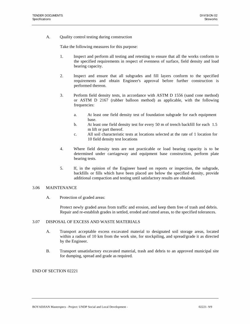
TENDER DOCUMENTS DIVISION 02 Specifications Siteworks
A. Quality control testing during construction
Take the following measures for this purpose:
1. Inspect and perform all testing and retesting to ensure that all the works conform to the specified requirements in respect of evenness of surface, field density and load bearing capacity.
2. Inspect and ensure that all subgrades and fill layers conform to the specified
requirements and obtain Engineer's approval before further construction is performed thereon.
3. Perform field density tests, in accordance with ASTM D 1556 (sand cone method)
or ASTM D 2167 (rubber balloon method) as applicable, with the following frequencies:
a. At least one field density test of foundation subgrade for each equipment
base. b. At least one field density test for every 50 m of trench backfill for each 1.5
m lift or part thereof. c. All soil characteristic tests at locations selected at the rate of 1 location for
10 field density test locations
4. Where field density tests are not practicable or load bearing capacity is to be determined under carriageway and equipment base construction, perform plate bearing tests.
5. If, in the opinion of the Engineer based on reports or inspection, the subgrade,
backfills or fills which have been placed are below the specified density, provide additional compaction and testing until satisfactory results are obtained.
3.06 MAINTENANCE
A. Protection of graded areas:
Protect newly graded areas from traffic and erosion, and keep them free of trash and debris. Repair and re-establish grades in settled, eroded and rutted areas, to the specified tolerances.
3.07 DISPOSAL OF EXCESS AND WASTE MATERIALS
A. Transport acceptable excess excavated material to designated soil storage areas, located
within a radius of 10 km from the work site, for stockpiling, and spread/grade it as directed by the Engineer.
B. Transport unsatisfactory excavated material, trash and debris to an approved municipal site
for dumping, spread and grade as required.
END OF SECTION 02221
BOYADJIAN Masterspecs - Project: UNDP Social and Local Development - 02221- 9/9

TENDER DOCUMENTS DIVISION 02 Specifications Siteworks
SECTION 02230
AGGREGATE OR GRANULAR SUBBASE
PART 1 GENERAL
1.01 SECTION INCLUDES
A. Aggregate or granular subbase as shown on the drawings.
1.02 RELATED SECTIONS
A. Section 01400 Quality Requirements.
B. Section 02210 Compaction and Testing of Earthworks.
C. Section 02232 Aggregate Base Course.
D. Section 02513 Pavements – Asphaltic Concrete.
1.03 REFERENCES
A. General Specifications for Roads and Bridge Construction, Ministry of Communications, the Kingdom of Saudi Arabia with the applicable addenda and circulars.
B. Materials and Research Department Manual of Materials and Tests (MRDTM) and all
current letters issued by Ministry of Communications.
C. American Association of State Highway and Transportation Officials:
1. AASHTO M 147 Standard Specification for Materials for Aggregate and Soil Aggregate Subbase, Base and Surface Courses.
2. AASHTO T 180 Standard Specification for Moisture-Density Relations of
Soils Using a 4.54 kg (10 lb) Rammer and a 457 mm (18 in) Drop.
D. American Society for Testing and Materials
1. ASTM C 136 Standard Test Method for Sieve Analysis of Fine and
Coarse Aggregates.
2. ASTM D 698 Standard Test Method for Laboratory Compaction Characteristics of Soil Using Standard Effort (12,400 ft- lbf/ft3 (600 kN-m/m3).
3. ASTM D 1556 Standard Test Method for Density of Soil in Place by the
Sand Cone Method.
4. ASTM D 1557 Standard Test method for Laboratory Compaction Characteristics of Soil Using Modified Effort (6,000 ft- lbf/ft3 (2,700 kN-m/m3)
BOYADJIAN Masterspecs - Project: UNDP Social and Local Development - 02230- 1/7

TENDER DOCUMENTS DIVISION 02 Specifications Siteworks
5. ASTM D 2167 Standard Test Method for Density and Unit Weight of Soil
6.
ASTM D 2487
in Place by the Rubber Balloon Method.
Standard Classification of Soils for Engineering Purposes (Unified Soil Classification System).
7.
ASTM D 2922 Standard Test Method for Density of Soil and Soil-
Aggregate in Place by Nuclear Methods (Shallow Depth).
8.
ASTM D 3017 Standard Test Method for Water Content of Soil and Rockin Place by Nuclear Methods (Shallow Depth).
9.
ASTM D 4318 Standard Test Method for Liquid Limit, Plastic Limit, andPlasticity Index of Soils.
1.04 SUBMITTALS
A. Comply with provisions of section 01300.
B. Formulate Job Mix Formula (JMF) with pertinent test data and results and submit for approval at least 30 days before producing subbase mixture.
C. Furnish the source and gradation of the aggregate for each mix.
D. Type of plant to be used for mixing each mix.
1.05 QUALITY REQUIREMENT
A. Determine the location, suitability and quality of materials available for the construction of the aggregate/granular base from a single source throughout the work.
B. Examine the substrata and the condition under which the aggregate/granular subbase is to be
laid and correct any unsatisfactory conditions. Do not proceed with the work until unsatisfactory conditions have been corrected in a manner acceptable to the Engineer.
C. Compaction testing and field quality control shall be conducted by an Independent Testing
Laboratory as per Section 01410.
PART 2 PRODUCTS
2.01 MATERIALS
A. Aggregate used for aggregate subbase to be free from vegetation matter and other deleterious substances and, when compacted under watering and rolling, form a firm, stable subbase. Coarse aggregate to be crushed stone, crushed slag, or crushed gravel. Fine aggregate, material passing the 4.75 mm (No. 44) sieve, to consist of natural or crushed sand and fine material particles.
B. Furnish, produce, stockpile, blend and mix all necessary materials using such equipment and
procedures as will produce specified aggregate subbase.
BOYADJIAN Masterspecs - Project: UNDP Social and Local Development - 02230- 2/7

TENDER DOCUMENTS DIVISION 02 Specifications Siteworks
C. Aggregate to conform to one of the following grading and quality requirements on the road bed after all blending and mixing and spreading and before compacting, when tested in accordance with ASTM C 136.
AGGREGATE SUBBASES GRADATION REQUIREMENTS
Sieve Sizes Grading I Grading II
62.5 mm (2½ inch) 100 -
50 mm (2 inch) 90-100 100
37.5 mm (1½ inch) - 90-100
25 mm (1 inch) - 55-85
19 mm (¾ inch) - 50-80
9.5 mm (3/8 inch) - 40-70
4.75 mm (No. 4) 35-70 30-60
2.54mm (No. 10) - 20-50
0.425 mm (No. 40) - 10-30
0.075 mm (No. 200) 0-15 0-15
QUALITY REQUIREMENTS
Sand Equivalent 25 min.
Plasticity Index 6 max.
Abrasion Loss 50 max.
California Bearing Ratio (CBR) 50 min.
D. When the aggregate (coarse, fine, supplemental fine) is separated into two (2) or more sizes, provide the information consisting of gradations for all individual sizes, the proportions of each individual size to be used, and the mathematically combined gradation for each mix to be furnished as per requirements shown above and show the percentage passing each of the specified sieve sizes.
E. Provide the Engineer access to the materials sampling and testing operations at all times.
The combined aggregate, including mineral additives, shall conform to the approved job mix formula grading within the following tolerances:
BOYADJIAN Masterspecs - Project: UNDP Social and Local Development - 02230- 3/7

TENDER DOCUMENTS DIVISION 02 Specifications Siteworks
9.75 mm (3/8”) and larger sieves, + 11 percentage points 4.75 mm (No. 4) sieve, + 10 percentage points 2.36 mm (No. 8) sieve, + 9 percentage points 0.300 mm (No. 50) sieve, + 8 percentage points 0.075 mm (No. 200) sieve, + 8 percentage points
F. Do not begin production of aggregate subbase mixes until the Engineer has given written
acceptance of the Job Mix Formula.
G. Acceptance of the JMF by the Engineer does not relieve the obligation to produce aggregate base mixes to all specified requirements.
H. When there is change in the source of aggregate, furnish a new job mix design proposal and
samples of materials, as described above.
2.02 EQUIPMENT
A. Furnish all necessary equipment for production, stockpiling and hauling aggregate, preparing the subgrade and placing, compacting, finishing and maintaining the aggregate subbase according to the minimum type and number outlined in the detailed Program of Work as approved by the Engineer.
Perform blending, mixing aggregates and adjusting the moisture content as required for compaction in a central mixing plant or on the grade by means that insure uniformity.
Place and spread the blended and mixed aggregates to the width and thickness specified.
PART 3 EXECUTION
3.01 QUALITY CONTROL PROCEDURES
A. Test the aggregate furnished for subbase to control the quality. Forward copies of all test results to the Engineer at the end of each working day. The Engineer shall have access to the testing laboratory at all times and the right to obtain samples of the materials at any point during construction. When requested by the Engineer, obtain aggregate subbase materials and prepare duplicate samples by quartering. Deliver one (1) sample to the Engineer and test the duplicate sample.
B. Perform the following minimum types and number of tests:
1. Gradation, sand equivalent and plasticity index – One (1) test each per two thousand
(2000) cm of aggregates produced but not less than one (1) test per production day.
2. Abrasion Loss – One (1) test for the first, second and third five hundred (500) cubic meters of aggregate produced and one (1) test for each twenty five hundred (2,500) cubic meters thereafter.
3. CBR Value – One (1) test for each five thousand (5,000) cubic meters placed.
C. When test data indicate that the aggregate subbase does not conform to specified
BOYADJIAN Masterspecs - Project: UNDP Social and Local Development - 02230- 4/7

TENDER DOCUMENTS DIVISION 02 Specifications Siteworks
requirements, take effective action to correct production methods to assure that subbase aggregate will conform to all specified requirements. Such action to include halting production, changing the sources of aggregate supply, altering amount of aggregate scalped and rejected, increasing degree of crushing, and revising blending and handling methods. Such material if already placed, shall be removed and modified or replaced to produce material conforming to the specified requirements.
3.02 SURFACE PREPARATION
A. The surface to receive aggregate subbase immediately prior to spreading aggregate subbase,
to conform to specified compaction and elevation tolerances and to be free of loose or extraneous material.
B. Correct any deviation from specified elevation and compaction in the surface to receive
aggregate subbase.
C. When surfaces to receive aggregate subbase are lower than specified, fill the low areas with aggregate subbase. The volume of aggregate subbase so placed not to be measured for payment under any item listed in the Bill of Quantities.
3.03 PLACING AND SPREADING
A. Aggregate for subbase, immediately prior to spreading to be uniform mixtures free from
pockets and streaks of coarse or fine material and be deposited on the subgrade in uniform layers using approved equipment.
B. Shape the layers of aggregate subbase to such thickness that, after watering and compacting,
the completed subbase layer conform to the required width, grade and thickness within the tolerances specified in Paragraph 3.05 “Finishing”.
C. Handle the material avoiding segregation. Remix the segregated materials until uniform. The
water can either be added in the borrow pit or on a mixing platform or on the grade.
D. Where the subbase thickness is twenty (20) centimeters or less, the aggregate subbase may be spread and compacted in one (1) layer. Where the required thickness is more than twenty (20) cm, spread the aggregate subbase in two (2) or more layers of approximately equal thickness.
3.04 COMPACTING
A. Each layer of subbase material, after being shaped to the required lines and cross section, to
be compacted to a uniform density with no individual test being less than ninety-five percent (95%) of the maximum dry unit weight. Each of lot of subbase material to have a percent relative compaction of not less than ninety-nine percent (99%) of the maximum dry unit weight. Water or dry the subbase as may be necessary to obtain a moisture content suitable for compaction. Material which has dried prior to final compaction or which has dried and decompacted subsequent to final compaction to be watered and recompacted using equipment and procedures approved by the Engineer. When found impossible to return the material to its original or specified condition with respect to compaction, thickness, and surface tolerances, remove the material and reconstruct the course on a reapproved subgrade.
B. When there are delays in constructing the remaining pavement structure over a granular
course, verify the compaction of the granular course and deficient areas corrected or
BOYADJIAN Masterspecs - Project: UNDP Social and Local Development - 02230- 5/7

TENDER DOCUMENTS DIVISION 02 Specifications Siteworks
replaced to the satisfaction of the Engineer.
C. Plan the work and handle the various operations so that the least amount of water will be lost by evaporation from uncompleted surfaces. In case placing of succeeding layers of material is delayed, apply additional water to prevent ravelling or excessive drying.
D. Compact the material by means of approved compaction equipment, progressing gradually
from the outside towards the center, with each succeeding pass uniformly overlapping the previous pass. Continue rolling until the entire thickness of each layer is thoroughly and uniformly compacted to the specified density. The final rolling of the completed course to be done with a self-propelled roller as approved by the Engineer. Rolling to be accompanied by sufficient blading, in a manner approved by the Engineer, to insure a smooth surface, free from ruts or ridges and having the proper section and crown. When additional water is required, add it in the amount and manner approved by the Engineer. Construct the initial layers of material to a uniform grade and cross section, compact and obtain approval from the Engineer prior to the delivery of materials for a succeeding layer.
E. Prior to placing a succeeding layer of granular material, moist the surface of the underlayer
sufficiently, to insure bond between the layers. Blade/dress the edges and edge slopes of the base course to conform to the lines and dimensions shown on the plans, and present straight, neat and workmanlike lines and slopes as free of loose material as practicable.
F. Any areas inaccessible to normal compaction equipment to be compacted by means of
portable mechanical tampers until satisfactory compaction is obtained. When the last layer is to be trimmed to final grade by an automatic grading machine, construct it approximately one (1) to three (3) centimeters above grade, so that the grading machine cuts continually. After the final pass of the grading machine, wet and roll the subbase.
3.05 FINISHING
A. Place all subbase material, trim and finish in a neat and workmanlike manner in compliance
with the lines, grades and typical cross sections shown on the plans within the tolerances listed below. Check the cross section of the finished subbase in the presence of the Engineer at maximum intervals of twenty-five (25) meters and at intermediate points as directed by the Engineer. The deviation of the elevation of the surface above the design elevation to be not more than twenty (20) millimeters. Deviations above the design elevation not result in the diminished thickness of any subsequent pavement course. Compensate the deviation of the elevation below the design elevation by additional thickness of the subsequent pavement layer. Furnish all devices necessary to check the surface, such as stringlines, straightedges, etc., and the manpower necessary to handle the task.
3.06 MAINTENANCE AND PROTECTION
A. Following construction of the subbase course blade, broom, and otherwise maintain the
course, keeping it free from raveling and other defects that result in lost density until such time as the next element of the pavement structure is placed. Apply water at such time and in such quantities as directed by the Engineer. The Engineer has full authority to suspend all other work on the project to insure the proper maintenance of previously compacted material.
B. The Engineer shall determine when the surface of the subbase is in the proper condition to permit the placement of aggregate subbase course or the bituminous primer and/or surfacing
BOYADJIAN Masterspecs - Project: UNDP Social and Local Development - 02230- 6/7

TENDER DOCUMENTS DIVISION 02 Specifications Siteworks
to be applied. Continue to maintain the surface of the base course, including the application of necessary water, until such time as the bituminous primer or the subsequent layer is applied.
3.07 COMPACTION TEST TRIALS
A. When directed by the Engineer prior to the commencement of subbase compaction
operations, construct compaction trial lengths, not to exceed one (1) km.
1. The materials used in the trials to be that approved for use as aggregate subbase and the equipment be that according to the approved detailed Program of Work.
2. The object of these trials is to determine the adequacy of the equipment, the loose
depth measurements necessary to result in the specified compacted layer depths, the field moisture content, and the relationship between the number of compaction passes and the resulting density of the material.
B. Proceed with aggregate subbase work only after the methods and procedures established in
the compaction trial has been approved by the Engineer.
END OF SECTION 02230
BOYADJIAN Masterspecs - Project: UNDP Social and Local Development - 02230- 7/7

TENDER DOCUMENTS DIVISION 02 Specifications Siteworks
SECTION 02232
AGGREGATE BASE COURSE
PART 1 GENERAL
1.01 SECTIONS INCLUDES
A. Provision, spreading and compaction of materials of aggregate base course for roads in accordance with the specifications and in conformity with grade, lines and thickness shown on the drawings, including setting out of controls and furnishing of all plant, machinery, tools, equipment, guides, templates and labor.
1.02 RELATED SECTIONS
A. Section 01330 Submittal Procedures.
B. Section 01400 Quality Requirements.
C. Section 02210 Compaction and Testing of Earthwork.
D. Section 02230 Granular Sub-base.
E. Section 02513 Pavements – Asphaltic Concrete.
1.03 REFERENCES
A. General Specifications for Roads and Bridge construction, Ministry of Communications, in Kingdom of Saudi Arabia.
B. Ministry of Communications circular No. 2403 dated 24.05.1407 H, with other applicable
circulars and addenda to General Specifications.
C. American Society for Testing and Materials – ASTM.
1. ASTM C 131 Test Method for Resistance to Degradation of Small-Size Coarse Aggregate by Abrasion and Impact in the LosAngeles Machine.
2.
ASTM C 136 Sieve Analysis of Fine and Coarse Aggregate.
3.
ASTM D 1196 Standard Method for Non-Repetitive Static Plate Load Tests of Soil and Flexible Pavement Components, for Use in Evaluation and Design of Airport, and Highway Pavements.
4.
ASTM D 4318 Test Method for Liquid Limit, Plastic Limit and Plasticity Index of Soils.
5.
ASTM D 1883 Test Method for CBR (California Bearing Ratio) of Laboratory – Compacted Soils.
BOYADJIAN Masterspecs - Project: UNDP Social and Local Development - 02232- 1/8

TENDER DOCUMENTS DIVISION 02 Specifications Siteworks
1.04 SUBMITTALS
A. Comply with Section 01300.
B. Propose Job Mix Formula (JMF) with pertinent test data and results at least 30 days before producing aggregate base mixtures.
C. The source and gradation of the aggregate for each mix.
D. Type of plant to be used for mixing each mix.
1.05 QUALITY REQUIREMENTS
A. Determine the location, suitability and quantity of materials available for the supply of the aggregate base course from a single source throughout the work.
B. Examine the substrate and the condition under which the aggregate base is to be laid, and
correct any unsatisfactory conditions. Do not proceed with the work until unsatisfactory conditions have been corrected in an acceptable manner.
C. Compaction test and field quality control shall be conducted by Independent Testing
Laboratory as per Section 01410.
PART 2 PRODUCTS
2.01 MATERIALS
A. General: The aggregate to be hard durable crushed stone or gravel, clean and free from excessive flat, elongated, soft or disintegrated pieces as well as organic matter or other deleterious substances, and be in a readily compatible conditions by watering and rolling to form a firm and stable base course. Any fine aggregate added to obtain the desired gradation shall be screenings obtained from crushing of stone, gravel or slag.
B. Crushed stone aggregate not to contain more than eight (8) percent by weight flat, elongated,
soft, or disintegrated pieces. Aggregate retained on the 2.36mm (No. 8) sieve to consist of stone particles of which at least ninety percent (90%), by weight, to have minimum two (2) mechanically fractured faces.
C. Obtain the specified gradation by crushing, screening and blending processes, as necessary.
Furnish stockpile, blend and mix all necessary materials using equipment and procedures to produce the specified aggregate base.
D. If additional fine material, in excess of that already present in the base course material, is
necessary for correcting the gradation properties for satisfactory bonding of the base material, or for adjusting the material characteristics of the fraction passing the 0.425mm (No. 4) sieve, blend the additional material uniformly and mix with the crushed aggregates. Such mixing shall take place at the crusher, at an approved stationary proportioning and mixing plant or on a travelling plant. Reworking of the base course material in place to obtain the specified requirements is not permitted. The additional fine material obtained from crushing stones, gravel, or slag, to comply with the specified gradation of the final mixture.
BOYADJIAN Masterspecs - Project: UNDP Social and Local Development - 02232- 2/8

TENDER DOCUMENTS DIVISION 02 Specifications Siteworks
E. Aggregate shall conform to one of the following grading and quality requirements on the road bed after all blending and mixing and spreading and before compacting when tested in accordance with ASTM C 136.
AGGREGATE BASES GRADING REQUIREMENTS
Sieve Sizes
PERCENTAGE PASSING
Grading I Grading II Grading III
50 mm (2 inch)
100 - -
37.5 mm (1½ inch)
- 100 -
25 mm (1 inch)
55-85 70-95 100
19 mm (¾ inch)
50-80 55-85 70-100
4.75 mm (No. 4)
30-60 30-60 35-65
0.425 mm (No. 40)
10-25 10-25 15-25
0.075 mm (No. 200)
3-10 3-10 3-10
The fraction passing the No. 200 sieve shall not exceed ½ the fraction passing the 0.425mm (No. 40) sieve.
QUALITY REQUIREMENTS
Sodium Sulphate Soundness & Loss 12 max.
Abrasion Loss 45 max.
Sand Equivalent 45 min.
Liquid Limit 25 max
Plasticity Index 6 max.
California Bearing Ratio Grading I 100 min.
California Bearing Ratio Grading II 80 min.
California Bearing Ratio Grading III 65 min.
F. If the aggregate (coarse, fine, supplemental fine) is separated into two (2) or more sizes,
provide information consisting gradation and proportion of each individual size to be used, and the mathematically combined gradation for each mix. Such combined gradation meet the applicable grading requirements shown above and the percentage passing each of the specified sieve sizes.
BOYADJIAN Masterspecs - Project: UNDP Social and Local Development - 02232- 3/8

TENDER DOCUMENTS DIVISION 02 Specifications Siteworks
G. Provide the Engineer access to the materials sampling and testing operations at all times. The combined aggregate, including mineral additives, shall conform to the approved JMF grading within the following tolerances:
9.75 mm (3/8”) and larger sieves, + 9 percentage points 4.75 mm (No. 4) sieve, + 8 percentage points 2.36 mm (No. 8) sieve, + 7 percentage points 0.300 mm (No. 50) sieve, + 6 percentage points 0.075 mm (No. 200) sieve, + 4 percentage points
H. Do not begin production of aggregate base mixes until the Engineer has given written
acceptance of the JMF.
I. Acceptance of the JMF by the Engineer does not relieve obligation to produce aggregate base mixes conforming to all specified requirements.
J. When the source of aggregate require change due to any reason, furnish a new job mix
design proposal and samples of materials, as described above.
2.02 EQUIPMENT
A. Furnish all necessary equipment for production, stockpiling, moisture conditioning, and hauling aggregate, preparing the surface on which the aggregate base will be placed, and placing, spreading, compacting, finishing and maintaining the aggregate base in accordance with the minimum type and number outlined in the Contractor’s Program of Work as approved by the Engineer. Perform blending and mixing aggregates and adjusting the moisture content as required for compaction in a central mixing plant.
Place and spread the blended and mixed aggregates to the width and thickness specified using approved mechanical spreading equipment. Do not use motor graders for spreading.
PART 3 EXECUTION
3.01 QUALITY CONTROL PROCEDURES
A. Carry out all the tests required to control quality of aggregate base course and furnish copies of all test results to the Engineer at the end of each working day. Provide the Engineer access to the Contractor’s testing laboratory at all times and the Engineer to have right to obtain samples of the materials at any point during construction. When requested by the Engineer, deliver sample aggregate base materials and prepare duplicate samples, by quartering. One (1) sample to the Engineer and test the duplicate sample.
B. Perform the following minimum types and number of tests:
1. Gradation, sand equivalent and plasticity index – One (1) test each per one thousand
(1,000) cubic meters of aggregates produced but no less than one (1) test per production day.
2. Abrasion Loss – One (1) test for first, second and third five hundred (500) cubic
meters of aggregate produced and one (1) test for each twenty five hundred (500) cubic meters thereafter.
BOYADJIAN Masterspecs - Project: UNDP Social and Local Development - 02232- 4/8

TENDER DOCUMENTS DIVISION 02 Specifications Siteworks
3. Percent Crushed Faces – One (1) test for each five hundred (500) cubic meters of aggregate produced.
4. CBR Value – One (1) test for each five thousand (5,000) cubic meters.
C. When test data indicate that the aggregate base does not conform to specified requirements, take effective action to correct production methods to assure that the materials produced will conform to all specified requirements. Action taken shall include halting production, changing the sources of aggregate supply, altering amount of aggregate scalped and rejected, increasing degree of crushing, and revising blending and handling methods.
3.02 PREPARATION AND MAINTENANCE
A. Prepare the subgrade or subbase surface and maintain it true to cross section, grade and
density. The surface of the subgrade or subbase, immediately prior to receiving the aggregate base to conform to the specified cross section, grade and density and be free of any loose or extraneous material. All subgrade or subbase protection, maintenance or repair work is considered subsidiary to items in the Bill of Quantities.
3.03 MIXING
A. Mix the aggregate and the water thoroughly in a twin shaft pugmill type mixer, unless
another type of mixer is approved. The amount of water added to the aggregate to be an amount to produce the mixture with a satisfactory moisture content for compaction to the specified in-place density. Control the rate of flow of the water to the pugmill by valves or other devices which can be easily reset to change the rate of flow if desired. Equip the water supply system with a positive cut-off control to stop the flow of water simultaneously with any stoppage in the flow of aggregate into the pugmill.
3.04 TRANSPORTING
A. Transport the plant-mixed material suitably to deliver the mix to the project without loss or
segregation. Cover truck load with a heavy canvas sheet to reduce the loss of moisture in transit whenever the time between loading the work and spreading the moisture exceeds thirty (30) minutes.
3.05 PLACING AND SPREADING
A. Place the mixture on the existing roadway, approved subgrade or approved subbase, in a
uniform layer or layers not exceeding fifteen (15) centimeters in compacted depth. Where the required thickness is greater than fifteen (15) centimeters, place the material in layers of equal thickness. On using heavy duty vibratory compaction equipment approved by the Engineer, the maximum compacted layer thickness could be twenty (20) centimeters.
1. Take compaction samples from the entire layer including the lower part of the
increased thickness.
2. The coarse aggregate on the top of the Aggregate Base layers are not damaged or crushed.
Engineer will rescind approval for the increased thickness more than fifteen percent (15%) of the subsequent field density tests taken on the thicker layer initially fail, necessitating retesting after additional compaction.
BOYADJIAN Masterspecs - Project: UNDP Social and Local Development - 02232- 5/8

TENDER DOCUMENTS DIVISION 02 Specifications Siteworks
B. Place the mixture course on the roadbed to the required width and uncompacted thickness as follows:
1. Through an approved self-propelled spreading machine.
2. In a sized windrow from which a paving machine or travel plant will pick-up and
spread the aggregate base. C. To protect the underlayer and to allow proper drainage, begin the spreading of the base
course material along the centerline on stretches with a crowned section or on the high side of stretches with a one-way slope.
D. Handle the material properly to avoid segregation. If the approved spreader causes
segregation in the material, or leaves ridges or other objectionable marks on the surface which cannot be eliminated easily or prevented by adjustment to the spreading operation, discontinue the use of such approved spreader and replace it. Remove all segregated material and replace it with well-graded material. Do not do skin patching. Do only minor surface manipulation and watering to achieve the required surface tolerances during the compaction process.
E. No hauling or placement of material will be permitted when, in the judgement of the
Engineer, the weather or road conditions are such that hauling operations will cause rutting of the road surface or cause contamination of the subbase or base course material. Wet the subgrade or previous layer before placing the mixture to get good bond between the layers. Place and shape the mixture by power equipment to the lines, elevations, cross sections, depths and density specified in the following subsections.
3.06 COMPACTING
A. Compact each layer of aggregate base material, after being shaped to the required lines and
cross section, to a uniform density with no individual test being less than ninety-five percent (95%) of the maximum dry unit weight. The relative compaction for each lot of base material to be not less than one hundred percent (100%) of the maximum dry unit weight. Water/dry the aggregate base as necessary to obtain a moisture content suitable for compaction. Water and re-compact using equipment and approved procedures any material/surfaces which has dried prior to final compaction or which has dried and decompacted subsequent to final compaction. Failure to return the material to its original or specified condition with respect to compaction, thickness, and surfaces tolerances, remove the material and reconstruct the course on a reapproved subgrade.
B. When there are delays in constructing the remaining pavement structure over a granular
course, the compaction of the granular course shall be reverified and deficient areas corrected or replaced to the satisfaction of the Engineer.
C. Plan the work and handle the various operations so that the least amount of water will be lost
by evaporation from uncompleted surfaces.
D. Compact the material by means of approved compaction equipment, progressing gradually from the outside towards the center, with each succeeding pass uniformly overlapping the previous pass. Rolling to continue until the entire thickness of each layer is thoroughly and uniformly compacted to the specified density. Do not roll the base course when the underlayer is soft or yielding or when rolling causes undulation of the base course. The final rolling of the completed course to be done with a self-propelled roller as approved by the
BOYADJIAN Masterspecs - Project: UNDP Social and Local Development - 02232- 6/8

TENDER DOCUMENTS DIVISION 02 Specifications Siteworks
Engineer. Accompany the rolling by sufficient blading, in a manner approved by the Engineer, to insure a smooth surface, free from ruts or ridges and having the proper section and crown. Add additional water when required, the amount and manner as approved by the Engineer. Construct initial layers of material to a uniform grade and cross section and compact. Take Engineer’s approval prior to the delivery of materials for a succeeding layer.
E. Prior to placing a succeeding layer of granular material, moist sufficiently the surface of the
underlayer to insure bond between the layers. Blade/dress the edges and edge slopes of the base course to conform to the lines and dimensions shown on the plans, and present straight, neat and workmanlike lines and slopes as free of loose material as practicable.
F. Use portable mechanical tampers in areas inaccessible to normal compaction equipment
until satisfactory compaction is obtained. When the final layer is to be trimmed to required grade by an automatic grading machine, lay this layer approximately one (1) to three (3) centimeters above grade, so that the grading machine cuts continually. After the final pass of the grading machine, wet and roll the base. Use the excess material removed by the grading machine in shoulders, islands, or other areas for which aggregate base is specified, but not under roadway pavement.
3.07 FINISHING
A. Place, trim and finish all aggregate base material in a neat and workmanlike manner in
compliance with the lines, grades and typical cross sections shown on the plans or staked by the Engineer.
Accomplish grade control by means of grade stakes, steel pins or forms, placed in lanes parallel to the centerline of the road and at intervals sufficiently close to permit placing of string lines or straightedges for checking purposes.
3.08 MAINTENANCE AND PROTECTION
A. Following construction of the aggregate base course, blade, broom and otherwise maintain
the compacted course, keeping it free from raveling and other defects that result in lost density until such time as the next element of the pavement structure is placed. Apply water at such times and in such quantities as directed by the Engineer, and the Engineer has full authority to suspend all other work on the project to insure the proper maintenance of previously compacted material.
B. Repair any damage to the base course, or any layer thereof, caused from routing of
construction or other equipment over completed stretches as approved by the Engineer.
C. The Engineer to determine when the surface of the base course is in the proper condition to permit the bituminous prime and surfacing to be applied. Continue to maintain the surface of the base course, including the application of necessary water, until such time as the bituminous prime and surfacing is applied.
3.09 COMPACTION TEST TRIALS
A. When directed by the Engineer, prior to the commencement of aggregate base compaction
operations, construct compaction test trial lengths, not to exceed one (1) kilometer. The materials used in the trials to be that approved as aggregate base and the equipment as approved under detailed Program of Work.
BOYADJIAN Masterspecs - Project: UNDP Social and Local Development - 02232- 7/8
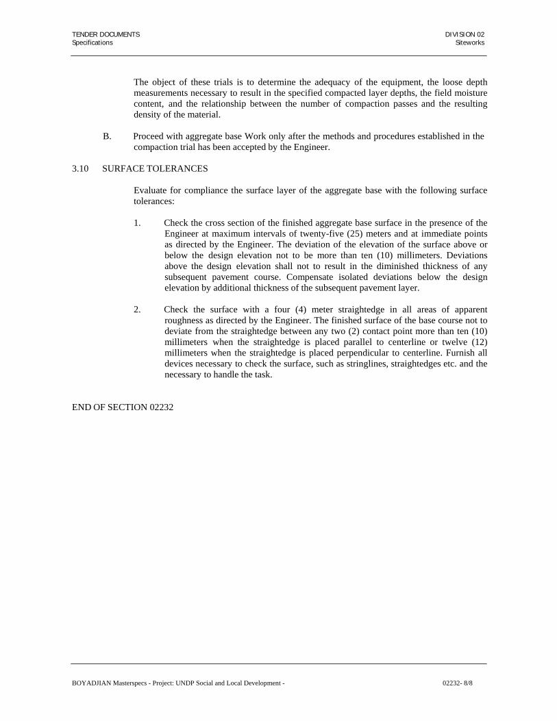
TENDER DOCUMENTS DIVISION 02 Specifications Siteworks
The object of these trials is to determine the adequacy of the equipment, the loose depth measurements necessary to result in the specified compacted layer depths, the field moisture content, and the relationship between the number of compaction passes and the resulting density of the material.
B. Proceed with aggregate base Work only after the methods and procedures established in the
compaction trial has been accepted by the Engineer.
3.10 SURFACE TOLERANCES
Evaluate for compliance the surface layer of the aggregate base with the following surface tolerances:
1. Check the cross section of the finished aggregate base surface in the presence of the
Engineer at maximum intervals of twenty-five (25) meters and at immediate points as directed by the Engineer. The deviation of the elevation of the surface above or below the design elevation not to be more than ten (10) millimeters. Deviations above the design elevation shall not to result in the diminished thickness of any subsequent pavement course. Compensate isolated deviations below the design elevation by additional thickness of the subsequent pavement layer.
2. Check the surface with a four (4) meter straightedge in all areas of apparent
roughness as directed by the Engineer. The finished surface of the base course not to deviate from the straightedge between any two (2) contact point more than ten (10) millimeters when the straightedge is placed parallel to centerline or twelve (12) millimeters when the straightedge is placed perpendicular to centerline. Furnish all devices necessary to check the surface, such as stringlines, straightedges etc. and the necessary to handle the task.
END OF SECTION 02232
BOYADJIAN Masterspecs - Project: UNDP Social and Local Development - 02232- 8/8

TENDER DOCUMENTS DIVISION 02 Specifications Siteworks
SECTION 02513
PAVEMENTS - ASPHALTIC CONCRETE
PART 1 GENERAL
1.01 SECTION INCLUDES
A. Asphalt Concrete Wearing Course.
B. Asphalt Concrete Leveling Course.
C. Asphalt Concrete Base Course.
D. Tack Coat.
E. Prime Coat.
1.02 RELATED SECTIONS
A. Section 01400 Quality Requirements
B. Section 02200 Earthwork.
C. Section 02210 Compaction and Testing of Earthwork.
D. Section 02220 Structural Excavation and Backfill.
E. Section 02230 Aggregate or Granular Subbase.
F. Section 02232 Aggregate Base Course.
1.03 REFERENCES
A. ASTM C 136 Sieve Analysis of Fine and Coarse Aggregate.
B. ASTM D 5 Test for Penetration of Bituminous Materials.
C. ASTM D 113 Test Method for Ductility of Bituminous Materials.
D. ASTM D 242 Mineral Filler for Bituminous Paving Mixtures.
E. ASTM D 979 Sampling of Bituminous Paving Mixtures.
F. ASTM D 1188 Bulk Specific Gravity of Compacted Bituminous Mixtures using Marshall Apparatus.
G. ASTM D 1559 Resistance to Plastic Flow of Bituminous Mixtures.
H. ASTM D 2172 Quantitative Extraction of Bitumen from Bituminous Paving.
I. ASTM D 3202 Percent Air Voids in Compacted Dense and Open Bituminous Paving
BOYADJIAN Masterspecs - Project: UNDP Social and Local Development - 02513- 1/14

TENDER DOCUMENTS DIVISION 02 Specifications Siteworks
Mixtures.
J. ASTM D 3549 Thickness of Height of Compacted Bituminous Paving Mixtures.
K. ASTM D 4791 Standard Test Method for Flat or Elongated Particles in Coarse Aggregate.
L. General Specifications for Road and Bridge Construction of Ministry of Communication, with applicable Addenda and Circulars. (M.O.C.).
M. Materials and Research Department Manual of Materials and Test (MRDTM) Ministry of
Communication, K.S.A.
N. Asphalt Institute Manual MS 2.
1.04 SUBMITTALS
A. Comply with Section 01330.
B. Mix Design of proposed asphalt concrete mixture.
C. Copies of test results from tests conducted to assure compliance to contract document requirements.
PART 2 PRODUCTS
2.01 MATERIALS
A. Bituminous material
1. Provide 4.0 to 7.0% of the total mix by weight penetration grade 60-70 asphalt
cement as bituminous material for base course, leveling course or wearing course complying to requirements of M.O.C. as shown in the following table.
BOYADJIAN Masterspecs - Project: UNDP Social and Local Development - 02513- 2/14

TENDER DOCUMENTS DIVISION 02 Specifications Siteworks
Test AASHTO Test
Method
Penetration Grade 60-70
Min. Max. o o
Penetration at 25 C (77 F) 100 g, 5 sec. T49 60 70
Penetration Ratio, percent minimum (Note 1) 25 25o
Viscosity at 135 C Kinematic (min) T201 170 ---o
Flash point Cleveland Open Cup F T48 450 ---o o
Ductility at 25 C (77 F) 5 cm per min, cm. T51 100 ---
Solubility in trichloroethylene percent T44 99 ---Thin film oven test, 1/8 in. (3.2 mm), 163 °C (325 °F) 5 hours. Lost on bending percent of original Penetration, of residue, percent of original Ductility of residue at 25°C (77°F), 5cm per min. cm.
--- 0.8 54 --- 50 ---
Spot Test (when and as specified with): Standard naphtha solvent Naphtha-xylene solvent, percent xylene Heptane-xylene solvent, percent xylene
T102Negative Negative Negative
BOYADJIAN Masterspecs - Project: UNDP Social and Local Development - 02513- 3/14

ds
TENDER DOCUMENTS DIVISION 02 Specifications Siteworks
Note 1: Penetration Ratio = Penetration at 4°C, 200 gms, 60 secon Penetration at 25°C, 100 gms, 5 second
2. Determine the optimum ratio between bituminous material and filler such that the
bituminous material-filler mixture will reach its softening point within the o
temperature range of 75-90 C, when tested in accordance with MRDTM 406 (Circular No. 2401, paragraphs 3 and 6, as amended). In particular, the softening
point shall be not less than 85 medium or low traffic.
B. Aggregate
o C for heavy traffic and not less than 75
o C for
1. Provide aggregates of hard durable particles or fragments free from decomposed
materials, organic materials and other deleterious substances not containing more than one percent (1.0%) by weight particles having a specific gravity below 1.95.
2. Provide coarse aggregate of crushed stone, crushed slag or crushed gravel retained
on a 4.75 mm (No. 4) sieve and containing no more than ten percent (10%) thin or elongated particles which have a maximum dimension more than five (5) times the minimum dimension as determined in accordance with ASTM D 4791.
3. Provide Fine aggregate material passing the 4.75 mm (no. 4) sieve and produced
from crushed stone, crushed slag or crushed gravel or manufactured sand. Natural sand may not be used without the prior written approval of the Engineer. When approved, the quantity of natural sand in the aggregate not to exceed fifteen percent (15%) of the weight passing the 4.75 mm (no. 4) sieve and the quantity of dune sand not more than fifty percent (50%) of the weight of natural sand authorized by the Engineer. Pay particular attention to the proper control of aggregate and especially to that of natural sand.
4. Provide supplemental fine aggregate mineral filler passing the 0.600 mm (No. 30)
sieve, including dust from the dust collection system. When furnished as supplemental fine aggregate, mineral filler, at the time of use, to be dry, free flowing, without lumps or agglomerations and conform to the requirements of AASHTO M-17.
5. Prior to the addition of bituminous material conform that the combined aggregate
meets the gradation and quality requirements as in Table 1 and Table 2 respectively:
a. The grading limits specified are based on materials of uniform specific gravity and shall be adjusted by the Engineer to compensate for any variations in specific gravity of the individual sizes. The Engineer may vary the gradings on the basis of Marshall Tests to obtain optimum stability and life of the completed Bituminous Concrete Pavement.
b. The gradation of the job mix materials shall be towards the coarse end of the specification.
c. Aggregate gradation for heavy traffic must avoid the area defined by the following equation:
BOYADJIAN Masterspecs - Project: UNDP Social and Local Development - 02513- 4/14

TENDER DOCUMENTS DIVISION 02 Specifications Siteworks
P = d d
0.45 + T
max
Where P = Percent passing
d = Sieve opening in mm d
max = The smallest sieve opening which is not allowed to retain any material (max size
aggregate) T = Vertical distance from the 0.45 power curve in %
The value of T are as follows: For 19 mm nominal size:
mm
d 2.36 2.0 1.18 0.6 .425 .30T (%) +0 +1 +3 +2 +1 +0
For greater than 19 mm nominal size
mm d 4.75 2.36 2.0 1.18 0.60 0.425 0.30 T(%) +0 +2.0 +2.5 +3.0 +2.0 +1.0 +0
AGGREGATE GRADING REQUIREMENTS – MRDTM 419
Table 1
BITUMINOUS BASE COURSE
Sieve Size Grading I 32 mm
Nominal Maximum
Grading II 22 mm
Nominal Maximum
Grading III 19 mm
Nominal Maximum37.5mm (1½ inch) 10025.0 mm (1 inch) 75 – 90 100 100 19.0 mm (¾ inch) 65 – 80 75 – 90 90 – 10012.5 mm (½ inch) 55 – 70 65 – 80 78 – 939.5 mm (3/8 inch) 45 – 60 55 – 65 57 – 724.75 mm (No. 4) 31 – 46 35 – 60 43 – 582.00 mm (No. 10) 18 – 33 20 – 35 28 – 430.425 mm (No. 40) 5 – 18 7 – 20 13 – 280.180 mm (No. 80) 3 – 13 5 – 25 – 0.075 mm (No. 200) 2 – 9 3 – 7 3 – 7
BOYADJIAN Masterspecs - Project: UNDP Social and Local Development - 02513- 5/14

TENDER DOCUMENTS DIVISION 02 Specifications Siteworks
BITUMINOUS WEARING COURSE
Sieve Size Grading I 16 mm
Nominal Maximum
Grading II 12.5 mm
Nominal Maximum
Grading III 9.5 mm
Nominal Maximum19.0 mm (¾ inch) 100 10012.5 mm (½ inch) 75 – 90 90 – 100 100 9.5 mm (3/8 inch) 64 – 79 78 – 83 90 – 1004.75 mm (No. 4) 41 – 56 46 – 60 54 – 682.00 mm (No. 10) 23 – 37 30 – 42 32 – 460.425 mm (No. 40) 7 – 20 14 – 25 14 – 250.180 mm (No. 80) 5 – 13 8 – 16 8 – 160.075 mm (No. 200) 3 – 8 3 – 7 3 – 7
BOYADJIAN Masterspecs - Project: UNDP Social and Local Development - 02513- 6/14

TENDER DOCUMENTS DIVISION 02 Specifications Siteworks
Table 2 QUALITY REQUIREMENTS
Bituminous Wearing Course Bituminous Base Course
Class A* Class B* Class C* Class A* Class B* Class C*Sodium Sulfate Soundness Loss, MRDTM 311-66 Percent Max
10
10
10
10
10
10 Abrasion Loss, MRDTM 309 – Percent, Max.
40 40 40 40
40
40
Clay and Friable Particles, MRDTM 312, Percent Max.
0.25 0.25 0.25 0.25
0.25
0.25
Sand Equivalent, MRDTM 313 – Percent, Min.
45 45 45 45
45
45
1) 75 Blow Marshall, MRDTM 410**
Stability – Kg. Min. 1000 750 500 1000 750 500Flow – mm 2-4 2-4 2-4 2-4 2-4 2-4Voids in Mineral Aggregate –
Percent, min,
Varies with Nominal Maximum Size per MS-2*** Voids in Mix – Percent 4-6 4-6 3-5 5-7 5-7 5-7
Bituminous Material – Percent of Total Weight
4.0-6.0 4.0-6.0 4.0-6.0 3.0-6.0 3.0-6.0 3.0-6.0
Retained Strength – Percent, Min.
75 75 75 70 70 70
2) Hveem, ASTM D 1560 – Stabilimeter, minimum 40 37 35 37 35 33
Voids in mix – percent 4-6 4-6 3-5 5-7 5-7 5-7 Filler/Bituminous Material Softening Point All Mixtures
0.62 minimum
Filler/Bituminous Material Ratio All Mixtures
Between 0.5 and 1.5
* Aggregate particles retained on the 2.36 mm (No. 8) sieve shall have the following
minimum percentage by weight, and have two (2) faces with mechanical fracture:
Class A Base and Wearing Course - 90% Class B Base and Wearing Course - 65% Class C Base and Wearing Course - 25%
Each fractured face shall have a minimum dimension from edge across the fractured face which is not less than one-third (1/3) the maximum dimension of the aggregate particle.
o
** The maximum loss of Marshall Stability by submerging specimens in water at 60 C o
for 24 hours as compared to stability measured after submersion in water at 60 C for 30 to 40 minutes shall not exceed 25%, for each asphalt concrete mix designation.
*** Asphalt Institute Manual MS-2.
BOYADJIAN Masterspecs - Project: UNDP Social and Local Development - 02513- 7/14

TENDER DOCUMENTS DIVISION 02 Specifications Siteworks
C. Mineral Fillers
1. Provide mineral fillers of either Portland cement, blended hydraulic cement or lime conforming to the following requirements:
Material Requirement Portland Cement, Type I or II ASTM C 150 Blended Hydraulic Cement, Type IP ASTM C 595 Lime, Type N or S ASTM C 207
2. When required, use the amount of mineral filler between one and two percent (1.0
and 2.0%) of the weight of aggregate, with the exact amount to be stated in the Job Mix Formula.
D. Medium and Rapid Curing Liquid Asphalts (MC & RC) for Tack Coat and Prime Coat.
Conform to the specification for medium curing MC-70 or MC 250 and Rapid Curing RC- 70 used as prime coat and tack coat respectively as below:
Tests AASHTO
Test MethodPrime Coat
MC-70Prime Coat
MC-250 Tack Coat
RC-70. Min. Max. Min. Max. Min. Max
Kinematic Viscocity at 60 °C (140 °F) – centistokes
T 201 70 140 250 500 70 140
Flash Point (Tag, open-cup), °C (F) T 79 38 --- (100)
66 --- (150)
--- ---
Water Percent T 55 ---- 0.2 ---- 0.2 --- 0.2
Distillation Test: Distillate percentage by volume of total distillate to 360 °C (680 °F) To 190 °C (374 °F) To 225 °C (680 °F) To 260 °C (680 °F) To 315 °C (680 °F) Residue from distillation to 360 °C (680 °F) volume percentage of sample by difference
T 78
--- --- 0 20
20 60 65 90 55 ---
--- --- 0 10 15 55 60 87 67 ---
10 --- 50 --- 70 --- 85 --- 55 ---
Tests on residue from distillation: Absolute viscosity at 60 °C (140 °F) poises
T 202/T49 300 1200 (T49)
300 1200 600 2400 (T-202)
Ductility 5 cm/min at 25 °C (77 °C) T 51 100 --- 100 --- 100 ---
Solubility in Trichloroethylene, percent
T 44 99.0 --- 99.0 --- 99.0 ---
Spot test with: Standard naphtha Naphtha-xylene solvent, - percent xylene Heptane-xylene solvent, - percent xylene
T 102 T 102
T 102
Negative Negative
Negative
Negative Negative
Negative
Negative Negative
Negative
BOYADJIAN Masterspecs - Project: UNDP Social and Local Development - 02513- 8/14

TENDER DOCUMENTS DIVISION 02 Specifications Siteworks
2.02 JOB MIX DESIGN
A. Formulate and propose job mix formula and submit to the Engineer for approval at least 30 days before producing bituminous concrete mixture.
B. Sample mixes and trial areas will be required to confirm the suitability of the proposal to
achieve compliance with the specification, and authorisation will be given by the Engineer in writing when a satisfactory method has been established and successful trials have been concluded.
C. Use hot-bin aggregate for the final job mix formula. Develop preliminary job mixes using
stockpiled aggregate, to demonstrate their suitability for the intended purpose.
D. Establish and submit the mix with single percentages for the coarse aggregate, fine aggregate, mineral filler, the amount of asphalt cement, the temperature of mix leaving the mixer and the temperature of mix delivered on the road. Confirm this Job Mix Formula to the following range of tolerances.
Maximum Variations of Aggregate Fractions, Asphalt Content and Mix Temperatures
Passing Sieve No. 4 and larger sieves +5.0% Passing Sieve No. 10 +4.0% Passing Sieve No. 40 +3.0% Passing Sieve No. 80 +2.0% Passing Sieve No. 200 +1.5% Asphalt content +0.4%
o Temperature at mix discharge (145 C minimum) 145-163 °C Temperature at laying 140-163 °C
E. When unsatisfactory results make it necessary or on proposing a new source of material, the
Engineer may ask for establishment of a new Job Mix Formula before the new material is used.
2.03 MIXING
A. Dry and heat the aggregate for the mixture to the required temperature. Properly adjust the
flames used for drying and heating to avoid damage to the aggregate and to avoid soot on the aggregate.
B. First mix the dried aggregate in the mixer, in the amount of each fraction of aggregates
required to meet the job-mix formula, followed by the necessary amount of filler, and mix for at least 10 seconds before the specified amount of bituminous material is added.
C. Mix the material until a complete and uniform coating of the particles throughout the
aggregate is secured. Wet mixing time will be approved by the Engineer for each type of plant and the aggregate used.
D. Produce the mixture as closely as practicable to the highest temperature limit which will
produce a workable mix within the specified temperature range.
BOYADJIAN Masterspecs - Project: UNDP Social and Local Development - 02513- 9/14

TENDER DOCUMENTS DIVISION 02 Specifications Siteworks
2.04 MIXING PLANT
A. Use the asphalt mixing plant for heating, proportioning and mixing the aggregates and asphalt cement either of the batch type or continuous mixing type, capable of producing a uniform mixture in the quantities required within the job-mix tolerance specified previously.
B. Provide the plant with an accurate mechanical means for feeding the mineral aggregate at a
uniform temperature. The feeder or feeders shall be capable of delivering in precise proportions the aggregate or aggregates required. When more than one cold feed elevator is used, each shall be fed as a separate unit and the individual controls shall be integrated with an overall master control.
C. Use drier or driers capable of drying and heating all aggregate to the required temperatures
with positive control of the temperature through the progress of all operations. Design driers so that aggregates will be agitated continuously during the process of heating.
D. Provide plant screens capable of screening all aggregates to the specified proportions and
with normal capacities in excess of the full capacity of the mixer. The dried aggregate shall be metered to the pugmill from the storage bins in a manner which will result in constantly uniform mixture complying with the job mix formula as specified.
E. Provide tanks used for storage of asphalt cement with a device for controlled heating of the
material temperature between 135 °C and 163 °C (225 °F and 325 °F). Accomplish heating so that no flame shall come in contact with the heating tank. Provide a circulating system of adequate size to insure proper and continuous circulation between the storage tank and mixer during the entire operating period. Keep when possible, the discharge end of the circulating pipeline below the surface of the asphalt in the tank while the pump is in operation. The storage tank to have a sufficient capacity to hold enough asphalt for at least one day's operation.
F. Size the bins for storage of dry aggregate to ensure continuous operation at rated capacity.
Maintain and equip the bins so that the flow of dried aggregate to the mixer is uniform and will result in the specified mixture.
G. Provide means to obtain the required percentage of asphalt in the mix within the tolerances
specified, either by weighing or measuring volumetrically. Where the quantity of asphalt is controlled by volumetric metering, make provision to check the weight of the asphalt delivered through the meter. Provide steam jacketing or other insulation to maintain the specified temperature of asphalt in pipelines, meters, weigh buckets, spray bars, flow lines or other containers.
H. Install an armoured thermometer of adequate range in the asphalt feed line at a location near
the discharge valve at the mixer unit.
I. Equip the plant with an approved thermometric instrument having an accuracy of 2.5 °C (5 °F) placed at the discharge chute of the drier to register automatically or indicate the temperature of heated aggregate. Use thermometric instrument sensitive to a rate of temperature change not less than 10°F (5°C) per minute. The Engineer may require the Contractor to test any thermometric equipment at any stage of the work, and has the authority to direct the repair or replacement of any equipment found to be inaccurate or undependable.
J. Provide the plant with a dust collector, designed to waste or return to the hot elevator by
BOYADJIAN Masterspecs - Project: UNDP Social and Local Development - 02513- 10/14

TENDER DOCUMENTS DIVISION 02 Specifications Siteworks
mechanical means all or part of the material collected. Approval of Engineer for the quantity of dust to be returned must be obtained. Provide the plant with a mixer cover and such additional housing as may be necessary to properly control the dust.
K. Provide and maintain adequate and safe stairways to the mixer platform and guarded ladders
to other plant units. Guard and protect all gears, pulleys, chains, and other dangerous moving parts. Provide ample and unobstructed space for the operator on the mixing platform. Maintain clear and unobstructed passage at all times in and around the truck loading space. Provide ladder or platform at the truck loading space to permit safe inspection of the mix as it is delivered to the truck.
PART 3 EXECUTION
3.01 TRANSPORTATION, LAYING AND COMPACTION OF ASPHALT SURFACING
A. Preparation of Surface:
Before laying the bituminous concrete surface course, check the base course to ensure that the surface is within the specified tolerance and is in all respects fit for laying the pavement then spray the bituminous prime coat on the surface as specified below.
1. Application of prime coat
a. Apply cut back bitumen MC 70 or MC 250 at the rate of 0.5 to 1.5 litres/m²
for prime coat. b. Apply the prime coat only when the existing surface is dry or slightly damp
and do not proceed when rain is imminent unless approved by the Engineer. The base-course on which it is to be applied shall be clean to the satisfaction of the Engineer.
c. Apply the cut-back asphalt prime coat by a pressure distributor to obtain uniform distribution at all points. Spread back disposable protective covering such as thick paper or polythene from the end of each application to cover the existing surfaces. Start and stop the flow through the nozzles on the disposable protective covering so that all nozzles are operating properly on the entire length being treated. While applying the prime coat, protect the surfaces of all adjacent structures and objects so as to prevent their being spattered or marred. Do not allow any bituminous material to discharge into a ditch or stream.
Do not commence laying of the bituminous course until the prime coat has been absorbed by the surface and approved by the Engineer.
2. Application of tack coat
Apply tack coat between the basecourse and wearing course or between two lifts of any of these courses. It shall be Rapid Curing Cut-Back Bitumen RC-70 applied at a
2 rate of 0.10 to 0.15 litres/m or as directed by the Engineer. Omit the tack coat if approved by the Engineer, when the previous course or lift is less than 48 hours old. During application of the tack coat, protect the surfaces of all adjacent structures and objects to prevent their being spattered or marred.
B. Transportation of Asphalt
BOYADJIAN Masterspecs - Project: UNDP Social and Local Development - 02513- 11/14

TENDER DOCUMENTS DIVISION 02 Specifications Siteworks
Transport the mixture from the mixing plant to the laying plant in metal lined lorries, which are to be sheeted for protection from the weather, or such other vehicles as may be approved by the Engineer. Do not send the loads out so late in the day as to prevent completion of the spreading and compaction during daylight hours unless otherwise approved by the Engineer. Deliver the mixture at a temperature between 135 °C and 163 °C (275 °F and 325 °F). No segregation of the material or excess loss of heat shall be allowed to occur during transport.
C. Laying of Asphaltic Concrete
Lay the asphaltic concrete by paving machine in layers as shown on the Drawings. The machine must be capable of producing a level and even running surface and must correct for any irregularities in the base. Provide paving machines capable of feeding material from the hopper across the full width of the screed.
1. Joints
a. Offset longitudinal joints for each course thirty (30) centimeters from the
joint in the immediate underlying course. Offset transverse joints a minimum of sixty (60) centimeters from the joint of the immediate underlying course.
b. Locate longitudinal joints within fifteen (15) centimeters of the centerline of
the roadway or within fifteen (15) centimeters of the centerline of a lane and to the minimum practical numbers. Form longitudinal joints by lapping the screed over the first layer placed, crowding a ridge of bituminous material at the joint and crimping the ridge of material into the joint by a compaction roller while the material is hot.
c. Form the transverse joints by cutting back the first layer placed to the full
depth of the layer, removing and wasting the material, spreading new bituminous material in sufficient quantity to create a compacted thickness equal to the thickness of the first layer. Cross roll the joint with one coverage and the joint checked with a straight edge not less than four (4) meters in length. Remove the high points and sags filled with additional bituminous material and the joint rolled a second time. Check the joint again with a straight edge, humps and sags adjusted as necessary, and rolled until the joint is complete and compacted as specified.
d. Tack coat all contact surfaces, where bituminous concrete mixtures are
placed against concrete or stone curb and gutter, bridge abutments, retaining walls, drainage facilities, a cold pavement joint or metal surface.
2. Compaction
a. Compact the mix thoroughly after spreading by rolling. Unless lower
temperatures are ordered by the Engineer, spread all courses of bituminous concrete pavement and perform the initial coverage or perform breakdown compaction when the temperature of the mixture is not less than one
o
hundred forty degrees Celsius (140 C). Complete all rolling before the o
temperature of the mixture drops below ninety degrees Celsius (90 C). b. Roll longitudinal joints first, then begin rolling at the lower edge and
BOYADJIAN Masterspecs - Project: UNDP Social and Local Development - 02513- 12/14

TENDER DOCUMENTS DIVISION 02 Specifications Siteworks
proceed towards the highest portion, except when compacting layers that are thicker than nine (9) centimeters. Begin compaction of layers more than nine (9) centimeters in thickness in the middle and proceed alternately towards each edge. When the roller is within sixty (60) centimeters of either edge proceed by lapping the uncompacted mixture by not more than thirty (30) centimeters per coverage.
c. A coverage consists of one pass of the roller over any portion of the layer
being placed.
d. Carry out the initial "breakdown" rolling by three wheeled rollers with a weight between 4.4 and 6.5 kg per mm width of rear wheel. Proceed the rollers onto fresh material with rear or driven wheels leading. When the rollers are reversed at the end of pass, place the steering wheels on compacted material and do not displace the mix by their movement while changing direction. After the initial rolling, achieve compaction by pneumatic tyred rollers, which are self propelled having a weight between 15 and 30 tonne, and tyre pressure which can be varied between 0.05 and
2 0.08 kg/mm . After the pneumatic tyre rolling, give a final finish by tandem roller.
e. Overlap each pass of the roller by the preceding one by half the width of the
roller wheel. Slightly vary lengths of alternate passes of the roller, maintain rolling speed about 3km per hour, and the number of passes about 5 or 6 over the same area. Keep the roller wheels clean and smooth and take care to ensure that the mixture does not adhere to the wheels, spraying a little water on them when required for this purpose. Commence rolling as soon as the freshly spread mix bears the weight of the roller without any undue movement or displacement and on no account allow the rollers to stand on the finished surface until it has thoroughly cooled. Immediately following initial rolling, check the surface with a straight edge to ensure that it meets with the tolerance requirements. Correct minor variations by rolling, but adjust larger imperfections by adding or taking away mix while it is still hot and workable.
f. Provide sufficient compaction equipment and continue compaction until
each lot of bituminous concrete pavement is compacted to an in-place density within the following range when compared to the theoretical maximum density determined from ASTM D 2041:
Bituminous Concrete Base Course - 92 to 95 Bituminous Concrete Leveling Course - 92 to 95 Bituminous Concrete Wearing Course - 91 to 94
3.02 TESTING OF ASPHALT SURFACE MATERIALS
A. Carry out the tests scheduled below as directed by the Engineer. Take at least one sample
for each day's paving.
1. Uncompacted Asphalt Concrete Mix:
a. Sampling ASTM D 979 b. Asphalt cement content ASTM D 2172
BOYADJIAN Masterspecs - Project: UNDP Social and Local Development - 02513- 13/14

TENDER DOCUMENTS DIVISION 02 Specifications Siteworks
c.
Sieve analysis of extracted
ASTM D 313 mineral matter ASTM C 136
d. Penetration of recovered ASTM D 5 asphalt cement
e. Ductility of recovered ASTM D 113 asphalt cement
f. Marshall stability and flow ASTM D 1559
2. Compacted Asphalt Concrete Mix:
a. Bulk density ASTM D 1188b. Marshall stability and flow ASTM D 1559c. Thickness or height of ASTM D 3549 compacted mix (coring)d. Air voids in compacted mix ASTM D 3203
B. Cut sample as directed by the Engineer from the previous day's paving. Supply and compact new material in the voids left by the sampling.
C. Conduct daily testing of the bituminous mixture to ensure compliance with the approved
job-mix formula and submit copies of the test results to the Engineer.
3.03 TOLERANCES
A. Test the surface by a 3 metre straight edge applied both parallel and at right angles to the centreline of the road. Designate an employee to use the straight edge under the direction of the Engineer in checking all surfaces. The variation of the surface from the testing edge of the straight edge between any two contacts with the surface shall not exceed 3 mm.
B. Place within the following surface tolerances and flush with top of castings, pads and other surface items at required elevations to provide continuous smooth surface.
Grade Max. Deviation in 3 metres
1% and less 3 mm Greater than 1% 6 mm
END OF SECTION 02513
BOYADJIAN Masterspecs - Project: UNDP Social and Local Development - 02513- 14/14

TENDER DOCUMENTS DIVISION 02 Specifications Siteworks
SECTION 02720
STORM WATER DRAINAGE SYSTEM
PART 1 GENERAL
1.01 SCOPE OF SECTION
A. Work Included: This Section covers the furnishing, installation and testing of the storm
water drainage systems which may include the piped storm water drainage collection on and disposal.
1.02 APPLICABLE CODES AND STANDARDS
A. The following Codes and Standards are intended to provide an acceptable level of quality for
materials and products. The Contractor may propose alternative codes and standards provided they give an equivalent degree of quality as the referenced codes and standards and are submitted for the Engineer's review in advance of their use.
British Standards (BS):
BS: 2494 - Elastomeric seals for Joints in Pipework and Pipelines
BS: 5481 - Unplasticised PVC Pipe and Fittings for Gravity Sewers
BS: 5955 - Code of Practice for Installation of unplasticised PVC Pipework (Part 6) for Gravity Drains and Sewers
BS: 6367 - Code of Practice for Drainage of Roof and Paved Areas.
BS: 8301 - Building Drainage
BS: 8005 - Sewerage
1.03 SUBMITTALS
A. Prior to commencing work, the Contractor shall submit the following to the Engineer for
review and approval.
B. Method Statement: Detailing the method and form of construction it is proposed to use to meet the requirements of the Specifications and Drawings and the types of pipes, fittings and accessories with the measures proposed for stockpiling and storage after delivery, and prior to installation.
BOYADJIAN Masterspecs - Project: UNDP Social and Local Development - 02720- 1/4

TENDER DOCUMENTS DIVISION 02 Specifications Siteworks
C. Manufacturer's Test Certificates and/or certificates of compliance with the specification for all materials, pipes, fittings and accessories it is proposed in incorporate site the Permanent Works.
D. Manufacturer's catalogues showing the data and schedules of parts for the pipes fittings and
accessories to facilitate assembly and disassembly.
E. Shop Drawings at a scale not smaller than 1:100 showing layout of drainage including all invert levels crossover levels cover levels setting out of terminal fittings, etc. Detail drawings at a scale of 1:20 of assembly procedures, joint details etc.
F. Samples of materials and fittings as required by the Engineer.
G. Manufacturer's recommended Specification for transporting, handling, loading and
unloading, stock piling and storage of materials.
1.04 OPERATION AND MAINTENANCE DATA
A. Comply with Section 15000.
PART 2 PRODUCTS
2.01 MATERIALS
A. All goods and products covered in these Specifications shall be procured, when available, from an in-Kingdom manufacturer. Procurement of all goods and products shall have the prior approval of the Engineer.
2.02 PIPEWORK
A. All pipework shall be the sizes indicated on the Drawing and shall be as specified in Section
02750 Underground Piping.
2.03 PRODUCT STORAGE AND HANDLING
A. All products shall be delivered in manufacturer's original protective packaging.
B. All products shall be inspected at time of delivery for damage and for compliance with Specifications.
C. Any products that are found to be damaged or not in accordance with the Specifications shall
immediately be repaired or removed from the site and replaced. Repairs shall not be undertaken before the Engineer has approved the Contractors's proposed action.
D. All products shall be handled and stored as recommended by the Manufacturer to prevent
damage and deterioration.
E. The Contractor shall supply handling equipment such as lifting beams, reinforced canvas slings, protective padding, struts, cradles, etc., required to handle the products without damaging hardware or linings and coatings.
F. Each pipe unit shall be site stored, stacked and handled into the final location in such
manner, and by such means, that affords its total protection from damage. The
BOYADJIAN Masterspecs - Project: UNDP Social and Local Development - 02720- 2/4

TENDER DOCUMENTS DIVISION 02 Specifications Siteworks
Manufacturer's recommendations shall be taken as the minimum requirement.
G. Products shall be protected against damage and the ambient conditions both during transport, site storage and immediately up to the time the products are installed. Precautions shall be taken to protect the product from mechanical damage and the effects of sunlight and heat, until the backfilling operations have been completed.
H. Site stacking of pipework shall be such that the pipework will not deform or be damaged in
any way by storage or retrieval.
I. Full consideration shall be given to safety aspects when locating, planning and constructing pipe stacking areas, and whilst stacking pipes.
PART 3 EXECUTION
3.01 INSPECTION
A. Immediately prior to installation, the products shall be inspected for damage by the
Contractor. Products that are found to be damaged or not in accordance with their respective standards and specifications shall not be incorporated in the Permanent Works, and shall be removed from site. Any remedial measures that the Contractor may propose must have the prior approval of the Engineer before being carried out.
3.02 GENERAL
A. The installation of the products comprising the storm water system shall be in accordance
with the approved Method Statement, Manufacturer's instruction and recommendations, the appropriate standards and/or as directed by the Engineer.
B. When a pipeline passes through a wall or other structure, less than one pipe length wide the
a clear space at least 75mm wide all round the pipe. Adequate means shall be provided to prevent soil from entering this gap.
3.03 TESTING
A. Contractor shall inform the Engineer sufficiently in advance to give him a reasonable
opportunity to attend all tests and inspections.
B. All sections of installation shall be checked to ensure they are free from obstruction debris before testing.
C. Obstruction Test - All pipelines having a nominal diameter of less than 300m shall be tested
for obstructions by drawing through each completed length a mandrel 750mm long and having a diameter 10mm less than the actual pipe diameter.
D. Contractor shall provide clean water, assistance and apparatus for testing and inspection as
required.
E. All lengths of drain shall be tested after laying and jointing but before covering and tested again after completion of backfilling.
F. A record of all tests shall be kept; a copy of which shall be given to the Engineer.
BOYADJIAN Masterspecs - Project: UNDP Social and Local Development - 02720- 3/4

TENDER DOCUMENTS DIVISION 02 Specifications Siteworks
G. All lengths of drain, manholes and inspection chambers shall be capable of passing the tests specified. All defects shall be located and remedied without delay and retested as instructed.
3.04 WATER TESTING OF PIPELINES
A. Temporarily seal low ends of drains and connections.
B. Fill system with water to produce 1.5m head in a standpipe at high end and not move them
4.0m head at low end.
C. Allow pipeline to stand for 2 hours for absorption, topping up as necessary.
D. Measure loss at water by noting the quantity of water needed to maintain the test head for 30 minutes.
E. Loss of water for drains to be not more than 1 litre per hour per metre diameter per linear
metre run.
END OF SECTION 02720
BOYADJIAN Masterspecs - Project: UNDP Social and Local Development - 02720- 4/4

TENDER DOCUMENTS DIVISION 02 Specifications Siteworks
SECTION 02726
MANHOLE COVERS AND FRAMES
PART 1 GENERAL
1.01 SCOPE OF SECTION
A. This Section covers the furnishing and installation of cast iron manhole covers/gratings and frames as shown on the Drawings and equipment schedule.
B. The term covers/gratings and frames shall include but shall not be limited to all manholes,
handholes, joint boxes, draw pits, valve chambers, water storage tanks access and sump pit covers and frames or gratings and frames.
1.02 WORK INCLUDED
A. The work includes the provision of all labour, materials and performance of all operations in
connection with the supply and application of sanitary sewerage as specified herein and where referred to on the Drawings.
B. Co-ordination: The Contractor shall be responsible for the full co-ordination of the work of
all trades.
1.03 QUALITY ASSURANCE
A. The Contractor shall be responsible for the quality of all materials and workmanship.
1.04 APPLICABLE CODES AND STANDARDS
A. The following Codes and Standards are intended to provide an acceptable level of quality for materials and products. The Contractor may propose alternative codes and standards provided they give an equivalent degree of quality as those referenced and are submitted for the Engineer's review and approval in advance of their use.
1. British Standards Institution (BS)
BS EN: 124 - Gully tops and Manhole tops for vehicular and pedestrian
areas. Design requirements, Type, Testing Marking, Quantity Control.
BS: 1452 - Grey Iron Casting
BS: 3416 - Black Bitumen Coating Solution for Cold Application
BS: 4164 - Coal Tar Based Hot Applied Coating Materials
1.05 SUBMITTALS
A. The Contractor shall submit for approval:
1. Manufacturers' catalogues and data detailing all items to be furnished under this
Section
BOYADJIAN Masterspecs - Project: UNDP Social and Local Development - 02726- 1/3

TENDER DOCUMENTS DIVISION 02 Specifications Siteworks
2. Certification that the castings comply with the cited Standards.
1.06 OPERATION AND MAINTENANCE DATA
A. Comply with Section 01500.
1.07 EXTRA MATERIALS
A. 2 sets of manhole cover lifting and unlocking keys to suit each type to manhole cover.
PART 2 PRODUCTS
2.01 GENERAL
A. All goods and products covered by these specifications shall be procured, when available, from a local manufacturer. Procurement of all goods and products manufactured out-of-Lebanon must have the prior approval of the Engineer.
B. Proprietary products considered by the Engineer to meet this specification shall be approved
by him based on the Contractor's report and recommendation prior to incorporation into the Permanent Works.
C. Covers/gratings and frames shall be grey cast iron castings. Grey cast iron shall conform to
or exceed the requirements of BS 1452 grade 220.
D. The bearing surfaces of frames and covers shall be machined to ensure that the covers will seat firmly in the frame without rocking or rattling. For square and rectangular manhole covers, a rubber gasket may be permitted in lieu of machining.
E. All edges of covers and frames shall be ground smooth.
F. Unless otherwise specified the castings shall have a priming coat of zinc silicate 75-micron
and finish coats of coal tar epoxy each 100 microns thick.
2.02 COVER TYPES
A. The types of covers/gratings and frames shall be as specified on the Drawings and defined as follows:
1. Heavy Duty: Covers/gratings and frames capable of bearing wheel loads of 11.5
tonnes and with permanent non-rock features.
Heavy-duty covers/gratings and frames shall be used in all main carriageways and elsewhere as specified on the Drawings.
2. Medium Duty: Covers/gratings and frames capable of bearing wheel loads up to 5.0
tonnes and with permanent non-rock features.
Medium duty covers/gratings and frames shall be used on all residential roads, walkways, verges and domestic accesses subject to light vehicular traffic only or where specified on the Drawings.
BOYADJIAN Masterspecs - Project: UNDP Social and Local Development - 02726- 2/3

TENDER DOCUMENTS DIVISION 02 Specifications Siteworks
3. Light Duty: Covers/gratings and frames for use in situations inaccessible to motor vehicles.
2.03 SPECIAL REQUIREMENTS
A. Sealed covers and frames:
Where a sealed cover is specified, the frame shall be provided with a continuous means of retaining a sealing material. Sealing may be of either single or double pattern and the minimum depth of penetration of the cover sealing flanges into the frame shall be 10 mm.
B. Lockable sealed covers:
The locking shall not nullify the seal. Where locking devices can be rendered ineffective by corrosion, they shall be suitably protected. If the locking device utilises a bolt connection, this shall be of stainless steel.
C. Inscriptions, manhole cover surfaces (protruding skid prevention pattern), lifting devices,
and any provision for gas detection on manhole covers shall be as shown on the Drawings.
D. Recessed cast iron covers shall receive in-fill material as specified by the manufacturer to meet the required design loads.
E. Inside buildings, any covers required, shall be airtight and lockable. The covers and frames
shall be of galvanized pressed steel construction with the cover recesses filled to match the surrounding floor finishes. These covers shall be detailed and specified on the Drawings.
PART 3 EXECUTION
3.01 INSTALLATION
A. The Contractor shall install the covers and frames strictly in accordance with the
Manufacturer's instructions and recommendations and to the details shown on Drawings and Schedules.
B. Covers/gratings and frames shall not be subject to any loads until such time the bedding
haunching materials have adequately cured.
C. All covers shall be bedded and levelled to prevent rocking and lateral movement of the frame.
D. All covers shall be set level with surrounding finishes and square with joints surrounding
finishes or with the building.
E. Where recessed type, infill covers are used in block pavior areas, frame is to be secured to top of manhole with expanding bolts of suitable size.
END OF SECTION 02726
BOYADJIAN Masterspecs - Project: UNDP Social and Local Development - 02726- 3/3


TENDER DOCUMENTS DIVISION 02 Specifications Siteworks
BOYADJIAN Masterspecs - Project: UNDP Social and Local Development - 02730 - 1/15
SECTION 02730
SANITARY SEWERAGE
PART 1 GENERAL
1.1 SECTION INCLUDES
The works covered under this contract include the supply, installation, testing, adjusting and putting into operation systems, components of systems, and individual items of equipment, and work related thereto, in accordance with the project Tender Documents. Products not mentioned but obviously necessary to the completion of those works shall be provided.
This section applies to, and is a part of each of the following sections of the specifications as if repeated therein verbatim. A. Sanitary sewer pipe.
B. Sanitary sewer manholes, frames and covers.
1.2 REFERENCES
A. General:
1. The following documents form part of the Specifications to the extent stated. Where differences exist between codes and standards, the one affording the greatest protection shall apply.
2. Unless otherwise noted, the referenced standard edition is the current one at the time of commencement of the Work.
B. International References:
1. ASTM A48 / A48M Standard Specification for Gray Iron Castings. 2. ASTM C150 Standard Specification for Portland Cement 3. ASTM C 443 Standard Specification for Joints for Concrete Pipe and
Manholes, Using Rubber Gaskets 4. ASTM C478 Standard Specification for Precast Reinforced Concrete
Manhole Sections 5. ASTM C923 Standard Specification for Resilient Connectors Between
Reinforced Concrete Manhole Structures, Pipes, and Laterals. 6. ASTM D1784 Standard Specification for Rigid Poly(Vinyl Chloride) (PVC)
Compounds and Chlorinated Poly(Vinyl Chloride) (CPVC) Compounds
7. ASTM D 2414 Standard Test Method for Carbon Black—Oil Absorption Number (OAN)
8. ASTM D 3034 Standard Specification for Type PSM Poly(Vinyl Chloride) and (PVC) Sewer Pipe and Fittings
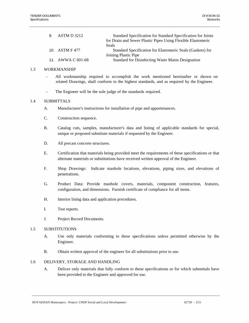
TENDER DOCUMENTS DIVISION 02 Specifications Siteworks
BOYADJIAN Masterspecs - Project: UNDP Social and Local Development - 02730 - 2/15
9. ASTM D 3212 Standard Specification for Standard Specification for Joints for Drain and Sewer Plastic Pipes Using Flexible Elastomeric Seals
10. ASTM F 477 Standard Specification for Elastomeric Seals (Gaskets) for Joining Plastic Pipe
11. AWWA C 601-68 Standard for Disinfecting Water Mains Designation
1.3 WORKMANSHIP
- All workmanship required to accomplish the work mentioned hereinafter or shown on related Drawings, shall conform to the highest standards, and as required by the Engineer.
- The Engineer will be the sole judge of the standards required.
1.4 SUBMITTALS
A. Manufacturer's instructions for installation of pipe and appurtenances.
C. Construction sequence.
B. Catalog cuts, samples, manufacturer's data and listing of applicable standards for special, unique or proposed substitute materials if requested by the Engineer.
D. All precast concrete structures.
E. Certification that materials being provided meet the requirements of these specifications or that alternate materials or substitutions have received written approval of the Engineer.
F. Shop Drawings: Indicate manhole locations, elevations, piping sizes, and elevations of penetrations.
G. Product Data: Provide manhole covers, materials, component construction, features, configuration, and dimensions. Furnish certificate of compliance for all items.
H. Interior lining data and application procedures.
I. Test reports.
J. Project Record Documents.
1.5 SUBSTITUTIONS
A. Use only materials conforming to these specifications unless permitted otherwise by the Engineer.
B. Obtain written approval of the engineer for all substitutions prior to use.
1.6 DELIVERY, STORAGE AND HANDLING
A. Deliver only materials that fully conform to these specifications or for which submittals have been provided to the Engineer and approved for use.

TENDER DOCUMENTS DIVISION 02 Specifications Siteworks
BOYADJIAN Masterspecs - Project: UNDP Social and Local Development - 02730 - 3/15
B. Store materials and handle to avoid damage. Replace any damaged materials. Remove damaged materials from site.
1.7 CONFLICTS
A. Expose potential conflicts such as utility lines and drainage structures in advance of construction. Verify elevations and locations and verify clearance for proposed construction.
B. Complete elements of work which can affect line and grade in advance of sanitary sewer construction unless noted on plans.
C. Notify the Engineer of conflicts discovered or changes needed to accommodate unknown conditions.
1.6 SPECIAL REQUIREMENTS
A. Stop Work: Stop work and notify the Engineer immediately if contaminated soils, historical artifacts or other environmental or historic items are encountered.
B. Conform to municipal and central government requirements.
PART 2 – PRODUCTS
2.1 PIPES AND FITTINGS
A. Description of Work
The work included under this part shall consist of pipes, fittings and equipment, as hereinafter specified and as shown on the Drawings. Such work shall include, without being limited to the items described in the following clauses of this part.
B. Arrangement and Alignment
- Install piping in a neat, workmanlike manner and the various lines shall be parallel to building walls wherever possible.
- Install pipe groups for plumbing parallel with pipes of other trades.
- Space pipe supports, arrange reducers and Pitch piping to allow air to be vented to system high points and to allow the system to be drained at the low points. However, where obstructions exist, automatic air vents shall be installed at all air pocket points and 1/2" (15 mm) drain gate valves shall be supplied and installed at all low points and riser legs.
C. Special Requirements for PVC Pipes
- Storage
PVC pipe and fittings shall be stored under cover at all times.
Sun light shall not be permitted to come into contact with the PVC materials at any time, except during installation in trench. The pipes shall be stored on flat level ground free from large or sharp edged stones or objects, and shall be stacked to a maximum hight of 1.5m. (or as

TENDER DOCUMENTS DIVISION 02 Specifications Siteworks
BOYADJIAN Masterspecs - Project: UNDP Social and Local Development - 02730 - 4/15
recommended by the manufacturer with sockets at alternate ends, and in such a manner as to prevent sagging or bending.
- Pipe Installation
Before installation, the pipe shall be inspected for defects.
Defective, damaged or unsound pipe will be rejected. Deflections from a straight line or grade, between the center lines extended, of any 2 connecting pipes made necessary by vertical curves or horizontal curves or offsets, shall not exceed 12500/D mm. per linear meter of pipe, where D represents the nominal internal diameter of the pipe expressed in millimeters. If the alignment requires deflections in excess of these limitations, special bends or a sufficient number of shorter lengths of pipe shall be furnished to provide angular deflections within the limit set forth. Except where necessary in making connections with other lines, pipe shall be laid with the bells facing in the direction of laying.
Pipes in trenches-Place each length of pipe with a uniformly distributed bearing for the bottom 0.3 of the pipe on the sand fill in the trench. Excavate recesses to accommodate pipe bells, sleeves, glands or other fittings. Take up and re-lay any pipe that has the grade or joint disturbed after laying. Clean the interior of the pipe of all foreign material before lowering into the trench, and keep clean during laying operations by means of plugs or other acceptable methods.
Plumbing vents exposed to sun light shall be protected by water- base synthetic latex paints.
- Thermal Expansions
When drainage and vent stacks exceed six (6) meters in height, approved expansion joints, restraint fittings and offsets shall be placed on vertical risers and horizontal branches as follows:
Expansion joints are recommended at alternate floors in all vertical stacks.
Expansion joints shall be placed in horizontal branches containing two or
more vertical risers and exceeding ten (10) meters in length immediately upstream of vertical riser whenever possible.
An expansion joint, shall be placed below the connection point of a waste pipe
to the stack, if this connection is exposed below floor slab, and above the connection point if this connection is above floor slab.
No expansion joints shall be required in building drain below grade.
- Thermal Expansion Fittings
Approved expansion fittings that utilize rubber-o-rings in a recessed groove may be used to compensate for thermal expansion. The ring slides along the pipe when expansion or contraction occurs. Expansion joints shall be installed by solvent cementing techniques.

TENDER DOCUMENTS DIVISION 02 Specifications Siteworks
BOYADJIAN Masterspecs - Project: UNDP Social and Local Development - 02730 - 5/15
D. General Requirements
- Make all changes in size and direction of piping with standard fittings.
- Make all branch connections with tees.
- Use eccentric reducing fittings or eccentric reducing couplings where required by the contract documents or where required to prevent pocketing of liquid or non- condensibles.
- Pipe bending shall not be resorted to except in extreme cases and only after the written
approval of the Engineer.
- Piping shall be designed with Loops to take the thermal expansion. Wherever this is not possible for physical reasons, expansion joints with guides shall be used.
- Installation of pipes shall be complete with all cutting, patching and making good of walls,
slabs, partitions, etc., due to fixing, supporting and anchoring of pipes.
- Automatic air vents shall be installed at all air pocket locations, and/or at the highest points in the lines.
- Pipes and fittings shall both be manufactured according to one single standard unit of
measurement, either both English or both metric.
E. Connection to Equipment
- Provide flanges or unions at all final connections to equipment and control valves to facilitate dismantling. Arrange connections so that the equipment being served may be removed without disturbing the piping.
- Install all supply piping, pumps and other equipment including gate valves and strainers
therein, at line size with the reduction in size being made only at the outlet piping from the control valve at the full size of the tapping in the equipment served.
F. Unions and Flanges
Unions and flanges shall be installed at all equipment inlets and outlets, at all valves inlets or outlets, on all pipe branches and in general, every 15 metres of pipe run.
Unions shall be used on all screwed pipes and shall be of the same quality and service. Flanges, suitable for welding, shall be used on all welded pipes, and shall be all steel construction to ASTM or BS Standards.
Threaded flanges shall be used on all threaded pipes; when flanged valves and equipment are connected to the pipes, flanges shall be of the same quality and service as the pipe served, and shall conform to ASTM or BS Standards.
G. Cleaning of Piping Systems
- Plug all opening ends of piping, valves and equipment except when actual work is being performed to minimize accumulation of dirt and debris.

TENDER DOCUMENTS DIVISION 02 Specifications Siteworks
BOYADJIAN Masterspecs - Project: UNDP Social and Local Development - 02730 - 6/15
- After installation is complete, place temporary screens at connections to all equipment and at automatic control valves where permanent strainers are not provided. - Prior to the performance of tests, flush out all piping that is to receive a hydrostatic test with clean water. - Remove dirt and debris collected at screens, strainers and other points from the system. - The Contractor shall disinfect water piping before it is placed in service. The Contractor shall furnish all equipment and materials necessary to do the work of disinfecting and shall perform the work in accordance with the procedure outlined in AWWA Standard for Disinfecting Water Mains Designation C 601-68. The dosage shall be such as to produce a chlorine residual for not less than 10 ppm after a contact period of not less than 24 hours. After treatment, the piping shall be flushed with clean water until the residual chlorine content does not exceed 0.2 ppm. During the disinfecting period, care shall be exercised to prevent contamination of water in steel main.
H. Material Tests and Identification
- In addition to the tests required for specific piping systems, the manufacturer shall test all materials as specified prior to delivery. - Check all materials for defects. Identify all materials with factory applied permanent stampings or markings designating their conformance to specified requirements.
I. Hydrostatic Pressure Tests
Test all piping systems as per the specifications under "Quality Requirements"
2.2 PIPE CLASSES: SANITARY SEWERS 4" - 15": (Gravity)
A. Polyvinyl Chloride Pipe (PVC)
1. Polyvinyl chloride pipes (PVC) shall be of the unplasticized rigid type and of high density and complete homogeneity material PVC pipes-Type 3 shall comply with B.S. 4660-1973 atmospheric pressure rating and tested at maximum static head.
2. PVC pipes socket shall be provided with elastomeric lip sealing ring.
3. PVC pipes-Type 3 are allowed to be used for drainage, sewer and storm water application, under building structures and outside building and/or as specifically mentioned in the schedule or pipe materials.
4. Conform to ASTM D 3034, pipe stiffness per ASTM D 2412, minimum thickness Solid Wall Pipe SDR 35.
5. PVC plastic in accordance with ASTM D 1784, Cell Classification 12454 B.

TENDER DOCUMENTS DIVISION 02 Specifications Siteworks
BOYADJIAN Masterspecs - Project: UNDP Social and Local Development - 02730 - 7/15
6. Integral Bell and spigot type rubber gasket push joint fittings conforming to ASTM D 3212 and ASTM F 477.
B Reinforced Concrete Pipe (RCP) 8” to 21” diameter:
1. Conform to ASTM C76.
2. Class IV, Wall B (Iowa DOT 3000D).
3. All joints to be sealed with rubber gaskets conforming to ASTM C 443.
4. Gasket to be P-4 Profile gasket.
5. Interior pipe barrel and all joint surfaces to be coated with two-component coal-tar epoxy polyamide black paint or approved equal.
2.3 PIPE JOINTS
A. Flanged Pipe Joints
- All flanged joints shall be made up with compressed ring type asbestos gaskets. Gaskets shall be 1.5 mm. thick.
- Bolts for flanges shall be of low carbon steel with hexagonal heads and hard pressed steel
hexagon nuts. Bolts shall be to ASTM specifications A 307 or SAE grade 2, with tensile strength of 64000 psi (441.3 Mpa) minimum.
- All bolt holes shall be spot faced. B)
B. Joints Between Dissimilar Materials
- Screwed Pipe to Cast Iron Pipe
Joints between wrought-iron, steel, brass or copper pipe and cast iron pipe shall be made with cast iron spigots screwed to the steel pipe and caulked to the cast iron pipe.
- Copper Tubing to Screwed Pipe Joints
Joints shall be made by the use of brass converter fittings. The joint between the copper pipe and the fitting shall be properly soldered, and the connection between the threaded pipe and the fitting shall be made with a standard pipe size screw joint.
C. Joints Between Dissimilar Metals (Dielectric isolators)
- Make joints between ferrous and non-ferrous screwed piping and equipment by using Teflon or nylon isolating materials in the form of screwed unions.
- Make joints between ferrous and non-ferrous flanged piping and equipment, "Task-Line"
insulating gaskets and "Teflon sleeves and washers between flanges, bolts and nuts.
- The entire insulating joint including the dielectric material shall be suitable to withstand

TENDER DOCUMENTS DIVISION 02 Specifications Siteworks
BOYADJIAN Masterspecs - Project: UNDP Social and Local Development - 02730 - 8/15
the temperature, pressure and other operating characteristics for the service for which they are used.
2.4 LUBRICANT FOR JOINT GASKETS:
A. Soap-based only.
B. DO NOT USE petroleum based lubricant.
2.5. STANDARD MANHOLES:
A. Concrete Manhole sections
1. Manholes shall be constructed of class "b" concrete as shown on the drawings. The base (where required) shall be of precast class "B" reinforced concrete. The shaft shall be constructed of poured reinforced concrete to suit the required depth. The top shall be of class "B" reinforced concrete. An opening suitable to the cover shall be left in the top around which the radial concrete ring is built for proper adjustment of levels.
2. The benching shall be formed in the bottom of manholes in class "B" CONCRETE. "U" channels shall be formed with bottom flush with inside surface of pipes and sides extending the full height of the largest pipe and then sloped back at a minimum fall of 10%. The benching and channels shall be finished with 2 cm thick rendering composed of 1/2 cement/sand mortar, and surface hardened with two coats of sodium silicate solution brushed on. The finished diameter of channels shall be the same as the diameter of pipes entering or leaving the manhole.
3. Joints: Flexible joint rubber ring gasket type, profile gasket or 0-ring gasket; conform to ASTM C443.
4. Steps: aluminum or copolymer encapsulated steel reinforcing bar spaced as per detail drawing.
5. The paint for the manhole interior shall be coated tar epoxy resin or approved equivalent.
6. Conform to standard drawings.
B. Pipe connections:
1. Use knockouts or saw cut openings for piping connections. Precast rubber sleeves not to be used.
2. Conform to standard drawings.
C. Frame and cover castings:
1. The Contractor shall finish and set level and the proper grade, a ductile iron frame and cover and grating of the form and dimensions shown on the Drawings. The concrete masonry shall be neatly and accurately brought to the dimensions of the base of the frame. The frames shall be thoroughly embedded in mortar. All covers and frames

TENDER DOCUMENTS DIVISION 02 Specifications Siteworks
BOYADJIAN Masterspecs - Project: UNDP Social and Local Development - 02730 - 9/15
shall be fill in type, with double seal class B125 similar to Saint Goban or approved equal.
2. All castings for frames covers, and gratings shall be of ductile iron. All castings shall be made accurately to dimensions and shall be machined to provide even bearing surfaces. Covers and gratings must fit the frames in any position and if found to rattle under traffic shall be replaced. Filling to obtain tight covers will not be permitted. No plugging, burning-in and filling will be allowed. All castings shall be carefully coated inside and out with coal tar pitch varnish of approved quality.
3. Refer also to Section 02726 Manhole Covers and Frames.
4. The words "SANITARY" in Arabic and English shall be cast into the covers.
D. Concrete adjusting rings:
1. Use precast concrete adjusting rings meeting ASTM C478 for any grade adjustment.
2. No bricks, HDPE, or site poured adjusting rings shall be used.
PART 3 – EXECUTION
3.1 EXAMINATION
A. Verify measurements at site; make necessary field measurements to accurately determine pipe make up lengths or closures.
B. Examine site conditions to insure that construction operation do not pose hazards to adjacent structures or facilities.
3.2 LINE AND GRADE
A. Install pipe to line and grade shown on plans. Set field grades to invert of pipes.
B. Notify the Engineer immediately if discrepancies or irregularities are discovered in line or grade shown by grade takes.
C. Make detailed measurements as required to construct work to line and grade established by line and grade hubs.
D. Use one of these methods to determine line and grade, or an alternate approved by Owner:
1. Batter Boards:
a. Set grade points at 1 meter intervals at convenient offset from centerline of pipe.
b. Set batter boards as necessary to construct to design line and grade.
c. Provide at least three batter boards at the pipe laying area during construction as check on accuracy of grades.

TENDER DOCUMENTS DIVISION 02 Specifications Siteworks
BOYADJIAN Masterspecs - Project: UNDP Social and Local Development - 02730 - 10/15
d. Check line and grade of each pipe length with grade rod and plumb bob.
2. Pipe Laser:
a. Set laser equipment to proper line and grade from line and grade hubs.
b. Check line and grade of laser at 1 meter intervals for first 4 meters and then at 2 meter intervals for each setup.
c. Check line and grade of each pipe length.
3. Survey Laser:
a. Set laser equipment to base elevation.
b. Check line and grade of each pipe length with grade rod.
3.3 PIPE INSTALLATION
A. Provide trench excavation, pipe bedding and backfill.
The laying of pipe underground will require trimming and grading of trench bottoms for pipe and will require backfilling with approved materials and tamping around all pipe to center line of pipes as the pipe laying process to provide protection and stabilization of the piping. Pipe laying work shall be conducted so that trenching operations are not advanced too far ahead of pipe laying operations resulting in excessive length of open trench.
The Contractor shall trim the bottom of all trenches to receive pipe and shall provide finish grade by hand methods. The bottoms of all trenches shall be rounded so that insofar as particular at least one-third of the circumference of the pipe will rest firmly on 20cms undisturbed sand at proper line and grade. Bell holes where required shall be dug to ensure pipe resting for its entire length upon the bottom of the trench. Trenches shall not be excavated below grade by machine.
After pipes have been tested and approved, trenches shall be backfilled with approved materials, carefully deposited in layers not to exceed 15 cms in thickness on both sides and thoroughly and carefully tamped. Backfilling and tamping in layers of 15 cms shall be conducted until a depth of 30 cms has been placed over the sand. No backfill shall be placed in a manner such as to cause injury to the pipe. Where pipe crossing occur, the lower pipe shall be laid first and the backfill thoroughly compacted to the level of the higher pipe before higher pipe is laid. Backfill materials under such conditions shall be earth, approved gravel on concrete as directed.
Where rock is encountered excavation shall conform to applicable provisions.
B. Begin at highest point in line. Lay groove or bell end pointing upstream unless specifically noted otherwise.
C. Prepare trench bottom to design line and grade so that only minor movement of pipe is necessary after installation. Use bedding as specified on detail drawing.

TENDER DOCUMENTS DIVISION 02 Specifications Siteworks
BOYADJIAN Masterspecs - Project: UNDP Social and Local Development - 02730 - 11/15
D. Inspect pipe for defects before carefully lowering into trench. Do not install damaged or defective pipe.
E. Clean pipe interior and joints prior to lowering into trench. Keep pipe clean during construction.
F. Do not lay pipe in water or on saturated soil or bedding, or allow water to rise in trench around pipe, unless approved by the Engineer.
G. Lay pipe to design line and grade.
H. Provide uniform bearing for full pipe barrel length.
1. Excavate bell holes as necessary for uniform support of pipe barrel on bedding material.
2. Do not block pipe above bedding unless controlled density fill, concrete bedding, or concrete easement is to be used.
I. Assemble joints as specified by pipe manufacturer.
J. Install cap at exposed ends of pipe whenever pipe installation is not in progress.
K. Do not disturb installed pipe and bedding when using movable trench boxes and shields. Block or anchor pipe as necessary to prevent joint displacement.
L. Saw cut ends of pipe at manholes and structures. Do not hammer cut or break pipe.
M. Correct misalignment, displacement or otherwise defective pipe by removing, relaying or replacing pipe at Contractor's expense.
N. To connect new pipe to existing manhole, sawcut or hammer out enough manhole wall and base to allow pipe to penetrate 3” past interior wall of manhole at elevation indicated. Sawcut out and pour new invert if elevation requires. Grout around pipe penetration.
3.4 PIPE JOINTING
A. Joint Cleaning: Clean joint surfaces with wire brush to remove soil or foreign material prior to jointing pipe
B. Assemble joints in accordance with pipe manufacturer's recommendations.
1. Use equipment that does not apply damaging forces to pipe joints.
2. Use bar and block or internal or external jointing devices or other devices as recommended by pipe manufacturers.
C. Polyvinyl Chloride Pipe (PVC):
1. Coat rubber gasket and joint with lubricant immediately prior to closing joint..

TENDER DOCUMENTS DIVISION 02 Specifications Siteworks
BOYADJIAN Masterspecs - Project: UNDP Social and Local Development - 02730 - 12/15
D. Connections Between Dissimilar Pipes:
1. Use Fernco couplings or equivalent.
2. Where adapters or couplings are not commercially available, the Engineer may authorize use of a reinforced concrete collar as per specs. Authorization for this will be very rare and must be explicitly approved.
3.5 TOLERANCES
A. Horizontal and vertical alignment of each pipe length of gravity sewer lines shall not vary from design lines and grade by more than 1 % of the inside diameter of the pipe or '1/4 inch, whichever is larger.
B. Tolerance allowed for gravity sewer lines only if design line and grade is sufficient to prevent backslope when tolerance limits are reached.
C. Reverse slope on gravity pipe is prohibited. Remove and relay pipe to proper grade.
D. Horizontal and vertical alignment of force mains shall not vary from design line and grade by more than 3 inches.
3.6 CONFLICTS
A. Provide temporary support for existing water, gas, telephone, power or other utilities or service that cross trench.
B. Compact backfill under existing utility crossing as specified in Utility Trench and Backfill. or construct utility line supports where indicated on plans or as directed by the Engineer.
3.7 MANHOLE INSTALLATION
A. Subgrade Preparation:
1. Undisturbed soil; Hand grade to accurate elevation.
2. Disturbed soil; Machine compact to 95 percent of Standard Proctor Density and hand grade to accurate elevation or install stabilization material as directed by the Engineer.
B. Installation of Poured In Place Base:
1. Bed base riser section in cement mortar.
2. Assure proper vertical and horizontal alignment of base riser section.
3. Invert to be same size as outlet pipe.
4. Provide smooth, semi-circular invert through manhole. This may be achieved by smoothly forming concrete in a curve to match long radius fitting size, or by bedding proper standard fittings such as wye and 1/8 bends in the concrete and leaving them in place.
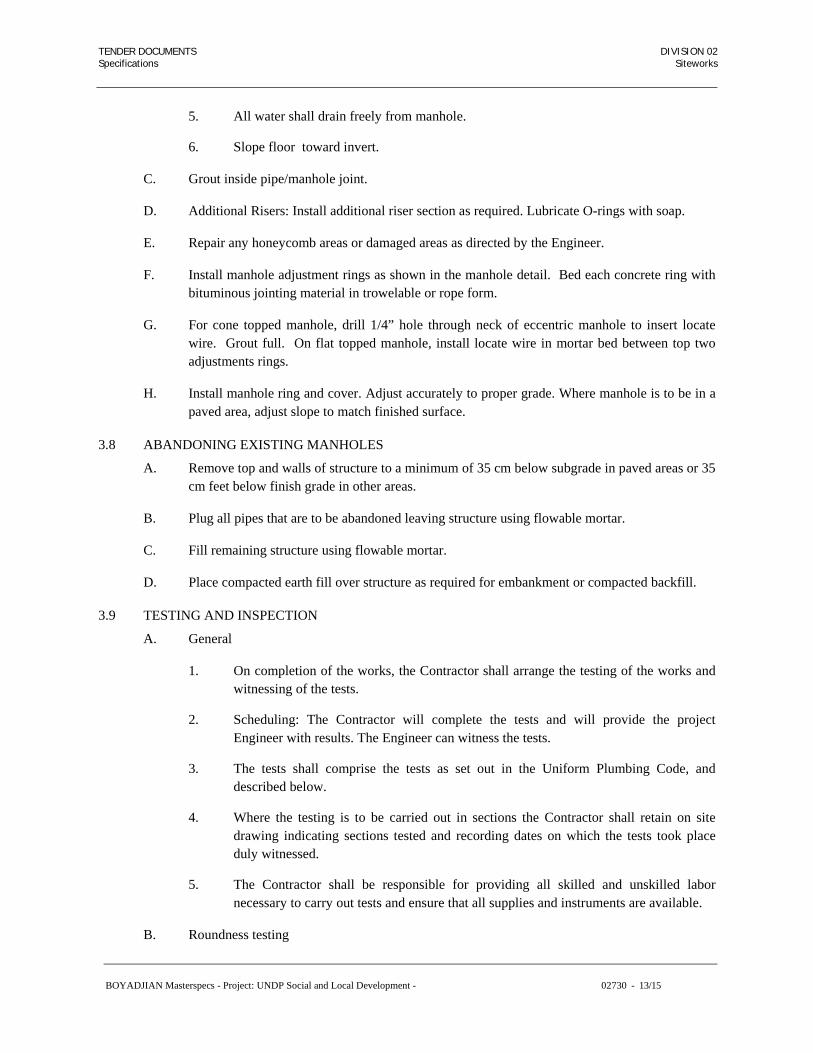
TENDER DOCUMENTS DIVISION 02 Specifications Siteworks
BOYADJIAN Masterspecs - Project: UNDP Social and Local Development - 02730 - 13/15
5. All water shall drain freely from manhole.
6. Slope floor toward invert.
C. Grout inside pipe/manhole joint.
D. Additional Risers: Install additional riser section as required. Lubricate O-rings with soap.
E. Repair any honeycomb areas or damaged areas as directed by the Engineer.
F. Install manhole adjustment rings as shown in the manhole detail. Bed each concrete ring with bituminous jointing material in trowelable or rope form.
G. For cone topped manhole, drill 1/4” hole through neck of eccentric manhole to insert locate wire. Grout full. On flat topped manhole, install locate wire in mortar bed between top two adjustments rings.
H. Install manhole ring and cover. Adjust accurately to proper grade. Where manhole is to be in a paved area, adjust slope to match finished surface.
3.8 ABANDONING EXISTING MANHOLES
A. Remove top and walls of structure to a minimum of 35 cm below subgrade in paved areas or 35 cm feet below finish grade in other areas.
B. Plug all pipes that are to be abandoned leaving structure using flowable mortar.
C. Fill remaining structure using flowable mortar.
D. Place compacted earth fill over structure as required for embankment or compacted backfill.
3.9 TESTING AND INSPECTION
A. General
1. On completion of the works, the Contractor shall arrange the testing of the works and witnessing of the tests.
2. Scheduling: The Contractor will complete the tests and will provide the project Engineer with results. The Engineer can witness the tests.
3. The tests shall comprise the tests as set out in the Uniform Plumbing Code, and described below.
4. Where the testing is to be carried out in sections the Contractor shall retain on site drawing indicating sections tested and recording dates on which the tests took place duly witnessed.
5. The Contractor shall be responsible for providing all skilled and unskilled labor necessary to carry out tests and ensure that all supplies and instruments are available.
B. Roundness testing

TENDER DOCUMENTS DIVISION 02 Specifications Siteworks
BOYADJIAN Masterspecs - Project: UNDP Social and Local Development - 02730 - 14/15
1. The Contractor shall test gravity lines for roundness by drawing a 7 1/2% deflected mandrel through the pipe.
2. To be used on PVC and polyethylene pipes.
C Pressure Testing (for projects with over 200’ of new sewer piping)
1. Owner shall conduct a low pressure air test per ASTM F1417.
2. To be used on PVC and polyethylene pipes.
3. Determine the test time required. A table of minimum test times for various pipe sizes is shown below.
4. Owner shall plug all openings in the test section.
5. If groundwater is present, air pressure shall be corrected by dividing water height over pipe (ft) by 2.31 and adding this psi to test pressure.
6. Add air until the internal pressure of the line is raised to 4 psig plus groundwater correction. Maintain pressure for 2 minutes to allow temperature equalization.
7. After pressure has stabilized between 3.5 and 4 psig, record pressure and begin timed test.
8. If the pressure drops more than 1.0 psig during the test time, the line has failed. Contractor must resolve failure at their expense.
9. Minimum Test Times
Pipe Size (Inches) Seconds/100 ft
4 20
6 45
8 75
10 120
12 170
D. Visual Inspection.
1. The Owner and Engineer will check the sewer piping for alignment and grade between manholes or intake structures by means of lamping. If any portion of the sewer system deviates from true line or grade, the Contractor shall be required to correct at the Contractor’s expense.
2. To be used on all pipes.

TENDER DOCUMENTS DIVISION 02 Specifications Siteworks
BOYADJIAN Masterspecs - Project: UNDP Social and Local Development - 02730 - 15/15
3. Manhole and intake structures are to be visually examined for leaks, damage, voids, porous areas, proper seals, and to verify that structure is proper size, to grade and plumb.
4. Contractor to repair or replace any unacceptable work at no additional cost to Owner. Items that can be repaired in manholes are small visible leaks and tie holes to patch.
E. Water Flow Inspection.
1. Water shall be supplied at the upstream structure and observed flowing into the adjacent structure downstream. The Engineer shall determine if the functionality of the sewer is acceptable.
F. Water Head Test (For projects with under 200’ of sewer piping).
1. Contractor shall provide a means for the owner to put 15’ head of water on the new sewer pipe.
2. The Engineer shall fill the sewer pipe with water up to 15’ above pipe invert and mark fill level.
3. Water shall not drop more than 6” in 2 hours. Pipe that fails this test shall be inspected by excavation at Contractor’s expense to determine cause of leak. Contractor shall repair leak as directed by owner, prior to a re-test
G. Trench Compaction
1. Utility Trench Excavation and Backfill for compaction testing.
END OF SECTION 02730

TENDER DOCUMENTS DIVISION 02 Specifications Siteworks
BOYADJIAN Masterspecs - Project: UNDP Social and Local Development - 02730 - 16/15

TENDER DOCUMENTS DIVISION 02 Specifications Siteworks
SECTION 02832
CHAIN LINK FENCE AND GATES
PART 1 GENERAL
1.01 SECTION INCLUDES
A. Fabrication, furnishing and installation of chain link fence, chain link gates, and extension
brackets with barbed wire.
1.02 RELATED SECTIONS
A. Section 01330 Submittal Procedures.
B. Section 02220 Structural Excavation and Backfill.
C. Section 03300 Cast in Place Concrete.
1.03 REFERENCES
A. ASTM A 121 Zinc coated (galvanized) steel barbed wire.
B. ASTM F 654 Residential Chain Link Fence Gates.
C. ASTM F 668 Poly Vinyl Chloride (PVC) Coated Steel Chain Link Fence Fabric.
D. ASTM F 900 Industrial and Commercial Swing Gates.
E. ASTM F 1083 Pipe, Steel, Hot Dipped, Zinc Coated (Galvanized), Welded, for Fence Structures.
F. ASTM F 1184 Industrial and Commercial Horizontal Slide Gates.
1.04 SUBMITTALS
A. Comply with Section 01330.
B. Submit for the Engineer’s information and acceptance the following:
1. The Manufacturer’s Certificates verifying the materials comply with the specified
standards.
2. Shop Drawings for fabrication, assembly and erection.
BOYADJIAN Masterspecs - Project: UNDP Social and Local Development - 02832- 1/5

TENDER DOCUMENTS DIVISION 02 Specifications Siteworks
PART 2 PRODUCTS
2.01 MATERIALS
Materials shall conform to the following:
A. General:
1. Materials for fencing and gates shall be in accordance with the standards listed in clause 1.02. All items of each type, such as posts, fabric, and accessories shall be from the same manufacturer and of the same size, design, and materials except as otherwise shown on the Drawings.
2. The fencing items and fittings shall be galvanized and where required shall have a
bonded polyvinyl chloride (PVC) coating. The bond between the vinyl coating and the metal surface shall be not less than the cohesive strength of the vinyl. The color of the vinyl coating shall be as shown on the drawings or as approved by the Engineer. Extruded PVC coatings or jacketed type coatings will not be accepted.
3. Concrete for post foundations shall be as shown on drawing in accordance with
Section 03300.
B. Wire and Fabric:
1. The Chain Link Fence fabric shall be Plastic Coated with 50 mm diamond mesh of 4.0 mm diameter wire with twisted and barbed top and bottom salvages. The fabric shall be of the size and dimensions shown on the Drawings.
2. The Line Wires (3 strands) shall be Plastic Coated 4.0 mm diameter. Tying wire for
fastening fabric to line posts shall be of nominal core diameter of 1.4 mm and nominal outside diameter of 2 mm. Galvanized steel bands shall be used for fastening the fabric to all corner, straining, end posts and gate frames.
C. Posts:
Intermediate, end corner, straining posts and struts shall be galvanized steel hollow circular sections to ASTM F 1083 Schedule 40.
As specified on the Drawings.
1. Intermediate or Line Posts - 60.3 mm outside diameter and 3.91 mm wall thickness
minimum.
2. End, Corner or Straining Posts - 73.0 mm outside diameter and 5.16 mm wall thickness minimum.
3. Struts - 48.3 mm outside diameter and 3.68 mm wall thickness minimum.
Where specified on the drawings posts shall be fitted with snap off failing footings as detailed to permit failure of the fencing when the moment at the post base is equal to 1.2 KNm.
BOYADJIAN Masterspecs - Project: UNDP Social and Local Development - 02832- 2/5

TENDER DOCUMENTS DIVISION 02 Specifications Siteworks
D. Gate Hinge Posts:
Gate hinge posts of galvanized steel hollow circular sections to ASTM F 1083 schedule 40, with the following diameters for the nominal width of a single gate, or one leaf of a double gate:
To 2.0 m width - outside diameter 114.3 mm by 6.02 mm, wall thickness
2.0 m to 4.0 m width - outside diameter 139.7 mm by 6.5 mm, wall thickness
4.0 m to 6.0 m width - outside diameter 168.3 mm by 7.11 mm, wall thickness
6.0 m to 8.0 m width - outside diameter 219.1 mm by 8.18 mm, wall thickness.
E. Miscellaneous Fencing Items:
1. Post tops, and other fittings and hardware shall be of galvanized steel, malleable iron, or wrought iron.
2. Stretcher bars of galvanized steel, not less than 5mm by 20mm or equivalent cross-
sectional area, and of lengths equal to the full height of the fabric to be used.
3. Bolts, nuts and other hardware shall be galvanized.
4. Horizontal braces shall be galvanized steel pipe at least 42.40 mm outside diameter and 3.2 mm wall thickness and diagonal bracing of galvanized steel truss rods at least 10 mm diameter with turnbuckles.
F. Gates:
1. Swing gate frames: Galvanized steel hollow circular sections with oustide diameter
not less than 48.30 mm by 3.68 mm wall thickness welded to form a rigid frame, with cross-bracing of galvanized steel rods, 10 mm in diameter.
2. Latches for swing gates with padlock eyes, forked or plunger-bar type, operated
from each side of the gate. Provide gate stops and keepers as required.
3. Hinges: manufacturer’s standard type which will ensure that gates cannot be readily detached by unauthorized persons.
4. Tie wire and stretcher bars as specified for other fencing herein.
G. Extension Brackets: Galvanised steel Y-shaped extension arms combined with the
post cap with three slots for supporting three strands of barbed wire and of sufficient strength to withstand the loads of all the strands of barbed wire.
H. Barbed Wire: Barbed wire consist of minimum three strands of 2.5 mm wire,
otherwise twisted with two-point 2.1 mm or heavier aluminum barbs spaced not more than 75 mm apart.
BOYADJIAN Masterspecs - Project: UNDP Social and Local Development - 02832- 3/5

TENDER DOCUMENTS DIVISION 02 Specifications Siteworks
PART 3 EXECUTION
3.01 ERECTION
A. Posts:
1. Erect space line posts not more than 3m apart, measured parallel to the slope of the natural ground. Set vertically the posts except in unusual situations as determined by the Engineer where posts are to be placed perpendicular to the slope of the ground.
2. Install gate posts where shown on the Drawings. Install corner posts where the
o
change in direction is 15 or more. Place straining posts not more than 150 m apart o
in a straight run and where the line changes direction by 15 or more.
B. Excavation for Posts:
1. Excavate in firm, undisturbed, or compacted soils to the minimum diameters and depths shown. Drill holes augered, or excavated with a post-hole digger.
2. In rock, submit for the Engineer’s approval, proposals for grouting line or straining
posts into 150 mm diameter holes at least 300 mm deep for line posts and not less than 450 mm deep for all other posts.
C. Setting Posts:
1. Place posts vertically and aligned within a tolerance ratio of 1 in 500. Set the top of
posts to the required height, and do not cut off.
2. Where snap off fence posts are required, place them in post holes with the snap fitting oriented to permit failure in the direction of the stream channel. Do not extend the snap off fitting more than 150 mm above the channel invert, but must be clear of the concrete base.
3. Place concrete of class C20S, in post holes in a continuous placement and compact
by rodding or by use of mechanical vibrators. Trowel-finish the top of footings and slope it to drain away water.
4. Install temporary guys or braces as required to hold the posts in position until the
concrete has set sufficiently, and do not hang any material on the posts for the first seven days after placing the concrete.
5. If the ground is firm enough to permit excavation of a post hole to neat lines, the
concrete may be placed without forms by completely filling the hole. Under these conditions moisten the earth coming in contact with the concrete prior to placing the concrete.
6. When the ground cannot be satisfactorily excavated to neat lines, use forms for
footings. Remove the form after 24 hours of placing concrete and paint the surface with 2 coats bituminous dampproofing. Backfill the footing with moistened material and tamp thoroughly. Cover the top of the concrete with not less than 100 mm of loose moistened material.
BOYADJIAN Masterspecs - Project: UNDP Social and Local Development - 02832- 4/5

TENDER DOCUMENTS DIVISION 02 Specifications Siteworks
7. Cure the concrete for a minimum of seven days before stretching the fabric and installing brace assemblies or gates.
D. Struts and Braces: Provide these at each gate, corner, straining and end posts at midheight of
the fabric. Extend the brace horizontally between the gate, corner, straining or end post and the adjacent line post. Provide the diagonal rod with a turnbuckle not less than 10 mm in diameter, and extend it from the line post end of the horizontal brace to the base of the gate, corner, straining or end post. Where fence lengths is of 90 m or longer, end at gate, corner, straining or end posts, provide a second similar diagonal rod from the midpoint of the gate, corner, straining or end post to the top of the adjacent line post.
E. Tension Wires: Fasten tension wires by clips at each gate, corner, straining or end post, and
stretch it tight with turnbuckles or propose an alternative method for approval of the Engineer. Taut the bottom tension wire between posts, 50 mm or less above the ground surface except where special closures are required.
F. Fabric and Barbed Wire:
1. Place the fabric on the outside of the posts, evenly stretched, and fastened to the post
by bands or tie wires not more than 360 mm apart on the posts. Fasten the fabric to the line wires by tie wires spaced not more than 600 mm apart.
2. Attach the stretcher bars to the fabric by clamps or other approved mechanical
means. Provide one stretcher bar for each gate, straining and end post, and two for each corner post. Provide sufficient clips for attaching the fabric and stretcher bars to the post at intervals not more than 400 mm apart.
3. Install three strands of barbed wire in to the slots of each arm of the extension
brackets and fastened by steel wire keys. Provide continuous barbed wire for each run of fence, drawn out and fastened securely with wire stretching bands to the extension brackets of the gate corner, straining or end posts.
G. Gates:
1. Erect the gates plumb and true, complete with all the necessary accessories for
satisfactory operation. Attach the chain link fabric to the gate frames by stretcher bars and tie wires as for the fence construction, and space tension connectors approximately 300 mm apart. Hung each gate on at least two hinges, clamped securely to the gatepost and allowing the gate to swing back against the fence.
2. Design the hinges and arrange such that the gate cannot be removed without
mechanically dismantling the hinges.
3. Provide extension arms on the end posts to carry strands of barbed wire aligned horizontally with those on the adjacent fence.
END OF SECTION 02832
BOYADJIAN Masterspecs - Project: UNDP Social and Local Development - 02832- 5/5

DIVISION 3
CONCRETE TABLE OF
CONTENTS
03100 FORMWORK 03200 CONCRETE REINFORCEMENT 03250 CONCRETE ACCESSORIES 03300 CAST IN PLACE CONCRETE 03355 EXPOSED AGGREGATE CONCRETE FINISH 03370 CONCRETE CURING 03720 CONCRETE REPAIR

TENDER DOCUMENTS DIVISION 03 Specifications Concrete
SECTION 03100
FORMWORK
PART 1 GENERAL
1.01 SECTION INCLUDES
A. Formwork for cast-in place concrete, with shoring, bracing and anchorage.
B. Openings for other work.
C. Form accessories.
D. Form stripping.
E. Formed concrete surface finishes.
F. Remedial work to defective surfaces.
1.02 RELATED SECTIONS
A. Section 01330 Submittal Procedures.
B. Section 03200 Concrete Reinforcement.
C. Section 03250 Concrete Accessories.
D. Section 03300 Cast In Place Concrete.
E. Section 03355 Exposed Aggregate Concrete Finish.
1.03 REFERENCES
A. ACI 117 Standard Specifications for Tolerances for Concrete Construction and Materials.
B. ACI 301 Structural Concrete for Buildings.
C. ACI 318 Building Code Requirements for Reinforced Concrete.
D. ACI 347 Recommended Practice for Concrete Formwork.
E. ASTM A 184 Fabricated Deformed Steel Bar Mats for Concrete Reinforcement.
1.04 DEFINITIONS
A. Formwork means the surface against which concrete is placed to form a face, together with all the immediate supports to retain it in position while concrete is placed.
B. Falsework means the structural elements supporting both the formwork and the concrete
until the concrete becomes self supporting.
BOYADJIAN Masterspecs - Project: UNDP Social and Local Development - 03100- 1/9

TENDER DOCUMENTS DIVISION 03 Specifications Concrete
C. A formed face is one which has been cast against formwork.
D. An exposed face is one which will remain visible when construction has been completed.
1.05 DESIGN REQUIREMENTS
A. Design, engineer and construct formwork, shoring and bracing to conform to code requirements; resultant concrete to conform to required shape, line and dimensions.
B. Design and construct formwork and falsework such that they support the loads imposed on
them by fresh concrete, together with additional stresses from vibrating equipment and construction traffic, so that after the concrete has hardened the formed faces are in the position and have the shape and profile as shown on the drawings within the limits of the dimensional tolerances.
C. The design of formwork is the responsibility of the Contractor.
1.06 SUBMITTALS FOR REVIEW
A. Comply with Section 01330.
B. Submit shop drawings and design calculations showing details of the proposed formwork
and falsework for approval of the Engineer.
C. Shop drawings: Indicate pertinent dimensions, materials, bracing and arrangement of joints and ties.
PART 2 PRODUCTS
2.01 MATERIALS
A. Construct temporary formwork of timbers, (soft wood plywood, plywood or lumber), metal sheet or other approved material such that concrete produced is of the required finish.
B. Construct permanent formwork of slabs or blocks of precast concrete, natural stone,
brickwork, preformed metal sheets or other approved material. Tighten them by such means as to prevent the leakage of grout from the concrete. Do not use breeze blocks or other porous materials as permanent formwork.
C. The type and treatment of any lining to the forms be appropriate to the concrete finish
required.
2.02 PREFABRICATED FORMS
A. Provide one or more of the following form types as per manufacturer’s standard product and as required by the project, matched, tight fitting, stiffened to support weight of concrete without deflection detrimental to tolerances and appearance of finished concrete surfaces.
1. Preformed steel forms of minimum 16 gauge or 1.5 mm thick.
2. Thermoplastic polystyrene preformed plastic forms.
BOYADJIAN Masterspecs - Project: UNDP Social and Local Development- 03100- 2/9

TENDER DOCUMENTS DIVISION 03 Specifications Concrete
3. Glass fiber fabric reinforced plastic forms.
4. Pan type: Steel or glass fiber of size and profile required.
2.03 FORMWORK ACCESSORIES
A. Form Ties: Removable type, galvanized metal or plastic, adjustable length, cone type, with waterproofing washer, free of defects.
B. Form Release Agent: Colorless mineral oil which do not stain concrete, or absorb
moisture, or impair natural bonding or color characteristics of coating intended for use on concrete and be one of the following types:
1. Cream emulsion.
2. Neat oil with surfactant added.
3. Chemical release agent.
C. Corners: Chamfered rigid plastic or wood strip 25 x 25 mm size of maximum
possible lengths.
D. Dovetail Anchor Slot: Galvanized steel, 0.8 mm thick, non-filled, release tape sealed slots, anchors for securing to concrete formwork.
E. Flashing Reglets: Galvanized steel or rigid PVC, 0.8 mm thick, longest possible
lengths, with alignment splines for joints, non-filled, release tape sealed slots, anchors to be secured to concrete formwork.
F. Nails, Spikes, Lag Bolts, Through Bolts, Anchorages: Sizes as required, of
sufficient strength and character to be secured to concrete formwork.
G. Waterstops: Preformed mineral colloid strips, 9 mm thick, moisture expanding.
PART 3 EXECUTION
3.01 EXAMINATION
A. Verify lines, levels and centers before proceeding with formwork. Ensure that dimensions agree with drawings.
3.02 EARTH FORMS
A. Earth forms are not permitted.
3.03 ERECTION
A. Erect formwork, shoring and bracing to achieve design requirements, in accordance with
requirements of ACI 301 and ACI 347.
B. Provide bracing to ensure stability of formwork. Shore or strengthen formwork subject to overstressing by construction loads. Props shall be carried to construction which is
BOYADJIAN Masterspecs - Project: UNDP Social and Local Development- 03100- 3/9

TENDER DOCUMENTS DIVISION 03 Specifications Concrete
sufficiently strong to afford the necessary support without injury to any portion of the structure. This may mean in some cases that they be carried down to the foundations or other suitable bases.
C. Arrange and assemble formwork to permit dismantling and stripping without shock and
disturbance. Do not damage concrete during stripping. Permit removal of remaining principal shores. The responsibility for the safe removal of the props rests with the Contractor.
D. Align joints and make watertight to prevent leakage of grout from concrete. Keep form
joints to a minimum.
E. All construction joints in formwork shall be tightly secured against previous or hardened concrete to prevent the formation of stepping or ridges in the concrete.
F. Formwork shall be constructed to provide straight and true angles, arises or edges. Provide
chamfer strips on external corners of beams columns and walls.
G. Formwork panels shall have true angles to permit accurate alignment at the sides and provide a clean line at construction joints in the concrete.
H. Coordinate this section with other sections of work which require attachment of components
to formwork.
I. When formwork is placed after reinforcement resulting in insufficient concrete cover over reinforcement before proceeding, request instructions from Engineer.
J. Fix formwork panels with their joints either vertical or horizontal unless otherwise specified.
K. Provide formwork to the top surface of concrete where the slope or nature of the Work requires it. Horizontal or inclined formwork to the upper surface of concrete is to be adequately secured against uplift due to the pressure of fresh concrete.
3.04 APPLICATION – FORM RELEASE AGENT
A. Store and use release agents strictly in accordance with the manufacturer's instructions.
B. Where the concrete surface is to be permanently exposed use only one agent throughout the
entire area.
C. Where the surface is to receive an applied finish, take care to ensure the compatibility of the release agent with the finish.
D. Release agents not to come in contact with the reinforcement.
3.05 INSERTS, EMBEDDED PARTS AND OPENINGS
A. Unless otherwise shown on the drawings or specifically approved, form all openings and
holes and cast all inserts and fixings at the time of pouring.
B. Locate and set in place items which will be cast directly in to concrete. Obtain approval for size, type and position of any hole, insert or fixing required before work proceeds.
BOYADJIAN Masterspecs - Project: UNDP Social and Local Development- 03100- 4/9

TENDER DOCUMENTS DIVISION 03 Specifications Concrete
C. Coordinate with work of other sections in forming and placing openings, slots, reglets, recesses, sleeves, bolts, anchors, other inserts, and components of other work.
D. Position recessed reglets for masonry anchors to the spacing and intervals required.
E. Install accessories in accordance with manufacturer’s instructions, straight, level, and plumb.
Ensure items are not disturbed during concrete placement.
F. Install waterstops in accordance with manufacturer’s instructions continuous without displacing reinforcement. Heat seal joints watertight.
G. Provide temporary ports or openings in formwork where required to facilitate cleaning and
inspection. Locate openings at bottom of forms to allow flushing water to drain.
H. Close temporary openings with tight fitting panels, flush with inside face of forms, and neatly fitted so joints will not be apparent in exposed concrete surfaces.
I. Do not drill or cut away any part of the concrete works without the specific approval of the
Engineer.
J. If such drilling or cutting is carried out without approval the affected parts is classed as defective work.
3.06 FORMWORK TIES
A. Obtain Engineer’s approval for the materials and position of any ties passing through the
concrete.
B. Remove a tie so that no part of it is remaining in the concrete.
C. Place the tie nearer to the finished surface of the concrete more than the specified thickness of cover to reinforcement.
D. Fill any holes left after the removal of ties with concrete or mortar of approved composition
unless otherwise specified.
E. In waterproof concrete use tie through the concrete of a type with a baffle.
3.07 DEFECTIVE FORMWORK
A. Where in the opinion of the Engineer any piece of formwork is damaged, deformed, worn or otherwise incapable of producing an acceptable finished concrete surface, he may declare such formwork defective. Repair such formwork to the satisfaction of the Engineer or remove from the site.
3.08 FORM CLEANING
A. Clean forms as erection proceeds, to remove foreign matter within forms.
B. Clean formed cavities of debris prior to placing concrete.
C. Flush with water or use compressed air to remove remaining foreign matter. Ensure that water and debris drain out through clean-out ports.
BOYADJIAN Masterspecs - Project: UNDP Social and Local Development- 03100- 5/9

TENDER DOCUMENTS DIVISION 03 Specifications Concrete
3.09 FINAL PREPARATIONS
A. Before concrete placing commences, secure all wedges and other adjusting devices against movement during concrete placing and maintain a watch on the formwork during placing to ensure no movement occurs.
3.10 STRIKING OF FORMWORK
A. Inform and take approval of the Engineer to strike any formwork.
B. Do not remove forms or bracing until concrete has gained sufficient strength.
C. Unless otherwise directed, do not apply treatment of any kind, other than that required for curing after removal of the forms until it has been inspected.
3.11 SUBSEQUENT POUR
A. Do not pour concrete against an existing concrete face until 24 hours of its casting.
3.12 FORMED CONCRETE SURFACE FINISHES
A. Classes of Finish: Achieve the surface finish on formed concrete surfaces as shown on the
Drawings and detailed hereunder.
1. Class F1 Finish
a. Provide this finish for surfaces against which backfill or further concrete will be placed.
b. Use sawn boards, sheet metal or any other suitable material which will prevent the loss of fine material from the concrete being placed.
2. Class F2 Finish
a. Provide this finish for surfaces which are permanently exposed to view but
where the highest standard of finish is not required. b. Use form faced with wrought thickened tongue and grooved boards with
square edges arranged in a uniform pattern and close jointed or with suitable sheet material. The thickness of boards or sheets be such that there is no visible deflection under the pressure exerted by the concrete placed against them.
c. Provide joints between boards or panels vertical and horizontal unless otherwise directed.
d. This finish do not require general filling of surface pitting. Fins, surface discolouration and other minor defects are remedied by methods agreed by the Engineer.
3. Class F3 Finish
a. Provide this finish for surfaces permanently exposed to view where good
appearance is of special importance.
BOYADJIAN Masterspecs - Project: UNDP Social and Local Development- 03100- 6/9

TENDER DOCUMENTS DIVISION 03 Specifications Concrete
b. To achieve this finish, which shall be free of board marks, face the formwork with plywood complying with ACI 301 or equivalent material in large sheets.
c. Arrange the sheets in an approved uniform pattern. Wherever possible,
arrange joints between sheets to coincide with architectural features or changes in direction of the surface. Keep joints between panels vertical and horizontal unless otherwise directed. Provide suitable joints between sheets to maintain accurate alignment in the plane of the sheets.
d. Unfaced wrought boarding or standard steel panels will not be permitted for
Class F3 finish.
e. Ensure that the surface is protected from rust marks, spillages and stains of all kinds.
4. Class F4 Finish
a. Provide this finish similar to that required for F3 but use it in places where a
first class alignment and a dense surface free from air holes and other defects is required.
b. Provide a high quality finish for exposed surfaces and be suitable for the
application of decorative finishes and in other similar circumstances.
c. Use this finish for concrete surface to have exposed aggregate finish complying with Section 03355.
d. Provide this finish with careful selection of materials and the highest quality
of workmanship and supervision at all stages.
B. Curved Surfaces
1. For curved surfaces where F2, F3 or F4 finishes are called for, build the formwork face with splines cut to make a tight surface and dressed to produce the required finish.
2. Alternatively face the single curvature surfaces with plastic or plywood linings
attached to the backing with adhesive or with escutcheon pins driven flush.
3. Ensure that linings shall not bulge, wrinkle or otherwise deform when subjected to temperature and moisture changes.
3.13 DIMENSIONAL TOLERANCES
A. Erect formwork such that dimensions of concrete construction are within the tolerances
quoted in ACI SP-16, ACI 301, ACI 318, ACI 347 and ASTM A184 for accuracy in Building, except where the tolerances given in the Specification are more onerous.
B. The permissible tolerances on formed concrete surfaces shall not exceed the values given in
Table 1.
BOYADJIAN Masterspecs - Project: UNDP Social and Local Development- 03100- 7/9

TENDER DOCUMENTS DIVISION 03 Specifications Concrete
TABLE 1
Class of Finish Tolerance in mm – see notes
A B C
F1
F2
F3
F4
10
5
2
Nil *
10
10
5
2
±25 to ±10
±15
±10
±5
Notes:- The tolerances A, B and C given in Table 1 are defined as follows:
A - is an abrupt irregularity in the surface due to misalignment or defects in the face of the formwork.
B - is a gradual deviation from a plane surface as indicated by a straight-edge 3 m long.
In case of curved surfaces replace the straight-edge by correctly shaped template.
C - is the amount by which the whole or part of a concrete face is displaced from the correct position shown on the drawings.
* Abrupt irregularities are not permitted in F4 finish. Remove by grinding any
irregularities which remain after removal of formwork to achieve a transition of 1 in 50 between the surfaces adjacent to the irregularity.
3.14 REMEDIAL WORK TO DEFECTIVE SURFACES
A. When on stripping any formwork the concrete surface is found to be defective in any wy, do
not attempt to remedy such defects prior to the Engineer’s inspection.
B. Do not make defective surfaces good by plastering at any stage.
C. Honeycombed Areas
1. Repair areas of honeycombing which the Engineer agrees by cutting back to sound concrete or to 75 mm whichever is the greater.
2. In the case of reinforced concrete cut back to at least 25 mm clear distance behind
the reinforcement or to 75 mm, whichever is the greater.
3. Make sides of the cavity at right-angles to the face of the concrete.
4. After cleaning out with water and compressed air, apply a thin layer of cement grout
BOYADJIAN Masterspecs - Project: UNDP Social and Local Development- 03100- 8/9

TENDER DOCUMENTS DIVISION 03 Specifications Concrete
on to the concrete surfaces in the cavity and then fill immediately with concrete of the same class as the main body but with aggregate larger than 20 mm nominal size removed.
5. Use form against the cavity along with a lip to enable concrete to be placed. Fill it
to a point above the top edge of the cavity.
6. After seven days remove the lip of concrete and grind the surface.
D. Grind the surface irregularities which are outside the limits of tolerance set out in Table 1 in the manner and to the extent instructed by the Engineer.
END OF SECTION 03100
BOYADJIAN Masterspecs - Project: UNDP Social and Local Development- 03100- 9/9

TENDER DOCUMENTS DIVISION 03 Specifications Concrete
SECTION 03200
CONCRETE REINFORCEMENT
PART 1 GENERAL
1.01 SECTION INCLUDES
A. Steel reinforcement for concrete in any part of the Works but excluding prestressing tendons or any other embedded steel.
1.02 RELATED SECTIONS
A. Section 01330 Submittal Procedures.
B.
Section 01400
Quality Requirements.
D.
Section 03100
Concrete Formwork.
E.
Section 03250
Concrete Accessories.
F.
Section 03300
Cast In Place Concrete.
G.
Section 03400
Precast Concrete.
H.
Section 03410
Structural Precast Concrete. 1.03 REFERENCES
A.
CRSI
Concrete Reinforcing Steel Institute - Manual of Practice.
B.
CRSI 63
Recommended Practice for Placing Reinforcing Bars.
C.
CRSI 65
Recommended Practice for Placing Bar Supports, Specification and Nomenclature.
D.
ACI 301
Structural Concrete for Buildings.
E.
ACI 318
Building Code Requirements for Reinforced Concrete.
F.
ACI SP 66
American Concrete Institute - Detailing Manual.
G.
ASTM A 184
Specification for Fabricated Deformed Steel Bar Mats for Concrete Reinforcement.
H.
ASTM A 185
Specification for Welded Steel Wire Fabric for Concrete Reinforcement.
I.
ASTM A 496
Specification for Steel Wire, Deformed, for Concrete Reinforcement.
J.
ASTM A 497
Specification for Welded Deformed Steel Wire Fabric for Concrete Reinforcement.
BOYADJIAN Masterspecs - Project: UNDP Social and Local Development- 03200- 1/5

TENDER DOCUMENTS DIVISION 03 Specifications Concrete
K. ASTM A 615 Specification for Deformed and Plain Billet Steel Bars for Concrete Reinforcement.
L. ASTM A 641 Specification for Zinc-Coated (Galvanized) Carbon Steel Wire.
M. ASTM A 767 Specification for Zinc-Coated (Galvanized) Bars for Concrete Reinforcement.
N. ASTM A 775 Specification for Epoxy-Coated Reinforcing Steel Bars.
O. ASTM A 884 Specification for Epoxy-Coated Steel Wire and Welded Wire Fabric for
Reinforcement.
P. ASTM A 934 Specification for Epoxy-Coated Pre-Fabricated Reinforcing Bars.
Q. AWS D 1.4 Structural Welding Code for Reinforcing Steel.
R. AWS D 12.1 Welding Reinforcement Steel, Metal Inserts and Connections in Reinforced Concrete Construction.
1.04 SUBMITTALS FOR REVIEW
A. Comply with Section 01330.
B. Submit for Engineer’s review all items described in this specification section.
C. Submit manufacturer’s certificate, certifying that the products meet or exceed specified
requirements.
1.05 HANDLING AND STORAGE OF MATERIALS
A. Comply with Section 01600.
B. Handle epoxy coated bars with the systems having padded contact area.
C. Use padded bundling bands or use suitable banding (use nylon rope instead of wire rope), to prevent damage to the coating.
D. Lift all the bundles of coated bars with a strong back, spreader bar, multiple supports or via
platform bridge to prevent bar-to-bar abrasion from sags in the bundles of coated bars.
E. Do not drop or drag bars or bundles.
F. Store reinforcement of all types on site in padded racks above ground in an approved manner so as to avoid damage to coatings.
G. Provide reinforcement free from loose scale, rust, oil, grease or any other material that may
impair the bond between the concrete and the reinforcement. Remove from site any reinforcement which has damaged the coating or pitted to an extent which, in the opinion of the Engineer, will affect its properties.
H. Store mild steel reinforcement separately from high yield reinforcement.
BOYADJIAN Masterspecs - Project: UNDP Social and Local Development- 03200- 2/5

TENDER DOCUMENTS DIVISION 03 Specifications Concrete
1.06 QUALITY ASSURANCE AND TESTS
A. Comply with Section 01400.
B. Perform work in accordance with CRSI 63, 65 of ACI 301, ACI SP-66, ACI 318, ASTM A 184 and ASTM A 775.
C. Provide Engineer with access to fabrication plant to facilitate inspection of reinforcement.
Provide notification of commencement and duration of shop fabrication in sufficient time to allow inspection.
D. The manufacturer's test certificate for ultimate strength, elongation and cold bending
together with the chemical analysis of the steel may be called for by the Engineer for any consignment of reinforcing steel direct from the manufacturer. Where steel is obtained from an indirect supplier, the Engineer may require tests in an approved laboratory to prove compliance with the appropriate American Standards.
E. The frequency of testing shall be as set out in the American Standards. Carry out additional
tests as instructed by the Engineer.
F. Any reinforcement which does not comply with the Specification remove immediately from site.
PART 2 PRODUCTS
2.01 REINFORCEMENT
A. Bars for reinforcement shall be:-
1. Hot rolled mild steel bars to ASTM A 615.
2. Hot rolled high yield deformed bars to ASTM A 615.
3. Steel fabric to ASTM A 185 plain type, ASTM A 497 welded deformed type, ASTM A 497 deformed type.
4. Reinforcing steel bars, welded wire fabric, and prefabricated reinforcing bars shall
be epoxy-coated to ASTM A 775, ASTM A 884 and ASTM A 934.
B. Deformed bars shall be as defined in ASTM A 615.
2.02 TYING DEVICES
A. Tying devices shall be:
1. Black annealed mild steel wire of 1.6 mm diameter.
2. Approved rustproof binding wire, or
3. Approved proprietary ties.
BOYADJIAN Masterspecs - Project: UNDP Social and Local Development- 03200- 3/5

TENDER DOCUMENTS DIVISION 03 Specifications Concrete
2.03 SPACER BLOCKS, CHAIRS, BOLSTERS, BAR SUPPORTS
A. Use spacer blocks chairs, bolsters, bar supports for ensuring that the correct cover is maintained to the reinforcement.
B. Provide blocks, chairs, bar supports and bolsters of such materials and design as will be
durable and not lead to corrosion of the reinforcement such as plastic and plastic coated steel, or current blocks. These are sized and shaped for strength and support of reinforcement during concrete placement conditions.
C. Use spacer blocks made from cement, sand and small aggregate not exceeding 50 mm
square in section and secure with wire to the reinforcement to ensure that they are not displaced when the concrete is poured. Make these of similar mix proportions and strength as the adjacent concrete.
PART 3 EXECUTION
3.01 CUTTING AND BENDING
A. Bend reinforcement to the dimensions given in the bar schedules in accordance with latest editions of ASTM A 184, ACI 318 CRSI 63 and CRSI 65 unless otherwise stated.
B. Do not heat reinforcement before bending.
C. Do not straighten or re-bend cold worked bars and hot rolled high yield bars once having
been bent. Where it is necessary to bend mild steel reinforcement already cast in the concrete, the internal radius of bend shall not be less than twice the diameter of the bar.
D. After bending, securely tie bars together in bundles or groups and legibly labelled as set out
in CRSI 63 and CRSI 65.
3.02 SPLICING AND WELDING
A. Locate reinforcing splices at point of minimum stress. Review and take instruction for location of splices with Engineer.
B. Do not weld or splice reinforcement except where required by the Contract or agreed by the
Engineer. When welding is employed follow the procedures shall be as set out in AWS D 1.4. Submit details of all welding techniques to be used and such trials made as are required to demonstrate the effect of the welding.
3.03 CLEANING OF REINFORCEMENT
A. Clean reinforcement free of all loose mill scale, rust, oil, grease, concrete or other harmful
matter at the time of concreting.
3.04 PLACEMENT AND FIXING OF REINFORCEMENT
A. Accurately place all reinforcement with the correct cover and fix securely in the positions as shown on the drawings. Give reasonable notice of the intention to pour to the Engineer and that the reinforcement fixing is complete.
BOYADJIAN Masterspecs - Project: UNDP Social and Local Development- 03200- 4/5

TENDER DOCUMENTS DIVISION 03 Specifications Concrete
B. At intersections bind together the reinforcement bars together with tying wire such that loose ends of the wire shall be turned towards the inside of the member.
C. Supply and fix all chairs required to support the top mat of slab reinforcement or space the
mats of all reinforcement adequately. In particular slab chairs must be close enough to prevent the reinforcement being bent or sagging.
D. Provide the actual concrete cover not less than the required nominal cover minus 5 mm. No
metal part of any device used for connecting bars or for maintaining reinforcement in the correct position shall remain within the specified minimum cover. Provide adequate mortar or plastic spacers to ensure the correct cover is achieved. The use of spacer blocks will not generally be permitted against a concrete face which is to be permanently exposed in the finished works.
3.05 PROJECTING REINFORCEMENT
A. Protect projecting reinforcement without affecting its bond properties ensure that it does not
cause rust staining to any part of the Works.
END OF SECTION 03200
BOYADJIAN Masterspecs - Project: UNDP Social and Local Development- 03200- 5/5

TENDER DOCUMENTS DIVISION 03 Specifications Concrete
SECTION 03250
CONCRETE ACCESSORIES
PART 1 GENERAL
1.01 SECTION INCLUDES
A. Accessories used in cast-in-place concrete construction, including but not limited to the following:
1. Expansion, contraction and construction joints.
2. Waterstops.
3. Joint sealants.
4. Coloured concrete.
5. Floor hardeners.
1.02 RELATED SECTIONS
A. Section 01330 Submittal Procedures.
B. Section 02220 Structural Excavation and Backfilling.
C. Section 02518 Concrete Pavers.
D. Section 03100 Formwork.
E. Section 03300 Cast in Place Concrete.
F. Section 03370 Concrete Curing.
1.03 REFERENCES
A. ASTM C 494 Specification for Chemical Admixtures for concrete.
B. ASTM D 1190 Concrete Joint Sealer, Hot-Poured Elastic Type.
C. ASTM D 1752 Preformed Sponge Rubber or Cork Expansion Joint Fillers for Concrete Paving and Structural Construction.
1.04 DEFINITIONS
A. Expansion and contraction joints are discontinuities in concrete designed to allow for
thermal and other movements in the concrete.
B. Expansions joints are formed with a gap between two concrete faces to permit subsequent expansion of the concrete. Expansion joints shall be formed in the positions and in accordance with the details shown on the drawings or elsewhere in the Specification.
BOYADJIAN Masterspecs - Project: UNDP Social and Local Development- 03250- 1/6

TENDER DOCUMENTS DIVISION 03 Specifications Concrete
C. Contraction joints are formed to permit initial contraction of the concrete and may include provision for subsequent filling. Contraction joints shall be either complete contraction joints or partial contraction joints and shall be formed in the positions and in accordance with the details shown on the drawings and elsewhere in the Specification.
D. A construction joint is the surface of contact whenever concrete is to be bonded to other
concrete which has hardened.
1.05 SUBMITTALS
A. Comply with Section 01330.
B. Submit all the items described in this specification section with product data, manufacturer’s installation instructions indicating procedures and interface required with adjacent work.
1.06 QUALITY ASSURANCE
A. Field Reference Samples:
1. Provide field constructed samples as identified and specified in this Section.
2. Engineer accepted samples will be quality control reference for remainder of Work
and considered as minimum quality standards.
3. An Engineer accepted field reference sample may be integrated into the Work.
4. If not integrated into Work, retain accepted samples in-place on site until related Work is completed and accepted.
PART 2 PRODUCTS
2.01 COMPRESSIBLE JOINT FILLER
A. Non-absorbent, closed cell, non-extruding, non bituminous complying to ASTM D 1752.
B. Shall have:-
1. A minimum of 85% recovery after 50% compression.
2. Water absorption not exceeding 1.5% by weight after 72 hours immersion.
3 3. Density between 37 and 40 kg/m .
C. Acceptable materials:-
1. Polyethylene foam expansion joint material.
2. Non-bituminous, wood fiber based joint material, Homex by Homasote or equal.
3. Standard or self-expanding cork material, ASTM D 1752.
4. Sponge rubber material, ASTM D 1752.
BOYADJIAN Masterspecs - Project: UNDP Social and Local Development- 03250- 2/6

TENDER DOCUMENTS DIVISION 03 Specifications Concrete
D. Manufacturer: Fosroc Jubail 03-362-3875 or approved equal.
2.02 JOINT SEALANTS
A. Gun grade, long life two part polysulphide sealing compound composed of selected fillers and pigments.
B. Non-toxic, non-flammable, non-shrinkable and shall have a cyclic movement
accommodation of + or - 17% of the mean joint width.
C. Conforming to ASTM D 1190 non-slumping based on polysulphide rubber cured by the addition of lead dioxide hardener of a strength specified by the manufacturer to suit site conditions.
D. Applied to a compatible polyethylene backing strip, all in accordance with the manufacturers
instructions.
E. Colour to be approved by the Engineer.
F. Manufacturer: Forsoc, Jubail, 03-362-3875 - or approved equal.
2.03 BACKING STRIP OR ROD
A. Closed cell foam, polyethylene compatible with furnished sealant rod, diameter minimum 3 mm larger than width of joint being sealed.
2.04 SLIP MEMBRANE
A. Proprietary sliding bearing premoulded strip bearing of neoprene rubber with 7 mm
minimum thickness reinforced with warpknitted polyster fabric.
B. Design: Done by the manufacturer of the material.
C. Installation: As per manufacturer’s recommendations, provided at locations recommended by the manufacturer.
D. Manufacturer: SK Bearings Ltd. Pampis Ford, Cambridge CB2-4HG or approved equal.
2.05 LAMINATED BEARINGS
A. Elastomeric laminated bearings mechanically interlocked of natural rubber module, layered
between metal plates.
B. Number of layers shall be sufficient to cater for all applied vertical load and required displacement at bearing location (under beams).
C. Bearings shall be mechanically anchored to the structure and be of precision manufacture
with strict quality control and to be of plan size suitable to the connection under consideration.
D. Manufacturer: CIPEC (France).
BOYADJIAN Masterspecs - Project: UNDP Social and Local Development- 03250- 3/6

TENDER DOCUMENTS DIVISION 03 Specifications Concrete
2.06 WATERSTOPS
A. Made of materials which are resistant to chlorides, sulphates or other deleterious substances which may be present in the environment of the Permanent Works.
B. Extruded from high quality unfilled polyvinylchloride (PVC) compounds and shall not
contain any scrap or reclaimed PVC. Waterstops be of the type recommended by the manufacturer for intended use.
C. Shall have an elongation breaking stress of at least 225% at 25°C, capable of
accommodating a transverse movement of at least 10 mm.
D. Supplied in maximum possible lengths consistent with ease of handling and construction requirements. Junctions between lengths of waterstops to be factory made.
E. The sizes as per the drawings and of the same profile throughout the project.
F. Manufacturer: Fosroc, Jubail or approved equal.
2.07 COLORED CONCRETE
A. Concrete shall comply with Section 03300.
B. Integral concrete colorant: Admixture conforming to ASTM C 494. Final colors to be selected by the Engineer.
C. Special Provisions for Colored Concrete:
1. Air-entraining agent must be approved by manufacturer of concrete colorant. Use no
other admixtures with colored concrete.
2. Whenever Section 03300 concrete mix requirement conflicts with colorant manufacturer’s requirement, colorant manufacturer’s requirements govern.
2.08 FLOOR HARDENERS
A. Abrasion resistant hardener
1. Hardeners containing non-metallic, rust free, emery aggregate with hardness value
not less than 9 on Mohs scale.
2. Premixed dry powder, colour as choosen by Engineer.
3. Follow manufacturer’s instructions.
B. Chemical Hardener
1. Factory blended dry powder of Magnesium flourosilicate and zinc flourosilicate.
2. Of non metallic, hard, dense surface resistant to oil and grease.
3. Follow manufacturer’s instruction and recommendation for different locations.
BOYADJIAN Masterspecs - Project: UNDP Social and Local Development- 03250- 4/6

TENDER DOCUMENTS DIVISION 03 Specifications Concrete
C. Manufacturer: Fosroc, Jubail or approved equal.
PART 3 EXECUTION
3.01 EXPANSION JOINTS
A. Form expansion joints in concrete structures by means of a closed cell filler board cast between the two adjoining edges of concrete. Provide expansion joints at spacings not exceeding 30 meters or where indicated and detailed on the drawings.
B. Tape all joints in the filler board to prevent concrete seepage.
C. Ensure that the expansion joint is not bridged at any point by concrete or any other solid
matter that makes the joint ineffective.
D. At exposed faces of expansion joints cut back the filler board on completion of the structure and seal the joint with an approved sealant and backing rod.
3.02 CONTRACTION JOINTS
A. Form contraction joints for slabs and walls at locations indicated on the drawings or at
suitable locations in the slabs as directed by the Engineer.
B. Place timber or plastic crack inducer at the bottom of the slab joint and form or cut a surface groove at the top surface immediately above.
3.03 CONSTRUCTION JOINTS
A. Form construction joints in solid slabs, beams and walls by inserting temporary vertical
stopping-off boards against which concrete can be properly compacted. The position at which such joints may be made are to be approved by the Engineer.
B. Cast the maximum length of concrete not exceeding 10 linear meters in one operation
without contraction joints. However, the maximum area of concrete that may be cast in one operation shall not exceed 400 square meters.
C. Expose aggregate on existing concrete surface with a light power tool over all contact areas,
except within 25 mm of permanently exposed faces. Do not carry out this operation until the concrete is in position for more than 24 hours. Remove all loose materials by compressed air and water jet. When instructed by the Engineer thoroughly saturate the face with water and apply a layer of 1:1 slurry of cement and sand immediately prior to the deposition of the fresh concrete.
3.04 WATERSTOPS
A. Provide waterstops where indicated and detailed on the drawings and at all horizontal and
vertical construction, contraction and expansion joints in basement construction whether or not indicated on the drawings.
B. Supply waterstops in maximum possible lengths consistent with ease of handling and
construction requirements.
BOYADJIAN Masterspecs - Project: UNDP Social and Local Development- 03250- 5/6

TENDER DOCUMENTS DIVISION 03 Specifications Concrete
C. Supply manufacturer’s ready made joints, other than butt joints. Fabricate butt joints on site in accordance with manufacturer's instructions and with equipment supplied for the purpose by the manufacturer to form a continuous network providing a watertight seal along the line of all joints. Test all site made butt joints by an approved means.
D. Store waterstop material carefully on site to avoid damage and contamination with oil,
grease or other pollutants and in cool well ventilated spaces away from direct sunlight.
E. Protect waterstops which are embedded in one side of a joint for a scheduled period of one month or more, from the sun by a method approved by the Engineer.
F. Firmly fix waterstops in the formwork so that they cannot be displaced during concreting.
Remove formwork around waterstops carefully to avoid damage. When waterstops suffer any damage which cannot be properly repaired insitu, the Engineer may require a section of concrete to be removed and the waterstops replaced.
G. Place and compact concrete carefully around waterstops to avoid distortion or displacement.
3.05 INTEGRAL COLORED CONCRETE AND FLOOR HARDENERS
A. Comply with recommendations and Application Instructions and other manufacturer’s
recommendations for acceptable techniques.
B. For stamped concrete finish, lay concrete and apply patterns as required by the pattern supplier and applicator.
C. For acceptance, completed floor areas must be uniform in color and be free from bumps or
depressions.
END OF SECTION 03250
BOYADJIAN Masterspecs - Project: UNDP Social and Local Development- 03250- 6/6

TENDER DOCUMENTS DIVISION 03 Specifications Concrete
SECTION 03300
CAST IN PLACE CONCRETE
PART 1 GENERAL
1.01 SECTION INCLUDES
A. Cast-in-place concrete for all structural and non-structural use.
B. Establishes the quality of materials and workmanship and defines how quality is measured for concrete work.
1.02 RELATED SECTIONS
A. Section 01330 Submittal Proceduress.
B Section 01400 Quality Requrements.
C. Section 03100 Concrete Formwork.
D. Section 03200 Concrete Reinforcement.
E. Section 03250 Concrete Accessories.
F. Section 03370 Concrete Curing.
G. Section 07105 Bituminous Membrane Waterproofing.
1.03 REFERENCES
A.
B.
ACI 207.1
ACI 207.2
Mass Concrete.
Effect of Restraint, Volume Change and Reinforcement on Cracking of Mass Concrete.
C.
ACI 207.4
Cooling and Insulating Systems for Mass Concrete.
D.
ACI 211.1
Selecting Proportions for Normal, Heavyweight, and Mass Concrete.
E.
ACI 211.2
Selecting Proportions for Structural Lightweight Concrete.
F.
ACI 221
Guide for Use of Normal Weight and Heavyweight Aggregates in Concrete.
G.
ACI 224
Control of Cracking in Concrete Structures.
H.
ACI 224.3
Joints in Concrete Construction.
I.
ACI 301
Structural Concrete for Buildings.
J.
ACI 302
Guide for Concrete Floor and Slab Construction.
K.
ACI 304
Recommended Practice for Measuring, Mixing, Transporting and Placing
BOYADJIAN Masterspecs - Project: UNDP Social and Local Development- 03300- 1/19

TENDER DOCUMENTS DIVISION 03 Specifications Concrete
Concrete.
L. ACI 305R Hot Weather Concreting.
M. ACI 306R Cold Weather Concreting.
N. ACI 318M Building Code Requirements For Reinforced Concrete.
O. ASTM C 31 Standard Practice for Making and Curing Test Specimens in the Field.
P. ASTM C 33 Standard Specifications for Concrete Aggregates.
Q. ASTM C 40 Standard Specifications for Organic Impurities in Fine Aggregates for Concrete.
R. ASTM C 42 Standard Specifications for Obtaining and Testing Drilled Cores and Sawed
Beams of Concrete
S. ASTM C 94 Standard Specifications for Ready-Mixed Concrete.
T. ASTM C 127 Standard Specifications for Specific Gravity and Absorption of Coarse Aggregate.
U. ASTM C 128 Standard Specifications for Specific Gravity and Absorption of Fine
Aggregate.
V. ASTM C 136 Standard Specifications for Sieve Analysis of Fine and Coarse Aggregates.
W. ASTM C 143 Standard Specifications for Slump of Hydraulic Cement Concrete.
X. ASTM C 150 Standard Specifications for Portland Cement.
Y. ASTM C 260 Standard Specifications for Air-Entraining Admixture for Concrete.
Z. ASTM C 470 Standard Specifications for Molds for Forming Concrete Test Cylinders Vertically.
AA. ASTM C 494 Standard Specifications for Chemical Admixtures for Concrete.
AB. ASTM C 618 Standard Specifications for Fly Ash and Raw or Calcinated Natural Pozzolan for Use as a Mineral Admixture in Portland Cement Concrete.
1.04 DEFINITIONS
A. Structural concrete is any class of concrete which is used in reinforced, prestressed or
unreinforced concrete construction subject to stress.
B. Non-structural concrete is composed of materials complying with this Section but for which no strength requirements are specified and which is used only for filling voids and similar purposes where it is not subjected to significant stresses.
C .Lightweight concrete screed is non-structural concrete made with light aggregate, but otherwise complying with this specification. Dry density shall not be greater than 1040
BOYADJIAN Masterspecs - Project: UNDP Social and Local Development- 03300- 2/19

TENDER DOCUMENTS DIVISION 03 Specifications Concrete
3 kg/m .
D. A pour refers to the operation of placing concrete into any mould, bay or formwork etc, and
also to the volume which has to be filled. Pours in vertical succession are also referred to as lifts.
E. Water/Cement ratio is the ratio by weight of the free water in the mix divided by the weight
of cement in the mix. Free water is the water in the mix excluding water absorbed by the aggregate.
1.05 SUBMITTALS
A. Comply with Section 01330.
B. Full details of all proposed materials to be used for making concrete. Do not place concrete
until the Engineer has approved the materials of which it is composed. Do not alter or replace approved materials without the consent of the Engineer.
C. The proposed name of the Independent Testing Authority complying to the requirements of
Section 01410.
D. Full details of the proposed batching plant, mode of transportation and placing equipment and make arrangements for inspection and certification, prior to the production of concrete complying with the procedure published by the Ready Mix Concrete Manufacturer’s Associations.
1.06 QUALITY ASSURANCE
A. Perform work in accordance with ACI 301.
B. The design of the structural concrete members to be in accordance with ACI 318M. Any
concrete design carried out to conform to the above standard unless otherwise instructed by the Engineer. The provisions of this standard, unless otherwise stated be held to be incorporated in this Specification.
C. No variations to the Specification or drawings to be made without approval. Submit details
of any reasons for the proposed variations from this Specification, the drawings, and the Engineer's written or drawn instructions for approval.
D. Comply with the appropriate American Standards and manufacturer’s specifications for all
materials used. Acquire cement and aggregate from the same source for all work. Mark, document and identify materials so as to ensure that they are used as specified.
E. Conform to ACI 305R when concreting during hot weather.
F. Perform all sampling, laboratory and site tests by an Independent Testing
Agency/Laboratory complying with section 01400.
G. Carry out all tests and checks on site in the presence of or as directed by the Engineer and as required by the Specification.
H. Maintain at the site the following apparatus in good operating condition:
BOYADJIAN Masterspecs - Project: UNDP Social and Local Development- 03300- 3/19

TENDER DOCUMENTS DIVISION 03 Specifications Concrete
1. Apparatus for assessing workability in accordance with ACI 304.
2. Apparatus for making concrete cylinders in accordance with ASTM C 470.
3. A maximum and minimum thermometer close to the works for measuring atmospheric shade temperature.
4. A wet and dry bulb thermometer for measuring relative humidities.
I. When the concrete arrived on site does not meet the specified slump or any other test
requirements and reached the site beyond the time limit, Engineer has authority to reject the load of concrete. Cart away the rejected concrete out of project site immediately.
PART 2 PRODUCTS
2.01 CONCRETE MATERIALS
A. Cement
1. Cement: Ordinary Portland Cement (OPC), complying with ASTM C 150, for all works above ground level. White or coloured cement shall comply with ASTM C 150.
2. Low-heat Portland cement, complying with ASTM C 150, in large concrete sections above
ground, where necessary, to reduce temperature development.
3. For work below ground level, use Sulphate Resisting Portland Cement (TYPE V) complying with ASTM C 150.
4. Obtain the cement directly from an approved manufacturer or an approved supplier and
deliver either in bulk by purpose built vehicles or in sealed bags. All cement to be free flowing and free of lumps.
5. The total alkali content of the cement expressed as the sodium oxide equivalent not to
exceed 0.6% by weight.
6. The tricalcium aluminate (C A) content of any cement not to exceed 8% and for sulphate 3
resisting cement 5%.
7. The sulphuric anhydride (SO ) content to be more than not 2.3%. 3
8. The heat of hydration not to exceed values listed in ASTM C 150.
9. The initial setting time to be not less than 45 minutes and the final setting time not more than
10 hours.
10. Certificates of cement tests done by the manufacturer will be called for by the Engineer. If such certificate is not made available, or when the Engineer considers that the manufacturer’s tests are inadequate, take samples for testing from different consignments as directed by the Engineer. Such samples to be of weight not less than 7 kg and be selected and tested by the Independent Testing Authority complying to the requirements of Section 01410.
BOYADJIAN Masterspecs - Project: UNDP Social and Local Development- 03300- 4/19

TENDER DOCUMENTS DIVISION 03 Specifications Concrete
11. Storage of Cement
a. Store bulk cement in weatherproof silos bearing a clear indication of the types of cement contained in them. Do not mix different types of cement in the same silo. Draw down silos frequently to prevent cement caking.
b. Store cement in bags in a suitable weatherproof structure of which the interior has to be dry and well ventilated at all times. Raise the floor above the surrounding ground level and construct such that no moisture rises through it. Stack closely each delivery of cement in bags but do not stack against an outside wall. Distinguish clearly different types of cement in bags by visible markings and store in separate stacks. Use cement in bags in the order of delivery. Do not use cement from broken bags.
c. Provide sufficient storage capacity on site to ensure that anticipated programme of work is not interrupted due to lack of cement.
B. Aggregates
1. Conform to the requirements for fine and coarse aggregates in ASTM C 33.
2. Consist of crushed or naturally occurring materials having hard, durable, strong
particles. Wash all aggregates with clean water. The use of marine aggregates will not be approved.
3. At least 45 days before concreting operations are due to commence, submit for approval
the proposed names of the pits, quarries or manufacturing plants to obtain aggregates, together with evidence showing that the material complies with the requirements of ACI 221.
4. Use fine aggregate of natural sand or of crushed clean hard rock or a mixture of these.
Conform to ASTM C 33. In order to achieve an acceptable grading it may be necessary to blend materials from more than one source refer Table 2 for grading requirements.
5. Fine aggregate not to contain excessive quantities of dust, soft or flaky particles, shells,
concealed lumps, shale or other contaminations likely to adversely affect the strength or durability of the concrete or to attack the reinforcement.
6. Provide coarse aggregates of naturally occurring crushed rock and not containing
harmful materials in sufficient quantity affecting adversely the strength or durability of the concrete or to attack the reinforcement.
7. Supply coarse aggregates in the nominal sizes specified and graded in accordance with
ASTM C 33 for single sized aggregates, refer Table 2.
8. Comply aggregates with the mechanical properties in ASTM C 33 and in addition the flakiness index when determined by the sieve method described in ASTM C 136 not exceed 40 for 40 mm aggregates, nor shall it exceed 35 for 20 mm aggregates. In watertight constructions, the coarse aggregates shall not have combined indices for flakiness and elongation exceeding 35, nor the flakiness index exceed 15.
9. The sulphate content (as SO ) of both the fine and coarse aggregates not to exceed 0.4%
3
by weight. The total sulphate content of all the ingredients in a mix including cement, water and admixtures not to exceed 4.0% of the weight of cement within the mix.
10. The chloride content (as Na Cl) shall not exceed 0.05% by weight. The total chloride
BOYADJIAN Masterspecs - Project: UNDP Social and Local Development- 03300- 5/19

TENDER DOCUMENTS DIVISION 03 Specifications Concrete
content arising from all ingredients in a mix including cement, water and admixtures not to exceed the following limits expressed as a percentage of the weight of the cement in the mix :-
a. For prestressed concrete, steam cured concrete or concrete containing sulphate
resisting cement : 0.05%. b. For any other reinforced concrete : 0.25% in 95% of all test results providing no
result is more than 0.4%.
11. The coarse aggregate when tested shall have a water absorption as defined in ASTM C 33. When the proposed aggregate has an absorption of more than the specified value, demonstrate by trial mixes and tests that the strength and durability of the concrete are not adversely affected and that adequate workability can be maintained during the placing and compacting processes.
12. Determine the “10% Fines” values, in accordance with ASTM C 33. Where aggregates
are to be used for concrete wearing surfaces, the “10% Fines” value to be as specified in ASTM C 33.
13. The weight loss after the magnesium sulphate soundness test, not to be more than 15%
for the fine aggregate and 18% for the coarse aggregate.
14. Aggregates not to contain any mineral known to have a potential to cause alkali silica, alkali silicate, alkali carbonate or any other damaging chemical reactions between alkalis and aggregates.
15. The grading of all aggregate, when analysed, to be as per ASTM C 33 for the nominal
size of aggregate specified and as given in Tables 1 and 2.
16. Carry out routine testing of aggregates for compliance with the specification during the period concrete is being produced. The routine tests include but are not limited to grading, silt and clay content, moisture content, check on organic impurities and chloride content. Perform these tests on aggregates from each separate source on the basis of one set of tests for each day on which aggregates are delivered to site provided that no set of tests shall represent more than 250 tonnes of coarse aggregate and provided also that the aggregates are of uniform quality.
17. Delivery and Storage of Aggregates
a. Deliver aggregates to site in clean and suitable vehicles. Do not deliver different
types or sizes of aggregates in one vehicle. b. Do not store aggregates in contact with the ground and protect against the intrusion of
the ground and other foreign matter. Provide a physical partition between the store heaps of fine and coarse aggregates and between separate heaped sizes of coarse aggregate which may have been segregated for mix control. When concreting is not being carried out, cover the store heaps to prevent contamination by wind blown material.
c. Remove aggregate from site immediately, which in the opinion of the Engineer are not clean or have become mixed due to defective storage.
C. Water
1. Use clean water free from all harmful matter in suspension or solution and satisfying the recommendations given in ASTM C 94. When directed by the Engineer, carry out tests in accordance with ASTM C 94 to establish compliance with the Specification.
BOYADJIAN Masterspecs - Project: UNDP Social and Local Development- 03300- 6/19

TENDER DOCUMENTS DIVISION 03 Specifications Concrete
Table 1
Sieve Percent Passing9.5 mm
4.75 mm
2.36 mm
1.18 mm
600 ìm
300 ìm
150 ìm
100 95 to 100
80 to 100
50 to 85
25 to 60
10 to 30
2 to 10
BOYADJIAN Masterspecs - Project: UNDP Social and Local Development- 03300- 7/19

TEND
ER DO
CUM
ENTS
Specifications D
IVISION
03Concrete
BO
YA
DJIA
N M
asterspecs - Project: U
ND
P Social and L
ocal Developm
ent- 03300- 8/19
Table 2 Grading Requirements for Course Aggregate
Size No. Nominal
Size mm
100 mm
90 mm
75 mm 63 mm 50 mm 37.5 mm 25 mm 19 mm 12.5 mm 9.5 mm 4.75 mm 2. 36 mm 1.18 mm
1
90-37.5
100
90 to 100
- 25 to 60 - 0 to 15 - 0 to 5 - - - - -
2
63-37.5
-
-
100 90 to 100 35 to 70 0 to 15 - 0 to 5 - - - - -
3
50-25.0
-
-
- 100 90 to 100 35 to 70 0 to 15 - 0 to 5 - - - -
357
50-4.75
-
-
- 100 90 to 100 - 35 to 70 - 10 to 30 - 0 to 5 - -
4
37.5-19.0
-
-
-
100 90 to 100 20 to 55 0 to 15 - 0 to 5 - - -
467
37.5-4.75
-
-
-
100 90 to 100 - 35 to 70 - 10 to 30 0 to 5 - -
5
25-12.5
-
-
- 100 90 to 100 20 to 55 0 to 10 0 to 5 - - -
56
25.0-9.5
-
-
- 100 90 to 100 40 to 85 10 to 40 0 to 15 0 to 5 - -
57
25.0-4.75
-
-
- 100 90 to 100 - 25 to 60 - 0 to 10 0 to 5 -
6
19.0-9.5
-
-
- 100 90 to 100 20 to 55 0 to 15 0 to 5 - -
67
19.0-4.75
-
-
- 100 90 to 100 - 20 to 55 0 to 10 0 to 5 -
7
12.5-4.75
-
-
- - 100 90 to 100 40 to 70 0 to 15 0 to 5 -
8
9.5-2.36
-
-
- - 100 85 to 100 10 to 30 0 to 10 0 to 5

TENDER DOCUMENTS DIVISION 03 Specifications Concrete
2.02 ADMIXTURES
A. Use suitable admixtures only with the prior written approval of the Engineer. Submit both the proposed dosage and method of use to the Engineer together with the following data:
1. The typical dosage and detrimental effects of underdosage and overdosage.
2. The chemical name(s) of the main active ingredient(s) in the admixture.
3. Whether or not the admixtures contain chlorides and, if so, the chloride content of the
admixture expressed as a percentage of equivalent anhydrous calcium chloride by weight of admixture.
4. Whether or not the admixture leads to the entrainment of air when used at the manufacturer's
recommended dosage.
B. Unless otherwise agreed on, comply admixture with one of the following standards:
1. ASTM C 618 Coal Fly Ash and Raw or Calcined Natural Pozzolan for Use as a Mineral Admixture in Portland Cement Concrete.
2. ASTM C 260 Air-Entraining Admixtures for Concrete.
3. ASTM C 494 Chemical Admixtures for Concrete.
C. The use of calcium chloride as an admixture will not be approved.
D. Pozzolan shall not be used in concrete mixes for construction of elevated slabs.
2.03 ACCESSORIES
A. Plastic Sheeting
1. Use the plastic or polythene sheeting material for placing, where shown, immediately below
concrete slabs, foundations, etc., and for other uses as defined elsewhere in the specification of 300 microns nominal thickness and a minimum thickness of 250 microns meeting the requirements of ASTM C 171.
2. The material to be chemically inert and unaffected by subsoil acids and alkalis.
3. Store the sheeting away from the direct rays of sun.
4. Make all joints in the plastic sheeting with jointing tape and minimum laps of 300 mm.
B. Bituminous Membrane Waterproofing
Where indicated on the drawings, bituminous waterproofing membrane to horizontal and vertical concrete surfaces of basements and other underground structures to conform to Section 07105.
C. Waterstops
Waterstops: Conforming to the requirements of Section 03250.
BOYADJIAN Masterspecs - Project: UNDP Social and Local Development- 03300- 9/19

TENDER DOCUMENTS DIVISION 03 Specifications Concrete
2.04 CONCRETE MIX
A. Formulate concrete mix from cement, aggregate and water, all as specified and approved. Do not add other ingredients without prior approval of the Engineer.
B. Design Mixes
1. Design the concrete mixes to the requirement of ACI 318 and ACI 211.1.
2. Design the concrete mix to have at least the required minimum cement content, maximum
water/cement ratio, the required average strength, f’ cr
in accordance with the requirements of
ACI 318 outlined in Chapter 5 and as per 2.04C, Table 3.
C. Concrete Classes
Following classes of concrete as shown in Table 3 is to be used in various locations indicated on the drawings. The class of concrete is denoted by the minimum 28 day cylinder strength and the type of cement. The specified compressive strength and other parameters specified are those assumed for the design of the structure and must be achieved in the finished structures.
TABLE 3
Class of Concrete
Minimum Cement Content kg/m³
Maximum Water Cement Ratios
Nominal Maximum
Aggregate size mm
Compressive Strength on
cylinder sample(f’c)
N/mm2
C20/S C40/S C60/S C40 C50 C60
300 (Type V) 400 (Type V) 400 (Type V) 400 (Type II) 400 (Type II)
400 (TYPE II)
0.40 0.39 0.40 0.40 0.40 0.40
20 20 20 20 20 20
20 40 60 40 50 60
D. Use Microsilica for the concrete in the construction of all walls and slabs to all the liquid
retaining structures. Provide microflow superplasterizer by Master Builder or approved equal, with the mix containing microsilicia additive in accordance with the manufacturer recommendation.
E. Quality Control of Concrete Production (Ready Mix Plant)
1. When a ready mix concrete supplier is used, propose names of suppliers to the Engineer, one
of which will be approved. Submit for each proposed supplier, plant and mix results of full scale trial mixes. The average strength obtained in 28 day tests from these trials to exceed the specified cylinder strength by at least the value given in 5.3.2.2 of ACI 318-95. Make
1 sure that the average strength (f cr) of delivered concrete is equal or exceeds the average
BOYADJIAN Masterspecs - Project: UNDP Social and Local Development- 03300- 10/19

TENDER DOCUMENTS DIVISION 03 Specifications Concrete
1 strength (f cr) of the approved design mixes.
2. Submit standard deviations for each supplier and plant, derived from results tested by an
independant agency on a recent construction project of similar size. Make available all the records to the Engineer upon request.
3. When designed mix is proposed, conduct preliminary tests in accordance with Specification
and send the results to the Engineer before placing any structural grade concrete. Do not place any structural concrete in the works until the relevant mix is approved by the Engineer. Conduct the preliminary tests at the start of the works on samples of the intended materials to be used for structural concrete grades. Repeat the preliminary tests when there is a change in source of supply and when in the opinion of the Engineer there is sufficient variation from the previously approved sample that new tests are required.
4. Take samples of concrete for each class of concrete in production at each plant and at the
point of discharge from the mixer or the ready mix delivery vehicle as instructed by the Engineer and in the presence of a representative of the Engineer, all in accordance with the sampling procedures described in ASTM C 31.
5. Measure the concrete slump of the different classes of concrete in accordance with ASTM C
143.
6. Concrete cylinders shall be 150 mm diameter. Take one set of samples for every 20 cubic meters of concrete placed with a minimum of one set of samples taken every day on which the mix is used. From each sample take three cylinders, one for testing after 7 days of casting and two for testing after 28 days of casting. The average strength of the two cylinders crushed at 28 days shall be referred to as one test result.
7. Provide field cured samples conforming to ASTM C 31 as directed by the Engineer.
8. Concrete shall be deemed to comply with the strength specified when both of the following
requirements are met:
a. Every arithmetic average of any three consecutive strength tests equals or exceeds the 1
average strength (f cr) at 28 days, and
b. No individual strength test (average of two cylinders) falls below the specified average 1 2
strength (f cr) at 28 days by more than 3.5 N/mm .
1 9. When any strength test of laboratory-cured cylinders falls below specified value (f cr) by
2
more than 3.5 N/mm or when tests of field-cured cylinders indicate deficiencies in protection and curing, take steps to assure that load-carrying capacity of the structure is not jeopardized.
a. When the likelihood of low-strength concrete is confirmed and calculations indicate
that load-carrying capacity is significantly reduced, carry out tests on cores drilled from the area in question in accordance with ASTM C 42. In such cases, take three cores for each strength test.
b. When concrete in the structure will be dry under service conditions, air dry the cores
o (temperature 15
o to 25 C, relative humidity less than 60%) for 7 days before test and
BOYADJIAN Masterspecs - Project: UNDP Social and Local Development- 03300- 11/19

TENDER DOCUMENTS DIVISION 03 Specifications Concrete
test them dry. When concrete in the structurewill be more than superficially wet under service conditions, immerse cores in water for at least 40 hr and test them wet.
c. Concrete in an area represented by core tests is considered structurally adequate when
the average strength result of three cores is equal to at least 85% of f c
and where no
single core is less than 75% of f’ . Additional testing of cores extracted from locations c
represented by erratic core strength results shall be permitted.
d. When the above criteria are not met and where the structural adequacy remains in doubt, follow the Engineer’s decision for the appropriate action.
10. All cylinders shall be clearly marked with the date of casting and supply accurate records to
the Engineer, stating the dates of casting and testing of samples, together with the results of tests and the exact position from where the sample was taken.
E. Mixing Concrete on Site
1. Unless otherwise agreed by the Engineer, mix concrete in an approved type of mechanical
weigh-batcher. No hand mixing will be allowed.
2. Maintain the weighing and water-dispensing mechanisms in good order.
3. The weights of cement and each size of aggregate as indicated by the mechanisms employed to be within a tolerance of +/- 2% of the respective weights per batch agreed by the Engineer. Adjust the weight of the fine and coarse aggregates to allow for the free water contained in the fine and coarse aggregates which are to be determined by approved methods immediately before mixing begins, and further as the Engineer requires.
4. Mix the materials until they are uniformly distributed and the mass is of uniform consistency
and colour, but in no case mixing time be less than two minutes after all the materials have been added to the drum. The drums on all mixers shall revolve at the speeds recommended by the manufacturer.
5. Thoroughly clean the mixers which have been out of use for more than 30 minutes before
any fresh concrete is mixed or before changing from one type of cement to another.
6. Record the following on delivery notes with each batch delivered:-
a. Date and time of arrival.
b. Time and place of mixing.
c. Registration of truck and depot.
d. Time and place of adding water.
e. Mix class.
f. Cement content.
g. Type of cement.
h. Details of any approved additives.
BOYADJIAN Masterspecs - Project: UNDP Social and Local Development- 03300- 12/19

TENDER DOCUMENTS DIVISION 03 Specifications Concrete
PART 3 EXECUTION
3.01 EXAMINATION
A. Comply with Section 01039.
B. Verify site conditions.
C. Verify requirements for concrete cover over reinforcement.
D. Verify that anchors, seats, plates, reinforcement and other items to be cast into concrete are accurately placed, positioned securely, and will not cause hardship in placing concrete.
3.02 PREPARATION
A. Prepare previously placed concrete by cleaning with steel brush and applying bonding agent.
B. Prepare construction joints by use of high pressure water jet or other methods approved by the
Engineer to remove surface laitance and loose concrete.
C. In locations where new concrete is dowelled to existing work, drill holes in existing concrete, insert steel dowels and pack solid with approved epoxy/non-shrink grout.
D. Coordinate the placement of joint devices with erection of concrete formwork and placement of
form accessories.
3.03 TRANSPORTING AND PLACING CONCRETE
A. Take acceptance of the Engineer for the method of transporting and placing concrete. Transport and place concrete such that contamination, segregation or loss of constituent materials does not occur.
B. Ensure all formwork and reinforcement placed in the proposed concreting area is clean and free
from standing water immediately before placing the concrete.
C. Place concrete in accordance with ACI 301, ACI 318 and ACI 304.
D. Notify Engineer minimum 24 hours prior to commencement of operations.
E. Ensure reinforcement, inserts, embedded parts, formed expansion and contraction joints are not disturbed during concrete placement.
F. Install vapor barrier/retarder under interior slabs on grade. Lap joints minimum 150 mm and seal
watertight by taping edges and ends.
G. Repair vapor barrier/retarder damaged during placement of concrete reinforcement by laping over damaged areas minimum 150 mm and sealing it watertight.
H. Do not place concrete in any part of the works until the Engineer's approval is received. The
Engineer shall have the right to reject any concrete which does not meet specified test requirements or time limitations.
1. In case concreting does not start within 24 hours of approval being given, obtain approval
BOYADJIAN Masterspecs - Project: UNDP Social and Local Development- 03300- 13/19

TENDER DOCUMENTS DIVISION 03 Specifications Concrete
again from the Engineer.
2. Proceed concreting continuously over the area between predetermined expansion, control and construction joints.
3. Do not place fresh concrete against cast-in-place concrete which has been in position for
more than 30 minutes unless construction joint is formed in accordance with this specification.
4. When cast-in-place concrete has been in place for 4 hours or more no further concrete shall
be placed against it for a further 20 hours.
o I. Concrete when deposited shall have a temperature of not less than 5
except with the approval of the Engineer.
o C and not more than 28 C
J. Except in the case of columns or where otherwise agreed by the Engineer, place the concrete in
horizontal layers to a compacted depth not exceeding 300 mm and consolidate each before the subsequent layer is placed.
K. Except in the case of columns or unless otherwise agreed by the Engineer, do not drop concrete
into place from a height exceeding 2 meters. When trunking or chutes are used, keep them clean and used in such a way as to avoid segregation.
L. Do not pump concrete through aluminium or alloy conduits. Carry out concreting continuously
and do not place concrete on concrete which has sufficiently set to cause the formation of seams or planes of weakness with the section. Where concrete cannot be placed continuously, form construction joints as specified and shown on the drawings or approved by the Engineer.
M. Keep the time elapsing between mixing and placing a batch of concrete as short as practicable.
The time to be no longer than will permit completion of placing and compaction before the onset of initial set and in any case not longer than one hour from the time the water is added to the mix.
3.04 PLACEMENT OF CONCRETE IN LARGE SECTIONS
A. Submit proposals for the casting of large concrete sections, where the minimum dimension is
greater than 500 mm, which shall include, but not limited to, proposed methods for controlling generated heat of hydration with supporting calculations, temperature monitoring and curing. Comply with the recommendations of ACI 207.1, ACI 207.2, ACI 207.4, ACI 211.1 and ACI 224.3. All proposals are subject to the Engineer’s approval.
B. Monitor the temperature of the concrete in large sections throughout pouring of the complete
section by the use of thermocouples. Ensure that the temperature of the concrete does not exceed o
70 C and that any temperature differential (center to surface) across the section does not exceed o
30 C. Continue temperature monitoring until the temperature in the hottest part of the section is o
less than 20 C greater than the minimum daily ambiant temperature.
3.05 INTERRUPTIONS TO PLACING
A. 1. When concrete placing is interrupted for any reason and the duration of the interruption cannot be forecast or is likely to be prolonged, take the necessary action to form a construction joint so as to eliminate as far as possible feather edges and sloping top surfaces and compact
BOYADJIAN Masterspecs - Project: UNDP Social and Local Development- 03300- 14/19

TENDER DOCUMENTS DIVISION 03 Specifications Concrete
thoroughly the concrete already placed.
2. Complete all the work on the concrete while it is still plastic and do not thereafter disturb until it is hard enough to resist damage.
3. Plant and materials to comply with this requirement shall be readily available at all times
during concrete placing.
4. The use of high pressure water blast equipment is also recommended immediately following the final set of concrete.
B. Before concreting is resumed after such an interruption cut out and remove all damaged or
uncompacted concrete, feather edges or any other undesirable features and leave a clean sound surface against which the fresh concrete can be placed.
C. Where it becomes possible to resume concrete placing without contravening the Specification
and the Engineer consents to a resumption, compact and thoroughly work the new concrete against the existing concrete so as to eliminate any cold joints.
3.06 PUMPED CONCRETE
A. Take Engineer’s written acceptance at the commencement of the Contract.
B. Furnish the Engineer with full details of the mix design, the area and volume of concrete to be
placed in an operation and the distance over which the concrete is to be pumped.
C. The foregoing Clause on mix design shall apply equally to a concrete that is designed to be "pumped".
3.07 COMPACTION OF CONCRETE
A. Compact concrete to produce a dense homogeneous mass with the assistance of mechanical
vibrators, keep sufficient mechanical vibrators in serviceable condition on site so that spare equipment is always available in the event of breakdowns.
B. Mechanical vibrators shall be of the immersion type capable of operating at between 7,000 and
10,000 cycles per minute.
C. Do not allow vibrator to be operated by workmen who do not have sufficient training in its use.
1. Insert vertically the tubular part of immersion vibrator into the full depth of the concrete to be vibrated at points 600 mm apart and at least 100 mm away from any formwork.
2. Keep the vibrators constantly moving whilst in action to prevent segregation.
3. Vibration shall not be applied directly or through the formwork or reinforcement to sections
or layers of concrete which have taken their initial set or to concrete which has ceased to become plastic under vibration.
4. Stop vibration after the decrease in volume is no longer apparent or before localised areas of
grout or laitance are formed.
5. When the supply of concrete from the mixer is interrupted, the vibrators shall be lifted out
BOYADJIAN Masterspecs - Project: UNDP Social and Local Development- 03300- 15/19

TENDER DOCUMENTS DIVISION 03 Specifications Concrete
clear from the work.
D. Take care to ensure that concrete is fully compacted around waterstops and embedded items without distorting, displacing or damaging the waterstops or other items.
3.08 PROTECTION OF FRESH CONCRETE
A. Protect freshly placed concrete from rainfall and from water running over the surface until it is sufficiently hard to resist damage from this cause.
B. Do not allow any traffic on any concrete surface until such time as it is hard enough to resist
damage by such traffic.
C. Do not subject concrete placed in the Permanent Works to any structural loading until it has attained at least it's minimum average strength as defined in 2.04 C.
3.09 CONCRETING IN HOT WEATHER
A. On exposed concrete surfaces in high temperatures and strong drying wind conditions, use a curing
method which shields the concrete. Apply the curing in position not later than half an hour after final tamping. When the surface exhibits cracking while the concrete is still plastic then retamp it to close the cracks.
o
B. Do not mix or place the concrete whilst the shade temperature is above 43 o
C on a rising
thermometer or above 45 C on a falling thermometer. Supply an accurate maximum/ minimum thermometer and hang it in an approved place in the Works site.
C. Plan the day's concreting in such a manner as to ensure that each bay or panel is completed at a
proper construction joint before the temperature rises above the permissible limit.
o D. The temperature of fresh mixed concrete at the point of placement not to exceed 28
C and take all necessary precautions to ensure that the limit is not exceeded. Concrete with a temperature less than
o
28 C can be produced by combinations of the following methods:
1. Use of sliced, flaked or crushed ice to reduce temperature of mixing water. All ice shall be melted before adding to concrete.
2. Night casting (subject to the prior acceptance of the Engineer).
3. Shading of aggregates.
4. Moistening of aggregates with potable water.
5. Cooling of formwork and reinforcement.
o
6. Using cement with a temperature of less than 77 C.
7. Use of white or light reflective paints on mixer drums and water storage tanks.
8. Shading of the mixing area.
BOYADJIAN Masterspecs - Project: UNDP Social and Local Development- 03300- 16/19

TENDER DOCUMENTS DIVISION 03 Specifications Concrete
3.10 FINISHES ON FREE SURFACES
A. Finish horizontal or nearly horizontal surface which are not cast against formwork to the class shown on the Drawings and detailed hereunder.
1. U1 Finish
a. Provide U1 finish to all surfaces for which no higher class of finish is called for on
the drawings, finishing schedule or instructed by the Engineer. b. Level and screed the concrete to produce a uniform plain or ridged surface, surplus
concrete being struck off by a straightedge immediately after compaction.
2. U2 Finish
Treat surface as Class U1 finish and after the concrete has hardened sufficiently, floated it by hand or machine sufficient only to produce a uniform surface free from screed marks.
3. U3 Finish
Float surface as for a U2 finish but to the tolerance stated below. When the moisture film has disappeared and the concrete has hardened sufficiently to prevent laitance from being worked to the surface. Steel-trowel it under firm pressure to produce a dense, smooth, uniform surface free from trowel marks.
4. U4 Finish
The requirement is similar to U3 finish, but the permissible tolerances are smaller.
5. U5 Finish – Brushed Finish
Prepare the concrete surface first as a U2 finish and then lightly brush with a stiff brush over the surface to produce a textured finish. Clean the surface when it is hard set.
B. Surface Tolerances
The permissible tolerances on free surfaces not to exceed the values given in Table 4.
Table 4
Surface Tolerances
Class Of Tolerance in mm – see Notes
A B C
U1 U2 U3 U4 U5
Not applicable Nil Nil Nil Nil
10 10 5 2 5
+20 or –10 +20 or –10
+12.5 or –7.5 +5 or –5
+12.5 or –7.5
Notes: 1. Column A is the maximum allowable value of any sudden change of level in the surface.
BOYADJIAN Masterspecs - Project: UNDP Social and Local Development- 03300- 17/19

TENDER DOCUMENTS DIVISION 03 Specifications Concrete
2. Column B is the maximum allowable value of any gradual irregularity of the surface, as indicated by the gap between the surface and a three metre long straightedge or correctly shaped template placed on the surface.
3. Column C is the maximum allowable value of the difference in level or position between a
straightedge or correctly shaped template placed on the surface and the specified level or position of that surface.
4. Where dimensional tolerances are given on the Drawings or elsewhere in the Specification they
shall take precedence over those given in Table 4.
3.11 PROTECTION TO SUBSTRUCTURE
A. Provide bituminous waterproofing membrane to the underside of slabs and vertical faces of concrete walls in basements and other underground structures where indicated on the drawings. Install Bituminous waterproofing membrane in accordance with the requirements of Section 07105.
B. Waterstops: Install in accordance with Section 03250.
C. Except where indicated otherwise on the drawings or agreed by the Engineer, protect all buried
concrete surfaces, exposed after the removal of formwork, using two coats of bituminous paint-on material and wrapping all buried surfaces with polyethelene sheet complying with clause 2.03A.
3.12 LIQUID CONTAINING CONSTRUCTION
A. Test all liquid containing construction to ensure that there is no leakage or damp penetration.
Carry out the testing before waterproofing and other finishes are applied to the construction and before back-filling any excavation.
B. Seal completely all drains and fill the construction with clean water to a predetermined level.
Once filled the level is to be recorded at daily intervals for a period of fourteen days or as otherwise directed by the Engineer. Ensure that the level of water is not affected by rainfall or undue evaporation.
C. When it is apparent from the test results, external inspection or any other source that leakage
or damp penetration has occurred, then carry out remedial work to make the construction completely watertight to the Engineers acceptance. Retest the construction until the results are satisfactory.
3.13 DEFECTIVE WORK
A. Carry out remedial treatment to surfaces as agreed with the Engineer following inspection immediately after removing the formwork.
B. Any concrete, the surface of which has been treated before being inspected by the Engineer,
is liable for rejection. C. Any concrete which in the opinion of the Engineer is damaged or is in any way defective
due to lack of compliance with any of the foregoing Clauses, or is not true to an acceptable line or level compatible with the requirements of second fixings and finishes, is deemed to be unacceptable and rejected.
D. Where rejected work has to be cut out or re-built, the operation shall be carried out immediately without any delay.
BOYADJIAN Masterspecs - Project: UNDP Social and Local Development-
03300- 18/19

TENDER DOCUMENTS DIVISION 03 Specifications Concrete
E. Propose the extent of the work to be removed and the methods to be used in the removal and replacement of the work for the Engineer's review.
F. The Engineer's acceptance must be obtained before any cutting of concrete is carried out. If
such cutting of concrete is carried out without the Engineer’s approval the affected areas shall be classified as defective.
3.14 RECORDS
A. Temperature: Keep daily record of maximum and minimum outside shade temperatures.
B. Concreting and Cylinders: Submit weekly to the Engineer a complete record of concreting,
giving the date, location, concrete grade cement content, No. of samples taken for testing, and source of supply (when more than one). These records to be set out in such a way that the test cylinder results can be easily referred to the concrete to which they relate.
END OF SECTION 03300
BOYADJIAN Masterspecs - Project: UNDP Social and Local Development- 03300- 19/19

TENDER DOCUMENTS DIVISION 03 Specifications Concrete
SECTION 03370
CONCRETE CURING
PART 1 GENERAL
1.01 SECTION INCLUDES
A. Curing of cast-in-place and precast concrete.
1.02 RELATED SECTIONS
A. Section 01330 Submittal Procedures.
B. Section 03300 Cast In Place Concrete.
C. Section 03355 Exposed Aggregate Concrete Finish.
1.03 REFERENCES
A. ACI 301 Structural Concrete for Buildings.
B. ACI 302 Recommended Practice for Concrete Floor and Slab Construction.
C. ACI 308 Standard Practice for Curing Concrete.
D. ASTM C 171 Sheet Materials for Curing Concrete.
E. ASTM C 309 Liquid Membrane-Forming Compounds for Curing Concrete.
1.04 SUBMITTALS
A. Comply with Section 01330.
B. Product Data: Provide data on all items specified under this Section.
1.05 QUALITY ASSURANCE
A. Perform work in accordance with ACI 301 and ACI 302.
PART 2 PRODUCTS
2.01 CURING COMPOUNDS
A. Use suitable curing compounds only with the written approval of the Engineer. Curing compounds to be in accordance with ASTM C 309. Submit both the proposed dosage and method of application to the Engineer.
B. Approve the use of the curing compound on surfaces which are to receive a bonded finish
only when it is proven beyond doubt that the use of the compound has no detrimental effect on the applied finish.
BOYADJIAN Masterspecs - Project: UNDP Social and Local Development- 03370- 1/3

TENDER DOCUMENTS DIVISION 03 Specifications Concrete
C. Curing compounds shall contain a dye to enable the extent of the spread to be seen easily.
D. Use curing compounds on surfaces exposed to the sky, containing sufficiently finely divided flake aluminium in suspension to produce a complete coverage of the surface with a metallic finish when applied at the rate recommended by the manufacturer.
E. Curing compounds to become stable and impervious to the evaporation of water from the
concrete surface within sixty minutes of application. The material not to react chemically with the concrete, crack, peel or disintegrate within three weeks after application.
2.02 SHEET MATERIALS FOR CURING CONCRETE
A. Sheet materials for curing concrete shall be in accordance with ASTM C 171.
B. Polyethylene film shall have a minimum thickness of 0.15 mm or as indicated on the
drawings whichever is more.
2.03 WATER
A. Water used for curing shall be of the same quality as that used for mixing concrete as described in Section 03300.
PART 3 EXECUTION
3.01 GENERAL
A. Cure surfaces in accordance with the recommendations of ACI 308.
B. Immediately after compaction and for 7 days thereafter, protect concrete against harmful effects of weather, including rain, rapid temperature changes, and from drying out. The methods of protection used to be subject to the acceptance of the Engineer.
C. Use such method of curing that it prevents loss of moisture from the concrete. On concrete
surfaces which are to be waterproofed, do not use curing compounds. Details of all curing methods to be used are subject to the approval of the Engineer.
3.02 METHODS OF CURING
A. For formed surfaces: Unless otherwise agreed by the Engineer all formwork to remain in
place for at least 48 hours; form when removed within 7 days of casting, cure the exposed concrete surface. Use insulated steel or timber for formwork which remains in place.
B. In cases where formwork is removed within 7 days of casting, cover the exposed concrete
surfaces closely with impermeable sheeting, properly secured to prevent its removal by wind and the development of air spaces beneath it. Alternatively keep the exposed surfaces continuously wet by means of a water spray or by covering with a water absorbent material which is kept wet. Subject to the approval of the Engineer, apply pigmented reflective curing compound immediately to the surface.
C. For other surfaces the above methods are acceptable subject to the additional requirement
that when the area considered is exposed to the effects of sun or wind, provide ponding to a depth of at least 50 mm. Start ponding as soon as possible at the end of concreting, but not
BOYADJIAN Masterspecs - Project: UNDP Social and Local Development- 03370- 2/3

TENDER DOCUMENTS DIVISION 03 Specifications Concrete
before the concrete can resist surface damage.
D. When the humidity is less than 50% and the wind speed exceeds 4 m/second, provide shelter to the concrete, during casting and for a period of at least 24 hours after casting. This is in addition to the curing procedures described previously. Formwork left in place is regarded as sheltering.
E. Limit the development of temperature differentials in concrete after placing by any means
appropriate to the circumstances as accepted by the Engineer.
END OF SECTION 03370
BOYADJIAN Masterspecs - Project: UNDP Social and Local Development- 03370- 3/3

TENDER DOCUMENTS DIVISION 03 Specifications Concrete
SECTION 03720
CONCRETE REPAIR
PART 1 GENERAL
1.01 SECTION INCLUDES
A. Methods and materials for the reports of defective concrete surfaces.
1.02 RELATED SECTIONS
A. Section 01330 Submittal Procedures.
B. Section 03250 Concrete Accessories.
C. Section 03300 Cast-In-Place Concrete.
D. Section 03400 Precast Concrete.
1.03 REFERENCES
A. ASTM C 33 Specifications for Concrete Aggregates.
B. ASTM C 150 Portland Cement.
C. ASTM C 404 Aggregates for Masonry Grouts.
D. ASTM C 882 Bond Strength of Epoxy Resin Systems Used with Concrete.
E. ASTM D 638 Test Method for Tensile Properties of Plastics.
F. ASTM D 695 Compressive Properties of Rigid Plastics.
G. ASTM D 790 Flexural Properties of Plastics and Electrical Insulating Materials.
1.04 SUBMITTALS
A. Comply with Section 01300.
B. Product Data: Indicate product standards, physical and chemical characteristics, technical specifications, limitations, maintenance instructions, and general recommendations regarding each material.
C. Manufacturer's Certificate: Certify that specified products shall meet or exceed
requirements.
1.05 QUALITY ASSURANCE
A. Materials Manufacturer: Company specialized in manufacturing the products specified in this Section with minimum three years experience.
B. Applicator: Company specialized in concrete repair with minimum ten years documented
BOYADJIAN Masterspecs - Project: UNDP Social and Local Development- 03720- 1/3

TENDER DOCUMENTS DIVISION 03 Specifications Concrete
experience.
1.06 DELIVERY, STORAGE, AND HANDLING
A. Comply with manufacturer’s instructions for storage, shelf life limitations, and handling.
PART 2 PRODUCTS
2.01 PATCHING MATERIALS
A. Epoxy Resin: Two-part epoxy adhesive containing 100% solids, meeting the following minimum characteristics:
Characteristic Test Method
1. Bond Strength ASTM C 882 30 Mpa
2. Tensile Strength ASTM D 638 45 Mpa
o
3. Elongation ASTM D 638 2 % precast at 7 days at 21 C
4. Flexural Strength ASTM D 790 45 Mpa
5. Compressive Strength ASTM D 695 55 MPa
B. Bonding Agent: Polyvinyl acetate emulsion, dispersed in water while mixing, non-coagulant in mix, water resistant when cured.
C. Portland Cement: ASTM C 150, Type I color as selected.
D. Sand: ASTM C 33; C 404; uniformly graded, clean.
E. Water: Clean and potable.
F. Cleaning Agent: Commercial muriatic acid.
2.02 MIXING EPOXY MORTARS
A. Mix epoxy mortars in accordance with manufacturer's instructions for purpose intended.
B. Mix components in clean equipment or containers. Conform to pot life and workability limits.
PART 3 EXECUTION
3.01 EXAMINATION
A. Verify that surfaces are ready to receive work.
B. Beginning of installation means acceptance of substrate.
BOYADJIAN Masterspecs - Project: UNDP Social and Local Development- 03720- 2/3

TENDER DOCUMENTS DIVISION 03 Specifications Concrete
3.02 PREPARATION
A. Clean concrete surfaces of dirt, laitance, corrosion, or other contamination; wire brush, rinse surface and allow to dry.
B. For areas patched with epoxy mortar, remove broken and soft concrete 6 mm deep. Remove
corrosion from steel. Clean surfaces mechanically; rinse with water.
3.03 REPAIR WORK
A. Repair exposed structural, shrinkage, and settlement cracks of concrete by the epoxy injection method.
B. Repair spalling, fill voids flush with surface, apply surface finish.
3.04 APPLICATION - EPOXY MORTAR
A. Trowel apply mortar mix. Tamp into place filling voids at spalled areas.
B. For patching honeycomb, trowel mortar onto the surface, work mortar into honeycomb to
bring surface flush with surrounding area. Finish trowelled surface to match surrounding area.
C. Cover exposed steel reinforcement with epoxy mortar, feather edges to flush surface.
3.05 APPLICATION - CEMENTITIOUS GROUT
A. Apply coating of bonding agent to concrete surfaces. Provide full surface coverage.
B. Apply cementitious grout by steel trowel. Tamp into place filling voids at spalled areas.
Work mix into honeycomb.
C. Damp cure cementitious grout for four days.
END OF SECTION 03720
BOYADJIAN Masterspecs - Project: UNDP Social and Local Development- 03720- 3/3

Masterspec (9/98) Division 04 Masonry
SECTION 04810 - UNIT MASONRY ASSEMBLIES PART 1 - GENERAL 1.1 RELATED DOCUMENTS
A. Drawings and general provisions of the Contract, including General and Supplementary Conditions and Division 1 Specification Sections, apply to this Section.
1.2 SUMMARY
A. This Section includes unit masonry assemblies consisting of the following:
1. Concrete masonry units. 2. Mortar and grout. 3. Masonry joint reinforcement. 4. Ties and anchors. 5. Embedded flashing. 6. Miscellaneous masonry accessories.
1.3 DEFINITIONS
A. Reinforced Masonry: Masonry containing reinforcing steel in grouted cells. 1.4 PERFORMANCE REQUIREMENTS
A. Provide unit masonry that develops the following net-area compressive strengths (f'm) at 28 days. Determine compressive strength of masonry by testing masonry prisms according to ASTM C 1314.
1. For Concrete Unit Masonry: f'm = 1500 psi (10.3 MPa)
2. For Load Bearing Concrete Unit Masonry: f'm = 2000 psi (13.8 MPa)
1.5 SUBMITTALS
A. Product Data: For each different masonry unit, accessory, and other manufactured product specified.
B. Shop Drawings: Show fabrication and installation details for the following:
1. Reinforcing Steel: Detail bending and placement of unit masonry reinforcing bars. Comply with ACI 315, "Details and Detailing of Concrete Reinforcement." Show elevations of reinforced walls.
2. Fabricated Flashing: Detail corner units, end-dam units, and other special applications.
C. Samples for Verification: For the following:
BOYADJIAN Masterspecs - Project: UNDP Social and Local Development - 04810 - 1

Masterspec (9/98) Division 04 Masonry
1. Full-size units for each different masonry unit required, showing the full range of
exposed dimensions to be expected in the completed construction. 2. Accessories embedded in the masonry.
D. List of Materials Used in Constructing Mockups: List generic product names together with
manufacturers, manufacturers' product names, model numbers, lot numbers, batch numbers, source of supply, and other information as required to identify materials used. Include mix proportions for mortar and grout and source of aggregates.
1. Submittal is for information only. Neither receipt of list nor approval of mockup
constitutes approval of deviations from the Contract Documents, unless such deviations are specifically brought to the attention of the Architect and approved in writing.
E. Qualification Data: For firms and persons specified in "Quality Assurance" Article.
F. Material Test Reports: From a qualified testing agency indicating and interpreting test
results of the following for compliance with requirements indicated:
1. Each type of masonry unit required. a. Include test results, measurements, and calculations establishing net-area
compressive strength of masonry units.
2. Mortar complying with property requirements of ASTM C 270. 3. Grout mixes complying with compressive strength requirements of ASTM C 476.
Include description of type and proportions of grout ingredients.
G. Material Certificates: Signed by manufacturers certifying that each of the following items complies with requirements:
1. Each type of masonry unit required.
a. Include test data, measurements, and calculations establishing net-area compressive strength of masonry units.
2. Each cement product required for mortar and grout, including name of manufacturer,
brand, type, and weight slips at time of delivery. 3. Each combination of masonry unit type and mortar type. Include statement of net-
area compressive strength of masonry units, mortar type, and net-area compressive strength of masonry determined according to Tables 1 and 2 in ACI 530.1/ASCE 6/TMS 602.
4. Each material and grade indicated for reinforcing bars. 5. Each type and size of joint reinforcement. 6. Each type and size of anchor, tie, and metal accessory.
1.6 QUALITY ASSURANCE
A. Testing Agency Qualifications: An independent testing agency, acceptable to authorities having jurisdiction, qualified according to ASTM C 1093 to conduct the testing indicated, as documented according to ASTM E 548.
B. Source Limitations for Masonry Units: Obtain exposed masonry units of a uniform texture
and color, or a uniform blend within the ranges accepted for these characteristics, through one source from a single manufacturer for each product required.
BOYADJIAN Masterspecs - Project: UNDP Social and Local Development - 04810 - 2

Masterspec (9/98) Division 04 Masonry
C. Source Limitations for Mortar Materials: Obtain mortar ingredients of a uniform quality,
including color for exposed masonry, from one manufacturer for each cementitious component and from one source or producer for each aggregate.
D. Preconstruction Testing Service: Engage a qualified independent testing agency to perform
the following preconstruction testing: 1. Concrete Masonry Unit Test: For each concrete masonry unit indicated, per ASTM C
140. 2. Mortar Test: For mortar properties per ASTM C 270. 3. Grout Test: For compressive strength per ASTM C 1019.
E. Preinstallation Conference: Conduct conference at Project site to comply with requirements
in Division 1 Section "Project Meetings." 1.7 DELIVERY, STORAGE, AND HANDLING
A. Store masonry units on elevated platforms in a dry location. If units are not stored in an enclosed location, cover tops and sides of stacks with waterproof sheeting, securely tied. If units become wet, do not install until they are dry.
1. Protect Type I concrete masonry units from moisture absorption so that, at the time of
installation, the moisture content is not more than the maximum allowed at the time of delivery.
B. Store cementitious materials on elevated platforms, under cover, and in a dry location. Do
not use cementitious materials that have become damp.
C. Store aggregates where grading and other required characteristics can be maintained and contamination avoided.
D. Deliver preblended, dry mortar mix in moisture-resistant containers designed for lifting and
emptying into dispensing silo. Store preblended, dry mortar mix in delivery containers on elevated platforms, under cover, and in a dry location or in a metal dispensing silo with weatherproof cover.
E. Store masonry accessories, including metal items, to prevent corrosion and accumulation of
dirt and oil. 1.8 PROJECT CONDITIONS
A. Protection of Masonry: During construction, cover tops of walls, projections, and sills with waterproof sheeting at end of each day's work. Cover partially completed masonry when construction is not in progress.
1. Extend cover a minimum of 24 inches (600 mm) down both sides and hold cover
securely in place. 2. Where one wythe of multiwythe masonry walls is completed in advance of other
wythes, secure cover a minimum of 24 inches (600 mm) down face next to unconstructed wythe and hold cover in place.
B. Do not apply uniform floor or roof loads for at least 12 hours and concentrated loads for at
least 3 days after building masonry walls or columns.
BOYADJIAN Masterspecs - Project: UNDP Social and Local Development - 04810 - 3

Masterspec (9/98) Division 04 Masonry
C. Stain Prevention: Prevent grout, mortar, and soil from staining the face of masonry to be left
exposed or painted. Immediately remove grout, mortar, and soil that come in contact with such masonry.
1. Protect base of walls from rain-splashed mud and from mortar splatter by coverings
spread on ground and over wall surface. 2. Protect sills, ledges, and projections from mortar droppings. 3. Protect surfaces of window and door frames, as well as similar products with painted
and integral finishes, from mortar droppings. 4. Turn scaffold boards near the wall on edge at the end of each day to prevent rain from
splashing mortar and dirt onto completed masonry.
D. Hot-Weather Requirements: Protect unit masonry work when temperature and humidity conditions produce excessive evaporation of water from mortar and grout. Provide artificial shade and wind breaks and use cooled materials as required.
1. When ambient temperature exceeds 100 deg F (38 deg C), or 90 deg F (32 deg C)
with a wind velocity greater than 8 mph (13 km/h), do not spread mortar beds more than 48 inches (1200 mm) ahead of masonry. Set masonry units within one minute of spreading mortar.
PART 2 - PRODUCTS 2.1 CONCRETE MASONRY UNITS
A. General: Provide shapes indicated and as follows:
1. Provide special shapes for lintels, corners, jambs, sash, control joints, headers, bonding, and other special conditions.
2. Provide square-edged units for outside corners, unless indicated as bullnose.
B. Concrete Masonry Units: ASTM C 129 for non-load-bearing units and ASTM C 90 for load-bearing units, or for exterior mechanical cladding (solid units) and as follows:
1. Unit Compressive Strength: Provide units with minimum average net-area
compressive strength for non-load-bearing units of 1500 psi (10.3 MPa) and for Load Bearing units 2000 psi (13.8 MPa).
2. Weight Classification: Normal weight, unless otherwise indicated. 3. Provide Type I, moisture-controlled units. 4. Size (Width): Manufactured to the following dimensions:
a. 100 mm nominal; 90 mm actual. b. 120 mm nominal; 110 mm actual. c. 150 mm nominal; 140 mm actual. d. 200 mm nominal; 190 mm actual. e. 250 mm nominal; 240 mm actual. f. 300 mm nominal; 290 mm actual.
5. Exposed Faces: Manufacturer's standard color and texture, unless otherwise indicated.
a. Where units are to receive a direct application of plaster, provide textured-face units made with gap-graded aggregates.
BOYADJIAN Masterspecs - Project: UNDP Social and Local Development - 04810 - 4

Masterspec (9/98) Division 04 Masonry
2.2 MORTAR AND GROUT MATERIALS
A. Portland Cement: ASTM C 150, Type I or II, except Type III may be used for cold-weather construction. Provide natural color or white cement as required to produce mortar color indicated.
B. Hydrated Lime: ASTM C 207, Type S.
C. Portland Cement-Lime Mix: Packaged blend of portland cement complying with ASTM C
150, Type I or Type III, and hydrated lime complying with ASTM C 207.
D. Mortar Cement: ASTM C 1329.
E. Masonry Cement: ASTM C 91.
F. Aggregate for Mortar: ASTM C 144; except for joints less than 1/4 inch (6.5 mm) thick, use aggregate graded with 100 percent passing the No. 16 (1.18-mm) sieve.
1. White-Mortar Aggregates: Natural white sand or ground white stone.
G. Aggregate for Grout: ASTM C 404.
H. Water: Potable.
2.3 MASONRY JOINT REINFORCEMENT
A. General: ASTM A 951and as follows: 1. Hot-dip galvanized, carbon-steel wire for both interior and exterior walls. 2. Wire Size for Side Rods: W2.8 or 0.188-inch (4.8-mm) diameter. 3. Wire Size for Cross Rods: W2.8 or 0.188-inch (4.8-mm) diameter. 4. Provide in lengths of not less than 10 feet (3 m), with prefabricated corner and tee
units where indicated.
B. For single-wythe masonry, provide either ladder or truss type with single pair of side rods and cross rods spaced not more than 16 inches (407 mm) o.c.
C. For multiwythe masonry, provide types as follows:
1. Ladder type with perpendicular cross rods spaced not more than 16 inches (407 mm)
o.c. and 1 side rod for each face shell of hollow masonry units more than 4 inches (100 mm) in width, plus 1 side rod for each wythe of masonry 4 inches (100 mm) or less in width.
2. Tab type with single pair of side rods spaced for embedment within each face shell of backup wythe and rectangular box-type cross ties spaced not more than 16 inches (407 mm) o.c. Size ties to extend at least halfway through outer wythe but with at least 5/8-inch (16-mm) cover on outside face.
2.4 TIES AND ANCHORS, GENERAL
A. General: Provide ties and anchors, specified in subsequent articles, made from materials that comply with this Article, unless otherwise indicated.
B. Hot-Dip Galvanized Carbon-Steel Wire: ASTM A 82; with ASTM A 153, Class B-2
coating. Wire diameter: 4.8mm
BOYADJIAN Masterspecs - Project: UNDP Social and Local Development - 04810 - 5
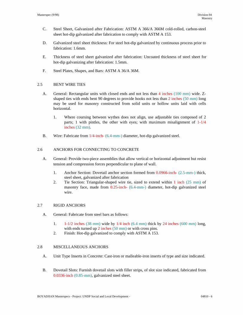
Masterspec (9/98) Division 04 Masonry
C. Steel Sheet, Galvanized after Fabrication: ASTM A 366/A 366M cold-rolled, carbon-steel
sheet hot-dip galvanized after fabrication to comply with ASTM A 153.
D. Galvanized steel sheet thickness: For steel hot-dip galvanized by continuous process prior to fabrication: 1.6mm.
E. Thickness of steel sheet galvanized after fabrication: Uncoated thickness of steel sheet for
hot-dip galvanizing after fabrication: 1.5mm.
F. Steel Plates, Shapes, and Bars: ASTM A 36/A 36M. 2.5 BENT WIRE TIES
A. General: Rectangular units with closed ends and not less than 4 inches (100 mm) wide. Z-shaped ties with ends bent 90 degrees to provide hooks not less than 2 inches (50 mm) long may be used for masonry constructed from solid units or hollow units laid with cells horizontal.
1. Where coursing between wythes does not align, use adjustable ties composed of 2
parts; 1 with pintles, the other with eyes; with maximum misalignment of 1-1/4 inches (32 mm).
B. Wire: Fabricate from 1/4-inch- (6.4-mm-) diameter, hot-dip galvanized steel.
2.6 ANCHORS FOR CONNECTING TO CONCRETE
A. General: Provide two-piece assemblies that allow vertical or horizontal adjustment but resist tension and compression forces perpendicular to plane of wall.
1. Anchor Section: Dovetail anchor section formed from 0.0966-inch- (2.5-mm-) thick,
steel sheet, galvanized after fabrication 2. Tie Section: Triangular-shaped wire tie, sized to extend within 1 inch (25 mm) of
masonry face, made from 0.25-inch- (6.4-mm-) diameter, hot-dip galvanized steel wire.
2.7 RIGID ANCHORS
A. General: Fabricate from steel bars as follows:
1. 1-1/2 inches (38 mm) wide by 1/4 inch (6.4 mm) thick by 24 inches (600 mm) long, with ends turned up 2 inches (50 mm) or with cross pins.
2. Finish: Hot-dip galvanized to comply with ASTM A 153. 2.8 MISCELLANEOUS ANCHORS
A. Unit Type Inserts in Concrete: Cast-iron or malleable-iron inserts of type and size indicated.
B. Dovetail Slots: Furnish dovetail slots with filler strips, of slot size indicated, fabricated from 0.0336-inch (0.85-mm), galvanized steel sheet.
BOYADJIAN Masterspecs - Project: UNDP Social and Local Development - 04810 - 6

Masterspec (9/98) Division 04 Masonry
C. Anchor Bolts: Steel bolts complying with ASTM A 307, Grade A (ASTM F 568, Property
Class 4.6); with ASTM A 563 (ASTM A 563M) hex nuts and, where indicated, flat washers; hot-dip galvanized to comply with ASTM A 153, Class C; of diameter and length indicated and in the following configurations:
1. Headed bolts. 2. Nonheaded bolts, bent in manner indicated.
2.9 EMBEDDED FLASHING MATERIALS
A. Metal Flashing: Fabricate from the following metal complying with requirements specified in Division 7 Section "Sheet Metal Flashing and Trim" and below:
1. Stainless Steel: 0.0156 inch (0.4 mm) thick. 2. Fabricate metal expansion-joint strips from sheet metal indicated above, formed to
shape indicated. 3. Fabricate metal flashing terminations from sheet metal indicated above. Extend at
least 3 inches (75 mm) into wall and out to exterior face of wall. At exterior face of wall, bend metal back on itself for 3/4 inch (19 mm) and then down into joint 3/8 inch (10 mm) to form a stop for retaining sealant backer rod.
B. Solder and Sealants for Sheet Metal Flashings: As specified in Division 7 Section "Sheet
Metal Flashing and Trim." 2.10 MISCELLANEOUS MASONRY ACCESSORIES
A. Compressible Filler: Premolded filler strips complying with ASTM D 1056, Grade 2A1; compressible up to 35 percent; of width and thickness indicated; formulated from neoprene, urethane or PVC.
B. Preformed Control-Joint Gaskets: Material as indicated below, designed to fit standard sash
block and to maintain lateral stability in masonry wall; size and configuration as indicated. 1. PVC: ASTM D 2287, Type PVC-65406.
C. Bond-Breaker Strips: Asphalt-saturated, organic roofing felt complying with ASTM D 226,
Type I (No. 15 asphalt felt).
D. Cavity Drainage Material: 1-inch- (25-mm-) thick, free-draining mesh; made from polyethylene strands and shaped to avoid being clogged by mortar droppings.
E. Reinforcing Bar Positioners: Wire units designed to fit into mortar bed joints spanning
masonry unit cells with loops for holding reinforcing bars in center of cells. Units are formed from 0.187-inch (4.8-mm) steel wire, hot-dip galvanized after fabrication.
1. Provide units with either two loops or four loops as needed for number of bars
indicated. 2.11 MORTAR AND GROUT MIXES
A. General: Do not use admixtures, including pigments, air-entraining agents, accelerators, retarders, water-repellent agents, antifreeze compounds, or other admixtures, unless otherwise indicated.
BOYADJIAN Masterspecs - Project: UNDP Social and Local Development - 04810 - 7

Masterspec (9/98) Division 04 Masonry
1. Do not use calcium chloride in mortar or grout.
B. Mortar for Unit Masonry: Comply with ASTM C 270, Proportion Specification.
1. Limit cementitious materials in mortar to portland cement, mortar cement, and lime. 2. For exterior, above-grade, load-bearing and non-load-bearing walls and parapet
walls; for interior load-bearing walls; for interior non-load-bearing partitions; and for other applications where another type is not indicated, use Type N.
C. Grout for Unit Masonry: Comply with ASTM C 476.
1. Use grout of type indicated or, if not otherwise indicated, of type (fine or coarse) that
will comply with Table 5 of ACI 530.1/ASCE 6/TMS 602 for dimensions of grout spaces and pour height.
2. Provide grout with a slump of 8 to 11 inches (200 to 280 mm) as measured according to ASTM C 143.
D. Epoxy Pointing Mortar: Mix epoxy pointing mortar to comply with mortar manufacturer's
directions. 2.12 SOURCE QUALITY CONTROL
A. Owner will engage a qualified independent testing agency to perform source quality-control testing indicated below:
1. Payment for these services shall be included in the Contract Sum. 2. Retesting of materials failing to meet specified requirements shall be done at
Contractor's expense.
B. Concrete Masonry Unit Tests: For each type of concrete masonry unit indicated, units will be tested according to ASTM C 140.
PART 3 - EXECUTION 3.1 EXAMINATION
A. Examine conditions, with Installer present, for compliance with requirements for installation tolerances and other conditions affecting performance.
1. For the record, prepare written report, endorsed by Installer, listing conditions
detrimental to performance. 2. Proceed with installation only after unsatisfactory conditions have been corrected.
B. Before installation, examine rough-in and built-in construction to verify actual locations of
piping connections. 3.2 INSTALLATION, GENERAL
A. Thickness: Build cavity and composite walls and other masonry construction to the full thickness shown. Build single-wythe walls to the actual widths of masonry units, using units of widths indicated.
BOYADJIAN Masterspecs - Project: UNDP Social and Local Development - 04810 - 8

Masterspec (9/98) Division 04 Masonry
B. Build chases and recesses to accommodate items specified in this Section and in other
Sections of the Specifications.
C. Leave openings for equipment to be installed before completing masonry. After installing equipment, complete masonry to match the construction immediately adjacent to the opening.
D. Cut masonry units with motor-driven saws to provide clean, sharp, unchipped edges. Cut
units as required to provide a continuous pattern and to fit adjoining construction. Where possible, use full-size units without cutting. Allow units cut with water-cooled saws to dry before placing, unless wetting of units is specified. Install cut units with cut surfaces and, where possible, cut edges concealed.
3.3 CONSTRUCTION TOLERANCES
A. Comply with tolerances in ACI 530.1/ASCE 6/TMS 602 and the following:
B. For conspicuous vertical lines, such as external corners, door jambs, reveals, and expansion and control joints, do not vary from plumb by more than 1/4 inch in 20 feet (6 mm in 6 m), nor 1/2 inch (12 mm) maximum.
C. For vertical alignment of exposed head joints, do not vary from plumb by more than 1/4
inch in 10 feet (6 mm in 3 m), nor 1/2 inch (12 mm) maximum.
D. For conspicuous horizontal lines, such as exposed lintels, sills, parapets, and reveals, do not vary from level by more than 1/4 inch in 20 feet (6 mm in 6 m), nor 1/2 inch (12 mm) maximum.
E. For exposed bed joints, do not vary from thickness indicated by more than plus or minus 1/8
inch (3 mm), with a maximum thickness limited to 1/2 inch (12 mm). Do not vary from bed-joint thickness of adjacent courses by more than 1/8 inch (3 mm).
F. For exposed head joints, do not vary from thickness indicated by more than plus or minus
1/8 inch (3 mm). Do not vary from adjacent bed-joint and head-joint thicknesses by more than 1/8 inch (3 mm).
3.4 LAYING MASONRY WALLS
A. Lay out walls in advance for accurate spacing of surface bond patterns with uniform joint thicknesses and for accurate location of openings, movement-type joints, returns, and offsets. Avoid using less-than-half-size units, particularly at corners, jambs, and, where possible, at other locations.
B. Lay concealed masonry with all units in a wythe in running bond or bonded by lapping not
less than 2 inches (50 mm). Bond and interlock each course of each wythe at corners. Do not use units with less than nominal 4-inch (100-mm) horizontal face dimensions at corners or jambs.
C. Stopping and Resuming Work: In each course, rack back one-half-unit length for one-half
running bond or one-third-unit length for one-third running bond; do not tooth. Clean exposed surfaces of set masonry, wet clay masonry units lightly if required, and remove loose masonry units and mortar before laying fresh masonry.
BOYADJIAN Masterspecs - Project: UNDP Social and Local Development - 04810 - 9
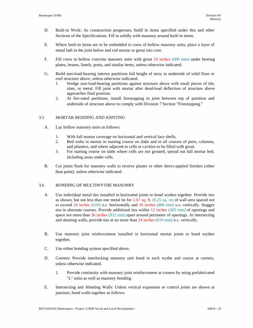
Masterspec (9/98) Division 04 Masonry
D. Built-in Work: As construction progresses, build in items specified under this and other
Sections of the Specifications. Fill in solidly with masonry around built-in items.
E. Where built-in items are to be embedded in cores of hollow masonry units, place a layer of metal lath in the joint below and rod mortar or grout into core.
F. Fill cores in hollow concrete masonry units with grout 24 inches (600 mm) under bearing
plates, beams, lintels, posts, and similar items, unless otherwise indicated.
G. Build non-load-bearing interior partitions full height of story to underside of solid floor or roof structure above, unless otherwise indicated. 1. Wedge non-load-bearing partitions against structure above with small pieces of tile,
slate, or metal. Fill joint with mortar after dead-load deflection of structure above approaches final position.
2. At fire-rated partitions, install firestopping in joint between top of partition and underside of structure above to comply with Division 7 Section "Firestopping."
3.5 MORTAR BEDDING AND JOINTING
A. Lay hollow masonry units as follows:
1. With full mortar coverage on horizontal and vertical face shells. 2. Bed webs in mortar in starting course on slabs and in all courses of piers, columns,
and pilasters, and where adjacent to cells or cavities to be filled with grout. 3. For starting course on slabs where cells are not grouted, spread out full mortar bed,
including areas under cells.
B. Cut joints flush for masonry walls to receive plaster or other direct-applied finishes (other than paint), unless otherwise indicated.
3.6 BONDING OF MULTIWYTHE MASONRY
A. Use individual metal ties installed in horizontal joints to bond wythes together. Provide ties as shown, but not less than one metal tie for 2.67 sq. ft. (0.25 sq. m) of wall area spaced not to exceed 24 inches (610) o.c. horizontally and 16 inches (406 mm) o.c. vertically. Stagger ties in alternate courses. Provide additional ties within 12 inches (305 mm) of openings and space not more than 36 inches (915 mm) apart around perimeter of openings. At intersecting and abutting walls, provide ties at no more than 24 inches (610 mm) o.c. vertically.
B. Use masonry joint reinforcement installed in horizontal mortar joints to bond wythes together.
C. Use either bonding system specified above.
D. Corners: Provide interlocking masonry unit bond in each wythe and course at corners,
unless otherwise indicated.
1. Provide continuity with masonry joint reinforcement at corners by using prefabricated "L" units as well as masonry bonding.
E. Intersecting and Abutting Walls: Unless vertical expansion or control joints are shown at
juncture, bond walls together as follows: BOYADJIAN Masterspecs - Project: UNDP Social and Local Development - 04810 - 10

Masterspec (9/98) Division 04 Masonry
1. Provide individual metal ties not more than 16 inches (406 mm) o.c.
3.7 CAVITIES
A. Keep cavities clean of mortar droppings and other materials during construction. Strike joints facing cavities flush.
1. Use wood strips temporarily placed in cavity to collect mortar droppings. As work
progresses, remove strips, clean off mortar droppings, and replace in cavity.
B. Parge cavity face of backup wythe using Type S or Type N mortar applied in a single coat approximately 3/8 inch (10 mm) thick. Trowel face of parge coat smooth.
3.8 ANCHORING MASONRY TO STRUCTURAL MEMBERS
A. Anchor masonry to structural members where masonry abuts or faces structural members to comply with the following:
1. Provide an open space not less than 1 inch (25 mm) in width between masonry and
structural member, unless otherwise indicated. Keep open space free of mortar or other rigid materials.
2. Anchor masonry to structural members with flexible anchors embedded in masonry joints and attached to structure.
3. Space anchors as indicated, but not more than 24 inches (610 mm) o.c. vertically and 36 inches (915 mm) o.c. horizontally.
3.9 CONTROL AND EXPANSION JOINTS
A. General: Install control and expansion joints in unit masonry where indicated. Build-in related items as masonry progresses. Do not form a continuous span through movement joints unless provisions are made to prevent in-plane restraint of wall or partition movement.
B. Form control joints in concrete masonry as follows:
1. Fit bond-breaker strips into hollow contour in ends of concrete masonry units on one
side of control joint. Fill resultant core with grout and rake joints in exposed faces.
C. Form expansion joints in brick made from clay or shale as follows:
1. Build flanges of metal expansion strips into masonry. Lap each joint 4 inches (100 mm) in direction of water flow. Seal joints below grade and at junctures with horizontal expansion joints, if any.
2. Build flanges of factory-fabricated, expansion-joint units into masonry. 3. Build in joint fillers where indicated. 4. Form open joint of width indicated, but not less than 3/8 inch (10 mm) for installation
of sealant and backer rod specified in Division 7 Section "Joint Sealants." Keep joint free and clear of mortar.
D. Build in horizontal, pressure-relieving joints where indicated; construct joints by either
leaving an air space or inserting a compressible filler of width required for installing sealant and backer rod specified in Division 7 Section "Joint Sealants."
BOYADJIAN Masterspecs - Project: UNDP Social and Local Development - 04810 - 11

Masterspec (9/98) Division 04 Masonry
1. Locate horizontal, pressure-relieving joints beneath shelf angles supporting masonry
veneer and attached to structure behind masonry veneer. 3.10 LINTELS
A. Provide masonry lintels where shown and where openings of more than 12 inches (305 mm) for block-size units are shown without structural steel or other supporting lintels. 1. Provide prefabricated or built-in-place masonry lintels. Use specially formed bond
beam units with reinforcing bars placed as indicated and filled with coarse grout. Cure precast lintels before handling and installing. Temporarily support built-in-place lintels until cured.
B. Provide minimum bearing of 8 inches (200 mm) at each jamb, unless otherwise indicated.
3.11 FLASHING, WEEP HOLES, AND VENTS
A. General: Install embedded flashing and weep holes in masonry at shelf angles, lintels, ledges, other obstructions to downward flow of water in wall, and where indicated.
B. Prepare masonry surfaces so they are smooth and free from projections that could puncture
flashing. Unless otherwise indicated, place through-wall flashing on sloping bed of mortar and cover with mortar. Before covering with mortar, seal penetrations in flashing with adhesive, sealant, or tape as recommended by flashing manufacturer.
C. Install flashing as follows:
1. At multiwythe masonry walls, including cavity walls, extend flashing from exterior
face of outer wythe of masonry, through outer wythe, turned up a minimum of 8 inches (200 mm), and through inner wythe to within 1/2 inch (13 mm) of the interior face of the wall in exposed masonry. Where interior surface of inner wythe is concealed by furring, carry flashing completely through inner wythe and turn flashing up approximately 2 inches (50 mm), unless otherwise indicated.
2. At lintels and shelf angles, extend flashing a minimum of 4 inches (100 mm) into masonry at each end. At heads and sills, extend flashing 4 inches (100 mm) at ends and turn flashing up not less than 2 inches (50 mm) to form a pan.
3. Extend sheet metal flashing 1/2 inch (13 mm) beyond face of masonry at exterior and turn flashing down to form a drip.
D. Install vents in vertical head joints at the top of each continuous cavity at spacing indicated.
Use round plastic tubing to form vents.
1. Close cavities off vertically and horizontally with blocking in manner indicated. Install through-wall flashing and weep holes above horizontal blocking.
E. Install reglets and nailers for flashing and other related construction where they are shown
to be built into masonry. 3.12 FIELD QUALITY CONTROL
A. Owner will engage a qualified independent testing agency to perform field quality-control testing indicated below.
1. Payment for these services will be made by Contractor.
BOYADJIAN Masterspecs - Project: UNDP Social and Local Development - 04810 - 12

Masterspec (9/98) Division 04 Masonry
2. Retesting of materials failing to meet specified requirements shall be done at
Contractor's expense.
B. Testing Frequency: Tests and Evaluations listed in this Article will be performed during construction for each 5000 sq. ft. (465 sq. m) of wall area or portion thereof.
C. Mortar properties will be tested per ASTM C 780.
D. Grout will be sampled and tested for compressive strength per ASTM C 1019.
E. Concrete Masonry Unit Tests: For each type of concrete masonry unit indicated, units will
be tested according to ASTM C 140. 3.13 REPAIRING, POINTING, AND CLEANING
A. Remove and replace masonry units that are loose, chipped, broken, stained, or otherwise damaged or that do not match adjoining units. Install new units to match adjoining units; install in fresh mortar, pointed to eliminate evidence of replacement.
B. Pointing: During the tooling of joints, enlarge voids and holes, except weep holes, and
completely fill with mortar. Point up joints, including corners, openings, and adjacent construction, to provide a neat, uniform appearance. Prepare joints for sealant application.
C. In-Progress Cleaning: Clean unit masonry as work progresses by dry brushing to remove
mortar fins and smears before tooling joints.
D. Final Cleaning: After mortar is thoroughly set and cured, clean exposed masonry as follows:
1. Remove large mortar particles by hand with wooden paddles and nonmetallic scrape hoes or chisels.
2. Test cleaning methods on sample wall panel; leave one-half of panel uncleaned for comparison purposes. Obtain Architect's approval of sample cleaning before proceeding with cleaning of masonry.
3. Protect adjacent stone and nonmasonry surfaces from contact with cleaner by covering them with liquid strippable masking agent, polyethylene film, or waterproof masking tape.
4. Wet wall surfaces with water before applying cleaners; remove cleaners promptly by rinsing the surfaces thoroughly with clear water.
5. Clean masonry with a proprietary acidic cleaner applied according to manufacturer's written instructions.
6. Clean concrete masonry by cleaning method indicated in NCMA TEK 8-2 applicable to type of stain on exposed surfaces.
3.14 MASONRY WASTE DISPOSAL
A. Recycling: Unless otherwise indicated, excess masonry materials are Contractor's property. At completion of unit masonry work, remove from Project site.
B. Disposal as Fill Material: Dispose of clean masonry waste, including broken masonry units,
waste mortar, and excess or soil-contaminated sand, by crushing and mixing with fill material as fill is placed.
1. Crush masonry waste to less than 4 inches (100 mm) in each dimension.
BOYADJIAN Masterspecs - Project: UNDP Social and Local Development - 04810 - 13

Masterspec (9/98) Division 04 Masonry
2. Mix masonry waste with at least two parts of specified fill material for each part of
masonry waste. Fill material is specified in Division 2 Section "Earthwork." 3. Do not dispose of masonry waste as fill within 18 inches (450 mm) of finished grade.
C. Excess Masonry Waste: Remove excess, clean masonry waste that cannot be used as fill, as
described above, and other masonry waste, and legally dispose of off Owner's property. END OF SECTION 04810 BOYADJIAN Masterspecs - Project: UNDP Social and Local Development - 04810 - 14

Masterspec (2001) Division 05
Metals
SECTION 05120 - STRUCTURAL STEEL PART 1 - GENERAL 1.1 RELATED DOCUMENTS
A. Drawings and general provisions of the Contract, including General and Supplementary Conditions and Division 1 Specification Sections, apply to this Section.
1.2 SUMMARY
A. This Section includes the following:
1. Structural steel. 2. Architecturally exposed structural steel. 3. Grout.
B. Related Sections include the following:
1. Division 1 Section "Quality Requirements" for independent testing agency procedures
and administrative requirements. 2. Division 5 Section "Steel Deck" for field installation of shear connectors. 3. Division 5 Section "Metal Fabrications" for miscellaneous steel fabrications not
defined as structural steel. 1.3 DEFINITIONS
A. Structural Steel: Elements of structural-steel frame, as classified by AISC's "Code of Standard Practice for Steel Buildings and Bridges," that support design loads.
B. Architecturally Exposed Structural Steel: Structural steel designated as architecturally
exposed structural steel in the Contract Documents. 1.4 PERFORMANCE REQUIREMENTS
A. Connections: Provide details of simple shear connections required by the Contract Documents to be selected or completed by structural-steel fabricator to withstand ASD-service loads indicated and comply with other information and restrictions indicated.
1. Select and complete connections using schematic details indicated and AISC's
"Manual of Steel Construction, Allowable Stress Design," Part 4. 2. Engineering Responsibility: Fabricator's responsibilities include using a qualified
professional engineer to prepare structural analysis data for structural-steel connections.
B. Construction: Type 1, rigid frame.
BOYADJIAN Masterspecs - Project: UNDP Social and Local Development - 05120 - 1
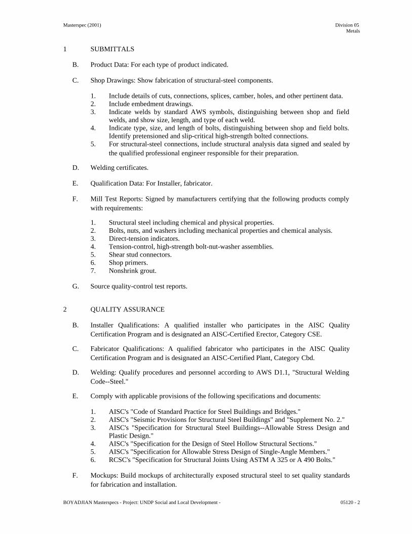
Masterspec (2001) Division 05 Metals
1 SUBMITTALS
B. Product Data: For each type of product indicated.
C. Shop Drawings: Show fabrication of structural-steel components.
1. Include details of cuts, connections, splices, camber, holes, and other pertinent data. 2. Include embedment drawings. 3. Indicate welds by standard AWS symbols, distinguishing between shop and field
welds, and show size, length, and type of each weld. 4. Indicate type, size, and length of bolts, distinguishing between shop and field bolts.
Identify pretensioned and slip-critical high-strength bolted connections. 5. For structural-steel connections, include structural analysis data signed and sealed by
the qualified professional engineer responsible for their preparation.
D. Welding certificates.
E. Qualification Data: For Installer, fabricator.
F. Mill Test Reports: Signed by manufacturers certifying that the following products comply with requirements:
1. Structural steel including chemical and physical properties. 2. Bolts, nuts, and washers including mechanical properties and chemical analysis. 3. Direct-tension indicators. 4. Tension-control, high-strength bolt-nut-washer assemblies. 5. Shear stud connectors. 6. Shop primers. 7. Nonshrink grout.
G. Source quality-control test reports.
2 QUALITY ASSURANCE
B. Installer Qualifications: A qualified installer who participates in the AISC Quality Certification Program and is designated an AISC-Certified Erector, Category CSE.
C. Fabricator Qualifications: A qualified fabricator who participates in the AISC Quality
Certification Program and is designated an AISC-Certified Plant, Category Cbd.
D. Welding: Qualify procedures and personnel according to AWS D1.1, "Structural Welding Code--Steel."
E. Comply with applicable provisions of the following specifications and documents:
1. AISC's "Code of Standard Practice for Steel Buildings and Bridges." 2. AISC's "Seismic Provisions for Structural Steel Buildings" and "Supplement No. 2." 3. AISC's "Specification for Structural Steel Buildings--Allowable Stress Design and
Plastic Design." 4. AISC's "Specification for the Design of Steel Hollow Structural Sections." 5. AISC's "Specification for Allowable Stress Design of Single-Angle Members." 6. RCSC's "Specification for Structural Joints Using ASTM A 325 or A 490 Bolts."
F. Mockups: Build mockups of architecturally exposed structural steel to set quality standards
for fabrication and installation.
BOYADJIAN Masterspecs - Project: UNDP Social and Local Development - 05120 - 2

Masterspec (2001) Division 05 Metals
1 Coordinate finish painting requirements with Division 9 painting Sections. 2 Approved mockups may become part of the completed Work if undisturbed at time of
Substantial Completion.
A. Preinstallation Conference: Conduct conference at Project site to comply with requirements in Division 1 Section "Project Management and Coordination."
2.2 DELIVERY, STORAGE, AND HANDLING
A. Store materials to permit easy access for inspection and identification. Keep steel members off ground and spaced by using pallets, dunnage, or other supports and spacers. Protect steel members and packaged materials from erosion and deterioration.
1. Store fasteners in a protected place. Clean and relubricate bolts and nuts that become
dry or rusty before use. 2. Do not store materials on structure in a manner that might cause distortion, damage,
or overload to members or supporting structures. Repair or replace damaged materials or structures as directed.
2.3 COORDINATION
A. Furnish anchorage items to be embedded in or attached to other construction without delaying the Work. Provide setting diagrams, sheet metal templates, instructions, and directions for installation.
PART 2 - PRODUCTS I. STRUCTURAL-STEEL MATERIALS
W-Shapes: ASTM A 572/A 572M.
Channels, Angles, M-Shapes: ASTM A 572/A 572M.
Plate and Bar: ASTM A 572/A 572M.
Cold-Formed Hollow Structural Sections: ASTM A 500, Grade B, structural tubing.
Steel Pipe: ASTM A 53/A 53M, Type E or S, Grade B.
Weight Class: Double-extra strong. Finish: Galvanized.
Medium-Strength Steel Castings: ASTM A 27/A 27M, Grade 65-35 (Grade 450-240),
carbon steel.
High-Strength Steel Castings: ASTM A 148/A 148M, Grade 80-50 (Grade 550-345), carbon or alloy steel.
Welding Electrodes: Comply with AWS requirements.
BOYADJIAN Masterspecs - Project: UNDP Social and Local Development - 05120 - 3

Masterspec (2001) Division 05 Metals
2.2 BOLTS, CONNECTORS, AND ANCHORS
A. High-Strength Bolts, Nuts, and Washers: ASTM A 325 (ASTM A 325M), Type 1, heavy hex steel structural bolts; ASTM A 563 (ASTM A 563M) heavy hex carbon-steel nuts; and ASTM F 436 (ASTM F 436M) hardened carbon-steel washers.
1. Finish: Hot-dip zinc coating, ASTM A 153/A 153M, Class C. 2. Direct-Tension Indicators: ASTM F 959, Type 325 (ASTM F 959M, Type 8.8,)
compressible-washer type.
a. Finish: Mechanically deposited zinc coating, ASTM B 695, Class 50.
B. High-Strength Bolts, Nuts, and Washers: ASTM A 490 (ASTM A 490M), Type 1, heavy hex steel structural bolts or tension-control, bolt-nut-washer assemblies with splined ends; ASTM A 563 (ASTM A 563M) heavy hex carbon-steel nuts; and ASTM F 436 (ASTM F 436M) hardened carbon-steel washers, plain.
1. Direct-Tension Indicators: ASTM F 959, Type 490 (ASTM F 959M,) Type 10.9,
compressible-washer type, plain.
C. Tension-Control, High-Strength Bolt-Nut-Washer Assemblies: ASTM F 1852, Type 1, heavy hex head steel structural bolts with splined ends; ASTM A 563 (ASTM A 563M) heavy hex carbon-steel nuts; and ASTM F 436 (ASTM F 436M) hardened carbon-steel washers.
1. Finish: Mechanically deposited zinc coating, ASTM B 695, Class 50.
D. Shear Connectors: ASTM A 108, Grades 1015 through 1020, headed-stud type, cold-
finished carbon steel; AWS D1.1, Type B.
E. Unheaded Anchor Rods: ASTM A 572/A 572M.
1. Configuration: Hooked. 2. Nuts: ASTM A 563 (ASTM A 563M) heavy hex carbon steel. 3. Plate Washers: ASTM A 572/A 572M carbon steel. 4. Washers: ASTM F 436 (ASTM F 436M) hardened carbon steel. 5. Finish: Hot-dip zinc coating, ASTM A 153/A 153M, Class C.
F. Headed Anchor Rods: ASTM A 307, Grade A (ASTM F 568M, Property Class 4.6),
straight.
1. Nuts: ASTM A 563 (ASTM A 563M) heavy hex carbon steel. 2. Plate Washers: ASTM A 572/A 572M carbon steel. 3. Washers: ASTM F 436 (ASTM F 436M) hardened carbon steel. 4. Finish: Hot-dip zinc coating, ASTM A 153/A 153M, Class C.
G. Threaded Rods: ASTM A 572/A 572M.
1. Nuts: ASTM A 563 (ASTM A 563M) heavy hex carbon steel. 2. Washers: ASTM A 572/A 572M carbon steel. 3. Finish: Hot-dip zinc coating, ASTM A 153/A 153M, Class C.
H. Clevises, Turnbuckles: ASTM A 108, Grade 1035, cold-finished carbon steel.
I. Eye Bolts and Nuts: ASTM A 108, Grade 1030, cold-finished carbon steel.
BOYADJIAN Masterspecs - Project: UNDP Social and Local Development - 05120 - 4

Masterspec (2001) Division 05 Metals
J. Sleeve Nuts: ASTM A 108, Grade 1018, cold-finished carbon steel.
3.5 PRIMER
A. Galvanizing Repair Paint: MPI#18, MPI#19, or SSPC-Paint 20. 3.6 GROUT
A. Cement Grout: Portland cement, ASTM C 150, Type I; and clean, natural sand, ASTM C 404, Size No. 2. Mix at ratio of 1 part cement to 2-1/2 parts sand, by volume, with minimum water required for placement and hydration.
B. Metallic, Shrinkage-Resistant Grout: ASTM C 1107, factory-packaged, metallic aggregate
grout, mixed with water to consistency suitable for application and a 30-minute working time.
C. Nonmetallic, Shrinkage-Resistant Grout: ASTM C 1107, factory-packaged, nonmetallic
aggregate grout, noncorrosive, nonstaining, mixed with water to consistency suitable for application and a 30-minute working time.
2.5 FABRICATION
A. Structural Steel: Fabricate and assemble in shop to greatest extent possible. Fabricate according to AISC's "Code of Standard Practice for Steel Buildings and Bridges" and AISC's "Specification for Structural Steel Buildings--Allowable Stress Design and Plastic Design."
1. Camber structural-steel members where indicated. 2. Identify high-strength structural steel according to ASTM A 6/ A 6M and maintain
markings until structural steel has been erected. 3. Mark and match-mark materials for field assembly. 4. Complete structural-steel assemblies, including welding of units, before starting
shop-priming operations.
B. Architecturally Exposed Structural Steel: Comply with fabrication requirements, including tolerance limits, of AISC's "Code of Standard Practice for Steel Buildings and Bridges" for structural steel identified as architecturally exposed structural steel.
1. Fabricate with exposed surfaces smooth, square, and free of surface blemishes
including pitting, rust, scale, seam marks, roller marks, rolled trade names, and roughness.
2. Remove blemishes by filling or grinding or by welding and grinding, before cleaning, treating, and shop priming.
C. Thermal Cutting: Perform thermal cutting by machine to greatest extent possible.
1. Plane thermally cut edges to be welded to comply with requirements in AWS D1.1.
D. Bolt Holes: Cut, drill, mechanically thermal cut, or punch standard bolt holes perpendicular
to metal surfaces.
E. Finishing: Accurately finish ends of columns and other members transmitting bearing loads. BOYADJIAN Masterspecs - Project: UNDP Social and Local Development - 05120 - 5

Masterspec (2001) Division 05 Metals
F. Shear Connectors: Prepare steel surfaces as recommended by manufacturer of shear
connectors. Use automatic end welding of headed-stud shear connectors according to AWS D1.1 and manufacturer's written instructions.
G. Steel Wall-Opening Framing: Select true and straight members for fabricating steel wall-
opening framing to be attached to structural steel. Straighten as required to provide uniform, square, and true members in completed wall framing.
H. Holes: Provide holes required for securing other work to structural steel and for passage of
other work through steel framing members.
1. Cut, drill, or punch holes perpendicular to steel surfaces. Do not thermally cut bolt holes or enlarge holes by burning.
2. Base-Plate Holes: Cut, drill, mechanically thermal cut, or punch holes perpendicular to steel surfaces.
3. Weld threaded nuts to framing and other specialty items indicated to receive other work.
2.6 SHOP CONNECTIONS
A. High-Strength Bolts: Shop install high-strength bolts according to RCSC's "Specification for Structural Joints Using ASTM A 325 or A 490 Bolts" for type of bolt and type of joint specified.
1. Joint Type: Snug tightened.
B. Weld Connections: Comply with AWS D1.1 for welding procedure specifications,
tolerances, appearance, and quality of welds and for methods used in correcting welding work.
1. Remove backing bars or runoff tabs, back gouge, and grind steel smooth. 2. Assemble and weld built-up sections by methods that will maintain true alignment of
axes without exceeding tolerances of AISC's "Code of Standard Practice for Steel Buildings and Bridges" for mill material.
3. Verify that weld sizes, fabrication sequence, and equipment used for architecturally exposed structural steel will limit distortions to allowable tolerances. Prevent weld show-through on exposed steel surfaces.
a. Grind butt welds flush. b. Grind or fill exposed fillet welds to smooth profile. Dress exposed welds.
2.7 SHOP PRIMING
A. Shop prime steel surfaces except the following:
1. Surfaces embedded in concrete or mortar. Extend priming of partially embedded members to a depth of 2 inches (50 mm).
2. Surfaces to be field welded. 3. Surfaces to be high-strength bolted with slip-critical connections. 4. Surfaces to receive sprayed fire-resistive materials. 5. Galvanized surfaces.
BOYADJIAN Masterspecs - Project: UNDP Social and Local Development - 05120 - 6

Masterspec (2001) Division 05 Metals
B. Surface Preparation: Clean surfaces to be painted. Remove loose rust and mill scale and
spatter, slag, or flux deposits. Prepare surfaces according to the following specifications and standards: 1. SSPC-SP 6/NACE No. 3, "Commercial Blast Cleaning."
C. Powder-Coated Finish: Immediately after cleaning, apply manufacturer's standard
thermosetting TGIC polyester, polyester urethane, or acrylic urethane powder coating with a cured film thickness not less than 1.5 mils (0.04 mm)complying with powder-coating manufacturer's written instructions for cleaning, conversion coating, and powder coating.
a. Color: As selected by Architect from manufacturer's full range.
2.8 GALVANIZING
A. Hot-Dip Galvanized Finish: Apply zinc coating by the hot-dip process to structural steel according to ASTM A 123/ A 123M.
1. Fill vent holes and grind smooth after galvanizing.
2.9 SOURCE QUALITY CONTROL
A. Owner will engage an independent testing and inspecting agency to perform shop tests and inspections and prepare test reports.
1. Provide testing agency with access to places where structural-steel work is being
fabricated or produced to perform tests and inspections.
B. Correct deficiencies in Work that test reports and inspections indicate does not comply with the Contract Documents.
C. Bolted Connections: Shop-bolted connections will be tested and inspected according to
RCSC's "Specification for Structural Joints Using ASTM A 325 or A 490 Bolts."
D. Welded Connections: In addition to visual inspection, shop-welded connections will be tested and inspected according to AWS D1.1 and the following inspection procedures, at testing agency's option:
1. Liquid Penetrant Inspection: ASTM E 165. 2. Magnetic Particle Inspection: ASTM E 709; performed on root pass and on finished
weld. Cracks or zones of incomplete fusion or penetration will not be accepted. 3. Ultrasonic Inspection: ASTM E 164. 4. Radiographic Inspection: ASTM E 94.
E. In addition to visual inspection, shop-welded shear connectors will be tested and inspected
according to requirements in AWS D1.1 for stud welding and as follows:
1. Bend tests will be performed if visual inspections reveal either a less-than-continuous 360-degree flash or welding repairs to any shear connector.
2. Tests will be conducted on additional shear connectors if weld fracture occurs on shear connectors already tested, according to requirements in AWS D1.1.
BOYADJIAN Masterspecs - Project: UNDP Social and Local Development - 05120 - 7

Masterspec (2001) Division 05 Metals
PART 3 - EXECUTION 3.1 EXAMINATION
A. Verify elevations of concrete- and masonry-bearing surfaces and locations of anchor rods, bearing plates, and other embedments, with steel erector present, for compliance with requirements.
B. Proceed with installation only after unsatisfactory conditions have been corrected.
3.2 PREPARATION
A. Provide temporary shores, guys, braces, and other supports during erection to keep structural steel secure, plumb, and in alignment against temporary construction loads and loads equal in intensity to design loads. Remove temporary supports when permanent structural steel, connections, and bracing are in place, unless otherwise indicated.
1. Do not remove temporary shoring supporting composite deck construction until cast-
in-place concrete has attained its design compressive strength. 3.3 ERECTION
A. Set structural steel accurately in locations and to elevations indicated and according to AISC's "Code of Standard Practice for Steel Buildings and Bridges" and "Specification for Structural Steel Buildings--Allowable Stress Design and Plastic Design."
B. Base and Bearing Plates: Clean concrete- and masonry-bearing surfaces of bond-reducing
materials, and roughen surfaces prior to setting base and bearing plates. Clean bottom surface of base and bearing plates.
1. Set base and bearing plates for structural members on wedges, shims, or setting nuts
as required. 2. Weld plate washers to top of base plate. 3. Snug-tighten anchor rods after supported members have been positioned and
plumbed. Do not remove wedges or shims but, if protruding, cut off flush with edge of base or bearing plate before packing with grout.
4. Promptly pack grout solidly between bearing surfaces and base or bearing plates so no voids remain. Neatly finish exposed surfaces; protect grout and allow to cure. Comply with manufacturer's written installation instructions for shrinkage-resistant grouts.
C. Maintain erection tolerances of structural steel and architecturally exposed structural steel
within AISC's "Code of Standard Practice for Steel Buildings and Bridges."
D. Align and adjust various members forming part of complete frame or structure before permanently fastening. Before assembly, clean bearing surfaces and other surfaces that will be in permanent contact with members. Perform necessary adjustments to compensate for discrepancies in elevations and alignment.
1. Level and plumb individual members of structure. 2. Make allowances for difference between temperature at time of erection and mean
temperature when structure is completed and in service. BOYADJIAN Masterspecs - Project: UNDP Social and Local Development - 05120 - 8

Masterspec (2001) Division 05 Metals
E. Splice members only where indicated.
F. Remove erection bolts on welded, architecturally exposed structural steel; fill holes with
plug welds; and grind smooth at exposed surfaces.
G. Do not use thermal cutting during erection unless approved by Engineer. Finish thermally cut sections within smoothness limits in AWS D1.1.
H. Do not enlarge unfair holes in members by burning or using drift pins. Ream holes that must
be enlarged to admit bolts. 3.4 FIELD CONNECTIONS
A. High-Strength Bolts: Shop install high-strength bolts according to RCSC's "Specification for Structural Joints Using ASTM A 325 or A 490 Bolts" for type of bolt and type of joint specified.
1. Joint Type: Snug tightened.
B. Weld Connections: Comply with AWS D1.1 for welding procedure specifications,
tolerances, appearance, and quality of welds and for methods used in correcting welding work.
1. Comply with AISC's "Code of Standard Practice for Steel Buildings and Bridges" and
"Specification for Structural Steel Buildings--Allowable Stress Design and Plastic Design" for bearing, adequacy of temporary connections, alignment, and removal of paint on surfaces adjacent to field welds.
2. Remove backing bars or runoff tabs, back gouge, and grind steel smooth. 3. Assemble and weld built-up sections by methods that will maintain true alignment of
axes without exceeding tolerances of AISC's "Code of Standard Practice for Steel Buildings and Bridges" for mill material.
4. Verify that weld sizes, fabrication sequence, and equipment used for architecturally exposed structural steel will limit distortions to allowable tolerances. Prevent weld show-through on exposed steel surfaces.
a. Grind butt welds flush. b. Grind or fill exposed fillet welds to smooth profile. Dress exposed welds.
3.5 FIELD QUALITY CONTROL
A. Testing Agency: Owner will engage a qualified independent testing and inspecting agency to inspect field welds and high-strength bolted connections.
B. Bolted Connections: Shop-bolted connections will be tested and inspected according to
RCSC's "Specification for Structural Joints Using ASTM A 325 or A 490 Bolts."
C. Welded Connections: Field welds will be visually inspected according to AWS D1.1.
1. In addition to visual inspection, field welds will be tested according to AWS D1.1 and the following inspection procedures, at testing agency's option:
a. Liquid Penetrant Inspection: ASTM E 165.
BOYADJIAN Masterspecs - Project: UNDP Social and Local Development - 05120 - 9

Masterspec (2001) Division 05 Metals
b. Magnetic Particle Inspection: ASTM E 709; performed on root pass and on
finished weld. Cracks or zones of incomplete fusion or penetration will not be accepted.
c. Ultrasonic Inspection: ASTM E 164. d. Radiographic Inspection: ASTM E 94.
D. Correct deficiencies in Work that test reports and inspections indicate does not comply with
the Contract Documents. 3.6 REPAIRS AND PROTECTION
A. Repair damaged galvanized coatings on galvanized items with galvanized repair paint according to ASTM A 780 and manufacturer's written instructions.
B. Touchup Painting: After installation, promptly clean, prepare, and prime or reprime field
connections, rust spots, and abraded surfaces of prime-painted joists and accessories, bearing plates, and abutting structural steel.
1. Clean and prepare surfaces by SSPC-SP 2 hand-tool cleaning or SSPC-SP 3 power-
tool cleaning. 2. Apply a compatible primer of same type as shop primer used on adjacent surfaces.
C. Touchup Painting: Cleaning and touchup painting are specified in Division 9 painting
Sections. BOYADJIAN Masterspecs - Project: UNDP Social and Local Development - 05120 - 10

Masterspec (1998) Division 05 Metals
SECTION 05310 - STEEL DECK
PART 1 - GENERAL 1.5 RELATED DOCUMENTS
A. Drawings and general provisions of the Contract, including General and Supplementary Conditions and Division 1 Specification Sections, apply to this Section.
1.6 SUMMARY
A. This Section includes the following:
1. Roof deck. 2. Noncomposite form deck.
B. Related Sections include the following:
1. Division 3 Section "Cast-in-Place Concrete" for concrete fill and reinforcing steel. 2. Division 5 Section "Structural Steel" for shop-welded shear connectors.
1.7 SUBMITTALS
A. Product Data: For each type of deck, accessory, and product indicated.
B. Shop Drawings: Show layout and types of deck panels, anchorage details, reinforcing channels, pans, deck openings, special jointing, accessories, and attachments to other construction.
C. Product Certificates: Signed by steel deck manufacturers certifying that products furnished
comply with requirements.
D. Welding Certificates: Copies of certificates for welding procedures and personnel.
E. Product Test Reports: From a qualified testing agency indicating that each of the following complies with requirements, based on comprehensive testing of current products:
1. Mechanical fasteners. 2. Acoustical roof deck.
F. Research/Evaluation Reports: Evidence of steel deck's compliance with building code in
effect for Project, from a model code organization acceptable to authorities having jurisdiction.
1.8 QUALITY ASSURANCE
A. Installer Qualifications: An experienced installer who has completed steel deck similar in material, design, and extent to that indicated for this Project and whose work has resulted in construction with a record of successful in-service performance.
BOYADJIAN Masterspecs - Project: UNDP Social and Local Development - 05310 - 1

Masterspec (1998) Division 05 Metals
G. Testing Agency Qualifications: An independent testing agency, acceptable to authorities
having jurisdiction, qualified according to ASTM E 329 to conduct the testing indicated, as documented according to ASTM E 548.
H. Welding: Qualify procedures and personnel according to AWS D1.1, "Structural Welding
Code--Steel," and AWS D1.3, "Structural Welding Code--Sheet Steel."
I. Fire-Test-Response Characteristics: Where indicated, provide steel deck units identical to those steel deck units tested for fire resistance per ASTM E 119 by a testing and inspection agency acceptable to authorities having jurisdiction.
1. Fire-Resistance Ratings: Indicated by design designations from UL's "Fire Resistance
Directory" or from the listings of another testing and inspecting agency. 2. Steel deck units shall be identified with appropriate markings of applicable testing
and inspecting agency.
J. AISI Specifications: Calculate structural characteristics of steel deck according to AISI's "Specification for the Design of Cold-Formed Steel Structural Members."
1.6 DELIVERY, STORAGE, AND HANDLING
A. Protect steel deck from corrosion, deformation, and other damage during delivery, storage, and handling.
B. Stack steel deck on platforms or pallets and slope to provide drainage. Protect with a
waterproof covering and ventilate to avoid condensation. 1.7 COORDINATION
A. Coordinate layout and installation of trench headers, preset inserts, duct fittings, and other components specified in Division 16 Section "Underfloor Raceway" with installation of cellular metal floor deck.
PART 2 - PRODUCTS 2.2 ROOF DECK
A. Steel Roof Deck: Fabricate panels, without top-flange stiffening grooves, to comply with "SDI Specifications and Commentary for Steel Roof Deck," in SDI Publication No. 29, and the following: 1. Galvanized Steel Sheet: ASTM A 653/A 653M, Structural Steel (SS), Grade 33
(230), G90 (Z275) zinc coating. 2. Deck Profile: Type NR, narrow rib. 3. Profile Depth: As indicated. 4. Design Uncoated-Steel Thickness: As indicated. 5. Span Condition: As indicated. 6. Side Laps: Overlapped or interlocking seam at Contractor's option.
BOYADJIAN Masterspecs - Project: UNDP Social and Local Development - 05310 - 2

Masterspec (1998) Division 05 Metals
2.4 COMPOSITE FLOOR DECK
A. Composite Steel Floor Deck: Fabricate panels, with integrally embossed or raised pattern ribs and interlocking side laps, to comply with "SDI Specifications and Commentary for Composite Steel Floor Deck," in SDI Publication No. 29, the minimum section properties indicated, and the following: 1. Galvanized Steel Sheet: ASTM A 653/A 653M, Structural Steel (SS), Grade 33
(230), G90 (Z275) zinc coating. 2. Profile Depth: As indicated. 3. Design Uncoated-Steel Thickness: .As indicated 4. Span Condition: As indicated.
2.5 NONCOMPOSITE FORM DECK
A. Noncomposite Steel Form Deck: Fabricate ribbed-steel sheet noncomposite form deck panels to comply with "SDI Specifications and Commentary for Noncomposite Steel Form Deck," in SDI Publication No. 29, the minimum section properties indicated, and the following: 1. Galvanized Steel Sheet: ASTM A 653/A 653M, Structural Steel (SS), Grade , G90
(Z275) zinc coating. 2. Profile Depth: .As indicated 3. Design Uncoated-Steel Thickness: .As indicated 4. Span Condition: As indicated. 5. Side Laps: Overlapped or interlocking seam at Contractor's option.
2.6 ACCESSORIES
A. General: Provide manufacturer's standard accessory materials for deck that comply with requirements indicated.
B. Mechanical Fasteners: Corrosion-resistant, low-velocity, power-actuated or pneumatically
driven carbon-steel fasteners; or self-drilling, self-threading screws.
C. Side-Lap Fasteners: Corrosion-resistant, hexagonal washer head; self-drilling, carbon-steel screws, No. 10 (4.8 mm) minimum diameter.
D. Flexible Closure Strips: Vulcanized, closed-cell, synthetic rubber.
E. Miscellaneous Sheet Metal Deck Accessories: Steel sheet, minimum yield strength of
33,000 psi (230 MPa), not less than 0.0359-inch (0.91-mm) design uncoated thickness, of same material and finish as deck; of profile indicated or required for application.
F. Steel Sheet Accessories: Steel sheet, of same material, finish, and thickness as deck, unless
otherwise indicated.
G. Pour Stops and Girder Fillers: Steel sheet, minimum yield strength of 33,000 psi (230 MPa), of same material and finish as deck, and of thickness and profile recommended by SDI Publication No. 29 for overhang and slab depth.
H. Column Closures, End Closures, Z-Closures, and Cover Plates: Steel sheet, of same
material, finish, and thickness as deck, unless otherwise indicated. BOYADJIAN Masterspecs - Project: UNDP Social and Local Development - 05310 - 3
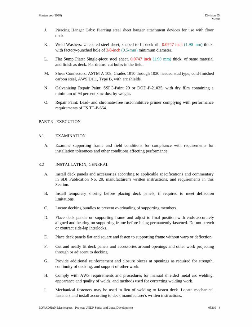
Masterspec (1998) Division 05 Metals
J. Piercing Hanger Tabs: Piercing steel sheet hanger attachment devices for use with floor
deck.
K. Weld Washers: Uncoated steel sheet, shaped to fit deck rib, 0.0747 inch (1.90 mm) thick, with factory-punched hole of 3/8-inch (9.5-mm) minimum diameter.
L. Flat Sump Plate: Single-piece steel sheet, 0.0747 inch (1.90 mm) thick, of same material
and finish as deck. For drains, cut holes in the field.
M. Shear Connectors: ASTM A 108, Grades 1010 through 1020 headed stud type, cold-finished carbon steel, AWS D1.1, Type B, with arc shields.
N. Galvanizing Repair Paint: SSPC-Paint 20 or DOD-P-21035, with dry film containing a
minimum of 94 percent zinc dust by weight.
O. Repair Paint: Lead- and chromate-free rust-inhibitive primer complying with performance requirements of FS TT-P-664.
PART 3 - EXECUTION 3.1 EXAMINATION
A. Examine supporting frame and field conditions for compliance with requirements for installation tolerances and other conditions affecting performance.
3.2 INSTALLATION, GENERAL
A. Install deck panels and accessories according to applicable specifications and commentary in SDI Publication No. 29, manufacturer's written instructions, and requirements in this Section.
B. Install temporary shoring before placing deck panels, if required to meet deflection
limitations.
C. Locate decking bundles to prevent overloading of supporting members.
D. Place deck panels on supporting frame and adjust to final position with ends accurately aligned and bearing on supporting frame before being permanently fastened. Do not stretch or contract side-lap interlocks.
E. Place deck panels flat and square and fasten to supporting frame without warp or deflection.
F. Cut and neatly fit deck panels and accessories around openings and other work projecting
through or adjacent to decking.
G. Provide additional reinforcement and closure pieces at openings as required for strength, continuity of decking, and support of other work.
H. Comply with AWS requirements and procedures for manual shielded metal arc welding,
appearance and quality of welds, and methods used for correcting welding work.
I. Mechanical fasteners may be used in lieu of welding to fasten deck. Locate mechanical fasteners and install according to deck manufacturer's written instructions.
BOYADJIAN Masterspecs - Project: UNDP Social and Local Development - 05310 - 4

Masterspec (1998) Division 05 Metals
3.3 ROOF DECK INSTALLATION
A. Fasten roof deck panels to steel supporting members by arc spot (puddle) welds of the surface diameter indicated or arc seam welds with an equal perimeter, but not less than 1-1/2 inches (38 mm) long, and as follows:
1. Weld Diameter: 3/4 inch (19 mm), nominal. 2. Weld Spacing: Weld edge and interior ribs of deck units with a minimum of two
welds per deck unit at each support. Space welds 18 inches (450 mm) apart, maximum.
3. Weld Washers: Install weld washers at each weld location.
B. Side-Lap and Perimeter Edge Fastening: Fasten side laps and perimeter edges of panels between supports, at intervals not exceeding the lesser of 1/2 of the span or 18 inches (450 mm), and as follows:
1. Mechanically fasten with self-drilling No. 10 (4.8-mm-) diameter or larger carbon-
steel screws.
C. End Bearing: Install deck ends over supporting frame with a minimum end bearing of 1-1/2 inches (38 mm), with end joints as follows:
1. End Joints: Butted.
D. Roof Sump Pans and Sump Plates: Install over openings provided in roof decking and weld
flanges to top of deck. Space welds not more than 12 inches (305 mm) apart with at least 1 weld at each corner.
E. Miscellaneous Roof Deck Accessories: Install ridge and valley plates, finish strips, cover
plates, end closures, and reinforcing channels according to deck manufacturer's written instructions. Weld to substrate to provide a complete deck installation.
F. Flexible Closure Strips: Install flexible closure strips over partitions, walls, and where
indicated. Install with adhesive according to manufacturer's written instructions to ensure complete closure.
3.4 FLOOR DECK INSTALLATION
A. Fasten floor deck panels to steel supporting members by arc spot (puddle) welds of the surface diameter indicated and as follows:
1. Weld Diameter: 3/4 inch (19 mm), nominal. 2. Weld Spacing: Weld edge ribs of panels at each support. Space additional welds an
average of 12 inches (305 mm) apart, but not more than 18 inches (457 mm) apart. 3. Weld Washers: Install weld washers at each weld location.
B. Side-Lap and Perimeter Edge Fastening: Fasten side laps and perimeter edges of panels
between supports, at intervals not exceeding the lesser of 1/2 of the span or 36 inches (910 mm), and as follows:
1. Mechanically fasten with self-drilling No. 10 (4.8-mm-) diameter or larger carbon-
steel screws.
C. End Bearing: Install deck ends over supporting frame with a minimum end bearing of 1-1/2 inches (38 mm), with end joints as follows:
BOYADJIAN Masterspecs - Project: UNDP Social and Local Development - 05310 - 5

Masterspec (1998) Division 05 Metals
1. End Joints: Butted.
D. Shear Connectors: Weld shear connectors through deck to supporting frame according to AWS D1.1 and manufacturer's written instructions. Butt end joints of deck panels; do not overlap. Remove and discard arc shields after welding shear connectors.
E. Pour Stops and Girder Fillers: Weld steel sheet pour stops and girder fillers to supporting structure
according to SDI recommendations, unless otherwise indicated.
F. Floor Deck Closures: Weld steel sheet column closures, cell closures, and Z-closures to deck, according to SDI recommendations, to provide tight-fitting closures at open ends of ribs and sides of decking. Weld cover plates at changes in direction of floor deck panels, unless otherwise indicated.
G. Install piercing hanger tabs not more than 14 inches (355 mm) apart in both directions, within 9
inches (228 mm) of walls at ends, and not more than 12 inches (305 mm) from walls at sides, unless otherwise indicated.
3.7 FIELD QUALITY CONTROL
A. Testing: Owner will engage a qualified independent testing agency to perform field quality-control testing.
B. Field welds will be subject to inspection.
C. Shear connector stud welds will be inspected and tested according to AWS D1.1 for stud welding
and as follows:
1. Shear connector stud welds will be visually inspected. 2. Bend tests will be performed if visual inspections reveal less than a full 360-degree flash or
welding repairs to any shear connector stud. 3. Tests will be conducted on additional shear connector studs if weld fracture occurs on shear
connector studs already tested according to AWS D1.1.
D. Testing agency will report test results promptly and in writing to Contractor and Architect.
E. Remove and replace work that does not comply with specified requirements.
F. Additional testing and inspecting, at Contractor's expense, will be performed to determine compliance of corrected work with specified requirements.
3.8 REPAIRS AND PROTECTION
A. Galvanizing Repairs: Prepare and repair damaged galvanized coatings on both surfaces of deck with galvanized repair paint according to ASTM A 780 and manufacturer's written instructions.
B. Provide final protection and maintain conditions to ensure that steel deck is without damage or
deterioration at time of Substantial Completion. END OF SECTION 05310 BOYADJIAN Masterspecs - Project: UNDP Social and Local Development -
05310 - 6
TENDER DOCUMENTS DIVISION 05

Specifications Metals
SECTION 05510
METAL STAIRS
PART 1 GENERAL
1.01 SECTION INCLUDES
A. This section includes internal and external shop fabricated pre assembled steel stairs with integral handrails and ballustrades shop primed and painted or finished as shown on the drawings and Contract Documents including but not limited to the following:-
1. Steel stair frame of structural sections, with open risers.
2. Open grate stair treads and landings.
3. Integral balusters and straight and curved handrailing.
4. Glazed ballustrades.
5. Anchors, Brackets, Accessories and Fixings.
1.02 RELATED SECTIONS
A. Section 01300 Submittals.
B. Section 05120 Structural Steel.
C. Section 05520 Handrails and Railings.
D. Section 05500 Miscellaneous Metal.
E. Section 05050 Metal Fastenings.
F. Section 09900 Painting.
1.03 REFERENCES
A. American National Standards Institute:
1. ANSI A 117.1 Accessible and Usable Building and Facilities.
B. American Society for Testing and Materials:
1. ASTM A 36M Carbon Structural Steel.
2. ASTM A 53 Hot Dipped, Zinc-coated Welded and Seamless Steel Pipe.
3. ASTM A 123 Zinc Coating (Hot Dip Galvanized) on Iron and Steel Products.
4. ASTM A 167 Stainless steel Heat Resistant Chromium-Nickel Steel Plate Sheet and Strip.
BOYADJIAN Masterspecs - Project: UNDP Social and Local Development - 05510 - 1/8

TENDER DOCUMENTS DIVISION 05 Specifications Metals
5. ASTM A 269 Seamless and Welded Austenitic Stainless Steel Tubing.
6. ASTM A 283 Carbon Steel Plates, Shapes and Bars.
7. ASTM A 312 M Seamless and Welded Austenitic Stainless Steel Pipe.
8. ASTM A 480 M General Requirements for Flat Rolled Stainless Steel Plate Sheet and Strip.
9. ASTM A 484 M General Requirements for Flat Rolled Stainless Steel Sheet, Strip,
Billets and Forgings.
10. ASTM A 500 Steel Tubing.
11. ASTM A 501 Hot Formed Welded & Seamless Carbon Steel Structural Tubing.
12. ASTM A 513 Type 5 Steel Tubing.
13. ASTM A 536 M General Requirement for Steel Carbon and High Strength Low Alloy Hot Rolled Steel Sheets and Cold Rolled Sheets.
14. ASTM A 569 Steel Sheet.
15. ASTM A 570 Steel Sheet Type E, Grade A Standard Weight Black Finish.
16. ASTM A 611 Steel Cold Rolled Sheets, Carbon, Structures.
17. ASTM A 666 Austenitic Stainless Steel Sheet Strip Plate and Flat Bar.
18. ASTM B 177 Chromium Electroplating on Steel for Engineering Use.
19. ASTM E 935 Test Methods for Performance of Permanent Metal Railing Systems
and Rails for Buildings.
20. ASTM E 985 Permanent Metal Railing Systems and Rails for Buildings.
21. ASTM F 593 Stainless Steel Bolts, Hex Cap Screws and Studs.
22. ASTM F 594 Stainless Steel Nuts.
C. American Institute of Steel Construction:
1. AISC S 326 Design Fabrication and Erection of Structural Steel for Building.
D. American Welding Society:
1. AWS D1.1 Structural Welding Code – Steel.
2. AWS A 2.4 Standard Symbols for Welding, Brazing, and Nondestructive Examination.
BOYADJIAN Masterspecs - Project: UNDP Social and Local Development - 05510 - 2/8

TENDER DOCUMENTS DIVISION 05 Specifications Metals
E. National Association of Architectural Metal Manufacturers (NAAMM):
1. NAAMM AMP 510 Metal Stairs Manual.
2. NAAMM MBG 531 Metal Bar Grating Manual.
F. The Society of Protective Coating (SSPC):
1. SSPC Steel Structures Painting Manual.
2. SSPC SP1 Solvent Cleaning.
3. SSPC SP 10 Near – White Blast Cleaning.
4. SSPC Paint 20 Zinc – Rich Primers (Type I – Inorganic and Type II – Organic).
1.04 DESIGN REQUIREMENTS
A. Fabricate stair assembly to support a uniform live load of 2.4 KN/m² with deflection of stringer or landing framing not to exceed 1/240 of span.
B. Railing assembly, wall rails, and attachments to resist lateral force of 0.5 KN at any point
without damage or permanent set.
1.05 SUBMITTALS
A. Comply with Section 01300.
B. Shop Drawings: Indicate profiles, sizes, connection attachments, reinforcing, anchorage, size and type of fasteners, and accessories.
C. Shop Drawings: Indicate welded connections using AWS A 2.0 welding symbols. Indicate
net weld lengths.
D. Samples: Submit one sample showing typical radius of painted galvanized steel.
E. Design Data: Submit design calculations.
1.06 QUALITY ASSURANCE
A. Perform work in accordance with ASTM E 985.
B. Welder’s Certificates: Submit under provisions of Section 01300, certifying welders employed on the work. Verifying AWS qualification within previous 12 months.
1.07 FIELD MEASUREMENTS.
A. Verify field measurements prior to fabrication.
BOYADJIAN Masterspecs - Project: UNDP Social and Local Development - 05510 - 3/8
TENDER DOCUMENTS DIVISION 05 Specifications Metals
PART 2 PRODUCTS
2.01 PRODUCTS
A. Handrail Wall Brackets: Unless otherwise indicated, malleable iron, 65 mm diameter wall plate; center of rail 75 mm from face of wall.
B. Stair Nosing for Steel Pan Stairs with Concrete Filled Stairs - 2 Piece: Sub-channel for
installation during concrete placement and abrasive tread plate for installation in final stages of construction.
1. Factory install temporary protective board in sub-channel for protection during
construction. Seal ends of sub-channel using heavy duty tape to eliminate concrete infiltration and staining. Construct sub-channels and abrasive carrying plates of extruded aluminum with mill finish.
2. Include concealed concrete anchors and tread plate securing screws. Protect
embedded items with heavy coating of factory applied clear lacquer.
3. Acceptable manufacturer’s and products or equal and approved:
a. Balco Inc.: Balco Two Component Stair Nosing, No. XH 330.
C. Gate Spring Pivot Hinge: Surface mounted, malleable iron, with anti-friction bearing, allowing spring tension adjustment after installation.
1. Acceptable manufacturers and products, or equal and approved:
a. McKinney Manufacturing Co.
b. Bommer Industries, Inc.
2.02 STEEL RAILING SYSTEM
A. Steel Sections and Tubing: All materials in hot rolled steel plates and sections shall be in accordance with ASTM A 501 and shall be grade A unless otherwise indicated on the Drawings.
B. Stainless Steel: Materials shall be as ASTM 480 M, ASTM A 167 and ASTM A 276 type
A2/304/306.
C. Steel Plates: ASTM A 283, type 302 or 304.
D. Steel Pipe: ASTM A 53, Grade B Schedule 40.
E. Rails and Posts: 50 mm diameter steel tubing pipe; welded joints.
F. Posts: 50 mm diameter steel tubing pipe; welded joints.
G. Fittings: Elbows, T-shapes, wall brackets, escutcheons; cast machined steel.
H. Mounting: Adjustable brackets and flanges, for bolting to concrete and masonry.
BOYADJIAN Masterspecs - Project: UNDP Social and Local Development - 05510 - 4/8

TENDER DOCUMENTS DIVISION 05 Specifications Metals
I. Exposed Fasteners: Flush countersunk screws or bolts; consistent with design of railing.
J. Splice Connectors: Steel welding collars.
K. Galvanizing: To ASTM A 123, provide minimum 600 g/sq m galvanized coating.
L. Stainless Steel: To ASTM A 480; Type 304/306.
M. Handrail: 50 mm diameter polished stainless steel.
N. Fixings: To manufacturer's detail, polished stainless steel or brass covering where exposed.
2.03 WELDING MATERIALS:
A. Metal arc welding of steel shall comply with AWS D1.1, D1.2 and D1.3. Electrodes for manual metal arc welding shall comply with AWS D1.1. Automatic welding processes shall deposit weld metal complying with AWS D1.1.
B. Tungsten arc welding of aluminum shall be in accordance with AWS D1.3. All materials
used in welding or brazing shall be compatible with the parent alloys which are being joined. The corrosion resistant properties and strength of the alloys shall not be unduly impaired by the process of welding and care shall be taken to avoid high residual welding stresses.
C. Electrodes used shall give a weld deposit having mechanical properties not less than the
minimum specified for the parent metal. All electrodes shall be used strictly in accordance with the manufacturer's recommendations.
D. The storage of the consumable materials shall comply with the recommendations of the
respective manufacturer and shall be in accordance with the best modern practice.
E. The Contractor's attention is drawn to the necessity for keeping basic electrodes dry. On site, the electrodes should be kept in heated portable quivers and only used when still warm.
F. The storage of wire for automatic and semi-automatic welding processes shall be such as to
avoid the formation of deleterious materials on the wire.
G. The Engineer shall have the right to inspect and approve the storage arrangements and may reject any materials which have been damaged or are considered unsuitable for any reason.
2.04 FABRICATION - GENERAL
A. Fit and shop assemble components in largest practical sections, for delivery to site.
B. Fabricate components with joints tightly fitted and secured. Provide spigots and sleeves to
accommodate site assembly and installation.
C. Continuously seal joined pieces by continuous welds.
D. Provide anchors, plates angles required for connecting railings to structure.
E. Exposed Mechanical Fastenings: Flush countersunk screws or bolts; unobtrusively located; consistent with design of component, except where specifically noted otherwise.
BOYADJIAN Masterspecs - Project: UNDP Social and Local Development - 05510 - 5/8

TENDER DOCUMENTS DIVISION 05 Specifications Metals
F. Supply components required for anchorage of fabrications. Fabricate anchors and related components of same material and finish as fabrication, except where specifically noted otherwise.
G. Exterior Components: Continuously seal joined pieces by intermittent welds and plastic
filler. Continuous welds. Drill condensate drainage holes at bottom of members at locations that will not encourage water intrusion.
H. Interior Components: Continuously seal joined pieces by intermittent welds and plastic
filler. Continuous welds.
I. Grind exposed joints flush and smooth with adjacent finish surface. Make exposed joints butt tight, flush, and hairline. Ease exposed edges to small uniform radius.
J. Accurately form components to suit stairs and landings, to each other and to building
structure.
K. Accommodate for expansion and contraction of members and building movement without damage to connections or members.
L. Use factory formed bends and elbows free from necking and distortions.
2.05 FABRICATION - STAIRS AND LANDINGS
A. Design and fabricate steel stairs to comply with recommendations of NAAMM Metal Stair
Manual.
B. Form treads with minimum 6 mm thick open grate; prime paint galvanized finish. Bolt to stringer support clips.
C. Use member sizes as defined by manufacturer in accordance with the design criteria laid out
in this specification.
D. Steel Stair Fabrication: Fabricate to dimension requirements and configuration indicated.
1. NAAMM classification: Commercial Class.
2. Design loading:
a. Design and fabricate stairs, landings, and component connections to support 2
live loads of not less than 488kg/m 1/360 of span.
creating a deflection not to exceed
b. Design and fabricate treads to support a concentrated load of 1465kg/m2 on a 100 mm square area centered on tread length.
c. Design and fabricate integral railings and component connections to be capable of resisting a load of 976kg/m2 concentrated load applied in any direction at any point on the top rail and a vertical and horizontal thrust of 75kg/m applied to the top railing without permanent set or damage. The two loads are not cumulative.
3. Stringers: Profile and sizing by fabricator using either channel or steel plate unless
otherwise indicated.
BOYADJIAN Masterspecs - Project: UNDP Social and Local Development - 05510 - 6/8

TENDER DOCUMENTS DIVISION 05 Specifications Metals
4. Treads and risers:
a. Metal thickness: Not less than 1.5 mm. b. Treads: Bent steel subtreads to receive concrete fill where shown on
drawings. c. Risers: Complete with formed nosings and sanitary cove. Delete sanitary
cove when resilient treads and risers will be installed. d. Design similar to NAAMM Stair Manual, Figure No. 6.
E. Railings and Handrails: Fabricate railings as shown from 32 mm schedule 40 pipe (outside
diameter 42 mm) and 13 mm square steel pickers.
PART 3 EXECUTION
3.01 EXAMINATION
A. Verify that field conditions are acceptable and are ready to receive work.
3.02 PREPARATION
A. Clean and strip primed steel items to bare metal where site welding is required.
B. Supply items required to be cast into concrete and embedded in masonry with setting templates.
3.03 INSTALLATION
A. Install components plumb and level, accurately fitted, free from distortion or defects.
B. Provide anchors, plates, angles, hangers and struts required for connecting stairs to structure.
C. Allow for erection loads, and for sufficient temporary bracing to maintain true alignment until completion of erection and installation of permanent attachments.
D. Field weld components indicated on shop drawings.
E. Field bolt and weld to match shop bolting and welding. Conceal bolts and screws whenever
possible. Where not concealed, use flush countersunk fastenings.
F. Mechanically fasten joints butted tight, flush, and hairline. Grind welds smooth and flush.
G. Obtain approval prior to site cutting or creating adjustments not scheduled.
H. After erection, prime welds, abrasions, and surfaces not shop primed, except surfaces to be in contact with concrete.
I. Install reinforcing mesh in tread and landing pans that are to receive concrete fill. Position
and securely fasten mesh midway in depth of concrete. Size mesh to cover entire are of tread or landing.
J. Perform cutting and altering to provide for installation of Work of other Sections that does
not affect stair appearance or structural integrity.
BOYADJIAN Masterspecs - Project: UNDP Social and Local Development - 05510 - 7/8

TENDER DOCUMENTS DIVISION 05 Specifications Metals
1. Do not perform cutting and altering that will affect appearance or structural integrity without Engineer’s review.
K. Assemble with spigots and sleeves to make tight joints and secure installation.
3.04 ERECTION TOLERANCES
A. Maximum Variation From Plumb: 6 mm per storey, non-
cumulative. B. Maximum Offset From True Alignment: 6 mm.
3.05 CLEANING
A. Comply with Section 01700.
B. Clean materials as recommended by manufacturer.
END OF SECTION 05510
BOYADJIAN Masterspecs - Project: UNDP Social and Local Development - 05510 8/8

Masterspec (2001) Division 07 Thermal & Moisture Protection
SECTION 07321 - CLAY ROOF TILES PART 1 - GENERAL 1.1 RELATED DOCUMENTS
A. Drawings and general provisions of the Contract, including General and Supplementary Conditions and Division 1 Specification Sections, apply to this Section.
1.2 SUMMARY
A. This Section includes the following:
1. Clay roof tiles. 2. Tile accessories.
1.3 DEFINITIONS
A. Roofing Terminology: Refer to ASTM D 1079, glossaries in RTI/WSRCA's "Concrete and Clay Roof Tile Design Criteria Installation Manual for Moderate Climate Regions," and NRCA's "The NRCA Roofing and Waterproofing Manual" for definitions of terms related to roofing work in this Section.
1.4 SUBMITTALS
A. Product Data: For each type of product indicated.
B. Samples for Initial Selection: For each type of clay tile and clay tile accessory indicated.
1. Include similar Samples of trim involving color selection.
C. Samples for Verification: For the following products, of sizes indicated, to verify color selected:
1. Clay Tile: Full size. 2. Clay Tile Accessories: Full size. 3. Fastenings: Wire-tie system components, 12 inches (300 mm) long. 4. Snow Guard: Full size.
D. Material Test Reports: For each type of tile.
E. Research/Evaluation Reports: For clay tile, fasteners, and fastener systems.
F. Maintenance Data: For clay tile roofing to include in maintenance manuals.
G. Warranties: Special warranties specified in this Section.
BOYADJIAN Masterspecs - Project: UNDP Social and Local Development - 07321 - 1

Masterspec (2001) Division 07 Thermal & Moisture Protection
1.5 QUALITY ASSURANCE
A. Source Limitations: Obtain clay tiles and clay tile accessories through one source from a single manufacturer.
B. Fire-Test-Response Characteristics: Provide clay tiles and related roofing materials with the
fire-test-response characteristics indicated, as determined by testing identical products per test method indicated below by UL or another testing and inspecting agency acceptable to authorities having jurisdiction. Identify materials with appropriate markings of applicable testing and inspecting agency.
1. Exterior Fire-Test Exposure: Class A; UL 790 or ASTM E 108 for application and
roof slopes indicated.
C. Mockups: Build mockups to verify selections made under sample submittals and to demonstrate aesthetic effects and set quality standards for materials and execution.
1. Approval of mockups is also for other material and construction qualities specifically
approved by Architect in writing. 2. Approval of mockups does not constitute approval of deviations from the Contract
Documents contained in mockups unless such deviations are specifically approved by Architect in writing.
3. Approved mockups may become part of the completed Work if undisturbed at time of Substantial Completion.
D. Preinstallation Conference: Conduct conference at Project site to comply with requirements
in Division 1 Section "Project Management and Coordination." 1.6 DELIVERY, STORAGE, AND HANDLING
A. Store underlayment rolls on end on pallets or other raised surfaces. Do not double-stack rolls.
1. Handle, store, and place roofing materials in a manner to avoid significant or
permanent damage to roof deck or structural supporting members.
B. Protect unused underlayment from weather, sunlight, and moisture when left overnight or when roofing work is not in progress.
1.7 PROJECT CONDITIONS
A. Weather Limitations: Proceed with installation only when existing and forecasted weather conditions permit roofing to be performed according to manufacturer's written instructions and warranty requirements.
1. Install self-adhering sheet underlayment within the range of ambient and substrate
temperatures recommended by manufacturer. 1.8 WARRANTY
A. Special Clay Roof Tile Manufacturer's Warranty: Manufacturer's standard form in which manufacturer agrees to repair or replace tile that fails in materials within specified warranty period. Material failures include manufacturing defects that result in leaks.
BOYADJIAN Masterspecs - Project: UNDP Social and Local Development - 07321 - 2

Masterspec (2001) Division 07 Thermal & Moisture Protection
1. Material Warranty Period: 50 years from date of Substantial Completion.
B. Special Roofing Installer's Warranty: Roofing Installer's warranty, on warranty form at end
of this Section, signed by roofing Installer, covering Work of this Section, in which roofing Installer agrees to repair or replace components of clay tile roofing that fail in materials or workmanship within the following warranty period:
1. Warranty Period: Five years from date of Substantial Completion.
PART 2 - PRODUCTS 2.1 MANUFACTURERS
A. In other Part 2 articles where titles below introduce lists, the following requirements apply to product selection:
1. Available Products: Subject to compliance with requirements, products that may be
incorporated into the Work include, but are not limited to, products specified. 2.2 CLAY TILES
A. Clay Tile: ASTM C 1167, molded- or extruded-clay roof tile units of shape and configuration indicated, kiln fired to vitrification, and free of surface imperfections. Provide with fastening holes prepunched at factory before firing.
1. Durability: Grade 1. 2. High-Profile Shape: Traditional Marseille.
3. Finish and Texture: Matte, smooth. 4. Color: Red Brick Color. 5. High-Profile-Shape Clay Tile Accessories: Ridge, hip and hip starter units, color to
match roof tile. 2.3 ACCESSORIES
A. Asphalt Roofing Cement: ASTM D 4586, Type II, asbestos free.
B. Butyl Sealant: ASTM C 1311, single-component, solvent-release butyl rubber sealant; polyisobutylene plasticized; heavy bodied.
C. Elastomeric Sealant: ASTM C 920, polyurethane-based joint sealant; of Type M or S, Grade
NS, Class 25, Use NT related to exposure, and, as applicable to joint substrates indicated, Use O.
D. Foam Adhesive: Two-component polyurethane expanding adhesive recommended for
application by tile manufacturer.
E. Mortar: ASTM C 270, Type M, natural color for concealed-from-view mortar.
1. Mortar Pigment: ASTM C 979. Produce mortar matching the color of tile selected for exposed-to-view mortar.
BOYADJIAN Masterspecs - Project: UNDP Social and Local Development - 07321 - 3

Masterspec (2001) Division 07 Thermal & Moisture Protection
F. Eave Closure: Manufacturer's standard zinc-tin alloy-coated, stainless-steel eave closure
formed to shape of tile.
G. Wood Nailers, Beveled Cant Strips and Battens: Comply with requirements in Division 6 Section "Rough Carpentry" for pressure-preservative-treated wood.
H. Mesh Fabric: 18-by-14 (1.1-by-1.4-mm) mesh of PVC-coated, glass-fiber thread.
2.4 FASTENERS
A. Roofing Nails: ASTM F 1667, hot-dip galvanized steel, 0.1055-inch- (2.7-mm-) diameter shank, sharp-pointed, conventional roofing nails with barbed shanks; minimum 3/8-inch-(10-mm-) diameter head; and of sufficient length to penetrate 3/4 inch (19 mm) into wood battens.
1. Where nails are in contact with metal flashing, use nails made from same metal as
flashing.
B. Felt Underlayment Nails: Aluminum, stainless-steel, or hot-dip galvanized steel wire with low-profile capped heads or disc caps, 1-inch (25-mm) minimum diameter.
C. Wood Batten Nails: ASTM F 1667, common or box, steel wire, flat head, and smooth
shank.
D. Wire Ties: Stainless steel, 0.083-inch (2.1-mm) minimum diameter.
E. Single-Line Wire-Tie System: Interconnecting eave-to-ridge system, minimum 0.09-inch-(2.3-mm-) diameter galvanized steel wire, preformed to accommodate tile type and application indicated.
F. Tile Locks: Hot-dip galvanized steel, 0.1-inch- (2.5-mm-) diameter wire device designed to
secure butt edges of cover tiles.
G. Storm Clips: Hot-dip galvanized steel strap-type, 0.04-by-1/2-inch (1.0-by-13-mm) L-shaped retainer clips designed to secure side edges of tiles. Provide with two fastener holes in base flange.
PART 3 - EXECUTION 3.1 EXAMINATION
A. Examine substrates, areas, and conditions, with Installer present, for compliance with requirements for installation tolerances and other conditions affecting performance of work.
1. Examine roof sheathing to verify that sheathing joints are supported by framing and
blocking or metal clips and that installation is within flatness tolerances. 2. Verify that substrate is sound, dry, smooth, clean, sloped for drainage, and
completely anchored; and that provision has been made for flashings and penetrations through roof.
3. For the record, prepare written report, endorsed by Installer, listing conditions detrimental to performance of work.
B. Proceed with installation only after unsatisfactory conditions have been corrected.
BOYADJIAN Masterspecs - Project: UNDP Social and Local Development - 07321 - 4

Masterspec (2001) Division 07 Thermal & Moisture Protection
3.2 WOOD NAILERS AND BATTENS
A. Install wood nailers at ridges hips rakes and securely fasten to roof deck.
B. Install beveled wood cant at eaves and securely fasten to roof deck.
C. Install nominal 1-by-2-inch (25-by-50-mm) wood battens horizontally over 1/2-inch- (13-mm-) high, pressure-preservative-treated wood lath strips 48 inches (1200 mm) long with ends separated by 1/2 inch (13 mm) at spacing required by roof tile manufacturer and securely fasten to roof deck.
1. Install nominal 1-by-2-inch (25-by-50-mm) wood counter battens vertically spaced
24 inches (600 mm) apart and securely fasten to roof deck. 3.3 TILE INSTALLATION
A. General: Install roof tiles according to manufacturer's written instructions and recommendations in RTI/WSRCA's "Concrete and Clay Roof Tile Design Criteria Installation Manual for Moderate Climate Regions," and to NRCA's "The NRCA Roofing and Waterproofing Manual."
1. Maintain uniform exposure and coursing of tiles throughout roof. 2. Extend tiles 2 inches (50 mm) over eave fasciae. 3. Nail Fastening: Drive nails to clear the tile so the tile hangs from the nail and is not
drawn up.
a. Install wire through nail holes of cut tiles that cannot be nailed directly to roof deck, and fasten to nails driven into deck.
4. Wire Tie Fastening: Install wire-tie systems and fasten tile according to
manufacturer's written instructions. 5. Install storm clips to capture edges of longitudinal sides of tiles and securely fasten to
roof deck. 6. Install tile locks to support and lock overlying tile butts to underlying tiles. 7. Cut and fit tiles neatly around roof vents, pipes, ventilators, and other projections
through roof. Fill voids with mortar. 8. Install tiles with color blend approved by Architect.
B. High-Profile Tile Installation:
1. Install tile eave closure. 2. Provide minimum 3-inch (75-mm) lap between succeeding courses of tiles. 3. Install roll rake tiles. 4. Install ridge tiles with laps facing away from prevailing wind. Seal laps with
elastomeric sealant.
C. Open Valleys: Cut tiles at open valleys to form straight lines. Maintain uniform width of exposed open valley from highest to lowest point.
1. Drill or notch cut valley tiles and wire tie to fastener placed clear of metal flashings.
Do not nail tiles to metal flashings. BOYADJIAN Masterspecs - Project: UNDP Social and Local Development - 07321 - 5

Masterspec (2001) Division 07 Thermal & Moisture Protection
D. Closed Valleys: Cut tiles at closed valleys to form straight lines, trimming upper concealed
corners of tiles. Maintain uniform gap of 1/2 to 3/4 inch (13 to 19 mm) at centerline of valley.
1. Drill or notch cut valley tiles and wire tie to fastener placed clear of valley metal
flashing. Do not nail tiles to metal flashings. 3.4 ADJUSTING AND CLEANING
A. Remove and replace damaged or broken tiles.
B. Remove excess tile and debris from Project site. 3.5 ROOFING INSTALLER'S WARRANTY
A. WHEREAS ……………………………………. of ………………………………………, herein called the "Roofing Installer," has performed roofing and associated work ("work") on the following project:
1. Owner: ……………………………………………………………………………… 2. Address: ………………………………………………………………………………. 3. Building Name/Type: ………………………………………………………………… 4. Address: ……………………………………………………………………………… 5. Area of Work: ………………………………………………………………………… 6. Acceptance Date: …………………………………………………………………… 7. Warranty Period: ……………………………………………………………………… 8. Expiration Date: ……………………………………………………………………….
B. AND WHEREAS Roofing Installer has contracted (either directly with Owner or indirectly
as a subcontractor) to warrant said work against leaks and faulty or defective materials and workmanship for designated Warranty Period,
C. NOW THEREFORE Roofing Installer hereby warrants, subject to terms and conditions
herein set forth, that during Warranty Period he will, at his own cost and expense, make or cause to be made such repairs to or replacements of said work as are necessary to correct faulty and defective work and as are necessary to maintain said work in a watertight condition.
D. This Warranty is made subject to the following terms and conditions:
1. Specifically excluded from this Warranty are damages to work and other parts of the
building, and to building contents, caused by:
a. lightning; b. peak gust wind speed exceeding 140 Km/hr; c. fire; d. failure of roofing system substrate, including cracking, settlement, excessive
deflection, deterioration, and decomposition; e. faulty construction of parapet walls, copings, chimneys, skylights, vents,
equipment supports, and other edge conditions and penetrations of the work; f. vapor condensation on bottom of roofing; and
BOYADJIAN Masterspecs - Project: UNDP Social and Local Development - 07321 - 6

Masterspec (2001) Division 07 Thermal & Moisture Protection
g. activity on roofing by others, including construction contractors, maintenance
personnel, other persons, and animals, whether authorized or unauthorized by Owner.
2. When work has been damaged by any of foregoing causes, Warranty shall be null and
void until such damage has been repaired by Roofing Installer and until cost and expense thereof have been paid by Owner or by another responsible party so designated.
3. Roofing Installer is responsible for damage to work covered by this Warranty but is not liable for consequential damages to building or building contents resulting from leaks or faults or defects of work.
4. During Warranty Period, if Owner allows alteration of work by anyone other than Roofing Installer, including cutting, patching, and maintenance in connection with penetrations, attachment of other work, and positioning of anything on roof, this Warranty shall become null and void on date of said alterations, but only to the extent said alterations affect work covered by this Warranty. If Owner engages Roofing Installer to perform said alterations, Warranty shall not become null and void unless Roofing Installer, before starting said work, shall have notified Owner in writing, showing reasonable cause for claim, that said alterations would likely damage or deteriorate work, thereby reasonably justifying a limitation or termination of this Warranty.
5. During Warranty Period, if original use of roof is changed, this Warranty shall become null and void on date of said change, but only to the extent said change affects work covered by this Warranty.
6. Owner shall promptly notify Roofing Installer of observed, known, or suspected leaks, defects, or deterioration and shall afford reasonable opportunity for Roofing Installer to inspect work and to examine evidence of such leaks, defects, or deterioration.
7. This Warranty is recognized to be the only warranty of Roofing Installer on said work and shall not operate to restrict or cut off Owner from other remedies and resources lawfully available to Owner in cases of roofing failure. Specifically, this Warranty shall not operate to relieve Roofing Installer of responsibility for performance of original work according to requirements of the Contract Documents, regardless of whether Contract was a contract directly with Owner or a subcontract with Owner's General Contractor.
E. IN WITNESS THEREOF, this instrument has been duly executed this ………………… day
of ……………………., ……………..
1. Authorized Signature: ……………………………………………………………… 2. Name: …………………………………………………………………………………. 3. Title: …………………………………………………………………………………...
END OF SECTION 07321
BOYADJIAN Masterspecs - Project: UNDP Social and Local Development - 07321 - 7

Masterspec (1999) Division 08 Doors & Windows
SECTION 08110 - STEEL DOORS AND FRAMES PART 1 - GENERAL 1.1 RELATED DOCUMENTS
A. Drawings and general provisions of the Contract, including General and Supplementary Conditions and Division 1 Specification Sections, apply to this Section.
1.2 SUMMARY
A. This Section includes the following:
1. Steel doors. 2. Steel door frames. 3. Fire-rated door and frame assemblies. 4. Louvers in doors.
B. Related Sections include the following:
1. Division 4 Section "Unit Masonry Assemblies" for installing anchors and grouting
frames in masonry construction. 2. Division 8 Section "Flush Wood Doors" for wood doors installed in steel frames. 3. Division 8 Section "Door Hardware (Scheduled by Describing Products)" for door
hardware and weather stripping. 4. Division 8 Section "Glazing" for glass in glazed openings in doors and frames.
1.3 DEFINITIONS
A. Steel Sheet Thicknesses: Thickness dimensions, including those referenced in ANSI A250.8, are minimums as defined in referenced ASTM standards for both uncoated steel sheet and the uncoated base metal of metallic-coated steel sheets.
1.4 SUBMITTALS
A. Product Data: For each type of door and frame indicated, include door designation, type, level and model, material description, core description, construction details, label compliance, sound and fire-resistance ratings, and finishes.
B. Shop Drawings: Show the following:
1. Elevations of each door design. 2. Details of doors including vertical and horizontal edge details. 3. Frame details for each frame type including dimensioned profiles. 4. Details and locations of reinforcement and preparations for hardware. 5. Details of each different wall opening condition. 6. Details of anchorages, accessories, joints, and connections. 7. Coordination of glazing frames and stops with glass and glazing requirements.
BOYADJIAN Masterspecs - Project: UNDP Social and Local Development - 08110 - 1

Masterspec (1999) Division 08 Doors & Windows
C. Samples for Initial Selection: Manufacturer's color charts showing the full range of colors
available for factory-finished doors and frames.
D. Door Schedule: Use same reference designations indicated on Drawings in preparing schedule for doors and frames.
E. Oversize Construction Certificates: For door assemblies required to be fire-protection rated
and exceeding size limitations of labeled assemblies. 1.5 QUALITY ASSURANCE
A. Steel Door and Frame Standard: Comply with ANSI A 250.8, unless more stringent requirements are indicated.
B. Fire-Rated Door Assemblies: Assemblies complying with NFPA 80 that are listed and
labeled by UL, Warnock Hersey, or another testing and inspecting agency acceptable to authorities having jurisdiction, for fire-protection ratings indicated, based on testing according to NFPA 252.
1. Test Pressure: Test at atmospheric pressure. 2. Oversize Fire-Rated Door Assemblies: For units exceeding sizes of tested assemblies,
provide certification by a testing agency acceptable to authorities having jurisdiction that doors comply with standard construction requirements for tested and labeled fire-rated door assemblies except for size.
3. Temperature-Rise Rating: Where indicated, provide doors that have a temperature-rise rating of 450 deg F (250 deg C) maximum in 30 minutes of fire exposure.
C. Fire-Rated Window Assemblies: Assemblies complying with NFPA 80 that are listed and
labeled by a testing and inspecting agency acceptable to authorities having jurisdiction, for fire ratings indicated, based on testing according to NFPA 257.
1.6 DELIVERY, STORAGE, AND HANDLING
A. Deliver doors and frames cardboard-wrapped or crated to provide protection during transit and job storage. Provide additional protection to prevent damage to finish of factory-finished doors and frames.
B. Inspect doors and frames on delivery for damage, and notify shipper and supplier if damage
is found. Minor damages may be repaired provided refinished items match new work and are acceptable to Architect. Remove and replace damaged items that cannot be repaired as directed.
C. Store doors and frames at building site under cover. Place units on minimum 4-inch- (100-
mm-) high wood blocking. Avoid using nonvented plastic or canvas shelters that could create a humidity chamber. If door packaging becomes wet, remove cartons immediately. Provide minimum 1/4-inch (6-mm) spaces between stacked doors to permit air circulation.
BOYADJIAN Masterspecs - Project: UNDP Social and Local Development - 08110 - 2

Masterspec (1999) Division 08 Doors & Windows
PART 2 - PRODUCTS 2.1 MANUFACTURERS
A. Available Manufacturers: Subject to compliance with requirements, manufacturers offering products that may be incorporated into the Work include, but are not limited to, the following:
1. Steel Doors and Frames:
a. Locally approved companies accepted by the Engineer. 2.2 MATERIALS
A. Electrolytic Zinc-Coated Steel Sheet: ASTM A 591/A 591M, Commercial Steel (CS), Class B coating; mill phosphatized; suitable for unexposed applications; stretcher-leveled standard of flatness where used for face sheets.
2.3 DOORS
A. General: Provide doors of sizes, thicknesses, and designs indicated.
B. Interior Doors: Provide doors complying with requirements indicated below by referencing ANSI 250.8 for level and model and ANSI A250.4 for physical-endurance level: 1. Level 3 and Physical Performance Level A (Extra Heavy Duty), Model 2 (Seamless),
consisting of two 0.053 inch (1.3 mm) thick face.
C. Exterior Doors: Provide doors complying with requirements indicated below by referencing ANSI A250.8 for level and model and ANSI A250.4 for physical-endurance level: 1. Level 4 and Physical Performance Level A (Maximum Duty), Model 2 (Seamless),
consisting of 0.067 inch (1.7 mm) thick face.
D. Door Louvers: Provide louvers for interior doors, where indicated, that comply with SDI 111C, with blades or baffles formed of 0.020-inch- (0.5-mm-) thick, cold-rolled steel sheet set into 0.032-inch- (0.8-mm-) thick steel frame.
1. Sightproof Louvers: Stationary louvers constructed with inverted V-shaped or Y-
shaped blades. 2. Lightproof Louvers: Stationary louvers constructed with baffles to prevent light from
passing from one side to the other, any angle. 3. Fire-Rated Automatic Louvers: Louvers constructed with movable blades closed by
actuating fusible links and listed and labeled for use in fire-rated door assemblies of type and fire-resistance rating indicated by the same testing and inspecting agency that established fire-resistance rating of door assembly.
E. Vision Lite Systems: Manufacturer's standard kits consisting of glass lite moldings to
accommodate glass thickness and size of vision lite indicated. 2.4 FRAMES
A. General: Provide steel frames for doors, transoms, sidelights, borrowed lights, and other openings that comply with ANSI A250.8 and with details indicated for type and profile. Conceal fastenings, unless otherwise indicated.
BOYADJIAN Masterspecs - Project: UNDP Social and Local Development - 08110 - 3

Masterspec (1999) Division 08 Doors & Windows
B. Frames of 0.067-inch- (1.7-mm-) thick steel sheet for:
1. Level 3 steel doors. 2. Wood doors.
C. Frames of 0.093-inch- (2.3-mm-) thick steel sheet for:
1. Level 4 steel doors.
D. Door Silencers: Except on weather-stripped frames, fabricate stops to receive three silencers
on strike jambs of single-door frames and two silencers on heads of double-door frames.
E. Plaster Guards: Provide 0.016-inch- (0.4-mm-) thick, steel sheet plaster guards or mortar boxes to close off interior of openings; place at back of hardware cutouts where mortar or other materials might obstruct hardware operation.
F. Supports and Anchors: Fabricated from not less than 0.042-inch- (1.0-mm-) thick,
electrolytic zinc-coated or metallic-coated steel sheet.
1. Wall Anchors in Masonry Construction: 0.177-inch- (4.5-mm-) diameter, steel wire complying with ASTM A 510 (ASTM A 510M) may be used in place of steel sheet.
G. Inserts, Bolts, and Fasteners: Manufacturer's standard units. Where zinc-coated items are to
be built into exterior walls, comply with ASTM A 153/A 153M, Class C or D as applicable. 2.5 FABRICATION
A. General: Fabricate steel door and frame units to comply with ANSI A250.8 and to be rigid, neat in appearance, and free from defects including warp and buckle. Where practical, fit and assemble units in manufacturer's plant. Clearly identify work that cannot be permanently factory assembled before shipment, to assure proper assembly at Project site.
B. Exterior Door Construction: For exterior locations and elsewhere as indicated, fabricate
doors, panels, and frames from metallic-coated steel sheet. Close top and bottom edges of doors flush as an integral part of door construction or by addition of 0.053-inch- (1.3-mm-) thick, metallic-coated steel channels with channel webs placed even with top and bottom edges.
C. Interior Door and Panel Faces: Fabricate exposed faces of doors and panels, including stiles
and rails of nonflush units, from the following material: 1. Metallic-coated steel sheet where indicated.
D. Core Construction: One of the following manufacturer's standard core materials that produce
a door complying with SDI standards: 1. Vertical steel stiffeners with rock wool.
E. Clearances for Non-Fire-Rated Doors: Not more than 1/8 inch (3.2 mm) at jambs and heads,
except not more than 1/4 inch (6.4 mm) between pairs of doors. Not more than 3/4 inch (19 mm) at bottom.
F. Clearances for Fire-Rated Doors: As required by NFPA 80.
G. Single-Acting, Door-Edge Profile: Beveled edge.
BOYADJIAN Masterspecs - Project: UNDP Social and Local Development - 08110 - 4

Masterspec (1999) Division 08 Doors & Windows
H. Double-Acting, Door-Edge Profile: Round vertical edges with 2-1/8-inch (54-mm) radius.
I. Tolerances: Comply with SDI 117, "Manufacturing Tolerances for Standard Steel Doors
and Frames."
J. Fabricate concealed stiffeners, reinforcement, edge channels, louvers, and moldings from either cold- or hot-rolled steel sheet.
K. Exposed Fasteners: Unless otherwise indicated, provide countersunk flat or oval heads for
exposed screws and bolts.
L. Thermal-Rated (Insulating) Assemblies: At exterior locations and elsewhere as shown or scheduled, provide doors fabricated as thermal-insulating door and frame assemblies and tested according to ASTM C 236 or ASTM C 976 on fully operable door assemblies.
1. Unless otherwise indicated, provide thermal-rated assemblies with U-value of 0.41
Btu/sq. ft. x h x deg F (2.33 W/sq. m x K) or better.
M. Sound-Rated (Acoustical) Assemblies: Where shown or scheduled, provide door and frame assemblies fabricated as sound-reducing type, tested according to ASTM E 1408, and classified according to ASTM E 413.
1. Unless otherwise indicated, provide acoustical assemblies with STC sound ratings of
33 or better.
N. Hardware Preparation: Prepare doors and frames to receive mortised and concealed hardware according to final door hardware schedule and templates provided by hardware supplier. Comply with applicable requirements in ANSI A250.6 and ANSI A115 Series specifications for door and frame preparation for hardware.
1. For concealed overhead door closers, provide space, cutouts, reinforcement, and
provisions for fastening in top rail of doors or head of frames, as applicable.
O. Frame Construction: Fabricate frames to shape shown.
1. Fabricate frames with mitered or coped and continuously welded corners and seamless face joints.
2. For exterior applications, fabricate frames with mitered or coped and continuously welded corners and seamless face joints.
3. Provide terminated stops, unless otherwise indicated.
P. Reinforce doors and frames to receive surface-applied hardware. Drilling and tapping for surface-applied hardware may be done at Project site.
Q. Locate hardware as indicated on Shop Drawings or, if not indicated, according to
ANSI A250.8.
R. Glazing Stops: Manufacturer's standard, formed from 0.032-inch- (0.8-mm-) thick steel sheet.
1. Provide nonremovable stops on outside of exterior doors and on secure side of
interior doors for glass, louvers, and other panels in doors. 2. Provide screw-applied, removable, glazing stops on inside of glass, louvers, and other
panels in doors.
S. Astragals: As required by NFPA 80 to provide fire ratings indicated.
BOYADJIAN Masterspecs - Project: UNDP Social and Local Development - 08110 - 5

Masterspec (1999) Division 08 Doors & Windows
2.6 FINISHES
A. Surface Preparation: Clean surfaces with nonpetroleum solvent so that surfaces are free of oil or other contaminants. After cleaning, apply a conversion coating of the type suited to the organic coating applied over it. Clean welds, mechanical connections, and abraded areas, and apply galvanizing repair paint specified below to comply with ASTM A 780.
1. Galvanizing Repair Paint: High-zinc-dust-content paint for regalvanizing welds in
galvanized steel, with dry film containing not less than 94 percent zinc dust by weight, and complying with DOD-P-21035 or SSPC-Paint 20.
B. Doors and frames and all exposed steel members are to be of powder coated finish. Items
indicated for powder coating, thickness of coating shall be minimum 60 microns (to be measured according to QUALICOAT regulation).
1. Color and Gloss: As selected by Architect from manufacturer's full range.
PART 3 - EXECUTION 3.1 INSTALLATION
A. General: Install steel doors, frames, and accessories according to Shop Drawings, manufacturer's data, and as specified.
B. Placing Frames: Comply with provisions in SDI 105, unless otherwise indicated. Set frames
accurately in position, plumbed, aligned, and braced securely until permanent anchors are set. After wall construction is completed, remove temporary braces and spreaders, leaving surfaces smooth and undamaged.
1. Except for frames located in existing walls or partitions, place frames before
construction of enclosing walls and ceilings. 2. In masonry construction, provide at least three wall anchors per jamb; install adjacent
to hinge location on hinge jamb and at corresponding heights on strike jamb. Acceptable anchors include masonry wire anchors and masonry T-shaped anchors.
3. In existing concrete or masonry construction, provide at least three completed opening anchors per jamb; install adjacent to hinge location on hinge jamb and at corresponding heights on strike jamb. Set frames and secure to adjacent construction with bolts and masonry anchorage devices.
4. In metal-stud partitions, provide at least three wall anchors per jamb; install adjacent to hinge location on hinge jamb and at corresponding heights on strike jamb. Attach wall anchors to studs with screws.
5. For in-place gypsum board partitions, install knock-down, drywall slip-on frames. 6. Install fire-rated frames according to NFPA 80. 7. For openings 90 inches (2286 mm) or more in height, install an additional anchor at
hinge and strike jambs.
C. Door Installation: Comply with ANSI A250.8. Fit hollow-metal doors accurately in frames, within clearances specified in ANSI A250.8. Shim as necessary to comply with SDI 122 and ANSI/DHI A115.1G.
1. Fire-Rated Doors: Install within clearances specified in NFPA 80. 2. Smoke-Control Doors: Install to comply with NFPA 105.
BOYADJIAN Masterspecs - Project: UNDP Social and Local Development - 08110 - 6

Masterspec (1999) Division 08 Doors & Windows
3.2 ADJUSTING AND CLEANING
A. Prime-Coat Touchup: Immediately after installation, sand smooth any rusted or damaged areas of prime coat and apply touch up of compatible air-drying primer.
B. Protection Removal: Immediately before final inspection, remove protective wrappings
from doors and frames. END OF SECTION 08110 BOYADJIAN Masterspecs - Project: UNDP Social and Local Development - 08110 - 7

Masterspec (1999) Division 08 Doors & Windows
SECTION 08211 - FLUSH WOOD DOORS PART 1 - GENERAL 1.1 RELATED DOCUMENTS
A. Drawings and general provisions of the Contract, including General and Supplementary Conditions and Division 1 Specification Sections, apply to this Section.
1.2 SUMMARY
A. This Section includes the following:
1. Solid-core doors with plastic-laminate faces. 2. Factory finishing flush wood doors. 3. Factory fitting flush wood doors to frames and factory machining for hardware. 4. Louvers for flush wood doors. 5. Electrolytic zinc coated powder coated steel frames (refer to section 08110).
B. Related Sections include the following: 1. Division 8 Section "Glazing" for glass view panels in flush wood doors.
1.3 SUBMITTALS
A. Product Data: For each type of door. Include details of core and edge construction, louvers, and trim for openings. Include factory-finishing specifications.
B. Shop Drawings: Indicate location, size, and hand of each door; elevation of each kind of
door; construction details not covered in Product Data; location and extent of hardware blocking; and other pertinent data.
1. Indicate dimensions and locations of mortises and holes for hardware. 2. Indicate dimensions and locations of cutouts. 3. Indicate requirements for veneer matching. 4. Indicate doors to be factory finished and finish requirements. 5. Indicate fire ratings for fire doors.
C. Samples for Initial Selection: Color charts consisting of actual materials in small sections for
the following:
1. Plastic-Laminate Door Faces: Show the full range of colors, textures, and patterns available.
2. Faces of Factory-Finished Doors: Show the full range of colors available for stained and opaque finishes.
D. Samples for Verification:
1. Factory finishes applied to actual door face materials, approximately 8 by 10 inches
(200 by 250 mm), for each material and finish. For each wood species and
BOYADJIAN Masterspecs - Project: UNDP Social and Local Development - 08211 - 1

Masterspec (1999) Division 08 Doors & Windows
transparent finish, provide set of three samples showing typical range of color and grain to be expected in the finished work.
2. Corner sections of doors, approximately 8 by 10 inches (200 by 250 mm), with door faces and edgings representing typical range of color and grain for each species of veneer and solid lumber required. Finish sample with same materials proposed for factory-finished doors.
3. Plastic laminate, 6 inches (150 mm) square, for each color, texture, and pattern selected.
4. Corner sections of plastic-laminate-clad doors, approximately 8 by 10 inches (200 by 250 mm), for each color, texture, and pattern selected.
5. Louver blade and frame sections, 6 inches (150 mm) long, for each material and finish specified.
6. Frames for light openings, 6 inches (150 mm) long, for each material, type, and finish required.
1.4 QUALITY ASSURANCE
A. Source Limitations: Obtain flush wood doors through one source from a single manufacturer.
B. Quality Standard: Comply with AWI's "Architectural Woodwork Quality Standards
Illustrated."
1. Provide AWI Quality Certification Labels or an AWI letter of licensing for Project indicating that doors comply with requirements of grades specified.
C. Fire-Rated Wood Doors: Doors complying with NFPA 80 that are listed and labeled by UL,
Warnock Hersey, or another testing and inspecting agency acceptable to authorities having jurisdiction, for fire ratings indicated, based on testing according to NFPA 252.
1. Test Pressure: Test at atmospheric pressure. 2. Oversize, Fire-Rated Wood Doors: For door assemblies exceeding sizes of tested
assemblies, provide oversize fire door label or certificate of inspection, from a testing and inspecting agency acceptable to authorities having jurisdiction, stating that doors comply with requirements of design, materials, and construction.
3. Temperature-Rise Rating: At exit enclosures, provide doors that have a temperature-rise rating of 450 deg F (250 deg C) maximum in 30 minutes of fire exposure.
D. Preinstallation Conference: Conduct conference at Project site to comply with requirements
in Division 1 Section "Project Management and Coordination." 1.5 DELIVERY, STORAGE, AND HANDLING
A. Comply with requirements of referenced standard and manufacturer's written instructions.
B. Package doors individually in cardboard cartons and wrap bundles of doors in plastic sheeting.
C. Mark each door on top and bottom rail with opening number used on Shop Drawings.
BOYADJIAN Masterspecs - Project: UNDP Social and Local Development - 08211 - 2

Masterspec (1999) Division 08 Doors & Windows
1.6 PROJECT CONDITIONS
A. Environmental Limitations: Do not deliver or install doors until building is enclosed, wet work is complete, and HVAC system is operating and will maintain temperature and relative humidity at occupancy levels during the remainder of the construction period.
B. Environmental Limitations: Do not deliver or install woodwork until building is enclosed,
wet work is complete, and HVAC system is operating and maintaining temperature between 60 and 90 deg F (16 and 32 deg C) and relative humidity between 43 and 70 percent during the remainder of the construction period.
1.7 WARRANTY
A. Special Warranty: Manufacturer's standard form, signed by manufacturer, Installer, and Contractor, in which manufacturer agrees to repair or replace doors that are defective in materials or workmanship, have warped (bow, cup, or twist) more than 1/4 inch (6.4 mm) in a 42-by-84-inch (1067-by-2134-mm) section, or show telegraphing of core construction in face veneers exceeding 0.01 inch in a 3-inch (0.25 mm in a 75-mm) span.
1. Warranty shall also include installation and finishing that may be required due to
repair or replacement of defective doors. 2. Warranty shall be in effect during the following period of time from date of
Substantial Completion:
a. Solid-Core Exterior Doors: Five years. b. Solid-Core Interior Doors: Life of installation.
PART 2 - PRODUCTS 2.1 MANUFACTURERS
A. Available Manufacturers: Subject to compliance with requirements, manufacturers offering products that may be incorporated into the Work include, but are not limited to, the following:
1. Flush Wood Doors:
a. Locally approved companies accepted by the Engineer.
2. Metal Louvers for Doors: a. Locally approved companies accepted by the Engineer.
2.2 DOOR CONSTRUCTION, GENERAL
A. Plastic-Laminate-Faced Doors:
1. Core: solid MDF or blockboard.Grade: Premium. 2. Laminate Faces: High-pressure decorative laminates complying with NEMA LD 3,
Grade HGS (0.048 inch / 1.2 mm thick). 3. Colors, Patterns, and Finishes: As selected by Architect from laminate manufacturer's
full range of products. 4. Stiles: Hardwood edges for staining to match faces. 5. Lipping: Solid Beech wood with polyurethane varnish.
BOYADJIAN Masterspecs - Project: UNDP Social and Local Development - 08211 - 3

Masterspec (1999) Division 08 Doors & Windows
2.3 LOUVERS AND LIGHT FRAMES
A. Wood Beads for Light Openings in Wood Doors:
1. Wood Species: Same species as door faces. 2. Profile: Manufacturer's standard shape. 3. At 20-minute, fire-rated, wood-core doors, provide wood beads and metal glazing
clips approved for such use. 2.4 FABRICATION
A. Factory fit doors to suit frame-opening sizes indicated, with the following uniform clearances and bevels, unless otherwise indicated:
1. Comply with clearance requirements of referenced quality standard for fitting.
Comply with requirements in NFPA 80 for fire-rated doors.
B. Factory machine doors for hardware that is not surface applied. Locate hardware to comply with DHI-WDHS-3. Comply with final hardware schedules, door frame Shop Drawings, DHI A115-W series standards, and hardware templates.
1. Coordinate measurements of hardware mortises in metal frames to verify dimensions
and alignment before factory machining. 2. Metal Astragals: Premachine astragals and formed-steel edges for hardware for pairs
of fire-rated doors.
C. Transom and Side Panels: Fabricate matching panels with same construction, exposed surfaces, and finish as specified for associated doors. Finish bottom edges of transoms and top edges of rabbeted doors same as door stiles.
1. Fabricate door and transom panels with full-width, solid-lumber, rabbeted, meeting
rails. Provide factory-installed spring bolts for concealed attachment into jambs of metal door frames.
D. Openings: Cut and trim openings through doors to comply with applicable requirements of
referenced standards for kind(s) of door(s) required.
1. Light Openings: Trim openings with moldings of material and profile indicated. 2. Louvers: Factory install louvers in prepared openings.
E. Exterior Doors: Factory treat exterior doors with water repellent after manufacturing has
been completed.
1. Flash top of outswinging doors (with manufacturer's standard metal flashing). 2.5 FACTORY FINISHING
A. General: Comply with AWI's "Architectural Woodwork Quality Standards Illustrated" for factory finishing.
B. Finish doors at factory.
BOYADJIAN Masterspecs - Project: UNDP Social and Local Development - 08211 - 4

Masterspec (1999) Division 08 Doors & Windows
PART 3 - EXECUTION 3.1 EXAMINATION
A. Examine doors and installed door frames before hanging doors.
1. Verify that frames comply with indicated requirements for type, size, location, and swing characteristics and have been installed with level heads and plumb jambs.
2. Reject doors with defects.
B. Proceed with installation only after unsatisfactory conditions have been corrected. 3.2 INSTALLATION
A. Hardware: For installation, see Division 8 Section "Door Hardware."
B. Manufacturer's Written Instructions: Install doors to comply with manufacturer's written instructions, referenced quality standard, and as indicated.
1. Install fire-rated doors in corresponding fire-rated frames according to NFPA 80.
C. Job-Fitted Doors: Align and fit doors in frames with uniform clearances and bevels as
indicated below; do not trim stiles and rails in excess of limits set by manufacturer or permitted for fire-rated doors. Machine doors for hardware. Seal cut surfaces after fitting and machining.
1. Clearances: Provide 1/8 inch (3.2 mm) at heads, jambs, and between pairs of doors.
Provide 1/8 inch (3.2 mm) from bottom of door to top of decorative floor finish or covering. Where threshold is shown or scheduled, provide 1/4 inch (6.4 mm) from bottom of door to top of threshold.
a. Comply with NFPA 80 for fire-rated doors.
2. Bevel non-fire-rated doors 1/8 inch in 2 inches (3-1/2 degrees) at lock and hinge
edges. 3. Bevel fire-rated doors 1/8 inch in 2 inches (3-1/2 degrees) at lock edge; trim stiles
and rails only to extent permitted by labeling agency.
D. Factory-Fitted Doors: Align in frames for uniform clearance at each edge.
E. Factory-Finished Doors: Restore finish before installation if fitting or machining is required at Project site.
3.3 ADJUSTING
A. Operation: Rehang or replace doors that do not swing or operate freely.
B. Finished Doors: Replace doors that are damaged or do not comply with requirements. Doors may be repaired or refinished if work complies with requirements and shows no evidence of repair or refinishing.
END OF SECTION 08211 BOYADJIAN Masterspecs - Project: UNDP Social and Local Development - 08211 - 5

Masterspec (1999) Division 08 Doors & Windows
SECTION 08520 - ALUMINUM WINDOWS PART 1 - GENERAL 1.1 RELATED DOCUMENTS
A. Drawings and general provisions of the Contract, including General and Supplementary Conditions and Division 1 Specification Sections, apply to this Section.
1.2 SUMMARY
A. This Section includes the following types of aluminum-framed windows: 1. Casement windows. 2. Fixed windows.
B. Related Sections include the following:
1. Division 8 Section "Glazing" for glazing requirements for aluminum windows, including those specified to be factory glazed.
1.3 DEFINITIONS
A. AW: Architectural.
B. C: Commercial.
C. HC: Heavy Commercial.
D. LC: Light Commercial.
E. R: Residential.
F. Performance grade number, included as part of the AAMA/NWWDA product designation code, is actual design pressure in pounds force per square foot (pascals) used to determine structural test pressure and water test pressure.
G. Structural test pressure, for uniform load structural test, is equivalent to 150 percent of
design pressure.
H. Minimum test size is smallest size permitted for performance class (gateway test size). Products must be tested at minimum test size or at a size larger than minimum test size to comply with requirements for performance class.
1.4 PERFORMANCE REQUIREMENTS
A. General: Provide aluminum windows capable of complying with performance requirements indicated, based on testing manufacturer's windows that are representative of those specified and that are of test size indicated below: 1. Size indicated.
BOYADJIAN Masterspecs - Project: UNDP Social and Local Development - 08520 - 1

Masterspec (1999) Division 08 Doors & Windows
B. Structural Performance: Provide aluminum windows capable of withstanding the following,
including wind loads based on passing AAMA/NWWDA 101/I.S.2, Uniform Load Structural Test, at basic wind speed indicated:
1. Deflection: Based on passing AAMA/NWWDA 101/I.S.2, Uniform Load Deflection
Test. 2. Deflection: Design glass framing system to limit lateral deflections of glass edges to
less than 1/175 of glass-edge length at design pressure based on structural computations.
3. Basic Wind Speed: As indicated in miles per hour (meters per second) at 33 feet (10 m) above grade. Determine wind loads and resulting design pressures applicable to Project according to the following, based on mean roof heights above grade as indicated on Drawings: a. Appendix B in AAMA/NWWDA 101/I.S.2.
4. Design Pressure: 30 lbf/sq. ft. (1440 Pa).
C. Air Infiltration: Maximum rate not more than indicated when tested according to
AAMA/NWWDA 101/I.S.2, Air Infiltration Test. 1. Maximum Rate: 0.1 cfm/sq. ft. (2 cu. m/h x sq. m) of area at an inward test pressure
of 6.24 lbf/sq. ft. (300 Pa).
D. Water Resistance: No water leakage as defined in AAMA/NWWDA referenced test methods at a water test pressure equaling that indicated, when tested according to AAMA/NWWDA 101/I.S.2, Water Resistance Test.
1. Test Pressure: 15 percent of positive design pressure, but not less than 2.86 lbf/sq. ft.
(140 Pa) or more than 12 lbf/sq. ft. (580 Pa).
E. Forced-Entry Resistance: Comply with Performance Level 10 requirements when tested according to ASTM F 588.
F. Condensation-Resistance Factor: Provide aluminum windows tested for thermal
performance according to AAMA 1503, showing a CRF of 45, where windows are indicated to be "thermally improved."
G. Thermal Transmittance: Provide aluminum windows with a whole-window U-value
maximum indicated at 15-mph (24-km/h) exterior wind velocity and winter condition temperatures when tested according to AAMA 1503 or ASTM E 1423.
1. U-Value: 1.7 W/sq. m x K.
H. Sound Transmission Class: Provide glazed windows rated for not less than 35 STC when
tested for laboratory sound transmission loss according to ASTM E 90 and determined by ASTM E 413.
I. Thermal Movements: Provide aluminum windows, including anchorage, that accommodate
thermal movements of units resulting from the following maximum change (range) in ambient and surface temperatures without buckling, distortion, opening of joints, failure of joint sealants, damaging loads and stresses on glazing and connections, and other detrimental effects. Base engineering calculation on actual surface temperatures of materials due to solar heat gain and nighttime-sky heat loss.
1. Temperature Change (Range): 120 deg F (67 deg C), ambient; 180 deg F (100 deg C)
material surfaces. BOYADJIAN Masterspecs - Project: UNDP Social and Local Development - 08520 - 2

Masterspec (1999) Division 08 Doors & Windows
J. Life-Cycle Testing: Test according to AAMA 910 and comply with
AAMA/NWWDA 101/I.S.2.
K. Casement Windows: Comply with AAMA/NWWDA 101/I.S.2 for the following tests:
1. Vertical Deflection Test. 2. Hardware Load Test. 3. Torsion Test.
L. Horizontal-Sliding Windows: Comply with AAMA/NWWDA 101/I.S.2 for the following
tests:
1. Operating Force. 2. Deglazing: When tested according to ASTM E 987.
1.5 SUBMITTALS
A. Product Data: Include construction details, material descriptions, fabrication methods, dimensions of individual components and profiles, hardware, finishes, and operating instructions for each type of aluminum window indicated.
B. Shop Drawings: Include plans, elevations, sections, details, hardware, attachments to other
Work, operational clearances, and the following:
1. Mullion details, including reinforcement and stiffeners. 2. Joinery details. 3. Expansion provisions. 4. Flashing and drainage details. 5. Weather-stripping details. 6. Glazing details. 7. Window cleaning provisions. 8. For installed products indicated to comply with design loads, include structural
analysis data signed and sealed by the qualified professional engineer responsible for their preparation and used to determine the following:
a. Structural test pressures and design pressures from basic wind speeds
indicated. b. Deflection limitations of glass framing systems.
C. Samples for Initial Selection: For units with factory-applied color finishes.
D. Samples for Verification: For aluminum window components required, prepared on Samples
of size indicated below.
1. Main Framing Member: 12-inch- (300-mm-) long, full-size sections of extrusions with factory-applied color finish.
2. Hardware: Full-size units with factory-applied finish. 3. Weather Stripping: 12-inch- (300-mm-) long sections. 4. Architect reserves the right to require additional samples that show fabrication
techniques, workmanship, and design of hardware and accessories.
E. Qualification Data: For Installer and. testing agency. BOYADJIAN Masterspecs - Project: UNDP Social and Local Development - 08520 - 3

Masterspec (1999) Division 08 Doors & Windows
F. Field Quality-Control Test Reports: From a qualified testing and inspecting agency engaged
by Contractor.
G. Product Test Reports: Based on evaluation of comprehensive tests performed within the last four years by a qualified testing agency, for each type, grade, and size of aluminum window. Test results based on use of down-sized test units will not be accepted.
H. Maintenance Data: For operable window sash, operating hardware, weather stripping, and
finishes to include in maintenance manuals. 1.6 QUALITY ASSURANCE
A. Installer Qualifications: An installer acceptable to aluminum window manufacturer for installation of units required for this Project.
B. Testing Agency Qualifications: An independent testing agency, acceptable to authorities
having jurisdiction, with the experience and capability to conduct the testing indicated, as documented according to ASTM E 548.
C. Source Limitations: Obtain aluminum windows through one source from a single
manufacturer.
D. Product Options: Drawings indicate size, profiles, and dimensional requirements of aluminum windows and are based on the specific system indicated. Refer to Division 1 Section "Product Requirements."
1. Do not modify intended aesthetic effects, as judged solely by Architect, except with
Architect's approval. If modifications are proposed, submit comprehensive explanatory data to Architect for review.
E. Fenestration Standard: Comply with AAMA/NWWDA 101/I.S.2, "Voluntary Specifications
for Aluminum, Vinyl (PVC) and Wood Windows and Glass Doors," for minimum standards of performance, materials, components, accessories, and fabrication unless more stringent requirements are indicated.
1. Provide AAMA or WDMA-certified aluminum windows with an attached label.
F. Glazing Publications: Comply with published recommendations of glass manufacturers and
GANA's "Glazing Manual" unless more stringent requirements are indicated.
G. Mockups: Build mockups to verify selections made under sample Submittals and to demonstrate aesthetic effects and qualities of materials and execution.
1. Build mockup in building envelope wall in locations shown on Drawings. 2. Perform tests specified in "Field Quality Control" Article. Modify mockup
construction and perform additional tests as required to achieve specified minimum acceptable results.
3. Approved mockups may become part of the completed Work if undisturbed at time of Substantial Completion.
H. Preinstallation Conference: Conduct conference at Project site to comply with requirements
in Division 1 Section "Project Management and Coordination." Review methods and procedures related to aluminum windows including, but not limited to, the following:
BOYADJIAN Masterspecs - Project: UNDP Social and Local Development - 08520 - 4

Masterspec (1999) Division 08 Doors & Windows
1. Inspect and discuss condition of substrate and other preparatory work performed by
other trades. 2. Review and finalize construction schedule and verify availability of materials,
Installer's personnel, equipment, and facilities needed to make progress and avoid delays.
3. Review required testing and inspecting procedures. 1.7 PROJECT CONDITIONS
A. Field Measurements: Verify aluminum window openings by field measurements before fabrication and indicate measurements on Shop Drawings.
1. Established Dimensions: Where field measurements cannot be made without delaying
the Work, establish opening dimensions and proceed with fabricating aluminum windows without field measurements. Coordinate wall construction to ensure that actual opening dimensions correspond to established dimensions.
1.8 WARRANTY
A. Special Warranty: Manufacturer's standard form in which manufacturer agrees to repair or replace aluminum windows that fail in materials or workmanship within specified warranty period. Failures include, but are not limited to, the following:
1. Failure to meet performance requirements. 2. Structural failures including excessive deflection. 3. Water leakage, air infiltration, or condensation. 4. Faulty operation of movable sash and hardware. 5. Deterioration of metals, metal finishes, and other materials beyond normal
weathering. 6. Insulting glass failure.
B. Warranty Period: Three years from date of Substantial Completion.
C. Warranty Period for Metal Finishes: 10 years from date of Substantial Completion.
D. Warranty Period for Glass: 10 years from date of Substantial Completion.
PART 2 - PRODUCTS 2.1 MANUFACTURERS
A. Available Manufacturers: Subject to compliance with requirements, manufacturers offering products that may be incorporated into the Work include, but are not limited to, the following:
1. Casement Windows:
a. Sidem.
2. Fixed Windows: a. Sidem.
BOYADJIAN Masterspecs - Project: UNDP Social and Local Development - 08520 - 5

Masterspec (1999) Division 08 Doors & Windows
2.2 MATERIALS, GENERAL
A. Aluminum Extrusions: Alloy and temper recommended by aluminum window manufacturer for strength, corrosion resistance, and application of required finish, but not less than 22,000-psi (150-MPa) ultimate tensile strength, not less than 16,000-psi (110-MPa) minimum yield strength, and not less than 0.062-inch (1.6-mm) thickness at any location for the main frame and sash members.
B. Fasteners: Aluminum, nonmagnetic stainless steel, epoxy adhesive, or other materials
warranted by manufacturer to be noncorrosive and compatible with aluminum window members, trim, hardware, anchors, and other components. Cadmium-plated steel fasteners are not permitted.
1. Reinforcement: Where fasteners screw-anchor into aluminum less than 0.125 inch
(3.2 mm) thick, reinforce interior with aluminum or nonmagnetic stainless steel to receive screw threads, or provide standard, noncorrosive, pressed-in, splined grommet nuts.
2. Exposed Fasteners: Unless unavoidable for applying hardware, do not use exposed fasteners. For application of hardware, use fasteners that match finish of member or hardware being fastened, as appropriate.
C. Anchors, Clips, and Accessories: Aluminum, nonmagnetic stainless steel, or zinc-coated
steel or iron complying with ASTM B 633 for SC 3 severe service conditions; provide sufficient strength to withstand design pressure indicated. Cadmium-plated steel anchors, clips, and accessories are not permitted.
D. Reinforcing Members: Aluminum, nonmagnetic stainless steel, nickel/chrome-plated steel
complying with ASTM B 456 for Type SC 3 severe service conditions, or zinc-coated steel or iron complying with ASTM B 633 for SC 3 severe service conditions; provide sufficient strength to withstand design pressure indicated. Cadmium-plated steel reinforcing members are not permitted.
E. Compression-Type Weather Stripping: Provide compressible weather stripping designed for
permanently resilient sealing under bumper or wiper action, and completely concealed when aluminum window is closed.
1. Weather-Stripping Material: Dense elastomeric gaskets complying with ASTM C 864.
F. Sliding-Type Weather Stripping (For horizontal sliding or double hung windows): Provide
woven-pile weather stripping of wool, polypropylene, or nylon pile and resin-impregnated backing fabric. Comply with AAMA 701/702.
1. Weather Seals: Provide weather stripping with integral barrier fin or fins of semirigid,
polypropylene sheet or polypropylene-coated material.
G. Replaceable Weather Seals: Comply with AAMA 701/702.
H. Sealant: For sealants required within fabricated windows, provide window manufacturer's standard, permanently elastic, nonshrinking, and nonmigrating type recommended by sealant manufacturer for joint size and movement.
BOYADJIAN Masterspecs - Project: UNDP Social and Local Development - 08520 - 6
Masterspec (1999) Division 08 Doors & Windows
2.3 GLAZING
A. Glass and Glazing Materials: Refer to Division 8 Section "Glazing" for glass units and glazing requirements applicable to glazed aluminum window units.
2.4 HARDWARE
A. General: Provide manufacturer's standard hardware fabricated from aluminum, stainless steel, carbon steel complying with AAMA 907, or other corrosion-resistant material compatible with aluminum; designed to smoothly operate, tightly close, and securely lock aluminum windows and sized to accommodate sash or ventilator weight and dimensions. Do not use aluminum in frictional contact with other metals. Where exposed, provide solid bronze, extruded, cast, or wrought aluminum, die-cast zinc with special coating finish] [or] [nonmagnetic stainless steel.
B. Sill Cap/Track: Extruded-aluminum with natural anodized finish track of thickness,
dimensions, and profile indicated; designed to comply with performance requirements indicated and to drain to the exterior.
C. Locks and Latches: Designed to allow unobstructed movement of the sash across adjacent
sash in direction indicated and operated from the inside only.
D. Roller Assemblies: Low-friction design.
E. Four- or Six-Bar Friction Hinges: Comply with AAMA 904.
1. Locking mechanism and handles for manual operation. 2. Friction Shoes: Provide friction shoes of nylon or other nonabrasive, nonstaining,
noncorrosive, durable material.
F. Casement Windows: Provide the following operating hardware:
1. Operator: Gear-type rotary operator located on jamb at sill.
a. Rating: Provide rotary operator rated C-R15 according to AAMA 901. 2. Hinge: Heavy-duty, concealed, four- or six-bar friction hinge with adjustable-slide
friction shoe; designed to permit ventilator operation for inside cleaning of outside glass face; two per ventilator.
3. Lock: Concealed multipoint locks operated by single lever handle or lift-type throw; three per ventilator.
2.5 FABRICATION
A. General: Fabricate aluminum windows, in sizes indicated, that comply with requirements and that meet or exceed AAMA/NWWDA 101/I.S.2 performance requirements for the following window type and performance class. Include a complete system for assembling components and anchoring windows. 1. Casement Windows: R. 2. Fixed Windows: R. 3. Horizontal-Sliding Windows: R.
B. Fabricate aluminum windows that are reglazable without dismantling sash or ventilator
framing. BOYADJIAN Masterspecs - Project: UNDP Social and Local Development - 08520 - 7

Masterspec (1999) Division 08 Doors & Windows
C. Weather Stripping: Provide full-perimeter weather stripping for each operable sash and
ventilator.
1. Horizontal-Sliding Windows: Provide operable sash with a double row of sliding weather stripping in horizontal rails and single- or double-row weather stripping in meeting or jamb stiles, as required to meet specified performance requirements. Provide compression-type weather stripping at perimeter of each movable panel where sliding-type weather stripping is not appropriate.
D. Weep Holes: Provide weep holes and internal passages to conduct infiltrating water to
exterior.
E. Mullions: Provide mullions and cover plates as shown, matching window units, complete with anchors for support to structure and installation of window units. Allow for erection tolerances and provide for movement of window units due to thermal expansion and building deflections, as indicated. Provide mullions and cover plates capable of withstanding design loads of window units.
F. Subframes: Provide subframes with anchors for window units as shown, of profile and
dimensions indicated but not less than 0.062-inch- (1.6-mm-) thick extruded aluminum. Miter or cope corners, and weld and dress smooth with concealed mechanical joint fasteners. Finish to match window units. Provide subframes capable of withstanding design loads of window units.
G. Factory-Glazed Fabrication: Glaze aluminum windows in the factory where practical and
possible for applications indicated. Comply with requirements in Division 8 Section "Glazing" and with AAMA/NWWDA 101/I.S.2.
H. Glazing Stops: Provide snap-on glazing stops coordinated with Division 8 Section "Glazing"
and glazing system indicated. Provide glazing stops to match sash and ventilator frames. 2.6 FINISHES
A. General: Comply with NAAMM's "Metal Finishes Manual for Architectural and Metal Products" for recommendations for applying and designating finishes.
B. Finish designations prefixed by AA comply with the system established by the Aluminum
Association for designating aluminum finishes.
C. Baked-Enamel Finish: AA-C12C42R1x (Chemical Finish: cleaned with inhibited chemicals; Chemical Finish: acid-chromate-fluoride-phosphate conversion coating; Organic Coating: as specified below). Apply baked enamel complying with paint manufacturer's written instructions for cleaning, conversion coating, and painting.
1. Organic Coating: Thermosetting, modified-acrylic enamel primer/topcoat system
complying with AAMA 2604 except with a minimum dry film thickness of 1.5 mils (0.04 mm), medium gloss.
a. Color: As selected by Architect from manufacturer's full range.
BOYADJIAN Masterspecs - Project: UNDP Social and Local Development - 08520 - 8

Masterspec (1999) Division 08 Doors & Windows
PART 3 - EXECUTION 3.1 EXAMINATION
A. Examine openings, substrates, structural support, anchorage, and conditions, with Installer present, for compliance with requirements for installation tolerances; rough opening dimensions; levelness of sill plate; coordination with wall flashings, vapor retarders, and other built-in components; operational clearances and other conditions affecting performance of work.
1. Masonry Surfaces: Visibly dry and free of excess mortar, sand, and other construction
debris.
B. Proceed with installation only after unsatisfactory conditions have been corrected. 3.2 INSTALLATION
A. General: Comply with manufacturer's written instructions for installing windows, hardware, accessories, and other components; Drawings; and Shop Drawings.
B. Install windows level, plumb, square, true to line, without distortion or impeding thermal
movement, anchored securely in place to structural support, and in proper relation to wall flashing and other adjacent construction.
C. Set sill members in bed of sealant or with gaskets, as indicated, for weathertight
construction.
D. Install windows and components to drain condensation, water penetrating joints, and moisture migrating within windows to the exterior.
E. Metal Protection: Separate aluminum and other corrodible surfaces from sources of
corrosion or electrolytic action at points of contact with other materials by complying with requirements specified in "Dissimilar Materials" Paragraph in Appendix B in AAMA/NWWDA 101/I.S.2.
3.3 FIELD QUALITY CONTROL
A. Testing Agency: Owner will engage a qualified independent testing and inspecting agency to perform field tests and inspections and to prepare test reports.
B. Testing Services: Testing and inspecting of installed windows shall take place as follows:
1. Testing Methodology: Testing of windows for air infiltration and water resistance
shall be performed according to AAMA 502, Test Method [A] [B], by applying same test pressures required to determine compliance with AAMA/NWWDA 101/I.S.2 in Part 1 "Performance Requirements" Article.
2. Testing Extent: Three windows as selected by Architect and a qualified independent testing and inspecting agency. Windows shall be tested immediately after installation.
3. Test Reports: Shall be prepared according to AAMA 502.
C. Remove and replace windows where test results indicate that they do not comply with
specified requirements.
BOYADJIAN Masterspecs - Project: UNDP Social and Local Development - 08520 - 9

Masterspec (1999) Division 08 Doors & Windows
D. Additional testing and inspecting, at Contractor's expense, will be performed to determine
compliance of replaced or additional work with specified requirements. 3.4 ADJUSTING
A. Adjust operating sashes and ventilators, screens, hardware, operators, and accessories for a tight fit at contact points and weather stripping for smooth operation and weathertight closure. Lubricate hardware and moving parts.
3.5 PROTECTION AND CLEANING
A. Protect window surfaces from contact with contaminating substances resulting from construction operations. In addition, monitor window surfaces adjacent to and below exterior concrete and masonry surfaces during construction for presence of dirt, scum, alkaline deposits, stains, or other contaminants. If contaminating substances do contact window surfaces, remove contaminants immediately according to manufacturer's written recommendations.
B. Clean aluminum surfaces immediately after installing windows. Avoid damaging protective
coatings and finishes. Remove excess sealants, glazing materials, dirt, and other substances.
C. Clean factory-glazed glass immediately after installing windows. Comply with manufacturer's written recommendations for final cleaning and maintenance. Remove nonpermanent labels and clean surfaces.
D. Remove and replace glass that has been broken, chipped, cracked, abraded, or damaged
during construction period. END OF SECTION 08520
BOYADJIAN Masterspecs - Project: UNDP Social and Local Development - 08520 - 10

Masterspec (1998) Division 08 Doors & Windows
SECTION 08712 - DOOR HARDWARE (SCHEDULED BY DESCRIBING PRODUCTS) PART 1 - GENERAL 1.1 RELATED DOCUMENTS
A. Drawings and general provisions of the Contract, including General and Supplementary Conditions and Division 1 Specification Sections, apply to this Section.
1.2 SUMMARY
A. This Section includes the following:
1. Commercial door hardware for the following:
B. Related Sections include the following:
1. Division 8 Section "Steel Doors and Frames" for astragals provided as part of a fire-
rated labeled assembly and for door silencers provided as part of the frame. 2. Division 8 Section "Flush Wood Doors" for astragals provided as part of a fire-rated
labeled assembly.
C. Products furnished, but not installed, under this Section include the following. Coordinating, purchasing, delivering, and scheduling remain requirements of this Section.
1. Cylinders for locks on aluminum and glass entrance doors. 2. Final replacement cores and keys to be installed by Owner.
1.3 DOOR HARDWARE ALLOWANCE
A. Door Hardware Selection: Furnish door hardware selected by Architect, in quantities specified in the Door Hardware Schedule.
B. Door Hardware Schedule: Organized into door sets indicating type, style, function, size,
label, hand, manufacturer, fasteners, location, and finish of each door hardware item. Include description of each electrified door hardware function, including sequence of operation.
C. Allowance Bidding: After Architect selects door hardware and issues the Door Hardware
Schedule, request bids from prequalified door hardware suppliers.
1. Door Hardware Supplier Qualifications: Comply with requirements specified in "Quality Assurance" Article.
D. Submittals: Coordinate and process Submittals and templates for door hardware in same
manner as Submittals for other Work.
E. Coordination: Coordinate door hardware with other Work. Furnish Shop Drawings of other Work where required or requested to coordinate installation.
BOYADJIAN Masterspecs - Project: UNDP Social and Local Development - 08712 - 1

Masterspec (1998) Division 08 Doors & Windows
F. Installation: General types and approximate quantities of door hardware are indicated in the
Door Hardware Schedule to help estimate installation. 1.4 SUBMITTALS
A. Product Data: Include installation details, material descriptions, dimensions of individual components and profiles, and finishes.
B. Shop Drawings: Details of electrified door hardware, indicating the following:
1. Wiring Diagrams: Detail wiring for power, signal, and control systems and
differentiate between manufacturer-installed and field-installed wiring. Include the following:
a. System schematic. b. Point-to-point wiring diagram. c. Riser diagram. d. Elevation of each door.
2. Detail interface between electrified door hardware and fire alarm, access control,
security, building control system.
C. Samples for Initial Selection: Manufacturer's color charts consisting of units or sections of units showing the full range of colors, textures, and patterns available for each type of door hardware indicated.
D. Samples: For exposed door hardware of each type indicated below, in specified finish, full
size. Tag with full description for coordination with the Door Hardware Schedule. Submit samples before, or concurrent with, submission of the final Door Hardware Schedule.
1. Door Hardware: As follows:
a. Hinges. b. Pivots. c. Locks and latches. d. Bolts. e. Exit devices. f. Cylinders and keys. g. Operating trim. h. Closers. i. Stops and holders. j. Protective trim. k. Door gasketing. l. Miscellaneous items.
2. Samples will be returned to Contractor. Units that are acceptable and remain
undamaged through submittal, review, and field comparison process may, after final check of operation, be incorporated into the Work, within limitations of keying requirements.
E. Door Hardware Schedule: Prepared by or under the supervision of supplier, detailing
fabrication and assembly of door hardware, as well as procedures and diagrams. Coordinate the final Door Hardware Schedule with doors, frames, and related work to ensure proper size, thickness, hand, function, and finish of door hardware.
BOYADJIAN Masterspecs - Project: UNDP Social and Local Development - 08712 - 2

Masterspec (1998) Division 08 Doors & Windows
1. Format: Comply with scheduling sequence and vertical format in DHI's "Sequence
and Format for the Hardware Schedule." 2. Organization: Organize the Door Hardware Schedule into door hardware sets
indicating complete designations of every item required for each door or opening.
a. Organize door hardware sets.
3. Content: Include the following information:
a. Type, style, function, size, label, hand, and finish of each door hardware item. b. Manufacturer of each item. c. Fastenings and other pertinent information. d. Location of each door hardware set, cross-referenced to Drawings, both on
floor plans and in door and frame schedule. e. Explanation of abbreviations, symbols, and codes contained in schedule. f. Mounting locations for door hardware. g. Door and frame sizes and materials. h. Description of each electrified door hardware function, including location,
sequence of operation, and interface with other building control systems.
1) Sequence of Operation: Include description of component functions that occur in the following situations: authorized person wants to enter; authorized person wants to exit; unauthorized person wants to enter; unauthorized person wants to exit.
4. Submittal Sequence: Submit the final Door Hardware Schedule at earliest possible
date, particularly where approval of the Door Hardware Schedule must precede fabrication of other work that is critical in the Project construction schedule. Include Product Data, Samples, Shop Drawings of other work affected by door hardware, and other information essential to the coordinated review of the Door Hardware Schedule.
F. Keying Schedule: Prepared by or under the supervision of supplier, detailing Owner's final
keying instructions for locks. Include schematic keying diagram and index each key set to unique door designations.
G. Product Certificates: Signed by manufacturers of electrified door hardware certifying that
products furnished comply with requirements.
1. Certify that door hardware approved for use on types and sizes of labeled fire doors complies with listed fire door assemblies.
H. Qualification Data: For firms and persons specified in "Quality Assurance" Article.
1. Include lists of completed projects with project names and addresses of architects and
owners, and other information specified.
I. Product Test Reports: Based on evaluation of comprehensive tests performed by manufacturer and witnessed by a qualified testing agency, indicating current products comply with requirements.
J. Maintenance Data: For each type of door hardware to include in maintenance manuals
specified in Division 1.
K. Warranties: Special warranties specified in this Section. BOYADJIAN Masterspecs - Project: UNDP Social and Local Development - 08712 - 3

Masterspec (1998) Division 08 Doors & Windows
1.5 QUALITY ASSURANCE
A. Installer Qualifications: An experienced installer who has completed door hardware similar in material, design, and extent to that indicated for this Project and whose work has resulted in construction with a record of successful in-service performance.
B. Supplier Qualifications: Door hardware supplier with warehousing facilities in Project's
vicinity and who is or employs a qualified Architectural Hardware Consultant, available during the course of the Work to consult with Contractor, Architect, and Owner about door hardware and keying.
1. Electrified Door Hardware Supplier Qualifications: An experienced door hardware
supplier who has completed projects with electrified door hardware similar in material, design, and extent to that indicated for this Project, whose work has resulted in construction with a record of successful in-service performance, and who is acceptable to manufacturer of primary materials.
a. Engineering Responsibility: Prepare data for electrified door hardware,
including Shop Drawings, based on testing and engineering analysis of manufacturer's standard units in assemblies similar to those indicated for this Project.
2. Scheduling Responsibility: Preparation of door hardware and keying schedules.
C. Architectural Hardware Consultant Qualifications: A person who is currently certified by
the Door and Hardware Institute as an Architectural Hardware Consultant and who is experienced in providing consulting services for door hardware installations that are comparable in material, design, and extent to that indicated for this Project.
1. Electrified Door Hardware Qualifications: Experienced in providing consulting
services for electrified door hardware installations.
D. Source Limitations: Obtain each type and variety of door hardware from a single manufacturer, unless otherwise indicated.
1. Provide electrified door hardware from same manufacturer as mechanical door
hardware, unless otherwise indicated. Manufacturers that are listed to perform electrical modifications, by a testing and inspecting agency acceptable to authorities having jurisdiction, are acceptable.
E. Regulatory Requirements: Comply with provisions of the following:
1. Where indicated to comply with accessibility requirements, comply with Americans
with Disabilities Act (ADA), "Accessibility Guidelines for Buildings and Facilities (ADAAG)," ANSI A117.1, as follows:
a. Handles, Pulls, Latches, Locks, and other Operating Devices: Shape that is
easy to grasp with one hand and does not require tight grasping, tight pinching, or twisting of the wrist.
b. Door Closers: Comply with the following maximum opening-force requirements indicated:
1) Interior Hinged Doors: 5 lbf (22.2 N) applied perpendicular to door. 2) Sliding or Folding Doors: 5 lbf (22.2 N) applied parallel to door at latch.
BOYADJIAN Masterspecs - Project: UNDP Social and Local Development - 08712 - 4
Masterspec (1998) Division 08 Doors & Windows
3) Fire Doors: Minimum opening force allowable by authorities having
jurisdiction.
2. NFPA 101: Comply with the following for means of egress doors:
a. Latches, Locks, and Exit Devices: Not more than 15 lbf (67 N) to release the latch. Locks shall not require the use of a key, tool, or special knowledge for operation.
b. Delayed-Egress Locks: Lock releases within 15 seconds after applying a force not more than 15 lbf (67 N) for not more than 3 seconds.
c. Door Closers: Not more than 30 lbf (133 N) to set door in motion and not more than 15 lbf (67 N) to open door to minimum required width.
3. Electrified Door Hardware: Listed and labeled as defined in NFPA 70, Article 100,
by a testing agency acceptable to authorities having jurisdiction.
F. Fire-Rated Door Assemblies: Provide door hardware for assemblies complying with NFPA 80 that are listed and labeled by a testing and inspecting agency acceptable to authorities having jurisdiction, for fire ratings indicated, based on testing according to NFPA 252.
1. Test Pressure: Test at atmospheric pressure.
G. Keying Conference: Conduct conference at Project site to comply with requirements in Division 1 Section "Project Meetings." Incorporate keying conference decisions into final keying schedule after reviewing door hardware keying system including, but not limited to, the following:
1. Function of building, flow of traffic, purpose of each area, degree of security
required, and plans for future expansion. 2. Preliminary key system schematic diagram. 3. Requirements for key control system. 4. Address for delivery of keys.
H. Preinstallation Conference: Conduct conference at Project site to comply with requirements
in Division 1 Section "Project Meetings." Review methods and procedures related to electrified door hardware including, but not limited to, the following:
1. Inspect and discuss electrical roughing-in and other preparatory work performed by
other trades. 2. Review sequence of operation for each type of electrified door hardware. 3. Review and finalize construction schedule and verify availability of materials,
Installer's personnel, equipment, and facilities needed to make progress and avoid delays.
4. Review required testing, inspecting, and certifying procedures. 1.6 DELIVERY, STORAGE, AND HANDLING
A. Inventory door hardware on receipt and provide secure lock-up for door hardware delivered to Project site.
B. Tag each item or package separately with identification related to the final Door Hardware
Schedule, and include basic installation instructions with each item or package. BOYADJIAN Masterspecs - Project: UNDP Social and Local Development - 08712 - 5

Masterspec (1998) Division 08 Doors & Windows
C. Deliver keys to Owner by registered mail or overnight package service.
1.7 COORDINATION
A. Templates: Obtain and distribute to the parties involved templates for doors, frames, and other work specified to be factory prepared for installing door hardware. Check Shop Drawings of other work to confirm that adequate provisions are made for locating and installing door hardware to comply with indicated requirements.
B. Electrical System Roughing-in: Coordinate layout and installation of electrified door
hardware with connections to power supplies, fire alarm system and detection devices, access control system, security system, building control system.
1.8 WARRANTY
A. General Warranty: Special warranties specified in this Article shall not deprive Owner of other rights Owner may have under other provisions of the Contract Documents and shall be in addition to, and run concurrent with, other warranties made by Contractor under requirements of the Contract Documents.
B. Special Warranty: Written warranty, executed by manufacturer agreeing to repair or replace
components of door hardware that fail in materials or workmanship within specified warranty period. Failures include, but are not limited to, the following:
1. Structural failures including excessive deflection, cracking, or breakage. 2. Faulty operation of operators and door hardware. 3. Deterioration of metals, metal finishes, and other materials beyond normal
weathering.
C. Warranty Period: Three years from date of Substantial Completion, unless otherwise indicated.
D. Warranty Period for Electromagnetic, Delayed-Egress Locks: Five years from date of
Substantial Completion.
E. Warranty Period for Manual Closers: 10 years from date of Substantial Completion.
F. Warranty Period for Concealed Floor Closers: Five years from date of Substantial Completion.
1.9 MAINTENANCE SERVICE
A. Maintenance Tools and Instructions: Furnish a complete set of specialized tools and maintenance instructions as needed for Owner's continued adjustment, maintenance, and removal and replacement of door hardware.
B. Maintenance Service: Beginning at Substantial Completion, provide six months' full
maintenance by skilled employees of door hardware Installer. Include quarterly preventive maintenance, repair or replacement of worn or defective components, lubrication, cleaning, and adjusting as required for proper door hardware operation. Provide parts and supplies as used in the manufacture and installation of original products.
BOYADJIAN Masterspecs - Project: UNDP Social and Local Development - 08712 - 6

Masterspec (1998) Division 08 Doors & Windows
1.10 EXTRA MATERIALS
A. Furnish full-size units of door hardware described below, before installation begins, that match products installed and that are packaged with protective covering for storage and identified with labels describing contents.
1. Door Hardware: Three percent of total quantity
PART 2 - PRODUCTS 2.1 HINGES, GENERAL
A. Quantity: Provide the following, unless otherwise indicated: 1. Two Hinges: For doors with heights up to 1524 mm. 2. Three Hinges: For doors with heights 1549 to 2286 mm. 3. Four Hinges: For doors with heights 2311 to 3048 mm. 4. For doors with heights more than 3048 mm, provide four hinges, plus one hinge for
every 750 mm of door height greater than 3048 mm.
B. Template Requirements: Except for hinges and pivots to be installed entirely (both leaves) into wood doors and frames, provide only template-produced units.
C. Hinge Weight: Unless otherwise indicated, provide the following:
1. Hinges: Double Ball Bearing - Standard Weight a. Size4 1/2 x4. b. Gauge of metal 0.134.
D. Hinge Base Metal: Stainless steel, with stainless-steel pin. ANSI A5112
E. Hinge Options: Where indicated in door hardware sets or on Drawings:
1. Non-removable Pins: Provide set screw in hinge barrel that, when tightened into a groove in hinge pin, prevents removal of pin while door is closed; for out-swinging exterior doors and out-swinging corridor doors with locks.
2. Corners: Square.
F. Fasteners: Comply with the following: 1. Machine Screws: For metal doors and frames. Install into drilled and tapped holes. 2. Wood Screws: For wood doors and frames. 3. Threaded-to-the-Head Wood Screws: For fire-rated wood doors. 4. Screws: Phillips flat-head; machine screws (drilled and tapped holes) for metal doors.
Finish screw heads to match surface of hinges. 2.2 HINGES
A. Butts and Hinges: Listed under Category A in BHMA’s “Certified Product Directory.”
B. Template Hinge Dimensions: ANSI/BHMAAI56.7.
C. Available Manufacturers: 1. Bommer Industries, Inc. 2. Hager Companies.
BOYADJIAN Masterspecs - Project: UNDP Social and Local Development - 08712 - 7

Masterspec (1998) Division 08 Doors & Windows
3. McKinney Products Company; an ASSA ABLOY Group company. 4. Stanley Commercial Hardware; Div. of The Stanley Works. 5. Or Approved Equivalent.
D. Base Metal: gainless steel.
2.3 PIVOTS AND PIVOT HINGES
A. Pivots: Listed under Category C in BHMA’s “Certified Product Directory.”
B. Self-Closing Pivots: Listed under Category A in BHMA’s “Certified Product Directory.”
C. Available Manufacturers: 1. DORMA Architectural Hardware; Member of The DORMA Group North America. 2. IVES Hardware; an Ingersoll-Rand Company. 3. Rixson Specialty Door Controls; an ASSA ABLOY Group company. 4. Or Approved Equivalent.
D. Center Pivot Sets: ANSI/BHMA Al 56.4, Grade 1, type and size required for application
indicated; complying with the following: 1. Top Pivots: Walking-beam type with retractable pin and oil-impregnated bronze
bearing; mortised into door and frame. 2. Bottom Pivots: Surface floor mounted and mortised into door; with thrust ball or
needle bearing.
E. Offset Pivot Sets: ANSIIBHMAAI56.4, Grade 1, type and size required for application
indicated; with oil-impregnated bronze bearing.
2.4 MECHANICAL LOCKS AND LATCHES
A. Lock Functions: Function numbers and descriptions indicated in door hardware sets comply with the following: 1. Mortise Locks: ANSI/BHMAAI56.13. ANSI tested and listed for series 1000 – Grade
1. 2. Lock trims: levers cast equal to BRL from Arrow.
a. Escutcheon (roses): wrought b. Finish: Stainless steel.
3. Available Manufacturers:
a. Arrow Lock and door hardware: am ASSA ABLOY Group company. b. Corbin Russwin Architectural Hardware; an ASSA ABLOY Group company. c. Falcon Locks: an Ingersoll Rand Company. d. SARGENT Manufacturing Company; an ASSA ABLOY Group company. e. Schlage Commercial Lock Division; an Ingersoll-Rand Company. f. Yale Commercial Locks and Hardware; an ASSA ABLOY Group company. g. Or approved equivalent.
2.5 AUXILIARY LOCKS AND LATCHES
A. Auxiliary Locks: ANSI/BHMA Al 56.5, Grade 1. 1. Available Manufacturers:
BOYADJIAN Masterspecs - Project: UNDP Social and Local Development - 08712 - 8

Masterspec (1998) Division 08 Doors & Windows
a. Arrow Lock and door hardware: am ASSA ABLOY Group company. b. Corbin Russwin Architectural Hardware; an ASSA ABLOY Group company. c. Falcon Locks: an Ingersoll Rand Company. d. SARGENT Manufacturing Company; an ASSAABLOY Group company. e. Schlage Commercial Lock Division; an Ingersoll-Rand Company. f. Yale Commercial Locks and Hardware; an ASSA ABLOY Group company. g. Or approved equivalent.
2.6 EXIT DEVICES, GENERAL
A. Exit Devices: ANSI/BHMA A156.3, Grade 1. Listed under Category G in BHMA’s “Certified Product Directory.”
B. Accessibility Requirements: Where handles, pulls, latches, locks, and other operating
devices are indicated to comply with accessibility requirements, comply with the U.S. 1. Engineerural & Transportation Barriers Compliance Board’s “Americans with
Disabilities Act (ADA), Accessibility Guidelines for Buildings and Facilities (ADAAG).”
C. Exit Devices for Means of Egress Doors: Comply with NFPA 101. Exit devices shall not
require more than 67N to release the latch. Locks shall not require the use of a key, tool, or
special knowledge for operation.
D. Panic Exit Devices: Listed and labeled by a testing and inspecting agency acceptable to
authorities having jurisdiction, for panic protection, based on testing according to UL 305.
E. Fire Exit Devices: Devices complying with NFPA 80 that are listed and labeled by a testing and inspecting agency acceptable to authorities having jurisdiction, for fire and panic protection, based on testing according to UL 305 and NFPA 252.
F. Outside Trim: Lever with cylinder; material and finish to match locksets, unless otherwise
indicated. 1. Match design for Iocksets and latchsets, unless otherwise indicated.
G. Electrical Modifications:
1. Exit devices indicated to have ~request-to-eXit” switches shall incorporate internal SPDT contacts for remote signaling of operation of the push pad. Switches shall be used in conjunction with the specified monitor switches and the security control system to accommodate “authorized egress”.
2. Exit devices indicated to have electric latch retraction shall be modified to electrically unlatch (dog down) upon receipt of a 24V signal and will remain unlatched until signal is interrupted.
3. Exit devices indicated to electrically lock (FAIL SAFE) or electrically unlock (FAIL SECURE), as indicated, shall actuate upon receipt of a 24V signal and will remain in this mode until signal is interrupted.
H. Available Manufacturers:
1. Arrow Lock and door hardware; an ASSA ABLOY Group company. 2. Corbin Russwin Architectural Hardware; an ASSA ABLOY Group company. 3. Falcon Locks: an Ingersoll-Rand company. 4. SARGENT Manufacturing Company; an ASSA ABLOY Group company. 5. Von Dupnn; an Ingersoll-Rand Company. 6. Yale Commercial Locks and Hardware; an ASSA ABLOY Group company.
BOYADJIAN Masterspecs - Project: UNDP Social and Local Development - 08712 - 9
Masterspec (1998) Division 08 Doors & Windows
7. Or approved equivalent.
2.7 LOCK CYLINDERS
A. Lock Cylinders: ANSI/BHMAAI56.5. Grade 1. 1. Provide cylinders for locksets. deadlocks, exit devices, and other control and locking
devices indicated in Schedule of Groups. 2. Furnish cylinders with all necessary extensions, cams and hardened collars required
for a complete installation. 3. Description:
a. Cylinders shall have a minimum of seven pins - Interchangeable cores b. Interchangeable Cores: Core insert, removable by use of a special key, and
usable with other manufacturers’ cylinders. Equip all cylinders with temporary, color-coded construction cores for use during construction.
B. Available Manufacturers:
1. Arrow Lock and door hardware; an ASSA ABLOY Group company. 2. Corbin Russwin Architectural Hardware; an ASSA ABLOY Group company. 3. Falcon Locks; an Ingersoll-Rand Company. 4. SARGENT Manufacturing Company; an ASSA ABLOY Group company. 5. Schlage Commercial Lock Division; an Ingersoll-Rand Company. 6. Yale Commercial Locks and Hardware; an ASSA ABLOY Group company. 7. Or approved equivalent.
2.8 KEYING
A. Keying System: Factory registered, complying with guidelines in ANSI/BHMA Al 56.28. Appendix A. Incorporate decisions made in keying conference, and as directed by Employer. Comply with the following:
1. Grand Master Key System: Cylinders are operated by a change key, a master key, and
a grand master key. 2. Keys: Restricted Key way.
B. Keys: Provide keys of nickel silver only. Furnish three cut keys per lock or equivalent
blanks, five master keys (per set), five grand master keys, 15 control keys (for removal of cores), and ten construction master keys.
1. Stamp all permanent keys “DO NOT DUPLICATE”. Change keys shall also be
inscribed with the number that identifies the cylinder to which it is associated.
2. When instructed, remove all construction cores and install permanent cores, as indicated in keying schedule, in the presence of a designated representative of the Gold Souks.
2.9 CLOSERS, GENERAL
A. Accessibility Requirements: Where handles, pulls, latches, locks, and other operating devices are indicated to comply with accessibility requirements, comply with the U.S.
BOYADJIAN Masterspecs - Project: UNDP Social and Local Development - 08712 - 10
Masterspec (1998) Division 08 Doors & Windows
1. Architectural & Transportation Barriers Compliance Board’s “Americans with
Disabilities Act (ADA), Accessibility Guidelines for Buildings and Facilities (ADAAG).”
2. Comply with the following maximum opening-force requirements: 3. Size of Units: Unless otherwise indicated, comply with manufacturer’s written
recommendations for size of door closers depending on size of door, exposure to weather, and anticipated frequency of use. Provide adjustable size closers 1-6 to meet field conditions and requirements for opening force.
4. Features: a. Non Handed. b. Two adjustable valves (sweep and latch). c. Adjustable backcheck. d. Finish: Aluminium 689 (AL).
5. Available Manufacturers: a. Arrow Lock and Door Hardware; and ASSA ABLOY Group company. b. Corbin Russwin Architectural Hardware; an ASSA ABLOY Group Company. c. LCN Closers; an Ingersoll-Rand Company. d. Norton Door Controls; an ASSAABLOY Group company. e. SARGENT Manufacturing Company; an ASSA ABLOY Group company. f. Yale Commercial Locks and Hardware; an ASSA ABLOY Group company. g. Or approved equivalent.
2.10 STOPS AND HOLDERS, GENERAL
A. Stops and Bumpers: ANSI/BHMAAI56.16, Grade 1. 1. Provide wall stops equal to HAGER wherever trim strikes wall, where wall stops are
not suitable, furnish floor stops 2. Do not mount floor stops where they will impede traffic. Where wall or floor stops
are not suitable, provide concealed overhead stops 3. Available Manufacturers:
a. Hager Companies. b. IVES Hardware; an Ingersoll-Rand Company. c. Rockwood Manufacturing Company. d. Triangle Brass Manufacturing Company. e. Or Approved Equivalent.
2.11 FABRICATION
A. Manufacturer’s Nameplate: Do not provide products that have manufacturer’s name or trade name displayed in a visible location except in conjunction with required fire-rated labels and as otherwise approved by Engineer. 1. Manufacturer’s identification is permitted on rim of lock cylinders only.
B. Base Metals: Produce door hardware units of base metal, fabricated by forming method
indicated, using manufacturer’s standard metal alloy, composition, temper, and hardness. Furnish metals of a quality equal to or greater than that of specified door hardware units and ANSIIBHMA Al 56.18. Do not furnish manufacturer’s standard materials or forming methods if different from specified standard.
C. Fasteners: Provide door hardware manufactured to comply with published templates
generally prepared for machine, wood, and sheet metal screws. Provide screws according to commercially recognized industry standards for application intended, except aluminum
BOYADJIAN Masterspecs - Project: UNDP Social and Local Development - 08712 - 11

Masterspec (1998) Division 08 Doors & Windows
fasteners are not permitted. Provide Phillips flat-head screws with finished heads to match surface of door hardware, unless otherwise indicated.
1. Concealed Fasteners: For door hardware units that are exposed when door is closed,
except for units already specified with concealed fasteners. Do not use through bolts for installation where bolt head or nut on opposite face is exposed unless it is the only means of securely attaching the door hardware. Where through bolts are used on hollow door and frame construction, provide sleeves for each through bolt.
2.12 FINISHES
A. General: Finishes shall conform to the quality of finish including thickness of plating or coating (if any), composition, hardness and other qualities complying with manufacturer’s standards, but in no case less than the standards established by ANSI/BHMA Al 56.18.
PART 3 - EXECUTION 3.1 EXAMINATION
A. Examine doors and frames, with Installer present, for compliance with requirements for installation tolerances, labeled fire door assembly construction, wall and floor construction, and other conditions affecting performance of door hardware.
B. Examine roughing-in for electrical power systems to verify actual locations of wiring
connections before electrified door hardware installation.
C. Proceed with installation only after unsatisfactory conditions have been corrected. 3.2 PREPARATION
A. Steel Doors and Frames: Comply with DHI A115 series.
1. Surface-Applied Door Hardware: Drill and tap doors and frames according to SDI 107.
B. Wood Doors: Comply with DHI A115-W series.
3.3 INSTALLATION
A. Mounting Heights: Mount door hardware units at heights indicated in following applicable publications, unless specifically indicated or required to comply with governing regulations:
1. Standard Steel Doors and Frames: DHI's "Recommended Locations for Architectural
Hardware for Standard Steel Doors and Frames." 2. Custom Steel Doors and Frames: DHI's "Recommended Locations for Builders'
Hardware for Custom Steel Doors and Frames." 3. Wood Doors: DHI WDHS.3, "Recommended Locations for Architectural Hardware
for Wood Flush Doors." BOYADJIAN Masterspecs - Project: UNDP Social and Local Development - 08712 - 12

Masterspec (1998) Division 08 Doors & Windows
B. Install each door hardware item to comply with manufacturer's written instructions. Where
cutting and fitting are required to install door hardware onto or into surfaces that are later to be painted or finished in another way, coordinate removal, storage, and reinstallation of surface protective trim units with finishing work specified in Division 9 Sections. Do not install surface-mounted items until finishes have been completed on substrates involved.
1. Set units level, plumb, and true to line and location. Adjust and reinforce attachment
substrates as necessary for proper installation and operation. 2. Drill and countersink units that are not factory prepared for anchorage fasteners.
Space fasteners and anchors according to industry standards.
C. Key Control System: Place keys on markers and hooks in key control system cabinet, as determined by final keying schedule.
D. Boxed Power Supplies: Locate power supplies as indicated or, if not indicated, above
accessible ceilings. Verify location with Architect. 1. Configuration: Provide the least number of power supplies required to adequately
serve doors with electrified door hardware. 3.4 FIELD QUALITY CONTROL
A. Independent Architectural Hardware Consultant: Owner will engage a qualified independent Architectural Hardware Consultant to perform inspections and to prepare inspection reports.
1. Independent Architectural Hardware Consultant will inspect door hardware and state in each report whether installed work complies with or deviates from requirements, including whether door hardware is properly installed and adjusted.
3.5 ADJUSTING
A. Initial Adjustment: Adjust and check each operating item of door hardware and each door to ensure proper operation or function of every unit. Replace units that cannot be adjusted to operate as intended. Adjust door control devices to compensate for final operation of heating and ventilating equipment and to comply with referenced accessibility requirements.
1. Spring Hinges: Adjust to achieve positive latching when door is allowed to close
freely from an open position of 30 degrees. 2. Electric Strikes: Adjust horizontal and vertical alignment of keeper to properly
engage lock bolt. 3. Door Closers: Adjust sweep period so that, from an open position of 70 degrees, the
door will take at least 3 seconds to move to a point 3 inches (75 mm) from the latch, measured to the leading edge of the door.
B. Six-Month Adjustment: Approximately six months after date of Substantial Completion,
Installer shall perform the following:
1. Examine and readjust each item of door hardware as necessary to ensure function of doors, door hardware, and electrified door hardware.
2. Consult with and instruct Owner's personnel on recommended maintenance procedures.
3. Replace door hardware items that have deteriorated or failed due to faulty design, materials, or installation of door hardware units.
BOYADJIAN Masterspecs - Project: UNDP Social and Local Development - 08712 - 13

Masterspec (1998) Division 08 Doors & Windows
3.6 CLEANING AND PROTECTION
A. Clean adjacent surfaces soiled by door hardware installation.
B. Clean operating items as necessary to restore proper function and finish.
C. Provide final protection and maintain conditions that ensure door hardware is without damage or deterioration at time of Substantial Completion.
3.7 DEMONSTRATION
A. Engage a factory-authorized service representative to train Owner's maintenance personnel to adjust, operate, and maintain door hardware and door hardware finishes.
END OF SECTION 08712 BOYADJIAN Masterspecs - Project: UNDP Social and Local Development - 08712 - 14

Masterspec (2002) Division 08 Doors & Windows
SECTION 08800 - GLAZING PART 1 - GENERAL 1.1 RELATED DOCUMENTS
A. Drawings and general provisions of the Contract, including General and Supplementary Conditions and Division 1 Specification Sections, apply to this Section.
1.2 SUMMARY
A. This Section includes glazing for the following products and applications, including those specified in other Sections where glazing requirements are specified by reference to this Section:
1. Windows. 2. Doors.
1.3 DEFINITIONS
A. Manufacturers of Glass Products: Firms that produce primary glass, fabricated glass, or both, as defined in referenced glazing publications.
B. Glass Thicknesses: Indicated by thickness designations in millimeters according to ASTM C
1036.
C. Interspace: Space between lites of an insulating-glass unit that contains dehydrated air or a specified gas.
D. Deterioration of Coated Glass: Defects developed from normal use that are attributed to the
manufacturing process and not to causes other than glass breakage and practices for maintaining and cleaning coated glass contrary to manufacturer's written instructions. Defects include peeling, cracking, and other indications of deterioration in metallic coating.
E. Deterioration of Insulating Glass: Failure of hermetic seal under normal use that is attributed
to the manufacturing process and not to causes other than glass breakage and practices for maintaining and cleaning insulating glass contrary to manufacturer's written instructions. Evidence of failure is the obstruction of vision by dust, moisture, or film on interior surfaces of glass.
F. Deterioration of Laminated Glass: Defects developed from normal use that are attributed to
the manufacturing process and not to causes other than glass breakage and practices for maintaining and cleaning laminated glass contrary to manufacturer's written instructions. Defects include edge separation, delamination materially obstructing vision through glass, and blemishes exceeding those allowed by referenced laminated-glass standard.
BOYADJIAN Masterspecs - Project: UNDP Social and Local Development - 08800 - 1
Masterspec (2002) Division 08 Doors & Windows
1.4 PERFORMANCE REQUIREMENTS
A. General: Provide glazing systems capable of withstanding normal thermal movement and wind and impact loads (where applicable) without failure, including loss or glass breakage attributable to the following: defective manufacture, fabrication, and installation; failure of sealants or gaskets to remain watertight and airtight; deterioration of glazing materials; or other defects in construction.
B. Glass Design: Glass thickness designations indicated are minimums and are for detailing
only. Confirm glass thicknesses by analyzing Project loads and in-service conditions. Provide glass lites in the thickness designations indicated for various size openings, but not less than thicknesses and in strengths (annealed or heat treated) required to meet or exceed the following criteria:
1. Glass Thicknesses: Select minimum glass thicknesses to comply with ASTM E 1300,
according to the following requirements: a. Specified Design Wind Loads: 80 mph (128 km/h), pressure test to 1/2 and 1-
1/2 x design pressure (positive and negative), but not less than wind loads applicable to Project as required by ASCE 7 "Minimum Design Loads for Buildings and Other Structures": Section 6.0 "Wind Loads."
b. Probability of Breakage for Vertical Glazing: 8 lites per 1000 for lites set vertically or not more than 15 degrees off vertical and under wind action.
1) Load Duration: 60 seconds or less.
c. Probability of Breakage for Sloped Glazing: 1 lite per 1000 for lites set more
than 15 degrees off vertical and under wind and snow action.
1) Load Duration: 30 days.
d. Maximum Lateral Deflection: For the following types of glass supported on all 4 edges, provide thickness required that limits center deflection at design wind pressure to 1/50 times the short side length or 1 inch (25 mm), whichever is less.
1) For monolithic-glass lites heat treated to resist wind loads. 2) For insulating glass. 3) For laminated-glass lites.
e. Minimum Glass Thickness for Exterior Lites: Not less than 6.0 mm. f. Thickness of Tinted and Heat-Absorbing Glass: Provide the same thickness for
each tint color indicated throughout Project.
C. Thermal Movements: Provide glazing that allows for thermal movements resulting from the following maximum change (range) in ambient and surface temperatures acting on glass framing members and glazing components. Base engineering calculation on surface temperatures of materials due to both solar heat gain and nighttime-sky heat loss.
1. Temperature Change (Range): 120 deg F (67 deg C), ambient; 180 deg F (100
deg C), material surfaces.
D. Thermal and Optical Performance Properties: Provide glass with performance properties specified based on manufacturer's published test data, as determined according to procedures indicated below:
BOYADJIAN Masterspecs - Project: UNDP Social and Local Development - 08800 - 2

Masterspec (2002) Division 08 Doors & Windows
1. For monolithic-glass lites, properties are based on units with lites of thickness indicated.
2. For laminated-glass lites, properties are based on products of construction indicated. 3. For insulating-glass units, properties are based on units with lites 6.0 mm thick and a
nominal 1/2-inch- (12.7-mm-) wide interspace. 4. Center-of-Glass Values: Based on using LBL-44789 WINDOW 5.0 computer
program for the following methodologies:
a. U-Factors: NFRC 100 expressed as Btu/ sq. ft. x h x deg F (W/sq. m x K). b. Solar Heat Gain Coefficient: NFRC 200. c. Solar Optical Properties: NFRC 300.
1.5 SUBMITTALS
A. Product Data: For each glass product and glazing material indicated.
B. Samples: For the following products, in the form of 12-inch- (300-mm-) square Samples for glass and of 12-inch- (300-mm-) long Samples for sealants. Install sealant Samples between two strips of material representative in color of the adjoining framing system.
1. Each color of tinted float glass. 2. Each type of patterned glass. 3. Coated vision glass. 4. Fire-resistive glazing products. 5. Each type of laminated glass with colored interlayer. 6. Insulating glass for each designation indicated. 7. For each color (except black) of exposed glazing sealant indicated.
C. Glazing Schedule: Use same designations indicated on Drawings for glazed openings in
preparing a schedule listing glass types and thicknesses for each size opening and location.
D. Product Certificates: Signed by manufacturers of glass and glazing products certifying that products furnished comply with requirements.
1. For solar-control low-e-coated glass, provide documentation demonstrating that
manufacturer of coated glass is certified by coating manufacturer.
E. Qualification Data: For installers.
F. Preconstruction Adhesion and Compatibility Test Report: From glazing sealant manufacturer indicating glazing sealants were tested for adhesion to glass and glazing channel substrates and for compatibility with glass and other glazing materials.
G. Product Test Reports: For each of the following types of glazing products:
1. Insulating glass. 2. Glazing sealants. 3. Glazing gaskets.
H. Warranties: Special warranties specified in this Section.
BOYADJIAN Masterspecs - Project: UNDP Social and Local Development - 08800 - 3

Masterspec (2002) Division 08 Doors & Windows
1.6 QUALITY ASSURANCE
A. Installer Qualifications: An experienced installer who has completed glazing similar in material, design, and extent to that indicated for this Project; whose work has resulted in glass installations with a record of successful in-service performance; and who employs glass installers for this Project who are certified under the National Glass Association Glazier Certification Program as Level 2 (Senior Glaziers) or Level 3 (Master Glaziers).
B. Source Limitations for Glass: Obtain the following through one source from a single
manufacturer for each glass type: clear float glass coated float glass laminated glass glass-clad polycarbonate and insulating glass.
C. Source Limitations for Glass Sputter-Coated with Solar-Control Low-E Coatings: Where
solar-control low-e coatings of a primary glass manufacturer that has established a certified fabricator program is specified, obtain sputter-coated solar-control low-e-coated glass in fabricated units from a manufacturer that is certified by coated-glass manufacturer.
D. Source Limitations for Glazing Accessories: Obtain glazing accessories through one source
from a single manufacturer for each product and installation method indicated.
E. Glass Product Testing: Obtain glass test results for product test reports in "Submittals" Article from a qualified testing agency based on testing glass products.
1. Glass Testing Agency Qualifications: An independent testing agency with the
experience and capability to conduct the testing indicated, as documented according to ASTM E 548.
F. Elastomeric Glazing Sealant Product Testing: Obtain sealant test results for product test
reports in "Submittals" Article from a qualified testing agency based on testing current sealant formulations within a 36-month period.
1. Sealant Testing Agency Qualifications: An independent testing agency qualified
according to ASTM C 1021 to conduct the testing indicated, as documented according to ASTM E 548.
2. Test elastomeric glazing sealants for compliance with requirements specified by reference to ASTM C 920, and where applicable, to other standard test methods.
G. Preconstruction Adhesion and Compatibility Testing: Submit to elastomeric glazing sealant
manufacturers, for testing indicated below, samples of each glazing material type, tape sealant, gasket, glazing accessory, and glass-framing member that will contact or affect elastomeric glazing sealants:
1. Use ASTM C 1087 to determine whether priming and other specific joint preparation
techniques are required to obtain rapid, optimum adhesion of glazing sealants to glass, tape sealants, gaskets, and glazing channel substrates.
2. Submit not fewer than eight pieces of each type of material, including joint substrates, shims, joint-sealant backings, secondary seals, and miscellaneous materials.
3. Schedule sufficient time for testing and analyzing results to prevent delaying the Work.
4. For materials failing tests, obtain sealant manufacturer's written instructions for corrective measures, including the use of specially formulated primers.
5. Testing will not be required if elastomeric glazing sealant manufacturers submit data based on previous testing of current sealant products for adhesion to, and compatibility with, glazing materials matching those submitted.
BOYADJIAN Masterspecs - Project: UNDP Social and Local Development - 08800 - 4

Masterspec (2002) Division 08 Doors & Windows
H. Safety Glazing Products: Comply with testing requirements in 16 CFR 1201 and, for wired glass, ANSI Z97.1.
1. Subject to compliance with requirements, obtain safety glazing products permanently
marked with certification label of the Safety Glazing Certification Council or another certification agency or manufacturer acceptable to authorities having jurisdiction.
2. Where glazing units, including Kind FT glass and laminated glass, are specified in Part 2 articles for glazing lites more than 9 sq. ft. (0.84 sq. m) in area, provide glazing products that comply with Category II materials, and for lites 9 sq. ft. (0.84 sq. m) or less in area, provide glazing products that comply with Category I or II materials.
I. Glazing Publications: Comply with published recommendations of glass product
manufacturers and organizations below, unless more stringent requirements are indicated. Refer to these publications for glazing terms not otherwise defined in this Section or in referenced standards.
1. GANA Publications: GANA Laminated Division's "Laminated Glass Design Guide"
and GANA's "Glazing Manual." 2. AAMA Publications: AAMA GDSG-1, "Glass Design for Sloped Glazing," and
AAMA TIR-A7, "Sloped Glazing Guidelines." 3. IGMA Publication for Sloped Glazing: IGMA TB-3001, "Sloped Glazing
Guidelines." 4. IGMA Publication for Insulating Glass: SIGMA TM-3000, "Glazing Guidelines for
Sealed Insulating Glass Units."
J. Insulating-Glass Certification Program: Permanently marked either on spacers or on at least one component lite of units with appropriate certification label of the following testing and inspecting agency:
1. Insulating Glass Certification Council. 2. Associated Laboratories, Inc.
K. Preinstallation Conference: Conduct conference at Project site to comply with requirements
in Division 1 Section "Project Management and Coordination." 1.7 DELIVERY, STORAGE, AND HANDLING
A. Protect glazing materials according to manufacturer's written instructions and as needed to prevent damage to glass and glazing materials from condensation, temperature changes, direct exposure to sun, or other causes.
B. For insulating-glass units that will be exposed to substantial altitude changes, comply with
insulating-glass manufacturer's written recommendations for venting and sealing to avoid hermetic seal ruptures.
1.8 PROJECT CONDITIONS
A. Environmental Limitations: Do not proceed with glazing when ambient and substrate temperature conditions are outside limits permitted by glazing material manufacturers and when glazing channel substrates are wet from rain, frost, condensation, or other causes.
BOYADJIAN Masterspecs - Project: UNDP Social and Local Development - 08800 - 5

Masterspec (2002) Division 08 Doors & Windows
1. Do not install liquid glazing sealants when ambient and substrate temperature conditions are outside limits permitted by glazing sealant manufacturer or below 40 deg F (4.4 deg C).
1.9 WARRANTY
A. Manufacturer's Special Warranty for Coated-Glass Products: Manufacturer's standard form, made out to Owner and signed by coated-glass manufacturer agreeing to replace coated-glass units that deteriorate as defined in "Definitions" Article, f.o.b. the nearest shipping point to Project site, within specified warranty period indicated below.
1. Warranty Period: 10 years from date of Substantial Completion.
B. Manufacturer's Special Warranty on Laminated Glass: Manufacturer's standard form, made
out to Owner and signed by laminated-glass manufacturer agreeing to replace laminated-glass units that deteriorate as defined in "Definitions" Article, f.o.b. the nearest shipping point to Project site, within specified warranty period indicated below.
1. Warranty Period: Five years from date of Substantial Completion.
C. Manufacturer's Special Warranty on Insulating Glass: Manufacturer's standard form, made
out to Owner and signed by insulating-glass manufacturer agreeing to replace insulating-glass units that deteriorate as defined in "Definitions" Article, f.o.b. the nearest shipping point to Project site, within specified warranty period indicated below.
1. Warranty Period: 10 years from date of Substantial Completion.
PART 2 - PRODUCTS 2.1 MANUFACTURERS
A. In other Part 2 articles where titles below introduce lists, the following requirements apply to product selection:
1. Available Products: Subject to compliance with requirements, products that may be
incorporated into the Work include, but are not limited to, products specified. 2.2 GLASS PRODUCTS
A. Heat-Treated Float Glass: ASTM C 1048; Type I (transparent flat glass); Quality-Q3; of class, kind, and condition indicated.
1. Fabrication Process: By horizontal (roller-hearth) process with roll-wave distortion
parallel to bottom edge of glass as installed, unless otherwise indicated. 2. Provide Kind HS (heat-strengthened) float glass in place of annealed float glass
where needed to resist thermal stresses induced by differential shading of individual glass lites and to comply with glass design requirements specified in Part 1 "Performance Requirements" Article.
3. For uncoated glass, comply with requirements for Condition A. 4. For coated vision glass, comply with requirements for Condition C (other uncoated
glass). BOYADJIAN Masterspecs - Project: UNDP Social and Local Development - 08800 - 6

Masterspec (2002) Division 08 Doors & Windows
5. Provide Kind FT (fully tempered) float glass in place of annealed or Kind HS (heat-strengthened) float glass where safety glass is indicated.
B. Pyrolytic-Coated Float Glass: ASTM C 1376, float glass with metallic-oxide coating applied
by pyrolytic deposition process during initial manufacture, and complying with other requirements specified.
C. Insulating-Glass Units, General: Factory-assembled units consisting of sealed lites of glass
separated by a dehydrated interspace, and complying with ASTM E 774 for Class CBA units and with requirements specified in this Article and in Part 2 "Insulating-Glass Units" Article.
1. Provide Kind HS (heat-strengthened) float glass in place of annealed glass where
needed to resist thermal stresses induced by differential shading of individual glass lites and to comply with glass design requirements specified in Part 1 "Performance Requirements" Article.
2. Provide Kind FT (fully tempered) glass lites where safety glass is indicated. 3. Overall Unit Thickness and Thickness of Each Lite: Dimensions indicated for
insulating-glass units are nominal and the overall thicknesses of units are measured perpendicularly from outer surfaces of glass lites at unit's edge.
4. Sealing System: Dual seal, with primary and secondary sealants as follows:
a. Manufacturer's standard sealants. b. Polyisobutylene and polysulfide. c. Polyisobutylene and silicone. d. Polyisobutylene and hot-melt butyl. e. Polyisobutylene and polyurethane.
5. Spacer Specifications: Manufacturer's standard spacer material and construction.
2.3 GLAZING GASKETS
A. Dense Compression Gaskets: Molded or extruded gaskets of material indicated below, complying with standards referenced with name of elastomer indicated below, and of profile and hardness required to maintain watertight seal:
1. Neoprene, ASTM C 864. 2. EPDM, ASTM C 864. 3. Silicone, ASTM C 1115. 4. Thermoplastic polyolefin rubber, ASTM C 1115. 5. Any material indicated above.
B. Lock-Strip Gaskets: Neoprene extrusions in size and shape indicated, fabricated into frames
with molded corner units and zipper lock-strips, complying with ASTM C 542, black. 2.4 GLAZING SEALANTS
A. General: Provide products of type indicated, complying with the following requirements:
1. Compatibility: Select glazing sealants that are compatible with one another and with other materials they will contact, including glass products, seals of insulating-glass units, and glazing channel substrates, under conditions of service and application, as demonstrated by sealant manufacturer based on testing and field experience.
BOYADJIAN Masterspecs - Project: UNDP Social and Local Development - 08800 - 7

Masterspec (2002) Division 08 Doors & Windows
2. Suitability: Comply with sealant and glass manufacturers' written instructions for selecting glazing sealants suitable for applications indicated and for conditions existing at time of installation.
3. Colors of Exposed Glazing Sealants: As selected by Architect from manufacturer's full range.
B. Elastomeric Glazing Sealants: Comply with ASTM C 920 and other requirements indicated
for each liquid-applied chemically curing sealant specified, including those referencing ASTM C 920 classifications for type, grade, class, and uses related to exposure and joint substrates.
1. Neutral-Curing Silicone Glazing Sealants GS-<#>:
a. Available Products:
1) Dow Corning Corporation; 791. 2) Dow Corning Corporation; 795. 3) GE Silicones; SilPruf NB SCS9000. 4) GE Silicones; UltraPruf II SCS2900. 5) Pecora Corporation; 865. 6) Pecora Corporation; 895. 7) Pecora Corporation; 898.
b. Type and Grade: S (single component) and NS (nonsag). c. Class: 50. d. Use Related to Exposure: NT (nontraffic). e. Uses Related to Glazing Substrates: M, G, A, and, as applicable to glazing
substrates indicated, O.
1) Use O Glazing Substrates: Coated glass.
C. Glazing Sealants for Fire-Resistive Glazing Products: Identical to products used in test assemblies to obtain fire-protection rating.
2.5 GLAZING TAPES
A. Back-Bedding Mastic Glazing Tapes: Preformed, butyl-based elastomeric tape with a solids content of 100 percent; nonstaining and nonmigrating in contact with nonporous surfaces; with or without spacer rod as recommended in writing by tape and glass manufacturers for application indicated; packaged on rolls with a release paper backing; and complying with ASTM C 1281 and AAMA 800 for products indicated below:
1. AAMA 804.3 tape, where indicated. 2. AAMA 806.3 tape, for glazing applications in which tape is subject to continuous
pressure. 3. AAMA 807.3 tape, for glazing applications in which tape is not subject to continuous
pressure.
B. Expanded Cellular Glazing Tapes: Closed-cell, PVC foam tapes; factory coated with adhesive on both surfaces; packaged on rolls with release liner protecting adhesive; and complying with AAMA 800 for the following types:
1. Type 1, for glazing applications in which tape acts as the primary sealant.
BOYADJIAN Masterspecs - Project: UNDP Social and Local Development - 08800 - 8
Masterspec (2002) Division 08 Doors & Windows
2. Type 2, for glazing applications in which tape is used in combination with a full bead of liquid sealant.
2.6 MISCELLANEOUS GLAZING MATERIALS
A. General: Provide products of material, size, and shape complying with referenced glazing standard, requirements of manufacturers of glass and other glazing materials for application indicated, and with a proven record of compatibility with surfaces contacted in installation.
B. Cleaners, Primers, and Sealers: Types recommended by sealant or gasket manufacturer.
C. Setting Blocks: Elastomeric material with a Shore, Type A durometer hardness of 85, plus
or minus 5.
D. Spacers: Elastomeric blocks or continuous extrusions with a Shore, Type A durometer hardness required by glass manufacturer to maintain glass lites in place for installation indicated.
E. Edge Blocks: Elastomeric material of hardness needed to limit glass lateral movement (side
walking).
F. Cylindrical Glazing Sealant Backing: ASTM C 1330, Type O (open-cell material), of size and density to control glazing sealant depth and otherwise produce optimum glazing sealant performance.
G. Perimeter Insulation for Fire-Resistive Glazing: Identical to product used in test assembly to
obtain fire-resistance rating. 2.7 FABRICATION OF GLAZING UNITS
A. Fabricate glazing units in sizes required to glaze openings indicated for Project, with edge and face clearances, edge and surface conditions, and bite complying with written instructions of product manufacturer and referenced glazing publications, to comply with system performance requirements.
B. Clean-cut or flat-grind vertical edges of butt-glazed monolithic lites in a manner that
produces square edges with slight kerfs at junctions with outdoor and indoor faces.
C. Grind smooth and polish exposed glass edges and corners. 2.8 INSULATING-GLASS UNITS
A. Insulating-Glass Units IG-1:
1. Approved Manufacturers:
a. Saint Gobain
b. Pilkington.
c. Glaver Bel
BOYADJIAN Masterspecs - Project: UNDP Social and Local Development - 08800 - 9

Masterspec (2002) Division 08 Doors & Windows
d. Ford
e. K-Lite
2. Overall Unit Thickness and Thickness of Each Lite: 24 mm, and 8.0 mm outdoor lite and 6.0 mm indoor lite as deemed necessary.
3. Interspace Content: Air. 4. Interspace (Cavity) Width: 10mm. 5. Outdoor Lite: Class 1 (clear) float glass.
a. Annealed. 6. Indoor Lite: Class 1 (clear) float glass.
a. Annealed. PART 3 - EXECUTION 3.1 EXAMINATION
A. Examine framing glazing, with Installer present, for compliance with the following:
1. Manufacturing and installation tolerances, including those for size, squareness, and offsets at corners.
2. Presence and functioning of weep system. 3. Minimum required face or edge clearances. 4. Effective sealing between joints of glass-framing members.
B. Proceed with installation only after unsatisfactory conditions have been corrected.
3.2 PREPARATION
A. Clean glazing channels and other framing members receiving glass immediately before glazing. Remove coatings not firmly bonded to substrates.
3.3 GLAZING, GENERAL
A. Comply with combined written instructions of manufacturers of glass, sealants, gaskets, and other glazing materials, unless more stringent requirements are indicated, including those in referenced glazing publications.
B. Glazing channel dimensions, as indicated on Drawings, provide necessary bite on glass,
minimum edge and face clearances, and adequate sealant thicknesses, with reasonable tolerances. Adjust as required by Project conditions during installation.
C. Protect glass edges from damage during handling and installation. Remove damaged glass
from Project site and legally dispose of off Project site. Damaged glass is glass with edge damage or other imperfections that, when installed, could weaken glass and impair performance and appearance.
D. Apply primers to joint surfaces where required for adhesion of sealants, as determined by
preconstruction sealant-substrate testing. BOYADJIAN Masterspecs - Project: UNDP Social and Local Development - 08800 - 10

Masterspec (2002) Division 08 Doors & Windows
E. Install setting blocks in sill rabbets, sized and located to comply with referenced glazing publications, unless otherwise required by glass manufacturer. Set blocks in thin course of compatible sealant suitable for heel bead.
F. Do not exceed edge pressures stipulated by glass manufacturers for installing glass lites.
G. Provide spacers for glass lites where length plus width is larger than 50 inches (1270 mm)
as follows:
1. Locate spacers directly opposite each other on both inside and outside faces of glass. Install correct size and spacing to preserve required face clearances, unless gaskets and glazing tapes are used that have demonstrated ability to maintain required face clearances and to comply with system performance requirements.
2. Provide 1/8-inch (3-mm) minimum bite of spacers on glass and use thickness equal to sealant width. With glazing tape, use thickness slightly less than final compressed thickness of tape.
H. Provide edge blocking where indicated or needed to prevent glass lites from moving
sideways in glazing channel, as recommended in writing by glass manufacturer and according to requirements in referenced glazing publications.
I. Set glass lites in each series with uniform pattern, draw, bow, and similar characteristics.
J. Where wedge-shaped gaskets are driven into one side of channel to pressurize sealant or
gasket on opposite side, provide adequate anchorage so gasket cannot walk out when installation is subjected to movement.
K. Square cut wedge-shaped gaskets at corners and install gaskets in a manner recommended
by gasket manufacturer to prevent corners from pulling away; seal corner joints and butt joints with sealant recommended by gasket manufacturer.
3.4 TAPE GLAZING
A. Position tapes on fixed stops so that, when compressed by glass, their exposed edges are flush with or protrude slightly above sightline of stops.
B. Install tapes continuously, but not necessarily in one continuous length. Do not stretch tapes
to make them fit opening.
C. Cover vertical framing joints by applying tapes to heads and sills first and then to jambs. Cover horizontal framing joints by applying tapes to jambs and then to heads and sills.
D. Place joints in tapes at corners of opening with adjoining lengths butted together, not lapped.
Seal joints in tapes with compatible sealant approved by tape manufacturer.
E. Do not remove release paper from tape until just before each glazing unit is installed.
F. Apply heel bead of elastomeric sealant.
G. Center glass lites in openings on setting blocks and press firmly against tape by inserting dense compression gaskets formed and installed to lock in place against faces of removable stops. Start gasket applications at corners and work toward centers of openings.
H. Apply cap bead of elastomeric sealant over exposed edge of tape.
BOYADJIAN Masterspecs - Project: UNDP Social and Local Development - 08800 - 11

Masterspec (2002) Division 08 Doors & Windows
3.5 GASKET GLAZING (DRY)
A. Fabricate compression gaskets in lengths recommended by gasket manufacturer to fit openings exactly, with allowance for stretch during installation.
B. Insert soft compression gasket between glass and frame or fixed stop so it is securely in
place with joints miter cut and bonded together at corners.
C. Center glass lites in openings on setting blocks and press firmly against soft compression gasket by inserting dense compression gaskets formed and installed to lock in place against faces of removable stops. Start gasket applications at corners and work toward centers of openings. Compress gaskets to produce a weathertight seal without developing bending stresses in glass. Seal gasket joints with sealant recommended by gasket manufacturer.
D. Install gaskets so they protrude past face of glazing stops.
3.6 SEALANT GLAZING (WET)
A. Install continuous spacers, or spacers combined with cylindrical sealant backing, between glass lites and glazing stops to maintain glass face clearances and to prevent sealant from extruding into glass channel and blocking weep systems until sealants cure. Secure spacers or spacers and backings in place and in position to control depth of installed sealant relative to edge clearance for optimum sealant performance.
B. Force sealants into glazing channels to eliminate voids and to ensure complete wetting or
bond of sealant to glass and channel surfaces.
C. Tool exposed surfaces of sealants to provide a substantial wash away from glass. 3.7 LOCK-STRIP GASKET GLAZING
A. Comply with ASTM C 716 and gasket manufacturer's written instructions. Provide supplementary wet seal and weep system, unless otherwise indicated.
3.8 CLEANING AND PROTECTION
A. Protect exterior glass from damage immediately after installation by attaching crossed streamers to framing held away from glass. Do not apply markers to glass surface. Remove nonpermanent labels, and clean surfaces.
B. Protect glass from contact with contaminating substances resulting from construction
operations, including weld splatter. If, despite such protection, contaminating substances do come into contact with glass, remove substances immediately as recommended by glass manufacturer.
C. Examine glass surfaces adjacent to or below exterior concrete and other masonry surfaces at
frequent intervals during construction, but not less than once a month, for buildup of dirt, scum, alkaline deposits, or stains; remove as recommended in writing by glass manufacturer.
D. Remove and replace glass that is broken, chipped, cracked, or abraded or that is damaged
from natural causes, accidents, and vandalism, during construction period. BOYADJIAN Masterspecs - Project: UNDP Social and Local Development - 08800 - 12

Masterspec (2002) Division 08 Doors & Windows
E. Wash glass on both exposed surfaces in each area of Project not more than four days before date scheduled for inspections that establish date of Substantial Completion. Wash glass as recommended in writing by glass manufacturer.
END OF SECTION 08800 BOYADJIAN Masterspecs - Project: UNDP Social and Local Development - 08800 - 13

Masterspec (2002) Division 08 Doors & Windows
SECTION 08800 - GLAZING PART 1 - GENERAL 1.1 RELATED DOCUMENTS
A. Drawings and general provisions of the Contract, including General and Supplementary Conditions and Division 1 Specification Sections, apply to this Section.
1.2 SUMMARY
A. This Section includes glazing for the following products and applications, including those specified in other Sections where glazing requirements are specified by reference to this Section:
1. Windows. 2. Doors.
1.3 DEFINITIONS
A. Manufacturers of Glass Products: Firms that produce primary glass, fabricated glass, or both, as defined in referenced glazing publications.
B. Glass Thicknesses: Indicated by thickness designations in millimeters according to ASTM C
1036.
C. Interspace: Space between lites of an insulating-glass unit that contains dehydrated air or a specified gas.
D. Deterioration of Coated Glass: Defects developed from normal use that are attributed to the
manufacturing process and not to causes other than glass breakage and practices for maintaining and cleaning coated glass contrary to manufacturer's written instructions. Defects include peeling, cracking, and other indications of deterioration in metallic coating.
E. Deterioration of Insulating Glass: Failure of hermetic seal under normal use that is attributed
to the manufacturing process and not to causes other than glass breakage and practices for maintaining and cleaning insulating glass contrary to manufacturer's written instructions. Evidence of failure is the obstruction of vision by dust, moisture, or film on interior surfaces of glass.
F. Deterioration of Laminated Glass: Defects developed from normal use that are attributed to
the manufacturing process and not to causes other than glass breakage and practices for maintaining and cleaning laminated glass contrary to manufacturer's written instructions. Defects include edge separation, delamination materially obstructing vision through glass, and blemishes exceeding those allowed by referenced laminated-glass standard.
BOYADJIAN Masterspecs - Project: UNDP Social and Local Development - 08800 - 1

Masterspec (2002) Division 08 Doors & Windows
1.4 PERFORMANCE REQUIREMENTS
A. General: Provide glazing systems capable of withstanding normal thermal movement and wind and impact loads (where applicable) without failure, including loss or glass breakage attributable to the following: defective manufacture, fabrication, and installation; failure of sealants or gaskets to remain watertight and airtight; deterioration of glazing materials; or other defects in construction.
B. Glass Design: Glass thickness designations indicated are minimums and are for detailing
only. Confirm glass thicknesses by analyzing Project loads and in-service conditions. Provide glass lites in the thickness designations indicated for various size openings, but not less than thicknesses and in strengths (annealed or heat treated) required to meet or exceed the following criteria:
1. Glass Thicknesses: Select minimum glass thicknesses to comply with ASTM E 1300,
according to the following requirements: a. Specified Design Wind Loads: 80 mph (128 km/h), pressure test to 1/2 and 1-
1/2 x design pressure (positive and negative), but not less than wind loads applicable to Project as required by ASCE 7 "Minimum Design Loads for Buildings and Other Structures": Section 6.0 "Wind Loads."
b. Probability of Breakage for Vertical Glazing: 8 lites per 1000 for lites set vertically or not more than 15 degrees off vertical and under wind action.
1) Load Duration: 60 seconds or less.
c. Probability of Breakage for Sloped Glazing: 1 lite per 1000 for lites set more
than 15 degrees off vertical and under wind and snow action.
1) Load Duration: 30 days.
d. Maximum Lateral Deflection: For the following types of glass supported on all 4 edges, provide thickness required that limits center deflection at design wind pressure to 1/50 times the short side length or 1 inch (25 mm), whichever is less.
1) For monolithic-glass lites heat treated to resist wind loads. 2) For insulating glass. 3) For laminated-glass lites.
e. Minimum Glass Thickness for Exterior Lites: Not less than 6.0 mm. f. Thickness of Tinted and Heat-Absorbing Glass: Provide the same thickness for
each tint color indicated throughout Project.
C. Thermal Movements: Provide glazing that allows for thermal movements resulting from the following maximum change (range) in ambient and surface temperatures acting on glass framing members and glazing components. Base engineering calculation on surface temperatures of materials due to both solar heat gain and nighttime-sky heat loss.
1. Temperature Change (Range): 120 deg F (67 deg C), ambient; 180 deg F (100
deg C), material surfaces.
D. Thermal and Optical Performance Properties: Provide glass with performance properties specified based on manufacturer's published test data, as determined according to procedures indicated below:
BOYADJIAN Masterspecs - Project: UNDP Social and Local Development - 08800 - 2
Masterspec (2002) Division 08 Doors & Windows
1. For monolithic-glass lites, properties are based on units with lites of thickness indicated.
2. For laminated-glass lites, properties are based on products of construction indicated. 3. For insulating-glass units, properties are based on units with lites 6.0 mm thick and a
nominal 1/2-inch- (12.7-mm-) wide interspace. 4. Center-of-Glass Values: Based on using LBL-44789 WINDOW 5.0 computer
program for the following methodologies:
a. U-Factors: NFRC 100 expressed as Btu/ sq. ft. x h x deg F (W/sq. m x K). b. Solar Heat Gain Coefficient: NFRC 200. c. Solar Optical Properties: NFRC 300.
1.5 SUBMITTALS
A. Product Data: For each glass product and glazing material indicated.
B. Samples: For the following products, in the form of 12-inch- (300-mm-) square Samples for glass and of 12-inch- (300-mm-) long Samples for sealants. Install sealant Samples between two strips of material representative in color of the adjoining framing system.
1. Each color of tinted float glass. 2. Each type of patterned glass. 3. Coated vision glass. 4. Fire-resistive glazing products. 5. Each type of laminated glass with colored interlayer. 6. Insulating glass for each designation indicated. 7. For each color (except black) of exposed glazing sealant indicated.
C. Glazing Schedule: Use same designations indicated on Drawings for glazed openings in
preparing a schedule listing glass types and thicknesses for each size opening and location.
D. Product Certificates: Signed by manufacturers of glass and glazing products certifying that products furnished comply with requirements.
1. For solar-control low-e-coated glass, provide documentation demonstrating that
manufacturer of coated glass is certified by coating manufacturer.
E. Qualification Data: For installers.
F. Preconstruction Adhesion and Compatibility Test Report: From glazing sealant manufacturer indicating glazing sealants were tested for adhesion to glass and glazing channel substrates and for compatibility with glass and other glazing materials.
G. Product Test Reports: For each of the following types of glazing products:
1. Insulating glass. 2. Glazing sealants. 3. Glazing gaskets.
H. Warranties: Special warranties specified in this Section.
BOYADJIAN Masterspecs - Project: UNDP Social and Local Development - 08800 - 3

Masterspec (2002) Division 08 Doors & Windows
1.6 QUALITY ASSURANCE
A. Installer Qualifications: An experienced installer who has completed glazing similar in material, design, and extent to that indicated for this Project; whose work has resulted in glass installations with a record of successful in-service performance; and who employs glass installers for this Project who are certified under the National Glass Association Glazier Certification Program as Level 2 (Senior Glaziers) or Level 3 (Master Glaziers).
B. Source Limitations for Glass: Obtain the following through one source from a single
manufacturer for each glass type: clear float glass coated float glass laminated glass glass-clad polycarbonate and insulating glass.
C. Source Limitations for Glass Sputter-Coated with Solar-Control Low-E Coatings: Where
solar-control low-e coatings of a primary glass manufacturer that has established a certified fabricator program is specified, obtain sputter-coated solar-control low-e-coated glass in fabricated units from a manufacturer that is certified by coated-glass manufacturer.
D. Source Limitations for Glazing Accessories: Obtain glazing accessories through one source
from a single manufacturer for each product and installation method indicated.
E. Glass Product Testing: Obtain glass test results for product test reports in "Submittals" Article from a qualified testing agency based on testing glass products.
1. Glass Testing Agency Qualifications: An independent testing agency with the
experience and capability to conduct the testing indicated, as documented according to ASTM E 548.
F. Elastomeric Glazing Sealant Product Testing: Obtain sealant test results for product test
reports in "Submittals" Article from a qualified testing agency based on testing current sealant formulations within a 36-month period.
1. Sealant Testing Agency Qualifications: An independent testing agency qualified
according to ASTM C 1021 to conduct the testing indicated, as documented according to ASTM E 548.
2. Test elastomeric glazing sealants for compliance with requirements specified by reference to ASTM C 920, and where applicable, to other standard test methods.
G. Preconstruction Adhesion and Compatibility Testing: Submit to elastomeric glazing sealant
manufacturers, for testing indicated below, samples of each glazing material type, tape sealant, gasket, glazing accessory, and glass-framing member that will contact or affect elastomeric glazing sealants:
1. Use ASTM C 1087 to determine whether priming and other specific joint preparation
techniques are required to obtain rapid, optimum adhesion of glazing sealants to glass, tape sealants, gaskets, and glazing channel substrates.
2. Submit not fewer than eight pieces of each type of material, including joint substrates, shims, joint-sealant backings, secondary seals, and miscellaneous materials.
3. Schedule sufficient time for testing and analyzing results to prevent delaying the Work.
4. For materials failing tests, obtain sealant manufacturer's written instructions for corrective measures, including the use of specially formulated primers.
5. Testing will not be required if elastomeric glazing sealant manufacturers submit data based on previous testing of current sealant products for adhesion to, and compatibility with, glazing materials matching those submitted.
BOYADJIAN Masterspecs - Project: UNDP Social and Local Development - 08800 - 4
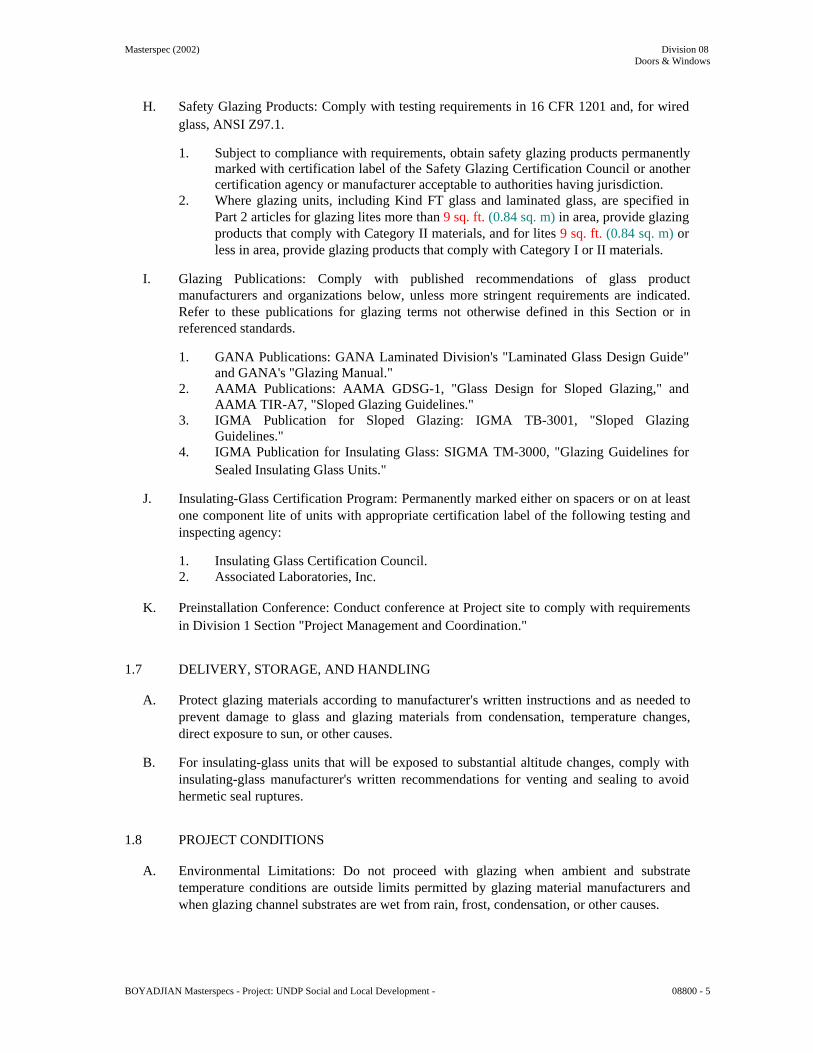
Masterspec (2002) Division 08 Doors & Windows
H. Safety Glazing Products: Comply with testing requirements in 16 CFR 1201 and, for wired glass, ANSI Z97.1.
1. Subject to compliance with requirements, obtain safety glazing products permanently
marked with certification label of the Safety Glazing Certification Council or another certification agency or manufacturer acceptable to authorities having jurisdiction.
2. Where glazing units, including Kind FT glass and laminated glass, are specified in Part 2 articles for glazing lites more than 9 sq. ft. (0.84 sq. m) in area, provide glazing products that comply with Category II materials, and for lites 9 sq. ft. (0.84 sq. m) or less in area, provide glazing products that comply with Category I or II materials.
I. Glazing Publications: Comply with published recommendations of glass product
manufacturers and organizations below, unless more stringent requirements are indicated. Refer to these publications for glazing terms not otherwise defined in this Section or in referenced standards.
1. GANA Publications: GANA Laminated Division's "Laminated Glass Design Guide"
and GANA's "Glazing Manual." 2. AAMA Publications: AAMA GDSG-1, "Glass Design for Sloped Glazing," and
AAMA TIR-A7, "Sloped Glazing Guidelines." 3. IGMA Publication for Sloped Glazing: IGMA TB-3001, "Sloped Glazing
Guidelines." 4. IGMA Publication for Insulating Glass: SIGMA TM-3000, "Glazing Guidelines for
Sealed Insulating Glass Units."
J. Insulating-Glass Certification Program: Permanently marked either on spacers or on at least one component lite of units with appropriate certification label of the following testing and inspecting agency:
1. Insulating Glass Certification Council. 2. Associated Laboratories, Inc.
K. Preinstallation Conference: Conduct conference at Project site to comply with requirements
in Division 1 Section "Project Management and Coordination." 1.7 DELIVERY, STORAGE, AND HANDLING
A. Protect glazing materials according to manufacturer's written instructions and as needed to prevent damage to glass and glazing materials from condensation, temperature changes, direct exposure to sun, or other causes.
B. For insulating-glass units that will be exposed to substantial altitude changes, comply with
insulating-glass manufacturer's written recommendations for venting and sealing to avoid hermetic seal ruptures.
1.8 PROJECT CONDITIONS
A. Environmental Limitations: Do not proceed with glazing when ambient and substrate temperature conditions are outside limits permitted by glazing material manufacturers and when glazing channel substrates are wet from rain, frost, condensation, or other causes.
BOYADJIAN Masterspecs - Project: UNDP Social and Local Development - 08800 - 5

Masterspec (2002) Division 08 Doors & Windows
1. Do not install liquid glazing sealants when ambient and substrate temperature conditions are outside limits permitted by glazing sealant manufacturer or below 40 deg F (4.4 deg C).
1.9 WARRANTY
A. Manufacturer's Special Warranty for Coated-Glass Products: Manufacturer's standard form, made out to Owner and signed by coated-glass manufacturer agreeing to replace coated-glass units that deteriorate as defined in "Definitions" Article, f.o.b. the nearest shipping point to Project site, within specified warranty period indicated below.
1. Warranty Period: 10 years from date of Substantial Completion.
B. Manufacturer's Special Warranty on Laminated Glass: Manufacturer's standard form, made
out to Owner and signed by laminated-glass manufacturer agreeing to replace laminated-glass units that deteriorate as defined in "Definitions" Article, f.o.b. the nearest shipping point to Project site, within specified warranty period indicated below.
1. Warranty Period: Five years from date of Substantial Completion.
C. Manufacturer's Special Warranty on Insulating Glass: Manufacturer's standard form, made
out to Owner and signed by insulating-glass manufacturer agreeing to replace insulating-glass units that deteriorate as defined in "Definitions" Article, f.o.b. the nearest shipping point to Project site, within specified warranty period indicated below.
1. Warranty Period: 10 years from date of Substantial Completion.
PART 2 - PRODUCTS 2.1 MANUFACTURERS
A. In other Part 2 articles where titles below introduce lists, the following requirements apply to product selection:
1. Available Products: Subject to compliance with requirements, products that may be
incorporated into the Work include, but are not limited to, products specified. 2.2 GLASS PRODUCTS
A. Heat-Treated Float Glass: ASTM C 1048; Type I (transparent flat glass); Quality-Q3; of class, kind, and condition indicated.
1. Fabrication Process: By horizontal (roller-hearth) process with roll-wave distortion
parallel to bottom edge of glass as installed, unless otherwise indicated. 2. Provide Kind HS (heat-strengthened) float glass in place of annealed float glass
where needed to resist thermal stresses induced by differential shading of individual glass lites and to comply with glass design requirements specified in Part 1 "Performance Requirements" Article.
3. For uncoated glass, comply with requirements for Condition A. 4. For coated vision glass, comply with requirements for Condition C (other uncoated
glass). BOYADJIAN Masterspecs - Project: UNDP Social and Local Development - 08800 - 6

Masterspec (2002) Division 08 Doors & Windows
5. Provide Kind FT (fully tempered) float glass in place of annealed or Kind HS (heat-strengthened) float glass where safety glass is indicated.
B. Pyrolytic-Coated Float Glass: ASTM C 1376, float glass with metallic-oxide coating applied
by pyrolytic deposition process during initial manufacture, and complying with other requirements specified.
C. Insulating-Glass Units, General: Factory-assembled units consisting of sealed lites of glass
separated by a dehydrated interspace, and complying with ASTM E 774 for Class CBA units and with requirements specified in this Article and in Part 2 "Insulating-Glass Units" Article.
1. Provide Kind HS (heat-strengthened) float glass in place of annealed glass where
needed to resist thermal stresses induced by differential shading of individual glass lites and to comply with glass design requirements specified in Part 1 "Performance Requirements" Article.
2. Provide Kind FT (fully tempered) glass lites where safety glass is indicated. 3. Overall Unit Thickness and Thickness of Each Lite: Dimensions indicated for
insulating-glass units are nominal and the overall thicknesses of units are measured perpendicularly from outer surfaces of glass lites at unit's edge.
4. Sealing System: Dual seal, with primary and secondary sealants as follows:
a. Manufacturer's standard sealants. b. Polyisobutylene and polysulfide. c. Polyisobutylene and silicone. d. Polyisobutylene and hot-melt butyl. e. Polyisobutylene and polyurethane.
5. Spacer Specifications: Manufacturer's standard spacer material and construction.
2.3 GLAZING GASKETS
A. Dense Compression Gaskets: Molded or extruded gaskets of material indicated below, complying with standards referenced with name of elastomer indicated below, and of profile and hardness required to maintain watertight seal:
1. Neoprene, ASTM C 864. 2. EPDM, ASTM C 864. 3. Silicone, ASTM C 1115. 4. Thermoplastic polyolefin rubber, ASTM C 1115. 5. Any material indicated above.
B. Lock-Strip Gaskets: Neoprene extrusions in size and shape indicated, fabricated into frames
with molded corner units and zipper lock-strips, complying with ASTM C 542, black. 2.4 GLAZING SEALANTS
A. General: Provide products of type indicated, complying with the following requirements:
1. Compatibility: Select glazing sealants that are compatible with one another and with other materials they will contact, including glass products, seals of insulating-glass units, and glazing channel substrates, under conditions of service and application, as demonstrated by sealant manufacturer based on testing and field experience.
BOYADJIAN Masterspecs - Project: UNDP Social and Local Development - 08800 - 7

Masterspec (2002) Division 08 Doors & Windows
2. Suitability: Comply with sealant and glass manufacturers' written instructions for selecting glazing sealants suitable for applications indicated and for conditions existing at time of installation.
3. Colors of Exposed Glazing Sealants: As selected by Architect from manufacturer's full range.
B. Elastomeric Glazing Sealants: Comply with ASTM C 920 and other requirements indicated
for each liquid-applied chemically curing sealant specified, including those referencing ASTM C 920 classifications for type, grade, class, and uses related to exposure and joint substrates.
1. Neutral-Curing Silicone Glazing Sealants GS-<#>:
a. Available Products:
1) Dow Corning Corporation; 791. 2) Dow Corning Corporation; 795. 3) GE Silicones; SilPruf NB SCS9000. 4) GE Silicones; UltraPruf II SCS2900. 5) Pecora Corporation; 865. 6) Pecora Corporation; 895. 7) Pecora Corporation; 898.
b. Type and Grade: S (single component) and NS (nonsag). c. Class: 50. d. Use Related to Exposure: NT (nontraffic). e. Uses Related to Glazing Substrates: M, G, A, and, as applicable to glazing
substrates indicated, O.
1) Use O Glazing Substrates: Coated glass.
C. Glazing Sealants for Fire-Resistive Glazing Products: Identical to products used in test assemblies to obtain fire-protection rating.
2.5 GLAZING TAPES
A. Back-Bedding Mastic Glazing Tapes: Preformed, butyl-based elastomeric tape with a solids content of 100 percent; nonstaining and nonmigrating in contact with nonporous surfaces; with or without spacer rod as recommended in writing by tape and glass manufacturers for application indicated; packaged on rolls with a release paper backing; and complying with ASTM C 1281 and AAMA 800 for products indicated below:
1. AAMA 804.3 tape, where indicated. 2. AAMA 806.3 tape, for glazing applications in which tape is subject to continuous
pressure. 3. AAMA 807.3 tape, for glazing applications in which tape is not subject to continuous
pressure.
B. Expanded Cellular Glazing Tapes: Closed-cell, PVC foam tapes; factory coated with adhesive on both surfaces; packaged on rolls with release liner protecting adhesive; and complying with AAMA 800 for the following types:
1. Type 1, for glazing applications in which tape acts as the primary sealant.
BOYADJIAN Masterspecs - Project: UNDP Social and Local Development - 08800 - 8

Masterspec (2002) Division 08 Doors & Windows
2. Type 2, for glazing applications in which tape is used in combination with a full bead of liquid sealant.
2.6 MISCELLANEOUS GLAZING MATERIALS
A. General: Provide products of material, size, and shape complying with referenced glazing standard, requirements of manufacturers of glass and other glazing materials for application indicated, and with a proven record of compatibility with surfaces contacted in installation.
B. Cleaners, Primers, and Sealers: Types recommended by sealant or gasket manufacturer.
C. Setting Blocks: Elastomeric material with a Shore, Type A durometer hardness of 85, plus
or minus 5.
D. Spacers: Elastomeric blocks or continuous extrusions with a Shore, Type A durometer hardness required by glass manufacturer to maintain glass lites in place for installation indicated.
E. Edge Blocks: Elastomeric material of hardness needed to limit glass lateral movement (side
walking).
F. Cylindrical Glazing Sealant Backing: ASTM C 1330, Type O (open-cell material), of size and density to control glazing sealant depth and otherwise produce optimum glazing sealant performance.
G. Perimeter Insulation for Fire-Resistive Glazing: Identical to product used in test assembly to
obtain fire-resistance rating. 2.7 FABRICATION OF GLAZING UNITS
A. Fabricate glazing units in sizes required to glaze openings indicated for Project, with edge and face clearances, edge and surface conditions, and bite complying with written instructions of product manufacturer and referenced glazing publications, to comply with system performance requirements.
B. Clean-cut or flat-grind vertical edges of butt-glazed monolithic lites in a manner that
produces square edges with slight kerfs at junctions with outdoor and indoor faces.
C. Grind smooth and polish exposed glass edges and corners. 2.8 INSULATING-GLASS UNITS
A. Insulating-Glass Units IG-1:
1. Approved Manufacturers:
a. Saint Gobain
b. Pilkington.
c. Glaver Bel
BOYADJIAN Masterspecs - Project: UNDP Social and Local Development - 08800 - 9

Masterspec (2002) Division 08 Doors & Windows
d. Ford
e. K-Lite
2. Overall Unit Thickness and Thickness of Each Lite: 24 mm, and 8.0 mm outdoor lite and 6.0 mm indoor lite as deemed necessary.
3. Interspace Content: Air. 4. Interspace (Cavity) Width: 10mm. 5. Outdoor Lite: Class 1 (clear) float glass.
a. Annealed. 6. Indoor Lite: Class 1 (clear) float glass.
a. Annealed. PART 3 - EXECUTION 3.1 EXAMINATION
A. Examine framing glazing, with Installer present, for compliance with the following:
1. Manufacturing and installation tolerances, including those for size, squareness, and offsets at corners.
2. Presence and functioning of weep system. 3. Minimum required face or edge clearances. 4. Effective sealing between joints of glass-framing members.
B. Proceed with installation only after unsatisfactory conditions have been corrected.
3.2 PREPARATION
A. Clean glazing channels and other framing members receiving glass immediately before glazing. Remove coatings not firmly bonded to substrates.
3.3 GLAZING, GENERAL
A. Comply with combined written instructions of manufacturers of glass, sealants, gaskets, and other glazing materials, unless more stringent requirements are indicated, including those in referenced glazing publications.
B. Glazing channel dimensions, as indicated on Drawings, provide necessary bite on glass,
minimum edge and face clearances, and adequate sealant thicknesses, with reasonable tolerances. Adjust as required by Project conditions during installation.
C. Protect glass edges from damage during handling and installation. Remove damaged glass
from Project site and legally dispose of off Project site. Damaged glass is glass with edge damage or other imperfections that, when installed, could weaken glass and impair performance and appearance.
D. Apply primers to joint surfaces where required for adhesion of sealants, as determined by
preconstruction sealant-substrate testing. BOYADJIAN Masterspecs - Project: UNDP Social and Local Development - 08800 - 10

Masterspec (2002) Division 08 Doors & Windows
E. Install setting blocks in sill rabbets, sized and located to comply with referenced glazing publications, unless otherwise required by glass manufacturer. Set blocks in thin course of compatible sealant suitable for heel bead.
F. Do not exceed edge pressures stipulated by glass manufacturers for installing glass lites.
G. Provide spacers for glass lites where length plus width is larger than 50 inches (1270 mm)
as follows:
1. Locate spacers directly opposite each other on both inside and outside faces of glass. Install correct size and spacing to preserve required face clearances, unless gaskets and glazing tapes are used that have demonstrated ability to maintain required face clearances and to comply with system performance requirements.
2. Provide 1/8-inch (3-mm) minimum bite of spacers on glass and use thickness equal to sealant width. With glazing tape, use thickness slightly less than final compressed thickness of tape.
H. Provide edge blocking where indicated or needed to prevent glass lites from moving
sideways in glazing channel, as recommended in writing by glass manufacturer and according to requirements in referenced glazing publications.
I. Set glass lites in each series with uniform pattern, draw, bow, and similar characteristics.
J. Where wedge-shaped gaskets are driven into one side of channel to pressurize sealant or
gasket on opposite side, provide adequate anchorage so gasket cannot walk out when installation is subjected to movement.
K. Square cut wedge-shaped gaskets at corners and install gaskets in a manner recommended
by gasket manufacturer to prevent corners from pulling away; seal corner joints and butt joints with sealant recommended by gasket manufacturer.
3.4 TAPE GLAZING
A. Position tapes on fixed stops so that, when compressed by glass, their exposed edges are flush with or protrude slightly above sightline of stops.
B. Install tapes continuously, but not necessarily in one continuous length. Do not stretch tapes
to make them fit opening.
C. Cover vertical framing joints by applying tapes to heads and sills first and then to jambs. Cover horizontal framing joints by applying tapes to jambs and then to heads and sills.
D. Place joints in tapes at corners of opening with adjoining lengths butted together, not lapped.
Seal joints in tapes with compatible sealant approved by tape manufacturer.
E. Do not remove release paper from tape until just before each glazing unit is installed.
F. Apply heel bead of elastomeric sealant.
G. Center glass lites in openings on setting blocks and press firmly against tape by inserting dense compression gaskets formed and installed to lock in place against faces of removable stops. Start gasket applications at corners and work toward centers of openings.
H. Apply cap bead of elastomeric sealant over exposed edge of tape.
BOYADJIAN Masterspecs - Project: UNDP Social and Local Development - 08800 - 11

Masterspec (2002) Division 08 Doors & Windows
3.5 GASKET GLAZING (DRY)
A. Fabricate compression gaskets in lengths recommended by gasket manufacturer to fit openings exactly, with allowance for stretch during installation.
B. Insert soft compression gasket between glass and frame or fixed stop so it is securely in
place with joints miter cut and bonded together at corners.
C. Center glass lites in openings on setting blocks and press firmly against soft compression gasket by inserting dense compression gaskets formed and installed to lock in place against faces of removable stops. Start gasket applications at corners and work toward centers of openings. Compress gaskets to produce a weathertight seal without developing bending stresses in glass. Seal gasket joints with sealant recommended by gasket manufacturer.
D. Install gaskets so they protrude past face of glazing stops.
3.6 SEALANT GLAZING (WET)
A. Install continuous spacers, or spacers combined with cylindrical sealant backing, between glass lites and glazing stops to maintain glass face clearances and to prevent sealant from extruding into glass channel and blocking weep systems until sealants cure. Secure spacers or spacers and backings in place and in position to control depth of installed sealant relative to edge clearance for optimum sealant performance.
B. Force sealants into glazing channels to eliminate voids and to ensure complete wetting or
bond of sealant to glass and channel surfaces.
C. Tool exposed surfaces of sealants to provide a substantial wash away from glass. 3.7 LOCK-STRIP GASKET GLAZING
A. Comply with ASTM C 716 and gasket manufacturer's written instructions. Provide supplementary wet seal and weep system, unless otherwise indicated.
3.8 CLEANING AND PROTECTION
A. Protect exterior glass from damage immediately after installation by attaching crossed streamers to framing held away from glass. Do not apply markers to glass surface. Remove nonpermanent labels, and clean surfaces.
B. Protect glass from contact with contaminating substances resulting from construction
operations, including weld splatter. If, despite such protection, contaminating substances do come into contact with glass, remove substances immediately as recommended by glass manufacturer.
C. Examine glass surfaces adjacent to or below exterior concrete and other masonry surfaces at
frequent intervals during construction, but not less than once a month, for buildup of dirt, scum, alkaline deposits, or stains; remove as recommended in writing by glass manufacturer.
D. Remove and replace glass that is broken, chipped, cracked, or abraded or that is damaged
from natural causes, accidents, and vandalism, during construction period. BOYADJIAN Masterspecs - Project: UNDP Social and Local Development - 08800 - 12

Masterspec (2002) Division 08 Doors & Windows
E. Wash glass on both exposed surfaces in each area of Project not more than four days before date scheduled for inspections that establish date of Substantial Completion. Wash glass as recommended in writing by glass manufacturer.
END OF SECTION 08800 BOYADJIAN Masterspecs - Project: UNDP Social and Local Development - 08800 - 13

Masterspec (2002) Division 09 Finishes
SECTION 09220 - PORTLAND CEMENT PLASTER PART 1 - GENERAL 1.1 RELATED DOCUMENTS
A. Drawings and general provisions of the Contract, including General and Supplementary Conditions and Division 1 Specification Sections, apply to this Section.
1.2 SUMMARY
A. This Section includes the following:
1. Nonstructural steel framing and furring. 2. Interior portland cement plasterwork on metal lath and solid- plaster bases.
1.3 SUBMITTALS
A. Product Data: For each type of product indicated.
B. Shop Drawings: Show locations and installation of control and expansion joints including plans, elevations, sections, details of components, and attachments to other work.
C. Samples for Initial Selection: For each type of factory-prepared finish coat indicated.
1.4 QUALITY ASSURANCE
A. Fire-Test-Response Characteristics: For portland cement plaster assemblies with fire-resistance ratings, provide materials and construction identical to those tested in assembly indicated according to ASTM E 119 by an independent testing and inspecting agency acceptable to authorities having jurisdiction.
B. Mockups: Before plastering, install mockups of at least 100 sq. ft. (9 sq. m) in surface area
to demonstrate aesthetic effects and set quality standards for materials and execution.
1. Install mockups for each type of finish indicated. 2. For interior plasterwork, simulate finished lighting conditions for review of mockups. 3. Approved mockups may become part of the completed Work if undisturbed at time of
Substantial Completion.
C. Preinstallation Conference: Conduct conference at Project site to comply with requirements in Division 1 Section "Project Management and Coordination."
1.5 DELIVERY, STORAGE, AND HANDLING
A. Store materials inside under cover and keep them dry and protected against damage from weather, direct sunlight, surface contamination, corrosion, construction traffic, and other causes.
BOYADJIAN Masterspecs - Project: UNDP Social and Local Development - 09220 - 1

Masterspec (2002) Division 09 Finishes
1.6 PROJECT CONDITIONS
A. Comply with ASTM C 926 requirements.
B. Interior Plasterwork: Maintain room temperatures at greater than 40 deg F (4.4 deg C) for at least 48 hours before plaster application, and continuously during and after application.
1. Avoid conditions that result in plaster drying out during curing period. Distribute heat
evenly; prevent concentrated or uneven heat on plaster. 2. Ventilate building spaces as required to remove water in excess of that required for
hydrating plaster in a manner that prevents drafts of air from contacting surfaces during plaster application and until plaster is dry.
C. Exterior Plasterwork:
1. Apply and cure plaster to prevent plaster drying out during curing period. Use
procedures required by climatic conditions, including moist curing, providing coverings, and providing barriers to deflect sunlight and wind.
2. Apply plaster when ambient temperature is greater than 40 deg F (4.4 deg C). 3. Protect plaster coats from freezing for not less than 48 hours after set of plaster coat
has occurred.
D. Factory-Prepared Finishes: Comply with manufacturer's written recommendations for environmental conditions for applying finishes.
PART 2 - PRODUCTS 2.1 MANUFACTURERS
A. In other Part 2 articles where titles below introduce lists, the following requirements apply to product selection:
1. Available Products: Subject to compliance with requirements, products that may be
incorporated into the Work include, but are not limited to, products specified. 2.2 NONSTRUCTURAL STEEL FRAMING MEMBERS, GENERAL
A. Available Manufacturers: 1. Expamet 2. Catnic.
B. Components, General: Comply with ASTM C 1063. For steel sheet components not
included in ASTM C 1063, comply with ASTM C 645 requirements for metal, unless otherwise indicated.
C. Cold-Rolled Channels: Base metal thickness of 0.0538 inch (1.37 mm) with
ASTM A 653/A 653M, G60 (Z180), hot-dip galvanized zinc coating.
D. Wire: ASTM A 641/A 641M, Class 1 zinc coating, soft temper, not less than 0.0475-inch (1.21-mm) diameter, unless otherwise indicated.
BOYADJIAN Masterspecs - Project: UNDP Social and Local Development - 09220 - 2

Masterspec (2002) Division 09 Finishes
2.3 METAL LATH
A. Expanded-Metal Lath: ASTM C 847 with ASTM A 653/A 653M, G60 (Z180), hot-dip galvanized zinc coating.
1. Available Manufacturers:
a. Expamet. b. Catnic.
2. Diamond-Mesh Lath: Flat.
a. Weight: 3.4 lb/sq. yd. (1.8 kg/sq. m).
B. Paper Backing: FS UU-B-790, Type I Grade B, Style 1a vapor-retardant paper.
1. Provide paper-backed lath unless otherwise indicated.
2.4 ACCESSORIES
A. General: Comply with ASTM C 1063 and coordinate depth of trim and accessories with thicknesses and number of plaster coats required.
B. Zinc and Zinc-Coated (Galvanized) Accessories:
1. Available Manufacturers:
a. Expamet. b. Catnic.
2. Cornerite: Fabricated from metal lath with ASTM A 653/A 653M, G60 (Z180), hot-dip galvanized zinc coating.
3. External-Corner Reinforcement: Fabricated from metal lath with ASTM A 653/A 653M, G60 (Z180), hot-dip galvanized zinc coating. 4. Cornerbeads: Fabricated from zinc or zinc-coated (galvanized) steel.
a. Small nose cornerbead with expanded flanges; use unless otherwise indicated. b. Small nose cornerbead with perforated flanges; use on curved corners. c. Small nose cornerbead with expanded flanges reinforced by perforated
stiffening rib; use on columns and for finishing masonry corners.
5. Casing Beads: Fabricated from zinc or zinc-coated (galvanized) steel; square-edged style; with expanded flanges.
6. Control Joints: Fabricated from zinc or zinc-coated (galvanized) steel; one-piece-type, folded pair of unperforated screeds in M-shaped configuration; with perforated flanges and removable protective tape on plaster face of control joint.
7. Expansion Joints: Fabricated from zinc or zinc-coated (galvanized) steel; folded pair of unperforated screeds in M-shaped configuration; with expanded flanges.
8. Two-Piece Expansion Joints: Fabricated from zinc or zinc-coated (galvanized) steel; formed to produce slip-joint and square-edged reveal that is adjustable from 1/4-to-5/8-inch (6.34-to-16-mm) wide; with perforated flanges.
2.5 MISCELLANEOUS MATERIALS
A. Water for Mixing: Potable and free of substances capable of affecting plaster set or of damaging plaster, lath, or accessories.
BOYADJIAN Masterspecs - Project: UNDP Social and Local Development - 09220 - 3

Masterspec (2002) Division 09 Finishes
B. Fiber for Base Coat: Alkaline-resistant glass or polypropylene fibers, 1/2 inch (13 mm)
long, free of contaminants, manufactured for use in portland cement plaster.
C. Bonding Compound: ASTM C 932.
D. Steel Drill Screws: For metal-to-metal fastening, ASTM C 1002 or ASTM C 954, as required by thickness of metal being fastened; with pan head that is suitable for application; in lengths required to achieve penetration through joined materials of not fewer than three exposed threads.
E. Fasteners for Attaching Metal Lath to Substrates: Complying with ASTM C 1063.
F. Isolation Strip at Exterior Walls:
1. Asphalt-Saturated Organic Felt: ASTM D 226, Type I (No. 15 asphalt felt),
unperforated. 2. Foam Gasket: Adhesive-backed, closed-cell vinyl foam strips that allow fastener
penetration without foam displacement, 1/8 inch (3.1 mm) thick, in width to suit steel stud size.
2.6 PLASTER MATERIALS
A. Portland Cement: ASTM C 150, Type I.
1. Color for Finish Coats: White or Gray.
B. Colorants for Job-Mixed Finish-Coats: Colorfast mineral pigments that produce finish plaster color to match Architect's sample.
C. Lime: ASTM C 206, Type S; or ASTM C 207, Type S.
D. Sand Aggregate: ASTM C 897.
1. Color for Job-Mixed Finish Coats: White.
E. Exposed Aggregates for Finish Coats: For marblecrete finish, clean, sound, crushed marble
matching color and size gradation of Architect's sample.
F. Ready-Mixed Finish-Coat Plaster: Mill-mixed portland cement, aggregates, coloring agents, and proprietary ingredients.
2.7 PLASTER MIXES
A. General: Comply with ASTM C 926 for applications indicated.
1. Fiber Content: Add fiber to base-coat mixes after ingredients have mixed at least two minutes. Comply with fiber manufacturer's written instructions for fiber quantities in mixes, but do not exceed 1 lb of fiber/cu. ft. (16 kg of fiber/cu. m) of cementitious materials. Reduce aggregate quantities accordingly to maintain workability.
B. Base-Coat Mixes for Use over Metal Lath: Scratch and brown coats for three-coat
plasterwork as follows:
1. Portland Cement Mixes: BOYADJIAN Masterspecs - Project: UNDP Social and Local Development - 09220 - 4

Masterspec (2002) Division 09 Finishes
a. Scratch Coat: For cementitious material, mix 1 part portland cement and 3/4 to
1-1/2 parts lime. Use 2-1/2 to 4 parts aggregate per part of cementitious material (sum of separate volumes of each component material).
b. Brown Coat: For cementitious material, mix 1 part portland cement and 3/4 to 1-1/2 parts lime. Use 3 to 5 parts aggregate per part of cementitious material (sum of separate volumes of each component material).
C. Base-Coat Mixes for Use over Monolithic Concrete: Single base coats for two-coat
plasterwork as follows:
1. Portland Cement Mix: For cementitious material, mix 1 part portland cement and 0 to 3/4 part admixture for better workability. Use 2-1/2 to 4 parts aggregate per part of cementitious material (sum of separate volumes of each component material).
D. Base-Coat Mixes for Use over Concrete Unit Masonry: Single base coats for two-coat
plasterwork as follows:
1. Portland Cement Mix: For cementitious material, mix 1 part portland cement and 3/4 to 1-1/2 parts admixture for better workability. Use 2-1/2 to 4 parts aggregate per part of cementitious material (sum of separate volumes of each component material).
E. Job-Mixed Finish-Coat Mixes:
1. Portland Cement Mix: For cementitious materials, mix 1 part portland cement and 3/4
to 1-1/2 parts lime. Use 1-1/2 to 3 parts aggregate per part of cementitious material (sum of separate volumes of each component material).
F. Factory-Prepared Finish-Coat Mixes: For ready-mixed finish-coat plasters and acrylic-based
finish coatings, comply with manufacturer's written instructions. PART 3 - EXECUTION 3.1 EXAMINATION
A. Examine areas and substrates, with Installer present, and including welded hollow-metal frames, cast-in anchors, and structural framing, for compliance with requirements and other conditions affecting performance.
1. Proceed with installation only after unsatisfactory conditions have been corrected.
3.2 PREPARATION
A. Protect adjacent work from soiling, spattering, moisture deterioration, and other harmful effects caused by plastering.
B. Prepare solid-plaster bases that are smooth or that do not have the suction capability
required to bond with plaster according to ASTM C 926. 3.3 INSTALLING NONSTRUCTURAL STEEL FRAMING, GENERAL
A. General: Comply with requirements in ASTM C 1063 for applications indicated. BOYADJIAN Masterspecs - Project: UNDP Social and Local Development - 09220 - 5

Masterspec (2002) Division 09 Finishes
1. Comply with ASTM C 754 for installation of items not addressed in ASTM C 1063.
B. Install supplementary framing, blocking, and bracing at terminations in plaster assemblies to
support fixtures, equipment services, heavy trim, grab bars, toilet accessories, furnishings, or similar construction.
C. Isolate steel framing from building structure to prevent transfer of loading imposed by
structural movement.
1. Isolate ceiling assemblies where they abut or are penetrated by building structure. 2. Isolate partition framing and wall furring where it abuts structure, except at floor. At
head of assemblies, install slip-type joints that avoid axial loading and that support assembly laterally.
D. Do not bridge building control and expansion joints with steel framing or furring members.
Frame both sides of joints independently.
E. Soffits: Unless otherwise detailed on Drawings, install furred or suspended soffits to comply with requirements for ceiling installation; install framed soffits to comply with requirements for partition installation.
3.4 INSTALLING METAL LATH
A. Expanded-Metal Lath: Install according to ASTM C 1063.
1. Partition Framing and Vertical Furring: Install flat diamond-mesh lath. 2. Flat-Ceiling and Horizontal Framing: Install flat diamond-mesh lath. 3. Curved-Ceiling Framing: Install flat diamond-mesh lath. 4. On Solid Surfaces, Not Otherwise Furred: Install self-furring diamond-mesh lath.
3.5 INSTALLING ACCESSORIES
A. Install according to ASTM C 1063 and at locations indicated on Drawings.
B. Reinforcement for External Corners:
1. Install lath-type external-corner reinforcement at exterior locations. 2. Install cornerbead at interior locations.
C. Control Joints: Install control joints in specific locations approved by Architect for visual
effect as follows:
1. As required to delineate plasterwork into areas (panels) of the following maximum sizes:
a. Vertical Surfaces: 144 sq. ft. (13.4 sq. m). b. Horizontal and other Nonvertical Surfaces: 100 sq. ft. (9.3 sq. m).
2. At distances between control joints of not greater than 18 feet (5.5 m) o.c. 3. As required to delineate plasterwork into areas (panels) with length-to-width ratios of
not greater than 2-1/2:1. 4. Where control joints occur in surface of construction directly behind plaster.
BOYADJIAN Masterspecs - Project: UNDP Social and Local Development - 09220 - 6

Masterspec (2002) Division 09 Finishes
5. Where plasterwork areas change dimensions, to delineate rectangular-shaped areas
(panels) and to relieve the stress that occurs at the corner formed by the dimension change.
3.6 PLASTER APPLICATION
A. General: Comply with ASTM C 926.
1. Do not deviate more than plus or minus 1/4 inch in 10 feet (6.4 mm in 3 m) from a true plane in finished plaster surfaces, as measured by a 10-foot (3-m) straightedge placed on surface.
2. Grout hollow-metal frames, bases, and similar work occurring in plastered areas, with base-coat plaster material, before lathing where necessary. Except where full grouting is indicated or required for fire-resistance rating, grout at least 6 inches (152 mm) at each jamb anchor.
3. Finish plaster flush with metal frames and other built-in metal items or accessories that act as a plaster ground, unless otherwise indicated. Where casing bead does not terminate plaster at metal frame, cut base coat free from metal frame before plaster sets and groove finish coat at junctures with metal.
4. Provide plaster surfaces that are ready to receive field-applied finishes indicated.
B. Bonding Compound: Apply on unit masonry and concrete plaster bases.
C. Concealed Interior Plasterwork:
1. Where plaster application will be concealed behind built-in cabinets, similar furnishings, and equipment, apply finish coat.
2. Where plaster application will be concealed above suspended ceilings and in similar locations, finish coat may be omitted.
3. Where plaster application will be used as a base for adhesive application of tile and similar finishes, finish coat may be omitted.
3.7 CUTTING AND PATCHING
A. Cut, patch, replace, and repair plaster as necessary to accommodate other work and to restore cracks, dents, and imperfections. Repair or replace work to eliminate blisters, buckles, crazing and check cracking, dry outs, efflorescence, sweat outs, and similar defects and where bond to substrate has failed.
3.8 CLEANING AND PROTECTION
A. Remove temporary protection and enclosure of other work. Promptly remove plaster from doorframes, windows, and other surfaces not indicated to be plastered. Repair floors, walls, and other surfaces stained, marred, or otherwise damaged during plastering.
END OF SECTION 09220 BOYADJIAN Masterspecs - Project: UNDP Social and Local Development - 09220 - 7
Masterspec (2000) Division 09 Finishes
SECTION 09310 - CERAMIC TILE PART 1 - GENERAL 1.1 RELATED DOCUMENTS
A. Drawings and general provisions of the Contract, including General and Supplementary Conditions and Division 1 Specification Sections, apply to this Section.
1.2 SUMMARY
A. This Section includes the following: 1. Ceramic. 2. Metal edge strips installed as part of tile installations.
B. Related Sections include the following:
1. Division 9 Section "Portland Cement Plaster" for portland cement scratch coat over metal lath on wall surfaces.
1.3 DEFINITIONS
A. Module Size: Actual tile size (minor facial dimension as measured per ASTM C 499) plus joint width indicated.
B. Facial Dimension: Nominal tile size as defined in ANSI A137.1.
1.4 PERFORMANCE REQUIREMENTS
A. Static Coefficient of Friction: For tile installed on walkway surfaces, provide products with the following values as determined by testing identical products per ASTM C 1028:
1. Level Surfaces: Minimum 0.6. 2. Step Treads: Minimum 0.6. 3. Ramp Surfaces: Minimum 0.8.
1.5 SUBMITTALS
A. Product Data: For each type of product indicated.
B. Shop Drawings: Show locations of each type of tile and tile pattern. Show widths, details, and locations of expansion, contraction, control, and isolation joints in tile substrates and finished tile surfaces.
C. Samples for Initial Selection: For each type of tile and grout indicated. Include Samples of
accessories involving color selection.
D. Samples for Verification:
BOYADJIAN Masterspecs - Project: UNDP Social and Local Development - 09310 - 1

Masterspec (2000) Division 09 Finishes
1. Full-size units of each type and composition of tile and for each color and finish
required. 2. Full-size units of each type of trim and accessory for each color and finish required. 3. Metal edge strips in 6-inch (150-mm) lengths.
E. Master Grade Certificates: For each shipment, type, and composition of tile, signed by tile
manufacturer and Installer.
F. Product Certificates: For each type of product, signed by product manufacturer.
G. Qualification Data: For Installer.
H. Material Test Reports: For each tile-setting and -grouting product. 1.6 QUALITY ASSURANCE
A. Source Limitations for Tile: Obtain all tile of same type and color or finish from one source or producer.
1. Obtain tile from same production run and of consistent quality in appearance and
physical properties for each contiguous area.
B. Source Limitations for Setting and Grouting Materials: Obtain ingredients of a uniform quality for each mortar, adhesive, and grout component from a single manufacturer and each aggregate from one source or producer.
C. Source Limitations for Other Products: Obtain each of the following products specified in
this Section through one source from a single manufacturer for each product: 1. Metal edge strips.
D. Mockups: Build mockups to verify selections made under sample Submittals and to
demonstrate aesthetic effects and qualities of materials and execution.
1. Build mockup of each type of floor tile installation. 2. Build mockup of each type of wall tile installation. 3. Approved mockups may become part of the completed Work if undisturbed at time of
Substantial Completion.
E. Preinstallation Conference: Conduct conference at Project site to comply with requirements in Division 1 Section "Project Management and Coordination."
1.7 DELIVERY, STORAGE, AND HANDLING
A. Deliver and store packaged materials in original containers with seals unbroken and labels intact until time of use. Comply with requirement in ANSI A137.1 for labeling sealed tile packages.
B. Store tile and cementitious materials on elevated platforms, under cover, and in a dry
location.
C. Store aggregates where grading and other required characteristics can be maintained and contamination avoided.
BOYADJIAN Masterspecs - Project: UNDP Social and Local Development - 09310 - 2

Masterspec (2000) Division 09 Finishes
D. Store liquid latexes and emulsion adhesives in unopened containers and protected from
freezing.
E. Handle tile that has temporary protective coating on exposed surfaces to prevent coated surfaces from contacting backs or edges of other units. If coating does contact bonding surfaces of tile, remove coating from bonding surfaces before setting tile.
1.8 PROJECT CONDITIONS
A. Environmental Limitations: Do not install tile until construction in spaces is complete and ambient temperature and humidity conditions are maintained at the levels indicated in referenced standards and manufacturer's written instructions.
1.9 EXTRA MATERIALS
A. Furnish extra materials described below that match products installed and that are packaged with protective covering for storage and identified with labels describing contents.
1. Tile and Trim Units: Furnish quantity of full-size units equal to 3 percent of amount
installed, for each type, composition, color, pattern, and size indicated. PART 2 - PRODUCTS 2.1 MANUFACTURERS
A. In other Part 2 articles where titles below introduce lists, the following requirements apply for product selection:
1. Available Products: Subject to compliance with requirements, products that may be
incorporated into the Work include, but are not limited to, the products specified. 2.2 PRODUCTS, GENERAL
A. ANSI Ceramic Tile Standard: Provide tile that complies with ANSI A137.1, "Specifications for Ceramic Tile," for types, compositions, and other characteristics indicated.
1. Provide tile complying with Standard grade requirements, unless otherwise indicated. 2. For facial dimensions of tile, comply with requirements relating to tile sizes specified
in Part 1 "Definitions" Article.
B. ANSI Standards for Tile Installation Materials: Provide materials complying with ANSI standards referenced in "Setting and Grouting Materials" Article.
C. Colors, Textures, and Patterns: Where manufacturer's standard products are indicated for
tile, grout, and other products requiring selection of colors, surface textures, patterns, and other appearance characteristics, provide specific products or materials complying with the following requirements:
1. As selected by Engineer from manufacturer's full range.
BOYADJIAN Masterspecs - Project: UNDP Social and Local Development - 09310 - 3

Masterspec (2000) Division 09 Finishes
D. Factory Blending: For tile exhibiting color variations within ranges selected during Sample
submittals, blend tile in factory and package so tile units taken from one package show same range in colors as those taken from other packages and match approved Samples.
E. Mounting: For factory-mounted tile, provide back- or edge-mounted tile assemblies as
standard with manufacturer, unless otherwise indicated.
1. Where tile is indicated for installation in wet areas, do not use back- or edge-mounted tile assemblies unless tile manufacturer specifies in writing that this type of mounting is suitable for installation indicated and has a record of successful in-service performance.
F. Factory-Applied Temporary Protective Coating: Where indicated under tile type, protect
exposed surfaces of tile against adherence of mortar and grout by precoating with continuous film of petroleum paraffin wax, applied hot. Do not coat unexposed tile surfaces.
2.3 TILE PRODUCTS
A. Manufacturers: a. Unitech, Caesar, RAK or approved equivalent
B. Non Slip Ceramic Tile: Flat tile as follows:
1. Composition: High industrial Gres Ceramic (Massive). 2. Facial Dimensions: As indicated on the drawings. 3. Thickness: Minimum 0.315 inch (8.0 mm). 4. Face: Plain with square or cushion edges. 5. For latex-portland cement-mortared and -grouted paver tile, precoat with temporary
protective coating. 6. First choice tiles. 7. Single fire tiles 8. Water Absorption 0 to 0.5%
C. Glazed Paver Tile: Flat tile as follows:
1. Composition: Impervious natural clay or porcelain. 2. Facial Dimensions: As indicated on the drawings. 3. Thickness: Minimum 0.315inch (8.0 mm). 4. Face: Plain with square or cushion edges. 5. First choice tiles. 6. Single fire tiles 7. Water Absorption 0 to 0.5% 8. Wearing Surface: Nonabrasive. Abrasion resistance Pei 4
D. Wall Tile Trim Units: Matching characteristics of adjoining flat tile and coordinated with
sizes and coursing of adjoining flat tile where applicable. Provide shapes as follows, selected from manufacturer's standard shapes:
1. Base for Portland Cement Mortar Installations: Coved, module size 4-1/4 by 4-1/4
inches (108 by 108 mm). 2. Base for Thin-Set Mortar Installations: Straight, module size 4-1/4 by 4-1/4 inches
(108 by 108 mm). BOYADJIAN Masterspecs - Project: UNDP Social and Local Development - 09310 - 4
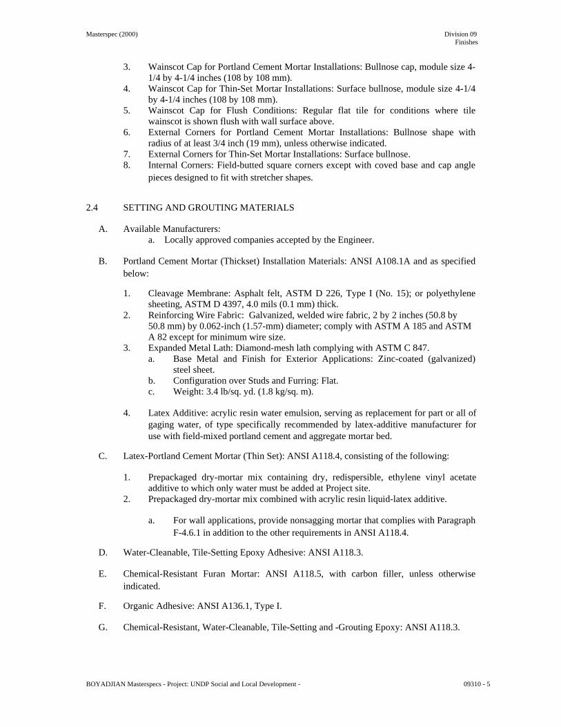
Masterspec (2000) Division 09 Finishes
3. Wainscot Cap for Portland Cement Mortar Installations: Bullnose cap, module size 4-
1/4 by 4-1/4 inches (108 by 108 mm). 4. Wainscot Cap for Thin-Set Mortar Installations: Surface bullnose, module size 4-1/4
by 4-1/4 inches (108 by 108 mm). 5. Wainscot Cap for Flush Conditions: Regular flat tile for conditions where tile
wainscot is shown flush with wall surface above. 6. External Corners for Portland Cement Mortar Installations: Bullnose shape with
radius of at least 3/4 inch (19 mm), unless otherwise indicated. 7. External Corners for Thin-Set Mortar Installations: Surface bullnose. 8. Internal Corners: Field-butted square corners except with coved base and cap angle
pieces designed to fit with stretcher shapes. 2.4 SETTING AND GROUTING MATERIALS
A. Available Manufacturers: a. Locally approved companies accepted by the Engineer.
B. Portland Cement Mortar (Thickset) Installation Materials: ANSI A108.1A and as specified
below:
1. Cleavage Membrane: Asphalt felt, ASTM D 226, Type I (No. 15); or polyethylene sheeting, ASTM D 4397, 4.0 mils (0.1 mm) thick.
2. Reinforcing Wire Fabric: Galvanized, welded wire fabric, 2 by 2 inches (50.8 by 50.8 mm) by 0.062-inch (1.57-mm) diameter; comply with ASTM A 185 and ASTM A 82 except for minimum wire size.
3. Expanded Metal Lath: Diamond-mesh lath complying with ASTM C 847. a. Base Metal and Finish for Exterior Applications: Zinc-coated (galvanized)
steel sheet. b. Configuration over Studs and Furring: Flat. c. Weight: 3.4 lb/sq. yd. (1.8 kg/sq. m).
4. Latex Additive: acrylic resin water emulsion, serving as replacement for part or all of
gaging water, of type specifically recommended by latex-additive manufacturer for use with field-mixed portland cement and aggregate mortar bed.
C. Latex-Portland Cement Mortar (Thin Set): ANSI A118.4, consisting of the following:
1. Prepackaged dry-mortar mix containing dry, redispersible, ethylene vinyl acetate
additive to which only water must be added at Project site. 2. Prepackaged dry-mortar mix combined with acrylic resin liquid-latex additive.
a. For wall applications, provide nonsagging mortar that complies with Paragraph
F-4.6.1 in addition to the other requirements in ANSI A118.4.
D. Water-Cleanable, Tile-Setting Epoxy Adhesive: ANSI A118.3.
E. Chemical-Resistant Furan Mortar: ANSI A118.5, with carbon filler, unless otherwise indicated.
F. Organic Adhesive: ANSI A136.1, Type I.
G. Chemical-Resistant, Water-Cleanable, Tile-Setting and -Grouting Epoxy: ANSI A118.3.
BOYADJIAN Masterspecs - Project: UNDP Social and Local Development - 09310 - 5

Masterspec (2000) Division 09 Finishes
1. Provide product capable of withstanding continuous and intermittent exposure to
temperatures of up to 140 deg F (60 deg C) and 212 deg F (100 deg C), respectively, and certified by grout manufacturer for intended use.
2.5 MISCELLANEOUS MATERIALS
A. Metal Edge Strips: Angle or L-shape, height to match tile and setting-bed thickness, metallic or combination of metal and PVC or neoprene base, designed specifically for flooring applications, stainless steel; ASTM A 666, 300 Series exposed-edge material.
B. Temporary Protective Coating: Either product indicated below that is formulated to protect
exposed surfaces of tile against adherence of mortar and grout; compatible with tile, mortar, and grout products; and easily removable after grouting is completed without damaging grout or tile.
1. Petroleum paraffin wax, fully refined and odorless, containing at least 0.5 percent oil
with a melting point of 120 to 140 deg F (49 to 60 deg C) per ASTM D 87. 2. Grout release in form of manufacturer's standard proprietary liquid coating that is
specially formulated and recommended for use as temporary protective coating for tile.
C. Tile Cleaner: A neutral cleaner capable of removing soil and residue without harming tile
and grout surfaces, specifically approved for materials and installations indicated by tile and grout manufacturers.
D. Grout Sealer: Manufacturer's standard silicone product for sealing grout joints that does not
change color or appearance of grout. 2.6 MIXING MORTARS AND GROUT
A. Mix mortars and grouts to comply with referenced standards and mortar and grout manufacturers' written instructions.
B. Add materials, water, and additives in accurate proportions.
C. Obtain and use type of mixing equipment, mixer speeds, mixing containers, mixing time,
and other procedures to produce mortars and grouts of uniform quality with optimum performance characteristics for installations indicated.
PART 3 - EXECUTION 3.1 EXAMINATION
A. Examine substrates, areas, and conditions where tile will be installed, with Installer present, for compliance with requirements for installation tolerances and other conditions affecting performance of installed tile.
BOYADJIAN Masterspecs - Project: UNDP Social and Local Development - 09310 - 6

Masterspec (2000) Division 09 Finishes
1. Verify that substrates for setting tile are firm; dry; clean; free of oil, waxy films, and
curing compounds; and within flatness tolerances required by referenced ANSI A108 Series of tile installation standards for installations indicated.
2. Verify that installation of grounds, anchors, recessed frames, electrical and mechanical units of work, and similar items located in or behind tile has been completed before installing tile.
3. Verify that joints and cracks in tile substrates are coordinated with tile joint locations; if not coordinated, adjust joint locations in consultation with Architect.
B. Proceed with installation only after unsatisfactory conditions have been corrected.
3.2 PREPARATION
A. Remove coatings, including curing compounds and other substances that contain soap, wax, oil, or silicone, that are incompatible with tile-setting materials.
B. Provide concrete substrates for tile floors installed with adhesives or thin-set mortar that
comply with flatness tolerances specified in referenced ANSI A108 Series of tile installation standards.
1. Fill cracks, holes, and depressions with trowelable leveling and patching compound
according to tile-setting material manufacturer's written instructions. Use product specifically recommended by tile-setting material manufacturer.
2. Remove protrusions, bumps, and ridges by sanding or grinding.
C. Blending: For tile exhibiting color variations within ranges selected during Sample submittals, verify that tile has been factory blended and packaged so tile units taken from one package show same range of colors as those taken from other packages and match approved Samples. If not factory blended, either return to manufacturer or blend tiles at Project site before installing.
D. Field-Applied Temporary Protective Coating: Where indicated under tile type or needed to
prevent grout from staining or adhering to exposed tile surfaces, precoat them with continuous film of temporary protective coating, taking care not to coat unexposed tile surfaces.
3.3 INSTALLATION, GENERAL
A. ANSI Tile Installation Standards: Comply with parts of ANSI A108 Series "Specifications for Installation of Ceramic Tile" that apply to types of setting and grouting materials and to methods indicated in ceramic tile installation schedules.
B. TCA Installation Guidelines: TCA's "Handbook for Ceramic Tile Installation." Comply with
TCA installation methods indicated in ceramic tile installation schedules.
C. Extend tile work into recesses and under or behind equipment and fixtures to form complete covering without interruptions, unless otherwise indicated. Terminate work neatly at obstructions, edges, and corners without disrupting pattern or joint alignments.
D. Accurately form intersections and returns. Perform cutting and drilling of tile without
marring visible surfaces. Carefully grind cut edges of tile abutting trim, finish, or built-in items for straight aligned joints. Fit tile closely to electrical outlets, piping, fixtures, and other penetrations so plates, collars, or covers overlap tile.
BOYADJIAN Masterspecs - Project: UNDP Social and Local Development - 09310 - 7

Masterspec (2000) Division 09 Finishes
E. Jointing Pattern: Lay tile in grid pattern, unless otherwise indicated. Align joints when
adjoining tiles on floor, base, walls, and trim are same size. Lay out tile work and center tile fields in both directions in each space or on each wall area. Adjust to minimize tile cutting. Provide uniform joint widths, unless otherwise indicated.
F. Lay out tile wainscots to next full tile beyond dimensions indicated.
G. Expansion Joints: Locate expansion joints and other sealant-filled joints, including control,
contraction, and isolation joints, where indicated during installation of setting materials, mortar beds, and tile. Do not saw-cut joints after installing tiles.
1. Locate joints in tile surfaces directly above joints in concrete substrates.
H. Grout tile to comply with requirements of the following tile installation standards:
1. For ceramic tile grouts (sand-portland cement; dry-set, commercial portland cement;
and latex-portland cement grouts), comply with ANSI A108.10. 2. For chemical-resistant epoxy grouts, comply with ANSI A108.6. 3. For chemical-resistant furan grouts, comply with ANSI A108.8.
3.4 FLOOR TILE INSTALLATION
A. General: Install tile to comply with requirements in the Floor Tile Installation Schedule, including those referencing TCA installation methods and ANSI A108 Series of tile installation standards.
1. For installations indicated below, follow procedures in ANSI A108 Series tile
installation standards for providing 95 percent mortar coverage.
a. Exterior tile floors. b. Tile floors in wet areas. c. Tile floors composed of tiles 8 by 8 inches (200 by 200 mm) or larger.
B. Joint Widths: Install tile on floors with the following joint widths:
1. Paver Tile: 1/4 inch (6.35 mm).
C. Stone Thresholds: Install stone thresholds at locations indicated; set in same type of setting bed as abutting field tile, unless otherwise indicated.
1. Set thresholds in latex-portland cement mortar for locations where mortar bed would
otherwise be exposed above adjacent nontile floor finish.
D. Metal Edge Strips: Install at locations indicated or where exposed edge of tile flooring meets carpet, wood, or other flooring that finishes flush with top of tile.
E. Grout Sealer: Apply grout sealer to grout joints according to grout-sealer manufacturer's
written instructions. As soon as grout sealer has penetrated grout joints, remove excess sealer and sealer that has gotten on tile faces by wiping with soft cloth.
3.5 WALL TILE INSTALLATION
A. Install types of tile designated for wall installations to comply with requirements in the Wall Tile Installation Schedule, including those referencing TCA installation methods and ANSI setting-bed standards.
BOYADJIAN Masterspecs - Project: UNDP Social and Local Development - 09310 - 8

Masterspec (2000) Division 09 Finishes
B. Install metal lath and scratch coat for walls to comply with ANSI A108.1A, Section 4.1.
C. Joint Widths: Install tile on walls with the following joint widths:
1. Paver Tile: 1/4 inch (6.35 mm). 3.6 CLEANING AND PROTECTING
A. Cleaning: On completion of placement and grouting, clean all ceramic tile surfaces so they are free of foreign matter.
1. Remove epoxy and latex-portland cement grout residue from tile as soon as possible. 2. Clean grout smears and haze from tile according to tile and grout manufacturer's
written instructions, but no sooner than 10 days after installation. Use only cleaners recommended by tile and grout manufacturers and only after determining that cleaners are safe to use by testing on samples of tile and other surfaces to be cleaned. Protect metal surfaces and plumbing fixtures from effects of cleaning. Flush surfaces with clean water before and after cleaning.
3. Remove temporary protective coating by method recommended by coating manufacturer that is acceptable to tile and grout manufacturer. Trap and remove coating to prevent it from clogging drains.
B. When recommended by tile manufacturer, apply coat of neutral protective cleaner to
completed tile walls and floors. Protect installed tile work with kraft paper or other heavy covering during construction period to prevent staining, damage, and wear.
C. Prohibit foot and wheel traffic from tiled floors for at least seven days after grouting is
completed.
D. Before final inspection, remove protective coverings and rinse neutral cleaner from tile surfaces.
3.7 FLOOR TILE INSTALLATION SCHEDULE
A. Tile Installation FTI-<1>: Chemical-resistant interior floor installation on concrete; chemical-resistant, water-cleanable, tile-setting and -grouting epoxy; epoxy grout; TCA F131 and ANSI A108.6.
1. Tile Type: Unglazed paver tile. 2. Grout: Chemical-resistant, water-cleanable, tile-setting and -grouting epoxy.
3.8 WALL TILE INSTALLATION SCHEDULE
A. Tile Installation WTI-<1>: interior wall installation over sound, dimensionally stable masonry or concrete; thin-set mortar; TCA W202 and ANSI A108.5.
1. Tile Type: Unglazed paver tile. 2. Thin-Set Mortar: Latex- portland cement mortar. 3. Grout: Standard unsanded cement grout.
END OF SECTION 09310 BOYADJIAN Masterspecs - Project: UNDP Social and Local Development - 09310 - 9
Masterspec (1999) Division 09 Finishes
SECTION 09912 - PAINTING PART 1 - GENERAL 1.1 RELATED DOCUMENTS
A. Drawings and general provisions of the Contract, including General and Supplementary Conditions and Division 1 Specification Sections, apply to this Section.
1.2 SUMMARY
A. This Section includes surface preparation and field painting of exposed interior items and surfaces.
1. Surface preparation, priming, and finish coats specified in this Section are in addition
to shop priming and surface treatment specified in other Sections.
B. Paint exposed surfaces, except where these Specifications indicate that the surface or material is not to be painted or is to remain natural. If an item or a surface is not specifically mentioned, paint the item or surface the same as similar adjacent materials or surfaces. If a color of finish is not indicated, Architect will select from standard colors and finishes available.
1. Painting includes field painting of exposed bare and covered pipes and ducts
(including color coding), hangers, exposed steel and iron supports, and surfaces of mechanical and electrical equipment that do not have a factory-applied final finish.
C. Do not paint prefinished items, concealed surfaces, finished metal surfaces, operating parts,
and labels.
1. Prefinished items include the following factory-finished components:
a. Architectural woodwork. b. Acoustical wall panels. c. Metal toilet enclosures. d. Metal lockers. e. Unit kitchens. f. Elevator entrance doors and frames. g. Elevator equipment. h. Finished mechanical and electrical equipment. i. Light fixtures.
2. Concealed surfaces include walls or ceilings in the following generally inaccessible
spaces:
a. Foundation spaces. b. Furred areas. (Unless otherwise indicated in the schedule of finish) c. Ceiling plenums. (Unless otherwise indicated in the schedule of finish) d. Utility tunnels. e. Pipe spaces. f. Duct shafts. g. Elevator shafts. (Unless otherwise indicated in the schedule of finish)
BOYADJIAN Masterspecs - Project: UNDP Social and Local Development - 09912 - 1

Masterspec (1999) Division 09 Finishes
3. Finished metal surfaces include the following:
a. Anodized aluminum. b. Stainless steel. c. Chromium plate. d. Copper and copper alloys. e. Bronze and brass.
4. Operating parts include moving parts of operating equipment and the following:
a. Valve and damper operators. b. Linkages. c. Sensing devices. d. Motor and fan shafts.
5. Labels: Do not paint over UL, FMG, or other code-required labels or equipment
name, identification, performance rating, or nomenclature plates. 1.3 DEFINITIONS
A. General: Standard coating terms defined in ASTM D 16 apply to this Section.
1. Flat refers to a lusterless or matte finish with a gloss range below 15 when measured at an 85-degree meter.
2. Eggshell refers to low-sheen finish with a gloss range between 20 and 35 when measured at a 60-degree meter.
3. Semigloss refers to medium-sheen finish with a gloss range between 35 and 70 when measured at a 60-degree meter.
4. Full gloss refers to high-sheen finish with a gloss range more than 70 when measured at a 60-degree meter.
1.4 SUBMITTALS
A. Product Data: For each paint system indicated. Include block fillers and primers.
1. Material List: An inclusive list of required coating materials. Indicate each material and cross-reference specific coating, finish system, and application. Identify each material by manufacturer's catalog number and general classification.
2. Manufacturer's Information: Manufacturer's technical information, including label analysis and instructions for handling, storing, and applying each coating material.
B. Samples for Initial Selection: For each type of finish-coat material indicated.
1. After color selection, Architect will furnish color chips for surfaces to be coated.
C. Samples for Verification: For each color and material to be applied, with texture to simulate
actual conditions, on representative Samples of the actual substrate.
1. Provide stepped Samples, defining each separate coat, including block fillers and primers. Use representative colors when preparing Samples for review. Resubmit until required sheen, color, and texture are achieved.
2. Provide a list of materials and applications for each coat of each Sample. Label each Sample for location and application.
BOYADJIAN Masterspecs - Project: UNDP Social and Local Development - 09912 - 2

Masterspec (1999) Division 09 Finishes
3. Submit three Samples on the following substrates for Architect's review of color and
texture only:
a. Concrete: 4-inch- (100-mm-) square Samples for each color and finish. b. Concrete Unit Masonry: 4-by-8-inch (100-by-200-mm) Samples of masonry,
with mortar joint in the center, for each finish and color. c. Painted Wood: 8-inch- (200-mm-) square Samples for each color and material
on hardboard. d. Stained or Natural Wood: 4-by-8-inch (100-by-200-mm) Samples of natural-or
stained-wood finish on representative wood surfaces. e. Ferrous Metal: 3-inch- (75-mm-) square Samples of flat metal and 6-inch-(150-
mm-) long Samples of solid metal for each color and finish.
D. Qualification Data: For Applicator. 1.5 QUALITY ASSURANCE
A. Applicator Qualifications: A firm or individual experienced in applying paints and coatings similar in material, design, and extent to those indicated for this Project, whose work has resulted in applications with a record of successful in-service performance.
B. Source Limitations: Obtain block fillers and primers for each coating system from the same
manufacturer as the finish coats.
C. Benchmark Samples (Mockups): Provide a full-coat benchmark finish sample for each type of coating and substrate required. Comply with procedures specified in PDCA P5. Duplicate finish of approved sample Submittals.
1. Architect will select one room or surface to represent surfaces and conditions for
application of each type of coating and substrate.
a. Wall Surfaces: Provide samples on at least 100 sq. ft. (9 sq. m). b. Small Areas and Items: Architect will designate items or areas required.
2. Apply benchmark samples, according to requirements for the completed Work, after
permanent lighting and other environmental services have been activated. Provide required sheen, color, and texture on each surface.
a. After finishes are accepted, Architect will use the room or surface to evaluate
coating systems of a similar nature.
3. Final approval of colors will be from benchmark samples. 1.6 DELIVERY, STORAGE, AND HANDLING
A. Deliver materials to Project site in manufacturer's original, unopened packages and containers bearing manufacturer's name and label and the following information:
1. Product name or title of material. 2. Product description (generic classification or binder type). 3. Manufacturer's stock number and date of manufacture. 4. Contents by volume, for pigment and vehicle constituents. 5. Thinning instructions. 6. Application instructions.
BOYADJIAN Masterspecs - Project: UNDP Social and Local Development - 09912 - 3

Masterspec (1999) Division 09 Finishes
7. Color name and number. 8. VOC content.
B. Store materials not in use in tightly covered containers in a well-ventilated area at a
minimum ambient temperature of 45 deg F (7 deg C). Maintain storage containers in a clean condition, free of foreign materials and residue.
1. Protect from freezing. Keep storage area neat and orderly. Remove oily rags and
waste daily. 1.7 PROJECT CONDITIONS
A. Apply waterborne paints only when temperatures of surfaces to be painted and surrounding air are between 50 and 90 deg F (10 and 32 deg C).
B. Apply solvent-thinned paints only when temperatures of surfaces to be painted and
surrounding air are between 45 and 95 deg F (7 and 35 deg C).
C. Do not apply paint in snow, rain, fog, or mist; or when relative humidity exceeds 85 percent; or at temperatures less than 5 deg F (3 deg C) above the dew point; or to damp or wet surfaces.
1. Painting may continue during inclement weather if surfaces and areas to be painted
are enclosed and heated within temperature limits specified by manufacturer during application and drying periods.
1.8 EXTRA MATERIALS
A. Furnish extra paint materials from the same production run as the materials applied and in the quantities described below. Package with protective covering for storage and identify with labels describing contents. Deliver extra materials to Owner.
1. Quantity: Furnish Owner with an additional 3 percent, but not less than 1 gal. (3.8 L)
or 1 case, as appropriate, of each material and color applied. PART 2 - PRODUCTS 2.1 MANUFACTURERS
A. Available Products: Subject to compliance with requirements, products that may be incorporated into the Work include, but are not limited to, products listed in other Part 2 articles.
1. Tinol 2. Sipes (First choice)
2.2 PAINT MATERIALS, GENERAL
A. Material Compatibility: Provide block fillers, primers, and finish-coat materials that are compatible with one another and with the substrates indicated under conditions of service and application, as demonstrated by manufacturer based on testing and field experience.
BOYADJIAN Masterspecs - Project: UNDP Social and Local Development - 09912 - 4

Masterspec (1999) Division 09 Finishes
B. Material Quality: Provide manufacturer's best-quality paint material of the various coating
types specified that are factory formulated and recommended by manufacturer for application indicated. Paint-material containers not displaying manufacturer's product identification will not be acceptable.
1. Proprietary Names: Use of manufacturer's proprietary product names to designate
colors or materials is not intended to imply that products named are required to be used to the exclusion of equivalent products of other manufacturers. Furnish manufacturer's material data and certificates of performance for proposed substitutions.
C. Colors: Match Architect's samples.
2.3 INTERIOR PRIMERS
A. Interior Gypsum Board Primer: Factory-formulated latex-based primer for interior application. 1. Applied at a dry film thickness of not less than 1.6 mils (0.041 mm).
B. Interior Plaster Primer: Factory-formulated latex-based primer for interior application.
1. Applied at a dry film thickness of not less than 1.9 mils (0.048 mm). 2.4 INTERIOR FINISH COATS
A. Plaster: Provide the following finish systems over new interior plaster surfaces: 1. Interior Flat Acrylic Paint: Factory-formulated flat acrylic-emulsion latex paint for
interior application. a. Applied at a dry film thickness of not less than 1.8 mils (0.046 mm).
2. Low-Luster Acrylic-Enamel Finish: Three finish coats over a primer.
a. Primer: Interior plaster primer. b. Finish Coats: Interior low-luster acrylic enamel.
PART 3 - EXECUTION 3.1 EXAMINATION
A. Examine substrates, areas, and conditions, with Applicator present, for compliance with requirements for paint application.
1. Proceed with paint application only after unsatisfactory conditions have been
corrected and surfaces receiving paint are thoroughly dry. 2. Start of painting will be construed as Applicator's acceptance of surfaces and
conditions within a particular area.
B. Coordination of Work: Review other Sections in which primers are provided to ensure compatibility of the total system for various substrates. On request, furnish information on characteristics of finish materials to ensure use of compatible primers.
1. Notify Architect about anticipated problems when using the materials specified over
substrates primed by others.
BOYADJIAN Masterspecs - Project: UNDP Social and Local Development - 09912 - 5

Masterspec (1999) Division 09 Finishes
3.2 PREPARATION
A. General: Remove hardware and hardware accessories, plates, machined surfaces, lighting fixtures, and similar items already installed that are not to be painted. If removal is impractical or impossible because of size or weight of the item, provide surface-applied protection before surface preparation and painting.
1. After completing painting operations in each space or area, reinstall items removed
using workers skilled in the trades involved.
B. Cleaning: Before applying paint or other surface treatments, clean substrates of substances that could impair bond of the various coatings. Remove oil and grease before cleaning.
1. Schedule cleaning and painting so dust and other contaminants from the cleaning
process will not fall on wet, newly painted surfaces.
C. Surface Preparation: Clean and prepare surfaces to be painted according to manufacturer's written instructions for each particular substrate condition and as specified.
1. Provide barrier coats over incompatible primers or remove and reprime. 2. Cementitious Materials: Prepare concrete, concrete unit masonry, cement plaster, and
mineral-fiber-reinforced cement panel surfaces to be painted. Remove efflorescence, chalk, dust, dirt, grease, oils, and release agents. Roughen as required to remove glaze. If hardeners or sealers have been used to improve curing, use mechanical methods of surface preparation.
a. Use abrasive blast-cleaning methods if recommended by paint manufacturer. b. Determine alkalinity and moisture content of surfaces by performing
appropriate tests. If surfaces are sufficiently alkaline to cause the finish paint to blister and burn, correct this condition before application. Do not paint surfaces if moisture content exceeds that permitted in manufacturer's written instructions.
c. Clean concrete floors to be painted with a 5 percent solution of muriatic acid or other etching cleaner. Flush the floor with clean water to remove acid, neutralize with ammonia, rinse, allow to dry, and vacuum before painting.
d. Apply several layers of putty (minimum of three coats)
D. Material Preparation: Mix and prepare paint materials according to manufacturer's written instructions.
1. Maintain containers used in mixing and applying paint in a clean condition, free of
foreign materials and residue. 2. Stir material before application to produce a mixture of uniform density. Stir as
required during application. Do not stir surface film into material. If necessary, remove surface film and strain material before using.
3. Use only thinners approved by paint manufacturer and only within recommended limits.
E. Tinting: Tint each undercoat a lighter shade to simplify identification of each coat when
multiple coats of same material are applied. Tint undercoats to match the color of the finish coat, but provide sufficient differences in shade of undercoats to distinguish each separate coat.
BOYADJIAN Masterspecs - Project: UNDP Social and Local Development - 09912 - 6

Masterspec (1999) Division 09 Finishes
3.3 APPLICATION
A. General: Apply paint according to manufacturer's written instructions. Use applicators and techniques best suited for substrate and type of material being applied.
1. Paint colors, surface treatments, and finishes are indicated in the paint schedules. 2. Do not paint over dirt, rust, scale, grease, moisture, scuffed surfaces, or conditions
detrimental to formation of a durable paint film. 3. Provide finish coats that are compatible with primers used. 4. The term "exposed surfaces" includes areas visible when permanent or built-in
fixtures, grilles, convector covers, covers for finned-tube radiation, and similar components are in place. Extend coatings in these areas, as required, to maintain system integrity and provide desired protection.
5. Paint surfaces behind movable equipment and furniture the same as similar exposed surfaces. Before final installation of equipment, paint surfaces behind permanently fixed equipment or furniture with prime coat only.
6. Paint interior surfaces of ducts with a flat, nonspecular black paint where visible through registers or grilles.
7. Paint back sides of access panels and removable or hinged covers to match exposed surfaces.
8. Finish exterior doors on tops, bottoms, and side edges the same as exterior faces. 9. Finish interior of wall and base cabinets and similar field-finished casework to match
exterior. 10. Sand lightly between each succeeding enamel or varnish coat.
B. Scheduling Painting: Apply first coat to surfaces that have been cleaned, pretreated, or
otherwise prepared for painting as soon as practicable after preparation and before subsequent surface deterioration.
1. The number of coats and film thickness required are the same regardless of
application method. Do not apply succeeding coats until previous coat has cured as recommended by manufacturer. If sanding is required to produce a smooth, even surface according to manufacturer's written instructions, sand between applications.
2. Omit primer over metal surfaces that have been shop primed and touchup painted. 3. If undercoats, stains, or other conditions show through final coat of paint, apply
additional coats until paint film is of uniform finish, color, and appearance. Give special attention to ensure that edges, corners, crevices, welds, and exposed fasteners receive a dry film thickness equivalent to that of flat surfaces.
4. Allow sufficient time between successive coats to permit proper drying. Do not recoat surfaces until paint has dried to where it feels firm, and does not deform or feel sticky under moderate thumb pressure, and until application of another coat of paint does not cause undercoat to lift or lose adhesion.
C. Application Procedures: Apply paints and coatings by brush, roller, spray, or other
applicators according to manufacturer's written instructions.
1. Brushes: Use brushes best suited for type of material applied. Use brush of appropriate size for surface or item being painted.
2. Rollers: Use rollers of carpet, velvet-back, or high-pile sheep's wool as recommended by manufacturer for material and texture required.
3. Spray Equipment: Use airless spray equipment with orifice size as recommended by manufacturer for material and texture required.
BOYADJIAN Masterspecs - Project: UNDP Social and Local Development - 09912 - 7

Masterspec (1999) Division 09 Finishes
D. Minimum Coating Thickness: Apply paint materials no thinner than manufacturer's
recommended spreading rate to achieve dry film thickness indicated. Provide total dry film thickness of the entire system as recommended by manufacturer.
E. Mechanical and Electrical Work: Painting of mechanical and electrical work is limited to
items exposed in equipment rooms and occupied spaces.
F. Mechanical items to be painted include, but are not limited to, the following:
1. Uninsulated metal piping. 2. Uninsulated plastic piping. 3. Pipe hangers and supports. 4. Tanks that do not have factory-applied final finishes. 5. Visible portions of internal surfaces of metal ducts, without liner, behind air inlets
and outlets. 6. Duct, equipment, and pipe insulation having "all-service jacket" or other paintable
jacket material. 7. Mechanical equipment that is indicated to have a factory-primed finish for field
painting.
G. Electrical items to be painted include, but are not limited to, the following:
1. Switchgear. 2. Panelboards. 3. Electrical equipment that is indicated to have a factory-primed finish for field
painting.
H. Prime Coats: Before applying finish coats, apply a prime coat, as recommended by manufacturer, to material that is required to be painted or finished and that has not been prime coated by others. Recoat primed and sealed surfaces where evidence of suction spots or unsealed areas in first coat appears, to ensure a finish coat with no burn-through or other defects due to insufficient sealing.
I. Pigmented (Opaque) Finishes: Completely cover surfaces as necessary to provide a smooth,
opaque surface of uniform finish, color, appearance, and coverage. Cloudiness, spotting, holidays, laps, brush marks, runs, sags, ropiness, or other surface imperfections will not be acceptable.
J. Completed Work: Match approved samples for color, texture, and coverage. Remove,
refinish, or repaint work not complying with requirements. 3.4 FIELD QUALITY CONTROL
A. Owner reserves the right to invoke the following test procedure at any time and as often as Owner deems necessary during the period when paint is being applied:
1. Owner will engage a qualified independent testing agency to sample paint material
being used. Samples of material delivered to Project will be taken, identified, sealed, and certified in the presence of Contractor.
2. Testing agency will perform appropriate tests for the following characteristics as required by Owner: a. Quantitative materials analysis
b. Abrasion resistance
BOYADJIAN Masterspecs - Project: UNDP Social and Local Development - 09912 - 8

Masterspec (1999) Division 09 Finishes
c. Apparent reflectivity
d. Flexibility
e. Washability
f. Absorption
g. Accelerated weathering
h. Dry opacity
i. Accelerated yellowness
j. Recoating
k. Skinning
l. Color retention
m. Alkali and mildew resistance
3. Owner may direct Contractor to stop painting if test results show material being used
does not comply with specified requirements. Contractor shall remove noncomplying paint from Project site, pay for testing, and repaint surfaces previously coated with the noncomplying paint. If necessary, Contractor may be required to remove noncomplying paint from previously painted surfaces if, on repainting with specified paint, the two coatings are incompatible.
3.5 CLEANING
A. Cleanup: At the end of each workday, remove empty cans, rags, rubbish, and other discarded paint materials from Project site.
1. After completing painting, clean glass and paint-spattered surfaces. Remove spattered
paint by washing and scraping without scratching or damaging adjacent finished surfaces.
3.6 PROTECTION
A. Protect work of other trades, whether being painted or not, against damage from painting. Correct damage by cleaning, repairing or replacing, and repainting, as approved by Architect.
B. Provide "Wet Paint" signs to protect newly painted finishes. After completing painting
operations, remove temporary protective wrappings provided by others to protect their work.
1. After work of other trades is complete, touch up and restore damaged or defaced painted surfaces. Comply with procedures specified in PDCA P1.
3.7 INTERIOR PAINT SCHEDULE
A. Plaster: Provide the following finish systems over new interior plaster surfaces:
1. Flat Acrylic Finish: Three finish coats over a primer.
a. Putty: Minimum of three coats BOYADJIAN Masterspecs - Project: UNDP Social and Local Development - 09912 - 9

Masterspec (1999) Division 09 Finishes
b. Primer: Interior plaster primer. c. Finish Coats: Interior flat acrylic paint.
2. Low-Luster Acrylic-Enamel Finish: Three finish coats over a primer.
a. Primer: Interior plaster primer. b. Finish Coats: Interior low-luster acrylic enamel.
END OF SECTION 09912 BOYADJIAN Masterspecs - Project: UNDP Social and Local Development - 09912 - 10


Masterspec (1999) Division 14 Conveying Systems
SECTION 14210 - ELECTRIC TRACTION ELEVATORS PART 1 - GENERAL 1.1 RELATED DOCUMENTS
A. Drawings and general provisions of the Contract, including General and Supplementary Conditions and Division 1 Specification Sections, apply to this Section.
1.2 SUMMARY
A. This Section includes electric traction elevators.
1. Seismic switches required by ASME A17.1 are included.
B. Related Sections include the following:
1. Division 3 Section "Cast-in-Place Concrete" for setting sleeves, inserts, and anchoring devices in concrete.
2. Division 16 Sections for electrical service for elevators to and including fused disconnect switches at machine room door and standby power source, transfer switch, and connection from auxiliary contacts in transfer switch to controller.
1.3 DEFINITIONS
A. Defective Elevator Work: Operation or control system failures; performances below specified ratings; excessive wear; unusual deterioration or aging of materials or finishes; unsafe conditions; the need for excessive maintenance; abnormal noise or vibration; and similar unusual, unexpected, and unsatisfactory conditions.
1.4 SUBMITTALS
A. Product Data: Include capacities, sizes, performances, operations, safety features, finishes, and similar information.
B. Shop Drawings: Show plans, elevations, sections, and large-scale details indicating service
at each landing, machine room layout, coordination with building structure, relationships with other construction, and locations of equipment and signals. Indicate variations from specified requirements, maximum dynamic and static loads imposed on building structure at points of support, and maximum and average power demands.
C. Samples: For exposed finishes of cars, hoistway doors and frames, and signal equipment; 3-
inch- (75-mm-) square samples of sheet materials; and 4-inch (100-mm) lengths of running trim members.
D. Manufacturer Certificates: Signed by elevator manufacturer certifying that hoistway, pit,
and machine room layout and dimensions, as shown on Drawings, and electrical service, as shown and specified, are adequate for elevator system being provided.
BOYADJIAN Masterspecs - Project: UNDP Social and Local Development - 14210 - 1

Masterspec (1999) Division 14 Conveying Systems
E. Maintenance Manuals: Include operation and maintenance instructions, parts listing with sources indicated, recommended parts inventory listing, emergency instructions, and similar information. Include diagnostic and repair information available to manufacturer's and Installer's maintenance personnel. Submit for Owner's information at Project closeout as specified in Division 1.
F. Inspection and Acceptance Certificates and Operating Permits: As required by authorities
having jurisdiction for normal, unrestricted elevator use. 1.5 QUALITY ASSURANCE
A. Installer Qualifications: Elevator manufacturer or an experienced installer approved by elevator manufacturer who has completed elevator installations similar in material, design, and extent to that indicated for this Project and with a record of successful in-service performance.
B. Regulatory Requirements: In addition to local governing regulations, comply with
applicable provisions in ASME A17.1, "Safety Code for Elevators and Escalators" and to EN 81 PART 1 & 2 and to National standard 11267 / 97.
1. Seismic Risk Zone: Project is located in Zone 3 or greater.
C. Accessibility Requirements: In addition to local governing regulations, comply with
Section 4.10 in the U.S. Architectural & Transportation Barriers Compliance Board's "Americans with Disabilities Act (ADA), Accessibility Guidelines (ADAAG)."
1.6 COORDINATION
A. Coordinate installation of sleeves, block outs, elevator equipment with integral anchors, and other items that are embedded in concrete or masonry for elevator equipment. Furnish templates, sleeves, elevator equipment with integral anchors, and installation instructions and deliver to Project site in time for installation.
B. Coordinate locations and dimensions of other work relating to electric traction elevators
including pit ladders, sumps, and floor drains in pits; entrance subsills; and electrical service, electrical outlets, lights, and switches in pits and machine rooms.
1.7 WARRANTY
A. Special Manufacturer's Warranty: Written warranty, signed by manufacturer agreeing to repair, restore, or replace defective elevator work within specified warranty period.
1. Warranty Period: 12 months from date of Substantial Completion.
1.8 MAINTENANCE SERVICE
A. Initial Maintenance Service: Beginning at Substantial Completion, provide 12 months' full maintenance service by skilled employees of the elevator Installer. Include monthly preventive maintenance, repair or replacement of worn or defective components, lubrication, cleaning, and adjusting as required for proper elevator operation at rated speed and capacity. Provide parts and supplies as used in the manufacture and installation of original equipment.
BOYADJIAN Masterspecs - Project: UNDP Social and Local Development - 14210 - 2

Masterspec (1999)
1. Include 24-hour-per-day, 7-day-per-week emergency callback service.
Division 14 Conveying Systems
a. Response Time: Two hours or less.
B. Continuing Maintenance Proposal: Provide a continuing maintenance proposal from
Installer to Owner in the form of a standard yearly (or other period) maintenance agreement, starting on date initial maintenance service is concluded. State services, obligations, conditions, and terms for agreement period and for future renewal options.
PART 2 - PRODUCTS 2.1 MANUFACTURERS
A. Available Manufacturers: Subject to compliance with requirements, manufacturers offering electric traction elevators that may be incorporated into the Work include, but are not limited to, the following:
1. Mitsubishi Electric Corporation – Japan. 2. Otis Elevator Co. 3. Schindler Elevator Corp.
2.2 MATERIALS AND COMPONENTS
A. General: Provide manufacturer's standard elevator systems. Where components are not otherwise indicated, provide standard components, published by manufacturer as included in standard preengineered elevator systems and as required for a complete system.
B. Passenger Elevator Machines: Provide variable-voltage, variable-frequency ac-type
hoisting machines. Provide solid-state power converters. 1. Provide line filters or chokes to prevent electrical peaks or spikes from feeding back
into building power system.
C. Inserts: Furnish required concrete and masonry inserts and similar anchorage devices for installing guide rails, machinery, and other components of elevator work where installation of devices is specified in another Specification Section.
D. Machine Beams: Provide framing to support elevator hoisting machine and deflector
sheaves from the building structure. Comply with Division 5 Section "Metal Fabrications" for materials and fabrication.
E. Roller Guides: Provide roller guides at top and bottom of car and counterweight frames or
sliding shoes.
F. Car Frame and Platform: Welded steel units.
G. Finish Materials: Provide the following materials and finishes for exposed parts of elevator car enclosures, car doors, hoistway entrance doors and frames, and signal equipment as indicated: 1. Satin Stainless Steel: ASTM A 666, Type 304 or 316 anticorrosion, with No. 4,
directional satin finish. BOYADJIAN Masterspecs - Project: UNDP Social and Local Development - 14210 - 3

Masterspec (1999) Division 14 Conveying Systems
2.3 OPERATION SYSTEMS
A. Passenger Elevators: Provide manufacturer's standard microprocessor operation system for each elevator or group of elevators as required to provide type of operation system indicated. 1. Multiple-Car Group: Provide "group automatic operation" as defined in
ASME A17.1.
B. Auxiliary Operations: In addition to primary operation system features, provide the following operational features for elevators where indicated:
1. Standby Power Operation: On activation of standby power, cars are returned to a
designated floor and parked with doors open. One car is returned at a time, with priority given to loaded cars. If a car cannot be returned after two attempts, each of a preselected length of time, it is removed from the system. When all cars have been returned or removed from the system, one car is automatically placed in service. If car selected for service cannot operate within 60 seconds, the system removes car from service and places another car in service. Cars can be manually put in service on standby power, either for return operation or for regular operation, by switches in control panel located at main lobby. Manual operation causes automatic operation to cease.
2. Independent Service: Keyswitch in car control station removes car from group operation and allows it to respond only to car calls. Key cannot be removed from keyswitch when car is in independent service. When in independent service, doors close only in response to the door close button.
3. Loaded-Car Bypass: When car load exceeds a predetermined weight, car will respond only to car calls, not to hall calls. Predetermined weight can be adjusted.
4. Automatic Dispatching of Loaded Car: When car load exceeds a predetermined weight, doors will begin closing.
5. Nuisance Call Cancel: When car calls exceed a preset number while the car load is less than a predetermined weight, all car calls are canceled. Preset number of calls and predetermined weight can be adjusted.
6. Distributed Parking: When cars are not required for response to calls, they are parked with doors closed, distributed in predetermined zones throughout the building. One zone shall include the main floor and the adjacent floors; the remaining floors shall be divided into approximately equal zones.
C. Security Features: In addition to above operational features, provide the following security
features, where indicated. Security features shall not affect emergency firefighters' service.
1. Keyswitch Feature: Car and hall push buttons are activated and deactivated by security keyswitches. Key is removable only in deactivated position.
2. Secured Landing Feature: Allows each landing to be secured or cleared. If landing is secured, car buttons for that landing do not register a call unless landing access code is entered within a predetermined time period after landing button is pressed. When a secured landing button is pressed, a "Restricted Floor" lamp lights and remains lit until landing access code has been entered or predetermined time period has elapsed.
a. Access codes are programmed at each car operating panel using a security
keyswitch. Secured landing feature is activated and deactivated by a security keyswitch at the main landing.
3. Car-to-Lobby Feature: Feature, activated by a keyswitch at main lobby, that causes
all cars in a group to return immediately to lobby and open doors for inspection. On BOYADJIAN Masterspecs - Project: UNDP Social and Local Development - 14210 - 4

Masterspec (1999)
4.
Division 14 Conveying Systems
deactivation by keyswitch, cars complete calls registered before keyswitch activation and resume normal operation. Card-Reader Operation: For access to restricted landings. Provide required conductors in traveling cable and panel in machine room for interconnecting card readers, other security access system equipment, and elevator controllers. Allow space in car as indicated for card reader.
a. When system is activated, car calls to restricted landings do not register until
card is accepted by security access system. Security access system determines which landings are restricted and which of those are accessible to cardholder.
2.4 SIGNAL EQUIPMENT
A. General: Provide signal equipment for each elevator or group of elevators with hall-call and car-call buttons that light when activated and remain lit until call has been fulfilled. Fabricate lighted elements of acrylic or other permanent, nonyellowing translucent plastic.
B. Car Control Stations: Provide fully recessed car control stations with applied metal
faceplates. Mount in return panel adjacent to car door, if not otherwise indicated.
1. Include call buttons for each landing served and other buttons, switches, and controls required for specified car operation.
2. Mark buttons and switches with manufacturer's standard identification for required use or function that complies with ASME A17.1.
3. Mount controls at heights complying with the U.S. Architectural & Transportation Barriers Compliance Board's "Americans with Disabilities Act (ADA), Accessibility Guidelines (ADAAG)."
4. Provide two car control stations in each passenger elevator; equip only one with required keyswitches, if any.
C. Emergency Communication System: Provide system that complies with ASME A17.1 and
the U.S. Architectural & Transportation Barriers Compliance Board's "Americans with Disabilities Act (ADA), Accessibility Guidelines (ADAAG)." On activation, system dials preprogrammed number of monitoring station and identifies elevator location to monitoring station. System provides two-way voice communication without using a handset and provides visible signals that indicate when system has been activated and when monitoring station has responded. System is contained in flush-mounted cabinet, with identification, instructions for use, and battery backup power supply.
D. Fire Department Communication System: Provide flush-mounted cabinet in each car and
required conductors in traveling cable for fire department communication system specified in Division 16 Sections.
E. Car Position Indicator: For passenger elevator cars, provide illuminated-signal type, digital-
display type, or segmented type, located above car door or above car control station. Also provide audible signal to indicate to passengers that car is either stopping at or passing each of the floors served.
1. Include travel direction arrows if not provided in car control station.
F. Hall Push-Button Stations: Provide one hall push-button station at each landing for each
elevator or group of elevators, but not less than one station for each four elevators in a group. For each group of passenger elevators, locate between two elevators at center of group or at location most convenient for approaching passengers.
BOYADJIAN Masterspecs - Project: UNDP Social and Local Development - 14210 - 5

Masterspec (1999)
1. 2.
Division 14 Conveying Systems
Provide units with flat faceplate for mounting with body of unit recessed in wall. Provide units with direction-indicating buttons; two buttons at intermediate landings; one button at terminal landings.
G. Hall Lanterns: Provide units with illuminated arrows, but provide single arrow at terminal
landings.
1. Provide units with flat faceplate for mounting with body of unit recessed in wall and with illuminated elements projecting from faceplate for ease of angular viewing.
2. Place lanterns either above or beside each hoistway entrance, unless otherwise indicated. Mount at a minimum of 72 inches (1829 mm) above finished floor.
a. At manufacturer's option, for single elevators or for only two cars in a group,
lanterns may be located in car doorjambs instead of entrance jambs.
3. With each lantern, provide audible signals indicating car arrival and direction of travel. Signals sound once for up and twice for down.
a. At manufacturer's option, audible signals may be placed on each car.
H. Hall Position Indicators: Provide illuminated-signal type or digital-display type, located
above each hoistway entrance at each floor. Provide units with flat faceplate for mounting with body of unit recessed in wall.
I. Corridor Call Station Pictograph Signs: Provide signs matching hall push-button stations
with text and graphics according to ASME A17.1, Appendix H. 2.5 DOOR REOPENING DEVICES
A. Infrared Array: Provide door reopening devices with a uniform array of 36 or more microprocessor-controlled, infrared light beams projecting across car entrance. Interruption of one or more of the light beams shall cause doors to stop and reopen. 1. Nudging Feature: After car doors are prevented from closing for a predetermined
adjustable time, through activating door reopening device, a loud buzzer shall sound and doors shall begin to close at reduced kinetic energy.
2.6 PASSENGER ELEVATOR CAR ENCLOSURES
A. General: Provide manufacturer's standard steel-framed car enclosures with nonremovable wall panels, suspended ceiling, trim, accessories, access doors, doors, power door operators, sills (thresholds), lighting, and ventilation.
1. Floor finish: Marble flooring.. 2. Metal Wall Panels: Flush hollow-metal construction, fabricated from metal
indicated. 3. Fabricate car with recesses and cutouts for signal equipment. 4. Fabricate car door frame integrally with front wall of car. 5. Stainless-Steel Doors: Flush, hollow-metal construction, fabricated from stainless
steel. 6. Sills: Extruded metal, with grooved surface, 1/4 inch (6.4 mm) thick. Provide
polished finish on nickel silver. 7. Luminous Ceiling: Fluorescent light fixtures and ceiling panels of translucent acrylic
or other permanent rigid plastic complying with flammability requirements.
BOYADJIAN Masterspecs - Project: UNDP Social and Local Development - 14210 - 6

Masterspec (1999)
8. Handrails: Stainless Steel of same finish of doors.
Division 14 Conveying Systems
2.7 PASSENGER HOISTWAY ENTRANCES
A. General: Provide manufacturer's standard horizontal-sliding, door-and-frame hoistway entrances complete with track systems, hardware, sills, and accessories. Provide frame size and profile to coordinate with hoistway wall construction.
B. Materials and Fabrication: Provide manufacturer's standards but not less than the following:
1. Stainless-Steel Frames: Formed stainless-steel sheet. 2. Stainless-Steel Doors and Transoms: Flush, hollow-metal construction, fabricated
from stainless steel. 3. Sills: Extruded metal, with grooved surface, 1/4 inch (6.4 mm) thick. Provide
polished finish on nickel silver. 4. Nonshrink, Nonmetallic Grout: Factory-packaged, nonstaining, noncorrosive,
nongaseous grout complying with ASTM C 1107. 2.8 PASSENGER ELEVATORS
A. Service Elevator.
1. Type: Gearless traction. 2. Rated Speed: 1.0 m/s VVVF. 3. Operation System: automatic operation, full collective operation. 4. Floors served: Refer to drawings. 5. Position of machinery: Above hoistway. 6. Auxiliary Operations:
a. Standby power operation. b. Independent service. c. Nuisance call cancel. d. Distributed parking. e. Earthquake Emergency Operation: Comply with requirements in
ASME A17.1.
7. Security Features: Keyswitch feature Secured landing feature Car-to-lobby feature Card-reader operation.
8. Car Enclosures: As follows:
a. b. c. d. e. f. g. h. i. j. k.
Inside Width: Refer to drawings. Inside Depth: Refer to drawings Front Walls: Satin stainless steel with integral car door frames. Car Fixtures: Satin stainless steel. Side and Rear Wall Panels: Satin stainless steel. Reveals: Satin stainless steel. Door Faces (Interior): Satin stainless steel. Door Sills: Nickel silver. Ceiling: Luminous ceiling. Handrails: Satin stainless steel, at side and rear walls. Floor recessed and prepared to receive dimension stone tile (specified in Division 9 Section "Dimension Stone Tile"). Provide cementitious backer units applied over 5/8-inch (16-mm) underlayment grade, exterior plywood, screwed to car platform.
14210 - 7

Masterspec (1999)
9. Hoistway Entrances: As follows:
Division 14 Conveying Systems
a. Width: Refer to drawings b. Height: (2100 mm). c. Type: Two-speed center opening (VVVF inverter control system). d. Frames: Satin stainless steel. e. Doors and Transoms: Satin stainless steel. f. Sills: Nickel silver. g. Doors shall be two hours fire rated.
10. Hall Fixtures: Satin stainless steel.
11. Buffer Type: Spring buffers (Car & Counterweight)
12. Guide Shoes: Sliding.
13. Safety Gear: Gradual
14. Additional Requirements: As follows:
a. Provide inspection certificate in each car, mounted under acrylic cover with satin stainless-steel frame.
b. Provide a lamp inside the hoistway at each stop as per the requirements of the
NFPA.
c. Intercom: incorporated to the machine room and supervisory room.
d. Emergency alarm: via intercom to the machine room and supervisory room.
e. Power-on releveling: if a car stops at a door zone due to the failure of normal power, the car will relevel to secure the floor level with the doors open after the normal power has recovered.
f. Safe landing: If there is a malfunction and the elevator stops between floors,
the controller performs a diagnostic check before moving the elevator to the nearest floor.
g. Next Landing: If the elevator doors cannot open fully at the destination floor
for any reason, the doors will close and the elevator will proceed to the next floor.
h. Emergency car lighting: turns on immediately when power fails, and provides
a minimum level of illumination within the car.
i. Attentive announcement: a synthesized voice instructs passengers in case normal operation is suspended (English only).
PART 3 - EXECUTION 3.1 EXAMINATION
A. Examine elevator areas, with Installer present, for compliance with requirements for installation tolerances and other conditions affecting performance. Examine hoistways, hoistway openings, pits, and machine rooms as constructed; verify critical dimensions; and
BOYADJIAN Masterspecs - Project: UNDP Social and Local Development - 14210 - 8

Masterspec (1999) Division 14 Conveying Systems
examine supporting structure and other conditions under which elevator work is to be installed. Proceed with installation only after unsatisfactory conditions have been corrected.
1. For the record, prepare a written report, endorsed by Installer, listing dimensional
discrepancies and conditions detrimental to performance. 3.2 INSTALLATION
A. Comply with manufacturer's written instructions.
B. Welded Construction: Provide welded connections for installing elevator work where bolted connections are not required for subsequent removal or for normal operation, adjustment, inspection, maintenance, and replacement of worn parts. Comply with AWS standards for workmanship and for qualifications of welding operators.
C. Sound Isolation: Mount rotating and vibrating equipment on vibration-isolating mounts
designed to minimize transmission of vibrations to structure and thereby minimize structure-borne noise from elevator system.
D. Lubricate operating parts of systems, including ropes, as recommended by manufacturers.
E. Alignment: Coordinate installation of hoistway entrances with installation of elevator guide
rails for accurate alignment of entrances with cars. Where possible, delay final adjustment of sills and doors until car is operable in shaft. Reduce clearances to minimum, safe, workable dimension at each landing.
F. Leveling Tolerance: 1/8 inch (3 mm), up or down, regardless of load and direction of travel.
G. Set sills flush with finished floor surface at landing. Fill space under sill solidly with
nonshrink, nonmetallic grout. 3.3 FIELD QUALITY CONTROL
A. Acceptance Testing: On completion of elevator installation and before permitting use (either temporary or permanent) of elevators, perform acceptance tests as required and recommended by ASME A17.1 and governing regulations and agencies.
B. Operating Test: Load elevators to rated capacity and operate continuously for 30 minutes
over full travel distance, stopping at each level and proceeding immediately to the next. Record temperature rise of elevator machines during 30-minute test period. Record failure of elevators to perform as required.
1. Perform operating test specified above on one elevator of each type, capacity, speed,
and travel distance.
C. Advise Owner, Architect, and authorities having jurisdiction in advance of dates and times tests are to be performed on elevators.
3.4 DEMONSTRATION
A. Instruct Owner's personnel in proper use, operation, and daily maintenance of elevators. Review emergency provisions, including emergency access and procedures to be followed at time of operational failure and other building emergencies. Train Owner's personnel in
BOYADJIAN Masterspecs - Project: UNDP Social and Local Development - 14210 - 9

Masterspec (1999) Division 14 Conveying Systems
procedures to follow in identifying sources of operational failures or malfunctions. Confer with Owner on requirements for a complete elevator maintenance program.
B. Make a final check of each elevator operation with Owner's personnel present and before
date of Substantial Completion. Determine that operation systems and devices are functioning properly.
3.5 PROTECTION
A. Temporary Use: Do not use elevators for construction purposes unless cars are provided with temporary enclosures, either within finished cars or in place of finished cars, to protect finishes from damage.
1. Provide full maintenance service by skilled, competent employees of elevator
Installer for elevators used for construction purposes. Include preventive maintenance, repair or replacement of worn or defective components, lubrication, cleaning, and adjusting as required for proper elevator operation at rated speed and capacity. Use same parts and supplies as used in the manufacture and installation of original equipment.
2. Provide protective coverings, barriers, devices, signs, and other procedures to protect elevators. If, despite such protection, elevators become damaged, engage elevator Installer to restore damaged work so no evidence remains of correction work. Return items that cannot be refinished in the field to the shop, make required repairs and refinish entire unit, or provide new units as required.
END OF SECTION 14210
BOYADJIAN Masterspecs - Project: UNDP Social and Local Development - 14210 - 10

TABLE OF CONTENTS
15010 15020 15060 15100 15140 15160 15175 15190 15405 15440 15801 15802 15991
- BASIC MECHANICAL REQUIREMENTS - PAINTING - PIPES AND FITTINGS - VALVES - SUPPORTS AND ANCHORS - PUMPS - TANKS - MECHANICAL IDENTIFICATION - SOIL, WASTE & ROOF DRAINAGE PIPING SYSTEMS - PLUMBING FIXTURES - AIR DISTRIBUTION - HOT WATER SYSTEM - TESTING, ADJUSTING AND BALANCING
BOYADJIAN Masterspecs - Project: UNDP Social and Local Development - 15000

Division 15BASIC MECHANICAL REQUIREMENT
SECTION 15010 - BASIC MECHANICAL REQUIREMENT
PART 1 - GENERAL
1.1 SUMMARY
A. This section generally specifies administrative and procedure requirements regarding Mechanical Work. Additional requirements are specified in various sections of Division 15 and also may be required during the execution work due to project conditions.
B. The requirements of this Section do not supersede or take precedence over any provision of the General Conditions of Contract and the particular Conditions.
1.2 EXTENT OF WORK
A. The Contractor will be handed one set of Mechanical, Electrical, Structural and Architectural drawings, specifications & bill of quantities. It is the Contractor’s responsibility to prepare Shop Drawings and Composite Drawings for the Associated Electrical and Mechanical works using the information from all the drawings. The Contractor shall ensure that all sleeves, openings, shafts and other works embedded in the concrete works are well integrated and do not conflict with each other and/or any other services shown on the drawings and to be installed under other contracts.
B. The Contractor shall supply all labor, materials, equipment, tools, appurtenances, storage, services and temporary work, necessary to completely install, in accordance with these specifications and the drawings.
C. Work, materials, equipment or services not specifically mentioned in other clauses of these specifications or elsewhere, or indicated on the drawings but found necessary for the completion and perfect functioning of the installations must be included in the Contractor's price.
D. D. The work shall include also operation of the installations after completion and acceptance including maintenance and guarantee of the works as described hereinafter.
E. The work shall be designed and carried out in accordance with the contract drawings and specifications as well as the required standards.
F. The following builder’s work shall be considered as part of this work: 1. Concrete foundations and pads under pumps, HVAC equipments and other equipment.
2. All Builders’ work in connection with fixing support, hangers, anchors, etc.
3. Cutting or forming all openings, mortar, chase, etc., in floors, walls and ceilings required for the installation and making good after.
4. Painting items of equipment and exposed pipes and supports.
5. Labeling.
BOYADJIAN Masterspecs - Project: UNDP Social and Local Development - 15010 - 1

Division 15BASIC MECHANICAL REQUIREMENT
1.3 SYSTEM DESCRIPTION
A. Division 15 of this specification covers the supply and installation of the mechanical and Air Conditioning services as shown on the Drawings and Specification.
B. To balance, adjust and test heating and cooling systems, air-moving equipment, air distribution, exhaust air systems and other systems as herein specified.
C. It shall be clearly understood that these specifications and design drawings are complimentary documents, intended for the selection of equipment having the general and specific characteristics as detailed in the documents.
D. Unless otherwise specifically stated, the mechanical installation shall be complete, ready for operation and fully integrated and co-ordinate with all other building items.
E. Materials and methods included in this Section are of a general nature, and apply to most systems and installations in this Contract. Refer to individual system sections for materials and methods specifically required for the respective systems.
F. The systems described include the following: 1. Ventilation. 2. Fuel Oil System. 3. Domestic Cold and Hot Water 4. Drinking Water. 5. Irrigation Water. 6. Automatic Controls. 7. Underground Drainage. 8. Sanitary Soil and Waste Drainage. 9. Sanitary Fixtures. 10. Rain Water Drainage.
G. Air-conditioning equipment capacities are based on the conditions indicated in the schedule of equipments.
1.4 QUALITY ASSURANCE
A. Materials and equipment shall conform to the latest edition of reference specifications specified herein and to applicable codes and requirements of local authorities having jurisdiction.
1. Mechanical equipment shall conform to the latest version of ASHRAE Standard 90-1980.2. Reference Standards a. Provide materials and equipment listed by Underwriters’ Laboratories, Inc. except in those cases where an Underwriters’ Laboratories listing is not available.
b. Comply with the latest applicable standards of the following:
BOYADJIAN Masterspecs - Project: UNDP Social and Local Development - 15010 - 2

Division 15BASIC MECHANICAL REQUIREMENT
ASE American Society of Engineers.ARI Air-conditions and Refrigeration Institute. ANSI – American National Standards Institute. ASTM – American Society of Testing Materials AMCA – Air – moving and Conditioning Association. AGA American Gas Association. NEMA National Electrical Manufactures Association. NFPA for fire protection. ISO International Standardization organization. National Plumbing Code.
1.5 SUBMITTALS
A. Definitions: The required submittals of this division, in addition to the definitions of the General Conditions, and elsewhere in the contract documents, are further categorized for convenience as follows: 1. Product data shall include manufacturer’s latest standard printed literature such as manufacturer’s installation instructions, catalog cuts, color charts, roughing diagrams, wiring diagrams and performance curves on materials, equipment and systems for this project. Product data shall include references to applicable specification section and item number. Product data shall be provided in addition to the required shop drawing submittals. 2. Shop drawings shall be submitted to the Engineer for Approval as described hereinafter, and should be based on equipments already approved. 3. Samples shall include physical examples of materials in complete units for visual inspection. Samples shall indicate applicable specification section number and item numbers within that section. 4. Certificates shall include statements of applicability, certifying reports from governing and testing agencies, industry standards and applicable certificates specified in each Section of the specifications. 5. Test and inspection reports shall include reports specified in each section of the specifications. 6. Miscellaneous submittals shall include submittals related directly to the work (non- administrative) including warranties, maintenance agreements, workmanship bonds, reports, physical work records, copies of industry standards, record drawings, field measurement data and similar information applicable to the work and not processed as shop drawings, product data, samples or certificates. 7. No equipment or materials are to be purchased or delivered to site until the required submittals have been approved. 8. In specifying and selecting equipment, fixtures or accessories, model numbers of certain manufacturers' catalogues are referred to as an indication. This procedure is adopted to describe the type, shape, and / or function of the items specified, and to establish standard of quality and performance. Other items from approved manufacturers, judged by the engineer to be similar in shape and performance to the one specified will be accepted. Reference to approved manufacturers and model numbers does not imply approval of same. Contractors shall submit all equipment and materials for approval irrespective of whether a model number or approved manufacturer is listed or not. It is pointed out that the term "or approved equal" shall I mean items or equipment approved by the engineer, whose decision in approving or rejecting shall be final and not subject to any justifications.
1.6 INTENT
15010 - 3

Division 15BASIC MECHANICAL REQUIREMENT
A. The purpose of the shop drawings and specification is to provide an approach for intended complete installations, finished, fully adjusted, tested commissioned and put in perfect operating condition. The spirit as well as the letter of the drawings and specification shall be followed, and all work shall be executed according to the true intent and meaning of the drawings and specifications. The shop drawings should be coordinated with other trades and finalized in case of any crossing or unexecuted conditions.
1.7 DISCREPANCIES AND OMISSIONS
A. It is the responsibility of the Contractor, to inform the Engineer of any discrepancies in the drawings and specifications before signing the Contract, default of which will make him responsible for any errors or omissions in the drawings and specifications even though these have been approved by the Engineer.
B. All costs incurred by any changes or alterations necessitated by any errors or omissions shall be on the Contractor’s own expense without having the right to ask the employer for any indemnity.
C. The Contractor is responsible for any discrepancy in the executed works due to wrong coordination, defective works or missing any component of the Electrical and Mechanical Works that shall be installed under this Contract to avoid breaking concrete in the future. The Contractor shall execute all the necessary works at his own expense in order to resolve defective, wrong or missing works.
1.8 ENGINEER’S DRAWINGS
A. The Engineer’s drawings are generally diagrammatic and include general layouts and typical details of the various systems to be installed. No deviations from the drawings shall be made without receipt of prior written approval from the Engineer.
B. The drawings shall not be scaled. The Contractor shall base all measurements both horizontal and vertical from established benchmarks. All work shall agree with these established lines and levels. All measurements shall be verified on Site and checked as to correctness of same as related to the work.
C. The Contractor shall check all Architectural, Structural and Electrical drawings in laying out work for verifying the adequacy of space in which work will be installed. Maximum headroom and space conditions shall be maintained all points. Where head room or space conditions appear inadequate the Engineer shall be notified before proceeding with installation.
BOYADJIAN Masterspecs - Project: UNDP Social and Local Development - 15010 - 4

Division 15BASIC MECHANICAL REQUIREMENT
1.9 COMPOSITE, SHOP AND INSTALLATION DRAWINGS
A. Prior to starting the work the Contractor shall submit to the Engineer for approval detailed composite, shop and installation drawings showing the scale dimensions of equipment, pipes, etc. in plan and elevation with clearances and relation of same to the space assigned. Minimum scale of shop drawings shall be 1/50.
B. Where the work be installed in close proximity to, or will interfere with the work of other trades, the Contractor shall coordinate space conditions to make a satisfactory to a suitable scale of less than 1/50, clearly showing how work will be installed in relation with work of other trades.
C. Prior to submissions of the drawings, the Contractor shall submit lists of the equipment and materials with the names of proposed manufactures. Lists shall show submission dates. The drawings will not be accepted prior to submissions of such lists. Drawings of interrelated items shall be submitted at approximately the same time.
D. Drawings of equipment and material shall include detailed manufacturer’s drawings, cuts of catalogues and descriptive literature, showing specifications, type, performance characteristics, construction, component parts, dimensions, size arrangements, operating clearance, capacity, electrical characteristics, power requirements, motor, drive and testing information. Data of a general nature will not be accepted.
E. Catalogues, pamphlets or manufacturer’s drawings submitted for approval shall be clearly marked in ink for proper identification of the item being proposed.
F. Deviations from the specifications and drawings shall be indicated clearly with the reason for each deviation.
G. All submissions for approval shall be furnished in three copies and submitted sufficiently in advance of requirements to allow the Engineer ample time for checking and approving. Failure of the Contractor to submit the drawing in ample advance time shall not entitle him to an extension of contract time, and no claim for extension by reason of such default will be allowed.
H. No equipment or material shall be purchased, delivered to the site or installed until the contractor has in his possession the approved drawings for the particular equipment or material.
I. Approval rendered on drawings shall not relieve the Contractor from his responsibility toprovide equipment and material to meet the performance and quality standards as indicated on the drawings and as described in the specification or to be of physical size to fit the space assigned for it.
J. Material not covered by drawings such as pipe, fitting and incidentals shall be submitted for approval in letter form giving ratings and names of manufacturers.
K. During the progress of the work, drawings shall be submitted as required by the Engineer and as specified elsewhere in this specification. These drawings shall comprise but not necessarily
BOYADJIAN Masterspecs - Project: UNDP Social and Local Development - 15010 - 5

Division 15BASIC MECHANICAL REQUIREMENT
L. be limited to concrete bases for equipment with location of anchors bolts, manufacturers certified installation drawings and instructions, certified performance characteristics of equipment, wiring diagrams of motor controllers and control systems, etc.
M. Where required by the Engineer the Contractor shall submit for approval samples of material to be used and workmanship proposed. The Contractor shall not use material or workmanship that does not correspond to the approved samples.
1.10 COORDINATION WITH OTHER TRADES
A. The Contractors shall plan and coordinate the work with all other trades in advance of requirements and shall provide all necessary resources to ensure compliance with the construction program. Contractor shall submit to the Engineer a set of composite coordination drawings in plans and sections with minimum scale of 1/50.
B. The Contractor shall coordinate the space requirements of all other trades involved and shall be responsible for the sufficiency of the size of the shafts and chases and adequate clearance in double partitions, hung ceilings, etc. for the proper installation of the work.
C. The Contractor shall furnish to other trades, as required, all necessary templates, patterns, setting plans and shop details for the proper installation and coordination of adjacent work.
D. The Contractor shall undertake to make, without extra charge, minor changes and modifications in the layout as needed to prevent conflict with work of other trades or for proper execution of the work
E. Any extra cost incurred by lack of coordination on the part of the Contractor shall be at his own expense.
1.11 RECORD DRAWINGS
The Contractor shall submit to the Engineer for record 3 complete sets of hard copies of the as-built drawings with two set of soft copies on CAD2012 including electrical wiring diagrams, reflecting all the changes made from the original drawings during the progress of the work. The drawings and electrical wiring diagrams shall show all labeled equipment, valves, controls, instruments and electrical devices.
1.12 INSTRUCTION MANUALS AND SPARE PARTS LISTS
The Contractor shall furnish four copies of an instruction manual bound in booklet form containingthe following information:
A. Brief description of every system and equipment with basic operating features.
B. Descriptive literature of all equipment and components with manufacturer’s name, model number, capacity rating and operating characteristic.
C. Service manual for every major piece of equipment giving operating and maintenance instructions, starting and shutdown instructions, lubrication instructions and possible breakdown and repairs, the service manual shall be prepared specially by the manufacturer for the particular equipment.
D. Manufacturer’s list of general spare parts for every piece of equipment with unit prices.
BOYADJIAN Masterspecs - Project: UNDP Social and Local Development - 15010 - 6

Division 15BASIC MECHANICAL REQUIREMENT
E. Manufacturer’s list of recommended spare parts for one year of operation for every piece of equipment with unit prices.
F. Detailed and simplified one line, color-coded flow diagrams of every system with tag number, location and function of each valve and instrument.
G. The instruction manual shall be submitted in draft form to the Engineer for his review and approval as to the fulfillment of the specified requirements prior to final issue.
H. The instruction manual shall be submitted to the Engineer at least four weeks in advance of the complete date of the system to be available for the final inspection prior to acceptance of respective systems.
1.13 DELIVERY, STORAGE AND HANDLINGDeliver products to the project properly identified with name, model number, types, grades, compliance labels and other information needed for identification
1.14 EQUIPMENT AND MATERIAL QUALITY WORKMANSHIP
A. All equipment arid material provided by the Contractor shall be new, free from defects and of the same type, standard and quality as set forth in the specification.
B. Equipment and material of similar application shall be of the same manufacturer unless otherwise specified.
C. All workmanship shall be of the highest standards of the industry, of accepted engineering practice and to the entire satisfaction of the Engineer. Poor workmanship shall be rejected and the work reinstalled when in the judgment of the Engineer, the workmanship is not of the highest quality.
1.15 SUBSTITUTION OF EQUIPMENT AND MATERIAL
A. Reference in the drawings and specifications to any equipment or material by name, make or catalogue number, as well as any list of approved manufacturers, shall be interpreted as establishing a standard of quality and performance and shall not in any way be construed as an intention to eliminate the products of other manufacturers and suppliers having approved equivalent products.
B. Approval of a manufacturer does not necessarily constitute approval of his equipment as equal to those specified. After award of Contract and before start of construction, the Contractor shall submit for the approval of the Engineer a complete summary of proposed equivalent to be furnished indicating service, manufacturer, figure number, type and pressure rating.
1.14
BOYADJIAN Masterspecs - Project: UNDP Social and Local Development - 15010 - 7

Division 15BASIC MECHANICAL REQUIREMENT
C. The Tender shall be based on the trade name and catalogue reference named in the specification and products of the approved manufacturers. Should the Contractor wish to use any equipment, material or products other than those specified, he should so state as an alternative to the Tender, naming the proposed substitutions and indicating what difference, if any, will be made to the Contract, price and detailing all differences entailed by the substitution.
D. All the times the Engineer shall be the only judge of equality between the proposed alternative and the item specified. No alternative shall be implemented without the written approval of the Engineer.
E. Where the Contractor proposes to use equipment other than that specified or indicated which requires any redesign of the structure, partitions, foundations, piping, wiring or any other part of the works, all such redesign, new drawings and detailing required shall be prepared by the Contractor at his own expense. All additional costs resulting from such substitution if approved by the Engineer in writing shall be paid by the Contractor.
F. Where such approved substitution requires a different quantity or arrangement of piping, wiring, conduit and equipment from that specified or shown on the drawings, the Contractor shall provide all such piping, structural supports, installation, controllers, motors, starters, electrical wiring and conduits and any other additional equipment required by the system, at no additional cost to the Employer.
G. In specifying and selecting equipment, fixtures or accessories, model numbers of certain manufacturers' catalogues are referred to as an indication. This procedure is adopted to describe the type, shape, and / or function of the items specified, and to establish standard of quality and performance. Other items from approved manufacturers, judged by the engineer to be similar in shape and performance to the one specified will be accepted. Reference to approved manufacturers and model numbers does not imply approval of same. Contractors shall submit all equipment and materials for approval irrespective of whether a model number or approved manufacturer is listed or not. It is pointed out that the term "or approved equal" shall I mean items or equipment approved by the engineer, whose decision in approving or rejecting shall be final and not subject to any justifications.
1.16 PROTECTION
A. The Contractor shall order all equipment from the manufacturer specifying adequate packing for export at the factory to avoid damage during shipment to the Site.
B. The Contractor shall be responsible for safe storage and the adequate protection of all material and equipment until finally installed, tested and accepted.
C. He shall protect work against theft, injury or damage and shall carefully store material and equipment received on Site in their original crates or containers until they are installed. This responsibility shall embrace any delay pending final testing of systems and equipment due to any condition.
D. The Contractor shall close open ends of work with temporary covers or plugs during construction and storage to prevent entry of obstructing material.
E. The Contractor shall coordinate the protection of the work of all trades and shall be liable for any damage sustained to other trades resulting from his work.
BOYADJIAN Masterspecs - Project: UNDP Social and Local Development - 15010 - 8

Division 15BASIC MECHANICAL REQUIREMENT
F. If any equipment is damaged during shipment be before it is tested and accepted, the Contractor shall replace or repair the equipment depending on the extent of damage and as determined and decided by the Engineer, on the Contractor’s own account and without additional cost to the Employer.
1.17 ACCESSIBILITY
A. Contractor shall be responsible for determining in advance of purchase that equipment and materials proposed for installation shall fit into the confines indicated areas, allowing adequate space for maintenance.
B. All work shall be installed so as to be readily accessible for operation, maintenance and repair. Deviations from the drawings may be made to accomplish this, after the written approval of the Engineer.
C. Concealed valves and devices shall be grouped together in as practical a way as possible in order to be accessible through access doors.
1.18 ACCESS DOORS
A. The Contractor shall arrange for access doors and frames to be provided for easy access to concealed equipment, controls, valves, traps, vents, drains, cleanout and other devices that require periodic operation, inspection or maintenance.
B. However, the dimensions and locations of access doors shall be the responsibility of the Contractor and shall have the approval of the Engineer before the work is installed.
C. Requirements of access doors shall be submitted in sufficient advance time to be installed in the normal course of the work.
D. The Contractor shall be responsible for the correct identification of access doors by means of buttons, tabs or makers, to indicate the location of concealed work. The method and schedule for identification of access doors shall be approved by the Engineer.
1.19 NAMEPLATES
Each piece of equipment provided shall carry, at a conspicuous location, attached in a permanentmanner to the equipment at the factory, a certified nameplate on which shall be printed or stamped clearly the name and address of the manufacturer, the equipment model number, serial number, date of manufacture, Electrical characteristics, performance rating or duty, pressure, temperature or other limitations and all other pertinent data as deemed necessary by the manufacturer for any future reference to the equipment.
1.20 LABELING
A. The Contractor shall label and identify all pipe works, ductworks, equipment, instruments, controls, electrical devices, valves, etc. as to duty, service or function and direction of flow.
B. Labels on equipment shall be of laminated bakelite with black surface and white core, with incised lettering nomenclature written in English.
C. Labels shall be attached to equipment, instruments, controls, electrical devices, etc. or to adjacent permanent surfaces, in an approved permanent manner.
BOYADJIAN Masterspecs - Project: UNDP Social and Local Development - 15010 - 9

Division 15BASIC MECHANICAL REQUIREMENT
D. The Contractor shall submit to the Engineer for his approval prior to installation a schedule of all equipment, valves and devices to be labeled and the suggested nomenclature.
E. Controls and electrical devices shall be labeled to indicate clearly which equipment they control.
F. Refer to section 15190 for Mechanical Identification.
1.21 GUARANTEE
A. All works are to be guaranteed for a period of one year dated from the final acceptance of the work by the Owner.
B. Repairs or replacements made under the guarantee shall bear an additional one year guarantee dated from the final acceptance of the repair or replacement.
C. Provide complete warranty information for each item to include product or equipment, date of beginning of warranty or bond, duration of warranty or bond, and names, addresses, and telephone numbers and procedures for filling a claim and obtaining warranty services.
D. The guarantee is to cover perfect mechanical operation of systems, acceptable noise and vibration levels, reasonable consumption of power, fuel and water, and perfect attainment of temperature and humidities within specified design conditions for HVAC systems.
E. If during the guarantee period any equipment or material proves defective or any part of system fails to function properly, equipment is to be replaced and defects and malfunctions corrected as directed by the Engineer.
F. If during the guarantee period any piece of equipment is replace or rebuilt, the guarantee period for this equipment is to be extended for a new period equal to the original guarantee period.
G. During the guarantee period, provide necessary skills and labor to assure proper operation and to provide regular and preventive maintenance for equipment and controls, on a continuous 24-hours basis.
H. Act promptly to correct problems arising in operation of equipment or system.
I. Provide Owner with monthly inspection certificates of equipment, record findings on a checklist and certify that each piece of equipment has been examined, is operating as intended and has been properly maintained as recommended by manufacturer.
J. Check all controls monthly to ascertain that they function as designed.
K. Spare part for normal wear and tear during guarantee period are to be provided by Contractor.
L. An acceptable tolerance for various system is as follows: Room temperature = ± 1°C Relative humidity = ± 5%
1.22 MAINTENANCE The Contractor shall provide one-year maintenance of all the mechanical systems included in this contract starting the completion of all works and issuing the final handover of all the systems. Maintenance works shall start when the Engineer issue a letter for the Contractor to proceed with
BOYADJIAN Masterspecs - Project: UNDP Social and Local Development - 15010 - 10

Division 15BASIC MECHANICAL REQUIREMENT
the maintenance works. All systems shall be maintained by their suppliers and not by the installerand contractor technicians.
1.23 SPARE PARTS Contractor to submit priced spare part list for 2 years.
PART 2 – PRODUCTS
2.1 MACHINERY BASES
A. Provide concrete bases for all equipments. Dimensions and thickness of each base depends on type of equipment and is included in calculations to be submitted for approval. B. Contractor should coordinate with civil Engineer in charge and should have his permission after checking the following points during calculations:
1. To check if the original slab could sustain the total load of the machines and the floating floors as per the given loads. In the other words, the load carrying capacity of the slab has to be fully rechecked. 2. To check again if the existing slabs on which the machines are placed are stiff enough and not overloaded. The original slabs should not be overloaded and the necessary precautions taken with the usual margins.
PART 3 – EXECUTION
3.1 EXAMINATION Examine conditions at the job site where Mechanical Work is to be performed to insure proper arrangement and fit of the work. Start of work implies acceptance of job site conditions.
PREPARATION The Engineer’s drawings issued with these specifications show the approximate location of mechanical apparatus, the exact locations are subject to the approval of the Engineer.
INSTALLATION
A. Sequence, coordinate and integrate the various elements of mechanical systems, materials and equipment. Comply with the following requirements.
B. Coordinate mechanical systems, equipment and material installation with other building components.
C. Verify dimensions by field measurements.
D. Arrange for chases, slots and opening in other building components during progress of construction, to allow for electrical installations.
E. Coordinate the installation of required supporting devices and sleeves to be set in poured-in- place concrete and other structural components, as they are constructed.
F. Sequence, coordinate and integrate installations of mechanical materials and equipment for efficient flow of the Work. Give particular attention to large equipment requiring positioning prior to closing in the building.
G. Where mounting heights are not detailed or dimensioned, install systems, material, and equipment to provide the maximum headroom possible.
3.2
3.3
BOYADJIAN Masterspecs - Project: UNDP Social and Local Development - 15010 - 11

Division 15BASIC MECHANICAL REQUIREMENT
H. Coordinate connection of mechanical systems with exterior underground and overhead utilities and services. Comply with requirements of governing regulations, franchised service companies and controlling agencies. Provide required connection for each service.
I. Install systems materials and equipment to conform with approved submittal data, includingcoordination drawings, to greatest extent possible. Conform to arrangements indicated by the Contract Documents, recognizing that portions of the work are shown only in diagrammatic form. Where coordination requirements conflict with individual system requirements, refer conflict to the Engineer.
J. Install systems, materials and equipment level and plumb, parallel; and perpendicular to the other building systems and components, where installed exposed in finished and concealed spaces.
K. Install mechanical equipment to facilitate servicing, maintenance and repair or replacement of equipment components. As much as practical, connect equipment for ease of disconnecting, with minimum of interference with other installations.
L. Install access panels or doors where units are concealed behind finished surfaces. Access panels and doors are specified in Section 15050 - “Basic Mechanical Materials and Methods”.
M. Install systems, materials and equipment giving right-of-way priority to systems required to be installed at a specified slope.
N. Painting
1. Follow manufacturer’s recommendations for surface preparation and application procedures for paints and finishes. 2. Thoroughly clean surfaces requiring prime painting of rust, loose scale, oil, grease and dirt by the use of wire brushes, solvent and other required means. 3. Do not paint on damp or frosty surfaces or during wet, foggy or freezing weather. 4. Spread and brush paint evenly to eliminate drips, runs or sagging. 5. Fill voids, open or hollow places and irregularities with compound. 6. Thoroughly clean and retouch damaged or dirtied shop coat surfaces. 7. Do not paint controls, nameplates or labels. 8. Paint thickness is measured when dry. 9. Machinery: Before shipment, paint machinery including fans, compressors, pumps and motors with the manufacturer's standard shop prim coat. 10. Piping a. Prime coat steel and cast iron piping and related pipe supports, immediately after insulation, regardless of whether or not they will be subsequently covered with insulation and/or finished paint. Apply prime coat in accordance with manufacture’s specifications. Do not prime galvanized metals. b. Approved Manufacturers: Primers - Ungalvanized Steel Piping. Sipes Tinol or approved equal.
O. Cutting and Patching
1. Perform cutting and patching in accordance with the provisions of the Contract Documents. In addition to the requirements specified, the following requirements apply:
a. Perform cutting, filling and patching of equipment and materials required to: 1). Uncover Work to provide for installation of ill-timed Work.
BOYADJIAN Masterspecs - Project: UNDP Social and Local Development - 15010 - 12

Division 15BASIC MECHANICAL REQUIREMENT
2.
3.
4.
5.
6.
7.
2). Remove and replace defective Work. 3). Remove and replace Work not conforming to requirements of the Contract Documents. 4). Remove samples of installed Work as specified for testing. 5). Install equipment and materials in existing structures. 6). Upon written instructions from the Engineer, uncover and restore Work to provide for Engineer observation of concealed Work. Cut remove and legally dispose of selected electrical equipment, component and materials as indicated, including but not limited to removal of mechanical items indicated to be removed and items made obsolete by the new work. Protect the structure, furnishings; finishes and adjacent materials not indicated or scheduled to be removed. Provide and maintain temporary partitions or dust barriers adequate to prevent the spread of dust and dirt to adjacent areas. Protection of Installed Work: During cutting and patching operations, protect adjacent installations. Patch existing finished surfaces and building components using new materials matching existing materials and experienced Installers. Installer's qualifications refer to the materials and methods required for the surface and building components being patched. Patch finished surfaces and building components using new materials specified for the original installation and experienced Installers. Installer’s qualifications refer to the materials and methods required for the surface and building components being patched.
3.4 FIELD QUALITY CONTROL
A. Tests
1. Perform tests on individual equipment, systems and controls in the presence of the Representatives of the Employer, Engineer and such other parties, as may have legal jurisdiction. 2. Supply labor, materials, properly calibrated instruments, power, etc., required for testing, unless otherwise indicated. 3. Before conducting any tests on system or equipment, thoroughly clean the associated systems or equipment just prior to testing. 4. Test equipment and systems, which normally operate during certain seasons during the appropriate seasons. Where the equipment or system under test is interrelated with and depends upon other equipment, systems, and/or controls for proper operation, functioning and performance, operate the latter simultaneously with the equipment or system under test. 5. The duration of tests shall be as determined by authorities having jurisdiction, but in no case less than the time prescribed in each section of the specifications. 6. In general, apply pressure tests to piping only, before connection of fixtures, equipment and appliances. Do not subject any piping, fixtures, equipment or appliances to pressures exceeding their test rating. 7. Promptly repair or replace defective work and repeat the tests until the particular system and components parts thereof receive the approval for the Engineer. Replace any damages resulting from tests, as directed by the Engineer. 8. Prepare tests procedures, tests sheets and visual control sheets and submit to the Engineer for approval. 9. Submit test records on reproducible sheets to the Engineer for approval and include approved copy in the instruction Manual. The Engineer shall approve the format of the record sheet prior to actual testing of equipment. 10. During tests of equipment and systems, fully instruct the Employer's representative on the operation and maintenance of the equipment and systems. This period is in addition to any required special instruction, elsewhere specified.
BOYADJIAN Masterspecs - Project: UNDP Social and Local Development - 15010 - 13

Division 15BASIC MECHANICAL REQUIREMENT
B. Final Inspection
1. At final inspection, it is essential that certain trades be properly represented including the following:
a. Mechanical Contractor including people thoroughly familiar with the project, its intent, equipment and system installation and operation. b. Mechanical equipment manufacturer. c. The automatic control manufacturer representatives familiar with the installation who can demonstrate to the Employer’s satisfaction that the controls perform according to the specified requirements. d. The Electrical Contractor’s, representatives familiar with the installation’s wiring and interlocking.
2. The Mechanical Contractor shall verify the actual operation of equipment and controls prior to final inspection
3.5 CLEANING, ADJUSTING AND BALANCING-GENERAL
A. Thoroughly clean any apparatus before placing in operation. Restore finished surfaces if damaged and deliver the entire installation in an approved condition.
B. Adjust and balance systems to operate as shown and specified.
3.6 INSERTS AND SLEEVES
A. Refer to Division 15 Section “ PIPES AND PIPE FITTINGS” for the installation of pipe sleeves.
B. Inserts in concrete for supports are to be as specified in other Division 15 Section.
C. Lay out the work in accordance with approved shop drawings. Furnish and set in place, in advance of placing of slabs or construction of walls, all inserts and sleeves necessary to complete the Work.
D. Pipe Sleeves: Unless otherwise indicated or specified, pipe sleeves are to be as follows:
1. General floor sleeves are to be standard weight galvanized steel pipe with bottom and flush with surface, calked with glass wool and sealed at top and bottom with fire rated sealant. Top end is to extend 25 mm above floor level in mechanical rooms. Top end of sleeves is to be flush with finished floor surface in finished rooms. 2. Sleeves in Foundation Walls: Cast iron fabricated sleeves, flush inside and outside, calked watertight. 3. Sleeves in Concrete Walls: Standard weight galvanized steel pipe, flush with wall surface at both ends, caulked with glass wool sealed at both faces with butyl mastic. 4. Sleeves in Interior Partitions and Ceilings: 20 gauge galvanized steel with lock joints. 5. Sleeves for insulated piping are to be approximately 20 mm larger than pipe passing through. Sleeves for insulated piping are to be large enough to accommodate the full thickness of the pipe covering with clearance for expansion and contraction. 6. Fire Rated Wall of Floor Sleeves-Galvanized Pipe: Refer to passive fire prevention system in Section 15060 paragraph 2.5.
E. Duct Sleeves: Where ducts pass through walls and partitions, provide sheet metal sleeves and pack tight between duct and opening with fiber glass. The exposed side of ductwork is to have
BOYADJIAN Masterspecs - Project: UNDP Social and Local Development - 15010 - 14

Division 15BASIC MECHANICAL REQUIREMENT
galvanized 40 mm angle iron closure around duct. The angle irons are to be secured to the wallconstruction. Fire rated walls shall have factory fabricated wall sleeves for fire dampers.
3.7 EXCAVATION AND BACKFILLING PIPE TRENCHES
A. Excavation and backfilling of trenches required for the installation of all utility services and underground piping within the building, and to points of connection with exterior underground utilities outside of the building, are to be performed by each trade for its work as specified.
B. Excavate to the required depths and grade, the bottoms of trenches to secure the required slope for pipelines. Rock or existing concrete, where encountered, are to be excavated to a minimum depth of 150 mm below the bottom of pipe. Where mud or otherwise unstable soil is encountered in the bottom of the trench which is incapable of supporting the pipe or utility lines, such soil is to be removed to form bearing and the trench is to be backfilled with sand to the proper grade and tamped to provide uniformly firm support. Pipe is not to be laid on frozen subgrade.
C. Trench Size: Sides of trenches at point 300 mm above the top of pipe is not to be more than 4/3 overall lateral dimension of the pipe, expressed in millimeters plus 200 mm. Above this point the sides of trenches are to be kept as nearly vertical as possible and are to be braced and shored to protect foundations, utility pipe lines and workmen. Where machines are used to excavate pipe trenches, such machine excavation is to terminate 75 mm above the invert of the pipe. Final excavation and shaping of the trench is to be performed only for short distances in advance of the pipe laying.
D. Separation: Separate trenches are to be provided for potable water and sewer lines.
E. The trenches are not to be backfilled until the piping has been tested by the Contractor as required and reviewed by the Engineer and any local authorities having jurisdiction.
3.8 MAINTENANCE AND GUARANTEE OF EQUIPMENT AND SYSTEM PRIOR TO FINALACCEPTANCE
A. Take necessary measures to insure adequate protection of equipment and materials during delivery, storage, installation and shutdown conditions. This responsibility shall include provisions required to meet the conditions incidental to the delays pending final test of systems and equipment under seasonal conditions.
B. Operate the completed systems for a period of time prescribed by the Engineer to determinate the capability of the equipment and controls to conform to the requirements of the drawings and specifications.
C. Guarantee period for mechanical works shall be 365 days from the date of issuance of taking over certificate. D. Make final operating tests with systems in simultaneous operation and building in normal operating modes.
3.9 TRAINING
A. The Contractor shall instruct and train Owners designated personal in the operation and maintenance of every part, device and piece of equipment in the systems with emphasis on proper startup and shutdown procedures, preventive maintenance and lubrication procedures with recommended lubricants, overhaul and maintenance methods, adjustment and calibration of instruments and controls, use of special tools and safe practices. The duration of training shall be for a total period of ninety working days, eight hours a day. This period shall follow the final inspection date and shall not necessarily consists of a single series of consecutive
BOYADJIAN Masterspecs - Project: UNDP Social and Local Development - 15010 - 15

Division 15BASIC MECHANICAL REQUIREMENT
days. Apportion time between Summer, Winter, and intermediate operating seasons asmutually agreed.
B. All expenses for training Owners personnel shall be at Contractor’s own cost.
C. Commencement date of training shall be subject to client approval.
END OF SECTION 15010
BOYADJIAN Masterspecs - Project: UNDP Social and Local Development - 15010 - 16

Division 15PAINTING
SECTION 15020- PAINTING
A. U SCOPE
Supply and apply all painting to the various services provided under this Contract.
Painting shall be executed in accordance with the requirements and instructions of this Section.
B. U GENERAL REQUIREMENTS
Surfaces requiring prime painting shall be cleaned thoroughly of rust, scale, oil, grease and dirt. Use wirebrushing, sand blasting or solution cleaning as needed.
All items that have rusted or corroded shall be cleaned and/or painted to the satisfaction of the Engineer. Nopainting shall be applied on rusted, damp or dirty surfaces.
The paint shall be evenly and well brushed out to prevent drops, runs or saggings. Care shall be taken not topaint over controls, labels and nameplates.
C. U PAINT TYPES & FINISHES
a- Refer to Division 9 Section “Painting” for paint materials, surface preparation, and application ofpaint.
The primer and finishing coats for painting hot surfaces shall be special heat resistant type acrylic basepaint.
The primer and finishing coats for painting cold surfaces shall be acrylic base paint.
c- Apply paint to exposed piping according to the following, unless otherwise indicated:
1- Interior, Ferrous Piping : use semigloss, acrylic-enamel finish. Include finish coat over enamel undercoat and primer. 2- Interior, Galvanized Steel Piping : use semigloss, acrylic-enamel finish. Include two finish coats over galvanized metal primer. 3- Interior, Ferrous Supports : use semigloss, acrylic-enamel finish. Include finish coat over enamel undercoat and primer. 4- Exterior, Ferrous Piping : use semigloss, acrylic-enamel finish. Include two finish coats over rust- inhibitive metal primer. 5- Exterior, Galvanized Steel Piping : use semigloss, acrylic enamel finish. Include two finish coats over galvanized metal primer. 6- Exterior, Ferrous Supports : use semigloss, acrylic-enamel finish. Include two finish coats over rust-inhibitive metal primer. Do not paint piping specialties with factory applied finish.
Damage and Touchup : repair marred and damaged factory painted finishes with materials andprocedures to match original factory finish.
The above shall not relieve the Contractor to supply specific paint types other than those mentionedherein and which may be necessary to be used for specific applications.
b-
d-
e-
f-
BOYADJIAN Masterspecs - Project: UNDP Social and Local Development - 15020 - 1

Division 15PAINTING
D. PIPING, FRAMES, SUPPORTS AND DUCTWORKS
All black steel piping including flanges, bolts, nuts, cast iron valves and accessories, valve wheels and allferrous parts are to be painted with two coats of zinc chromate primer whether or not they are to be insulated. When bare or exposed to view, they are to be further painted with two coats of approved oil paint.
Ductwork shall be painted inside or outside with one coat dull black fire resistant paint where visible throughair outlets or through the false ceilings.
Hangers and supports including clamps, rods, bolts, nuts etc.. To be painted with two coats of zinc chromateprimer and where exposed to view with two additional coats of approved oil paint.
All exposed uninsulated surfaces or jacket insulation shall receive two coats of primer and two coats offinishing paint. Special etch primers shall be used for galvanized surfaces (pipes, ducts etc....) Unless mentioned otherwise, uninsulated and unwrapped pipes, flanges, valves, laid in trenches, wall chases, in fill or underground, shall receive two layers of asphalt solution soaked jute applied as follows:
a.
b.
Clean pipe surface as stated here above and apply one coat of asphalt over the bare pipe.
Wrap pipe with the first asphalt soaked jute layer and apply one coat of asphalt over the first jutelayer.
Repeat the above two operations for the second layer.
Under tiles, protection may be replaced by embedding pipes in an asphalt cork sawdust cementmixture.
c.
d.
E. EQUIPMENT AND PANELS
Equipment and panels installed under this Contract shall have two shop priming coats of corrosion protectivepaint and at least two factories applied finishing coats.
All factory painted surfaces shall be cleaned thoroughly and inspected on site for scratches and etchings andshall be retouched where necessary.
F. COLOUR CODING AND IDENTIFICATION
The finishing coat colors for exposed metallic surfaces or insulated surfaces shall conform to the schedule:
a. b. c. d. e.
All factory painted equipmentEquipment not factory painted Structural frames and supports Pipe services Ducts
Keep their colorGrey Black as per ASME color code. Aluminum
Piping, cables and wires shall be identified at intervals not exceeding four meters and at all crossings throughslabs and walls. Identification shall include:
- - -
Type of service. Direction of flow where applicable Size
Colored cables and wires shall be used and the same color shall be maintained throughout the project for thesame circuit or function. A schedule of colors shall be submitted by the Contractor for the Engineer's approval and adoption.
The type and flow direction of the fluid conveyed in pipes and ducts shall be painted in red at intervals notexceeding four meters and at all crossings through slabs and walls.
END OF SECTION
BOYADJIAN Masterspecs - Project: UNDP Social and Local Development - 15020 - 2

Division 15PIPES AND FITTINGS
SECTION 15060 - PIPES AND FITTINGS
PART 1 – GENERAL
1.1 RELATED WORK
A. Division 15 - Mechanical
1.2 SYSTEM DESCRIPTION
A. This section covers the general piping and fittings supply and installation required for the works.
1.3 REFERENCES A. Reference Standards The latest edition of the following standards: 1. American Society for Testing and Materials (ASTM): a. ASTM A53B Welded and Seamless Steel Pipe for Ordinary Use, Specification for Black and Hot Dipped Zinc Coated.
2. American National Standards Institute (ANSI): Standards as specified herein.
SUBMITTALS A. Product Data Descriptive literature for each of the actual proposed material to be used including: 1. Operating Pressure Ranges. 2. Pressure Losses. 3. Fluid Flows. 4. Test Reports. 5. Certificates of approval. B. Shop Drawings Shop drawings for each of the proposed systems shall includes following: 1. Working or manufacturing drawings. 2. Calculations. 3. Installations details 4. Connections to other services. 5. Accessories available indicating those included. 6. System diagrams. 1.5QUALITY ASSURANCE A. Submit welder certificated signed by the Contractor certifying that welders comply with the technical requirements. 1.6WORK INCLUDED ELSEWHERE A. Soil, Waste, and Roof Drainage Piping Systems. B. Sections related to External Site Utilities. PART 2 – PRODUCTS 2.1PIPES A. Service Schedule ServicePiping Class
-
- -
- -
Domestic cold water supply underground outside the building.
Domestic cold water supply inside the building.Domestic hot water supply and return inside the building. Service Fire Protection water supply pipes. Drainage and vent pipes above ground
Multilayer
GSP GSP Piping Class BSP UPVC
15060 - 1
1.4

Division 15PIPES AND FITTINGS
- - - - - - - - - - - - - - -
Sanitary sewer under building structureSanitary sewer under ground and outside building. Sanitary sewer under Roads. Storm drain above ground Storm drain under building structure Laboratory waste Piping Laboratory under bench waste piping Gas Fuel Oil Drainage pipe from CSSD, Laundry Chilled Water A/C Condensate drain Refrigerant Medical gas Vacuum & Medical Compressed air
UPVC UPVC UPVC UPVC UPVC HDPE HDPE BSP BSP UPVC BSP PPVC CUP type 3 CUP type 2 CUP type 2
B. Sizes 1. Unless otherwise specified steel pipe work of 65 mm nominal bore and over shall be welded joints, while 50 mm nominal bore and below the pipe work shall be screwed joints.
2.2 PIPING MATERIALS
A. UPVC Pressure Piping
1. Pipe work: a. The pipe work and fittings shall be U.P.V.C. in accordance with EN 1452, suitable for pressure pipes (10 bars). b. Fittings shall be in accordance with EN 1452. c. The pipe work and fittings shall be installed strictly in accordance with the manufacturers recommendations, copies, of technical instructions on the laying of U.P.V.C. pipe work shall be obtained from the manufacturer’s Technical Service Department before work proceeds. d. When jointing pipe work the spigot and socket ends shall be supported clear of the ground to prevent dirt deposits on the joint, solvent or lubricant. Only solvent and lubricant made by the manufacturer of the pipe shall be used. e. When making flanged joints the correct flanges and seal rings shall be used with seal gasket set square between mating flange and all bolts secured evenly. f. Where solvent joints are used a mechanical joint incorporating a seal ring shall be incorporated where necessary to allow for thermal movement. g. Test pressure shall be applied to the system after a period of not less than 24 hours. h. Where joints are to be made between dissimilar materials a proper purpose made flanged adapter shall be used. i. No attempt shall be made to alter or manufacture U.P.V.C. fillings on site. j. All underground UPVC pipes shall be encased with reinforced concrete 150mm thick. k. All exposed UPVC pipes in false ceiling areas should be acoustic type.
2. Mechanical Joints: a. When making a mechanical joint a check shall be made to ensure that the depth of entry mark is indicated on every spigot before insertion into the socket, so that the spigot enters the socket within 13/25 mm of the socket. b. The spigot end of the pipe shall be chamfered to half the wall thickness and made with suitable hand tools provided by the manufacturer. c. When making a mechanical joint care shall be taken ensure that the seal ring is not misplaced. d. Due allowance shall be made for the control of thermal movement.
BOYADJIAN Masterspecs - Project: UNDP Social and Local Development - 15060 - 2

Division 15PIPES AND FITTINGS
e. Solvent Joints: f. When making a solvent joint the spigot and sockets shall be wiped clean and thoroughly degreased with cleaner to remove oil, grease, etc, after which the spigot and socket shall have solvent adhesive applied. g. The sockets and spigots shall be assembled as quickly as possible after applying the adhesive and within forty seconds after which it shall be held together for up to five minutes. h. Special care shall be taken to prevent dirt and rubbish entering the open ends of pipes during erection. Wrought iron screwed caps or plugs, or plastic covers only shall be used. Wood, rag or paper plugs shall not be used. Failure to comply with this instruction shall mean that the Engineer shall have the right to order the pipe work to be dismantled for as far as considered necessary and the pipe work to be cleaned internally. Such work shall be carried out by the Contractor and all cost shall be borne by the Contractor. i. The Contractor is reminded that the valve fitted to the open end of disconnected pipes is not considered satisfactory to prevent the entry of rubbish. The open end shall be capped, plugged or crimped.
B. Polypropylene pipes (PPR)
1. PPR pipes shall be high density, rigid type, working at 6 bars pressure at 90° C, according to DIN 16892/93. 2. Pipes shall be welded by an approved special electric welding process. 3. All tees, branches, reducers, shall be welded in the same manner of pipes. 4. PPR are allowed to be used for heating and domestic cold and hot water pipes, inside apartments, under tiles and inside walls. 5. Approved manufacturer: Coestherm or approved equal.
C. High density polyethylene pipes (HDPE)
1. HDPE pipe (high density polyethylene pipe), should be without any lubrificant and conform to French norm NFT 54072 (polyethylene 5). 2. HDPE pipe should be specified by a blue sign for potable water network (public water), in order to be sure of the quality of the water (without odors). The storage of HDPE pipe shouldn’t be in an exposed area to the sun and high temperature. 3. The thermo fusion should be executed by mirror or electrical collars. 4. Approved manufacturer: Future Pipe or approved equal.
D. Multi-Layer Pipes
1. Multi-layer pipes shall be of the longitudinally lap-welded aluminum with the inner and outer layers made of cross-linked polyethylene tightly bonded the aluminum by means of adhesives. 2. Multi-layer composite pipe shall be approved by DVGW for potable water. 3. Multi-layer pipes are allowed to be used for domestic cold & hot water supply 3 application and for potable water. 4. Multilayer pipe shall be similar to unipipe or approved equal. 5. Multi-layer pipes shall be of the diffusion type 5 layers composite pipes, with a longitudinally overlapped welded aluminum with the inner and outer layers made of cross- linked polyethylene tightly bonded to the aluminum by means of adhesives: 6. Permanent load up to : max. 95 ºC/10 bars 7. Peak load : max. 110 ºC/10 bars 8. Pipe roughness : 0.0004 mm 9. Thermal conductivity : 0.40 w (mk) 10. Thermal expansion coefficient : 25 x 10-6 m/mk
BOYADJIAN Masterspecs - Project: UNDP Social and Local Development - 15060 - 3

Division 15PIPES AND FITTINGS
11. All fittings shall be nickel-plated brass type pipes and pipe fittings shall be to Din 1988. Fittings shall be manufactured by the same pipe manufacturer. E. Copper Pipes (CUP) Type 2
CUP shall be to BS 2871 Part 1 table X or table Y Copper Water Tube. Table X tubes shall be used within the building and Table Y tubes for underground installation. Cup shall be suitable for jointing with compression fitting joints. Fittings shall be to BS 864 Part 2 - type A brass. CUP are allowed to be used for Medical gas piping and/or as specifically mentioned in the schedule of pipe materials. All copper tubes shall be marked with the manufacturer's name or trade mark and tube type, at intervals not to exceed 500mm. All fittings shall be marked in accordance with the applicable standard and must be marked with the manufacturer's name or trade mark.
F. Copper Pipes (CUP) Type 3 Copper pipes shall be of the seamless hard drawn tubing type K or L to ASTM B88. Tubing, to be used, shall have been cleaned by the manufacturer and the open ends capped to preserve cleanliness. Cup shall be designed, constructed and installed in compliance with ASA B9.1 and ASA B35.5 (safety code for Mechanical Refrigeration). CUP shall be suitable for solder jointing with forged or wrought copper fittings. Cast fittings should not be used because they might be porous and allow the refrigerant to leak. Surfaces to be soldered shall be cleaned bright. The joints shall be given a thin coating of approved soldering flux and the tubing end inserted into the fitting as far as possible. Heating and finishing of the joint shall be done in accordance with the recommendations of the manufacturer of the fittings. During the heating, the pipe and fittings must be kept full of an inert gas N or CO2 to prevent formation of scale. The solder metal to be used shall be a non-ferrous metal or alloy having a melting point ْ◌◌ْ below 800◌ F (427◌C) and below that of the metal being joined, an accepted solder is Sil- Fos to make copper to copper joints. When solenoid valves are being installed, the coil should be removed, and no heat shall be applied near the bulb of the expansion valve. CUP are allowed to be used to carry refrigerants 12, 22, and 500 only and/or as specifically mentioned in the schedule of pipe materials. G. Galvanized Steel Piping 1. Welded and seamless galvanized steel pipes shall be schedule 40 to ASTM A53 grade B. Pipes shall be cold drawn for sizes up to 50mm diameter and hot drawn for larger sizes. Hot drawn pipes to have wall thickness along the total length of the pipe. 2. All fittings elbows, tees, unions, etc. to be of same quality and weight of pipe, as specified below. 3. All pipes to be identified by logo, size, thickness, material and heat number. 4. Pipe wall thickness and weight should be as follows:
Pipe size (inch) (1/2) (3/4) (1) (11/4) (11/2) (2) (21/2) (3)
Pipe size (mm)16 20 25 32 40 50 65 80
Wall thickness (mm)2.77 2.87 3.38 3.56 3.68 3.91 5.16 5.49
Weight per m 1.27 1.69 2.50 3.39 4.05 5.44 8.63 11.3
15060 - 4

Division 15PIPES AND FITTINGS
(4) (5) (6) (8) (10)
H. Black Steel Piping
110125 160 200 250
6.026.55 7.11 8.18 9.27
16.07 21.77 28.26 42.55 60.30
1. Black steel pipes shall be seamless schedule 40 to ASTM A106 grade B 2. Fittings shall be threaded up to 2” (50mm) diameter and welded for 2 1/2” (65mm) diameter and above. Pipes shall be cold drawn for sizes up to 50mm diameter and hot drawn for larger sizes. Hot drawn pipes to have wall thickness along the total length of the pipe. 3. All fittings elbows, tees, unions, etc. to be of same quality and weight of pipe, as specified below 4. End of pipes for 2” (50mm) shall be plain, straight cut and cupped ends. 2 112” (65mm) diameter and above pipe shall have beveled ends. 5. All pipes to be identified by logo, size, thickness, material and heat number.
I. Galvanized & Black Steel Fittings
1. Pipe Fittings, welded a. Black steel fittings from 2 1/2 " (65mm) and larger to be steel butt-welded fittings, material ASTM A234 grade WPB, ANSI B16.9 beveled ends. b. Recommended content of impurities: S=15 to 20/1000 P=15 to 20/1000 c. Logo, material, thickness and heat number must be hot stamped on each piece of fittings. d. All pieces of fittings to be coated with anti-rust paint.
2. Pipe Fittings, Black malleable iron a. Black malleable iron fittings conform to: 6681 GR B30.O6 or ASTM A197 b. Black malleable iron fittings up to 2” (50mm) to be screwed conform to BS 143 having taper external threads and taper internal jointing threads conform to BS2I filling to have a full clear bore and high factor of safety over stated working pressures. c. All female outlets to have banded reinforcement. d. All unions to have preferably spherical seat.
e. Each piece of malleable iron filling has to be factory tested either by pressure or hydrostatically.
3. Pipe iron malleable iron galvanized a. Same as black malleable iron fittings but hot-drip Zinc coated. b. Coating conforms to BS 729 and ASTM 153 minimum coating 600g1m2. c. Galvanized fittings to be used up to 6”. 4. Steel flanges a. Black forged steel flanges to conform to ASTM A105. b. Type of flange slip-on (S/O), spirally grooved to match gasket flanges to be fully machined after normalizing heat treatment. c. Flanges to be drilled according to the matching equipment or valves: S/0, PNIO as per BS 4504 TABLE 10/5 S/0, PNI6 as per BS 4504 TABLE 16/5 Screwed bars, PNI6 as per BS 4504 TABLE 16/4 Blind, PNI6 as per BS 4504 TABLE 16/8C S/O, ASA 150, ANSI B16.5, RF.
BOYADJIAN Masterspecs - Project: UNDP Social and Local Development - 15060 - 5
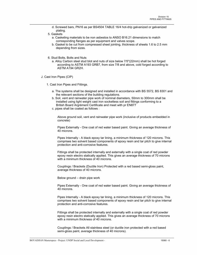
Division 15PIPES AND FITTINGS
d. Screwed bars, PN16 as per BS4504 TABLE 16/4 hot-drip galvanized or galvanized plating. 5. Gaskets a. Casketing materials to be non asbestos to ANSO B16.21 dimensions to match corresponding flanges as per equipment and valves scope. b. Gasket to be cut from compressed sheet jointing, thickness of sheets 1.6 to 2.5 mm depending from sizes.
6. Stud Bolts, Bolts and Nuts a. Alloy Carbon steel stud blot and nuts of size below 7/5"(22mm) shall be hot forged according to ASTM A193 GRB7, from size 7/8 and above, cold forged according to ASTM A194 GR2H.
J. Cast Iron Pipes (CIP)
1. Cast Iron Pipes and Fittings.
a. The systems shall be designed and installed in accordance with BS 5572, BS 8301 and the relevant sections of the building regulations. b. Soil, vent and rainwater pipe work of nominal diameters, 50mm to 300mm shall be installed using light weight cast iron socketless soil and fittings conforming to a British Board Argrément Certificate and meet with pr EN877 c. pipes shall be coated as follows :
Above ground soil, vent and rainwater pipe work (inclusive of products embedded inconcrete)
Pipes Externally - One coat of red water based paint. Giving an average thickness of40 microns.
Pipes Internally - A black epoxy tar lining, a minimum thickness of 120 microns. Thiscomprises two solvent based components of epoxy resin and tar pitch to give internal protection and anti-corrosive features.
Fittings shall be protected internally and externally with a single coat of red powderepoxy resin electro statically applied. This gives an average thickness of 70 microns with a minimum thickness of 40 microns.
Couplings / Brackets (Ductile Iron) Protected with a red based semi-gloss paint,average thickness of 40 microns.
Below ground – drain pipe work
Pipes Externally - One coat of red water based paint. Giving an average thickness of40 microns.
Pipes Internally - A black epoxy tar lining, a minimum thickness of 120 microns. Thiscomprises two solvent based components of epoxy resin and tar pitch to give internal protection and anti-corrosive features.
Fittings shall be protected internally and externally with a single coat of red powderepoxy resin electro statically applied. This gives an average thickness of 70 microns with a minimum thickness of 40 microns.
Couplings / Brackets All stainless steel (or ductile iron protected with a red basedsemi-gloss paint, average thickness of 40 microns).
BOYADJIAN Masterspecs - Project: UNDP Social and Local Development - 15060 - 6

Division 15PIPES AND FITTINGS
Additional anti-corrosive wrapping will be required with either Polyethylene sleeving in accordance with ISO 8180 or Adhesive tapes, e.g. “long Maflowrap”, or “Densotape”, or similar. *
(Or optional all stainless steel couplings)
Where pipes are cut on site, ends shall be cut clean and square with burrs removed. Allcut ends shall be made good/re-coated strictly in accordance with manufacturers' recommendations.
All pipes and fittings shall be jointed by means of all stainless steel couplings,including set screws and nuts, or optional ductile iron couplings. The couplings shall incorporate a synthetic EPDM rubber gasket as standard or Nitrite to special order. Earth continuity shall be provided for.
Joints to cast iron drain and to other materials shall be made using standard couplingsor step couplings as described in clause (e), or traditional joint connectors.
2.3 PIPE FITTINGS AND SPECIALTIES
A. General 1. Refer to individual piping system sections for required pipe fillings and specialties not covered herein. 2. Pipes shall be joined via the Victual grooved coupling style. 3. All ground components shall be of one manufacturer and conform to local code approval and/or as listed by ANSI-B-31.1, B-31.3, B-31.9.
B. Elbows, Tees, Reducers 1. These fittings shall comply with ASTM and ANSI B16 as described in relevant sections of specifications. The wall thickness shall at least be as specified for the straight pipes. 2. All fittings shall be factory made. 3. Unless otherwise stated, elbows shall be long radius bends with a radius of 1.5 times the nominal size, and shall be smooth and not made of welded segments. 4. Tees up to and including an outside diameter of 323.9mm shall be of the pressed type.
5. Unless otherwise specified, reducers shall be made with a length L = 3 (D-d), where L is the construction length, D the outer diameter of the large end and d that of the small end. Unless otherwise stated, the wall thickness of a reducer shall be the same as that of the adjacent large straight pipe.
C. Carbon Steel Pipes Couplings & Fittings 1. Pipe Jointing Method: Pipes shall be joined via the Victual grooved coupling Style 07 Zero Flex Rigid coupling with Angle Pad Design. Victual Style 77 or 75 shall be used where system flexibility is required, at pumps and mechanical equipment to reduce vibration, noise and to accommodate for thermal expansion and contraction. All couplings shall be cast of ductile iron conforming to ASTM A-395, Grade 65-45-15 or malleable iron conforming to ASTM A-47 Grade 32510. Housings shall be red or orange enamel coated or hot dip galvanized. 2. Gaskets: Shall be Grade “E” EPDM compound (green color-coded) conforming to ASTM D-2000, UL listed classified to ANSI/NSF 61 for water supply systems. All gaskets shall be selected as per manufacturer’s recommendation according to service application. Gaskets must be manufactured by the same source for couplings and fittings to secure compatibility.
BOYADJIAN Masterspecs - Project: UNDP Social and Local Development - 15060 - 7

Division 15PIPES AND FITTINGS
3. Grooved Fittings and Coating: Shall be Victual fittings cast of ductile iron conforming to ASTM A-395, Grade 65-45-15 with grooved ends, malleable iron conforming to ASTM A-47 Grade 32510, forged steel to ASTM A-234. Fittings shall be alkynde enamel painted; hot dip galvanized to ASTM A-153. 4. Branch Outlets - Hole Cut Pipe: Hole cut branch outlets shall be Victual style 920, 920N Mechanical T branch connections with locating collar emerging into the hole. Gaskets shall be Grade E standard pressure responsive gasket. 5. Flange Adapter: Vic-Flange® Adapter Style 741 2"-24" (DN50-DN600), for connection to ANSI class 125/150 flanged components. Cast of ductile iron conforming to ASTM A- 536, Grade 65-45-12. Vic-Flange® Adapter Style 743 2"-12" (DN50-DN300), for connection to ANSI class 250/300 flanged components. Cast of ductile iron conforming to ASTM A-536, Grade 65-45-12.
D. Fire Fighting Couplings & Fittings 1. Pipe Jointing Method: Pipes shall be joined via the Victaulic grooved Style 005 Rigid Firelock Coupling with Angle Pad Design for pressures up to 300psi. Style 07 Zero Flex Design shall be used for pressure ratings above 300psi. Victaulic Style 77 or 75 shall be used where system flexibility is required, at pumps and mechanical equipment to reduce vibration and noise. All couplings shall be cast of ductile iron conforming to ASTM A- 395, Grade 65-45-15 or malleable iron conforming to ASTM A-47 Grade 32510. Housings shall be red or orange enamel coated or hot dip galvanized. 2. Gaskets: Shall be Grade “E” EPDM Type ‘A’ compound (violet color coded) conforming to ASTM D-2000, UL listed classified to ANSI/NSF 61 for water supply systems and Flush Seal gaskets for dry service. All gaskets shall be selected as per manufacturer’s recommendation according to service application. Gaskets must be manufactured by the same source for couplings and fittings to secure compatibility. 3. Grooved Fittings and Coating: Shall be cast of ductile iron conforming to ASTM A-395, Grade 65-45-15 or ASTM A-563, Grade 65-45-12 with grooved ends for direct connection into the grooved piping system. Fittings shall be orange or red enamel coated or hot dip galvanized.
4. Branch Outlets - Hole Cut Pipe: Hole cut branch outlets shall be Victaulic style 920, 920N, or 922 sprinkler T and branch connections with locating collar emerging into the hole. Gaskets shall be Grade E standard pressure responsive gasket. Branches shall have a machine cut hole at a predetermined position, on the centerline of the pipe, of a size to receive the housing collar, in accordance with Victaulic specifications using Victaulic Hole Cut Machines.
2.4 HANGERS AND SUPPORTS
A. Mechanical Installation System
1. All installation material used for supporting and fixing mechanical pipe systems should be of a Pre-engineered modern flexible type that gives a tested and reliable supporting solution without the need for welding, drilling or subsequent galvanizing for corrosion protection. 2. The system should provide for easy access and disassembly for future maintenance, and shall be product of well known manufacturer such as SILKA or approved equal. 3. The Contractor should provide shop drawings and load calculations to verify the suitability of the system for critical load applications as per the engineer’s requirement. 4. The system should consist of the following components: a. C-channels should be used as the main item for supporting pipe and duct and runs and structures. C-channel should be made in accordance with British Standards of width 41 mm, and height of channel shall be selected according to load calculation, made of cold rolled steel strip of thickness 2.5 mm steel grade ST32-2 as per DIN 10025. The
BOYADJIAN Masterspecs - Project: UNDP Social and Local Development - 15060 - 8

Division 15PIPES AND FITTINGS
b.
c.
d. e.
steel is Sendzimir galvanized to a thickness of 20 microns. The channel in ward sideshould include fine serrations that insure strong friction hold of the assemble nuts and accessories. The channel inward side should be slotted for greater flexibility and should include longitudinal swaging to increase rigidity and stiffness. Double channels connected with tubular rivets shall be used where greater strength and stiffness is required. Supporting distance and calculation of pipe loads for pipe nuts should be verified by channel design in accordance with manufacturer recommendations. C-channel accessories as recommended by the channel manufacturer should be used for assembly of various channel structures as appropriate for the application. These accessories include fixing nuts with serration, angles, brackets and pipe ring saddles. Pipe Ring Clamps : Galvanized, pre-engineered pipe ring clamps should be used for fixing all pipes to channel system or directly to the concrete structure. The contractor should verify that the pipe supported weight does not exceed the recommended maximum load of the clamp as provided by the manufacturer. The clamps should consist of two half rings suitably connected with welded on connection nut for fixing the clamp to the threaded rod. The rings for all piping systems should provided with a pre-fitted rubber inlay with suitable temperature resistance characteristics for the application. For PVC installation requirement refer to section 15405. Threaded Rods used should be manufactured as per DIN 976 of Steel Grade 4.6, galvanized and used to support pipe duct ring clamps onto the C-channel or directly to concrete anchors depending on the application. The threaded rods, nuts and flat washers used should have a clean thread and flawless galvanized condition.
Concrete Anchors: Internally threaded Anchors used for fixing threaded rods and pipe clamps should be made from galvanized steel, anchors should have a flared end for accurate setting flush with the surface, and should have an intelligent expansion selection that adapts to suit strength of the base material. Concrete stud anchors should be used for fixing C-channels to the concrete suitable for through in-place fattening with reliable fixing. All Concrete anchors used should be provided with full load characteristics and used in accordance with manufacturer recommendations with regards to application and setting details. Concrete Anchors should also be fire rated to verify that they can withstand the required loads within the fire integrity limits of the supporting building structure. g. For riser pipes, Anchor Fixed Point Clamps should be used to support the weight of the riser pipe . Fixed Point Clamps should be used in location as recommended by supporting system manufacturer and approved by the Engineer.
B. Pipe Hangers, Upper Attachments 1. Individual or continuous preset concrete inserts. 2. Beam clamps and anchor bolts may be used for steel construction. 3. self-drilling expansion shells for 75 mm pipe and smaller may be used in existing concrete structures. See special details for larger piping. E. Hanger Rods 1. Galvanized solid steel, all thread rods, with lock nuts (10mm dia. Per pipe) 2. For trapez supports submit calculation for threaded hanger rod diameter with at least 8 times load factor.
C. Pipe Hangers, Lower Attachments 1. Lower attachments for individual runs of pipe shall be as follows, unless indicated otherwise: a. steel piping up to 125 mm: steel clevis; b. steel piping 150 mm and larger, not subject to thermal expansion: steel clevis; c. steel piping 150 mm and larger, subject to thermal expansion: d. pipe roller support;
BOYADJIAN Masterspecs - Project: UNDP Social and Local Development - 15060 - 9
f.

Division 15PIPES AND FITTINGS
e. copper tubing, all sizes: copper-plated steel clevis, except where hanger is installed around the outside of insulation, not in contact with pipe, where steel clevis hangers may be used; f. cast iron pipe, all sizes: steel clevis.
F. Vertical Pipe Supports 1. At intermediate floors use extension pipe clamps. 2. At top of risers, use hangers as specified above. 3. At base of risers, use stiff-leg pipe support immediately adjacent to elbow. For cast iron soil or storm riser use solid concrete block.
G. Trapeze Hangers 1. Where numerous pipes are run in parallel to one another, they may be supported from a trapeze type hanger arrangement. Rollers supports shall be used to support each run of piping on trapeze hangers to permit independent movement of individual pipes. 2. Piping supports shall consist of channels, fittings, pipe brackets, pipe rollers, pipe clamps, post bases, stud nuts, etc., as required to properly support and hang piping.
H. Stiff-legs or Stanchions 1. Stiff-legs or two-leg stanchion supports shall be provided in cases where support from overhead structure is not possible. Pipe rollers shall be provided for pipe rigidly supported from floor.
I. Alignment Guides 1. Guides to be constructed with steel base and T-bar with teflon or graphite plates bounded to the steel components to allow minimum static friction and self-lubrication for unlimited movement. Units shall be factory painted. Guide base shall be welded to the pipe; like F & S "unislide", Elcen, or equal.
J. Flexible Ball Joints 1. units shall carbon steel construction, screwed, flanged, or welded connection as required, suitable for temperatures of 274 degrees C and pressure of 8.3 MPa; provide for 15 degrees angular flex and 360 degrees rotation.
K. Anti-Vibration Suspension Hangers 1. Combination type, shall have a double-deflection neoprene element in series with a steel coil spring; deflection of 8 mm; steel coil spring shall be selected from a 25 mm static deflection series with a minimum additional travel of 12 mm; spring diameter shall be large enough to permit 15 degree angular misalignment of the rod connecting the hanger to the upper attachment without rubbing the hanger box.
L. Spacing of Pipe Supports 1. Spacing Support Schedule: a. The maximum spacing for pipe supports shall be as follows:
NOMINALHORIZONTAL (m)BORE mm STEEL COPPER UPVC CPVC 10-12-1.0- 151.81.20.8 20-322.41.80.8 40-502.42.41.0 65-802.52.51.2
VERTICAL (m) STEEL COPPER UPVC CPVC -1.2- 2.51.80.8 2.52.41.0 2.52.51.5 2.52.51.7
BOYADJIAN Masterspecs - Project: UNDP Social and Local Development - 15060 - 10

Division 15PIPES AND FITTINGS
100 &2.52.51.22.52.51.7 above b. Hangers and supports shall in no case be less than one (1) hanger per, 2.5m.
2. The spacing of pipe group supports shall be based on the smallest nominal bore pipe using the hanger, in accordance with the spacing support schedule above. Alternatively intermediate supports can be given to a particular pipe, if conditions permit.
2.5 PASSIVE FIRE PREVENTION SYSTEM
A. All openings through fire rated walls, ceilings and floors due to penetrations of mechanical installations as well as those due to construction joints, should be sealed with fire rated products suitable for the specific application as specified hereunder. All material selected shall be UL listed.
B. The product shall be capable of stopping the passage of fire, air and water through wall, floor and ceiling penetrating, cladding and expansion joints. The product shall exhibit the minimum designed fire resistant properties.
C. The products shall be obtained from an approved, established and proven firm and qualities shall be applied strictly in accordance with the written instructions of the manufacturer and to the approval of the Engineer.
D. The recommended treatments for various applications shall be as follows: 1. Metal pipe and duct crossings: the annular space around the pipe shall be packed with UL listed fire rated from backing material and the ends shall be filled and sealed with fire rated Elastic sealant according to manufacturer data. The size of the circular opening shall be maintained as the barest minimum as recommended by the mastic manufacturer. 2. Non-metal pipe and conduit crossings less than 50 mm in diameter : The annular space around the pipe shall be packed with fire rated foam as backing material. The ends should then be filled and sealed with intumescent, graphite based, fire rated mastic with expansion pressure of minimum 6 bar. The circular opening shall be maintained strictly as the barest minimum recommended by the mastic manufacturer. For pipes/conduits more than 50mm in diameter, the pipe/conduit shall be wrapped with a fire rated, intumescent, graphite, based, fire rated wrap and applied strictly according to the manufacturer specifications, all UL Listed.
2.6 PIPE SLEEVES
A. General 1. Sleeves for all pipes passing through floors, walls, partitions, (except where floors and walls are a part of fire-rated assembly) concrete beams, girders, and any other building construction shall be provided in types as described below, and of adequate diameter to allow minimum of 19mm clearance all around between sleeve and pipe. When pipe is insulated, insulation shall pass continuously through sleeve with 19 mm clearance between insulation and sleeve. 2. Pipes passing through fire-rated walls, partitions, or floor shall be sealed, smoke-tight, with a fire proof compound. Insulation shall not pass through the sleeve as specified above. Fill inner space with Rockwool insulation with fire rated compound up to the rating of the wall. 3. Allow 50 mm of steel sleeve above F.F.L, and flush with walls.
B. Pipe Sleeves Material 1. Galvanized Schedule 40 steel pipe when installed in: a. Concrete or masonry walls and concrete bases.
BOYADJIAN Masterspecs - Project: UNDP Social and Local Development - 15060 - 11

Division 15PIPES AND FITTINGS
b. Beams with poured concrete fireproofing. c. Concrete floors and mechanical equipment room floors. d. Concrete floors with metal under deck (tack weld to deck). 2. 18-Gage Galvanized steel when installed in: a. Plaster or dry wall. b. Air plenums.
2.7 FLASHING
A. Steel Flashing: 26 gauge (0.50) galvanized steel.
B. Lead Flashing: 24.5 kg/m2 (5lb/sq.ft.) sheet lead for waterproofing, 5kg/m2 (1 lb/sq.ft.) sheet lead to sound proofing.
C. Safes: 24.5 kg/m2 (5lb/sq.ft.) sheet lead or 0.20 mm (8mil) thick neoprene.
D. Caps: Steel, 22 gauge (0.80 mm) minimum, 16 gauge (1.50 mm) at fire resistance structures.
2.8 SEALANTS
A. Sealant for Pipe Sleeves 1. All sealants materials shall be a single compounds, primerless, non- sagging type in neutral color. 2. Polysulfide: one part, gun grade. 3. Acrylic Latex: one part, gun grade, paintable, with a temperature range from -17 to +82 degrees C. 4. Butyl: one part, gun grade, suitable for both horizontal and vertical joints. 5. Fire rating compound similar to wall rating and as described under paragraph 2.05 of this section.
2.9 COMPENSATORS
A. General 1. All compensators shall be selected for the function it is to perform and the suitability for the fluid type; pressure and temperature to be conveyed. 2. The compensator shall be the same size bore as the pipework it shall be connected to, and shall have flanged connections for ease of maintenance. B. Compensators 1. The compensator shall absorb movement under strict guiding in an axial direction only. No side thrusts can be permitted. 2. The stainless steel convolutions of the number required to accommodate the determined movement shall be protected internally and externally by a heavy mild steel sleeve for physical protection against damage. 3. The compensator shall be capable of a working pressure of 2.5 MPa and a temperature range of -15 to 4000c. 4. Large expansion compensators capable of up to 200mm shall be considered to keep the number of compensators to a minimum. 5. It shall be suitable for LPHW, chilled water, HWS in long straight runs such as crawlways and service tunnels.
2.10 THERMAL EXPANSION FIXED POINT SYSTEM
BOYADJIAN Masterspecs - Project: UNDP Social and Local Development - 15060 - 12

Division 15PIPES AND FITTINGS
A. Where metal pipes are subject to thermal expansion, particular attention should be given and pipe runs should be studied and designed to compensate for the expansion forces and reduce the stress on the pipes and supporting system.
B. The constructor should provide sufficient shop drawings and load calculations to verify the suitability of the system for critical thermal applications run as per the engineers requirement. Allowance for free thermal expansion distance at pipe bends should be marked.
C. The following components should be used to control thermal expansion: 1. Slide guides: Use side and Roll Connectors with integrated sliding components on all pipe runs subject to high thermal movement. The guide should be used in accordance with manufacturer load limits and movement limits. The slides should be resistant to operating temperatures of the supported pipes. 2. Anchor fixed Point Pipe Clamps : Where necessary and according to the thermal study, use fixed point for a flexible and reliable fixing system against axial thermal expansion forces. The anchor points should be used strictly in accordance with the manufacturer recommendations and loading characteristics and in accordance with the calculated expansion forces provided by the thermal study. 3. Expansion compensators : For critical application and if expansion movement cannot be taken up by free movement of the pipe bends, expansion compensators or bellows of the axial and/or angular type should be used in conjunction with the fixed anchor points and in accordance with the thermal study. Expansion compensators should be used in accordance with manufacturer recommendations.
2.11 ACCESSORIES
A. Safety or Relief Valves
1. The relief valves shall be set to a maximum of 0.3 bar above the working pressure of the line in which they are fitted or as indicated on drawings. Safety and relief valves shall be suitable for the operating condition of the system. 2. They shall be of the totally enclosed spring loaded type with padlock. 3. Safety valves and relief valves shall have a full bore discharge connection. Where any law point occurs in the discharge run, it shall be fitted with a 22 mm size copper waste pipe carried clear of the insulation for drainage. The discharge and waste pipes shall be run to visible safe positions to be agreed.. 4. Relief valves shall be ASME approved and labeled, size, capacity and setting as indicated.
B. Temperature and Pressure Test Pugs 1. Provide temperature and pressure test plugs as described in Section 15990.
PART 3 - EXECUTION
3.1 PIPING INSTALLATIONS
A. General 1. Installation instructions contained in this Section pertain to most systems. For specific requirements for installation of each system, refer to individual system specification sections.
B. Piping Installation Generalities 1. Conceal all pipe installations in walls, pipe chases, utility spaces, above ceilings, etc. unless other wise indicated. Under slab piping shall be kept to the absolute minimum. 2. Install all piping free of sags or bends and with ample space between piping to permit proper installation.
BOYADJIAN Masterspecs - Project: UNDP Social and Local Development - 15060 - 13

Division 15PIPES AND FITTINGS
3. Install piping at right angles or parallel to building walls. Diagonal or bent piping will not be permitted. 4. Install piping tight to slabs, beams, joints etc. where possible and such that any removable ceiling panels may be removed for access above ceilings. 5. Protect all piping from entrance of dirt or other foreign materials during the construction period. At the completion of the project, all dirt and foreign matter in piping shall be removed completely. 6. Piping passing through exterior building walls shall be caulked whether tight. 7. Provide drain lines from all relief valves and condensate pans and run drain line full size to the nearest floor or equipment drain. 8. All water piping shall have draining points at all low points. For mains, risers and branch lines there shall be at least a 20 mm drain valve with a threaded hose connection for other points a15 mm drain valve and hose and hose connection shall be provided. 9. Water piping shall be securely anchored to insure proper direction of expansion and contraction. 10. Expansion loops or expansion joints shall be provided as indicated and required, and shall be cold sprung. 11. Verify existing grades, inverts, and topographic conditions prior to any trenching, excavation, or installations. 12. Horizontal piping shall slope uniformly without sags or humps to provide for complete drainage of systems and elimination of air. 13. Piping shall be cut accurately to measurements established at the site, worked into place without springing or forcing, and shall clear all windows, doors and other openings. 14. Cutting or other weakening or building structure to facilitate piping installation is not permitted, install to permit free expansion and contraction without damage. 15. Swing joints at runouts to equipment and risers. Provide expansion loops at all other points for flexible piping systems. 16. Drain piping from pump glands, relief valves, condensate drain pan etc. to spell over open sight drains, or other acceptable discharge points terminating drain line with plain end (unthreaded) pipe. 17. Provide necessary temporary connections, valves, oversize flushing connections, pumps, etc. as required to properly clean and test systems. 18. coordinate piping installations with ductwork, structure, lighting, electrical conduit and all other materials and equipment. 19. use flexible pipe connectors for all inlet and discharge final connections to pumps (except in line pumps) and other vibration producing equipment.
20. Provide flanges on all valves, apparatus, and equipment having 50 mm and larger connections. 21. Reduction in pipe sizes except in drainage pipe, shall be made using eccentric reducer couplings installed with the level side up on water piping and level side down on steam and condensate piping. 22. Provide unions adjacent to each valve at the final connection to each piece of equipment of plumbing fixture having 50 mm and smaller connections and where otherwise indicated. 23. Wherever wells are installed in piping for thermometers, pressure gages, probes, etc., pipe size shall be increased by one pipe diameter to accommodate same. 24. Provide air chambers at the top of all hot and cold domestic risers, at the end of each water header in utility spaces, at the end of each branch line, and at the top of all branches to fixtures. Provide shock absorbers at each solenoid valve or piece of equipment that has a quick closing type valve. Air chambers shall be a minimum of two pipe sizes larger than the terminating pipe and shall be equipped with an accessible drain valve and air recharging petcock or installed at least 600 mm above fixture to permit recharging by draining air chamber.
BOYADJIAN Masterspecs - Project: UNDP Social and Local Development - 15060 - 14
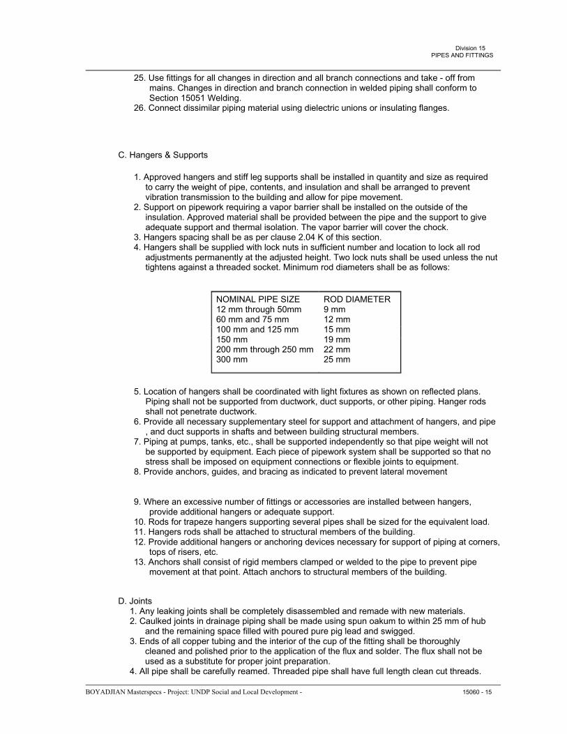
Division 15PIPES AND FITTINGS
25. Use fittings for all changes in direction and all branch connections and take - off from mains. Changes in direction and branch connection in welded piping shall conform to Section 15051 Welding. 26. Connect dissimilar piping material using dielectric unions or insulating flanges.
C. Hangers & Supports
1. Approved hangers and stiff leg supports shall be installed in quantity and size as required to carry the weight of pipe, contents, and insulation and shall be arranged to prevent vibration transmission to the building and allow for pipe movement. 2. Support on pipework requiring a vapor barrier shall be installed on the outside of the insulation. Approved material shall be provided between the pipe and the support to give adequate support and thermal isolation. The vapor barrier will cover the chock. 3. Hangers spacing shall be as per clause 2.04 K of this section. 4. Hangers shall be supplied with lock nuts in sufficient number and location to lock all rod adjustments permanently at the adjusted height. Two lock nuts shall be used unless the nut tightens against a threaded socket. Minimum rod diameters shall be as follows:
NOMINAL PIPE SIZE12 mm through 50mm 60 mm and 75 mm 100 mm and 125 mm 150 mm 200 mm through 250 mm 300 mm
ROD DIAMETER9 mm 12 mm 15 mm 19 mm 22 mm 25 mm
5. Location of hangers shall be coordinated with light fixtures as shown on reflected plans. Piping shall not be supported from ductwork, duct supports, or other piping. Hanger rods shall not penetrate ductwork. 6. Provide all necessary supplementary steel for support and attachment of hangers, and pipe , and duct supports in shafts and between building structural members. 7. Piping at pumps, tanks, etc., shall be supported independently so that pipe weight will not be supported by equipment. Each piece of pipework system shall be supported so that no stress shall be imposed on equipment connections or flexible joints to equipment. 8. Provide anchors, guides, and bracing as indicated to prevent lateral movement
9. Where an excessive number of fittings or accessories are installed between hangers, provide additional hangers or adequate support. 10. Rods for trapeze hangers supporting several pipes shall be sized for the equivalent load. 11. Hangers rods shall be attached to structural members of the building. 12. Provide additional hangers or anchoring devices necessary for support of piping at corners, tops of risers, etc. 13. Anchors shall consist of rigid members clamped or welded to the pipe to prevent pipe movement at that point. Attach anchors to structural members of the building.
D. Joints 1. Any leaking joints shall be completely disassembled and remade with new materials. 2. Caulked joints in drainage piping shall be made using spun oakum to within 25 mm of hub and the remaining space filled with poured pure pig lead and swigged. 3. Ends of all copper tubing and the interior of the cup of the fitting shall be thoroughly cleaned and polished prior to the application of the flux and solder. The flux shall not be used as a substitute for proper joint preparation. 4. All pipe shall be carefully reamed. Threaded pipe shall have full length clean cut threads.
BOYADJIAN Masterspecs - Project: UNDP Social and Local Development - 15060 - 15

Division 15PIPES AND FITTINGS
5. All sockets and pipe ends of PVC shall be cleaned and solvent cement applied for full circumferential cover. E. Pipework Expansion 1. The contractor shall supply and fix expansion devices, anchors and guides to adequately allow for the expansion and contraction of the pipework. The minimum number considered necessary are shown on the contract drawings. 2. Whenever possible, such as brunch take-offs, natural expansion shall be used with the configuration of the pipework system. 3. Pipe work expansion shall be carefully controlled to prevent damage to the pipework system, equipment, structure, etc. 4. Special consideration shall be given to LTHW and hot water services. 5. Cold water pipework generally where installed in the services building main services duct, equipment rooms and other areas where relatively high ambient temperatures may occur , and where movement cannot be absorbed naturally, shall incorporate flanged joints of the type which allow expansion, contraction and some measure of lateral movement. These joints shall be a mechanical pipe coupling consisting of a center sleeve, and flanges wedge shaped rubber sealing rings and nuts and bolts. The main components shall be constructed from high quality malleable or cast iron for sizes up to 80 mm diameter and steel above this size. All nuts and bolts shall be galvanized . Sealing rings shall be suitable for the liquid type, temperature and pressure range. Sizes up to 345 mm diameter shall be supplied preassembled. Larger sizes shall be supplied unfitted for ease of handling. Coupling shall allow for a setting regularity of -‘- 6° up to 600 mm + 5°for 600 mm to 750 mm and 4° for 750 to 900 m. Each coupling shall allow for a repeated maximum pipe movement of 9.5 mm and sufficient couplings shall be installed on this basis. 6. All expansion devices shall be suitable insulated to prevent accident to personnel, but does not restrict the movement of the pipework 7. All expansion devices and natural expansion pipework systems shall be installed with 50 % cold draw of the total movement. 8. Anchor points shall be provided as shown on the drawings. The anchor shall be capable of resisting the maximum stresses that be applied. The contractor shall ensure that the structure, that the anchor is attached to, shall also be capable of withstanding the same stresses. 9. The method of anchoring the pipework to a secured point shall be: a. Mild Steel - Welding b. Cast iron - Two wrought iron stirrups acting as clamps, bolted, with sufficient thread for tightening, to a secured cast iron chair c. Copper - A wide copper strap, undersized to give sufficient grip, when bolted together around the pipe shall be attracted to the secured point. 10. Care shall be taken when installing and positioning guides to ensure that the amount of free play in the pipeline is kept to an absolute minimum and that the resulting thrust of expansion is taken up in the designed manner. Means for lubrication shall be provided where necessary, inforced PTFE in order to allow reduced frictional resistance to movement. Guides and skid supports shall be provided in accordance with the manufacturers recommendations and shall form part of the submission.
3.2 VIBRATION CONTROL
A. General 1. All vibrating equipment connected to the pipework system shall be isolated to eliminate transmission of noise and vibration.
B. Noise Criteria 1. Each piece of mechanical equipment selected shall be evaluated for quietness. Particular care shall be taken to evaluate acoustical performance as well as mechanical function. Sound pressure level within spaces shall not exceed the NC curves indicated.
BOYADJIAN Masterspecs - Project: UNDP Social and Local Development - 15060 - 16

Division 15PIPES AND FITTINGS
C. Piping Insulations 1. All piping 63 mm and larger specified with vibration isolation shall have anti - vibration hangers . Static deflections as follows: a. First three hangers away from any spring isolated piece of equipment shall have hangers with same static deflection as equipment isolators. b. All others shall have 25 mm static deflection. 2. All piping 50 mm and smaller shall have isolators as follows: a. First three hangers away from any spring isolated piece of equipment shall have hangers with same static deflection as equipment isolators. b. For insulated piping outside equipment rooms isolators are not required. c. Install temporary anchors as required to permit readjustment of springs in risers and to fix direction of pipe movement and final operating deflection of springs d. Provide permanent limit stops to prevent excessive vertical motion in risers in event system is drained and to prevent excessive lateral motion.
3.3 ACCESSIBILITY
A. Locate all equipment that must be serviced, or maintained, in fully accessible positions. Minor deviations from the drawings may be allowed for better accessibility at written approval.
B. Allow ample space for removal of parts that may require replacement or service in the future.
C. Extend all grease fittings to an accessible location.
3.4 MECHANICAL CUTTING AND PATCHING
A. Contractor shall be responsible for all culling, fitting, or patching of his work which may be required to make its several parts come together properly and fit it to receive, or be received, by work of other trades. Cutting of structural members shall not be done without written approval.
B. Any cost caused by defective or ill-timed work shall be borne by the contractor, as determined by the Engineer. Contractor shall not endanger any work, persons, or construction by cuffing, digging or otherwise.
C. Place sleeves through all walls , floors, and ceilings during the initial construction where it is necessary for piping to go through. When this is not done, do all cutting and patching required for the installation of the work. Any damage caused to the building by this cutting and patching, shall be corrected at no additional cost.
D. Patching of all openings for new installations and all openings resulting from the removal or relocation of any installations shall be done by craftsmen skilled in the particular trade effected, with materials of like type adjoining openings.
END OF SECTION 15060
BOYADJIAN Masterspecs - Project: UNDP Social and Local Development - 15060 - 17

Division 15 VALVES
SECTION 15100 - VALVES
PART 1 - GENERAL
1.1 SUMMARY
A. Provide labor, materials, equipment and services, and perform operations required for complete installation of Valves and related work as indicated on the drawings and specified herein.
B. Work Included: The work shall include, but not be limited to, the following: 1. Types of valves specified in this section include the following:
a. Gate Valves.
b. Check Valves.
c. Globe Valves.
d. Float Valves.
e. Pressure Reducing Valves.
f. Double Regulating Valves.
g. Strainer.
h. Temperature and pressure relief valves.
i.
j.
l.
Ball Valves.
Plug Valves.
Flexible Connections.
k. Expansion Joints.
2. Valves furnished as part of factory-fabricated equipment, are specified as part of equipment assembly in other Division 15 sections.
C. Related Work Specified Elsewhere 1. Basic Mechanical Requirements - Section 15010.
1.2 SUBMITTALS
Submit the following in accordance with requirements specified under Submittals in Section15010. 1. Product data: Submit copies of manufacturer's latest published literature for materials and equipment specified herein for approval; obtain approval before ordering materials.
1.3 DELIVERY, STORAGE AND HANDLING
Exercise proper care in the handling of work so as not to injure the finished surfaces, and takeproper precautions to protect the work from damage after it is in place.
PART 2 - PRODUCTS
2.1 GENERAL
A. Provide valves of same type by one manufacturer.B. Provide valves with manufacturer’s name (or trademark) and pressure rating clearly marked on valve body.
BOYADJIAN Masterspecs - Project: UNDP Social and Local Development - 15100 - 1
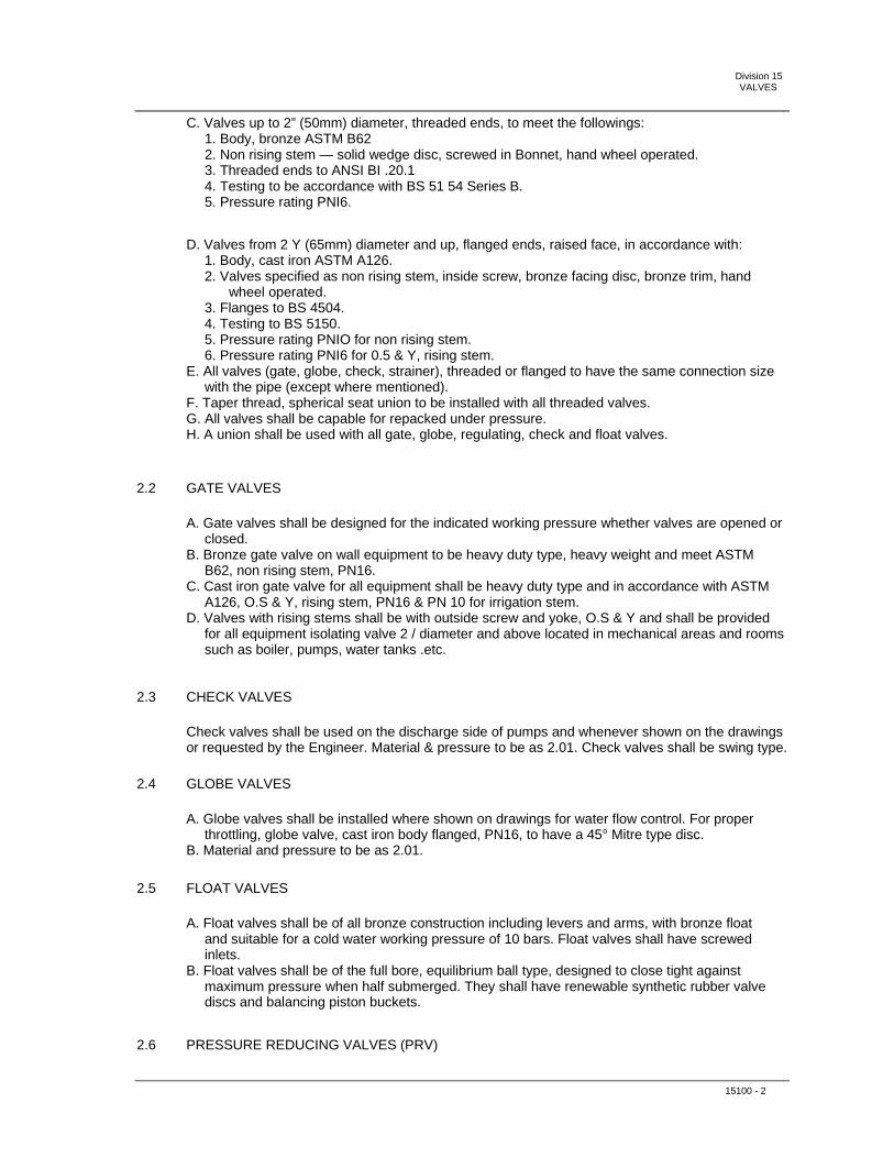
Division 15 VALVES
C. Valves up to 2” (50mm) diameter, threaded ends, to meet the followings: 1. Body, bronze ASTM B62 2. Non rising stem — solid wedge disc, screwed in Bonnet, hand wheel operated. 3. Threaded ends to ANSI BI .20.1 4. Testing to be accordance with BS 51 54 Series B. 5. Pressure rating PNI6.
D. Valves from 2 Y (65mm) diameter and up, flanged ends, raised face, in accordance with: 1. Body, cast iron ASTM A126. 2. Valves specified as non rising stem, inside screw, bronze facing disc, bronze trim, hand wheel operated. 3. Flanges to BS 4504. 4. Testing to BS 5150. 5. Pressure rating PNIO for non rising stem. 6. Pressure rating PNI6 for 0.5 & Y, rising stem. E. All valves (gate, globe, check, strainer), threaded or flanged to have the same connection size with the pipe (except where mentioned). F. Taper thread, spherical seat union to be installed with all threaded valves. G. All valves shall be capable for repacked under pressure. H. A union shall be used with all gate, globe, regulating, check and float valves.
2.2 GATE VALVES
A. Gate valves shall be designed for the indicated working pressure whether valves are opened or closed. B. Bronze gate valve on wall equipment to be heavy duty type, heavy weight and meet ASTM B62, non rising stem, PN16. C. Cast iron gate valve for all equipment shall be heavy duty type and in accordance with ASTM A126, O.S & Y, rising stem, PN16 & PN 10 for irrigation stem. D. Valves with rising stems shall be with outside screw and yoke, O.S & Y and shall be provided for all equipment isolating valve 2 / diameter and above located in mechanical areas and rooms such as boiler, pumps, water tanks .etc.
2.3 CHECK VALVES
Check valves shall be used on the discharge side of pumps and whenever shown on the drawingsor requested by the Engineer. Material & pressure to be as 2.01. Check valves shall be swing type.
2.4 GLOBE VALVES
A. Globe valves shall be installed where shown on drawings for water flow control. For proper throttling, globe valve, cast iron body flanged, PN16, to have a 45° Mitre type disc. B. Material and pressure to be as 2.01.
2.5 FLOAT VALVES
A. Float valves shall be of all bronze construction including levers and arms, with bronze float and suitable for a cold water working pressure of 10 bars. Float valves shall have screwed inlets. B. Float valves shall be of the full bore, equilibrium ball type, designed to close tight against maximum pressure when half submerged. They shall have renewable synthetic rubber valve discs and balancing piston buckets.
2.6 PRESSURE REDUCING VALVES (PRV)
15100 - 2

Division 15 VALVES
Pressure reducing valves to be of the self-contained, direct acting, spring loaded, diaphragm type,with stainless steel filter mesh (0.016mm) around the seat. Replacement of any part must be done without removing the valve body from the pipe. 1. Pressure reducing valves size from 2” to be in accordance with: a. Brass body, threaded connections, steel adjustment spring not in contact with water NBR diaphragm and seals, stainless steel or synthetic valve material, set pressure to appear on a set point scale, set pressure to maintain constant even when fluctuation on the inlet side occurs. b. Inlet pressure up to 25 bars. c. Outlet pressure from 1.5 to 6 bars. Pressure gage shall be connected to the valve. 2. Pressure reducing valves size from 2 1/2” and larger in accordance with: a. Cast iron body, flanged, synthetic coating inside and outside (toxically safe) steel adjustment spring not in contact with water, brass seat, EPDM diaphragm set pressure to maintain constant even fluctuation on the inlet side occurs. Set pressure to appear on a scale. b. b. Inlet pressure depend on application 16 or 25 bars. Outlet pressure from 1.5 to 6 bars. c. Pressure gage shall be connected to the valve. 3. Pressure reducing valves shall be as manufactured by BRAUKMANN, WATTS or approved equal.
2.7 DOUBLE REGULATING VALVES
Double regulating valve shall be of the Y-pattern bronze globe valves, it shall have a characterizedthrottling disk with sufficient authority to regulate flow in a circuit incorporating a Flow Measurement Valve. The valves shall have a unique device which enables the disk to be locked in position to control flow at a pre determined rate. An Allen key (3mm) shall be supplied for lock adjustment. Tight closure of the valve shall be assured by use of a PTFE disc insert. The valves shall be rendered ‘tamper proof’.
1. Pressure regulating valve, size up to 2” (50mm) diameter to be in accordance with: a. Bronze body, screwed equal percentage fixed orifice or variable orifice. Accuracy of flow measurement L5% , with digital high strength melon, hand wheel with a gear operated gear mechanism. Two different scales: one for complete rotation (4rotations), one for indicating the division of each turn in tenths from zero to nine. b. Operating pressure 20 bars.
2. Pressure regulating valve, size 2 1/2” and larger to be in accordance with: a. Cast iron body, flanged, variable orifice. Accuracy of flow measurement +5% , with micrometer style hand wheel with a gear operated gear mechanism. Two different scales: 3. one for complete rotation (4rotations) 4. one for indicating the division of each turn in tenths from zero to nine. b. Operating pressure 16 bars.
2.8 SHUT OFF & BUTTERFLY VALVE
Shall be Victaulic Series 705-W or 705 as UL listed and FM approved for 300psi (2065 kPa)service supplied with a ductile iron body conforming to ASTM A-536 coated with a polyphenylene sulfide blend, a disc of ductile iron conforming to ASTM A-536 with EPDM coating providing bubble tight shut off. Sizes 2½-6" (65-150 mm) shall have an approved weatherproof manual actuator suitable for indoor or outdoor use with two single pole, double throw supervisory switches either pre-wired (WRD) or unwired (UWD) monitoring the open position.
BOYADJIAN Masterspecs - Project: UNDP Social and Local Development - 15100 - 3

Division 15 VALVES
2.9 CHECK & NON RETURN VALVE
Shall be Victaulic series 717 and 717R Vic-Check single disc, spring loaded, check valves 2½ -12" (65-300 mm) as UL listed and FM approved for a single check and anti-water hammer service for horizontal or vertical installation, supplied drilled, tapped and plugged downstream for drainage outlet with Grade “E” EPDM seal, housing cast of ductile iron conforming to ASTM A- 536 Grade 65-45-12 with grooved ends for installation with Victaulic grooved end couplings rated for service up to 250 PSI (1725 kPa) working pressure.
2.10 BALL VALVES
Shall be Series 727 FireBall Valves, sizes 2 - 3" (50-80 mm), as UL listed for Specification 1091and FM approved for 1112, supplied with a ductile iron body to ASTM A-536 and a ball to Type 316 stainless steel. Series 727 will be either un-supervised or will have factory installed double pole, double throw switches monitoring the open position. The series 727 is supplied with grooved ends to connect with Victaulic grooved end couplings and rated service up to 300psi (2065 kPa) working pressure. Valves shall be installed in accordance with the latest published Victaulic specifications.
2.11 ALARM CHECK VALVE
Shall be Victaulic FireLock Series 751 11/2 – 6” (40 – 150 mm) spring assisted, UL listed and FMapproved for vertical installation supplied with Grade “E” EPDM clapper seal, housing cast of Ductile Iron to ASTM A-536 Grade 65-45-12, serviceable without removal from the line. Valve to be connected with Victaulic couplings as applicable rated for service up to 300 psi (2065 kPa) working pressure.
2.12 DRY PIPE VALVES
Shall be Victaulic Fire Lock Series 756 1 ½ - 6” (40 – 150 mm), low differential, latched closed,spring assisted, self resetting clapper, UL listed and FM approved for vertical installation supplied with Grade “E” EPDM seal, housing cast of Ductile iron conforming to ASTM A-536 Grade 65- 45-12 serviceable without removal from the line. Valve to be connected with Victaulic couplings as applicable rated for service up to 300 psi (2065 kPa) working pressure.
2.13 ACTUATED CHECK VALVE WITH DELUGE TRIm
Shall be Victaulic Fire Lock Series 758 1-1/2 – 6” (40-150 mm) low differential, latched closedspring assisted, self resetting clapper, pneumatic, hydraulic or electric release, UL listed and FM approved for vertical installation supplied with Grade “E” EPDM clapper seal, housing cast of ductile iron to ASTM A-536 Grade 65-45-12 serviceable without removal from the line to be connected with Victaulic couplings as applicable rated for service up to 300 psi (2065 kPa) working pressure.
2.14 ACTUATED CHECK VALVE WITH PRE-ACTION TRIM
Shall be Victaulic Fire Lock Series 758 1-1/2 – 6” (40-150 mm) low differential, latched closedspring assisted, self resetting clapper, pneumatic, hydraulic or electric release, non single, or double interlock, UL listed and FM approved for vertical installation supplied with Grade “E” EPDM clapper seal, housing cast of ductile iron to ASTM A-536 Grade 65-45-12 serviceable without removal from the line to be connected with Victaulic couplings as applicable rated for service up to 300 psi (2065 kPa) working pressure
2.15 FLANGES AND GASKETS
15100 - 4

Division 15 VALVES
A. Flanges shall be class 125 flat faced forged carbon, steel, weld neck to ANSI B16.1. B. Gaskets shall be non asbestos to ANSI B16.21 and dimension to suit ANSI B16.5 class 125, flat faced compressed sheeting 1.6mm thick. C. Stud bolts shall be to ASTM A193 grade B7, threaded full length complete with 2 nuts ASTM A194 grade 2 H.
2.16 STRAINERS
A. Water strainer shall be supplied and installed at the suction connection of all pumps, and ahead of all automatic flow control valves. B. Strainers must have a large screening area assuring free flow of liquid with minimal pressure loss. Stainless steel or copper perforated screen. C. Bronze strainer, screwed up to 2” in accordance with: 1. Screen perforation hole diameter 0.8mm body to have hexagonal end connection on both side. 2. Y type, screwed in cap. 3. Pressure rating 25 bars. D. Cast iron strainer, flanged, 2 %“ and larger in accordance with: 1. Screen perforated hole diameter 0.75 mm. 2. Y type, bolted cap. 3. Cap drilled & tapped. 4. Pressure rating 16 bars.
2.17 FLEXIBLE PUMP CONNECTORS
A. Shall have excellent ability to isolate sound and vibration, used to protect mechanical equipment by relieving piping stresses caused by piping misalignment. Rubber material to be Neoprene for cover and tube. Flexible connection have to withstand an internal pressure of 10 bars and 660 mm vacuum, size up to 2” to have galvanized double union ends threaded, twin rubber sphere. B. Size larger than 2” with floating flanges single sphere. C. For fire pumps, use adequate pressure class 150.
2.18 PLUG VALVES
A. Plug valves, 50mm(2") and smaller. Rated at labor WOG; bronze body, with straightway pattern, square head, and threaded ends. B. Plug valves, 65mm(2 ½") and larger: MSS SP-78; rated at 12 bar WOG; lubricated plug type, with semi steel body, single gland, wrench operated and flanged ends.
2.19 WALL MOUNTED WATER TAPS
Wall taps installed outside the building and on balconies shall be jet cock with isolating valve,non-return valve, double service and finishing facade plate.
2.20 SECTION VALVES AND SPECIALTIES
A. Combined Pressure/Temperature Relief Valves: diaphragm operated, cast-iron or , brass body valve, with low inlet pressure check valve, inlet strainer removable without system shut-down, and non-corrosive valve seat and stem. Select valve size, capacity, and operating pressure to suit system. Valve shall be factory-set at operating pressure and have the capability for field adjustment. Valve shall be suitable for a pressure up to 150 psi (1030 Kpa) with temperature relief set 100 °C. Valve shall be AGA and ASME rated similar to Watts regulator CO or approved equal.
BOYADJIAN Masterspecs - Project: UNDP Social and Local Development - 15100 - 5

Division 15 VALVES
B. Safety relief valve designed, manufactured, tested, and labeled in accordance with the requirements of Section IV of the ASME Boiler and Pressure Vessel Code. Valve body shall be cast-iron, with all wetted internal working parts made of brass and rubber, 860 kPa working pressure and 121 °C maximum operating temperature. Select valve to suit actual system pressure and kCal capacity. Provide with fast fill feature for filling hydronic system.
2.21 SELF BALANCING VALVE
A. The self balancing valve is a differential bypass valve which shall modulate. Open or close according to the set differential pressure between chilled water supply and return pipes. The differential bypass valve shall be complete with pressure controller. Two way modulating valve and all related accessories and controls. Pressure controller shall be suitable for converting subranges of positive pressure. Negative pressure and pressure differential into electrical output signals and to control operation of modulating valve accordingly. B. Pressure controller shall be suitable for liquids with differential pressure up to 10 bars. Output signals shall be from Zero to 20 mA (0 to 10 V). C. The sensor section and the terminal connection box shall be made of die cast aluminum from one unit. The evaluation electronics shall be housed in module casing of makrolon.
2.22 FLEXIBLE EXPANSION JOINTS
A. Stainless steel expansion joints, to have stainless steel 321 corrugated metal sheets with welded steel tube ends. An internal stainless steel 304 sleeve to protect bellows. Steel tube ends or threaded for sizes up to 2"(50mm), and flanged with ties for seizes larger than 2"(50mm). B. Calculation must be presented to the Engineer showing the number of joints used in relation between the total length expanded and the axial movement of the joint. C. Pressure rating 10 bars or 25 bars depending on application.
2.23 AUTOMATIC AIR VENT
A. Automatic air vents shall be installed as shown on the drawings, at all high points in the system and where indicated by the Engineer. B. Automatic air vents of the free floating mechanism type. They shall support a working pressure up to 150psi, body and cap 250psi. C. Mechanism of automatic air vent shall be interchangeable. D. Each automatic air vent shall be completed as specified herein after: 1. Cast iron body, ASTM-278. 2. Stainless steel seat and valve, heat treated. 3. Interchangeable free floating mechanism. 4. Stainless steel float, heli arc welded. 5. Vent test cock. 6. Isolating valve, 25Opsi. E. E. Automatic air vents shall be as Manufactured by ARMSTRONG , WATTS or any approved equal.
2.24 VALVES BOXES
A. Supply and install, wherever shown on the drawings and as specified herein, all valve boxes.B. Size and number of valves in each valve box shall be as shown on drawings. C. Concrete valve box shall be of masonry wall construction or metaic wall construction encased within masonry. PVC valve boxes shall be similar to Rain Bird Model 1419-13B or approved equal with “Irrigation Control Valve — Contaminated Water Do Not Drink” engraved on the
BOYADJIAN Masterspecs - Project: UNDP Social and Local Development - 15100 - 6
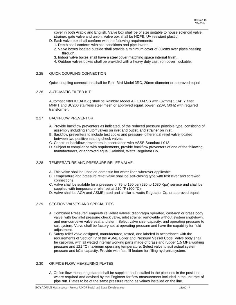
Division 15 VALVES
cover in both Arabic and English. Valve box shall be of size suitable to house solenoid valve, strainer, gate valve and union. Valve box shall be HDPE, UV resistant plastic. D. Each valve box shall conform with the following requirements: 1. Depth shall conform with site conditions and pipe inverts. 2. Valve boxes located outside shall provide a minimum cover of 3Ocms over pipes passing through. 3. Indoor valve boxes shall have a steel cover matching space internal finish. 4. Outdoor valves boxes shall be provided with a heavy duty cast iron cover, lockable.
2.25 QUICK COUPLING CONNECTION
Quick coupling connections shall be Rain Bird Model 3RC, 20mm diameter or approved equal.
2.26 AUTOMATIC FILTER KIT
Automatic filter Kit(AFK-1) shall be Rainbird Model AF 100-LSS with (32mm) 1 1/4" Y filterMNPT and SC200 stainless steel mesh or approved equal, power: 220V, 50HZ with required transformer.
2.27 BACKFLOW PREVENTOR
A. Provide backflow preventers as indicated, of the reduced pressure principle type, consisting of assembly including shutoff valves on inlet and outlet, and strainer on inlet. B. Backflow preventers to include test cocks and pressure- differential relief valve located between two positive seating check valves. C. Construct backflow preventers in accordance with ASSE Standard I 013. D. Subject to compliance with requirements, provide backflow preventers of one of the following manufacturers, or approved equal: Rainbird, Watts Regulator Co.
2.28 TEMPERATURE AND PRESSURE RELIEF VALVE
A. This valve shall be used on domestic hot water lines wherever applicable. B. Temperature and pressure relief valve shall be self-closing type with test lever and screwed connections. C. Valve shall be suitable for a pressure of 75 to 150 psi (520 to 1030 Kpa) service and shall be supplied with temperature relief set at 210 °F (100 °C). D. Valve shall be AGA and ASME rated and similar to watts Regulator Co. or approved equal.
2.29 SECTION VALVES AND SPECIALTIES
A. Combined Pressure/Temperature Relief Valves: diaphragm operated, cast-iron or brass body valve, with low inlet pressure check valve, inlet strainer removable without system shut-down, and non-corrosive valve seat and stem. Select valve size, capacity, and operating pressure to suit system. Valve shall be factory-set at operating pressure and have the capability for field adjustment. B. Safety relief valve designed, manufactured, tested, and labeled in accordance with the requirements of Section IV of the ASME Boiler and Pressure Vessel Code. Valve body shall be cast-iron, with all wetted internal working parts made of brass and rubber 1.5 MPa working pressure and 121 °C maximum operating temperature. Select valve to suit actual system pressure and kCal capacity. Provide with fast fill feature for filling hydronic system.
2.30 ORIFICE FLOW MEASURING PLATES
A. Orifice flow measuring plated shall be supplied and installed in the pipelines in the positions where required and advised by the Engineer for flow measurement included in the unit rate of pipe run. Plates to be of the same pressure rating as values installed on the line.
BOYADJIAN Masterspecs - Project: UNDP Social and Local Development - 15100 - 7
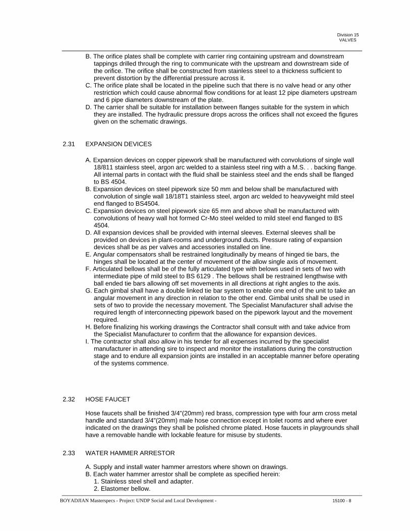
Division 15 VALVES
B. The orifice plates shall be complete with carrier ring containing upstream and downstream tappings drilled through the ring to communicate with the upstream and downstream side of the orifice. The orifice shall be constructed from stainless steel to a thickness sufficient to prevent distortion by the differential pressure across it. C. The orifice plate shall be located in the pipeline such that there is no valve head or any other restriction which could cause abnormal flow conditions for at least 12 pipe diameters upstream and 6 pipe diameters downstream of the plate. D. The carrier shall be suitable for installation between flanges suitable for the system in which they are installed. The hydraulic pressure drops across the orifices shall not exceed the figures given on the schematic drawings.
2.31 EXPANSION DEVICES
A. Expansion devices on copper pipework shall be manufactured with convolutions of single wall 18/811 stainless steel, argon arc welded to a stainless steel ring with a M.S. . . backing flange. All internal parts in contact with the fluid shall be stainless steel and the ends shall be flanged to BS 4504. B. Expansion devices on steel pipework size 50 mm and below shall be manufactured with convolution of single wall 18/18T1 stainless steel, argon arc welded to heavyweight mild steel end flanged to BS4504. C. Expansion devices on steel pipework size 65 mm and above shall be manufactured with convolutions of heavy wall hot formed Cr-Mo steel welded to mild steel end flanged to BS 4504. D. All expansion devices shall be provided with internal sleeves. External sleeves shall be provided on devices in plant-rooms and underground ducts. Pressure rating of expansion devices shall be as per valves and accessories installed on line. E. Angular compensators shall be restrained longitudinally by means of hinged tie bars, the hinges shall be located at the center of movement of the allow single axis of movement. F. Articulated bellows shall be of the fully articulated type with belows used in sets of two with intermediate pipe of mild steel to BS 6129 . The bellows shall be restrained lengthwise with ball ended tie bars allowing off set movements in all directions at right angles to the axis. G. Each gimbal shall have a double linked tie bar system to enable one end of the unit to take an angular movement in any direction in relation to the other end. Gimbal units shall be used in sets of two to provide the necessary movement. The Specialist Manufacturer shall advise the required length of interconnecting pipework based on the pipework layout and the movement required. H. Before finalizing his working drawings the Contractor shall consult with and take advice from the Specialist Manufacturer to confirm that the allowance for expansion devices. I. The contractor shall also allow in his tender for all expenses incurred by the specialist manufacturer in attending sire to inspect and monitor the installations during the construction stage and to endure all expansion joints are installed in an acceptable manner before operating of the systems commence.
2.32 HOSE FAUCET
Hose faucets shall be finished 3/4"(20mm) red brass, compression type with four arm cross metalhandle and standard 3/4"(20mm) male hose connection except in toilet rooms and where ever indicated on the drawings they shall be polished chrome plated. Hose faucets in playgrounds shall have a removable handle with lockable feature for misuse by students.
2.33 WATER HAMMER ARRESTOR
A. Supply and install water hammer arrestors where shown on drawings. B. Each water hammer arrestor shall be complete as specified herein: 1. Stainless steel shell and adapter. 2. Elastomer bellow.
BOYADJIAN Masterspecs - Project: UNDP Social and Local Development - 15100 - 8

Division 15 VALVES
3. Hydraulic displacement fluid. 4. Pressurized insert gas pneumatic displacement chamber. 5. 15 mm NPT threaded connection 6. Isolating ball valve. C. Approved manufacturers: 1. JOSAM (USA) 2. ZURN (USA or approved equal
2.34 UTILITIES SERVICE MAINS
A. The contractor shall connect the water, service lines to city mains including all necessary excavation, backfilling. B. Contractor shall connect also sewage and rain water pipes to city mains including all necessary civil and mechanical works.
2.35 APPROVED MANUFACTURERS (for valves)
Except where otherwise specified, approved manufacturers for valves specified are as follows: 1. Crane Co. 2. Newman- Hattersly 3. VICTAULIC or approved equal.
END OF SECTION 15100
BOYADJIAN Masterspecs - Project: UNDP Social and Local Development - 15100 - 9

Division 15SUPPORTS AND ANCHORS
SECTION 15140 - SUPPORTS AND ANCHORS
PART 1 – GENERAL
1.1 SUMMARY
A. Provide labor, materials, equipment and services, and perform operations required for complete installation of Piping and Fittings and related work as indicated on the drawings and specified herein. B. Work Included The work shall include, but not be limited to, the following: 1. Extent of supports and anchors required by this section is indicated on drawings and/or specified in other Division 15 sections. 2. Supports and anchors shall be of approved type, selected from an approved manufacture. No field fabrication is acceptable unless otherwise advised by the Engineer. 3. Supports and anchors furnished as part of factory-fabricated equipment, are specified as part of equipment assembly in other Division I 5 sections. C. Related Work Specified Elsewhere 1. Basic Mechanical Requirements - Section 15010 2. Basic Mechanical Materials and Methods - Section 15050
1.2 QUALITY ASSURANCE A. Materials and work shall conform to the latest edition of reference specifications and industry standards listed below and specified herein and to applicable codes and requirements of local authorities having jurisdiction, whichever is more stringent. 1. Code Compliance: Comply with applicable plumbing codes pertaining to product materials and installation of supports and anchors.
SUBMITTALS A. Submit the following in accordance with the requirements specified under Submittals in Section 15010. 1. Shop Drawings: Submit shop drawings for work specified herein for approval. Shop drawings for each type of support and anchor, indicating dimensions, weights, required clearances, and methods of assembly or components. 2. Product Data a. Submit copies of manufacturer's latest published literature for materials specified herein for approval; obtain approval before ordering materials. b. Data shall include manufacturer's technical product data, including installation instructions for each type of support and anchor. Submit pipe hanger and support schedule showing manufacturer's figure number, size, location, and features for each required pipe hanger and support.
DELIVERY, STORAGE AND HANDLINGA. Exercise proper care in the handling of work so as not to injure the finished surfaces, and protect the work from damage after it is in place.
1.3
1.4
APPROVED MANUFACTURER A. WALRAVEN (Holland) B. SIKLA (Germany) C. HILTI (USA) or approved equal PART 2 - PRODUCTS
1.5
BOYADJIAN Masterspecs - Project: UNDP Social and Local Development - 15140 - 1

Division 15SUPPORTS AND ANCHORS
Material shall be product of approved manufacture. No field fabrication is acceptable. Design of supportsystem shall be done by the approved support manufacturer including submittal of all necessary calculations for the Engineer approval.
PART 3 - EXECUTION
3.1 EXAMINATION Examine conditions at the job site where work of this section is to be performed to insure proper arrangement and fit of the work. Start of work implies acceptance of job site conditions.
PREPARATION A. Examine the Contract Drawings and specifications in order to insure the completeness of the work required under this Section. Provide supplementary parts necessary to complete work, though not specifically indicated on Drawings or specified herein. B. Verify measurements and dimensions at the jobsite and cooperate in the coordination and scheduling of the work of this Section with the work of related trades, so as not to delay job progress. C. Proceed with installation of hangers, supports and anchors only after required building structural work has been completed in areas where the work is to be installed. Correct inadequacies including (but not limited to) proper placement of inserts, anchors and other building structural attachments. D. Prior to installation of hangers, supports, anchors and associated work, Contractor shall meet at project site with installer of each component of associated work, inspection and testing agency representatives (if any), installers of other work requiring coordination with work of this section and Engineer for purpose of reviewing material selections and procedures to be followed in performing the work in compliance with requirements specified.
INSTALLATION Installation of Hangers and Supports 1. Install hangers, supports, clamps and attachments to support piping properly from building structure. Arrange for grouping of parallel runs of horizontal piping to support together on trapeze type hangers where possible. Install supports as directed by the Engineer. Where supporting piping of various sizes together by trapeze hangers, space hangers for smallest pipe size or install intermediate supports for smaller diameter pipe. Do not use wire or perforated metal to support piping, and do not support piping from other piping. 2. Install hangers and supports complete with necessary inserts, bolts, rods, nuts, washers and other accessories. Except as otherwise indicated for exposed continuous pipe runs, install hangers and supports of same type and style as installed for adjacent similar piping.
ADJUSTING AND CLEANINGA. Hanger Adjustment Adjust hangers so as to distribute loads equally on attachments. B. Support Adjustment Provide grout under supports so as to bring piping and equipment to proper level and elevations. C. Cleaning Clean factory-finished surfaces. Repair any marred or scratched surfaces with manufacturer’s touchup paint.
3.2
3.3
3.4
END OF SECTION 15140
BOYADJIAN Masterspecs - Project: UNDP Social and Local Development - 15140 - 2

Division 15 PUMPS
SECTION 15160 -PUMPS
PART 1 - GENERAL
1.1 DESCRIPTION OF WORK
A. Extent of work: The extent of pump work is indicated on drawings and in schedules, and by requirements of this section.
B. The application of general use centrifugal type pumps required include: 1. Cold water booster pumps. 2. Submersible pumps. 3. Hot water circulator pumps. 4. Cooling and heating pumps.
C. Electrical connections for pump motors are specified in applicable Division 16 sections.
1.2 APPROVED MANUFACTURERS
A. Salmson (France) B. Grundfoss (USA) C. ITT Lowara (Italy) or approved equal
1.3 QUALITY ASSURANCE
A. Manufacturers: Firms regularly engaged in manufacture of general use centrifugal pumps with characteristics, pipe sizes and capacities required, whose products have been in satisfactory use in similar service for not less than 5 years.
B. Electrical Standards: Provide electric motors and products which have been listed and labeled by Underwriters Laboratories and comply with National Electrical Manufacturers Association (NEMA) standards.
C. Certification, Pump Performance, Provide pumps whose performance under specified conditions, is certified by the manufacturer. Contractor to submit certificate of origin with shipment certificate to the engineer.
D. All pumps shall be assembled in country of origin. Local assembly is not acceptable.
E. All pumping units shall be designed and built for twenty-four hour continuous service at any and all points within the specified range of operation, without overheating, without cavitation, without excessive vibration or strain and requiring only that degree of maintenance generally accepted as normal for the specific type of pump required. All parts and components of all pumping units shall be designed and built for interchange ability so that replacement parts may be installed without any additional fitting or machining. Upon request, or if hereafter specified, the manufacturer shall submit evidence that the tolerances and finishes on the detail drawings so permit, and the manufacturer's shop is equipped with the necessary machinery, jigs, fixtures and gauges to assure such interchange ability.
BOYADJIAN Masterspecs - Project: UNDP Social and Local Development - 15160 - 1

Division 15 PUMPS
F. Failure to successfully comply with the requirements of the previous paragraphs will constitute grounds for disqualification of the pump manufacturer. Poor performance of similar pumping equipment now in operation under the specified conditions of service and pump rating constitute grounds for disqualification of the pump manufacturer, supplier or both, unless such poor performance has been corrected.
G. Codes and Standards: Comply with the applicable requirements of the following codes and standards: 1. ASTM : American Society for Testing and Materials. A 48 : Specification for Gray Iron Castings. A 493 : Specification for Stainless and Heat Resisting Steel for Cold Heating and Cold Forging - Bar and Wire. A 666 : Specification for Austentic Stainless Steel Sheet, Strip, Plate and Flat Bar for Structural Applications. 2. ANSI : American National Standards Institute.
1.4 SUBMITTALS
A. Manufacturer’s Data: Submit manufacturer’s data on pumps, including but not limited to, pump characteristics and performance curves.
B. Pump Characteristics Curves: 1. Submit for each pump specified, copies of the characteristic curves of the proposed pump. Such curves shall be plotted on 216 mm by 276mm graph paper. For each pump (or pumping unit where overall efficiency is specified) the following characteristic curves shall be shown as ordinates plotted against the rate of flow of the pump: a. Total Dynamic Head. b. Pump Efficiency. c. Brake Horsepower. d. Net Positive Suction Head. e. Power Input to Electric Drive Motor. f. Overall Efficiency of Pumping Unit. g. Total Inertia.
2. Indicate the limits of the range of rate of flow at which the pump can successfully operate on such curve when the operable range differs from the complete range shown. Approval of the characteristic pump curve shall in no way be construed to be permissive to proceed with the manufacture of the pump. Upon receipt of an approved pump curve, the Contractor shall submit, if he has not previously done so, all other drawings, material lists and other information specified, requested and/or necessary to coordinate the pumping installation with the balance of the work and to show complete compliance with all details of the Contract Documents.
C. Shop Drawings: 1. Submit drawings and information necessary for final design of foundations, structural supports, connected piping and valves, pump drip and drainage piping, electrical connections, starting and protective equipment and auxiliary equipment.
2. Submit for all pumping units, a dimensioned and scaled assembly outline drawing or drawings of the complete pump, drive and all associated equipment furnished. Such drawing or drawings shall show plan, elevation and any other view or section requested.
3. For all pumping units a scaled cross-sectional drawing of the assembled pump showing full details and materials of construction shall be submitted for approval. For pumping
BOYADJIAN Masterspecs - Project: UNDP Social and Local Development - 15160 - 2

Division 15 PUMPS
units powered by motors rated at 20 horsepower or less, catalog cuts may be submitted tosupplement the outline and cross furnished with steel base plates, sub-bases and similar components, detailed dimensioned drawings giving full information thereon shall be submitted for approval. Steel components shall be at least 9.5 mm thick and no undrained pockets will be permitted.
1.5 PRODUCT DELIVERY, STORAGE AND HANDLING
A. Deliver and store pump products in factory-wrapped packaged which properly protect pumps against weather, dirt and damage. B. Handle pumps carefully to avoid damage to motors, components, enclosures and finish. Do not install damaged units, replace and return damaged units to pump manufacturer.
PART 2 - PRODUCTS
2.1 WATER PUMPS
A. General:
1. Provide electric motor driven, volute type centrifugal pumps as indicated on drawings. Equip with insulated, quiet, TEFC, when installed outside or drip proof, for indoor installation, ball bearing type motor of rotation speed, hp rating and power characteristics indicated factory align and couple motor to pump. Provide pumps rated for capacities, pressures and suction/discharge heads as shown on drawings, with flanged pipe connections, with dynamically balanced enclosed type impellers locked to pump shafts and shall be rated for 1200C water temperature and shall be close-coupled or with flexible coupling as indicated on drawings.
2. Domestic booster shall be centrifugal type multi stage pump complete with control panel.
3. Chilled water pumps shall be centrifugal, end-suction type, single stage, horizontal, and as specified.
4. The pumps shall be of cast iron bronze fitted construction. The volute and bearing brackets are to be cast iron the impeller of bronze and the pump shaft of stainless steel. The pumps shall employ a mechanical seal, with a carbon seal ring and ceramic seat. The motor shall be resilient mounted equipped with oil lubricated journal bearings or as indicated on the drawings.
B. Pump characteristics: The Contractor shall provide pumps according to the capacities and schedules as shown on drawings. The pump shut-off pressure shall not be less than 25% higher than the design load. The speed shall not exceed 1450 RPM. C. Equip pumps with sleeve bearings and force feed lubrication systems, and protect pump shafts internally with non-ferrous sleeves, Provide bearing bracket assemblies of the type which can be removed without disturbing piping or motors.
D. All pumps shall be connected to building control system as indicated under electrical section.
2.2 END SUCTION CENTRIFUGAL PUMP
A. Type: horizontal, base mounted, end suction, single stage, centrifugal type, directly connected to motor through a heavy duty flexible coupling, with heavy gauge coupling guard.
B. Base: pump and motor to be mounted on common steel base adequately reinforced against deflection, with drip rim, drain tapping, bolt holes and grouting hole.
BOYADJIAN Masterspecs - Project: UNDP Social and Local Development - 15160 - 3

Division 15 PUMPS
C. Bearings: pump rotating element to be supported by two heavy duty grease lubricated ball bearings mounted in heavy iron frame with adequate supports to base for maximum rigidity.
D. Pump casing: high tensile strength close grain cast iron with smooth waterways, register fitted and bolted to bearing frame for permanent alignment, with bronze wear rings and tapped and plugged bottom drain and top vent connections.
E. Impeller: bronze, enclosed type, fitted to shaft with key and locked in place.
F. Shaft: one piece stainless steel, sized to carry axial and radial thrust with minimum deflection.
G. Mechanical seal: Ni-resist face, carbon washer and stainless steel metal parts.
H. Electric motor: totally enclosed, fan cooled, squirrel cage, induction type, with permanently lubricated and sealed ball bearings.
I. Manufacturers to be proposed by tenderer as part of his tender, in all cases to be approved byEngineer.
2.3 IN-LINE CIRCULATORS
Description: In-line, centrifugal, single-stage, bronze-fitted, split case design; rated for 860kPaminimum working pressure and a continuous water temperature of 1070C include the following:
1. Casing: cast iron, with threaded companion flanges for piping connections smaller than 65mm and threaded gate tappings at inlet and outlet connections.
2. Connection Option: Include unions, instead of threaded companion flanges, at connections for casings that are not available with threaded companion flanges.
3. Impeller: ASTM B584, cast bronze, statically and dynamically balanced, closed, overhung, single suction, and keyed to shaft.
4. Shaft and Sleeve: stainless steel shaft with oil-lubricated copper sleeve.
5. Seals: mechanical DUNA-N type. Include carbon-steel rotating ring, stainless steel spring, ceramic seat, and flexible bellows and gasket.
6. Pump bearings: Oil lubricated, bronze journal and thrust type.
7. Motor bearings: Oil lubricated, sleeve type.
8. Coupling: flexible, capable of absorbing torsional vibration and shaft misalignment.
9. Motor: resiliently mounted to pump casing.
10. Manufacturers to be proposed by tenderer as part of his tender, in all cases to be approved by Consultant.
2.4 VERTICAL MULTI STAGE PUMP
A. General
1. Supply and install wherever shown on the drawings vertical multi stage centrifugal pumps of capacities as indicated in the capacity schedule and/or shown on the drawings.
BOYADJIAN Masterspecs - Project: UNDP Social and Local Development - 15160 - 4

Division 15 PUMPS
2. Each pump shall be of the type specified and shall be directly coupled to an electric motor.
3. Pump casing shall be of stainless steel 316L, with smooth water ways and fitted with stainless steel wear ring. Impeller shall be stainless steel, enclosed, accurately machined and statically and dynamically balanced. Shaft shall be one piece stainless steel 316L with stainless steel sleeve of ample size to carry any axial and radial thrust.
4. Pump shall have mechanical shaft seal of extra hard carbon and ceramic type. Pump ball shall be of ample size to withstand all axial and radial thrust.
5. Each pump, for water supply application, shall be complete with the following: a. Electric control panel complete with circuit breakers, starters, automatic electric alternators, indicating lights and selector switches. Panel shall be made of sheet steel of dust and rust proof type with lockable door. b. Float switched, installed in both domestic water reservoirs, and control cables between the float switches and the electric control panel.
6. Pump speed shall be as shown in the pump schedule.
7. Method of Control of Pumps used for Water Supply application a. One pump shall act as a standby (as indicated in the pump schedule) b. A low water level float switch installed in the lower water tank shall prevent either of the pumps to run dry if the lower tank is empty.
c. A float switch installed in the roof water tank with two predetermined levels. The high level when reached shall stop the pump automatically and the low level when reached shall start the pump automatically. d. An electric alternator shall alternate the duty and standby pumps on every cycle. In case of failure of duty pump to start, the standby shall be automatically started.
2.5 SUBMERSIBLE SEWAGE SUMP PUMPS
A. Supply and install all sewage sump pumps wherever shown on the drawings and as specified herein.
B. Sump pumps shall be submersible direct connected with a guide rail system, duplex assembly complete as specified in the following clauses: a. Pumps Each pump shall be of the non-clog, centrifugal, submersible, type all stainless steel 316L designed for pumping raw sewage and brine water complete with: a. Stainless steel casing. b. Open type 316L stainless steel impeller able to pass solids up to 65 mm diameter (φ 2 1/2”). c. Stainless steel shaft. d. Mechanical seal. e. Water cooled, totally enclosed electric motor, rated for continuous duty. Motor speed shall not exceed 1 450 rpm. Motor to have thermal overload protection and moisture sensing probes, pump and motor bearings shall be heavy duty, permanently lubricated and sealed ball bearings guaranteed for a minimum of 100,000 hours continuous operation. Include a 3 conductor waterproof power cable of length required, but not less than 6m with a grounding plug and cable sealing assembly for connecting at pump. f. Oil casing. g. Cables and floats fixing frame.
BOYADJIAN Masterspecs - Project: UNDP Social and Local Development - 15160 - 5

Division 15 PUMPS
h. i. j. k. l.
One check valve and one gate valve at pump outlet. Air tight access cover and frame. Level regulators of the pear-shaped type. Guide rail, bracket & discharge connection with stainless steel chain and lifting Yoke. Control panel with submersible electric flexible cable between pump and control panel. m. Grouting in cast iron frame with cast iron cover plate and upper guide rail.
1. Sump pumps shall be installed in a concrete pit to be constructed by the Concretor with checker plate cover over each pump. 2. The Contractor shall coordinate his piping with the Concretor and shall install all pipes connected to the sumps pit in accordance with the layouts shown on the drawings. 3. It shall be his responsibility to coordinate and determine pipes inverts and locations of pipe connections to the pit.
B. Controls
1. An automatic operating and control panel shall be provided for sump pumps operation. Pumps shall be monitored by the BMS system. 2. Automatic control unit with level regulators to start and stop the pumps automatically. The control unit shall also alternate the operation of the pumps to equalize their operating time. In case of failure of one pump; the control unit shall initiate an alarm and automatically start the other pump. 3. The level regulators (float switches) shall be of polypropylene housing with eccentrically positioned lead weight, mercury switch and 1 3 meters water proof cable.
4. The panel shall be of light alloy construction, perfectly sealed against dust and water and shall house pumps starters, breakers, floats, relays, interlocks, pilot lights, cables, wires, etc,... to obtain to following results: a. At low water level in the collecting pit, controls shall be inoperative. b. When water level rises to the first normal level in the collecting pit, the lead pump shall start. c. When water level rises to the second normal level in the collecting pit, the second pump shall start. d. When water level drops to the first level, the last pump to start shall stop. The first pump shall keep on running until water level drops to the low water level setting. e. An automatic alternating relay shall alternate pumps lead role after each cycle. f. Should the water level rise to the alarm preset level or drop to the alarm preset low level, controls shall act to operate an alarm bell which shall remain in operation until put off manually. Alarm shall be indicated on the central alarm panel.
C. Capacity 1. Capacity of each sump pump shall be as shown on the drawings.
2.6 SUBMERSIBLE DRAINAGE PUMPS
A. Supply and install submersible drainage pumps where shown on the Drawings and of indicated capacities and heads.
B. The pump and motor housing shall form a compact integral unit and shall be of the completely submersible type. Pump shall be as specified in paragraph 2.05 for sewage pump except that it shall have base with strainer with 304L stainless steel construction.
2.7 COLD WATER HYDRO-PNEUMATIC PRESSURE SET (BOOSTER SET)
BOYADJIAN Masterspecs - Project: UNDP Social and Local Development - 15160 - 6

Division 15 PUMPS
A. Supply and install all cold water hydro-pneumatic pressure sets wherever shown on the drawings and as specified herein.
B. Each cold water pressure set shall be pneumatic, packaged type, triplex or duplex type as shown on drawings, complete with pneumatic pressure tank, interconnecting piping, fittings, controls, specialties and control panel all mounted on the same steel frame with heavy gauge steel protective casing, and all factory assembled and tested.
C. Field assembled pumps and panels are not approved.
D. Each cold water pressure sets shall be complete as specified in the following clauses: 1. Pumps Each pump shall be centrifugal, vertical multistage, silent type, complete with flexibly coupled electric motor and couplings. The pump and motor assembly shall be mounted on a steel bed plate with an approved vibration isolator. Pumps construction shall be as described in paragraph 2.04 of this specifications.. Each pump shall include: a. Casing drain and vent plugs. b. Gauge tappings. c. Drip Chamber or tray with drain connection. d. Gate valve and strainer at its suction. e. Silent check valve and globe valve at its discharge. f. Pressure switches. g. Pressure gauge and gauge cock at its discharge. h. Reinforced type flexible connectors at pump’s suction and discharge. i. Hydro-Pneumatic Pressure Tank Each pressure tank shall be cylindrical or spherical, closed type, constructed in compliance with an approval international code for unfired pressure vessels. Each pneumatic pressure tank shall include: a. An inert gas chamber. b. Flexible butyl or neoprene membrane separating the insert gas chamber from water, and suitable for drinking water applications. c. Air recharge valve if tank is not permanently charged at factory. d. Pressure gauge and gauge cock. e. Gate shut-off valve. 2. Capacity − Capacity of each cold water pressure set shall be as given in the schedules of capacities and/or the Bills of Quantities. − Cold Water Pressure Set Operation and Control − Supply and install for each Cold water pressure set a system control and control panel which shall include all necessary pressure switches, pressure regulating valves, instruments, operating relays, safety relays as well as cables, wires, etc connecting it to the corresponding pump and storage tank or reservoir to obtain the following functions: a. When line pressure drops, the pump shall operate and remain in operation until flow stops or the pressure switch reaches its high limit setting. A minimum run- time relay, adjustable type shall be provided to prevent frequent on/off operation. If pressure drops below a preset value, the second pump shall operate. b. When suction water level drops to 100 mm above top of suction pipe, the pump shall stop by the action of a low level float switch; it shall not be able to run even if other controls call for its operation. c. After water level rises to 150 mm above suction pipe, controls shall allow pump operation again. d. If operating pump fails to start the second pump shall operate automatically. e. An automatic sequencing control shall be provided to operate pumps in a rotational sequence after each cycle.
BOYADJIAN Masterspecs - Project: UNDP Social and Local Development - 15160 - 7

Division 15 PUMPS
f. Panel shall be provided with OFF-MANUAL-AUTO selector switch to allow thesystem to be stopped and/or put on manual or automatic operation.
g. Panel shall be provided with an alarm buzzer and switch which shall be put in operation in case of fault. h. For each function specified with the panel, a pilot light shall be provided to indicate the status of the particular function. Pilot lights colors shall be selected in accordance with the function to be indicated. i. A delay relay shall be incorporated within the panel to prevent immediate start- up upon re-establishment of power after power failure. j. Booster set shall be monitored by the building management system.
2.8 FIRE PUMP TEST METERS
Shall be Victaulic Style 735, 21/2”-12” Fire Pump Test Meter, FM approved, incorporating acalibrated venturi and attached GPM meter, to be installed on the discharge side of the fire pump, to accurately measure pump performance. Test meter shall be supplied with grooved ends for installation with Victaulic grooved end couplings.
PART 3 – EXECUTION
3.1 INSPECTION
The Contractor shall examine substrates upon which and conditions under which pumps shall beinstalled. If conditions found detrimental these shall be rectified and no work shall be conducted until unsatisfactory conditions have been corrected in a manner acceptable to the Engineer.
3.2 INSTALLATION OF PUMPS
A. Install pumps where shown, in accordance with manufacturer’s written instructions, and with recognized industry practices, to ensure that pumps comply with requirements and serve intended purposes. Comply with NEMA standards and requirements of NEC.
B. Coordinate with other work (piping) as necessary to interface installation of pumps with piping and other components of water system.
C. Check alignment and, where necessary (and possible), realign shafts of motors and pumps within tolerances recommended by manufacturer.
D. Install units on vibration mounts, comply with manufacturer's indicated installation method, if any, and with Division 15 sections.
3.3 ELECTRICAL CONNECTIONS
A. Ensure that pump units are wired properly, with rotation in direction indicated and intended for proper pump performance.
B. Provide positive electrical pump and motor grounding.
3.4 FIELD QUALITY CONTROL Upon completion of installation of pump, and after motor has been energized with normal power source, bleed air from pump casing and test pump to demonstrate compliance with requirements. When possible, field correct malfunctioning units, then retest to demonstrate compliance. Replace units which cannot be satisfactorily corrected.
END OF SECTION 15160
BOYADJIAN Masterspecs - Project: UNDP Social and Local Development - 15160 - 8

Division 15 TANKS
SECTION 15175 - TANKS
PART 1 – GENERAL
1.1 SUMMARY
A. Provide labor, materials, equipment and services, and perform operations required for complete installation of Plumbing Equipment and related work as indicated on the drawings and specified herein.
B. Work Included The work shall include, but not be limited to, the following: 1. Water tank. 2. Expansion Tanks. 3. Chemical Feed pot. 4. Potable water tank.
C. Related Work Specified Elsewhere 1. Basic Mechanical Requirements - Section 15010. 2. Basic Mechanical Materials and Methods - Section 15050.
1.2 QUALITY ASSURANCE
A. Materials and work shall conform to the latest edition of industry standards, reference specifications listed below and specified herein and to applicable codes and requirements of local authorities having jurisdiction, whichever is more stringent.
B. Qualifications 1. The Contractor shall provide the equipment specified, or equipment of the same standard of construction and performance as produced by one of the listed manufacturers. 2. Approval of the manufacturer does not necessarily constitute approval of its products as equal to those specified. Immediately after the awarding of the contract and prior to the start of construction, submit to the Engineer for approval a complete written summary of the proposed manufacturer’s equipment.
C. Test 1. Factory Tests a. Before shipment, the manufacturer shall test components hydrostatically at 150% of rated design pressure for ability to withstand maximum design pressure and for tightness. b. Conduct factory performance test on actual pumps to be furnished. Furnish sufficient lead notice to Engineer to permit witnessing of test. Furnish certificate of test.
SUBMITTALS
Submit the following in accordance with Section 1 5010.
1. Product Data c. Submit copies of manufacturer’s latest published literature for materials specified herein for approval; obtain approval before ordering materials. d. Data shall include manufacturer’s technical product data, including installation instructions, and dimensioned drawings for each type of manufactured piping specialty. Include pressure drop curve or chart for each type and size of pipeline strainer. Submit
BOYADJIAN Masterspecs - Project: UNDP Social and Local Development - 15175- 1

Division 15 TANKS
schedule showing manufacturer’s figure number, size, location, and features for each required piping specialty. 2. Shop Drawings Submit shop drawings for work specified herein for approval. a. A complete detailed set of construction and erection drawings for equipment including vibration isolators and bases indicating dimensions, materials of construction and methods of assembly. b. Complete capacity and performance data including items indicated in the equipment schedules and specifications.
Maintenance Data Submit maintenance data and spare parts lists for each type of manufacturedpiping specialty. Include this data, product data, and shop drawings in maintenance manual in accordance with requirements of Section 15010.
DELIVERY, STORAGE AND HANDLING
A. Deliver materials and handle so as to prevent the inclusion of foreign materials and the damage of materials. B. Store materials and equipment where designated and assume responsibility and security for materials and equipment. Take precautions for protection from detrimental conditions.
PART 2 - PRODUCTS
TANKS MATERIALS/EQUIPMENT
A. Stainless Steel Water Tank
1. Tank shall be constructed of 3 mm thick welded stainless steel 316 L sheet metal to the capacities indicated on the drawings. 2. Tank shall be tested for leaks before installation. 3. Tank shall be mounted on a steel support and shall be equipped with the following: a. Access cover. b. Level indicator. c. Fill, vent and overflow pipe. d. Drain valve. e. Supply line with valve. f. Tank will be local made. B. Chemical Feeder Pot
1. The unit shall be of a quality construction with dished ends for safe operation at pressure and shall be supplied complete with all valves and funnels all factory assembled. The feeder unit shall be supplied with a stand and shall be pressure tested with a certificate from the factory.
2. Chemical feeder pot shall be similar to Houseman dosage pots or approved equal.
C. Expansion tank
1. Provide compression tank (expansion tank) as shown on the drawings, constructed for 930 Kpa working pressure, stamped with “ U” symbol and supplied with National Board From U-i denoting compliance with ASME boiler and pressure vessel code. Provide fittings and connections to related equipment in accordance with tanks manufacturer’s recommendations. Tank shall be insulated externally. Insulation shall be same type used
BOYADJIAN Masterspecs - Project: UNDP Social and Local Development - 15175- 2

Division 15 TANKS
for exposed ductwork, specified hereinbefore. Tank diaphragm shall withstand 10 deg. C up to 120 deg C suitable for heating and chilled water systems. 2. Refer to drawings for tank support.
D. Concrete water tanks
1. Supply and install in each compartment of the basement reservoir the followings: a. Balancing piston type float valve with shut-off valve. b. Level float switches assemblies as required and as necessary for the control of the relevant systems. c. Water level alarm float switches connected to central alarm panel, located in the maintenance block. d. Drain valve. e. Drain and overflow to nearest drain provision or as shown on the drawings and vent pipes with insect copper mesh screen. f. All pipes into the water tank shall be located in place before concreting and shall be provided with no-leak flanges welded to the pipe. g. Stainless steel ladders and access doors as shown on drawings. h. Water tanks shall be monitored by BMS with all necessary controls. i. Contractor shall supply all material and labour to treat concrete water tanks with internal lining, non toxic, solvent free epoxy paint, two epoxy resin system with water proofing capabilities minimum thickness 200 micron. Material used shall be suitable for potable water and accordingly . will not contaminate water.
PART 3 - EXECUTION
EXAMINATION Examine conditions at the job site where work of this section is to be performed to insure proper arrangement and fit of the work. Start of work implies acceptance of job site conditions.
PREPARATION
A. Examine the Contract Drawings and specifications in order to insure the completeness of the work required under this Section.
B. Verify measurements and dimensions at the job site and cooperate in the coordination and scheduling of the work of this Section with the work of related trades, so as not to delay job progress. INSTALLATION
A. Construct apparatus of materials and pressure ratings suitable for the conditions encountered during continuous operation.
B. Where corrosion can occur, appropriate corrosion-resistant materials and assembly methods use including isolation of dissimilar metals against galvanic interaction.
C. Where components are or may come in contact, although the materials may basically be similar, use hardness differentials of at least 50 Brinell to prevent seizure and reduce wear.
D. Grout base plates completely to provide a rigid non-deflecting support.
E. Provide OSHA approved sheet metal guards over couplings.
BOYADJIAN Masterspecs - Project: UNDP Social and Local Development - 15175- 3

Division 15 TANKS
F. Pipe vents, bleeds, gland and base drains, and blowoff connections to nearest floor drain using copper tubing.
G. Provide nameplates; attach to unit showing the following information: 1. Maker’s name, date of manufacture, size and type. 2. Rated capacity, design and operating pressure ratings. 3. Rated horsepower, full load amperes. 4. Voltage, number of phases, frequency. 5. Temperature rise or class of insulation. 6. other information, as applicable, as noted herein or directed by Engineer.
H. Provide direction arrow indicating direction of rotation of pump, where pumps are included in assembly.
FELD QUALITY CONTROL
A. Field Tests 1. Perform field test to demonstrate the ability of the equipment to meet contract requirements. 2. Should any part of the apparatus or system fail to meet the contract requirements, adjust, repair or replace any defective or inoperative parts and, on completion, again conduct the complete performance tests. 3. Refer to appropriate sections for additional required test data.
B. Include results of factory and field tests in the Instruction Manual as described in the appropriate sections.
END OF SECTION 15175
BOYADJIAN Masterspecs - Project: UNDP Social and Local Development - 15175- 4
Division 15 DOMESTIC AND SOFT WATER PIPNG SYSTEMS
SECTION 15401 - DOMESTIC AND SOFT WATER PIPING SYSTEMS PART 1 - GENERAL 1.1 SCOPE
A. The work described in this section of the specification is related to the hot , cold, and soft
water distribution systems.
B. The contractor shall prior to the ordering of any equipment obtain two separate samples of the water
to be supplied to the site. These samples shall be sent to a laboratory for a water analysis to establish all characteristics and a copy of the analysis shall be forward to the consultants.
C. It shall be the contractor’s responsibility to verify all equipment specified for water treatment
for size, flow rates and produce. 1.2 RELATED WORK
A. Section 15010: Basic Mechanical Requirement. B. Section 15050: Basic Materials and Methods. C. Section 15060: Pipe and Pipe Fittings. D. Section 15100: Valves. E. Section 15250: Insulation. F. Section 15991: Testing and Commissioning.
1.3 SYSTEMS DESCRIPTION
A. The hot and cold water systems comprise of a system of pipe work, valves fittings and
appurtenances providing hot & cold water for ablutionary purposes to the various plumbing fixtures situated throughout the buildings. The work includes recirculation hot water and specialties.
B. The soft water system comprises of a system of pipe work, valves, fittings and
appurtenances providing soft water for cooling and heating plants and where applicable. 1.4 QUALITY ASSURANCE
The water softening plant shall be designed, manufactured, tested, certified and stamped in accordance with the requirements of ASME code, Section VIII Div. I, Unfired Pressure Vessel Code or any other similar international society.
1.5 REFERENCES
A. ASTM D 859: Silica in Water and Waste Water. B. ASTM D 1125: Electrical Conductivity and Resistivity of Water C. ASTM D 1126: Hardness in Water.
PART 2 - PRODUCTS 2.1 WATER SERVICES
See section 15060 Pipe and Pipe Fittings for Water Services Piping Materials and Installation. 2.2 MATERIALS
15401 1

Division 15 DOMESTIC AND SOFT WATER PIPNG SYSTEMS
A. Copper Piping Refer to Section 15060. B. Galvanized Steel Piping Refer to Section 15060. C. Black Steel Piping Refer to Section 15060. D. UPVC Pressure Piping Refer to Section 15060. E. Accessories
1. Flexible pipe connectors shall have a stainless steel bellows with a woven flexible bronze
wire reinforcing protective jacket. Connectors shall be minimum of 300 mm in length with thread male or flanged ends as required for proper installations. Sweat end connections re not acceptable. Connectors shall be rated for 1 MPa water working pressure, 120°C operating temperature and suitable for up to maximum 20 mm misalignment.
2. Shock absorbers shall be elastomer bellows type, with stainless steel shell, glycerin hydraulic displacement fluid and pressurized argon pneumatic displacement cushion. Shock absorbers shall be individually sized as required for equipment served.
F. Valves and Specialties
1. Hose bibs shall be polished chrome faucet with flange, indexed lever handle, 20
mm female inlet and 20 mm hose thread spout, single for concealed piping. 2. Wall Hydrant
a. Loose-key operator, lock type Packing nut, stainless steel stem, cast brass body to fit one modular brick course and 20 mm hose threaded spout with vacuum breaker. Wall hydrants shall be located on the exterior ground floor of all buildings at an average interval of approximately 30 meters.
b. Exposed surfaces shall be polished chrome plated. 3. Float valves for use on incoming supplies to cold water storage tanks shall be cast brass
or gunmetal up to 75mm dia. And cast iron with bronze seats for 100 mm dia. And above. G. Domestic Hot Water Storage Heater
a. Type: vertical or horizontal as shown on drawings glass-lined steel tank type, with fixed
convex ends, complete with removable copper tube U-bend heating section suitable for heating tank contents with hot water. Insulation and outer jacketing, accessories and controls all factories packaged and tested.
b. Heating coils shall be provided with strainers, valves and all other accessories as
detailed on drawings. c. Operating pressure: tank to be designed for 8 bars working pressure in tank and 8 bars
working pressure in tubes and to be hydrostatically tested at factory to 10 bars.
d. Tank to be welded carbon steel plate In accordance with ASME Code or EN Standard,
with two permanently attached lifting lugs. Manhole with cover and all necessary connections for water inlet, water outlet. Drain, relief valve, anti- vacuum valves, pressure gauge, thermometer, temperature controller and heating section.
e. Tank lining internal surfaces and surfaces in contact with water including manhole and cover and heating section connection surfaces are to be glass lined. Before lining the steel tank is to be thoroughly cleaned, welding slag removed and welds deposits, sharp edges and projections ground smooth.
BOYADJIAN Masterspecs Project: UNDP Social and Local Development 15401 2

Division 15 DOMESTIC AND SOFT WATER PIPNG SYSTEMS
f. Connections 50 mm diameter and under to be threaded and over 50 mm diameter to
be flanged. Heating section connection to be flanged. Connections to be non-ferrous couplings suitably capped at factory to preclude dirt and protect threads.
g. Heating sections to be constructed of’ seamless copper tubes expanded into copper or copper lined steel tube sheet with copper spun into each tube hole. Tubes to be supported on non-ferrous tube spacer and cross- bar. Adequate number of supports to be provided to prevent tube sag. Heating section to have flanged, close grain cast iron head with inside baffle and necessary connections for heating medium inlet and outlet. Drain and vent.
h. Accessories: heaters to be complete with anti-vacuum valves, pressure and temperature relief valve of type and size recommended by heater manufacturer and two mild steel supporting cradles. Shipped loose for field installation.
i. Test: steel tank and copper lining to be individually hydrostatically tested at factory. With copper lining still under pressure water is to be heated to minimum 52 °C and vacuum of 737 mm of mercury is to be applied between shell and copper lining to evacuate water behind lining and to verify lining tightness under vacuum conditions. Certificate of test to he furnished by manufacturer.
j. Shop drawings: submit for approval outline drawing of heater showing dimensions and size. Location and rating of connections. Prior to manufacturing heater.
k. Manufacturers obtain heater from one of the following: Adamson (U.S.A) De Dietrich (France) or approved equal.
H. Pumps
Pump casings shall be bronze with TEFC motor refer to section 15140.
I. Electric Water Heater
a. Supply and install electric water heaters wherever shown on the drawings of capacities
as indicated on the drawings. b. Each electric water heater shall be of the cylindrical storage type constructed of heavy
gauge steel with white enamel finish and glass lining from inside. c. Heater shall have polyurethane foam insulation wall between the outer, casing and the glass
lining all around top and bottom of cylinder. Heater shall be suitable for a working pressure of 100 psi (690 Kpa) and shall be certified by UL or equivalent European Norm.
d. Each electric water heater shall be complete with the following: a. Fast acting surface mounted thermostat for automatic temperature control. b. Factory installed sensitive high limit energy cut-off (for safety to prevent overheating)
present at 210 °F (99 °C ) and shall be listed and labeled by UL, AGA or CE. c. Electric element of 3000 watt capacity and smaller as indicated on the drawings.
Element shall be constructed of highest quality resistance wire sheathed in mineral filling and the whole encased in a copper tube and subjected to a high voltage test.
d. Removable heating water seamless copper coil, U bend heating section with L 3 way motorized valve and all valves and accessories as detailed on drawings.
e. A non return valve at the cold water inlet to the heater. f. Pressure relief valve installed between heater and non return valve and shall be
listed by AGA and shall be labeled by AGA, ASME or CE. g. Removable access panel to the heating element and thermostat. h. Factory installed nipples. i. Gate valves on cold and hot water connections. j. Wall fixing brackets and support.
e. Approved Manufacturers:
Buderus (Germany) Thermex (France)
BOYADJIAN Masterspecs Project: UNDP Social and Local Development 15401 3

Division 15 DOMESTIC AND SOFT WATER PIPNG SYSTEMS
De Dietrich (France) Or approved equal.
J. Polyethylene tank
a. Tank shall be constructed with polyethylene according to ASTM tests. b. Tank shall be tested for leaks before installation. c. Tank shall be mounted on steel supports of 10cm height, and shall be equipped with
the following : a. Manhole and manhole cover (access). b. Fill and distribution pipes. c. Float valve. d. Overflow, drain, supply and fill lines. e. Two gate valve.
d. Approved Manufacturer: NTG or approved equal K. Filter
The filter shall be of the pressure high flow rate, super filter type. 1. Capacity
Filter shall have the capacity indicated on the Drawings and/or specified in the schedule of Equipment at a filter and backwash rate of 5 gpm/ft2 (3.4 LPS/m2) of filter area.
2. Materials
a. Tank shall be made of composite or heavy gauge reinforced fiberglass construction or composite having a vertical cylindrical shape with dished and flanged heads suitable for a working pressure of 10 bar. All pipe connections to the tank shall be flanged except for pipe sizes 1 1/2” (40 mm) and smaller which shall be screwed. Tank shall have a manhole complete with cover, gasket, bolt and yoke located on the top.
b. Tank shall be designed in accordance with ASME Section VIII Dlv- I or equivalent International Standard. Tank shall have a baffle to promote even distribution of the effluent over the filter bed, and shall be equipped with a suitable under drain.
c. The effluent laterals shall be 150 mm apart and shall have 27/64” (11 mm) diameter orifices every 150 mm.
d. The effluent laterals shall be of corrosion-resistant pipe with orifices directed downwards. The effluent header shall be of schedule 80 steel.
e. Tank supports shall be of the adjustable jacklegs. f. Internal finish lining shall be smooth, dust free, without pin holes or voids
and completely nontoxic. g. Sand filter media shall consist of sand, gravel and rocks layers. Sand shall be of hard
durable grains of uniformly graded silica sand free from foreign materials, limestone or clay. Sand shall be of 0.39mm, effective size with uniformity co-efficient of 1.2 to 1.4 Gravel and rock shall consist of clean, hard, rounded stones with an average specific gravity of not less than 2.5 and should be free shale, mica, clay and other impurities.
h. Carbon filter media shall consist of granular activated carbon and should be capable to remove chlorine & organic color.
i. Valves shall be of the butterfly type automatic electrically actuated suitable for 150 psi. (1035 Kpa) complete with companion flanges, gaskets and bolts. All face piping shall be UPVC, PN16. Filter shall be automatic backwash type and as indicated on drawings.
j. Filter pressure tank shall be structural or approved equal. k. Valves shall be Autotroll or approved equal.
BOYADJIAN Masterspecs Project: UNDP Social and Local Development 15401 4

Division 15 DOMESTIC AND SOFT WATER PIPNG SYSTEMS
L. SOFTENING UNIT
a. General Description System to comprise two composite vessels, filled with softening grade strong cation resin and support gravel media. Softeners shall be single type with one brine tank and feeder pump.
Vessels to include top screen, bottom distributor and riser tube.
Control valves shall be top mounted type, brass bodied, 5 cycles programmable, with inlet and outlet connections and to include water meter with setting range up to 375 m3. Brine tank assembly should include top opening HDPE tank, inclusive of brine well, salt grid, safety brine valve (float valve), air check and removable cover.
Vessels will be operated depending on the flow passage.
b. Design Parameter The operating feed water temperature will vary between a maximum of 25 Degrees centigrade and minimum of 18 Degrees Centigrade.
Feed Water hardness is in the range of 200-300 ppm as Ca CO3 and Feed water TDS is in the range of 500 –1000 mg/l. Required system capacity is 2 L/S, 2 softeners each 2 L/S. softeners shall operate as duty – standby and shall alternate automatically.
The system’s total exchange capacity to be verified by the Contractor.
The total flow will be per one softener. Regeneration of the resin will be initiated for each softener by a separate impeller based water meter, which will send the signal to the control valve through a mechanical signal.
System should be configured to automatically exclude hard water passage during the non - service cycles.
System and piping configuration should allow for partial blending of product (soft) water with feed (hard) water.
System to include safety brine valve in the brine tank to avoid brine tank overflow due to power outages.
c. Assembly System to be completely assembled, piped, wired and tested at site as a complete packaged duplex unit. Steel parts and other components subject to corrosion to be treated with epoxy paint as necessary.
d. Composite Tanks: Tanks to be of composite material, 4 inch threaded top opening complete with base. Operating pressure 0 - 10 bars. Operating temperature 1- 50 degrees centigrade
Sport Facilities 15401 - 5

Division 15 DOMESTIC AND SOFT WATER PIPNG SYSTEMS
Minimum Fatigue testing 250, 00 cycles between 0 - 10 bar. Manufacturer: Structural Europe or approved equal.
e. Control Valves:
Valves to have fully adjustable cycles, type, meter initiated, include water meter, electromechanical control type, brass bodied.
Valves should be equipped with the appropriate drain line flow controllers and brine line flow controllers
Operating pressure range: 1.8 -8.5 bars
Working temperature range: 1- 43 degrees centigrade
Manufacturer: Autotroll Controls top mount or approved equal.
f. Softening Resin: Strong Cation resin, Gel type, Na+ form, softening grade, minimum total exchange capacity of 2.0 equivalents/liter, particle density of 1.3 gm/l, maximum operating temperature 120 degrees centigrade
Manufacturer: Dow Chemical Company or approved equal.
g. Brine Tank Assembly:
Rotary molded, high-density polyethylene (HDPE), inclusive of top cover, polypropylene salt grid, slotted brine well and brass safety brine valve (float valve).
M. UV Sterilizer
UV sterilizer shall be heavy duty stainless steel pressure vessel with heavy duty quartz jacket to protect UV lamp and insure peak UV radiation to the liquid complete with built in flow control, view port, light sensor with audible alarm, 220 VAC, 30000 micro watt. Sec/cm2 of 2537 A (254 nm) UV energy. Working pressure shall be 125 Psi with 9000 hr bulb life (approx. 1 year). Unit shall be provides with a set of 3 spare lamps.
N. Sediment and Carbon Filters (SDF & CF)
a. Filters shall be residential type, fully automatic back washable, complete with corrosion proof fiberglass mineral tank with brass control valve and fully adjustable timer. Filter shall accommodate activated carbon for carbon filter and graded density media for sediment filters. Filters shall have high efficiency back wash program and single lever bypass valve. Filters shall have five years warranty from date of substantial handover.
b. Filters shall be similar to Aqua-Pure Model ABF100 or approved equal. PART 3 - EXECUTION 3.1 INSTALLATIONS
See Section 15050: Basic Materials and Methods, for general piping installation instructions.
A. Supplies and Trim
All supplies, hardware, trim traps, etc. to fixtures and equipment shall be chrome plated brass if exposed to view.
B. Vacuum Breakers
BOYADJIAN Masterspecs Project: UNDP Social and Local Development 15401 6

Division 15 DOMESTIC AND SOFT WATER PIPNG SYSTEMS
Vacuum breakers shall be furnished and installed on all faucets and valves which have provisions for hose connections and water supplies to equipment or devices that have inlets below the overflow rim.
C. Underground Piping
No underground or under slab water piping within building shall be permitted unless specifically shown otherwise on the drawings.
D. Joints
Joints shall be made using 95-5 Tin- Antimony solder ASTM B-32. Joints for underground ( if any ) shall be made using a brazing compound containing silver alloys having a melting point of 520°C or higher. Wrought copper and bronze fittings shall be to ANSI B 16.22.
E. Flushing of pipe work Systems
1. Prior to the chemical cleaning or treatment of any pipe work system, the entire system, sectional or as whole, shall be subjected to a full bore rapid flush to ensure the complete removal of any loose foreign material. This shall also apply to pipe work systems where chemical cleaning is not called for. Flushing shall be carried out without circulating water through any filter, pump, coil, heat exchanger etc., and the Contractor shall be responsible for providing temporary by-pass connections where necessary to enable this to be achieved. The Contractor shall also be responsible for providing temporary fill and drain points on each system and for making whatever temporary arrangements that may be necessary to have adequate raw water available at the fill points and for the removal of flushing water from the drain points.
2. Temporary drain points for flushing shall not be less than 65 mm diameter in pipe work of 65 mm nominal bore or larger and pipeline size in pipe work of less than 65 mm nominal bore.
3. If flushing of a system is carried out on a Section basis, it shall be done in such a manner that foreign material cannot be introduced into a section of pipe work already flushed.
4. The contractors' proposals and timing for flushing out of pipe work should be submitted to the Engineer.
5. The entire flushing operation of a system shall be carried out of the satisfaction of the Engineer, and in accordance with the AwwA No. B300 recommendation.
F. Chemical Cleaning
1. All pipe systems shall be chemically cleaned internally prior to commissioning and to the Engineer agreed program. The systems shall first be treated to remove corrosion products, followed by a further treatment to inhibit corrosion.
2. The Contractor shall provide suitable tapping points for chemical introduction and all necessary drainage/flushing connections etc.
3. The Contractor shall allow in his tender for discharging the effluent including diluting the discharge to meet the local Authority’s requirements and all charges levied by the local Authority.
4. The Contractor shall ensure tat the pipe work system installed under this Contract is totally isolated from any other or existing systems before chemically cleaning out.
5. The Contractor shall also include for the full duty to be treated such that sufficient protection remains to prevent corrosion occurring for a period of 6 months from the date of handover.
6. Any equipment liable to deterioration due to the cleaning operation shall be removed from the pipeline and the necessary temporary make-up pieces installed.
7. The Contractor shall also include for providing water heaters, circulator and bypass lines etc., where necessary.
PRESERVATION OF WATER QUALITY
BOYADJIAN Masterspecs Project: UNDP Social and Local Development 15401 7

Division 15 DOMESTIC AND SOFT WATER PIPNG SYSTEMS
A. General
1. All parts of hot and cold water circuits in contact with the water shall have clean disinfected surfaces before being installed.
2. Materials specified and used shall be proof against the following hazards: a. Dezincification or galvanic action b. Chlorine treatments c. Imparting taste or odor to the water
3. Contamination of water by lead, copper or other elements in excess of standards laid down by the EEC.
4. Bacterial growth due to nutrients in pipe work materials, jointing materials, pastes and compounds, fluxes, solders, thread sealant tapes, gaskets, grommets, tap washers, O rings, gland packing, valve seats, filters, hoses, greases, lubricants, protective coatings or linings.
5. All materials and fittings shall be an approved type as tested and listed by the U.K. Water Research Center as suitable for potable water and not capable of promoting bacterial growth.
6. Pipe work circuits for cold water shall be run below or away from hot pipes to minimize heat gain and keep water temperature below 20oC to prevent the colonization of Legionnnella bacteria.
7. Backflow prevention devices or air graps shall be provided and specified herein based on BS 6700 and to BS 6281 Parts 1 ,2 and 3 and BS 6282 Parts 1 , 2, 3 and 4 as appropriate.
B. Disinfecting of Hot and Cold Water Systems
1. Disinfecting shall be carried out following satisfactory flushing pressure testing and selling to work prior to handover.
2. The whole of each system including systems, vessels, pipe work, shall be disinfected with chlorine by a specialist organization certified to BS 5750 Part 1 for this type of work or the Water Undertaking as agreed with the Engineer.
3. The producers shall follow DOH Code of Practice “The Control of Legionella in Health Care Premises “and BS 6700 section 13.9 as outlined in the following clauses.
4. Flushing and disinfection shall not be a substitute for a high degree of cleanliness during installation.
C. Distribution Pipe work Chlorination
1. Chlorination shall be generally to the Department of Health Code of Practice” The Control of Legionella in Health Care Premises”.
2. The mains supply to storage cisterns shall have been satisfactory chlorinated as necessary, and all cisterns cleared of all visible contaminants before services within buildings are treated.
3. The capacities of the systems shall be calculated to determine amounts of chlorine to be added.
4. All water shall be drained off and all draw off points closed and all isolating valves opened except on cistern outflow.
5. After flushing, the system shall be filled with water and the servicing valve on the supply to the cistern shall be closed.
6. Following this the capacity of the system shall be assessed and a calculated quantity of sodium hypochlorite of known strength shall be added to the cistern to give a free residual chlorine concentration of 50 ppm to the cistern water content. The chlorinated water shall be drawn around the system by successively opening each draw-off fitting. Working away from the cistern, and closing it when chlorinated water at 40-50 ppm is discharged, the concentration being determined by calorimetric methods. The cistern shall be refilled and
BOYADJIAN Masterspecs Project: UNDP Social and Local Development 15401 8

Division 15 DOMESTIC AND SOFT WATER PIPNG SYSTEMS
chlorinated as above during these operations, to maintain a residual chlorine level of 50ppm in the cistern at all times. The contact time shall commence when the entire system is filled with chlorinated water, together with the cistern to overflow level.
7. It is essential that the internal coatings of cisterns are thoroughly cured before
disinfections take place and care must be taken not to exceed 5 ppm chlorine concentration.
8. The above procedures shall apply to cold water services and to the secondary circuits of hot water systems before heat is applies and with the water cold. Care shall be taken not to use excessive amounts of chlorine which may affect pipe work or other materials.
9. Records shall be kept of all procedures, checks, tests and witnessing. D. Prevention of Water Stagnation
1. Regular draining off of water and re-filling with potable water shall be allowed for after chlorination.
2. Draining down and re-filling shall be on a routine basis twice weekly until handover.
E. Water Quality Tests
1. The Contractor shall allow for all systems to have been satisfactory set to work and disinfected before water samples are taken.
2. Analysis of both hot and cold water supplies shall be allowed for taken from representative sampling points at draw off and storage positions with the system at working temperatures.
3. Water quality tests shall include for all samples to be tested in accordance with the DoH/DoE Report No.71 - The Bacteriological Examination of Water Supplies, or any method approved and employed by the Public Analyst.
4. All the samples shall be tested for E.Coli and chemical analysis including copper and lead content. The quality of potable water at outlets, (as sampled) and as supplied by the Water Authority, to be generally to EC Directive, 1 5 July 1980, 80/778/EEC “Quality of Water intended for Human Consumption “.Potable water from a borehole supply must comply with DoE Circular 25/84 and EC Directive 80/778/EEC.
5. The Contractor shall provide for samples to be taken and analyzed initially as a reference point as agreed with the Engineer.
6. Samples shall be taken from: 7. Main supply on site 8. Storage cisterns ( Hot/Cold) 9. Selected hot and cold outlets ( to be agreed with the Engineer ) in each Department 10. The Contractor shall allow for the tests to be carried out by the Public Health Authority
Laboratory Service or the local Water Undertaking as agreed with the Engineer. 11. Two sets of tests shall be included, the first after setting-to-work and disinfecting and the
second in conjunction with the handover date and the date for occupation of the premises.
F. Legionnaires Diseases Precaution
1. Legionnaires Disease precaution shall be in accordance with the requirements of the Department of Health Code of Practice – The control of Legionellae in Health Care Remises (HMSO) – Clause 2210 – 2207, Commissioning and Testing.
2. The length of hot water system dead legs shall be revised to 5.0 meters. 3. The Contractor shall include for taking water samples for Legionellae bacteria normal
hot and cold water systems. The method for taking samples shall be in accordance with the Public Health Laboratory Service requirements.
4. The Contractor shall provide for the tests to be carried out by the Public Health Laboratories &/or other certified laboratories on samples taken from representative sampling points when the systems are at working temperatures and conditions.
BOYADJIAN Masterspecs Project: UNDP Social and Local Development 15401 9

Division 15 DOMESTIC AND SOFT WATER PIPNG SYSTEMS
5. Temperature of the water (hot or cold) at the sampling points shall be recorded at the
time of taking each sample. 6. Water samples for analysis shall be taken from three hot and three cold outlets, the
location of the outlets to be determined by the Engineer. 7. The Contractor shall provide for the samples and their analysis to be carried out prior
to Practical Completion and the Engineer notified of the results.
G. Analysis Reports
1. All test reports shall be discussed with the Engineer and the Medical Officer for Infection Control and where results are not satisfactory, suitable remedial action shall be agreed upon and undertaken by the Controller.
2. If the results are found to be unsatisfactory due to poor workmanship and/or use of unacceptable components, all remedial work shall be carried out at the Contractors expense.
H. Water quality: The requested water quality is as follows: 1. Totals solids : 300mg/l max. 2. Color (Platinum cobalt scale) : 5 units max. 3. Turbidity : 5 units max. 4. Smell : Unperceivable 5. Iron : 0.3 mg/l 6. Manganese : 0.05 7. Copper : 0.05 8. Zink : 5 9. Calcium : 75 10. Magnesium : 30 11. Sulphates : 100 12. Chlorides : 100 13. PH = : 7 14. Max. total hardness : 15
M. Potable water station: Because of high TDS which is around 500‐1000ppm, this is not in the range of accepted potable water chart. In this case, a reverse osmosis suitable for this TDS will be installed to lower TDS to the potable range of between 300 and 50ppm.
‐ Brand name: Merlin, from GE ‐ Accepted TDS: up to 2000ppm ‐ Flow per day: up to 700 gallons per day ‐ Recovery: 50%
Recommended in case of steal piping:
‐ Anti‐corrosion feeder pump because of aggressive product water of Merlin.
END OF SECTION 15401
BOYADJIAN Masterspecs Project: UNDP Social and Local Development 15401 10

Division 15 SOIL,WASTE AND ROOF DRAINGGE PIPING SYSTEMS
SECTION 15405 - SOIL, WASTE AND ROOF DRAINAGE PIPING SYSTEMS
PART 1 - GENERAL
1.1 SCOPE
The work described in this section of the specification is related to the soil, waste and ventilatingpipework installation and the storm drainage system.
1.2 RELATED WORK
A. B. C. D.
Section 15160 : Pumps. Section 15050 : Basic Materials and Methods. Section 15060 : Pipe & Pipe Fittings. Section 15991 : Testing and Commissioning.
1.3 SYSTEM DESCRIPTION
A. Building shall have a comprehensive system of soil, waste, anti-syphon ventilation so designed as to convey all soil, waste to sump pits with lifting stations to city sewage. Rainwater pipe work is designed to be free discharged to the sea. B. Drainage system for basement floor shall be drained to lift station and then pumped to city networks.
1.4 QUALITY ASSURANCE
A. Comply with the provisions of ASME B31 .9 “ Building Services Piping “ for materials, products and installations. B. Provide listing, approval stamp, label or other marking on piping made to specified standards.
PART 2 - PRODUCTS
2.1 ACCESSORIES A. Perforated PVC Pipes Perforated PVC pipes shall be suitable for agriculture drainage wrapped with coconut fiber layer fixed to the pipe by means of plastic threads similar to Frankishe type FE-KOKOFIL or approved equal. B. Roof Vents and Vent Caps 1. Supply and install all roof vents and vent caps wherever shown on the drawings and as specified herein. 2. Each roof vent and vent cap shall be of UPVC and conforming with the following requirements: a. Vent shall be full size of stack connected to it and provided with cap. Side openings shall be provided with plastic insect mesh screen securely fixed onto body. b. Vent shall be provided with an extension nipple for fixing onto the vented stack. C. Parking Drain (PD) 1. Provide roof drains of size as indicated on drawings, including features, as specified herein. 3. Provide drains may have threaded or caulked outlets. Horizontal or vertical discharge with adaptor to galvanized steel pipes.
15405 - 1

Division 15 SOIL,WASTE AND ROOF DRAINGGE PIPING SYSTEMS
4. Parking drains to be flashed with 2.7 kg ( 6 pound) sheet lead and secured with flashing clamps. 5. Parking drain shall coated cast iron. large sump, elevated dome type, side or bottom discharge or angle type side discharge as required and approved by the Engineer, complete with lightweight, shock resistant, aluminum elevated dome strainer, non-puncturing flashing clamping collar with integral gravel guard and perforated extension sleeve for up to 50 mm thick roof insulation and bottom inside caulking outlet of same size as rainwater pipe.
6. Roof drains shall UPVC, REDI or approved equal. 7. In locations where specialized roof outlets or finishes are required the plumbing sub- contractor is referred to the drawings concerned where the type of these units will be specified. 8. Where traps are required they shall be ‘P’ outgo. The trap shall be jointed to the bellmouth outlet by means of a caulked lead joint, or compression fitting with neoprene rubber gasket, as described hereinafter. D. Terrace Drain (TD and floor drain (FD) 1. Drain shall be of UPVC Junction box with grating. 2. Junction box shall be similar to Redi Model Y220004 for gulley, and paffle model Yl112004 with 110 mm diameter side outlet or approved equal.
2.2 UPVC PRESSURE PIPING
Pressure UPVC pipes shall be as described in section 1 5060 Paragraph 2.02E for water pipingsystem suitable for pressure pipes up to 16 bars.
2.3 UPVC CONDENSATE DRAIN PIPE
1. UPVC pipes shall be extructed unplasticized polyvinyl chloride conforming to the following European Norm. All pipes shall be of European origin. 2. Pipes 32mm, 40mm & 50mm installed aboveground to EN 1329. Pipes shall be European make with solvent cement joints or rubber joints. Pipe fittings shall be of UPVC of same weight and quality of pipe. Fire stops shall be provided on pipes penetrating fire rated walls and slabs. DRAINAGE PIPES
NOT IN USE
2.5 DRAINAGE ACCESSORIESRefer to schedule of equipments for different types of floor drains, area drains, shower drain, flower bed drain, balcony drain.
2.4
PART 3 - EXECUTION
3.1 GENERAL
BOYADJIAN Masterspecs - Project: UNDP Social and Local Development - 15405 - 2

Division 15 SOIL,WASTE AND ROOF DRAINGGE PIPING SYSTEMS
A. Install PVC pipes and fittings according to CISPI latest edition of PVC soil pipe and fittings hand book. B. Soil and waste sacks shall be carried up full bore 460mm above roof level and ion any case not less than 915 mm above the head of any window within a horizontal distance of 3 m form the pipe and shall be provided with wire balloon guards and roof connectors. C. Branch ventilating pipes shall be connected within the limits of 75 mm and 450 mm from the crown on the trap. From WC's they shall be connected to the cast iron/steel connectors or branches immediately following thimbles from "P" traps. D. Main branch ventilating pipes shall be run above spill-over level of fitments except where shown, and if connected to main soil, soil-waste or waste pipes, the connections shall be at a point above spill-over level of the highest fitment connected to the main soil, soil-waste pipe. E. Single Stack (i.e. Unventilated One-Pipe) Systems shall have branch pipes fixed accurately and to the correct gradients and heights. The connection to the main soil-waste pipes shall be made by means of approved fillings fixed accurately. F. The connection of galvanized steel branch soils and wastes from sanitary fittings to cast iron stacks shall be made using screwed iron. G. Joints of length to length for galvanized steel pipework will be by means of fillings threaded only standard pipe fittings shall be used. Bending of pipes is prohibited. H. Where galvanized steel pipes are in contact with concrete or cement mortar, or clinker type blockwork they must be wrapped with self adhesive cellulose tape or coated externally to resist chemical attach. I. Pipework shall be installed to the routes and diameters indicated on the drawings and where exposed shall run in parallel lines when grouped together to obtain a neat and satisfactory appearance. J. Open ends of pipework left during the progress of work shall be blanked off with a temporary plug or cap to prevent the entry of any foreign matter. K. Make changes in direction for drainage and vent piping using appropriate Y - branches , Y - branched with 1/8 bends, and long sweep 1/4 ,115, 1/6, 1/8, and 1/16 bends. Use long turn double - Y branch and 1/8 - bend fittings where 2 fixtures are installed back to back or side by side and have a common drain. Where different sizes of drainage pipes and fillings are connected use standards increases and reducers. L. Branches on waste and soil pipe work must be swept in with the direction of flow. M. Pipes shall be spaced in ducts in a manner which will permit subsequent access to any pipe for maintenance or removal without disturbance to the remaining pipes. N. Long radius bends shall be provided at the connection of all soil and rain water stacks to the underground drain, with an access pipe above floor level.
3.2 GENERAL REQUIREMENTS FOR PIPE INSTALLATION
A. B. C. D.
E.
F.
G. H. I.
J.
All pipes shall be installed in straight parallel lines.Pipes shall be spaced to permit their installation, maintenance and insulation. Concealed pipes shall be installed in such a way as to permit their maintenance and inspection. All pipes shall be so installed as to ensure easy and even flow of the water to and from all equipment and fixtures. Pipelines shall be installed in a manner to allow for easy air escape and system draining. It shall be endeavored to obtain this naturally by gravity. However, where this cannot be met, provision should be made to ensure quick and positive drainage and noiseless air discharge. Drain pipes shall be joined together in a manner satisfying perfect running condition. Vent pipes shall not be trapped and shall be graded to drip back to waste or soil line. All vents for waste and soil stacks shall extend above the highest point of the roof and shall be equipped with a vent head and cap as specified. Free discharge outlets of rain water drains shall be done in 45° or 90° combination of bends as found necessary by the Engineer.
15405 - 3

Division 15 SOIL,WASTE AND ROOF DRAINGGE PIPING SYSTEMS
K. Sleeves shall be supplied and installed wherever pipes cross slabs, walls, partitions, etc.L. Connection of plastic underground pipes to manholes shall be made by means of a suitable manhole lining to ensure adequate bonding to the concrete. M. Cleanouts shall be placed at all changes in direction whether shown on the drawings or not. N. In case of welding work to be done in proximity of plastic pipes, special care shall be taken to avoid damaging the pipes.
3.3 CONDITIONS FOR PIPE ASSEMBLY
A. Before installation, all pipes shall be cleaned of all foreign matter and shall be reamed smooth after cutting. All trenches shall be cleaned up. B. Pipes shall be carefully cut by hacksaw or by special pipe culling machine. C. Steel pipe ends shall be cleaned and smoothed on edge to avoid all roughness and unevenness before welding or threading. D. Threading shall be done for the total length of joint or accessory with a reliable threading machine. E. Plastic pipes when cut, shall be debarred and chamfered according to the instructions of the manufacturer to ensure a proper and easy assembly. F. All changes in pipe size shall be made with fittings. Eccentric reducing fittings shall be used to prevent pocketing. G. Change in direction of piping shall be made with long radius fittings. H. The exposed ends of incomplete or unconnected work shall be plugged. Plugging shall be perfect with gate valves, counter flange plugs or thread plugs. I. All piping subject expansion and contraction shall be installed with expansion bends, swing joints made up of fittings or other approved methods or devices. Branch lines from lines subject to expansion and contraction shall have a swing joint at the point of connection with the main. Expansion joints shall be installed even if not shown on the drawings or count for in the bill of quantities.
3.4 JOINTING
A. Plastic Pipes
1. Solvent weld joints shall be made with the proper solvent cement furnished by the manufacturer for that purpose. Both, the inside of the socket and the outside of the spigot end of the pipe shall be roughened using sand paper. All grease and dirt shall be removed from the surface with a special cleaning fluid supplied by the manufacturer. Immediately after cleaning, solvent cement shall be applied and pipe pushed into the socket up to the shoulder without turning. 2. Rubber ring joints shall be made with the proper sealing ring furnished by the manufacturer for that purpose. After the spigot end has been lubricated, it shall be pushed fully into the socket and then pulled out by about 3mm per meter of pipe length (but in no case less than 1cm) to allow for longitudinal thermal expansion. 3. Cleaning and lubrication shall be as recommended by the manufacturer. No oil or grease should be used.
CONNECTIONS TO SANITARY FITTINGS
A. General The following connections to sanitary fittings are to be provided where arrangements to the contrary are not indicated on the drawings. Suitable adaptors shall be provided between polypropylene pipes and fixtures pipe connections.
BOYADJIAN Masterspecs - Project: UNDP Social and Local Development - 15405 - 4

Division 15 SOIL,WASTE AND ROOF DRAINGGE PIPING SYSTEMS
B. Connections to Basins Connection shall be made to the 35 mm BSPT male thread waste connector by means of a 35 mm diameter two piece copper compression outlet 75 mm water seal “ P” trap.
C. Connection to Baths . Unless otherwise shall stated connections to baths, shall be made with 42 mm two piece, deep seal copper trap with overflow connection and bent tail pipe.
D. Connections to Sinks Unless otherwise stated connections to sinks shall be made with a 42 mm two piece, deep seal copper trap.
E. Connections to Shower Trays 1. Unless otherwise stated connections to shower trays shall be made with a 42 mm two piece, deep seal copper trap. 2. The waste outlet from the shower tray shall be of the “ clear-bore “ type with removal grid. F. Connections to W.C.’s and slop Sinks Connections to W.C.’s and slop sinks shall be made by means of a flexible push fit connector manufactured from Ethol Vynel Acitate ( E.V.A.) and so constructed as to be self sealing. The connector being fitted strictly in accordance with the manufacturer’s instructions.
FIXING
A. The contractor shall be responsible for determining the nature of the materials to be fixed to and for marking out positions of fixing for the cutting of cavities where required. Where cast iron, galvanized steel and PVC pipes are fixed in a vertical plane they shall be plumb or in alignment with the structure, and provided with sufficient fixing to ensure a rigid installation on completion . Spacing of fixtures shall be in accordance with the Uniform Plumbing Code. At changes of direction in the vertical plane, fixings shall be located on the sockets of the bends. Where pipes are located against walls they shall be provided with sufficient clearance from same to permit maintenance and painting. Pipes laid horizontally or to gradients shall be fixed as shown as on the spacing chart and around the socket of pipe. All pipework shall be symmetrical and correctly aligned as required. The pipes shall be installed to true gradients free from high spots or depressions. Failure to comply with this requirements shall render the contractor liable at his own expense to any alteration, removal or replacement that is required.
B. Spacing 1. The contractor shall provide supports at the spacing outlined in the following table:
Material Pipe size mm Interval for Horizontal pipes m Interval for Vertical pipes m
Cl Plastic Plastic
All 65/50/40 75 & above
1.51.2 1.8
1.52.4 3.0
BOYADJIAN Masterspecs - Project: UNDP Social and Local Development - 15405 - 5

Division 15 SOIL,WASTE AND ROOF DRAINGGE PIPING SYSTEMS
2. At changes in direction in the pipe run additional supports shall be provided adjacent to each side of the change of direction, On pipe runs that extend from floor to ceiling a minimum of one additional mid-way support shall be provided irrespective of greater distances specified in the table.
3. Hangers on plastic pipes shall be design which does not clamp the pipe tightly but permits axial movement.
4. Support but do not rigidly restrain plastic pipes at end of branches and at change of direction or elevation. Vertical piping shall be maintained in the straight alignment. Support trap arms in excess of 900 mm in length as close as possible to the trap.
C. Brick or Blockwork Walls 1. Where pipes are to be fixed against brick or blockwork walls they shall be secured thereto by bituminous coated 25 mm wide by 4.7 mm thick cast iron two piece brackets for securing to the socket of the pipe with tails for building into structure. The bracket band around the socket of the pipe shall be secured together by means of 8 mm hexagonal headed brass bolts, nuts and washers. The bracket tails shall be set into the structure of a depth to give clearance behind the pipes barrel when fixed 40 mm from the face of the finished wall. Where pipes are to be fixed against walls where building in is not permitted they shall be secured thereto by brackets of mild steel. The tails of the brackets shall be turned out at right angles and drilled to receive bolt or screw fixings plugged into wall. 2. Where pipes 50 mm and under are to be fixed to walls and partitions fixing shall be by means of two piece brass clip split pattern bracket of the appropriate size. The walls shall be drilled and plugged and the clip secured with dome headed black japanned screws of the required size. 3. Where pipes 50 mm are to be fixed to walls and partitions fixing shall comprise mild steel trice drilled and counter sunk back plate for screw fixing to structure incorporating female boss short extension rod and two piece brass ring clip of the appropriate diameter with securing brass screws and boss for extension rod. The walls shall be drilled and plugged as required and the ring dip backplate secured thereto by means of black japanned screws. On completion the pipe shall be fixed so that a clearance of 25 mm is provided to future finished surfaces.
D. Duct Fixing 1. Where pipes are to be fixed in ducts in conjunction with other pipes, the contractor shall provide angle iron bearers of approved size to bridge the duct cavity. The pipes shall be fixed to the angle bearers by means of brackets as before described but having welded boss on the back face to receive screwed extension rod tail. The angle bearer shall be drilled to the correct size to pass the extension rod which shall then be double bolted thereto. The burring out of holes in the angle bearers will not be permitted. 2. Where pipes are to be fixed in ducts to angle iron bearers the pipe shall be fixed by means of two piece ring pattern brass clip with threaded boss. The angle iron support shall be drilled to the correct size to receive the extension rod which shall be a maximum of 150mm long of appropriate diameter for the nine brackets, threaded both ends and secured to the angle support with nut and luck nut. The pipe fixing ring shall be threaded onto the extension rod and on completion the extension rod bracket shall be square to the pipe.
E. Suspended Pipes Concrete Floors
1. Where pipes are to be suspended below slabs where floor screeds are to be formed they shall be supported by means of hangers comprising 100 x 100 x 6 mm mild steel plate set at structural slab level with 9.5 mm extension rods double bolted or welded thereto of the required length for suspension. The rod shall be complete with adjusting and locking nuts
BOYADJIAN Masterspecs - Project: UNDP Social and Local Development - 15405 - 6

Division 15 SOIL,WASTE AND ROOF DRAINGGE PIPING SYSTEMS
for adjustment of gradient and threaded end for insertion into the welded boss of the pipebracket.
2. Where pipes are to be suspended from ceilings and soffits the pipes shall be fixed by a bracket comprising ring clip, extension rod and backplate.
3. The backplate shall be of the screw fixing pattern with A.S.P.T. female boss for extension rod. The structure shall be drilled and plugged and required and bracket secured with dome headed black japanned screws of suitable size. The extension rod shall be of sufficient diameter for the duty and of the required length for the application, with threaded end s to receive backplate ring clip. The ring clip shall be two piece pattern. 4. Where more than one pipe is required to be supported from one extension rod, Approval of the Engineer to the method proposed is to be obtained. 5. Where pipes are to be suspended below slabs where screeds are to be formed they shall be supported by means of hangers comprising 100 x 100 x 5 mm mild steel plate set at structural slab level with extension rod double bolted thereto or welded to the required length for suspension. 6. The extension rod shall have threaded end to receive two piece pattern ring clip.
CUTS lN PIPES
A. Cut length to tubes shall be made by means of wheel type cutters or sharp hacksaws to give a clean true square face to the pipe . Irregularities to cut faces are to be filed smooth and the internal burr removed by means of a burring reamer. Reductions to the true bore of the pipe are to be made good by the insertion of a metal turn - pin. B. Cut lengths to cast iron pipes shall be made by means of wheel type cutting tools to give a clean true square face to the axis of the pipe. Exposed metal shall be coated to the axis of the pipe. Exposed metal shall be coated with tar based solution applied before installation of the pipe.
SOUND INSULATION
Where pipework due to its location is required to be insulated against sound transmission a 0.25mm thick strip of rubber shall be inserted between the inner face of the pipe clip and the galvanized steel pipe. 50 mm thick mineral wool 50kg/m3 shall be wrapped around the pipe with cartoon and cotton canvas on top not less than 272g/m2 and painted with two coats of heat resistant water paint. A coat of primary paint shall be applied of the color requested by the Engineer. The strip shall be trimmed in a workmanlike manner.
PAINTING
The contractor shall paint all pipe supports of mild steel to prevent corrosion with one coat ofred oxide primer.
CO - ORDINATION
A. In areas such as false ceilings, builders work ducts, floor ducts, trenches and where different services are run in close proximity, the contractor shall ensure that his services do not prevent the installation of other services.
BOYADJIAN Masterspecs - Project: UNDP Social and Local Development - 15405 - 7

Division 15 SOIL,WASTE AND ROOF DRAINGGE PIPING SYSTEMS
B. In this respect the contractor will be deemed to have consulted other trades and all relevant drawings issued by the consultant and sub - contractors. The contractor shall not install any services in these areas until routing has been agreed with other trades.
PROVISION OF ACCESS
Access points as before described are to be provided at the base of the soil pipes immediatelyprior to connection with the drainage system and elsewhere as required to be in such position that all times the location is accessible to ensure necessary clearance of the system. Where working is in confined ducts the contractor shall be responsible for determining this position in relation to any other service.
PROTECTION OF WORKS
A. Both during and on completion of the works the contractor is to be held responsible for the full protection of his works and freedom from blockages and obstructions.
B. Prior to commissioning tests, grease felt washers to access doors shall be regreased and the whole installation presented as new for testing.
PIPE SLEEVES
A. Provide all pipe openings through walls, partitions and slabs with sleeves having an internal diameter at least 2” larger than the outside diameter of the pipe for uninsulated lines or of the insulation for insulated pipes.
B. Install sleeves through interior walls and partitions flush with finished surfaces; sleeves through outside walls to project 15 mm. on each side of the finished wall; and floor sleeves to project 50mm. above finished floors.
C. Set sleeves in place before pouring concrete or securely fasten and grout in with cement.
D. Sleeve construction: 1. Interior Partitions – galvanized sheet iron. 2. Interior & Exterior Masonry Walls and Floors-galvanized steel pipe.
E. Fill the space between outside of pipe or insulation and the inside of the sleeve or framed opening with fibrous asbestos in interior walls and floors and pack with oakum, seal with lead and waterlight mastic or asphalt in exterior walls.
F. Sleeves in fire rated wall shall be galvanized steel pipe 2 sizes bigger with fire resistant seal as wall rating.
PIPE ACCESSORIES \ FITTINGS
A. General
1. The accessories shall be of the same standard as the pipes on which they are tinged, threaded or welded depending on the type and the diameter of the pipe and the location in which the pipes are installed. 2. For PVC pipes, all fittings shall be made of PVC from the same series and by the same manufacturer of the pipes.
B. Clamps for Plastic Pipes
BOYADJIAN Masterspecs - Project: UNDP Social and Local Development - 15405 - 8

Division 15 SOIL,WASTE AND ROOF DRAINGGE PIPING SYSTEMS
1. Plastic pipes shall be supported with galvanized steel clamps with rubber pad as recommended by the pipes manufacturer. 2. Anchorage of the Plastic pipe work shall be provided by using clamps with an in- laid plastic strip to ensure a firm hold after each group of fittings immediately following the last coupling, and using loose clamps between the fittings. 3. Horizontal lines shall be supported at intervals of 10 times the outside pipe diameter. 4. Vertical lines shall be supported at no more than 2 meters interval.
C. Connection to Equipment and Control Valves
1. Provide flanges or unions at all final connections to equipment and control valves to facilitate dismantling. Arrange connections so that the equipment being served may be removed without disturbing the piping. 2. Install all supply piping, pumps and other equipment including gate valves and strainers therein, at line size with the reduction in size being made only at the outlet piping from the control valve at the full size of the tapping in the equipment served.
D. Hangers, Supports, Anchors and Guides - General
1. Support, anchor and guide all piping to preclude failure or deformation. Construct and install hangers, supports, anchors, guides and accessories to the approval of the Engineer. Do not use wire, tape or metal bands. Supports shall be designed to support weight of pipe, weight of fluid and weight of pipe insulation. 2. Fasten piping securely to the structure without overstressing any portion of the supports or the structure itself. Secure pipe supports, anchors and guides to concrete by means of inserts or if greater load carrying capacity is required by means of steel fishplates embedded in the concrete. 3. Uninsulated copper or brass pipe and/or tubing shall be isolated from ferrous hangers or supports. 4. Support piping and tubing at intervals indicated in the schedule hereinafter and at all changes direction. Maximum deflection shall not exceed 3 mm. 5. Clearance for application of specified Vapor sealed insulation without cutting pipeline covering or fitting covering in installation of pipe hangers and fittings shall be provided. 6. Furnish pipe hangers and supports complete with rods, bolts, lock nuts, swivels, couplings, brackets and all other components and accessories, to allow installation to freely expand and contract. 7. Hangers shall be formed steel clevis type, unless otherwise specified, with adjustable attachment to hanger rod. For copper or brass pipe, use plastic sheathed hangers. Pipe hangers shall fit over vapor sealed insulated piping. 8. Where pipe exceeds maximum loading recommended for clevis type hanger, provide steel pipe clamps. 9. Provide trapeze hangers where several pipes can be installed parallel and at the same level. Trapeze shall be of steel channel sized to support load and drilled for rod hanger at each end. Provision should be made to keep the lines in their relative position to each other by the use of either clamps or clips. 10. Use roller supports, where provision for expansion is required. Rollers shall have cast iron adjustable bases.
11. For hanger rods on piping 10 mm thru 50 mm inclusive use 10 mm rods, and for piping 65 mm thru 125 mm use 16 mm rods, and for piping 150 mm thru 300 mm use 22 mm rods.
BOYADJIAN Masterspecs - Project: UNDP Social and Local Development - 15405 - 9

Division 15 SOIL,WASTE AND ROOF DRAINGGE PIPING SYSTEMS
12. Provide additional steel members required for hanging piping systems in areas with special conditions, or where vertical or horizontal structural steel supports are required other than those provided in the structure. 13. Provide lateral bracing for supporting rods over 450mm. long braced at every fourth hanger with diagonal bracing attached to slab or beam. 14. Floor supports - provide for supporting horizontal piping from floors with cast-iron rests, with pipe nipples to suit. Fasten to floor. Where provision for expansion is required, provide pipe roll stands, without vertical adjustment. Provide concrete or steel pipe piers, fasten stands to piers.
15. Wall supports - provide for supporting horizontal piping from wall with steel J-Hook for pipe located close to wall and not larger than 80 mm pipe. For greater loads, up to 680 Kg maximum loading provide welded steel bracket. 16. Vertical piping supports-support cast-iron soil pipe at every floor and at base of stack, other pipes at every floor unless shown otherwise. Use steel extension pipe clamps. Refer to manufacturer's rated maximum loading for each size pipe. Bolt clamps securely to pipe, rest clamp-end extension on building structure. Place pipe clamps at ceiling below, support clamp and extension form inserts where pipe sleeves extend above floor. 17. Pipe-covering (insulation) protection saddles. a. Provide hanger shields to protect vapor sealed pipe insulation within mechanical equipment rooms at each support point by a 3600 insert of high density, 100 psi, waterproofed calcium silicate encased in a 1200 sheet metal shield. Insert thickness shall be same as insulation. Shield length shall equal nominal pipe diameter, minimum but shall not be shorter than 100mm. and need not be longer than 300mm. if bearing load causes no discernible deformation. Insert shall extend 25mm. beyond sheet metal shield. 100mm. shields shall be 26 gauge minimum. Shields 130 to 230mm. long shall be 20 gauge minimum. Shields longer than 230mm. shall be 16 gauge. b. Provide penetration shields to encase insulated pipes penetrating fire walls or floors in a 3600, 24 gauge minimum sheet metal hanger shield with insert of high density, 100 psi. waterproofed calcium silicate the same thickness as insulation and further enclosed within the sleeve, sized for maximum 25mm. spacing between sleeve and insulation shield, pack annular space between sleeve and shield on both ends with double neoprene coated asbestos rope. Install an escutcheon plate to completely cover the wall penetration opening and fit snugly over the pipe insulation shield. Insert shall extend at least 25mm. beyond penetrated surface and escutcheon. c. Provide oversize hangers with blocking the same thickness as the insulation to pitch vapor sealed insulated pipes accurately at time of insulation. 18. Hangers on plastic pipes shall be of design which does not clamp the pipe tightly but permits axial movement. 19. Support but do not rigidly restrain plastic pipes at end of branches and at change of direction or elevation. Vertical piping shall be maintained in the straight alignment. Support trap arms in excess of 900mm in length as close as possible to the trap. 20. Approved Manufacturers Fee & Mason Mfg. Co. Inc. Grinnel ITT Corp. or approved equal.
E. Cleaning of Piping Systems
1. Plug all opening ends of piping, valves and equipment except when actual work is being performed to minimize accumulation of dirt and debris. 2. After installation is complete, place temporary screens at connections to all equipment and at automatic control valves where permanent strainers are not provided.
BOYADJIAN Masterspecs - Project: UNDP Social and Local Development - 15405 - 10

Division 15 SOIL,WASTE AND ROOF DRAINGGE PIPING SYSTEMS
3. Prior to the performance of tests, flush out all piping that is to receive a hydrostatic test with clean water. 4. Remove dirt and debris collected at screens, strainers and other points from the system. 5. The Contractor shall disinfect water piping before it is placed in service. The Contractor shall furnish all equipment and materials necessary to do the work of disinfecting and shall perform the work in accordance with the procedure outlined in AWWA Standard for Disinfecting Water Mains Designation C 601-68. The dosage shall be such as to produce a chlorine residual for not less than I10 ppm after a contact period of not less than 24 hours.
6. After treatment, the piping shall be flushed with clean water until the residual chlorine content does not exceed 0.2 ppm. During the disinfecting period, care shall be exercised to prevent contamination of water in steel main.
MANHOLE
A. Manhole Construction
Manholes shall be constructed of class “B” concrete as shown on the drawings. The base (where required) shall be of precast class “B” reinforced concrete. The shaft shall be constructed of poured reinforced concrete to suit the required depth. The top shall be of class “B” reinforced concrete. An opening suitable for the cover shall be left in the top around which the radial concrete bricks or concrete ring are built for proper adjustment of levels. Bricks shall be fully bedded in mortar and the inside surface of joints finished flush and clean. 5. The benching shall be formed in the bottom of manholes in class “B” concrete. “U” channels shall be formed with bottom flush with inside surfaces of pipes and sides extending the full height of the largest pipe and then sloped back at a minimum fall of 10%. The benching and channels shall be finished with 2 cm thick rendering composed of 1/2 cement/sand mortar, and surface hardened with two coats of sodium silicate solution brushed on. The finished diameter of channels shall be the same as the diameter of pipes entering or leaving the manhole. 6. The paint for the manhole interior shall be coal tar epoxy resin.
B. Frames, Covers & Gratings
1. The Contractor shall furnish and set level and to the proper grade, a ductile iron frame and cover or frame and grating of the form and dimensions shown on the Drawings. The concrete masonry shall be neatly and accurately brought to the dimensions of the base of the frame. The frames shall be thoroughly embedded in mortar. All covers and frames shall be fill in type, with double seal class B125 similar to Saint Goban or approved equal.
2. All castings for frames, covers and gratings shall be ductile iron. All castings shall be made accurately to dimensions and shall be machined to provide even bearing surfaces. Covers and gratings must fit the frames in any position and if found to rattle under traffic, shall be replaced. Filling to obtain tight covers will not be permitted. No plugging, burning-in or filling will be allowed. All castings shall be carefully coated inside and out with coal tar pitch varnish of approved quality.
TRENCH GRATE & FRAME
A. Supply and install wherever shown on drawings trench grates and frames as hereinafter specified.
BOYADJIAN Masterspecs - Project: UNDP Social and Local Development - 15405 - 11
1. 2. 3. 4.

Division 15 SOIL,WASTE AND ROOF DRAINGGE PIPING SYSTEMS
B. Grate shall be ductile iron, heavy rectangular, sectional bar pattern, suitable for car parking. Grate openings shall be laid in wide dimensions in a steel frame with flat bar anchors and nailing clips. Grating and frame shall be Saint Gobain Model RE 4OD3HD, 400 mm wide with frame Transilinea D400 Model RH4OTGGR or approved equal.
C. All trenches shall be lined with coal tar Epoxy Resin coating.
TESTING OF THE WORK
A. On completion of the soil and waste pipe works or section of the work as may be required the contractor shall arrange the testing of the works and witnessing of the tests.
B. The tests shall comprise an air test as set out in the Uniform Plumbing Code, and described below.
C. Where the testing is to be carried out in sections the contractor shall retain on site a drawing indicating sections tested and recording dates on which the tests took place duly witnessed.
D. The contractor shall be responsible for providing all skilled and unskilled labor necessary to carry out tests and ensure that all supplies and instruments are available.
E. Water Test 1. Apply the water tests to every part of each drainage system. Test each system in its entirety or in sections. Tightly close openings in the piping. 2. If testing the system in sections, tightly plug each opening, except the highest opening of the section being tested, and fill each section with water. Test every section with a head of water equivalent to the greatest floor-to-floor distance between floors with a minimum of at least a 1 0 foot head of water. 3. Keep the water in the system, or in the portion under test, for at least 15 minutes before inspection starts. 4. There shall be no leakage.
F. Smoke Test 1. After connecting fixtures, perform a smoke test on the sanitary and laboratory drainage systems. 2. Fill traps with water, then produce a thick, penetrating smoke with one or more approved smoke machines and inject into the entire system. As the smoke appears at the stack openings on the roof, tightly close such openings and apply a pressure equivalent to a 1 inch water column. 3. Maintain pressure of 1 inch water column for at least 15 minutes before inspection starts. 4. Inspect traps. There shall be no leakage.
G. Correct defects detected by any test and retest.
PROTECTION
The Contractor shall be responsible for repairing and replacing plumbing Materials andequipment, whether or not installed, which are damaged due to freeze ups, until the systems are approved by the Engineer and turned over to the Employer.
3.19 APPROVED MANUFACTURERS:Dalmin (Italy) Redi (Italy) Wavin (German)
15405 - 12

Division 15 SOIL,WASTE AND ROOF DRAINGGE PIPING SYSTEMS
or approved equal 3.20 Cast Iron Fittings Pont à Mousson-Model SMU (France) or approved equal
END OF SECTION 15405
t.
BOYADJIAN Masterspecs - Project: UNDP Social and Local Development - 15405 - 13

Division 15PLUMBING FIXTURES & TRIM
SECTION 15440 – PLUMBING FIXTURES & TRIM
PART 1 - GENERAL
1.1 SUMMARY
A. Provide labor, materials, equipment and services, and perform operations required for complete installation of Plumbing Fixtures and related work as indicated on the drawings and specified herein.
B. Work Included: The work shall include, but not be limited to, the following: 1. Kitchen Sinks 2. Lavatories 3. Water closets and seats 4. Bidets 5. Showers 6. and all other sanitary fixtures
1.02 RELATED WORK A. Section 15401 : B. Section 15405 : C. Section 15100 :
Domestic and Soft Water Piping Systems.Soil, Waste, Rainwater Piping Systems. Valves.
1.03 QUALITY ASSURANCE
Materials and work shall conform to the latest edition of industry standards, reference specifications specified herein and to applicable codes and requirements of local authorities having jurisdiction, whichever is more stringent.
1.04 SUBMITTALS
Submit the following in accordance with the requirements specified under Submittals in Section15010. 1. Product Data: Submit copies of manufacturer’s latest published literature for materials specified herein for approval, and obtain approval before ordering materials. 2. Shop Drawings Submit shop drawings for work specified herein for approval. 3. Maintenance Data Submit maintenance data and spare parts lists for each type of manufactured piping specialty. Include this data, product data, and shop drawings in maintenance manual in accordance with Requirements of Section 15010.
1.05 DELIVERY, STORAGE AND HANDLING
A. Deliver materials and handle so as to prevent the inclusion of foreign materials and the damage of materials. B. Store materials and equipment where designated. Assume responsibility and security for materials and equipment and protect form detrimental conditions.
PART 2 - PRODUCTS
2.01 SYSTEM DESCRIPTION
A. Sanitary fittings throughout the buildings will be white vitreous china of matching design.
BOYADJIAN Masterspecs - Project: UNDP Social and Local Development - 15440 - 1

Division 15PLUMBING FIXTURES & TRIM
B. Where vitreous china is not available white glazed fireclay fittings shall be used, e.g. shower trays, heavy medical fittings , laboratory sinks and cleaners sinks.
C. All taps, valves and sprays shall be made of good quality cast brass and chromium plated. All hand held sprays in whatever location shall be fitted with backflow (anti- vacuum ) preventors.
2.02 GENERAL REQUIREMENT
A. Each plumbing fixture mentioned in this section shall be provided with individual chrome plated angle valve or chrome plated in wall valve as required to isolate the individual fixture for maintenance, complete with chrome plate escutcheon and copper pipe with all accessories.
B. For fixtures dimensions, identification, and selected model refer to Architectural drawings.
C. For toilet, accessories refer to Architectural drawings.
D. All sanitary fixtures shall be from one brand and supplier.
2.03
A.
STANDARD SANITARY FIXTURES
FLOOR STANDING WC WITH CONCEALED FLUSHING CISTERN (TYPE WC-1),
Western water closets floor standing for concealed installationshall be made of vitreous china, floor mounted. (Duravit, Armittage Shank, Ideal Standard, Kohler or approved equivalent)
Western water closets shall be provided with built-in "S" trap, anti-vandal seat and cover (Pressalitor approved equivalent) , brass holding bolts, washers, nuts, china caps. The spray assembly unit shall consist of a flexible hose, nozzle with aerator, mounting bracket, exposed vacuum breaker and self-closing push-button valve.The associated concealed flushing cistern shall be provided with a quiet anti-vandal action flush valve (Grohe, Viega or approved equivalent).
The closets shall be provided with seats of smooth non- absorbent material, stainless steel anti vandal toilet paper holders.
B. LAVATORY BASINS
Wall hung type made of vitreous china (Duravit, Armittage Shank, Ideal Standard, Kohler or approved equivalent) , punched for concealed wall hangers, with tap holes centre-set with spray spout. Lavatory basins shall be supplied with fixtures with handle stops, and "P" bottle traps made ofchrome-plated cast brass or approved equal material with cleanout plug. Strainer shall be made of copper alloy or corrosion-resistant steel. Taps (Grohe, Hansgrohe, Presto or approved equivalent) shall have replaceable seats and the stem of valve disc shall rotate onto the seat.
Lavatory shall be provided with vitreous china shelf, Vitreous China pedestals, semi recessedsoap holder, and crystal glass mirror and towel holder and accessories.
C. SHOWER TRAY
Shower Tray shall be made of enamelled fireclay with nonskid bottom, it shall be providedwith a connected overflow lip and waste chrome plated waste strainer.
Shower Try shall be provided with a showerhead fitting. Showerhead shall be complete withspray, excutcheon and arm. All exposed parts shall be polished chrome-plated.
BOYADJIAN Masterspecs - Project: UNDP Social and Local Development - 15440 - 2

Division 15PLUMBING FIXTURES & TRIM
Showerhead shall be provided with mixing valve with integral check stops. Valve bodya madeof bronze with brass wall plate.
Shower Tray shall be provided with vitreous china semi recessed soap and sponge holder anddouble robe hook.
D. HOSE BIBB – TYPE HB
To consist of chrome plated metal bibcock, 15 mm male back inlet connection and 15 mmmale, hose thread outlet, Grohe No. 30012 or approved equal, with 15 mm chrome plated metal hose coupling female threaded, Grohe No. 13914 or approved equal.
E. EMERGENCY EYE WASH (EEW-1)
Contractor to provide Emergency eye wash for every UPS room, including connections towater supply network and drainage network with all required accessories.
1.11 JANITORS SINK
Sink shall be of enamelled fire clay complete with:
• • • • •
P Trap. Two 15mm diameter taps (chrome plated) 40mm diameter grid waste Stainless steel hinged bucket grating 305mm high legs with supports to wall
1.12 SINKS
Sinks shall be single or double compartments, made of stainless steel, enameled cast iron, andenameled steel or of stoneware. Sinks shall be provided with the following:
• •
•
Mounting flange Combination sink tap centre-set with swing spout with vacuum breaker. All parts shall be chrome-plated. Strainer with brass body and rubber stoppers or open strainer, basket and tailpiece, and a cast brass P- trap. All parts shall be chrome plated.
Kitchen sinks shall be provided with drain boards. Underside of compartment and drain boardshall be undercoated when made of cast iron or steel.
Stainless steel sinks shall be of satin finish with undersides undercoated for sound dampening.Compartments and tap deck shall be recessed below outside edge of sink. The mixer shall be provided with a gooseneck swing spout and aerator mounted on common deck base. The waste fitting shall be of the duo strainer type complete with a conical basket. Sinks shall be provided with vitreous china semi recessed soap and sponge holder.
1.13 BATH ROOMS ACCESSORIES
Bath rooms fixtures shall be provided with crystal glass mirrors, with guaranteed coating andchromed mirror clips, toilet-roll holders, towel holders, and shelves, as described under each sanitary fixture and Bills of Quantities as shown on architectural Drawings (Toilets and Kitchens Details).
BOYADJIAN Masterspecs - Project: UNDP Social and Local Development - 15440 - 3

Division 15PLUMBING FIXTURES & TRIM
PART 3 - EXECUTION
3.1 EXAMINATION A. Examine conditions at the job site where work of this section is to be performed to insure proper arrangement and fit of the work. Start of work implies acceptance of job site conditions.
PREPARATION A. Examine the Contract Drawings and specifications in order to insure the completeness of the work required under this Section. B. Verify measurements and dimensions at the job site and cooperate in the. coordination and scheduling of the work of this Section with the work of related trades, so as not to delay job progress.
INSTALLATION A. The installation and connection of all sanitary fixtures shown on the drawings or provided later shall satisfy the following specifications: 1. Ample application of Detroleum jelly shall be applied to all surfaces of exposed chrome plated piping, valves and fittings and stainless steel fixtures immediately after installation. B. Concealed brackets, hangers and plates shall have a shop coat of paint. 1. All exposed piping and trim shall be chrome plated and fully protected during installation. Strap or padded wrenches shall be used on chrome pipe fittings and valves.
2. All exposed metal parts in the sanitary blocks shall be chrome plated. 3. All exposed valves in the sanitary blocks shall be chrome plated of the recessed type. Plumbing fixtures shall be complete with all required trimmings, including faucets, waste plugs, traps, supplies, stop valves, escutcheons and casings and all necessary hangers, plates, brackets, anchors and supports. All fixtures shall be individually trapped. All fixtures shall be equipped with chrome plated angle valves, whether specified, shown on drawings or not. Fixtures shall be set in a neat, finished and uniform manner making the connection to all fixtures at right angles with the walls, unless otherwise directed by the Engineer. 1. Roughing for this work must be accurately laid out so as to conform with the finished wall material. 2. Fixtures are not to be set until so directed by the Engineer. The location and disposition of all items shall be as indicated on the relevant or drawings. It is to be noted that all fixtures mentioned below shall be approved for shapes and , colors before ordering
3.2
3.3
C.
D. E.
F.
G. H.
END OF SECTION 15440
BOYADJIAN Masterspecs - Project: UNDP Social and Local Development - 15440 - 4

Division 15AIR DISTRIBTION
SECTION 15801 – AIR DISTRIBUTION
PART 1 - GENERAL
1.1 RELATED WORK
A. B. C. D. E. F.
1.2
Section 15050 Basic Materials and MethodsSection 15200 Noise and Vibration Control Section 15250 Insulation Section 15800 General HVAC Requirements Section 15900 Automatic Controls Section 15991 Testing and Commissioning
SYSTEM DESCRIPTION
A. Provide air distribution equipment and system as indicated on the drawings and specified herein. B. Work incorporated in this section includes : 1. Air handling Units and Accessories 2. Fan Coil Units 3. Fans 4. Filters
1.3 QUALITY ASSURANCE
A. Codes and Standards 1. Unit fans shall be tested and performance rated in accordance with the current AMCA standards. 2. Unit coils shall be ARI or EN/CE certified and labeled. 3. Electric heating coil shall be UL listed and labeled
B. Manufacturer’s Qualifications 1. Manufacturer shall be presently engaged in the manufacturer of material and equipment similar to that specified herein. In addition manufacturer must have the necessary experience, technical qualifications, facilities, and engineering organization to undertake and execute all the required work. 2. The manufacturer shall be approved. 3. Manufacturer shall have not less than five (5) years experience in manufacturing the system specified herein, and will have supplied and have in operation at least 5 systems similar in magnitude to the system proposed for this installation. 4. Manufacturer must be able to demonstrate a sufficient inventory to assure readily available replacement parts as such items become necessary.
1.4 SUBMITTALS
A. Product Data 1. Description literature for each of the actual proposed equipment to be used including: a. Capacity b. Operating Pressure Ranges. c. Pressure Losses. d. Fluid Flows. e. Test Reports.
BOYADJIAN Masterspecs - Project: UNDP Social and Local Development - 15801 - 1

Division 15AIR DISTRIBTION
f. Certificates of approval including noise level ratings for fans and terminal units.g. Operation and Maintenance Data. h. Any Other Technical Data.
B. Shop Drawings 1. Shop drawings for each of the actual proposed equipment shall include the following: a. Working or Manufacturing Drawings. b. Calculations. c. Installation Details. d. Connections by Other Services. e. Wiring and Control Diagrams. f. Accessories available indicating those included. g. Pictures and System Diagrams.
REFERENCES
A. American Society of Heating Refrigeration and Air Conditioning Engineers (ASHRAE ) Guide and Data Books B. Underwriters Laboratory ( UL ) 1. Standard 181 Standard for Factory Made Air Duct Materials and Air Duct Connectors.
1.6 APPROVED MANUFACTURESA. Fans 1. Penn USA 2. Greenheck USA 3. Woods England 4. Cook USA Or approved equal B. Air outlets 1. Trox 2. UIC 3. KBE Or approved equal C. Filters 1. American Air Filters Co 2. Cambridge Filter Corp. Or approved equal
D. Fan coil units and Air handling units 1. Carrier 2. York 3. Trane 4. CIAT Or approved equal
PART 2 - PRODUCT
2.1 AIR HANDLING UNITS
A. General
1. Packaged central station air handling units shall be generally horizontal arranged for horizontal air discharge all component parts shall be selected, manufactured and assembled by the same suppliers.
BOYADJIAN Masterspecs - Project: UNDP Social and Local Development - 15801 - 2

Division 15AIR DISTRIBTION
2. Air handling shall be of double skinned construction with the exception of the normal filter sections which shall be constructed in such a manner as to prevent leakage or passing of air round the sides of the filter frames 3. Equipment design shall be such that the selected filter media bearings insulation etc. will be suitable for the ambient temperature existing within the unit duct when heating coils are operating at their working temperature 4. All lubrication points shall be easily accessible with external lubrication nipples provided to enable recharging of bearing whilst equipment is running 5. Lifting lugs shall be provided to enable lifting of equipment by crane and to assist in the positioning of sections at site 6. Each unit shall be constructed to prevent drumming distortion and vibration and shall be of a modular construction for ease of handling and replacement of sections
B. Casings
1. Construction shall consist of a frame fabricated from heavy gage steel for maximum strength and rigidity with minimum strength and rigidity with minimum weight 2. Unit Framework Frame construction shall be of sufficient strength and rigidity to support the components and fittings forming the air handling unit 3. The unit casing shall be suitable stiffened to conform to the pressure characteristics of the system under all operating conditions 4. Inspection panels shall be provided to facilitate access to all sections of the unit. Panels shall be easily removable. Where access doors are provided these shall be of the quick release type 5. Where applicable, fixed and removable sections and panels shall be insulated with an approved fire resistant thermal insulation, and double skinned. 6. All components shall be phosphatized to resist corrosion. The primer shall be an enamel finish to provide an exceptionally hard, rust resistant finish. This shall be followed by an air-dried enamel top coat, applied before assembly. Finally, after assembly, the complete unit shall be given an external overspray of enamel for additional protection.
C. Insulation
All fan sections, coil sections and filter sections shall be insulated using 50 mm thick, panel,with mineral wool 50 kg/m3 or polyurethane injection and all other necessary material to attain a maximum reflected noise to the surrounding unit of 50 dbA. Units located false ceiling shall have additional sound treatment in the ceiling void (executed by the contractor) to reduce the reflective noise to the specified room noise level.
D. Double Skin Construction
Sections shall be double skinned using 50 mm thick panel with 50 kg/m3 mineral wool orpolyurethane injection and manufactured from I mm solid galvanized steel sheet for inner and outer panels. All panels associated with each section shall be double formed, and the cavity filled with 50mm mineral wool or polyurethane injection. Maximum noise transmitted to surroundings should not exceed 5OdbA. AHU casing to be designed by manufacturer to attain maximum specified transmitted noise All sound proof study shall be done by a specialized firm subject to the approval of the Engineer.
E. Fan Section
1. Fans shall be double width double inlet centrifugal type with airfoil blades to suit the pressure and operating characteristics specified Inlet guide vanes shall be provided where applicable
BOYADJIAN Masterspecs - Project: UNDP Social and Local Development - 15801 - 3

Division 15AIR DISTRIBTION
2. Fan housing shall be constructed from mild steel sheet with angle stiffeners utilized to prevent vibration and drumming The casing shall be constructed to a truly volute form 3. Casing shall have rigid cone inlets truly circular and free from dents All fan housings shall be welded on assembly irrespective of pressure and air volume to provide a rigid airtight housing 4. Impellers shall be robustly fabricated from steel sheet with a cast iron boss and fabricated steel back plate the boss shall be bored and keywayed to the shaft. Impellers shall be rigidly braced to ensure concentricity and eliminate vibration they shall be statically and dynamically balanced on their shafts after assembly. 5. Shafts shall be cold finished, turned, and polished steel sized so the first critical speed is at least 25% greater than the operating fan speed Flats or keyways shall be machined on to the shaft to provide a means of securing the impeller. Keyways shall be provided for all driving pulleys. 6. Bearings shall be self-aligning, grease lubricated ball or roller type with extended greasing points carried to outside the casing. Minimum average life of bearing shall be 20,000 hours. Bearings shall be located on either side of the fan wheel. 7. All parts of fans motors liable to deterioration shall be protected by paint or grease before delivery to site. 8. Fan performance data shall be in accordance with ARI standard 430-66. 9. The fan and motor assembly is to be mounted on a combined frame, isolated from the fan section by rubber-in shear isolators and flexible fan connection. 10. A double ended fan shaft and extra mounting base for standby motor shall be provided where indicated.
F. Motors Section
1. Motors shall be unit mounted, internally arranged on fan bases with tension to provide adequate drive belt adjustment. 2. Air handling units of operating rooms and delivery suits should have duty and standby motors as indicated on drawing. 3. The electric motor shall, unless otherwise stated, be squirrel caged induction type, as specified generally in Section 16150 but with class F insulation and shall be suitably rated for the duty as shown in the schedules. 4. Fan drives shall be of the Vee-belt pattern with variable pitch (adjustable) pulley type taper lock pattern. Belts shall be matched and be of anti- static type. 5. Motor Temperature Protection a. All fan motors above 4kw rating shall be fitted with bimetallic type temperature sensing winding protection. The temperature sensing circuits shall be connected to the central control and monitoring system (BMS).
G. Mounting and Accessories
1. Anti-vibration mounts shall be provided as necessary, selected and supplied in accordance with Section 15200. 2. Flexible connections shall be of high density material and shall be securely fixed to the unit Sections by means of fixing strips and flanged connectors. All flexible connections shall be air-tight and suitable for the maximum operating pressures associated with the system.
H. Filter/ Damper Section
1. Air handling unit shall be fitted with washable type aluminum filters and motorized dampers which shall be electrically interlocked with the fan. 2. Access doors shall be provided giving access to the dampers.
BOYADJIAN Masterspecs - Project: UNDP Social and Local Development - 15801 - 4

Division 15AIR DISTRIBTION
I. Heating Coils
1. Heating coils shall be manufactured form 16 mm O/D solid drawn seamless copper tube staggered in the direction of air flow. Tube return bend shall be copper and brazed to tube ends. 2. Fins shall be continues aluminum having extended collars for spacing and bonding mechanically to the tube. Support plates shall be fitted as required to provide support and rigidity to the fin tubes. Headers shall be of gray cast iron with die formed lipped holes to receive tube ends which shall be brazed. Coil shall have unti-corrosion paint factory applied to withstand the severe ambient conditions. 3. Tube sheets and top and bottom plates shall be of heavy gage galvanized steel. All tube sheets shall have died formed lipped holes to receive tubes. 4. Coil headers shall be fitted with valve vent tapings and plugged drain bosses to facilitate venting and draining. 5. Coils shall be air pressure tested to 2MPa while immersing the coil in a tank of water after completion. 6. Tubes shall be mechanically expanded on to the fin collar. 7. All coils shall have ARI Certifications. Maximum face velocity thru coil is 2.8m/s. 8. Coil section shall be arranged for removal of the coil from either side of the casing. Connections shall be screwed. 9. No part of the coil tube ends or headers shall be external to the section. Air baffles shall be arranged to prevent air by-pass of the coil. Coils shall be suitably sealed with grommets where connections pass through unit casing. 10. Duct mounted heating coil shall be slip in type complete with casing and access door for coil removal as detailed in SMACNA standard and approved by the Engineer.
2.7 AIR HANDLING UNIT FOR THE OPERATING ROOM, ICU & CCU
1. Unit: Central station, double skin, draw-through, vertical or horizontal type as indicated complete with electric motor, V-belt drive, air filters and accessories.
2. Construction: To be double skinned, sectionalized, comprising fan section, coil section and specified accessories as specifically designed by manufacturer for unit. Fan and coil section casings and accessory casings to be heavy gauge, mill galvanized formed steel panels adequately braced and reinforced for maximum rigidity. Casing panels to be removable for easy access to internal components.
3. Fresh Air Unit: To be of same construction as air handling unit but comprising fan section with coil section, when required, high velocity filter section, and specified accessories as specifically designed by manufacturer for unit.
4. Casing: Factory fabricated acoustic panel casings, double skin 0.5 mm thick galvanized outer and inner sheets, a “Penta Post” supporting frame Panels and frames are to be secured using internally bolted fixings so that welding minimized and integrity of the galvanized finish is maintained. Panels are to be provided with 25 mm thick fiberglass filter and to be designed to withstand an internal positive pressure of 250mm water gauge in the outlet section and an internal negative pressure of 75mm water gauge in the fan inlet section. Casing to be fitted with rails for mounting the unit components and all sections requiring servicing are to be fitted with quick release doors. All panels are to be screwed on external side to permit removal of components through either side of unit. Casing to be self supporting on 3m horizontal span or 36m vertical span.
5. Coating: Casing panels are to be pre-coated externally and internally with 10 microns of primer and 200 microns of plastisol topesart.
BOYADJIAN Masterspecs - Project: UNDP Social and Local Development - 15801 - 5

Division 15AIR DISTRIBTION
6. Insulation: All sections to be thermally and acoustically insulated with 25mm thick 41 kg/m3 density neoprene coated fiberglass insulation secured to internal surface of casing panels with waterproof adhesive and permanent fasteners.
7. Insulation: Insulation to have the following acoustic absorption:
Octave pass Hans 2 Mid-frequency (Hz) 125 Alpha Sabine coefficient
3250 0.82
4500 0.86
51000 0.98 0.4
8. Fan Section:To have one or more centrifugal fans, with BI blades, mounted and keyed on common heat - treated ground and polished solid steel shaft. Shaft to be supported on self- aligning pillow block regreasible ball bearings. Fan wheels and scrolls to be bonoderized steel painted with baked enamel or unpainted mill galvanized steel.
9. Inlet Guide Vanes: To be provided where indicated in the schedule of equipment, in both inlets of fan and to be installed within the inlet bells. Vane operating shafts to be connected to control ring by crank arms. Both sets of vanes to be operated by a lever on the fan scroll with connecting shaft between inlets. Operating of inlet vanes to be by means of a pressure controller.
10. Motor: Totally enclosed, squirrel cage, induction type, mounted on adjustable bracket securely supported on internal framing of fan section with minimum class F insulation. Stand-by motors to be provided for operation theaters and recover, intensive care and emergency and as shown on schedule of equipment. Stand-by motor is to be installed side by side with the duty motor on the same base and is to be permanently connected to the drive assembly. Once the duty motor fails to start the stand-by motor is to start and drive the fan automatically. Both motors have to be monitored from the BACS. Once a motor fails to start an alarm signal is to be activated at the operator console.
11. Drive: To comprise fan pulley, adjustable motor sheave, V-belt, belt guard and provision for belt tensioning adjustment.
12. Coil Section:To have heavy duty coil tracks extending full width to support coils throughout their length and to provide easy removal of coils from coil connections side of casing. Condensate drain pan of double wall construction is to extend under whole coil section, fixed to it and adequately pitched to amply sized threaded drain connections on both sides. Pan to be treated against corrosion and adequately insulated and vapor sealed between outer and inner walls. Stacked cooling coils to have intermediate drain pans with drop tubes at either end to drain into main drain pan.
13. Coil Construction: To be removable cartridge type, constructed of heavy wall seamless copper tubes bonded to aluminum fins by mechanical expansion and staggered in direction of air flow. Coil to be leak tested at factory to 2410 Kpa minimum air pressure with coil submerged in water. Coil face area is not to exceed 2.5 meters per second coil face velocity at specified air quantity. Coil to have number of rows and fins per cm to satisfy required capacity at specified condition, with not more than 5 fins per cm.
14. Chilled Water Coil: To have galvanized steel casing and steel headers treated against corrosion. Coil to be mounted in coil section to be free draining and continuously vented with non-air trapping circuits. Headers and U-bends to be within casing. Coil to have vent and drain fittings on each header. Number of circuits to be such that water velocity satisfies specified conditions without exceeding specified maximum water pressure drop through coil. Water velocity through tubes is not exceeding 1.8 meters per second and not less than 0.76 meters per second.
BOYADJIAN Masterspecs - Project: UNDP Social and Local Development - 15801 - 6

Division 15AIR DISTRIBTION
15. High Velocity Filter Section: To be bolted to coil section inlet complete with access doors for easy removal of filters from either side and with required number of high velocity, 50mm thick, permanent, cleanable, aluminum air filters.
16. Bag Filter Section: To be standard double skinned, bag section provided with stiffener bars for rigidity, with double skinned, down stream access door, provided with compartment lifting. Bag filter media 550 m thick, fire resistant fine -fibered all glass medium 80-90 % dust framing, section to be provided with hanging clips bulkhead light and glass inspection panel.
17 .Mixing Box:To be standard, bolted to filer section with parallel blade interconnected outside and return air dampers. Dampers blades to be brake formed at edges, mechanically secured to 16mm diameter steel rods rotating in nylon bushings and mounted in rigid galvanized steel damper frames. Dampers to be sectionalized to limit bald length to maximum 1250 mm.
18. Dampers Leakage Rate: Do not exceed the following for a pressure differential between the up-stream part and down -stream part of damper of 100 pa when damper is closed.
Number of Modules
1 Leak (m3/hr)
2 130
3260
4390
5520
6650
7780
8 910 1040
19. Droplet Eliminator: For air velocities higher than 2.5 m/s, to be constructed from specially fabricated PVC.
20. Flexible Connection: Air handling units to be provided with flexible connection section where installed above expansion joints as shown on the drawings. Flexible connection to be heavy duty, fire retardant and resistant to the requirements of NFPA 90 A.
21. Accessories:Access doors to be double skinned, gasketed air tight to ASTM 1056-79 and provided with heavy hinges and quick release catches. All service and inspection doors to be mounted flush, sheathed to match the unit siding. Doors to open against the air pressure.
22. Vibration isolators: To be provided on all air handling units and to be spring type, free standing and laterally stable without any housing and complete with 6mm neoprene acoustical friction pads between the base plate, and the support. All mountings to have leveling bolts that must be rigidly bolted to the equipment. Spring diameters to be not less than 0.8 of the compressed height of the spring at rated load. Springs to have a minimum additional travel to solid equal to 50% of the rated deflection.
APPROVED MANUFACTURERS
Trane Co. Carrier Corp. York HITACHI CIAT Or approved equal.
2.2 FAN COIL UNITS
BOYADJIAN Masterspecs - Project: UNDP Social and Local Development - 15801 - 7
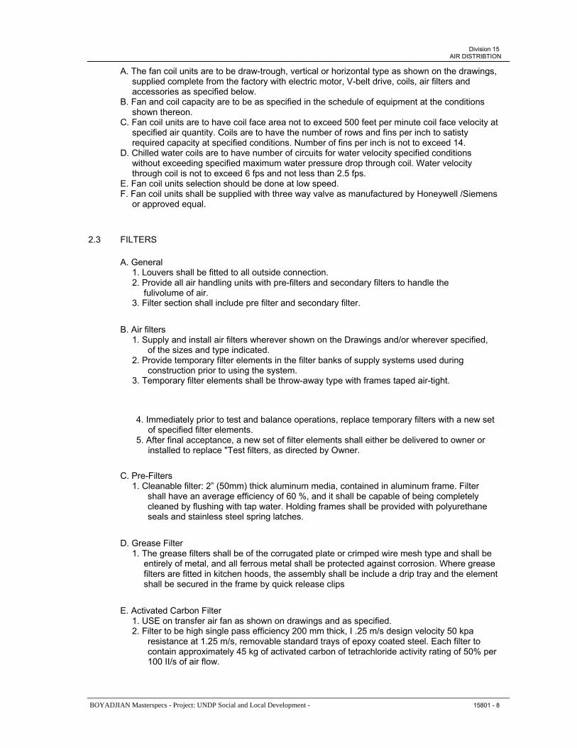
Division 15AIR DISTRIBTION
A. The fan coil units are to be draw-trough, vertical or horizontal type as shown on the drawings, supplied complete from the factory with electric motor, V-belt drive, coils, air filters and accessories as specified below. B. Fan and coil capacity are to be as specified in the schedule of equipment at the conditions shown thereon. C. Fan coil units are to have coil face area not to exceed 500 feet per minute coil face velocity at specified air quantity. Coils are to have the number of rows and fins per inch to satisty required capacity at specified conditions. Number of fins per inch is not to exceed 14. D. Chilled water coils are to have number of circuits for water velocity specified conditions without exceeding specified maximum water pressure drop through coil. Water velocity through coil is not to exceed 6 fps and not less than 2.5 fps. E. Fan coil units selection should be done at low speed. F. Fan coil units shall be supplied with three way valve as manufactured by Honeywell /Siemens or approved equal.
2.3 FILTERS
A. General 1. Louvers shall be fitted to all outside connection. 2. Provide all air handling units with pre-filters and secondary filters to handle the fulivolume of air. 3. Filter section shall include pre filter and secondary filter.
B. Air filters 1. Supply and install air filters wherever shown on the Drawings and/or wherever specified, of the sizes and type indicated. 2. Provide temporary filter elements in the filter banks of supply systems used during construction prior to using the system. 3. Temporary filter elements shall be throw-away type with frames taped air-tight.
4. Immediately prior to test and balance operations, replace temporary filters with a new set of specified filter elements. 5. After final acceptance, a new set of filter elements shall either be delivered to owner or installed to replace "Test filters, as directed by Owner.
C. Pre-Filters 1. Cleanable filter: 2” (50mm) thick aluminum media, contained in aluminum frame. Filter shall have an average efficiency of 60 %, and it shall be capable of being completely cleaned by flushing with tap water. Holding frames shall be provided with polyurethane seals and stainless steel spring latches.
D. Grease Filter 1. The grease filters shall be of the corrugated plate or crimped wire mesh type and shall be entirely of metal, and all ferrous metal shall be protected against corrosion. Where grease filters are fitted in kitchen hoods, the assembly shall be include a drip tray and the element shall be secured in the frame by quick release clips
E. Activated Carbon Filter 1. USE on transfer air fan as shown on drawings and as specified. 2. Filter to be high single pass efficiency 200 mm thick, I .25 m/s design velocity 50 kpa resistance at 1.25 m/s, removable standard trays of epoxy coated steel. Each filter to contain approximately 45 kg of activated carbon of tetrachloride activity rating of 50% per 100 II/s of air flow.
BOYADJIAN Masterspecs - Project: UNDP Social and Local Development - 15801 - 8

Division 15AIR DISTRIBTION
3. Filter casing to be of 14 gauge steel to permit stacking the filters one on top of other with filters foolted together and caulked. All parts of the filter casing and frame to be dual coated with corrosion resistant epoxy. 4. Filter shall be similar to American air filters model AF-1000 or approved equal.
F. Secondary Filter 1. Shall be of the high efficiency disposable bag filter type. The bag filter section shall be capable of accepting 50mm thick pre-filters and a combination of 300mm by 600 mm (nominal) bag filters. The bag filters shall be of 95% efficiency against ASHRAE 52 Atmospheric Duct Spot Test. 2. The section shall be insulated with glass fiber and of double skinned construction. A hinged access door shall be provided for filter changing.
G. HEPA Filter 1. Filters should be cleanable and removable, maid in aluminum with a thickness of 5cm. They should be used as pre-filters for air handling units serving special rooms. 2. Air velocity through the filters should be 300fpm. Filters could be installed in V shape inside a galvanized frame. 3. Fresh air box should be galvanized and should have a damper. 4. Air handling units serving operating theaters should have pre-filter in aluminum, cleanable, 5cm thickness and a type bag class EU8 filter. 5. Hepa filter class EU11 should be installed at each duct branch serving the operating theater, in false ceiling. 6. Hepa filters should be easy accessible for maintenance and should have ∆P controller.
H. Filter Mixing Box 1. Combination filter mixing box shall have parallel blades of internal merging of air streams. Leaving side shall have bolt holes compatible with unit and other accessories. Unit shall be designed to hold 2” (50 mm) plated, permanent filter.
FANS
A. General
1. The Contractor shall supply and install where shown on the Drawings, fans as described hereinafter and of capacities indicated in the Capacity Schedule on the Drawings.
2. The fan motors and starters shall be in accordance with the Electrical division of these specifications and shall have built it over load protection with disconnect switch factory assembled.
3. Test and rate all fans in accordance with the standards of the AMCA All fans must bear the AMCA certified rating seal
4. Make appropriate allowance for the effects on fan performance of all installation conditions including plenum enclosures and inlet and discharge arrangements so that actual installed fan performance equals that specified.
5. Balance all fan wheels and all other moving components statically and dynamically Where coating is specified and it affects the balance of the fan wheel perform balancing after the coating has been applied.
6. Drill all fan shafts on the center line to receive a tachometer.
BOYADJIAN Masterspecs - Project: UNDP Social and Local Development - 15801 - 9

Division 15AIR DISTRIBTION
7. Belt driven fans shall be connected to the driving motor by means of an approved V-belt drive with adjustable sheaves unless otherwise designated V-belt drives shall be designed for 50% overload capacity and the motors for such drives shall be equipped with adjustable bases or slide rails.
8. Bearings shall be self-aligning grease lubricated ball-bearing type and shall be complete with grease fillings extended for easy access where necessary.
9. Weather proof hoods should be provided for all motors and drives exposed to weather to the approval of the Engineer.
10. Back draft dampers gravity type shall be installed on the fan discharge of all fans discharging directly to the atmosphere except the kitchen hood fan.
11. Fans scheduled for the high temperature exhaust systems (smoke exhaust) shall include an up blast arrangement on the discharge and insulated heat shield to protect motor and drive all designed for high temperature services.
12. Axial fans should have a maximum speed of 950 rpm
13. Centrifugal fans shall have drip proof fan cooled electric motor designed for maximum speed of 1450 rpm
14. Fans are to operate steadily without pulsation at design conditions Centrifugal fan characteristic curves must be such that the fan operating point falls below the point of no flow static pressure to the right of the point corresponding to that of maximum mechanical efficiency, and a I 5% increase in static pressure over that specified results in not more than a 15% reduction in cfm and does not affect the stability of fan operation. If necessary accomplish the foregoing by modifying the width of the wheel and/or by providing inlet vanes to change the characteristic curve.
15. Performance curves shall be submitted for each fan for approval.
16. Smoke exhaust fans in parking floors shall be rated for 400oC for 1 hour and shall be of 2 speed and interlocked with fire panel an carbon monoxide detection system.
17. Kitchen exhaust fan shall be rated for 200oC continuous operation.
B. Axial Flow Fans
1. Axial flow fans shall be either the single stage type or the multi-stage contra-rotating type, with each impeller mounted on an independents motor. Casings shall be rigidly constructed of mild steel stiffened and braced to obviate drumming and vibration. Cast iron or fabricated steel feet shall be provided where necessary for bolting to the base or supports. Inlet and outlet ducts shall terminate in flanged rings for easy removal. The length of the casing shall be greater than the length of the fan or fans and motor or motors in order that the complete section may be removed without disturbing adjacent ductwork. Flexible connections shall be provided as specified on the outlet and inlet connection to joining to the ductwork to prevent transmission of vibration to the ductwork system. Electrical connections to the motors shall be through an external terminal box secured to the casing. 2. Impellers shall be of aluminum, the blades of which shall be secured to the hubs or the blades and hub shall be formed in one piece. The hub shall be keyed to a substantial mild steel shaft and the whole statically and dynamically balanced. The blades shall be of
BOYADJIAN Masterspecs - Project: UNDP Social and Local Development - 15801 - 10

Division 15AIR DISTRIBTION
aerofoil section. Shafts shall be carried in two bearings which may be ball, roller or sleevetype. Lubricators shall be extended to the outside of the casing.
3. Fume extract fans shall generally comply with the requirements for axial flow fans but shall be of corrosion resistant and non-sparking construction, with steel casings lined internally minimum 3 mm PVC which is to be carried over the flange facings and externally with epoxy enamel. Impellers shall be molded glass fiber and motors and mountings shall be protected by a coating of polyurethane compound. Motors shall be in a compartment outside of the air stream.
C. Exhaust Fan
Shall be of the centrifugal single or double inlet backward curved blades type with two-piecehousing where wheel, shaft and inlet pan assembly installed in lower housing section. Fan shall be complete with: a. Electric motor mounted on one chassis with the fan. b. Reinforced heavy gauge fan casing. c. Metallic fixing frame and supports. d. Dust proof, non-fused disconnect switch. e. Pulleys, belt drive and belt guard. f. Vibration isolators. g. Heavy flanges on both sections of housing for assembly. Flanged joints shall be gasketed for air tightness.
D. Fresh Air Fans
1. Fan shall be of the centrifugal single or double inlet width, backward curved blades type with non-overloading design wheel diameters and outlets areas shall be in accordance with standard size adopted by the AMCA for non-overloading fans. Inlets shall be fully stream lined and housing shall be suitably braced to prevent vibration or pulsation. 2. Fan shall be supplied complete with: a. Electric motor mounted on one chassis with the fan. b. Reinforced heavy gauge fan casing. c. Pulleys belt drive and belt guard (of expanded metal with tachometer hole). d. Vibration isolators e. Fan wheels with die formed backward curved blades designed for maximum efficiency and quiet operations. Wheels shall be statically and dynamically balanced. f. Heavy flanges on both sides of housing Flanged joints shall be gasketed for air tightness. g. Fan inertia should be checked against motor capability. If fan inertia is found larger then a centrifugal or plate clutching service should be used to enable the fan to be brought up to speed without damaging the motor. h. Motorized damper at fan outlet to open and close with fan on/off operation
E. Centrifugal In-Line Fan
1. Fan shall be of the centrifugal in-line type all aluminum construction and shall be complete with: a. Electric motor mounted outside the air stream when air temperature inside the duct is above 200 °F (93 °C) otherwise inside air stream. b. Metallic fixing frame and supports. c. Dust proof none fused disconnect switch under motor casing. d. Belt drive and belt guard or as stated in Capacity Schedule. e. Vibration isolators. f. Aluminum air foils blades impeller with non overloading horse power characteristic.
BOYADJIAN Masterspecs - Project: UNDP Social and Local Development - 15801 - 11

Division 15AIR DISTRIBTION
g. Flexible duct connection at each end.
F. Propeller Fans Wall and Window Fans
1. Impellers of wall fans shall be of aluminum and of window fans of PVC, the blades of which shall be fastened to the hub, or the blades and hub shall be formed in one piece The bearings may be of ball roller or sleeve type.
2. Propeller fans shall be either ring mounted or diaphragm mounted in a casing as indicated. Where they are mounted in casing, the casing shall not be longer than the length of the motor and impeller. The casing shall be of steel and shall have flanged ends and shall incorporate an inspection door. A terminal box shall be mounted externally on the casing.
3. The tip speed of fans shall not exceed 20 m/s. Fans shall be as detailed on the drawings.
4. Fans shall be with outside grille, opposed blade damper that opens and closes automatically by means of electromagnet with enough length of electrical flexible cord (including ground conductor) with suitable connecting end.
G. Cabinet Type Fan
1. Transfer & Exhaust air fans shall be of the centrifugal type utility fans double inlet width backward curved blades type with non-overloading design wheel diameters and outlets areas shall be in accordance with the standard sizes adopted by the AMCA for non- overloading fans Inlets shall be fully stream lined and housing shall be suitably braced to prevent vibration or pulsation Fans shall be acoustically engineered in a compact insulated cabinet made of powder coated galvanized casing and 50mm mineral wool with internal perforated galvanized steel.
2. Fan shall have Swing -outdoor with motor and impeller for easy maintenance and cleaning Fan shall have additional galvanized steel protection from rain with all necessary supports all to the approval of the Engineer
3. Fans located indoor shall have a very low noise level not exceeding 35dBA Outdoor fans shall have a noise level not exceeding 55dBA
4. Parking fans shall be rated to withstand 400°C for one hour and shall be of the 2speed type connected to fire panel and CO detectors
5. Fan shall be supplied complete with a. Dust proof non-fused disconnect switch b. Electric motor mounted on one chassis with the fan with built in thermal contact c. Reinforced heavy gauge fan casing suitable for outdoor installation d. Metallic fixing frame and supports e. Pulleys belt drive and belt guard f. Vibration isolators g. Fan wheels with die formed backward curved blades designed for maximum efficiency and quiet operations Wheels shall be statically and dynamically balanced h. Heavy flanges on both sides of housing Flanged joints shall be gasketed for air tightness
i. Speed controller from 100 — 0 %
6. Fans shall be System Air model RSl or approved equal
BOYADJIAN Masterspecs - Project: UNDP Social and Local Development - 15801 - 12

Division 15AIR DISTRIBTION
H. Roof Extract Fans
1. Roof extract units are to be of the vertical discharge type constructed from flat aluminum alloy panels, incorporating bird guards and air operated shutters. The impeller is to be of the Mixed Flow type having asymmetric blade spacing and to be dynamically balanced after manufacture. An electrical isolator is balanced after manufacture. An electrical isolator is to be incorporated in the unit, accessible from outside the casting through a quick release waterproof cover. It is required that all major components should be easily replaced and/or maintained via removable access panels. Fan shall be fitted with weather proof non fused disconnect switch under fan cowl with galvanized steel bird screen.
2. Belt driven units are to have the motor and fan assembly supported on anti-vibration mountings. The fan shaft is to rotate in a one piece bearing assembly to facilitate quick maintenance and is to be sealed against dust.
3. Direct driven units are to incorporate the facility of complete fan and motor assembly removal easy maintenance. Motor shall be suitable for outdoor operation.
4. Smoke exhaust fans shall be rated to withstand 400°C for one hour.
5. Kitchen hood exhaust fan shall be up blast type and should withstand 200°C for continuous operation.
I. Duct Exhaust Fan
1. This fan shall be duct-mounted, centrifugal exhauster.
2. Wheels shall be aluminum with spun inlet cone to reduce turbulence. Wheels vanes must be welded to the inlet cone to insure permanent wheel stability and alignment. Motors shall be mounted out of air stream within a spun aluminum dome and shall be mounted on vibration isolators.
ANTI-VIBRATION MOUNTINGS
Mountings For Fans Motors and any other vibration inducting equipment shall be as specified in Section 15200.
PART 3 – EXECUTION
3.1 GENERAL
A. Air- handling units, fans and equipment generally shall be floor mounted on 100 mm raised concrete housekeeping pads and supported from building structural frame using vibration isolators. Provide all supporting steel, anchors etc. required to properly support the unit.
B. Replace throwaway filters just prior to building acceptance and after the system has been balanced.
3.2 CONNECT1ONS TO BUILDER’S WORK
A. Where metal ducts and fan inlets and outlets connect to builder’s work, connections shall be by either built-in timber frames or built-in companion rings or flanges. Built-in timber frames shall be used except where the connection is to be made in fire barrier walls or in the fixing of fire dampers. Timber frames shall be constructed in hardwood of 50 mm minimum thickness.
BOYADJIAN Masterspecs - Project: UNDP Social and Local Development - 15801 - 13

Division 15AIR DISTRIBTION
Companion rings or flanges shall be provided with an adequate number of suitably sized ragbolts or similar fixing devices.
B. In all cases the duct end shall be finished with a mating flange and where this is fixed to a timber frame the flange shall be wide enough to overlap the joint between timber and masonry by least 15 mm.
C. The material of the duct shall be extended in the form of a spigot, beyond the flanged connection and into the builder’s work cavity.
D. Joints between mating flanges and companion rings or hardwood frames shall be fitted with a sealing gasket as specified previously.
3.3 FIELD QUALITY CONTROL
Tests During Construction 1. The testing shall be performed by the Mechanical Subcontractor and supervised by Engineer familiar with testing procedures. See Section “Testing and Balancing of Mechanical Systems.” 2. The size of the test section may vary from a complete supply or exhaust system to a portion of a system, depending on its complexity and size. The Engineer shall use Appendix F in the SMACNA Manual as a guide in determining test section sizes and locations. 3. Refer To Section 15991 for Testing & Commissioning.
END OF SECTION 15801
BOYADJIAN Masterspecs - Project: UNDP Social and Local Development - 15801 - 14

Division 15HOT WATER SYSTEM
SECTION 15802 - HOT WATER SYSTEM
PART 1- GENERAL
1.1 RELATED WORK
A. B. C. D. E. F.
1.2
Section 15060 Pipe and Pipe Fittings.Section 15100 Valves. Section 15160 Pumps. Section 15250 Insulation. Section 15900 Control & Instrumentation. Section 15991 Testing and Commissioning.
SYSTEM DESCRIPTION
General 1. System shall comprise heating distribution circuits providing connections from hot water boilers to domestic hot water storage heaters as detailed on the drawings. 2. Provide and install where indicated on the drawings sealed expansion unit for each separate heating system.
1.3 REFERENCES
Refer to individual materials for specified standards.
1.4 SUBMITTALS
A. Product Data 1. Descriptive literature for each of the actual proposed equipment to be used including: a. Capacity b. Operating Pressure Ranges c. Pressure Losses d. Fluid Flows e. Test Reports f. Certificates of Approval g. Operation and Maintenance Data h. Any other Technical Data
B. Shop Drawings 1. Shop Drawings for each of the actual proposed equipment shall include the following: a. Working or Manufacturing Drawings b. Calculations c. Installation Details d. Connections by other services e. Wiring and Control Diagrams f. Accessories Available Indicating Those Included g. System Diagrams.
BOYADJIAN Masterspecs - Project: UNDP Social and Local Development - 15802 - 1

Division 15HOT WATER SYSTEM
PART 2- PRODUCTS
2.1 MATERIALS
A. The pipework shall be as specified in Section 1 5060 Seamless black steel schedule 40, ASTM A53 Grade B.
B. Valves shall be as specified in Section 15100
C. Insulation shall be as specified in Section 15250
2.2 PUMPS
A. The pumps shall be of the horizontal end suction centrifugal as specified in Section 15160 and shown on the schedules
B. Pump capacities and head (for snow melting system only) should be calculated based on brine composed of 35% ethylene glycol by weight
2.3 STEAM BOILER
a. The contractor shall furnish and install one boiler capable of supplying saturated steam at 150 psi operating pressure.
b. The boiler shall be of tile boiler-burner packaged scotch fire tube wet back design, oil fired and UL listed.
c. The unit shall be rated at 5.0 square feet of fire side heating surface per boiler horsepower.
d. The unit shall meet the requirements of ASME code for 150-psi steam working pressure.
e. The unit shall have a three pass design feature with a rear combustion chamber that is totally surrounded by water, with a factory installed 22 gauge enameled steel jacket with mineral fiber insulation. All heating surfaces should be accessible without disturbing the burner equipment. The hinged steel front flue doors of the boilers shall be lined with refractory insulation contained by welded steel liner and guaranteed for a period of 10 years.
f. Unit shall be complete with all accessories and controls consisting and not limited to acombination water column, pump control, low water cut-off, safety valves, steam pressure gauge operating and limit pressure controls and a 3” flue gas thermometer.
g. Unit shall be factory firetested, fired with the specified fuel, fuel to air ratios adjusted in addition to checking, all controls and operating sequence.
h. A detailed original and certified report of this test should be delivered with the unit.
i. Burner shall be equipped with MEMA. A control cabinet with electronic flame safeguardand programming controls, air flow safety switch and all necessary accessories.
2.4 HEATING WATER TREATMENT
BOYADJIAN Masterspecs - Project: UNDP Social and Local Development - 15802 - 2

Division 15HOT WATER SYSTEM
A. Contractor shall assign a chemical specialist to execute all chemical treatment works subject to the approval of the Engineer
B. The scope of work for the chemical treatment specialist is as follows: 1. Chemical Supply 2. Supervision of treatment program applied 3. Water analysis and recommendations
C. The mechanical contractor shall make sure that the following are completed and handed over to the engineer prior to commencement of water treatment work s 1. System is electromechanical operating . 2. System is tested and pressurized for leaks . 3. System to be cleaned should be final and any new loops to be connected should be separately . 4. Drain points should be provided and sufficient for quick system draining . 5. Make-up water supply should match with system volume .
2.5 HEATING WATER CHEMICAL TREATMENT PROGRAM
A. Expected water holding capacity is to be verified by the contractor and submitted for review.
B. Chemical Flushing Program
1. Alkatreat 20 or approved equal is added into the system during the initial water fill and circulated to remove oil & grease deposits. 2. System solution is drained completely and flushed then refilled again 3. During refilling and draining phases strainers has to be removed and cleaned and reinstalled after final flushing 4. This should include the strainers ( FCU & Pumps & AHU) System should be flushed until water PH is as raw water or neutral and TDS is within 1 0% of raw/make-up water supply 5. Chemtreat 248 or approved equal should be introduced during system refill to ensure efficient dispersion through out the system refill to ensure efficient dispersion through out the system. 6. Circulate this solution for 10-16 hours. Time will be specified by the specialized chemist who is attending the site. 7. On the completion of the above procedure, system water should be drained and flush thoroughly. 8. Strainers are to be cleaned as above. 9. System is to be flushed completely until system water is neutral or as ran water. 10. Refill system with raw water and add Alkatreat 20 or approved equal. 11. On completion of above strainers should be cleaned as above properly. 12. System is to be refilled and flushed thoroughly to ensure removal of suspended and solubilized debris. 13. Cooltreat 01 1 or approved equal is to be added & circulated for 1 hour & drained. 14. Strainers are to checked & cleaned before the chemical treatment injection ( final)
15. When strainers check test reveal that they are clean, fresh water is to circulate for 1-2 hours to ensure that circulating water parameters are within 10% of raw/make-up supply.
16. Individual strainers will be checked at random for the presence of any residual suspended material which may have accumulated from low flow areas and/or restricted/small bore pipe work following the above procedures. 17. If strainers are blocked or system water values are greater than 10% of the incoming supply, the Cooltreat 01 1 flush should be repeated until strainers and water quality meet the required parameters given below.
BOYADJIAN Masterspecs - Project: UNDP Social and Local Development - 15802 - 3

Division 15HOT WATER SYSTEM
18. On completion of above treatment chemicals are to be added.
C. Chemical Treatment Program
1. Heatreat 502 (or approved equal). Initial shot dose Annual running dose 2. Microtreat 2200 ( or approved equal) Initial shot dose Annual running dose 3. The Contractor should make sure that the make up water before chemical injection should be soft water of maximum total hardness around 50-70 PPM as CaCO3.
D. General
1. The Contractor should make sure that the water treatment specialist execute the following tasks during the one year guarantee period. 2. Schedule visits frequency: 6 per annum. 3. The following is carried out on every visit by the chemist: a. Full on-site analysis of all waters connected with the system. b. Wiring a report on his findings and any recommendations he may have. c. Checking the operation of the dosage/ control equipment. d. Checking the record chemical treatment stock levels. e. Training the Hotel staff at start-up 4. Plant inspection: observe/monitor the water treatment program in action.
PART 3 - EXECUTION
GENERAL INSTALLATION
A. Piping
1. The piping shall be installed generally as described in Section 1 5060 and as shown on the drawings for heating water. 2. Install thermometers in piping system adjacent to the heat exchanger inlet and outlet secondary connections. 3. Install strainers in water piping a head of all pumps, automatic modulating valves, and heating coils. 4. Provide balancing valves and pressure gage cocks in all returns from equipment and three way valve bypass loops to balance the system. 5. Balancing valves shall be required on the return of each branch main to balance the system. 6. Provide flexible connections at the inlet and outlet to all major equipment which require vibration isolation.
B. General: Except as otherwise indicated, install heating plant work, including components and controls required for boiler operation, in accordance with boiler manufacturer’s instructions, and with recognized industry practices, to ensure that boiler equipment complies with requirements and serves intended purposes.
C. Locate boilers in general position indicated in relation to other work. Position boilers with sufficient clearance for normal service and maintenance, including clearance for cleaning and replacement of tubes and clearance for component replacement.
D. Paint damaged and abraded factory finish with touch-up paint matching factory finish.
BOYADJIAN Masterspecs - Project: UNDP Social and Local Development - 15802 - 4

Division 15HOT WATER SYSTEM
EXAMINATION OF RELATED WORK
Observe installation of other work (related and connected to boiler work) and after completioncheck for inadequacies and protect operation and performance of boiler work to suit boiler manufacturer’s requirements and to the Royal Commission’s satisfaction and approval, do not start boiler work until inadequacies have been corrected in a manner acceptable to the Engineer.
FIELD QUALITY CONTROL Manufacturer's Supervision: Boiler manufacturer shall supervise field assembly (if any) and installation of boiler work, with a factory-trained technical service representative, for a minimum of 2 working days, plus one additional day for each boiler unit in excess of one. Prepare manufacturer's written report of installation.
TESTING
General: Except as otherwise indicated, test boiler as directed by the Engineer.
END OF SECTION 15802
BOYADJIAN Masterspecs - Project: UNDP Social and Local Development - 15802 - 5

Division 15TESTING AND COMMISONING
SECTION 15991 -TESTING AND COMMISSIONING
PART 1 - GENERAL
1.1 RELATED WORK
Division 15 - Mechanical
1.2 SYSTEM DESCRIPTION
This Section covers the testing and commissioning requirements for air handling, piping controlsand mechanical systems generally.
1.3 QUALITYASSURANCE
A. The Contractor shall employ the services of a specialist independent international commissioning company for commissioning, testing & balancing. The independent testing and balancing company is to have no vested interest in the project and not belong wholly or partly to a company related to the supply or design of HVAC equipment or systems.
B. The independent company must have been established and carried out commissioning works on at least five projects within the geographical area. The Engineers employed by the independent Commissioning Company shall have at least 5 years proven experience within commissioning. Testing and balancing.
C. All engineering services systems are to be thoroughly commissioned and tested to prove that they are capable of achieving the specified performance, to prove the correct and stable operation of all control systems and are safe to operate and maintain.
1.4 SUBMITTALS
A. Testing and Balancing
1. Certificate
a. Submit Warning Certificate.b. Fully detailed method statements are to be provided in advance for approval for each system to indicate the methods to be employed. Tests are to be carried out in accordance with agreed recognized standards such as those produced by C.I.B.S.E I/ B.S.R.1.A.
2. Data Sheets
a. Submit type written data sheets on each item of testing equipment to be used.b. Include name of device, manufacturer's name, model number, latest data of calibration, calibration due data and correction factors. c. All products and instrumentation used shall be subject to approval.
BOYADJIAN Masterspecs - Project: UNDP Social and Local Development - 15991 - 1

Division 15TESTING AND COMMISONING
3. Reports form
a. Submit specimen copies of report forms, for approval for their use on this project.b. Forms shall be quarto paper for loose leaf binding, with blanks for listing of the required test ratings and for certification of report.
4. Provision of Test Point and accessories
a. All required test points, although not mentioned in the BOQ, are deemed to be included in the pipework and ductwork installations and included in the unit rate of these systems. The contractor shall allow sufficient points and where required by the Engineer for the correct and complete regulation, testing and commissioning. All test points shall be indicated on the working and record drawings. Test points shall be fitted with removable plugs, flanges or other approved devices appropriate to the service concerned.. b. Balancing valves and dampers shall be included on every main branch and subcircuit to facilitate system commissioning. All such devices shall be identified on the working drawings and . submitted for approval. c. Each volume control damper and fire damper shall be complete with adjacent access panel. d. Balancing valves shall be propriety commissioning sets consisting of double regulating valve and close coupled orifice plate. e. The Contractor shall prepare system loading diagrams for each system including control dampers, regulating valves and test points and shall indicate their physical location in pipework or ductwork. f. Environmental tests are to include, where necessary, the provision of artificial loads to simulate the full range of operating conditions. The correct operation of each system is to be demonstrated on completion of the commissioning and testing.
5. Recording of Test Results
a. The Contractor shall give 7 days notice, to the Engineer in writing, prior to any regulation, testing and balancing being undertaken to enable he Engineer to witness the work. b. The Contractor shall formulate and provide all test sheets to a format agreed by the Engineer. Each sheet shall contain the project title, the logos of the Employer and the Engineer. Each sheet shall have witnessing signatory space specific to the Contractor's Engineer, and the Engineer's designed representative. c. The test result sheets shall be fully cross-referenced to the system loading diagrams which shall be updated to include the actual test results. d. Duplicate signed test certificates shall be provided after each test, which will be countersigned by the Engineer who witnesses the test. The test certificate shall give the following particulars: Apparatus or Section under test Makers number ( if any) Nature, duration and conditions of test Result of test e. No test shall be valid until the test certificate is provided.
f. Duplicate copies of test certificates carried out at manufacturer works shall beforwarded to the Engineer for approval prior to dispatch of the article to site.
BOYADJIAN Masterspecs - Project: UNDP Social and Local Development - 15991 - 2

Division 15TESTING AND COMMISONING
g. No Section of the works shall be insulated or in any other way concealed prior to testing and inspection and subsequent concealment where applicable shall only take place following written authority from the Engineer. h. All necessary facilities, measuring and recording instruments including test pumps and gauges for inspection/testing and commissioning requirements shall be provided and shall be checked or calibrated as necessary before use. The Engineer reserves the right to call for a demonstration of the accuracy of any instruments provided.
6. Testing Instruments
a. The Contractor shall submit with his Tender a full list of instruments, together with relevant standards, which he intends to use in the regulation, testing and balancing of the Contract Works. The Contractor shall include the full cost of regular calibration test to be carried out on all instruments used and the cost of any necessary recalibration. Certified documentation confirming current certificate calibration shall be available for examination by the Engineer at all times. Instruments not supported by up-to-date calibration certificates shall not be used. b. All instruments necessary for conducting the test shall be provided including the following minimum range: c. Tube type velometer ( Range I .5 to 1 3 m/sec). d. Sloping tube manometers. e. Pitot tubes of various length to suit duct sizes. f. Mercury in glass thermometers. g. Weekly recording thermometers. h. Weekly recording R.H. meters. i. Specially mounted anemometers fixed in a conical sheet metalwork hood for measuring accurately air flow from diffusers. Ammeters. Tachometers. Surface contact dial indicating pyrometer. Hot wire digital anemometers. Sound meters. Digital touch thermometers. Multi-channel digital thermometers ( where necessary). “U” tube manometers. Commissioning set electronic flow meters. Brass cased certified thermometers. j. The Contractor shall prepare and submit with his Tender a schedule of recommended test equipment suitable for Technician Grade maintenance staff to assess whether the commissioned standards are being maintained. Whilst the level of equipment need not be comparable to the Specialist Commissioning Contractors own test equipment it should meet the following requirements: Measurement of air and water temperatures including all test probes. Air flow measurement, both in duct and at diffuser discharge. Water flow measurement using commissioning valves sets provided under the Mechanical Services Contract. 7. Final Report
a. Upon completion, all information shall be neatly typed accompanying schematic diagrams of systems tested. b. All test reports shall be assembled, indexed, and submitted to the Engineer.
PART 2 - PRODUCTS
NOT USED
BOYADJIAN Masterspecs - Project: UNDP Social and Local Development - 15991 - 3

Division 15TESTING AND COMMISONING
PART 3 - EXECUTION
3.1 OPERATIONS OF EQUIPMENT & SYSTEMS
The Contractor shall make the necessary adjustments for each system and piece of apparatusinstalled, using factory-trained technicians wherever practicable, and shall thoroughly instruct the client appointed representative in the roper operation of the apparatus. Printed instructions written in both Arabic and English, shall be permanently attached to the relevant equipment.
3.2 TESTING GENERALLY
A. Where an individual inspection or test takes place at a sub-contractor s work a representative of the client will be required to be present.
B. Unless otherwise indicated the Contract shall include the cost of all tests necessary instruments equipment supervision and labor both at the manufacturer s plant and on site The accuracy of the test instruments shall be demonstrated where so directed.
C. The site test shall be of at least six hours duration On large installations the site test may last several days and shall be long enough to allow the taking of all the measurements required in subsequent clauses of this Section and to demonstrate the performance of the installation Any defects of workmanship materials and performance maladjustments or other irregularities which become apparent during the tests shall be rectified by the Contractor at his expense and the tests shall be repeated at the Contractor s expense to the satisfaction.
D. The Contractor s representative present at the site tests shall be fully conversant with the operation of the thermostatic controls the control panel and the refrigeration system representatives of the manufacturers of the equipment shall be present.
3.3 TESTS AT MANUFACTURERS WORKS
A. Unless otherwise indicated tests shall be carried out in accordance with the appropriate Standard or Code or Practice Test certificates for works tests shall be submitted induplicate.
B. Test certificates shall be submitted 1. For HVAC equipment: Type test certificates showing motors and fans characteristic curves and type test certificates for sound levels.
2. For Pumps Type test certificates for head discharge speed and power input.
3. For Electrical Motors Type test certificates for motors of 40 KW output and above routine ( individual ) test certificate. 4. For Starters and Control Gear Type test certificates for control panels as a whole routine ( individual ) high voltage test. 5. For Other Electrical Equipment Such as air heaters ( but excluding thermostatic control equipment ) test certificates. 6. For Hydraulic Equipment: Test certificates for hydraulic and air pressure testing at works.
C. Testing is to include as a minimum.
1. Pipework Cleanliness, internal and external Flow rate/balancing
BOYADJIAN Masterspecs - Project: UNDP Social and Local Development - 15991 - 4

Division 15TESTING AND COMMISONING
System component pressure dropsPressure reducing valve settings Safety relief valve selling and operation Operation of all components Performance-temperature/noise Purity of Fluid Earth bonding
2. Ductwork Leakage Cleanless, internal and external Damper Operation Fire & smoke operation Flow rate balancing System component performances- heating/cooling batteries filter C.VN.V box operation / calibration Performance-temperature/noise air change Operation of all components Purity Earth bonding
3. Plant Equipment Operation-normal abnormal safety devices interlocks Performance duty I speed / pressure / efficiency / noise Standby Component performance- heat / cool / batteries /filter Cleanliness, internal and external Vibration Electrical safety I security / bonding
4. Room Environmental - temp, humidity, air change, noise Air flow direction, distribution, draughts
5. Control Component operation Settings Control action — limits response time alarms interlocks Electrical safety/security/bonding
6. BMS Full functional tests
D. The Mechanical Services Contractors shall include for the setting to work of the installation, preparation of as fitted drawings and operating and maintenance manuals and the provision of labels and charts to be undertaken by a Commissioning Specialist, as identified in section 3 of the specification.
E. The Commissioning Specialist must be appointed and identified to the Professional Team within 4 weeks of the Contractor receiving an order to proceed or before any working program is agreed, whichever is the sooner.
3.4 PRESSURE TESTING OF PIPEWORK SYSTEMS
A. Upon the completion of each length or section of the pipework the Contractor shall subject the length or section to a hydraulic test and demonstrate to the satisfaction of the Engineer that the length of the section is sound and watertight. The test pressure shall be one and a half times the maximum working pressure or 700 KPa, whichever is the greater, for a
BOYADJIAN Masterspecs - Project: UNDP Social and Local Development - 15991 - 5

Division 15TESTING AND COMMISONING
period of two consecutive hours. Items of equipment, e.g. safety valves, bursting discs, setto operate at or below this pressure shall be isolated or removed prior to applying this test.
B. All faults discovered during such-test- shall be remedied by the Contractor at his own expense and the test re-applied until the Engineer is satisfied that the section is sound and watertight.
C. Installations sections thereof which will be embedded in the structure or concealed in permanently sealed ducts, trenches etc., shall be individually tested as they are laid and before being embedded or concealed.
D. All pressure tests shall be carried out before the application of thermal insulation.
E. On completion of the test, the water is to be released and drained completely away as rapidly as possible, the section then being thoroughly sluiced through to ensure the removal of as much dirt and foreign mailer as possible before being refilled and put into service.
3.5 AIR LEAK TESTING OF DUCTWORK SYSTEMS
A. General
1. All ductwork and equipment items shall be checked for air leakage. This shall be completed before installation or enclosure of ductwork and before any terminal units are fixed.
2. The air leakage tests shall be based on the measurement of air leakage at constant pressure. The test pressure shall be the design static pressure of the section to be tested plus 250 pa. The aggregate of air leakage shall not exceed 1% of the system design air flow rate, and leaks shall not be audible. The air leakage rate for any section shall not be in excess of the permissible rate, in m3/s per meter, for the whole system.
3. Sufficient time shall be allowed, before testing, for the sealant to cure. The ductwork system, or section to be tasted shall be sealed by the incorporation of, blanking plates fitted at flanged joints, for main ducts and for small open ends, polythene bags may be used. The polythene bags may be retained to aid in preventing the ingress of dirt into the system.
4. Care shall be exercised in jointing tested sections of the ductwork system together, as it will generally be impracticable to test such joints.
B. Test Apparatus and Methods
1. Portable test apparatus shall be provided by the Contractor and shall comprise the following equipment: Electrically driven fan capable of delivering not less than O.03m31s against a duct pressure of 2.5 Kpa, a static pressure gage suitable for recording the duct static pressure test, an inclined pressure gage, a variable speed type, and a flow measuring device complete with test cocks. The accuracy of the measuring device shall be +/-5% of the permitted air leakage rate.
2. The apparatus shall be connected to the blanking plate inserted in the section of ductwork to be tested. With the bleed valve fully open or the variable speed motor set to minimum speed, start-up fan, and adjust fan speed or close bleed valve until static pressure reading on static pressure gage reaches desired value. If pressure cannot be obtained, the ductwork shall be checked for obvious leaks and rectified. With the duct section maintained at the
BOYADJIAN Masterspecs - Project: UNDP Social and Local Development - 15991 - 6

Division 15TESTING AND COMMISONING
test pressure, the ductwork shall be checked for major and audible leaks. The leakage rate,as indicated on the inclined pressure gage, connected across the flow measuring device, shall be recorded and checked that it is within the permitted limits. This leakage rate shall be maintained for at least I 5 consecutive minutes without increasing.
3. The fan shall then be turned off and the pressure in the test section of duct returned to zero before starting the fan again and establish that the air leakage rate has not increased from the previous reading.
4. Any results not within the permitted limits shall require that the ductwork be examined and any leaks rectified. Time shall be allowed for the sealant to cure before the test is restarted.
5. Readings of the test for each section of ductwork shall be recorded and presented to the Engineer before any further work is carried out on the section of ductwork tested.
3.6 TESTING OF SOIL, WASTE AND ROOF DRAINAGE PIPING SYSTEMS
A. On completion of the soil and waste pipe works or section of the work as may be required the plumbing contractor shall arrange the testing of the works.
B. The tests shall comprise an air test as set out in the Uniform Plumbing Code, and described in section 1 5405, and a performance discharge test as required. Should the Engineer deem the test unsatisfactory his visit shall at his desecration be considered abortive and all costs incurred in respect of time, travel and expenses shall be recoverable from the contractor who shall then rectify the works and arrange for a further test to be witnessed at his own expense.
C. Where the testing is to be carried out in sections the Contractor shall retain on site a drawing indicating sections tested and recording dates on which the tests took place duly witnessed.
D. The Contractor shall be responsible for providing all skilled and unskilled labor necessary to carry out tests and ensure that all supplies and instruments are available.
3.7 COMMISSIONING GENERALLY
A. General
1. Each installation shall be fully commissioned. Commissioning shall include the balancing and regulation of air and water distribution systems and the final adjustment of control system.
2. Particular attention shall be paid to: a. The maintenance of cleanliness of all equipment and distribution and distribution systems during construction and ensuring that distribution systems are cleared through as part of commissioning. b. The protection of equipment, particularly sensitive of fragile items, from the activities of other trades during construction and from dirt and maloperation during commissioning. c. The protection of Electrical equipment from damp during construction and commissioning.
B. Adjustment
Adjustments shall be made to the following items: a. Adjust blowers, fans and ducts to deliver or exhaust design air flow rate.
BOYADJIAN Masterspecs - Project: UNDP Social and Local Development - 15991 - 7

Division 15TESTING AND COMMISONING
b. c. d. e. f. g. h.
3.8
Adjust diffusers, register, and grilles to deliver or exhaust design air flow rate.Adjust relief dampers and vents. Adjust diffusers, registers, and grilles to minimize drafts. Adjust all zones for design supply and return air flow rates. Adjust blowers and fans to design revolutions. Balance cooling water systems to achieve design flow characteristics. Balance domestic hot water return loop.
COMMISSIONING OF AIR SYSTEMS
A. Preparation
Prior to system testing and balancing.1. Systems shall be fully operational. 2. All filters shall be clean. 3. Temperature and system controls shall be checked for proper operation. 4. Fan rotation shall be checked.
B. Air blower and FCU System
1. Air flow quantities where required, shall be measured by pitot tube and inclined manometer using multi-point traversing techniques. 2. The following items shall be specifically checked and/or adjusted and recorded on the Site Test Certificate for each air handling unit. a. External air dry bulb temperature and relative humidity. b. Air dry bulb temperature and relative humidity in each space. c. Air dry bulb temperature and relative humidity in each main return duct. d. Air dry bulb temperature and relative humidity before and after each air heater. e. Air dry bulb temperature and relative humidity before and after each air cooler. f. Air dry bulb temperature and relative humidity before and after a humidifying equipment. g. Air dry bulb temperature and relative humidity before and after a fresh and return air mixing chamber. h. Air dry bulb temperature and relative humidity in each main supply air duct. i. Fresh air quantity ( m3/s). j. Air flow ( m3/s) and resistance ( Pa or mm of water ) across a main fan. k. Air flow ( m3/s) and resistance ( Pa or mm of water ) across each heater. l. Air flow ( m3/s) and resistance ( Pa or mm of water ) across each cooler. m. Air flow ( m3/s) and resistance ( Pa or mm of water ) across each humidifying equipment.
3. Perform the following minimum air system tests balancing. a. Air flow (m3Is) in each main supply, return a grille and diffuser. b. Air flow (m3Is) at each supply grille and diffuser. c. Fan and motor speeds, air quantity and dry bulb temperature and relative humidity, both on and off the cooling coil, for at least two of each size fan of the cooler unit. d. Main fan and motor speeds. e. Current taken under running conditions for each fan above 4 KW and each electric air heater, and maximum current for each electric air heater. f. In cooperation with the temperature control system installer, set adjustments of automatically operated dampers to operate as specified, indicated and noted. C. Record Data
Record the following minimum data:1. Air flow rate delivery and rpm of blowers and fans.
BOYADJIAN Masterspecs - Project: UNDP Social and Local Development - 15991 - 8

Division 15TESTING AND COMMISONING
2. 3. 4. 5.
Static pressure at inlet and outlet of blowers and fans.All equipment nameplate data. Actual running current and voltage of fan motors. Air flow rate, delivery or exhaust at each diffuser, register and grille.
COMMISSIONING OF WATER SYSTEMS
Preparation
Prior to system testing and balancing1. Open all valves to full open position. Close coil bypass stop valves. Set mixing valves to full coil flow. 2. Remove and clean all strainers. 3. Examine water in system and determine if water has been treated and cleaned. 4. Check pump rotation. 5. Clean and set automatic fill valves for required system pressure. 6. Check expansion tanks to determine that they are not air bound after the system is completely full of water. 7. Check air vents at high points of water systems and determine if all are installed and operating freely. 8. Set all temperature controls of all coils calling for full heating. Same procedure when balancing hot water coils: set for full heating. 9. Check operating of automatic bypass valve, if furnished. 10. Check and set operating temperature of boilers to design requirements. 11. A complete air balance must be accomplished before beginning the water system test and balance.
A. Water Handling Systems
1. General The satisfactory operation of all make-up, drain and overflow arrangement shall be checked. Where water treatment is included initial commissioning shall be carried out and then rates of flow, dosing quantities etc., shall be calibrated and set for routine operation.
2. Perform the following minimum water system test and balance: a. Set water pumps to proper flow rate. b. Adjust water flow through equipment. c. Check leaving water temperatures and return water temperature. Reset to correct design temperatures. d. Check water temperatures at inlet side of coils. Note rise or drop of temperatures from sources. e. Proceed to balance each water coil. f. Upon completion of flow readings and adjustments at coils, mark all settings and record data. g. After adjustments to coils are made, recheck settings at pumps and readjust if required. h. Install pressure gages in gage fittings provided on coil, read pressure drop through coil at set flow rate for full heating. Set pressure drop across bypass valve to match coil full flow pressure drop. B. Record Data
Record the following minimum data at each cooling element:1. Inlet water temperature. 2. Leaving water temperatures. 3. Pressure drop of each coil. 4. Pressure drop across bypass valve.
BOYADJIAN Masterspecs - Project: UNDP Social and Local Development - 15991 - 9

Division 15TESTING AND COMMISONING
5. Pump operating suction and discharge pressures.6. List all mechanical specifications of pumps. Check and record starter sizes, heater sizes, etc. 7. Rated and actual running amperage of pump motor. 8. Water balance device readings and settings.
COMMISSIONING OF REFRIGERATION SYSTEM During erection, commissioning and at the end of commissioning particular attention shall be paid to competent workmanship adequate sealing of valves and fittings and comprehensive leak testing, to minimize future leakage of refrigerant. The following items shall be checked and/or tested and entered on the Site Test Certificate: a. Refrigerant suction and discharge pressure and temperatures. b. Compressor and motor speeds. c. Compressor oil pressure. d. The satisfactory operation and set operating pressures of high pressure, low pressure and oil pressure failure cut-outs. e. Current taken by each compressor at full load and at each step of capacity reduction. f. Inlet and outlet water temperature and pressure in the air cooled chillers circuits.
CONTROL SYSTEMS
Particular attention shall be paid to the following features:1. Satisfactory operation of any automatic or manually operated sequences to be used in the event of fire. 2. Safety in the event of failure and of sudden resumption of electric supply. The following items shall be checked and/or tested and recorded on the Site Test Certificate: 1. Set desired value of all control devices. 2. Satisfactory operation of equipment protection devices. 3. Satisfactory operation of all sequencing operations and alternate working selections, and automatic or manual change-over or duplicate equipment.
NOISE AND SOUND CONTROL
A. Sound level readings shall be taken with a simple sound level meter using the ‘A’ scale weighting network. The spaces in which readings shall be taken as agreed but will in general, be the following: 1. Equipment rooms. 2. Occupied rooms adjacent to equipment rooms. 3. Outside equipment rooms facing air intakes and exhausts and condensing discharge, to assess possible nuisance to adjacent accommodation, if the adjacent accommodation is private residential building tests may be required at night. 4. In the space served by the first grille or diffuser after a fan outlet. 5. In at least two of the spaces served by fan coil units.
B. Alternatively, sound level readings shall be taken using a sound analyses to give an octave band analysis of the sound spectrum and to pinpoint the frequency values of peak sound levels.
COMMISSIONING OF BOILER EQUIPMENT
A. Maximum Continuous Rating Test 1. During the commissioning period a maximum continuous rating test shall be carried out on each of the boilers. 2. The test shall be for a period of 4 consecutive hours exclusive of the time required for preparation, attaining test conditions and running down. During this test it shall only be
BOYADJIAN Masterspecs - Project: UNDP Social and Local Development - 15991 - 10

Division 15TESTING AND COMMISONING
necessary to measure the evaporation of the boiler, the amount of fuel fired and the exitflue gas temperature.
B. Acceptance Tests 1. On completion of the installation the Contractor shall carry out thermal efficiency tests on all the boilers. These tests shall take place during periods of maximum loads and the Contractor shall allow for adequate visits to satisfactorily test the thermal efficiency of the boilers and performance of ancillary equipment. 2. Test and record flue gas exit velocity, temperature and C02 content by volume, fuel consumption. 3. The following shall be checked and be tested and recorded on the Site Test Certificate: a. The boiler relief valves and any other relief valves shall be tested and proved to lift at their required pressure using live steam.
SETTING TO WORK
The work shall be considered to consist of three separate sections of activity, namely Pie-Commissioning, Commissioning and Post-Commissioning.
A. Pre-Commissioning The Mechanical Services Contractor and their specialists as specified elsewhere and as follows shall generally carry out pre-Commissioning:
1. Hydraulic Pipeline Testing The Mechanical Services Contractor shall test all pipework installations. 2. Flushing All pipework installation, except compressed air systems, shall be flushed by the mechanical services contractor. The commissioning specialist shall be in attendance and witness the flushing exercises and the subsequent cleaning of the strainers. 3. Pre-commissioning Cleaning Low temperature hot water installations shall be pre- commission cleaned and treated by the mechanical services contractors water treatment specialist. The commissioning specialist shall be in attendance and witness the pre-commissioning cleaning and treatment. 4. Sterilization and chlorination All domestic hot and cold water systems shall be sterilized and chlorinated by the mechanical services contractor. The commissioning specialist shall be in attendance and witness the sterilization and chlorinating exercises. 5. Water Supplies The commissioning specialist shall confirm the presence of water supplies to all tanks and outlets.
6. Plant and Ductwork cleaning The Mechanical services contractor shall thoroughly clean all internal and external surfaces of ductwork and plant. 7. Electrical Supplies The mechanical Services contractors controls specialist shall commission the whole controls installation. The commissioning specialist shall establish that all electrical connections have been made during pre commissioning and that power is available to all equipment. 8. Rotating Equipment The commissioning specialist shall check for free rotation of equipment and correct alignment, security and tension of belt drives and operate fans and pumps to check direction of rotation. 9. Test certificates The Mechanical Services Contractor shall provide copies of all tests undertaken at manufacturers work and pre-commissioning tests.
B. Commissioning
BOYADJIAN Masterspecs - Project: UNDP Social and Local Development - 15991 - 11

Division 15TESTING AND COMMISONING
1. The commissioning specialist shall commission the whole of the Mechanical Services installations, working in conjunction with the commissioning Engineers of equipment manufactures and systems specialists. 2. Where manufacturers offer a commissioning service this must be used in preference to other methods. All manufacturers reports shall be included in the final documentation. 3. The commissioning specialist shall regulate and adjust valves, apparatus, plant and equipment such that the whole of the works shall be left in a satisfactory working order to the requirements of the professional team. 4. Before commencing final balancing of water circulation systems the mechanical services contractors shall remove, clean and replace all stainers. 5. Where appropriate the systems shall be commissioned in accordance with the latest edition of the C.I.B.S.E./B.I.S.R.A commissioning codes. 6. Upon completion of all tests and balancing of the systems, the whole of the works shall be operated under normal working conditions and fine tuning of controls undertaken to achieve stable operating conditions of the plants and within the building. 7. The commissioning Specialist shall be required to work closely in conjunction with the control specialist to fine-tune the systems. 8. This operation of the installations under normal working conditions and fine tuning shall be undertaken during the commissioning period and shall not be considered as post commission proving. 9. The commissioning Specialist shall maintain a diary on site and record all activities of other specialist and manufactures commissioning engineers. The diary shall be available for inspection by the Professional Team at all times. 10. The commissioning Specialist shall provide all necessary instrumentation and measurement devices along with current calibration certificates for commissioning of the works.
C. Post Commissioning
1. The commissioning Specialist shall demonstrate and prove to the Professional Team that the system operates correctly, with stability and the commissioning Specialist shall undertake tests as directed by the Professional Team. 2. The commissioning Specialist shall be resident on site full time throughout the post- commissioning period. 3. The commissioning Specialist shall, in conjunction with the Mechanical Services Sub- Contractor and his other specialists, instruct the employer in the operation, inspection, inspection and general maintenance of the whole of the Mechanical Services Installations.
4. The commissioning Specialist shall supply and place in position and maintain operation of and calibrate a number of 7 day/24 hr temperature and humidity recorders for a minimum period of seven consecutive days or otherwise as specified. The records shall be positioned and re-located as directed by the professional Team.
D. Commissioning Report
1. The commissioning Specialist shall prepare a Commissioning Report for submission to the Professional Team and ultimately for inclusion in the O&M Manual. The report shall contain the following: 2. Plant run times during tests 3. Air flow volumes for each system, including duct traverse record sheets. 4. Terminal grille and diffuser volume flow records for all systems, including hood factor tests etc. 5. Central plant test data including filter and coil pressure drops, etc. 6. Fan performance including fan curves and plotted performance on high and low volumes where applicable.
BOYADJIAN Masterspecs - Project: UNDP Social and Local Development - 15991 - 12

Division 15TESTING AND COMMISONING
7. Pump performance including Pump curves and plotted performance on high and low volumes where applicable. 8. Water distribution systems water flow balance control valve duties including valve performance data charts. 9. Refrigeration plant commissioning data including water flows for low temperature hot water. 10. Control settings for all plant 11. Control selling programmed into Building Management System 12. Control Panel fuse ratings and overload settings 13. Record of all temperature and pressure point tests 14. Equipment running current for all three phases 15. Noise level recordings including sketch plan of positions where readings were taken. 16. Pressure test certificates 17. Clean water/system certificates for domestic water systems 18. Sketch diagrams of systems indicating all equipment controls and control and regulating valves all referenced. 19. Provision shall be made in the report for recording alterations made to control set points during post-commissioning and the first twelve months of plant operation. 20. Provision shall be made in the report of recording test data during any re commissioning exercise.
SCOPE OF WORK A. Pre-Commissioning The Independent Commissioning Specialist Company shall provide a part/full time engineer/s to evaluate the systems prior to installations being complete The engineer shall review the systems being installed and provide a detailed report to the Consultant Engineer B. Commissioning The Independent Commissioning Specialist Company shall provide a full time engineer/s to carry out the commissioning of the installations. The engineer shall provide the Consultant Engineer with a weekly report. C. Post Commissioning The Independent Commissioning Specialist Company shall demonstrate and prove to the Consultant Engineer that the system operates correctly and meet the performance criteria. D. Duct Work Insulation Testing The Independent Commissioning Company shall use a Thermographic techniques to inspect all finished duct work to prove the insulation integrity. The temperature surrounding the duct work shall be recorded on a area by area basis. Any leakage shall be digitally photographed and recorded together with the Thermographic image. This report shall be given to the contractor to rectify and leakages or break down of insulation. The Independent Commissioning Company shall then re-survey these area and confirm that these works have been completed satisfactorily. E. Electrical Testing 1. The Independent Commissioning Company shall use a Thermographic techniques to inspect all the electrical systems including the following HV through to LV. Inclusive of switchgear, standby alternators, busbar risers, transformers, cables, MDB, SMDB, final DB’s, fire alarm, audio, PABX, UPS & CVT. 2. The refrigeration systems shall be inspected including cold stores, refrigerators, air handling units and fan coil units. 3. The heaters and boilers shall be inspected including ovens, kilns, furnaces and chimneys. 4. All engines shall be inspected including generators, fire pumps, all domestic pumps, motors, oil sump temperatures, exhaust gas temperatures.
F. Testing & Balancing — Air Systems The Independent Commissioning Specialist Company shall provide for Testing of the air systems based upon but not limited to the following information.
BOYADJIAN Masterspecs - Project: UNDP Social and Local Development - 15991 - 13

Division 15TESTING AND COMMISONING
a. b. c. d. e. f. g. h.
Number of Air Handling UnitsNumber of Fans Number of Fan Coil Units Number of Smoke Extract Number of Kitchen Canopies Number of Volume Control Dampers Number of Outlet Grilles Number of Inlet Grilles
G. Testing & Balancing – Water Systems The Independent Commissioning Specialist Company shall Provide Testing of the water systems but not limited to the following information: a. Number of Water Coils b. Number of Boilers c. Number of Pumps d. Number of Pressure Units
e. f. g. h.
Number of Commissioning SetsNumber of Two Port Valves Number of Three Port Valves Number of Pressure Reducing Valves
H. Electrical Testing The Independent Commissioning Specialist Company shall provide Testing of the following systems but not limited to: a. Number of Air Handling Units b. Number of Fan Coil Units c. Number of chillers d. Number of Fans e. Number of Heaters f. Number of Boilers g. Number of Fire Pumps h. Number of Domestic Pumps
I. Approved CompaniesThe contractor should submit the name of the company for the approval of the Engineer.
END OF SECTION 15991
BOYADJIAN Masterspecs - Project: UNDP Social and Local Development - 15991 - 14

16050 16110 16120 16135 16139 16140 16425 16442 16443 16476 16511 16520
TABLE OF CONTENTS BASIC ELECTRICAL REQUIREMENTS RACEWAYS CONDUCTORS AND CABLES ELECTRICAL CABINETS, BOXES AND FITTINGS CABLE TRAYS WIRING DEVICES AND DISCONNECTS MAIN DISTRIBUTION BOARDS PANELBOARDS MOTOR-CONTROL CENTERS AND MOTOR-CONTROL PANELS LV CIRCUIT BREAKERS INTERIOR LIGHTING FIXTURES EXTERIOR LIGHTING FIXTURES
BOYADJIAN Masterspecs - Project: UNDP Social and Local Development 16000 - 0
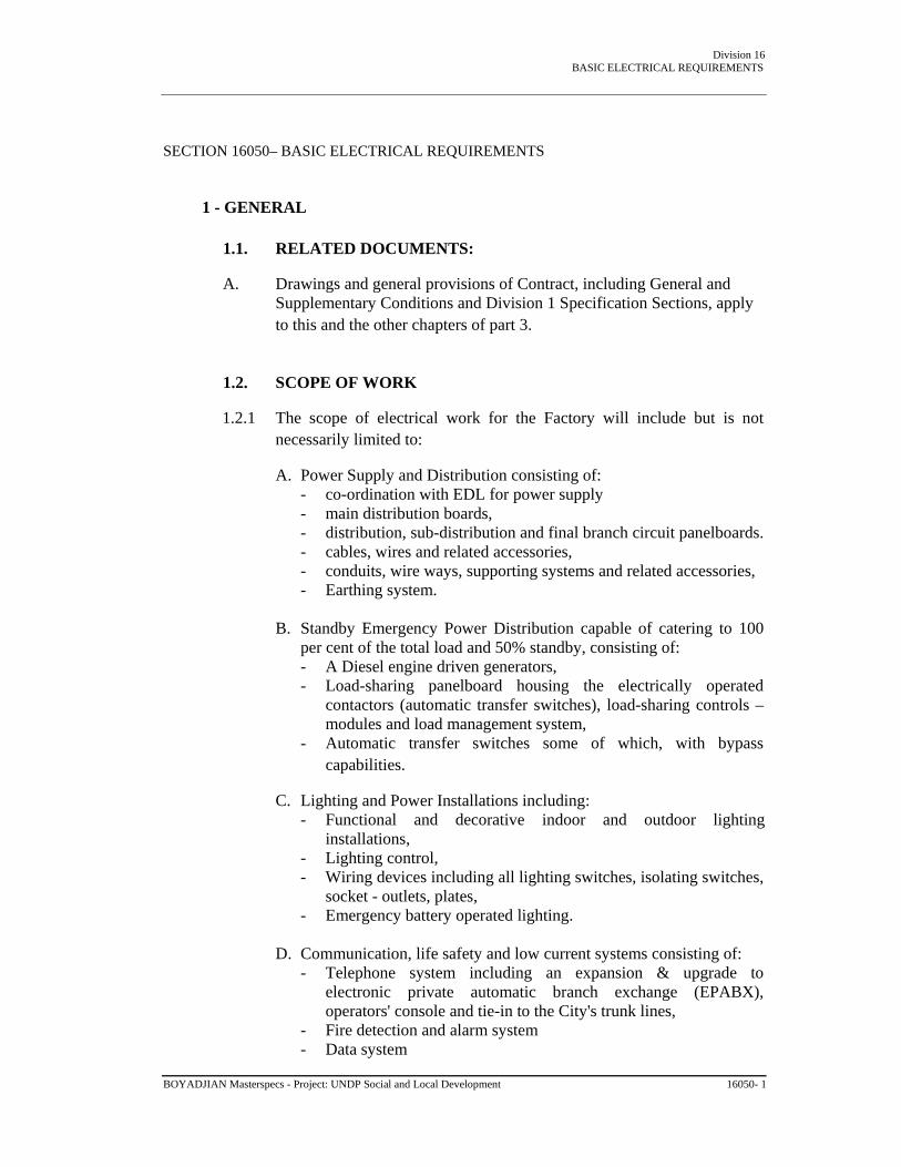
Division 16 BASIC ELECTRICAL REQUIREMENTS
SECTION 16050– BASIC ELECTRICAL REQUIREMENTS
1 - GENERAL
1.1. RELATED DOCUMENTS:
A. Drawings and general provisions of Contract, including General and Supplementary Conditions and Division 1 Specification Sections, apply to this and the other chapters of part 3.
1.2. SCOPE OF WORK
1.2.1 The scope of electrical work for the Factory will include but is not necessarily limited to:
A. Power Supply and Distribution consisting of:
- co-ordination with EDL for power supply - main distribution boards, - distribution, sub-distribution and final branch circuit panelboards. - cables, wires and related accessories, - conduits, wire ways, supporting systems and related accessories, - Earthing system.
B. Standby Emergency Power Distribution capable of catering to 100
per cent of the total load and 50% standby, consisting of: - A Diesel engine driven generators, - Load-sharing panelboard housing the electrically operated
contactors (automatic transfer switches), load-sharing controls – modules and load management system,
- Automatic transfer switches some of which, with bypass capabilities.
C. Lighting and Power Installations including:
- Functional and decorative indoor and outdoor lighting installations,
- Lighting control, - Wiring devices including all lighting switches, isolating switches,
socket - outlets, plates, - Emergency battery operated lighting.
D. Communication, life safety and low current systems consisting of:
- Telephone system including an expansion & upgrade to electronic private automatic branch exchange (EPABX), operators' console and tie-in to the City's trunk lines,
- Fire detection and alarm system - Data system
BOYADJIAN Masterspecs - Project: UNDP Social and Local Development 16050- 1

Division 16 BASIC ELECTRICAL REQUIREMENTS
- Satellite and Master Antenna Television system - Digital closed circuit television system - Public address system - Access control system
1.2.2. Unless otherwise specified, includes the supply, installation, testing and
commissioning of the complete electrical systems, equipment and materials shown on the Drawings and/or described in the Specification together with all associated ancillary work, support work and builder's work in connection.
1.2.3. Incoming power supply and connection will be provided by the Local
Power Authority at 220/380 V to the location shown on the Drawings.
1.2.4. Telephone public exchange lines will be brought into the premises by the Local Telephone Authority to the location shown on the Drawings and/or to be agreed with the Authority.
1.3. GENERAL REQUIREMENTS
1.3.1. INSTALLATIONS GENERALLY:
A. Carry out electrical work in accordance with the Drawings, Specification and Regulations, ensuring compliance with design and performance requirements, to provide safe and protected systems with equipment readily accessible for operation, maintenance and repair
B. Installations are to be complete, ready for operation and fully
integrated and coordinated with all other work
C. Installations are to be carried out by qualified personnel
D. Provide accessories necessary to complete the installations, of the types specified or recommended for the purpose by the manufacturer of the equipment or accessories.
1.3.2 EQUIPMENT SPACES AND ROOMS: check that dimensions,
structure, ventilating and cooling arrangements and other provisions in equipment spaces and rooms are suitable for installation, operation and maintenance of proposed equipment. Note any discrepancies on the shop and construction drawings. The Contractor is responsible of planning the erection of the electrical equipment such that it is not interfering with any other trade in the building.
1.3.3. POWER SUPPLY: liaise with the Local Power Authority to confirm:
- Characteristics of supply and system earthing - Location of incoming supply shown on the Drawings
BOYADJIAN Masterspecs - Project: UNDP Social and Local Development 16050- 2

Division 16 BASIC ELECTRICAL REQUIREMENTS
- Space requirements and associated builder's work for the Authority's installations.
- Make necessary arrangements at the earliest opportunity to ensure connection as and when required, and inform the Engineer in the event of any foreseen delay.
1.3.4. KWH-METERING: liaise with the Local Power Authority and provide
necessary instrumentation, enclosures and accessories required by them to effect a complete kwh-metering installation.
1.3.5. TELEPHONE PUBLIC EXCHANGE LINES: liaise with the Local
Telephone Authority to confirm location of connection of public telephone exchange lines into the premises.
1.3.6. Systems used before substantial completion for the benefit of the
Contractor are to have all consumable elements, such as lamps etc. and defective equipment replaced by new, within 7 days prior to the date of substantial completion.
1.4. DESIGN CONDITIONS
1.4.1. Nominal characteristics of power supply and distribution are as follows:
A. low voltage : 380 V, 3 phase, 4 wire, solidly earthed neutral
B. frequency : 50 Hz.
1.4.2. DISTRIBUTION SYSTEMS are to be supplied or derived from the voltage system previously described, as shown on the Drawings, or as otherwise specified.
1.4.3. EQUIPMENT is to be designed for the system voltage and frequency
previously described, unless otherwise specified. Special provisions are to be made for equipment sensitive to power supply frequency and voltage variations and for equipment operated at other voltages/frequencies or by direct current sources.
1.4.4. KWH-METERING will be at low voltage, as shown on the Drawings.
1.4.5. CLIMATIC CONDITIONS: equipment, including transformers,
switchgear, cables, relays, lighting fixtures, motors etc., is to be designed and derated for continuous and trouble free service under the following climatic conditions:
A. altitude : sea level
B. maximum ambient temperature: 40 deg. C (in the shade)
BOYADJIAN Masterspecs - Project: UNDP Social and Local Development 16050- 3
Division 16 BASIC ELECTRICAL REQUIREMENTS
C. minimum ambient temperature: 0 deg. C
D. maximum relative humidity: 90 %
E. atmospheric conditions: 1 bar
Where design and operating conditions, different from the above are required for particular equipment, they are described in the specification of the equipment concerned.
1.4.6. REGULATIONS: carry out electrical work in accordance with the
current issue of the local codes of practice, local power authority regulations and IEC Regulations for Electrical Installations, where not in contradiction with the local codes of practice and regulations, herein referred to collectively as 'the Regulations'.
1.4.7. CONFLICT should an instance occur in this specification or on the
drawings in which material or construction methods called for are less than minimum requirement of the Regulations, the Engineer shall be immediately informed in writing. Consequent to Engineers approval, supply the materials and perform the work as through called for to minimum code standards.
1.4.8. STANDARDS: unless otherwise specified, equipment and materials are
to be manufactured and installed in compliance with the relevant recommendations of the following: IEC : The International Electro-technical Commission ISO : The International Standardization Organization EN : European Norm NF-USE : The French Regulation BS : The British regulation CCITT : The International Telephone and Telegraph Consultative Committee CCIR : The International Radio Consultative Committee CISPR : The International Special Committee on Radio Interference
EIA/TIA : Electronics Industries association / Telecommunications Industry Associations. IEEE : Institute of Electrical and Electronics Engineers, Inc.
or other equal and approved standards, herein referred to as 'the Standards'. Local standards, where enforced and relevant, are to have precedence over the Standards.
1.5. THE DRAWINGS
1.5.1 EQUIPMENT LOCATIONS shown on the Drawings indicate the
approximate locations and general layout of equipment. Exact and final BOYADJIAN Masterspecs - Project: UNDP Social and Local Development 16050- 4

Division 16 BASIC ELECTRICAL REQUIREMENTS
locations and layouts together with dimensions, weights, mounting methods and accessories, where relevant are to be shown on the shop and construction drawings. All protecting device shall show: the short circuit current value for single and three phase current, the voltage drop, the indirect protection function in case of a fault with respect the earthing system.
1.5.2. WIRING LAYOUTS shown on the Drawings are to be used as a guide
only to defining basic positions, circuiting, loading and switching arrangements. Actual layouts and details of routing of circuits are to be shown on the shop and construction drawings.
1.5.3. WIRING LAYOUTS shown on the Drawings for work not included in
the Electrical Work are shown for convenience and reference only.
1.5.4. SYMBOLS: in order to provide sufficient detail and a minimum degree of clarity on the drawings, the symbols used for the various electrical devices, particularly wall mounted devices, take up more space on the drawings than the device does on the wall. Because of drafting limitations these locations must be considered as being symbolic rather than exact physical locations of the devices.
1.5.5 The devices shall be installed with prime regard for convenience of
operation and the best usage of the wall space for this and other purposes rather than string the devices out along the wall so as to coincide with the scaled locations of the symbols. In locating the outlets, follow the criteria provided on detail drawings where provided, and co-ordinate with furniture. Submittal of detail drawings is required for this purpose before execution. Do not scale from design drawings.
1.6. EQUIPMENT AND MATERIALS
1.6.1. AVAILABILITY: confirm availability of equipment and materials
proposed for use in the work prior to submission for approval. If, after approval, equipment or materials cease to be available, submit alternative items of equal quality and type for approval.
1.6.2. ACCEPTANCE BY AUTHORITY: confirm that proposed equipment
and material characteristics where required are compatible with the requirements of the Local Power Authority or other authorities having jurisdiction and are acceptable to them. Inform the Engineer of any modifications necessary to comply with the Local Power Authority's requirements.
1.6.3. MANUFACTURERS' STANDARDS: equipment is to be the latest standard product of the manufacturer. Component parts are to be the product of a single manufacturer, unless otherwise approved and provided that components made by other manufacturers are of a standard design and are interchangeable.
BOYADJIAN Masterspecs - Project: UNDP Social and Local Development 16050- 5

Division 16 BASIC ELECTRICAL REQUIREMENTS
1.6.4. APPROVED MANUFACTURERS: listing of approved manufacturers in the Specification does not necessarily constitute approval of their standard products as equal to those specified. As certain that listed manufacturers are able to supply equipment and material in conformity with the Specification.
1.6.5. FACTORY ASSEMBLY: equipment generally is to be supplied in
complete factory assembled units ready for installation on site. Dis-assembly necessary for transportation or other purposes is to be arranged to limit site work to simple re- assembly and inter-wiring of control and power cabling.
1.6.6. STORAGE OF MATERIALS: equipment and materials are to be stored
in an approved location, under cover, free from humidity, dust, debris and rodents. Equipment sensitive to heat and humidity is to be kept in climatically conditioned areas until installed and handed over.
1.6.7. DEFECTIVE EQUIPMENT: the Employer reserves the right to operate
operable defective equipment during the Defects Liability Period until it can be removed from service for repair or replacement.
1.6.8. WARRANTY: where required by the Specification, provide a warranty,
signed by the manufacturer (including his agreement to replace promptly, defective equipment or parts thereof, as instructed by the Engineer) covering materials and workmanship for the period stated in the Specification, starting at substantial completion. The Contractor is to assign the benefits of such warranty to the Employer.
1.6.9. SPARE PARTS: not later than the date of substantial completion,
provide spare parts required by the Specification, together with suitable means of identifying, storing and securing same.
1.6.10. TOOLS AND INSTRUMENTS: not later than the date of substantial
completion, provide sets of tools and instruments required by the Specification, together with suitable means of identifying, storing and securing same.
1.6.11. LABEL AND IDENTIFY all equipment, instruments, control and
electrical devices etc. to indicate duty, service or function, to the satisfaction of the Engineer. Labels are to be laminated plastic or anodised aluminium discs with black surface and white core with incised lettering in English or Arabic to the satisfaction of the Engineer. Alternative methods of labelling may be submitted for approval. Fix labels with non-corrodible screws to equipment, or to adjacent permanent surfaces or as approved by the Engineer.
1.6.12. EQUIPMENT NAMEPLATES are to be non-corroding, robust metal,
inscribed in English, and firmly fixed to equipment at factory. Nameplates are to indicate name and address of manufacturer, model,
BOYADJIAN Masterspecs - Project: UNDP Social and Local Development 16050- 6

Division 16 BASIC ELECTRICAL REQUIREMENTS
serial number, basic characteristics and ratings of equipment and are to include elementary diagrams etc., all in accordance with the Standards.
1.6.13. FIREPROOFING: Where cables, cable trays, busducts or conduits pass
through floors and fire rated walls, pack space between wiring and sleeve full with materials and seal with approved caulking compound.
1.7. SUBMISSIONS
1.7.1. GENERALLY: submit for approval, manufacturers' technical literature, shop and construction drawings and other information required by the Specification, before ordering equipment or materials and before executing any related work on site.
1.7.2. TECHNICAL LITERATURE is to include detailed manufacturers'
specifications and original catalogues or catalogue cuts, characteristics, model number, application and operating criteria of all equipment and materials, together with other information necessary to satisfy the Engineer that proposed equipment and systems are suitable and adequate.
1.7.3. SHOP AND CONSTRUCTION DRAWINGS are to demonstrate to the
Engineer that the design requirements are understood by indicating all equipment and material proposed to be supplied and installed and by detailing fabrication and installation methods proposed to be used. Shop and construction drawings are to clearly state the name and location of the work, the names of the Engineer and Contractor, submission date, cross-references to the Drawings and Specification and the specific reference number, location, service and function of each item.
1.7.4. LIST OF PROPOSED MANUFACTURERS of all equipment and
materials, including all items for which choice of manufacturer is at the discretion of the Contractor, is to be submitted for approval.
1.7.5. TEST CERTIFICATES AND REPORTS: where required by the
Specification, submit manufacturer's type and routine test certificates and reports for equipment and devices. Complete test results are to be submitted in clearly identified and organized booklets, indicating item of equipment, make, model, type, date of tests, type of tests, descriptions and procedures.
1.7.6. LABORATORY TESTS: if manufacturer's test certificates are
considered unsatisfactory, then independent laboratory tests are to be carried out on equipment in accordance with the Specification and the Standards, as required by the Engineer.
1.7.7. SPARE PARTS SCHEDULES: submit with the Tender itemised
schedules of spare parts to be provided, as required by the Specification, BOYADJIAN Masterspecs - Project: UNDP Social and Local Development 16050- 7

Division 16 BASIC ELECTRICAL REQUIREMENTS
and state against each item the manufacturer's unit price including packaging and delivery to site.
1.7.8. TOOLS AND INSTRUMENTS SCHEDULES: submit with the Tender
itemized schedules of tools and instruments to be provided, as required by the Specification, and state against each item the manufacturer's unit price including packaging and delivery to site.
1.7.9. LABELLING SCHEDULE: submit for approval, prior to installation, a
schedule of all equipment and devices to be labeled and the suggested details, lettering, position and fixing methods of each label indicating its application.
1.7.10 SAMPLES: submit samples of all equipment and materials for approval.
Major items of equipment for which samples cannot be submitted are to be demonstrated in existing installations or by manufacturer's information, test certificates and reports.
2 - SPECIAL REQUIREMENTS FOR ELECTRONIC EQUIPMENT
2.1. REQUIREMENTS
2.1.1. CONSTRUCTION: electronic components of communication systems,
security systems and special systems and electronic components forming part of the power generation and distribution system are to be solid-state integrated construction, unless otherwise approved.
2.1.2 TEMPERATURE LIMITS: manufacturer is to indicate maximum and
minimum ambient temperatures acceptable for the equipment to operate continuously and normally and beyond which electronic components may suffer permanent damage.
2.1.3. ALTERNATIVE ELECTRONIC EQUIPMENT may be submitted for
approval, provided such equipment meets or exceeds the functional capabilities and/or performance parameters of the equipment specified. Proposals for alternative equipment will be considered only if accompanied by the following information:
A. list of operational characteristics and performance parameters
B. list of differences in operation and performance between proposed
and specified equipment
C. list of changes required and resulting implications
D. drawings indicating changes required to system wiring
E. statement of advantages of proposed equipment over that specified. BOYADJIAN Masterspecs - Project: UNDP Social and Local Development 16050- 8

Division 16 BASIC ELECTRICAL REQUIREMENTS
2.1.4. PROTECTION: solid state equipment under normal conditions of operation is to withstand any surges which might be produced by sudden mains or standby power switching operations. Protective devices are to be provided to protect against surges, failure of output stages due to open circuit, short-circuit or impedance mismatch. In the absence of IEC standards comply with IEEE standard 472 (ANSI/IEEE C37.90 "Guide for Surge Withstand Capability Tests". System/equipment which may be adversely affected by short duration power blackouts shall be capable of riding through such a disturbance by having an internal battery back-up to the memory / microprocessor, etc.
2.1.5. INDICATOR LIGHTS shall be Light Emitting Diodes (LEDs).
2.1.6. ELECTROMAGNETIC RELAYS and control/small power transformers
are to be designed to withstand the 500 V a.c. test voltage between winding and winding or winding and core.
2.1.7. DUST COVERS, easily removable for inspection and servicing, are to
be provided for all relays and sensitive elements.
2.1.8. OUTDOOR EQUIPMENT, electronic or other, is to be designed for maximum ambient temperature or direct sun and is to be protected/enclosed, as applicable, against dust and weather conditions.
2.1.9. EXTERNAL INTERFERENCE: carry out field investigations and tests
to determine possible interference from outside sources. Design electronic equipment to ensure trouble-free operation.
2.1.10. SEGREGATION OF WIRING: design wiring so that low current circuits
are segregated from power wiring, using different conduits and wireways for the purpose. Composite wiring is acceptable for the same system in accordance with the relevant codes. Cable insulation is to be same grade for all conductors in a common enclosure.
2.1.11. POWER SUPPLY UNITS for low current systems which are fed from
the LV supply are to be independently fused on the live conductor and are to have front panel mains indicator light, on/off switch and standard cartridge type fuse holder. Blown fuse indicator lamp is to be provided when fuse does not have an indicator.
3 - TESTS ON SITE, RECORDS, TRAINING AND MAINTENANCE
3.1. TESTS ON SITE
3.1.1. GENERALLY: carry out inspection and acceptance tests on site on each complete system, before final placement into service, in accordance with the Regulations and Standards, as described in the Specification and
BOYADJIAN Masterspecs - Project: UNDP Social and Local Development 16050- 9

Division 16 BASIC ELECTRICAL REQUIREMENTS
required by the Engineer.
3.1.2. TEST SCHEDULES AND PROCEDURES are to be submitted for approval and are to include details of testing equipment to be provided.
3.1.3. WITNESSING: inspection and acceptance tests are to be carried out in
the presence of the Engineer and, when required, by an authorized representative of the Local Power Authority.
3.1.4. VISUAL INSPECTION: visually check proper installation, connections
and nameplate data before testing.
3.1.5. INSULATION RESISTANCE: test the feeders, lighting and power circuits, motors and other power equipment of low voltage installations with a megger of not less than 500 V d.c. for installations rated up to 500 V (r.m.s. value of a.c. supply) and 1000 V d.c. for installations rated above 500 V up to 1000 V, and as required by the particular Section of the Specification.
3.1.6. INSULATION RESISTANCE: unless otherwise specified or approved,
test the circuit insulation resistance related to communications and security systems with a megger of not less than 500 V operating voltage, with equipment disconnected.
3.1.7. CONTINUITY: test all feeders and circuits for continuity.
3.1.8. OPERATIONAL TESTS: carry out operational tests on all equipment
and complete systems to verify proper performance in compliance with the Specification. Tests are to be carried out under normal operating conditions for not less than 3 days, and as required by the Engineer.
3.1.9. SPECIFIC TESTS: carry out specific tests required by the Specification
and any other tests required by the Engineer to verify compliance of the installations with the Specification.
3.1.10. LOAD BALANCE: upon completion of the building and immediately
prior to final inspection and take-over, check load balance on all feeders and at distribution centers, panels, etc. Conduct tests by turning on all possible loads in the building and checking the load current balance. If load unbalance exceeds 15%, rearrange and reconnect circuits to balance the load after Engineer's approval.
3.1.11. VOLTAGE CHECKS: perform voltage checks throughout the building
and if directed by the Engineer, adjust the transformer tap settings where a transformer is provided on the supply end, or report to power authority for adjustment necessary.
3.1.12. CURRENT CHECKS: In cooperation with the mechanical sub-
BOYADJIAN Masterspecs - Project: UNDP Social and Local Development - 16050-10-

Division 16 BASIC ELECTRICAL REQUIREMENTS
contractor, take clip-on ammeter readings on all phases of all mechanical equipment motors with motors operating under full load conditions. Test readings shall be submitted to the Consultant.
3.2. RECORDS
3.2.1. GENERALLY: not later than the date of substantial completion, provide the Engineer with four copies of all approved as-installed drawings, test records, manufacturers' guarantees and warranties, operating and maintenance manuals and other records required by the Specification.
3.2.2. PRESENTATION OF RECORDS is to be in A4 size plastic covered,
loose-leaf ring binders or other approved binders with hard covers, each indexed, divided and appropriately cover titled. Drawings larger than A4 size are to be folded in the binders so that they may be unfolded without being detached.
3.2.3. AS-INSTALLED DRAWINGS are to contain the complete assembled
information included on the construction drawings, prepared in the same manner, and up-dated to indicate the systems, labeling, referencing, mounting methods, routing etc. as installed. Submit complete drawings for approval. Provide the Engineer with one set of transparencies in addi-tion to the four copies required.
3.2.4. TEST RECORDS are to include test certificates of type tests, routine
tests, site tests, commissioning and performance tests and all other tests on equipment and installations described in the Specification and required by the Engineer. Information is to include test procedures and results, conditions under which tests were carried out including set points, temperatures and the like, dates, location and attendance by authorized representatives etc.
3.2.5. OPERATING AND MAINTENANCE MANUALS are to contain the
following:
A. Technical description of each system and item of equipment installed, written to ensure that the Employer's staff fully understand the scope and facilities provided.
B. Diagrammatic drawings of each system indicating principle
components and items of equipment.
C. Schedules (system by system) of equipment installed giving manufacturer, catalogue list numbers, model, rating, capacity and operating characteristics; each item is to have a unique code and number, cross- referenced to the diagrammatic drawings and layout drawings.
BOYADJIAN Masterspecs - Project: UNDP Social and Local Development - 16050-11-

Division 16 BASIC ELECTRICAL REQUIREMENTS
D. Name, address, telephone, telex and fax numbers of the manufacturer of every item of equipment.
E Name, address, telephone and telex numbers of equipment
agents/representatives for emergency services and procedures.
F. Manufacturer's service manual for each major item of equipment, assembled specifically for the project, including detailed drawings, illustrations, circuit details, operating and maintenance instructions, modes of operation, control provisions, sequences and interlocks and preventative maintenance program.
G. Schedules of all fixed and variable equipment settings established
during commissioning.
H. Procedures for fault finding, where applicable.
I. Manufacturers' lists of recommended spare parts for items subject to wear and deterioration, giving expected running period and indicating specifically those items which may involve extended deliveries.
3.2.6. OPERATING AND MAINTENANCE MANUALS: prepare two tem-
porary copies with provisional record drawings and preliminary performance data and make available at time of testing and commencement of commissioning to enable the Employer's staff to familiarize themselves with the installations. Temporary copies are to be in the same format as the final manuals with temporary insertions for items which cannot be finalized until installations are commissioned and performance tested.
3.3. TRAINING
3.3.1. OPERATION AND MAINTENANCE TRAINING: before the date of substantial completion, explain and demonstrate to the Employer's maintenance staff the purpose, function and operation of the installations including all items and procedures listed in the operating and maintenance manuals. Include for not less than thirty days for this pur- pose.
3.4. MAINTENANCE
3.4.1. MAINTENANCE CONTRACTS: where required by the Specification, submit supplementary proposals for annual maintenance contracts. The proposals are to:
A. include for maintaining the installations in efficient working order
BOYADJIAN Masterspecs - Project: UNDP Social and Local Development - 16050-12-

Division 16 BASIC ELECTRICAL REQUIREMENTS
including routine and emergency service checks, adjustments, lubrication and the supply and replacement of damaged parts etc.
B. set out the terms of the offer, the work to be carried out, the
guarantees of performance and the price of the work or part thereof for the first twelve months after substantial completion.
The proposals will not be considered as part of the Tender.
END OF SECTION 16050 BOYADJIAN Masterspecs - Project: UNDP Social and Local Development - 16050-13-

Division 16 Raceways
SECTION 16110- RACEWAYS PART 1 - GENERAL
1.1 1.2
RELATED DOCUMENTS: A. Drawings and general provisions of Contract, including General and
Supplementary Conditions and Specification Sections, apply to this Section.
SUMMARY: A. This Section includes raceways for electrical wiring. Types of raceways in this
section include the following:
1. 2. 3. 4. 5. 6.
Rigid heavy gauge steel conduit. Flexible steel conduit. Liquid-tight flexible steel conduit. Rigid heavy gauge PVC conduit. Flexible PVC conduit. Wiring and cable trunking.
B. Related Sections: The following Division 16 Sections contain requirements
that relate to this Section:
1. "Cable Trays" for cabletray type raceways. 2. "Wires and Cables" for other wiring methods. 3. "Supporting Devices" for raceway. 4. "Electrical Cabinets, Boxes and Fittings".
1.3
SUBMITTALS:
A. Product Data: manufacturer's catalogues for each type of raceway specified. B. Samples: 15 cm long sample of each type and size of surface raceway with
required finish.
C. Installation Instructions: Manufacturer's written installation instructions for wireway, surface raceway, and non-metallic raceway products.
BOYADJIAN Masterspecs - Project: UNDP Social and Local Development 16110 - 1

Division 16 Raceways
D. Shop Drawings: Submit dimensioned drawings of raceway systems showing layout of raceways and fittings, spatial relationships to associated equipment, and adjoining raceways, if any. Show connections to electrical power panels and feeders. Provide the following:
1.
2.
3.
4.
Exact routing of conduits, trunking etc. with indication of boxes, accessories and expansion joints, size and type of conduits and boxes.
Typical assembly details of installation of trunking, trays etc.
Construction details of pull boxes Typical installation details including connection of conduits to metal enclosure, connection of flexible conduits, vapour-tight installations in cold rooms, weatherproof installations outdoors etc. and earthing connections.
E. Maintenance Data: Submit maintenance data and parts lists for each type of
raceway system installed, including furnished specialities and accessories.
1.4 QUALITY ASSURANCE:
A. B.
Manufacturers: Firms regularly engaged in manufacture of raceway systems of types and sizes required, whose products have been in satisfactory use in similar service for not less than 5 years.
Codes and Standards:
1. Codes and Standards: Comply with local national code, Standards and Regulations having jurisdiction in host country or as recommended by the Authority for the project.
2. IEC Compliance: Comply with applicable IEC requirements pertaining to raceways where not in contradiction with above.
1.5 SEQUENCING AND SCHEDULING:
A. Coordinate with other Work, including metal and concrete deck installations, as necessary to interface installation of electrical raceways and components with other Work.
BOYADJIAN Masterspecs - Project: UNDP Social and Local Development 16110 - 2

Division 16 Raceways
PART 2 - PRODUCTS
2.1 2.2
MANUFACTURERS: A. Available Manufacturers: Subject to compliance with requirements,
manufacturers offering products that may be incorporated in the Work include, but are not limited to, the following:
Decoduct Clipsal Mashco or approved equal.
STEEL CONDUIT AND TUBING: A. General: Provide steel conduit and fittings of types, and sizes as required for
each service indicated. Provide proper selection to fulfill wiring requirements in compliance with applicable portions of Codes and Standards for raceways and the applicable Regulations.
B. Rigid Heavy Gauge Steel Conduit: Heavy gauge drawn and welded steel, threaded at both ends, with class 4 protection for rigid steel conduit, zinc coated inside and outside by hot-dip process or sherardizing.
1. 2.
3.
4.
Fittings Generally: threaded type, galvanized or cadmium plated malleable cast iron. Fittings used in corrosive atmospheres are to be specially treated. Locknuts: for securing conduit to metal enclosure are to be heavy hexagonal pattern, for fastening. Bushings: for terminating conduits are to be smooth rounded brass rings. Miscellaneous Fittings: including reducers, chase nipples, three piece unions, split couplings and plugs are to be standard fittings designed and manufactured for the particular application.
BOYADJIAN Masterspecs - Project: UNDP Social and Local Development 16110 - 3

Division 16 Raceways
C. Flexible Steel Conduit: cold rolled and annealed, non-threaded type, formed from continuous length of helical wound and interlocked strip steel, with fused zinc coating on inside and outside.
1. 2. 3.
Fittings Generally: threadless, hinged clamp type, galvanized or cadmium plated malleable cast iron. Fittings used in corrosive atmospheres are to be specially treated. Straight Connectors: one piece body, female end having hinged clamp and deep slotted machine screws for securing to conduit, male end having thread and locknut. Angle Connectors: 45 or 90 degrees terminal connectors as specified for straight connectors, except that body is to be two-piece with removable upper section.
D. Liquid-Tight Flexible Metal Conduit: constructed of single strip, flexible,
continuous, interlocked, and double-wrapped steel; galvanized inside and outside; coated with liquid-tight jacket of flexible polyvinyl chloride (PVC).
E. Rigid Steel Conduit Accessories:
1. 2. 3.
Sleeves Through Outside Walls: cast iron, with end and intermediate integral flanges, and internal diameter larger than diameter of through-conduit. Length is to correspond to wall thickness. Space between sleeve and conduit is to be packed with oakum to within 50 mm of both faces of wall, remainder of sleeve packed with plastic compound or lead, held in place by heavy escutcheon plates bolted at both ends to flanged ends of sleeve. Alternatively, sleeves are to be equal to O.Z/Gedney, Type WSK and approved, with cable or conduit bolted pressure-sealing components. Supports and Hangers: galvanized malleable cast iron straps or structural steel sections with hot dip galvanized bolts and nuts. Refer to Section "Supporting Devices" for other requirements. Expansion Joint for Embedded Steel Conduits: watertight, flexible conduit with end fittings to receive fixed conduits. Length is to allow movement within range of joint and is not to be less than 20 times diameter of conduit. Conduit is to be covered with thick rubber tubing with 5 mm minimum gap all around tube. Bonding jumper with earth clamp is to be electrically connected both sides of joint. Fitting is to be equal to O.Z/Gedney, Type DX and approved.
BOYADJIAN Masterspecs - Project: UNDP Social and Local Development 16110 - 4

4.
Division 16 Raceways
Expansion Joint for Exposed Steel Conduits: sleeve with fittings to permit telescoping of one conduit into sleeve. Movable conduit is to be fitted with water-tight bushing. Joint is to be weatherproof, of galvanized malleable iron or steel. Bonding jumper with earth clamp is to electrically connect both sides of joint. Expansion fitting is to be equal to O.Z/Gedney, Type DXX and approved.
2.3
PVC CONDUIT: A. General: Provided UPVC conduit and fittings of types and sizes indicated for
each service. Where types and sizes are not indicated, provide proper selection to fulfill wiring requirements, which comply with provisions of applicable codes and standards.
B. Rigid Heavy Gauged UPVC Conduit: rigid unplasticized polyvinyl chloride with high impact and high temperature resistance, flame retardant, non- hygroscopic and non-porous, conforming to IEC 423, 614-1 and 614-2 CEE 26, or other equal and approved standards.
1. 2.
Fittings Generally: unbreakable, non-inflammable, self-extinguishing, heavy moulded plastic. Expansion couplings are to be telescoping double tube type, with at least two inner watertight neoprene rings. Assembly: conduits, boxes and accessories, are to be assembled by cementing, using manufacturer's recommended products and appropriate connectors or spouts. Where no spouts are available use smooth bore male PVC bushes and sockets.
C. Flexible UPVC Conduit: flame retardant, heat resistant, non-hygroscopic PVC,
high resistance to impact, ribbed on circumference for flexibility.
2.4 WIRING AND CABLE TRUNKING:
A. B.
General: are to include wire way base, clip-on covers, couplings, end plates, wall flanges, panel to trunking rubber grommets, elbows, tees, adaptor plates and necessary hangers, supports and accessories. Sizes shall be as required to accommodate number of conductors permitted by the applicable standards and/or as shown on the Drawings. Steel Trunking: Construct steel trunking galvanized sheet steel, minimum 1.5 mm thick, protected internally and externally with corrosion resistant finish such as zinc or cadmium with top coat of enamel.
BOYADJIAN Masterspecs - Project: UNDP Social and Local Development 16110 - 5

Division 16 Raceways
C. Weatherproof Wiring and Cable Trunking: trunking and cover constructed of hot-dip galvanized sheet steel.
1. 2.
3.
4.
Construction: provide trunking with outwardly turned flanges to receive cover, and internal sleeve coupling between sections, permitting cutting of trunking on site. Gaskets: neoprene bonded cork gaskets are to be fitted throughout, between any two attached surfaces. Screws: removable flanged covers are to be secured with galvanized steel holding screws. Finish: protect sheet metal parts with rust inhibiting coating and baked enamel finish. Plate finish hardware to prevent corrosion. Protect screws installed toward inside of wire way with spring nuts to prevent wire insulation damage.
PART 3 - EXECUTION
3.1 3.2
INSPECTION: A. Examine areas and conditions under which raceways are to be installed, and
substrate which will support raceways. Do not proceed with work until unsatisfactory conditions have been corrected in manner acceptable to Engineer.
INSTALLATION OF RACEWAYS: A. General: Install raceways as indicated and shown on construction/shop
drawings, in accordance with manufacturer's written installation instructions where applicable and in compliance with applicable Code, Regulations and Standards. Install plumb and level, and maintain required clearances.
B. Co-ordinate with other work: including wires/cables, boxes, and panel work, as necessary to interface installation of electrical raceways and components with other work.
BOYADJIAN Masterspecs - Project: UNDP Social and Local Development 16110 - 6

Division 16 Raceways
C. Use: unless otherwise specifically indicated all light and power circuits, communications, signal and low current systems wiring are to be drawn inside conduits or wireways up to the various electric power consuming equipment as shown on the Drawings. Separate conduit and wireway installations are to be used for HV cables, normal light and power circuits, emergency light and power circuits, telephone, other communication, signal and low current systems wiring.
D. Boxes: junction, pull and splice boxes of ample capacity are to be provided as indicated or required. Boxes are to remain permanently accessible.
E. Tools And Accessories for forming and installing conduit and wireway systems are to be purpose made for the particular application and used in accordance with manufacturers' instructions.
F. Fixing: conduits and wireway installations are to be concealed as much as possible.
G. Sizes of conduits and wireways, not shown on the Drawings, are to be selected in accordance with the Regulations and in relation to the number and size of conductors. Minimum size of conduit for all applications is to be 20 mm diameter, unless otherwise shown on the Drawings.
3.3 INSTALLATION OF CONDUITS:
A. General: Install concealed conduits in new construction work, in walls, underfloor, in slabs, or above false ceilings. Follow indications on design drawings and or the approved shop drawings.
1. 2.
Mechanically Fasten: conduits and wireways are to be effectively joined together and connected to electrical boxes, fittings and cabinets to provide firm mechanical assembly. Earthing jumpers are to be installed on steel conduits where required to ensure effective electrical continuity irrespective of whether a separate protective earth conductor is required or not. Avoid use of dissimilar metals throughout system to eliminate possibility of electrolysis. Where dissimilar metals are in contact, coat surfaces with corrosion inhibiting compound before assembling and use earth-bonding jumper for electrical continuity.
BOYADJIAN Masterspecs - Project: UNDP Social and Local Development 16110 - 7

3. 4. 5. 6. 7. 8. 9.
Division 16 Raceways
Install miscellaneous fittings such as chase nipples, 3-piece unions, split couplings, and plugs that have been specifically designed and manufactured for their particular application. Install expansion fittings in straight runs of raceways every 30 meters, or wherever structural expansion joints are crossed. Set conduit and boxes for connection to units only after receiving final approved drawings with dimensions and after checking location with other trades. Provide 2mm diameter galvanized pull wire fastened by wood blocks or threaded iron plugs at ends in all empty conduits. Test Conduits installed, but left empty, with ball mandrel. Clear or replace any conduit that rejects ball mandrel. Restore conduit and surrounding surfaces to original condition. Sleeves: obtain approval for positioning sleeves where conduits pass through reinforced concrete. Additional openings may be allowed in finished slabs but are to be drilled and not broken. Fix sleeves rigidly to maintain position and alignment during construction work. Waterproof Construction: conduits are not to cross waterproof construction unless permitted by the Engineer. Specially designed and approved fittings are to be used. Make Good all holes for conduit sleeves passing through walls, floors and ceilings with fire-resisting cement and fire stop fitting with a wye fill opening, or approved material to full thickness. Bends: conduit runs between outlet and outlet, fitting and fitting or outlet and fitting are not to contain more than the equivalent of 2 quarter bends (180 degree total).
10. Conduits Entering Cold Stores are to be made vapour tight, so that vapour
from outside cannot enter conduit.
11. Draining: arrange conduits so that condensed moisture can drain to screwed plug at lowest point.
12. Conduit And Fittings Installed Outdoors are to be watertight and highly resistant to corrosion. Use appropriate fittings, threaded and hubbed boxes, gaskets with screw on covers and the like.
13. Flexible Conduit For Slide Rail Mounted Motor is to have sufficient slack to allow for movement of motor over entire slide rail length.
14. Standard Elbows are to be used for conduit sizes over 40 mm. For smaller sizes, field bends may be used provided no damage occurs to conduit.
BOYADJIAN Masterspecs - Project: UNDP Social and Local Development - 16110 - 8

Division 16 Raceways
15. Tags: fit to conduits entering or leaving floors, walls or ceilings for identification of conduit and circuits. Tags are also to be placed at suitable intervals throughout the system. Refer to Section "Identification".
16. Damage To Protective Coating of conduits is to be repaired to original degree of protection.
17. Outdoor Mounted Steel Conduit: apply anti-corrosion coating of zinc- chromate based paint and two weather resistant finish coats of enamel, of approved colour, or other equal and approved coating.
18. Galvanized Steel Conduit Run In Screed is to be painted with heavy coat of emulsified bitumen.
19. Galvanized Steel Conduits Buried In Ground or placed in wet or damp locations are to be coated with two heavy coats of hot bitumen. Conduits are to be covered by at least 600 mm of earth if buried in planting soil .
20. Cut conduits straight, properly ream, and cut threads for heavy wall conduit deep and clean.
21. Field-bend conduit with benders designed for purpose so as not to distort nor vary internal diameter.
22. Fasten conduit terminations to boxes or enclosures by appropriate methods and terminate with bushing where conduits do not terminate in hubs.
23. Conduits are not to cross pipe shafts, or ventilating duct and openings. 24. Keep conduits a minimum distance of 150 mm from parallel runs of flues,
hot water pipes or other sources of heat. Wherever possible, install horizontal raceway runs above water and steam piping.
25. Support riser conduit at each floor level with clamp hangers or other methods as described in Section "Supporting Systems".
26. Use of running threads at conduit joints and terminations is prohibited. Where required, use 3-piece union or split coupling.
BOYADJIAN Masterspecs - Project: UNDP Social and Local Development 16110 - 9

Division 16 Raceways
27. Complete installation of electrical raceway system, including boxes, enclosures etc., before starting installation of cables/wires within raceway system. Cap empty conduits until wiring is in progress, using standard manufacturer's fittings.
28. Space occupation factor in conduits shall never exceed Code/Regulations requirements except if approved under special cases.
B. Conduit Application: Provide rigid heavy gauge galvanized steel, heavy gauge PVC conduit or other types of conduit in accordance with the following:
1. Use rigid heavy gauge galvanized steel (GI) conduit in mechanical equipment rooms, electrical equipment rooms, and crawl spaces, ceiling plenum areas.
2. Use rigid heavy gauge galvanized seamless steel conduit in areas classified as Class I, Division 2, and Hazardous Areas. Flexible conduit will not be acceptable, except with specific approval.
3. Use flexible conduit, metallic or non-metallic consistent with fixed installation, in movable partitions and from outlet boxes to recessed lighting fixtures over false ceilings, and final minimum Regulation/Code length of connection to motors, or control items subject to movement or vibration, and through cellular precast concrete panels where required.
4. Use rigid heavy gauge PVC conduit in embedded, under-floor and above false ceiling installations for lighting, power and low current circuits.
5. Rigid galvanized steel conduit, intermediate metal conduit and corrosion- treated electrical metallic tubing shall be used as permitted by codes for above-ground installations and for wiring in non-hazardous areas of the building.
6. Use liquid-tight flexible steel conduit where subjected to one or more of the following conditions:
• Exterior location. • Moist or humid atmosphere where condensate can be expected to
accumulate. • Corrosive atmosphere • Subjected to water spray or dripping oil, water or grease.
7. Use non-ferrous conduit or tubing for circuits operating above 50 Hz. Use PVC conduit for this purpose unless otherwise required or approved by the Engineer. Such installations include low current, communication and signal system wiring, except where otherwise shown on the Drawings or described in the particular Section of the Specification.
BOYADJIAN Masterspecs - Project: UNDP Social and Local Development 16110 - 10

Division 16 Raceways
C. Underground Ducts and Conduits in Slab on Grade: Use heavy gauge PVC conduits or ducts. Draw up coupling and conduit sufficiently tight to ensure water tightness. Use manufacturer's recommended cement and procedures.
1. For floors-on-grade, install conduits under concrete slabs. 2. For underground installations, install ducts at a minimum of 600 mm below
finished grade for low voltage and 800 mm for high voltage services. Use appropriate duct separators - for proper spacing of ducts.
D. Conduits in Concrete Slabs:
1. 2. 3.
4.
5.
6.
Place conduits in middle third of slab thickness where practical, between bottom reinforcing steel and top reinforcing steel, leaving at least 25 mm concrete cover. Place conduits either parallel, or at right angles, to main reinforcing steel and fasten to reinforcing steel by positive wire fasteners at the proper distance from the concrete face. Place conduits larger than 25 mm parallel with or at right angles to reinforcement, closest possible to slab supports. Separate conduits by not less than one diameter of the larger conduit of two parallel conduits in a group, to ensure proper concrete bond. Conduits crossing in slab must be reviewed for proper cover by the Engineer. Embedded conduit diameter is not to exceed 1/3 of slab thickness. Special cases shall be reviewed by the Engineer. Bends of embedded conduits into partitions and stub-ups shall rise a minimum of 100 mm above finished floor. Stub-ups shall be galvanized rigid steel. Arrange so that the curved portion of bends is not visible above finished slab. Protect all stubs against damage.
BOYADJIAN Masterspecs - Project: UNDP Social and Local Development - 16110 - 11

Division 16 Raceways
7. Stub-up Connections: Extend conduits through concrete floor for
connection to free-standing equipment with an adjustable top or coupling threaded inside for plugs and set flush with finished floor. Extend conductors to equipment with rigid steel conduit. Flexible metal conduit may be used 100 mm above the floor. Where equipment connections are not made under this contract install screwdriver-operated threaded flush plugs, flush with floor.
E. Install conduits: so as not to damage or run through structural members. Avoid horizontal or cross runs in building partitions or side walls.
F. Exposed Conduits:
1. 2.
3.
Install exposed conduits and extensions from concealed conduit systems neatly, parallel with, or at right angles to nearby surfaces or structural members and follow the surface contours as much as practicable. Install exposed conduit work so as not to interfere with ceiling inserts, lights or ventilation ducts or outlets. Support exposed conduits by use of galvanized wall brackets, ceiling trapeze or pipe straphangers. Support conduits on each side of bends and on linear spacing not to exceed 1.50m. Refer to Section "Supporting Devices".
4. Run conduits exposed for outlets on waterproof walls. Set anchors for supporting conduit on waterproof wall in waterproof cement.
5. Above requirements for exposed conduits also apply to conduits installed in space above false ceilings, and in crawl spaces.
G. Heavy Gauge PVC Conduits:
1. 2.
Make cemented joints in accordance with recommendations of manufacturer. Use manufacturers standard fittings, couplings, bends, terminations and cementing compound. Install PVC conduits in accordance with approved applicable standards and methods.
H. Steel Conduit Fittings:
1.
2.
Fit ridged locknuts inside and outside of surface of metal enclosure to which conduit is fixed for proper fastening. Bushings for terminating conduits smaller than 32 mm are to have flared bottom and ribbed sides, with smooth upper edges to prevent injury to cable insulation.
BOYADJIAN Masterspecs - Project: UNDP Social and Local Development 16110 - 12

3. 4.
Division 16 Raceways
Install insulated type bushings for terminating conduits 32 mm and larger. Bushings are to have flared bottom and ribbed sides, upper edge to have phenolic insulating ring moulded into bushing. Bushing of standard or insulated type to have screw type grounding terminal.
I. Explosion Proof Fittings:
1.
2.
3.
4.
Explosion proof seal, drain, and breather conduit fittings shall be installed as required by code. An appropriate seal shall be provided in each conduit (duct) run entering or leaving manholes, fuel pits, or other hazardous areas. Fittings and sealing compound shall be designated for application in Class 1, Group D, and hazardous locations. Combination seal and drain fittings may be used in lieu of 2 separate fittings.
3.4
INSTALLATION OF RACEWAYS AND WIREWAYS, OTHER THAN CONDUITS: A. General: Mechanically assemble metal enclosures, and raceways for conductors
to form continuous electrical conductor, and connect to electrical boxes, fittings and cabinets as to provide effective electrical continuity and rigid mechanical assembly.
B. Avoid use of dissimilar metals throughout system to eliminate possibility of electrolysis. Where dissimilar metals are in contact, coat all surfaces with corrosion inhibiting compound before assembling.
C. Install expansion fittings in all raceways wherever structural expansion joints are crossed.
D. Make changes in direction of raceway run with purpose made fittings, supplied by raceway manufacturer. No field bends of raceway sections will be permitted.
E. Properly support and anchor raceways for their entire length by structural
materials.
F. Use boxes as supplied by raceway manufacturer wherever junction, pull or device boxes are required.
END OF SECTION 16110 BOYADJIAN Masterspecs - Project: UNDP Social and Local Development 16110 - 13

Division 16 Conductors and Cables
SECTION 16120 CONDUCTORS AND CABLES
PART 1 - GENERAL
1.1 1.2
RELATED DOCUMENTS: Drawings and general provisions of Contract, including General and Supplementary Conditions and Specification Sections, apply to this Section.
SUMMARY: A. This Section includes wires, cables, and connectors for power, lighting, signal,
control and related systems rated 600 volts and less.
B. Extent of electrical wire and cable work is indicated by drawings and schedules. C. Types of electrical wire, cable, and connectors specified in this section include
the following:
1. Single core copper conductor/cables 2. Multicore copper conductor/cables 3. Fixtures wires. 4. Control and signal cables.
D. Applications of electrical wire, cable, and connectors required for project are as follows:
1. 2. 3. 4. 5.
For power distribution circuits. For lighting circuits. For appliance and equipment circuits. For motor-branch circuits. For signal and control circuits where not specifically required otherwise under other sections of the specification.
E. Related Sections: The following Sections contain requirements that relate to
this section: 1. Division 16 Section "Electrical Boxes, Cabinets and Fittings" for
connectors for Terminating Cables in boxes and other electrical enclosures.
BOYADJIAN Masterspecs - Project: UNDP Social and Local Development 16120 - 1

Division 16 Conductors and Cables
1.3 SUBMITTALS:
A. Product Data: submit manufacturer's data on electrical wires, cables and connectors.
B. Field Test Reports: indicating and interpreting test results relative to
compliance with performance requirements of testing standards.
C. Technical Data: submit data for approval including, but not limited to, the following: Constructional details, standards to which cables comply, current carrying capacities, derating factors for grouping and temperature
Manufacturer's catalogue cuts
Dimensional and electrical characteristics Samples of each cable and wire and, if requested by the Engineer, other accessories.
D. Certificate Of Origin: for each lot of cable supplied, provide a certificate of origin issued by manufacturer stating origin, date of manufacture, composition, and standards to which it complies and test certificates.
E. Shop And Construction Drawings: submit drawings for approval including, but not limited to, the following: 1. Exact routing layouts, sections and profiles of bus ducts, trays, feeder, sub
feeder cables and branch circuits, with indication of any equipment to show and verify coordination between various trades
2. Details of supports and fixings for buses, trays and cables
3. Details of connections to transformers, switchboards, panelboards etc. 4. Details of terminations, splices and tapings where permitted, glands and
bushings at enclosures
5. Number and size of conductors in conduit for all branch circuits in accordance with final conduit routing.
BOYADJIAN Masterspecs - Project: UNDP Social and Local Development 16120 - 2

Division 16 Conductors and Cables
1.4 QUALITY ASSURANCE:
A. Regulatory Requirements: Comply with provisions of the statutory laws having jurisdiction and local codes of practice applicable to the job site/host country.
B. Current Carrying Capacities of Conductors have been determined in accordance with the Regulations for specified type of insulation and expected conditions of installation. No change will be accepted in specified type of insulation unless warranted by special conditions and approved by the Engineer. Check various loads and current carrying capacities and report any discrepancies or insufficiency of sizes indicated to the Engineer.
C. Standards: wires and cables are to comply with IEC or other equally approved standards and are to bear the mark of identification of the Standards to which they are manufactured. Wires and cables not having this identification will be rejected.
D. Conform to applicable codes and regulations regarding toxicity of combustion products of insulating materials.
E. Manufacturers: Firms regularly engaged in manufacture of electrical wire and cable products of types and sizes required, whose products have been in satisfactory use in similar service for not less than 5 years.
1.5
DELIVERY, STORAGE, AND HANDLING: A. Deliver wire and cable properly packaged in factory-fabricated type containers,
wound on factory reels.
B. Store wire and cable in clean dry space in original containers. Protect products from weather, damaging fumes, construction debris and traffic.
C. Handle wire and cable carefully to avoid abrasing, puncturing and tearing wire and cable insulation and sheathing. Ensure that dielectric resistance integrity of wires/cables is maintained.
BOYADJIAN Masterspecs - Project: UNDP Social and Local Development 16120 - 3

Division 16 Conductors and Cables
PART 2 - PRODUCTS
2.1 MANUFACTURERS:
A. Available Manufacturers: Subject to compliance with requirements,
manufacturers offering products which may be incorporated in the work include, but are not limited to, the following:
Wire and Cable
Liban Cable (Lebanon)
Connectors for Wires and Cable Conductors:
Pirelli - General (England) 3M Company (USA) WAGO (Germany)
2.2
WIRES AND CABLES A. General: Unless otherwise specified or shown on the Drawings, cables and
other feeders are to have copper conductors. Cable conductors are to be stranded, based on IEC 228 Class 2. Signal and control cables are to have solid conductors unless otherwise specified. Flexible cords are to have finely stranded conductors. Conductors of single core cables 25mm2 and above are to be compacted. Multi-core cables 35 mm2 and above are to be of sectoral shape.
1. 2.
Conductor Sizes: are to be metric and as shown on the Drawings. Conductors with cross-sectional area smaller than specified will not be accepted. Building Wiring Insulation: Insulation is to be colour coded or otherwise identified as follows: a. Neutral is to be as:
- Black (Wires) - Grey (Cables)
b. Protective earth is to be green or green/yellow striped c. Phase colours are suggested as:
- Red, Yellow, and Blue (Wires) - Black, Red, and Blue (Cables)
B. LV Wires:
1. Single Core PVC Insulated Wires: unless otherwise specified, single conductor wires for wiring in conduit are to have annealed copper conductors, generally with concentric strands and insulated with
BOYADJIAN Masterspecs - Project: UNDP Social and Local Development 16120 - 4

Division 16 Conductors and Cables
flame retardant, moisture and heat resistant PVC/E to IEC 227, suitable for wet locations and for conductor temperature of 85 deg. C. Wires are to be 450/750 V grade.
C. LV Cables:
1. 2. 3.
4.
Multi-Core PVC Insulated Cables (0.6/1 kV): to have annealed, copper conductors, insulated with PVC/E to IEC 227, flame retardant, moisture and heat resistant, suitable for wet locations and conductor temperatures of 85 deg. C, laid up, bedded with suitable filler and sheathed with PVC. Armoured cables are to have single layer of galvanized steel wire armour with PVC over sheath. Cables are to comply with IEC 502 and IEC 540. Single Core XLPE insulated Feeder Cables (0.6/1 kV): Single-core circular stranded, annealed copper conductors, insulated with flame retardant, moisture and heat resistant cross-linked polyethylene (XLPE), suitable for wet locations and conductor temperatures of 90 deg. C. and PVC over sheath. Armoured cables are to have taped bedding, single wire aluminium armour and PVC over-sheath. Multicore XLPE insulated Feeder Cables (0.6/1 kV): Single core annealed copper conductors, XLPE insulated, for conductor temperature of 90 deg. C, laid up and bedded with suitable non-hygroscopic material compatible with the insulation and PVC over sheathed, colour black. Armoured cables are to have single layer of galvanized steel wire applied helically over extruded PVC bedding (which may be an integral part of filling) and over sheathed with PVC, colour black. PVC over sheaths are to be type ST2 to IEC 502. Flexible Cable for Connection to appliances, window fans, pendants etc.: is to be 300/500 V grade, three or four core, with tinned finely stranded copper wires, EPR insulated, twisted and sheathed with chlorosulphonated polyethylene (CSP compound) and with strengthening cord.
D. Control and Signal Cables
1.
Multicore PVC Insulated Control Cables: 0.6/1 kV rating, solid 1.5 mm2, 2.5 mm2 or solid 4 mm2 plain circular copper conductors, with heat resistive PVC/E to IEC 227, rated for 85 deg. C, of 7, 12, 19, 24, 30 or 37 cores. Cores are to be laid up together and filled with non-hygroscopic material, PVC over sheathed, to form compact and circular cable for use in switchgear, control gear and generally for control of power and lighting systems. Armoured cable is to have extruded PVC bedding which may be an integral part of the filling, galvanized steel wire armouring, and over sheath of PVC type ST2 to IEC 502, colour black. Core identification is to be white printed numbers 1, 2, 3 etc. over black insulation.
BOYADJIAN Masterspecs - Project: UNDP Social and Local Development 16120 - 5

2. 3.
Division 16 Conductors and Cables
PE Insulated Control and Signal Cables: for use on instrumentation or data systems, are to be generally 300 V rating, polyethylene insulated, colour coded, tinned copper conductors (0.6 mm diameter), twisted together into pairs. Multi-pair core assembly is to be covered with binder tape, spirally wound 0.075 mm bare copper shielding tape and provided with drain wire and overall PVC sheath. Control And Signal Cables, enclosed in conduit and raceways with power cables, are to be insulated for same voltage grade.
E. Connectors (LV Power)
1. 2. 3.
Connector - Type A-1: pressure indent type, for terminating or making T- taps and splices on conductors 10 mm2 and smaller. Connector is to be non-ferrous copper alloy applied to conductor by mechanical crimping pressure, with vinyl insulating sleeves or phenolic insulating covers. Connector - Type A-2: bolted pressure split type for terminating or making T-taps and splices on conductors 16 mm2 and larger. Connector is to be cast non-ferrous copper alloy applied to conductor by clamping with minimum of two screws and provided with phenolic insulating cover. Connector - Type B-1: pre-insulated, spring type, for branch circuit and fixture wiring. Connector is to be steel encased spring with shell, insulated with vinyl cap and skirt, type Scotchlok brand, as manufactured by Minnesota Mining & Mfg. Co. or other equal and approved.
BOYADJIAN Masterspecs - Project: UNDP Social and Local Development 16120 - 6

Division 16 Conductors and Cables
PART 3 - EXECUTION
3.1
INSTALLATION OF WIRES AND CABLES: A. General: Install electrical cables, wires and wiring connectors as indicated, in
compliance with applicable requirements of the Regulations/codes applicable, IEC, and in accordance with recognized industry practices. Building wires and cables are to be installed in conduit, trunking or ducts indoors and in conduit and ducts outdoors, unless shown otherwise on the drawings.
B. Co-ordinate: wire/cable installation work including electrical raceway and equipment installation work, as necessary to properly interface installation of wires/cables with other work.
C. Run d.c. wiring in separate conduits than a.c. wiring. D. Run: emergency lighting and power circuits in separate conduits from normal
wiring.
E. Use pulling compound or lubricant, where necessary; compound or lubricant used must not deteriorate conductor or insulation and must be approved by the Engineer.
F. Use pulling means including, fish tape, cable, rope and basket weave wire/cable grips which will not damage cables or raceway.
G. Maintain colour coding throughout installation. Phase- conductors for which outer jacket is not colour coded are to have engraved alphanumeric mark (L1, L2, L3) or colour coded heat-shrinkable sleeves.
H. Buried Cables: cables buried directly in the ground are to be armoured type, unless otherwise indicated in particular Sections of the Specification or on the Drawings.
I. Install exposed cable, parallel and perpendicular to surfaces, or exposed
structural members, and follow surface contours, where possible.
J. Keep conductor splices to minimum. In case of splices, these are to be inside splice boxes, pull or junction boxes.
K. Install splices and tapes which possess equivalent-or-better mechanical strength and insulation ratings than conductors being spliced.
L. Use splice and tap connectors which are compatible with conductor material. M. Tighten electrical connectors and terminals, including screws and bolts, in
accordance with manufacturer's published torque tightening values. Where
BOYADJIAN Masterspecs - Project: UNDP Social and Local Development 16120 - 7

Division 16 Conductors and Cables
manufacturer's torquing requirements are not indicated, tighten connectors and terminals to comply with tightening torques specified in recognized standards.
N. Pull cables simultaneously where more than one cable is being installed in the same raceway.
O. Branch Circuit Work originating from light and power panelboards is to be arranged as shown on the Drawings. Loads on various phases of panelboards are to be balanced.
P. Control Cables may be fixed to racks, installed directly on cable trays or pulled in conduit and trunking indoors, and in underground ducts or in conduit outdoors.
Q. Bunching Of Wires In Raceways is to be in accordance with raceway filling factors permitted by the Regulations.
R. Before Pulling Wires In Conduits check that inside of conduit (and raceway in general) is free of burrs and is dry and clean.
S. Support: cables and wires pulled inside very high conduit risers are to be supported at upper end of risers and at intermediate points by split rubber grommets to relieve any stresses on conductors, where required.
T. Extra Length: at every branch circuit outlet and pull- box, every cable passing through is to be left slack to allow inspection and for connections to be made. Cables terminating in outlet boxes are to be left with at least 250 mm extra length for terminations.
U. Joints or Taps in wires and cables, if permitted, are to be permanently accessible or made only in boxes or cabinet gutters.
V. Connectors for terminating or making T-taps and splices are to be Type A-1 on conductors 10 mm2 or smaller, Type A- 2 for conductors 16 mm2 and larger, and Type B-1 for branch circuit and fixture wiring.
W. Insulating Covers are to be applied to prevent exposure of bare cable connections.
X. Switch Legs for local wall switches are to have distinctive colour, selected as complementary to cable colour coding used in the project.
Y. Terminations: conductors of wires and cables up to 16 mm2 are to be tightly twisted and where possible doubled back before being clamped with set screws. Where two or more wires are looped into same terminal these conductors are to be tightly twisted together before inserting into terminals. In no case is bare conductor to be allowed to project beyond any insulated shrouding or mounting of a line terminal. Cables sizes 16 mm2 and larger are
BOYADJIAN Masterspecs - Project: UNDP Social and Local Development - 16120 - 8

Division 16 Conductors and Cables
to terminate in tunnel lugs with set-screw, or by using bolted or sweated compression connectors.
Z. Tagging: tag main and feeder cables in pull-boxes, wireways and wiring gutters of panelboards or distribution cabinets. Tags are to identify cable or circuit number and conductor size in accordance with the Schedules. 1. Tagging: where two or more circuits are run to or through a control device,
outlet box or ceiling junction box, each circuit is to be tagged as a guide in making connections.
BOYADJIAN Masterspecs - Project: UNDP Social and Local Development - 16120 - 9

Division 16 Conductors and Cables
3.2 FEEDER AND SUB-FEEDER CABLE INSTALLATION
A. Cables Generally are to be run through duct-banks, shafts or special recesses, clamped to steel racks or cable trays. Cables run through ventilation shafts are to be installed in steel conduits.
B. Fixing: single cables above suspended ceilings or in concealed spaces are to be fixed directly to walls or ceilings but must be accessible. Where two or more cables are run in parallel, they are to be fixed on galvanized steel perforated trays or on other approved special cable supporting and protecting arrangement.
C. Clamps: where cables are fixed to steel trays or supporting structures, approved galvanized cast steel clamps (or moulded plastic or die cast Aluminium clamps for single core cables) are to be used at distances not exceeding 20 diameters. Cables shall be laid parallel in one plane, with the exception of single core cables in "trefoil" formation, with spacing between cables equal to the larger of the two adjacent cables.
D. Joints or Splices will not be accepted on main and sub- feeders. Cables are to be supplied in lengths sufficient for straight through unjointed termination-to- termination pull.
E. Cables laid direct in the ground shall be at a minimum depth of 750 mm below finished level. A 100 mm tamped bedding and 100 mm tamped covering of sifted soil or sand is to be provided with a tile cover all along the route of the cables for protection. Surface cable markers shall be provided on every change of direction and at 50 m intervals when in a straight line. A tape marker shall be embedded at 300 mm below ground level, all along the cable trench.
F. Where cables are installed in underground ducts the ducts shall be laid with a minimum covering of 700 mm to finished level. The ends of the ducts shall be sealed immediately after any cable installation. The ends of any unused ducts shall be plugged and sealed.
1. Draw wires are to be left in all unused ducts. 2. Just before pulling cables in, ducts shall be cleared with a mandrel 13 mm
(1/2 inch) smaller than the internal diameter of the duct and followed by a circular wire brush 13 mm (1/2 inch) larger in diameter than the duct.
G. Directly Buried Cables crossing under roads, pipe banks or other services, are to be drawn in heavy-duty PVC duct banks. In no case are cables to be directly buried in concrete, in masonry or in floor finishings.
H. Buried Cables Liable To Mechanical Damage are to be drawn through PVC conduit or asbestos cement pipe. If steel conduit is used, all three-phase conductors, neutral and protective earth circuits are to be in the same conduit.
BOYADJIAN Masterspecs - Project: UNDP Social and Local Development - 16120 - 10

I. J.
Division 16 Conductors and Cables
Where multiple runs occur the cables shall be installed such that crossovers are avoided wherever practicable; if unavoidable, suitable separators for at least 1 m each side from the cross-point must be provided according to approved details. Where cables are run on ladder rack and cable tray, the size and routes of the rack and tray shall be carefully selected taking into account other services. In addition to these routes the Contractor shall include for any vertical drops of cable tray and supporting brackets where cables drop from the main runs to switchgear and equipment.
K. In situations where individual cables pass through walls, the cables shall be
sleeved and suitably sealed. Fire barriers are to be provided as necessary by the Safety Code applicable.
L. Cables rising from ground level up walls or stanchions shall be protected by a substantial steel frame to a height of 1.5 meters. Such framework shall be approved by the Engineer prior to the commencement of work.
M. Exposure To Heat: route wires and cables to prevent exposure to excessive heat or to corrosive agents. If such condition is unavoidable, cables are to be type designed for particular condition.
N. Insulating Covers are to be applied to prevent exposure of bare cable connections. Insulating cover is to be purpose made and is to provide minimum insulation level equal to that of conductor insulation.
O. Glands and Cable Boxes for various single-core and multicore cables are to be purpose made and suitable for rigid mounting to equipment enclosure.
P. Cables shall be identified at regular intervals and terminations with approved cable markers.
3.3 FEEDER CABLE JOINTING AND TERMINATING
A. Through Joints will not be allowed in feeder cables where adequate manufacturer's lengths are available. Where a joint is necessary, it has to be made inside boxes, handholes or manholes.
BOYADJIAN Masterspecs - Project: UNDP Social and Local Development - 16120 - 11

Division 16 Conductors and Cables
B. Recommendations: through joints and terminations are to be carried out strictly in accordance with cable manufacturer's recommendations, and made with correct specified materials, boxes, tapes, compounds or mixtures, glands and bonds as applicable.
C. Jointing: skilled operatives are to be employed for jointing of cables. Qualifications of operatives are to be submitted to the Engineer prior to work commencing on site. Joints are to be filled with epoxy resin after taping unless contrary to cable manufacturer's recommendations. Sample site constructed cable terminations and through-joints are to be submitted to the Engineer prior to commencing work on site. Samples are to be constructed in the presence of the Engineer and are to be available to the Engineer for test and inspection in accordance with manufacturer's recommendations.
D. Cutting Tools for jointing and terminating cables are to be purpose made, to prevent damage to insulation in general, and to cable sheathing..
E. Cleaning Of Lacquer On Conductors is to be by use of 'Scotch Brite' sponge and white spirit or equal approved.
3.4
FIELD QUALITY CONTROL: A. Cable Tests are to be carried out in accordance with the requirements of the
Regulations and Standards.
B. Test Equipment: provide megger testers of various ranges as applicable, and HV test equipment as necessary for testing MV installations. Use 500 V megger on installations with nominal voltage up to 500 V, 1000 V megger on installations with nominal voltage over 500V up to 1000V.
C. Insulation Resistance tests for LV power and lighting installations is to be measured in accordance with IEE Regulations 613-5 through 613-8 and 713- 04.
D. Insulation Resistance for control and signal cables is to be minimum 10000 Megohm-km for PE insulated cables and 100 Megohm-km for PVC insulated cables, all measured core- core and core-earth, in accordance with the Regulations.
E. F.
Prior to energization of circuitry, check installed wires and cables with megohm meter to determine insulation resistance levels to ensure requirements are fulfilled. Prior to energization, test wires and cables for electrical continuity and for short-circuits.
BOYADJIAN Masterspecs - Project: UNDP Social and Local Development - 16120 - 12

Division 16 Conductors and Cables
G. Subsequent to wire and cable hook-ups, energize circuitry and demonstrate functioning in accordance with requirements. Where necessary, correct malfunctioning units, and then retest to demonstrate compliance.
END OF SECTION 16120 BOYADJIAN Masterspecs - Project: UNDP Social and Local Development - 16120 - 13

Division 16 Electrical Cabinet, Boxes and Fittings
SECTION 16135 ELECTRICAL CABINETS, BOXES AND FITTINGS
PART 1 - GENERAL
1.1 RELATED DOCUMENTS:
A. Drawings and general provisions of Contract, and Specification Sections, apply to this Section.
B. Requirements of the following Division 16 Sections apply to these sections.
1. "Basic Electrical Requirements". 2. "Wiring Devices" 3. "Raceways"
1.2 SUMMARY:
A. This section includes cabinets, boxes, and fittings for electrical installations and certain types of electrical fittings not covered in other sections. Types of products specified in this Section include: 1. 2. 3. 4.
Outlet and device boxes. Pull and junction boxes. Cabinets (for telephone and signal wiring methods) Hinged door enclosures (for diversified switchgear and control gear applications).
1.3
DEFINITIONS: A. Cabinets: An enclosure designed either for surface or for flush mounting and
having a frame, or trim in which a door or doors may be mounted.
B. Device Box: An outlet box designed to house a receptacle device or a wiring box designed to house a switch.
C. Enclosure: A box, case, cabinet, or housing for electrical wiring or components.
D. Hinged Door Enclosure: An enclosure designed for surface mounting and having swinging doors or covers secured directly to and telescoping with the walls of the box.
E. Outlet Box: A wiring enclosure where current is taken from a wiring system to supply utilization equipment.
BOYADJIAN Masterspecs - Project: UNDP Social and Local Development - 16135- 1

Division 16 Electrical Cabinet, Boxes and Fittings
F. Wiring Box: An enclosure designed to provide access to wiring systems or for the mounting of indicating devices or of switches for controlling electrical circuits.
1.4 SUBMITTALS:
A. General: Submit the following in accordance with Conditions of Contract and Division 1 Specification Sections:
1.
2.
Product data for cabinets and enclosures and boxes of various types. Shop drawings for floor boxes and special boxes, enclosures and cabinets that are to be shop fabricated, (nonstock items). For shop fabricated junction and pull boxes, show accurately scaled views and spatial relationships to adjacent equipment. Show box types, dimensions, and finishes. Show mounting methods, indoor, outdoor or other.
1.5
QUALITY ASSURANCE: A. Manufacturers: Firms regularly engaged in manufacture of electrical cabinets,
enclosures, boxes and fittings, of types, sizes, and capacities required, whose products have been in satisfactory use in similar service for not less than 3 years.
B. Standards: IEC439, IEC536, IEC144 and 79, NFC 63-410, NFC 15-100, C13- 100, C12-100 or approved equal for system of wiring selected.
C. Regulation or Code Compliance: Components and installation shall comply with the applicable code of practice or Regulations enforced in the host country/state.
BOYADJIAN Masterspecs - Project: UNDP Social and Local Development - 16135- 2

Division 16 Electrical Cabinet, Boxes and Fittings
PART 2 - PRODUCTS
2.1 MANUFACTURERS:
A. Available Manufacturers: Subject to compliance with requirements,
manufacturers offering products that may be incorporated in the Work include, but are not limited to, the following:
1. 2.
Boxes:
Legrand Vimar Bticino Decoduct or approved equal
Cabinets: Syslink 3M e-net or approved equal
2.2
2.3
CABINETS, BOXES AND FITTINGS, GENERAL: A. Electrical Cabinets, Boxes, and Fittings: Of indicated types, sizes, and
protection classes. Where not indicated, provide units of types, sizes, and classes appropriate for the use and location. Provide all items complete with covers and accessories required for the intended use. Provide gaskets for units in damp or wet locations.
MATERIALS AND FINISHES:
A. Sheet Steel: Flat-rolled, code-gage, galvanized steel to applicable standards. B. Fasteners for General Use: Corrosion resistant screws and hardware including
cadmium and zinc plated items.
C. Fasteners for Damp or Wet Locations: Stainless steel screws and hardware. D. Cast Metal for Boxes, Enclosures, and Covers: Copper-free aluminum except
as otherwise specified.
E. Exterior Finish: baked enamel, (grey or beige as selected by the Engineer), for items exposed in finished locations except as otherwise indicated.
F. Painted Interior Finish: Where not indicated, white baked enamel.
BOYADJIAN Masterspecs - Project: UNDP Social and Local Development - 16135- 3

Division 16 Electrical Cabinet, Boxes and Fittings
G. Fittings for Boxes, Cabinets, and Enclosures: Malleable iron or zinc plated steel for conduit hubs, bushings and box connecters, conformant with respective standards applicable (conduit Standards applicable or approved for project, for use with appropriate device outlets).
H. Gaskets: Neoprene gaskets.
2.4
2.5 2.6
METALLIC OUTLET, DEVICE AND SMALL WIRING BOXES: A. General: Electrical metallic outlet boxes and fittings shall be of type, shape,
size, and depth compatible with location and application. Refer to Section "Wiring Devices" of Division 16.
B. Steel Boxes: Boxes for indoor applications shall be sheet steel with stamped knockouts, covers and accessories as suitable for each location, including mounting brackets and straps, cable clamps, exterior rings and fixture studs, conforming with the approved Standards and applicable Code or Regulations.
C. Cast-Aluminum Boxes: Copper free, cast aluminum, threaded raceway entries, with features and accessories suitable for each location including mounting ears, screw holes for devices and closure plugs.
NONMETALLIC OUTLET, DEVICE AND SMALL WIRING BOXES: A. General: Conform to approved Standard for nonmetallic outlet boxes, device
boxes, covers, and supports, flush device boxes and covers. Boxes shall be molded U-PVC units of type, shape, size, and depth to suit location and application. Refer to Section "Wiring Devices" for device outlet boxes.
B. Boxes for Concealed Work: Mounting provisions and conduit entrances to suit installation conditions and wiring method used.
C. Boxes for Exposed Work: Ultra-violet stabilized, nonconductive, high impact- resistant boxes with integrally molded raceway entrance hubs and removable mounting flanges. Boxes shall be equipped with threaded metallic inserts for device and cover plate mounting screws. Each box shall have a molded cover of matching U-PVC material suitable for the application. Provide gasket of PVC or neoprene for outdoor or wet locations.
PULL AND JUNCTION BOXES: A. General: Comply with applicable project Standards, and approved Code, for
boxes over 1500 cu.cm (100 cubic inches) volume. Boxes shall have screwed or bolted-on covers of material same as box and shall be of size and shape to suit application.
BOYADJIAN Masterspecs - Project: UNDP Social and Local Development - 16135- 4

Division 16 Electrical Cabinet, Boxes and Fittings
B. Hot-Dipped Galvanized Steel Boxes: Sheet steel with welded seams. Where necessary to provide a rigid assembly, construct with internal structural steel bracing. Hot-dip galvanized after fabrication. Cover shall be gasketed.
C. Boxes Approved for Classified Locations: Cast metal or cast nonmetallic boxes conforming to approved Standards/Regulations for use in Hazardous (Classified) Locations," listed and labelled for use in the specific location classification, and with the specific hazardous material encountered. Conduit entrances shall be integral threaded type.
2.7
CABINETS: A. Comply with approved applicable Standards and Codes for telephone cabinets,
terminal cabinets, signal and telecommunication cabinets and the like.
B. Construction: Sheet steel IP54 to IEC 144 except as otherwise indicated. Cabinet shall consist of a box and a front consisting of a one-piece frame and a hinged door. Arrange door to close against a rabbet placed all around the inside edge of the frame, with a uniformly close fit between door and frame. Provide concealed fasteners, not over 600 mm apart, to hold fronts to cabinet boxes and provide for adjustment. Provide flush or concealed door hinges not over 600 mm apart and not over 150 mm from top and bottom of door. For flush cabinets, make the front approximately 19 mm larger than the box all around. For surface mounted cabinets make front same height and width as box.
C. Doors: Double doors for cabinets wider than 600 mm. Telephone cabinets wider than 1200 mm may have double flap or sliding doors. Removable doors will only be accepted if approved.
D. Locks: Combination spring catch and key lock, with all locks for cabinets of the same system keyed alike. Locks may be omitted on signal, power, and lighting cabinets located within electrical closets and mechanical-electrical rooms. Locks shall be of a type to permit doors to latch closed without locking.
2.8
STEEL ENCLOSURES WITH HINGED DOORS: A. Comply with IEC 439, "Cabinets and Enclosures", "Enclosures for Industrial
Controls and Systems" for diversified switchgear and control gear applications.
B. Construction: Sheet steel, 1.5 mm (16 gage), minimum, with continuous welded seams. Protection class as indicated; arranged for surface mounting.
BOYADJIAN Masterspecs - Project: UNDP Social and Local Development - 16135- 5

Division 16 Electrical Cabinet, Boxes and Fittings
C. Doors: Hinged directly to cabinet and removable, with approximately 19 mm flange around all edges, shaped to cover edge of box. Provide handle operated, key locking latch. Individual door width shall be no greater than 60 cm. Provide multiple doors where required.
D. Mounting Panel: Provide painted removable internal mounting panel for component installation.
E. Enclosure: IP41 to IEC 144 except as otherwise indicated. Where door gasketing is required, provide neoprene gasket attached with oil-resistant adhesive, and held in place with steel retaining strips
PART 3 - EXECUTION
3.1 3.2
INSTALLATION, GENERAL: A. Locations: Install items where indicated and where required to suit code
requirements and installation conditions.
B. Cap unused knockout holes where blanks have been removed and plug unused conduit hubs.
C. Support and fasten items securely in accordance with Division 16 Section "Supporting Devices".
D. Sizes shall be adequate to meet Code or Regulation requirements, but in no case smaller than sizes indicated.
E. Remove sharp edges where they may come in contact with wiring or personnel.
APPLICATIONS: A. Cabinets, Indoors, Flush mounted: IP30 to IEC 144 except as otherwise
indicated.
B. Hinged Door Enclosures, Indoors: IP51 to IEC 144 except as otherwise indicated.
C. Hinged Door Enclosures Outdoors: IP54 to IEC 144 with drip hood, factory tailored to individual units.
D. Outlet Boxes and Fittings: Install outlet and device boxes and associated covers and fittings of materials and types suitable for each location.
BOYADJIAN Masterspecs - Project: UNDP Social and Local Development - 16135- 6

Division 16 Electrical Cabinet, Boxes and Fittings
E. Interior Dry Locations: IP30 to IEC 144, sheet steel or nonmetallic as permitted by local code.
F. Locations Exposed to Weather or Dampness: Cast metal, IP65, to IEC 144
G. Corrosive Locations: IP55 TO IEC 144. H. Pull and Junction Boxes: Install pull and junction boxes of materials and IEC
or NEMA types suitable for each location except as otherwise indicated.
3.3 3.4
INSTALLATION OF OUTLET BOXES: A. Mounting: Mount outlet boxes for switches with the long axis vertical or as
indicated. Mount boxes for receptacles either vertically or horizontally but consistently either way. Three or more gang boxes shall be mounted with the long axis horizontal. Locate box covers or device plates so they will not span different types of building finishes either vertically or horizontally. Locate boxes for switches near doors on the side opposite the hinges and close to door trim.
B. Ceiling Outlets: For fixtures, where wiring is concealed, use outlet boxes 100 mm square shape, by 37.5 mm deep, minimum.
C. Cover Plates for Surface Boxes: Use plates sized to box front without overlap. D. Protect outlet boxes to prevent entrance of plaster, and debris. Thoroughly
clean foreign material from boxes before conductors are installed.
E. Concrete Boxes: Use extra deep boxes to permit side conduit entrance without interfering with reinforcing, but do not use such boxes with over 150 mm depth.
INSTALLATION OF PULL AND JUNCTION BOXES: A. Box Selection: For boxes in main feeder conduit runs, use sizes not smaller
than 200 mm square shape by 100 mm deep. Do not exceed 6 entering and 6 leaving raceways in a single box. Quantities of conductors (including equipment grounding conductors) in pull or junction box shall be in accordance with the applicable codes and regulations.
B. Mount pull boxes in inaccessible ceilings with the covers flush with the finished ceiling.
C. Provide pull and junction boxes for telephone, signal, and other systems at least 50 percent larger than would be required by Standard or Regulation, or as indicated. Locate boxes strategically and provide shapes to permit easy pulling of future wires or cables of types normal for such systems.
BOYADJIAN Masterspecs - Project: UNDP Social and Local Development - 16135- 7

Division 16 Electrical Cabinet, Boxes and Fittings
3.5 EARTHING:
A. Electrically earth metallic cabinets, boxes, and enclosures. Where wiring to item includes an earthing conductor, provide an earthing terminal in the interior of the cabinet, box or enclosure.
3.6
CLEANING AND FINISH REPAIR: A. Upon completion of installation, inspect components. Remove burrs, dirt, and
construction debris and repair damaged finish including chips, scratches, abrasions and weld marks.
B. Galvanized Finish: Repair damage using a zinc-rich paint recommended by the manufacturer.
C. Painted Finish:. Repair damage using matching corrosion inhibiting touch-up coating.
END OF SECTION 16135 BOYADJIAN Masterspecs - Project: UNDP Social and Local Development - 16135- 8

Division 16 Cable Trays
SECTION 16139 - CABLE TRAYS PART 1 - GENERAL 1.1 1.2
A. A. B.
RELATED DOCUMENTS Drawings and general provisions of the Contract, including General and Supplementary Conditions and Division 1 Specification Sections, apply to this Section. SUMMARY This Section includes steel cable trays and accessories. Related Sections include the following:
1. "Through-Penetration Fire stop Systems" for fire stopping materials and installation at
penetrations through walls, ceilings, and other fire-rated elements. 2. Division 16 Section "Supporting Devices" for cable tray supports not specified in this
Section.
1.3 SUBMITTALS
A. Product Data: Include data indicating dimensions and finishes for each type of cable tray indicated.
B. Shop Drawings: For each type of cable tray.
1. Show fabrication and installation details of cable tray, including plans, elevations, and sections of components and attachments to other construction elements. Designate components and accessories, including clamps, brackets, hanger rods, splice-plate connectors, expansion-joint assemblies, straight lengths, and fittings.
C. Coordination Drawings: Floor plans and sections drawn to scale. Include scaled cable tray layout and relationships between components and adjacent structural and mechanical elements. Show the following: 1. Vertical and horizontal offsets and transitions. 2. Clearances for access above and to side of cable trays. 3. Vertical elevation of cable trays above floor or bottom of ceiling structure.
D. Product Certificates: For each type of cable tray, signed by product manufacturer. E. Field Test Reports: Written reports specified in Part 3. F. Operation and Maintenance Data: For cable trays to include in emergency, operation, and
maintenance manuals.
BOYADJIAN Masterspecs - Project: UNDP Social and Local Development - 16139 - 1

Division 16 Cable Trays
1.4 QUALITY ASSURANCE
A. B.
Manufacturers: Firms regularly engaged in manufacture of cable trays and fittings of types and capacities required, whose products have been in satisfactory use in similar service for not less than 5 years. Source Limitations: Obtain cable tray components through one source from a single manufacturer.
1.5 COORDINATION
A. Coordinate layout and installation of cable trays and suspension system with other construction that penetrates ceilings or is supported by them, including light fixtures, HVAC equipment, fire- suppression system, and partition assemblies.
PART 2 - PRODUCTS 2.1 MANUFACTURERS
A. Available Manufacturers: Subject to compliance with requirements, manufacturers offering products that may be incorporated into the Work include, but are not limited to, the following: 1. SFSP 2. ABB 3. SWIFT
Or equivalent.
2.2 MATERIALS AND FINISHES
A. Cable Trays, Fittings, and Accessories: Steel, with the following finish: 1. Hot-dip galvanized after perforation and fabrication, complying with
ASTM A 123/A 123M, Class B2.
B. Protect steel hardware against corrosion by galvanizing according to ASTM B 633 or cadmium plating according to ASTM B 766.
C. Fabricate cable tray products with rounded edges and smooth surfaces. D. Sizes and Configurations: Refer to the Cable Tray on Drawings for specific sizes and
configurations.
2.3 CABLE TRAY ACCESSORIES
A. Fittings: Tees, crosses, risers, elbows, and other fittings as indicated, of same materials and finishes as cable tray.
B. Covers: Ventilated-hat type of same materials and finishes as cable tray.
BOYADJIAN Masterspecs - Project: UNDP Social and Local Development - 16139 - 2

Division 16 Cable Trays
C. Barrier Strips: Same materials and finishes as cable tray.
2.4
D. A. B.
Cable tray supports and connectors, including bonding jumpers, as recommended by cable tray manufacturer. WARNING SIGNS Lettering: 40-mm- high, black letters on yellow background with legend "WARNING! NOT TO BE USED AS WALKWAY, LADDER, OR SUPPORT FOR LADDERS OR PERSONNEL." Materials and fastening are specified in Division 16 Section "Electrical Identification."
PART 3 - EXECUTION 3.1 3.2
A. B. A. B. C. D. E. F. G. H. I.
EXAMINATION Examine substrates, areas, and conditions for compliance with requirements for installation tolerances and other conditions affecting performance. Proceed with installation only after unsatisfactory conditions have been corrected. CABLE TRAY INSTALLATION Remove burrs and sharp edges from cable trays. Conform to manufacturer's recommendations for selection and installation of supports Fasten cable tray supports securely to building structure. Make connections to equipment with flanged fittings fastened to cable tray and to equipment. Support cable tray independently of fittings. Do not carry weight of cable tray on equipment enclosure. Install expansion connectors where cable tray crosses building expansion joint and in cable tray runs that exceed 27 m. Make changes in direction and elevation using standard fittings. Make cable tray connections using standard fittings. Locate cable tray above piping unless accessibility to cable tray is required or unless otherwise indicated. Seal penetrations through fire and smoke barriers according to Division 7 Section "Through- Penetration Firestop Systems." Sleeves for Future Cables: Install capped sleeves for future cables through firestop-sealed cable tray penetrations of fire and smoke barriers.
BOYADJIAN Masterspecs - Project: UNDP Social and Local Development - 16139 - 3
J. K. L. M.
Division 16 Cable Trays
Workspace: Install cable trays with sufficient space to permit access for installing cables. Install barriers to separate cables of different systems, such as power, communications, and data processing; or of different insulation levels, such as 600, 5000, and 15 000 V. Install covers after installation of cable is completed. After installation of cable trays is completed, install warning signs in visible locations on or near cable trays.
3.3
3.4
A. B. A.
CONNECTIONS Ground cable trays according to manufacturer's written instructions. Tighten electrical connectors and terminals according to manufacturer's published torque- tightening values. If manufacturer's torque values are not indicated, use those specified in UL 486A and UL 486B. FIELD QUALITY CONTROL Testing: Perform the following field quality-control testing:
1. After installing cable trays and after electrical circuitry has been energized, test for
compliance with requirements. 2. Perform the following electrical test and visual and mechanical inspections:
a. b.
Visually inspect each cable tray joint and each ground connection for mechanical continuity. Measure ground resistance of each system of cable tray from the most remote element to the point where connection is made to service disconnect enclosure grounding terminal. Record resistance in ohms.
3. Report results in writing.
3.5 PROTECTION
A. Provide final protection and maintain conditions, in a manner acceptable to manufacturer and Installer, that ensure cable tray is without damage or deterioration at time of Substantial Completion. 1. Repair damage to galvanized finishes with zinc-rich paint recommended by cable tray
manufacturer. 2. Repair damage to PVC or paint finishes with matching touchup coating recommended by
cable tray manufacturer.
END OF SECTION 16139 BOYADJIAN Masterspecs - Project: UNDP Social and Local Development - 16139 - 4

Division 16 Wiring Devices And Disconnects
SECTION 16140 WIRING DEVICES AND DISCONNECTS
PART 1 - GENERAL
1.1 RELATED DOCUMENTS:
A. Drawings and general provisions of Contract, including General and Supplementary Conditions and Specification Sections, apply to this Section.
B. Requirements of the following Division 16 Sections apply to this section:
1- 2- 3- 4- 5-
"Basic Electrical Requirements" " Voice and Data Communication Cabling " " Lighting controls " " Electronic Private Automatic Branch Exchange " " Master Antenna Television "
1.2 SUMMARY:
A. This Section includes the following:
1- 2- 3- 4- 5- 6- 7-
Outlet boxes and plates Lighting switches Socket outlets Plugs Disconnect Switches Switched dimmers, Incandescent/Fluorescent Time switches
B. Related Sections: The following sections contain requirements that relate to this section:
1- Division 16 Section "Circuit and Motor Disconnects" for devices other than snap (lighting) switches and plug/receptacle sets used as disconnects for motors.
2- Division 16 Section "Electrical Cabinets, Boxes and Fittings" for electrical installation of cabinets and boxes other than wiring devices boxes.
2- Division 16 Section "Electrical Identification" for requirements and legends to be engraved on wall plates.
3- Division 16 Section "Lighting Control Equipment" for dimmers other than those covered by this section.
BOYADJIAN Masterspecs - Project: UNDP Social and Local Development - 16140 - 1

Division 16 Wiring Devices And Disconnects
4- Division 16 Sections "Telephone Systems" "Television", "Intercom" and for wiring devices required.
1.3
1.4
SUBMITTALS: A. Product Data: Submit manufacturer's data on each electrical wiring device
specified for approval by the Engineer.
B. Submit samples of those products indicated for sample submission in Engineer's comments on product data submittal. Include color and finish samples of device plates and other items per Engineer's request.
QUALITY ASSURANCE: A. Regulatory Requirements: Comply with Local wiring regulations for electrical
installations.
B. Standards Compliance: Provide wiring devices which are listed and complies with IEC439, IEC536, IEC144 and 79, NFC 63-410, NFC 15-100, C13-100, C12-100 .
PART 2 - PRODUCTS 2.1
MANUFACTURERS: A. General: As a guide to the product, manufacturer and catalogue reference is
given for each item specified. Equal products of other manufacturers may be approved if conforming to requirements.
B. Manufacturers: Subject to compliance with requirements, manufacturers offering products which may be incorporated in the work include, but are not limited to, the following:
Legrand Arteor Vimar Plana white or approved equal.
2.2 OUTLET BOXES AND PLATES-GENERALLY:
A. Surface Or Recessed Boxes: provide compatible type with conduit or cable system and of shapes and sizes compatible with standards applicable to switches, socket outlets and lighting fixtures approved.
B. Unused Openings: close with knock-out closers manufactured for the purpose.
BOYADJIAN Masterspecs - Project: UNDP Social and Local Development - 16140 - 2

Division 16 Wiring Devices And Disconnects
C. Blank Plates: provide blank plates on outlet boxes on which no apparatus is installed or where apparatus installed does not have suitable cover for box. Blank plates for wall outlets are to be attached by a bridge with slots for horizontal and vertical adjustment.
D. Floor Outlets and Plates: water-tight and impact resistant, compatible with raceway system indicated.
2.3 2.4
METALLIC OUTLET BOXES A. Manufacturers: obtain metallic outlet boxes from same manufacturer of conduit
system or equally approved compatible with wiring device specified, and to the satisfaction of the Engineer.
B. Recessed And Concealed Boxes: galvanized pressed steel, with knock-outs for easy field installation. Special boxes are to be punched as required on Site.
C. Exposed Surface Mounted Boxes: galvanized cast iron with threaded hubs. D. Outdoor Surface Or Recessed Boxes: galvanized cast iron with threaded hubs
and neoprene gaskets to ensure water tightness and with stainless steel or non- ferrous, corrosion resistant screws.
MOULDED PLASTIC OUTLET BOXES A. Type: heavy gauge pressure moulded plastic, minimum 2 mm thick, self
extinguishing, with softening point not less than 85 deg. C. Boxes are to have provision for securely terminating conduits and are to be manufacturer's standard for required application.
B. Fittings: provide brass inset threads to receive cover screws and for mounting
devices or accessories, push-fit brass earth terminals, and steel insert clips to provide additional support for pendants or for heat conduction. Provide Neoprene gaskets for weatherproof installations.
2.5
PLATES AND CORD-OUTLETS A. Wall plates: single and combination, of types, sizes, and with ganging and
cutouts as indicated. Provide plates which mate and match with wiring devices to which attached. Provide metal screws for securing plates to devices with screw heads colored to match finish of plates. Provide wall plate color to match wiring devices except as otherwise indicated. Provide wall plates with engraved legend where indicated. Conform to requirements of Section "Electrical Identification." Provide plates possessing the following additional construction features:
BOYADJIAN Masterspecs - Project: UNDP Social and Local Development - 16140 - 3

Division 16 Wiring Devices And Disconnects
B. Cord Extension plates: are to have threaded cord grip bushings of same material and finish as plates.
C. Plastic Plates: heavy gauge, break resistant, pressure moulded plastic.
D. Metal Plates: heavy gauge, minimum 1 mm thick, and polish satin finish. E. Cast Aluminum Plates: heavy gauge, pressure die cast aluminum, with polished
satin finish and protective layer of lacquer, non-ferrous nickel plated screws, stainless steel spring (where required), neoprene gaskets or brass retaining chain with screw cap.
F. Cable/Cord Outlet is to be used for up to 45 A, 250 V rating for connection of power/control cable of fixed appliances. Plate is to have threaded cord grip to anchor cable securely to cover. Box is to include fixed terminal block and cable clamp for termination of cable/cord within.
2.6 2.7
LIGHTING SWITCHES A. General: quick-make, quick-break quiet type with silver alloy contacts in arc
resisting moulded base, with toggle, rocker or push-button as specified, for inductive or resistive loads up to full rated capacity, and arranged for side and/or back connection.
B. Types: single, two-way or intermediate, single pole or double pole, as shown on the Drawings.
C. General Lighting Switch: 16A, 250 V a.c., rocker operated, grid-switch with plastic plate, for indoor installations in general, unless otherwise indicated.
D. Weatherproof Switch: 16 A, 250 V, for installation outdoors, with weatherproof plate, synthetic gasket, weatherproof outlet box, on/off indication, IP 56 enclosure.
SOCKET OUTLETS A. General: provide injection moulded plastic base socket outlets with self-
adjusting, non-expanding contacts to prevent permanent distortion, arranged for side and/or back connection and with screw terminals accepting at least three parallel branch-circuit wires.
B. Types: provide socket outlets conforming to standard practice. C. Duplex Sockets: provide two socket outlets mounted in parallel under one
common plate with break-off feature for two circuit connection.
D. Weatherproof Socket Outlets provide types indicated, enclosed in surface or recessed mounted cast metal box and with spring-retained gasketted hinged
BOYADJIAN Masterspecs - Project: UNDP Social and Local Development - 16140 - 4

Division 16 Wiring Devices And Disconnects
flap. Enclosure is to be pre-designed box and cover for type of socket outlet specified.
E. Standard Socket Outlet: switched, polarized, grounding type, with three pin- holes (two poles and earth), rated 16 A, 250 V, Schucko type with plastic plate.
F. Weatherproof Socket Outlet: Same as the standard socket, but with weatherproof enclosure IP56.
G. UPS Socket Outlet: Same as the standard socket, but with red coloured.
2.8
2.9
PLUGS A. Type: compatible with type of socket outlet specified, break resistant, of impact
resistant moulded insulating material (separable construction), with solid brass pins and cord grip and of shape providing easy hand-grip for removal. Special purpose type plugs are to be approved by the Engineer.
B. Quantity: supply number equal to 20% of total number of each type of socket outlet supplied.
C. Cord and Plug Sets: Match voltage and current ratings and number of conductors to requirements of the equipment being connected. 1. Cord: Rubber-insulated, stranded copper conductors, with silicon rubber
jacket. Grounding conductor has green insulation. Ampacity is equipment rating plus 30 percent minimum.
2. Plug: Male configuration with nylon body and integral cable-clamping jaws. Match to cord and to receptacle type intended for connection.
SWITCH DISCONNECTOR (DISCONNECTING SWITCHES) A. RATING: 690 V, 2,3 or 4 pole, load break, short- circuit make, in accordance
with IEC 947-3, utilization category 22 for heating and lighting loads, category 23 for motor circuits, and with ampere rating shown on the Drawings.
B. DESIGN: non- fusible, air- break switch disconnect, single throw, safety type, housed in separate metallic or polycarbonate enclosure with arc quenching devices on each pole.
C. OPERATING MECHANISM: quick- make, quick- break, independent of operator, with external operating handle mechanically interlocked to prevent opening door unless switch is in open position. Switch disconnect is to have provision for by- passing interlock. Position of handle is to be positive and clearly indicated on cover.
BOYADJIAN Masterspecs - Project: UNDP Social and Local Development - 16140 - 5

Division 16 Wiring Devices And Disconnects
D. ENCLOSURE: General purpose polycarbonate for indoor use IP 42 and weather- proof type cast- metal or sheet steel for outdoor installations IP 65 IK 08, unless otherwise required or shown on the Drawings. Locking of operating handle is to be possible in open and closed positions.
E. MANUFACTURERS: obtain switch disconnect from one of the following of the following or other equal and approved:
1- ABB 2- Schneider 3- Mitsubishi
PART 3 - EXECUTION
3.1
INSTALLATION OF WIRING DEVICES AND ACCESSORIES: A. Install wiring devices and accessories as indicated, in accordance with
applicable requirements, Local Electrical Code or Regulations and in accordance with recognized industry practices to fulfil project requirements.
B. Coordinate with other Work, including painting, electrical boxes and wiring installations, as necessary to interface installation of wiring devices with other Work.
C. Install wiring devices only in electrical boxes, which are clean; free from building materials, dirt, and debris.
D. Install galvanized steel wall plates in unfinished spaces. E. Locate switches at strike sides of doors, whether shown on the Drawings or not.
In locating outlets allow for overhead pipes, ducts, variations in arrangement, thickness of finishings, window trim, paneling and other architectural features. Electrical Design Drawings: generally show approximate locations of outlets and equipment. Exact locations are to be determined from interior finishings and detail drawings. Any condition that would place an outlet in an unsuitable location is to be referred to the Engineer.
F. Unless otherwise shown or instructed, mount lighting switches and socket outlets generally at 1100 mm and 300 mm from finished floor level respectively. Mount switches with long dimension vertical and operating handle, if of the toggle type, up when switch is in the on position.
G. Connect Switches in the phase wire. Do not run neutral wire through switch boxes switches having neutral shunt or bridge.
H. Provide Additional Outlets to those shown on the Drawings as required by equipment manufacturers for control or other wiring.
BOYADJIAN Masterspecs - Project: UNDP Social and Local Development - 16140 - 6

I.
J.
Division 16 Wiring Devices And Disconnects
Securely exposed outlet boxes: securely fasten to wall with machine screws to permanent inserts or lead anchors. Provide neat openings for recessed boxes, allowing for thickness of finishings, and use extension rings if required. Repair damaged finishings to original condition before installation of fittings or plates.
K. Install exposed boxes and plates plumb, square and parallel to finished wall
surface. Exposed plates covering recessed boxes are to rest neatly on wall surface without gaps, and fully covering the box.
L. Arrange grouped outlets uniformly and neatly so that use of devices is convenient and clear.
M. Follow manufacturer's instructions for installation of waterproof fittings and connection to conduit system to fully achieve required degree of protection.
N. Connection of Appliances:
1.
2.
Where appliance is designed to adapt directly to outlet box, extend electrical wiring to incoming terminals inside appliance Where appliance is not designed to adapt to outlet box, install connecting wiring in flexible conduit or special flexible cable, mechanically protected, firmly fixed to outlet box cover plate and to terminal box on appliance, with suitable accessories.
O. Install wiring devices after wiring work is completed.
P. Install wall plates after painting work is completed. Q. Tighten connectors and terminals, including screws and bolts, in accordance
with equipment manufacturer's published torque tightening values for wiring devices.
3.2 3.3
PROTECTION: A. Protect installed components from damage. Replace damaged items prior to
final acceptance.
FIELD QUALITY CONTROL A. Carry out visual inspection of fittings and equipment for fixing and
workmanship.
B. Testing: Prior to energizing circuits, test wiring for electrical continuity, and for short-circuits. Ensure proper polarity of connections is maintained.
BOYADJIAN Masterspecs - Project: UNDP Social and Local Development - 16140 - 7

Division 16 Wiring Devices And Disconnects
Subsequent to energizing, test wiring devices and demonstrate compliance with requirements, operating each operable device at least six times.
END OF SECTION 16140
BOYADJIAN Masterspecs - Project: UNDP Social and Local Development - 16140 - 8

Division 16Main Distribution Boards
SECTION 16425 MAIN DISTRIBUTION BOARDS
PART 1 - GENERAL
1.1 RELATED DOCUMENTS:
A. Drawings and general provisions of Contract, including General and Supplementary Conditions and Specification sections, apply to work of this section.
B. Division-16 "Electrical Basic Requirements" section applies to work specified in this section.
1.2 SUMMARY:
A. This section includes Main Distribution Board (MDB) work as indicated by drawings and schedules.
1. 2.
Relevance to codes or standards of this Specification.Work includes mounting frames, fittings, cable termination accessories, gland plates, and supports.
B. Related Sections: The following sections contain requirements that relate to this Section:
"LV Circuit Breakers" "Conductors and Cables" "Earthing"
1.3 SUBMITTALS:
A. Equipment Data: submit for approval detailed description of main distribution boards and major components supported by manufacturer's catalogues, indicating compliance with the Standards, equipment characteristics, details of construction, operating data, dimensions and weights etc. Give details of miscellaneous items including incoming and outgoing feeder terminal arrangement, connections at busbars, isolating, earthing, interlocks, control devices, indicating and metering instruments etc.
B. Tests and Certificates: submit complete certified test records in accordance with the Standards.
C. Shop And Construction Drawings: submit drawings for approval including, but not limited to, the following:
1. Plans and elevations with indication of built-on equipment, exact dimensions andweights
16425 - 1 BOYADJIAN Masterspecs - Project: UNDP Social and Local Development -

Division 16Main Distribution Boards
2. 3. 4.
5. 6. 7.
8.
Arrangement of boards inside rooms allocated, indicating spaces and clearancesArrangement of equipment inside board One-line diagram of power system showing current ratings of switchgear and busbars and types and locations of protective gear (relays, instruments, CTs, VTs etc.) Schematic and elementary diagrams of control circuits Foundation details, grouting holes, installation details Arrangement of incoming and outgoing feeders, terminal fittings, instruments, busbar connections etc. Metering and indicative instruments.
D. Technical Literature: submit the following for approval prior to placing orders for equipment manufacture:
1.
2.
Schedule of circuit breaker application, indicating type, range, features and characteristics, short- circuit ratings, time-current curves etc. Method of setting of protective devices for overload, short-circuit and earth-fault currents as coordinated with upstream and downstream systems based on specific coordination curves of protective devices used and specific calculated prospective short-circuit currents at various points Test methods on site and references.
3.
1.4 SPARE PARTS AND TOOLS
A. Spare Parts: provide manufacturer's recommended spare parts for emergency replacement and/or one year's maintenance including, but not limited to, the following:
1. 2.
3.
One set of fixed and moving contacts for every type of replaceable contact set. One operating motor and/or coil for each type of electrically operated circuit breaker Two sets of each type and rating of indicating light, fuse, LED, control switches, and similar devices subject to failure or breakage at any time.
B. Tools and Instruments: provide tools and instruments required for normal routine inspection and maintenance and testing of circuit breakers and protective devices as appropriate for type of switchgear supplied.
1.5 QUALITY ASSURANCE:
A. Manufacturer's Qualifications: Firms regularly engaged in the manufacture of main distribution boards, of types, sizes and capacities required, and whose products have been in satisfactory use in similar service for not less than 5 years. Main distribution boards must be type tested and assembled by a certified assembler.
B. Contractor's Qualifications: Firm with at least 5 years of successful installation experience on projects utilizing switchboard units similar to those required for this project. Certified assembler
BOYADJIAN Masterspecs - Project: UNDP Social and Local Development - 16425 - 2

Division 16Main Distribution Boards
C. Source Limitations: manufacturer.
Obtain switchboards through one source from a single
D. Codes and Standards:
1. Standards
a. Panel boards shall be, as a minimum, form 2b and complying, as a minimum, with IEC 947-IEC 439-1.
b. Circuit breakers are to comply with IEC 898 and as specified in Section "LV Circuit Breakers".
c. Other components, where not otherwise specified, are to comply with the relevant IEC standards, such as IEC 185, IEC, 529 and IEC 664.
2. Electrical Regulations/Code Compliance:Comply with applicable local regulations/code requirements of the authority having jurisdiction. This will have precedence over other codes/standards nominated for the project, unless otherwise approved in writing.
1.6 DELIVERY, STORAGE, AND HANDLING:
A. Deliver MDB's and components properly packaged and mounted on pallets, or skids to facilitate handling of heavy items. Utilize factory-fabricated type containers or wrappings for MDB's and components, which protect equipment from damage. Install gravity measuring meters in containers, which indicate whether container has been bumped or dropped. Return G-meters to manufacturer for reuse upon delivery of MDB's. Inspect equipment to ensure that no damage has occurred during shipment.
B. Store MDBs in original packaging and protect from weather and construction traffic. Wherever possible, store indoors; where necessary to store outdoors, store above grade and enclose with watertight wrapping.
C. Handle MDBs carefully to prevent physical damage to equipment and components. Remove packaging, including the opening of crates and containers, avoiding the use of excessive hammering and jarring which would damage the electrical equipment contained therein. Do not install damaged equipment; remove from site and replace damaged equipment with new.
1.7 SEQUENCING AND SCHEDULING:
A. Schedule delivery of MDB and accessories equipment, which permits ready building ingress for large equipment components to their designated installation spaces. Co- ordinate delivery of equipment with the installation of other building components.
BOYADJIAN Masterspecs - Project: UNDP Social and Local Development - 16425 - 3

Division 16Main Distribution Boards
B. Coordinate the size and location of concrete equipment pads. Cast anchor bolt inserts into pad. Concrete, reinforcement, and formwork requirements are specified in Division 3.
C. Coordinate with other electrical work including raceways, electrical boxes and fittings, and cabling/wiring work, as necessary to interface installation of MDBs with other work.
PART 2 - PRODUCTS
2.1 MANUFACTURERS:
A.Available Manufacturers: Subject to compliance with requirements, manufacturers offering MDB's which may be incorporated in the work include; but are not limited to, the following:
Schneider ABB Mitsubishi or other approved equal.
2.2 GENERAL REQUIREMENTS
A. Generally: main distribution boards are to be dead- front type, metal enclosed, multi- cubicle, floor mounted, free standing, 600 V class of service switchboards, with fixed or draw-out switchgear, manually or manually and electrically operated, as shown on the Drawings, with matching vertical sections to form a continuous integral and rigid structure.
B. General Construction: rigidly framed and bolted, with electro-galvanized sheet steel enclosures, minimum thickness 1.5 mm, phosphatized, primed with rust inhibiting primer and finished with thermal polymerized polyester epoxy powder coating, grey colour to approval. Switchgear is to be vermin, dust and rodent proof, IP 51 protection to IEC 947-1 with adequate lifting means and base-frames and capable of being moved into position and directly bolted to floor without additional sills.
C. Ventilation: compartments are to be ventilated, where required, by approved methods complying with the Standards.
D. Fastenings between structural members are to be bolted.
E. Extension of structure and busbars is to be possible at either end of switchboard.
F. Arrangement is to permit incoming and outgoing busbars and cables to enter enclosure as indicated on the Drawings and connect at respective terminals without inconvenience to installation or maintenance.
BOYADJIAN Masterspecs - Project: UNDP Social and Local Development - 16425 - 4

Division 16Main Distribution Boards
G. Removing Circuit Breakers: suitable arrangements and equipment are to be provided for extracting, lifting and unloading switchgear from enclosures as appropriate for type of switchgear.
H. Spare And Space Positions are defined as follows:
Spare position:
Space position:
fully equipped enclosure with switchgear
fully equipped enclosure ready to receive switchgear.
I. Busbars: to be site rated for normal current as shown on the Drawings or at least site rated to same rating as main circuit breaker frame size, and braced for a symmetrical rms short- circuit duty equal to or higher than main circuit breaker interrupting duty, for minimum of one second unless otherwise specified or shown on the Drawings. Busbars are to be copper, of sufficient size to limit temperature rise to allowable insulation or equipment temperature ratings, and to maximum 40 deg. C above average ambient temperature of 35 deg. C outside enclosure. Connections and buswork are to be bolted with copper alloy hardware and are to be accessible for inspection and maintenance. Contact surfaces are to be electro-silver plated.
J. Connections from busbar to switchgear are to be rated to carry full continuous current rating of switchgear frame and are to be insulated.
K. Full Size Neutral is to be continuous through all sections. Neutral bus is to be insulated and separate from earth bus and connected to it with removable links.
L. Earth Bus is to extend full length of board, firmly fixed to each section in accordance with the Regulations and Standards, complete with two main earthing lugs (one at each end), and required number of feeder protective earth connectors. The minimum cross section of earth bar should be of 120mm2 and two numbers should be provided. A tinned copper link of a minimum size 120mm2 shall also be provided for connecting the neutral busbar of the Distribution board with the earth bar.
M. Switchboard Type: switchboard(s) are to be of the following type(s):
1. Front accessible, wall (rear) aligned, with fixed or withdrawable main circuit breaker sections (type and rating as shown in Schedules) and fixed group mounted outgoing MCCB distribution section(s).
N. Fixed Main Circuit Breaker Section is to individually accommodate main circuit breaker, main cable entry with terminal fitting assembly and metering compartment. Where required an additional cable pull section is to be provided, depending on actual configuration shown on the Drawing. Where placed against a wall, accessibility is to be possible from front and sides or only from front of section.
O. Front and Rear Accessible Fixed Group-Mounted Feeder MCCB Distribution Sections are to rear align with main section(s) and be of uniform depth, with all devices removable from the front and mounted on a panelboard type base. Cables are to be
BOYADJIAN Masterspecs - Project: UNDP Social and Local Development - 16425 - 5

Division 16Main Distribution Boards
accommodated in extra wide vertical gutters. Sides, top and rear are to be covered with removable screw-on plates having formed edges all around. Plates are to be sectionalized and removable, covered by trims, and secured by self-tapping screws.
2.3 CIRCUIT BREAKERS:
A. Except as otherwise indicated, provide circuit breakers and ancillary components, of types, sizes, ratings and electrical characteristics shown on drawings, which comply with manufacturer's standard design, materials, components, and construction in accordance with published product information, and as required for a complete installation and as approved by the Engineer.
MDB's MUST ONLY INCLUDE 100% RATED CB's CAPABLEREPEATEDLY OPENING ON RATED SHORT CIRCUITS OF THE MDB.
OF
B. Provide circuit-breakers as specified in Division 16 Section "LV Circuit Breakers", of the following types:
1.
2.
Power Air Circuit Breakers (PACB's); electrically operated or electrically and mechanically operated as shown on drawings or schedules. Moulded Case Circuit Breakers (MCCB's) meeting with specification of "MCCB's for MDB's and DP's Type 1."
C. Provide the following accessories as required on drawings: 1. Electrical operator 2. Control and interlocking functions 3. Undervoltage release 4. Shunt trip coil 5. Alarm and auxiliary switches 6. Padlocking device 7. Key lock device.
D. Non-fused Current-Limiting Circuit Breakers where high interrupting duty is required for small normal current ranges and with accessories as stated above for MCCBs, as shown on drawings.
2.4
A.
METERING INSTRUMENTS
Instrument Transformers:
1.
2.
Potential Transformers: Secondary voltage rating of 230 V and NEMA accuracyclass of 0.3 with burdens of W, X, and Y. Current Transformers: Ratios shall be as indicated with accuracy class and burden suitable for connected relays, meters, and instruments.
B. Multifunction Digital-Metering Monitor: Microprocessor-based unit fitted with a communication interface JBUS/MODBUS protocol, , 38400 baud speed and suitable hardware interface for connection to PLC using BACnet interface:
16425 - 6

Division 16Main Distribution Boards
1. Switch-selectable digital display of the following values with maximum accuracytolerances as indicated:
a. b. c. d. e. f. g. h.
i.
Phase Currents, Each Phase: Plus or minus 1 percent.Phase-to-Phase Voltages, Three Phase: Plus or minus 1 percent. Phase-to-Neutral Voltages, Three Phase: Plus or minus 1 percent. Megawatts: Plus or minus 2 percent. Megavars: Plus or minus 2 percent. Power Factor: Plus or minus 2 percent. Frequency: Plus or minus 0.5 percent. Megawatt Demand:Plus or minus 2 percent; demand interval programmable from 5 to 60 minutes. Accumulated Energy, Megawatt Hours:Plus or minus 2 percent. Accumulated values unaffected by power outages up to 72 hours.
2. Mounting: Display and control unit flush or semiflush mounted in instrument compartment door.
2.5 WIRING
A. Arrangement: wiring is to be modularly and neatly arranged on master terminal boards with suitable numbering strips and appropriate cartridge type fuses where required.
B. Connections are to be made at front of terminal board and with no live metal exposed.
C. Metal Cases of instruments, control switches, relays etc. are to be connected, by bare copper conductors not less than 2.5 mm2 section, to nearest earthing bar.
D. Control Wiring: copper, PVC insulated, 85 deg. C, 600 V grade, and PVC sheathed for multi-core cables. Finely stranded copper conductor, silicon rubber insulated cables are to be used in proximity to higher temperature components and as flexible cable.
E. Ferrules: wires are to be fitted with numbered ferrules of approved type at each termination.
2.6 MISCELLANEOUS
A. Anti-Condensation Heaters with disconnect switch and pilot lamp are to be provided in switchboard, controlled by thermostat and/or hygrostat where this is a requirement by local authorities.
B. Schematic and Wiring Diagram is to be provided suitably located within each cubicle.
BOYADJIAN Masterspecs - Project: UNDP Social and Local Development - 16425 - 7

Division 16Main Distribution Boards
PART 3 - EXECUTION
3.1 EXAMINATION:
A. Examine areas and conditions under which switchboards and components are to be installed, and notify Engineer in writing of conditions detrimental to proper completion of the work. Do not proceed with the work until unsatisfactory conditions have been corrected in a manner acceptable to the Installer.
3.2 INSTALLATION OF SWITCHBOARDS:
A. Install switchboards as indicated, in accordance with manufacturer's written instructions, and with recognized industry practices; complying with applicable requirements of applicable standards or codes approved.
B. Equipment Bases: ensure that concrete bases and foundations provided for installation of equipment are constructed in accordance with approved shop and construction drawings and equipment manufacturers' drawings and that holes for fixing bolts and provisions for passage of cables etc. are provided as required.
C. Cable Trenches: ensure that trench construction and covers provided for installation of power and control cables are in accordance with approved shop and construction drawings.
D. Built-In Items: ensure that equipment supports, fixings and the like, and sleeves for passage of feeders and cables which are to be built into concrete foundations, bases, cable trenches or building structure are provided as and when required and that they are properly installed.
E. Equipment: install on concrete bases etc., and assemble completely plumb and level, before grouting in holding-down bolts.
F. Supports And Terminations: install all incoming and outgoing cable supports, cable ends and termination fittings required for power and control cables. Unless otherwise stated all terminations shall be suitable for external cables of type Cu, PVC/PVC (outgoing cables) and Cu PVC/PVC (incoming cable) as applicable. Suitable cable clamps and removable (split type) cable plates shall be provided at the base of the cubicle to suit the cable size. Each clamp for outgoing/incoming cable shall have its own independent set of fixing bolts and nuts. The clamps for outgoing cables shall be of cast aluminium or galvanized iron. The clamps for outgoing cables shall be of cast aluminium or galvanized iron. The clamps for incoming cables shall be of aluminium or other approved non-magnetic material. The total thickness of a clamp shall not be less than 5mm. Cable clamps shall be mounted on the continuous earth bar of the Distribution Board. The arrangement of fixing the clamp shall serve two purpose, (1) to support rising run of the cable from the trench to the Distribution Board and (2) to provide solid earth connection of the armour of the cable to the earth bar. The cable clamps for outgoing feeders shall be of twin leaf type so that cable is supported by the inner clamp and armour wires are tightened between inner and outer clamps. The disposition of all cables, clamps, plates and terminations shall be such that they do not
BOYADJIAN Masterspecs - Project: UNDP Social and Local Development - 16425 - 8

Division 16Main Distribution Boards
impede access to the terminations or any other apparatus.
G. Relays: set in accordance with manufacturer's instructions and in accordance with an approved scheme.
H. Make Good damaged painted surfaces, clean and apply rust-inhibiting prime coat and two finishing coats of approved enamel upon delivery of equipment to site, or as required by the Engineer.
I. Tighten connectors and terminals, including screws and bolts, in accordance with equipment manufacturer's published torque tightening values for equipment connectors. Where manufacturer's torquing requirements are not indicated, tighten connectors and terminals to comply with tightening torques specified in applicable standards.
3.3 FIELD QUALITY CONTROL:
A. Equipment: inspect equipment upon delivery to Site and report any damage to the Engineer.
B. Switchgear: inspect and check switchgear for completeness, component ratings, types, sizes, and wiring connections. Check phasing of busbars, contacts and clearances.
C. Tests: after installation and before handover, carry out all tests required by the governing codes and any other tests the Engineer may require to check compliance of installation with the Specification, including insulation resistance tests and operational tests.
D. Main and Control Circuits: using 1000 V megger (2000 Megohm range), check insulation resistance between phases, between phases and earth/enclosure and between neutral and earth.
E. Primary Injection Tests: provide portable test equipment to test time-delay characteristics of circuit breakers by simulating an overload or fault condition. Measure and record all test results and ambient conditions and compare with manufacturer's data.
F. Instantaneous Trip Elements: test by high current primary injection, using high-current primary injection test- sets and report all readings.
G. Prior to energization of circuitry, check all accessible connections to manufacturer's torque tightening specifications.
H. Prior to energization of switchboards, check with ground resistance tester phase-to- phase and phase-to-ground insulation resistance levels to ensure requirements are fulfilled.
I. Prior to energization, check switchboards for electrical continuity of circuits, and for short-circuits.
BOYADJIAN Masterspecs - Project: UNDP Social and Local Development - 16425 - 9

Division 16Main Distribution Boards
3.4 ADJUSTING AND CLEANING:
A. Adjust operating mechanisms for free mechanical movement.
B. Touch-up scratched or marred surfaces to match original finishes.
3.5 EARTHING:
A. Provide equipment-earthing connections for switchboards as indicated. Tighten connections to comply with tightening torques specified in applicable standards to assure permanent and effective earthing.
3.6 DEMONSTRATION:
A. Subsequent to wire and cable hook-ups, energize switchboards and demonstrate functioning in accordance with requirements. Where necessary, correct malfunctioning units, and then retest to demonstrate compliance
END OF SECTION 16425
BOYADJIAN Masterspecs - Project: UNDP Social and Local Development - 16425 - 10

Division 16Panelboards
SECTION 16442 PANELBOARDS
PART 1 - GENERAL
1.1 RELATED DOCUMENTS:
A. Drawings and general provisions of Contract, including General and Supplementary Conditions and Specification sections, apply to work of this section.
B. Division-16 "Basic Electrical Requirements" section applies to work specified in this section.
C. Division-16 “Electrical Power Monitoring and Control”
1.2 SUMMARY:
A. This section includes panelboards for distribution and subdistribution of electric power and for protection of circuits, including fixing and supporting materials and materials for termination of feeders, subcircuits and branch circuits.
B. Types of panelboards and enclosures required for the project include the following: DP: Distribution Panel board. PB: Final branch circuit panel board. PCP: Pump control panel
Note 1: Final branch circuit panelboards are designated with eitherminiature circuit breaker (MCB) or moulded case circuit breaker (MCCB) protection on subfeeder or branch circuits, as shown on the drawings.
Distribution panelboard are designated with ultimate short circuit rated moulded case circuit breakers, up to 600 A rating. C. Fuses required in connection with installation of panelboards and enclosures are specified in another Division-16 section.
D. Refer to other Division-16 sections "Conductors & Cables", "Electrical Cabinets, Boxes and Fittings", and "Raceways” required in conjunction with installation of panelboards and enclosures.
E. Refer to division 16 section "LV Circuit Breakers" for circuit breaker applications and recommended types and frames for this project.
BOYADJIAN Masterspecs - Project: UNDP Social and Local Development 16442 - 1
Note 2:

Division 16Panelboards
1.3 SUBMITTALS:
A Product Data: Submit manufacturer's data and catalogues on panelboards andenclosures.
B. Dimensions and contents of each panelboard.
C. Coordinated tabulations of series short circuit combination of circuit breakers.
D. Wiring Diagrams:Submit wiring diagrams for panelboards showing connections to electrical power feeders and distribution branches.
E. Typical mounting details, labels, tags.
F. Tests and certificates: submit complete certified test records in accordance with the Standards applicable.
1.4 QUALITY ASSURANCE:
A. Manufacturer's Qualifications: Firms regularly engaged in manufacture of panelboards and enclosures, of types, sizes, and ratings required, whose products have been in satisfactory use in similar service for not less than 5 years.
B. Installer's Qualifications: A firm with at least 3 years of successful installation experience on projects utilizing panelboards similar to those required for this project.
C. Codes and Standards:
1. IEC 439, Factory Built Assembles of Low Voltage Switchgear and Controlgear.
Electrical Code Compliance: Comply with applicable local code, regulations and requirements of the authority having jurisdiction, as applicable to installation, and construction of electrical panelboards and enclosures in this project.
2.
D. Source Limitations: Obtain distribution and panel boards through one source from a single manufacturer.
1.5 DELIVERY, STORAGE, AND HANDLING:
A. Deliver DP’s, PB’s and PCP’s and components properly packaged and mounted on
BOYADJIAN Masterspecs - Project: UNDP Social and Local Development - 16442 - 2

Division 16Panelboards
pallets, or skids to facilitate handling of heavy items. Utilize factory-fabricated type containers or wrappings for DP's and PB’s and components, which protect equipment from damage. Install gravity measuring meters in containers, which indicate whether container has been bumped or dropped. Return G-meters to manufacturer for reuse upon delivery of panels. Inspect equipment to ensure that no damage has occurred during shipment.
B. Store panels in original packaging and protect from weather and construction traffic. Wherever possible, store indoors; where necessary to store outdoors, store above grade and enclose with watertight wrapping.
C. Handle panels carefully to prevent physical damage to equipment and components. Remove packaging, including the opening of crates and containers, avoiding the use of excessive hammering and jarring which would damage the electrical equipment contained therein. Do not install damaged equipment; remove from site and replace damaged equipment with new.
1.6 SEQUENCING AND SCHEDULING:
A. Coordinate installation of panelboards and enclosures with civil/architectural program and installation of wires/cables, electrical boxes and fittings, and raceway work.
PART 2 - PRODUCTS
2.1 MANUFACTURERS:
Available Manufacturers:Subject to compliance with requirements, manufacturers offering electrical panelboard products, which may be incorporated in the work, include but are not limited to, the following:
Schneider ABB Mitsubishi or other approved equal.
2.2 PANELBOARDS - GENERAL
A. Schedules on drawings indicate type and requirements of each panelboard. These are defined by the following criteria:
1. Type of construction (MCB or MCCB), referring to type of branch circuit breakers required. 2. Voltage, number of phases and wires 3. Branch circuit breaker trip rating and wire size
BOYADJIAN Masterspecs - Project: UNDP Social and Local Development - 16442 - 3

Division 16Panelboards
4. Main circuit breaker trip rating and frame size (maximum continuous rating) for MCCB 5. Short-circuit interrupting capacity (IC) in kA 6. Special arrangement or provisions.
B. Rated insulation voltage is to be in accordance with the respective Standards.
C. Panelboards are to be totally enclosed, dead front type, protection code IP42, in accordance with IEC 144 and are to be factory designed and assembled.
D. Earthing bar is to be provided in every panelboard.
E. Protection is to be fully rated throughout the systems.
F. Series (Cascade) coordinated protection (integrated equipment short circuit ratings) will only be acceptable within final branch circuit panelboards, between branch circuit breakers and the main incoming circuit breaker, in accordance with an integrated series combination chart prepared by the manufacturer, where short-circuit ratings are beyond available fully rated types specified, and with the approval of the Engineer.
G. Circuit breakers are to be non-fused type.
H. Circuit breaker arrangement: panelboards are to have one main incoming circuit breaker and the required number of branch circuit breakers, arranged as shown on the Schedules, including spare circuit breakers and spaces for future expansion. Three-phase panelboards are to be designed for sequence phase connection of branch circuit devices.
I. Branch circuit numbering: on 3-phase panelboard schedules, circuits 1 and 2are to be connected to red (R) phase, 3 and 4 to black (Y) phase, 5 and 6 to blue (B) phase etc., to conform with branch circuit numbering shown on the Drawings.
2.3 PANELBOARD ENCLOSURES
A. Type: general purpose type, suitable for relevant ambient conditions, flush or surface mounted as shown on the Drawings, comprising box, trim or trim and door to approved manufacturer's standards and sizes.
B. Construction: recessed mounting box with multiple knockouts, trim and doors where required, are to be electro-galvanized sheet steel of gauges not less than specified in accordance with the Standards, minimum 1.5 mm (16-gage) thickness. Welded joints are to be galvanized after manufacture. Gutter spaces are to conform to the Standards, but are not to be less than 100 mm on all sides.
BOYADJIAN Masterspecs - Project: UNDP Social and Local Development - 16442 - 4

Division 16Panelboards
Enclosure is to have predesigned angles or threaded end studs to support andadjust mounting of interior panelboard assembly.
C. Trims are to cover and overlap front shield, covering all terminals and bus compartments, to form a dead front panel. Trims are to be fixed to cabinet/box by adjustable quarter-turn clamps engaging flange of box (use of screws engaging holes in flange box is not acceptable). Screws where used are to be oval-head, countersunk and flush. Trims for flush mounted panelboards are to overlap box and front shields by at least 20 mm. Trims for surface mounted panelboards are to be exactly sized to form flush fit to box.
D. Doors are to have piano type concealed hinges integral with trim, and flush combination cylinder lock and catch. Doors over 1000 mm high are to have vault-type handle and multiple point latch mechanism. Locks are to be flush and keyed alike.
E. Finish: inner and outer surfaces of cabinet/boxes, trims, doors etc. are to be cleaned, phosphatized, chrome passivated and treated with final thermosetting epoxy powder modified by polyester resins providing high resistance to mechanical injury, heat, acid and alkali solvents, grease, ageing and corrosion and of standard grey colour to the approval of the Engineer.
F. Directories under glassine with directory frame, or an approved alternative durable arrangement, are to be provided on inside face of doors, or in metal label holders when trim without doors is specified. Directories are to be typed to identify panelboards and clearly indicate circuit number and description of load.
G. Outdoor enclosures are to be heavy duty sheet steel cabinets, minimum 1.5 thick, fully weatherproofed (IP 55), without knockouts, but with removable sealed/gasketed bottom gland plates and gasketed doors.
2.4 BUSBARS
A. Type: one piece, 98% pure electrolytic copper totally insulated, based on maximum total temperature rise of 40 deg. C over an ambient 35 deg. C at full continuous rating. Bolted or clamped contact surfaces are to have maximum current density not exceeding requirements of the approved standards. Aluminium is not to be used for busbars or panelboard parts.
B. Design: busbars are to be shrouded/insulated and rigidly designed so that branch circuit devices can be removed without disturbing adjacent units or changed without additional machining, drilling or tapping. Busing is to be full size without reduction. Busing and blank plates are to allow installation of future circuit devices, where indicated on the Drawings.
BOYADJIAN Masterspecs - Project: UNDP Social and Local Development - 16442 - 5

Division 16Panelboards
C. Rating: busbar rating is to be at least equal to main circuit breaker frame size. Where no main circuit breaker is required, busbars are to have main lugs or disconnect switch, with nominal rating equal to standard circuit breaker frame sizes, and as shown on the Drawings.
D. Short-Circuit Duty: busbars are to carry maximum short-circuit duty of main protective device, which is to be at least maximum short-circuit at point of application for one second, without showing any signs of degradation.
E. Terminals and Connections are to be anti-turn, solderless screw-pressure type. Screws and bolts used for making copper/copper connections are to be hard copper alloy with lock washers (riveted bus connections are not acceptable).
F. Neutral Bar is to be solid and fully insulated from cabinet or box. One solderless box type set-screw connector is to be provided for neutral wire of each branch circuit and one bolted clamp-type connector or anti-turn lug with set-screw for main incoming neutral wire. Neutral is to be fully sized and rated as for phase busbars.
G. Earthing Bar is to copper, brazed to panelboard cabinet, with bolted pressure connector for main conductor and one set-screw-type tunnel terminal for each outgoing conductor, to provide secure and reliable contact with all metal parts and enclosure.
2.5 DISTRIBUTION PANELBOARDS (DP)
A. DP: to have voltage rating 240 V, 380 V, 480 V or 600 V a.c. maximum, and 250 V d.c. maximum, conforming to IEC 439. Panelboard is to be recessed or surface mounted type, as shown on the Drawings, complete with trim and door, adjustable trim fixation for flush panels, and with ratings of main circuit breaker and busbars of 100 A, 225/250 A, 400 A or 600 A, 3-phase, 4-wire, with 2 or 3-pole branch circuit breakers, 100 A or 150/160 A frame size for voltages up to 600 V a.c., and 100 A to 225 A frame size at 240 V a.c. Digital Metering shall be provided in DPs.
Multifunction Digital-Metering Monitor: Microprocessor-based unit fitted with a communication interface JBUS/MODBUS protocol, 38400 baud speed and suitable hardware interface for connection to PLC using BACnet interface:
1. Switch-selectable digital display of the following values with maximum accuracytolerances as indicated:
Phase Currents, Each Phase: Plus or minus 1 percent.Phase-to-Phase Voltages, Three Phase: Plus or minus 1 percent. Phase-to-Neutral Voltages, Three Phase: Plus or minus 1 percent. Megawatts: Plus or minus 2 percent. Megavars: Plus or minus 2 percent. Power Factor: Plus or minus 2 percent.
BOYADJIAN Masterspecs - Project: UNDP Social and Local Development - 16442 - 6

Division 16Panelboards
Frequency: Plus or minus 0.5 percent.h. Megawatt Demand: Plus or minus 2 percent; demand interval programmable from 5 to 60 minutes. i.Accumulated Energy, Megawatt Hours: Plus or minus 2 percent. Accumulated values unaffected by power outages up to 72 hours.
2. Mounting: Display and control unit flush or semiflush mounted in instrument compartment door.
C. Construction: sheet steel, minimum 1.5 mm thick for cabinet/box and minimum 2 mm thick for trim or trim and door. Fronts are to be single or twin covers to shield circuit breakers, terminals and live ends.
D. Interior of Panelboard is to be pan assembly consisting of galvanized sheet steel chassis minimum 2 mm thick, folded, flanged and reinforced, with busbars vertically arranged and mounted on moulded insulators.
E. Moulded Insulators are to have minimum temperature rating of 130 deg. C and insulation grade of 3.5 kV for one minute.
F. Circuit Breakers are to be mounted in twin arrangement (except for larger circuit breakers) and bolted rigidly to copper cross and centre bus connectors.
2.6 FINAL BRANCH CIRCUIT PANELBOARDS - GENERALLY
A. Arrangement: to comprise set of homogeneous branch circuit breakers with unified profile and base, and one main circuit breaker. Single and multi-pole circuit breakers or other devices are to occupy modular spaces. Accommodation of contactors and split-bus arrangement or other devices is not to change regularity of standard box width.
B. Indoor Enclosure: sheet steel, minimum 1.0 mm thick for box/cabinet and minimum 1.5mm thick for front shield, trim and door. Fixings for flush trim are to be adjustable to allow for miss-alignment between box and wall surface. Wiring spaces (gutters) are to be at least 100 mm wide. Larger gutters are to be provided where tap-off insulated split connectors are required. Knockouts are to be provided in top or bottom of enclosures and are to provide a neat and uniform conduit/cable terminal arrangement.
2.7 FINAL BRANCH CIRCUIT PANELBOARDS - TYPE MCCB
A. Type: 240 V a.c. or up to 480 V a.c. service voltages, lighting and distribution type (lighting and appliance type, to N.E.C.), single-phase and neutral (SPN) or 3-phase and neutral (TPN), with bolted 1, 2, or 3-pole MCCBs on branch circuits and 2, 3 or 4-pole MCCB on main incoming.
BOYADJIAN Masterspecs - Project: UNDP Social and Local Development - 16442 - 7
Division 16Panelboards
B. Branch Circuit Breakers are to be 1, 2 or 3-pole, rated 100 A frame size, with trip ratings between 15 A and 100 A, and compatible ICs, selected from normal (N), high-break (H) or current-limiting (L) range, as indicated in section "LV Circuit Breakers" of this specification.
C. Main Circuit Breaker is to be 2 or 3-pole 100 A, or 2, 3 or 4-pole 160 A, 225/250 A or 400 A continuous rating (frame size), with trip ratings and fully rated non-current limiting ICs of normal (N) or high-break (H) ranges, with or without residual current device (RCD) as indicated on the Drawings.
D. Short-Circuit Rating: final panelboards only may have integrated equipment (series) short-circuit rating in accordance with conditional article stipulated above:"Series (Cascade) Coordinated Protection".
E. Digital Metering shall be provided in PB where indicated in the panel boards schedules. Reading shall be done from the control room.
2.8 FINAL BRANCH CIRCUIT PANELBOARDS - TYPE MCB
A. Internal Assembly: to comprise removable back plate or back pan of rigid construction, attached to enclosure by four captive screws through keyhole fixings, and provided with DIN rails in horizontal arrangement for SPN panels, and in vertical arrangement for TPN panels. Assembly is to be complete with neutral terminal block, earthing bar and one-piece insulated bolt-on/comb-type phase busbars. Busbars are to be single-phase or 3-phase with spade connectors for fixing by tightening a single screw on circuit breaker. Insulation is to be high thermal rating, capable of carrying maximum short-circuit current for one second without overheating beyond acceptable limits required by the Standards. Panelboards are to comply with IEC.
B. SPN Type Panelboards are to be suitable for 240 V maximum service voltage, single-phase and neutral, with MCBs on branch circuits and main incoming.
C. SPN Type Main Circuit Breaker is to be double-pole MCB, with or without earth leakage device (RCD), as shown in the Schedules.
D. Single Pole And Double Pole MCBs for 240 V service, are to have trip ratingsbetween 6A and 50A, with ICs as required in the Schedules.
E. TPN Type Panelboards are to be suitable for up to 415 V a.c. maximum service voltage, 3-phase and neutral, with MCBs on branch circuits and 3 or 4-pole MCB, MCCB or MCS as main incoming, as shown on the drawings.
F. Triple-Pole Branch Circuit Breakers are to have trip ratings between 6 A and 100A, with IC as required in the Schedules.
BOYADJIAN Masterspecs - Project: UNDP Social and Local Development - 16442 - 8

Division 16Panelboards
G. TPN Type Panelboard Main Circuit Breakers are to be MCB or MCCB, 100A, continuous current rating with trip range 25A to 100A, or 225 A MCCB with trip range 70A to 225A, normal (N) or high-break (H) duty with/without RCD as shown on the Drawings. MCS where indicated, may be used with frame size up to 225A.
H. Short-Circuit Rating: Final Panelboards may have an integrated equipment (series) short-circuit rating in accordance with the requirements for "Series (Cascade) Coordinated Protection" described in this Section.
PART 3 - EXECUTION
3.1 EXAMINATION:
A. Examine areas and conditions under which panelboards and enclosures are to be installed, notify Engineer and correct conditions detrimental to proper completion of work. Do not proceed with work until unsatisfactory conditions have been corrected in a manner acceptable to the Engineer.
3.2 INSTALLATION OF PANELBOARDS:
A. Install panelboards and enclosures as indicated, in accordance with manufacturer's written instructions, requirements of applicable standards of Installation, and in compliance with recognized industry practices to ensure that products fulfill requirements.
B. Align, level and securely fasten panelboards to structure, ensuring that they are permanently and mechanically anchored.
C. Fix surface mounted outdoor panelboards at least 25 mm from wall ensuring supporting members do not prevent flow of air.
D. Do not use connecting conduits to support panelboards.
E. Close unused openings in panelboard cabinets.
F. Do not install interior of panelboards in cabinets until all conduit connections to cabinet have been completed.
G. Wiring inside panelboards to be neatly arranged, accessible and strapped to prevent tension on circuit breaker terminals. Tap-off connections on a riser feeder are to be split and bolted type, fully insulated.
BOYADJIAN Masterspecs - Project: UNDP Social and Local Development - 16442 - 9

Division 16Panelboards
H. Trim: fix plumb and square prior to painting. Fix trim for flush mounted cabinets flush with wall surface finish.
I Protection: treat concealed surfaces of recessed cabinets with heavy field application of waterproof compound prior to installation.
Tighten connectors and terminals, including screws and bolts, in accordancewith equipment manufacturer's published torque tightening values for equipment connectors. Where manufacturer's torquing requirements are not indicated, tighten connectors and terminals to comply with tightening torques specified in the approved standards.
J.
K. Fill out panelboard's circuit directory card upon completion of installation work in a proper and neat manner acceptable to the Engineer.
3.3 EARTHING:
A. Provide equipment earthing connections for panelboard enclosures as indicated and as recommended in the Regulations and Codes applicable. Refer to Section "Earthing".
3.4 FIELD QUALITY CONTROL:
A. Prior to energization of electrical circuitry, check all accessible connections to manufacturer's tightening torque specifications.
B. Prior to energization of panelboards, check with earth resistance tester phase- to-phase and phase-to-earth and neutral to earth insulation resistance levels to ensure requirements are fulfilled. Record all readings, using 500 V megger for equipment on 240V systems, 1000V megger for equipment on systems up to 600V for 1 minute with CBs in open position.
C. Prior to energization, check panelboards for electrical continuity of circuits, and for short-circuits.
D. Ensure and test earth continuity and resistance in accordance with Section "Earthing".
E. Carry out circuit breaker tests as required in Division 16 Section "LV Circuit Breakers" and as required by the Engineer.
F. Routine Tests on Site are to be carried out, in accordance with the Standards, on all panelboards assembled from standardized components of the manufacturer outside the works of the manufacturer.
3.5 ADJUSTING AND CLEANING:
16442 - 10

Division 16Panelboards
A. Adjust operating mechanisms for free mechanical movement.
B. Touch-up scratched or marred surfaces to match original finishes.
3.6 DEMONSTRATION:
A. Subsequent to wire and cable hook-ups, energize panelboards and demonstrate functioning in accordance with requirements. Where necessary, correct malfunctioning units, and then retest to demonstrate compliance.
END OF SECTION 16442
BOYADJIAN Masterspecs - Project: UNDP Social and Local Development - 16442 - 11

Division 16 MOTOR-CONTROL CENTERS AND MOTOR-CONTROL PANELS
SECTION 16443 MOTOR-CONTROL CENTERS AND MOTOR-CONTROL PANELS
PART 1 - GENERAL
1.1 RELATED DOCUMENTS
A. Drawings and general provisions of the Contract, including General and Supplementary Conditions and Division 1 Specification Sections, apply to this Section.
1.2 SUMMARY
A. This Section includes motor-control centers and panels for use on ac circuits rated 600 V and less.
1.3 SUBMITTALS
A. Product Data: For each type of controller and each type of motor-control center, motor-control panel. Include dimensions and manufacturer's technical data on features, performance, electrical characteristics, ratings, and finishes.
B. Shop Drawings: For each motor-control center and motor-control panel. 1. Include dimensioned plans, elevations, sections, and details, including required clearances and service space around equipment. Show tabulations of installed devices, equipment features, and ratings. Include the following: a. Each installed unit's type and details. b. Nameplate legends. c. Short-circuit current ratings of buses and installed units. d. Vertical and horizontal bus capacities. e. Compliance with standard stated for series rating of overcurrent protective devices in combination controllers. f. Features, characteristics, ratings, and factory settings of each motor-control center and motor-control panel unit.
2. Wiring Diagrams: Power, signal, and control wiring for class and type of motor-control center and motor-control panel. Provide schematic wiring diagram for each type of controller.
C. Coordination Drawings: Floor plans, drawn to scale, showing dimensioned layout, required working clearances, and required area above and around motor-control centers and motor-control panels where pipe and ducts are prohibited. Show motor-control center and motor-control panel layout and relationships between electrical components and adjacent structural and mechanical elements. Show support locations, type of support, and weight on each support. Indicate field measurements.
D. Qualification Data: For manufacturer.E. Field quality-control test reports. F. Operation and Maintenance Data: For motor-control centers and motor-control
BOYADJIAN Masterspecs - Project: UNDP Social and Local Development 16443 - 1

Division 16 MOTOR-CONTROL CENTERS AND MOTOR-CONTROL PANELS
panels, all installed devices, and components to include in emergency, operation, and maintenance manuals. In addition to items specified in Division 1 Section "Closeout Procedures," include the following: 1- Routine maintenance requirements for motor-control centers and motor-control panels and all installed components. 2- Manufacturer's written instructions for testing and adjusting overcurrent protective devices.
G. Load-Current and List of Settings of Adjustable Overload Relays: Compile after motors have been installed and arrange to demonstrate that dip switch settings for motor running overload protection suit actual motor to be protected.
1.3 QUALITY ASSURANCE
A. Manufacturer Qualifications: A qualified manufacturer. Maintain, within 80 km of Project site, a service center capable of providing training, parts, and emergency maintenance and repairs.
B. Source Limitations: Obtain motor-control centers, motor-control panels and controllers of a single type through one source from a single manufacturer.
C. Electrical Works shall comply with any of the following standards: ANSI, NEMA, BS, VDE, DIN, and IEC.
D. Product Selection for Restricted Space: Drawings indicate maximum dimensions for motor-control centers and panels, including clearances between motor-control centers, motor-control centers and for adjacent surfaces and other items. Comply with indicated maximum dimensions and clearances.
1.4 DELIVERY, STORAGE, AND HANDLING
A. Deliver motor-control centers and motor-control panels in shipping splits of lengths thatcan be moved past obstructions in delivery path as indicated.
B. Store motor-control centers and motor-control panels in original packaging and protect from weather and construction traffic. Wherever possible, store indoors; where necessary to store outdoors, store above grade and enclose with watertight wrapping.
C. Handle motor-control centers and motor-control panels carefully to prevent physical damage to equipment and components. Remove packaging, including the opening of crates and containers, avoiding the use of excessive hammering and jarring which would damage the electrical equipment contained therein. Do not install damaged equipment; remove from site and replace damaged equipment with new.
1.5 COORDINATION
A. Coordinate layout and installation of motor-control centers with other construction
BOYADJIAN Masterspecs - Project: UNDP Social and Local Development 16443 - 2

Division 16 MOTOR-CONTROL CENTERS AND MOTOR-CONTROL PANELS
including conduit, piping, equipment, and adjacent surfaces. Maintain required workspaceclearances and required clearances for equipment access doors and panels. B. Coordinate size and location of concrete bases. Cast anchor-bolt inserts into bases. Concrete, reinforcement, and formwork requirements are specified in Division 3 Section "Cast-in- Place" Concrete."
B. Coordinate features, accessories, and functions of each motor-control center, motor-control panel, each controller, and each installed unit with ratings and characteristics of supply circuit, motor, required control sequence, and duty cycle of motor and load.
1.7 EXTRA MATERIALS
A. Furnish extra materials described below that match products installed and that are packaged with protective covering for storage and identified with labels describing contents. 1- Spare Fuses: Furnish one spare for every five installed, but no fewer than one set of three of each type and rating. 2- Indicating Lights: Two of each type installed.
PART 2 - PRODUCTS
2.1 MANUFACTURERS
A. Available Manufacturers:Subject to compliance with requirements, manufacturers offering products that may be incorporated into the Work include, but are not limited to, the following: 1- Schneider 2- ABB 3- Mitsubishi or other approved equal.
2.2 GENERAL REQUIREMENTS
a. Ratings of circuit breakers serving electric motors are design values and must be checkedand readjusted, if need be, to conform to motor actual power and rating as recommended by motors Manufacturers.
b. Control voltage for starters and control circuits shall not exceed 220 volts.
c. Power and control wiring to run in conduit unless otherwise specified.
d. Power and control wiring to run in separate conduits.
e. Rigid conduits are not to terminate in nor be fastened to a motor frame or base.
f. Flexible conduits to be used at motor. Allow sufficient slack to permit motor to slide
BOYADJIAN Masterspecs - Project: UNDP Social and Local Development - 16443 - 3

Division 16 MOTOR-CONTROL CENTERS AND MOTOR-CONTROL PANELS
over adjustable length of motor base. Length and radius to be sufficient to permit bendingof feeder cables without damage to conductor or its insulation. Flexible conduits are not to used in place of rigid conduit except at motor connections, unless otherwise specified.
g. Conduits are to be supported with conduit supports in an adequate approved manner.
h. Conduits are not to cross pipe or vent shafts, ducts or openings. They are to be run a minimum 100 mm away from pipes of non-electrical services.
i. Detailed control wiring diagrams and a list of control equipment with descriptive literature are to be submitted for approval. Free hand field wiring diagrams or sketches will not be accepted.
j. Circuits to be arranged to satisfy operating requirements specified for various equipmentdriven by electricity and other requirements pertaining to proper functioning and operation of equipment.
k. Circuits to be protected with high rupturing capacity fuses or circuit breakers. Auxiliary supply for controls other than from main power circuit, to be effectively isolated by auxiliary contacts on main isolator.
l. Motors to be earthed by connecting green insulated conductor from earthing bushing instarter to motor frame. Run earth conductor together with circuit wiring and terminate in motor terminal box, provided earth terminal in box is connected to motor frame. If this is not feasible, extend earth conductor through insulated bushed opening in terminal box and connect to motor base.
m. Equipment to be earthed by connecting non-current carrying metal parts of system to earth source. Non-current carrying metal parts include conduits, cable trays, outlet boxes, cabinets, enclosures, doors, grilles, and barriers protecting or shielding electrical equipment from direct access.
n. Detailed wiring diagram is to be fixed inside each starter enclosure cover to clearly indicate circuits.
o. Control and power wires are to be identified either by distinctive coloured insulation, engraved tags or other approved method. p. Circuit breakers earth fault detection and interruption are to be co-ordinated with those of main incoming breaker on main distribution panel.
2.3 ELECTRIC MOTORS
Under mechanical scope of work. Refer to Division 15 “Motors”.
2.4 STARTERS
Starters for three phase motors to be magnetic type to automatically disconnect
BOYADJIAN Masterspecs - Project: UNDP Social and Local Development - 16443 - 4

Division 16 MOTOR-CONTROL CENTERS AND MOTOR-CONTROL PANELS
motor from power supply in case of supply failure, excessive voltage drop, over current and lack of balance in phases. Overload trips to be provided for three phases.
Motor data is to be obtained from equipment supplier before ordering any motor starter, or motor nameplate checked for full load current rating and allowable temperature rise in order to select proper overload thermal element for motor starter. Short circuit protection device fitted to starter to be independent of controller and overload protection.
Control for starters and control circuits are not to exceed 220 V.Step down control circuit transformers to be two winding isolating type. Control circuit protection to be high rupturing capacity fuses or circuit breakers. Auxiliary supply for controls, other than from main power circuit, to be effectively isolated by auxiliary contacts on main isolator. Control devices on starters to be as follows unless otherwise indicated or required by driven equipment: start stop push buttons, one red pilot light for "running", one group pilot light for "stopped" and one reset push button.
Starter type A for single phase motors not exceeding 1/2 HP to be surface or flushmounted, manual two pole toggle type, for non reversing across the line starting, fitted with one overload element.
Starter type B for three phase motors not exceeding 10 HP to be direct on line, nonreversing, magnetic type, with manual reset, 3 pole overload relay and low voltage protection, unless otherwise required by local regulations.
Starter type C for three phase motors over 10 HP, but not exceeding 50 HP, to beautomatic star delta magnetic non reversing type, with 3 pole overload relay and adjustable low voltage relay, unless otherwise required by local regulations.
Starter type D for three phase motors over 50 HP to be multiple step auto transformer non reversing matype, with 3 pole overload relay, adjustable low voltage relay, earth leakage relay and with unbalanced current protection, unless otherwise required by local regulations.
Individually mounted starters to be totally enclosed in sheet steel enclosure with baked enamel finish. Design is to suit location and application. It is to be impossible to open enclosure door unless isolator is in open position. Nameplates: starters and controls to have engraved nameplates identifying system or defining its function.
2.5COMBINATION STARTERS ISOLATING SWITCHES
Components to comprise magnetic starter, isolating switch and short circuit protection devices required by the Standards, in approved sheet metal enclosure to suit application. Isolating switch operating mechanism quick make, quick break, with external operating handle mechanically interlocked with enclosure cover necessitating disconnecting switch to be in OFF position for access to inside of
BOYADJIAN Masterspecs - Project: UNDP Social and Local Development - 16443 - 5

Division 16 MOTOR-CONTROL CENTERS AND MOTOR-CONTROL PANELS
enclosure. Means are to be provided for by passing interlocks. Position of isolatingswitch to be clearly indicated on cover. Isolating switches to comply with Division 16 section “Circuit and Motor Disconnects”
Short circuit protection gear to be HRC fused cartridges or moulded case circuit breakers of appropriate current rupturing capacity. Operation of circuit breaker to be possible from outside of enclosure. Position of breaker ON/OFF/TRIPPED to be clearly indicated by position of handle.
2.6 PUSH BUTTONS
Push buttons to be one unit momentary contact START/STOP with normally openor normally closed contacts as required by wiring diagrams and with lockout attachments. Heads to be color coded and STOP button to be protected. Push buttons controlling one piece of equipment to be housed in separate enclosure.
2.7 RELAYS
Relays to be multi pole with normally open or normally closed contacts, electricallyoperated at 220 V maximum, and magnetically held. Contacts to be double break, silvered type, interchangeable from normally open to normally closed without additional parts. Relays are to be rated at 10A, 600 V.
2.8 CIRCUIT BREAKERS
Circuit breaker to comply with specification Division 16 section “Circuit Breakers”. Circuit breakers to be thermal magnetic type, with moulded case, manually operated for normal switching functions and automatically operated under overload and short circuit conditions.
Circuit breakers to give positive trip free operation on abnormal overloads, with quick make quick break contacts under both manual and automatic operation. Stationary and movable contacts to be non welding silver alloy adequately protected with effective and rapid arc interruption.
Branch circuit breakers to be 100 A frame size, unless otherwise shown. Main circuit breakers to be 100 A frame size or larger as shown on the Drawings. Breakers of 225 amp frame size and larger to have interchangeable trip units and adjustable instantaneous trips unless otherwise shown.
Main incoming breakers to be current operated, earth leakage type, or suitably equipped to provide earth fault protection. Earth fault detection and interruption to be time coordinated with those of main incoming breaker on main distribution board. Multiple pole breakers to have single handle mechanism. Each pole to have inverse time delay thermal overcurrent trip element and magnetic instantaneous overcurrent trip element for simultaneous tripping of all poles. Trip elements to be
BOYADJIAN Masterspecs - Project: UNDP Social and Local Development - 16443 - 6

Division 16 MOTOR-CONTROL CENTERS AND MOTOR-CONTROL PANELS
ambient temperature compensated type.
2.9 MOTOR CONTROL CENTER
Totally enclosed freestanding sectional type, with sections joined to form one assembly. Sections to be designed to allow other sections to be easily added or removed. Construction to be 2 mm thick sheet steel, adequately reinforced and braced for maximum rigidity, sand blasted, rust inhibited after fabrication and sprayed with one coat primer and two coats enamel internally and externally. Components motor control centre to include the following:
1. Main incoming circuit breaker or isolating switch as shown on the Drawings for terminating incoming supply cables and isolating the busbar system
2. Main copper busbars rated as main incoming circuit breaker or as shown on the Drawings
3. Branch copper busbars of adequate capacity to distribute power to each circuit breakerand starter served
4. Neutral copper busbar rated at full capacity of main busbar and distributed throughout whole motor control centre
5. Earth copper busbars minimum 25 x 6 mm extending full length of motor control centre
6. Multifunction Digital-Metering Monitor: microprocessor-based unit suitable for three- or four-wire systems and with the following features:
a. Inputs from sensors or 5-A current-transformer secondaries, and potential terminals ratedto 600 V. b. Switch-selectable digital display of the following: 1) Phase Currents, Each Phase: Plus or minus 1 percent. 2) Phase-to-Phase Voltages, Three Phase: Plus or minus 1 percent. 3) Phase-to-Neutral Voltages, Three Phase: Plus or minus 1 percent. 4) Three-Phase Real Power: Plus or minus 2 percent. 5) Three-Phase Reactive Power: Plus or minus 2 percent. 6) Power Factor: Plus or minus 2 percent. 7) Frequency: Plus or minus 0.5 percent. 8) Integrated Demand with Demand Interval Selectable from 5 to 60Minutes: Plus or minus 2 percent. 9) Accumulated energy, in megawatt hours (joules), plus or minus 2 percent; stored values unaffected by power outages for up to 72 hours.
c. Mounting: Display and control unit flush or semiflush mounted in instrument compartment door.
1- Starters, circuit breakers, push buttons, indicating lights, switches, relays, contactors
BOYADJIAN Masterspecs - Project: UNDP Social and Local Development - 16443 - 7

Division 16 MOTOR-CONTROL CENTERS AND MOTOR-CONTROL PANELS
and accessories as shown on the Drawings2- Interconnecting and interlock wiring.
Busbars to be adequately isolated and braced to sustain maximum possible shortcircuit current. Compartment doors to be interlocked so that isolators or breakers must be in OFF position before door can be opened.
Spare positions to be fully equipped cells ready for connection to motors are to beprovided in adequate number. Space positions to be fully equipped cells ready to receive control unit are to be provided in adequate number. Space positions to have blank cover plates.
Starters, Switches, other components and electrical devices to be clearly labelled inEnglish as to number and function, with incised letters on black Bakelite with white laminated core. Labels to be permanently fixed under each component. Incoming line connections to be made with solderless, terminal four bolt type clamps. Labels starters, switches, electrical devices and accessories to be clearly labelled in English as to function and number. Labels to be permanently fixed under each component.
Schematic and wiring diagrams to be firmly fixed within motor control centre, showing each component and cross- referenced with component labels. Submit for approval electrical schematic diagram of whole installation, suggested layout of motor control centre, interior wiring details and complete technical literature on all proposed components, prior to fabrication or purchase.
2.10 MOTOR CONTROL PANELS
Motor control panels to be wall mounted or unit mounted, lockable type. Construction to be minimum 1.5 mm thick hot-dip galvanized steel sheet, finished with one coat etch primer and one coat stove enamel internally and externally. Panels installed outdoors to have weatherproof totally sealed water and dustproof enclosures.
Panels are to contain necessary breakers, starters, push button switches, selectorswitches, relays, indicating lights, interconnecting and interlock wiring and all devices and accessories required for automatic or manual operation of equipment as specified under equipment concerned. Labels starters, switches, electrical devices and accessories to be clearly labelled in English as to function and number. Labels to be permanently fixed under each component.
Schematic and wiring diagrams to be mounted in permanent approved manner oninside of panel door. Diagrams are to show each component cross referenced with component labels.
2.11 SWITCHES
BOYADJIAN Masterspecs - Project: UNDP Social and Local Development - 16443 - 8

Division 16 MOTOR-CONTROL CENTERS AND MOTOR-CONTROL PANELS
Float switches to be level operated, heavy duty, bracket mounted type, suitable forapplication in open tanks, complete with 178 mm spun copper float, brass rod, two stops, floor mounting stand, lever and counterweight. Switch to have oil tight and dust tight enclosure and 2 pole double throw silver contacts that open on liquid rise. Float switch to be as manufactured by Square D, Type BW 3, or approved equal. Pressure switch to be industrial, heavy duty, bellows actuated type, suitable for water 2 service, with contacts to close on falling pressure. Range to be 0.1 to 8 kg/cm . Switch to be good for 1720 kPa operating pressure and to have 6 mm pipe tap bottom connection. It is to have oil tight and dust tight enclosure, single pole double throw contacts and setting adjustment.
Pressure switch to be as manufactured by Square D Company Type ACW-1 or approved equal. Low suction pressure switch to be industrial, sensitive, low range, diaphragm actuated type, suitable for water service, with range of 2 to 20 kPa of falling pressure, preset at factory to 3 kPa. Switch to be good for 690 kPa operating pressure and to have 6 mm pipe tap bottom connection. It is to have oil tight and dust tight enclosure, single pole double throw contacts, range adjustment knob, sealing cap and range locking nut. Low suction pressure switch to be as manufactured by Square D Company Type AMW-1 or approved equal.
PART 3 - EXECUTION
3.1 EXAMINATION
A. Examine areas and surfaces to receive motor-control centers for compliance with requirements, installation tolerances and other conditions affecting performance. 1. Proceed with installation only after unsatisfactory conditions have been corrected.
3.2 APPLICATIONS
A. Select features of each controller to coordinate with ratings and characteristics of supply circuit and motor; required control sequence; duty cycle of motor, controller, and load; and configuration of pilot device and control circuit affecting controller functions.
B. Select horsepower rating of controllers to suit motor controlled.
3.3 INSTALLATION
A. See Division 16 Section "Basic Electrical Requirements" for general installation instructions.
B. Anchor each motor-control center assembly to steel-channel sills arranged and sized
BOYADJIAN Masterspecs - Project: UNDP Social and Local Development - 16443 - 9
Division 16 MOTOR-CONTROL CENTERS AND MOTOR-CONTROL PANELS
according to manufacturer's written instructions. Attach by bolting. Level and grout sills flush with motor-control center mounting surface.
C. Install motor-control centers on concrete bases.
D. Controller Fuses: Install fuses in each fusible switch. Comply with requirements in Division 16 Section "Fuses."
3.4 CONCRETE BASES
A. Coordinate size and location of concrete bases. Verify structural requirements with structural engineer.
3.5 IDENTIFICATION
A. Identify motor-control center and motor-control panel, components, and control wiring according to Division 16 Section "Electrical Identification."
B. Operating Instructions: Frame printed operating instructions for motor-control centers and motor-control panels, including control sequences and emergency procedures. Fabricate frame of finished metal, and cover instructions with clear acrylic plastic. Mount on front of motor-control centers.
3.6 CONTROL WIRING INSTALLATION
A. Install wiring between motor-control devices according to Division 16 Section "Cables and Wires."
B. Bundle, train, and support wiring in enclosures.
C. Connect hand-off-automatic switch and other automatic-control devices where applicable.
1Connect selector switches to bypass only manual- and automatic-control devices that have no safety functions when switch is in hand position. 2Connect selector switches with motor-control circuit in both hand and automatic positions for safety-type control devices such as low- and high-pressure cutouts, high- temperature cutouts, and motor overload protectors.
BOYADJIAN Masterspecs - Project: UNDP Social and Local Development - 16443 - 10

Division 16 MOTOR-CONTROL CENTERS AND MOTOR-CONTROL PANELS
3.7 CONNECTIONS A. Conduit installation requirements are specified in other Division 16 Sections. Drawings indicate general arrangement of conduit, fittings, and specialties. B. Ground equipment according to Division 16 Section "Earthing."
3.8 FIELD QUALITY CONTROL
A. Prepare for acceptance tests as follows:1- Test insulation resistance for each motor-control center element, bus, component, connecting supply, feeder, and control circuit. 2- Test continuity of each circuit.
B. Manufacturer's Field Service: Engage a factory-authorized service representative to perform the following: 1- Inspect controllers, wiring, components, connections, and equipment installation. 2- Report results in writing.
C. Perform the following field tests and inspections and prepare test reports: 1. Perform each electrical test and visual and mechanical inspection, except for optional tests. Certify compliance with test parameters. 2. Correct malfunctioning units on-site, where possible, and retest to demonstrate compliance; otherwise, replace with new units and retest.
3.9 ADJUSTING
A. Set field-adjustable switches and circuit-breaker trip ranges.
3.10 DEMONSTRATION
A. Engage a factory-authorized service representative to train Owner's maintenance personnel to adjust, operate, and maintain components of motor-control centers and motor-control panels including solid-state controllers. Refer to Division 1 Section "Demonstration and Training."
END OF SECTION 16443
BOYADJIAN Masterspecs - Project: UNDP Social and Local Development - 16443 - 11

Division 16 MOTOR-CONTROL CENTERS AND MOTOR-CONTROL PANELS
SECTION 16443 MOTOR-CONTROL CENTERS AND MOTOR-CONTROL PANELS
PART 1 - GENERAL
1.1 RELATED DOCUMENTS
A. Drawings and general provisions of the Contract, including General and Supplementary Conditions and Division 1 Specification Sections, apply to this Section.
1.2 SUMMARY
A. This Section includes motor-control centers and panels for use on ac circuits rated 600 V and less.
1.3 SUBMITTALS
A. Product Data: For each type of controller and each type of motor-control center, motor-control panel. Include dimensions and manufacturer's technical data on features, performance, electrical characteristics, ratings, and finishes.
B. Shop Drawings: For each motor-control center and motor-control panel. 1. Include dimensioned plans, elevations, sections, and details, including required clearances and service space around equipment. Show tabulations of installed devices, equipment features, and ratings. Include the following: a. Each installed unit's type and details. b. Nameplate legends. c. Short-circuit current ratings of buses and installed units. d. Vertical and horizontal bus capacities. e. Compliance with standard stated for series rating of overcurrent protective devices in combination controllers. f. Features, characteristics, ratings, and factory settings of each motor-control center and motor-control panel unit.
2. Wiring Diagrams: Power, signal, and control wiring for class and type of motor-control center and motor-control panel. Provide schematic wiring diagram for each type of controller.
C. Coordination Drawings: Floor plans, drawn to scale, showing dimensioned layout, required working clearances, and required area above and around motor-control centers and motor-control panels where pipe and ducts are prohibited. Show motor-control center and motor-control panel layout and relationships between electrical components and adjacent structural and mechanical elements. Show support locations, type of support, and weight on each support. Indicate field measurements.
D. Qualification Data: For manufacturer.E. Field quality-control test reports. F. Operation and Maintenance Data: For motor-control centers and motor-control
BOYADJIAN Masterspecs - Project: UNDP Social and Local Development 16443 - 1
Division 16 MOTOR-CONTROL CENTERS AND MOTOR-CONTROL PANELS
panels, all installed devices, and components to include in emergency, operation, and maintenance manuals. In addition to items specified in Division 1 Section "Closeout Procedures," include the following: 1- Routine maintenance requirements for motor-control centers and motor-control panels and all installed components. 2- Manufacturer's written instructions for testing and adjusting overcurrent protective devices.
G. Load-Current and List of Settings of Adjustable Overload Relays: Compile after motors have been installed and arrange to demonstrate that dip switch settings for motor running overload protection suit actual motor to be protected.
1.3 QUALITY ASSURANCE
A. Manufacturer Qualifications: A qualified manufacturer. Maintain, within 80 km of Project site, a service center capable of providing training, parts, and emergency maintenance and repairs.
B. Source Limitations: Obtain motor-control centers, motor-control panels and controllers of a single type through one source from a single manufacturer.
C. Electrical Works shall comply with any of the following standards: ANSI, NEMA, BS, VDE, DIN, and IEC.
D. Product Selection for Restricted Space: Drawings indicate maximum dimensions for motor-control centers and panels, including clearances between motor-control centers, motor-control centers and for adjacent surfaces and other items. Comply with indicated maximum dimensions and clearances.
1.4 DELIVERY, STORAGE, AND HANDLING
A. Deliver motor-control centers and motor-control panels in shipping splits of lengths thatcan be moved past obstructions in delivery path as indicated.
B. Store motor-control centers and motor-control panels in original packaging and protect from weather and construction traffic. Wherever possible, store indoors; where necessary to store outdoors, store above grade and enclose with watertight wrapping.
C. Handle motor-control centers and motor-control panels carefully to prevent physical damage to equipment and components. Remove packaging, including the opening of crates and containers, avoiding the use of excessive hammering and jarring which would damage the electrical equipment contained therein. Do not install damaged equipment; remove from site and replace damaged equipment with new.
1.5 COORDINATION
A. Coordinate layout and installation of motor-control centers with other construction
BOYADJIAN Masterspecs - Project: UNDP Social and Local Development 16443 - 2

Division 16 MOTOR-CONTROL CENTERS AND MOTOR-CONTROL PANELS
including conduit, piping, equipment, and adjacent surfaces. Maintain required workspaceclearances and required clearances for equipment access doors and panels. B. Coordinate size and location of concrete bases. Cast anchor-bolt inserts into bases. Concrete, reinforcement, and formwork requirements are specified in Division 3 Section "Cast-in- Place" Concrete."
B. Coordinate features, accessories, and functions of each motor-control center, motor-control panel, each controller, and each installed unit with ratings and characteristics of supply circuit, motor, required control sequence, and duty cycle of motor and load.
1.7 EXTRA MATERIALS
A. Furnish extra materials described below that match products installed and that are packaged with protective covering for storage and identified with labels describing contents. 1- Spare Fuses: Furnish one spare for every five installed, but no fewer than one set of three of each type and rating. 2- Indicating Lights: Two of each type installed.
PART 2 - PRODUCTS
2.1 MANUFACTURERS
A. Available Manufacturers:Subject to compliance with requirements, manufacturers offering products that may be incorporated into the Work include, but are not limited to, the following: 1- Schneider 2- ABB 3- Mitsubishi or other approved equal.
2.2 GENERAL REQUIREMENTS
a. Ratings of circuit breakers serving electric motors are design values and must be checkedand readjusted, if need be, to conform to motor actual power and rating as recommended by motors Manufacturers.
b. Control voltage for starters and control circuits shall not exceed 220 volts.
c. Power and control wiring to run in conduit unless otherwise specified.
d. Power and control wiring to run in separate conduits.
e. Rigid conduits are not to terminate in nor be fastened to a motor frame or base.
f. Flexible conduits to be used at motor. Allow sufficient slack to permit motor to slide
BOYADJIAN Masterspecs - Project: UNDP Social and Local Development - 16443 - 3

Division 16 MOTOR-CONTROL CENTERS AND MOTOR-CONTROL PANELS
over adjustable length of motor base. Length and radius to be sufficient to permit bendingof feeder cables without damage to conductor or its insulation. Flexible conduits are not to used in place of rigid conduit except at motor connections, unless otherwise specified.
g. Conduits are to be supported with conduit supports in an adequate approved manner.
h. Conduits are not to cross pipe or vent shafts, ducts or openings. They are to be run a minimum 100 mm away from pipes of non-electrical services.
i. Detailed control wiring diagrams and a list of control equipment with descriptive literature are to be submitted for approval. Free hand field wiring diagrams or sketches will not be accepted.
j. Circuits to be arranged to satisfy operating requirements specified for various equipmentdriven by electricity and other requirements pertaining to proper functioning and operation of equipment.
k. Circuits to be protected with high rupturing capacity fuses or circuit breakers. Auxiliary supply for controls other than from main power circuit, to be effectively isolated by auxiliary contacts on main isolator.
l. Motors to be earthed by connecting green insulated conductor from earthing bushing instarter to motor frame. Run earth conductor together with circuit wiring and terminate in motor terminal box, provided earth terminal in box is connected to motor frame. If this is not feasible, extend earth conductor through insulated bushed opening in terminal box and connect to motor base.
m. Equipment to be earthed by connecting non-current carrying metal parts of system to earth source. Non-current carrying metal parts include conduits, cable trays, outlet boxes, cabinets, enclosures, doors, grilles, and barriers protecting or shielding electrical equipment from direct access.
n. Detailed wiring diagram is to be fixed inside each starter enclosure cover to clearly indicate circuits.
o. Control and power wires are to be identified either by distinctive coloured insulation, engraved tags or other approved method. p. Circuit breakers earth fault detection and interruption are to be co-ordinated with those of main incoming breaker on main distribution panel.
2.3 ELECTRIC MOTORS
Under mechanical scope of work. Refer to Division 15 “Motors”.
2.4 STARTERS
Starters for three phase motors to be magnetic type to automatically disconnect
BOYADJIAN Masterspecs - Project: UNDP Social and Local Development - 16443 - 4

Division 16 MOTOR-CONTROL CENTERS AND MOTOR-CONTROL PANELS
motor from power supply in case of supply failure, excessive voltage drop, over current and lack of balance in phases. Overload trips to be provided for three phases.
Motor data is to be obtained from equipment supplier before ordering any motor starter, or motor nameplate checked for full load current rating and allowable temperature rise in order to select proper overload thermal element for motor starter. Short circuit protection device fitted to starter to be independent of controller and overload protection.
Control for starters and control circuits are not to exceed 220 V.Step down control circuit transformers to be two winding isolating type. Control circuit protection to be high rupturing capacity fuses or circuit breakers. Auxiliary supply for controls, other than from main power circuit, to be effectively isolated by auxiliary contacts on main isolator. Control devices on starters to be as follows unless otherwise indicated or required by driven equipment: start stop push buttons, one red pilot light for "running", one group pilot light for "stopped" and one reset push button.
Starter type A for single phase motors not exceeding 1/2 HP to be surface or flushmounted, manual two pole toggle type, for non reversing across the line starting, fitted with one overload element.
Starter type B for three phase motors not exceeding 10 HP to be direct on line, nonreversing, magnetic type, with manual reset, 3 pole overload relay and low voltage protection, unless otherwise required by local regulations.
Starter type C for three phase motors over 10 HP, but not exceeding 50 HP, to beautomatic star delta magnetic non reversing type, with 3 pole overload relay and adjustable low voltage relay, unless otherwise required by local regulations.
Starter type D for three phase motors over 50 HP to be multiple step auto transformer non reversing matype, with 3 pole overload relay, adjustable low voltage relay, earth leakage relay and with unbalanced current protection, unless otherwise required by local regulations.
Individually mounted starters to be totally enclosed in sheet steel enclosure with baked enamel finish. Design is to suit location and application. It is to be impossible to open enclosure door unless isolator is in open position. Nameplates: starters and controls to have engraved nameplates identifying system or defining its function.
2.5COMBINATION STARTERS ISOLATING SWITCHES
Components to comprise magnetic starter, isolating switch and short circuit protection devices required by the Standards, in approved sheet metal enclosure to suit application. Isolating switch operating mechanism quick make, quick break, with external operating handle mechanically interlocked with enclosure cover necessitating disconnecting switch to be in OFF position for access to inside of
BOYADJIAN Masterspecs - Project: UNDP Social and Local Development - 16443 - 5

Division 16 MOTOR-CONTROL CENTERS AND MOTOR-CONTROL PANELS
enclosure. Means are to be provided for by passing interlocks. Position of isolatingswitch to be clearly indicated on cover. Isolating switches to comply with Division 16 section “Circuit and Motor Disconnects”
Short circuit protection gear to be HRC fused cartridges or moulded case circuit breakers of appropriate current rupturing capacity. Operation of circuit breaker to be possible from outside of enclosure. Position of breaker ON/OFF/TRIPPED to be clearly indicated by position of handle.
2.6 PUSH BUTTONS
Push buttons to be one unit momentary contact START/STOP with normally openor normally closed contacts as required by wiring diagrams and with lockout attachments. Heads to be color coded and STOP button to be protected. Push buttons controlling one piece of equipment to be housed in separate enclosure.
2.7 RELAYS
Relays to be multi pole with normally open or normally closed contacts, electricallyoperated at 220 V maximum, and magnetically held. Contacts to be double break, silvered type, interchangeable from normally open to normally closed without additional parts. Relays are to be rated at 10A, 600 V.
2.8 CIRCUIT BREAKERS
Circuit breaker to comply with specification Division 16 section “Circuit Breakers”. Circuit breakers to be thermal magnetic type, with moulded case, manually operated for normal switching functions and automatically operated under overload and short circuit conditions.
Circuit breakers to give positive trip free operation on abnormal overloads, with quick make quick break contacts under both manual and automatic operation. Stationary and movable contacts to be non welding silver alloy adequately protected with effective and rapid arc interruption.
Branch circuit breakers to be 100 A frame size, unless otherwise shown. Main circuit breakers to be 100 A frame size or larger as shown on the Drawings. Breakers of 225 amp frame size and larger to have interchangeable trip units and adjustable instantaneous trips unless otherwise shown.
Main incoming breakers to be current operated, earth leakage type, or suitably equipped to provide earth fault protection. Earth fault detection and interruption to be time coordinated with those of main incoming breaker on main distribution board. Multiple pole breakers to have single handle mechanism. Each pole to have inverse time delay thermal overcurrent trip element and magnetic instantaneous overcurrent trip element for simultaneous tripping of all poles. Trip elements to be
BOYADJIAN Masterspecs - Project: UNDP Social and Local Development - 16443 - 6

Division 16 MOTOR-CONTROL CENTERS AND MOTOR-CONTROL PANELS
ambient temperature compensated type.
2.9 MOTOR CONTROL CENTER
Totally enclosed freestanding sectional type, with sections joined to form one assembly. Sections to be designed to allow other sections to be easily added or removed. Construction to be 2 mm thick sheet steel, adequately reinforced and braced for maximum rigidity, sand blasted, rust inhibited after fabrication and sprayed with one coat primer and two coats enamel internally and externally. Components motor control centre to include the following:
1. Main incoming circuit breaker or isolating switch as shown on the Drawings for terminating incoming supply cables and isolating the busbar system
2. Main copper busbars rated as main incoming circuit breaker or as shown on the Drawings
3. Branch copper busbars of adequate capacity to distribute power to each circuit breakerand starter served
4. Neutral copper busbar rated at full capacity of main busbar and distributed throughout whole motor control centre
5. Earth copper busbars minimum 25 x 6 mm extending full length of motor control centre
6. Multifunction Digital-Metering Monitor: microprocessor-based unit suitable for three- or four-wire systems and with the following features:
a. Inputs from sensors or 5-A current-transformer secondaries, and potential terminals ratedto 600 V. b. Switch-selectable digital display of the following: 1) Phase Currents, Each Phase: Plus or minus 1 percent. 2) Phase-to-Phase Voltages, Three Phase: Plus or minus 1 percent. 3) Phase-to-Neutral Voltages, Three Phase: Plus or minus 1 percent. 4) Three-Phase Real Power: Plus or minus 2 percent. 5) Three-Phase Reactive Power: Plus or minus 2 percent. 6) Power Factor: Plus or minus 2 percent. 7) Frequency: Plus or minus 0.5 percent. 8) Integrated Demand with Demand Interval Selectable from 5 to 60Minutes: Plus or minus 2 percent. 9) Accumulated energy, in megawatt hours (joules), plus or minus 2 percent; stored values unaffected by power outages for up to 72 hours.
c. Mounting: Display and control unit flush or semiflush mounted in instrument compartment door.
1- Starters, circuit breakers, push buttons, indicating lights, switches, relays, contactors
BOYADJIAN Masterspecs - Project: UNDP Social and Local Development - 16443 - 7

Division 16 MOTOR-CONTROL CENTERS AND MOTOR-CONTROL PANELS
and accessories as shown on the Drawings2- Interconnecting and interlock wiring.
Busbars to be adequately isolated and braced to sustain maximum possible shortcircuit current. Compartment doors to be interlocked so that isolators or breakers must be in OFF position before door can be opened.
Spare positions to be fully equipped cells ready for connection to motors are to beprovided in adequate number. Space positions to be fully equipped cells ready to receive control unit are to be provided in adequate number. Space positions to have blank cover plates.
Starters, Switches, other components and electrical devices to be clearly labelled inEnglish as to number and function, with incised letters on black Bakelite with white laminated core. Labels to be permanently fixed under each component. Incoming line connections to be made with solderless, terminal four bolt type clamps. Labels starters, switches, electrical devices and accessories to be clearly labelled in English as to function and number. Labels to be permanently fixed under each component.
Schematic and wiring diagrams to be firmly fixed within motor control centre, showing each component and cross- referenced with component labels. Submit for approval electrical schematic diagram of whole installation, suggested layout of motor control centre, interior wiring details and complete technical literature on all proposed components, prior to fabrication or purchase.
2.10 MOTOR CONTROL PANELS
Motor control panels to be wall mounted or unit mounted, lockable type. Construction to be minimum 1.5 mm thick hot-dip galvanized steel sheet, finished with one coat etch primer and one coat stove enamel internally and externally. Panels installed outdoors to have weatherproof totally sealed water and dustproof enclosures.
Panels are to contain necessary breakers, starters, push button switches, selectorswitches, relays, indicating lights, interconnecting and interlock wiring and all devices and accessories required for automatic or manual operation of equipment as specified under equipment concerned. Labels starters, switches, electrical devices and accessories to be clearly labelled in English as to function and number. Labels to be permanently fixed under each component.
Schematic and wiring diagrams to be mounted in permanent approved manner oninside of panel door. Diagrams are to show each component cross referenced with component labels.
2.11 SWITCHES
BOYADJIAN Masterspecs - Project: UNDP Social and Local Development - 16443 - 8

Division 16 MOTOR-CONTROL CENTERS AND MOTOR-CONTROL PANELS
Float switches to be level operated, heavy duty, bracket mounted type, suitable forapplication in open tanks, complete with 178 mm spun copper float, brass rod, two stops, floor mounting stand, lever and counterweight. Switch to have oil tight and dust tight enclosure and 2 pole double throw silver contacts that open on liquid rise. Float switch to be as manufactured by Square D, Type BW 3, or approved equal. Pressure switch to be industrial, heavy duty, bellows actuated type, suitable for water 2 service, with contacts to close on falling pressure. Range to be 0.1 to 8 kg/cm . Switch to be good for 1720 kPa operating pressure and to have 6 mm pipe tap bottom connection. It is to have oil tight and dust tight enclosure, single pole double throw contacts and setting adjustment.
Pressure switch to be as manufactured by Square D Company Type ACW-1 or approved equal. Low suction pressure switch to be industrial, sensitive, low range, diaphragm actuated type, suitable for water service, with range of 2 to 20 kPa of falling pressure, preset at factory to 3 kPa. Switch to be good for 690 kPa operating pressure and to have 6 mm pipe tap bottom connection. It is to have oil tight and dust tight enclosure, single pole double throw contacts, range adjustment knob, sealing cap and range locking nut. Low suction pressure switch to be as manufactured by Square D Company Type AMW-1 or approved equal.
PART 3 - EXECUTION
3.1 EXAMINATION
A. Examine areas and surfaces to receive motor-control centers for compliance with requirements, installation tolerances and other conditions affecting performance. 1. Proceed with installation only after unsatisfactory conditions have been corrected.
3.2 APPLICATIONS
A. Select features of each controller to coordinate with ratings and characteristics of supply circuit and motor; required control sequence; duty cycle of motor, controller, and load; and configuration of pilot device and control circuit affecting controller functions.
B. Select horsepower rating of controllers to suit motor controlled.
3.3 INSTALLATION
A. See Division 16 Section "Basic Electrical Requirements" for general installation instructions.
B. Anchor each motor-control center assembly to steel-channel sills arranged and sized
BOYADJIAN Masterspecs - Project: UNDP Social and Local Development - 16443 - 9

Division 16 MOTOR-CONTROL CENTERS AND MOTOR-CONTROL PANELS
according to manufacturer's written instructions. Attach by bolting. Level and grout sills flush with motor-control center mounting surface.
C. Install motor-control centers on concrete bases.
D. Controller Fuses: Install fuses in each fusible switch. Comply with requirements in Division 16 Section "Fuses."
3.4 CONCRETE BASES
A. Coordinate size and location of concrete bases. Verify structural requirements with structural engineer.
3.5 IDENTIFICATION
A. Identify motor-control center and motor-control panel, components, and control wiring according to Division 16 Section "Electrical Identification."
B. Operating Instructions: Frame printed operating instructions for motor-control centers and motor-control panels, including control sequences and emergency procedures. Fabricate frame of finished metal, and cover instructions with clear acrylic plastic. Mount on front of motor-control centers.
3.6 CONTROL WIRING INSTALLATION
A. Install wiring between motor-control devices according to Division 16 Section "Cables and Wires."
B. Bundle, train, and support wiring in enclosures.
C. Connect hand-off-automatic switch and other automatic-control devices where applicable.
1Connect selector switches to bypass only manual- and automatic-control devices that have no safety functions when switch is in hand position. 2Connect selector switches with motor-control circuit in both hand and automatic positions for safety-type control devices such as low- and high-pressure cutouts, high- temperature cutouts, and motor overload protectors.
BOYADJIAN Masterspecs - Project: UNDP Social and Local Development - 16443 - 10

Division 16 MOTOR-CONTROL CENTERS AND MOTOR-CONTROL PANELS
3.7 CONNECTIONS A. Conduit installation requirements are specified in other Division 16 Sections. Drawings indicate general arrangement of conduit, fittings, and specialties. B. Ground equipment according to Division 16 Section "Earthing."
3.8 FIELD QUALITY CONTROL
A. Prepare for acceptance tests as follows:1- Test insulation resistance for each motor-control center element, bus, component, connecting supply, feeder, and control circuit. 2- Test continuity of each circuit.
B. Manufacturer's Field Service: Engage a factory-authorized service representative to perform the following: 1- Inspect controllers, wiring, components, connections, and equipment installation. 2- Report results in writing.
C. Perform the following field tests and inspections and prepare test reports: 1. Perform each electrical test and visual and mechanical inspection, except for optional tests. Certify compliance with test parameters. 2. Correct malfunctioning units on-site, where possible, and retest to demonstrate compliance; otherwise, replace with new units and retest.
3.9 ADJUSTING
A. Set field-adjustable switches and circuit-breaker trip ranges.
3.10 DEMONSTRATION
A. Engage a factory-authorized service representative to train Owner's maintenance personnel to adjust, operate, and maintain components of motor-control centers and motor-control panels including solid-state controllers. Refer to Division 1 Section "Demonstration and Training."
END OF SECTION 16443
BOYADJIAN Masterspecs - Project: UNDP Social and Local Development - 16443 - 11

Division 16LV Circuit Breakers
SECTION 16476 LV CIRCUIT BREAKERS
PART 1 - GENERAL
1.1 RELATED DOCUMENTS:
A. Drawings and general provisions of Contract, including General and Supplementary Conditions and Specification sections, apply to the work of this section.
B. Division-16 "Basic Electrical Requirements" section apply to work of this section.
C. Division-16 "Switchboards" and "Panelboards" sections.
D. Division-16 "Conductors and Cables" Section.
1.2 SUMMARY:
A. Extent of Low Voltage (LV) circuit-breaker (CB) work is indicated by drawings and schedules.
B. Types of circuit breakers in this section include the following:
1. 2. 3. 4.
Power Air Circuit Breakers, Insulated Case (PACB's) Moulded.case circuit breakers (MCCB's). Miniature Circuit Breakers (MCB's) Moulded Case Switch (MCS)
1.3 SUBMITTALS:
A. Product Data: Submit manufacturer's product data including frame size (continuous current rating), short circuit interrupting ratings, special and regular features of mounting, trip rating and illustrated relay features etc. as required by the Engineer and installation instructions for each type of circuit breaker.
B. Wiring Diagrams: Submit wiring diagrams for circuit breakers and accessories showing connections to electrical power feeders and associated equipment. Differentiate between portions of wiring which are manufacturer-installed and portions which are field-installed.
C. Certification: Submit certified type test and routine factory test data which indicates current-interrupting ratings for each circuit breaker.
BOYADJIAN Masterspecs - Project: UNDP Social and Local Development - 16476 - 1

Division 16LV Circuit Breakers
D. Protection coordination: submit complete network study showing proper selection of circuit breakers characteristic time-current curves that will achieve discrimination under fault conditions between down stream and up-stream circuit breakers to and including power company's source protection at the substations.
1.4 QUALITY ASSURANCE:
A. Manufacturer's Qualifications: Firms regularly engaged in manufacture of circuit breakers of types, ratings, and capacities required, whose products have been in satisfactory use in similar service for not less than 5 years.
B. Installer's Qualifications: Firm with at least 3 years of successful installation experience on projects utilizing circuit-breaker devices similar to those required for this project.
C. Codes and Standards:
1. Electrical Code Compliance: Comply with (SCECO) local electrical coderequirements of the authority having jurisdiction, as applicable to construction and installation of circuit breakers.
IEC Compliance: Comply with IEC 898 for miniature circuit breakers.
Testing Laboratory Compliance:Comply with applicable Testing Authority requirements in country of origin, which apply to construction and installation of circuit breakers of types specified.
NEMA Compliance: Comply with applicable requirements of NEMA StdsPub/No.'s AB 1, 2 and 3, SG 3 and 250 where not in contradiction with IEC 898.
2.
3.
4.
1.5 DELIVERY, STORAGE AND HANDLING:
A. Deliver circuit breakers and components in factory-fabricated type containers or wrappings, which properly protect devices from damage.
B. Store circuit breakers in original packaging and protect from weather and construction traffic. Wherever possible, store indoors; where necessary to store outdoors, store above grade and enclose with watertight wrapping.
C. Handle circuit breakers carefully to prevent physical damage to CBs and components. Do not install damaged CBs; remove from site and replace damaged devices with new.
BOYADJIAN Masterspecs - Project: UNDP Social and Local Development - 16476 - 2

Division 16LV Circuit Breakers
PART 2 - PRODUCTS
2.1 MANUFACTURERS:
A. Available Manufacturers:Subject to compliance with requirements, manufacturers offering circuit-breaker products which may be incorporated in the work include, but are not limited to, the following: Shneider ABB Mistsubishi
2.2 CIRCUIT BREAKERS:
A. General: Except as otherwise indicated, provide circuit breakers and ancillary components, of types, sizes, ratings and electrical characteristics indicated, which comply with manufacturer's standard design, materials, components, and construction in accordance with published product information, and as required for a complete installation which shall be subject to approval or rejection of the Engineer.
B. Power Air Circuit Breakers (PACBs) , Insulated Case
1. Type: encased in high strength, high temperature resistant, moulded plastic insulating materials, for normal operation at maximum temperature within enclosure at point of application, tested to approve standards, manually operated for normal functions, and automatically tripped under overcurrent conditions. Trip power is to be derived from main power circuit, with sufficient tripping energy to reliably trip circuit breaker. Fixed mounted circuit breaker is to be rear connected.
BOYADJIAN Masterspecs - Project: UNDP Social and Local Development - 16476 - 3

Division 16LV Circuit Breakers
2. Construction: manually or manually and electrically operated, as shown onthe Drawings, with two-step spring charged, stored energy mechanism, quick-make, quick-break type, electrically and mechanically trip-free, to prevent maintaining circuit breaker closed against overcurrent condition whether under manual or automatic operation. Electrically operated circuit breakers are to have integrally mounted spring charging motor mechanism automatically recharged upon closing. Both manually or manually and electrically operated circuit breakers are to have mechanical built-in charging lever and are to include open and close direct acting push buttons. Stored energy provision is to allow open/close/open sequence of operation without use of external energy. Safety feature is to allow discharging stored energy without closing circuit breaker. Circuit breaker is to have arc-quenching device on each pole and replaceable arcing contacts.
Control Power for electrically charged, CB and/or for shunt and undervoltage trip devices, where required, is to be 120V ac obtained from in-built MDB control power transformer, connected and fused on bus-side.
Rating: 3-pole, 600 V class, with continuous current rating (frame size) asshown on the Drawings, ranging between 400 A and 4000 A (400, 800, 1200, 1600, 2000, 2500 3000, and 4000 A), fully rated (100%) for service under worst site conditions. Breakers are to be rated for a symmetrical rms service short-circuit breaking capacity as shown on the Drawings, to IEC 947-2 sequence II (rated service short-circuit breaking capacity) at specified voltage and frequency, meeting with IEC 157-1 category P-2 and IEC 947- 2, sequence I, II, III and IV tests (for circuit breakers of utilization category B), tested in an enclosure substantially the same as the enclosure in which they are to be installed.
Trip Unit: to be totally enclosed, solid state device, interchangeable for compatible frame sizes, pluggable into front of circuit breaker, tamper- proof and with transparent, sealable cover. Trip unit is to be direct-acting trip device, current transformer operated, with flux transfer shunt trip that requires no external power. It is to have adjustable ampere setting (0.5 - 1.0 times sensor rating) with adjustable long-time delay, short-time pick-up and short-time delay, earth-fault pick-up and time delay and over-ride instantaneous discriminator. Current setting range is to be by replaceable elements within the maximum frame size rating. Once removed, circuit breaker is to remain in the trip-free position. Earth-fault trip is to be adjustable, range up to 40% of frame size, with adjustable time delay between 0.1 and 0.5 seconds. Short time delay is to be adjustable in steps, 2 - 10 times sensor rating, with settable or adjustable time band having maximum fixed delay of 0.2 seconds. Selective over-ride protection is to allow full sensitivity up to interrupting capacity of circuit breaker.
Position Indicators: to be positive with trip indication target. Target indicator is to be mechanical and is to give indication even when control power has been lost.
3.
4.
5.
6.
BOYADJIAN Masterspecs - Project: UNDP Social and Local Development - 16476 - 4

Division 16LV Circuit Breakers
7. Circuit Breaker Accessories are to include the following:
a.
b. c. d. e. f.
Padlocking or keylocking provisions for all positions (disconnected, test, connected, closing blocking, open) Overload, short-circuit, ground fault trip LEDS Trip indicator and reset button Operations counter On/off pilot lights Shunt trip coil and closing solenoid for remote control.
7. Auxiliary Contacts: to include N.O. and N.C. contacts on switchgear as required, plus 2 N.O. and 2 N.C. spare contacts.
C. Moulded Case Circuit Breakers (MCCBs)
1. Type: totally enclosed, moulded case, constructed from high quality, hightemperature resistant, tropicalized, moulded insulating materials designed for normal operation at maximum temperature within enclosure at point of application, , and provided with front operated single toggle type handle mechanism for manual operation of main contacts in addition to automatic operation under overcurrent conditions. Tripping to be indicated by handle automatically assuming a middle position between manual on and off positions. Multi-pole breakers are to have common integral trip bar for simultaneous operation of all poles. Ampere rating is to be clearly visible. All terminals are to be box lug or clamp type with set screws, suitable for copper or Aluminium conductors.
Circuit Breaker Trip Units: unless otherwise specified or shown on the Drawings, circuit breakers up to and including 600/630 A frame size, are to be non-current limiting thermal-magnetic type, having bi-metallic inverse time delay overcurrent element for small overloads and instantaneous magnetic overcurrent trip element for operation under short- circuit conditions on each pole. Circuit breakers 250 A and larger are to have adjustable instantaneous trips. Where solid-state electronic trip circuit breakers are required these are indicated in the Panelboards / Distribution board Schedules suffixed with the letter "e".
2.
BOYADJIAN Masterspecs - Project: UNDP Social and Local Development - 16476 - 5
Division 16LV Circuit Breakers
3. Switching Mechanism: quick-make, quick-break type, with positive trip- free operation so that contacts cannot be held closed against excess currents under manual or automatic operation. Contacts are to be non- welding silver alloy with approved arc-quenching devices of metallic grid construction.
Thermal Overcurrent Trips are to be compensating type to allow for ambient temperature higher at breaker than at protected circuit or device. Compensation is to be applicable between 25 and 50 deg. C. In case of adjustable thermal settings, range of adjustment is not to exceed maximum trip rating shown on the Drawings/Schedules.
Trip Current Rating (Amps) indicates nominal maximum rating at which overload element is set to operate.
MCCBS For MDBs and DPs Type 1: non-current limiting, type, rated for maximum voltage of 600V.a.c. and 250V dc, utilization Category B, fully rated (100%) with continuous duty at site conditions, and with frame size and interrupting capacity to IEC 947-2, sequence II (rated service short- circuit breaking capacity), and maximum trip rating as shown on Drawings. Circuit breakers at specified voltage and frequency are to meet IEC 947-2 test sequences I, II, III and IV. Frame sizes normally selected are to be in accordance with Tables at end of this section of the Specification, with service short circuit capacities at 50% of indicated ultimate breaking capacities.
MCCBs Application For LPs, PPs SDPs type 2: to IEC 947-2 with Sequence III (ultimate) short-circuit capacity or NEMA standards AB1- 1975 and UL listed. Preferred ratings are shown in the tables at end of this section.
Tripped Position: when tripped automatically by overcurrent condition, operating mechanism of circuit breaker is to assume an intermediate position clearly indicated by the handle between on and off positions.
Interchangeable Trips: circuit breakers 250 A frame size to 600/630 A frame size are to accept either thermal or electronic interchangeable trip units.
4.
5.
6.
7.
8.
9.
10. Sealing: circuit breakers with non-interchangeable trip units are to be sealed. Circuit breakers with interchangeable trip units are to have trip unit covers sealed to prevent tampering.
BOYADJIAN Masterspecs - Project: UNDP Social and Local Development - 16476 - 6

Division 16LV Circuit Breakers
11. Electronic Trip Units, applicable to circuit breakers 400 A frame size and larger, are to be solid state with long time delay settings between 0.5 and 1.0 times maximum trip rating, short time delay range of 3 to 10 times maximum trip rating with a maximum clearing time of 0.2 seconds, and instantaneous protection adjustable from 5 to 10 times continuous rating. Solid-state trip units are to be insensitive to changes in ambient temperature between -20 and +55 deg. C. Earth fault protection is to be built into trip unit where specified, adjustable between 0.2 and 0.6 of normal phase current pick-up with maximum time-delay of 0.2 seconds, with integral current transformers. Push-to-trip button is to be provided on cover for testing the trip unit.
12. Accessories: circuit breakers are to be designed to accommodate standard attachments including shunt-trip, under- voltage release, combined auxiliary and alarm switches, and electrical operator to any circuit breaker of rating (frame size) 100 A and over. Padlocking and key-lock devices are to be provided where shown on the Drawings.
13. Residual Current Operated Earth Leakage Trip Devices (RCDs): provide add-on or built-in earth leakage accessories, where required and as shown on the Drawings. Protection against earth leakage current, in addition to overcurrent and short-circuit protection, is to be in accordance with the Regulations. Trip current sensitivity on breakers for branch circuits is to be 30 mA maximum; and for main breakers trip ratings are to be as shown on the Drawings. Circuit breakers are to include current transformer with tripping coil assembly, test button and trip free mechanism to ensure circuit breaker cannot be held closed against earth faults.
14. Current Limiting Circuit Breakers: moulded case type without fusible elements. When operating within current limiting range, the I2t of let- through current is to be less than 1/2 cycle wave of symmetrical protective short-circuit current as compatible with breaker construction.
15. Current Limiting Circuit Breakers are to have, on each pole, adjustable inverse time-delay over-current characteristics for overload protection and instantaneous trip for short-circuit protection. Operation of main contacts is to be based on electro-magnetic repulsion forces between contacts created by fault current. Ratings are specified at rated voltage for an rms value of prospective short-circuit current.
E. Miniature Circuit Breakers (MCBs)
1.
2.
Type: thermal magnetic non-adjustable type, tested in accordance with IEC898. Minimum Short-Circuit Breaking Capacities are to be as follows:
6 - 100 A MCB : 6, 10, 16 kA or 25 kA at 240/415 V a.c.
BOYADJIAN Masterspecs - Project: UNDP Social and Local Development - 16476 - 7

Division 16LV Circuit Breakers
3. Construction: MCBs are to be tropicalized for operation at ambient temperatures up to 70 deg. C within panelboard enclosure and humidity up to 95%, and are to be constructed from high quality, high temperature, moulded insulating materials. Guaranteed duties and characteristics are to be submitted for temperatures above 40 deg. C. MCBs and combinational devices are to be modular, of unified profile and mounted to a standard DIN rail.
Operation: under overload conditions, thermal tripping is to provide closeprotection of insulated conductors. Under short-circuit conditions, magnetic trip is to operate at 7 - 10 times normal rated current (type 3 characteristic). Magnetic operation is to be in the current limiting region and opening time is not to exceed 5 milli-seconds.
Ratings: preferred rated currents are to be 6, 10, 15, 20, 25, 30, 40, 50, 60,80 and 100 A, calibrated at 40 deg. C, available as 1, 2, 3 and 4-pole circuit breakers. Derating above 40 deg. C is not to exceed 1% per deg. C, and loading is not to exceed 70% of circuit breaker rating.
Residual Current Devices for earth leakage protective circuit breakers maybe add-on devices, or built-in and integral with the standard miniature circuit breaker. Non-adjustable sensitivities of 10 mA, 30 mA, 100 mA and 300 mA are to be available for all ratings of 2-pole and 4-pole circuit breakers.
Auxiliaries, where required or shown on the Drawings, are to include alarm switch, auxiliary switch, shunt trip, under voltage trip and similar units which are to be modular additions to the circuit breakers.
4.
5.
6.
7.
PART 3 - EXECUTION
3.1 EXAMINATION:
A. Examine areas and conditions under which circuit breakers are to be installed and evaluate conditions detrimental to proper completion of the Work. Do not proceed with the Work until unsatisfactory conditions have been corrected in an acceptable manner.
3.2 INSTALLATION OF CIRCUIT BREAKERS:
A. Install circuit breakers and accessories as indicated, in accordance with manufacturer's written instructions and with recognized industry practices to ensure that protective devices comply with requirements. Comply with requirements of Local Regulations and Standards, and applicable approved or
BOYADJIAN Masterspecs - Project: UNDP Social and Local Development - 16476 - 8

Division 16LV Circuit Breakers
recommended "Standard of Installation" pertaining to installation of circuit breakers and general wiring practices.
B. Coordinate with other work, including electrical wiring work, switchboards, panelboards as necessary to interface installation of circuit breaker work with other work.
C. Fasten circuit breakers without causing mechanical stresses, twisting or misalignment being exerted by clamps, supports, or cabling.
D. Tighten electrical connectors and terminals, including screws and bolts, in accordance with equipment manufacturer's published torque tightening values for equipment connectors. Where manufacturer's torquing requirements are not indicated, tighten connectors and terminals to comply with tightening torques of compatible standards.
3.3 ADJUST AND CLEAN:
A. Inspect circuit-breaker operating mechanisms for malfunctioning and, where necessary, clean and adjust units for free mechanical movement.
3.4 EARTHING:
A. Provide equipment earthing connections for circuit breakers as indicated. Tighten connectors to comply with tightening torques specified in manufacturers standards or compatible international standards to assure permanent and effective earthing.
3.5 FIELD QUALITY CONTROL:
A. Upon completion of installation and after circuitry has been energized, demonstrate capability and compliance of system with requirements. Where possible, correct malfunctioning units on site, then retest to demonstrate compliance; otherwise, remove and replace with new units, and proceed with retesting. Testing and retesting at no cost to Employer.
BOYADJIAN Masterspecs - Project: UNDP Social and Local Development - 16476 - 9

Division 16LV Circuit Breakers
B. Circuit Breakers: tests are to include operation of every circuit breaker manually. Check automatic operation of selected circuit breakers, as required by the Engineer, by applying necessary short-circuit, overload and earth leakage current for tripping circuit breaker as applicable and compare with manufacturer's data/characteristic curves. Measure and report ambient temperature inside enclosure.
1. Primary Injection Tests: Provide primary injection portable test equipmentto test time-delay characteristics of circuit breakers by simulating an overload or fault condition. Measure and record all test results and ambient conditions and compare with manufacturer's data.
Instantaneous Trip Elements: Test instantaneous trip by high current primary injection, using high-current primary injection test-sets and report all readings.
2.
3.6 MCCB PREFERRED RATINGS
A. Frame Size is defined as maximum continuous current rating of circuit breaker which corresponds with its maximum trip range listed below and which is to be related to minimum acceptable short-circuit interrupting ratings, based on fully rated interrupting duties: normal duty (N), high break (H), or current limiting (L), as specified/shown on drawings.
B. Frame Sizes are generally to be selected with minimum interrupting capacities at specified voltages and rated frequency, in accordance with the following table:
BOYADJIAN Masterspecs - Project: UNDP Social and Local Development - 16476 - 10

Division 16LV Circuit Breakers
Trip rangeMinimum Symm. rms ratedRatingframe sizebreaking capacityvolts (amperes)(ultimate in KA)(a.c.) __________________________________________________________________ NHL
TABLE 3
Thermal-magnetic
15-100 (1p,2p,3p) 15-100 (1p) 15-100 (2,3p) 15-160 (1p) 15-160 (2,3,4p) 70-250 (2,3,4p) 100-400(3,4p) 250-630(3,4p) Electronic
100-400 (3,4p) 250-630 (2,3,4p) 400-800 (2,3,4p) 600-1250 (2,3,4p)
1018 18 25 65 65 65 65
-65 65 65 100 100 100 100
- - - - 150 150 150 150
120/240 120/240 240 240 240 240 240 240
6565 65 65
100100 100 100
150150 150 150
240 240 240 240
END OF SECTION 16476
BOYADJIAN Masterspecs - Project: UNDP Social and Local Development - 16476 - 11

Division 16Interior Lighting
SECTION 16511 INTERIOR LIGHTING
PART 1 - GENERAL
1.1 RELATED DOCUMENTS:
A. Drawings and general provisions of Contract, including General and Supplementary Conditions and Specification sections, apply to work of this section.
B. Division-16 "Basic Electrical Requirements" and " Basic Electrical Materials and Methods" sections apply to work specified in this section.
1.2 SUMMARY:
A. This section includes complete interior lighting fixtures, emergency lighting units, control gear, mounting provisions, accessories and connection to circuit wiring and to corresponding lighting control equipment. . B. Extent, location, and details of interior lighting fixture work are indicated on drawings and in schedules.
C. Types of interior lighting fixtures in this section include the following:
1. High-intensity-discharge (HID). High-pressure-sodium. Metal-halide. Fluorescent. Emergency
2. 3.
D. Design Layout: fixture layout has been determined from photometric data of specified fixtures to achieve desired level and uniformity of illumination. Reflected ceiling plans are to be checked to ensure exact positions of fixtures with respect to structural members, ducts, pipes, other installations and ceiling panels/tiles, where required. Certain fixtures are shown in provisional posi- tions, pending preparation of final equipment layout drawings. Such fixtures are to be located in coordination with final equipment layout so that illumination is as intended by the design.
1.3 DEFINITIONS
A. Emergency Lighting Unit: A fixture with integral emergency battery power supply and the means for controlling and charging the battery. They are also known as an emergency light set or package.
BOYADJIAN Masterspecs - Project: UNDP Social and Local Development - 16511 - 1

Division 16Interior Lighting
B. Fixture: A complete lighting unit, exit sign, or emergency lighting unit. Fixtures include lamps and parts required to distribute the light, position and protect lamps, and connect lamps to the power supply. Internal battery powered exit signs and emergency lighting units also include a battery and the means for controlling and recharging the battery. Emergency lighting units are available with and without integral lamp heads and lamps.
C. Luminaire: Fixture.
D. Rated Average Life: The time after which the average of a lamp type lumen output has reached down to 80% of its initial 100 hr value as specified, under normal conditions.
1.4 SUBMITTALS:
A. Product Data: Submit manufacturer's product data and installation instructions on each type interior building lighting fixture and component, any modification made necessary, catalog number, serial number, operating characteristics and photometric data.
1. 2.
Data on batteries and chargers of emergency lighting units. Sound performance data for air handling fixtures. Provide certified test reports indicating sound power level and sound transmission class.
B. Shop Drawings: Submit layout drawings of interior lighting fixtures on reflected ceiling plans and their spatial relationship to each other and to other trades or systems such as structural members, ducts, pipes etc.. In addition, submit fixture shop drawings in booklet form with separate sheet for each fixture, assembled in "luminaire type" alphabetical or numerical order, with proposed fixture and accessories clearly indicated on each sheet. Submit details indicating compatibility with ceiling grid system.
C. Wiring Diagrams: Submit wiring diagrams for interior lighting fixtures showing connections to electrical power panels, switches, dimmers, controllers, and feeders. Differentiate between portions of wiring which are manufacturer- installed and portions which are field-installed.
D. Samples: Submit one complete operating unit for each type of light fixture specified, together with color and texture samples where required. E. Maintenance Data: Submit maintenance data and parts list for each interior lighting fixture and accessory; including "trouble-shooting" maintenance guide. Include that data, product data, and shop drawings in a maintenance manual; in accordance with general requirements of Division 1.
BOYADJIAN Masterspecs - Project: UNDP Social and Local Development - 16511 - 2

Division 16Interior Lighting
1.5 QUALITY ASSURANCE:
A. Manufacturer's Qualifications: Firms regularly engaged in manufacture of interior lighting fixtures of sizes, types and ratings required, whose products have been in satisfactory use in similar service for not less than 5 years.
B. Fixture Design And Standards: the Specification and the Drawings are a guide to the selection of lighting characteristics and lighting fixtures, giving general features of construction, materials, method of installation and conditions of operation. Unless otherwise specified, fixtures are to be manufacturer's standard series, designed and manufactured for the purpose and application required, generally in accordance with the Schedule of Lighting Fixtures and complying with IEC 598 and CISPR 15.
C. Special Listing and Labelling: Provide fixtures for use in damp or wet locations, underwater, and recessed in combustible construction specifically listed and labelled for such use.
D. Installer's Qualifications: Firms with at least 3 years of successful installation experience on projects with interior lighting fixture work similar to that required for this project.
E. Electrical Code Compliance: Comply with (SCECO) local code requirements or other code applicable to installation, and construction of interior building lighting fixtures approved for the project and as referenced in pertinent specification in this section.
1.6 DELIVERY, STORAGE AND HANDLING:
A. Deliver interior lighting fixtures in factory-fabricated containers or wrappings, which properly protect fixtures from damage.
B. Store interior lighting fixtures in original packaging. Store inside well- ventilated area protected from weather, moisture, soiling, extreme temperatures, humidity, laid flat and blocked off ground.
C. Handle interior lighting fixtures carefully to prevent damage, breaking, and scoring of finishes. Do not install damaged units or components; replace with new.
1.7 SEQUENCING AND SCHEDULING:
A. Coordinate with other work including wires/cables, electrical boxes and fittings, and raceways, to properly interface installation of interior lighting fixtures with other work.
BOYADJIAN Masterspecs - Project: UNDP Social and Local Development - 16511 - 3

Division 16Interior Lighting
B. Sequence interior lighting installation with other work to minimize possibility of damage and soiling during remainder of construction.
1.8
A.
EXTRA MATERIALS
Furnish extra materials matching products installed, as described below, packaged with protective covering for storage, and identified with labels describing contents. Deliver extra materials to the Owner.
1.
2.
3.
4.
5.
Complete Fixtures: A quantity equal to 10 percent of installed units of types shown on drawings for interior lighting: Lamps: 10 lamps for each 100 of each type and rating installed. Furnish at least 1 of each type. Plastic Diffusers and Lenses: 1 for each 100 of each type and rating installed. Furnish at least 1 of each type. Ballasts: 1 for each 100 of each type and rating installed. Furnish at least 1 of each type. Globes and Guards: 1 for each 20 of each type and rating installed. Furnish at least 1 of each type.
PART 2 - PRODUCTS
2.1 MANUFACTURERS:
A. Available Manufacturers:Subject to compliance with requirements, manufacturers are indicated on drawings against each luminaire selected in the design. Equal products may be considered subject to final decision and approval of the Engineer and may be, but are not limited to, the following: Philips Debbas Siblini ASTRA 3F Fillipi
2.2 LIGHTING FIXTURE CONSTRUCTION - GENERAL
A. Generally: construction and wiring of fixtures are to comply with the Regulations and Standards. Fixtures are to be fabricated, assembled and wired entirely at factory. Manufacturer's name, factory inspection stamp and official quality label are to be fixed to each fixture supplied.
B. Lighting Fixtures (Luminaires): to be manufacturer's standard, as given in Lighting Fixture Schedules shown on the Drawings, or equal.
BOYADJIAN Masterspecs - Project: UNDP Social and Local Development - 16511 - 4

Division 16Interior Lighting
C. Sheet Steel Housings: to be not less than 0.6 mm thick, and thicker when required by the Specification or the Standards.
D. Sheet Steel Reflectors: to be not less than 0.5 mm thick.
E. Aluminium Reflectors: to be not less than 0.7 mm thick, unless otherwise approved.
F. Fabrication: metalwork is to be mitred, welded and ground smooth without tool marks or burrs. Flat metal parts are to be stiffened by forming grooves and edges during fabrication. Metal parts are to have finish free from irregularities.
G. Rust-Proof Ferrous Base: ferrous metal parts are to be bonderized (treated with corrosion resistant phosphate solution) and given an approved rust-inhibiting prime coat before application of final finish.
H. Finish For Non-Reflecting Metal Surfaces: approved baked enamel paint. Paint colour on fixture frames and trims is to be as specified or as selected by the Engineer.
I. Finish For Light Reflecting Surfaces: white baked enamel paint having reflection factor not less than 85%. Mirror reflectors, where specified, are to be highly polished, anodized aluminium with reflection factors not less than 97%.
Mechanical Resistance Of Finish: after finish has been applied on steel surfacesand cured, it is to withstand a 6 mm radius bend without showing signs of cracking, peeling or loosening from base metal.
J.
K. Resistance Of Finish To Ultra-Violet: finish is to withstand 72 hours exposure to an ultra-violet RS lamp placed 100 mm from surface without discolouring, hardening or warping, and is to retain the same reflection factor after exposure.
L. Heat Resistance: finishes, wires and components inside fixtures are to be certified materials to resist the temperatures or other conditions encountered in the fixtures.
M. Wiring Inside Fixtures: to be not less than 1.5 mm2, and insulated for 240 V application. Insulation is to have acceptable characteristics to resist maximum temperatures inside fixtures. Wiring is to be terminated on screw type fixed insulating terminal blocks.
N. Hinges: fixtures with visible frames and hinged diffusers are to have concealed hinges and catches, and stainless steel retaining clips. Other alternative equally durable products may be submitted for approval. O. Suspension and Aligners: to be provided for pendant fixtures for axial, vertical and horizontal alignment. Vertical adjustment is to be minimum 25 mm.
BOYADJIAN Masterspecs - Project: UNDP Social and Local Development - 16511 - 5

Division 16Interior Lighting
Hangars to be 12 mm (1/2 inch) steel tubing of same finish as fixture with ceiling canopy or as approved or selected by Engineer.
P. Recessed Fixtures: to be constructed to fit into suspended ceilings without distorting fixture or ceiling. Plaster rings are to be provided for plaster or concrete ceilings.
Q. Removal Of Parts for maintenance is to be possible without removing fixture housing.
R. Lenses, Diffusers, Covers, and Globes: 100 percent virgin acrylic plastic or water white, annealed crystal glass except as indicated.
1.
2.
Plastic: Highly resistant to yellowing and other changes due to aging, exposure to heat and UV radiation. Lens Thickness: 4 mm (0.125 inches), minimum.
S. Exit Signs For self contained exit signs, provide integral automatic high/low trickle charger in a self-contained power pack, with sealed, maintenance-free, nickel cadmium battery and with special project warranty. As given in Lighting Fixture Schedules shown on the Drawings, or equal.
2.3 FLUORESCENT FIXTURES
A. Lamp Holders Generally: to IEC 400, heavy duty, moulded white plastic with non-corroding spring contacts.
B. Lamp Holders For Industrial Fittings: spring loaded turret type, heavy duty, dust protected.
C. Ballasts Generally: To IEC 82. Only single or two-lamp ballasts are to be used in any one fixture. Two-lamp ballasts are to be lead-lag, series type. Equipment is to be enclosed in sheet steel casing with corrosion resistant finish.
D. Ballast Thermosetting Compound is not to soften, liquify or support combustion under any operating condition or upon ballast failure, and is to fill ballast enclosure and dampen vibrations. Temperature rise, under normal operating conditions, is not to exceed 55 deg. C above maximum ambient temperature of 40 deg. C.
E. Ballast Protection: each ballast is to have one-time external fuse and fuse holder rated in accordance with manufacturer's instructions.
F. Ballast Type: Electronic, flicker-free warm start, over-voltage protection, constant light operation, as stated in fixture description and as shown on the Drawings. Sound rating is not to exceed level given in the Standards.
BOYADJIAN Masterspecs - Project: UNDP Social and Local Development - 16511 - 6

Division 16Interior Lighting
G. Ballast Rating: ballast is to be manufactured and certified for the specific lamp it controls and for operation from nominal power supply, with voltage and frequency equal to nominal voltage and frequency of distribution network.
H. Capacitors: to IEC 566, having snap-type connectors and fastening, bolt type M8, for fixing to fixture.
I. Starters, if required, are to comply with IEC 155, and are to be selected in conjunction with respective ballast and lamp.
J. Electronic Ballasts for use on 26 mm and 38 mm diameter krypton or argon filled tubes are to be used in conjunction with electronic dimming controls. Dimming is to be possible down to 5% of normal output. Ballasts are to be as manufactured by Helvar or Osram or other equal and approved, with service life in excess of 10000 hours.
K. Ballasts should have: sound rating A, total harmonic distortion rating less than 10%.
2.4 HIGH INTENSITY DISCHARGE LAMP FIXTURES
A. Type: fixtures are to be complete units including integral ballasts (and ignitors for HPS lamps where indicated) and lamps of required number and type, and are to have lighting distribution characteristics equivalent to model and manufacturer indicated in the fixture description.
B. Accessories: fixtures are to have mounting accessories, such as suspension rods or chains, rails or brackets, and protective glass covers with gaskets for protection against dust and humidity or type of corrosive atmosphere predominant in the location.
C. Ballasts And Ignition Devices are to be power factor compensated to at least 0.9 lagging, and type specially selected for lamp type and size used. Lamp is to be able to start with at least +/-10% variation from nominal line voltage and continue in normal operation with dips attaining 20% for four seconds. Compensation is to ensure there is no great increase in operating current during starting and that gear losses do not exceed 10% of normal wattage. RF sup- pression circuit is to be provided.
2.5 LAMPS
A. Rated Voltage of PL lamps is to be equal to nominal voltage of distribution network. Lamps with different rated voltages are not acceptable.
B. Reflector Lamps (R): for indoor and outdoor use, with silver reflector and prismatic lens. Light beam is to be narrow (spot), wide (flood) or extra-wide (wide flood) as indicated in the fixture description.
BOYADJIAN Masterspecs - Project: UNDP Social and Local Development - 16511 - 7

Division 16Interior Lighting
C. Circular Fluorescent Lamps: 32 W, 305 mm diameter, or 60 W, 406 mm diameter as shown on the Drawings.
D. PL-C Compact Lamps: single ended, compact-miniature lamp, consisting of four narrow fluorescent tubes welded together, with integral instant starter and capacitor and with special two-pin plug-in base and socket. Guaranteed rated life is to be above 5000 hours and luminous output above the following:
600 lumens for 10 W lamps (95 mm long)
900 lumens for 13 W lamps (130 mm long)
1200 lumens for 18 W lamps (150 mm long)
1800 lumens for 26 W lamps (170 mm long).
Lamps are to be type PLC as manufactured by Osram, Philips or other equaland approved, with warm colour impression.
E. High Pressure Sodium Lamps: type SONT (tubular), with guaranteed average rated life (down to 80% output) above 10000 hours, and having initial luminous output above the following:
15000 lumens for 150 W lamps
25000 lumens for 250 W lamps
50000 lumens for 400 W lamps
135000 lumens for 1000 W lamps.
F. Metal Halide Lamps: comprising quartz discharge tube enclosed in clear tubular hard-glass outer bulb, operating on same principle as all gas discharge tubes with iodide additives indium, thalium and sodium in the mercury discharge, to increase intensity in three spectral bands; blue, green and yellow- red with high colour rendering. Lamps are to be to IEC 188 with E40 base. Guaranteed average life is not to be less than 10000 hours and luminious outputs, after 100 hours burning, are to be above the following:
32500 lumens for 400 W lamps90000 lumens for 1000 W lamps 190000 lumens for 2000 W lamps.
Permissible base temperature is to be not greater than 250 deg. C, and maximum bulb temperature not greater than 550 deg. C. Lamp burning position for 2000 W, 230 V lamp is to be possible up to 75 degrees.
BOYADJIAN Masterspecs - Project: UNDP Social and Local Development - 16511 - 8

Division 16Interior Lighting
J.
A.
Fluorescent Emergency Lighting Fixtures
Internal Type: Self-contained, modular, battery-inverter unit factory mounted within fixture body.
1.
2. 3.
4.
5.
Emergency Connection: Operate one fluorescent lamp continuously. Connectunswitched circuit to battery-inverter unit and switched circuit to fixture ballast. Night Light Connection: Operate one fluorescent lamp continuously. Test Switch and Light-Emitting-Diode Indicator Light: Visible and accessible without opening fixture or entering ceiling space. Battery: Sealed, maintenance-free, nickel-cadmium type with minimum seven- year nominal life. Charger: Fully automatic, solid-state, constant-current type.
B. Central Type: Factory installed, full light output, fluorescent emergency ballast to operate lamps indicated from a remote emergency power source.
External Type: Self-contained, modular, battery-inverter unit, suitable for powering oneor more fluorescent lamps, remote mounted from light fixture.
1.
2.
3.
4.
Emergency Connection: Operate one fluorescent lamp continuously. Connectunswitched circuit to battery-inverter unit and switched circuit to fixture ballast. Night Light Connection: Operate one fluorescent lamp in a remote fixture continuously. Battery: Sealed, maintenance-free, nickel-cadmium type with minimum seven- year nominal life. Charger: Fully automatic, solid-state, constant-current type.
C.
PART 3 - EXECUTION
3.1 EXAMINATION:
A. Examine areas and conditions under which lighting fixtures are to be installed, and substrate for supporting lighting fixtures. Notify Engineer in writing of conditions detrimental to proper completion of the work. Do not proceed with work until unsatisfactory conditions have been corrected in an acceptable manner to the Engineer.
3.2 INSTALLATION
A. Generally: install fixtures level, aligned and parallel or square to building lines and at uniform heights as shown on the Drawings or as approved by the Engineer. Make final height adjustment after installation.
B. Fixture Support: provide fixture and/or fixture outlet boxes with hangers, brackets and flanged bolted fittings, as necessary, to support weight of fixture.
BOYADJIAN Masterspecs - Project: UNDP Social and Local Development - 16511 - 9

Division 16Interior Lighting
Submit details of hangers etc. and method of fastening for approval. Rigidly secure fixtures mounted on outlet boxes to fixture studs. Install hooks or extension pieces, when required, for proper installation. Provide one point of support in addition to the outlet box fixture stud for individually mounted fix- tures longer than 600 mm.
C. Stem Hangers: provide two stem hangers for individually mounted pendant fixtures. Stems are to have suspension aligners and are to be of suitable length for suspending fixtures at required height.
D. Suspended Ceilings: if ceiling construction is unable to support weight of fixtures without strain or deformation, suspend fixtures directly from building structure.
E. Solid Ceilings: coordinate dimensions of recesses in ceilings with exact fixture dimensions and structural elements.
F. Continuous Rows: arrange fixtures so that individual fixtures can be removed without dismantling remaining fixtures. Provide minimum spacing between fixtures.
G. Cover Plates: install cover plates over fixture outlet box or opening in ceiling or structure when left unused.
H. Flush Recessed Fixtures: install to completely eliminate light leakage within fixture and between fixture and adjacent finished surface.
I. Ventilation: keep ventilation channels free after fixture is installed, if requiredby the design of the fixture.
Earth metal frames of fixtures as described in Section 16452 of the Specification.
J.
K. Tightness: ensure that enclosed fixtures are reasonably insect/dust tight when installed, and completely weather- proof for installations subject to weather conditions.
L. Lamps For Permanent Installation: place new lamps in fixtures immediately prior to hand-over and when instructed by the Engineer. Lamps used for temporary service are not to be used for final lamping of fixtures.
3.3 FIELD QUALITY CONTROL
A. Visual Inspection: check neatness of installation, uniformity of equipment and nameplates etc.
B. Illumination Measurements: to be taken at selected locations, to determine level and uniformity.
BOYADJIAN Masterspecs - Project: UNDP Social and Local Development - 16511 - 10

Division 16Interior Lighting
C. Operation: check lighting installations for operation including control and regulation equipment.
D. Electrical Data: measure power factor, current and voltage at start for installations with discharge lamps.
E. Furnish stock or replacement lamps as indicated above, of each type and size lamp used in each type fixture. Deliver replacement stock as directed to Owner's storage space.
F. Provide instruments to make and record test results.
G. Tests: Give advance notice of dates and times for field tests. Verify normal operation of each fixture after fixtures have been installed and circuits have been energized with normal power source. Interrupt electrical energy to demonstrate proper operation of emergency lighting installation. Include the following in tests of emergency lighting equipment.
1. 2. 3. 4.
Duration of supply.Low battery voltage shut-down. Normal transfer to battery source and retransfer to normal. Low supply voltage transfer.
H. Replace or repair malfunctioning fixtures and components, then retest. Repeat procedure until all units operate properly.
3.4 ADJUSTING AND CLEANING:
A. Clean interior lighting fixtures of dirt and construction debris upon completion of installation. Clean fingerprints and smudges from lenses.
B. Protect installed fixtures from damage during remainder of construction period.
3.5 EARTHING:
A. Provide equipment earthing connections for interior lighting fixtures as indicated in Section "Earthing". Tighten connections to comply with tightening torques specified in applicable standards to assure permanent and effective grounds.
3.6 DEMONSTRATION:
A. Upon completion of installation of interior lighting fixtures, and after building circuitry has been energized, apply electrical energy to demonstrate capability and compliance with requirements. Where possible, correct malfunctioning
BOYADJIAN Masterspecs - Project: UNDP Social and Local Development - 16511 - 11

Division 16Interior Lighting
units at site, then retest to demonstrate compliance; otherwise, remove and replace with new units, and proceed with retesting.
END OF SECTION 16511
BOYADJIAN Masterspecs - Project: UNDP Social and Local Development - 16511 - 12

Division 16Exterior Lighting Fixtures
SECTION 16520 EXTERIOR LIGHTING FIXTURES
A. LAMPS
Lamps shall be furnished and installed in all lighting fittings furnished under this contract.
B. POLES
Lighting poles shall be provided complete with base plates, base compartments anddoors, foundations and concrete pedestals for protection against damage by vehicular traffic, earthing, erection, and painting.
The poles shall be made of heavy duty, galvanized steel in a single - piece construction. The poles shall have a mounting height of 3.5meters.
The bottom parts of the poles shall be provided with suitable control gear compartments equipped with weather-proof doors of adequate dimensions to suit the control gear and cable connection and cut-out boxes employed. The design of the compartment doors shall prevent the ingress of rain into the compartment, and shall have an approved method of locking arrangement allowing only authorized personnel to open the doors with special tools or keys.
Lighting poles shall be provided with base plates. These base plates shall be shopwelded to the poles in an approved manner, and suitable stiffness provided. The welding work shall have a neat finish according to standard engineering practice.
The poles shall be corrosion protected both inside and out and the base plates shallbe coated with black bituminous paint.
Wherever possible, each pole shall be provided with an earthing rod driven in thesoil and connected to the pole in an approved manner.
The earth rods shall be of either solid copper or copper clad steel having steel tipsand steel driving heads complete with couplers and cable connecting clamps. The earth rods shall be 1.5 meters long shall have a diameter of not less than 15mm. The connection between the earth rod and the pole shall be means of copper cable of adequate cross-section.
Excavation for foundations and backfilling shall be carried out in accordance with good practice, and surplus excavated material shall be carted away to a dumping place just after excavation. Concrete for foundations and pedestales shall comply with the requirements of Grade "A" concrete, and steel form boxes, concrete mixing, casting, consolidating and curing shall be carried out to the satisfaction of the Engineer.
BOYADJIAN Masterspecs - Project: UNDP Social and Local Development - 16520 - 1

Division 16Exterior Lighting Fixtures
The pole shall have two coats of paint. The colour of the finishing coat of paint shall be subject to the approval of the Engineer. The paint supplied shall be of a good quality suitable for the prevailing climatic conditions and shall be subject to the approval of the Engineer.
Lighting poles shall be fed from a 3-phase power circuit through multi core PVC/PVC/CU cables running in PVC duct directly buried in ground. The PVC ducts shall be of suitable sizes.
1. Cable Connections
Adequate loops of cable shall be provided at each pole location sothat the cable may be cut and introduced into the base compartments of the poles. The length of extra cable shall be sufficient to reach the connection boxes, but undue wastage shall be avoided. Termination of cables shall be done in a neat manner, and cables shall be properly clamped in the cable glands and the ends of the cores shall be well tightened in their respective terminations
2. Connection Boxes
Connection boxes shall be provided at each pole and shall be of the metal clad type. They shall be so constructed as to prevent moisture running down the cable from entering to boxes. Each box shall comprise HRC fuses and fuse holders, insulated connectors, solid neutral link, earth terminal block and compression-type cable glands.
The Contractor shall submit for approval detailed dimensioned drawings showing method of construction and attachment to the pole
C. LANTERNS AND LAMPS
The description of Lanterns and lamps are as specified.
Each lantern shall accommodate the lamp with specifications as detailed under lamps.
BOYADJIAN Masterspecs - Project: UNDP Social and Local Development - 16520 - 2

Division 16Exterior Lighting Fixtures
D. CONTROL GEAR
The control gear employed shall be fully tropicalized and shall be either of the make of the lamp manufacturers themselves or of a make approved by them, and shall be fully suitable for the lamps employed and for a supply voltage of 220 ± 6% volts, 50Hz. Capacitors shall be included for improving the power factor of the lamp circuit to 0.9 or better. Bidders shall submit details of the electrical characteristic of the lamp circuit, including staring current, total power and power factor. The wiring used shall have adequate size and type of insulation to suit the Prevailing operating conditions.
E. LAYOUT OF POLES
The proposed location of lighting poles as shown on the plans is only indicative ofthe desired location. The exact position shall be determined on site and co- ordinated with other works all to the approval of the Engineer.
F. LOW VOLTAGE CABLES AND WIRING
1.Low Voltage Cables Requirements of the Division 16 Section 16120 “CONDUCTORS AND CABLES” apply to these sections.
2. LV. Cable Installation
Low voltage cables shall be directly buried in trenches.The Contractor shall excavate a trench 75 cms deep and of suitable width to accommodate the number of cables laying side by side with a minimum of 15 cms interaxial spacing between adjacent cables. The cables shall be laid over a bed of soft sand and covered by another layer of soft sand and then covered by suitable protective concrete tiles. The trench shall then be backfilled in layers of 30 cms and well-rammed and consolidated with water. Extra excavation material shall be carted away to suitable dumping place.
3. Road Crossings
Where cables cross roads, whether existing, under construction orproposed, the Contractor shall provide cable ducts to facilitate installation or future removal and replacement of cables without breaking the asphalt or disturbing traffic. These ducts shall be provided in locations to be indicated to the Contractor on site. They shall consist of 10 cms concrete pipe ducts laid at about 70 cms below the surface of the asphalt over a level bed of concrete.
BOYADJIAN Masterspecs - Project: UNDP Social and Local Development - 16520 - 3
Division 16Exterior Lighting Fixtures
4. Cable Jointing
Jointing of cables when absolutely necessary shall be carried out according to the instructions of the manufacturer of the joints. The cores of cables shall be joined colour to colour. Otherwise cable jointing shall be avoided.
G. AS CONSTRUCTED RECORD DRAWINGS
The Contractor shall take detailed records of the exact locations of boxes and poles,their types, etc., and also of the exact route and locations of cables and joints. These details shall be neatly recorded on "As Constructed" record drawings, which shall be submitted to the Engineer before the works are taken over. These drawings shall include one transparency and three prints on strong and durable printing paper, preferably plastic. The prints shall be presented bound in stiff folders bearing the contract reference name and number and relevant particulars.
H. SITE TESTING
After the equipment has been installed, the following tests shall be carried out by the contractor before the works are taken over.
1. Insulation Test
By means of a megger or other method, to ensure that the insulationof the cables and other equipment has not been damaged during transit or installation and jointing and termination. The insulation resistances obtained shall be recorded.
2. Continuity Test
By approved means to ensure that the various cores of the cables arenot cut or unconnected along the route. This test shall also include a pole check to ensure that all terminations are tight and in their correct positions.
3. Photometric Tests
To be carried out at night with the necessary testing equipment to ensure that lighting lanterns and lamps are fixed in their correct positions. To adjust flood-lighting lanterns to obtain as uniform a distribution of ground illumination as much as possible and to remove any possible glare on adjacent roads, and to ensure that the proper levels of illumination are obtained
BOYADJIAN Masterspecs - Project: UNDP Social and Local Development - 16520 - 4

Division 16Exterior Lighting Fixtures
I. MANHOLES AND HANDHOLES
1. General
Construction of manholes and handholes shall include excavation, backfilling, cart away surplus excavation, concrete building base, walls and top slab, supply and fixing of complete iron work, cast iron cover and frame and steps as per the drawings and the specifications.
In case the standard types of manholes and handholes cannot be constructed,the contractor shall modify the dimensions of the manholes and handholes so as to adjust them to site.
In cases of manholes of standard sizes, precast concrete manholes may beused. These precast concrete manholes shall be factory cast in high strength concrete enabling on site installation to be accomplished with a minimum of concreting work, and with the use of higher strength concrete, enables the wall and slab thickness to be reduced thus reducing the weight of the manholes.
All cast iron items of manholes and handholes shall be painted with a blackcorrosion resistant paint.
A plastic number name plate with the manhole number stamped or engravedclearly on it shall be installed in the shaft in such a manner that it may be easily read without entering the manholes.
2. Construction of Manholes and Handholes
All excavation for the construction of manholes and handholes shall be carried out in accordance with the relevant sections of the Specifications.
Excavated holes for manholes and handholes shall be level and free fromstones or other obstructing objects and accommodation made for the sump.
Manholes and handholes shall have walls, floor and roof constructed of reinforced concrete.
Where a construction joint is employed to facilitate the construction of thewalls of manholes, a water barrier shall be provided.
The Contractor shall take particular care to ensure that the concrete is properly placed and compacted around the ducts entering the chamber. A minimum distance of 50 mm between the outside walls of the ducts shall be maintained.
BOYADJIAN Masterspecs - Project: UNDP Social and Local Development - 16520 - 5

Division 16Exterior Lighting Fixtures
Tops of the manholes shall be finished at a depth sufficient to allow the construction of a shaft of proper depth while maintaining the internal height of the manholes constant as shown on the drawings.
Surface of manholes cover slabs shall be matched to the level of extensionfrom the kerb top with the necessary grading. The cover and frame shall be finish level with kerb top level or finished tile level.
If manholes and handholes have to be constructed in locations that will nothave a horizontal finish, the contractor shall clear, grade and slope the area for a distance of 3 m around the manhole or handhole. The slope shall not be less than 4% downwards in direction away from the manhole and handhole.
Immediately after removal of the outside formwork, the external surface ormanholes and handholes shall be treated with a water proofing paint if required.
The space outside manholes and handholes shall be carefully filled in withearth free from stones and rammed; care being taken to avoid any damages.
3. Manhole and Handhole Accessories
Manholes shall be equipped with the following: Cover and frame, steel ladder, (where applicable) cable racks, anchor iron and sump hole. Handholes shall be equipped with cover and frame.
All accessories shall be as herein specified. Any alternative material mustbe approved before use.
All mild steel iron used for the accessories shall conform with B.S. 3706 and shall be given one coat of anti-rust base and 2 coats of enamel paint with a smooth finish, except the portion to be embedded in.
4. Covers and Frames
Covers and frames shall be manufactured from cast iron in accordance withB.S. 1452. Covers shall be round with possibility to be filled with a layer of 3 cm of concrete where required and marked in English in moulded letters.
The horizontal and vertical seating faces of both covers and frames shall bemachined to ensure that when assembled, a continuous metal to metal contact is obtained.
BOYADJIAN Masterspecs - Project: UNDP Social and Local Development - 16520 - 6

Division 16Exterior Lighting Fixtures
A film of suitable medium duty graphite grease shall be applied after installation to the seating faces of covers to proof them against the ingress of sand, silt, and water.
Covers should be manufactured with a small front to back taper, to facilitatethe sliding out operation and reduce to a minimum the possibility of the cover binding within the frame
Covers shall be fitted with a lifting key of a proper design to enable the operator to maintain full control of the cover during removal and replacement and also to minimize the possibility of accidents. A key form shall prevent the unauthorized removal of a cover. A wheeled hydraulic or lever type lifting devices shall be supplied for lifting covers.
Covers and frames for use on residential streets shall be heavy duty type andcapable of withstanding without deformation a slow moving dynamic load of 11 1/2 tones and include an adequate factor of safety. Covers and frames for use in footpaths shall be of lightweight construction and be able to withstand a 2 1/2 tone static load applied on a 100 mm diameter block.
Installation of covers and frames on site shall be carried-out in accordancewith manufacturer’s instruction.
END OF SECTION 16520
BOYADJIAN Masterspecs - Project: UNDP Social and Local Development - 16520 - 7
Division 13 Video Surveillance
SECTION 13760 - VIDEO SURVEILLANCE
1. GENERAL
1.1 SUMMARY
A. This section includes the security system, whereas the location of the security equipment and devices is indicated on the related drawings.
B. The required security systems are as follows:
1. Security operator console
2. Closed circuit television system (CCTV)
1.2 SUBMITTAL
A. Before the start of the construction of the project, the system supplier shall meet the electrical installation contractor to develop the shop drawings. Shop drawings submitted for approval shall include point-to-point wiring diagrams for each component.
B. Shop drawings shall include riser diagrams and system data.
C. Equipment design consideration for future expansion shall be considered.
D. Drawings submitted shall reflect only security system related equipment and peripherals.
E. Together with the shop drawings, separate drawings of control panels with details of wiring within each control panel shall be submitted.
F. Shop drawings shall include an overall security riser diagram, detailing exact equipment and wiring at each equipment location.
G. All system riser diagrams provided shall contain detailed exact equipment and wiring at each location and shall as well include all cabling and all components proposed for centralized security control.
H. Product data
1.
Complete manufacturer’s technical data sheets of systems and components shall be submitted, including block diagrams with regard to the inter-relation chips, power calculations and specifications.
13760- 1
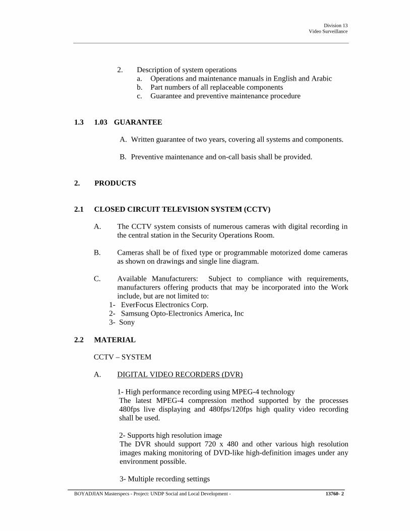
Division 13 Video Surveillance
2. Description of system operations a. Operations and maintenance manuals in English and Arabic b. Part numbers of all replaceable components c. Guarantee and preventive maintenance procedure
1.3 1.03 GUARANTEE
A. Written guarantee of two years, covering all systems and components.
B. Preventive maintenance and on-call basis shall be provided.
2. PRODUCTS
2.1 CLOSED CIRCUIT TELEVISION SYSTEM (CCTV)
A. The CCTV system consists of numerous cameras with digital recording in the central station in the Security Operations Room.
B. Cameras shall be of fixed type or programmable motorized dome cameras as shown on drawings and single line diagram.
C. Available Manufacturers: Subject to compliance with requirements, manufacturers offering products that may be incorporated into the Work include, but are not limited to:
1- EverFocus Electronics Corp. 2- Samsung Opto-Electronics America, Inc 3- Sony
2.2 MATERIAL
CCTV – SYSTEM
A. DIGITAL VIDEO RECORDERS (DVR)
1- High performance recording using MPEG-4 technology The latest MPEG-4 compression method supported by the processes 480fps live displaying and 480fps/120fps high quality video recording shall be used.
2- Supports high resolution image The DVR should support 720 x 480 and other various high resolution images making monitoring of DVD-like high-definition images under any environment possible.
3- Multiple recording settings
BOYADJIAN Masterspecs - Project: UNDP Social and Local Development - 13760- 2

Division 13 Video Surveillance
The DVR can be set for general, event, and / or scheduled recording simultaneously, so it is ready to handle any operating environment. Additionally, the image quality can be set to four different levels for more effective control of recording quality.
4- Various controllers including mouse, remote control and controller The DVR should come with an infrared wireless remote control, and offer simple GUI and a mouse for experienced PC users
5- Easy-to-use and convenient GUI Pop-up style menu and GUI shall make it very easy to operate the DVR.
6- Front USB port and AV output port 2 front USB ports shall be accessible for connecting mouse or back-up devices like DVD+RW or USB memory sticks. Video / Audio ports shall also be located on the front.
7- Optimal network speed The DVR should recognize line status automatically and configure the optimal network according to its environment.
8- Stable network speed 480fps Image processing chip for networking shall be used in the DVR to prevent interference from the main system's surveillance, record, play, and other settings during data transmissions.
9- Manages up to 5 DVR simultaneously A standard application provided, can be connected to five DVR and manage all of them simultaneously. This Network Viewer shall support live video monitoring of DVR, replay, menu setting modification, PTZ camera control, and other functions through a network.
10- Large data back up using DVD+RW The DVR shall come with a DVD+RW to support high capacity, high resolution record data back-ups. The front USB port can also be used for easy data back-up to a USB memory stick.
11- Built-in 250GB HDD, expandable up to 2TB The DVR shall be equipped with large 250GB internal HDD and support up to four internal HDD making it ideal for long-term data storage. (Up to 2TB with 4 x 500GB HDD)
12- Supports scalability of DVR/PTZ Dome using system controller The system controller SCC-3100A, shall allow control of up to 255 DVR and PTZ dome cameras. The DVR shall provide multi-protocol to support connecting and controlling a variety of peripherals making it easy to build medium to large security systems.
13- Supports text recording of ATM/POS transaction
BOYADJIAN Masterspecs - Project: UNDP Social and Local Development - 13760- 3
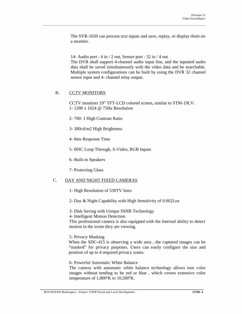
Division 13 Video Surveillance
The SVR-1650 can process text inputs and save, replay, or display them on a monitor.
14- Audio port : 4 in / 2 out, Sensor port : 32 in / 4 out The DVR shall support 4-channel audio input line, and the inputted audio data shall be saved simultaneously with the video data and be searchable. Multiple system configurations can be built by using the DVR 32 channel sensor input and 4- channel relay output.
B. CCTV MONITORS
CCTV monitors 19” TFT-LCD colored screen, similar to STM-19LV: 1- 1280 x 1024 @ 75Hz Resolution
2- 700: 1 High Contrast Ratio
3- 300cd/m2 High Brightness
4- 8ms Response Time
5- BNC Loop Through, S-Video, RGB Inputs
6- Built-in Speakers
7- Protecting Glass
C. DAY AND NIGHT FIXED CAMERAS
1- High Resolution of 530TV lines
2- Day & Night Capability with High Sensitivity of 0.002Lux
3- Disk Saving with Unique SSNR Technology 4- Intelligent Motion Detection This professional camera is also equipped with the Internal ability to detect motion in the scene they are viewing.
5- Privacy Masking When the SDC-415 is observing a wide area , the captured images can be “masked” for privacy purposes. Users can easily configure the size and position of up to 4 required privacy zones.
6- Powerful Automatic White Balance The camera with automatic white balance technology allows true color images without tending to be red or blue , which covers extensive color temperature of 1,800ºK to 10,500ºK.
BOYADJIAN Masterspecs - Project: UNDP Social and Local Development - 13760- 4

Division 13 Video Surveillance
7- Camera ID Setting Users can use the camera identification (CAMERA ID) to assign a name to the camera. The camera ID consists of up to 15 alphanumeric characters.
D. HIGH RESOLUTION DAY & NIGHT 3-AXIS DOME CAMERA
1- Mountable to any places with 3-axis rotating structure
2- Built-in auto iris 3X varifocal lens (f=3~9mm)
3- High resolution of 530TV lines, High sensitivity of 0.002Lux
4- Day & Night, Unique SSNR, noise reduction technology (SID-450)
E. SYSTEM KEYBOARD CONTROLLER
1- Capable of Controlling of Both Speed Dome Cameras & DVRs
2- Centralized Control of up to 255 Units from a Single Controller
3- Configurable to Connect Multiple System controllers up to 16 Units
4- Ergonomic Design and Easy-to-Use Keypad
5- 3D Joystick LCD Display (20 x 4 lines)
6- Multi-Protocol Support Control of PTZ Functions
7- Large Character (SCC-3100A)
F. CAMERA-SUPPORTING EQUIPMENT
1- Minimum Load Rating: Rated for load in excess of the total weight supported times a minimum safety factor of two.
2- Pan Units: Motorized automatic-scanning units arranged to provide remote-controlled manual and automatic camera panning action and equipped with matching mounting brackets.
a. Scanning Operation: Silent, smooth, and positive. b. Stops: Adjustable without disassembly, to limit the scanning arc.
3- Pan-and-Tilt Units: Motorized units arranged to provide remote-controlled aiming of cameras with smooth and silent operation and equipped with matching mounting brackets.
a. Panning Rotation: 0 to 355 degrees, with adjustable stops. b. Tilt Movement: 90 degrees, plus or minus 5 degrees, with
adjustable stops.
BOYADJIAN Masterspecs - Project: UNDP Social and Local Development - 13760- 5

Division 13 Video Surveillance
c. Speed: 12 degrees per second in both horizontal and vertical planes.
d. Wiring: Factory prewired for camera and zoom lens functions and pan-and-tilt power and control.
e. Retain subparagraph below if pan-and-tilt information is to be displayed at control station. Delete heater if one is provided in camera enclosure.
f. Built-in encoders or potentiometers for position feedback, and thermostat-controlled heater.
g. Retain subparagraph below if any pan-and-tilt unit is remotely controlled and is scheduled with computer-controlled preset positioning feature.
h. Pan-and-tilt unit shall be available with preset positioning capability to recall the position of a specific scene.
G. Mounting Brackets for Fixed Cameras: Type matched to items supported and mounting conditions. Include manual pan-and-tilt adjustment.
H. Protective Housings for Fixed and Movable Cameras:
Steel enclosures with internal camera mounting and connecting provisions that are matched to camera/lens combination and mounting and installing arrangement of camera to be housed.
i. Coordinate requirements in first subparagraph below with Division 13 Section "Intrusion Detection." Delete if not part of intrusion detection system.
j. Camera Viewing Window: Polycarbonate window, aligned with camera lens.
k. Duplex Receptacle: Internally mounted. l. Alignment Provisions: Camera mounting shall provide for field
aiming of camera and permit removal and reinstallation of camera lens without disturbing camera alignment.
m. Built-in thermostat-activated heater unit. Units shall be automatically controlled so the environmental limits of the camera equipment are not exceeded.
n. With sun shield that does not interfere with normal airflow around the housing.
o. Mounting bracket and hardware for wall or ceiling mounting of the housing. Bracket shall be of same material as the housing; mounting hardware shall be stainless steel.
p. Finish: Housing and mounting bracket shall be factory finished using manufacturer's standard finishing process suitable for the environment.
I. VARIFOCAL LENSES
BOYADJIAN Masterspecs - Project: UNDP Social and Local Development - 13760- 6

Division 13 Video Surveillance
1. Lens format 2. Iris control 3. Focal length 4. Focus control 5. Zoom control
1/3” Auto DC control 3.5-8 mm Manual Manual
J. CCTV POWER WIRING AND VIDEO COAXIAL CABLE
The power wiring running from low voltage power supplies to CCTV-camera equipment shall be sized by such method that voltage drop will not exceed the CCTV equipment manufacturers written requirements.
Separate runs from low voltage camera power supplies to each camera location shall be provided. The use of one pair of wires to power more than one camera will not be accepted.
Coaxial cable connectors to be used for all CCTV equipment shall be crimp type BNC. The use of twist type BNC connectors and “F” type connectors will not be accepted.
Coaxial cable shall be of solid copper center conductor and 95% minimum coverage copper braid.
The maximum dc resistance of the center conductor shall be a 65 Ohms per 1000 feet and maximum attenuation 0.45 db/100 FT at 10MHz. Temperature range shall be as from minus 30 degree to plus 75 degree Celsius.
Video amplifier to be installed in the Security Operations Room if needed; field equipment will not be approved.
3. EXECUTION
A. Install, test and commission the security system as in these specifications and in line with the approved drawing.
B. Where required derive 240V, 50 Hz, single phase power supply to the system device through the electrical sockets. Location of such outlets shall be identified on the drawings well in advance and approved by the Engineer and shall be executed by the main contractor.
C. All the central system components and devices shall be fully tested and demonstrated as a system to the Client.
D. After installation and before termination, all wiring and cabling shall be checked and tested prior to starting any commissioning activity. Provide grommets and strain relief material where necessary, to avoid abrasion of
BOYADJIAN Masterspecs - Project: UNDP Social and Local Development - 13760- 7

Division 13 Video Surveillance
wire and excess tension.
E. Provide terminal blocks, labels, tags and other permanent markings to clearly indicate the function, source and destination of all cabling. All cables and wires shall be identified, utilizing heat shrink, preprinted, polyolefin wire markers.
F. Competent start up personnel shall be provided by the Contractor until the system is fully functional. If, in Client’s judgment the Contractor is not demonstrating progress in solving any technical problems, the Contractor shall supply manufacturer’s representative and diagnostic equipment at no extra cost, until the problems are resolved.
G. All electronic equipment should be grounded prior to applying power.
H. Before the final acceptance the Contractor shall deliver 2 (two) copies of System Operation and Maintenance Manuals in ring binders.
I. A statement of guarantee including date of termination and the name and phone number of the person to be called in the event of equipment failure.
J. Individual factory issued manuals, containing all technical information on each piece of equipment installed. Advertising brochures or operational instructions shall not be used in lieu of the required technical manuals and information. All manuals shall be printed to ensure their performance.
K. Activate all alarm or other output devices that are in the system for proper operation, including supervisory and trouble circuit tests.
L. A check out report for each piece of equipment shall be prepared by the Contractor and submitted to the Client, one copy of which shall be registered with equipment manufacturers.
END OF SECTION 13760
BOYADJIAN Masterspecs - Project: UNDP Social and Local Development - 13760- 8
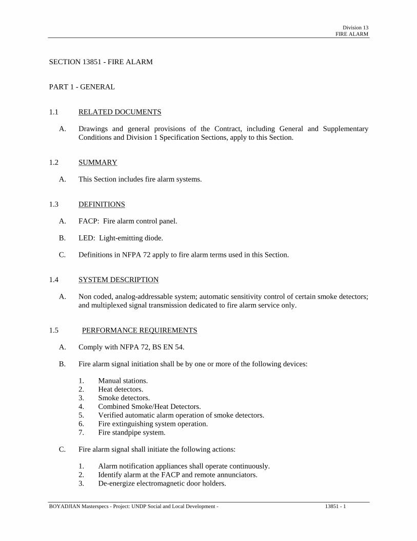
Division 13 FIRE ALARM
SECTION 13851 - FIRE ALARM PART 1 - GENERAL 1.1 RELATED DOCUMENTS
A. Drawings and general provisions of the Contract, including General and Supplementary Conditions and Division 1 Specification Sections, apply to this Section.
1.2 SUMMARY
A. This Section includes fire alarm systems. 1.3 DEFINITIONS
A. FACP: Fire alarm control panel.
B. LED: Light-emitting diode.
C. Definitions in NFPA 72 apply to fire alarm terms used in this Section. 1.4 SYSTEM DESCRIPTION
A. Non coded, analog-addressable system; automatic sensitivity control of certain smoke detectors; and multiplexed signal transmission dedicated to fire alarm service only.
1.5 PERFORMANCE REQUIREMENTS
A. Comply with NFPA 72, BS EN 54.
B. Fire alarm signal initiation shall be by one or more of the following devices:
1. Manual stations. 2. Heat detectors. 3. Smoke detectors. 4. Combined Smoke/Heat Detectors. 5. Verified automatic alarm operation of smoke detectors. 6. Fire extinguishing system operation. 7. Fire standpipe system.
C. Fire alarm signal shall initiate the following actions:
1. Alarm notification appliances shall operate continuously. 2. Identify alarm at the FACP and remote annunciators. 3. De-energize electromagnetic door holders.
BOYADJIAN Masterspecs - Project: UNDP Social and Local Development - 13851 - 1

Division 13 FIRE ALARM
4. Transmit an alarm signal to the remote alarm receiving station. 5. Activate voice/alarm communication system. 6. Switch heating, ventilating, and air-conditioning equipment controls to fire alarm mode. 7. Close smoke dampers in air ducts of system serving zone where alarm was initiated. 8. Record events in the system memory.
D. Supervisory signal initiation shall be by the operation of a fire-protection system valve tamper.
E. System trouble signal initiation shall be by one or more of the following devices or actions:
1. Open circuits, shorts and grounds of wiring for initiating device, signaling line, and
notification-appliance circuits. 2. Opening, tampering, or removal of alarm-initiating and supervisory signal-initiating
devices. 3. Loss of primary power at the FACP. 4. Ground or a single break in FACP internal circuits. 5. Abnormal ac voltage at the FACP. 6. A break in standby battery circuitry. 7. Failure of battery charging. 8. Abnormal position of any switch at the FACP or annunciator. 9. Fire-pump power failure, including a dead-phase or phase-reversal condition. 10. Low-air-pressure switch operation on a dry-pipe or pre action sprinkler system.
F. System Trouble and Supervisory Signal Actions: Ring trouble bell and annunciate at the FACP.
Record the event on system printer. 1.6 SUBMITTALS
A. Product Data: For each type of product indicated.
B. Shop Drawings:
1. Shop Drawings shall be prepared by persons with the following qualifications:
a. Trained and certified by manufacturer in fire alarm system design.
2. System Operation Description: Detailed description for this Project, including method of operation and supervision of each type of circuit and sequence of operations for manually and automatically initiated system inputs and outputs. Manufacturer's standard descriptions for generic systems are not acceptable.
3. Device Address List: Coordinate with final system programming. 4. System riser diagram with device addresses, conduit sizes, and cable and wire types and
sizes. 5. Wiring Diagrams: Power, signal, and control wiring. Include diagrams for equipment
and for system with all terminals and interconnections identified. Show wiring color code.
6. Batteries: Size calculations. 7. Duct Smoke Detectors: Performance parameters and installation details for each
detector, verifying that each detector is listed for the complete range of air velocity, temperature, and humidity possible when air-handling system is operating.
BOYADJIAN Masterspecs - Project: UNDP Social and Local Development - 13851 - 2

Division 13 FIRE ALARM
8. Ductwork Coordination Drawings: Plans, sections, and elevations of ducts, drawn to scale and coordinating the installation of duct smoke detectors and access to them. Show critical dimensions that relate to placement and support of sampling tubes, the detector housing, and remote status and alarm indicators. Locate detectors according to manufacturer's written recommendations.
9. Voice/Alarm Signaling Service: Equipment rack or console layout, grounding schematic, amplifier power calculation, and single-line connection diagram.
10. Floor Plans: Indicate final outlet locations showing address of each addressable device. Show size and route of cable and conduits.
C. Qualification Data: For Installer.
D. Field quality-control test reports.
E. Operation and Maintenance Data: For fire alarm system to include in emergency, operation,
and maintenance manuals. Comply with NFPA 72, Appendix A, recommendations for Owner's manual. Include abbreviated operating instructions for mounting at the FACP.
1.7 QUALITY ASSURANCE
A. Installer Qualifications: Personnel shall be trained and certified by manufacturer for installation of units required for this Project.
B. Electrical Components, Devices, and Accessories: Listed and labeled as defined in NFPA 70,
Article 100, by a testing agency acceptable to authorities having jurisdiction, and marked for intended use. Listed and approved by Vds & conform to equivalent DIN/EN standards.
1.8 EXTRA MATERIALS
A. Furnish extra materials described below that match products installed and that are packaged with protective covering for storage and identified with labels describing contents.
1. Lamps for Remote Indicating Lamp Units: Quantity equal to 10 percent of amount
installed, but not less than 1 unit. 2. Lamps for Strobe Units: Quantity equal to 10 percent of amount installed, but not less
than 1 unit. 3. Smoke, Heat, and Combined Detectors: Quantity equal to 10 percent of amount of each
type installed, but not less than 1 unit of each type. 4. Detector Bases: Quantity equal to 2 percent of amount of each type installed, but not less
than 1 unit of each type. 5. Keys and Tools: One extra set for access to locked and tamper proofed components. 6. Audible and Visual Notification Appliances: One of each type installed. 7. Fuses: Two of each type installed in the system.
BOYADJIAN Masterspecs - Project: UNDP Social and Local Development - 13851 - 3

Division 13 FIRE ALARM
PART 2 - PRODUCTS 2.1 MANUFACTURERS
A. Manufacturers: Subject to compliance with requirements, provide products by one of the following:
1. FACP and Equipment:
a. Bosh, Germany b. Esser – Germany c. Thorn, UK
or equivalent approval.
2. Wire and Cable: a. Beldin. b. West Penn c. Pirelli
or equivalent approval. 2.2 FACP
A. General Description: 1. Modular, power-limited design with electronic modules, UL 864 listed. 2. Decentralized intelligence. 3. Addressable initiation devices that communicate device identity and status.
a. Smoke sensors shall additionally communicate sensitivity setting and allow for
adjustment of sensitivity at the FACP. b. Temperature sensors shall additionally test for and communicate the sensitivity
range of the device. c. Combination of both.
4. Addressable control circuits for operation of mechanical equipment.
.
B. Alphanumeric Display and System Controls: Arranged for interface between human operator at
the FACP and addressable system components including annunciation and supervision. Display alarm (VGA), supervisory, and component status messages and the programming and control menu.
1. Annunciator and Display: VGA LCD display. 2. Keypad: Arranged to permit entry and execution of programming, display, and control
commands; and to indicate control commands to be entered into the system for control of smoke-detector sensitivity and other parameters.
C. Circuits:
BOYADJIAN Masterspecs - Project: UNDP Social and Local Development - 13851 - 4

Division 13 FIRE ALARM
1. Signaling Line Circuits: NFPA 72, Class A.
a. System Layout: Install no more than 125 addressable devices on each loop.
2. Notification-Appliance Circuits: NFPA 72, Class A. 3. Actuation of alarm notification appliances annunciation, smoke control, elevator recall,
and actuation of suppression systems shall occur within 10 seconds after the activation of an initiating device.
4. Electrical monitoring for the integrity of wiring external to the FACP for mechanical equipment shutdown and magnetic door-holding circuits is not required, provided a break in the circuit will cause doors to close and mechanical equipment to shut down.
D. Smoke-Alarm Verification:
1. Initiate audible and visible indication of an "alarm verification" signal at the FACP. 2. Activate a listed and approved "alarm verification" sequence at the FACP and the
detector. 3. Sound general alarm if the alarm is verified. 4. Cancel FACP indication and system reset if the alarm is not verified.
E. Notification-Appliance Circuit: Operation shall sound in a temporal pattern, complying with
ANSI S3.41.
F. Elevator Controls: Heat detector in machine room shuts down elevator power by operating a shunt trip in a circuit breaker feeding the elevator.
1. A field-mounted relay actuated by the fire detector or the FACP closes the shunt trip
circuit and operates building notification appliances and annunciator.
G. Power Supply for Supervision Equipment: Supply for audible and visual equipment for supervision of the ac power shall be from a dedicated dc power supply, and power for the dc component shall be from the ac supply.
H. Alarm Silencing, Trouble, and Supervisory Alarm Reset: Manual reset at the FACP and remote
annunciators, after initiating devices are restored to normal.
1. Silencing-switch operation halts alarm operation of notification appliances and activates an "alarm silence" light. Display of identity of the alarm zone or device is retained.
2. Subsequent alarm signals from other devices or zones reactivate notification appliances until silencing switch is operated again.
3. When alarm-initiating devices return to normal and system reset switch is operated, notification appliances operate again until alarm silence switch is reset.
I. Walk Test: A test mode to allow one person to test alarm and supervisory features of initiating
devices. Enabling of this mode shall require the entry of a password. The FACP and annunciators shall display a test indication while the test is underway. If testing ceases while in walk-test mode, after a preset delay, the system shall automatically return to normal.
J. Remote Smoke-Detector Sensitivity Adjustment: Controls shall select specific addressable
smoke detectors for adjustment, display their current status and sensitivity settings, and control of changes in those settings. Allow controls to be used to program repetitive, time-scheduled,
BOYADJIAN Masterspecs - Project: UNDP Social and Local Development - 13851 - 5

Division 13 FIRE ALARM
and automated changes in sensitivity of specific detector groups. Record sensitivity adjustments and sensitivity-adjustment schedule changes in system memory.
K. Alarm Signaling Service:
1. Indicated number of alarm channels for automatic, simultaneous transmission of different
announcements to different zones.
a. Allow the application of and evacuation signal to indicated number of zones and, at the same time.
b. Generate tones to be sequenced of the type recommended by NFPA 72 and that are compatible with tone patterns of the notification-appliance circuits of the FACP.
2. Notification-Appliance Circuits: NFPA 72, Class A.
L. Primary Power: 24-V dc obtained from 230-V ac service and a power-supply module.
Initiating devices, notification appliances, signaling lines, trouble signal, and supervisory signal shall be powered by the 24-V dc source.
1. The alarm current draw of the entire fire alarm system shall not exceed 80 percent of the
power-supply module rating. 2. Power supply shall have a dedicated fused safety switch for this connection at the service
entrance equipment. Paint the switch box red and identify it with "FIRE ALARM SYSTEM POWER."
M. Secondary Power: 24-V dc supply system with batteries and automatic battery charger and an
automatic transfer switch.
1. Batteries: nickel cadmium rechargeable batteries.
2. Battery and Charger Capacity: Comply with NFPA 72.
N. Surge Protection:
1. Install surge protection on normal ac power for the FACP and its accessories. 2. Install surge protectors recommended by FACP manufacturer. Install on all system
wiring external to the building housing the FACP.
O. Instructions: Computer printout or typewritten instruction card mounted behind a plastic or glass cover in a stainless-steel or aluminum frame. Include interpretation and describe appropriate response for displays and signals. Briefly describe the functional operation of the system under normal, alarm, and trouble conditions.
2.3 MANUAL FIRE ALARM BOXES
A. Description: UL 38 listed; finished in red with molded, raised-letter operating instructions in contrasting color. Station shall show visible indication of operation. Mounted on recessed outlet box; if indicated as surface mounted, provide manufacturer's surface back box.
BOYADJIAN Masterspecs - Project: UNDP Social and Local Development - 13851 - 6

Division 13 FIRE ALARM
1. Single-action mechanism, breaking-glass or plastic-rod type. With integral addressable module, with built-in CPU, arranged to communicate manual-station status (normal, alarm, or trouble) to the FACP.
2. Station Reset: Key- or wrench-operated switch. 2.4 SYSTEM SMOKE DETECTORS
A. General Description:
1. UL 268 listed, operating at 24-V dc, nominal. 2. Integral Addressable Module: Address automatically allocated (soft), with built-in CPU ,
arranged to communicate detector status (normal, alarm, or trouble) to the FACP. 3. Plug-in Arrangement: Detector and associated electronic components shall be mounted
in a plug-in module that connects to a fixed base. Provide terminals in the fixed base for connection of building wiring.
4. Built-in short circuit isolator. 5. Self-Restoring: Detectors do not require resetting or readjustment after actuation to
restore them to normal operation. 6. Integral Visual-Indicating Light: LED type. Indicating detector has operated and power-
on status. 7. Remote Control: Unless otherwise indicated, detectors shall be analog-addressable type,
individually monitored at the FACP for calibration, sensitivity, and alarm condition, and individually adjustable for sensitivity from the FACP.
a. Rate-of-rise temperature characteristic shall be selectable at the FACP for 8 or 11
deg C per minute. b. Fixed-temperature sensing shall be independent of rate-of-rise sensing and shall be
settable at the FACP to operate at 57 or 68 deg C. c. Provide multiple levels of detection sensitivity for each sensor.
B. Duct Smoke Detectors:
1. Photoelectric Smoke Detectors:
a. Sensor: LED or infrared light source with matching silicon-cell receiver. b. Detector Sensitivity: Between 0.008 and 0.011 percent/mm smoke obscuration
when tested according to UL 268A.
2. UL 268A listed, operating at 24-V dc, nominal. 3. Integral Addressable Module: Arranged to communicate detector status (normal, alarm,
or trouble) to the FACP. 4. Plug-in Arrangement: Detector and associated electronic components shall be mounted
in a plug-in module that connects to a fixed base. The fixed base shall be designed for mounting directly to the air duct. Provide terminals in the fixed base for connection to building wiring.
a.
Weatherproof Duct Housing Enclosure: UL listed for use with the supplied detector. The enclosure shall comply with NEMA 250 requirements for Type 4X.
13851 - 7

Division 13 FIRE ALARM
5. Self-Restoring: Detectors shall not require resetting or readjustment after actuation to restore them to normal operation.
6. Integral Visual-Indicating Light: LED type. Indicating detector has operated and power-on status.
7. Remote Control: Unless otherwise indicated, detectors shall be analog-addressable type, individually monitored at the FACP for calibration, sensitivity, and alarm condition, and individually adjustable for sensitivity from the FACP.
8. Each sensor shall have multiple levels of detection sensitivity. 9. Sampling Tubes: Design and dimensions as recommended by manufacturer for the
specific duct size, air velocity, and installation conditions where applied. 10. Relay Fan Shutdown: Rated to interrupt fan motor-control circuit.
2.5 HEAT DETECTORS
A. General: UL 521 listed. Automatically addressable, with built-in short circuit isolator and built-in CPU.
B. Heat Detector, Combination Type: Actuated by either a fixed temperature of 57 deg C or rate-
of-rise of temperature that exceeds 8 deg C per minute, unless otherwise indicated.
1. Mounting: Plug-in base, interchangeable with smoke-detector bases. 2. Integral Addressable Module: Address automatically allocated (soft), arranged to
communicate detector status (normal, alarm, or trouble) to the FACP.
C. Heat Detector, Fixed-Temperature Type: Actuated by temperature that exceeds a fixed temperature of 88 deg C.
1. Mounting: Plug-in base, interchangeable with smoke-detector bases. 2. Integral Addressable Module: Arranged to communicate detector status (normal, alarm,
or trouble) to the FACP.
D. Continuous Linear Heat-Detector System: Consists of detector cable and control unit.
1. Detector Cable: Rated detection temperature 68 deg C. Listed for "regular" service and a standard environment. Cable includes two steel actuator wires twisted together with spring pressure, wrapped with protective tape, and finished with PVC outer sheath. Each actuator wire is insulated with heat-sensitive material that reacts with heat to allow the cable twist pressure to short circuit wires at the location of elevated temperature.
2. Control Unit: Two-zone or multizone unit as indicated. Provides same system power supply, supervision, and alarm features as specified for the central FACP.
3. Signals to the Central FACP: Any type of local system trouble is reported to the central FACP as a composite "trouble" signal. Alarms on each detection zone are individually reported to the central FACP as separately identified zones.
4. Integral Addressable Module: Arranged to communicate detector status (normal, alarm, or trouble) to the FACP.
BOYADJIAN Masterspecs - Project: UNDP Social and Local Development - 13851 - 8

Division 13 FIRE ALARM
2.6 COMBINED OPTICAL/HEAT DETECTOR
A. Comply with EN 54: Part 5 & 7and Vds approved
Combines two individual sensing elements to provide excellent cover for both types of fire. Two separate optical detection angles for smoke and thermistor for heat. Equipped with built-in CPU.
2.7 NOTIFICATION APPLIANCES
A. Description: Equipped for mounting as indicated and with screw terminals for system connections.
1. Combination Devices: Factory-integrated audible and visible devices in a single-
mounting assembly.
B. Bells: Electric-vibrating, 24-V dc, under-dome type; with provision for housing the operating mechanism behind the bell. Bells shall produce a sound-pressure level of 94 dBA, measured 3 m from the bell. 254-mm size, unless otherwise indicated. Bells are weatherproof where indicated.
C. Chimes, Low-Level Output: Vibrating type, 75-dBA minimum rated output.
D. Chimes, High-Level Output: Vibrating type, 81-dBA minimum rated output.
E. Horns: Electric-vibrating-polarized type, 24-V dc; with provision for housing the operating
mechanism behind a grille. Horns shall produce a sound-pressure level of 90 dBA, measured 3 m from the horn.
F. Visible Alarm Devices: Xenon strobe lights listed under UL 1971, with clear or nominal white
polycarbonate lens mounted on an aluminum faceplate. The word "FIRE" is engraved in minimum 25-mm- high letters on the lens.
1. Rated Light Output: as required by NPFA 72, according to installation method and
room dimensions. 2. Strobe Leads: Factory connected to screw terminals.
2.8 ADDRESSABLE INTERFACE DEVICE
A. Description: Microelectronic monitor/control module listed for use in providing a system address for listed alarm-initiating devices for wired applications with normally open contacts and to control the functioning of certain systems through dry contacts.
B. Integral Relay: Capable of providing a direct signal to the elevator controller to initiate elevator
recall to a circuit-breaker shunt trip for power shutdown. BOYADJIAN Masterspecs - Project: UNDP Social and Local Development - 13851 - 9

Division 13 FIRE ALARM
2.9 DIGITAL ALARM COMMUNICATOR TRANSMITTER
A. Listed and labeled according to UL 632.
B. Functional Performance: Unit receives an alarm, supervisory, or trouble signal from the FACP, and automatically captures one or two telephone lines and dials a preset number for a remote central station. When contact is made with the central station(s), the signal is transmitted. The unit supervises up to two telephone lines. Where supervising 2 lines, if service on either line is interrupted for longer than 45 seconds, the unit initiates a local trouble signal and transmits a signal indicating loss of telephone line to the remote alarm receiving station over the remaining line. When telephone service is restored, unit automatically reports that event to the central station. If service is lost on both telephone lines, the local trouble signal is initiated.
C. Secondary Power: Integral rechargeable battery and automatic charger. Battery capacity is
adequate to comply with NFPA 72 requirements.
D. Self-Test: Conducted automatically every 24 hours with report transmitted to central station. 2.10 GUARDS FOR PHYSICAL PROTECTION
A. Description: Welded wire mesh of size and shape for the manual station, smoke detector, gong, or other device requiring protection.
1. Factory fabricated and furnished by manufacturer of the device. 2. Finish: Paint of color to match the protected device.
2.11 WIRE AND CABLE
A. Wire and cable for fire alarm systems shall be UL listed and labeled as complying with NFPA 70, Article 760.
B. Signaling Line Circuits: Twisted, shielded cable size as recommended by system manufacturer.
1. Circuit Integrity Cable:
a- Twisted shielded cable 18 AWG for fire alarm signal service (detectors loop).
Complying with requirements in UL 1424 and in UL 2196 for a 2-hour rating.
b- Fire Retardant cables are allowed to be used only in conduits embedded in ceilings where in all other areas and conduits the fire rated cables are used.
C. Non-Power-Limited Circuits: Solid-copper conductors with 600-V rated, 75 deg C, color-coded
insulation.
1. Low-Voltage Circuits: No. 16 AWG, minimum. 2. Line-Voltage Circuits: No. 12 AWG, minimum. 3. Multi conductor Armored Cable: NFPA 70 Type MC, copper conductors, TFN/THHN
conductor insulation, copper drain wire, copper armor with outer jacket with red identifier stripe, UL listed for fire alarm and cable tray installation, plenum rated, and complying with requirements in UL 2196 for a 2-hour rating.
BOYADJIAN Masterspecs - Project: UNDP Social and Local Development - 13851 - 10

Division 13 FIRE ALARM
PART 3 - EXECUTION 3.1 EQUIPMENT INSTALLATION
A. Smoke or Heat Detector Spacing:
1. Smooth ceiling spacing shall not exceed the rating of the detector. 2. Spacing of heat detectors for irregular areas, for irregular ceiling construction, and for
high ceiling areas, shall be determined according to Appendix A in NFPA 72. 3. Spacing of heat detectors shall be determined based on guidelines and recommendations
in NFPA 72.
B. HVAC: Locate detectors not closer than 1 m from air-supply diffuser or return-air opening.
C. Heat Detectors in Elevator Shafts: Coordinate temperature rating and location with sprinkler rating and location.
D. Remote Status and Alarm Indicators: Install near each smoke detector and each sprinkler water-
flow switch and valve-tamper switch that is not readily visible from normal viewing position.
E. Audible Alarm-Indicating Devices: Install not less than 150 mm below the ceiling. Install bells and horns on flush-mounted back boxes with the device-operating mechanism concealed behind a grille.
F. Visible Alarm-Indicating Devices: Install adjacent to each alarm bell or alarm horn and at least
150 mm below the ceiling.
G. Device Location-Indicating Lights: Locate in public space near the device they monitor.
H. FACP: Surface mount with tops of cabinets not more than 1830 mm above the finished floor.
I. Annunciator: Install with top of panel not more than 1830 mm above the finished floor. 3.2 WIRING INSTALLATION
A. Install wiring according to the following:
1. NECA 1. 2. TIA/EIA 568-A.
B. Wiring Method: Install wiring in raceway according to Division 16 Section "Raceways and
Boxes."
1. Fire alarm circuits and equipment control wiring associated with the fire alarm system shall be installed in a dedicated raceway system. This system shall not be used for any other wire or cable.
BOYADJIAN Masterspecs - Project: UNDP Social and Local Development - 13851 - 11

Division 13 FIRE ALARM
C. Wiring within Enclosures: Separate power-limited and non-power-limited conductors as recommended by manufacturer. Install conductors parallel with or at right angles to sides and back of the enclosure. Bundle, lace, and train conductors to terminal points with no excess. Connect conductors that are terminated, spliced, or interrupted in any enclosure associated with the fire alarm system to terminal blocks. Mark each terminal according to the system's wiring diagrams. Make all connections with approved crimp-on terminal spade lugs, pressure-type terminal blocks, or plug connectors.
D. Cable Taps: Use numbered terminal strips in junction, pull, and outlet boxes, cabinets, or
equipment enclosures where circuit connections are made.
E. Color-Coding: Color-code fire alarm conductors differently from the normal building power wiring. Use one color-code for alarm circuit wiring and a different color-code for supervisory circuits. Color-code audible alarm-indicating circuits differently from alarm-initiating circuits. Use different colors for visible alarm-indicating devices. Paint fire alarm system junction boxes and covers red.
3.3 IDENTIFICATION
A. Identify system components, wiring, cabling, and terminals according to Division 16 Section "Electrical Identification."
B. Install instructions frame in a location visible from the FACP.
C. Paint power-supply disconnect switch red and label "FIRE ALARM."
3.4 GROUNDING
A. Ground the FACP and associated circuits; comply with IEEE 1100. Install a ground wire from main service ground to the FACP.
3.5 FIELD QUALITY CONTROL
A. Manufacturer's Field Service: Engage a factory-authorized service representative to inspect, test, and adjust field-assembled components and equipment installation, including connections, and to assist in field testing. Report results in writing.
B. Perform the following field tests and inspections and prepare test reports:
1. Before requesting final approval of the installation, submit a written statement using the
form for Record of Completion shown in NFPA 72.
2. Visual Inspection: Conduct a visual inspection before any testing. Use as-built drawings and system documentation for the inspection. Identify improperly located, damaged, or nonfunctional equipment, and correct before beginning tests.
BOYADJIAN Masterspecs - Project: UNDP Social and Local Development - 13851 - 12

Division 13 FIRE ALARM
3. Testing: Follow procedure and record results complying with requirements in NFPA 72.
a. Detectors that are outside their marked sensitivity range shall be replaced.
4. Test and Inspection Records: Prepare according to NFPA 72, including demonstration of sequences of operation by using the matrix-style form in Appendix A in NFPA 70.
3.6 ADJUSTING
A. Occupancy Adjustments: When requested within 12 months of date of Substantial Completion, provide on-site assistance in adjusting system to suit actual occupied conditions. Provide up to two visits to Project outside normal occupancy hours for this purpose.
B. Follow-Up Tests and Inspections: After date of Substantial Completion, test the fire alarm
system complying with testing and visual inspection requirements in NFPA 72. Perform tests and inspections listed for three monthly, and one quarterly, periods.
C. Annual Test and Inspection: One year after date of Substantial Completion, test the fire alarm
system complying with the testing and visual inspection requirements in NFPA 72. Perform tests and inspections listed for monthly, quarterly, semiannual, and annual periods. Use forms developed for initial tests and inspections.
D. Warranty: 3 years
E. Spare parts availability shall be guaranteed for minimum of 10 years.
3.7 DEMONSTRATION
A. Engage a factory-authorized service representative to train Owner's maintenance personnel to adjust, operate, and maintain the fire alarm system, appliances, and devices.
END OF SECTION 13851
BOYADJIAN Masterspecs - Project: UNDP Social and Local Development - 13851 - 13

Division 16 Voice & Data Communication Cabling
SECTION 16750 - VOICE AND DATA COMMUNICATION CABLING PART 1 - GENERAL 1.1 RELATED DOCUMENTS
A. Drawings and general provisions of the Contract, including General and Supplementary Conditions and Division 1 Specification Sections, apply to this Section.
1.2 SUMMARY
A. This Section includes wire, cable, connecting devices, installation, and testing for wiring systems to be used as signal pathways for voice and high-speed data transmission.
1.3 DEFINITIONS
A. EMI: Electromagnetic interference.
B. IDC: Insulation displacement connector.
C. LAN: Local area network.
D. PVC: Polyvinyl chloride.
E. STP: Shielded twisted pair.
F. UTP: Unshielded twisted pair. 1.4 SUBMITTALS
A. Product Data: Include data on features, ratings, and performance for each component specified.
B. Shop Drawings: Include dimensioned plan and elevation views of each individual component. Show equipment assemblies, method of field assembly, workspace requirements, and access for cable connections.
1. System labeling schedules, including electronic copy of labeling schedules, as specified
in Part 3, in software and format selected by Owner. 2. Wiring diagrams. Show typical wiring schematics including the following:
a. Workstation outlets, jacks, and jack assemblies. b. Patch cords. c. Patch panels.
C. Cable Administration Drawings: As specified in Part 3.
BOYADJIAN Masterspecs - Project: UNDP Social and Local Development - 16750 -1

Division 16 Voice & Data Communication Cabling
D. Samples: For workstation outlets, jacks, jack assemblies, and faceplates for color selection and evaluation of technical features.
E. Product Certificates: For each type of cable, connector, and terminal equipment, signed by
product manufacturer.
F. Qualification Data: For Installer.
G. Field quality-control test reports.
H. Operation and Maintenance Data: For voice and data communication cabling to include in emergency, operation, and maintenance manuals.
1.5 QUALITY ASSURANCE
A. Installer Qualifications: System installer must have on staff a registered communication distribution designer certified by Building Industry Consulting Service International.
B. Source Limitations: Obtain all products except twisted-pair and fiber-optic cables through one
source from a single manufacturer.
C. Electrical Components, Devices, and Accessories: Listed and labeled as defined in NFPA 70, Article 100, by a testing agency acceptable to authorities having jurisdiction, and marked for intended use.
D. Comply with NFPA 70.
1.6 COORDINATION
A. Coordinate service entrance arrangement with local exchange carrier. 1.7 EXTRA MATERIALS
A. Furnish extra materials described below that match products installed and that are packaged with protective covering for storage and identified with labels describing contents.
1. Cable: 76 m of each size and type used for Project. Furnish on reels. 2. Patch-Panel Units: One of each type for every six installed, but no fewer than one. 3. Connecting Blocks: One of each type for every 25 installed, but no fewer than one. 4. Outlet Assemblies: One of each type for every 25 installed, but no fewer than one.
BOYADJIAN Masterspecs - Project: UNDP Social and Local Development - 16750 - 2
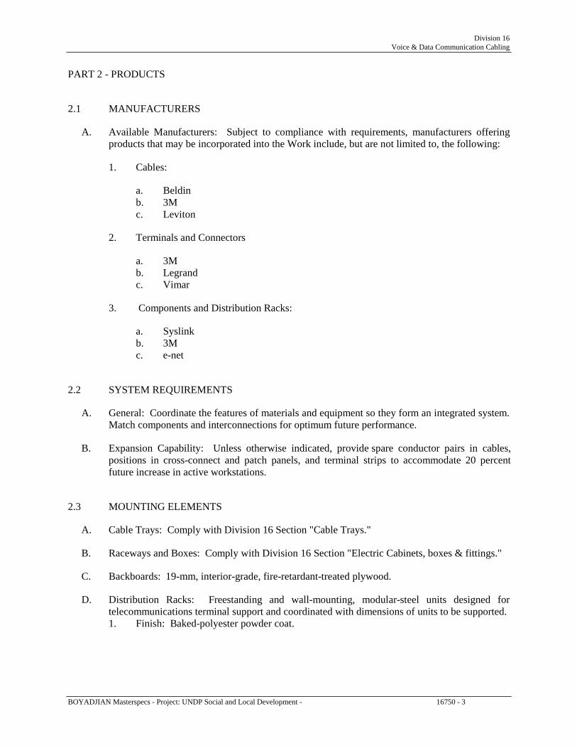
Division 16 Voice & Data Communication Cabling
PART 2 - PRODUCTS 2.1 MANUFACTURERS
A. Available Manufacturers: Subject to compliance with requirements, manufacturers offering products that may be incorporated into the Work include, but are not limited to, the following:
1. Cables:
a. Beldin b. 3M c. Leviton
2. Terminals and Connectors
a. 3M b. Legrand c. Vimar
3. Components and Distribution Racks:
a. Syslink b. 3M c. e-net
2.2 SYSTEM REQUIREMENTS
A. General: Coordinate the features of materials and equipment so they form an integrated system. Match components and interconnections for optimum future performance.
B. Expansion Capability: Unless otherwise indicated, provide spare conductor pairs in cables,
positions in cross-connect and patch panels, and terminal strips to accommodate 20 percent future increase in active workstations.
2.3 MOUNTING ELEMENTS
A. Cable Trays: Comply with Division 16 Section "Cable Trays."
B. Raceways and Boxes: Comply with Division 16 Section "Electric Cabinets, boxes & fittings."
C. Backboards: 19-mm, interior-grade, fire-retardant-treated plywood.
D. Distribution Racks: Freestanding and wall-mounting, modular-steel units designed for telecommunications terminal support and coordinated with dimensions of units to be supported. 1. Finish: Baked-polyester powder coat.
BOYADJIAN Masterspecs - Project: UNDP Social and Local Development - 16750 - 3

Division 16 Voice & Data Communication Cabling
2.4 TWISTED-PAIR CABLES, CONNECTORS, AND TERMINAL EQUIPMENT
A. Cables: Listed as complying with Category 6 of TIA/EIA-568-C.
B. Conductors: Solid copper.
C. UTP Cable: Comply with TIA/EIA-568-C. Four, thermoplastic-insulated, individually twisted pairs of conductors; No. 24 AWG, color-coded; enclosed in PVC jacket.
D. UTP Plenum Cable: Listed for use in air-handling spaces. Features are as specified for cables,
conductors, UTP cable, and workstation cable except materials are modified as required for listing.
E. UTP Cable Connecting Hardware: Comply with TIA/EIA-568-C, RJ-45 Type.
F. Patch Panel: Modular panels housing multiple-numbered jack units RJ-45 -type connectors at
each jack for permanent termination of pair groups of installed cables.
1. Number of Jacks per Field: One for each four-pair UTP cable.
G. Jacks and Jack Assemblies for UTP Cable: Modular, color-coded, RJ-45 receptacle units. Use keyed jacks for data service.
H. UTP Patch Cords: Four-pair cables in 1200-mm lengths, terminated with RJ-45 plug at each
end. Use keyed plugs for data service.
I. Workstation Outlets: Dual jack-connector assemblies mounted in single or multigang faceplate.
1. Faceplate: As selected by Architect/ID. 2. Mounting: Flush, unless otherwise indicated. 3. Legend: Factory labeled, top jack "Voice" and bottom jack "Data," by silk-screening or
engraving. 2.5 FIBER-OPTIC CABLES, CONNECTORS, AND TERMINAL EQUIPMENT
A. Cables: Factory fabricated, jacketed, low loss, glass type, fiber optic, multimode, graded index, operating at 850 and 1300 nm. 1. Backbone, Strands per Cable: 6, unless otherwise indicated. 2. Dimensions: 50-micrometer core diameter; 125-micrometer cladding diameter. 3. Maximum Attenuation: Minus 3.75 dB/km at 850 nm; minus 1.5 dB/km at 1300 nm. 4. Minimum Modal Bandwidth: 160 MHz/km at 850 nm; 500 MHz/km at 1300 nm. 5. Operating Temperature Range: Minus 20 to plus 70 deg C.
B. Plenum Cable: Listed for use in plenums.
C. Cable Connectors: Quick-connect, simplex- and duplex-type SC couplers with self-centering,
axial alignment mechanisms. Insertion loss not more than 0.7 dB.
D. Patch Panel: Modular panels housing multiple-numbered, duplex cable connectors. BOYADJIAN Masterspecs - Project: UNDP Social and Local Development - 16750 - 4

Division 16 Voice & Data Communication Cabling
1. Permanent Connection: Permanently connect one end of each connector module to installed cable fiber.
2. Number of Connectors per Field: One for each fiber of cable or cables assigned to field, plus spares and blank positions adequate to satisfy specified expansion criteria.
3. Mounting: Rack.
E. Patch Cords: Dual fiber cables in 900-mm lengths.
1. Terminations: Two duplex connectors arranged to mate with patch-panel connectors, one at each end of each fiber in cord.
2.6 IDENTIFICATION PRODUCTS
A. Comply with Division 16 Section "General Electrical Requirements" and the following:
1. Cable Labels: Self-adhesive vinyl or vinyl-cloth wraparound tape markers, machine printed with alphanumeric cable designations.
PART 3 - EXECUTION 3.1 EXAMINATION
A. Examine pathway elements intended for cables. Check raceways, cable trays, and other elements for compliance with space allocations, installation tolerances, hazards to cable installation, and other conditions affecting installation. Proceed with installation only after unsatisfactory conditions have been corrected.
3.2 APPLICATION OF MEDIA
A. Backbone Cable for Data Service: Use Fiber optic cable for runs between equipment rooms and wiring closets and for runs between wiring closets.
B. Backbone Cable for Voice Service: Use UTP Category 3 cable for runs between equipment
rooms and wiring closets and for runs between wiring closets.
C. Horizontal Cable for Data Service: Use UTP Category 6 cable for runs between wiring closets and workstation outlets.
D. Horizontal Cable for Voice Service: Use UTP Category 6 cable for runs between wiring
closets and workstation outlets. 3.3 INSTALLATION
A. Wiring Method: Install wiring and fiber optic in raceway and cable tray except within consoles, cabinets, desks, and counters. Conceal raceway and wiring except in unfinished spaces.
BOYADJIAN Masterspecs - Project: UNDP Social and Local Development - 16750 - 5

Division 16 Voice & Data Communication Cabling
B. Install cables using techniques, practices, and methods that are consistent with Category 6 rating of components and that ensure Category 6 performance of completed and linked signal paths, end to end.
C. Install cables without damaging conductors, shield, or jacket.
D. Do not bend cables, in handling or in installing, to smaller radii than minimums recommended
by manufacturer.
E. Pull cables without exceeding cable manufacturer's recommended pulling tensions.
1. Pull cables simultaneously if more than one is being installed in same raceway. 2. Use pulling compound or lubricant if necessary. Use compounds that will not damage
conductor or insulation. 3. Use pulling means, including fish tape, cable, rope, and basket-weave wire or cable grips,
that will not damage media or raceway.
F. Install exposed cables parallel and perpendicular to surfaces or exposed structural members and follow surface contours where possible.
G. Secure and support cables at intervals not exceeding 760 mm and not more than 150 mm from
cabinets, boxes, fittings, outlets, racks, frames, and terminals.
H. Wiring within Wiring Closets and Enclosures: Provide conductors of adequate length. Train conductors to terminal points with no excess. Use lacing bars to restrain cables, to prevent straining connections, and to prevent bending cables to smaller radii than minimums recommended by manufacturer.
I. Separation of Wires: Comply with TIA/EIA-569-A rules for separating unshielded copper
voice and data communication cabling from potential EMI sources, including electrical power lines and equipment.
J. Make splices, taps, and terminations only at indicated outlets, terminals, and cross-connect and
patch panels.
K. Use splice and tap connectors compatible with media types. 3.4 GROUNDING
A. Comply with Division 16 Section "Grounding and Bonding."
B. Ground cable shields, drain conductors, and equipment to eliminate shock hazard and to minimize ground loops, common-mode returns, noise pickup, cross talk, and other impairments.
C. Bond shields and drain conductors to ground at only one point in each circuit.
D. Signal Ground Terminal: Locate in each equipment room and wiring closet; isolate from power
system and equipment grounding.
E. Signal Ground Bus: Mount on wall of main equipment room with standoff insulators. BOYADJIAN Masterspecs - Project: UNDP Social and Local Development - 16750 - 6

Division 16 Voice & Data Communication Cabling
F. Signal Ground Backbone Cable: Extend from signal ground bus to signal ground terminal in each equipment room and wiring closet.
3.5 INSTALLATION IN EQUIPMENT ROOMS AND WIRING CLOSETS
A. Install plywood backboards on walls of equipment rooms and wiring closets from floor to ceiling.
B. Mount patch panels, terminal strips, and other connecting hardware on backboards, unless
otherwise indicated.
C. Group connecting hardware for cables into separate logical fields.
D. Use patch panels to terminate cables entering the space, unless otherwise indicated. 3.6 INSTALLATION STANDARDS
A. Comply with requirements in TIA/EIA-568-C and TIA/EIA-569-A. 3.7 IDENTIFICATION
A. In addition to requirements in this Article, comply with applicable requirements in Division 16 Section "Electrical Identification" and TIA/EIA-606.
B. System: Use a unique, three-syllable, alphanumeric designation for each cable, and label cable
and jacks, connectors, and terminals to which it connects with same designation. Use logical and systematic designations for facility's architectural arrangement.
1. First syllable identifies and locates equipment room or wiring closet where cables
originate. 2. Second syllable identifies and locates cross-connect- or patch-panel field in which cables
terminate. 3. Third syllable designates type of media (copper or fiber) and position occupied by cable
pairs or fibers in field.
C. Workstation: Label cables within outlet boxes.
D. Distribution Racks and Frames: Label each unit and field within that unit.
E. Within Connector Fields in Equipment Rooms and Wiring Closets: Label each connector and each discrete unit of cable-terminating and connecting hardware. Where similar jacks and plugs are used for both voice and data communication cabling, use a different color for jacks and plugs of each service.
F. Cables, General: Label each cable within 100 mm of each termination and tap, where it is
accessible in a cabinet or junction or outlet box, and elsewhere as indicated. BOYADJIAN Masterspecs - Project: UNDP Social and Local Development - 16750 - 7

Division 16 Voice & Data Communication Cabling
G. Exposed Cables and Cables in Cable Trays and Wire Troughs: Label each cable at intervals not exceeding 4.5 m.
H. Cable Schedule: Post in prominent location in each equipment room and wiring closet. List
incoming and outgoing cables and their designations, origins, and destinations. Protect with rigid frame and clear plastic cover. Furnish an electronic copy of final comprehensive schedules for Project, in software and format selected by Owner.
I. Cable Administration Drawings: Show building floor plans with cable administration point
labeling. Identify labeling convention and show labels for telecommunications closets, entrance pathways and cables, terminal hardware and positions, horizontal cables, work areas and workstation terminal positions, grounding buses and pathways, and equipment grounding conductors. Follow convention of TIA/EIA-606. Furnish electronic record of all drawings, in software and format selected by Owner.
3.8 FIELD QUALITY CONTROL
A. Perform the following field tests and inspections and prepare test reports:
1. Operational Test: After installation of cables and connectors, demonstrate product capability and compliance with requirements. Test each signal path for end-to-end performance from each end of all pairs installed. Remove temporary connections when tests have been satisfactorily completed.
2. Copper Cable Procedures: Inspect for physical damage and test each conductor signal path for continuity and shorts. Use Class 2, bidirectional, Category 6 tester. Test for faulty connectors, splices, and terminations. Test according to TIA/EIA-TSB67, "Transmission Performance Specifications for Field Testing of Unshielded Twisted-Pair Cabling Systems." Link performance for UTP cables must meet minimum criteria of TIA/EIA-568-C.
B. Remove malfunctioning units, replace with new units, and retest as specified above.
END OF SECTION 16750
BOYADJIAN Masterspecs - Project: UNDP Social and Local Development - 16750 - 8

Division 16 Master Antenna Television System
SECTION 16785 - MASTER ANTENNA TELEVISION SYSTEM PART 1 - GENERAL 1.1 RELATED DOCUMENTS
A. Drawings and general provisions of the Contract, including General and Supplementary Conditions and Division 1 Specification Sections, apply to this Section.
1.2 SUMMARY
A. This Section includes the following:
1. Master antenna television systems using direct broadcast satellite service, off-air antenna system as the signal source.
2. Broadband coaxial cabling for distributing television signal to interface points. 1.3 DEFINITIONS
A. Agile Receiver: A broadband receiver that can be tuned to any desired channel.
B. Broadband: For the purposes of this Section, wide bandwidth equipment or systems that can carry signals occupying in the frequency range of 54 to 1002 MHz. A broadband communication system can simultaneously accommodate television, voice, data, and many other services.
C. Carrier: A pure-frequency signal that is modulated to carry information. In the process of
modulation, it is spread out over a wider band. The carrier frequency is the center frequency on any television channel.
D. CATV: Community antenna television; a communication system that simultaneously
distributes several different channels of broadcast programs and other information to customers via a coaxial cable.
E. CCTV: Closed-circuit television.
F. CEA: Consumer Electronics Association.
G. dBmV: Decibels relative to 1 mV across 75 ohms. Zero dBmV is defined as 1 mV across 75
ohms. dBmV = 20 log 10(V1/V2) where V1 is the measurement of voltage at a point having identical impedance to V2 (0.001 V across 75 ohms).
H. Headend: The control center of the master antenna television system, where incoming signals
are amplified, converted, processed, and combined into a common cable along with any locally originated television signals, for transmission to user-interface points. It is also called the "Central Retransmission Facility."
BOYADJIAN Masterspecs - Project: UNDP Social and Local Development - 16785 - 1

Division 16 Master Antenna Television System
I. MATV: Master antenna television; a small television antenna distribution system usually restricted to one or two buildings.
J. RF: Radio frequency.
1.4 SYSTEM DESCRIPTION
A. System shall consist of off-air signal reception, direct broadcast satellite service and a coaxial cable distribution system.
B. Headend equipment shall consist of receiving antennas and associated signal amplification and
equalization.
C. Distribution of direct broadcast satellite service signals and off air signal, ready for connection into the distribution system as shown on drawings. Obtain signal levels, and noise and distortion characteristics from service provider as the point of departure for system layout and final equipment selection.
D. Cable distribution system consisting of coaxial cables, user interfaces, multi switchers and
splitters, RF amplifiers, Sat line amplifiers, signal equalizers, power supplies, and required hardware complying with IEEE 802.7 and resulting in performance parameters specified in this Section.
E. Hardware Requirements: Use modular, plug-in, solid-state electronic components. Mount
amplifiers and other powered equipment in standard 480-mm cabinet complying with EIA 310.
F. Off-Air Stations: Install antennas for the reception and distribution of scheduled stations. 1.5 PERFORMANCE REQUIREMENTS
A. Minimum acceptable distribution system performance at all user-interface points shall be as follows:
1. RF Video Carrier Level: Between 3 and 12 dBmV. 2. Relative Video Carrier Level: Within 3 dB to adjacent channel. 3. Carrier Level Stability, Short Term: Level shall not change more than 0.5 dB during a
60-minute period. 4. Carrier Level Stability, Long Term: Level shall not change more than 2 dB during a 24-
hour period. 5. Channel Frequency Response: Across any 6-MHz channel in 54- to 220-MHz frequency
range, referenced to video carrier, signal amplitude shall be plus or minus 1 dB, maximum.
6. Carrier-to-Noise Ratio: 45 dB or more. 7. RF Visual Signal-to-Noise Ratio: 43 dB or more. 8. RF FM Carrier Level: 13 to 17 dB below video carrier level. 9. FM Frequency Response: More than the 88- to 108-MHz frequency range, signal
amplitude is plus or minus 0.75 dB, maximum. 10. FM Carrier-to-Noise Ratio: More than 24 dB.
BOYADJIAN Masterspecs - Project: UNDP Social and Local Development - 16785 - 2

Division 16 Master Antenna Television System
1.6 SUBMITTALS
A. Product Data: For each type of product indicated.
B. Shop Drawings: Show fabrication and installation details for television equipment.
1. Include plans, elevations, sections, details, and attachments to other work. 2. For coaxial cable, include the following installation data for each type used:
a. Nominal OD. b. Minimum bending radius. c. Maximum pulling tension.
3. Wiring Diagrams: Power, signal, and control wiring; and grounding. 4. Design Calculations: Calculate signal attenuation budget and show calculated line and
equipment losses for the system based on the functional block diagram, to show that proposed system layout can be expected to perform up to specification. Calculate signal strength from sources to headend input points for each antenna and CATV grouping. Allowable losses between components and User Interface shall be used to determine size and type of coaxial cable.
C. Equipment List: Include every piece of equipment by model number, manufacturer, serial
number, location, and date of original installation. Add testing record of each piece of adjustable equipment, listing name of person testing, date of test, and description of as-left set points.
D. Source quality-control test reports on coaxial cable sweep tests.
E. Field quality-control test reports.
F. Operation and Maintenance Data: For headend and distribution system to include in
emergency, operation, and maintenance manuals. In addition to items specified in Division 1 Section Operation and Maintenance Data," include the following:
1. Lists of spare parts and replacement components recommended to be stored at the site for
ready access. 2. Include dimensioned plan and elevation views of components and enclosures. Show
access and workspace requirements.
G. Samples: Full size, for each outlet and finish plate, for colors and textures required. 1.7 QUALITY ASSURANCE
A. Electrical Components, Devices, and Accessories: Listed and labeled as defined in NFPA 70, Article 100, by a testing agency acceptable to authorities having jurisdiction, and marked for intended use.
B. Comply with NECA 1.
C. Comply with NFPA 70.
BOYADJIAN Masterspecs - Project: UNDP Social and Local Development - 16785 - 3

Division 16 Master Antenna Television System
1.8 PROJECT CONDITIONS
A. Environmental Limitations: System components shall be equipped and rated for the environments where installed.
B. Environmental Conditions: Capable of withstanding the following environmental conditions
without mechanical or electrical damage or degradation of operating capability:
1. Interior, Uncontrolled Environment: System components, except central-station control unit shall be rated for continuous operation in ambient conditions of 0 to 50 deg C dry bulb and 20 to 90 percent relative humidity, noncondensing.
2. Exterior Environment: System components installed in locations exposed to weather shall be rated for continuous operation in ambient conditions of 0 to plus 50 deg C dry bulb and 20 to 90 percent relative humidity, condensing. Rate for continuous operation when exposed to rain winds up to 137 km/h.
1.9 COORDINATION
A. Coordinate size and location of raceway system, and provisions for electrical power to equipment of this Section.
B. Coordinate Work of this Section with requirements of off-air signal reception and direct
broadcast satellite service provider.
C. Coordinate size and location of concrete bases. Cast anchor-bolt inserts into bases. Concrete, reinforcement, and formwork requirements are specified in Division 3 Section "Cast-in-Place Concrete."
D. Coordinate installation of curbs, equipment supports, and roof penetrations. These items are
specified in Division 7 Section "Roof Accessories." 1.10 MAINTENANCE SERVICE
A. Initial Maintenance Service: Beginning at Substantial Completion, provide 12 months' full maintenance by skilled employees of MATV system Installer. Include quarterly adjusting as required for optimum system performance.
1.11 EXTRA MATERIALS
A. Furnish extra materials described below, before installation begins, that match products installed and that are packaged with protective covering for storage and identified with labels describing contents. Provide no fewer than one of each item listed below. Deliver extra materials to Owner.
1. Fuses: One for every 10; each type and rating. 2. Splitters: One for every 10 installed. 3. MATV Distribution Power Amplifiers: One for every 10; each type installed. 4. MATV Signal Traps: One for every 10; each type used.
BOYADJIAN Masterspecs - Project: UNDP Social and Local Development - 16785 - 4

Division 16 Master Antenna Television System
5. MATV Attenuators: One for every 10; each type used. 6. Cable: 30 m; each type used.
PART 2 - PRODUCTS 2.1 MANUFACTURERS
A. In other Part 2 articles where titles below introduce lists, the following requirements apply to product selection:
1. Available Manufacturers: Subject to compliance with requirements, manufacturers
offering products that may be incorporated into the Work include, but are not limited to, manufacturers specified.
2. Manufacturers: Subject to compliance with requirements, provide products by
one of the following or equal approved: 1- AlCAD 2- Katherin 3- Siemens
2.2 SYSTEMS REQUIREMENTS
A. Components: Modular plug-in, heavy-duty, industrial- or commercial-grade units.
B. Equipment: Silicon-based, solid-state, integrated circuit devices.
C. Power Supply Characteristics: Devices shall be within specified parameters for ac supply voltages within the range of 200 to 240 V.
D. Protect signal cables and connected components against transient-voltage surges by suppressors
and absorbers designed specifically for the purpose.
E. RF, IF and Video Impedance Matching: Signal-handling components, including connecting cable, shall have end-to-end impedance-matched signal paths. Match and balance devices used at connections where it is impossible to avoid impedance mismatch or mismatch of balanced circuits to unbalanced circuits.
2.3 MATV EQUIPMENT
A. Description: Signal-source components, signal-processing and amplifying equipment, distribution components, and interconnecting wiring. System shall receive signals from sources, amplify and process them, and distribute them to multi-switcher then to outlets for receiving sets.
B. MATV System Quantitative Performance Requirements: Level and quality of signal at each
outlet from each designated channel and source shall comply with Specifications below when tested according to 47 CFR 76.
BOYADJIAN Masterspecs - Project: UNDP Social and Local Development - 16785 - 5

Division 16 Master Antenna Television System
2.4 OFF-AIR ANTENNAS
A. Antennas shall be tested, marked, and packaged, complying with EIA 774, EIA CEB 6, and EIA CEB 7. Antennas shall be labeled complying with CEA antenna mapping program.
B. Off-Air, Mast-Mounted Antennas: Weatherproof single-channel or broadband type, constructed
of high-strength anodized aluminum and rated to survive in a 160-km/h wind, minimum.
1. Elements: Internally dampened against such mechanical vibration as may occur in service.
2. Ends of Crossarms and Elements: Sealed. 3. Mounting and Connecting Hardware: Corrosion proof. 4. Frequency Range: Matched to source frequencies. 5. FM Antenna: Separate from the broadband antenna and omnidirectional type, with 2-
dB minimum gain.
C. Antenna-Supporting Structures: Prefabricated, hot-dip galvanized-steel units.
1. Strength of Structure and Attachments: Adequate to withstand 160-km/h winds while supporting installed antennas.
2. Comply with 47 CFR 17 and TIA/EIA 222. 2.5 SATELLITE DISH:
A. Satellite Dish is to be provided complete with feed hours, low noise amplifiers, down converters and is to have the following technical specifications:
Frequency range F/D ratio Diameter Noise temperature Gain at 11.3 GHZ Max. Wind speed Material
Elevation angle
: 10.95 12.75 GHZ : 0.41 : 1.8 m : 31 K at 40 degree elevation : 46 dB : 120 km/h for operation, 160 km/h for survival : high quality light weight aluminium reflector with galvanized steel
mount : 0-70 degrees
B. Satellite Dish: Each dish shall be in light metal; single piece construction. It shall contain the low noise block converter (LNB). The LNB converts the satellite signal from its incoming frequency of around 11 GHz to a signal at about1 GHz. This lower frequency signal then passes through a cable to the satellite receiver. Three dishes will be provided to capture ArabSat, NileSat and Hotbird. The tenant from his post and after installing his own receiver will have the opportunity to watch hundreds of free channels as well as other coded channels after being subscribed to watch these channels.
BOYADJIAN Masterspecs - Project: UNDP Social and Local Development - 16785 - 6

Division 16 Master Antenna Television System
2.6 MATV HEADEND COMPONENTS
A. Headend Equipment: Channel mixers, processors for channel translation, Combining networks for receiving off-air television and FM signals and outputting the signals to cable distribution system. Equip coaxial down leads of the off-air antennas with preamplifiers to send signals at strength required by headend. Headend component performance specified in this Article is minimum acceptable; better performance may be required to meet minimum acceptable system performance standard in Part 1.
1. House units in standard 483-mm electronic equipment cabinet complying with EIA 310.
B. Antenna Combiner: Directional coupler design network, combining up to eight antenna signals
into a single output. Frequency response of the device shall be 5 to 400 MHz, and the insertion loss between input ports shall be not less than 40 dB.
C. Down-Lead Preamplifiers: Antenna mast-mounted preamplifier designed to boost antenna
signal, contained in weatherproof housing, single-channel or broadband type. Install power supplies indoors at headend equipment, connected through power inserters to provide power to preamplifiers through the coaxial down-lead cable.
1. Frequency Response: Plus or minus 0.75 dB. 2. Minimum Input: Minus 20 dBmV. 3. Return Loss: 14 dB. 4. I/O Impedance: 75 ohms.
D. Channel Mixers: Use for nonadjacent channels only.
1. Insertion Loss (Maximum 54 to 216 MHz): 2.5 dB. 2. Return Loss: 14 dB. 3. Out-of-Band Rejection: 12 dB. 4. I/O Impedance: 75 ohms.
E. Processors: One for each channel to be translated.
1. Bandwidth: 6 MHz. 2. Return Loss: 16 dB, within the 6-MHz bandwidth. 3. Noise: Not more than 10 dB at maximum gain. 4. Input Level Range, VHF: Minus 20 to plus 30 dBmV. 5. Input Level Range, UHF: Minus 20 to plus 25 dBmV. 6. Output Level Range: 50 to 60 dBmV. 7. Carrier-to-Noise Ratio: Minus 57 dB at plus 10-dBmV input. 8. Automatic Gain Control: Plus or minus 1-dB output variation for rated input level range
variation. 9. Frequency Stability: Plus or minus 10 KHz over the operational temperature range. 10. Spurious Output: 60 dB below the video carrier with video carrier output level at plus 60
dBmV and audio carrier level at plus 45 dBmV. 11. Adjacent Channel Rejection: Not less than 60 dB. 12. I/O Impedance: 75 ohms.
F. Broadband Amplifier:
BOYADJIAN Masterspecs - Project: UNDP Social and Local Development - 16785 - 7

Division 16 Master Antenna Television System
1. Frequency Range: 54 to 108, 174 to 220 MHz. 2. Frequency Response: Plus or minus 1.0 dB across passband. 3. Maximum Noise: 10 dB. 4. Minimum Return Loss: 16 dB. 5. I/O Impedance: 75 ohms.
G. Single-Channel Amplifiers:
1. Frequency Range: 6 MHz for specified channel. 2. Frequency response: Plus or minus 0.5 dB. 3. Minimum Return Loss: 14 dB. 4. Maximum Noise: 10 dB. 5. Automatic Gain Control: Plus or minus 1-dB output variation for rated input level range
variation. 6. Skirt Rejection: Minus 26 dB at plus or minus 5 MHz from channel center. 7. Sound Trap: Adjustable to 10 VdB of attenuation of the sound carrier. 8. Impedance: 75 ohms for input and output terminals.
H. FM Module: One RF processor module for each station listed.
1. Frequency: Between 88 to 108 MHz. 2. Output Level: 52 dBmV. 3. Output Level Control: Plus or minus 10 dB. 4. Stability: 0.005 percent, crystal controlled. 5. Sensitivity: 3 mV for 30-dB quieting. 6. Input Level: 60 mV, stereo. 7. Image Rejection: 901 dB. 8. Passband: 200 kHz. 9. Selectivity: Plus or minus 150 kHz or less, at 30 dB down. Plus or minus 250 kHz or
less, at 50 dB down.
I. Combining network (mixer) shall be used to combine the off-air TV FM and CATV signals into a single-broadband output. With an output test point, 75-ohm television jack, mixer output step attenuator dual-pilot insertion network, and a removable mixer-to-trunk jumper.
1. Passband: As required by system performance. 2. Distortion: Not more than plus or minus 0.1 dB over any 6-MHz segment. 3. Distortion: Not more than plus or minus 0.5 dB over the 54- to 216-MHz frequency
range. 4. Nominal Insertion Loss:
a. 15 dB maximum, channel input to single-system output. b. 13 dB maximum, channel input to mixer output. c. 20 dB maximum at test point, e.g., loss from trunk output.
5. Isolation between any Two Inputs: 30 dB. 6. Impedance: 70 ohms for input and output terminals.
BOYADJIAN Masterspecs - Project: UNDP Social and Local Development - 16785 - 8

Division 16 Master Antenna Television System
2.7 DISTRIBUTION COMPONENTS
A. Distribution components shall be for signal processing and distribution downstream from headend equipment.
B. Signal Power Splitters and Isolation Taps: Metal-enclosed directional couplers with brass
connector parts. Where installed in signal circuits used to supply cable-powered amplifiers, power throughput capacity shall exceed load by at least 25 percent.
1. Return Loss: 17 dB. 2. RFI Shielding: 100 dB. 3. Isolation: 25 dB. 4. Impedance: 75 ohms for input and output terminals. 5. Electrically powered components shall be UL labeled.
C. Distribution System Amplifiers: Powered by coaxial cable system, equipped with surge
protection device and external test points to allow convenient signal monitoring.
D. Cable System Power Supplies: Plug-in modular construction, with surge, short circuit, and overload protection.
E. Signal Traps: Packaged filters tuned to interference frequencies encountered in Project.
F. Attenuators: Passive, of fixed value, used to balance signal levels.
G. Terminating Resistors: Enclosed units rated 0.5 W and matched for coaxial impedance.
H. User-Interface Device: Flush, female-type outlets, designed to mimic power duplex outlet, for
mounting in standard outlet box, with metallic parts of anodized brass, beryllium copper, or phosphor bronze. Cable connector mounting shall be semirecessed so its protrusion is flush with the plane of device plate. Feedthrough-type cable connection shall not be used.
1. Cable Connector: SAT-TV-FM, TV-FM , TV, FM as shown on drawing. 2. Wall Plates: Match materials and finish of power outlets in same space. 3. Attenuation: Less than 0.1 dB. 4. Voltage Standing-Wave Ratio: Less than 1.15 to 1.
I. Multi switcher: IF/RF switcher with 8 IF, 1RF inputs/outputs, and 4 terminal outputs DiSEqC
controlled, enabling switching of different RF/IF channels as an output from each receiver. 2.8 CABLES
A. Available Manufacturers: 1. Beldin Inc.; Electronics Division. 2. West Penn Wire/CDT; a division of Cable Design Technologies, Inc.
B. Cable Characteristics: Broadband type, recommended by cable manufacturer specifically for
broadband MATV applications. Coaxial cable and accessories shall have 75-ohm nominal impedance with a return loss of 20 dB minimum from 7 to 806 MHz, and shall be listed to comply with NFPA 70, Articles 810 and 820.
BOYADJIAN Masterspecs - Project: UNDP Social and Local Development - 16785 - 9

Division 16 Master Antenna Television System
C. RG-11, Outdoor Antenna Lead-In Cable, Indoor Riser Cable: No. 14 AWG, solid, copper-covered steel conductor; gas-injected foam-PE insulation. Double shielded with 100 percent aluminum polyester tape, and 60 percent aluminum braid. Jacketed with sunlight-resistant black PVC or PE. Suitable for outdoor installations in ambient temperatures ranging from minus 40 to plus 85 deg C; NFPA 70, Type CATV.
D. RG-6, Indoor horizontal Distribution Cable, Indoor Headend Cable: No. 16 AWG, solid,
copper-covered steel conductor; gas-injected foam-PE insulation. Double shielded with 100 percent aluminum-foil shield, 60 percent aluminum braid. Jacketed with black PVC or PE. Suitable for indoor installations; NFPA 70, Type CATV or CM.
2.9 CABLE CONNECTORS
A. MATV Coaxial Cable Connectors: Type F, 75 ohms.
B. Patch Panels: Standard electrical enclosures, suitable for environmental conditions at the installed location, with bulkheads and Type F connectors for splicing and patching coaxial cable.
2.10 SOURCE QUALITY CONTROL
A. Cable products shall be sweep tested at the factory before shipping at frequencies from 5 MHz to 1 GHz. Sweep test shall test the frequency response, or attenuation over frequency, of a cable by generating a voltage whose frequency is varied through the specified frequency range and graphing the results.
PART 3 - EXECUTION 3.1 EXAMINATION
A. Examine pathway elements intended for coaxial cable installation. Check raceways, cables, trays, and other elements for compliance with accessibility for installation and maintenance, and other conditions affecting installation.
B. Examine roughing-in for antenna to verify actual locations of cable connections before antenna
installation.
C. Examine walls, floors, roofs, equipment bases, and roof supports for suitable conditions where television equipment is to be installed.
D. Proceed with installation only after unsatisfactory conditions have been corrected.
BOYADJIAN Masterspecs - Project: UNDP Social and Local Development - 16785 - 10

Division 16 Master Antenna Television System
3.2 INSTALLATION
A. Install signal line surge suppressors on coaxial cables entering headend equipment space and at antenna mounted amplifiers. Comply with Division 16 Section "Transient Voltage Suppression."
B. Support and anchor antenna towers, masts, and mountings.
1. Concrete Foundations: Reinforced concrete complying with Division 3 Section "Cast-in-
Place Concrete." 2. Steel Anchorage Components: Galvanized-steel shapes and plates complying with
Division 5 Section "Structural Steel." 3.3 GENERAL WIRING
A. Wiring within Enclosures: Bundle, lace, and train conductors to terminal points with no excess and without exceeding manufacturer's limitations on bending radii. Provide and use lacing bars and distribution spools.
B. Splices, Taps, and Terminations: For power and control wiring, use numbered terminal strips in
junction, pull, and outlet boxes; terminal cabinets; and equipment enclosures.
C. Grounding: According to recommendations in IEEE 142 and IEEE 1100. 3.4 COAXIAL CABLE INSTALLATION
A. Cold-Weather Installation: Bring cable to room temperature before dereeling. Heat lamps may not be used for heating.
B. Cable may not be installed in same raceway with power cable.
C. Coaxial cable shall not be spliced except on plywood backboards in wire closets, or in cabinets
designated for the purpose.
D. Outdoor connections shall be installed in enclosures meeting NEMA 250, Type 4X. Connectors shall be corrosion resistant with properly designed O-rings to keep out moisture.
E. Do not use water-based cable pulling lubricants with PVC-jacketed cable.
F. Do not exceed manufacturer's recommended minimum bending radiuses
G. Attach antenna lead-in cable to support structure at intervals not exceeding 1 m.
H. Pulling Cable: Do not exceed manufacturer's recommended pulling tensions. Do not install
bruised, kinked, scored, deformed, or abraded cable. Do not splice cable between termination, tap, or junction points. Remove and discard cable if damaged during installation and replace it with new cable.
BOYADJIAN Masterspecs - Project: UNDP Social and Local Development - 16785 - 11

Division 16 Master Antenna Television System
I. Exposed Cable: Install parallel to building lines, follow surface contours, and support cable according to manufacturer's written instructions. Do not run adjacent and parallel to power or data cables.
J. Cable Support: Install supports at intervals recommended in writing by cable manufacturer.
Install supports within 150 mm of connector so no weight of cable is carried by connector. Use no staples or wire ties, pull tie-wrap snug, and do not over tighten.
K. Signal Equalization: Where system performance may be degraded in certain operating modes,
revise component connections and install distribution amplifiers and attenuators as required, providing a balanced signal across the system.
L. Install passive circuit devices, such as splitters and attenuators, in wire closets or cabinets. Do
not install attenuators as part of user-interface device outlets. 3.5 ANTENNA AND HEADEND INSTALLATION
A. Mount headend equipment in electronic equipment cabinets recommended by manufacturer. Group related items in methodical sequence.
B. Arrange equipment to facilitate access for maintenance and to preserve headroom and passage
space. Parts that require periodic service or maintenance shall be readily accessible. Headend components that require tuning adjustments shall be accessible from the front of equipment cabinets.
C. Align antenna elements to achieve maximum signal level and quality.
D. Antenna-Supporting Structure: Increase antenna height as required to obtain signal strength
needed for specified system performance.
1. Attachment to Building: Use 10-mm- minimum expansion anchors for masonry, and place anchors clear of grout or mortar joints.
2. Grounding: As a minimum, comply with section “Grounding”
E. Antenna Cable Entrance: Use entrance fittings, seal, and waterproof penetrations of the building envelope.
3.6 IDENTIFICATION
A. Identify system components, wiring, cabling, and terminals according to Division 16 Section "Electrical Identification."
3.7 FIELD QUALITY CONTROL
A. Inspection: Verify that units and controls are properly installed, connected, and labeled, and that interconnecting wires and terminals are identified.
BOYADJIAN Masterspecs - Project: UNDP Social and Local Development - 16785 - 12

Division 16 Master Antenna Television System
B. Pretesting: Align and adjust system and pretest components, wiring, and functions to verify that they comply with specified requirements. Replace malfunctioning or damaged items. Retest until satisfactory performance and conditions are achieved. Prepare television equipment for acceptance and operational testing as follows:
1. Use an agile receiver and signal strength meter or spectrum analyzer for testing. 2. Off-Air, Mast-Mounted Antenna Sources: Connect receiver to the down lead of a 10-
element, single-channel antenna, tuned and oriented to optimize reception for the channel and placed at system antenna's location. Alternatively, connect receiver to a single-channel video amplifier connected to the down lead of the above single-channel antenna.
3. Satellite Earth-Station System Sources: Adapt receiver to the output of satellite-TV receiver.
C. Test Schedule: Schedule tests after pretesting has successfully been completed and system has
been in normal functional operation for at least 14 days. Provide a minimum of 10 days' notice of test schedule.
D. Operational Tests: Perform operational system tests to verify that system complies with
Specifications. Include all modes of system operation. Test equipment for proper operation in all functional modes.
E. Distribution System Acceptance Tests:
1. Field-Strength Instrument: Rated for minus 40-dBmV measuring sensitivity and a
frequency range of 54 to 812 MHz, minimum. Provide documentation of recent calibration against recognized standards.
2. Signal Level and Picture Quality: Use a field-strength meter or spectrum analyzer, and a standard TV receiver to measure signal levels and check picture quality at all outlets. User-interface outlets.
a. Test the signal strength in dBmV at 55, 151, 547, and 750 MHz. b. Minimum acceptable signal level is 0 dBmV (1000 mV). c. Maximum acceptable signal level over the entire bandwidth is 15 dBmV. d. Television receiver shall show no evidence of cross-channel intermodulation, ghost
images, or beat interference.
3. Signal-to-Noise-Ratio Test: Use a field-strength meter to make a sequence of measurements at the output of the last distribution amplifier or of another agreed-on location in system. With system operating at normal levels, tune meter to the picture carrier frequency of each of the designated channels in turn and record the level. With signal removed and input to corresponding headend amplifier terminated at 75 ohms, measure the level of noise at same tuning settings. With meter correction factor added to last readings, differences from first set must not be less than 45 dB.
F. Qualitative and Quantitative Performance Tests: Demonstrate reception quality of color-
television program transmissions at each user interface from each designated channel and source. Quality shall be equal to or superior than that obtained with performance checks specified below, using a standard, commercial, cable-ready, color-television receiver. Level and quality of signal at each outlet and from each designated channel and source shall comply with the following Specifications when tested according to 47 CFR 76:
BOYADJIAN Masterspecs - Project: UNDP Social and Local Development - 16785 - 13

Division 16 Master Antenna Television System
1. RF video-carrier level. 2. Relative video-carrier level. 3. Carrier level stability, 60-minute and 24-hour periods. 4. Broadband frequency response. 5. Channel frequency response. 6. Carrier-to-noise ratio. 7. RF visual signal-to-noise ratio. 8. RF FM carrier level. 9. FM frequency response. 10. FM carrier-to-noise ratio.
G. Record test results.
H. Retest: Correct deficiencies identified by tests and observations and retest until requirements
specified in Part 1 are met.
END OF SECTION 16785 BOYADJIAN Masterspecs - Project: UNDP Social and Local Development - 16785 - 14