TABLE OF CONTENTS - UNDP | Procurement Notices
76
GENERAL SPECIFICATIONS FOR CONCRETE WORKS TABLE OF CONTENTS 1 General .............................................................................................................1 1.1 Scope of Section ........................................................................................................................ 1 1.2 Submissions to the Engineer ...................................................................................................... 1 2 Formwork...........................................................................................................2 2.1 Definitions ..................................................................................................................................... 2 2.2 Construction of Formwork and Falsework.............................................................................. 2 2.3 Preparation of Formwork........................................................................................................... 3 2.4 Removal of Formwork ................................................................................................................ 4 2.5 Formed Surface Finishes ............................................................................................................ 5 2.5.1 Classes of Finish ....................................................................................................................... 5 2.5.2 Curved Surfaces ..................................................................................................................... 6 2.5.3 Tolerances ................................................................................................................................ 6 2.6 Remedial Work to Defective Surfaces.................................................................................... 7 2.6.1 Minor Defects .......................................................................................................................... 7 2.6.2 Major Defects .......................................................................................................................... 8 2.6.3 Cracked Concrete............................................................................................................... 10 3 Reinforcement................................................................................................... 11 3.1 Materials ..................................................................................................................................... 11 3.2 Storage of Reinforcement ...................................................................................................... 11 3.3 Cutting and Bending Reinforcement ................................................................................... 11 3.4 Fixing Reinforcement ............................................................................................................... 12 3.5 Cover to Reinforcement ......................................................................................................... 13 4 Concrete.......................................................................................................... 14 4.1 Definitions ................................................................................................................................... 14 4.2 Materials for Concrete............................................................................................................. 14 4.2.1 General................................................................................................................................... 14 4.2.2 Requirements for Cements ................................................................................................. 15 4.2.3 Transporting, Storing and Testing of Cement .................................................................. 15 4.2.4 Aggregates for Concrete ................................................................................................... 16 4.2.5 Aggregates for Mortar ......................................................................................................... 18 4.2.6 Aggregates for Pavement Concrete ............................................................................... 18 4.2.7 Testing Aggregate ................................................................................................................ 19 4.2.8 Delivery and Storage of Aggregates ............................................................................... 20
-
Upload
khangminh22 -
Category
Documents
-
view
0 -
download
0
Transcript of TABLE OF CONTENTS - UNDP | Procurement Notices

GENERAL SPECIFICATIONS FOR CONCRETE WORKS
TABLE OF CONTENTS
1 General .............................................................................................................1
1.1 Scope of Section ........................................................................................................................ 1
1.2 Submissions to the Engineer ...................................................................................................... 1
2 Formwork...........................................................................................................2
2.1 Definitions ..................................................................................................................................... 2
2.2 Construction of Formwork and Falsework.............................................................................. 2
2.3 Preparation of Formwork ........................................................................................................... 3
2.4 Removal of Formwork ................................................................................................................ 4
2.5 Formed Surface Finishes ............................................................................................................ 5
2.5.1 Classes of Finish ....................................................................................................................... 5
2.5.2 Curved Surfaces ..................................................................................................................... 6
2.5.3 Tolerances ................................................................................................................................ 6
2.6 Remedial Work to Defective Surfaces .................................................................................... 7
2.6.1 Minor Defects .......................................................................................................................... 7
2.6.2 Major Defects .......................................................................................................................... 8
2.6.3 Cracked Concrete ............................................................................................................... 10
3 Reinforcement ................................................................................................... 11
3.1 Materials ..................................................................................................................................... 11
3.2 Storage of Reinforcement ...................................................................................................... 11
3.3 Cutting and Bending Reinforcement ................................................................................... 11
3.4 Fixing Reinforcement ............................................................................................................... 12
3.5 Cover to Reinforcement ......................................................................................................... 13
4 Concrete .......................................................................................................... 14
4.1 Definitions ................................................................................................................................... 14
4.2 Materials for Concrete ............................................................................................................. 14
4.2.1 General................................................................................................................................... 14
4.2.2 Requirements for Cements ................................................................................................. 15
4.2.3 Transporting, Storing and Testing of Cement .................................................................. 15
4.2.4 Aggregates for Concrete ................................................................................................... 16
4.2.5 Aggregates for Mortar ......................................................................................................... 18
4.2.6 Aggregates for Pavement Concrete ............................................................................... 18
4.2.7 Testing Aggregate ................................................................................................................ 19
4.2.8 Delivery and Storage of Aggregates ............................................................................... 20

ii
4.2.9 Water for Concrete and Mortar ........................................................................................ 20
4.2.10 Admixtures ......................................................................................................................... 21
4.3 Design of Concrete Mixes ....................................................................................................... 22
4.3.1 Classes of Concrete ............................................................................................................. 22
4.3.2 Design of Proposed Mixes ................................................................................................... 22
4.3.3 Trial Mixes ................................................................................................................................ 24
4.3.4 Quality Control of Concrete Production ......................................................................... 26
4.3.5 Failure to Comply with Requirements ............................................................................... 26
4.4 Mixing Concrete ....................................................................................................................... 27
4.4.1 Equipment .............................................................................................................................. 27
4.4.2 Batching of Materials for Concrete .................................................................................. 27
4.4.3 Mixing Procedures ................................................................................................................ 29
4.5 Transport of Concrete .............................................................................................................. 30
4.6 Placing of Concrete ................................................................................................................. 30
4.6.1 Consent for Placing .............................................................................................................. 30
4.6.2 Preparation of Surfaces to Receive Concrete ............................................................... 30
4.6.3 Placing Procedures .............................................................................................................. 31
4.6.4 Interruptions to Placing ........................................................................................................ 32
4.6.5 Heights of Concrete Lifts ..................................................................................................... 33
4.6.6 Placing Sequence ................................................................................................................ 33
4.7 Compaction of Concrete ....................................................................................................... 34
4.7.1 General Requirements ........................................................................................................ 34
4.7.2 Vibration Equipment ............................................................................................................ 34
4.7.3 Method of Vibration ............................................................................................................. 35
4.8 Curing of Concrete .................................................................................................................. 35
4.8.1 General................................................................................................................................... 35
4.8.2 Loss of Moisture ..................................................................................................................... 36
4.8.3 Limitation of Differential and Peak Temperatures .......................................................... 36
4.9 Protection of Fresh Concrete ................................................................................................. 37
4.10 Concrete in Hot or Cold Weather ......................................................................................... 37
4.10.1 General .............................................................................................................................. 37
4.10.2 Concrete Placing in Cold Weather .............................................................................. 37
4.10.3 Concrete Placing in Hot Weather................................................................................. 37
4.11 Finishes on Free Surfaces ......................................................................................................... 38
4.11.1 U1 Finish .............................................................................................................................. 38
4.11.2 U2 Finish .............................................................................................................................. 38
4.11.3 U3 Finish .............................................................................................................................. 38
4.11.4 U4 Finish .............................................................................................................................. 39

iii
4.11.5 Tolerances .......................................................................................................................... 39
4.12 Construction Joints ................................................................................................................... 39
4.13 Expansion and Contraction Joints ........................................................................................ 41
4.13.1 General .............................................................................................................................. 41
4.13.2 Compressible Joint Filler .................................................................................................. 41
4.13.3 Sealants .............................................................................................................................. 42
4.14 Water stops ................................................................................................................................ 42
4.15 Records of Concrete Placing ................................................................................................. 44
4.16 Mortar .......................................................................................................................................... 44
4.17 Concrete for Non Structural Purposes .................................................................................. 44
4.18 Shotcrete (Sprayed Concrete) .............................................................................................. 45
4.18.1 Scope of Work................................................................................................................... 45
4.18.2 Submittals ........................................................................................................................... 46
4.18.3 Standards ........................................................................................................................... 46
4.18.4 Materials ............................................................................................................................. 46
4.18.5 Batching and Mixing ........................................................................................................ 48
4.18.6 Procedures ......................................................................................................................... 48
4.18.7 Mix Design .......................................................................................................................... 50
4.18.8 Preconstruction Testing ................................................................................................... 50
4.18.9 Work Quality Control........................................................................................................ 52
4.18.10 Control of Rebound ......................................................................................................... 53
4.18.11 Application ........................................................................................................................ 53
4.18.12 Filling of Soft Indented or Shattered Areas .................................................................. 55
4.18.13 Tolerances on Finished Surfaces .................................................................................... 55
4.18.14 Water Pressure Relief Holes ............................................................................................. 55
4.18.15 Shotcrete Applications – General ................................................................................. 55
4.18.16 Shotcrete Application Above Ground......................................................................... 56
4.18.17 Curing ................................................................................................................................. 56
4.19 Concreting Around Pipes ........................................................................................................ 56
4.20 Grouting of Pockets and Holes, Underpinning of Baseplates, Setting Frames ............. 57
4.21 Hand Mixed Concrete ............................................................................................................. 58
4.22 Concrete Linings in Underground Works .............................................................................. 58
4.22.1 Method of Working .......................................................................................................... 58
4.22.2 Lining Formwork ................................................................................................................ 59
4.22.3 Concrete for Linings ......................................................................................................... 59
4.22.4 Preparation of Surfaces................................................................................................... 59
4.22.5 Placing Concrete in Linings ............................................................................................ 59
4.22.6 Construction Joints ........................................................................................................... 60

iv
4.22.7 Location of Embedded Steelwork ................................................................................ 61
4.22.8 Grouting Concrete Linings.............................................................................................. 61
4.23 Sliding Formwork ....................................................................................................................... 61
4.24 Water Tightness Test for Concrete Water Tanks .................................................................. 62
4.24.1 General .............................................................................................................................. 62
4.24.2 Water Tightness Test 63
4.24.3 Measurements .................................................................................................................. 66
5 Precast Concrete ................................................................................................ 67
5.1 Formwork .................................................................................................................................... 67
5.2 Reinforcement........................................................................................................................... 67
5.3 Casting of Units .......................................................................................................................... 67
5.4 Curing Precast Units.................................................................................................................. 67
5.5 Dimensional Tolerances ........................................................................................................... 68
5.6 Surface Finish ............................................................................................................................. 68
5.7 Handling and Storage of Units ............................................................................................... 68
5.8 Purchased Units ......................................................................................................................... 69
5.9 Testing Units ................................................................................................................................ 69
6 Concrete Ancillaries ............................................................................................ 70
7 Standards ......................................................................................................... 71
1 GENERAL
1
1 GENERAL
1.1 SCOPE OF SECTION
This section covers formwork, reinforcement, concrete and joints in the concrete required in
the Permanent Works.
Formwork constitutes formwork, falsework and void formers required for the placing of
concrete.
Reinforcement constitutes plain and deformed bar reinforcement and steel fabric to be cast
into concrete but does not include pre-stressing tendons or any other embedded steel.
Concrete constitutes concrete and mortar other than special concretes and mortars specified
in other sections of the Specification.
A list of applicable international standards is included under Sub-Section 7 of this
specification.
1.2 SUBMISSIONS TO THE ENGINEER
The Contractor shall submit to the Engineer all documents etc. as required by the relevant
clauses of the Conditions of Contract. With regard concrete works, the submissions are in
particular two copies of each of the following:
• shop drawings, details and calculations
• reinforcement detail drawings
• bar bending schedules

2 FORMWORK
2
2 FORMWORK
2.1 DEFINITIONS
Formwork means the surface against which concrete is placed to form a face, together with
all the immediate supports to retain it in position while concrete is placed.
Falsework means the structural elements supporting both the formwork and the concrete
until the concrete becomes self-supporting.
A formed face is one which has been cast against formwork.
An exposed face is one which will remain visible when construction has been completed.
2.2 CONSTRUCTION OF FORMWORK AND FALSEWORK
The design, provision and maintenance of all falsework shall be the responsibility of the
Contractor and shall be in accordance with BS 5268 and BS 5975. When requested, he shall
provide a design analysis for particular parts of the work and erection shall not commence
until he has received the written permission of the Engineer. Notwithstanding any approval
given or implied or comments made, design shall remain the responsibility of the Contractor.
Whether or not a design analysis has been requested, before construction begins the
Contractor shall submit to the Engineer drawings showing details of the proposed formwork
and falsework including void formers where required.
Formwork and falsework shall be so constructed that they will support the loads imposed on
them by the fresh concrete together with additional loads imposed by vibrating equipment
and by construction traffic, so that after the concrete has hardened the formed faces shall be
in the positions shown on the Drawings within the tolerances set out in Sub-Section 2.5.3.
Ground supports shall be properly founded on footings designed to prevent settlement.
Joints in formwork for exposed faces shall, unless otherwise specified, be evenly spaced and
horizontal or vertical and shall be continuous or form a regular pattern.
All joints in formwork including formwork for construction joints shall be tight against the
escape of cement and fines. Where reinforcement projects through formwork, the form shall
fit closely round the bars.
Formwork shall be so designed that it may be easily removed from the work without damage
to the faces of the concrete. It shall also incorporate provisions for making minor adjustments
in position, if required, to ensure the correct location of concrete faces. Due allowance shall
be made in the position of all formwork for movement and settlement under the weight of
fresh concrete.
Where overhangs in formwork occur, means shall be provided to permit the escape of air
and to ensure that the space is filled completely with fully compacted concrete.

2 FORMWORK
3
Formwork shall be provided for concrete surfaces at slopes of 30° to the horizontal or
steeper. Surfaces at slopes less than 20° may be formed by screeding. Surfaces at slopes
between 20° and 30° shall generally be formed unless the Contractor can demonstrate to the
satisfaction of the Engineer that such slopes can be screeded with the use of special screed
boards to hold the concrete in place during vibration.
Horizontal or inclined formwork to the upper surface of concrete shall be adequately secured
against uplift due to the pressure of fresh concrete. Formwork to voids within the body of the
concrete shall also be tied down or otherwise secured against floating.
The internal and external angles on concrete surfaces shall be formed with fillets and
chamfers of 25 x 25 mm unless otherwise shown on the Drawings. Tops of lifts shall have a
20 x 20 mm grout check set true to line, to present a neat joint when the next lift is placed.
Supports for formwork may be bolted to previously placed concrete provided the type of bolt
used is acceptable to the Engineer. If metal ties through the concrete are used in conjunction
with bolts, the metal left in shall not be closer than 50 mm to the face of the concrete.
Removable tapered plugs shall be used against the formwork when casting in all metal ties
through the concrete where the surface finishes is Class F3 or higher.
Formwork shall not be re-used after it has suffered damage which is sufficient to impair the
finished surfaces of the concrete.
Where circumstances prevent easy access within the form for cleaning and inspection,
temporary openings for this purpose shall be provided through the formwork.
Shear keys shall be provided in all vertical battered or sloping contraction or construction
joints of the size and shape indicated on the Drawings.
Where precast concrete elements are specified for use as permanent formwork, or proposed
by the Contractor and agreed by the Engineer, they shall comply with the requirements of
Sub-Section 5 of the Specification. Such elements shall be set true to line and level within
the tolerances prescribed for the appropriate class of finish in Sub-Section 2.5.3 and fixed so
that they cannot move when concrete is placed against them.
2.3 PREPARATION OF FORMWORK
Before any reinforcement is placed into position within formwork, the latter shall be
thoroughly cleaned and then dressed with a release agent. The agent shall be either a
suitable oil incorporating a wetting agent, an emulsion of water suspended in oil or a low
viscosity oil containing chemical agents. The Contractor shall not use an emulsion of oil
suspended in water nor any release agent which causes staining or discoloration of the
concrete, air holes on the concrete surface, or retards the set of the concrete.
In order to avoid colour differences on adjacent concrete surfaces, only one type of release
agent shall be used in any one section of the Works.

2 FORMWORK
4
In cases where it is necessary to fix reinforcement before placing formwork, all surface
preparation of formwork shall be carried out before it is placed into position. The Contractor
shall not allow reinforcement or pre-stressing tendons to be contaminated with formwork
release agent.
Before placing concrete all dirt, construction debris and other foreign matter shall be
removed completely from within the placing area.
Before concrete placing commences, all wedges and other adjusting devices shall be
secured against movement during concrete placing and the Contractor shall maintain a
watch on the formwork during placing to ensure that no movement occurs.
2.4 REMOVAL OF FORMWORK
Formwork shall be carefully removed without shock or disturbance to the concrete. No
formwork shall be removed until the concrete has gained sufficient strength to withstand
safely any stresses to which it may thereby be subjected.
Formwork may be removed when the concrete has attained the strength set out in the
following table, where 'C' is the characteristic strength used for design purposes for a given
class of concrete, provided that the attained strength is determined by making test cubes and
curing them under the same conditions as the concrete to which they refer.
Position of Formwork Strength to be Attained
Vertical or near vertical faces of reinforced walls, beams
and columns 0.3 C
Underside of arches, beams and slabs (formwork only) 0.5 C
Supports to underside of arches, beams and slabs 1.0 C
Arched linings in tunnels and underground works 3 N/mm2
Alternatively the stripping times required to achieve the strengths in the table above for the
anticipated range of ambient temperatures shall be agreed in advance by the Contractor and
Engineer for each class of concrete.
Compliance with these requirements shall not relieve the Contractor of his obligation to delay
removal of formwork until the removal can be completed without damage to the concrete.
The Contractor will be held responsible for and shall make good at his cost all injury and
damage arising from the premature stripping of formwork.
If the Contractor wishes to strip formwork from the underside of arches beams and slabs
before the expiry of the period for supports set out above, it shall be designed so that it can

2 FORMWORK
5
be removed without disturbing the supports. The Contractor shall not remove supports
temporarily for the purpose of stripping formwork and subsequently replace them.
As soon as the formwork has been removed, any allowable remedial measures to the
surfaces shall be carried out as specified below. Bolt holes in concrete faces other than
construction joints which are not required for subsequent operations shall be completely filled
with mortar sufficiently dry to prevent any slumping at the face. The mortar shall be mixed in
the same proportions as the fine aggregate and cement in the surrounding concrete and with
the same materials and shall be finished flush with the face of the concrete.
2.5 FORMED SURFACE FINISHES
2.5.1 Classes of Finish
The surface finish to be achieved on formed concrete surfaces shall be as shown on the
Drawings and defined hereunder. The selection of materials for the formwork, the design of
the formwork and its fixing shall be such as to achieve the required surface finish without any
subsequent remedial work.
Classes of unformed free surface finishes are defined in Sub-Section 4.11.
Class F1 Finish: This finish is for surfaces against which backfill or further concrete will be
placed. Unless specifically directed otherwise, formwork may be sawn boards, sheet metal or
any other suitable material which will prevent the loss of fine material from the concrete being
placed.
Class F2 Finish: This finish is for surfaces which are permanently exposed to view. Forms to
provide a Class F2 finish shall be faced with wrought tongued and grooved boards with
square edges arranged in a uniform pattern and close jointed or with suitable sheet material.
The thickness of boards or sheets shall be such that there shall be no visible deflection under
the pressure exerted by the concrete placed against them. Joints between boards or panels
shall be horizontal and vertical unless otherwise directed. This finish shall be such as to
require no general filling of surface pitting, but fins, surface discoloration and other minor
defects shall be remedied by methods agreed by the Engineer.
Class F3 Finish: This finish is for surfaces which will be in contact with flowing water, for
tunnel lining, for reservoirs, and for surfaces prominently exposed to view where good
appearance is of special importance. To achieve this finish, which shall be free of board
marks, the formwork shall be faced with plywood complying with BS 1088 or equivalent
material in large sheets. The sheets shall be arranged in an approved uniform pattern.
Wherever possible, joints between sheets shall be arranged to coincide with architectural
features or changes in direction of the surface. All joints between panels shall be vertical and
horizontal unless otherwise directed. Suitable joints shall be provided between sheets to
maintain accurate alignment in the plane of the sheets. Unfaced wrought boarding or
standard steel panels will not be permitted for Class F3 finish. The Contractor shall ensure
that the surface is protected from rust marks, spillages and stains of all kinds.

2 FORMWORK
6
Class F4 Finish: This finish is similar to that required for F3 but is used in places where a first
class alignment and a particularly dense surface free from air holes and other defects is
required, suitable for the application of decorative finishes and at locations which will be in
contact with water flowing at high velocities and/or through significant curvatures.
The Contractor's attention is drawn to the fact that this finish requires careful selection of
materials and the highest quality of workmanship and supervision at all stages. A proprietary
formwork lining membrane may be appropriate to aid the achievement of this class of finish.
2.5.2 Curved Surfaces
For curved surfaces where F2, F3 or F4 finishes are called for the formwork face shall be
built up of splines cut to make a tight surface which shall then be dressed to produce the
required finish.
Alternatively single curvature surfaces may be faced with plastic or plywood linings attached
to the backing with adhesive or with escutcheon pins driven flush. Linings shall not bulge,
wrinkle or otherwise deform when subjected to temperature and moisture changes.
2.5.3 Tolerances
All parts of formed concrete surfaces shall be within the tolerances set out in the following
table:
Class of
Finish
Tolerances in mm (see Note 1)
A B C
F1 10 10 + 25 to - 10
F2 5 10 + 15 to - 10
F3 2 5 + 10 to - 10
F4 Nil (see Note 2) 2 + 5 to - 5
Notes:
1. The tolerances A, B and C given in the table are defined as follows:
• 'A' is an abrupt irregularity in the surface due to misaligned formwork or defects in the face of the formwork;
• 'B' is a gradual deviation from a plane surface as indicated by a straightedge 3 m long. In the case of curved surfaces the straightedge shall be replaced by a correctly shaped template;
• 'C' is the amount by which the whole or part of a concrete face is displaced from the correct position shown on the Drawings.
2 FORMWORK
7
2. Abrupt irregularities are not permitted in an F4 finish. Any residual irregularities which
remain after removal of formwork shall be removed by grinding to achieve a transition
of 1 in 50 between the surfaces adjacent to the irregularity.
3. Where a surface lies in the vertical plane, the maximum deviation from true vertically
shall not be greater than 2mm per meter vertical height.
In cases where the Drawings call for tolerances other than those given in the table above,
the Drawings shall have precedence.
Where precast units have been set to a specified tolerance, further adjustments shall be
made as necessary to produce a satisfactory straight or curved line. When the Engineer has
approved the alignment, the Contractor shall fix the units so that there is no possibility of
further movement.
2.6 REMEDIAL WORK TO DEFECTIVE SURFACES
2.6.1 Minor Defects
a. General
This clause covers the remedial work required to repair defects of a non-structural nature.
The repair of defects of a structural nature such as honeycombing extending to
reinforcement, lack of bond on construction surfaces, shrinkages, cracks etc. are covered in
Sub-Section 2.6.2.
Prior to undertaking permanent work, the Contractor shall submit details of all proposed
methods of repairing surface blemishes and shall, where required by the Engineer, carry out
trials on test panels to prove the adequacy of the proposed methods and competence of the
workmen.
Immediately after the removal of the shuttering, the Contractor shall inspect the concrete and
shall report any defects to the Engineer. All repair work on such defects and the timing of
such repairs shall be agreed by the Engineer prior to the work being done. The repair work
shall be carried out by skilled workmen only, and shall be completed to the satisfaction of the
Engineer.
Generally where repairs are required, they shall be carried out immediately after forms have
been stripped. Proprietary bonding agents acceptable to the Engineer shall be used where
repairs are made on concrete which is older than 7 days.
No plastering of surfaces will be permitted unless specifically stated or ordered. If surfaces
are not true to shape due to inaccurate formwork or poor placing or any other cause
whatsoever, the Engineer may order the removal of the whole of the section and its
reconstruction.

2 FORMWORK
8
b. Repairs
Surface defects such as small areas of honeycombing, cavities produced by form ties, large
isolated blow holes, broken corner edges, etc. shall be repaired with mortar consisting of
cement and sand in the same ratio as that of the concrete being repaired. The materials
used shall be of the same type and from the same source as those used in the production of
the concrete and if necessary a pigment shall be added to the mortar in order to obtain a
colour match with the concrete.
Surfaces to be repaired shall be thoroughly cleaned of loose particles and laitance before
applying the mortar.
All repaired surfaces shall be cured as specified for that structure or as agreed by the
Engineer.
Where the concrete has been damaged by adhesion of the concrete to the formwork panel,
the cracked and loose concrete shall be removed or where lifting of the fresh concrete at
construction joints has occurred, the crack shall be scraped out immediately on both sides of
the wall to a depth of at least 50 mm. The cavities so formed shall thereafter be repaired as
described above.
Surface irregularities which are outside the limits of tolerance A set out in the table in Sub-
Section 2.5.3 shall be ground down in the manner and to the extent instructed by the
Engineer.
Defects other than those mentioned above shall be dealt with as agreed by the Engineer.
c. Rubbing of Surface
If the finish of exposed formed surfaces does not comply with the requirements for uniformity
of texture, appearance and colour, the Contractor shall rub down the exposed surfaces of the
entire structure or any part thereof as specified below.
The surface shall be saturated with water for at least one hour. Initial rubbing shall be carried
out with a medium coarse carborundum stone, using a small amount of mortar, consisting of
cement and sand in the same ratio as that of the concrete being rubbed down, on the face.
Rubbing shall be continued until all form marks, projections and irregularities are removed
and a uniform surface is obtained. The final rubbing shall be carried out with a fine
carborundum stone and water. This rubbing shall continue until the entire surface is of a
smooth, even texture and is uniform in colour. Thereafter the surface shall be washed with a
brush to remove surplus paste and powder.
Where the concrete surfaces formed by sliding formwork require treatment in order to
achieve the surface finish specified for the member, the concrete shall, as soon as the
surfaces are exposed under the formwork, be floated with rubber-lined floats to the desired
finish.
2.6.2 Major Defects
a. General

2 FORMWORK
9
Concrete damaged by improper curing, traffic or any other cause or any concrete which is
honeycombed or has interstices or is not homogeneous or which is not true to dimensions, or
the surface finish defects fall outside those covered by Sub-Section 2.6.1, may be classed as
defective work. Such defective work shall be removed and the Contractor shall replace it with
acceptable concrete of specified strength without any additional payment.
If on stripping any formwork the concrete surface is found to be defective in any way, the
Contractor shall submit to the Engineer his proposal for remedying the defects and shall
make no attempt to remedy such defects prior to the Engineer's inspection and the receipt of
the Engineer's agreement to his proposal.
In assessing the Contractor's proposals for remedying any defects the Engineer may request
further investigation into the integrity of the concrete. Such investigations shall be carried out
by the Contractor at no additional payment. On completion of his assessment the Engineer
shall either accept or reject the Contractor's proposal. In the case of the latter the work
referred to shall be deemed not acceptable and shall be removed together with any
subsequent permanent works that may have been placed and such removal is necessary to
effect the reconstruction of the defective work.
Defects other than those mentioned below shall be dealt with as agreed by the Engineer.
b. Honeycombed and Porous Concrete
In all structures, honeycombed and porous concrete shall be cut out fully to sound concrete
or as otherwise agreed by the Engineer, but the depth of cut out shall not be less than 100
mm or 25 mm clear distance behind reinforcement whichever is the greater.
On exposed surfaces the perimeter of the repair shall be neatly defined by disc cuts not less
than 25 mm deep. The cavity shall have roughened sides at least 75 mm in depth for the full
perimeter and the sides of the cavity shall be splayed back to form a dovetail.
After cleaning out with water and compressed air, a thin layer of cement grout or a
proprietary bonding agent approved by the Engineer shall be brushed on the concrete
surfaces in the cavity and it shall then be filled immediately with concrete of the same class
as the main body but with aggregate larger than 20 mm nominal size removed, or as
otherwise directed by the Engineer. A form shall be used against the cavity, provided with a
lip to enable concrete to be placed. The form shall be filled to a point above the top edge of
the cavity.
The concrete shall contain the minimum quantity of water to reduce shrinkage as much as
possible and shall be thoroughly vibrated into place. Afterwards the lip of concrete shall be
broken off and the surface made good. If instructed by the Engineer, suitable shrinkage
reducing agents or other additives shall be used.
When required by the Engineer, the Contractor shall drill and grout in injection pipes for
subsequent grouting of any remaining voids.
Where acceptable to the Engineer, honeycombed concrete may be grouted with an epoxy
grout of suitable viscosity for penetrating all voids.

2 FORMWORK
10
Where repairs are to be made with concrete, they shall be carried out as soon as possible to
achieve the best bond between the repair and the parent concrete. If repairs are delayed
longer than 7 days after concreting a suitable wet to dry epoxy bonding agent shall be used.
All epoxy materials shall be used strictly in accordance with the manufacturer's instructions.
2.6.3 Cracked Concrete
Surface cracks having a width equal or greater than 2 mm shall be pressure grouted using
appropriate chemical or epoxy grouts applied strictly in accordance with the manufacturer's
instructions.

3 REINFORCEMENT
11
3 REINFORCEMENT
3.1 MATERIALS
In general the reinforcement used in the permanent works shall be either Grade 425,
deformed high yield steel bars or Grade 250, plain round mild steel bars to BS 4449. Other
types of reinforcement may be required in certain areas as shown on the drawings or agreed
with the Engineer. All reinforcement shall comply with the appropriate British Standards,
which include the following:
• BS 4449 for hot rolled plain bar and high yield deformed bar
• BS 4482 for hard drawn mild steel wire
• BS 4483 for steel mesh fabric
All reinforcement for use in the Permanent Works shall be tested for compliance with the
appropriate British Standard in a laboratory acceptable to the Engineer and two copies of
each test certificate shall be supplied to the Engineer. The frequency of testing shall be as
set out in the British Standard.
In addition to the testing requirements described above, the Contractor shall carry out
additional tests as instructed by the Engineer.
Any reinforcement which does not comply with the Specification shall be removed from Site.
All mechanical couplers used shall be subject to the approval of the Engineer.
For all mechanical couplers proposed the Contractor shall submit to the Engineer test
certificates from a recognized testing authority certifying that the tensile and other properties
of the couplers comply with the appropriate British Standards or equivalent standards as
approved by the Engineer.
3.2 STORAGE OF REINFORCEMENT
Reinforcement shall be stored on Site either in racks or on a hard impermeable base so that
it remains straight and free from contamination.
Any reinforcement which is likely to remain in storage for a long period shall be protected
from the weather so as to avoid corrosion and pitting. All reinforcement which has become
corroded or pitted to an extent which, in the opinion of the Engineer, will affect its properties
shall be removed from Site.
3.3 CUTTING AND BENDING REINFORCEMENT
The Contractor shall cut reinforcement to length and bend it to the shape shown on the
schedules within the dimensional tolerances given in BS 8666. Bars shall be bent cold by the
application of slow steady pressure. No flame cutting of high yield bars shall be permitted,
except where approved by the Engineer. Hooks or right angle bends shall be formed where

3 REINFORCEMENT
12
called for by the schedules and to the dimensions and tolerances specified in BS 8666. At
temperatures below 5°C the rate of bending shall be reduced if necessary to prevent fracture
of the steel.
After bending, bars shall be securely tied together in bundles or groups and legibly labelled
as set out in BS 8666.
Reinforcement shall be thoroughly cleaned and all dirt, scale, loose rust, oil and other
contaminants removed before it is placed in the Permanent Works.
3.4 FIXING REINFORCEMENT
Reinforcement shall be securely fixed in position within a dimensional tolerance of 20 mm in
any direction parallel to a concrete face and within a tolerance of 5 mm at right angles to a
face, provided that the cover is not thereby decreased below the minimum shown on the
Drawings.
Unless otherwise agreed by the Engineer, all intersecting bars shall either be tied together
with 1.6 mm diameter soft annealed iron wire and the ends of the wire turned into the body of
the concrete, or shall be secured with a wire clip of a type agreed by the Engineer.
Spacer blocks shall be used for ensuring that the correct cover is maintained on the
reinforcement. Blocks shall be as small as practicable and of a shape agreed by the
Engineer. They shall be made from dense concrete of the same materials as the member in
which they are located, but using 10 mm aggregate and cured in accordance with Sub-
Section 4. They shall have 1.6 mm diameter soft annealed iron wire embedded in them to
facilitate their fixing to the reinforcement.
Alternatively another type of spacer block may be used subject to the Engineer's agreement.
Reinforcement shall be rigidly fixed so that no movement can occur during concrete placing.
The Contractor shall provide for all stools and other fixing materials/bars required for the
support of the reinforcement. Any fixings made to the formwork shall not be within the space
to be occupied by the concrete being currently placed.
On no account shall reinforcing steel be used as a means of support for shuttering or
scaffolding and the steel shall be kept entirely free from strain while concrete is being placed.
No splices shall be made in the reinforcement except where shown on the Working Drawings
or agreed by the Engineer.
Reinforcement shall not be welded except where required by the Contract or agreed by the
Engineer. If welding is employed, the procedures shall be as set out in BS 2640 for gas
welding or BS 7123 for metal arc welding. Full strength butt welds shall only be used for steel
complying with BS 4449, and if used on high yield deformed bars complying with BS 4449
the permissible stresses in the vicinity of the weld shall be reduced to those applicable to
plain bars complying with that specification.

3 REINFORCEMENT
13
The quality and strength of welding will be assessed by destructive laboratory testing of
samples selected by the Engineer.
Mechanical splices shall not be used unless the Engineer agrees otherwise.
The Contractor shall ensure that reinforcement left exposed in the Permanent Works shall
not suffer distortion, displacement or other damage. When it is necessary to bend protruding
reinforcement aside temporarily, the internal radius of the bend shall not be less than four
times the bar diameter for plain bars or six times the bar diameter for high yield bars. Such
bends shall be carefully straightened before concrete placing continues, without leaving
residual kinks or damaging the concrete round them.
High tensile bars shall not be bent after placing in the Works.
Before concrete is placed in any section of the Permanent Works which includes
reinforcement, the reinforcement shall be completely clean and free from all contamination
including concrete which may have been deposited on it from previous operations.
In members that are formed with sliding formwork, spacer "ladders" for the placing and fixing
of the wall reinforcement shall be used at spacing agreed with the Engineer. The ties shall be
spaced at multiples of the horizontal spacing of the horizontal bar spacing in the wall, and be
used to secure the horizontal reinforcement. The laps in the horizontal reinforcement shall be
staggered to ensure that no part of two laps in any four consecutive layers lie in the same
vertical plane.
Where holes are to be drilled subsequently, the Contractor shall ensure that the
reinforcement is placed clear of the corridor required for drilling and shall mark the location of
the hole by attaching a suitable former to the shutter.
3.5 COVER TO REINFORCEMENT
The concrete cover to reinforcement shall be equal to or greater than the cover stated in the
general notes accompanying the Drawings, or indicated on the Drawings but shall not be
less than 10 mm greater than the nominal maximum size of the aggregate.
When directed, the Contractor shall measure the cover to all reinforcement with a cover
meter as soon as the formwork has been stripped and submit the record of this survey to the
Engineer as soon as practical.
Where cover meters show cover less than specified above the work shall be rectified to the
satisfaction of the Engineer.
The Contractor shall, in addition, provide onsite two portable electronic cover meters for the
sole use of the Engineer. The Contractor shall recalibrate these cover meters weekly on a
test section of the concrete containing the full range of reinforcement used on site set at
known depths. The cover meters shall be capable of accurately measuring covers 25 mm
greater than the greatest minimum cover specified.
Precast concrete members with inadequate cover shall be rejected and removed from Site.

4 CONCRETE
14
4 CONCRETE
All aspects of concrete to be provided for the Permanent Works shall be in accordance with
EN 206 and BS 8110.
4.1 DEFINITIONS
Structural concrete is any class of concrete which is used in reinforced, unreinforced or pre-
stressed concrete construction.
Non-structural concrete is composed of materials complying with the specification which is
used only for filling voids and for similar purposes.
No fines concrete is composed of cement and of aggregates sized between 40 mm and 12
mm only.
Shotcrete (sprayed concrete) is an intimate mixture of cement, aggregates, water and (if
applicable) additives, shot into place by means of compressed air through a spray nozzle.
Rebound is defined as the constituents of shotcrete that rebound from the surfaces during
the application of shotcrete.
A formed surface is a face which has been cast against formwork.
A free surface is a horizontal or nearly horizontal surface produced by screeding or trowelling
to the level and finish required.
A pour refers to the operation of placing concrete into any mould, bay or formwork, etc., and
also to the volume which has to be filled. Pours in vertical succession are also referred to as
lifts.
Water/cement ratio is the ratio of the weight of the free water in the mix to the weight of
cement content in the mix. Free water is the water in the mix excluding water absorbed by
the aggregate.
Characteristic strength means the specified 28 day cube strength (150 mm cubes) below
which not more than 5% of the test results may be expected to fail.
4.2 MATERIALS FOR CONCRETE
4.2.1 General
The Contractor shall submit to the Engineer full details of all materials which he proposes to
use for making concrete not less than 30 days before he proposes to commence batching of
Trial Mixes specified in Sub-Section 4.3 and shall provide samples of the proposed materials
as directed by the Engineer. No concrete shall be placed in the Permanent Works until the
Engineer has approved the materials of which it is composed. Approved materials shall not
thereafter be altered or replaced by other materials without the consent of the Engineer.

4 CONCRETE
15
The Contractor shall ensure that the sources of supply are sufficient to meet the quantities
and rates of supply required to comply with the Contractor's programme.
In the event that any source of supply has to be changed for any reason, the tests and trial
mixes shall be repeated.
4.2.2 Requirements for Cements
The term ‘cement’ means Portland Cement (Pc) or, subject to the prior approval of the
Engineer, a combination of Pc and ground granulated blast furnace slag (g.g.b.s) in
accordance with BS 6699 or pulverized fuel ashes (p.f.a.) in accordance with BS 3892,
unless otherwise stated.
Ordinary Portland Cement used in the works shall comply with the requirements of EN 197
and shall come from a single source of supply.
Admixtures shall only be used on the written approval of the Engineer.
Should low alkali Portland Cement be called for, the cement shall not contain more than
0.6% by weight of alkali measured as sodium and potassium oxides and expressed as the
"equivalent sodium oxide content".
If approved by the Engineer for use in water retaining structures, the target mean proportion
of g.g.b.s. shall not exceed 50% and the target mean proportion of p.f.a. shall not exceed
35%. This applies to blended cement and combinations made at the mixer.
4.2.3 Transporting, Storing and Testing of Cement
Bulk cement shall be transported to the Site in watertight containers built and equipped for
the purpose, and shall be stored on Site in weatherproof silos.
Bagged cement shall be transported to Site in vehicles provided with effective means of
ensuring that it is protected from weather. Cement in bags shall be stored in a suitable
weatherproof structure of which the interior shall be dry and well ventilated at all times. The
floor shall be raised above the surrounding ground level and shall be so constructed that no
moisture rises through it. Each delivery of cement in bags shall be stacked together in one
place; the height of the stack shall at no time exceed 3 meters. The bags shall be closely
stacked so as to reduce air circulation and shall not be stacked against an outside wall.
Different types of cement in bags shall be clearly distinguished by visible markings and shall
be stored in separate stacks. Cement from broken bags shall not be used in the Permanent
Works.
The Contractor shall store at the Site sufficient cement so that construction of the Works is
not delayed and at least sufficient for the programmed requirements for the succeeding three
weeks. In arranging his storage facilities he shall take into account all factors which might
cause delays in the supply of cement such as the manufacturer's capacity, time for transport
to the Site, holidays, weather conditions and breakdowns. Cement shall be used in the same
chronological order as that in which it is delivered to Site.

4 CONCRETE
16
Cement which has become hardened or lumpy or fails to comply with the Specification in any
way shall be removed from the Site.
All cement used in the Permanent Works shall be tested by the manufacturer or the
Contractor at the laboratory on Site or at another laboratory acceptable to the Engineer. The
tests shall be in accordance with BS 4550 and EN 196, and the Contractor shall supply two
copies of each test certificate to the Engineer. The requirements for acceptance of cement
are as follows:
• Specific surface : not less than 225 m²/kg
• Chemical composition : within the limits set out in BS EN 197
• Minimum mortar cube strengths : 23 N/mm2 after 3 days
41 N/mm2 after 28 days
• Setting time: initial : not less than 45 minutes
final : not more than 10 hours
• Soundness : expansion not more than 10 mm
• Heat of hydration (if required) : not more than 250 kJ/kg at 7 days
not more than 290 kJ/kg at 28 days
Each set of tests carried out by the manufacturer or Contractor shall relate to not more than
one day's output of each plant, and shall be made on samples taken from cement which is
subsequently delivered to the Site. Alternatively, subject to the agreement of the Engineer,
the frequency of testing shall be one set of tests for every 200 tons of cement delivered to
Site from each plant.
Cement which is stored on Site for longer than two months shall be retested in a laboratory
acceptable to the Engineer at the rate of one set of tests for every 200 tons, and at monthly
intervals thereafter.
Cement which does not comply with the Specification shall not be used in the Permanent
Works.
The temperature of the cement shall at no time be permitted to exceed 50°C.
The Contractor shall keep full records of all data relevant to the manufacture, delivery,
testing, and use of all cement used in the Permanent Works and shall provide the Engineer
with two copies thereof.
4.2.4 Aggregates for Concrete
The Contractor is free to obtain aggregates from any source.
Aggregates for concrete shall conform to the requirements for fine and coarse aggregates in
BS 882 and EN 12620. Fine and coarse aggregates shall separately conform to the
requirements set out below.

4 CONCRETE
17
a. General Requirements
Aggregate shall be clean, hard, durable and frost resistant and shall not contain iron pyrites,
iron oxides (other than magnetite), mica, shale, coal or other laminar, soft or porous
materials.
b. Grading:
Fine aggregate shall conform to BS 882 Table 4, Zones C or M. In order to achieve an
acceptable grading it may be necessary to blend materials from more than one source.
Coarse aggregates shall be supplied in the nominal sizes specified and shall be graded in
accordance with BS 882 for single sized aggregates. A coarse aggregate shall be
predominantly angular, rounded or irregular as defined in BS 812: Part 1.
c. Chlorides:
The chloride content shall not exceed 0.03% by weight expressed as chloride ion when
tested in accordance with BS 812 subject to the further restriction on total chloride content
hereunder.
d. Sulphates:
The sulphate content shall not exceed 0.4 per cent by weight expressed as SO3 when tested
in accordance with BS 812: Part 118 subject to the further restriction on total sulphate
hereunder.
e. Total Chloride and Sulphate Content:
The total chloride content arising from all ingredients in a mix including cement, water and
admixtures shall not exceed the following limits, expressed as chloride ion and as a
percentage of the weight of cement in the mix:
• for pre-stressed concrete, steam cured concrete or concrete containing sulphate resisting or super sulphated cement: 0.05%;
• for any other reinforced concrete 0.3% in 95% of all test results providing no result is more than 0.5%.
The total sulphate content expressed as SO3 of all the ingredients in a mix including cement,
water and admixtures shall not exceed 4.0% of the weight of cement in the mix.
f. Soundness:
After testing using the procedure set out in BS 812: Part 121, aggregates shall not show a
weight loss of more than 18 per cent.
g. Alkali Reactive Minerals:
No part of the aggregates shall contain any mineral known to have a potential to cause alkali
silica, alkali silicate, alkali carbonate or any other damaging chemical reaction between
alkalis and aggregates. The minerals present should be determined by ASTM C294 on a
range of samples selected to include every mineral type present in the aggregate as a whole

4 CONCRETE
18
irrespective of the proportion of the mineral. The reactivity of the minerals shall be assessed
by ASTM Test Designation C289 and BS 812: Part 106.
If during the course of the test it is concluded that the presence of a potentially reactive
mineral cannot be discounted and that an unequivocal identification of a potentially reactive
mineral is not possible, alternative tests shall be carried out such as to provide the required
identification.
If the presence of a potentially reactive material cannot be discounted then either
• a low alkali Portland cement shall be used, or
• the reactive alkali of the mix as assessed in accordance with BS EN 206 or BS 5328: Part 4 and expressed as sodium oxide equivalent, (Na2O) e, shall not exceed 3.0 kg/m3.
h. Flakiness:
Flakiness Index of coarse aggregates when tested in accordance with BS 812 shall be as set
out hereunder and not as given in BS 882 Table 1:
• for nominal 40 mm aggregate and above: not more than 40;
• for nominal 20 mm aggregate and below: not more than 35.
i. Water Absorption:
The coarse aggregate shall not have a water absorption of more than 2.5 per cent and fine
aggregates shall have an absorption of not more than 3% when tested as set out in BS 812
or BS EN 1097: Part 6.
j. Organic Impurities:
Fine aggregate shall be tested as set out in BS 1377: Part 3 and rejected if the percentage of
organic matter exceeds 1 per cent.
k. Shrinkage:
Aggregates for structural concrete shall have an intrinsic shrinkage value such that shrinkage
of the resultant concrete shall not be greater than 0.05% when tested in accordance with
BRE Digest No. 35, Second Series (Building Research Station, Garston, Watford WD2 7JR.
England), Shrinkage of Natural Aggregates in Concrete.
l. Thermal Properties:
Coarse aggregates used for water retaining structures shall have a low coefficient of thermal
expansion.
4.2.5 Aggregates for Mortar
Aggregates for mortar shall conform to BS 1200.
4.2.6 Aggregates for Pavement Concrete
Aggregates for pavement concrete shall comply with the requirements of this Section.

4 CONCRETE
19
4.2.7 Testing Aggregate
a. Acceptance Testing
The Contractor shall deliver to the Engineer samples containing not less than 50 kg of any
aggregate which he proposes to use in the Permanent Works and shall supply such further
samples as the Engineer may require. Each sample shall be clearly labelled to show its
origin and shall be accompanied by all the information called for in BS 882 and EN 12620.
Tests to determine compliance of the aggregates with all the requirements of Sub-Sections
4.2.4, 4.2.5 or 4.2.6 shall be carried out by the Contractor in a laboratory acceptable to the
Engineer. If the tested materials fail to comply with the Specification, further tests shall be
made in the presence of the Contractor and the Engineer and acceptability of the material
shall be based on such tests.
The acceptance tests carried out by the Contractor shall generally be on three representative
samples of fine and coarse aggregates taken in the presence of the Engineer. Total numbers
of tests required for acceptance are as follows:
Test Fine Aggregates Coarse Aggregates
Water absorption - 3 *
Flakiness Index - 3 *
Shell content determination - 3 *
Test for shell content (where
required) - 1
10% fines test or aggregate Impact
Value – 3 *
Grading 3 * 3 on each nominal size
Chloride content 3 * 3 *
Sulphate content 3 * 3 *
Soundness - 3 *
Petrographic examination as required (minimum 3) as required (minimum 3)
Clay, silt and dust determination 3 3
Organic impurities 3 3 * One test on each sample
If at any time a significant physical or chemical change in the nature of the coarse or fine
aggregate occurs, or a new source of aggregate is used, the Engineer may direct that some
or all of the acceptance testing is repeated.
b. Routine Testing
The Contractor shall carry out routine testing of aggregates for compliance with the
Specification during the period in which concrete is being produced for the Permanent
Works. The tests set out below shall be performed on aggregates from each separate source

4 CONCRETE
20
on the basis of one set of tests for each 250 tonnes of fine aggregate or more than 500
tonnes of coarse aggregate, provided also that the aggregates are of uniform quality. If the
aggregate from any source is variable, the frequency of testing shall be as instructed by the
Engineer.
• Grading: BS 812 or EN 933: Part 2
• Silt and clay content: BS 812 or EN 932
• Moisture content: BS 812 or EN 109 : Part 5
Check on organic impurities: A 350 cc graduated bottle filled to the 120 cc mark with the
aggregate sample, and a 3 percent solution of sodium hydroxide in water added to bring the
total volume of aggregate plus liquid after shaking to 200 cc. The bottle is stoppered and
allowed to stand for 24 hours. If after 24 hours the colour of the solution is no darker than
pale brown the aggregate tested may be deemed satisfactory.
In addition to the above routine tests, the Contractor shall carry out the following tests at the
frequencies stated:
Moisture content: As frequently as may be required in order to control the water content of
the concrete as required by the Specification.
Chloride content: As frequently as may be required to ensure that the proportion of chlorides
in the aggregates does not exceed the limit stated in the Specification.
The Contractor shall take account of the fact that when the chloride content is variable it may
be necessary to test every load in order to prevent excessive amounts of chloride
contaminating the concrete. For this purpose the Contractor shall use the Quantab rapid field
test. In the event of disagreement regarding the results of the field test, the chloride content
of the aggregate shall be determined in the laboratory as described in BS 812 (the Volhard
test).
4.2.8 Delivery and Storage of Aggregates
Aggregates shall be delivered to Site in clean and suitable vehicles. Different types or sizes
of aggregate shall not be delivered in one vehicle.
Each type or size of aggregate shall be stored in a separate bin or compartment having a
base such that contamination of the aggregate is prevented. Dividing walls between bins
shall be substantial and continuous so that no mixing of types or sizes occurs.
The storage of aggregates shall be arranged so that, as far as possible, rapid drying out in
hot weather is prevented in order to avoid sudden fluctuations in water content. Storage of
fine aggregates shall be arranged so that they can drain sufficiently before use in order to
prevent fluctuations in water content of the concrete.
4.2.9 Water for Concrete and Mortar
Water for mixing or curing concrete or mortar shall not contain more than the following
concentrations of impurities:

4 CONCRETE
21
max ppm
• Sum of sulphates, alkali carbonates and bicarbonates 1000
• Chlorides 500
• Suspended solids 2000
• Other dissolved solid 2000
At the commencement of the Works the Contractor shall send a sample of the water
proposed for concrete and mortar to an accredited laboratory capable of carrying out the full
analysis of potable water in accordance with either the "Analysis of Raw, Potable and Waste
Waters" published by Her Majesty's Stationery Office (HMSO) or "The Standard Method of
Examination of Water and Waste Waters" published by the American Water Works
Association (AWWA). The results of the analysis shall be submitted to the Engineer. The
sample of water sent for analysis shall be taken in the presence of the Engineer. If the water
selected comes from a reliable potable water source the Contractor shall obtain a copy of a
recent analysis from the chemist of the Water Authority. If the Engineer considers this
satisfactory the tests required above need not be carried out.
The water shall be retested at intervals of one month initially until sufficient results are
available to determine the suitability of the source. The frequency of testing may then be
reduced.
If the source of water is changed it shall be tested as above. If the water contains in excess
of 80 per cent of the maximum concentration of any of impurities given above it shall be
retested at intervals of not more than two months or as directed by the Engineer.
4.2.10 Admixtures
The use of admixtures in concrete may be required under the Contract to promote special
properties to the concrete or may be proposed by the Contractor to assist compliance with
the Specification.
If the Contractor proposes to use admixtures he shall submit to the Engineer full details of
the admixture he proposes to use and the manner in which he proposes to add it to the mix.
The information provided shall include:
i. The typical dosage and the detrimental effects of an excess or deficiency in the dosage.
ii. The chemical names of the main active ingredients in the admixture.
iii. Whether or not the admixture contains chlorides, and if so the chloride ion content expressed as a percentage by weight of admixture.
iv. Whether the admixture leads to the entrainment of air when used at the manufacturer's recommended dosage and if so, the extent to which it does so.
v. Long and short term effects of the admixture on concrete including the effects on different types of cement and aggregates.
vi. Storage life.
4 CONCRETE
22
vii. Safety precautions required in handling.
viii. Compatibility with other additives.
ix. Compliance with Standards.
The chloride ion content of any admixture shall not exceed 2% by weight of the admixture
nor 0.03% by weight of the cement in the mix.
Admixtures shall not be mixed together without the consent of the Engineer.
Admixtures shall comply with BS EN 480 and shall not have any adverse effect on the
properties of the concrete.
4.3 DESIGN OF CONCRETE MIXES
4.3.1 Classes of Concrete
Concrete classes are shown on the Drawings in the style: A/B
where: A = 28 days characteristic strength (N/mm²)
B = maximum aggregate size
The grading may be followed by the suffices:
NF = No Fines
NS = Non-Structural
Concrete classes are shown alternatively by designation of anticipated usage. The grades of
concrete mix that shall be used in the works are set out in the table in Sub-Section 4.3.2.
4.3.2 Design of Proposed Mixes
The Contractor shall design the mixes which he proposes to use in the Permanent Works to
achieve homogenous durable concrete which will have the required strength, and other
criteria specified and which will achieve acceptable workability and resistance to segregation
during handling and placing. The proposed mixes shall also comply with the following
requirements:
i. The aggregate portion shall be well graded from the nominal maximum size of stone down to 150 micron size.
ii. The cement contents shall not be less than that shown in the table below.
iii. The maximum cement content will not exceed 400 kg/m3.
iv. The water/cement ratio shall be the minimum consistent with adequate workability but in any case not greater than that shown in the table below.
v. The workability shall be consistent with ease of placing and proper compaction having regard to the presence of reinforcement and embedded items, and the proposed method of placing.
vi. The Contractor shall take into account the requirement for temperature control of massive concrete elements or units. Massive elements are defined by a reference

4 CONCRETE
23
thickness tr = 2A/C, where A is the cross sectional area of the element and C its circumference. Elements are considered massive if tr exceeds 0.5 m.
vii. The "required compressive strength" of cubes crushed on site at 28 days shall be determined by adding to the control strength a figure equivalent to 1.65 x the standard deviation of the cube results (for a permitted 5% failure rate). Until such time as sufficient cubes or at least 40 cubes sampled in a period of not less than 6 days have been tested to enable the standard deviation to be determined statistically, the concrete mix shall be designed so that the average cube strength is greater than the control strength by at least 12 N/mm2. A value not less than 6 N/mm2 may be employed if data of the plant, the materials and the operatives are available from previous use to justify this margin until such time as specific information is available from the site operations.
Where the maximum size aggregate is 40 mm or less, the control strength shall be
the characteristic strength. Where the maximum size aggregate is 75 mm the control
strength shall be the characteristic strength multiplied by the factors defined in Sub-
Section 4.3.3.
viii. The drying shrinkage determined in accordance with BS 1881 or EN 12390 shall not be greater than 0.05%.
ix. Plastic shrinkage shall be limited such that cracking does not occur along reinforcement with minimum cover.
x. For water retaining structures and reservoirs, the minimum cement content shall be 325 kg/m3. A maximum water/cement ratio of 0.55 shall be used except when Portland pulverized-fuel ash cement or a combination of ordinary Portland cement and p.f.a. is used, in which case the water/cement ratio shall be 0.50. The 28-day characteristic cube strength shall not be less than 35 N/mm2, and the concrete shall be classed as Class 35/20. Plasticizers may be used to reduce water/cement ratios.
Where cements containing p.f.a. are used, the maximum permissible cement content
may be increased to 450 kg/m3.
xi. For tunnel lining, where pumping of the concrete is approved by the Engineer, the concrete mix to be pumped shall be so designed that ¬
• Slump will not exceed 125 mm;
• Graded aggregate and suitable admixtures be used, wherever necessary, with a view to improving the pump-ability of the mix; and
• Its shrinkage capacity shall not be excessively higher than that of ordinary concrete mixes.

4 CONCRETE
24
Class
Characteristi
c Strength
(N/mm2)
MSA
(mm)
Min Cement
Content
(kg/m3)
Maximum
Water/Cement
Ratio
Anticipated
Usage
15/40 15 40 Fill Concrete
20/20 20 20 270 0.65 Blinding
25/20 25 20 280 0.60 Non water-retaining
structures
35/20 35 20 325 0.55
Water retaining
structures (without
p.f.a.)
40/20 40 20 350 0.50 Precast concrete
NS: Non Structural Concrete as Specified in Sub-Section 4.17 NF: No Fines Concrete as Specified in Sub-Section 4.17
The Contractor shall submit to the Engineer full details of all the mixes he proposes to use
not less than 30 days prior to the production of trial mixes. The details to be submitted shall
include as a minimum the following:
(i) aggregate source
(ii) proportions of aggregate sizes
(iii) cement content, including extender
(iv) aggregate/cement and water/cement ratios
(v) batch quantities
(vi) additives
(vii) workability
(viii) flakiness index of aggregates
(ix) estimated standard deviation
(x) target strength
(xi) mixing time.
4.3.3 Trial Mixes
Not less than 28 days before the date on which the Contractor proposes to use a mix in the
Permanent Works, he shall in the presence of a representative of the Engineer prepare six
separate batches to the full capacity of the mixer of the proposed mix on separate days,
using the materials, plant and equipment which will be used for the Permanent Works. He

4 CONCRETE
25
shall take sufficient samples from each batch to prepare twelve standard 150 mm test cubes
in accordance with EN 12390: Part 1.
If the proposed mixes contain admixtures to improve workability the Contractor shall prepare
identical trial mixes omitting the admixture if so instructed by the Engineer in order to
determine the effect of the admixture.
If the mix satisfies the requirements of Sub-Section 4.3.2 (v) to the satisfaction of the
Engineer, the average slump obtained for each class shall be adopted as the target slump for
that grade of concrete.
Three of the cubes from each batch of twelve shall be tested for crushing strength at seven
days and six more from each batch at 28 days, all in accordance with EN 12390. The
remaining three cubes from each batch shall be tested as instructed by the Engineer.
The density of all the cubes shall be determined before the cubes are crushed.
The average value of the crushing strength of the thirty-six cubes tested at 28 days shall not
be less than the "required compressive strength" of cubes as defined in Sub-Section 4.3.2
(vii) for the class of concrete tested.
If the 28 day strength as defined above is less than the required compression strength the
mix shall be adjusted in order to comply. If adjustment of aggregate proportions does not
increase the strength the water cement ratio shall be reduced. An increase in cementitious
content will not normally be acceptable.
In order to save time and expense, initial trials on any mix may be carried out using cubes
tested at 7 days where a relationship between 7 day and 28 day strengths has been agreed
between the Contractor and the Engineer. The final results of the trials would nevertheless
still have to be confirmed by 28 day cube results.
The Contractor shall carry out tests to determine the drying shrinkage of the concrete.
Based on the results of the tests on the trial mixes, the Contractor shall submit full details of
his proposals for mix design to the Engineer, including the type and source of each
ingredient, the proposed proportions of each mix and the results of the tests on the trial
mixes.
If required by the Engineer, the Contractor shall place not less than one cubic metre of any
trial mix into formwork prepared to simulate conditions which will apply during construction of
the Permanent Works, including reinforcement if appropriate, and using the plant and
equipment which he proposes to use for the Permanent Works.
The timing for the removal of formwork shall be in accordance with Sub-Section 2.4. and the
concrete surfaces inspected jointly by the Contractor and the Engineer.
If the Engineer does not agree to a proposed concrete mix for any reason, the Contractor
shall amend his proposals and carry out further trial mixes. No mix shall be used in the
Permanent Works without the written consent of the Engineer.

4 CONCRETE
26
If the properties of the concrete or of the constituent materials vary during concrete
production, the Engineer may require further trial mixes to be made.
The Contractor shall arrange for supplying concrete, making, transporting, curing and testing
test cubes and recording the test results which shall be submitted to the Engineer in
accordance with Sub-Section 4.15 for both trial mixes and quality control of concrete
production unless stated otherwise.
4.3.4 Quality Control of Concrete Production
For each class of concrete in production at each plant for use in the Permanent Works,
samples of concrete shall be taken at the point of mixing or of deposition as instructed by the
Engineer and in the presence of a representative of the Engineer, all in accordance with the
sampling procedures described in EN 12390.
Samples shall be taken on the basis of one for each 100 m3 of concrete placed but in any
case not less than one sample per day or one sample for each pour of more than 10 m3
concrete placed, whichever is the more frequent, for each class of concrete produced.
The slump of each sample carried out in accordance with EN 12390 shall be determined at
the time of sampling. The slump of each batch of concrete shall similarly be determined.
The concrete shall be deemed to comply with the workability requirements if the slump is
within ± 20% of the target slump established from the trial mixes.
Six test cubes shall be cast from each sample and cured as set out in EN 12390: Part 2.
Additional cubes as instructed by the Engineer shall be made for testing at ages more than
28 days.
Three cubes shall be tested at 7 days and three at 28 days. The average strength of the
three cubes crushed at 28 days shall be referred to as one test result.
Concrete shall be deemed to comply with the strength specified if:
i. no more than 3 test results from any set of 40 consecutive test results fall below the specified control strength;
ii. the average of any 6 successive test results for the same class of concrete is not less than the specified control strength plus 3 N/mm2;
iii. no single cube result is less than the specified control strength minus 3 N/mm² for that class of concrete.
4.3.5 Failure to Comply with Requirements
The Contractor shall undertake such action as the Engineer may consider appropriate to
remedy concrete which fails to comply with the Specification. Such action may include but is
not necessarily confined to the following:
i. adjusting the mix proportions until the concrete again complies with the Specification;
ii. cutting test cores from the failed concrete and testing in accordance with BS 1881;
iii. full scale load tests or sonic investigations;

4 CONCRETE
27
iv. carrying out additional works to overcome the effect of the failed concrete;
v. removing the failed concrete;
vi. increasing the frequency of sampling until control is again established.
4.4 MIXING CONCRETE
4.4.1 Equipment
Before any equipment for batching, mixing, transporting, placing, compacting and finishing
concrete is ordered or delivered to Site, the Contractor shall submit to the Engineer full
details including drawings of all the equipment which he proposes to use and the
arrangements he proposes to make.
4.4.2 Batching of Materials for Concrete
Unless otherwise authorized by the Engineer, the quantities of material for each batch of
concrete shall be measured separately by weight. The batching plant shall be suitable for
weighing out, for any particular batch of concrete, the aggregate, cement and water in
quantities up to half the weight of cement if required and any approved admixtures.
Apparatus shall be included to record automatically, within an accuracy of plus or minus one
per cent, the weight of cement used in the production of each mix of concrete.
The blades of pan mixers shall be maintained within the tolerances specified by the
manufacturer of the mixer and the blades shall be replaced when it is no longer possible to
maintain the tolerances by adjustment.
The bins for storage of concrete constituents in the batching plant shall be of a self -cleaning
type and shall be drawn down until they are practically empty at least three times per week.
Aggregate of nominal size 40 mm and larger shall be deposited in the storage bins in a way
to avoid separation. Those bins used for storing sand shall be fitted with drainage outlets to
prevent the build-up of free water in the bottom of the bins. The weighing hoppers shall be
constructed so as to permit the convenient removal of overweight material in excess of the
prescribed tolerances. The equipment for cement handling shall be constructed so as to
minimise the release of dust during operation.
The quantity of water to be added to each batch shall be automatically adjusted to
compensate for the variation in moisture content of the coarse and fine sands. The sand bins
shall be covered. The readings of percentage moisture content shall be integrated with the
weight of sand to give the quantity of water contained in the sand. This quantity shall be
automatically fed into a water meter, clearly visible to the batching plant operator, which has
been pre-set with the total quantity of water required for each class of mix. The water meter
shall also be linked with the control valve feeding water into the mixer so that when the total
quantity of water has been introduced into the mixer the control valve is automatically closed.
The water supply circuit shall be fitted with safety devices to prevent spillage or leakage of
extra water into the mixer.

4 CONCRETE
28
Provision for the dispensing of approved admixtures shall include means for obtaining
uniform dispersion into the concrete. Admixtures in liquid form shall be discharged into the
mixing water and admixtures in powder form shall be discharged concurrently with the
cement.
The constituents of each batch shall be weighed within an accuracy of plus or minus one per
cent for cement and water and concrete admixture, plus or minus two per cent for fine
aggregates and coarse aggregates up to and including 40 mm in size, and plus or minus
three per cent for coarse aggregate of larger size.
Convenient facilities shall be provided for readily obtaining representative samples of
cement, admixtures, sand and each class of coarse aggregate between the supply bins and
the mixers.
The facilities shall also include means for obtaining representative samples of concrete at the
point of discharge of each mixer.
The Contractor shall provide standard test weights, at least equivalent to the maximum
working load used on the most heavily loaded scale, and other auxiliary equipment required
for checking the satisfactory operation of each scale or other measuring device. Tests of the
weighing mechanisms shall be carried out in the presence and to the approval of the
Engineer. The Contractor shall furnish the Engineer with copies in duplicate of the complete
results of the tests and shall make such adjustments, repairs or replacements as the
Engineer may consider necessary to ensure satisfactory performance.
The plant shall be arranged in a way which will permit the inspection and checking of all
operations by one person. The box containing the levers and/or weights of the weighing
scales of the batching plant shall be locked and the keys shall be kept by the Engineer's
Representative.
At intervals decided by the Engineer, but which will normally be not less frequently than once
per day, the Contractor shall carry out tests by a method agreed by the Engineer to
determine the free moisture content of the aggregates. Based on these tests, adjustments
shall be made to the quantity of water added to the mix to maintain the approved
water/cement ratio.
The Contractor shall prepare a mix content record for each mix showing show the following
information:
• class of concrete and mix designation
• quantities of cements, fine aggregates, coarse aggregates, water and additives in each mix
• the location to which the mix is to be sent
• the truck or skip number used to move the concrete
• the numbers of mixes in each truck or skip.
One copy of the record for each truck or skip load shall be delivered to the location where the
concrete is to be placed and handed to the Engineers Representative.

4 CONCRETE
29
A second copy of the record shall be delivered to the Engineer daily on the day following the
date of mixing.
4.4.3 Mixing Procedures
Concrete mixing machines shall be capable of producing a uniform distribution of the
ingredients throughout the mass.
The mixing operation shall be under the control of a suitably experienced supervisor.
Automatic operations shall not be interfered with by operators. The sequence of filling a
mixer with the concrete ingredients shall be subject to the agreement of the Engineer and,
unless otherwise authorized, the same sequence of filling shall be followed throughout the
work. The quantity of mixed material per batch shall not exceed the manufacturer's rated
capacity of the mixer.
The period of mixing shall be measured from the time when all the materials except the full
amount of water are in the drum until the commencement of discharge. An automatic timing
device shall be used to set the duration of mixing, which shall not be less than the values
given in the following table:
Mixer Capacity Mixing Time
1.5 m3 or less 1.5 minutes
Exceeding 1.5 m3 but not exceeding 2.5 m3 2.0 minutes
Exceeding 2.5 m3 but not exceeding 3.5 m3 2.5 minutes
Exceeding 3.5 m3 Time to be agreed by the
Engineer
In addition, mixing shall continue for at least one minute after all the water required has been
admitted.
The nominal drum or pan capacity of the mixer shall not be exceeded. The speed of rotation
of a mixer shall be that recommended by the manufacturer of the machine. Each mixer shall
be equipped with an automatic recorder of the number of batches mixed.
After the concrete has been mixed no subsequent addition of water shall be made in the
course of concreting.
Mixers which have been out of use for more than 30 minutes shall be thoroughly cleaned
before any fresh concrete is mixed.

4 CONCRETE
30
4.5 TRANSPORT OF CONCRETE
The concrete shall be discharged from the mixer and transported to the Works by means
which shall prevent adulteration, segregation or loss of ingredients, and which shall ensure
that the concrete is of the required workability at the point and time of placing. The loss of
slump between discharge from the mixer and placing shall not exceed 25 mm. Primary
control of slump will be at the point of deposition of the concrete in the Works.
Should the Contractor wish to pump concrete to any section of the Works, then he shall
satisfy the Engineer regarding his proposals, which shall include the provision of such spare
items of plant necessary to avoid delays due to mechanical breakdown. If the Contractor
wishes to vary the agreed design mix proportions in order to permit concrete to be placed by
pumping, then details of his revised mix design shall be submitted to the Engineer and trial
mixes prepared in accordance with this Specification. Precautions shall be taken to avoid
depositing water or grout in the Works during starting-up operations or in flushing or clearing
of the pipeline. The concrete shall pass through the pipeline in not more than 20 minutes.
The time elapsing between mixing and placing a batch of concrete shall be as short as
practicable and in any case no longer than will permit completion of placing and compaction
before the onset of initial set. If the placing of any batch of concrete is delayed beyond this
period, the concrete shall not be placed in the Permanent Works.
4.6 PLACING OF CONCRETE
4.6.1 Consent for Placing
Concrete shall not be placed in any part of the Permanent Works until the Engineer's consent
has been given in writing, and the Contractor shall give the Engineer at least 18 hours’ notice
of his intention to place concrete.
When all preparatory work for a proposed pour has been completed, the Contractor shall
request the Engineer's written consent to commence concrete placing at a specified time not
less than three hours after making the request.
If concrete placing is not commenced within 24 hours of the Engineer's consent, the
Contractor shall again request written consent as specified above.
4.6.2 Preparation of Surfaces to Receive Concrete
Excavated surfaces on which concrete is to be deposited shall be prepared as set out in
Sub-Section 6.4.1 of the Specification.
Existing concrete surfaces shall be prepared as set out in Sub-Section 4.12. Before
deposition of further concrete they shall be clean, hard and sound and if required by the
Engineer shall be wet but without any freestanding water.
Any flow of water into an excavation shall be diverted through proper side drains to a sump,
or be removed by other suitable methods which will avoid washing away the freshly
deposited concrete or any of its constituents. Any underdrains constructed for this purpose

4 CONCRETE
31
shall be completely grouted up when they are no longer required by a method agreed by the
Engineer.
If so instructed by the Engineer, surfaces against which concrete is to be placed shall receive
a prior coating of mortar complying with Sub-Section 4.16. or microcrete mixed in the
proportions similar to those of the fines portion in the concrete to be placed. The mortar or
microcrete shall be kept ahead of the concrete and shall be well worked into all parts of the
excavated surfaces and shall be not less than 5 mm thick.
If any fissures have been cleaned out as described in Sub-Section 6.4.1 of the Specification,
they shall be filled with the mortar or with concrete as instructed by the Engineer.
The amount of mortar or microcrete placed at any one time shall be limited so that it does not
dry out or set before being covered with concrete.
4.6.3 Placing Procedures
The concrete shall be deposited as nearly as possible in its final position. It shall be placed
so as to avoid segregation of the concrete and displacement of the reinforcement, other
embedded items, or formwork. It shall be brought up in layers approximately parallel to the
construction joint planes and not exceeding 500 mm in compacted thickness unless
otherwise permitted or instructed by the Engineer, but the layers shall not be less than four
times the maximum nominal size of aggregate in thickness.
Layers shall not be placed so that they form feather edges nor shall they be placed on a
previous layer which has taken its initial set. In order to comply with this requirement, a layer
may be started before completion of the preceding layer.
All the concrete in a single bay or pour shall be placed as a continuous operation. It shall be
carefully worked round all obstructions, irregularities in the foundations and the like so that all
parts are completely full of compacted concrete with no segregation or honeycombing. It
shall also be carefully worked round and between water stops, reinforcement, embedded
steelwork and similar items which protrude above the surface of the completed pour.
Placing of concrete in continuous walls of water retaining structures shall commence at
convenient points on the perimeter of the wall and shall proceed in both directions
simultaneously until the ends of the lift unite at intermediate points between the
commencement points such that fresh concrete from one direction meets fresh concrete from
the other direction. The Contractor's plant and organization on Site shall be sufficient to
ensure that a lift of 500 mm in compacted thickness can be poured for the full circumference
of the structure in a continuous operation not exceeding 10 hours in duration.
All work shall be completed on each batch of concrete before its initial set commences and
thereafter the concrete shall not be disturbed before it has set hard. No concrete that has
partially hardened during transit shall be used in the Permanent Works and the transport of
concrete from the mixer to the point of placing shall be such that this requirement can be
complied with.
4 CONCRETE
32
Concrete shall not be placed during rain which is sufficiently heavy or prolonged to wash
mortar from coarse aggregate on the exposed faces of fresh concrete. Means shall be
provided to remove any water accumulating on the surface of the placed concrete. Concrete
shall not be deposited into such accumulations of water.
During periods when wind is liable to accelerate the drying of exposed concrete surfaces,
covers shall be provided for all fresh concrete surfaces which are not being worked on.
Water shall not be added to concrete for any reason.
When concrete is discharged above its place of final deposition, segregation shall be
prevented by the use of chutes, downpipes, trunking, baffles or other appropriate devices.
Unless otherwise agreed by the Engineer concrete shall not be allowed to fall freely through
a height greater than 1.2 meters.
When placing concrete round galleries and other places of difficult access, the Contractor
shall take particular care to ensure that the equipment used and the method of its operation
is such that the concrete is placed without segregation. Special care shall also be taken
during vibration of the concrete to ensure that all irregularities in the rock surfaces are
completely filled. Placing equipment shall only be operated by experienced workmen.
Forms for walls, columns and other thin sections of significant height shall be provided with
openings or other devices that will permit the concrete to be placed in a manner that will
prevent segregation and accumulations of hardened concrete on the formwork or
reinforcement above the level of the placed concrete.
When it is necessary to place concrete under water the Contractor shall submit to the
Engineer his proposals, which shall conform to the recommendations of BS 8004, for the
method and equipment to be employed. The concrete shall be deposited either by bottom-
discharging watertight containers or through funnel-shaped hoppers which are kept
continuously full with concrete up to a level above the water and which shall have the
discharging bottom fitted with a trapdoor and immersed in the concrete in order to reduce to
a minimum the contact of the concrete with the water. Special care shall be taken to avoid
segregation.
If the concrete in a hopper pipe is allowed to fall to such an extent that water enters the pipe,
the latter shall be removed from the pour and filled with concrete before being again lowered
into the placing position.
During and after concreting under water, pumping or de-watering in the immediate vicinity
shall be suspended if there is any danger that such work will disturb the freshly placed
concrete.
4.6.4 Interruptions to Placing
The face from which placing of concrete is to commence shall be selected so that if an
emergency occurs which prevents the layer being completed; the construction joint will be
formed in a structurally favourable position.

4 CONCRETE
33
If concrete placing is interrupted for any reason and the duration of the interruption cannot be
forecast or is likely to be prolonged, the Contractor shall immediately take the necessary
action to form a construction joint so as to eliminate as far as possible feather edges and
sloping top surfaces and shall thoroughly compact the concrete already placed in
accordance with Sub-Section 4.7. All work on the concrete shall be completed while it is still
plastic and it shall not thereafter be disturbed until it is hard enough to resist damage. Plant
and materials to comply with this requirement shall be readily available at all times during
concrete placing.
Before concreting is resumed after such an interruption the Contractor shall cut out and
remove all damaged or uncompacted concrete, feather edges or any other undesirable
features and shall leave a clean sound surface against which the fresh concrete may be
placed.
If it becomes possible to resume concrete placing without contravening the Specification and
the Engineer consents to a resumption, the new concrete shall be thoroughly worked in and
compacted against the existing concrete so as to eliminate any cold joints.
4.6.5 Heights of Concrete Lifts
Concrete in the Permanent Works shall generally be placed in lifts not exceeding 2.5 meters
but the Engineer may authorize or instruct different heights to be used according to the
section of concrete being placed.
Approval will only be given for placing concrete in lifts exceeding 2.5 m in height where the
Contractor demonstrates to the satisfaction of the Engineer that his plant and organization on
Site are sufficient to ensure a continuous uninterrupted pour in accordance with the
Specification.
4.6.6 Placing Sequence
Unless otherwise approved by the Engineer, concrete shall be cast in one operation between
external faces of concrete and joints shown on the Drawings. The sequence of construction
shall be such that the effects of shrinkage and thermal contraction are minimized.
The Contractor shall submit a detailed concreting programme to the Engineer for his
approval at least one month ahead of concreting.
Where required by the Engineer to limit the opening of construction joints due to shrinkage,
concrete shall not be placed against adjacent concrete which is less than 21 days old.
When the Drawings call for contraction gaps in concrete, these shall be of the widths and in
the locations shown on the Drawings and they shall not be filled until the full time interval
shown on the Drawings has elapsed.

4 CONCRETE
34
4.7 COMPACTION OF CONCRETE
4.7.1 General Requirements
The Contractor shall thoroughly compact all concrete immediately after it has been placed in
position. In general, the concrete shall be placed in layers not exceeding 0.5 meter in depth
after compaction. Unless otherwise authorized by the Engineer, compaction shall be
accomplished with the aid of approved immersion vibrators, together if necessary with rods,
shovels and the like. Particular care shall be taken to fill all voids and to work the concrete
against rock and existing concrete surfaces, round any reinforcement and embedded fixtures
and into the corners of the formwork.
If the Contractor does not wish to use immersion vibrators for any portion of the Permanent
Works, he shall submit his proposals for alternative vibrators or compaction equipment and
shall await the Engineer's approval of the equipment before commencing to concrete the
portion concerned.
Concrete shall not be subject to disturbance by vibration within 4 hours to 24 hours after
compaction.
4.7.2 Vibration Equipment
Vibrators shall be of a type and size capable of fully compacting the concrete being placed.
Vibrators shall operate at a frequency of between 7 000 and 10 000 cycles per minute or to
the Engineer's approval.
For concretes containing aggregates of size 75 mm, the vibrators used shall be of at least
100 mm diameter and generally requiring two workmen to operate, but smaller vibrators shall
also be available for use in places where access is restricted and adjacent to intricate
formwork, water stops, instruments, pipes, ducts, embedded steelwork, etc.
The number of vibrators in use on each pour shall collectively be capable of achieving the
specified compaction at a rate of at least 20% in excess of the average placing rate. In
addition standby vibrators of a similar size shall be available for immediate use on each pour.
The numbers of such standby vibrators shall be not less than one quarter of the number
actually in use as specified above, or a minimum of one where less than four vibrators are
actually in use. The pour shall not commence until the specified number of standby vibrators
are available at the pour.
Where compressed air vibrators are used the Contractor shall ensure that the air pressure at
the pour shall not fall below the operating pressure recommended by the manufacturers of
the vibrators and where electrical vibrators are used the Contractor shall likewise ensure that
the voltage does not fall below that recommended by the manufacturer for correct operation
of equipment.
The length of the vibrating element of immersion vibrators shall be sufficient to penetrate
through the layer of concrete being placed and re-vibrate the upper portion of the underlying
layer of concrete.

4 CONCRETE
35
4.7.3 Method of Vibration
Only workmen skilled and experienced in the use of vibrators shall be employed on this type
of work.
In compacting large volumes of concrete compaction of the un-vibrated heap of concrete
shall commence with the vibrators being inserted into the leading face of the heap to form a
toe in order to retain the remainder of the heap during compaction. Vibration shall then
continue by gradually working towards the previously vibrated concrete. The slope of the
face after completion of vibration shall be not steeper than 25° to the horizontal and
succeeding buckets shall be discharged partly on top of this face.
Immersion vibrators shall be inserted vertically to penetrate into the layer underneath at
regular intervals which shall not exceed the distance from the element over which vibration is
visibly effective, and in any case shall not exceed 600 mm. Vibrators shall not be used to
move concrete laterally and shall be withdrawn slowly to prevent the formation of voids.
Vibration shall not be applied by way of reinforcement nor shall vibrators be allowed to touch
formwork or reinforcement or other embedded items as far as is practicable.
Vibration shall be continued at each point until the concrete ceases to contract, a thin layer of
mortar has appeared on the surface and air bubbles have ceased to appear. The period of
vibration necessary shall be determined carefully by trial in the presence of the Engineer.
Vibration shall be continued for this period at each point before any further concrete is
superimposed.
4.8 CURING OF CONCRETE
4.8.1 General
Concrete shall be protected during the first stage of hardening from loss of moisture and from
the development of temperature differentials within the concrete sufficient to cause cracking.
The methods used for curing shall not cause damage of any kind to the concrete.
Curing shall be continued for as long as may be necessary to achieve the above objectives
but in any case for at least fourteen days or until the concrete is covered by later construction
whichever is the shorter period.
The above objectives are covered in Sub-Sections 4.8.2. and 4.8.3., but nothing shall
prevent both objectives being achieved by a single method where circumstances permit.
The curing process shall commence as soon as the concrete is hard enough to resist
damage from the process, and in the case of large areas or continuous pours shall
commence on the completed section of the pour before the rest of the pour is finished.
Details of the Contractor's proposals for curing concrete shall be submitted to the Engineer
before the placing of concrete commences in the Permanent Works.

4 CONCRETE
36
4.8.2 Loss of Moisture
The Contractor shall keep the exposed surfaces continuously wet by means of a water spray
or by covering with a water absorbent material which is kept wet.
Water used for curing shall be of the same quality as that used for mixing as stated in Sub-
Section 4.2.9.
Formed surfaces may be cured by retaining the formwork in place for the required curing
period.
If the use of the foregoing methods is inappropriate, surfaces which will not have further
concrete bonded to them and which are not to receive an application of a finish may, subject
to the approval of the Engineer, be cured by the application of an approved curing
compound. Curing compounds shall contain a fugitive dye to enable the extent of the spread
to be seen easily.
Curing compound used on surfaces exposed to the sky shall contain sufficient finely divided
flake aluminium in suspension to produce a complete coverage of the surface with a metallic
finish when applied at the rate recommended by the manufacturer.
Curing compounds shall become stable and impervious to the evaporation of water from the
concrete surface within 60 minutes of application. The material shall not react chemically with
the concrete and shall not crack, peel or disintegrate within four weeks after application.
If instructed by the Engineer, the Contractor shall, in addition to the curing provisions set out
above provide a suitable form of shading to prevent the direct rays of the sun reaching the
concrete surfaces for at least the first four days of the curing period.
4.8.3 Limitation of Differential and Peak Temperatures
The Contractor shall limit the development of heat in concrete after placing to such that the
temperature gradient at any point within the pour shall not exceed 25°C per linear metre and
the absolute temperature at any point shall not exceed 50°C.
In order to achieve this control, the Contractor shall use means appropriate to the
circumstances as accepted by the Engineer which may include:
i. limiting concrete temperatures at placing as set out in Sub-Section 4.10.3;
ii. use of low heat cement or p.f.a, subject to the agreement of the Engineer;
iii. insulation of exposed concrete surfaces by insulating blankets. Such blankets shall have a thermal conductivity C value less than 1.0 W/m2/°C;
iv. leaving formwork in place during the curing period (steel forms shall be suitably insulated on the outside);
v. preventing rapid dissipation of heat from surfaces by shielding from wind;
vi. avoiding the use of water sprays when such use would cause rapid cooling of the surfaces and using curing compounds instead;
vii. shielding concrete surfaces from clear night skies, together with the use of heaters where appropriate.

4 CONCRETE
37
Where instructed by the Engineer, the Contractor shall demonstrate the control of
temperature by the installation of appropriate temperature measuring devices at selected
locations to monitor the development of temperature profiles.
4.9 PROTECTION OF FRESH CONCRETE
Freshly placed concrete shall be protected from rainfall and from water running over the
surface until it is sufficiently hard to resist damage from this cause.
No traffic shall be allowed on any concrete surface until such time as it is hard enough to
resist damage by such traffic.
Concrete placed in the Permanent Works shall not be subjected to any structural loading
until it has attained at least its required control strength as defined in Sub-Section 4.3.2 (vii).
If the Contractor desires to impose structural loads on newly-placed concrete, he shall make
at least three test cubes and cure them in the same conditions as the concrete they
represent. These cubes shall be tested singly at suitable intervals in order to estimate the
time at which the required compressive strength is reached.
4.10 CONCRETE IN HOT OR COLD WEATHER
4.10.1 General
The Contractor shall prevent damage to concrete arising from exposure to extreme
temperatures, and shall maintain in good working order all plant and equipment required for
this purpose.
In the event that conditions become such that even with the use of the equipment the
requirements cannot be met, concrete placing shall immediately cease until such time as the
requirements can again be met.
4.10.2 Concrete Placing in Cold Weather
Provided the ambient air temperature does not fall below 10°C, no special precautions need
be taken to protect concrete from the effects of cold weather.
If the ambient air temperature is in the range 0°C to 10°C and freezing conditions are
confined to ground frosts during the night, the Contractor shall take precautions as approved
by the Engineer so as to ensure that concrete is placed and compacted at a temperature of
not less than 5°C and that it is subsequently covered and protected from cold winds and
frosts so that its temperature will not fall below 5°C for at least 3 days.
4.10.3 Concrete Placing in Hot Weather
During hot weather the Contractor shall take all measures necessary to limit the temperature
of concrete at the time of placing in the Permanent Works and to ensure that the concrete
does not lose any moisture during transporting and placing. The concrete temperature at the
time of placing shall not exceed 25°C unless the Contractor can demonstrate that a higher

4 CONCRETE
38
temperature, not exceeding 30°C, allows the subsequent temperature to be controlled as
specified in Sub-Section 4.8.3.
Such measures may include but are not necessarily limited to the following:
i. shielding aggregates from direct sunshine;
ii. sun shields on mixing plants and transporting equipment;
iii. Cooling the mixing water – if ice is used for this purpose it shall be in flake form (lump ice shall not be allowed to enter the tank supplying the mixer drum), and no ice shall be present in the concrete when the concrete is discharged from the point of mixing;
iv. covering skips closely with polythene sheet so that the latter is in contact with the concrete;
v. painting all equipment and sun shields white.
Areas in which concrete is to be placed shall be shielded from direct sunshine and rock or
concrete surfaces shall be thoroughly wetted if instructed by the Engineer to reduce
absorption of water from the concrete placed on or against them. Concrete shall not be
placed against formwork that is hotter than 30°C.
After concrete in any part of an area has been placed, the specified curing process shall be
commenced as soon as possible. If any interval occurs between completion of placing and
start of curing, the concrete shall be closely covered during the interval with polythene sheet
to prevent loss of moisture.
4.11 FINISHES ON FREE SURFACES
Horizontal or nearly horizontal surfaces which are not cast against formwork shall be finished
to the class shown on the Drawings and defined hereunder.
4.11.1 U1 Finish
All surfaces on which no higher class of finish is called for on the Drawings or instructed by
the Engineer shall be given a U1 finish.
The concrete shall be levelled and screeded to produce a uniform plain or ridged surface,
surplus concrete being struck off by a straightedge immediately after compaction.
4.11.2 U2 Finish
The surface shall first be treated as a Class U1 finish and after the concrete has hardened
sufficiently, it shall be floated by hand or machine sufficient only to produce a uniform surface
free from screed marks.
4.11.3 U3 Finish
The surface shall be floated as for a U2 finish but to the tolerance stated below. When the
moisture film has disappeared and the concrete has hardened sufficiently to prevent laitance
from being worked to the surface, it shall be teel-trowelled under firm pressure to produce a
dense, smooth uniform surface free from trowel marks.

4 CONCRETE
39
4.11.4 U4 Finish
The requirement is similar to a U3 finish but the permissible tolerances are smaller.
4.11.5 Tolerances
The permissible tolerances on free surfaces shall not exceed the values given in the
following table:
Class of Finish
Tolerances in mm (see Note)
A B C
U1 not applicable 10 + 15 to - 10
U2 Nil 7 + 10 to - 7
U3 Nil 5 + 7 to - 5
U4 Nil 2 + 5 to - 2
Note: The tolerances A, B and C given in the table are defined as follows:
• "A' is the maximum allowable value of any sudden change of level in the surface;
• "B" is the maximum allowable value of any gradual irregularity of the surface, as indicated by the gap between the surface and a three metre long straightedge or correctly shaped template placed on the surface;
• "C" is the maximum allowable value of the difference in level or position between a straightedge or correctly shaped template placed on the surface and the specified level or position of that surface.
Where dimensional tolerances are given on the Drawings or elsewhere in the Specification
they shall take precedence over those given in the table above.
4.12 CONSTRUCTION JOINTS
Whenever concrete is to be bonded to other concrete which has hardened, the surface of
contact between the sections shall be deemed a construction joint.
Where construction joints are shown on the Contractor’s Working Drawings, the Contractor
shall form such joints in those positions. Any change in the location of joints or additional
joints which the Contractor requires to make for the purpose of construction shall be subject
to the agreement of the Engineer and details shall be submitted with the Programme of
Works required by the Conditions of Contract. The exact location of all construction joints
shall be submitted to the Engineer at least four weeks prior to the start of construction of the
relevant part of the Works. Construction joints shall be in vertical or horizontal planes except

4 CONCRETE
40
in sloping slabs where they shall be normal to the exposed surface or elsewhere where the
Drawings require a different arrangement.
Construction joints shall be so arranged as to reduce to a minimum the effects of shrinkage
in the concrete after placing, and shall be placed in the most advantageous positions with
regard to stresses in the structures and the desirability of staggering joints.
Feather edges of concrete at joints shall be avoided and any feather edges which may have
formed where reinforcing bars project through a joint shall be cut back until sound concrete
has been reached.
The intersections of horizontal or near horizontal joints and exposed faces of concrete shall
appear as straight lines produced by use of a guide strip fixed to the formwork at the top of
the concrete lift, or by other means acceptable to the Engineer.
Construction joints formed as free surfaces shall not exceed a slope of 2% from the
horizontal.
Stub columns, stub walls or kickers on footings shall be cast integrally with the base concrete
or footing and not afterwards, even when a different class of concrete is to be used in
subsequent pours.
The surface of the fresh concrete in horizontal or near horizontal joints shall be thoroughly
cleaned and roughened by means of wire brushing after the initial set but prior to the final
set, or by means of high pressure water and air jets when the concrete is hard enough to
withstand the treatment without the leaching of cement. The surface of vertical or near
vertical joints shall be similarly treated if circumstances permit the removal of formwork at a
suitable time.
Where concrete has become too hard for the above treatment to be successful, the surface
whether formed or free is to be thoroughly scabbled by mechanical means or wet sand
blasted and then washed with clean water. The indentations produced by scabbling shall be
not less than 10 mm deep and shall not extend closer than 40 mm to a finished face.
Construction joints where curing has ceased and which have dried out shall be kept
continuously wet for 48 hours where the surface has dried out for longer than 7 days, and for
24 hours where it has dried out for less than 7 days, before placing the next concrete in
addition to being washed shortly before concreting. Shortly before concreting is commenced
the surface shall be thoroughly cleaned of all loose concrete, shavings, dust and extraneous
material by washing by high pressure water jets, and standing water shall be blown off with
clean compressed air. Any standing water in or on the construction joint surface shall be
mopped up or blown away by means of compressed air jets. Shutters shall be provided with
properly formed windows at the level of the previous pour to permit the proper cleaning of the
surfaces before concreting recommences.
If instructed by the Engineer, the surface of the concrete shall be thoroughly brushed with a
thin layer of mortar complying with Sub-Section 4.16 and having the same or greater strength
as that of the concrete, or microcrete mixed in proportions similar to those of the fines portion
4 CONCRETE
41
in the concrete to be placed all as set out in Sub-Section 4.6.2, immediately prior to the
deposition of fresh concrete. The mortar shall be kept just ahead of the fresh concrete being
placed and the fresh layer of concrete shall be thoroughly and systematically vibrated to full
depth to ensure complete bond with the adjacent layer.
No mortar or concrete may be placed in position on or against a construction joint until the
joint has been inspected and passed by the Engineer.
Construction joints between lifts in mass concrete structures shall incorporate a shear key,
generally formed by a 0.25 m high upstand extending the full width of the block between
joints, and the central third of the length.
Vertical or inclined construction joints of any kind shall not be permitted in the walls of water
retaining structures except where instructed or specifically approved by the Engineer.
The formwork to walls or columns shall be overfilled with concrete when pouring and poorer
material such as scum, laitance and porous concrete which collects at the top shall then be
removed by striking off level with the top of the formwork within four hours after the concrete
is placed.
4.13 EXPANSION AND CONTRACTION JOINTS
4.13.1 General
Expansion and contraction joints are discontinuities in concrete designed to allow for thermal
or other movements in the concrete.
Expansion joints are formed with a gap between the concrete faces to permit subsequent
expansion of the concrete. Contraction joints are formed to permit initial contraction of the
concrete and may include provision for subsequent filling.
Expansion and contraction joints shall be formed in the positions and in accordance with the
details shown on the Drawings or elsewhere in the Specification.
4.13.2 Compressible Joint Filler
Compressible joint filler shall consist of sheets or strips of the following materials complying
with the requirements of the relevant specifications listed:
i. Bitumen impregnated fibre board and bitumen impregnated cork board – US Federal Specification HH-F-341F or AASHTO Specification M213
ii. Resin impregnated cork board – US Federal Specification HH-F-341E
iii. Flexible foams of expanded polyethylene, polyurethane, PVC or polypropylene –AASHTO Specification M153
iv. Rigid foams of expanded polyethylene polyurethane or polystyrene – BS 4840 or BS 3837.
Other compressible joint filler materials may be used if approved by the Engineer after
submission of full specifications and information by the Contractor.

4 CONCRETE
42
4.13.3 Sealants
Thermoplastic hot-poured sealants shall comply with the requirements of US Federal
Specification SS-S-1410B, BS 2499 or AASHTO Specification M173. The sealants shall be
of the rubberised bituminous type containing a minimum of 20% natural or synthetic rubber.
Thermoplastic cold-applied sealants shall comply with the requirements of US Federal
Specification SS-S-156. The sealant shall be of the rubberised bituminous type containing a
minimum of 20% natural or synthetic rubber.
Thermosetting chemically cured sealants shall comply with the requirements of US Federal
Specification SS-S-195B, American National Standards Institute Specification ANSI A 116.1
(formerly ASA A 116.1 and USASI A 116.1) or BS 4254. The final IRHD (International
Rubber Hardness Degree) of the sealant shall be 20 ± 5.
Other sealants may be used if approved by the Engineer after submission of full
specifications and information by the Contractor.
Where the type of sealant is not specified on the Drawings, the selection of the type of
sealant to be used in any application shall be generally in accordance with BS 6213 and
subject to the approval of the Engineer to ensure that its properties are suitable for the
application.
4.14 WATER STOPS
All references to water stops include also grout stops.
Water stops shall be of the material and form shown on the Drawings. No water stop material
shall be brought onto Site until the Contractor has submitted full details of the materials he
proposes to use, including samples, and these have been approved by the Engineer. All
samples shall be of adequate length for testing.
Water stops shall be made of materials which are resistant to chlorides, sulphates, or other
deleterious substances which may be present in the environment of the Permanent Works.
Rubber water stops may be of natural or synthetic rubber and shall have an elongation at
breaking stress of at least 500 per cent at 25°C and shall be capable of accommodating a
transverse movement of at least 50 mm.
Polyvinyl chloride (PVC) water stops shall be extruded from an unfilled plasticised PVC
polymer or copolymer which does not contain any reclaimed or scrap PVC. PVC water stops
shall have an elongation at breaking stress of at least 225% at 25°C and shall be capable of
accommodating a transverse movement of at least 10 mm.
Low modulus water stops shall be of rubber or PVC as described above but shall have an
elongation of at least 200% at 25°C under a tensile stress of 6 N/mm2 and shall be capable
of accommodating a transverse movement of at least 50 mm.

4 CONCRETE
43
Hydrophilic rubber water stops shall be of a compound or combination of materials to impart
hydrophilic properties such as 'Hydrotite’, ‘Adeka Ultra-Seal’, ‘Earth Shield’, ‘Supercast SW’
or similar approved by the Engineer.
Water stops shall be supplied in lengths as long as possible consistent with ease of handling
and construction requirements.
In rubber or plastic materials joints other than butt joints shall be supplied ready made by the
manufacturer. Butt joints shall be made on site in accordance with the manufacturer's
instructions and with equipment supplied for the purpose by the manufacturer.
Water stop material shall be stored carefully on site to avoid damage and contamination with
oil, grease, or other pollutants. Rubber and plastic water stops shall be stored in cool well
ventilated places away from direct sunlight.
Hydrophilic water stops shall be delivered in factory sealed and labelled packaging and
protected from moisture that may cause premature water stop swelling.
Rubber and plastic water stops which are embedded in one side of a joint more than one
month before the scheduled date of placing concrete on the other side shall be protected
from the sun.
Water stops shall be firmly fixed in the formwork so that they cannot be displaced during
concrete placing and shall be completely free of all dirt, grease, oil, etc., before placing
concrete. Water stops shall be placed perpendicular to the plane of the joint and the centre of
the water stop shall correspond with the joint opening.
Concrete shall be placed carefully round water stops so as to avoid distortion or
displacement and shall be fully compacted. Where water stops lie in a horizontal or nearly
horizontal plane the Contractor shall ensure that no voids are left on the underside of the
water stop.
Hydrophilic water stops shall be installed in accordance with the approved manufacturer’s
instructions and recommendations.
Formwork around water stops shall be carefully removed to avoid damage. If water stops
suffer any damage which cannot be properly repaired in situ the Engineer may require a
section of concrete to be removed and the water stop replaced.
Vertical water stops commencing at rock level shall be anchored into pockets cut into the
foundation. The pockets shall be 400 mm x 700 mm x 500 mm deep, and the sides shall not
slope more than 20° from the vertical. The preferred method of forming the pockets shall be
by line drilling or core drilling, where this is possible. The pockets shall be thoroughly washed
and cleaned, and backfilled from the bottom upwards with concrete of the same strength as
the parent concrete but in all cases with 20 mm aggregate.

4 CONCRETE
44
4.15 RECORDS OF CONCRETE PLACING
Records in a form agreed by the Engineer shall be kept by the Contractor of the details of
every pour of concrete placed in the Permanent Works. These records shall include class of
concrete, location of pour, date of pour, ambient temperature and concrete temperature at
time of placing, moisture contents of aggregates, details of mixes, batch numbers, cement
batch number, results of all tests undertaken, location of test cube sample points and details
of any cores taken.
The Contractor shall supply to the Engineer four copies of these records each week covering
work carried out during the preceding week. In addition he shall supply to the Engineer
monthly histograms of all 28 day cube strengths together with accumulative and monthly
standard deviations and any other information which the Engineer may require concerning
the concrete placed in the Permanent Works.
4.16 MORTAR
This clause covers mortar for use ahead of concrete placing, and other uses not covered
elsewhere in the Specification.
Mortar shall be composed of fine aggregate complying with Sub-Section 4.2.4 and the type
of cement specified. The mix proportions shall be as stated on the Drawings or elsewhere in
this Specification or if not stated shall be one part of cement to two parts of fine aggregate by
weight.
Small quantities of mortar may be hand mixed but for amounts over 0.5 m³ a mechanical
mixer shall be used.
The water content of the mortar shall be as low as possible consistent with the use for which
it is required but in any case the water/cement ratio shall not be more than 0.5.
Mortar which is specified as ’dry pack’ shall be mixed with sufficient water for the mix to
become cohesive but not plastic when squeezed in the hand. Dry pack mortar shall be
rammed into the cavity it is required to fill, using a hand rammer with sufficient force to
ensure full compaction.
4.17 CONCRETE FOR NON STRUCTURAL PURPOSES
Non-structural concrete (NS concrete) shall be used only for non-structural purposes where
shown on the Drawings or agreed or directed by the Engineer.
NS concrete shall be composed of aggregates complying with all-in aggregate within the
grading limits of Table 5 of BS 882, Sub-Section 4.2.4 and the type of cement specified.
The weight of cement mixed with 0.3 m3 of combined or all-in aggregate shall not be less
than 50 kg. The mix shall be proportioned by weight or by volume. The maximum aggregate
size shall be 40 mm nominal.

4 CONCRETE
45
The concrete shall be mixed by machine or by hand to a uniform colour and consistency
before placing. The quantity of water used shall not exceed that required to produce a
concrete with sufficient workability to be placed and compacted where required.
The concrete shall be compacted by hand or by mechanical vibration.
No Fines concrete (NF concrete) is intended for use where a porous concrete is required and
shall only be used where shown on the Drawings or instructed by the Engineer.
The mix shall consist of the cement specified and aggregate complying with this section. The
aggregate size shall be 40 mm to 12 mm only or as shown on the Drawings or directed by
the Engineer. The weight of cement mixed with 0.3 cubic meter of aggregate shall not be
less than 50 kg. The quantity of water shall not exceed that required to produce a smooth
cement paste which will coat evenly the whole of the aggregate.
Blinding concrete shall be Class 15/40 or Class 20/20 as indicated on the Drawings.
4.18 SHOTCRETE (SPRAYED CONCRETE)
4.18.1 Scope of Work
This clause applies to shotcrete required in any part of the Works including underground
works and includes sprayed mortar.
The work under this Section includes all labour, materials, equipment and services required
for the execution of shotcrete work under this Contract. Shotcrete shall be applied to
unstable or weak rock surfaces along the tunnel according to the temporary support classes
shown on the drawings or as directed by the Engineer.
The Contractor shall design the mix, furnish materials, place, cure and test shotcrete as
necessary to provide temporary or permanent protection and/or support of excavation
surfaces.
The Contractor shall furnish all materials, labour and equipment for preparing test panels,
both for trial mixes and during the course of the work, and for testing cores from panels or
from in-situ shotcrete.
When the shotcrete is intended to remain as a permanent protection of rock/soil surfaces, the
thickness of such lining shall be as specified in the drawings or as directed by the Engineer.
Shotcrete shall be placed with meshes of welded wire fabric, as specified, and may be used
in conjunction with rock bolts.
Where applicable, and subject to approval by the Engineer, shotcrete reinforced with welded
wire fabric meshes may be replaced by steel fibre shotcrete mix by means of equipment
designed for that purpose.
The Contractor shall maintain adequate stockpiles of materials for shotcrete for immediate
use. Any damage or delay resulting from shortage of such materials shall be to the
Contractor's expense.

4 CONCRETE
46
4.18.2 Submittals
At 30 days from the date of receipt of Notice to Commence, the following submittals shall be
sent to the Engineer for approval:
• details, including numbers and type of equipment proposed for mixing, applying and curing the shotcrete;
• manufacturers' certificates giving full details of any proposed admixture, and the Contractor's proposal regarding the use of such admixtures, including certification of harmlessness to operatives;
The selection of method, i.e. dry-mix or wet-mix process is the Contractor's option.
4.18.3 Standards
The aspects of shotcrete construction including equipment, crew organisation, preliminary
preparation, proportioning, shotcrete placement, and quality control shall conform to the
requirements of ACI Manual of Concrete Practice, Part 5, Guide to Shotcrete, reported by the
ACI Committee 506 or any other approved guideline or as directed by the Engineer.
4.18.4 Materials
Cement, aggregate, water, and admixtures shall comply with Sub-Section 4.2, except as
noted below.
a. Aggregate
Aggregate gradation used in shotcrete shall conform to those established by the pre-
construction trial mix tests. The gradation shall not be changed without the prior approval of
the Engineer. Unless otherwise approved by the Engineer, the percentages of fine and
coarse aggregate shall conform to the grading, measured by weight, shown in the following
table. They shall be taken as a guide for mix design purposes, but may be modified, subject
to the results of the trial mix tests specified hereinafter.
Shotcrete or mortar made with finer sand will have a higher water requirement and
correspondingly increased drying shrinkage.
The following table gives the recommended aggregate grading envelopes for shotcrete.
Sieve Size Fine Aggregate
Coarse Aggregate
US Standard Sieve mm 2.5 – 10 mm 5 – 18 mm
1” 25 – – 100
¾” 18 – – 90 – 100
½” 12 – 100 –
3/8” 10 100 85 – 100 20 – 55
No. 4 5 95 – 100 10 – 30 0 – 10

4 CONCRETE
47
No. 8 2.5 80 – 100 0 – 10 0 – 5
No. 16 1.25 50 – 85 0 – 5 –
No. 30 0.63 25 – 60 – –
No. 50 0.315 10 – 50 – –
No. 100 0.160 2 – 10 – –
The maximum aggregate size fractions of the mix shall depend on the shotcrete thickness
and be determined by suitability tests.
No more than 5% of the aggregate, by weight, shall pass the US Standard Sieve No.200
(0.075 mm). In the case of manufactured sand, if the material finer than the No. 200 sieve
(0.075 mm) consists of the dust of fracture, essentially free of clay or shale, these limits may
be increased to 7%.
Should the nature of the aggregates used during the course of the work change (e.g. source,
rock type, shape) from that used in the trial mix tests, the Contractor shall produce new trial
mixes, using the new aggregates.
b. Water
Mixing water shall be clean and free from substances which may be injurious to concrete or
steel.
c. Admixtures
Admixtures may be used in shotcrete to enhance certain shotcrete properties, for special
shotcrete applications, and for certain conditions of shotcrete placement.
Admixtures shall meet the requirements of the Sub-Section 4.10 of this Specification.
The use of admixtures in shotcrete shall be tested prior to large scale use to determine that
the advantages expected are obtained.
The use of some rapid set accelerators results in considerable reductions of ultimate
shotcrete strength, and they shall be thoroughly evaluated before use. Some of these
admixtures are caustic and care shall be exercised in handling them. Only accelerating
agents free from chloride shall be used.
d. Reinforcement
Welded wire fabric (mesh) shall conform to the relevant Standard BS 4483 of this
Specification. General requirements are described in the Sub-Section 3 of this Specification.
As an alternative to welded wire fabric meshes, the Contractor may propose the use of
fibrous reinforcement (steel fibres), containing artificial fibres of size and concentration
recommended by the manufacturer for the intended use, or as otherwise approved by the
Engineer.

4 CONCRETE
48
Recommendations of ACI Committee 544 "State of the Art Report on Fiber Reinforced
Concrete (ACI-544.I.R.-82) shall be applied for the use of steel fibre reinforced concrete.
4.18.5 Batching and Mixing
The correct proportions of sand and cement shall be established by weigh batching and
cement shall not be added more than 1 hour before the time of placing the shotcrete.
The sand shall be dampened or dried as required to bring the moisture content to a
satisfactory consistent level. Fluctuations in moisture contents shall be minimised.
The water/cement ratio of the fresh shotcrete in place shall be in general between 0.35 and
0.50. The mix will contain sufficient water to meet the required water/cement ratio but less
water than will cause sloughing.
The mixing equipment shall be capable of thoroughly mixing the aggregate and cement so
that the aggregate particles are thoroughly coated and capable of producing the mix in
sufficient quantity to maintain continuity of placing. The Contractor shall demonstrate that the
mixing plant he proposes to use is capable of meeting these requirements.
The mixer shall be self-cleaning and capable of discharging all material without any carrying-
over from one batch to the next. It shall be inspected by the Contractor and thoroughly
cleaned at least once a day.
The quantity of any additive used shall be kept to the absolute necessary minimum and shall
be fed by the machine direct and in the exact proportion by weight.
The non-lift mixing process shall take at least two minutes and the composition of the mix
shall remain unchanged until it is applied.
During handling, the mixed concrete shall be protected against dripping water.
The use of ready mix from transit-mixing plants is allowed for subordinate structural parts
only and is subject to explicit approval by the Engineer in writing.
4.18.6 Procedures
Before commencing application of shotcrete, the Contractor shall submit to the Engineer full
details of the plant he proposes to use for the mixing and application of shotcrete and of the
arrangements he proposes to make.
Prior to start of spraying concrete operations in any area the Contractor shall, in close
cooperation with the Engineer and as part of the initial application establish procedures for
the application of shotcrete which will produce the best quality product with the minimum of
rebound. Such establishment of procedures shall include minor variations to mixes, if
required, and the establishment of acceptable finishes and thicknesses of layer and
quantities to be discharged at the nozzle to a unit area of rock or other surfaces, as required
by the Engineer.
The Contractor shall develop operating procedures and operations to the satisfaction of the
Engineer to give:

4 CONCRETE
49
• minimum rebound
• no inclusion of rebound in the finished shotcrete
• as smooth a finished surface as possible
• no hollow area in the shotcrete
• a minimum of shrinkage cracks, and
• good adherence of the shotcrete to rock or other surface.
The Contractor shall make available all and any equipment, machinery, etc., meeting the
requirements of continuous spraying procedure, particularly with respect to the workmanlike
construction of the thick shotcrete linings, if any, with a structural function.
The Contractor shall advise the Engineer of the brand names and type, number and capacity
of the spraying machines he proposes to use, together with all other equipment required to
carry out the spraying operations. All equipment shall require approval by the Engineer. The
spraying method shall be indicated.
All equipment required to prepare, mix and place shotcrete shall be kept clean and
maintained in good operating conditions at all times during the performance of the works.
The shotcrete machine shall have an adequate placing capacity to ensure minimum delays
to excavation and other operations. The equipment shall be such that the rapid hardening
additive can be mixed satisfactorily and immediately before placing.
The air supply shall have sufficient capacity to meet the requirement for the size of nozzle
and the working conditions. The water supply shall be pressurised to overcome the air
pressure at the nozzle to ensure that the water is intimately mixed with the other materials.
The Contractor shall ensure that the air compressor he intends to employ is of sufficient
capacity to maintain continuity of placing. The compressor shall maintain a supply of clean
dry air adequate to maintain sufficient nozzle velocity for all parts of the work while
simultaneously operating a blow pipe for clearing any rebound if required.
The quality of the shotcrete as placed depends on the experience and reliability of the
operators as well as on the correct nozzle spacing and spray angle. Only trained and tested
operators with appropriate experience shall be employed for shotcrete operations. The
Contractor shall satisfy the Engineer that the personnel are capable of doing work of a high
standard prior to any shotcrete work being undertaken in the Works. For this purpose each
nozzle man and back-up team shall carry out a series of trial applications in the presence of
the Engineer to demonstrate their ability in applying shotcrete on vertical and overhead
surfaces. Test panels as described in Sub-Section 4.18.5 shall be made by each operator.
No operator will be approved unless the 28 day crushing strength of all tests exceed the
design requirements.
If, in the opinion of the Engineer, operation of spraying equipment becomes unsatisfactory,
the Contractor shall make all necessary repairs or replacement of the equipment. The
Engineer may direct that spraying ceases until the Engineer's instructions are complied with,

4 CONCRETE
50
and the Contractor shall have no grounds for any additional payments or extension of time
on this account.
In all areas where excavation is proceeding, the Contractor shall ensure that sufficient
equipment is available to apply shotcrete at any face.
4.18.7 Mix Design
The mix design shall be carried out by the Contractor and details submitted to the Engineer
for approval. The proportions shall be developed in accordance with the recommendation of
ACI 211.1 and ACI 214 for obtaining specified compressive strengths. Aggregate content
corrections shall be done in the case of wet-mix process. Shotcrete mixes shall not be used
in the Works until approved by the Engineer. Mix proportions shall be varied as directed to
maintain rebound at a minimum.
Mixes shall be such that the aggregate gradation and cement content after placing are as
those obtained from samples taken from test panels produced from approved trial mixes. All
constituents shall be uniformly dispersed throughout the mix. The use of admixtures in
shotcrete shall be tested for compatibility with cement in accordance with ASTM C 1141 prior
to large scale use and to determine that the advantages expected are obtained.
Accelerator (e.g. Sigunit of SIKA or approved equal) shall be added to the mix to speed-up
the setting rate of the cement. The maximum content of accelerator by weight of cement
shall be according to manufacturer’s instructions.
4.18.8 Preconstruction Testing
For the purpose of approving mix design, the Contractor shall prepare not less than four test
panels for each mix for testing in the presence of the Engineer initially at 30 days before any
shotcrete placing is started in the Works, before approval of an additive is given, when the
use of new equipment is proposed, and subsequently whenever, in the opinion of the
Engineer, shotcrete is being produced which may not meet this Specification.
Preparation and testing shall comply with ASTM C 1140. The Contractor shall furnish all
plant, equipment, materials and assistance necessary and carry out all work to obtain
representative test panels of shotcrete.
Test panels moulds at least 750 mm square and at least 150 mm thick shall be constructed
for each mix designed and for each position required in the works such as down hand,
vertical and overhead positions, and for each proposed nozzle man. Panel moulds shall be
formed from plywood at least 20 mm thick, be adequately braced and be held rigidly in
position. Panels shall be made in the presence of the Engineer.
Separate test panels shall be constructed with and without accelerator. For each important
shotcrete section of the Works one test, consisting of three panels, shall be performed.
The test panels shall be positioned alongside the area of placement and at the same angle
and shall be sprayed by each proposed nozzle man in rotation so that the tests shall
represent the quality of the shotcrete being placed by each nozzle man.

4 CONCRETE
51
The panels shall be left undisturbed at the point of placing until the final set has taken place.
They shall be kept moist and at 21°C ± 5°C until moved to test laboratory.
Test panels and specimens shall be transported by the Contractor to the Site Laboratory
immediately after final set has taken place and in such a manner as to prevent their being
damaged in any way.
Five drilled cores with a diameter of 100 mm and L/D of at least 1 (L: Length, D: Diameter)
shall be obtained from each panel at right angles to the plane of the panel. Cores shall not be
taken within 10 cm of the edges of the panel.
Visually grade the reinforced specimens for compliance with grade requirements of ACI
506.2. Determination of grade shall be by computing the mean of a minimum of three test
specimens, by excluding the best and worst test result of the five tested specimen. A mean
grade of 2.5 or less is acceptable. Individual shotcrete cores with a grade greater than 3 are
unacceptable.
Only nozzle men with a test panel mean core grade less than or equal to 2.5 shall be allowed
to place job shotcrete. When the prequalification test panel is rejected, a second panel may
be shot. When the nozzle man’s second mean core grade is greater than 2.5, the nozzle
man shall not be permitted to shoot on the project.
The non-reinforced specimens shall be tested for compliance with the specified physical
properties in accordance with ASTM C 42.
After 12 hours five cores from one test panel shall be tested for compression and the
average is calculated by deleting the best and worst test result. In the case cores cannot be
drilled after 12 hours, non-destructive strength tests (impact hammer), as specified further,
shall be carried out by the Contractor in the presence of the Engineer.
Five specimens from another test panel shall be core drilled and tested for compression and
the average is calculated by deleting the best and worst test result at 24 hours. After 48
hours five specimens from the last test panel shall be core drilled and carefully stored. At 28
days these specimens shall then be tested for compression and the average is calculated by
deleting the best and worst test result. The core testing shall be carried out in the
Contractor's laboratory.
Core strengths shall be corrected for L/D as described in ASTM C 42. The cores shall be
stored, cured and tested in accordance with ASTM Standard Method C 42. All cores shall be
suitably labelled to identify them with the panels from which they have been taken, and the
location in the Works to which they relate.
The required cylinder compressive strength for each set of five 12-hours cores, by deleting
the best and worst test result (5 N/mm²), 24-hours cores (10 N/mm²) as well as 28-day cores
(25 N/mm²) shall be satisfied if the mean compressive strength of a test set of three cores
(by testing five cores and deleting the best and worst result) shall equal or exceed 1/0,85 (=
118%) of the specified cylinder compressive strength with no individual core with a
compressive strength less than the required cylinder compressive strength.

4 CONCRETE
52
Should any of the cores reveal defects such as a lack of compaction, dry patches, voids or
sand pockets, or should the strength test results be unsatisfactory, the Engineer may require
further tests or cores to be taken from the remainder of the panel(s) or he may reject the
procedure used to make the defective test panel and require that a replacement test panel
be made with a modified procedure.
The procedures described above shall determine the optimum proportions to achieve the
result desired. Once the mix proportions have been established they shall be monitored.
4.18.9 Work Quality Control
One test panel shall be sprayed for every 100 m³ of shotcrete applied, measured in
theoretical quantities. Fifteen cores of 100 mm diameter shall be drilled from the panel. Five
cores each shall be tested for compressive strength after 1, 7 and 28 days.
Test panels for shotcrete quality control to determine the suitability of admixtures shall be
made as specified previously for preconstruction testing and as directed.
The required cylinder compressive strength for each test set of three 12-hours cores (5
N/mm²), 24-hours cores (10 N/mm²) as well as three 28-day cores (25 N/mm²) shall be
satisfied if the mean compressive strength of a set of three cores (by testing five cores and
deleting the best and worst result) shall equal or exceed 1/0,9 (= 111%) of the specified
cylinder compressive strength with no individual core with a compressive strength less than
the required cylinder compressive strength.
In the case cores cannot be drilled after 12 hours, non-destructive strength tests (impact
hammer), shall be carried out by the Contractor in the presence of the Engineer in order to
determine the early compressive strength of shotcrete. The Engineer may also require non-
destructive strength tests before 12 hours after shotcrete placement.
Non-destructive strength tests will be carried out by means of dynamic ball impact hammers
which shall be supplied by the Contractor, including equipment calibration. Impact hammers
shall be suitable also for early strength determination, i.e. approximately 10 N/mm² or lower.
Testing shall be performed and evaluated in compliance with DIN 2048 or equivalent
international standard.
The Contractor shall drill cored holes not less than 25 mm in diameter in places instructed by
the Engineer to determine the thickness of shotcrete. Alternatively the Contractor, subject to
the agreement of the Engineer, may fix thickness indicators at not more than one metre
centres on the surface to which the shotcrete is to be applied. Such indicators shall be easily
visible during and after the spraying operation.
When instructed by the Engineer, the Contractor shall drill 100 mm diameter cores in the
shotcrete, and these cores shall be tested in a similar manner to those from the test panels.
Test holes in shotcrete surfaces shall be filled by ramming in dry pack concrete of a similar
mix to the surrounding concrete which shall be finished flush.

4 CONCRETE
53
4.18.10 Control of Rebound
Under no circumstances shall rebound be worked back into the construction. If it does not fall
clear of the work it must be removed. Rebound which has been removed shall not be
included in later batches. The quantity and nature of rebound shall be ascertained at the
request of the Engineer.
All rebound must be removed from the working area and Site by skip, chute or similar
method. The rebound shall not cause any contamination of adjacent structures or completed
work.
The basic screening necessary to avoid contamination from the shotcrete process and the
means of disposal of the rebound material from the working area shall be provided by the
Contractor. The Contractor shall satisfy the Engineer that the measures provided are
adequate to provide complete compliance with this clause.
4.18.11 Application
Shotcrete can be applied by two methods, either the dry mix method or the wet mix method,
the choice of which shall be at the discretion of the Contractor.
a. Dry Mix Method
Applying this method, materials are pre-mixed and then fed to the gun. At the same time an
accelerator is added to the gun. The material is then carried in suspension by compressed
air through a hose to the nozzle. At the nozzle, water is injected into the material in a number
of fine streams. As the material passes through the final portion of the nozzle, it is mixed with
the water. Mixing continues as the stream of material and water passes between the nozzle
and the point of impingement.
b. Wet Mix Method
Applying this method, materials are pre-mixed with water added in the required ratio and
then fed to the pumps. Concrete accelerators will be injected in the pressurised air line at the
nozzle of the shotcreting hose and then sprayed onto the surface to be sprayed with
concrete.
c. General
Shotcrete shall be applied so that it neither sags nor slumps, and each layer shall be not less
than 50 mm thick unless otherwise shown on the Drawings.
Formwork or guides shall be fixed rigidly. Reinforcement shall also be fixed rigidly so that no
movement occurs during spraying. If shotcrete is applied directly onto the rock, the
reinforcing wire mesh has to be fixed to the rock as tightly as possible, in order to reduce the
movement of the reinforcement to a minimum.
During starting or stopping the spraying operation, or when the delivery from the nozzle is
irregular, the nozzle shall be directed away from the work.

4 CONCRETE
54
The flow of the material at the nozzle shall be continuous and uniform and the rate of
application over any given area shall be uniform. Slugs, sand spots, wet areas or other
defects shall be cut out and corrected as specified herein.
When shotcreting is to be performed near existing structures, the Contractor shall ensure
that no damage results to the structure and shall protect the surfaces of structures before
shotcreting.
The quantities of shotcrete to be discharged at the nozzle shall be determined on the basis of
the average thickness of shotcrete shown on the drawings or required by the Engineer and
taking due account of rebound. Once procedures for the application of shotcrete are
established, subsequent work shall be carried out accordingly.
If reinforcement is to be embedded, shotcrete shall be applied so that voids cannot form
under the steel bars.
The water pressure shall be greater than the air pressure in case of the dry shotcreting
method to ensure complete wetting of the materials at the nozzle and to give the nozzle man
a quick, positive control.
Compressed air and pressure water shall be free from oil and shall not be liable to pressure
fluctuations.
In the case of applying the wet shotcreting method the air pressure recommended by the
manufacturer's instruction shall be maintained. Shotcrete shall be applied to rock surfaces as
soon as possible after excavation and removal of spoil. For inclined surfaces application shall
begin at the bottom.
Before a succeeding layer of shotcrete is placed, the preceding layer shall be checked for
drumminess, to the satisfaction of the Engineer. The Contractor shall repair all drummy,
sandy, cracked or spalled areas and any other areas where, in the opinion of the Engineer,
the shotcrete is faulty, by removing the shotcrete to a sound area of rock or shotcrete,
carrying out surface preparation as specified herein and reshooting that area to the
satisfaction of the Engineer.
The working area shall be well illuminated to a minimum lighting intensity of 50 lux. Cap
lamps attached to safety helmets shall not be accepted as sufficient. Dust pollution shall be
minimised by means of pre-damping of materials, additional ventilation, water sprays, and
maintaining equipment in good order. Protective clothing and dust masks shall be provided
for and used by operators.
If at any time the Engineer considers that the environmental conditions of the area where
shotcrete is being applied are likely to cause a health hazard or affect the quality of the
finished work because of excessive dust or lack of adequate ventilation or lighting, he may
order the Contractor to suspend operations on shotcrete work until steps are taken to
improve the conditions in the affected area. No additional payment will be made either for the
additional measures called for or for any delays resulting from such suspension of works.
Concrete shall not be sprayed when the air temperature is 5°C or less.

4 CONCRETE
55
Freshly sprayed shotcrete shall be completely protected from drying out for a minimum
period of three days after spraying.
4.18.12 Filling of Soft Indented or Shattered Areas
Where instructed by the Engineer, the Contractor shall fill soft indented or shattered areas of
the rock face with shotcrete. The preceding layer shall be allowed to harden before the
following layer is applied.
4.18.13 Tolerances on Finished Surfaces
In the case of tunnels the finished surface shall not project beyond the clearance surface
indicated on the Drawings.
All surface finishes are to be reasonably uniform in texture and free from blemishes. If any
surface shows a lack of compaction or bond, dry patches, voids, sand pockets, sags or
slumps, the material shall be removed immediately over an area not less than 300 mm
square and resprayed at once.
Finished shotcrete surfaces shall be such as to require no further treatment. If surface finish
and roughness do not satisfy the Engineer, or do not meet the requirements of a minimum
radius of 300 mm for edges in the shotcrete lining or of a depth/height less than 1/10 of the
span of any depression/protrusion, then a thin levelling course shall be placed on the fresh
shotcrete on the instructions of the Engineer. This thin levelling course shall be included in
the unit prices for the respective shotcrete items. Whether or not a smooth finished surface is
additionally required will be decided by the Engineer.
4.18.14 Water Pressure Relief Holes
Water Pressure relief holes shall be drilled through permanent shotcrete surfaces where
shown on the Drawings or if directed by the Engineer. The holes shall be a minimum of 38
mm diameter and be drilled at least 100 mm into rock.
When drain holes have been drilled and instruments have been installed into rock on which
shotcrete is to be placed, the Contractor shall take all necessary precautions to prevent such
holes from being plugged or instruments from being damaged.
4.18.15 Shotcrete Applications – General
Shotcrete whether as a sealing tunnel lining or as an arch with load bearing functions shall
show in the entire cross-section a uniform, compact, monolithic (not stratified) texture, free of
cracks. Any openings in the rock formation shall be secured against loosening and undue
yielding of the rock by the shotcrete layer.
All steel parts such as wire, reinforcing steel, mesh, rock bolts, rock bolt plates and nuts,
arched steel rib supports (lattice girders) and the like remaining in the shotcrete shall be
covered neatly throughout their entire extent by at least 30 mm of shotcrete.

4 CONCRETE
56
Any adherent rebound and/or loose or clogged material from previous applications shall
carefully be removed before spraying. Any steel inserts shall be fixed in such a way that they
will not give rise to laminated cross-sectional separation.
If local conditions permit and economy of work is not prejudiced, the sprayed-on concrete
layer as a final tunnel lining may assume any structural functions required.
The Contractor shall be fully responsible for an efficient method and the use of appropriate
equipment. This responsibility shall rest with him also in cases where subcontractors may be
engaged for this work.
4.18.16 Shotcrete Application Above Ground
Spraying concrete above ground shall not be carried out when, in the opinion of the Engineer
shotcrete cannot be placed effectively because of adverse weather and wind conditions,
unless adequate cover is provided over the working area until the shotcrete has been cured
sufficiently to prevent damage.
4.18.17 Curing
During a period depending on local conditions and to be agreed upon with the Engineer, the
freshly placed shotcrete shall be protected against sunshine, cold, rain, running water,
chemical attack, and vibrations until it hardens, and it shall be kept moist for at least 7 days.
If shotcreting is carried out under adverse weather conditions or low temperatures, an
additional protective application shall be provided.
In case of open air spraying, the surface shall be protected from the direct rays of the sun for
the first 3 days.
4.19 CONCRETING AROUND PIPES
Where pipes pass through or are to be set into concrete work, they shall be well cleaned (to
bare metal in the case of ductile iron or steel pipes) and the concrete worked thoroughly into
contact with the pipe wall.
The Contractor shall take particular care to ensure that pipes are correctly aligned and that
shuttering is carefully cut to the shape of the pipe. No concrete shall be poured until these
preparations have been completed to the satisfaction of the Engineer.
Pipes should in all cases preferably be cast into concrete. Openings may be left into which
pipes are to be set at a later stage only with the specific approval of the Engineer. If the
Engineer approves an opening for this purpose, a square hole to accommodate the pipe
shall be left in the concrete exposing part of the reinforcement, and a recessed central key
formed in the bottom and sides of the opening. The key shall be not less than 50 mm deep
and tapering from 75 mm wide at the surface to 50 mm wide at its base. The dimensions of
the hole shall be the minimum necessary to accommodate the largest cross section of the
pipe and permit filling of the hole with concrete in accordance with this Specification.

4 CONCRETE
57
Prior to filling with concrete the surfaces of the existing surrounding concrete shall be
roughened, moistened and coated with an approved Epoxy adhesive to aid adhesion and
ensure a sound bond. The pipe shall be then set into position and the hole filled with
concrete. Formwork shall be so arranged that concrete can be poured into the opening from
one side and rise up the other side to a level at least 300 mm above the top of the opening.
Excess concrete shall then be removed while still green, and all surfaces neatly finished and
thereafter kept moist until set by wrapping with wet sacking or some other approved method.
Once set the joint between the new and the old concrete shall be hacked back on both sides
of the wall to form a V-joint 20 mm deep and caulked with cement caulking with an approved
epoxy mortar admixture.
4.20 GROUTING OF POCKETS AND HOLES, UNDERPINNING OF BASEPLATES, SETTING FRAMES
Pockets and holding-down bolt holes shall be thoroughly cleaned out using compressed air
and water jets. Holes drilled by a diamond bit shall be roughened. The pockets and holes
shall be filled either with a proprietary non-shrink chloride free grout approved by the
Engineer or with grout consisting of cement and clean fresh water mixed in the proportion of
two parts by weight of cement to one part by weight of water. The pouring of liquid grout shall
cease as soon as each hole is filled, and any excess grout on the surface of the concrete
foundation shall be completely removed and the surface dried off before the next operation
proceeds.
Where recesses to be filled are of significant dimensions the Engineer may instruct the
Contractor to use a mix of one part cement to two parts sand and small stone aggregate to
reduce shrinkage.
The space between the top surface of foundation concrete and the underside of baseplates
shall be filled either with a proprietary non-shrink chloride free grout approved by the
Engineer or with a special mortar made up in the following proportions:
• Portland Cement 50 kg
• Fine aggregate 50 kg
• Additive an additive acceptable to the Engineer to counteract shrinkage in proportions recommended by the manufacturer.
The special mortar shall be mixed with the lowest water/cement ratio which will result in a
consistency of mix of sufficient workability to enable maximum compaction to be achieved.
The special mortar shall then be well rammed in horizontally below the baseplate and from
one edge only until it is extruded from the other three sides. The mortar which has extruded
shall then be rammed back to ensure complete support without voids.
Proprietary grouts shall be used in accordance with manufacturer's instructions. The
Contractor shall obtain the approval of the Engineer to use such proprietary grouts not less
than four weeks prior to their intended use in the Permanent Works.

4 CONCRETE
58
Where necessary bolts shall be set directly into position by template. A small annular
opening may be provided when holding-down bolts are set into concrete to provide for final
adjustment by bending. Manhole frames, step irons and all such metal work are wherever
possible to be set directly in place, or else where necessary bedded on a previously
prepared bed of concrete or mortar, and the surrounding concrete carefully tamped into
contact with the metal work. After the concrete has set and the formwork has been removed,
the surface of the concrete shall be neatly finished off by pointing around metal work, and all
exposed metal surfaces shall be carefully cleaned and a double coat of black bituminous
paint applied unless otherwise indicated on the Drawings or in the Bill of Quantities.
Bolt holes shall be formed in concrete either by setting tapered boxes into position before
concrete is placed, or by drilling into the concrete after it has set. The method to be adopted
shall be at the discretion of the Engineer.
The position of bolt holes shall be to a maximum tolerance of ± 10 mm, and the Contractor
shall be responsible for ensuring that the position and alignment of each hole is such as to
provide a satisfactory bolted connection. Care must be taken to ensure that the depth of any
hole is not excessive.
4.21 HAND MIXED CONCRETE
Concrete for structural purposes shall not be mixed by hand. Where non-structural concrete
is required, hand mixing may be carried out subject to the agreement of the Engineer.
The mixing shall be done on a hard impermeable surface. The materials shall be turned over
not less than three times dry, water shall then be sprayed on and the materials again turned
over not less than three times in a wet condition and worked together until a mixture of
uniform consistency is obtained.
For hand mixed concrete not more than 0.5 m3 shall be mixed at one time. During windy
weather efficient precautions shall be taken to prevent cement from being blown away during
the process of gauging and mixing.
4.22 CONCRETE LININGS IN UNDERGROUND WORKS
4.22.1 Method of Working
The Contractor shall submit to the Engineer full details of the Constructional Plant he
proposes to use, the methods of work he proposes to adopt and the programme he proposes
to follow in placing concrete linings in underground works. The details to be submitted shall
include a statement of the procedure to be followed to ensure that the excavated profile gives
the required minimum lining thickness.
The installation of the concrete lining inside the tunnels and shafts is allowed as soon as the
trend lines of deformation monitoring suggest that the deformations at any part of the tunnel
cross section are and will stay within a limit of maximum 1.00 mm per month.

4 CONCRETE
59
4.22.2 Lining Formwork
Formwork for tunnel linings shall be approved by the Engineer. It shall be rigid and strong
and capable of being adjusted accurately to the prescribed alignment.
The formwork shall generally be faced with metal or other approved material for repetitive
sections of the work and shall be provided with openings having an area of not less than 0.5
m² at three metre centres horizontally and circumferentially. A series of openings shall be
provided in the crown of the formwork. All openings shall be provided with rigid closing
pieces secured by a system of positive quick action locks. The closing pieces shall be
constructed to close tolerances and shall be maintained to a standard that will ensure on
completion a surface free from irregularities and loss of grout.
The formwork shall be grout tight and the Contractor shall pay particular attention to the use
of seals built into the shutter to ensure a grout tight joint between the walls and invert of the
tunnel and at the construction joints.
Formwork to transitions and other non-repetitive sections may be constructed with timber
built up of splines, but in accordance with the foregoing requirements for access hatches and
grout tightness. The formwork shall be lined with plywood or other suitable materials so that
board markings are eliminated.
4.22.3 Concrete for Linings
Concrete shall be of the class shown on the Drawings. It shall comply with the relevant
clauses of this Section of the Specification and have a workability suitable for placing in
accordance with Sub-Section 4.22.5.
4.22.4 Preparation of Surfaces
The ground against which concrete is to be placed shall be cleaned to remove all loose
material, dirt and debris. Water lying on surfaces shall be removed and water entering the
area to be concreted shall be diverted so that it cannot damage the placed concrete. Rock
bolts, anchor bars and other fastenings and previously applied shotcrete shall be in a
condition satisfactory to the Engineer.
4.22.5 Placing Concrete in Linings
Concrete shall be placed so that the space between the formwork and the surrounding
ground is completely filled including any voids over the arch of tunnels and other similar
places and so that no voids, honeycombing or cold joints are visible on the face of the lining
after completion.
Notwithstanding any agreement of the Engineer to the concreting cycle proposed by the
Contractor, the period of such cycle shall be extended in the event of damage being caused
to the concrete lining due to too early removal of the formwork.
The Contractor shall take such precautions and adopt such methods as will ensure that all
voids in the excavations are completely filled with concrete and that the space between the

4 CONCRETE
60
shutter and the rock is completely filled and free from honeycombing particularly at the crown
of the arch.
The concrete shall be transported from the mixing plant in suitable vehicles which shall
ensure that there is no segregation of materials during transportation. The rate of supply
shall be carefully matched to ensure that cold joints do not form in the concrete and that all
concrete is placed in its final position within 45 minutes of being mixed.
Concrete for hydraulic tunnel linings shall be pumped into position by a positive displacement
reciprocating pump located close to the section being lined and using methods which do not
cause segregation or require remixing of the concrete. Pneumatic placers shall not be used.
The location of pipework associated with pumping shall be approved by the Engineer.
Concrete in the walls of tunnels shall be placed through the openings in the formwork and
compacted with immersion vibrators. The placing shall continue equally in parallel layers in
both wall until only the crown of the arch remains to be completed.
Placing of the concrete in the arch shall be either by pumping from the end adjacent to the
construction joint and forcing the concrete towards the stop end shutter or by immersing the
open end of the supply pipe in the concrete and gradually withdrawing the supply as the
concrete advances. The point of discharge when concreting the crown above the spring line
shall be kept buried sufficiently to allow enough pressure to be built up to completely fill the
crown, including areas of over break in the crown.
Where the lining thickness is insufficient to use a concrete delivery pipe between the shutter
and rock surface, concreting ports shall be provided in the crown shutter at intervals of not
more than two metres.
Concrete vibrators shall not be run in circumstances likely to draw concrete away from
contact with the rock surface in the crown unless pressure is maintained by the concrete
pump while vibrators are run. This requirement is of particular importance at the end of a
concreting cycle.
4.22.6 Construction Joints
Construction joints shall generally be formed at locations and angles to the line of the tunnel
or shaft in a manner approved by the Engineer.
Prior to the concreting of an adjacent section of lining, the surface of the construction joint
shall be cleaned of all laitance, lose or defective concrete coatings and foreign material.
Cleaning shall be effected by the use of high velocity air water jets and/or sandblasting
followed by thorough washing or other means approved by the Engineer.
Before deposition of further concrete, the surface of the existing concrete shall be clean, hard
and sound and if required by the Engineer shall be wet without any freestanding water.
If not otherwise indicated on the Drawings or instructed by the Engineer, construction joints
shall be sealed with hydrophilic water stops, placed in a half-depth indentation preformed in
the previous end stop shutter, in accordance with Sub-Section 4.14. A polysulphide sealant
4 CONCRETE
61
shall be provided in a cleanly preformed indentation at the inner surface of construction joints
in concrete lining to tunnels and shafts.
4.22.7 Location of Embedded Steelwork
Where concrete linings are to be constructed in areas in which steelwork is cast in, careful
note shall be made of the exact locations of all steelwork. This information is required so that
holes can be drilled for post-lining grouting to ensure complete filling of the spaces between
the excavated surface or rock support layers and the final lining.
The above record will be required whether or not sleeves are provided for grouting.
4.22.8 Grouting Concrete Linings
Not sooner than 28 days after placing the concrete, the interface between the concrete and
the surrounding ground shall be grouted to the extent shown on the Drawings and in
accordance with the requirements set out in Sub-Section 6.4.2 of the Specification.
4.23 SLIDING FORMWORK
Prior to fabrication or bringing the assembly and auxiliary equipment to the Site, the
Contractor shall submit drawings of the complete sliding formwork assembly to the Engineer
for acceptance. The drawings shall show full details of the forms, jacking frames, access
ladders, hanging platforms, safety rails and curing skirts, as well as details of the jacks and
jack layouts.
The Contractor shall be required to submit to the Engineer, before sliding commences, an
instruction manual wherein the sliding technique, jacking procedure, methods of keeping the
formwork level, procedure to be adopted to prevent bonding of the concrete to the forms and
method to release the forms in the event of bonding, the instrumentation and monitoring of
the slide, correcting for verticality, twisting and levelness, etc. are described in detail.
The formwork panels shall be inclined to give a small taper, the forms being slightly wider at
the bottom than at the top. The taper shall be designed to produce the specified concrete
thickness at mid-lift level of the form.
The spacing of the jacks with their jack rods must be so designed that the dead load of the
sliding formwork assembly, the frictional load and the mass of materials, personnel and
equipment are evenly distributed and within the design capacity of the jacks used.
Concrete sections with dimensions smaller than 200 mm shall not be formed with sliding
formwork, unless approved by the Engineer.
During the entire duration of the sliding operations a competent person on the Contractor's
staff, who is fully acquainted with the sliding technique and the Contractor's methods of
construction shall be in attendance on the sliding platform and in control of the sliding
operations.

4 CONCRETE
62
The Contractor shall give the Engineer 24 hours’ notice of his intention to commence with a
slide. Permission to commence with the slide shall not be given by the Engineer before the
sliding formwork assembly is fully operative and the complete stock of all materials required
for the slide as well as back-up equipment are on Site.
The Contractor shall ensure that the rate of sliding is such that the concrete at the bottom of
the formwork has obtained sufficient strength to support itself and all loads that may be
imposed upon it at the time, and that the concrete does not adhere to the sides of the forms.
The sliding operations shall be continuous, without any interruptions, until the full height of
the structure is reached. The rate of sliding shall be agreed with the Engineer.
Concrete shall be cast in uniform layers along the formwork so that the top surface of the
concrete does not differ by more than 150 mm at any part of the formwork. In addition, the
level of the concrete shall never be more than 300 mm below the top of the sliding panel.
The working platform must be kept clean and no concrete which has partially dried out may
be swept into the formwork.
When the sliding operations are delayed for more than 45 minutes, the Contractor shall
prevent adhesion of the setting concrete to the formwork panels by easing the forms or by
moving them slightly every 10 minutes, or alternatively, where reversible jacks are used, by
lowering the forms by 10 mm to 25 mm. Wherever interruptions occur emergency
construction joints shall be formed and treated in accordance with Sub-Section 4.12 and,
where appropriate, Sub-Section 4.22.6 Before concreting is restarted, the form shall be
adjusted to fit snugly into the hardened concrete so as to avoid steps forming on the exposed
concrete surface. When sliding is recommenced, care shall be exercised to prevent the fresh
concrete from being lifted off from the old concrete.
4.24 WATER TIGHTNESS TEST FOR CONCRETE WATER TANKS
4.24.1 General
Water tanks testing shall be done according to the method specified below.
The testing of tanks or water containment structures shall confirm to the following standards,
as applicable to the project and as modified herein:
i. Reinforced concrete water retaining structures-ACI 350 IR and as specified herein.
ii. Wire wound pre-stressed concrete tanks AWWA D110 or ACI 344 R-W.
iii. Pre-stressed tendon tanks- ACI 344 R-T.
iv. Steel tanks AWWA D100.
If water tanks are not above ground, perform water tightness tests prior to placing backfill
around the water tank in order to permit observations and detection of leakage points. Walls
may be backfilled prior to testing only when approved in writing by the Engineer. The request
to backfill prior to testing shall include a description of the method proposed to detect
leakage points after the backfill is in place. Approval place backfill prior testing shall not relive
the Contractor of the responsibility for conducting water tightness tests.

4 CONCRETE
63
a. Inspection:
Inspect the water tank for potential leakage paths such as cracks, voids, etc. and repair such
paths in compliance with the provisions specified herein.
b. Preparation:
Thoroughly clean the water tank to be tested of dirt, mud and construction debris prior to
initiating water tightness tests. The walls, floors and sumps shall be flushed with water to
provide a clean surface, ready for testing.
Inlet and outlet pipes not required being operational for the tests might be temporarily sealed
or bull-headed prior to testing.
Confirm adequacy of seals around gates and valves and reset or seal as approved by the
Engineer. Estimates of gate or valve leakage will not be allowed as adjustments to the
measured tank or structure leakage.
c. Conditions for Testing-Concrete Water Tanks:
Do not begin initial filling of concrete water tank until all concrete elements of the water tank
have attained the designed compressive strength of the concrete (28 days), nor less than 14
days after all concrete walls or base slabs have been placed.
d. Reports:
Submit to the Engineer water tightness test results for the water tank tested. The report
should include the test date, the operating level, level records, test duration, temperature,
attendees, and other related information.
Notify the Engineer of the scheduling of tests three working days prior to the tests. The
Engineer should attend and monitor any water tightness testing performed on the water tank.
4.24.2 Water Tightness Test
Water tightness test shall be carried out before any internal painting or external isolation of
water tank walls.
a. Filling the Water Tanks with Water
The water tank shall be slowly filled with potable water keeping the level in the tank at a
maximum height rate of 1.2 metres per 24 hours until the maximum operating level is
reached.
If the water tank is divided into two compartments, the water tank shall be slowly filled with
potable water keeping the level in both sections of the water tank at the same height. Filling
of the water tank shall be done at a maximum rate of 1.2 metres per 24 hours up to the
maximum operating level.
If there is any leakage during the test period (24 hours), the tank shall be emptied and the
leakage shall be repaired before continuing.
b. Procedure
i. Filling of reinforced concrete water tanks shall not exceed a rate of 1.2m in 24 hours.

4 CONCRETE
64
ii. Fill unlined (fair face) or partially lined (plastered) concrete water tanks to the maximum operating water surface level and maintain the water at that level for 24 hours.
iii. Measure the drop in water level over the next 72 hours to determine the water volume loss for comparison with the allowable leakage limits (72 hours to minimize water absorption by the concrete during testing process).
iv. Measure and record loss of water volume should be at 24 hours intervals. The loss of volume is usually determined by measuring the drop in water surface elevation, and computing the change volume of the contained water. Measure water surface level at not less than locations at 180° apart and preferably at four locations 90 degrees apart. Record water temperature 450 mm below the water surface when taking the first and last sets of measurements.
v. If all records for the loss of water volume over the 72 hours does not exceed the allowable leakage limits, the leakage should be considered acceptable.
vi. If the leakage (loss of waster volume) in any of the three days exceeds the maximum allowable leakage limits, the leakage test should be extended to a total of five days.
vii. If at the end of the five days the average daily leakage (average loss of volume) does not exceed the maximum allowable limits, the test should be considered acceptable.
viii. If the leakage of the water volume exceeds the maximum allowable leakage limits, leakage should be considered excessive and the tank should be emptied and repaired.
c. Acceptance
The following conditions shall be considered as NOT meeting the criteria for acceptance
regardless of the actual loss of water volume from the water tank:
i. Ground water leakage into the water tank through floors, walls, or wall-floor joints.
ii. Water tank which exhibit flowing water from joints, cracks or from beneath the foundation (except for under-drain systems).
iii. Lined concrete water tanks or pre-stressed concrete water tanks on which moisture can be picked up by a dry hand from the exterior surface of the walls.
iv. Damp spots on the exterior wall surfaces of the water tank appears.
The water tightness of concrete tanks should be considered acceptable when loss of water
volume is within the allowable leakage limits listed bellow:
i. For unlined (fair face) tanks with a side water depth of 7.5 m or less, loss of volume not exceeding 0.10% in 24 hours.
ii. For tanks with lined (plastered) walls and a side water depth 9.0 m or less, loss of volume not exceeding 0.06% in 24 hours. Steel diaphragms in concrete walls shall be considered the same as a wall liner.
iii. For completely lined tanks (walls and ceiling), loss of volume not exceeding 0.025% in 24 hours.

4 CONCRETE
65
d. Open Water Tanks
During the test period, the ambient evaporation of water shall be measured at a location near
the water tank in an evaporation pan or by other approved means. Evaporation for local
areas measured shall be considered.
If the drop in the tank water surface in a 24 hours period exceeds the normal evaporation of
water by 0.1% of the filled total volume, the leakage shall be considered excessive and shall
be repaired before continuing.
e. Repairs and Retesting
A water tank failing the water tightness test and not exhibiting visible leakage may be
retested after an additional stabilization period of 7 days. Tanks failing this second test shall
be repaired prior to further testing.
Water tanks which fail the water tightness test, and water tanks showing visible leakage,
shall be repaired in compliance with the provisions specified herein.
Repair and retesting of tanks shall be accomplished at no additional cost to the Employer.
The Contractor shall make all necessary repairs if the tank fails the water tightness test or is
otherwise defective. The method of repair shall be subject to prior approval by the Engineer.
1. Minor Concrete Repair:
The most common repair method for small areas of honeycombed concrete (rock
pockets) and other defective concrete is removal and replacement with non-shrink
aggregate grout (which may include pea gravel aggregate) bonded to the concrete
with an epoxy bonding agent. The minimum strength of material used in the repair
shall equal or exceed that specified for the concrete.
Defective tie hole patches shall be removed and the holes repacked or epoxy injected.
2. Epoxy Injection Grouting:
• Walls: Damp or wet spots on a wall resulting from leakage through the wall shall be
repaired with a high-pressure epoxy injection grouting system or other method
acceptable to the Engineer. When epoxy grouting is to be performed, a low-viscosity,
two-component, water-insensitive, nontoxic epoxy-resin system with an in-line
metering and mixing system shall be used. The pumps shall be capable of producing
minimum injection pressure of 100 psi (680 KPa). Injection pressure shall be limited
to 300 psi (2.1 MPa) to ensure complete penetration of the defect without damaging
the structure. Epoxy shall reach a minimum compressive strength of 6,000 psi (40
MPa) in 24 hours in accordance with the requirements of ASTM D695. An applicator
with successful past experience in water structures shall be present on the job at all
times while repairs are being made. Work shall be guaranteed against failure of the
epoxy bond in the repair areas for a minimum period of one year.
Any exposed defect receiving epoxy repair shall first be cleaned of dirt, laitance, and
other material that might prevent proper bonding. A suitable temporary seal shall

4 CONCRETE
66
then be applied to the surface of the defect to prevent the escape of the epoxy. Entry
ports shall be spaced along the seal at intervals not greater than the thickness of the
cracked element. The epoxy shall be injected into the crack at the lowest port first,
with sufficient pressure to advance the epoxy to an adjacent port, using a small
nozzle held tightly against the port. The operation shall continue until epoxy material
begins to extrude from the adjacent port. The original port shall be sealed and the
injection shall be repeated in one continuous operation until the crack has been
injected with epoxy for its entire length. All ports, including adjacent locations where
epoxy seepage occurs, shall be sealed as necessary to prevent drips and runouts.
On completion of the injection of the crack, the grout shall be allowed to cure for
sufficient time to allow the removal of the temporary seal without any draining or
running out of the adhesive epoxy material from the crack. The surface of the crack
shall then be finished with the adjacent surfaces and shall show no indentations or
evidence of port filling.
• Floors, Piping and Valves:
Generally the loss of water through the tank floor, piping, and valves is difficult to
determine separately. The total water loss shall not exceed the criteria set forth in
Sub-Section 4.24.2-c If the loss of water exceeds the criteria, the tank floor shall be
inspected for point sources of leakage with the tank full or empty.
Water loss through floor joints or shrinkage cracks shall be located and the defective
sections removed and replaced, or repaired by epoxy injection grouting as specified
earlier or by other means acceptable to the Engineer. Any potential point sources of
leakage found shall be repaired and the water tightness test repeated.
4.24.3 Measurements
Unless otherwise provided for by specific items in the Bill of Quantities, water tank testing
shall not be measured for separate payment but shall be deemed to be subsidiary works, the
cost of which is to be included within the other prices for concrete works.

5 PRECAST CONCRETE
67
5 PRECAST CONCRETE
5.1 FORMWORK
Moulds for precast units shall comply with the general requirements of Sub-Section 2.
Moulds shall be so constructed that they do not suffer distortion or dimensional changes
during use and are tight against loss of cement or fines from the concrete.
Moulds shall be set up on firm foundations so that no settlement occurs under the weight of
the fresh concrete.
Moulds shall be constructed so that units may be removed from them without sustaining any
damage.
Release agents used for demoulding shall not stain the concrete or affect its properties in
any way.
5.2 REINFORCEMENT
Reinforcement in precast units shall comply with the requirements of Sub-Section 3. When
preformed cages are used the cages shall be made up on jigs to ensure dimensional
accuracy and shall be carefully supported within the mould in such a way that they cannot
move when concrete is placed. Reinforcement complying with BS 4449 may be tack welded
where bars cross to provide rigidity in the cage but cold worked steel bars shall not be
welded.
The concrete cover to reinforcement shall be equal to or greater than the cover stated in the
general notes accompanying the Drawings or indicated on the Drawings. Precast members
with inadequate cover shall be rejected and removed from Site.
Bars shall be spaced so that the minimum clear distance between them is the maximum
nominal aggregate size plus five millimetres but in any case not less than the diameter of the
bars.
Bars may be placed in pairs provided that there are no laps in the paired lengths.
5.3 CASTING OF UNITS
Concrete for precast units shall comply with Sub-Section 4, using the class of concrete
specified on the Drawings. The concrete in each unit shall be placed in one operation.
The area in which units are cast shall be adequately protected from the weather so that the
process is not affected by rain, freezing conditions, sun or drying winds.
5.4 CURING PRECAST UNITS
Requirements for curing shall be generally as set out in Sub-Section 4.
5 PRECAST CONCRETE
68
The Contractor shall ensure that units do not suffer any loss of moisture or sudden changes
of temperature for at least four days after casting. If a water spray is permitted for curing, the
water shall be at a temperature within 5°C of the temperature of the unit being cured.
If the Contractor proposes curing at elevated temperatures, the method shall be subject to
the agreement of the Engineer and shall include means whereby units are heated and
subsequently cooled evenly without any sudden changes of temperature.
5.5 DIMENSIONAL TOLERANCES
Units shall be accurately formed to the dimensions shown on the Drawings and within the
tolerances set out in BS 8110 unless closer tolerances are called for elsewhere in the
Contract.
5.6 SURFACE FINISH
The formed faces of precast units shall be finished to Class F3 as set out in Sub-Section 2
unless another class of finish is specified on the Drawings.
Free faces shall be finished to Class U2 unless another class of finish is specified elsewhere.
In cases where a special finish is required a trial panel shall be constructed by the Contractor
which after approval by the Engineer shall be kept available for inspection at the place of
casting and production units shall thereafter match the approved pattern.
Surfaces of precast units against which concrete is to be placed shall have an exposed
aggregate finish.
5.7 HANDLING AND STORAGE OF UNITS
Precast units shall be handled in a manner which will not cause damage of any kind and
shall be stored on a hard, impermeable base. Precast units shall be handled and stored so
that no stresses shall be induced in excess of those which they will incur in their final
positions in the Permanent Works unless they have been designed to resist such stresses.
Units shall be provided with adequate lifting holes or loops, placed in the locations shown on
the Drawings or agreed by the Engineer and they shall be lifted only by such holes or loops.
Units are to be indelibly marked to indicate the final orientation. Where it is not possible to
provide holes or loops, suitable sling positions shall be indicated in paint on the units.
Units shall be marked indelibly with the reference number and date of casting and shall be
stacked on suitable packers which will not damage the concrete or stain the surfaces.
Reference numbers shall correspond with those shown on placing plans and shall be clearly
visible after the unit has been fixed in place. Not more than two packers shall be placed
under each unit and these shall be located either at the positions of the permanent support
points or in positions such that the induced stresses in the unit will be a minimum.

5 PRECAST CONCRETE
69
5.8 PURCHASED UNITS
If the Contractor proposes to purchase precast units from a supplier, he shall ensure that
such units comply with the requirements of the Specification and shall carry out any tests
which the Engineer may require to check compliance. The Contractor shall provide free
facilities for the Engineer to inspect the manufacturer's premises.
Units shall not be obtained from any supplier who refuses free access by the Engineer to the
factory to inspect and test materials and workmanship.
5.9 TESTING UNITS
Precast units shall be capable of safely sustaining the loads which they have been designed
to carry. If instructed by the Engineer, the Contractor shall subject units selected by the
Engineer to load tests simulating the working conditions. Details of such tests shall be
agreed between the Engineer and the Contractor.
In the case of units subject to bending loads the test piece shall be supported at full span and
a loading equivalent to 125% of the sum of the live and dead loads which were assumed in
the design shall be maintained for one hour without the appearance of any signs of distress.
The recovery one hour after the removal of load shall be not less than 75% of the full load
deflection.
If the unit fails to meet the above requirements, further tests shall be carried out on two more
units. If either of these fail the whole batch of units will be rejected.
If the Engineer so requires, a test to destruction shall also be carried out which on units
subject to bending shall be as follows:
i. The unit shall be supported at full span and a load applied in increments instructed by the Engineer up to 95% of the designed ultimate load. This load shall be held for 15 minutes without failure of the unit. The deflection at the end of this period shall be not more than 1/40th of the span. The load shall then be further increased until failure occurs.
ii. If the unit fails to sustain the required load for the prescribed period or if the deflection exceeds the specified amount, the Engineer may order two further tests, and if either of these fail, the batch of units which they represent may be rejected.

6 CONCRETE ANCILLARIES
70
6 CONCRETE ANCILLARIES
Concrete inserts for the support of cabling, pipework etc. shall be formed from proprietary
units approved by the Engineer and formed from hot dip galvanised steel.
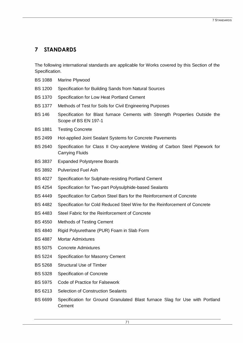
7 STANDARDS
71
7 STANDARDS
The following international standards are applicable for Works covered by this Section of the
Specification.
BS 1088 Marine Plywood
BS 1200 Specification for Building Sands from Natural Sources
BS 1370 Specification for Low Heat Portland Cement
BS 1377 Methods of Test for Soils for Civil Engineering Purposes
BS 146 Specification for Blast furnace Cements with Strength Properties Outside the
Scope of BS EN 197-1
BS 1881 Testing Concrete
BS 2499 Hot-applied Joint Sealant Systems for Concrete Pavements
BS 2640 Specification for Class II Oxy-acetylene Welding of Carbon Steel Pipework for
Carrying Fluids
BS 3837 Expanded Polystyrene Boards
BS 3892 Pulverized Fuel Ash
BS 4027 Specification for Sulphate-resisting Portland Cement
BS 4254 Specification for Two-part Polysulphide-based Sealants
BS 4449 Specification for Carbon Steel Bars for the Reinforcement of Concrete
BS 4482 Specification for Cold Reduced Steel Wire for the Reinforcement of Concrete
BS 4483 Steel Fabric for the Reinforcement of Concrete
BS 4550 Methods of Testing Cement
BS 4840 Rigid Polyurethane (PUR) Foam in Slab Form
BS 4887 Mortar Admixtures
BS 5075 Concrete Admixtures
BS 5224 Specification for Masonry Cement
BS 5268 Structural Use of Timber
BS 5328 Specification of Concrete
BS 5975 Code of Practice for Falsework
BS 6213 Selection of Construction Sealants
BS 6699 Specification for Ground Granulated Blast furnace Slag for Use with Portland
Cement

7 STANDARDS
72
BS 7123 Specification for Metal Arc Welding of Steel for Concrete Reinforcement
BS 7973 Spacers and Chairs for Steel Reinforcement and their Specification
BS 7979 Specification for Limestone Fines for Use with Portland Cement
BS 8004 Code of Practice for Foundations
BS 8007 Code of Practice for Design of Concrete Structures for Retaining Aqueous
Liquids
BS 8110 Structural Use of Concrete
BS 812 Testing Aggregates
BS 8666 Specification for Scheduling, Dimensioning, Bending and Cutting of Steel
Reinforcement for Concrete
BS 882 Specification for Aggregates from Natural Sources for Concrete
EN 1008 Mixing Water for Concrete
EN 1097 Tests for Mechanical and Physical Properties of Aggregates
EN 12350 Testing Fresh Concrete
EN 12390 Testing Hardened Concrete
EN 12620 Aggregates for Concrete
EN 196 Methods of Testing Cement
EN 197 Cement
EN 206 Concrete – Specification, Performance, Production and Conformity
EN 480 Admixtures for Concrete, Mortar and Grout – Test Methods
EN 932 Tests for General Properties of Aggregates
EN 933 Tests for Geometrical Properties of Aggregates
EN 934 Admixtures for Concrete, Mortar and Grout
EN 998 Specification for Mortar for Masonry