
UNDP Kundoz - Afghanistan
259
UNDP UNITED NATIONS DEVELOPMENT PROGRAMME PROJECT SPECIFICATION Renovation of Kundoz MDR Ward Kundoz - Afghanistan JAN 2022
-
Upload
khangminh22 -
Category
Documents
-
view
1 -
download
0
Transcript of UNDP Kundoz - Afghanistan

UNDP UNITED NATIONS DEVELOPMENT PROGRAMME
PROJECT SPECIFICATION
Renovation of Kundoz MDR Ward
Kundoz - Afghanistan
JAN 2022

UNDP
UNITED NATIONS DEVELOPMENT PROGRAMME
PROJECT SPECIFICATION
Renovation of Kundoz MDR ward
Kundoz- Afghanistan
Jan 27 2022

Index
Project Schedules
1.0 General 1.1 Preliminaries 1.2 General Requirements 1.3 Contractor Quality Control 1.4 Health and Safety 1.5 Environmental Impacts
2.0 Site 2.1 Demolition 2.2 Site Preparation 2.3 Earthwork 2.4 Service Trenching 2.5 Landscape- Walls and Fences 2.6 Landscape-Soils and Planting 2.7 Pavement Base and Subbase 2.8 Concrete Pavement 2.9 Pavers-Mortar Bed 2.10 Pavers-Sand Bed 2.11 Pavement Kerb, Channel and Linemarking
3.0 Structure 3.1 Concrete-General 3.2 Concrete-Finishes 3.3 Precast Concrete 3.4 Earth Block Walling 3.5 Brickwork 3.6 Stonework 3.7 Light Steelwork 3.8 Steelwork Painting 3.9 Light Timberwork 3.10 Concrete Masonry Unit 3.11 Structural Steel
4.0 Enclosure 4.1 Waterproofing 4.2 Roofing 4.3 Windows and Window Hardware 4.4 Doors and Door Hardware 4.5 Glazing 4.6 Glass Blockwork 4.7 Insulation and Vapour Barriers 4.8 Exterior Insulation and Finish System (EIFS)
5.0 Interior 5.1 Lining 5.2 Partitions-Systems 5.3 Room Dividers 5.4 Suspended Ceilings 5.5 Joinery 5.6 Metalwork 5.7 Stainless Steel benching 5.8 Fire Extinguishers and Blankets 5.9 Window Coverings

6.0 Finish 6.1 Plastering 6.2 Cementitious Toppings 6.3 Tiling 6.4 Vinyl Finishes 6.5 Carpets 6.6 Painting Water Services 8.1 Water Services 8.2 Hot Water Heating Services Electrical Services 9.1 Electrical Services 9.2 Generating Sets

PRELIMINARIES 1.1
Page 1 of 5
1.1 PRELIMINARIES
1.1.1 GENERAL
1.1.1.1 Pre-Construction Work
Notice to Proceed will be issued within 3 days after signing the contract. The contract period begins on the day the Notice to Proceed is issued.
The Engineer and Contractor will carry out a joint condition-in survey using video or digital photographs to record the condition of the site upon handover to the Contractor. This will determine the state of the site that the Contractor must hand back upon completion of the works. The Contractor will carry out a detailed site set out survey for the works.
The contractor may not proceed with on-site mobilization or construction works before the Engineer approves the following documentation that shall be covered in Program:
Condition-in Survey
Site Survey
Work Method Statement
Program
Quality Assurance / Quality Control Plan (QA/QC) as per minimum requiement 1.3 Contractor’s Quality Control Plan specification.
Health and Safety Plan (H&S) as per minimum requirement Health and Safety Specification no. 1.4.
Environmental Protection Plan as per minimum requirement ...
Dust and Noise Protection Plan
Schedule of Materials and Installed Equipment
A Pre-Construction Meeting will be held between the Engineer and the Contractor to review the above documentation. If the documentation is incomplete, the Contractor will have 3 calendar days to revise and resubmit the documentation for approval.
Site restrictions
Site security limitations: Comply with any restrictions on site area, access or working times advised by the Engineer.
Access: Access on to and within the site, use of the site for temporary works and constructional plant, including working and storage areas, location of offices, workshops, sheds, roads and parking, is restricted to the areas shown on the drawings or as agreed with the Engineer.
Occupied Areas of Site or Buildings
For the parts of the site designated as occupied areas in the Occupied Areas schedule:
Allow occupants to continue using the area for the required period.
Make available safe access for occupants.
Arrange work to minimise nuisance to occupants and ensure their safety.
Protect occupants against weather, dust, dirt, water or other nuisance, by such means as temporary screens.
Protection of persons and property

PRELIMINARIES 1.1
Page 2 of 5
Temporary works: Provide and maintain required barricades, guards, fencing, shoring, temporary roadways, footpaths, signs, lighting and traffic flagging.
Accessways, services: Do not obstruct or damage roadways and footpaths, drains and watercourses and other existing services in use on or adjacent to the site. Determine the location of such services. If damage occurs, immediately repair it at the Contractors cost.
Property: Do not damage property which is to remain on or adjacent to the site, including adjoining property encroaching onto the site. If damage occurs, immediately repair it at the Contractors cost.
Existing services
Attend to existing services as follows:
If the service is to be continued, repair, divert or relocate as required.
If the service is to be abandoned, cut and seal or disconnect, and make safe.
Submit proposals to the Engineer for action for existing services before starting this work. Minimise the number and duration of interruptions.
Adjoining Property
Records: For properties described in the Adjoining Properties to be Recorded schedule:
The Contractor is to inspect the properties with the Engineer and owners and occupants of the properties, before start of work.
Make detailed records of conditions existing within the properties, especially structural defects and other damage or defacement.
Arrange for at least 2 copies of each record, including drawings, written descriptions, and photographs, to be endorsed by the owners and occupants, or their representatives, as evidence of conditions existing before commencement of work.
Submit one endorsed copy of each record to the Engineer. The Contractor is to keep the other endorsed copy.
1.1.1.2 Construction Plant
Access
Access route and site access point are as shown on the drawings or as agreed with the Engineer.
Use of Existing Services
Existing services may be used as temporary services for the performance of the contract subject to conditions stated in the Existing Services schedule.
Contractors Facilities and Work Practices
The Contractor is required to provide adequate toilet and washroom facilities for his staff. These facilities shall be kept clean and serviceable at all times.
The Contractor is required to provide adequate first aid equipment on-site, failure of the Contractor to ensure the availability of first aid equipment on-site will result in an immediate ‘stop work’ order being issued. All costs and time delays resulting from any such ‘stop work’ order are entirely the Contractors responsibility.
A site office will be established by the Contractor at the work site. The location of the site office will be identified by the Engineer to the Contractor. The office will have a complete set of the contract documents.
The Contractor is to maintain a safe, healthy and tidy worksite at all times and all work activities are to be performed with protective and safety equipment appropriate for the task. The Contractor is entirely

PRELIMINARIES 1.1
Page 3 of 5
responsible for workplace safety and unsafe work practices will be identified and recommendations made for revised work methods as appropriate.
The Contractor will be required to comply to the approved Health and Safety Plan.
Project Signboards
Provide project-specific signboards and the following:
Location, size and wording as directed by Engineer.
Maintain in good condition for duration of the work.
Remove on completion.
Obtain approval before display of advertisements or provision of other signboards.
1.1.1.3 Building the Works
Surveys
Setting out: Set out the works from the dimensioned drawings
Check surveys: Check the setout regularly on site
Final survey: Confirm final setout of roads, services and buildings on the as constructed drawings after Practical Completion
Survey marks
Definition: The term “survey mark” means a survey peg, bench mark, reference mark, signal, alignment, level mark or any other mark used or intended to be used for the purpose of setting out, checking or measuring the work.
Care of survey marks: Preserve and maintain the survey marks in their true positions. The Contractor shall check survey marks for consistency and if there are inconsistencies, the Contractor shall give written information to the Engineer with his proposed corrections. If the survey marks are damaged, the Contractor shall immediately advise the Engineer and rectify the damage.
Contractor's Representative
The contractor must employ a suitably experienced engineer as the Site Manager. This person must be on site during working hours, and fluent in English and technical terminology. The Contractor’s Site Manager will have the authority to make all decisions concerning the project on behalf of the Contractor.
Program of Work
The Contractor is to provide a construction baseline program with MS Project which has the following information:
Sequence of Work. (Work Breakdown Structure)
Activity inter-relationships. (Should be closed loop)
Activity durations with start and finish dates
Periods within which various stages or parts of the work are to be executed.
Time scale: Calendar Days
Line items in program are to be based on UNDP Bill of Quantities numbering system (see index). Update the program weekly. Submit hardcopy and softcopy. Identify changes since the previous version, and show the actual starts and finishes, actual percentage of completion for each item of work.

PRELIMINARIES 1.1
Page 4 of 5
Site Meetings
Hold and attend weekly site meetings throughout the contract and ensure attendance of appropriate subcontractors, the Site Manager and Engineer. The meeting schedule may be modified by the Engineer.
The meeting will consider the following items:
Technical issues.
Commercial issues.
Program.
Quality of work.
Items Supplied by Owner
Materials and other items identified in the Items to be Supplied schedule will be supplied free of charge to the Contractor for installation in the execution of the works. Unload and take delivery of them, inspect them for defects and then take care of them. If defects are found, advise. Return unused items to the owner.
1.1.1.4 Completion of the Works
Final Cleaning
Before Practical Completion, clean throughout, including interior and exterior surfaces exposed to view. Clean carpeted and soft surfaces. Clean debris from the site, roofs, gutters, downpipes and drainage systems. Remove waste and surplus materials.
Reinstatement
Before practical completion, clean and repair damage caused by installation or
use of temporary work and restore existing facilities used during construction to original condition.
Adjoining Property
At practical completion, for properties described in the Adjoining Properties to be Recorded schedule inspect the properties with the Engineer and owners and occupants of the properties, recording any damage that has occurred since the pre-commencement inspection.
Post Construction Works
The Contractor will provide the following documentation after all site construction has been completed:
Warranty Statement
Material Test Certificates
As-Built Drawings
List of the suppliers with their contact information
Spare materials, where applicable
A condition-out survey will be conducted with the Contractor and Engineer at which damages caused by the Contractor will be identified. The Engineer will determine if the Contractor is to make repairs or if the damage will be deducted from the Contractor’s final invoice.
Removal of plant
Within 10 working days after practical completion, remove temporary works and construction plant no longer required. Remove the balance before the end of the defects liability period.

PRELIMINARIES 1.1
Page 5 of 5
1.1.1.5 Payment for the works
Anticipated Progress Claims Schedule
The method of measurement and payment will be SMM7 – Standard Method of Measurement for Building Works (latest version).
The Contractor is to submit a schedule of anticipated progress claims which will be made throughout the contract. Submit a revised schedule with each progress claim.
1.1.1.6 Miscellaneous
Compliance with the Law
The Contractor is responsible for compliance with all requirements of authorities. The owner, before entering into the contract, has given the notices, paid the fees, and obtained the permits, approvals and other authorisations stated in the Prior Applications and Approvals schedule.

GENERAL REQUIREMENTS 1.2
Page 1 of 3
1.2 GENERAL REQUIREMENTS
1.2.1 GENERAL
1.2.1.1 CONTRACT DOCUMENTS
Drawings
Large scale drawings take precedence over small scale drawings. Written or calculatable dimensions take precedence over scaled dimensions.
If there are any errors in dimensions, set out or size, immediately notify the Engineer.
Schedule
The schedule forms part of the specification. Information in the schedule will take precedence over information in the specification.
Bill Of Quantities
If there are any errors in description of items or omissions in the BOQ, immediately notify the Engineer.
If there are any items which are unclear or are not available within the project program, immediately notify the Engineer.
Services diagrammatic layouts
Layouts of service lines, plant and equipment shown on the drawings are diagrammatic only, except where figured dimensions are provided or calculable.
Before commencing work:
Obtain measurements and other necessary information.
Coordinate the design and installation in conjunction with all trades.
Site Levels
Spot levels and identified levels on drawings take precedence over contour lines and ground profile lines.
1.2.1.2 INSPECTION
Inspection Notification Schedule
The Contractor is to notify the Engineer when the items identified in the Inspection notification
schedule are ready for inspection.
Written Notice
Minimum notice for inspections to be made on site is 24 hours for off site personnel, 4 hours for onsite personnel.
If notice of inspection is required in respect of parts of the works that are to be concealed, advise when the inspection can be made before concealment.
1.2.1.3 SUBMISSIONS
Samples
The Engineer must approve the laboratory used for testing.
Submit nominated samples for approval of the Engineer.
If it is intended to incorporate samples into the works, submit proposals for approval. Only incorporate samples in the works which have been approved. Do not incorporate other samples.

GENERAL REQUIREMENTS 1.2
Page 2 of 3
Keep endorsed samples in good condition on site, until practical completion.
Shop Drawings
General: If required, submit dimensioned drawings showing details of the fabrication and installation of services and equipment, including relationship to building structure and other services, cable type and size, and marking details.
Diagrammatic layouts: Coordinate work shown diagrammatically in the contract documents, and submit dimensioned set-out drawings.
1.2.2 PRODUCTS
1.2.2.1 TESTS
Notice
Give notice of time and place of nominated tests.
Attendance
The Contractor is to carry out and attend all tests where nominated in this specification.
The independent approved testing laboratory shall perform the required tests and report results of all tests noting if the tested material passed or failed such tests and shall furnish copies to the Engineer.
1.2.2.2 MATERIALS AND COMPONENTS
Consistency
For the whole quantity of each material or product use the same approved manufacturer or source and provide consistent type, size, quality and appearance.
Manufacturers’ or Suppliers’ Recommendations
Proprietary items: Select, if no selection is given, and transport, deliver, store, handle, protect, finish, adjust, prepare for use, and provide manufactured items in accordance with the current written recommendations and instructions of the manufacturer or supplier.
Proprietary systems/assemblies: Assemble, install or fix in accordance with the current written recommendations and instructions of the manufacturer or supplier.
Project modifications: Advise of activities that supplement, or are contrary to, manufacturer’s or suppliers’ written recommendations and instructions.
Proprietary Items
Identification of a proprietary item does not necessarily imply exclusive preference for the item so identified, but indicates the necessary properties of the item.
Alternatives: If alternatives are proposed, submit proposed alternatives and include samples, available technical information, reasons for proposed substitutions and cost. If necessary, provide an English translation. State if provision of proposed alternatives will necessitate alteration to other parts of the works and advise consequent costs.
1.2.3 EXECUTION
Use of explosives will not be permitted.

GENERAL REQUIREMENTS 1.2
Page 3 of 3
1.2.3.1 COMPLETION
Warranties
Name the owner as warrantee in conformance with the Warranty schedule. Register with manufacturers as necessary. Retain copies delivered with components and equipment.
Commencement: Commence warranty periods at practical completion or at acceptance of installation, if acceptance is not concurrent with practical completion.
1.2.3.2 OPERATION AND MAINTENANCE MANUALS
General
General: Submit operation and maintenance manuals for installations.
Format – hard copy
These will be A4 size loose leaf, in commercial quality files with hard covers, each indexed, divided and titled. Include the following features:
Cover: Identify each binder with typed or printed title “OPERATION AND MAINTENANCE MANUAL”, to spine. Identify title of project and date of issue.
Drawings: Fold drawings to A4 size and accommodate them in the files so that they may be unfolded without being detached from the rings.
Text: Manufacturers’ printed data, including associated diagrams, or typewritten, single-sided on paper, in clear concise English.
Number of copies: 3.
Format – soft copy
- In PDF, AutoCad or Microsoft Word, Excel format.
- On compact disk properly identified as above
Number of copes: 3.

GENERAL REQUIREMENTS 1.3
Page 1 of 6
1.3 CONTRACTOR QUALITY CONTROL PROGRAM
1.3.1 GENERAL
When the specification requires a Contractor Quality Control Program, the Contractor shall establish, provide, and maintain an effective Quality Control Program that details the methods and procedures that will be taken to assure that all materials and completed construction required by this contract conform to contract plans, technical specifications and other requirements, whether manufactured by the Contractor, or procured from subcontractors or vendors. Although guidelines are established and certain minimum requirements are specified herein and elsewhere in the contract technical specifications, the Contractor shall assume full responsibility for accomplishing the stated purpose.
The intent of this section is to enable the Contractor to establish a necessary level of control that will:
a. Adequately provide for the production of acceptable quality materials.
b. Provide sufficient information to assure both the Contractor and the Engineer that the specification requirements can be met.
c. Allow the Contractor as much latitude as possible to develop his or her own standard of control.
The Contractor shall be prepared to discuss and present, at the preconstruction conference, his/her understanding of the quality control requirements. The Contractor shall not begin any construction or production of materials to be incorporated into the completed work until the Quality Control Program has been reviewed by the Engineer. No partial payment will be made for materials subject to specific quality control requirements until the Quality Control Program has been reviewed.
The quality control requirements contained in this section and elsewhere in the contract technical specifications are in addition to and separate from the acceptance testing requirements. Acceptance testing requirements are the responsibility of the Engineer.
1.3.2 DESCRIPTION OF PROGRAM.
General Description
The Contractor shall establish a Quality Control Program to perform inspection and testing of all items of work required by the technical specifications, including those performed by subcontractors. This Quality Control Program shall ensure conformance to applicable specifications and plans with respect to materials, workmanship, construction, finish, and functional performance. The Quality Control Program shall be effective for control of all construction work performed under this Contract and shall specifically include surveillance and tests required by the technical specifications, in addition to other requirements of this section and any other activities deemed necessary by the Contractor to establish an effective level of quality control.
Quality Control Program
The Contractor shall describe the Quality Control Program in a written document that shall be reviewed by the Engineer prior to the start of any production, construction, or off-site fabrication.
The Engineer will choose an adequate period for review. A minimum of 5 days before the preconstruction conference or the start of work is recommended.
Submittal of the written Quality Control Program prior to the preconstruction conference will allow the Engineer to review the contents and make suggestions at the preconstruction meeting.
Submittal of the written Quality Control Program prior to the start of work will allow for detailed discussion of the requirements at the preconstruction meeting. This will give the Contractor a better understanding of the requirements before developing the Quality Control Program.

GENERAL REQUIREMENTS 1.3
Page 2 of 6
When selecting the required days for the contractor to submit the Quality Control program, adequate time should be allowed for the Quality Control Program to be a supplement to the Owner's Construction Management Plan.
The Quality Control Program shall be organized to address, as a minimum, the following items:
a. Quality control organization;
b. Project progress schedule;
c. Submittals schedule;
d. Inspection requirements;
e. Quality control testing plan;
f. Documentation of quality control activities; and
g. Requirements for corrective action when quality control and/or acceptance criteria are not met.
The Contractor is encouraged to add any additional elements to the Quality Control Program that he/she deems necessary to adequately control all production and/or construction processes required by this contract.
1.3.3 QUALITY CONTROL ORGANIZATION
The Contractor Quality Control Program shall be implemented by the establishment of a separate quality control organization. An organizational chart shall be developed to show all quality control personnel and how these personnel integrate with other management/production and construction functions and personnel.
The organizational chart shall identify all quality control staff by name and function, and shall indicate the total staff required to implement all elements of the Quality Control Program, including inspection and testing for each item of work. If necessary, different technicians can be utilized for specific inspection and testing functions for different items of work. If an outside organization or independent testing laboratory is used for implementation of all or part of the Quality Control Program, the personnel assigned shall be subject to the qualification requirements of paragraph 100-03a and 100-03b. The organizational chart shall indicate which personnel are Contractor employees and which are provided by an outside organization.
The quality control organization shall consist of the following minimum personnel:
a. Program Administrator: The Program Administrator shall be a full-time employee of the Contractor, or a consultant engaged by the Contractor. The Program Administrator shall have a minimum of 5 years of experience in building construction and shall have had prior quality control experience on a project of comparable size and scope as the contract.
Additional qualifications for the Program Administrator shall include at least 1 of the following requirements:
(1) Professional engineer with 1 year of building construction acceptable to the Engineer.
(2) Engineer-in-training with 2 years of building construction experience acceptable to the Engineer.
(3) An individual with 3 years of building construction experience acceptable to the Engineer, with a Bachelor of Science Degree in Civil Engineering, Civil Engineering Technology or Construction.
(4) Certified Construction materials technician
The Program Administrator shall have full authority to institute any and all actions necessary for the successful implementation of the Quality Control Program to ensure compliance with the contract plans

GENERAL REQUIREMENTS 1.3
Page 3 of 6
and technical specifications. The Program Administrator shall report directly to a responsible officer of the construction firm.
The Engineer may require a full time, on-site Program Administrator, should the project be of sufficient scope and size.
b. Quality Control Technicians. A sufficient number of quality control technicians necessary to adequately implement the Quality Control Program shall be provided. These personnel shall be either engineers, engineering technicians, or experienced craftsman with qualifications in the appropriate field higher construction materials technician and shall have a minimum of 2 years of experience in their area of expertise.
The quality control technicians shall report directly to the Program Administrator and shall perform the following functions:
(1) Inspection of all materials, construction, plant, and equipment for conformance to the technical specifications, and as required by Section 1.3.6
(2) Performance of all quality control tests as required by the technical specifications and Section 100-07.
c. Staffing Levels. The Contractor shall provide sufficient qualified quality control personnel to monitor each work activity at all times. Where material is being produced in a plant for incorporation into the work, separate plant and field technicians shall be provided at each plant and field placement location. The scheduling and coordinating of all inspection and testing must match the type and pace of work activity. The Quality Control Program shall state where different technicians will be required for different work elements.
1.3.4 PROJECT PROGRESS SCHEDULE
The Contractor shall submit a coordinated construction schedule for all work activities. The schedule shall be prepared as a network diagram in Critical Path Method (CPM), PERT, or other format, or as otherwise specified in the contract. As a minimum, it shall provide information on the sequence of work activities, milestone dates, and activity duration. Ms Project and soft copy has to be submitted.
The Contractor shall maintain the work schedule and provide an update and analysis of the progress schedule on a twice monthly basis, or as otherwise specified in the contract. Submission of the work schedule shall not relieve the Contractor of overall responsibility for scheduling, sequencing, and coordinating all work to comply with the requirements of the contract.
1.3.5 SUBMITTALS SCHEDULE
The Contractor shall submit a detailed listing of all submittals (e.g., mix designs, material certifications) and shop drawings required by the technical specifications. The listing can be developed in a spreadsheet format and shall include:
a. Specification item number;
b. Item description;
c. Description of submittal;
d. Specification paragraph requiring submittal; and
e. Scheduled date of submittal.

GENERAL REQUIREMENTS 1.3
Page 4 of 6
1.3.6 INSPECTION REQUIREMENTS
Quality control inspection functions shall be organized to provide inspections for all definable features of work, as detailed below. All inspections shall be documented by the Contractor as specified by Section 1.3.7.
Inspections shall be performed daily to ensure continuing compliance with contract requirements until completion of the particular feature of work. These shall include the following minimum requirements:
a. During plant operation for material production, quality control test results and periodic inspections shall be utilized to ensure the quality of aggregates and other mix components, and to adjust and control mix proportioning to meet the approved mix design and other requirements of the technical specifications. All equipment utilized in proportioning and mixing shall be inspected to ensure its proper operating condition. The Quality Control Program shall detail how these and other quality control functions will be accomplished and utilized.
b. During field operations, quality control test results and periodic inspections shall be utilized to ensure the quality of all materials and workmanship. All equipment utilized in placing, finishing, and compacting shall be inspected to ensure its proper operating condition and to ensure that all such operations are in conformance to the technical specifications and are within the plan dimensions, lines, grades, and tolerances specified. The Program shall document how these and other quality control functions will be accomplished and utilized.
1.3.7 QUALITY CONTROL TESTING PLAN
As a part of the overall Quality Control Program, the Contractor shall implement a quality control testing plan, as required by the technical specifications. The testing plan shall include the minimum tests and test frequencies required by each technical specification Item, as well as any additional quality control tests that the Contractor deems necessary to adequately control production and/or construction processes.
The testing plan can be developed in a spreadsheet fashion and shall, as a minimum, include the following:
a. Specification item number (e.g., P-401);
b. Item description (e.g., Plant Mix Bituminous Pavements);
c. Test type (e.g., gradation, grade, asphalt content);
d. Test standard (e.g., ASTM or AASHTO test number, as applicable);
e. Test frequency (e.g., as required by technical specifications or minimum frequency when requirements are not stated);
f. Responsibility (e.g., plant technician); and
g. Control requirements (e.g., target, permissible deviations).
The testing plan shall contain a statistically-based procedure of random sampling for acquiring test samples in accordance with ASTM D 3665. The Engineer shall be provided the opportunity to witness quality control sampling and testing.
All quality control test results shall be documented by the Contractor as required by Section 1.3.8.
1.3.8 DOCUMENTATION
The Contractor shall maintain current quality control records of all inspections and tests performed. These records shall include factual evidence that the required inspections or tests have been performed, including type and number of inspections or tests involved; results of inspections or tests; nature of defects, deviations, causes for rejection, etc.; proposed remedial action; and corrective actions taken.

GENERAL REQUIREMENTS 1.3
Page 5 of 6
These records must cover both conforming and defective or deficient features, and must include a statement that all supplies and materials incorporated in the work are in full compliance with the terms of the contract. Legible copies of these records shall be furnished to the Engineer daily. The records shall cover all work placed subsequent to the previously furnished records and shall be verified and signed by the Contractor's Program Administrator.
Specific Contractor quality control records required for the contract shall include, but are not necessarily limited to, the following records:
a. Daily Inspection Reports. Each Contractor quality control technician shall maintain a daily log of all inspections performed for both Contractor and subcontractor operations on a form acceptable to the Engineer. These technician's daily reports shall provide factual evidence that continuous quality control inspections have been performed and shall, as a minimum, include the following:
(1) Technical specification item number and description;
(2) Compliance with approved submittals;
(3) Proper storage of materials and equipment;
(4) Proper operation of all equipment;
(5) Adherence to plans and technical specifications;
(6) Review of quality control tests; and
(7) Safety inspection.
The daily inspection reports shall identify inspections conducted, results of inspections, location and nature of defects found, causes for rejection, and remedial or corrective actions taken or proposed.
The daily inspection reports shall be signed by the responsible quality control technician and the Program Administrator. The Engineer shall be provided at least one copy of each daily inspection report on the work day following the day of record.
b. Daily Test Reports. The Contractor shall be responsible for establishing a system that will record all quality control test results. Daily test reports shall document the following information:
(1) Technical specification item number and description;
(2) Test designation;
(3) Location;
(4) Date of test;
(5) Control requirements;
(6) Test results;
(7) Causes for rejection;
(8) Recommended remedial actions; and
(9) Retests.
Test results from each day's work period shall be submitted to the Engineer prior to the start of the next day's work period. When required by the technical specifications, the Contractor shall maintain statistical quality control charts. The daily test reports shall be signed by the responsible quality control technician and the Program Administrator.
1.3.9 CORRECTIVE ACTION REQUIREMENTS
The Quality Control Program shall indicate the appropriate action to be taken when a process is deemed, or believed, to be out of control (out of tolerance) and detail what action will be taken to bring the process

GENERAL REQUIREMENTS 1.3
Page 6 of 6
into control. The requirements for corrective action shall include both general requirements for operation of the Quality Control Program as a whole, and for individual items of work contained in the technical specifications.
The Quality Control Program shall detail how the results of quality control inspections and tests will be used for determining the need for corrective action and shall contain clear sets of rules to gauge when a process is out of control and the type of correction to be taken to regain process control.
When applicable or required by the technical specifications, the Contractor shall establish and utilize statistical quality control charts for individual quality control tests. The requirements for corrective action shall be linked to the control charts.
1.3.10 SURVEILLANCE BY THE ENGINEER
All items of material and equipment shall be subject to surveillance by the Engineer at the point of production, manufacture or shipment to determine if the Contractor, producer, manufacturer or shipper maintains an adequate quality control system in conformance with the requirements detailed herein and the applicable technical specifications and plans. In addition, all items of materials, equipment and work in place shall be subject to surveillance by the Engineer at the site for the same purpose.
Surveillance by the Engineer does not relieve the Contractor of performing quality control inspections of either on-site or off-site Contractor's or subcontractor's work.
1.3.11 NONCOMPLIANCE.
The Engineer will notify the Contractor of any noncompliance with any of the foregoing requirements. The Contractor shall, after receipt of such notice, immediately take corrective action. Any notice, when delivered by the Engineer or his/her authorized representative to the Contractor or his/her authorized representative at the site of the work, shall be considered sufficient notice.
In cases where quality control activities do not comply with either the Contractor Quality Control Program or the contract provisions, or where the Contractor fails to properly operate and maintain an effective Quality Control Program, as determined by the Engineer, the Engineer may:
(1) Order the Contractor to replace ineffective or unqualified quality control personnel or subcontractors.
(2) Order the Contractor to stop operations until appropriate corrective actions are taken.

HEALTH AND SAFETY 1.4
Page 1 of 9
1.4 HEALTH AND SAFETY
1.4.1 GENERAL
1.4.1.1 1.1 Responsibility For Safety
The contractor shall be responsible for the safety of all operations in connection with the Contract and shall take all necessary actions and precautions to ensure the safety of all persons who may be in, on or adjacent to the Site.
1.4.1.2 Compliance With UNDP Workplace Safety and Health Policy & Procedures
The Contractor shall comply with the compliance with the UNDP Workplace Safety and Health Policy & Procedures for the purposes of this clause including all sub clauses under it) and any amendment or re-enactment thereto and including but not limited to:
Any other rules and regulations, Standards and Codes of Practices related and relevant to the promotion of safe practices and conduct at the worksite.
It shall be the duty of the Contractor to comply with all such requirements of the Workplace Safety and Health Policy & Procedures, as affect him or any person or persons employed by him, and as related to any work, act or operation performed or about to be performed by him. The Contractor shall not permit any person to do anything not in accordance with the generally accepted principles of safe and sound practices.
The Contractor shall ensure a safe environment on the site at all times. All safety provisions shall be properly maintained and shall not be removed. The Contractor shall ensure that necessary and sufficient precautions are taken by his workmen when safety provisions are used. The Contractor shall not allow any of the safety provisions to be used unless he has satisfied himself that the provisions are safe.
Where UNDP Project Manager appoints an engineer to carry out any work for any temporary works specified below, the engineer shall comply with any duties imposed on him under those regulations:
1) Cantilevered platforms erected more than 3m above ground;
2) Formwork structure;
3) Runway and ramp for use of motor trucks or heavy vehicles;
4) Stability of structure adjacent to excavation;
5) Shoring and bracing for trench excavation > 4m; and
Duties on engineers undertaking temporary works regulated by UNDP Health & Safety Policy & Procedures:
a) Design it to acceptable codes and standards and in accordance with good engineering practices;
b) Ensure that it is constructed accordance with his design;
c) When it is constructed, satisfy himself that it is safe for its intended use and if so, issue a certificate stating that it is safe for its intended use;
d) The engineer shall exercise due diligence when carrying out his duties; and
The Contractor shall ensure that the requirements of Health & Safety Policy & Procedures and the requirements specified hereunder are strictly complied with at all times.
1.4.1.3 Undertaking by Contractor
The Contractor shall undertake to ensure that the provisions of the Health & Safety Policy and Procedures are complied with. The attached safety provisions undertaking form for the Occupier/Contractor in “Appendix I” shall be complied by a Managing Director or other duly authorized representative of the company/firm awarded the Contract.
HEALTH AND SAFETY 1.4
Page 2 of 9
1.4.1.4 Site Safety Programme
The Contractor shall not begin any construction or production of materials to be incorporated into the completed work until the Contractor’s Health and Safety Plan has been reviewed by UNDP. The relevant safety equipment and safe method of work employed at each stage of construction shall be described in detail. Special risks involving specialized equipment shall also be highlighted. The programme shall also include company safety policy, risk assessment, safety rules and regulations, small group activities, safety promotion programme (safety slogans, safety campaign, slide shows etc), safety training, emergency procedures and other such activities. The safety programme must be displayed outside the site office. The Contractor shall display safety posters at the site office, site canteen, exit/entry points of buildings and passenger cum material hoist area.
1.4.1.5 Monthly Safety Review
The Contractor shall carry out monthly safety review of the measures contained within the Safety Programme to demonstrate that the required level of safety are being achieved and maintained and make a full report to UNDP on each such review. UNDP will review the Safety Programme from time to time and will advise the Contractor of any matter with which he is not satisfied and the Contractor shall take such steps as are necessary to satisfy UNDP. UNDP will carry out such safety studies or audits, as considered necessary. The Contractor shall make available, specialist personnel as the UNDP may consider necessary for the performance of such safety studies or audits.
1.4.1.6 Risk Management
The contractor shall conduct a risk assessment in relation to the safety and health risks posed to any person who may be affected by his undertaking prior to the commencement of work in accordance to UNDP Health and Safety Policy & Procedures
The contractor shall take all reasonably practicable steps to eliminate any foreseeable risk to any person who may be affected by his undertaking.
The contractor shall maintain a record of risk assessments conducted, including any control measures taken or to be taken and any safe work procedures.
The contractor shall ensure that his employees are informed of the nature of the risk involved, the measures implemented to control the risk and applicable safe work procedures. Whenever the assessment of a risk is revised, or where control measures or safe work procedures are changed, employer shall inform employees of such changes.
1.4.2 SITE SAFETY MEASURES
1.4.2.1 Physical Measures
The contractor must develop procedures in a fall protection plan for the construction site if his worker at the work site may fall 3 metres or more and the worker is not protected by guardrails.
The contractor must have a fall protection system in place and available at the construction site before work with a risk of falling begins.
The contractor must have the following devices and system in place prior to start of the work:
(i) fall arresting devices such as rope grabs, guard rails etc
(ii) safety belts, body harness, lanyards consisting of carabiners, D-rings, O-Rings, ovals rings, self locking connectors and snap hooks
1.4.2.2 Metal Access Scaffold And Working Platforms
The Contractor shall provide, erect and maintain metal access scaffold for all building blocks of 2 storey and above or 3.0 m in height and above.
The scaffold shall be erected ahead of the structural work from the second storey and supported by cantilevered platforms erected according to the reasonable safety standards. The cantilevered platforms

HEALTH AND SAFETY 1.4
Page 3 of 9
shall project about 1.1m from the edge of the building or any other distance. The scaffold shall be erected within 300mm from the building edge. Where the structure does not allow the scaffold to be erected from the second storey or where the building is less than 12.0m in height, the Contractor may erect the scaffold from the first storey subject to review by UNDP.
The Contractor and his Engineer shall ensure that the building structure can resist the load imposed by the scaffold. The scaffold shall be designed to carry metal working platforms and two working levels in use concurrently. The maximum average loading per working level per bay is 220 kg per m
2. Signboards
showing the maximum loading allowed on the scaffold may be displayed on the scaffold.
The Contractor shall provide, erect and maintain continuous metal work platforms or other types of work
platforms at every alternate lift starting from the 2nd
lift of the scaffold, the immediate level below the top most level and the roof level of the building block under construction.
Where the height between the work platform at the roof level and the platform directly below is two lifts or less, the latter work platform may not be necessary. No omission from the Contract Sum shall be made in the event that such a work platform is not necessary.
The material used for the metal work platform shall be steel. Work platforms shall be adequately secured to scaffolding frames at the required levels. The connections between work platform and scaffolding frame, and between the work platforms shall be subject to review by UNDP.
For any portion of the work platform where the use of metal is not suitable, the Contractor may use timber platform subject to the review by the SO. The platform shall be complete with at least 90 mm high coloured toeboards and metal guardrails at least 1.0 m above the work platform.
The work platform shall be at least 500mm in width. The platform shall be used for:
(i) Erecting and dismantling of formwork of structural elements;
(ii) Transferring of formwork or other materials from one working level to another; and
(iii) External finishing works.
The Contractor shall provide, erect and maintain an overlying screening net to cover the entire external face of the scaffold. The installation of the net shall follow the erection of the scaffold closely. A 90mm high coloured toeboard shall be provided at the base of the net. After installation, there shall be no opening between separate sets of the net and any torn net shall be replaced or repaired immediately. The scaffold shall be effectively tied to the building structure by means of tie-backs. All tie-backs shall be painted with bright colour for easy identification.
For buildings next to areas less than 30m away from the Site boundary, the Contractor shall provide special mid-height platform supporting metal access scaffold at the building elevation directly facing public areas, walkways, children playgrounds, schools and other locations with public traffic.
The special mid-height work platform shall be installed from the floor level at the mid height of the building and shall project 6m from the edge of the floor. They shall be supported at the floor level below by diagonal members. Tension tie backs to upper floors shall not be used.
Around the edges of the 6m platform, guardrails and toe boards shall be provided. Guardrail shall have sufficient strength and rigidity to withstand, without permanent deformation or failure, a 50 kg loads applied in any direction at right angles to the guardrail.
The work platform and its supports shall be designed by an Engineer to a uniformly distributed live load of 1.5 kg per m² and the loading from the scaffold. Supports for platform shall be spaced at not more than 1.8m centre to centre.
1.4.2.3 Personal Protective Equipment
The Contractor shall provide and maintain suitable personal protective equipment for all workmen employed on the Site.
The Personal Protective Equipment consists of the following:

HEALTH AND SAFETY 1.4
Page 4 of 9
Hearing protection equipment such as ear defenders, ear plugs etc. (where required)
Eye protection such as safety eye wear, welding goggles and shields etc.
Foot protection such as safety shoes/boots etc.
Head protection such as hard hats
Limb and body protection such as gloves, reflective vests etc.
Respirators, as necessary and adequate
The Contractor shall ensure that such personal protective equipment comply with the requirements of UNDP.
The Contractor shall also ensure that all equipment is properly used by his workmen during the course of their work. The Contractor shall record the issuance of all equipment to his workmen in the prescribed forms and such forms shall be kept in the site office and made available for inspection at all times.
1.4.2.4 Overhead Shelters
The Contractor shall provide, erect and maintain overhead shelters at every point of entry/exit of buildings two or more storey in height. The overhead shelters shall be constructed immediately below the second storey. The overhead shelters shall project at least 3.0m from the building edge and shall be at least 1.5m wide. The overhead shelters shall be made of curved metal roofing with a diameter of at least 1.5m or pitched metal roofing with a slope greater than one in two, with timber boarding below supported by steel pipes resting on rigid bases.
The access to, along and egress from the entry/exit points shall be kept free from obstructions and accumulation of oil, grease, water and other substances that may cause slipping and tripping.
Overhead shelters shall also be provided for person(s) exposed to falling objects.
1.4.2.5 Peripheral Overhead Shelters
The Contractor shall provide peripheral overhead shelters for buildings of 15.0m or more in height. It shall be erected in place when the construction reaches the third storey slab. The overhead shelter shall be at least 2.0m wide, and inclined so that the outer edge is at least 150mm higher than the inner edge. The overhead shelter shall be sufficiently strong to support a weight of at least 75 kg point load.
1.4.2.6 Barricades To Lift Openings, Voids, Open Sides Of Buildings And Excavations
The Contractor shall barricade all lift openings, internal voids, open sides of buildings and excavations where a person is liable to fall. The barricade shall be at least 1.1m high and shall have sufficient strength and rigidity to withstand a lateral point load of 50 kg.
1.4.2.7 Suspended Scaffolds
A suspended scaffold system shall only be used for touching up, repair and redecoration and minor work. Where suspended scaffold system is to be used, the Contractor shall notify UNDP prior to its installation and usage. The safe working load will be prominently displayed. The Contractor shall ensure that there are weekly checks and additional check after inclement weather by his supervisor and monthly check by an Engineer (Civil). Where the use of access scaffolding is not stipulated, suspended scaffold may be used for finishing works. Independent lifelines shall be provided for suspended scaffold riggers and users to anchor their safety harness attached with shock absorbing device.
1.4.2.8 Ladders
The Contractor must ensure that ladders are in an acceptable sound condition and submit a written inspection report to UNDP.
If the ladder is made of a material other than steel, the contractor must ensure that the ladder is in sound condition.
If the ladder is constructed of lumber/timber, the contractor must ensure that the timber is free of loose knots or knot holes, must not have a split and must be strong and sturdy.

HEALTH AND SAFETY 1.4
Page 5 of 9
The contractor’s worker must ensure that:
the ladder is secured against movement and placed on a base that is stable
the base of an inclined ladder is no further from the base of the wall or structure than 1.4 of the height to where the ladder contacts the wall or structure.
1.4.2.9 Mobile Cranes
No person shall install, repair, alter or dismantle a mobile crane unless he is an approved mechanic. The contractor/mechanic shall ensure, so far as is reasonably practicable, that the mobile crane is erected, installed or modified in such a manner that it is safe, and without risk to health, when properly used.
The Contractor shall ensure that the crane access is properly constructed and weekly check by supervisor is carried out. The boom of the mobile crane with hoisted load shall not be allowed to swing outside the contract boundary without the review by UNDP. All hoisting areas must be effectively barricaded.
The Contractor shall ensure there is installation of barriers to warn the crane operator of depressions, excavated areas and other obstructions.
The Contractor shall station a lifting supervisor on the Site to oversee and guide the crane operator during positioning, hoisting and slewing. The Contractor shall ensure daily checks are carried out by the crane operator. The cranes must have overhaul checks before being used on the Site.
1.4.2.10 Temporary Chute For The Removal Of Construction Debris
The Contractor shall provide adequate number of temporary chutes to dispose construction debris from the upper storey of all building blocks 2 storey and above. It shall be erected to follow the structural work. A large bin at the lower end of each chute shall be provided and emptied regularly. "DANGER - KEEP OUT" in the official languages shall be posted at the bin area.
1.4.2.11 Warning Signs And Lights
The Contractor shall display warning signs of sizes 900 mm x 600 mm at strategic points around the periphery of the Site where trespassing is likely to occur. Such signs shall have the words "DANGER - KEEP OUT" in the two languages (Dari & English) painted in red on a white background in gloss finishing paint. Warning lights shall be placed at similar positions at night to serve as warnings.
1.4.2.12 Housekeeping
The Contractor shall maintain and ensure a safe working environment by keeping the Site neat and tidy, and free from hazards and debris. Materials shall be stacked up safely. All work areas and access thereto shall be kept free from hazards and debris.
Housekeeping shall be carried out in such a manner and at such times so as not to cause any inconvenience to either the adjoining occupiers or the public. Debris shall be wetted to minimize the risk of dust. Containers for debris and rubbish are to be provided at the designated places.
1.4.2.13 Temporary Staircases
The Contractor shall provide and maintain a minimum 0.8m wide temporary metal staircase from one working floor to another. The staircase shall be placed against the adjacent staircase wall or formwork of the staircase walls that are under construction. The outer sides of the staircases shall be provided with metal handrails 1.1m above the outer staircase strings. The bottom of the staircase shall be covered fully with metal plate.
1.4.2.14 Safety Information Signboard And Assembly Stage
The Contractor shall erect and maintain a Safety Information Signboard and Assembly Stage. The signboard shall be 6.0m x 3.0m, made of timber plywood and fixed at a steel frame. The signboard shall

HEALTH AND SAFETY 1.4
Page 6 of 9
consist of safety posters, safety theme and pictures, safety news, photos of good safety measures, one 600mm x 1500mm mirror. The safety posters, news and photos shall be protected from weather.
The arrangement and size of display of all items referred herein shall be submitted to the UNDP. The stage shall be constructed in front of the signboard and made of concrete. The stage shall consist of a raised platform of 4.5m x 1.0m with at least one step.
The location of the signboard and stage shall be review by UNDP. As and when instructed by UNDP, the Contractor shall remove or relocate and reconstruct the signboard and stage, and reinstate all the affected ground to the satisfaction of UNDP, all at the cost and expense of the Contractor. On Substantial Completion of the Works, the signboard and stage shall be cleared away upon the review of UNDP.
1.4.2.15 Gas Cylinders And Related Equipment
The Contractor shall use gas cylinders, each fitted with a low pressure gauge, a high pressure gauge, a reducing valve with pressure regulator, and a safety relief device. The gas cylinders shall not be kept in the same room where welding, cutting or heating is being carried out or placed within five metres of any source of heat. The gas cylinders must always be kept upright in a wheeled-trolley. When lifted by crane, hoist or derrick, cylinders must be placed in cradles or skip box design. Protective valve caps shall also be in place.
The hose connecting a gas cylinder to an apparatus for cutting, welding, heating or other related works shall be of good construction and sound material, free from defect, properly maintained, and not entangled or kinked. Valves and fittings shall be tested for leak with “soap water” everyday before use.
1.4.2.16 Safety Reflective Apparel (Traffic Control)
A worker designated to control traffic shall wear approved type of reflective apparel during all hours of the day when so engaged.
1.4.2.17 Health Measures
Noise Management
The contractor shall as far as practicable, ensure that all processes, machines and equipment used, do not cause workers to be exposed to excessive noise, i.e. above an equivalent sound level of 85 dBA for 8 hour workday. This can be done by implementing one or more of the following measures:
Engineering noise control, e.g., modifying noisy processes, machines and equipment, relocating noisy processes or isolating them within enclosures, erecting sound barriers, reducing kinetic or potential energy and regularly maintaining machines and equipment;
Administrative noise control, e.g., rotating noisy jobs among workers so that they are not exposed to noise above the permissible exposure limit;
Using quiet machines and equipment when such machines and equipment are available in the market. Examples are generators, compressors and concrete breakers. The contractor shall provide hearing protectors for workers who are exposed to excessive noise and ensure that they are worn at all times. Warning signs to remind workers that hearing protectors must be worn shall be put up at areas with excessive noise.
Contract workers should be trained and educated on the hazards of noise, noise control and the prevention.
First-Aid
All workplaces as specified within the class or description shall establish and implement a first-aid programme to provide emergency treatment to victims of accidents, chemical poisoning or excessive exposure to toxic substances.
The programme shall include: -
• First-aid facilities;

HEALTH AND SAFETY 1.4
Page 7 of 9
• First-aid boxes;
• First-aid room, where there are 500 or more workers at site;
• First-aid treatment procedures;
• First aid for exposure to toxic or corrosive substances
• Standard procedures;
• Maintenance of first-aid facilities.
All first-aid provisions shall comply with the UNDP Health & Safety (First-Aid) Regulations.
1.4.2.18 Electrical Works
Where work to be carried out involves electricity/power, installing temporary wiring, usage of power tools and equipment, no worker shall connect, maintain or modify electrical tools, equipment or installation unless the worker is a qualified electrician.
The contractor shall take every reasonable precaution to prevent hazards to workers from energized electrical equipment, installations and conductors
No person, other than a person authorized to do so by the contractor of the project, shall enter or be permitted to enter a room or other enclosure containing exposed energized electrical parts.
The entrance to a room or other enclosure containing exposed energized electrical parts shall be marked by conspicuous warning signs stating that entry by unauthorized persons is prohibited.
All electrical equipment, installations, conductors and insulating materials shall be suitable for their intended use and shall be installed, maintained, modified and operated so as not to pose a hazard to a worker.
Contractor shall use mats, shields or other protective devices or equipment, including personal protective equipment, adequate to protect the worker from electrical shock and burns.
1.4.2.19 Work in Confined Space
Where work is to be carried out in any confined space as defined in UNDP, code of practice for entry into and safe working in confined spaces shall be followed.
1.4.2.20 Excavations and Tunnels
No person shall enter or be permitted to enter an excavation that does not comply with this Part.
Work shall not be performed in a trench unless another worker is working above ground in close proximity to the trench or to the means of access to it.
The type of soil in which an excavation is made shall be determined by visual and physical examination of the soil,
(a) at the walls of the excavation; and
(b) within a horizontal distance from each wall equal to the depth of the
excavation measured away from the excavation.
Before an excavation is begun,
(a) gas, electrical and other services in and near the area to be excavated shall
be accurately located and marked; and
(b) if a service may pose a hazard, the service shall be shut off and disconnected.
An excavation in which a worker may work shall have a clear work space of at least 450 mm between the wall of the excavation and any formwork or masonry or similar wall.
The walls of an excavation shall be stripped of loose rock or other material that may slide, roll or fall upon a worker.

HEALTH AND SAFETY 1.4
Page 8 of 9
A level area extending at least one metre from the upper edge of each wall of an excavation shall be kept clear of equipment, excavated soil, rock and construction material.
The stability of a wall of an excavation shall be maintained where it may be affected by stockpiling excavated soil or rock or construction materials.
No person shall operate a vehicle or other machine and no vehicle or other machine shall be located in such a way as to affect the stability of a wall of an excavation.
If a person could fall into an excavation that is more than 2.4 metres deep, a barrier at least 1.1 metres high shall be provided at the top of every wall of the excavation that is not sloped.
Where the excavation is a trench and the depth exceeds six metres or the width exceeds 3.6 metres, a support system shall consisting of either timber or of an engineered support system designed for the specific location and project shall be installed.
1.4.2.21 Control of Traffic
If vehicle traffic at the construction site is dangerous to workers, pedestrians, school children on foot, the contractor and his workers must ensure that the traffic movement is controlled to protect against accident related injuries and fatalities.
The contractor must designate a worker to control traffic on the construction site, the contractor must ensure that the designated traffic controller wears a reflective vest, safety footwear and hard hat.
The passage of vehicles across a footpath shall be supervised to remove danger to the school children and the public.
The contractor and his workers must be vigilant at all times and must ensure that pedestrians and school children DO NOT cross the safety barriers and enter the construction site.
1.4.2.22 Others
The Contractor shall provide and maintain guards, fences or barriers around the construction site, excavations, lift pits or other similar potential places of danger to prevent accidents. The guards, fences and barriers shall be of sound material, good construction and possess adequate strength.
1.4.3 NON-COMPLIANCE WITH CONTRACT SAFETY SPECIFICATIONS
In the event of contravention or non-compliance with the safety specifications, UNDP shall suspend the progress of works or any part of them if necessary for the safety of the works or if he is of the opinion that the working environment or procedure is unsafe for the works to continue. In such event, the Contractor shall not be entitled to any claims for compensation or extension of time for completion.

HEALTH AND SAFETY 1.4
Page 9 of 9
Appendix I
Form For Undertaking Safety Provision By Contractor
Project Manager
United Nations Office for Project Services
Kabul Schools Project
Copy: UNDP Health & Safety Officer
RE : SAFETY PROVISIONS AT
I, __________________________________ of _______________________________________
(Name of Managing Director) (Name of Company)
I/C No:__________________ understand that as the Contractor of /for the above worksite / work area or order, it is my duty and responsibility to ensure that the provisions of UNDP Health & Safety Policy & Procedures, and any amendments or re-enactments thereto are complied with.
(Managing Director) (Signature)
(Name of Company / Company Stamp) (Date)

Environmental Impacts and Recommended Mitigation Measures 1.5
Page 1 of 4
1.5 ENVIRONMENTAL IMPACTS AND RECOMMENDED MITIGATION MEASURES
1.5.1 GENERAL
Project works are to be assessed by UNDP to identify any significant impacts on environmental or social characteristics of the project area. This notwithstanding, some impact can be expected to occur during the course of construction activities. These impacts can be appropriately managed or mitigate by the measures contained in the following environmental mitigation list.
1.5.1 CLIMATE AND AIR QUALITY
Impacts to local air quality during construction can be anticipated due to fugitive dust generation in and around the construction area. Mitigation measures shall be implemented to avoid any significant impact.
Construction activities will also result in the generation of diesel exhaust from heavy equipment and generators. Following mitigation measures shall be implemented to avoid any significant impact:
1.5.1.1 Mitigation 1
The generation of dust during construction shall be mitigated through avoidance strategies as follow:
Subcontractor shall be required to spray water during windy conditions.
Trucks carrying earth, sand or stone shall be covered to avoid spilling.
Open burning shall be prohibited on the construction sites.
1.5.1.2 Mitigation 2
The generation of diesel exhaust emissions during construction shall be mitigated through avoidance strategies as follows:
All equipment shall be in good operating condition.
Machinery shall not be left idling unless necessary during winter operations.
1.5.2 SURFACE WATER
Construction activities can result in increased turbidity of runoff water due to soil erosion. Mitigation measures shall be implemented to avoid any significant impact.
Construction activities can also result in contamination of runoff due to leaking fuel or lubricants from construction equipment. Mitigation measures shall be implemented to avoid any significant impact.
Construction of the facilities will result in an increase in hardscaping, with a resulting incremental increase in surface water runoff. If minor paving is planned, then little runoff will leave the construction site and may not impact on surrounding drainages.
To avoid significant impacts following mitigations shall be implemented:
1.5.2.1 Mitigation 1
Impacts due to soil erosion shall be mitigated by careful grading of the construction site such that significant amounts of water is not allowed run off of the construction site into adjacent drainages.
Where excavated soils are stored on site, adequate measures shall be implemented to control runoff, including covering exposed soils, construction of settling basins, or erection of physical barriers.
1.5.2.2 Mitigation 2
Machinery and equipment shall be maintained in good working condition and shall be regularly inspected for leaks. Any maintenance of equipment or machinery onsite could only occur over non-permeable areas with adequate containment measures to capture spills.

Environmental Impacts and Recommended Mitigation Measures 1.5
Page 2 of 4
Fuel storage shall be provided with adequate containment measures to capture spills.
1.5.3 GROUNDWATER
Construction activities can result in contamination of runoff due to leaking fuel or lubricants from construction equipment. 1.5.3.2 Mitigation 2 will also prevent groundwater contamination.
Construction of the facilities will result in an increase in hardscaping resulting in a incremental decrease in groundwater percolation. If minor paving is planned, it may not decrease and will not impact on groundwater supplies. In most cases 1.5.3.1 Mitigation 1 will prevent groundwater contamination.
1.5.4 TERRESTRIAL ECOLOGY
If the project site is urban site and is with no natural habitats or significant natural flora or fauna, then no impacts are anticipated and no mitigation measures will be required. Otherwise the subcontractor shall contact UNDP for mitigation measures requirement policy and guidance prior to commencing site works.
1.5.5 SOCIOECONOMICS
Construction of projects, depending to the type of the project, will result in a significant number of construction jobs. Employment will result in multiplier effects by generating commerce with benefits provided throughout the local economy.
If the program includes capacity building component, which will promote on-the-job skills training in construction methods, quality control, and/or construction safety, the skill transfer will result in improved capacity of local contractors to successful undertake future construction projects.
Improved and expanded educational facilities will result in improved learning opportunities and provide long-term benefits to the local economy.
In such cases, the following mitigations shall be implemented:
1.5.5.1 Mitigation 1
The program shall include capacity building, including classroom and on-the-job training, in construction methods, quality control, and construction safety.
1.5.5.2 Mitigation 2
The use of local subcontractors shall be encouraged wherever possible.
1.5.6 TRAFFIC AND TRANSPORTATION
Construction activities will result in additional truck traffic and potential traffic congestion on local streets, depending on the site location. The truck traffic will also result in potential threats to pedestrian safety. Following mitigation measures shall be implemented to avoid any significant impact if the project site is in urban:
Note: Operational impacts may need to be assessed should construction activities alter the current usage of the sites or traffic flow patterns.
1.5.6.1 Mitigation 1
Delivery of materials and equipment to the site shall be scheduled during periods of light traffic (e.g. early morning or late afternoon).
1.5.6.2 Mitigation 2
Where necessary, pedestrian access-way improvements shall be provided prior to commencing construction activities. These improvements could include sidewalks, fencing, or alternate routes.

Environmental Impacts and Recommended Mitigation Measures 1.5
Page 3 of 4
1.5.6.3 Mitigation 3
The construction contractor shall provide flag men and other traffic control measures to avoid conflicts between construction traffic and other vehicles and /or pedestrians.
1.5.7 VISUAL QUALITY
Construction activities may result in a short-term impact to the visual quality of buildings. In particular, buildings in progress are generally stark in appearance. Additionally, construction material and wastes may result in a cluttered site. Following mitigation measures shall be implemented to avoid any significant impact on this issue:
1.5.7.1 Mitigation 1
The subcontractor shall be required to maintain a site free from rubbish. The contractor shall be required to conduct regular housekeeping to include removal of rubbish, construction waste, and proper storage of construction material.
1.5.8 RECREATION
As per architectural principles, new buildings are usually sited to minimize the impact on available recreational fields. Although no mitigation is practically required, sufficient space shall be maintained for the existing recreational fields.
1.5.9 CULTURAL
Depending to the location of the project, if buried cultural or archaeological resources may be uncovered during construction activities, following mitigation measures shall be implemented to avoid any significant impact:
1.5.9.1 Mitigation 1
If potential cultural or archaeological resources are unearthed during construction, activities in that area shall immediately cease. The appropriate government office shall be contacted until such time as the government office provides authorization.
1.5.10 NOISE
Construction activities will result in noise impacts resulting from the use of heavy equipment and machinery. Noise levels will be typical for construction sites and no significantly loud equipment should be avoided if possible (i.e., pile drivers, crushers, etc.). Following mitigation measures shall be implemented to avoid significant impact:
1.5.10.1 Mitigation 1
The contractor shall as far as practicable, ensure that all processes, machines and equipment used implement one or more of the following measures:
Engineering noise control, e.g., modifying noisy processes, machines and equipment, relocating noisy processes or isolating them within enclosures, erecting sound barriers, reducing kinetic or potential energy and regularly maintain machines and equipment.
Using quiet machines and equipment when such machines and equipment are available in the market. Examples are generators, compressors and concrete breakers. The contractor shall provide hearing protectors for workers who are exposed to excessive noise and ensure that they are worn at all times. Warning signs to remind workers that hearing protectors must be worn shall be put at areas with excessive nose.

Environmental Impacts and Recommended Mitigation Measures 1.5
Page 4 of 4
1.5.10.2 Mitigation 2
To the extent practicable, construction activities shall occur during normal working times. Where necessary to conduct operations in late evening or early morning, these operations shall be short in duration and shall be coordinated in advance with the project team and nearby inhabitants.
1.5.10.3 Mitigation 3
A community outreach program shall be implemented to ensure that local residents are aware of the purpose of the construction activities and have the opportunity to report any impacts.
1.5.11 SOLID, HAZARDOUS AND SPECIAL WASTES
Construction activities, including demolition and excavation, will result in solid wastes requiring disposal. There could also be evidence of hazardous or special wastes on the project sites that may result in contamination through spillage or unearthing.
Construction activities may result in the generation of hazardous wastes, including oils and lubricants. Accidental release of these wastes may result in impacts. To avoid such impact following mitigation measures shall be considered:
1.5.11.1 Mitigation 1
Solid wastes shall be transported off the site and disposed of in a disposal site previously approved by the relevant authority and/ or Ministry of Urban Development.
1.5.11.2 Mitigation 2
In the event buried hazardous wastes are uncovered during excavation, all construction activities shall cease.
1.5.12 GEOLOGIC AND SEISMIC HAZARDS
In areas considered as high seismic risk zones, infrastructure will be designed in accordance with approved seismic codes. Therefore, impacts related to geologic and seismic hazards are considered unlikely and no mitigation measure seems required.
1.5.13 UNEXPLODED ORDINANCE
Construction sites have mostly been surface survey and cleared of UXO in urban areas. However, heavy rains, frost heaves, or other factors in urban areas and at any case in rural areas can result in UXOs being uncovered. Disturbance or handling of UXOs can result in loss of life or limb.
To avoid significant impacts on this issue following mitigation measures shall be considered:
1.5.13.1 Mitigation 1
If a potential UXO is identified, the area shall be immediately vacated and secured. UNMACA or other qualified and authorized disposal organization shall be immediately notified and arrangements made to dispose of the potential UXO.
1.5.13.2 Mitigation 2
If excavation is required below the depth which has already been cleared, or if excavation is required outside the area that is not known as a clear zone, a certified demining organization shall be employed to survey and clear the area prior to any works.
1.5.13.3 Mitigation 3
UXO safety training shall be provided onsite to all workers. Training shall incorporate how to identify potential UXO and the appropriate response as described in 1.5.14.1 Mitigation 1.

DEMOLITION 2.1
Page 1 of 1
2.1 DEMOLITION
2.1.1 GENERAL
2.1.1.1 Interpretation
Demolished materials classes
Salvaged for re-use: Demolished materials scheduled for re-use in the works.
Salvaged for disposal: Demolished materials scheduled for re-use elsewhere.
Demolished for re-use: Non-scheduled demolished materials proposed by contractor for re-use in the works.
Demolished for removal: Other demolished materials.
2.1.1.2 Inspection
Notice
Give sufficient notice so that inspection may be made of the following:
Adjacent structures before commencement of demolition.
Propping of structures prior to demolition works.
Structure after stripping and removal of roof coverings and other external cladding.
Underground structures after demolition above them.
2.1.2 PRODUCTS
2.1.2.1 Demolished Materials
Demolished Materials
Ownership: Ownership of demolished materials is described in the Demolished Materials Classes table.
Demolished Materials Classes Table
Class Ownership
Salvaged for reuse Principal/Proprietor
Salvaged for disposal Principal/Proprietor
Demolished for re-use Principal/Proprietor
Demolished for removal Contractor
Reuse: If it is proposed to reuse demolished materials in the works, submit proposals.
Salvage: Recover without damage materials to be salvaged, for reuse in conformance with the
Salvaged Materials for Reuse Schedule or for disposal in conformance with the Salvaged Materials
for Disposal Schedule.
Removal: Remove from the site demolished materials which are the property of the contractor. Do not burn or bury on site.
Transit: Prevent spillage of demolishing materials in transit.

DEMOLITION 2.1
Page 2 of 2
2.1.3 EXECUTION
2.1.3.1 Support
Temporary Support
If temporary support is required, certification for its design and installation is required from a professional engineer engaged by the contractor.
Until permanent support is provided, provide temporary support for sections of existing buildings which are to be altered and which normally rely for support on work to be demolished.
Support excavations for demolition of underground structures. Provide supports to adjacent structures where necessary, sufficient to prevent damage resulting from the works.
Permanent Supports
If permanent supports for adjacent structures are necessary and are not described, give notice and obtain instructions.
2.1.3.2 Protection
Encroachment
Prevent the encroachment of demolished materials onto adjoining property, including public places.
Weather Protection
If walls or roofs are opened for alterations and additions or the surfaces of adjoining buildings are exposed, provide temporary covers to prevent water penetration. Provide covers to protect existing plant and equipment and materials intended for re-use.
Dust Protection
Provide dust-proof screens, bulkheads and covers to protect existing finishes and the immediate environment from dust and debris.
Security
If a wall or roof is opened for alterations and additions, provide security against unauthorised entry to the building.
2.1.3.3 Demolition
Explosives
Do not use explosives in the demolition process.
2.1.3.4 Hazardous Materials
General
General: Hazardous materials that have already been identified are set out in the Identified
Hazardous Materials Schedule.
Hazardous Materials
General: Give notice immediately hazardous materials or conditions are found, including the following:
Asbestos or material containing asbestos.

DEMOLITION 2.1
Page 3 of 3
Flammable or explosive liquids or gases.
Toxic, infective or contaminated materials.
Radiation or radioactive materials.
Noxious or explosive chemicals.
Tanks or other containers which have been used for storage of explosive, toxic, infective or contaminated substances.
2.1.3.5 Completion
Notice of Completion
Give at least 3 working days’ notice of completion of demolition so that adjacent structures may be inspected following completion of demolition.
Make good any damage arising out of demolition work. Obtain written acceptance from the owner of each adjoining property of completeness and standard of making good.
Temporary Support
General: Clear away at completion of demolition.

SITE PREPARATION 2.2
Page 1 of 3
2 SITE
2.2 SITE PREPARATION
2.2.1 GENERAL
2.2.1.1 Aims
Responsibilities
The aim of this worksection is to clear the site and put in place adequate environmental controls to allow the commencement of earthworks and/or building works.
2.2.1.2 Submissions
Execution
Submit the methods and equipment proposed for the earthworks, including the following:
Dewatering and groundwater control and disposal of surface water.
Control of erosion and contamination of the site, surrounding areas and drainage systems.
Dust control.
Noise control.
2.2.2 EXECUTION
2.2.2.1 Trees
Work near Trees
Keep the area within the dripline free of construction material and debris. Do not place bulk materials and harmful materials under or near trees. Do not place spoil from excavations against tree trunks. Prevent wind-blown materials such as cement from harming trees and plants.
Prevent damage to tree bark. Do not attach stays, guys and the like to trees. Protect, by fencing if necessary, all trees or native growth from any damage caused by construction operations.
If excavation is required near trees to be retained, give notice and obtain instructions. Open up excavations under tree canopies for as short a period as possible.
Use hand methods to locate, expose and cleanly remove the roots on the line of excavation. If it is necessary to excavate within the drip line, use hand methods such that root systems are preserved intact and undamaged.
Backfill to excavations around tree roots with backfill free from weed growth and harmful materials. Place the backfill layers, each of 300 mm maximum depth, compacted to a dry density similar to that of the original or surrounding soil. Do not backfill around tree trunks to a height greater than 300 mm above the original ground surface. Immediately after backfilling, thoroughly water the root zone surrounding the tree.
Water trees as necessary, including where roots are exposed at ambient temperature > 35C.
2.2.2.2 Existing Services
Maintain existing utilities that are to remain in service. Before excavating over or adjacent to existing utilities, notify Engineer to ensure protective work will be coordinated and performed in accordance with requirements. If existing service lines, utilities and utility structures, which are to remain in service, are uncovered or encountered during these operations, safeguard and protect from damage. Before

SITE PREPARATION 2.2
Page 2 of 3
commencing earthworks, locate and mark existing underground services in the areas which will be affected by the earthworks operations including clearing, excavating and trenching. Within limits of excavation, remove existing piping, subsoil drainage systems, conduit, manholes and relocated items, which are to be abandoned. Plug open ends of utilities to remain with concrete. Re-route existing subsoil drains which obstruct work around new construction, or incorporate them into new drainage systems. Existing Facilities: Protect and maintain in satisfactory manner, existing pavements, curbs, gutters, structures, conduits, fences, walls and other facilities to remain above and below grade. Restore facilities damaged by construction operations. Pumping and Draining: Excavate areas in such manner as to afford adequate drainage. Control grading in vicinity of excavated areas so ground surface will slope to prevent water running into excavated areas. Until work is completed, remove water from areas of construction that may interfere with proper performance of work or that may result in damage to the soil sub-grade and provide sumps, pumps, well points, electric power and attendance required for this purpose on a 24 hour basis if necessary. Protect construction from water during construction, including prevention of erosion of completed work during construction and until permanent drainage and erosion controls are operational. Repair adjoining properties, facilities and streets damaged due to improper protection. Do not excavate by machine within 1 m of existing underground services.
2.2.2.3 Environmental Protection
Dust Protection
Provide dust-proof screens, bulkheads and covers to protect existing finishes and the immediate environment from dust and debris.
Dewatering
Keep groundworks free of water. Provide and maintain slopes and drains on excavations and embankments to ensure free drainage. Place construction, including fill, masonry, concrete and services, on ground from which free water has been removed. Prevent water flow over freshly laid work.
2.2.2.4 Site Clearing
Extent
Clear only the following site areas:
Areas to be occupied by works such as buildings, paving, excavation, regrading and landscaping.
Other areas designated to be cleared.
Contractor’s site areas: If not included within the areas specified above, clear generally only to the extent necessary for the performance of the works.
Clearing and Grubbing
A. The work includes clearing and grubbing areas within the boundary limits shown on the plans or staked by the Engineer. This work also includes protecting from harm all trees, bushes, shrubs or other objects selected to remain.
1. “Clearing” means removing and disposing of all unwanted material from the surface such as trees brush, down timber or other natural materials.
2. “Grubbing” means removing and disposing of al unwanted vegetative matter from the underground such as sod, stumps, roots, buried logs or other debris.
3. “Debris” means all non-usable natural material produced by clearing and grubbing.

SITE PREPARATION 2.2
Page 3 of 3
Remove everything on or above the site surface, including rubbish, scrap, grass, vegetable matter and organic debris, scrub, trees, timber, stumps, boulders and rubble.
Remove tree stumps and roots over 75 mm diameter to a minimum depth of 500 mm below subgrade under buildings, embankments or paving, or 300 mm below finished surface in unpaved areas. Holes remaining after grubbing shall be backfilled with sand material to prevent ponding of water. The material shall be compacted to the relative density of the existing adjacent ground material.
Old works: Remove old works, including slabs, foundations, pavings, drains and manholes found on the surface unless identified on the drawings to remain intact.
2.2.2.5 Topsoil
Topsoil is the upper portion of a soil, usually dark colored and rich in organic material.
All topsoil shall be stripped over the area on which construction or grading takes place. This topsoil shall be carefully stockpiled to be reused for landscaping on completion of the building operations or otherwise disposed of as directed.
2.2.2.6 Disposal of materials
Remove cleared and grubbed material from the site.

EARTHWORK 2.3
Page 1 of 8
2.3 EARTHWORK
2.3.1 GENERAL
2.3.1.1 Interpretation
Description
Perform earthwork necessary to complete site clearing, excavating, filling, and grading, including
preparation of sub-grade for building and structures, and in accordance with Contract Documents.
Definitions
For the purposes of this work section the definitions given below apply.
A. Unauthorized Excavation: Removal of materials beyond indicated sub-grade elevations or
dimensions without Engineer's authorization. No payment will be made for unauthorized excavation or
remedial work.
B. Authorized Additional Excavation: Removal of material authorized by Engineer based on
determination by Testing Agency that the material is soil not capable of supporting design
load, or otherwise unsuitable material.
C. Bad ground: Ground unsuitable for the purposes of the works, including fill liable to subsidence,
ground containing cavities, faults or fissures, ground contaminated by harmful substances and ground
which is or becomes soft, wet or unstable.
D. Line of influence: A line extending downward and outward from the bottom edge of a footing, slab
or pavement and defining the extent of foundation material having influence on the stability or support
of the footings, slab or pavement.
Project Conditions
Examine site, drawings, records of existing utilities and construction, record of test borings, and
subsurface exploration report available. Records of test borings are for information only and are not
guaranteed to represent all conditions that will be encountered.
2.3.1.2 Records of Measurement
Excavation and Backfilling
Do not commence backfilling or place permanent works in the excavation until the following have been
agreed and recorded:

EARTHWORK 2.3
Page 2 of 8
Depths of excavations related to the datum.
Final plan dimensions of excavations.
Method of measurement: The volume excavated material will be calculated from the measurements
given on the drawing. No allowance will be made for bulking.
Excavate the ground as found. No additional payment will be made for rock excavation, or over
excavation. Over-excavation at footings shall be filled with concrete during footing placement.
2.3.1.3 Inspection
Notice
Give sufficient written notice so that inspection may be made of the following:
Excavation completed to contract levels or founding material.
Filling completed to contract levels.
2.3.1.4 Tolerances
Tolerances
Finish the surface to the required level, grade and shape within the following tolerances:
Under building slabs and load bearing elements: + 0, -40 mm.
Pavement sub grades; + 0, - 60 mm.
Other ground surfaces: 50 mm, provided the area will drain and matches adjacent
construction where required.
2.3.2 PRODUCTS
2.3.2.1 Fill materials
General
Fill material is to be inorganic, non-perishable material.
Excluded materials:
Organic soils.
Materials contaminated through past site usage.
Silts or silt-like materials.
Fill containing wood, metal, plastic, boulders or other deleterious material.

EARTHWORK 2.3
Page 3 of 8
Classifications for structural fill are based on the intended use of the fill, and defined as follows:( all
subject to approval)
Class I structural fill - used as support for shallow foundations, paved areas, and slabs each with
loadings of 3660 kgf/m2 or more, for storage tanks, truck turnarounds, and base course and sub-base
course. The fill must not contain more than 15% clay ( non plastic ).
Class II structural fill - used as support for shallow foundations, paved areas, and slabs each with a
minimum loading of 2000 kgf/m2 and for parking areas, backfill around foundations, the construction of
embankments, and for roadways pavement sub grades.
Class III non-structural fill - used in areas where installation of structures or equipment is not planned
and in open areas where grading is only required to reach levels noted on the drawings.
Re-use of Material Recovered from Excavation
Re-use excavated material elsewhere on site if approved by the Engineer.
Additional filling layers: (Geotextile)
Quality – Geotextiles shall conform to the requirements mentioned at the given project schedules.
Besides, Geotextiles shall only be used after the Engineer approves its quality.
2.3.3 EXECUTION
2.3.3.1 Preparation
A. Reference Points: Provide and maintain throughout construction, benchmarks and other reference
points on and off site.
B. Site Preparation: Clean areas within Contract Limit Lines as required. Remove trees (except trees
indicated to remain or to be relocated), shrubs and vegetation. Prior to removal of trees or other
existing items, verify removal with Engineer in writing.
1. Remove existing concrete, masonry, rubble, and paving to a depth of at least 60 centimeters below
sub-grade in paved and graded areas. In areas to be paved, spread leveling courses of crushed
material acceptable to Engineer over surface of remaining rubble and compact with vibrating
compactors. Provide additional crushed material and compact as required to produce a dense uniform
surface. Lift thickness, measured before compaction, shall not exceed 20 centimeters. Refer to
paragraphs FILLING for material and compaction requirements of the sub grade.
2. Remove rubble beneath areas where building slabs are to be supported on grade. Remove
abandoned slabs, footings, foundation walls, pits, manholes, conduit, pipes and other existing below-
grade construction that may obstruct new work. Demolish and remove such obstructions as required
to provide at least 60 centimeters horizontal and vertical clearance from new construction, including

EARTHWORK 2.3
Page 4 of 8
excavation and placement of engineered fill beneath footing and slabs-on-grade.
3. Beneath areas where building slabs, walks and paving are supported on grade, excavate existing fill
soils and loose, soft, or disturbed natural soils and replace with properly compacted fill per the
recommendations of the Geotechnical Report.
C. Fill above described areas to sub-grade with acceptable material as specified in the Geotechnical
Report.
2.3.3.2 Removal of topsoil
General
Topsoil is the upper portion of a soil, usually dark colored and rich in organic material.
Where applicable, remove topsoil to all areas to be cut, areas to be filled, areas to be occupied by
structures, pavements, embankments and the like.
The depth specified should be varied to suit the recommendations of the geotechnical report.
Re-use of removed topsoil
Re-use removed topsoil elsewhere on site as directed by the Engineer.
2.3.3.3 Excavation
Extent
Excavate over the site to give correct levels for construction, pavements, filling and landscaping.
Excavate for footings, pits and shafts, to the required sizes and depths. Confirm that bearing capacity
is adequate.
Proof Rolling
Proof roll excavations for pavements, filling and non-spanning slabs on ground to determine the extent
of any bad ground.
Disposal of Excess Excavated Material
Remove the following material from site and dispose of legally:
1. Unsuitable excavated materials.
2. Excess excavated material.
3. Stripped topsoil which is not being stockpiled for future work, unless disposition on site is directed
by Engineer.
B. Do not burn material resulting from clearing and grubbing operations on site.

EARTHWORK 2.3
Page 5 of 8
2.3.3.4 Bearing surfaces
General
Provide flat bearing surfaces for load bearing elements including footings. Step to suit changes in
levels. Make the steps to the appropriate courses if supporting masonry.
2.3.3.5 Reinstatement of excavation
General
Where excavation is deeper than the required depth, fill and consolidate to the correct depth.
2.3.3.6 Supporting Excavations
Provision of Supports
Provide temporary supports to all excavations greater than 1.8m deep. Confirm type of supports and
level of protection required with the Engineer.
Removal of Supports
Remove temporary supports progressively as backfilling proceeds.
2.3.3.7 Adjacent Structures
Temporary Supports
Provide supports to adjacent structures where necessary, sufficient to prevent damage arising from
the works. This applies to all structures where the line of influence is interfered with by the proposed
excavation works.
Lateral supports: Provide lateral support using shoring.
Vertical supports: Provide vertical support where necessary using piling or underpinning or both.
Permanent supports
If permanent supports for adjacent structures are necessary and are not described, give notice and
obtain instructions.
2.3.3.8 Preparation for filling
General
Materials for fills shall be approved by Engineer.

EARTHWORK 2.3
Page 6 of 8
Prepare the ground surface before placing fill (including topsoil fill), ground slabs or load bearing
elements. Shape to assist drainage. Compact the ground exposed after stripping or excavation.
2.3.3.9 Placing Fill
General
Layers: Place fill in maximum 15cm horizontal layers across the fill area.
Mix: Place fill in a uniform mixture.
Protection: Protect the works from damage due to compaction operations. Where necessary, limit the
size of compaction equipment or compact by hand. Commence compacting each layer at the structure
and proceed away from it.
Execution of Geotextile layer:
If geotextile is one of the layers shown among the filling layers, following specification shall be
considered in specific to the geotextile material execution:
Quality: Geotextiles shall conform to the requirements mentioned at the given project schedules.
Besides, Geotextiles shall only be used after the Engineer approves its quality.
Storage: Before use, the geotextile shall be stored in a clean, dry location out of direct sunlight, not
subject to extremes of either hot or cold temperatures, and with the manufacturer's protective cover
undisturbed. Receiving, storage, and handling at the job site shall be in accordance with the
requirements listed in ASTM D 4873.
Surface preparation: The surface on which the geotextile is to be placed shall be graded to the neat
lines and grades as shown on the drawings. It shall be reasonably smooth and free of loose rock and
clods, holes, depressions, projections, muddy conditions, and standing or flowing water (unless
otherwise specified anywhere in given documents).
Placement: Before the geotextile is placed, the soil surface will be reviewed for quality assurance of
the design and construction. The geotextile shall be placed on the approved prepared surface at the
locations and in accordance with the details shown on the drawings and specified in the given project
schedules. It shall be unrolled along the placement area and loosely laid, without stretching, in such a
manner that it conforms to the surface irregularities when material are placed on or against it. The
geotextile may be folded and overlapped to permit proper placement in designated area(s).
The geotextile shall be joined by overlapping a minimum of 18 inches (unless otherwise specified) and
secured against the underlying foundation material. Securing pins, approved and provided by the
geotextile manufacturer, shall be placed along the edge of the panel or roll material to adequately hold
it in place during installation. Pins shall be steel or fiberglass formed as a U, L, or T shape or contain
"ears" to prevent total penetration through the geotextile. Steel washers shall be provided on all but

EARTHWORK 2.3
Page 7 of 8
the U-shaped pins. The upstream or upslope geotextile shall overlap the abutting downslope
geotextile. At vertical laps, securing pins shall be inserted through the bottom layers along a line
through approximately the mid-point of the overlap. At horizontal laps and across slope labs, securing
shall be inserted through the bottom layer only. Securing pins shall be placed along a line about 2
inches in from the edge of the placed geotextile at intervals not to exceed 12 feet unless otherwise
specified. Additional pins shall be installed as necessary and where appropriate to prevent any undue
slippage or movement of the geotextile. The use of securing pins will be held to the minimum
necessary. Pins are to remain in place unless otherwise specified. The geotextile shall be furnished in
rolls not less than 12 ft. in width.
Should the geotextile be torn or punctured, or the overlaps or sewn joint disturbed, as evidenced by
visible geotextile damage, subgrade pumping, intrusion, or grade distortion, the backfill around the
damaged or displaced area shall be removed and restored to the original approved condition. The
repair shall consist of a patch of the same type of geotextile being used and overlaying the existing
geotextile. When the geotextile seams are required to be sewn, the overlay patch shall extend a
minimum of 1 foot beyond the edge of any damaged area and joined by sewing as required for the
original geotextile except that the sewing shall be a minimum of 6 inches from the edge of the
damaged geotextile. Geotextile panels joined by overlap shall have the patch extend a minimum of
2 feet from the edge of any damaged area.
The geotextile shall not be placed until it can be anchored and protected with the specified covering
within 48 hours or protected from exposure to ultraviolet light. In no case shall material be dropped on
uncovered geotextile from a height of more than 3 feet.
2.3.3.10 Compaction Requirements for Fill and Subgrade
Compaction
Compact each layer of fill with acceptable equipment to achieve the following minimum percentages of
maximum dry density at the moisture content specified in these Specifications. Class II and III fill shall
be compacted to a minimum of 90% relative compaction (ASTM D1557); Class I fill must contain less
than 15% clay (finer than 0.005 mm) and shall be compacted to 95% relative compaction (ASTM
D1557). Compaction or consolidations by soaking or jetting with water are not acceptable alternative
methods to utilization of mechanical equipment.
Moisture Control for Fill and Sub-grade
1. Maintain moisture content by wetting or drying manipulation. Suspend compacting
operations when satisfactory results cannot be obtained because of rain or other
unsatisfactory conditions.
2. Fill and sub-grade material to be compacted in accordance with requirements of Specifications,
which does not contain sufficient moisture shall be sprinkled with water.

EARTHWORK 2.3
Page 8 of 8
3. Reduce moisture content of fill and sub-grade material containing excess moisture prior to or during
compaction to moisture content not greater than three percentage points (3%) above optimum.
4. Reduce moisture content of material which displays pronounced elasticity or deformation under
action of loaded rubber tired conveyances to optimum if necessary to secure stability.
5. For sub-grade material, these requirements for maximum moisture apply at time of compaction of
sub-grade. Subgrade and fill soils shall not be allowed to dry/or crack and shall be kept moist
(between optimum and three percent above optimum moisture content) until covered with subsequent
construction.
Density
Compact the subgrade exposed by excavation to a minimum depth of 15cm. Compact each layer of fill
to the required depth and density, as a systematic construction operation. Shape surfaces to provide
drainage and prevent ponding.
Density of all layers of filling are to be approved by the Engineer before subsequent layers are placed.
Maximum rock and lump size in layer after compaction: 2/3 compacted layer thickness.
Tests
Soils Testing Laboratory will perform tests herein specified and additional tests required, and submit
test reports to Engineer including the following:
1. Optimum Moisture-Maximum Density curve shall be supplied by the Soils Testing Laboratory.
Determine maximum densities by ASTM D1557.
2. Import material shall be tested and approved prior to importing to the job site. Up to three days of
testing are required before approval of soils.

SERVICE TRENCHING 2.4
Page 1 of 2
2.4 SERVICE TRENCHING
2.4.1 GENERAL
2.4.1.1 Inspection
Notice
Give sufficient notice so that inspection may be made at the following stages:
Service trenches excavated before laying the service.
Services laid in trenches and ready for backfilling.
2.4.2 EXECUTION
2.4.2.1 Excavating
Excavation
Excavate for underground services, to required levels and grades. Generally make the trenches straight between inspection points and junctions, with vertical sides and uniform grades.
Trench Widths
General: Keep trench widths to the minimum required for laying and bedding of the relevant service and construction of pits.
Trench Depths
If excavation is necessary below the zone of influence of the underside of adjacent footings, give notice, and provide support for the footings as instructed.
Obstructions
Clear trenches of sharp projections. Cut back roots encountered in trenches to at least 600 mm clear of services. Remove other obstructions including stumps and boulders which may interfere with services or bedding.
Dewatering
Keep trenches free of water. Place bedding material, services and backfilling on firm ground free of surface water.
Excess Excavation
If trench excavation exceeds the correct depth, reinstate to the correct depth and bearing value using compacted bedding material or sand stabilised with 1 part of cement to 20 parts of sand by weight.
2.4.2.2 Backfilling
General
Do not install backfill until required inspections and testing are completed.
Backfill service trenches as soon as possible after the service has been laid and bedded, if possible on the same working day.

SERVICE TRENCHING 2.4
Page 2 of 2
Backfill Material
Install backfill materials in layers not exceeding 15 centimeters in thickness and compact to 95 percent of the maximum density. Install and compact sand bedding to provide a uniform full length bearing under piping and conduits.
Where portions of existing structures, walks, paving, or other improvements are removed or cut for piping or conduit installation, replace the material with equal quality, finished to match adjoining existing improvements.
General fill with no stones greater than 25 mm occurring within 150 mm of the service, or other materials as required for particular services or locations.
Under roads and paved areas and within 4 m of building: Coarse sand, controlled low strength material or fine crushed rock.
In topsoil areas: Complete the backfilling with topsoil for at least the top 100 mm.
Use appropriate marking tape to identify services.
2.4.2.3 Reinstatement of Surfaces
General
Reinstate existing surfaces removed or disturbed by trench excavations to match existing and adjacent work.
LANDSCAPE – WALLS AND FENCES 2.5
Page 1 of 5
2.5 LANDSCAPE – WALLS AND FENCES
2.5.1 GENERAL
2.5.1.1 Inspection
Notice
Give sufficient notice so inspection may be made of the following:
Setting out before commencement of construction.
Filter fabric and subsurface drainage in place before backfilling.
2.5.2 PRODUCTS
2.5.2.1 Timber
Hardwood
All hardwood in timber fences is to be without any rot, significant knots, twists, or other defects which may affect its strength and to be as per Engineer’s approval.
Preservative treatment: Provide only timbers with preservative treatment painted on the timbers surface where the timber is in the ground, or ensure that all timber is highly resistant to rot.
2.5.2.2 Steel
Steel Tubes and Channels
All steel tubes and channels used for posts, rails, stays are to be painted or galvanised to ensure the maximum lifetime for the item without significant maintenance.
2.5.2.3 Wire
Chainwire, cable wire, tie wire and barbed wire are to be galvanised or other suitable metallic finish for maximum lifetime.
2.5.2.4 Concrete Walls
General
Concrete walls and concrete foundations are to be constructed as shown on the drawings.
2.5.2.5 Stone Walls
Walling Stone
Natural stone: Stone of uniform quality, sound and free from defects liable to affect its strength, appearance or durability.
Field stone: Local weathered uncut random sized natural stones.
Quarried stone: Cut or uncut random or regular size stone.

LANDSCAPE – WALLS AND FENCES 2.5
Page 2 of 5
2.5.2.6 Crib Walls
General
Type: Proprietary system of interlocking precast concrete units with selected backfill placed and compacted progressively to form a retaining wall.
2.5.2.7 Gabion Walls
General
Type: Proprietary system of rock filled wire baskets.
2.5.2.8 Brick Walls
General
Brick walls on stone or concrete foundations are to be constructed as shown on the drawings.
2.5.2.9 Earth Block Walls
General
Earth block walls on stone or concrete foundations are to be constructed as shown on the drawings.
2.5.2.10 Filter Fabric
General
Type: Polymeric fabric formed from a plastic yarn composed of at least 85% by weight of propylene, ethylene, amide or vinyledenechloride and containing stabilisers or inhibitors to make the filaments resistant to deterioration due to ultraviolet light.
Protection
Provide heavy duty protective covering. Store clear of the ground and out of direct sunlight. During installation do not expose the filter fabric to sunlight for more than 14 days.
2.5.3 EXECUTION
2.5.3.1 General
Set out
General: Set out the wall and fence lines and mark the positions of posts, gates and bracing panels.
Clearing
Extent: Except trees or shrubs to be retained, clear vegetation within 1 m of the landscape walls. Grub out stumps and roots of removed trees or shrubs and trim the grass to ground level, but do not remove the topsoil.
Excavation
Excavate for foundations and footings.

LANDSCAPE – WALLS AND FENCES 2.5
Page 3 of 5
Earth Footings
Backfill with earth around posts, compacting firmly by hand or machine in 150 mm deep layers.
Concrete Footings
In ground: Place mass concrete around posts and finish with a weathered top falling 25 mm from the post to ground level.
On slabs: Provide welded and drilled post flanges and fix with 3 masonry anchors per post.
Strip footings: Place mass concrete or reinforced concrete footings for walls. Refer to drawings for details.
2.5.3.2 Gates
Types
Gates are to be constructed with minimum 30 x 30mm steel tube frames for rigidity. Infill panels can be steel sheet, steel mesh, timber boards or other material as identified on the drawings.
Hardware
Provide the following:
Drop bolt and ferrule to each leaf of double gates.
Latch to one leaf of double gates.
Provision for locking by padlock.
Holding lugs for security bars to inside face of double gates with vehicle access.
Minimum of 2 hinges for gates 1.2m high. 3 hinges for gates 1.2 to 2.1m high. 4 hinges for gates greater than 2.1m high.
Hand Access
General: Where required, provide hand holes to give access from outside to reach locking provision.
2.5.3.3 Timber Fencing
Timber Picket Fence
Height (mm):As shown on drawings
Maximum post spacing: 2400 mm.
Member sizes (dressed):
Posts: 90 x 90 mm.
Rails: 70 x 40 mm.
Pickets: 70 x 19 mm.
Picket spacing: 125 mm maximum.
Footing type: Earth.
Footing size: 200 mm diameter x 600 mm depth.
Installation
General: Mortice posts, taper splice rails and nail twice in mortices. Set pickets and palings clear of the ground.
Picket fence: Nail twice to each rail.

LANDSCAPE – WALLS AND FENCES 2.5
Page 4 of 5
2.5.3.4 Chainwire Barriers
Fence Dimensions
Maximum post spacing: 3000 mm.
Component Sizes
Intermediate posts: 42.4 mm diameter, 2.6 mm wall thickness.
End, corner and gate posts: 60.3 mm diameter, 2.9 mm wall thickness.
Chainwire: 3.15 mm diameter wire woven to form uniform mesh.
Mesh generally: 50 mm.
Tie wire: 2 mm diameter.
Post and rail barriers:
Rails and gooseneck stay: 33.7 mm diameter, 2.6 mm wall thickness.
Railless barriers:
Struts: 42.4 mm diameter, 2.6 mm wall thickness.
Cable wires:
Two strands: 3.15 mm diameter wire.
One strand: 4 mm helicoil wire.
Security barriers:
Chainwire selvedges: Twisted and barbed.
Barbed wire to security fencing post extensions: Barbs at 95 mm maximum centres.
Installation
Posts: Do not splice members except in posts when splice is embedded at least 150 mm into concrete. Fit tightly fitting steel caps to posts, except where fixed to overhead structure.
Chainwire: Lace chainwire to end and gate posts. Tie chainwire twice around members at 250 mm maximum intervals. Twist ends twice and cut off neatly.
Cable wire: Tension cable wire(s) to support chainwire after at least 24 hour curing of concrete footings.
Footing type: Concrete.
Footing size:
Intermediate and end posts: 225 mm diameter x 600 mm depth.
Corner posts and gate: 225 mm diameter x 900 mm depth.
Post and rail barriers:
Rails: Connect rail(s) to posts using bolted split pipe fittings and purpose-made caps and brackets with rail apertures.
Continuous rail type fences: Join the rails together in long lengths using purpose-made sleeves or socketed connections, and pass them through the apertures of caps and brackets on intermediate posts.
Railless barriers:
Struts: Provide struts at ends, corners and gates.
Security barriers:
Security fencing: Strain barbed wire between post extensions.
Gates
Frame tubes: 33.7 mm diameter, 2 mm wall thickness.

LANDSCAPE – WALLS AND FENCES 2.5
Page 5 of 5
Chainwire: Match fence.
Maximum width: 3600 mm.
Security barriers:
Barbed wire security gate extension supports: 26.9 mm diameter, 2 mm wall thickness.
Barbed wire: Match fence.
2.5.3.5 Stone Walls
Construction
Select the stones for their locations and lay them in the wall with the minimum of stonecutting.
Footings: Select the largest, flattest and most regular stones for footings, and set them in concrete blinding in accordance with drawings.
Copings: Select stones of reasonably uniform size and finish the top of the wall to a level line or cap with precast concrete sections.
Retaining Walls
Construction: Where dry stone walls act as retaining walls, construct the stonework to be free draining through the wall. Batter back the wall face 50 – 70 mm for every 300 mm in height. Cap the top of the wall. Backfill progressively, with a layer at least 300 mm thick of porous material, such as coarse aggregate or crushed rock in the size range 20 – 40 mm. Install filter fabric to stop movement of silt into porous material.
Minimum thickness: 450 mm.
Where stone walls are mortared, batter back the wall face 50 – 70 mm for every 300 mm in height. Cap the top of the wall. Backfill progressively, with a layer at least 300 mm thick of porous material, such as coarse aggregate or crushed rock in the size range 20 – 40 mm. Install filter fabric to stop movement of silt into porous material. Install a slotted pipe drain at the bottom of the wall backfill to ensure all water is drained away from the wall face.
Minimum thickness: 450 mm.
2.5.3.6 Crib Walls
Construction
Construct walls in conformance with the manufacturer’s written requirements or specific design included in the drawings.
2.5.3.7 Gabion Walls
Assembly
Construction: Assemble the baskets and join them together by wiring along edges both horizontally and vertically before placing the rock fill. Fix the top of the basket by wiring to both the sides and the diaphragms.
2.5.3.8 Brick, Earth Block Walls
Construction
Construct walls in conformance with the specific design included in the drawings. Construction of brickwork and earth blockwork to be in accordance with the relevant specification sections.

LANDSCAPE – SOILS AND PLANTING 2.6
Page 1 of 6
2.6 LANDSCAPE – SOILS AND PLANTING
2.6.1 GENERAL
2.6.1.1 Submissions
Suppliers
Obtain statements from suppliers of plant materials, giving the following:
Particulars of the supplier’s experience in the required type of work.
Lead times for delivery of the material to the site.
2.6.1.2 Inspection
Notice
Give sufficient notice so that inspection may be made of the following:
lawns prepared before seeding
plant holes excavated and prepared for planting
setout of gravel paths prepared for filling
2.6.2 PRODUCTS
2.6.2.1 Topsoil
Source
Import topsoil unless the topsoil type can be provided from material recovered from the site.
Additives
Use additives to raise topsoil to the required standard approved by the Engineer.
2.6.2.2 Compost and Fertiliser
Compost
Provide well rotted vegetative material or animal manure, free from harmful chemicals, grass and weed growth.
Fertiliser
Provide proprietary fertilisers, delivered to the site in sealed bags marked to show manufacturer or vendor, weight, fertiliser type, recommended uses and application rates.
2.6.2.3 Gravel Paths
Provide paths constructed with consolidated small gravel chippings and concrete edging pavers where shown on plans.

LANDSCAPE – SOILS AND PLANTING 2.6
Page 2 of 6
2.6.3 EXECUTION
2.6.3.1 Preparation
Vegetative Spoil
Remove vegetative spoil from site. Do not burn.
2.6.3.2 Rockwork
Rock Work
General: Place rocks while ground formation work is being carried out. Provide site rock, otherwise provide imported rock. Bury rock two thirds by volume, with weathered faces exposed. Protect the weathered faces from damage.
Site rock: Stockpile for future placement and accessibility for lifting. Dispose of other rock off site.
Imported rock: Provide rock which has been selected before delivery.
2.6.3.3 Subsoil
Ripping
Rip parallel to the final contours wherever possible. Do not rip when the subsoil is wet or plastic. Do not rip within the dripline of trees and shrubs to be retained.
Ripping depths: Rip the subsoil to the following typical depths:
Compacted subsoil: 300 mm.
Heavily compacted clay subsoil: 450 mm.
Planting Beds
Excavated: Excavate to bring the subsoil to at least 300 mm below finished design levels. Shape the subsoil to fall to subsoil drains where applicable. Break up the subsoil to a further depth of 100 mm.
Unexcavated: Remove weeds, roots, builder’s rubbish and other debris. Bring the planting bed to 75 mm below finished design levels.
Cultivation
Minimum depth: 100 mm.
Services and roots: Do not disturb services or tree roots; if necessary cultivate these areas by hand.
Cultivation: Thoroughly mix in materials required to be incorporated into the subsoil. Cultivate manually within 300 mm of paths or structures. Remove stones exceeding 50 mm, and weeds, rubbish or other deleterious material brought to the surface during cultivation. Trim the surface to design levels after cultivation.
Additives
Apply additives after ripping or cultivation and incorporate into the upper 100 mm layer of the subsoil.
Refer to the Soil additives schedule.
2.6.3.4 Topsoil
Placing Topsoil

LANDSCAPE – SOILS AND PLANTING 2.6
Page 3 of 6
Spread the topsoil on the prepared subsoil and grade evenly. Ensure that grassed areas may be finished flush with adjacent hard surfaces such as kerbs, paths and mowing strips.
Contamination: Where diesel oil, cement or other toxic material has been spilt on the subsoil or topsoil, excavate the contaminated soil, dispose of it off the site, and replace it with site soil or imported topsoil.
Finishing: Feather edges into adjoining undisturbed ground.
Consolidation
Compact lightly and uniformly in 150 mm layers. Produce a finished topsoil surface which has the following characteristics:
Smooth and free from stones or lumps of soil.
Graded evenly into adjoining ground surfaces.
Ready for planting.
Topsoil Depths
Spread topsoil to the following typical depths:
Excavated planting areas: If using organic mulch, 200 mm.
Irrigated grassed areas generally: 150 mm.
Non-irrigated grass areas: 100 mm.
Surplus Topsoil
Spread surplus topsoil on designated areas on site, if any; otherwise, dispose off site.
Designated areas to be determined by the Engineer.
2.6.3.5 Grass Seeding
Preparation
Prepare the areas to be sown. Spread the fertiliser evenly over the cultivated bed within 48 hours before sowing, and rake lightly into the surface. If a prepared area becomes compacted from any cause before sowing can begin, rework the ground surface before sowing.
Sowing
Do not sow if frost is likely before the plant has reached an established state, or in periods of extreme heat, cold or wet, or when wind velocities exceed 8 km/h. Provide even distribution. Lightly rake the surface to cover the seed.
Rolling
Roll the seed bed immediately after sowing.
Roller weight (maximum):
Clay and packing (heavy) soils: 90 kg/m width.
Sandy and light soils: 300 kg/m width.
Watering
Before germination: Water the seeded area with a fine spray until the topsoil is moistened to its full depth. Continue watering until germination to keep the surface damp and the topsoil moist but not waterlogged.
After germination: Water to maintain a healthy condition, progressively hardened off to the natural climatic conditions.

LANDSCAPE – SOILS AND PLANTING 2.6
Page 4 of 6
Germination
Maintain sown areas until healthy grass covers the whole of the seeded area.
Reseeding: If germination has not been attained within one month, reseed the sown areas.
Weeding
Remove weeds that occur in sown areas. Where necessary spray with a selective weedkiller for broad leafed weeds. Do not spray grass seeded areas within 3 months of germination.
Protection
Protect the newly sown areas against traffic until well established. Protection method to be approved by the Engineer.
Mowing
Mow to maintain the grass height within the required range. Do not remove more than one third of the grass height at any one time. Carry out the last mowing within 7 days before the end of the planting establishment period. Remove grass clippings from the site after each mowing.
2.6.3.6 Plants
Plants
Characteristics: Provide plants with the following characteristics:
Large healthy root systems.
Vigorous, well established, free from disease and pests.
Suitable for planting in the natural climatic conditions prevailing at the site.
Replacement: Replace damaged or failed plants with plants of the same type and size.
Plant Containers
Supply plants in weed-free containers of the required size.
Open rooted stock: If trees are to be supplied as open rooted stock, ensure this is appropriate to the species, variety, size, and time of year for planting.
Refer to the Plant Schedule.
Labelling
Label at least one plant of each species or variety in a batch with a durable, readable tag.
Storage
Deliver plant material to the site on a day to day basis, and plant immediately after delivery.
2.6.3.7 Planting
Individual Plantings in Grassed Areas
Excavate a hole to twice the diameter of the root ball and at least 100 mm deeper than the root ball. Break up the base of the hole to a further depth of 100 mm, and loosen compacted sides of the hole to prevent confinement of root growth.
Locations

LANDSCAPE – SOILS AND PLANTING 2.6
Page 5 of 6
If it appears necessary to vary plant locations and spacings to avoid service lines, or to cover the area uniformly, or for other reasons, obtain directions from the Engineer.
Planting Conditions
Do not plant in unsuitable weather conditions such as extreme heat, cold, wind or rain. In other than sandy soils, suspend excavation when the soil is wet, or during frost periods.
Watering
Thoroughly water the plants before planting, immediately after planting, and as required to maintain growth rates free of stress.
Placing
Remove the plant from the container with minimum disturbance to the root ball, ensure that the root ball is moist and place it in its final position, in the centre of the hole.
Fertilising
In planting beds and individual plantings, place fertiliser pellets around the plants at the time of planting.
Watering Basins for Plants in Grass
Except in irrigated grassed areas and normally moist areas, construct a watering basin around the base of each individual plant, consisting of a raised ring of soil capable of holding at least 10 L.
2.6.3.8 Stakes and Ties
Stakes
Use Hardwood stakes, straight, free from knots or twists, pointed at one end.
Drive stakes into the ground at least one third of their length, avoiding damage to the root system.
Stake sizes:
For plants 2.5 m high: Three 50 x 50 x 2400 mm stakes per plant.
For plants 1 – 2.5 m high: Two 50 x 50 x 1800 mm stakes per plant.
Ties
Provide ties fixed securely to the stakes, one tie at half the height of the main stem, others as necessary to stabilise the plant.
Tie types for plants < 2.5 m high: 50 mm sack webbing stapled to the stake.
2.6.3.9 Gravel Paths
Pavement
Use small size gravel in layers not exceeding 150mm thick to form paths where shown on drawings. Colour and type of gravel to approval of Engineer. Retain sides of path with either:
Precast decorative concrete paving edge strips, colour to approval of Engineer.
Concrete kerbs

LANDSCAPE – SOILS AND PLANTING 2.6
Page 6 of 6
2.6.3.10 Planting Establishment
Period
The planting establishment period commences at the date of practical completion and finishes at the date of final certificate.
Existing Planting and Grass
Where existing grass or planting is within the landscape contract area, maintain it as for the corresponding classifications of new grass or planting.
Recurrent Works
Throughout the planting establishment period, carry out maintenance work including, watering, mowing, weeding, rubbish removal, reseeding, staking and tying, replanting, cultivating, and keeping the site neat and tidy.

PAVEMENT BASE AND SUBBASE 2.7
Page 1 of 2
2.7 PAVEMENT BASE AND SUBBASE
2.7.1 GENERAL
2.7.1.1 Inspection
Notice
Give sufficient notice so that inspection may be made of the following:
Prepared subgrade.
Proof rolling of base prior to sealing.
2.7.1.2 Tests
Compaction Control Tests
The placement and compaction criteria of fill shall be in accordance with K20-1CS.
Frequency of Compaction Control Tests
Not less than the following (whichever requires the most tests):
1 test per layer per 25 lineal metres for 2-lane roads.
1 test per layer per 1000 m2 for carparks.
tests per layer.
2.7.2 PRODUCTS
2.7.2.1 Base and Subbase Material
General
Base and subbase materials shall comply with the Base and Subbase Compliance schedule.
2.7.3 EXECUTION
2.7.3.1 Subgrade preparation
General
Subgrade preparation to be undertaken in accordance with the Earthwork worksection.
2.7.3.2 Subbase and Base Compaction
General
Compact each layer of fill to the required depth and density, as a systematic construction operation.
Unstable areas: Any unstable areas which develop during rolling or are identified by proof rolling shall be removed for the full depth of the layer and disposed of and replaced with fresh material.
Compaction Requirements

PAVEMENT BASE AND SUBBASE 2.7
Page 2 of 2
Apply uniform and sufficient compactive effort over the whole area to be compacted. Use rollers appropriate to the materials and compaction requirements.
Moisture Content
During spreading and compaction, maintain materials at the optimum moisture content to permit maximum compaction of the material.
Spraying: Maintain moisture content. Use water spraying equipment capable of distributing water uniformly in controlled quantities over uniform lane widths.
2.7.3.3 Placing Base and Subbase
General
Weak surfaces: Do not place material on a surface which has been so weakened by moisture that it will not support, without damage, the constructional plant required to perform the work.
Spreading: Spread material in uniform layers without segregation.
Moisture content: Maintain wet mixed materials at the required moisture content before and during spreading. Add water to dry mixed materials through fine sprays to the entire surface of the layer after spreading, to bring the material to the required moisture content.
Layer thickness: 150 mm maximum and 75 mm minimum (after compaction). Provide equal layers in multilayer courses.

CONCRETE PAVEMENT 2.8
Page 1 of 7
2.8 CONCRETE PAVEMENT
2.8.1 GENERAL
2.8.1.1 Interpretation
Definitions
For the purposes of this worksection the definitions given below apply.
Absolute level tolerance: Maximum deviation from design levels.
Relative level tolerance: Maximum deviation from a 3 m straight edge laid on the surface.
2.8.1.2 Inspection
Notice
Give sufficient notice so that inspection may be made of the following:
Base or subgrade before covering.
Membrane or film underlay installed on the base.
Concrete formwork, reinforcement and dowels in position.
Commencement of concrete placing.
2.8.1.3 Submissions
Products – Proposals
Curing compounds: If it is proposed to use a liquid membrane-forming curing compound submit certified test results for water retention.
Curing by the covering sheet method: Submit details of the proposed covering material.
Repair materials: Submit proposals for epoxy resin/grout and elastomeric sealant.
2.8.1.4 Tests
General
Perform tests of the type and frequency necessary to adequately control the materials and processes
used in the construction of the works and in conformance with the Pavement Tests Table.
Compliance Assessment Tests
Timing: Obtain materials samples at the time of delivery to the site.
Location: Sample from selected sample sites within designated uniform test lots, consisting of an area placed, or compacted or both in one day. Test lots must be uniform in terms of material properties and density.
Specimen type: A set of compression test specimens shall consist of four 200 x 200 x 200 mm cubes, each cube being one specimen.
The specimens within each set shall be tested at the following ages in conformance with the
Pavement Tests Table.
- One at 7 days for information.

CONCRETE PAVEMENT 2.8
Page 2 of 7
- Two at 28 days. The 28 day strength shall be taken as the average of the two specimens. If one specimen in this test shows evidence of improper sampling, molding or testing, it shall be discarded. The remaining specimen shall be considered the test result. Should both specimens show the specified defects, the entire test shall be discarded.
- The fourth shall be retained as a spare to be tested as required.
Discharge Slump Tests
Carry out slump tests at approximately one quarter and three quarter points of the load during discharge.
Working slump: 100mm
Maximum slump: 125 mm. Note concrete with slump greater than this value will be rejected and removed from the site at the contractors cost.
Flexural Strength Assessment Of Concrete
Acceptance criterion: The average strength of any set of 3 consecutive project samples must not exceed the specified maximum value.
Pavement Tests Table
Samples ASTM C172
Curing ASTM C31
Testing ASTM C39
Slump Determination ASTM C143
Air Content ASTM C231 or C173
2.8.2 PRODUCTS
2.8.2.1 Products
Reinforcement
All reinforcing shall be supported and wired together to prevent displacement by construction loads, or the placing of concrete, beyond the tolerances specified in ACI 301. Any tack or spot welding of reinforcement shall not be performed without approval from the Engineer.
Reinforcement shall be free of loose rust and of any other coating which may adversely affect the bond.
Splices in bar reinforcement shall be located and lapped as shown on the design drawings. Bars in lapped splices shall be in contact unless otherwise shown on the design drawings. Additional splices, if required, shall be made only at locations, and in a manner approved by the Engineer. Welded splices shall not be used. All lap splices in bar reinforcement shall be fully in compliance with ACI 318-02.
Welded wire fabric used in concrete paving shall have lapped splices made so that the overlap between the outermost cross wires of each fabric sheet is at least 50 mm.
Unless specifically indicated on the design drawings, splicing by means of proprietary mechanical splices shall not be used.
Concrete spacers, metal or plastic bar spacers i.e. chairs, shall be used for obtaining proper spacing of reinforcement from the bottom and sides of formwork.

CONCRETE PAVEMENT 2.8
Page 3 of 7
Dowels
Provide each dowel in one piece, straight, cut accurately to length with ends square and free from burrs. Fix in locations as shown on the design drawings.
Aggregate
Aggregate size:
For fixed form placement: < 40 mm.
For slip form placement: To be a size compatible with the paving machine.
Washing: Wash aggregate as necessary or as directed to remove significant dust or achieve requirements for soluble salt content or concrete drying shrinkage.
Aggregate Sieve Table
Sive size Percent by weight passing
mm in
Coarse Sieves
25 1 90-100
19 3/4 40-85
12.5 1/2 10-40
9.5 3/8 0-15
Fine Sieves
4.75 No. 4 95-100
2.36 No. 8 80-100
1.18 No. 16 50-85
600 μm No. 30 25-60
300 μm No. 50 5-30
150 μm No. 100 0-10
Cement
Cement shall conform to the requirements of ASTM specification C-150 Type 1 or similar approved standard for normal Portland cement.
Cement shall be free from any hardened lumps and foreign matter. It shall have a minimum of 90% of particles by weight passing the 75-micron sieve, an initial setting time in excess of 30 minutes and a final setting time of less than 7 hours.
Cement shall be stored in a waterproof shaded area. The cement stacks shall be placed at a minimum distance of 300mm from the walls. The damp proof floor shall be constructed by raising it minimum 300mm above the ground.
Curing Products
Curing compounds: Obtain approval from the Engineer for all curing compounds prior to use.

CONCRETE PAVEMENT 2.8
Page 4 of 7
Covering sheet materials: To be opaque polyethylene film, or burlap-polyethylene sheet, or equivalent material.
Concrete
Ready-mixed concrete shall comply with M-150 (1:2:4) for non-reinforced mass concrete and M-200 (1:1.5:3) for reinforced concrete and the requirements of these standards.
On site batch mixed concrete shall have characteristics and proportions of concrete ingredients which conform to those specified in M-150 (1:2:4) and M-200 (1:1.5:3).
Admixtures: Introduce in solution in a portion of the mixing water. Ensure a uniform distribution of the admixture in the batch within the mixing period.
Mixing time: Measure the mixing time after solid materials are in the mixer, provided that mixing water is introduced before a quarter of the mixing time has elapsed. Increase mixing time if necessary to obtain the required uniformity and consistence of concrete. Do not overmix such that additions of water are needed.
Transport: Transport and discharge the concrete without segregation.
Elapsed delivery time: Discharge truck mixed concrete within a time (t hours) determined as follows, where T is the temperature of the concrete in degrees Celsius:
t = 2 - 0.05T.
2.8.3 EXECUTION
2.8.3.1 Placing
Rate
Place at a rate of at least 25 linear metres of pavement per hour.
Tolerances
Edges abutting gutters: Within 5 mm of the level of the actual gutter edge.
Rigid pavement surface:
Absolute tolerance: ± 10 mm.
Relative tolerance: 5 mm.
Concrete surface course: + unspecified, - 5 mm.
Joint locations (rigid pavement): 15 mm.
Cold Weather
Subbase: Ensure that the subbase surface is free of frost.
Cold weather concreting shall be in accordance with the following:
a. The guidelines of ACI 306R shall be followed when the Forecasted Mean Daily Temperature drops below 4°C for three consecutive days. The minimum concrete temperature when delivered at the site
shall be in accordance with the Minimum Cold Weather Temperature Table.
b. If water or aggregate is heated above 38°C, the water shall be combined with the aggregate in the mixer before cement is added. Cement shall not be mixed with water or with mixtures of water and aggregate having a temperature greater than 38°C.
c. Concrete shall only be poured when the ambient temperature is rising.
d. All concrete shall be insulated from freezing for the greater of following:
1. 3 days

CONCRETE PAVEMENT 2.8
Page 5 of 7
2. Until the concrete reaches an in-place compressive strength of 35 kg/cm2,
e. All materials shall be free from frost.
f. Accelerating admixtures shall not be used without approval from the Engineer.
Maintain the concrete at a temperature of at least 10C for at least 24 hours after placing.
Admixtures
General: Do not add calcium chloride, salts, chemicals or other material to the mix to lower the freezing point of the concrete.
Minimum Cold Weather Temperature Table
AIR TEMPERATURE °C
MINIMUM CONCRETE TEMPERATURE °C
For Sections With Smallest
Dimension Less Than 300 mm
For Sections With Smallest
Dimension 300 mm Or Greater
-1 to 4 16 13
-18 to -1 18 16
Below -18 21 18
Hot Weather
Avoid premature stiffening of the mix and reduce water absorption and evaporation losses. If the
temperature of the surrounding air is higher than 32C:
Mix, transport, place and compact the concrete as rapidly as possible, and cover with an impervious membrane or hessian kept wet until moist curing begins.
Hold the concrete to a temperature 32C when placed.
Hot weather concreting shall be in accordance with the following:
a. Concrete temperatures shall be kept within desirable limits using methods recommended in ACI 305R.
b. For mass concrete, i.e., concrete sections having a minimum dimension of 750mm or greater, the maximum acceptable concrete temperature is 21°C at time of discharge.
c. For other concrete structures, the maximum acceptable concrete temperature is 32°C at time of discharge.
d. If ice is used as part of the mixing water, mixing should be continued until the ice is completely melted.
e. Retempering shall not increase the water content above that in the mix design.
Placing in Fixed Forms
Place concrete uniformly over the width of the slab or lane and so that the face is generally vertical and normal to the direction of placing. Hand spread concrete using shovels, not rakes.

CONCRETE PAVEMENT 2.8
Page 6 of 7
Compact concrete using internal mechanical vibration of sufficient amplitude to produce noticeable vibrations at 300 mm radius. Insert vibrators into the concrete to the depth which will provide the best compaction, but not deeper than 50 mm above the surface of the subbase, and for a duration sufficient to produce satisfactory compaction, but not longer than 30 seconds in any one location.
Slip Form Placing
Spreading: Place the plastic concrete in a uniform layer over the width of the slab being placed. Do not damage the existing surface and edge of previously constructed concrete.
Vibration: Use suitable internal vibrators or surface type equipment with vibrating beam or beams of adequate power to fully compact the whole depth of the concrete.
Slab edges: Use supplementary immersion type vibrators next to slab edges if necessary to ensure that the sides of slabs present a uniform dense appearance free from honeycombing or areas deficient in fines over at least 95% of the surface.
Finishing
Immediately after placement and spreading and compaction of the plastic concrete, start finishing operations to achieve finish shown on the drawings.
Curing
Protect fresh concrete from premature drying and from excessively hot or cold temperatures. Maintain the concrete at a reasonably constant temperature with minimum moisture loss for the curing period.
Temperature: Maintain the concrete at a temperature > 5C for at least 7 days.
Curing compound method: Spray the entire surface including edges using a mechanical sprayer, at a uniform application rate of at least 0.35 L/m
2. Respray defective areas within 30 minutes. Respray
within 3 hours after heavy rain. Apply as a continuous coating without visible breaks or pinholes.
Covering sheet method: Immediately after finishing operations cover concrete using damp hessian or cotton mats overlapped at least 150 mm and anchored against displacement by wind or other interference. Keep the mats continuously damp until covered by the covering sheet material. Repair tears and the like immediately.
Joint sawing: Sheet materials may be removed for the minimum distance and period to permit joint sawing, provided the concrete is kept moist by other means.
Moist curing method: Immediately after finishing operations keep the concrete surface continuously damp by spraying constantly with water, fog, or mist, using suitable spraying equipment.
Minimum curing time: 7 days.
2.8.3.2 Joints
Joints
Construct expansion, contraction and construction joints straight and plumb. Make transverse joints normal to longitudinal joints. Extend transverse expansion and contraction joints continuously from edge to edge of the pavement through interconnected slabs.
Transverse construction joints: To be as follows:
Planned location: Terminate each day’s placing operation at a transverse construction joint located to coincide with a planned contraction or expansion joint.
Unplanned joints: If placement is interrupted for 30 minutes or longer, form a tied transverse construction joint within the middle third of the distance between planned joints but no closer than 1.5 m to the nearest planned joint. If necessary remove placed concrete back to the required location.
Expansion joints: Provide formed full depth joints around structures and features which project through, into or against the pavement, and elsewhere as required.

CONCRETE PAVEMENT 2.8
Page 7 of 7
2.8.3.3 Completion
Protection
Keep traffic, including construction plant, off the pavement entirely during curing, and thereafter permit access only to necessary constructional plant vehicles until the pavement is at least 14 days old.
Traffic on Pavement
General: Give notice before opening the pavement to traffic before the work is completed. Provide adequate means of protection.

PAVERS – MORTAR BED 2.9
Page 1 of 5
2.9 PAVERS – MORTAR BED
2.9.1 GENERAL
2.9.1.1 Inspection
Notice
Give sufficient notice so that inspection may be made of the following:
Substrate immediately before tiling.
Trial set-outs before execution.
Control joints before sealing.
2.9.1.2 Submissions
Samples
Submit labelled samples of pavers, grout and sealants, illustrating the range of variation in colour and finish.
2.9.1.3 Tolerances
Completed paving
Conform to the Surface Level Tolerances Table:
Surface Level Tolerances Table
Item Level tolerance
Absolute Relative
Vehicular pavements- mortar ± 5 mm 5 mm
Footpaths- mortar ± 10 mm <10 mm
2.9.2 PRODUCTS
2.9.2.1 Mortar
Materials
Cement shall conform to the requirements of ASTM specification C-150 Type 1 or similar approved standard for normal Portland cement.
White cement: Iron salts content 1%.
Off-white cement: Iron salts content 2.5%.
Lime: Confirm source of Lime with Engineer to ensure highest quality Lime is used in the mortar. Protect from damage on site and store minimum 300mm above ground in waterproof storage facility.
Sand: Fine aggregate with a low clay content selected for grading, sharp and free from efflorescing salts. River or pit sand should be sharp, angular, hard, clean uncoated particles free from clay and organic impurities.

PAVERS – MORTAR BED 2.9
Page 2 of 5
Water: Water to be used for the mixing of mortar should be clean and free from oil, acid, alkali, salts, organic materials or other substances that are harmful to the mortar mix.
Measurement of volume: Measure binders and sand by volume using buckets or boxes. Do not allow sand to bulk by absorption of water.
Bedding Mortar
Proportioning: Standard and ratio of mix for all mortar shall be M-400 (1:3), M-300 (1:4), M-250 (1:5) and M-200 (1:6).Provide minimum water.
2.9.2.2 Grout
Type
Cement based proprietary grout: Mix with water. Fine sand may be added as a filler in wider joints.
Portland cement based grout: Mix with fine sand. Provide minimum water consistent with workability.
For joints < 3 mm: 1 cement:2 sand.
For joints 3 mm: 1 cement:3 sand.
Pigments
Pigments for coloured grout: Provide colourfast fillers compatible with the grout material. For cement-based grouts, provide lime-proof natural or synthetic metallic oxides compatible with cement.
Water
General: To be clean and free from any deleterious matter.
2.9.2.3 Pavers
Concrete and Clay Segmental Paving Units
Provide labelled samples of all pavers for approval of the Engineer prior to use. Ensure that the horizontal dimensions of each paver have a maximum variation of 3mm in 300mm. Any pavers outside this tolerance will be rejected and removed from the site. Ensure that all pavers are free from fault lines, cracked edges, surface flakes, mould marks or other defects before use.
Stone Paving Units
Provide labelled samples of all pavers for approval of the Engineer prior to use. Ensure that all stone pavers are free from fault lines, cracked edges, surface flakes or other defects before use.
2.9.3 EXECUTION
2.9.3.1 Substrates
Drying and Shrinkage
Before paving, allow at least the following times to elapse (for initial drying out and shrinkage) for these substrates:
Concrete slabs: 42 days.
Toppings on slabs: A further 21 days.

PAVERS – MORTAR BED 2.9
Page 3 of 5
2.9.3.2 Preparation
Trial Set-out
Prepare a trial paving set-out to each area as follows to:
Maximise the size of equal margins of cut pavers.
Locate movement joints.
Note minor variations in joint widths to eliminate cut tiles at margins.
Ambient Temperature
General: If the ambient temperature is < 5 or > 35°C, do not lay pavers.
Substrates
Ensure substrates are as follows:
Clean and free of any deposit or finish which may impair adhesion or location of pavers.
Excessive projections are hacked off and voids and hollows are filled with a cement:sand mix not stronger than the substrate nor weaker than the bedding.
Absorbent substrates: If suction is excessive, control it by dampening but avoid over-wetting and do not apply mortar bedding to substrates showing surface moisture.
Dense concrete: If not sufficiently rough to provide a mechanical key, roughen by scabbling or the like to remove 3 mm of the surface and expose the aggregate; then apply a bonding treatment.
Fixtures
Before paving ensure that fixtures interrupting the surface are accurately positioned in their designed or optimum locations relative to the paving layout.
2.9.3.3 Paving Generally
Variations
If necessary, distribute variations in hue, colour, or pattern uniformly, by mixing pavers or paving batches before laying.
Paving Joints
Joint widths: Set out pavers to give uniform joint widths of 6 < 12 mm.
Margins
Provide whole or purpose-made pavers at margins where practicable, otherwise set out to give equal margins of cut pavers. If margins less than half paver width are unavoidable, locate the cut pavers where they are least conspicuous.
Protection
Traffic: Keep pedestrian and vehicular traffic off paving until the bedding has set and attained its working strength.
Cleaning: Keep the work clean as it proceeds and protect finished work from damage.
Refer to Paving schedule for details of pavers, bedding and grout.

PAVERS – MORTAR BED 2.9
Page 4 of 5
2.9.3.4 Mortar Bedding
Preparation of Pavers
Suction: Soak porous pavers in water for half an hour and then drain until the surface water has disappeared.
Bedding
Use bedding methods and materials which are appropriate to the paver, the substrate, the conditions of service, and which leave the paver firmly and solidly bedded in the bedding material and adhered to the substrate. Form falls integral with the substrate.
Mortar Beds
Either lightly dust the screeded bed surface with dry cement and trowel level until the cement is damp, or spread a thin slurry of neat cement, or cement-based thin bed adhesive, on to the tile back. Do not provide mortar after initial set has occurred.
Nominal thickness of 20mm for mortar bed unless noted otherwise on drawings.
2.9.3.5 Movement Joints
General
Provide movement joints in the following locations:
Location:
Over structural (isolation, contraction, expansion) joints.
At internal corners.
Around the perimeter at abutments.
At junctions between different substrates.
To divide large paved areas into bays, maximum 5 m wide, maximum 16 m2.
At abutments with the building structural frame and over supporting walls or beams where flexing of the substrate is anticipated.
Depth of joint: Right through to the substrate.
Sealant width: 6 – 25 mm.
Depth of elastomeric sealant: One half the joint width, or 6 mm, whichever is the greater.
Movement Joint Materials
Divider strip: A proprietary expansion joint consisting of a neoprene filler sandwiched between plates with lugs or ribs for mechanical keying. Set flush with the finished surface.
Proprietary slide plate divider strip: An arrangement of interlocking metal plates grouted into pockets formed in the concrete joint edges.
Sealant: Two-pack self-levelling non-hardening mould resistant, one-part silicone or polyurethane sealant applied over a backing rod. Finish flush with the tile surface.
Backing rod: Compressible closed cell polyethylene foam with a bond-breaking surface.
2.9.3.6 Grouted and Caulked Joints
Grouted Joints
Commence grouting as soon as practicable after bedding has set. Clean out joints as necessary before grouting.

PAVERS – MORTAR BED 2.9
Page 5 of 5
Face grouting: Fill the joints solid and tool flush. Clean off surplus grout. Wash down when the grout has set. When grout is dry, polish the surface with a clean cloth.
2.9.3.7 Completion
Cleaning
Completion: Leave pavements clean on completion.

PAVERS – SAND BED 2.10
Page 1 of 3
2.10 PAVERS – SAND BED
2.10.1 GENERAL
2.10.1.1 Inspection
Notice
Give sufficient notice so that inspection may be made of the following:
Completed base preparation.
Completed trial set-out for segmental paving.
2.10.1.2 Tolerances
Tolerances
Conform to the Surface Level Tolerances Table:
Surface Level Tolerances Table
Item Level tolerance
Absolute Relative
Vehicular pavements ± 10 mm 10 mm
Footpaths ± 10 mm 5 mm
2.10.2 PRODUCTS
2.10.2.1 Materials
Bedding Sand
Grading: All sand must pass through a sieve with 2.0mm apertures.
Moisture content: Uniform in moisture content with spread.
Deleterious material: Free of deleterious material, such as soluble salts which may cause efflorescence.
Joint Filling Sand
Grading: All sand must pass through a sieve with 1.0mm apertures.
Moisture content: The sand shall be dry when spread.
Deleterious material: Free of deleterious material, such as soluble salts which may cause efflorescence.
2.10.2.2 Components
Concrete and Clay Segmental Paving Units
Provide labelled samples of all pavers for approval of the Engineer prior to use. Ensure that the horizontal dimensions of each paver have a maximum variation of 3mm in 300mm. Any pavers outside

PAVERS – SAND BED 2.10
Page 2 of 3
this tolerance will be rejected and removed from the site. Ensure that all pavers are free from fault lines, cracked edges, surface flakes, mould marks or other defects before use.
Stone Paving Units
Provide labelled samples of all pavers for approval of the Engineer prior to use. Ensure that all stone pavers are free from fault lines, cracked edges, surface flakes or other defects before use.
2.10.3 EXECUTION
Refer to Paving schedule for details of pavers and bedding.
2.10.3.1 Subgrade Preparation
General
The subgrade shall be prepared in accordance with the Earthwork worksection.
2.10.3.2 Subbase and Base
General
The subbase and base shall be prepared in accordance with the Pavement base and subbase worksection.
2.10.3.3 Bedding Sand
General
Preparation: Remove all loose material from the prepared base.
Spreading: Screed uncompacted sand over prepared base in a uniform manner to achieve a 30 mm thick layer. Maintain sand at a uniform loose density.
2.10.3.4 Laying Paving
General
Pattern: Paving units are to be laid on the screeded sand bedding to the nominated pattern shown on the drawings.
Joints: Paving units are to be laid with a 2 – 3 mm gap between adjoining units.
Cut courses: Do not use cut units with a plain dimension of less than 50 mm.
Control joints: Where paving units are to be placed over control joints in an underlying concrete base, a joint is to be provided in the pavers. The joint shall be 10 mm wide and filled with approved jointing material.
2.10.3.5 Compaction of Bedding
General
After laying of the paving units the sand bedding shall be fully compacted using a vibrating plate compactor.
Joint filling: All paving units are to be compacted to design levels prior to the commencement of joint filling.

PAVERS – SAND BED 2.10
Page 3 of 3
2.10.3.6 Joint Filling
General
Spread dry sand over the paving units and fill the joints by brooming. Undertake one or more passes with the vibrating plate compactor and refill the joints with sand. Repeat the process until the joints are completely filled.
Timing: Fill joints on the same day that pavers are compacted.
2.10.3.7 Protection of the Work
General
Protection: All vehicular and pedestrian traffic shall be prevented from using the pavement until all compaction and joint filling is completed and all edge restraints are in place.
2.10.3.8 Cleaning
Cleaning
General: Leave pavements clean on completion.

PAVEMENT KERB, CHANNEL AND LINEMARKING 2.11
Page 1 of 3
2.11 PAVEMENT KERB, CHANNEL AND LINEMARKING
2.11.1 GENERAL
2.11.1.1 Inspection
Notice
Give sufficient notice so that inspection may be made of the following:
Set out of kerbs and channels.
Set out of linemarking prior to painting.
2.11.1.2 Tolerances
Kerbs and channels conform to the following:
Absolute level tolerance: 10 mm.
Maximum deviation from design alignment: 50 mm.
Maximum deviation from a 3 m straightedge placed on horizontal, vertical, or sloping surfaces required to be straight: 5 mm.
Linemarking to conform to the following:
The location of markings shall not vary from the locations shown on the drawings by more than 50 mm.
2.11.1.3 Interpretation
Definitions
General: For the purposes of this worksection the definitions given below apply.
Absolute level tolerance: Maximum deviation from design levels.
Relative level tolerance: Maximum deviation from a 3 m straightedge laid on the surface
Channels and kerbs: Includes all forms of concrete gutters, dish drains, grated drains and mountable barrier kerbing.
2.11.2 PRODUCTS
2.11.2.1 Materials
Concrete
Ready-mixed concrete shall comply with M-150 (1:2:4) for non-reinforced mass concrete and M-200 (1:1.5:3) for reinforced concrete and the requirements of these standards.
On site batch mixed concrete shall have characteristics and proportions of concrete ingredients which conform to those specified in M-150 (1:2:4) and M-200 (1:1.5:3).
Pavement Marking Paint
Provide samples of pavement marking paint and technical specifications for approval by the Engineer prior to use on site.

PAVEMENT KERB, CHANNEL AND LINEMARKING 2.11
Page 2 of 3
2.11.3 EXECUTION
2.11.3.1 Linemarking
Setting out
Set out the work to ensure that all markings are placed in accordance with the drawings.
Surface Preparation
Clean dry surface: Pavement markings shall only be applied to clean dry surfaces. Clean the surface to ensure a satisfactory bond between the markings and wearing surface of the pavement.
Wet weather: Pavement marking shall not be carried out during wet weather or if rain is likely to fall during the process.
Provision for traffic: Provide for traffic while undertaking the work and protect the pavement markings until the material has hardened sufficiently so that traffic will not cause damage.
Mixing of paint: All paint shall be thoroughly mixed in its original container before use to produce a smooth uniform product.
Application of Paint
Pavement markings shall be straight or with smooth, even curves where intended. All edges shall have a clean, sharp cut off. Any marking material applied beyond the defined edge of the marking shall be removed leaving a neat and smooth marking on the wearing surface of the pavement.
Removal of Pavement Markings
General: Remove pavement markings, no longer required, from the wearing surface of pavements without significant damage to the surface.
2.11.3.2 Channels and Kerbs
General
Before placing any kerb and/or gutter, the foundation material shall be shaped and compacted to form a firm base. Where placed on pavement courses, the foundation shall be compacted to the requirements of the Pavement base and subbase worksection.
Kerb and/or gutters may be constructed in fixed forms, by extrusion or by slip forming in accordance with the drawings. The foundation, concrete quality, curing and testing details shall be in accordance with the Concrete Paving worksection.
Tolerances
The level at any point on the surface of the gutters shall be within ± 10 mm of design levels. When a straight edge 3 m long is laid on top of or along the face of the kerb or on the surface of gutters, the surface shall not vary more than 5 mm from the edge of the straight edge.
Joints
Contraction joints: Formed every 3 m of gutter length for a minimum of 50% of cross sectional area. The joint shall be tooled 20 mm in depth to form a neat groove of 5 mm minimum width.
Expansion joints: 15 mm in width for the full depth of the kerb and gutter. Joints shall be constructed at intervals not exceeding 15 m and where the gutter is attached to pits and retaining walls. Expansion joints shall consist of approved preformed jointing material.

PAVEMENT KERB, CHANNEL AND LINEMARKING 2.11
Page 3 of 3
Concrete pavement: Where kerbs and/or gutters are cast adjacent with a concrete pavement the same type of contraction, construction and expansion joints specified in the concrete base shall be continued across the kerb and/or gutter.
Backfill
Timing: After the new kerb and gutter has been constructed and not earlier than three days after placing, the spaces on both sides of the kerb and/or gutters shall be backfilled and reinstated in accordance with the drawings.
Material: Backfill material behind the kerb shall consist of granular material, free of organic material, clay and rock in excess of 50 mm diameter.
Compaction: Backfill material behind the kerb shall be compacted in layers not greater than 150 mm thick.

CONCRETE - GENERAL 3.1
Page 1 of 15
3.1 CONCRETE – GENERAL
3.1.1 GENERAL
3.1.1.1 Inspection
Notice
Give sufficient notice so that inspection may be made of the following:
Base or subgrade before covering.
Membrane or film underlay installed on the base.
Completed formwork, and reinforcement, cores, fixings and embedded items fixed in place.
Surfaces or elements to be concealed in the final work before covering.
Commencement of concrete placing.
REFERENCES
ASTM – C33 Concrete
ASTM – C150 Portland Cement
ACI 318 - Building Code Requirements for Structural Concrete
ASTM C494 - Chemical Admixtures for Concrete
ASTM C94 - Ready-Mixed Concrete
ACI 304 - Recommended Practice for Measuring, Mixing, Transporting and Placing Concrete.
ACI 305 - Recommended Practice for Hot Weather Concreting.
ACI 306 - Recommended Practice for Cold Weather Concreting.
ACI 301 - Specifications for Structural Concrete for Buildings.
3.1.1.2 Submissions
Submit mix designs for each concrete strength identifying all admixtures, mix ingredients and properties.
Products – Proposals
Curing compounds: If it is proposed to use a liquid membrane-forming curing compound submit certified test results for water retention.
Curing by the covering sheet method: Submit details of the proposed covering material.
Repair materials: Submit proposals for epoxy resin/grout and elastomeric sealant.
3.1.1.3 Tests
General
Perform tests of the type and frequency necessary to adequately control the materials and processes
used in the construction of the works and in conformance with the Concrete Tests Table.
Compliance Assessment Tests
Timing: Obtain materials samples at the time of delivery to the site.

CONCRETE - GENERAL 3.1
Page 2 of 15
Location: Sample from selected sample sites within designated uniform test lots, consisting of an area placed, or compacted or both in one day. Test lots must be uniform in terms of material properties and density.
Flatness and Levelness of Floors
Floors shall be measured for levelness and flatness as indicated below. Measurements shall be made within 24 hrs after placement of the slab and shall be reported to the Engineer as soon as possible and not later than 72 hrs after installation. All tests are to be performed prior to removing shoring. Proposed sectional boundaries for taking measurements shall be submitted to the Engineer for review and approval prior to pouring the slabs. In general, use one-half bay spacings, control and cold joint locations for sectional boundaries.
Where these tolerances are not met it shall be immediately be brought to the Engineer’s attention.
Remedial measures can be conducted with approval of the Engineer but should remedial measures not be possible, the contractor shall remove and replace the portions of the slab that are not in conformance at the contractor’s expense.
Testing of Concrete
Contractor’s Independent Testing/Inspection Laboratory shall perform following tests. Samples for testing shall be obtained in accordance with ASTM C172, and shall be taken from as close to point of placement as possible.
The specimens within each set shall be tested at the following ages in conformance with the Concrete
Tests table.
1. Compressive Strength Tests: Specimen type: A set of compression test specimens shall consist of six 200 x 200 x 200 mm cubes or six 150mm diameter x 300 mm high cylinders. Cast at least 1 set from each day's placing. Cast an additional set for each 38 m
3, or fraction thereof, or not less than one
set for each 185 m2 of surface area for slabs and walls, of each strength of structural concrete. Date
cylinders, assign record number, and tag showing the location from which sample was taken. Also record slump test result of sample. Do not make more than 2 series of tests from any 1 location or batch of concrete.
2. Test Cylinders: Samples will be made in accordance with ASTM C172. Cast cylinders according to ASTM C31; 24 hours later, store cylinders under moist curing conditions at about 21°C. Test according to ASTM C39 at 7 and 28 day ages. The remaining cylinder shall be kept in reserve in case tests are unsatisfactory.
3. Control Test Cylinders: Cast a set of two or more cylinders for each day's placing of concrete for slabs supported on shoring. Place test cylinders on slabs represented by cylinders and cure the same as slabs. Test cylinders to determine proper times for removal of shores and re-shoring. A strength test shall be the average of the compressive strengths of 2 cylinders made from the same sample of concrete and tested at 28 days.
4. Core Tests: If tests show the compressive strength of any concrete falls below the required minimum, additional testing of concrete which unsatisfactory tests represent may be required. Make core tests at approved locations according to ASTM C42. Fill core holes with drypack concrete of strength required for concrete. Contractor shall bear cost of tests for below-strength concrete even if such tests indicate concrete has attained required minimum compressive strength, and all costs for required corrections.
5. Discharge Slump Tests: Carry out slump tests at approximately one quarter and three quarter points of the load during discharge.
See section 3.1.2.7 for slump and water/cement ratios.
Concrete Tests Table:
Samples ASTM C172
Curing of Samples ASTM C31

CONCRETE - GENERAL 3.1
Page 3 of 15
Cylinder or Cube Testing (see below) ASTM C39,
Slump Determination ASTM C143
Air Content (for mix design – test by concrete supplier) ASTM C231 or C173
Conversion between Cube and Cylinder Strengths
The following matching values of cylinder and cube strengths convert between cylinder and cube strengths, employing linear interpolation for intermediate values and linear extrapolation for values outside the range.
Cylinder Strength Cube Strength
MPa Psi MPa Psi
12 1740 15 2175
16 2320 20 2900
20 2900 25 3625
25 3625 30 4350
30 4350 37 5365
35 5075 45 6525
50 7250 60 8700
3.1.2 PRODUCTS
3.1.2.1 Reinforcement
a. Welded Wire Mesh: Welded plain cold-drawn steel wire fabric, ASTM A185, in flat sheets, not rolls. Welded wire fabric used in concrete paving shall have lapped splices made so that the overlap between the outermost cross wires of each fabric sheet is at least 50 mm.
b. Reinforcing Bars: Deformed steel bars, ASTM A 615, Grade 60.
c. Joint Dowel Bars: Plain steel bars, ASTM A 615, Grade 60. Provide each dowel in one piece, straight, cut accurately to length with ends square and free from burrs. Fix in locations as shown on the design drawings
All reinforcing shall be supported and wired together to prevent displacement by construction loads, or the placing of concrete, beyond the tolerances specified in ACI 301. Any tack or spot welding of reinforcement shall not be performed without approval from the Engineer.
Reinforcement shall be free of loose rust and of any other coating which may adversely affect the bond.
Splices in bar reinforcement shall be located and lapped as shown on the design drawings. Bars in lapped splices shall be in contact unless otherwise shown on the design drawings. Additional splices, if required, shall be made only at locations, and in a manner approved by the Engineer. Welded splices shall not be used. All lap splices in bar reinforcement shall be fully in compliance with ACI 318-05.
Unless specifically indicated on the design drawings, splicing by means of proprietary mechanical splices shall not be used.
Concrete spacers, metal or plastic bar spacers i.e. chairs, shall be used for obtaining proper spacing of reinforcement from the bottom and sides of formwork.

CONCRETE - GENERAL 3.1
Page 4 of 15
3.1.2.2 Formwork
Construct forms according to ACI 347 "Recommended Practice for Concrete Formwork", and conforming to tolerances specified in ACI 301, "Specifications for Structural Concrete for Buildings"
Construct formwork to support concrete for full duration of critical curing period. Construct in a durable manner with sufficient props and fixings to ensure that the formwork remains in position at all times.
Metal formwork shall not be used in cold weather use (see below).
Formwork plans and details to be submitted to Engineer for approval.
Materials: Use a formwork system and material so that there will not be any additional plastering required on concrete surfaces. Wooden planks shall not be used as formwork.
Workmanship: Rigidly construct forms to prevent mortar leakage, sagging, displacement or bulging between studs. Use clean, sound, approved form material, coated with specified materials only, not oil. Provide backing on all plywood joints.
Formwork Erection and Removal: Conform to ACI 301 and ACI 347.
Cleanouts and Cleaning: Provide temporary openings in all wall forms and other vertical forms for cleaning and inspection. Clean forms and surfaces to receive concrete prior to placing.
Re-Use: Clean and recondition form material before re-use.
Form Removal: Do not remove concrete forms until concrete attains sufficient strength to support its own weight and all superimposed loads as determine by testing field cured concrete cylinders, but not sooner than specified in ACI 347, paragraph 3.6.2.3. Load supporting forms may be removed when concrete has attained 75% of required 28 day compressive strength, but no sooner than 10 days provided construction is re-shored.
1. Re-shore structural members as specified below because of design requirements or construction conditions to permit successive construction.
2. Remove formwork progressively so unbalanced loads are not imposed on the structure.
3. Avoid damage concrete surfaces during form removal.
4. Store reusable forms for exposed architectural concrete to prevent damage to contact surfaces.
5. Remove formwork in same sequence as concrete placement to achieve similar concrete surface coloration.
6. Re-shoring loads to the lower floors shall be consistent with the design loads specified on the
construction documents and with the acquired strength of the lower floors based on the time they have been allowed to cure before being loaded.
Re-shoring
1. Minimum re-shoring shall consist of not less than half the full required shoring added under last placed floor over which full shoring is to be placed for the next floor above. Leave re-shoring in place for at least 10 days after the floor above is placed, but in no case remove re-shoring until next concrete placing has attained a compressive strength equal to 75% of that required for the 28 day age as determined by control test cylinders specified hereinafter.
2. Record: Maintain a form and shoring removal record.
Survey and Adjustment
Check forms before and during placement of concrete, using an instrument, and make corrections as work proceeds.
3.1.2.3 Cores, fixings and embedded items
A. Where work of other sections require openings for passage of pipes, conduits, ducts, and other inserts in the concrete, obtain all dimensions and other information. All necessary pipe sleeves, anchors, or other required inserts shall be accurately installed as part of the work of other sections, according to following requirements

CONCRETE - GENERAL 3.1
Page 5 of 15
B. Conduits or Pipes: Locate so as not to reduce strength of concrete. In no case place pipes, other than conduits, in a slab 108 mm thick or less. Conduit buried in a concrete slab shall not have an outside diameter greater than 1/3 the slab thickness nor be placed below the bottom reinforcing steel or over top reinforcing steel.
C. Sleeves: Pipe sleeves may pass through slabs or walls if not exposed to rusting or other deterioration and are of uncoated or galvanized iron or steel. Provide sleeves of diameter large enough to pass any hub or coupling on pipe, including any insulation.
D. Conduits: Conduits may be embedded in walls only if the outside diameter does not exceed 1/3 the wall thickness, are spaced no closer than 3 diameters on centers, and do not impair the strength of the structure.
Inspection: Obtain inspection and approval of forms before placing structural concrete.
Adjoining elements
For adjoining elements to be fixed to or supported on the concrete, provide for the required fixings. If required, provide for temporary support of adjoining elements during construction of the concrete.
Protection
Grease threads. Protect embedded items against damage.
Compatibility: Ensure inserts, fixings and embedded items are compatible with each other, with the reinforcement and with the concrete mix to be used.
Corrosion: If in external or exposed locations, galvanize anchor bolts and embedded fixings.
Structural Integrity
Fix cores and embedded items to prevent movement during concrete placing. In locating cores, fixings and embedded items, reposition but do not cut reinforcement, and maintain cover to reinforcement.
Tolerances
Maximum deviation from correct positions:
Cores and embedded items generally: 10 mm.
Other fixing bolts: 3 mm.
3.1.2.4 Polymeric Film Underlay
Location
Provide a vapour barrier under slabs on ground including integral ground beams and footings.
Installation
Lay over the base, lap joints at least 200 mm and seal the laps and penetrations with waterproof adhesive tape. Face the laps away from the direction of concrete pour. Patch or seal punctures or tears before pouring concrete. Cut back as required after concrete has gained strength and forms have been removed.
Base preparation
According to base type, as follows:
- Concrete working base: Remove projections above the plane surface, and loose material.
- Graded prepared subgrade: Blind with sufficient sand to create a smooth surface free from hard projections. Wet the sand just before laying the underlay.

CONCRETE - GENERAL 3.1
Page 6 of 15
3.1.2.5 Curing Products
Curing compounds: Liquid-Membrane Forming and Sealing Curing Compound: Comply with ASTM C 309, Type I, Class A unless other type acceptable to Engineer. Moisture loss no more than
0.055 gr./sq. cm. when applied at 5 m2/liters. Obtain approval from the Engineer for all curing
compounds prior to use.
Covering sheet materials: To be opaque polyethylene film, or burlap-polyethylene sheet, or equivalent material.
3.1.2.6 Concrete
Furnish ready-mixed concrete from an approved concrete batch plant. Conform to ASTM C94, except materials, testing, and mix designs as specified herein. Use transit mixer trucks equipped with automatic devices for recording number of revolutions of drum. Design mix to produce normal-weight concrete consisting of Portland cement, aggregate, water-reducing or high-range water-reducing admixture (super-plasticizer), air-entraining admixture, and water to produce the following properties:
1. Compressive Strength: All concrete shall be C30 with a minimum cylindrical compressive strength of 25 N/mm2 (3625 psi) at 28 days.
2. Slump: Adjust quantity of water so concrete at point and time of placing does not exceed the following slumps when tested according to ASTM C143. Use the minimum water necessary for workability required by part of structure being cast.
Slump Limit
Slump and Water/Cement Ratios
Part of Structure Maximum Slump Maximum Water Cement Ratio
Footings, foundation walls, and mass concrete, not reinforced
100 mm 0.5
Slabs on grade, reinforced and non-reinforced 100 mm 0.45
Reinforced concrete over 200 mm thick 100 mm 0.5
Reinforced concrete 200 mm or less thick 100 mm 0.5
All other concrete 100 mm 0.5
If super-plastizers are used, slumps may be 180 mm for all concrete, with water-cement ratio unchanged or lower than slumps without admixture.
3. Air Content: 5 to 8 percent.
Source Quality Control
Refer to the following paragraphs for specific procedures. Concrete materials which, by previous tests or actual service, have shown conformance may be used without testing when so approved by the Engineer. Approved testing Laboratory performs following conformance tests:
1. Portland Cement: Furnish Mill Certificates, acceptable to the Engineer, showing conformance with requirements specified; otherwise, the Contractor’s approved independent testing/inspection laboratory shall test cement in accordance with ASTM C150.
2. Aggregate For Normal Weight Concrete: Test the aggregate before and after concrete mix is designed and whenever character of aggregate varies or source of material is changed. Include a sieve analysis. Obtain samples of aggregates at the dry batching or ready-mix concrete plant in
accordance with ASTM D75 and perform tests for the following properties:

CONCRETE - GENERAL 3.1
Page 7 of 15
3. Lightweight Aggregates: Test the lightweight aggregates before mix is designed and whenever the character of aggregate varies or source is changed in accordance with ASTM C330. Include a sieve analysis and report on unit weights, deleterious substances, unburned or under-burned lumps, loss on ignition, soundness, and staining materials.
Materials
A. Portland cement: Cement shall conform to the requirements of ASTM specification C-150 Type 1 or similar approved standard for normal Portland cement as approved by Engineer.
Cement shall be free from any hardened lumps and foreign matter. It shall have a minimum of 90% of particles by weight passing the 75-micron sieve, an initial setting time in excess of 30 minutes and a final setting time of less than 7 hours.
Cement shall be stored in a waterproof shaded area. The cement stacks shall be placed at a minimum distance of 300mm from the walls. The damp proof floor shall be constructed by raising it minimum 300mm above the ground.
B. Aggregates:
1. Normal weight aggregates: ASTM C33.
2. Lightweight aggregates: ASTM C330, expanded shale type coarse aggregate, dry loose weight maximum 38 lbs. per cubic foot, maximum 9/16" size; all aggregate vacuum or thermally fully saturated for pumped concrete.
C. Admixtures
1. Chemical (Water Reducing) Admixture: ASTM C494, Type A, D, or E. Only one brand. When used, are subject to approval of the ENGINEER, and must reduce the mixing water at least 10% without entraining air in excess of 2% by volume. If the water reducing agent entrains more than 2% air, the water reduction shall be at least 12 %, but in no case shall the water reducing agent entrain air in excess of 4 %.
2. Air-entraining admix: ASTM C260.
3. Super-Plasticizers (High Range Water Reducers): ASTM C494, Type F or G. Master Builders "Rheobuild", Euclid "Eucon 37" or equal, capable of producing concrete which can be placed at 8-11” slump without segregation, capable of maintaining slump within 50 mm of that initially mixed for 2 hours, and of maintaining concrete temperature within 2° F. from time of batching for 2 hours minimum.
4. Concrete Waterproofing Admixure: Xypex Concentrate Admix C-1000 (standard set time) or C-2000 (extended set time), or approved equal that shall be of the cementitious crystalline type that chemically controls and permanently fixes a non-soluble crystalline structure throughout the capillary voids of the concrete. Use of waterproofing admixture shall be at locations specified per the Architectural drawings or schedules and shall follow all manufacturer recommendations for quantity and preparation.
D. Water: From potable domestic source. Water must be tested in an approved laboratory and deemed suitable for concrete, plaster, etc.
E. Curing Materials:
1. Liquid Curing compound: ASTM C309, Type I, Class B, W.R. Meadows 1100 Series, Master Builders "Mastercure W", or equal,
2. Curing sheet: ASTM C171, non-staining white types.
3. Evaporation retardant and finishing aid: Master Builders "Confilm", Euclid "Eucobar", or equal.
F. Vapor barrier: At typical locations use under slab vapor/methane membrane barrier as specified in Section 03106.
G. Non-shrink grout:
1. Pre-package, non-metallic, non-gaseous when tested in accordance with ASTM C117, Grade C at fluid (flow cone) consistency of 20- to 30- seconds. Grout shall attain 530 kg/m
2 compressive strength

CONCRETE - GENERAL 3.1
Page 8 of 15
in 28-days at specified flow and shall not bleed. [Master Builders "Masterflow 928", Euclid Chemical Co. "Euco Hi-Flow Grout", L&M Construction Chemicals “Crystex”]
2. Epoxy grout where indicated: Multi-component, premeasured, fastcuring combination of thermosetting resins and inert fillers, [Master Builders "Ceilcote 648", Sikadur 42 Industrial Group-Pak by Sika Chemical Corporation, or Euclid "Euco High Strength Grout"].
H. Drypack: Field mixture of 1 part Portland cement to 2 parts fine aggregate mixed to a damp consistency such that a ball molded in the hands will stick together and hold its shape. At Contractor's option, the specified admixture may be added for increased workability at lower water/cement ratio. In lieu of field mixing, Contractor may use factory mixed drypack material, such as [Master Builders "SetGrout" or Euclid "Euco Dry Pack Grout"].
I. Expansion Joint Filler: Asphalt impregnated fiber or non-extruding foam type, conforming to ASTM D994 and D1751, or D1752.
J. Construction Joint Materials: "[Key-Kold]" or "[Kwik-Joint]", of profiles indicated.
K. Bonding Agent: "[Weld-Crete]", manufactured by , Master Builders "Concresive]", or equal.
L. Integral Color Concrete: As specified in Section [03331]
Concrete Mix Designs
Contractor’s approved independent testing/inspection laboratory shall design concrete mixes for concrete requiring 28-day cylindrical compressive strength exceeding 25N/mm
2 (3625 psi). Mix
designs shall be stamped and signed by the approved laboratory. Contractor shall bear all costs for concrete mix designs.
1. Strength Requirements: Design mixes for structural concrete for minimum 28-day compressive strengths required by Drawings and Specifications. All mix designs for structural concrete shall be proportioned in accordance with Section 3.9 of ACI 301. If trial batches are used, the mix design shall be prepared by an independent testing laboratory and shall achieve an average compressive strength 85 kg/cm
2 higher than the specified strength. This over-design shall be increased to 100 kg/cm
2 when
concrete strengths over 350 kg/cm2 are used.
Physical Properties, Units Test Method Minimum Values
Sieve Analysis ASTM C136
Organic Impurities ASTM C40 Fine Aggregate not darker than reference standard colour
Soundness ASTM C88 Loss after 5 cycles not more than 8% of coarse aggregate, nor more than 10% of fine aggregate
Abrasion ASTM C131 Weight loss not more than 10.5% after 100 revolutions, 42% after 500 revolutions
Deleterious materials ASTM C33
Materials finer than No. 200 sieve ASTM C117 Not over 1% for gravel, 1.5% for crushed aggregate
Reactivity potential ASTM C227, C289, C342
Ratio of silica released to reduction in alkalinity not to exceed 1.0
Sand equivalent ASTM D2419 California sand equivalent values operating range not below 71%
2. Basis of Mix Designs: Design all mixes for workability and durability of concrete. Control mixes in accordance with ACI 301. Make adjustments in water/cement ratios as necessary for required concrete
CONCRETE - GENERAL 3.1
Page 9 of 15
strengths at the Contractor's expense. Calcium chloride, thiocyanates or admixtures containing more than 0.05% chloride ions are not permitted.
3. Maximum Aggregate Sizes: Not exceeding 3/4 of minimum clear space between bars and between bars and forms, nor larger than 1/5 of least dimensions between the forms. Design the mixes with 1" maximum size, except maximum 38 mm size for foundations and maximum 10 mm size at congested reinforcing or thin sections, when approved by the Owner’s Representative.
4. Lightweight Structural Concrete: Design for air-dry density of 1794 kg/m3 maximum. With each
mix design, include test reports showing that concrete covered by the mix design meets shrinkage test requirements specified under Article "Field Quality Control" herein, or include certified test reports showing conformance as furnished by ready-mix concrete manufacturer.
Delivery, Storage, and Handling
A. Deliver all materials in timely manner to ensure uninterrupted progress of the Work.
B. Store materials by methods that prevent damage and permit ready access for inspection and identification.
Project Site Conditions
Do not place concrete during rain or adverse weather conditions without means to prevent all damage. Conform to requirements specified hereinafter whenever concrete placement is required during cold or hot weather.
On-Site Batch Mixed Concrete
On site batch mixed concrete shall be used only where designated and shall have characteristics and proportions of concrete ingredients conforming to those specified above.
Mixing time: Measure the mixing time after solid materials are in the mixer, provided that mixing water is introduced before a quarter of the mixing time has elapsed. Increase mixing time if necessary to obtain the required uniformity and consistence of concrete. Do not overmix such that additions of water are needed.
3.1.2.7 Transport
Transport and discharge the concrete without segregation.
Elapsed delivery time: Discharge truck mixed concrete within a time (t hours) determined as follows, where T is the temperature of the concrete in degrees Celsius:
t = 2 - 0.05T.
3.1.3 EXECUTION
3.1.3.1 Preparation For Concrete Placing
A. Remove all free water from forms before concrete is deposited. Remove hardened concrete, debris, and foreign materials from interior surfaces of forms, exposed reinforcing, and from surfaces of mixing and conveying equipment.
B. Wet materials sufficiently to reduce adsorption and to help maintain concrete workability.
C. Earth Subgrade: Dampen 24 hours before placing concrete, but do not muddy. Re-roll where necessary for smoothness and remove loose material.
D. Gravel Fill: Recompact disturbed gravel and bring to correct elevation.
E. Sand Beds or Subslab Drainage Fill: Re-compact disturbed material and bring to correct elevation
F. Vapor Barrier: Install under interior floor slabs on grade. Lap joints 200 mm in the direction of concrete spreading and tape seal. Seal the joints at walls and around penetrations with tape.
G. Screeds: Set screeds at walls and maximum 2.4 m centers between. Set to provide level floor. Check with an instrument level, transit, or laser during placing operation to maintain level floor.

CONCRETE - GENERAL 3.1
Page 10 of 15
H. Screeds Over Vapor Barrier: Use weighted pad or cradle type screeds and do not drive stakes through the vapor barrier. Check with an instrument level, transit, or laser.
I. Metal Floor Decking: Verify that decking joints are sealed and there are no openings or voids that will permit concrete leakage.
J. Expansion Joint Filler: Install where slabs abut buildings and elsewhere as indicated. Install full depth of concrete with top level with finished surface of concrete.
3.1.3.2 Conveying and Placing
Do not place concrete until subbase and forms have been checked for line and grade. Moisten subbase if required to provide a uniform dampened condition at time concrete is placed. Use placing methods which avoid segregation and loss of concrete, and which minimise plastic settlement. Maintain a generally vertical and plastic concrete edge at faces of a pour. Do not place concrete around manholes or other structures until they are at required finish elevation and alignment.
Place concrete by methods that prevent segregation of mix. Consolidate concrete along face of forms and adjacent to transverse joints with internal vibrator. Keep vibrator away from joint assemblies, reinforcement, or side forms. Use only square-faced shovels for hand-spreading. Do not use rakes. Consolidate with care to prevent dislocation of reinforcing, dowels, and joint devices.
Do not place concrete until the reinforcing steel, forms, or metal decking have been approved. Do not use aluminum tubes or any aluminum equipment for pumping concrete, nor allow concrete to free fall from its point of release at mixer, hoppers, tremies, or conveying equipment more than 1.5 m for concealed concrete and 1 m for exposed concrete. Deposit concrete so that the surface is kept level throughout, a minimum being permitted to flow from one portion to another. Place concrete in horizontal layers not more than 450 mm thick within 45 minutes after water is first added to the batch. Place concrete by methods that prevent segregation of materials.
Exception: When using super-plasticizers, the free fall, horizontal layer thickness and time limitations may be doubled.
Where new concrete is placed against or on old or existing concrete, apply bonding agent to properly prepared surface of old concrete prior to placement of new concrete.
3.1.3.3 Joints In Concrete
Locate joints only where approved, and obtain prior approval for points of stoppage of any pour. Clean and roughen the surface of construction joints by removing the entire surface and exposing 6.5 mm amplitude of clean aggregate solidly embedded in mortar matrix by chipping, use of an approved surface retarder, or equal. Water and keep hardened concrete wet for not less than 24 hours and slush with portland cement slurry just before placing joining concrete. Cover horizontal surfaces of existing or previously placed and hardened concrete with a 50 mm thick layer of fresh concrete less 50% of coarse aggregate just before balance of concrete is placed.
Construction Joints
Location: Do not relocate or eliminate construction joints, or make construction joints not shown on the drawings. If emergency construction joints are made necessary by unforeseen interruptions to the concrete pour, consult Engineer and submit a report on the action taken.
Joint preparation: Roughen and clean the hardened concrete joint surface. Remove loose or soft material, free water, and foreign matter. Dampen the surface just before placing the fresh concrete and coat with a neat cement slurry.
Expansion joints
Conform to details and approved submittal.
Preparation: Before filling, dry and clean the joint surfaces, and prime.
Joint filling: Fill with jointing materials. Finish visible jointing material neatly flush with adjoining surfaces except for those joints shown to be sealed with sealant.

CONCRETE - GENERAL 3.1
Page 11 of 15
Watertightness: Apply the jointing material so that joints subject to ingress of water are made watertight.
Control Joints
Provide for concrete slabs as indicated. At Contractor's option, "Soff-Cut" saw may be used to depth of 32 mm (1-1/4") immediately providing spalling or undercutting of the concrete does not occur, and in no case shall slab reinforcement be cut or damaged. Conventional saws shall be used as soon as possible without dislodging aggregate to ¼ slab thickness. Complete sawing of joints within 12 hours after finishing is completed. If early sawing causes undercutting or washing of the concrete, delay the sawing operation and repair the damaged areas. The saw cut shall not vary more than 13mm (1/2”) from the true joint alignment. Discontinue sawing if a crack develops ahead of a saw cut. Immediately after each joint is sawed, thoroughly clean the saw cut and adjacent concrete surface. Respray surfaces treated with curing compound which are damaged during the sawing operations as soon as the water disappears. Protect joints in a manner to prevent the curing compound from entering the joints. Conform to approved submittal.
3.1.3.4 Compaction
Compact each layer of the concrete as placed with mechanical vibrators or equivalent equipment. Transmit vibration directly to concrete and in no case through the forms unless approved. Accomplish thorough compaction. Supplement by rodding or spading by hand adjacent to forms. Compact concrete into corners and angles of forms and around reinforcement and embedded fixtures. Re-compact deep sections with congestion due to reinforcing steel as required.
Layers: Place concrete in layers 300 mm thick, such that each succeeding layer is compacted before previous layer has taken initial set.
Use bonding agent at locations where fresh concrete is placed against hardened or
partially hardened concrete surfaces.
Deposit and spread concrete in a continuous operation between transverse joints as far as possible.
Compact concrete using internal mechanical vibration of sufficient amplitude to produce noticeable vibrations at 300 mm radius. Insert vibrators into the concrete to the depth which will provide the best compaction, but not deeper than 50 mm above the surface of the subbase, and for a duration sufficient to produce satisfactory compaction, but not longer than 30 seconds in any one location.
Operation of Vibrators
Do not horizontally transport concrete in forms with vibrators nor allow vibrators to contact forms or reinforcing. Push vibrators vertically into the preceding layers that are still plastic and slowly withdraw, producing maximum obtainable density in concrete without creating voids or segregation. In no case disturb concrete that has partially set. Vibrate at intervals not exceeding two-thirds the effective visible vibration diameter of the submerged vibrator. Avoid excessive vibration that causes segregation. Use and type of vibrators shall conform to ACI 309 "Recommended Practice for Consolidation of Concrete".
Do not allow vibrators to come into contact with partially hardened concrete, reinforcement or items including pipes and conduits embedded in concrete. Do not use vibrators to move concrete along the forms. Avoid over-vibration that may cause segregation.
Vertical elements: In vertical elements, limit the free fall of concrete to 1500 mm per 100 mm element thickness, up to a maximum free fall of 3000 mm, using enclosed vertical chutes or access hatches in forms.
Use bonding agent at locations where fresh concrete is placed against hardened or partially hardened concrete surfaces.
Deposit and spread concrete in a continuous operation between transverse joints as far as possible. If interrupted for more than 1/2 hour, place a construction joint.
Correction of Segregation

CONCRETE - GENERAL 3.1
Page 12 of 15
Before placing next layer of concrete, and at the top of last placement for vertical elements, remove concrete containing excess water or fine aggregate or showing deficiency of coarse aggregate and fill the space with compacted concrete of correct proportions.
3.1.3.5 Waterproof Membranes
Perform work adjacent to waterproof membranes to prevent damage to membranes. Arrange work so that membrane is left unprotected for minimum period of time, as approved. Prior to placing concrete, inspect the membrane and arrange for repair to all damage which may have occurred.
3.1.3.6 Rain
Do not expose concrete to rain before it has been placed and set.
3.1.3.7 Slabs
1. Float Finish: Place, consolidate, strike off and level concrete slab to proper elevation. Use highway straightedge, bull float or darby. Remove all bleed water. After the concrete has stiffened sufficiently to permit the operation, and water sheen has disappeared, the surface shall be floated, at least twice, to a uniform sandy texture.
2. On-Grade Slabs: Generally locate joints on column lines, exact locations as directed or approved. Submit joint locations and pour sequence for review and approval.
3. On-Grade Slab Construction and Contraction Joints: Use types as indicated at column lines intermediate locations.
3.1.3.8 Cold Weather Provisions
A. The guidelines of ACI 306R shall be followed when the Forecasted Mean Daily Temperature drops below 4°C for three consecutive days. The minimum concrete temperature when delivered at the site shall be in accordance with ACI 306R.
B. Normal Concrete: When the temperature is below 4°C. the temperature of the concrete placed in the forms shall be at least 10°C. When the temperature is below –1°C. the temperature of the concrete as mixed shall be 18°C. In all cases, when the daily average temperature is below 4°C. the concrete shall be kept at 10°C. for the 72 hours and then allowed to drop uniformly to the air temperature over the next 24 hours.
Concrete temperature shall be measured by placing a thermometer 50 mm below the top of the concrete being placed.
C. Air-entrained concrete shall be kept at the above temperature for 27 hours and above freezing for an additional 72 hours.
D. No calcium chloride shall be used to accelerate hardening of concrete. Contractor to certify that any additive used does not contain calcium chloride.
E. If low temperature accelerating admixture is proposed, adjust concrete mix as required and obtain approval of Engineer.
F. All concrete materials, reinforcement, forming materials and ground with which concrete is to come in contact shall be free of frost.
G. The covering or other protection used in connection with the curing shall remain in place and intact for at least 24 hours.
H. The work shall be protected from the elements, flowing water, and defacements of any nature during the construction operations.
I. Conform to the provisions of ACI 306, Recommended Practice for Cold Weather Concreting, except as modified herein.
J. Subbase: Ensure that the subbase surface is free of frost.

CONCRETE - GENERAL 3.1
Page 13 of 15
K. If water or aggregate is heated above 38°C, the water shall be combined with the aggregate in the mixer before cement is added. Cement shall not be mixed with water or with mixtures of water and aggregate having a temperature greater than 38°C.
L. Hot water may be added to the concrete on-site. A minimum of 70% mix-design water must be added at the batching plant. The water temperature may not exceed 60°C. Mixing must conform to ASTM C94 Section 11.
M. Concrete shall only be poured when the ambient temperature is rising.
N. All concrete shall be insulated from freezing for the greater of following:
1. 3 days
2. Until the concrete reaches an in-place compressive strength of 35 kg/cm2,
O. Metal formwork shall not be used in cold weather concrete.
P. All materials shall be free from frost.
3.1.3.9 Hot Weather Provisions
Conform to ACI 305R and the following requirements:
Take extra care to reduce the temperature of the concrete being placed, and to prevent rapid drying of newly placed concrete. When the outdoor ambient temperature is more than 32°C, shade the fresh concrete as soon as possible after placing, and start curing as soon as the surface of the fresh concrete is sufficiently hard to permit it without damage. Concrete placement temperatures shall be controlled by the Contractor and shall not be limited to:
1. Shading and cooling the aggregate;
2. Avoiding use of hot cement;
3. Cooling mixing water by additions of ice;
4. Insulating water supply lines and tanks; and
5. Insulating mixer drums or cooling them with sprays or wet burlap.
6. For mass concrete, i.e., concrete sections having a minimum dimension of 750mm or greater, the maximum acceptable concrete temperature is 21°C at time of discharge.
7. For other concrete structures, the maximum acceptable concrete temperature is 32°C at time of discharge.
8. Avoid premature stiffening of the mix and reduce water absorption and evaporation losses. If the
temperature of the surrounding air is higher than 32C:
- Mix, transport, place and compact the concrete as rapidly as possible, and cover with an impervious membrane or hessian kept wet until moist curing begins.
- Hold the concrete to a temperature 32C when placed.
9. If ice is used as part of the mixing water, mixing should be continued until the ice is completely melted.
10. Retempering shall not increase the water content above that in the mix design.
3.1.3.10 Curing Formed Concrete
Protect fresh concrete from premature drying and from excessively hot or cold temperatures. Maintain the concrete at a reasonably constant temperature with minimum moisture loss for the curing period.
Temperature: Maintain the concrete at a temperature above 5C and below 32°C for at least 7 days.
Curing compound method: Spray the entire surface including edges using a mechanical sprayer, at a uniform application rate as per manufacturer’s specifications. Respray defective areas within 30 minutes. Respray within 3 hours after heavy rain. Apply as a continuous coating without visible breaks or pinholes.
Covering sheet method: Immediately after finishing operations cover concrete using damp hessian or cotton mats overlapped at least 150 mm and anchored against displacement by wind or other

CONCRETE - GENERAL 3.1
Page 14 of 15
interference. Keep the mats continuously damp until covered by the covering sheet material. Repair tears and the like immediately.
Joint sawing: Sheet materials may be removed for the minimum distance and period to permit joint sawing, provided the concrete is kept moist by other means.
Moist curing method: Immediately after finishing operations keep the concrete surface continuously damp by spraying constantly with water, fog, or mist, using suitable spraying equipment. In cold weather, only steam is allowed for curing.
Do not use any type of finishing or curing materials or methods that interfere with the correct application or bonding of subsequent materials; verify exact requirements as they apply to all applicable materials.
3.1.3.11 Patching Formed Concrete
A. Remove fins, projections, and offsets. Cut out rock pockets, honeycomb, and all other defects to sound concrete, with edges of cuts straight and back-beveled. Dampen cut-outs and edges, and scrub with neat Portland cement slurry just before patching, or apply an approved epoxy concrete adhesive.
B. Saturate form tie holes with water and fill voids and patches with flush smooth finished mortar of same mix as concrete (less coarse aggregate), cure, and dry.
3.1.3.12 Grouting and Drypacking
A. Install as indicated or required. Where grouting and drypacking is part of the work of other sections, it shall conform to the following requirements, as applicable.
B. Drypacking: Mix materials thoroughly with minimum amount of water. Install drypack by forcing and rodding to fill voids and provide complete bearing under plates. Finish exposed surfaces smooth and cure with damp burlap or liquid curing compound.
C. Non-Shrink Grouting:
Mixing: Mix the approved non-shrink grout material with sufficient water per manufacturers recommendations.
Application: Surfaces to receive the non-shrink grout shall be clean, and shall be moistened thoroughly immediately before placing the mortar. Before grouting, surfaces to be in contact shall be roughened and cleaned thoroughly, all loose particles shall be removed and the surface flushed thoroughly with neat cement grout immediately before the grouting mortar is placed. Place fluid grout from one side only and puddle, chain, or pump for complete filling of voids; do not remove the dams or forms until grout attains initial set. Finish exposed surfaces smooth, and cure as recommended by grout manufacturer.
3.1.3.13 Elapsed delivery time
General: Ensure that the elapsed time between the wetting of the mix and the discharge of the mix at
the site is in conformance with the Elapsed delivery time table. Do not discharge below 10C or above
32C.
Elapsed Delivery Time Table (without admixtures)
Concrete temperature at
time of discharge (C)
Maximum elapsed time
(hours)
10 – 24 2.00
24 – 27 1.50
27 – 30 1.00
30 – 32 0.75

CONCRETE - GENERAL 3.1
Page 15 of 15
3.1.3.14 Finishing
Immediately after placement and spreading and compaction of the plastic concrete, start finishing operations to achieve finish shown on the drawings.
3.1.3.15 Finishing Exposed Formed Concrete
Sack and patch as required to remove fins and correct errors.
3.1.3.16 Tolerances
Allowable Tolerances: Construct concrete conforming to the tolerances specified in ACI 117 "Recommended Tolerances for Concrete Construction and Materials", as applicable, unless exceeded by requirements of regulatory agencies or otherwise indicated or specified. In exceptional cases, where corrections can be met by a subsequent sequence of work, the method must be approved by the Engineer prior to commencing work.
3.1.4 COMPLETION
3.1.4.1 Protection
Keep traffic, including construction plant, off the pavement entirely during curing, and thereafter permit access only to necessary constructional plant vehicles until the pavement is at least 14 days old.
3.1.4.2 Traffic on pavement
General: Give notice before opening the pavement to traffic before the work is completed. Provide adequate means of protection.

CONCRETE- FINISHES 3.2
Page 1 of 3
3.2 CONCRETE- FINISHES
3.2.1 GENERAL
3.2.1.1 Tolerances
General
Allowable Tolerances: Construct concrete conforming to the tolerances specified in ACI 117 "Recommended Tolerances for Concrete Construction and Materials", as applicable, unless otherwise indicated by these contract documents. In exceptional cases, where corrections can be met by a subsequent sequence of work, the method must be approved by the Engineer prior to commencing work.
Unformed surfaces: Confirm conformance with the Tolerance classes table for the class of finish nominated using a straight edge placed anywhere on the surface in any direction.
Tolerances Class Table
Class Measurement Maximum deviation (mm)
A 3 m straight edge 3
B 3 m straight edge 6
C 600 mm straight edge 6
3.2.2 PRODUCTS
3.2.2.1 Materials
Surface Hardeners, Sealers and Protectors
Supply: If required by the project documentation, provide proprietary products in accordance with the manufacturer’s written requirements.
3.2.3 EXECUTION
3.2.3.1 Surface modifiers
General
Application: Apply to clean surfaces in accordance with the manufacturer’s requirements.
3.2.3.2 Unformed Surfaces
General
Screed and level slab surfaces to finished levels, to tolerance class C.
Finishing Methods
Broom finish: After floating draw a broom or hessian belt across the surface to produce a coarse even-textured slip-resistant transverse-scored surface.

CONCRETE- FINISHES 3.2
Page 2 of 3
Machine floated finish: After screeding and when the concrete has stiffened sufficiently, work the slab surface using a machine float. Hand float in locations inaccessible to the machine float. Cut and fill to tolerance class B and refloat immediately to a uniform, smooth texture.
Scored or scratch finish: After screeding, give the surface a coarse scored texture using a stiff brush or rake drawn across the surface before final set.
Steel trowelled finish: After machine floating, use power trowels to produce a smooth surface relatively free from defects. Then, when the surface has hardened sufficiently, use steel hand trowels to produce the final finish free of trowel marks and defects, and uniform in texture and appearance, to tolerance class A.
Wood float finish: After screeding, machine produce the final finish using a wood float, to tolerance class B.
Polished Finishes
Water blast: After steel trowelling, water blast the cured surface to provide texture or to form patterns without exposing the coarse aggregate using medium pressure water jets. Ensure that aggregate is not removed to a depth greater than 10mm.
Applied finish: To a steel trowel finished surface, apply a proprietary liquid or dry shake material in accordance with the manufacturer’s written requirements.
Burnished finish: Continue steel trowelling until the concrete surface attains a polished or glossy appearance.
Surface Finishes
General: Provide surface finishes in conformance with the Concrete Finishes Schedule.
3.2.3.3 Formed surfaces
General
Provide formed concrete finishes in conformance with the Concrete Surface Finishes schedule.
Damage: Do not damage concrete works through premature removal of formwork.
Curing
General: If forms are stripped when concrete is at an age less than the minimum curing period, commence curing exposed faces as soon as the stripping is completed.
Finishing Methods
If exposed formed concrete elements are to have a finish other than off the form, provide details of proposed procedures. If not identified otherwise, all formed surfaces will be off form finish.
Exposed aggregate finish: Remove the vertical face forms while the concrete is green but set. Wet the surface and scrub using stiff fibre or wire brushes, using clean water freely, until the surface film of mortar is mechanically removed, and the aggregate uniformly exposed. Do not use acid etching. Rinse the surface with clean water.
Floated finishes:
Sand floated finish: Remove the forms while the concrete is green. Wet the surface and rub using a wood float. Rub fine sand into the surface until a uniform colour and texture are produced.
Grout floated finish: Remove the forms while the concrete is green. Dampen the surface and spread a slurry, using hessian pads or sponge rubber floats. Remove surplus slurry and work until a uniform colour and texture are produced.

CONCRETE- FINISHES 3.2
Page 3 of 3
Surface Repairs
Surface repair method: Before commencing repairs, submit proposals to the Engineer for approval.

PRECAST CONCRETE 3.3
Page 1 of 3
3.3 PRECAST CONCRETE
3.3.1 GENERAL
3.3.1.1 Definitions
Definitions
For the purposes of this worksection the following definition applies:
Precast units: Concrete elements manufactured in other than their final position including elements manufactured on site but excluding tilt-up panels.
3.3.1.2 Inspection
Notice
Give sufficient notice so that inspection may be made of the following:
Formwork dimensions and stability.
Panel edge details and penetrations.
Connection materials, reinforcement and inserts in place.
3.3.1.3 Submissions
Subcontractors
Submit name and contact details of proposed manufacturer of precast concrete units.
Design
Veneered fabrication: If veneered fabrication is proposed submit proposals to the Engineer.
Contractor design: Provide verification by a professional engineer of compliance of the design with project documents.
Shop Drawings
Submit shop drawings of precast units showing the proposed details for their design, manufacture, assembly, transport and installation, including the following:
Project title and manufacturer's name.
Shape or profile drawings (submit these before fabrication of moulds and tooling).
Concrete mix and type of cement if special-class concrete.
Veneer details, if applicable.
Surface finish class and surface treatment, if applicable.
Curing and protection methods.
Marking plan.
Equipment and methods for handling, transport and installation, including lifting inserts and pick-up points.
Calculated maximum loadings on lifting and bracing inserts and attachments.
Evidence of load capacity of lifting and bracing inserts and attachments in the form of test reports or calculations.

PRECAST CONCRETE 3.3
Page 2 of 3
Lifting
Early lifting: If it is proposed to lift the units by their designated lifting points before 28 day strength has been achieved, submit evidence to demonstrate that the unit has adequate strength to carry its own weight without damage or residual cracking or deflection on removal of the lifting device.
Attachments for handling purposes: If it is proposed to locate lifting attachments, holes and other temporary fixings for handling purposes on visible faces of units, submit proposals.
Lifting units: If it is proposed to lift or support units at other than specified points, submit proposals.
3.3.1.4 Prototypes
General
Provide prototypes in accordance with the Precast Concrete Prototypes schedule.
Maintain prototypes on site, undamaged and protected from discolouration for comparison with manufactured precast units.
Test Panels
Make separate test panels for surface finish, colour, or both, in conformance with the Precast
Concrete Prototypes schedule.
3.3.2 PRODUCTS
3.3.2.1 Precast units
Marking
Identification: Identify units by marks which are as follows:
Remain legible until after the unit has been fixed in place.
Are not visible in the completed structure.
Show the date of casting.
Show the correct orientation of the unit.
On other than units manufactured as a standard product, indicate the locations within the structure in accordance with the marking plan.
Tolerances
Fixings and embedded items in precast units: To be maximum of 5mm from design location unless agreed otherwise with the Engineer.
Lifting Devices
Capacity: Design each lifting device for a working load at least 1.65 times the maximum calculated
static load at that point and an ultimate load 4 times the maximum static load.
Attachments
Sealing: Recess lifting attachments such as ferrules, or other types of cast-in fixings, and provide plugs for sealing.

PRECAST CONCRETE 3.3
Page 3 of 3
3.3.2.2 Veneered construction
General
Use a method which ensures that delamination of the veneer will not occur. Obtain approval from the Engineer prior to construction commencing.
3.3.3 EXECUTION
3.3.3.1 Handling
Precautions
Lift or support units only at designated or other approved points. Use handling methods which do not overstress, warp or damage the units. Protect the units against staining, discolouration and other damage until they are installed in their final location.
Attachments
Remove temporary attachments after erection. Seal or otherwise make good residual recesses.
3.3.3.2 Installation
General
Fixing: Fix the units securely and accurately in their final positions.
Ancillaries: Provide components and materials, including fasteners, braces, shims, jointing strips, sealant, flashings, grout and mortar, necessary for the installation of the units.

EARTH BLOCK WALLING 3.4
Page 1 of 7
3.4 EARTH BLOCK WALLING
3.4.1 GENERAL
3.4.1.1 Inspection
Notice
Give sufficient notice so that inspection may be made of the following:
Forms for blocks prior to casting blocks.
Completed blocks prior to use.
Damp-proof courses, in position.
Built-in items, in position.
3.4.1.2 Tests
Unit Sampling
Rate: For each test, sample units at the rate of 1 per 500, randomly selected.
Unit tests
Dry density: Field or laboratory test for block in the range of 1200 – 2000 kg/m3.
Absorption:
Application: Stabilised units for maximum absorption of 2.5% by weight.
Sample size: 100 mm cube, cut from a sample unit.
Dimensional accuracy:
Confirm size of block is within an acceptable range of variance not greater than10mm per 300mm length of block.
Robustness: Unit must remain intact, but corner chipping is permitted, consistent with the unit remaining suitable for wall construction.
Defects:
Breakages (maximum): 50 x 50 x 50 mm broken off per unit.
Cracks (maximum): 75 mm long, 3 mm wide, 5 mm deep.
3.4.1.3 Samples
General
Colour and texture: Supply sample units indicating the range of likely variation. Label, and store on site under cover when accepted.
Number: 4.
Size: Full size.
Facework: Provide a sample panel.
Size (minimum): 900 mm long x 600 mm high.
Location to be determined on site.

EARTH BLOCK WALLING 3.4
Page 2 of 7
3.4.1.4 Tolerances
Tolerances
Conform to the Tolerances Table.
3.4.1.5 Tolerances Table
Property Tolerance criteria: Permitted deviation (mm)
Horizontal position of any earth wall element specified or shown in plan at its base or at each storey level
45 mm
Deviation with a storey from a vertical line through the base of the member
35 mm per 3 m of height
Deviation from vertical in total height of building (from base)
40 mm
Relative displacement between loadbearing walls in adjacent storeys intended to be in vertical alignment
40 mm
Deviation (bow) from line in plan in any length up to 10 m
Single curvature: 45 mm
Deviation from design wall thickness - 20 mm, + 40 mm
3.4.2 PRODUCTS
3.4.2.1 Materials
Soil Particle Sizes
Sand: 0.06 – 2.0 mm.
Coarse aggregate: 2.0 – 25 mm.
Soil Particle Size Distribution
Organic content: < 2%.
Clay and silt content: 10 – 30%.
Sand and coarse aggregate content: 30 – 80%.
Water
Clean, fresh, free from impurities.
Crack-control Agent
Straw:
Length: 40 – 60 mm.
Ratio: 5 kg to 30 kg of straw/m3 of soil.
Stabilising Agent
Type: Cement.

EARTH BLOCK WALLING 3.4
Page 3 of 7
Standard: Cement shall conform to the requirements of ASTM specification C-150 Type 1 or similar approved standard for normal Portland cement.
Mortar
Earthen mortar: Same mix as for the units, but with added sand, and no straw or particles over 6 mm. Thoroughly soak and mix to prevent clay-balling.
Water repellent additive may be added to improve water resistance. Provide a submission to the Engineer for approval.
3.4.2.2 Components
Damp-proof Courses
Material: Embossed Polythene sheeting. Install sheeting at base of all walls to stop moisture rising up wall structures.
Masonry Units
Formed size (h x w x l): 100 x 250 x 350 mm unless approved otherwise by the Engineer.
Nailing Blocks
Solid timber, or hollow timber box filled with earthen mortar. Timber unseasoned or thoroughly pre- wetted.
Steel Components, Including Reinforcement
All steel components to be galvanised for maximum durability after incorporation into the structure.
Window and Door Lintels
Lintels: Use steel, concrete or timber lintels in accordance with the manufacturers’ technical literature
or conform to the Steel Angle and T-Lintels Table.
3.4.2.3 Steel Angle and T-Lintels Table
Maximum
span
(mm)
Wall height above 600 mm Wall height above > 600 mm, 1800 mm
Angle lintel size T-Lintel
dimensions:
H x W x T
(mm)
Bearing
min.
(mm)
Angle lintel size T-Lintel
dimensions:
H x W x T
(mm)
Bearing
min.
(mm)
1000 Two 75 x 50 x 5 Unequal angles
81 x 150 x 6 100 Two 125 x 75 x 8 Unequal angles
136 x 150 x 6 200
2000 Two 100 x 75 x 6 Unequal angles
136 x 150 x 6 150 Two 150 x 90 x 8 Unequal angles
156 x 150 x 6 200
2400 Two 125 x 75 x 8 Unequal angles
156 x 150 x 6 150 Two 150 x 90 x 10 Unequal angles
160 x 150 x 10 250
2800 Two 150 x 90 x 8 Unequal angles
158 x 150 x 8 200 Two 150 x 100 x 10 Unequal angles
210 x 200 x 10 300
3000 Two 150 x 90 x 10 Unequal angles
160 x 150 x 10 200 Two 150 x 100 x 12 Unequal angles
210 x 200 x 10 300
Timber Lintels
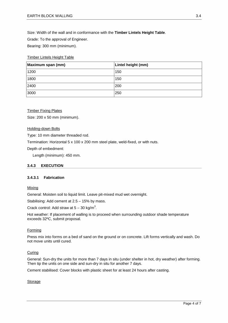
EARTH BLOCK WALLING 3.4
Page 4 of 7
Size: Width of the wall and in conformance with the Timber Lintels Height Table.
Grade: To the approval of Engineer.
Bearing: 300 mm (minimum).
Timber Lintels Height Table
Maximum span (mm) Lintel height (mm)
1200 150
1800 150
2400 200
3000 250
Timber Fixing Plates
Size: 200 x 50 mm (minimum).
Holding-down Bolts
Type: 10 mm diameter threaded rod.
Termination: Horizontal 5 x 100 x 200 mm steel plate, weld-fixed, or with nuts.
Depth of embedment:
Length (minimum): 450 mm.
3.4.3 EXECUTION
3.4.3.1 Fabrication
Mixing
General: Moisten soil to liquid limit. Leave pit-mixed mud wet overnight.
Stabilising: Add cement at 2.5 – 15% by mass.
Crack control: Add straw at 5 – 30 kg/m3.
Hot weather: If placement of walling is to proceed when surrounding outdoor shade temperature exceeds 32ºC, submit proposal.
Forming
Press mix into forms on a bed of sand on the ground or on concrete. Lift forms vertically and wash. Do not move units until cured.
Curing
General: Sun-dry the units for more than 7 days in situ (under shelter in hot, dry weather) after forming. Then tip the units on one side and sun-dry in situ for another 7 days.
Cement stabilised: Cover blocks with plastic sheet for at least 24 hours after casting.
Storage

EARTH BLOCK WALLING 3.4
Page 5 of 7
Stack cured units close to point of use on boards off the ground. Stack on edge, 2 – 3 rows high. Orient stacks for equal exposure to sun and wind on both faces. Protect the tops of stacks against the weather.
3.4.3.2 Laying Units
General
Drying: Do not lay units until they are dry and at least 28 days after forming.
Unstabilised units: Sprinkle with water before laying. Relay disturbed units in fresh mortar.
Temperature: Do not lay when ambient temperature is or is expected to be < 5C within 48 hours of placement. Do not lay on frozen materials.
Daily progress: Establish leads at corners. Step back incomplete walls, do not tooth. Cover incomplete work at the top. Lay a maximum of 500 – 700 mm height per day.
Voids at dissimilar materials: Fill with earthen mortar.
Protection: Protect tops of walls from rain until the roof is in place.
Joints
Bedding: Full flush type, with no open head joints.
Bond: Running bond. Overlap units 100 mm.
Type: Flush, 13 – 19 mm thick. Tool concave at exposed surfaces. Remove excess mortar.
Control joints:
Spacing as identified on drawings.
Protection
Unstabilised units: Do not locate unstabilised units within 100 mm of adjacent floor levels, within 225 mm of adjacent ground levels, within 100 mm of the top of unenclosed walls and parapets, around roof drains, and in other areas where there is risk of moisture.
3.4.3.3 Damp-proof Courses
Location
At the base of the earth walls above footings or slab (plinth).
Walls on Slabs
Finish flush with outer face of slab and inner face of wall. Upturn on inside behind skirting and downturn at outer face of slab, at least 25 mm.
Installation
General: Lay in long lengths, in a single width. Lay full width at angles and intersections and lap at least 150 mm at joints. Step as necessary.
3.4.3.4 Fixings and Embedded Items
Nailing blocks and nailers
Installation: Build-in as the work progresses. Use nailing blocks to fix all window frames, door frames and other wall mounted fixtures.

EARTH BLOCK WALLING 3.4
Page 6 of 7
Partitions: Nail timber framed partitions to nailing blocks.
3.4.3.5 Reinforcement
Installation
Do not cut, weld or grind on site. Build-in as work progresses. Lap 450 mm at splices. Fold and bend at corners so that the longitudinal wires are continuous. Stop 200 mm short of control joints. Place in centre of the width of the wall, and in the bedding joint.
Cover (minimum):
75 mm for exposed surfaces.
25 mm for protected surfaces.
Vertical intervals (maximum): 500 mm, for full height of the wall.
3.4.3.6 Steel Lintels
Installation
Do not cut, weld or grind on site. Build-in as work progresses. Keep lintels 10 mm clear of heads and frames. Install T-lintels with horizontal component at the bottom, centred in the width of the wall.
Propping: Temporarily prop lintels during construction and until the wall reaches its required strength.
3.4.3.7 Timber Lintels
Installation
Build-in as work progresses. Keep lintels 10 mm clear of heads and frames.
3.4.3.8 Pipes and Conduits
Installation
Installation: Lay conduits and water pipes in mortar joints as far as possible. Otherwise lay in chases.
Cover (minimum): 100 mm, if built-in.
Chases: Maximum depth 50 mm. Run vertically, not horizontally. Do not chase in exposed facework. Thicken the walls for larger piping.
3.4.3.9 Bond Beams
Positions
Provide a continuous bond beam to bearing walls, at framed floor and at roof bearing levels. Build-in as work progresses. Anchor the floor and roof structures to the bond beams. Bond beams may be concrete, timber or steel beams as identified on the drawings.
Position: Centre on the wall.
Bedding: Mortar levelling course.
3.4.3.10 Holding-down Bolts
General
Cover (minimum): 75 mm. Location: Refer to drawings for locations, length of holding down bolts.
EARTH BLOCK WALLING 3.4
Page 7 of 7
Installation
Set in perpends and units split lengthwise, in alternating courses. Do not locate within 150 mm of end of wall. Locate in the centre of wall.
3.4.3.11 Finishes
Appearance
Marks and stains: Remove at completion.
Efflorescence: Remove before sealing or rendering.
Mud Render
General: Render the exteriors of walls made of unstabilised units.
Preparation: Brush the substrate, score and moisten.
Mix: 3:1 clay:clean sand, with straw reinforcing, and enough water to make a paste.
Render: Two coats, each 5 – 7 mm thick.
Finish: Polish the coating using sheepskin or small rounded stones.
3.4.3.12 Temporary Work
Facework sample panel
If not incorporated, demolish panel.
Refer to the Earth Block Walling Construction Schedule and drawings for details of locations and built in components.

BRICKWORK 3.5
Page 1 of 6
3.5 BRICKWORK
3.5.1 GENERAL
3.5.1.1 Inspection
Notice
Give sufficient notice so that inspection may be made of the following:
Set out of brickwork to lintels, arches and other architectural features.
Damp-proof courses, in position.
Lintels, in position.
3.5.2 PRODUCTS
3.5.2.1 Materials
First Class Bricks
First Class Bricks shall be made from good brick earth free from saline deposits, and shall be sand molded. They shall be thoroughly burnt by coal without being vitrified, of uniform and good color, shall be regular and uniform in size, shape and texture with sharp square edges and parallel faces. They must emit a clear metallic ringing sound when struck one against another. They shall be free from flaws, cracks, chips, stones, and nodules of lime or canker. A First Class Brick shall not absorb more than 1/6th of its weight of water after being soaked for one hour.
Second Class Bricks
Second Class Bricks shall be as well burnt as First Class or may be slightly over burnt but not vitrified, and must give a clear ringing sound when struck one against another. Slight irregularities in size, shape or color are acceptable provided irregular or uneven courses do not result. Second Class Bricks may have slight chips or flaws but must be free from lime or canker nodules. They shall not absorb more than 1/4th of their weight of water after being soaked for one hour.
General
Machine made pressed bricks shall be standard commercial products, locally manufactured unless specified. The Engineer prior to use in the Works shall approve the use of machine made pressed bricks.
Bricks not meeting the above requirements shall not be used in brickwork.
First and Second Class Bricks should have these dimensions after burning: 220mm x 105mm x 65mm. Dimensions may vary according to manufacturer, but must be approved by Engineer before laying. The unit weight of First and Second Class Bricks shall not be less than 1100 kg/m
3.
The crushing strength of bricks shall be tested in a laboratory. The average crushing strength of First and Second Class Bricks shall not be less than 10.3 MPa (105 kg/cm
2).
At the start of the works samples of the bricks shall be tested for crushing strength and water absorption, and brickwork shall only commence when the Engineer has approved the bricks. The Contractor may then only change the source of supply of bricks after samples from the new supplier have similarly been tested and approved.
Mortar Materials
Cement shall conform to the requirements of ASTM specification C-150 Type 1 or similar approved standard for normal Portland cement.

BRICKWORK 3.5
Page 2 of 6
White cement: Iron salts content 1%.
Off-white cement: Iron salts content 2.5%.
Lime: Confirm source of Lime with Engineer to ensure highest quality Lime is used in the mortar. Protect from damage on site and store minimum 300mm above ground in waterproof storage facility.
Sand: Fine aggregate with a low clay content selected for grading, sharp and free from efflorescing salts. River or pit sand should be sharp, angular, hard, clean uncoated particles free from clay and organic impurities.
Water: Water to be used for the mixing of mortar should be clean and free from oil, acid, alkali, salts, organic materials or other substances that are harmful to the mortar mix.
Measurement of volume: Measure binders and sand by volume using buckets or boxes. Do not allow sand to bulk by absorption of water.
Mortar
Proportioning: Standard and ratio of mix for all mortar shall be M-400 (1:3), M-300 (1:4), M-250 (1:5) and M-200 (1:6).Provide minimum water.
3.5.2.2 Components
Nailing blocks
Solid timber, or hollow timber box filled with earthen mortar. Timber unseasoned or thoroughly pre- wetted.
Steel components, including reinforcement
All steel components to be galvanised for maximum durability after incorporation into the structure.
Window and Door lintels
Lintels: Use steel, concrete or timber lintels in accordance with the manufacturers’ technical literature
or conform to the Steel angle and T-lintels table.
Steel Angle and T-Lintels Table
Maximum
span
(mm)
Wall height above 600 mm Wall height above > 600 mm, 1800 mm
Angle lintel size T-Lintel
dimensions:
H x W x T
(mm)
Bearing
min.
(mm)
Angle lintel size T-Lintel
dimensions:
H x W x T
(mm)
Bearing
min.
(mm)
1000 Two 75 x 50 x 5 Unequal angles
81 x 150 x 6 100 Two 125 x 75 x 8 Unequal angles
136 x 150 x 6 200
2000 Two 100 x 75 x 6 Unequal angles
136 x 150 x 6 150 Two 150 x 90 x 8 Unequal angles
156 x 150 x 6 200
2400 Two 125 x 75 x 8 Unequal angles
156 x 150 x 6 150 Two 150 x 90 x 10 Unequal angles
160 x 150 x 10 250
2800 Two 150 x 90 x 8 Unequal angles
158 x 150 x 8 200 Two 150 x 100 x 10 Unequal angles
210 x 200 x 10 300
3000 Two 150 x 90 x 10 Unequal angles
160 x 150 x 10 200 Two 150 x 100 x 12 Unequal angles
210 x 200 x 10 300
Timber Lintels
Size: Width of the wall and in conformance with the Timber Lintels Height table.
Grade: Best quality of imported Russian timber or suitable approved local timber.

BRICKWORK 3.5
Page 3 of 6
Bearing: 300 mm (minimum).
Timber Lintels Height Table
Maximum span (mm) Lintel height (mm)
1200 150
1800 150
2400 200
3000 250
Timber Fixing Plates
Size: 200 x 50 mm (minimum).
Holding-down Bolts
Type: 10 mm diameter threaded rod.
Termination: Horizontal 5 x 100 x 200 mm steel plate, weld-fixed, or with nuts.
Depth of embedment:
Length (minimum): 450 mm.
3.5.3 EXECUTION
Refer to Brickwork Construction schedule for details of brickwork and mortar types.
3.5.3.1 General
General
Construction of masonry brickwork shall not commence until the Engineer has accepted the footings on which it is to be placed.
Brickwork shall be built plumb, curved or battered as shown on the Drawings or as may be required, by skilled masons and properly supervised workmen. Bricks shall be clean and if necessary, they shall be scrubbed. Bricks shall be soaked in water for at least one hour before use.
Brick should be laid as indicated in drawings or schedules, or as specified by Engineer. All horizontal joints shall be parallel and level. Vertical joints in alternate courses shall come directly over one another. Joint thickness shall be 8mm and shall in no case exceed 12mm. The height of four courses including 4 bed joints shall rise 300mm. Set out brickwork with joints of uniform width and minimise cutting of masonry units.
Walls shall always be carried up regularly along their entire length unless otherwise directed by the Engineer. Bricks should be laid so that only full courses are used to avoid splitting bricks at beams, ledges, lintels.
Mortar Mix
Mortar mixing shall be done in a mechanical mixer unless the Engineer specifically permits hand mixing. If hand-mixing is done, the operation shall be carried out on a clean watertight platform and cement & sand shall be first mixed dry in the required proportion to obtain a uniform colour and then the mortar shall be mixed for at least two minutes after addition of water.
Cement Mortar shall be mixed in such quantities as can be used in the work within 30 minutes. Mortar, which has taken initial set, shall not be used, nor shall it be re-mixed with fresh mortar.
Preparing lime putty:

BRICKWORK 3.5
Page 4 of 6
Using hydrated lime: Add lime to water in a clean container and stir to a thick creamy consistency. Leave undisturbed for at least 16 hours. Remove excess water and protect from drying out.
Using quicklime: Run to putty as soon as possible after receipt of quicklime. Partly fill clean container with water, add lime to half the height of the water, then stir and hoe ensuring that no lime remains exposed above the water. Continue stirring and hoeing for at least 5 minutes after all reaction has ceased, then sieve into a maturing bin. Leave undisturbed for at least 14 days. Protect from drying out.
Mortar proportions (cement:lime:sand): As defined on drawings.
Sand stockpile: Ensure sand is dry and stored undercover to avoid errors in volume batching during the mixing process.
Protection from Contamination
Protect masonry materials and components from ground moisture and contamination.
Building-In
Embedded items: Build in fixing blocks, brackets, lintels and accessories as the construction proceeds.
Steel door frames: Fill the backs of jambs and heads solid with mortar as the work proceeds.
Joining to Existing
If jointing to existing work is required, provide a straight joint. Do not tooth new masonry into existing work.
Chasing
Chasing of brickwork shall be to the Brickwork Chasing table and subject to the following limitations:
Parallel chases on opposite faces of a wall shall not be closer than 600 mm to each other.
Brickwork Chasing Table
Brick thickness (mm) Depth of chase (maximum mm)
More than 250 thick 35
250 thick 25
100 thick non load bearing walls only 20
Joint Finish
Lay brickwork on a full bed of mortar. Fill perpendicular joints solid.
Finish:
Externally: Tool to give a dense water-shedding finish for face brickwork or rake not more than 10mm to give a key for render finish.
Internally: If wall is to be plastered, rake not more than 10 mm to give a key.
Temporary Support
If the final stability of the brickwork or blockwork is dependent on structural elements to be constructed after the brickwork, provide proposals for temporary support or bracing for the approval of the Engineer.
BRICKWORK 3.5
Page 5 of 6
3.5.3.2 Facework
Cleaning
General: Clean progressively as the work proceeds to remove mortar smears, stains and discolouration.
Colour mixing
Evenly distribute the colour range of units and prevent colour concentrations and “banding” unless specifically identified as a feature of the brickwork.
Bricks or mortar shall not be stained or painted.
3.5.3.3 Damp-proof courses
Damp-proof Courses
Material: Embossed Polythene sheeting or bitumen membrane as approved by Engineer. Install sheeting at base of all walls to stop moisture rising up wall structures.
Location
Provide damp-proof courses as follows:
Walls built off slabs on ground: In the bottom course of the wall on top of the slab.
Walls adjoining infill floor slabs: In the course above the slab. Project 40 mm and dress down over the membrane turned up against the wall.
Installation
Lay in long lengths. Lap full width at angles and intersections and at least 150 mm at joints. Step as necessary, but not exceeding 2 courses per step. Sandwich damp-proof courses between mortar.
3.5.3.4 Control of movement
Joints
Provide joints as follows:
Expansion joints for brickwork:
Maximum length of continuous wall face: 8 m.
Closest joint location to external corner: 2.5m
Maximum vertical spacing: 8 m.
Width of control joint: 10 mm 20 mm.
Width of horizontal joint: 15 mm 20 mm.
Filler material: Provide compatible sealant and bond breaking backing materials which are non-staining to masonry.
Bond breaking materials: To be non-adhesive to sealant, or faced with a non-adhering material.
Foamed materials: To be closed-cell or impregnated, not water-absorbing.
Joint filling:
Installation: Clean the joints thoroughly and insert an easily compressible backing material before sealing.
Sealant depth: Fill the joints with a gun-applied flexible sealant for a depth of at least two-thirds the joint width.

BRICKWORK 3.5
Page 6 of 6
Refer to the Brickwork Construction and drawings for details of locations, types and extent of built in components.
STONEWORK 3.6
1
3.6 STONEWORK
3.6.1 GENERAL
3.6.1.1 Inspection
Notice
Give sufficient notice so that inspection may be made of the following:
The prepared stone sample range.
Lintels in position.
Damp proof courses in position.
3.6.1.2 Tolerances
Dimensions of Stone Units
Maximum deviation from required dimensions:
Load bearing stone in cut blocks: 4 mm.
Other stone used in foundations or not exposed to view: No size requirement unless noted otherwise in this work section .
3.6.2 PRODUCTS
3.6.2.1 Natural stone
Stone Types
Sandstone defects: Minor shale laminates and minor concentrations of carbonaceous material (tea leaves) are acceptable in visible faces. Neither defect is acceptable in carved or moulded work.
Granite defects: Igneous stone (e.g. granite) obtained from quarry stone extracted in blocks sufficiently large to suit the project requirements, and containing no more than a small degree of microcracking.
Stone Selection
Grading: Select stone of the designated quality grade.
Matching: Within each grade, select stone for the best match of colour and pattern.
Source of Stone Supply
Ensure the stone quarry or supplier can provide all stone required for the project without the need to find alternative supplies.
3.6.3 MORTAR
Mortar Materials
Cement shall conform to the requirements of ASTM specification C-150 Type 1 or similar approved standard for normal Portland cement.
White cement: Iron salts content 1%.
Off-white cement: Iron salts content 2.5%.

STONEWORK 3.6
2
Sand: Fine aggregate with a low clay content selected for grading, sharp and free from efflorescing salts. River or pit sand should be sharp, angular, hard, clean uncoated particles free from clay and organic impurities.
Water: Water to be used for the mixing of mortar should be clean and free from oil, acid, alkali, salts, organic materials or other substances that are harmful to the mortar mix.
Crushed stone: Fine aggregate consisting partly or wholly of crushed stone, made from material of the same type as the stone facing.
Measurement of volume: Measure binders and sand by volume using buckets or boxes. Do not allow sand to bulk by absorption of water.
Mortar
Standard and ratio of mix for all mortar shall be M-400 (1:3), M-300 (1:4), M-250 (1:5) and M-200 (1:6).Provide minimum water.
Mortar Mix
Mortar mixing shall be done in a mechanical mixer unless the Engineer specifically permits hand mixing. If hand-mixing is done, the operation shall be carried out on a clean watertight platform and cement & sand shall be first mixed dry in the required proportion to obtain a uniform color and then the mortar shall be mixed for at least two minutes after addition of water.
Cement Mortar shall be mixed in such quantities as can be used in the work within 30 minutes. Mortar, which has taken initial set, shall not be used, nor shall it be re-mixed with fresh mortar.
Sand stockpile: Ensure sand is dry and stored undercover to avoid errors in volume batching during the mixing process.
3.6.4 EXECUTION
Refer to Stonework construction schedule for details of stonework and mortar types.
3.6.4.1 Workmanship
Cutting
Perform the necessary cutting and shaping of stone to designated profiles including weathering, jointing, chasing, forming grooves. Make the bed, face and back joints of the stone square and true where dimensioned stone is required.
Carving and Moulding
Achieve a clean sharp finish. Carry out all work identified on the drawings to the approval of the Engineer.
3.6.4.2 Laying Units
Bedding
Remove dust and foreign material from the bedding surfaces. Water the face of the stone units so that full strength joints are achieved. Where possible, bed and joint the stone in one operation. Lay each stone on a full bed of mortar. Solidly fill and grout vertical joints as the work proceeds. Point up joints around flashings as necessary.
Natural Bed

STONEWORK 3.6
3
Lay loadbearing sedimentary stone with its natural bed at 90 degrees to the load, except for the following:
Cladding panels: In non-loadbearing cladding panels, form each panel with its natural bed at right angles to the face.
Temporary Support
Provide support as necessary to the stone while the mortar is curing, using bracing, joint spacers, or both.
Bracing and joint spacers: Non-damaging and non-staining softwood wedges soaked in water. Do not allow metal pinch bars to bear directly on the stone.
Raking and Toothing
Raise advanced work no more than 1.5 m above the general level, and rake back. Do not tooth stonework for subsequent additions except where toothing is shown on the drawings.
Bonding
Bond the masonry so as to provide stability and monolithic structural action to the stonework assembly.
3.6.4.3 Stone foundations
Stone Footings
Construct the footing course entirely of through stones, and if stepping is necessary, overlap the stepped courses at least 300 mm.
Subfloor Stone Foundation Walls
Minimum foundation wall thicknesses:
Supporting masonry walls 100 mm thick: 300 mm.
Supporting masonry walls 250 mm thick: 450 mm.
Supporting masonry walls 370 mm thick: 600 mm.
Stone sizes:
Maximum height: 350 mm.
Minimum height: Generally 175 mm; through stones 300 mm.
Bond pattern: Provide through stones as follows:
All stones in top and bottom courses.
Elsewhere as header units.
Slab bearings: Provide continuous bearing at least 100 mm wide to the edge of suspended slabs.
3.6.4.4 Damp-Proof Courses
Material
Material: Embossed Polyethylene sheeting. Install sheeting at base of all walls to stop moisture rising up wall structures.
Location
Provide damp-proof courses as follows:
Walls built off slabs on ground: In the bottom course of the wall on top of the slab.
Walls adjoining infill floor slabs: In the course above the slab. Project 40 mm and dress down over the membrane turned up against the wall.

STONEWORK 3.6
4
Installation
Lay in long lengths. Lap full width at angles and intersections and at least 150 mm at joints. Step as necessary, but not exceeding 2 courses per step. Sandwich damp-proof courses between mortar.
3.6.4.5 Jointing and Pointing
Joints
Size (mm): Not less than 3mm or more than 5mm for dimensioned stonework. Size may vary for non dimensioned stonework from 10mm to 30mm. Joint size should not exceed this without approval of the Engineer.
Jointing material: Mortar with a strength less than the stonework.
Pointing material: Coloured mortar or mortar as above, refer to Schedule or drawings.
Sealant Jointing
Preparation for Jointing
Immediately before jointing remove loose particles from the joint, using brushes or compressed air.
Taping
Protect the stonework surface on each side of the joint using 50 mm wide masking tape or equivalent means. On completion of pointing remove the tape and remove any stains or marks from the stonework surface.
Jointing Materials
Use recommended jointing and pointing materials which are compatible with each other and with the contact surfaces and non staining to finished surfaces.
Priming: Apply the recommended primer to the surfaces in contact with sealant materials.
Sealant colour: Refer to Schedule or drawings.
Foamed materials (in compressible fillers and backing rods): Closed cell or impregnated types which do not absorb water.
Sealant Application
Apply the sealant to dry joint surfaces. Do not apply the sealant in unsuitable weather conditions (e.g.
when the ambient temperature is outside the range 5 – 50C) or outside the recommended working time for the material or the primer.
Joint Finish
General: Produce a smooth, slightly concave surface using a tool designed for the purpose.
3.6.4.6 Completion
Cleaning
Cleaning: Leave the stonework clean on completion.
Refer to the Stonework Construction Schedule and drawings for details of locations, types and extent of built in components.

LIGHT STEELWORK 3.7
Page 1 of 2
3.7 LIGHT STEELWORK
3.7.1 GENERAL
3.7.1.1 Inspection
Notice
Give notice so that inspection may be made of steel framing erected before lining or cladding.
3.7.1.2 Submissions
Design
The Contractor is to confirm that all proposed member sizes are available for the project in accordance with the drawings and BOQ. If selected sizes are not available, seek alternatives and obtain approval from the Engineer.
3.7.2 EXECUTION
3.7.2.1 General
Fabrication
Length: Cut members accurately to length so that they fit firmly against abutting members.
Service holes: Form holes by drilling or punching if needed.
Bushes: Provide plastic bushes or grommets to site cut holes.
Swarf: Remove swarf and other debris from cold-formed steel framing immediately.
Site work: If possible, do not fabricate on site where welded connections are required.
Fastening
Select from the following:
Bolting.
Self-drilling, self-tapping screws.
Blind rivets.
Welding
Burning: Avoid procedures that result in greater than localised “burning” of the sheets or framing members. Protect other adjoining materials from damage during welding activities.
Other workers: Protect other workers on site from welding flash, sparks and other potential injuries during welding activities.
Prefabricated frames
Protect frames from damage or distortion during storage, transport and erection.
Unseasoned Timber

LIGHT STEELWORK 3.7
Page 2 of 2
Do not fix in contact with framing without fully painting the timber and/or the steel to avoid future rusting of the steel.
Earthing
Permanent earthing: Required.
Temporary earthing: Provide temporary earthing during erection until the permanent earthing is installed.
Protection
Coatings which have been damaged by welding or other causes shall be restored. Thoroughly clean affected areas to base metal and coat with zinc rich organic primer.
3.7.2.2 Trusses
Fabrication
Factory assemble trusses and transport to site where possible. Obtain approval from the Engineer if it is required to fabricate trusses on site.
Marking
Permanently mark each truss to show:
Manufacturer.
Tag or number.
Location.
Support points.
Installation
Fix to support structures, plumb to within H/200, where H is the height at the apex.
3.7.2.3 Completion
Cleaning
On completion of framing remove debris from any gaps between members.

STEELWORK PAINTING 3.8
1
3.8 STEELWORK PAINTING
3.8.1 GENERAL
3.8.1.1 Inspection
Notice
Give sufficient notice so that inspection may be made of the following:
Surfaces after preparation prior to application of first coating.
Coating after application of final coat.
3.8.1.2 Samples
Painting and Coating Colour
Submit a sample of the finished product for each different coating system.
Size of each sample: 200 x 200 mm.
3.8.2 PRODUCTS
3.8.2.1 General
General
All protective coatings must be handled, stored, mixed and applied strictly in accordance with the manufacturer’s instructions and Product Data Sheets.
3.8.3 EXECUTION
3.8.3.1 Protection
Surroundings
Provide protection of the surroundings to the coating works and ensure that no abrasive, overspray or paint waste debris is released either to air, ground or to any watercourse. Repair or clean damage as appropriate.
Contamination
Ensure protection of sensitive items during surface preparation and coating works. Do not permit surface preparation debris to contaminate coated surfaces which are not yet dry, nor cause damage to any other services or equipment.
Stacking and Handling
Do not stack, handle or transport coated items until the coating has sufficiently cured so as to resist handling actions.
Stack and handle all steelwork using fabric slings or padded chains, used in a manner that ensures that no damage is caused to the coating system. Adopt soft packaging, carpet strips or other deformable materials between all steel items. Do not permit steel to steel contact in any situation.

STEELWORK PAINTING 3.8
2
Water ponding: Stack coated items so that water ponding does not or cannot occur whilst the items are in storage, transport or “laydown”.
Repair of Coating Damage
If damage occurs repair so as to ensure that the full corrosion protection ability of the system is reinstated.
3.8.3.2 Surface Preparation
General
Coatings shall be applied only to properly prepared and cleaned surfaces.
Surface Preparation
Ensure all surfaces are free from oil, grease, dirt, bird droppings or any other contaminants, particularly soluble contaminants.
Surface defects: Remove or correct other surface defects, including cracks, laminations, deep pitting, undercutting, weld spatter, slag, burrs, fins and sharp edges.
Remove all weld spatter by grinding or chipping.
Priming
Prime coat all surfaces with zinc rich primer on the same day as the completion of surface preparation works. In every case, the specified surface preparation standard, in both cleanliness and profile, shall be evident at the time that the primer coating is applied.
3.8.3.3 Coating application
General
Apply the coatings in accordance with the Interior and Exterior Painting schedules.
Final Surface Preparation or Coating Application
Limits: If the following climatic/substrate conditions are present do not apply coating:
The ambient air temperature is below 5°C or above 40°C.
The substrate temperature is below 10°C or above 35°C.
The surface to be coated is wet or damp.
Defects: Apply materials so as to produce an even coating free from film defects.
Detail: Stripe coat all welds, bolt holes, sharp edges and difficult to spray areas by brushing in with the prime coat and intermediate coat material prior to the full coating application.
Subsequent Coats
Ensure that before any subsequent coating layer is applied, the surface condition of the preceding coat is complete and correct in all respects, including its cleanliness and freedom from defects. Correct any defects before the next coating layer is applied.

LIGHT TIMBERWORK 3.9
Page 1 of 3
3.9 LIGHT TIMBERWORK
3.9.1 GENERAL
3.9.1.1 Inspection
Notice
Give sufficient notice so that inspection may be made of the following:
Timber framing after erection before lining or cladding.
Roof framing and connection to wall and ceiling structures.
3.9.1.2 Submissions
Design
The Contractor is to confirm that all proposed member sizes are available for the project in accordance with the drawings and BOQ. If selected sizes are not available, seek alternatives and obtain approval from the Engineer.
3.9.2 PRODUCTS
3.9.2.1 Timber
Timber Grades
Structural timbers:
Appearance grade if exposed to view in the finished work: Use best quality timber free from twists, knots, splits and other visual or physical defects.
Structural grade if concealed in the building:
Lower quality timber with some visual defects acceptable but with minimal physical defects.
3.9.2.2 Sheet Products
Structural Plywood Panels
All structural plywood panels used for construction purposes are to be approved by the Engineer. Refer to drawings and BOQ for details of locations and sizes. All structural plywood is to be tested before use to the satisfaction of the Engineer to ensure that it will be suitable for the proposed use.
Use branded or certified plywood products where possible.
Hardboard or Fibreboard Panels
All hardboard or fibreboard panels used for construction purposes are to be approved by the Engineer. Refer to drawings and BOQ for details of locations and sizes. All material is to be tested before use to the satisfaction of the Engineer to ensure that it will be suitable for the proposed use.
Use branded or certified products where possible.
3.9.2.3 Components
Steel Post Bases
Minimum dimensions:
LIGHT TIMBERWORK 3.9
Page 2 of 3
Stirrup: 75 mm wide x 6 mm thick.
Dowel: 20 mm diameter heavy tube.
Location: To timber posts supported off concrete slabs or footings.
Finish: Galvanize after fabrication.
Fasteners
Material:
Use best quality steel bolts, washers and nuts for bolted connections. Washers to be used both sides of timber to avoid crushing of the timber at the connection point.
Use best quality screws to avoid damage to screw heads during tightening process.
Use best quality bright steel nails for internal work protected from the weather and galvanised nails for external fixings exposed to the weather.
Lightweight allow bolts and screws will not be permitted.
Installation: Pre drill holes in hardwood timber to avoid splitting the timber.
Do not split or otherwise damage the timber or fastener by hammering bolts or screws into the timber.
3.9.3 EXECUTION
3.9.3.1 General
Protection from Weather
General: Provide temporary protection for members until permanent covering is in place.
3.9.3.2 Floor framing
Bearers and Joists
Levelling: Level bearers and joists by packing for the full width of the member.
Joints: Locate joints only over supports:
Minimum bearing of bearers: 50 mm.
Minimum bearing of joists: 30 mm.
Fixing: Secure bearers and joists to supports to provide restraint against lateral movement.
Joist restraint: If joist timber is unseasoned, the span 3000 mm, provide solid blocking between each joist in rows at 1800 mm centres and at the ends of the joists over the supports.
Members: Provide bearers and joists where shown on the drawings and in the BOQ.
Flooring
Provide flooring of structural plywood where shown on the drawings and in the BOQ.
3.9.3.3 Roof and ceiling framing
Wall Plates
Fix timber wall plates to top of masonry walls with either straps or bolts, or provide fixings cast into the ring beam as required.
Ceiling Framing
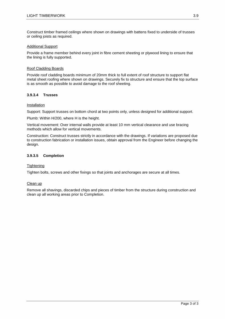
LIGHT TIMBERWORK 3.9
Page 3 of 3
Construct timber framed ceilings where shown on drawings with battens fixed to underside of trusses or ceiling joists as required.
Additional Support
Provide a frame member behind every joint in fibre cement sheeting or plywood lining to ensure that the lining is fully supported.
Roof Cladding Boards
Provide roof cladding boards minimum of 20mm thick to full extent of roof structure to support flat metal sheet roofing where shown on drawings. Securely fix to structure and ensure that the top surface is as smooth as possible to avoid damage to the roof sheeting.
3.9.3.4 Trusses
Installation
Support: Support trusses on bottom chord at two points only, unless designed for additional support.
Plumb: Within H/200, where H is the height.
Vertical movement: Over internal walls provide at least 10 mm vertical clearance and use bracing methods which allow for vertical movements.
Construction: Construct trusses strictly in accordance with the drawings. If variations are proposed due to construction fabrication or installation issues, obtain approval from the Engineer before changing the design.
3.9.3.5 Completion
Tightening
Tighten bolts, screws and other fixings so that joints and anchorages are secure at all times.
Clean up
Remove all shavings, discarded chips and pieces of timber from the structure during construction and clean up all working areas prior to Completion.

STRUCTURAL STEEL 3.11
Page 1 of 7
3.11 STRUCTURAL STEEL
3.11.1 GENERAL
This section includes fabrication and erection of structural steel work, as shown on drawings including schedules, notes, and details showing size and location of members, typical connections, and types of steel required. Structural steel is that work defined in American Institute of Steel Construction (AISC) "Code of Standard Practice for Steel Buildings and Bridges" and as otherwise shown on drawings.
Related Sections: Refer to the following sections for related work:
3.1 Concrete Concrete General
3.8 Steelwork painting
3.10 Concrete Blockwork
REFERENCES
American Society of Testing and Materials (ASTM)
ASTM - A6: Specification for General Requirements for Delivery of Rolled Steel Plates, Shapes, Sheet Piling and Bars for Structural Use
ASTM - A36: Specification for Structural Steel
ASTM - A53: Specification for Pipe, Steel, Black and Hot-Dipped, Zinc-Coated Welded and Seamless
ASTM - A307: Specification for Carbon Steel Bolts and Studs, 60000 psi Tensile Strength
ASTM - A325: Specification for High-Strength Bolts for Structural Steel Joints
ASTM - A500: Specification for Cold-Formed Welded and Seamless Carbon Steel Structural Tubing in Rounds and Shapes
ASTM - A501:Specification for Hot-Formed Welded and Seamless Carbon Steel Structural Tubing
ASTM - E94: Guide for Radiographic Testing
ASTM - E142: Method for Controlling Quality of Radiographic Testing
ASTM - F959: Specification for Compressible-Washer-Type Direct Tension Indicators for Use with Structural Fasteners
American Welding Society (AWS)
AWS - D1.1: Structural Welding Code - Steel
3.11.1.1 Inspection
Notice
Give notice so that inspection may be made of steel framing before erection, lining or cladding.
3.11.1.2 Submissions
Product Data:
Submit product data or manufacturer's specifications and installation instructions for the following products. Include laboratory test reports and other data to show compliance with specifications (including specified standards).
- Structural steel (each type), including certified copies of mill reports covering chemical and physical properties.

STRUCTURAL STEEL 3.11
Page 2 of 7
- Anchor bolts.
- Unfinished threaded fasteners.
- High-strength bolts (each type), including nuts and washers; include direct tension indicators if used.
Material Safety Data Sheets (MSDS):
Submit MSDS for structural steel (each type), anchor bolts, unfinished threaded fasteners, high-strength bolts (each type) including nuts and washers, structural steel primer paint and nonmetallic shrinkage-resistant grout.
Shop drawings:
Submit shop drawings, including complete details and schedules for fabrication and assembly of structural steel members, procedures, and diagrams.
- Include details of cuts, connections, cambers, holes and other pertinent data. Indicate welds by standard AWS symbols and show size, length, and type of each weld.
- Provide setting drawings, templates, and directions for installation of anchor bolts and other anchorages to be installed as work of other sections.
Welder Certifications:
Provide certification that welders to be employed in work have satisfactorily passed qualification tests in accordance with AWS D1.1. If recertification of welders is required, retesting will be Contractor's responsibility.
Test reports:
Submit test reports conducted on shop- and field-bolted and welded connections. Include data on type(s) of tests conducted and test results.
Welding Procedures:
Provide written welding procedure specification (WPS) document per AWS Code requirements.
QUALITY ASSURANCE
Codes and Standards: Comply with provisions of the following, except as otherwise indicated:
- AISC "Code of Standard Practice for Steel Buildings and Bridges" with paragraph 4.2.1 modified by deletion of the following sentence: "This approval constitutes the owner's acceptance of all responsibility for the design adequacy of any detail configuration of connections developed by the fabricator as a part of his preparation of these shop drawings."
- AISC "Specifications for Structural Steel Buildings" including the "Commentary", later referred to as "AISC Specifications".
- ASTM A325 or A490 Bolts "Specifications for Structural Joints using".
- AWS D1.1
- ASTM A6
Qualifications for Welding Work: Qualify welding procedures and welding operators in accordance with the requirements of AWS D1.1.
All materials used shall not contain asbestos fibers.
DELIVERY, STORAGE, AND HANDLING

STRUCTURAL STEEL 3.11
Page 3 of 7
- Deliver materials to site at such intervals to ensure uninterrupted progress of work.
- Deliver anchor bolts and anchorage devices, which are to be embedded in cast-in-place concrete or masonry, in ample time so that work will not be delayed.
- Store materials to permit easy access for inspection and identification. Keep steel members off ground by using pallets, platforms, or other supports. Protect steel members and packaged materials from corrosion and deterioration. If bolts and nuts become dry or rusty, clean and lubricate before use.
Do not store materials on structure in a manner that might cause distortion or damage to members or supporting structures. Repair or replace damaged materials or structures as directed.
PROJECT CONDITIONS
Field Measurements: Check actual locations of walls and other construction to which steel framing must fit, by accurate field measurements before fabrication; show recorded measurements on final shop drawings.
3.11.2 PRODUCTS
3.11.2.1 Materials
Metal Surfaces, General: For fabrication of work that will be exposed to view, use only materials that are smooth and free of surface blemishes including pitting, rust and scale seam marks, roller marks, rolled trade names, and roughness. Remove such blemishes by grinding, or by welding and grinding, prior to cleaning, treating, and applying surface finishes.
Structural Steel Shapes, Plates, and Bars: ASTM A36
Cold-Formed Steel Tubing: ASTM A500, Grade B.
Hot-Formed Steel Tubing: ASTM A501.
Steel Pipe: ASTM A53, Type E or S, Grade B: or ASTM A501.
Finish: Black, except where indicated to be galvanized.
Steel Castings: ASTM A27, Grade 65-35, medium-strength carbon steel.
Headed Stud-Type Shear Connectors: ASTM A108, Grade 1015 or 1020, cold-finished carbon steel with dimensions complying with AISC Specifications.
Anchor Bolts: ASTM A307, nonheaded type unless otherwise indicated.
Unfinished Threaded Fasteners: ASTM A307, Grade A, regular low-carbon steel bolts and nuts; provide hexagonal heads and nuts for all connections.
High-Strength Threaded Fasteners: Heavy hexagon structural bolts, heavy hexagon nuts, and hardened washers, as follows:
- Quenched and tempered medium-carbon steel bolts, nuts and washers, complying with ASTM A325.
- Where indicated as galvanized, provide units that are zinc-coated, either mechanically deposited complying with ASTM B695, Class 50, or hot-dip galvanized complying with ASTM A153.
Direct Tension Indicators: ASTM F959, type as required; use at Contractor's option.
Electrodes for Welding: Comply with AWS Code.
Structural Steel Primer Paint: Red oxide, lead- and cadmium-free, corrosion-inhibiting primer complying with performance requirements of FS TT-P-664.
Non-metallic Shrinkage-Resistant Grout: Premixed, nonmetallic, noncorrosive, nonstaining product containing selected silica sands, Portland cement, shrinkage compensating agents, plasticizing and water-reducing agents, complying with ASTM C1107 (formerly referenced as CE CRD C621).

STRUCTURAL STEEL 3.11
Page 4 of 7
Subject to compliance with requirements, products that may be incorporated in the work include, but are not limited to, the following:
100 Non-Shrink Grout (Non-Metallic) - Conspec, Inc.
Crystex - L & M Construction Chemicals, Inc.
Euco N-S Grout - Euclid Chemical Co.
Kemset - Chem-Masters Corp.
Sonogrout - Sonneborn Building Products Div., Rexnord Chemical Products, Inc.
Supreme Grout - Cormix, Inc.
Sure-Grip High Performance Grout - Dayton Superior
Vibropruf #11 - Lambert Corp.
3.11.2.2 Fabrication
Shop Fabrication and Assembly:
Fabricate and assemble structural assemblies in shop to greatest extent possible. Fabricate items of structural steel in accordance with AISC Specifications and as indicated on final shop drawings. Provide camber in structural members where indicated.
- Properly mark and match-mark materials for field assembly. Fabricate for delivery sequence that will expedite erection and minimize field handling of materials.
- Where finishing is required, complete assembly, including welding of units, before start of finishing operations. Provide finish surfaces of members exposed in final structure free of markings, burrs, and other defects.
Connections:
Weld or bolt shop connections, as indicated.
- Bolt field connections, except where welded connections or other connections are indicated.
- Provide high-strength threaded fasteners, unless otherwise indicated.
High-Strength Bolted Connections:
Install high-strength threaded fasteners in accordance with AISC "Specifications for Structural Joints using ASTM A325 or A490 Bolts".
Welded Construction:
Comply with AWS Code for procedures, appearance and quality of welds, and methods used in correcting welding work.
Shear Connectors:
Prepare steel surfaces as recommended by manufacturer of shear connectors. Weld shear connectors in field, spaced as shown, to beams and girders in composite construction. Use automatic end welding of headed stud shear connectors in accordance with manufacturer's printed instructions.
Steel Wall Framing:
Select members that are true and straight for fabrication of steel wall framing. Straighten as required to provide uniform, square, and true members in complete wall framing.
Build up welded door frames attached to structural steel framing. Weld exposed joints continuously and grind smooth. Plug-weld steel bar stops to frames, except where shown removable. Secure

STRUCTURAL STEEL 3.11
Page 5 of 7
removable stops to frames with countersunk, cross-recessed head machine screws, uniformly spaced not more than 10 inches (25 cm) o.c., unless otherwise indicated.
Holes for Other Work:
Provide holes required for securing other work to structural steel framing and for passage of other work through steel framing members, as shown on final shop drawings.
- Provide threaded nuts welded to framing and other specialty items as indicated to receive other work.
- Cut, drill, or punch holes perpendicular to metal surfaces. Do not flame-cut holes or enlarge holes by burning. Drill holes in bearing plates.
3.11.2.3 Shop Drawing
General:
Shop-paint structural steel, except those members or portions of members to be embedded in concrete or mortar. Paint embedded steel that is partially exposed on exposed portions and initial 2 inches (51 mm) of embedded areas only.
- Do not paint surfaces to be welded or high-strength bolted with friction-type connections.
- Do not paint surfaces scheduled to receive sprayed-on fireproofing.
- Apply 2 coats of paint to surfaces that are inaccessible after assembly or erection. Change color of second coat to distinguish it from first.
Surface Preparation:
After inspection and before shipping, clean steelwork to be painted. Remove loose rust, loose mill scale, and spatter, slag, or flux deposits. Clean steel in accordance with SSPC as follows:
SP-1 "Solvent Cleaning"
SP-2 "Hand-Tool Cleaning"
SP-3 "Power-Tool Cleaning"
Painting:
Immediately after surface preparation, apply structural steel primer paint in accordance with manufacturer's instructions and at a rate to provide dry film thickness of not less than 3.0 mils. Use painting methods that result in full coverage of joints, corners, edges, and exposed surfaces. Refer to 3.8 Steelwork Painting and 6.6 Painting Sections for more details.
3.11.2.4 Source Quality Control
Materials and fabrication procedures are subject to inspection and tests in mill, shop, and field, conducted by a qualified inspection agency. Such inspections and tests will not relieve Contractor of responsibility for providing materials and fabrication procedures in compliance with specified requirements. Promptly remove and replace materials or fabricated components that do not comply.
3.11.3 EXECUTION
3.11.3.1 Erection
Temporary Shoring and Bracing:
Provide temporary shoring and bracing members with connections of sufficient strength to bear imposed loads. Remove temporary members and connections when permanent members are in place

STRUCTURAL STEEL 3.11
Page 6 of 7
and final connections are made. Provide temporary guy lines to achieve proper alignment of structures as erection proceeds.
Anchor Bolts:
Furnish anchor bolts and other connectors required for securing structural steel to foundations and other in-place work. Furnish templates and other devices as necessary for presetting bolts and other anchors to accurate locations.
Setting Bases and Bearing Plates:
Clean concrete and masonry bearing surfaces of bond-reducing materials and roughen to improve bond to surfaces. Clean bottom surface of base and bearing plates.
- Set loose and attached base plates and bearing plates for structural members on wedges or other adjusting devices.
- Tighten anchor bolts after supported members have been positioned and plumbed. Do not remove wedges or shims, but if protruding, cut off flush with edge of base or bearing plate prior to packing with grout.
- Pack grout solidly between bearing surfaces and bases or plates to insure that no voids remain. Finish exposed surfaces, protect installed materials, and allow to cure.
- For proprietary grout materials, comply with manufacturer's instructions.
Field Assembly:
Set structural frames accurately to lines and elevations indicated and in accordance with AISC Specifications. Align and adjust various members forming part of complete frame or structure before permanently fastening. Clean bearing surfaces and other surfaces that will be in permanent contact before assembly. Perform necessary adjustments to compensate for discrepancies in elevations and alignment.
- Level and plumb individual members of structures within specified AISC tolerances.
- Establish required leveling and plumbing measurements on mean operating temperature of structure. Make allowances for difference between temperature at time of erection and mean temperature at which structure will be when completed and in service.
- Splice members only where indicated and accepted on shop drawings.
- Comply with AISC Specifications for bearing, adequacy of temporary connections, alignment, and removal of paint on surfaces adjacent to field welds.
- Do not enlarge unfair holes in members by burning or by using drift pins, except in secondary bracing members. Ream holes that must be enlarged to admit bolts.
Gas Cutting:
Do not use gas cutting torches in field for correcting fabrication errors in primary structural framing. Cutting will be permitted only on secondary members that are not under stress, as acceptable to the SDR. Finish gas-cut sections equal to a sheared appearance when permitted. Comply with NFPA 51B for cutting processes.
Touch-Up Painting:
Immediately after erection, clean field welds, bolted connections, and abraded areas of shop paint. Apply paint to exposed areas using same material as used for shop painting.
Apply by brush or spray to provide minimum dry film thickness of 3.0 mils.

STRUCTURAL STEEL 3.11
Page 7 of 7
3.11.3.2 Quality Control
Sandia National Laboratories (SNL) may engage an independent testing and inspection agency to inspect high-strength bolted connections and welded connections and to perform tests and prepare test reports.
- Testing agency shall conduct and interpret tests, state in each report whether test specimens comply with requirements, and specifically state any deviations therefrom.
- Provide access for testing agency to places where structural steel work is being fabricated or produced so required inspection and testing can be accomplished.
- Testing agency may inspect structural steel at plant before shipment. SNL reserves the right, at any time before construction complete, to reject materials not complying with specified requirements.
Correct Deficiencies in structural steel work that inspections and laboratory test reports have indicated are not in compliance with requirements. Perform additional tests, at Contractor's expense, as necessary to reconfirm any noncompliance of original work and to show compliance of corrected work.
Shop-Bolted and Field-Bolted Connections: Inspect or test in accordance with AISC Specifications.
Verify that gaps of installed direct tension indicators are less than gaps specified in ASTM F959, Table 2.
Shop Welding and Field Welding: Inspect and test during fabrication for shop welding and during erection for field welding, of structural steel assemblies, as follows:
- Certify welders and conduct inspections and tests as required. Record types and locations of defects found in work. Record work required and performed to correct deficiencies.
- Perform visual inspection of all welds.
- Perform tests up to and including 100% of welds at SNL's option. Inspection procedures may include the following:
a. Liquid Penetrant Inspection: ASTM E165.
b. Magnetic Particle Inspection: ASTM E709; performed on root pass and on finished weld. Cracks or zones of incomplete fusion or penetration are not acceptable.
c. Radiographic Inspection: ASTM E94 and ASTM E142; minimum quality level "2-2T".
d. Ultrasonic Inspection: ASTM E164.
Acceptance criteria shall be as specified in AWS D1.1.
3.11.3.3 Completion
Cleaning
On completion of framing remove debris from any gaps between members.

WATERPROOFING 4.1
Page 1 of 4
4.1 WATERPROOFING
4.1.1 GENERAL
4.1.1.1 Interpretations
Definitions
Performance Requirements: Provide waterproofing that prevents the passage of water through surfaces.
For the purposes of this worksection the definitions given below apply.
Substrates: The surfaces on which membrane systems are laid.
Bitumen: A viscous material comprising complex hydrocarbons which is soluble in carbon disulphide, softens when it is heated, is waterproof and has good powers of adhesion. It is produced as a refined by-product of oil.
Bond breakers: Layers which prevent membranes from bonding to the backgrounds.
Membranes: Impervious barriers to liquid water which may be:
Liquid applied: Membranes applied in liquid or gel form and air cured to form a seamless film.
Sheet applied: Membranes applied in sheet form with joints lapped and bonded.
Membrane systems: Combinations of membranes, flashings, drainage and accessories which form waterproof barriers and which may be:
Loose-laid.
Bonded to backgrounds fully or partially.
4.1.1.2 Inspection
Notice
Give sufficient notice so that inspection may be made as follows:
Background preparation completed.
Before membranes are finished, covered up or concealed.
4.1.2 PRODUCTS
4.1.2.1 Membranes
Membrane Systems
To be proprietary membrane systems where possible having certification from an international testing organisation.
Internal Roof Outlets for Membrane Roof
Proprietary funnel shaped sump cast into the roof slab, set flush with membrane, with a flat removable grating and provision (e.g. clamp ring) for sealing the membrane into the base of the outlet.
4.1.3 EXECUTION
Refer to Single layer, Multi layer and Liquid Waterproofing System schedules for details of systems.

WATERPROOFING 4.1
Page 2 of 4
4.1.3.1 Preparation
General
Prepare backgrounds as follows:
Check that pipes, conduits and other penetrations of waterproofing membrane have been installed before beginning this work.
Fill all cracks in backgrounds wider than 1.5 mm with a filler compatible with the membrane system. Remove ridges and fins, leaving a smooth, clean surface.
Fill voids and hollows in concrete backgrounds with a concrete mix not stronger than the background.
Remove excessive projections.
Remove deleterious and loose material.
Check that areas to be waterproofed slope to drain, are clean and dry. Leave the surface free of contaminates, clean and dust free.
Moisture Content
Concrete backgrounds: Cure for > 21 days.
Falls
Verify that falls in backgrounds are > 1:100.
Joints and Fillets
Internal corners: Provide 45° fillets.
External corners: Round or arris edges.
Movement control joints: Prepare all background joints to suit the membrane system.
Priming
If required, prime the backgrounds with compatible primers to ensure adhesion of membrane systems.
4.1.3.2 Application
Job Conditions
Apply waterproofing materials when the temperature in the space to be waterproofed and the substrate to be waterproofed are above 5-degree C.
Do not apply waterproofing materials to damp, wet or frost covered surfaces.
Illuminate work areas during installation to provide the same or greater level of illumination required to properly perform this work, and as will occur in the room or space after the building is in operation.
Examine surfaces to be waterproofed.
Correct conditions detrimental to the proper and timely completion of this work before proceeding with installation.
Protection
Protect membrane from damage during installation.

WATERPROOFING 4.1
Page 3 of 4
Drains
Prevent moisture from tracking under the membranes at drainage locations.
Drains and cages: Provide grates or cages, to prevent blockage from debris.
Overflows: Turn the membranes into the overflow to prevent moisture from tracking behind the membrane.
Sheet joints
Bituminous sheet membranes:
Side laps > 50 mm.
End laps > 100 mm.
Synthetic rubber membranes:
Factory–vulcanized laps > 40 mm.
Field side laps > 50 mm for side laps.
Field end-laps > 100 mm for end laps.
Curing of liquid applied systems
To the manufacturers’ instructions.
Movement Control Joints
Locate over movement control joints in the substructure.
Fillets and bond breakers: Provide of sufficient dimension to allow the membrane to accommodate the movement.
Bonded membranes: Carry movement joints in the substrate through the surface finish.
Membrane Terminations
Edge protection: Provide upturns above the maximum water level expected from the exposure conditions of rainfall intensity and wind.
Minimum height of 200mm for all upturns above membrane level unless noted otherwise on the drawings.
Anchoring: Secure sheet membranes along the top edge.
Edge protection: Protect edges of the membrane.
Waterproofing above terminations: Waterproof the structure above the termination to prevent moisture entry behind the membrane using cappings, waterproof membranes or waterproof coatings.
Membrane Vertical Penetrations
Pipes, ducts, and vents: Provide separate sleeves for all pipes, ducts, and vents and have them fixed to the substrate. Minimum height of 200mm for all sleeves above membrane level unless noted otherwise on the drawings.
Overlaying Finishes on Membranes
Compatibility: If a membrane is to be overlayed with another system such as tiles, pavers, ballast, insulation, soil, and the like, provide an overlaying system that is compatible with and not cause damage to the membrane.
Ensure that no damage is caused to the membrane during the laying of the overlay material. If any damage occurs immediately stop work and repair the damage before proceeding with the overlay process.

WATERPROOFING 4.1
Page 4 of 4
Bonded or partially bonded systems: If the topping or bedding mortar requires to be bonded to the membrane, provide sufficient movement joints in the topping or bedding mortar to reduce the movement over the membrane.
Warranty
Submit sample copies of warranty for waterproofing membrane to be provided under this Section, clearly defining terms, conditions, and time periods for the warranty.

ROOFING 4.2
Page 1 of 5
4.2 ROOFING
4.2.1 GENERAL
4.2.1.1 Inspection
Notice
Give sufficient notice so that inspection may be made of:
Roof framing during construction.
Those parts of the roofing, vapour barrier, insulation and roof plumbing installation which will be covered up or concealed.
4.2.1.2 Submissions
Samples
Submit samples of the following showing the range of variation available:
Corrugated and flat metal roof sheeting
Roof cappings, flashings, gutters, downpipes
4.2.2 PRODUCTS
4.2.2.1 Materials and components
Fasteners
Self-drilling screws: Corrosion resistant screws to approval of Engineer.
Nuts and bolts: Corrosion resistant fastenings to approval of Engineer.
Fastenings to timber battens or purlins: Provide fastenings just long enough to penetrate the thickness of the timber without piercing the underside.
4.2.2.2 Corrugated metal roofing and cladding
General
Provide a proprietary system of preformed corrugated sheets and all purpose-made accessories
required to complete the installation to roof framing or wall framing. Refer to Corrugated sheet
roofing materials schedule for details.
4.2.2.3 Flat Sheet metal Roofing and Cladding
General
Provide a system of flat metal sheets and all purpose-made accessories required to complete the
installation to roof framing or wall framing. Refer to Flat sheet roofing materials schedule for details.
4.2.2.4 Glazed Roofing and Skylights
General

ROOFING 4.2
Page 2 of 5
Provide a proprietary overhead glazing system fixed to glazing bars or directly to the roof framing.
Provide all purpose-made accessories required to complete the installation. Refer to Glazed roofing
materials and skylight schedule for details.
4.2.2.5 Roof Ventilators
General
Provide proprietary roof mounted ventilators and all purpose-made accessories required to complete the installation where shown on the drawings to ventilate the roof space.
Provide fabricated ventilators in walls as shown on the drawings to ventilate the roof space.
Refer to Roof ventilators schedule for details.
4.2.3 EXECUTION
4.2.3.1 Installation
Protection
Keep the roofing and rainwater system free of debris and loose material during construction, and leave them clean and unobstructed on completion. Repair damage to the roofing and rainwater system.
If it is necessary to repair minor damage to metal roofing, do so immediately after the damage has occurred. The Contractor is take care to not damage other surfaces during the repair works.
Thermal Movement
Provide for thermal movement in the roof installation and the structure, including movement in joints and fastenings.
4.2.3.2 Sheet Metal Roofing and Cladding
Roofing Sheet Installation
Fixings: Provide all fixings required to fix the roof sheeting to the framing so that the entire roof covering is waterproof and secure. All loose edges are to be fixed down to ensure that they cannot get loose in high winds.
Expansion joints: refer to drawings for locations of expansion joints in roofs and details of construction.
Ridges and Eaves
Treat ends of sheets as follows:
Project sheets 50 mm into gutters.
Close off ribs of ribbed sheeting at bottom of sheets using mechanical means or with purpose-made end caps.
Turn pans of ribbed sheeting up at tops and down into gutters by mechanical means.
Provide pre-cut notched eaves flashings and birdproofing wire mesh where necessary.
Ridge and Eaves Capping
Finish off along ridge and side eaves edges with purpose-made ridge capping and eaves cappings.
End Laps
Where end laps are unavoidable in roof sheeting, and the sheet profile is not suitable for interlocking or contact end laps, construct a stepped type lap. Refer to details on drawings as required.
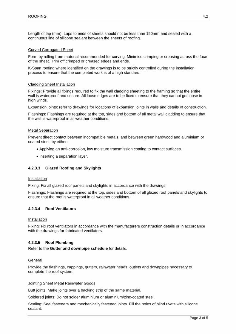
ROOFING 4.2
Page 3 of 5
Length of lap (mm): Laps to ends of sheets should not be less than 150mm and sealed with a continuous line of silicone sealant between the sheets of roofing.
Curved Corrugated Sheet
Form by rolling from material recommended for curving. Minimise crimping or creasing across the face of the sheet. Trim off crimped or creased edges and ends.
K-Span roofing where identified on the drawings is to be strictly controlled during the installation process to ensure that the completed work is of a high standard.
Cladding Sheet Installation
Fixings: Provide all fixings required to fix the wall cladding sheeting to the framing so that the entire wall is waterproof and secure. All loose edges are to be fixed to ensure that they cannot get loose in high winds.
Expansion joints: refer to drawings for locations of expansion joints in walls and details of construction.
Flashings: Flashings are required at the top, sides and bottom of all metal wall cladding to ensure that the wall is waterproof in all weather conditions.
Metal Separation
Prevent direct contact between incompatible metals, and between green hardwood and aluminium or coated steel, by either:
Applying an anti-corrosion, low moisture transmission coating to contact surfaces.
Inserting a separation layer.
4.2.3.3 Glazed Roofing and Skylights
Installation
Fixing: Fix all glazed roof panels and skylights in accordance with the drawings.
Flashings: Flashings are required at the top, sides and bottom of all glazed roof panels and skylights to ensure that the roof is waterproof in all weather conditions.
4.2.3.4 Roof Ventilators
Installation
Fixing: Fix roof ventilators in accordance with the manufacturers construction details or in accordance with the drawings for fabricated ventilators.
4.2.3.5 Roof Plumbing
Refer to the Gutter and downpipe schedule for details.
General
Provide the flashings, cappings, gutters, rainwater heads, outlets and downpipes necessary to complete the roof system.
Jointing Sheet Metal Rainwater Goods
Butt joints: Make joints over a backing strip of the same material.
Soldered joints: Do not solder aluminium or aluminium/zinc-coated steel.
Sealing: Seal fasteners and mechanically fastened joints. Fill the holes of blind rivets with silicone sealant.

ROOFING 4.2
Page 4 of 5
Jointing system: Refer to the Gutter and downpipe schedule for specific jointing details for each type of element.
Flashings and Cappings
Installation: Flash roof junctions, upstands, abutments and projections through the roof. Preform to required shapes where possible. Cut, notch, bend or dress down as necessary to follow the profile of adjacent surfaces. Lap joints 150 mm in running lengths. Provide matching expansion joints at 6 m maximum intervals.
Upstands: Flash projections above or through the roof with two part flashings, consisting of a base flashing and a cover flashing, with at least 100 mm vertical overlap. Provide for independent movement between the roof and the projection.
Wall abutments: Provide overflashings where roofs abut walls, stepped to the roof slope in brickwork.
In masonry: Build cover flashing at least 100mm into the wall at least 250mm above the roof level. Provide base flashing on roof and provide at least 100mm vertical overlap.
In concrete: Turn cover flashing at least 30 mm into sawcut grooves at least 250mm above the roof level, wedge at 200 mm centres with compatible material and render over top of flashing. Provide base flashing on roof and provide at least 100mm vertical overlap.
Fixing to pipes: Solder, or seal with neutral cured silicone rubber and either of the following:
Secure with a clamping ring.
Provide a proprietary flexible clamping shoe with attached metal surround flashing.
Gutters
Prefabricate gutters to the required shape where possible. Form stop ends, bends and returns. Provide overflows to prevent back-flooding.
Gutter and sump support: Provide framing and lining to support valley gutters, box gutters and sumps. Line the whole area under the gutters and sumps.
Support: Steel straps as shown on drawings or as approved by the Engineer.
Lining: Timber boards or plywood as shown on drawings or as approved by the Engineer.
Valley gutters: Profile to suit the valley boarding. Nail or screw to the valley boarding at the top end to prevent the gutter creeping downwards.
Gratings and guards: Provide removable gratings over rainwater heads and sumps:
Type: Wire mesh cages reinforced with steel bars where required due to size and expected snow loads. Refer to drawings for details.
Expansion joints: Provide expansion joints in guttering longer than 30 m:
Type: Refer to drawings for details.
Downpipes
Prefabricate downpipes to the required section and shape where possible. Connect heads to gutter outlets and, if applicable, connect feet to rainwater drains.
Access cover: Provide a removable watertight access cover at the foot of each downpipe stack if the downpipe is connected to rainwater drains.
Downpipe support: Provide supports and fixings for downpipes.
4.2.3.6 Roof Mounted Equipment Access
Walkway
Product: Provide proprietary walkway system to locations as shown on drawings. Provide fabricated system constructed as shown on drawings. Fabricate in accordance with metalwork section of the specification.

ROOFING 4.2
Page 5 of 5
Installation: Install proprietary systems in accordance with manufacturers details and as identified on drawings.
4.2.4 COMPLETION
4.2.4.1 Roof Inspection
The Contractor is to closely inspect the entire roof covering and metal cladding to walls at completion of the works.
Make good any defects or damage to the sheeting, cappings or flashings. Remove all loose metal and other rubbish, spare nails, screws, filings and other debris.
Clean down the roof, gutters, downpipe outlets to ensure that it is good condition ready for occupation.

WINDOWS AND WINDOW HARDWARE 4.3
Page 1 of 3
4.3 WINDOWS AND WINDOW HARDWARE
4.3.1 GENERAL
4.3.1.1 Interpretation
Definitions
For the purposes of this worksection windows also includes louvres, either vertical or horizontal, set into frames.
4.3.1.2 Inspection
Notice
Give sufficient notice so that inspection may be made of the following:
Openings prepared to receive windows (where windows are to be installed in prepared openings).
Fabricated window assemblies delivered to the site, before installation.
Commencement of window installation.
4.3.2 PRODUCTS
4.3.2.1 Louvre assemblies
General
Provide louvre blades mounted in a surround frame and able to withstand the wind pressure for that location without failure or permanent distortion of blades, and without blade flutter.
Adjustable louvres
Provide louvre blades clipped into holders which pivot, linked together in banks, each bank operated by an operating handle incorporating a latching device, or by a locking bar.
Screens
Provide metallic coated steel wire mesh screens behind louvres to prevent the entry of birds, rodents and wind blown leaves and papers.
4.3.2.2 Insect screens
Aluminium Framed Screens
Provide insect screens with mesh frame channel. Provide an extended frame section where necessary to adapt to window opening gear.
Mesh: Fix the mesh into the frame channel with a continuous resilient gasket, so that the mesh is taut and without distortion.
Fixed Screens
Provide fixed screens to the window frames with a clipping device which permits removal for cleaning.
Hinged Screens
Hinge at the side to give access to opening sash.

WINDOWS AND WINDOW HARDWARE 4.3
Page 2 of 3
Sliding Screens
Provide a matching aluminium head guide, sill runner, and frame stile sections for screens not part of the window frame.
Hardware: Nylon slide runners and finger pull handle.
4.3.2.3 Security Window Grilles
General
Provide security grilles in accordance with the drawings or proprietary metal security grille screens, fixed to the building structure with tamper resistant fastenings.
4.3.2.4 Window Hardware
Hardware
Provide hardware of sufficient strength and quality to perform its function, appropriate to the intended conditions of use and climate and fabricated with fixed parts firmly joined.
4.3.3 EXECUTION
4.3.3.1 INSTALLATION
General
Install windows so that the frames:
Are plumb, level and straight within acceptable building tolerances.
Are fixed or anchored to the building structure to resist the wind loading.
Will not carry any building loads, including loads caused by structural deflection.
Allow for thermal movement.
Flashing and Weatherings
Install moulds, sealant and cement pointing as required so that water is prevented from penetrating the building between the window frame and the building structure.
Fixing and Fasteners
Materials: Use materials compatible with the item being fixed and of sufficient strength, size and quality to perform their function.
Concealed fixings: Provide a corrosion resistant finish.
Exposed fixings: Match exposed fixings to the material being fixed.
Support: Provide appropriate back support (for example blocking and backing plates) for hardware fixings.
Window fastener spacing (nominal): 600 mm.
Window fasteners: Conceal fasteners where possible.
Packing: Pack behind fixing points with durable full width packing.
Prepared masonry openings: If fixing timber windows into existing prepared openings with fastenings through the frame face, make the fastener heads finish below the surface and fill the hole for a smooth surface finish.
Joints

WINDOWS AND WINDOW HARDWARE 4.3
Page 3 of 3
Make accurately fitted tight joints so that neither fasteners nor fixing devices such as pins, screws, adhesives and pressure indentations are visible on exposed surfaces.
Operation
Ensure moving parts operate freely and smoothly, without binding or sticking and are lubricated.
Supply
Deliver window hardware items, ready for installation, in individual complete sets for each window.
In a separate dust and moisture proof package labelled for the specific window.
Including the necessary templates, fixings and fixing instructions.
Refer to the drawings and Window, Louvre and Security grille/shutter schedules for details of
windows. Refer to the Window hardware schedule for details of window hardware.
4.3.4 COMPLETION
4.3.4.1 Cleaning
The Contractor is to clean all frames, glass, hardware at completion. Any damage to frames, or broken glass is to be repaired or replaced to the satisfaction of the Engineer.
4.3.4.2 Adjustment
Leave the hardware properly adjusted with working parts in working order and lubricated where appropriate.
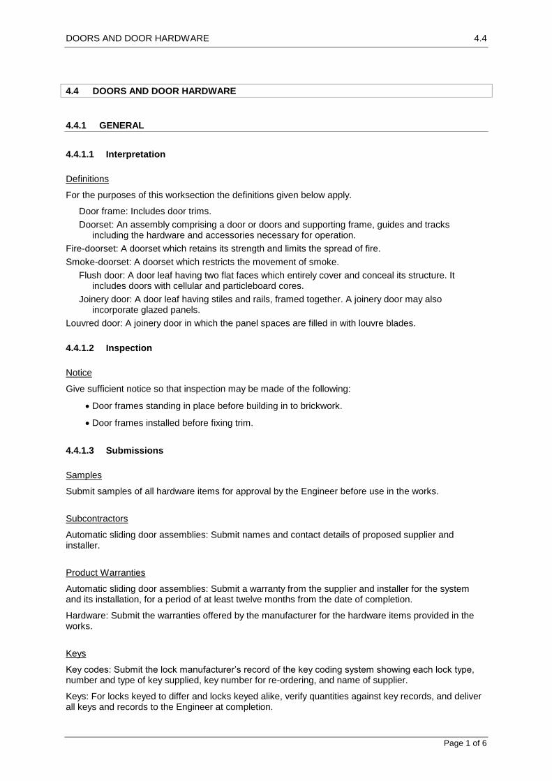
DOORS AND DOOR HARDWARE 4.4
Page 1 of 6
4.4 DOORS AND DOOR HARDWARE
4.4.1 GENERAL
4.4.1.1 Interpretation
Definitions
For the purposes of this worksection the definitions given below apply.
Door frame: Includes door trims.
Doorset: An assembly comprising a door or doors and supporting frame, guides and tracks including the hardware and accessories necessary for operation.
Fire-doorset: A doorset which retains its strength and limits the spread of fire.
Smoke-doorset: A doorset which restricts the movement of smoke.
Flush door: A door leaf having two flat faces which entirely cover and conceal its structure. It includes doors with cellular and particleboard cores.
Joinery door: A door leaf having stiles and rails, framed together. A joinery door may also incorporate glazed panels.
Louvred door: A joinery door in which the panel spaces are filled in with louvre blades.
4.4.1.2 Inspection
Notice
Give sufficient notice so that inspection may be made of the following:
Door frames standing in place before building in to brickwork.
Door frames installed before fixing trim.
4.4.1.3 Submissions
Samples
Submit samples of all hardware items for approval by the Engineer before use in the works.
Subcontractors
Automatic sliding door assemblies: Submit names and contact details of proposed supplier and installer.
Product Warranties
Automatic sliding door assemblies: Submit a warranty from the supplier and installer for the system and its installation, for a period of at least twelve months from the date of completion.
Hardware: Submit the warranties offered by the manufacturer for the hardware items provided in the works.
Keys
Key codes: Submit the lock manufacturer’s record of the key coding system showing each lock type, number and type of key supplied, key number for re-ordering, and name of supplier.
Keys: For locks keyed to differ and locks keyed alike, verify quantities against key records, and deliver all keys and records to the Engineer at completion.

DOORS AND DOOR HARDWARE 4.4
Page 2 of 6
4.4.2 PRODUCTS
4.4.2.1 Frames
Aluminium Frames
To be assembled from aluminium sections, including necessary accessories such as buffers, strike plates, fixing ties or brackets, and suitable for fixing specified hardware.
Timber Frames
To be constructed with best quality timber. Obtain approval from the Engineer for the timber selection before use. Construct as shown on the drawings and ensure that all joints are securely made to avoid distortion of the frame in use.
Steel Frames
To be folded from metallic-coated steel sheet sections, joints to be continuously welded, including necessary accessories such as buffers, strike plates, spreaders, fixing ties or brackets, and suitable for fixing specified hardware.
Finish: Grind the welds smooth, prepare and paint the welded joints with primer. Then prime the entire frame.
Hardware and accessories: Provide for fixing hardware including hinges and closers, using 4 mm backplates inside the frame. Screw fix the hinges into the back plates.
Base metal thickness:
General: ≥ 1.1 mm.
Fire rated doorsets: ≥ 1.4 mm.
Security doorsets: ≥ 1.6 mm.
4.4.2.2 Doors
Flush Doors
Cellular core flush doors:
Provide a subframe of 25 mm minimum width timber around openings for louvres and glazing.
Provide additional material to take hardware and fastenings.
Cut outs: If openings are required in flush doors (e.g. for louvres or glazing) make the cut outs not closer than 120 mm to the edges of the doors.
Solid core flush doors:
Core of timber strips laid edge to edge, fully glued to each other and to facings each side of no less than two sheets of timber veneer.
Single thickness of moisture resistant general purpose particleboard.
Refer to drawings and Flush Doors schedule for details.
Joinery Doors
Fabricate joinery doors as shown on the drawings and in the Joinery Doors schedule.
PVC Doors
Fabricate PVC doors as shown on the drawings and in the PVC Doors schedule.
Construction

DOORS AND DOOR HARDWARE 4.4
Page 3 of 6
Form rebates to suit standard rebated door hardware.
Louvre grilles: Construct by inserting the louvre blades into a louvre frame, and fix the frame into the door.
Double doors
Provide rebated meeting stiles unless the doors open in both directions. Chamfer square edged doors to prevent binding between the leaves.
4.4.2.3 Doorsets
Automatic Sliding Door Assemblies
Provide auto sliding door assemblies in accordance with the Automatic door schedule.
Toughened Glass Door Assemblies
Provide toughened glass door assemblies with matching concealed hinges and patch fittings as appropriate. Ensure that all glass edges are protected during installation and polish on completion.
Fire-Resistant Doorsets
Provide fire resistant doors and frames as matched sets for door openings required to have a fire
rating. Refer to the Fire and smoke resistant doorsets schedule for details.
Provide copies of test certificates from recognised authorities proving the performance of the doorsets.
Smoke-Resistant Doorsets
Provide smoke resistant doors and frames as matched sets for door openings required to have a
smoke stopping capability. Refer to the Fire and Smoke Resistant Doorsets schedule for details.
Provide copies of test certificates from recognised authorities proving the performance of the doorsets or seals to frames.
Security Screen Doorsets
Provide security screen doorsets in accordance with the Security Screen Doors schedule.
4.4.2.4 Ancillary materials
Nylon brush seals
To be dense nylon bristles locked into galvanized steel strips and fixed in a groove in the edge of the door or in purpose-made anodised aluminium holders fixed to the door
Pile weather strips
To be polypropylene or equivalent pile and backing, low friction silicone treated, ultra-violet stabilised.
Door Seals
To be proprietary items as identified in Schedules and to approval of Engineer.
4.4.2.5 Hinges
Butt hinge sizes
Refer to Hinge Table A and Hinge Table B in which length (l) is the dimension along the knuckles, and width (w) is the dimension across both hinge leaves when opened flat.

DOORS AND DOOR HARDWARE 4.4
Page 4 of 6
Steel, stainless steel, brass, bronze butt hinges for timber doors in timber or steel frames: To
Hinge table A.
Aluminium hinges for aluminium doors, or for doors of other materials in aluminium frames: To
Hinge table B.
Hinge materials
Aluminium hinges: High tensile aluminium with fixed stainless steel pins in nylon bushes, and with nylon washers to each knuckle joint.
Doors fitted with closers: Provide low friction bearing hinges.
Hinge Pins
Exterior or security doors opening out: Provide fixed pin hinges.
Hinge Table A
Nominal hinge size
l x w x t (mm)
Door leaves not exceeding any of the following
Mass (kg) Width (mm) Thickness (mm)
70 x 50 x 1.6 16 620 30
85 x 60 x 1.6 20 820 35
100 x 75 x 1.6 30 920 40
100 x 75 x 2.5 50 920 50
100 x 75 x 3.2 70 1020 50
125 x 100 x 3.2 80 1220 50
Hinge Table B
Nominal hinge size
l x w x t (mm)
Door leaf not
exceeding mass (kg)
Minimum construction
Knuckles Screws/hinge leaf
100 x 70 x 3 30 3 3
100 x 80 x 3.5 50 5 4
Number of Hinges
Provide 3 hinges for doors up to 2200 mm high, and 4 for door leaves between 2200 mm and 3000 mm high.
Wide Throw
If necessary, provide wide throw hinges to stop doors binding on obstacles such as nibs or deep reveals.
4.4.2.6 Door Hanging Systems
General
Provide sliding door tracks in conformance with the schedules.
4.4.2.7 Locks and Latches
General Door Hardware

DOORS AND DOOR HARDWARE 4.4
Page 5 of 6
Provide hardware of sufficient strength and quality to perform its function, appropriate to the intended conditions of use and climate and fabricated with fixed parts firmly joined.
Bolts
Provide bolts including barrel bolts and tower bolts with associated hardware, including lock plates, ferrules or floor sockets.
Furniture
Provide lock and latch furniture suitable for use with the lock or latch to which it is installed with the corresponding level of performance.
Strike Plates
Use strike plates provided with the locks or latches.
Fire Rated Door closers
Provide closers tested and certified for use as components of fire door assemblies.
Door Controllers Performance
Provide door controllers, including door closers, floor or head spring pivots which are suitable for the door type, size, weight and swings required and the operating conditions, including wind pressure.
4.4.3 EXECUTION
4.4.3.1 Frames
General
Install doors so that the frames:
Are plumb, level and straight within acceptable building tolerances.
Are fixed or anchored to the building structure to resist the wind loading.
Will not carry any building loads, including loads caused by structural deflection.
Allow for thermal movement.
Flashing and Weatherings
Install moulds, sealant and cement pointing as required so that water is prevented from penetrating the building between the door frame and the building structure.
Aluminium frames
Building in to masonry: Screw galvanized steel brackets twice to jambs and build in.
Fixing to masonry openings: Use proprietary expansion anchors and screw through jambs at each fixing.
Frame Fixing
Brackets: Metallic-coated steel:
Width: 25 mm.
Thickness: 1.5 mm.
Jamb fixing centres: 600 mm.

DOORS AND DOOR HARDWARE 4.4
Page 6 of 6
Fixing and Fasteners
Materials: Use materials compatible with the item being fixed and of sufficient strength, size and quality to perform their function.
Concealed fixings: Provide a corrosion resistant finish.
Exposed fixings: Match exposed fixings to the material being fixed.
Support: Provide appropriate back support (for example blocking and backing plates) for hardware fixings.
Packing: Pack behind fixing points with durable full width packing.
Prepared masonry openings: If fixing timber door frames into existing prepared openings with fastenings through the frame face, make the fastener heads finish below the surface and fill the hole for a smooth surface finish.
Joints
Make accurately fitted tight joints so that neither fasteners nor fixing devices such as pins, screws, adhesives and pressure indentations are visible on exposed surfaces.
Operation
Ensure moving parts operate freely and smoothly, without binding or sticking and are lubricated.
Supply
Deliver door hardware items, ready for installation, in individual complete sets for each door.
In a separate dust and moisture proof package labelled for the specific door.
Including the necessary templates, fixings and fixing instructions.
Refer to the drawings and Flush doors, Joinery doors, PVC doors, Security screen doors, Fire
and smoke resistant doorset and Automatic door schedules for details of frames, doors and hardware.
4.4.4 COMPLETION
4.4.4.1 Cleaning
The Contractor is to clean all frames, doors, glass, hardware at completion. Any damage to frames and doors, or broken glass is to be repaired or replaced to the satisfaction of the Engineer.
4.4.4.2 Adjustment
Leave the hardware properly adjusted with working parts in working order and lubricated where appropriate.

GLAZING 4.5
Page 1 of 3
4.5 GLAZING
4.5.1 GENERAL
4.5.1.1 Inspection
Notice
Inspection: Give sufficient notice so that inspection may be made of the following:
- Glass products before they are installed.
4.5.2 PRODUCTS
4.5.2.1 Glass
Glass and Glazing Materials
Glass and glazing materials generally: Free from defects which detract from appearance or interfere with performance under normal conditions of use.
Glazing plastics: Free from surface abrasions, and warranted by the manufacturer for 10 years against yellowing or other colour change, loss of strength and impact resistance, and general deterioration.
Refer to Annealed Glasses, Processed Glasses and Fabricated Glass Units schedules for specific details for the works.
4.5.2.2 Glazing materials
General
Glazing materials (including putty, glazing compounds, sealants, gaskets, glazing tapes, spacers, setting blocks): Appropriate for the conditions of application and the required performance.
Jointing Materials
Provide recommended jointing and pointing materials which are compatible with each other and with the contact surfaces and non staining to finished surfaces. Do not provide bituminous materials on absorbent surfaces.
Pile Weather Strips
Materials: Polypropylene or equivalent pile and backing, low friction silicone treated, ultra violet stabilised.
Finned type: A pile weather seal with a central polypropylene fin bonded into the centre of the backing rod and raised above the pile level.
Extruded Gaskets and Seals
Type: Non cellular (solid) seals to exclude water from glass/frame junctions.
Material:
Rubber products to be neoprene, ethylene propylene diene monomer (EPDM) or silicone rubber.
Flexible polyvinyl chloride (PVC)
Priming

GLAZING 4.5
Page 2 of 3
Apply the recommended primer to the surfaces in contact with sealant materials.
Movement Joints
Depth of elastomeric sealant: One half the joint width, or 6 mm, whichever is the greater.
Foamed materials (in compressible fillers and backing rods): Closed-cell or impregnated types which do not absorb water.
Bond breaking: Provide backing rods, and other back-up materials for sealants, which do not adhere to the sealant.
Glazing Films
Supply films identified in the schedules to approval of the Engineer. All films are to be proprietary products installed strictly in a accordance with the manufacturers instructions.
4.5.2.3 Mirrors
Refer to Mirrors schedule for details.
Reflective surface
Type: Silver layer deposited on the glass or glazing plastic.
4.5.3 EXECUTION
4.5.3.1 Glass Processing
General
Perform required processes on glass, including cutting, obscuring, silvering and bending. Form necessary holes, including for fixings, equipment, access holes and speaking holes. Process exposed glass edges to a finish that will reduce the risk of injury.
4.5.3.2 Installation
General
Install the glass so that:
Each piece is held firmly in place by permanent means which enable it to withstand the normal loadings and ambient conditions at its location without distortion or damage to glass and glazing materials.
Building movements are not transferred to the glass.
External glazing is watertight and airtight.
Toughened glass: Do not cut, work, or permanently mark after toughening. Use installation methods which prevent the glass making direct contact with metals or other non-resilient materials.
Frameless installations: Join the vertical edges of adjacent glass panels with silicone jointing compound.
External timber framed glazing: Glaze with putty. Do not dry bead into timber frames.
4.5.3.3 Fixing mirrors
Screw fixing

GLAZING 4.5
Page 3 of 3
Direct to wall plugs with dome-headed chromium-plated screws in each corner and at 900 mm maximum centres around perimeter. Provide polyethylene sleeves and washers to prevent contact between screw and glass. Do not over-tension the screws.
Frame fixing
Proprietary aluminium frames to mirror perimeter, corners mitred. Attach the frame to the wall with concealed screw fixings. Frames and finish to approval of the Engineer.
Bead fixing
Rebated timber beads to mirror perimeter, corners mitred. Screw fix the beads to the substrate.
4.5.3.4 Glazed Shower Screens
Type
Proprietary system comprising frames of extruded aluminium, stainless steel, or PVC, assembled around safety glass to form fixed panels and sliding, hinged or pivoted doors.
Water Shedding
Provide an assembly which sheds water to the inside without retaining it on the frame surfaces. Seal the edge of the frame to adjoining surfaces with a resilient strip.
Sliding Assemblies
Hanging: Hang the sliding sash on stainless steel or nylon sheaves on overhead channel track formed in the frame head, and fit nylon or equivalent bottom guides.
Hardware: Pull handles on both sides of sash, or of leading sash in multiple sash arrangements.
4.5.4 COMPLETION
4.5.4.1 Cleaning
Replace damaged glass and leave the work clean, polished, free from defects, and in good condition.

GLASS BLOCKWORK 4.6
Page 1 of 4
4.6 GLASS BLOCKWORK
4.6.1 GENERAL
4.6.1.1 Inspection
Notice
Give sufficient notice so that inspection may be made of the following:
Frame and expansion jointing installed, before reinforcing.
Perimeter and vertical reinforcing installed, before placing mortar and blocks.
4.6.1.2 Submissions
Samples
Glass blocks: Submit 2 blocks of each type showing size, colour, design and pattern of faces.
Accessories: Submit samples of reinforcing, fasteners, expansion materials and sealant.
4.6.2 PRODUCTS
4.6.2.1 Mortar-jointed panels
Perimeter
Frames:
Size: 100 x 50 x 6 mm.
Material: Aluminium channel.
Fixing: 10 mm masonry anchors with galvanized washers.
Drainage: Drill holes in web of sill channel.
Expansion jointing and sill channel lining: 10 mm (minimum) x width of the channel rebate.
Glass blocks
Refer to Glass Block schedule for block types.
Mortar
Cement: Slow setting Portland cement with low shrinkage.
Hydrated lime: calcium, or pressure-hydrated dolomitic lime if > 92% of active ingredients are hydrated.
Sand: Clean sharp river mineral sand, salt free, no admixtures, no iron compounds.
Water: Clean, potable.
Mortar and pointing mix by volume (cement:lime:sand): 1:0.25:3. As dry as practicable.
Pigments: Powder oxides.
Colour: Refer to Glass Block schedule
Reinforcement: 4.5 – 6 mm diameter, in lengths to suit full width or height of panel, as appropriate.
Fire-Rated Panels
Perimeter
Frames:

GLASS BLOCKWORK 4.6
Page 2 of 4
Size: 150 x 75 x 9 mm.
Material: Mild steel channel.
Fixing: 10 mm masonry anchors with heavy galvanized washers.
Drainage: Drill holes in web of sill channel.
Expansion jointing:
Type: Ceramic fibre blanket, 38 mm (minimum) x width of channel rebate.
Sill channel lining: Ceramic fibre board, 12 mm (minimum) x width of channel rebate.
Glass Blocks
Refer to Glass Block schedule for block types.
Mortar
Cement: Slow setting Portland cement with low shrinkage.
Sand: Clean sharp river mineral sand, salt free, no admixtures, no iron compounds.
Water: Clean, potable.
Mortar and pointing mix by volume (cement:sand): 1:3. As dry as practicable.
Compressive strength (minimum): 10 MPa at 2 days, 35 MPa at 28 days.
Pigments: Powder oxides.
Colour: Refer to Glass block schedule
Reinforcement: 6 mm diameter, in lengths to suit full width or height of panel, as appropriate.
Finish
Sealant: Fire resistant non-setting non-staining waterproof elastomeric sealant, hardening only at the surface.
4.6.2.2 Sealant-jointed panels
Perimeter
Frames: Proprietary extruded aluminium frame.
Fixing: 12 gauge 40 mm long stainless steel pan head screws, with nylon masonry plugs where appropriate.
Glass Blocks
Refer to Glass Block schedule for block types.
Panels
Reinforcement: 50 x 3 mm flat bars.
Block-locating clips: Proprietary plastic clips designed to clip on the reinforcement and fit the glass block edges.
Finish
Grouting sealant: Silicone.
Colour: Refer to Glass block schedule
4.6.3 EXECUTION
Ambient Conditions
General: Do not install below 5C. Maintain panels above 5C for the first 48 hours after construction.

GLASS BLOCKWORK 4.6
Page 3 of 4
Perimeter
Frames: Erect 4-sided frame mitred at corners, spaced 5 mm clear of the structure on packing.
Fixing: 400 mm centres. Centre hole on each side circular, other holes slotted longitudinally 50 mm.
Packing: 75 x 75 x 2 mm zinc-plated steel.
Sill channel: Lay sill channel lining in rebate.
Jamb and head channels: Adhesive-fix expansion jointing in rebates.
Panels
Laying blocks: By hand, may be knocked into position using a rubber or soft nylon hammer. Align block patterns consistently. Prevent mortar extrusion under load while setting.
Bond: Stack bond.
Reinforcement:
Frame: Two rods all round, hooked and connected with wire at the corners. Horizontal rods to be a tie rod assembly, with 6 mm diameter tie rods at 200 mm centres, spacing the main rods 40 – 45 mm apart.
Joint: Two rods in at least every second horizontal joint, and every tenth vertical joint. Overlap 230 mm (minimum) at corners. Do not tie vertical rods to horizontal rods. Do not impinge on expansion joints. Tie joint reinforcement to frame reinforcement.
Cover (minimum): 15 mm to outside face, 10 mm to inside face, 5 mm to blocks.
Joints:
Widths (clear): 10 – 15 mm. For curved walls, 5 – 20 mm for vertical joints.
Width tolerance: 3 mm.
Placing mortar: Do not retemper mortar. Do not furrow joints. Fill channel frame and panel joints.
Pointing: Point before mortar has hardened. Neatly tool to a smooth, dense concave joint. Remove excess mortar from glass surfaces using a damp cloth before mortar set occurs, without damaging the glass. Protect against premature drying, but do not moisten.
4.6.3.1 Sealant-Jointed Panels
Perimeter
Frames:
Assembly: Mitre frame at corners. Assemble with connection angles and cleats, drill, and fix frame to angles with blind rivets.
Fixing jamb frames: Position screws to clear the ends of the reinforcing bars. Fix screws with neoprene washers and through the packing, at 400 mm (maximum) centres, and pairs 100 mm from ends.
Fixing sill frame: Fix screws with neoprene washers and through the packing, at 800 mm (maximum) centres, and 100 mm from ends.
Packing: Locate to square the frame, maximum 10 mm, to sill and jamb frames only.
Panels
Laying blocks: Select and orient glass blocks to ensure consistent coursing dimensions. Lightly clean edges with steel wool.
Block-locating clips: Locate onto sill frame profile 20 mm from each corner and centred at every perpend, ribbed side up. Insert in perpends, including at jamb frames, centred at course centre line. Clip onto reinforcing bars 20 mm from the ends and centred at every perpend, ribbed side up. Insert above top course 20 mm from each corner and centred at every perpend.
Bond: Stack bond.
Joint reinforcement: Joint: Run reinforcement horizontally, and slot into the jamb frame channels on top of the glass block courses, except the top course, finishing 3 mm short of the jamb frame rebate faces.
Joints:

GLASS BLOCKWORK 4.6
Page 4 of 4
Widths: 3 – 4 mm.
Finish
Jointing: Clean and dry substrates. Execute work neatly, without gaps and holes. Inject structural sealant into blockwork joints to a depth of 5 – 8 mm.
Grouting: Clean and dry substrates. Execute work neatly, without gaps and holes. Apply grouting sealant to mitred frame corner joints, and apply to blockwork joints, including at the perimeter frame, to both panel faces. Remove excess sealant from glass at completion, without damaging the glass.
4.6.3.2 Maintenance
Mortar-Jointed and Fire-Rated Panels
Final clean: Wash using clean water. Remove dry powder using a clean soft dry cloth.

INSULATION AND VAPOUR BARRIERS 4.7
Page 1 of 2
4.7 INSULATION AND VAPOUR BARRIERS
4.7.1 GENERAL
4.7.1.1 Interpretation
Definitions
General: For the purposes of this worksection the definitions given below apply.
Sarking-type material: Flexible reflective foil membrane material normally used for waterproofing, vapour proofing or thermal reflectance.
Mineral wool (including glasswool and rockwool): Entangled mat of fibrous non-crystalline material derived from inorganic oxides or minerals, rock, slag or glass, processed at high temperatures from a molten state.
Vapour barrier: A material or system that adequately impedes the transmission of water vapour.
4.7.1.2 Inspection
Notice
Give sufficient notice so that inspection may be made of the insulation to roof space in areas which will be covered up or concealed.
4.7.2 PRODUCTS
4.7.2.1 Materials and components
Bulk Insulation
Mineral wool blankets and cut pieces: Provided in bulk rolls for laying over roof structures or on roof slabs and batts to suit ceiling member spacing.
Polystyrene (extruded rigid cellular sheets): Provided in modular panels for fixing to walls and roof slabs.
Reflective insulation: Provided in bulk foil rolls for laying over roof structures and foil batts to suit ceiling member spacing.
Sarking-Type Material
Sarking: Reflective foil fixed as a membrane to reduce liquid water transfer in walls or roof structures but allow water vapour to move through the building envelope.
Vapour barrier: Reflective foil sealed as a membrane to stop all liquid water and water vapour transfer.
Fasteners and Supports
Metallic-coated steel.
4.7.3 EXECUTION
4.7.3.1 General
Bulk insulation
Batts: Fit tightly between framing members. If support is not otherwise provided, fix over wire mesh stapled to the framing and stretch tight.

INSULATION AND VAPOUR BARRIERS 4.7
Page 2 of 2
Reflective Foil Laminate
To timber: Metallic-coated flat head nails or staples at 300 mm maximum centres.
To steel or aluminium: Double sided pressure sensitive tape.
Overlap (minimum): 150 mm and adhesive fix.
Roof Sarking Locations
Location: Provide sarking under metal sheet roofs. Fix over timber supports and run rolls across roof plane. Overlap each layer of foil so that any water will run down the slope and discharge into the gutter without dripping into the roof space.
4.7.3.2 Roof insulation
General
Location: The whole of the ceiling area, except the following:
Eaves, overhangs, rooflights, vents and openings.
Roofs to outbuildings, garages, and semi-enclosed spaces such as verandahs, porches.
Installation
Refer to the drawings and Insulation schedule for details of insulation requirements for the works.

EXTERIOR INSULATION AND FINISH SYSTEMS (EIFS) 4.8
Page 1 of 9
4.8 EXTERIOR INSULATION AND FINISH SYSTEM (EIFS)
4.8.1 GENERAL
4.8.1.1 SUMMARY
Provide Exterior Insulation and Finish System (EIFS) for vertical above grade concrete, masonry and exterior wall sheathing including labor, materials, equipment and supervision etc. necessary to complete the exterior wall and finish systems.
4.8.1.2 SUBMITTALS
1. Manufacturer's specifications, details, installation instructions and product data.
2. Manufacturer’s code compliance report.
3. Manufacturer's standard warranty.
4. Manufacturer's certificate of compliance with EIMA standards.
5. Applicator's certificate of instruction.
6. Samples for approval as directed by Engineer.
7. EPS board manufacturer's certificate of compliance with the current edition of EIMA Guideline Specifications for the use of Expanded Polystyrene (EPS) Insulation Board.
8. Sealant manufacturer's certificate of compliance with ASTM C 1382.
9. Prepare and submit project-specific details (when required by contract documents).
4.8.1.3 REFERENCES
ASTM Standards:
1. B 117 Test Method for Salt Spray (Fog) Testing
2. C 150 Specification for Portland Cement
3. C 297 Test Method for Tensile Strength of Flat Sandwich Constructions in Flatwise
Plane
4. C 578 Specification for Preformed, Cellular Polystyrene Thermal Insulation
5. C 1177 Specification for Glass Mat Gypsum for Use as Sheathing
6. C 1382 Test Method for Determining Tensile Adhesion Properties of Sealants When
Used in Exterior Insulation and Finish Systems (EIFS) Joints
7. D 968 Test Method for Abrasion Resistance of Organic Coatings by Falling Abrasive
8. D 2247 Practice for Testing Water Resistance of Coatings in 100% Relative Humidity
9. D 3273 Test for Resistance to Growth of Mold on the Surface of Interior Coatings in an
Environmental Chamber
10. D 4258 Standard Practice for Surface Cleaning Concrete for Coating
11. D 4261 Standard Practice for Surface Cleaning Concrete Unit Masonry for Coating
12. E 84 Test Method for Surface Burning Characteristics of Building Materials
13. E 96 Test Methods for Water Vapor Transmission of Materials
14. E 108 Method for Fire Tests of Roof Coverings
15. E 119 Method for Fire Tests of Building Construction and Materials
16. E 283 Test Method for Determining the Rate of Air Leakage Through Exterior
Windows, Curtain Walls, and Doors under Specified Pressure Differences Across the
Specimen.
17. E 330 Test Method for Structural Performance of Windows, Curtain Walls, and Doors
by Uniform Static Air Pressure Difference
18. E 331 Test Method for Water Penetration of Exterior Windows, Curtain Walls, and
Doors by Uniform Static Air Pressure Difference
19. G 153 Recommended Practice for Operating Light-and Water-Exposure Apparatus
(Carbon-Arc Type) for Exposure of Nonmetallic Materials

EXTERIOR INSULATION AND FINISH SYSTEMS (EIFS) 4.8
Page 2 of 9
20. G 154 Recommended Practice for Operating Light-and Water-Exposure Apparatus
(Fluorescent UV-Condensation Type) for Exposure of Nonmetallic Materials
Building Code Standards
1. UBC Standard 26-4 (formerly 17-6), “Method of Test for the Evaluation of Flammability Characteristics of Exterior, Nonload-Bearing Wall Panel Assemblies Using Foam Plastic Insulation,” International Conference of Building Officials (ICBO), Inc.
2. Section 1407.0, 1999 National Building Code, Building Officials and Code Administrators International (BOCA), Inc.
3. Section 2603.4.7, 1997 Standard Building Code, Southern Building Code Congress International (SBCCI), Inc.
4. AC24 Interim Criteria for Exterior Insulation and Finish Systems (EIFS) (July 1, 2003)
5. AC219 Acceptance Criteria for Exterior Insulation and Finish systems (March 1, 2004)
National Fire Protection Association (NFPA) Standards
1. NFPA 268, “Standard Test Method for Determining Ignitability of Exterior Wall Assemblies Using a Radiant Heat Energy Source”
2. NFPA 285, “Standard Method of Test for the Evaluation of Flammability Characteristics of Exterior Non-Load-Bearing Wall Assemblies containing Combustible Components Using the Intermediate-Scale, Multistory Test Apparatus”
EIMA (EIFS Industry Members Association) Standards and Publications
1. 101.01 Standard Test Method for Freeze-Thaw Resistance of Exterior Insulation and Finish Systems (EIFS), Class PB (Modified ASTM C 67)
2. 101.02 Standard Test Method for Resistance to Water Penetration of Exterior Insulation and Finish Systems (EIFS), Class PB (Modified ASTM E 331)
3. ASTM E 2134.01 Standard Test Method for Evaluating the Tensile-Adhesion Performance of an Exterior Insulation and Finish System (EIFS) (101.03 Standard Test Method for Determining tensile Adhesion Strength of Exterior Insulation and Finish System (EIFS)., and Components, Class PB (Modified ASTM C 297)
4. 101.86 Standard Test Method for Resistance of Exterior Insulation and Finish Systems (EIFS), Class PB, to the Effects of Rapid Deformation (Impact)
5. ASTM E 2098 Standard Test Method for Determining Tensile Breaking Strength of Glass Fiber Reinforcing Mesh for Use in Class PB Exterior Insulation and Finish System after Exposure to a Sodium Hydroxide Solution (105.01 Standard Test Method for Alkali Resistance of Glass Fiber Reinforcing Mesh for use in Exterior Insulation and Finishing Systems (EIFS), Class PB)
6. ASTM E 2430 Standard Specification for Expanded Polystyrene (EPS) Thermal Insulation Boards for use in Exterior Insulation and Finish Systems (EIFS) (EIMA Guideline Specification for Expanded Polystyrene (EPS) Insulation Board)
4.8.1.4 DESIGN REQUIREMENTS
Wind Load
Design for maximum allowable system deflection, normal to the plane of the wall, of L/240.
Design for wind load in conformance with code requirements.
Moisture Control
Prevent the accumulation of water behind the EIF system, either by condensation or leakage through the wall construction, in the design and detailing of the wall assembly.

EXTERIOR INSULATION AND FINISH SYSTEMS (EIFS) 4.8
Page 3 of 9
Provide flashing to direct water to the exterior where it is likely to penetrate components in the wall assembly, including, above window and door heads, beneath window and door sills, at roof/wall intersections, decks, abutments of lower walls with higher walls, above projecting features, and at the base of the wall.
Air Leakage Prevention if an air barrier is desired or required in the wall construction.
Vapour Diffusion and Condensation-- perform a dew point analysis of the wall assembly to determine the potential for accumulation of moisture in the wall assembly as a result of water vapor diffusion and condensation. Adjust insulation thickness and/or other wall assembly components accordingly to minimize the risk of condensation. Avoid the use of vapor retarders on the interior side of the wall in warm, humid climates.
Impact Resistance
Provide ultra-high impact resistance to a minimum height of 2 m above finished grade at all areas accessible to pedestrian traffic and other areas exposed to abnormal stress or impact as indicated in drawing, schedules, or Bill of Quantities.
Color Selection
Select finish coat with a light reflectance value of 20 or greater. (The use of dark colors is not recommended with EIF Systems that incorporate expanded polystyrene [EPS]. EPS has a service
temperature limitation of approximately 160 F [71C]).
Joints
Design minimum ¾ inch (19 mm) wide expansion joints in the EIFS where they exist in the substrate or supporting construction, where the EIFS adjoins dissimilar construction or materials, at changes in building height, and at floor lines in multi-level wood frame construction.
Design minimum ½ inch (13 mm) wide sealant joints at all penetrations through the EIFS (windows, doors, etc.).
Specify compatible backer rod and sealant that has been evaluated in accordance with ASTM C 1382 and that meets minimum 50% elongation after conditioning.
Design joints with secondary moisture protection and drain joints to the exterior.
Grade Condition
Do not specify EIFS below grade (unless designed for use below grade and permitted by code) or for use on surfaces subject to continuous or intermittent water immersion or hydrostatic pressure.
Trim, Projecting Architectural Features and Reveals
All trim and projecting architectural features must have a minimum 1:2 [27] slope along their top
surface. All horizontal reveals must have a minimum 1:2 [27] slope along their bottom surface. Increase slope for northern climates to prevent accumulation of ice/snow and water on surface. Where trim/feature or bottom surface of reveal projects more than 2 inches (51 mm) from the face of the EIFS wall plane, protect the top surface with waterproof base coat. Avoid the use of trim and features that exceed the maximum allowable thickness of EPS permitted by code (typically 4 inches [100 mm]) unless approved by the code official. Periodic inspections and increased maintenance may be required to maintain surface integrity of EIFS on weather exposed sloped surfaces. Limit projecting features to easily accessible areas and limit total area to facilitate maintenance and minimize maintenance.
Do not use EIFS on weather exposed projecting ledges, sills, or other projecting features unless supported by framing or other structural support and protected with metal coping or flashing.
Fire Protection
Do not use foam plastic in excess of 4 inches (100 mm) thick unless approved by the code official.
Where a fire-resistance rating is required by code use EIFS over rated assembly (EIFS is considered not to add or detract from the fire-resistance of the rated assembly).
Refer to manufacturer’s applicable code compliance report for other limitations that may apply.

EXTERIOR INSULATION AND FINISH SYSTEMS (EIFS) 4.8
Page 4 of 9
4.8.1.5 PERFORMANCE REQUIREMENTS
EIF System Performance
Durability
TEST METHOD CRITERIA RESULTS
1. Accelerated Weathering
ASTM G 153
(Formerly ASTM G 23)
No deleterious effects at 2000 hours when viewed under 5x magnification
1. Accelerated Weathering
ASTM G 154
(Formerly ASTM G 53)
No deleterious effects at 2000 hours when viewed under 5x magnification
2. Freeze/Thaw Resistance
EIMA 101.01
(Modified ASTM C-67)
No deleterious effects at 60 cycles
3. Water Penetration EIMA 101.02
(Modified ASTM E 331)
No water penetration beyond the plane of the base coat/EPS board interface after 15 minutes at 6.24 psf (299 Pa) or 20% of design wind pressure, whichever is greater
4. Tensile Adhesion EIMA 101.03
(modified ASTM C-297)
No failure in the adhesive, base coat, or finish coat. Minimum 5 psi (34 kPa) tensile strength before/after accelerated weathering and freeze/thaw exposure
5. Water Resistance ASTM D 2247 No deleterious effects* at 14 day exposure
6. Salt Spray ASTM B 117 No deleterious effects* at 300 hours
7. Abrasion Resistance ASTM D 968 No cracking or loss of film integrity at 528 quarts (500 L) of sand
8. Mildew Resistance ASTM D 3273 No growth supported during 28 day exposure period
*No deleterious effects: no cracking, checking, crazing, erosion, rusting, blistering, peeling or delamination
Fire
TEST METHOD CRITERIA RESULTS
1. Full Scale Diversified Fire Test
ASTM E 108 (Modified)
No significant contribution to vertical or horizontal flame spread
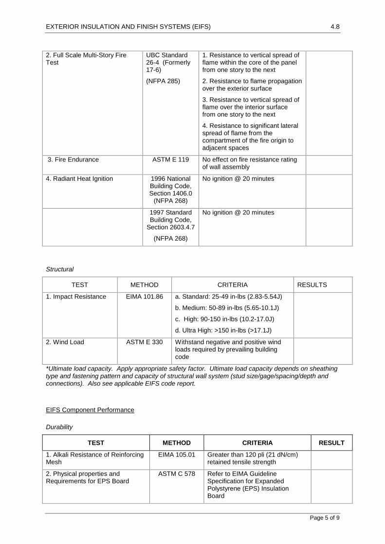
EXTERIOR INSULATION AND FINISH SYSTEMS (EIFS) 4.8
Page 5 of 9
2. Full Scale Multi-Story Fire Test
UBC Standard 26-4 (Formerly 17-6)
(NFPA 285)
1. Resistance to vertical spread of flame within the core of the panel from one story to the next
2. Resistance to flame propagation over the exterior surface
3. Resistance to vertical spread of flame over the interior surface from one story to the next
4. Resistance to significant lateral spread of flame from the compartment of the fire origin to adjacent spaces
3. Fire Endurance ASTM E 119 No effect on fire resistance rating of wall assembly
4. Radiant Heat Ignition 1996 National Building Code, Section 1406.0
(NFPA 268)
No ignition @ 20 minutes
1997 Standard Building Code,
Section 2603.4.7
(NFPA 268)
No ignition @ 20 minutes
Structural
TEST METHOD CRITERIA RESULTS
1. Impact Resistance EIMA 101.86 a. Standard: 25-49 in-lbs (2.83-5.54J)
b. Medium: 50-89 in-lbs (5.65-10.1J)
c. High: 90-150 in-lbs (10.2-17.0J)
d. Ultra High: >150 in-lbs (>17.1J)
2. Wind Load ASTM E 330 Withstand negative and positive wind loads required by prevailing building code
*Ultimate load capacity. Apply appropriate safety factor. Ultimate load capacity depends on sheathing type and fastening pattern and capacity of structural wall system (stud size/gage/spacing/depth and connections). Also see applicable EIFS code report.
EIFS Component Performance
Durability
TEST METHOD CRITERIA RESULT
1. Alkali Resistance of Reinforcing Mesh
EIMA 105.01 Greater than 120 pli (21 dN/cm) retained tensile strength
2. Physical properties and Requirements for EPS Board
ASTM C 578 Refer to EIMA Guideline Specification for Expanded Polystyrene (EPS) Insulation Board

EXTERIOR INSULATION AND FINISH SYSTEMS (EIFS) 4.8
Page 6 of 9
Fire
TEST METHOD CRITERIA RESULT
1. Surface Burning ASTM E 84 Adhesive, insulation board, finish coat each have a flame spread of 25 or less and smoke developed of 450 or less
4.8.1.6 QUALITY ASSURANCE
Manufacturer requirements
Member in good standing of the EIFS Industry Members Association (EIMA).
System manufacturer for a minimum of twenty-five (25) years.
Manufacturing facilities ISO 9001:2000 Certified Quality System.
Manufacturer’s wall assembly listed in Gypsum Association Fire Resistance Design Manual.
Contractor requirements
Engaged in application of EIFS for a minimum of three (3) years.
Knowledgeable in the proper use and handling of materials.
Employ skilled mechanics who are experienced and knowledgeable in EIFS application, and familiar with the requirements of the specified work.
Provide the proper equipment, manpower and supervision on the job site to install the system in compliance with specifications and details and the project plans and specifications.
Insulation board manufacturer requirements
Recognized by System Producer as capable of producing insulation board to meet system requirements, and/or hold a valid licensing agreement with Ssytem Producer.
Label insulation board with information required by Sytem Producer, the approved listing agency and the applicable building code.
Mock-up Testing
Construct full-scale mock-up of typical EIFS/window wall assembly with specified tools and materials and test air and water infiltration and structural performance in accordance with ASTM E 283, E 331 and E 330, respectively, through independent laboratory. Mock-up shall comply with requirements of project specifications. Where mock-up is tested at job site maintain approved mock-up at site as reference standard. If tested off-site accurately record construction detailing and sequencing of approved mock-up for replication during construction.
Inspections
Provide independent third party inspection where required by code or contract documents.
Conduct inspections in accordance with code requirements and contract documents.
4.8.1.7 DELIVERY, STORAGE AND HANDLING
Deliver all materials in their original sealed containers bearing manufacturer's name and identification of product.
Protect coatings (pail products) from freezing and temperatures in excess of 32 C. Store away from direct sunlight.
Protect Portland cement based materials (bag products) from moisture and humidity. Store under cover off the ground in a dry location.

EXTERIOR INSULATION AND FINISH SYSTEMS (EIFS) 4.8
Page 7 of 9
4.8.1.8 PROJECT/SITE CONDITIONS
Maintain ambient and surface temperatures above 40F (4C) during application and drying period, minimum 24 hours after application of EIFS.
Provide supplementary heat for installation in temperatures less than 40F (4C).
Provide protection of surrounding areas and adjacent surfaces from application of materials.
4.8.1.9 COORDINATION/SCHEDULING
Provide site grading such that EIFS terminates above finished grade a minimum of 8 inches (203 mm) or as required by code.
Provide protection of rough openings before installing windows, doors, and other penetrations through the wall and provide sill flashing.
Install window and door head flashing immediately after windows and doors are installed.
Install diverter flashings wherever water can enter the wall assembly to direct water to the exterior.
Install copings and sealant immediately after installation of the EIF system and when EIFS coatings are dry.
Attach penetrations through EIFS to structural support and provide water tight seal at penetrations.
4.8.1.10 WARRANTY
Provide manufacturer's standard limited labor and materials warranty.
4.8.2 PRODUCTS
4.8.2.1 MANUFACTURERS
Provide EIFS and accessories from single source manufacturer or approved supplier.
4.8.2.2 SURFACE PREPARATION
(optional components, depending on substrate condition)
Conditioner
An acrylic based surface conditioner (used for chalking surfaces or excessively absorptive concrete, plaster or masonry).
Leveler
(selection by Engineer)
One-component, polymer-modified cement-based leveler with fiber reinforcement (used for concrete, or plaster surfaces; for leveling up to 3 mm).
One-component, polymer modified, cement based leveler with fiber reinforcement (used for concrete, masonry or plaster surfaces; for leveling up to 6 mm).
4.8.2.3 ADHESIVE
(selection by Engineer)
Cementitious Adhesives
One-component, polymer-modified, cement based high build adhesive (for use over concrete, masonry or plaster surfaces)
One-component , polymer-modified, cement based high build adhesive (for use over concrete, masonry or plaster surfaces).
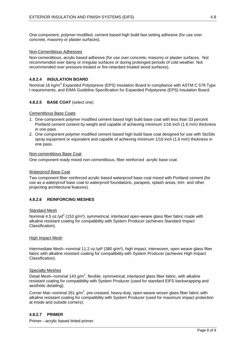
EXTERIOR INSULATION AND FINISH SYSTEMS (EIFS) 4.8
Page 8 of 9
One-component, polymer-modified, cement based high build fast setting adhesive (for use over concrete, masonry or plaster surfaces).
Non-Cementitious Adhesives
Non-cementitious, acrylic based adhesive (for use over concrete, masonry or plaster surfaces. Not recommended over damp or irregular surfaces or during prolonged periods of cold weather. Not recommended over pressure-treated or fire-retardant treated wood surfaces).
4.8.2.4 INSULATION BOARD
Nominal 16 kg/m3 Expanded Polystyrene (EPS) Insulation Board in compliance with ASTM C 578 Type
I requirements, and EIMA Guideline Specification for Expanded Polystyrene (EPS) Insulation Board.
4.8.2.5 BASE COAT (select one)
Cementitious Base Coats
1. One-component polymer modified cement based high build base coat with less than 33 percent
Portland cement content by weight and capable of achieving minimum 1/16 inch (1.6 mm) thickness
in one pass.
2. One component polymer modified cement based high build base coat designed for use with StoSilo
spray equipment or equivalent and capable of achieving minimum 1/16 inch (1.6 mm) thickness in
one pass.
Non-cementitious Base Coat
One component ready mixed non-cementitious, fiber reinforced acrylic base coat.
Waterproof Base Coat
Two component fiber reinforced acrylic based waterproof base coat mixed with Portland cement (for use as a waterproof base coat to waterproof foundations, parapets, splash areas, trim and other projecting architectural features).
4.8.2.6 REINFORCING MESHES
Standard Mesh
Nominal 4.5 oz./yd2 (153 g/m²), symmetrical, interlaced open-weave glass fiber fabric made with
alkaline resistant coating for compatibility with System Producer (achieves Standard Impact Classification).
High Impact Mesh
Intermediate Mesh--nominal 11.2 oz./yd² (380 g/m²), high impact, interwoven, open weave glass fiber fabric with alkaline resistant coating for compatibility with System Producer (achieves High Impact Classification).
Specialty Meshes
Detail Mesh--nominal 143 g/m2, flexible, symmetrical, interlaced glass fiber fabric, with alkaline
resistant coating for compatibility with System Producer (used for standard EIFS backwrapping and aesthetic detailing).
Corner Mat--nominal 261 g/m2, pre-creased, heavy-duty, open-weave woven glass fiber fabric with
alkaline resistant coating for compatibility with System Producer (used for maximum impact protection at inside and outside corners).
4.8.2.7 PRIMER
Primeracrylic based tinted primer.

EXTERIOR INSULATION AND FINISH SYSTEMS (EIFS) 4.8
Page 9 of 9
4.8.2.8 FINISH COAT
Acrylic based textured wall coating with graded marble aggregate.
(Note: finish color may have a lightness value of 20% or greater)
4.8.2.9 JOB MIXED INGREDIENTS
Water--Clean and potable.
Portland cement--Type I in conformance with ASTM C 150.
4.8.3 EXECUTION
4.8.3.1 ACCEPTABLE INSTALLERS
Prequalify under Quality Assurance requirements of this specification (section 1.06.B).
4.8.3.2 EXAMINATION
Inspect surfaces for:
1. Contamination -- algae, chalkiness, dirt, dust, efflorescence, form oil, fungus, grease,
laitance, mildew or other foreign substances.
2. Surface absorption and chalkiness.
3. Cracks -- measure crack width and record location of cracks.
4. Damage and deterioration.
5. Moisture content and moisture damage -- use a moisture meter to determine if the surface is
dry enough to receive the EIFS and record any areas of moisture damage.
6. Compliance with specification tolerances -- record areas that are out of tolerance (greater
than ¼ inch in 8-0 feet [6mm in 2438 mm] deviation in plane).
Inspect sheathing application for compliance with applicable requirement:
Cementitious sheathing--Consult manufacturer's published recommendations
Report deviations from the requirements of project specifications or other conditions that might adversely affect the EIFS installation to the General Contractor. Do not start work until deviations are corrected.
4.8.3.3 SURFACE PREPARATION
Remove surface contaminants on concrete and concrete masonry surfaces (refer to ASTM D 4258 and D 4261).
Apply conditioner by sprayer or roller to chalking or excessively absorptive surfaces.
Replace weather-damaged sheathing and repair damaged or cracked surfaces.
Level surfaces to comply with required tolerances.
4.8.3.4 INSTALLATION
As per Manifacturer instructions.
4.8.3.5 PROTECTION
Provide protection of installed materials from water infiltration into or behind them.
Provide protection of installed materials from dust, dirt, precipitation, freezing and continuous high humidity until they are fully dry.

LINING 5.1
Page 1 of 4
5.1 LINING
5.1.1 GENERAL
5.1.1.1 Inspection
Notice
Inspection: Give sufficient notice so that inspection may be made of the wall face or framing before installation of linings.
5.1.1.2 Submissions
Samples
Plasterboard: Submit two 300x300mm samples of each type.
Fibre cement sheet: Submit two 300x300mm samples of each type.
Accessories: Submit samples of accessories, fasteners, trims and cornices.
5.1.1.3 Tolerances
Surface
Flatness, twist and bow: ≤ 3.0 mm deviation from a 1.5 m straightedge placed in any position.
5.1.2 PRODUCTS
5.1.2.1 Materials and Components
Plasterboard
Plasterboard sheet lining to be imported sheet material, size, type and thickness in accordance with
the Sheet Lining Schedule, to the approval of the Engineer.
Fibre Cement
Fibre cement sheet lining to be imported sheet material, size, type and thickness in accordance with
the Sheet Lining Schedule, to the approval of the Engineer.
Fasteners
Steel nails: Hot dip galvanized.
Screws: Coated steel cross head screws.
Adhesives
For plasterboard: Epoxy grout adhesive as supplied by the plasterboard sheet manufacturers.
For cement sheet: Mastic adhesive.
Sealants

LINING 5.1
Page 2 of 4
Fire rated sealant: Non-hardening sealant compatible with the materials to be sealed and having a fire rating equal to that of the partition it seals.
Acoustic sealant: Non-hardening sealant compatible with the materials to be sealed and having a specific gravity of not less than 1.5 gm/cubic centimetre and of 100% polyurethane mastic.
5.1.3 EXECUTION
5.1.3.1 Construction Generally
Conditions
Do not commence lining work until such time as the building or zone in question is enclosed and weathertight and all wet trades have been completed.
Substrates or Framing
Before fixing linings check and, if necessary, adjust the alignment of wall faces or framing. Make good any damaged areas that may affect the fixing of the lining. Ensure that there are no projections from the face of the wall structure that may affect the installation of the lining material.
Ceiling Linings
Do not install ceilings until at least 14 days after the timber roof structure is fully loaded where this is used for support of the ceiling.
Accessories and Trim
Provide accessories and trim necessary to complete the installation.
Adhesives
Provide adhesives of types appropriate to their purpose, and apply them so that they transmit the loads imposed, without causing discolouration of finished surfaces.
5.1.3.2 Plasterboard lining
Supports
Install timber battens or galvanized steel channels as follows:
Where framing member spacing exceeds the recommended spacing.
Where direct fixing of the plasterboard is not possible due to the arrangement or alignment of the framing or wall face.
Installation
Gypsum plasterboard: Install strictly in accordance with manufacturers recommendations.
Framed construction: Screw or nail or combine with adhesive.
Masonry construction: Fix using adhesive direct to masonry.
Suspended ceilings: Fix using screw or screw and adhesive to ceiling members.
To steel channels: Fix using screw or screw and adhesive.
Multiple Sheet Layers
Application: Fire rated and acoustic rated walls.

LINING 5.1
Page 3 of 4
Joints: Fill and flush up all joints and fixings in each layer and caulk up perimeters and penetrations before commencing succeeding layers. Stagger all sheet joints by minimum 200 mm.
Joints
Flush joints: Provide recessed edge sheets and finish flush using perforated paper reinforcing tape.
Butt joints: Make joints over framing members or otherwise provide back blocking.
External corner joints: Make joints over metallic-coated steel corner beads.
Control joints: Install purpose-made metallic-coated control joint beads at not more than 12 m centres in walls and ceilings and to coincide with structural movement joints.
5.1.3.3 Fibre Cement Lining
Supports
Install timber battens or galvanized steel channels as follows:
Where framing member spacing exceeds the recommended spacing.
Where direct fixing of the fibre cement is not possible due to the arrangement or alignment of the framing or substrate.
Installation
Run sheets across the framing members. In flush jointed applications, stagger end joints in a brick pattern and locate them on framing members, away from the corners of large openings. Provide supports at edges and joints.
Timber framed construction: Nail only or combined with adhesive.
Steel framed construction: Screw only or combined with adhesive.
Masonry construction: Fix using adhesive direct to masonry.
Suspended flush ceilings: Fix using screw or screw and adhesive to ceiling members or support frame.
Ceilings and soffits: Provide battens where fixing to underside of rafters, roof trusses and purlins.
Multiple Sheet Layers
Application: Fire rated and acoustic rated walls.
Joints: Fill and flush up all joints and fixings in each layer and caulk up perimeters and penetrations before commencing succeeding layers. Stagger all sheet joints by minimum 200 mm.
Joints
Flush joints: Provide recessed edge sheets and finish flush using perforated paper reinforcing tape.
Movement joints in walls: Position a stud parallel to the joint on each side.
Movement joints in ceilings and soffits: Provide movement joints to divide ceilings into bays not larger than 10.8 x 7.2 m and soffit linings into bays not larger than 4.2 x 4.2 m or 5.4 x 3.6 m. Provide framing parallel to the joint on each side. Do not fix the lining to abutting building surfaces.
External corner joints: Make joints over metallic-coated steel corner beads.
Control joints: Provide purpose-made metallic-coated control joint beads at ≤ 7.2 m centres in walls and ceilings and to coincide with structural movement joints.
5.1.3.4 Ceiling Access
General

LINING 5.1
Page 4 of 4
Location: Provide personnel access ways to each separate ceiling space.
Size (mm): Minimum of 600 x 600 mm
Material: Match adjacent ceiling lining.
Type: Plain cover supported on all sides by timber trim fixed to underside of ceiling.
5.1.3.5 Cornices
General
Plasterboard cornice: Install plasterboard trims to the junctions between wall surfaces and ceilings as shown on the drawings.
Timber cornices: Install timber trims to the junctions between wall surfaces and ceilings as shown on the drawings.
5.1.3.6 Completion
General
Ensure that all surfaces are protected, dry and free from damage until paint finishes are to be applied. All plasterboard and fibre cement surfaces must dry for at least 7 days before painting is to commence.

PARTITIONS – SYSTEMS 5.2
Page 1 of 3
5.2 PARTITIONS – SYSTEMS
5.2.1 GENERAL
5.2.1.1 Interpretation
Definitions
For the purposes of this worksection the definitions given below apply.
Partition – fully demountable: A partition system in which any component may be demounted without damage, using only small hand tools, and subsequently reassembled without cutting, trimming or refinishing.
Partition – semi demountable: A partition system in which the major components are designed to be removed and reused but panels or linings, which are likely to be damaged during removal, are not.
Partition – non demountable: A partition system in which major components, such as panels or linings, are likely to be damaged during removal and may require cutting, trimming or structural repair before reuse.
Cool room panel system: A partition system fabricated to suit specific thermal conditions in which the insulated panels are designed to be removed and reused but panels or trims are likely to be damaged during removal.
5.2.1.2 Inspection
Notice
Give sufficient notice so that inspection may be made of the following stages:
Installation of framing / fixings before they are enclosed.
5.2.1.3 Submissions
Samples
Submit samples as follows:
A sample, at least 300 x 300mm, of each panel type.
Floor and ceiling fixings and adjustments.
Samples at least 100 mm long of each structural section, including posts, sills, transoms, door frames, ceiling channels and metal channel headrails, and each moulding, cover strip and bead.
Skirting, skirting duct, skirting duct stop ends, returns and removable covers.
5.2.1.4 Tolerances
General
Deviation (from true grid lines and planes): up to 3 mm maximum in a 1500mm length.
Misalignment (of adjoining surfaces at grid junctions): 3 mm maximum.
Flatness, twist and bow: Maximum 3 mm deviation from a 1500mm straightedge placed in any position.
Products

PARTITIONS – SYSTEMS 5.2
Page 2 of 3
5.2.1.5 Partitions
General
Provide proprietary non-load-bearing partition wall framing and lining comprising cold formed steel or
extruded aluminium members, or both, in conformance with the Partition schedule.
Building Movements
Provide clearances or movement joints so that partitions are not damaged by structural building movements such as long term slab deflection. Where fire resistance or acoustic properties are specified provide a resilient foam or mastic seal having properties equal to those required for the partition.
Control Joints
General: Provide for control joints in sheet finishes where required by the structural frame.
5.2.2 EXECUTION
5.2.2.1 Preparation
General
Prepare the base to receive the partitions. Ensure that all surfaces are flat without lumps or hollows that could affect the performance of the partition system.
Set out
Set out the partitions so that the partition grid, as expressed in panel joints and centrelines of frame members, coincides with the ceiling grid and the building grid, if applicable.
5.2.2.2 Erection
Partition Erection
Install the partitions so they:
Are plumb, level, on their correct alignments, and firmly fixed.
Have adequate top support by fixing the top plate to the ceiling structure or slab soffit, or are stabilised by lapping and fastening intersecting or butting plates together.
Have bottom plates fixed at 600 mm maximum centres generally, and 100 mm maximum from ends.
Install coolroom panel systems to manufacturers recommendations and standard details where feasible. Ensure that all seal strips, cover strips, accessories, fixings needed to satisfactorily carry out the installation are provided and installed to the approval of the Engineer.
Fixing
Conceal fixings. For demountable items provide fixings capable of being repeatedly removed and replaced without damage to finishes.
Fixing to masonry: Provide masonry anchors of expansion or chemical grout type. Do not provide explosive-driven fastenings.
Fixing to suspended ceilings: Provide adequate top support to the partition without damage to the ceiling components.
Protection

PARTITIONS – SYSTEMS 5.2
Page 3 of 3
Protect existing work from damage during the installation and make good any damage. Provide temporary coverings if necessary.
Sound Properties
Preserve the sound reduction properties of partitions by sealing flanking sound transmission paths during installation, including junctions between partitions and other building surfaces, air gaps around doorsets, recesses, such as pelmets and blind boxes and cut-outs for services. Avoid cut-outs next to or back-to-back with each other.
Sealing methods: Use appropriate sealing methods, such as durable resilient gaskets or closed cell foam strips. Provide solid resilient materials in preference to foamed materials whenever possible.
Support
Provide additional support in the form of framing for fixing hardware, fixtures and fittings.
5.2.2.3 Services
Services Access
Conceal associated building services, either within cavities in the partition structure, or within ducted skirtings supplied as part of the partition system, or both. Provide removable or demountable components of the partition system, for access to services concealed within partition cavities.

ROOM DIVIDERS 5.3
Page 1 of 1
5.3 ROOM DIVIDERS
5.3.1 GENERAL
5.3.1.1 Inspection
Notice
Give sufficient notice so that inspection may be made of the following:
Overhead tracks installed before dividers/door panels are hung and ceiling installed.
5.3.1.2 Submissions
Samples
Submit 2 samples of each of the following where applicable:
Sections proposed to be used for frames, louvres and slats.
Colour range samples of facings and prefinished production material.
Manufacturer’s standard door furniture items.
5.3.1.3 Tolerances
Tolerances
Deviation (from true grid lines and planes): up to 3 mm maximum in a 1500mm length.
Misalignment (of adjoining surfaces at grid junctions): 3 mm maximum.
Flatness, twist and bow: Maximum 3 mm deviation from a 1500mm straightedge placed in any position.
5.3.2 EXECUTION
5.3.2.1 Completion
Maintenance Manual
Submit manufacturer’s published recommendations for service use.
Cleaning
Temporary coating: On or before completion of the works, or before joining up to other surfaces, remove all traces of temporary coatings used as a means of protection.
5.3.3 SELECTIONS
Refer to the Folding Doors, Accordion Doors and Operable Walls Schedules for details of room dividers for the works.

SUSPENDED CEILINGS 5.4
Page 1 of 3
5.4 SUSPENDED CEILINGS
GENERAL
5.4.1.1 Inspection
Notice
Give sufficient notice so that inspection may be made of the framing preparation and setout of suspended ceilings before installation of panels.
5.4.1.2 Submissions
Samples
Submit samples as follows:
Ceiling material: Sheet, panel, tile, with insulation
Methods: Methods of jointing, fixing, height adjustment.
Suspension: Sections proposed for suspension system, including wall angles and trim.
PRODUCTS
5.4.1.3 Linings
Fibrous Plaster Tiles
All imported fibrous plaster tiles with hard cast plaster face for decorative ceiling sections.
Plasterboard Panels
All imported glass fibre reinforced gypsum plasterboard panels or tiles to approval of the Engineer.
Refer to the Suspended ceiling schedule.
Suspension System
Refer to the Suspended ceiling schedule.
EXECUTION
5.4.1.4 Installation
Ceiling Grid
Set out the ceiling grid so that panel joints and centrelines of visible suspension members coincide with grid lines shown on the drawings. If not otherwise shown, set out so that opposite margins are equal.
Pattern and texture: Set out patterned or heavily textured materials to give consistency in direction of pattern or texture.
Special sized panels: Provide special sized purpose-made panels to fill non-standard margins, openings and penetrations.
Cut Tile Edges

SUSPENDED CEILINGS 5.4
Page 2 of 3
General: Conceal, or finish to match prefinished edges.
Lighting
Fit lights within the ceiling grid system to ensure that distortion, overloading or excessive vertical deflection is prevented. Support lights on the ceiling primary grid members.
Proprietary Systems
Provide suspended ceilings as complete proprietary systems, each fabricated by one manufacturer and installed by a specialist installer of demonstrated capacity.
Protection
Protect existing work from damage during the installation.
Stability
Install the ceilings level; and fix so that under normal conditions there is no looseness or rattling of ceiling components.
Supports
Bracing
General: Provide bracing to prevent lateral movement and to resist any imposed horizontal seismic force.
External Suspended Ceilings
Support external suspended ceilings on rigid members capable of carrying the imposed loads. Install members to minimise any eccentricity, and ensure that the upward and downward wind loads are carried through to the supporting structure.
Movement joints
Install the ceiling with control joints to correspond in location and direction to those in the structural frame.
Finishes
Repair damaged finishes by replacement or refinishing of the item. All repairs are to be completed so no sign of the damage is visible in the completed work.
Support members
Grid members: If required, notch grid members at the junction with the perimeter trim to ensure the panels lie flat on the perimeter trim.
Services: Do not suspend from services (e.g. pipework or ductwork) unless the service has been designed to accept the ceiling load. In locations where services obstruct the ceiling supports, provide bridging and suspension on each side of the services.
Spacing: Space the support members as required by the loads on the system and the type of ceiling, and allow for the installation of services and accessories, including ductwork, light fittings and diffusers. Provide additional support or suspension members for the fixing of such items.
Suspension system
Height adjustment: Provide height adjustment by means of a length adjustment device at each suspension point, permitting length variation of at least 50 mm.

SUSPENDED CEILINGS 5.4
Page 3 of 3
5.4.1.5 Panels
General
Fitting: Fit panels accurately and neatly, free from air leakage and staining.
Panel lock clips: If panels are exposed to wind loads or if required for security, insert locking clips at the junction of rails and panels.
Accessories and Trim
Provide accessories and trim necessary to complete the installation.
Plasterboard trim: Provide purpose-made corner beads, casing beads and stop beads.
Metal Trim: Provide trims at junctions with other building elements and surfaces, such as walls, beams and penetrations, consistent with the style, materials and finishes of the ceiling system generally.
Service Penetrations
Provide openings for, and fit the ceiling system up to, all services elements such as light fittings, ventilation outlets, detectors, sprinklers and loudspeakers.
5.4.1.6 Access Panels
Finish
Match the ceiling panels in appearance and performance and mark the panel for easy identification.
COMPLETION
5.4.1.7 Spares
Supply spare matching tiles and accessories of each type for future replacement purposes. Store the spare materials on site where directed.

JOINERY 5.5
Page 1 of 5
5.5 JOINERY
GENERAL
5.5.1.1 Tolerances
Responsibilities
Fabricate and install joinery items. Items to be undamaged, plumb, level, straight and free of distortion
and to the Tolerances table.
Tolerances Table
Property Tolerance criteria
Plumb and level 2 mm in 800 mm
Offsets in flush adjoining surfaces < 1 mm
Alignment of adjoining doors < 1.5 mm
5.5.1.2 Inspection
Notice
Give sufficient notice so that inspection may be made of the following:
Shop fabricated or assembled items ready for delivery to the site.
Site erected assemblies on completion of erection.
5.5.1.3 Submissions
Samples
Submit samples to the Sample Table for approval by the Engineer.
Sample Table
Description No. of samples
Each type of board to be used complete with finish and edge stripping 2
Typical item of hardware indicating each finish 2
Stone benchtop indicating range of colours 2
Timber balustrade section 1
The finish to all stainless steel items 2
Complete timber bench cupboard door, including hardware 1
Complete drawer front, including hardware 1

JOINERY 5.5
Page 2 of 5
PRODUCTS
5.5.1.4 Joinery Materials and Components
Joinery Timber
All joinery timber shall be to approval of the Engineer.
Plywood
All plywood shall be to approval of the Engineer.
Decorative Overlays
Timber veneer or laminate to approval of the Engineer.
Thickness (minimum):
For horizontal surfaces fixed to a continuous background: 1.2 mm minimum.
For vertical surfaces fixed to a continuous background: 0.8 mm.
For edge strips: 0.8 mm.
Stone Facings
Provide stone slabs to benchtops within the visual range of the approved samples.
Timber Veneers
Provide veneers falling within the visual range of the approved samples.
5.5.1.5 JOINERY ITEMS
General
Provide materials noted on drawings as follows:
Joinery components and their location, indicative construction details, trims, materials, dimensions and thicknesses, and finishes shall be as detailed.
All dimensions noted on drawings shall be confirmed on site before construction of the joinery.
Finishes selections and hardware are noted in the Joinery Fixtures schedule.
5.5.1.6 Kitchen Assemblies
Plinths
Material: Construct from exterior grade general purpose plywood unless already in place as a concrete plinth.
Thickness: 16 mm.
Fabrication: Form up with front and back members and full height cross members at not more than 900 mm centres.
Finish: Decorative laminated sheet or ceramic/ stone tile finish unless otherwise specified.
Installation: Fix to floor and secure to wall to provide level platform for carcasses.
Carcasses
Material: Select from the following:
Melamine overlaid high moisture resistant particleboard.
Approved solid timber sections.

JOINERY 5.5
Page 3 of 5
Thickness: 16 mm minimum.
Joints: Select from the following:
Proprietary mechanical connections.
Screws and glue.
Shelves: Support on battens or fix directly into grooves in side walls of joinery units.
Finish: Decorative laminated sheet or solid timber finish.
Fasteners: Conceal with finish.
Installation: Secure to walls at not more than 600 mm centres.
Drawer Fronts and Doors
Material: Refer to the drawings for specific details of joinery or select from the following:
Melamine overlaid high moisture resistant particleboard.
Approved solid timber sections with or without inset glass panels.
Metal grille or sheet metal panels fixed over timber frames
Thickness: 16 mm minimum.
Maximum door size: 2400 mm high, 900 mm wide, 1.5 m2 on face.
Finish: Decorative laminated sheet, solid timber finish or paint.
Drawer Backs, Sides and Bottoms
Material: Select from the following:
Melamine overlaid high moisture resistant particleboard.
Approved solid timber sections.
Thickness: 12 mm minimum.
Finish: Decorative laminated sheet or solid timber finish.
Laminated Benchtops
Material: High moisture resistant particleboard.
Benchtop thickness: 33 mm.
Finish: Decorative laminated sheet.
Exposed edges: Extend laminate over shaped nosing, finishing > 50 mm back on underside or provide solid timber edge trim.
Installation: Fix to carcass at least twice per 600 mm length of benchtop.
Joint sealing: Clamp with proprietary mechanical connectors to ensure high quality connection between benchtop sections. Ensure joints in benchtops are clear of sinks to avoid water damage to joint.
Stone or Concrete Benchtops
Material:
Thickness is to be minimum of 40mm unless noted otherwise on the drawings.
Concrete benchtops may have a polished finish or be covered with ceramic tiles.
Splashback:
Material is identical to benchtop unless noted otherwise in the Joinery fixtures schedule.
Thickness is to be 16mm for high moisture resistant particleboard with laminate finish.
Thickness is to be 20mm minimum for stone.
Thickness is to be 40mm minimum for concrete. Alternatively use ceramic tile splashback for concrete benchtops.

JOINERY 5.5
Page 4 of 5
Waterproof silicone sealant is to be used as a continuous seal between the benchtop and splashback.
Drawer and Door Hardware
Hinges, drawer runners, door handles and locks are to be to the approval of the Engineer.
5.5.1.7 Timber Balustrades
Provide materials for the approval of the Engineer before installation. Ensure all dimensions are checked on site before construction starts. Refer to BOQ and drawings for extent of work.
EXECUTION
5.5.1.8 Joinery
General
Joints: Provide materials in single lengths whenever possible. If joints are necessary make them over supports.
Framing: Frame and trim where necessary for openings, including those required by other trades.
Accessories and Trim
Provide accessories and trim necessary to complete the installation.
Fasteners
Visibility: Do not provide visible fixings except in the following locations:
Inside cupboards and drawer units.
Inside open units.
Visible fixings: Where fastenings are unavoidable on visible joinery faces, sink the heads below the surface and fill the sinking flush with a material compatible with the surface finish. In surfaces which are to have clear or tinted timber finish provide matching wood plugs showing face (not end) grain. In surfaces which are to have laminate finish provide proprietary screws and caps finished to match.
Fixings: Screws with washers into timber or steel framing, or masonry anchors to brickwork.
Adhesives
Provide adhesives to transmit the loads imposed and to ensure the rigidity of the assembly, without causing discolouration of finished surfaces.
Finishing
Edge strips: Finish exposed edges of sheets with edge strips which match sheet faces or use solid timber trims as noted on the drawings.
Matching: For surfaces which are to have clear or tinted finish, arrange adjacent timber pieces to match the grain and colour.
Hygiene requirements: To all food handling areas and voids at the backs of units to all areas, seal all carcass junctions with walls and floors, and to cable entries, with silicone sealant for vermin proofing. Apply water resistant sealants around all plumbing fixtures and ensure the sealants are fit for purpose.
5.5.1.9 Delivery and storage
General

JOINERY 5.5
Page 5 of 5
Deliver joinery units to site in unbroken wrapping or containers so that its moisture content is not adversely affected. Do not store in areas of wet plaster. Keep storage to a minimum by delivering items only when required for installation.
Examine joinery units for completeness and repair defects before installing in place.
Background
Clean all background surfaces that will be permanently concealed behind joinery before installing in place.
5.5.1.10 Timber Balustrades
General
Provide a balustrade to the stair and landing, consisting of posts, handrail, infill panels, and associated mouldings as noted in the BOQ and drawings.
5.5.1.11 Completion
Cleaning
Temporary coatings: On or before completion of the works, or before joining up to other surfaces, remove all traces of temporary coatings used as a means of protection.
General: Remove all dust, marks and rubbish from all surfaces and internal spaces. Clean and polish all surfaces such as solid timber, anodised or painted metals, glass, stone, concrete, ceramic tiles and laminates.
Refer to the Joinery fixtures schedule for locations, type and finishes of joinery items.

METALWORK 5.6
Page 1 of 4
5.6 METALWORK
GENERAL
5.6.1.1 Inspection
Notice
Give sufficient notice so that inspection may be made of the following:
Shop fabricated or assembled items ready for delivery to the site.
Site erected assemblies on completion of erection.
5.6.1.2 Submissions
Samples
Submit samples to the Sample table for approval by the Engineer.
Sample Table
Description No. of samples
Each type of metal item to be purchased 2
Typical joints of welded or fabricated items 2
Finished sample of each type of painted or anodised metalwork indicating range within colour specified and finish
2
The finish to all stainless steel items 2
Manufacturer’s data: Submit manufacturer’s published product data and details for purchased items.
Stainless steel: For each batch of stainless steel supplied to the works, submit the certificate of compliance specified for the applicable standard.
PRODUCTS
5.6.1.3 Materials and components
Metals
Performance: Provide metals suited to their required function, finish and method of fabrication, in sections of strength and stiffness adequate for their purpose.
Rivets
Use blind rivets where available in the required metal.
Masonry Anchors
Proprietary types comprising screws or bolts in self-expanding sockets.
Masonry Plugs
Screws in purpose-made resilient plastic sockets or fixed to timber plugs built into the wall surface.

METALWORK 5.6
Page 2 of 4
EXECUTION
5.6.1.4 Construction Generally
Metals
Provide metals so that they transmit the loads imposed and ensure the rigidity of the assembly without causing deflection or distortion of finished surfaces.
Fasteners
Materials: Provide fasteners in materials of mechanical strength and corrosion resistance at least equal to that of the lowest resistant metal joined.
To copper and copper alloys: Provide copper or copper-alloy fixing devices only.
To aluminium and aluminium alloys: Provide aluminium alloy or stainless steel fixing devices only.
To stainless steel: Provide appropriate stainless steel materials only.
Fabrication
Workshop: Fabricate and pre-assemble items in the workshop wherever practicable.
Edges and surfaces: Keep clean, neat and free from burrs and indentations. Remove sharp edges without excessive radiusing.
Tube bends: Form bends in tube without visibly deforming the cross section.
Colour finished work: Match colours of sheets, extrusions and heads of fasteners.
Thermal movement: Accommodate thermal movement in joints and fastenings.
Fabrication Tolerances
Structural work generally: 2 mm from design dimensions.
Joints
Fit joints to an accuracy appropriate to the class of work. Finish visible joints made by welding, brazing or soldering using grinding, buffing or other methods appropriate to the class of work, before further treatment.
Self-finished metals: Free of surface colour variations, after jointing.
Joints: Fit accurately to a hairline where feasible.
Marking
Provide suitable and sufficient marks or other means for identifying each member of site-erected assemblies, and for their correct setting out, location, erection and connection.
Splicing
Provide structural members in single lengths where possible. Obtain approval of the Engineer for locations of joints where splices in metalwork cannot be avoided.
5.6.1.5 Welding and brazing
General
Quality: Provide finished welds which are free of surface and internal cracks, slag inclusion, and porosity.
Brazing

METALWORK 5.6
Page 3 of 4
General: Ensure brazed joints have sufficient lap to provide a mechanically sound joint. Do not used butt joints relying on the filler metal fillet only.
5.6.1.6 Stainless Steel Fabrication
Welding Stainless Steel
All tube, angle or thick plate material is to be welded unless noted otherwise on the drawings. Ensure that welds do not discolour the final surface finish in the welding process.
Riveting
Riveting may be used only to join stainless steel sheet or strip less than 1 mm thick. Drill (not punch) the rivet hole, and drive the rivet cold. On completion, clean and passivate the riveted assembly.
Soldering
Do not solder stainless steel.
5.6.1.7 Metal fixtures
General
Provide metal fixtures where noted on drawings and in the Metal fixtures schedule as follows:
Components such as toilet roll holders, towel rails, soap dishes and their location, indicative construction details, trims, materials, dimensions and thicknesses, and finishes shall be as detailed or described in the schedule.
All dimensions noted on drawings shall be confirmed on site.
5.6.1.8 Pipe Handrails, Stairs, Ladders and Balustrades
Assembly
Material: Refer to drawings and BOQ for details of member sizes and assembly of components.
Fabrication
Method: Welding.
Joints: Produce smooth unbroken surfaces at joints. Make end-to-end joints over an internal sleeve.
Bends: Make changes of direction in rails by evenly curved pipe bends.
Free ends: Seal the free ends of pipes with fabricated or purpose-made end caps.
Fixing to Structure
Provide fabricated predrilled or purpose-made brackets or post bases, and attach the pipework to the building structure with fixings, including bolts into masonry anchors, and coach screws or bolts into timber, of metal compatible with the pipework.
Galvanizing
If possible, complete fabrication before galvanizing; otherwise apply a zinc-rich primer to affected joint surfaces.
Painting
If possible, complete fabrication before painting; otherwise apply paint to affected joint surfaces after fixing on site. Make good all damaged painted surfaces before completion of the building works. Paint
finish in accordance with the Exterior and Interior painting schedules.

METALWORK 5.6
Page 4 of 4
5.6.1.9 Corner Guards and Vehicle Guards
Corner Guards
Where corners of the structure are required to be protected from mechanical damage, provide metal corner guards as follows and as identified on the drawings or in the BOQ:
Consisting of angle sections or sections fabricated from metal sheet bent to the radius or angle of the corner.
Fitting close to adjoining surface finishes.
Solidly grouted up at the back to eliminate voids.
Securely fixed by a method which does not cause distortion in the guard surface, and consists of either concealed built in lugs, or flush countersunk head fixings into masonry anchors.
Paint finish in accordance with the Exterior and Interior Painting schedules.
Vehicle Guards
Where external features such as lamp posts, fire hose reels or pedestrian walkways are required to be protected from vehicle damage, provide metal guards as follows and as identified on the drawings and in the BOQ:
Consisting of steel pipe posts set in deep concrete pads with welded end caps or bent to form a rail and two posts.
Steel barrier rails securely bolted to the posts.
Heavy duty protection posts will be large diameter steel pipe posts filled with concrete.
Paint finish in accordance with the Exterior and Interior painting schedules.
5.6.1.10 Water Storage Tanks and Stands
Water Tanks
Fabricate metal water storage tanks to sizes shown on drawings and as identified in the BOQ. Allow for all reinforcement of tank walls, floors, and around fixtures projecting from the tank.
Bolt together prefabricated plastic or metal water storage tanks to sizes shown on drawings and as identified in the BOQ.
Fabricate metal tank stands for the water storage tanks as identified on the drawings and in the BOQ.
Refer to the Metal fixtures schedule for details.
Paint finish in accordance with the Exterior and Interior Painting schedules.
COMPLETION
5.6.1.11 Maintenance manual
General: Submit manufacturer’s published recommendations for service use.
5.6.1.12 Cleaning
Temporary coatings: On or before completion of the works, or before joining up to other surfaces, remove all traces of temporary coatings used as a means of protection.

STAINLESS STEEL BENCHING 5.7
Page 1 of 5
5.7 STAINLESS STEEL BENCHING
5.7.1 GENERAL
5.7.1.1 Inspection
Notice
Give sufficient notice so that inspection may be made of the units when fabrication is complete, before delivery.
5.7.1.2 Submissions
Samples
Submit samples to the Sample Table for approval by the Engineer.
Sample Table
Description No. of samples
Typical joints of welded or fabricated items 2
The finish to all stainless steel items 2
Stainless steel: For each batch of stainless steel supplied to the works, submit the certificate of compliance specified for the applicable standard.
Site Welding
General: If site welding is proposed, submit details indicating location and process.
5.7.2 PRODUCTS
5.7.2.1 Materials
Stainless Steel
Plate, sheet, strip, bar and pipe: To ASTM standards.
Type: 304.
Stainless Steel Sheet
Surface finish: Fine brushed finish not including to underside of shelves, and door backs and drawer backs.
Thickness: 1.2 mm minimum.
Particleboard
Use moisture resistant particleboard minimum thickness 12mm to splashback and 25mm to benchtop as substrate for support of flat sheet.
Plywood

STAINLESS STEEL BENCHING 5.7
Page 2 of 5
Use external grade structural plywood minimum thickness 12mm to splashback and 25mm to benchtop as substrate for support of flat sheet.
5.7.2.2 Components
Fasteners
Material: Stainless steel.
Dimensional system: Metric.
Bolt and screw heads: Polished, pan type or countersunk.
Hardware
Material: Stainless steel.
Handles: Stainless steel unless noted otherwise.
Sealants
Type: Neutral cure one-part silicone.
Performance: Flexible. Resistant to growth of mould, bacteria and fungi. Colourfast.
Adhesive
Type: Spray contact adhesive.
5.7.3 EXECUTION
5.7.3.1 Fabrication Generally
Stainless Steel Welding
Process: Gas tungsten arc welding.
Weld type: Butt.
Surface finish: Grade I, 120 grit.
Welding materials: Compatible with metal being welded.
Weld quality: Free from imperfections such as cracks and pits. Grind and polish to give required surface finish. Continuous exposed welds.
Joints: Strength at least that of parent metal. Free from crevices and folds.
Joint position: At corners and edges as far as possible. Minimise joints in flat panels.
Protection
Provide temporary self-adhesive plastic film to stainless steel surfaces.
Hardware Fixing
Drill and tap, or weld fix.
Linishing Grain Direction
Benches and shelves: Lengthwise.
Bowls: Horizontal to sides, parallel to bench grain to bottom. Mitre at bottom corners.

STAINLESS STEEL BENCHING 5.7
Page 3 of 5
Abutting surfaces: Parallel where possible.
5.7.3.2 Bench Tops Fabrication
Bench tops
Material: Stainless steel sheet.
Thickness: 2 mm.
Refer to drawings for details of bench construction and nominal overall sizes. Confirm all dimensions on site before fabricating bench units.
Exposed corners: Radius exposed corners at least 5 mm, including back vertical corners of upstands.
Internal back vertical corners: Fuse only from behind.
Wet bench perimeter: Except at wall flashing, provide a raised bead, with a fascia.
Dry bench perimeter: Except at wall flashing, provide a fascia.
Fascia
Fascia height: 30mm unless noted otherwise.
Fascia return: Full depth of bench top unless noted otherwise.
Drainer
Drainer falls to sinks: 1:50, 450 mm long.
Drainer surface: Plain.
Wall Splashback
Type: Integral.
Height above bench: 300mm unless noted otherwise.
Ends: Return for full width of bench top.
Fixing to Support Frame
Type: Screw fix benchtop to support frame through welded lugs on front and back frames at 600mm centres into plywood or particleboard substrate. Provide star washers under screwheads.
If no substrate is used, weld benchtop to frame on welded lugs on front and back frames at maximum 300mm centres.
5.7.3.3 Bowl Fabrication
Bowls
Type: Deep drawn stainless steel.
Thickness:
Capacity < 75 L: 1.6 mm.
Capacity 75 L: 2 mm.
Internal radii: 25 mm minimum.
Minimum depth: 250 mm.
Wastes:
Size (minimum): 50mm diameter.

STAINLESS STEEL BENCHING 5.7
Page 4 of 5
Position: Centred in single bowls, adjacent in double bowls.
Plug: Heavy-duty commercial.
Fall to waste (minimum):
Capacity < 75 L: 10 mm.
Capacity 75 L: 25 mm.
5.7.3.4 Frame Fabrication
Bench Top Support Frame
Support: Provide sufficient support so that no load is placed on the waste pipe or water connections.
Design deflection (maximum): 3 mm.
Members: 31.8 x 31.8 x 1.6 mm stainless steel pipe. Seal ends.
Extent: Perimeter and at sides of bowls, with additional members spaced as follows:
1.6 mm sheet: 350 mm maximum centres.
2 mm sheet: 500 mm maximum centres.
Maximum unsupported area: 0.3 m2.
If 25mm plywood or particleboard substrate is used, the benchtop can be supported on front and back rails only, with additional members at 1200mm maximum centres.
Connections: Welded.
Bench Legs
Members: 31.8 x 31.8 x 1.6 mm stainless steel pipe. Seal ends.
Fixing to bench top support frame: Weld all around at junctions.
Spacing: 1200 mm maximum.
Fixing to walls: Predrilled 100 x 50 x 2 mm stainless steel plate welded to legs at 600 mm high.
Feet: Nylon or chrome-plated aluminium, adjustable vertically ± 25 mm. Threaded section must not protrude from leg.
5.7.3.5 Shelving Fabrication
Under Bench Shelving
Material: Stainless steel.
Thickness: 1.6 mm.
Shelf support: 30 x 30 x 5 mm stainless steel angles.
Extent: Perimeter, with additional angles spaced to give a maximum unsupported area of 0.3 m2.
Connections: Welded.
Fixing of support to legs: Welded.
If 25mm plywood or particleboard substrate is used, the shelf can be supported on front and back rails only, with additional members at 1200mm maximum centres.
Fixing of shelf to support: as for benchtop support.
Over Bench Shelving
Material: Stainless steel.
Thickness: 1.6 mm.

STAINLESS STEEL BENCHING 5.7
Page 5 of 5
Shelf support: 25.4 x 25.4 x 1.6 mm stainless steel pipe brackets minimum 300mm high above the shelf level. Seal ends.
Spacing: 900 mm maximum with 25mm substrate or shelf fabricated with 30 x 30 x 5 mm stainless steel angles, 600mm with 12mm substrate.
Fixing to wall: Two 50 x 50 x 5 mm stainless steel plates, fixed with at least two M8 bolts. Weld to top and bottom of the support brackets.
Fixing of shelf to support: Screw fix minimum of 3 times through tube into side of shelf or shelf angles. Seal between shelf and support.
5.7.3.6 Drawers Fabrication
Drawers
Material: Stainless steel.
Thickness: 1.2 mm.
Construction: Welded.
Frames: Removable, and interchangeable with other drawer frames. Provide extension-type drawer slide mechanism and front panel. Provide rubber stops at rear.
Front panel: 20 mm thick double pan construction.
Housing: Back and 2 sides, of a neat external appearance.
Runners: Incline to rear so drawers roll closed. Provide stop so drawer cannot be pulled out accidentally.
Locks: Chrome-plated brass.
5.7.3.7 Installation Generally
Welding
Preference should be given to any other fixing method other than site welding. Obtain approval from the Engineer for any proposed site welding.
Sealing
Gaps < 5 mm wide: Apply sealant at the following locations:
Butt joints between benches.
Between benches, including flashings, and walls.
Spaces and gaps under benches.
Gaps 5 mm wide: Close with stainless steel infill panels.
Floor fixing
8 mm diameter stainless steel dowels, sealed to floor with silicone sealant.
5.7.3.8 Completion
Protection
General: Temporary self-adhesive plastic film: Remove from stainless steel surfaces.
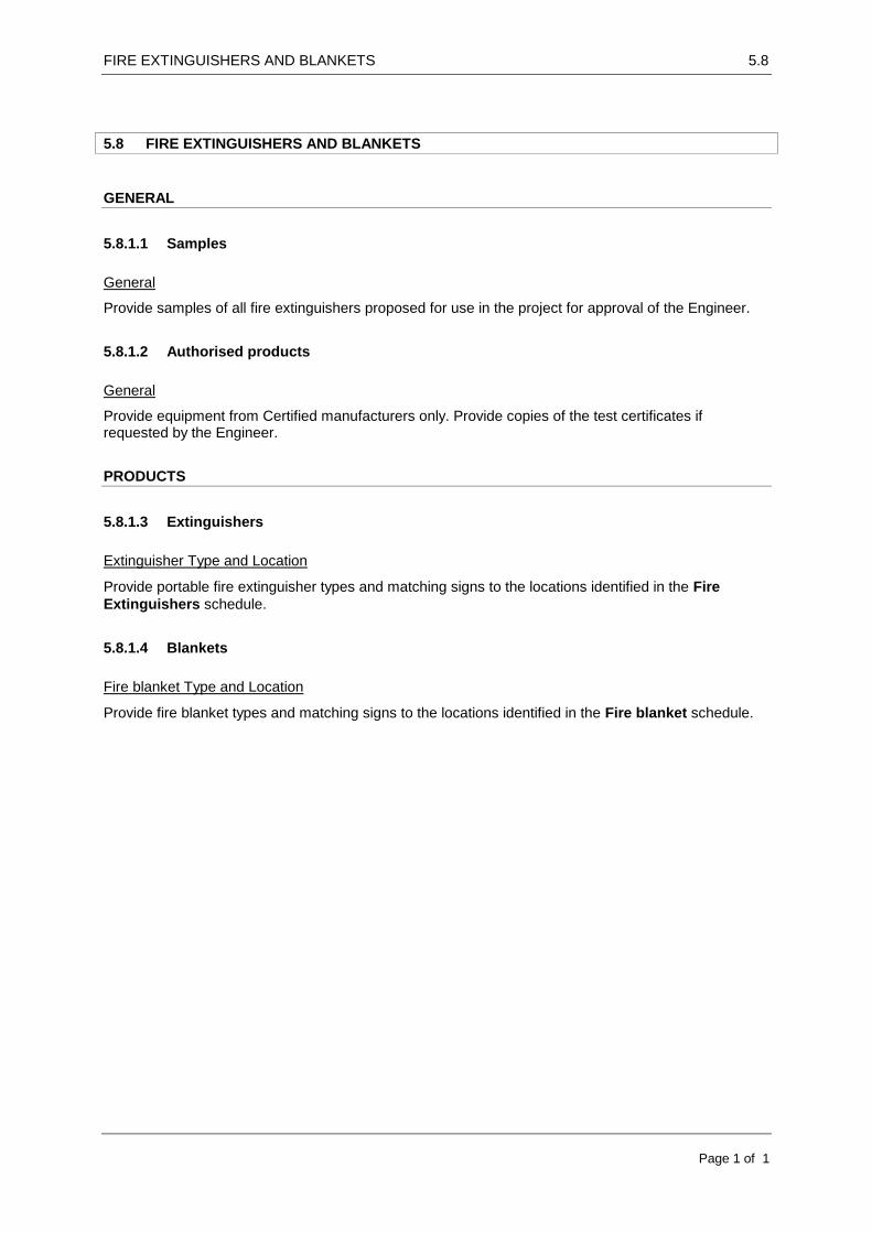
FIRE EXTINGUISHERS AND BLANKETS 5.8
Page 1 of 1
5.8 FIRE EXTINGUISHERS AND BLANKETS
GENERAL
5.8.1.1 Samples
General
Provide samples of all fire extinguishers proposed for use in the project for approval of the Engineer.
5.8.1.2 Authorised products
General
Provide equipment from Certified manufacturers only. Provide copies of the test certificates if requested by the Engineer.
PRODUCTS
5.8.1.3 Extinguishers
Extinguisher Type and Location
Provide portable fire extinguisher types and matching signs to the locations identified in the Fire
Extinguishers schedule.
5.8.1.4 Blankets
Fire blanket Type and Location
Provide fire blanket types and matching signs to the locations identified in the Fire blanket schedule.
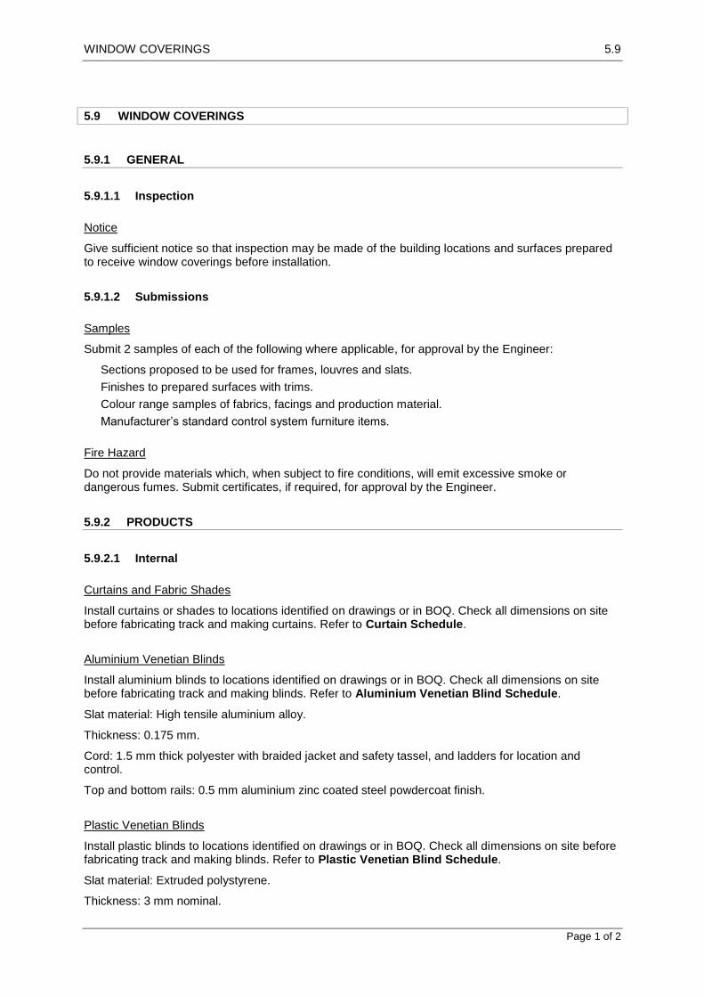
WINDOW COVERINGS 5.9
Page 1 of 2
5.9 WINDOW COVERINGS
5.9.1 GENERAL
5.9.1.1 Inspection
Notice
Give sufficient notice so that inspection may be made of the building locations and surfaces prepared to receive window coverings before installation.
5.9.1.2 Submissions
Samples
Submit 2 samples of each of the following where applicable, for approval by the Engineer:
Sections proposed to be used for frames, louvres and slats.
Finishes to prepared surfaces with trims.
Colour range samples of fabrics, facings and production material.
Manufacturer’s standard control system furniture items.
Fire Hazard
Do not provide materials which, when subject to fire conditions, will emit excessive smoke or dangerous fumes. Submit certificates, if required, for approval by the Engineer.
5.9.2 PRODUCTS
5.9.2.1 Internal
Curtains and Fabric Shades
Install curtains or shades to locations identified on drawings or in BOQ. Check all dimensions on site before fabricating track and making curtains. Refer to Curtain Schedule.
Aluminium Venetian Blinds
Install aluminium blinds to locations identified on drawings or in BOQ. Check all dimensions on site before fabricating track and making blinds. Refer to Aluminium Venetian Blind Schedule.
Slat material: High tensile aluminium alloy.
Thickness: 0.175 mm.
Cord: 1.5 mm thick polyester with braided jacket and safety tassel, and ladders for location and control.
Top and bottom rails: 0.5 mm aluminium zinc coated steel powdercoat finish.
Plastic Venetian Blinds
Install plastic blinds to locations identified on drawings or in BOQ. Check all dimensions on site before fabricating track and making blinds. Refer to Plastic Venetian Blind Schedule.
Slat material: Extruded polystyrene.
Thickness: 3 mm nominal.

WINDOW COVERINGS 5.9
Page 2 of 2
Slat width: 50 mm nominal.
Cord: Internal 2.3 mm thick polyester.
Tape: To allow a 42 mm pitch between ladders and a 8 mm slat overlap.
Top and bottom rails: 0.5 mm aluminium zinc coated steel powdercoat finish.
Timber Venetian Blinds
Install timber blinds to locations identified on drawings or in BOQ. Check all dimensions on site before fabricating track and making blinds. Refer to Timber Venetian Blind Schedule.
Slat material: Approved timber
Thickness: 5 mm nominal.
Slat width: 50 mm nominal.
Cord: Internal 2.3 mm thick polyester.
Tape: To allow a 42 mm pitch between ladders and a 8 mm slat overlap.
Top and bottom rails: 0.5 mm aluminium zinc coated steel powdercoat finish.
Vertical louvre Blinds
Install vertical blinds to locations identified on drawings or in BOQ. Check all dimensions on site before fabricating track and making blinds. Refer to Vertical Louvre Blind Schedule.
Type: Louvres supported by a carrier system which traverses on wheels and operates with a friction spring loaded clutch mechanism.
Louvre blades: Heavy duty fabric or vinyl coated fabric blades in single, straight lengths finishing 10 mm above floor or sill level, without twists, warp, bows, edge ripples or fraying. Fix a weight into a pocket formed in the bottom of each blade.
Spacings: Space the blades evenly with plastic spacers which lock into the carrier rail to provide a continuous linkage, and fix with sealed plastic slat holders carried by plastic rotation pivots. Connect the bottoms of the blades by a plastic link chain with reversers.
Tracks: Fabricated to suit size of blades for width of window or within a pelmet extending past the face of the window.
Operation: Dual continuous loop chains controlling the functions of tilting and drawing.
5.9.3 EXECUTION
5.9.3.1 Installation
General
Fixing: Secure the tracks with ceiling clamps or wall mounted brackets so that there are no fixings through the track.
5.9.3.2 Completion
Maintenance Manual
Submit the manufacturers’ data as follows:
Recommendations for service use, care and maintenance.
List of manufacturers and suppliers of replacement parts.

PLASTERING 6.1
Page 1 of 5
6.1 PLASTERING
6.1.1 GENERAL
6.1.1.1 Interpretation
Abbreviations
For the purpose to this work section the abbreviations given below apply.
CRF: Cement render – finish.
CRM: Cement render – medium.
CRS: Cement render – stronger.
CRW: Cement render – weaker.
LF: Lime felting render- weaker.
GPM: Gypsum render - medium
GPF: Gypsum plaster – finish.
6.1.1.2 Inspection
Notice
Give sufficient notice so inspection may be made of the following:
Backgrounds immediately before applying base coats.
Finish treatments before decoration.
6.1.2 PRODUCTS
6.1.2.1 Materials and components
Accessories
Beads: To be metal proprietary sections manufactured to be fixed to backgrounds and/or embedded in the plaster to form and protect plaster edges and junctions.
Aggregates
Sand: To be fine, sharp, well-graded sand with a low clay content and free from efflorescing salts.
Bonding products
To be proprietary products manufactured for bonding cement-based plaster to solid backgrounds.
Cement
Cement shall conform to the requirements of ASTM specification C-150 Type 1 or similar approved standard for normal Portland cement.
Colouring Products
To be proprietary products manufactured for colouring cement plaster.
Integral pigment proportion: 5% by mass of cement.

PLASTERING 6.1
Page 2 of 5
Curing Products
To be proprietary products manufactured for use with the plaster system.
Gypsum Plaster
To be a proprietary product containing calcium sulfate hemihydrate with additives to modify setting.
Lime
Confirm source of Lime with Engineer to ensure highest quality Lime is used in the mortar. Protect from damage on site and store minimum 300mm above ground in waterproof storage facility.
Preparing lime putty:
Using hydrated lime: Add lime to water in a clean container and stir to a thick creamy consistency. Leave undisturbed for at least 16 hours. Remove excess water and protect from drying out.
Using quicklime: Run to putty as soon as possible after receipt of quicklime. Partly fill clean container with water, add lime to half the height of the water, then stir and hoe ensuring that no lime remains exposed above the water. Continue stirring and hoeing for at least 5 minutes after all reaction has ceased, then sieve into a maturing bin. Leave undisturbed for at least 14 days. Protect from drying out.
Mixes
Select a mix ratio to suit the application in conformity to the Mixes table.
Measurement: Measure binders and sand by volume using buckets or boxes. Do not allow sand to bulk by absorption of water.
Plaster mixing: Machine mix for greater than 3 minutes and less than 6 minutes.
Strength of successive coats: Ensure successive coats are no richer in binder than the coat to which they are applied.
Mixes Table
Mix type Application Upper and lower limits of proportions by volume
Gypsum Cement Lime Sand
Cement render coats in: Single or multi-coat
systems with integral finishing treatments
Base coats in multi-coat systems with cement or gypsum finishes
CRS Dense and smooth concrete and masonry Thrown finishing treatments Tiled finishes Gypsum finishes Cement finishes
- -
1 1
0 0.5
3 4.5
CRM Clay or concrete masonry - -
1 1
0.5
4.5 6
CRW Lightweight concrete masonry and other weak backgrounds
- -
1 1
6 9
Cement finish coats CRF Cement render base coats - -
1 1
1
1.5 2
Lime felting finish coats LF Cement render base coats 1 3
Gypsum medium coats GPM Gypsum render base coats Ready-Mix
Gypsum finish coats GPF Gypsum render finish coat Ready-Mix
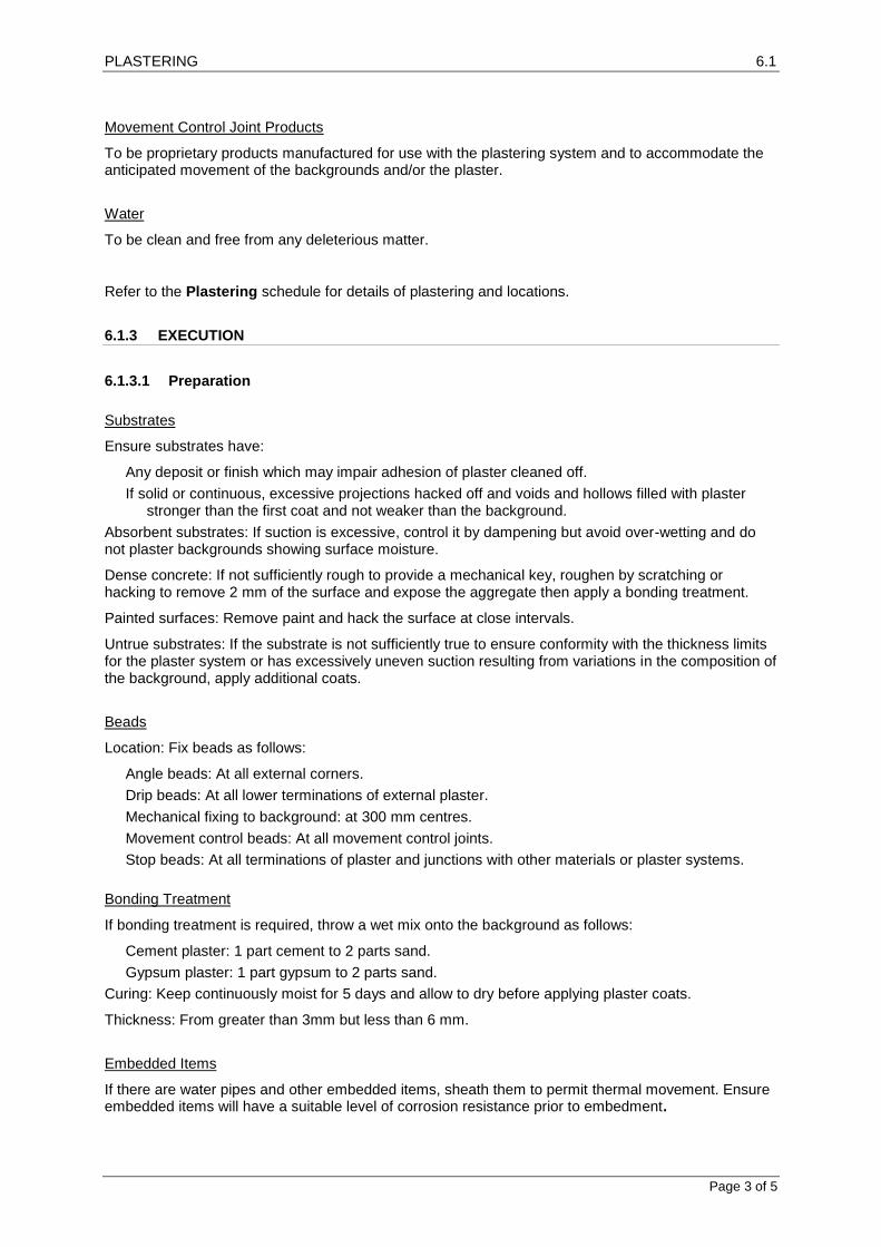
PLASTERING 6.1
Page 3 of 5
Movement Control Joint Products
To be proprietary products manufactured for use with the plastering system and to accommodate the anticipated movement of the backgrounds and/or the plaster.
Water
To be clean and free from any deleterious matter.
Refer to the Plastering schedule for details of plastering and locations.
6.1.3 EXECUTION
6.1.3.1 Preparation
Substrates
Ensure substrates have:
Any deposit or finish which may impair adhesion of plaster cleaned off.
If solid or continuous, excessive projections hacked off and voids and hollows filled with plaster stronger than the first coat and not weaker than the background.
Absorbent substrates: If suction is excessive, control it by dampening but avoid over-wetting and do not plaster backgrounds showing surface moisture.
Dense concrete: If not sufficiently rough to provide a mechanical key, roughen by scratching or hacking to remove 2 mm of the surface and expose the aggregate then apply a bonding treatment.
Painted surfaces: Remove paint and hack the surface at close intervals.
Untrue substrates: If the substrate is not sufficiently true to ensure conformity with the thickness limits for the plaster system or has excessively uneven suction resulting from variations in the composition of the background, apply additional coats.
Beads
Location: Fix beads as follows:
Angle beads: At all external corners.
Drip beads: At all lower terminations of external plaster.
Mechanical fixing to background: at 300 mm centres.
Movement control beads: At all movement control joints.
Stop beads: At all terminations of plaster and junctions with other materials or plaster systems.
Bonding Treatment
If bonding treatment is required, throw a wet mix onto the background as follows:
Cement plaster: 1 part cement to 2 parts sand.
Gypsum plaster: 1 part gypsum to 2 parts sand.
Curing: Keep continuously moist for 5 days and allow to dry before applying plaster coats.
Thickness: From greater than 3mm but less than 6 mm.
Embedded Items
If there are water pipes and other embedded items, sheath them to permit thermal movement. Ensure embedded items will have a suitable level of corrosion resistance prior to embedment.

PLASTERING 6.1
Page 4 of 5
6.1.3.2 Application
Plastering is to follow ASTM C842-05 standard for Application of Interior Gypsum Plaster.
Plastering
General: Provide plaster finishes as follows:
Resistant to impacts expected in use.
Free of irregularities.
Consistent in texture and finish.
Firmly bonded to substrates for the expected life of the application.
As a suitable substrate for the nominated final finish.
Base coats: Scratch-comb each base coat in two directions when it has stiffened.
A bonding agent is required before the application of Gypsum Plaster – Medium (GPM) on concrete surfaces.
Finishing Treatments
Bag: To be a finish mainly free from sand by rubbing the finish coat with a Hessian pad when it has set firm.
Carborundum stone: To be a smooth finish free from sand by, rubbing the finish coat with a fine carborundum stone when it has set hard.
Steel trowel: To be a smooth dense surface by steel trowelling which is not glass-like and is free from shrinkage cracks and crazing.
Wood or plastic float: To be an even surface by wood or plastic floating the finish coat on application.
Incidental Work
Return plaster into reveals, beads, sills, recesses and niches. Plaster faces, ends, and soffits of projections in the background, such as string courses, sills, and other wall features. Trim around openings. Plaster exposed inside of built-in cupboards.
Joining-Up
If joining up is required, ensure joints will not be visible in the finished work after decoration.
Movement Control Joints
Provide movement control joints in the finish to coincide with movement joints in the background. Ensure that the joint in the background is not bridged during plastering.
Depth: Extend the joint right through the plaster and reinforcement to the background.
Width: 3 mm, or the same width as the background joint, whichever is greater.
Damp-proof courses: Do not continue plaster across damp-proof courses.
V-joints: Provide V-joints, cut right through the plaster to the background, at the following locations:
Abutments with metal door frames.
Abutments with other finishes.
Junctions between different backgrounds.
Plaster Thickness
Conform to the Plaster Thickness table.

PLASTERING 6.1
Page 5 of 5
Plaster Thickness Table
Plaster Application Upper limit of thickness (mm)
Single coat systems
Multi-coat systems
Base coat(s) Finish coat System
Cement render base coats and cement finish
On clay and concrete brickwork and other backgrounds
15 13 4 16
Gypsum Plaster On smooth dense concrete
- 10 4 13
On clay and concrete brickwork and other backgrounds
- 13 4 16
Temperature
If the ambient temperature is less than 10ºC or more than 30ºC ensure that the temperature of mixes, backgrounds and reinforcement are, at the time of application, greater than 5ºC or less than 35ºC.
6.1.3.3 Tolerances
General
Conform to the Tolerances table.
Tolerances Table
Property Tolerance criteria: Permitted deviation (mm)
Features1: Verticality in 2000 mm 3
Features: Horizontality in 2000 mm 3
Soffits: Horizontality in 2000 mm 5
Walls: Verticality in 2000 mm 5
Walls: Flatness2 in 2000 mm 4
1 Features: Conspicuous horizontal or vertical lines including external corners, parapets, reveals,
heads, sills, movement control joints and mouldings. 2 Flatness: Measured under a straightedge laid in any direction on a plane surface.
6.1.3.4 Completion
Curing
General: Prevent premature or uneven drying out and protect from the sun and wind.
Keeping moist: If a proprietary curing agent is not used, keep the plaster moist as follows:
Cementitious Base coats and single coat systems: Keep continuously moist for 2 days and allow to dry for 5 days before applying further plaster coats.
Cementitious finish coats: Keep continuously moist for 2 days.

CEMENTITIOUS TOPPINGS 6.2
Page 1 of 5
6.2 CEMENTITIOUS TOPPINGS
6.2.1 GENERAL
6.2.1.1 Interpretations
Abbreviations
For the purposes of this worksection the abbreviations given below apply.
BCS: Bonded – cement and sand.
BFC: Bonded – fine concrete.
FFC: Floating – fine concrete.
MGR: Monolithic – granolithic.
SFC: Separated – fine concrete.
6.2.1.2 Tolerances
General
Thickness:
Thickness < 15 mm: ± 2 mm.
Thickness ≥ 15 < 30 mm: ± 5 mm.
Thickness ≥ 30 mm: ± 10 mm.
Flatness: Measured under a 3000 mm straightedge laid in any direction on a plane surface:
Grade A: < 3 mm.
Grade B: ≥ 3 < 5 mm.
Grade C: ≥ 5 < 10 mm.
6.2.2 PRODUCTS
6.2.2.1 Products
Admixtures
Introduce in solution in a portion of the mixing water. Ensure a uniform distribution of the admixture in the batch within the mixing period.
Aggregates
Coarse aggregate: To be nominal single size.
Fine aggregate: To be fine, sharp, well-graded sand with a low clay content and free from efflorescing salts.
Bonding products
To be proprietary products manufactured for bonding cement-based toppings to concrete backgrounds.
Cement
Cement shall conform to the requirements of ASTM specification C-150 Type 1 or similar approved standard for normal Portland cement.

CEMENTITIOUS TOPPINGS 6.2
Page 2 of 5
Colouring products
To be proprietary products manufactured for colouring cement toppings.
Integral pigment proportion: 5% by mass of cement.
Coloured chips
To be marble chips of selected colour or proprietary products manufactured for distribution in cement toppings.
Concrete
On site batch mixed concrete shall have characteristics and proportions of concrete ingredients which conform to those specified in M-150 (1:2:4).
Curing products
To be proprietary products manufactured for use with cement-based toppings and with the floor finish to be laid on the toppings.
Mixes
Provide concrete as follows or select mix proportions to the Mixes table.
Air entrainment: ≤ 3%.
Nominal coarse aggregate size: ≤ 0.3 x topping thickness.
Slump: 80 mm.
Water quantity: Use the minimum necessary to achieve full compaction and prevent excessive water being brought to the surface during compaction.
Mixes Table
Mix type Thickness (mm) Upper and lower limits of proportion by mass (mm)
Cement Fine aggregate
Coarse aggregate
Bonded – cement and sand
BCS 35 1 1
3 4.5
0 0
Bonded – fine concrete BFC 40 1 1
3 3
1 2
Floating – fine concrete FFC 100 1 1
3 3
1 2
Monolithic – granolithic MGR Floors and treads: 25 Risers and skirtings: 13
1 2 1
Separated – fine concrete SFC 70 1 1
3 3
1 2
Movement Control Joint Products
Provide products manufactured for use with cement based toppings and accommodate the anticipated movement of the backgrounds and/or the toppings.
Sealing Products
Provide proprietary products manufactured for the sealing of movement joints in cement-based toppings.

CEMENTITIOUS TOPPINGS 6.2
Page 3 of 5
Slip-resistance products
Provide proprietary products manufactured to improve the wet-slip resistance of toppings.
Silicon carbide granules:
Granule size: 300 < 600 µm.
Colour: Black.
Surface treatment products
Provide proprietary products manufactured for use with cement- based toppings to change the characteristics of the surface of the finished topping.
Reinforcement
All reinforcing shall be supported and wired together to prevent displacement by construction loads, or the placing of concrete, beyond the tolerances specified in ACI 301. Any tack or spot welding of reinforcement shall not be performed without approval from the Engineer.
Reinforcement shall be free of loose rust and of any other coating which may adversely affect the bond.
Water
General: To be clean and free from any deleterious matter.
Refer to the Cementitious Toppings schedule for details of toppings and locations.
6.2.3 EXECUTION
6.2.3.1 Preparation
Backgrounds
Ensure backgrounds have:
Any deposit which may impair adhesion of monolithic or bonded toppings cleaned off.
Excessive projections hacked off and voids and hollows filled with a mix not stronger than the background nor weaker than the topping.
Hardened concrete roughened by scratching or hacking to remove 2 mm of the surface and expose the aggregate.
Bonded Toppings
Before laying topping wash the subfloor with water and use a bonding product or treat as follows:
Keep wet for ≥ 2 hours.
Remove surplus water and brush on neat cement or a clean slurry of cement and water.
Place the topping while the slurry is wet.
6.2.3.2 Application
Laying
Spread the mix and compact and level the surface to finished levels.
Monolithic toppings: Lay while concrete subfloor is plastic and surface water is no longer visible.
Toppings over 50 mm thick:
Lay in two layers of equal thickness.

CEMENTITIOUS TOPPINGS 6.2
Page 4 of 5
Place a layer of reinforcement between the layers of toppings. Lap reinforcement 100 mm and tie. Do not create four way laps.
Floating and Trowelling
Machine float finish:
After levelling, consolidate the surface using a machine float.
Cut and fill and refloat immediately to a uniform, smooth, granular texture.
Hand float in locations inaccessible to the machine float.
Flatness: Grade B.
Steel trowel finish: After machine floating finish as follows:
When the surface has hardened sufficiently, use steel hand trowels to produce the final consolidated finish free of trowel marks and uniform in texture and appearance.
Flatness: Grade A.
Wood float finish: After machine floating finish as follows:
Use wood or plastic hand floats to produce the final consolidated finish free of float marks and uniform in texture and appearance.
Flatness: Grade A.
Floor Finish Dividers
Finish cementitious toppings at junctions with differing floor finishes with a corrosion resistant metal dividing strip suitable fixed to the background, with top edge flush to the finished floor. If changes of floor finish occur at doorways make the junction directly below the closed door.
Monolithic Toppings
Coved skirtings: Form coves in the topping material, and finish the top to a neatly struck line. Mitre internal and external angles.10 mm radius to top of skirting. 25mm radius to junction between floor and skirting.
Movement Control Joints
Provide movement control joints to divide toppings into bays as follows
Form in situ using square edge steel forms and trowelling a 3 mm radius to edges.
Form a groove, extending at least one quarter the depth of the section, either by using a grooving tool, by sawing, or by inserting a premoulded strip.
Install a movement control joint product.
Bay sizes:
Area: ≤ 15 m2.
Length to width ratio: ≤ 1:1.5.
Joints in background: Provide movement control joints in toppings to coincide with joints in the background.
Slip-Resistance Treatment
Stair treads: Form two grooves and fill with a silicon carbide two-part resin.
Dimensions: 10 mm deep, 15 mm wide, length width of tread less 100 mm.
Position:
First groove: Centre 35 mm from tread nose.
Second groove: Centre 60 mm from step nose.
Plane surfaces: Apply silicon carbide granules after floating and before the topping surface has set, and trowel into the surface so that the granules remain exposed.
Application rate: 1 kg/m2 evenly distributed.

CEMENTITIOUS TOPPINGS 6.2
Page 5 of 5
Surface Colouring
Apply the colouring product or coloured marble chips after floating and before the topping surface has set and trowel into the surface so that it is even in colour distribution.
Temperature
If the ambient temperature is less than 10ºC or more than 30ºC ensure that the temperature of mixes, backgrounds and reinforcement are, at the time of application, greater than 5ºC or less than 35ºC.
6.2.3.3 Completion
Curing
General: Prevent premature or uneven drying out and protect from the sun and wind.
Curing: Use a curing product or, as soon as it has set sufficiently, keep the toppings moist by covering with polyethylene film for seven days.

TILING 6.3
Page 1 of 7
6.3 TILING
6.3.1 GENERAL
Furnish all tools, equipment, materials, supplies, accessories and perform all labor to install ceramic tile work indicated on the Contract Drawings and as hereinafter specified.
6.3.1.1 Inspection
Notice
Give sufficient notice so that inspection may be made of the following:
Floor preparation and set out of floor tiles before fixing.
Wall preparation and set out of wall tiles before fixing.
Control joints before sealing and grouting.
6.3.1.2 Submissions
Samples
Submit labelled samples of tiles, including fittings, accessories, grout and sealants, illustrating the range of variation in colour and finish.
6.3.1.3 Interpretations
Definitions
For the purposes of this worksection the definitions given below apply.
Substrates: The surfaces on which tiles are bedded.
Bedding: Mixtures of materials which are applied to substrates in a plastic state and dry and cure to adhere tiles to substrates.
Adhesive bedding: Tiling adhered by adhesives.
Mortar bedding: Tiling adhered in a cementitious mortar bed.
Pavers: Slabs made from clays, stone, precast concrete and/or other inorganic raw materials generally over 20 mm thick used as coverings for floors and supported over continuous substrates.
Tiles: Thin slabs made from clays and/or other inorganic raw materials used generally as coverings for floors and walls and adhered to continuous supporting substrates.
Natural stone: Tiles cut from natural stone.
Industrial cast: Tile products of reconstituted stone. Also known as manufactured stone.
Cementitious: Manufactured cement based pre-finished tiles.
Terrazzo – cementitious: Manufactured cementitious terrazzo tiles formed in a suitable machine to give sufficient compaction and density to the finished surface, and moisture cured before grinding and honed at the place of manufacture. Thickness usually 35 mm.
Wet areas: Areas within buildings with water supply and drainage systems.
6.3.1.4 Tolerances
Completed tiling
Conform to the Tolerances table.
Tolerances Table

TILING 6.3
Page 2 of 7
Property Tolerance criteria
Alignment: Deviation of the finished tiles from a 3 m straight edge laid against any joints
< 4 mm
Flatness: Deviation of any plane surface under a 3 m straight edge laid in any direction on an area of uniform grade
< 4 mm
6.3.2 PRODUCTS
6.3.2.1 Tiles and accessories
Provide tiles and accessories to the Wall Tiling and Floor Tiling schedules.
Coves, nosings and skirtings: To be matching stop-end and internal and external angle tiles moulded for that purpose.
Exposed edges: To be purpose-made border tiles with the exposed edge glazed to match the tile face. If such tiles are not available, round edge with grout.
6.3.2.2 Adhesives
Type
General: Provide adhesives to the Wall Tiling schedule and to the Floor Tiling schedule and compatible with the materials and surfaces to be adhered.
Prohibited uses: Do not provide the following combinations:
Cement-based adhesives on wood, metal, painted or glazed surfaces, gypsum-based plaster.
Organic solvent-based adhesives on painted surfaces.
Organic PVC-based adhesives and organic natural rubber latex adhesives in damp or wet conditions.
PVA (polyvinyl acetate) based adhesives in wet areas or externally.
6.3.2.3 Mortar
Materials
Cement: Cement shall conform to the requirements of ASTM specification C-150 Type 1 or similar approved standard for normal Portland cement.
White cement: Iron salts content 1%.
Off-white cement: Iron salts content 2.5%.
Lime: Confirm source of Lime with Engineer to ensure highest quality Lime is used in the mortar. Protect from damage on site and store minimum 300mm above ground in waterproof storage facility.
Sand: Fine aggregate with a low clay content selected for grading, sharp and free from efflorescing salts.
Measurement of volume: Measure binders and sand by volume using buckets or boxes. Do not allow sand to bulk by absorption of water.
Bedding mortar
Proportioning: Select proportions from the range 1:3 – 1:4 cement:sand to obtain satisfactory adhesion. Provide minimum water.
Terra cotta tiles: Use proprietary polymer modified mortar.
Water
General: To be clean and free from any deleterious matter.

TILING 6.3
Page 3 of 7
6.3.2.4 Grout
Type
Cement based proprietary grout: Mix with water. Fine sand may be added as a filler in wider joints.
Terra cotta tiles: Use proprietary polymer modified grout.
Portland cement based grout: Mix with fine sand. Provide minimum water consistent with workability.
For joints < 3 mm: 1 cement:2 sand.
For joints 3 mm: 1 cement:3 sand.
Pigments
Pigments for coloured grout: Provide colourfast fillers compatible with the grout material. For cement-based grouts, provide lime-proof natural or synthetic metallic oxides compatible with cement.
6.3.3 EXECUTION
Provide tiling systems to walls, floors and other substrates as follows:
Consistent in colour and finish.
Firmly bonded to substrates for the expected life of the installation.
Resistant to expected impacts in use.
Set out with joints accurately aligned in both directions and wall tiling joints level and plumb.
To direct all water flowing from supply points to drainage outlets without leakage to the substrate or adjacent areas.
6.3.3.1 JOB CONDITIONS
Provide tiling systems to walls, floors and other substrates as follows:
Consistent in colour and finish.
Firmly bonded to substrates for the expected life of the installation.
Resistant to expected impacts in use.
Set out with joints accurately aligned in both directions and wall tiling joints level and plumb.
To direct all water flowing from supply points to drainage outlets without leakage to the substrate or adjacent areas.
Protection
Protect adjacent surfaces against damage during progress of the work of this Section.
Coordination and Cooperation
Coordinate work of this Section with work of other trades. Perform work without delay to the work in progress.
Workmanship
In accordance with best practice; work performed by skilled workers; jointings, intersections and returns well formed; drilling and cutting neatly done without marring the material; joints straight and solidly filled conforming to applicable "Standard Specifications" of the American National Standards Institute, Inc. ANSI A108.1 and ANSI A108.2.
6.3.3.2 Substrates
Drying and Shrinkage
Before tiling, allow at least the following times to elapse (for initial drying out and shrinkage) for these substrates:

TILING 6.3
Page 4 of 7
Concrete slabs: 42 days.
Concrete blockwork: 28 days.
Toppings on slabs and rendering on blockwork: A further 21 days.
6.3.3.3 Preparation
Ambient temperature
Install mortar and set and grout the tile, only when the temperature is at least 10°C and rising. If the ambient temperature is less than 10°C or more than 35°C, do not lay tiles.
Substrates
Ensure substrates are as follows:
Clean and free of any deposit or finish which may impair adhesion or location of tiles.
If solid or continuous, excessive projections are hacked off and voids and hollows are filled with a cement:sand mix not stronger than the substrate nor weaker than the bedding.
Absorbent substrates: If suction is excessive, control it by dampening but avoid over-wetting and do not apply mortar bedding to substrates showing surface moisture.
Dense concrete: If not sufficiently rough to provide a mechanical key, roughen by scratching or hacking to remove 3 mm of the surface and expose the aggregate; then apply a bonding treatment.
6.3.3.4 Tiling Generally
Sequence
General: Fix wall tiles before floor tiles.
Cutting and Laying
Cutting: Cut tiles neatly to fit around fixtures and fittings, and at margins where necessary. Drill holes without damaging tile faces. Rub edges smooth without chipping.
Laying: Return tiles into sills and openings. Butt up to returns, frames, fittings, and other finishes.
Variations
Distribute variations in hue, colour, or pattern uniformly, by mixing tiles or tile batches before laying.
Protection
Floor tiles: Keep traffic off floor tiles until the bedding has set and attained its working strength.
Cleaning: Keep the work clean as it proceeds and protect finished work from damage.
6.3.3.5 Setting out
Tile joints
Set out tiles to give uniform joint widths within the following limits:
Ceramic floor tiles: 4 to 6 mm.
Quarry floor tiles: 6 to 12 mm.
Terrazzo and stone pavers to floor: 2 to 3 mm.
Large and/or irregular floor tiles: 6 to 12 mm.
Mounted mosaics: To match mounting pattern.
Ceramic wall tiles: 3 to 5 mm.
Terrazzo and stone wall panels: 2 to 3 mm.

TILING 6.3
Page 5 of 7
Margins
Provide whole or purpose-made tiles at margins where practicable, otherwise set out to give equal margins of cut tiles. If margins less than half tile width are unavoidable, locate the cut tiles where they are least conspicuous.
Fixtures
If possible position tiles so that holes for fixtures and other penetrations occur at the intersection of horizontal and vertical joints or on the centre lines of tiles. Continue tiling fully behind fixtures which are not built in to the tiling surface. Before tiling ensure that fixtures interrupting the tile surfaces are accurately positioned in their designed or optimum locations relative to the tile layout.
6.3.3.6 Falls and levels
Grading
Grade floor tiling to even and correct falls to floor wastes and elsewhere as required. Make level junctions with walls. Where falls are not required lay level.
Fall, general: 1:100 minimum.
Fall, in shower areas: 1:60 minimum.
6.3.3.7 Bedding
Preparation of Tiles
Adhesive bedding: Fix tiles dry; do not soak.
Mortar bedding: Soak porous tiles in water for half an hour and then drain until the surface water has disappeared.
Terra cotta tiles: Use pre sealed tiles or apply a breathable sealer and lay dry. If a final sealed finish is selected, use a compatible laying sealer.
Bedding
Use bedding methods and materials which are appropriate to the tile, the substrate, the conditions of service, and which leave the tile firmly and solidly bedded in the bedding material and adhered to the substrate. Form falls integral with the substrate.
Thin Adhesive Beds
Provide only if the substrate deviation is less than 3 mm when tested with a 3 m straight edge. Cover the entire tile back with adhesive when the tile is bedded.
Thickness: 1.5 – 3 mm.
Thick Adhesive Beds
Provide on substrates with deviations up to 6 mm when tested with a 3 m straight edge, and with tiles having deep keys.
Nominal thickness: 6 mm.
Adhesive Bedding Application
Apply adhesive by notched trowel to walls and floors and direct to tiles if required, to provide evenly distributed coverage after laying.
Wall tile spacers: Do not use spacer types that inhibit the distribution of adhesive.
Curing: Allow the adhesive to cure for the period nominated by the manufacturer prior to grouting or allowing foot traffic.

TILING 6.3
Page 6 of 7
Mortar Beds
For floor tiles: Either lightly dust the screeded bed surface with dry cement and trowel level until the cement is damp, or spread a thin slurry of neat cement, or cement-based thin bed adhesive, on to the tile back. Do not provide mortar after initial set has occurred.
Nominal thickness: 20 to 40 mm.
6.3.3.8 Movement joints
General
Provide movement joints to the Tile Movement Joints schedule and as follows:
Over structural (isolation, contraction, expansion) joints.
Close to external corners in large tiled areas.
Around the perimeter of the floor.
At junctions between different substrates.
To divide large tiled areas into bays, maximum 5 m wide, maximum 16 m2.
At abutments with the building structural frame and over supporting walls or beams where flexing of the substrate is anticipated.
Depth of joint: Right through to the substrate.
Sealant width: 6 – 10 mm.
Depth of elastomeric sealant: One half the joint width, or 6 mm, whichever is the greater.
Movement Joint Materials
Divider strip: A proprietary expansion joint consisting of a neoprene filler sandwiched between plates with lugs or ribs for mechanical keying. Set flush with the finished surface.
Sealant: Two-pack self-levelling non-hardening mould resistant, one-part silicone or polyurethane sealant applied over a backing rod. Finish flush with the tile surface.
Backing rod: Compressible closed cell polyethylene foam with a bond-breaking surface.
6.3.3.9 Grouted and caulked joints
Grouted joints
Commence grouting as soon as practicable after bedding has set. Clean out joints as necessary before grouting.
Face grouting: Fill the joints solid and tool flush. Clean off surplus grout. Wash down when the grout has set. When grout is dry, polish the surface with a clean cloth.
Edges of tiles: Grout exposed edge joints.
Mosaic Tiles
Grouting mosaics: If paper faced mosaics are to be bedded in cement mortar, pre-grout the sheeted mosaics from the back before fixing. After fixing, rub grout into the surface of the joints to fill any voids left from pre-grouting. Clean off surplus grout. When grout has set, wash down. If necessary use a proprietary cement remover.
Sealant Joints
Provide joints filled with sealant and finished flush with the tile surface as follows:
Where tiling is cut around sanitary fixtures.
Around fixtures interrupting the tile surface, for example pipes, brackets, bolts and nibs.
At junctions with elements such as window and door frames and built-in cupboards.
Width: 5 mm.

TILING 6.3
Page 7 of 7
Depth: Equal to the tile thickness.
6.3.3.10 Joint Accessories
Floor Finish Dividers
Finish tiled floors at junctions with differing floor finishes with a corrosion resistant metal dividing strip suitably fixed to the substrate, with top edge flush with the finished floor. Where changes of floor finish occur at doorways make the junction directly below the closed door.
6.3.3.11 Completion
Cementitious Terrazzo Tiled Surfaces
In situ grind and polish the completed installation with equipment nominated by the tile supplier.
Spare Tiles
Supply spare matching tiles and accessories of each type for future replacement purposes. Store the spare materials on site where directed by the Engineer.
Quantity: At least 1% of the quantity installed.
Cleaning
Clean tiled surfaces using an appropriate tile cleaning agent, and polish:
1. Remove mortar and grout prior to hardening during progress of work. 2. Clean surfaces thoroughly after grouting and pointing have set sufficiently; remove all cement, dust and other foreign matter with plain water or mild alkaline cleaner. Sandblasting of exposed surfaces is prohibited. 3. Cleaning with a solution not stronger than 10 percent muriatic acid to 90 percent water permitted only on unglazed tile; thoroughly wash afterwards with clean water. Completely protect hardware and fittings metal surfaces, cast iron and vitreous items from acid and fumes. 4. Cleaning shall be done in accordance with the manufacturer's recommendations.

VINYL FINISHES 6.4
Page 1 of 4
6.4 VINYL FINISHES
6.4.1 GENERAL
6.4.1.1 Inspection
Notice
Give sufficient notice so that inspection may be made of the substrate immediately before fixing vinyl finishes.
6.4.1.2 Submissions
Samples
Range: Submit labelled samples of vinyl finishes illustrating the range of colour, pattern or texture as seen in the finished work.
Minimum size per sample:
Sheet: 450 x 450 mm.
Linear accessories (coving, skirting, stair nosing, protection strips, and the like): A piece 300 mm long.
Welded joints: Submit a sample joint 300 mm long.
Identification
Labelling: Label each sample, giving brand, product name, and manufacturer’s code reference
6.4.2 PRODUCTS
6.4.2.1 Marking
Identification
Deliver materials to the site in the manufacturer’s containers legibly marked to show the following:
Manufacturer’s identification.
Product brand name.
Product type.
Dimensions and quantity.
Handling and installation instructions.
6.4.2.2 Sheets and Tiles
Edges of Sheets and Tiles
Ensure edges are firm, unchipped, machine-cut accurately to size and square to the face, and that tile edges are square to each other.
Polyvinyl Chloride (PVC)
Resilient floor covering, jute or polyester felt backing: To BS EN 650.
Resilient floor covering, with foam layer: To BS EN 651.
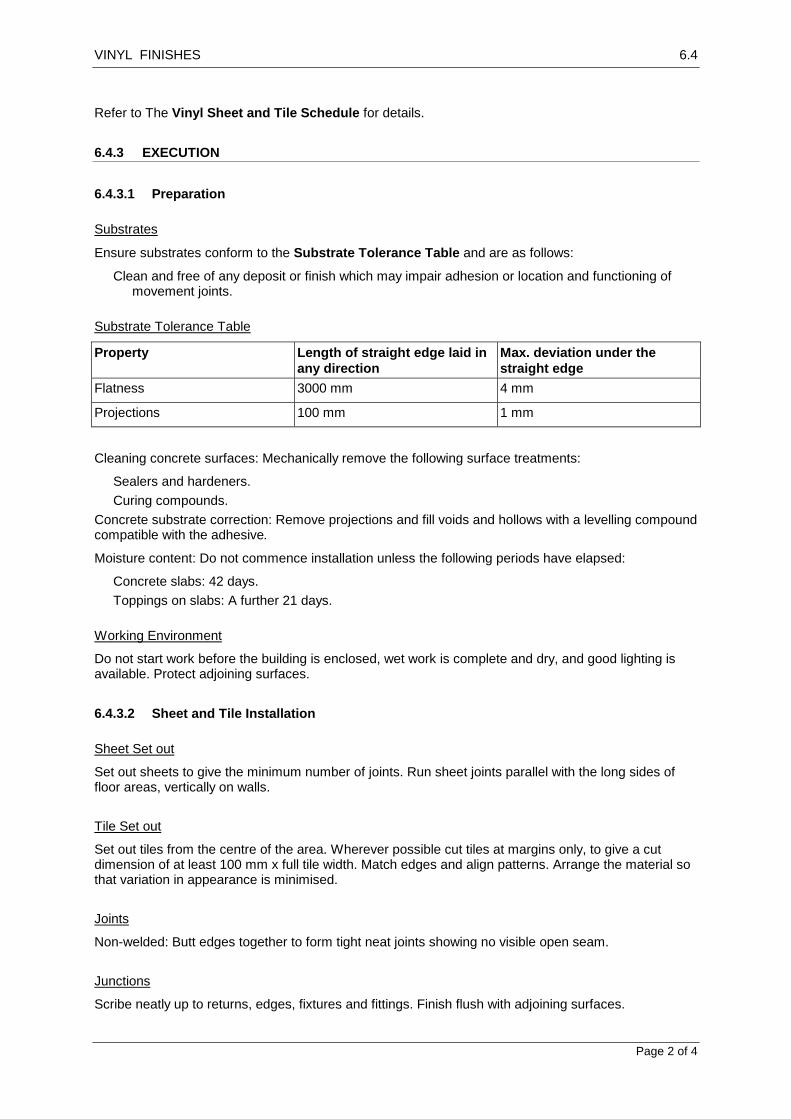
VINYL FINISHES 6.4
Page 2 of 4
Refer to The Vinyl Sheet and Tile Schedule for details.
6.4.3 EXECUTION
6.4.3.1 Preparation
Substrates
Ensure substrates conform to the Substrate Tolerance Table and are as follows:
Clean and free of any deposit or finish which may impair adhesion or location and functioning of movement joints.
Substrate Tolerance Table
Property Length of straight edge laid in
any direction
Max. deviation under the
straight edge
Flatness 3000 mm 4 mm
Projections 100 mm 1 mm
Cleaning concrete surfaces: Mechanically remove the following surface treatments:
Sealers and hardeners.
Curing compounds.
Concrete substrate correction: Remove projections and fill voids and hollows with a levelling compound compatible with the adhesive.
Moisture content: Do not commence installation unless the following periods have elapsed:
Concrete slabs: 42 days.
Toppings on slabs: A further 21 days.
Working Environment
Do not start work before the building is enclosed, wet work is complete and dry, and good lighting is available. Protect adjoining surfaces.
6.4.3.2 Sheet and Tile Installation
Sheet Set out
Set out sheets to give the minimum number of joints. Run sheet joints parallel with the long sides of floor areas, vertically on walls.
Tile Set out
Set out tiles from the centre of the area. Wherever possible cut tiles at margins only, to give a cut dimension of at least 100 mm x full tile width. Match edges and align patterns. Arrange the material so that variation in appearance is minimised.
Joints
Non-welded: Butt edges together to form tight neat joints showing no visible open seam.
Junctions
Scribe neatly up to returns, edges, fixtures and fittings. Finish flush with adjoining surfaces.

VINYL FINISHES 6.4
Page 3 of 4
Rolling
Where rolling is required, roll the finish in 2 directions before the adhesive sets, using a 70 kg multi-wheeled roller.
Cleaning
Keep the surface clean as the work proceeds.
6.4.3.3 Vinyl Sheeting
Welded joints
Heat welding: After fixing, groove the seams using a grooving tool and weld the joints with matching filler rod and using a hot air welding gun. When the weld rod has cooled, trim off flush.
Cold welding: Apply seaming compound 100 mm wide to the substrate centrally under the seam. Roll the seam until the compound is forced up into the joint. Clean off flush using a damp cloth.
Epoxy jointing: Join seams with epoxy adhesive.
6.4.3.4 Stairs
Vinyl
Preformed: Provide purpose-made vinyl stair finish combining riser, nosing and tread in the one element. Lay each step consecutively with the joint at the bottom of each riser.
Formed in situ: Fit the sheet vinyl to each tread, and to the riser above, in one piece, coved in the angle. Accurately scribe, cut and fit to stair nosings and perimeters.
Stair Nosings
Aluminium: Purpose-made extruded anti-slip aluminium nosing.
Vinyl: Purpose-made moulded anti-slip section, matching the stair finish.
Refer to the Stair Vinyl Finishes Schedule.
6.4.3.5 Joints and Accessories
Refer to the Vinyl Finishes Joint and Accessories Schedule for details.
Junctions
Finish junctions flush with adjoining surfaces. Where changes of floor finish occur at doorways locate the joint on the centreline of the closed door leaf.
Cover Strips
Provide edge cover strips at junctions with different floor finishes and to exposed edges.
Metal cover strip: Extruded tapered strip 25 mm wide, of the same thickness as the sheet or tile. Fix with masonry anchors at 200 mm maximum centres.
UPVC cover strip: Feather-edge strip matching the floor finish, fixed with contact adhesive.
Movement Joints
Location: Provide movement joints as follows:
Over structural (isolation, contraction, expansion) joints.

VINYL FINISHES 6.4
Page 4 of 4
At junctions between different substrates.
Depth of joint: Right through to the substrate.
Sealant width: 6 – 10 mm.
Depth of elastomeric sealant: One half the joint width, or 6 mm, whichever is the greater.
Vinyl Skirting
Feather edge: Moulded PVC skirting section.
Flat skirting: Flat PVC skirting section.
Fixing: Fix to walls with contact adhesive.
Minimum height: 100 mm.
Coves and Nosings
Coved skirtings: Carry the flooring material up over a profiled coving section to form skirting, weld all joints. Minimum radius of 20mm to coving.
6.4.3.6 Completion
Protection
Keep traffic off floors until bonding has set or for 24 hours after laying, whichever period is the longer. Do not allow water in contact with the finish for 7 days.
Reinstatement: Repair or replace faulty or damaged work. If the work cannot be repaired satisfactorily, replace the whole area affected.
Spare Materials
General: Supply spare matching covering materials and accessories of each type for future replacement purposes. Store the spare materials on site where directed.
Quantity: At least 1% of the quantity installed.
Cleaning
Clean the finished surface. Buff and polish. Before handover, mop and leave the finished surface clean and undamaged on completion.
Refer to the Vinyl Sheet and Tile Schedule for details and locations of vinyl finishes.

CARPETS 6.5
Page 1 of 3
6.5 CARPETS
6.5.1 GENERAL
6.5.1.1 Inspection
Notice
Give sufficient notice so that inspection may be made of the following:
Subfloor prepared to receive the carpet installation.
Fixings, edge strips, and underlay installed ready to lay carpet.
6.5.1.2 Submissions
Samples
General: Submit labelled production run samples illustrating the range of colour and pattern available in the required carpet types.
Sample size:
Carpet: 1 m long x roll width or 1 m wide, whichever is less.
Edge strip: Submit a 300 mm length of each type.
Accessories: Submit one sample of each of the following:
Carpet gripper.
Heat-bonding tape.
Bonding adhesive.
6.5.2 PRODUCTS
6.5.2.1 Carpet
Batching
Carpet laid in a single area and of a single specified type, quality, colour and design, must come from one manufacturing batch and dye lot.
Insect Resistance
Insecticide: Provide carpets and underlays composed entirely of materials either inherently resistant to insect attack, or treated against insect attack, including by moth and carpet beetle.
6.5.2.2 Entry Mats
Coir mats
Provide a mat made to fit each designated mat recess to the Entry Mats Schedule. Refer to drawings for locations.
6.5.2.3 Adhesives and Tapes
Adhesives

CARPETS 6.5
Page 2 of 3
Compatible with the floor covering material, and suitable for bonding it to the subfloor.
Friction compound: Suitable for holding tiles in position without permanent sticking.
Hot-melt Adhesive Tapes
Commercial grade glass fibre and cotton thermoplastic adhesive coated tape 60 mm wide on a 90 mm wide metal foil base and backed with silicon-coated release paper.
6.5.2.4 Strips
Preformed Gripper Strips
Commercial grade plywood carpet gripper strip with 3 rows of rust-resistant angled pins of length appropriate to the carpet type.
Size (minimum): 33 mm wide x 7 mm thick.
Location: At edges, except where edge strips are used. Provide double gripper strips to edges where recommended.
Edge Strips
Type: Heavy duty edge strip appropriate to the floor covering type (tackless or adhesive fixed), capable where necessary of accommodating different levels of adjacent floor finishes.
Form: Metal moulding or extrusion, with vinyl inserts.
Location: At exposed edges of the carpet, and at junctions with differing floor finishes or finishes of a different thickness. Where edge strips occur at doorways, locate the junctions directly below the closed door.
6.5.3 EXECUTION
6.5.3.1 Substrate
Substrates
General: Ensure substrates conform to the Substrate Tolerance Table and are as follows:
Clean and free of any deposit or finish which may impair adhesion or location and functioning of movement joints.
Substrate Tolerance Table
Property Length of straight edge laid in
any direction
Max. deviation under the
straight edge
Flatness 3000 mm 8 mm
Smoothness 200 mm 2 mm
Concrete substrate correction: Remove projections and fill voids and hollows with a levelling compound compatible with the adhesive.
Moisture content: Do not commence installation unless the following periods have elapsed:
Concrete slabs: 42 days.
Toppings on slabs: A further 21 days.
Fixtures: Remove door stops and other fixtures, and refix in position undamaged on completion of the installation.

CARPETS 6.5
Page 3 of 3
6.5.3.2 Laying Carpet
Setting out
Lay the carpet in continuous lengths without cross joins in the body of the area. Where unavoidable cross joins occur at doorways, locate the joins directly below the closed doors.
Partition layout: Confirm that permanent partitions have been installed before starting carpet laying.
Fixing Underfelt
Glue continuously to concrete at edges and joints with a 100 mm wide strip to each piece, and at 600 mm centres both ways with 150 mm diameter patches.
Seaming Methods
Woven carpet: Machine or hand sew. Do not provide glued taped seams.
Tufted carpet: Seam with hot-melt adhesive tape.
Fixing
Permanent stick method: Immediately after laying, and again one hour later, roll the carpet from the centre diagonally towards each edge using a 65 kg multi-wheeled roller. Do not roll foam-backed carpet.
Dual bonded underlay: Fix with adhesive between carpet and underlay, and between underlay and subfloor.
Gripping system: Preformed gripper strip and tackless edge strip. Space fixings at 150 mm maximum centres.
Cutting Laid Carpet
Method: Where penetrations through laid carpet are necessary for electrical, telephone or other outlets, cut the carpet either by cross cutting or by cutting rectangular or circular openings.
6.5.3.3 Laying on stairs
Fixing Method
To concrete stairs: Adhesive fixing.
Laying Method
Closed rise types: Apply the floor covering continuously to the treads and risers.
6.5.3.4 Completion
Cleaning
Progressively clean the work. Remove waste, excess materials and adhesive.
Final cleaning: When the installation is complete, clean the carpet as necessary to remove extraneous matter, marks and soiling and to lift the pile where appropriate.
Protection: provide fabric drop sheets. Do not use plastic sheeting. If wheeled traffic is to follow carpet installation protect with hardboard sheets butted and fixed with adhesive tape.
Refer to the Carpet and Laying Schedule for types and locations of carpets.

PAINTING 6.6
Page 1 of 5
6.6 PAINTING
6.6.1 GENERAL
6.6.1.1 Inspection
Notice
Give sufficient notice so that inspection may be made of the substrate immediately before application of paint finishes.
Materials and Equipment Not to be Painted
Unless scheduled, specified, or required by the drawings to be painted, the following items do not require painting. These surfaces shall be left completely clean and free from droppings and accidentally applied material.
1. Non-ferrous metals, chrome plated metal, and stainless steel. 2. Finish Hardware. 3. Ceramic tile. 4. Floor finish materials. 5. Acoustic tile. 6. Equipment furnished with complete factory-applied finish, (except A.C. units) unless specifically
noted on the drawings or specified herein to be painted.
6.6.1.2 Submissions
Prior to start of painting, submit three copies of a complete list of all materials, identified by manufacturer's name and product label or stock number, to the Engineer for approval. This list shall be in the form of a repetition of the paint finishes specified, with the addition of the specific product intended for each coat.
Clear Finish Coated Samples
Submit pieces of timber or timber veneer matching the timber to be used in the works, prepared and coated in accordance with the paint system.
Opaque Coated Samples
Provide approx 600x600mm samples on representative substrates of each paint system showing surface preparation, colour, gloss level and texture.
6.6.2 PRODUCTS
6.6.2.1 Materials General
Thinners, vehicles, pigments, and other incidental materials intended to be combined with or used with factory-mixed products shall be of the types and kinds recommended by the paint manufacturer for the intended purpose. Include listing of such materials in the material list required hereinafter.
Deliver materials to the job in unopened containers bearing manufacturer's name and product designation corresponding to designation on material list.
Insofar as practicable, each kind of coating for the various types of paint finish shall be factory-mixed to match approved samples and colors, and of consistencies ready for immediate application.
6.6.2.2 Paints
Combinations
Do not combine paints from different manufacturers in a paint system.

PAINTING 6.6
Page 2 of 5
Clear timber finish systems: Provide only the combinations of putty, stain and sealer recommended by the manufacturer of the top coats.
Delivery
Deliver paints to the site in the manufacturer’s labelled and unopened containers.
Tinting
Provide only products which are colour tinted by the manufacturer or supplier.
6.6.2.3 Putty
Non-timber substrates: Oil-based or polymeric based.
Timber finishes: Lacquer or water based only.
6.6.3 EXECUTION
6.6.3.1 General
Store and mix paint materials in places as directed. Portions of the building used for paint storage and mixing shall be suitably safeguarded against stains, damage and defects. Take adequate precautions against fire hazard.
Mixing and thinning of prepared paints: In accordance with recommendations of manufacturer whose material is being altered, where necessary to produce satisfactory results.
Painting materials required for use on the project shall conform in all respects, with applicable air pollution control regulations.
6.6.3.2 Preparation
Order of Work
Other trades: Before painting, complete the work of other trades as far as practicable within the area to be painted, except for installation of fittings and laying flooring materials.
Clear finishes: Complete clear timber finishes before commencing opaque paint finishes in the same area.
Acceptance of Surface
Inspect surfaces to be treated to effectively safeguard work of others and to preserve painted work free from damage of every nature.
All surfaces which are found to be unsuitable for application of paint finish, shall be properly prepared before painting is started. Application of the first coat of paint shall be construed as acceptance of the surface as satisfactory for application of painter's finish.
Report unsatisfactory conditions disclosed by inspections in writing for correction. Do not proceed with the work until such unsatisfactory conditions have been properly corrected.
Protection
Fixtures: Remove door furniture, switch plates, light fittings and other fixtures before starting to paint, and refix in position undamaged on completion of the installation.
Adjacent surfaces: Protect adjacent finished surfaces liable to damage from painting operations.
Under no circumstances is the painter allowed to get paint on any surface which is not to be painted. The painter is required to protect all surfaces other than the one which is to be painted immediately, with coverings. These include, but are not limited to: drop cloths, masking tape, plastic sheeting, and

PAINTING 6.6
Page 3 of 5
paper. No paint may be allowed on glass, stone, floors, stone walls, suspended ceilings, windows or any other surface which is not mean to be painted.
Cover well with drop cloths and do not use fixtures or finished building construction of any type for scaffolding or support of scaffolding.
Post signs immediately following application of paint. Exercise proper care to completely protect fixtures, and cabinets that will be installed before painting operations are complete.
In the event finish materials which require no painting should be accidentally splashed with paint or otherwise disfigured by unauthorized application of paint, and if the paint cannot be removed without damage to the material involved, then these materials shall be removed and replaced with new materials, and all costs incidental thereto shall be paid by the Contractor. Cleaning and removal of unauthorized paint or other such materials shall be accomplished with materials and procedures which are non-injurious to the surface, all as approved by the Architect.
After completion and acceptance of the painter's work in any area, the Contractor shall be responsible for provision and maintenance of such forms of protection that may be required to protect finished work from damage from any cause prior to acceptance of the job by the Owner. Schedule the work, and exclude traffic and unauthorized personnel from finished areas, to the extent necessary to prevent damage.
“Wet paint” warning
Place notices conspicuously and do not remove them until paint is dry.
Restoration
Clean off marks, paint spots and stains progressively and restore damaged surfaces to their original condition. Touch up damaged decorative paintwork or misses only with the paint batch used in the original application.
Substrate preparation
Prepare substrates to receive the painting systems.
Cleaning: Clean down the substrate surface. Do not cause undue damage to the substrate or damage to, or contamination of, the surroundings.
Filling: Fill cracks and holes with fillers, sealants, putties or grouting cements as appropriate for the finishing system and substrate, and sand smooth.
Clear finish: Provide filler tinted to match the substrate.
Clear timber finish systems: Prepare the surface so that its attributes will show through the clear finish without blemishes, by methods which may involve the following:
Removal of discolourations, including staining by oil, grease and nailheads.
Puttying.
6.6.3.3 Painting
Provide coating systems to substrates as follows and as scheduled:
Consistent in colour, gloss level, texture and thickness.
Free of runs, sags, blisters, or other discontinuities.
Fully adhered.
Resistant to expected impacts in use.
Resistant to environmental degradation within the manufacturer’s stated life span.
Number of Coats
The number of coats specified is minimum that shall be applied. It is intended that paint finishes of even, uniform color, free from cloudy or mottled surfaces, be provided. The work shall be "spot-

PAINTING 6.6
Page 4 of 5
coated" or undercoated as necessary. Unless specified as one coat or two coat systems, each paint system consists of at least 3 coats comprising priming coat and 2 top coats.
Each coat shall be of a proper ground color to receive a succeeding coat, and wherever practicable, shall differ in color tint. Each coat shall be approved by the Architect before the next coat is applied; otherwise an extra coat will be required over the entire surface involved, except where otherwise directed.
Drying
Ensure that the moisture content of the substrate is at or below the recommended maximum level for the type of paint and the substrate material.
Paint application
Apply the first coat immediately after substrate preparation and before contamination of the substrate can occur. Apply subsequent coats after the manufacturer’s recommended drying period has elapsed.
Priming before fixing
Apply one coat of wood primer (2 coats to end grain) to the back of the following before fixing in position:
Timber door and window frames.
Bottoms of external doors.
Associated trims and glazing beads.
Spraying
If the paint application is by spraying, use conventional or airless equipment which does the following:
Satisfactorily atomises the paint being applied.
Does not require the paint to be thinned beyond the maximum amount recommended by the manufacturer.
Does not introduce oil, water or other contaminants into the applied paint.
Sanding
Clear finishes: Sand the sealer using the finest possible abrasive and avoid cutting through the colour. Take special care with round surfaces and edges.
Repair of Galvanizing
For galvanized surfaces which have been subsequently welded, prime the affected area.
6.6.4 SELECTIONS
6.6.4.1 Paint Systems
Paint System Description
Choose from the following paint systems and substrates and paint in accordance with manufacturers recommendations and Interior and Exterior Painting schedules.
Paint Systems
Flat water based: Interior
Low gloss water based: Interior

PAINTING 6.6
Page 5 of 5
Flat or low gloss water based: Exterior
Semi-gloss water based: Interior
Semi-gloss water based: Exterior
Gloss water based: Interior
Gloss water based: Exterior
Semi-gloss, oil based: Interior
Full gloss, oil based: Interior
Full gloss, oil based: Exterior
Texture finish, water based: Interior
Texture finish, water based: Exterior
Varnish clear: Interior
Varnish clear: Exterior
Varnish tinted: Interior
Opaque timber finish, water based: Exterior
Clear or tinted timber finish, oil based: Interior
Clear or tinted timber finish, oil based: Exterior
Paving paint - Semi gloss oil based
Roofing paint, oil based
Low flame spread specialised coating
Substrate Types
Existing paintwork (oil based)
Existing paintwork (water based)
Concrete
Cement render
Fibre cement
Brickwork
Stonework
Set plaster
Glass reinforced gypsum plaster
Plasterboard (paper faced)
Iron and steel
Aluminium
Metallic-coated steel
Oil-based air-drying primed metal
Organic or inorganic zinc primed metal
Timber
Particleboard
UPVC
Colour Selection
As nominated in the Interior and Exterior painting schedules.

MECHANICAL SERVICES 7.1
Page 1 of 6
7.1 MECHANICAL SERVICES
7.1.1 GENERAL
7.1.1.1 Aims
Airconditioning Load Calculations
Calculate the cooling and heating loads using one of the following:
Manual methods: AIRAH DA9, ASHRAE or Carrier.
Electronic methods: ACADS-BSG Camel, Carrier E20 or Trane Trace.
Design
General: Provide systems designed in conformance with the following unless specific items of equipment are identified in the schedules.
Outside design conditions: Use outdoor design conditions listed in AIRAH DA9, Table 1 or Table 1A for the location geographically closest to the site and Comfort Conditions.
Inside design conditions:
Summer: 25ºC dry bulb, 50% relative humidity
Winter: 20ºC dry bulb.
Zoning: Divide the systems into temperature controlled zones to suit the proposed uses of the facility and heat loss/gain conditions.
Fresh air: Supply fresh air to spaces with airconditioning systems via the air handling systems as applicable.
Windows, walls, floors and roofs: Refer to drawings for construction and insulation.
Lighting load: Refer to drawings for lighting layout and details.
Supply air: To each airconditioned space 4.5 L/s/m2 at all times the plant is operational.
Ambient noise emitted: Lower than the level that can be heard within a habitable room in any neighbouring premises, regardless of whether any door or window to that room is open.
Fire separation: Refer to drawings.
Heating: Use reverse cycle plant to provide heating.
Duct design: Size ductwork as follows:
Rigid sheet metal duct: 6 m/s and 1.2 Pa/m.
Flexible duct: 4.0 m/s.
7.1.1.2 Submissions
General
Before starting work, submit the following for approval from the Engineer:
Outside design conditions, corresponding geographic location and source of data.
Calculated total and sensible cooling capacities and heating capacity.
Name of calculation method used.
Makes and model numbers of proposed equipment.
Any assumptions on which the calculations are based.
Details of any departures from this specification.

MECHANICAL SERVICES 7.1
Page 2 of 6
Details of fire provisions.
A drawing of the proposed duct, pipe and equipment layout. Show proposed zoning and methods of heating.
7.1.1.3 Inspection
Notice
Give sufficient notice so that inspection may be made of the equipment in place before connection and commissioning.
7.1.2 PRODUCTS
Refer to Non-ducted and Ducted Air Conditioning System Schedules for details.
7.1.2.1 Airconditioning Equipment
Standards
Ducted airconditioners: To appropriate international standards from country of origin.
Non-ducted airconditioners: To appropriate international standards from country of origin.
Equipment
Performance: Provide equipment as follows:
Is made by a manufacturer with a demonstrated ability to provide spare parts and service promptly to the site.
Will operate within the specified range of outdoor design conditions under the calculated loads without excessive head pressure or icing.
Reverse cycle units: Provide an effective outdoor coil defrost facility that prevents room temperature
dropping more than 3C during defrost.
Cabinet: Aluminium, powder coated steel or moulded ABS plastic with metallic-coated steel or stainless steel fasteners. Insulate and vapour seal cabinet and drain trays to prevent external condensation under all operating conditions.
Drain trays: Aluminium, stainless steel or plastic to collect all moisture inside indoor and outdoor units.
Filters: Washable panel type.
Coils: Copper tube with aluminium plate fins.
Controls
Provide the following functions:
Temperature control for each zone located to accurately sense zone temperature.
Fan speed selection for multi and variable speed fans.
7.1.2.2 Electric Duct Heaters
General
Standard: To appropriate international standards from country of origin.
Elements: Sheathed in steel or nickel alloy.
Frames: Assemble elements in a galvanized steel frame with terminal connections contained in an enclosed terminal box.

MECHANICAL SERVICES 7.1
Page 3 of 6
Heating section: Install to allow access to the terminal box and removal of the assembly without disturbing other components.
Refer to Power Accessories Schedule.
7.1.2.3 Grilles and Diffusers
Refer to Air Grills Schedule for details.
General
Size and locate diffusers to provide even air distribution and temperatures without draughts.
Ceiling diffusers: Provide at least one per airconditioned room and at least one per 12 m2.
Construction:
Variable volume diffusers: Powder coated pressed steel.
All others: Powder coated aluminium.
Dampers: Provide a damper to each diffuser and grille. If connected by flexible duct, locate the damper at the duct spigot unless a damper in this position is inaccessible.
Supply Diffusers and Grilles
Louvre ceiling diffusers: Multi-bladed, removable core 4-way blow configuration, fitted with a matt black blanking plate for 1, 2, or 3-way blow, as appropriate. If the outlet neck is smaller than the outlet necessary to suit the louvre face size, provide a matt black reducer neck.
Side wall registers: Double deflection type with horizontal front louvre blades and vertical rear blades at
19 mm maximum centres, capable of field adjustment of air throw over the range 45. Support blades > 600 mm long at mid point on a notched support bar.
Return or Exhaust Grilles – Indoor
Ceiling and wall louvre type: Half chevron louvres at 25 mm maximum centres.
Egg crate type (ceiling use only): Elements at 90 to each other, and at 15 mm maximum centres.
Door grilles: Full chevron, 50% minimum free area. Frame to suit door thickness.
External Intake and Discharge Louvres
General: Refer to Windows worksection.
7.1.2.4 Fans
Refer to Power Accessories Schedule for details.
General
Guards: Provide galvanized steel or bronze mesh guards.
Steel components: Corrosion protect by zinc plating or better.
Motors in air stream: Direct mount to impellers. Provide terminal boxes external to fan casings and wired to fan motors.
Motor minimum degree of protection: IP55.
Bearings: Provide sealed for life or grease packed bearings.
Balancing: Dynamically balance impellers.
Connections: Provide flexible duct connections at fan.

MECHANICAL SERVICES 7.1
Page 4 of 6
Centrifugal and Mixed-Flow In-Line Fans
Casings: Rectangular or circular manufactured from metallic-coated steel sheet, fibreglass or plastic with spigot or flanges for duct mounting.
Impellers: Backward or forward curved blades, constructed from metallic-coated steel, aluminium or polypropylene. Provide fans with non-overloading power characteristics.
Propeller Fans
Mounting: Mount on contoured diaphragm plate.
Impellers: Aluminium or UV stabilised ABS or polypropylene.
Window or Wall Mounted Fans
Propeller type: Complete with isolating mountings, discharge cowls or louvres, birdmesh guards and backdraft shutters.
Roof Mounted Fans
Type: Centrifugal, mixed flow or propeller. Comply with the respective clauses above.
Housing: House fans in compact bases fitted with weathering skirts and manufactured from zinc-coated steel or UV stabilised plastic or composite.
Finish:
Metallic-coated steel: UV stabilised powder coat to match roof colour.
Other materials: Manufacturer’s standard colour.
Vertical discharge fans: Provide weatherproof galvanized steel, plastic or aluminium backdraft dampers where the weather may enter when units are stopped.
Birdmesh: Where backdraft dampers are not fitted, provide birdmesh guards.
7.1.3 EXECUTION
7.1.3.1 Ductwork
Rigid Duct
Material: Metallic-coated sheet steel.
Flexible Duct
Material: Alumidised fabric clamped on formed metal helix with insulation blanket wrapped around duct and covered with an outer vapour barrier.
Installation: Install flexible duct as straight as possible with minimum number of bends. Maximise bend radius. Check for and rectify any crushed flexible duct.
Support: Limit sag to < 40 mm/m.
Duct Insulation
Insulate ducts to reduce heat gain and prevent condensation. Provide continuous vapour barrier around ducts carrying conditioned air. Insulate flexible connections on ducts carrying air below ambient temperature.
Cleaning
Clean interior of ductwork progressively during installation.
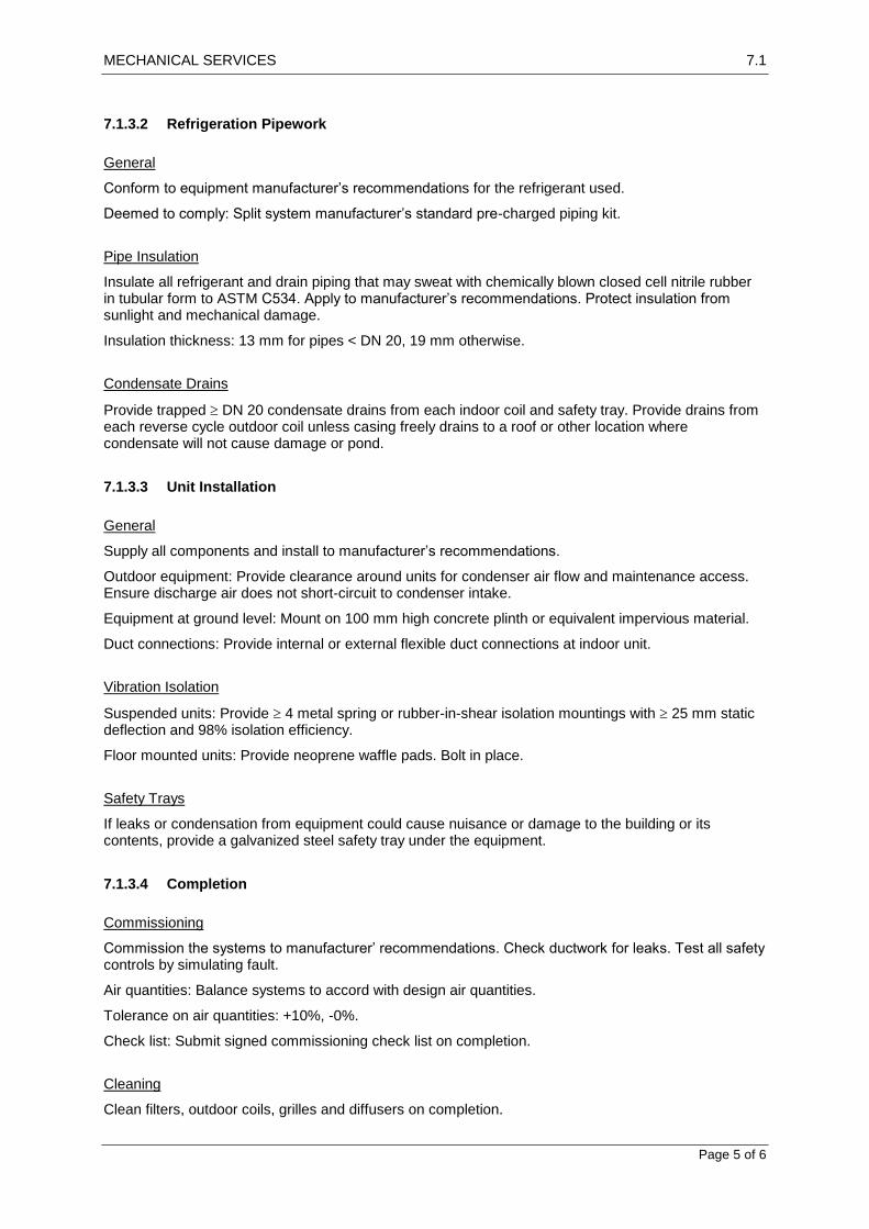
MECHANICAL SERVICES 7.1
Page 5 of 6
7.1.3.2 Refrigeration Pipework
General
Conform to equipment manufacturer’s recommendations for the refrigerant used.
Deemed to comply: Split system manufacturer’s standard pre-charged piping kit.
Pipe Insulation
Insulate all refrigerant and drain piping that may sweat with chemically blown closed cell nitrile rubber in tubular form to ASTM C534. Apply to manufacturer’s recommendations. Protect insulation from sunlight and mechanical damage.
Insulation thickness: 13 mm for pipes < DN 20, 19 mm otherwise.
Condensate Drains
Provide trapped DN 20 condensate drains from each indoor coil and safety tray. Provide drains from each reverse cycle outdoor coil unless casing freely drains to a roof or other location where condensate will not cause damage or pond.
7.1.3.3 Unit Installation
General
Supply all components and install to manufacturer’s recommendations.
Outdoor equipment: Provide clearance around units for condenser air flow and maintenance access. Ensure discharge air does not short-circuit to condenser intake.
Equipment at ground level: Mount on 100 mm high concrete plinth or equivalent impervious material.
Duct connections: Provide internal or external flexible duct connections at indoor unit.
Vibration Isolation
Suspended units: Provide 4 metal spring or rubber-in-shear isolation mountings with 25 mm static deflection and 98% isolation efficiency.
Floor mounted units: Provide neoprene waffle pads. Bolt in place.
Safety Trays
If leaks or condensation from equipment could cause nuisance or damage to the building or its contents, provide a galvanized steel safety tray under the equipment.
7.1.3.4 Completion
Commissioning
Commission the systems to manufacturer’ recommendations. Check ductwork for leaks. Test all safety controls by simulating fault.
Air quantities: Balance systems to accord with design air quantities.
Tolerance on air quantities: +10%, -0%.
Check list: Submit signed commissioning check list on completion.
Cleaning
Clean filters, outdoor coils, grilles and diffusers on completion.

MECHANICAL SERVICES 7.1
Page 6 of 6
Operating and Maintenance Instructions
Provide written operating and maintenance instructions containing:
Contractor’s contact details for service calls.
Manufacturer’s maintenance and operation literature.
Manufacturer’s warranty certificates if the manufacturer’s warranty period is greater than the defects liability period.
Description of day to day operation.
Schedule of recommended maintenance.
Record drawing: Provide a drawing of the system as installed.
7.1.3.5 Maintenance
General
Provide corrective maintenance on the installation.
Maintenance period: 6 months from the date of commissioning of the systems or the duration of the Defects Liability Period if greater than 6 months.
Warranty: Warrant the installation for the whole of the maintenance period.
Corrective maintenance: Attend site and undertake corrective maintenance within 24 hours of receipt of verbal or written advice.
Maintenance reports: Provide a signed maintenance report setting out the work done and any measured values after each visit.

WATER SERVICES 8.1
Page 1 of 6
8
8.1 WATER SERVICES
8.1.1 GENERAL
8.1.1.1 Aims
Responsibilities
Provide water services systems subject to the site and other constraints below:
Cold water services: Connect the cold water supply system to the water source with a stop valve at the connection point. Provide the water source if required to suit the particular conditions as defined on the drawings. Provide the cold water installation to the draw-off points or connections to other services.
This is typical text. Edit to suit the project.
Hot water services: Provide the hot water installation from the cold water connection points to the draw-off points or connections to other services.
This is typical text. Edit to suit the project.
Hose reel system: Provide the hose reel system where defined on the drawings and in the BOQ.
Describe the required system. Delete if not applicable.
Sanitary plumbing and drainage: Provide the plumbing and drainage system where defined on the drawings and in the BOQ.
Describe the required system.
Stormwater: Provide the stormwater system where defined on the drawings and in the BOQ.
Describe the required system.
Subsoil drainage: Provide the subsoil drainage system where defined on the drawings and in the BOQ.
8.1.1.2 Inspection
Notice
Give sufficient notice so that inspection may be made of the following:
Underground pipework prior to concealment.
Above ground pipework prior to concealment.
8.1.1.3 Submissions
Execution Details
Before starting the respective portions of the installation, submit the following for approval from the Engineer:
Embedded services: Proposed method for embedding services in concrete walls or floors or chasing into concrete or masonry walls.
Fixing of services: Typical details of locations, types and methods of fixing of services to structure.
Inaccessible services: If services will be enclosed and not accessible after completion, submit proposals for location of service runs and fittings.
Proposals for location of exposed piping.

WATER SERVICES 8.1
Page 2 of 6
Samples
Provide samples listed in the Water Services Samples schedule.
8.2 EXECUTION
Refer to the Water system piping schedule for details of all pipe types.
8.2.1.1 Installation generally
Accessories
Provide the accessories and fittings necessary for the proper functioning of the systems, including taps, valves, outlets, pressure and temperature control devices, strainers, gauges and pumps.
Isolating valves: provide valves so that isolation of parts of the system in the event of leaks or maintenance causes a minimum of inconvenience to building occupants.
Arrangement
Services and equipment: Locate and arrange so that:
Failure of plant and equipment (including leaks) does not create a hazard for the building occupants and causes a minimum or no damage to the building, its finishes and contents.
maintenance operations can be carried out in a safe and efficient manner, with a minimum of inconvenience and disruption to building occupants and without damaging adjacent structures, fixtures or finishes.
Embedded Pipes
Do not embed pipes that operate under pressure in concrete or surfacing material of a building without prior written approval. If embedding is approved:
Install in continuous lengths without fittings wherever possible.
Do not lay across joints between adjoining sections of concrete through which reinforcement does not extend.
Pressure test and rectify leaks before the concrete is poured.
Penetrations and Fixing
Limitations: Do not penetrate or fix to the following without prior approval:
Structural building elements including external walls, fire walls, fire doors and access panels, other tested and rated assemblies or elements, floor slabs and beams.
Membrane elements including damp-proof courses, waterproofing membranes and roof coverings.
Fire rated building elements: Seal penetrations with a system that maintains the fire rating of the element.
Membranes: If approval is given to penetrate membranes, provide a waterproof seal to the approval of the Engineer between the membrane and the penetrating component.
Piping
Install piping in straight lines, plumb and to uniform grades. Arrange and support the piping so that it remains free from vibration and water hammer, while permitting movement in both structure and services. Keep the number of joints to a minimum. Prevent direct contact between incompatible metals.
Concealment: If practicable, conceal piping and fittings requiring maintenance or servicing so that they are accessible within non-habitable enclosed spaces such as roof spaces, subfloor spaces and ducts. Provide at least 25 mm clearance between adjacent pipelines (measured from the piping insulation where applicable).

WATER SERVICES 8.1
Page 3 of 6
Cover plates: Where exposed piping emerges from wall, floor or ceiling finishes, provide cover plates of stainless steel or non-ferrous metal finished to match the piping.
Pipe support materials: To be the same as the piping or galvanized or non-ferrous metals, with bonded PVC or glass fibre woven tape sleeves where needed to separate dissimilar metals.
Pits
Location: Install below-ground water meters, control valves and gas regulators in concrete access pits with removable pit covers.
Internal dimensions: To give 300 mm clear space all around the fittings in the pit.
Concrete: Grade M-200, 100 mm thick, with reinforcement fabric.
Pit covers: To be minimum of 5mm thick steel covers with finger holes for easy removal.
Installation: Grade floor to a point on one side and drain to the stormwater drainage system. Carry the pit walls up to 50 mm above finished ground level. Cast in the pit cover frame flush with the top. Trowel the top smooth.
Valve boxes
Location: Install underground isolating valves in concrete access pits with removable pit covers.
Identification: Mark the box covers with the name of the service.
8.2.1.2 Installation of Fixtures
General
Accessories: Use manufacturer's brackets and accessories where these are available and suitable for the mounting substrate.
Protection: Deliver fixtures to site protected from damage under site conditions by coatings, coverings and packaging. Remove only sufficient protection to permit installation.
Installation
Connections: Connect to each fixture supply and waste services. Install plumb and level.
Cutting and fitting: If it is necessary to cut and/or fit substrate to install an item carry out this before the surface is finished or painted. Remove items when required for painting and protect until re-installed. Reinstall when painting and finishing is complete. Cap or plug the open ends of pipes.
Substrate and fixings: Before installation make sure that the substrate to which the fixtures are to be installed is adequate. In solid walls confirm adequacy of the material at fixing locations.
8.2.1.3 Painting, finishes and marking
Exceptions
Do not paint chromium or nickel plating, anodised aluminium, glass reinforced plastic, stainless steel, non-metallic flexible materials and normally lubricated machined surfaces.
Finishes
Finish exposed piping, including fittings and supports, as follows:
In internal locations such as toilet and kitchen areas: Chrome plate copper piping with bright finish.
Externally and steel piping and iron fittings internally: Paint.
In concealed but accessible spaces (including cupboards and non-habitable enclosed spaces): Leave copper and plastic unpainted except for identification marking. Prime steel piping and iron fittings.
Valves: Finish valves to match connected piping.

WATER SERVICES 8.1
Page 4 of 6
Marking and Labelling
Mark services and equipment to provide a ready means of identification.
Locations exposed to weather: Provide durable materials.
Pipes, conduits and ducts: Identify and label.
Consistency: Label and mark equipment using a consistent scheme across all services elements of the project.
8.2.1.4 Hot and Cold Water Services
Fittings and Accessories
Provide the fittings necessary for the proper functioning of the water supply system, including taps, valves, backflow prevention devices, temperature control devices, strainers.
Line Strainers
Type: Low resistance, Y-form bronze bodied type, with screen of dezincification resistant brass, stainless steel or monel.
Screen perforations: 0.8 mm maximum.
Piping Insulation
Application: Fit insulation tightly to piping surfaces without gaps. Minimise number of joints. Insulate fittings for the same thermal resistance as the piping insulation. Install the insulation on unions and other items requiring service so that it is readily removable. Provide supports formed to fit around the insulation so the insulation thickness is reduced by < 10%.
Material: Select from the following:
Polyester in moulded tubular sections faced with factory bonded aluminium foil laminate or integral polyester scrim.
Polyolefin foam: Cross linked closed cell polyolefin foam faced with factory bonded aluminium foil laminate.
Tapware
Provide the tapware in accordance with the Sanitary fixtures schedule.
Metal heads and handles: Provide brass fittings or suitably bush to prevent electrolysis and growth.
Plastic heads and handles: Provide break-resistant fittings of a compact nature, to prevent fracture and exposure of jagged or rough edges.
Tap positions: Locate hot tap to the left of or above, the cold tap.
Thermostatic Mixing Valves
Water temperature regulated by a single hand control, capable of delivering water at the temperature of either of the supply systems and at any temperature in between and suitable for controlling single or multiple outlets, as appropriate. Refer to the Sanitary fixtures schedule.
Controls: Incorporate the following:
A temperature sensitive automatic control which maintains temperature at the pre-selected setting and rapidly shuts down the flow if either supply system fails or if the normal discharge water temperature is exceeded.
8.2.1.5 Water Heaters
Standard Electric Systems

WATER SERVICES 8.1
Page 5 of 6
Provide standard electrical water boilers as identified in the BOQ to locations identified on the drawings. Refer to the Water heater schedule.
Solar Water Systems
Provide a proprietary automatic water heater comprising solar collector and storage container, with or without supplementary heating unit and including connections, controls and necessary fittings.
8.2.1.6 Hose Reels
General
Provide hose reels with swivel hose guides in accordance with the Fire hose reels schedule.
8.2.1.7 Stormwater
Cleaning
During construction, use temporary covers to openings and keep the system free of debris.
Downpipe Connections
Turn up underground drainage pipelines to finish 50 mm above finished ground or pavement level.
Access Pits
Cover levels: Locate the top of covers or gratings, including frames as follows:
In paved areas: Flush with the paving surface.
In landscaped areas: 25 mm above finished surface.
Stormwater Drains
Provide stormwater drains to connect downpipes, surface drains, subsoil drains and drainage pits to the outlet point or discharge point.
Downpipe connections: Turn up underground drainage pipelines with bends to meet the downpipe, finishing 50 mm (nominal) above finished ground or pavement level. Seal joints between downpipes and drains. Alternatively, terminate downpipe minimum of 100mm above adjacent ground level and discharge water to surface run off area. Allow for scour protection to bottom of downpipe.
Lined Surface Drains-Grated Trenches
Provide precast or cast in situ concrete lined trenches with painted or galvanized steel gratings.
8.2.1.8 Subsoil Drains
General
Provide subsoil drains to intercept groundwater seepage and prevent water build-up behind walls and under floors and pavements. Connect subsoil drains to surface drains or to the stormwater drainage system as applicable.
Connection: Connect subsoil drains to the stormwater drainage system.
Filters: UV resistant geotextile material with a permeability ≥ 10 times that of the native soil and capable of retaining particles of 0.25 mm size. Securely fit or join the sock at each joint.
Subsoil drains: Provide proprietary perforated plastic pipe.

WATER SERVICES 8.1
Page 6 of 6
8.2.1.9 Sanitary Plumbing and Drainage
Vent pipes
Staying to roof: If fixings for stays penetrate the roof covering, seal the penetrations and make watertight.
Terminations: Provide bird-proof vent cowls of the same material and colour as the vent pipe.
Sanitary Fixtures
Provide sanitary fixtures in the Sanitary fixtures schedule complete with all accessories necessary for correct installation and use.
8.2.1.10 Completion
Testing
Hydrostatic tests: Do not install insulation until the piping has been tested. Pressure test cold and hot water services to ensure that all pipework is free from leaks. Include pipe joints, valve seats, tap washers and strainers. Repair as necessary, replace if damaged and retest.
Completion
Hot and cold water services: On completion, flush pipelines using water and leave them clean.
Stormwater and wastewater services: On completion, flush the system using water and leave clean.
Charging
On completion of installation, commissioning, and testing, fill the hot and cold water systems with water, turn on control and isolating valves and the energy supply and leave the water supply system in full operational condition.
Operation and Maintenance Manuals
Provide written operating and maintenance instructions containing:
Contractor's contact details for service calls.
Manufacturer's maintenance and operation literature.
Description of day-to-day operation.
Record Drawings
Provide a drawing of the system as installed. Show dimensions, types and location of the services in relation to permanent site features and other underground services. Include all changes made during commissioning and the maintenance period.
Diagrams: Include diagrammatic drawings of each system.
Services below ground: Where pipes and fittings are below ground show the depth and dimensioned references that will allow the future location of the service for maintenance or expansion.

WATER SERVICES 8.1
Page 1 of 3
8.2 HOT WATER HEATING SERVICES
8.2.1 GENERAL
Responsibilities
Provide services systems subject to the site and following constraint:
Hot water services: Provide the hot water installation from the existing hot water heating system main network draw-off points or connections to other services.
8.2.1.1 Inspection
Notice
Give sufficient notice so that inspection may be made of the following:
Underground pipework prior to concealment.
Above ground pipework and fixture installation prior to concealment.
8.2.1.2 Submissions
Execution Details
Before starting the respective portions of the installation, submit the following for approval from the Engineer:
Embedded services: Proposed method for embedding services in concrete walls or floors or chasing into concrete or masonry walls.
Fixing of services: Typical details of locations, types and methods of fixing of services to structure.
Inaccessible services: If services will be enclosed and not accessible after completion, submit proposals for location of service runs and fittings.
Proposals for location of exposed piping.
Samples
Provide samples listed in the Hot water heating Services Samples schedule.
8.2.2 PRODUCTS AND EXECUTION
Refer to the Hot water heating system piping schedule for details of all pipe types.
8.2.2.1 Installation generally
Accessories
Provide the accessories and fittings necessary for the proper functioning of the systems, including valves, outlets, pressure and temperature control devices, strainers, gauges and pumps.
Isolating valves: provide valves so that isolation of parts of the system in the event of leaks or maintenance causes a minimum of inconvenience to building occupants.
Embedded Pipes
Do not embed pipes that operate under pressure in concrete or surfacing material of a building without prior written approval. If embedding is approved:

WATER SERVICES 8.1
Page 2 of 3
Install in continuous lengths without fittings wherever possible.
Do not lay across joints between adjoining sections of concrete through which reinforcement does not extend.
Pressure test and rectify leaks before the concrete is poured.
Penetrations and Fixing
Limitations: Do not penetrate or fix to the following without prior approval:
Structural building elements including external walls, fire walls, fire doors and access panels, other tested and rated assemblies or elements, floor slabs and beams.
Membrane elements including damp-proof courses, waterproofing membranes and roof coverings.
Fire rated building elements: Seal penetrations with a system that maintains the fire rating of the element.
Membranes: If approval is given to penetrate membranes, provide a waterproof seal to the approval of the Engineer between the membrane and the penetrating component.
Piping
Install piping in straight lines, plumb and to uniform grades. Arrange and support the piping so that it remains free from vibration and water hammer, while permitting movement in both structure and services. Keep the number of joints to a minimum. Prevent direct contact between incompatible metals.
Concealment: If practicable, conceal piping and fittings requiring maintenance or servicing so that they are accessible within non-habitable enclosed spaces such as roof spaces, subfloor spaces and ducts. Provide at least 75 mm clearance between adjacent pipelines (measured from the piping insulation where applicable).
Pipe support materials: To be the same as the piping or galvanized or non-ferrous metals, with bonded PVC or glass fibre woven tape sleeves where needed to separate dissimilar metals.
Technical service room
See drawing for location, architectural dimensions and structural specs of the technical room.
8.2.2.2 Installation of Fixtures
General
Accessories: Use manufacturer's brackets and accessories where these are available and suitable for the mounting substrate.
Protection: Deliver fixtures to site protected from damage under site conditions by coatings, coverings and packaging. Remove only sufficient protection to permit installation.
Installation
Connections: Connect to each fixture supply and waste services. Install plumb and level.
Cutting and fitting: If it is necessary to cut and/or fit substrate to install an item carry out this before the surface is finished or painted. Remove items when required for painting and protect until re-installed. Reinstall when painting and finishing is complete. Cap or plug the open ends of pipes.
Substrate and fixings: Before installation make sure that the substrate to which the fixtures are to be installed is adequate. In solid walls confirm adequacy of the material at fixing locations.
8.2.2.3 Execution generally

WATER SERVICES 8.1
Page 3 of 3
In order to execute best hot water central heating system the contractor shall consider following general points:
1. All the pipes used in the system shall be steel pipes and shall be integral-cast pipes with no sign of joint-lines along the pipe surface.
2. Connection method for all pipes shall be either electrical or gas welding method.
3. Pipes with diameter of up to 20mm shall be bended directly in the turns and corners and shall not be fitted using elbows or other fittings.
4. Pipes having 25mm to 100mm diameter shall be redirected in turns and corners using steel elbows welded in connection points, no screwing method is allowed.
5. Valves used in hot water heating system shall be of purposely designed valves to be fitted using screwing methods with the system. Valves with diameter 32mm or more shall be of flanged type valves only.
6. Main supply pipes (with diameters of 32mm to 100mm) shall be properly heat insulated using mineral wool insulation sheets having an R-value of not less than 5.
7. The heating system shall have 2 separate water filters one installed at the incoming point where the liquid comes from the boiling center and another installed at the end of the system where the water circulates back toward the boiling system. This is required to filter any dusty granulations, stains etc arise either at the boiling center or at the radiators.
8. The system shall be equipped by a manometer to show the system pressure for all the time.
9. The heating system shall be equipped by 2 separate thermometers: one installed to show the incoming liquid temperature (could be up to 120 ºC) and another to display the outgoing liquid temperature. These help monitoring staff to identify many of the system problems.
10. There are different types and standard sizes of plates and radiators that can be used in different building types as per given drawings:
Plate sizes of: 500X160mm, 600X150mm, 900X150mm, 1200X150mm and 1200X300mm.
Plate types: Cast iron, Steel, Aluminum.
Cast-iron type: This type has a very good quality and takes longer to get hot and takes longer to loose its potential temperature.
Steel type: This type is good but exposed to rust/corrosion. This type, however, gets hot and cool quickly.
Aluminum type: This type is safe against rust/corrosion and can get hot and cool quickly too.
11. The hot water heating system shall be equipped with air venting valves. These valves are vital to make sure no air exist within the system during installation and during first time circulation of the liquid into the system.
12. Proper supports and clips are to be used to mount the radiators on the walls firmly and safely. The supports shall prevent all radiator movement; horizontally, vertically; and prevent them from being tilted and turning and falling.
13. Leakage test shall be applied on overall heating system using special machinery establishing at least (4 to 5 bar pressure for pipes up to 25mm and 4 to 8 bar pressure for pipes with diameter of 32 to 100mm) at least 24 hours continuous testing period.
14. Painting: surfaces for all steel pipes and other members shall be neat and free of any dust or materials (use proper sand papers if required). After the substrate is ready for painting; one coat of anti-rust paint following with two other coats of oil-based painting to be applied. In case the Cast-Iron radiator used in the system, the radiators shall also be painted with one coat of anti-rust following two coats of oil-based painting.

ELECTRICAL SERVICES 9.1
Page 1 of 13
9 ELECTRICAL
9.1 ELECTRICAL SERVICES
9.1.1 GENERAL
9.1.1.1 AIMS
Responsibilities
Provide electrical systems in conformance with the Electrical Systems Schedule.
Qualification
Use only persons appropriately experienced and qualified to undertake the electrical design and construction work on the systems documented.
Performance
Carry out verification tests and measurements to show compliance with the specification.
Rates for installation work
Rates for installation of cabling, light fittings, sockets, switches and all other electrical components are to include allowance for fixings, connection, chasing of wiring and any other works required for the installation of the electrical system to a fully operational and safe working condition.
9.1.1.2 Inspection
Notice
Give sufficient notice so that inspection may be made of the following:
Underground electrical services conduits prior to concealment.
Above ground electrical services conduits in walls prior to concealment.
Switchboards prior to installation.
Inspection and testing on completion
To verify that the requirements of this specification have been met, all electrical installations and any alterations, additions or repairs to an existing electrical installation, after completion and before being energised shall be:
- Inspected as far as is practicable
- Tested
Precautions shall be taken to insure the safety of persons and to avoid damage to property and the electrical installation equipment during inspection and testing.
NOTE: if requires, the contractor is responsible to provide temporary power generator in order to undertake all needed testing.
A visual inspection shall be made when work on an electrical installation has been completed in order to verify that the work complies with the requirements of this specification. The visual inspection shall be carried out before, or in association with testing and shall where practicable be made before the relevant part of the electrical installation is placed in service. Visual inspections shall be carried out prior to the completion of the installation where that part of the electrical installation will be covered by following works.
The following items provide a guide to the matters to be checked during the visual inspection to assess that the relevant requirements of this specification have been met.
General:
- Protection against direct contact with live parts e.g. Insulation and enclosure.

ELECTRICAL SERVICES 9.1
Page 2 of 13
- Protection against indirect contact with exposed conductive parts, e.g. Double insulation or isolating transformers.
- Protection against hazardous part, e.g. Enclosure, guarding or screening of flammable materials, hot surfaces and parts that may cause physical injury.
- Protection against spread of fire, e.g. Penetration of fire barriers.
- General condition of the electrical equipment, e.g. Signs of damage that could impair safe operation, disconnection of unused electrical equipment.
Consumers Mains:
- Current carrying capacity.
- Voltage drop.
- Underground installation conditions, e.g. Enclosure, depth of burial and mechanical protection.
- Aerial installation conditions.
- Connection of wiring.
- Protection against external influences.
Switchboards:
- Location, e.g. Access and egress.
- Protective devices, e.g. Overload and residual current rating, fault current rating.
- Isolating devices, e.g. Main switches.
- Connecting devices, e.g. Neutral bars, earth bars and live links.
- Connection and fixing of wiring and switchgear.
- Identification and labelling of electrical equipment.
- Protection against external influences.
Wiring systems:
- Conductor size, e.g. Current-carrying capacity and voltage drop.
- Identification of cable cores.
- Adequate support and fixing.
- Connections and enclosures.
- Particular installation conditions, e.g. Underground, aerial and emergency systems.
- Segregation from other services and electrical installations.
- Protection against external influences, e.g. Enclosure.
Electrical equipment:
- Isolation and switching devices for protection against injury from mechanical movement devices and motors.
- Isolation and switching devices for protection against thermal effects, e.g. Motors, room heaters and water heaters.
- Switching devices for particular electrical equipment, e.g. Socket outlets and cooking appliances.
- Particular installation conditions, e.g. Locations affected by water, explosive atmospheres, extra low voltage and high voltage.
- Compliance with required standard.
- Connection, support and fixing.
- Protection against external influences.
Earthing:
- Multiple earth neutral (MEN) connection.
- Earth electrode.
- Earthing conductors, e.g. Size and identification.
- Equipotential bonding conductors, e.g. Size and identification.
- Connections, joints and terminations.
- Protection against external influences.
- Connection to earthing arrangements for tother systems.

ELECTRICAL SERVICES 9.1
Page 3 of 13
- Creation of earthed situation that may require earthing of additional electrical equipment.
Testing:
After completion of, or in association with the visual inspection tests, testing shall be carried out on the electrical installation to verify that it complies with ther requirements of this specification and that it is suitable for the use intended.
Sequence of tests as noted:
9.1.2 EXECUTION
9.1.2.1 GENERAL
General
Arrangement: Arrange services so that services running together are parallel with each other and with adjacent building elements.
Installation: Install equipment and services plumb, fix securely and organise reticulated services neatly. Allow for movement in both structure and services.
Lifting: Provide heavy items of equipment with permanent fixtures for lifting as recommended by the manufacturer.
Suspended ground floors: Keep all parts of services under suspended ground floors > 150 mm clear of the ground surface. Make sure services do not impede access.
Samples
Samples: Provide samples of all accessories and light fittings for the approval of the Engineer prior to use in the project.
Installation of accessories
General: Install accessories in conformance with the Installation of accessories table.
Flush mounting: Provide flush mounted accessories except in plant rooms.
Mounting heights: To on-site direction
Consumers mains test - polarity
Sub-mains tests - polarity
Final sub-circuit test –
- polarity
- connections
Fault loop impedance test
Verification of operation of
residual current devices
Earth resistance test – continuity of
main earthing conductor
Insulation resistance test of
installation
Earth resistance test for other
earthed & equipotential bonded parts

ELECTRICAL SERVICES 9.1
Page 4 of 13
Restricted location: Do not install wall boxes across junctions of wall finishes.
Surface mounting: Proprietary mounting blocks.
9.1.2.2 Installation Of Accessories Table
Wall construction Installation and concealed cabling facilities
Rendered brickwork partition Flush wall box with conduit chased into wall
Double sided face brick partition Vertically mounted flush wall box with conduit concealed in cut bricks
Concrete wall or slab Flush wall box or flush mounted outlet with thermoplastic insulated cables in conduit integral with slab. Do not chase into concrete walls without obtaining approval from the Engineer.
Installation of ceiling mounted appliances
Connections: Provide flush mounted outlets on the ceiling next to support brackets.
Fixing: Provide support brackets fixed through ceiling to the building structure. Brace appliances that have excessive bending moments, are heavy or vibrate, to prevent horizontal movement.
Electrical installations
All cabling and wiring is to be installed in approved PVC conduit or within a metal cable tray for horizontal runs within the ceiling. there will be no exceptions. Any cabling installed otherwise will be removed and replaced correctly at the contractor’s expense. All below ceiling level electrical circuits are to be installed in surface mounted conduits.
International standard connectors (chocolate block) for the wiring and cabling are to be used for all connections, no other method is acceptable.
All IP ratings given refer to Ingress Protection (IP) Codes to AS1939.
NOTE: Simple twisting of wires as a means of connecting wires and cables with protective electrical tape is not acceptable.
Earthing/Grounding
All installed electrical fixtures and fittings are to be earthed to the main earth system for the facility, there are no exceptions to this requirement.
All protective earthing conductors should be incorporated in the same wiring enclosure as the associated live conductors or in the adjacent vicinity.
Where a ‘clean’ earth is specified for a particular item of electrical equipment, the manufacturer of the electrical equipment shall be consulted in order to confirm the necessary arrangements.
Precautions shall be taken against the risk of damage to the earthing arrangement and other metallic part of the electrical installation through electrolysis or galvanic action.
The size of an earthing conductor shall be such that it meets the requirements of the IEC regulations and is in accordance with the Earth conductor size table.
Earth Conductor Size Table
Nominal size of live
conductor (mm²)
Nominal size of copper earthing conductor (mm²)
With copper live conductors With aluminium live conductors
1
1.5
2.5
1*
1.5*
2.5
-
-
-
4
6
2.5
2.5
-
2.5

ELECTRICAL SERVICES 9.1
Page 5 of 13
10 4 2.5
16
25
35
6
6
10
4
6
6
50
70
95
16
25
25
10
10
16
120
150
185
35
50
70
25
25
35
240
300
400
95
120
120
50
70
95
500
630
120
120
95
120
* These earthing conductors may be used only where incorporated in a multicore cable or flexible cord.
9.1.2.3 LOW VOLTAGE POWER SYSTEMS
General
Provide a complete operational low voltage power system, comprising the following and to the
Electrical supply mains and Electrical switchboard design schedules:
Supply from mains power
Metering.
Consumers mains and switchboard.
Submains and sub boards.
Final subcircuits.
Submissions
Technical data: Submit documentation to fully describe the proposed installation. As a minimum provide:
Submain cable routes and support or enclosure method.
Switchboard cupboard layouts including risers.
Accessories
Provide the following and to the Power accessories and Lighting control and fittings schedules:
General power outlets.
Isolating switches.
Three phase outlets.
Ceiling mounted sweep fans
Duct heaters
Wall, window or roof mounted exhaust fans
Light switches
Light fittings
Emergency lighting and exit signs
Other equipment as identified in the Schedule
Junction and terminal boxes

ELECTRICAL SERVICES 9.1
Page 6 of 13
Shall be manufactured from PVC and rated to IP56. They shall come complete with a rigid PVC cover attached by means of screws.
Switches
All switches are to be manufactured in compliance with international standards IP24. rate is to include allowance for installation of switches recessed into the wall. Switches are to be installed in locations as shown on the drawings.
Wiring systems
Selection: Provide wiring systems appropriate to the installation conditions and the function of the load. All wiring quality to be approved by the Engineer before installation commences.
Power cables
Copper cable generally, multi-stranded except for MIMS. All cabling is to be manufactured to international standard (BS 5467 or BS 6500) and meet all appropriate safety and performance requirements.
Minimum size:
Lighting subcircuits: 1.5 mm2.
Power subcircuits: 2.5 mm2.
Submains: 6 mm2.
Voltage drop: Install final subcircuit cables within the voltage drop parameters dictated by the route length and load.
Dummy load tests
Where electrical tests are required and the actual load is not available, provide a dummy load equal to at least 75% of the design load.
9.1.2.4 SWITCHBOARDS
General
Provide proprietary switchboards to the following and to the Electrical switchboard design schedule:
Main switchboard.
Distribution boards.
Distribution boards shall be constructed from steel with a lockable door. Borads shall be sealed to meet a rating of IP56. All cable entry and exit points shall be constructed using suitable sized, proprietary PVC cable glands.
Statutory authority’s equipment
Refer to local supply authority service rules to determine their requirements. Install equipment supplied by the statutory authority, and provide wiring to complete the installation.
Cable entries
Single core cables rated > 300 A: Arrange to minimise eddy currents.
Construction
Fixing: Before making interpanel connections, fix assemblies and metering equipment enclosures into position, level and plumb.
Cable entries: Neatly adapt one or more cable entry plates, if fitted, to accept incoming cable enclosure. Provide the minimum number of entry plates to leave spare capacity for future cable entries. Do not run cables into the top of weatherproof assemblies.
Single core cables rated > 300 A: Pass separately through non-ferrous gland plates. Do not provide metal saddles.

ELECTRICAL SERVICES 9.1
Page 7 of 13
Cable enclosures: Continue cable enclosures to or into assemblies and fit cable entry plates so that the IP rating of the assembly and the fire rating of the cable are maintained.
Cable supports: Support or tie mains and submains cables within 200 mm of terminations.
9.1.2.5 SWITCHBOARD COMPONENTS
Switch-isolator and combination fuse-switch units
Rated current: To suit unit installed in enclosure.
Rated fault capacity: Provide units selected for short-circuit making capacity that is at least the fault level at assembly incoming terminals.
Breaking capacity: At least the rated full load current.
Rated duty: Uninterrupted in non-ventilated enclosure.
Operation: Independent manual operation including positive ‘ON/OFF’ indicator.
Locking: Provide for padlocking in the ‘OFF’ position.
Handles: Removable only when switch is in open position.
Fuse links: Isolated when switch contacts are open.
Moulded case and miniature circuit breakers
Moulded case breakers to International Standards.
Miniature circuit breakers to International Standards
Fault capacity > 10 kA circuit breakers to approval of Engineer
Fault capacity < 10 kA, current rating < 100 A: Miniature overcurrent circuit breakers
Mounting: Mount circuit breakers so that the ‘ON/OFF’ and current rating indications are clearly visible with covers or escutcheons in position. Align operating toggles of each circuit breaker in the same plane.
Clip tray chassis: For miniature overcurrent circuit breakers provide clip tray assemblies capable of accepting single, double, or triple circuit breakers, and related busbars. Provide moulded clip-on pole fillers for unused portions.
Residual current devices
Integral type: Incorporate earth leakage in circuit breaker protection operation.
Maximum tripping current: 30 mA.
Fuses with enclosed fuse links
Standards: To International Standards
Fault level: Provide fuses suitable for the fault level at the assembly, and which discriminate with other protective equipment.
Let-through energy and peak cut-off current: To suit protected equipment.
Fuse-holders: Mount fuse-holders so that fuse carriers may be withdrawn directly towards the operator and away from live parts. Provide fixed insulation which shrouds live metal when the fuse carrier is withdrawn.
Barriers: Provide barriers on both sides of each fuse link, preventing inadvertent electrical contact between phases by the insertion of screwdriver.
Fuse links: Enclosed, high rupturing capacity type mounted in a fuse carrier. If necessary for safe removal and insertion of the fuse carrier, provide extraction handles. Mount on clips within the spares cabinet.
Identification: Clearly indicate manufacturer or distributor.
Contactors

ELECTRICAL SERVICES 9.1
Page 8 of 13
Standard: To International Standards.
Rated operational current: Full load current of the load controlled.
Minimum rating: 16 A.
Mounting: Mount with sufficient clearance to allow full access for maintenance, removal and replacement of coils and contacts, without the need to disconnect wiring or remove other equipment.
Interconnection: Do not connect contactors in series or parallel to achieve ratings.
9.1.2.6 LIGHTING
General
Provide a complete operational lighting system, tested and commissioned.
Proprietary equipment: Provide only proprietary lights, fittings and accessories.
Modifications and refurbishing: Carry out to the original manufacturer’s standards.
Lamps
Lamps: Provide all lights complete with lamps and accessories.
Verify operation: Install lamps in all lights and verify correct operation before completion
Low voltage lamps: Provide lamps strictly in accordance with the light manufacturer’s recommendation.
Dichroic lamps: Provide dichroic lamps with integral reflector which match the design specification.
Lighting Control System
Provide the following and to the Schedules:
Lighting switches.
Dimmers.
Automatic control systems.
External light fittings.
Internal light fittings.
Documentation: Provide complete technical and operational documentation for the lighting control system where installed.
Installation
Supports: Mount lights on proprietary supports by means of battens, trims or packing material to suit location.
Completion
Verify the operation of all lights.
9.1.2.7 EMERGENCY EVACUATION LIGHTING
General
Provide a complete operational emergency evacuation lighting system, tested and commissioned to International Standards.
Single-point system lights
Visual indicator lights: Provide a red indicator, readily visible when the light is in its operating location, which indicates that the battery is being charged.
Inverter system: Provide protection of the inverter system against damage in the event of failure, removal or replacement of the lamp, while in normal operation.

ELECTRICAL SERVICES 9.1
Page 9 of 13
Local test switches: Provide a momentary action test switch, accessible from below the ceiling, on each fitting to temporarily disconnect the mains supply and connect the battery to the lamp.
Common test switches: Provide a common test switch on the distribution board which disconnects main supply to the lights and tests for discharge performance, after testing, this switch must automatically revert to normal operating mode.
Batteries
Type: Lead-acid or nickel-cadmium batteries capable of operating each lamp at its rated output continuously at least 2 hours during completion tests and 1.5 hours during subsequent tests.
Battery life: At least 3 years when operating under normal conditions at an ambient temperature of 25ºC and subjected to charging and discharging at 6 monthly intervals.
Marking: Indelibly mark each battery with its date of manufacture.
Power supply to single-point systems
Provide an unswitched active supply to each fitting and exit sign, originating from the test switch control panel.
9.1.2.8 TELECOMMUNICATION CABLING
General
Provide a complete operational telecommunications cabling system, tested and commissioned to International Standards. Provide accommodation for telecommunications cabling infrastructure complying with relevant clearance requirements from power cable distribution systems.
Include the following and to the Telecommunication equipment schedule:
Building distributor.
Backbone cabling.
Floor distributors.
Consolidation points.
Equipment racks and patch cords.
Horizontal cabling.
Telecommunications outlets.
Fly leads.
Equipment racks
Type: 19 inch rack.
Free standing racks: Provide adjustable feet.
Modular connector patch panels
Terminations: Terminate directly to the modular connector.
Patch cords: Terminate cord ends with appropriate registered jacks.
Optical fibre termination panels
Break out trays: Provide fibre optic cable break out trays at each group of fibre optic cable terminations.
Loom cables: Neatly loom cables and lay stripped cables into the break out tray.
Secure cables: Ensure that cables are secured by the sheath and that there is no stress on the fibre optic cores.
Patch cords
Provide terminated patch cords for 60% of the total incoming and outgoing ports used.
Records
Record book: Provide a record book at each cross connect.

ELECTRICAL SERVICES 9.1
Page 10 of 13
Records in pencil: Complete the records in pencil for each termination and jumper, providing origin and destination and type of service.
Location: Secure log books in each distribution frame records holder.
Cable separation
Low voltage cables: Separate telecommunications cables not enclosed in conduits or ducts from low voltage services by at least 150 mm.
Electromagnetic interference (EMI): Provide clearance to minimise the effect of EMI where communications cables are installed parallel and adjacent to power cables carrying loads in excess of 200 A.
Installation
Crossover: Install cables neatly and without crossovers between cables.
Loom size: Loom cables into groups not exceeding 50 cables, and hold looms in place using reusable cable ties at least 20 mm wide. Do not exert compressive force on the cables when installing cable straps.
Telecommunications outlets
Outlets: Provide RJ45 8 way modular jacks except where documented otherwise.
Pinouts: The pinouts vary with the application. Determine required pinouts before making cable terminations.
Fly leads
Provide minimum 2000mm long fly leads to 50% of the outlets installed.
Earthing system
Communication earth system (CES): Provide a communications earth terminal (CET) associated with the local protective earth (PE) system adjacent to each electrical distribution board.
9.1.2.9 AUTOMATIC FIRE DETECTION
General
Provide a fully operational system, tested and commissioned in accordance with International Standards.
Base station monitoring system connection
Connection: Connect the installation to the fire alarm monitoring base station via telecommunication
carrier lines where identified in the Fire detection equipment schedule.
Installation wiring
Conductor size: > 1.5 mm2 TPI 220 V rated, with red and white insulation.
Sheathing: Red.
Fire indicator panels
Provide metal cubicle-type enclosures to locations identified on drawings.
Detectors
Provide the following detector types as indicated on the drawings:
-Point type heat detectors.
-Duct sampling units.
-Integral heat detector/alarm units.

ELECTRICAL SERVICES 9.1
Page 11 of 13
-Point type smoke detectors.
-Integral smoke detector/alarm units.
Self-indicating detectors
Provide a light emitting diode mounted in a clearly visible position, which illuminates whenever detector operation causes an alarm condition to register on the fire indicator panel. Provide self-indicating devices which, if faulty, will not render the detector inoperative under fire conditions.
Mounting positions of light emitting diodes:
Visible detectors: On the outside of the detector or its base.
Detectors concealed above ceilings: On the underside of the ceiling immediately below the detector.
Detectors in other concealed spaces: On a visible panel close to the entry to the concealed space housing the detector.
Installation
Install detectors so they can be easily inspected and tested in situ, and readily withdrawn for service.
Control facilities
Provide ancillary control device circuits and connections for automatically controlling and releasing magnetic door holders to operate the relevant fire doors under fire alarm conditions.
Fire fan control and indication panels
Provide fire detection and alarm signals for the fire fan control panel to be incorporated by mechanical services.
9.1.2.10 ACCESS CONTROL
General
Provide a complete operational access control system, tested and commissioned in accordance with
International Standards as applicable. Refer to the Access control equipment schedule.
Processors or panels
Capacity: Provide separate entry/exit control modules for each designated door.
Users: Program the system to match the number of authorised users with unique access codes.
Time zones: At least 3 per day, with provision for weekends and public holidays.
Door control devices
Provide electric strikes, electric locks, drop bolts, or similar devices to suit door construction and hardware.
Fail-safe: Connect door control devices in a fail-safe mode to permit exit in the event of power failure.
Authorised products: Provide equipment approved for use by the Engineer.
Double leaf doors (solid frame): Provide an electric strike or lock on the fixed leaf, connected to the door frame by concealed flexible wiring.
Activation
Provide keypads, card readers or other activation devices, and locate next to entry points.
External: Provide weatherproof (IP56) hoods or housings for external units.
Mounting height: 1200 mm from floor level.
Vehicle control

ELECTRICAL SERVICES 9.1
Page 12 of 13
Vehicle access control: Provide a vehicle access control system combining connection to vehicular doors and boom gates, and interconnection to the main access control system.
Exit Loop detection: Provide a buried loop detection system adjacent to the exit point to activate boom gates or vehicular doors on approach by a vehicle. Connect so that doors or gates close after a pre-set time.
Interlock: Provide a photo electric beam safety interlock.
Interlock function: To prevent door or gate from closing until the vehicle has cleared the exit point.
Push-buttons and readers: Where practicable, provide direct wall mounting for push-buttons or readers; otherwise provide a mounting bollard and extension arm.
Mounting height: 1000 mm from floor level.
Reed switches: Provide heavy duty reed switches on both sides of vehicle doors, which generate a door closed indication at the control panel.
Intercom
Base station: Provide an intercom base station at each external entry point, interconnected with the individual local stations. Include speakers and microphones.
Construction: Wall mounted flush stainless steel panel.
Weatherproofing: IP56.
Dial: Digital push-button type.
Schedule: Provide a weatherproof (IP56) schedule holder and card identifying individual local stations. Locate next to the intercom panel.
Local station: Provide wall mounted intercom local stations, interconnected with the base stations and external entry points.
Type: Surface mounted, removable handset type.
Operation: Provide an audible tone device to indicate that the individual station is being called, and a press-to-talk switch so that the local station can communicate with the base station only when the switch is held down.
Door control: Provide integral momentary action door release switches to operate the door release or opening mechanisms at each external entry point.
9.1.2.11 LABELLING
General
Provide labels including control and circuit equipment ratings, functional units, notices for operational and maintenance personnel, incoming and outgoing circuit rating, sizes and origin of supply and kW ratings of motor starters.
Identifying labels
Provide labels fixed to access panels, doors, covers and escutcheon panels and internal equipment, indicating the relevant information and componentry.
Single-line diagrams
Custom-built assemblies: Provide single-line diagrams.
Format: Non-fading print, at least A3 size, showing the situation as installed.
Mounting: Enclose in a folder and fix close to assembly.
Marking cables
Identify the origin of all wiring by means of legible indelible marking.

ELECTRICAL SERVICES 9.1
Page 13 of 13
Identification labels: Provide durable labels fitted to each core and sheath, permanently marked with numbers, letters or both to suit the connection diagrams.
Telecommunications Cabling
Label telecommunications cables. cross connects and outlets.
Labels: Label cables to indicate the origin and destination of the cable. Label outlets to show the origin of the cross connect, the workstation or outlet number, and the port designation.
Location marking
Accurately mark the location of underground cables with route markers consisting of a marker plate set flush in a concrete base.
Location: Place markers at each joint, route junction, change of direction, termination and building entry point and in straight runs at intervals of not more than 100 m.
Concrete bases: 200 mm diameter x 200 mm deep, minimum.
Direction marking: Show the direction of the cable run by means of direction arrows on the marker plate. Indicate distance to the next marker.
Plates: Brass, minimum size 75 x 75 x 1 mm thick.
Plate fixing: Waterproof adhesive and 4 brass or stainless steel countersunk screws.
Marker height: Set the marker plate flush with paved surfaces, and 25 mm above other surfaces.
Labelling – Minimum Lettering Heights
Main assembly designation: 25 mm.
Distribution assembly designations: 15 mm.
Small proprietary distribution boards: 10 mm.
Main switches: 10 mm.
Outgoing functional units: 8 mm.
Identifying labels (on outside of cabinet rear covers): 4 mm.
Danger, warning and caution notices: 10 mm for main heading, 5 mm for remainder.
Other labels including equipment labels within cabinets: 3 mm.
Label colours
Generally black lettering on white background except as follows:
Main switch and caution labels: Red lettering on white background.
Danger, warning labels: White lettering on red background.
Fixing
General: Fix labels securely.
Fixing methods: Use screws and double-sided adhesive. Fixed in extruded aluminium sections attached to panels with rivets or countersunk screws.
Permanent fixing: Fix labels permanently in place.
Refer to drawings, BOQ and Electrical Schedules for details and locations of all fixtures, fittings and cabling.
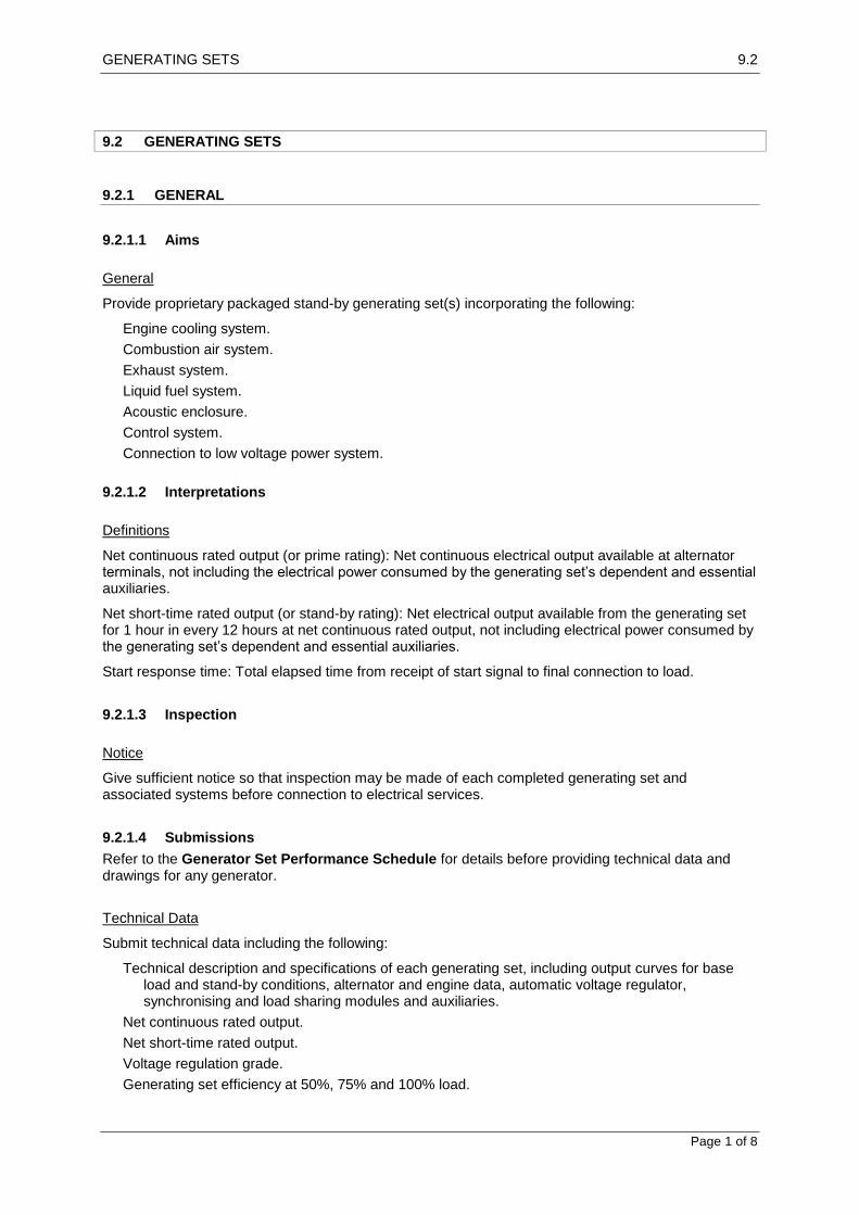
GENERATING SETS 9.2
Page 1 of 8
9.2 GENERATING SETS
9.2.1 GENERAL
9.2.1.1 Aims
General
Provide proprietary packaged stand-by generating set(s) incorporating the following:
Engine cooling system.
Combustion air system.
Exhaust system.
Liquid fuel system.
Acoustic enclosure.
Control system.
Connection to low voltage power system.
9.2.1.2 Interpretations
Definitions
Net continuous rated output (or prime rating): Net continuous electrical output available at alternator terminals, not including the electrical power consumed by the generating set’s dependent and essential auxiliaries.
Net short-time rated output (or stand-by rating): Net electrical output available from the generating set for 1 hour in every 12 hours at net continuous rated output, not including electrical power consumed by the generating set’s dependent and essential auxiliaries.
Start response time: Total elapsed time from receipt of start signal to final connection to load.
9.2.1.3 Inspection
Notice
Give sufficient notice so that inspection may be made of each completed generating set and associated systems before connection to electrical services.
9.2.1.4 Submissions
Refer to the Generator Set Performance Schedule for details before providing technical data and drawings for any generator.
Technical Data
Submit technical data including the following:
Technical description and specifications of each generating set, including output curves for base load and stand-by conditions, alternator and engine data, automatic voltage regulator, synchronising and load sharing modules and auxiliaries.
Net continuous rated output.
Net short-time rated output.
Voltage regulation grade.
Generating set efficiency at 50%, 75% and 100% load.

GENERATING SETS 9.2
Page 2 of 8
Evidence that the engine type has previously passed cold starting tests at the minimum ambient site temperature.
Shop Drawings
Submit shop drawings indicating the following:
Location and size of fuel tanks.
Physical size of generating set base and clearances for maintenance.
Location and estimated size of control and distribution boards.
Maximum mass and overall dimensions of each separable assembly.
Access clearances for operational maintenance and dismantling.
Control diagrams.
Details of control panels
Details of foundations and anti-vibration mountings.
9.2.2 PRODUCTS
9.2.2.1 General
Multiple Generating Sets
For multiple generating sets operating in parallel, provide generating sets of the same make and type.
Mounting
Mount the engine and alternator units on a common structural steel frame to support the generating set assembly and the engine local control board.
Coupling
Directly couple the engine and generator shafts with a self-aligning type coupling, capable of transmitting the engine maximum output torque under operating conditions, including starting and overload.
9.2.2.2 Alternators
General
Voltage waveform: Sinusoidal, with total wave form deviation not exceeding 10%.
Excitation: Provide self-regulated brushless type exciters.
Overspeed: Withstand a speed of 1.2 times unit rated speed for both alternator and engine.
Alternator underspeed withstand: Normal operation at net continuous rated output at a speed of 0.95 times unit rated speed, without overheating.
Number of poles: 4.
Enclosure classification: IP21, with screened ventilation openings.
Anti-condensation Heaters
Provide at least 2 anti-condensation heaters within the winding enclosure.
Rating: Rate heaters to maintain the windings and insulation at least 6C above ambient temperature when the alternator is at rest and one heater is in service.

GENERATING SETS 9.2
Page 3 of 8
Location: Locate a heater at each end of alternator windings in a position which allows heat transfer to the winding insulation by convection, without exceeding maximum allowable insulation temperature. Do not fix heaters to windings.
Terminations: Connect heaters to separate identified terminals within a separate accessories terminal box which is connected to a permanent supply.
Connection diagram: Provide a connection diagram for the heaters. Locate within the terminal box.
Winding Thermistors
Provide thermistors to alternator stator windings.
Thermistor type: Positive temperature coefficient.
Thermistor temperatures:
Engine shutdown: 160C.
Winding temperature high pre-alarm: 140C.
Terminal Boxes
Construction: Provide metal terminal boxes. Size to allow the current transformers, power and control cables and cable lugs to be neatly installed and terminated with necessary clearances between live parts and the box, and without placing undue strain on termination points.
Supply cable terminal box: Provide removable lid and side covers.
Terminals: Provide star connected windings. Bring both ends of each winding out to separate terminals. Establish a neutral terminal.
Sealing: Provide neoprene or bonded cork gaskets between terminal boxes and their frames and covers.
9.2.2.3 Engines
General
Sizing: When sizing the engine, take into account the nature of connected loads including auxiliaries, harmonics and transient operation.
Bearings: Provide front and rear main bearings, so that crankshaft alignment is not affected by dismantling of the alternator.
Governing
Provide electronic or mechanically controlled governors which enable engines to operate continuously at 1480 r/min from no-load to the maximum rated electrical load connected to the alternator. Provide filters which ensure that harmonics or switching spikes generated by the load do not interfere with the operation of the governor, overspeed or underspeed cut out devices.
9.2.2.4 Fuel Storage
General
Provide daily fuel tank capacity and bulk storage capacity to the capacities identified in the Generator
Set Fuel Tanks Schedule.
9.2.2.5 Controls
General

GENERATING SETS 9.2
Page 4 of 8
Provide automatic and manual modes, or manual modes only, depending on generator set capacity to start and shut down generating sets in the selected sequence and, if operating in parallel, share the load in proportion to their rated kW capacities.
Manual Sequence Control
Provide controls to manually synchronise and shut-down each generating set. Include emergency stop, meters, selector switches, check sychroniser and status indicating lights.
Automatic Start Control
Provide for the following:
When a “start” signal is received, generating sets start automatically, come on-line and, when synchronised, connect to the load.
Connection of alternators for sequential control of load sharing/shedding.
Shutdown of alternate machines.
Automatic Engine Shutdown
Provide for generating sets to run to suit the load demand until receipt of the mains “restored” signal is received. At this point the automatic sequenced engine shutdown signal must be activated after an adjustable time delay of 0 – 30 min.
Emergency and Fault Shutdown
Provide a shutdown control system which disconnects the alternators, and shuts down engines upon the occurrence of fault conditions.
Provide for the following conditions to register as audible and visible alarms and to cause each generating set main circuit breaker to open immediately and each generating set to immediately shutdown:
Emergency stop push-button: Pressed.
Generating set: Over voltage.
Generating set: Over current.
Engine: Overspeed.
Engine oil pressure: Low.
Daily fuel tank: Low.
Jacket water temperature: High.
Automatic Synchronising
Provide synchronising modules which automatically synchronise each incoming alternator supply frequency and phase angle to the live busbars.
Emergency Stop Push-buttons
Generating sets < 2 m long: Provide one push-button per generating set.
Other generating sets: Provide 2 push-buttons per generating set. Locate one on each side or locate one of the push-buttons in the engine local control board.
Type: 40 mm diameter red, palm operated type mounted in a metal wall box. Wire to disconnect the generator and immediately shut down the engine when the controls are in the automatic or manual mode.

GENERATING SETS 9.2
Page 5 of 8
9.2.2.6 Control Panels
General
Provide control panels, switchgear and controlgear assemblies required to enable the safe operation of the generating set and the interconnections with the low voltage supply service.
Engine Local Control Board
For each generating set, provide the following minimum level of information and equipment:
Key operated local engine start/stop control.
Controls for auto/off/manual/load test.
Emergency manual shutdown.
Speed indicator, kW meter, frequency meter, ammeter, and hours run meter.
Indicator showing generating set under local control.
Oil pressure indicator.
Coolant temperature indicator.
Automatic voltage regulator consisting of the following:
Switch to select manual or automatic voltage control.
Solid-state type automatic voltage regulator.
Under and overvoltage sensing.
Over and underspeed sensors.
9.2.2.7 Batteries and Chargers
General
Provide separate batteries and charger systems for the following:
Engine start.
Control and alarm functions.
Chargers – Control and Alarm Batteries
Select the charger to suit the batteries supplied.
9.2.2.8 Starting
Electric Starting
Provide starter motors, batteries and chargers, and associated control equipment to automatically start each engine.
Wiring: Wire starter motors so that starter motor solenoid contacts are on the active side and field windings are at earth potential when the motor is de-energised. Provide an interlock, connected directly to the engine, to prevent the starter motor operating when the engine is running.
Starting Batteries
Locate in proprietary battery holders attached to the generating set, or on purpose-built stands next to the set and constructed of timber or other corrosion resistant material. Isolate batteries from vibration.
Capacity: Sufficient to crank the engine for 3 successive attempted starts, repeated at 5 min intervals.
Isolator: Provide a lockable isolator to prevent accidental starting.
Starting Batteries Chargers

GENERATING SETS 9.2
Page 6 of 8
Mains power: Connect chargers to the mains power to ensure that power is maintained to the charger under all supply conditions.
9.2.2.9 Acoustic Enclosures
General
Provide weatherproof acoustic enclosures to surround generating sets, including inlet and outlet sound attenuators.
Sound Pressure Level Limit
85 dB (A) at 12 locations 1 m from the enclosure exterior surface, at 1.5 m above floor level, measured with the generating set operating at constant maximum rated full load output, with doors closed and service penetrations sealed.
Doors
Provide doors of same material as the enclosure. Provide door stays to each door.
Ventilation
Provide ventilation to the enclosure so that:
With generating sets running at full rated output the enclosure temperature rise does not exceed
10C.
Hazardous concentrations of toxic or explosive fumes and gases are prevented.
9.2.3 EXECUTION
9.2.3.1 General
Plinths
Provide reinforced concrete plinths for floor mounted equipment, sized to suit equipment footprints.
Resilient Mounts
Provide at least 6 resilient mounting blocks between the frame and the plinth.
Drip Trays
Provide removable drip trays under those parts of the assembly where fuel or lubricant leakage may occur. Provide overflow outlet pipes taken to a point where a receptacle can be fitted under the pipe outlet.
Capacity: At least 1.5 times the oil capacity of the engine sump.
Material: 1.6 mm galvanized steel with brazed joints and rolled edges.
9.2.3.2 Engine Cooling
General
Provide a cooling system consisting of radiators, fans and pumps.
Cooling air ductwork: Connect the cooling air outlet to generator room cooling air outlet.

GENERATING SETS 9.2
Page 7 of 8
9.2.3.3 Engine Air Intake
General
Filters: Provide dry type air intake filters of sufficient capacity to permit continuous engine operation for 200 hours before filter servicing becomes necessary.
Fans: Provide a fan selected for the installed system air pressure drop. Include power absorbed by the fan under site operating conditions when calculating generator output.
9.2.3.4 Exhaust System
General
Provide exhaust piping from the engine complete with silencers, piping, ductwork, supports and expansion devices.
Weatherproofing
Provide weatherproof flashing, sleeves and acoustic seals where the exhaust system penetrates the roof or external walls.
9.2.3.5 Fuel System
Stop valves
Provide stop valves on the inlet to, and outlets from, the daily service tank.
9.2.3.6 Completion
Completion Tests
For each generating set carry out the following:
Check tightness of connections and securing devices.
Verify correctness of operation of protection devices and systems including sensor settings. Simulate actual conditions as far as possible, in order to test responses to faults imposed.
Cold start with the engine having been at rest for the previous 24 hours.
Continuous operational trial consisting of:
4 hours at 100% rated power.
1 hour at 110% rated power.
30 min at 75% rated power.
30 min at 50% rated power.
Record fuel consumption for each step of the continuous trial.
Continuous operational trial: During the trial, measure the following at maximum intervals of 30 minutes:
Generator kW and kVAr output.
Generator output voltage.
Generator output current.
Generator output frequency.
Oil pressure and water temperature.
Synchronisation and load sharing tests: For generating sets running in parallel perform tests to verify automatic synchronisation and load sharing including the following:
Sequence start and shutdown of each generating set.
Parallel operation of generating sets.

GENERATING SETS 9.2
Page 8 of 8
Synchronising of generating sets.
Operation of controls, switchgear and auxiliaries.
Temporary Test Loads
Provide test loads including power and control wiring, ancillary equipment and test instruments to achieve the kW, kvar and necessary load steps.