SPECIFICATIONS MANUAL - Outagamie County
356
SPECIFICATIONS MANUAL OUTAGAMIE COUNTY BREWSTER VILLAGE HOMESTEAD BATHING SUITE ALTERATION For APPLETON, WISCONSIN IMPORTANT NOTE: The drawings and the specifications together represent the Construction Documents, and as such, must be used together as the basis of design. The Contractor is specifically instructed not to limit their understanding of the scope of this project based upon the Specifications Index. The Contractor is responsible to review all information in both the drawings and specifications, and is therefore, required to provide all defined, and reasonably implied, scope of work no matter where it appears in the Construction Documents. In addition, the Contractor is to review any formally provided modifications, clarifications, addendums and/or other information and incorporate that information into the Contractor’s understanding of the scope of the project. APRIL 19, 2021 McM. No. O0002-06-20-00156 1445 MCMAHON DRIVE P.O. BOX 1025 NEENAH, WI 54956 54957-1025 AAP:lam PH. 920.751.4200 FX. 920.751.4284
-
Upload
khangminh22 -
Category
Documents
-
view
0 -
download
0
Transcript of SPECIFICATIONS MANUAL - Outagamie County

SPECIFICATIONS MANUAL
OUTAGAMIE COUNTY BREWSTER VILLAGE
HOMESTEAD BATHING SUITE ALTERATION
For
APPLETON, WISCONSIN
IMPORTANT NOTE: The drawings and the specifications together represent the Construction Documents, and as such, must be used together as the basis of design. The Contractor is specifically instructed not to limit their understanding of the scope of this project based upon the Specifications Index. The Contractor is responsible to review all information in both the drawings and specifications, and is therefore, required to provide all defined, and reasonably implied, scope of work no matter where it appears in the Construction Documents. In addition, the Contractor is to review any formally provided modifications, clarifications, addendums and/or other information and incorporate that information into the Contractor’s understanding of the scope of the project. APRIL 19, 2021 McM. No. O0002-06-20-00156 1445 MCMAHON DRIVE P.O. BOX 1025 NEENAH, WI 54956 54957-1025 AAP:lam PH. 920.751.4200 FX. 920.751.4284

SPECIFICATIONS MANUAL
OUTAGAMIE COUNTY BREWSTER VILLAGE
HOMESTEAD BATHING SUITE ALTERATION
For
BREWSTER VILLAGE APPLETON, WISCONSIN
ARCHITECT McMAHON ASSOCIATES INC.
1445 McMahon Drive Neenah, WI 54956
Telephone: (920)751-4200 / FAX: (920)751-4284
CONSULTANTS
HVAC McMAHON ASSOCIATES INC.
1445 McMahon Drive Neenah, WI 54956
Telephone: (920)751-4200 / FAX: (920)751-4284
ELECTRICAL McMAHON ASSOCIATES INC.
1445 McMahon Drive Neenah, WI 54956
Telephone: (920)751-4200 / FAX: (920)751-4284
PLUMBING McMAHON ASSOCIATES INC.
1445 McMahon Drive Neenah, WI 54956
Telephone: (920)751-4200 / FAX: (920)751-4284
Prepared By:
APRIL 19, 2021
© MCMAHON ASSOCIATES INC. ALL RIGHTS RESERVED AAP:lam I.D. Projects \ O0002 \ 062000156 \ Admin \ Spec

TABLE OF CONTENTS
DIVISION 00 PROCUREMENT & CONTRACTING REQUIREMENTS
DIVISION 01 GENERAL REQUIREMENTS
DIVISION 02 EXISTING CONDITIONS
DIVISION 03 CONCRETE
DIVISION 05 METALS
DIVISION 06 WOOD, PLASTICS & COMPOSITES
DIVISION 07 THERMAL & MOISTURE PROTECTION
DIVISION 08 OPENINGS
DIVISION 09 FINISHES
DIVISION 10 SPECIALTIES
DIVISION 12 FURNISHINGS
DIVISION 22 PLUMBING
DIVISION 23 HEATING, VENTILATING, AND AIR CONDITIONING
DIVISION 26 ELECTRICAL
DIVISION 28 ELECTRONIC SAFETY & SECURITY

ID: PROJECTS \ O0002 \ 62000156 \ ADMIN \ SPEC \ DIV-00
DIVISION 00 – PROCUREMENT AND CONTRACTING REQUIREMENTS
REQUEST FOR BID – Brewster Village Bathing Suite Alteration
Instruction to Bidders – General Information Appendix A
Bid Form Supplement to Bid Forms (Document 00400)
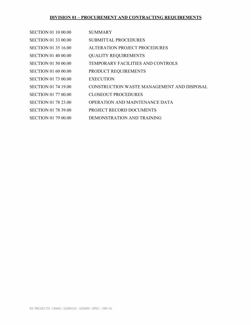
DIVISION 01 – PROCUREMENT AND CONTRACTING REQUIREMENTS
ID: PROJECTS \ O0002 \ 62000156 \ ADMIN \ SPEC \ DIV-01
SECTION 01 10 00.00 SUMMARY
SECTION 01 33 00.00 SUBMITTAL PROCEDURES
SECTION 01 35 16.00 ALTERATION PROJECT PROCEDURES
SECTION 01 40 00.00 QUALITY REQUIREMENTS
SECTION 01 50 00.00 TEMPORARY FACILITIES AND CONTROLS
SECTION 01 60 00.00 PRODUCT REQUIREMENTS
SECTION 01 73 00.00 EXECUTION
SECTION 01 74 19.00 CONSTRUCTION WASTE MANAGEMENT AND DISPOSAL
SECTION 01 77 00.00 CLOSEOUT PROCEDURES
SECTION 01 78 23.00 OPERATION AND MAINTENANCE DATA
SECTION 01 78 39.00 PROJECT RECORD DOCUMENTS
SECTION 01 79 00.00 DEMONSTRATION AND TRAINING
ID: PROJECTS \ O0002 \ 62000156 \ ADMIN \ SPEC \ DIV-01 01 10 00.00 - 1
SECTION 01 10 00.00
SUMMARY
PART 1 - GENERAL
1.1 SUMMARY
A. Section Includes:
1. Project information. 2. Work covered by Contract Documents. 3. Phased construction. 4. Access to site. 5. Coordination with occupants. 6. Work restrictions. 7. Specification and Drawing conventions.
1.2 PROJECT INFORMATION
A. Project Identification: Brewster Village Bathing Suite Project.
1. Project Location: 3300 West Brewster Street, Appleton, WI 54914.
B. Owner: Outagamie County.
1. Owner's Representative: Isaiah Tate, Environmental Services Director; [email protected].
C. Architect: Marley Gast, Architect; [email protected].
1.3 WORK COVERED BY CONTRACT DOCUMENTS
A. The Work of Project is defined by the Contract Documents and consists of the following:
1. Remodel of existing household bathing suite and other Work indicated in the Contract Documents.
1.4 WORK UNDER SEPARATE CONTRACTS
A. General: Cooperate fully with separate contractors so work on those contracts may be carried out smoothly, without interfering with or delaying Work under this Contract or other contracts. Coordinate the Work of this Contract with work performed under separate contracts.

ID: PROJECTS \ O0002 \ 62000156 \ ADMIN \ SPEC \ DIV-01 01 10 00.00 - 2
1.5 ACCESS TO SITE
A. General: Contractor shall have limited use of Project site for construction operations. Contractor shall coordinate with Owner.
B. Use of Site: Do not disturb portions of Project site beyond areas in which the Work is indicated.
1. Driveways, Walkways, and Entrances: Keep driveways and loading areas, and entrances serving premises clear and available to Owner, Owner's employees, and emergency vehicles at all times. Do not use these areas for parking or for storage of materials.
C. Condition of Existing Building: Maintain portions of existing building affected by construction operations in a weathertight condition throughout construction period. Repair damage caused by construction operations.
1.6 COORDINATION WITH OCCUPANTS
A. Full Owner Occupancy: Owner will occupy site and existing building(s) during entire construction period. Cooperate with Owner during construction operations to minimize conflicts and facilitate Owner usage. Perform the Work so as not to interfere with Owner's day-to-day operations. Maintain existing exits unless otherwise indicated.
1.7 WORK RESTRICTIONS
A. Work Restrictions, General: Comply with restrictions on construction operations.
1. Comply with limitations on use of public streets and with other requirements of authorities having jurisdiction.
B. On-Site Work Hours: Coordinate with Owner.
C. Existing Utility Interruptions: Do not interrupt utilities serving facilities occupied by Owner or others unless permitted under the following conditions and then only after providing temporary utility services according to requirements indicated:
1. Notify Owner not less than two days in advance of proposed utility interruptions. 2. Obtain Owner's written permission before proceeding with utility interruptions.
D. Restricted Substances: Use of tobacco products and other controlled substances on Project site is not permitted.
PART 2 - PRODUCTS (Not Used)
PART 3 - EXECUTION (Not Used)
END OF SECTION
ID: PROJECTS \ O0002 \ 62000156 \ ADMIN \ SPEC \ DIV-01 01 33 00.00 - 1
SECTION 01 33 00.00
SUBMITTAL PROCEDURES
PART 1 - GENERAL
1.1 SUMMARY
A. Section includes requirements for the submittal schedule and administrative and procedural requirements for submitting Shop Drawings, Product Data, and other submittals.
1.2 DEFINITIONS
A. Action Submittals: Written and graphic information and physical samples that require Architect's responsive action. Action submittals are those submittals indicated in individual Specification Sections as "action submittals."
B. Informational Submittals: Written and graphic information and physical samples that do not require Architect's responsive action. Submittals may be rejected for not complying with requirements. Informational submittals are those submittals indicated in individual Specification Sections as "informational submittals."
1.3 SUBMITTAL FORMATS
A. Submittal Information: Include the following information in each submittal:
1. Project name. 2. Date. 3. Name of Architect. 4. Name of Construction Manager. 5. Name of Contractor. 6. Name of firm or entity that prepared submittal. 7. Names of subcontractor, manufacturer, and supplier. 8. Unique submittal number, including revision identifier. Include Specification Section
number with sequential alphanumeric identifier; and alphanumeric suffix for resubmittals.
9. Category and type of submittal. 10. Submittal purpose and description. 11. Number and title of Specification Section, with paragraph number and generic name for
each of multiple items. 12. Drawing number and detail references, as appropriate. 13. Indication of full or partial submittal. 14. Location(s) where product is to be installed, as appropriate. 15. Other necessary identification. 16. Remarks. 17. Signature of transmitter.
ID: PROJECTS \ O0002 \ 62000156 \ ADMIN \ SPEC \ DIV-01 01 33 00.00 - 2
B. Metadata: Include the following information as keywords in the electronic submittal file metadata: 1. Project name. 2. Number and title of appropriate Specification Section. 3. Manufacturer name. 4. Product names.
C. Options: Identify options requiring selection by Architect.
D. Deviations and Additional Information: On each submittal, clearly indicate deviations from requirements in the Contract Documents, including minor variations and limitations; include relevant additional information and revisions, other than those requested by Architect on previous submittals. Indicate by highlighting on each submittal or noting on attached separate sheet.
E. PDF Submittals: Prepare submittals as PDF package, incorporating complete information into each PDF file. Name PDF file with submittal number.
F. Submittals for Web-Based Project Software: Prepare submittals as PDF files, or other format indicated by Project software website.
1.4 SUBMITTAL PROCEDURES
A. Prepare and submit submittals required by individual Specification Sections. Types of submittals are indicated in individual Specification Sections.
1. Email: Prepare submittals as PDF package, and transmit to Architect by sending via email. Include PDF transmittal form. Include information in email subject line as requested by Architect.
2. Web-Based Project Software: Prepare submittals in PDF form, and upload to web-based Project software website. Enter required data in web-based software site to fully identify submittal.
B. Coordination: Coordinate preparation and processing of submittals with performance of construction activities.
1. Coordinate each submittal with fabrication, purchasing, testing, delivery, other submittals, and related activities that require sequential activity.
2. Coordinate transmittal of different types of submittals for related parts of the Work so processing will not be delayed because of need to review submittals concurrently for coordination.
a. Architect reserves the right to withhold action on a submittal requiring coordination with other submittals until related submittals are received.
C. Processing Time: Allow time for submittal review, including time for resubmittals, as follows. Time for review shall commence on Architect's receipt of submittal. No extension of the Contract Time will be authorized because of failure to transmit submittals enough in advance of the Work to permit processing, including resubmittals.
ID: PROJECTS \ O0002 \ 62000156 \ ADMIN \ SPEC \ DIV-01 01 33 00.00 - 3
1. Initial Review: Allow 10 days for initial review of each submittal. Allow additional time if coordination with subsequent submittals is required. Architect will advise Contractor when a submittal being processed must be delayed for coordination.
2. Intermediate Review: If intermediate submittal is necessary, process it in the same manner as initial submittal.
3. Resubmittal Review: Allow five days for review of each resubmittal.
D. Resubmittals: Make resubmittals in same form and number of copies as initial submittal.
1. Note date and content of previous submittal. 2. Note date and content of revision in label or title block and clearly indicate extent of
revision. 3. Resubmit submittals until they are marked with approval notation from Architect's action
stamp.
E. Distribution: Furnish copies of final submittals to manufacturers, subcontractors, suppliers, fabricators, installers, authorities having jurisdiction, and others as necessary for performance of construction activities. Show distribution on transmittal forms.
F. Use for Construction: Retain complete copies of submittals on Project site. Use only final action submittals that are marked with approval notation from Architect's stamp.
1.5 SUBMITTAL REQUIREMENTS
A. Product Data: Collect information into a single submittal for each element of construction and type of product or equipment.
1. If information must be specially prepared for submittal because standard published data are unsuitable for use, submit as Shop Drawings, not as Product Data.
2. Mark each copy of each submittal to show which products and options are applicable. 3. Include the following information, as applicable:
a. Manufacturer's catalog cuts. b. Manufacturer's product specifications. c. Standard color charts. d. Statement of compliance with specified referenced standards. e. Testing by recognized testing agency. f. Application of testing agency labels and seals. g. Notation of coordination requirements. h. Availability and delivery time information.
4. For equipment, include the following in addition to the above, as applicable:
a. Wiring diagrams that show factory-installed wiring. b. Printed performance curves. c. Operational range diagrams. d. Clearances required to other construction, if not indicated on accompanying Shop
Drawings.

ID: PROJECTS \ O0002 \ 62000156 \ ADMIN \ SPEC \ DIV-01 01 33 00.00 - 4
5. Submit Product Data before Shop Drawings, and before or concurrent with Samples.
6. Submit Product Data in the following format:
a. PDF electronic file.
B. Shop Drawings: Prepare Project-specific information, drawn accurately to scale. Do not base Shop Drawings on reproductions of the Contract Documents or standard printed data.
1. Preparation: Fully illustrate requirements in the Contract Documents. Include the following information, as applicable:
a. Identification of products. b. Schedules. c. Compliance with specified standards. d. Notation of coordination requirements. e. Notation of dimensions established by field measurement. f. Relationship and attachment to adjoining construction clearly indicated. g. Seal and signature of professional engineer if specified.
2. Sheet Size: Except for templates, patterns, and similar full-size Drawings, submit Shop Drawings on sheets at least 8-1/2 by 11 inches (215 by 280 mm), but no larger than 30 by 42 inches (750 by 1067 mm).
3. Submit Shop Drawings in the following format:
a. PDF electronic file.
C. Samples: Submit Samples for review of kind, color, pattern, and texture for a check of these characteristics with other elements and for a comparison of these characteristics between submittal and actual component as delivered and installed.
1. Transmit Samples that contain multiple, related components such as accessories together in one submittal package.
2. Identification: Attach label on unexposed side of Samples that includes the following:
a. Project name and submittal number. b. Generic description of Sample. c. Product name and name of manufacturer. d. Sample source. e. Number and title of applicable Specification Section.
3. Email Transmittal: Provide PDF transmittal. Include digital image file illustrating Sample characteristics, and identification information for record.
4. Web-Based Project Software: Prepare submittals in PDF form, and upload to web-based Project software website. Enter required data in web-based software site to fully identify submittal.
5. Disposition: Maintain sets of approved Samples at Project site, available for quality-control comparisons throughout the course of construction activity. Sample sets may be used to determine final acceptance of construction associated with each set.
ID: PROJECTS \ O0002 \ 62000156 \ ADMIN \ SPEC \ DIV-01 01 33 00.00 - 5
a. Samples that may be incorporated into the Work are indicated in individual Specification Sections. Such Samples must be in an undamaged condition at time of use.
b. Samples not incorporated into the Work, or otherwise designated as Owner's property, are the property of Contractor.
6. Samples for Initial Selection: Submit manufacturer's color charts consisting of units or sections of units showing the full range of colors, textures, and patterns available.
a. Number of Samples: Submit one full set(s) of available choices where color, pattern, texture, or similar characteristics are required to be selected from manufacturer's product line. Architect will return submittal with options selected.
7. Samples for Verification: Submit full-size units or Samples of size indicated, prepared from same material to be used for the Work, cured and finished in manner specified, and physically identical with material or product proposed for use, and that show full range of color and texture variations expected. Samples include, but are not limited to, the following: partial sections of manufactured or fabricated components; small cuts or containers of materials; complete units of repetitively used materials; swatches showing color, texture, and pattern; color range sets; and components used for independent testing and inspection.
a. Number of Samples: Submit two sets of Samples. Architect will retain one Sample set; remainder will be returned.
1) Submit a single Sample where assembly details, workmanship, fabrication techniques, connections, operation, and other similar characteristics are to be demonstrated.
2) If variation in color, pattern, texture, or other characteristic is inherent in material or product represented by a Sample, submit at least three sets of paired units that show approximate limits of variations.
D. Product Schedule: As required in individual Specification Sections, prepare a written summary indicating types of products required for the Work and their intended location. Include the following information in tabular form:
1. Submit product schedule in the following format:
a. PDF electronic file.
E. Qualification Data: Prepare written information that demonstrates capabilities and experience of firm or person. Include lists of completed projects with project names and addresses, contact information of architects and owners, and other information specified.
F. Design Data: Prepare and submit written and graphic information indicating compliance with indicated performance and design criteria in individual Specification Sections. Include list of assumptions and summary of loads. Include load diagrams if applicable. Provide name and version of software, if any, used for calculations. Number each page of submittal.
G. Certificates:
ID: PROJECTS \ O0002 \ 62000156 \ ADMIN \ SPEC \ DIV-01 01 33 00.00 - 6
1. Certificates and Certifications Submittals: Submit a statement that includes signature of entity responsible for preparing certification. Certificates and certifications shall be signed by an officer or other individual authorized to sign documents on behalf of that entity. Provide a notarized signature where indicated.
2. Installer Certificates: Submit written statements on manufacturer's letterhead certifying that Installer complies with requirements in the Contract Documents and, where required, is authorized by manufacturer for this specific Project.
3. Manufacturer Certificates: Submit written statements on manufacturer's letterhead certifying that manufacturer complies with requirements in the Contract Documents. Include evidence of manufacturing experience where required.
4. Material Certificates: Submit written statements on manufacturer's letterhead certifying that material complies with requirements in the Contract Documents.
5. Product Certificates: Submit written statements on manufacturer's letterhead certifying that product complies with requirements in the Contract Documents.
6. Welding Certificates: Prepare written certification that welding procedures and personnel comply with requirements in the Contract Documents. Submit record of Welding Procedure Specification and Procedure Qualification Record on AWS forms. Include names of firms and personnel certified.
H. Test and Research Reports:
1. Compatibility Test Reports: Submit reports written by a qualified testing agency, on testing agency's standard form, indicating and interpreting results of compatibility tests performed before installation of product. Include written recommendations for primers and substrate preparation needed for adhesion.
2. Field Test Reports: Submit written reports indicating and interpreting results of field tests performed either during installation of product or after product is installed in its final location, for compliance with requirements in the Contract Documents.
3. Material Test Reports: Submit reports written by a qualified testing agency, on testing agency's standard form, indicating and interpreting test results of material for compliance with requirements in the Contract Documents.
4. Preconstruction Test Reports: Submit reports written by a qualified testing agency, on testing agency's standard form, indicating and interpreting results of tests performed before installation of product, for compliance with performance requirements in the Contract Documents.
5. Product Test Reports: Submit written reports indicating that current product produced by manufacturer complies with requirements in the Contract Documents. Base reports on evaluation of tests performed by manufacturer and witnessed by a qualified testing agency, or on comprehensive tests performed by a qualified testing agency.
6. Research Reports: Submit written evidence, from a model code organization acceptable to authorities having jurisdiction, that product complies with building code in effect for Project. Include the following information:
a. Name of evaluation organization. b. Date of evaluation. c. Time period when report is in effect. d. Product and manufacturers' names. e. Description of product. f. Test procedures and results. g. Limitations of use.

ID: PROJECTS \ O0002 \ 62000156 \ ADMIN \ SPEC \ DIV-01 01 33 00.00 - 7
1.6 DELEGATED-DESIGN SERVICES
A. Performance and Design Criteria: Where professional design services or certifications by a design professional are specifically required of Contractor by the Contract Documents, provide products and systems complying with specific performance and design criteria indicated.
1. If criteria indicated are insufficient to perform services or certification required, submit a written request for additional information to Architect.
B. Delegated-Design Services Certification: In addition to Shop Drawings, Product Data, and other required submittals, submit digitally signed PDF file and three paper copies of certificate, signed and sealed by the responsible design professional, for each product and system specifically assigned to Contractor to be designed or certified by a design professional.
1. Indicate that products and systems comply with performance and design criteria in the Contract Documents. Include list of codes, loads, and other factors used in performing these services.
1.7 CONTRACTOR'S REVIEW
A. Action Submittals and Informational Submittals: Review each submittal and check for coordination with other Work of the Contract and for compliance with the Contract Documents. Note corrections and field dimensions. Mark with approval stamp before submitting to Architect.
B. Contractor's Approval: Indicate Contractor's approval for each submittal with a uniform approval stamp. Include Project name and location, submittal number, Specification Section title and number, name of reviewer, date of Contractor's approval, and statement certifying that submittal has been reviewed, checked, and approved for compliance with the Contract Documents.
1. Architect will not review submittals received from Contractor that do not have Contractor's review and approval.
1.8 ARCHITECT'S REVIEW
A. Action Submittals: Architect will review each submittal, indicate corrections or revisions required, and return it.
1. PDF Submittals: Architect will indicate, via markup on each submittal, the appropriate action.
2. On advice of counsel, retain appropriate terms for action stamp and insert term and explanation of each action taken in first subparagraph below. See example in the Evaluations.
ID: PROJECTS \ O0002 \ 62000156 \ ADMIN \ SPEC \ DIV-01 01 33 00.00 - 8
B. Informational Submittals: Architect will review each submittal and will not return it, or will return it if it does not comply with requirements. Architect will forward each submittal to appropriate party.
C. Partial submittals prepared for a portion of the Work will be reviewed when use of partial submittals has received prior approval from Architect.
D. Incomplete submittals are unacceptable, will be considered nonresponsive, and will be returned for resubmittal without review.
E. Architect will return without review submittals received from sources other than Contractor.
F. Submittals not required by the Contract Documents will be returned by Architect without action.
PART 2 - PRODUCTS (Not Used)
PART 3 - EXECUTION (Not Used)
END OF SECTION

ID: PROJECTS \ O0002 \ 62000156 \ ADMIN \ SPEC \ DIV-01 01 35 16.00 - 1
SECTION 01 35 16.00
ALTERATION PROJECT PROCEDURES
PART 1 - GENERAL
1.1 SUMMARY
A. Section includes special procedures for alteration work.
1.2 DEFINITIONS
A. Alteration Work: This term includes remodeling, renovation, repair, and maintenance work performed within existing spaces or on existing surfaces as part of the Project.
B. Consolidate: To strengthen loose or deteriorated materials in place.
C. Design Reference Sample: A sample that represents the Architect's prebid selection of work to be matched; it may be existing work or work specially produced for the Project.
D. Dismantle: To remove by disassembling or detaching an item from a surface, using gentle methods and equipment to prevent damage to the item and surfaces; disposing of items unless indicated to be salvaged or reinstalled.
E. Match: To blend with adjacent construction and manifest no apparent difference in material type, species, cut, form, detail, color, grain, texture, or finish; as approved by Architect.
F. Refinish: To remove existing finishes to base material and apply new finish to match original, or as otherwise indicated.
G. Repair: To correct damage and defects, retaining existing materials, features, and finishes. This includes patching, piecing-in, splicing, consolidating, or otherwise reinforcing or upgrading materials.
H. Replace: To remove, duplicate, and reinstall entire item with new material. The original item is the pattern for creating duplicates unless otherwise indicated.
I. Replicate: To reproduce in exact detail, materials, and finish unless otherwise indicated.
J. Reproduce: To fabricate a new item, accurate in detail to the original, and from either the same or a similar material as the original, unless otherwise indicated.
K. Retain: To keep existing items that are not to be removed or dismantled.
L. Strip: To remove existing finish down to base material unless otherwise indicated.
ID: PROJECTS \ O0002 \ 62000156 \ ADMIN \ SPEC \ DIV-01 01 35 16.00 - 2
1.3 PROJECT MEETINGS FOR ALTERATION WORK
A. Preliminary Conference for Alteration Work: Before starting alteration work, conduct conference at Project site.
1. Attendees: In addition to representatives of Owner, Architect, and Contractor, and others deemed necessary shall be represented at the meeting.
2. Agenda: Discuss items of significance that could affect progress of alteration work.
3. Reporting: Record conference results and distribute copies to everyone in attendance and to others affected by decisions or actions resulting from conference.
B. Coordination Meetings: Conduct coordination meetings specifically for alteration work at regular intervals.
1.4 MATERIALS OWNERSHIP
A. Historic items, relics, and similar objects including, but not limited to, cornerstones and their contents, commemorative plaques and tablets, antiques, and other items of interest or value to Owner that may be encountered or uncovered during the Work, regardless of whether they were previously documented, remain Owner's property.
1.5 QUALITY ASSURANCE
A. Title X Requirement: Each firm conducting activities that disturb painted surfaces shall be a "Lead-Safe Certified Firm" according to 40 CFR 745, Subpart E, and use only workers that are trained in lead-safe work practices.
B. Alteration Work Program: Prepare a written plan for alteration work for whole Project, including each phase or process and protection of surrounding materials during operations. Show compliance with indicated methods and procedures specified in this and other Sections. Coordinate this whole-Project alteration work program with specific requirements of programs required in other alteration work Sections.
1. Dust and Noise Control: Include locations of proposed temporary dust- and noise-control partitions and means of egress from occupied areas coordinated with continuing on-site operations and other known work in progress.
2. Debris Hauling: Include plans clearly marked to show debris hauling routes, turning radii, and locations and details of temporary protective barriers.
C. Fire-Prevention Plan: Prepare a written plan for preventing fires during the Work, including placement of fire extinguishers, fire blankets, rag buckets, and other fire-control devices during each phase or process. Coordinate plan with Owner's fire-protection equipment and requirements. Include fire-watch personnel's training, duties, and authority to enforce fire safety.
D. Safety and Health Standard: Comply with ANSI/ASSE A10.6.
ID: PROJECTS \ O0002 \ 62000156 \ ADMIN \ SPEC \ DIV-01 01 35 16.00 - 3
1.6 STORAGE AND HANDLING OF SALVAGED MATERIALS
A. Salvaged Materials:
1. Clean loose dirt and debris from salvaged items unless more extensive cleaning is indicated.
2. Pack or crate items after cleaning; cushion against damage during handling. Label contents of containers.
3. Store items in a secure area until delivery to Owner. 4. Transport items to Owner's storage area designated by Owner. 5. Protect items from damage during transport and storage.
B. Salvaged Materials for Reinstallation:
1. Repair and clean items for reuse as indicated. 2. Pack or crate items after cleaning and repairing; cushion against damage during handling.
Label contents of containers. 3. Protect items from damage during transport and storage. 4. Reinstall items in locations indicated. Comply with installation requirements for new
materials and equipment unless otherwise indicated. Provide connections, supports, and miscellaneous materials to make items functional for use indicated.
C. Existing Materials to Remain: Protect construction indicated to remain against damage and soiling from construction work. Where permitted by Architect, items may be dismantled and taken to a suitable, protected storage location during construction work and reinstalled in their original locations after alteration and other construction work in the vicinity is complete.
D. Storage: Catalog and store items within a weathertight enclosure where they are protected from moisture, weather, condensation, and freezing temperatures.
1. Identify each item for reinstallation with a nonpermanent mark to document its original location. Indicate original locations on plans, elevations, sections, or photographs by annotating the identifying marks.
2. Secure stored materials to protect from theft. 3. Control humidity so that it does not exceed 85 percent. Maintain temperatures 5 deg F (3
deg C) or more above the dew point.
PART 2 - PRODUCTS - (Not Used)
PART 3 - EXECUTION
3.1 PROTECTION
A. Protect persons, motor vehicles, surrounding surfaces of building, building site, plants, and surrounding buildings from harm resulting from alteration work.
1. Use only proven protection methods, appropriate to each area and surface being protected.
ID: PROJECTS \ O0002 \ 62000156 \ ADMIN \ SPEC \ DIV-01 01 35 16.00 - 4
2. Provide temporary barricades, barriers, and directional signage to exclude the public from areas where alteration work is being performed.
3. Erect temporary barriers to form and maintain fire-egress routes. 4. Erect temporary protective covers over walkways and at points of pedestrian and
vehicular entrance and exit that must remain in service during alteration work. 5. Contain dust and debris generated by alteration work, and prevent it from reaching the
public or adjacent surfaces. 6. Provide shoring, bracing, and supports as necessary. Do not overload structural elements. 7. Protect floors and other surfaces along hauling routes from damage, wear, and staining. 8. Provide supplemental sound-control treatment to isolate demolition work from other
areas of the building.
B. Temporary Protection of Materials to Remain:
1. Protect existing materials with temporary protections and construction. Do not remove existing materials unless otherwise indicated.
2. Do not attach temporary protection to existing surfaces except as indicated as part of the alteration work program.
C. Comply with each product manufacturer's written instructions for protections and precautions. Protect against adverse effects of products and procedures on people and adjacent materials, components, and vegetation.
D. Utility and Communications Services:
1. Notify Owner, Architect, authorities having jurisdiction, and entities owning or controlling wires, conduits, pipes, and other services affected by alteration work before commencing operations.
2. Disconnect and cap pipes and services as required by authorities having jurisdiction, as required for alteration work.
3. Maintain existing services unless otherwise indicated; keep in service, and protect against damage during operations. Provide temporary services during interruptions to existing utilities.
E. Existing Drains: Prior to the start of work in an area, test drainage system to ensure that it is functioning properly. Notify Architect immediately of inadequate drainage or blockage. Do not begin work in an area until the drainage system is functioning properly.
1. Prevent solids such as adhesive or mortar residue or other debris from entering the drainage system. Clean out drains and drain lines that become sluggish or blocked by sand or other materials resulting from alteration work.
2. Protect drains from pollutants. Block drains or filter out sediments, allowing only clean water to pass.
F. Existing Roofing: Prior to the start of work in an area, install roofing protection.
3.2 PROTECTION FROM FIRE
A. General: Follow fire-prevention plan and the following:
ID: PROJECTS \ O0002 \ 62000156 \ ADMIN \ SPEC \ DIV-01 01 35 16.00 - 5
1. Comply with NFPA 241 requirements unless otherwise indicated. 2. Remove and keep area free of combustibles, including rubbish, paper, waste, and
chemicals, unless necessary for the immediate work.
a. If combustible material cannot be removed, provide fire blankets to cover such materials.
B. Heat-Generating Equipment and Combustible Materials: Comply with the following procedures while performing work with heat-generating equipment or combustible materials, including welding, torch-cutting, soldering, brazing, removing paint with heat, or other operations where open flames or implements using high heat or combustible solvents and chemicals are anticipated:
1. Obtain Owner's approval for operations involving use of open-flame or welding or other high-heat equipment. Notify Owner at least 72 hours before each occurrence, indicating location of such work.
2. As far as practicable, restrict heat-generating equipment to shop areas or outside the building.
3. Do not perform work with heat-generating equipment in or near rooms or in areas where flammable liquids or explosive vapors are present or thought to be present. Use a combustible gas indicator test to ensure that the area is safe.
4. Use fireproof baffles to prevent flames, sparks, hot gases, or other high-temperature material from reaching surrounding combustible material.
5. Prevent the spread of sparks and particles of hot metal through open windows, doors, holes, and cracks in floors, walls, ceilings, roofs, and other openings.
6. Fire Watch: Before working with heat-generating equipment or combustible materials, station personnel to serve as a fire watch at each location where such work is performed. Fire-watch personnel shall have the authority to enforce fire safety. Station fire watch according to NFPA 51B, NFPA 241, and as follows:
a. Train each fire watch in the proper operation of fire-control equipment and alarms. b. Prohibit fire-watch personnel from other work that would be a distraction from
fire-watch duties. c. Cease work with heat-generating equipment whenever fire-watch personnel are not
present. d. Have fire-watch personnel perform final fire-safety inspection each day beginning
no sooner than 30 minutes after conclusion of work in each area to detect hidden or smoldering fires and to ensure that proper fire prevention is maintained.
e. Maintain fire-watch personnel at each area of Project site until 60 minutes after conclusion of daily work.
C. Fire-Control Devices: Provide and maintain fire extinguishers, fire blankets, and rag buckets for disposal of rags with combustible liquids. Maintain each as suitable for the type of fire risk in each work area. Ensure that nearby personnel and the fire-watch personnel are trained in fire-extinguisher and blanket use.
D. Sprinklers: Where sprinkler protection exists and is functional, maintain it without interruption while operations are being performed. If operations are performed close to sprinklers, shield them temporarily with guards.

ID: PROJECTS \ O0002 \ 62000156 \ ADMIN \ SPEC \ DIV-01 01 35 16.00 - 6
1. Remove temporary guards at the end of work shifts, whenever operations are paused, and when nearby work is complete.
3.3 PROTECTION DURING APPLICATION OF CHEMICALS
A. Protect motor vehicles, surrounding surfaces of building, building site, plants, and surrounding buildings from harm or spillage resulting from applications of chemicals and adhesives.
B. Cover adjacent surfaces with protective materials that are proven to resist chemicals selected for Project unless chemicals being used will not damage adjacent surfaces as indicated in alteration work program. Use covering materials and masking agents that are waterproof and UV resistant and that will not stain or leave residue on surfaces to which they are applied. Apply protective materials according to manufacturer's written instructions. Do not apply liquid masking agents or adhesives to painted or porous surfaces. When no longer needed, promptly remove protective materials.
C. Do not apply chemicals during winds of sufficient force to spread them to unprotected surfaces.
D. Neutralize alkaline and acid wastes and legally dispose of off Owner's property.
E. Collect and dispose of runoff from chemical operations by legal means and in a manner that prevents soil contamination, soil erosion, undermining of paving and foundations, damage to landscaping, or water penetration into building interior.
3.4 GENERAL ALTERATION WORK
A. Notify Architect of visible changes in the integrity of material or components whether from environmental causes including biological attack, UV degradation, freezing, or thawing or from structural defects including cracks, movement, or distortion.
1. Do not proceed with the work in question until directed by Architect.
END OF SECTION

ID: PROJECTS \ O0002 \ 62000156 \ ADMIN \ SPEC \ DIV-01 01 40 00.00 - 1
SECTION 01 40 00.00
QUALITY REQUIREMENTS
PART 1 - GENERAL
1.1 SUMMARY
A. Section includes administrative and procedural requirements for quality assurance and quality control.
B. Testing and inspection services are required to verify compliance with requirements specified or indicated. These services do not relieve Contractor of responsibility for compliance with the Contract Document requirements.
1. Specified tests, inspections, and related actions do not limit Contractor's other quality-assurance and quality-control procedures that facilitate compliance with the Contract Document requirements.
2. Requirements for Contractor to provide quality-assurance and quality-control services required by Architect, Owner, or authorities having jurisdiction are not limited by provisions of this Section.
1.2 DEFINITIONS
A. Experienced: When used with an entity or individual, "experienced" unless otherwise further described means having successfully completed a minimum of five previous projects similar in nature, size, and extent to this Project; being familiar with special requirements indicated; and having complied with requirements of authorities having jurisdiction.
B. Field Quality-Control Tests: Tests and inspections that are performed on-site for installation of the Work and for completed Work.
C. Installer/Applicator/Erector: Contractor or another entity engaged by Contractor as an employee, Subcontractor, or Sub-subcontractor, to perform a particular construction operation, including installation, erection, application, assembly, and similar operations.
1. Use of trade-specific terminology in referring to a trade or entity does not require that certain construction activities be performed by accredited or unionized individuals, or that requirements specified apply exclusively to specific trade(s).
D. Mockups: Full-size physical assemblies that are constructed on-site either as freestanding temporary built elements or as part of permanent construction. Mockups are constructed to verify selections made under Sample submittals; to demonstrate aesthetic effects and qualities of materials and execution; to review coordination, testing, or operation; to show interface between dissimilar materials; and to demonstrate compliance with specified installation tolerances. Mockups are not Samples. Unless otherwise indicated, approved mockups establish the standard by which the Work will be judged.
ID: PROJECTS \ O0002 \ 62000156 \ ADMIN \ SPEC \ DIV-01 01 40 00.00 - 2
E. Preconstruction Testing: Tests and inspections performed specifically for Project before products and materials are incorporated into the Work, to verify performance or compliance with specified criteria.
F. Product Tests: Tests and inspections that are performed by a nationally recognized testing laboratory (NRTL) according to 29 CFR 1910.7, by a testing agency accredited according to NIST's National Voluntary Laboratory Accreditation Program (NVLAP), or by a testing agency qualified to conduct product testing and acceptable to authorities having jurisdiction, to establish product performance and compliance with specified requirements.
G. Source Quality-Control Tests: Tests and inspections that are performed at the source; for example, plant, mill, factory, or shop.
H. Testing Agency: An entity engaged to perform specific tests, inspections, or both. Testing laboratory shall mean the same as testing agency.
I. Quality-Assurance Services: Activities, actions, and procedures performed before and during execution of the Work to guard against defects and deficiencies and substantiate that proposed construction will comply with requirements.
J. Quality-Control Services: Tests, inspections, procedures, and related actions during and after execution of the Work to evaluate that actual products incorporated into the Work and completed construction comply with requirements. Contractor's quality-control services do not include contract administration activities performed by Architect.
1.3 DELEGATED-DESIGN SERVICES
A. Performance and Design Criteria: Where professional design services or certifications by a design professional are specifically required of Contractor by the Contract Documents, provide products and systems complying with specific performance and design criteria indicated.
1.4 CONFLICTING REQUIREMENTS
A. Conflicting Standards and Other Requirements: If compliance with two or more standards or requirements are specified and the standards or requirements establish different or conflicting requirements for minimum quantities or quality levels, comply with the most stringent requirement. Refer conflicting requirements that are different, but apparently equal, to Architect for direction before proceeding.
B. Minimum Quantity or Quality Levels: The quantity or quality level shown or specified shall be the minimum provided or performed. The actual installation may comply exactly with the minimum quantity or quality specified, or it may exceed the minimum within reasonable limits. To comply with these requirements, indicated numeric values are minimum or maximum, as appropriate, for the context of requirements. Refer uncertainties to Architect for a decision before proceeding.
ID: PROJECTS \ O0002 \ 62000156 \ ADMIN \ SPEC \ DIV-01 01 40 00.00 - 3
1.5 INFORMATIONAL SUBMITTALS
A. Testing Agency Qualifications: For testing agencies specified in "Quality Assurance" Article to demonstrate their capabilities and experience. Include proof of qualifications in the form of a recent report on the inspection of the testing agency by a recognized authority.
B. Permits, Licenses, and Certificates: For Owner's record, submit copies of permits, licenses, certifications, inspection reports, releases, jurisdictional settlements, notices, receipts for fee payments, judgments, correspondence, records, and similar documents established for compliance with standards and regulations bearing on performance of the Work.
1.6 REPORTS AND DOCUMENTS
A. Test and Inspection Reports: Prepare and submit certified written reports specified in other Sections. Include the following:
1. Date of issue. 2. Project title and number. 3. Name, address, telephone number, and email address of testing agency. 4. Dates and locations of samples and tests or inspections. 5. Names of individuals making tests and inspections. 6. Description of the Work and test and inspection method. 7. Identification of product and Specification Section. 8. Complete test or inspection data. 9. Test and inspection results and an interpretation of test results. 10. Record of temperature and weather conditions at time of sample taking and testing and
inspection. 11. Comments or professional opinion on whether tested or inspected Work complies with
the Contract Document requirements. 12. Name and signature of laboratory inspector. 13. Recommendations on retesting and reinspecting.
B. Manufacturer's Technical Representative's Field Reports: Prepare written information documenting manufacturer's technical representative's tests and inspections specified in other Sections. Include the following:
1. Statement on condition of substrates and their acceptability for installation of product. 2. Statement that products at Project site comply with requirements. 3. Summary of installation procedures being followed, whether they comply with
requirements and, if not, what corrective action was taken. 4. Results of operational and other tests and a statement of whether observed performance
complies with requirements. 5. Other required items indicated in individual Specification Sections.
1.7 QUALITY ASSURANCE
A. General: Qualifications paragraphs in this article establish the minimum qualification levels required; individual Specification Sections specify additional requirements.
ID: PROJECTS \ O0002 \ 62000156 \ ADMIN \ SPEC \ DIV-01 01 40 00.00 - 4
B. Manufacturer Qualifications: A firm experienced in manufacturing products or systems similar to those indicated for this Project and with a record of successful in-service performance, as well as sufficient production capacity to produce required units.
C. Fabricator Qualifications: A firm experienced in producing products similar to those indicated for this Project and with a record of successful in-service performance, as well as sufficient production capacity to produce required units.
D. Installer Qualifications: A firm or individual experienced in installing, erecting, applying, or assembling work similar in material, design, and extent to that indicated for this Project, whose work has resulted in construction with a record of successful in-service performance.
E. Professional Engineer Qualifications: A professional engineer who is legally qualified to practice in jurisdiction where Project is located and who is experienced in providing engineering services of the kind indicated. Engineering services are defined as those performed for installations of the system, assembly, or product that are similar in material, design, and extent to those indicated for this Project.
F. Specialists: Certain Specification Sections require that specific construction activities shall be performed by entities who are recognized experts in those operations. Specialists shall satisfy qualification requirements indicated and shall be engaged for the activities indicated.
1. Requirements of authorities having jurisdiction shall supersede requirements for specialists.
G. Testing Agency Qualifications: An NRTL, an NVLAP, or an independent agency with the experience and capability to conduct testing and inspection indicated, as documented according to ASTM E 329; and with additional qualifications specified in individual Sections; and, where required by authorities having jurisdiction, that is acceptable to authorities.
1. NRTL: A nationally recognized testing laboratory according to 29 CFR 1910.7. 2. NVLAP: A testing agency accredited according to NIST’s National Voluntary
Laboratory Accreditation Program.
H. Manufacturer's Technical Representative Qualifications: An authorized representative of manufacturer who is trained and approved by manufacturer to observe and inspect installation of manufacturer's products that are similar in material, design, and extent to those indicated for this Project.
I. Preconstruction Testing: Where testing agency is indicated to perform preconstruction testing for compliance with specified requirements for performance and test methods, comply with the following:
1. Contractor responsibilities include the following:
a. Provide test specimens representative of proposed products and construction. b. Submit specimens in a timely manner with sufficient time for testing and analyzing
results to prevent delaying the Work. c. Build laboratory mockups at testing facility using personnel, products, and
methods of construction indicated for the completed Work.
ID: PROJECTS \ O0002 \ 62000156 \ ADMIN \ SPEC \ DIV-01 01 40 00.00 - 5
d. When testing is complete, remove test specimens and test assemblies, and mockups; do not reuse products on Project.
2. Testing Agency Responsibilities: Submit a certified written report of each test, inspection, and similar quality-assurance service to Architect with copy to Contractor. Interpret tests and inspections and state in each report whether tested and inspected work complies with or deviates from the Contract Documents.
J. Mockups: Before installing portions of the Work requiring mockups, build mockups for each form of construction and finish required to comply with the following requirements, using materials indicated for the completed Work:
1. Build mockups in location indicated or, if not indicated, as directed by Architect. 2. Notify Architect seven days in advance of dates and times when mockups will be
constructed. 3. Demonstrate the proposed range of aesthetic effects and workmanship. 4. Obtain Architect's approval of mockups before starting corresponding work, fabrication,
or construction.
a. Allow seven days for initial review and each re-review of each mockup.
5. Maintain mockups during construction in an undisturbed condition as a standard for judging the completed Work.
6. Demolish and remove mockups when directed unless otherwise indicated.
K. Laboratory Mockups: Comply with requirements of preconstruction testing and those specified in individual Specification Sections.
1.8 QUALITY CONTROL
A. Owner Responsibilities: Where quality-control services are indicated as Owner's responsibility, Owner will engage a qualified testing agency to perform these services.
1. Owner will furnish Contractor with names, addresses, and telephone numbers of testing agencies engaged and a description of types of testing and inspection they are engaged to perform.
2. Costs for retesting and reinspecting construction that replaces or is necessitated by work that failed to comply with the Contract Documents will be charged to Contractor.
B. Contractor Responsibilities: Tests and inspections not explicitly assigned to Owner are Contractor's responsibility. Perform additional quality-control activities, whether specified or not, to verify and document that the Work complies with requirements.
1. Where services are indicated as Contractor’s responsibility, engage a qualified testing agency to perform quality-control services.
a. Contractor shall not employ same entity engaged by Owner, unless agreed to in writing by Owner.

ID: PROJECTS \ O0002 \ 62000156 \ ADMIN \ SPEC \ DIV-01 01 40 00.00 - 6
2. Notify testing agencies at least 24 hours in advance of time when Work that requires testing or inspection will be performed.
3. Where quality-control services are indicated as Contractor's responsibility, submit a certified written report, in duplicate, of each quality-control service.
4. Testing and inspection requested by Contractor and not required by the Contract Documents are Contractor's responsibility.
5. Submit additional copies of each written report directly to authorities having jurisdiction, when they so direct.
C. Retesting/Reinspecting: Regardless of whether original tests or inspections were Contractor's responsibility, provide quality-control services, including retesting and reinspecting, for construction that replaced Work that failed to comply with the Contract Documents.
D. Testing Agency Responsibilities: Cooperate with Architect and Contractor in performance of duties. Provide qualified personnel to perform required tests and inspections.
1. Notify Architect and Contractor promptly of irregularities or deficiencies observed in the Work during performance of its services.
2. Determine the locations from which test samples will be taken and in which in-situ tests are conducted.
3. Conduct and interpret tests and inspections and state in each report whether tested and inspected work complies with or deviates from requirements.
4. Submit a certified written report, in duplicate, of each test, inspection, and similar quality-control service through Contractor.
5. Do not release, revoke, alter, or increase the Contract Document requirements or approve or accept any portion of the Work.
6. Do not perform duties of Contractor.
E. Manufacturer's Field Services: Where indicated, engage a factory-authorized service representative to inspect field-assembled components and equipment installation, including service connections. Report results in writing as specified in Section 01 33 00.00 "Submittal Procedures."
F. Associated Contractor Services: Cooperate with agencies and representatives performing required tests, inspections, and similar quality-control services, and provide reasonable auxiliary services as requested. Notify agency sufficiently in advance of operations to permit assignment of personnel. Provide the following:
1. Access to the Work. 2. Incidental labor and facilities necessary to facilitate tests and inspections. 3. Adequate quantities of representative samples of materials that require testing and
inspection. Assist agency in obtaining samples. 4. Facilities for storage and field curing of test samples. 5. Preliminary design mix proposed for use for material mixes that require control by testing
agency. 6. Security and protection for samples and for testing and inspection equipment at Project
site. 7. Delivery of samples to testing agency.
ID: PROJECTS \ O0002 \ 62000156 \ ADMIN \ SPEC \ DIV-01 01 40 00.00 - 7
G. Coordination: Coordinate sequence of activities to accommodate required quality-assurance and quality-control services with a minimum of delay and to avoid necessity of removing and replacing construction to accommodate testing and inspection.
1. Schedule times for tests, inspections, obtaining samples, and similar activities.
1.9 SPECIAL TESTS AND INSPECTIONS
A. Special Tests and Inspections: Owner will engage a qualified testing agency to conduct special tests and inspections required by authorities having jurisdiction as the responsibility of Owner.
B. Special tests and inspections conducted by a qualified testing agency as required by authorities having jurisdiction, as indicated in individual specification sections, and as follows:
1. Verifying that manufacturer maintains detailed fabrication and quality-control procedures and reviewing the completeness and adequacy of those procedures to perform the Work.
2. Notifying Architect and Contractor promptly of irregularities and deficiencies observed in the Work during performance of its services.
3. Submitting a certified written report of each test, inspection, and similar quality-control service to Architect with copy to Contractor and to authorities having jurisdiction.
4. Submitting a final report of special tests and inspections at Substantial Completion, which includes a list of unresolved deficiencies.
5. Interpreting tests and inspections and stating in each report whether tested and inspected work complies with or deviates from the Contract Documents.
6. Retesting and reinspecting corrected work.
PART 2 - PRODUCTS (Not Used)
PART 3 - EXECUTION
3.1 TEST AND INSPECTION LOG
A. Test and Inspection Log: Prepare a record of tests and inspections. Include the following:
1. Date test or inspection was conducted. 2. Description of the Work tested or inspected. 3. Date test or inspection results were transmitted to Architect. 4. Identification of testing agency or special inspector conducting test or inspection.
B. Maintain log at Project site. Post changes and revisions as they occur.
3.2 REPAIR AND PROTECTION
A. General: On completion of testing, inspection, sample taking, and similar services, repair damaged construction and restore substrates and finishes.
ID: PROJECTS \ O0002 \ 62000156 \ ADMIN \ SPEC \ DIV-01 01 40 00.00 - 8
1. Provide materials and comply with installation requirements specified in other Specification Sections or matching existing substrates and finishes. Restore patched areas and extend restoration into adjoining areas with durable seams that are as invisible as possible. Comply with the Contract Document requirements for cutting and patching in Section 01 73 00.00 "Execution."
B. Protect construction exposed by or for quality-control service activities.
C. Repair and protection are Contractor's responsibility, regardless of the assignment of responsibility for quality-control services.
END OF SECTION
ID: PROJECTS \ O0002 \ 62000156 \ ADMIN \ SPEC \ DIV-01 01 50 00.00 - 1
SECTION 01 50 00.00
TEMPORARY FACILITIES AND CONTROLS
PART 1 - GENERAL
1.1 SUMMARY
A. Section includes requirements for temporary utilities, support facilities, and security and protection facilities.
B. Related Requirements:
1. Section 01 10 00.00 "Summary" for work restrictions and limitations on utility interruptions.
1.2 USE CHARGES
A. General: Installation and removal of and use charges for temporary facilities shall be included in the Contract Sum unless otherwise indicated. Allow other entities engaged in the Project to use temporary services and facilities without cost, including, but not limited to, Owner's construction forces, Architect, testing agencies, and authorities having jurisdiction.
B. Water and Sewer Service from Existing System: Water from Owner's existing water system is available for use without metering and without payment of use charges. Provide connections and extensions of services as required for construction operations.
C. Electric Power Service from Existing System: Electric power from Owner's existing system is available for use without metering and without payment of use charges. Provide connections and extensions of services as required for construction operations.
1.3 INFORMATIONAL SUBMITTALS
A. Site Utilization Plan: Show temporary facilities, utility hookups, staging areas, and parking areas for construction personnel.
B. Fire-Safety Program: Show compliance with requirements of NFPA 241 and authorities having jurisdiction. Indicate Contractor personnel responsible for management of fire-prevention program.
1.4 QUALITY ASSURANCE
A. Electric Service: Comply with NECA, NEMA, and UL standards and regulations for temporary electric service. Install service to comply with NFPA 70.
ID: PROJECTS \ O0002 \ 62000156 \ ADMIN \ SPEC \ DIV-01 01 50 00.00 - 2
B. Tests and Inspections: Arrange for authorities having jurisdiction to test and inspect each temporary utility before use. Obtain required certifications and permits.
C. Accessible Temporary Egress: Comply with applicable provisions in the United States Access Board's ADA-ABA Accessibility Guidelines and ICC/ANSI A117.1.
1.5 PROJECT CONDITIONS
A. Temporary Use of Permanent Facilities: Engage Installer of each permanent service to assume responsibility for operation, maintenance, and protection of each permanent service during its use as a construction facility before Owner's acceptance, regardless of previously assigned responsibilities.
PART 2 - PRODUCTS
A. Common-Use Field Office: Of sufficient size to accommodate needs of Owner, Architect, and construction personnel office activities and to accommodate Project meetings specified in other Division 01 Sections. Keep office clean and orderly.
2.2 EQUIPMENT
A. Fire Extinguishers: Portable, UL rated; with class and extinguishing agent as required by locations and classes of fire exposures.
B. HVAC Equipment: Unless Owner authorizes use of permanent HVAC system, provide vented, self-contained, liquid-propane-gas or fuel-oil heaters with individual space thermostatic control.
1. Use of gasoline-burning space heaters, open-flame heaters, or salamander-type heating units is prohibited.
2. Heating Units: Listed and labeled for type of fuel being consumed, by a qualified testing agency acceptable to authorities having jurisdiction, and marked for intended location and application.
3. Permanent HVAC System: If Owner authorizes use of permanent HVAC system for temporary use during construction, provide filter with MERV of 8 at each return-air grille in system and remove at end of construction and clean HVAC system as required in Section 01 77 00.00 "Closeout Procedures."
PART 3 - EXECUTION
3.1 INSTALLATION, GENERAL
A. Locate facilities where they will serve Project adequately and result in minimum interference with performance of the Work. Relocate and modify facilities as required by progress of the Work.
1. Locate facilities to limit site disturbance as specified in Section 01 10 00.00 “Summary.”
ID: PROJECTS \ O0002 \ 62000156 \ ADMIN \ SPEC \ DIV-01 01 50 00.00 - 3
B. Provide each facility ready for use when needed to avoid delay. Do not remove until facilities are no longer needed or are replaced by authorized use of completed permanent facilities.
3.2 TEMPORARY UTILITY INSTALLATION
A. General: Install temporary service or connect to existing service.
1. Arrange with utility company, Owner, and existing users for time when service can be interrupted, if necessary, to make connections for temporary services.
B. Sewers and Drainage: Provide temporary utilities to remove effluent lawfully.
1. Connect temporary sewers to municipal system as directed by authorities having jurisdiction.
C. Water Service: Connect to Owner’s existing water service facilities. Clean and maintain water service facilities in a condition acceptable to Owner. At Substantial Completion, restore these facilities to condition existing before initial use.
D. Sanitary Facilities: Provide temporary toilets, wash facilities, and drinking water for use of construction personnel. Comply with requirements of authorities having jurisdiction for type, number, location, operation, and maintenance of fixtures and facilities.
E. Temporary Heating and Cooling: Provide temporary heating and cooling required by construction activities for curing or drying of completed installations or for protecting installed construction from adverse effects of low temperatures or high humidity. Select equipment that will not have a harmful effect on completed installations or elements being installed.
F. Ventilation and Humidity Control: Provide temporary ventilation required by construction activities for curing or drying of completed installations or for protecting installed construction from adverse effects of high humidity. Select equipment that will not have a harmful effect on completed installations or elements being installed. Coordinate ventilation requirements to produce ambient condition required and minimize energy consumption.
G. Isolation of Work Areas in Occupied Facilities: Prevent dust, fumes, and odors from entering occupied areas.
H. Electric Power Service: Provide electric power service and distribution system of sufficient size, capacity, and power characteristics required for construction operations.
I. Lighting: Provide temporary lighting with local switching that provides adequate illumination for construction operations, observations, inspections, and traffic conditions.
1. Install and operate temporary lighting that fulfills security and protection requirements without operating entire system.
J. Telephone Service: Provide temporary telephone service in common-use facilities for use by all construction personnel. Install one land-based telephone line(s) for each field office.
K. Electronic Communication Service: Provide a desktop computer in the primary field office.

ID: PROJECTS \ O0002 \ 62000156 \ ADMIN \ SPEC \ DIV-01 01 50 00.00 - 4
3.3 SUPPORT FACILITIES INSTALLATION
A. General: Comply with the following:
1. Provide construction for temporary offices, shops, and sheds located within construction area or within 30 feet (9 m) of building lines that is noncombustible according to ASTM E 136. Comply with NFPA 241.
2. Maintain support facilities until Architect schedules Substantial Completion inspection. Remove before Substantial Completion. Personnel remaining after Substantial Completion will be permitted to use permanent facilities, under conditions acceptable to Owner.
B. Temporary Roads and Paved Areas: Construct and maintain temporary roads and paved areas adequate for construction operations. Locate temporary roads and paved areas within construction limits.
1. Provide dust-control treatment that is nonpolluting and nontracking. Reapply treatment as required to minimize dust.
C. Parking: Use designated areas of Owner's existing parking areas for construction personnel.
D. Dewatering Facilities and Drains: Comply with requirements of authorities having jurisdiction. Maintain Project site, excavations, and construction free of water.
1. Dispose of rainwater in a lawful manner that will not result in flooding Project or adjoining properties or endanger permanent Work or temporary facilities.
2. Remove snow and ice as required to minimize accumulations.
E. Project Signs: Provide Project signs only as reviewed and approved by Owner. Unauthorized signs are not permitted.
F. Waste Disposal Facilities: Comply with requirements specified in Section 01 74 19.00 "Construction Waste Management and Disposal."
G. Waste Disposal Facilities: Provide waste-collection containers in sizes adequate to handle waste from construction operations. Comply with requirements of authorities having jurisdiction. Comply with progress cleaning requirements in Section 01 73 00.00 "Execution."
H. Lifts and Hoists: Provide facilities necessary for hoisting materials and personnel.
1. Truck cranes and similar devices used for hoisting materials are considered "tools and equipment" and not temporary facilities.
I. Existing Elevator Use: Use of Owner's existing elevators will be permitted, provided elevators are cleaned and maintained in a condition acceptable to Owner. At Substantial Completion, restore elevators to condition existing before initial use, including replacing worn cables, guide shoes, and similar items of limited life.
1. Do not load elevators beyond their rated weight capacity. 2. Provide protective coverings, barriers, devices, signs, or other procedures to protect
elevator car and entrance doors and frame. If, despite such protection, elevators become

ID: PROJECTS \ O0002 \ 62000156 \ ADMIN \ SPEC \ DIV-01 01 50 00.00 - 5
damaged, engage elevator Installer to restore damaged work so no evidence remains of correction work. Return items that cannot be refinished in field to the shop, make required repairs and refinish entire unit, or provide new units as required.
J. Temporary Stairs: Until permanent stairs are available, provide temporary stairs where ladders are not adequate.
K. Existing Stair Usage: Use of Owner's existing stairs will be permitted, provided stairs are cleaned and maintained in a condition acceptable to Owner. At Substantial Completion, restore stairs to condition existing before initial use.
1. Provide protective coverings, barriers, devices, signs, or other procedures to protect stairs and to maintain means of egress. If stairs become damaged, restore damaged areas so no evidence remains of correction work.
L. Temporary Use of Permanent Stairs: Use of new stairs for construction traffic will be permitted, provided stairs are protected and finishes restored to new condition at time of Substantial Completion.
3.4 SECURITY AND PROTECTION FACILITIES INSTALLATION
A. Protection of Existing Facilities: Protect existing vegetation, equipment, structures, utilities, and other improvements at Project site and on adjacent properties, except those indicated to be removed or altered. Repair damage to existing facilities.
1. Where access to adjacent properties is required in order to affect protection of existing facilities, obtain written permission from adjacent property owner to access property for that purpose.
B. Environmental Protection: Provide protection, operate temporary facilities, and conduct construction as required to comply with environmental regulations and that minimize possible air, waterway, and subsoil contamination or pollution or other undesirable effects.
C. Temporary Erosion and Sedimentation Control: Provide measures to prevent soil erosion and discharge of soil-bearing water runoff and airborne dust to undisturbed areas and to adjacent properties and walkways, according to requirements of EPA Construction General Permit or authorities having jurisdiction, whichever is more stringent.
D. Stormwater Control: Comply with requirements of authorities having jurisdiction. Provide barriers in and around excavations and subgrade construction to prevent flooding by runoff of stormwater from heavy rains.
E. Tree and Plant Protection: Install temporary fencing located as indicated or outside the drip line of trees to protect vegetation from damage from construction operations. Protect tree root systems from damage, flooding, and erosion.
F. Pest Control: Engage pest-control service to recommend practices to minimize attraction and harboring of rodents, roaches, and other pests and to perform extermination and control procedures at regular intervals so Project will be free of pests and their residues at Substantial Completion. Perform control operations lawfully, using environmentally safe materials.

ID: PROJECTS \ O0002 \ 62000156 \ ADMIN \ SPEC \ DIV-01 01 50 00.00 - 6
G. Site Enclosure Fence: Before construction operations begin, furnish and install site enclosure fence in a manner that will prevent people from easily entering site except by entrance gates.
1. Extent of Fence: As required to enclose entire Project site or portion determined sufficient to accommodate construction operations.
2. Maintain security by limiting number of keys and restricting distribution to authorized personnel. Furnish one set of keys to Owner.
H. Security Enclosure and Lockup: Install temporary enclosure around partially completed areas of construction. Provide lockable entrances to prevent unauthorized entrance, vandalism, theft, and similar violations of security. Lock entrances at end of each workday.
I. Barricades, Warning Signs, and Lights: Comply with requirements of authorities having jurisdiction for erecting structurally adequate barricades, including warning signs and lighting.
J. Temporary Egress: Maintain temporary egress from existing occupied facilities as indicated and as required by authorities having jurisdiction.
K. Temporary Enclosures: Provide temporary enclosures for protection of construction, in progress and completed, from exposure, foul weather, other construction operations, and similar activities. Provide temporary weathertight enclosure for building exterior.
1. Where heating or cooling is needed and permanent enclosure is incomplete, insulate temporary enclosures.
L. Temporary Partitions: Provide floor-to-ceiling dustproof partitions to limit dust and dirt migration and to separate areas occupied by Owner from fumes and noise.
1. Construct dustproof partitions with gypsum wallboard with joints taped on occupied side, and fire-retardant-treated plywood on construction operations side.
2. Where fire-resistance-rated temporary partitions are indicated or are required by authorities having jurisdiction, construct partitions according to the rated assemblies.
3. Provide walk-off mats at each entrance through temporary partition.
M. Temporary Fire Protection: Install and maintain temporary fire-protection facilities of types needed to protect against reasonably predictable and controllable fire losses. Comply with NFPA 241; manage fire-prevention program.
1. Prohibit smoking in construction areas. Comply with additional limits on smoking specified in other Sections.
2. Supervise welding operations, combustion-type temporary heating units, and similar sources of fire ignition according to requirements of authorities having jurisdiction.
3. Develop and supervise an overall fire-prevention and -protection program for personnel at Project site. Review needs with local fire department and establish procedures to be followed. Instruct personnel in methods and procedures. Post warnings and information.
4. Provide temporary standpipes and hoses for fire protection. Hang hoses with a warning sign stating that hoses are for fire-protection purposes only and are not to be removed. Match hose size with outlet size and equip with suitable nozzles.

ID: PROJECTS \ O0002 \ 62000156 \ ADMIN \ SPEC \ DIV-01 01 50 00.00 - 7
3.5 MOISTURE AND MOLD CONTROL
A. Contractor's Moisture-Protection Plan: Describe delivery, handling, storage, installation, and protection provisions for materials subject to water absorption or water damage.
1. Indicate procedures for discarding water-damaged materials, protocols for mitigating water intrusion into completed Work, and replacing water-damaged Work.
2. Indicate sequencing of work that requires water, such as sprayed fire-resistive materials, plastering, and terrazzo grinding, and describe plans for dealing with water from these operations. Show procedures for verifying that wet construction has dried sufficiently to permit installation of finish materials.
3. Indicate methods to be used to avoid trapping water in finished work.
B. Exposed Construction Period: Before installation of weather barriers, when materials are subject to wetting and exposure and to airborne mold spores, protect as follows:
1. Protect porous materials from water damage. 2. Protect stored and installed material from flowing or standing water. 3. Keep porous and organic materials from coming into prolonged contact with concrete. 4. Remove standing water from decks. 5. Keep deck openings covered or dammed.
C. Partially Enclosed Construction Period: After installation of weather barriers but before full enclosure and conditioning of building, when installed materials are still subject to infiltration of moisture and ambient mold spores, protect as follows:
1. Do not load or install drywall or other porous materials or components, or items with high organic content, into partially enclosed building.
2. Keep interior spaces reasonably clean and protected from water damage. 3. Periodically collect and remove waste containing cellulose or other organic matter. 4. Discard or replace water-damaged material. 5. Do not install material that is wet. 6. Discard and replace stored or installed material that begins to grow mold. 7. Perform work in a sequence that allows wet materials adequate time to dry before
enclosing the material in gypsum board or other interior finishes.
D. Controlled Construction Period: After completing and sealing of the building enclosure but prior to the full operation of permanent HVAC systems, maintain as follows:
1. Control moisture and humidity inside building by maintaining effective dry-in conditions. 2. Use temporary or permanent HVAC system to control humidity within ranges specified
for installed and stored materials. 3. Comply with manufacturer's written instructions for temperature, relative humidity, and
exposure to water limits.
3.6 OPERATION, TERMINATION, AND REMOVAL
A. Supervision: Enforce strict discipline in use of temporary facilities. To minimize waste and abuse, limit availability of temporary facilities to essential and intended uses.

ID: PROJECTS \ O0002 \ 62000156 \ ADMIN \ SPEC \ DIV-01 01 50 00.00 - 8
B. Maintenance: Maintain facilities in good operating condition until removal.
1. Maintain operation of temporary enclosures, heating, cooling, humidity control, ventilation, and similar facilities on a 24-hour basis where required to achieve indicated results and to avoid possibility of damage.
C. Temporary Facility Changeover: Do not change over from using temporary security and protection facilities to permanent facilities until Substantial Completion.
D. Termination and Removal: Remove each temporary facility when need for its service has ended, when it has been replaced by authorized use of a permanent facility, or no later than Substantial Completion. Complete or, if necessary, restore permanent construction that may have been delayed because of interference with temporary facility. Repair damaged Work, clean exposed surfaces, and replace construction that cannot be satisfactorily repaired.
1. Materials and facilities that constitute temporary facilities are property of Contractor. Owner reserves right to take possession of Project identification signs.
2. At Substantial Completion, repair, renovate, and clean permanent facilities used during construction period. Comply with final cleaning requirements specified in Section 01 77 00.00 "Closeout Procedures."
END OF SECTION

ID: PROJECTS \ O0002 \ 62000156 \ ADMIN \ SPEC \ DIV-01 01 60 00.00 - 1
SECTION 01 60 00.00
PRODUCT REQUIREMENTS
PART 1 - GENERAL
1.1 SUMMARY
A. Section includes administrative and procedural requirements for selection of products for use in Project; product delivery, storage, and handling; manufacturers' standard warranties on products; special warranties; and comparable products.
1.2 DEFINITIONS
A. Products: Items obtained for incorporating into the Work, whether purchased for Project or taken from previously purchased stock. The term "product" includes the terms "material," "equipment," "system," and terms of similar intent.
1. Named Products: Items identified by manufacturer's product name, including make or model number or other designation shown or listed in manufacturer's published product literature that is current as of date of the Contract Documents.
2. New Products: Items that have not previously been incorporated into another project or facility. Products salvaged or recycled from other projects are not considered new products.
3. Comparable Product: Product that is demonstrated and approved by Architect through submittal process to have the indicated qualities related to type, function, dimension, in-service performance, physical properties, appearance, and other characteristics that equal or exceed those of specified product.
B. Basis-of-Design Product Specification: A specification in which a single manufacturer's product is named and accompanied by the words "basis-of-design product," including make or model number or other designation. In addition to the basis-of-design product description, product attributes and characteristics may be listed to establish the significant qualities related to type, function, in-service performance and physical properties, weight, dimension, durability, visual characteristics, and other special features and requirements for purposes of evaluating comparable products of additional manufacturers named in the specification.
1.3 ACTION SUBMITTALS
A. Comparable Product Request Submittal: Submit request for consideration of each comparable product. Identify basis-of-design product or fabrication or installation method to be replaced. Include Specification Section number and title and Drawing numbers and titles.
1. Architect's Action: If necessary, Architect will request additional information or documentation for evaluation within seven days of receipt of a comparable product request. Architect will notify Contractor of approval or rejection of proposed comparable
ID: PROJECTS \ O0002 \ 62000156 \ ADMIN \ SPEC \ DIV-01 01 60 00.00 - 2
product request within five days of receipt of request, or five days of receipt of additional information or documentation, whichever is later.
a. Use product specified if Architect does not issue a decision on use of a comparable product request within time allocated.
1.4 QUALITY ASSURANCE
A. Compatibility of Options: If Contractor is given option of selecting between two or more products for use on Project, select product compatible with products previously selected, even if previously selected products were also options.
1.5 PRODUCT DELIVERY, STORAGE, AND HANDLING
A. Deliver, store, and handle products using means and methods that will prevent damage, deterioration, and loss, including theft and vandalism. Comply with manufacturer's written instructions.
B. Delivery and Handling:
1. Schedule delivery to minimize long-term storage at Project site and to prevent overcrowding of construction spaces.
2. Coordinate delivery with installation time to ensure minimum holding time for items that are flammable, hazardous, easily damaged, or sensitive to deterioration, theft, and other losses.
3. Deliver products to Project site in an undamaged condition in manufacturer's original sealed container or other packaging system, complete with labels and instructions for handling, storing, unpacking, protecting, and installing.
4. Inspect products on delivery to determine compliance with the Contract Documents and to determine that products are undamaged and properly protected.
C. Storage:
1. Store products to allow for inspection and measurement of quantity or counting of units. 2. Store materials in a manner that will not endanger Project structure. 3. Store products that are subject to damage by the elements, under cover in a weathertight
enclosure above ground, with ventilation adequate to prevent condensation. 4. Protect foam plastic from exposure to sunlight, except to extent necessary for period of
installation and concealment. 5. Comply with product manufacturer's written instructions for temperature, humidity,
ventilation, and weather-protection requirements for storage. 6. Protect stored products from damage and liquids from freezing.
1.6 PRODUCT WARRANTIES
A. Warranties specified in other Sections shall be in addition to, and run concurrent with, other warranties required by the Contract Documents. Manufacturer's disclaimers and limitations on

ID: PROJECTS \ O0002 \ 62000156 \ ADMIN \ SPEC \ DIV-01 01 60 00.00 - 3
product warranties do not relieve Contractor of obligations under requirements of the Contract Documents.
1. Manufacturer's Warranty: Written warranty furnished by individual manufacturer for a particular product and specifically endorsed by manufacturer to Owner.
2. Special Warranty: Written warranty required by the Contract Documents to provide specific rights for Owner.
B. Special Warranties: Prepare a written document that contains appropriate terms and identification, ready for execution.
1. Manufacturer's Standard Form: Modified to include Project-specific information and properly executed.
2. Specified Form: When specified forms are included with the Specifications, prepare a written document using indicated form properly executed.
3. See other Sections for specific content requirements and particular requirements for submitting special warranties.
C. Submittal Time: Comply with requirements of Section 01 77 00.00 “Closeout Procedures.”
PART 2 - PRODUCTS
2.1 PRODUCT SELECTION PROCEDURES
A. General Product Requirements: Provide products that comply with the Contract Documents, are undamaged and, unless otherwise indicated, are new at time of installation.
1. Provide products complete with accessories, trim, finish, fasteners, and other items needed for a complete installation and indicated use and effect.
2. Standard Products: If available, and unless custom products or nonstandard options are specified, provide standard products of types that have been produced and used successfully in similar situations on other projects.
3. Owner reserves the right to limit selection to products with warranties meeting requirements of the Contract Documents.
4. Where products are accompanied by the term "as selected," Architect will make selection.
5. Descriptive, performance, and reference standard requirements in the Specifications establish salient characteristics of products.
B. Product Selection Procedures:
1. Product: Where Specifications name a single manufacturer and product, provide the named product that complies with requirements. Comparable products or substitutions for Contractor's convenience will be considered for review and approval.
2. Manufacturer/Source: Where Specifications name a single manufacturer or source, provide a product by the named manufacturer or source that complies with requirements. Comparable products or substitutions for Contractor's convenience will be considered for review and approval.
ID: PROJECTS \ O0002 \ 62000156 \ ADMIN \ SPEC \ DIV-01 01 60 00.00 - 4
3. Basis-of-Design Product: Where Specifications name a product, or refer to a product indicated on Drawings, and include a list of manufacturers, provide the specified or indicated product or a comparable product by one of the other named manufacturers. Drawings and Specifications indicate sizes, profiles, dimensions, and other characteristics that are based on the product named. Comply with requirements in "Comparable Products" Article for consideration of an unnamed product by one of the other named manufacturers.
C. Visual Matching Specification: Where Specifications require "match Architect's sample," provide a product that complies with requirements and matches Architect's sample. Architect's decision will be final on whether a proposed product matches.
1. If no product available within specified category matches and complies with other specified requirements, provide alternative product for review.
D. Visual Selection Specification: Where Specifications include the phrase "as selected by Architect from manufacturer's full range" or similar phrase, select a product that complies with requirements. Architect will select color, gloss, pattern, density, or texture from manufacturer's product line that includes both standard and premium items.
2.2 COMPARABLE PRODUCTS
A. Conditions for Consideration of Comparable Products: Architect will consider Contractor's request for comparable product when the following conditions are satisfied. If the following conditions are not satisfied, Architect may return requests without action, except to record noncompliance with these requirements:
1. Evidence that proposed product does not require revisions to the Contract Documents, is consistent with the Contract Documents, will produce the indicated results, and is compatible with other portions of the Work. Detailed comparison of significant qualities of proposed product with those named in the Specifications. Significant product qualities include attributes such as type, function, in-service performance and physical properties, weight, dimension, durability, visual characteristics, and other specific features and requirements.
2. Evidence that proposed product provides specified warranty. 3. List of similar installations for completed projects with project names and addresses and
names and addresses of architects and owners, if requested. 4. Samples, if requested.
PART 3 - EXECUTION (Not Used)
END OF SECTION
ID: PROJECTS \ O0002 \ 62000156 \ ADMIN \ SPEC \ DIV-01 01 73 00.00 - 1
SECTION 01 73 00.00
EXECUTION
PART 1 - GENERAL
1.1 SUMMARY
A. Section includes general administrative and procedural requirements governing execution of the Work including, but not limited to, the following:
1. Construction layout. 2. Field engineering and surveying. 3. Installation of the Work. 4. Cutting and patching. 5. Coordination of Owner-installed products. 6. Progress cleaning. 7. Starting and adjusting. 8. Protection of installed construction.
1.2 INFORMATIONAL SUBMITTALS
A. Certificates: Submit certificate signed by professional engineer certifying that location and elevation of improvements comply with requirements.
B. Landfill Receipts: Submit copy of receipts issued by a landfill facility, licensed to accept hazardous materials, for hazardous waste disposal.
C. Certified Surveys: Submit two copies signed by land surveyor.
D. Final Property Survey: Submit 10 copies showing the Work performed and record survey data.
1.3 QUALITY ASSURANCE
A. Land Surveyor Qualifications: A professional land surveyor who is legally qualified to practice in jurisdiction where Project is located and who is experienced in providing land-surveying services of the kind indicated.
B. Cutting and Patching: Comply with requirements for and limitations on cutting and patching of construction elements.
1. Structural Elements: When cutting and patching structural elements, notify Architect of locations and details of cutting and await directions from Architect before proceeding. Shore, brace, and support structural elements during cutting and patching. Do not cut and patch structural elements in a manner that could change their load-carrying capacity or increase deflection.

ID: PROJECTS \ O0002 \ 62000156 \ ADMIN \ SPEC \ DIV-01 01 73 00.00 - 2
2. Operational Elements: Do not cut and patch operating elements and related components in a manner that results in reducing their capacity to perform as intended or that results in increased maintenance or decreased operational life or safety.
3. Other Construction Elements: Do not cut and patch other construction elements or components in a manner that could change their load-carrying capacity, that results in reducing their capacity to perform as intended, or that results in increased maintenance or decreased operational life or safety.
4. Visual Elements: Do not cut and patch construction in a manner that results in visual evidence of cutting and patching. Do not cut and patch exposed construction in a manner that would, in Architect's opinion, reduce the building's aesthetic qualities. Remove and replace construction that has been cut and patched in a visually unsatisfactory manner.
PART 2 - PRODUCTS
2.1 MATERIALS
A. General: Comply with requirements specified in other Sections.
B. In-Place Materials: Use materials for patching identical to in-place materials. For exposed surfaces, use materials that visually match in-place adjacent surfaces to the fullest extent possible.
1. If identical materials are unavailable or cannot be used, use materials that, when installed, will provide a match acceptable to Architect for the visual and functional performance of in-place materials.
PART 3 - EXECUTION
3.1 EXAMINATION
A. Existing Conditions: The existence and location of underground and other utilities and construction indicated as existing are not guaranteed. Before beginning sitework, investigate and verify the existence and location of underground utilities, mechanical and electrical systems, and other construction affecting the Work.
1. Before construction, verify the location and invert elevation at points of connection of sanitary sewer, storm sewer, and water-service piping; underground electrical services; and other utilities.
2. Furnish location data for work related to Project that must be performed by public utilities serving Project site.
B. Examination and Acceptance of Conditions: Before proceeding with each component of the Work, examine substrates, areas, and conditions, with Installer or Applicator present where indicated, for compliance with requirements for installation tolerances and other conditions affecting performance. Record observations.

ID: PROJECTS \ O0002 \ 62000156 \ ADMIN \ SPEC \ DIV-01 01 73 00.00 - 3
1. Examine roughing-in for mechanical and electrical systems to verify actual locations of connections before equipment and fixture installation.
2. Examine walls, floors, and roofs for suitable conditions where products and systems are to be installed.
3. Verify compatibility with and suitability of substrates, including compatibility with existing finishes or primers.
C. Proceed with installation only after unsatisfactory conditions have been corrected. Proceeding with the Work indicates acceptance of surfaces and conditions.
3.2 PREPARATION
A. Existing Utility Information: Furnish information to local utility and Owner that is necessary to adjust, move, or relocate existing utility structures, utility poles, lines, services, or other utility appurtenances located in or affected by construction. Coordinate with authorities having jurisdiction.
B. Field Measurements: Take field measurements as required to fit the Work properly. Recheck measurements before installing each product. Where portions of the Work are indicated to fit to other construction, verify dimensions of other construction by field measurements before fabrication. Coordinate fabrication schedule with construction progress to avoid delaying the Work.
C. Space Requirements: Verify space requirements and dimensions of items shown diagrammatically on Drawings.
3.3 CONSTRUCTION LAYOUT
A. Verification: Before proceeding to lay out the Work, verify layout information shown on Drawings, in relation to the property survey and existing benchmarks. If discrepancies are discovered, notify Architect promptly.
B. General: Engage a land surveyor to lay out the Work using accepted surveying practices.
1. Establish benchmarks and control points to set lines and levels at each story of construction and elsewhere as needed to locate each element of Project.
2. Establish limits on use of Project site. 3. Establish dimensions within tolerances indicated. Do not scale Drawings to obtain
required dimensions. 4. Inform installers of lines and levels to which they must comply. 5. Check the location, level and plumb, of every major element as the Work progresses. 6. Notify Architect when deviations from required lines and levels exceed allowable
tolerances. 7. Close site surveys with an error of closure equal to or less than the standard established
by authorities having jurisdiction.
C. Site Improvements: Locate and lay out site improvements, including pavements, grading, fill and topsoil placement, utility slopes, and rim and invert elevations.

ID: PROJECTS \ O0002 \ 62000156 \ ADMIN \ SPEC \ DIV-01 01 73 00.00 - 4
D. Building Lines and Levels: Locate and lay out control lines and levels for structures, building foundations, column grids, and floor levels, including those required for mechanical and electrical work. Transfer survey markings and elevations for use with control lines and levels. Level foundations and piers from two or more locations.
E. Record Log: Maintain a log of layout control work. Record deviations from required lines and levels. Include beginning and ending dates and times of surveys, weather conditions, name and duty of each survey party member, and types of instruments and tapes used. Make the log available for reference by Architect.
3.4 FIELD ENGINEERING
A. Reference Points: Locate existing permanent benchmarks, control points, and similar reference points before beginning the Work. Preserve and protect permanent benchmarks and control points during construction operations.
B. Benchmarks: Establish and maintain a minimum of two permanent benchmarks on Project site, referenced to data established by survey control points. Comply with authorities having jurisdiction for type and size of benchmark.
1. Record benchmark locations, with horizontal and vertical data, on Project Record Documents.
C. Certified Survey: On completion of foundation walls, major site improvements, and other work requiring field-engineering services, prepare a certified survey showing dimensions, locations, angles, and elevations of construction and sitework.
D. Final Property Survey: Engage a land surveyor to prepare a final property survey showing significant features (real property) for Project. Include on the survey a certification, signed by land surveyor, that principal metes, bounds, lines, and levels of Project are accurately positioned as shown on the survey.
1. Recording: At Substantial Completion, have the final property survey recorded by or with authorities having jurisdiction as the official "property survey."
3.5 INSTALLATION
A. General: Locate the Work and components of the Work accurately, in correct alignment and elevation, as indicated.
1. Make vertical work plumb and make horizontal work level. 2. Where space is limited, install components to maximize space available for maintenance
and ease of removal for replacement. 3. Conceal pipes, ducts, and wiring in finished areas unless otherwise indicated.
B. Comply with manufacturer's written instructions and recommendations for installing products in applications indicated.
ID: PROJECTS \ O0002 \ 62000156 \ ADMIN \ SPEC \ DIV-01 01 73 00.00 - 5
C. Install products at the time and under conditions that will ensure the best possible results. Maintain conditions required for product performance until Substantial Completion.
D. Conduct construction operations so no part of the Work is subjected to damaging operations or loading in excess of that expected during normal conditions of occupancy.
E. Sequence the Work and allow adequate clearances to accommodate movement of construction items on site and placement in permanent locations.
F. Tools and Equipment: Do not use tools or equipment that produce harmful noise levels.
G. Templates: Obtain and distribute to the parties involved templates for work specified to be factory prepared and field installed. Check Shop Drawings of other Work to confirm that adequate provisions are made for locating and installing products to comply with indicated requirements.
H. Attachment: Provide blocking and attachment plates and anchors and fasteners of adequate size and number to securely anchor each component in place, accurately located and aligned with other portions of the Work. Where size and type of attachments are not indicated, verify size and type required for load conditions.
1. Mounting Heights: Where mounting heights are not indicated, mount components at heights directed by Architect.
2. Allow for building movement, including thermal expansion and contraction. 3. Coordinate installation of anchorages. Furnish setting drawings, templates, and directions
for installing anchorages, including sleeves, concrete inserts, anchor bolts, and items with integral anchors, that are to be embedded in concrete or masonry. Deliver such items to Project site in time for installation.
I. Joints: Make joints of uniform width. Where joint locations in exposed work are not indicated, arrange joints for the best visual effect. Fit exposed connections together to form hairline joints.
J. Remove and replace damaged, defective, or non-conforming Work.
K. Hazardous Materials: Use products, cleaners, and installation materials that are not considered hazardous.
3.6 CUTTING AND PATCHING
A. Cutting and Patching, General: The General Contractor is responsible for the full scope of this project. It is the General Contractor’s decision whether these items will be self-performed by the General Contractor or performed by another contractor under the General Contractor’s contract. Employ skilled workers to perform cutting and patching. Proceed with cutting and patching at the earliest feasible time, and complete without delay.
1. Cut in-place construction to provide for installation of other components or performance of other construction, and subsequently patch as required to restore surfaces to their original condition.

ID: PROJECTS \ O0002 \ 62000156 \ ADMIN \ SPEC \ DIV-01 01 73 00.00 - 6
B. Existing Warranties: Remove, replace, patch, and repair materials and surfaces cut or damaged during installation or cutting and patching operations, by methods and with materials so as not to void existing warranties.
C. Temporary Support: Provide temporary support of work to be cut.
D. Protection: Protect in-place construction during cutting and patching to prevent damage. Provide protection from adverse weather conditions for portions of Project that might be exposed during cutting and patching operations.
E. Adjacent Occupied Areas: Where interference with use of adjoining areas or interruption of free passage to adjoining areas is unavoidable, coordinate cutting and patching according to requirements in Section 01 10 00.00 "Summary."
F. Existing Utility Services and Mechanical/Electrical Systems: Where existing services/systems are required to be removed, relocated, or abandoned, bypass such services/systems before cutting to prevent interruption to occupied areas.
G. Cutting: Cut in-place construction by sawing, drilling, breaking, chipping, grinding, and similar operations, including excavation, using methods least likely to damage elements retained or adjoining construction. If possible, review proposed procedures with original Installer; comply with original Installer's written recommendations.
1. In general, use hand or small power tools designed for sawing and grinding, not hammering and chopping. Cut holes and slots neatly to minimum size required, and with minimum disturbance of adjacent surfaces. Temporarily cover openings when not in use.
2. Finished Surfaces: Cut or drill from the exposed or finished side into concealed surfaces. 3. Concrete and Masonry: Cut using a cutting machine, such as an abrasive saw or a
diamond-core drill. 4. Excavating and Backfilling: Comply with requirements in applicable Sections where
required by cutting and patching operations. 5. Mechanical and Electrical Services: Cut off pipe or conduit in walls or partitions to be
removed. Cap, valve, or plug and seal remaining portion of pipe or conduit to prevent entrance of moisture or other foreign matter after cutting.
6. Proceed with patching after construction operations requiring cutting are complete.
H. Patching: Patch construction by filling, repairing, refinishing, closing up, and similar operations following performance of other work. Patch with durable seams that are as invisible as practicable. Provide materials and comply with installation requirements specified in other Sections, where applicable.
1. Inspection: Where feasible, test and inspect patched areas after completion to demonstrate physical integrity of installation.
2. Exposed Finishes: Restore exposed finishes of patched areas and extend finish restoration into retained adjoining construction in a manner that will minimize evidence of patching and refinishing.
3. Floors and Walls: Where walls or partitions that are removed extend one finished area into another, patch and repair floor and wall surfaces in the new space. Provide an even surface of uniform finish, color, texture, and appearance. Remove in-place floor and wall coverings and replace with new materials, if necessary, to achieve uniform color and appearance.
ID: PROJECTS \ O0002 \ 62000156 \ ADMIN \ SPEC \ DIV-01 01 73 00.00 - 7
4. Ceilings: Patch, repair, or rehang in-place ceilings as necessary to provide an even-plane surface of uniform appearance.
5. Exterior Building Enclosure: Patch components in a manner that restores enclosure to a weathertight condition and ensures thermal and moisture integrity of building enclosure.
I. Cleaning: Clean areas and spaces where cutting and patching are performed. Remove paint, mortar, oils, putty, and similar materials from adjacent finished surfaces.
3.7 PROGRESS CLEANING
A. General: Clean Project site and work areas daily, including common areas. Enforce requirements strictly. Dispose of materials lawfully.
1. Comply with requirements in NFPA 241 for removal of combustible waste materials and debris.
2. Do not hold waste materials more than seven days during normal weather or three days if the temperature is expected to rise above 80 deg F (27 deg C).
3. Containerize hazardous and unsanitary waste materials separately from other waste. Mark containers appropriately and dispose of legally, according to regulations.
B. Site: Maintain Project site free of waste materials and debris.
C. Work Areas: Clean areas where work is in progress to the level of cleanliness necessary for proper execution of the Work.
1. Remove liquid spills promptly. 2. Where dust would impair proper execution of the Work, broom-clean or vacuum the
entire work area, as appropriate.
D. Installed Work: Keep installed work clean. Clean installed surfaces according to written instructions of manufacturer or fabricator of product installed, using only cleaning materials specifically recommended. If specific cleaning materials are not recommended, use cleaning materials that are not hazardous to health or property and that will not damage exposed surfaces.
E. Concealed Spaces: Remove debris from concealed spaces before enclosing the space.
F. Exposed Surfaces in Finished Areas: Clean exposed surfaces and protect as necessary to ensure freedom from damage and deterioration at time of Substantial Completion.
G. Waste Disposal: Do not bury or burn waste materials on-site. Do not wash waste materials down sewers or into waterways.
H. During handling and installation, clean and protect construction in progress and adjoining materials already in place. Apply protective covering where required to ensure protection from damage or deterioration at Substantial Completion.
I. Clean and provide maintenance on completed construction as frequently as necessary through the remainder of the construction period. Adjust and lubricate operable components to ensure operability without damaging effects.

ID: PROJECTS \ O0002 \ 62000156 \ ADMIN \ SPEC \ DIV-01 01 73 00.00 - 8
J. Limiting Exposures: Supervise construction operations to ensure that no part of the construction, completed or in progress, is subject to harmful, dangerous, damaging, or otherwise deleterious exposure during the construction period.
3.8 STARTING AND ADJUSTING
A. Start equipment and operating components to confirm proper operation. Remove malfunctioning units, replace with new units, and retest.
B. Adjust equipment for proper operation. Adjust operating components for proper operation without binding.
C. Test each piece of equipment to verify proper operation. Test and adjust controls and safeties. Replace damaged and malfunctioning controls and equipment.
D. Manufacturer's Field Service: Comply with qualification requirements in Section 01 40 00.00 "Quality Requirements."
3.9 PROTECTION OF INSTALLED CONSTRUCTION
A. Provide final protection and maintain conditions that ensure installed Work is without damage or deterioration at time of Substantial Completion.
B. Protection of Existing Items: Provide protection and ensure that existing items to remain undisturbed by construction are maintained in condition that existed at commencement of the Work.
C. Comply with manufacturer's written instructions for temperature and relative humidity.
END OF SECTION
ID: PROJECTS \ O0002 \ 62000156 \ ADMIN \ SPEC \ DIV-01 01 74 19.00 - 1
SECTION 01 74 19.00
CONSTRUCTION WASTE MANAGEMENT AND DISPOSAL
PART 1 - GENERAL
1.1 SUMMARY
A. Section includes administrative and procedural requirements for the following:
1. Salvaging nonhazardous demolition and construction waste. 2. Recycling nonhazardous demolition and construction waste. 3. Disposing of nonhazardous demolition and construction waste.
1.2 DEFINITIONS
A. Construction Waste: Building, structure, and site improvement materials and other solid waste resulting from construction, remodeling, renovation, or repair operations. Construction waste includes packaging.
B. Demolition Waste: Building, structure, and site improvement materials resulting from demolition operations.
C. Disposal: Removal of demolition or construction waste and subsequent salvage, sale, recycling, or deposit in landfill, incinerator acceptable to authorities having jurisdiction, or designated spoil areas on Owner’s property.
D. Recycle: Recovery of demolition or construction waste for subsequent processing in preparation for reuse.
E. Salvage: Recovery of demolition or construction waste and subsequent sale or reuse in another facility.
F. Salvage and Reuse: Recovery of demolition or construction waste and subsequent incorporation into the Work.
1.3 QUALITY ASSURANCE
A. Waste Management Coordinator Qualifications: Experienced firm, or individual employed and assigned by General Contractor, with a record of successful waste management coordination of projects with similar requirements.
1.4 WASTE MANAGEMENT PLAN
A. General: Develop a waste management plan according to requirements in this Section. Plan shall consist of waste identification, waste reduction work plan, and cost/revenue

ID: PROJECTS \ O0002 \ 62000156 \ ADMIN \ SPEC \ DIV-01 01 74 19.00 - 2
analysis. Distinguish between demolition and construction waste. Indicate quantities by weight or volume, but use same units of measure throughout waste management plan.
B. Waste Reduction Work Plan: List each type of waste and whether it will be salvaged, recycled, or disposed of in landfill or incinerator. Include points of waste generation, total quantity of each type of waste, quantity for each means of recovery, and handling and transportation procedures.
1. Salvaged Materials for Reuse: For materials that will be salvaged and reused in this Project, describe methods for preparing salvaged materials before incorporation into the Work.
2. Salvaged Materials for Sale: For materials that will be sold to individuals and organizations, include list of their names, addresses, and telephone numbers.
3. Salvaged Materials for Donation: For materials that will be donated to individuals and organizations, include list of their names, addresses, and telephone numbers.
4. Recycled Materials: Include list of local receivers and processors and type of recycled materials each will accept. Include names, addresses, and telephone numbers.
5. Disposed Materials: Indicate how and where materials will be disposed of. Include name, address, and telephone number of each landfill and incinerator facility.
6. Handling and Transportation Procedures: Include method that will be used for separating recyclable waste including sizes of containers, container labeling, and designated location where materials separation will be performed.
PART 2 - PRODUCTS (NOT USED).
PART 3 - EXECUTION
3.1 PLAN IMPLEMENTATION
A. Site Access and Temporary Controls: Conduct waste management operations to ensure minimum interference with roads, streets, walks, walkways, and other adjacent occupied and used facilities.
1. Designate and label specific areas on Project site necessary for separating materials that are to be salvaged and recycled.
2. Comply with Section 01 50 00.00 "Temporary Facilities and Controls" for controlling dust and dirt, environmental protection, and noise control.
3.2 SALVAGING DEMOLITION WASTE
A. Salvaged Items for Reuse in the Work:
1. Clean salvaged items. 2. Pack or crate items after cleaning. Identify contents of containers with label indicating
elements, date of removal, quantity, and location where removed. 3. Store items in a secure area until installation. 4. Protect items from damage during transport and storage.
ID: PROJECTS \ O0002 \ 62000156 \ ADMIN \ SPEC \ DIV-01 01 74 19.00 - 3
5. Install salvaged items to comply with installation requirements for new materials and equipment. Provide connections, supports, and miscellaneous materials necessary to make items functional for use indicated.
B. Salvaged Items for Owner's Use:
1. Clean salvaged items. 2. Pack or crate items after cleaning. Identify contents of containers with label indicating
elements, date of removal, quantity, and location where removed. 3. Store items in a secure area until delivery to Owner. 4. Transport items to Owner's storage area on-site designated by Owner. 5. Protect items from damage during transport and storage.
3.3 DISPOSAL OF WASTE
A. General: Except for items or materials to be salvaged or recycled, remove waste materials from Project site and legally dispose of them in a landfill or incinerator acceptable to authorities having jurisdiction.
1. Except as otherwise specified, do not allow waste materials that are to be disposed of accumulate on-site.
2. Remove and transport debris in a manner that will prevent spillage on adjacent surfaces and areas.
B. General: Except for items or materials to be salvaged or recycled, remove waste materials from Owner’s property and legally dispose of them.
C. Burning: Do not burn waste materials.
3.4 ATTACHMENTS
END OF SECTION
ID: PROJECTS \ O0002 \ 62000156 \ ADMIN \ SPEC \ DIV-01 01 77 00.00 - 1
SECTION 01 77 00.00
CLOSEOUT PROCEDURES
PART 1 - GENERAL
1.1 SUMMARY
A. Section includes administrative and procedural requirements for contract closeout, including, but not limited to, the following:
1. Substantial Completion procedures. 2. Final completion procedures. 3. Warranties. 4. Final cleaning. 5. Repair of the Work.
1.2 ACTION SUBMITTALS
A. Product Data: For each type of cleaning agent.
B. Contractor's List of Incomplete Items: Initial submittal at Substantial Completion.
C. Certified List of Incomplete Items: Final submittal at final completion.
1.3 CLOSEOUT SUBMITTALS
A. Certificates of Release: From authorities having jurisdiction.
B. Certificate of Insurance: For continuing coverage.
1.4 SUBSTANTIAL COMPLETION PROCEDURES
A. Contractor's List of Incomplete Items: Prepare and submit a list of items to be completed and corrected (Contractor's punch list) and reasons why the Work is incomplete.
B. Submittals Prior to Substantial Completion: Complete the following a minimum of five days prior to requesting inspection for determining date of Substantial Completion. List items below that are incomplete at time of request.
1. Certificates of Release: Obtain and submit releases from authorities having jurisdiction permitting Owner unrestricted use of the Work and access to services and utilities. Include occupancy permits, operating certificates, and similar releases.
2. Submit closeout submittals specified in other Division 01 Sections, including project record documents, operation and maintenance manuals, damage or settlement surveys, property surveys, and similar final record information.

ID: PROJECTS \ O0002 \ 62000156 \ ADMIN \ SPEC \ DIV-01 01 77 00.00 - 2
3. Submit closeout submittals specified in individual Sections, including specific warranties, workmanship bonds, maintenance service agreements, final certifications, and similar documents.
4. Submit maintenance material submittals specified in individual Sections, including tools, spare parts, extra materials, and similar items, and deliver to location designated by Architect. Label with manufacturer's name and model number.
5. Submit testing, adjusting, and balancing records. 6. Submit changeover information related to Owner's occupancy, use, operation, and
maintenance.
C. Procedures Prior to Substantial Completion: Complete the following a minimum of five days prior to requesting inspection for determining date of Substantial Completion. List items below that are incomplete at time of request.
1. Advise Owner of pending insurance changeover requirements. 2. Make final changeover of permanent locks and deliver keys to Owner. Advise Owner's
personnel of changeover in security provisions. 3. Complete startup and testing of systems and equipment. 4. Perform preventive maintenance on equipment used prior to Substantial Completion. 5. Instruct Owner's personnel in operation, adjustment, and maintenance of products,
equipment, and systems. 6. Advise Owner of changeover in utility services. 7. Participate with Owner in conducting inspection and walkthrough with local emergency
responders. 8. Terminate and remove temporary facilities from Project site, along with mockups,
construction tools, and similar elements. 9. Complete final cleaning requirements. 10. Touch up paint and otherwise repair and restore marred exposed finishes to eliminate
visual defects.
D. Inspection: Submit a written request for inspection to determine Substantial Completion a minimum of five days prior to date the Work will be completed and ready for final inspection and tests. On receipt of request, Architect will either proceed with inspection or notify Contractor of unfulfilled requirements. Architect will prepare the Certificate of Substantial Completion after inspection or will notify Contractor of items, either on Contractor's list or additional items identified by Architect, that must be completed or corrected before certificate will be issued.
1. Reinspection: Request reinspection when the Work identified in previous inspections as
incomplete is completed or corrected. 2. Results of complete inspection will form the basis of requirements for final completion.
1.5 FINAL COMPLETION PROCEDURES
A. Submittals Prior to Final Completion: Before requesting final inspection for determining final completion, complete the following:
1. Submit a final Application for Payment. 2. Certified List of Incomplete Items: Submit certified copy of Architect's Substantial
Completion inspection list of items to be completed or corrected (punch list), endorsed
ID: PROJECTS \ O0002 \ 62000156 \ ADMIN \ SPEC \ DIV-01 01 77 00.00 - 3
and dated by Architect. Certified copy of the list shall state that each item has been completed or otherwise resolved for acceptance.
3. Certificate of Insurance: Submit evidence of final, continuing insurance coverage complying with insurance requirements.
4. Submit pest-control final inspection report.
B. Inspection: Submit a written request for final inspection to determine acceptance. On receipt of request, Architect will either proceed with inspection or notify Contractor of unfulfilled requirements. Architect will prepare a final Certificate for Payment after inspection or will notify Contractor of construction that must be completed or corrected before certificate will be issued.
1. Reinspection: Request reinspection when the Work identified in previous inspections as
incomplete is completed or corrected.
1.6 LIST OF INCOMPLETE ITEMS (PUNCH LIST)
A. Organization of List: Include name and identification of each space and area affected by construction operations for incomplete items and items needing correction including, if necessary, areas disturbed by Contractor that are outside the limits of construction.
1. Organize list of spaces in sequential order. 2. Organize items applying to each space by major element, including categories for ceiling,
individual walls, floors, equipment, and building systems. 3. Submit list of incomplete items in the following format:
a. PDF electronic file. Architect will return annotated file.
1.7 SUBMITTAL OF PROJECT WARRANTIES
A. Time of Submittal: Submit written warranties on request of Architect for designated portions of the Work where warranties are indicated to commence on dates other than date of Substantial Completion, or when delay in submittal of warranties might limit Owner's rights under warranty.
B. Organize warranty documents into an orderly sequence based on the table of contents of Project Manual.
C. Warranty Electronic File: Provide warranties and bonds in PDF format. Assemble complete warranty and bond submittal package into a single electronic PDF file with bookmarks enabling navigation to each item. Provide bookmarked table of contents at beginning of document.
D. Warranties in Paper Form:
1. Bind warranties and bonds in heavy-duty, three-ring, vinyl-covered, loose-leaf binders, thickness as necessary to accommodate contents, and sized to receive 8-1/2-by-11-inch (215-by-280-mm) paper.
E. Provide additional copies of each warranty to include in operation and maintenance manuals.

ID: PROJECTS \ O0002 \ 62000156 \ ADMIN \ SPEC \ DIV-01 01 77 00.00 - 4
PART 2 - PRODUCTS
2.1 MATERIALS
A. Cleaning Agents: Use cleaning materials and agents recommended by manufacturer or fabricator of the surface to be cleaned. Do not use cleaning agents that are potentially hazardous to health or property or that might damage finished surfaces.
PART 3 - EXECUTION
3.1 FINAL CLEANING
A. General: Perform final cleaning. Conduct cleaning and waste-removal operations to comply with local laws and ordinances and Federal and local environmental and antipollution regulations.
B. Cleaning: Employ experienced workers or professional cleaners for final cleaning. Clean each surface or unit to condition expected in an average commercial building cleaning and maintenance program. Comply with manufacturer's written instructions.
1. Complete the following cleaning operations before requesting inspection for certification of Substantial Completion for entire Project or for a designated portion of Project:
a. Clean Project site, yard, and grounds, in areas disturbed by construction activities, including landscape development areas, of rubbish, waste material, litter, and other foreign substances.
b. Clean exposed exterior and interior hard-surfaced finishes to a dirt-free condition, free of stains, films, and similar foreign substances. Avoid disturbing natural weathering of exterior surfaces. Restore reflective surfaces to their original condition.
c. Sweep paved areas broom clean. Remove petrochemical spills, stains, and other foreign deposits.
d. Remove debris and surface dust from limited access spaces, including roofs, plenums, shafts, trenches, equipment vaults, manholes, attics, and similar spaces.
e. Sweep concrete floors broom clean in unoccupied spaces. f. Vacuum carpet and similar soft surfaces, removing debris and excess nap; clean
according to manufacturer's recommendations if visible soil or stains remain. g. Clean transparent materials, including mirrors, and glass in doors and windows.
Remove glazing compounds and other noticeable, vision-obscuring materials. Replace chipped or broken glass and other damaged transparent materials. Polish mirrors and glass, taking care not to scratch surfaces.
h. Clean plumbing fixtures to a sanitary condition, free of stains, including stains resulting from water exposure.
i. Replace disposable air filters and clean permanent air filters. Clean exposed surfaces of diffusers, registers, and grills.
j. Clean light fixtures, lamps, globes, and reflectors to function with full efficiency. k. Leave Project clean and ready for occupancy.

ID: PROJECTS \ O0002 \ 62000156 \ ADMIN \ SPEC \ DIV-01 01 77 00.00 - 5
3.2 REPAIR OF THE WORK
A. Complete repair and restoration operations, before requesting inspection for determination of Substantial Completion.
B. Repair, or remove and replace, defective construction. Repairing includes replacing defective parts, refinishing damaged surfaces, touching up with matching materials, and properly adjusting operating equipment. Where damaged or worn items cannot be repaired or restored, provide replacements. Remove and replace operating components that cannot be repaired. Restore damaged construction and permanent facilities used during construction to specified condition.
1. Remove and replace chipped, scratched, and broken glass, reflective surfaces, and other
damaged transparent materials. 2. Touch up and otherwise repair and restore marred or exposed finishes and surfaces.
Replace finishes and surfaces that that already show evidence of repair or restoration.
a. Do not paint over "UL" and other required labels and identification, including mechanical and electrical nameplates. Remove paint applied to required labels and identification.
3. Replace parts subject to operating conditions during construction that may impede operation or reduce longevity.
4. Replace burned-out bulbs, bulbs noticeably dimmed by hours of use, and defective and noisy starters in fluorescent and mercury vapor fixtures to comply with requirements for new fixtures.
END OF SECTION
ID: PROJECTS \ O0002 \ 62000156 \ ADMIN \ SPEC \ DIV-01 01 78 23.00 - 1
SECTION 01 78 23.00
OPERATION AND MAINTENANCE DATA
PART 1 - GENERAL
1.1 SUMMARY
A. Section includes administrative and procedural requirements for preparing operation and maintenance manuals, including the following:
1. Operation and maintenance documentation directory manuals. 2. Emergency manuals. 3. Systems and equipment operation manuals. 4. Systems and equipment maintenance manuals. 5. Product maintenance manuals.
1.2 CLOSEOUT SUBMITTALS
A. Submit operation and maintenance manuals indicated. Provide content for each manual as specified in individual Specification Sections, and as reviewed and approved at the time of Section submittals. Submit reviewed manual content formatted and organized as required by this Section.
B. Format: Submit operation and maintenance manuals in the following format:
1. PDF electronic file. Assemble each manual into a composite electronically indexed file.
Submit on digital media acceptable to Architect.
a. Name each indexed document file in composite electronic index with applicable item name. Include a complete electronically linked operation and maintenance directory.
b. Enable inserted reviewer comments on draft submittals.
2. Two paper copies for Owner. Include a complete operation and maintenance directory. Enclose title pages and directories in clear plastic sleeves.
C. Final Manual Submittal: Submit each manual in final form prior to requesting inspection for Substantial Completion and at least five days before commencing demonstration and training.
1.3 REQUIREMENTS FOR EMERGENCY, OPERATION, AND MAINTENANCE MANUALS
A. Directory: Prepare a single, comprehensive directory of emergency, operation, and maintenance data and materials, listing items and their location to facilitate ready access to desired information.
ID: PROJECTS \ O0002 \ 62000156 \ ADMIN \ SPEC \ DIV-01 01 78 23.00 - 2
B. Organization of Manuals: Unless otherwise indicated, organize each manual into a separate section for each system and subsystem, and a separate section for each piece of equipment not part of a system. Each manual shall contain the following materials, in the order listed:
1. Title page. 2. Table of contents. 3. Manual contents.
C. Title Page: Include the following information:
1. Subject matter included in manual. 2. Name and address of Project. 3. Name and address of Owner. 4. Date of submittal. 5. Name and contact information for Contractor. 6. Name and contact information for Construction Manager. 7. Name and contact information for Architect. 8. Name and contact information for Commissioning Authority. 9. Names and contact information for major consultants to the Architect that designed the
systems contained in the manuals. 10. Cross-reference to related systems in other operation and maintenance manuals.
D. Table of Contents: List each product included in manual, identified by product name, indexed to the content of the volume, and cross-referenced to Specification Section number in Project Manual.
E. Manual Contents: Organize into sets of manageable size. Arrange contents alphabetically by system, subsystem, and equipment. If possible, assemble instructions for subsystems, equipment, and components of one system into a single binder.
F. Identification: In the documentation directory and in each operation and maintenance manual, identify each system, subsystem, and piece of equipment with same designation used in the Contract Documents. If no designation exists, assign a designation according to ASHRAE Guideline 4, "Preparation of Operating and Maintenance Documentation for Building Systems."
G. Manuals, Paper Copy: Submit manuals in the form of hard copy, bound and labeled volumes.
1. Binders: Heavy-duty, three-ring, vinyl-covered binders, in thickness necessary to accommodate contents, sized to hold 8-1/2-by-11-inch (215-by-280-mm) paper; with clear plastic sleeve on spine to hold label describing contents and with pockets inside covers to hold folded oversize sheets.
a. Identify each binder on front and spine, with printed title "OPERATION AND
MAINTENANCE MANUAL," Project title or name, and subject matter of contents, and indicate Specification Section number on bottom of spine. Indicate volume number for multiple-volume sets.
2. Dividers: Heavy-paper dividers with plastic-covered tabs for each section of the manual.
Mark each tab to indicate contents. Include typed list of products and major components

ID: PROJECTS \ O0002 \ 62000156 \ ADMIN \ SPEC \ DIV-01 01 78 23.00 - 3
of equipment included in the section on each divider, cross-referenced to Specification Section number and title of Project Manual.
3. Protective Plastic Sleeves: Transparent plastic sleeves designed to enclose diagnostic software storage media for computerized electronic equipment.
4. Drawings: Attach reinforced, punched binder tabs on drawings and bind with text.
a. If oversize drawings are necessary, fold drawings to same size as text pages and use as foldouts.
b. If drawings are too large to be used as foldouts, fold and place drawings in labeled envelopes and bind envelopes in rear of manual. At appropriate locations in manual, insert typewritten pages indicating drawing titles, descriptions of contents, and drawing locations.
1.4 EMERGENCY MANUALS
A. Emergency Manual: Assemble a complete set of emergency information indicating procedures for use by emergency personnel and by Owner's operating personnel for types of emergencies indicated.
B. Content: Organize manual into a separate section for each of the following:
1. Type of emergency. 2. Emergency instructions. 3. Emergency procedures.
C. Type of Emergency: Where applicable for each type of emergency indicated below, include instructions and procedures for each system, subsystem, piece of equipment, and component:
1. Fire. 2. Flood. 3. Gas leak. 4. Water leak. 5. Power failure. 6. Water outage. 7. System, subsystem, or equipment failure. 8. Chemical release or spill.
D. Emergency Instructions: Describe and explain warnings, trouble indications, error messages, and similar codes and signals. Include responsibilities of Owner's operating personnel for notification of Installer, supplier, and manufacturer to maintain warranties.
E. Emergency Procedures: Include the following, as applicable:
1. Instructions on stopping. 2. Shutdown instructions for each type of emergency. 3. Operating instructions for conditions outside normal operating limits. 4. Required sequences for electric or electronic systems. 5. Special operating instructions and procedures.

ID: PROJECTS \ O0002 \ 62000156 \ ADMIN \ SPEC \ DIV-01 01 78 23.00 - 4
1.5 SYSTEMS AND EQUIPMENT OPERATION MANUALS
A. Systems and Equipment Operation Manual: Assemble a complete set of data indicating operation of each system, subsystem, and piece of equipment not part of a system. Include information required for daily operation and management, operating standards, and routine and special operating procedures.
B. Content: In addition to requirements in this Section, include operation data required in individual Specification Sections and the following information:
1. System, subsystem, and equipment descriptions. Use designations for systems and equipment indicated on Contract Documents.
2. Performance and design criteria if Contractor has delegated design responsibility. 3. Operating standards. 4. Operating procedures. 5. Operating logs. 6. Wiring diagrams. 7. Control diagrams. 8. Piped system diagrams. 9. Precautions against improper use. 10. License requirements including inspection and renewal dates.
C. Descriptions: Include the following:
1. Product name and model number. Use designations for products indicated on Contract Documents.
2. Manufacturer's name. 3. Equipment identification with serial number of each component. 4. Equipment function. 5. Operating characteristics. 6. Limiting conditions. 7. Performance curves. 8. Engineering data and tests. 9. Complete nomenclature and number of replacement parts.
D. Operating Procedures: Include the following, as applicable:
1. Startup procedures. 2. Equipment or system break-in procedures. 3. Routine and normal operating instructions. 4. Regulation and control procedures. 5. Instructions on stopping. 6. Normal shutdown instructions. 7. Seasonal and weekend operating instructions. 8. Required sequences for electric or electronic systems. 9. Special operating instructions and procedures.
E. Systems and Equipment Controls: Describe the sequence of operation, and diagram controls as installed.

ID: PROJECTS \ O0002 \ 62000156 \ ADMIN \ SPEC \ DIV-01 01 78 23.00 - 5
F. Piped Systems: Diagram piping as installed, and identify color coding where required for identification.
1.6 SYSTEMS AND EQUIPMENT MAINTENANCE MANUALS
A. Systems and Equipment Maintenance Manuals: Assemble a complete set of data indicating maintenance of each system, subsystem, and piece of equipment not part of a system. Include manufacturers' maintenance documentation, preventive maintenance procedures and frequency, repair procedures, wiring and systems diagrams, lists of spare parts, and warranty information.
B. Content: For each system, subsystem, and piece of equipment not part of a system, include source information, manufacturers' maintenance documentation, maintenance procedures, maintenance and service schedules, spare parts list and source information, maintenance service contracts, and warranties and bonds, as described below.
C. Manufacturers' Maintenance Documentation: Include the following information for each component part or piece of equipment:
1. Standard maintenance instructions and bulletins; include only sheets pertinent to product or component installed. Mark each sheet to identify each product or component incorporated into the Work. If data include more than one item in a tabular format, identify each item using appropriate references from the Contract Documents. Identify data applicable to the Work and delete references to information not applicable.
a. Prepare supplementary text if manufacturers' standard printed data are not available and where the information is necessary for proper operation and maintenance of equipment or systems.
2. Drawings, diagrams, and instructions required for maintenance, including disassembly and component removal, replacement, and assembly.
3. Identification and nomenclature of parts and components. 4. List of items recommended to be stocked as spare parts.
D. Maintenance Procedures: Include the following information and items that detail essential maintenance procedures:
1. Test and inspection instructions. 2. Troubleshooting guide. 3. Precautions against improper maintenance. 4. Disassembly; component removal, repair, and replacement; and reassembly instructions. 5. Aligning, adjusting, and checking instructions. 6. Demonstration and training video recording, if available.
E. Maintenance and Service Schedules: Include service and lubrication requirements, list of required lubricants for equipment, and separate schedules for preventive and routine maintenance and service with standard time allotment.
F. Spare Parts List and Source Information: Include lists of replacement and repair parts, with parts identified and cross-referenced to manufacturers' maintenance documentation and local sources of maintenance materials and related services.
ID: PROJECTS \ O0002 \ 62000156 \ ADMIN \ SPEC \ DIV-01 01 78 23.00 - 6
G. Warranties and Bonds: Include copies of warranties and bonds and lists of circumstances and conditions that would affect validity of warranties or bonds.
1. Include procedures to follow and required notifications for warranty claims.
H. Drawings: Prepare drawings supplementing manufacturers' printed data to illustrate the relationship of component parts of equipment and systems and to illustrate control sequence and flow diagrams. Coordinate these drawings with information contained in record Drawings to ensure correct illustration of completed installation.
1.7 PRODUCT MAINTENANCE MANUALS
A. Product Maintenance Manual: Assemble a complete set of maintenance data indicating care and maintenance of each product, material, and finish incorporated into the Work.
B. Content: Organize manual into a separate section for each product, material, and finish. Include source information, product information, maintenance procedures, repair materials and sources, and warranties and bonds, as described below.
C. Product Information: Include the following, as applicable:
1. Product name and model number. 2. Manufacturer's name. 3. Color, pattern, and texture. 4. Material and chemical composition. 5. Reordering information for specially manufactured products.
D. Maintenance Procedures: Include manufacturer's written recommendations and the following:
1. Inspection procedures. 2. Types of cleaning agents to be used and methods of cleaning. 3. List of cleaning agents and methods of cleaning detrimental to product. 4. Schedule for routine cleaning and maintenance. 5. Repair instructions.
E. Repair Materials and Sources: Include lists of materials and local sources of materials and related services.
F. Warranties and Bonds: Include copies of warranties and bonds and lists of circumstances and conditions that would affect validity of warranties or bonds.
1. Include procedures to follow and required notifications for warranty claims.
PART 2 - PRODUCTS (Not Used)
PART 3 - EXECUTION (Not Used)
END OF SECTION

ID: PROJECTS \ O0002 \ 62000156 \ ADMIN \ SPEC \ DIV-01 01 78 39.00 - 1
SECTION 01 78 39.00
PROJECT RECORD DOCUMENTS
PART 1 - GENERAL
1.1 SUMMARY
A. Section includes administrative and procedural requirements for project record documents, including the following:
1. Record Drawings. 2. Record Specifications. 3. Record Product Data.
1.2 CLOSEOUT SUBMITTALS
A. Record Drawings: Comply with the following:
1. Number of Copies: Submit one set of marked-up record prints. 2. Number of Copies: Submit copies of record Drawings as follows:
a. Initial Submittal:
1) Submit one paper-copy set of marked-up record prints. 2) Submit PDF electronic files of scanned record prints.
b. Final Submittal:
1) Submit one paper-copy set of marked-up record prints. 2) Submit PDF electronic files of scanned record prints and one set of prints.
B. Record Specifications: Submit annotated PDF electronic files of Project's Specifications, including addenda and contract modifications.
C. Record Product Data: Submit annotated PDF electronic files and directories of each submittal.
1.3 RECORD DRAWINGS
A. Record Prints: Maintain one set of marked-up paper copies of the Contract Drawings and Shop Drawings, incorporating new and revised drawings as modifications are issued.
1. Preparation: Mark record prints to show the actual installation where installation varies from that shown originally. Require individual or entity who obtained record data,

ID: PROJECTS \ O0002 \ 62000156 \ ADMIN \ SPEC \ DIV-01 01 78 39.00 - 2
whether individual or entity is Installer, subcontractor, or similar entity, to provide information for preparation of corresponding marked-up record prints.
a. Give particular attention to information on concealed elements that would be difficult to identify or measure and record later.
b. Accurately record information in an acceptable drawing technique. c. Record data as soon as possible after obtaining it. d. Record and check the markup before enclosing concealed installations.
2. Mark the Contract Drawings and Shop Drawings completely and accurately. Use personnel proficient at recording graphic information in production of marked-up record prints.
3. Mark record sets with erasable, red-colored pencil. Use other colors to distinguish between changes for different categories of the Work at same location.
4. Mark important additional information that was either shown schematically or omitted from original Drawings.
5. Note Construction Change Directive numbers, alternate numbers, Change Order numbers, and similar identification, where applicable.
B. Format: Identify and date each record Drawing; include the designation "PROJECT RECORD DRAWING" in a prominent location.
1. Record Prints: Organize record prints into manageable sets. Bind each set with durable paper cover sheets. Include identification on cover sheets.
2. Format: Annotated PDF electronic file. 3. Identification: As follows:
a. Project name. b. Date. c. Designation "PROJECT RECORD DRAWINGS." d. Name of Architect. e. Name of Contractor.
1.4 RECORD SPECIFICATIONS
A. Preparation: Mark Specifications to indicate the actual product installation where installation varies from that indicated in Specifications, addenda, and contract modifications.
1. Give particular attention to information on concealed products and installations that cannot be readily identified and recorded later.
2. Mark copy with the proprietary name and model number of products, materials, and equipment furnished, including substitutions and product options selected.
3. Record the name of manufacturer, supplier, Installer, and other information necessary to provide a record of selections made.
4. Note related Change Orders, record Product Data, and record Drawings where applicable.
B. Format: Submit record Specifications as annotated PDF electronic file.
ID: PROJECTS \ O0002 \ 62000156 \ ADMIN \ SPEC \ DIV-01 01 78 39.00 - 3
1.5 RECORD PRODUCT DATA
A. Recording: Maintain one copy of each submittal during the construction period for project record document purposes. Post changes and revisions to project record documents as they occur; do not wait until end of Project.
B. Preparation: Mark Product Data to indicate the actual product installation where installation varies substantially from that indicated in Product Data submittal.
1. Give particular attention to information on concealed products and installations that cannot be readily identified and recorded later.
2. Include significant changes in the product delivered to Project site and changes in manufacturer's written instructions for installation.
3. Note related Change Orders, record Specifications, and record Drawings where applicable.
C. Format: Submit record Product Data as annotated PDF electronic file.
1. Include record Product Data directory organized by Specification Section number and title, electronically linked to each item of record Product Data.
1.6 MISCELLANEOUS RECORD SUBMITTALS
A. Assemble miscellaneous records required by other Specification Sections for miscellaneous record keeping and submittal in connection with actual performance of the Work. Bind or file miscellaneous records and identify each, ready for continued use and reference.
B. Format: Submit miscellaneous record submittals as PDF electronic file.
1.7 MAINTENANCE OF RECORD DOCUMENTS
A. Maintenance of Record Documents: Store record documents in the field office apart from the Contract Documents used for construction. Do not use project record documents for construction purposes. Maintain record documents in good order and in a clean, dry, legible condition, protected from deterioration and loss. Provide access to project record documents for Architect' reference during normal working hours.
PART 2 - PRODUCTS
PART 3 - EXECUTION
END OF SECTION
ID: PROJECTS \ O0002 \ 62000156 \ ADMIN \ SPEC \ DIV-01 01 79 00.00 - 1
SECTION 01 79 00.00
DEMONSTRATION AND TRAINING
PART 1 - GENERAL
1.1 SUMMARY
A. Section includes administrative and procedural requirements for instructing Owner's personnel, including the following:
1. Instruction in operation and maintenance of systems, subsystems, and equipment. 2. Demonstration and training video recordings.
1.2 INFORMATIONAL SUBMITTALS
A. Instruction Program: Submit outline of instructional program for demonstration and training, including a list of training modules and a schedule of proposed dates, times, length of instruction time, and instructors' names for each training module. Include learning objective and outline for each training module.
1. Indicate proposed training modules using manufacturer-produced demonstration and training video recordings for systems, equipment, and products in lieu of video recording of live instructional module.
1.3 CLOSEOUT SUBMITTALS
A. Demonstration and Training Video Recordings: Submit two copies within seven days of end of each training module.
1. At completion of training, submit complete training manual(s) for Owner's use prepared in same PDF file.
1.4 QUALITY ASSURANCE
A. Facilitator Qualifications: A firm or individual experienced in training or educating maintenance personnel in a training program similar in content and extent to that indicated for this Project, and whose work has resulted in training or education with a record of successful learning performance.
B. Instructor Qualifications: A factory-authorized service representative, experienced in operation and maintenance procedures and training.

ID: PROJECTS \ O0002 \ 62000156 \ ADMIN \ SPEC \ DIV-01 01 79 00.00 - 2
1.5 COORDINATION
A. Coordinate instruction schedule with Owner's operations. Adjust schedule as required to minimize disrupting Owner's operations and to ensure availability of Owner's personnel.
B. Coordinate content of training modules with content of approved emergency, operation, and maintenance manuals. Do not submit instruction program until operation and maintenance data have been reviewed and approved by Architect.
1.6 INSTRUCTION PROGRAM
A. Program Structure: Develop an instruction program that includes individual training modules for each system and for equipment not part of a system, as required by individual Specification Sections.
B. Training Modules: Develop a learning objective and teaching outline for each module. Include a description of specific skills and knowledge that participant is expected to master. For each module, include instruction for the following as applicable to the system, equipment, or component:
1. Basis of System Design, Operational Requirements, and Criteria: Include the following:
a. System, subsystem, and equipment descriptions. b. Performance and design criteria if Contractor is delegated design responsibility. c. Operating standards. d. Regulatory requirements. e. Equipment function. f. Operating characteristics. g. Limiting conditions. h. Performance curves.
2. Documentation: Review the following items in detail:
a. Emergency manuals. b. Systems and equipment operation manuals. c. Systems and equipment maintenance manuals. d. Product maintenance manuals. e. Project Record Documents. f. Identification systems. g. Warranties and bonds. h. Maintenance service agreements and similar continuing commitments.
3. Emergencies: Include the following, as applicable:
a. Instructions on meaning of warnings, trouble indications, and error messages. b. Instructions on stopping. c. Shutdown instructions for each type of emergency. d. Operating instructions for conditions outside of normal operating limits. e. Sequences for electric or electronic systems. f. Special operating instructions and procedures.
ID: PROJECTS \ O0002 \ 62000156 \ ADMIN \ SPEC \ DIV-01 01 79 00.00 - 3
4. Operations: Include the following, as applicable:
a. Startup procedures. b. Equipment or system break-in procedures. c. Routine and normal operating instructions. d. Regulation and control procedures. e. Control sequences. f. Safety procedures. g. Instructions on stopping. h. Normal shutdown instructions. i. Operating procedures for emergencies. j. Operating procedures for system, subsystem, or equipment failure. k. Seasonal and weekend operating instructions. l. Required sequences for electric or electronic systems. m. Special operating instructions and procedures.
5. Adjustments: Include the following:
a. Alignments. b. Checking adjustments. c. Noise and vibration adjustments. d. Economy and efficiency adjustments.
6. Troubleshooting: Include the following:
a. Diagnostic instructions. b. Test and inspection procedures.
7. Maintenance: Include the following:
a. Inspection procedures. b. Types of cleaning agents to be used and methods of cleaning. c. List of cleaning agents and methods of cleaning detrimental to product. d. Procedures for routine cleaning. e. Procedures for preventive maintenance. f. Procedures for routine maintenance. g. Instruction on use of special tools.
8. Repairs: Include the following:
a. Diagnosis instructions. b. Repair instructions. c. Disassembly; component removal, repair, and replacement; and reassembly
instructions. d. Instructions for identifying parts and components. e. Review of spare parts needed for operation and maintenance.

ID: PROJECTS \ O0002 \ 62000156 \ ADMIN \ SPEC \ DIV-01 01 79 00.00 - 4
1.7 PREPARATION
A. Assemble educational materials necessary for instruction, including documentation and training module. Assemble training modules into a training manual organized in coordination with requirements in Section 01 78 23.00 "Operation and Maintenance Data."
B. Set up instructional equipment at instruction location.
1.8 INSTRUCTION
A. Facilitator: Engage a qualified facilitator to prepare instruction program and training modules, to coordinate instructors, and to coordinate between Contractor and Owner for number of participants, instruction times, and location.
B. Engage qualified instructors to instruct Owner's personnel to adjust, operate, and maintain systems, subsystems, and equipment not part of a system.
C. Scheduling: Provide instruction at mutually agreed-on times. For equipment that requires seasonal operation, provide similar instruction at start of each season.
1. Schedule training with Owner with at least seven days' advance notice.
D. Training Location and Reference Material: Conduct training on-site in the completed and fully operational facility using the actual equipment in-place. Conduct training using final operation and maintenance data submittals.
E. Cleanup: Collect used and leftover educational materials and remove from Project site. Remove instructional equipment. Restore systems and equipment to condition existing before initial training use.
1.9 DEMONSTRATION AND TRAINING VIDEO RECORDINGS
A. Digital Video Recordings: Provide high-resolution, digital video in MPEG format, produced by a digital camera with minimum sensor resolution of 12 megapixels and capable of recording in full HD mode with vibration reduction technology.
1. Submit video recordings on CD-ROM or thumb drive.
B. Recording: Mount camera on tripod before starting recording, unless otherwise necessary to adequately cover area of demonstration and training. Display continuous running time.
C. Light Levels: Verify light levels are adequate to properly light equipment. Verify equipment markings are clearly visible prior to recording.
D. Preproduced Video Recordings: Provide video recordings used as a component of training modules in same format as recordings of live training.

ID: PROJECTS \ O0002 \ 62000156 \ ADMIN \ SPEC \ DIV-01 01 79 00.00 - 5
PART 2 - PRODUCTS
PART 3 - EXECUTION
END OF SECTION
DIVISION 02 – EXISTING CONDITIONS
ID: PROJECTS \ O0002 \ 62000156 \ ADMIN \ SPEC \ DIV-02
SECTION 02 41 19.00 SELECTIVE DEMOLITION

ID: PROJECTS \ O0002 \ 62000156 \ ADMIN \ SPEC \ DIV-02 02 41 19.00 - 1
SECTION 02 41 19.00
SELECTIVE DEMOLITION
PART 1 - GENERAL
1.1 SUMMARY
A. Section Includes:
1. Demolition and removal of selected portions of building or structure.
2. Demolition and removal of selected site elements.
3. Salvage of existing items to be reused or recycled.
1.2 MATERIALS OWNERSHIP
A. Contractor to coordinate with Owner prior to demolition.
1.3 INFORMATIONAL SUBMITTALS
A. Proposed Protection Measures: Submit report, including Drawings, that indicates the measures
proposed for protecting individuals and property, for environmental protection, for dust control
and, for noise control. Indicate proposed locations and construction of barriers.
B. Schedule of selective demolition activities with starting and ending dates for each activity.
C. Statement of Refrigerant Recovery: Signed by refrigerant recovery technician.
1.4 CLOSEOUT SUBMITTALS
A. Inventory of items that have been removed and salvaged.
1.5 QUALITY ASSURANCE
A. Refrigerant Recovery Technician Qualifications: Certified by an EPA-approved certification
program.
1.6 FIELD CONDITIONS
A. Owner will occupy portions of building immediately adjacent to selective demolition area.
Conduct selective demolition so Owner's operations will not be disrupted.
B. Conditions existing at time of inspection for bidding purpose will be maintained by Owner as
far as practical.
ID: PROJECTS \ O0002 \ 62000156 \ ADMIN \ SPEC \ DIV-02 02 41 19.00 - 2
1. Before selective demolition, Owner will remove the following items:
a. Coordinate directly with Owner.
C. Notify Architect of discrepancies between existing conditions and Drawings before proceeding
with selective demolition.
D. Hazardous Materials: It is not expected that hazardous materials will be encountered in the
Work.
1. Hazardous materials will be removed by Owner before start of the Work.
2. If suspected hazardous materials are encountered, do not disturb; immediately notify
Architect and Owner. Hazardous materials will be removed by Owner under a separate
contract.
E. Storage or sale of removed items or materials on-site is not permitted.
F. Utility Service: Maintain existing utilities indicated to remain in service and protect them
against damage during selective demolition operations.
1. Maintain fire-protection facilities in service during selective demolition operations.
G. Arrange selective demolition schedule so as not to interfere with Owner's operations.
1.7 WARRANTY
A. Existing Warranties: Remove, replace, patch, and repair materials and surfaces cut or damaged
during selective demolition, by methods and with materials and using approved contractors so
as not to void existing warranties.
PART 2 - PRODUCTS
2.1 PERFORMANCE REQUIREMENTS
A. Regulatory Requirements: Comply with governing EPA notification regulations before
beginning selective demolition. Comply with hauling and disposal regulations of authorities
having jurisdiction.
B. Standards: Comply with ASSE A10.6 and NFPA 241.
PART 3 - EXECUTION
3.1 EXAMINATION
A. Verify that utilities have been disconnected and capped before starting selective demolition
operations.
ID: PROJECTS \ O0002 \ 62000156 \ ADMIN \ SPEC \ DIV-02 02 41 19.00 - 3
B. Inventory and record the condition of items to be removed and salvaged.
3.2 PREPARATION
A. Refrigerant: Before starting demolition, remove refrigerant from mechanical equipment
according to 40 CFR 82 and regulations of authorities having jurisdiction.
3.3 UTILITY SERVICES AND MECHANICAL/ELECTRICAL SYSTEMS
A. Existing Services/Systems to Remain: Maintain services/systems indicated to remain and
protect them against damage.
B. Existing Services/Systems to Be Removed, Relocated, or Abandoned: Locate, identify,
disconnect, and seal or cap off utility services and mechanical/electrical systems serving areas
to be selectively demolished.
1. Arrange to shut off utilities with utility companies.
2. If services/systems are required to be removed, relocated, or abandoned, provide
temporary services/systems that bypass area of selective demolition and that maintain
continuity of services/systems to other parts of building.
3. Disconnect, demolish, and remove fire-suppression systems, plumbing, and HVAC
systems, equipment, and components indicated on Drawings to be removed.
a. Contractor shall maximize recycling.
b. Piping to Be Removed: Remove portion of piping indicated to be removed and cap
or plug remaining piping with same or compatible piping material.
c. Piping to Be Abandoned in Place: Drain piping and cap or plug piping with same
or compatible piping material and leave in place.
d. Equipment to Be Removed: Disconnect and cap services and remove equipment.
e. Equipment to Be Removed and Reinstalled: Disconnect and cap services and
remove, clean, and store equipment; when appropriate, reinstall, reconnect, and
make equipment operational.
f. Equipment to Be Removed and Salvaged: Disconnect and cap services and remove
equipment and deliver to Owner.
g. Ducts to Be Removed: Remove portion of ducts indicated to be removed and plug
remaining ducts with same or compatible ductwork material.
h. Ducts to Be Abandoned in Place: Cap or plug ducts with same or compatible
ductwork material and leave in place.
3.4 PROTECTION
A. Temporary Protection: Provide temporary barricades and other protection required to prevent
injury to people and damage to adjacent buildings and facilities to remain.
B. Temporary Shoring: Design, provide, and maintain shoring, bracing, and structural supports as
required to preserve stability and prevent movement, settlement, or collapse of construction and

ID: PROJECTS \ O0002 \ 62000156 \ ADMIN \ SPEC \ DIV-02 02 41 19.00 - 4
finishes to remain, and to prevent unexpected or uncontrolled movement or collapse of
construction being demolished.
C. Remove temporary barricades and protections where hazards no longer exist.
3.5 SELECTIVE DEMOLITION
A. General: Demolish and remove existing construction only to the extent required by new
construction and as indicated. Use methods required to complete the Work within limitations of
governing regulations and as follows:
1. Neatly cut openings and holes plumb, square, and true to dimensions required. Use
cutting methods least likely to damage construction to remain or adjoining construction.
Use hand tools or small power tools designed for sawing or grinding, not hammering and
chopping. Temporarily cover openings to remain.
2. Cut or drill from the exposed or finished side into concealed surfaces to avoid marring
existing finished surfaces.
3. Do not use cutting torches until work area is cleared of flammable materials. At
concealed spaces, such as duct and pipe interiors, verify condition and contents of hidden
space before starting flame-cutting operations. Maintain portable fire-suppression devices
during flame-cutting operations.
4. Maintain fire watch during and for at least 4 hours after flame-cutting operations.
5. Locate selective demolition equipment and remove debris and materials so as not to
impose excessive loads on supporting walls, floors, or framing.
6. Dispose of demolished items and materials promptly. Comply with requirements in
Section 01 74 19.00 "Construction Waste Management and Disposal."
B. Site Access and Temporary Controls: Conduct selective demolition and debris-removal
operations to ensure minimum interference with roads, streets, walks, walkways, and other
adjacent occupied and used facilities.
C. Removed and Salvaged Items:
1. Clean salvaged items.
2. Pack or crate items after cleaning. Identify contents of containers.
3. Store items in a secure area. Coordinate location with Owner.
4. Protect items from damage during transport and storage.
D. Removed and Reinstalled Items:
1. Clean and repair items to functional condition adequate for intended reuse.
2. Pack or crate items after cleaning and repairing. Identify contents of containers.
3. Protect items from damage during transport and storage.
4. Reinstall items in locations indicated. Comply with installation requirements for new
materials and equipment. Provide connections, supports, and miscellaneous materials
necessary to make item functional for use indicated.
E. Existing Items to Remain: Protect construction indicated to remain against damage and soiling
during selective demolition. When permitted by Architect, items may be removed to a suitable,

ID: PROJECTS \ O0002 \ 62000156 \ ADMIN \ SPEC \ DIV-02 02 41 19.00 - 5
protected storage location during selective demolition and cleaned and reinstalled in their
original locations after selective demolition operations are complete.
3.6 CLEANING
A. Remove demolition waste materials from Project site and recycle or dispose of them according
to Section 01 74 19.00 "Construction Waste Management and Disposal."
1. Do not allow demolished materials to accumulate on-site.
2. Remove and transport debris in a manner that will prevent spillage on adjacent surfaces
and areas.
3. Remove debris from elevated portions of building by chute, hoist, or other device that
will convey debris to grade level in a controlled descent.
4. Comply with requirements specified in Section 01 74 19.00 "Construction Waste
Management and Disposal."
B. Burning: Do not burn demolished materials.
C. Clean adjacent structures and improvements of dust, dirt, and debris caused by selective
demolition operations. Return adjacent areas to condition existing before selective demolition
operations began.
END OF SECTION

DIVISION 03 – CONCRETE
ID: PROJECTS \ O0002 \ 62000156 \ ADMIN \ SPEC \ DIV-03
SECTION 03 30 00.00 CAST-IN-PLACE CONCRETE

ID: PROJECTS \ O0002 \ 62000156 \ ADMIN \ SPEC \ DIV-03 03 30 00.00 - 1
SECTION 03 30 00.00
CAST-IN-PLACE CONCRETE
PART 1 - GENERAL
1.1 REFERENCES
A. ACI 211.1 - Standard Practice For Selecting Proportions For Normal, Heavyweight &
Mass Concrete.
B. ACI 301 - Specifications For Structural Concrete For Buildings.
C. ACI 302.1R - Guide For Concrete Floor & Slab.
D. ACI 305R - Hot Weather Concreting.
E. ACI 306R - Cold Weather Concreting.
F. ACI 308 - Standard Practice For Curing Concrete.
G. ACI 318/318R - Building Code Requirements For Structural Concrete & Commentary.
H. ACI 347R - Guide To Form Work For Concrete.
I. ACI SP-15 - Field Reference Manual.
J. ACI SP-66 - ACI Detailing Manual.
K. ASTM A-185 - Standard Specification For Steel Welded Fabric, Plain, For Concrete
Reinforcement.
L. ASTM A-615 - Standard Specification For De-Formed & Plain Billet-Steel Bars For
Concrete Reinforcement.
M. ASTM C-31 - Standard Practice For Making & Curing Concrete Test Specimens In The
Field.
N. ASTM C-33 - Standard Specification For Concrete Aggregates.
O. ASTM C-39 - Standard Test Method For Compressive Strength Of Cylindrical Concrete
Specimens.
P. ASTM C-94 - Standard Specification For Ready-Mixed Concrete.
Q. ASTM C-150 - Standard Specification For Portland Cement.
R. ASTM C-260 - Standard Specification For Air-Entraining Admixtures For Concrete.

ID: PROJECTS \ O0002 \ 62000156 \ ADMIN \ SPEC \ DIV-03 03 30 00.00 - 2
S. ASTM C-309 - Standard Specification For Liquid Membrane-Forming Compounds For
Curing Concrete.
T. ASTM C-494 - Standard Specification For Chemical Admixtures For Concrete.
U. ASTM C-618 - Standard Specification For Coal Fly Ash & Raw Or Calcined Natural
Pozzolan For Use As A Mineral Admixture In Portland Cement Concrete.
V. ASTM C-1107 - Standard Specification For Packaged, Dry, Hydraulic-Cement Grout
(non-shrink).
W. AWS D1.4 - Structural Welding Code - Reinforcing Steel.
X. CRSI MSP-1 - Manual Of Standard Practice.
1.2 SUBMITTALS
A. General: Submittals required in this specification shall be submitted for review and
acceptance.
B. Product Data: Submit manufacturer’s product data for all concrete and concrete accesso-
ries.
C. Aggregates: Submit test reports showing compliance with specified quality and
gradation. If ARCHITECT so desires, samples of the aggregates must be submitted to the
ARCHITECT at least 2-weeks before delivery of material to the site. Material must not
be delivered until the ARCHITECT has reviewed the samples furnished.
D. Shop Drawings: Submit shop drawings for fabrication and placement of the following:
1. Reinforcement: Comply with ACI SP-66. Include bar schedules, diagrams of
bent bars, arrangement of concrete reinforcement and splices.
E. Quality Control Submittals: Submit the following information related to quality
assurance requirements specified:
1. Design Data: Submit proposed mix designs and test data before concrete opera-
tions begin. Identify, for each mix submitted, the method by which proportions
have been selected.
2. Test & Inspection Reports: Testing agencies shall report results of concrete and
concrete material tests and inspections performed during the course of the work
to the OWNER, ARCHITECT and CONTRACTOR. Final reports shall be
provided within 7-days of test completion.
3. Certifications: Submit affidavits from an independent testing agency certifying
that all materials furnished under this section conform to the specifications.
ID: PROJECTS \ O0002 \ 62000156 \ ADMIN \ SPEC \ DIV-03 03 30 00.00 - 3
F. Placement Schedule: Submit concrete placement schedule at least thirty (30) calendar
days prior to start of actual concrete placement operations. Include location of all joints
indicated on the drawings, plus anticipated construction joints.
G. Delivery Tickets: Submit copies of delivery tickets complying with ASTM C-94 for
each load of concrete delivered to site.
H. Cold Weather Concreting: Submit description of planned protective measures.
I. Hot Weather Concreting: Submit description of planned protective measures.
1.3 QUALITY ASSURANCE
A. Codes & Standards: Comply with the following documents, except where requirements
of the contract documents or of governing codes and governing authorities are more
stringent:
1. ACI-301.
2. ACI-318.
3. CRSI Manual Of Standard Practice.
B. Testing Agency Services: Employ, at CONTRACTOR’s expense, an independent testing
agency acceptable to the ARCHITECT to perform specified tests and other services
required for quality assurance.
1. Testing services on concrete materials shall meet the requirements of ASTM
C-1007.
2. Testing services on reinforcing steel shall meet ASTM E-329 requirements.
C. Source Of Material: Obtain materials of each type from same source for the entire
project, unless new source is approved by the ARCHITECT.
D. The concrete supplier shall conform to the requirements of the NRMCA Certification
Plan in relation to material storage, batching, central mixer, delivery units, ticketing
systems, etc. Proof of compliance shall be submitted to the ARCHITECT.
1.4 DELIVERY, STORAGE & HANDLING
A. Deliver reinforcement to project site, bundled and tagged, with metal tags indicating bar
size, lengths and other data corresponding to information shown on placement drawings.
B. Store cementitious materials in dry, weather-tight location. Maintain accurate records of
shipment and use.
C. Store aggregates to permit free drainage and to avoid contamination with deleterious
matter or other aggregates. When stockpiled on ground, discard bottom 6-inches of pile.
D. Handle aggregates to avoid segregation.

ID: PROJECTS \ O0002 \ 62000156 \ ADMIN \ SPEC \ DIV-03 03 30 00.00 - 4
1.5 PROJECT CONDITIONS
A. Cold Weather Concreting: Comply fully with the recommendations of ACI 306.
B. Hot Weather Concreting: Comply fully with the recommendations of ACI 305R.
PART 2 – PRODUCTS
2.1 FORM WORK
A. Facing Materials:
1. Exposed Finish Concrete: Materials that will produce smooth, stain-free, final
appearance and minimize number of joints.
2. Unexposed finish concrete: Any standard form materials that produce
structurally sound concrete.
3. Provide materials with sufficient strength to resist hydrostatic head without bow
or deflection in excess of allowable tolerances.
B. Form Work Accessories:
1. Form Coating: Form release agent that will not adversely affect concrete
surfaces or prevent subsequent application of concrete coatings.
2. Metal Ties: Commercially manufactured types; cone snap ties, tapered remov-
able bolt, or other type which will leave no metal closer than 1½-inches from
surface of concrete when forms are removed, leaving not more than a
1-inch-diameter hole in concrete surface.
2.2 REINFORCING MATERIALS
A. Reinforcing Bars: ASTM A-615, 60 ksi yield grade billet steel deformed bars; un-coated
finish.
B. Welded Wire Fabric: ASTM A-185, cold-drawn steel, plain; un-coated finish.
C. Reinforcing Accessories:
1. Tie wire: Black annealed type, 16½-gauge or heavier.
2. Supports: Bar supports conforming to specifications of CRSI “Manual of
Standard Practice.”
2.3 CONCRETE MATERIALS

ID: PROJECTS \ O0002 \ 62000156 \ ADMIN \ SPEC \ DIV-03 03 30 00.00 - 5
A. Portland Cement: ASTM C-150, and as follows:
1. Type I, normal, gray color, except where other type is specifically permitted or
required.
2. Type III, gray color shall be used where high early strength concrete is specified.
Type III may replace Type I for concrete placed during cold weather.
3. Other types of cement may be used for specific purpose upon review by the
ARCHITECT.
B. Fly Ash: ASTM C-618, Type C. Type F fly ash shall not be used.
C. Water: Potable.
D. Aggregates: Normal weight concrete: ASTM C-33.
E. Admixtures – General: Admixtures, which contain calcium chloride, shall not be used.
Other admixtures not listed below may be used for specific purposes upon the review of
the ARCHITECT.
F. Air-Entraining Admixture: ASTM C-260 and certified by manufacturer for compatibility
with other mix components.
G. Water-Reducing Admixture: ASTM C-494, Type A.
H. Water-Reducing, Retarding Admixture: ASTM C-494, Type D.
I. Water-Reducer & Accelerating Admixtures: ASTM C-494, Type E.
2.4 MISCELLANEOUS MATERIALS & ACCESSORIES
A. Vapor Retarder: Membrane for installation beneath slabs on grade, resistant to decay
when tested in accordance with ASTM E-154, and as follows:
1. ASTM D-2103, 10 mil thick, clear polyethylene film.
B. Non-Shrink Grout (non-metallic): ASTM C-1107.
1. Type: Grout shall be a pre-packaged, natural aggregate grout. Grout shall
comply with ASTM C-1107 and shall be certified that the post-hardening and
non-shrink property is not based on gas expansion.
2. Strength: 3,500 psi at 1-day; 4,500 psi at 3-days; 6,500 psi at 7-days; and 7,500
psi at 28-days, when cured at 72ºF, as well as meet the 3-day, 7-day and 28-day
strengths when tested and cured at the 45º and 95ºF limits.
C. Curing Materials: Curing Compound: ASTM C-309. Membrane curing compounds
shall exceed the minimum moisture loss requirements of ASTM C-309 when applied at
350 square feet/gallon.
ID: PROJECTS \ O0002 \ 62000156 \ ADMIN \ SPEC \ DIV-03 03 30 00.00 - 6
D. Epoxy Bonding Systems: ASTM C-881; Type, grade and class as required for project
conditions.
E. Expansion Joint Filler: Refer to “Part 3 – Execution”.
F. Concrete Sealer: Concrete sealer shall be used only when called for on the drawings.
Membrane Forming Compound: ASTM C1315 Type I, Class A.
2.5 CONCRETE MIX DESIGN
A. General: Concrete shall be composed of cement, fine aggregate, coarse aggregate, water
and admixtures as specified. Proportions of ingredients shall produce concrete that will
work readily into corners and angles of forms, bond to reinforcement, without segre-
gation or excessive bleed water forming on the surface of the concrete. Do not begin
concrete operations until proposed mixes have been reviewed by the ARCHITECT.
B. Proportioning Of Normal Weight Concrete: Comply with recommendations of ACI
211.1.
C. Required Average Strength: For each type and strength of concrete, establish the
required average strength f(cr) of the design mix on the basis of either field experience or
trial mixtures, as specified in ACI 301, and proportion mixes accordingly. If trial
mixtures method is used, employ an independent testing agency acceptable to the
ARCHITECT for preparing and reporting proposed mix designs.
D. Fly Ash: The CONTRACTOR may elect to replace a portion of the Portland cement with
fly ash, except concrete for finished floors up to a maximum percentage by weight of
cement plus fly ash of 20%.
E. Admixtures:
1. Air-Entraining Admixture: Add a rate to achieve specified air content.
a. Do not use at interior slab-on-grade in heated areas.
b. Maximum air content on interior trowel finished slabs shall not exceed
3% entrapped air.
2. Water-Reducing Admixture: Add, as required, for placement and workability.
Add at uniform dosages to provide uniform strength, as analyzed by ACI 214.
3. Water Reducing & Retarding Admixture: Add, as required, in concrete mixes to
be placed at ambient temperatures above 90ºF. Add at uniform dosages to
provide uniform strength, as analyzed by ACI 214.
4. Water Reducing & Accelerating Admixture: Add, as required, in concrete mixes
to be placed at ambient temperatures below 50ºF.
5. Do not use admixtures not specified or approved.
F. Classes Of Concrete
1. Class A - All concrete for this project, except uses indicated in Class B and C.

ID: PROJECTS \ O0002 \ 62000156 \ ADMIN \ SPEC \ DIV-03 03 30 00.00 - 7
2. Class B - Concrete for foundations greater than 12-inches thick.
3. Class C - Concrete for interior slabs-on-grade and elevated slabs in heated areas.
Class Compressive
Strength
(28-Day)
Minimum
Cementi-
tious
Material
(lbs./C.Y.)
Maximum
Aggregate
Size
Maximum
Slump
Water/
Cement
Ratio
Total Air
Content
A
B
C
4,000 psi
4,000 psi
4,000 psi
530
530
530
¾
1 ½
¾
3-inch
3-inch
3-inch
.45
.45
.52
6% +/- 1½%
5% +/- 1½%
-----
2.6 CONTROL OF MIX IN THE FIELD
A. Slump: A tolerance of up to 1-inch above that specified will be permitted for one (1)
batch in five (5) consecutive batches tested. Concrete of lower slump than that specified
may be used, provided proper placing and consolidation is obtained.
B. Total Air Content: A tolerance of +/-1½ % of that specified will be allowed for field
measurements.
C. Do not use batches that exceed tolerances.
2.7 CONCRETE MIXING
A. Transit Mixers: Mix concrete materials in transit mixers, complying with requirements of
ASTM C-94.
2.8 SYNTHETIC FIBER REINFORCING (SFR)
A. Acceptable Manufacturer / Model
1. Fibermesh Company.
2. FORTA Corporation.
3. Or equal.
B. When called for on Drawings, the Synthetic Fiber Reinforcing (SFR) used shall be a
collated fibrillated polypropylene fibrous material.
C. The SFR shall be 3/4-inch long, unless specifically noted otherwise.
D. The SFR shall be added at Manufacturer's recommended rate, but not less than 1.5 lbs.
per cubic yard.

ID: PROJECTS \ O0002 \ 62000156 \ ADMIN \ SPEC \ DIV-03 03 30 00.00 - 8
E. The SFR shall be in strict accordance with Manufacturer's specifications and recommen-
dations as to type and amount of reinforcing material, measure consistency and workabil-
ity, or fiber reinforced concrete in accordance with the following:
1. ASTM C-995 - Test Method For Time Of Flow Of Fiber-Reinforced Concrete
Through Inverted Slump Cone.
2. ASTM C-1018 - Test Method For Flexure Toughness Of Fiber-Reinforced
Concrete.
3. ASTM C1116 - Standard Specification For Fiber-Reinforced Concrete &
Shotcrete.
4. ACI Committee 544 recommendation of fiber-reinforced concrete.
PART 3 - EXECUTION
3.1 CONCRETE FORM PREPARATION
A. General: Comply with requirements of ACI-301 for form work, and as herein specified.
The CONTRACTOR is responsible for design, engineering, and construction of form
work, and for its timely removal.
B. Earth Forms: Earth forms are not permitted.
3.2 CONNECTION TO EXISTING CONCRETE
A. Preparation: At locations where new concrete is to join existing concrete, prepare
existing surface by cleaning with wire brush and applying bonding compound in
accordance with manufacturer’s instructions.
B. Doweled Connections: Unless noted otherwise, at locations where new concrete is
doweled to existing work, drill holes in existing concrete and epoxy anchor the steel
dowels.
3.3 VAPOR BARRIER INSTALLATION
A. General: Place vapor retarder sheet over prepared base material, aligning longer dimen-
sion parallel to direction of pour and lapped 6 inches. Seal joints with appropriate tape.
3.4 PLACING REINFORCEMENT
A. General: Comply with requirements of ACI-301 and as herein specified.
B. Preparation: Clean reinforcement of loose rust and mill scale, soil, and other materials,
which adversely affect bond with concrete.
C. Placement:

ID: PROJECTS \ O0002 \ 62000156 \ ADMIN \ SPEC \ DIV-03 03 30 00.00 - 9
1. Place reinforcement to achieve not less than minimum concrete coverages, as
follows:
a. Un-Formed Concrete In Contact With Earth = 3-inches.
b. Formed Concrete In Contact With Earth Or Water = 2-inches.
c. Other Concrete = 1½-inches.
2. Accurately position, support and secure reinforcement against displacement.
3. Lap splices shall be the following bar diameters unless noted otherwise on draw-
ings. Locate splices at point of minimum stress.
a. Horizontal reinforcement so placed that more than 12-inches of concrete
is cast below the reinforcement. (i.e. horizontal wall reinforcement and
top beam reinforcement).
Reinforcement Lap Length In Bar
Diameters
#3 through #6 50
#7 through #11 62
b. All other reinforcement.
Reinforcement Lap Length In Bar
Diameters
#3 through #6 38
#7 through #11 48
4. Do not field-bend partially embedded bars unless otherwise indicated or approv-
ed.
5. Use approved bar supports and tie wire, as required. Set wire ties to avoid
contact with or penetration of exposed concrete surfaces. Tack welding of rein-
forcing is not permitted.
6. Wire Fabric: Install in maximum lengths possible, lapping adjoining pieces not
less than one (1) full mesh. Offset end laps to prevent continuous laps in either
direction and splice laps with tie wire.
D. Welding: Welding of reinforcement is not permitted.
E. Re-Entrant Corners: At all re-entrant corners in slabs, walls and topping, the
CONTRACTOR shall install two (2) #3 x 3’-0” long, each face, @ 3-inch o.c.
3.5 JOINT CONSTRUCTION
A. Construction Joints: Locate and install construction joints as indicated on drawings. If
construction joints are not indicated, locate in manner that will not impair strength and
will have least impact on appearance, as acceptable to the ARCHITECT.

ID: PROJECTS \ O0002 \ 62000156 \ ADMIN \ SPEC \ DIV-03 03 30 00.00 - 10
1. Reinforcement: Continue reinforcement across and perpendicular to
construction joints, unless details specifically indicate otherwise.
2. Walls: Distance between construction joints shall not exceed 60-feet in any
horizontal direction.
B. Saw-Cut Joints: Construct saw-cut joints in slabs poured on grade to form panels of sizes
indicated on drawings, but not more than 15 feet apart in either direction.
1. Saw cuts: Form joints by means of saw cuts one-fourth slab depth or clear
distance to rebar minus ½-inch. Do not cut slab reinforcement.
3.6 CONCRETE PLACEMENT
A. Preparation:
1. Provide materials necessary to ensure adequate protection of concrete during
inclement weather before beginning installation of concrete.
2. Sub-grades shall be sprinkled sufficiently to eliminate water loss from the
concrete. Concrete shall not be placed on frozen ground or in forms with a frost
coating.
3. Before placing the concrete, the CONTRACTOR shall notify all other trades that
may have some involvement in the area to be poured.
B. Inspection:
1. Before beginning concrete placement, inspect form work, reinforcing steel and
items to be embedded; verifying all such work has been completed.
a. Wood Forms: Moisten immediately before placing concrete in locations
where form coatings are not used.
C. Placement – General: Comply with requirement of ACI 304 and as follows:
1. Schedule continuous placement of concrete to prevent the formation of cold
joints.
2. Provide construction joints if concrete for a particular element or component
cannot be placed in a continuous operation. When work is resumed, the surface
of the construction joint shall be roughened, thoroughly cleaned of foreign
matter and coated with approximately 15 to 20 mils thickness of “Concresive
LPL” liquid or paste. Fresh concrete shall be placed within 90-minutes of
applying “Concresive LPL”.
3. Deposit concrete as close as possible to its final location, to avoid segregation.
Concrete shall not be allowed to free fall over 2’-0”.
4. Concrete shall be conveyed from the mixer to the place of final deposit by meth-
ods that will prevent the separation or loss of the materials.
5. Concrete shall not be deposited during rain, unless adequately protected, and, in
any case, shall be protected from rain until it has hardened sufficiently so that it
will not be damaged.

ID: PROJECTS \ O0002 \ 62000156 \ ADMIN \ SPEC \ DIV-03 03 30 00.00 - 11
D. Placement In Forms: Limit horizontal layers to depths that can be properly consolidated,
but in no event greater than 24-inches.
1. Consolidate concrete by means of mechanical vibrators, inserted vertically in
freshly placed concrete in a systematic pattern at close intervals in accordance
with ACI 309R. Penetrate previously placed concrete to ensure that separate
concrete layers are knitted together.
2. Vibrate concrete sufficiently to achieve consistent consolidation without
segregation of coarse aggregates.
3. Do not use vibrators to move concrete laterally.
E. Slab Placement: Schedule continuous placement and consolidation of concrete within
planned construction joints.
1. Thoroughly consolidate concrete without displacing reinforcement or embedded
items, using internal vibrators, vibrating screeds, roller pipe screeds or other
means acceptable to ARCHITECT.
2. Strike off and level concrete slab surfaces, using highway straightedges, darbies
or bull floats before bleed water can collect on surface. Do not work concrete
further until finishing operations are commenced.
F. Cold Weather Placement: Comply with recommendations of ACI 306 when air tempera-
tures are expected to drop below 40ºF either during concrete placement operations or
before concrete has cured.
G. Hot Weather Placement: Comply with recommendations of ACI 305R when ambient
temperatures before, during or after concrete placement is expected to exceed 90ºF or
when combinations of high air temperature, low relative humidity and wind speed are
such that the rate of evaporation from freshly poured concrete would otherwise exceed
0.2 pounds per square foot per hour.
3.7 FINISHING FORMED SURFACES
A. Repairs, General: Repair surface defects, including tie holes, immediately after removing
form work.
B. Unexposed Form Finish: Repair tie holes and patch defective areas. Rub down or chip
off fins or other raised areas exceeding ¼-inch height.
C. Exposed Form Finish: Repair and patch defective areas, with fins or other projections
completely removed or smoothed.
3.8 FINISHING SLABS
A. Finishing Operations – General:
1. Do not directly apply water to slab surface or dust with cement.
2. Use hand or powered equipment only as recommended in ACI 302.1R.
ID: PROJECTS \ O0002 \ 62000156 \ ADMIN \ SPEC \ DIV-03 03 30 00.00 - 12
3. Screeding: Strike-off to required grade and within surface tolerances indicated.
Verify conformance to surface tolerances. Correct deficiencies while concrete is
still plastic.
4. Bull Floating: Immediately following screeding, bull float or darby before bleed
water appears to eliminate ridges, fill in voids, and embed coarse aggregate.
Recheck and correct surface tolerances.
5. Final Floating: Float to embed coarse aggregate, to eliminate ridges, to compact
concrete, to consolidate mortar at surface, and to achieve uniform, sandy texture.
Recheck and correct surface tolerances.
6. Troweling: Trowel immediately following final floating. Apply first troweling
with power trowel except in confined areas, and apply subsequent trowelings
with hand trowels. Wait between trowelings to allow concrete to harden. Do
not over-trowel. Begin final troweling when surface produces a ringing sound as
trowel is moved over it. Consolidate concrete surface by final troweling
operation. Completed surface shall be free of trowel marks, uniform in texture
and appearance, and within surface tolerance specified.
a. Grind smooth surface defects, which would telegraph through final floor
covering system.
B. Coordinate appearance and texture of required final finishes with the ARCHITECT
before application.
C. Broomed Float Finish: After floating and when water sheen has practically disappeared,
apply uniform transverse corrugations approximately 1/16-inch deep, without tearing
surface.
D. Trowel Finish: As specified above.
E. Slab Surface Tolerances:
1. Achieve flat, level planes except where grades are indicated. Slope uniformly to
drains.
2. Floated finishes: Depressions between high spots shall not exceed 5/16-inch
under a 10-foot straightedge.
3. Troweled finishes: Achieve level surface plane so that depressions between high
spots do not exceed the following dimension, using a 10-foot straightedge:
a. 1/8-inch.
F. Slab Finish Schedule: Apply finishes in the following typical locations and as otherwise
shown on the drawings:
1. Broomed float:
a. Sidewalks.
b. Exterior slabs not otherwise scheduled.
2. Trowel finish:

ID: PROJECTS \ O0002 \ 62000156 \ ADMIN \ SPEC \ DIV-03 03 30 00.00 - 13
a. Exposed interior floors not otherwise scheduled.
b. Surfaces to receive resilient tile.
c. Surfaces to receive carpet.
3.9 CONCRETE CURING & PROTECTION
A. General:
1. Prevent premature drying of freshly placed concrete, and protect from exces-
sively cold or hot temperatures until concrete has cured.
2. Provide curing of concrete by one of the methods listed and as appropriate to
service conditions and type of applied finish in each case.
B. Curing Period:
1. Not less than 7-days for standard cements and mixes.
C. Formed Surfaces: Cure formed concrete surfaces by moist curing with forms in place for
full curing period or until forms are removed.
D. Surfaces Not in Contact with Forms:
1. Start curing as soon as free water has disappeared, but before surface is dry.
Acceptable curing methods:
a. Water ponding.
b. Water-saturated sand.
c. Water-fog spray.
d. Saturated burlap: Provide 4-inch minimum overlap at joints.
e. Curing compounds.
E. Avoid rapid drying at end of curing period.
3.10 REMOVAL OF FORMS & SUPPORTS
A. Non-Load-Bearing Form Work: Provided that concrete has hardened sufficiently that it
will not be damaged, forms not actually supporting weight of concrete or weight of soffit
forms may be removed after concrete has cured at not less than 50ºF for 24-hours.
Maintain curing and protection operations after form removal.
B. Load-Bearing Form Work: Do not remove shoring and forms supporting weight of
concrete such as beam soffits, joists, slabs and other structural elements, until concrete
has attained at least the specified compressive strength f ’c and until the CONTRACTOR
has determined that the actual compressive strength attained is adequate to support the
weight of the concrete and superimposed loads.
C. Test field-cured specimens to determine potential compressive strength of concrete for
specific locations.

ID: PROJECTS \ O0002 \ 62000156 \ ADMIN \ SPEC \ DIV-03 03 30 00.00 - 14
3.11 MISCELLANEOUS CONCRETE ITEMS
A. Beam Bearing Plates, Column Base Plates: Provide, as indicated on drawings. Set
anchor bolts at correct elevations, complying with diagrams or templates of equipment
manufacturer.
1. Grout under base plates and foundations, as indicated, with non-shrink grout.
2. Use non-metallic grout for exposed conditions, unless otherwise indicated.
3.12 QUALITY CONTROL TESTING DURING CONSTRUCTION
A. General:
1. Testing and analysis of concrete will be performed under provisions of Division
1.
2. Materials and operations shall be tested and inspected as work progresses.
Failure to detect defective work shall not prevent rejection when defect is
discovered, nor shall it obligate the ARCHITECT for final acceptance.
B. Composite Sampling, Making & Curing Of Specimens: ASTM C-172 and ASTM C-31.
C. Slump: ASTM C-143. One (1) test per batch.
1. Modify sampling to comply with ASTM C-94.
D. Air Content Of Normal Weight Concrete: ASTM C-173 or ASTM C-231. One (1) test
per strength test performed on air-entrained concrete.
E. Concrete Temperature:
1. Test hourly when air temperature is 40ºF or below.
2. Test hourly when air temperature is 90ºF or above.
3. Test each time a set of strength test specimens is made.
F. Compressive Strength Tests: ASTM C-39.
1. Compressive Test Specimens: Mold and cure one (1) set of four (4) standard
cylinders for each compressive strength test required.
2. Testing for acceptance of potential strength of as-delivered concrete:
a. Obtain samples on statistically sound, random basis.
b. Minimum frequency:
1) One (1) set per 50 cubic yards or fraction thereof for each day’s
pour of each concrete class.
2) Each class of concrete change.
3) Each change in source of supply.

ID: PROJECTS \ O0002 \ 62000156 \ ADMIN \ SPEC \ DIV-03 03 30 00.00 - 15
4) If, within 48-hours of concrete placement, the temperature is
expected to fall below 45ºF, two (2) additional cylinders shall be
made and field cured under the same conditions as that concrete
used in the structure.
c. Test one (1) specimen per set at 7-days for information, unless an earlier
age is required.
d. Test two (2) specimens per set for acceptance of strength potential; test
at 28-days, unless other age is specified. The test result shall be the
average of the two specimens. If one (1) specimen shows evidence of
improper sampling, molding or testing, the test result shall be the result
of the remaining specimen. If both show such evidence, discard the test
result and inform the ARCHITECT.
e. Retain one (1) specimen from each set for later testing, if required.
f. Strength potential of as-delivered concrete will be considered acceptable
if all of the following criteria are met:
1) No individual test result falls below specified compressive
strength by more than 500 psi.
2) Not more than 5% of individual test results fall below specified
compressive strength f’(c).
3) Average of any three (3) consecutive strength test results equals
or exceeds specified compressive strength f’(c).
G. Test Results: Testing agency shall report test results in writing to ARCHITECT and
CONTRACTOR within 24-hours of test.
1. Test reports shall contain the following data:
a. Project name, number and other identification.
b. Name of concrete testing agency.
c. Date and time of sampling.
d. Concrete type, class and any admixtures.
e. Location of concrete batch in the completed work.
f. All information required by respective ASTM test methods.
2. Non-destructive testing devices, such as impact hammer or sonoscope, may be
used at ARCHITECT’s option for assistance in determining probable concrete
strength at various locations or for selecting areas to be cored, but such tests
shall not be the sole basis for acceptance or rejection.
3. The testing agency shall make additional tests of in-place concrete, as directed
by the ARCHITECT, when test results indicate that specified strength and other
concrete characteristics have not been attained.
a. Testing agency may conduct tests of cored cylinders with ASTM C-42,
or other tests, as directed.
b. Cost of additional testing shall be borne by the CONTRACTOR when
unacceptable concrete has been verified.

ID: PROJECTS \ O0002 \ 62000156 \ ADMIN \ SPEC \ DIV-03 03 30 00.00 - 16
END OF SECTION

DIVISION 05 – METALS
ID: PROJECTS \ O0002 \ 62000156 \ ADMIN \ SPEC \ DIV-05
SECTION 05 12 00.00 STRUCTURAL STEEL

ID: PROJECTS \ O0002 \ 62000156 \ ADMIN \ SPEC \ DIV-05 05 12 00.00 - 1
SECTION 05 12 00.00
STRUCTURAL STEEL
PART 1 - GENERAL
1.1 REFERENCES
A. ASTM A-36 - Standard Specification For Carbon Structural Steel.
B. ASTM A-53 - Standard Specification For Pipe, Steel, Black & Hot-Dipped, Zinc-Coated,
Welded & Seamless.
C. ASTM A-123 - Standard Specification For Zinc (Hot Dip Galvanized) Coatings On Iron
& Steel Products.
D. ASTM A-153 - Standard Specification For Zinc Coating (Hot Dip) on Iron & Steel Hard-
ware.
E. ASTM A-307 - Standard Specification For Carbon Steel Bolts & Studs, 60,000 psi
Tensile Strength.
F. ASTM A-325 - Standard Specification For Structural Bolts, Steel, Heat Treated, 120/105
ksi Minimum Tensile Strength.
G. ASTM A-500 - Standard Specification For Cold-Formed Welded & Seamless Carbon
Steel Structural Tubing In Round & Shapes.
H. ASTM A-563 - Standard Specification For Carbon & Alloy Steel Nuts.
I. ASTM A-992 - Standard Specification For Structural Steel Shapes.
J. ASTM F-436 - Standard Specification For Hardened Steel Washers.
K. ASTM F-1554 - Standard Specifications For Anchor Bolts, Steel, 36, 55 & 105 ksi Yield
Strength.
L. AWS A-2.0 - Standard Welding Symbols.
M. AWS D-1.1 - Structural Welding Code.
N. AISC 303 - Code Of Standard Practice For Steel Buildings & Bridges.
O. AISC 360 - Specification For Structural Steel Buildings.
P. RCSC - Specification For Structural Joints Using ASTM A-325 or A-490 Bolts.

ID: PROJECTS \ O0002 \ 62000156 \ ADMIN \ SPEC \ DIV-05 05 12 00.00 - 2
1.2 SUBMITTALS
A. Submit under provision of Division 1.
B. Shop Drawings:
1. Indicate profiles, sizes, spacing and locations of structural members, openings,
attachments and fasteners.
2. Connections and connections not detailed.
3. Indicate welded connections with AWS A-2.0 welding symbols. Indicate net
weld lengths.
C. Manufacturer's Mill Certificate: Submit under provisions of Division 1, certifying that
products meet or exceed specified requirements.
D. Welder's Certificates: Submit under provision of Division 1, certifying welders
employed on the work, verifying AWS qualifications within the previous 12-months.
1.3 QUALITY ASSURANCE
A. Fabricate structural steel members in accordance with AISC Standards.
B. Maintain one (1) copy of document on site.
1.4 QUALIFICATIONS
A. Fabricator: Company specializing in performing the work of this section with minimum
5-years documented experience.
B. Erector: Company specializing in performing the work of this section with minimum
5-years documented experience.
1.5 FIELD MEASUREMENTS
A. Verify that field measurements are as shown on Drawings.
PART 2 - PRODUCTS
2.1 MATERIALS
A. W-Shape Structural Steel Members: ASTM A-992.
B. Channels, Angles, S-Shapes, M-Shapes: ASTM A-36.
C. Bars, Plates & Rounds: ASTM A-36.
ID: PROJECTS \ O0002 \ 62000156 \ ADMIN \ SPEC \ DIV-05 05 12 00.00 - 3
D. Structural Tubes: ASTM A-500, Grade B.
E. Pipe: ASTM A-53, Grade B.
F. Bolts, Nuts & Washers: ASTM A-325 (galvanized to ASTM A-153 for galvanized mem-
bers), ASTM A-563 and ASTM F-436.
G. Anchor Bolts: ASTM F-1554, Grade 36.
H. Welding Materials: AWS D-1.1; type required for materials being welded.
I. Grout: ASTM C-1107, non-shrink type, pre-mixed compound, consisting of non-metallic
aggregate, cement, water reducing and plasticizing additives, capable of developing a
minimum compressive strength of 7,000 psi at 28-days.
2.2 FABRICATION
A. Structural Steel: Fabricate and assemble in shop to greatest extent possible. Fabricate
according to AISC 303 and AISC 360.
B. Loose Plates: Fabricate flat; size and thickness, as indicated.
1. Drill holes for anchor bolts where required.
2. Weld headed studs to plates, as required.
C. Loose Lintels: As indicated.
1. Weld double lintels together, where indicated.
2. Where bearing dimension is not indicated, provide minimum of 8-inches bearing
on each side of opening.
D. Miscellaneous Framing: As indicated, with welded-on anchors.
1. In Concrete & Masonry: Set framing prior to placement of structure or provide
appropriate inserts in structure for attachment of anchors.
2. Prepare to receive attached members and components.
2.3 FINISH
A. Prepare structural component surfaces in accordance with Division 9.
B. Shop prime structural steel members. Provide a high solids epoxy coating, 8 DMT
minimum for surfaces in contact with masonry or concrete. Do not prime the following:
1. Galvanized steel members.
2. Steel members embedded in concrete or mortar.
3. Steel members to receive sprayed-on fire-proofing.
4. Steel members for which an entirely field-applied coating is required.
ID: PROJECTS \ O0002 \ 62000156 \ ADMIN \ SPEC \ DIV-05 05 12 00.00 - 4
C. Where construction documents call for galvanizing, galvanize structural steel members to
ASTM A-123, provide minimum 1.25 ounce/square foot galvanized coating.
D. Provide finishes as per Division 9.
2.4 SOURCE QUALITY CONTROL & TESTS
A. Testing and analysis of components will be performed under provisions of Division 1.
PART 3- EXECUTION
3.1 EXAMINATION
A. Verify that field conditions are acceptable and are ready to receive work.
B. Beginning of installation means erector accepts existing conditions.
3.2 ERECTION
A. Allow for erection loads and for sufficient temporary bracing to maintain structure safe,
plumb and in true alignment until completion of erection and installation of permanent
bracing.
B. Field weld components indicated on Drawings and Shop Drawings.
C. Do not field cut or alter structural members without review of ENGINEER /
ARCHITECT.
D. After erection, prime welds, abrasions and surfaces not shop primed or galvanized,
including surfaces to be in contact with concrete.
E. Grout under baseplates and bearing plates in accordance with Manufacturer's
recommendations.
F. Erect structural steel in accordance with AISC Specifications.
3.3 ERECTION TOLERANCES
A. Maximum Variation From Plumb: ¼-inch per story, non-cumulative.
B. Maximum Offset From True Alignment: ¼-inch.
3.4 INSTALLATION – LOOSE PLATES
A. Loose Plates Set On Concrete Or Masonry:

ID: PROJECTS \ O0002 \ 62000156 \ ADMIN \ SPEC \ DIV-05 05 12 00.00 - 5
1. Clean setting surfaces and roughen surfaces to improve bond.
2. Set plates at proper elevations and level, with firm bearing on substrate.
a. After members bearing on plates have been installed, tighten anchor
bolts.
3.5 FIELD QUALITY CONTROL
A. Field inspection will be performed under provisions of Division 1.
END OF SECTION

DIVISION 06 – WOOD, PLASTICS, AND COMPOSITES
ID: PROJECTS \ O0002 \ 62000156 \ ADMIN \ SPEC \ DIV-06
SECTION 06 10 53.00 MISCELLANEOUS ROUGH CARPENTRY
SECTION 06 41 16.00 PLASTIC-LAMINATE-FACED ARCHITECTURAL CABINETS

ID: PROJECTS \ O0002 \ 62000156 \ ADMIN \ SPEC \ DIV-06 06 10 53.00 - 1
SECTION 06 10 53.00
MISCELLANEOUS ROUGH CARPENTRY
PART 1 - GENERAL
1.1 SUMMARY
A. Section Includes:
1. Wood blocking, cants, and nailers.
2. Plywood backing panels.
PART 2 - PRODUCTS
2.1 WOOD PRODUCTS, GENERAL
A. Lumber: DOC PS 20 and applicable rules of grading agencies indicated. If no grading agency is
indicated, provide lumber that complies with the applicable rules of any rules-writing agency
certified by the ALSC Board of Review. Provide lumber graded by an agency certified by the
ALSC Board of Review to inspect and grade lumber under the rules indicated.
1. Factory mark each piece of lumber with grade stamp of grading agency.
B. Maximum Moisture Content of Lumber: 19 percent unless otherwise indicated.
2.2 WOOD-PRESERVATIVE-TREATED MATERIALS
A. Preservative Treatment by Pressure Process: AWPA U1; Use Category UC2 for interior
construction not in contact with ground, Use Category UC3b for exterior construction not in
contact with ground, and Use Category UC4a for items in contact with ground.
1. Preservative Chemicals: Acceptable to authorities having jurisdiction and containing no
arsenic or chromium.
B. Kiln-dry lumber after treatment to a maximum moisture content of 19 percent. Do not use
material that is warped or does not comply with requirements for untreated material.
C. Mark lumber with treatment quality mark of an inspection agency approved by the ALSC Board
of Review.
D. Application: Treat items indicated on Drawings, and the following:
1. Wood cants, nailers, curbs, equipment support bases, blocking, stripping, and similar
members in connection with roofing, flashing, vapor barriers, and waterproofing.

ID: PROJECTS \ O0002 \ 62000156 \ ADMIN \ SPEC \ DIV-06 06 10 53.00 - 2
2. Wood sills, sleepers, blocking, furring, stripping, and similar concealed members in
contact with masonry or concrete.
3. Wood framing and furring attached directly to the interior of below-grade exterior
masonry or concrete walls.
4. Wood framing members that are less than 18 inches (460 mm) above the ground in
crawlspaces or unexcavated areas.
5. Wood floor plates that are installed over concrete slabs-on-grade.
2.3 FIRE-RETARDANT-TREATED MATERIALS
A. Fire-Retardant-Treated Lumber and Plywood by Pressure Process: Products with a flame-spread
index of 25 or less when tested according to ASTM E 84, and with no evidence of significant
progressive combustion when the test is extended an additional 20 minutes, and with the flame
front not extending more than 10.5 feet (3.2 m) beyond the centerline of the burners at any time
during the test.
1. Exterior Type: Treated materials shall comply with requirements specified above for fire-
retardant-treated lumber and plywood by pressure process after being subjected to
accelerated weathering according to ASTM D 2898. Use for exterior locations and where
indicated.
2. Interior Type A: Treated materials shall have a moisture content of 28 percent or less
when tested according to ASTM D 3201 at 92 percent relative humidity. Use where
exterior type is not indicated.
3. Design Value Adjustment Factors: Treated lumber shall be tested according to
ASTM D 5664, and design value adjustment factors shall be calculated according to
ASTM D 6841.
B. Kiln-dry lumber after treatment to a maximum moisture content of 19 percent.
C. Identify fire-retardant-treated wood with appropriate classification marking of qualified testing
agency.
D. Application: Treat items indicated on Drawings, and the following:
1. Concealed blocking.
2. Plywood backing panels.
2.4 MISCELLANEOUS LUMBER
A. General: Provide miscellaneous lumber indicated and lumber for support or attachment of other
construction, including the following:
1. Blocking.
2. Nailers.
B. Dimension Lumber Items: Construction or No. 2 grade lumber of any species.
C. Concealed Boards: 19 percent maximum moisture content of any of the following species and
grades:
ID: PROJECTS \ O0002 \ 62000156 \ ADMIN \ SPEC \ DIV-06 06 10 53.00 - 3
1. Mixed southern pine or southern pine, No. 2 grade; SPIB.
2. Eastern softwoods, No. 2 Common grade; NELMA.
3. Northern species, No. 2 Common grade; NLGA.
4. Western woods, Construction or No. 2 Common grade; WCLIB or WWPA.
2.5 PLYWOOD BACKING PANELS
A. Equipment Backing Panels: Plywood, DOC PS 1, fire-retardant treated, in thickness indicated
or, if not indicated, not less than 3/4-inch (19-mm) nominal thickness.
2.6 FASTENERS
A. General: Provide fasteners of size and type indicated that comply with requirements specified in
this article for material and manufacture.
1. Where carpentry is exposed to weather, in ground contact, pressure-preservative treated,
or in area of high relative humidity, provide fasteners with hot-dip zinc coating
complying with ASTM A 153/A 153M.
B. Screws for Fastening to Metal Framing: ASTM C 1002, length as recommended by screw
manufacturer for material being fastened.
C. Power-Driven Fasteners: Fastener systems with an evaluation report acceptable to authorities
having jurisdiction, based on ICC-ES AC70.
PART 3 - EXECUTION
3.1 INSTALLATION, GENERAL
A. Framing Standard: Comply with AF&PA's WCD 1, "Details for Conventional Wood Frame
Construction," unless otherwise indicated.
B. Set carpentry to required levels and lines, with members plumb, true to line, cut, and fitted. Fit
carpentry accurately to other construction. Locate nailers, blocking, and similar supports to
comply with requirements for attaching other construction.
C. Install plywood backing panels by fastening to studs; coordinate locations with utilities
requiring backing panels. Install fire-retardant-treated plywood backing panels with
classification marking of testing agency exposed to view.
D. Do not splice structural members between supports unless otherwise indicated.
E. Comply with AWPA M4 for applying field treatment to cut surfaces of preservative-treated
lumber.
F. Securely attach carpentry work to substrate by anchoring and fastening as indicated, complying
with the following:

ID: PROJECTS \ O0002 \ 62000156 \ ADMIN \ SPEC \ DIV-06 06 10 53.00 - 4
1. Table 2304.10.1, "Fastening Schedule," in ICC's International Building Code.
2. Table R602.3(1), "Fastener Schedule for Structural Members," and Table R602.3(2),
"Alternate Attachments," in ICC's International Residential Code for One- and Two-
Family Dwellings.
3. ICC-ES evaluation report for fastener.
3.2 PROTECTION
A. Protect wood that has been treated with inorganic boron (SBX) from weather. If, despite
protection, inorganic boron-treated wood becomes wet, apply EPA-registered borate treatment.
Apply borate solution by spraying to comply with EPA-registered label.
END OF SECTION
ID: PROJECTS \ O0002 \ 62000156 \ ADMIN \ SPEC \ DIV-06 06 41 16.00 - 1
SECTION 06 41 16.00
PLASTIC-LAMINATE-CLAD ARCHITECTURAL CABINETS
PART 1 - GENERAL
1.1 SUMMARY
A. Section Includes:
1. Plastic-laminate-faced architectural cabinets.
2. Wood furring, blocking, shims, and hanging strips for installing plastic-laminate-faced
architectural cabinets that are not concealed within other construction.
B. Related Requirements:
1. Section 12 36 61.16 “Solid Surfacing Countertops.”
1.2 ACTION SUBMITTALS
A. Product Data: For each type of product.
1. Include data for fire-retardant treatment from chemical-treatment manufacturer and
certification by treating plant that treated materials comply with requirements.
B. Shop Drawings: For plastic-laminate-faced architectural cabinets.
1. Include plans, elevations, sections, and attachment details.
C. Samples: For each exposed product and for each color and texture specified.
1.3 INFORMATIONAL SUBMITTALS
A. Quality Standard Compliance Certificates: AWI Quality Certification Program.
1.4 QUALITY ASSURANCE
A. Fabricator Qualifications: Shop that employs skilled workers who custom fabricate products
similar to those required for this Project and whose products have a record of successful in-
service performance.
1. Shop Certification: AWI's Quality Certification Program accredited participant.
B. Installer Qualifications: Fabricator of products.
ID: PROJECTS \ O0002 \ 62000156 \ ADMIN \ SPEC \ DIV-06 06 41 16.00 - 2
PART 2 - PRODUCTS
2.1 PLASTIC-LAMINATE-FACED ARCHITECTURAL CABINETS
A. Quality Standard: Unless otherwise indicated, comply with the "Architectural Woodwork
Standards" for grades of cabinets indicated for construction, finishes, installation, and other
requirements.
1. Provide inspections of fabrication and installation together with labels and certificates
from AWI certification program indicating that woodwork complies with requirements of
grades specified.
B. Grade: Premium.
C. Type of Construction: Frameless.
D. Door and Drawer-Front Style: Flush overlay.
E. High-Pressure Decorative Laminate: NEMA LD 3, grades as indicated or if not indicated, as
required by quality standard.
1. Manufacturers: Subject to compliance with requirements, provide products by the
following:
a. Formica Corporation.
F. Laminate Cladding for Exposed Surfaces:
1. Horizontal Surfaces: Grade HGS.
2. Postformed Surfaces: Grade HGP.
3. Vertical Surfaces: Grade VGS.
4. Edges: PVC tape, 0.018-inch (0.460-mm) minimum thickness, matching laminate in
color, pattern, and finish.
5. Pattern Direction: Verify with Architect.
G. Materials for Semi-exposed Surfaces:
1. Surfaces Other Than Drawer Bodies: High-pressure decorative laminate, NEMA LD 3,
Grade CLS.
2. Drawer Sides and Backs: Thermoset decorative panels with PVC or polyester edge
banding.
3. Drawer Bottoms: Thermoset decorative panels.
H. Concealed Backs of Panels with Exposed Plastic-Laminate Surfaces: High-pressure decorative
laminate, NEMA LD 3, Grade BKL.
I. Drawer Construction: Fabricate with exposed fronts fastened to subfront with mounting screws
from interior of body.
1. Join subfronts, backs, and sides with glued rabbeted joints supplemented by mechanical
fasteners or glued dovetail joints.

ID: PROJECTS \ O0002 \ 62000156 \ ADMIN \ SPEC \ DIV-06 06 41 16.00 - 3
J. Colors, Patterns, and Finishes: Provide materials and products that result in colors and textures
of exposed laminate surfaces complying with the following requirements:
1. As selected by Architect from laminate manufacturer's full range.
a. Basis of Design: Cascara Teakwood (8909).
2.2 WOOD MATERIALS
A. Wood Products: Provide materials that comply with requirements of referenced quality standard
for each type of architectural cabinet and quality grade specified unless otherwise indicated.
1. Wood Moisture Content: 5 to 10 percent.
B. Composite Wood and Agrifiber Products: Provide materials that comply with requirements of
referenced quality standard for each type of architectural cabinet and quality grade specified
unless otherwise indicated.
1. Medium-Density Fiberboard (MDF): ANSI A208.2, Grade 130, made with binder
containing no urea formaldehyde.
2. Particleboard: ANSI A208.1, Grade M-2.
3. Veneer-Faced Panel Products (Hardwood Plywood): HPVA HP-1, made with adhesive
containing no urea formaldehyde.
4. Thermoset Decorative Panels: Particleboard or MDF finished with thermally fused,
melamine-impregnated decorative paper and complying with requirements of
NEMA LD 3, Grade VGL, for Test Methods 3.3, 3.4, 3.6, 3.8, and 3.10.
2.3 CABINET HARDWARE AND ACCESSORIES
A. General: Provide cabinet hardware and accessory materials associated with architectural
cabinets.
B. Butt Hinges: 2-3/4-inch (70-mm), five-knuckle steel hinges made from 0.095-inch- (2.4-mm-)
thick metal, and as follows:
1. Semiconcealed Hinges for Flush Doors: BHMA A156.9, B01361.
2. Semiconcealed Hinges for Overlay Doors: BHMA A156.9, B01521.
C. Frameless Concealed Hinges (European Type): BHMA A156.9, B01602, 135 degrees of
opening, self-closing.
D. Back-Mounted Pulls: BHMA A156.9, B02011.
E. Wire Pulls: Back mounted, solid metal, 4 inches (100 mm) long, 5/16 inch (8 mm) in diameter.
F. Adjustable Shelf Standards and Supports: BHMA A156.9, B04071; with shelf rests, B04081.
G. Shelf Rests: BHMA A156.9, B04013; metal, two-pin type with shelf hold-down clip.
H. Drawer Slides: BHMA A156.9.
ID: PROJECTS \ O0002 \ 62000156 \ ADMIN \ SPEC \ DIV-06 06 41 16.00 - 4
1. Grade 1HD-100 and Grade 1HD-200: Side mounted; full-extension type; zinc-plated-
steel ball-bearing slides.
2. Static Load Capacity: Extra Heavy Duty Grade; 500 lb. weight capacity.
I. Door Locks: National Cabinet Lock 107.
J. Drawer Locks: National Cabinet Lock 107.
K. Door and Drawer Silencers: BHMA A156.16, L03011.
L. Exposed Hardware Finishes: For exposed hardware, provide finish that complies with
BHMA A156.18 for BHMA finish number indicated.
1. Satin Chromium Plated: BHMA 626 for brass or bronze base; BHMA 652 for steel base.
2.4 MISCELLANEOUS MATERIALS
A. Furring, Blocking, Shims, and Hanging Strips: Softwood or hardwood lumber, kiln-dried to less
than 15 percent moisture content.
B. Anchors: Select material, type, size, and finish required for each substrate for secure anchorage.
Provide metal expansion sleeves or expansion bolts for post-installed anchors. Use nonferrous-
metal or hot-dip galvanized anchors and inserts at inside face of exterior walls and at floors.
C. Adhesive for Bonding Plastic Laminate: Do not use adhesives that contain urea formaldehyde.
2.5 FABRICATION
A. Complete fabrication, including assembly and hardware application, to maximum extent
possible before shipment to Project site. Disassemble components only as necessary for
shipment and installation. Where necessary for fitting at site, provide ample allowance for
scribing, trimming, and fitting.
B. Shop-cut openings to maximum extent possible to receive hardware, appliances, electrical work,
and similar items. Locate openings accurately and use templates or roughing-in diagrams to
produce accurately sized and shaped openings. Sand edges of cutouts to remove splinters and
burrs.
PART 3 - EXECUTION
3.1 INSTALLATION
A. Before installation, condition cabinets to humidity conditions in installation areas for not less
than 72 hours.
B. Grade: Install cabinets to comply with quality standard grade of item to be installed.
ID: PROJECTS \ O0002 \ 62000156 \ ADMIN \ SPEC \ DIV-06 06 41 16.00 - 5
C. Anchor cabinets to anchors or blocking built in or directly attached to substrates. Secure with
wafer-head cabinet installation screws.
D. Install cabinets level, plumb, and true in line to a tolerance of 1/8 inch in 96 inches (3 mm in
2400 mm) using concealed shims.
1. Scribe and cut cabinets to fit adjoining work, refinish cut surfaces, and repair damaged
finish at cuts.
2. Install cabinets without distortion so doors and drawers fit openings and are accurately
aligned. Adjust hardware to center doors and drawers in openings and to provide
unencumbered operation. Complete installation of hardware and accessory items as
indicated.
3. Fasten wall cabinets through back, near top and bottom, and at ends not more than 16
inches (400 mm) o.c. with No. 10 wafer-head sheet metal screws through metal backing
or metal framing behind wall finish or toggle bolts through metal backing or metal
framing behind wall finish.
END OF SECTION
DIVISION 07 – THERMAL AND MOISTURE PROTECTION
ID: PROJECTS \ O0002 \ 62000156 \ ADMIN \ SPEC \ DIV-07
SECTION 07 92 00.00 JOINT SEALANTS
SECTION 07 92 19.00 ACOUSTICAL JOINT SEALANTS
ID: PROJECTS \ O0002 \ 62000156 \ ADMIN \ SPEC \ DIV-07 07 92 00.00 - 1
SECTION 07 92 00.00
JOINT SEALANTS
PART 1 - GENERAL
1.1 SUMMARY
A. Section Includes:
1. Mildew-resistant joint sealants.
2. Latex joint sealants.
1.2 ACTION SUBMITTALS
A. Product Data: For each joint-sealant product.
B. Samples: For each kind and color of joint sealant required.
C. Joint-Sealant Schedule: Include the following information:
1. Joint-sealant application, joint location, and designation.
2. Joint-sealant manufacturer and product name.
3. Joint-sealant formulation.
4. Joint-sealant color.
1.3 QUALITY ASSURANCE
A. Testing Agency Qualifications: Qualified according to ASTM C 1021 to conduct the testing
indicated.
1.4 WARRANTY
A. Special Installer's Warranty: Installer agrees to repair or replace joint sealants that do not
comply with performance and other requirements specified in this Section within specified
warranty period.
1. Warranty Period: Five years from date of Substantial Completion.
B. Special Manufacturer's Warranty: Manufacturer agrees to furnish joint sealants to repair or
replace those joint sealants that do not comply with performance and other requirements
specified in this Section within specified warranty period.
1. Warranty Period: Five years from date of Substantial Completion.
ID: PROJECTS \ O0002 \ 62000156 \ ADMIN \ SPEC \ DIV-07 07 92 00.00 - 2
PART 2 - PRODUCTS
2.1 JOINT SEALANTS, GENERAL
A. Colors of Exposed Joint Sealants: As selected by Architect from manufacturer's full range.
2.2 MILDEW-RESISTANT JOINT SEALANTS
A. Mildew-Resistant Joint Sealants: Formulated for prolonged exposure to humidity with fungicide
to prevent mold and mildew growth.
B. Silicone, Mildew Resistant, Acid Curing, S, NS, 25, NT: Mildew-resistant, single-component,
nonsag, plus 25 percent and minus 25 percent movement capability, nontraffic-use, acid-curing
silicone joint sealant; ASTM C 920, Type S, Grade NS, Class 25, Use NT.
1. Manufacturers: Subject to compliance with requirements, provide products by the
following:
a. Tremco Incorporated.
C. Acrylic Latex: Acrylic latex or siliconized acrylic latex, ASTM C 834, Type OP, Grade NF.
1. Manufacturers: Subject to compliance with requirements, provide products by the
following:
a. Tremco Incorporated.
2.3 JOINT-SEALANT BACKING
A. Cylindrical Sealant Backings: ASTM C 1330, Type C (closed-cell material with a surface skin)
or any of the preceding types, as approved in writing by joint-sealant manufacturer for joint
application indicated, and of size and density to control sealant depth and otherwise contribute
to producing optimum sealant performance.
1. Manufacturers: Subject to compliance with requirements, provide products by one of the
following:
a. Alcot Plastics Ltd.
b. BASF Corp. - Construction Chemicals.
c. Construction Foam Products; a division of Nomaco, Inc.
B. Bond-Breaker Tape: Polyethylene tape or other plastic tape recommended by sealant
manufacturer.

ID: PROJECTS \ O0002 \ 62000156 \ ADMIN \ SPEC \ DIV-07 07 92 00.00 - 3
2.4 MISCELLANEOUS MATERIALS
A. Primer: Material recommended by joint-sealant manufacturer where required for adhesion of
sealant to joint substrates indicated, as determined from preconstruction joint-sealant-substrate
tests and field tests.
B. Cleaners for Nonporous Surfaces: Chemical cleaners acceptable to manufacturers of sealants
and sealant backing materials.
C. Masking Tape: Nonstaining, nonabsorbent material compatible with joint sealants and surfaces
adjacent to joints.
PART 3 - EXECUTION
3.1 PREPARATION
A. Surface Cleaning of Joints: Clean out joints immediately before installing joint sealants to
comply with joint-sealant manufacturer's written instructions and the following requirements:
1. Remove laitance and form-release agents from concrete.
2. Clean nonporous joint substrate surfaces with chemical cleaners or other means that do
not stain, harm substrates, or leave residues capable of interfering with adhesion.
B. Joint Priming: Prime joint substrates where recommended by joint-sealant manufacturer or as
indicated by preconstruction joint-sealant-substrate tests or prior experience. Apply primer to
comply with joint-sealant manufacturer’s written instructions. Confine primers to areas of joint
sealant bond; do not allow spillage or migration onto adjoining surfaces.
C. Masking Tape: Use masking tape where required to prevent contact of sealant or primer with
adjoining surfaces that would otherwise be permanently stained or damaged by such contact or
by cleaning methods required to remove sealant smears. Remove tape immediately after tooling
without disturbing joint seal.
3.2 INSTALLATION OF JOINT SEALANTS
A. General: Comply with ASTM C 1193 and joint-sealant manufacturer's written installation
instructions for products and applications indicated, unless more stringent requirements apply.
B. Install sealant backings of kind indicated to support sealants during application and at position
required to produce cross-sectional shapes and depths of installed sealants relative to joint
widths that allow optimum sealant movement capability.
C. Install bond-breaker tape behind sealants where sealant backings are not used between sealants
and backs of joints.
D. Install sealants using proven techniques that comply with the following and at the same time
backings are installed:
1. Place sealants so they directly contact and fully wet joint substrates.
ID: PROJECTS \ O0002 \ 62000156 \ ADMIN \ SPEC \ DIV-07 07 92 00.00 - 4
2. Completely fill recesses in each joint configuration.
3. Produce uniform, cross-sectional shapes and depths relative to joint widths that allow
optimum sealant movement capability.
E. Tooling of Nonsag Sealants: Immediately after sealant application and before skinning or curing
begins, tool sealants to form smooth, uniform beads of configuration indicated. Use tooling
agents that are approved in writing by sealant manufacturer and that do not discolor sealants or
adjacent surfaces.
1. Remove excess sealant from surfaces adjacent to joints.
2. Use tooling agents that are approved in writing by sealant manufacturer and that do not
discolor sealants or adjacent surfaces.
3. Provide concave joint profile per Figure 8A in ASTM C 1193 unless otherwise indicated.
3.3 JOINT-SEALANT SCHEDULE
A. Joint-Sealant Application: Interior joints in vertical surfaces and horizontal nontraffic surfaces
not subject to significant movement.
1. Joint Locations:
a. Control joints on exposed interior surfaces of exterior walls.
b. Perimeter joints between interior wall surfaces and frames of interior doors and
windows.
c. Interior non-moving exposed sealants in gypsum drywall construction.
d. Other joints as appropriate for application
2. Joint Sealant: Acrylic latex, paintable, non-staining, non-sag.
3. Joint-Sealant Color: As selected by Architect from manufacturer's full range of colors.
B. Joint-Sealant Application: Mildew-resistant interior joints in vertical surfaces and horizontal
nontraffic surfaces.
1. Joint Locations:
a. Joints between plumbing fixtures and adjoining walls, floors, and counters.
b. Tile control and expansion joints where indicated.
c. Other joints as appropriate for application.
2. Joint Sealant: Silicone, mildew resistant, acid curing, S, NS, 25, NT.
3. Joint-Sealant Color: As selected by Architect from manufacturer's full range of colors.
C. Joint-Sealant Application: Concealed mastics:
1. Joint Locations:
a. Aluminum thresholds.
2. Joint Sealant: Butyl-rubber based.
3. Joint-Sealant Color: As selected by Architect from manufacturer's full range of colors.
END OF SECTION

ID: PROJECTS \ O0002 \ 62000156 \ ADMIN \ SPEC \ DIV-07 07 92 19.00 - 1
SECTION 07 92 19.00
ACOUSTICAL JOINT SEALANTS
PART 1 - GENERAL
1.1 SUMMARY
A. Section includes acoustical joint sealants.
1.2 ACTION SUBMITTALS
A. Product Data: For each acoustical joint sealant.
B. Samples: For each kind and color of acoustical joint sealant required.
C. Acoustical-Joint-Sealant Schedule: Include the following information:
1. Joint-sealant application, joint location, and designation.
2. Joint-sealant manufacturer and product name.
3. Joint-sealant formulation.
4. Joint-sealant color.
1.3 INFORMATIONAL SUBMITTALS
A. Product test reports.
1.4 WARRANTY
A. Special Installer's Warranty: Installer agrees to repair or replace acoustical joint sealants that do
not comply with performance and other requirements specified in this Section within specified
warranty period.
1. Warranty Period: Two years from date of Substantial Completion.
B. Special Manufacturer's Warranty: Manufacturer agrees to furnish acoustical joint sealants to
repair or replace those joint sealants that do not comply with performance and other
requirements specified in this Section within specified warranty period.
1. Warranty Period: Two years from date of Substantial Completion.

ID: PROJECTS \ O0002 \ 62000156 \ ADMIN \ SPEC \ DIV-07 07 92 19.00 - 2
PART 2 - PRODUCTS
2.1 PERFORMANCE REQUIREMENTS
A. Provide acoustical joint-sealant products that effectively reduce airborne sound transmission
through perimeter joints and openings in building construction, as demonstrated by testing
representative assemblies according to ASTM E 90.
2.2 ACOUSTICAL JOINT SEALANTS
A. Acoustical Sealant: Manufacturer's standard nonsag, paintable, nonstaining latex acoustical
sealant complying with ASTM C 834.
1. Manufacturers: Subject to compliance with requirements, provide products by the
following:
a. Hilti, Inc.
2. Colors of Exposed Acoustical Joint Sealants: As selected by Architect from
manufacturer's full range of colors.
B. Primer: Material recommended by acoustical-joint-sealant manufacturer where required for
adhesion of sealant to joint substrates.
C. Cleaners for Nonporous Surfaces: Chemical cleaners acceptable to manufacturers of sealants
and sealant backing materials.
D. Masking Tape: Nonstaining, nonabsorbent material compatible with joint sealants and surfaces
adjacent to joints.
PART 3 - EXECUTION
3.1 PREPARATION
A. Surface Cleaning of Joints: Clean out joints immediately before installing acoustical joint
sealants to comply with joint-sealant manufacturer's written instructions.
B. Joint Priming: Prime joint substrates where recommended by acoustical-joint-sealant
manufacturer.
C. Masking Tape: Use masking tape where required to prevent contact of sealant or primer with
adjoining surfaces.
3.2 INSTALLATION OF ACOUSTICAL JOINT SEALANTS
A. Comply with acoustical joint-sealant manufacturer's written installation instructions unless more
stringent requirements apply.
ID: PROJECTS \ O0002 \ 62000156 \ ADMIN \ SPEC \ DIV-07 07 92 19.00 - 3
B. Where indicated on Drawings: Seal construction at perimeters, behind control joints, and at
openings and penetrations with a continuous bead of acoustical joint sealant. Install acoustical
joint sealants at both faces of partitions, at perimeters, and through penetrations. Comply with
ASTM C 919, ASTM C 1193, and manufacturer's written recommendations for closing off
sound-flanking paths around or through assemblies, including sealing partitions to underside of
floor slabs above acoustical ceilings.
C. Acoustical Ceiling Areas: Apply acoustical joint sealant at perimeter edge moldings of
acoustical ceiling areas in a continuous ribbon concealed on back of vertical legs of moldings
before they are installed.
END OF SECTION
DIVISION 08 – OPENINGS
ID: PROJECTS \ O0002 \ 62000156 \ ADMIN \ SPEC \ DIV-08
SECTION 08 31 00.00 ACCESS DOORS AND PANELS
SECTION 08 81 13.00 DECORATIVE GLASS GLAZING

ID: PROJECTS \ O0002 \ 62000156 \ ADMIN \ SPEC \ DIV-08 08 31 00.00 - 1
SECTION 08 31 00
ACCESS DOORS AND PANELS
PART 1 GENERAL
1.1 SECTION INCLUDES
A. Ceiling mounted access units.
1.2 SUBMITTALS
A. Product Data: Provide sizes, types, finishes, hardware, scheduled locations, and details of
adjoining work.
PART 2 PRODUCTS
2.1 ACCESS DOORS AND PANELS ASSEMBLIES
A. Ceiling-Mounted Units:
1. Style: Flush Access Door
2. Location: As indicated on drawings.
3. Panel Material: Steel, hot-dipped zinc, or zinc-aluminum-alloy coated; prime coat suitable
for painting.
4. Size - Other Ceilings: As indicated on Drawings.
5. Door/Panel: Concealed hinge, standard duty, with tool-operated spring or cam lock and no
handle. Verify with Owner.
B. Manufacturers: Subject to compliance with requirements, provide products by the following:
1. ACUDOR Products Inc.
2. Babcock-Davis.
3. Bauco Access Panel Solutions Inc.
4. Cendrex, Inc.
5. Karp Associates, Inc.
6. Milcor, Inc.
7. Studco Building Systems.
ID: PROJECTS \ O0002 \ 62000156 \ ADMIN \ SPEC \ DIV-08 08 31 00.00 - 2
PART 3 EXECUTION
3.1 EXAMINATION
A. Verify that rough openings are correctly sized and located.
3.2 PREPARATION
A. Clean surfaces thoroughly prior to proceeding with this work.
B. Prepare surfaces using methods recommended by manufacturer for applicable substrates in
accordance with project conditions.
3.3 INSTALLATION
A. Install units in accordance with manufacturer's instructions.
B. Install frames plumb and level in openings, and secure units rigidly in place.
C. Position units to provide convenient access to concealed equipment when necessary.
END OF SECTION

ID: PROJECTS \ O0002 \ 62000156 \ ADMIN \ SPEC \ DIV-08 08 81 13.00 - 1
SECTION 08 81 13.00
DECORATIVE GLASS GLAZING
PART 1 - GENERAL
1.1 SUMMARY
A. Section Includes:
1. Glass with decorative film overlay.
1.2 COORDINATION
A. Coordinate glazing channel dimensions to provide necessary bite on glass, minimum edge and
face clearances, and adequate sealant thicknesses, with reasonable tolerances.
1.3 ACTION SUBMITTALS
A. Product Data: For each type of product.
B. Shop Drawings: For decorative glass. Show fabrication and installation details.
C. Glass Samples: For each type of decorative glass, 12 inches (300 mm) square.
D. Decorative Glazing Schedule: List decorative glass types for each location. Use same
designations indicated on Drawings.
E. Delegated-Design Submittal: For decorative glass indicated to comply with performance
requirements and design criteria, including analysis data signed and sealed by the qualified
professional engineer responsible for their preparation.
1.4 CLOSEOUT SUBMITTALS
A. Maintenance data.
1.5 QUALITY ASSURANCE
A. Installer Qualifications: A qualified installer who employs glass installers for this Project who
are certified under NGA's Certified Glass Installer Program.
B. Sealant Testing Agency Qualifications: An independent testing agency qualified according to
ASTM C 1021 to conduct the testing indicated.

ID: PROJECTS \ O0002 \ 62000156 \ ADMIN \ SPEC \ DIV-08 08 81 13.00 - 2
1.6 WARRANTY
A. Special Warranty on Laminated Glass: Manufacturer agrees to replace laminated-glass units
that deteriorate within specified warranty period. Deterioration of laminated glass is defined as
defects developed from normal use that are not attributed to glass breakage or to maintaining
and cleaning laminated glass contrary to manufacturer's written instructions. Defects include
edge separation, delamination materially obstructing vision through glass, and blemishes
exceeding those allowed by referenced laminated-glass standard.
1. Warranty Period: Five years from date of Substantial Completion.
PART 2 - PRODUCTS
2.1 PERFORMANCE REQUIREMENTS
A. General Performance: Installed glazing systems shall withstand normal thermal movement and
impact loads (where applicable) without failure, including loss or glass breakage attributable to
the following: defective manufacture, fabrication, or installation; deterioration of glazing
materials; or other defects in construction.
B. Delegated Design: Engage a qualified professional engineer.
C. Structural Performance: Decorative glass installed adjacent to walking surfaces shall withstand
the following design loads within limits and under conditions indicated:
1. Differential deflection of adjacent unsupported edges shall not exceed glass thickness
when subjected to 50 lbf/ft. (730 N/m) applied horizontally to one panel at any point up
to 42 inches (1067 mm) above the adjacent walking surface.
2. Base design on thickness at thinnest part of the glass.
D. Safety Glazing: Where safety glazing is indicated, provide glazing that complies with
16 CFR 1201, Category II.
2.2 GLASS PRODUCTS, GENERAL
A. Glazing Publications: Comply with published recommendations of glass product manufacturers
and "GANA's "Glazing Manual" unless more stringent requirements are indicated. See these
publications for glazing terms not otherwise defined in this Section or in referenced standards.
B. Safety Glazing Labeling: Where safety glazing is indicated, permanently mark glazing with
certification label of the SGCC or another certification agency acceptable to authorities having
jurisdiction or manufacturer. Label shall indicate manufacturer's name, type of glass, thickness,
and safety glazing standard with which glass complies.
C. Thickness: Where glass thickness is indicated, it is a minimum. Provide glass lites in
thicknesses as needed to comply with requirements indicated.
D. Strength: Where annealed float glass is indicated, provide annealed float glass, heat-
strengthened float glass, or fully tempered float glass as needed to comply with requirements

ID: PROJECTS \ O0002 \ 62000156 \ ADMIN \ SPEC \ DIV-08 08 81 13.00 - 3
indicated. Where heat-strengthened glass is indicated, provide heat-strengthened float glass or
fully tempered float glass as needed to comply with requirements indicated. Where fully
tempered glass is indicated, provide fully tempered float glass.
2.3 GLASS PRODUCTS
A. Fully Tempered Glass: ASTM C 1048, Kind FT (fully tempered), Condition A (uncoated)
unless otherwise indicated, Type I, Class 1 (clear) or Class 2 (tinted) as indicated, Quality-Q3.
1. Manufacturers: Subject to compliance with requirements, available manufacturers
offering products that may be incorporated into the Work include, but are not limited to,
the following:
a. Oldcastle Building Envelope.
b. Guardian Industries Corp.; SunGuard.
c. Pilkington North America.
d. Cardinal Glass Industry, Inc.
e. PPG Industries.
B. Decorative Film Overlay: Translucent, dimensionally stable, 2-mil- (0.05-mm-) minimum
thickness, with pressure-sensitive, clear adhesive back for adhering to glass and releasable
protective backing.
1. Manufacturers: Subject to compliance with requirements, available manufacturers
offering products that may be incorporated into the work include, but are not limited to
the following:
a. Solyx.
2. Pattern: To be selected by Architect from manufacturer’s full range, including, but not
limited to, Decorative Window Films and Architectural Window Films.
a. Basis-of-Design: Solyx SX-SC387 Linen.
2.4 GLAZING SEALANTS
A. General:
1. Suitability: Comply with sealant and glass manufacturers’ written instructions for
selecting glazing suitable for applications indicated and for conditions exiting at time of
installation.
a. Colors: As selected by Architect from manufacturer’s full range.
2.5 GLAZING TAPES
A. As necessary for a complete and code compliant installation.
ID: PROJECTS \ O0002 \ 62000156 \ ADMIN \ SPEC \ DIV-08 08 81 13.00 - 4
2.6 MISCELLANEOUS GLAZING MATERIALS
A. Cleaners, Primers, and Sealers: Types recommended by sealant or gasket manufacturer.
B. Other materials as necessary for a complete and code compliant installation.
2.7 HARDWARE FOR GLASS INSTALLATION
A. Hardware: Continuous top track.
1. Basis-of-Design Product: Subject to compliance with requirements, provide the following
comparable products:
a. Armstrong: AXI0M Glazing Channel Trim; AXGC acoustical-to-acoustical and
required accessories.
2. Dimensions: As indicated on Drawings.
3. Material and Finish: As selected by Architect from manufacturer’s full range.
B. Hardware: Continuous floor track.
1. Dimensions: As indicated on Drawings.
2. Material and Finish: As indicated on Drawings.
C. Fasteners: Fabricated of same basic metal and alloy as fastened metal and matching it in
finished color and texture where fasteners are exposed.
D. Gaskets: Manufacturer's standard, compatible with decorative glass type indicated.
E. Anchors and Inserts: Provide devices as required for hardware installation. Provide metal
expansion-bolt devices for drilled-in-place anchors.
2.8 DECORATIVE-GLASS FABRICATION
A. Edge Finishing: Finish edges smooth and polished, without chips, scratches, or warps.
1. Finished Edge: Flat polished.
B. Decorative Film Overlay: Apply squarely aligned to glass edges, uniformly smooth, and free
from tears, air bubbles, wrinkles, and rough edges, with graphic image as indicated on Drawings
to the back face of clean glass, according to manufacturer's written instructions, including
surface preparation and application temperature limitations.

ID: PROJECTS \ O0002 \ 62000156 \ ADMIN \ SPEC \ DIV-08 08 81 13.00 - 5
PART 3 - EXECUTION
3.1 PREPARATION
A. Clean glazing channels and other framing members receiving glass immediately before glazing.
Remove coatings not firmly bonded to substrates.
3.2 INSTALLATION
A. Set decorative-glass units in each series true in line with uniform orientation, pattern, draw,
bow, and similar characteristics.
B. Set glass lites with proper orientation so that each outer surface faces the direction indicated on
Drawings.
C. Install glass with hardware and accessories according to hardware manufacturer's written
instructions. Attach hardware securely to mounting surfaces.
3.3 GLAZING, GENERAL
A. Comply with combined written instructions of manufacturers of glass, sealants, gaskets, and
other glazing materials, unless more stringent requirements are indicated, including those in
referenced glazing publications.
B. Protect glass edges from damage during handling and installation. Remove damaged glass from
Project site and legally dispose of off Project site. Damaged glass includes glass with edge
damage or other imperfections that, when installed, could weaken glass, impair performance, or
impair appearance.
C. Apply primers to joint surfaces where required for adhesion of sealants, as determined by
preconstruction testing.
D. Install setting blocks in sill rabbets, sized and located to comply with references glazing
publications, unless otherwise required by glass manufacturer. Set blocks in thin course of
compatible sealant suitable for heel bead.
E. Do not exceed edge pressures stipulated by glass manufacturers for installing glass lites.
F. Provide edge blocking where indicated or needed to prevent glass lites from moving sideways
in glazing channel, as recommended in writing by glass manufacturer and according to
requirements in referenced glazing publications.
3.4 CLEANING AND PROTECTION
A. Immediately after installation, remove nonpermanent labels and clean surfaces.

ID: PROJECTS \ O0002 \ 62000156 \ ADMIN \ SPEC \ DIV-08 08 81 13.00 - 6
B. Protect glass from contact with contaminating substances resulting from construction
operations. If, despite such protection, contaminating substances do come into contact with
glass, remove substances immediately as recommended in writing by glass manufacturer.
C. Remove and replace glass that is damaged during construction period.
END OF SECTION

DIVISION 09 – FINISHES
ID: PROJECTS \ O0002 \ 62000156 \ ADMIN \ SPEC \ DIV-09
SECTION 09 22 16.00 NON-STRUCTURAL METAL FRAMING
SECTION 09 29 00.00 GYPSUM BOARD
SECTION 09 30 13.00 CERAMIC TILING
SECTION 09 51 13.00 ACOUSTICAL PANEL CEILINGS
SECTION 09 91 23.00 INTERIOR PAINTING

ID: PROJECTS \ O0002 \ 62000156 \ ADMIN \ SPEC \ DIV-09 09 22 16.00 - 1
SECTION 09 22 16.00
NON-STRUCTURAL METAL FRAMING
PART 1 - GENERAL
1.1 SUMMARY
A. Section Includes:
1. Non-load-bearing steel framing systems for interior partitions.
2. Suspension systems for interior ceilings and soffits.
1.2 ACTION SUBMITTALS
A. Product Data: For each type of product.
PART 2 - PRODUCTS
2.1 PERFORMANCE REQUIREMENTS
A. Fire-Test-Response Characteristics: For fire-resistance-rated assemblies that incorporate non-
load-bearing steel framing, provide materials and construction identical to those tested in
assembly indicated, according to ASTM E 119 by an independent testing agency.
B. STC-Rated Assemblies: For STC-rated assemblies, provide materials and construction identical
to those tested in assembly indicated on Drawings, according to ASTM E 90 and classified
according to ASTM E 413 by an independent testing agency.
2.2 FRAMING SYSTEMS
A. Framing Members, General: Comply with ASTM C 754 for conditions indicated.
1. Steel Sheet Components: Comply with ASTM C 645 requirements for metal unless
otherwise indicated.
2. Protective Coating: ASTM A 653/A 653M, G40 (Z120), hot-dip galvanized unless
otherwise indicated.
B. Studs and Tracks: ASTM C 645.
1. Steel Studs and Tracks:
a. Minimum Base-Metal Thickness: As required by performance requirements for
horizontal deflection 0.0269 inch (0.683 mm).

ID: PROJECTS \ O0002 \ 62000156 \ ADMIN \ SPEC \ DIV-09 09 22 16.00 - 2
b. Depth: As indicated on Drawings.
C. Slip-Type Head Joints: Where indicated, provide one of the following:
1. Single Long-Leg Track System: ASTM C 645 top track with 2-inch- (51-mm-) deep
flanges in thickness not less than indicated for studs, installed with studs friction fit into
top track and with continuous bridging located within 12 inches (305 mm) of the top of
studs to provide lateral bracing.
2. Double-Track System: ASTM C 645 top outer tracks, inside track with 2-inch- (51-mm-)
deep flanges in thickness not less than indicated for studs and fastened to studs, and outer
track sized to friction-fit over inner track.
3. Deflection Track: Steel sheet top track manufactured to prevent cracking of finishes
applied to interior partition framing resulting from deflection of structure above; in
thickness not less than indicated for studs and in width to accommodate depth of studs.
D. Flat Strap and Backing Plate: Steel sheet for blocking and bracing in length and width indicated.
1. Minimum Base-Metal Thickness: 0.0269 inch (0.683 mm).
E. Cold-Rolled Channel Bridging: Steel, 0.0538-inch (1.367-mm) minimum base-metal thickness,
with minimum 1/2-inch- (13-mm-) wide flanges.
1. Depth: 1-1/2 inches (38 mm).
2. Clip Angle: Not less than 1-1/2 by 1-1/2 inches (38 by 38 mm), 0.068-inch- (1.72-mm-)
thick, galvanized steel.
F. Hat-Shaped, Rigid Furring Channels: ASTM C 645.
1. Minimum Base-Metal Thickness: 0.0329 inch (0.836 mm).
2. Depth: 7/8 inch (22.2 mm).
G. Resilient Furring Channels: 1/2-inch- (13-mm-) deep, steel sheet members designed to reduce
sound transmission.
H. Cold-Rolled Furring Channels: 0.053-inch (1.34-mm) uncoated-steel thickness, with minimum
1/2-inch- (13-mm-) wide flanges.
1. Depth: 3/4 inch (19 mm).
2. Furring Brackets: Adjustable, corrugated-edge-type steel sheet with minimum uncoated-
steel thickness of 0.0329 inch (0.8 mm).
3. Tie Wire: ASTM A 641/A 641M, Class 1 zinc coating, soft temper, 0.062-inch- (1.59-
mm-) diameter wire, or double strand of 0.048-inch- (1.21-mm-) diameter wire.
2.3 SUSPENSION SYSTEMS
A. Tie Wire: ASTM A 641/A 641M, Class 1 zinc coating, soft temper, 0.062-inch- (1.59-mm-)
diameter wire, or double strand of 0.048-inch- (1.21-mm-) diameter wire.
B. Hanger Attachments to Concrete:

ID: PROJECTS \ O0002 \ 62000156 \ ADMIN \ SPEC \ DIV-09 09 22 16.00 - 3
1. Powder-Actuated Fasteners: Capable of sustaining a load equal to 10 times that imposed
as determined by ASTM E 1190.
C. Wire Hangers: ASTM A 641/A 641M, Class 1 zinc coating, soft temper, 0.16 inch (4.12 mm) in
diameter.
D. Flat Hangers: Steel sheet, 1 by 3/16 inch (25 by 5 mm) by length indicated.
E. Carrying Channels (Main Runners): Cold-rolled, commercial-steel sheet with a base-metal
thickness of 0.0538 inch (1.367 mm) and minimum 1/2-inch- (13-mm-) wide flanges.
1. Depth: 1-1/2 inches (38 mm).
F. Furring Channels (Furring Members):
1. Cold-Rolled Channels: 0.0538-inch (1.367-mm) uncoated-steel thickness, with minimum
1/2-inch- (13-mm-) wide flanges, 3/4 inch (19 mm) deep.
2. Steel Studs and Tracks: ASTM C 645.
a. Minimum Base-Metal Thickness: 0.0269 inch (0.683 mm).
b. Depth: 1-5/8 inches (41 mm).
3. Hat-Shaped, Rigid Furring Channels: ASTM C 645, 7/8 inch (22 mm) deep.
a. Minimum Base-Metal Thickness: 0.0296 inch (0.752 mm).
2.4 AUXILIARY MATERIALS
A. General: Provide auxiliary materials that comply with referenced installation standards.
1. Fasteners for Steel Framing: Of type, material, size, corrosion resistance, holding power,
and other properties required to fasten steel members to substrates.
B. Isolation Strip at Exterior Walls: Provide one of the following:
1. Asphalt-Saturated Organic Felt: ASTM D 226/D 226M, Type I (No. 15 asphalt felt),
nonperforated.
2. Foam Gasket: Adhesive-backed, closed-cell vinyl foam strips that allow fastener
penetration without foam displacement, 1/8 inch (3.2 mm) thick, in width to suit steel
stud size.
PART 3 - EXECUTION
3.1 INSTALLATION, GENERAL
A. Installation Standard: ASTM C 754.
1. Gypsum Veneer Plaster Assemblies: Also comply with requirements in ASTM C 844 that
apply to framing installation.
ID: PROJECTS \ O0002 \ 62000156 \ ADMIN \ SPEC \ DIV-09 09 22 16.00 - 4
2. Gypsum Board Assemblies: Also comply with requirements in ASTM C 840 that apply
to framing installation.
B. Install framing and accessories plumb, square, and true to line, with connections securely
fastened.
C. Install supplementary framing, and blocking to support fixtures, equipment services, heavy trim,
grab bars, toilet accessories, furnishings, or similar construction.
D. Install bracing at terminations in assemblies.
E. Do not bridge building control and expansion joints with non-load-bearing steel framing
members. Frame both sides of joints independently.
3.2 INSTALLING FRAMED ASSEMBLIES
A. Install framing system components according to spacings indicated, but not greater than
spacings required by referenced installation standards for assembly types.
B. Where studs are installed directly against exterior masonry walls or dissimilar metals at exterior
walls, install isolation strip between studs and exterior wall.
C. Install studs so flanges within framing system point in same direction.
D. Install tracks at floors and overhead supports. Extend framing full height to structural supports
or substrates above suspended ceilings except where partitions are indicated to terminate at
suspended ceilings. Continue framing around ducts that penetrate partitions above ceiling.
1. Slip-Type Head Joints: Where framing extends to overhead structural supports, install to
produce joints at tops of framing systems that prevent axial loading of finished
assemblies.
2. Door Openings: Screw vertical studs at jambs to jamb anchor clips on door frames; install
track section (for cripple studs) at head and secure to jamb studs.
a. Install two studs at each jamb unless otherwise indicated.
b. Install cripple studs at head adjacent to each jamb stud, with a minimum 1/2-inch
(13-mm) clearance from jamb stud to allow for installation of control joint in
finished assembly.
c. Extend jamb studs through suspended ceilings and attach to underside of overhead
structure.
3. Other Framed Openings: Frame openings other than door openings the same as required
for door openings unless otherwise indicated. Install framing below sills of openings to
match framing required above door heads.
4. Fire-Resistance-Rated Partitions: Install framing to comply with fire-resistance-rated
assembly indicated and support closures and to make partitions continuous from floor to
underside of solid structure.
5. Sound-Rated Partitions: Install framing to comply with sound-rated assembly indicated.
E. Direct Furring:

ID: PROJECTS \ O0002 \ 62000156 \ ADMIN \ SPEC \ DIV-09 09 22 16.00 - 5
1. Screw to wood framing.
2. Attach to concrete or masonry with stub nails, screws designed for masonry attachment,
or powder-driven fasteners spaced 24 inches (610 mm) o.c.
3.3 INSTALLING CEILING SUSPENSION SYSTEMS
A. Install suspension system components according to spacings indicated, but not greater than
spacings required by referenced installation standards for assembly types.
B. Isolate suspension systems from building structure where they abut or are penetrated by
building structure to prevent transfer of loading imposed by structural movement.
C. Suspend hangers from building structure as follows:
1. Install hangers plumb and free from contact with insulation or other objects within ceiling
plenum that are not part of supporting structural or suspension system.
a. Splay hangers only where required to miss obstructions and offset resulting
horizontal forces by bracing, countersplaying, or other equally effective means.
2. Where width of ducts and other construction within ceiling plenum produces hanger
spacings that interfere with locations of hangers required to support standard suspension
system members, install supplemental suspension members and hangers in the form of
trapezes or equivalent devices.
3. Wire Hangers: Secure by looping and wire tying, either directly to structures or to inserts,
eye screws, or other devices and fasteners that are secure and appropriate for substrate,
and in a manner that will not cause hangers to deteriorate or otherwise fail.
4. Flat Hangers: Secure to structure, including intermediate framing members, by attaching
to inserts, eye screws, or other devices and fasteners that are secure and appropriate for
structure and hanger, and in a manner that will not cause hangers to deteriorate or
otherwise fail.
5. Do not attach hangers to steel roof deck.
6. Do not attach hangers to permanent metal forms. Furnish cast-in-place hanger inserts that
extend through forms.
7. Do not attach hangers to rolled-in hanger tabs of composite steel floor deck.
8. Do not connect or suspend steel framing from ducts, pipes, or conduit.
D. Fire-Resistance-Rated Assemblies: Wire tie furring channels to supports.
E. Installation Tolerances: Install suspension systems that are level to within 1/8 inch in 12 feet (3
mm in 3.6 m) measured lengthwise on each member that will receive finishes and transversely
between parallel members that will receive finishes.
END OF SECTION

ID: PROJECTS \ O0002 \ 62000156 \ ADMIN \ SPEC \ DIV-09 09 29 00.00 - 1
SECTION 09 29 00.00
GYPSUM BOARD
PART 1 - GENERAL
1.1 SUMMARY
A. Section Includes:
1. Interior gypsum board.
2. Tile backing panels.
1.2 ACTION SUBMITTALS
A. Product Data: For each type of product.
PART 2 - PRODUCTS
2.1 PERFORMANCE REQUIREMENTS
A. Fire-Resistance-Rated Assemblies: For fire-resistance-rated assemblies, provide materials and
construction identical to those tested in assembly indicated according to ASTM E 119 by an
independent testing agency.
2.2 GYPSUM BOARD, GENERAL
A. Size: Provide maximum lengths and widths available that will minimize joints in each area and
that correspond with support system indicated.
2.3 INTERIOR GYPSUM BOARD
A. Mold-Resistant Gypsum Board: ASTM C 1396/C 1396M. With moisture- and mold-resistant
core and paper surfaces.
1. Manufacturers: Subject to compliance with requirements, provide products by one of the
following:
a. American Gypsum.
b. CertainTeed Corporation.
c. Georgia-Pacific Gypsum, LLC.
d. National Gypsum Company.
e. USG Corporation.
ID: PROJECTS \ O0002 \ 62000156 \ ADMIN \ SPEC \ DIV-09 09 29 00.00 - 2
2. Thickness: 5/8 inch (15.9 mm), Type X.
3. Long Edges: Tapered.
4. Mold Resistance: ASTM D 3273, score of 10 as rated according to ASTM D 3274.
2.4 TILE BACKING PANELS
A. Cementitious Backer Units: ANSI A118.9 and ASTM C 1288 or ASTM C 1325, with
manufacturer's standard edges.
1. Manufacturers: Subject to compliance with requirements, provide products by one of the
following:
a. American Gypsum.
b. CertainTeed Corporation.
c. Georgia-Pacific Gypsum, LLC.
d. National Gypsum Company.
e. USG Corporation.
2. Thickness: 5/8 inch (15.9 mm).
3. Mold Resistance: ASTM D 3273, score of 10 as rated according to ASTM D 3274.
2.5 TRIM ACCESSORIES
A. Interior Trim: ASTM C 1047.
1. Material: Galvanized or aluminum-coated steel sheet or rolled zinc.
2.6 JOINT TREATMENT MATERIALS
A. General: Comply with ASTM C 475/C 475M.
B. Joint Tape:
1. Interior Gypsum Board: Paper.
2. Tile Backing Panels: As recommended by panel manufacturer.
C. Joint Compound for Interior Gypsum Board: For each coat, use formulation that is compatible
with other compounds applied on previous or for successive coats.
D. Joint Compound for Tile Backing Panels:
1. Cementitious Backer Units: As recommended by backer unit manufacturer.
2.7 AUXILIARY MATERIALS
A. General: Provide auxiliary materials that comply with referenced installation standards and
manufacturer's written instructions.
ID: PROJECTS \ O0002 \ 62000156 \ ADMIN \ SPEC \ DIV-09 09 29 00.00 - 3
B. Laminating Adhesive: Adhesive or joint compound recommended for directly adhering gypsum
panels to continuous substrate.
C. Steel Drill Screws: ASTM C 1002 unless otherwise indicated.
D. Acoustical Sealant: Manufacturer's standard nonsag, paintable, nonstaining latex sealant
complying with ASTM C 834. Product effectively reduces airborne sound transmission through
perimeter joints and openings in building construction as demonstrated by testing representative
assemblies according to ASTM E 90.
PART 3 - EXECUTION
3.1 APPLYING AND FINISHING PANELS
A. Examine panels before installation. Reject panels that are wet, moisture damaged, and mold
damaged.
B. Comply with ASTM C 840.
C. Isolate perimeter of gypsum board applied to non-load-bearing partitions at structural
abutments. Provide 1/4- to 1/2-inch- (6.4- to 12.7-mm-) wide spaces at these locations and trim
edges with edge trim where edges of panels are exposed. Seal joints between edges and abutting
structural surfaces with acoustical sealant.
D. For trim with back flanges intended for fasteners, attach to framing with same fasteners used for
panels. Otherwise, attach trim according to manufacturer's written instructions.
E. Prefill open joints, rounded or beveled edges, and damaged surface areas.
F. Apply joint tape over gypsum board joints, except for trim products specifically indicated as not
intended to receive tape.
G. Gypsum Board Finish Levels: Finish panels to levels indicated below and according to
ASTM C 840:
1. Level 1: Ceiling plenum areas, concealed areas, and where indicated.
2. Level 2: Panels that are substrate for tile.
3. Level 3: Where indicated on Drawings.
4. Level 4: At panel surfaces that will be exposed to view unless otherwise indicated.
a. Primer and its application to surfaces are specified in Section 09 91 23.00 "Interior
Painting."
H. Cementitious Backer Units: Finish according to manufacturer's written instructions.
3.2 APPLYING TEXTURE FINISHES
A. Surface Preparation and Primer: Prepare and apply primer to gypsum panels and other surfaces
receiving texture finishes. Apply primer to surfaces that are clean, dry, and smooth.
ID: PROJECTS \ O0002 \ 62000156 \ ADMIN \ SPEC \ DIV-09 09 29 00.00 - 4
B. Texture Finish Application: Mix and apply finish using powered spray equipment, to produce a
uniform texture matching existing adjacent finish and free of starved spots or other evidence of
thin application or of application patterns matching existing adjacent gypsum.
3.3 PROTECTION
A. Protect installed products from damage from weather, condensation, direct sunlight,
construction, and other causes during remainder of the construction period.
B. Remove and replace panels that are wet, moisture damaged, and mold damaged.
END OF SECTION
ID: PROJECTS \ O0002 \ 62000156 \ ADMIN \ SPEC \ DIV-09 09 30 13.00 - 1
SECTION 09 30 13.00
CERAMIC TILING
PART 1 - GENERAL
1.1 SUMMARY
A. Section Includes:
1. Porcelain tile.
2. Waterproof membrane for thinset applications.
1.2 ACTION SUBMITTALS
A. Product Data: For each type of product.
B. Samples:
1. Each type and composition of tile and for each color and finish required.
2. Assembled samples mounted on a rigid panel, with grouted joints, for each type and
composition of tile and for each color and finish required.
1.3 MAINTENANCE MATERIAL SUBMITTALS
A. Furnish extra materials that match and are from same production runs as products installed and
that are packaged with protective covering for storage and identified with labels describing
contents.
1. Tile and Trim Units: Furnish quantity of full-size units equal to 3 percent of amount
installed for each type, composition, color, pattern, and size indicated.
1.4 WARRANTY
A. Manufacturer/Installer shall warrant installed system for a period of one year from date of
Substantial Completion against failure of workmanship and materials:
PART 2 - PRODUCTS
2.1 PRODUCTS, GENERAL
A. ANSI Ceramic Tile Standard: Provide Standard-grade tile that complies with ANSI A137.1 for
types, compositions, and other characteristics indicated.

ID: PROJECTS \ O0002 \ 62000156 \ ADMIN \ SPEC \ DIV-09 09 30 13.00 - 2
B. ANSI Standards for Tile Installation Materials: Provide materials complying with
ANSI A108.02, ANSI standards referenced in other Part 2 articles, ANSI standards referenced
by TCNA installation methods specified in tile installation schedules, and other requirements
specified.
2.2 TILE PRODUCTS
A. Ceramic Tile Type: Glazed Porcelain.
1. Daltile, Volume 1.0.
2. Certification: Tile certified by the Porcelain Tile Certification Agency.
3. Face Size: 12 inches by 24 inches.
4. Face Size: Variation: Rectified.
5. Thickness: 5/16 inch.
6. Dynamic Coefficient of Friction: Not less than 0.65.
7. Tile Color, Glaze, and Pattern: As selected by Architect from manufacturer’s full range.
8. Grout Color: As selected by Architect from manufacturer’s full range.
9. Trim Units: Coordinated with sizes and coursing of adjoining flat tile where applicable
and matching characteristics of adjoining flat tile. Provide shapes as follows, selected
from manufacturer’s standard shapes:
a. Base: Square, module size 6 inches by 12 inches.
b. Wainscot Cap: Bullnose, module size 3 inches by 12 inches.
c. External Corners: Surface bullnose, module size same as adjoining flat tile.
B. Ceramic Tile Type: Porcelain Tile.
1. Daltile, Reminiscent.
2. Certification: Tile certified by the Porcelain Tile Certification Agency.
3. Face Size: 12 inches by 24 inches.
4. Face Size: Variation: Rectified.
5. Thickness: 3/8 inch.
6. Tile Color, Glaze, and Pattern: As selected by Architect from manufacturer’s full range.
7. Grout Color: As selected by Architect from manufacturer’s full range.
8. Trim Units: Coordinated with sizes and coursing of adjoining flat tile where applicable
and matching characteristics of adjoining flat tile. Provide shapes as follows, selected
from manufacturer’s standard shapes:
a. Base: Square, module size 6 inches by 12 inches.
b. Wainscot Cap: Bullnose, module size 3 inches by 12 inches.
c. External Corners: Surface bullnose, module size same as adjoining flat tile
2.3 THRESHOLDS
A. General: Fabricate to sizes and profiles indicated on Drawings.

ID: PROJECTS \ O0002 \ 62000156 \ ADMIN \ SPEC \ DIV-09 09 30 13.00 - 3
2.4 WATERPROOF MEMBRANE
A. General: Manufacturer's standard product that complies with ANSI A118.10 and is
recommended by the manufacturer for the application indicated. Include reinforcement and
accessories recommended by manufacturer.
B. Polyethylene Sheet: Polyethylene faced on both sides with fleece webbing; 0.008-inch (0.2-
mm) nominal thickness.
1. Manufacturers: Subject to compliance with requirements, available manufacturers
offering products that may be incorporated into the Work include, but are not limited to,
the following:
a. Schluter Systems L.P.
2.5 CRACK ISOLATION MEMBRANE
A. General: Manufacturer's standard product that complies with ANSI A118.12 for standard
performance and is recommended by the manufacturer for the application indicated. Include
reinforcement and accessories recommended by manufacturer.
2.6 SETTING MATERIALS
A. Modified Dry-Set Mortar (Thinset): ANSI A118.4.
1. Manufacturers: Subject to compliance with requirements, provide products by one of the
following:
a. Bostik, Inc.
b. Custom Building Products.
c. MAPEI Corporation.
d. Summitville Tiles, Inc.
2. Provide prepackaged, dry-mortar mix to which only water must be added at Project site.
3. Provide prepackaged, dry-mortar mix combined with liquid-latex additive at Project site.
4. For wall applications, provide nonsagging mortar.
2.7 GROUT MATERIALS
A. Water-Cleanable Epoxy Grout: ANSI A118.3.
1. Manufacturers: Subject to compliance with requirements, provide products by one of the
following:
a. Bostik, Inc.
b. Custom Building Products.
c. MAPEI Corporation.
d. Summitville Tiles, Inc.

ID: PROJECTS \ O0002 \ 62000156 \ ADMIN \ SPEC \ DIV-09 09 30 13.00 - 4
2.8 MISCELLANEOUS MATERIALS
A. Trowelable Underlayments and Patching Compounds: Latex-modified, portland cement-based
formulation provided or approved by manufacturer of tile-setting materials for installations
indicated.
B. Metal Edge Strips: Angle or L-shape, height to match tile and setting-bed thickness, metallic or
combination of metal and PVC or neoprene base, designed specifically for flooring
applications; stainless-steel, ASTM A 666, 300 Series exposed-edge material.
C. Floor Sealer: Manufacturer's standard product for sealing grout joints and that does not change
color or appearance of grout.
PART 3 - EXECUTION
3.1 EXAMINATION
A. Examine substrates, areas, and conditions where tile will be installed, with Installer present, for
compliance with requirements for installation tolerances and other conditions affecting
performance of the Work.
1. Verify that substrates for setting tile are firm; dry; clean; free of coatings that are
incompatible with tile-setting materials, including curing compounds and other
substances that contain soap, wax, oil, or silicone; and comply with flatness tolerances
required by ANSI A108.01 for installations indicated.
2. Verify that concrete substrates for tile floors installed with thinset mortar comply with
surface finish requirements in ANSI A108.01 for installations indicated.
B. Proceed with installation only after unsatisfactory conditions have been corrected.
3.2 PREPARATION
A. Fill cracks, holes, and depressions in concrete substrates for tile floors installed with thinset
mortar with trowelable leveling and patching compound specifically recommended by tile-
setting material manufacturer.
B. Where indicated, prepare substrates to receive waterproofing by applying a reinforced mortar
bed that complies with ANSI A108.1A and is sloped 1/4 inch per foot (1:50) toward drains.
C. Blending: For tile exhibiting color variations, verify that tile has been factory blended and
packaged so tile units taken from one package show same range of colors as those taken from
other packages and match approved Samples. If not factory blended, either return to
manufacturer or blend tiles at Project site before installing.
3.3 CERAMIC TILE INSTALLATION
A. Comply with TCNA's "Handbook for Ceramic, Glass, and Stone Tile Installation" for TCNA
installation methods specified in tile installation schedules. Comply with parts of the

ID: PROJECTS \ O0002 \ 62000156 \ ADMIN \ SPEC \ DIV-09 09 30 13.00 - 5
ANSI A108 series "Specifications for Installation of Ceramic Tile" that are referenced in TCNA
installation methods, specified in tile installation schedules, and apply to types of setting and
grouting materials used.
1. For the following installations, follow procedures in the ANSI A108 series of tile
installation standards for providing 95 percent mortar coverage:
a. Tile floors in wet areas.
b. Tile floors consisting of tiles 8 by 8 inches (200 by 200 mm) or larger.
c. Tile floors consisting of rib-backed tiles.
B. Extend tile work into recesses and under or behind equipment and fixtures to form complete
covering without interruptions unless otherwise indicated. Terminate work neatly at
obstructions, edges, and corners without disrupting pattern or joint alignments.
C. Accurately form intersections and returns. Perform cutting and drilling of tile without marring
visible surfaces. Carefully grind cut edges of tile abutting trim, finish, or built-in items for
straight aligned joints. Fit tile closely to electrical outlets, piping, fixtures, and other
penetrations so plates, collars, or covers overlap tile.
D. Provide manufacturer's standard trim shapes where necessary to eliminate exposed tile edges.
E. Where accent tile differs in thickness from field tile, vary setting bed thickness so that tiles are
flush.
F. Jointing Pattern: Lay tile in grid pattern unless otherwise indicated. Lay out tile work and center
tile fields in both directions in each space or on each wall area. Lay out tile work to minimize
the use of pieces that are less than half of a tile. Provide uniform joint widths unless otherwise
indicated.
G. Joint Widths: Unless otherwise indicated, install tile with the following joint widths:
1. Porcelain Tile: 3/16 inch.
H. Lay out tile wainscots to dimensions indicated or to next full tile beyond dimensions indicated.
I. Expansion Joints: Provide expansion joints and other sealant-filled joints, including control,
contraction, and isolation joints, where indicated. Form joints during installation of setting
materials, mortar beds, and tile. Do not saw-cut joints after installing tiles.
1. Where joints occur in concrete substrates, locate joints in tile surfaces directly above
them.
J. Metal Edge Strips: Install at locations indicated.
K. Floor Sealer: Apply floor sealer to grout joints in tile floors according to floor-sealer
manufacturer's written instructions. As soon as floor sealer has penetrated grout joints, remove
excess sealer and sealer from tile faces by wiping with soft cloth.

ID: PROJECTS \ O0002 \ 62000156 \ ADMIN \ SPEC \ DIV-09 09 30 13.00 - 6
L. Install tile backing panels and treat joints according to ANSI A108.11 and manufacturer's
written instructions for type of application indicated. Use modified dry-set mortar for bonding
material unless otherwise directed in manufacturer's written instructions.
M. Install waterproofing to comply with ANSI A108.13 and manufacturer's written instructions to
produce waterproof membrane of uniform thickness that is bonded securely to substrate.
N. Install crack isolation membrane to comply with ANSI A108.17 and manufacturer's written
instructions to produce membrane of uniform thickness that is bonded securely to substrate.
3.4 INTERIOR CERAMIC TILE INSTALLATION SCHEDULE
A. Interior Floor Installations, Concrete Subfloor:
1. Ceramic Tile Installation: TCNA F115; thinset mortar; epoxy grout.
B. Interior Wall Installations, Wood or Metal Studs or Furring:
1. Ceramic Tile Installation: TCNA W244C or TCNA W244F; thinset mortar on
cementitious backer units or fiber-cement backer board.
C. Shower Receptor and Wall Installations:
1. Ceramic Tile Installation: TCNA B415; thinset mortar on waterproof membrane over
cementitious backer units or fiber-cement backer board.
END OF SECTION

ID: PROJECTS \ O0002 \ 62000156 \ ADMIN \ SPEC \ DIV-09 09 51 13.00 - 1
SECTION 09 51 13.00
ACOUSTICAL PANEL CEILINGS
PART 1 - GENERAL
1.1 SUMMARY
A. Section includes acoustical panels and exposed suspension systems for interior ceilings.
1.2 ACTION SUBMITTALS
A. Product Data: For each type of product.
B. Samples: For each exposed product and for each color and texture specified.
1.3 INFORMATIONAL SUBMITTALS
A. Product test reports.
1.4 CLOSEOUT SUBMITTALS
A. Maintenance data.
PART 2 - PRODUCTS
2.1 PERFORMANCE REQUIREMENTS
A. Surface-Burning Characteristics: Comply with ASTM E 84; testing by a qualified testing
agency. Identify products with appropriate markings of applicable testing agency.
1. Flame-Spread Index: Class A according to ASTM E 1264.
2. Smoke-Developed Index: 450 or less.
2.2 ACOUSTICAL PANELS ACT-1
A. Manufacturers: Subject to compliance with requirements, provide products by the following:
1. Armstrong World Industries, Inc.
B. Acoustical Panel Standard: Manufacturer's standard panels according to ASTM E 1264.
C. Armstrong, Ultima Health Zone, 24 inches by 24 inches, #1935.

ID: PROJECTS \ O0002 \ 62000156 \ ADMIN \ SPEC \ DIV-09 09 51 13.00 - 2
D. Color: White.
E. Light Reflectance (LR): 0.86
F. Ceiling Attenuation Class (CAC): 38.
G. Noise Reduction Coefficient (NRC): 0.70.
H. Edge/Joint Detail: Square.
I. Thickness: 3/4 inch (19 mm).
J. Modular Size: 24 by 24 inches (610 by 610 mm).
2.3 ACOUSTICAL PANELS ACT-2
A. Manufacturer’s: Subject to compliance with requirements, provide products by the following:
1. Armstrong World Industries, Inc.
B. Acoustical Panel Standard: Manufacturer’s standard panels according to ASTM E 1264.
C. Armstrong, Ultima Health Zone Create!, 24 inches by 24 inches.
D. Design Theme: Design intent, Design 051 Dragonflies. Verify design with Owner.
E. Edge/Joint Detail: Square.
F. Ceiling Attenuation Class (CAC): 35.
G. Noise Reduction Coefficient (NRC): 0.75.
H. Thickness: ¾ inch (19mm).
I. Modular Size: 24 by 24 inches (610mm by 610mm).
2.4 METAL SUSPENSION SYSTEM ACT-1 & ACT-2
A. Manufacturers: Subject to compliance with requirements, provide products by the following:
1. Armstrong World Industries, Inc.
B. Metal Suspension-System Standard: Manufacturer's standard, direct-hung, metal suspension
system and accessories according to ASTM C 635/C 635M.
C. Armstrong, Clean room Aluminum 15/16 inch Exposed Tee System.
1. Color: White.
2. Manufacturer’s standard moldings for edges and penetrations.
ID: PROJECTS \ O0002 \ 62000156 \ ADMIN \ SPEC \ DIV-09 09 51 13.00 - 3
PART 3 - EXECUTION
3.1 PREPARATION
A. Measure each ceiling area and establish layout of acoustical panels to balance border widths at
opposite edges of each ceiling. Avoid using less-than-half-width panels at borders unless
otherwise indicated.
B. Layout openings for penetrations centered on the penetrating items.
3.2 INSTALLATION
A. Install acoustical panel ceilings according to ASTM C 636/C 636M and manufacturer's written
instructions.
B. Install edge moldings and trim of type indicated at perimeter of acoustical ceiling area and
where necessary to conceal edges of acoustical panels.
1. Apply acoustical sealant in a continuous ribbon concealed on back of vertical legs of
moldings before they are installed.
2. Do not use exposed fasteners, including pop rivets, on moldings and trim.
3. Measure ceiling area and establish layout of acoustical panels to balance border widths at
opposite edges of ceiling. Avoid using less-than-half-width panels at borders, and
comply with layout shown on reflected ceiling plan.
END OF SECTION

ID: PROJECTS \ O0002 \ 62000156 \ ADMIN \ SPEC \ DIV-09 09 91 23.00 - 1
SECTION 09 91 23.00
INTERIOR PAINTING
PART 1 - GENERAL
1.1 SUMMARY
A. Section includes surface preparation and the application of paint systems on the following
interior substrates:
1. Steel.
2. Gypsum board.
3. Other where indicated.
1.2 DEFINITIONS
A. MPI Gloss Level 1: Not more than five units at 60 degrees and 10 units at 85 degrees, according
to ASTM D 523.
B. MPI Gloss Level 2: Not more than 10 units at 60 degrees and 10 to 35 units at 85 degrees,
according to ASTM D 523.
C. MPI Gloss Level 3: 10 to 25 units at 60 degrees and 10 to 35 units at 85 degrees, according to
ASTM D 523.
D. MPI Gloss Level 4: 20 to 35 units at 60 degrees and not less than 35 units at 85 degrees,
according to ASTM D 523.
E. MPI Gloss Level 5: 35 to 70 units at 60 degrees, according to ASTM D 523.
F. MPI Gloss Level 6: 70 to 85 units at 60 degrees, according to ASTM D 523.
G. MPI Gloss Level 7: More than 85 units at 60 degrees, according to ASTM D 523.
1.3 ACTION SUBMITTALS
A. Product Data: For each type of product. Include preparation requirements and application
instructions.
1. Include Printout of current "MPI Approved Products List" for each product category
specified, with the proposed product highlighted.
B. Samples: For each type of paint system and in each color and gloss of topcoat.
ID: PROJECTS \ O0002 \ 62000156 \ ADMIN \ SPEC \ DIV-09 09 91 23.00 - 2
PART 2 - PRODUCTS
2.1 MANUFACTURERS
A. Manufacturers: Subject to compliance with requirements, provide products by one of the
following:
1. Sherwin-Williams Company (The).
2.2 PAINT, GENERAL
A. MPI Standards: Products shall comply with MPI standards indicated and shall be listed in its
"MPI Approved Products Lists."
B. Material Compatibility:
1. Materials for use within each paint system shall be compatible with one another and
substrates indicated, under conditions of service and application as demonstrated by
manufacturer, based on testing and field experience.
2. For each coat in a paint system, products shall be recommended in writing by topcoat
manufacturers for use in paint system and on substrate indicated.
C. Colors:
1. Sherwin-Williams “City Loft” (SW 7631), EP-1
2. Sherwin-Williams “Rain” (SW 6219), EP-2.
3. Verify other colors with Architect.
4. Steel Frames: Verify with Owner and Architect.
2.3 PRIMERS
A. Primer, Gypsum Board:
1. Sherwin-Williams: Promar 200 Zero VOC Latex Primer, B28W2600.
B. Primer, Steel:
1. Sherwin-Williams: Pro-Cryl Universal Primer, B66-310 Series.
2.4 PAINTS
A. Paint, Gypsum Board:
1. Sherwin-Williams: Pro Industrial Water Based Catalyzed Epoxy Eg-Shel, B73-360
Series.
B. Paint, Steel Doors:
ID: PROJECTS \ O0002 \ 62000156 \ ADMIN \ SPEC \ DIV-09 09 91 23.00 - 3
1. Sherwin-Williams: Pro Industrial Water Based Catalyzed Epoxy Eg-Shel, B73-360
Series.
PART 3 - EXECUTION
3.1 EXAMINATION
A. Examine substrates and conditions, with Applicator present, for compliance with requirements
for maximum moisture content and other conditions affecting performance of the Work.
B. Maximum Moisture Content of Substrates: When measured with an electronic moisture meter
as follows:
1. Concrete: 12 percent.
2. Fiber-Cement Board: 12 percent.
3. Masonry (Clay and CMUs): 12 percent.
4. Wood: 15 percent.
5. Gypsum Board: 12 percent.
6. Plaster: 12 percent.
C. Verify suitability of substrates, including surface conditions and compatibility with existing
finishes and primers.
D. Proceed with coating application only after unsatisfactory conditions have been corrected.
1. Application of coating indicates acceptance of surfaces and conditions.
3.2 PREPARATION
A. Comply with manufacturer's written instructions and recommendations in "MPI Architectural
Painting Specification Manual" applicable to substrates and paint systems indicated.
B. Remove hardware, covers, plates, and similar items already in place that are removable and are
not to be painted. If removal is impractical or impossible because of size or weight of item,
provide surface-applied protection before surface preparation and painting.
1. After completing painting operations, use workers skilled in the trades involved to
reinstall items that were removed. Remove surface-applied protection if any.
C. Clean substrates of substances that could impair bond of paints, including dust, dirt, oil, grease,
and incompatible paints and encapsulants.
1. Remove incompatible primers and reprime substrate with compatible primers or apply tie
coat as required to produce paint systems indicated.

ID: PROJECTS \ O0002 \ 62000156 \ ADMIN \ SPEC \ DIV-09 09 91 23.00 - 4
3.3 APPLICATION
A. Apply paints according to manufacturer's written instructions and recommendations in "MPI
Architectural Painting Specification Manual."
B. Apply paints to produce surface films without cloudiness, spotting, holidays, laps, brush marks,
roller tracking, runs, sags, ropiness, or other surface imperfections. Cut in sharp lines and color
breaks.
3.4 CLEANING AND PROTECTION
A. Protect work of other trades against damage from paint application. Correct damage to work of
other trades by cleaning, repairing, replacing, and refinishing, as approved by Architect, and
leave in an undamaged condition.
B. At completion of construction activities of other trades, touch up and restore damage or defaced
painted surfaces.
3.5 INTERIOR PAINTING SCHEDULE
A. Steel Substrates:
1. Prime Coat: Sherwin-Williams Pro-Cryl Universal Primer, B66-310 Series.
2. Intermediate Coat: Sherwin-Williams Pro Industrial Water Based Catalyzed Epoxy Eg-
Shel, B73-360 Series.
3. Top Coat: Sherwin-Williams Pro Industrial Water Based Catalyzed Epoxy Eg-Shel, B73-
360 Series.
B. Gypsum Board Substrates:
1. Prime Coat: Sherwin-Williams ProMar 200 Zero VOC Latex Primer, B28W2600.
2. Intermediate Coat: Sherwin-Williams Pro Industrial Water Based Catalyzed Epoxy Eg-
Shel, B73-360 Series.
3. Top Coat: Sherwin-Williams Pro Industrial Water Based Catalyzed Epoxy Eg-Shel, B73-
360 Series.
END OF SECTION

DIVISION 10 – SPECIALTIES
ID: PROJECTS \ O0002 \ 62000156 \ ADMIN \ SPEC \ DIV-10
SECTION 10 21 23.00 CUBICLE CURTAINS AND TRACKS
SECTION 10 28 00.00 TOILET, BATH, AND LAUNDRY ACCESSORIES
ID: PROJECTS \ O0002 \ 62000156 \ ADMIN \ SPEC \ DIV-10 10 21 23.00 - 1
SECTION 10 21 23.00
CUBICLE CURTAINS AND TRACK
PART 1 - GENERAL
1.1 SUMMARY
A. Section Includes:
1. Curtain tracks and carriers.
2. Curtains.
1.2 ACTION SUBMITTALS
A. Product Data: For each type of product.
B. Shop Drawings: Show layout of cubicles, sizes of curtains, number of carriers, anchorage
details, and accessories.
C. Samples: For each type of curtain.
1.3 CLOSEOUT SUBMITTALS
A. Operation and maintenance data.
PART 2 - PRODUCTS
2.1 PERFORMANCE REQUIREMENTS
A. Curtains: Provide curtain fabrics with the following characteristics:
1. Launderable to a temperature of not less than 160 deg F (71 deg C).
2. Flame resistant and identical to those that have passed NFPA 701 when tested by a
testing and inspecting agency acceptable to authorities having jurisdiction.
2.2 CURTAIN AND SUPPORT-SYSTEM MANUFACTURERS
A. Manufacturers: Subject to compliance with requirements, provide products by one of the
following:
1. General Cubicle; C/S Construction Specialties.
2. Inpro Corporation.
3. Standard Textile Co., Inc.

ID: PROJECTS \ O0002 \ 62000156 \ ADMIN \ SPEC \ DIV-10 10 21 23.00 - 2
2.3 CURTAIN SUPPORT SYSTEMS
A. Extruded-Aluminum Curtain Track: Not less than 1-1/4 inches wide by 3/4 inch high (32 mm
wide by 19 mm high).
1. Finish: Clear anodized or baked enamel.
B. Curtain Track Accessories: Fabricate from same material and with same finish as track.
C. Curtain Carriers: Two nylon rollers and nylon axle or one-piece nylon glide with aluminum
hook.
D. Exposed Fasteners: Stainless steel.
E. Concealed Fasteners: Hot-dip galvanized.
2.4 CURTAINS
A. Cubicle Curtain Fabric: Curtain manufacturer's standard, 100 percent polyester, inherently and
permanently flame resistant, stain resistant, and antimicrobial.
1. Pattern and Color: As selected by Architect form manufacturer’s full range of product
lines.
B. Curtain Grommets: Nickel-plated brass; spaced not more than 6 inches (152 mm) o.c.;
machined into top hem.
C. Mesh Top: Not less than 22-inch- (559-mm-) high mesh top of No. 50 nylon mesh.
1. Color: to be selected by Architect form manufacturer’s full range.
D. Beaded-Chain Curtain Drop: 3 inches long, if required; nickel-plated steel with aluminum hook.
E. Fabricate curtains as follows:
1. Width: Equal to track length from which curtain is hung plus 10 percent added fullness,
but not less than 12 inches (305 mm) added fullness.
2. Length: Equal to floor-to-ceiling height, minus depth of track and carrier at top, and
minus clearance above the finished floor as follows:
a. Cubicle Curtains: 6 inches.
F. Vertical Seams: Not less than 1/2 inch (13 mm) wide, double turned and double stitched.
PART 3 - EXECUTION
3.1 INSTALLATION
A. General: Install tracks level and plumb, according to manufacturer's written instructions.
ID: PROJECTS \ O0002 \ 62000156 \ ADMIN \ SPEC \ DIV-10 10 21 23.00 - 3
B. Up to 20 feet (6.0 m) in length, provide track fabricated from single continuous length.
1. Curtain Track Mounting: As indicated on Drawings.
C. Surface-Track Mounting: Fasten tracks to ceilings at intervals recommended by manufacturer.
Fasten tracks to structure at each splice and tangent point of each corner. Center fasteners in
track to ensure unencumbered carrier operation.
D. Track Accessories: Install splices, end caps, connectors, end stops, coupling and joining sleeves,
and other accessories as required for a secure and operational installation.
E. Curtain Carriers: Provide curtain carriers adequate for 6-inch (152-mm) spacing along full
length of curtain plus an additional carrier.
F. Curtains: Hang curtains on each curtain track.
END OF SECTION

ID: PROJECTS \ O0002 \ 62000156 \ ADMIN \ SPEC \ DIV-10 10 28 00.00 - 1
SECTION 10 28 00.00
TOILET, BATH, AND LAUNDRY ACCESSORIES
PART 1 - GENERAL
1.1 SUMMARY
A. Section Includes:
1. Public-use washroom accessories.
2. Public-use shower room accessories.
B. Owner-Furnished Material to be Installed by General Contractor: Hand sanitizer dispensers,
soap dispenser, toilet tissue dispenser, paper towel dispenser, and gloves dispenser.
1.2 ACTION SUBMITTALS
A. Product Data: For each type of product.
PART 2 - PRODUCTS
2.1 PUBLIC-USE WASHROOM AND SHOWER ROOM ACCESSORIES
A. Installation by General Contractor.
B. Any necessary backing by General Contractor.
C. See Accessory Schedule on Drawings.
PART 3 - EXECUTION
3.1 INSTALLATION
A. Install accessories according to manufacturers' written instructions, using fasteners appropriate
to substrate indicated and recommended by unit manufacturer. Install units level, plumb, and
firmly anchored in locations and at heights indicated.
B. Grab Bars: Install to withstand a downward load of at least 250 lbf (1112 N), when tested
according to ASTM F 446.
END OF SECTION
DIVISION 12 – FURNISHINGS
ID: PROJECTS \ O0002 \ 62000156 \ ADMIN \ SPEC \ DIV-12
SECTION 12 36 61.16 SOLID SURFACING COUNTERTOPS
ID: PROJECTS \ O0002 \ 062000156 \ ADMIN \ SPEC \ DIV-12 12 36 61.16 - 1
SECTION 12 36 61.16
SOLID SURFACING COUNTERTOPS
PART 1 - GENERAL
1.1 SUMMARY
A. Section Includes:
1. Solid surface material countertops.
1.2 ACTION SUBMITTALS
A. Product Data: For countertop materials.
B. Shop Drawings: For countertops. Show materials, finishes, edge and backsplash profiles,
methods of joining, and cutouts for plumbing fixtures.
C. Samples: For each type of material exposed to view.
PART 2 - PRODUCTS
2.1 SOLID SURFACE COUNTERTOP MATERIALS
A. Solid Surface Material: Homogeneous-filled plastic resin complying with ICPA SS-1.
1. Manufacturers: Subject to compliance with requirements, provide products by the
following:
a. Formica Corporation.
2. Type: Provide Standard type unless Special Purpose type is indicated.
3. Colors and Patterns: As selected by Architect from manufacturer's full range of product
lines.
a. Basis of Design: Drift Travertine (787).
B. Particleboard: ANSI A208.1, Grade M-2.
C. Plywood: Exterior softwood plywood complying with DOC PS 1, Grade C-C Plugged, touch
sanded.
ID: PROJECTS \ O0002 \ 062000156 \ ADMIN \ SPEC \ DIV-12 12 36 61.16 - 2
2.2 COUNTERTOP FABRICATION
A. Fabricate countertops according to solid surface material manufacturer's written instructions and
to the AWI/AWMAC/WI's "Architectural Woodwork Standards."
1. Grade: Premium.
B. Countertops: 1/2-inch- (12.7-mm-) or 3/4-inch- (19-mm-) thick, solid surface material with
front edge built up with same material.
C. Cutouts and Holes:
1. Undercounter Plumbing Fixtures: Make cutouts for fixtures in shop using template or
pattern furnished by fixture manufacturer. Form cutouts to smooth, even curves.
2.3 INSTALLATION MATERIALS
A. Adhesive: Product recommended by solid surface material manufacturer.
B. Sealant for Countertops: Comply with applicable requirements in Section 07 92 00.00 "Joint
Sealants."
PART 3 - EXECUTION
3.1 INSTALLATION
A. Fasten countertops by screwing through corner blocks of base units into underside of
countertop. Predrill holes for screws as recommended by manufacturer.
B. Fasten subtops to cabinets by screwing through subtops into cornerblocks of base cabinets.
Shim as needed to align subtops in a level plane.
C. Secure countertops to subtops with adhesive according to solid surface material manufacturer's
written instructions.
D. Bond joints with adhesive and draw tight as countertops are set. Mask areas of countertops
adjacent to joints to prevent adhesive smears.
E. Install backsplashes and end splashes by adhering to wall and countertops with adhesive.
F. Install aprons to backing and countertops with adhesive.
G. Complete cutouts not finished in shop. Mask areas of countertops adjacent to cutouts to prevent
damage while cutting. Make cutouts to accurately fit items to be installed, and at right angles to
finished surfaces unless beveling is required for clearance. Ease edges slightly to prevent
snipping.
H. Apply sealant to gaps at walls; comply with Section 07 92 00.00 "Joint Sealants."
END OF SECTION
DIVISION 22 - PLUMBING
ID: PROJECTS \ O0002 \ 062000156 \ ADMIN \ SPEC \ DIV-22
SECTION 22 00 10.00 PLUMBING GENERAL PROVISIONS
SECTION 22 05 29.00 HANGERS & SUPPORTS FOR PLUMBING PIPING & EQUIPMENT
SECTION 22 07 19.00 PLUMBING PIPING INSULATION
SECTION 22 11 13.00 FACILITY WATER DISTRIBUTION PIPING
SECTION 22 13 16.00 SANITARY WASTE & VENT PIPING
SECTION 22 13 19.00 SANITARY WASTE PIPING SPECIALTIES
SECTION 22 40 00.00 PLUMBING FIXTURES
ID: PROJECTS \ O0002 \ 062000156 \ ADMIN \ SPEC \ DIV-22 22 00 10.00 - 1
SECTION 22 00 10.00
PLUMBING GENERAL PROVISIONS
PART 1 - GENERAL
1.1 SCOPE OF WORK
A. Plumbing work shall consist of sanitary waste and vent, potable water, insulation,
excavation and backfill, fixtures, specialties, supports, and accessories, for a complete
and operational system. Perform all work in conformance with the Drawings and
Specifications, and Federal, State and local codes.
1.2 WORK BY OTHERS
A. Line voltage wiring by Electrical CONTRACTOR.
B. HVAC equipment.
1.3 VISIT TO SITE
A. CONTRACTOR shall visit building site and become thoroughly familiar with all
conditions affecting the work.
1.4 PERMITS, FEES, CODES & REGULATIONS
A. Comply with all Federal, State and Local codes, laws, regulations and requirements.
1.5 STATE PLAN APPROVAL
A. Preparation of Drawings for State plan approval and plan approval fee will be performed
by ENGINEER / ARCHITECT.
1.6 INTENT OF DRAWINGS & SPECIFICATIONS
A. The Specifications and Drawings are intended to provide for a finished and complete
plumbing system. Incidental details not usually shown or specified, but necessary for
proper installation, are considered part of the Plumbing Scope Of Work.
B. Minor deviations from the drawings may be made to allow for better accessibility or rout-
ing. Change of magnitude will not be allowed, unless authorized by the ENGINEER /
ARCHITECT.
ID: PROJECTS \ O0002 \ 062000156 \ ADMIN \ SPEC \ DIV-22 22 00 10.00 - 2
1.7 CUTTING & PATCHING
A. Plumbing CONTRACTOR shall be responsible for all cutting and patching for the
installation of this work. Carefully review the Drawings and Specifications to confirm
which walls, floors and ceilings require demolition and restoration. Any cutting or
restoration not shown to be provided by the Plumbing CONTRACTOR. Coordinate all
core drilling, sleeving and cutting with the General CONTRACTOR.
PART 2 - PRODUCTS
Not Applicable.
PART 3 - EXECUTION
3.1 RECORD DRAWINGS
A. Plumbing CONTRACTOR shall provide a marked-up set of Plumbing Drawings to the
ENGINEER / ARCHITECT that indicate dimensions and depths of buried piping, and
any piping, equipment or fixture changes from the Design Drawings.
END OF SECTION
ID: PROJECTS \ O0002 \ 062000156 \ ADMIN \ SPEC \ DIV-22 22 05 29.00 - 1
SECTION 22 05 29.00
HANGERS & SUPPORTS FOR PLUMBING PIPING & EQUIPMENT
PART 1 - GENERAL
1.1 SCOPE OF WORK
A. Equipment and pipe hangers, supports and associated anchors.
B. Sleeves and seals.
C. Flashing and sealing equipment and pipe penetrations.
1.2 RELATED WORK
A. Section 22 07 19.00 “Plumbing Piping Insulation.”
1.3 SUBMITTALS
A. Submit product data under provisions of Section 01 33 00.00 “Submittal Procedures.”
B. Indicate hanger and support framing, and attachment methods.
PART 2 - PRODUCTS
2.1 PIPE HANGERS & SUPPORTS
A. Hangers For Insulated Pipe Sizes ½ to 12-Inches: Carbon steel, adjustable, clevis;
Cooper B-Line, B3100, or equal.
B. Multiple Or Trapeze Hangers: Galvanized, 1-5/8” x 1-5/8”; Cooper B-Line, B24, or
equal. 14-gauge Unistrut with Unistrut clamp at each hanger. Where copper or plastic
pipes are clamped to Unistrut, provide Cooper B-Line, BVT or BVP, VIBRA clamp, or
equal.
C. Vertical Support: Steel riser clamp compatible with pipe material; PVC coated for plastic
and copper pipe.
D. Hangers For Non-Insulated Steel Pipe Sizes ½ to 12-Inches: Carbon steel, adjustable,
clevis; Cooper B-Line, B3100, or equal.
E. Copper Pipe Support - Non-Insulated: Carbon steel ring, adjustable, copper plated with
plastic coating; Cooper B-Line, B3170 CTC, or equal.
ID: PROJECTS \ O0002 \ 062000156 \ ADMIN \ SPEC \ DIV-22 22 05 29.00 - 2
F. Plastic Pipe Support - Non-Insulated: Carbon steel ring, adjustable, pre-galvanized,
plastic coated; Cooper B-Line, Figure 200 C, or equal.
G. Roof Top Supports: Rubber support base with galvanized Unistrut channel and
galvanized Unistrut clamp; Cooper B Line, DB10 Dura-Blok, or equal,
H. Shield For Insulated Piping (2-inch & Smaller): 16-gauge galvanized steel shield over
insulation in 120° segments, minimum 12-inches long at pipe support.
I. Shields For Insulated Piping 2½-inches & Larger: Hard block non-conducting saddles in
90° segments, 12-inch minimum length, block thickness same as insulation thickness.
J. All hangers shall be oversized so that insulation extends continuous through hanger for
all insulated piping.
2.2 HANGER RODS
A. Steel Hanger Rods: Galvanized, threaded both ends or continuous threaded.
2.3 INSERTS
A. Malleable iron case with slotted cadmium plated threaded insert for hanger rod.
PART 3 - EXECUTION
3.1 MECHANICAL ANCHORS
A. All mechanical anchors for anchorage to concrete shall comply with American Concrete
Institute (ACI) 318, Appendix D, for use in cracked concrete.
3.2 INSERTS
A. Provide inserts for suspending hangers from reinforced concrete slabs and sides of rein-
forced concrete beams.
B. Provide hooked rod to concrete reinforcement section for inserts carrying pipe over
4-inches.
C. Where concrete slabs form finished ceiling, provide inserts to be flush with slab surface.
D. Where inserts are omitted, provide self-drilling anchor, expansion bolts or drill through
concrete slab from below, and provide thru-bolt with recessed square steel plate and nut
above flush with top, recessed into and grouted flush with slab.

ID: PROJECTS \ O0002 \ 062000156 \ ADMIN \ SPEC \ DIV-22 22 05 29.00 - 3
3.3 PIPE HANGERS & SUPPORTS
A. Support piping as provided in Table 22 05 29.00-1.
Pipe
Material
Pipe
Size
Max. Horizontal
Hanger Spacing
Hanger Rod
Diameter
Max. Vertical
Support Spacing
Steel ½" - 1¼"
1½" - 2"
2½" - 3"
4" - 6"
8"- 12"
14" - 18"
6'-6"
10'-0"
10'-0"
10'-0"
14'-0"
20'-0"
3/8”
3/8”
1/2"
5/8"
3/4"
7/8"
15'-0"
15'-0"
15'-0"
15'-0"
15'-0"
15'-0"
Copper ½" - 1¼"
1½" - 2"
2½" - 4"
5" - 6"
6'-0"
10'-0"
10'-0"
10'-0"
3/8"
3/8"
1/2”
5/8"
10'-0"
10'-0"
10'-0"
10'-0"
Cast Iron 1½" - 4"
5" - 6"
8" - 10"
12"
5'-0'
5'-0"
5'-0"
5'-0"
3/8"
1/2"
5/8"
3/4"
15'-0"
15'-0"
15'-0"
15'-0"
Plastic ½" - 4"
6" - 8"
10" - 12"
4'-0"
4'-0"
4'-0"
3/8"
1/2"
5/8"
10'-0"
10'-0"
10'-0"
B. Install hangers to provide minimum 1½-inch space between finished covering and
adjacent work.
C. Place a hanger within 12-inches of each horizontal elbow.
D. Use hangers with 1½-inch minimum vertical adjustment.
E. Support horizontal cast iron pipe adjacent to each hub, with 5-feet maximum spacing
between hangers.
F. Support vertical piping at every floor, and as scheduled.
G. Where several pipes can be installed in parallel and at same elevation, provide multiple or
trapeze hangers.
H. Support riser piping independently of connected horizontal piping.
I. At trapeze hangers, roof supports, and pipe supported by wall brackets, provide Unistrut
clamp or U-bolt pipe at each bracket or hanger. Unistrut clamps shall be of the same
material specified for channel system.
J. Provide hanger or floor stand on piping adjacent to each flexible connection to equipment
or pumps.
K. Review drawings for spacing of structural members and provide additional structural
supports, as required, so maximum hanger spacing is not exceeded.
END OF SECTION

ID: PROJECTS \ O0002 \ 062000156 \ ADMIN \ SPEC \ DIV-22 22 07 19.00 - 1
SECTION 22 07 19.00
PLUMBING PIPING INSULATION
PART 1 - GENERAL
1.1 SCOPE OF WORK
A. Domestic Water Piping Insulation: Cold, Hot, Hot water re-circulating.
1.2 RELATED WORK
A. Section 22 05 29.00 “Hangers & Supports For Plumbing Piping & Equipment.”
1.3 REFERENCES
A. ASTM C-177 - Steady State Thermal Transmission Properties By Means Of The
Guarded Hot Plate
B. ASTM C-518 - Steady State Thermal Transmission Properties By Means Of Heat-Flow
Meter
C. ASTM E-84 - Surface Burning Characteristics Of Building Materials
1.4 QUALITY ASSURANCE
A. Applicator: Company specializing in piping insulation application with 3-years
minimum experience.
1.5 SUBMITTALS
A. Submit product data as provided in Section 01 33 00.00 “Submittal Procedures.”
B. Include product description, list of materials and thickness for each service, and
locations.
C. Submit Manufacturer’s installation instructions.
D. Submit Underwriters Laboratories (UL) listed system for penetrations through smoke
and/or fire-rated floors or walls.

ID: PROJECTS \ O0002 \ 062000156 \ ADMIN \ SPEC \ DIV-22 22 07 19.00 - 2
PART 2 – PRODUCTS
2.1 COLD WATER, HOT WATER, HOT WATER RE-CIRCULATING
A. Heavy density, 2-piece, fiberglass, with ASJ/SSL-II jacket; Owens-Corning, or equal.
B. Insulate fittings with insulating cement to an equal thickness to the adjoining pipe insula-
tion. Alternatively, ‘Zeston’ style pre-molded PVC fittings may be used.
C. Thickness of insulation shall be 1-inch.
D. Insulation shall be tested in accordance with UL-723, with a fire hazard classification not
exceeding 25 flame spread or 50 smoke developed.
PART 3 - EXECUTION
3.1 PREPARATION
A. Install materials after piping has been tested and reviewed.
3.2 INSTALLATION
A. Install materials in accordance with Manufacturer’s instructions.
B. Continue insulation with vapor barrier through penetrations and hangers. Insulation shall
be continuous through valves and unions.
C. Through fire-rated assemblies, provide an Underwriter’s Laboratory (UL) listed
insulation system, as required for the piping material and fire-rated assembly.
D. Seal and secure butt ends and fittings with adhesive; Aeroseal, or equal.
E. Insulate both horizontal and vertical roof drain piping.
F. For roof bowls, insulate with 1-inch sheet insulation; Aerocel, or equal.
G. At hangers, where a continuous vapor barrier is maintained, provide a molded foam glass
insulation block on the bottom half of the pipe. Provide a 16-gauge saddle, 12-inches
long, over the pipe insulation between the jacket and the hanger.
3.3 AIR PLENUM INSULATION
A. Insulation CONTRACTOR shall carefully review HVAC Drawings for piping to be
insulated in ventilation air plenum spaces.

ID: PROJECTS \ O0002 \ 062000156 \ ADMIN \ SPEC \ DIV-22 22 07 19.00 - 3
B. All materials shall conform to Wisconsin Administrative Code, Comm 64.0602, for use
in air plenums.
END OF SECTION
ID: PROJECTS \ O0002 \ 062000156 \ ADMIN \ SPEC \ DIV-22 22 11 13.00 - 1
SECTION 22 11 13.00
FACILITY WATER DISTRIBUTION PIPING
PART 1 - GENERAL
1.1 SUBMITTALS
A. Submit product data, as specified in Section 01 33 00.00 “Submittal Requirements.”
B. Include data on pipe, fittings, valves and accessories.
C. Submit Underwriter’s Laboratories (UL) listed fire-stopping system for penetrations
through fire-rated assemblies.
1.2 RELATED SECTIONS
A. Section 22 05 29.00 “Hangers & Supports For Plumbing Piping & Equipment.”
B. Section 22 07 19.00 “Plumbing Piping Insulation.”
1.3 REFERENCE STANDARDS
A. Pipe & Pipe Fittings For Water Supply Systems:
B. Made of a material that contains a weighted average of not more than 0.25% lead in the
wetted surface material.
C. Plumbing fixture fittings that are end-point devices covered by the scope of NSF 61,
Section 9, and installed to supply water intended for human ingestion:
D. Conform to NSF 61, Section 9.
PART 2 - PRODUCTS
2.1 WATER PIPE - ABOVE GRADE (3-inch & smaller)
A. Copper: Type L, hard drawn pipe - ASTM B-88; Wrought Iron Copper Fittings -
ANSI/ASME B-16.29 or cast brass fittings - ANSI/ASME B-16.23; Joints - ANSI/ASTM
B-32; Solder Grade - Lead free fittings; Viega Propress or equal.
ID: PROJECTS \ O0002 \ 062000156 \ ADMIN \ SPEC \ DIV-22 22 11 13.00 - 2
2.2 WATER SHUT-OFF VALVE (3-inch & Smaller)
A. Apollo, 77FLF-140, or Nibco T585-70-66: Brass threaded full port ball valve, 600 psig
WOG, 150 psig saturated steam, 316 stainless steel ball and stem, RPTFE seats and
packing, zinc-plated lever with vinyl cover.
2.3 WATER CHECK VALVE
A. Nibco, S-413-Y-LF/ T-413-Y-LF, or equal: Swing check, bronze body, soldered or
threaded ends, PTFE disk.
PART 3 - EXECUTION
3.1 PREPARATION
A. Ream pipe and tube ends. Remove burrs.
B. Remove scale and dirt on inside and outside before assembly.
C. Prepare piping connections to equipment with flanges or unions.
3.2 INSTALLATION
A. Provide non-conducting dielectric connections when joining dissimilar metals.
B. Provide adapters between piping of dissimilar metals.
3.3 APPLICATION
A. Install unions downstream of equipment or apparatus connections.
3.4 DISINFECTION OF DOMESTIC WATER PIPING SYSTEM
A. Prior to starting work, verify system is complete, flushed and clean.
B. Inject disinfectant (free chlorine in liquid, powder, tablet or gas form) throughout system
to obtain 50 to 80 mg/L residual.
C. Bleed water from outlets to ensure distribution and test for disinfectant residual at mini-
mum 15% of outlets.
D. Maintain disinfectant in system for 24-hours.
E. Flush disinfectant from system until residual is equal to that of incoming water or
1.0 mg/L.

ID: PROJECTS \ O0002 \ 062000156 \ ADMIN \ SPEC \ DIV-22 22 11 13.00 - 3
F. Take samples no sooner than 24-hours after flushing from furthest outlet and from water
entry, and analyze in accordance with AWWA C-601. CONTRACTOR shall include
cost of analyzing water sample.
3.5 TESTING OF PIPING SYSTEMS
A. Test interior water piping to a minimum of 1½-times the maximum working pressure of
the system, or a minimum of 100 psi. Hold test for a minimum of 2-hours.
B. Hydrostatic Test (Fire Protection Service)
1. The hydrostatic testing of the completed water main shall conform to the condi-
tions and requirements for Flushing & Testing, per NFPA Standards for fire
sprinkler use. CONTRACTOR shall backfill the trench before commencing the
test. The test pressure of the water main shall be 200 psi for a test period of
2-hours. The allowable leakage shall not exceed that amount determined by the
following formula.
L = SDP0.5
133,200
Where D = Nominal Pipe Diameter In Inches;
L = Allowable Leakage in Gallons/Hour;
P = Average Test Pressure (psi); and
S = Length Of Pipe To Be Tested.
2. The cost of the testing of the pipe lines shall be borne by the CONTRACTOR,
who must furnish all necessary equipment for the tests. The test shall be
performed in the presence of the ENGINEER / ARCHITECT or qualified
representative of the OWNER.
3.6 SEALING & FIRE-STOPPING
A. Plumbing CONTRACTOR shall reference the Drawings for identification of fire and/or
smoke related floors or walls.
B. Penetrations or installation within all fire rated assemblies shall be performed to provide
a fire resistant rating of at least equal to the hourly resistant rating of the floor, wall or
partition. All systems shall meet the test standards of ASTM E-814 and UL 1479, and
utilize a UL-approved through penetration fire stop system, which is applicable to the fire
rated assembly material, pipe material, and classification of the fire rated assembly.
C. Materials for fire-stopping shall consist of intumescent wrap-strips, intumescent fire-stop
collars, fire-stop putty, fire-stop mortar, or a combination of the systems, to provide a UL
listed system.
D. For non-fire rated floors and walls, caulk annular space to provide a smoke-proof and
water-proof penetration.
ID: PROJECTS \ O0002 \ 062000156 \ ADMIN \ SPEC \ DIV-22 22 11 13.00 - 4
3.7 PIPING IN AIR PLENUMS
A. PVC, CPVC and PEX piping shall not be used in ventilation plenum spaces, including
plenum ceilings. CONTRACTOR shall carefully review HVAC Drawings and transition
to non-combustible material in ventilation plenum spaces and plenum ceilings.
END OF SECTION

ID: PROJECTS \ O0002 \ 062000156 \ ADMIN \ SPEC \ DIV-22 22 13 16.00 - 1
SECTION 22 13 16.00
SANITARY WASTE & VENT PIPING
PART 1 - GENERAL
1.1 SUBMITTALS
A. Submit product data, as specified in Section 01 33 00.00 “Submittal Requirements.”
B. Include data on pipe and fittings.
C. Submit Underwriter’s Laboratories (UL) listed fire-stopping system for penetrations
through fire-rated assemblies.
1.2 RELATED SECTIONS
A. Section 22 05 29.00 “Hanger & Supports For Plumbing Piping & Equipment.”
PART 2 - PRODUCTS
2.1 SANITARY WASTE & VENT - BELOW GRADE
A. PVC: Schedule 40 - ASTM D-1785; Schedule 40 DWV Fittings - ASTM D-2466;
Solvent Cement - Connections per ASTM D-2855.
B. Cast Iron: Service Weight Hub & Spigot Soil Pipe & Fittings - ASTM A-74; With
Neoprene Compression Gaskets - ASTM C-564.
2.2 SANITARY WASTE & VENT - ABOVE GRADE
A. PVC: Schedule 40 - ASTM D-1785; Schedule 40 DWV Fittings - ASTM D-2466;
Solvent Cement - Connections per ASTM D-2855.
B. Cast Iron: No-Hub Pipe & Fittings - CISPI-301; No-Hub Couplings - CISPI-310.
PART 3 - EXECUTION
3.1 SANITARY WASTE & VENT TESTING
A. Test sanitary waste and vent by filling with water so that the highest point in the system
is under a 10-foot head of water. Hold test for 15-minutes before the start of inspection.
The system shall be water tight throughout the system.

ID: PROJECTS \ O0002 \ 062000156 \ ADMIN \ SPEC \ DIV-22 22 13 16.00 - 2
B. Alternately, test the sanitary waste and vent system by filling with compressed air to a
gauge pressure of 5 psi. Hold test for 15-minutes without introducing additional air.
3.2 SEALING & FIRE-STOPPING
A. Plumbing CONTRACTOR shall reference the Drawings for identification of fire and/or
smoke related floors or walls.
B. Penetrations or installation within all fire rated assemblies shall be performed to provide
a fire resistant rating of at least equal to the hourly resistant rating of the floor, wall or
partition. All systems shall meet the test standards of ASTM E-814 and UL 1479, and
utilize a UL approved through penetration fire stop system, which is applicable to the fire
rated assembly material, pipe material and classification of the fire rated assembly.
C. Materials for fire-stopping shall consist of intumescent wrap-strips, intumescent fire-stop
collars, fire-stop putty, fire-stop mortar, or a combination of the systems, to provide a UL
listed system.
D. For non-fire rated floors and walls, caulk annular space to provide a smoke-proof and
water-proof penetration.
3.3 PIPING IN AIR PLENUMS
A. PVC piping shall not be used in ventilation plenum spaces, including plenum ceilings.
CONTRACTOR shall carefully review HVAC Drawings and transition to non-combus-
tible material in ventilation plenum spaces and plenum ceilings.
END OF SECTION
ID: PROJECTS \ O0002 \ 062000156 \ ADMIN \ SPEC \ DIV-22 22 13 19.00 - 1
SECTION 22 13 19.00
SANITARY WASTE PIPING SPECIALTIES
PART 1 - GENERAL
1.1 SUBMITTALS
A. Submit product data, as specified in Section 01 33 00.00 “Submittal Procedures.”
B. Include data on specialties in this section.
PART 2 - PRODUCTS
2.1 FLOOR DRAINS
A. See Plans for manufacturer and model numbers.
2.2 CLEAN-OUTS
A. See Plans for manufacturer and model numbers.
2.3 TRENCH DRAIN
A. See floor plan for manufacturer and model numbers.
PART 3 - EXECUTION
3.1 INSTALLATION
A. Install specialties in compliance with Manufacturer's recommendations.
END OF SECTION
ID: PROJECTS \ O0002 \ 062000156 \ ADMIN \ SPEC \ DIV-22 22 40 00.00 - 1
SECTION 22 40 00.00
PLUMBING FIXTURES
PART 1 - GENERAL
1.1 SUBMITTALS
A. Shop Drawings:
1. Submit product data, as specified in Section 01 33 00.00 “Submittal Procedures.”
2. Include fixtures, sizes, utility sizes, trim and finishes.
B. Operation & Maintenance Data:
1. Submit operation and maintenance data, as specified in Section 01 78 23.00
“Operation & Maintenance Data.”
2. Include fixture trim exploded view and replacement parts list.
PART 2 - PRODUCTS
2.1 WATER CLOSET
A. See plan for manufacturer and model numbers.
2.2 SINKS
A. See plan for manufacturer and model numbers.
2.3 SHOWERS
A. See plan for manufacturer and model numbers.
2.4 SHAMPOO SINK
A. See plan for manufacturer and model numbers.
PART 3 - EXECUTION
3.1 INSTALLATION
A. Install fixtures in accordance with Manufacturer’s recommendations.
B. Test all fixtures for leaks, and demonstrate operation to OWNER’s Representative.

ID: PROJECTS \ O0002 \ 062000156 \ ADMIN \ SPEC \ DIV-22 22 40 00.00 - 2
C. For Americans With Disabilities Act (ADA) accessible water closets, position flush valve
actuator to face wide side of toilet stall or room.
END OF SECTION

DIVISION 23 – HEATING, VENTILATING, AND AIR CONDITIONING
ID: PROJECTS \ O0002 \ 062000156 \ ADMIN \ SPEC \ DIV-23
SECTION 23 05 03.00 GENERAL PROVISIONS FOR HVAC WORK
SECTION 23 05 05.00 BASIC HVAC MATERIALS AND METHODS
SECTION 23 05 23.00 GENERAL-DUTY VALVES FOR HVAC PIPING
SECTION 23 05 29.00 HANGERS AND SUPPORTS FOR PIPING EQUIPMENT
SECTION 23 05 93.00 TESTING, ADJUSTING, AND BALANCING FOR HVAC
SECTION 23 07 00.00 HVAC INSULATION
SECTION 23 09 20.00 BUILDING AUTOMATION SYSTEM – BAS
SECTION 23 36 00.00 AIR TERMINAL UNITS
SECTION 23 37 13.00 DIFFUSERS, REGISTERS, AND GRILLES
SECTION 23 82 16.00 AIR COILS
SECTION 23 83 18.00 RADIANT-HEATING HYDRONIC PANELS
ID: PROJECTS \ O0002 \ 062000156 \ ADMIN \ SPEC \ DIV-23 23 05 03.00 - 1
SECTION 23 05 03.00
GENERAL PROVISIONS FOR HVAC WORK
PART 1 - GENERAL
1.1 SUMMARY
A. The work under Division 23 "Heating, Ventilating, and Air Conditioning (HVAC)" shall
include all labor, services, materials and equipment and performance of all work required for
the installation of all mechanical work as shown on the Drawings and herein specified in the
following Sections.
B. Should there be any discrepancies or a question of intent, refer the matter to the
Architect/Engineer for decision before ordering any equipment or materials or before starting
any related work.
C. Where work connects to that of another trade, or to piping or equipment in place, take
measurements in the field to make connecting work come true and line up with the item being
connected.
D. Where work specified under other Divisions of the Specifications connects to equipment which
is a part of Division 23, provide proper connection(s) to such equipment.
E. Minor items and accessories or devices reasonably inferable as necessary, to the complete and
proper installation and operation of any system, shall be provided by the Trade Contractor for
such system whether or not they are specifically called for by the Specifications or Drawings.
F. The Drawings and Specifications are to be taken together. Work specified and not shown or
work shown and not specified shall be performed or furnished as though mentioned in both
Specifications and Drawings. If there is a discrepancy between the Drawings and Specifications
as to the quantity or quality to be provided, the greater quantity or the better quality shall be
provided.
1.2 DEFINITIONS
A. "Piping" includes, in addition to pipe, all fittings, valves, hangers, and other supports and
accessories related to such piping.
B. "Ductwork" includes, in addition to ducts, all fittings, transitions, dampers, hangers and other
supports and accessories related to such ductwork.
C. "Concealed" means hidden from sight in chases, furred spaces, shafts, hung ceilings, embedded
in construction, in crawl spaces or buried.
D. "Exposed" means not installed underground or "concealed" as defined above.
E. "Invert Elevations" means the elevation of the inside bottom of pipe or duct.
ID: PROJECTS \ O0002 \ 062000156 \ ADMIN \ SPEC \ DIV-23 23 05 03.00 - 2
F. "HVAC Work" is all of the work in Division 23.
1.3 QUALITY ASSURANCE
A. Each major component of equipment to have the manufacturer's name, address, model number
and rating on a plate securely affixed in a conspicuous place.
B. Code Ratings, labels or other data which are die-stamped or otherwise affixed to the surface of
the equipment shall be in visible location.
C. All equipment provided under Division 23 to perform with the least possible noise and vibration
consistent with its duty. Quietness of operation of all equipment is a requirement. Any
equipment, as determined by the Owner’s Representative, Architect/Engineer or School
Principal to be producing objectionable noise or transmitting noise or vibration to the building
to be repaired or removed and replaced.
D. All workmanship shall be first class in every respect and shall be performed only by skilled
mechanics.
E. Shutdown and Notifications:
1. It is imperative that service interruptions on the various existing utilities be held to an
absolute minimum. Wherever possible provide suitable temporary services or
connections, where continuity of service for essential systems can be maintained by this
means. It will be the Owner's final prerogative to decide which systems are to be
considered as essential, and to establish the maximum allowable shutdown time, if any,
for each system.
2. Owner will require not less than 72 hours advance notice, in writing, that an interruption
of service in any system is desired. Such notice shall identify the system or systems
involved, and shall be submitted in duplicate, one copy of which will be signed and
returned by the Owner's authorized representative stating whether the requested
shutdown will be permitted or not.
F. Existing Utilities:
1. Location of utilities as shown on the drawings has been determined from the best
available information and is given for convenience; however, Owner does not assume
responsibility in the event that during construction, utilities other than those shown may
be encountered, and that the actual location of those which are shown may be different
from the location as shown on the plans.
2. Assume responsibility for interference with or damage to any existing utilities, and repair
or replace same with the least possible delay.
G. Notify Architect of broken or open pipes discovered during construction.
H. Layout and establish the lines and levels necessary for work.
I. The following Standards shall be used where referenced by the following abbreviations:
1. AABC: Associated Air Balance Council

ID: PROJECTS \ O0002 \ 062000156 \ ADMIN \ SPEC \ DIV-23 23 05 03.00 - 3
2. ADC: Air Diffusion Council
3. AGA: American Gas Association
4. AIA: American Institute of Architects
5. AMCA: Air Moving and Conditioning Association
6. ANSI: American National Standards Institute
7. ARI: Air Conditioning and Refrigeration Institute
8. ASE: Association of Safety Engineers
9. ASHRAE: American Society of Heating, Refrigeration and Air Conditioning Engineers
10. ASME: American Society of Mechanical Engineers
11. ASPE: American Society of Plumbing Engineers
12. ASTM: American Society of Testing and Materials
13. AWPB: American Wood Preserves Bureau
14. AWS: American Welding Society
15. AWWA: American Water Works Association
16. CSA: Canadian Standards Association
17. CISPI: Cast Iron Soil Pipe Institute
18. EIA: Electronic Industries Association
19. EPA: Environmental Protection Agency
20. FDA: Food and Drug Administration
21. FM: Factory Mutual Insurance Association
22. HIS: Hydraulic Institute Standards
23. IRI: Industrial Risk Insurers
24. IBR: Institute of Boiler and Radiator Manufacturers
25. IEEE: Institute of Electrical and Electronics Engineers
26. MCAA: Mechanical Contractors' Association of America
27. NIST: National Institute of Standards and Testing
28. NEBB: National Environmental Balancing Bureau
29. NEC: National Electric Code
30. NECA: National Electric Contractors Association
31. NEMA: National Electrical Manufacturers Association
32. NFPA: National Fire Protection Association
33. NSC: National Safety Council
34. NSF: National Sanitation Foundation
35. OSHA: Occupational Safety & Health Administration
36. SAE: Society of Automotive Engineers
37. SBI: Steel Boiler Institute Industry
38. SMACNA: Sheet Metal and Air Conditioning Contractors National Association
39. TIMA: Thermal Insulation Manufacturers Association
40. UL: Underwriters' Laboratories
41. USDA: United States Department of Agriculture
J. Project Certification:
1. Each trade shall submit a project certification, guaranteeing that this project was
constructed and will operate in accordance with the performance requirements of the
Drawings and Specifications. This certification shall be signed by a principal of the firm
and shall be delivered to the Architect/Engineer prior to final payment.
K. Drawings:

ID: PROJECTS \ O0002 \ 062000156 \ ADMIN \ SPEC \ DIV-23 23 05 03.00 - 4
1. The Drawings are essentially diagrammatic in nature and show general arrangement of
the equipment, piping, ductwork, accessories, etc. Because of the small scale of the
Drawings, it is not possible to show each offsets, fittings, and accessories, which may be
required. Carefully investigate the structural conditions, Architectural Drawings,
Equipment Drawings, and the finished conditions of the work and arrange such work
accordingly, furnish any fittings, pipe accessories that may be required to meet such
conditions.
2. Any changes from the plans necessary to make the work conform to building as
constructed and to fit work of other trades, or to conform to rules of the governing
authorities and regulations, shall be met without extra cost to the Owner.
3. The layout of the piping, ductwork, equipment, etc., as shown on the Drawings shall be
checked and exact locations shall be determined by the dimensions of equipment
approved and Contractor shall obtain the Architect’s approval for revised layout before
the apparatus is installed. Consult the Architectural, Structural, and Equipment Drawings
for the dimensions, locations of partitions, locations and sizes of structural supports,
foundations, etc.
4. Refer to the Architectural Plans for details and large scale Drawings and to approved
Shop Drawing of equipment furnished under other Contracts or Sections of the
Specifications for exact location of service connections. The equipment Shop Drawings
will be furnished to the Contractor before roughing in. Contractor shall not install any
piping or ductwork for said equipment until they have received approved Coordination
Drawings for same.
L. Minor Deviations:
1. The dimensions of equipment hereinafter specified or indicated on the Drawings are
intended to establish the outlines and characteristics of such equipment in general. Minor
deviations in dimensions will be permitted to allow the manufacturers specified to bid on
their nearest stock equipment, provided the specified ratings are met or exceeded.
2. Where manufacturers' catalog numbers or types are mentioned in the Specifications or
indicated on the Drawings, they are intended to be used as a guide only and shall not be
interpreted as taking precedence over the basic rating and duty specified. In all cases,
manufacturers shall verify the duty specified with particular characteristics of the
equipment they intend to offer for approval and shall also pay the additional charges as
may be required under other Divisions.
M. Interferences:
1. Before making any installation, the work of the trades must be coordinated and the
necessary changes shall be made to avoid interferences or improper effect on work to be
performed by any other Section. In the event that interferences develop, the Architect's
decision will be final and no additional compensation will be allowed for moving of
misplaced piping, ducts, conduit and/or equipment.

ID: PROJECTS \ O0002 \ 062000156 \ ADMIN \ SPEC \ DIV-23 23 05 03.00 - 5
PART 2 - PRODUCTS
2.1 MATERIALS AND EQUIPMENT
A. Unless otherwise specified, all material and equipment incorporated in the work under the
contract shall be new.
B. Material and equipment specified by one or more manufacturer's name, trade name and/or
model number does not limit a bidder from bidding on other equipment providing the procedure
set forth in the Conditions of the Contract and hereinafter specified is followed.
C. The various mechanical systems have been engineered and designed on equipment name and
catalog numbers specified or designated on the Drawings.
D. A Contractor who intends to furnish equipment listed as approved equal shall proceed as
follows:
1. Obtain Architect/Engineer's approval of said equipment.
2. Be fully responsible for said equipment.
3. Include in the Base Bid, all cost for any changes that may be required in his work and/or
work of other trades for the proper installation and functioning of said equipment.
PART 3 - EXECUTION
3.1 ALTERATIONS IN PRESENT BUILDING AND SITE
A. Take particular note of the revisions and alterations of existing services, utilities, etc., due to the
new construction as indicated on the Drawings and/or as required by alterations to the existing
building.
1. Where necessary, reroute piping, ducts, etc. from within walls, floors, ceilings, etc. being
removed. The Trade Contractor involved with the interrupted service shall be
responsible for accomplishing the required work whether shown on the Drawings or not.
2. Cap all abandoned or terminated piping, etc. below floor, behind wall surface, above
ceiling, etc. as required to be completely concealed after new work is complete.
3. In general, mechanical remodeling work is shown on the Mechanical Drawings but
carefully study all Drawings for all contracts for "demolition" and "remodeling" work in
the existing buildings and field check to verify locations where such work is being done
to determine the exact extent of work required. No extra will be allowed for additional
work required because of demolition or remodeling whether or not work is specifically
noted, itemized or shown on the Drawings.
4. Maintaining of Present Services: Maintain all services in the existing building. This
shall include all temporary or permanent piping connections, etc., required to provide and
maintain services to the present buildings and the equipment served. In the case of
change over piping and ductwork or where new service connections are to be made to
existing services and service interruptions can in no way be avoided, the service
interruptions shall be with the minimum of inconvenience to the School. If the Owner’s
Representative directs that such work be performed during premium time hours then the
ID: PROJECTS \ O0002 \ 062000156 \ ADMIN \ SPEC \ DIV-23 23 05 03.00 - 6
Contractor shall be reimbursed for the premium time portion of the direct labor cost of
the workmen actually performing the work. All costs (except for premium time portion
of labor costs) incurred in order to comply with the foregoing shall be included in the
Contractor's original bid for the work and without additional costs to the Board.
5. Remove or reroute, as required, all services at existing buildings to be demolished.
3.2 DISPOSITION OF REMOVED EQUIPMENT
A. Where existing materials or equipment are specified to be removed from service, the Trade
Contractor shall take possession of same and remove them from the site promptly, except as
specified below or unless otherwise noted on Drawings.
B. All salvageable material and equipment, including but not necessarily limited to, electrical
fixtures, conduit, wiring, plumbing fixtures, heating units, piping, valves, etc., shall be removed
and maintained in as good condition as possible and turned over to the owner maintenance
department. However, if the Owner decides any such materials are of no value, then they shall
become the property of the Contractor who shall remove such discarded work from the premises
and dispose of same.
C. Existing equipment or systems, etc. which are specified to be replaced by new equipment, or
systems, etc. shall not be removed from service until the new equipment, materials, systems,
etc. have actually arrived at the project site.
3.3 INSTALLATION
A. Each Trade Contractor shall be responsible for all of his work fitting into place in a satisfactory
and neat workmanlike manner acceptable to the Architect/Engineer.
B. Confer with other Trade Contractors regarding the location and size of pipes, equipment,
fixtures, conduit, ducts, openings, switches, outlets, etc., in order that there may be no
interference between the installation of the progress of the work of any Trade Contractor on the
project. The Architectural Drawings shall take precedence over the Mechanical and Electrical
Drawings.
C. The Mechanical Drawings are diagrammatic and shall be followed as closely as actual
construction of the building and the work of other trade contractors will permit. All changes
from Drawings necessary to make the work of each Contractor conform to the building
construction and the work of other trade contractors shall be done at the appropriate Trade
Contractor's expense.
D. Unless explicitly stated to the contrary, each Trade Contractor shall furnish and install each item
of equipment or material hereinafter specified, complete with all necessary fittings, supports,
trim, piping, insulation, etc., as required for a complete and operating installation.
E. All equipment and materials shall be installed according to the manufacturer's instructions
unless otherwise specifically directed by the Trade Contract Documents. All piping, valves,
connections, and other like items recommended by the manufacturer or required for proper
operation shall be provided without additional cost to the Board.
ID: PROJECTS \ O0002 \ 062000156 \ ADMIN \ SPEC \ DIV-23 23 05 03.00 - 7
F. All references to Contractors in Specifications and Drawings shall refer to the respective Trade
Contractor performing that portion of the work.
G. In general, all piping, ductwork and similar items shall be installed concealed from view above
the ceiling, in partitions, shafts, chases, unless otherwise indicated.
H. Locations of items not definitely fixed by dimensions are approximate only and exact locations
necessary to secure the best conditions and results shall be determined at the site, subject to
review.
I. Where pipes are in partitions, furred out spaces and chases, obtain information as to their exact
location and size and install work so as to be entirely concealed in the allotted space. If
conflicts arise making this impossible, obtain instructions from the Architect/Engineer before
proceeding with the work.
J. Wherever two or more pipes are to be installed in parallel, or parallel to the piping of other
trades, the piping shall be installed with sufficient space between pipes to allow for the proper
application of pipe covering, painting and servicing.
K. Furnish advance information on locations and sizes of frames, boxes, sleeves and openings
needed for the work, and also furnish information and shop drawings necessary to permit
installation of other work without delay.
L. Where there is evidence that parts of the Mechanical Work will interfere with other work, assist
in working out space conditions and/or the structure, make necessary adjustments to
accommodate the work.
M. Mechanical Work installed before coordinating with other work so as to cause interference with
other work shall be changed to correct such condition without additional cost to the Board.
N. In no case shall any pipe, conduit, duct, or item of equipment be installed where it is supported
on or suspended from another pipe, conduit, duct or item of equipment.
O. Where an item or task is specified to be provided "under this Section," it shall be understood
that, that item or task is the responsibility of the trade responsible for that Section, but the work
must be performed by qualified workmen of the appropriate trade.
P. Accessibility:
1. Install Mechanical work to permit removal (without damage to other parts) of coils, heat
exchangers, pumps, fan shafts and wheels, belt guards, sheaves and drives, and other
parts requiring periodic replacement or maintenance.
2. Arrange pipes, ducts, and equipment to permit ready access to valves, cocks, traps,
starters, motors, dampers, control components, and to clear the openings of swinging and
overhead doors and of access panels.
3. Change dimensions of ductwork when required to meet job conditions but maintain the
same equivalent cross-sectional area.
4. Provide access panels in equipment, ducts, and like items for inspection of interiors and
proper maintenance.
END OF SECTION

ID: PROJECTS \ O0002 \ 062000156 \ ADMIN \ SPEC \ DIV-23 23 05 05.00 - 1
SECTION 23 05 05.00
BASIC HVAC MATERIALS AND METHODS
PART 1 - GENERAL
1.1 SUMMARY
A. Section includes the following:
1. Piping materials and installation instructions common to most piping systems.
2. Escutcheons.
3. Dielectric fittings.
4. Mechanical sleeve seals.
5. Equipment nameplate data requirements.
6. Nonshrink grout for equipment installations.
7. Field-fabricated metal and wood equipment supports.
8. Installation requirements common to equipment specification sections.
9. Mechanical demolition.
10. Cutting and patching.
11. Touchup painting and finishing.
12. Access panels.
13. Flashings.
14. Cleaning.
B. Pipe and pipe fitting materials are specified in Division 22.
1.2 DEFINITIONS
A. Finished Spaces: Spaces other than mechanical and electrical equipment rooms, furred spaces,
pipe and duct shafts, unheated spaces immediately below roof, spaces above ceilings,
unexcavated spaces, crawl spaces, and tunnels.
B. Exposed, Interior Installations: Exposed to view indoors. Examples include finished occupied
spaces and mechanical equipment rooms.
C. Exposed, Exterior Installations: Exposed to view outdoors, or subject to outdoor ambient
temperatures and weather conditions. Examples include rooftop locations.
D. Concealed, Interior Installations: Concealed from view and protected from physical contact by
building occupants. Examples include above ceilings and in duct shafts.
E. Concealed, Exterior Installations: Concealed from view and protected from weather conditions
and physical contact by building occupants, but subject to outdoor ambient temperatures.
Examples include installations within unheated shelters.
F. The following are industry abbreviations for rubber materials:

ID: PROJECTS \ O0002 \ 062000156 \ ADMIN \ SPEC \ DIV-23 23 05 05.00 - 2
1. BS: Acrylonitrile-butadiene-styrene plastic.
2. CPVC: Chlorinated polyvinyl chloride plastic.
3. CR: Chlorosulfonated polyethylene synthetic rubber.
4. EPDM: Ethylene-propylene-diene terpolymer rubber.
5. NBR: Acrylonitrile-butadiene rubber.
6. PE: Polyethylene plastic.
7. PVC: Polyvinyl chloride plastic.
1.3 SUBMITTALS
A. Refer to Division 01 Section “Submittal Procedures” for administrative and procedural
requirements for submitting Shop Drawings, Product Data, Samples, and other miscellaneous
submittals.
B. Product Data: For dielectric fittings, flexible connectors, mechanical sleeve seals, access panels
and identification materials and devices.
C. Coordination Drawings: For access panel and door locations.
D. Coordination Drawings: Detail major elements, components, and systems of mechanical
equipment and materials in relationship with other systems, installations, and building
components. Show space requirements for installation and access. Indicate if sequence and
coordination of installations are important to efficient flow of the Work. Include the following:
1. Planned piping layout, including valve and specialty locations and valve-stem movement.
2. Planned duct systems layout, including elbow radii and duct accessories.
3. Clearances for installing and maintaining insulation.
4. Clearances for servicing and maintaining equipment, accessories, and specialties,
including space for disassembly required for periodic maintenance.
5. Equipment and accessory service connections and support details.
6. Exterior wall and foundation penetrations.
7. Fire-rated wall and floor penetrations.
8. Floor plans and details to indicate penetrations in floors, walls, and ceilings and their
relationship to other penetrations and installations.
9. Reflected ceiling plans to coordinate and integrate installation of air outlets and inlets,
light fixtures, communication system components, sprinklers, and other ceiling-mounted
items.
10. Access panel locations in ceilings/walls/floors.
1.4 QUALITY ASSURANCE
A. Requirements of Regulatory Agencies:
1. American Society for Testing and Materials
a. ASTM A 53-98: Specification for Pipe, Steel, Black and Hot-Dipped, Zinc-Coated
Welded and Seamless
ID: PROJECTS \ O0002 \ 062000156 \ ADMIN \ SPEC \ DIV-23 23 05 05.00 - 3
b. ASTM B 32-96: Specification for Solder Metal
c. ASTM B 813-93: Specification for Liquid and Paste Fluxes for Soldering
Applications of Copper and Copper Alloy Tube
d. ASTM B 828-98: Practice for Making Capillary Joints by Soldering of Copper and
Copper Alloy Tube and Fittings
e. ASTM D 1785-96b: Specification for Poly(Vinyl Chloride) (PVC) Plastic Pipe,
Schedules 40, 80, and 120
f. ASTM D 2564-96a: Specification for Solvent Cements for Poly(Vinyl Chloride)
(PVC) Plastic Piping Systems
g. ASTM D 2672-96a: Specification for Joints for IPS PVC Pipe Using Solvent
Cement
h. ASTM D 2855-96: Practice for Making Solvent-Cemented Joints with Poly(Vinyl
Chloride) (PVC) Pipe and Fittings
i. ASTM F 402-93: Practice for Safe Handling of Solvent Cements, Primers, and
Cleaners Used for Joining Thermostatic Pipe and Fittings
j. ASTM F 493-97: Specification for Solvent Cements for Chlorinated Poly(Vinyl
Chloride) (CPVC) Plastic Pipe and Fittings
k. ASTM F 656-96a: Specification for Primers for Use in Solvent Cement Joints of
Poly(Vinyl Chloride) (PVC) Plastic Pipe and Fittings
2. American Water Works Association
a. AWWA C110-98: Ductile-Iron and Gray-Iron Fittings, 3 In. through 48 In. (76
mm through 1219 mm), for Water and Other Liquids
b. AWWA C219-97: Bolted, Sleeve-Type Couplings for Plain-End Pipe
3. Copper Development Association Inc.
a. Copper Tube Handbook. 1995.
4. Manufacturers Standardization Society of the Valve and Fittings Industry, Inc.
B. Equipment of higher electrical characteristics, physical dimensions, capacities, and ratings may
be furnished provided such proposed equipment is approved in writing and connecting
mechanical and electrical services, circuit breakers, conduit, motors, bases, and equipment
spaces are increased. Additional costs shall be approved in advance by appropriate Contract
Modification for these increases. If minimum energy ratings or efficiencies of equipment are
specified, equipment must meet design and commissioning requirements.
1.5 DELIVERY, STORAGE, AND HANDLING
A. Deliver pipes and tubes with factory-applied end caps. Maintain end caps through shipping,
storage, and handling to prevent pipe-end damage and prevent entrance of dirt, debris, and
moisture.
B. Protect stored pipes and tubes from moisture and dirt. Elevate above grade. Do not exceed
structural capacity of floor, if stored inside.
C. Protect flanges, fittings, and piping specialties from moisture and dirt.
ID: PROJECTS \ O0002 \ 062000156 \ ADMIN \ SPEC \ DIV-23 23 05 05.00 - 4
1.6 SEQUENCING AND SCHEDULING
A. Coordinate phasing and sequencing of all work with the Owner and Maintenance Personnel.
B. Coordinate mechanical equipment installation with other building components.
C. Arrange for pipe spaces, chases, slots, and openings in building structure during progress of
construction to allow for mechanical installations.
D. Sequence, coordinate, and integrate installations of mechanical materials and equipment for
efficient flow of the Work.
E. Coordinate installation of identifying devices after completing covering and painting, if devices
are applied to surfaces. Install identifying devices before installing acoustical ceilings and
similar concealment.
F. Coordinate connection of electrical services.
1.7 WARRANTY
A. Provide warranty on materials and labor for one year from date of substantial completion.
PART 2 - PRODUCTS
2.1 MANUFACTURERS
A. Manufacturers: Subject to compliance with requirements, provide products by one of the
following manufacturers:
1. Dielectric Unions: No preference.
2. Dielectric Flanges: No preference.
3. Dielectric-Flange Insulating Kits: No preference.
4. Dielectric Couplings: No preference.
5. Dielectric Nipples: No preference.
6. Metal, Flexible Connectors:
a. Grinnell Corp.; Grinnell Supply Sales Co.
b. Mercer Rubber Co.
c. Metraflex Co.
7. Rubber, Flexible Connectors:
a. General Rubber Corp.
b. Metraflex Co.
c. Red Valve Co., Inc.

ID: PROJECTS \ O0002 \ 062000156 \ ADMIN \ SPEC \ DIV-23 23 05 05.00 - 5
2.2 PIPE, TUBE, AND FITTINGS
A. Refer to individual Division 22 piping Sections for pipe, tube, and fitting materials and joining
methods.
B. Pipe Threads: ASME B1.20.1 for factory-threaded pipe and pipe fittings.
2.3 JOINING MATERIALS
A. Refer to individual Division 22 piping Sections for special joining materials not listed below.
B. Solder Filler Metals: ASTM B 32, lead-free alloys. Include water-flushable flux according to
ASTM B 813.
2.4 DIELECTRIC FITTINGS
A. Description: Combination fitting of copper alloy and ferrous materials with threaded, solder-
joint, plain, or weld-neck end connections that match piping system materials.
B. Insulating Material: Suitable for system fluid, pressure, and temperature.
C. Dielectric Unions: Factory-fabricated, union assembly, for 250-psig minimum working
pressure at 180 deg F.
D. Dielectric Flanges: Factory-fabricated, companion-flange assembly, for 150- or 300-psig
minimum working pressure as required to suit system pressures.
E. Dielectric-Flange Kits: Companion-flange assembly for field assembly. Include flanges, full-
face- or ring-type neoprene or phenolic gasket, phenolic or polyethylene bolt sleeves, phenolic
washers, and steel backing washers. Separate companion flanges and steel bolts and nuts shall
have 150- or 300-psig minimum working pressure where required to suit system pressures.
F. Dielectric Couplings: Galvanized-steel coupling with inert and noncorrosive, thermoplastic
lining; threaded ends; and 300-psig minimum working pressure at 225 deg F.
G. Dielectric Nipples: Electroplated steel nipple with inert and noncorrosive, thermoplastic lining;
plain, threaded, or grooved ends; and 300-psig minimum working pressure at 225 deg F.
2.5 FLEXIBLE CONNECTORS
A. General: Fabricated from materials suitable for system fluid and that will provide flexible pipe
connections. Include 125-psig minimum working-pressure rating, unless higher working
pressure is indicated, and ends according to the following:
1. 2-Inch NPS and Smaller: Threaded.
2. 2-1/2-Inch NPS and Larger: Flanged.
B. Bronze-Hose, Flexible Connectors: Corrugated, bronze, inner tubing covered with bronze wire
braid. Include copper-tube ends or bronze flanged ends, braze welded to hose.

ID: PROJECTS \ O0002 \ 062000156 \ ADMIN \ SPEC \ DIV-23 23 05 05.00 - 6
C. Stainless-Steel-Hose/Steel Pipe, Flexible Connectors: Corrugated, stainless-steel, inner tubing
covered with stainless-steel wire braid. Include steel nipples or flanges, welded to hose. Do not
use for potable water.
D. Stainless-Steel-Hose/Stainless-Steel Pipe, Flexible Connectors: Corrugated, stainless-steel,
inner tubing covered with stainless-steel wire braid. Include stainless-steel nipples or flanges,
welded to hose. Do not use for potable water.
E. Couplings may be used to provide allowance for controlled pipe movement, expansion,
contraction, and or deflection to absorb movement for thermal changes, setting or seismic action
and also vibration attenuation.
PART 3 - EXECUTION
3.1 MECHANICAL DEMOLITION
A. Refer to Division 01 Section "Cutting and Patching" and Division 02 Section "Selective
Demolition" for general demolition requirements and procedures.
B. Remove and cap all inactive or abandoned piping and ductwork. Larger duct and pipe located
in accessible areas shall be removed and capped at the discretion of the contractor with
concurrence of Owner and Building Engineer.
C. Disconnect, demolish, and remove mechanical systems, equipment, and components indicated
on the drawings to be removed.
1. Piping to Be Removed: Remove portion of piping indicated to be removed and cap or
plug remaining piping with same or compatible piping material.
2. Piping to Be Abandoned in Place: Drain piping and cap or plug piping with same or
compatible piping material.
3. Ducts to Be Removed: Remove portion of ducts indicated to be removed and plug
remaining ducts with same or compatible ductwork material.
4. Equipment to Be Removed and Reinstalled: Disconnect and cap services and remove,
clean, and store equipment; when appropriate, reinstall, reconnect, and make equipment
operational.
D. If pipe, insulation, or equipment to remain is damaged in appearance or is unserviceable,
remove damaged or unserviceable portions and replace with new products of equal capacity and
quality.
3.2 PIPING SYSTEMS - COMMON REQUIREMENTS
A. Install piping according to the following requirements and Division 22 Sections specifying
piping systems.
B. Drawing plans, schematics, and diagrams indicate general location and arrangement of piping
systems. Indicated locations and arrangements were used to size pipe and calculate friction

ID: PROJECTS \ O0002 \ 062000156 \ ADMIN \ SPEC \ DIV-23 23 05 05.00 - 7
loss, expansion, pump sizing, and other design considerations. Install piping as indicated unless
deviations to layout are approved on Coordination Drawings.
C. Install piping in concealed locations, unless otherwise indicated and except in equipment rooms
and service areas.
D. Install piping indicated to be exposed and piping in equipment rooms and service areas at right
angles or parallel to building walls. Diagonal runs are prohibited unless specifically indicated
otherwise.
E. Install piping above accessible ceilings to allow sufficient space for ceiling panel removal.
F. Install piping to permit valve servicing.
G. Install piping at indicated slopes.
H. Install piping free of sags and bends.
I. Install fittings for changes in direction and branch connections.
J. Install piping to allow application of insulation.
K. Select system components with pressure rating equal to or greater than system operating
pressure.
L. Install escutcheons for penetrations of walls, ceilings, and floors according to the following:
1. New Piping:
a. Piping with Fitting or Sleeve Protruding from Wall: One-piece, deep-pattern type.
b. Chrome-Plated Piping: One-piece, cast-brass type with polished chrome-plated
finish.
c. Insulated Piping: One-piece, stamped-steel type with spring clips.
d. Bare Piping at Wall and Floor Penetrations in Finished Spaces: One-piece,
stamped-steel type.
e. Bare Piping at Ceiling Penetrations in Finished Spaces: One-piece, stamped-steel
type and set screw.
f. Bare Piping in Unfinished Service Spaces: One-piece, stamped-steel type with
concealed hinge and set screw.
g. Bare Piping in Equipment Rooms: One-piece, stamped-steel type with set screw.
2. Existing Piping: Use the following:
a. Chrome-Plated Piping: Split-casting, cast-brass type with chrome-plated finish.
b. Insulated Piping: Split-plate, stamped-steel type with concealed hinge and spring
clips.
c. Bare Piping at Wall and Floor Penetrations in Finished Spaces: Split-plate,
stamped-steel type with concealed hinge and spring clips.
d. Bare Piping at Ceiling Penetrations in Finished Spaces: Split-plate, stamped-steel
type with concealed hinge and set screw.

ID: PROJECTS \ O0002 \ 062000156 \ ADMIN \ SPEC \ DIV-23 23 05 05.00 - 8
e. Bare Piping in Unfinished Service Spaces: Split-plate, stamped-steel type with
concealed hinge and set screw.
M. Sleeves are not required for core-drilled holes.
N. Permanent sleeves are not required for holes formed by removable PE sleeves.
O. Install sleeves for pipes passing through concrete and masonry walls, gypsum-board partitions,
and concrete floor and roof slabs.
1. Cut sleeves to length for mounting flush with both surfaces.
a. Exception: Extend sleeves installed in floors of mechanical equipment areas or
other wet areas 2 inches above finished floor level. Extend cast-iron sleeve fittings
below floor slab as required to secure clamping ring if ring is specified.
2. Install sleeves in new walls and slabs as new walls and slabs are constructed.
3. Install sleeves that are large enough to provide 1/4-inch annular clear space between
sleeve and pipe or pipe insulation. Use the following sleeve materials:
a. Steel Pipe Sleeves: For pipes smaller than NPS 6.
b. Steel Sheet Sleeves: For pipes NPS 6 and larger, penetrating gypsum-board
partitions.
c. Stack Sleeve Fittings: For pipes penetrating floors with membrane waterproofing.
Secure flashing between clamping flanges. Install section of cast-iron soil pipe to
extend sleeve to 2 inches above finished floor level. Refer to Division 07 Section
"Sheet Metal Flashing and Trim" for flashing.
1) Seal space outside of sleeve fittings with grout.
4. Except for underground wall penetrations, seal annular space between sleeve and pipe or
pipe insulation, using joint sealants appropriate for size, depth, and location of joint.
Refer to Division 07 Section "Joint Sealants" for materials and installation.
P. Aboveground, Exterior-Wall Pipe Penetrations: Seal penetrations using sleeves and mechanical
sleeve seals. Select sleeve size to allow for 1-inch (25-mm) annular clear space between pipe
and sleeve for installing mechanical sleeve seals.
1. Install steel pipe for sleeves smaller than 6 inches in diameter.
2. Install cast-iron "wall pipes" for sleeves 6 inches and larger in diameter.
3. Mechanical Sleeve Seal Installation: Select type and number of sealing elements
required for pipe material and size. Position pipe in center of sleeve. Assemble
mechanical sleeve seals and install in annular space between pipe and sleeve. Tighten
bolts against pressure plates that cause sealing elements to expand and make watertight
seal.
Q. Verify final equipment locations for roughing-in.

ID: PROJECTS \ O0002 \ 062000156 \ ADMIN \ SPEC \ DIV-23 23 05 05.00 - 9
3.3 PIPING JOINT CONSTRUCTION
A. Join pipe and fittings according to the following requirements and Division 22 Sections
specifying piping systems.
B. Ream ends of pipes and tubes and remove burrs. Bevel plain ends of steel pipe.
C. Remove scale, slag, dirt, and debris from inside and outside of pipe and fittings before
assembly.
D. Soldered Joints: Apply ASTM B 813, water-flushable flux, unless otherwise indicated, to tube
end. Construct joints according to ASTM B 828 or CDA's "Copper Tube Handbook," using
lead-free solder alloy complying with ASTM B 32.
3.4 PIPING CONNECTIONS
A. Make connections according to the following, unless otherwise indicated:
1. Install unions, in piping NPS 2 and smaller, adjacent to each valve and at final connection
to each piece of equipment.
2. Dry Piping Systems: Install dielectric unions and flanges to connect piping materials of
dissimilar metals.
3. Wet Piping Systems: Install dielectric coupling and nipple fittings to connect piping
materials of dissimilar metals
3.5 EQUIPMENT INSTALLATION - COMMON REQUIREMENTS
A. Install equipment to provide maximum possible headroom, if mounting heights are not
indicated.
B. Install equipment according to approved submittal data. Portions of the Work are shown only in
diagrammatic form. Refer conflicts to Architect.
C. Install equipment level and plumb, parallel and perpendicular to other building systems and
components in exposed interior spaces, unless otherwise indicated.
D. Install mechanical equipment to facilitate service, maintenance, and repair or replacement of
components. Connect equipment for ease of disconnecting, with minimum interference to other
installations. Extend grease fittings to accessible locations.
E. Install equipment giving right of way to piping installed at required slope.
F. Install flexible connectors on equipment side of shutoff valves, horizontally and parallel to
equipment shafts if possible.
3.6 CUTTING AND PATCHING
A. Cut, channel, chase, and drill floors, walls, partitions, ceilings, and other surfaces necessary for
mechanical installations. Perform cutting by skilled mechanics of trades involved.

ID: PROJECTS \ O0002 \ 062000156 \ ADMIN \ SPEC \ DIV-23 23 05 05.00 - 10
B. Repair cut surfaces to match adjacent surfaces.
3.7 CLEANING
A. Coordinate general cleanup with the work as specified in Division 1.
3.8 ACCESS PANELS
A. Where control valves, shut-off valves, drip traps, heating coils, dampers, pull boxes or other
specialties, which require service or adjustment, are installed above inaccessible type furred
ceilings or within furred walls, the Trade Contractor whose equipment is involved shall furnish
and install access panels as required.
B. Each Trade shall confer with other trades with respect to access panel locations, and shall
wherever practical group valves, traps, dampers, etc. in such a way as to be accessible from a
single panel and eliminate as many access panels as possible.
C. In those cases where a drop ceiling panels can be used for above ceiling equipment access, no
access door is required.
3.9 ERECTION
A. Provide all necessary rigging, scaffolding, tools, tackle, labor and other like items necessary for
the complete installation of the equipment.
B. Adapt his work to job conditions and install his work to clear beams, joists and light fixtures,
adjusting risers, avoiding interferences with windows and openings, raising or lowering work to
permit the passing of ductwork or the work of other trades, all as required or as job conditions
dictate, without additional costs to the Owner.
C. Trade Contractor shall not rig, tie to, or rest weight upon any part of the building or make use of
any stairway until specific permission is obtained.
1. Permission to rig to or make use of any part of the building premises shall not relieve the
contractor of responsibility for any damage.
D. Cut, fit, and place miscellaneous metal supports accurately in location, alignment, and elevation
to support and anchor mechanical materials and equipment.
E. Field Welding: Comply with AWS D1.1, "Structural Welding Code--Steel."
3.10 FLASHINGS
A. Openings in roof shall be flashed with 40 lb. sheet lead, in one piece, extending 24" under
roofing in all directions from drains, pipes, or ducts, with upper edge at least 8" above the roof
and turned over and down into increaser or sleeve or over curb for at least 1" and tightly bound
with nonferrous wire.

ID: PROJECTS \ O0002 \ 062000156 \ ADMIN \ SPEC \ DIV-23 23 05 05.00 - 11
1. All lead flashings shall be entirely painted with a good coat of black asphaltum before
installation.
2. Roof flashing must be approved in writing by the Roofing Trade contractor to the effect
that such flashing will not void guarantees or bonds pertaining to the roofing contract.
3. Coordinate with the work under Division 07.
3.11 OPENINGS
A. Where temporary openings are necessary thru walls and partitions of the building for the entry
or installation of tanks, fans, or other machinery or apparatus, or for driveways and other
facilities, the permanent work of the mechanical trades at said openings shall be temporarily
omitted and installed after equipment is brought into the building or after temporary facilities
are removed.
B. No cutting or drilling of any building structural members will be permitted, unless the specific
extent and limits are approved, in writing, by the Architect.
C. All openings in the existing structure shall be core drilled with a diamond drill. The use of
jackhammers will not be permitted.
D. The Contractor shall notify the Architect if any existing openings are uncovered adjacent to
location of a new opening. The new opening shall not be drilled if the existing can be used
unless directed by the Architect.
END OF SECTION

ID: PROJECTS \ O0002 \ 062000156 \ ADMIN \ SPEC \ DIV-23 23 05 23.00 - 1
SECTION 23 05 23.00
GENERAL-DUTY VALVES FOR HVAC PIPING
PART 1 - GENERAL
1.1 SUMMARY
A. Section includes the following general-duty valves:
1. Copper-alloy ball valves.
2. Bronze check valves.
3. Bronze gate valves.
4. Bronze globe valves.
1.2 DEFINITIONS
A. The following are standard abbreviations for valves:
1. CWP: Cold working pressure.
1.3 SUBMITTALS
A. Product Data: For each type of valve indicated. Include body, seating, and trim materials;
valve design; pressure and temperature classifications; end connections; arrangement;
dimensions; and required clearances. Include list indicating valve and its application. Include
rated capacities; shipping, installed, and operating weights; furnished specialties; and
accessories.
1.4 QUALITY ASSURANCE
A. ASME Compliance: ASME B31.9 for building services piping valves.
B. ASME Compliance for Ferrous Valves: ASME B16.10 and ASME B16.34 for dimension and
design criteria.
C. NSF Compliance: NSF 61 for valve materials for potable-water service.
1.5 DELIVERY, STORAGE, AND HANDLING
A. Prepare valves for shipping as follows:
1. Protect internal parts against rust and corrosion.
2. Protect threads, flange faces, grooves, and weld ends.
3. Set gate closed to prevent rattling.

ID: PROJECTS \ O0002 \ 062000156 \ ADMIN \ SPEC \ DIV-23 23 05 23.00 - 2
4. Set ball and plug valves open to minimize exposure of functional surfaces.
5. Block check valves in either closed or open position.
B. Use the following precautions during storage:
1. Maintain valve end protection.
2. Store valves indoors and maintain at higher than ambient dew-point temperature. If
outdoor storage is necessary, store valves off the ground in watertight enclosures.
C. Use sling to handle large valves; rig sling to avoid damage to exposed parts. Do not use hand-
wheels or stems as lifting or rigging points.
PART 2 - PRODUCTS
2.1 MANUFACTURERS
A. Subject to compliance with requirements, provide valves by one of the following:
B. Bronze ball valves:
1. Conbraco Industries, Inc.; Apollo Div.
2. Crane Co.; Crane Valve Group; Stockham Div.
3. NIBCO INC.
4. Watts Industries, Inc.; Water Products Div.
C. Ferrous-alloy butterfly valves:
1. Crane Co.; Crane Valve Group; Stockham Div.
2. Milwaukee Valve Company.
3. NIBCO INC.
4. Watts Industries, Inc.; Water Products Div.
D. Bronze check valves:
1. Crane Co.; Crane Valve Group; Stockham Div.
2. Milwaukee Valve Company.
3. NIBCO INC.
4. Watts Industries, Inc.; Water Products Div.
E. Ferrous-alloy wafer check valves:
1. Crane Co.; Crane Valve Group; Stockham Div.
2. NIBCO INC.
3. Watts Industries, Inc.; Water Products Div.
4. Watts Industries, Inc.; Water Products Div.
F. Bronze globe valves:
1. Crane Co.; Crane Valve Group; Stockham Div.
2. Milwaukee Valve Company.
ID: PROJECTS \ O0002 \ 062000156 \ ADMIN \ SPEC \ DIV-23 23 05 23.00 - 3
3. NIBCO INC.
2.2 VALVES, GENERAL
A. Refer to PART 3 "Valve Applications" Article for applications of valves.
B. Bronze Valves: NPS 2 and smaller with threaded ends, unless otherwise indicated.
C. Ferrous Valves: NPS 2-1/2 and larger with flanged ends, unless otherwise indicated.
D. Valve Pressure and Temperature Ratings: Not less than indicated and as required for system
pressures and temperatures.
E. Valve Sizes: Same as upstream pipe, unless otherwise indicated.
F. Valve Actuators:
1. Lever Handle: For quarter-turn valves NPS 6 and smaller, except plug valves.
2. Wrench: For plug valves with square heads. Furnish Owner with 1 wrench for every 10
plug valves, for each size square plug head.
G. Valves in insulated piping shall have 2-inch stem extensions and the following features:
1. Ball valves shall have extended operating handle of no-thermal conductive material,
protective sleeve that allows operation of valve without breaking the vapor seal or
disturbing insulation, and memory stops that are fully adjustable after insulation is
applied.
2. Solder Joint: With sockets according to ASME B16.18.
a. Caution: Use solder with melting point below 840 deg F for angle, check, gate,
and globe valves; below 421 deg F for ball valves.
3. Threads shall be in accordance with ASME B1.20.1.
H. Valve bypass and drain connections shall follow MSS SP-45.
2.3 BRONZE BALL VALVES
A. Ball Valves, 4 Inches and Smaller: MSS SP-110, Class 150, 600-psi CWP, ASTM B 584
bronze body and bonnet, 2-piece construction; chrome-plated brass ball, standard port for 1/2-
inch valves and smaller and conventional port for 3/4-inch valves and larger; blowout proof;
bronze or brass stem; teflon seats and seals; threaded or soldered end connections:
1. Stem Extension: For valves installed in insulated piping.
2. Memory Stop: For operator handles.
ID: PROJECTS \ O0002 \ 062000156 \ ADMIN \ SPEC \ DIV-23 23 05 23.00 - 4
2.4 BRONZE CHECK VALVES
A. Swing Check Valves, 2-1/2 Inches and Smaller: MSS SP-80; Class 125, 200-psi CWP, or Class
150, 300-psi CWP; horizontal swing, Y-pattern, ASTM B 62 cast-bronze body and cap, rotating
bronze disc with rubber seat or composition seat, threaded or soldered end connections:
B. Swing Check Valves, 3 Inches and Larger: MSS SP-71, Class 125, 200-psi CWP, ASTM A
126 cast-iron body and bolted cap, horizontal-swing bronze disc, flanged or grooved end
connections.
2.5 BRONZE GLOBE VALVES
A. Globe Valves, 2-1/2 Inches and Smaller: MSS SP-80; Class 125, 200-psi CWP, or Class 150,
300-psi CWP; ASTM B 62 cast-bronze body and screwed bonnet, rubber, bronze, or teflon disc,
silicon bronze-alloy stem, teflon-impregnated packing with bronze nut, threaded or soldered end
connections; and with aluminum or malleable-iron handwheel.
2.6 CAST-IRON GLOBE VALVES
A. Globe Valves, 3 Inches and Larger: MSS SP-85, Class 125, 200-psi CWP, ASTM A 126 cast-
iron body and bolted bonnet with bronze fittings, renewable bronze seat and disc, brass-alloy
stem, outside screw and yoke, teflon-impregnated packing with cast-iron follower, flanged end
connections; and with cast-iron handwheel.
PART 3 - EXECUTION
3.1 EXAMINATION
A. Examine piping system for compliance with requirements for installation tolerances and other
conditions affecting performance. Proceed with installation only after unsatisfactory conditions
have been corrected.
B. Examine valve interior for cleanliness, freedom from foreign matter, and corrosion. Remove
special packing materials, such as blocks, used to prevent disc movement during shipping and
handling.
C. Operate valves in positions from fully open to fully closed. Examine guides and seats made
accessible by such operations.
D. Examine threads on valve and mating pipe for form and cleanliness.
E. Examine mating flange faces for conditions that might cause leakage. Check bolting for proper
size, length, and material. Verify that gasket is of proper size, that its material composition is
suitable for service, and that it is free from defects and damage.
F. Do not attempt to repair defective valves; replace with new valves.

ID: PROJECTS \ O0002 \ 062000156 \ ADMIN \ SPEC \ DIV-23 23 05 23.00 - 5
3.2 VALVE APPLICATIONS
A. Refer to piping Sections for specific valve applications. If valve applications are not indicated,
use the following:
1. Shutoff Service: Ball, butterfly, or gate or plug valves.
2. Throttling Service: Ball, butterfly, or globe valves.
3. Pump Discharge: Spring-loaded, lift-disc check valves.
B. If valves with specified SWP classes or CWP ratings are not available, the same types of valves
with higher SWP class or CWP ratings may be substituted.
C. Chilled-Water Piping: Use the following types of valves:
1. Ball Valves, NPS 2 and Smaller: 600-psig CWP rating, copper alloy.
2. Butterfly Valves, NPS 2-1/2 and Larger: Flangeled, 150-psig CWP rating, ferrous alloy,
with EPDM liner.
3. Swing Check Valves, NPS 2 and Smaller: Type 4, Class 125, bronze.
4. Swing Check Valves, NPS 2-1/2 and Larger: Type II, Class 125, gray iron.
5. Wafer Check Valves, NPS 2-1/2 and Larger: Single-plate, wafer, Class 125 or 150
ferrous alloy.
6. Gate Valves, NPS 2 and Smaller: Type 2, Class 125, bronze.
7. Gate Valves, NPS 2-1/2 and Larger: Type I, Class 125, OS&Y, bronze-mounted cast
iron.
8. Globe Valves, NPS 2 and Smaller: Type 2, Class 150, bronze.
9. Globe Valves, NPS 2-1/2 and Larger: Type I, Class 125, bronze-mounted cast iron.
D. Heating Water Piping: Use the following types of valves:
1. Ball Valves, NPS 2 and Smaller: Two-piece, 600-psig CWP rating, copper alloy.
2. Ball Valves, NPS 2-1/2 and Larger: Class 150, ferrous alloy.
3. Butterfly Valves, NPS 2-1/2 and Larger: Flanged, 150-psig CWP rating, ferrous alloy,
with EPDM liner.
4. Swing Check Valves, NPS 2 and Smaller: Type 4, Class 125, bronze.
5. Swing Check Valves, NPS 2-1/2 and Larger: Type II, Class 125, gray iron.
6. Wafer Check Valves, NPS 2-1/2 and Larger: Single-plate, double-flanged Class 125,
ferrous alloy.
7. Gate Valves, NPS 2 and Smaller: Type 2, Class 125, bronze.
8. Gate Valves, NPS 2-1/2 and Larger: Type I, Class 125, OS&Y, bronze-mounted cast
iron.
9. Globe Valves, NPS 2 and Smaller: Type 2, Class 125, bronze.
10. Globe Valves, NPS 2-1/2 and Larger: Type I, Class 125, bronze-mounted cast iron.
11. Globe Valves, NPS 2-1/2 and Larger: Type I, Class 125, bronze-mounted cast iron.
3.3 VALVE INSTALLATION
A. Piping installation requirements are specified in other Division 22 Sections. Drawings indicate
general arrangement of piping, fittings, and specialties.

ID: PROJECTS \ O0002 \ 062000156 \ ADMIN \ SPEC \ DIV-23 23 05 23.00 - 6
B. Install valves with unions or flanges at each piece of equipment arranged to allow service,
maintenance, and equipment removal without system shutdown.
C. Locate valves for easy access and provide separate support where necessary.
D. Install valves in horizontal piping with stem at or above center of pipe.
E. Install valves in position to allow full stem movement.
F. Install check valves for proper direction of flow and as follows:
3. Swing Check Valves: In horizontal position with hinge pin level.
3.4 JOINT CONSTRUCTION
A. Refer to Division 23 Section "Basic HVAC Materials and Methods" for basic piping joint
construction.
B. Soldered Joints: Use ASTM B 813, water-flushable, lead-free flux; ASTM B 32, lead-free-
alloy solder; and ASTM B 828 procedure, unless otherwise indicated.
3.5 ADJUSTING
A. Adjust or replace valve packing after piping systems have been tested and put into service but
before final adjusting and balancing. Replace valves if persistent leaking occurs.
END OF SECTION
ID: PROJECTS \ O0002 \ 062000156 \ ADMIN \ SPEC \ DIV-23 23 05 29.00 - 1
SECTION 23 05 29.00
HANGERS AND SUPPORTS FOR PIPING AND EQUIPMENT
PART 1 - GENERAL
1.1 SUMMARY
A. Section includes the following hangers and supports for mechanical system piping and
equipment:
1. Steel pipe hangers and supports.
2. Thermal-hanger shield inserts.
3. Fastener systems.
1.2 DEFINITIONS
A. MSS: Manufacturers Standardization Society for The Valve and Fittings Industry Inc.
B. Terminology: As defined in MSS SP-90, "Guidelines on Terminology for Pipe Hangers and
Supports."
1.3 SUBMITTALS
A. Product Data: For the following:
1. Steel pipe hangers and supports.
2. Thermal-hanger shield inserts.
3. Pipe positioning systems.
B. Shop Drawings: Signed and sealed by a qualified professional engineer. Show fabrication and
installation details and include calculations for the following:
1. Trapeze pipe hangers. Include Product Data for components.
2. Metal framing systems. Include Product Data for components.
3. Equipment supports.
C. Welding certificates.
1.4 QUALITY ASSURANCE
A. Welding: Qualify procedures and personnel according to AWS D1.1, "Structural Welding
Code--Steel." and ASME Boiler and Pressure Vessel Code: Section IX.

ID: PROJECTS \ O0002 \ 062000156 \ ADMIN \ SPEC \ DIV-23 23 05 29.00 - 2
1.5 PERFORMANCE REQUIREMENTS
A. Design supports for multiple pipes, including pipe stands, capable of supporting combined
weight of supported systems, system contents, and test water.
1.6 WARRANTY
A. Provide warranty on materials and labor for 18 months starting from date of delivery, or one
year from date of substantial completion, whichever is longer.
PART 2 - PRODUCTS
2.1 MANUFACTURERS
A. Manufacturers: Subject to compliance with requirements, provide products by one of the
following manufacturers:
1. Steel Pipe Hangers and Supports:
a. Anvil
b. B-Line Systems, Inc.; a division of Cooper Industries.
c. Carpenter & Paterson, Inc.
2. Mechanical-Expansion Anchors:
a. B-Line Systems, Inc.; a division of Cooper Industries.
b. Hilti, Inc.
c. ITW Ramset/Red Head.
3. Thermal-Hanger Shield Inserts:
a. Carpenter & Paterson, Inc.
b. PHS Industries, Inc.
c. Pipe Shields, Inc.
4. Pipe Positioning Systems:
a. C & S Mfg. Corp.
b. HOLDRITE Corp.; Hubbard Enterprises.
c. Samco Stamping, Inc.
2.2 STEEL PIPE HANGERS AND SUPPORTS
A. Description: MSS SP-58, Types 1 through 58, factory-fabricated components. Refer to PART
3 "Hanger and Support Applications" Article for where to use specific hanger and support types.
B. Corrosion Protection: Hangers and components shall be galvanized or painted with carbo-zinc
#11.
ID: PROJECTS \ O0002 \ 062000156 \ ADMIN \ SPEC \ DIV-23 23 05 29.00 - 3
C. Threads: All threads shall be UNC unless otherwise specified.
D. Heat Transmission: Supports, guides and anchors shall limit the amount of heat transmitted to
the structural steel. Temperature of supporting parts shall be based on a 100°F per inch
temperature gradient from the outside pipe surface.
2.3 TRAPEZE PIPE HANGERS
A. Description: MSS SP-69, Type 59, shop- or field-fabricated pipe-support assembly made from
structural-steel shapes with MSS SP-58 hanger rods, nuts, saddles, and U-bolts.
2.4 FASTENER SYSTEMS
A. Mechanical-Expansion Anchors: Insert-wedge-type zinc-coated steel, for use in hardened
portland cement concrete with pull-out, tension, and shear capacities appropriate for supported
loads and building materials where used.
2.5 THERMAL-HANGER SHIELD INSERTS
A. Description: 100 psig minimum, compressive-strength insulation insert encased in sheet metal
shield.
B. Insulation-Insert Material for Cold Piping: Water-repellent treated, ASTM C 533, Type I
calcium silicate with vapor barrier.
C. Insulation-Insert Material for Hot Piping: Water-repellent treated, ASTM C 533, Type I
calcium silicate.
D. For Trapeze or Clamped Systems: Insert and shield shall cover entire circumference of pipe.
E. For Clevis or Band Hangers: Insert and shield shall cover lower 180 degrees of pipe.
F. Insert Length: Extend 2 inches beyond sheet metal shield for piping operating below ambient
air temperature.
2.6 PIPE POSITIONING SYSTEMS
A. Description: IAPMO PS 42, system of metal brackets, clips, and straps for positioning piping in
pipe spaces for plumbing fixtures for commercial applications.
2.7 MISCELLANEOUS MATERIALS
A. Structural Steel: ASTM A 36/A 36M, steel plates, shapes, and bars; black and galvanized.
ID: PROJECTS \ O0002 \ 062000156 \ ADMIN \ SPEC \ DIV-23 23 05 29.00 - 4
PART 3 - EXECUTION
3.1 HANGER AND SUPPORT APPLICATIONS
A. Specific hanger and support requirements are specified in Sections specifying piping systems
and equipment.
B. Comply with MSS SP-69 for pipe hanger selections and applications that are not specified in
piping system Sections.
C. Use hangers and supports with galvanized, metallic coatings for piping and equipment that will
not have field-applied finish. Hangers installed outdoors shall have two coats of rust inhibitor
paint after installation and adjustment.
D. Use nonmetallic coatings on attachments for electrolytic protection where attachments are in
direct contact with copper tubing.
E. Use padded hangers for piping that is subject to scratching.
F. Horizontal-Piping Hangers and Supports: Unless otherwise indicated and except as specified in
piping system Sections, install the following types:
1. Adjustable, Steel Clevis Hangers (MSS Type 1): For suspension of noninsulated or
insulated stationary pipes, NPS 1/2 to NPS 30.
2. U-Bolts (MSS Type 24): For support of heavy pipes, NPS 1/2 to NPS 30.
3. Single Pipe Rolls (MSS Type 41): For suspension of pipes, NPS 1 to NPS 30, from 2
rods if longitudinal movement caused by expansion and contraction might occur.
4. Adjustable Roller Hangers (MSS Type 43): For suspension of pipes, NPS 2-1/2 to
NPS 20, from single rod if horizontal movement caused by expansion and contraction
might occur.
G. Hanger-Rod Attachments: Unless otherwise indicated and except as specified in piping system
Sections, install the following types:
1. Steel Turnbuckles (MSS Type 13): For adjustment up to 6 inches for heavy loads.
2. Steel Clevises (MSS Type 14): For 120 to 450 deg F piping installations.
3. Swivel Turnbuckles (MSS Type 15): For use with MSS Type 11, split pipe rings.
4. Malleable-Iron Sockets (MSS Type 16): For attaching hanger rods to various types of
building attachments.
5. Steel Weldless Eye Nuts (MSS Type 17): For 120 to 450 deg F piping installations.
H. Building Attachments: Unless otherwise indicated and except as specified in piping system
Sections, install the following types:
1. Steel or Malleable Concrete Inserts (MSS Type 18): For upper attachment to suspend
pipe hangers from concrete ceiling.
2. Side-Beam or Channel Clamps (MSS Type 20): For attaching to bottom flange of beams,
channels, or angles.
3. Center-Beam Clamps (MSS Type 21): For attaching to center of bottom flange of beams.
ID: PROJECTS \ O0002 \ 062000156 \ ADMIN \ SPEC \ DIV-23 23 05 29.00 - 5
4. Welded Beam Attachments (MSS Type 22): For attaching to bottom of beams if loads
are considerable and rod sizes are large.
5. Top-Beam Clamps (MSS Type 25): For top of beams if hanger rod is required tangent to
flange edge.
6. Side-Beam Clamps (MSS Type 27): For bottom of steel I-beams.
7. Steel-Beam Clamps with Eye Nuts (MSS Type 28): For attaching to bottom of steel I-
beams for heavy loads.
8. Linked-Steel Clamps with Eye Nuts (MSS Type 29): For attaching to bottom of steel I-
beams for heavy loads, with link extensions.
9. Malleable Beam Clamps with Extension Pieces (MSS Type 30): For attaching to
structural steel.
10. Welded-Steel Brackets: For support of pipes from below, or for suspending from above
by using clip and rod. Use one of the following for indicated loads:
a. Light (MSS Type 31): 750 lb (340 kg).
b. Medium (MSS Type 32): 1500 lb (680 kg).
c. Heavy (MSS Type 33): 3000 lb (1360 kg).
11. Side-Beam Brackets (MSS Type 34): For sides of steel or wooden beams.
12. Plate Lugs (MSS Type 57): For attaching to steel beams if flexibility at beam is required.
13. Horizontal Travelers (MSS Type 58): For supporting piping systems subject to linear
horizontal movement where headroom is limited.
I. Saddles and Shields: Unless otherwise indicated and except as specified in piping system
Sections, install the following types:
1. Steel Pipe-Covering Protection Saddles (MSS Type 39): To fill interior voids with
insulation that matches adjoining insulation.
2. Protection Shields (MSS Type 40): Of length recommended in writing by manufacturer
to prevent crushing insulation.
3. Thermal-Hanger Shield Inserts: For supporting insulated pipe.
J. Comply with MSS SP-69 for trapeze pipe hanger selections and applications that are not
specified in piping system Sections.
K. Comply with MFMA-102 for metal framing system selections and applications that are not
specified in piping system Sections.
L. Use powder-actuated fasteners or mechanical-expansion anchors instead of building
attachments where required in concrete construction.
M. Use pipe positioning systems in pipe spaces behind plumbing fixtures to support supply and
waste piping for plumbing fixtures.
3.2 HANGER AND SUPPORT INSTALLATION
A. Steel Pipe Hanger Installation: Comply with MSS SP-69 and MSS SP-89. Install hangers,
supports, clamps, and attachments as required to properly support piping from building
structure.

ID: PROJECTS \ O0002 \ 062000156 \ ADMIN \ SPEC \ DIV-23 23 05 29.00 - 6
B. Trapeze Pipe Hanger Installation: Comply with MSS SP-69 and MSS SP-89. Arrange for
grouping of parallel runs of horizontal piping and support together on field-fabricated trapeze
pipe hangers.
1. Pipes of Various Sizes: Support together and space trapezes for smallest pipe size or
install intermediate supports for smaller diameter pipes as specified above for individual
pipe hangers.
2. Field fabricates from ASTM A 36/A 36M, steel shapes selected for loads being
supported. Weld steel according to AWS D1.1.
3. Trapeze bars shall be tightly secured to structural members at two points with bolts or
other similar mechanical fasteners. Hangers from bar joist and fabricated truss members
shall be located at the panel points of the structural members. C-clamp type hangers
attached to one side of double-angle bottom members are not allowed. Point loads shall
not exceed the lesser of:
a. Manufacturer’s certified recommendation for the component parts.
b. The following maximum point loads, and maximum hanger spacings as herein
specified, for structural elements in any direction; except as specifically approved
by the Structural Engineer of Record:
Structural Element TypeMaximum Hanger
Point Load (lb)
Metal deck without concrete topping 50
Composite metal deck slab with concrete topping 50
Steel Beams:
All channels, W4 through W8 100
W10 through W14 200
W16 through W24 400
W27 through W36 750
Built-up structural steel trusses 250
Reinforced post-tensioned concrete elements
Slabs up to 6 inches thick 150
Slabs over 6 inches thick 250
Joists 8 inches wide 250
Beam/girders 8 inches wide 500
C. Metal Framing System Installation: Arrange for grouping of parallel runs of piping and support
together on field-assembled metal framing systems.
ID: PROJECTS \ O0002 \ 062000156 \ ADMIN \ SPEC \ DIV-23 23 05 29.00 - 7
D. Thermal-Hanger Shield Installation: Install in pipe hanger or shield for insulated piping.
E. Fastener System Installation:
1. Drive screws, pins, studs, etc., of the type which are secured in place by means of
explosive force may be used as a means of securing any of the hangers subject to the
following:
a. The stud, pin or fastener shall be caused to have a velocity not in excess of 300 feet
per second when measured 6-1/2 feet from the muzzle of the tool by accepted
ballistic test methods.
b. Only workmen qualified by instructions of the manufacturers representative and/or
licensed by the state and local authorities shall be assigned to use a powder
actuated fastening tool.
c. Where practical, tools of only one manufacturer shall be used on a project.
d. Only cartridges and fasteners supplied by the manufacturer of the tool shall be
used to operate that tool.
e. Powder actuated fastening tools shall be handled with the same care as firearms.
f. All safety devices incorporated in the tool by the manufacturer shall be used at all
times.
g. Acceptable types of powder actuated fastening tools are:
1) Piston Tool - Low Velocity Type - is a tool utilizing a piston, activated by
the power of a blank cartridge furnished by the manufacturer for use with it,
to drive a stud, pin or fastener into a work surface.
2) Powder Assisted Hammer Drive Tool - Low Velocity Type - is a tool
utilizing a captive piston, activated by a blow from a 4 lb. hammer
supplemented by the power of a blank cartridge furnished by the
manufacturer for use with the tool, to drive a stud, pin or fastener into a
work surface.
2. Install mechanical-expansion anchors in concrete after concrete is placed and completely
cured. Install fasteners according to manufacturer's written instructions.
F. Pipe Positioning System Installation: Install support devices to make rigid supply and waste
piping connections to each plumbing fixture. Refer to Division 22 Section "Plumbing Fixtures"
for plumbing fixtures.
G. Install hangers and supports complete with necessary inserts, bolts, rods, nuts, washers, and
other accessories.
H. Equipment Support Installation: Fabricate from welded-structural-steel shapes.
I. Install hangers and supports to allow controlled thermal and seismic movement of piping
systems, to permit freedom of movement between pipe anchors, and to facilitate action of
expansion joints, expansion loops, expansion bends, and similar units.
J. Install lateral bracing with pipe hangers and supports to prevent swaying.
K. Install building attachments within concrete slabs or attach to structural steel. Install additional
attachments at concentrated loads, including valves, flanges, and strainers, NPS 2-1/2 and larger
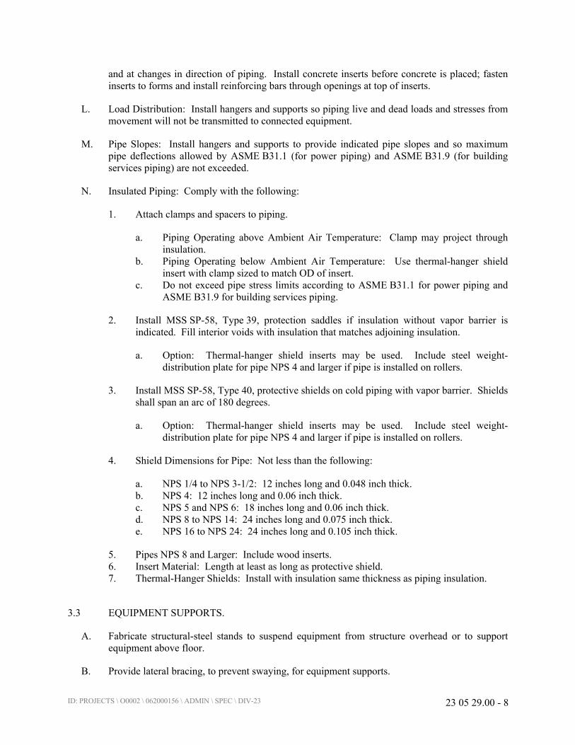
ID: PROJECTS \ O0002 \ 062000156 \ ADMIN \ SPEC \ DIV-23 23 05 29.00 - 8
and at changes in direction of piping. Install concrete inserts before concrete is placed; fasten
inserts to forms and install reinforcing bars through openings at top of inserts.
L. Load Distribution: Install hangers and supports so piping live and dead loads and stresses from
movement will not be transmitted to connected equipment.
M. Pipe Slopes: Install hangers and supports to provide indicated pipe slopes and so maximum
pipe deflections allowed by ASME B31.1 (for power piping) and ASME B31.9 (for building
services piping) are not exceeded.
N. Insulated Piping: Comply with the following:
1. Attach clamps and spacers to piping.
a. Piping Operating above Ambient Air Temperature: Clamp may project through
insulation.
b. Piping Operating below Ambient Air Temperature: Use thermal-hanger shield
insert with clamp sized to match OD of insert.
c. Do not exceed pipe stress limits according to ASME B31.1 for power piping and
ASME B31.9 for building services piping.
2. Install MSS SP-58, Type 39, protection saddles if insulation without vapor barrier is
indicated. Fill interior voids with insulation that matches adjoining insulation.
a. Option: Thermal-hanger shield inserts may be used. Include steel weight-
distribution plate for pipe NPS 4 and larger if pipe is installed on rollers.
3. Install MSS SP-58, Type 40, protective shields on cold piping with vapor barrier. Shields
shall span an arc of 180 degrees.
a. Option: Thermal-hanger shield inserts may be used. Include steel weight-
distribution plate for pipe NPS 4 and larger if pipe is installed on rollers.
4. Shield Dimensions for Pipe: Not less than the following:
a. NPS 1/4 to NPS 3-1/2: 12 inches long and 0.048 inch thick.
b. NPS 4: 12 inches long and 0.06 inch thick.
c. NPS 5 and NPS 6: 18 inches long and 0.06 inch thick.
d. NPS 8 to NPS 14: 24 inches long and 0.075 inch thick.
e. NPS 16 to NPS 24: 24 inches long and 0.105 inch thick.
5. Pipes NPS 8 and Larger: Include wood inserts.
6. Insert Material: Length at least as long as protective shield.
7. Thermal-Hanger Shields: Install with insulation same thickness as piping insulation.
3.3 EQUIPMENT SUPPORTS.
A. Fabricate structural-steel stands to suspend equipment from structure overhead or to support
equipment above floor.
B. Provide lateral bracing, to prevent swaying, for equipment supports.
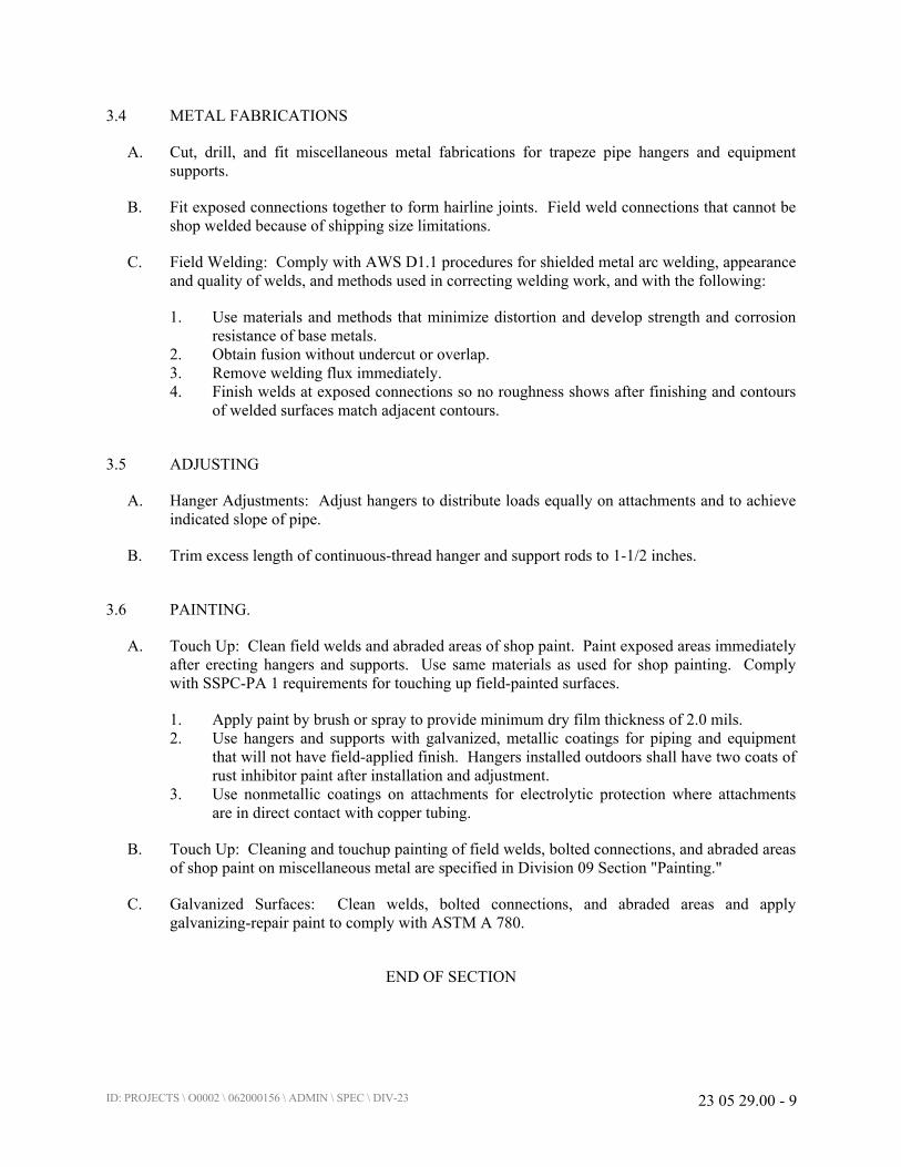
ID: PROJECTS \ O0002 \ 062000156 \ ADMIN \ SPEC \ DIV-23 23 05 29.00 - 9
3.4 METAL FABRICATIONS
A. Cut, drill, and fit miscellaneous metal fabrications for trapeze pipe hangers and equipment
supports.
B. Fit exposed connections together to form hairline joints. Field weld connections that cannot be
shop welded because of shipping size limitations.
C. Field Welding: Comply with AWS D1.1 procedures for shielded metal arc welding, appearance
and quality of welds, and methods used in correcting welding work, and with the following:
1. Use materials and methods that minimize distortion and develop strength and corrosion
resistance of base metals.
2. Obtain fusion without undercut or overlap.
3. Remove welding flux immediately.
4. Finish welds at exposed connections so no roughness shows after finishing and contours
of welded surfaces match adjacent contours.
3.5 ADJUSTING
A. Hanger Adjustments: Adjust hangers to distribute loads equally on attachments and to achieve
indicated slope of pipe.
B. Trim excess length of continuous-thread hanger and support rods to 1-1/2 inches.
3.6 PAINTING.
A. Touch Up: Clean field welds and abraded areas of shop paint. Paint exposed areas immediately
after erecting hangers and supports. Use same materials as used for shop painting. Comply
with SSPC-PA 1 requirements for touching up field-painted surfaces.
1. Apply paint by brush or spray to provide minimum dry film thickness of 2.0 mils.
2. Use hangers and supports with galvanized, metallic coatings for piping and equipment
that will not have field-applied finish. Hangers installed outdoors shall have two coats of
rust inhibitor paint after installation and adjustment.
3. Use nonmetallic coatings on attachments for electrolytic protection where attachments
are in direct contact with copper tubing.
B. Touch Up: Cleaning and touchup painting of field welds, bolted connections, and abraded areas
of shop paint on miscellaneous metal are specified in Division 09 Section "Painting."
C. Galvanized Surfaces: Clean welds, bolted connections, and abraded areas and apply
galvanizing-repair paint to comply with ASTM A 780.
END OF SECTION

ID: PROJECTS \ O0002 \ 062000156 \ ADMIN \ SPEC \ DIV-23 23 05 93.00 - 1
SECTION 23 05 93.00
TESTING, ADJUSTING, AND BALANCING FOR HVAC
PART 1 - GENERAL
1.1 SUMMARY
A. Section includes procedural requirements for testing, adjusting, and balancing (TAB) of new
and existing systems to achieve the required flows within the limits of the fan and the motor HP.
The testing, adjusting, and balancing work includes producing design objectives for the
following:
1. Air Systems:
a. Constant-volume air systems.
b. Existing Systems.
2. Hydronic Piping Systems:
a. Variable-flow systems.
b. Heat Transfer Coils.
3. HVAC equipment quantitative-performance settings.
1.2 DEFINITIONS
A. AABC: Associated Air Balance Council.
B. NEBB: National Environmental Balancing Bureau.
C. TAB: Testing, Adjusting, and Balancing.
D. TABB: Testing, Adjusting, and Balancing Bureau.
E. TAB Firm: Entity responsible for performing and reporting TAB procedures.
F. TAB Specialist: Entity engaged by TAB Firm to perform TAB work.
1.3 SUBMITTALS
A. Qualification Data: Within 30 days of Notice to Proceed, submit documentation for the TAB
contractor and the Project's TAB team members.
B. Contract Documents Examination Report: Within 30 days of Notice to Proceed, submit the
Contract Documents Examination Report.
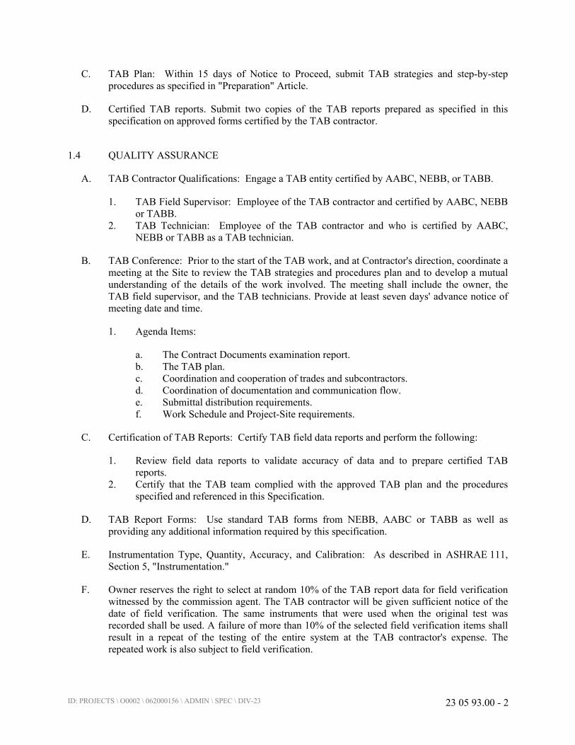
ID: PROJECTS \ O0002 \ 062000156 \ ADMIN \ SPEC \ DIV-23 23 05 93.00 - 2
C. TAB Plan: Within 15 days of Notice to Proceed, submit TAB strategies and step-by-step
procedures as specified in "Preparation" Article.
D. Certified TAB reports. Submit two copies of the TAB reports prepared as specified in this
specification on approved forms certified by the TAB contractor.
1.4 QUALITY ASSURANCE
A. TAB Contractor Qualifications: Engage a TAB entity certified by AABC, NEBB, or TABB.
1. TAB Field Supervisor: Employee of the TAB contractor and certified by AABC, NEBB
or TABB.
2. TAB Technician: Employee of the TAB contractor and who is certified by AABC,
NEBB or TABB as a TAB technician.
B. TAB Conference: Prior to the start of the TAB work, and at Contractor's direction, coordinate a
meeting at the Site to review the TAB strategies and procedures plan and to develop a mutual
understanding of the details of the work involved. The meeting shall include the owner, the
TAB field supervisor, and the TAB technicians. Provide at least seven days' advance notice of
meeting date and time.
1. Agenda Items:
a. The Contract Documents examination report.
b. The TAB plan.
c. Coordination and cooperation of trades and subcontractors.
d. Coordination of documentation and communication flow.
e. Submittal distribution requirements.
f. Work Schedule and Project-Site requirements.
C. Certification of TAB Reports: Certify TAB field data reports and perform the following:
1. Review field data reports to validate accuracy of data and to prepare certified TAB
reports.
2. Certify that the TAB team complied with the approved TAB plan and the procedures
specified and referenced in this Specification.
D. TAB Report Forms: Use standard TAB forms from NEBB, AABC or TABB as well as
providing any additional information required by this specification.
E. Instrumentation Type, Quantity, Accuracy, and Calibration: As described in ASHRAE 111,
Section 5, "Instrumentation."
F. Owner reserves the right to select at random 10% of the TAB report data for field verification
witnessed by the commission agent. The TAB contractor will be given sufficient notice of the
date of field verification. The same instruments that were used when the original test was
recorded shall be used. A failure of more than 10% of the selected field verification items shall
result in a repeat of the testing of the entire system at the TAB contractor's expense. The
repeated work is also subject to field verification.
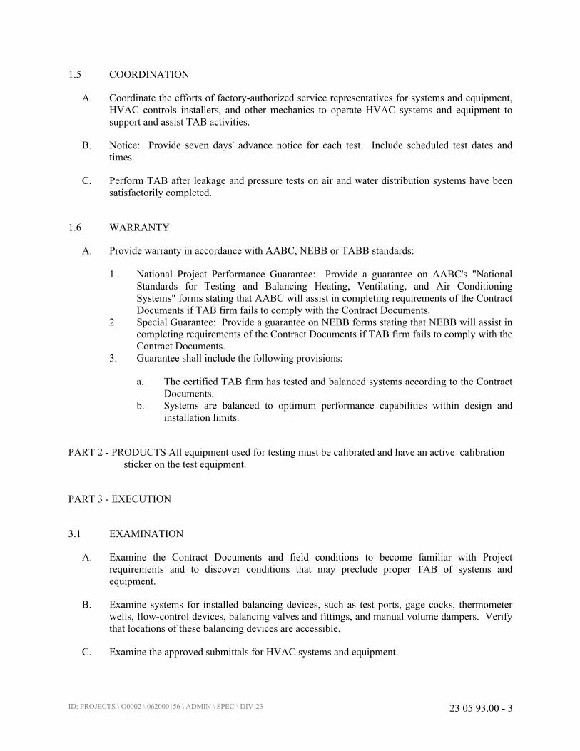
ID: PROJECTS \ O0002 \ 062000156 \ ADMIN \ SPEC \ DIV-23 23 05 93.00 - 3
1.5 COORDINATION
A. Coordinate the efforts of factory-authorized service representatives for systems and equipment,
HVAC controls installers, and other mechanics to operate HVAC systems and equipment to
support and assist TAB activities.
B. Notice: Provide seven days' advance notice for each test. Include scheduled test dates and
times.
C. Perform TAB after leakage and pressure tests on air and water distribution systems have been
satisfactorily completed.
1.6 WARRANTY
A. Provide warranty in accordance with AABC, NEBB or TABB standards:
1. National Project Performance Guarantee: Provide a guarantee on AABC's "National
Standards for Testing and Balancing Heating, Ventilating, and Air Conditioning
Systems" forms stating that AABC will assist in completing requirements of the Contract
Documents if TAB firm fails to comply with the Contract Documents.
2. Special Guarantee: Provide a guarantee on NEBB forms stating that NEBB will assist in
completing requirements of the Contract Documents if TAB firm fails to comply with the
Contract Documents.
3. Guarantee shall include the following provisions:
a. The certified TAB firm has tested and balanced systems according to the Contract
Documents.
b. Systems are balanced to optimum performance capabilities within design and
installation limits.
PART 2 - PRODUCTS All equipment used for testing must be calibrated and have an active calibration
sticker on the test equipment.
PART 3 - EXECUTION
3.1 EXAMINATION
A. Examine the Contract Documents and field conditions to become familiar with Project
requirements and to discover conditions that may preclude proper TAB of systems and
equipment.
B. Examine systems for installed balancing devices, such as test ports, gage cocks, thermometer
wells, flow-control devices, balancing valves and fittings, and manual volume dampers. Verify
that locations of these balancing devices are accessible.
C. Examine the approved submittals for HVAC systems and equipment.

ID: PROJECTS \ O0002 \ 062000156 \ ADMIN \ SPEC \ DIV-23 23 05 93.00 - 4
D. Examine design data including HVAC system descriptions, statements of design assumptions
for environmental conditions and systems' output, and statements of philosophies and
assumptions about HVAC system and equipment controls.
E. Examine system and equipment installations and verify that field quality-control testing,
cleaning, and adjusting specified in individual Sections have been performed.
F. Examine test reports specified in individual system and equipment Sections.
G. Examine terminal units, such as variable-air-volume boxes, and verify that they are accessible
and their controls are connected and functioning.
H. Examine strainers. Verify that screens are clean and proper perforations are provided. Verify
that startup screens are replaced by permanent screens with indicated perforations.
I. Examine two-way valves for proper installation for their intended function of diverting or
mixing fluid flows.
J. Examine heat-transfer coils for correct piping connections and for clean and straight fins.
K. Examine system pumps to ensure absence of entrained air in the suction piping.
L. Examine equipment for installation and properly operating safety interlocks and controls.
M. Report deficiencies discovered before and during performance of TAB procedures. Observe
and record system reactions to changes in conditions. Record default set points if different from
indicated values.
3.2 PREPARATION
A. Prepare a TAB Plan that includes strategies and step-by-step procedures.
B. Complete system-readiness checks and prepare reports. Verify the following:
1. Permanent electrical-power wiring is complete.
2. Hydronic systems are filled, clean, and free of air.
3. Automatic temperature-control systems are operational.
4. Equipment and duct access doors are securely closed.
5. Balance, smoke, and fire dampers are open.
6. Isolating and balancing valves are open and control valves are operational.
7. Ceilings are installed in critical areas where air-pattern adjustments are required and
access to balancing devices is provided.
8. Windows and doors can be closed so indicated conditions for system operations can be
met.
3.3 GENERAL PROCEDURES FOR TESTING AND BALANCING
A. Perform testing and balancing procedures on each system according to the procedures contained
in AABC's "National Standards for Total System Balance," ASHRAE 111, NEBB's "Procedural
ID: PROJECTS \ O0002 \ 062000156 \ ADMIN \ SPEC \ DIV-23 23 05 93.00 - 5
Standards for Testing, Adjusting, and Balancing of Environmental Systems," or SMACNA's
"HVAC Systems - Testing, Adjusting, and Balancing," and this Section.
1. Comply with requirements in ASHRAE 62.1-2007, Section 7.2.2, "Air Balancing."
B. Cut insulation, ducts, pipes, and equipment cabinets for installation of test probes to the
minimum extent necessary for TAB procedures.
1. After testing and balancing, patch probe holes in ducts with same material and thickness
as used to construct ducts.
C. Mark equipment and balancing devices, including damper-control positions, valve position
indicators, fan-speed-control levers, and similar controls and devices, with paint or other
suitable, permanent identification material to show final settings.
D. Take and report testing and balancing measurements in inch-pound (IP) units.
E. HVAC system lineup. The contractor will test the system in the normal system lineups.
1. A hydronic system with two chillers designed to run at the same time, the system will be
balanced with pumps flowing to both chillers. All pump data will also be collected when
the pump is flowing to only one chiller.
2. Air systems will be balanced while aligned for minimum outside air flow and the position
of the outside air dampers will be recorded for the minimum position.
3. It s not acceptable to balance air systems when the normal boundaries, doors, walls, or
ductwork are not in their design configuration.
3.4 GENERAL PROCEDURES FOR BALANCING AIR SYSTEMS
A. Prepare test reports for both fans and outlets. Obtain manufacturer's outlet factors and
recommended testing procedures. Crosscheck the summation of required outlet volumes with
required fan volumes.
B. Prepare schematic diagrams of systems' "as-built" duct layouts.
C. For variable-air-volume systems, develop a plan to simulate diversity.
D. Determine the best locations in main and branch ducts for accurate duct-airflow measurements.
E. Check airflow patterns from the outdoor-air louvers and dampers and the return- and exhaust-air
dampers through the supply-fan discharge and mixing dampers.
F. Locate start-stop and disconnect switches, electrical interlocks, and motor starters.
G. Verify that motor starters are equipped with properly sized thermal protection.
H. Check dampers for proper position to achieve desired airflow path.
I. Check for airflow blockages.
J. Check condensate drains for proper connections and functioning.

ID: PROJECTS \ O0002 \ 062000156 \ ADMIN \ SPEC \ DIV-23 23 05 93.00 - 6
K. Check for proper sealing of air-handling-unit components.
L. Check for proper sealing of air duct system.
3.5 PROCEDURES FOR CONSTANT-VOLUME AIR SYSTEMS
A. Make note of existing cfm air flow going to this room before replacing any equipment. New
system flow should be no less than original flow.
1. Measure total airflow.
a. Where sufficient space in ducts is unavailable for Pitot-tube traverse
measurements, measure airflow at terminal outlets and inlets and calculate the total
airflow.
2. Measure fan static pressures as follows to determine actual static pressure:
a. Measure outlet static pressure as far downstream from the fan as practical and
upstream from restrictions in ducts such as elbows and transitions.
b. Measure static pressure directly at the fan outlet or through the flexible connection.
c. Measure inlet static pressure of single-inlet fans in the inlet duct as near the fan as
possible, upstream from the flexible connection, and downstream from duct
restrictions.
d. Measure inlet static pressure of double-inlet fans through the wall of the plenum
that houses the fan.
3. Measure static pressure across each component that makes up an air-handling unit,
rooftop unit, and other air-handling and -treating equipment.
a. Report the cleanliness status of filters and the time static pressures are measured.
4. Measure static pressures entering and leaving other devices, such as sound traps, heat-
recovery equipment, and air washers, under final balanced conditions.
5. Review Record Documents to determine variations in design static pressures versus
actual static pressures. Calculate actual system-effect factors. Recommend adjustments
to accommodate actual conditions.
6. Do not make fan-speed adjustments that result in motor overload. Consult equipment
manufacturers about fan-speed safety factors. Modulate dampers and measure fan-motor
amperage to ensure that no overload will occur. Measure amperage in full-cooling, full-
heating, economizer, and any other operating mode to determine the maximum required
brake horsepower.
B. Adjust volume dampers for main duct, sub-main ducts, and major branch ducts to indicated
airflows within specified tolerances.
1. Measure airflow of sub-main and branch ducts.
a. Where sufficient space in sub-main and branch ducts is unavailable for Pitot-tube
traverse measurements, measure airflow at terminal outlets and inlets and calculate
the total airflow for that zone.

ID: PROJECTS \ O0002 \ 062000156 \ ADMIN \ SPEC \ DIV-23 23 05 93.00 - 7
2. Measure static pressure at a point downstream from the balancing damper, and adjust
volume dampers until the proper static pressure is achieved.
3. Re-measure each sub-main and branch duct after all have been adjusted. Continue to
adjust sub-main and branch ducts to indicated airflows within specified tolerances.
C. Measure air outlets and inlets without making adjustments.
1. Measure terminal outlets using a direct-reading hood or outlet manufacturer's written
instructions and calculating factors.
D. Adjust air outlets and inlets for each space to indicated airflows within specified tolerances of
indicated values. Make adjustments using branch volume dampers rather than extractors and
the dampers at air terminals.
1. Adjust each outlet in same room or space to within specified tolerances of indicated
quantities without generating noise levels above the limitations prescribed by the
Contract Documents.
2. Adjust patterns of adjustable outlets for proper distribution without drafts.
3.6 PROCEDURES FOR CONSTANT -AIR-VOLUME SYSTEMS
A. Compensating for Diversity: When the total airflow of all terminal units is more than the
indicated airflow of the fan, place the selected air terminal units at its required airflow with the
remainder at maximum-airflow condition until the total airflow of the terminal units equals the
indicated airflow required by the space.
1. Minimum outside air flow rate must be verified under three conditions, with the OA
damper position recorded in each configuration.
a. This system will be utilizing the original fresh air percentage that is existing at
from the main system for this remodel.
B. Pressure-Independent, Air-Volume Systems: After the fan systems have been adjusted, adjust
the variable-air-volume systems as follows:
1. Set outdoor-air dampers at minimum, and set return- and exhaust-air dampers at a
position that simulates full-cooling load.
2. Select the terminal unit that is most critical to the supply-fan airflow and static pressure.
Measure static pressure. Adjust system static pressure so the entering static pressure for
the critical terminal unit is not less than the sum of the terminal-unit manufacturer's
recommended minimum inlet static pressure plus the static pressure needed to overcome
terminal-unit discharge system losses.
3. Measure total system airflow. Adjust to within indicated airflow.
4. Set terminal units at maximum airflow and adjust controller or regulator to deliver the
designed maximum airflow. Use terminal-unit manufacturer's written instructions to
make this adjustment. When total airflow is correct, balance the air outlets downstream
from terminal units the same as described for constant-volume air systems.
5. Set terminal units at minimum airflow and adjust controller or regulator to deliver the
designed minimum airflow. Check air outlets for a proportional reduction in airflow the
same as described for constant-volume air systems.

ID: PROJECTS \ O0002 \ 062000156 \ ADMIN \ SPEC \ DIV-23 23 05 93.00 - 8
a. If air outlets are out of balance at minimum airflow, report the condition but leave
outlets balanced for maximum airflow.
6. Measure the exhaust airflow to the return duct while operating at supply air flow airflow
and minimum outdoor cfm.
a. Adjust the fan and balance the return-air ducts and inlets the same as described for
constant-volume air systems.
3.7 GENERAL PROCEDURES FOR HYDRONIC SYSTEMS
A. Prepare test reports with pertinent design data, and number in sequence starting at pump to end
of system. Check the sum of branch-circuit flows against the approved pump flow rate. Correct
variations that exceed plus or minus 5 percent.
B. Prepare schematic diagrams of systems' "as-built" piping layouts.
C. Prepare hydronic systems for testing and balancing according to the following, in addition to the
general preparation procedures specified above:
1. Open all manual valves for maximum flow.
2. Check liquid level in expansion tank.
3. Check makeup water-station pressure gage for adequate pressure for highest vent.
4. Check flow-control valves for specified sequence of operation, and set at indicated flow.
5. Set differential-pressure control valves at the specified differential pressure. Do not set at
fully closed position when pump is positive-displacement type unless several terminal
valves are kept open.
6. Set system controls so automatic valves are wide open to heat exchangers.
7. Check pump-motor load. If motor is overloaded, throttle main flow-balancing device so
motor nameplate rating is not exceeded.
8. Check air vents for a forceful liquid flow exiting from vents when manually operated.
3.8 PROCEDURES FOR VARIABLE-FLOW HYDRONIC SYSTEMS
A. Balance systems with automatic two-way control valves by setting systems at maximum flow
through heat-exchange terminals and proceed as specified above for hydronic systems.
3.9 PROCEDURES FOR PRIMARY-SECONDARY HYDRONIC SYSTEMS
A. Balance the primary circuit flow first and then balance the secondary circuits.
3.10 PROCEDURES FOR HEAT EXCHANGERS
A. Measure water flow through all circuits.
B. Adjust water flow to within specified tolerances.
C. Measure inlet and outlet water temperatures.
ID: PROJECTS \ O0002 \ 062000156 \ ADMIN \ SPEC \ DIV-23 23 05 93.00 - 9
D. Measure inlet steam pressure.
E. Check settings and operation of safety and relief valves. Record settings.
3.11 PROCEDURES FOR HEAT-TRANSFER COILS
A. Measure, adjust, and record the following data for each water coil:
1. Entering- and leaving-water temperature.
2. Water flow rate.
3. Water pressure drop.
4. Dry-bulb temperature of entering and leaving air.
5. Wet-bulb temperature of entering and leaving air for cooling coils.
6. Airflow.
7. Air pressure drop.
B. Measure, adjust, and record the following data for each electric heating coil:
1. Nameplate data.
2. Airflow.
3. Entering- and leaving-air temperature at full load.
4. Voltage and amperage input of each phase at full load and at each incremental stage.
5. Calculated kilowatt at full load.
6. Fuse or circuit-breaker rating for overload protection.
C. Measure, adjust, and record the following data for each steam coil:
1. Dry-bulb temperature of entering and leaving air.
2. Airflow.
3. Air pressure drop.
4. Inlet steam pressure.
D. Measure, adjust, and record the following data for each refrigerant coil:
1. Dry-bulb temperature of entering and leaving air.
2. Wet-bulb temperature of entering and leaving air.
3. Airflow.
4. Air pressure drop.
5. Refrigerant suction pressure and temperature.
3.12 PROCEDURES FOR TESTING, ADJUSTING, AND BALANCING EXISTING SYSTEMS
A. Perform a preconstruction inspection of existing equipment that is to remain and be reused.
1. Measure and record the operating speed, airflow, and static pressure of each fan.
2. Measure motor voltage and amperage. Compare the values to motor nameplate
information.
3. Check the refrigerant charge.
4. Check the condition of filters.

ID: PROJECTS \ O0002 \ 062000156 \ ADMIN \ SPEC \ DIV-23 23 05 93.00 - 10
5. Check the condition of coils.
6. Check the operation of the drain pan and condensate-drain trap.
7. Check bearings and other lubricated parts for proper lubrication.
8. Report on the operating condition of the equipment and the results of the measurements
taken. Report deficiencies.
B. Before performing testing and balancing of existing systems, inspect existing equipment that is
to remain and be reused to verify that existing equipment has been cleaned and refurbished.
Verify the following:
1. New filters are installed.
2. Coils are clean and fins combed.
3. Drain pans are clean.
4. Fans are clean.
5. Bearings and other parts are properly lubricated.
6. Deficiencies noted in the preconstruction report are corrected.
C. Perform testing and balancing of existing systems. Adjust fans to deliver total indicated
airflows within the maximum allowable fan speed listed by fan manufacturer and within the
limits of the motor HP. All fans shall deliver the design air flow capacity at actual static
pressure up to design static. Fan sheaves shall be replaced as necessary to obtain desire results.
1. Compare the indicated airflow of the renovated work to the measured fan airflows, and
determine the new fan speed and the face velocity of filters and coils.
2. Verify that the indicated airflows of the renovated work result in filter and coil face
velocities and fan speeds that are within the acceptable limits defined by equipment
manufacturer.
3. Balance each air outlet.
3.13 TEMPERATURE-CONTROL VERIFICATION
A. Verify that controllers are calibrated and commissioned.
B. Check transmitter and controller locations and note conditions that would adversely affect
control functions.
C. Record controller settings and note variances between set points and actual measurements.
D. Check the operation of limiting controllers (i.e., high- and low-temperature controllers).
E. Check free travel and proper operation of control devices such as damper and valve operators.
F. Check the sequence of operation of control devices. Note air pressures and device positions and
correlate with airflow and water flow measurements. Note the speed of response to input
changes.
G. Check the interaction of electrically operated switch transducers.
H. Check the interaction of interlock and lockout systems.

ID: PROJECTS \ O0002 \ 062000156 \ ADMIN \ SPEC \ DIV-23 23 05 93.00 - 11
I. Check main control supply-air pressure and observe compressor and dryer operations.
J. Record voltages of power supply and controller output. Determine whether the system operates
on a grounded or nongrounded power supply.
K. Note operation of electric actuators using spring return for proper fail-safe operations.
3.14 TOLERANCES
A. Set HVAC system air flow rates and water flow rates within the following tolerances:
1. Supply, Return, and Exhaust Fans and Equipment with Fans: Plus or minus 10 percent.
2. Air Outlets and Inlets: Plus or minus 10 percent.
3. Heating-Water Flow Rate: Plus or minus 10 percent.
3.15 REPORTING
A. Initial Construction-Phase Report: Based on examination of the Contract Documents as
specified in "Examination" Article, prepare a report on the adequacy of design for systems'
balancing devices. Recommend changes and additions to systems' balancing devices to
facilitate proper performance measuring and balancing. Recommend changes and additions to
HVAC systems and general construction to allow access for performance measuring and
balancing devices.
3.16 FINAL REPORT
A. General: Prepare a certified written report; tabulate and divide the report into separate sections
for tested systems and balanced systems.
1. Include a certification sheet at the front of the report's binder, signed and sealed by the
certified testing and balancing engineer.
2. Include a list of instruments used for procedures, along with proof of calibration.
B. Final Report Contents: In addition to certified field-report data, include the following:
1. Pump curves.
2. Fan curves.
3. Manufacturers' test data.
4. Field test reports prepared by system and equipment installers.
5. Other information relative to equipment performance; do not include Shop Drawings and
product data.
C. General Report Data: In addition to form titles and entries, include the following data:
1. Title page.
2. Name and address of the TAB contractor.
3. Project name.
4. Project location.
5. Architect's name and address.
ID: PROJECTS \ O0002 \ 062000156 \ ADMIN \ SPEC \ DIV-23 23 05 93.00 - 12
6. Engineer's name and address.
7. Contractor's name and address.
8. Report date.
9. Signature of TAB supervisor who certifies the report.
10. Table of Contents with the total number of pages defined for each section of the report.
Number each page in the report.
11. Summary of contents including the following:
a. Indicated versus final performance.
b. Notable characteristics of systems.
c. Description of system operation sequence if it varies from the Contract
Documents.
12. Nomenclature sheets for each item of equipment.
13. Data for terminal units, including manufacturer's name, type, size, and fittings.
14. Notes to explain why certain final data in the body of reports vary from indicated values.
15. Test conditions for fans and pump performance forms including the following:
a. Settings for outdoor-, return-, and exhaust-air dampers.
b. Conditions of filters.
c. Cooling coil, wet- and dry-bulb conditions.
d. Face and bypass damper settings at coils.
e. Fan drive settings including settings and percentage of maximum pitch diameter.
f. Inlet vane settings for variable-air-volume systems.
g. Settings for supply-air, static-pressure controller.
h. Other system operating conditions that affect performance.
D. System Diagrams: Include schematic layouts of air and hydronic distribution systems. Present
each system with single-line diagram and include the following:
1. Quantities of outdoor, supply, return, and exhaust airflows.
2. Water and steam flow rates.
3. Duct, outlet, and inlet sizes.
4. Pipe and valve sizes and locations.
5. Terminal units.
6. Balancing stations.
7. Position of balancing devices.
E. Round, Flat-Oval, and Rectangular Duct Traverse Reports: Include a diagram with a grid
representing the duct cross-section and record the following:
1. Report Data:
a. System and air-handling-unit number.
b. Location and zone.
c. Traverse air temperature in deg F.
d. Duct static pressure in inches wg.
e. Duct size in inches.
f. Duct area in sq. ft.
g. Indicated air flow rate in cfm.
h. Indicated velocity in fpm.
ID: PROJECTS \ O0002 \ 062000156 \ ADMIN \ SPEC \ DIV-23 23 05 93.00 - 13
i. Actual air flow rate in cfm.
j. Actual average velocity in fpm.
k. Barometric pressure in psig.
F. Air-Terminal-Device Reports:
1. Unit Data:
a. System and air-handling unit identification.
b. Location and zone.
c. Apparatus used for test.
d. Area served.
e. Make.
f. Number from system diagram.
g. Type and model number.
h. Size.
i. Effective area in sq. ft.
2. Test Data (Indicated and Actual Values):
a. Air flow rate in cfm
b. Air velocity in fpm
c. Preliminary air flow rate as needed in cfm
d. Preliminary velocity as needed in fpm
e. Final air flow rate in cfm
f. Final velocity in fpm
g. Space temperature in deg F
G. System-Coil Reports: For reheat coils and water coils of terminal units, include the following:
1. Unit Data:
a. System and air-handling-unit identification.
b. Location and zone.
c. Room or riser served.
d. Coil make and size.
e. Flowmeter type.
2. Test Data (Indicated and Actual Values):
a. Air flow rate in cfm
b. Entering-water temperature in deg F.
c. Leaving-water temperature in deg F.
d. Water pressure drop in feet of head or psig.
e. Entering-air temperature in deg F.
f. Leaving-air temperature in deg F.
3. Test Data (Indicated and Actual Values):
a. Inlet-duct static pressure in inches wg.
b. Outlet-duct static pressure in inches wg.

ID: PROJECTS \ O0002 \ 062000156 \ ADMIN \ SPEC \ DIV-23 23 05 93.00 - 14
c. Entering-air, dry-bulb temperature in deg F.
d. Leaving-air, dry-bulb temperature in deg F.
e. Condenser entering-water temperature in deg F.
f. Condenser leaving-water temperature in deg F.
g. Condenser-water temperature differential in deg F.
h. Condenser entering-water pressure in feet of head or psig.
i. Condenser leaving-water pressure in feet of head or psig.
j. Condenser-water pressure differential in feet of head or psig.
k. Control settings.
l. Unloader set points.
m. Low-pressure-cutout set point in psig.
n. High-pressure-cutout set point in psig.
o. Suction pressure in psig.
p. Suction temperature in deg F.
q. Condenser refrigerant pressure in psig.
r. Condenser refrigerant temperature in deg F.
s. Oil pressure in psig.
t. Oil temperature in deg F.
u. Voltage at each connection.
v. Amperage for each phase.
w. Kilowatt input.
x. Crankcase heater kilowatt.
y. Number of fans.
z. Condenser fan rpm.
aa. Condenser fan airflow rate in cfm.
bb. Condenser fan motor make, frame size, rpm, and horsepower.
cc. Condenser fan motor voltage at each connection.
dd. Condenser fan motor amperage for each phase.
H. Heat-Exchanger/Converter Test Reports: For steam and hot-water heat exchangers, include the
following:
1. Unit Data:
a. Unit identification.
b. Location.
c. Service.
d. Make and type.
e. Model and serial numbers.
f. Ratings.
2. Primary Water Test Data (Indicated and Actual Values):
a. Entering-water temperature in deg F.
b. Leaving-water temperature in deg F.
c. Entering-water pressure in feet of head or psig.
d. Water pressure differential in feet of head or psig.
e. Water flow rate in gpm.
3. Secondary Water Test Data (Indicated and Actual Values):

ID: PROJECTS \ O0002 \ 062000156 \ ADMIN \ SPEC \ DIV-23 23 05 93.00 - 15
a. Entering-water temperature in deg F.
b. Leaving-water temperature in deg F.
c. Entering-water pressure in feet of head or psig.
d. Water pressure differential in feet of head or psig.
e. Water flow rate in gpm
I. Boiler Test Reports:
1. Unit Data:
a. Unit identification.
b. Location.
c. Service.
d. Make and type.
e. Model and serial numbers.
f. Fuel type and input in Btuh.
g. Number of passes.
h. Ignition type.
i. Burner-control types.
j. Voltage at each connection.
k. Amperage for each phase.
2. Test Data (Indicated and Actual Values):
a. Operating pressure in psig.
b. Operating temperature in deg F.
c. Entering-water temperature in deg F.
d. Leaving-water temperature in deg F.
e. Number of safety valves and sizes in NPS.
f. Safety valve settings in psig.
g. High-limit setting in psig.
h. Operating-control setting.
i. High-fire set point.
j. Low-fire set point.
k. Voltage at each connection.
l. Amperage for each phase.
m. Draft fan voltage at each connection.
n. Draft fan amperage for each phase.
o. Manifold pressure in psig.
J. Instrument Calibration Reports:
1. Report Data:
a. Instrument type and make.
b. Serial number.
c. Application.
d. Dates of use.
e. Dates of calibration.
ID: PROJECTS \ O0002 \ 062000156 \ ADMIN \ SPEC \ DIV-23 23 05 93.00 - 16
3.17 INSPECTIONS
A. Initial Inspection:
1. After testing and balancing are complete, operate each system and randomly check
measurements to verify that the system is operating according to the final test and balance
readings documented in the final report.
2. Check the following for each system:
a. Measure airflow of at least 10 percent of air outlets.
b. Measure water flow of at least 5 percent of terminals.
c. Measure room temperature at each thermostat/temperature sensor. Compare the
reading to the set point.
d. Verify that balancing devices are marked with final balance position.
e. Note deviations from the Contract Documents in the final report.
B. Final Inspection:
1. After initial inspection is complete and documentation by random checks verifies that
testing and balancing are complete and accurately documented in the final report, request
that a final inspection be made by Owner’s Representative.
2. The TAB contractor's test and balance engineer shall conduct the inspection in the
presence of the Board Authorized Representative.
3. The Board Authorized Representative shall randomly select measurements, documented
in the final report, to be rechecked. Rechecking shall be limited to either 10 percent of
the total measurements recorded or the extent of measurements that can be accomplished
in a normal 8-hour business day.
4. If rechecks yield measurements that differ from the measurements documented in the
final report by more than the tolerances allowed, the measurements shall be noted as
"FAILED."
5. If the number of "FAILED" measurements is greater than 10 percent of the total
measurements checked during the final inspection, the testing and balancing shall be
considered incomplete and shall be rejected.
C. TAB Work will be considered defective if it does not pass final inspections. If TAB Work fails,
proceed as follows:
1. Recheck all measurements and make adjustments. Revise the final report and balancing
device settings to include all changes; resubmit the final report and request a second final
inspection.
2. If the second final inspection also fails, Owner may contract the services of another TAB
contractor to complete TAB Work according to the Contract Documents and deduct the
cost of the services from the original TAB contractor's final payment.
D. Prepare test and inspection reports.
3.18 ADDITIONAL TESTS
A. Within 90 days of completing TAB, perform additional TAB to verify that balanced conditions
are being maintained throughout and to correct unusual conditions.
ID: PROJECTS \ O0002 \ 062000156 \ ADMIN \ SPEC \ DIV-23 23 05 93.00 - 17
B. Seasonal Periods: If initial TAB procedures were not performed during near-peak summer and
winter conditions, perform additional TAB during near-peak summer and winter conditions.
END OF SECTION

ID: PROJECTS \ O0002 \ 062000156 \ ADMIN \ SPEC \ DIV-23 23 07 00.00 - 1
SECTION 23 07 00.00
HVAC INSULATION
PART 1 - GENERAL
1.1 SUMMARY
A. Section includes the following materials and accessories for insulating HVAC equipment and
piping that is not factory insulated:
1. Insulation Materials:
a. Calcium silicate.
b. Flexible elastomeric.
c. Mineral fiber.
2. Fire-rated insulation systems.
3. Insulating cements.
4. Adhesives.
5. Mastics.
6. Lagging adhesives.
7. Sealants.
8. Factory-applied jackets.
9. Field-applied jackets.
10. Tapes.
11. Securements.
12. Corner angles.
1.2 DEFINITIONS
A. Hot Surfaces: Normal operating temperatures of 100 deg F or higher.
B. Dual-Temperature Surfaces: Normal operating temperatures that vary from hot to cold.
C. Cold Surfaces: Normal operating temperatures less than 75 deg F.
D. Thermal Resistivity: "R-values" represent the reciprocal of thermal conductivity (K-value).
Thermal conductivity is the rate of heat flow through a homogeneous material exactly 1 inch
thick. Thermal resistivity’s are expressed by the temperature difference in degrees F between
two exposed faces required to cause one Btu to flow through one square foot of material, in one
hour, at a given mean temperature.
1.3 SUBMITTALS
A. Product Data: For each type of product indicated. Include thermal conductivity, thermal
resistivity (R-value), thickness, and jackets (both factory and field applied, if any).

ID: PROJECTS \ O0002 \ 062000156 \ ADMIN \ SPEC \ DIV-23 23 07 00.00 - 2
B. Shop Drawings:
1. Detail application of protective shields, saddles, and inserts at hangers for each type of
insulation and hanger.
2. Detail attachment and covering of heat tracing, if any, inside insulation.
3. Detail insulation application at pipe expansion joints for each type of insulation.
4. Detail insulation application at elbows, fittings, flanges, valves, and specialties for each
type of insulation.
5. Detail removable insulation at piping specialties, equipment connections, and access
panels.
6. Detail application of field-applied jackets.
7. Detail application of identification
8. Detail application at linkages of control devices.
9. Detail field application for each equipment type.
10. Detail outdoor duct insulation installation.
C. Samples: For each type of insulation jacket, and identification indicated. Identify each Sample,
describing product and intended use.
1. Sample Sizes:
a. Preformed Pipe Insulation Materials: 12 inches long by NPS 2.
b. Sheet Form Insulation Materials: 12 inches square.
c. Jacket Materials for Pipe: 12 inches long by NPS 2.
d. Sheet Jacket Materials: 12 inches square.
e. Manufacturer's Color Charts: For products where color is specified, show the full
range of colors available for each type of finish material.
D. Material Test Reports: From a qualified testing agency acceptable to the authorities having
jurisdiction indicating, interpreting, and certifying test results for compliance of insulation
materials, sealers, attachments, cements, and jackets with requirements indicated. Include dates
of tests and test methods employed.
E. Qualification Data: For Installer.
1.4 QUALITY ASSURANCE
A. Installer Qualifications: Skilled mechanics who have successfully completed an apprenticeship
program or another craft training program certified by the Department of Labor, Bureau of
Apprenticeship and Training.
B. Surface-Burning Characteristics: Except where indicated otherwise, insulation and related
materials shall have fire-test-response characteristics indicated, as determined by testing
identical products per ASTM E 84, by UL or another testing and inspecting agency acceptable
to the authorities having jurisdiction. Identify materials with appropriate markings of applicable
testing and inspecting agency.
1. Insulation: Flame-spread index of 25 or less, and smoke-developed index of 50 or less.

ID: PROJECTS \ O0002 \ 062000156 \ ADMIN \ SPEC \ DIV-23 23 07 00.00 - 3
1.5 DELIVERY, STORAGE, AND HANDLING
A. Deliver materials to Project site in original packages and containers with seals unbroken and
bearing manufacturer's original labels, including manufacturer's name, product name, and
directions for storing, handling, and use.
B. Store materials in a clean, dry, fully enclosed, conditioned space where they will be protected
against damage from moisture, humidity, temperature extremes, direct sunlight, surface
contamination, and other causes.
1. Remove damaged or wet insulation from Project site and dispose of legally.
1.6 COORDINATION
A. Coordinate size and location of supports, hangers, and insulation shields specified in
Division 23 Section "Hangers and Supports for Piping and Equipment."
B. Coordinate clearance requirements with piping Installer for piping insulation application, duct
Installer for duct insulation application, and equipment Installer for equipment insulation
application. Before preparing piping and ductwork shop drawings, establish and maintain
clearance requirements for installation of insulation and field-applied jackets and finishes and
for space required for maintenance.
C. Coordinate installation and testing of heat tracing, if required for the Project.
1.7 SCHEDULING
A. Schedule insulation application after pressure testing systems and after installation and testing
of heat tracing, if required for the Project. Insulation application may begin on segments that
have satisfactory test results.
B. Complete installation and concealment of plastic materials as rapidly as possible in each area of
construction.
1.8 WARRANTY
A. Special Warranty: Submit a written warranty, signed by the manufacturer and Installer,
agreeing to replace components that fail in material or workmanship within 18 months from
date of delivery, or one year from date of Preliminary Acceptance / Substantial Completion,
whichever is longer.
PART 2 - PRODUCTS
2.1 INSULATION – GENERAL
A. Products shall not contain asbestos, lead, mercury, or mercury compounds.
ID: PROJECTS \ O0002 \ 062000156 \ ADMIN \ SPEC \ DIV-23 23 07 00.00 - 4
B. Products that come in contact with stainless steel shall have a leachable chloride content of less
than 50 ppm when tested according to ASTM C 871.
C. Insulation materials for use on austenitic stainless steel shall be qualified as acceptable
according to ASTM C 795.
D. Foam insulation materials shall not use CFC or HCFC blowing agents in the manufacturing
process.
2.2 INSULATION MATERIALS
A. Flexible Elastomeric Insulation: Closed-cell, sponge- or expanded-rubber materials. Comply
with ASTM C 534, Type I for tubular materials and Type II for sheet materials.
1. Products: Subject to compliance with requirements, provide one of the following:
a. Aeroflex USA Inc.; Aerocel.
b. Armacell LLC; AP Armaflex.
c. K-Flex USA; Insul-Sheet and Insul-Tube.
B. Mineral-Fiber Blanket Insulation: Mineral or glass fibers bonded with a thermosetting resin.
Comply with ASTM C 553, Type II and ASTM C 1290, Type III with factory-applied FSK
jacket. Factory-applied jacket requirements are specified in Article "Jackets", Paragraph
"Factory-Applied Jackets."
1. Products: Subject to compliance with requirements, provide one of the following:
a. CertainTeed Corp.; SoftTouch Duct Wrap.
b. Johns Manville; Microlite XG.
c. Knauf Insulation; Friendly Feel Duct Wrap.
d. Manson Insulation Inc.; Alley Wrap.
e. Owens Corning; SOFTR All-Service Duct Wrap.
C. Mineral-Fiber Board Insulation: Mineral or glass fibers bonded with a thermosetting resin.
Comply with ASTM C 612, Type IB. For duct and plenum applications, provide insulation
with factory-applied FSK jacket. For equipment applications, provide insulation with factory-
applied ASJ. Factory-applied jacket requirements are specified in Article "Jackets", Paragraph
"Factory-Applied Jackets."
1. Products: Subject to compliance with requirements, provide one of the following:
a. CertainTeed Corp.; Commercial Board.
b. Johns Manville; 800 Series Spin-Glas.
c. Knauf Insulation; Insulation Board.
d. Manson Insulation Inc.; AK Board.
e. Owens Corning; Fiberglas 700 Series.
D. Calcium Silicate Insulation:

ID: PROJECTS \ O0002 \ 062000156 \ ADMIN \ SPEC \ DIV-23 23 07 00.00 - 5
1. Manufacturers: Subject to compliance with requirements, provide products by one of the
following:
a. Industrial Insulation Group, LLC (IIG).
2. Properties:
a. Compressive Strength: ASTM C 165; 100 psi, minimum, at 5 percent deformation.
b. Dry Density, Average: ASTM C 302; 14.0 pcf, minimum.
c. Fire-Test-Response Characteristics: ASTM E 84; flame spread index of 0 and
smoke developed index of 0, as determined by testing identical products per
ASTM E 84 by UL or another testing and inspecting agency acceptable to the
authorities having jurisdiction. Identify materials with appropriate markings of
applicable testing and inspecting agency.
3. Preformed Pipe Sections: Flat-, curved-, and grooved-block sections of noncombustible,
inorganic, hydrous calcium silicate with a non-asbestos fibrous reinforcement. Comply
with ASTM C 533, Type I.
4. Prefabricated Fitting Covers: Comply with ASTM C 450 and ASTM C 585 for
dimensions used in preforming insulation to cover valves, elbows, tees, and flanges.
E. Mineral-Fiber, Preformed Pipe Insulation: Mineral or glass fibers bonded with a thermosetting
resin. Comply with ASTM C 547.
1. Products: Subject to compliance with requirements, provide one of the following:
a. Johns Manville; Micro-Lok.
b. Knauf Insulation; Earthwool 1000º Pipe Insulation.
c. Manson Insulation Inc.; Alley-K.
d. Owens Corning; Fiberglas Pipe Insulation.
2. Type (Typical): For piping up to 850 deg F, provide Type I, Grade A, pipe insulation
with factory-applied ASJ-SSL or ASJ+/SSL, as applicable to manufacturer.
3. Type (High Temperature): For piping up to 1200 deg F, provide Type II, Grade A, pipe
insulation with factory-applied ASJ-SSL or ASJ+/SSL, as applicable to manufacturer.
4. Factory-Applied Jacket: Factory-applied jacket requirements are specified in Article
"Jackets", Paragraph "Factory-Applied Jackets."
F. Mineral-Fiber, Pipe and Tank Insulation: Mineral or glass fibers bonded with a thermosetting
resin. Semirigid board material with factory-applied FSK jacket complying with ASTM C 1393,
Type II or Type IIIA Category 2, or with properties similar to ASTM C 612, Type IB. Nominal
density is 2.5 lbs./cu. ft. or more. Thermal conductivity (k-value) at 100 deg F is 0.29 Btu x
in./h x sq. ft. x deg F or less. Factory-applied jacket requirements are specified in Article
"Jackets", Paragraph "Factory-Applied Jackets."
1. Products: Subject to compliance with requirements, provide one of the following:
a. CertainTeed Corporation; CrimpWrap.
b. Johns Manville; Micro-Flex.
c. Knauf Insulation; KwikFlex Pipe and Tank Insulation.
d. Manson Insulation Inc.; AK Flex.
ID: PROJECTS \ O0002 \ 062000156 \ ADMIN \ SPEC \ DIV-23 23 07 00.00 - 6
e. Owens Corning; Fiberglas Pipe and Tank Insulation.
2.3 FIRE-RATED INSULATION SYSTEMS
A. Fire-Rated Blanket: High-temperature, flexible, blanket insulation with FSK jacket that is
tested and certified to provide a 2-hour fire rating by UL or another testing and inspecting
agency acceptable to the authorities having jurisdiction.
1. Products: Subject to compliance with requirements, provide one of the following:
a. CertainTeed Corp.; FlameChek.
b. Johns Manville; Firetemp Wrap.
c. Nelson Firestop Products; Nelson FSB Flameshield Blanket.
d. Thermal Ceramics; FireMaster Duct Wrap.
e. 3M; Fire Barrier Wrap Products.
f. Unifrax Corporation; FyreWrap.
2.4 INSULATING CEMENTS
A. Mineral-Fiber Insulating Cement: Comply with ASTM C 195.
1. Products: Subject to compliance with requirements, provide one of the following:
a. Insulco, Division of MFS, Inc.; Triple I.
b. Ramco Insulation, Inc.; Supertemp 1900 / PKI Super-Stik.
B. Mineral-Fiber, Hydraulic-Setting Insulating and Finishing Cement: Comply with
ASTM C 449/C 449M.
1. Products: Subject to compliance with requirements, provide one of the following:
a. Insulco, Division of MFS, Inc.; SmoothKote.
b. Ramco Insulation, Inc.; Ramcote 1200 / PKI Quik Cote.
2.5 ADHESIVES
A. Adhesives, General: All adhesives and mastics used on the interior of the building shall comply
with the following, unless otherwise indicated:
1. The testing and product requirements of the California Department of Health Services'
"Standard Practice for the Testing of Volatile Organic Emissions from Various Sources
Using Small-Scale Environmental Chambers," including 2004 Addenda.
B. Compatibility: Materials shall be compatible with insulation materials, jackets, and substrates
and for bonding insulation to itself and to surfaces to be insulated, unless otherwise indicated.
C. Aerosol Adhesives: Aerosol adhesives shall comply with Green Seal Standard for Commercial
Adhesives GS-36 (2000).
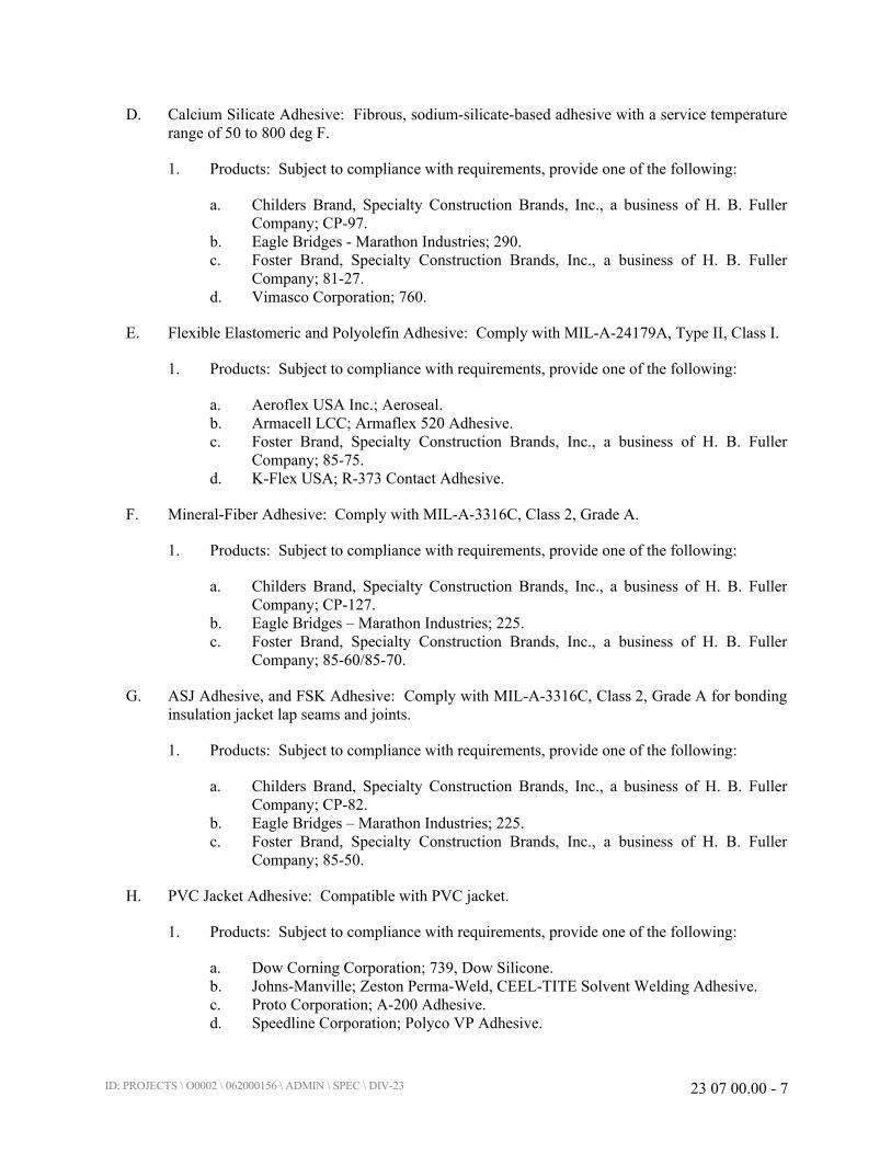
ID: PROJECTS \ O0002 \ 062000156 \ ADMIN \ SPEC \ DIV-23 23 07 00.00 - 7
D. Calcium Silicate Adhesive: Fibrous, sodium-silicate-based adhesive with a service temperature
range of 50 to 800 deg F.
1. Products: Subject to compliance with requirements, provide one of the following:
a. Childers Brand, Specialty Construction Brands, Inc., a business of H. B. Fuller
Company; CP-97.
b. Eagle Bridges - Marathon Industries; 290.
c. Foster Brand, Specialty Construction Brands, Inc., a business of H. B. Fuller
Company; 81-27.
d. Vimasco Corporation; 760.
E. Flexible Elastomeric and Polyolefin Adhesive: Comply with MIL-A-24179A, Type II, Class I.
1. Products: Subject to compliance with requirements, provide one of the following:
a. Aeroflex USA Inc.; Aeroseal.
b. Armacell LCC; Armaflex 520 Adhesive.
c. Foster Brand, Specialty Construction Brands, Inc., a business of H. B. Fuller
Company; 85-75.
d. K-Flex USA; R-373 Contact Adhesive.
F. Mineral-Fiber Adhesive: Comply with MIL-A-3316C, Class 2, Grade A.
1. Products: Subject to compliance with requirements, provide one of the following:
a. Childers Brand, Specialty Construction Brands, Inc., a business of H. B. Fuller
Company; CP-127.
b. Eagle Bridges – Marathon Industries; 225.
c. Foster Brand, Specialty Construction Brands, Inc., a business of H. B. Fuller
Company; 85-60/85-70.
G. ASJ Adhesive, and FSK Adhesive: Comply with MIL-A-3316C, Class 2, Grade A for bonding
insulation jacket lap seams and joints.
1. Products: Subject to compliance with requirements, provide one of the following:
a. Childers Brand, Specialty Construction Brands, Inc., a business of H. B. Fuller
Company; CP-82.
b. Eagle Bridges – Marathon Industries; 225.
c. Foster Brand, Specialty Construction Brands, Inc., a business of H. B. Fuller
Company; 85-50.
H. PVC Jacket Adhesive: Compatible with PVC jacket.
1. Products: Subject to compliance with requirements, provide one of the following:
a. Dow Corning Corporation; 739, Dow Silicone.
b. Johns-Manville; Zeston Perma-Weld, CEEL-TITE Solvent Welding Adhesive.
c. Proto Corporation; A-200 Adhesive.
d. Speedline Corporation; Polyco VP Adhesive.
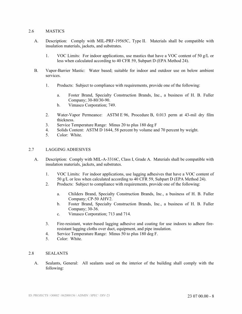
ID: PROJECTS \ O0002 \ 062000156 \ ADMIN \ SPEC \ DIV-23 23 07 00.00 - 8
2.6 MASTICS
A. Description: Comply with MIL-PRF-19565C, Type II. Materials shall be compatible with
insulation materials, jackets, and substrates.
1. VOC Limits: For indoor applications, use mastics that have a VOC content of 50 g/L or
less when calculated according to 40 CFR 59, Subpart D (EPA Method 24).
B. Vapor-Barrier Mastic: Water based; suitable for indoor and outdoor use on below ambient
services.
1. Products: Subject to compliance with requirements, provide one of the following:
a. Foster Brand, Specialty Construction Brands, Inc., a business of H. B. Fuller
Company; 30-80/30-90.
b. Vimasco Corporation; 749.
2. Water-Vapor Permeance: ASTM E 96, Procedure B, 0.013 perm at 43-mil dry film
thickness.
3. Service Temperature Range: Minus 20 to plus 180 deg F
4. Solids Content: ASTM D 1644, 58 percent by volume and 70 percent by weight.
5. Color: White.
2.7 LAGGING ADHESIVES
A. Description: Comply with MIL-A-3316C, Class I, Grade A. Materials shall be compatible with
insulation materials, jackets, and substrates.
1. VOC Limits: For indoor applications, use lagging adhesives that have a VOC content of
50 g/L or less when calculated according to 40 CFR 59, Subpart D (EPA Method 24).
2. Products: Subject to compliance with requirements, provide one of the following:
a. Childers Brand, Specialty Construction Brands, Inc., a business of H. B. Fuller
Company; CP-50 AHV2.
b. Foster Brand, Specialty Construction Brands, Inc., a business of H. B. Fuller
Company; 30-36.
c. Vimasco Corporation; 713 and 714.
3. Fire-resistant, water-based lagging adhesive and coating for use indoors to adhere fire-
resistant lagging cloths over duct, equipment, and pipe insulation.
4. Service Temperature Range: Minus 50 to plus 180 deg F.
5. Color: White.
2.8 SEALANTS
A. Sealants, General: All sealants used on the interior of the building shall comply with the
following:
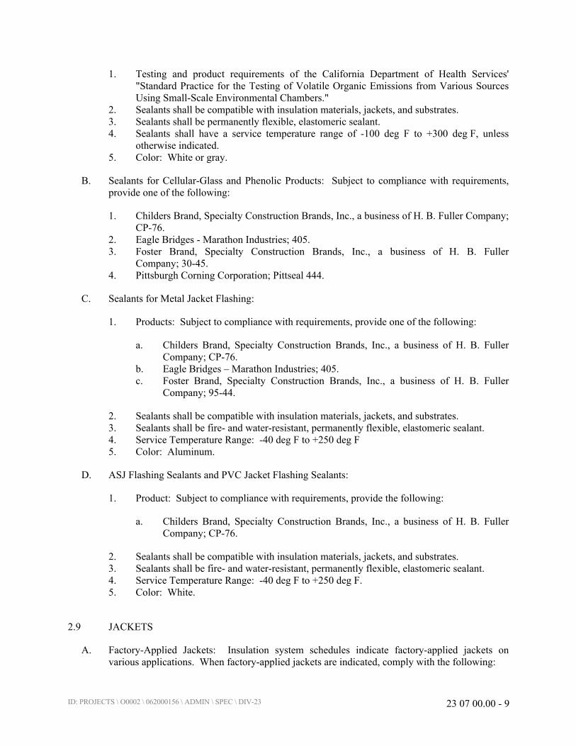
ID: PROJECTS \ O0002 \ 062000156 \ ADMIN \ SPEC \ DIV-23 23 07 00.00 - 9
1. Testing and product requirements of the California Department of Health Services'
"Standard Practice for the Testing of Volatile Organic Emissions from Various Sources
Using Small-Scale Environmental Chambers."
2. Sealants shall be compatible with insulation materials, jackets, and substrates.
3. Sealants shall be permanently flexible, elastomeric sealant.
4. Sealants shall have a service temperature range of -100 deg F to +300 deg F, unless
otherwise indicated.
5. Color: White or gray.
B. Sealants for Cellular-Glass and Phenolic Products: Subject to compliance with requirements,
provide one of the following:
1. Childers Brand, Specialty Construction Brands, Inc., a business of H. B. Fuller Company;
CP-76.
2. Eagle Bridges - Marathon Industries; 405.
3. Foster Brand, Specialty Construction Brands, Inc., a business of H. B. Fuller
Company; 30-45.
4. Pittsburgh Corning Corporation; Pittseal 444.
C. Sealants for Metal Jacket Flashing:
1. Products: Subject to compliance with requirements, provide one of the following:
a. Childers Brand, Specialty Construction Brands, Inc., a business of H. B. Fuller
Company; CP-76.
b. Eagle Bridges – Marathon Industries; 405.
c. Foster Brand, Specialty Construction Brands, Inc., a business of H. B. Fuller
Company; 95-44.
2. Sealants shall be compatible with insulation materials, jackets, and substrates.
3. Sealants shall be fire- and water-resistant, permanently flexible, elastomeric sealant.
4. Service Temperature Range: -40 deg F to +250 deg F
5. Color: Aluminum.
D. ASJ Flashing Sealants and PVC Jacket Flashing Sealants:
1. Product: Subject to compliance with requirements, provide the following:
a. Childers Brand, Specialty Construction Brands, Inc., a business of H. B. Fuller
Company; CP-76.
2. Sealants shall be compatible with insulation materials, jackets, and substrates.
3. Sealants shall be fire- and water-resistant, permanently flexible, elastomeric sealant.
4. Service Temperature Range: -40 deg F to +250 deg F.
5. Color: White.
2.9 JACKETS
A. Factory-Applied Jackets: Insulation system schedules indicate factory-applied jackets on
various applications. When factory-applied jackets are indicated, comply with the following:
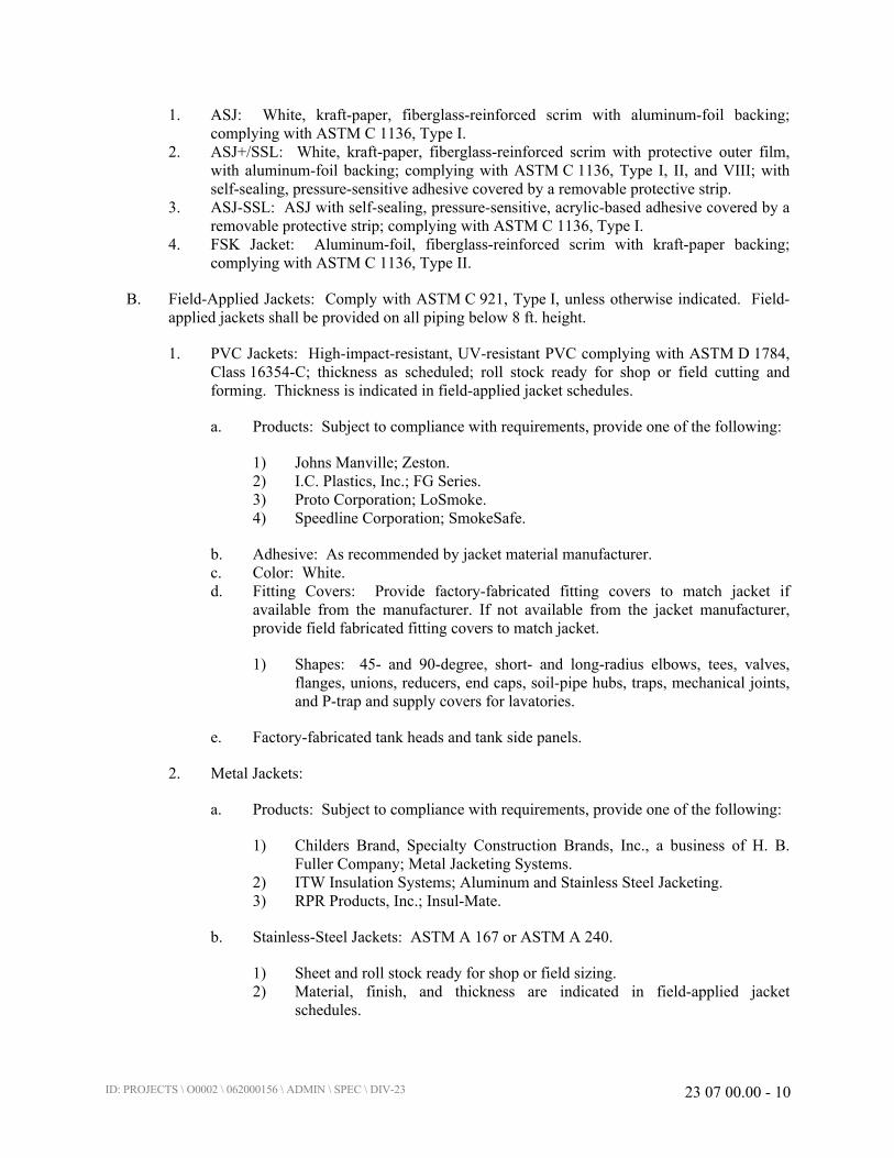
ID: PROJECTS \ O0002 \ 062000156 \ ADMIN \ SPEC \ DIV-23 23 07 00.00 - 10
1. ASJ: White, kraft-paper, fiberglass-reinforced scrim with aluminum-foil backing;
complying with ASTM C 1136, Type I.
2. ASJ+/SSL: White, kraft-paper, fiberglass-reinforced scrim with protective outer film,
with aluminum-foil backing; complying with ASTM C 1136, Type I, II, and VIII; with
self-sealing, pressure-sensitive adhesive covered by a removable protective strip.
3. ASJ-SSL: ASJ with self-sealing, pressure-sensitive, acrylic-based adhesive covered by a
removable protective strip; complying with ASTM C 1136, Type I.
4. FSK Jacket: Aluminum-foil, fiberglass-reinforced scrim with kraft-paper backing;
complying with ASTM C 1136, Type II.
B. Field-Applied Jackets: Comply with ASTM C 921, Type I, unless otherwise indicated. Field-
applied jackets shall be provided on all piping below 8 ft. height.
1. PVC Jackets: High-impact-resistant, UV-resistant PVC complying with ASTM D 1784,
Class 16354-C; thickness as scheduled; roll stock ready for shop or field cutting and
forming. Thickness is indicated in field-applied jacket schedules.
a. Products: Subject to compliance with requirements, provide one of the following:
1) Johns Manville; Zeston.
2) I.C. Plastics, Inc.; FG Series.
3) Proto Corporation; LoSmoke.
4) Speedline Corporation; SmokeSafe.
b. Adhesive: As recommended by jacket material manufacturer.
c. Color: White.
d. Fitting Covers: Provide factory-fabricated fitting covers to match jacket if
available from the manufacturer. If not available from the jacket manufacturer,
provide field fabricated fitting covers to match jacket.
1) Shapes: 45- and 90-degree, short- and long-radius elbows, tees, valves,
flanges, unions, reducers, end caps, soil-pipe hubs, traps, mechanical joints,
and P-trap and supply covers for lavatories.
e. Factory-fabricated tank heads and tank side panels.
2. Metal Jackets:
a. Products: Subject to compliance with requirements, provide one of the following:
1) Childers Brand, Specialty Construction Brands, Inc., a business of H. B.
Fuller Company; Metal Jacketing Systems.
2) ITW Insulation Systems; Aluminum and Stainless Steel Jacketing.
3) RPR Products, Inc.; Insul-Mate.
b. Stainless-Steel Jackets: ASTM A 167 or ASTM A 240.
1) Sheet and roll stock ready for shop or field sizing.
2) Material, finish, and thickness are indicated in field-applied jacket
schedules.

ID: PROJECTS \ O0002 \ 062000156 \ ADMIN \ SPEC \ DIV-23 23 07 00.00 - 11
3) Moisture Barrier for Indoor Applications: 1-mil-thick, heat-bonded
polyethylene and kraft paper.
4) Moisture Barrier for Outdoor Applications: 2.5-mil-thick polysurlyn.
5) Factory-Fabricated Fitting Covers: Fabricated from the same material,
finish, and thickness as jacket. Provide factory-fabricated covers for
preformed 2-piece or gore, 45- and 90-degree, short- and long-radius
elbows; tee covers; flange and union covers; end caps; beveled collars; and
valve covers. Field fabricate fitting covers only if factory-fabricated fitting
covers are not available.
c. Aluminum Jackets: Comply with ASTM B 209, Alloy 3003, Temper H-14.
1) Sheet and roll stock ready for shop or field sizing.
2) Finish and thickness are indicated in field-applied jacket schedule.
3) Moisture Barrier for Indoor Applications: 2.5-mil thick polysurlyn.
4) Moisture Barrier for Outdoor Applications: 2.5-mil thick polysurlyn.
5) Factory-Fabricated Fitting Covers: Fabricated from the same material,
finish, and thickness as jacket. Provide factory-fabricated covers for
preformed 2-piece or gore, 45- and 90-degree, short- and long-radius
elbows; tee covers; flange and union covers; end caps; beveled collars; and
valve covers. Field fabricate fitting covers only if factory-fabricated fitting
covers are not available.
2.10 TAPES
A. ASJ Tape: White vapor-retarder tape matching factory-applied jacket with acrylic adhesive,
complying with ASTM C 1136.
1. Products: Subject to compliance with requirements, provide one of the following:
a. Avery Dennison Corporation, Specialty Tapes Division; Fasson 0836.
b. Compac Corporation; 104 and 105.
c. Ideal Tape Co., Inc., an American Biltrite Company; 428 ASJ.
d. Venture Tape; 1540 CW Plus, 1542 CW Plus, and 1542 CW Plus/SQ.
2. Width: 3 inches.
3. Thickness: 11.5 mils.
4. Adhesion: 90 ounces force/inch in width.
5. Elongation: 2 percent.
6. Tensile Strength: 40 lbf/inch in width.
7. ASJ Tape Disks and Squares: Precut disks or squares of ASJ tape.
B. ASJ+ Tape: White vapor-retarder tape matching factory-applied jacket, complying with
ASTM C 1136.
1. Products: Subject to compliance with requirements, provide one of the following:
a. Avery Dennison Corporation, Specialty Tapes Division; Fasson 0839.
b. Venture Tape; 106FXP.

ID: PROJECTS \ O0002 \ 062000156 \ ADMIN \ SPEC \ DIV-23 23 07 00.00 - 12
C. FSK Tape: Foil-face, vapor-retarder tape matching factory-applied jacket with acrylic adhesive;
complying with ASTM C 1136.
1. Products: Subject to compliance with requirements, provide one of the following:
a. Avery Dennison Corporation, Specialty Tapes Division; Fasson 0827.
b. Compac Corporation; 110 and 111.
c. Ideal Tape Co., Inc., an American Biltrite Company; 491 AWF FSK.
d. Venture Tape; 1525 CW NT, 1528 CW, and 1528 CW/SQ.
2. Width: 3 inches.
3. Thickness: 6.5 mils.
4. Adhesion: 90 ounces force/inch in width.
5. Elongation: 2 percent.
6. Tensile Strength: 40 lbf/inch in width.
7. FSK Tape Disks and Squares: Precut disks or squares of FSK tape.
D. PVC Tape: White vapor-retarder tape matching field-applied PVC jacket with acrylic adhesive.
Suitable for indoor and outdoor applications.
1. Products: Subject to compliance with requirements, provide one of the following:
a. Avery Dennison Corporation, Specialty Tapes Division; Fasson 0555.
b. Compac Corporation; 130.
c. Ideal Tape Co., Inc., an American Biltrite Company; 370 White PVC tape.
d. Proto Corporation; PVC Tape.
e. Venture Tape; 1506 CW NS.
2. Width: 2 inches.
3. Thickness: 6 mils
4. Adhesion: 64 ounces force/inch in width.
5. Elongation: 500 percent.
6. Tensile Strength: 18 lbf/inch in width.
2.11 SECUREMENTS
A. Bands:
1. Products: Subject to compliance with requirements, provide one of the following:
a. ITW Insulation Systems; Gerrard Strapping and Seals.
b. RPR Products, Inc.; Insul-Mate Strapping, Seals, and Springs.
2. Stainless Steel: ASTM A 167 or ASTM A 240, Type 304; 0.020-inch thick, 3/4-inch
wide with wing seal or closed seal.
a. Type 304 for interior installations.
b. Type 316 for exterior installations, and interior installations subject to high
humidity.
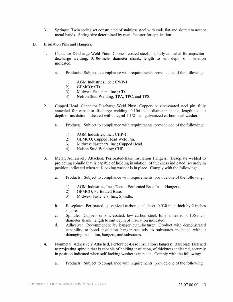
ID: PROJECTS \ O0002 \ 062000156 \ ADMIN \ SPEC \ DIV-23 23 07 00.00 - 13
3. Springs: Twin spring set constructed of stainless steel with ends flat and slotted to accept
metal bands. Spring size determined by manufacturer for application.
B. Insulation Pins and Hangers:
1. Capacitor-Discharge-Weld Pins: Copper- coated steel pin, fully annealed for capacitor-
discharge welding, 0.106-inch- diameter shank, length to suit depth of insulation
indicated.
a. Products: Subject to compliance with requirements, provide one of the following:
1) AGM Industries, Inc.; CWP-1.
2) GEMCO; CD.
3) Midwest Fasteners, Inc.; CD.
4) Nelson Stud Welding; TPA, TPC, and TPS.
2. Cupped-Head, Capacitor-Discharge-Weld Pins: Copper- or zinc-coated steel pin, fully
annealed for capacitor-discharge welding, 0.106-inch- diameter shank, length to suit
depth of insulation indicated with integral 1-1/2-inch galvanized carbon-steel washer.
a. Products: Subject to compliance with requirements, provide one of the following:
1) AGM Industries, Inc.; CHP-1.
2) GEMCO; Cupped Head Weld Pin.
3) Midwest Fasteners, Inc.; Cupped Head.
4) Nelson Stud Welding; CHP.
3. Metal, Adhesively Attached, Perforated-Base Insulation Hangers: Baseplate welded to
projecting spindle that is capable of holding insulation, of thickness indicated, securely in
position indicated when self-locking washer is in place. Comply with the following:
a. Products: Subject to compliance with requirements, provide one of the following:
1) AGM Industries, Inc.; Tactoo Perforated Base Insul-Hangers.
2) GEMCO; Perforated Base.
3) Midwest Fasteners, Inc.; Spindle.
b. Baseplate: Perforated, galvanized carbon-steel sheet, 0.030 inch thick by 2 inches
square.
c. Spindle: Copper- or zinc-coated, low carbon steel, fully annealed, 0.106-inch-
diameter shank, length to suit depth of insulation indicated.
d. Adhesive: Recommended by hanger manufacturer. Product with demonstrated
capability to bond insulation hanger securely to substrates indicated without
damaging insulation, hangers, and substrates.
4. Nonmetal, Adhesively Attached, Perforated-Base Insulation Hangers: Baseplate fastened
to projecting spindle that is capable of holding insulation, of thickness indicated, securely
in position indicated when self-locking washer is in place. Comply with the following:
a. Products: Subject to compliance with requirements, provide one of the following:

ID: PROJECTS \ O0002 \ 062000156 \ ADMIN \ SPEC \ DIV-23 23 07 00.00 - 14
1) GEMCO; Nylon Hangers.
2) Midwest Fasteners, Inc.; Nylon Insulation Hangers.
b. Baseplate: Perforated, nylon sheet, 0.030 inch thick by 1-1/2 inches in diameter.
c. Spindle: Nylon, 0.106-inch- diameter shank, length to suit depth of insulation
indicated, up to 2-1/2 inches.
d. Adhesive: Recommended by hanger manufacturer. Product with demonstrated
capability to bond insulation hanger securely to substrates indicated without
damaging insulation, hangers, and substrates.
5. Self-Sticking-Base Insulation Hangers: Baseplate welded to projecting spindle that is
capable of holding insulation, of thickness indicated, securely in position indicated when
self-locking washer is in place. Comply with the following requirements:
a. Products: Subject to compliance with requirements, provide one of the following:
1) AGM Industries, Inc.; Tactoo Self-Adhering Insul-Hangers.
2) GEMCO; Peel & Press.
3) Midwest Fasteners, Inc.; Self Stick.
b. Baseplate: Galvanized carbon-steel sheet, 0.030 inch thick by 2 inches square.
c. Spindle: Copper- or zinc-coated, low carbon steel, fully annealed, 0.106-inch-
diameter shank, length to suit depth of insulation indicated.
d. Adhesive-backed base with a peel-off protective cover.
6. Insulation-Retaining Washers: Self-locking washers formed from 0.016-inch- thick,
galvanized-steel sheet, with beveled edge sized as required to hold insulation securely in
place but not less than 1-1/2 inches in diameter.
a. Protect ends with capped self-locking washers incorporating a spring steel insert to
ensure permanent retention of cap in exposed locations.
7. Nonmetal Insulation-Retaining Washers: Self-locking washers formed from 0.016-inch-
thick nylon sheet, with beveled edge sized as required to hold insulation securely in place
but not less than 1-1/2 inches in diameter.
C. Staples: Outward-clinching insulation staples, nominal 3/4-inch- wide, stainless steel or Monel.
D. Wire: 0.062-inch soft-annealed, stainless steel.
1. Manufacturers: Subject to compliance with requirements, provide products by one of the
following:
a. C & F Wire.
b. Childers Brand, Specialty Construction Brands, Inc., a business of H. B. Fuller
Company.
c. ITW Insulation Systems / PABCO Metals Corporation.
d. RPR Products, Inc.
ID: PROJECTS \ O0002 \ 062000156 \ ADMIN \ SPEC \ DIV-23 23 07 00.00 - 15
2.12 CORNER ANGLES
A. PVC Corner Angles: 30 mils thick, minimum 1-inch by 1-inch, PVC according to
ASTM D 1784, Class 16354-C. White or color-coded to match adjacent surface.
B. Stainless-Steel Corner Angles: 0.024-inch thick, minimum 1-inch by 1-inch, stainless steel
according to ASTM A 167 or ASTM A 240, Type 304 or Type 316.
PART 3 - EXECUTION
3.1 EXAMINATION
A. Examine substrates and conditions for compliance with requirements for installation and other
conditions affecting performance of insulation application.
1. Verify that systems and equipment to be insulated have been tested and are free of
defects.
2. Verify that surfaces to be insulated are clean and dry.
B. Proceed with installation only after unsatisfactory conditions have been corrected.
3.2 PREPARATION
A. Surface Preparation: Clean and dry surfaces to receive insulation. Remove materials that will
adversely affect insulation application.
B. Coordinate insulation installation with the trade installing heat tracing, if any. Comply with
requirements for heat tracing that apply to insulation.
C. Mix insulating cements with clean potable water; if insulating cements are to be in contact with
stainless-steel surfaces, use demineralized water.
3.3 INSTALLATION – GENERAL
A. Install insulation materials, accessories, and finishes according to the manufacturer’s written
instructions with smooth, straight, and even surfaces; free of voids throughout the length of
equipment, ducts and fittings, and piping including fittings, valves, and specialties.
B. Install insulation materials, forms, vapor barriers or retarders, jackets, and thicknesses required
for each item of equipment, duct system, and pipe system specified.
C. Install accessories compatible with insulation materials and suitable for the service. Install
accessories that do not corrode, soften, or otherwise attack insulation or jacket in either wet or
dry state.
D. Keep insulation materials dry during application and finishing.
E. Install insulation with least number of joints practical.
ID: PROJECTS \ O0002 \ 062000156 \ ADMIN \ SPEC \ DIV-23 23 07 00.00 - 16
F. Install insulation with longitudinal seams at top and bottom of horizontal runs.
G. Install insulation with tight longitudinal seams and end joints. Bond seams and joints with
adhesive recommended by insulation material manufacturer.
H. Install multiple layers of insulation with longitudinal and end seams staggered.
I. Install vapor barriers on insulated pipes, ductwork, and equipment having surface operating
temperatures below 60 deg F.
J. Do not weld brackets, clips, or other attachment devices to piping, fittings, and specialties.
K. Where vapor barrier is indicated or required, seal joints, seams, and penetrations in insulation at
hangers, supports, anchors, and other projections with vapor-barrier mastic. Staples are not
acceptable.
1. Install insulation continuously through hangers and around anchor attachments.
2. For insulation application where vapor barriers are indicated, extend insulation on anchor
legs from point of attachment to supported item to point of attachment to structure. Taper
and seal ends at attachment to structure with vapor-barrier mastic.
3. Install insert materials and install insulation to tightly join the insert. Seal insulation to
insulation inserts with adhesive or sealing compound recommended by insulation
material manufacturer.
4. Cover inserts with jacket material matching adjacent pipe insulation. Install shields over
jacket, arranged to protect jacket from tear or puncture by hanger, support, or shield.
L. Apply adhesives, mastics, and sealants at manufacturer's recommended coverage rate and wet
and dry film thicknesses.
M. Install insulation with factory-applied jackets as follows:
1. Draw jacket tight and smooth.
2. Cover circumferential joints with 3-inch- wide strips, of same material as insulation
jacket. Secure strips with adhesive and outward clinching staples along both edges of
strip, spaced 4 inches o.c.
3. Install insulation with longitudinal seams at bottom of pipe. Overlap jacket longitudinal
seams at least 1-1/2 inches. Clean and dry surface to receive self-sealing lap. Staple laps
with outward clinching staples along edge at 2 inches o.c.
a. For below ambient services, apply vapor-barrier mastic over staples as required to
maintain continuity of vapor barrier.
b. Do not staple longitudinal laps on insulation applied to piping systems with a
surface temperature at or below 35 deg F.
4. Cover joints and seams with tape as recommended by insulation material manufacturer to
maintain vapor seal.
5. Where vapor barriers are indicated, apply vapor-barrier mastic on seams and joints and at
ends adjacent to duct and pipe flanges and fittings.
6. At penetrations in jackets for thermometers, and pressure gages, fill and seal voids with
vapor barrier coating.

ID: PROJECTS \ O0002 \ 062000156 \ ADMIN \ SPEC \ DIV-23 23 07 00.00 - 17
N. Cut insulation in a manner to avoid compressing insulation more than 75 percent of its nominal
thickness.
O. Finish installation with systems at operating conditions. Repair joint separations and cracking
due to thermal movement.
P. Repair damaged insulation facings by applying same facing material over damaged areas.
Extend patches at least 4 inches beyond damaged areas. Adhere, staple, and seal patches similar
to butt joints.
Q. For above ambient services, do not install insulation to the following:
1. Vibration-control devices.
2. Testing agency labels and stamps.
3. Nameplates and data plates.
4. Manholes.
5. Handholes.
6. Cleanouts.
3.4 PENETRATIONS
A. Insulation Installation at Roof Penetrations: Install insulation continuously through roof
penetrations.
1. Seal penetrations with flashing sealant.
2. For applications requiring only indoor insulation, terminate insulation above roof surface
and seal with joint sealant. For applications requiring indoor and outdoor insulation,
install insulation for outdoor applications tightly joined to indoor insulation ends. Seal
joint with joint sealant.
3. Extend jacket of outdoor insulation outside roof flashing at least 2 inches below top of
roof flashing.
4. Seal jacket to roof flashing with flashing sealant.
B. Insulation Installation at Above-Ground Exterior Wall Penetrations: Install insulation
continuously through wall penetrations.
1. Seal penetrations with flashing sealant.
2. For applications requiring only indoor insulation, terminate insulation inside wall surface
and seal with joint sealant. For applications requiring indoor and outdoor insulation,
install insulation for outdoor applications tightly joined to indoor insulation ends. Seal
joint with joint sealant.
3. Extend jacket of outdoor insulation outside wall flashing and overlap wall flashing at
least 2 inches.
4. Seal jacket to wall flashing with flashing sealant.
C. Insulation Installation at Underground Exterior Wall Penetrations: Terminate insulation flush
with sleeve seal. Seal terminations with flashing sealant.
D. Insulation Installation at Interior Wall and Partition Penetrations (Non Fire Rated): Install
insulation continuously through walls and partitions.

ID: PROJECTS \ O0002 \ 062000156 \ ADMIN \ SPEC \ DIV-23 23 07 00.00 - 18
3.5 INSTALLATION OF PIPE INSULATION
A. General: Requirements in this article apply to all pipe insulation materials, unless more specific
requirements are indicated for individual pipe insulation types.
B. Insulation Installation on Fittings, Valves, Strainers, Flanges, and Unions:
1. Install insulation over fittings, valves, strainers, flanges, unions, and other specialties with
continuous thermal and vapor-retarder integrity, unless otherwise indicated.
2. Pipe Elbows: Insulate pipe elbows using preformed fitting insulation or mitered fittings
made from same material and density as adjacent pipe insulation. Each piece shall be
butted tightly against adjoining piece and bonded with adhesive. Fill joints, seams, voids,
and irregular surfaces with insulating cement finished to a smooth, hard, and uniform
contour that is uniform with adjoining pipe insulation.
3. Tee Fittings: Insulate tee fittings with preformed fitting insulation or sectional pipe
insulation of same material and thickness as used for adjacent pipe. Cut sectional pipe
insulation to fit. Butt each section closely to the next and hold in place with tie wire.
Bond pieces with adhesive.
4. Valves: Insulate valves using preformed fitting insulation or sectional pipe insulation of
same material, density, and thickness as used for adjacent pipe. Overlap adjoining pipe
insulation by not less than two times the thickness of pipe insulation, or one pipe
diameter, whichever is thicker. For valves, insulate up to and including the bonnets,
valve stuffing-box studs, bolts, and nuts. Fill joints, seams, and irregular surfaces with
insulating cement.
5. Strainers: Insulate strainers using preformed fitting insulation or sectional pipe insulation
of same material, density, and thickness as used for adjacent pipe. Overlap adjoining
pipe insulation by not less than two times the thickness of pipe insulation, or one pipe
diameter, whichever is thicker. Fill joints, seams, and irregular surfaces with insulating
cement. Insulate strainers so strainer basket flange or plug can be easily removed and
replaced without damaging the insulation and jacket. Provide a removable reusable
insulation cover. For below ambient services, provide a design that maintains vapor
barrier.
6. Fittings and Unions: Insulate flanges and unions using a section of oversized preformed
pipe insulation. Overlap adjoining pipe insulation by not less than two times the
thickness of pipe insulation, or one pipe diameter, whichever is thicker.
7. Cover segmented insulated surfaces with a layer of finishing cement and coat with a
mastic. Install vapor-barrier mastic for below ambient services and a breather mastic for
above ambient services. Reinforce the mastic with fabric-reinforcing mesh. Trowel the
mastic to a smooth and well-shaped contour.
8. For services not specified to receive a field-applied jacket except for flexible elastomeric,
install fitted PVC cover over elbows, tees, strainers, valves, flanges, and unions.
Terminate ends with PVC end caps. Tape PVC covers to adjoining insulation facing
using PVC tape.
9. Stencil or label the outside insulation jacket of each union with the word "UNION."
Match size and color of pipe labels.
C. Insulate instrument connections for thermometers, pressure gages, pressure temperature taps,
test connections, flow meters, sensors, switches, and transmitters on insulated pipes, vessels,
and equipment. Shape insulation at these connections by tapering it to and around the
connection with insulating cement and finish with finishing cement, mastic, and flashing
sealant.

ID: PROJECTS \ O0002 \ 062000156 \ ADMIN \ SPEC \ DIV-23 23 07 00.00 - 19
D. Install removable insulation covers at locations where access is required (e.g. unions, flanges,
strainers, valves, and pumps). Installation shall conform to the following:
1. Make removable flange and union insulation from sectional pipe insulation of same
thickness as that on adjoining pipe. Install same insulation jacket as adjoining pipe
insulation.
2. When flange and union covers are made from sectional pipe insulation, extend insulation
from flanges or union long at least two times the insulation thickness over adjacent pipe
insulation on each side of flange or union. Secure flange cover in place with stainless-
steel bands. Select band material compatible with insulation and jacket.
3. Construct removable valve insulation covers in same manner as for flanges except divide
the two-part section on the vertical centerline of valve body.
4. When covers are made from block insulation, make two halves, each consisting of
mitered blocks wired to stainless-steel fabric. Secure this wire frame, with its attached
insulation, to flanges with tie wire. Extend insulation at least 2 inches over adjacent pipe
insulation on each side of valve. Fill space between flange or union cover and pipe
insulation with insulating cement. Finish cover assembly with insulating cement applied
in two coats. After first coat is dry, apply and trowel second coat to a smooth finish.
5. Unless a PVC jacket is indicated in field-applied jacket schedules, finish exposed
surfaces with a metal jacket.
3.6 INSTALLATION OF FLEXIBLE ELASTOMERIC INSULATION (INDOOR)
A. Seal longitudinal seams and end joints with manufacturer's recommended adhesive to eliminate
openings in insulation that allow passage of air to surface being insulated.
B. Insulation Installation on Pipe Flanges:
1. Install pipe insulation to outer diameter of pipe flange.
2. Make width of insulation section same as overall width of flange and bolts, plus twice the
thickness of pipe insulation.
3. Fill voids between inner circumference of flange insulation and outer circumference of
adjacent straight pipe segments with cut sections of sheet insulation of same thickness as
pipe insulation.
4. Secure insulation to flanges and seal seams with manufacturer's recommended adhesive
to eliminate openings in insulation that allow passage of air to surface being insulated.
C. Insulation Installation on Pipe Fittings and Elbows:
1. Install mitered sections of pipe insulation.
2. Secure insulation materials and seal seams with manufacturer's recommended adhesive to
eliminate openings in insulation that allow passage of air to surface being insulated.
D. Insulation Installation on Valves and Pipe Specialties:
1. Install preformed valve covers manufactured of same material as pipe insulation when
available.
2. When preformed valve covers are not available, install cut sections of pipe and sheet
insulation to valve body. Arrange insulation to permit access to packing and to allow
valve operation without disturbing insulation.
ID: PROJECTS \ O0002 \ 062000156 \ ADMIN \ SPEC \ DIV-23 23 07 00.00 - 20
3. Install insulation to flanges as specified for flange insulation application.
4. Secure insulation to valves and specialties and seal seams with manufacturer's
recommended adhesive to eliminate openings in insulation that allow passage of air to
surface being insulated.
3.7 INSTALLATION OF MINERAL-FIBER INSULATION
A. Insulation Installation on Straight Pipes and Tubes:
1. Secure each layer of preformed pipe insulation to pipe with wire or bands and tighten
bands without deforming insulation materials.
2. Where vapor barriers are indicated, seal longitudinal seams, end joints, and protrusions
with vapor-barrier mastic and joint sealant.
3. For insulation with factory-applied jackets on above-ambient surfaces, secure laps with
outward clinched staples at 6 inches o.c.
4. For insulation with factory-applied jackets on below-ambient surfaces, do not staple
longitudinal tabs but secure tabs with additional adhesive as recommended by insulation
material manufacturer and seal with vapor-barrier mastic and flashing sealant.
B. Insulation Installation on Pipe Flanges:
1. Install preformed pipe insulation to outer diameter of pipe flange.
2. Make width of insulation section same as overall width of flange and bolts, plus twice the
thickness of pipe insulation.
3. Fill voids between inner circumference of flange insulation and outer circumference of
adjacent straight pipe segments with mineral-fiber blanket insulation.
4. Install jacket material with manufacturer's recommended adhesive, overlap seams at least
1 inch, and seal joints with flashing sealant.
C. Insulation Installation on Pipe Fittings and Elbows:
1. Install preformed sections of same material as straight segments of pipe insulation when
available.
2. When preformed insulation elbows and fittings are not available, install mitered sections
of pipe insulation, to a thickness equal to adjoining pipe insulation. Secure insulation
materials with wire or bands.
D. Insulation Installation on Valves and Pipe Specialties:
1. Install preformed sections of same material as straight segments of pipe insulation when
available.
2. When preformed sections are not available, install mitered sections of pipe insulation to
valve body.
3. Arrange insulation to permit access to packing and to allow valve operation without
disturbing insulation.
4. Install insulation to flanges as specified for flange insulation application.
E. Blanket Insulation Installation on Ducts and Plenums: Secure with adhesive and insulation
pins.

ID: PROJECTS \ O0002 \ 062000156 \ ADMIN \ SPEC \ DIV-23 23 07 00.00 - 21
1. Apply adhesives according to manufacturer's recommended coverage rates per unit area,
for 100 percent coverage of duct and plenum surfaces.
2. Apply adhesive to entire circumference of ducts and to all surfaces of fittings and
transitions.
3. Install either capacitor-discharge-weld pins and speed washers or cupped-head, capacitor-
discharge-weld pins on sides and bottom of horizontal ducts and sides of vertical ducts as
follows:
a. On duct sides with dimensions 18 inches and smaller, place pins along longitudinal
centerline of duct. Space 3 inches maximum from insulation end joints, and 16
inches o.c.
b. On duct sides with dimensions larger than 18 inches place pins 16 inches o.c. each
way, and 3 inches maximum from insulation joints. Install additional pins to hold
insulation tightly against surface at cross bracing.
c. Pins may be omitted from top surface of horizontal, rectangular ducts and plenums.
d. Do not over compress insulation during installation.
e. Impale insulation over pins and attach speed washers.
f. Cut excess portion of pins extending beyond speed washers or bend parallel with
insulation surface. Cover exposed pins and washers with tape matching insulation
facing.
4. For ducts and plenums with surface temperatures below ambient, install a continuous
unbroken vapor barrier. Create a facing lap for longitudinal seams and end joints with
insulation by removing 2 inches from one edge and one end of insulation segment.
Secure laps to adjacent insulation section with 1/2-inch outward-clinching staples,
1 inch o.c. Install vapor barrier consisting of factory- or field-applied jacket, adhesive,
vapor-barrier mastic, and sealant at joints, seams, and protrusions.
a. Repair punctures, tears, and penetrations with tape or mastic to maintain vapor-
barrier seal.
b. Install vapor stops for ductwork and plenums operating below 50 deg F at 18-foot
intervals. Vapor stops shall consist of vapor-barrier mastic applied in a z-shaped
pattern over insulation face, along butt end of insulation, and over the surface.
Cover insulation face and surface to be insulated a width equal to twice the
insulation thickness but not less than 3 inches.
5. Overlap unfaced blankets a minimum of 2 inches on longitudinal seams and end joints.
At end joints, secure with steel bands spaced a maximum of 18 inches o.c.
6. Install insulation on rectangular duct elbows and transitions with a full insulation section
for each surface. Install insulation on round and flat-oval duct elbows with individually
mitered gores cut to fit the elbow.
7. Insulate duct stiffeners, hangers, and flanges that protrude beyond insulation surface with
6-inch-wide strips of same material used to insulate duct. Secure on alternating sides of
stiffener, hanger, and flange with pins spaced 6 inches o.c.
F. Board Insulation Installation on Ducts and Plenums: Secure with adhesive and insulation pins.
1. Apply adhesives according to manufacturer's recommended coverage rates per unit area,
for 100 percent coverage of duct and plenum surfaces.
2. Apply adhesive to entire circumference of ducts and to all surfaces of fittings and
transitions.

ID: PROJECTS \ O0002 \ 062000156 \ ADMIN \ SPEC \ DIV-23 23 07 00.00 - 22
3. Install either capacitor-discharge-weld pins and speed washers or cupped-head, capacitor-
discharge-weld pins on sides and bottom of horizontal ducts and sides of vertical ducts as
follows:
a. On duct sides with dimensions 18 inches and smaller, place pins along longitudinal
centerline of duct. Space 3 inches maximum from insulation end joints, and 16
inches o.c.
b. On duct sides with dimensions larger than 18 inches space pins 16 inches o.c. each
way, and 3 inches maximum from insulation joints. Install additional pins to hold
insulation tightly against surface at cross bracing.
c. Pins may be omitted from top surface of horizontal, rectangular ducts and plenums.
d. Do not over compress insulation during installation.
e. Cut excess portion of pins extending beyond speed washers or bend parallel with
insulation surface. Cover exposed pins and washers with tape matching insulation
facing.
4. For ducts and plenums with surface temperatures below ambient, install a continuous
unbroken vapor barrier. Create a facing lap for longitudinal seams and end joints with
insulation by removing 2 inches from one edge and one end of insulation segment.
Secure laps to adjacent insulation section with 1/2-inch outward-clinching staples,
1 inch o.c. Install vapor barrier consisting of factory- or field-applied jacket, adhesive,
vapor-barrier mastic, and sealant at joints, seams, and protrusions.
a. Repair punctures, tears, and penetrations with tape or mastic to maintain vapor-
barrier seal.
b. Install vapor stops for ductwork and plenums operating below 50 deg F at 18-foot
intervals. Vapor stops shall consist of vapor-barrier mastic applied in a z-shaped
pattern over insulation face, along butt end of insulation, and over the surface.
Cover insulation face and surface to be insulated a width equal to twice the
insulation thickness but not less than 3 inches.
5. Install insulation on rectangular duct elbows and transitions with a full insulation section
for each surface. Groove and score insulation to fit as closely as possible to outside and
inside radius of elbows. Install insulation on round and flat-oval duct elbows with
individually mitered gores cut to fit the elbow.
6. Insulate duct stiffeners, hangers, and flanges that protrude beyond insulation surface with
6-inch-wide strips of same material used to insulate duct. Secure on alternating sides of
stiffener, hanger, and flange with pins spaced 6 inches o.c.
3.8 FIELD-APPLIED JACKET INSTALLATION
A. Where PVC jackets are indicated, install with 1-inch overlap at longitudinal seams and end
joints. Install with longitudinal seams along top and bottom of tanks and vessels for horizontal
applications. Seal with adhesive recommended by insulation manufacturer.
1. Apply two continuous beads of adhesive to seams and joints, one bead under lap and the
finish bead along seam and joint edge.
B. Where stainless steel or aluminum jackets are indicated, install with 2-inch overlap at
longitudinal seams and end joints. Longitudinal seams shall be overlapped to shed water. Seal

ID: PROJECTS \ O0002 \ 062000156 \ ADMIN \ SPEC \ DIV-23 23 07 00.00 - 23
end joints with weatherproof sealant recommended by insulation manufacturer. Secure jacket
with stainless-steel bands on 12-inch centers and at end joints.
3.9 LABELING AND IDENTIFYING INSTALLATION
A. Piping Systems: Install pipe markers on each system. Include arrows showing normal direction
of flow.
1. Plastic markers with application systems. Install on pipe insulation segment where
required for hot non-insulated pipes.
a. Fasten markers on pipes smaller than 6-inch diameter by one of following
methods:
1) Snap-on application of pre-tensioned semi-rigid plastic pipe marker.
2) Adhesive lap joint in pipe marker overlap.
3) Laminated or bonded application of pipe marker to pipe (or insulation).
4) Taped to pipe (or insulation) with color-coded plastic adhesive tape, not less
than 3/4-inch wide, lapped 1-1/2 inches minimum at both ends of pipe
marker, and covering full circumference of pipe.
b. Fasten markers on pipes 6-inch and larger diameter by one of following methods:
1) Laminated or bonded application of pipe marker to pipe (or insulation).
2) Taped to pipe (or insulation) with color-coded plastic adhesive tape, not less
than 1-1/2-inches wide, lapped 3 inches minimum at both ends of pipe
marker, and covering full circumference of pipe.
3) Strapped to pipe (or insulation) with manufacturer's standard stainless steel
bands.
2. Locate pipe markers and color bands as follows wherever piping is exposed in finished
spaces, machine rooms, accessible maintenance spaces (shafts, tunnels, plenums) and
exterior non-concealed locations.
a. Near each valve and control device.
b. Near each branch connection, excluding short take-offs for fixtures and terminal
units. Mark each pipe at branch, where flow pattern is not obvious.
c. Near penetrations through walls, floors, ceilings, or enter non-accessible
enclosures.
d. At access doors, manholes, and similar access points that permit view of concealed
piping.
e. Near major equipment items and other points of origination and termination.
f. Spaced at a maximum of 50-feet o.c. along each run. Reduce intervals to 25 feet in
congested areas of piping and equipment.
g. On piping above removable acoustical ceilings, except omit intermediately spaced
markers.
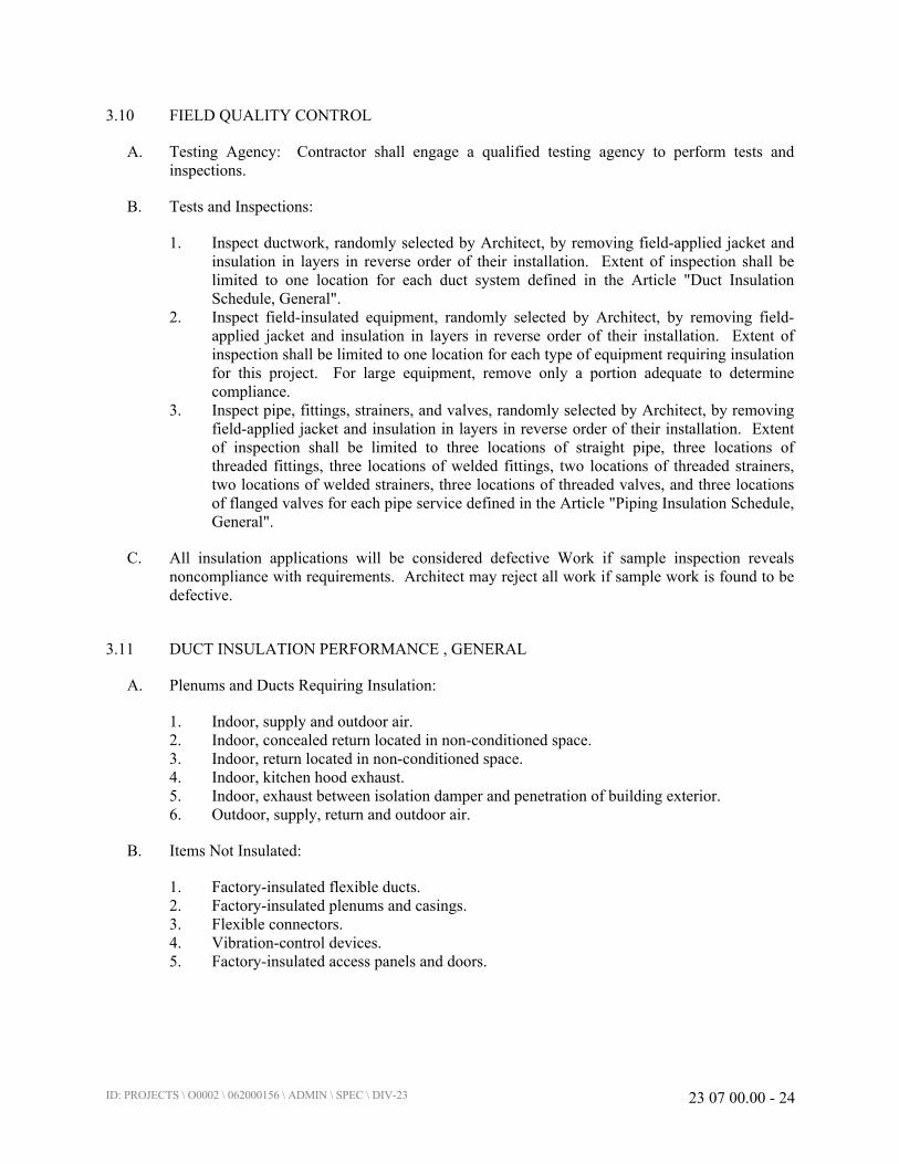
ID: PROJECTS \ O0002 \ 062000156 \ ADMIN \ SPEC \ DIV-23 23 07 00.00 - 24
3.10 FIELD QUALITY CONTROL
A. Testing Agency: Contractor shall engage a qualified testing agency to perform tests and
inspections.
B. Tests and Inspections:
1. Inspect ductwork, randomly selected by Architect, by removing field-applied jacket and
insulation in layers in reverse order of their installation. Extent of inspection shall be
limited to one location for each duct system defined in the Article "Duct Insulation
Schedule, General".
2. Inspect field-insulated equipment, randomly selected by Architect, by removing field-
applied jacket and insulation in layers in reverse order of their installation. Extent of
inspection shall be limited to one location for each type of equipment requiring insulation
for this project. For large equipment, remove only a portion adequate to determine
compliance.
3. Inspect pipe, fittings, strainers, and valves, randomly selected by Architect, by removing
field-applied jacket and insulation in layers in reverse order of their installation. Extent
of inspection shall be limited to three locations of straight pipe, three locations of
threaded fittings, three locations of welded fittings, two locations of threaded strainers,
two locations of welded strainers, three locations of threaded valves, and three locations
of flanged valves for each pipe service defined in the Article "Piping Insulation Schedule,
General".
C. All insulation applications will be considered defective Work if sample inspection reveals
noncompliance with requirements. Architect may reject all work if sample work is found to be
defective.
3.11 DUCT INSULATION PERFORMANCE , GENERAL
A. Plenums and Ducts Requiring Insulation:
1. Indoor, supply and outdoor air.
2. Indoor, concealed return located in non-conditioned space.
3. Indoor, return located in non-conditioned space.
4. Indoor, kitchen hood exhaust.
5. Indoor, exhaust between isolation damper and penetration of building exterior.
6. Outdoor, supply, return and outdoor air.
B. Items Not Insulated:
1. Factory-insulated flexible ducts.
2. Factory-insulated plenums and casings.
3. Flexible connectors.
4. Vibration-control devices.
5. Factory-insulated access panels and doors.

ID: PROJECTS \ O0002 \ 062000156 \ ADMIN \ SPEC \ DIV-23 23 07 00.00 - 25
3.12 DUCT AND PLENUM INSULATION SCHEDULE
A. LINED DUCT AND PLENUMS – NOT PERMITTED
B. INSULATION APPLICATION SCHEDULE
1. General: Abbreviations used in the following schedules include:
a. Field-Applied Jackets: P - PVC, K - Foil and Paper, A - Aluminum, SS - Stainless
Steel.
C. Indoor, Concealed duct insulation shall be mineral fiber blanket unless indicated otherwise.
D. DUCT SYSTEMS INSULATION SCHEDULE
DUCT LOCATION
OUTSIDE AIR, SUPPLY AIR,
EXHAUST AIR (DOWNSTREAM OF
DAMPER) INSULATION
INSTALLED R-VALUE
(H·Ft2·deg F/BTU)
RETURN AIR INSULATION
INSTALLED R-VALUE
(H·Ft2·deg F/BTU)
Exterior of Building
(Notes 5, 6, 8)8.0 8.0
Ventilated Attic
(Notes 5, 7)8.0 8.0
Unvented Attic Above
Insulated Ceiling
(Notes 5, 7)
8.0 8.0
Unvented Attic with Roof
Insulation
(Notes 1, 5, 7)
6.0 N/A
Unconditioned Space
(Notes 2, 5, 6, 7)8.0 8.0
Indirectly Conditioned
Space
(Notes 3, 7)
N/A N/A
Ceiling Cavity / Shafts /
Soffits / Mechanical
Spaces and Rooms
(Notes 4, 5, 6, 7)
6.0 N/A
Exposed Locations within
Conditioned SpaceN/A N/A
Buried 6.0 N/A
NOTE 1: INSULATION R-VALUES, MEASURED IN (H X FT^2 X F)/BTU, ARE FOR THE INSULATION AS
INSTALLED AND DO NOT INCLUDE FILM RESISTANCE. WHERE EXTERIOR WALLS ARE
USED AS PLENUM WALLS, WALL INSULATION SHALL BE AS REQUIRED BY APPLICABLE
CODES AND AUTHORITIES HAVING JURISDICTION. INSULATION RESISTANCE MEASURED
ON A HORIZONTAL PLANE IN ACCORDANCE WITH ASTM C518 AT A MEAN TEMPERATURE
OF 75 DEG F AT THE INSTALLED THICKNESS.
NOTE 2: INCLUDING CRAWL SPACES (BOTH VENTILATED/NON-VENTILATED), FRAMED CAVITIES
IN WALLS, FLOOR AND CEILING ASSEMBLIES WHICH (A) SEPARATE CONDITIONED SPACE
FROM UNCONDITIONED SPACE OR OUTSIDE AIR, AND (B) ARE UNINSULATED ON THE SIDE
FACING AWAY FROM CONDITIONED SPACE.

ID: PROJECTS \ O0002 \ 062000156 \ ADMIN \ SPEC \ DIV-23 23 07 00.00 - 26
NOTE 3: RETURN AIR PLENUMS WITH OR WITHOUT EXPOSED ROOFS ABOVE.
NOTE 4: CAVITY CONTAINED WITHIN THE INSULATED BUILDING ENVELOPE.
NOTE 5: VAPOR BARRIER REQUIRED.
NOTE 6: FIELD APPLIED JACKET (STAINLESS STEEL, OR ALUMINUM, FOR EXTERIOR
APPLICATIONS, PVC FOR INTERIOR EXPOSED LOCATIONS).
NOTE 7: PROVIDE MINERAL FIBER BOARD WITH FIELD APPLIED JACKET (SS, OR AL, ALL SERVICE
INTERIOR) IN EXPOSED LOCATIONS IN LIEU OF MINERAL FIBER BLANKET.
NOTE 8: PROVIDE FLEXIBLE ELASTOMERIC INSULATION FOR OUTDOOR DUCTWORK
3.13 PIPING INSULATION SCHEDULE, GENERAL
A. Acceptable preformed pipe and tubular insulation materials and thicknesses are identified for
each piping system and pipe size range. If more than one material is listed for a piping system,
selection from materials listed is Contractor's option.
B. Items Not Insulated: Unless otherwise indicated, do not install insulation on the following:
1. Drainage piping located in crawl spaces.
2. Underground piping.
3. Chrome-plated pipes and fittings unless there is a potential for personnel injury.
3.14 PIPING INSULATION SCHEDULE
A. Abbreviations used in the following schedule include:
1. Field-Applied Jackets: P - PVC, K - Foil and Paper, A - Aluminum, SS - Stainless Steel.
2. Pipe Sizes: NPS - Nominal Pipe Size.
B. Minimum HVAC Pipe Insulation Thickness Table (Non-LEED Projects)
HEATING
SYSTEMS
(Steam and Hot
Water) (Note 1)
FLUID
OPERATING
TEMPERATURE
RANGE (deg F)
INSULATION TYPE / FIELD-
APPLIED JACKET /
IDENTIFICATION
PIPE SIZE AND INSULATION THICKNESS
(INCHES)
(Note 5, 6)
Glass FiberFlexible
Elastomeric
<1
(Note 4)
1 to
<1-1/2
1-1/2
to <4
4 to
<8≥8
Steam - High
Pressure/
Temperature
>350 X 4.5 5.0 5.0 5.0 5.0
Steam - Medium
Pressure/
Temperature
251 – 350 X 3.0 4.0 4.5 4.5 4.5
Steam - Low
Pressure/
Temperature
201 – 250 X 2.5 2.5 3.0 3.0 3.0
Hot Water 141 to 200 X X 1.5 1.5 2.0 2.0 2.0
Hot Water 60 to 140 X X 1.0 1.0 2.0 2.0 2.0
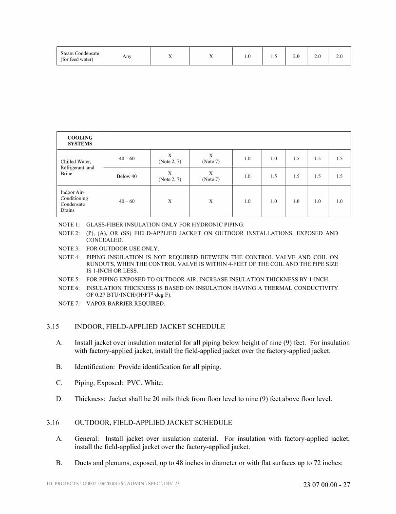
ID: PROJECTS \ O0002 \ 062000156 \ ADMIN \ SPEC \ DIV-23 23 07 00.00 - 27
Steam Condensate
(for feed water)Any X X 1.0 1.5 2.0 2.0 2.0
COOLING
SYSTEMS
40 – 60X
(Note 2, 7)
X
(Note 7)1.0 1.0 1.5 1.5 1.5
Chilled Water,
Refrigerant, and
BrineBelow 40
X
(Note 2, 7)
X
(Note 7)1.0 1.5 1.5 1.5 1.5
Indoor Air-
Conditioning
Condensate
Drains
40 – 60 X X 1.0 1.0 1.0 1.0 1.0
NOTE 1: GLASS-FIBER INSULATION ONLY FOR HYDRONIC PIPING.
NOTE 2: (P), (A), OR (SS) FIELD-APPLIED JACKET ON OUTDOOR INSTALLATIONS, EXPOSED AND
CONCEALED.
NOTE 3: FOR OUTDOOR USE ONLY.
NOTE 4: PIPING INSULATION IS NOT REQUIRED BETWEEN THE CONTROL VALVE AND COIL ON
RUNOUTS, WHEN THE CONTROL VALVE IS WITHIN 4-FEET OF THE COIL AND THE PIPE SIZE
IS 1-INCH OR LESS.
NOTE 5: FOR PIPING EXPOSED TO OUTDOOR AIR, INCREASE INSULATION THICKNESS BY 1-INCH.
NOTE 6: INSULATION THICKNESS IS BASED ON INSULATION HAVING A THERMAL CONDUCTIVITY
OF 0.27 BTU·INCH/(H·FT2·deg F).
NOTE 7: VAPOR BARRIER REQUIRED.
3.15 INDOOR, FIELD-APPLIED JACKET SCHEDULE
A. Install jacket over insulation material for all piping below height of nine (9) feet. For insulation
with factory-applied jacket, install the field-applied jacket over the factory-applied jacket.
B. Identification: Provide identification for all piping.
C. Piping, Exposed: PVC, White.
D. Thickness: Jacket shall be 20 mils thick from floor level to nine (9) feet above floor level.
3.16 OUTDOOR, FIELD-APPLIED JACKET SCHEDULE
A. General: Install jacket over insulation material. For insulation with factory-applied jacket,
install the field-applied jacket over the factory-applied jacket.
B. Ducts and plenums, exposed, up to 48 inches in diameter or with flat surfaces up to 72 inches:
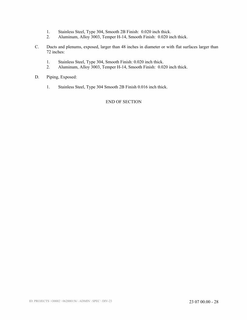
ID: PROJECTS \ O0002 \ 062000156 \ ADMIN \ SPEC \ DIV-23 23 07 00.00 - 28
1. Stainless Steel, Type 304, Smooth 2B Finish: 0.020 inch thick.
2. Aluminum, Alloy 3003, Temper H-14, Smooth Finish: 0.020 inch thick.
C. Ducts and plenums, exposed, larger than 48 inches in diameter or with flat surfaces larger than
72 inches:
1. Stainless Steel, Type 304, Smooth Finish: 0.020 inch thick.
2. Aluminum, Alloy 3003, Temper H-14, Smooth Finish: 0.020 inch thick.
D. Piping, Exposed:
1. Stainless Steel, Type 304 Smooth 2B Finish 0.016 inch thick.
END OF SECTION

ID: PROJECTS \ O0002 \ 062000156 \ ADMIN \ SPEC \ DIV-23 23 09 20.00 - 1
SECTION 23 09 20.00
BUILDING AUTOMATION SYSTEM (BAS)
PART 1 - GENERAL
1.1 SUMMARY
A. Section includes the installation of a building automation system (BAS) for control and
monitoring of mechanical systems as indicated.
1.2 SYSTEM DESCRIPTION (HC MUST USE THE BUILDINGS EXISTING DDC CONTROL
SYSTEM BY ACC PLANNED SERVICES @ 920-997-0780).
A. The distributed digital control (DDC) and building automation system (BAS) defined herein
shall provide a complete LONMARK® or Native BACnet® Building Automation System
(BAS) for all mechanical systems and other facility systems as included in the project
documents. The contractor shall provide a complete and operational system to perform all
sequences of operations stated in the Article "Sequence of Operation" or as shown on the
control drawings.
B. The BAS shall utilize electronic sensing, microprocessor-based digital control, and electronic
actuation of dampers and valves to perform the control sequences and functions specified. The
BAS for this project shall consist of monitoring and control of the systems indicated.
C. The BAS system shall include a webserver (control system server CSS), a separate operator
workstation (OWS), a laptop (portable operator terminal POT), all the software tools required to
maintain or configure the server, OWS, and any local devices.
D. All interlock wiring for mechanical system equipment shall be by this contractor unless
specifically stated otherwise. This shall include, but not be limited to, items such as thermostats
for unit heaters, interlock wiring to central boiler control panels, chiller flow switches, and duct
smoke detectors.
1.3 APPLICATION OF OPEN PROTOCOLS
A. Subject to the detailed requirements provided throughout the specification, the BAS and digital
control and communications components installed, as work of this contract shall be an
integrated distributed processing system utilizing one of the following standards:
1. BACnet: System components shall communicate using native BACnet in accordance
with ASHRAE Standard 135 and current addenda and annexes, including all
workstations, all BACnet building controllers (B-BC), advanced application controllers
(B-AAC) and all application specific controllers (B-ASC). Gateways to other
communication protocols are not acceptable. All controllers must be BACnet Testing
Labs listed for their required profile (B-BC, B-AAC or B-ASC).

ID: PROJECTS \ O0002 \ 062000156 \ ADMIN \ SPEC \ DIV-23 23 09 20.00 - 2
2. LonTalk: Provide control products and systems that comply with the latest version of the
ANSI/EIA standard 709.1 and the LonTalk protocol of the Interoperability Standards as
published by the LONMARK™ Association. All architectures involving tunneling the
LonTalk protocol across an IP network must incorporate ISO Layer 3 transparent routing.
B. Throughout these specifications, there are parallel requirements for BACnet or LonWorks
systems. Such requirements shall be interpreted in light of whether the contractor is installing a
BACnet, LonWorks, or a hybrid system.
1.4 QUALITY ASSURANCE
A. Qualifications: The following companies are acceptable to install a web-based BAS system:
1. Automated Comfort Control Inc.
2085 W. Packard Street
Appleton, WI 54914
Contact: Paul Thomson
(920-997-0780
1.5 CODES AND STANDARDS
A. American Society of Heating, Refrigeration and Air Conditioning Engineers (ASHRAE)
Standards:
1. 90.1: Energy Standard for Buildings Except Low-Rise Residential Buildings.
2. 62.1: Ventilation for Acceptable Indoor Air Quality.
3. 135: BACnet - A Data Communication Protocol for Building Automation and Control
Networks, current version including all annexes and addenda.
4. 55: Thermal Environmental Conditions for Human Occupancy.
B. Electronics Industries Alliance:
1. EIA-709.1-A-99: Control Network Protocol Specification.
2. EIA-709.3-99: Free-Topology Twisted-Pair Channel Specification.
3. EIA-232: Interface Between Data Terminal Equipment and Data Circuit-Terminating
Equipment Employing Serial Binary Data Interchange.
4. EIA-458: Standard Optical Fiber Material Classes and Preferred Sizes.
5. EIA-485: Standard for Electrical Characteristics of Generator and Receivers for use in
Balanced Digital Multipoint Systems.
6. EIA-472: General and Sectional Specifications for Fiber Optic Cable.
7. EIA-475: Generic and Sectional Specifications for Fiber Optic Connectors and all
Sectional Specifications.
8. EIA-573: Generic and Sectional Specifications for Field Portable Polishing Device for
Preparation Optical Fiber and all Sectional Specifications.
9. EIA-590: Standard for Physical Location and Protection of Below-Ground Fiber Optic
Cable Plant and all Sectional Specifications.
10. EIA-852: Tunneling of Component Network Data over IP Channels.
C. Underwriters Laboratories
ID: PROJECTS \ O0002 \ 062000156 \ ADMIN \ SPEC \ DIV-23 23 09 20.00 - 3
1. UL 916: Energy Management Systems.
D. NEMA Compliance
1. NEMA 250: Enclosure for Electrical Equipment.
2. NEMA ICS 1: General Standards for Industrial Controls.
E. NFPA Compliance
1. NFPA 90A: "Standard for the Installation of Air Conditioning and Ventilating Systems"
where applicable to controls and control sequences.
2. NFPA 70: National Electrical Code (NEC).
F. Institute of Electrical and Electronics Engineers (IEEE)
1. IEEE 142: Recommended Practice for Grounding of Industrial and Commercial Power
Systems.
2. IEEE 802.3: CSMA/CD (Ethernet – Based) LAN.
3. IEEE 802.4: Token Bus Working Group (ARCNET – Based) LAN.
1.6 DEFINITIONS
A. Acknowledged: Data is broadcast repeatedly until an acknowledgement is received. Used for
critical data using one to one bindings only. This type of service shall not be used for one to
many bindings.
B. Adjustable (ADJ): A characteristic of a control logic parameter such that it can be varied by the
operator without downloading the program.
C. Analog Calibration Offsets: For all analog input measured variables, with the exception of
velocity pressure, the value measured by the hardware based analog input point shall be
adjusted to match the value reported by a certified test instrument. An analog calibration offset
is a parameter that can be added or subtracted from the raw value measured by the sensor to
produce a calibrated value used by the control logic and reported to the operator workstations.
The initial value of this parameter is set at zero and it is adjusted when the calibration process is
executed. This adjustment is referred to as a single point calibration. These parameters are
mandatory for all analog inputs except velocity pressure sensors. These offset values are
configuration parameters and shall be written to EEPROM. It shall be possible to change the
value of these parameters from a graphic page.
D. Advanced Application Controller (AAC): A device with limited resources relative to the
Building Controller (BC). It may support a level of programming and may also be intended for
application specific applications. A fully programmable control module. This control module
shall be capable of certain advanced features found in Building Controllers (e.g. storing trends,
and initiating read and write requests) but it shall not serve as a master controller. Advanced
Application Controllers may reside on either the Ethernet/IP backbone or on a subnet. A
BACnet device to be used as an AAC will meet the requirements of ASHRAE 135, Annex L
and will be listed as an AAC by BACnet Testing Labs. A BTL listed device will carry the BTL
Mark.

ID: PROJECTS \ O0002 \ 062000156 \ ADMIN \ SPEC \ DIV-23 23 09 20.00 - 4
E. Application Programming Tool: A vendor unique software tool used to create applications for
programmable controllers.
F. Application Protocol Data Unit (APDU): A unit of data specified in an application protocol and
consisting of application protocol control information and application user data (ISO 9545).
G. Application Specific Controller (ASC): A device with limited resources relative to the
Advanced Application Controller (AAC). A pre-programmed control module, intended for use
in a specific application. ASCs shall have limited configurability, allowing the user to select
various pre-programmed options, but it shall not be fully customizable. A BACnet device used
as an ASC will meet the requirements of ASHRAE 135, Annex L and will be listed as an ASC
by BACnet Testing Labs. A BTL listed device will carry the BTL Mark.
H. BACnet/BACnet Standard: BACnet communication requirements, as defined by
ASHRAE/ANSI 135, current version including all annexes and addenda.
I. Bandwidth Utilization: The average utilization of the network capacity. Network loading is
controlled by the use of event driven broadcast based data propagation and the use of
appropriate binding services.
J. Binding Services: When the network management tool within Niagara or Plexus is used to
establish a binding, one of the following three types of binding services shall be selected:
1. Unacknowledged: The data being broadcast is sent one time and an acknowledgement of
receipt is not required. Used for non-critical data where there is no significant impact
should the receiving device have to wait for the next broadcast.
2. Unacknowledged Repeated: The data being broadcast is sent three times and an
acknowledgement of receipt is not required. Used for most process control related data
requiring timely receipt of the data.
3. Acknowledged: The data is broadcast repeatedly until an acknowledgement is received.
Used for critical data using one to one bindings only. This type of service shall not be
used for one to many bindings.
K. Binding: The concept of associating an output network variable from one device to the input
network variable of a second device. There are three types of bindings:
1. One to One: A single output network variable is bound to a single input network variable
2. One to Many: A single output network variable is bound to input network variables on
multiple devices.
3. Many to One: Output network variables from multiple devices are bound to a single
input network variable on a different device.
L. Broadcasting: The propagation of data from a device to the control network. Software objects
that broadcast data to the network shall include the following parameters:
M. Building Automation System (BAS): The entire integrated energy management and control
system.
N. Building Controller (BC): A fully programmable control module capable of storing trends and
schedules, serving as a router to devices on a subnet, and initiating read and write requests to
other controllers. Typically this controller is located on the Ethernet/IP backbone of the BAS. A

ID: PROJECTS \ O0002 \ 062000156 \ ADMIN \ SPEC \ DIV-23 23 09 20.00 - 5
BACnet device to be used as a BC shall meet the requirements of ASHRAE 135, Annex L and
will be listed as a BC by BACnet Testing Labs. A BTL listed device will carry the BTL Mark.
O. Bus Topology: A term used to describe the sequential connection of devices on a LON
segment. The communication cable runs from device to device with no tees or stubs from the
main communication cable to a device.
P. Change of Value (COV): An event that occurs when a measured or calculated analog value
changes by a predefined amount (ASHRAE/ANSI 135-1995).
Q. Channel: A LON network consisting of two segments connected by a physical layer repeater or
router configured as a repeater. Each segment can support a theoretical limit of 64 connections.
R. Client: A device that is the requestor of services from a server. A client device makes requests
of, and receives responses from, a server device.
S. Configuration Parameter: An input network variable to a controller that is written to the
EEPROM.
T. Connection: Made when a device is physically connected to the FTT-10 communication cable.
Devices that count against the number of connections limit include LON Talk Adapters
(PCLTA, PCC 10 etc.), any sensor, actuator, or controller with a FTT-10 transceiver and
Neuron chip, and a router or repeater. Terminators are not considered to be a connection.
U. Continuous Monitoring: Sampling and recording of a variable based on time or change of state
(e.g. trending an analog value, monitoring a binary change of state).
V. Control System Server (CSS), Web Server (WS): Provides access to the control system. This
device will allow access to the control system with a web browser over the CPS WAN. As the
BAS network devices are stand-alone, the CSS is not required for communications to occur.
The webserver will have two NIC cards so that is functions as the bridge between the local
supervisory LAN and the CPS LAN.
W. Controller or Control Unit (CU): Intelligent stand-alone control panel. Controller is a generic
reference and is a PCU.
X. CPS WAN: Reference to the Owner Information Technology network, used for normal
business-related e-mail and Internet communication.
Y. Direct Digital Control (DDC): Microprocessor-based control including Analog/Digital
conversion and program logic
Z. Enumerated SNVT: Defines the format of a single piece of data using a state description
concept. The data will consist of a series of integers and each integer shall convey a defined
condition or state. The list of available enumerated SNVT types is defined in the LonMark
Standard Enumeration Master List, dated May 2002. This document is available on the
Echelon.com web site.
AA. Error Rate: A measurement of communication quality that assesses the number of defective
data packets as a percentage of the total number of data packets. Defective data packets are
generally the result of poor installation practices or improper cable selection.
ID: PROJECTS \ O0002 \ 062000156 \ ADMIN \ SPEC \ DIV-23 23 09 20.00 - 6
BB. Event Driven Communication: A term used to describe the propagation of data from a device to
the network based on broadcasting rather than polling. The send on delta parameter is used to
define the event and the data propagation is further controlled by the minimum and maximum
send time parameters.
CC. Free Topology: A data wiring topology that allows for loops, tees, y-connections etc. When
this topology is used only one terminator of a specific design is required and allowable cable
lengths are significantly reduced.
DD. Functional Profile: A collection of variables required to define a the key parameters for a
standard application. As this applies to the HVAC industry, this would include applications like
VAV terminal, fan coil units, and the like.
EE. Gateway (GTWY): A device, which contains two or more dissimilar networks/protocols,
permitting information exchange between them (ASHRAE/ANSI 135-1995).
FF. Hand Held Device (HHD): Manufacturer’s microprocessor based device for direct connection
to a Controller.
GG. Host-Based Controller: Applicable only to Lon-based controllers where the on-board Neuron
chip is used solely as the Communications Interface and a processor independent from the
Neuron chip to is used to execute Application control and I/O processes.
HH. JACE: Java Control Engine. Term used within the Niagara Framework to describe a
component that serves several key functions:
1. Serve as the LANID.
2. Collection of data from a FTT-10 LonTalk channel.
3. Transmission of data to operator workstations on the TCP/IP network.
4. Location for time schedules to support all of the devices on the LonTalk channel.
5. Support for 1 LonTalk channel (two segments, 40 nodes each).
6. Location for trend logs for all data to be trended from the devices on the LonTalk
channel.
7. Location for alarm handling software. The JACE shall process event broadcasted data
from the devices (alarm indication) and enter the appropriate alarm information in the
alarm reporting system at the TCP/IP level.
II. Local Supervisory LAN Interface Device (LANID): Device used to facilitate communication
and sharing of data throughout the BAS and CPS WAN
JJ. LonMark Profile: To enhance interchangeability of control components at the sensor, actuator,
terminal unit controller and package equipment controller level, the LonMark Association has
created profiles that define the network image for these devices. These profiles define
mandatory input and output variables and configuration parameters and a required format for
each. Conformance to a LonMark profile provides to the facility owner the opportunity to
replace a control component manufactured by one vendor with a similar component
manufactured by a different vendor provided the embedded application of the replacement
controller meets the sequence of control requirements.
KK. Media Access Control address (MAC): Hardware address that uniquely identifies each node of
a network. Each different type of network medium requires a different MAC layer.
ID: PROJECTS \ O0002 \ 062000156 \ ADMIN \ SPEC \ DIV-23 23 09 20.00 - 7
LL. Managed Communication: Transmission of data from a controller to a data manager, which in
turn re-broadcasts the data to a second controller.
MM. Manual Control: Where the operator takes control of an end device and forces a specific
position or state. The manual mode and the desired manual position or states are parameters
that are set by the operator.
NN. Many to One: Output network variables from multiple devices are bound to a single input
network variable on a different device.
OO. Maximum Send Time Parameter: Parameter used to ensure the periodic update of network data.
If a time period equal to the value of this parameter has expired without a broadcast of the
variable, a re-broadcast of the current value shall be executed. See also "Send on Delta" and
"Maximum Send Time."
PP. Maximum Send Time: Adjustable parameter that defines the maximum time period between
broadcasts of a software object’s data to the network. Should the value of a software object
remain constant over an extended period of time, the value will be rebroadcast once every
maximum time period.
QQ. Minimum Send Time Parameter: Parameter used to control unnecessary broadcasting of data
onto the network. Broadcast of an updated value shall not occur unless a time period equal to
the value of this parameter has expired. The expiration of the time period does not mandate a
re-broadcast. See also "Send on Delta" and "Maximum Send Time" definitions.
RR. Minimum Send Time: Adjustable parameter that defines a mandatory time period during which
no broadcasting of data will occur. Once this time period has been exceeded without a
broadcast, the send on delta parameter or the maximum send time parameter shall determine
when a broadcast is initiated.
SS. Multiple Controller Integrated Control (MCIC): Where multiple controllers with I/O are used
to control a single mechanical system, which is sub-divided into a collection of processes to be
controlled. All primary measured variables and the end device associated with a single process
along with the primary control logic for the process shall be contained within a single controller.
Secondary data from one process that affects the control of another process may be sent from
one controller to the primary controller controlling the process. When data is sent from one
controller to another controller, broadcasting concepts as defined above must be used. If the
data being received over the network only affects the general thermodynamic or psychometric
performance of the process but does not have a significant affect on safety or equipment
protection then unacknowledged repeated binding services shall be used. If the data being
received over the network has a safety or equipment protection impact, then acknowledged
repeated binding services shall be used. In both cases peer-to-peer communication is
mandatory. All controllers must be on the same channel. Managed communication shall not be
used to move data between the multiple controllers.
TT. One to Many: A single output network variable is bound to input network variables on multiple
devices.
UU. One to One: A single output network variable is bound to a single input network variable.

ID: PROJECTS \ O0002 \ 062000156 \ ADMIN \ SPEC \ DIV-23 23 09 20.00 - 8
VV. Open Database Connectivity (ODBC): Open standard application-programming interface (API)
for accessing a database, making access to any data, regardless of which database management
system (DBMS) is handling the data, possible.
WW. Operator Interface (OI): A device used by the operator to manage the BAS.
XX. Operator Workstation (OWS): Used to interface with the BAS system via the internet or the
Local Supervisory LAN.
YY. Peer-to-Peer Communication: Data is broadcast from its origin and is received by the final
device requiring the data without being received and retransmitted by a third device.
ZZ. Polling Communication: The concept of a control device requesting a network variable from a
second control device at a specified interval. Polling communication is typically used to
populate dynamic data on an active graphic page and for temporary or short term trending of
data where the trend data is not stored at the controller level.
AAA. Portable Operators Terminal (POT): Laptop PC used both for direct connection to a controller
and for remote dial up connection.
BBB. Primary Control Unit (PCU): A fully programmable device capable of carrying out a number of
tasks including control and monitoring via direct digital control (DDC) of specific systems.
CCC. Protocol Implementation Conformance Statement (PICS): A written document, created by the
manufacturer of a device, identifying the particular options specified by BACnet that are
implemented in the device.
DDD. Repeater: A physical device used to connect two segments and isolate physical problems.
Typically required to allow the use of additional devices or additional cable length.
EEE. Router: A device that connects two or more networks at the network layer.
FFF. Segment: A single section of a LON network that contains no routers or repeaters.
GGG. Send on Delta Parameter: A parameter used to control unnecessary broadcasting of data onto
the network. For binary data the send on delta parameter is assumed to be a change of state.
HHH. Send on Delta: Adjustable parameter that defines a requirement to broadcast when the data
generated by the software object changes by an amount that exceeds this parameter’s value. For
binary data this parameters defaults to a change of state. The broadcast of data is initiated when
this criteria and the minimum send time requirement have been met.
III. Simple SNVT: Defines the format of a single piece of data. The definition of a simple SNVT
in the master list of SNVTs will include the type of variable being measured (temperature,
electric current, power etc.), the data type (signed integer, unsigned integer, floating point etc.),
the data range, the resolution of the data and the engineering units.
JJJ. Smart Device: A control I/O device such as a smart sensor (SS) or smart actuator (SA) that can
directly communicate with the controller network to which it is connected rather than through a
binary or analog signal.

ID: PROJECTS \ O0002 \ 062000156 \ ADMIN \ SPEC \ DIV-23 23 09 20.00 - 9
KKK. Standard Network Variable Type (SNVT): Data format statement for implicit (open)
communication on a LonTalk network. The current master list of SNVTs is available from
Echelon.com in a document defined as SNVT Master List, Version 11, Revision 2, dated May
2002.
LLL. Standardized Query Language (SQL): Standardized means for requesting information from a
database.
MMM. Stand-Alone Controller: A stand-alone controller has provisions for all of the physical
inputs and physical outputs associated with a single mechanical component such as a terminal
unit, air handling unit, chiller or boiler. The controller shall also have embedded in it all of the
control logic that associated the physical inputs to the physical outputs. A stand-alone
controller may rely on other networked devices for time schedule inputs and trend data storage.
NNN. Structured SNVT: Defines the format of a network variable that contains several different data
elements. A simple SNVT or an enumerated SNVT may define each data element within a
structured SNVT.
OOO. Supervisory Logic: The concept of gathering performance data from multiple terminal units to
determine if a specific condition exists within the family of terminal devices.
PPP. Terminator: An electronic component that consists of a resistive and capacitive circuit
specifically designed to enhance the quality of communications on a segment. On a bus
topology, a terminator is connected to each end of a segment. For a channel consisting of two
bus topology segments, a total of 4 terminators are required, one at each end of each segment.
QQQ. Test Mode: A concept where the operator from the operator workstation can interrupt the flow
of data from a sensor to the control logic and insert a mandatory test value or test state to be
used by the control logic. The test mode and the desired test value or states are parameters that
are set by the operator.
RRR. Unacknowledged Repeated: The data being broadcast is sent three times and an
acknowledgement of receipt is not required. This type of service shall be used for most process
control related data requiring timely receipt of the data.
SSS. Unacknowledged: The data being broadcast is sent one time and an acknowledgement of
receipt is not required. This type of service shall be used for non-critical data where there is no
significant impact should the receiving device have to wait for the next broadcast.
TTT. Web Server: Refer to "Control System Server."
UUU. XIF File: A file indicating the interface specifications for LonMark devices.
VVV. XML (Extensible Markup Language): A specification developed by the World Wide Web
Consortium.
ID: PROJECTS \ O0002 \ 062000156 \ ADMIN \ SPEC \ DIV-23 23 09 20.00 - 10
1.7 FUNCTIONAL INTENT
A. Where detailed functional or performance requirements are specified, products intended for the
Project, conforming to the specified requirements, must be submitted to, and approved by, CPS
prior to shipment to the Project site.
1.8 SUBMITTALS
A. Electronic Submittals: While all requirements for hard copy submittal apply, control submittals
and O&M information shall also be provided in electronic format as follows.
1. Drawings and Diagrams: Shop drawings shall be provided on electronic media as an
AutoCAD 2000 or later version drawing file and/or Adobe Portable Document Format
file. All ‘x reference’ and font files must be provided with AutoCAD files.
2. Other Submittals: All other submittals shall be provided in Adobe Portable Document
Format (PDF). Provide documents, such as Cheat Sheets and Trouble Shooting Guide, in
rich text format (rtf) or Microsoft Word format as required.
B. Product Data: For each control device, panel, and accessory indicated or furnished. Include
dimensions, capacities, performance and electrical characteristics, and material finishes.
Include installation and start-up instructions. When manufacturer's cutsheets apply to a product
series rather than a specific product, clearly indicate applicable data by highlighting or by other
meansGeneral catalogs shall not be accepted as cutsheets to fulfill submittal requirements.
C. Shop Drawings: Submit shop drawings for each control system, including a complete drawing
for each air handling unit, system, pump, device, etc. with all point descriptors, addresses and
point names indicated. Each shop drawing shall contain the following information:
1. System Architecture and System Layout:
a. One-line diagram indicating schematic locations of all control units, workstations,
LAN interface devices, gateways, etc. Indicate network number, device ID,
address, device instance, MAC address, drawing reference number, and controller
type for each control unit. Indicate media, protocol, baud rate, and type of each
LAN. For LonTalk systems indicate all LonTalk nodes, including Neuron ID and
domain, sub-network and channel addresses. Indicate media, protocol, baud rate,
and type of each LAN. All optical isolators, repeaters, end-of-line resistors,
junctions, terminators, ground locations etc. shall be located on the diagram.
b. Provide floor plans locating all control units, workstations, servers, LAN interface
devices, gateways, etc. Include all WAN and LAN communication wiring routing,
power wiring, power originating sources, and low voltage power wiring. Indicate
network number, device ID, address, device instance, MAC address, drawing
reference number, and controller type for each control unit. Indicate media,
protocol, baud rate, and type of each LAN. For LonTalk systems provide as-built
network architecture drawings showing all LonTalk nodes, including Neuron ID
and domain, sub-network and channel addresses. All optical isolators, repeaters,
end-of-line resistors, junctions, ground locations etc. shall be located on the floor
plans. Wiring routing as-built conditions shall be maintained accurately
throughout the construction period and the drawing shall be updated to accurately
reflect accurate, actual installed conditions.

ID: PROJECTS \ O0002 \ 062000156 \ ADMIN \ SPEC \ DIV-23 23 09 20.00 - 11
2. Schematic flow diagram of each air and water system showing fans, coils, dampers,
valves, pumps, heat exchange equipment and control devices. Include contractor written
description of sequence of operation.
3. All physical points on the schematic flow diagram shall be indicated with names,
descriptors, and point addresses identified as listed in the point summary table.
4. Label each control device with setting.
5. Label each input and output with the appropriate range.
6. Provide a Bill of Materials with each schematic. Indicate device identification to match
schematic and actual field labeling, quantity, actual product ordering number,
manufacturer, description, size, voltage range, pressure range, temperature range, etc. as
applicable. Also identify the specification section and specification reference.
7. Provide a valve or damper and the associated actuator information including size, Cv,
design flow, design pressure drop, manufacturer, model number, close off rating, etc.
Indicate normal (fail) positions of spring return valves and dampers. This is the valve or
damper position with no power to the actuator.
8. Indicate all required electrical wiring. Electrical wiring diagrams shall include both
ladder logic type diagram for motor starter, boiler burner, chiller, RTU, control, and
safety circuits and detailed digital interface panel point termination diagrams with all
wire numbers and terminal block numbers identified. Provide panel termination
drawings on separate drawings. Ladder diagrams shall appear on system schematic.
Clearly differentiate between portions of wiring, which are existing, factory-installed and
portions to be field-installed. For all devices with safety circuits, incuding burners and
chillers, field wiring will be labeled and all added devices will be properly mounted. Any
internal wiring changes shall be approved by the manuafacturer in writing. If for example
a gas booster needs to be tied into the burner circuit the manaufacturer shall identify the
terminal points and provide an updated control diagram.
9. Sample Operator Interface Graphic Screens for each unique type of system, with final
screens to be received 60 days prior to system startup.
10. Details of control panels, including controls, instruments, and labeling shown in plan or
elevation indicating the installed locations.
11. Sheets shall be consecutively numbered.
12. Each sheet shall have a title indicating the type of information included and the HVAC
system controlled.
13. Table of Contents listing sheet titles and sheet numbers.
14. Legend and list of abbreviations.
15. Provide an operating schedule for review. The schedule will have a schedule for each
AHU/RTU and the associated equipment. Terminal units serving the principals office
and associated administrative areas will have a separate schedule from the classrooms.
D. Product Line Demonstrated History: The product line being proposed for the project must have
an installed history of demonstrated satisfactory operation for a length of 1 year since date of
final completion in at least 10 installations of comparative size and complexity. Submittals
shall document this requirement with references.
E. Qualifications: For manufacturer, companies, Contractor and key personnel.
F. Checkout and Testing Forms: Submit a blank copy of the forms that will be used during Point-
to-Point Checkout, Prefunctional Checkout.
1. Point-to-Point Checkout Form containing the following information:

ID: PROJECTS \ O0002 \ 062000156 \ ADMIN \ SPEC \ DIV-23 23 09 20.00 - 12
a. Each point is addressed, labeled and that proper communication exists between the
controller and the field device.
b. Documents that installed condition match the control drawings and that any
changes or differences are noted on the drawings.
2. Pre-functional Checkout Forms containing the following information:
a. Documents correct voltage and or current present as well as verifying circuits are
free from grounds or faults for each control device.
b. Obtain and Record Test and Balance settings and incorporate into the BAS.
Information from the TAB contractor shall include:
1) Water and air system differential pressure and flow settings.
c. Calibration data for all sensing and actuating devices recording final measured and
displayed value. Record the type and model of the meter(s) that determined the
measured value for analog inputs.
d. For analog outputs record both the displayed output as well state of the receiving
device.
e. For digital input/outputs record the signal at the controller and the state of the
sensing/control device.
f. For actuators:
1) Check to ensure that actuated device moves smoothly and results are
repeatable thru full range and seals tightly when the appropriate signal is
applied to the operator.
2) Check for appropriate fail position, and that the stroke and range is as
required.
3) For sequenced electronic actuators, calibrate in accordance with
manufacturer’s instructions to required ranges. Record final settings.
g. For all valves and actuators, verify the actual position against the Operator
Interface readout. Set pumps to normal operating mode. With command valve
closed, verify that valve is closed, and adjust output zero signal as required. With
command valve open, verify position is full open and adjust output signal as
required. Command the valve to not less than three (3) intermediate positions. If
actual valve position doesn’t correspond correctly, replace actuator.
h. Valve leak check: Verify proper close-off of the valves. Ensure the valve seats
properly by simulating the maximum anticipated pressure difference across the
circuit.
i. For air and water flow measuring stations the data recorded will include the
independent flow measurement, area, and the independently measured output of
the flow station. The BAS input from the flow station and any factors used to
calculate the flow including area and any constants used in the calculation of flow.
Two sets of data shall be collected. The first at design flow and the second at 50%
of design flow. It is not acceptable to simply add a correction factor to address
differences between the flow station and the independent reading.
j. For Operator Interfaces and Web accessible display:
ID: PROJECTS \ O0002 \ 062000156 \ ADMIN \ SPEC \ DIV-23 23 09 20.00 - 13
1) Verify that all elements on the graphics are functional and are properly
bound to physical devices and/or virtual points, and that hot links or page
jumps are functional and logical.
2) Output all specified BAS reports for review and approval.
3) Verify that the alarm pop ups, printing, and logging are functional and in
accordance with requirements.
4) Verify that all points are trended and are archiving to disk. Provide a sample
to the Commissioning Authority and CPS for review.
5) Verify that paging/dial-out alarm annunciation is functional.
6) Verify the functionality of remote Operator Interfaces and that a robust
connection can be established consistently.
7) Verify that required third party software applications required with the bid
are installed and are functional.
k. For all actuating devices record final settings for device.
l. Document verification of point to graphics binding for all points displayed on the
workstation and that webserver display have been mapped correctly, and display
the correct information.
3. Functional Performance Forms shall contain:
a. List of all sequences, modes of operation and setpoint that initiates each sequence
and/or mode. For each confirm that proper sequence of operation. Document any
variance between designed sequence and actual condition.
b. Record tuning parameters and response time for each control loop.
c. Document all alarm and safeties test and final results.
d. Results of trends including controlled points, setpoints, actual readings and other
point defined by the Boards Authorized Representative.
G. Testing Plan:
1. Submit a plan for executing all phases of testing and completion of checkout forms. This
includes the following: manufacturers’ normal testing, point-to-point testing, pre-
functional testing, and functional performance testing. The testing plan shall show the
overall milestones of the controls work and testing of the controls system.
2. Provide the schedule for completing each phase of testing for each system or set of
equipment including, but not limited to, air handlers, chillers, boilers, unit-vents, VAV
boxes, network wiring, and operator workstations. Schedules shall show the time frame
needed to complete the tasks.
3. The testing plan shall identify other trade milestones that impact the successful
completion of during each phase of testing.
4. This plan is not meant to take precedence over any other plan but is intended to provide
coordination assistance to all trades as the project is scheduled.
H. Open Protocol Information:
1. General: Provide all information necessary for review of the proposed system, including
information required by the authority maintaining the protocol standard to determine if
the product selected for implementation complies with the protocol standards specified.
2. LonWorks Systems:

ID: PROJECTS \ O0002 \ 062000156 \ ADMIN \ SPEC \ DIV-23 23 09 20.00 - 14
a. Binding table indicating all Network Variables used in the project, Neuron ID and
domain, subnet and channel address, and associated bound variables. Clearly
indicate which parameters of a functional profile are bound and can be overridden.
b. A point binding diagram shall be provided with each control schematic depicting
all bound network variables along with the associated functional profiles.
c. LonMark functional profile certifications.
d. For Host-Based Controllers: Controller programming and configuration tool and or
plug in required for all controllers with a minimum of 3 licenses as applicable.
e. For non-host Controllers: LonTalk Neuron C source code and/or Neuron C
application programming interface tool (3 licenses) and associated files required
for all controllers.
f. Backup of systems configuration database on CD. This shall be provided at
Preliminary Acceptance and at the end of the warranty period.
g. Documentation of all explicit messaging.
h. XIF files for all LonMark components.
3. BACnet Systems:
a. BACnet object description, object ID, and device ID, for each I/O point.
b. Documentation for any non-standard BACnet objects, properties, or enumerations
used detailing their structure, data types, and any associated lists of enumerated
values.
c. Submit PICS indicating the standardized BACnet device profile, functionality and
configuration of each controller along with proof of BTL listing.
I. Framed Control Drawings: After completion of installation and check out, but prior to training,
laminated control drawings including system control schematics, sequences of operation, and
panel termination drawings, shall be provided in panels for major pieces of equipment.
Terminal unit drawings shall be located in the central plant equipment panel or mechanical
room panel.
J. Control Logic Documentation (to be received and updated prior to training):
1. Submit control logic program listings (for graphical programming) and logic flow charts
illustrating (for line type programs) to document the control software of all control units.
2. Control logic shall be annotated to describe how it accomplishes the sequence of
operation. Annotations shall be sufficient to allow an operator to relate each program
component (block or line) to corresponding portions of the specified Sequence of
Operation.
3. Include written description of each control sequence.
4. Include control response, settings, setpoints, throttling ranges, gains, reset schedules,
adjustable parameters, and limits.
5. Sheets shall be consecutively numbered.
6. Each sheet shall have a title indicating the controller designations and the HVAC system
controlled.
7. Include Table of Contents listing sheet titles and sheet numbers
8. Submit one complete set of programming and operating manuals for all digital controllers
concurrently with control logic documentation. This set will count toward the required
number of Operation and Maintenance materials specified below.
K. Training Plan:

ID: PROJECTS \ O0002 \ 062000156 \ ADMIN \ SPEC \ DIV-23 23 09 20.00 - 15
1. Training shall be provided in one, four-hour session. A training plan is not required for
opposite season or refresher training.
L. Operation and Maintenance Manual: (All documentation to be received and updated prior to
training)
1. Submit maintenance instructions and spare parts lists for each type of control device,
control unit, and accessory.
2. Submit BAS User’s Guides (Operating Manuals) for each controller type and for all
workstation hardware and software and workstation peripherals.
3. Submit BAS advanced Programming Manuals for each controller type and for all
workstation software.
4. Include all as built submittals (product data, shop drawings, control logic documentation,
hardware manuals, software manuals, installation guides or manuals, maintenance
instructions, and spare parts lists) in maintenance manual, in accordance with
requirements of Division 01 Section "Operations and Maintenance Manual."
M. Training Manual: Submit training manual electronically for review. Once accepted, provide
three hard copies and one electronic copy of the training manual at the start of training. Note
only the initial 8 hours of training which include the Cheat Sheets will occur before the
demonstration is completed. Include the following:
1. Cheat Sheets or quick reference section with step-by-step guidance with a level of detail
that will allow someone with no experience with the control system to follow the
instructions. The quick reference guidance can be provided one of two ways: screen
prints with bubbled text describing the navigation required or written description of the
steps to be taken with screen prints provided to facilitate the written explanation. The
required cheat sheets shall include:
a. Logins and logoffs.
b. Adjust and restore set points.
c. Overrides and releasing overrides. Include instructions for running a report to list
all points currently overridden.
d. Start, group, plot and export Trends.
e. Adjust schedules and add holidays.
f. Processing of alarms including acknowledgement, review of alarm report, and
clearing of alarm history.
g. Backup and restoration of system data.
h. Demonstrate how to clear/reset all field devices that may require manual
intervention.
i. Demonstrate how to reset motor starter and the significance of Hand-Off-Auto
switch position on motor starters.
j. Demonstration of each input and output device. Provide a picture of each input or
output device with a brief narrative on its operation.
k. Demonstrate how to place the boiler or chiller system into manual control and
boiler control, and how to restore the system to BAS control.
2. Operating instructions including system startup and shutdown, seasonal and emergency
instruction.
3. Trouble Shooting Guide. Include actions to be taken to trouble shoot problems with the
OWS, PCU’s CSS, and local control devices.

ID: PROJECTS \ O0002 \ 062000156 \ ADMIN \ SPEC \ DIV-23 23 09 20.00 - 16
4. Setpoint Table.
5. Preventative maintenance instructions.
6. Color print of each unique screen.
7. Final Sequence of Operations. This document shall be printed but shall also be provided
electronically in rich text format (rtf). The sequence shall provide not only the original
design sequence from the specifications and drawings but also the any changes to the
sequence.
8. Complete set of the design control drawings (provided by the Architect on 11”x17”
sheets). The manual will have a TAB for these drawings. The printed drawings will come
from the Architect or Engineer.
9. List of all alarm points and alarm priority.
N. Demonstration of portable operator interface device display capabilities.
O. Manufacturers Certificates: For all listed and/or labeled products, provide certificate of
conformance. Include all LonMark functional profiles certifications for systems used on this
project.
P. Product Warranty Certificates: Submit manufacturers product warranty certificates covering the
hardware provided.
1.9 PROJECT RECORD DOCUMENTS
A. The Project Record documents that have not already been submitted as part of the Operating
and Maintenance Manual or Training Manual are to be submitted with the Record Documents.
Any documents in the Operating and Maintenance Manual or Training Manual that have
changed since they were submitted will need to be re-submitted as part of the Project record
documents. All of these documents maybe submitted electronically.
B. Record copies of product data and control shop drawings updated to reflect the final installed
condition.
C. Record copies of approved control logic programming and database on CDs. The CDs will
contain all information required to reinstall the control system program. It will include actual
setpoints and settings of controls, final sequence of operation, including changes to programs
made after submission and approval of shop drawings and including changes to programs made
during specified testing.
D. Graphic Software: Record copies of approved project specific graphic software on CDs.
E. For LonTalk systems provide as-built network architecture drawings showing all LonTalk
nodes, including Neuron ID and domain, sub-network and channel addresses. For BACnet
systems provide as-built network architecture drawings showing all BACnet nodes including a
description field with specific controller identification, description and location information.
F. Include individual floor plans with controller locations with all interconnecting wiring routing
including space sensors, LAN wiring, power wiring, low voltage power wiring. Indicate device
instance, MAC address and drawing reference number.
G. Provide record riser diagram showing the location of all controllers.

ID: PROJECTS \ O0002 \ 062000156 \ ADMIN \ SPEC \ DIV-23 23 09 20.00 - 17
H. Maintain project record documents throughout the warranty period and submit final documents
at the end of the warranty period
1.10 OPERATOR INTERFACE
A. The Operator Interface (OI) shall provide for overall system supervision, graphical user
interface, management report generation, alarm annunciation, remote monitoring, and trend
reporting.
1.11 SYSTEM ARCHITECTURE
A. Application of Open Protocols:
1. Subject to the detailed requirements provided throughout the specifications, the BAS and
digital control and communications components installed, as work of this contract shall
be an integrated distributed processing system utilizing the following standards:
a. LonTalk: Provide control products and systems that comply with the latest version
of the ANSI/EIA standard 709.1 and the LonTalk protocol of the Interoperability
Standards as published by the LONMARK™ Association. All architectures
involving tunneling the LonTalk protocol across an IP network must incorporate
ISO Layer 3 transparent routing.
b. BACnet or Hybrid System: The system architecture shall consist of a BACnet IP
Router, a single Local Area Network (LAN) or two-level LANs that support BCs,
AACs, ASCs, Operator Workstations (OWS), Smart Devices (SD), and Remote
Communication Devices (RCDs) as applicable. In no event shall there be more
than two levels of LAN topology within the system, excluding wiring to sensors
with no control intelligence.
B. The system provided shall incorporate hardware resources sufficient to meet the functional
requirements specified. The Contractor shall include all items not specifically itemized in these
Specifications that are necessary to implement, maintain, and operate the system in compliance
with the functional intent of these Specifications.
C. The system shall be configured as a distributed processing network(s) capable of expansion as
specified below. Refer to the network architecture on the BAS drawings for other requirements
and details.
D. The system architecture shall consist of an Ethernet-based, wide area network (WAN), a single
Local Area Network (LAN) or multi-leveled LANs that support PCUs, Operator Workstations
(OWS), and Remote Communication Devices (RCDs) as applicable. The following indicates a
functional description of the BAS structure.
1. CPS WAN: Intranet-based network connecting multiple facilities with a central data
warehouse and server, accessible via standard web-browser. This is an existing
infrastructure and contractor is not required to configure any components of this WAN.
2. Local BAS Supervisory LAN: The Local BAS Supervisory LAN shall be an Ethernet-
based, 100 Mbps LAN connecting Primary Control LANs and OWSs. The LAN serves
as the inter-PCU gateway and OWS-to-PCU gateway and communications path and as
ID: PROJECTS \ O0002 \ 062000156 \ ADMIN \ SPEC \ DIV-23 23 09 20.00 - 18
the connection point for the CPS WAN. LAN shall be IEEE 802.3 Ethernet over Fiber or
Category 5 cable with switches and routers that support 100 Mbps throughput. Power-
line carrier communication shall not be acceptable for communications. The higher level
layers of this network shall be the following:
a. LonWorks Supervisory LAN: Individual Primary Control LonTalk Networks
routed over IP using LonTalk to IP routers.
b. BACnet Local Supervisory LAN: BACnet/IP as defined in Addendum A (Annex
J) of the BACnet standard, and shall share a common network number for the
Ethernet backbone, as defined in BACnet.
3. Primary Controller LAN (‘Primary LAN’): High-speed, peer-to-peer communicating
LAN used to connect and Primary Control (PCUs) and communicate exclusively control
information. Acceptable technologies include:
a. LonTalk: The LonTalk standalone BAS shall be comprised of a network of PCUs
supporting LonTalk protocol (EIA 709.1) and twisted pair, bus topology
transceivers (EIA 709.3). The network shall communicate at 78 kbps. The
network shall be installed utilizing the Bus Topology. The network shall consist of
a single channel with 2 segments. Each segment shall be limited to a maximum of
40 nodes or as required to meet performance and standalone requirements, and to
meet the requirements for response time, trending and bandwidth utilization as
specified elsewhere in the specifications. A terminator shall be installed at both
ends of each segment.
b. BACnet: Network used to connect AACs, ASCs or SDs. These can be Master
Slave/ Token Passing or polling, or ARCnet in accordance with IEEE 802.4, in
addition to those allowed for Primary Controller LANs. Network speed vs. the
number of controllers on the LAN shall be dictated by the response time and
trending requirements. The primary network shall communicate at a minimum of
38 kbps. Each secondary network may support up to 32 communicating devices
without segmentation or repeaters subject to the requirements for response time,
trending and bandwidth utilization.
E. Dynamic Data Access: Any data throughout any level of the network shall be available to and
accessible by all other devices, Controllers and OWS, whether directly connected or connected
remotely.
F. Remote Data Access: The system shall support the following methods of remote access to the
building data.
1. Dial-in via minimum of a 56k modem. The purpose of the remote access via phone is to
allow for the contractor to access the control system. Dial-in connection shall allow
access to all control system facilities and graphics with appropriate password. The
Owner shall provide and pay for the voice grade phone line to support this remote
connection.
a. Browser-based access: A remote user, connecting via the CPS WAN and using a
standard browser shall be able access all control system facilities and graphics with
proper password. The remote access user will not need to load Java or other
applications to view the web pages.

ID: PROJECTS \ O0002 \ 062000156 \ ADMIN \ SPEC \ DIV-23 23 09 20.00 - 19
G. Network Performance: The communication speed between the controllers, control LAN
interface devices, and operator interface devices shall be sufficient to ensure fast system
response time under any loading condition. Contractor shall submit guaranteed response times
with shop drawings including calculations to support the guarantee. In no case shall delay times
between an event, request, or command initiation and its completion be greater than those listed
herein. Contractor shall reconfigure LAN as necessary to accomplish these performance
requirements. The performance will also include the trending of all AI, AO and DI points at 15-
minute intervals. Generally requirements do not apply when a remote connection must be
established via modem:
1. 5 seconds between a Level 1 (critical) alarm occurrence and annunciation at operator
workstation.
2. 10 seconds between a Level 2 alarm occurrence and annunciation at operator
workstation.
3. 20 seconds between and a Level 3-5 alarm occurrence and annunciation at operator
workstation.
4. 10 seconds between an operator command via the operator interface to change a setpoint
and the subsequent change in the controller.
5. 5 seconds between an operator command via the operator interface to start/stop a device
and the subsequent command to be received at the controller.
6. 10 seconds between a change of value or state of an input and it being updated on the
operator interface.
7. Graphic Display, 10 seconds between an operator selection of a graphic and it completely
painting the screen and updating all points.
8. Graphic Refresh, every 15 seconds the graphic shall automatically refresh all graphic
data.
H. Control Systems Server (CSS) and Operator Work Station (OWS): These are two separate
computers that maintain the systems configuration and programming database and is the
operating platform for the operator interface (OI). It shall hold the backup files of the
information downloaded into the individual controllers and as such support uploading and
downloading that information directly to/from the controllers. It shall be located within each
facility. It shall also act as a control information server to non-control system based programs.
It shall allow secure multiple-access to the control information.
I. The PCUs shall monitor, control, and provide the field interface for all points specified. Each
PCU shall be capable of performing all specified energy management functions, and all DDC
functions, independent of other PCUs and operator interface devices.
J. Systems Configuration Database: The system architecture shall support maintaining the
systems configuration database on a server or workstation on the Local Supervisory LAN. User
tools provided to the Owner shall allow configuring, updating, and maintaining current
configurations and settings whether they are initiated at the server or the end device.
1. Database Schema shall be published and provided to the Owner to facilitate easy access
to the data.
2. Database shall be ODBC compliant or a data access driver shall be provided to act as an
ODBC or OLE DB data provider.
3. For a LON system: The SCD and associated network services shall be Echelon
LonWorks Network Services (LNS) (latest version) compliant, no exceptions allowed.
The Network Management Application shall be LonMaker™ for Windows (latest

ID: PROJECTS \ O0002 \ 062000156 \ ADMIN \ SPEC \ DIV-23 23 09 20.00 - 20
released version) service tool (including hardware, software and any peripheral devices
required) and is to be used for commissioning and management of the LonTalk control
architecture, no exceptions allowed. The network management service tool shall remain
on the project as the property of the Owner. A copy of the LonTalk network database
shall be archived on the service tool and the operator interface, documenting system
bindings and node addressing. In addition all system variables shall have a plain English
language description for each variable. This service tool shall be used for all system
maintenance and expansion, so that the network database backup remains current
K. Interruptions or fault at any point on any Primary Controller LAN shall not interrupt
communications between other nodes on the network. If a LAN is severed, two separate
networks shall be formed and communications within each network shall continue
uninterrupted.
L. All line drivers, repeaters, terminators, signal boosters, and signal conditioners shall be provided
as necessary for proper data communication.
M. Anytime any controller’s database or program is changed in the field, the controller shall be
capable of automatically uploading the new data to the OWS and CSS.
1.12 WARRANTY MAINTENANCE
A. Contractor shall warrant all products and labor for a period of one (1) year after Final
Acceptance.
B. The Owner reserves the right to make changes to the BAS during the warranty period. Such
changes do not constitute a waiver of warranty. The Contractor shall warrant parts and
installation work regardless of any such changes made by CPS, unless the Contractor provides
clear and convincing evidence that a specific problem is the result of such changes to the BAS.
C. At no cost to CPS, during the warranty period, the Contractor shall provide maintenance
services for software and hardware components as specified below:
1. Maintenance services shall be provided for all devices and hardware specified in Division
23 Section " Building Automation System (BAS)" Sections. Service all equipment per
the manufacturer’s recommendations. All devices shall be calibrated within the last
month of the warranty period.
2. Emergency Service: Any malfunction, failure, or defect in any hardware component or
failure of any control programming that would result in property damage or loss of
comfort control shall be corrected and repaired following telephonic notification by CPS
to the Contractor.
a. Response by telephone to any request for service shall be provided within two (2)
hours of the initial telephone request for service.
b. In the event that the malfunction, failure, or defect is not corrected through the
telephonic communication, at least one (1) hardware and software technician,
trained in the system to be serviced, shall be dispatched to the site within eight (8)
hours of the initial telephone request for such services, as specified.
c. Emergency service shall be available on a 24-hour, 7-day-a-week basis.
ID: PROJECTS \ O0002 \ 062000156 \ ADMIN \ SPEC \ DIV-23 23 09 20.00 - 21
3. Normal Service: Any malfunction, failure, or defect in any hardware component or
failure of any control programming that would not result in property damage or loss of
comfort control shall be corrected and repaired following telephonic notification by CPS
to the Contractor.
a. Response by telephone to any request for service shall be provided within eight (8)
working hours (contractor specified 40 hr/week normal working period) of the
initial telephone request for service.
b. In the event that the malfunction, failure, or defect is not corrected through the
telephonic communication, at least one (1) hardware and software technician,
trained in the system to be serviced, shall be dispatched to the site within three (3)
working days of the initial telephone request for such services, as specified.
4. Telephonic Request for Service: Contractor shall provide up to three telephone numbers
for CPS to call in the event of a need for service. At least one of the lines shall be
attended 24 hours a day, 7 days a week. Alternatively, pagers can be used for technicians
trained in system to be serviced. A technician shall respond to every call within 15
minutes.
5. Technical Support: Contractor shall provide technical support by telephone throughout
the warranty period.
6. Preventive maintenance shall be provided throughout the warranty period in accordance
with the hardware component manufacturer's requirements.
1.13 DELIVERY, STORAGE, AND HANDLING
A. Provide factory-shipping cartons for each piece of equipment and control device. Maintain
cartons during shipping, storage and handling as required to prevent equipment damage, and to
eliminate dirt and moisture from equipment. Store equipment and materials inside and protect
from weather.
1.14 LISTING AND LABELING
A. The BAS and components shall be listed by Underwriters Laboratories (UL 916) as an Energy
Management System.
B. BACnet controllers, B-BC, B-AAC, B-ASC, etc. shall carry the BTL Mark for their device
profile.
PART 2 - PRODUCTS
2.1 MATERIALS AND EQUIPMENT
A. Materials shall be new, the best of their respective kinds without imperfections or blemishes,
and not be damaged in any way. Used equipment shall not used in any way for the permanent
installation except where drawings or specs specifically allow existing materials to remain in
place.

ID: PROJECTS \ O0002 \ 062000156 \ ADMIN \ SPEC \ DIV-23 23 09 20.00 - 22
2.2 UNIFORMITY
A. To the extent practical, all equipment of the same type serving the same function shall be
identical and from the same manufacturer.
PART 3 - EXECUTION
3.1 INSPECTION
A. Examine areas and conditions under which control systems are to be installed. Do not proceed
with work until unsatisfactory conditions have been corrected.
3.2 INSTALLATION OF CONTROL SYSTEMS
A. General: Install systems and materials in accordance with manufacturer's instructions,
roughing-in drawings and details shown on drawings.
3.3 DIGITAL CONTROL STATIONS, CONTROLLER QUANTITY AND LOCATION
A. Individual Digital Control Stations (DCS) are referenced to indicate allocation of points to each
DCS and DCS location. Digital control stations shall consist of one or multiple controllers to
meet requirements specified.
B. Contractor shall locate DCSs as required. It is the Contractor's responsibility to provide enough
controllers to ensure a completely functioning system, according to the point list, trending
requirements and sequence of operations.
C. Contractor shall provide the following, as a minimum:
1. One DCS (including at least one controller) for each air handler located in an applicable
mechanical room.
2. One controller shall be provided for each terminal unit unless indicated otherwise.
3.4 SURGE PROTECTION
A. The Contractor shall furnish and install any power supply surge protection, filters, and other
equipment as necessary for proper operation and protection of all PCUs, operator interfaces,
printers, routers, gateways and other hardware and interface devices. All equipment shall be
capable of handling voltage variations 10% above or below measured nominal value, with no
affect on hardware, software, communications, and data storage.
3.5 DEMOLITION AND REUSE OF EXISTING MATERIALS AND EQUIPMENT
A. HC is to reuse the existing water control now being used by the room air coil. HC is to install a
new hot water control valve for the radiant panels and HW control box.

ID: PROJECTS \ O0002 \ 062000156 \ ADMIN \ SPEC \ DIV-23 23 09 20.00 - 23
3.6 IDENTIFICATION STANDARDS
A. Controller Identification. All controllers shall be identified by a plastic engraved nameplate
securely fastened to the outside of the controller enclosure.
B. Panel Identification. All local control panels shall be identified by a plastic engraved nameplate
securely fastened to the outside of the controller enclosure.
C. Field Devices. All field devices shall be identified by a typed (not handwritten) securely
attached tag label.
D. Panel Devices. All panel devices shall be identified by a typed label securely fastened to the
backplane of the local control panel.
E. Raceway Identification. All the covers to junction and pull boxes of the control system
raceways shall be painted blue or have identification labels stating "Control System Wiring"
affixed to the covers. Labels shall be typed, not hand written.
F. Wire Identification. All low and line voltage control wiring shall be identified by a number, as
referenced to the associated control diagram, at each end of the conductor or cable.
Identification number shall be permanently secured to the conductor or cable and shall be typed
END OF SECTION

ID: PROJECTS \ O0002 \ 062000156 \ ADMIN \ SPEC \ DIV-23 23 36 00.00 - 1
SECTION 23 36 00.00
AIR TERMINAL UNITS
PART 1 - GENERAL
1.1 SUMMARY
A. Section includes the following:
1. Shutoff single-duct air terminal units.
1.2 SUBMITTALS
A. Product Data: For each type of product indicated, include rated capacities, furnished specialties,
sound-power ratings, and accessories.
B. Shop Drawings: Detail equipment assemblies and indicate dimensions, required clearances,
method of field assembly, components, and location and size of each field connection.
1. Include a schedule showing unique model designation, room location, model number,
size, and accessories furnished.
2. Wiring Diagrams: Power, signal, and control wiring.
C. Operation and Maintenance Data: For air terminal units to include in emergency, operation, and
maintenance manuals.
1. Instructions for resetting minimum and maximum air volumes.
2. Instructions for adjusting software set points.
1.3 QUALITY ASSURANCE
A. Manufacturer's Qualifications: Firms regularly engaged in manufacturer of air terminals with
characteristics, sizes, and capacities required, whose products have been in satisfactory use in
similar service for not less than 5 years.
B. Codes and Standards
1. Air Diffusion Council (ADC) Compliance: Provide air terminals which have been tested
and rated in accordance with ADC standards, and bear ADC Seal.
2. ARI Compliance: Provide air terminals which have been tested and rated in accordance
with ARI 880 "Industry Standard for Air Terminals" and bear ARI certification seal.
3. NFPA Compliance: Install air terminals according to NFPA 90A, "Standard for the
Installation of Air Conditioning and Ventilating Systems."
4. Comply with NFPA 70 for electrical components and installation.

ID: PROJECTS \ O0002 \ 062000156 \ ADMIN \ SPEC \ DIV-23 23 36 00.00 - 2
1.4 DELIVERY, STORAGE AND HANDLING
A. Deliver air terminals wrapped in factory-fabricated fiberboard type containers. Identify on
outside of container type of air terminal and location to be installed. Avoid crushing or bending
and prevent dirt and debris from entering and settling in boxes.
B. Store air terminals in original cartons and protect from weather and construction work traffic.
Where possible, store indoors; when necessary to store outdoors, store above grade and enclose
with waterproof wrapping.
1.5 COORDINATION
A. Coordinate layout and installation of air terminal units and suspension system with other
construction that penetrates ceilings or is supported by them, including light fixtures, HVAC
equipment, fire-suppression system, and partition assemblies.
PART 2 - PRODUCTS
2.1 MANUFACTURERS:
A. Subject to compliance with requirements, provide products by one of the following
manufacturers:
1. Hot Water Control Air Terminal Units:
a. Nailor Industries of Texas Inc.
b. Price Industries.
c. Titus.
d. Krueger
e. Metal Aire.
f. Trane an Ingersoll Rand Company
2.2 SHUTOFF SINGLE-DUCT AIR TERMINAL UNITS
A. Configuration: Constant flow assembly inside unit casing with control components located
inside a protective metal shroud.
B. Casing: 0.034-inch steel or 0.032-inch aluminum.
1. Casing Lining: Adhesive attached, 3/4-inch- thick, polyurethane foam insulation
complying with UL 181 erosion requirements, and having a maximum flame-spread
index of 25 and a maximum smoke-developed index of 50, for both insulation and
adhesive, when tested according to ASTM E 84.
2. Air Inlet: Round stub connection or S-slip and drive connections for duct attachment.
3. Air Outlet: S-slip and drive connections, size matching inlet size.
4. Access: Removable insulated panels for access to dampers, coil and other parts requiring
service, adjustment, or maintenance; with airtight gasket and quarter-turn latches. Access
to the component will only require removing the access door.

ID: PROJECTS \ O0002 \ 062000156 \ ADMIN \ SPEC \ DIV-23 23 36 00.00 - 3
C. Regulator Assembly: Extruded-aluminum or galvanized-steel components; key damper blades
onto shaft with nylon-fitted pivot points located inside unit casing.
1. Automatic Flow-Control Assembly: Combined spring rates shall be matched for each
volume-regulator size with machined dashpot for stable operation.
2. Factory-calibrated and field-adjustable assembly with shaft extension for connection to
externally mounted control actuator.
D. Hot-Water Heating Coil (Where scheduled): Copper tube, mechanically expanded into
aluminum-plate fins; leak tested underwater to 200 psig and factory installed.
1. Provide access door between the air terminal unit box and the coil to allow access to the
upstream side of the coil for inspection and cleaning.
2.3 CONTROLS
A. Hot Water Air Control Box shall be controlled by the packaged AHU controller. Coordinate
with existing AHU packaged controls.
2.4 SOURCE QUALITY CONTROL
A. Identification: Label each air terminal unit with plan number, nominal airflow, maximum and
minimum water flow settings set airflows, coil type, and ARI certification seal.
B. Verification of Performance: Rate air terminal units according to ARI 880.
PART 3 - EXECUTION
3.1 INSTALLATION
A. Install constant air flow terminal units level and plumb. Maintain sufficient clearance for
normal service and maintenance, 2 foot minimum or as required by code for all access doors or
panels.
3.2 CONNECTIONS
A. Install piping adjacent to air terminal units to allow service and maintenance.
B. Connect ducts to air terminal units according to Division 23.
C. Ground units with electric heating coils according to Division 26.
D. Connect wiring according to Division 26.
E. Tighten electrical connectors and terminals according to manufacturer's published torque-
tightening values. If manufacturer's torque values are not indicated, use those specified in
UL 486A and UL 486B.
ID: PROJECTS \ O0002 \ 062000156 \ ADMIN \ SPEC \ DIV-23 23 36 00.00 - 4
F. Provide access doors on the upstream side of all heating coils.
3.3 FIELD QUALITY CONTROL
A. Manufacturer's Field Service: Engage a factory-authorized service representative to test, and
adjust field-assembled components and equipment installation, including connections, and to
assist in field testing. Report results in writing.
B. Perform the following field tests and inspections and prepare test reports:
1. After installing air terminal units and after electrical circuitry has been energized, test for
compliance with requirements.
2. Leak Test (when hydronic coils are provided): After installation, fill water coils and test
for leaks. Repair leaks and retest until no leaks exist.
3. Operational Test: After electrical circuitry has been energized, start units to confirm
proper motor rotation and unit operation.
4. Test and adjust controls and safeties. Replace damaged and malfunctioning controls and
equipment.
C. If found defective, Remove & Replace malfunctioning units and retest as specified above.
3.4 DEMONSTRATION
A. Train Owner's maintenance personnel to adjust, operate, and maintain air terminal units.
3.5 CLEANING
A. Clean interiors to remove foreign material and construction debris. Vacuum clean fan wheel,
heating coil and cabinet.
3.6 CONTRACTOR STARTUP AND REPORTING
A. Complete installation and startup checks according to manufacturer's written instructions and do
the following:
1. Verify that inlet duct connections are as recommended by air terminal unit manufacturer
to achieve proper performance.
2. Verify that controls and control enclosure are accessible.
3. Verify that control connections are complete.
4. Verify that nameplate and identification tag are visible.
5. Verify that controls respond to inputs as specified.
B. Provide written report to owner documenting all of the above requirements.
END OF SECTION
ID: PROJECTS \ O0002 \ 062000156 \ ADMIN \ SPEC \ DIV-23 23 37 13.00 - 1
SECTION 23 37 13.00
DIFFUSERS, REGISTERS, AND GRILLES
PART 1 - GENERAL
1.1 SUMMARY
A. Section includes ceiling- and wall-mounted diffusers, registers, and grilles.
1.2 DEFINITIONS
A. Diffuser: Circular, square, or rectangular air distribution outlet, generally located in the ceiling
and comprised of deflecting members discharging supply air in various directions and planes
and arranged to promote mixing of primary air with secondary room air.
B. Grille: A louvered or perforated covering for an opening in an air passage, which can be
located in a sidewall, ceiling, or floor.
C. Register: A combination grille and damper assembly over an air opening.
1.3 SUBMITTALS
A. Product Data: For each product indicated, include the following:
1. Data Sheet: Indicate materials of construction, finish, and mounting details; and
performance data including throw and drop, static-pressure drop, and noise ratings.
2. Diffuser, Register, and Grille Schedule: Indicate Drawing designation, room location,
quantity, model number, size, and accessories furnished.
B. Coordination Drawings: Reflected ceiling plans, drawn to scale, on which the following items
are shown and coordinated with each other, based on input from installers of the items involved:
1. Ceiling suspension assembly members.
2. Method of attaching hangers to building structure.
3. Size and location of initial access modules for acoustical tile.
4. Ceiling-mounted items including lighting fixtures, diffusers, grilles, speakers, sprinklers,
access panels, and special moldings.
5. Duct access panels.
1.4 QUALITY ASSURANCE
A. ARI Compliance: Test and rate diffusers, registers, and grilles in accordance with ARI 650
"Standard for Diffusers, registers, and grilles".
ID: PROJECTS \ O0002 \ 062000156 \ ADMIN \ SPEC \ DIV-23 23 37 13.00 - 2
B. ASHRAE Compliance: Test and rate diffusers, registers, and grilles in accordance with
ASHRAE 70 "Method of Testing for Rating the Air Flow Performance of Outlets and Inlets".
C. ADC Compliance: Test and rate diffusers, registers, and grilles in certified laboratories under
requirements of ADC 1062 "Certification, Rating and Test Manual".
D. ADC Seal: Provide diffusers, registers, and grilles bearing ADC Certified Rating Seal.
E. NFPA Compliance: Install diffusers, registers, and grilles in accordance with NFPA 90A
"Standard for the Installation of Air Conditioning and Ventilating Systems".
1.5 DELIVERY, STORAGE AND HANDLING
A. Deliver diffusers, registers, and grilles wrapped in factory-fabricated fiber- board type
containers. Identify on outside of container type of outlet or inlet and location to be installed.
Avoid crushing or bending and prevent dirt and debris from entering and settling in devices.
B. Store diffusers, registers, and grilles in original cartons and protect from weather and
construction work traffic. Where possible, store indoors; when necessary to store outdoors,
store above grade and enclose with waterproof wrapping.
1.6 WARRANTY
A. Provide warranty on materials and labor for 18 months starting from date of delivery, or one
year from date of substantial completion, whichever is longer.
PART 2 - PRODUCTS
2.1 MANUFACTURERS
A. Subject to compliance with requirements, provide diffusers by one of the following:
1. Ceiling Air Diffusers:
a. Nailor.
b. Titus Products Div.; Philips Industries, Inc.
c. Tuttle & Bailey; Div. of Interpace Corp.
d. Price Industries.
2. Wall Registers and Grilles
a. Nailor.
b. Titus Products Div.; Philips Industries, Inc.
c. Tuttle & Bailey; Div. of Interpace Corp.
d. Price Industries.

ID: PROJECTS \ O0002 \ 062000156 \ ADMIN \ SPEC \ DIV-23 23 37 13.00 - 3
2.2 CEILING AIR DIFFUSERS
A. General: Except as otherwise indicated, provide manufacturer's standard ceiling air diffusers
where shown; of size, shape, capacity and type indicated; constructed of materials and
components as indicated, and as required for complete installation.
B. Performance: Provide ceiling air diffusers that have, as minimum, temperature and velocity
traverses, throw and drop, and noise criteria ratings for each size device as listed in
manufacturer's current data.
C. Ceiling Compatibility: Provide diffusers with border styles that are compatible with adjacent
ceiling systems, and that are specifically manufactured to fit into ceiling module with accurate
fit and adequate support. Refer to general construction drawings and specifications for types of
ceiling systems which will contain each type of ceiling air diffuser.
D. Types: Provide ceiling diffusers of type, capacity, and with accessories and finishes as listed on
diffuser schedule.
2.3 WALL REGISTERS AND GRILLES
A. General: Except as otherwise indicated, provide manufacturer's standard wall registers and
grilles where shown; of size, shape, capacity and type indicated; constructed of materials and
components as indicated, and as required for complete installation.
B. Performance: Provide wall registers and grilles that have, as minimum, temperature and
velocity traverses, throw and drop, and noise criteria ratings for each size device as listed in
manufacturer's current data.
C. Wall Compatibility: Provide registers and grilles with border styles that are compatible with
adjacent wall systems, and that are specifically manufactured to fit into wall construction with
accurate fit and adequate support. Refer to general construction drawings and specifications for
types of wall construction which will contain each type of wall register and grille.
D. Types: Provide wall registers and grilles of type, capacity, and with accessories and finishes as
listed on schedule.
2.4 DOOR AND TRANSFER GRILLES
A. General: Except as otherwise indicated, provide manufacturer's standard wall registers and
grilles where shown; of size, shape, capacity and type indicated; constructed of materials and
components as indicated, and as required for complete installation.
B. Performance: Provide wall registers and grilles that have, as minimum, temperature and
velocity traverses, throw and drop, and noise criteria ratings for each size device as listed in
manufacturer's current data.
C. Construction: Outer borders shall be constructed of heavy extruded aluminum and shall have
countersunk screw holes for a neat appearance. Border shall be interlocked at the four corners
and mechanically staked to form a rigid frame. Extruded aluminum inverted V-blades with a

ID: PROJECTS \ O0002 \ 062000156 \ ADMIN \ SPEC \ DIV-23 23 37 13.00 - 4
deflection shall be used to create a sight proof design and provide additional stiffness to the
grille.
D. Types: Provide wall grilles of type, capacity, and with accessories and finishes as listed on
schedule.
2.5 SOURCE QUALITY CONTROL
A. Verification of Performance: Rate diffusers, registers, and grilles according to ASHRAE 70,
"Method of Testing for Rating the Performance of Air Outlets and Inlets."
PART 3 - EXECUTION
3.1 EXAMINATION
A. Examine areas where diffusers, registers, and grilles are to be installed for compliance with
requirements for installation tolerances and other conditions affecting performance of
equipment.
B. Proceed with installation only after unsatisfactory conditions have been corrected.
3.2 INSTALLATION
A. Install diffusers, registers, and grilles level and plumb.
B. Ceiling-Mounted Outlets and Inlets: Drawings indicate general arrangement of ducts, fittings,
and accessories. Air outlet and inlet locations have been indicated to achieve design
requirements for air volume, noise criteria, airflow pattern, throw, and pressure drop. Make
final locations where indicated, as much as practicable. For units installed in lay-in ceiling
panels, locate units in the center of panel. Where architectural features or other items conflict
with installation, notify Architect for a determination of final location.
C. Install diffusers, registers, and grilles with airtight connections to ducts and to allow service and
maintenance of dampers, air extractors, and fire dampers.
3.3 CLEANING
A. After installation of diffusers, registers, and grilles, inspect exposed finish. Clean exposed
surfaces to remove burrs, dirt, and smudges. Replace diffusers, registers, and grilles that have
damaged finishes.
3.4 CONTRACTOR STARTUP AND REPORTING
A. After installation, adjust diffusers, registers, and grilles to air patterns indicated, or as directed,
before starting air balancing.
END OF SECTION

ID: PROJECTS \ O0002 \ 062000156 \ ADMIN \ SPEC \ DIV-23 23 82 16.00 - 1
SECTION 23 82 16.00
AIR COILS
PART 1 - GENERAL
1.1 SUMMARY
A. Section includes the following types of air coils that are not an integral part of air-handling
units:
1. Hot-water.
1.2 SUBMITTALS
A. Product Data: For each type of product indicated. Include construction details, material
descriptions, dimensions of individual components and profiles, and finishes for each air coil.
Include rated capacity and pressure drop for each air coil.
B. Shop Drawings: Diagram power, signal, and control wiring.
C. Coordination Drawings: Reflected ceiling plans, drawn to scale, on which coil location and
ceiling-mounted access panels are shown and coordinated with each other.
D. Field quality-control test reports: Field Quality-Control Test Reports: Submit reports
documenting the activities required to be performed in PART 3. These reports are to be
submitted two weeks after the startup is completed.
E. Operation and Maintenance Data: For air coils to include in operation and maintenance
manuals.
F. Training Reports: Submit reports on training documenting dates and attendance.
1.3 QUALITY ASSURANCE
A. Electrical Components, Devices, and Accessories: Listed and labeled as defined in NFPA 70,
Article 100, by a testing agency acceptable to authorities having jurisdiction, and marked for
intended use.
1.4 DELIVERY, STORAGE AND HANDLING
A. Comply with ASHRAE 62, Section 7 (practices to be followed during construction and startup).
Protect equipment from rain and other sources of moisture by appropriate in-transit and on-site
procedures.
B. Follow manufacturer’s recommendations for handling, unloading and storage.

ID: PROJECTS \ O0002 \ 062000156 \ ADMIN \ SPEC \ DIV-23 23 82 16.00 - 2
C. Seal openings to protect against damage during shipping, handling and storage.
D. Provide shrink-wrap around entire exterior of coil. The membrane shall cover the entire coil to
fully protect it during shipping and storage.
E. Storage: Store per manufacturer’s written recommendations. Store coils indoors in a warm,
clean, dry place where the units will be protected from weather, construction traffic, dirt, dust,
water and moisture.
PART 2 - PRODUCTS
2.1 MANUFACTURERS
A. Subject to compliance with requirements, provide products by one of the following
manufacturers:
1. Water Coils:
a. Aerofin Corporation.
b. Heatcraft Refrigeration Products LLC; Heat Transfer Division.
c. USA Coil & Air.
d. McQuay.
e. York.
f. Trane.
2.2 WATER COILS
A. Performance Ratings: Tested and rated according to ARI 410 and ASHRAE 33.
B. Minimum Working-Pressure/Temperature Ratings: 200 psig, 325 deg F.
C. Source Quality Control: Factory tested to 300 psig.
D. Tubes: ASTM B 743 copper, minimum 0.025 inch thick. Increase minimum thickness to 0.035
inch for pre-heat coils and all coils in 100% outside air units).
E. Fins: Aluminum, minimum 0.010 inch thick.
F. Headers: Seamless copper tube with brazed joints, prime coated.
G. Frames: ASTM A 666, Type 304 stainless steel, minimum 0.0625 inch thick for slip-in
mounting.
H. Face-and-Bypass Dampers: Alternating arrangement of coil segments and dampers.
1. Coil Configuration: Horizontal tubes.
2. Dampers: Extruded-aluminum blades with edge and end seals; full-length drive rod and
mount for actuator outside the airstream.

ID: PROJECTS \ O0002 \ 062000156 \ ADMIN \ SPEC \ DIV-23 23 82 16.00 - 3
PART 3 - EXECUTION
3.1 EXAMINATION
A. Examine ducts, plenums, and casings to receive air coils for compliance with requirements for
installation tolerances and other conditions affecting coil performance.
B. Examine roughing-in for piping systems to verify actual locations of piping connections before
coil installation.
C. Proceed with installation only after unsatisfactory conditions have been corrected.
3.2 INSTALLATION
A. Install coils level and plumb.
B. Install coils in metal ducts and casings constructed according to SMACNA's "HVAC Duct
Construction Standards, Metal and Flexible."
C. Install stainless-steel drain pan under each cooling coil.
1. Construct drain pans according to ASHRAE 62.
2. Construct drain pans to extend beyond coil length and width and to connect to condensate
trap and drainage.
3. Extend drain pan upstream and downstream from coil face.
4. Extend drain pan under coil headers and exposed supply piping.
D. Install moisture eliminators for cooling coils. Extend drain pan under moisture eliminator.
E. Straighten bent fins on air coils.
F. Clean coils using materials and methods recommended in writing by manufacturers, and clean
inside of casings and enclosures to remove dust and debris.
G. Piping installation requirements are specified in other Division 22 Sections. Drawings indicate
general arrangement of piping, fittings, and specialties.
H. Install piping adjacent to coils to allow service and maintenance.
I. Connect water piping with unions and shutoff valves to allow coils to be disconnected without
draining piping. Control valves and other piping specialties specified in Division 23. See
drawings and details for additional requirements.
3.3 CLEANING
A. Clean coils on completion of installation, according to manufacturer's written instructions.
Remove foreign material and construction dirt and dust. Vacuum clean coil entering air face.

ID: PROJECTS \ O0002 \ 062000156 \ ADMIN \ SPEC \ DIV-23 23 82 16.00 - 4
3.4 CONTRACTOR STARTUP AND REPORTING
A. Perform the following field tests and inspections and prepare test reports:
3.5 DEMONSTRATION AND TRAINING
A. HC installer to train Owner's maintenance personnel to adjust, operate, and maintain the coils.
1. Train Owner's maintenance personnel on procedures and schedules for starting up and
shutting down, troubleshooting, servicing, and maintaining chillers. The training will
occur after the startup report has been provided to the owner and the trainer will provide
two (2) Installation and Operations manuals for the use of the owners personnel during
training.
2. Review data in maintenance manuals. Refer to Division 01 Section "Operation and
Maintenance Data." All required and recommended maintenance will be reviewed as well
as operational trouble shooting. If the IOM does not include a written trouble shooting
guide one will be provided.
3. Schedule training with Owner, through Architect, with at least seven days' advance
notice.
END OF SECTION

ID: PROJECTS \ O0002 \ 062000156 \ ADMIN \ SPEC \ DIV-23 23 83 18.00 - 1
SECTION 23 83 18.00
RADIANT-HEATING HYDRONIC PANELS
PART 1 - GENERAL
1.1 SUMMARY
A. Section includes hydronic heating panels.
1.2 DEFINITIONS
A. Radiant Heat: Defined as Heat energy transmitted by electromagnetic waves to the space.
1.3 SUBMITTALS
A. Product Data: Include rated capacities, specialties, and accessories for each product indicated.
B. Shop Drawings: Include plans, elevations, sections, details, and attachments to other work.
Detail equipment assemblies and suspension and attachment. Indicate dimensions, weights,
loads, and required clearances, method of field assembly, components, and location and size of
each field connection.
1. Piping Diagrams: See drawing details for this information.
C. Coordination Drawings: Reflected ceiling plan(s) and other details, drawn to scale, on which
the following items are shown and coordinated with each other, based on input from installers
of the items involved:
1. Suspended ceiling components.
2. Structural members to which heaters and suspension systems will be attached.
3. Size and location of initial access modules for acoustical tile.
4. Items penetrating finished ceiling, including the following:
a. Lighting fixtures.
b. Air outlets and inlets.
c. Speakers.
d. Sprinklers.
e. Access panels.
5. Perimeter moldings.
D. Samples for Initial Selection: For units with factory-applied color finishes.
E. Samples for Verification: For each type of exposed finish required, provide sample color panels
for Owner and Architect to choose from.
ID: PROJECTS \ O0002 \ 062000156 \ ADMIN \ SPEC \ DIV-23 23 83 18.00 - 2
1.4 QUALITY ASSURANCE
A. MFG Components, Devices, and Accessories: Listed and labeled as defined for use in this
application. And as tested by the testing agency acceptable to authorities having jurisdiction,
and marked for intended use.
B. Manufacturer's Qualifications: Firms regularly engaged in manufacture of radiant units, of
types and sizes required, whose products have been in satisfactory use in similar service for not
less than 3 years. All products are to have catalogue performance data and certified test data.
1.5 DELIVERY, STORAGE AND HANDLING
A. Handle panels and components carefully to prevent damage, breaking, denting and scoring. Do
not install damaged components; replace with new.
B. Store all components in a clean dry place. Protect from weather, dirt, fumes, water,
construction debris, and physical damage.
C. Comply with Manufacturer's rigging and installation instructions for installing panels, and
moving them to final location.
1.6 COORDINATION
A. Coordinate layout and installation of radiant heaters and panels and suspension system
components with other construction that penetrates ceilings or is supported by them, including
light fixtures, HVAC equipment, fire-suppression system, and partition assemblies.
B. Insulate above panels and insulate all piping going to, between and from hydronic panels to
minimize heat loss from the piping and maximize heat performance of the hot water panel.
1.7 WARRANTY
A. Written manufacturer’s warranty covering parts and labor for a period of one year from
customer acceptance.
PART 2 - PRODUCTS
2.1 MANUFACTURERS
A. Subject to compliance with requirements, provide products by one of the following:
1. AIRTEX Radiant Systems; a division of Engineered Air Ltd.
2. Rosemex Products.
3. Shalley Radiant Ceiling Co.
4. Steel Ceilings, Inc.
5. Sterling Radiator Co.
ID: PROJECTS \ O0002 \ 062000156 \ ADMIN \ SPEC \ DIV-23 23 83 18.00 - 3
2.2 HYDRONIC HEATING PANELS
A. Description: The radiant ceiling shall consist of extruded aluminum with copper tubing of
0.504 in. I.D. mechanically attached to the aluminum face plate. The copper tube shall be held
in place by an aluminum saddle which extends more than half way around the diameter for the
tube. A non-hardening heat conductive paste shall be placed between the copper tubing and the
aluminum face plate. Panels shall weigh no more than 2.15 lb/ft2 when operating. The use of
adhesive and/or clips to attach the copper tube to the extrusion will not be acceptable.
B. Refer to the contract drawings for details and dimensions. Panels shall run continuously from
wall to wall and specified widths are minimum allowable.
C. Panels: Minimum 0.0336-inch- thick, galvanized-steel sheet.
D. Backing Insulation: Minimum 1-inch thick, mineral or glass fibers bonded with a thermosetting
resin. Comply with ASTM C 612, Type IA or Type IB with factory-applied jacket.
E. Exposed-Side Panel Finish: As selected by Architect.
F. Factory Piping: ASTM B 88, Type L copper tube with ASME B16.22 wrought-copper fittings
and brazed joints. Piping shall be mechanically bonded to panel.
PART 3 - EXECUTION
3.1 EXAMINATION
A. Examine areas to receive radiant heating units for compliance with requirements for installation
tolerances and other conditions affecting performance.
B. Examine roughing-in for hydronic piping connections to verify actual locations before radiant
heating and cooling unit installation.
C. Proceed with installation only after unsatisfactory conditions have been corrected.
3.2 INSTALLATION
A. Install radiant heating units level and plumb.
B. Suspend radiant heaters from structure.
C. Support for Radiant Heating Panels in or on Grid-Type Suspended Ceilings: Use grid as a
support element.
1. Install a minimum of four ceiling support system rods or wires for each panel. Locate not
more than 6 inches from panel corners.
2. Support Clips: Fasten to panel and to ceiling grid members at or near each panel corner
with clips designed for the application.

ID: PROJECTS \ O0002 \ 062000156 \ ADMIN \ SPEC \ DIV-23 23 83 18.00 - 4
3. Panels of Sizes Less Than Ceiling Grid: Install as indicated on reflected ceiling plans or
center in acoustical panel, and support panels independently with at least two 3/4-inch
metal channels spanning and secured to ceiling tees.
D. Verify locations of heating output dial on the wall for occupant adjustment. Note radiant panel
shall put out a constant heat until the dial on the wall is turned off. Install heating output
devices on wall and 60” above finished floor.
3.3 CONNECTIONS
A. Piping installation requirements are specified in Division 23 Section "Hydronic Piping."
Drawings indicate general arrangement of piping, fittings, and specialties.
B. Unless otherwise indicated, install shutoff valve and union or flange at each connection.
C. Install piping adjacent to unit to allow service and maintenance.
3.4 CLEANING
A. After construction and painting are completed, clean all exposed surfaces and vacuum interiors.
B. Retouch marred or scratched surfaces. If units have factory-finished cabinets, use materials
furnished by the manufacturer.
3.5 CONTRACTOR STARTUP AND REPORTING
A. Testing: Perform the following field tests and inspections and prepare test reports:
1. Test and adjust controls and safeties. Replace damaged and malfunctioning controls and
units.
B. Remove and replace malfunctioning units and retest as specified above.
C. After installing panels, inspect unit cabinet for damage to finish. Remove paint splatters and
other spots, dirt, and debris. Repair damaged finish to match original finish.
END OF SECTION
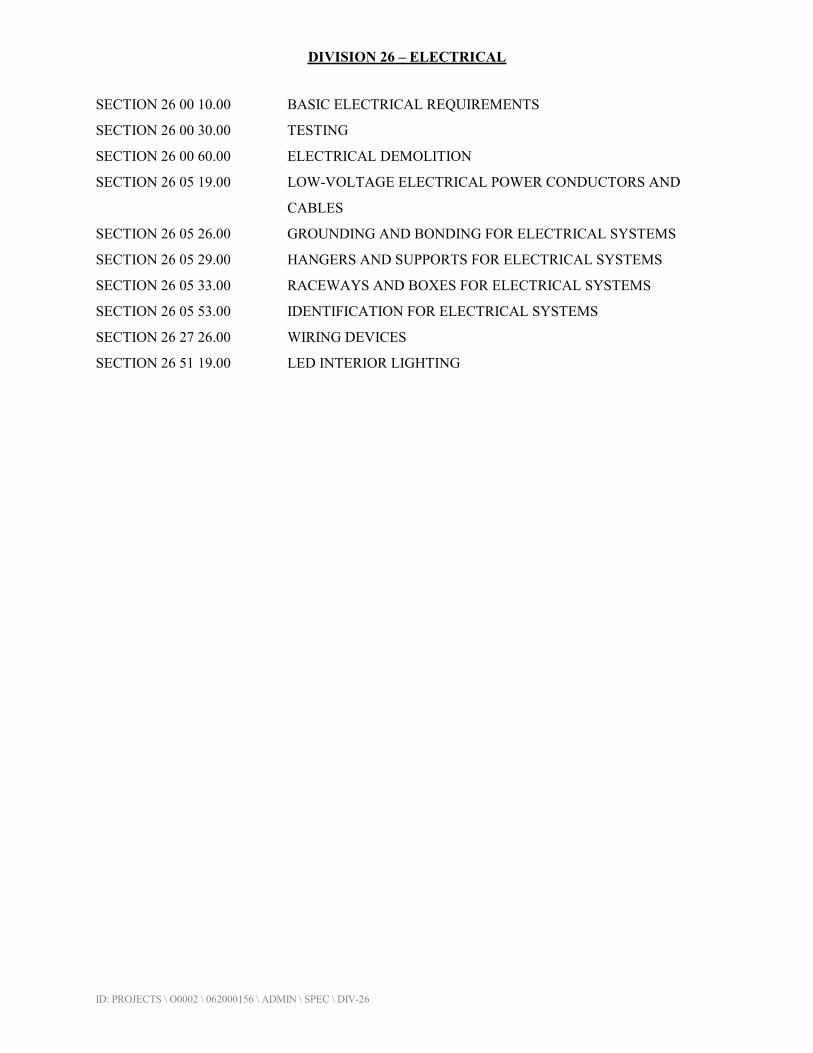
DIVISION 26 – ELECTRICAL
ID: PROJECTS \ O0002 \ 062000156 \ ADMIN \ SPEC \ DIV-26
SECTION 26 00 10.00 BASIC ELECTRICAL REQUIREMENTS
SECTION 26 00 30.00 TESTING
SECTION 26 00 60.00 ELECTRICAL DEMOLITION
SECTION 26 05 19.00 LOW-VOLTAGE ELECTRICAL POWER CONDUCTORS AND
CABLES
SECTION 26 05 26.00 GROUNDING AND BONDING FOR ELECTRICAL SYSTEMS
SECTION 26 05 29.00 HANGERS AND SUPPORTS FOR ELECTRICAL SYSTEMS
SECTION 26 05 33.00 RACEWAYS AND BOXES FOR ELECTRICAL SYSTEMS
SECTION 26 05 53.00 IDENTIFICATION FOR ELECTRICAL SYSTEMS
SECTION 26 27 26.00 WIRING DEVICES
SECTION 26 51 19.00 LED INTERIOR LIGHTING

ID: PROJECTS \ O0002 \ 062000156 \ ADMIN \ SPEC \ DIV-26 26 00 10.00 - 1
SECTION 26 00 10.00
BASIC ELECTRICAL REQUIREMENTS
PART 1 - GENERAL
1.1 SECTION INCLUDES
A. Basic electrical requirements specifically applicable to Division 26 - Electrical, and
complementary to Division 1 - General Requirements.
1.2 SCOPE
A. All work included in Division 26 and its Sections is coordinated with and complementary
to all the requirements and conditions set forth in other Divisions and Sections of the
Specifications, and associated Drawings, wherever applicable to the Electrical Work.
B. The intent and object of these Specifications and Drawings is to include a complete
wiring system from service entrance to each and every device indicated or specified,
including connecting all electrical devices and/or equipment furnished by the OWNER or
other CONTRACTORS.
1.3 GENERAL REQUIREMENTS
A. The work covered by this Division of the Specification is part of the General Contract
and includes the furnishing of all labor, materials, tools, transportation, permits,
certificates, temporary protection and storage required to complete the Electrical Work.
B. Wherever the words ‘the Electrical CONTRACTOR’, ‘CONTRACTOR’ or ‘this
CONTRACTOR’ appear in this Division of these Specifications, they apply specifically
to the Electrical CONTRACTOR.
C. The CONTRACTOR shall read the entire Specification including Division 1 - General
Requirements, which contain provisions equally applicable to the successful Bidder and
their Subcontractors. The CONTRACTOR shall also thoroughly examine all the project
Drawings and the proposed construction site.
D. It shall be the Electrical CONTRACTOR's responsibility to notify other Contractors to
arrange clearances and access openings for all large electrical equipment.
E. Electrical equipment delivered to the job site sectionalized for shipping purposes shall be
assembled according to Manufacturer's instructions. This shall include interconnecting
bus work, and all other wiring and removal of bracing and supports installed to safeguard
devices during shipment.

ID: PROJECTS \ O0002 \ 062000156 \ ADMIN \ SPEC \ DIV-26 26 00 10.00 - 2
F. The Electrical CONTRACTOR shall be responsible for unloading, placing into storage, if
necessary, removal from storage, and setting in place, all equipment and material
required for completion of the electrical installation.
G. Where material substitutions have been accepted by the ENGINEER / ARCHITECT and
it is later found that material substitutions alter the design or space requirements indicated
on the Drawings or in the Specifications, the Electrical CONTRACTOR shall be respon-
sible for the cost involved to revise the design and construction including the cost of all
allied trades involved.
1.4 REGULATORY REQUIREMENTS
A. All work under Division 26 - Electrical shall conform to the latest edition of the follow-
ing Codes and Regulatory Requirements.
1. ANSI/NFPA-70 - National Electrical Code.
2. ANSI/NFPA-101 - Life Safety Code.
3. ANSI C-2 - National Electrical Safety Code.
4. Safety Standards For Electrical Systems, as contained in the Code of Federal
Regulations Title 29, Part 1910, Subpart S-Electrical.
5. Applicable State Electrical Code.
6. Applicable Local Electrical Code.
7. Applicable State & Local Building Codes.
B. The Electrical CONTRACTOR shall not assume that any Drawing or Specification
forming a part of the Contract Documents authorizes the violation of any Code, Regula-
tion or Standard. Where conflicts arise, it shall be deemed that the CONTRACTOR has
estimated the cost of all work to be completed in accord with the prevailing Code.
C. The Electrical CONTRACTOR shall be licensed to perform electrical work in the
jurisdiction in which the project is located.
D. The CONTRACTOR shall obtain all necessary permits for electrical work. Any required
fees and sales or use taxes applicable to this branch of work shall be paid by the Electri-
cal CONTRACTOR.
E. Upon completion of the work, the CONTRACTOR shall deliver to the OWNER all
required certificates of inspection and approval.
1.5 DRAWINGS & SPECIFICATIONS
A. The Drawings, which constitute a part of the Contract, are diagrammatic in nature and
indicate the general arrangement of circuits and outlets, location of switches, panel board
and other work; but accuracy is not guaranteed, and field verification of all locations and
dimensions is directed.
B. The Drawings will not show all structural and installation details. It shall be the responsi-
bility of the CONTRACTOR to make a complete and satisfactory installation in accord-
ance with the best modern practice and methods.

ID: PROJECTS \ O0002 \ 062000156 \ ADMIN \ SPEC \ DIV-26 26 00 10.00 - 3
C. CONTRACTOR shall be responsible for all dimensions required for laying-out and
installing the work. Any information involving accurate measurements of the building
shall be taken from the Architectural and Structural Drawings, or at the building.
D. Generally, outlets shall be located, as required, for proper installation of equipment or to
meet Code requirements. Locations of equipment required to be wired shall be coordin-
ated with CONTRACTORS of other trades. The CONTRACTOR shall consult the
ENGINEER / ARCHITECT and refer to all details, sections, elevations and equipment
plans and the plans of other trades for exact location.
E. The ENGINEER / ARCHITECT reserves the right to make reasonable changes in the
location of outlets, apparatus or equipment up to the time of roughing-in. Such changes
as directed shall be made by the CONTRACTOR without additional compensation.
1.6 SUBMITTALS
A. Submit under provisions of Division 1.
B. Shop Drawing Submittals:
1. Include products specified in Division 26 - Electrical.
2. Group submittal data of related systems, products and accessories into a single
submittal.
3. Submit Shop Drawings in brochure form; provide an Index Sheet referencing all
items included.
4. ENGINEER / ARCHITECT’s review of Manufacturer's drawings constitutes
acceptance of general design only, and will not release the CONTRACTOR from
fulfilling the terms and intent of the Drawings and Specifications.
C. Operation & Maintenance Data:
1. Submit under provisions of Division 1.
1.7 RECORD DOCUMENTS
A. Scope:
1. It is the intent of this Section that all wiring systems included in the project be
fully documented. Record documents shall include all electrical devices and
equipment furnished by the Electrical CONTRACTOR, other Contractors and the
OWNER. Such documentation shall consist of Record Drawings’.
B. Record Drawings:
1. Record Drawings shall consist of marked-up Drawings, and shall contain the
following information:
a. Conduit routing for conduits 1-inch and larger.
b. Location of:

ID: PROJECTS \ O0002 \ 062000156 \ ADMIN \ SPEC \ DIV-26 26 00 10.00 - 4
1) Large pull boxes and junction boxes (8-inches and larger).
2) Equipment enclosures.
3) Light switches and receptacles.
4) Control stations.
5) Equipment shown on the Drawings.
6) Information as specified elsewhere in this Division.
2. CONTRACTOR shall also document the Electrical Work on Drawings obtained
from other sources.
a. Provide drawings of equipment furnished by this CONTRACTOR or
other Contractors, which may be found on door panels or within instruc-
tion manuals shipped with the equipment. CONTRACTOR shall mark
up such drawings to reflect any changes made as part of the Electrical
Work.
b. Provide documentation of modifications that may have been made to
electrical equipment by Manufacturer’s Representatives or start-up
personnel. It shall be the responsibility of the CONTRACTOR to obtain
a copy of such changes, and include that information with the record
documentation.
c. CONTRACTOR shall mark up submittal drawings of equipment
furnished by this CONTRACTOR or other Contractors to reflect any
changes made to the equipment as part of the Electrical Work.
3. CONTRACTOR shall maintain a copy of the Record Drawings on-site, and keep
them up to date to reflect the work completed to date.
4. Prior to final payment, the CONTRACTOR shall submit one (1) complete, clear,
concise and clean set of marked-up prints.
1.8 GUARANTEES
A. Provide guarantees, warranties and bonds under provisions of Division 1.
B. CONTRACTOR shall leave the entire electrical system in good working order and shall,
at their expense, repair, rebuild, remodel and make good and acceptable all defective
labor and materials that may develop within 1-year after completion and final acceptance
of the work hereunder and as further described under the General Conditions Of The
Construction Contract.
C. It may be necessary to energize portions of the electrical system prior to final acceptance
of the complete work. It is the intent of these Specifications that the above guarantee
period shall be 1-year after final acceptance.

ID: PROJECTS \ O0002 \ 062000156 \ ADMIN \ SPEC \ DIV-26 26 00 10.00 - 5
PART 2 - PRODUCTS
2.1 MATERIALS & EQUIPMENT
A. Furnish under provisions of Division 1.
B. All materials used for the electrical installation shall be new and unused, except as other-
wise indicated, and shall be uniform in type and manufacture for the entire electrical
installation.
C. All materials shall be suitable for the conditions and duties imposed upon them in service
and shall be the latest standard catalog products of reputable Manufacturers.
D. Substitutions: Subject to provisions of Division 1 - General Requirements, and the
Standard General Conditions Of The Construction Contract.
2.2 MANUFACTURERS
A. Manufacturers shall have a minimum 5-years continuous experience in the manufacture
of products specified under this Section.
B. Where materials, equipment, apparatus or other products are specified by Manufacturer,
brand name, type or catalog number, such designation is to establish standards of desired
quality and style and shall be the basis of the Bid.
C. Where ‘Acceptable Manufacturers’ are listed, the list is for general acceptance only.
Actual product used must conform to Drawings and Specifications, and be of equivalent
type, function, appearance and quality as the specified Manufacturer, brand name, type or
catalog number, if so specified. Products used shall be subject to review, under
provisions of Division 1 - General Requirements, and the Standard General Conditions
Of The Construction Contract.
2.3 LISTING OR LABELING
A. Materials and equipment of the types for which there are National Board of Fire Under-
writers (UL) listings and label service, shall be so labeled and shall be used by the
CONTRACTOR.
B. Listed or labeled equipment shall be used or installed in accordance with any instructions
included in the listing or labeling.

ID: PROJECTS \ O0002 \ 062000156 \ ADMIN \ SPEC \ DIV-26 26 00 10.00 - 6
PART 3 - EXECUTION
3.1 EQUIPMENT WIRING
A. The Electrical CONTRACTOR shall check the Drawings and Specifications of all other
Divisions of work, such as Heating, Ventilating, Air Conditioning, Plumbing, Mechanical
Equipment, etc., for equipment and work, which must be included in order to provide a
complete electrical installation.
B. Prior to energizing any equipment, the CONTRACTOR shall first make a thorough
inspection of it, and remove all packing, braces and shipping supports, and thoroughly
vacuum (or blow out with compressed air) all dirt and debris.
C. All associated starters, motor controls, pilot devices, etc. that may be furnished by others,
shall be delivered to the Electrical CONTRACTOR, who shall receive, handle, set, mount
and install this equipment. Unless stated elsewhere, the Electrical CONTRACTOR shall
provide all starters, motor controls, disconnects and pilot devices.
D. All motor control wiring less than 120-volts associated with heating, ventilating, air
conditioning, plumbing and mechanical equipment shall be considered ‘low voltage wir-
ing’, and shall be wired by the Electrical CONTRACTOR, except as may be specified in
Divisions 22, 23, 40, 41, 43 and/or 44. The Electrical CONTRACTOR shall extend and
supply power to the primary circuit of associated low voltage control transformers, and
shall be responsible for all low voltage wiring associated with building service motors,
such as door operators, alarm, instrumentation, etc. Wiring shall be in full compliance
with the Drawings and Specifications established under architectural, heating, ventilating
and mechanical equipment Divisions of the project.
E. All motor control wiring 120-volts and greater shall be considered ‘line voltage wiring’,
and shall be furnished, installed, wired and connected by the Electrical CONTRACTOR,
except as may be specified in Divisions 22, 23, 40, 41, 43 and/or 44.
F. It shall be the responsibility of the Electrical CONTRACTOR to obtain Manufacturer's
wiring diagrams of all electrical equipment furnished by other Contractors and shall not
proceed to wire the equipment without this information.
G. The Electrical CONTRACTOR shall check all Drawings and Specifications to determine
the requirements for motor disconnect switches. Whether or not specifically indicated on
the Drawings or in the Specifications, the Electrical CONTRACTOR shall be responsible
for furnishing motor disconnect switches to conform with regulatory requirements.
3.2 FINAL TESTS & DEMONSTRATIONS
A. Adjust work under provisions of Division 1 - General Requirements.
B. The CONTRACTOR shall test all work and all equipment installed by them, to ensure its
proper and safe operation in accordance with the true intent of the Drawings and Specifi-
cations. The CONTRACTOR shall check all interlocking and automatic control sequen-
ces, and shall test the operation of all safety and protective devices. The CONTRACTOR
ID: PROJECTS \ O0002 \ 062000156 \ ADMIN \ SPEC \ DIV-26 26 00 10.00 - 7
shall rectify all defects, shall cooperate in this work with the Electric Utility, Supplier /
Vendor's Representatives, and all other persons as directed by the OWNER or their
Representatives, in order to achieve the proper and intended operation of all equipment.
C. The CONTRACTOR shall test, adjust and record operating voltages, at each system level
before energizing branch circuit. This record of operating voltages shall be turned over
to the ENGINEER / ARCHITECT in a typed format. Transformer taps must be adjusted
to obtain, as near as possible, nominal system voltage. Where transformer is under utility
jurisdiction, obtain services of utility to correct voltage. The CONTRACTOR shall be
responsible for replacement of all devices and equipment damaged due to failure to
comply with this requirement.
D. The CONTRACTOR shall balance load among feeder conductors at each panel board,
switchboard or substation, and shall reconnect loads, as may be necessary, to obtain a
reasonable balance of load on each phase. Electrical unbalance shall not exceed 7½%.
E. The CONTRACTOR shall provide all instruments and equipment necessary to perform
required tests.
F. All checks and tests shall be permanently recorded and three (3) copies submitted to the
ENGINEER / ARCHITECT in a typed format. The tests shall include:
1. System Grounding.
2. Fuses:
a. Equipment nameplate requirement.
b. Actual fuse rating.
3. Breakers:
a. Nameplate.
b. Setting.
4. Motors:
a. Nameplate.
b. Overload relay element.
c. Protective relay (if any) setting.
d. Voltage and current phase readings.
e. Direction of rotation.
5. 500-volt Megger check on equipment up to 2,000-volts.
6. Ampere readings on any cable operating in parallel to ensure an even division of
current.
7. Solid-state equipment shall not be Megger checked.
G. The CONTRACTOR shall, upon request, demonstrate proper operation of all electrical
systems and equipment in the presence of the ENGINEER / ARCHITECT and/or other
designated persons.
ID: PROJECTS \ O0002 \ 062000156 \ ADMIN \ SPEC \ DIV-26 26 00 10.00 - 8
3.3 CLEANUP & PAINTING
A. Provide final cleaning under provisions of Division 1.
B. The Electrical CONTRACTOR shall periodically remove from the site all debris and
rubbish accumulating as a result of the electrical installation. Upon completion of the
project, shall dispose of all debris and rubbish and shall:
1. Leave electrical equipment rooms broom clean.
2. Clean interior of all panel cabinets, pull boxes and other equipment enclosures.
3. Wash and wipe clean all lighting fixtures, lamps and other electrical equipment
that may have become soiled during the installation.
C. If, during the installation, the finish of any electrical equipment has deteriorated or has
been damaged, the Electrical CONTRACTOR shall restore its condition and appearance
to the satisfaction of the OWNER.
END OF SECTION

ID: PROJECTS \ O0002 \ 062000156 \ ADMIN \ SPEC \ DIV-26 26 00 30.00 - 1
SECTION 26 00 30.00
TESTING
PART 1 - GENERAL
1.1 SCOPE OF WORK
A. CONTRACTOR shall test all equipment.
B. This Section of Specification covers the tests and checks that shall be made on all electri-
cal equipment and wiring to ensure compliance with the applicable Codes and Standards,
and with the Drawings and Specifications. Wherever possible, all checks and tests shall
be made just prior to energizing the equipment or circuits, and shall be coordinated with
the field schedule and field conditions.
C. Before testing and energizing a system, all necessary precautions shall be taken to ensure
the safety of personnel and equipment. All conductors and all electrical equipment shall
be properly insulated and enclosed. All enclosures for conductors and equipment shall be
properly grounded. Insulation resistance measurements must have been made and
approved on all conductors, and energized parts of electrical equipment.
D. After the electrical installation is complete, make tests to demonstrate that all systems are
in proper working order and in accordance with the Contract Documents. Tests are in
addition to, and no substitution for, tests of individual items at Manufacturer's plant.
Make insulation and ground resistance tests before operating tests. Determine proper
rotation of motors before permanent connections are made.
E. Pay all costs for tests, including expenses incidental to re-tests occasioned by defects and
failures of equipment to meet these Specifications.
F. Replace wiring and equipment found defective of failing to meet specified requirements,
without charge.
G. Furnish three (3) copies of all test results to ENGINEER / ARCHITECT.
H. Unless otherwise specified, the CONTRACTOR shall supply electric current necessary
for tests.
1.2 REFERENCE STANDARDS
A. NEMA: National Electrical Manufacturers Association.
B. IEEE: Institute Of Electrical & Electronic Engineers.
ID: PROJECTS \ O0002 \ 062000156 \ ADMIN \ SPEC \ DIV-26 26 00 30.00 - 2
PART 2 - PRODUCTS
2.1 TESTING EQUIPMENT
A. Furnish suitable electrical instruments, including voltmeters, ammeters, wattmeters,
tachometers, and all other equipment necessary to perform tests specified.
B. Make necessary openings in circuits for testing instruments, and place and connect all
instruments, equipment and devices necessary for the tests. Upon completion of tests,
remove instruments and instrument connections and restore all circuits to permanent
condition.
2.2 TESTING
A. Coordinate activities and cooperate with OWNER and others on the project to ensure that
systems are energized when required, when loads are applied and that other requirements
of this Section of the Specifications are carried out in a timely, coordinated basis.
B. Notify the ENGINEER / ARCHITECT seven (7) calendar days or more in advance when
any test is to be performed.
C. Make up no permanent connections at transformers, motors, motor control centers and
generator until correct phase rotation of all equipment is determined. Install and insulate
these connections temporarily when determining proper rotation. Make permanent
connections after proper rotation has been established and subsequent to completion of
insulation resistance and dielectric tests.
PART 3 - EXECUTION
3.1 INSULATION RESISTANCE TESTS OF CIRCUITS, 600-VOLTS & BELOW
A. Do not subject conductors rated 600-volts and below to high potential dielectric tests.
Test each complete feeder and branch circuit of 600-volts or below with everything but
power supply and power-consuming equipment connected thereto. Insulation resistance
between conductors and between each conductor and ground shall not be less than
1,000,000-ohms, unless otherwise accepted by the ENGINEER / ARCHITECT.
B. Determine insulation resistance values with all switch-gear, substations, transformers,
motor control centers, panel boards, switches, receptacles and over-current devices in
place.
C. Use megohmeter having output of at least 1,000-volts to determine insulation resistance
value for 600-volt rated conductors.
D. List each circuit and measured resistance on Test Data Sheets.
ID: PROJECTS \ O0002 \ 062000156 \ ADMIN \ SPEC \ DIV-26 26 00 30.00 - 3
E. Maintain records of all insulation resistance values. Identify conductor or equipment and
the date when that resistance value was taken. Arrange information in suitable, neat,
tabular form and return three (3) copies to the ENGINEER / ARCHITECT.
3.2 INSULATION RESISTANCE TESTS FOR MOTORS
A. After installation, test windings of all 3-phase motors with megohmeter in accordance
with and meeting requirements of IEEE Standard No. 43.
3.3 GROUND RESISTANCE
A. Test each ground rod in accordance with IEEE Standard 142, and submit tabulation of
results to ENGINEER / ARCHITECT. Include identification of electrode, date of
reading and ground resistance value in results.
B. Test each entire grounding system for continuity of connections and for resistance.
Ensure that ground resistance of conduits, equipment cases and supporting frames does
not vary appreciably from that of system as whole and does not exceed 5-ohms.
3.4 OPERATING TESTS
A. Operate each motor and associated equipment, as nearly as possible, under normal
operating conditions for as long as feasible and for length of time sufficient to demon-
strate correct alignment, temperature rise, speed and satisfactory operation. Load motors
to full capacity or as near as possible.
B. Operate switches, circuit breakers and control devices to show correct and satisfactory
operation.
C. Associated equipment includes instruments, meters, relays, circuit breakers, switches and
other devices in motor control centers, panel boards, control and instrumentation panels,
etc., related to motor being tested.
D. Where tests of any of above-referenced equipment is included in other sections of these
Specifications, coordinating testing, as directed by ENGINEER / ARCHITECT, to avoid
duplication and conflict between tests.
E. Perform above tests in addition to, and not in substitution for, required Manufacturer's
factory tests of individual items.
3.5 TESTS
A. The CONTRACTOR shall check and test all transformers, power panels, feeders, power
and control cables and connections, and motors to assure correct phase sequence and
rotation. Phase sequence shall be A-B-C, as follows:
ID: PROJECTS \ O0002 \ 062000156 \ ADMIN \ SPEC \ DIV-26 26 00 30.00 - 4
1. Top to bottom, left to right, and front to rear, when facing protective or
disconnecting mechanism.
2. Phasing shall be accomplished by using distinctive colors for various phases, as
indicated.
B. After wires and cables are in place and connected to devices and equipment, the system
shall be tested for short circuits, improper grounds and other faults. If fault condition is
present, the trouble shall be rectified, then re-tested.
C. Phase conductors, if shorted, grounded or at fault, shall be removed, replaced and then re-
tested.
D. A voltage test shall be made at the last outlet on each circuit. If drop in potential exceeds
2%, the CONTRACTOR shall correct the condition by locating the ground or high resis-
tance splice or connection and re-test.
E. Any wiring device, electrical apparatus or lighting fixture grounded or shortened on any
integral ‘live’ part, shall be removed and the trouble rectified by replacing the defective
parts or materials.
F. Upon completion of the Electrical Work, CONTRACTOR shall place the entire installa-
tion in operation, test for proper function, and show systems and equipment to be free of
defects. Motors and driven equipment shall not be run until properly lubricated. Pumps
shall not be run until water or process fluid supply is connected and turned on. Test and
record motor maximum load amperage and terminal voltage when uncoupled and
coupled for each motor.
G. ENGINEER / ARCHITECT will conduct, from time to time, such tests as may be
required to any part of the equipment to determine if it is installed in accordance with
Specifications. CONTRACTOR shall extend to the ENGINEER / ARCHITECT all
facilities to this end, and shall furnish skilled or unskilled help, as required. All test
results shall be given to the ENGINEER / ARCHITECT promptly upon completion of a
test.
H. CONTRACTOR shall provide assistance to the various Equipment Manufacturers' Field
Engineers, as required in the testing and adjusting of the electrical power and control
equipment. Cooperation of the CONTRACTOR must be such that a minimum of time is
required for equipment testing.
I. A log shall be maintained for all tests. This log shall be certified before completion of
the job, both as to test value and date of test. All major equipment, such as switchgear,
substations, motor control centers and motors, shall be energized initially in the presence
of the ENGINEER / ARCHITECT.
J. Any faults or failures in the work performed by this CONTRACTOR or in materials or
equipment furnished by this CONTRACTOR shall be corrected or replaced promptly by
this CONTRACTOR at their own expense. Any faults in materials or equipment
furnished by the CONTRACTOR, which are the result of careless, incompetent or
improper handling or installation by this CONTRACTOR, shall be corrected or replaced
promptly by this CONTRACTOR at their own expense.

ID: PROJECTS \ O0002 \ 062000156 \ ADMIN \ SPEC \ DIV-26 26 00 30.00 - 5
K. All tests shall be made at the CONTRACTOR's expense and certification of the tests
shall be submitted to the ENGINEER / ARCHITECT.
3.6 WIRE & CABLE TESTING (600-volts)
A. The 600-volt insulated wires and cables shall be factory tested prior to shipment in
accordance with ICEA Standards for the insulation specified.
B. The following 600-volt wires and cables shall be tested after installation, but before final
connections are made up:
1. All feeders from the 480-volt substations.
2. All 480-volt motor cables.
3. All transformer primary and secondary feeder cables.
C. For the above listed wires and cables, 1,000-volt megger test, as specified in ICEA, shall
be applied for a period, as specified in the Standard, between the conductors specified in
the Standard, between the conductors in the same conduit and between each conductor to
ground.
END OF SECTION
ID: PROJECTS \ O0002 \ 062000156 \ ADMIN \ SPEC \ DIV-26 26 00 60.00 - 1
SECTION 26 00 60.00
ELECTRICAL DEMOLITION
PART 1 - GENERAL
1.1 SCOPE OF WORK
A. Provide demolition and site removal of designated electrical systems, as described herein
and as indicated on the Drawings.
1.2 SAFETY
A. Perform all work in accordance with OSHA regulations.
B. Suitably guard from accidental contact any live parts that may become exposed during
the course of the work.
PART 2 - PRODUCTS
Not Applicable.
PART 3 - EXECUTION
3.1 EXAMINATION
A. Visit the project site and thoroughly investigate existing conditions prior to submitting
Bid. Carefully evaluate all existing material, equipment, etc., which is to be removed,
reinstalled, altered or modified, and include all associated costs in the Bid.
B. Determine existing installation that is to remain, to serve areas outside the limits of
demolition and include all costs for work that may be required to maintain existing
services. No additional charges will be allowed for failure to include all labor and
material required for relocation or modification required to maintain the existing electri-
cal installation beyond the limits of work.
C. Verify field dimensions and circuiting arrangements are as indicated on the Drawings.
D. Verify that abandoned wiring and equipment serve only abandoned facilities.
E. Demolition Drawings are based upon casual field observation. Report discrepancies to
ENGINEER / ARCHITECT before disturbing existing installation.
F. Beginning of demolition means installer accepts existing conditions.

ID: PROJECTS \ O0002 \ 062000156 \ ADMIN \ SPEC \ DIV-26 26 00 60.00 - 2
3.2 PREPARATION
A. Disconnect electrical systems in walls, floors and ceilings scheduled for removal.
B. Coordinate utility service outages with Utility Company and the OWNER.
C. Provide temporary wiring and connections to maintain existing systems in service during
construction. When work must be performed on energized equipment or circuits, use
personnel experienced in such operations.
D. Existing Electrical Service:
1. Maintain existing system in service until new system is complete and ready for
service. Disable system only to make switchovers and connections. Obtain
permission from OWNER at least 24-hours before partially or completely
disabling system. Minimize outage duration.
E. Existing Fire Alarm System:
1. Maintain existing system in service until new system is accepted. Disable system
only to make switchovers and connections. Notify OWNER and local Fire
Service at least 24-hours before partially or completely disabling system.
Minimize outage duration.
3.3 DEMOLITION & EXTENSION OF EXISTING ELECTRICAL WORK
A. Demolish and extend existing electrical work under provisions of Divisions 01 - General
Requirements, and Division 02 - Existing Conditions, and this Section.
B. Remove, relocate and extend existing installations to accommodate new construction.
C. Remove abandoned wiring to source of supply.
D. Remove any exposed abandoned conduit and junction boxes, including abandoned
conduit above accessible ceilings. Cut conduit flush with walls and floors and patch
surfaces with expansive grout.
E. Disconnect abandoned outlets and remove devices. Remove abandoned outlets if conduit
servicing them is abandoned and removed. Provide blank cover for abandoned outlets
that are not removed.
F. Disconnect and remove abandoned panelboards and distribution equipment.
G. Disconnect and remove electrical devices and equipment serving utilization equipment
that has been removed.
H. Disconnect and remove abandoned luminaires. Remove brackets, stems, hangers and
other accessories.

ID: PROJECTS \ O0002 \ 062000156 \ ADMIN \ SPEC \ DIV-26 26 00 60.00 - 3
I. Salvage selected equipment designated on Drawings or designated by the OWNER. Store
in location on job site, as directed by the OWNER.
J. Repair adjacent construction and finishes damaged during demolition and extension
work.
K. Maintain access to existing electrical installations that remain active. Modify installation
or provide access panel as appropriate.
L. Extend existing installations using materials and methods consistent with existing electri-
cal installations, or as specified.
3.4 CUTTING & PATCHING
A. Protect existing electrical equipment and installations. If equipment or installation is
damaged or disturbed in the course of the work, remove damaged portions and install
new products of equal quality and functionality. Repair adjacent building construction
and finishes damaged in the course of the work.
B. Cut, Channel, Chase & Drill: Floors, walls, partitions, ceilings or other existing surfaces,
as required to permit electrical installations.
1. The Electrical CONTRACTOR shall be responsible for this work.
2. The work shall be performed by skilled mechanics of the involved trades.
3.5 CLEANING & REPAIR
A. Clean and repair existing materials and equipment that are to remain or are to be reused.
B. Panelboards: Clean exposed surfaces and check tightness of electrical connections.
Replace damaged circuit breakers and provide closure plates for vacant positions.
Provide typed circuit directory showing revised circuiting arrangement.
C. Luminaires: Clean existing luminaires in place. Use mild detergent to clean all surfaces;
rinse with clean water and wipe dry. Wipe clean all exposed lamps.
3.6 INSTALLATION
A. Install relocated materials and equipment, as indicated on the Drawings and under the
provisions of Division 1 - General Requirements.
END OF SECTION
ID: PROJECTS \ O0002 \ 062000156 \ ADMIN \ SPEC \ DIV-26 26 05 19.00 - 1
SECTION 26 05 19.00
LOW-VOLTAGE ELECTRICAL POWER CONDUCTORS AND CABLES
PART 1 - GENERAL
1.1 SUMMARY
A. Section Includes:
1. Copper building wire rated 600 V or less.
2. Connectors, splices, and terminations rated 600 V and less.
1.2 ACTION SUBMITTALS
A. Product Data: For each type of product.
PART 2 - PRODUCTS
2.1 COPPER BUILDING WIRE
A. Description: Flexible, insulated and uninsulated, drawn copper current-carrying conductor with
an overall insulation layer or jacket, or both, rated 600 V or less.
B. Manufacturers: Subject to compliance with requirements, provide products by one of the
following:
1. General Cable Technologies Corporation.
2. Service Wire Co.
3. Southwire Company.
C. Standards:
1. Listed and labeled as defined in NFPA 70, by a qualified testing agency, and marked for
intended location and use.
2. RoHS compliant.
3. Conductor and Cable Marking: Comply with wire and cable marking according to UL's
"Wire and Cable Marking and Application Guide."
D. Conductors: Copper, complying with ASTM B 3 for bare annealed copper and with ASTM B 8
for stranded conductors.
E. Conductor Insulation:
1. Type THHN and Type THWN-2: Comply with UL 83.
2. Type XHHW-2: Comply with UL 44.

ID: PROJECTS \ O0002 \ 062000156 \ ADMIN \ SPEC \ DIV-26 26 05 19.00 - 2
2.2 CONNECTORS AND SPLICES
A. Description: Factory-fabricated connectors, splices, and lugs of size, ampacity rating, material,
type, and class for application and service indicated; listed and labeled as defined in NFPA 70,
by a qualified testing agency, and marked for intended location and use.
B. Manufacturers: Subject to compliance with requirements, provide products by one of the
following:
1. 3M Electrical Products.
2. AFC Cable Systems; a part of Atkore International.
3. Hubbell Power Systems, Inc.
4. Ideal Industries, Inc.
5. ILSCO.
6. O-Z/Gedney; a brand of Emerson Industrial Automation.
7. Service Wire Co.
8. Thomas & Betts Corporation; A Member of the ABB Group.
C. Jacketed Cable Connectors: For steel and aluminum jacketed cables, zinc die-cast with set
screws, designed to connect conductors specified in this Section.
D. Lugs: One piece, seamless, designed to terminate conductors specified in this Section.
1. Material: Copper.
2. Type: Two hole with long barrels.
3. Termination: Crimp.
PART 3 - EXECUTION
3.1 CONDUCTOR MATERIAL APPLICATIONS
A. Feeders: Copper; solid for No. 14 AWG and smaller; stranded for No. 12 AWG and larger.
B. Branch Circuits: Copper. Solid for No. 14 AWG and smaller; stranded for No. 12 AWG and
larger.
C. Power-Limited Fire Alarm and Control: Solid for No. 12 AWG and smaller.
3.2 CONDUCTOR INSULATION AND MULTICONDUCTOR CABLE APPLICATIONS AND
WIRING METHODS
A. Feeders: Type THHN/THWN-2, single conductors in raceway.
B. Feeders Concealed in Concrete, below Slabs-on-Grade, and Underground: Type XHHW-2,
single conductors in raceway.
C. Exposed Branch Circuits, Including in Crawlspaces: Type THHN/THWN-2, single conductors
in raceway.

ID: PROJECTS \ O0002 \ 062000156 \ ADMIN \ SPEC \ DIV-26 26 05 19.00 - 3
D. Branch Circuits Concealed in Ceilings, Walls, and Partitions: Type THHN/THWN-2, single
conductors in raceway.
E. Branch Circuits Concealed in Concrete, below Slabs-on-Grade, and Underground:
Type XHHW-2, single conductors in raceway.
3.3 INSTALLATION OF CONDUCTORS AND CABLES
A. Conceal cables in finished walls, ceilings, and floors unless otherwise indicated.
B. Complete raceway installation between conductor and cable termination points according to
Section 26 05 33.00 "Raceways and Boxes for Electrical Systems" prior to pulling conductors
and cables.
C. Use manufacturer-approved pulling compound or lubricant where necessary; compound used
must not deteriorate conductor or insulation. Do not exceed manufacturer's recommended
maximum pulling tensions and sidewall pressure values.
D. Use pulling means, including fish tape, cable, rope, and basket-weave wire/cable grips, that will
not damage cables or raceway.
E. Install exposed cables parallel and perpendicular to surfaces of exposed structural members, and
follow surface contours where possible.
F. Support cables according to Section 26 05 29.00 "Hangers and Supports for Electrical Systems."
3.4 CONNECTIONS
A. Tighten electrical connectors and terminals according to manufacturer's published torque-
tightening values. If manufacturer's torque values are not indicated, use those specified in
UL 486A-486B.
B. Make splices, terminations, and taps that are compatible with conductor material and that
possess equivalent or better mechanical strength and insulation ratings than unspliced
conductors.
C. Wiring at Outlets: Install conductor at each outlet, with at least 6 inches (150 mm) of slack.
3.5 IDENTIFICATION
A. Identify and color-code conductors and cables according to Section 26 05 53.00 "Identification
for Electrical Systems."
B. Identify each spare conductor at each end with identity number and location of other end of
conductor, and identify as spare conductor.

ID: PROJECTS \ O0002 \ 062000156 \ ADMIN \ SPEC \ DIV-26 26 05 19.00 - 4
3.6 SLEEVE AND SLEEVE-SEAL INSTALLATION FOR ELECTRICAL PENETRATIONS
A. Install sleeves and sleeve seals at penetrations of exterior floor and wall assemblies.
3.7 FIRESTOPPING
A. Apply firestopping to electrical penetrations of fire-rated floor and wall assemblies to restore
original fire-resistance rating of assembly.
END OF SECTION
ID: PROJECTS \ O0002 \ 062000156 \ ADMIN \ SPEC \ DIV-26 26 05 26.00 - 1
SECTION 26 05 26.00
GROUNDING AND BONDING FOR ELECTRICAL SYSTEMS
PART 1 - GENERAL
1.1 SUMMARY
A. Section includes grounding and bonding systems and equipment.
1.2 ACTION SUBMITTALS
A. Product Data: For each type of product.
1.3 QUALITY ASSURANCE
A. Testing Agency Qualifications: Certified by NETA.
PART 2 - PRODUCTS
2.1 SYSTEM DESCRIPTION
A. Electrical Components, Devices, and Accessories: Listed and labeled as defined in NFPA 70, by
a qualified testing agency, and marked for intended location and application.
B. Comply with UL 467 for grounding and bonding materials and equipment.
2.2 MANUFACTURERS
A. Manufacturers: Subject to compliance with requirements, available manufacturers offering
products that may be incorporated into the Work include, but are not limited to, the following:
1. Burndy; Part of Hubbell Electrical Systems.
2. ERICO International Corporation.
3. ILSCO.
4. O-Z/Gedney; a brand of Emerson Industrial Automation.
5. Thomas & Betts Corporation; A Member of the ABB Group.
2.3 CONDUCTORS
A. Insulated Conductors: Copper or tinned-copper wire or cable insulated for 600 V unless
otherwise required by applicable Code or authorities having jurisdiction.

ID: PROJECTS \ O0002 \ 062000156 \ ADMIN \ SPEC \ DIV-26 26 05 26.00 - 2
B. Bare Copper Conductors:
1. Solid Conductors: ASTM B 3.
2. Stranded Conductors: ASTM B 8.
3. Tinned Conductors: ASTM B 33.
4. Bonding Cable: 28 kcmil, 14 strands of No. 17 AWG conductor, 1/4 inch (6 mm) in
diameter.
5. Bonding Conductor: No. 4 or No. 6 AWG, stranded conductor.
6. Bonding Jumper: Copper tape, braided conductors terminated with copper ferrules; 1-5/8
inches (41 mm) wide and 1/16 inch (1.6 mm) thick.
7. Tinned Bonding Jumper: Tinned-copper tape, braided conductors terminated with copper
ferrules; 1-5/8 inches (41 mm) wide and 1/16 inch (1.6 mm) thick.
C. Grounding Bus: Predrilled rectangular bars of annealed copper, 1/4 by 4 inches (6.3 by 100
mm) in cross section, with 9/32-inch (7.14-mm) holes spaced 1-1/8 inches (28 mm) apart.
Stand-off insulators for mounting shall comply with UL 891 for use in switchboards, 600 V and
shall be Lexan or PVC, impulse tested at 5000 V.
2.4 CONNECTORS
A. Listed and labeled by an NRTL acceptable to authorities having jurisdiction for applications in
which used and for specific types, sizes, and combinations of conductors and other items
connected.
B. Welded Connectors: Exothermic-welding kits of types recommended by kit manufacturer for
materials being joined and installation conditions.
C. Bus-Bar Connectors: Mechanical type, cast silicon bronze, solderless compression-type wire
terminals, and long-barrel, two-bolt connection to ground bus bar.
D. Bus-Bar Connectors: Compression type, copper or copper alloy, with two wire terminals.
E. Beam Clamps: Mechanical type, terminal, ground wire access from four directions, with dual,
tin-plated or silicon bronze bolts.
F. Cable-to-Cable Connectors: Compression type, copper or copper alloy.
G. Cable Tray Ground Clamp: Mechanical type, zinc-plated malleable iron.
H. Conduit Hubs: Mechanical type, terminal with threaded hub.
I. Ground Rod Clamps: Mechanical type, copper or copper alloy, terminal with hex head bolt.
J. Ground Rod Clamps: Mechanical type, copper or copper alloy, terminal with hex head bolt.
K. Lay-in Lug Connector: Mechanical type, copper rated for direct burial terminal with set screw.
L. Service Post Connectors: Mechanical type, bronze alloy terminal, in short- and long-stud
lengths, capable of single and double conductor connections.
M. Signal Reference Grid Clamp: Mechanical type, stamped-steel terminal with hex head screw.

ID: PROJECTS \ O0002 \ 062000156 \ ADMIN \ SPEC \ DIV-26 26 05 26.00 - 3
N. Straps: Solid copper, cast-bronze clamp or copper lugs. Rated for 600 A.
O. U-Bolt Clamps: Mechanical type, copper or copper alloy, terminal listed for direct burial.
P. Water Pipe Clamps:
1. Mechanical type, two pieces with zinc-plated bolts.
a. Material: Die-cast zinc alloy.
b. Listed for direct burial.
2. U-bolt type with malleable-iron clamp and copper ground connector.
PART 3 - EXECUTION
3.1 APPLICATIONS
A. Conductors: Install solid conductor for No. 8 AWG and smaller, and stranded conductors for
No. 6 AWG and larger unless otherwise indicated.
B. Underground Grounding Conductors: Install bare tinned-copper conductor, No. 2/0 AWG
minimum.
1. Bury at least 24 inches (600 mm) below grade.
C. Grounding Bus: Install in electrical equipment rooms, in rooms housing service equipment, and
elsewhere as indicated.
1. Install bus horizontally, on insulated spacers 2 inches (50 mm) minimum from wall, 6
inches (150 mm) above finished floor unless otherwise indicated.
2. Where indicated on both sides of doorways, route bus up to top of door frame, across top
of doorway, and down; connect to horizontal bus.
D. Conductor Terminations and Connections:
1. Pipe and Equipment Grounding Conductor Terminations: Bolted connectors.
2. Underground Connections: Welded connectors except at test wells and as otherwise
indicated.
3. Connections to Ground Rods at Test Wells: Bolted connectors.
4. Connections to Structural Steel: Welded connectors.
3.2 GROUNDING SEPARATELY DERIVED SYSTEMS
A. Generator: Install grounding electrode(s) at the generator location. The electrode shall be
connected to the equipment grounding conductor and to the frame of the generator.

ID: PROJECTS \ O0002 \ 062000156 \ ADMIN \ SPEC \ DIV-26 26 05 26.00 - 4
3.3 EQUIPMENT GROUNDING
A. Install insulated equipment grounding conductors with all feeders and branch circuits.
B. Install insulated equipment grounding conductors with the following items, in addition to those
required by NFPA 70:
1. Feeders and branch circuits.
2. Lighting circuits.
3. Receptacle circuits.
4. Single-phase motor and appliance branch circuits.
5. Three-phase motor and appliance branch circuits.
6. Flexible raceway runs.
C. Air-Duct Equipment Circuits: Install insulated equipment grounding conductor to duct-mounted
electrical devices operating at 120 V and more, including air cleaners, heaters, dampers,
humidifiers, and other duct electrical equipment. Bond conductor to each unit and to air duct
and connected metallic piping.
D. Water Heater, Heat-Tracing, and Antifrost Heating Cables: Install a separate insulated
equipment grounding conductor to each electric water heater and heat-tracing cable. Bond
conductor to heater units, piping, connected equipment, and components.
3.4 INSTALLATION
A. Grounding Conductors: Route along shortest and straightest paths possible unless otherwise
indicated or required by Code. Avoid obstructing access or placing conductors where they may
be subjected to strain, impact, or damage.
B. Ground Bonding Common with Lightning Protection System: Comply with NFPA 780 and
UL 96 when interconnecting with lightning protection system. Bond electrical power system
ground directly to lightning protection system grounding conductor at closest point to electrical
service grounding electrode. Use bonding conductor sized same as system grounding electrode
conductor, and install in conduit.
C. Ground Rods: Drive rods until tops are 2 inches (50 mm) below finished floor or final grade
unless otherwise indicated.
1. Interconnect ground rods with grounding electrode conductor below grade and as
otherwise indicated. Make connections without exposing steel or damaging coating if
any.
D. Bonding Straps and Jumpers: Install in locations accessible for inspection and maintenance
except where routed through short lengths of conduit.
1. Bonding to Structure: Bond straps directly to basic structure, taking care not to penetrate
any adjacent parts.
2. Bonding to Equipment Mounted on Vibration Isolation Hangers and Supports: Install
bonding so vibration is not transmitted to rigidly mounted equipment.

ID: PROJECTS \ O0002 \ 062000156 \ ADMIN \ SPEC \ DIV-26 26 05 26.00 - 5
3. Use exothermic-welded connectors for outdoor locations; if a disconnect-type connection
is required, use a bolted clamp.
E. Grounding and Bonding for Piping:
1. Metal Water Service Pipe: Install insulated copper grounding conductors, in conduit,
from building's main service equipment, or grounding bus, to main metal water service
entrances to building. Connect grounding conductors to main metal water service pipes;
use a bolted clamp connector or bolt a lug-type connector to a pipe flange by using one of
the lug bolts of the flange. Where a dielectric main water fitting is installed, connect
grounding conductor on street side of fitting. Bond metal grounding conductor conduit or
sleeve to conductor at each end.
2. Water Meter Piping: Use braided-type bonding jumpers to electrically bypass water
meters. Connect to pipe with a bolted connector.
3. Bond each aboveground portion of gas piping system downstream from equipment
shutoff valve.
3.5 FIELD QUALITY CONTROL
A. Perform tests and inspections.
B. Tests and Inspections:
1. After installing grounding system but before permanent electrical circuits have been
energized, test for compliance with requirements.
2. Inspect physical and mechanical condition. Verify tightness of accessible, bolted,
electrical connections with a calibrated torque wrench according to manufacturer's
written instructions.
C. Grounding system will be considered defective if it does not pass tests and inspections.
D. Prepare test and inspection reports.
END OF SECTION
ID: PROJECTS \ O0002 \ 062000156 \ ADMIN \ SPEC \ DIV-26 26 05 29.00 - 1
SECTION 26 05 29.00
HANGERS AND SUPPORTS FOR ELECTRICAL SYSTEMS
PART 1 - GENERAL
1.1 SUMMARY
A. Section Includes:
1. Steel slotted support systems.
2. Conduit and cable support devices.
3. Mounting, anchoring, and attachment components, including powder-actuated fasteners,
mechanical expansion anchors, concrete inserts, clamps, through bolts, toggle bolts, and
hanger rods.
1.2 ACTION SUBMITTALS
A. Product Data: For each type of product.
1.3 SUPPORT, ANCHORAGE, AND ATTACHMENT COMPONENTS
A. Steel Slotted Support Systems: Preformed steel channels and angles with minimum 13/32-inch-
(10-mm-) diameter holes at a maximum of 8 inches (200 mm) o.c. in at least one surface.
1. Manufacturers: Subject to compliance with requirements, provide products by one of the
following:
a. B-line, an Eaton business.
b. ERICO International Corporation.
c. Thomas & Betts Corporation; A Member of the ABB Group.
d. Unistrut; Part of Atkore International.
2. Standard: Comply with MFMA-4 factory-fabricated components for field assembly.
3. Material for Channel, Fittings, and Accessories: Galvanized steel or painted steel.
4. Channel Width: 1-5/8 inches (41.25 mm).
5. Metallic Coatings: Hot-dip galvanized after fabrication and applied according to MFMA-
4.
6. Painted Coatings: Manufacturer's standard painted coating applied according to MFMA-
4.
7. Protect finishes on exposed surfaces from damage by applying a strippable, temporary
protective covering before shipping.
B. Conduit and Cable Support Devices: Steel hangers, clamps, and associated fittings, designed for
types and sizes of raceway or cable to be supported.

ID: PROJECTS \ O0002 \ 062000156 \ ADMIN \ SPEC \ DIV-26 26 05 29.00 - 2
C. Support for Conductors in Vertical Conduit: Factory-fabricated assembly consisting of threaded
body and insulating wedging plug or plugs for nonarmored electrical conductors or cables in
riser conduits. Plugs shall have number, size, and shape of conductor gripping pieces as
required to suit individual conductors or cables supported. Body shall be made of malleable
iron.
D. Structural Steel for Fabricated Supports and Restraints: ASTM A 36/A 36M steel plates, shapes,
and bars; black and galvanized.
E. Mounting, Anchoring, and Attachment Components: Items for fastening electrical items or their
supports to building surfaces include the following:
1. Powder-Actuated Fasteners: Threaded-steel stud, for use in hardened portland cement
concrete, steel, or wood, with tension, shear, and pullout capacities appropriate for
supported loads and building materials where used.
a. Manufacturers: Subject to compliance with requirements, provide products by one
of the following:
1) Hilti, Inc.
2) MKT Fastening, LLC.
2. Mechanical-Expansion Anchors: Insert-wedge-type, zinc-coated steel, for use in
hardened portland cement concrete, with tension, shear, and pullout capacities
appropriate for supported loads and building materials where used.
a. Manufacturers: Subject to compliance with requirements, provide products by one
of the following:
1) B-line, an Eaton business.
2) Hilti, Inc.
3) MKT Fastening, LLC.
3. Concrete Inserts: Steel or malleable-iron, slotted support system units are similar to MSS
Type 18 units and comply with MFMA-4 or MSS SP-58.
4. Clamps for Attachment to Steel Structural Elements: MSS SP-58 units are suitable for
attached structural element.
5. Through Bolts: Structural type, hex head, and high strength. Comply with ASTM A 325.
6. Toggle Bolts: All-steel springhead type.
7. Hanger Rods: Threaded steel.
PART 2 - EXECUTION
2.1 APPLICATION
A. Comply with the following standards for application and installation requirements of hangers
and supports, except where requirements on Drawings or in this Section are stricter:
1. NECA 1.

ID: PROJECTS \ O0002 \ 062000156 \ ADMIN \ SPEC \ DIV-26 26 05 29.00 - 3
2. NECA 101
3. NECA 102.
B. Comply with requirements in Division 7 for firestopping materials and installation for
penetrations through fire-rated walls, ceilings, and assemblies.
C. Comply with requirements for raceways and boxes specified in Section 26 05 33.00 "Raceways
and Boxes for Electrical Systems."
D. Maximum Support Spacing and Minimum Hanger Rod Size for Raceways: Space supports for
EMT, IMC, and RMC as required by NFPA 70. Minimum rod size shall be 1/4 inch (6 mm) in
diameter.
E. Multiple Raceways or Cables: Install trapeze-type supports fabricated with steel slotted support
system, sized so capacity can be increased by at least 25 percent in future without exceeding
specified design load limits.
1. Secure raceways and cables to these supports with two-bolt conduit clamps.
F. Spring-steel clamps designed for supporting single conduits without bolts may be used for 1-
1/4-inch and smaller raceways serving branch circuits and communication systems above
suspended ceilings, and for fastening raceways to trapeze supports.
2.2 SUPPORT INSTALLATION
A. Comply with NECA 1 and NECA 101 for installation requirements except as specified in this
article.
B. Raceway Support Methods: EMT, IMC, and RMC supported by openings through structure
members, according to NFPA 70, shall not be permitted.
C. Strength of Support Assemblies: Where not indicated, select sizes of components so strength
will be adequate to carry present and future static loads within specified loading limits.
Minimum static design load used for strength determination shall be weight of supported
components plus 200 lb (90 kg).
D. Mounting and Anchorage of Surface-Mounted Equipment and Components: Anchor and fasten
electrical items and their supports to building structural elements by the following methods
unless otherwise indicated by code:
1. To Wood: Fasten with lag screws or through bolts.
2. To New Concrete: Bolt to concrete inserts.
3. To Masonry: Approved toggle-type bolts on hollow masonry units and expansion anchor
fasteners on solid masonry units.
4. To Existing Concrete: Expansion anchor fasteners.
5. Instead of expansion anchors, powder-actuated driven threaded studs provided with lock
washers and nuts may be used in existing standard-weight concrete 4 inches (100 mm)
thick or greater. Do not use for anchorage to lightweight-aggregate concrete or for slabs
less than 4 inches (100 mm) thick.
ID: PROJECTS \ O0002 \ 062000156 \ ADMIN \ SPEC \ DIV-26 26 05 29.00 - 4
6. To Steel: Welded threaded studs complying with AWS D1.1/D1.1M, with lock washers
and nuts or beam clamps (MSS SP-58,Type 19, 21, 23, 25, or 27), complying with
MSS SP-69.
7. To Light Steel: Sheet metal screws.
8. Items Mounted on Hollow Walls and Nonstructural Building Surfaces: Mount cabinets,
panelboards, disconnect switches, control enclosures, pull and junction boxes,
transformers, and other devices on slotted-channel racks attached to substrate.
E. Drill holes for expansion anchors in concrete at locations and to depths that avoid the need for
reinforcing bars.
END OF SECTION

ID: PROJECTS \ O0002 \ 062000156 \ ADMIN \ SPEC \ DIV-26 26 05 33.00 - 1
SECTION 26 05 33.00
RACEWAYS AND BOXES FOR ELECTRICAL SYSTEMS
PART 1 - GENERAL
1.1 SUMMARY
A. Section Includes:
1. Metal conduits and fittings.
2. Nonmetallic conduits and fittings.
3. Metal wireways and auxiliary gutters.
4. Nonmetal wireways and auxiliary gutters.
5. Surface raceways.
6. Boxes, enclosures, and cabinets.
1.2 ACTION SUBMITTALS
A. Product Data: For each type of product.
PART 2 - PRODUCTS
2.1 METAL CONDUITS AND FITTINGS
A. Metal Conduit:
1. Manufacturers: Subject to compliance with requirements, provide products by one of the
following:
a. AFC Cable Systems; a part of Atkore International.
b. Allied Tube & Conduit; a part of Atkore International.
c. O-Z/Gedney; a brand of Emerson Industrial Automation.
2. Listing and Labeling: Metal conduits, tubing, and fittings shall be listed and labeled as
defined in NFPA 70, by a qualified testing agency, and marked for intended location and
application.
3. GRC: Comply with ANSI C80.1 and UL 6.
4. ARC: Comply with ANSI C80.5 and UL 6A.
5. IMC: Comply with ANSI C80.6 and UL 1242.
6. PVC-Coated Steel Conduit: PVC-coated rigid steel conduit.
a. Comply with NEMA RN 1.
b. Coating Thickness: 0.040 inch (1 mm), minimum.

ID: PROJECTS \ O0002 \ 062000156 \ ADMIN \ SPEC \ DIV-26 26 05 33.00 - 2
7. EMT: Comply with ANSI C80.3 and UL 797.
8. FMC: Comply with UL 1; zinc-coated steel or aluminum.
9. LFMC: Flexible steel conduit with PVC jacket and complying with UL 360.
B. Metal Fittings: Comply with NEMA FB 1 and UL 514B.
1. Manufacturers: Subject to compliance with requirements, provide products by one of the
following:
a. AFC Cable Systems; a part of Atkore International.
b. Allied Tube & Conduit; a part of Atkore International.
c. O-Z/Gedney; a brand of Emerson Industrial Automation.
2. Listing and Labeling: Listed and labeled as defined in NFPA 70, by a qualified testing
agency, and marked for intended location and application.
3. Fittings, General: Listed and labeled for type of conduit, location, and use.
4. Fittings for EMT:
a. Material: Steel.
b. Type: Compression.
5. Expansion Fittings: PVC or steel to match conduit type, complying with UL 651, rated
for environmental conditions where installed, and including flexible external bonding
jumper.
6. Coating for Fittings for PVC-Coated Conduit: Minimum thickness of 0.040 inch (1 mm),
with overlapping sleeves protecting threaded joints.
C. Joint Compound for IMC, GRC, or ARC: Approved, as defined in NFPA 70, by authorities
having jurisdiction for use in conduit assemblies, and compounded for use to lubricate and
protect threaded conduit joints from corrosion and to enhance their conductivity.
2.2 METAL WIREWAYS AND AUXILIARY GUTTERS
A. Manufacturers: Subject to compliance with requirements, provide products by one of the
following:
1. B-line, an Eaton business.
2. Hoffman; a brand of Pentair Equipment Protection.
3. MonoSystems, Inc.
4. Square D.
B. Description: Sheet metal, complying with UL 870 and NEMA 250, Type 1 unless otherwise
indicated, and sized according to NFPA 70.
1. Metal wireways installed outdoors shall be listed and labeled as defined in NFPA 70, by a
qualified testing agency, and marked for intended location and application.
C. Fittings and Accessories: Include covers, couplings, offsets, elbows, expansion joints, adapters,
hold-down straps, end caps, and other fittings to match and mate with wireways as required for
complete system.

ID: PROJECTS \ O0002 \ 062000156 \ ADMIN \ SPEC \ DIV-26 26 05 33.00 - 3
2.3 BOXES, ENCLOSURES, AND CABINETS
A. Manufacturers: Subject to compliance with requirements, provide products by one of the
following:
1. Crouse-Hinds, an Eaton business.
2. EGS/Appleton Electric.
3. Hoffman; a brand of Pentair Equipment Protection.
4. Hubbell Incorporated.
5. O-Z/Gedney; a brand of Emerson Industrial Automation.
B. General Requirements for Boxes, Enclosures, and Cabinets: Boxes, enclosures, and cabinets
installed in wet locations shall be listed for use in wet locations.
C. Sheet Metal Outlet and Device Boxes: Comply with NEMA OS 1 and UL 514A.
D. Cast-Metal Outlet and Device Boxes: Comply with NEMA FB 1, ferrous alloy, Type FD, with
gasketed cover.
E. Nonmetallic Outlet and Device Boxes: Not permitted.
F. Small Sheet Metal Pull and Junction Boxes: NEMA OS 1.
G. Box extensions used to accommodate new building finishes shall be of same material as
recessed box.
H. Device Box Dimensions: 4 inches square by 2-1/8 inches deep (100 mm square by 60 mm
deep).
I. Gangable boxes are allowed only if necessary for remodeling purposes.
J. Hinged-Cover Enclosures: Comply with UL 50 and NEMA 250, Type 1 with continuous-hinge
cover with flush latch unless otherwise indicated.
1. Metal Enclosures: Steel, finished inside and out with manufacturer's standard enamel.
2. Nonmetallic Enclosures: Plastic.
3. Interior Panels: Steel; all sides finished with manufacturer's standard enamel.
K. Cabinets:
1. NEMA 250, Type 1 galvanized-steel box with removable interior panel and removable
front, finished inside and out with manufacturer's standard enamel.
2. Hinged door in front cover with flush latch and concealed hinge.
3. Key latch to match panelboards.
4. Metal barriers to separate wiring of different systems and voltage.
5. Accessory feet where required for freestanding equipment.
6. Nonmetallic cabinets shall be listed and labeled as defined in NFPA 70, by a qualified
testing agency, and marked for intended location and application.

ID: PROJECTS \ O0002 \ 062000156 \ ADMIN \ SPEC \ DIV-26 26 05 33.00 - 4
PART 3 - EXECUTION
3.1 RACEWAY APPLICATION
A. Outdoors: Apply raceway products as specified below unless otherwise indicated:
1. Exposed Conduit: GRC.
2. Concealed Conduit, Aboveground: GRC.
3. Underground Conduit: RNC, Type EPC-40-PVC.
4. Connection to Vibrating Equipment (Including Transformers and Hydraulic, Pneumatic,
Electric Solenoid, or Motor-Driven Equipment): LFMC.
5. Boxes and Enclosures, Aboveground: NEMA 250, Type 4.
B. Indoors: Apply raceway products as specified below unless otherwise indicated.
1. Exposed, Not Subject to Physical Damage: EMT.
2. Exposed, Not Subject to Severe Physical Damage: EMT.
3. Exposed and Subject to Severe Physical Damage: GRC.
4. Concealed in Ceilings and Interior Walls and Partitions: EMT.
5. Connection to Vibrating Equipment (Including Transformers and Hydraulic, Pneumatic,
Electric Solenoid, or Motor-Driven Equipment): FMC, except use LFMC in damp or wet
locations.
6. Damp or Wet Locations: GRC.
7. Boxes and Enclosures: NEMA 250, Type 1, except use NEMA 250, Type 4 stainless
steel in institutional and commercial kitchens and damp or wet locations.
C. Minimum Raceway Size: 3/4-inch (21-mm) trade size.
D. Raceway Fittings: Compatible with raceways and suitable for use and location.
1. Rigid and Intermediate Steel Conduit: Use threaded rigid steel conduit fittings unless
otherwise indicated. Comply with NEMA FB 2.10.
2. PVC Externally Coated, Rigid Steel Conduits: Use only fittings listed for use with this
type of conduit. Patch and seal all joints, nicks, and scrapes in PVC coating after
installing conduits and fittings. Use sealant recommended by fitting manufacturer and
apply in thickness and number of coats recommended by manufacturer.
3. EMT: Use compression, steel fittings. Comply with NEMA FB 2.10.
4. Flexible Conduit: Use only fittings listed for use with flexible conduit. Comply with
NEMA FB 2.20.
E. Do not install aluminum conduits, boxes, or fittings in contact with concrete or earth.
F. Install surface raceways only where indicated on Drawings.
3.2 INSTALLATION
A. Comply with requirements in Section 26 05 29.00 "Hangers and Supports for Electrical
Systems" for hangers and supports.
ID: PROJECTS \ O0002 \ 062000156 \ ADMIN \ SPEC \ DIV-26 26 05 33.00 - 5
B. Comply with NECA 1 and NECA 101 for installation requirements except where requirements
on Drawings or in this article are stricter. Comply with NECA 102 for aluminum conduits.
Comply with NFPA 70 limitations for types of raceways allowed in specific occupancies and
number of floors.
C. Do not install raceways or electrical items on any "explosion-relief" walls or rotating
equipment.
D. Do not fasten conduits onto the bottom side of a metal deck roof.
E. Keep raceways at least 6 inches (150 mm) away from parallel runs of flues and steam or hot-
water pipes. Install horizontal raceway runs above water and steam piping.
F. Comply with requirements in Section 26 05 29.00 "Hangers and Supports for Electrical
Systems" for hangers and supports.
G. Arrange stub-ups so curved portions of bends are not visible above finished slab.
H. Install no more than the equivalent of three 90-degree bends in any conduit run except for
control wiring conduits, for which fewer bends are allowed. Support within 12 inches (300 mm)
of changes in direction.
I. Make bends in raceway using large-radius preformed ells. Field bending shall be according to
NFPA 70 minimum radii requirements. Use only equipment specifically designed for material
and size involved.
J. Conceal conduit and EMT within finished walls, ceilings, and floors unless otherwise indicated.
Install conduits parallel or perpendicular to building lines.
K. Support conduit within 12 inches (300 mm) of enclosures to which attached.
L. Raceways Embedded in Slabs:
1. Run conduit larger than 1-inch (27-mm) trade size, parallel or at right angles to main
reinforcement. Where at right angles to reinforcement, place conduit close to slab
support. Secure raceways to reinforcement at maximum 10-foot (3-m) intervals.
2. Arrange raceways to cross building expansion joints at right angles with expansion
fittings.
3. Arrange raceways to keep a minimum of 2 inches (50 mm) of concrete cover in all
directions.
4. Do not embed threadless fittings in concrete unless specifically approved by Architect for
each specific location.
M. Stub-ups to Above Recessed Ceilings:
1. Use EMT, IMC, or RMC for raceways.
2. Use a conduit bushing or insulated fitting to terminate stub-ups not terminated in hubs or
in an enclosure.

ID: PROJECTS \ O0002 \ 062000156 \ ADMIN \ SPEC \ DIV-26 26 05 33.00 - 6
N. Threaded Conduit Joints, Exposed to Wet, Damp, Corrosive, or Outdoor Conditions: Apply
listed compound to threads of raceway and fittings before making up joints. Follow compound
manufacturer's written instructions.
O. Coat field-cut threads on PVC-coated raceway with a corrosion-preventing conductive
compound prior to assembly.
P. Terminate threaded conduits into threaded hubs or with locknuts on inside and outside of boxes
or cabinets. Install bushings on conduits up to 1-1/4-inch (35-mm) trade size and insulated
throat metal bushings on 1-1/2-inch (41-mm) trade size and larger conduits terminated with
locknuts. Install insulated throat metal grounding bushings on service conduits.
Q. Install pull wires in empty raceways. Use polypropylene or monofilament plastic line with not
less than 200-lb (90-kg) tensile strength. Leave at least 12 inches (300 mm) of slack at each end
of pull wire. Cap underground raceways designated as spare above grade alongside raceways in
use.
R. Surface Raceways:
1. Install surface raceway with a minimum 2-inch (50-mm) radius control at bend points.
2. Secure surface raceway with screws or other anchor-type devices at intervals not
exceeding 48 inches (1200 mm) and with no less than two supports per straight raceway
section. Support surface raceway according to manufacturer's written instructions. Tape
and glue are not acceptable support methods.
S. Install devices to seal raceway interiors at accessible locations. Locate seals so no fittings or
boxes are between the seal and the following changes of environments. Seal the interior of all
raceways at the following points:
1. Where conduits pass from warm to cold locations, such as boundaries of refrigerated
spaces.
2. Where an underground service raceway enters a building or structure.
3. Conduit extending from interior to exterior of building.
4. Conduit extending into pressurized duct and equipment.
5. Conduit extending into pressurized zones that are automatically controlled to maintain
different pressure set points.
6. Where otherwise required by NFPA 70.
T. Flexible Conduit Connections: Comply with NEMA RV 3. Use a maximum of 72 inches (1830
mm) of flexible conduit for recessed and semirecessed luminaires, equipment subject to
vibration, noise transmission, or movement; and for transformers and motors.
1. Use LFMC in damp or wet locations subject to severe physical damage.
2. Use LFMC or LFNC in damp or wet locations not subject to severe physical damage.
U. Mount boxes at heights indicated on Drawings. If mounting heights of boxes are not
individually indicated, give priority to ADA requirements. Install boxes with height measured to
center of box unless otherwise indicated.

ID: PROJECTS \ O0002 \ 062000156 \ ADMIN \ SPEC \ DIV-26 26 05 33.00 - 7
V. Recessed Boxes in Masonry Walls: Saw-cut opening for box in center of cell of masonry block,
and install box flush with surface of wall. Prepare block surfaces to provide a flat surface for a
raintight connection between the box and cover plate or the supported equipment and box.
W. Horizontally separate boxes mounted on opposite sides of walls so they are not in the same
vertical channel.
X. Locate boxes so that cover or plate will not span different building finishes.
Y. Support boxes of three gangs or more from more than one side by spanning two framing
members or mounting on brackets specifically designed for the purpose.
Z. Fasten junction and pull boxes to or support from building structure. Do not support boxes by
conduits.
AA. Set metal floor boxes level and flush with finished floor surface.
3.3 SLEEVE AND SLEEVE-SEAL INSTALLATION FOR ELECTRICAL PENETRATIONS
A. Install sleeves and sleeve seals at penetrations of exterior floor and wall assemblies.
3.4 FIRESTOPPING
A. Install firestopping at penetrations of fire-rated floor and wall assemblies. Comply with
requirements in Division 7.
3.5 PROTECTION
A. Protect coatings, finishes, and cabinets from damage and deterioration.
1. Repair damage to galvanized finishes with zinc-rich paint recommended by
manufacturer.
2. Repair damage to PVC coatings or paint finishes with matching touchup coating
recommended by manufacturer.
END OF SECTION
ID: PROJECTS \ O0002 \ 062000156 \ ADMIN \ SPEC \ DIV-26 26 05 53.00 - 1
SECTION 26 05 53.00
IDENTIFICATION FOR ELECTRICAL SYSTEMS
PART 1 - GENERAL
1.1 RELATED DOCUMENTS
A. Drawings and general provisions of the Contract, including General and Supplementary
Conditions and Division 01 Specification Sections, apply to this Section.
1.2 SUMMARY
A. Section Includes:
1. Color and legend requirements for raceways, conductors, and warning labels and signs.
2. Labels.
3. Bands and tubes.
4. Tapes and stencils.
5. Tags.
6. Signs.
7. Cable ties.
8. Paint for identification.
9. Fasteners for labels and signs.
1.3 ACTION SUBMITTALS
A. Product Data: For each type of product.
PART 2 - PRODUCTS
2.1 PERFORMANCE REQUIREMENTS
A. Comply with ASME A13.1.
B. Comply with NFPA 70.
C. Comply with ANSI Z535.4 for safety signs and labels.
D. Adhesive-attached labeling materials, including label stocks, laminating adhesives, and inks
used by label printers, shall comply with UL 969.
E. Thermal Movements: Allow for thermal movements from ambient and surface temperature
changes.

ID: PROJECTS \ O0002 \ 062000156 \ ADMIN \ SPEC \ DIV-26 26 05 53.00 - 2
1. Temperature Change: 120 deg F (67 deg C), ambient; 180 deg F (100 deg C), material
surfaces.
2.2 COLOR AND LEGEND REQUIREMENTS
A. Raceways and Cables Carrying Circuits at 600 V or Less:
1. Black letters on an orange field.
2. Legend: Indicate voltage.
B. Color-Coding for Phase and Voltage-Level Identification, 600 V or Less: Use colors listed
below for ungrounded feeder and branch-circuit conductors.
1. Color shall be factory applied or field applied for sizes larger than No. 8 AWG if
authorities having jurisdiction permit.
2. Colors for 208/120-V Circuits:
a. Phase A: Black.
b. Phase B: Red.
c. Phase C: Blue.
3. Colors for 240-V Circuits:
a. Phase A: Black.
b. Phase B: Red.
4. Colors for 480/277-V Circuits:
a. Phase A: Brown.
b. Phase B: Orange.
c. Phase C: Yellow.
5. Color for Neutral: White or gray.
6. Color for Equipment Grounds: Green or green with a yellow stripe.
7. Colors for Isolated Grounds: Green with white stripe.
C. Warning Label Colors:
1. Identify system voltage with black letters on an orange background.
D. Warning labels and signs shall include, but are not limited to, the following legends:
1. Multiple Power Source Warning: "DANGER - ELECTRICAL SHOCK HAZARD -
EQUIPMENT HAS MULTIPLE POWER SOURCES."
2. Workspace Clearance Warning: "WARNING - OSHA REGULATION - AREA IN
FRONT OF ELECTRICAL EQUIPMENT MUST BE KEPT CLEAR FOR 36 INCHES
(915 MM)."
E. Equipment Identification Labels:
1. Black letters on a white field.

ID: PROJECTS \ O0002 \ 062000156 \ ADMIN \ SPEC \ DIV-26 26 05 53.00 - 3
2.3 LABELS
A. Vinyl Wraparound Labels: Preprinted, flexible labels laminated with a clear, weather- and
chemical-resistant coating and matching wraparound clear adhesive tape for securing label ends.
1. Manufacturers: Subject to compliance with requirements, available manufacturers
offering products that may be incorporated into the Work include, but are not limited to
the following:
a. Brady Corporation.
b. Panduit Corp.
B. Snap-around Labels: Slit, pretensioned, flexible, preprinted, color-coded acrylic sleeves, with
diameters sized to suit diameter and that stay in place by gripping action.
1. Manufacturers: Subject to compliance with requirements, available manufacturers
offering products that may be incorporated into the Work include, but are not limited to
the following:
a. Brady Corporation.
b. Panduit Corp.
C. Self-Adhesive Wraparound Labels: Preprinted, 3-mil- (0.08-mm-) thick, polyester flexible label
with acrylic pressure-sensitive adhesive.
1. Manufacturers: Subject to compliance with requirements, available manufacturers
offering products that may be incorporated into the Work include, but are not limited to
the following:
a. Brady Corporation.
b. Panduit Corp.
2. Self-Lamination: Clear; UV-, weather- and chemical-resistant; self-laminating, protective
shield over the legend. Labels sized such that the clear shield overlaps the entire printed
legend.
3. Marker for Labels: Permanent, waterproof, black ink marker recommended by tag
manufacturer.
4. Marker for Labels: Machine-printed, permanent, waterproof, black ink recommended by
printer manufacturer.
D. Self-Adhesive Labels: Polyester, thermal, transfer-printed, 3-mil- (0.08-mm-) thick, multicolor,
weather- and UV-resistant, pressure-sensitive adhesive labels, configured for intended use and
location.
1. Manufacturers: Subject to compliance with requirements, available manufacturers
offering products that may be incorporated into the Work include, but are not limited to
the following:
a. Brady Corporation.
b. Panduit Corp.

ID: PROJECTS \ O0002 \ 062000156 \ ADMIN \ SPEC \ DIV-26 26 05 53.00 - 4
2. Minimum Nominal Size:
a. 1-1/2 by 6 inches (37 by 150 mm) for raceway and conductors.
b. 3-1/2 by 5 inches (76 by 127 mm) for equipment.
c. As required by authorities having jurisdiction.
2.4 TAPES AND STENCILS
A. Marker Tapes: Vinyl or vinyl-cloth, self-adhesive wraparound type, with circuit identification
legend machine printed by thermal transfer or equivalent process.
1. Manufacturers: Subject to compliance with requirements, available manufacturers
offering products that may be incorporated into the Work include, but are not limited to
the following:
a. Carlton Industries, LP.
b. Ideal Industries, Inc.
c. Panduit Corp.
B. Self-Adhesive Vinyl Tape: Colored, heavy duty, waterproof, fade resistant; not less than 3 mils
(0.08 mm) thick by 1 to 2 inches (25 to 50 mm) wide; compounded for outdoor use.
1. Manufacturers: Subject to compliance with requirements, available manufacturers
offering products that may be incorporated into the Work include, but are not limited to
the following:
a. Brady Corporation.
b. Carlton Industries, LP.
C. Tape and Stencil: 4-inch- (100-mm-) wide black stripes on 10-inch (250-mm) centers placed
diagonally over orange background and is 12 inches (300 mm) wide. Stop stripes at legends.
1. Manufacturers: Subject to compliance with requirements, available manufacturers
offering products that may be incorporated into the Work include, but are not limited to
the following:
a. HellermannTyton.
b. Marking Services, Inc.
D. Stenciled Legend: In nonfading, waterproof, black ink or paint. Minimum letter height shall be
1 inch (25 mm).
2.5 TAGS
A. Write-on Tags:
1. Manufacturers: Subject to compliance with requirements, available manufacturers
offering products that may be incorporated into the Work include, but are not limited to,
the following:
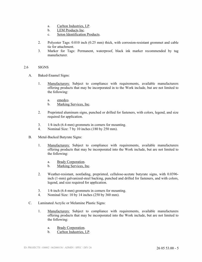
ID: PROJECTS \ O0002 \ 062000156 \ ADMIN \ SPEC \ DIV-26 26 05 53.00 - 5
a. Carlton Industries, LP.
b. LEM Products Inc.
c. Seton Identification Products.
2. Polyester Tags: 0.010 inch (0.25 mm) thick, with corrosion-resistant grommet and cable
tie for attachment.
3. Marker for Tags: Permanent, waterproof, black ink marker recommended by tag
manufacturer.
2.6 SIGNS
A. Baked-Enamel Signs:
1. Manufacturers: Subject to compliance with requirements, available manufacturers
offering products that may be incorporated in to the Work include, but are not limited to
the following:
a. emedco.
b. Marking Services, Inc.
2. Preprinted aluminum signs, punched or drilled for fasteners, with colors, legend, and size
required for application.
3. 1/4-inch (6.4-mm) grommets in corners for mounting.
4. Nominal Size: 7 by 10 inches (180 by 250 mm).
B. Metal-Backed Butyrate Signs:
1. Manufacturers: Subject to compliance with requirements, available manufacturers
offering products that may be incorporated into the Work include, but are not limited to
the following:
a. Brady Corporation.
b. Marking Services, Inc.
2. Weather-resistant, nonfading, preprinted, cellulose-acetate butyrate signs, with 0.0396-
inch (1-mm) galvanized-steel backing, punched and drilled for fasteners, and with colors,
legend, and size required for application.
3. 1/4-inch (6.4-mm) grommets in corners for mounting.
4. Nominal Size: 10 by 14 inches (250 by 360 mm).
C. Laminated Acrylic or Melamine Plastic Signs:
1. Manufacturers: Subject to compliance with requirements, available manufacturers
offering products that may be incorporated into the Work include, but are not limited to
the following:
a. Brady Corporation.
b. Carlton Industries, LP.

ID: PROJECTS \ O0002 \ 062000156 \ ADMIN \ SPEC \ DIV-26 26 05 53.00 - 6
2. Engraved legend.
3. Thickness:
a. For signs up to 20 sq. in. (129 sq. cm), minimum 1/16 inch (1.6 mm) thick.
b. For signs larger than 20 sq. in. (129 sq. cm), 1/8 inch (3.2 mm) thick.
2.7 CABLE TIES
A. Manufacturers: Subject to compliance with requirements, available manufacturers offering
products that may be incorporated into the Work include, but are not limited to the following:
1. Ideal Industries, Inc.
2. Panduit Corp.
B. General-Purpose Cable Ties: Fungus inert, self-extinguishing, one piece, self-locking, and
Type 6/6 nylon.
1. Minimum Width: 3/16 inch (5 mm).
2. Tensile Strength at 73 Deg F (23 Deg C) according to ASTM D 638: 12,000 psi (82.7
MPa).
3. Temperature Range: Minus 40 to plus 185 deg F (Minus 40 to plus 85 deg C).
4. Color: Black, except where used for color-coding.
C. Plenum-Rated Cable Ties: Self-extinguishing, UV stabilized, one piece, and self-locking.
1. Minimum Width: 3/16 inch (5 mm).
2. Tensile Strength at 73 Deg F (23 Deg C) according to ASTM D 638: 7000 psi (48.2
MPa).
3. UL 94 Flame Rating: 94V-0.
4. Temperature Range: Minus 50 to plus 284 deg F (Minus 46 to plus 140 deg C).
5. Color: Black.
2.8 MISCELLANEOUS IDENTIFICATION PRODUCTS
A. Paint: Comply with requirements in painting Sections for paint materials and application
requirements. Retain paint system applicable for surface material and location (exterior or
interior).
B. Fasteners for Labels and Signs: Self-tapping, stainless-steel screws or stainless-steel machine
screws with nuts and flat and lock washers.
PART 3 - EXECUTION
3.1 INSTALLATION
A. Verify and coordinate identification names, abbreviations, colors, and other features with
requirements in other Sections requiring identification applications, Drawings, Shop Drawings,
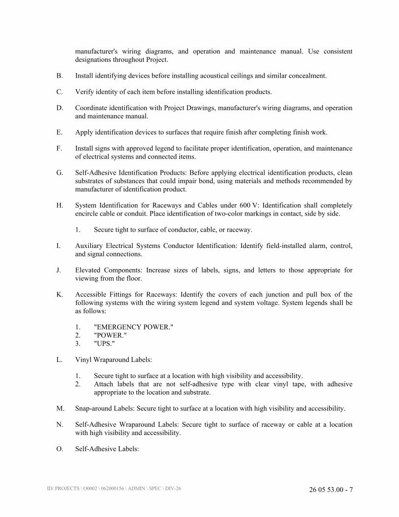
ID: PROJECTS \ O0002 \ 062000156 \ ADMIN \ SPEC \ DIV-26 26 05 53.00 - 7
manufacturer's wiring diagrams, and operation and maintenance manual. Use consistent
designations throughout Project.
B. Install identifying devices before installing acoustical ceilings and similar concealment.
C. Verify identity of each item before installing identification products.
D. Coordinate identification with Project Drawings, manufacturer's wiring diagrams, and operation
and maintenance manual.
E. Apply identification devices to surfaces that require finish after completing finish work.
F. Install signs with approved legend to facilitate proper identification, operation, and maintenance
of electrical systems and connected items.
G. Self-Adhesive Identification Products: Before applying electrical identification products, clean
substrates of substances that could impair bond, using materials and methods recommended by
manufacturer of identification product.
H. System Identification for Raceways and Cables under 600 V: Identification shall completely
encircle cable or conduit. Place identification of two-color markings in contact, side by side.
1. Secure tight to surface of conductor, cable, or raceway.
I. Auxiliary Electrical Systems Conductor Identification: Identify field-installed alarm, control,
and signal connections.
J. Elevated Components: Increase sizes of labels, signs, and letters to those appropriate for
viewing from the floor.
K. Accessible Fittings for Raceways: Identify the covers of each junction and pull box of the
following systems with the wiring system legend and system voltage. System legends shall be
as follows:
1. "EMERGENCY POWER."
2. "POWER."
3. "UPS."
L. Vinyl Wraparound Labels:
1. Secure tight to surface at a location with high visibility and accessibility.
2. Attach labels that are not self-adhesive type with clear vinyl tape, with adhesive
appropriate to the location and substrate.
M. Snap-around Labels: Secure tight to surface at a location with high visibility and accessibility.
N. Self-Adhesive Wraparound Labels: Secure tight to surface of raceway or cable at a location
with high visibility and accessibility.
O. Self-Adhesive Labels:

ID: PROJECTS \ O0002 \ 062000156 \ ADMIN \ SPEC \ DIV-26 26 05 53.00 - 8
1. On each unit of equipment, install unique designation label that is consistent with wiring
diagrams, schedules, and operation and maintenance manual.
2. Unless otherwise indicated, provide a single line of text with 1/2-inch- (13-mm-) high
letters on 1-1/2-inch- (38-mm-) high label; where two lines of text are required, use labels
2 inches (50 mm) high.
P. Snap-around Color-Coding Bands: Secure tight to surface at a location with high visibility and
accessibility.
Q. Heat-Shrink, Preprinted Tubes: Secure tight to surface at a location with high visibility and
accessibility.
R. Marker Tapes: Secure tight to surface at a location with high visibility and accessibility.
S. Self-Adhesive Vinyl Tape: Secure tight to surface at a location with high visibility and
accessibility.
1. Field-Applied, Color-Coding Conductor Tape: Apply in half-lapped turns for a minimum
distance of 6 inches (150 mm) where splices or taps are made. Apply last two turns of
tape with no tension to prevent possible unwinding.
T. Tape and Stencil: Comply with requirements in painting Sections for surface preparation and
paint application.
U. Floor Marking Tape: Apply stripes to finished surfaces following manufacturer's written
instructions.
V. Write-on Tags:
1. Place in a location with high visibility and accessibility.
2. Secure using general-purpose cable ties.
W. Baked-Enamel Signs:
1. Attach signs that are not self-adhesive type with mechanical fasteners appropriate to the
location and substrate.
2. Unless otherwise indicated, provide a single line of text with 1/2-inch- (13-mm-) high
letters on minimum 1-1/2-inch- (38-mm-) high sign; where two lines of text are required,
use signs minimum 2 inches (50 mm) high.
X. Metal-Backed Butyrate Signs:
1. Attach signs that are not self-adhesive type with mechanical fasteners appropriate to the
location and substrate.
2. Unless otherwise indicated, provide a single line of text with 1/2-inch- (13-mm-) high
letters on minimum 1-1/2-inch- (38-mm-) high sign; where two lines of text are required,
use signs minimum 2 inches (50 mm) high.
Y. Laminated Acrylic or Melamine Plastic Signs:
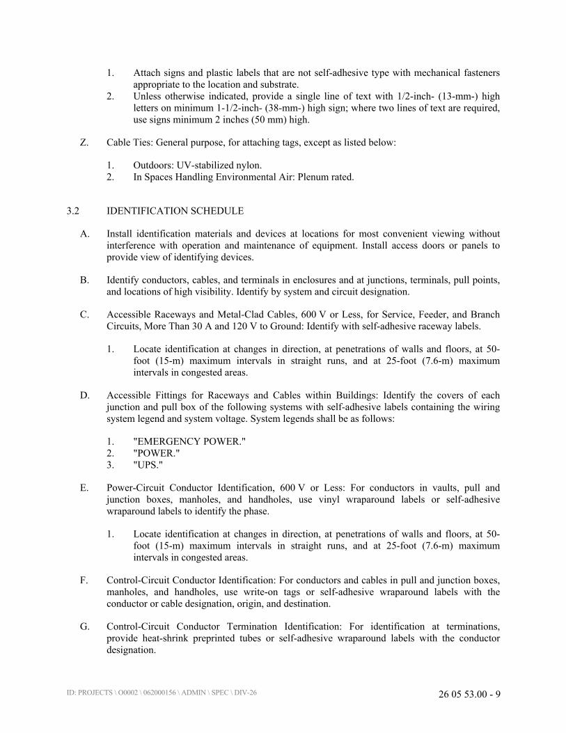
ID: PROJECTS \ O0002 \ 062000156 \ ADMIN \ SPEC \ DIV-26 26 05 53.00 - 9
1. Attach signs and plastic labels that are not self-adhesive type with mechanical fasteners
appropriate to the location and substrate.
2. Unless otherwise indicated, provide a single line of text with 1/2-inch- (13-mm-) high
letters on minimum 1-1/2-inch- (38-mm-) high sign; where two lines of text are required,
use signs minimum 2 inches (50 mm) high.
Z. Cable Ties: General purpose, for attaching tags, except as listed below:
1. Outdoors: UV-stabilized nylon.
2. In Spaces Handling Environmental Air: Plenum rated.
3.2 IDENTIFICATION SCHEDULE
A. Install identification materials and devices at locations for most convenient viewing without
interference with operation and maintenance of equipment. Install access doors or panels to
provide view of identifying devices.
B. Identify conductors, cables, and terminals in enclosures and at junctions, terminals, pull points,
and locations of high visibility. Identify by system and circuit designation.
C. Accessible Raceways and Metal-Clad Cables, 600 V or Less, for Service, Feeder, and Branch
Circuits, More Than 30 A and 120 V to Ground: Identify with self-adhesive raceway labels.
1. Locate identification at changes in direction, at penetrations of walls and floors, at 50-
foot (15-m) maximum intervals in straight runs, and at 25-foot (7.6-m) maximum
intervals in congested areas.
D. Accessible Fittings for Raceways and Cables within Buildings: Identify the covers of each
junction and pull box of the following systems with self-adhesive labels containing the wiring
system legend and system voltage. System legends shall be as follows:
1. "EMERGENCY POWER."
2. "POWER."
3. "UPS."
E. Power-Circuit Conductor Identification, 600 V or Less: For conductors in vaults, pull and
junction boxes, manholes, and handholes, use vinyl wraparound labels or self-adhesive
wraparound labels to identify the phase.
1. Locate identification at changes in direction, at penetrations of walls and floors, at 50-
foot (15-m) maximum intervals in straight runs, and at 25-foot (7.6-m) maximum
intervals in congested areas.
F. Control-Circuit Conductor Identification: For conductors and cables in pull and junction boxes,
manholes, and handholes, use write-on tags or self-adhesive wraparound labels with the
conductor or cable designation, origin, and destination.
G. Control-Circuit Conductor Termination Identification: For identification at terminations,
provide heat-shrink preprinted tubes or self-adhesive wraparound labels with the conductor
designation.
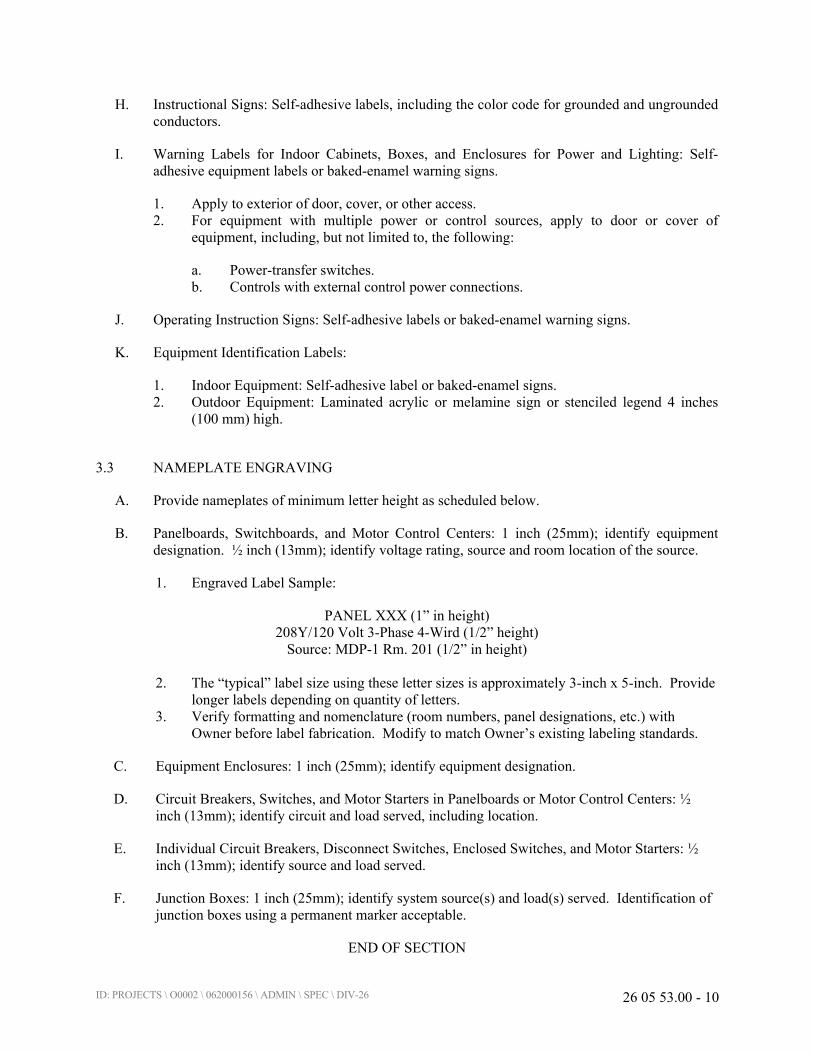
ID: PROJECTS \ O0002 \ 062000156 \ ADMIN \ SPEC \ DIV-26 26 05 53.00 - 10
H. Instructional Signs: Self-adhesive labels, including the color code for grounded and ungrounded
conductors.
I. Warning Labels for Indoor Cabinets, Boxes, and Enclosures for Power and Lighting: Self-
adhesive equipment labels or baked-enamel warning signs.
1. Apply to exterior of door, cover, or other access.
2. For equipment with multiple power or control sources, apply to door or cover of
equipment, including, but not limited to, the following:
a. Power-transfer switches.
b. Controls with external control power connections.
J. Operating Instruction Signs: Self-adhesive labels or baked-enamel warning signs.
K. Equipment Identification Labels:
1. Indoor Equipment: Self-adhesive label or baked-enamel signs.
2. Outdoor Equipment: Laminated acrylic or melamine sign or stenciled legend 4 inches
(100 mm) high.
3.3 NAMEPLATE ENGRAVING
A. Provide nameplates of minimum letter height as scheduled below.
B. Panelboards, Switchboards, and Motor Control Centers: 1 inch (25mm); identify equipment
designation. ½ inch (13mm); identify voltage rating, source and room location of the source.
1. Engraved Label Sample:
PANEL XXX (1” in height)
208Y/120 Volt 3-Phase 4-Wird (1/2” height)
Source: MDP-1 Rm. 201 (1/2” in height)
2. The “typical” label size using these letter sizes is approximately 3-inch x 5-inch. Provide
longer labels depending on quantity of letters.
3. Verify formatting and nomenclature (room numbers, panel designations, etc.) with
Owner before label fabrication. Modify to match Owner’s existing labeling standards.
C. Equipment Enclosures: 1 inch (25mm); identify equipment designation.
D. Circuit Breakers, Switches, and Motor Starters in Panelboards or Motor Control Centers: ½
inch (13mm); identify circuit and load served, including location.
E. Individual Circuit Breakers, Disconnect Switches, Enclosed Switches, and Motor Starters: ½
inch (13mm); identify source and load served.
F. Junction Boxes: 1 inch (25mm); identify system source(s) and load(s) served. Identification of
junction boxes using a permanent marker acceptable.
END OF SECTION
ID: PROJECTS \ O0002 \ 062000156 \ ADMIN \ SPEC \ DIV-26 26 27 26.00 - 1
SECTION 26 27 26.00
WIRING DEVICES
PART 1 - GENERAL
1.1 SUMMARY
A. Section Includes:
1. Straight-blade convenience receptacles.
2. GFCI receptacles.
3. Toggle switches.
4. Wall-box dimmers.
5. Wall plates.
1.2 ACTION SUBMITTALS
A. Product Data: For each type of product.
1.3 CLOSEOUT SUBMITTALS
A. Operation and maintenance data.
PART 2 - PRODUCTS
2.1 GENERAL WIRING-DEVICE REQUIREMENTS
A. Wiring Devices, Components, and Accessories: Listed and labeled as defined in NFPA 70, by a
qualified testing agency, and marked for intended location and application.
B. Comply with NFPA 70.
C. Devices that are manufactured for use with modular plug-in connectors may be substituted
under the following conditions:
1. Connectors shall comply with UL 2459 and shall be made with stranding building wire.
2. Devices shall comply with the requirements in this Section.
D. Devices for Owner-Furnished Equipment:
1. Receptacles: Match plug configurations.
E. Source Limitations: Obtain each type of wiring device and associated wall plate from single
source from single manufacturer.

ID: PROJECTS \ O0002 \ 062000156 \ ADMIN \ SPEC \ DIV-26 26 27 26.00 - 2
2.2 STRAIGHT-BLADE RECEPTACLES
A. Duplex Convenience Receptacles, 125 V, 20 A, Hospital Grade: Comply with NEMA WD 1,
NEMA WD 6 Configuration 5-20R, UL 498, and FS W-C-596.
1. Manufacturers: Subject to compliance with requirements, provide products by one of the
following:
a. Eaton (Arrow Hart).
b. Hubbell Incorporated; Wiring Device-Kellems.
c. Leviton Manufacturing Co., Inc.
d. Pass & Seymour/Legrand (Pass & Seymour).
2.3 GFCI RECEPTACLES
A. General Description:
1. 125 V, 20 A, straight blade, non-feed-through type.
2. Hospital Grade.
3. Comply with NEMA WD 1, NEMA WD 6 Configuration 5-20R, UL 498, UL 943
Class A, and FS W-C-596.
4. Include indicator light that shows when the GFCI has malfunctioned and no longer
provides proper GFCI protection.
B. Duplex GFCI Convenience Receptacles:
1. Manufacturers: Subject to compliance with requirements, provide products by one of the
following:
a. Eaton (Arrow Hart).
b. Hubbell Incorporated; Wiring Device-Kellems.
c. Leviton Manufacturing Co., Inc.
d. Pass & Seymour/Legrand (Pass & Seymour).
2.4 TOGGLE SWITCHES
A. Comply with NEMA WD 1, UL 20, and FS W-S-896.
B. Switches, 120/277 V, 20 A:
1. Three-way switch:
a. Decora style
b. Manufacturers: Subject to compliance with requirements, provide products by one
of the following:
1) Eaton (Arrow Hart).
2) Hubbell Incorporated; Wiring Device-Kellems.
3) Leviton Manufacturing Co., Inc.
4) Pass & Seymour/Legrand (Pass & Seymour).
ID: PROJECTS \ O0002 \ 062000156 \ ADMIN \ SPEC \ DIV-26 26 27 26.00 - 3
2.5 WALL-BOX DIMMERS
A. See plans for manufacturer and model numbers.
1. Color: Gray.
2.6 WALL PLATES
A. Single and combination types shall match corresponding wiring devices.
1. Plate-Securing Screws: Metal with head color to match plate finish.
2. Material for Finished Spaces: Smooth, high-impact thermoplastic.
B. Wet-Location, Weatherproof Cover Plates: NEMA 250, complying with Type 3R, weather-
resistant, die-cast aluminum with lockable cover.
2.7 FINISHES
A. Device Color:
1. Wiring Devices Connected to Normal Power System: Gray unless otherwise indicated or
required by NFPA 70 or device listing.
2. Wiring Devices Connected to Emergency Power System: Red.
B. Wall Plate Color: For plastic covers, match device color.
PART 3 - EXECUTION
3.1 INSTALLATION
A. Comply with NECA 1, including mounting heights listed in that standard, unless otherwise
indicated.
B. Coordination with Other Trades:
1. Protect installed devices and their boxes. Do not place wall finish materials over device
boxes and do not cut holes for boxes with routers that are guided by riding against outside
of boxes.
2. Keep outlet boxes free of plaster, drywall joint compound, mortar, cement, concrete, dust,
paint, and other material that may contaminate the raceway system, conductors, and
cables.
3. Install device boxes in brick or block walls so that the cover plate does not cross a joint
unless the joint is troweled flush with the face of the wall.
4. Install wiring devices after all wall preparation, including painting, is complete.
C. Conductors:

ID: PROJECTS \ O0002 \ 062000156 \ ADMIN \ SPEC \ DIV-26 26 27 26.00 - 4
1. Do not strip insulation from conductors until right before they are spliced or terminated
on devices.
2. Strip insulation evenly around the conductor using tools designed for the purpose. Avoid
scoring or nicking of solid wire or cutting strands from stranded wire.
3. The length of free conductors at outlets for devices shall meet provisions of NFPA 70,
Article 300, without pigtails.
4. Existing Conductors:
a. Cut back and pigtail, or replace all damaged conductors.
b. Straighten conductors that remain and remove corrosion and foreign matter.
c. Pigtailing existing conductors is permitted, provided the outlet box is large enough.
D. Device Installation:
1. Replace devices that have been in temporary use during construction and that were
installed before building finishing operations were complete.
2. Keep each wiring device in its package or otherwise protected until it is time to connect
conductors.
3. Do not remove surface protection, such as plastic film and smudge covers, until the last
possible moment.
4. Connect devices to branch circuits using pigtails that are not less than 6 inches (152 mm)
in length.
5. When there is a choice, use side wiring with binding-head screw terminals. Wrap solid
conductor tightly clockwise, two-thirds to three-fourths of the way around terminal
screw.
6. Use a torque screwdriver when a torque is recommended or required by manufacturer.
7. When conductors larger than No. 12 AWG are installed on 15- or 20-A circuits, splice
No. 12 AWG pigtails for device connections.
8. Tighten unused terminal screws on the device.
9. When mounting into metal boxes, remove the fiber or plastic washers used to hold
device-mounting screws in yokes, allowing metal-to-metal contact.
E. Receptacle Orientation:
a. Hospital-Grade Receptacle Orientation: Orient receptacle with ground pin or
neutral pin at top.
F. Device Plates: Do not use oversized or extra-deep plates. Repair wall finishes and remount
outlet boxes when standard device plates do not fit flush or do not cover rough wall opening.
G. Dimmers:
1. Install dimmers within terms of their listing.
2. Verify that dimmers used for fan-speed control are listed for that application.
3. Install unshared neutral conductors on line and load side of dimmers according to
manufacturers' device listing conditions in the written instructions.
H. Arrangement of Devices: Unless otherwise indicated, mount flush, with long dimension vertical
and with grounding terminal of receptacles on top. Group adjacent switches under single,
multigang wall plates.
ID: PROJECTS \ O0002 \ 062000156 \ ADMIN \ SPEC \ DIV-26 26 27 26.00 - 5
I. GFCI Receptacles: Install non-feed-through-type GFCI receptacles where protection of
downstream receptacles is not required.
J. Identification:
1. Identify cover or cover plate for device with panelboard identification and circuit number
in accordance with Section 260553 "Identification for Electrical Systems."
a. Mark cover or cover plate using hot, stamped, or engraved machine printing with
black-filled lettering, and provide durable wire markers or tags inside device box
or outlet box.
3.2 FIELD QUALITY CONTROL
A. Test Instruments: Use instruments that comply with UL 1436.
B. Test Instrument for Convenience Receptacles: Digital wiring analyzer with digital readout or
illuminated digital-display indicators of measurement.
C. Perform the following tests and inspections:
1. Tests for Convenience Receptacles:
a. Line Voltage: Acceptable range is 105 to 132 V.
b. Percent Voltage Drop under 15-A Load: A value of 6 percent or higher is
unacceptable.
c. Ground Impedance: Values of up to 2 ohms are acceptable.
d. GFCI Trip: Test for tripping values specified in UL 1436 and UL 943.
e. Using the test plug, verify that the device and its outlet box are securely mounted.
f. Tests shall be diagnostic, indicating damaged conductors, high resistance at the
circuit breaker, poor connections, inadequate fault current path, defective devices,
or similar problems. Correct circuit conditions, remove malfunctioning units and
replace with new ones, and retest as specified above.
D. Wiring device will be considered defective if it does not pass tests and inspections.
E. Prepare test and inspection reports.
END OF SECTION

ID: PROJECTS \ O0002 \ 062000156 \ ADMIN \ SPEC \ DIV-26 26 51 19.00 - 1
SECTION 26 51 19.00
LED INTERIOR LIGHTING
PART 1 - GENERAL
1.1 ACTION SUBMITTALS
A. Product Data: For each type of product, arranged by designation.
1.2 CLOSEOUT SUBMITTALS
A. Operation and maintenance data.
PART 2 - PRODUCTS
2.1 LUMINAIRE REQUIREMENTS
A. Electrical Components, Devices, and Accessories: Listed and labeled as defined in NFPA 70, by
a qualified testing agency, and marked for intended location and application.
B. Standards:
1. ENERGY STAR certified.
2. UL Listing: Listed for damp location.
3. Recessed luminaires shall comply with NEMA LE 4.
C. Lamps dimmable from 100 percent to 0 percent of maximum light output.
D. Internal driver.
E. Nominal Operating Voltage: 277 V ac.
1. Lens Thickness: At least 0.125 inch (3.175 mm) minimum unless otherwise indicated.
2.2 MATERIALS
A. Metal Parts:
1. Free of burrs and sharp corners and edges.
2. Sheet metal components shall be steel unless otherwise indicated.
3. Form and support to prevent warping and sagging
B. Doors, Frames, and Other Internal Access: Smooth operating, free of light leakage under
operating conditions, and designed to permit relamping without use of tools. Designed to
ID: PROJECTS \ O0002 \ 062000156 \ ADMIN \ SPEC \ DIV-26 26 51 19.00 - 2
prevent doors, frames, lenses, diffusers, and other components from falling accidentally during
relamping and when secured in operating position.
2.3 METAL FINISHES
A. Variations in finishes are unacceptable in the same piece.
2.4 LUMINAIRE SUPPORT
A. Comply with requirements in Section 26 05 29.00 "Hangers and Supports for Electrical
Systems" for channel and angle iron supports and nonmetallic channel and angle supports.
B. Single-Stem Hangers: 1/2-inch (13-mm) steel tubing with swivel ball fittings and ceiling
canopy. Finish same as luminaire.
C. Wires: ASTM A 641/A 641 M, Class 3, soft temper, zinc-coated steel, 12 gage (2.68 mm).
D. Rod Hangers: 3/16-inch (5-mm) minimum diameter, cadmium-plated, threaded steel rod.
E. Hook Hangers: Integrated assembly matched to luminaire, line voltage, and equipment with
threaded attachment, cord, and locking-type plug.
PART 3 - EXECUTION
3.1 INSTALLATION
A. Comply with NECA 1.
B. Install luminaires level, plumb, and square with ceilings and walls unless otherwise indicated.
C. Install lamps in each luminaire.
D. Supports: Sized and rated for luminaire weight.
E. Flush-Mounted Luminaire Support: Secured to outlet box.
F. Wall-Mounted Luminaire Support:
1. Attached to structural members in walls.
2. Do not attach luminaires directly to gypsum board.
G. Ceiling-Mounted Luminaire Support:
1. Ceiling mount with two 5/32-inch- (4-mm-) diameter aircraft cable supports adjustable to
120 inches (6 m) in length.
2. Ceiling mount with pendant mount with 5/32-inch- (4-mm-) diameter aircraft cable
supports adjustable to 120 inches (6 m) in length.
3. Ceiling mount with hook mount.
ID: PROJECTS \ O0002 \ 062000156 \ ADMIN \ SPEC \ DIV-26 26 51 19.00 - 3
H. Suspended Luminaire Support:
1. Pendants and Rods: Where longer than 48 inches (1200 mm), brace to limit swinging.
2. Stem-Mounted, Single-Unit Luminaires: Suspend with twin-stem hangers. Support with
approved outlet box and accessories that hold stem and provide damping of luminaire
oscillations. Support outlet box vertically to building structure using approved devices.
3. Continuous Rows of Luminaires: Use tubing or stem for wiring at one point and wire
support for suspension for each unit length of luminaire chassis, including one at each
end.
4. Do not use ceiling grid as support for pendant luminaires. Connect support wires or rods
to building structure.
I. Ceiling-Grid-Mounted Luminaires:
1. Secure to any required outlet box.
2. Secure luminaire using approved fasteners in a minimum of four locations, spaced near
corners of luminaire.
J. Comply with requirements in Section 26 05 19.00 "Low-Voltage Electrical Power Conductors
and Cables" for wiring connections.
K. Identify system components, wiring, cabling, and terminals. Comply with requirements for
identification specified in Section 26 05 53.00 "Identification for Electrical Systems."
3.2 FIELD QUALITY CONTROL
A. Perform the following tests and inspections:
1. Operational Test: After installing luminaires, switches, and accessories, and after
electrical circuitry has been energized, test units to confirm proper operation.
2. Test for Emergency Lighting: Interrupt power supply to demonstrate proper operation.
Verify transfer from normal power to battery power and retransfer to normal.
B. Luminaire will be considered defective if it does not pass operation tests and inspections.
C. Prepare test and inspection reports.
END OF SECTION

DIVISION 28 – ELECTRONIC SAFETY AND SECURITY
ID: PROJECTS \ O0002 \ 062000156 \ ADMIN \ SPEC \ DIV-28
SECTION 28 46 21.11 ADDRESSABLE FIRE-ALARM SYSTEMS

ID: PROJECTS \ O0002 \ 062000156 \ ADMIN \ SPEC \ DIV-28 28 46 21.11 - 1
SECTION 28 46 21.11
ADDRESSABLE FIRE-ALARM SYSTEMS
PART 1 - GENERAL
1.1 SUMMARY
A. Section Includes:
1. Existing fire-alarm system to be modified.
2. Addressable fire-alarm system.
1.2 DEFINITIONS
A. FACU: Fire-alarm control unit.
B. Voltage Class: For specified circuits and equipment, voltage classes are defined as follows:
1. Control Voltage: Listed and labeled for use in remote-control, signaling, and power-
limited circuits supplied by a Class 2 or Class 3 power supply having rated output not
greater than 150 V and 5 A, allowing use of alternate wiring methods complying with
NFPA 70, Article 725.
2. Low Voltage: Listed and labeled for use in circuits supplied by a Class 1 or other power
supply having rated output not greater than 1000 V, requiring use of wiring methods
complying with NFPA 70, Article 300, Part I.
1.3 SEQUENCING AND SCHEDULING
A. Existing Fire-Alarm Equipment: Maintain existing equipment fully operational until new
equipment has been tested and accepted. When new equipment is installed, label it "NOT IN
SERVICE" until it is accepted. Remove labels from new equipment when put into service, and
label existing fire-alarm equipment "NOT IN SERVICE" until removed from building.
1.4 INFORMATIONAL SUBMITTALS
A. Field quality-control reports.
B. Qualification Statements: For Installer.
1.5 QUALITY ASSURANCE
A. Installer Qualifications:
ID: PROJECTS \ O0002 \ 062000156 \ ADMIN \ SPEC \ DIV-28 28 46 21.11 - 2
1. Personnel must be trained and certified by manufacturer for installation of units required
for this Project.
2. Installation must be by personnel certified by NICET as fire-alarm Level III technician.
3. Obtain certification by NRTL in accordance with NFPA 72.
4. Licensed or certified by authorities having jurisdiction.
PART 2 - PRODUCTS
2.1 EXISTING FIRE-ALARM SYSTEM TO BE MODIFIED
A. Basis for Pricing: Simplex 4100
B. Source Limitations for Fire-Alarm System and Components: Components must be compatible
with, and operate as extension of, existing system. Provide system manufacturer's certification
that components provided have been tested as, and will operate as, a system.
2.2 ADDRESSABLE FIRE-ALARM SYSTEM
A. Description:
1. Noncoded, UL-certified addressable system, with multiplexed signal transmission
andhorn-and-strobe notification for evacuation.
B. Performance Criteria:
1. Regulatory Requirements:
a. Fire-Alarm Components, Devices, and Accessories: Listed and labeled by a NRTL
in accordance with NFPA 70 for use with selected fire-alarm system and marked
for intended location and application.
2. General Characteristics:
a. Fire-alarm signal initiation must be by one or more of the following devices and
systems:
1) Manual stations.
2) Heat detectors.
3) Smoke detectors.
4) Duct smoke detectors.
5) Automatic sprinkler system water flow.
b. Fire-alarm signal must initiate the following actions:
1) Continuously operate alarm notification appliances.
2) Identify alarm and specific initiating device at FACU, connected network
control panels, off-premises network control panels, and remote
annunciators.
3) Transmit alarm signal to remote alarm receiving station.
4) Record events in system memory.

ID: PROJECTS \ O0002 \ 062000156 \ ADMIN \ SPEC \ DIV-28 28 46 21.11 - 3
c. Supervisory signal initiation must be by one or more of the following devices and
actions:
1) Valve supervisory switch.
2) Zones or individual devices have been disabled.
3) FACU has lost communication with network.
d. System trouble signal initiation must be by one or more of the following devices
and actions:
1) Open circuits, shorts, and grounds in designated circuits.
2) Opening, tampering with, or removing alarm-initiating and supervisory
signal-initiating devices.
3) Loss of communication with addressable sensor, input module, relay,
control module, remote annunciator, printer interface, or Ethernet module.
4) Loss of primary power at FACU.
5) Ground or single break in internal circuits of FACU.
6) Abnormal ac voltage at FACU.
7) Break in standby battery circuitry.
8) Failure of battery charging.
9) Abnormal position of switch at FACU or annunciator.
e. System Supervisory Signal Actions:
1) Identify specific device initiating event at FACU, connected network control
panels, off-premises network control panels, and remote annunciators.
2) After time delay of 200 seconds, transmit trouble or supervisory signal to
remote alarm receiving station.
3) Transmit system status to building management system.
4) Display system status on graphic annunciator.
PART 3 - EXECUTION
3.1 EXAMINATION
A. Examine areas and conditions for compliance with requirements for ventilation, temperature,
humidity, and other conditions affecting performance of the Work.
1. Verify that manufacturer's written instructions for environmental conditions have been
permanently established in spaces where equipment and wiring are installed, before
installation begins.
B. Examine roughing-in for electrical connections to verify actual locations of connections before
installation.
C. Proceed with installation only after unsatisfactory conditions have been corrected.
ID: PROJECTS \ O0002 \ 062000156 \ ADMIN \ SPEC \ DIV-28 28 46 21.11 - 4
3.2 PREPARATION
A. Preinstallation Testing: Perform verification of functionality of installed components of existing
system prior to starting work. Document equipment or components not functioning as designed.
B. Interruption of Existing Fire-Alarm Service: Do not interrupt fire-alarm service to facilities
occupied by Owner or others unless permitted under the following conditions and then only
after arranging to provide temporary guard service in accordance with requirements indicated:
1. Notify Owner no fewer than seven days in advance of proposed interruption of fire-alarm
service.
2. Do not proceed with interruption of fire-alarm service without Owner's written
permission.
C. Protection of In-Place Conditions: Protect devices during construction unless devices are placed
in service to protect facility during construction.
3.3 INSTALLATION OF EQUIPMENT
A. Comply with NECA 305, NFPA 72, NFPA 101, and requirements of authorities having
jurisdiction for installation and testing of fire-alarm equipment. Install electrical wiring to
comply with requirements in NFPA 70 including, but not limited to, Article 760, "Fire Alarm
Systems."
1. Devices placed in service before other trades have completed cleanup must be replaced.
2. Devices installed, but not yet placed, in service must be protected from construction dust,
debris, dirt, moisture, and damage in accordance with manufacturer's written storage
instructions.
B. Connecting to Existing Equipment: Verify that existing fire-alarm system is operational before
making changes or connections.
1. Connect new equipment to existing control panel in existing part of building.
2. Connect new equipment to existing monitoring equipment at supervising station.
C. Visible Alarm-Indicating Devices: Install adjacent to each alarm bell or alarm horn and at least
6 inch (150 mm) below ceiling. Install devices at same height unless otherwise indicated.
3.4 ELECTRICAL CONNECTIONS
A. Install electrical devices furnished by manufacturer, but not factory mounted, in accordance
with NFPA 70 and NECA 1.
3.5 CONTROL CONNECTIONS
A. Install control and electrical power wiring to field-mounted control devices.
B. Install nameplate for each control connection, indicating field control panel designation and I/O
control designation feeding connection.
ID: PROJECTS \ O0002 \ 062000156 \ ADMIN \ SPEC \ DIV-28 28 46 21.11 - 5
3.6 PATHWAYS
A. Pathways above recessed ceilings and in inaccessible locations may be routed exposed.
1. Exposed pathways located less than 96 inch (2440 mm) above floor must be installed in
EMT.
B. Pathways must be installed in EMT.
C. Exposed EMT must be painted red enamel.
3.7 GROUNDING
A. Ground shielded cables at control panel location only. Insulate shield at device location.
3.8 FIELD QUALITY CONTROL
A. Administrant for Tests and Inspections:
1. Engage factory-authorized service representative to administer and perform tests and
inspections on components, assemblies, and equipment installations, including
connections.
B. Tests and Inspections:
1. Visual Inspection: Conduct visual inspection prior to testing.
a. Inspection must be based on completed record Drawings and system
documentation that is required by "Completion Documents, Preparation" table in
"Documentation" section of "Fundamentals" chapter in NFPA 72.
b. Comply with "Visual Inspection Frequencies" table in "Inspection" section of
"Inspection, Testing and Maintenance" chapter in NFPA 72; retain
"Initial/Reacceptance" column and list only installed components.
2. System Testing: Comply with "Test Methods" table in "Testing" section of "Inspection,
Testing and Maintenance" chapter in NFPA 72.
3. Test audible appliances for public operating mode in accordance with manufacturer's
written instructions. Perform test using portable sound-level meter complying with
Type 2 requirements in ASA S1.4 Part 1/IEC 61672-1.
4. Test audible appliances for private operating mode in accordance with manufacturer's
written instructions.
5. Test visible appliances for public operating mode in accordance with manufacturer's
written instructions.
6. Factory-authorized service representative must prepare "Fire Alarm System Record of
Completion" in "Documentation" section of "Fundamentals" chapter in NFPA 72 and
"Inspection and Testing Form" in "Records" section of "Inspection, Testing and
Maintenance" chapter in NFPA 72.
C. Reacceptance Testing: Perform reacceptance testing to verify proper operation of added or
replaced devices and appliances.

ID: PROJECTS \ O0002 \ 062000156 \ ADMIN \ SPEC \ DIV-28 28 46 21.11 - 6
D. Fire-alarm system will be considered defective if it does not pass tests and inspections.
E. Prepare test and inspection reports.
END OF SECTION