A New Morphing Wing Mechanism Using Smart Actuators Controlled by a Self-Tuning Fuzzy Logic...
12
American Institute of Aeronautics and Astronautics 1 A New Morphing Wing Mechanism Using Smart Actuators Controlled by a Self-Tuning Fuzzy Logic Controller T. L Grigorie 1 , A. V. Popov 2 and R. M. Botez 3 École de Technologie Supérieure, Montréal, Québec H3C 1K3, Canada M. Mamou 4 and Y. Mébarki 5 National Research Council, Ottawa, Ontario K1A 0R6, Canada The paper presents the design of an intelligent actuation control concept, self-tuning fuzzy logic Proportional-Integral-Derivative plus conventional On-Off, for a new morphing mechanism using smart materials made of Shape Memory Alloy (SMA) for the actuators. In this way, two fuzzy inference systems were developed and implemented in the self-tuning fuzzy logic controller. In the design phase, the input-output mappings of the fuzzy models were designed and a final architecture for the hybrid controller was obtained. The shapes chosen for inputs membership functions of both fuzzy inference systems were s-functions, π- functions, respectively z-functions, while the product fuzzy inference and the center average defuzzifier were applied (Sugeno). The obtained controller was numerically and experimentally implemented using the Matlab/Simulink software. Following preliminary numerical simulations which were conducted to tune the controller, an experimental validation was performed: bench tests and wind tunnel tests. Simultaneously, the aerodynamic part of the morphing wing model was validated: optimized airfoils were experimentally validated with the theoretically-determined airfoils obtained earlier. Also, the transition point real time position detection and visualization were realized in wind tunnel tests. Nomenclature i q A = associated individual antecedent fuzzy sets of each input variable i b 0 = scalar offset dY 1 , dY 2 = displacements of the two control points of the flexible skin dY 1opt = optimal vertical displacement of actuator 1 dY 2opt = optimal vertical displacement of actuator 2 dY 1real = real vertical displacement of actuator 1 dY 2real = real vertical displacement of actuator 2 e = actuation loop error F aero = aerodynamic force i(t) = command variable (electrical current in the present case) in1, in2 = inputs of the fuzzy inference systems M = Mach number N = number of rules mf = membership function 1 Postdoctoral Fellowship, Laboratory of Research in Active Controls, Avionics and AeroServoElasticity, 1100 Notre-Dame West Street. Member AIAA. 2 Ph.D. Student, Laboratory of Research in Active Controls, Avionics and AeroServoElasticity, 1100 Notre-Dame West Street. Member AIAA. 3 Professor, Laboratory of Research in Active Controls, Avionics and AeroServoElasticity, 1100 Notre-Dame West Street. Member AIAA. 4 Senior Research Officer, Aerodynamics Laboratory, Montreal Road, Uplands Building U66. Member AIAA. 5 Associate Research Officer, Aerodynamics Laboratory, Montreal Road, Uplands Building U66. Member AIAA.
Transcript of A New Morphing Wing Mechanism Using Smart Actuators Controlled by a Self-Tuning Fuzzy Logic...

American Institute of Aeronautics and Astronautics
1
A New Morphing Wing Mechanism Using Smart Actuators Controlled by a Self-Tuning Fuzzy Logic Controller
T. L Grigorie1, A. V. Popov2 and R. M. Botez3 École de Technologie Supérieure, Montréal, Québec H3C 1K3, Canada
M. Mamou4 and Y. Mébarki5 National Research Council, Ottawa, Ontario K1A 0R6, Canada
The paper presents the design of an intelligent actuation control concept, self-tuning fuzzy logic Proportional-Integral-Derivative plus conventional On-Off, for a new morphing mechanism using smart materials made of Shape Memory Alloy (SMA) for the actuators. In this way, two fuzzy inference systems were developed and implemented in the self-tuning fuzzy logic controller. In the design phase, the input-output mappings of the fuzzy models were designed and a final architecture for the hybrid controller was obtained. The shapes chosen for inputs membership functions of both fuzzy inference systems were s-functions, π-functions, respectively z-functions, while the product fuzzy inference and the center average defuzzifier were applied (Sugeno). The obtained controller was numerically and experimentally implemented using the Matlab/Simulink software. Following preliminary numerical simulations which were conducted to tune the controller, an experimental validation was performed: bench tests and wind tunnel tests. Simultaneously, the aerodynamic part of the morphing wing model was validated: optimized airfoils were experimentally validated with the theoretically-determined airfoils obtained earlier. Also, the transition point real time position detection and visualization were realized in wind tunnel tests.
Nomenclature i
qA = associated individual antecedent fuzzy sets of each input variable ib0 = scalar offset
dY1, dY2 = displacements of the two control points of the flexible skin dY1opt = optimal vertical displacement of actuator 1 dY2opt = optimal vertical displacement of actuator 2 dY1real = real vertical displacement of actuator 1 dY2real = real vertical displacement of actuator 2 e = actuation loop error Faero = aerodynamic force i(t) = command variable (electrical current in the present case) in1, in2 = inputs of the fuzzy inference systems M = Mach number N = number of rules mf = membership function
1 Postdoctoral Fellowship, Laboratory of Research in Active Controls, Avionics and AeroServoElasticity, 1100 Notre-Dame West Street. Member AIAA. 2 Ph.D. Student, Laboratory of Research in Active Controls, Avionics and AeroServoElasticity, 1100 Notre-Dame West Street. Member AIAA. 3 Professor, Laboratory of Research in Active Controls, Avionics and AeroServoElasticity, 1100 Notre-Dame West Street. Member AIAA. 4 Senior Research Officer, Aerodynamics Laboratory, Montreal Road, Uplands Building U66. Member AIAA. 5 Associate Research Officer, Aerodynamics Laboratory, Montreal Road, Uplands Building U66. Member AIAA.

American Institute of Aeronautics and Astronautics
2
q = number of inputs Re = Reynolds number x = independent variable on the universe of discourse xleft = left breakpoint characterizing membership functions xright = right breakpoint characterizing membership functions xq = individual input variables yi = first-order polynomial function in the consequent α = angle of attack
I. Introduction ODAY, aeronautical transport is evolving at a very fast pace, as compared to the beginning of the aviation era; aeronautical traffic tripled during the last fifteen years, and by 2025, is projected to double from today’s levels.
This traffic is expected to see an estimated +3.0% increase in the number of passengers per year, to approximately 1 billion by 2016; will be accompanied by a load factor increase of 81.7% as compared to today’s values by 2025.1 This evolution will need the new technologies development in the design and building of modern aircraft equipped with active control systems.
During the same time period, fuel cost increases will lead to a slowdown in the aerospace industry, which in turn will stimulate research to find technological solutions; this will specifically involve designing new fuel economy consumption methods. A new green trend has indeed started to spread out from the automobile industry into the aircraft industry, in which research is being carried out to reduce fuel consumption by reducing drag, which is directly related to the airflow type around the aerodynamic aircraft body design. The drag reduction concept is connected to the laminar flow and to the displacement of the transition point between laminar and turbulent flows towards the trailing edge.
Numerous studies show that the transition between laminar and turbulent flows is influenced by the shape of the wing airfoil. Aerodynamic studies from the beginning of the aviation history show that for a certain flight condition characterized by a given Mach number and a given Reynolds number, the airflow around a wing airfoil is laminar at the leading edge, but becomes turbulent at a certain point due to air viscosity. A turbulent flow is not desired because of its negative effect in terms of drag increase, which, over time, leads to high fuel consumption, and consequently, increased operating costs.
One of the methods for airfoil changes was developed at Kentucky University, which consisted of deflecting the wing upper surface using adaptive actuators.2-5 It was shown that the actuators activated oscillatory motions of a certain frequency to the boundary layer flow over the upper surface. These actuators were made of piezo-electric materials which changed their shapes when connected to an electrical current differential voltage. The wind tunnel tests showed that the displacement of the transition point to the trailing edge resulted in the drag decrease and in the lift increase.3
Another method for changing the airfoil shape involved the use of a bump, which was inflated with air. This method was conceived by researchers at Stuttgart University.6-7 In this method, the airfoil geometry was modified in order to decrease the negative effects of shockwaves in transonic flow. The results obtained by the airfoil optimization showed a 70% decrease in the wave drag and a 15% decrease in the wing total drag.
At the German Aerospace Research Center (DLR), researchers simulated the changes of the airfoil shape using an inflated bump.8-9 The results obtained showed a 10% drag reduction for Mach numbers between 0.72 and 0.77. A basic theory was developed for changing the airfoil shape in transonic flow.
Another method for changing the airfoil shape was studied by the Aerospace Company Embraer.10-11 In this case, the leading and trailing edges changed their shapes by curving the camber line. The results obtained by Embraer were promising as they showed a reduction in drag value by up to 24%.
A 1991 study conducted at NASA’s Langley laboratory evaluated the application of the hybrid laminar flow control (HLFC) on subsonic aircrafts and bi-motor aircraft transporters.12-13 The study was realized by using the FLOPS optimizing flight system as well as a CFD code. The researchers studied the laminar flow over the upper surface of the wing, and over the vertical and horizontal stabilizers. They also studied the advantages of the laminar flow over the nacelles.
The here presented research was realized as part of a major project initiated and financially supported by following government and industry associations: the Consortium for Research and Innovation in Aerospace in Quebec (CRIAQ), the National Sciences and Engineering Research Council of Canada (NSERC), Bombardier Aerospace, Thales Avionics and the National Research Council Canada Institute for Aerospace Research (NRC-IAR).
T

American Institute of Aeronautics and Astronautics
3
II. Project Short Description The project aimed to realize a theoretical and experimental aerodynamic wind tunnel study of a rectangular wing
equipped with a flexible skin, smart actuators and pressure sensors, able of changing its shape using an active controller, in order to move the position of transition from laminar to turbulent flow.
This multidisciplinary project was realized by several collaborating teams from the École de Technologie Supérieure in Montreal, the Laboratory of Memory Alloys and Intelligent Systems (LAMSI), the Laboratory of Research in Avionics and Aero-Servo-Elasticity (LARCASE), École Polytechnique, and the National Research Council Canada Institute for Aerospace Research (NRC-IAR). The teams were each assigned the following responsibilities in the project, respectively: the LAMSI team was charged with designing and manufacturing the actuators and flexible skin as well as the model internal structure; the École Polytechnique team had the responsibility of designing the optimized airfoils for each airflow condition using CFD codes in order to analyze the transition from laminar to turbulent flow; the NRC-IAR team had to organize and run the wind tunnel tests, while the LARCASE team was responsible for the integration and validation of the control and monitoring systems of the morphing wing model.
In the first stage of this project the determination of some optimized airfoils was made. The optimized airfoils were derived by Ecole Polytechnique team for 35 different flow conditions, expressed in terms of five Mach numbers (0.2, 0.225, 0.25, 0.275, 0.3) and seven angles of attack (-1˚, -0.5˚, 0˚, 0.5˚, 1˚, 1.5˚, 2˚) combinations.14 As a reference airfoil was used a laminar WTEA-TE1 airfoil given by the NRC-IAR team.15-16 Further, the optimized airfoils were used as a starting point in the actuation system design (Fig. 1).
The design of the actuation system were performed by the LAMSI team and supposed three major steps: optimization of the number and positions of flexible skin actuation points, establishment of each actuation line’s architecture, and the analytical modeling of the smart materials actuators used in this application.17-21 The wing model was equipped with a flexible skin made of composite materials morphed by two actuation lines (Fig. 2); the chosen model was rectangular with a chord of 0.5 m and a span of 0.9 m. The flexible skin
was manufactured by LAMSI team in a 4 ply laminate structure in a polymer matrix, with two unidirectional carbon fiber inner plies and two hybrid Kevlar®/carbon fiber outer plies. The hybrid Kevlar®/carbon fiber was used in the chordwise direction, in which flexibility was needed for profile modification, whereas the low-modulus unidirectional carbon fiber was spanwise installed, in which case rigidity was preferred. The total thickness of the skin was 1.3 mm, the total Young modulus was 60 GPa, Poisson’s ratios were 0.12 for carbon/Kevlar® hybrid and 0.25 for unidirectional carbon.17-21 Each actuation line uses shape memory alloys SMA wires as actuators. At the same time, 32 pressure sensors (16 optical and 16 Kulite), distributed on the flexible skin chord-wise and span-wise, were installed by the LARCASE team on the wing’s flexible skin (Fig. 3). These sensors were positioned on two diagonal lines at an angle of 15 degrees from its centerline. The rigid lower structure was made from aluminum, and was designed by the NRC-IAR team to allow space for the actuation system and its wiring.
1% 70%25.3% 47.6%
Actuators action
Airfoil chord [m x 10-2]
Air
foil
def
lect
ion
[m x
10-2
]
0 10 20 30 40 50-15
-10
-5
0
5
10
15Flexible skin
Figure 1. Morphed airfoil shapes for different flow cases.
airfoilleading edge
Airfoil lowersurface (rigid)
Actuationpoints
Firstactuating line
From powersupply #1
From powersupply #2
Secondactuating line
Gas springs
SMA actuators
Airfoil trailingedge
Airfoil uper surface - flexibleskin part (morphed)
Airfoil uper surface(rigid part)
roller rod
cam
Figure 2. Model of the flexible structure.

American Institute of Aeronautics and Astronautics
4
The next purpose of the project was the design of the control for the actuation lines. In this design, numerical simulations of the open loop morphing wing integrated system, based on a SMA non-linear analytical model, were used first. The non-linear model used here was based on a numerical finite element method and was built by Terriault et al. using Lickhatchev’s theoretical model.22 The inputs of the SMA model were the alloy initial temperature, the electrical current (heating) and the applied force, while its outputs were the actuator displacement and the alloy temperature. To use the SMA shape-changing characteristics, an initialization by an external force was required to pass initially through the transformation phase and then returning to the initial phase at the end of the cooling phase. For the actuation lines controller different architectures were developed: by using classical PID architecture, and fuzzy logic based - PIDs with constant coefficients or in self-tuning variant. The developed architectures were firstly tuned and tested through numerical simulations by using Matlab/Simulink software. As subsequent validation methods, bench tests and wind tunnel tests were performed.23-24 Simultaneously, the transition point real time position detection and visualization were realized. Finally, the design and the experimental validation in wind tunnel tests were performed for the morphing wing closed loop system.25-26
The shape memory actuator wires used here were made of nickel - titanium, and contract as muscles do when electrically driven. Each of our actuation lines uses three SMA wires (1.8 m in length) as actuators, and contains a cam, which moves in translation relative to the structure (on the x-axis in Fig. 4). The cam causes the rod movement to be related on the roller and on the skin (on the z-axis). A compression gas spring was also used as recall. When the SMA is heated the actuator contracts and the cam moves to the right, resulting in the rise of the roller and the displacement of the skin upwards. Cooling of the SMA, results in a cam motion to the left, and thus a movement of the skin downwards.
To control the transition point position through morphing of the airfoil shape the actuation system was controlled by the instrumentality of two electrical power supplies. The command of power supply was given by a controller, which receives information about the external airflow state from a set of several pressure sensors. The controller compares the information received from sensors with the information stored in a database in the computer memory. If the controller executes the command from the information stored in the database, then the control strategy is defined as open loop, because of the fact that the controller gives no feedback about the airflow state. If the controller receives information from the sensors about the airflow state and compares it with the information stored in the database, then decisions can be made and actuators states can be adjusted and we further define the control strategy as closed loop. So, depending on the project evolution phase, two architectures were considered for our morphing system: open loop and closed loop. The difference between these two architectures is given by the use of the transition point as feedback signal.
III. Self-tuning Fuzzy Logic Controller Architecture The objective of here presented research work was to develop an actuation intelligent control concept using a
self-tuning fuzzy logic controller for a new morphing mechanism using smart materials, like Shape Memory Alloy (SMA), as actuators. This work was performed in the open loop development phase of our morphing wing project. The strong nonlinearities of the SMA actuators’ characteristics and the system requirements have led to a hybrid controller architecture as a combination of a bi-positional (particularly an on-off one) and a Fuzzy Logic Controller (FLC). In the chosen architecture, the controller must behave as a switch between the SMA cooling and heating phases, situations where the output current is 0 A, or is controlled by the FLC. The designed controller was also used in the closed loop architecture of the morphing wing system as an internal loop, and was valid in the same configuration for both of the two controlled actuation lines.
Chord wisedistribution of sensors
Actuator cam
SMA wiresOpticalsensors
Kulitesensors
Leading edge
Trailing edge
Figure 3. Pressure sensors distribution on the flexible skin.
Gas springRoller
Firstactuating line
SMA actuator
Rod
Cam
Flexible skin(airfoil upper surface)
Airfoilleading edge
Airfoil trailing edge
Airfoil lower surface
x
z
Secondactuating line
Figure 4. Mechanical schematic of the morphing wing model.

American Institute of Aeronautics and Astronautics
5
A schematic of the controller basic principle for the open loop structure is shown in Fig. 5. The 35 optimized airfoils, derived for each of the 35 previously mentioned flight conditions, were introduced in a database. In this way, each of the 35 flight conditions was characterized by a pair of optimal vertical deflections (dY1opt, dY2opt), representing the vertical actuation distances needed to pass from the reference profile to the corresponding optimized profile. So, when a flight condition was required the SMA actuators should be controlled to morph the airfoil until the vertical deflections of the two actuation lines (dY1real, dY2real) became equal to the required deflections (dY1opt, dY2opt). The vertical deflections of the real airfoil at the actuation points were measured using two position transducers. The controller’s role was to send a command to supply an electrical current signal to the SMA actuators, based on the error signals (e) between the required vertical displacements and the obtained displacements.
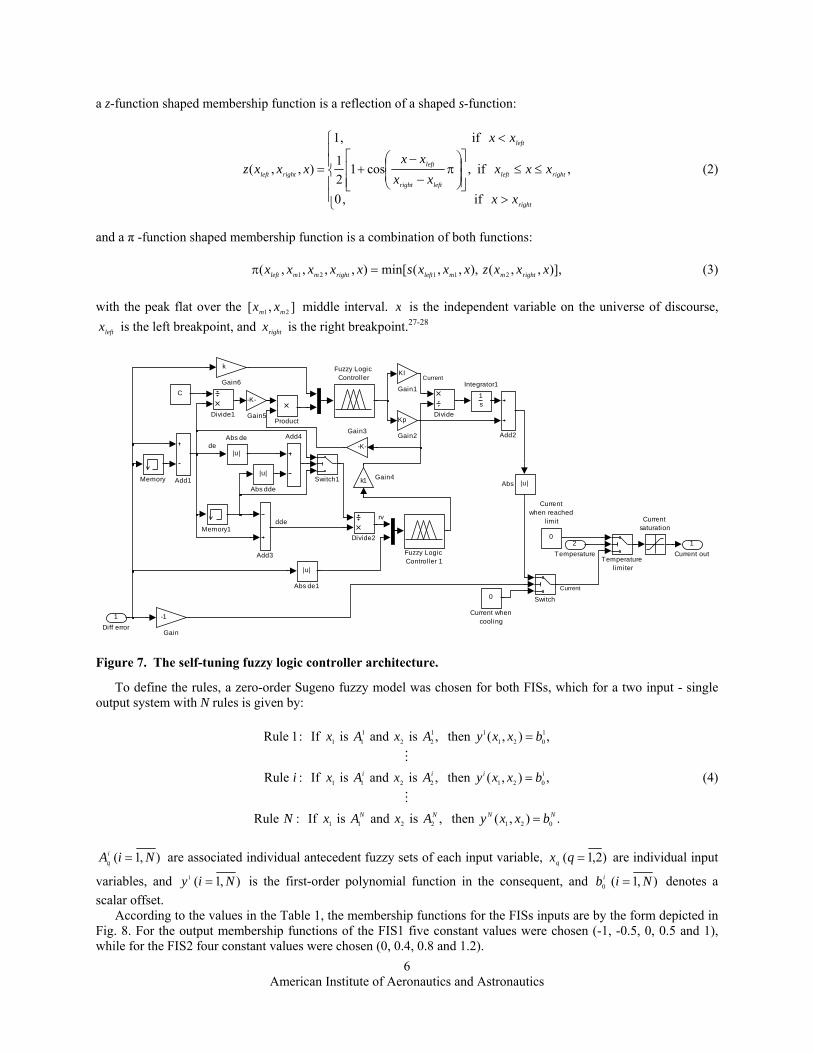
Based on the preliminary numerical simulation of the SMA actuators behavior, and on the mechanical model developed for the morphing wing, the Matlab/Simulink schema in Fig. 6 was derived with the aim to simulate and to tune the actuation lines controller. The “Integrated controller” block models the hybrid controller (self-tuning fuzzy27 plus on-off), and its detailed Simulink scheme is shown in Fig. 7. From the model can be easily seen that the implementation scheme considered the SMA actuators’ physical limitations in terms of temperature and supplying currents. The block inputs are the control error and the SMA wires temperatures, while its output is the electrical current used to control the actuators. One of the switches assured the functioning in tandem of the fuzzy controller with the on-off controller selecting one of the two options: error is positive or not. Another switch protected the morphing wing system by switching the electrical current value to 0A when the SMA temperature value is over the imposed limit. As a supplementary protection measure, a current saturation block was used to prevent the current from going over the physical limit supported by the SMA wires.
In Fig. 7 two “Fuzzy Logic Controller” blocks can be observed. The upper “Fuzzy Logic Controller” in the scheme is the main fuzzy controller, while the other one is used to adjust the coefficients deserving the other one. To obtain these blocks, two fuzzy inference systems (FIS) were developed and implemented: FIS1 for the main fuzzy controller, and FIS2 for the second fuzzy controller. The shapes chosen for inputs membership functions of both fuzzy inference systems were s-functions, π-functions, respectively z-functions, while the product fuzzy inference and the center average defuzzifier were applied (Sugeno). Generally, an s-function shaped membership function can be implemented using a cosine function:
,
if,1
if,cos12
1
if,0
),,(
right
rightleft
leftright
right
left
rightleft
xx
xxxxx
xx
xx
xxxs (1)
, M,Re
Pilot
Control
Flightconditions
Optimisedairfoils
databasedY1opt
dY2opt
Real airfoil
Integratedcontroller
dY1realdY2real
SMAactuators
e=dYopt- dYreal
Airflowperturbations
Current
Positiontransducers
dY1real
dY2real
Figure 5. Schematic of the controller basic principle for the open loop structure.
Temperature[K]
skin deflection [mm]
skindeflection
[mm]
desired deflection [mm]
SMA elongation[m]
skindeflection
[mm]
0
skin deflexion [mm]
1
1 4.5
desired skin deflection
[mm]
3/1000
cam factormm to m
XY Graph
Scope
0.078
SMA max set [m]
0
SMA elongation [m]
Current
Force
Displacement
Temperature
SMA Model1.8
SMA Initiallength [m]
1.8
SMA Initiallength
Diff error
Temperature
Current out
Integrated controller
Memory
F aero [N]
x [m]
F SMA [N]
y [mm]
Mechanical system
0
Current [A]
273.15
Celsius to Kelvin
1500
Aerodynamicforce [N]
Figure 6. Simulation model of the controlled morphing wing system in open loop.
American Institute of Aeronautics and Astronautics
6
a z-function shaped membership function is a reflection of a shaped s-function:
,
if,0
if,cos12
1
if,1
),,(
right
rightleft
leftright
left
left
rightleft
xx
xxxxx
xx
xx
xxxz (2)
and a π -function shaped membership function is a combination of both functions:
)],,,(),,,(min[),,,,( 21121 xxxzxxxsxxxxx rightmmleftrightmmleft (3)
with the peak flat over the ],[ 21 mm xx middle interval. x is the independent variable on the universe of discourse,
leftx is the left breakpoint, and rightx is the right breakpoint.27-28
To define the rules, a zero-order Sugeno fuzzy model was chosen for both FISs, which for a two input - single output system with N rules is given by:
.),(then,isandisIf:Rule
,),(then,isandisIf:Rule
,),(then,isandisIf:1Rule
0212211
0212211
1
021
11
22
1
11
NNNN
iiii
bxxyAxAxN
bxxyAxAxi
bxxyAxAx
(4)
),1( NiAi
q are associated individual antecedent fuzzy sets of each input variable, )2,1( qxq are individual input
variables, and ),1( Niyi is the first-order polynomial function in the consequent, and ),1(0 Nibi denotes a
scalar offset. According to the values in the Table 1, the membership functions for the FISs inputs are by the form depicted in
Fig. 8. For the output membership functions of the FIS1 five constant values were chosen (-1, -0.5, 0, 0.5 and 1), while for the FIS2 four constant values were chosen (0, 0.4, 0.8 and 1.2).
de
dderv
1
Current outTemperature
limiter
Switch1
Switch
Product
Memory1
Memory
1s
Integrator1
k
Gain6
-K-
Gain5
k1 Gain4
-K-
Gain3
Kp
Gain2
KI
Gain1
-1
Gain
Fuzzy Logic Controller 1
Fuzzy Logic Controller
Divide2
Divide1 Divide
C
0
Current whencooling
Current saturation
0
Currentwhen reached
limit
Add4
Add3
Add2
Add1
|u|
Abs de1
|u|
Abs de
|u|
Abs dde|u|Abs
2
Temperature
1
Diff error
Current
Current
Figure 7. The self-tuning fuzzy logic controller architecture.

American Institute of Aeronautics and Astronautics
7
Table 1 Parameters of the inputs’ membership functions
FIS Input mf mf type. mf parameters
xleft xm1 xm2 xright
FIS1 1 and 2
mf1 )and( 1
2
1
1 AA z - function -1 - - 0
mf2 )and( 2
2
2
1 AA π - function -1 0 0 1
mf3 )and( 3
2
3
1 AA s - function 0 - - 1
FIS2
1
mf1 )( 1
1A z - function 0 - - 1
mf2 )( 2
1A π - function 0 1 1 2
mf3 )( 3
1A s - function 1 - - 2
2
mf1 )( 1
2A z - function 0 - - 0.4
mf2 )( 2
2A π - function 0 0.4 0.4 0.8
mf3 )( 3
2A π - function 0.4 0.4 0.8 1.2
mf4 )( 4
2A π - function 0.06 0.54 0.66 1.14
Starting from the inputs’ and output’s membership functions of the two FISs, a set of 9 inference rules were obtained (N=9) for the FIS1:
,1)2,1(then,is2andis1If:9Rule
,5.0)2,1(then,is2andis1If:8Rule
,0)2,1(then,is2andis1If:7Rule
,5.0)2,1(then,is2andis1If:6Rule
,0)2,1(then,is2andis1If:5Rule
,5.0)2,1(then,is2andis1If:4Rule
,0)2,1(then,is2andis1If:3Rule
,5.0)2,1(then,is2andis1If:2Rule
,1)2,1(then,is2andis1If:1Rule
93
2
3
1
82
2
3
1
71
2
3
1
63
2
2
1
52
2
2
1
41
2
2
1
33
2
1
1
22
2
1
1
11
2
1
1
ininyAinAin
ininyAinAin
ininyAinAin
ininyAinAin
ininyAinAin
ininyAinAin
ininyAinAin
ininyAinAin
ininyAinAin
(5)
and 12 inference rules (N=12) for the FIS2:
.4.0)2,1(then,is2andis1If:12Rule
,8.0)2,1(then,is2andis1If:11Rule
,2.1)2,1(then,is2andis1If:10Rule
,2.1)2,1(then,is2andis1If:9Rule
,0)2,1(then,is2andis1If:8Rule
,4.0)2,1(then,is2andis1If:7Rule
,8.0)2,1(then,is2andis1If:6Rule
,8.0)2,1(then,is2andis1If:5Rule
,0)2,1(then,is2andis1If:4Rule
,0)2,1(then,is2andis1If:3Rule
,4.0)2,1(then,is2andis1If:2Rule
,8.0)2,1(then,is2andis1If:1Rule
124
2
3
1
113
2
3
1
102
2
3
1
91
2
3
1
84
2
2
1
73
2
2
1
62
2
2
1
51
2
2
1
44
2
1
1
33
2
1
1
22
2
1
1
11
2
1
1
ininyAinAin
ininyAinAin
ininyAinAin
ininyAinAin
ininyAinAin
ininyAinAin
ininyAinAin
ininyAinAin
ininyAinAin
ininyAinAin
ininyAinAin
ininyAinAin
(6)

American Institute of Aeronautics and Astronautics
8
The rule-based inference chosen for each consequent is presented in Fig. 9, for both fuzzy inference systems. With the previous considerations, the fuzzy control surfaces for the FISs result by the forms presented in Fig. 10.
After a tuning operation the optimum values of the controller basic gains were established. Further, the controller was tested through numerical simulation to ensure that it works well. A relevant test was for a successive steps signal applied to the input of the controlled actuator; the obtained characteristics are shown in Fig. 11. The results confirm that the obtained controller works very well in both phases (heating and cooling) of the SMA actuators.
IV. Wind Tunnel Validation of the Controller The wind tunnel tests were performed in the IAR-NRC wind tunnel at Ottawa. During the project were made
different wind tunnel tests in order to validate the interaction between the components of physical model of the morphing wing (Fig. 12).
input1
Deg
ree
of m
embe
rshi
p
0
0.2
0.4
0.6
0.8
1 mf1 mf2 mf3
-1 -0.5 0 0.5 1
"FIS1"
input2D
egre
e of
mem
bers
hip
0
0.2
0.4
0.6
0.8
1 mf1 mf2 mf3
-1 -0.5 0 0.5 1
"FIS1"
input2
mf1 mf2 mf3mf4
Deg
ree
of m
embe
rshi
p
0
0.2
0.4
0.6
0.8
1
0 0.2 0.4 0.6 0.8 1 1.2
"FIS2"
input1
Deg
ree
of m
embe
rshi
p
0
0.2
0.4
0.6
0.8
1 mf1 mf2 mf3
0 0.5 1 1.5 2
"FIS2"
Figure 8. Membership functions for the FISs inputs.
FIS2 FIS1
Figure 9. Rule-based inference for the fuzzy inference systems.
FIS2FIS1
Figure 10. The fuzzy control surfaces.

American Institute of Aeronautics and Astronautics
9
Based on the theoretical and numerical simulation results analysis, two Programmable Switching Power Supplies AMREL SPS100-33, controlled by Matlab/Simulink through a Quanser Q8 data acquisition card, were used to implement the controller physical model.30-31 The power supplies have RS-232 and GPIB IEEE-488 as standard features and technical characteristics that include: Power 3.3kW, Voltage (dc) 0-100 V, Current (dc) 0-33 A. The Q8 data acquisition card has 8 single-ended analog inputs with 14-bit resolution. All 8 channels can be sampled simultaneously at 100 kHz, with an A/D conversion times of 2.4 µs/channel. Simultaneous sampling and sampling frequencies of up to 350 kHz for two channels can be performed. Also, the Q8 card is equipped with 8 analog outputs, software programmable voltage ranges and simultaneous update capability with an 8 µs settling time over the full scale (20V).
The acquisition board was connected to a PC and programmed via Matlab/Simulink R2006b and WinCon 5.2 (Fig. 13). The input were two signals from the Linear Variable Differential Transformer (LVDT) potentiometers, which indicate the positions of the SMA actuators, and six signals from thermocouples installed on each of the SMA wires’ components. The acquisition sampling time was set to 10 µs. The output channels of the acquisition board were used to control each power supply through analog/external control by means of a DB-15 I/O connector.
In the open loop wind tunnel tests, simultaneously with the controller validation, the real-time detection of the transition point and visualization were performed, for all the 35 optimized airfoils. Also, a comparative study was realized based on the transition point position for the reference airfoil and for each optimized airfoil, with the aim to validate the aerodynamic part of the project. All tests confirmed the well work of the designed controller.
0 20 40 60 80 100 1200
1
2
3
4
5
6
7
8
Time [s]
Ver
tica
l dis
plac
emen
t [m
m]
desiredobtained
30 40 50 60 70 80 90 100 110Temperature [oC]
0
1
2
3
4
5
6
7
8
Ver
tica
l dis
plac
emen
t [m
m]
Figure 11. Numerical simulation results for the actuation line controller.
0
Volts
Temp
StartVolt
termocouple1
termocouple2
termocouple3
position 2
temp
amps
control V
start 5V
SMA2
termocouple1
termocouple2
termocouple3
position 1
temp
amps
control V
start 5V
SMA1
Q8Quanser
Analog OutputQ8Quanser
Analog Input
Amps
Analog Input
Analog Output
0
Figure 13. Matlab/Simulink actuators control.
Figure 12. Wind tunnel morphing wing model.

American Institute of Aeronautics and Astronautics
10
In Fig. 14 are shown the results obtained for the run test 42 (airfoil case C107, Mach = 0.2, alpha = 2 degree). From figure can be observed that the controller work even the actuator required displacement is zero because of the gas springs pretension forces.
The transition detection was performed in real time using the pressure data signals obtained from the Kulite pressure sensors. The pressure data were acquired using the IAR-NRC analog data acquisition system, which was connected to the sensors. The sampling rate of each channel was at 15 kHz, which allowed a pressure fluctuation FFT spectral decomposition of up to 7.5 kHz for all channels. The signals were processed in real time using Simulink. The pressure signals were analyzed using Fast Fourier Transforms (FFT) decomposition to detect the magnitude of the noise in the surface air flow. Subsequently, the data was filtered by means of high-pass filters and processed by calculating the Root Mean Square (RMS) of the signal to obtain a plot diagram of the pressure fluctuations in the flow boundary layer. This signal processing is necessary to disparate the inherent electronically induced noise, by the Tollmien-Schlichting waves that are responsible for triggering the transition from laminar to turbulent flow. The measurements showed that in the processed data, the transition appeared at frequencies between 3÷5kHz and the magnitude of the pressure variations in the laminar flow boundary layer are on the order of 5e-4 Pa. The transition from the laminar flow to turbulent flow was shown by an increase in the pressure fluctuation, which was indicated by a drastic variation of the pressure signal RMS. For the wind tunnel test the preloaded forces of the gas springs were reconsidered to the 1500 N because of the presence of the aerodynamic forces on the flexible skin of the wing.
The experimental results show a decrease of the SMA wires work temperatures vis-à-vis of numerically simulated cases. An explanation can be the appearing of the aerodynamic forces with particular values for each flight condition. The decrease of these temperatures is a beneficial one taking into account the negative impact of a strong thermal field on the other component of the system, especially on the flexible skin and on the pressure sensors. Also, from the experimental results a high frequency noise influencing the LVDT sensors and the thermocouples instrumentation amplifiers can be observed. The noise sources are the wind tunnel vibrations and instrumentation electrical fields. With this noise, the amplitude of the actuation error (difference between the realized deflections and desired deflections) is under 0.07 mm, but this don’t affecting the transition, which is stable on a sensor with a high RMS spike; Fig. 15 presents the results obtained on the transition monitoring for the run test in Fig. 14. The actuation line control obtained precision can have some influence in the transition point position detection only if the density of the chord disposed pressure sensors becomes bigger; from the experimental data evaluation one concluded that, even the value of the error is 1 mm around the optimized values, the transition point position on the airfoil surface is not significantly changed. In Fig. 15 are presented the outputs of the Kulite pressure sensors in leading edge – trailing edge sense of positioning and the real time pressure signals RMS for each of these sensors. The sensors # 11 and # 12 were removed from plots due to the bad dynamic signals which show electrical failure of the sensors. Sensor # 5 showed a misalignment of the Cp value with its neighbours which means there is a leak or a pinched reference tube. The dynamic signal of the sensor # 5 was good and for that reason the sensor value was kept on the plots. The left hand column presents the results for reference airfoil, and the right hand column the results for optimized airfoil. The spike of the RMS suggests that we have turbulence on the sensor no. 13, near the trailing edge.
0 50 100 150 200 250 300 350 400-1
0
1
2
3
4
5
6
7
8
9
Time (sec)
Y (
mm
)
Run 42f time history
SMA#1 realised
desiredSMA#2 realised
desired
20 25 30 35 40 45 50 55 600
1
2
3
4
5
6
7
8
Temperature (deg C)
Y (
mm
)
Run 42f temperature-displacement diagram
SMA#1
SMA#2
0 50 100 150 200 250 300 350 40020
25
30
35
40
45
50
55
60
Time (sec)
Tem
pera
ture
(de
g C
)
Run 42f time history
Thermocouple SMA#1
Thermocouple SMA#2
Figure 14. Wind tunnel results for airfoil case C107: M= 0.2, = 2o.

American Institute of Aeronautics and Astronautics
11
V. Conclusions The objective of here presented research work was to develop an intelligent actuation control concept for a
morphing mechanism using smart materials, like Shape Memory Alloy (SMA), as actuators. These smart actuators modify the upper surface of a wing made of a flexible skin so the laminar to turbulent transition point moves close to the wing airfoil trailing edge. The final purpose of the research project was to obtain a drag reduction as a function of flow condition, by changing the wing shape.
The strong nonlinearities of the SMA actuators’ characteristics and the system requirements have led to a hybrid controller architecture as a combination of a bi-positional (particularly an on-off one) and a self-tuning fuzzy logic controller. In the chosen architecture, the controller behaved as a switch between the SMA cooling and heating phases, situations where the output current is 0 A, or is controlled by the FLC.
The numerical and experimental results obtained for the actuators control were very good, the controller fully satisfying the requirements imposed for the project purpose achievement.
Acknowledgments The authors would like to thank the Consortium for Research and Innovation in Aerospace in Quebec (CRIAQ),
Thales Avionics Inc., Bombardier Aerospace, and the National Sciences and Engineering Research Council (NSERC) for their financial support. We would like also to thank Dr. George Henri Simon for initiating the CRIAQ 7.1 project and Dr. Philippe Molaret from Thales Avionics and Dr. Eric Laurendeau from Bombardier Aerospace for their help and fruitful discussions.
Figure 15. Results obtained on the transition monitoring for the case M= 0.2, = 2o.

American Institute of Aeronautics and Astronautics
12
References 1Shellabarger, N., “National Forecast Overview 2008-2025”, Director Aviation Policy and Plans, Federal Aviation
Administration, 2008 2Munday, D., and Jacob, J., “Active control separation on a wing with oscillating camber”, AIAA Journal of Aircraft, vol.
39(1), Paper AIAA 2001–0293, 2002. 3Jacob, J.D., “Aerodynamic flow control using shape adaptive surfaces”, ASME 17th Biennial Conference on Mechanical
Vibration and Noise, Symposium on Structronics, Mechatronics, and Smart Materials, Las Vegas, Nevada, September, 1999. 4Munday, D., Jacob, J.D., and Huang, G., “Active flow control of separation on a wing with oscillatory camber”, 40th AIAA
Aerospace Sciences Meeting, Reno, NV. Paper AIAA-2002-0413, 2002. 5Munday, D., Jacob, J. D., Hauser, T., and Huang, G., “Experimental and numerical investigation of aerodynamic flow
control using oscillating adaptive surfaces”, 1st AIAA Flow Control Conference, AIAA Paper No. 2002-2837, St. Louis, 2002. 6Lutz, T., Sommerer, A., and Wagner, S., “Design of adaptive transonic airfoils by means of numerical optimization”,
University of Stuttgart, Germany, 2000. 7Wadehn, W., Sommerer, A., Lutz, Th., Fokin, D., Pritschow, G., and Wagner, S., “Structural concepts and aerodynamic
design of shock control bumps”, Proceedings 23nd ICAS Congress, Toronto, Canada, September 8 - 13, 2002. 8Sobieczky, H., and Geissler, W., “Active flow control based on transonic design concepts”, DLR German Aerospace
Research Establishment, AIAA Paper 99-3127, 1999. 9Sobieczky, H., Geissler, W., and Hannemann, M., “Expansion shoulder bump for wing section viscous/wave drag control”,
FLOWCON IUTAM Symposium on Mechanics of Passive and Active Flow Control, Gottingen, Germany, 1998. 10Catalano, F.M., Greco Jr., P.C., and Martins, A.L., “Viscous and wave drag optimization for a transport aircraft mission
adaptive wing”, ICAS Congress, Aircraft Laboratory – University of São Paulo-Brazil and Embraer, 2002. 11Martins, A.L., and Catalano, F.M., “Drag optimization for transport aircraft mission adaptive wing”, Journal of the
Brazilian Society of Mechanical Sciences, vol. 25, no. 1, 2003. 12Pinkerton, J. L., Moses, R. W., “A feasibility study to control airfoil shape using THUNDER”, Langley Research Center,
Hampton, Virginia, NASA Technical Memorandum 4767, 1997. 13Arcara, P.C., Jr., Bartlett, D.W., and McCullers, L.A., “Analysis for the application of hybrid laminar flow control to a
long-range subsonic transport aircraft”, Aerospace Technology Conference and Exposition, Long Beach, CA, Sep. 23-26, 1991. 14Sainmont, C., Paraschivoiu, I. and Coutu, D., “Multidisciplinary Approach for the Optimization of a Laminar Airfoil
Equipped with a Morphing Upper Surface”, NATO AVT-168 Symposium on "Morphing Vehicle", Evora, Portugal, 2009. 15Khalid, M., and Jones, D.J., “Navier Stokes Investigation of Blunt Trailing Edge Airfoils using O-Grids”, AIAA Journal of
Aircraft, vol.30, no.5, pp. 797-800, 1993. 16Khalid, M., and Jones, D.J., “A CFD Investigation of the Blunt Trailing Edge Airfoils in Transonic Flow”, Inaugural
Conference of the CFD Society of Canada, June, 1993. 17Georges, T.,Brailovski, V., Morellon, E., Coutu, D. and Terriault, P., “Design of Shape Memory Alloy Actuators for
Morphing Laminar Wing With Flexible Extrados”, Journal of Mechanical Design, Vol. 31, No. 9, September, 2009. 18Brailovski, V., et al., “Morphing laminar wing with flexible extrados powered by shape memory alloy actuators”, Proc.
ASME Conf. Smart Materials, Adaptive Structures and Intelligent Systems (SMASIS 2008), Paper 337, Ellicott City, USA, 2008. 19Coutu, D., Brailovski, V., Terriault, P. and Fischer, C., “Experimental validation of the 3D numerical model for an adaptive
laminar wing with flexible extrados”, 18th International Conference of Adaptive Structures and Technologies, Ottawa, Ontario, 3-5 October, 2007.
20Coutu, D., Brailovski, V. and Terriault, P., “Promising benefits of an active-extrados morphing laminar wing”, AIAA Journal of Aircraft, Vol. 46(2), pp. 730-731, 2009.
21Coutu, D., Brailovski, V., Terriault, P., and Fischer, C., “Experimental Validation of the 3D Numerical Model for an Adaptive Laminar Wing with Flexible Extrados”, 18th International Conference of Adaptive Structures and Technologies, Ottawa, Ontario, 3–5 Oct. 2007.
22Terriault, P., Viens, F., and Brailovski, V., “Non-isothermal Finite Element Modeling of a Shape Memory Alloy Actuator Using ANSYS”, Computational Materials Science, Vol. 36, No. 4, pp. 397-410, July, 2006.
23Popov, A-V., Botez, R. M., Mamou, M. and Grigorie, T.L., “Optical sensor pressure measurements variations with temperature in wind tunnel testing”, AIAA Journal of Aircraft, Vol. 46 (4), pp. 1314-1318, 2009.
24Popov, A.V., Grigorie, T. L., Botez, R.M., Mamou, M., and Mebarki, Y., “Real Time Morphing Wing Optimization Validation Using Wind-Tunnel Tests”, AIAA Journal of Aircraft, Vol. 47, No. 4, pp. 1346-1355, July–August, 2010.
25Popov, A.V., Labib, M., Fays, J., and Botez, R.M., “Closed-Loop Control Simulations on a Morphing Wing”, AIAA Journal of Aircraft, Vol. 45, No. 5, pp. 1794-1803, September–October, 2008.
26Popov, A.V., Grigorie, T. L., Botez, R.M., Mamou, M., and Mebarki, Y., “Closed-Loop Control Validation of a Morphing Wing Using Wind Tunnel Tests”, AIAA Journal of Aircraft, Vol. 47, No. 4, pp. 1309-1317, July–August, 2010.
27Karasakal, O., Yesil, E., Guzelkaya, M., and Eksin I., “Implementation of a New Self-Tuning Fuzzy PID Controller on PLC”, Turk. J. Elec. Eng. & Comp. Sci., vol.13, iss. 2., pp. 277-286, 2005.
28Jantzen, J., “Tuning of fuzzy PID controllers”, Technical Report 98-H871, Department of Automation, Technical University of Denmark, September, 1998.
29Zadeh, L. A., “Fuzzy sets”, Information Control, Vol. 8, pp: 339-353, 1965. 30Park, J., and Mackay, S., “Practical data acquisition for instrumentation and control systems”, Elsevier, UK, 2003. 31Austerlitz, H., “Data acquisition techniques using PCs”, Elsevier, USA, 2003.