MODIS Edge User Manual - Snap-on
222
User Manual Scope Multimeter Scanner Quick Lookups Guided Component Tests Tools OBD-II/EOBD Previous Vehicle and Data Scope Multimeter Scanner Quick Lookups Guided Component Tests Tools OBD-II/EOBD Previous Vehicle and Data BC ZEEMS341A Rev. D 26-G-18 NA
-
Upload
khangminh22 -
Category
Documents
-
view
0 -
download
0
Transcript of MODIS Edge User Manual - Snap-on

User Manual
Scope MultimeterScanner
Quick Lookups
Guided ComponentTests
Tools
OBD-II/EOBD
Previous Vehicleand Data
Scope MultimeterScanner
Quick Lookups
Guided ComponentTests
Tools
OBD-II/EOBD
Previous Vehicleand Data
BC
ZEEMS341A Rev. D 26-G-18 NA
i
Legal Information
TrademarksSnap-on is a trademark, registered in the United States and other countries, of Snap-on Incorporated. This publication contains many Snap-on Incorporated trademarks, including but not limited to Snap-on, SureTrack and ShopStream. All other marks are trademarks or registered trademarks of their respective holders.
Copyright Information© 2018 Snap-on Incorporated. All rights reserved.
Disclaimer of Warranties and Limitation of LiabilitiesAll pictures and illustrations shown are for reference purposes only. All information, specifications and illustrations in this manual are based on the latest information available at the time of printing and are subject to change without notice. While the authors have taken due care in the preparation of this manual, nothing contained herein:
• Modifies or alters in any way the standard terms and conditions of the purchase, lease, or rental agreement under the terms of which the equipment to which this manual relates was acquired.
• Increases in any way the liability to the customer or to third parties.
Snap-on® reserves the right to make changes at any time without notice.
IMPORTANT:Before operating or maintaining this unit, please read this manual carefully paying extra attention to the safety warnings and precautions.
Software License InformationUse of Software is governed by the terms and conditions of the End User License Agreement. The diagnostic tool should not be initially operated until the End User License Agreement is read. Use of the device acknowledges your acceptance of the End User License Agreement. The Snap-on Incorporated Software End User License Agreement may be provided with the diagnostic tool, and is available at: https://eula.snapon.com/diagnostics.
Patent InformationFor a listing of Snap-on products that are protected by patents in the United States and elsewhere, visit: https://patents.snapon.com
User Manual InformationThis manual includes information and images applicable with diagnostic software version 18.4 and later. Some information within this manual may not be applicable with other diagnostic software versions.
The information in this manual is periodically revised to ensure the latest information is included. The current version of this manual and other technical documentation is available online from Snap-on Diagnostics.

ii
FCC Compliance StatementThis equipment has been tested and found to comply with the limits for a Class B digital device, pursuant to part 15 of the FCC rules. These limits are designed to provide reasonable protection against harmful interference in a residential installation. This equipment generates, uses and can radiate radio frequency energy and, if not installed and used in accordance with the instructions, may cause harmful interference to radio communications. However, there is no guarantee that interference will not occur in a particular installation. If this equipment does cause harmful interference to radio or television reception, which can be determined by turning the equipment off and on, the user is encouraged to try to correct the interference by one or more of the following measures:
• Reorient or relocate the receiving antenna.
• Increase the separation between the equipment and receiver.
• Connect the equipment into an outlet on a circuit different from that to which the receiver is connected.
• Consult the dealer or an experienced radio/TV technician for help.
CAUTIONYou are cautioned that changes or modifications not expressly approved by the party responsible for compliance could void your authority to operate the equipment.
FCC RF Radiation Exposure Statement 1. This transmitter must not be co-located or operating in conjunction with any other antenna or transmitter. 2. This equipment complies with FCC RF radiation exposure limits set forth for an uncontrolled environment. This
device was tested for typical lap held operations with the device contacted directly to the human body to the back side of the Display Unit. To maintain compliance with FCC RF exposure compliance requirements, avoid direct contact to the transmitting antenna during transmitting.
3. According to FCC 15.407(e), the device is intended to operate in the frequency band of 5.15GHz to 5.25GHz under all conditions of normal operation. Normal operation of this device is restricted to indoor use only to reduce any potential for harmful interference to co-channel MSS operations.
iii
Product Support Information
Product Support Information
Phone / E-mail - Technical Assistance1-800-424-7226 / [email protected]
or use our online contact form - https://www1.snapon.com/diagnostics/us/Contact
Website Links:
Snap-on Diagnostics and Information
• http://diagnostics.snapon.com
Manuals / Technical Documentation - This manual is periodically revised to ensure the latest information is included. Download the latest version of this manual and other related technical documentation at:
• http://diagnostics.snapon.com/usermanuals
For technical assistance in all other markets, contact your selling agent.
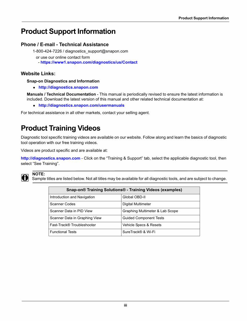
Product Training VideosDiagnostic tool specific training videos are available on our website. Follow along and learn the basics of diagnostic tool operation with our free training videos.
Videos are product specific and are available at:
http://diagnostics.snapon.com - Click on the “Training & Support” tab, select the applicable diagnostic tool, then select “See Training”.
NOTE:i Sample titles are listed below. Not all titles may be available for all diagnostic tools, and are subject to change.
Snap-on® Training Solutions® - Training Videos (examples)
Introduction and Navigation Global OBD-II
Scanner Codes Digital Multimeter
Scanner Data in PID View Graphing Multimeter & Lab Scope
Scanner Data in Graphing View Guided Component Tests
Fast-Track® Troubleshooter Vehicle Specs & Resets
Functional Tests SureTrack® & Wi-Fi
iv
Diagnostic Quick Tips - Video Series
Diagnostic Quick Tips - Video SeriesSnap-on Diagnostic Quick Tips videos are available at no charge on our website and on our YouTube channel. These videos are developed from real repair case studies to help professional technicians use diagnostic tools to solve specific vehicle problems (e.g. performing a Ford Relative Injector Flow Test).
Additional videos are also available showing specific diagnostic tool features (e.g. ShopStream Connect - Software Updates).
Figure 1-1
Videos are available at:
http://diagnostics.snapon.com - Click on the “Training & Support” tab, select the applicable diagnostic tool, then select “See Quick Tips”
https://www.youtube.com/user/snaponscanner/videos - Use the search function to find a title, or enter “Diagnostic Quick Tips” in the search field to see a list of all applicable titles.
NOTE:i URL links (above) and titles listed (below) are subject to change and may not be available in all markets.
A sample list of titles are listed below, other titles may be available.
Some videos may not applicable for use with all diagnostic tools.
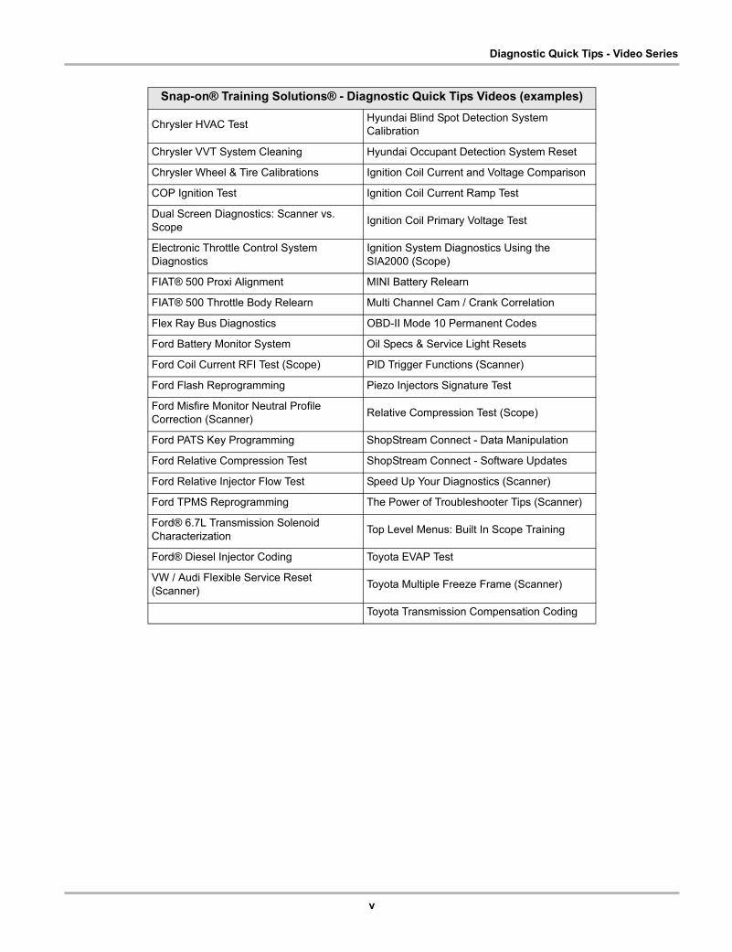
Snap-on® Training Solutions® - Diagnostic Quick Tips Videos (examples)
Air/Fuel Ratio Sensor TestFuel Injector Voltage and Current Tests (Scope)
Alternator Ripple Test (Scope) Fuel Pump Current Ramp Test (Scope)
BMW® Rain Sensor Calibration Harley-Davidson® ABS Brake Bleed
CAN Bus Diagnostics (Scope) Harley-Davidson® Functional Tests
Chevrolet® Volt Coolant Pump Bleed Harley-Davidson® Key Fob Programming
v
Diagnostic Quick Tips - Video Series
Chrysler HVAC TestHyundai Blind Spot Detection System Calibration
Chrysler VVT System Cleaning Hyundai Occupant Detection System Reset
Chrysler Wheel & Tire Calibrations Ignition Coil Current and Voltage Comparison
COP Ignition Test Ignition Coil Current Ramp Test
Dual Screen Diagnostics: Scanner vs. Scope
Ignition Coil Primary Voltage Test
Electronic Throttle Control System Diagnostics
Ignition System Diagnostics Using the SIA2000 (Scope)
FIAT® 500 Proxi Alignment MINI Battery Relearn
FIAT® 500 Throttle Body Relearn Multi Channel Cam / Crank Correlation
Flex Ray Bus Diagnostics OBD-II Mode 10 Permanent Codes
Ford Battery Monitor System Oil Specs & Service Light Resets
Ford Coil Current RFI Test (Scope) PID Trigger Functions (Scanner)
Ford Flash Reprogramming Piezo Injectors Signature Test
Ford Misfire Monitor Neutral Profile Correction (Scanner)
Relative Compression Test (Scope)
Ford PATS Key Programming ShopStream Connect - Data Manipulation
Ford Relative Compression Test ShopStream Connect - Software Updates
Ford Relative Injector Flow Test Speed Up Your Diagnostics (Scanner)
Ford TPMS Reprogramming The Power of Troubleshooter Tips (Scanner)
Ford® 6.7L Transmission Solenoid Characterization
Top Level Menus: Built In Scope Training
Ford® Diesel Injector Coding Toyota EVAP Test
VW / Audi Flexible Service Reset (Scanner)
Toyota Multiple Freeze Frame (Scanner)
Toyota Transmission Compensation Coding
Snap-on® Training Solutions® - Diagnostic Quick Tips Videos (examples)

vi
Contents
Safety Information ................................................................................................................x
Using This Manual..............................................................................................................xii
Chapter 1: Introduction........................................................................................................1
Control Buttons.......................................................................................................................1Data and Power Connections.................................................................................................2Battery Pack and Stand..........................................................................................................3Power Sources .......................................................................................................................4
Internal Battery Pack........................................................................................................4AC Power Supply .............................................................................................................4Vehicle Power ..................................................................................................................4
Technical Specifications .........................................................................................................5
Chapter 2: Basic Operation and Navigation ......................................................................6
Turning On/Off and Emergency Shutdown.............................................................................6Turning On .......................................................................................................................6Turning Off .......................................................................................................................6Emergency Shutdown......................................................................................................7
Wi-Fi Connection ...................................................................................................................7Basic Navigation.....................................................................................................................7
Home Screen Layout .......................................................................................................7Title Bar............................................................................................................................8Home Screen Icons .........................................................................................................9Common Toolbar Control Icons .....................................................................................10Scroll Bar .......................................................................................................................11
Screen Messages.................................................................................................................11System Messages..........................................................................................................11Communication Messages.............................................................................................12
Data Cable Connection ........................................................................................................12Optional Data Cables and Adapters ..............................................................................13
Chapter 3: Scanner.............................................................................................................14
Screen Layout and Toolbar Icons.........................................................................................14Screen Layout ................................................................................................................14Scanner Control Icons ...................................................................................................15
Scanner Demonstration Program .........................................................................................15Scanner Operation ...............................................................................................................16
Vehicle Identification ......................................................................................................16System Main Menu Options...........................................................................................20Codes Menu...................................................................................................................20Saving and Reviewing Scanner / OBD-II/EOBD Data Files...........................................28Functional Tests.............................................................................................................30Generic Functions..........................................................................................................31
Exiting Scanner ....................................................................................................................33

vii
Chapter 4: Vehicle Code Scan / (ALTUS™)......................................................................34
Using Code Scan..................................................................................................................35Total Number of Systems (modules) Analyzed..............................................................37List of All the Systems Analyzed with DTCs Totals........................................................37SureTrack® Common Replaced Parts Graph...............................................................38Global OBDII DTCs........................................................................................................39Readiness Monitor Test Status ......................................................................................39
Vehicle System Report (ALTUS™) ......................................................................................40Printing the Vehicle System Report ...............................................................................40
Chapter 5: SureTrack .........................................................................................................41
SureTack - Diagnostic Tool Features ...................................................................................41Basic Operation and Navigation ....................................................................................41
SureTrack - Online Community ............................................................................................47Main Topic Links ............................................................................................................47Quick Reference ............................................................................................................47Finding your SureTrack Authorization Code ..................................................................48Creating a SureTrack Account .......................................................................................49Logging In (active account) ............................................................................................53Logging In with New Authorization Code (active account) ............................................54Logging In with New Authorization Code (expired account) ..........................................55SureTrack Features .......................................................................................................57SureTrack Screens ........................................................................................................58
Chapter 6: Quick Lookups.................................................................................................63
Oil Specs and Resets ...........................................................................................................63Operation .......................................................................................................................64Reset Procedure ............................................................................................................68
Tire and Wheel Service ........................................................................................................71Operation .......................................................................................................................71
Chapter 7: OBD-II/EOBD ....................................................................................................79
Basic Operations ..................................................................................................................79Screen Layout and Toolbar Controls .............................................................................79Connecting the Data Cable ............................................................................................79Saving and Reviewing Data Files ..................................................................................79
OBD-II/EOBD Menu .............................................................................................................79OBD Health Check.........................................................................................................80OBD Direct .....................................................................................................................82
Chapter 8: Guided Component Tests ...............................................................................89
Training and Classes............................................................................................................89Power User Tests ..........................................................................................................90
Screen Layout and Icons......................................................................................................93Screen Layout ................................................................................................................93Guided Component Tests Control Icons ........................................................................94
Operation..............................................................................................................................95Component Information .................................................................................................96Tests ..............................................................................................................................98Saving and Reviewing Data Files ................................................................................100
viii
Chapter 9: Scope Multimeter...........................................................................................101
Overview.............................................................................................................................101Digital Multimeter (DMM) .............................................................................................101Graphing Multimeter (GMM) ........................................................................................102Lab Scope....................................................................................................................103
Tests and Capabilities (Quick Reference) ..........................................................................104Test Leads and Accessories ..............................................................................................106
Channel 1 Lead............................................................................................................106Channel 2 Lead............................................................................................................106Alligator Clips and Probes............................................................................................107Secondary Ignition Coil Adapter Lead and Clip-on Adapter (optional) ............................................................................................................107Low Amp Current Probe (optional)...............................................................................107Temperature Probe Adapter (optional) ........................................................................108Pressure Transducers and Adapters (optional) ...........................................................108Waveform Demonstration Tools (optional)...................................................................109
General Information............................................................................................................110Scope Multimeter Screen Layout and Features...........................................................110Measurement Out of Range (Alert) ..............................................................................112
Operation and Controls ......................................................................................................113Test Lead / Probe Connection .....................................................................................113Test Lead / Probe Calibration ......................................................................................114Control Panel and Settings ..........................................................................................115Secondary Ignition Testing ..........................................................................................131
Optional Settings ................................................................................................................133Display (Grid on/off) .....................................................................................................133Divisions.......................................................................................................................134
Saving and Reviewing Scope / Multimeter Data Files........................................................138Data Buffer ...................................................................................................................138Saving Files .................................................................................................................139Stopping and Reviewing Data Files .............................................................................140Saving Screens............................................................................................................141Using the Zoom Function .............................................................................................141
General Reference ............................................................................................................144Basic Setup Tips (unknown signal type) .....................................................................144Using Known Good Waveforms...................................................................................145Troubleshooting Signals .............................................................................................148Units of Measurement / Conversions...........................................................................149Glossary of Common Terms .......................................................................................151
Chapter 10: Previous Vehicles and Data........................................................................154
Previous Vehicles and Data Menu .....................................................................................154Vehicle History .............................................................................................................154View Saved Data .........................................................................................................155Viewing Codes and Code Scan Results ......................................................................156Delete Saved Data .......................................................................................................158
Chapter 11: Tools .............................................................................................................159
Tools Menu.........................................................................................................................159Connect-to-PC .............................................................................................................160

ix
Configure Shortcut Button............................................................................................161System Information ......................................................................................................161Settings ........................................................................................................................162
Chapter 12: Maintenance .................................................................................................170
Cleaning and Inspecting the Diagnostic Tool .....................................................................170Cleaning the Touch Screen .........................................................................................170
Battery Pack Service ..........................................................................................................170Battery Pack Safety Guidelines ...................................................................................171Replacing the Battery Pack..........................................................................................172Disposing of the Battery Pack......................................................................................173
Chapter 13: ALTUS (ALTUSDRIVE.com) - Cloud Sharing/Storage..............................174
Key Features ......................................................................................................................174Important Notes ..................................................................................................................174Registration - Getting Started .............................................................................................175
ALTUS - New User Registration ..................................................................................175ALTUS - SureTrack User Setup...................................................................................176ALTUS Setup Information Screen................................................................................177
Using ALTUS......................................................................................................................178Quick Reference (print / download / share) .................................................................178Logging in to ALTUS (registered user).........................................................................178Navigating ALTUS (Toolbars) ......................................................................................179My Files........................................................................................................................179Search..........................................................................................................................184Favorites ......................................................................................................................185Profile ...........................................................................................................................185
Chapter 14: Wi-Fi Connection / Troubleshooting..........................................................191
Checking if Wi-Fi is On/Off .................................................................................................191Checking if Wi-Fi is Connected ..........................................................................................192Wi-Fi Icons (Setup).............................................................................................................192Turning Wi-Fi On and Connecting to a Network.................................................................192Add Network Advanced (Connecting to a hidden network).............................................................................................................194Wi-Fi Testing ......................................................................................................................194Wi-Fi Troubleshooting and Status Messages.....................................................................196
Informative Messages..................................................................................................198
Chapter 15: ShopStream Connect ..................................................................................199
Using SSC (Connecting to your PC) ..................................................................................199SSC Main Screen ...............................................................................................................200Scanner DataViewer...........................................................................................................201Image Viewer......................................................................................................................202Printing the (Code Scan) Vehicle System Report...............................................................203Customizing the (Code Scan) Vehicle System Report .......................................................204Software Upgrades and Updates .......................................................................................207
End User License Agreement ......................................................................................208

x
Safety Information
READ ALL INSTRUCTIONSFor your own safety, the safety of others, and to prevent damage to the product and vehicles upon which it is used, it is important that all instructions and safety messages in this manual and the accompanying Important Safety Instructions manual be read and understood by all persons operating, or coming into contact with the product, before operating. We suggest you store a copy of each manual near the product in sight of the operator.
For your safety, read all instructions. Use your diagnostic tools only as described in the tool user’s manual. Use only manufacturer recommended parts and accessories with your diagnostic tools.
This product is intended for use by properly trained and skilled professional automotive technicians. The safety messages presented throughout this manual and the accompanying Important Safety Instructions manual are reminders to the operator to exercise extreme care when using this product.
There are many variations in procedures, techniques, tools, and parts for servicing vehicles, as well as in the skill of the individual doing the work. Because of the vast number of test applications and variations in the products that can be tested with this instrument, we cannot possibly anticipate or provide advice or safety messages to cover every situation. It is the responsibility of the automotive technician to be knowledgeable of the system being tested. It is essential to use proper service methods and test procedures. It is important to perform tests in an appropriate and acceptable manner that does not endanger your safety, the safety of others in the work area, the equipment being used, or the vehicle being tested.
It is assumed that the operator has a thorough understanding of vehicle systems before using this product. Understanding of these system principles and operating theories is necessary for competent, safe and accurate use of this instrument.
Before using the equipment, always refer to and follow the safety messages and applicable test procedures provided by the manufacturer of the vehicle or equipment being tested. Use the product only as described in it’s user manual. Use only manufacturer recommended parts and accessories with your product.
Read, understand and follow all safety messages and instructions in this manual, the accompanying Important Safety Instructions manual, and on the test equipment.
Environmental Conditions:
• This product is intended for indoor use only
• This product is rated for Pollution Degree 2 (normal conditions)
xi
Safety Information Safety Signal Words
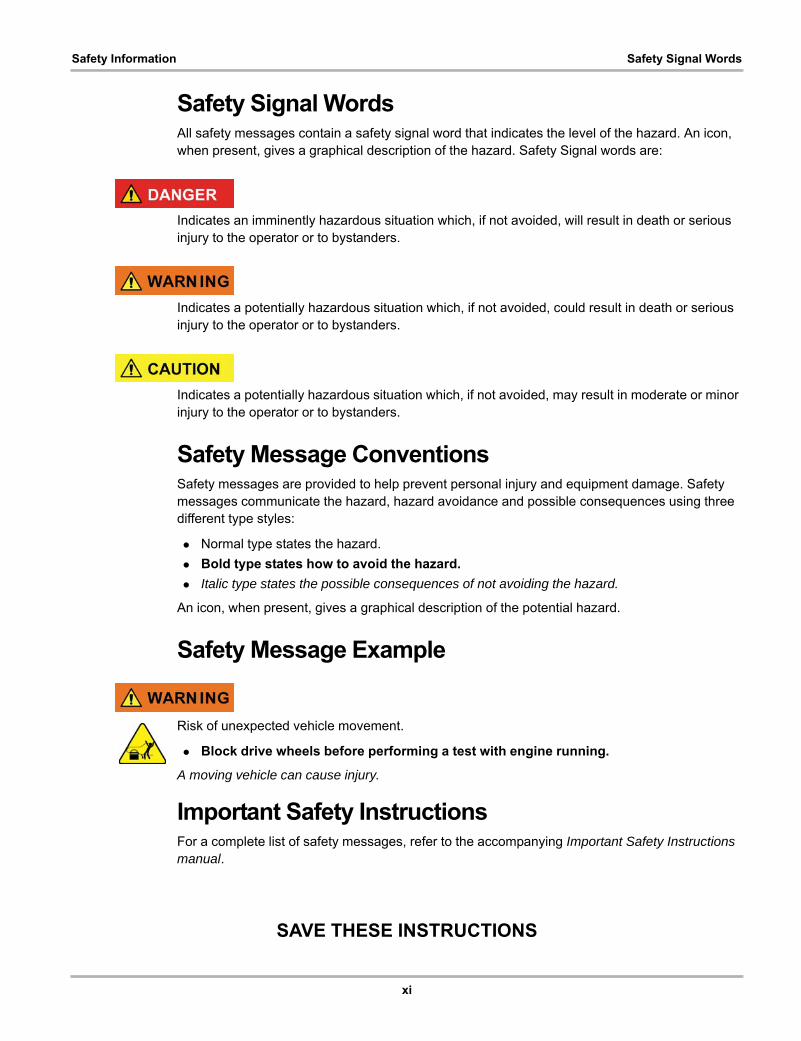
Safety Signal WordsAll safety messages contain a safety signal word that indicates the level of the hazard. An icon, when present, gives a graphical description of the hazard. Safety Signal words are:
Indicates an imminently hazardous situation which, if not avoided, will result in death or serious injury to the operator or to bystanders.
Indicates a potentially hazardous situation which, if not avoided, could result in death or serious injury to the operator or to bystanders.
Indicates a potentially hazardous situation which, if not avoided, may result in moderate or minor injury to the operator or to bystanders.
Safety Message ConventionsSafety messages are provided to help prevent personal injury and equipment damage. Safety messages communicate the hazard, hazard avoidance and possible consequences using three different type styles:
• Normal type states the hazard.
• Bold type states how to avoid the hazard.
• Italic type states the possible consequences of not avoiding the hazard.
An icon, when present, gives a graphical description of the potential hazard.
Safety Message Example
Risk of unexpected vehicle movement.
• Block drive wheels before performing a test with engine running.
A moving vehicle can cause injury.
Important Safety InstructionsFor a complete list of safety messages, refer to the accompanying Important Safety Instructions manual.
SAVE THESE INSTRUCTIONS
xii
Using This Manual
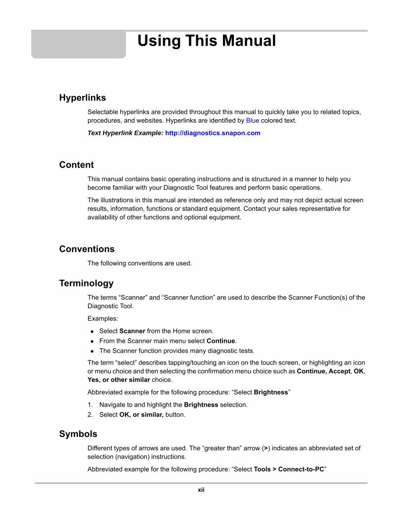
Hyperlinks
Selectable hyperlinks are provided throughout this manual to quickly take you to related topics, procedures, and websites. Hyperlinks are identified by Blue colored text.
Text Hyperlink Example: http://diagnostics.snapon.com
Content
This manual contains basic operating instructions and is structured in a manner to help you become familiar with your Diagnostic Tool features and perform basic operations.
The illustrations in this manual are intended as reference only and may not depict actual screen results, information, functions or standard equipment. Contact your sales representative for availability of other functions and optional equipment.
Conventions
The following conventions are used.
Terminology
The terms “Scanner” and “Scanner function” are used to describe the Scanner Function(s) of the Diagnostic Tool.
Examples:
• Select Scanner from the Home screen.
• From the Scanner main menu select Continue.
• The Scanner function provides many diagnostic tests.
The term “select” describes tapping/touching an icon on the touch screen, or highlighting an icon or menu choice and then selecting the confirmation menu choice such as Continue, Accept, OK, Yes, or other similar choice.
Abbreviated example for the following procedure: “Select Brightness”
1. Navigate to and highlight the Brightness selection.
2. Select OK, or similar, button.
Symbols
Different types of arrows are used. The “greater than” arrow (>) indicates an abbreviated set of selection (navigation) instructions.
Abbreviated example for the following procedure: “Select Tools > Connect-to-PC”
xiii
Using This Manual
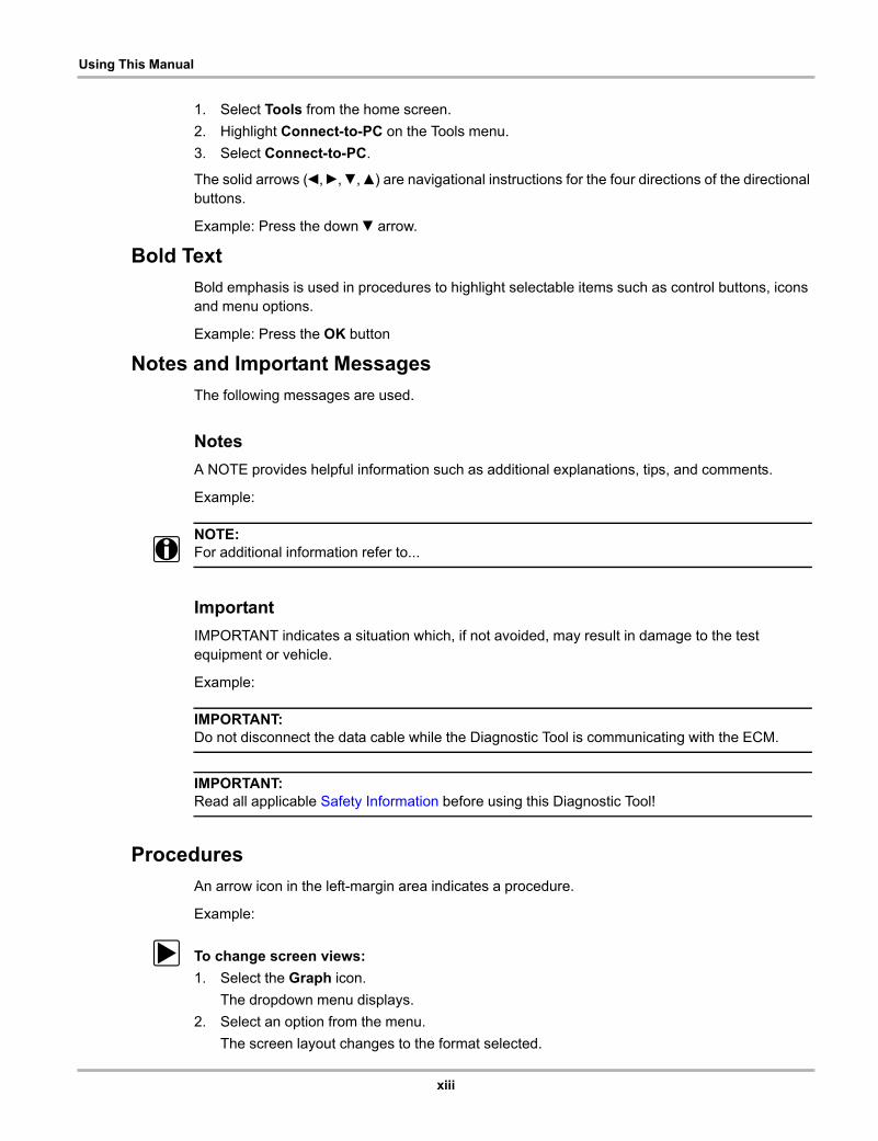
1. Select Tools from the home screen.
2. Highlight Connect-to-PC on the Tools menu.
3. Select Connect-to-PC.
The solid arrows (e, c, d, b) are navigational instructions for the four directions of the directional buttons.
Example: Press the down d arrow.
Bold Text
Bold emphasis is used in procedures to highlight selectable items such as control buttons, icons and menu options.
Example: Press the OK button
Notes and Important Messages
The following messages are used.
Notes
A NOTE provides helpful information such as additional explanations, tips, and comments.
Example:
NOTE:i For additional information refer to...
Important
IMPORTANT indicates a situation which, if not avoided, may result in damage to the test equipment or vehicle.
Example:
IMPORTANT:Do not disconnect the data cable while the Diagnostic Tool is communicating with the ECM.
IMPORTANT:Read all applicable Safety Information before using this Diagnostic Tool!
Procedures
An arrow icon in the left-margin area indicates a procedure.
Example:
z To change screen views:
1. Select the Graph icon.
The dropdown menu displays.
2. Select an option from the menu.
The screen layout changes to the format selected.
1
Chapter 1 Introduction
The MODIS™ Edge is a multi-function tool that combines a Diagnostic Scan Tool with a two-channel lab scope, graphing multimeter, and the exclusive Snap-on® Guided Component Tests database into a single hand-held unit.
This chapter introduces the basic features of the Diagnostic Tool, including the control buttons, data ports, battery pack, and power sources. Technical Specifications are provided at the end of this chapter.
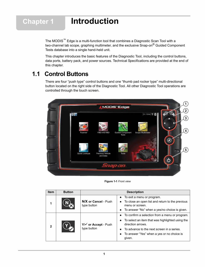
1.1 Control ButtonsThere are four “push type” control buttons and one “thumb pad rocker type” multi-directional button located on the right side of the Diagnostic Tool. All other Diagnostic Tool operations are controlled through the touch screen.
Figure 1-1 Front view
Item Button Description
1N/X or Cancel - Push type button
• To exit a menu or program.
• To close an open list and return to the previous menu or screen.
• To answer “No” when a yes/no choice is given.
2Y/a or Accept - Push type button
• To confirm a selection from a menu or program.
• To select an item that was highlighted using the direction arrows.
• To advance to the next screen in a series.
• To answer “Yes” when a yes or no choice is given.
Scope MultimeterScanner
Quick Lookups
Guided ComponentTests
Tools
OBD-II/EOBD
Previous Vehicleand Data
Scope MultimeterScanner
Quick Lookups
Guided ComponentTests
Tools
OBD-II/EOBD
Previous Vehicleand Data
1
2
3
4
5
2
Introduction Data and Power Connections
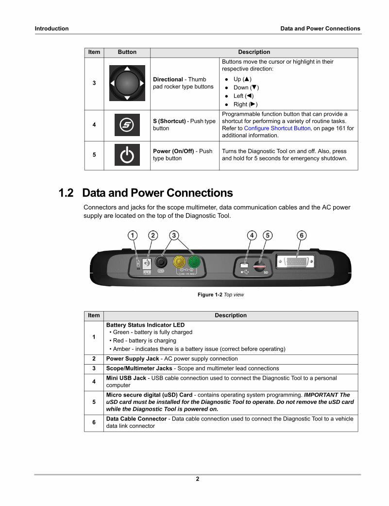
1.2 Data and Power ConnectionsConnectors and jacks for the scope multimeter, data communication cables and the AC power supply are located on the top of the Diagnostic Tool.
Figure 1-2 Top view
3Directional - Thumb pad rocker type buttons
Buttons move the cursor or highlight in their respective direction:
• Up (b)
• Down (d)
• Left (e)
• Right (c)
4S (Shortcut) - Push type button
Programmable function button that can provide a shortcut for performing a variety of routine tasks. Refer to Configure Shortcut Button‚ on page 161 for additional information.
5Power (On/Off) - Push type button
Turns the Diagnostic Tool on and off. Also, press and hold for 5 seconds for emergency shutdown.
Item Button Description
Item Description
1
Battery Status Indicator LED • Green - battery is fully charged
• Red - battery is charging
• Amber - indicates there is a battery issue (correct before operating)
2 Power Supply Jack - AC power supply connection
3 Scope/Multimeter Jacks - Scope and multimeter lead connections
4Mini USB Jack - USB cable connection used to connect the Diagnostic Tool to a personal computer
5Micro secure digital (uSD) Card - contains operating system programming. IMPORTANT The uSD card must be installed for the Diagnostic Tool to operate. Do not remove the uSD card while the Diagnostic Tool is powered on.
6Data Cable Connector - Data cable connection used to connect the Diagnostic Tool to a vehicle data link connector

3
Introduction Battery Pack and Stand
1.3 Battery Pack and Stand
Figure 1-3 Rear view
Item Description
1Built in-Stand (shown closed) - The built-in stand extends from the back of the Diagnostic Tool and clips into the Diagnostic Tool for storage.
2 Battery Cover
4
Introduction Power Sources
1.4 Power SourcesYour Diagnostic Tool can receive power from any of the following sources:
• Internal Battery Pack
• AC Power Supply
• Vehicle Power
1.4.1 Internal Battery Pack
The Diagnostic Tool can be powered from the internal rechargeable battery pack. A fully charged battery provides sufficient power for about 3 hours of continuous operation.
Battery charging occurs when the Diagnostic Tool is connected to the AC Power Supply and to a live AC power source.
The Battery Status Indicator LED (located next to the power supply jack) indicates battery status (Figure 1-3).
• Green - indicates battery is fully charged
• Red - indicates battery is charging
• Amber - indicates a battery issue. This is usually caused by excessive battery temperature (above 104°F/40°C), which disables charging. Allow the Diagnostic Tool to cool down before continuing operation.
1.4.2 AC Power Supply
The Diagnostic Tool can be powered from a standard AC outlet using the AC power supply. The connector on the end of the output cable of the AC power supply attaches to the power supply input jack on top of the Diagnostic Tool. Use only the AC power supply provided.
IMPORTANT:Never connect the AC power supply to the power supply input on the Diagnostic Tool when the Diagnostic Tool is communicating with a vehicle.
1.4.3 Vehicle Power
All OBD-II/EOBD vehicles have vehicle battery power (B+) available on the DLC. The Diagnostic Tool is powered through the Data Cable when connected to the vehicle DLC. A green LED indicator on the DLC end of the data cable, illuminates when power is being supplied to the cable. If the LED fails to illuminate, check that the data cable is properly connected and then check the DLC power circuit. See Data Cable Connection‚ on page 12 for additional data cable information.
An optional power cable is required when testing non-OBD-II/EOBD models that do not have vehicle battery power (B+) available on the DLC. Contact your sales representative for availability.
IMPORTANT:Never connect the optional power cable to the power supply input on the Diagnostic Tool when the Diagnostic Tool is communicating with a vehicle.

5
Introduction Technical Specifications
1.5 Technical SpecificationsItem Description / Specification
Touch Screen Resistive Touch Panel
Display8.0 inch diagonal, Color LCD
800 x 480 resolution SWVGA
Meter Category 1
Battery
Rechargeable lithium-ion battery pack
Approximately 3 hour run time
Approximately 5 hour charge time
Power Supply Supply Rating; 15VDC, 2A
DC Operating Voltage 10 to 30VDC
Width 11.06 in. (281.0 mm)
Height 6.29 in. (160.0 mm)
Depth 1.58 in. (40.3 mm)
Weight (including battery): 2.65 lb (1.20 kg)
Operating Temperature Range (ambient)
At 0 to 90% relative humidity (non-condensing) 32 to 113°F (0 to 45°C)
Storage Temperature (ambient)
At 0 to 70% relative humidity (non-condensing) –4 to 140°F (–20 to 60°C)
Operating Altitude Maximum 2000 m
Environmental Conditions
This product is intended for indoor use only
This product is rated for Pollution Degree 2 (normal conditions)
6
Chapter 2 Basic Operation and Navigation
This chapter describes basic Diagnostic Tool operation, navigation, screen layout, icon functions, and screen messages. Before you operate the Diagnostic Tool, make sure the battery pack is fully charged or the Diagnostic Tool is powered by the AC power supply.
2.1 Turning On/Off and Emergency ShutdownThe following sections describe how to turn the Diagnostic Tool on and off and how to perform an emergency shutdown.
2.1.1 Turning On
The Diagnostic Tool will automatically turn on and open the Home screen (Figure 2-1) when power is supplied through the Data Cable or by the AC Power Supply. If the Diagnostic Tool does not automatically turn on, press and release the Power button on the front of the Diagnostic Tool to turn the Diagnostic Tool on.
2.1.2 Turning Off
IMPORTANT:All vehicle communication must be terminated BEFORE turning off the Diagnostic Tool. A warning message displays if you attempt to turn the Diagnostic Tool off while communicating with the vehicle. Forcing a shut down while communicating may lead to ECM problems on some vehicles. Never disconnect the Data Cable when the Diagnostic Tool is communicating with the vehicle ECM.
z To turn off the Diagnostic Tool:
1. Press the N/X button or select the Back or Home icon to navigate to the Home screen.
The “stopping communication” message appears briefly before the Home screen displays.
2. Disconnect the Diagnostic Tool Data Cable from the vehicle.
3. Press and release the Power button.
A confirmation screen displays.
4. Press the Y/a button or select OK from the menu to turn the Diagnostic Tool off. To continue operating, press the N/X button or select Cancel from the menu.
7
Basic Operation and Navigation Wi-Fi Connection
2.1.3 Emergency Shutdown
IMPORTANT:Using the emergency shutdown procedure while communicating with the vehicle ECM may lead to ECM problems on some vehicles.
During normal operation turn the Diagnostic Tool off using the Turning Off procedure above. The emergency shutdown procedure should only be used If the Diagnostic Tool does not respond to navigation or control buttons or exhibits erratic operation. To force an emergency shutdown, press and hold the Power button for five seconds until the Diagnostic Tool turns off.
2.2 Wi-Fi Connection See Wi-Fi Connection / Troubleshooting‚ on page 191.
2.3 Basic Navigation
2.3.1 Home Screen Layout
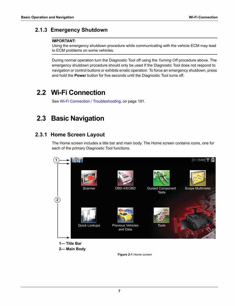
The Home screen includes a title bar and main body. The Home screen contains icons, one for each of the primary Diagnostic Tool functions.
1— Title Bar
2— Main BodyFigure 2-1 Home screen
1
2
Scope MultimeterScanner Guided ComponentTests
Tools
OBD-II/EOBD
Previous Vehiclesand Data
Quick Lookups
8
Basic Operation and Navigation Basic Navigation
2.3.2 Title Bar
The title bar at the top of the screen provides basic information about current Diagnostic Tool operating conditions. Title bar options vary depending upon vehicle make and model, what function is active, what test is being performed, or what menu is selected. The title bar contains information only, there are no selectable items.
Elements of the Title bar let you know at a glance:
• What Diagnostic Tool function is currently active.
• The current time.
• Wi-Fi signal strength
• The source and status of the power being supplied to the Diagnostic Tool.
An active function icon is always displayed along the left-hand edge of the Title bar. These icons resemble their Home screen icon counterparts in appearance and color. The name of the function displays to the right of the icon on some screens.
A real time clock displays to the left of the power supply icon. The clock is powered by a dedicated internal battery, so the correct time is maintained even when the main battery pack is discharged. Use the Tools function to set the clock and format how time is displayed. See Clock Settings‚ on page 166 for additional information.
The Title bar displays other information that varies depending upon what functions are being performed. Other information may include:
• The identification (ID) of the test vehicle
• The name of the active menu or function
• The name of the test being performed
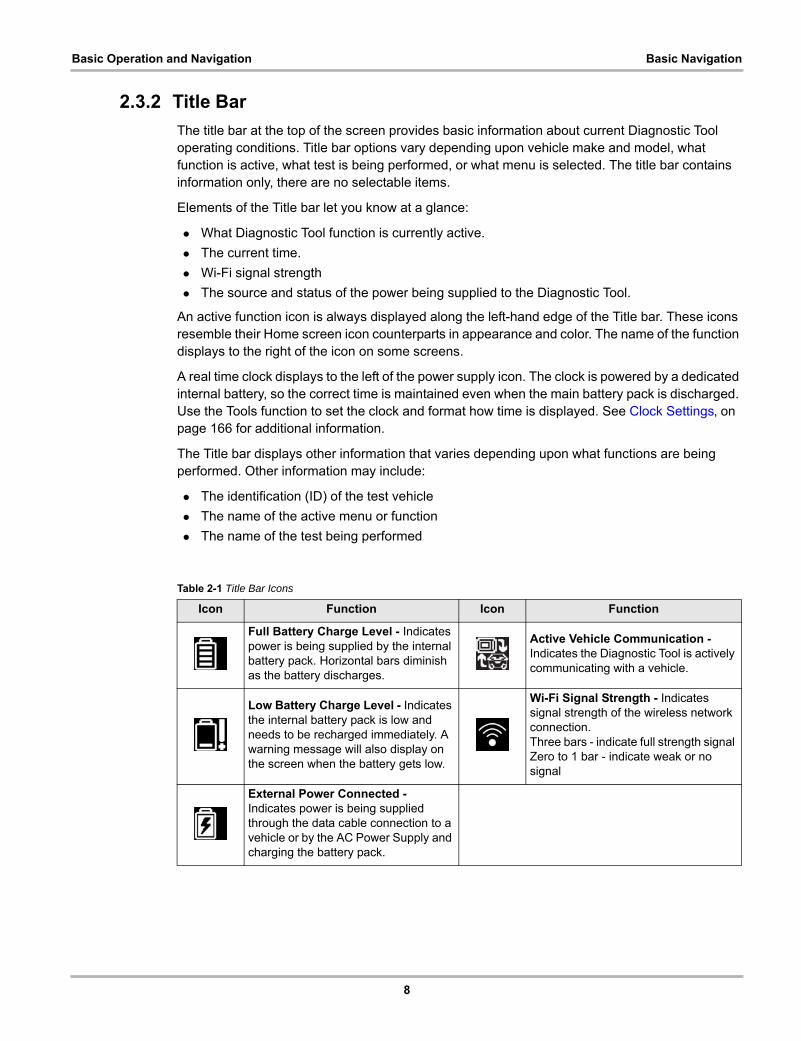
Table 2-1 Title Bar Icons
Icon Function Icon Function
Full Battery Charge Level - Indicates power is being supplied by the internal battery pack. Horizontal bars diminish as the battery discharges.
Active Vehicle Communication - Indicates the Diagnostic Tool is actively communicating with a vehicle.
Low Battery Charge Level - Indicates the internal battery pack is low and needs to be recharged immediately. A warning message will also display on the screen when the battery gets low.
Wi-Fi Signal Strength - Indicates signal strength of the wireless network connection.Three bars - indicate full strength signal Zero to 1 bar - indicate weak or no signal
External Power Connected - Indicates power is being supplied through the data cable connection to a vehicle or by the AC Power Supply and charging the battery pack.
9
Basic Operation and Navigation Basic Navigation
2.3.3 Home Screen Icons
Each available Diagnostic Tool function is represented by a icon on the home screen. The table below provides descriptions of the icon functions.
Select an icon from the Home screen to start a function. You can also use the control buttons to activate a function, a yellow border around the icon indicates it is highlighted, or in focus. Use the Directional buttons (e, c, b, d) to highlight the desired function and then press the Y/a button to select it. A “please wait” message may display briefly, then automatically clear once the function is loaded and ready for use.
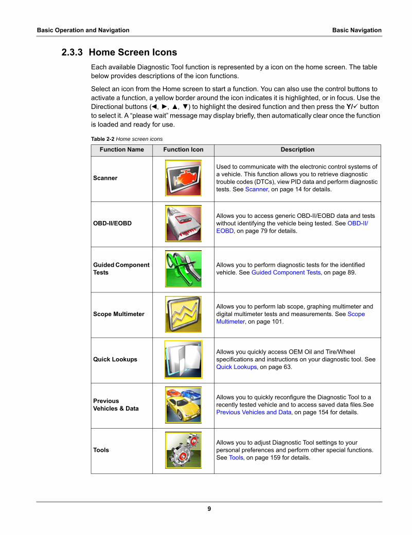
Table 2-2 Home screen icons
Function Name Function Icon Description
Scanner
Used to communicate with the electronic control systems of a vehicle. This function allows you to retrieve diagnostic trouble codes (DTCs), view PID data and perform diagnostic tests. See Scanner‚ on page 14 for details.
OBD-II/EOBDAllows you to access generic OBD-II/EOBD data and tests without identifying the vehicle being tested. See OBD-II/EOBD‚ on page 79 for details.
Guided Component Tests
Allows you to perform diagnostic tests for the identified vehicle. See Guided Component Tests‚ on page 89.
Scope MultimeterAllows you to perform lab scope, graphing multimeter and digital multimeter tests and measurements. See Scope Multimeter‚ on page 101.
Quick LookupsAllows you quickly access OEM Oil and Tire/Wheel specifications and instructions on your diagnostic tool. See Quick Lookups‚ on page 63.
PreviousVehicles & Data
Allows you to quickly reconfigure the Diagnostic Tool to a recently tested vehicle and to access saved data files.See Previous Vehicles and Data‚ on page 154 for details.
ToolsAllows you to adjust Diagnostic Tool settings to your personal preferences and perform other special functions. See Tools‚ on page 159 for details.
10
Basic Operation and Navigation Basic Navigation
2.3.4 Common Toolbar Control Icons
Common control icon functions are described in the following table. Specific function control icons are described in their applicable chapters. Displayed control icons vary depending on the active function or test. Select a control icon on a screen to activate a control function. You can also use the control buttons to activate a function, a yellow border around the icon indicates it is highlighted, or in focus. Use the Directional buttons (e, c, b, d) to highlight the desired function and then press the icon, or the Y/a button to select it.
The icons below are used to navigate through paused or saved data (“movie”) files during playback.
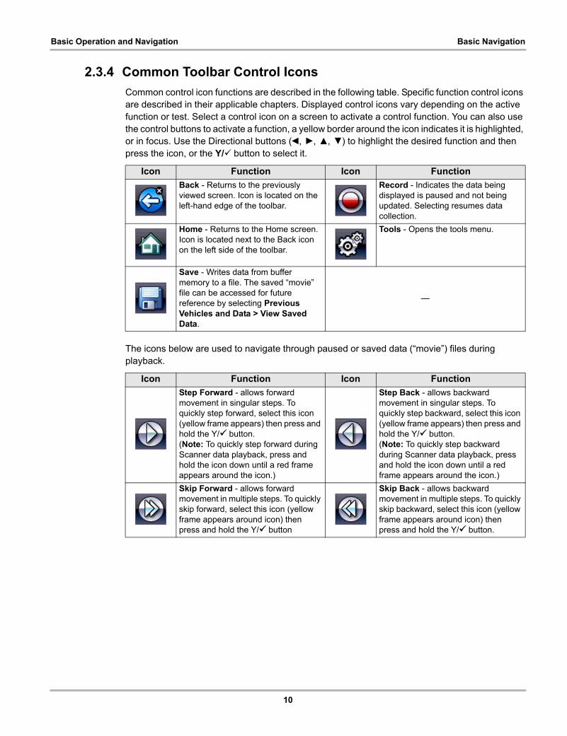
Icon Function Icon Function
Back - Returns to the previously viewed screen. Icon is located on the left-hand edge of the toolbar.
Record - Indicates the data being displayed is paused and not being updated. Selecting resumes data collection.
Home - Returns to the Home screen. Icon is located next to the Back icon on the left side of the toolbar.
Tools - Opens the tools menu.
Save - Writes data from buffer memory to a file. The saved “movie” file can be accessed for future reference by selecting Previous Vehicles and Data > View Saved Data.
—
Icon Function Icon Function
Step Forward - allows forward movement in singular steps. To quickly step forward, select this icon (yellow frame appears) then press and hold the Y/a button.(Note: To quickly step forward during Scanner data playback, press and hold the icon down until a red frame appears around the icon.)
Step Back - allows backward movement in singular steps. To quickly step backward, select this icon (yellow frame appears) then press and hold the Y/a button.(Note: To quickly step backward during Scanner data playback, press and hold the icon down until a red frame appears around the icon.)
Skip Forward - allows forward movement in multiple steps. To quickly skip forward, select this icon (yellow frame appears around icon) then press and hold the Y/a button
Skip Back - allows backward movement in multiple steps. To quickly skip backward, select this icon (yellow frame appears around icon) then press and hold the Y/a button.
11
Basic Operation and Navigation Screen Messages
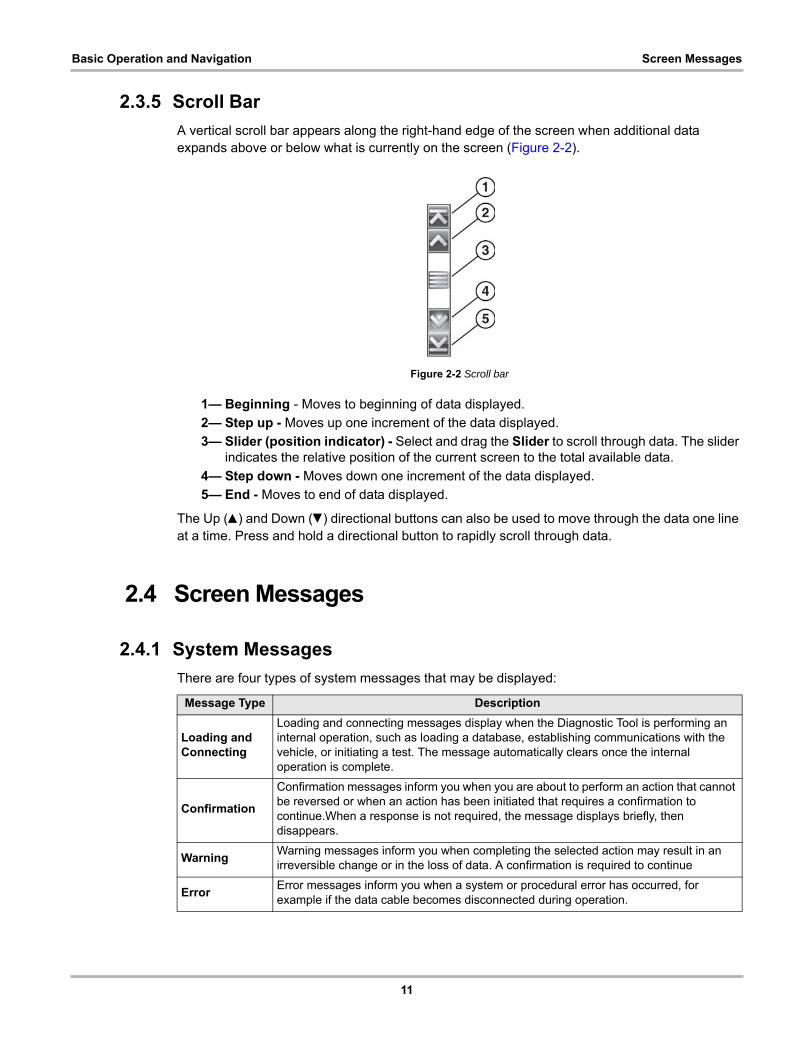
2.3.5 Scroll Bar
A vertical scroll bar appears along the right-hand edge of the screen when additional data expands above or below what is currently on the screen (Figure 2-2).
Figure 2-2 Scroll bar
1— Beginning - Moves to beginning of data displayed.
2— Step up - Moves up one increment of the data displayed.
3— Slider (position indicator) - Select and drag the Slider to scroll through data. The slider indicates the relative position of the current screen to the total available data.
4— Step down - Moves down one increment of the data displayed.
5— End - Moves to end of data displayed.
The Up (b) and Down (d) directional buttons can also be used to move through the data one line at a time. Press and hold a directional button to rapidly scroll through data.
2.4 Screen Messages
2.4.1 System Messages
There are four types of system messages that may be displayed:
Message Type Description
Loading and Connecting
Loading and connecting messages display when the Diagnostic Tool is performing an internal operation, such as loading a database, establishing communications with the vehicle, or initiating a test. The message automatically clears once the internal operation is complete.
Confirmation
Confirmation messages inform you when you are about to perform an action that cannot be reversed or when an action has been initiated that requires a confirmation to continue.When a response is not required, the message displays briefly, then disappears.
WarningWarning messages inform you when completing the selected action may result in an irreversible change or in the loss of data. A confirmation is required to continue
ErrorError messages inform you when a system or procedural error has occurred, for example if the data cable becomes disconnected during operation.

12
Basic Operation and Navigation Data Cable Connection
2.4.2 Communication Messages
When “no communication” messages are displayed, it indicates the Diagnostic Tool and the vehicle electronic control module are not communicating.
The following conditions cause “no communication” messages to display:
• The Diagnostic Tool is unable to establish a communication link with the vehicle.
• The vehicle is not equipped with the system that was selected.
• There is a loose connection.
• There is a blown vehicle fuse.
• There is a wiring fault on the vehicle.
• There is a circuit fault in the data cable or adapter.
• Incorrect vehicle identification was entered.
Refer to the Vehicle Communication Software manuals for manufacturer-specific problems.
2.5 Data Cable ConnectionConnection of the data cable to the Diagnostic Tool and vehicle data link connector (DLC) is required for Scanner and OBD-II/EOBD testing.
IMPORTANT:Use the approved cables and accessories for your diagnostic tool. Cable length must not exceed 114.17 inches (2.9 meters).
Depending on the vehicle, the supplied DA-4 data cable may be used alone or may require optional adapters.
• All OBD-II/EOBD compliant vehicles - Use the supplied DA-4 data cable. The 26-pin end of the cable attaches to the data cable connector on the top of the Diagnostic Tool. The16-pin end connects to the vehicle DLC.
• All OBD-I (non-OBD-II/EOBD) compliant vehicles - Use the supplied DA-4 data cable with the optional DA-5 adapter and a manufacturer specific adapter. The 26-pin end of the cable attaches to the data cable connector on the top of the Diagnostic Tool. The16-pin end connects to the DA-5 adapter, the DA-5 adapter connects to the manufacturer specific adapter and then connects to the vehicle DLC.
On-screen cable and adapter connection instructions are provided while using the Scanner and OBD-II/EOBD functions. The instructions may also include the location of the vehicle DLC (Figure 2-3).
Figure 2-3 Vehicle connection data cable message
13
Basic Operation and Navigation Data Cable Connection
For data cable vehicle power connection information, see Vehicle Power‚ on page 4.
NOTE:i The data cable, includes an LED light on the vehicle DLC connector end, that can be used for
locating the vehicle DLC. The LED light is powered by the diagnostic tool battery.
z To connect the data cable to the vehicle:
1. After identifying a vehicle using the Scanner or OBD-II/EOBD function, review the on-screen information for data cable usage and DLC location (Figure 2-3).
2. Connect the data cable to the diagnostic tool.
3. If needed, press the LED light button switch on the end of the cable to turn the LED light on, and locate the DLC.
4. Select Continue once the data cable is connected.
The Diagnostic Tool establishes communication with the vehicle, then displays a list of available tests. If the Diagnostic Tool is unable to establish a communications link, a “no communications” message displays.
2.5.1 Optional Data Cables and Adapters
The following optional data cable adapters and cables are available to extend the vehicle communication capabilities of your diagnostic tool:
Contact your sales representative for purchasing information.
• An optional 9 ft. (2.7 m) OBD-II data cable is available, for extended range capabilities.
• An optional OBD-I data cable adapter kit is available for U.S. domestic and Asian vehicles. The kit includes common adapters and cables, providing OBD-I connection capabilities.
• An optional European OBD-II/EOBD data cable adapter kit is available for select European vehicles. The kit includes multiple adapters, cables and personality keys, providingOBD-II/EOBD connection capabilities for vehicles such as Mercedes Benz, VW and BMW. Diagnostic tool communication with European vehicles requires the activation of the optional European vehicle software.

14
Chapter 3 Scanner
This chapter describes the basic operation of the Scanner function.
The Scanner icon is located on the Home screen.
The Scanner function allows your diagnostic tool to communicate with the electronic control systems of a vehicle. This allows you to retrieve diagnostic trouble codes (DTCs), view PID data and perform diagnostic tests.
3.1 Screen Layout and Toolbar IconsThe following screen layout and toolbar controls apply to both the Scanner and the OBD-II/EOBD functions.
3.1.1 Screen Layout
1— Title bar—shows active test, vehicle and diagnostic tool status
2— Toolbar—contains control icons
3— Main body—displays menus, PID and test dataFigure 3-1 Screen layout
The Title bar appears for all functions and displays information only, there are no selectable items. Refer to Title Bar‚ on page 8 for details.
15
Scanner Scanner Demonstration Program
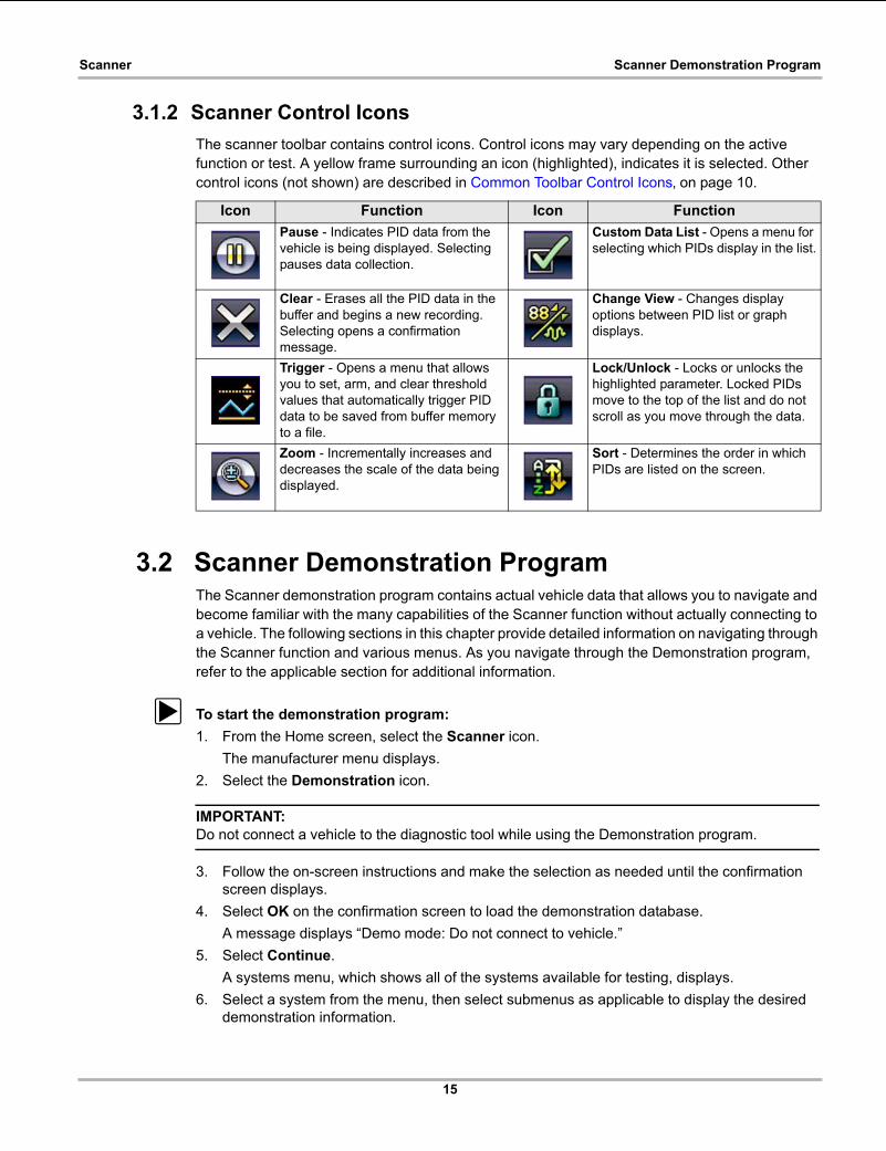
3.1.2 Scanner Control Icons
The scanner toolbar contains control icons. Control icons may vary depending on the active function or test. A yellow frame surrounding an icon (highlighted), indicates it is selected. Other control icons (not shown) are described in Common Toolbar Control Icons‚ on page 10.
3.2 Scanner Demonstration ProgramThe Scanner demonstration program contains actual vehicle data that allows you to navigate and become familiar with the many capabilities of the Scanner function without actually connecting to a vehicle. The following sections in this chapter provide detailed information on navigating through the Scanner function and various menus. As you navigate through the Demonstration program, refer to the applicable section for additional information.
z To start the demonstration program:
1. From the Home screen, select the Scanner icon.
The manufacturer menu displays.
2. Select the Demonstration icon.
IMPORTANT:Do not connect a vehicle to the diagnostic tool while using the Demonstration program.
3. Follow the on-screen instructions and make the selection as needed until the confirmation screen displays.
4. Select OK on the confirmation screen to load the demonstration database.
A message displays “Demo mode: Do not connect to vehicle.”
5. Select Continue.
A systems menu, which shows all of the systems available for testing, displays.
6. Select a system from the menu, then select submenus as applicable to display the desired demonstration information.
Icon Function Icon Function
Pause - Indicates PID data from the vehicle is being displayed. Selecting pauses data collection.
Custom Data List - Opens a menu for selecting which PIDs display in the list.
Clear - Erases all the PID data in the buffer and begins a new recording. Selecting opens a confirmation message.
Change View - Changes display options between PID list or graph displays.
Trigger - Opens a menu that allows you to set, arm, and clear threshold values that automatically trigger PID data to be saved from buffer memory to a file.
Lock/Unlock - Locks or unlocks the highlighted parameter. Locked PIDs move to the top of the list and do not scroll as you move through the data.
Zoom - Incrementally increases and decreases the scale of the data being displayed.
Sort - Determines the order in which PIDs are listed on the screen.

16
Scanner Scanner Operation
3.3 Scanner Operation
3.3.1 Vehicle Identification
The vehicle must be correctly identified for the diagnostic tool to communicate, and display data correctly. Menus and navigation will vary by vehicle.
Depending on the vehicle, the vehicle identification process may require manual entry of the vehicle information, or it may be automated. The following three Scanner functions are available to identify the vehicle:
Instant ID - Automatically completes the identification process upon initial communication between diagnostic tool and the vehicle using OBD-II VIN mode $09. Instant ID requires specific vehicle support and procedures, see Instant ID‚ on page 19 for additional information.
Auto ID - Automatically completes the identification process after the vehicle make and year are manually entered.
Manual ID - Allows for manual entry of all required vehicle identification criteria.
z Use the following procedure to identify a vehicle.
NOTE:i The following procedure applies to most OBD-II vehicles, and may vary depending on the vehicle.
Not all vehicles support the Instant ID and/or Auto ID functions.
1. Connect the data cable to the diagnostic tool. See Data Cable Connection‚ on page 12.
2. Turn the vehicle ignition switch on.
1. Connect the data cable to the vehicle data link connector (DLC). See Data Cable Connection‚ on page 12.
NOTE:i If the diagnostic tool is off, when the OBD-II data cable is connected to the vehicle DLC, the
diagnostic tool should automatically turn on. If the tool did not turn on when the data cable was connected to the vehicle, check the vehicle DLC for power. Most OBD-II vehicles supply power to the DLC, which in-turn supplies power and turns on the diagnostic tool when the cable is connected.
2. If required, turn the diagnostic tool on.
3. Depending on the vehicle:
a. Instant ID may occur, as indicated by an audible "beep" sounded within 5 seconds after the diagnostic tool turns on. Select the Scanner icon, then wait for the vehicle confirmation screen (Figure 3-2) and select OK to continue. Then proceed to step 6. See Instant ID‚ on page 19‚ for additional information about this function.

17
Scanner Scanner Operation
Figure 3-2 Vehicle confirmation screen
b. If Instant ID is not supported, you will be prompted to select the vehicle make andyear (If needed). Then a menu option is displayed to choose either Automatic ID or Manual ID.
- Selecting Automatic ID (If supported by the vehicle) will briefly display a communications screen informing you that the diagnostic tool is attempting to establish communication with the vehicle and determine vehicle identification.
Once the vehicle has been identified, the vehicle confirmation screen displays. If the vehicle information is correct, select OK to continue, then proceed to step 6.
If the vehicle does not support Auto ID, the diagnostic tool will attempt to identify the vehicle and then display a message indicating that vehicle identification cannot be made. If this occurs, proceed to “Selecting Manual ID” next.
- Selecting Manual ID allows you to manually enter all the vehicle information to identify the vehicle.
b1.) Follow the screen prompts to enter all the information required to identify the vehicle. b2.) Once the vehicle has been identified, the vehicle confirmation screen displays (Figure 3-2). If the vehicle information is correct, select OK to continue, then proceed to step 6.

18
Scanner Scanner Operation
4. After the vehicle is identified, a menu of available systems, and options are displayed. Select a system or option (Figure 3-3).
NOTE:i Only the systems and options supported for the vehicle are included in the menu list.
Figure 3-3 Typical systems menu
If a system (e.g. Engine, Transmission, Antilock Brakes, etc) is selected, the diagnostic tool may establish communication with the vehicle, then display the system main menu (available tests) (Figure 3-4). For sub-menu option information, see System Main Menu Options‚ on page 20.
Figure 3-4 System main menu
19
Scanner Scanner Operation
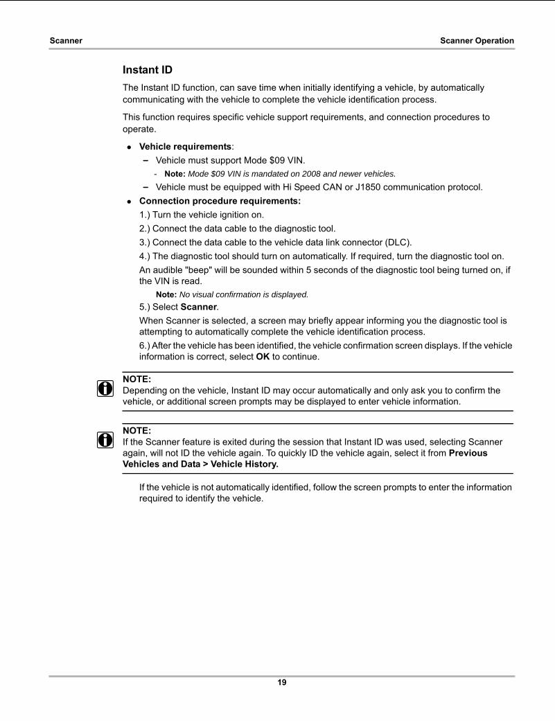
Instant ID
The Instant ID function, can save time when initially identifying a vehicle, by automatically communicating with the vehicle to complete the vehicle identification process.
This function requires specific vehicle support requirements, and connection procedures to operate.
• Vehicle requirements:
– Vehicle must support Mode $09 VIN.
- Note: Mode $09 VIN is mandated on 2008 and newer vehicles.
– Vehicle must be equipped with Hi Speed CAN or J1850 communication protocol.
• Connection procedure requirements:
1.) Turn the vehicle ignition on.
2.) Connect the data cable to the diagnostic tool.
3.) Connect the data cable to the vehicle data link connector (DLC).
4.) The diagnostic tool should turn on automatically. If required, turn the diagnostic tool on.
An audible "beep" will be sounded within 5 seconds of the diagnostic tool being turned on, if the VIN is read.
Note: No visual confirmation is displayed.
5.) Select Scanner.
When Scanner is selected, a screen may briefly appear informing you the diagnostic tool is attempting to automatically complete the vehicle identification process.
6.) After the vehicle has been identified, the vehicle confirmation screen displays. If the vehicle information is correct, select OK to continue.
NOTE:i Depending on the vehicle, Instant ID may occur automatically and only ask you to confirm the
vehicle, or additional screen prompts may be displayed to enter vehicle information.
NOTE:i If the Scanner feature is exited during the session that Instant ID was used, selecting Scanner
again, will not ID the vehicle again. To quickly ID the vehicle again, select it from Previous Vehicles and Data > Vehicle History.
If the vehicle is not automatically identified, follow the screen prompts to enter the information required to identify the vehicle.
20
Scanner Scanner Operation
3.3.2 System Main Menu Options
Once a System is selected (e.g. Engine, Transmission, Antilock Brakes, etc) is selected, the diagnostic tool may establish communication with the vehicle, then display the System Main Menu (available tests).
NOTE:i Menus and navigation will vary by vehicle.
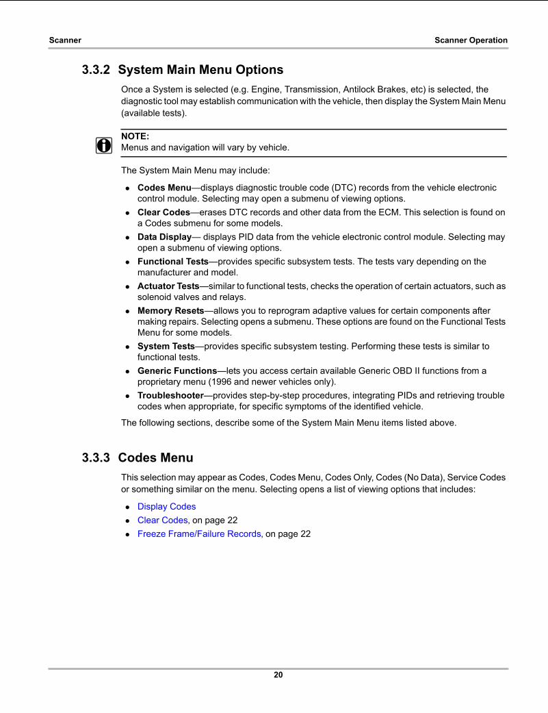
The System Main Menu may include:
• Codes Menu—displays diagnostic trouble code (DTC) records from the vehicle electronic control module. Selecting may open a submenu of viewing options.
• Clear Codes—erases DTC records and other data from the ECM. This selection is found on a Codes submenu for some models.
• Data Display— displays PID data from the vehicle electronic control module. Selecting may open a submenu of viewing options.
• Functional Tests—provides specific subsystem tests. The tests vary depending on the manufacturer and model.
• Actuator Tests—similar to functional tests, checks the operation of certain actuators, such as solenoid valves and relays.
• Memory Resets—allows you to reprogram adaptive values for certain components after making repairs. Selecting opens a submenu. These options are found on the Functional Tests Menu for some models.
• System Tests—provides specific subsystem testing. Performing these tests is similar to functional tests.
• Generic Functions—lets you access certain available Generic OBD II functions from a proprietary menu (1996 and newer vehicles only).
• Troubleshooter—provides step-by-step procedures, integrating PIDs and retrieving trouble codes when appropriate, for specific symptoms of the identified vehicle.
The following sections, describe some of the System Main Menu items listed above.
3.3.3 Codes Menu
This selection may appear as Codes, Codes Menu, Codes Only, Codes (No Data), Service Codes or something similar on the menu. Selecting opens a list of viewing options that includes:
• Display Codes
• Clear Codes‚ on page 22
• Freeze Frame/Failure Records‚ on page 22
21
Scanner Scanner Operation
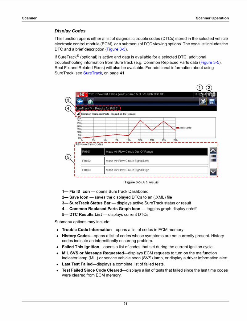
Display Codes
This function opens either a list of diagnostic trouble codes (DTCs) stored in the selected vehicle electronic control module (ECM), or a submenu of DTC viewing options. The code list includes the DTC and a brief description (Figure 3-5).
If SureTrack® (optional) is active and data is available for a selected DTC, additional troubleshooting information from SureTrack (e.g. Common Replaced Parts data (Figure 3-5), Real Fix and Related Fixes) will also be available. For additional information about using SureTrack, see SureTrack‚ on page 41.
Figure 3-5 DTC results
1— Fix It! Icon — opens SureTrack Dashboard
2— Save Icon — saves the displayed DTCs to an (.XML) file
3— SureTrack Status Bar — displays active SureTrack status or result
4— Common Replaced Parts Graph Icon — toggles graph display on/off
5— DTC Results List — displays current DTCs
Submenu options may include:
• Trouble Code Information—opens a list of codes in ECM memory
• History Codes—opens a list of codes whose symptoms are not currently present. History codes indicate an intermittently occurring problem.
• Failed This Ignition—opens a list of codes that set during the current ignition cycle.
• MIL SVS or Message Requested—displays ECM requests to turn on the malfunction indicator lamp (MIL) or service vehicle soon (SVS) lamp, or display a driver information alert.
• Last Test Failed—displays a complete list of failed tests.
• Test Failed Since Code Cleared—displays a list of tests that failed since the last time codes were cleared from ECM memory.
22
Scanner Scanner Operation
Clear Codes
The diagnostic tool clears codes from the vehicle electronic control module memory on most vehicles. If this function is not available on the test vehicle, Clear Codes does not appear as a menu option.
NOTE:i Clear Codes is also available from OBD-II Health Check (see OBD Health Check‚ on page 80).
z To clear codes:
1. Select Clear Codes from the Codes Menu.
A confirmation message displays.
2. Make sure any conditions shown on the confirmation message are met, then select Yes.
A “codes cleared” message displays once the operation is complete.
3. Select Continue to return to the Codes Menu.
IMPORTANT:Clearing codes erases all temporary ECM information, including Freeze Frame/Failure Records. Make sure no vital diagnostic information will be lost before clearing codes.
Saving Codes
When viewing individual system codes (e.g. engine, transmission) selecting the Save icon from the toolbar saves the results as a report formatted file.
When system codes are saved, a confirmation message is displayed indicating that the file was saved.
Message Example: “Saving A2810005.XML”
The saved file(s) can be viewed on the diagnostic tool - See Viewing Code Results on the Diagnostic Tool‚ on page 157.
Code Scan
See Vehicle Code Scan / (ALTUS™)‚ on page 34.
Freeze Frame/Failure Records
This selection displays the DTC that was set, along with corresponding data, when the ECM commanded the malfunction indicator lamp (MIL) to turn on.

23
Scanner Scanner Operation
Data Display
Select Data to view PID data from the vehicle ECM. In data display mode the screen has a toolbar and a main body (Figure 3-6).
Figure 3-6 Data display screen
The toolbar control icons are described in Scanner Control Icons‚ on page 15 and Common Toolbar Control Icons‚ on page 10.
During data display the main body of the screen is divided into two columns; the left-hand column has a description of the parameter and the right-hand column shows the parameter value or state. Parameters are listed in the order in which they are transmitted by the ECM, so expect variations between years, makes, and models.
Up to three parameters can be locked, or fixed, at the top of the list. Locked parameters do not change as you scroll through the parameter list. The Lock/Unlock icon on the toolbar selects which parameters are fixed (see Locking Parameters‚ on page 25).
Displayed data may also be paused or saved for detailed review and future reference, see Saving Files‚ on page 28 and Pausing and Reviewing Data Files‚ on page 29.
24
Scanner Scanner Operation
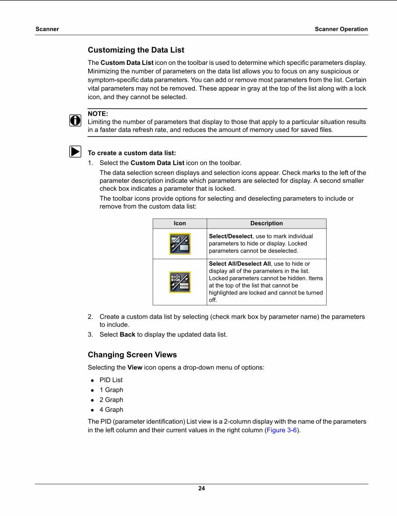
Customizing the Data List
The Custom Data List icon on the toolbar is used to determine which specific parameters display. Minimizing the number of parameters on the data list allows you to focus on any suspicious or symptom-specific data parameters. You can add or remove most parameters from the list. Certain vital parameters may not be removed. These appear in gray at the top of the list along with a lock icon, and they cannot be selected.
NOTE:i Limiting the number of parameters that display to those that apply to a particular situation results
in a faster data refresh rate, and reduces the amount of memory used for saved files.
z To create a custom data list:
1. Select the Custom Data List icon on the toolbar.
The data selection screen displays and selection icons appear. Check marks to the left of the parameter description indicate which parameters are selected for display. A second smaller check box indicates a parameter that is locked.
The toolbar icons provide options for selecting and deselecting parameters to include or remove from the custom data list:
2. Create a custom data list by selecting (check mark box by parameter name) the parameters to include.
3. Select Back to display the updated data list.
Changing Screen Views
Selecting the View icon opens a drop-down menu of options:
• PID List
• 1 Graph
• 2 Graph
• 4 Graph
The PID (parameter identification) List view is a 2-column display with the name of the parameters in the left column and their current values in the right column (Figure 3-6).
Icon Description
Select/Deselect, use to mark individual parameters to hide or display. Locked parameters cannot be deselected.
Select All/Deselect All, use to hide or display all of the parameters in the list. Locked parameters cannot be hidden. Items at the top of the list that cannot be highlighted are locked and cannot be turned off.

25
Scanner Scanner Operation
The 1, 2, and 4 Graph views divide the screen horizontally to simultaneously display data graphs for the indicated number of parameters (Figure 3-7). Use the scroll bar or the up (b) and down (d) icons to view other parameters in the list.
Figure 3-7 Four graph view
NOTE:i Any previously set conditions, such as held data or locked lines of data, remain in effect when the
screen view is changed.
Locking Parameters
Use the Lock/Unlock icon to hold selected lines of the data in place and prevent them from scrolling, or to release previously locked lines of data. Up to three lines of data may be held at a time. This feature allows you to position related parameters together, making it easier to monitor their values and spot inconsistencies.
Locked parameters display as the top frames on the main body of the display screen, as well as at their usual position within the data list (Figure 3-8). A lock icon appears to the left of the parameter name to indicate it is locked.
z To lock parameters:
1. Highlight the parameter to be locked.
2. Select the Lock/Unlock icon on the toolbar to lock it.
A copy of the locked parameter is now shown at the top of the data list, and a lock icon appears alongside the parameter name.
3. Highlight and select additional parameters to lock.
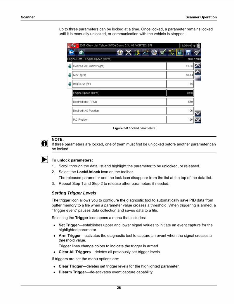
26
Scanner Scanner Operation
Up to three parameters can be locked at a time. Once locked, a parameter remains locked until it is manually unlocked, or communication with the vehicle is stopped.
Figure 3-8 Locked parameters
NOTE:i If three parameters are locked, one of them must first be unlocked before another parameter can
be locked.
z To unlock parameters:
1. Scroll through the data list and highlight the parameter to be unlocked, or released.
2. Select the Lock/Unlock icon on the toolbar.
The released parameter and the lock icon disappear from the list at the top of the data list.
3. Repeat Step 1 and Step 2 to release other parameters if needed.
Setting Trigger Levels
The trigger icon allows you to configure the diagnostic tool to automatically save PID data from buffer memory to a file when a parameter value crosses a threshold. When triggering is armed, a "Trigger event" pauses data collection and saves data to a file.
Selecting the Trigger icon opens a menu that includes:
• Set Trigger—establishes upper and lower signal values to initiate an event capture for the highlighted parameter.
• Arm Trigger—activates the diagnostic tool to capture an event when the signal crosses a threshold value.
Trigger lines change colors to indicate the trigger is armed.
• Clear All Triggers—deletes all previously set trigger levels.
If triggers are set the menu options are:
• Clear Trigger—deletes set trigger levels for the highlighted parameter.
• Disarm Trigger—de-activates event capture capability.

27
Scanner Scanner Operation
• Clear All Triggers—deletes all previously set trigger levels.
z To set trigger levels:
1. Highlight the parameter to be used for triggering the recording.
2. Select the Trigger icon.
3. Select Set Trigger from the drop-down menu.
A graph of the highlighted parameter with a trigger toolbar above it fills the main body of the screen (Figure 3-9).
Figure 3-9 Trigger set screen
The trigger level line displays as a solid line running horizontally across the data graph. An upper and lower trigger level must be set, the upper level is set first.
4. Select the plus (+) and minus (–) icons on the toolbar, or use the up b and down d arrow buttons to position the upper trigger level to where you want it on the graph.
5. Select a on the toolbar, or press the Y/a button, to set the upper threshold.
A lower trigger level line now appears at the mid-point of the graph.
6. Select the plus (+) and minus (–) icons on the toolbar, or use the up b and down d arrow buttons to position the lower trigger level line to where you want it on the graph.
7. Select a on the toolbar, or press the Y/a button, to set the lower threshold.
The display returns to the PID data view and the trigger points appear as horizontal lines across the designated parameter graph. Repeat this procedure to establish trigger points for other parameters if desired. Once armed, any data points that register outside of your set conditions pause data collection and save data to a file.
NOTE:i Only three parameters can have trigger levels set at one time, but only one of the conditions needs
to be satisfied for triggering to occur.
28
Scanner Scanner Operation
z To arm triggers:
1. Select the Trigger icon on the toolbar.
2. Select Arm Triggers from the drop-down menu.
The trigger lines on the data graphs change color to indicate an armed condition.
Triggers for all of the graphs are armed simultaneously. Once triggering is armed, it remains in that state until you switch it off. If trigger settings are modified or are added for other parameters, they are armed as soon as you exit the setting screen.
3.3.4 Saving and Reviewing Scanner / OBD-II/EOBD Data Files
The following procedures are used when saving and reviewing data files for Scanner and OBD-II/EOBD.
Saving Files
During normal operation, data from the vehicle’s ECM is continuously being stored in buffer memory as it is displayed onscreen. Buffer memory is limited to a predetermined “total” size and is displayed on the counter (located below the toolbar on the right side of the screen) (Figure 3-11).
Selecting Save writes the stored buffer memory to a file. Saving data is useful when trying to isolate an intermittent problem or to verify a repair during a road test. The saved file can be played back (similar to a movie clip) by selecting Previous Vehicles and Data > View Saved Data. See View Saved Data‚ on page 155 for additional information.
NOTE:i The Save icon performs the same function as “Save Movie” function choice for the programmable
Shortcut button, see Configure Shortcut Button‚ on page 161 for details.
The saved data file can also be downloaded to a personal computer (PC) using the Mini USB jack. Once connected to the PC, the data files can be printed, transferred, and copied using ShopStream Connect. ShopStream Connect is an application that creates an interface between the diagnostic tool and a PC. The ShopStream Connect application is available free online, see the ShopStream Connect website information at the front of this manual for additional information.
The toolbar control icons are described in Scanner Control Icons‚ on page 15 and Common Toolbar Control Icons‚ on page 10.
z To save data:
• Select Save.
A save dialog box displays while data is being saved. The data is saved when the message box disappears.
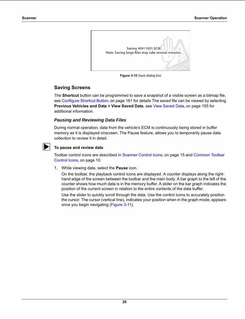
29
Scanner Scanner Operation
Figure 3-10 Save dialog box
Saving Screens
The Shortcut button can be programmed to save a snapshot of a visible screen as a bitmap file, see Configure Shortcut Button‚ on page 161 for details The saved file can be viewed by selecting Previous Vehicles and Data > View Saved Data, see View Saved Data‚ on page 155 for additional information.
Pausing and Reviewing Data Files
During normal operation, data from the vehicle’s ECM is continuously being stored in buffer memory as it is displayed onscreen. The Pause feature, allows you to temporarily pause data collection to review it in detail.
z To pause and review data
Toolbar control icons are described in Scanner Control Icons‚ on page 15 and Common Toolbar Control Icons‚ on page 10.
1. While viewing data, select the Pause icon.
On the toolbar, the playback control icons are displayed. A counter displays along the right-hand edge of the screen between the toolbar and the main body. A bar graph to the left of the counter shows how much data is in the memory buffer. A slider on the bar graph indicates the position of the current screen in relation to the entire contents of the data buffer.
Use the slider to quickly scroll through the data. Use the control icons to accurately position the cursor. The cursor (vertical line), indicates your position when in the graph mode, appears once you begin navigating (Figure 3-11).

30
Scanner Scanner Operation
Figure 3-11
2. Scroll up or down to review the list of data.
3. Select the desired control icon to move forward or back incrementally in the selected direction.
z To resume:
• Select the Record icon.
The display changes back to display data and the Pause icon is shown on the toolbar. A vertical rule runs through the data graph to indicate data was paused at that point.
NOTE:i The Shortcut icon can be set to perform the Pause/Play function. See Configure Shortcut Button‚
on page 161 for additional information.
3.3.5 Functional Tests
The Functional Tests selection is used to access vehicle-specific subsystem tests. Available tests vary by manufacturer, year, and model. Only the tests available for the identified vehicle display in the menu.
There are several types of functional tests:
• Information Tests—these are read-only tests, like selecting “VIN” from a Functional Tests menu to display the VIN of the identified vehicle.
1— Skip Back
2— Skip Forward
3— Step Back
4— Step Forward
5— Record
6— Bar Graph
7— Slider
8— Counter (current position / total)
9— Cursor
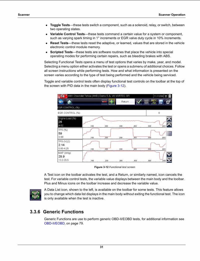
31
Scanner Scanner Operation
• Toggle Tests—these tests switch a component, such as a solenoid, relay, or switch, between two operating states.
• Variable Control Tests—these tests command a certain value for a system or component, such as varying spark timing in 1° increments or EGR valve duty cycle in 10% increments.
• Reset Tests—these tests reset the adaptive, or learned, values that are stored in the vehicle electronic control module memory.
• Scripted Tests—these tests are software routines that place the vehicle into special operating modes for performing certain repairs, such as bleeding brakes with ABS.
Selecting Functional Tests opens a menu of test options that varies by make, year, and model. Selecting a menu option either activates the test or opens a submenu of additional choices. Follow all screen instructions while performing tests. How and what information is presented on the screen varies according to the type of test being performed and the vehicle being serviced.
Toggle and variable control tests often display functional test controls on the toolbar at the top of the screen with PID data in the main body (Figure 3-12).
Figure 3-12 Functional test screen
A Test icon on the toolbar activates the test, and a Return, or similarly named, icon cancels the test. For variable control tests, the variable value displays between the main body and the toolbar. Plus and Minus icons on the toolbar increase and decrease the variable value.
A Data List icon, shown to the left, is available on the toolbar for some tests. This feature allows you to change which data list displays in the main body without exiting the functional test. The icon is only available when the test is inactive.
3.3.6 Generic Functions
Generic Functions are use to perform generic OBD-II/EOBD tests, for additional information see OBD-II/EOBD‚ on page 79.
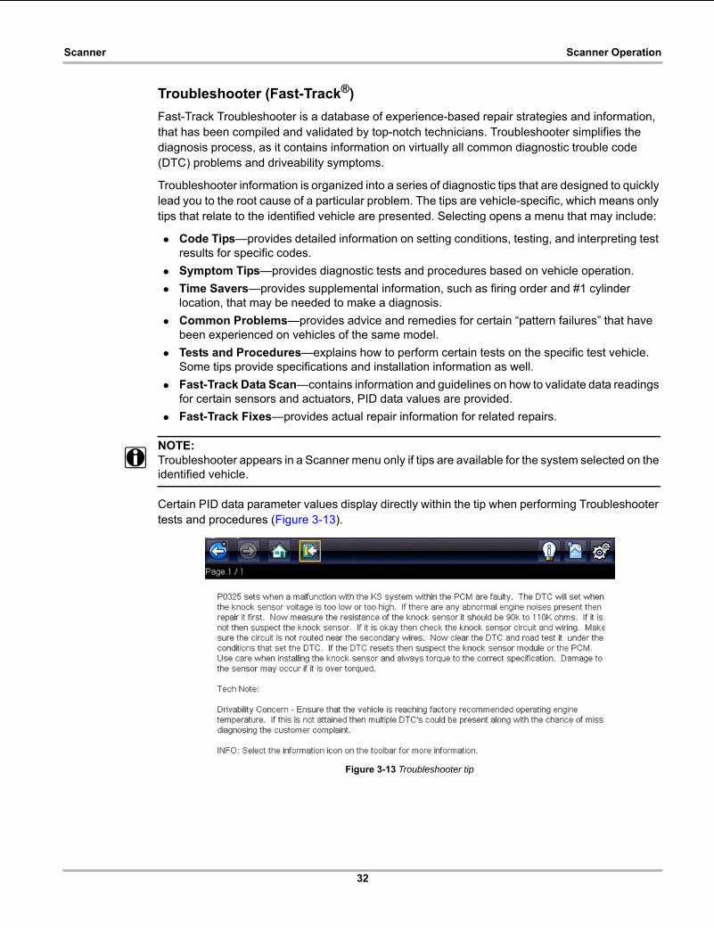
32
Scanner Scanner Operation
Troubleshooter (Fast-Track®)
Fast-Track Troubleshooter is a database of experience-based repair strategies and information, that has been compiled and validated by top-notch technicians. Troubleshooter simplifies the diagnosis process, as it contains information on virtually all common diagnostic trouble code (DTC) problems and driveability symptoms.
Troubleshooter information is organized into a series of diagnostic tips that are designed to quickly lead you to the root cause of a particular problem. The tips are vehicle-specific, which means only tips that relate to the identified vehicle are presented. Selecting opens a menu that may include:
• Code Tips—provides detailed information on setting conditions, testing, and interpreting test results for specific codes.
• Symptom Tips—provides diagnostic tests and procedures based on vehicle operation.
• Time Savers—provides supplemental information, such as firing order and #1 cylinder location, that may be needed to make a diagnosis.
• Common Problems—provides advice and remedies for certain “pattern failures” that have been experienced on vehicles of the same model.
• Tests and Procedures—explains how to perform certain tests on the specific test vehicle. Some tips provide specifications and installation information as well.
• Fast-Track Data Scan—contains information and guidelines on how to validate data readings for certain sensors and actuators, PID data values are provided.
• Fast-Track Fixes—provides actual repair information for related repairs.
NOTE:i Troubleshooter appears in a Scanner menu only if tips are available for the system selected on the
identified vehicle.
Certain PID data parameter values display directly within the tip when performing Troubleshooter tests and procedures (Figure 3-13).
Figure 3-13 Troubleshooter tip

33
Scanner Exiting Scanner
3.4 Exiting ScannerThe Scanner function remains open as long as there is an active communication link with the vehicle. You must interrupt this communication link in order to exit from tests and power down the diagnostic tool. A warning message displays if you attempt to shut down while the diagnostic tool is communicating with the vehicle.
NOTE:i Damage to the vehicle electronic control module (ECM) may occur if communication is disrupted.
Make sure the data cable is properly connected at all times during testing. Exit all tests before disconnecting the data cable or powering down the diagnostic tool.
z To exit the Scanner function:
1. From any active data screen, select the Back icon on the toolbar.
The “stopping communications” message briefly displays followed by the Data menu.
2. From the Data Menu, select Back on the toolbar.
The “stopping communications” message displays again, then the Main menu. Once the Main menu is displayed, communication has been terminated and it is safe to return to the Home screen and power down the diagnostic tool.

34
Chapter 4 Vehicle Code Scan / (ALTUS™)
Code Scan allows you to quickly scan all supported vehicle control modules for codes. In addition, Global OBD-II codes and Readiness Monitors are scanned giving you a complete health check of vehicle systems.
One of the benefits of performing a code scan is that you can quickly show your customer diagnostic related issues with a pre scan report, and then after repairing the issues you can use the post scan report to show that the repairs were completed (Figure 4-1). In addition, by using ALTUS the reports can be given to the customer and also saved for your own records, for more information, see Vehicle System Report (ALTUS™)‚ on page 40.
IMPORTANT:PRE / POST Scan Importance - As many systems do not turn on the check engine light or other indicator, performing a vehicle code scan before making any repairs may help in troubleshooting, by identifying possible unknown issues that may be related to the present symptoms.
Performing pre and post scans also allows you to record in report format the pre-condition of the vehicle and compare the post scan after work is complete to confirm the repairs were completed properly.
Pre and post scan is required by some manufacturers for pre and post collision work as well as by some insurance companies.
Figure 4-1
Vehicle System ReportVEHICLE INFORMATIONVIN JN8AS5MT0FW000000MAKE NissanYEAR 2016MODEL RogueENGINE 2.5L L4 MFI (QR25DE)SYSTEM CodeScanLICENSE PLATE
CODE SCAN RESULTSSystems Analyzed: 10
Engine: 0Transmission: 0Antilock Brakes: 0Airbag: 0Body Control Module - Codes: 3Electronic Power Steering: 0Intelligent Power Distribution Module: 0Meter: 0Tire Pressure Monitor - Codes: 3OBDII: 0
Body Control Module - CodesC1704 | Low Pressure Left FrontC1706 | Low Pressure Right RearC1707 | Low Pressure Left Rear
Tire Pressure Monitor - CodesC1704 | Low Pressure Left FrontC1706 | Low Pressure Right RearC1707 | Low Pressure Left Rear
READINESS MONITORSTests Complete
MisfireFuel SystemComprehensive ComponentEGR/VVTCatalystEvaporative SystemOxygen SensorOxygen Sensor Heater
Page: 1 2/13/70 :etaD )ED52RQ( IFM 4L L5.2 eugoR nassiN 6102 017 11:30AM
Vehicle System ReportVEHICLE INFORMATIONVIN JN8AS5MT0FW000000MAKE NissanYEAR 2016MODEL RogueENGINE 2.5L L4 MFI (QR25DE)SYSTEM CodeScanLICENSE PLATE
CODE SCAN RESULTSSystems Analyzed: 10
Engine: 0Transmission: 0Antilock Brakes: 0Airbag: 0Body Control Module: 0Electronic Power Steering: 0Intelligent Power Distribution Module: 0Meter: 0Tire Pressure Monitor: 0OBDII: 0
READINESS MONITORSTests Complete
MisfireFuel SystemComprehensive ComponentEGR/VVTCatalystEvaporative SystemOxygen SensorOxygen Sensor Heater
Page: 1 2016 Nissan Rogue 2.5L L4 MFI (QR25DE) Date: 07/31/2017 2:14PM
Pre Scan
Post Scan
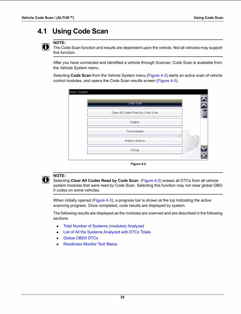
35
Vehicle Code Scan / (ALTUS™) Using Code Scan
4.1 Using Code Scan
NOTE:i The Code Scan function and results are dependent upon the vehicle. Not all vehicles may support
this function.
After you have connected and identified a vehicle through Scanner, Code Scan is available from the Vehicle System menu.
Selecting Code Scan from the Vehicle System menu (Figure 4-2) starts an active scan of vehicle control modules, and opens the Code Scan results screen (Figure 4-3).
Figure 4-2
NOTE:i Selecting Clear All Codes Read by Code Scan (Figure 4-2) erases all DTCs from all vehicle
system modules that were read by Code Scan. Selecting this function may not clear global OBD-II codes on some vehicles.
When initially opened (Figure 4-3), a progress bar is shown at the top indicating the active scanning progress. Once completed, code results are displayed by system.
The following results are displayed as the modules are scanned and are described in the following sections.
• Total Number of Systems (modules) Analyzed
• List of All the Systems Analyzed with DTCs Totals
• Global OBDII DTCs
• Readiness Monitor Test Status

36
Vehicle Code Scan / (ALTUS™) Using Code Scan
Figure 4-3 Code Scan in process
Code Scan control icons are located on the upper toolbar (Figure 4-3), and provide the following functions.
After the code scan has competed it is automatically saved as an .XML file on the diagnostic tool, and is uploaded to your account on ALTUSDRIVE.com (if registered and connected).
A confirmation message is displayed indicating that the file was saved (e.g. Message Example: “Saving A2810005.XML”).
To view the report on the diagnostic tool, see Viewing Code Results on the Diagnostic Tool‚ on page 157.
To view/print the report on ALTUS, see Vehicle System Report (ALTUS™)‚ on page 40.
NOTE:i The code scan can also be saved manually by selecting the Save icon.
Icon Function
Refresh - Refreshes the code scan data (restarts the code scan)
System - Opens the main menu of the system selected (highlighted)
Save - Saves the code scan results as an (.XML) file. See Viewing Codes and Code Scan Results‚ on page 156.

37
Vehicle Code Scan / (ALTUS™) Using Code Scan
4.1.1 Total Number of Systems (modules) Analyzed
The total number of systems analyzed is actively displayed at the top of the screen as they are scanned.
Figure 4-4 Code Scan systems analyzed result total
4.1.2 List of All the Systems Analyzed with DTCs Totals
A categorized system list with DTC totals is displayed in the order they are scanned. To view the main menu for a system in the list, select the system, then select the System icon (Figure 4-5).
Figure 4-5 System icon (opens Main Menu)
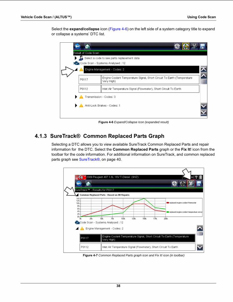
38
Vehicle Code Scan / (ALTUS™) Using Code Scan
Select the expand/collapse icon (Figure 4-6) on the left side of a system category title to expand or collapse a systems’ DTC list.
Figure 4-6 Expand/Collapse Icon (expanded result)
4.1.3 SureTrack® Common Replaced Parts Graph
Selecting a DTC allows you to view available SureTrack Common Replaced Parts and repair information for the DTC. Select the Common Replaced Parts graph or the Fix It! icon from the toolbar for the code information. For additional information on SureTrack, and common replaced parts graph see SureTrack®‚ on page 40.
Figure 4-7 Common Replaced Parts graph icon and Fix It! icon (in toolbar)
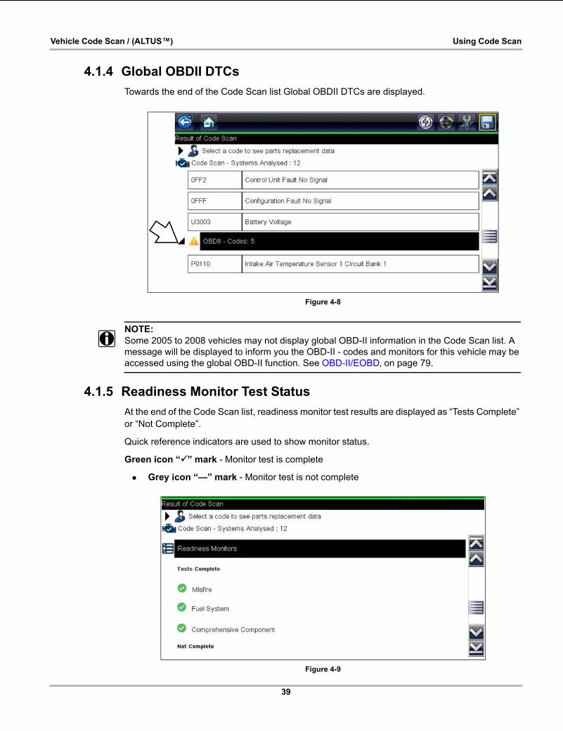
39
Vehicle Code Scan / (ALTUS™) Using Code Scan
4.1.4 Global OBDII DTCs
Towards the end of the Code Scan list Global OBDII DTCs are displayed.
Figure 4-8
NOTE:i Some 2005 to 2008 vehicles may not display global OBD-II information in the Code Scan list. A
message will be displayed to inform you the OBD-II - codes and monitors for this vehicle may be accessed using the global OBD-II function. See OBD-II/EOBD‚ on page 79.
4.1.5 Readiness Monitor Test Status
At the end of the Code Scan list, readiness monitor test results are displayed as “Tests Complete” or “Not Complete”.
Quick reference indicators are used to show monitor status.
Green icon “a” mark - Monitor test is complete
• Grey icon “—” mark - Monitor test is not complete
Figure 4-9
40
Vehicle Code Scan / (ALTUS™) Vehicle System Report (ALTUS™)
NOTE:i Monitors that are not supported by the vehicle are not displayed in Code Scan.
4.2 Vehicle System Report (ALTUS™)After a code scan is completed the results of the scan are automatically configured into a Vehicle System Report that is uploaded and saved to your ALTUS online account (if registered and connected). Report examples are shown in Figure 4-1.
Using ALTUS the report can be printed, downloaded, attached to an e-mail or other social media app to share with others. For additional information on using ALTUS, see ALTUS (ALTUSDRIVE.com) - Cloud Sharing/Storage‚ on page 174.
NOTE:i Code scan reports are automatically saved each time a code scan is performed. If using ALTUS,
the report is automatically uploaded to your online ALTUS account on ALTUSDRIVE.com.
The code scan/vehicle system report includes:
• Basic vehicle information
• A list of the code scan results by system
• Individual system DTCs with a brief description
• Global OBD codes
• Readiness monitor test status
4.2.1 Printing the Vehicle System Report
Use ALTUS to print the vehicle system report from your PC or mobile device, see Quick Reference (print / download / share)‚ on page 178.
The vehicle system report can also be customized and printed using ShopStream Connect - See Printing the (Code Scan) Vehicle System Report‚ on page 203.
41
Chapter 5 SureTrack
5.1 SureTack - Diagnostic Tool FeaturesSureTrack is an integrated Wi-Fi function that provides you expert automotive information directly on your diagnostic tool, via wireless network connection to our Snap-on web services network.
SureTrack includes a comprehensive source of expert automotive knowledge for professional technicians, combining diagnostic experience and detailed vehicle-specific parts replacement records. SureTrack can provide you with vehicle specific part replacement, diagnostic and repair information related to the diagnostic trouble codes (DTCs) found when checking codes with the Scanner. If diagnostic Tips, Fixes or parts information is available for a DTC, simply select the applicable SureTrack icon from the DTC results list to review the information and start the repair.
SureTrack Features:
• Up-to-the-minute diagnostic intelligence based on vehicles currently being serviced by professional shops
• Provides the following diagnostic information (if available) all based on the vehicle ID and diagnostic trouble codes (DTCs) selected
• Common Replaced Parts Graph — displays the replacement parts most frequently used to successfully complete repairs based on actual vehicle repairs
• Tips - Experience-based diagnostic and repair tips and information for the selected DTC
• Related Tips - Additional Tips that may be related to the selected DTC
• Real Fixes - Verified successful repair information and/or procedures for the selected DTC
• Related Real Fixes - Additional Real Fixes that may be related to the selected DTC.
All information (e.g. replaced parts data, tips and fixes) have been obtained from professional automotive OEM and specialty technicians from a vast range of repair shops.
NOTE:i SureTrack Tips, Fixes, and Common Replaced Parts information may not always be available for
every vehicle DTC. Only available information is displayed.
5.1.1 Basic Operation and Navigation
Before you can begin using SureTrack, you must:
• Verify that you have the current software upgrade installed. SureTrack is only active with current software versions. Contact your sales representative for purchasing information.
• Turn the Wi-Fi radio on. For Wi-Fi setup and connection see, Wi-Fi Connection / Troubleshooting‚ on page 191.
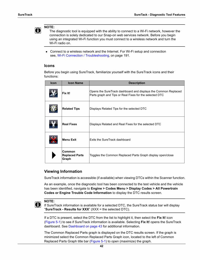
42
SureTrack SureTack - Diagnostic Tool Features
NOTE:i The diagnostic tool is equipped with the ability to connect to a Wi-Fi network, however the
connection is solely dedicated to our Snap-on web services network. Before you begin using an integrated Wi-Fi function you must connect to a wireless network and turn the Wi-Fi radio on.
• Connect to a wireless network and the Internet. For Wi-Fi setup and connection see, Wi-Fi Connection / Troubleshooting‚ on page 191.
Icons
Before you begin using SureTrack, familiarize yourself with the SureTrack icons and their functions:
Viewing Information
SureTrack information is accessible (if available) when viewing DTCs within the Scanner function.
As an example, once the diagnostic tool has been connected to the test vehicle and the vehicle has been identified, navigate to Engine > Codes Menu > Display Codes > All Powertrain Codes or Engine Trouble Code Information to display the DTC results screen.
NOTE:i If SureTrack information is available for a selected DTC, the SureTrack status bar will display
“SureTrack - Results for XXX” (XXX = the selected DTC).
If a DTC is present, select the DTC from the list to highlight it, then select the Fix It! icon (Figure 5-1) to see if SureTrack information is available. Selecting Fix It! opens the SureTrack dashboard. See Dashboard on page 43 for additional information.
The Common Replaced Parts graph is displayed on the DTC results screen. If the graph is minimized select the Common Replaced Parts Graph icon, located to the left of Common Replaced Parts Graph title bar (Figure 5-1) to open (maximize) the graph.
Icon Icon Name Description
Fix It!Opens the SureTrack dashboard and displays the Common Replaced Parts graph and Tips or Real Fixes for the selected DTC
Related Tips Displays Related Tips for the selected DTC
Real Fixes Displays Related and Real Fixes for the selected DTC
Menu Exit Exits the SureTrack dashboard
Common Replaced Parts Graph
Toggles the Common Replaced Parts Graph display open/close
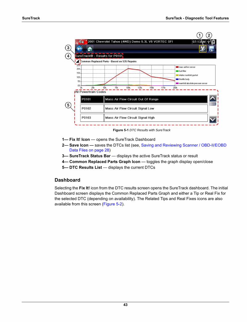
43
SureTrack SureTack - Diagnostic Tool Features
Figure 5-1 DTC Results with SureTrack
1— Fix It! Icon — opens the SureTrack Dashboard
2— Save Icon — saves the DTCs list (see, Saving and Reviewing Scanner / OBD-II/EOBD Data Files on page 28)
3— SureTrack Status Bar — displays the active SureTrack status or result
4— Common Replaced Parts Graph Icon — toggles the graph display open/close
5— DTC Results List — displays the current DTCs
Dashboard
Selecting the Fix It! icon from the DTC results screen opens the SureTrack dashboard. The initial Dashboard screen displays the Common Replaced Parts Graph and either a Tip or Real Fix for the selected DTC (depending on availability). The Related Tips and Real Fixes icons are also available from this screen (Figure 5-2).

44
SureTrack SureTack - Diagnostic Tool Features
Figure 5-2 SureTrack Dashboard
Common Replaced Parts Graph
The Common Replaced Parts graph (if available) is displayed by selecting the Fix It! icon or can be viewed directly from the DTC results screen by selecting the Common Replaced Parts Graph icon, located to the left of Common Replaced Parts Graph title bar. The Common Replaced Parts graph shows the percentage of verified fixes (using the parts listed) derived from the total number of repairs by mileage. The graph may display one or more replacement parts based on the captured information.
The example below (Figure 5-3) shows two common replaced parts used in the repair of DTC P0106. In this example, the PCV valve is the most common replaced part based on 973 repairs involving vehicles with up to 200k miles, 17% of those 973 repairs occurred at 125k miles.
Figure 5-3 Common Replaced Parts Graph
1— Fix It! Icon
2— Related Tips Icon
3— Real Fixes Icon
4— Dashboard Exit Icon
5— Common Replaced Part Graph Icon — toggles graph display open/close
6— Common Replaced Part Graph
7— Tip

45
SureTrack SureTack - Diagnostic Tool Features
Tips and Related Tips– Tips - Experience-based diagnostic and repair tips and information for the selected DTC
– Related Tips - Additional Tips that may be related to the selected DTC
Tips have been researched and obtained from professional automotive OEM and specialty technicians from a vast range of repair shops. Tips may not be available for every vehicle and/or DTC.
Tips (if available) can be displayed in two ways:
• Selecting the Fix It! icon from the DTC results screen opens the SureTrack dashboard which may include Tip(s) for the selected DTC. If Tips are not available for the DTC, Real Fixes may be displayed.
• Selecting the Related Tips icon will display a list of Related Tips. Selecting an item from the list, opens additional details about the Related Tip (Figure 5-4).
Figure 5-4 Tip(s) Screens
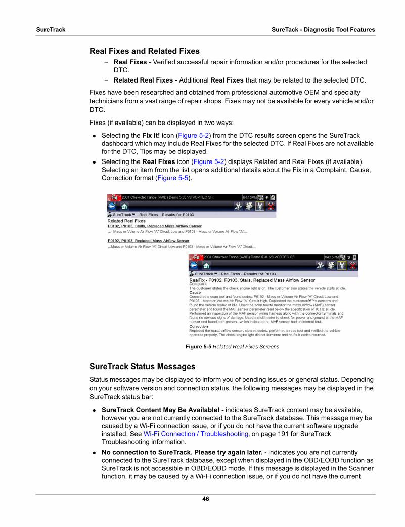
46
SureTrack SureTack - Diagnostic Tool Features
Real Fixes and Related Fixes– Real Fixes - Verified successful repair information and/or procedures for the selected
DTC.
– Related Real Fixes - Additional Real Fixes that may be related to the selected DTC.
Fixes have been researched and obtained from professional automotive OEM and specialty technicians from a vast range of repair shops. Fixes may not be available for every vehicle and/or DTC.
Fixes (if available) can be displayed in two ways:
• Selecting the Fix It! icon (Figure 5-2) from the DTC results screen opens the SureTrack dashboard which may include Real Fixes for the selected DTC. If Real Fixes are not available for the DTC, Tips may be displayed.
• Selecting the Real Fixes icon (Figure 5-2) displays Related and Real Fixes (if available). Selecting an item from the list opens additional details about the Fix in a Complaint, Cause, Correction format (Figure 5-5).
Figure 5-5 Related Real Fixes Screens
SureTrack Status Messages
Status messages may be displayed to inform you of pending issues or general status. Depending on your software version and connection status, the following messages may be displayed in the SureTrack status bar:
• SureTrack Content May Be Available! - indicates SureTrack content may be available, however you are not currently connected to the SureTrack database. This message may be caused by a Wi-Fi connection issue, or if you do not have the current software upgrade installed. See Wi-Fi Connection / Troubleshooting‚ on page 191 for SureTrack Troubleshooting information.
• No connection to SureTrack. Please try again later. - indicates you are not currently connected to the SureTrack database, except when displayed in the OBD/EOBD function as SureTrack is not accessible in OBD/EOBD mode. If this message is displayed in the Scanner function, it may be caused by a Wi-Fi connection issue, or if you do not have the current

47
SureTrack SureTrack - Online Community
software upgrade installed. See Wi-Fi Connection / Troubleshooting‚ on page 191 for SureTrack Troubleshooting information.
• Loading content from SureTrack - indicates SureTrack information is being accessed from the SureTrack database.
• A new diagnostic software upgrade is available. See your sales representative for details - indicates your access to SureTrack will be expiring soon and you should contact your sales representative to purchase the current software upgrade.
• Your SureTrack access has expired. See your Sales representative to renew. - indicates your access to SureTrack has expired and you should contact your sales representative to purchase the current software upgrade.
• Verified parts replacement data not available. Tap the wrench icon for more results. - indicates that Common Replaced Parts information (graph) is not available, however other types of SureTrack information may be (e.g. Real Fixes and Tips). Select the Fix It! icon to see if other information is available.
5.2 SureTrack - Online CommunityYour diagnostic tool includes access to the online SureTrack Community. You can use your PC to access the latest Real Fixes, Related Tips, and Common Repair Procedures information.
SureTrack is an evolving database of "real-world" automotive repair knowledge based on expert knowledge and millions of actual repair orders. It was designed to help you improve diagnostic accuracy and reduce repair times.
5.2.1 Main Topic Links• Finding your SureTrack Authorization Code page 48
• Creating a SureTrack Account page 49
• Logging In (active account) page 53
• Logging In with New Authorization Code (active account) page 54
• SureTrack Features page 57
• SureTrack Screens page 58
5.2.2 Quick Reference
SureTrack Community FAQ’s
For the latest SureTrack Community information and answers to frequently asked questions visit: mitchell1.com/support/suretrack-faqs/
Using SureTrack for the First Time
If you have purchased a new diagnostic tool, you will need to create a SureTrack account before you can access SureTrack. See Creating a SureTrack Account‚ on page 49 for instructions.
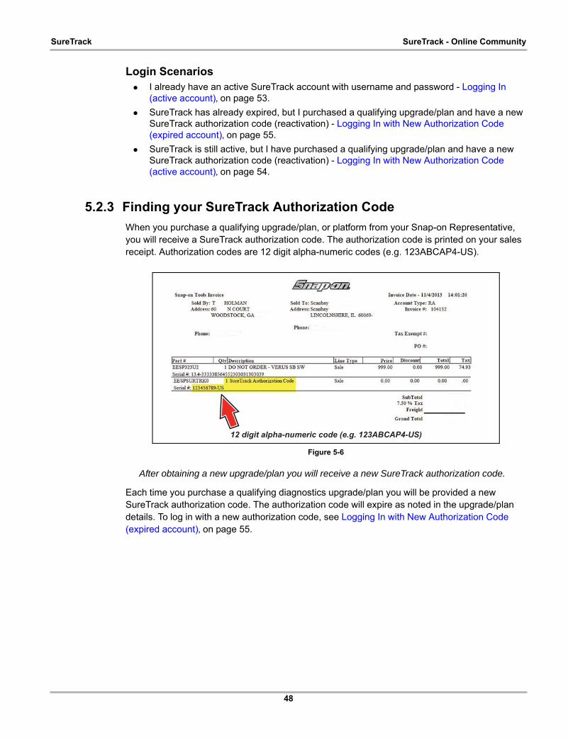
48
SureTrack SureTrack - Online Community
Login Scenarios • I already have an active SureTrack account with username and password - Logging In
(active account)‚ on page 53.
• SureTrack has already expired, but I purchased a qualifying upgrade/plan and have a new SureTrack authorization code (reactivation) - Logging In with New Authorization Code (expired account)‚ on page 55.
• SureTrack is still active, but I have purchased a qualifying upgrade/plan and have a new SureTrack authorization code (reactivation) - Logging In with New Authorization Code (active account)‚ on page 54.
5.2.3 Finding your SureTrack Authorization Code
When you purchase a qualifying upgrade/plan, or platform from your Snap-on Representative, you will receive a SureTrack authorization code. The authorization code is printed on your sales receipt. Authorization codes are 12 digit alpha-numeric codes (e.g. 123ABCAP4-US).
Figure 5-6
After obtaining a new upgrade/plan you will receive a new SureTrack authorization code.
Each time you purchase a qualifying diagnostics upgrade/plan you will be provided a new SureTrack authorization code. The authorization code will expire as noted in the upgrade/plan details. To log in with a new authorization code, see Logging In with New Authorization Code (expired account)‚ on page 55.
12 digit alpha-numeric code (e.g. 123ABCAP4-US)
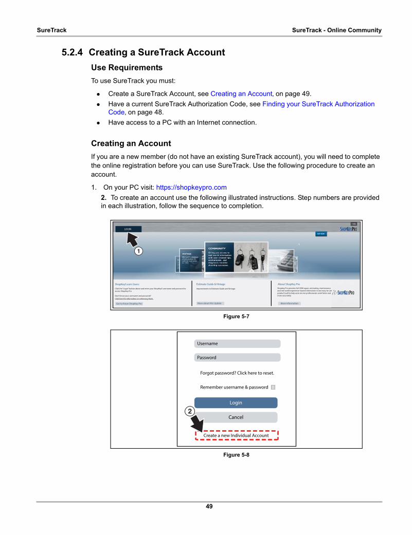
49
SureTrack SureTrack - Online Community
5.2.4 Creating a SureTrack Account
Use Requirements
To use SureTrack you must:
• Create a SureTrack Account, see Creating an Account‚ on page 49.
• Have a current SureTrack Authorization Code, see Finding your SureTrack Authorization Code‚ on page 48.
• Have access to a PC with an Internet connection.
Creating an Account
If you are a new member (do not have an existing SureTrack account), you will need to complete the online registration before you can use SureTrack. Use the following procedure to create an account.
1. On your PC visit: https://shopkeypro.com
2. To create an account use the following illustrated instructions. Step numbers are provided in each illustration, follow the sequence to completion.
Figure 5-7
Figure 5-8
1
LOGIN
ShopKey5.com Users:
Get to Know ShopKey Pro
Click the “Login” button above and enter your ShopKey5 username and password to
access ShopKey Pro
Don’t know your username and password?
Click here for information on retrieving them.
More about this Update
Improvements to Estimate Guide and Vintage.
Estimate Guide & Vintage
More Information
Shopkey Pro provides full OEM repair, estimating, maintenance
and real-world experience-based information in one easy-to-use
product built to help auto service professionals work faster and
more accurately.
About ShopKey Pro
Login
Cancel
Username
Password
Forgot password? Click here to reset.
Remember username & password
Create a new Individual Account
2

50
SureTrack SureTrack - Online Community
Figure 5-9
Figure 5-10
Figure 5-11
CreateCancel
Password*
Online Profile
Address
Name
Email Address*
Phone
Username*
Retype Password*
City*
Address Line 2
Address Line 1
First Name* Last Name* Phone Number
State* Zipcode
*3 Enter all required information.
4
5Done
Congradulations! Your account has been created.
Success X
This account can be used to contribute to the community and
manage your profile.
To link this account to your shop, have your shop add you in
Profile Manager.
Login
Cancel
Username
Password
Forgot password? Click here to reset.
Remember username & password
Create a new Individual Account
X
6
7
8
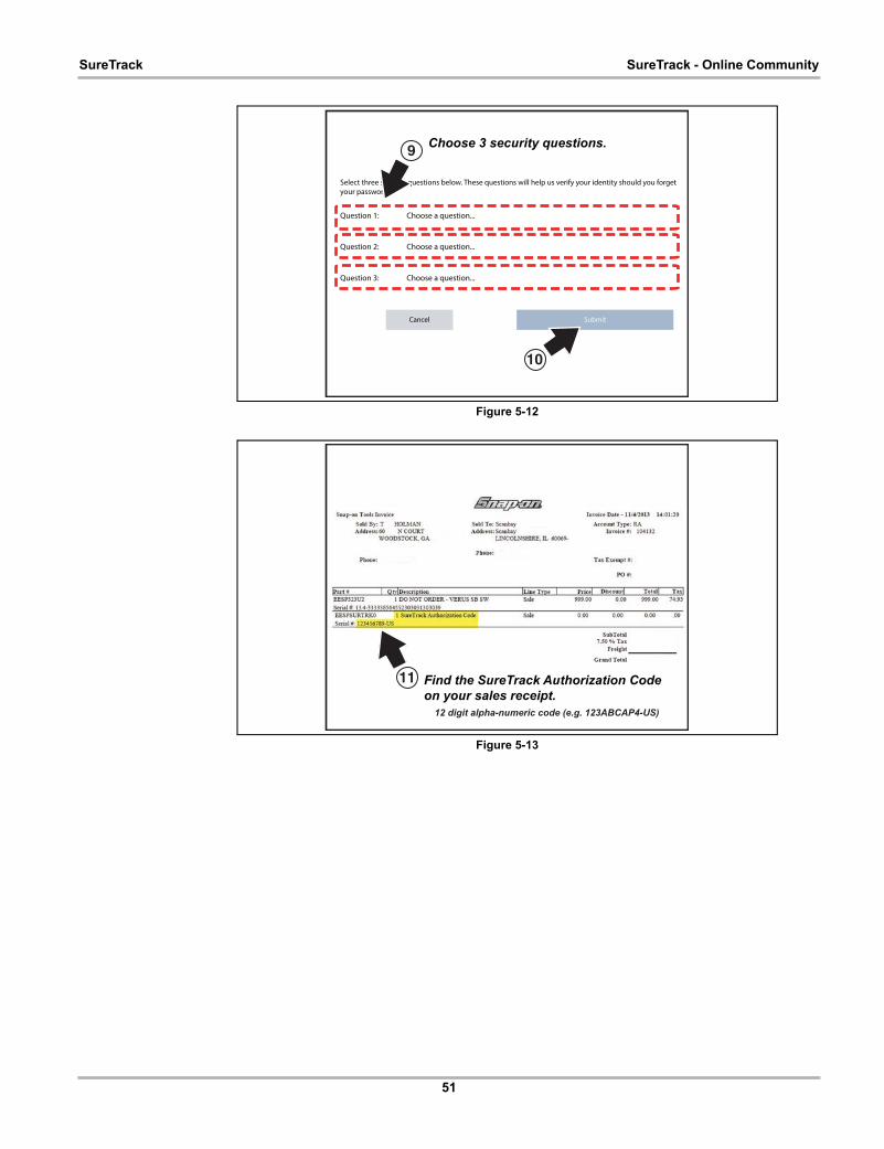
51
SureTrack SureTrack - Online Community
Figure 5-12
Figure 5-13
SubmitCancel
Question 3: Choose a question...
Question 2: Choose a question...
Question 1: Choose a question...
Select three security questions below. These questions will help us verify your identity should you forget
your password.
9
10
Choose 3 security questions.
11 Find the SureTrack Authorization Codeon your sales receipt.
12 digit alpha-numeric code (e.g. 123ABCAP4-US)
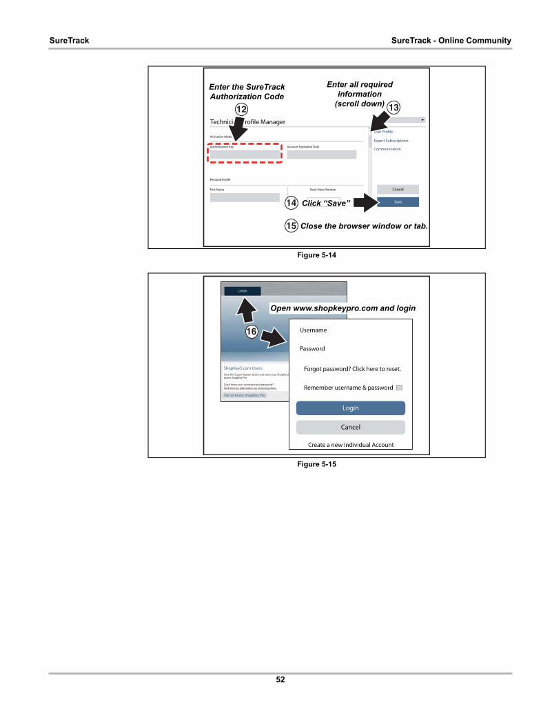
52
SureTrack SureTrack - Online Community
Figure 5-14
Figure 5-15
Technician Profile Manager
Authorization Key Account Expiration Date
Activation Mode
Personal Profile
First Name Rank: New Member
Save
Cancel
User Profile
Expert Subscriptions
Communication
12
14
Enter the SureTrackAuthorization Code
Enter all requiredinformation
(scroll down) 13
Click “Save”
15 Close the browser window or tab.
16
Open www.shopkeypro.com and login
Login
Cancel
Username
Password
Forgot password? Click here to reset.
Remember username & password
Create a new Individual Account
LOGIN
ShopKey5.com Users:
Get to Know ShopKey Pro
Click the “Login” button above and enter your ShopKey5access ShopKey Pro
Don’t know your username and password?
Click here for information on retrieving them.
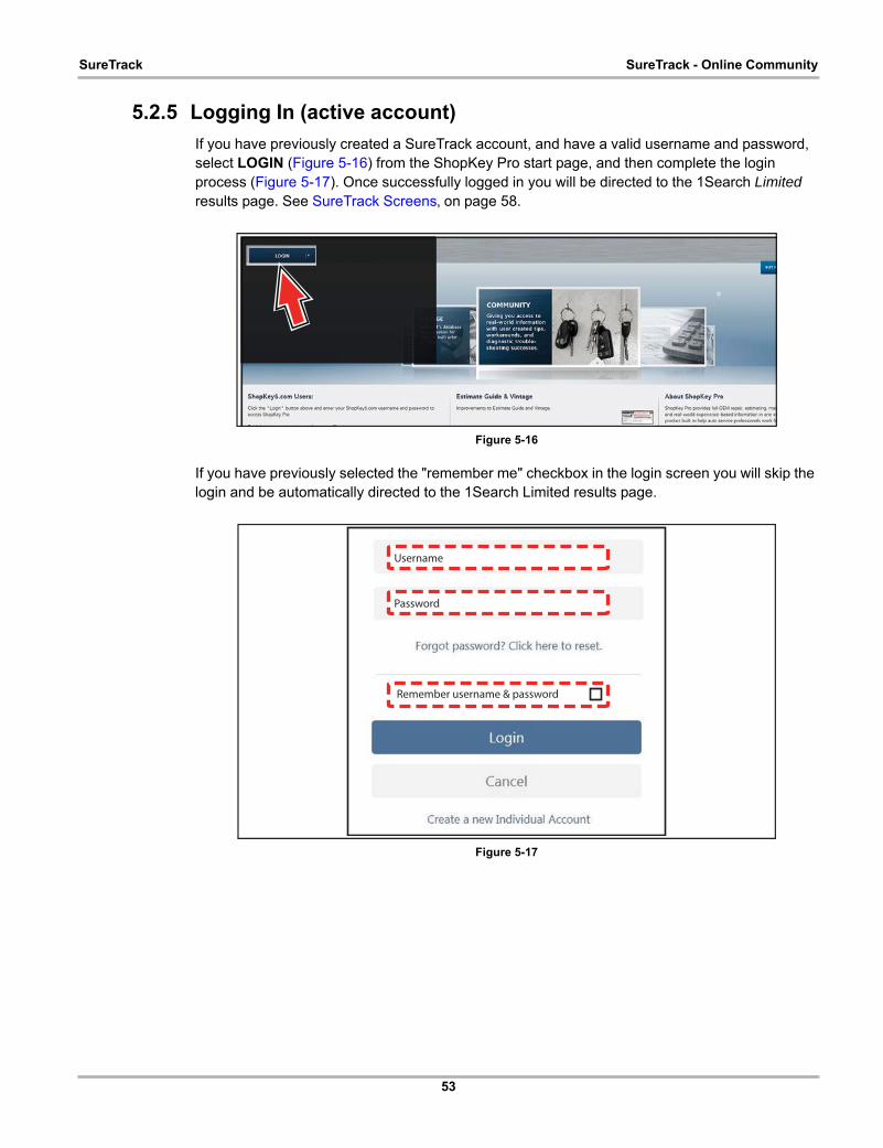
53
SureTrack SureTrack - Online Community
5.2.5 Logging In (active account)
If you have previously created a SureTrack account, and have a valid username and password, select LOGIN (Figure 5-16) from the ShopKey Pro start page, and then complete the login process (Figure 5-17). Once successfully logged in you will be directed to the 1Search Limited results page. See SureTrack Screens‚ on page 58.
Figure 5-16
If you have previously selected the "remember me" checkbox in the login screen you will skip the login and be automatically directed to the 1Search Limited results page.
Figure 5-17
Username
Password
Remember username & password

54
SureTrack SureTrack - Online Community
5.2.6 Logging In with New Authorization Code (active account)
Use the following instructions, if you have purchased a qualifying upgrade/plan and your SureTrack account is active (has not expired). To find your new authorization code, see Finding your SureTrack Authorization Code‚ on page 48.
1. Log in to ShopKeyPro.com using your current username and password.
2. At the ShopKey Pro start page, select your username (Figure 5-18), then select Profile Manager from the dropdown menu.
Figure 5-18
3. Log in to the Profile Manger (Figure 5-19) using your current username and password.
4. Enter your new Authorization code (Figure 5-19).
Figure 5-19
5. Review and update the rest of your profile and make sure all required fields are filled out.
6. Select Save.
Username
Enter new code here.

55
SureTrack SureTrack - Online Community
7. Exit the Profile Manager by selecting your username (near the top right) and select Logout.
8. When the login screen displays, login using your current username and password.
9. Confirm the new expiration date by logging back into Profile Manger to check it.
5.2.7 Logging In with New Authorization Code (expired account)
Use the following instructions, if your SureTrack account has expired, and you have purchased a qualifying upgrade/plan. Your new upgrade/plan comes with a new SureTrack authorization code. To find your new authorization code, see Finding your SureTrack Authorization Code‚ on page 48.
1. Log in to ShopKeyPro.com using your using your current username and password.
When your SureTrack account has expired, and you try to login you are directed to an information window (Figure 5-20).
2. Scroll down and select the link shown in (Figure 5-20)
Figure 5-20
3. The SureTrack FAQ webpage opens (Figure 5-21).
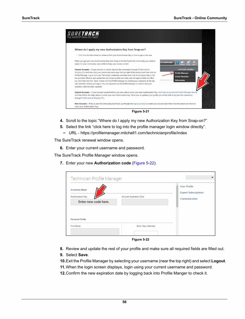
56
SureTrack SureTrack - Online Community
Figure 5-21
4. Scroll to the topic “Where do I apply my new Authorization Key from Snap-on?”
5. Select the link “click here to log into the profile manager login window directly”.
– URL - https://profilemanager.mitchell1.com/technicianprofile/index
The SureTrack renewal window opens.
6. Enter your current username and password.
The SureTrack Profile Manager window opens.
7. Enter your new Authorization code (Figure 5-22).
Figure 5-22
8. Review and update the rest of your profile and make sure all required fields are filled out.
9. Select Save.
10.Exit the Profile Manager by selecting your username (near the top right) and select Logout.
11.When the login screen displays, login using your current username and password.
12.Confirm the new expiration date by logging back into Profile Manger to check it.
Enter new code here.

57
SureTrack SureTrack - Online Community
5.2.8 SureTrack Features
SureTrack is an integrated part of ShopKey Pro, and includes two navigation modules providing search and forum capabilities:
• 1Search™ Limited
• Sure Track Community.
1Search™ Limited
The 1Search Limited module includes the following information features:
• Real Fixes and Tips - real-world fixes and repair tips captured from actual repair orders and the experiences of professional technicians.
• Common Repair Procedures Graph - graphical display of the specific parts and procedures most frequently used to fix the selected code or symptom.
• ProView - provides graphical displays showing the direct relationship between a code or symptom to the component used to fix them.
• Component Tests - includes instructions on how to test the component, and descriptions of component operation, component locations, test locations, connector end views and even sample waveforms.
• TSB's - OEM technical service bulletins.• Safety Recalls and Campaigns - safety recall and service campaign information.
SureTrack Community
The Sure Track Community module is a forum-based application that connects you with a community of other professional technicians to find and share information, ask questions, and provide your own tips.

58
SureTrack SureTrack - Online Community
5.2.9 SureTrack Screens
SureTrack Home Page (within ShopKey Pro)
The SureTrack Home page within ShopKey Pro includes:
Figure 5-23
1. Change Vehicle* - dropdown menu provides options to change the active vehicle
2. Active Vehicle* - displays active vehicle
3. Recall/Campaigns* - displays available OEM recalls and campaigns
4. Help* - provides SureTrack and ShopKey Pro online help topics
5. Contact Us* - provides options for contacting ShopKey Pro customer service
6. Settings* - provides general setting options and information
7. Logout* - logs you off of ShopKey Pro
8. User ID options menu* - displays username, selecting opens Profile Manager and other options
9. Main Menu (dropdown)* - Options are Home, 1Search Limited, and SureTrack Community
10.General Training and Information Links (various) * available on all pages
1 2 34
5 67
89
10
Username
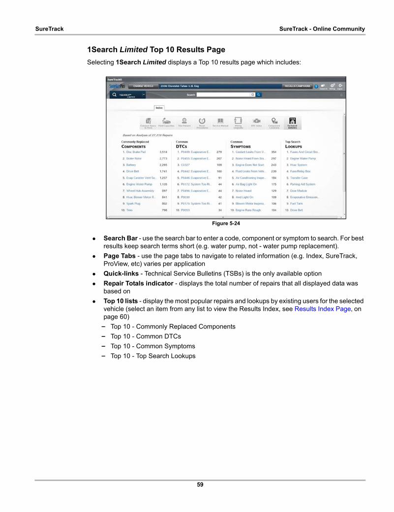
59
SureTrack SureTrack - Online Community
1Search Limited Top 10 Results Page
Selecting 1Search Limited displays a Top 10 results page which includes:
Figure 5-24
• Search Bar - use the search bar to enter a code, component or symptom to search. For best results keep search terms short (e.g. water pump, not - water pump replacement).
• Page Tabs - use the page tabs to navigate to related information (e.g. Index, SureTrack, ProView, etc) varies per application
• Quick-links - Technical Service Bulletins (TSBs) is the only available option
• Repair Totals indicator - displays the total number of repairs that all displayed data was based on
• Top 10 lists - display the most popular repairs and lookups by existing users for the selected vehicle (select an item from any list to view the Results Index, see Results Index Page‚ on page 60)
– Top 10 - Commonly Replaced Components
– Top 10 - Common DTCs
– Top 10 - Common Symptoms
– Top 10 - Top Search Lookups
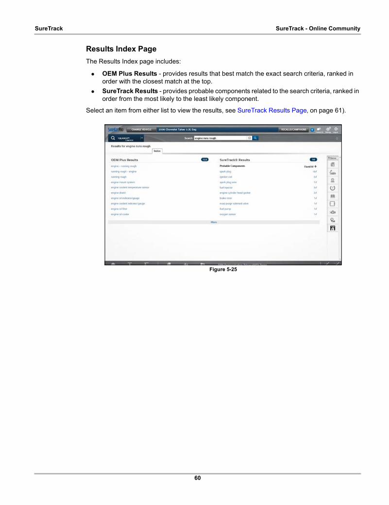
60
SureTrack SureTrack - Online Community
Results Index Page
The Results Index page includes:
• OEM Plus Results - provides results that best match the exact search criteria, ranked in order with the closest match at the top.
• SureTrack Results - provides probable components related to the search criteria, ranked in order from the most likely to the least likely component.
Select an item from either list to view the results, see SureTrack Results Page‚ on page 61).
Figure 5-25
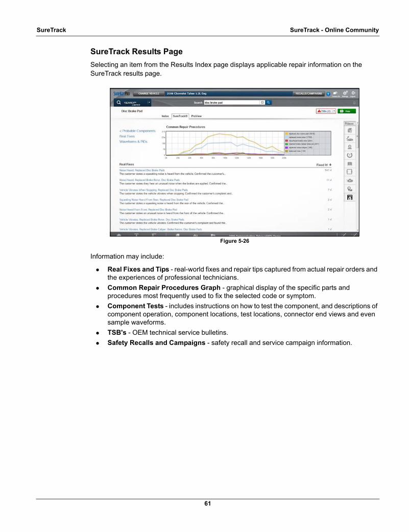
61
SureTrack SureTrack - Online Community
SureTrack Results Page
Selecting an item from the Results Index page displays applicable repair information on the SureTrack results page.
Figure 5-26
Information may include:
• Real Fixes and Tips - real-world fixes and repair tips captured from actual repair orders and the experiences of professional technicians.
• Common Repair Procedures Graph - graphical display of the specific parts and procedures most frequently used to fix the selected code or symptom.
• Component Tests - includes instructions on how to test the component, and descriptions of component operation, component locations, test locations, connector end views and even sample waveforms.
• TSB's - OEM technical service bulletins.
• Safety Recalls and Campaigns - safety recall and service campaign information.

62
SureTrack SureTrack - Online Community
ProView Results Page
Selecting the ProView tab from the SureTrack results page opens ProView. ProView provides graphical displays showing the direct relationship between a code or symptom to the component used to fix them.
Figure 5-27
Information may include:
• Radial Graph - showing the relationship of the code or symptom to possible at fault components.
• Component Frequency Graphs - showing the most commonly replaced component for that code or symptom.
• Common Replaced Parts Graphs - showing the mileage at which the most common component is replaced.
63
Chapter 6 Quick Lookups
This chapter describes the basic operation, and navigation of the Quick Lookups function. The Quick Lookups icon is located on the Home screen.
Quick Lookups includes Oil Specs and Resets and Tire and Wheel Service vehicle information functions:
6.1 Oil Specs and ResetsOil Specs and Resets is located in the Quick Lookups main menu (Quick Lookups > Oil Specs and Resets).
Oil Specs and Resets provides OEM information on your diagnostic tool, via wireless network connection with our Snap-on Information Service. This feature allows you quick access to the following information:
• Fluid capacity and specifications
• Scanner functional resets
• Service reset procedures and information
NOTE:i
— Oil Specs and Resets vehicle coverage is the same as the Scanner vehicle coverage.
— Not all vehicles may have on-board diagnostic tool reset capabilities, or have information available.
— The diagnostic tool is equipped with the ability to connect to a Wi-Fi network, however the connection is solely dedicated to our Snap-on Information Service. Before you begin using this function you must connect to a wireless network and turn the Wi-Fi radio on. See Wi-Fi Connection / Troubleshooting‚ on page 191 for instructions.
— If you experience a wireless network connection loss, Oil Specs and Resets information will not refresh and/or may cause the function to stop. To continue use, you must re-establish your Internet connection.
— Performance may vary depending on your wireless network equipment and ISP.
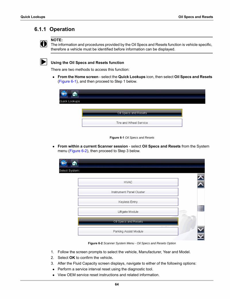
64
Quick Lookups Oil Specs and Resets
6.1.1 Operation
NOTE:i The information and procedures provided by the Oil Specs and Resets function is vehicle specific,
therefore a vehicle must be identified before information can be displayed.
z Using the Oil Specs and Resets function
There are two methods to access this function:
• From the Home screen - select the Quick Lookups icon, then select Oil Specs and Resets (Figure 6-1), and then proceed to Step 1 below.
Figure 6-1 Oil Specs and Resets
• From within a current Scanner session - select Oil Specs and Resets from the System menu (Figure 6-2), then proceed to Step 3 below.
Figure 6-2 Scanner System Menu - Oil Specs and Resets Option
1. Follow the screen prompts to select the vehicle, Manufacturer, Year and Model.
2. Select OK to confirm the vehicle.
3. After the Fluid Capacity screen displays, navigate to either of the following options:
• Perform a service interval reset using the diagnostic tool.
• View OEM service reset instructions and related information.

65
Quick Lookups Oil Specs and Resets
NOTE:i Depending on the active function, descriptive information is displayed in the main body of the
screen. If applicable, use the scroll bar or directional buttons (b, d) to scroll up/down to view all of the information.
Icons
The following provides a brief description of the related Oil Specs and Resets toolbar icon functions. Detailed descriptions are provided in the following sections.
Fluid Capacity
Selecting Fluid Capacity displays OEM recommended fluid specifications (Figure 6-3).
NOTE:i The Fluid Capacity screen is the default screen.
Typical information may include:
• Vehicle engine information
• Oil capacity specifications with or without oil filter
• Oil rating, weight and type
• Special notes
Figure 6-3 Typical Oil Specification Result
Icon Icon Name Description
Fluid CapacityDisplays OEM recommended engine oil specification and capacity information.
Functional Reset(Scanner)
Opens the Scanner service reset menu for the selected vehicle, providing options for available resets using the diagnostic tool.
Reset ProcedureDisplays OEM service interval reset instructions, to perform a manual reset of the service indicator.
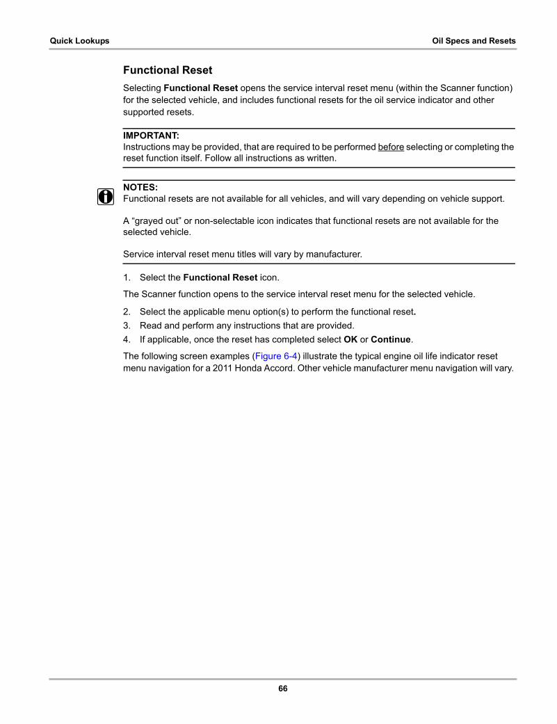
66
Quick Lookups Oil Specs and Resets
Functional Reset
Selecting Functional Reset opens the service interval reset menu (within the Scanner function) for the selected vehicle, and includes functional resets for the oil service indicator and other supported resets.
IMPORTANT:Instructions may be provided, that are required to be performed before selecting or completing the reset function itself. Follow all instructions as written.
NOTES:i Functional resets are not available for all vehicles, and will vary depending on vehicle support.
A “grayed out” or non-selectable icon indicates that functional resets are not available for the selected vehicle.
Service interval reset menu titles will vary by manufacturer.
1. Select the Functional Reset icon.
The Scanner function opens to the service interval reset menu for the selected vehicle.
2. Select the applicable menu option(s) to perform the functional reset.
3. Read and perform any instructions that are provided.
4. If applicable, once the reset has completed select OK or Continue.
The following screen examples (Figure 6-4) illustrate the typical engine oil life indicator reset menu navigation for a 2011 Honda Accord. Other vehicle manufacturer menu navigation will vary.
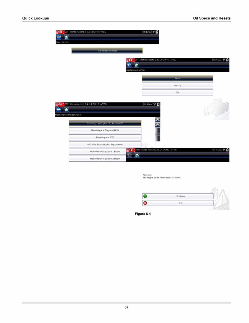
67
Quick Lookups Oil Specs and Resets
Figure 6-4
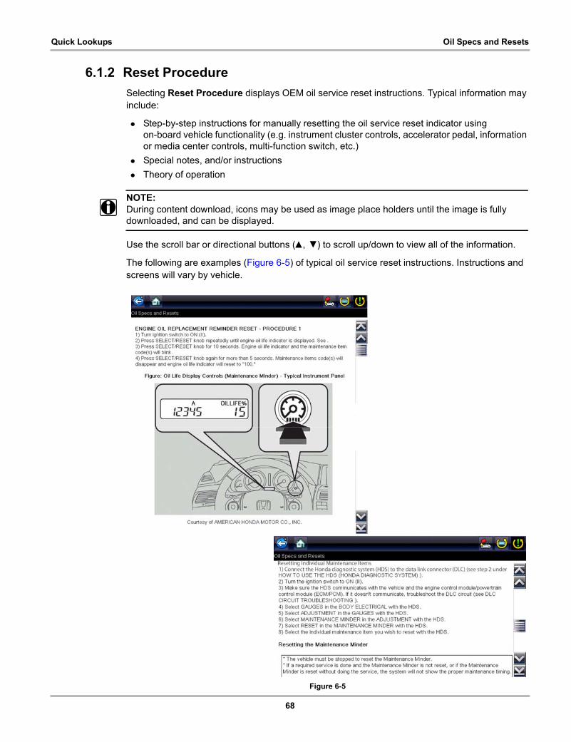
68
Quick Lookups Oil Specs and Resets
6.1.2 Reset Procedure
Selecting Reset Procedure displays OEM oil service reset instructions. Typical information may include:
• Step-by-step instructions for manually resetting the oil service reset indicator using on-board vehicle functionality (e.g. instrument cluster controls, accelerator pedal, information or media center controls, multi-function switch, etc.)
• Special notes, and/or instructions
• Theory of operation
NOTE:i During content download, icons may be used as image place holders until the image is fully
downloaded, and can be displayed.
Use the scroll bar or directional buttons (b, d) to scroll up/down to view all of the information.
The following are examples (Figure 6-5) of typical oil service reset instructions. Instructions and screens will vary by vehicle.
Figure 6-5
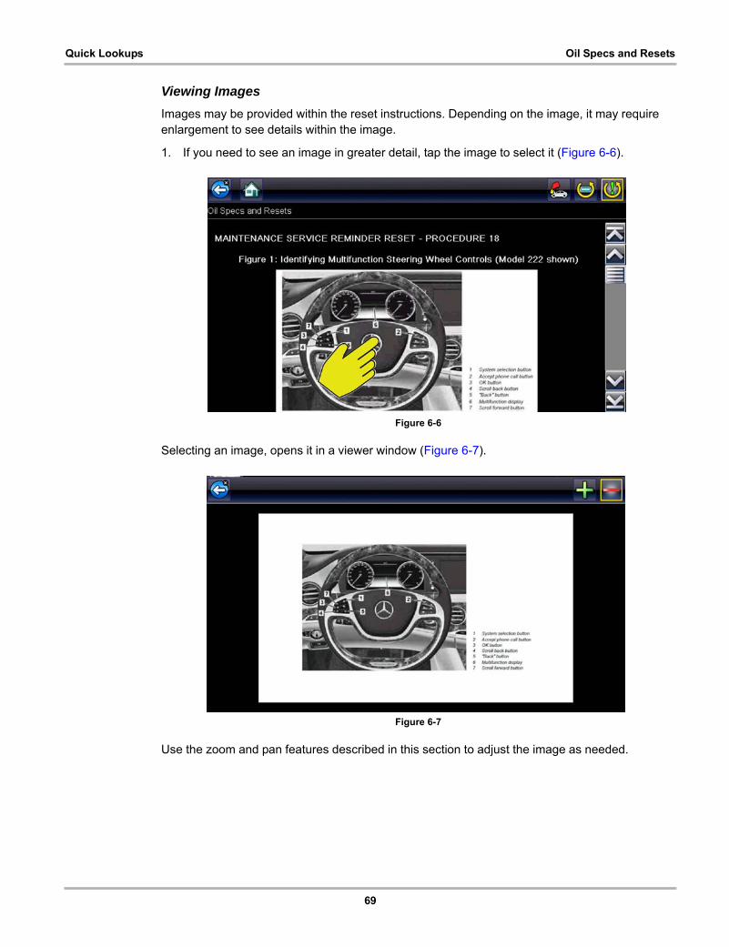
69
Quick Lookups Oil Specs and Resets
Viewing Images
Images may be provided within the reset instructions. Depending on the image, it may require enlargement to see details within the image.
1. If you need to see an image in greater detail, tap the image to select it (Figure 6-6).
Figure 6-6
Selecting an image, opens it in a viewer window (Figure 6-7).
Figure 6-7
Use the zoom and pan features described in this section to adjust the image as needed.
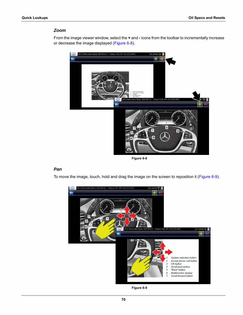
70
Quick Lookups Oil Specs and Resets
Zoom
From the image viewer window, select the + and - icons from the toolbar to incrementally increase or decrease the image displayed (Figure 6-8).
Figure 6-8
Pan
To move the image, touch, hold and drag the image on the screen to reposition it (Figure 6-9).
Figure 6-9
71
Quick Lookups Tire and Wheel Service
6.2 Tire and Wheel ServiceTire and Wheel Service is located in the Quick Lookups main menu (Quick Lookups > Tire and Wheel Service).
Tire and Wheel Service provides OEM information on your diagnostic tool, via wireless network connection with our Snap-on Information Service. This feature allows you quick access to the following information:
• Tire Pressure Monitoring System (TPMS) Indicator Reset Procedures
• TPMS Relearn Procedures
• Tire Pressure Sensor Removal/Installation Procedures
• Tire Fitment Specifications
Tire and Wheel Service can also provide (when available) quick access to the following diagnostic functions when connected to a vehicle:
• View and Clear TPMS Related Codes
• View TPMS Related Data
• Perform TPMS Related Functional Tests
• View TPMS Troubleshooter Information
NOTE:i
— Tire and Wheel Service vehicle coverage is the same as the Scanner vehicle coverage.
— Not all vehicles may have on-board diagnostic tool reset capabilities, or have information available.
— The diagnostic tool is equipped with the ability to connect to a Wi-Fi network, however the connection is solely dedicated to our Snap-on Information Service. Before you begin using this function you must connect to a wireless network and turn the Wi-Fi radio on. See Wi-Fi Connection / Troubleshooting‚ on page 191 for instructions.
— If you experience a wireless network connection loss, Tire Service information will not refresh and/or may cause the function to stop. To continue use, you must re-establish your Internet connection.
— Performance may vary depending on your wireless network equipment and ISP.
6.2.1 Operation
NOTE:i The information and procedures provided by the Tire and Wheel Service function is vehicle
specific, therefore a vehicle must be identified before information can be displayed.
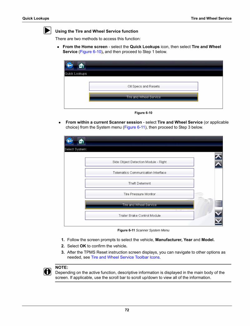
72
Quick Lookups Tire and Wheel Service
z Using the Tire and Wheel Service function
There are two methods to access this function:
• From the Home screen - select the Quick Lookups icon, then select Tire and Wheel Service (Figure 6-10), and then proceed to Step 1 below.
Figure 6-10
• From within a current Scanner session - select Tire and Wheel Service (or applicable choice) from the System menu (Figure 6-11), then proceed to Step 3 below.
Figure 6-11 Scanner System Menu
1. Follow the screen prompts to select the vehicle, Manufacturer, Year and Model.
2. Select OK to confirm the vehicle.
3. After the TPMS Reset instruction screen displays, you can navigate to other options as needed, see Tire and Wheel Service Toolbar Icons.
NOTE:i Depending on the active function, descriptive information is displayed in the main body of the
screen. If applicable, use the scroll bar to scroll up/down to view all of the information.
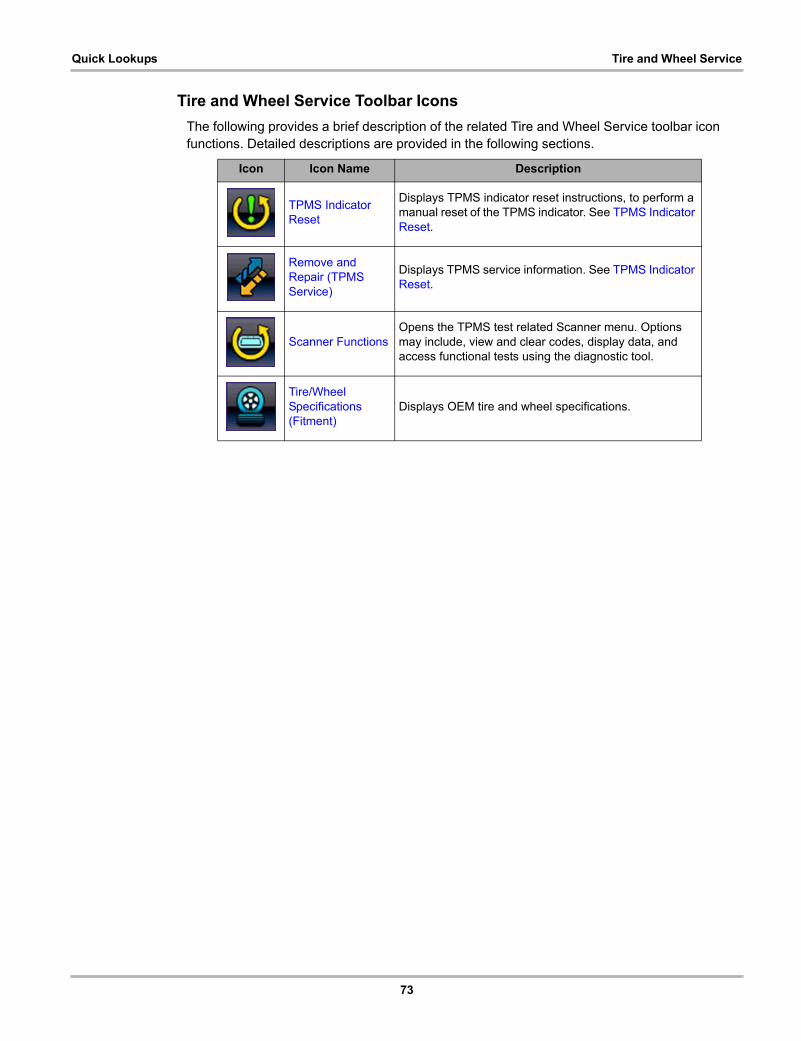
73
Quick Lookups Tire and Wheel Service
Tire and Wheel Service Toolbar Icons
The following provides a brief description of the related Tire and Wheel Service toolbar icon functions. Detailed descriptions are provided in the following sections.
Icon Icon Name Description
TPMS Indicator Reset
Displays TPMS indicator reset instructions, to perform a manual reset of the TPMS indicator. See TPMS Indicator Reset.
Remove and Repair (TPMS Service)
Displays TPMS service information. See TPMS Indicator Reset.
Scanner FunctionsOpens the TPMS test related Scanner menu. Options may include, view and clear codes, display data, and access functional tests using the diagnostic tool.
Tire/Wheel Specifications (Fitment)
Displays OEM tire and wheel specifications.
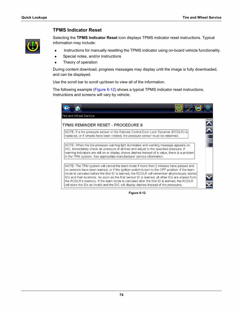
74
Quick Lookups Tire and Wheel Service
TPMS Indicator Reset
Selecting the TPMS Indicator Reset icon displays TPMS indicator reset instructions. Typical information may include:
• Instructions for manually resetting the TPMS indicator using on-board vehicle functionality.
• Special notes, and/or instructions
• Theory of operation
During content download, progress messages may display until the image is fully downloaded, and can be displayed.
Use the scroll bar to scroll up/down to view all of the information.
The following example (Figure 6-12) shows a typical TPMS indicator reset instructions. Instructions and screens will vary by vehicle.
Figure 6-12

75
Quick Lookups Tire and Wheel Service
TPMS Remove & Repair (TPMS Service)
Selecting the Remove & Repair (TPMS Service) icon displays TPMS service information. Typical information may include:
• Removal and installation instructions.
• Relearn/enable procedures
• Diagnostic testing procedures
• Theory of operation
During content download, progress messages may display until the image is fully downloaded, and can be displayed.
Use the scroll bar to scroll up/down to view all of the information.
The following are examples (Figure 6-13) of typical TPMS service procedures. screens, results will vary by vehicle.
Figure 6-13
76
Quick Lookups Tire and Wheel Service
Scanner Functions
Selecting the Scanner Function icon opens the TPMS Scanner test menu for the selected vehicle. Options may include:
• View and Clear Codes
• View Data
• Perform TPMS Related Functional Tests/Resets
• View TPMS Troubleshooter Information
IMPORTANT:Functional test instructions may be provided, that are required to be performed before selecting or completing the function itself. Follow all instructions as written.
NOTE:i Scanner functions require connection and communication with the vehicle.
Functional tests/resets are not available for all vehicles, and will vary depending on vehicle support.
A “grayed out” or non-selectable icon indicates that functional resets/rests are not available for the selected vehicle.
Service test/reset menu titles will vary by manufacturer.
The following screen examples (Figure 6-14) illustrate some typical TPMS functional test screens.
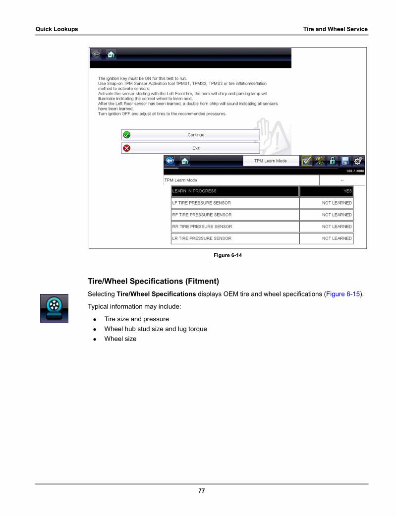
77
Quick Lookups Tire and Wheel Service
Figure 6-14
Tire/Wheel Specifications (Fitment)
Selecting Tire/Wheel Specifications displays OEM tire and wheel specifications (Figure 6-15).
Typical information may include:
• Tire size and pressure
• Wheel hub stud size and lug torque
• Wheel size
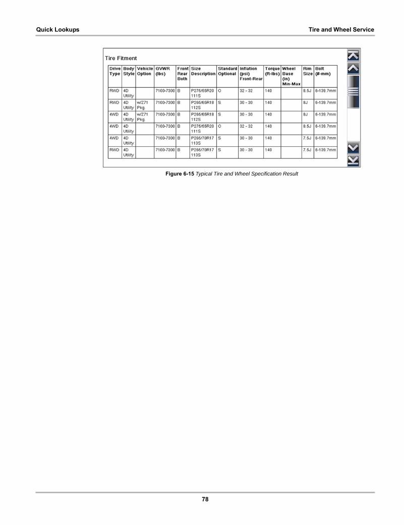
78
Quick Lookups Tire and Wheel Service
Figure 6-15 Typical Tire and Wheel Specification Result
79
Chapter 7 OBD-II/EOBD
This chapter describes the basic operation of the OBD-II/EOBD function.
The OBD-II/EOBD icon is located on the Home screen.
The OBD-II/EOBD function allows you to access “generic” OBD-II/EOBD data. Generic OBD-II/EOBD data is data limited to emission related diagnostics such as:
• Checking for emissions-related diagnostic trouble codes (DTCs)
• Checking the cause of an illuminated malfunction indicator lamp (MIL)
• Checking monitor status prior to emissions certification testing
To access other available electronic control module (ECM) data for vehicle specific systems, parameters or enhanced diagnostics use the Scanner function, see Scanner on page 14.
NOTE:i The OBD-II/EOBD function can also be used to access “generic” OBD-II/EOBD data for
OBD-II/EOBD compliant vehicles that are not included in the Scanner function databases.
7.1 Basic Operations
7.1.1 Screen Layout and Toolbar Controls
Screen layout and toolbar controls are similar to the Scanner function, see Scanner Control Icons‚ on page 15.
7.1.2 Connecting the Data Cable
Connection of the data cable to the Diagnostic Tool and vehicle DLC is required for OBD-II/EOBD testing, see Data Cable Connection‚ on page 12.
7.1.3 Saving and Reviewing Data Files
Save and Pause control icon operation and data review procedures are the same as used for the Scanner function, see Saving and Reviewing Scanner / OBD-II/EOBD Data Files‚ on page 28.
7.2 OBD-II/EOBD MenuThe following options are available from the OBD-II/EOBD menu:
• OBD Health Check
• OBD Direct
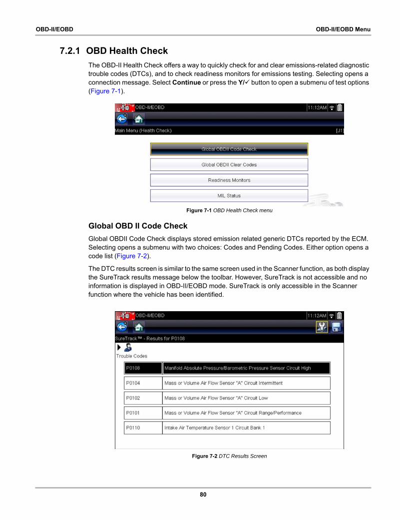
80
OBD-II/EOBD OBD-II/EOBD Menu
7.2.1 OBD Health Check
The OBD-II Health Check offers a way to quickly check for and clear emissions-related diagnostic trouble codes (DTCs), and to check readiness monitors for emissions testing. Selecting opens a connection message. Select Continue or press the Y/a button to open a submenu of test options (Figure 7-1).
Figure 7-1 OBD Health Check menu
Global OBD II Code Check
Global OBDII Code Check displays stored emission related generic DTCs reported by the ECM. Selecting opens a submenu with two choices: Codes and Pending Codes. Either option opens a code list (Figure 7-2).
The DTC results screen is similar to the same screen used in the Scanner function, as both display the SureTrack results message below the toolbar. However, SureTrack is not accessible and no information is displayed in OBD-II/EOBD mode. SureTrack is only accessible in the Scanner function where the vehicle has been identified.
Figure 7-2 DTC Results Screen
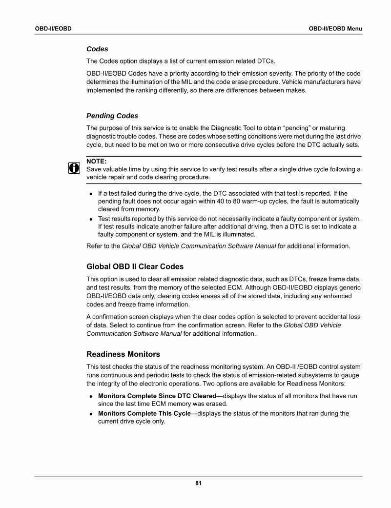
81
OBD-II/EOBD OBD-II/EOBD Menu
Codes
The Codes option displays a list of current emission related DTCs.
OBD-II/EOBD Codes have a priority according to their emission severity. The priority of the code determines the illumination of the MIL and the code erase procedure. Vehicle manufacturers have implemented the ranking differently, so there are differences between makes.
Pending Codes
The purpose of this service is to enable the Diagnostic Tool to obtain “pending” or maturing diagnostic trouble codes. These are codes whose setting conditions were met during the last drive cycle, but need to be met on two or more consecutive drive cycles before the DTC actually sets.
NOTE:i Save valuable time by using this service to verify test results after a single drive cycle following a
vehicle repair and code clearing procedure.
• If a test failed during the drive cycle, the DTC associated with that test is reported. If the pending fault does not occur again within 40 to 80 warm-up cycles, the fault is automatically cleared from memory.
• Test results reported by this service do not necessarily indicate a faulty component or system. If test results indicate another failure after additional driving, then a DTC is set to indicate a faulty component or system, and the MIL is illuminated.
Refer to the Global OBD Vehicle Communication Software Manual for additional information.
Global OBD II Clear Codes
This option is used to clear all emission related diagnostic data, such as DTCs, freeze frame data, and test results, from the memory of the selected ECM. Although OBD-II/EOBD displays generic OBD-II/EOBD data only, clearing codes erases all of the stored data, including any enhanced codes and freeze frame information.
A confirmation screen displays when the clear codes option is selected to prevent accidental loss of data. Select to continue from the confirmation screen. Refer to the Global OBD Vehicle Communication Software Manual for additional information.
Readiness Monitors
This test checks the status of the readiness monitoring system. An OBD-II /EOBD control system runs continuous and periodic tests to check the status of emission-related subsystems to gauge the integrity of the electronic operations. Two options are available for Readiness Monitors:
• Monitors Complete Since DTC Cleared—displays the status of all monitors that have run since the last time ECM memory was erased.
• Monitors Complete This Cycle—displays the status of the monitors that ran during the current drive cycle only.
82
OBD-II/EOBD OBD-II/EOBD Menu
Selection of either option displays test results as shown in the data viewer (Figure 7-3).
Quick reference indicators are used to show monitor status on the left side of the screen (Figure 7-3):
• Green icon “a” mark - Monitor test is complete
• Grey icon “—” mark - Monitor test is not complete
• Red icon “X” mark - Monitor test is not supported by vehicle
Figure 7-3 Readiness monitor test report
Use the scroll bar to view the entire list of Readiness Monitors.
Selecting Save from the toolbar saves the monitor data as an .SCM file for review at a later time. See View Saved Data‚ on page 155 for additional information.
MIL Status
This test checks the ECM commanded state (on or off) if the malfunction indicator lamp.
7.2.2 OBD Direct
OBD Direct includes the following menu and submenu choices:
• OBD Diagnose
– Start Communication - initiates a test session– Connector Information - provides DLC location details– Manual Protocol Selection - provides choices for communication protocol
• OBD Training Mode - allows you to familiarize yourself with the capabilities of OBD-II/EOBD while navigating through menus without being connected to a vehicle.
Start Communication
Use the following procedure to begin an OBD-II/EOBD test session:
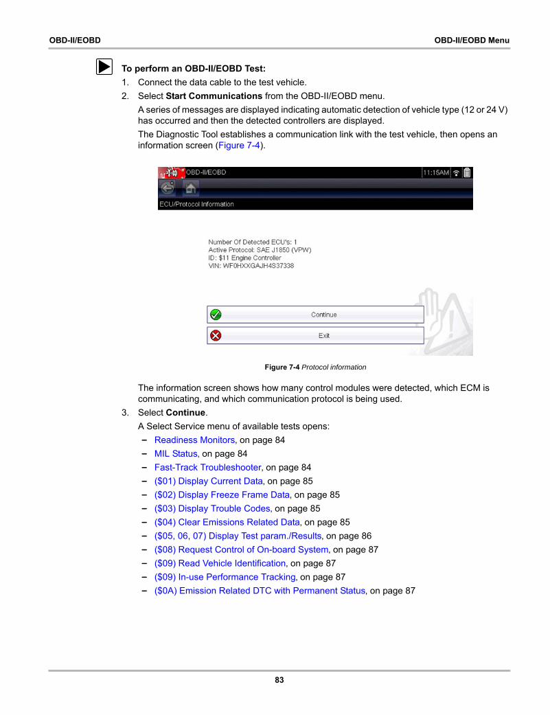
83
OBD-II/EOBD OBD-II/EOBD Menu
z To perform an OBD-II/EOBD Test:
1. Connect the data cable to the test vehicle.
2. Select Start Communications from the OBD-II/EOBD menu.
A series of messages are displayed indicating automatic detection of vehicle type (12 or 24 V) has occurred and then the detected controllers are displayed.
The Diagnostic Tool establishes a communication link with the test vehicle, then opens an information screen (Figure 7-4).
Figure 7-4 Protocol information
The information screen shows how many control modules were detected, which ECM is communicating, and which communication protocol is being used.
3. Select Continue.
A Select Service menu of available tests opens:
– Readiness Monitors‚ on page 84
– MIL Status‚ on page 84
– Fast-Track Troubleshooter‚ on page 84
– ($01) Display Current Data‚ on page 85
– ($02) Display Freeze Frame Data‚ on page 85
– ($03) Display Trouble Codes‚ on page 85
– ($04) Clear Emissions Related Data‚ on page 85
– ($05, 06, 07) Display Test param./Results‚ on page 86
– ($08) Request Control of On-board System‚ on page 87
– ($09) Read Vehicle Identification‚ on page 87
– ($09) In-use Performance Tracking‚ on page 87
– ($0A) Emission Related DTC with Permanent Status‚ on page 87
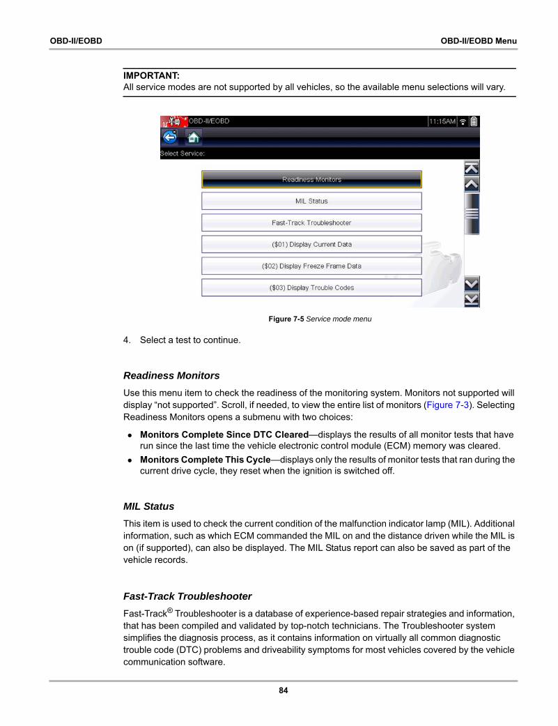
84
OBD-II/EOBD OBD-II/EOBD Menu
IMPORTANT:All service modes are not supported by all vehicles, so the available menu selections will vary.
Figure 7-5 Service mode menu
4. Select a test to continue.
Readiness Monitors
Use this menu item to check the readiness of the monitoring system. Monitors not supported will display “not supported”. Scroll, if needed, to view the entire list of monitors (Figure 7-3). Selecting Readiness Monitors opens a submenu with two choices:
• Monitors Complete Since DTC Cleared—displays the results of all monitor tests that have run since the last time the vehicle electronic control module (ECM) memory was cleared.
• Monitors Complete This Cycle—displays only the results of monitor tests that ran during the current drive cycle, they reset when the ignition is switched off.
MIL Status
This item is used to check the current condition of the malfunction indicator lamp (MIL). Additional information, such as which ECM commanded the MIL on and the distance driven while the MIL is on (if supported), can also be displayed. The MIL Status report can also be saved as part of the vehicle records.
Fast-Track Troubleshooter
Fast-Track® Troubleshooter is a database of experience-based repair strategies and information, that has been compiled and validated by top-notch technicians. The Troubleshooter system simplifies the diagnosis process, as it contains information on virtually all common diagnostic trouble code (DTC) problems and driveability symptoms for most vehicles covered by the vehicle communication software.
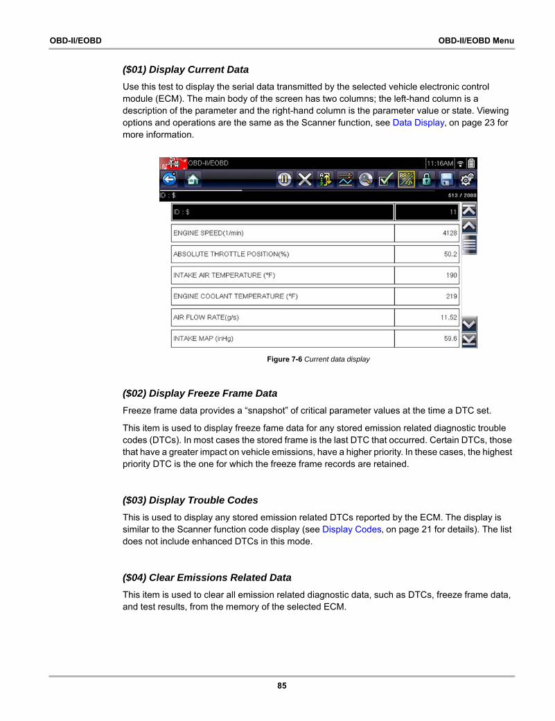
85
OBD-II/EOBD OBD-II/EOBD Menu
($01) Display Current Data
Use this test to display the serial data transmitted by the selected vehicle electronic control module (ECM). The main body of the screen has two columns; the left-hand column is a description of the parameter and the right-hand column is the parameter value or state. Viewing options and operations are the same as the Scanner function, see Data Display‚ on page 23 for more information.
Figure 7-6 Current data display
($02) Display Freeze Frame Data
Freeze frame data provides a “snapshot” of critical parameter values at the time a DTC set.
This item is used to display freeze fame data for any stored emission related diagnostic trouble codes (DTCs). In most cases the stored frame is the last DTC that occurred. Certain DTCs, those that have a greater impact on vehicle emissions, have a higher priority. In these cases, the highest priority DTC is the one for which the freeze frame records are retained.
($03) Display Trouble Codes
This is used to display any stored emission related DTCs reported by the ECM. The display is similar to the Scanner function code display (see Display Codes‚ on page 21 for details). The list does not include enhanced DTCs in this mode.
($04) Clear Emissions Related Data
This item is used to clear all emission related diagnostic data, such as DTCs, freeze frame data, and test results, from the memory of the selected ECM.

86
OBD-II/EOBD OBD-II/EOBD Menu
z To clear emission related Data:
1. Select Clear Emissions Related Data from the menu.
A confirmation message displays to help prevent loss of any vital data (Figure 7-7).
Figure 7-7 Clear codes confirmation message
2. Continue from the confirmation message.
The screen updates several times as ECM memory is erased, then a “data has been cleared” message displays.
3. Select Continue to return to the Select Service menu.
($05, 06, 07) Display Test param./Results
This option opens a submenu of parameters and test results from various sensors, monitor test results, and a record of DTC setting conditions detected during the last drive cycle. The submenu includes:
• ($05) Oxygen Sensor Monitoring
• ($06) On-board Monitored Systems
• ($07) DTCs Detected During Last Drive
($05) Oxygen Sensor Monitoring
This option opens a menu of tests available for checking the integrity of the oxygen (O2) sensors. Making a selection displays all of the pertinent O2 sensor parameters for the specific test. The test identification (ID) displays at the top of the data list.
($06) On-board Monitored Systems
This option opens a menu of tests from the monitored systems. The available data is for specific systems and components that the on-board diagnostic system monitors continuously, such as misfire, or non-continuously, such as the catalyst system. Making a menu selection displays the test results.
87
OBD-II/EOBD OBD-II/EOBD Menu
($07) DTCs Detected During Last Drive
This test opens a record of any DTCs that set during the last completed drive cycle. Select to open the DTC list.
($08) Request Control of On-board System
This service enables bidirectional control of the ECM. This service allows the Diagnostic Tool to control the operation of an on-board system, test, or component.
($09) Read Vehicle Identification
The purpose of this service is to enable the Diagnostic Tool to request and display vehicle-specific information, such as the vehicle identification number (VIN), the calibration identification, and the calibration verification number (CVN), of the test vehicle. Select a menu item to retrieve the information. Select Return to go back to the menu.
($09) In-use Performance Tracking
This option displays the “In-use Performance Tracking” of data. It is a record of the number of times each of the monitor tests have been completed. Select Return to go back to the menu.
($0A) Emission Related DTC with Permanent Status
This option displays a record of any “permanent” codes. A permanent status DTC is one that was severe enough to illuminate the MIL at some point, but the MIL may not be on at the present time.
Whether the MIL was switched off by clearing codes or because the setting conditions did not repeat after a specified number of drive cycles, a record of the DTC is retained by the ECM. Permanent status codes automatically clear after repairs have been made and the related system monitor runs successfully.
Connector Information
This option opens a database of vehicle diagnostic connector locations that includes most makes and models. The menu driven interface leads you quickly to difficult to find test connectors.
z To locate a vehicle diagnostic connector:
1. Select Connector Information from the System menu.
A list of vehicle manufacturers displays.
2. Select a manufacturer from the list.
A list of models available from the selected manufacturer displays.
3. Select a model from the list.
If a cable adapter is needed, which one and how to connect it displays.
4. Select Continue.
Information on where to locate the vehicle diagnostic connector displays.
5. Select Continue to return to the System menu.

88
OBD-II/EOBD OBD-II/EOBD Menu
Manual Protocol Selection
Communication protocol is a standardized way of transferring data between an ECM and a Diagnostic Tool. Global OBD may use the following communication protocols:
• ISO 15765-4 (CAN)
• ISO 27145 (WWHOBD CAN)
• ISO J1939 (CAN)
• ISO 9141-2 (K-LINE)
• SAE J1850 PWM (Pulse Width Modulation)
• SAE J1850 VPW (Variable Pulse Width)
• ISO 14230-4 (Keyword Protocol 2000)
• SAE J2284/ISO 15765-4 (CAN)
When initially attempting to establish communication with the ECM the Diagnostic Tool attempts to communicate trying each protocol in order to determine which one is being used. During normal operation the communication protocol is automatically detected. If automatic detection fails, communication protocol can be manually selected.
IMPORTANT:Using unsupported OBD communication protocols may activate warning lights and can set network related faults. Only use the manual selection option when OBD protocol is already known.
Select Manual Protocol Selection to open a menu of options (Figure 7-8).
Figure 7-8 Manual protocol selection menu
Select the Back icon or press the N/X button to return to the OBD-II/EOBD Main menu.

89
Chapter 8 Guided Component Tests
The Guided Component Tests function provides you with an extensive collection of vehicle specific component tests and reference information. It is like having access to a complete library of automotive repair manuals for testing multiple vehicle components.
The preconfigured meter tests and reference information provided are vehicle specific and designed to help save you diagnostic time, verify faulty components, and verify the repair.
Detailed instructions and reference information are provided to guide you through the testing process, from locating the component, to selecting the appropriate test, showing test lead connections, and illustrating electrical connector and pin configurations. In addition, test results (including waveform examples), procedures, tips, and specifications may also be provided.
NOTE:i Availability of tests and information may vary.
As an added resource, Training and Classes provides even more support by including (non-vehicle specific) tests and resources that allow you to quickly perform common tests, review basic reference information and more.
8.1 Training and ClassesTraining and Classes is a companion feature to the Guided Component Tests function. This resource includes a wide collection of common (non-vehicle specific) reference information and tests, such as measuring fuel pump current ramp, and monitoring CKP and CMP signals simultaneously. Also included are, basic component operation and theory information, testing procedures, tips, definitions, illustrations, diagnostic tool feature descriptions and accessory information.
z To access Training and Classes:
1. Select Guided Component Tests from the Home screen.
2. Select Training and Classes from the Vehicle Make menu (Figure 8-1) to access the menu options.
Each menu option is described in the following sections:
All features and information are subject to change. The following is for reference only.
• Power User Tests
• How To Guide
• Features and Benefits
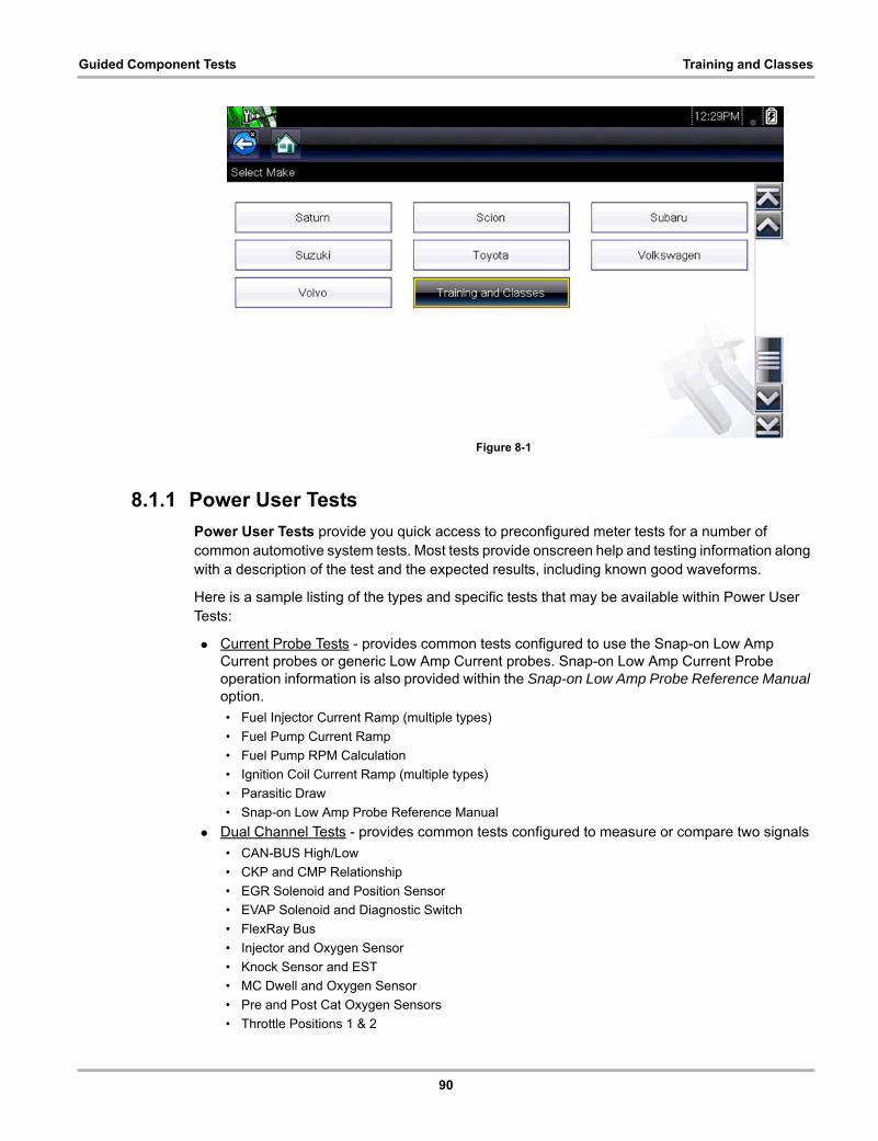
90
Guided Component Tests Training and Classes
Figure 8-1
8.1.1 Power User Tests
Power User Tests provide you quick access to preconfigured meter tests for a number of common automotive system tests. Most tests provide onscreen help and testing information along with a description of the test and the expected results, including known good waveforms.
Here is a sample listing of the types and specific tests that may be available within Power User Tests:
• Current Probe Tests - provides common tests configured to use the Snap-on Low Amp Current probes or generic Low Amp Current probes. Snap-on Low Amp Current Probe operation information is also provided within the Snap-on Low Amp Probe Reference Manual option.
• Fuel Injector Current Ramp (multiple types)
• Fuel Pump Current Ramp
• Fuel Pump RPM Calculation
• Ignition Coil Current Ramp (multiple types)
• Parasitic Draw
• Snap-on Low Amp Probe Reference Manual
• Dual Channel Tests - provides common tests configured to measure or compare two signals
• CAN-BUS High/Low
• CKP and CMP Relationship
• EGR Solenoid and Position Sensor
• EVAP Solenoid and Diagnostic Switch
• FlexRay Bus
• Injector and Oxygen Sensor
• Knock Sensor and EST
• MC Dwell and Oxygen Sensor
• Pre and Post Cat Oxygen Sensors
• Throttle Positions 1 & 2

91
Guided Component Tests Training and Classes
• WSS (Hall Effect Type)
• Transducer Tests - provides common single and dual channel tests configured to measure various types of pressures, voltage and current. Transducers are available as optional equipment.
• A/T Line Pressure and Shift Solenoid
• A/T Line Pressure Test
• EGR Temperature Sensor and EGR Vacuum
• Exhaust Back Pressure Test
• Fuel Pressure and Fuel Pump Current
• Fuel Pressure and Fuel Pump Voltage
• Fuel Pressure Test
How To Guide
The How To option provides multiple topics and references ranging from instructional and basic theory to troubleshooting and testing instructions. Menu options may include:
• 10-minute Electronic Classes—provides basic electrical theory and testing information. Topics may include:
• Ohm’s Law
• Variable Resistors
• Amperage
• Diode Continuity
• Electrical Circuits
• Guided Voltage Drop Test
• Other Electrical Measurements
• Resistance
• Scientific Notation
• Voltage
• 15-minute Ignition Class—provides basic introductory ignition system information. Topics may include:
• Introduction
• Coil on Plug (COP)
• Conventional
• Waste Spark
• Illustrated Terms & Definitions—provides common term definitions, illustrations and tips associated with automotive component testing.
• No-Start Basics—provides basic step-by-step procedures for the diagnosis of a no-start condition on carbureted and fuel injected vehicles.
• O2 Sensor & Feedback System Analysis—provides basic definition and theory information for the following O2 sensor topics:
• Air Fuel Ratio Sensors
• Correct PCM Response (includes configured meter test)
• Heated Oxygen Sensor
• Non-Heated Oxygen Sensor
• Open and Closed Loop
• Oxygen Sensor Types
• Understanding Oxygen Sensors (includes configured meter test)
• Snap-on Automotive Theory— provides basic theory information on multiple topics including:
• Air Conditioning
• Diagnosing Battery Draws
92
Guided Component Tests Training and Classes
• Diesel Particulate Filters
• Electronic Parking Assistance
• HID Headlights
• Hybrid Vehicles
• LIN-BUS
• Supplemental Restraint Systems
• Tire Pressure Monitoring (TPMS)
• Test Tips—provides basic testing information, tips and procedures for specific tests and meter operations. Topics may include:
• Alternator Ripple Test
• EVP Sensor Test
• Frequency, Pulse Width and Duty Cycle Test
• Graphing AC Voltage
• Injector Pulse Width Test
• Parasitic Draw Test
• Reading Pulsed DTC’s
• TPS Sweep Test
• Using Cursors
• Using Pressure Transducers
• Using Triggers
• Wiggle Test
• Zirconia Oxygen Sensor Rise Time
• Theory and Operation—provides basic theory information for the following topics:
• Oxygen Sensors
• Relays
• 20-minute Current Ramp Classes—provides an introduction to current ramp testing using the Snap-on Low Amp Current Probes. Snap-on Low Amp Current Probe operation information is also provided within the Snap-on Low Amp Probe Reference Manual option. Topics may include:
• Fuel Injector Current Ramp (multiple types)
• Fuel Pump Current Ramp
• Fuel Pump RPM Calculation
• Ignition Coil Current Ramp (multiple types)
• Parasitic Draw
• Snap-on Low Amp Probe Reference Manual
• Using Fuse Box for Current Test Hard to Reach Wiring
Features and Benefits
Selecting Features and Benefits provides basic feature description and operational information about the diagnostic tool. Additional information is provided for ShopStream Connect, optional waveform demonstration boards and optional accessories. Selections include:
• 5-Minute Walk Thru With Demo Board—provides instructions on the operation of the optional waveform demonstration board(s) to sharpen your Lab Scope and Meter skills. Topics may include:
• New Demo Board (PN) #EESX306A—provides functionality information and basic step-by-step demonstration information of multiple generated waveforms
• Old Demo Board (PN) #SSP816—provides functionality information and basic step-by-step demonstration information for multiple generated waveforms
The optional demonstration board(s) generate various waveforms similar to signals commonly found on modern vehicle control systems. The demonstration board(s) not only
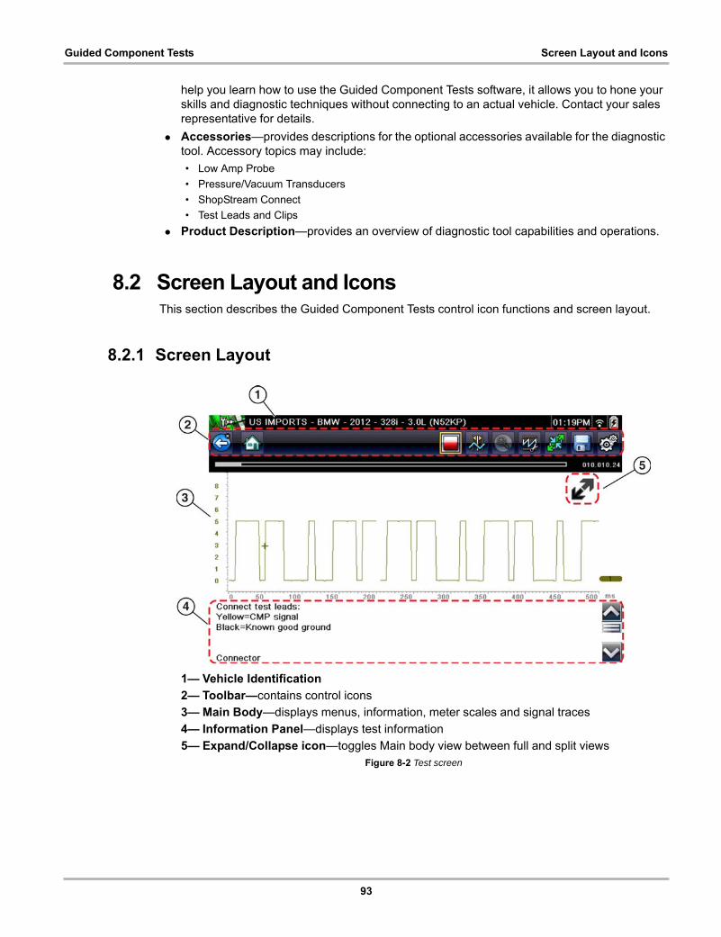
93
Guided Component Tests Screen Layout and Icons
help you learn how to use the Guided Component Tests software, it allows you to hone your skills and diagnostic techniques without connecting to an actual vehicle. Contact your sales representative for details.
• Accessories—provides descriptions for the optional accessories available for the diagnostic tool. Accessory topics may include:
• Low Amp Probe
• Pressure/Vacuum Transducers
• ShopStream Connect
• Test Leads and Clips
• Product Description—provides an overview of diagnostic tool capabilities and operations.
8.2 Screen Layout and IconsThis section describes the Guided Component Tests control icon functions and screen layout.
8.2.1 Screen Layout
1— Vehicle Identification
2— Toolbar—contains control icons
3— Main Body—displays menus, information, meter scales and signal traces
4— Information Panel—displays test information
5— Expand/Collapse icon—toggles Main body view between full and split viewsFigure 8-2 Test screen
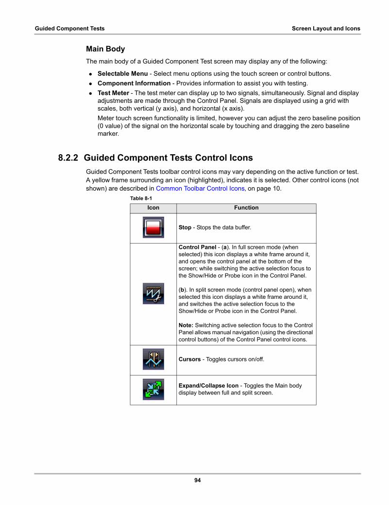
94
Guided Component Tests Screen Layout and Icons
Main Body
The main body of a Guided Component Test screen may display any of the following:
• Selectable Menu - Select menu options using the touch screen or control buttons.
• Component Information - Provides information to assist you with testing.
• Test Meter - The test meter can display up to two signals, simultaneously. Signal and display adjustments are made through the Control Panel. Signals are displayed using a grid with scales, both vertical (y axis), and horizontal (x axis).
Meter touch screen functionality is limited, however you can adjust the zero baseline position(0 value) of the signal on the horizontal scale by touching and dragging the zero baseline marker.
8.2.2 Guided Component Tests Control Icons
Guided Component Tests toolbar control icons may vary depending on the active function or test. A yellow frame surrounding an icon (highlighted), indicates it is selected. Other control icons (not shown) are described in Common Toolbar Control Icons‚ on page 10.
Table 8-1
Icon Function
Stop - Stops the data buffer.
Control Panel - (a). In full screen mode (when selected) this icon displays a white frame around it, and opens the control panel at the bottom of the screen; while switching the active selection focus to the Show/Hide or Probe icon in the Control Panel.
(b). In split screen mode (control panel open), when selected this icon displays a white frame around it, and switches the active selection focus to the Show/Hide or Probe icon in the Control Panel.
Note: Switching active selection focus to the Control Panel allows manual navigation (using the directional control buttons) of the Control Panel control icons.
Cursors - Toggles cursors on/off.
Expand/Collapse Icon - Toggles the Main body display between full and split screen.
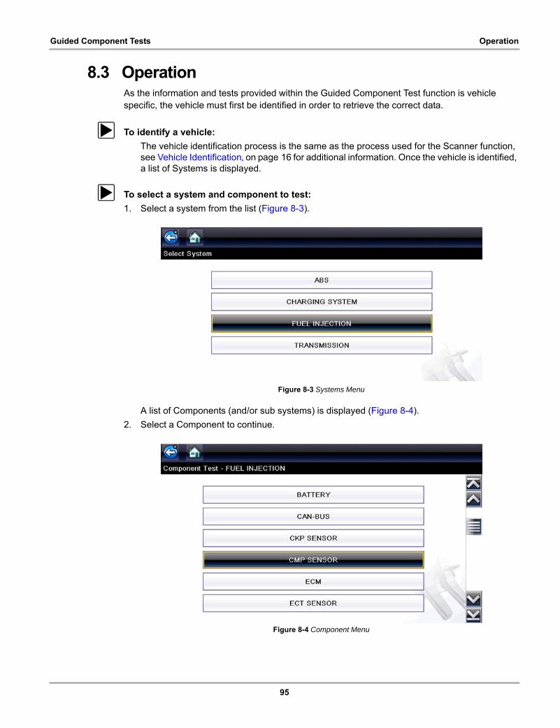
95
Guided Component Tests Operation
8.3 OperationAs the information and tests provided within the Guided Component Test function is vehicle specific, the vehicle must first be identified in order to retrieve the correct data.
z To identify a vehicle:
The vehicle identification process is the same as the process used for the Scanner function, see Vehicle Identification‚ on page 16 for additional information. Once the vehicle is identified, a list of Systems is displayed.
z To select a system and component to test:
1. Select a system from the list (Figure 8-3).
Figure 8-3 Systems Menu
A list of Components (and/or sub systems) is displayed (Figure 8-4).
2. Select a Component to continue.
Figure 8-4 Component Menu
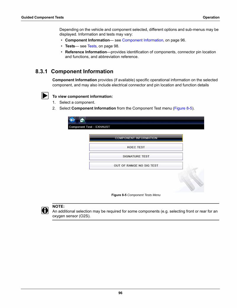
96
Guided Component Tests Operation
Depending on the vehicle and component selected, different options and sub-menus may be displayed. Information and tests may vary:
• Component Information— see Component Information‚ on page 96.
• Tests— see Tests‚ on page 98.
• Reference Information—provides identification of components, connector pin location and functions, and abbreviation reference.
8.3.1 Component Information
Component Information provides (if available) specific operational information on the selected component, and may also include electrical connector and pin location and function details
z To view component information:
1. Select a component.
2. Select Component Information from the Component Test menu (Figure 8-5).
Figure 8-5 Component Tests Menu
NOTE:i An additional selection may be required for some components (e.g. selecting front or rear for an
oxygen sensor (O2S).
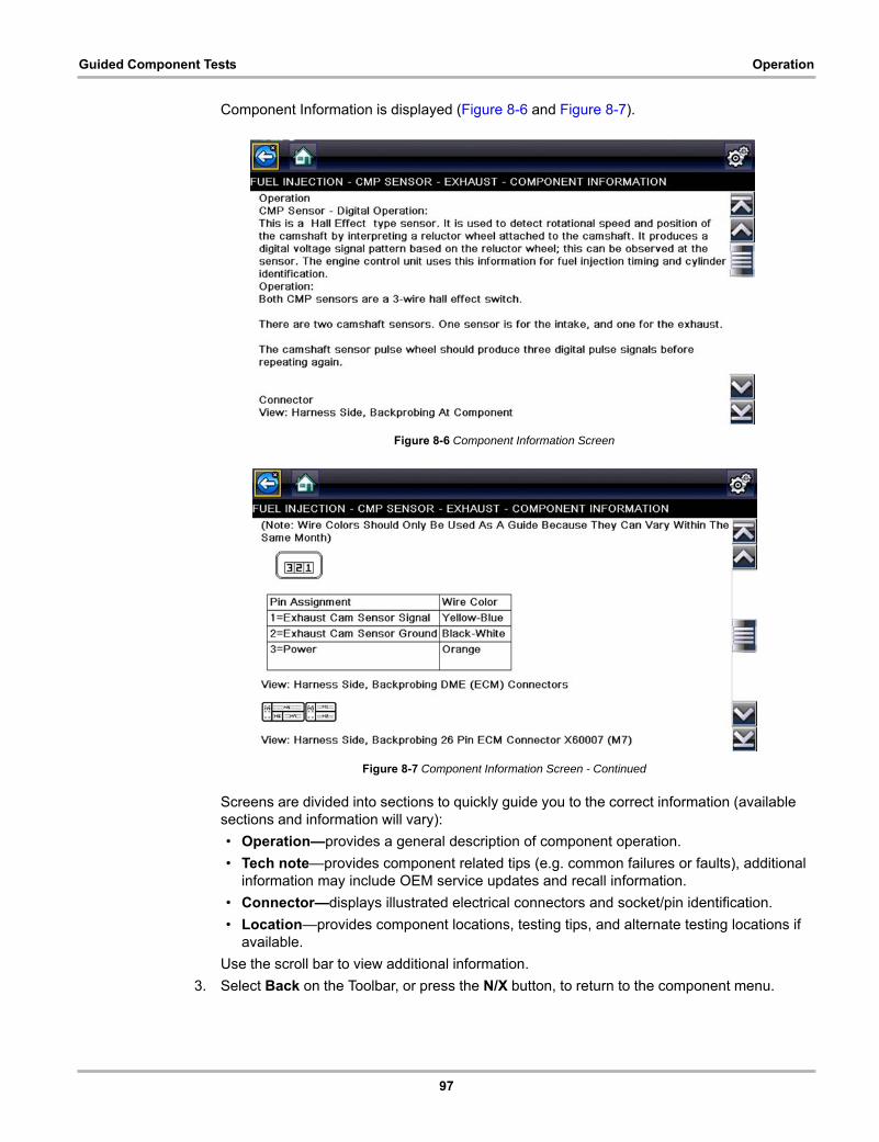
97
Guided Component Tests Operation
Component Information is displayed (Figure 8-6 and Figure 8-7).
Figure 8-6 Component Information Screen
Figure 8-7 Component Information Screen - Continued
Screens are divided into sections to quickly guide you to the correct information (available sections and information will vary):
• Operation—provides a general description of component operation.
• Tech note—provides component related tips (e.g. common failures or faults), additional information may include OEM service updates and recall information.
• Connector—displays illustrated electrical connectors and socket/pin identification.
• Location—provides component locations, testing tips, and alternate testing locations if available.
Use the scroll bar to view additional information.
3. Select Back on the Toolbar, or press the N/X button, to return to the component menu.
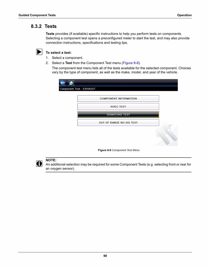
98
Guided Component Tests Operation
8.3.2 Tests
Tests provides (if available) specific instructions to help you perform tests on components. Selecting a component test opens a preconfigured meter to start the test, and may also provide connection instructions, specifications and testing tips.
z To select a test:
1. Select a component.
2. Select a Test from the Component Test menu (Figure 8-8).
The component test menu lists all of the tests available for the selected component. Choices vary by the type of component, as well as the make, model, and year of the vehicle.
Figure 8-8 Component Test Menu
NOTE:i An additional selection may be required for some Component Tests (e.g. selecting front or rear for
an oxygen sensor).
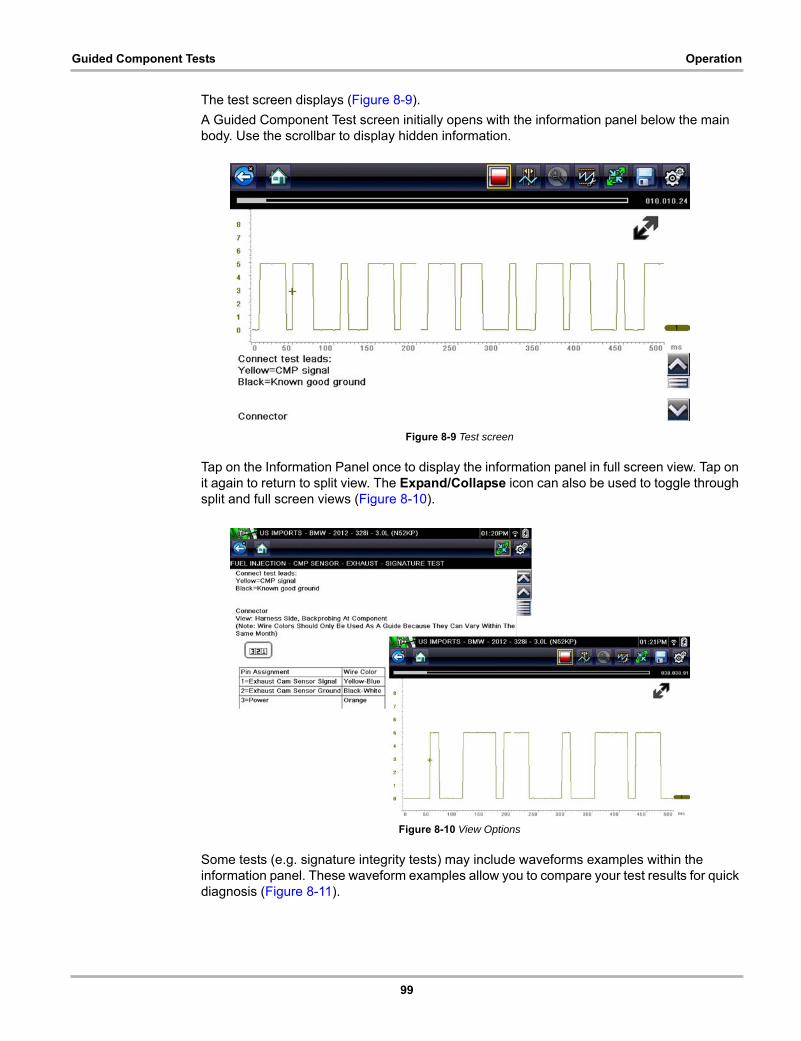
99
Guided Component Tests Operation
The test screen displays (Figure 8-9).
A Guided Component Test screen initially opens with the information panel below the main body. Use the scrollbar to display hidden information.
Figure 8-9 Test screen
Tap on the Information Panel once to display the information panel in full screen view. Tap on it again to return to split view. The Expand/Collapse icon can also be used to toggle through split and full screen views (Figure 8-10).
Figure 8-10 View Options
Some tests (e.g. signature integrity tests) may include waveforms examples within the information panel. These waveform examples allow you to compare your test results for quick diagnosis (Figure 8-11).
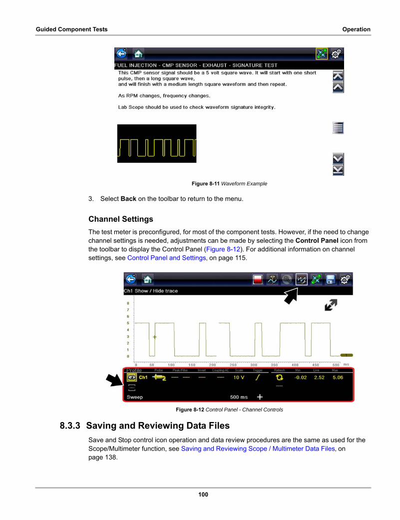
100
Guided Component Tests Operation
Figure 8-11 Waveform Example
3. Select Back on the toolbar to return to the menu.
Channel Settings
The test meter is preconfigured, for most of the component tests. However, if the need to change channel settings is needed, adjustments can be made by selecting the Control Panel icon from the toolbar to display the Control Panel (Figure 8-12). For additional information on channel settings, see Control Panel and Settings‚ on page 115.
Figure 8-12 Control Panel - Channel Controls
8.3.3 Saving and Reviewing Data Files
Save and Stop control icon operation and data review procedures are the same as used for the Scope/Multimeter function, see Saving and Reviewing Scope / Multimeter Data Files‚ on page 138.
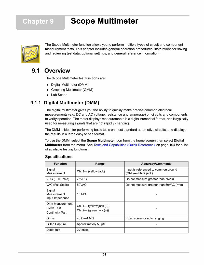
101
Chapter 9 Scope Multimeter
The Scope Multimeter function allows you to perform multiple types of circuit and component measurement tests. This chapter includes general operation procedures, instructions for saving and reviewing test data, optional settings, and general reference information.
9.1 OverviewThe Scope Multimeter test functions are:
• Digital Multimeter (DMM)
• Graphing Multimeter (GMM)
• Lab Scope
9.1.1 Digital Multimeter (DMM)
The digital multimeter gives you the ability to quickly make precise common electrical measurements (e.g. DC and AC voltage, resistance and amperage) on circuits and components to verify operation. The meter displays measurements in a digital numerical format, and is typically used for measuring signals that are not rapidly changing.
The DMM is ideal for performing basic tests on most standard automotive circuits, and displays the results in a large easy to see format.
To use the DMM, select the Scope Multimeter icon from the home screen then select Digital Multimeter from the menu. See Tests and Capabilities (Quick Reference)‚ on page 104 for a list of available testing functions.
Specifications
Function Range Accuracy/Comments
Signal Measurement
Ch. 1— (yellow jack)Input is referenced to common ground (GND— (black jack)
VDC (Full Scale) 75VDC Do not measure greater than 75VDC
VAC (Full Scale) 50VAC Do not measure greater than 50VAC (rms)
Signal Measurement Input Impedance
10 MΩ -
Ohm Measurement
Diode Test
Continuity Test
Ch. 1— (yellow jack (–))
Ch. 2— (green jack (+))-
Ohms 40 Ω—4 MΩ Fixed scales or auto ranging
Glitch Capture Approximately 50 µS -
Diode test 2V scale -
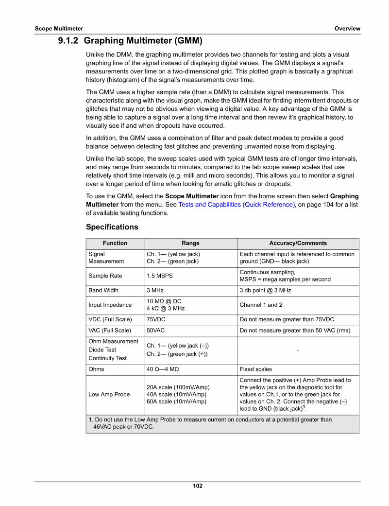
102
Scope Multimeter Overview
9.1.2 Graphing Multimeter (GMM)
Unlike the DMM, the graphing multimeter provides two channels for testing and plots a visual graphing line of the signal instead of displaying digital values. The GMM displays a signal’s measurements over time on a two-dimensional grid. This plotted graph is basically a graphical history (histogram) of the signal’s measurements over time.
The GMM uses a higher sample rate (than a DMM) to calculate signal measurements. This characteristic along with the visual graph, make the GMM ideal for finding intermittent dropouts or glitches that may not be obvious when viewing a digital value. A key advantage of the GMM is being able to capture a signal over a long time interval and then review it’s graphical history, to visually see if and when dropouts have occurred.
In addition, the GMM uses a combination of filter and peak detect modes to provide a good balance between detecting fast glitches and preventing unwanted noise from displaying.
Unlike the lab scope, the sweep scales used with typical GMM tests are of longer time intervals, and may range from seconds to minutes, compared to the lab scope sweep scales that use relatively short time intervals (e.g. milli and micro seconds). This allows you to monitor a signal over a longer period of time when looking for erratic glitches or dropouts.
To use the GMM, select the Scope Multimeter icon from the home screen then select Graphing Multimeter from the menu. See Tests and Capabilities (Quick Reference)‚ on page 104 for a list of available testing functions.
Specifications
Function Range Accuracy/Comments
Signal Measurement
Ch. 1— (yellow jack)Ch. 2— (green jack)
Each channel input is referenced to common ground (GND— black jack)
Sample Rate 1.5 MSPSContinuous sampling,MSPS = mega samples per second
Band Width 3 MHz 3 db point @ 3 MHz
Input Impedance10 MΩ @ DC4 kΩ @ 3 MHz
Channel 1 and 2
VDC (Full Scale) 75VDC Do not measure greater than 75VDC
VAC (Full Scale) 50VAC Do not measure greater than 50 VAC (rms)
Ohm Measurement
Diode Test
Continuity Test
Ch. 1— (yellow jack (–))
Ch. 2— (green jack (+))-
Ohms 40 Ω—4 MΩ Fixed scales
Low Amp Probe20A scale (100mV/Amp)40A scale (10mV/Amp)60A scale (10mV/Amp)
Connect the positive (+) Amp Probe lead to the yellow jack on the diagnostic tool for values on Ch.1, or to the green jack for values on Ch. 2. Connect the negative (–) lead to GND (black jack)1.
1. Do not use the Low Amp Probe to measure current on conductors at a potential greater than 46VAC peak or 70VDC.
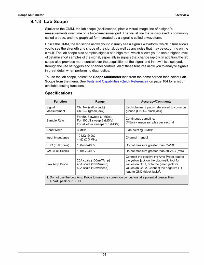
103
Scope Multimeter Overview
9.1.3 Lab Scope
Similar to the GMM, the lab scope (oscilloscope) plots a visual image line of a signal’s measurements over time on a two-dimensional grid. The visual line that is displayed is commonly called a trace, and the graphical form created by a signal is called a waveform.
Unlike the DMM, the lab scope allows you to visually see a signals waveform, which in turn allows you to see the strength and shape of the signal, as well as any noise that may be occurring on the circuit. The lab scope also samples signals at a high rate, which allows you to see a higher level of detail in short samples of the signal, especially in signals that change rapidly. In addition, the lab scope also provides more control over the acquisition of the signal and in how it is displayed, through the use of triggers and channel controls. All of these features allow you to analyze signals in great detail when performing diagnostics.
To use the lab scope, select the Scope Multimeter icon from the home screen then select Lab Scope from the menu. See Tests and Capabilities (Quick Reference)‚ on page 104 for a list of available testing functions.
Specifications
Function Range Accuracy/Comments
Signal Measurement
Ch. 1— (yellow jack)Ch. 2— (green jack)
Each channel input is referenced to common ground (GND— black jack).
Sample RateFor 50µS sweep 6 (MS/s)For 100µS sweep 3 (MS/s)For all other sweeps 1.5 (MS/s)
Continuous sampling,(MS/s) = mega samples per second
Band Width 3 MHz 3 db point @ 3 MHz
Input Impedance10 MΩ @ DC4 kΩ @ 3 MHz
Channel 1 and 2
VDC (Full Scale) 100mV–400V Do not measure greater than 75VDC.
VAC (Full Scale) 100mV–400V Do not measure greater than 50 VAC (rms).
Low Amp Probe20A scale (100mV/Amp)40A scale (10mV/Amp)60A scale (10mV/Amp)
Connect the positive (+) Amp Probe lead to the yellow jack on the diagnostic tool for values on Ch.1, or to the green jack for values on Ch. 2. Connect the negative (–) lead to GND (black jack)1.
1. Do not use the Low Amp Probe to measure current on conductors at a potential greater than 46VAC peak or 70VDC.
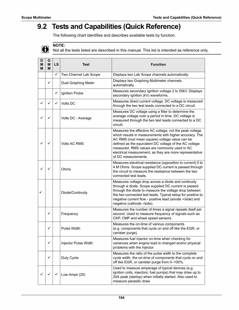
104
Scope Multimeter Tests and Capabilities (Quick Reference)
9.2 Tests and Capabilities (Quick Reference)The following chart identifies and describes available tests by function.
NOTE:i Not all the tests listed are described in this manual. This list is intended as reference only.
DMM
GMM
LS Test Function
a Two Channel Lab Scope Displays two Lab Scope channels automatically.
a Dual Graphing MeterDisplays two Graphing Multimeter channels automatically.
a Ignition ProbeMeasures secondary Ignition voltage 2 to 50kV. Displays secondary ignition (kV) waveforms.
a a a Volts DCMeasures direct current voltage. DC voltage is measured through the two test leads connected to a DC circuit.
a a Volts DC - Average
Measures DC voltage using a filter to determine the average voltage over a period in time. DC voltage is measured through the two test leads connected to a DC circuit.
a a Volts AC RMS
Measures the effective AC voltage, not the peak voltage which results in measurements with higher accuracy. The AC RMS (root mean square) voltage value can be defined as the equivalent DC voltage of the AC voltage measured. RMS values are commonly used in AC electrical measurement, as they are more representative of DC measurements.
a a Ohms
Measures electrical resistance (opposition to current) 0 to 4 M Ohms. Scope supplied DC current is passed through the circuit to measure the resistance between the two connected test leads.
a Diode/Continuity
Measures voltage drop across a diode and continuity through a diode. Scope supplied DC current is passed through the diode to measure the voltage drop between the two connected test leads. Typical setup for positive to negative current flow - positive lead (anode +/side) and negative (cathode -/side).
a FrequencyMeasures the number of times a signal repeats itself per second. Used to measure frequency of signals such as CKP, CMP and wheel speed sensors.
a Pulse WidthMeasures the on-time of various components (e.g. components that cycle on and off like the EGR, or canister purge).
a Injector Pulse WidthMeasures fuel injector on-time when checking for variances when engine load is changed and/or physical problems with the injector.
a Duty CycleMeasures the ratio of the pulse width to the complete cycle width, the on-time of components that cycle on and off like EGR, or canister purge from 0–100%.
a a a Low Amps (20)
Used to measure amperage of typical devices (e.g. ignition coils, injectors, fuel pumps) that may draw up to 20A peak (startup) when initially started. Also used to measure parasitic draw.
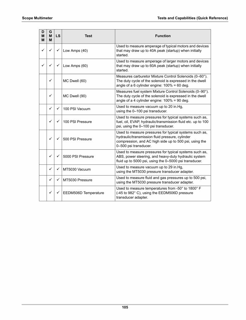
105
Scope Multimeter Tests and Capabilities (Quick Reference)
a a a Low Amps (40)Used to measure amperage of typical motors and devices that may draw up to 40A peak (startup) when initially started.
a a a Low Amps (60)Used to measure amperage of larger motors and devices that may draw up to 60A peak (startup) when initially started.
a MC Dwell (60)Measures carburetor Mixture Control Solenoids (0–60°). The duty cycle of the solenoid is expressed in the dwell angle of a 6 cylinder engine: 100% = 60 deg.
a MC Dwell (90)Measures fuel system Mixture Control Solenoids (0–90°). The duty cycle of the solenoid is expressed in the dwell angle of a 4 cylinder engine: 100% = 90 deg.
a a 100 PSI VacuumUsed to measure vacuum up to 20 in.Hg,using the 0–100 psi transducer.
a a 100 PSI PressureUsed to measure pressures for typical systems such as, fuel, oil, EVAP, hydraulic/transmission fluid etc. up to 100 psi, using the 0–100 psi transducer.
a a 500 PSI Pressure
Used to measure pressures for typical systems such as, hydraulic/transmission fluid pressure, cylinder compression, and AC high side up to 500 psi, using the 0–500 psi transducer.
a a 5000 PSI PressureUsed to measure pressures for typical systems such as, ABS, power steering, and heavy-duty hydraulic system fluid up to 5000 psi, using the 0–5000 psi transducer.
a a MT5030 VacuumUsed to measure vacuum up to 29 in.Hg,using the MT5030 pressure transducer adapter.
a a MT5030 PressureUsed to measure fluid and gas pressures up to 500 psi, using the MT5030 pressure transducer adapter.
a a EEDM506D TemperatureUsed to measure temperatures from -50° to 1800° F(-45 to 982° C), using the EEDM506D pressure transducer adapter.
DMM
GMM
LS Test Function
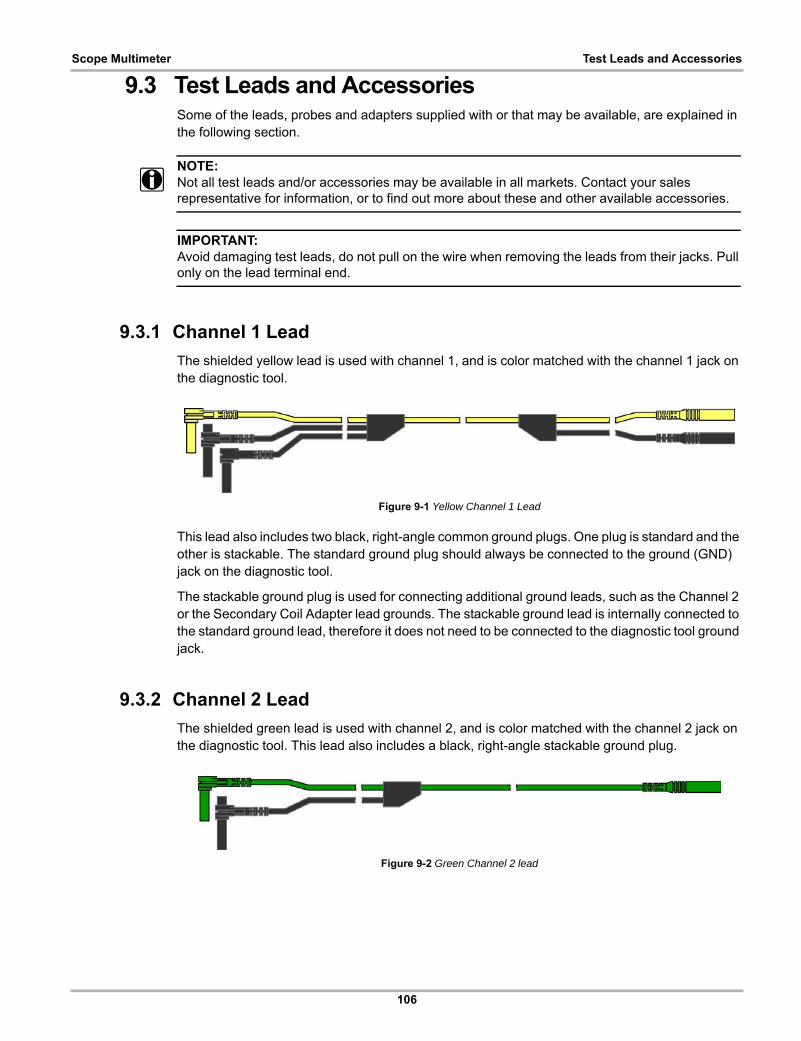
106
Scope Multimeter Test Leads and Accessories
9.3 Test Leads and AccessoriesSome of the leads, probes and adapters supplied with or that may be available, are explained in the following section.
NOTE:i Not all test leads and/or accessories may be available in all markets. Contact your sales
representative for information, or to find out more about these and other available accessories.
IMPORTANT:Avoid damaging test leads, do not pull on the wire when removing the leads from their jacks. Pull only on the lead terminal end.
9.3.1 Channel 1 Lead
The shielded yellow lead is used with channel 1, and is color matched with the channel 1 jack on the diagnostic tool.
Figure 9-1 Yellow Channel 1 Lead
This lead also includes two black, right-angle common ground plugs. One plug is standard and the other is stackable. The standard ground plug should always be connected to the ground (GND) jack on the diagnostic tool.
The stackable ground plug is used for connecting additional ground leads, such as the Channel 2 or the Secondary Coil Adapter lead grounds. The stackable ground lead is internally connected to the standard ground lead, therefore it does not need to be connected to the diagnostic tool ground jack.
9.3.2 Channel 2 Lead
The shielded green lead is used with channel 2, and is color matched with the channel 2 jack on the diagnostic tool. This lead also includes a black, right-angle stackable ground plug.
Figure 9-2 Green Channel 2 lead
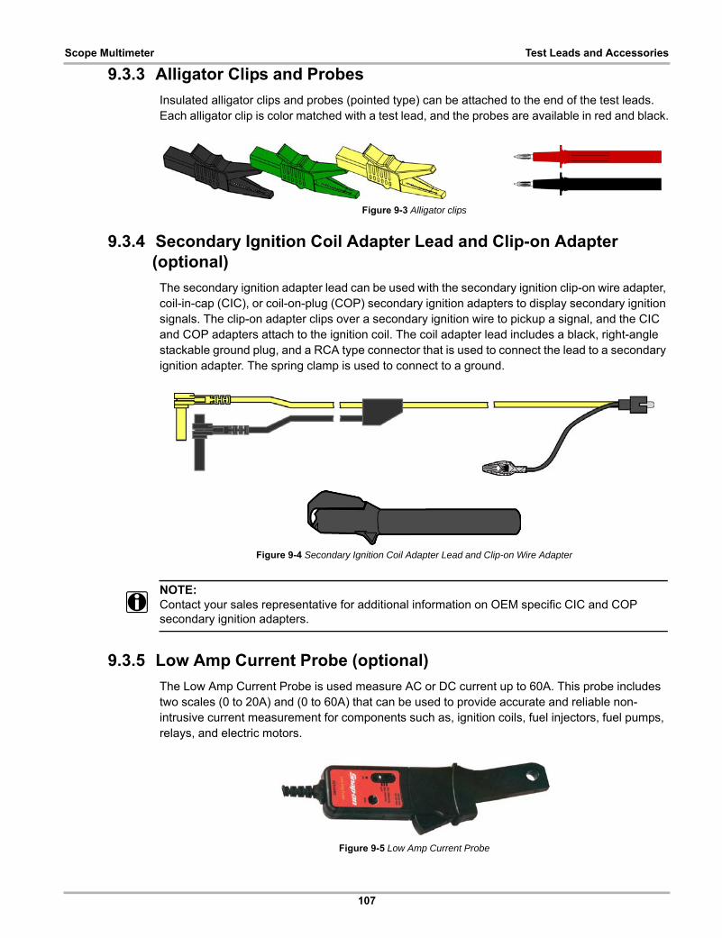
107
Scope Multimeter Test Leads and Accessories
9.3.3 Alligator Clips and Probes
Insulated alligator clips and probes (pointed type) can be attached to the end of the test leads. Each alligator clip is color matched with a test lead, and the probes are available in red and black.
Figure 9-3 Alligator clips
9.3.4 Secondary Ignition Coil Adapter Lead and Clip-on Adapter (optional)
The secondary ignition adapter lead can be used with the secondary ignition clip-on wire adapter, coil-in-cap (CIC), or coil-on-plug (COP) secondary ignition adapters to display secondary ignition signals. The clip-on adapter clips over a secondary ignition wire to pickup a signal, and the CIC and COP adapters attach to the ignition coil. The coil adapter lead includes a black, right-angle stackable ground plug, and a RCA type connector that is used to connect the lead to a secondary ignition adapter. The spring clamp is used to connect to a ground.
Figure 9-4 Secondary Ignition Coil Adapter Lead and Clip-on Wire Adapter
NOTE:i Contact your sales representative for additional information on OEM specific CIC and COP
secondary ignition adapters.
9.3.5 Low Amp Current Probe (optional)
The Low Amp Current Probe is used measure AC or DC current up to 60A. This probe includes two scales (0 to 20A) and (0 to 60A) that can be used to provide accurate and reliable non-intrusive current measurement for components such as, ignition coils, fuel injectors, fuel pumps, relays, and electric motors.
Figure 9-5 Low Amp Current Probe
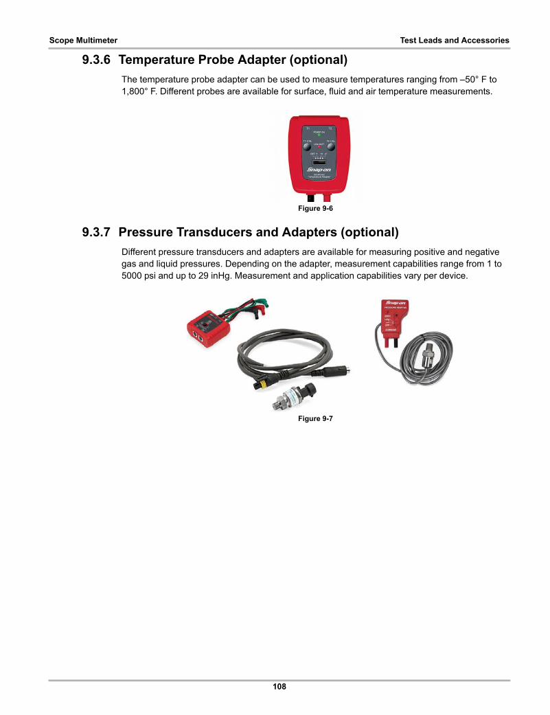
108
Scope Multimeter Test Leads and Accessories
9.3.6 Temperature Probe Adapter (optional)
The temperature probe adapter can be used to measure temperatures ranging from –50° F to 1,800° F. Different probes are available for surface, fluid and air temperature measurements.
Figure 9-6
9.3.7 Pressure Transducers and Adapters (optional)
Different pressure transducers and adapters are available for measuring positive and negative gas and liquid pressures. Depending on the adapter, measurement capabilities range from 1 to 5000 psi and up to 29 inHg. Measurement and application capabilities vary per device.
Figure 9-7

109
Scope Multimeter Test Leads and Accessories
9.3.8 Waveform Demonstration Tools (optional)
To help you sharpen your lab scope and graphing multimeter skills, optional waveform demonstration tools are available as a training aid. These demonstration tools generate common waveforms, and allow you to vary their display characteristics by turning glitches on/off, helping you to become more familiar with the lab scope controls. Common waveforms include, AC sine wave, variable frequency and pulse, secondary ignition, and more. There are two tools currently available, the standard model (Figure 9-8 left) and the vehicle simulator model (Figure 9-8 right) which produces waveforms (e.g. Crankshaft Position Sensor (CKP), Camshaft Position Sensor (CMP), Accelerator Pedal Sensor (APP), Wheel Speed Sensor (WSS) Signals, and more) representative of a 2012 BMW 328i Sedan.
Figure 9-8
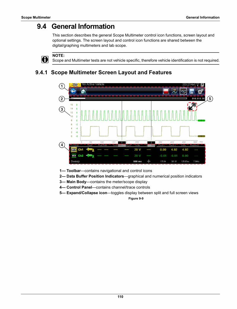
110
Scope Multimeter General Information
9.4 General InformationThis section describes the general Scope Multimeter control icon functions, screen layout and optional settings. The screen layout and control icon functions are shared between the digital/graphing multimeters and lab scope.
NOTE:i Scope and Multimeter tests are not vehicle specific, therefore vehicle identification is not required.
9.4.1 Scope Multimeter Screen Layout and Features
1— Toolbar—contains navigational and control icons
2— Data Buffer Position Indicators—graphical and numerical position indicators
3— Main Body—contains the meter/scope display
4— Control Panel—contains channel/trace controls
5— Expand/Collapse icon—toggles display between split and full screen viewsFigure 9-9

111
Scope Multimeter General Information
Scope Multimeter Control Icons
The following control icons are common across most Scope Multimeter functions, however use may vary depending on the active function or test. A yellow frame surrounding an icon (highlighted), indicates it is selected. Other control icons (not shown) are described in Common Toolbar Control Icons‚ on page 10.
Main Body
The main body may display the following:
• Menu - Select from a menu using the touch screen or the control buttons.
• Meter/Scope Display - Up to two signal traces can be displayed simultaneously. Each trace is displayed as voltage over time and the voltage level is recorded on the vertical, or “y”, axis and time is presented on the horizontal, or “x”, axis of the screen.
Data Buffer Position Indicators
The graphing multimeter and lab scope functions have the capability to save, store and playback, data (signals) utilizing internal storage “buffer” memory.
The Data Buffer Position Indicators are used to visually see the overall amount and position of the of stored buffer data during saving and playback.
For additional information on the Data Buffer, Data Buffer Position Indicator and Saving, Storing and Reviewing Data files, see Saving and Reviewing Scope / Multimeter Data Files‚ on page 138.
Icon Function
Stop - Stops the data buffer
Control Panel - (a). In full screen mode, when selected this icon becomes surrounded by a white frame and opens the control panel at the bottom of the screen while switching active selection focus to the Show/Hide or Probe icon in the Control Panel.(b). In split screen mode (control panel open), when selected this icon becomes surrounded by a white frame and switches active selection focus to the Show/Hide or Probe icon in the Control Panel.
Note: Switching active selection focus to the Control Panel allows manual navigation (using the directional control buttons) of the Control Panel control icons
Zoom - Increases and decreases screen magnification. The zoom function is only available during data review (scope stopped).
Cursors - Toggles cursors on/off.
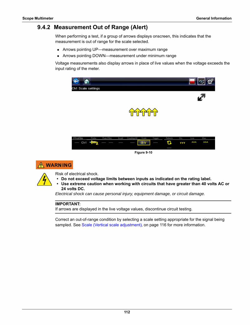
112
Scope Multimeter General Information
9.4.2 Measurement Out of Range (Alert)
When performing a test, if a group of arrows displays onscreen, this indicates that the measurement is out of range for the scale selected.
• Arrows pointing UP—measurement over maximum range
• Arrows pointing DOWN—measurement under minimum range
Voltage measurements also display arrows in place of live values when the voltage exceeds the input rating of the meter.
Figure 9-10
Risk of electrical shock.• Do not exceed voltage limits between inputs as indicated on the rating label.• Use extreme caution when working with circuits that have greater than 40 volts AC or
24 volts DC.Electrical shock can cause personal injury, equipment damage, or circuit damage.
IMPORTANT:If arrows are displayed in the live voltage values, discontinue circuit testing.
Correct an out-of-range condition by selecting a scale setting appropriate for the signal being sampled. See Scale (Vertical scale adjustment)‚ on page 116 for more information.

113
Scope Multimeter Operation and Controls
9.5 Operation and ControlsThis section describes the general operation and controls used to configure the scope or meter to perform testing. All three functions share similar control panel settings, see Control Panel and Settings‚ on page 115 for additional information.
NOTE:i The information in the following sections is intended as a guide and general overview of the
controls and functions used within the Scope Multimeter. Not all the settings or controls described throughout this section are applicable with all functions.
z To open a scope multimeter function:
1. Select the Scope Multimeter icon from the home screen.
2. Select either Lab Scope, Graphing Multimeter or Digital Multimeter from the menu.
9.5.1 Test Lead / Probe Connection
Standard “safety type” test lead jacks are located on the top of the diagnostic tool, and are compatible with many test leads and probes. Insert the applicable test lead or probe terminal end into the jack to compete the connection.
IMPORTANT:To avoid damaging test leads, do not pull on the wire when removing the leads from their jacks. Pull only on the lead terminal end.
1— Ground Jack (Black)
2— Channel 1 Jack (Yellow)
3— Channel 2 Jack (Green) Figure 9-11 Scope Multimeter Test Lead Jacks
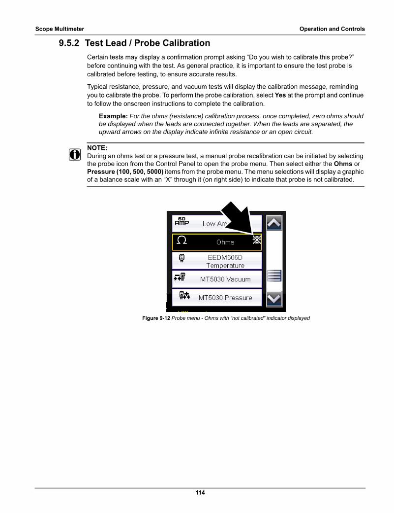
114
Scope Multimeter Operation and Controls
9.5.2 Test Lead / Probe Calibration
Certain tests may display a confirmation prompt asking “Do you wish to calibrate this probe?” before continuing with the test. As general practice, it is important to ensure the test probe is calibrated before testing, to ensure accurate results.
Typical resistance, pressure, and vacuum tests will display the calibration message, reminding you to calibrate the probe. To perform the probe calibration, select Yes at the prompt and continue to follow the onscreen instructions to complete the calibration.
Example: For the ohms (resistance) calibration process, once completed, zero ohms should be displayed when the leads are connected together. When the leads are separated, the upward arrows on the display indicate infinite resistance or an open circuit.
NOTE:i During an ohms test or a pressure test, a manual probe recalibration can be initiated by selecting
the probe icon from the Control Panel to open the probe menu. Then select either the Ohms or Pressure (100, 500, 5000) items from the probe menu. The menu selections will display a graphic of a balance scale with an “X” through it (on right side) to indicate that probe is not calibrated.
Figure 9-12 Probe menu - Ohms with “not calibrated” indicator displayed
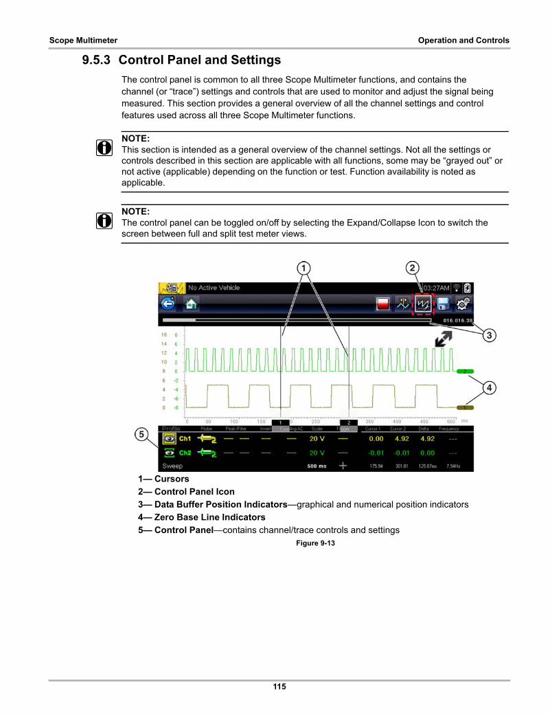
115
Scope Multimeter Operation and Controls
9.5.3 Control Panel and Settings
The control panel is common to all three Scope Multimeter functions, and contains the channel (or “trace”) settings and controls that are used to monitor and adjust the signal being measured. This section provides a general overview of all the channel settings and control features used across all three Scope Multimeter functions.
NOTE:i This section is intended as a general overview of the channel settings. Not all the settings or
controls described in this section are applicable with all functions, some may be “grayed out” or not active (applicable) depending on the function or test. Function availability is noted as applicable.
NOTE:i The control panel can be toggled on/off by selecting the Expand/Collapse Icon to switch the
screen between full and split test meter views.
1— Cursors
2— Control Panel Icon
3— Data Buffer Position Indicators—graphical and numerical position indicators
4— Zero Base Line Indicators
5— Control Panel—contains channel/trace controls and settings Figure 9-13
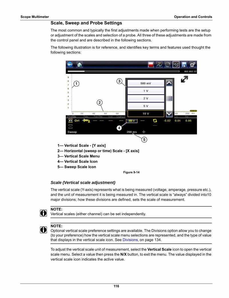
116
Scope Multimeter Operation and Controls
Scale, Sweep and Probe Settings
The most common and typically the first adjustments made when performing tests are the setup or adjustment of the scales and selection of a probe. All three of these adjustments are made from the control panel and are described in the following sections.
The following illustration is for reference, and identifies key terms and features used thought the following sections:
1— Vertical Scale - [Y axis]
2— Horizontal (sweep or time) Scale - [X axis]
3— Vertical Scale Menu
4— Vertical Scale Icon
5— Sweep Scale Icon Figure 9-14
Scale (Vertical scale adjustment)
The vertical scale (Y-axis) represents what is being measured (voltage, amperage, pressure etc.), and the unit of measurement it is being measured in. The vertical scale is “always” divided into10 major divisions; how these divisions are defined, sets the scale of measurement.
NOTE:i Vertical scales (either channel) can be set independently.
NOTE:i Optional vertical scale preference settings are available. The Divisions option allow you to change
(to your preference) how the vertical scale menu selections are represented, and the type of value that displays in the vertical scale icon. See Divisions‚ on page 134.
To adjust the vertical scale unit of measurement, select the Vertical Scale icon to open the vertical scale menu. Select a value then press the N/X button, to exit the menu. The value displayed in the vertical scale icon indicates the active value.

117
Scope Multimeter Operation and Controls
Example: Selecting 10V, changes the vertical scale to a 10V volt scale. The scale is “always” divided by 10, therefore each division is incremented by 1V.
Figure 9-15
Example: Selecting 50 psi displays a 50 psi scale that is divided by 10, therefore each division is incremented by 5 psi.
Figure 9-16

118
Scope Multimeter Operation and Controls
Sweep (Horizontal or Time scale adjustment)
The horizontal scale (X-axis) represents time, and the unit of measurement it is being measured in. The horizontal scale is “always” divided into10 major divisions, how these divisions are defined, sets the scale of measurement. The value displayed in the sweep Scale icon indicates the active sweep setting.
NOTE:i The sweep setting applies to all channels and cannot be set independently per channel.
To adjust the sweep scale unit of measurement value, select the Sweep Scale icon to open the sweep scale menu. Select a value then press the N/X button, to exit the menu.
1— Sweep Scale
2— Sweep Scale Menu
3— Sweep Scale Icon Figure 9-17
Example: Selecting 500ms, changes the sweep scale to a 500ms scale. The scale is “always” divided by 10, therefore each division is incremented by 50ms.
Figure 9-18
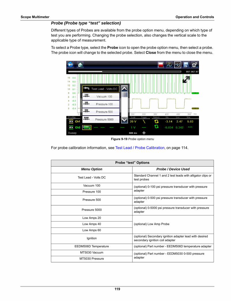
119
Scope Multimeter Operation and Controls
Probe (Probe type “test” selection)
Different types of Probes are available from the probe option menu, depending on which type of test you are performing. Changing the probe selection, also changes the vertical scale to the applicable type of measurement.
To select a Probe type, select the Probe icon to open the probe option menu, then select a probe. The probe icon will change to the selected probe. Select Close from the menu to close the menu.
Figure 9-19 Probe option menu
For probe calibration information, see Test Lead / Probe Calibration‚ on page 114.
Probe “test” Options
Menu Option Probe / Device Used
Test Lead - Volts DCStandard Channel 1 and 2 test leads with alligator clips or test probes
Vacuum 100 (optional) 0-100 psi pressure transducer with pressure adapterPressure 100
Pressure 500(optional) 0-500 psi pressure transducer with pressure adapter
Pressure 5000(optional) 0-5000 psi pressure transducer with pressure adapter
Low Amps 20
(optional) Low Amp ProbeLow Amps 40
Low Amps 60
Ignition(optional) Secondary ignition adapter lead with desired secondary ignition coil adapter
EEDM506D Temperature (optional) Part number - EEDM506D temperature adapter
MT5030 Vacuum (optional) Part number - EEDM5030 0-500 pressure adapterMT5030 Pressure
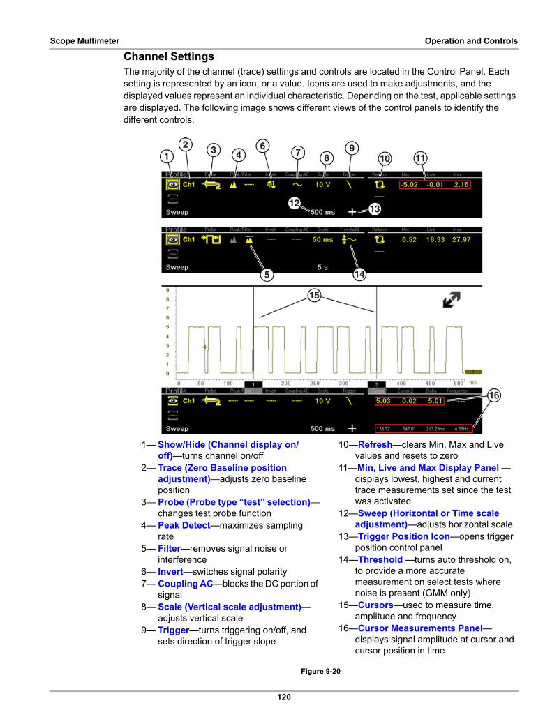
120
Scope Multimeter Operation and Controls
Channel SettingsThe majority of the channel (trace) settings and controls are located in the Control Panel. Each setting is represented by an icon, or a value. Icons are used to make adjustments, and the displayed values represent an individual characteristic. Depending on the test, applicable settings are displayed. The following image shows different views of the control panels to identify the different controls.
Figure 9-20
1— Show/Hide (Channel display on/off)—turns channel on/off
2— Trace (Zero Baseline position adjustment)—adjusts zero baseline position
3— Probe (Probe type “test” selection)—changes test probe function
4— Peak Detect—maximizes sampling rate
5— Filter—removes signal noise or interference
6— Invert—switches signal polarity7— Coupling AC—blocks the DC portion of
signal8— Scale (Vertical scale adjustment)—
adjusts vertical scale9— Trigger—turns triggering on/off, and
sets direction of trigger slope
10—Refresh—clears Min, Max and Live values and resets to zero
11—Min, Live and Max Display Panel —displays lowest, highest and current trace measurements set since the test was activated
12—Sweep (Horizontal or Time scale adjustment)—adjusts horizontal scale
13—Trigger Position Icon—opens trigger position control panel
14—Threshold —turns auto threshold on, to provide a more accurate measurement on select tests where noise is present (GMM only)
15—Cursors—used to measure time, amplitude and frequency
16—Cursor Measurements Panel—displays signal amplitude at cursor and cursor position in time
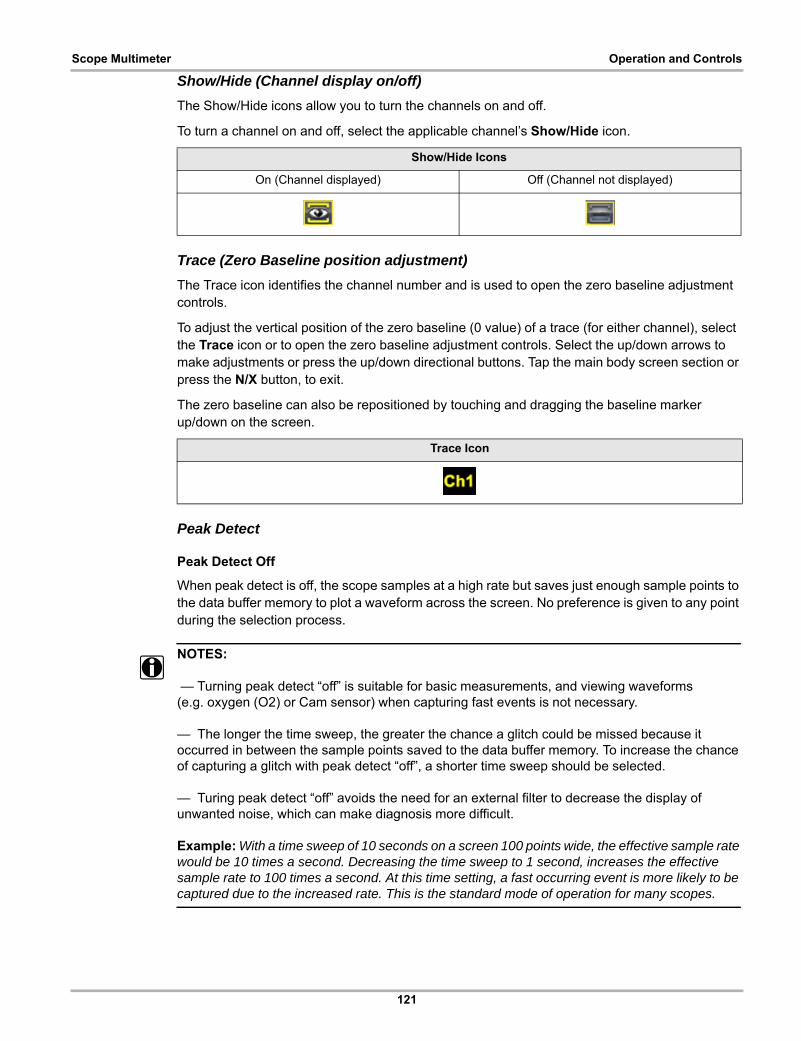
121
Scope Multimeter Operation and Controls
Show/Hide (Channel display on/off)
The Show/Hide icons allow you to turn the channels on and off.
To turn a channel on and off, select the applicable channel’s Show/Hide icon.
Trace (Zero Baseline position adjustment)
The Trace icon identifies the channel number and is used to open the zero baseline adjustment controls.
To adjust the vertical position of the zero baseline (0 value) of a trace (for either channel), select the Trace icon or to open the zero baseline adjustment controls. Select the up/down arrows to make adjustments or press the up/down directional buttons. Tap the main body screen section or press the N/X button, to exit.
The zero baseline can also be repositioned by touching and dragging the baseline marker up/down on the screen.
Peak Detect
Peak Detect Off
When peak detect is off, the scope samples at a high rate but saves just enough sample points to the data buffer memory to plot a waveform across the screen. No preference is given to any point during the selection process.
NOTES:i
— Turning peak detect “off” is suitable for basic measurements, and viewing waveforms(e.g. oxygen (O2) or Cam sensor) when capturing fast events is not necessary.
— The longer the time sweep, the greater the chance a glitch could be missed because it occurred in between the sample points saved to the data buffer memory. To increase the chance of capturing a glitch with peak detect “off”, a shorter time sweep should be selected.
— Turing peak detect “off” avoids the need for an external filter to decrease the display of unwanted noise, which can make diagnosis more difficult.
Example: With a time sweep of 10 seconds on a screen 100 points wide, the effective sample rate would be 10 times a second. Decreasing the time sweep to 1 second, increases the effective sample rate to 100 times a second. At this time setting, a fast occurring event is more likely to be captured due to the increased rate. This is the standard mode of operation for many scopes.
Show/Hide Icons
On (Channel displayed) Off (Channel not displayed)
Trace Icon

122
Scope Multimeter Operation and Controls
Peak Detect On
When peak detect is “on”, all sample points are evaluated. The points stored to the data buffer memory are intelligently selected to capture fast events that might be missed at slower effective sample rates. Peak Detect captures fast events, spikes and glitches for signals going in both positive and negative directions.
NOTES:i
— Turn peak detect "on" when capturing fast events (e.g. ignition firing voltage, glitches, and intermittent events).
— Turning peak detect “on” may capture unwanted noise, therefore, using peak detect may not be suitable for some tests (e.g. oxygen (O2) sensor), as the waveform may be more difficult to evaluate due to the additional noise that may be displayed.
— Peak Detect decreases the possibility of waveform aliasing.
To turn peak detect on and off, select the Peak Detect icon.
Peak Detect Icons
On (Sampling maximized) Off (Sampling not maximized)
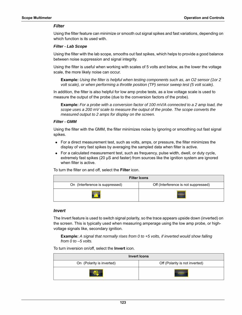
123
Scope Multimeter Operation and Controls
Filter
Using the filter feature can minimize or smooth out signal spikes and fast variations, depending on which function is its used with.
Filter - Lab Scope
Using the filter with the lab scope, smooths out fast spikes, which helps to provide a good balance between noise suppression and signal integrity.
Using the filter is useful when working with scales of 5 volts and below, as the lower the voltage scale, the more likely noise can occur.
Example: Using the filter is helpful when testing components such as, an O2 sensor (1or 2 volt scale), or when performing a throttle position (TP) sensor sweep test (5 volt scale).
In addition, the filter is also helpful for low amp probe tests, as a low voltage scale is used to measure the output of the probe (due to the conversion factors of the probe).
Example: For a probe with a conversion factor of 100 mV/A connected to a 2 amp load, the scope uses a 200 mV scale to measure the output of the probe. The scope converts the measured output to 2 amps for display on the screen.
Filter - GMM
Using the filter with the GMM, the filter minimizes noise by ignoring or smoothing out fast signal spikes.
• For a direct measurement test, such as volts, amps, or pressure, the filter minimizes the display of very fast spikes by averaging the sampled data when filter is active.
• For a calculated measurement test, such as frequency, pulse width, dwell, or duty cycle, extremely fast spikes (20 µS and faster) from sources like the ignition system are ignored when filter is active.
To turn the filter on and off, select the Filter icon.
Invert
The Invert feature is used to switch signal polarity, so the trace appears upside down (inverted) on the screen. This is typically used when measuring amperage using the low amp probe, or high-voltage signals like, secondary ignition.
Example: A signal that normally rises from 0 to +5 volts, if inverted would show falling from 0 to –5 volts.
To turn inversion on/off, select the Invert icon.
Filter Icons
On (Interference is suppressed) Off (Interference is not suppressed)
Invert Icons
On (Polarity is inverted) Off (Polarity is not inverted)
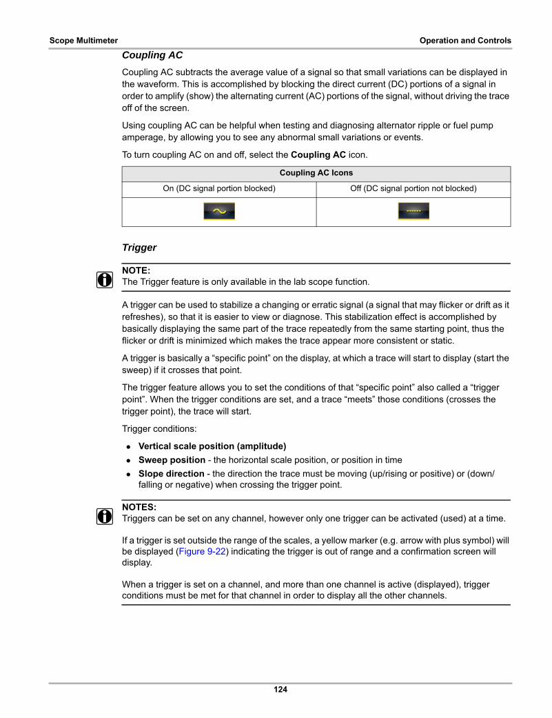
124
Scope Multimeter Operation and Controls
Coupling AC
Coupling AC subtracts the average value of a signal so that small variations can be displayed in the waveform. This is accomplished by blocking the direct current (DC) portions of a signal in order to amplify (show) the alternating current (AC) portions of the signal, without driving the trace off of the screen.
Using coupling AC can be helpful when testing and diagnosing alternator ripple or fuel pump amperage, by allowing you to see any abnormal small variations or events.
To turn coupling AC on and off, select the Coupling AC icon.
Trigger
NOTE:i The Trigger feature is only available in the lab scope function.
A trigger can be used to stabilize a changing or erratic signal (a signal that may flicker or drift as it refreshes), so that it is easier to view or diagnose. This stabilization effect is accomplished by basically displaying the same part of the trace repeatedly from the same starting point, thus the flicker or drift is minimized which makes the trace appear more consistent or static.
A trigger is basically a “specific point” on the display, at which a trace will start to display (start the sweep) if it crosses that point.
The trigger feature allows you to set the conditions of that “specific point” also called a “trigger point”. When the trigger conditions are set, and a trace “meets” those conditions (crosses the trigger point), the trace will start.
Trigger conditions:
• Vertical scale position (amplitude)
• Sweep position - the horizontal scale position, or position in time
• Slope direction - the direction the trace must be moving (up/rising or positive) or (down/falling or negative) when crossing the trigger point.
NOTES:i Triggers can be set on any channel, however only one trigger can be activated (used) at a time.
If a trigger is set outside the range of the scales, a yellow marker (e.g. arrow with plus symbol) will be displayed (Figure 9-22) indicating the trigger is out of range and a confirmation screen will display.
When a trigger is set on a channel, and more than one channel is active (displayed), trigger conditions must be met for that channel in order to display all the other channels.
Coupling AC Icons
On (DC signal portion blocked) Off (DC signal portion not blocked)

125
Scope Multimeter Operation and Controls
z To turn a trigger on/off:
A trigger is activated by selecting the trigger icon from the control panel, which then automatically initiates trigger slope setup.
1. Select the desired channel’s Trigger icon.
Each tap of the icon sets the trigger to a different slope setting, or turns the trigger off.
2. Select the desired slope setting, to turn the trigger on.
3. Proceed to “To set trigger position” next to complete the trigger set up.
z To set trigger position:
Trigger position (also called trigger level) can be adjusted in two ways:
– Dragging the trigger marker (Figure 9-21) on the touch screen - rough adjustment
– Using the trigger position control panel (Figure 9-21) - fine adjustment
The trigger marker is indicated by a plus symbol (+) on the display (Figure 9-22). The trigger marker represents the trigger point and is displayed on the screen when the trigger is turned on.
To roughly position the trigger marker, select and drag it into position using the touch screen.
4. To more accurately position the trigger marker, select the Trigger Position Control icon (Figure 9-22).
The trigger position control panel opens.
5. Use the directional controls provided, or the thumbpad directional controls to move the trigger marker into position (Figure 9-21). Sweep and vertical scale values are provided in the trigger position control panel, which gives you the precise position of the trigger marker.
Trigger Icon Description
Rising (up or positive) - Trigger is turned on to start the trace on the rising edge (as signal begins to rise)
Falling (down or negative) - Trigger is turned on to start the trace on the falling edge (as signal begins to fall)
Off - Trigger is turned off.

126
Scope Multimeter Operation and Controls
6. Press the N/X button, to exit.
1— Trigger Marker
2— Trigger Position Control PanelFigure 9-21 Trigger marker and position controls
1— Trigger Marker (out of range symbol)
2— Waiting for Trigger Message
3— Trigger Position Control IconFigure 9-22

127
Scope Multimeter Operation and Controls
Trigger Auto/Manual Mode (Optional Setting)
NOTE:i The Auto and Manual Trigger modes allow you to set the criteria used to display signals on the
screen. To change the trigger mode, the trigger must be set on one of the channels.
In both Auto and Manual Trigger mode the screen is updated when the signal crosses the trigger point in the selected direction (rising or falling), however:
• Auto Trigger—(default mode)
– when Auto Trigger is on, even if the signal does not cross the trigger point, the screen automatically updates after a short period (allowing you to see the waveform). When this occurs, the message "Waiting for the trigger" (Figure 9-22) is displayed on the screen. The trigger point can then be set to optimize viewing.
• Manual Trigger
– when Manual Trigger is on, if the signal does not cross the trigger point the screen will not update. This allows you to capture intermittent events, as the screen only updates when the signal meets your trigger selection.
NOTE:i When using Manual Trigger, it may be easier to initially set the trigger point using Auto Trigger, as
the screen will update regardless if the signal crosses the trigger point. Once the trigger point is set, then switch to Manual Trigger mode.
z Selecting Trigger Auto/Manual Mode:
1. From the Control Panel (on the test meter screen), turn the trigger on for the desired channel.
2. Select the Settings icon from the toolbar.
3. Select Settings > Configure Scope / Meter > Trigger Mode from the menu selections.
4. Select either Auto Trigger or Manual Trigger.
5. Select Back or press the N/X button to navigate back to the test meter screen.
Threshold
NOTE:i The Threshold function is only available in the Graphing Meter function for specific tests. This
function may also be referred to as Auto Threshold Select (ATS).
The Threshold function can be used, to display and obtain a more accurate measurement when measuring signals (e.g. Frequency, Duty Cycle, MC Dwell and Pulse Width) that may be difficult to display or have noise or other undesirable variations in the signal. When selected, the Threshold function automatically sets a trigger and determines a threshold level in the middle of the signal range (calculated from the Min and Max measurements) to be used as a reference point to calculate the measurement. The falling edge (slope) of the signal is used in determining the threshold level.
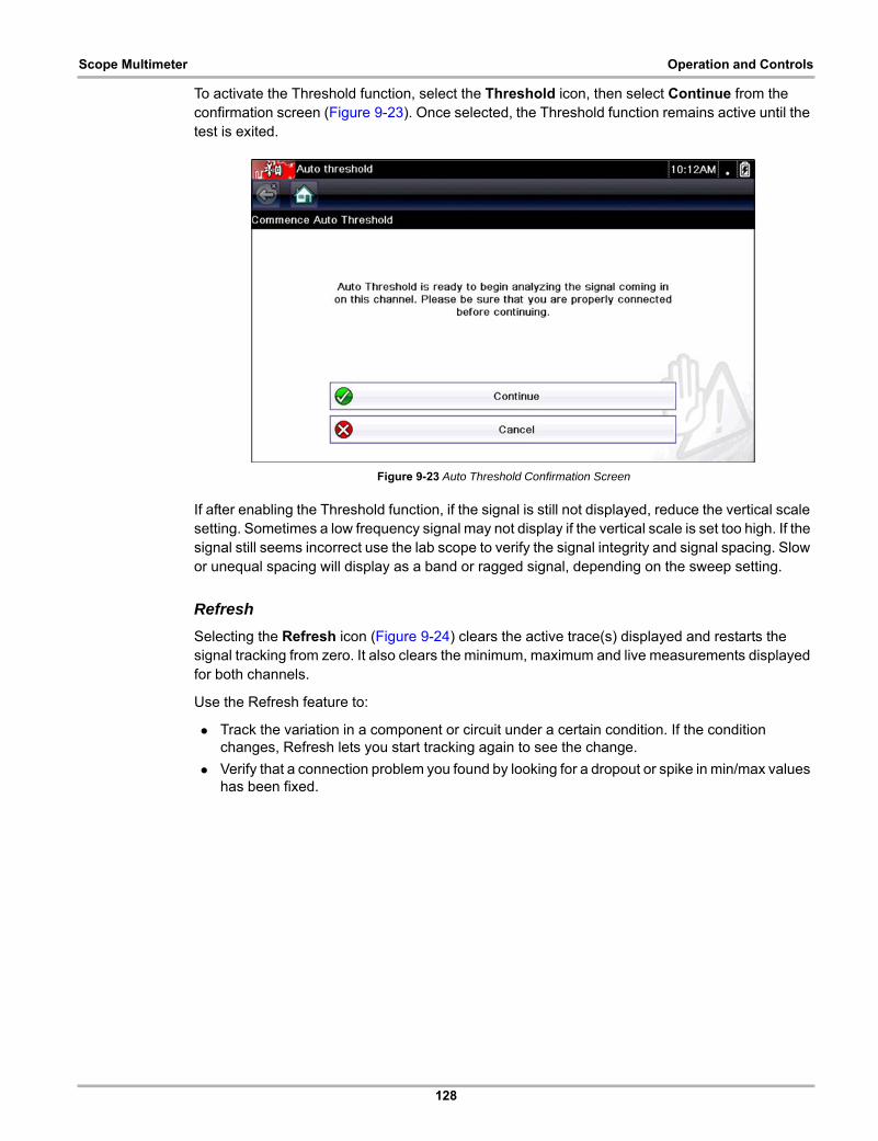
128
Scope Multimeter Operation and Controls
To activate the Threshold function, select the Threshold icon, then select Continue from the confirmation screen (Figure 9-23). Once selected, the Threshold function remains active until the test is exited.
Figure 9-23 Auto Threshold Confirmation Screen
If after enabling the Threshold function, if the signal is still not displayed, reduce the vertical scale setting. Sometimes a low frequency signal may not display if the vertical scale is set too high. If the signal still seems incorrect use the lab scope to verify the signal integrity and signal spacing. Slow or unequal spacing will display as a band or ragged signal, depending on the sweep setting.
Refresh
Selecting the Refresh icon (Figure 9-24) clears the active trace(s) displayed and restarts the signal tracking from zero. It also clears the minimum, maximum and live measurements displayed for both channels.
Use the Refresh feature to:
• Track the variation in a component or circuit under a certain condition. If the condition changes, Refresh lets you start tracking again to see the change.
• Verify that a connection problem you found by looking for a dropout or spike in min/max values has been fixed.
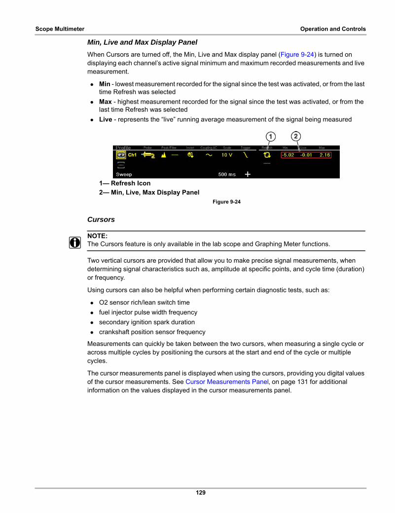
129
Scope Multimeter Operation and Controls
Min, Live and Max Display Panel
When Cursors are turned off, the Min, Live and Max display panel (Figure 9-24) is turned on displaying each channel’s active signal minimum and maximum recorded measurements and live measurement.
• Min - lowest measurement recorded for the signal since the test was activated, or from the last time Refresh was selected
• Max - highest measurement recorded for the signal since the test was activated, or from the last time Refresh was selected
• Live - represents the “live” running average measurement of the signal being measured
1— Refresh Icon
2— Min, Live, Max Display PanelFigure 9-24
Cursors
NOTE:i The Cursors feature is only available in the lab scope and Graphing Meter functions.
Two vertical cursors are provided that allow you to make precise signal measurements, when determining signal characteristics such as, amplitude at specific points, and cycle time (duration) or frequency.
Using cursors can also be helpful when performing certain diagnostic tests, such as:
• O2 sensor rich/lean switch time
• fuel injector pulse width frequency
• secondary ignition spark duration
• crankshaft position sensor frequency
Measurements can quickly be taken between the two cursors, when measuring a single cycle or across multiple cycles by positioning the cursors at the start and end of the cycle or multiple cycles.
The cursor measurements panel is displayed when using the cursors, providing you digital values of the cursor measurements. See Cursor Measurements Panel‚ on page 131 for additional information on the values displayed in the cursor measurements panel.
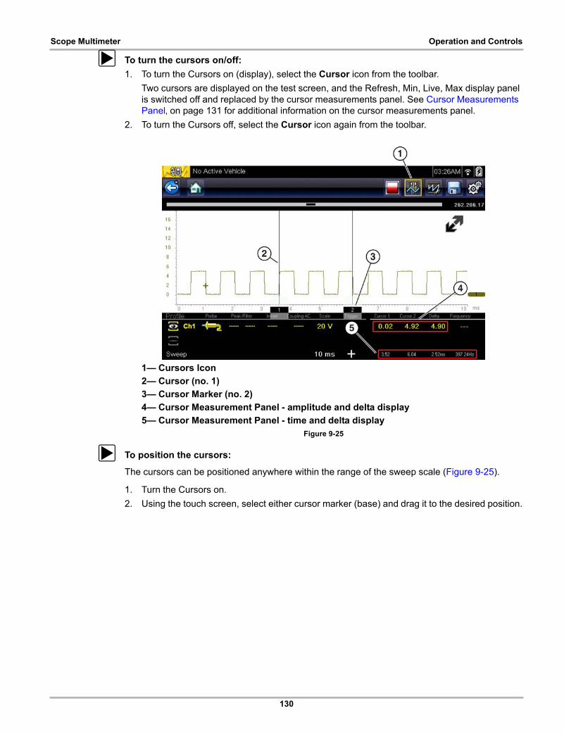
130
Scope Multimeter Operation and Controls
z To turn the cursors on/off:
1. To turn the Cursors on (display), select the Cursor icon from the toolbar.
Two cursors are displayed on the test screen, and the Refresh, Min, Live, Max display panel is switched off and replaced by the cursor measurements panel. See Cursor Measurements Panel‚ on page 131 for additional information on the cursor measurements panel.
2. To turn the Cursors off, select the Cursor icon again from the toolbar.
1— Cursors Icon
2— Cursor (no. 1)
3— Cursor Marker (no. 2)
4— Cursor Measurement Panel - amplitude and delta display
5— Cursor Measurement Panel - time and delta displayFigure 9-25
z To position the cursors:
The cursors can be positioned anywhere within the range of the sweep scale (Figure 9-25).
1. Turn the Cursors on.
2. Using the touch screen, select either cursor marker (base) and drag it to the desired position.
131
Scope Multimeter Operation and Controls
Cursor Measurements Panel
When the cursors are turned on, the Refresh, Min, Live, Max display panel is switched off and replaced by the Cursor Measurements Panel.
The cursor measurements panel displays the following signal and cursor measurements:
• Signal amplitude at two points
• Signal amplitude difference (delta) between two points
• Cursor position in time at two points
• Difference (delta) in time between the cursors
• Frequency - frequency of the signal for the time period between cursor 1 and 2
The cursor measurements panel contains values for each channel in two displays.
The amplitude and delta display is provided in the channel specific color and includes:
– Cursor 1 - signal amplitude at cursor 1 position
– Cursor 2 - signal amplitude at cursor 2 position
– Delta - signal amplitude difference between cursor 1 and 2
The time and delta display is gray in color and includes:
– Cursor 1 - cursor position in time at cursor 1
– Cursor 2 - cursor position in time at cursor 2
– Delta - difference in time between cursor 1 and 2
– Frequency - the frequency value (Hz) of the signal for the time period between cursor 1 and 2
NOTE:i Frequency is the number of times a signal repeats itself per second and is measured in hertz (Hz).
The frequency value displayed, is the inverse of the Delta value, and can also be calculated as 1 divided by Delta. The frequency value (Hz) shown is automatically calculated by the scope.
Example 1: Delta = 20.46ms, to get frequency divide 1 by .02046 (1/.02046 = 48.87Hz)
Example 2: Delta = 2.53ms, to get frequency divide 1 by .00253 (1/.00253 = 395.27Hz)
Use applicable decimal point placement during division as the Delta value changes.
9.5.4 Secondary Ignition Testing
The lab scope function can be used to display secondary ignition waveforms for conventional and select CIC and COP systems. To display secondary ignition waveforms, optional secondary ignition coil adapter(s) and a coil adapter lead assembly are required.
Contact your sales representative to purchase the optional adapter leads and/or Secondary Ignition Clip-on or COP/CIC Adapters.
• Adapter lead assembly needed:
– Secondary Coil Adapter Lead Assembly - connects the diagnostic tool to a secondary ignition adapter (yellow and black scope connectors and black RCA type adapter connector). See Secondary Ignition Coil Adapter Lead and Clip-on Adapter (optional)‚ on page 107.
• Secondary Ignition Adapters available:

132
Scope Multimeter Operation and Controls
Different secondary ignition coil adapters are available as optional equipment. These adapters attach to either the secondary lead (spark plug lead) or directly to the secondary ignition coil in order to pick up the secondary ignition signal.
– Universal kV Ignition Clip-on adapter - clips over a spark plug or coil lead. See Secondary Ignition Coil Adapter Lead and Clip-on Adapter (optional)‚ on page 107.
– Universal stick and flag type adapters - are loosely positioned next to or on a secondary ignition coil.
• General purpose single flag pick-up.
• General purpose stick pick-up.
– Vehicle specific Clip-on adapters - are directly attached to (or next to) a secondary ignition coil (COP type) or to a distributor cap (CIC type). Secondary ignition coil-on-plug (COP) and coil-in-cap (CIC) adapters are available for universal and engine specific applications. All the adapters listed are available individually.
• OEM specific COP adapters:
• Ford (COP-1)
• Chrysler (COP-2)
• VW/Audi (COP-3)
• Acura/Honda/Isuzu (COP-4)
• Volvo/BMW (COP-5)
• Mercedes-Benz (COP-6)
• Mercedes-Benz Dual Type (COP-7)
• BMW (COP-8)
• Lexus (COP-9)
• Chrysler/Jeep/Lexus/Toyota (COP-11)
• OEM specific CIC adapters:
• GM HEI (CIC-1)
• Toyota/Honda (CIC-2)
z Connecting the Secondary Coil Adapter Leads:
1. Connect the black (ground) lead into the diagnostic tool test lead ground jack.
2. Connect the yellow lead into the diagnostic tool test lead channel 1 jack.
3. Connect the adapter lead ground clamp to vehicle ground. If a jumper wire is used to extend the length of the adapter lead ground clamp lead, keep it as short as possible.
4. Connect the adapter lead RCA plug into the secondary ignition "clip-on" or COP/CIC coil adapter as needed.
5. Clamp the secondary clip-on adapter over a spark plug or coil lead, or attach the applicable COP/CIC coil adapter to the vehicle ignition coil.
6. Isolate the leads from other components, to avoid any unwanted noise that could be induced onto the signal.
7. From the lab scope function, select the Ignition Probe (probe setting).
8. If needed, turn the Invert function on.
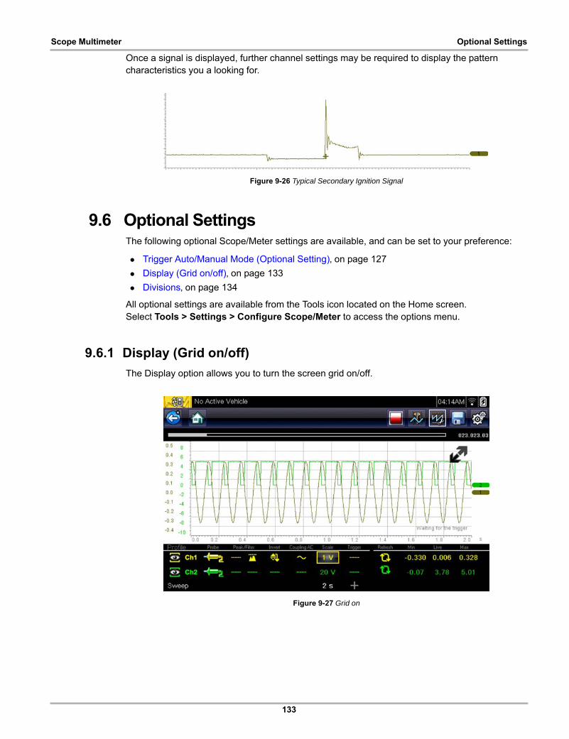
133
Scope Multimeter Optional Settings
Once a signal is displayed, further channel settings may be required to display the pattern characteristics you a looking for.
Figure 9-26 Typical Secondary Ignition Signal
9.6 Optional SettingsThe following optional Scope/Meter settings are available, and can be set to your preference:
• Trigger Auto/Manual Mode (Optional Setting)‚ on page 127
• Display (Grid on/off)‚ on page 133
• Divisions‚ on page 134
All optional settings are available from the Tools icon located on the Home screen. Select Tools > Settings > Configure Scope/Meter to access the options menu.
9.6.1 Display (Grid on/off)
The Display option allows you to turn the screen grid on/off.
Figure 9-27 Grid on
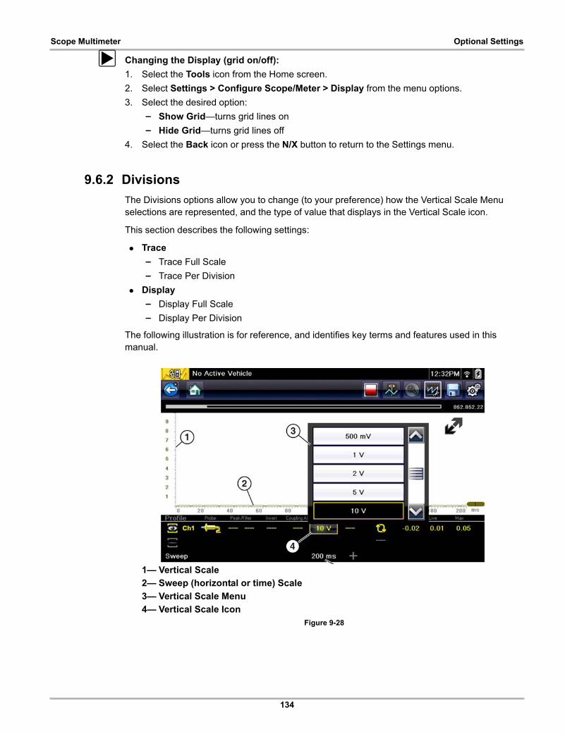
134
Scope Multimeter Optional Settings
z Changing the Display (grid on/off):
1. Select the Tools icon from the Home screen.
2. Select Settings > Configure Scope/Meter > Display from the menu options.
3. Select the desired option:
– Show Grid—turns grid lines on
– Hide Grid—turns grid lines off
4. Select the Back icon or press the N/X button to return to the Settings menu.
9.6.2 Divisions
The Divisions options allow you to change (to your preference) how the Vertical Scale Menu selections are represented, and the type of value that displays in the Vertical Scale icon.
This section describes the following settings:
• Trace
– Trace Full Scale
– Trace Per Division
• Display
– Display Full Scale
– Display Per Division
The following illustration is for reference, and identifies key terms and features used in this manual.
1— Vertical Scale
2— Sweep (horizontal or time) Scale
3— Vertical Scale Menu
4— Vertical Scale Icon Figure 9-28
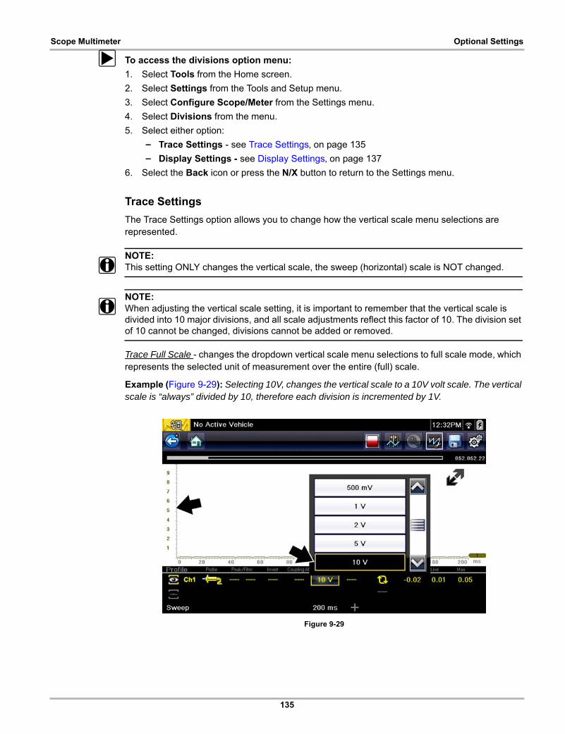
135
Scope Multimeter Optional Settings
z To access the divisions option menu:
1. Select Tools from the Home screen.
2. Select Settings from the Tools and Setup menu.
3. Select Configure Scope/Meter from the Settings menu.
4. Select Divisions from the menu.
5. Select either option:
– Trace Settings - see Trace Settings‚ on page 135
– Display Settings - see Display Settings‚ on page 137
6. Select the Back icon or press the N/X button to return to the Settings menu.
Trace Settings
The Trace Settings option allows you to change how the vertical scale menu selections are represented.
NOTE:i This setting ONLY changes the vertical scale, the sweep (horizontal) scale is NOT changed.
NOTE:i When adjusting the vertical scale setting, it is important to remember that the vertical scale is
divided into 10 major divisions, and all scale adjustments reflect this factor of 10. The division set of 10 cannot be changed, divisions cannot be added or removed.
Trace Full Scale - changes the dropdown vertical scale menu selections to full scale mode, which represents the selected unit of measurement over the entire (full) scale.
Example (Figure 9-29): Selecting 10V, changes the vertical scale to a 10V volt scale. The vertical scale is “always” divided by 10, therefore each division is incremented by 1V.
Figure 9-29
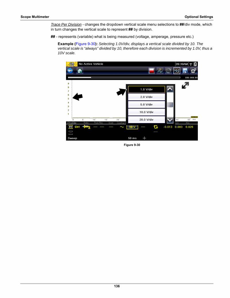
136
Scope Multimeter Optional Settings
Trace Per Division - changes the dropdown vertical scale menu selections to ##/div mode, which in turn changes the vertical scale to represent ## by division.
## - represents (variable) what is being measured (voltage, amperage, pressure etc.)
Example (Figure 9-30): Selecting 1.0V/div, displays a vertical scale divided by 10. The vertical scale is “always” divided by 10, therefore each division is incremented by 1.0V, thus a 10V scale.
Figure 9-30
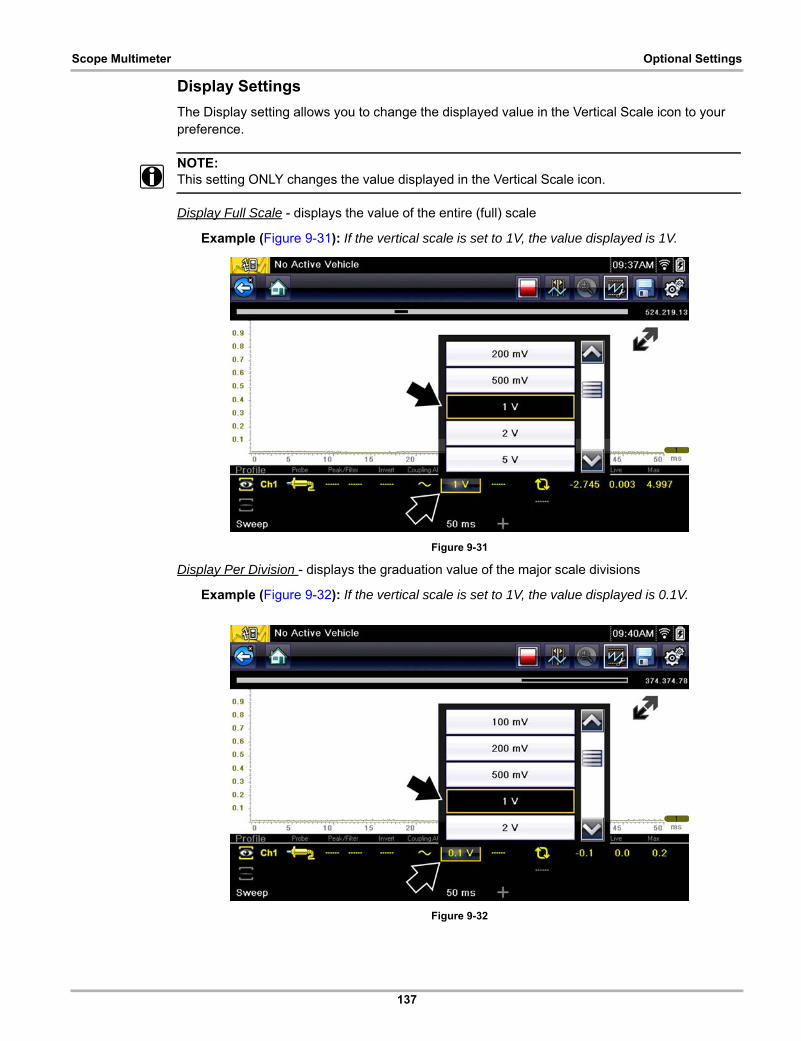
137
Scope Multimeter Optional Settings
Display Settings
The Display setting allows you to change the displayed value in the Vertical Scale icon to your preference.
NOTE:i This setting ONLY changes the value displayed in the Vertical Scale icon.
Display Full Scale - displays the value of the entire (full) scale
Example (Figure 9-31): If the vertical scale is set to 1V, the value displayed is 1V.
Figure 9-31
Display Per Division - displays the graduation value of the major scale divisions
Example (Figure 9-32): If the vertical scale is set to 1V, the value displayed is 0.1V.
Figure 9-32
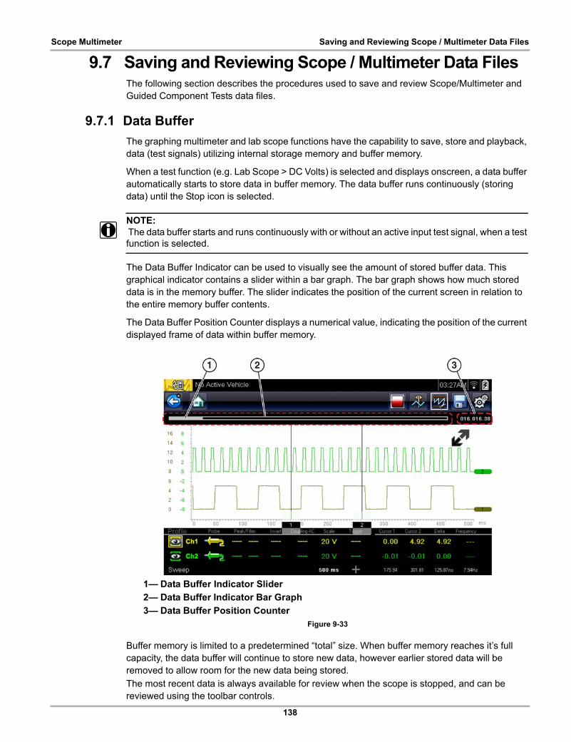
138
Scope Multimeter Saving and Reviewing Scope / Multimeter Data Files
9.7 Saving and Reviewing Scope / Multimeter Data FilesThe following section describes the procedures used to save and review Scope/Multimeter and Guided Component Tests data files.
9.7.1 Data Buffer
The graphing multimeter and lab scope functions have the capability to save, store and playback, data (test signals) utilizing internal storage memory and buffer memory.
When a test function (e.g. Lab Scope > DC Volts) is selected and displays onscreen, a data buffer automatically starts to store data in buffer memory. The data buffer runs continuously (storing data) until the Stop icon is selected.
NOTE:i The data buffer starts and runs continuously with or without an active input test signal, when a test
function is selected.
The Data Buffer Indicator can be used to visually see the amount of stored buffer data. This graphical indicator contains a slider within a bar graph. The bar graph shows how much stored data is in the memory buffer. The slider indicates the position of the current screen in relation to the entire memory buffer contents.
The Data Buffer Position Counter displays a numerical value, indicating the position of the current displayed frame of data within buffer memory.
1— Data Buffer Indicator Slider
2— Data Buffer Indicator Bar Graph
3— Data Buffer Position CounterFigure 9-33
Buffer memory is limited to a predetermined “total” size. When buffer memory reaches it’s full capacity, the data buffer will continue to store new data, however earlier stored data will be removed to allow room for the new data being stored.
The most recent data is always available for review when the scope is stopped, and can be reviewed using the toolbar controls.

139
Scope Multimeter Saving and Reviewing Scope / Multimeter Data Files
9.7.2 Saving Files
Selecting the Save icon writes the data stored in buffer memory to a file. Saving data files is useful when trying to isolate an intermittent problem or to verify a repair during a road test. The saved file can be played back (similar to a movie clip) by selecting Previous Vehicles and Data > View Saved Data. See View Saved Data‚ on page 155 for additional information.
NOTE:i The Save icon performs the same function as “Save Movie” function choice for the programmable
Shortcut button, see Configure Shortcut Button‚ on page 161 for details.
The saved file can also be downloaded to a personal computer (PC) using the Mini USB jack. Once connected to the PC, the files can be printed, transferred, and copied using ShopStream Connect. ShopStream Connect is a companion application that interfaces the diagnostic tool with a PC. ShopStream Connect is available at no cost, and can be downloaded online. See the ShopStream Connect website information at the front of this manual for additional information.
The toolbar control icons are described in Scope Multimeter Control Icons‚ on page 111 and Common Toolbar Control Icons‚ on page 10.
z To save files:
• Select the Save icon from the toolbar.
A save dialog box displays while files are being saved. The file is saved when the message box disappears.
Figure 9-34 Save dialog box
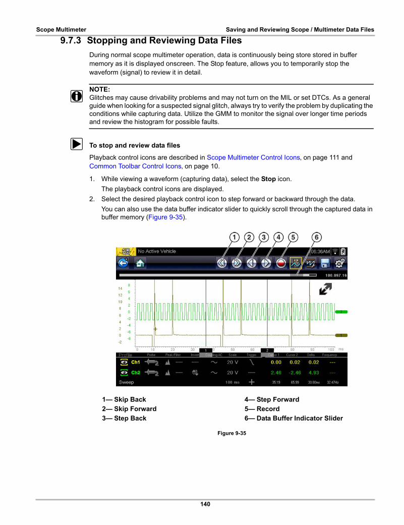
140
Scope Multimeter Saving and Reviewing Scope / Multimeter Data Files
9.7.3 Stopping and Reviewing Data Files
During normal scope multimeter operation, data is continuously being store stored in buffer memory as it is displayed onscreen. The Stop feature, allows you to temporarily stop the waveform (signal) to review it in detail.
NOTE:i Glitches may cause drivability problems and may not turn on the MIL or set DTCs. As a general
guide when looking for a suspected signal glitch, always try to verify the problem by duplicating the conditions while capturing data. Utilize the GMM to monitor the signal over longer time periods and review the histogram for possible faults.
z To stop and review data files
Playback control icons are described in Scope Multimeter Control Icons‚ on page 111 and Common Toolbar Control Icons‚ on page 10.
1. While viewing a waveform (capturing data), select the Stop icon.
The playback control icons are displayed.
2. Select the desired playback control icon to step forward or backward through the data.
You can also use the data buffer indicator slider to quickly scroll through the captured data in buffer memory (Figure 9-35).
Figure 9-35
1— Skip Back
2— Skip Forward
3— Step Back
4— Step Forward
5— Record
6— Data Buffer Indicator Slider
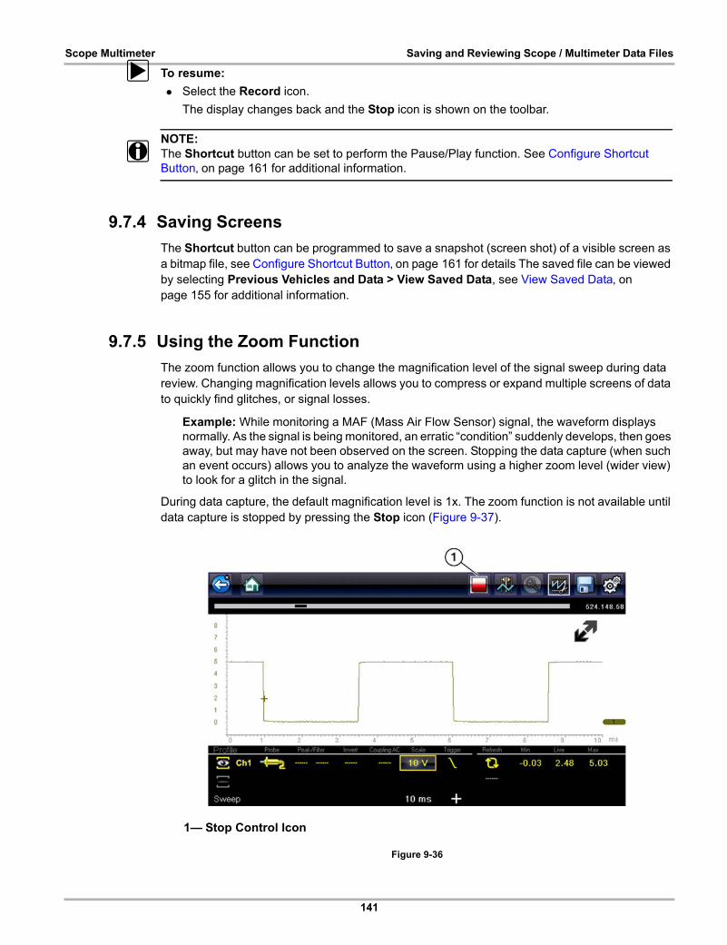
141
Scope Multimeter Saving and Reviewing Scope / Multimeter Data Files
z To resume:
• Select the Record icon.
The display changes back and the Stop icon is shown on the toolbar.
NOTE:i The Shortcut button can be set to perform the Pause/Play function. See Configure Shortcut
Button‚ on page 161 for additional information.
9.7.4 Saving Screens
The Shortcut button can be programmed to save a snapshot (screen shot) of a visible screen as a bitmap file, see Configure Shortcut Button‚ on page 161 for details The saved file can be viewed by selecting Previous Vehicles and Data > View Saved Data, see View Saved Data‚ on page 155 for additional information.
9.7.5 Using the Zoom Function
The zoom function allows you to change the magnification level of the signal sweep during data review. Changing magnification levels allows you to compress or expand multiple screens of data to quickly find glitches, or signal losses.
Example: While monitoring a MAF (Mass Air Flow Sensor) signal, the waveform displays normally. As the signal is being monitored, an erratic “condition” suddenly develops, then goes away, but may have not been observed on the screen. Stopping the data capture (when such an event occurs) allows you to analyze the waveform using a higher zoom level (wider view) to look for a glitch in the signal.
During data capture, the default magnification level is 1x. The zoom function is not available until data capture is stopped by pressing the Stop icon (Figure 9-37).
Figure 9-36
1— Stop Control Icon
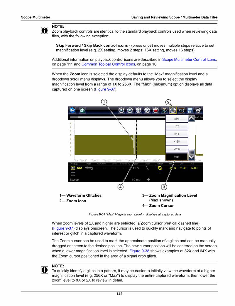
142
Scope Multimeter Saving and Reviewing Scope / Multimeter Data Files
NOTE:i Zoom playback controls are identical to the standard playback controls used when reviewing data
files, with the following exception:
Skip Forward / Skip Back control icons - (press once) moves multiple steps relative to set magnification level (e.g. 2X setting, moves 2 steps; 16X setting, moves 16 steps)
Additional information on playback control icons are described in Scope Multimeter Control Icons‚ on page 111 and Common Toolbar Control Icons‚ on page 10.
When the Zoom icon is selected the display defaults to the "Max" magnification level and a dropdown scroll menu displays. The dropdown menu allows you to select the display magnification level from a range of 1X to 256X. The "Max" (maximum) option displays all data captured on one screen (Figure 9-37).
Figure 9-37 “Max" Magnification Level - displays all captured data
When zoom levels of 2X and higher are selected, a Zoom cursor (vertical dashed line) (Figure 9-37) displays onscreen. The cursor is used to quickly mark and navigate to points of interest or glitch in a captured waveform.
The Zoom cursor can be used to mark the approximate position of a glitch and can be manually dragged onscreen to the desired position. The new cursor position will be centered on the screen when a lower magnification level is selected. Figure 9-38 shows examples at 32X and 64X with the Zoom cursor positioned in the area of a signal drop glitch.
NOTE:i To quickly identify a glitch in a pattern, it may be easier to initially view the waveform at a higher
magnification level (e.g. 256X or "Max") to display the entire captured waveform, then lower the zoom level to 8X or 2X to review in detail.
1— Waveform Glitches
2— Zoom Icon
3— Zoom Magnification Level (Max shown)
4— Zoom Cursor

143
Scope Multimeter Saving and Reviewing Scope / Multimeter Data Files
Figure 9-38 Examples of Magnification Level at 32X and 128X
Figure 9-39 shows an example at 16X of the same waveform shown in Figure 9-37 and Figure 9-38. In Figure 9-39 at 16X the glitches are easily seen as compared to higher magnification levels.
Figure 9-39 Example of Magnification Level at 16X. (For illustration purposes, the Zoom cursor has been positioned in the area near the glitches.)
1— Waveform Glitches
2— Magnification Level at 128X
3— Magnification Level at 32X
144
Scope Multimeter General Reference
9.8 General Reference
9.8.1 Basic Setup Tips (unknown signal type)
When conducting automotive diagnostics, situations may arise when you need to capture and analyze a signal that you are not familiar with, or know what the intended waveform pattern should look like, or even how to set the scope to acquire the signal.
The following tips are intended to provide guidance, at the most basic level to assist you in your lab scope diagnostics.
Testing information and/or procedures for testing certain components may be available in the Guided Component Test function, see Guided Component Tests‚ on page 89 for additional information. If you have already narrowed down the system and/or component to test, ID the vehicle within the Guided Component Test function, and check the available tests first, as this may save you some time.
If the Guided Component Test function, does not have the test you are looking for, you need to determine are few thing about what you are testing to get the scope / meter set up to capture a signal or make a measurement.
NOTE:i Testing information and known good waveform libraries may also be available from other sources
(e.g. SureTrack, ShopKey Pro or other online sources). Obtaining correct testing reference information can be a key advantage in making sound repair decisions.
Listed below are a few basic questions to help narrow down the testing direction to follow.
• Are you looking to make or test a simple voltage or current level or maybe check resistance or continuity? Then you may want to use the DMM.
• Are you looking to check a circuit/component for an erratic dropout or make a frequency test? You may want to use the GMM.
• Do you need to see signal details (level, shape, frequency etc.)? The lab scope may be the best choice.
• Are you testing a DC or AC signal?
• What is the operating range of the circuit?
• Do you know what type or shape the intended waveform should be?
After answering the questions above (at a minimum), you need to determine which Scope / Multimeter test function you are going to use (e.g. Lab Scope, DMM or GMM). See Tests and Capabilities (Quick Reference)‚ on page 104.
Once your test function is selected, you can now connect the test leads and select the applicable probe and scales:
Probe (test) type, see Probe (Probe type “test” selection)‚ on page 119
Vertical scale, see Scale (Vertical scale adjustment)‚ on page 116
Sweep scale, see Sweep (Horizontal or Time scale adjustment)‚ on page 118
Connect the test leads or probe, to the applicable test point(s). Always use the correct lead or probe designed for the test and ensure the signal and ground connections are clean and secure.
For the initial setup, you may wish to turn other channel settings off (e.g. Peak, Filter, Invert, AC Coupling, Threshold etc.), as these may affect the signal display. See Channel Settings‚ on page 120.
145
Scope Multimeter General Reference
As a default setting, trigger is normally off. The scope/meter uses internal circuitry to display a signal if present. However, in certain circumstances additional channel adjustments may be required, or the trigger mode may have to be turned on, for a signal that is present but is not displayed. You may also need to readjust the vertical scale if set to low, in order to bring the signal into the viewable display area.
At this point you should have a visible signal on the screen. An ideal signal should be displayed within the area of the display.
• If the signal goes beyond the top and bottom of the display, try and readjust the vertical scale to a higher setting, to bring the signal into the viewable display area.
Use the zero baseline controls or move the zero baseline marker onscreen to move the zero baseline of the signal vertically on the screen to the desired position. See Trace (Zero Baseline position adjustment)‚ on page 121.
• If the signal cycles are compressed (close to each other), try and readjust the sweep scale (horizontal scale) to a lower setting to display less cycles.
Once you have a usable signal displayed, if needed use the trigger function to stabilize a changing or erratic signal (a signal that may flicker or drift), so that it is easier to view. Try and set the trigger at the mid-point of the signal, and then adjust as needed from there. See Trigger‚ on page 124.
As all signals are different, and due to other variables, additional adjustments may be needed to get the signal displayed exactly how you need. Review the channel settings section in this manual for additional information on using the settings. See Channel Settings‚ on page 120.
At this point you should have a signal displayed that will allow you to see the overall signal characteristics, and allow you to begin your diagnosis.
Comparing your captured waveforms to known good waveforms, can be a time saver and provide supporting evidence when trying to determine a fault. See Using Known Good Waveforms‚ on page 145 for additional information.
9.8.2 Using Known Good Waveforms
In some cases captured waveforms may not provide enough information to determine if a suspected sensor or circuit is at fault. Comparing the test vehicle waveforms to known good waveforms, can help to provide supporting evidence when trying to determine a fault.
Known good waveform examples may be available from different sources including the Guided Component Tests function, information services (e.g. SureTrack) or from other sources.
One of the many resources available within the optional online version of SureTrack is the comprehensive collection of known good component waveform examples gathered through actual vehicle tests. Waveform and PID graph screenshot examples are provided by fellow member technicians and shared with all members in a searchable (vehicle/component specific) database.
As good practice, capturing waveforms before and after the repair will help you to build your own library of waveforms for future troubleshooting.
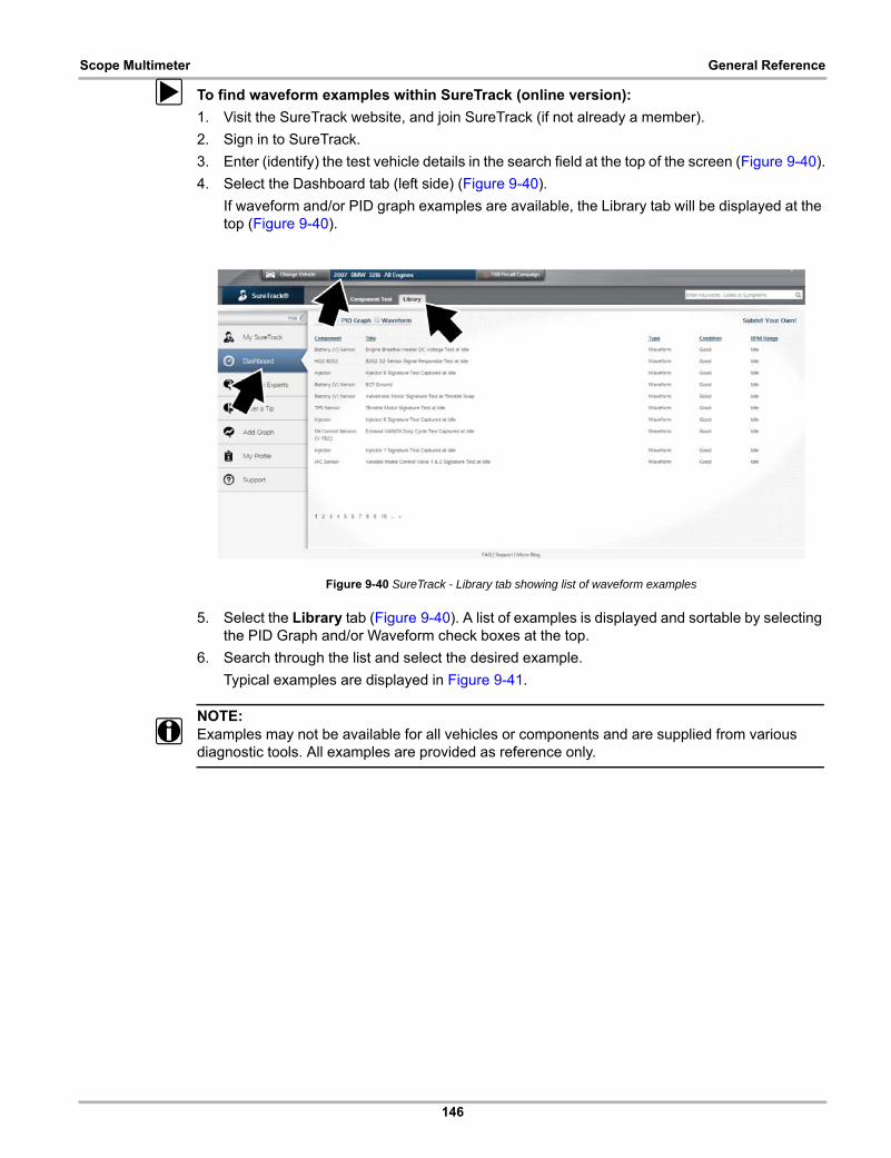
146
Scope Multimeter General Reference
z To find waveform examples within SureTrack (online version):
1. Visit the SureTrack website, and join SureTrack (if not already a member).
2. Sign in to SureTrack.
3. Enter (identify) the test vehicle details in the search field at the top of the screen (Figure 9-40).
4. Select the Dashboard tab (left side) (Figure 9-40).
If waveform and/or PID graph examples are available, the Library tab will be displayed at the top (Figure 9-40).
Figure 9-40 SureTrack - Library tab showing list of waveform examples
5. Select the Library tab (Figure 9-40). A list of examples is displayed and sortable by selecting the PID Graph and/or Waveform check boxes at the top.
6. Search through the list and select the desired example.
Typical examples are displayed in Figure 9-41.
NOTE:i Examples may not be available for all vehicles or components and are supplied from various
diagnostic tools. All examples are provided as reference only.
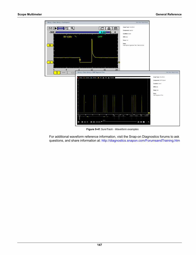
147
Scope Multimeter General Reference
Figure 9-41 SureTrack - Waveform examples
For additional waveform reference information, visit the Snap-on Diagnostics forums to ask questions, and share information at: http://diagnostics.snapon.com/ForumsandTraining.htm

148
Scope Multimeter General Reference
9.8.3 Troubleshooting Signals
When capturing signals, you may occasionally encounter problems with the way the signal initially displays. Noise, hash, fuzz are some of the terms used to describe, unwanted signals displaying in or on the signal you are trying to capture, basically making the signal unclear. The following tips are intended to provide some basic guidance, to help resolve these types of issues if encountered.
• Make sure you have the correct test leads connected to the applicable test point(s) and test lead jacks on the diagnostic tool.
• Ensure the signal and ground connections are clean and secure, at the test points and diagnostic tool.
• Ensure the polarity of the test leads connections are correct.
• If using stackable connectors, try to isolate or only connect the leads being used to capture the signal.
• Make sure the ground lead is providing a direct ground from the circuit to the diagnostic tool test lead jack.
• Isolate the test leads from other components, leads, or systems that may induce unwanted noise into the signal being tested (e.g. electric motors, secondary ignition components, relays, alternators, etc.)
• Use the shortest test leads possible.
• Try different test leads, to verify the issue. Use the recommended snap-on leads or probes available for the diagnostic tool or equivalent. Shielded test leads are recommended.
• Check the test lead or probes for damage.
• Enable or disable channel controls also to help try and clean the signal:
– Peak Detect—maximizes sampling rate, but may pickup unwanted noise
– Filter—removes signal noise or interference
– Invert—switches signal polarity
– Coupling AC—blocks the DC portion of signal
– Threshold —provides a more accurate measurement on select GMM tests where noise is present
– Scale (Vertical scale adjustment)—adjusts vertical scale. Using a higher setting may provide a cleaner signal in some situations.
For signals that do not display or display off the screen, erratic, compressed etc.:
• Use a trigger to help stabilize the signal. Try and set the trigger at the mid-point of the signal, and then adjust as needed from there. See Trigger‚ on page 124.
• If the signal wraps off the top and bottom of the display, try and readjust the vertical scale to a higher setting, to bring the signal into the viewable display area. See Scale (Vertical scale adjustment).
• If the signal cycles are compressed (close to each other), try and readjust the sweep scale (horizontal scale) to a lower setting to display less cycles. Try a higher setting if the cycles are spread too far across the screen and seem flat. See Sweep (Horizontal or Time scale adjustment)‚ on page 118.
• Move the zero baseline marker to move the zero baseline of the signal vertically on the screen to the desired position. See Trace (Zero Baseline position adjustment)‚ on page 121.
• Check calibration of test leads or probe(s) if applicable. See Test Lead / Probe Calibration‚ on page 114.

149
Scope Multimeter General Reference
9.8.4 Units of Measurement / Conversions
Base Units
(Symbol) / Unit Prefix Typical Expressions
(µ) micro 0.000001 or 10-6 or 1/1,000,000
(m) milli 0.001 or 10-3 or 1/1,000
(c) centi 0.01 or 10-2 or 1/100
(k) kilo 103 or 1,000
(M) mega 106 or 1,000,000
Electrical Units
(Symbol) / Description Equivalents
(V) Voltage V = I × R
(I) Current I = V ÷ R
(R) or (Ω) Resistance R = V ÷ I
(Hz) Frequency ƒ(freq.) = 1 ÷ T(time) or 1 cycle per second
Voltage
(µV) microvolt 1 µV = 0.000001 V
(mV) millivolt 1 mV = 0.001 V
(V) volt 1 V = 1000 mV
(kV) kilovolt 1kV = 1,000 Volts.
Ohms
(mΩ) milliohm 1 mΩ = 0.001 ohms
(Ω) ohm 1 Ω = 1000 mΩ
(kΩ) kiloohm 1 kΩ = 1000 Ω
(MΩ) megaohm 1 MΩ = 1,000,000 Ω
Amperes
(µA) microamps 1 µA = 0.000001 amps
(mA) milliamps 1 mA = 0.001 amps
(A) amps 1A = 1000 mA
(ka) kiloamps 1 ka = 1000 amps
Frequency
(MHz) megahertz 1 MHz = 1,000,000 Hertz
(kHz) kilohertz 1 kHz = 1000 Hertz
Pressure Units
(Symbol) / Description Equivalents
(psi) pounds per square inch1 psi = 6894.757 Pa1 psi = 0.06894757 bar1 psi = 2.036021 inHg
(bar)1 bar = 14.50377 psi1 bar = 100000 Pa1 bar = 29.52999 inHg
(Mbar) Millibar 1 Mbar = 0.001 bar
(Pa) pascal1 Pa = 0.0001450377 psi1 Pa = 0.00001 bar1 Pa = 0.0002952999 inHg
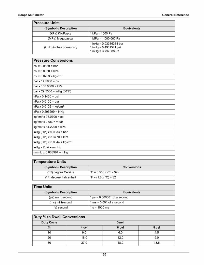
150
Scope Multimeter General Reference
(kPa) KiloPasca 1 kPa = 1000 Pa
(MPa) Megapascal 1 MPa = 1,000,000 Pa
(inHg) inches of mercury1 inHg = 0.03386388 bar1 inHg = 0.4911541 psi1 inHg = 3386.388 Pa
Pressure Conversions
psi x 0.0689 = bar
psi x 6.8950 = kPa
psi x 0.0703 = kg/cm²
bar x 14.5030 = psi
bar x 100.0000 = kPa
bar x 29.5300 = inHg (60°F)
kPa x 0.1450 = psi
kPa x 0.0100 = bar
kPa x 0.0102 = kg/cm²
kPa x 0.295299 = inHg
kg/cm² x 98.0700 = psi
kg/cm² x 0.9807 = bar
kg/cm² x 14.2200 = kPa
inHg (60°) x 0.0333 = bar
inHg (60°) x 3.3770 = kPa
inHg (60°) x 0.0344 = kg/cm²
inHg x 25.4 = mmHg
mmHg x 0.003994 = inHg
Temperature Units
(Symbol) / Description Conversions
(°C) degree Celsius °C = 0.556 x (°F - 32)
(°F) degree Fahrenheit °F = (1.8 x °C) + 32
Time Units
(Symbol) / Description Equivalents
(µs) microsecond 1 µs = 0.000001 of a second
(ms) millisecond 1 ms = 0.001 of a second
(s) second 1 s = 1000 ms
Duty % to Dwell Conversions
Duty Cycle Dwell
% 4 cyl 6 cyl 8 cyl
10 9.0 6.0 4.5
20 18.0 12.0 9.0
30 27.0 18.0 13.5
Pressure Units
(Symbol) / Description Equivalents
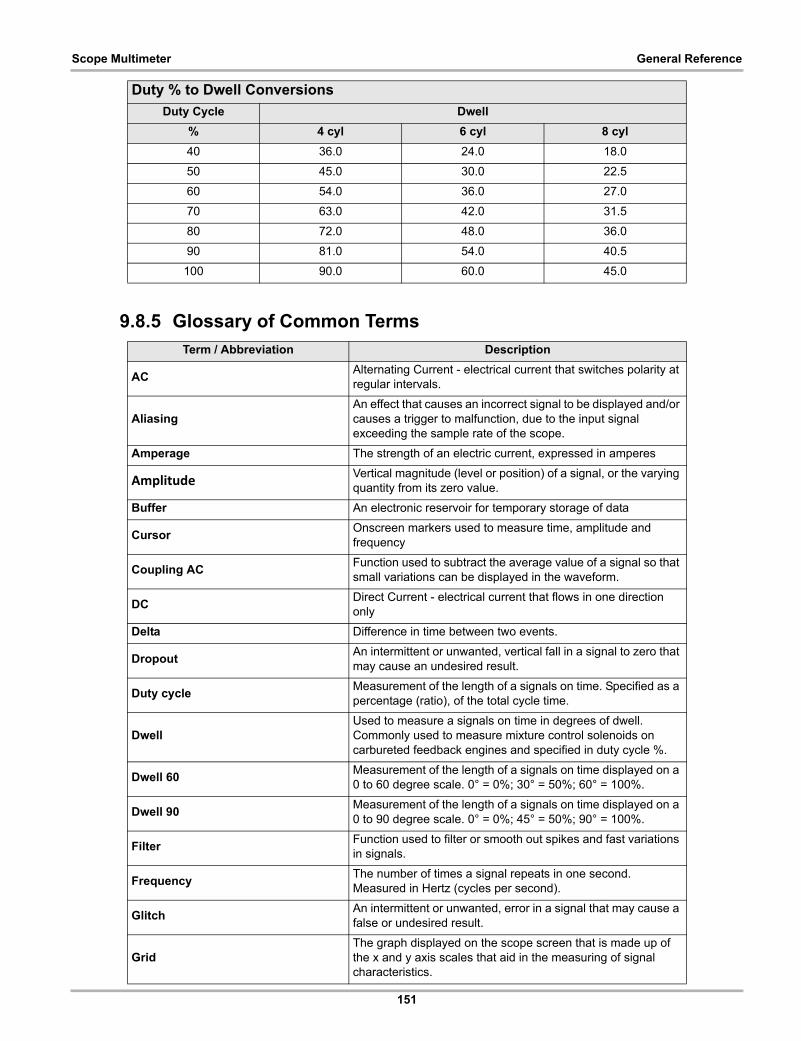
151
Scope Multimeter General Reference
9.8.5 Glossary of Common Terms
40 36.0 24.0 18.0
50 45.0 30.0 22.5
60 54.0 36.0 27.0
70 63.0 42.0 31.5
80 72.0 48.0 36.0
90 81.0 54.0 40.5
100 90.0 60.0 45.0
Term / Abbreviation Description
ACAlternating Current - electrical current that switches polarity at regular intervals.
AliasingAn effect that causes an incorrect signal to be displayed and/or causes a trigger to malfunction, due to the input signal exceeding the sample rate of the scope.
Amperage The strength of an electric current, expressed in amperes
AmplitudeVertical magnitude (level or position) of a signal, or the varying quantity from its zero value.
Buffer An electronic reservoir for temporary storage of data
CursorOnscreen markers used to measure time, amplitude and frequency
Coupling ACFunction used to subtract the average value of a signal so that small variations can be displayed in the waveform.
DCDirect Current - electrical current that flows in one direction only
Delta Difference in time between two events.
DropoutAn intermittent or unwanted, vertical fall in a signal to zero that may cause an undesired result.
Duty cycleMeasurement of the length of a signals on time. Specified as a percentage (ratio), of the total cycle time.
DwellUsed to measure a signals on time in degrees of dwell. Commonly used to measure mixture control solenoids on carbureted feedback engines and specified in duty cycle %.
Dwell 60Measurement of the length of a signals on time displayed on a 0 to 60 degree scale. 0° = 0%; 30° = 50%; 60° = 100%.
Dwell 90Measurement of the length of a signals on time displayed on a 0 to 90 degree scale. 0° = 0%; 45° = 50%; 90° = 100%.
FilterFunction used to filter or smooth out spikes and fast variations in signals.
FrequencyThe number of times a signal repeats in one second. Measured in Hertz (cycles per second).
GlitchAn intermittent or unwanted, error in a signal that may cause a false or undesired result.
GridThe graph displayed on the scope screen that is made up of the x and y axis scales that aid in the measuring of signal characteristics.
Duty % to Dwell Conversions
Duty Cycle Dwell
% 4 cyl 6 cyl 8 cyl
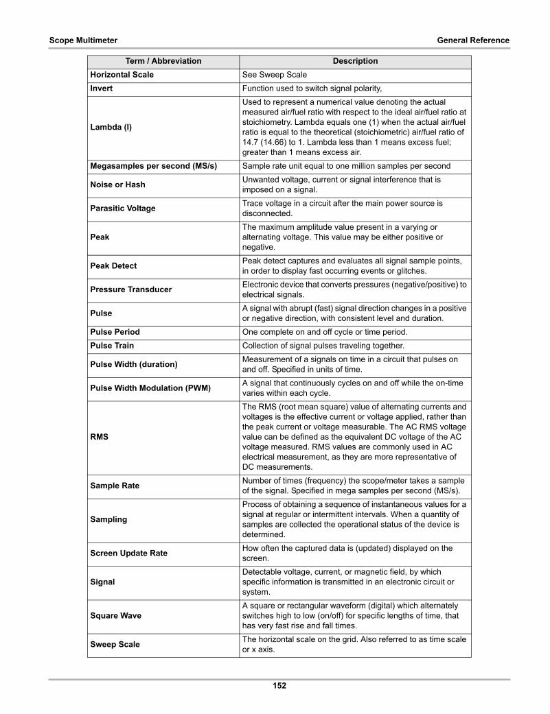
152
Scope Multimeter General Reference
Horizontal Scale See Sweep Scale
Invert Function used to switch signal polarity,
Lambda (l)
Used to represent a numerical value denoting the actual measured air/fuel ratio with respect to the ideal air/fuel ratio at stoichiometry. Lambda equals one (1) when the actual air/fuel ratio is equal to the theoretical (stoichiometric) air/fuel ratio of 14.7 (14.66) to 1. Lambda less than 1 means excess fuel; greater than 1 means excess air.
Megasamples per second (MS/s) Sample rate unit equal to one million samples per second
Noise or HashUnwanted voltage, current or signal interference that is imposed on a signal.
Parasitic VoltageTrace voltage in a circuit after the main power source is disconnected.
PeakThe maximum amplitude value present in a varying or alternating voltage. This value may be either positive or negative.
Peak DetectPeak detect captures and evaluates all signal sample points, in order to display fast occurring events or glitches.
Pressure TransducerElectronic device that converts pressures (negative/positive) to electrical signals.
PulseA signal with abrupt (fast) signal direction changes in a positive or negative direction, with consistent level and duration.
Pulse Period One complete on and off cycle or time period.
Pulse Train Collection of signal pulses traveling together.
Pulse Width (duration)Measurement of a signals on time in a circuit that pulses on and off. Specified in units of time.
Pulse Width Modulation (PWM)A signal that continuously cycles on and off while the on-time varies within each cycle.
RMS
The RMS (root mean square) value of alternating currents and voltages is the effective current or voltage applied, rather than the peak current or voltage measurable. The AC RMS voltage value can be defined as the equivalent DC voltage of the AC voltage measured. RMS values are commonly used in AC electrical measurement, as they are more representative of DC measurements.
Sample Rate Number of times (frequency) the scope/meter takes a sample of the signal. Specified in mega samples per second (MS/s).
Sampling
Process of obtaining a sequence of instantaneous values for a signal at regular or intermittent intervals. When a quantity of samples are collected the operational status of the device is determined.
Screen Update RateHow often the captured data is (updated) displayed on the screen.
SignalDetectable voltage, current, or magnetic field, by which specific information is transmitted in an electronic circuit or system.
Square WaveA square or rectangular waveform (digital) which alternately switches high to low (on/off) for specific lengths of time, that has very fast rise and fall times.
Sweep ScaleThe horizontal scale on the grid. Also referred to as time scale or x axis.
Term / Abbreviation Description
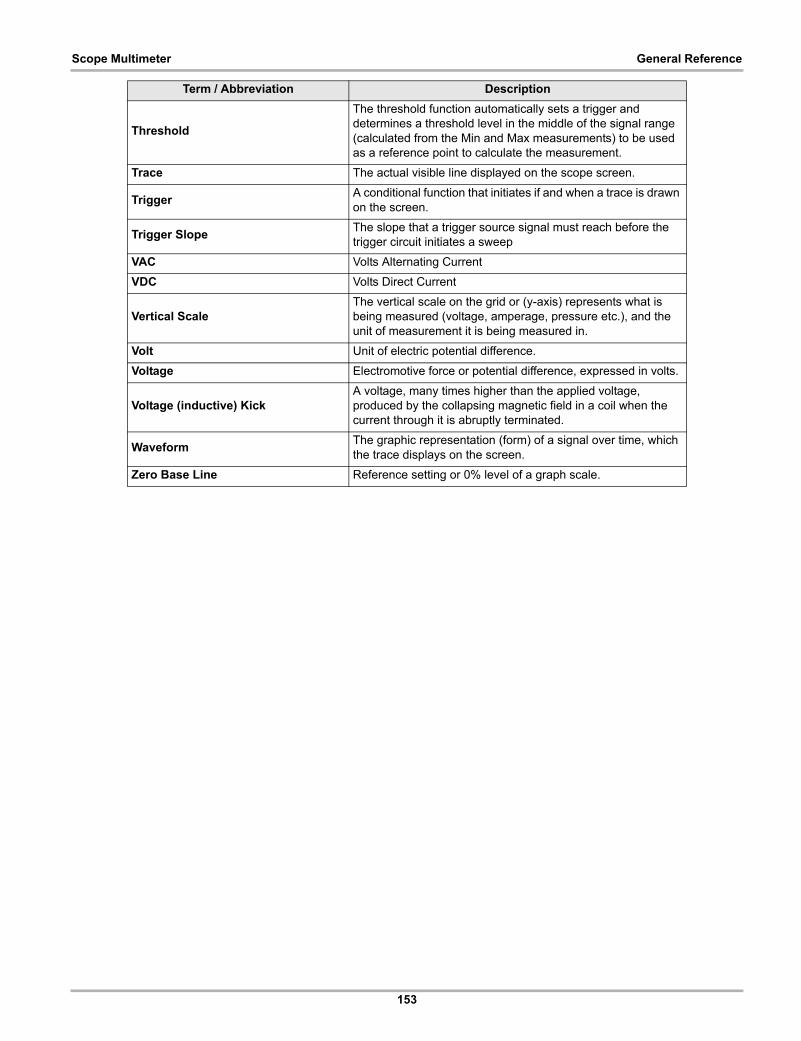
153
Scope Multimeter General Reference
Threshold
The threshold function automatically sets a trigger and determines a threshold level in the middle of the signal range (calculated from the Min and Max measurements) to be used as a reference point to calculate the measurement.
Trace The actual visible line displayed on the scope screen.
TriggerA conditional function that initiates if and when a trace is drawn on the screen.
Trigger Slope The slope that a trigger source signal must reach before the trigger circuit initiates a sweep
VAC Volts Alternating Current
VDC Volts Direct Current
Vertical ScaleThe vertical scale on the grid or (y-axis) represents what is being measured (voltage, amperage, pressure etc.), and the unit of measurement it is being measured in.
Volt Unit of electric potential difference.
Voltage Electromotive force or potential difference, expressed in volts.
Voltage (inductive) KickA voltage, many times higher than the applied voltage, produced by the collapsing magnetic field in a coil when the current through it is abruptly terminated.
WaveformThe graphic representation (form) of a signal over time, which the trace displays on the screen.
Zero Base Line Reference setting or 0% level of a graph scale.
Term / Abbreviation Description
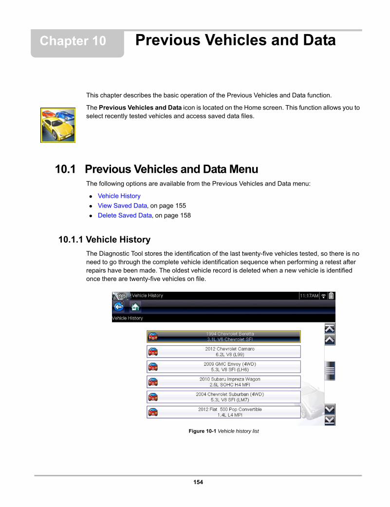
154
Chapter 10 Previous Vehicles and Data
This chapter describes the basic operation of the Previous Vehicles and Data function.
The Previous Vehicles and Data icon is located on the Home screen. This function allows you to select recently tested vehicles and access saved data files.
10.1 Previous Vehicles and Data MenuThe following options are available from the Previous Vehicles and Data menu:
• Vehicle History
• View Saved Data‚ on page 155
• Delete Saved Data‚ on page 158
10.1.1 Vehicle History
The Diagnostic Tool stores the identification of the last twenty-five vehicles tested, so there is no need to go through the complete vehicle identification sequence when performing a retest after repairs have been made. The oldest vehicle record is deleted when a new vehicle is identified once there are twenty-five vehicles on file.
Figure 10-1 Vehicle history list
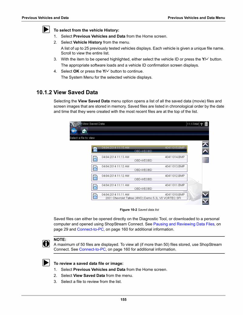
155
Previous Vehicles and Data Previous Vehicles and Data Menu
z To select from the vehicle History:
1. Select Previous Vehicles and Data from the Home screen.
2. Select Vehicle History from the menu.
A list of up to 25 previously tested vehicles displays. Each vehicle is given a unique file name. Scroll to view the entire list.
3. With the item to be opened highlighted, either select the vehicle ID or press the Y/a button.
The appropriate software loads and a vehicle ID confirmation screen displays.
4. Select OK or press the Y/a button to continue.
The System Menu for the selected vehicle displays.
10.1.2 View Saved Data
Selecting the View Saved Data menu option opens a list of all the saved data (movie) files and screen images that are stored in memory. Saved files are listed in chronological order by the date and time that they were created with the most recent files are at the top of the list.
Figure 10-2 Saved data list
Saved files can either be opened directly on the Diagnostic Tool, or downloaded to a personal computer and opened using ShopStream Connect. See Pausing and Reviewing Data Files‚ on page 29 and Connect-to-PC‚ on page 160 for additional information.
NOTE:i A maximum of 50 files are displayed. To view all (if more than 50) files stored, use ShopStream
Connect. See Connect-to-PC‚ on page 160 for additional information.
z To review a saved data file or image:
1. Select Previous Vehicles and Data from the Home screen.
2. Select View Saved Data from the menu.
3. Select a file to review from the list.
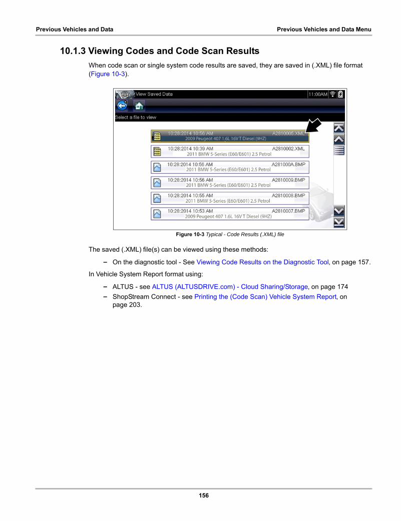
156
Previous Vehicles and Data Previous Vehicles and Data Menu
10.1.3 Viewing Codes and Code Scan Results
When code scan or single system code results are saved, they are saved in (.XML) file format (Figure 10-3).
Figure 10-3 Typical - Code Results (.XML) file
The saved (.XML) file(s) can be viewed using these methods:
– On the diagnostic tool - See Viewing Code Results on the Diagnostic Tool‚ on page 157.
In Vehicle System Report format using:
– ALTUS - see ALTUS (ALTUSDRIVE.com) - Cloud Sharing/Storage‚ on page 174
– ShopStream Connect - see Printing the (Code Scan) Vehicle System Report‚ on page 203.
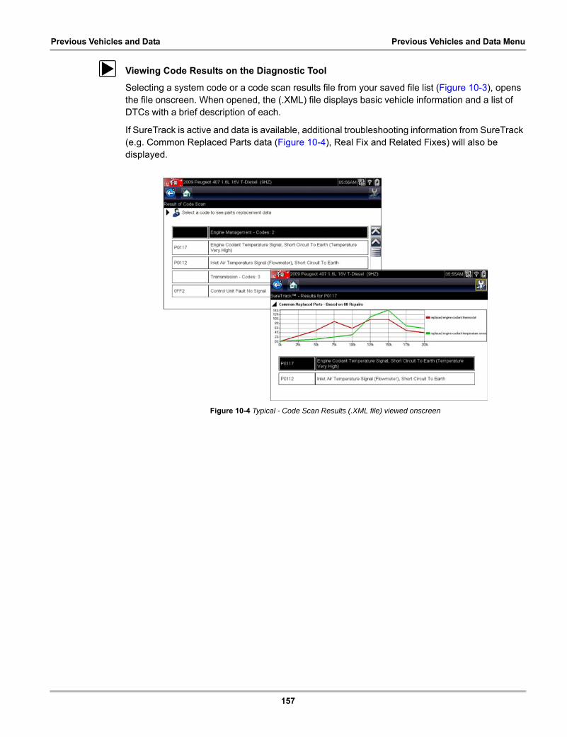
157
Previous Vehicles and Data Previous Vehicles and Data Menu
z Viewing Code Results on the Diagnostic Tool
Selecting a system code or a code scan results file from your saved file list (Figure 10-3), opens the file onscreen. When opened, the (.XML) file displays basic vehicle information and a list of DTCs with a brief description of each.
If SureTrack is active and data is available, additional troubleshooting information from SureTrack (e.g. Common Replaced Parts data (Figure 10-4), Real Fix and Related Fixes) will also be displayed.
Figure 10-4 Typical - Code Scan Results (.XML file) viewed onscreen
158
Previous Vehicles and Data Previous Vehicles and Data Menu
10.1.4 Delete Saved Data
This menu option is used to permanently erase saved files from memory.
z To delete a saved file:
1. Select Previous Vehicles and Data from the Home screen.
2. Select Delete Saved Data from the menu.
A list of saved files displays.
NOTE:i The Select All/Deselect All and Delete icons become available on the toolbar so that you can
either delete individual files or clear the entire memory buffer all at once.
3. Select a file from the list and a confirmation message displays.
4. Select an option from the confirmation message:
– OK—deletes the selected file and returns to the saved files list, which no longer includes the deleted file.
– Cancel—returns to the saved files list without deleting the selected file.
5. Select Back on the toolbar to return to the Previous Vehicles and Data menu, select Home to return to the Home screen.
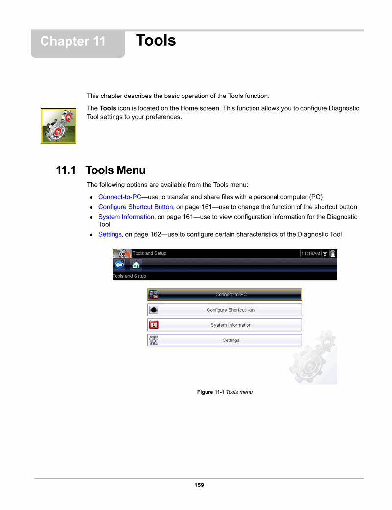
159
Chapter 11 Tools
This chapter describes the basic operation of the Tools function.
The Tools icon is located on the Home screen. This function allows you to configure Diagnostic Tool settings to your preferences.
11.1 Tools MenuThe following options are available from the Tools menu:
• Connect-to-PC—use to transfer and share files with a personal computer (PC)
• Configure Shortcut Button‚ on page 161—use to change the function of the shortcut button
• System Information‚ on page 161—use to view configuration information for the Diagnostic Tool
• Settings‚ on page 162—use to configure certain characteristics of the Diagnostic Tool
Figure 11-1 Tools menu
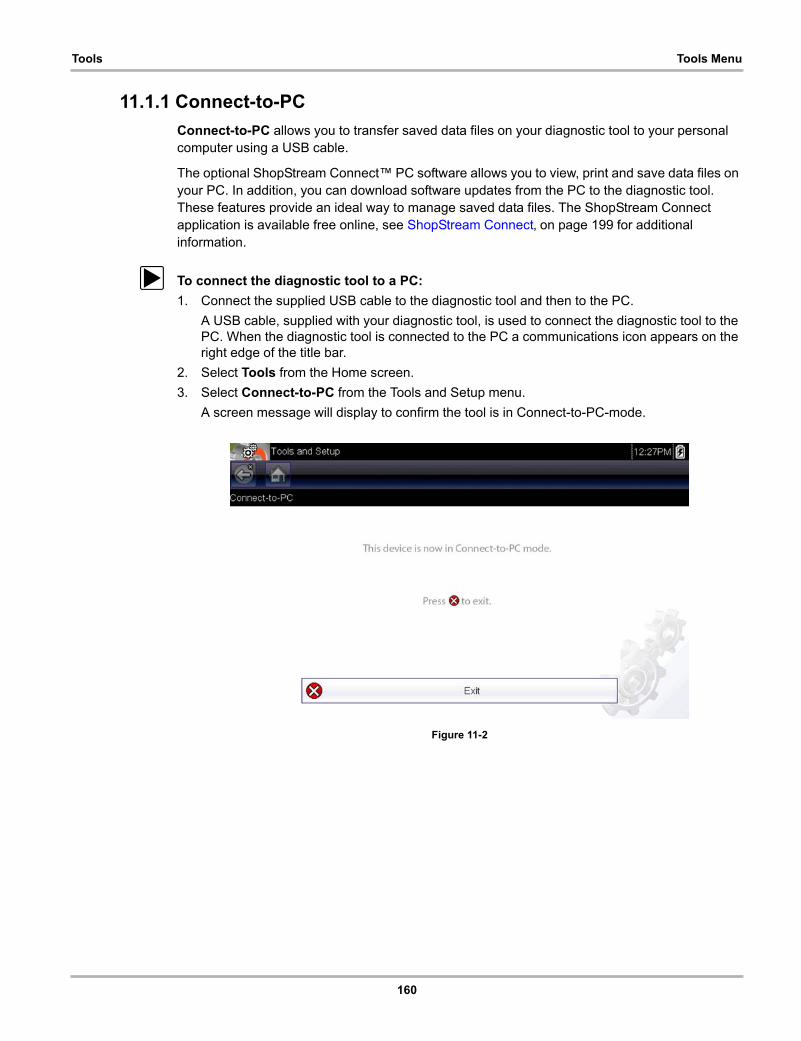
160
Tools Tools Menu
11.1.1 Connect-to-PC
Connect-to-PC allows you to transfer saved data files on your diagnostic tool to your personal computer using a USB cable.
The optional ShopStream Connect™ PC software allows you to view, print and save data files on your PC. In addition, you can download software updates from the PC to the diagnostic tool. These features provide an ideal way to manage saved data files. The ShopStream Connect application is available free online, see ShopStream Connect‚ on page 199 for additional information.
z To connect the diagnostic tool to a PC:
1. Connect the supplied USB cable to the diagnostic tool and then to the PC.
A USB cable, supplied with your diagnostic tool, is used to connect the diagnostic tool to the PC. When the diagnostic tool is connected to the PC a communications icon appears on the right edge of the title bar.
2. Select Tools from the Home screen.
3. Select Connect-to-PC from the Tools and Setup menu.
A screen message will display to confirm the tool is in Connect-to-PC-mode.
Figure 11-2
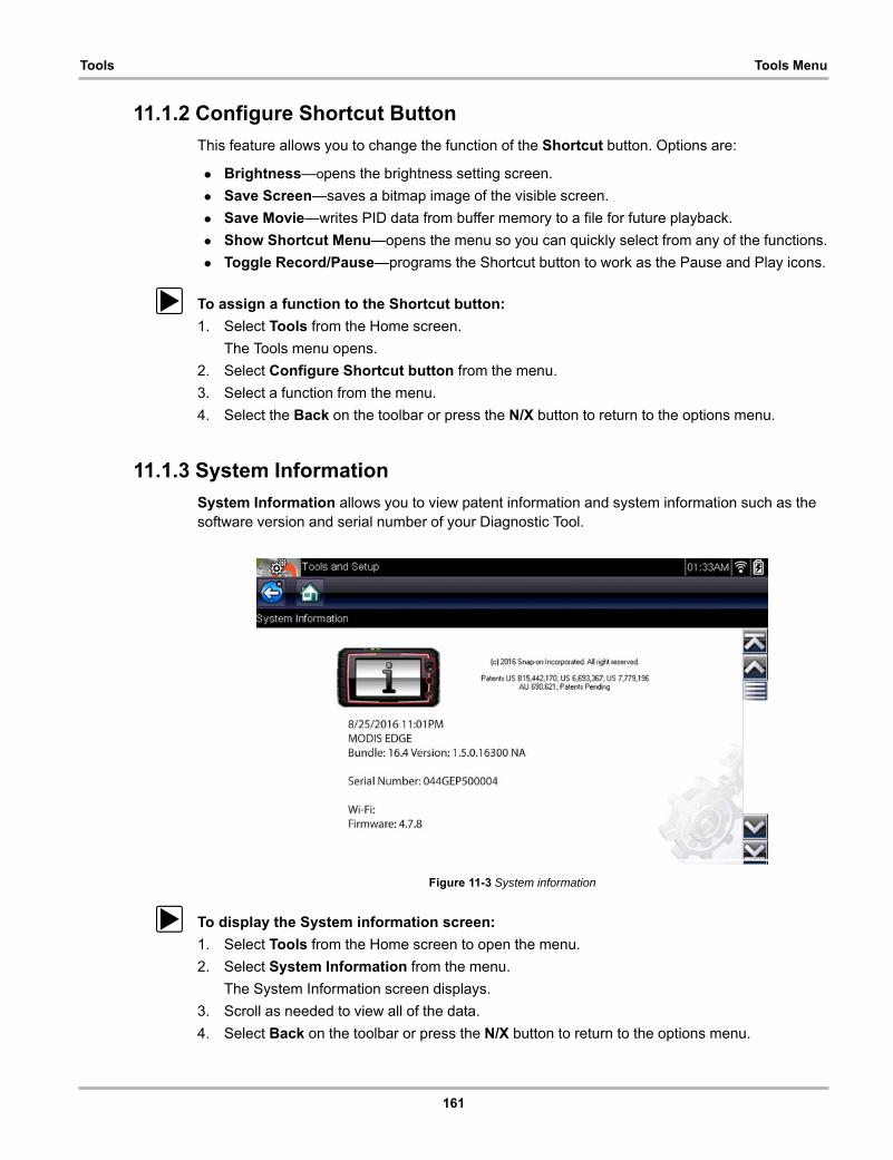
161
Tools Tools Menu
11.1.2 Configure Shortcut Button
This feature allows you to change the function of the Shortcut button. Options are:
• Brightness—opens the brightness setting screen.
• Save Screen—saves a bitmap image of the visible screen.
• Save Movie—writes PID data from buffer memory to a file for future playback.
• Show Shortcut Menu—opens the menu so you can quickly select from any of the functions.
• Toggle Record/Pause—programs the Shortcut button to work as the Pause and Play icons.
z To assign a function to the Shortcut button:
1. Select Tools from the Home screen.
The Tools menu opens.
2. Select Configure Shortcut button from the menu.
3. Select a function from the menu.
4. Select the Back on the toolbar or press the N/X button to return to the options menu.
11.1.3 System Information
System Information allows you to view patent information and system information such as the software version and serial number of your Diagnostic Tool.
Figure 11-3 System information
z To display the System information screen:
1. Select Tools from the Home screen to open the menu.
2. Select System Information from the menu.
The System Information screen displays.
3. Scroll as needed to view all of the data.
4. Select Back on the toolbar or press the N/X button to return to the options menu.

162
Tools Tools Menu
11.1.4 Settings
This Tools selection allows you to adjust certain basic Diagnostic Tool functions to your personal preferences. Selecting opens an additional menu that offers the following:
• System Settings - see System Settings‚ on page 162
• Configure Wi-Fi - see Wi-Fi Connection / Troubleshooting‚ on page 191
• Configure Scanner - see Configuring Scanner‚ on page 168
• Configure Units - see Configure Units‚ on page 169
System Settings
Selecting System Settings opens a menu with three options; Display, Date & Time and Auto VIN. Selecting either Display or Date & Time opens an additional menu (see below). Selecting Auto VIN provides the option to turn the Auto VIN feature on/off.
Display options include:
• Brightness‚ on page 163—adjusts the intensity of the screen back lighting.
• Color Theme‚ on page 163—changes the background color of the screen display.
• High Contrast Toolbar‚ on page 164—enhances toolbar graphics for poor lighting conditions.
• Font Type‚ on page 164—switches between standard and bold text for better visibility.
• Backlight Time‚ on page 165—adjusts how long the screen stays on with an idle Diagnostic Tool.
• Touch Screen Calibration‚ on page 165—calibrates the touch screen display.
Date & Time options include:
• Time Zone‚ on page 166—sets the internal clock to the local time standard.
• Clock Settings‚ on page 166—sets the time on the internal clock.
• Daylight Savings Time‚ on page 167—configures the clock for Daylight Savings Time.
• Time Format‚ on page 167—switches the time displays between a 12 or 24 hour clock.
• Date Format‚ on page 167—configures how the month, date, and year displays.

163
Tools Tools Menu
Brightness
Selecting this option opens the brightness setting screen for adjusting the back lighting of the display (Figure 11-4).
Figure 11-4 Brightness setting
Each push of the Plus and Minus icons, or the up (b) and down (d) arrows, incrementally changes the back lighting up or down respectively.
Select Back from the toolbar or press the N/X button to exit.
Color Theme
This option allows you to select between a white and black background for the screen. The black background can be beneficial when working under poor lighting conditions.
Selecting opens a menu with two choices: Day Theme (white background) and Night Theme (black background). Make a selection and a “please wait” message momentarily displays followed by the Home screen. The new toolbar setting is now active.
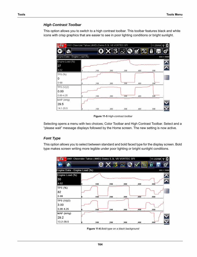
164
Tools Tools Menu
High Contrast Toolbar
This option allows you to switch to a high contrast toolbar. This toolbar features black and white icons with crisp graphics that are easier to see in poor lighting conditions or bright sunlight.
Figure 11-5 High-contrast toolbar
Selecting opens a menu with two choices; Color Toolbar and High Contrast Toolbar. Select and a “please wait” message displays followed by the Home screen. The new setting is now active.
Font Type
This option allows you to select between standard and bold faced type for the display screen. Bold type makes screen writing more legible under poor lighting or bright sunlight conditions.
Figure 11-6 Bold type on a black background
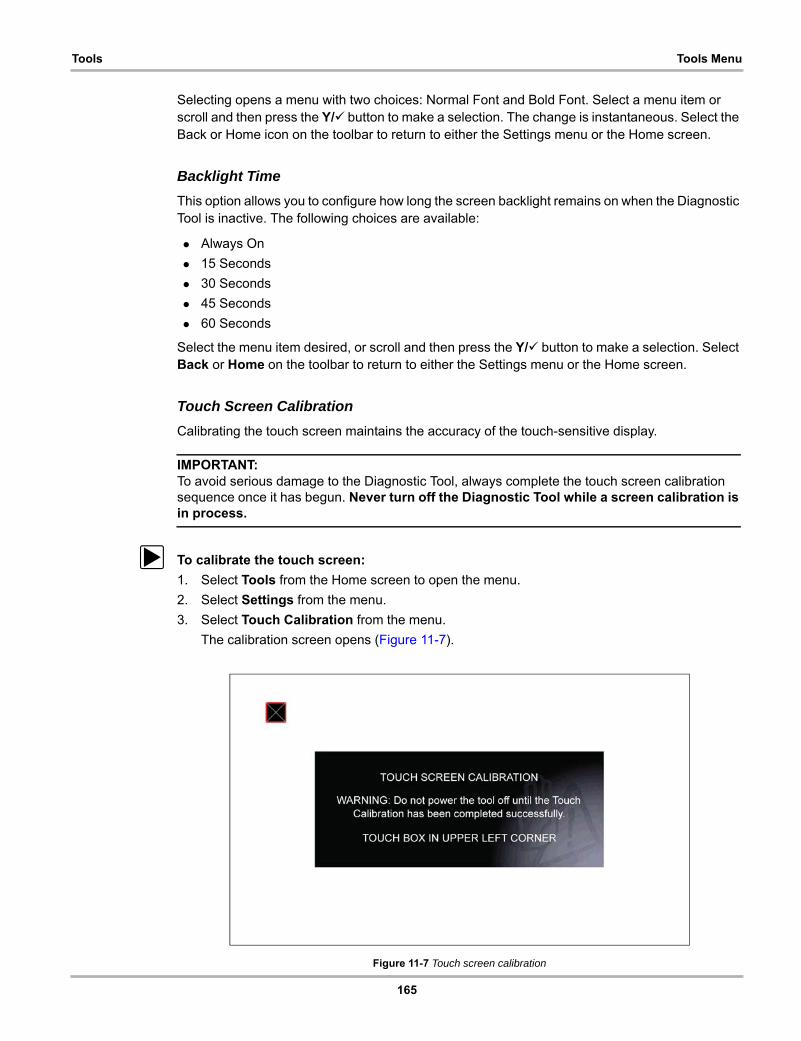
165
Tools Tools Menu
Selecting opens a menu with two choices: Normal Font and Bold Font. Select a menu item or scroll and then press the Y/a button to make a selection. The change is instantaneous. Select the Back or Home icon on the toolbar to return to either the Settings menu or the Home screen.
Backlight Time
This option allows you to configure how long the screen backlight remains on when the Diagnostic Tool is inactive. The following choices are available:
• Always On
• 15 Seconds
• 30 Seconds
• 45 Seconds
• 60 Seconds
Select the menu item desired, or scroll and then press the Y/a button to make a selection. Select Back or Home on the toolbar to return to either the Settings menu or the Home screen.
Touch Screen Calibration
Calibrating the touch screen maintains the accuracy of the touch-sensitive display.
IMPORTANT:To avoid serious damage to the Diagnostic Tool, always complete the touch screen calibration sequence once it has begun. Never turn off the Diagnostic Tool while a screen calibration is in process.
z To calibrate the touch screen:
1. Select Tools from the Home screen to open the menu.
2. Select Settings from the menu.
3. Select Touch Calibration from the menu.
The calibration screen opens (Figure 11-7).
Figure 11-7 Touch screen calibration
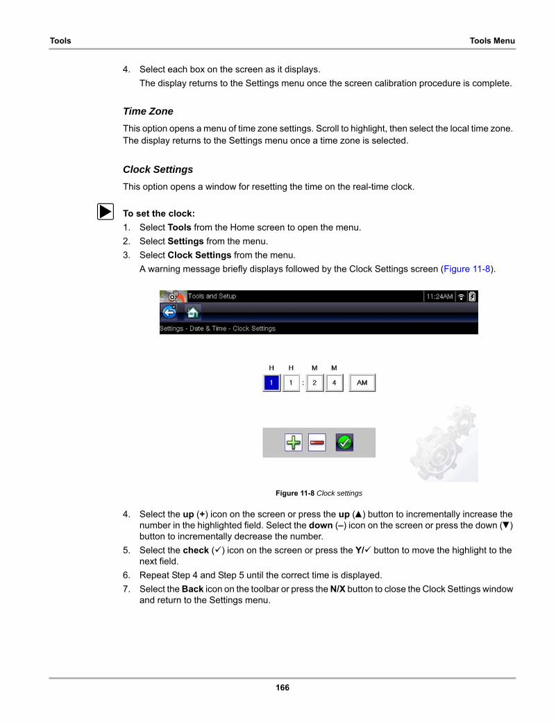
166
Tools Tools Menu
4. Select each box on the screen as it displays.
The display returns to the Settings menu once the screen calibration procedure is complete.
Time Zone
This option opens a menu of time zone settings. Scroll to highlight, then select the local time zone. The display returns to the Settings menu once a time zone is selected.
Clock Settings
This option opens a window for resetting the time on the real-time clock.
z To set the clock:
1. Select Tools from the Home screen to open the menu.
2. Select Settings from the menu.
3. Select Clock Settings from the menu.
A warning message briefly displays followed by the Clock Settings screen (Figure 11-8).
Figure 11-8 Clock settings
4. Select the up (+) icon on the screen or press the up (b) button to incrementally increase the number in the highlighted field. Select the down (–) icon on the screen or press the down (d) button to incrementally decrease the number.
5. Select the check (a) icon on the screen or press the Y/a button to move the highlight to the next field.
6. Repeat Step 4 and Step 5 until the correct time is displayed.
7. Select the Back icon on the toolbar or press the N/X button to close the Clock Settings window and return to the Settings menu.
167
Tools Tools Menu
Daylight Savings Time
This option opens a menu to configure the internal clock for Daylight Savings Time. Choose from:
• ON—sets the clock for Daylight Savings time.
• OFF—sets the clock for standard time.
Make either selection, then select the Back icon or press the N/X button to return to the menu.
Time Format
This option determines whether time is displayed on a 12 or 24 hour clock. Selecting opens a menu with two choices:
• 24 Hour Format
• 12 Hour Format
Make either selection, then select the Back icon or press the N/X button to return to the menu.
Date Format
This option allows you to select how date information is displayed. Select from:
• (MM_DD_YYYY)—Month, Day, Year
• (DD_MM_YYYY)—Day, Month, Year
• (YYYY_MM_DD)—Year, Month, Day
Make a selection, then select the Back icon or press the N/X button to return to the menu.
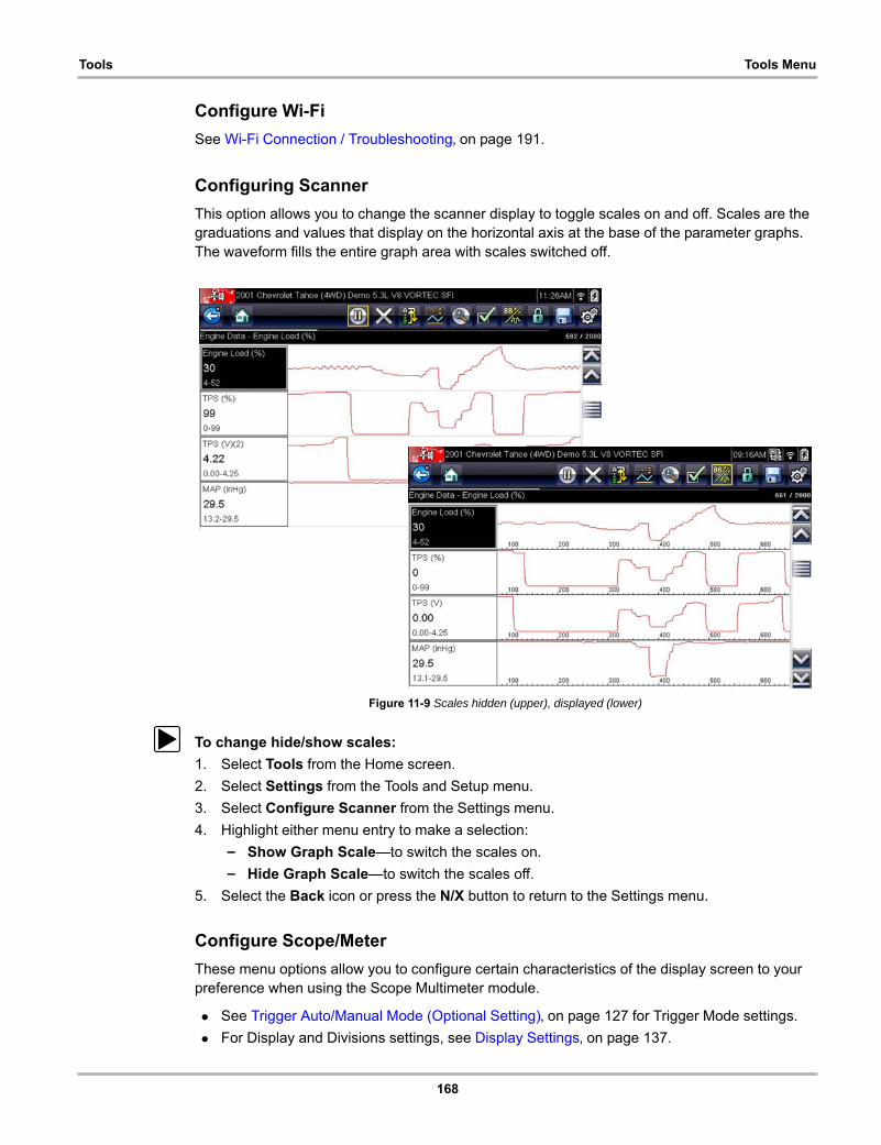
168
Tools Tools Menu
Configure Wi-Fi
See Wi-Fi Connection / Troubleshooting‚ on page 191.
Configuring Scanner
This option allows you to change the scanner display to toggle scales on and off. Scales are the graduations and values that display on the horizontal axis at the base of the parameter graphs. The waveform fills the entire graph area with scales switched off.
Figure 11-9 Scales hidden (upper), displayed (lower)
z To change hide/show scales:
1. Select Tools from the Home screen.
2. Select Settings from the Tools and Setup menu.
3. Select Configure Scanner from the Settings menu.
4. Highlight either menu entry to make a selection:
– Show Graph Scale—to switch the scales on.
– Hide Graph Scale—to switch the scales off.
5. Select the Back icon or press the N/X button to return to the Settings menu.
Configure Scope/Meter
These menu options allow you to configure certain characteristics of the display screen to your preference when using the Scope Multimeter module.
• See Trigger Auto/Manual Mode (Optional Setting)‚ on page 127 for Trigger Mode settings.
• For Display and Divisions settings, see Display Settings‚ on page 137.

169
Tools Tools Menu
Configure Units
Selecting opens a dialog box that allows you to choose between US customary or metric units of measure for temperature, vehicle speed, air pressure, and other pressures.
Figure 11-10 Configure units menu
z To change the units setup:
1. Select Tools from the Home screen to open the menu.
2. Select Configure Units to open the menu.
3. Select an item from the Configure Units menu.
4. Select a setting from the listed choices.
5. Select Back on the toolbar or press the N/X button to return to the options menu.

170
Chapter 12 Maintenance
This chapter describes basic cleaning and battery replacement procedures for your Diagnostic Tool.
12.1 Cleaning and Inspecting the Diagnostic ToolPeriodically perform the following tasks to keep your Diagnostic Tool in proper working order:
• Check the housing, cables and connectors for dirt and damage before and after each use.
• At the end of each work day, wipe the Diagnostic Tool housing, cables and connectors clean with a damp cloth.
IMPORTANT:Do not use any abrasive cleansers or automotive chemicals on the Diagnostic Tool.
12.1.1 Cleaning the Touch Screen
The touch screen can be cleaned with a soft cloth and a mild window cleaner.
IMPORTANT:Do not use any abrasive cleansers or automotive chemicals on the touch screen.
12.2 Battery Pack ServiceFollow all safety guidelines when handling the battery pack.
Risk of electric shock.• Prior to recycling the battery pack, protect exposed terminals with heavy insulating tape
to prevent shorting.• Disconnect all test leads and turn Diagnostic Tools off before removing the battery
pack.• Do not attempt to disassemble the battery pack or remove any component projecting
from or protecting the battery terminals.• Do not expose the Diagnostic Tool or battery pack to rain, snow, or wet conditions.• Do not short circuit the battery terminals.
Electric shock can cause injury.

171
Maintenance Battery Pack Service
Risk of explosion.• Use the proper factory battery pack only, incorrect replacement or tampering with the
battery pack may cause an explosion.Explosion can cause death or serious injury.
12.2.1 Battery Pack Safety Guidelines
IMPORTANT:The battery pack contains no user serviceable components. Tampering with the battery pack terminals or housing will void the product warranty.
Keep the following in mind when using and handling the battery pack:
• Do not short circuit battery terminals.
• Do not immerse the Diagnostic Tool or battery pack in water, or allow water to enter the Diagnostic Tool or battery compartment.
• Do not crush, disassemble, or tamper with the battery pack.
• Do not heat the battery pack to over 100°C (212°F), or dispose of it in a fire.
• Do not expose the battery pack to excessive physical shock or vibration.
• Keep the battery pack out of reach of children.
• Do not use a battery pack that appears to have suffered abuse or damage.
• Store the battery pack in a cool, dry, well ventilated area.
NOTE:i The battery pack should be used within a short period of time (about 30 days) after charging to
prevent loss of capacity due to self-discharging.
If long-term storage of the battery pack is necessary, it should be stored in a in cool, dry, well ventilated place with a 30 to 75 percent state of charge to prevent loss of characteristics.
To prolong the life of your battery, power off the Diagnostic Tool when not in use. The Diagnostic Tool has a built in charger that recharges the battery on demand whenever it is connected to a power source.
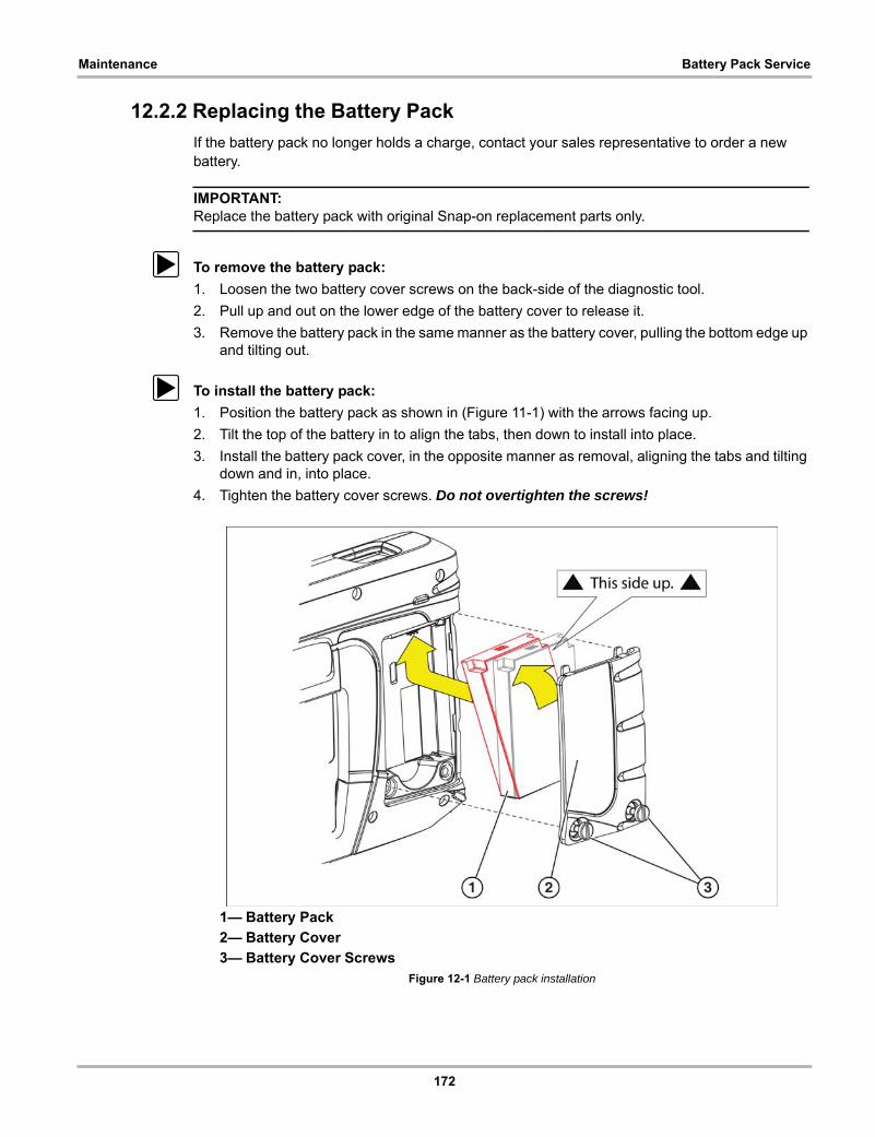
172
Maintenance Battery Pack Service
12.2.2 Replacing the Battery Pack
If the battery pack no longer holds a charge, contact your sales representative to order a new battery.
IMPORTANT:Replace the battery pack with original Snap-on replacement parts only.
z To remove the battery pack:
1. Loosen the two battery cover screws on the back-side of the diagnostic tool.
2. Pull up and out on the lower edge of the battery cover to release it.
3. Remove the battery pack in the same manner as the battery cover, pulling the bottom edge up and tilting out.
z To install the battery pack:
1. Position the battery pack as shown in (Figure 11-1) with the arrows facing up.
2. Tilt the top of the battery in to align the tabs, then down to install into place.
3. Install the battery pack cover, in the opposite manner as removal, aligning the tabs and tilting down and in, into place.
4. Tighten the battery cover screws. Do not overtighten the screws!
1— Battery Pack
2— Battery Cover
3— Battery Cover ScrewsFigure 12-1 Battery pack installation

173
Maintenance Battery Pack Service
12.2.3 Disposing of the Battery Pack
Always dispose of a lithium-ion battery pack according to local regulations, which vary for different countries and regions. The battery pack, while non-hazardous waste, does contain recyclable materials. If shipping is required, ship the battery pack to a recycling facility in accordance with local, national, and international regulations.
• For additional information within the United States of America contact: Rechargeable Battery Recycling Corporation (RBRC) at www.call2recycle.org Phone - 800 822-8837
• For additional information within Canada contact: Rechargeable Battery Recycling Corporation (RBRC) at www.call2recycle.ca Phone - 888 224 9764
Products bearing the WEEE logo (Figure 12-2) are subject to European Union regulations.
Figure 12-2 WEEE logo
NOTE:i Always dispose of materials according to local regulations.
Contact your sales representative for details.

174
Chapter 13 ALTUS (ALTUSDRIVE.com) - Cloud Sharing/Storage
ALTUS is a mobile-friendly cloud-based application designed specifically for technicians to store, organize and share diagnostic information.
This built-in feature automatically transfers code scan reports from the diagnostic tool to ALTUS (ALTUSDRIVE.com).
Main Topic Links• Quick Reference (print / download / share)
• Registration - Getting Started
• Using ALTUS
– ALTUS - New User Registration
– ALTUS - SureTrack User Setup
– ALTUS Setup Information Screen
– Logging in to ALTUS (registered user)
– Navigating ALTUS (Toolbars)
– My Files
– Search
– Favorites
– Profile
– File Detail (Tags)
– Sharing/E-mail an Individual Report (Link icon)
– Logging Out of ALTUS
13.1 Key Features• Automatically transfer code scan reports to ALTUS.
• Access and manage your ALTUS account, using your mobile device or PC.
• Share/send report files via e-mail, or other mobile apps.
• Tag reports (attach a descriptive key-name) to help you organize and search report files.
• Use the Search function to quickly find files by Tag, Description and Title.
13.2 Important Notes• To use ALTUS, registration and diagnostic tool Wi-Fi connection is required.
• The diagnostic tool only transfers code scan reports to ALTUS.
• ALTUS is continuously monitored for inappropriate content. Abuse (as determined by moderator) will result in account deactivation.
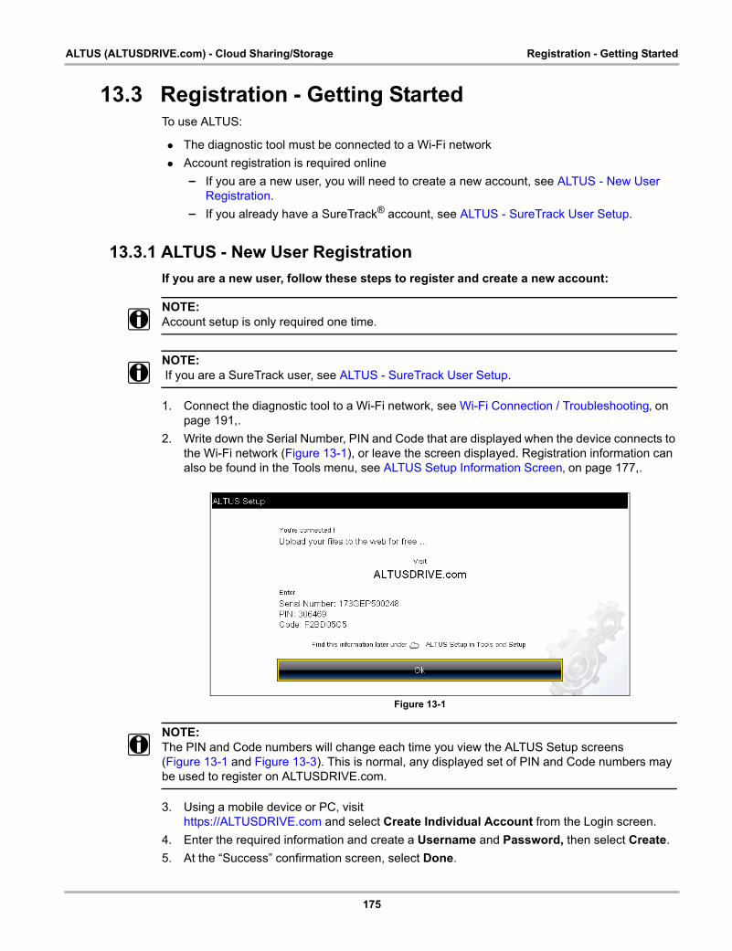
175
ALTUS (ALTUSDRIVE.com) - Cloud Sharing/Storage Registration - Getting Started
13.3 Registration - Getting StartedTo use ALTUS:
• The diagnostic tool must be connected to a Wi-Fi network
• Account registration is required online
– If you are a new user, you will need to create a new account, see ALTUS - New User Registration.
– If you already have a SureTrack® account, see ALTUS - SureTrack User Setup.
13.3.1 ALTUS - New User Registration
If you are a new user, follow these steps to register and create a new account:
NOTE:i Account setup is only required one time.
NOTE:i If you are a SureTrack user, see ALTUS - SureTrack User Setup.
1. Connect the diagnostic tool to a Wi-Fi network, see Wi-Fi Connection / Troubleshooting‚ on page 191,.
2. Write down the Serial Number, PIN and Code that are displayed when the device connects to the Wi-Fi network (Figure 13-1), or leave the screen displayed. Registration information can also be found in the Tools menu, see ALTUS Setup Information Screen‚ on page 177,.
Figure 13-1
NOTE:i The PIN and Code numbers will change each time you view the ALTUS Setup screens
(Figure 13-1 and Figure 13-3). This is normal, any displayed set of PIN and Code numbers may be used to register on ALTUSDRIVE.com.
3. Using a mobile device or PC, visit https://ALTUSDRIVE.com and select Create Individual Account from the Login screen.
4. Enter the required information and create a Username and Password, then select Create.
5. At the “Success” confirmation screen, select Done.
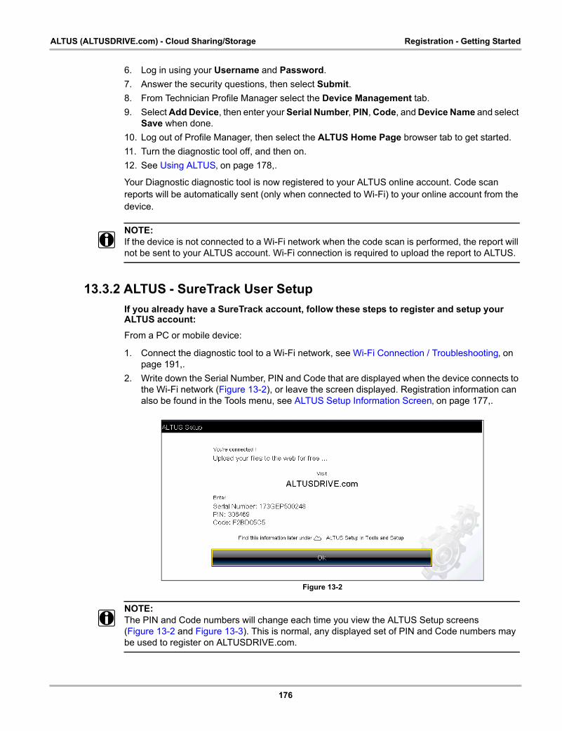
176
ALTUS (ALTUSDRIVE.com) - Cloud Sharing/Storage Registration - Getting Started
6. Log in using your Username and Password.
7. Answer the security questions, then select Submit.
8. From Technician Profile Manager select the Device Management tab.
9. Select Add Device, then enter your Serial Number, PIN, Code, and Device Name and select Save when done.
10. Log out of Profile Manager, then select the ALTUS Home Page browser tab to get started.
11. Turn the diagnostic tool off, and then on.
12. See Using ALTUS‚ on page 178,.
Your Diagnostic diagnostic tool is now registered to your ALTUS online account. Code scan reports will be automatically sent (only when connected to Wi-Fi) to your online account from the device.
NOTE:i If the device is not connected to a Wi-Fi network when the code scan is performed, the report will
not be sent to your ALTUS account. Wi-Fi connection is required to upload the report to ALTUS.
13.3.2 ALTUS - SureTrack User Setup
If you already have a SureTrack account, follow these steps to register and setup your ALTUS account:
From a PC or mobile device:
1. Connect the diagnostic tool to a Wi-Fi network, see Wi-Fi Connection / Troubleshooting‚ on page 191,.
2. Write down the Serial Number, PIN and Code that are displayed when the device connects to the Wi-Fi network (Figure 13-2), or leave the screen displayed. Registration information can also be found in the Tools menu, see ALTUS Setup Information Screen‚ on page 177,.
Figure 13-2
NOTE:i The PIN and Code numbers will change each time you view the ALTUS Setup screens
(Figure 13-2 and Figure 13-3). This is normal, any displayed set of PIN and Code numbers may be used to register on ALTUSDRIVE.com.
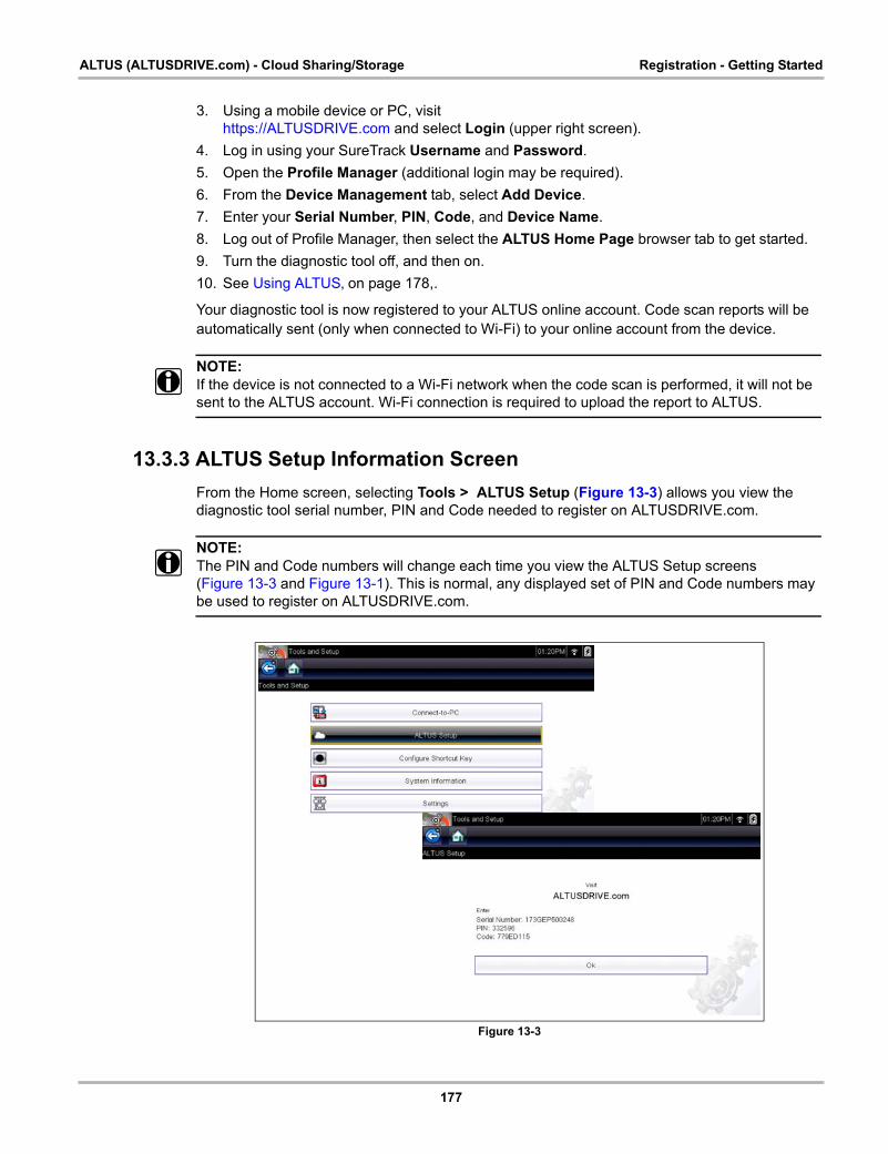
177
ALTUS (ALTUSDRIVE.com) - Cloud Sharing/Storage Registration - Getting Started
3. Using a mobile device or PC, visithttps://ALTUSDRIVE.com and select Login (upper right screen).
4. Log in using your SureTrack Username and Password.
5. Open the Profile Manager (additional login may be required).
6. From the Device Management tab, select Add Device.
7. Enter your Serial Number, PIN, Code, and Device Name.
8. Log out of Profile Manager, then select the ALTUS Home Page browser tab to get started.
9. Turn the diagnostic tool off, and then on.
10. See Using ALTUS‚ on page 178,.
Your diagnostic tool is now registered to your ALTUS online account. Code scan reports will be automatically sent (only when connected to Wi-Fi) to your online account from the device.
NOTE:i If the device is not connected to a Wi-Fi network when the code scan is performed, it will not be
sent to the ALTUS account. Wi-Fi connection is required to upload the report to ALTUS.
13.3.3 ALTUS Setup Information Screen
From the Home screen, selecting Tools > ALTUS Setup (Figure 13-3) allows you view the diagnostic tool serial number, PIN and Code needed to register on ALTUSDRIVE.com.
NOTE:i The PIN and Code numbers will change each time you view the ALTUS Setup screens
(Figure 13-3 and Figure 13-1). This is normal, any displayed set of PIN and Code numbers may be used to register on ALTUSDRIVE.com.
Figure 13-3
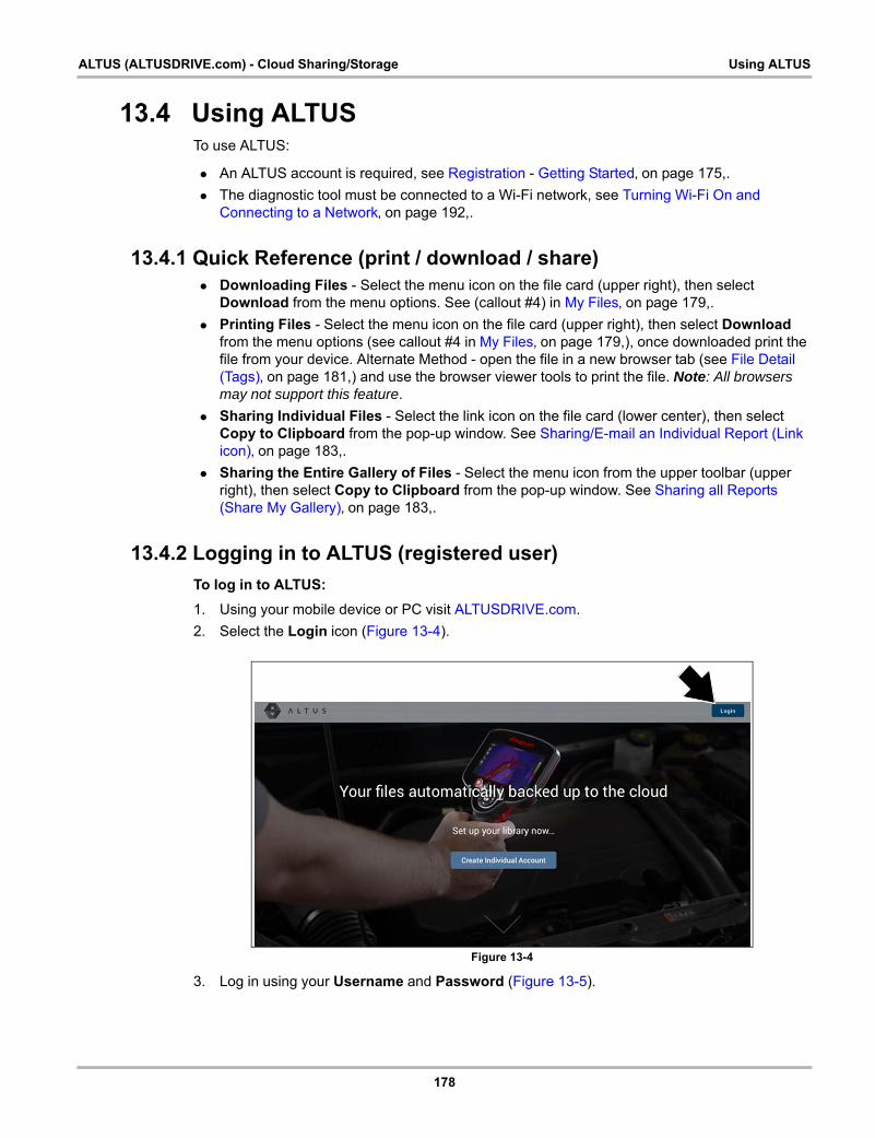
178
ALTUS (ALTUSDRIVE.com) - Cloud Sharing/Storage Using ALTUS
13.4 Using ALTUSTo use ALTUS:
• An ALTUS account is required, see Registration - Getting Started‚ on page 175,.
• The diagnostic tool must be connected to a Wi-Fi network, see Turning Wi-Fi On and Connecting to a Network‚ on page 192,.
13.4.1 Quick Reference (print / download / share) • Downloading Files - Select the menu icon on the file card (upper right), then select
Download from the menu options. See (callout #4) in My Files‚ on page 179,.
• Printing Files - Select the menu icon on the file card (upper right), then select Download from the menu options (see callout #4 in My Files‚ on page 179,), once downloaded print the file from your device. Alternate Method - open the file in a new browser tab (see File Detail (Tags)‚ on page 181,) and use the browser viewer tools to print the file. Note: All browsers may not support this feature.
• Sharing Individual Files - Select the link icon on the file card (lower center), then select Copy to Clipboard from the pop-up window. See Sharing/E-mail an Individual Report (Link icon)‚ on page 183,.
• Sharing the Entire Gallery of Files - Select the menu icon from the upper toolbar (upper right), then select Copy to Clipboard from the pop-up window. See Sharing all Reports (Share My Gallery)‚ on page 183,.
13.4.2 Logging in to ALTUS (registered user)
To log in to ALTUS:
1. Using your mobile device or PC visit ALTUSDRIVE.com.
2. Select the Login icon (Figure 13-4).
Figure 13-4
3. Log in using your Username and Password (Figure 13-5).
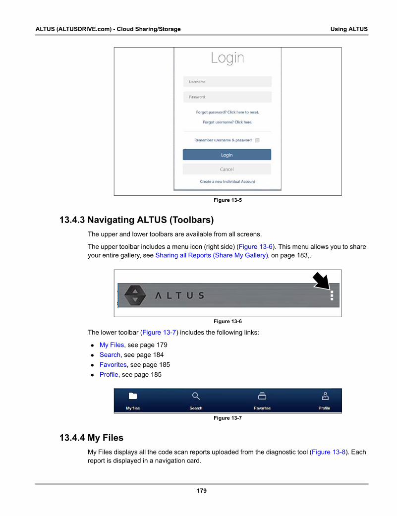
179
ALTUS (ALTUSDRIVE.com) - Cloud Sharing/Storage Using ALTUS
Figure 13-5
13.4.3 Navigating ALTUS (Toolbars)
The upper and lower toolbars are available from all screens.
The upper toolbar includes a menu icon (right side) (Figure 13-6). This menu allows you to share your entire gallery, see Sharing all Reports (Share My Gallery)‚ on page 183,.
Figure 13-6
The lower toolbar (Figure 13-7) includes the following links:
• My Files, see page 179
• Search, see page 184
• Favorites, see page 185
• Profile, see page 185
Figure 13-7
13.4.4 My Files
My Files displays all the code scan reports uploaded from the diagnostic tool (Figure 13-8). Each report is displayed in a navigation card.
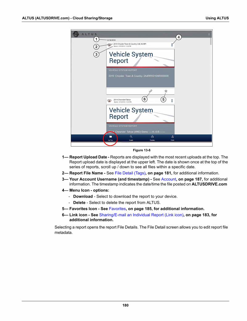
180
ALTUS (ALTUSDRIVE.com) - Cloud Sharing/Storage Using ALTUS
Figure 13-8
1— Report Upload Date - Reports are displayed with the most recent uploads at the top. The Report upload date is displayed at the upper left. The date is shown once at the top of the series of reports, scroll up / down to see all files within a specific date.
2— Report File Name - See File Detail (Tags)‚ on page 181, for additional information.
3— Your Account Username (and timestamp) - See Account‚ on page 187, for additional information. The timestamp indicates the date/time the file posted on ALTUSDRIVE.com
4— Menu Icon - options:
- Download - Select to download the report to your device.
- Delete - Select to delete the report from ALTUS.
5— Favorites Icon - See Favorites‚ on page 185, for additional information.
6— Link icon - See Sharing/E-mail an Individual Report (Link icon)‚ on page 183, for additional information.
Selecting a report opens the report File Details. The File Detail screen allows you to edit report file metadata.
8/18/2018
41
2
3
MyAcct - 8/16/2018, 1:12:20 PM
2010 Chrysler Town & Country 3.8L V6 MPI
MyAcct - 8/16/2018, 1:12:20 PM
2014 Chevrolet Tahoe 6 5
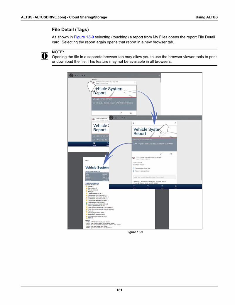
181
ALTUS (ALTUSDRIVE.com) - Cloud Sharing/Storage Using ALTUS
File Detail (Tags)
As shown in Figure 13-9 selecting (touching) a report from My Files opens the report File Detail card. Selecting the report again opens that report in a new browser tab.
NOTE:i Opening the file in a separate browser tab may allow you to use the browser viewer tools to print
or download the file. This feature may not be available in all browsers.
Figure 13-9
8/18/2018
MyAcct - 8/16/2018, 1:12:20 PM
2010 Chrysler Town & Country 3.8L V6 MPI
MyAcct - 8/16/2018, 1:12:20 PM
2014 Chevrolet Tahoe
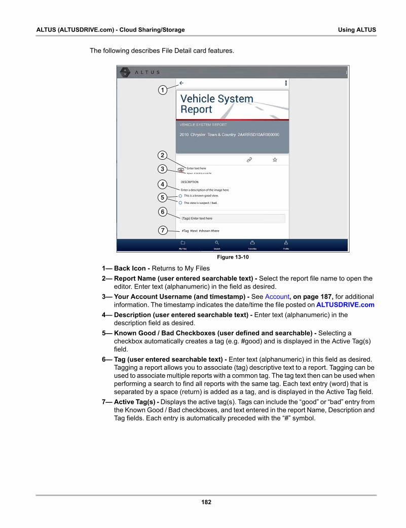
182
ALTUS (ALTUSDRIVE.com) - Cloud Sharing/Storage Using ALTUS
The following describes File Detail card features.
Figure 13-10
1— Back Icon - Returns to My Files
2— Report Name (user entered searchable text) - Select the report file name to open the editor. Enter text (alphanumeric) in the field as desired.
3— Your Account Username (and timestamp) - See Account‚ on page 187, for additional information. The timestamp indicates the date/time the file posted on ALTUSDRIVE.com
4— Description (user entered searchable text) - Enter text (alphanumeric) in the description field as desired.
5— Known Good / Bad Checkboxes (user defined and searchable) - Selecting a checkbox automatically creates a tag (e.g. #good) and is displayed in the Active Tag(s) field.
6— Tag (user entered searchable text) - Enter text (alphanumeric) in this field as desired. Tagging a report allows you to associate (tag) descriptive text to a report. Tagging can be used to associate multiple reports with a common tag. The tag text then can be used when performing a search to find all reports with the same tag. Each text entry (word) that is separated by a space (return) is added as a tag, and is displayed in the Active Tag field.
7— Active Tag(s) - Displays the active tag(s). Tags can include the “good” or “bad” entry from the Known Good / Bad checkboxes, and text entered in the report Name, Description and Tag fields. Each entry is automatically preceded with the “#” symbol.
MyAcct - 8/18/2018, 4:14:28 PM
DESCRIPTION
Enter a description of the image here.
This view is suspect / bad.
This is a known good view.
1
4
6
5
Enter text here
2
7
3
(Tags) Enter text here
#Tag #text #shown #here
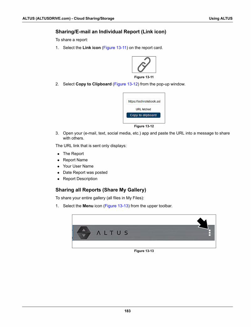
183
ALTUS (ALTUSDRIVE.com) - Cloud Sharing/Storage Using ALTUS
Sharing/E-mail an Individual Report (Link icon)
To share a report:
1. Select the Link icon (Figure 13-11) on the report card.
Figure 13-11
2. Select Copy to Clipboard (Figure 13-12) from the pop-up window.
Figure 13-12
3. Open your (e-mail, text, social media, etc.) app and paste the URL into a message to share with others.
The URL link that is sent only displays:
• The Report
• Report Name
• Your User Name
• Date Report was posted
• Report Description
Sharing all Reports (Share My Gallery)
To share your entire gallery (all files in My Files):
1. Select the Menu icon (Figure 13-13) from the upper toolbar.
Figure 13-13
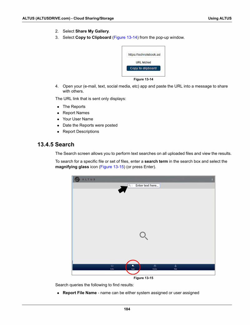
184
ALTUS (ALTUSDRIVE.com) - Cloud Sharing/Storage Using ALTUS
2. Select Share My Gallery.
3. Select Copy to Clipboard (Figure 13-14) from the pop-up window.
Figure 13-14
4. Open your (e-mail, text, social media, etc) app and paste the URL into a message to share with others.
The URL link that is sent only displays:
• The Reports
• Report Names
• Your User Name
• Date the Reports were posted
• Report Descriptions
13.4.5 Search
The Search screen allows you to perform text searches on all uploaded files and view the results.
To search for a specific file or set of files, enter a search term in the search box and select the magnifying glass icon (Figure 13-15) (or press Enter).
Figure 13-15
Search queries the following to find results:
• Report File Name - name can be either system assigned or user assigned
Enter text here...
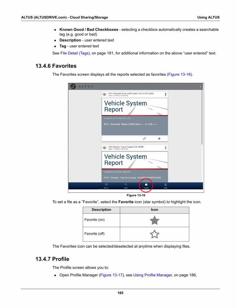
185
ALTUS (ALTUSDRIVE.com) - Cloud Sharing/Storage Using ALTUS
• Known Good / Bad Checkboxes - selecting a checkbox automatically creates a searchable tag (e.g. good or bad)
• Description - user entered text
• Tag - user entered text
See File Detail (Tags)‚ on page 181, for additional information on the above “user entered” text.
13.4.6 Favorites
The Favorites screen displays all the reports selected as favorites (Figure 13-16).
Figure 13-16
To set a file as a ”Favorite”, select the Favorite icon (star symbol) to highlight the icon.
The Favorites icon can be selected/deselected at anytime when displaying files.
13.4.7 Profile
The Profile screen allows you to:
• Open Profile Manager (Figure 13-17), see Using Profile Manager‚ on page 186,
Description Icon
Favorite (on)
Favorite (off)

186
ALTUS (ALTUSDRIVE.com) - Cloud Sharing/Storage Using ALTUS
• Logout of ALTUS, see Logging Out of ALTUS‚ on page 190,
Figure 13-17
Using Profile Manager1. To open the Profile Manager screen, select Profile from lower toolbar, then select Open
Profile Manager (Figure 13-17).
NOTE:i Profile Manager opens a new browser tab. To return to ALTUS after logging out of Profile
Manager, you must select the ALTUS Home Page browser tab.
2. Enter your Username and Password at the Login screen.
If you are a SureTrack user, please note that Profile Manager is the same as your SureTrack Profile Manager. Any changes you make will also be reflected in your SureTrack account.
Profile Manager includes five tabbed categories to help you manage your account information:
• Account‚ on page 187,
• Personal Information‚ on page 188,
• Expertise‚ on page 188,
• Profile Picture‚ on page 189,
• Device Management‚ on page 189,
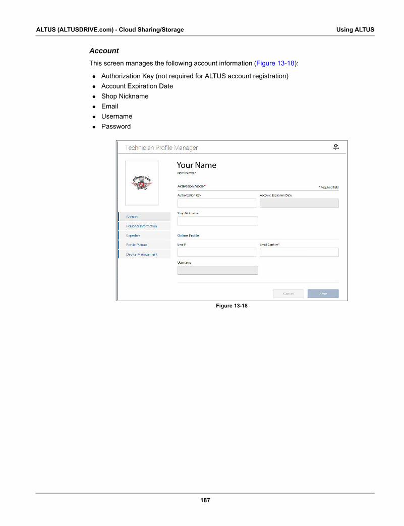
187
ALTUS (ALTUSDRIVE.com) - Cloud Sharing/Storage Using ALTUS
Account
This screen manages the following account information (Figure 13-18):
• Authorization Key (not required for ALTUS account registration)
• Account Expiration Date
• Shop Nickname
• Username
• Password
Figure 13-18
Your Name
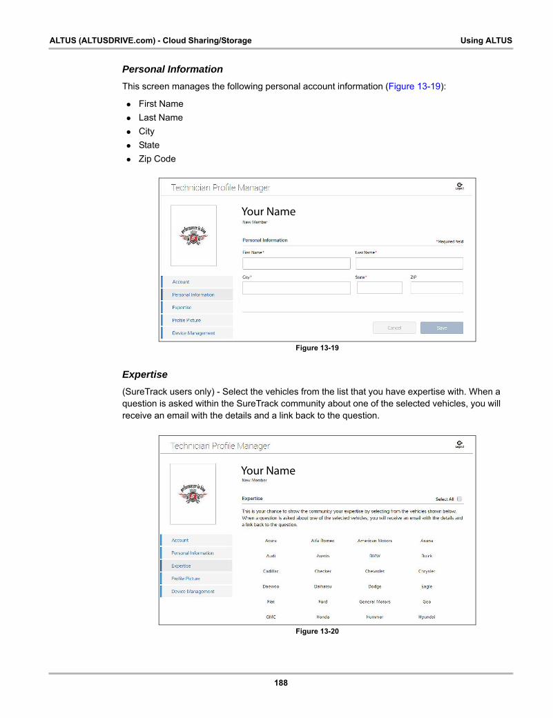
188
ALTUS (ALTUSDRIVE.com) - Cloud Sharing/Storage Using ALTUS
Personal Information
This screen manages the following personal account information (Figure 13-19):
• First Name
• Last Name
• City
• State
• Zip Code
Figure 13-19
Expertise
(SureTrack users only) - Select the vehicles from the list that you have expertise with. When a question is asked within the SureTrack community about one of the selected vehicles, you will receive an email with the details and a link back to the question.
Figure 13-20
Your Name
Your Name

189
ALTUS (ALTUSDRIVE.com) - Cloud Sharing/Storage Using ALTUS
Profile Picture
This screen allows you to personalize your profile picture, by selecting one of the provided images.
Device Management
This screen manages devices associated with your account (Figure 13-21):
Select Add a Device to setup and add an authorized device (e.g. Diagnostic Tool or Diagnostic Thermal Imager).
Enter the device:
• Serial Number - serial number of the device
• Code - authorization code specific to the device
• PIN - specific PIN associated to the device
• Device Name - user define name
When finished select Save to save and link the device to your account.
Figure 13-21
Logging Out of Profile Manager
Select the logout icon (upper right screen) to log out of Profile Manager (Figure 13-22).
Figure 13-22
NOTE:i Profile Manager opens a new browser tab. To return to ALTUS after logging out of Profile
Manager, you must select the ALTUS Home Page browser tab.
Your Name
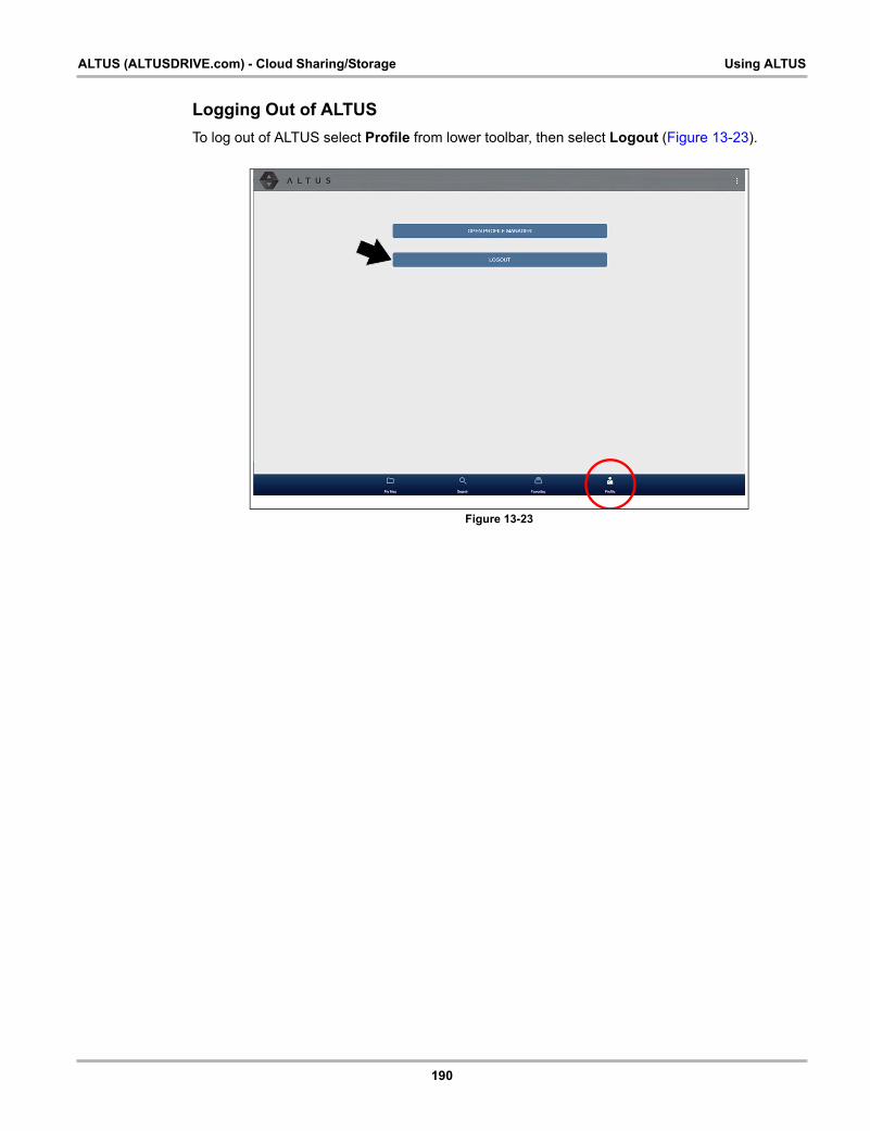
190
ALTUS (ALTUSDRIVE.com) - Cloud Sharing/Storage Using ALTUS
Logging Out of ALTUS
To log out of ALTUS select Profile from lower toolbar, then select Logout (Figure 13-23).
Figure 13-23

191
Chapter 14 Wi-Fi Connection / Troubleshooting
The diagnostic tool is equipped with many features that require Wi-Fi connection.
The Wi-Fi connection is solely dedicated to our Snap-on Web Services Network.
To use features like ALTUS, SureTrack, and Oil Specs and Resets a Wi-Fi connection is required. Authorization and registration is also required to use some of these features.
This section includes information on Wi-Fi connection and troubleshooting.
Main Topic Links• Checking if Wi-Fi is On/Off page 191
• Checking if Wi-Fi is Connected page 192
• Wi-Fi Icons (Setup) page 192
• Turning Wi-Fi On and Connecting to a Network page 192
• Add Network Advanced (Connecting to a hidden network) page 194
• Wi-Fi Testing page 194
• Wi-Fi Troubleshooting and Status Messages page 196
14.1 Checking if Wi-Fi is On/OffIf the Wi-Fi indicator is displayed in the title bar, Wi-Fi is on. If Wi-Fi is off, see Turning On Wi-Fi and Connecting to a Network to turn it on and connect.
Wi-Fi On Wi-Fi Off
Scope MultimeterScanner
Quick Lookups
Guided ComponentTests
Tools
OBD-II/EOBD
Previous Vehicleand Data

192
Wi-Fi Connection / Troubleshooting Checking if Wi-Fi is Connected
14.2 Checking if Wi-Fi is ConnectedCheck the Wi-Fi indicator in the title bar:
14.3 Wi-Fi Icons (Setup)Familiarize yourself with the following Wi-Fi icons and indicators from the Wi-Fi configuration screen.
14.4 Turning Wi-Fi On and Connecting to a Network1. From the Home screen, select Tools > Settings > Configure Wi-Fi.
2. Select the Wi-Fi icon (with checkmark) (Figure 14-1) to turn Wi-Fi on.
Figure 14-1 Wi-Fi Icon (shown off)
3. The Wi-Fi icon will change to the Wi-Fi symbol with “x” mark (Figure 14-2), indicating Wi-Fi is on.
Wi-Fi is on and connected to a network (1 to 3 bars).
Wi-Fi is on, but not connected (zero bars). See Wi-Fi Troubleshooting and Status Messages‚ on page 196,.
Wi-Fi Icon (toggle type) Wi-Fi Test Icon Wi-Fi Signal Strength Indicator
Select to turn Wi-Fi ON
Select to turn Wi-Fi OFF
Select to open the
Wi-Fi Test screen
Zero bars indicates no
signal
Three bars indicate full
strength signal
Displayed on Wi-Fi configuration screen onlyDisplayed on the title bar next to the
battery level indicator

193
Wi-Fi Connection / Troubleshooting Turning Wi-Fi On and Connecting to a Network
The screen will change to display available supported network connections.
4. Select your network. Use the scroll feature to show all active connections (Figure 14-2).
Figure 14-2 Wi-Fi Configuration Screen
1— Available Network Connections
2— Wi-Fi Icon (Wi-Fi shown on)
NOTE:i A password is required when choosing a secured (protected) network. Enter the password using
the on-screen keyboard and then select the check mark on the keyboard to continue.
Networks with a proxy, challenge page, or that require the user to accept terms of usage are not supported.
Wi-Fi performance varies depending on your wireless network equipment and ISP.
5. Select Connect to connect to your desired network or Cancel to cancel the request.
6. From the Connect confirmation screen select OK to continue using this connection or Forget to disconnect this connection.
• The screen will change to display your confirmed network connection and ALTUS registration information. For ALTUS registration information see ALTUS (ALTUSDRIVE.com) - Cloud Sharing/Storage‚ on page 174,.
• If the status message “Not Connected” is displayed, retry the configuration process or see Wi-Fi Testing, on page 194 for additional information.
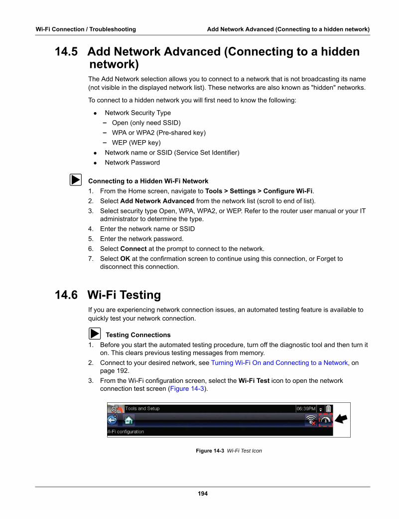
194
Wi-Fi Connection / Troubleshooting Add Network Advanced (Connecting to a hidden network)
14.5 Add Network Advanced (Connecting to a hidden network)
The Add Network selection allows you to connect to a network that is not broadcasting its name (not visible in the displayed network list). These networks are also known as "hidden" networks.
To connect to a hidden network you will first need to know the following:
• Network Security Type
– Open (only need SSID)
– WPA or WPA2 (Pre-shared key)
– WEP (WEP key)
• Network name or SSID (Service Set Identifier)
• Network Password
z Connecting to a Hidden Wi-Fi Network
1. From the Home screen, navigate to Tools > Settings > Configure Wi-Fi.
2. Select Add Network Advanced from the network list (scroll to end of list).
3. Select security type Open, WPA, WPA2, or WEP. Refer to the router user manual or your IT administrator to determine the type.
4. Enter the network name or SSID
5. Enter the network password.
6. Select Connect at the prompt to connect to the network.
7. Select OK at the confirmation screen to continue using this connection, or Forget to disconnect this connection.
14.6 Wi-Fi TestingIf you are experiencing network connection issues, an automated testing feature is available to quickly test your network connection.
z Testing Connections
1. Before you start the automated testing procedure, turn off the diagnostic tool and then turn it on. This clears previous testing messages from memory.
2. Connect to your desired network, see Turning Wi-Fi On and Connecting to a Network, on page 192.
3. From the Wi-Fi configuration screen, select the Wi-Fi Test icon to open the network connection test screen (Figure 14-3).
Figure 14-3 Wi-Fi Test Icon
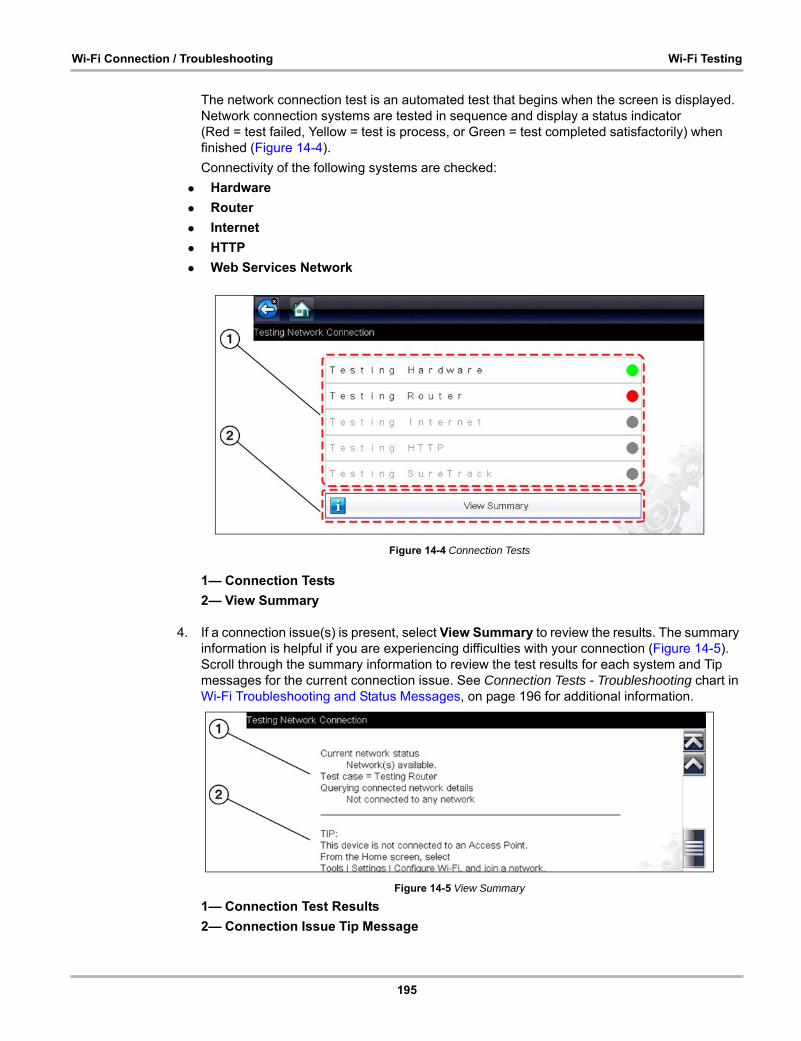
195
Wi-Fi Connection / Troubleshooting Wi-Fi Testing
The network connection test is an automated test that begins when the screen is displayed. Network connection systems are tested in sequence and display a status indicator (Red = test failed, Yellow = test is process, or Green = test completed satisfactorily) when finished (Figure 14-4).
Connectivity of the following systems are checked:
• Hardware
• Router
• Internet
• HTTP
• Web Services Network
Figure 14-4 Connection Tests
1— Connection Tests
2— View Summary
4. If a connection issue(s) is present, select View Summary to review the results. The summary information is helpful if you are experiencing difficulties with your connection (Figure 14-5). Scroll through the summary information to review the test results for each system and Tip messages for the current connection issue. See Connection Tests - Troubleshooting chart in Wi-Fi Troubleshooting and Status Messages, on page 196 for additional information.
Figure 14-5 View Summary
1— Connection Test Results
2— Connection Issue Tip Message

196
Wi-Fi Connection / Troubleshooting Wi-Fi Troubleshooting and Status Messages
14.7 Wi-Fi Troubleshooting and Status MessagesThe following troubleshooting information is not inclusive and is meant as a guide only. Other issues and solutions may arise that are not stated here. The following description of terms are provided for reference as used in the following troubleshooting chart:
• Router - The data transmission device directly connected to your ISP.
• Remote Wireless Access Point - A wireless connection device between the router and your diagnostic tool.
• Wi-Fi Radio - The internal diagnostic tool radio transmitting and receiving Wi-Fi signals.
• Network Connection - Also called Wi-Fi connection. The configured Wi-Fi router connection the diagnostic tool connects to. This connection can be secured (password protected) or unsecured (open).
Router Information
Router compatibility and setup are important factors to check when trying to determine connectivity problems. Although we have tested this device at the factory to verify connectivity, we cannot guaranty its connectivity with your specific equipment. There may be some situations that require your time for router connection troubleshooting and/or additional consultation and equipment. Snap-on Incorporated is not responsible for any costs incurred for any additional equipment, labor or consultation charges or any other costs that may result from correcting non-connectivity issues with this device.
Check Router Settings
Verify the following router settings BEFORE you begin troubleshooting a non-connectivity or “No Connection” problem. After each check, make any corrections as necessary then retest for connectivity. Contact your IT administrator or ISP for assistance.
1. Check your router connection and if applicable, the remote wireless access point connection.
2. Clear saved Wi-Fi networks, see Clearing Wi-Fi Networks‚ on page 196,.
3. Verify: (a). Router is configured to use Dynamic Host Configuration Protocol (DHCP), not a static IP address.
(b). Router and/or settings for this device are configured to 2.4GHz. 5GHz is not supported.
(c). Router is configured to B/G and/or N standard wireless networks to 2.4GHz. 5GHz is not supported. See your router "User Guide" for setup, connection and troubleshooting procedures.
4. Check for router firmware and update to current version, if applicable.
5. Restart or reset the router. See your router "User Guide" for procedures.
6. Connect to a different router.
Clearing Wi-Fi Networks
1. Select the Wi-Fi network that you are trying to connect to from the list of saved networks on the Wi-Fi configuration menu.
The Wi-Fi Summary page displays.
2. Select FORGET
The Wi-Fi Configuration menu displays.
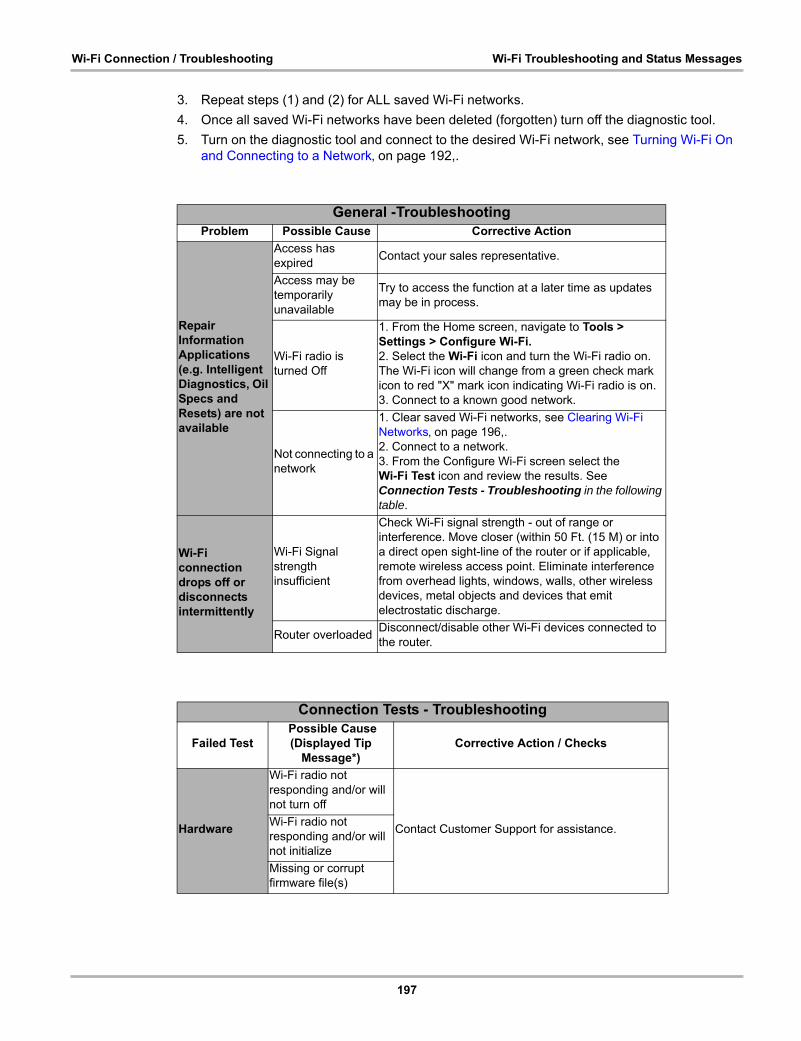
197
Wi-Fi Connection / Troubleshooting Wi-Fi Troubleshooting and Status Messages
3. Repeat steps (1) and (2) for ALL saved Wi-Fi networks.
4. Once all saved Wi-Fi networks have been deleted (forgotten) turn off the diagnostic tool.
5. Turn on the diagnostic tool and connect to the desired Wi-Fi network, see Turning Wi-Fi On and Connecting to a Network‚ on page 192,.
General -TroubleshootingProblem Possible Cause Corrective Action
Repair Information Applications (e.g. Intelligent Diagnostics, Oil Specs and Resets) are not available
Access has expired
Contact your sales representative.
Access may be temporarily unavailable
Try to access the function at a later time as updates may be in process.
Wi-Fi radio is turned Off
1. From the Home screen, navigate to Tools > Settings > Configure Wi-Fi.2. Select the Wi-Fi icon and turn the Wi-Fi radio on. The Wi-Fi icon will change from a green check mark icon to red "X" mark icon indicating Wi-Fi radio is on.3. Connect to a known good network.
Not connecting to a network
1. Clear saved Wi-Fi networks, see Clearing Wi-Fi Networks‚ on page 196,.2. Connect to a network.3. From the Configure Wi-Fi screen select the Wi-Fi Test icon and review the results. See Connection Tests - Troubleshooting in the following table.
Wi-Fi connection drops off or disconnects intermittently
Wi-Fi Signal strength insufficient
Check Wi-Fi signal strength - out of range or interference. Move closer (within 50 Ft. (15 M) or into a direct open sight-line of the router or if applicable, remote wireless access point. Eliminate interference from overhead lights, windows, walls, other wireless devices, metal objects and devices that emit electrostatic discharge.
Router overloadedDisconnect/disable other Wi-Fi devices connected to the router.
Connection Tests - Troubleshooting
Failed Test Possible Cause (Displayed Tip
Message*)Corrective Action / Checks
Hardware
Wi-Fi radio not responding and/or will not turn off
Contact Customer Support for assistance.Wi-Fi radio not responding and/or will not initialize
Missing or corrupt firmware file(s)
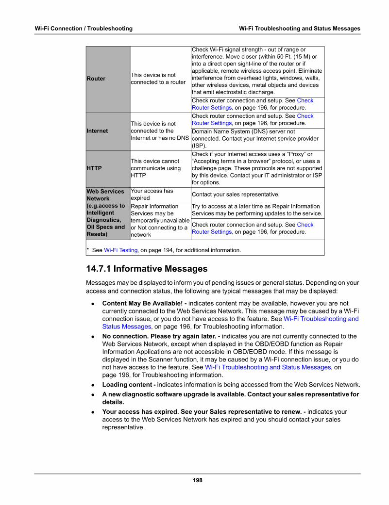
198
Wi-Fi Connection / Troubleshooting Wi-Fi Troubleshooting and Status Messages
14.7.1 Informative Messages
Messages may be displayed to inform you of pending issues or general status. Depending on your access and connection status, the following are typical messages that may be displayed:
• Content May Be Available! - indicates content may be available, however you are not currently connected to the Web Services Network. This message may be caused by a Wi-Fi connection issue, or you do not have access to the feature. See Wi-Fi Troubleshooting and Status Messages‚ on page 196, for Troubleshooting information.
• No connection. Please try again later. - indicates you are not currently connected to the Web Services Network, except when displayed in the OBD/EOBD function as Repair Information Applications are not accessible in OBD/EOBD mode. If this message is displayed in the Scanner function, it may be caused by a Wi-Fi connection issue, or you do not have access to the feature. See Wi-Fi Troubleshooting and Status Messages‚ on page 196, for Troubleshooting information.
• Loading content - indicates information is being accessed from the Web Services Network.
• A new diagnostic software upgrade is available. Contact your sales representative for details.
• Your access has expired. See your Sales representative to renew. - indicates your access to the Web Services Network has expired and you should contact your sales representative.
RouterThis device is not connected to a router
Check Wi-Fi signal strength - out of range or interference. Move closer (within 50 Ft. (15 M) or into a direct open sight-line of the router or if applicable, remote wireless access point. Eliminate interference from overhead lights, windows, walls, other wireless devices, metal objects and devices that emit electrostatic discharge.
Check router connection and setup. See Check Router Settings‚ on page 196, for procedure.
InternetThis device is not connected to the Internet or has no DNS
Check router connection and setup. See Check Router Settings‚ on page 196, for procedure.
Domain Name System (DNS) server not connected. Contact your Internet service provider (ISP).
HTTP This device cannot communicate using HTTP
Check if your Internet access uses a “Proxy” or “Accepting terms in a browser” protocol, or uses a challenge page. These protocols are not supported by this device. Contact your IT administrator or ISP for options.
Web Services Network (e.g.access to Intelligent Diagnostics, Oil Specs and Resets)
Your access has expired
Contact your sales representative.
Repair Information Services may be temporarily unavailable or Not connecting to a network
Try to access at a later time as Repair Information Services may be performing updates to the service.
Check router connection and setup. See Check Router Settings‚ on page 196, for procedure.
* See Wi-Fi Testing‚ on page 194, for additional information.
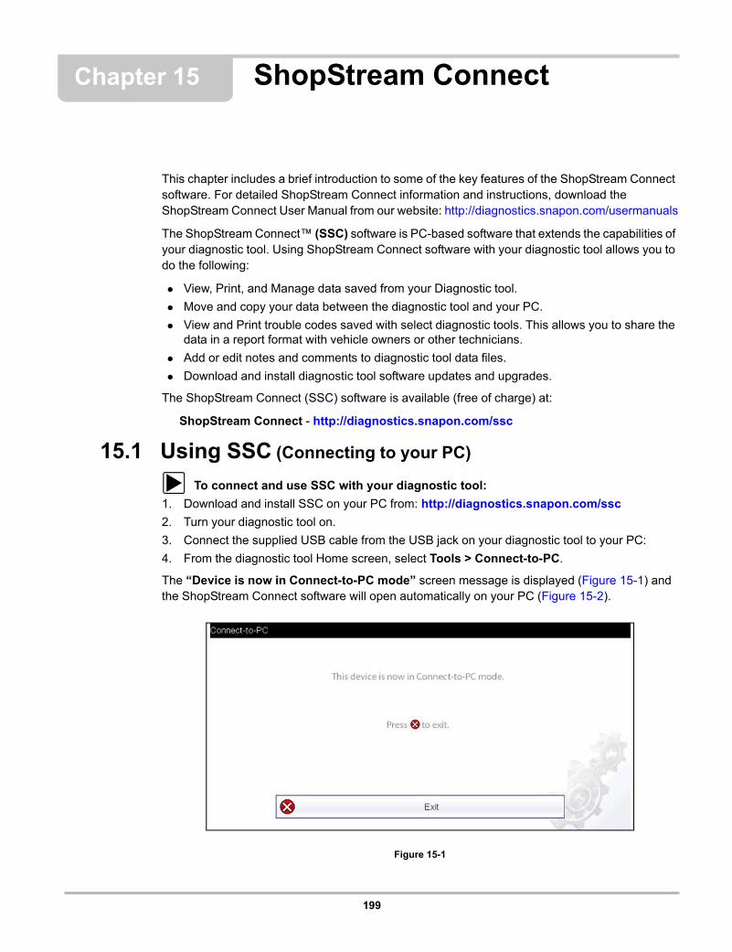
199
Chapter 15 ShopStream Connect
This chapter includes a brief introduction to some of the key features of the ShopStream Connect software. For detailed ShopStream Connect information and instructions, download the ShopStream Connect User Manual from our website: http://diagnostics.snapon.com/usermanuals
The ShopStream Connect™ (SSC) software is PC-based software that extends the capabilities of your diagnostic tool. Using ShopStream Connect software with your diagnostic tool allows you to do the following:
• View, Print, and Manage data saved from your Diagnostic tool.
• Move and copy your data between the diagnostic tool and your PC.
• View and Print trouble codes saved with select diagnostic tools. This allows you to share the data in a report format with vehicle owners or other technicians.
• Add or edit notes and comments to diagnostic tool data files.
• Download and install diagnostic tool software updates and upgrades.
The ShopStream Connect (SSC) software is available (free of charge) at:
ShopStream Connect - http://diagnostics.snapon.com/ssc
15.1 Using SSC (Connecting to your PC)
z To connect and use SSC with your diagnostic tool:
1. Download and install SSC on your PC from: http://diagnostics.snapon.com/ssc
2. Turn your diagnostic tool on.
3. Connect the supplied USB cable from the USB jack on your diagnostic tool to your PC:
4. From the diagnostic tool Home screen, select Tools > Connect-to-PC.
The “Device is now in Connect-to-PC mode” screen message is displayed (Figure 15-1) and the ShopStream Connect software will open automatically on your PC (Figure 15-2).
Figure 15-1
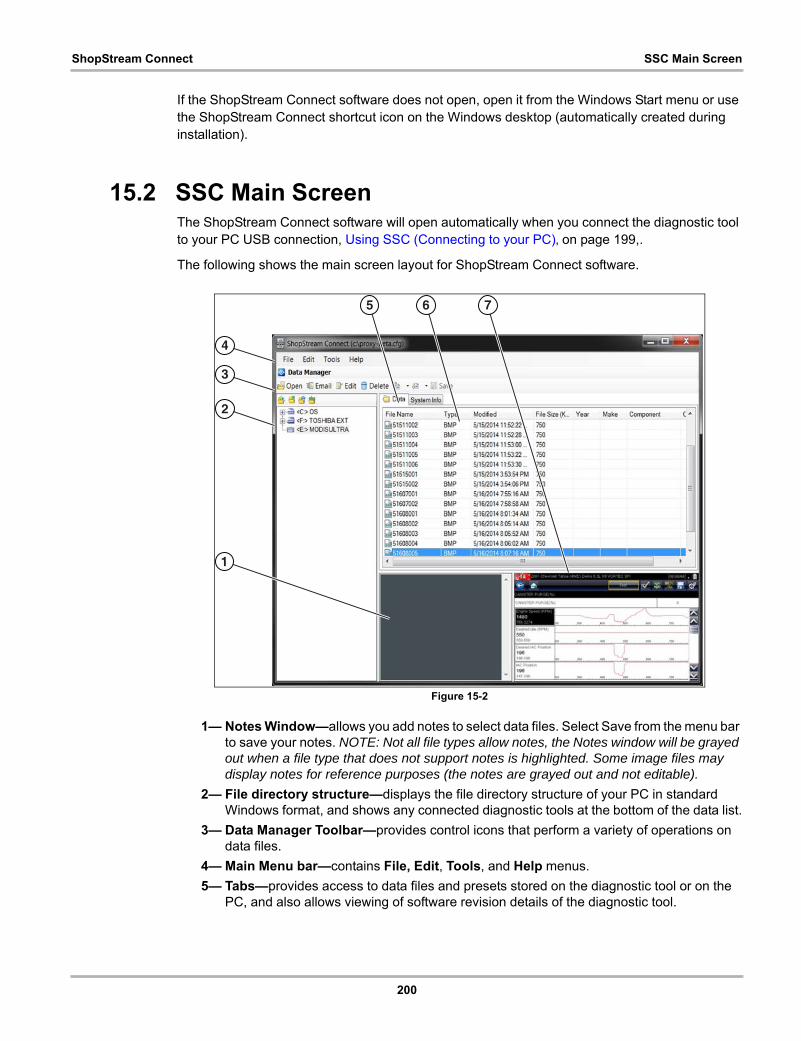
200
ShopStream Connect SSC Main Screen
If the ShopStream Connect software does not open, open it from the Windows Start menu or use the ShopStream Connect shortcut icon on the Windows desktop (automatically created during installation).
15.2 SSC Main ScreenThe ShopStream Connect software will open automatically when you connect the diagnostic tool to your PC USB connection, Using SSC (Connecting to your PC)‚ on page 199,.
The following shows the main screen layout for ShopStream Connect software.
Figure 15-2
1— Notes Window—allows you add notes to select data files. Select Save from the menu bar to save your notes. NOTE: Not all file types allow notes, the Notes window will be grayed out when a file type that does not support notes is highlighted. Some image files may display notes for reference purposes (the notes are grayed out and not editable).
2— File directory structure—displays the file directory structure of your PC in standard Windows format, and shows any connected diagnostic tools at the bottom of the data list.
3— Data Manager Toolbar—provides control icons that perform a variety of operations on data files.
4— Main Menu bar—contains File, Edit, Tools, and Help menus.
5— Tabs—provides access to data files and presets stored on the diagnostic tool or on the PC, and also allows viewing of software revision details of the diagnostic tool.
4
3
2
1
5 6 7
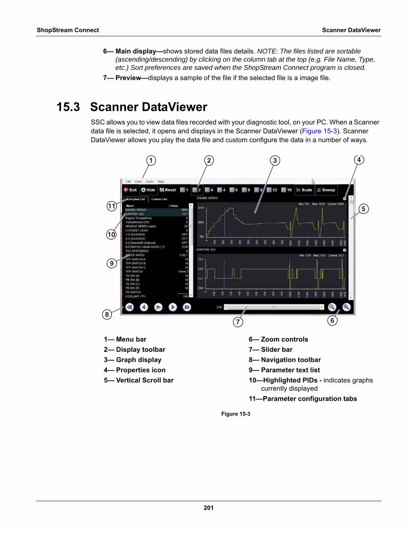
201
ShopStream Connect Scanner DataViewer
6— Main display—shows stored data files details. NOTE: The files listed are sortable (ascending/descending) by clicking on the column tab at the top (e.g. File Name, Type, etc.) Sort preferences are saved when the ShopStream Connect program is closed.
7— Preview—displays a sample of the file if the selected file is a image file.
15.3 Scanner DataViewerSSC allows you to view data files recorded with your diagnostic tool, on your PC. When a Scanner data file is selected, it opens and displays in the Scanner DataViewer (Figure 15-3). Scanner DataViewer allows you play the data file and custom configure the data in a number of ways.
Figure 15-3
1— Menu bar
2— Display toolbar
3— Graph display
4— Properties icon
5— Vertical Scroll bar
6— Zoom controls
7— Slider bar
8— Navigation toolbar
9— Parameter text list
10—Highlighted PIDs - indicates graphs currently displayed
11—Parameter configuration tabs
11
9
8
1 2 3 4
5
7 6
10

202
ShopStream Connect Image Viewer
15.4 Image ViewerSSC allows you to view and print .bmp, .jpg and .sps image files (screenshots) saved on your diagnostic tool, with your PC.
NOTE:i File extension types vary depending on the diagnostic tool. Not all the file extensions described
here may be available on your diagnostic tool.
Figure 15-4
1— Exit - closes the Image Viewer
2— Print - prints the image
3— Print Preview - allows the image to be previewed before printing
4— Captured Screen Image
431 2

203
ShopStream Connect Printing the (Code Scan) Vehicle System Report
15.5 Printing the (Code Scan) Vehicle System ReportTo print the Vehicle System Report, the saved code scan .XML file must be opened using ShopStream Connect.
To print the Vehicle System Report using ShopStream Connect:
1. Double-click the code scan .XML file from the file list to open the Vehicle System Report (Figure 15-5) in the Code Scan Viewer (Figure 15-6).
Figure 15-5
2. Select Print or Print Preview from the Code Scan Viewer menu to print or preview the Vehicle System Report (Figure 15-6).
Figure 15-6
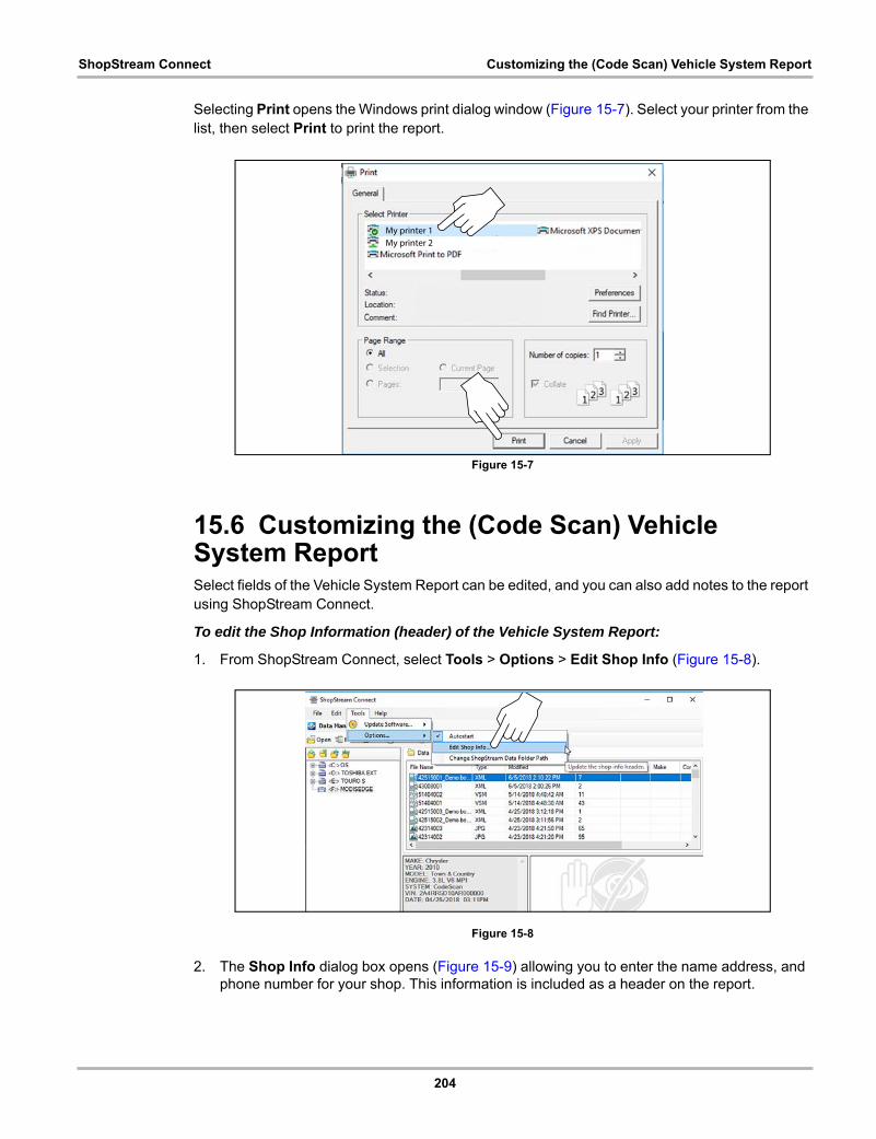
204
ShopStream Connect Customizing the (Code Scan) Vehicle System Report
Selecting Print opens the Windows print dialog window (Figure 15-7). Select your printer from the list, then select Print to print the report.
Figure 15-7
15.6 Customizing the (Code Scan) Vehicle System ReportSelect fields of the Vehicle System Report can be edited, and you can also add notes to the report using ShopStream Connect.
To edit the Shop Information (header) of the Vehicle System Report:
1. From ShopStream Connect, select Tools > Options > Edit Shop Info (Figure 15-8).
Figure 15-8
2. The Shop Info dialog box opens (Figure 15-9) allowing you to enter the name address, and phone number for your shop. This information is included as a header on the report.
My printer 1
My printer 2

205
ShopStream Connect Customizing the (Code Scan) Vehicle System Report
Figure 15-9
A preview panel at the bottom of the box shows how the information will appear on a print out (Figure 15-9).
3. Check the “Use Shop Info in Printout Header” box to show the Shop Info in the printout (Figure 15-9).
4. Check the “Use timestamp in Vehicle System Report” box to show the time the vehicle was scanned in the printout (Figure 15-9).
5. When you are finished editing, select Save (Figure 15-9) to save the information and close the dialog box.
To edit the VIN and License Plate fields, and/or add notes to the Vehicle System Report:
1. From ShopStream Connect, open the code scan .XML file to be edited (Figure 15-10).
2. Click in the editable fields as shown in (Figure 15-10) to change the values or add notes.
3. Check the “Add the notes to the printed copy” box to show the notes in the printout (Figure 15-10).
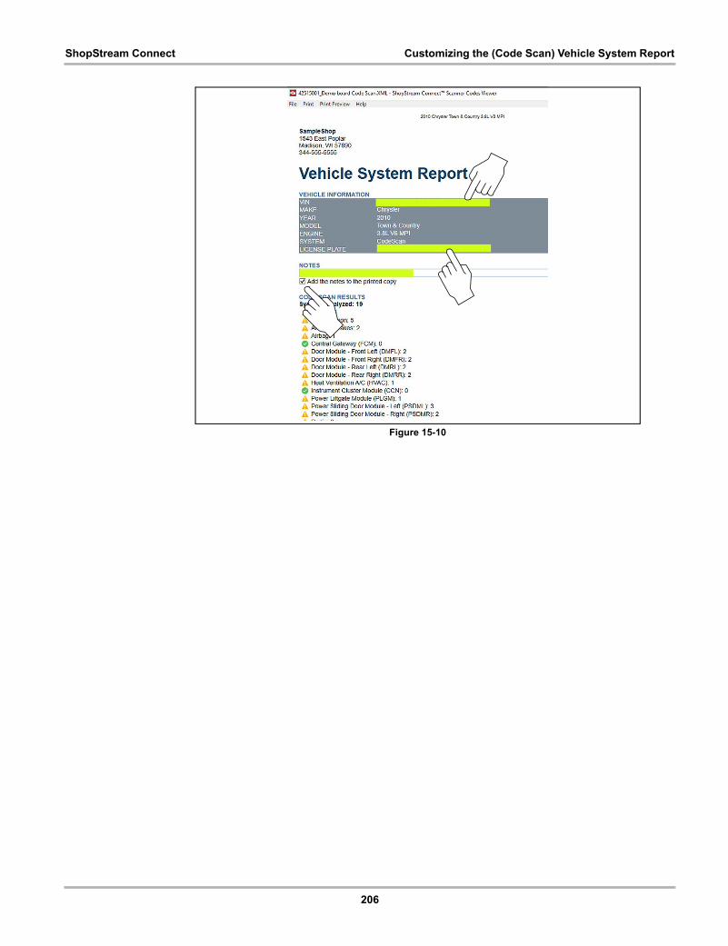
206
ShopStream Connect Customizing the (Code Scan) Vehicle System Report
Figure 15-10
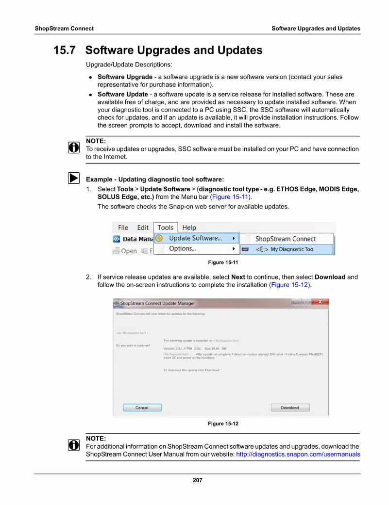
207
ShopStream Connect Software Upgrades and Updates
15.7 Software Upgrades and UpdatesUpgrade/Update Descriptions:
• Software Upgrade - a software upgrade is a new software version (contact your sales representative for purchase information).
• Software Update - a software update is a service release for installed software. These are available free of charge, and are provided as necessary to update installed software. When your diagnostic tool is connected to a PC using SSC, the SSC software will automatically check for updates, and if an update is available, it will provide installation instructions. Follow the screen prompts to accept, download and install the software.
NOTE:i To receive updates or upgrades, SSC software must be installed on your PC and have connection
to the Internet.
z Example - Updating diagnostic tool software:
1. Select Tools > Update Software > (diagnostic tool type - e.g. ETHOS Edge, MODIS Edge, SOLUS Edge, etc.) from the Menu bar (Figure 15-11).
The software checks the Snap-on web server for available updates.
Figure 15-11
2. If service release updates are available, select Next to continue, then select Download and follow the on-screen instructions to complete the installation (Figure 15-12).
Figure 15-12
NOTE:i For additional information on ShopStream Connect software updates and upgrades, download the
ShopStream Connect User Manual from our website: http://diagnostics.snapon.com/usermanuals
My Diagnostic Tool
ShopStream Connect will now check for updates for the following:
Do you wish to continue?
SOLUSULTRA
The following update is available for SOLUSULTRA
Version: 3.3.1.11769 [US] Size 38.96 MB
SOLUSULTRA 13.4.1. After update us complete: if direct connected, unplug USB cable - if using Compact Flash(CF)insert CF and power up the handheld.
To download this update click ‘Download’
(“My Diagnostic Tool”)
(“My Diagnostic Tool”)
(e.g. “My Diagnostic Tool”)
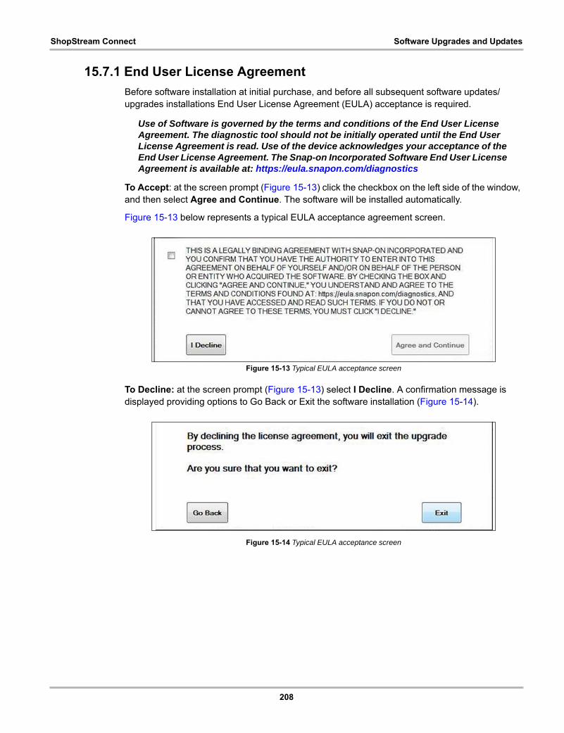
208
ShopStream Connect Software Upgrades and Updates
15.7.1 End User License Agreement
Before software installation at initial purchase, and before all subsequent software updates/upgrades installations End User License Agreement (EULA) acceptance is required.
Use of Software is governed by the terms and conditions of the End User License Agreement. The diagnostic tool should not be initially operated until the End User License Agreement is read. Use of the device acknowledges your acceptance of the End User License Agreement. The Snap-on Incorporated Software End User License Agreement is available at: https://eula.snapon.com/diagnostics
To Accept: at the screen prompt (Figure 15-13) click the checkbox on the left side of the window, and then select Agree and Continue. The software will be installed automatically.
Figure 15-13 below represents a typical EULA acceptance agreement screen.
Figure 15-13 Typical EULA acceptance screen
To Decline: at the screen prompt (Figure 15-13) select I Decline. A confirmation message is displayed providing options to Go Back or Exit the software installation (Figure 15-14).
Figure 15-14 Typical EULA acceptance screen