MH 310/320 PRO - Snap-on Equipment
40
MH 310/320 PRO OPERATION MANUAL NOTICE D'UTILISATION BETRIEBSANLEITUNG Pneumatic bead-pressing device Presse-talon pneumatique Pneumatischer Wulstniederhalter
-
Upload
khangminh22 -
Category
Documents
-
view
0 -
download
0
Transcript of MH 310/320 PRO - Snap-on Equipment

MH 310/320 PRO
OPERATION MANUALNOTICE D'UTILISATIONBETRIEBSANLEITUNG
Pneumatic bead-pressing devicePresse-talon pneumatiquePneumatischer Wulstniederhalter

2Operator’s Manual
Table of Contents
MH 310/320 PRO
Snap-on Equipment Srl a unico socio
Via per Carpi, 33 - ITALY - 42015 CORREGGIOTel. +39-(0)522-733489 - Fax. +39-(0)522-733610E-mail: [email protected]: http://www.gsboxer.com
DISCLAIMER OF WARRANTIESAND LIMITATIONS OF LIABILITIES
While the authors have taken care in the preparation ofthis manual, nothing contained herein:
- modifies or alters in any way the standard termsand conditions of the purchase, lease or rentalagreement under the terms of which the equipmentto which this manual relates was acquired,
- increases in any way the liability to the customeror to third parties.
TO THE READER
While every effort has been made to ensure that theinformation contained in this manual is correct, completeand up-to date, the right to change any part of thisdocument at any time without prior notice is reserved.
Before installing, maintaining oroperating this unit, please read
this manual carefully, payingextra attention to the safetywarnings and precautions.
All Information in this manual has beensupplied by the producer of theequipment:

3Betriebsanleitung
InhaltTable des matières
Manuel de l'opérateur MH 310/320 PRO MH 310/320 PRO
Snap-on Equipment Srl a unico socio
Via per Carpi, 33 - ITALY - 42015 CORREGGIOTel. +39-(0)522-733489 - Fax. +39-(0)522-733610E-mail: [email protected]: http://www.gsboxer.com
Snap-on Equipment Srl a unico socio
Via per Carpi, 33 - ITALY - 42015 CORREGGIOTel. +39-(0)522-733489 - Fax. +39-(0)522-733610E-mail: [email protected]: http://www.gsboxer.com
GEWÄHRLEISTUNGS- UNDHAFTUNGSAUSSCHLUSS
Die Informationen in dieser Bedienungsanleitung wurdengewissenhaft und sorgfältig zusammengestellt. DerInhalt oder Teile des Inhalts dieserBedienungsanleitung:
- haben keinen Einfluß auf die AllgemeinenGeschäftsbedingungen des Kaufvertrages,Leasingvertrages oder Mietvertrages auf dessenGrundlage das in dieser Bedienungsanleitungbeschriebene Gerät bezogen wurde,
- erweitern in keiner Weise den Haftungsanspruchdes Kunden oder Dritter.
AN DEN LESER
Bei der Zusammenstellung der in dieserBedienungsanleitung enthaltenen Informationen wurdegrößten Wert auf deren Richtigkeit, Vollständigkeit undAktualität gelegt. Wir behalten uns jedoch ausdrücklichdas Recht vor, diese Informationen jederzeit und ohnevorherige Ankündigung zu ändern.
Lesen Sie dieseBedienungsanleitung sorgfältig
durch, bevor Sie das Gerätinstallieren, warten oderbetreiben. Beachten Sie
insbesondere dieSicherheitsvorschriften und
Warnungen.
Alle in diesem Handbuch enthaltenenInformationen wurden durch denHersteller des Gerätes geliefert:
LIMITES D’APPLICATION DE LA GARANTIE ETLIMITATIONS DE LA GARANTIE
Bien que les auteurs aient accordé la plus grandeattention à la rédaction du présent manuel, aucunélément figurant dans ce dernier:
- ne modifie les conditions et les termes standardsd’un accord d’achat en crédit-bail ou de location,aux termes desquels les appareils traités dansle présent manuel sont achetés,
- ou n’augmente la responsabilité de la sociétéenvers le client ou les tiers.
POUR LE LECTEUR
Bien que tout effort ait été fait pour assurer l’exactitudedes informations figurant dans le présent manuel, commecomplément ou mise à jour de ce dernier, le droit d’yapporter des modifications à tout moment sans préavisest réservé.
Avant d’installer, d’entretenir oud’utiliser la machine, lire attentive-ment le présent manuel, en faisant
particulièrement attention auxavertissements et précautions de
sécurité.
Toutes les informations figurant dans leprésent manuel ont été fournies par le fa-bricant de l’équipement :

4Operator’s Manual
Table of Contents
Content
1. Safety 61.1 Format of this Manual 101.2 Marking data 102. Specifications 122.1 Conditions 123. Introduction 143.1 Optional accessories 164. Layout 204.1 Controls 204.2 Applied plates 205. Mounting and demounting
General precautions 225.1 Use as a demounting help device 225.1.1 Using the roller to demount the second bead 245.2 Use as a mounting help device 246. Maintenance 266.1 Storage 267. Trouble shooting 288. Disposal 30Appendix: Installation Instructions 33
MH 310/320 PRO

5Betriebsanleitung
InhaltTable des matières
Manuel de l'opérateur
Inhalt
1. Sicherheit. 71.1 Typographie 111.2 Markierungsdaten 112. Spezifikationen 132.1 Bedingungen 133. Einleitung 153.1 Zubehor auf Anfrage 174. Layout 214.1 Maschinenbedienung 214.2 Angebrachte Schilder 215. Benutzung und Vorsichtsmaßnahmen
für die Benutzung 235.1 Einsatz wahrend der Reifendemontage 235.1.1 Einsatz der Rolle beim Demontieren der zweiten Wulst 255.2 Einsatz wahrend der Reifenmontage 256. Wartung 276.1 Lagerung 277. Fehlerbeseitigung 298. Entsorgung 31Anhang: Installationsanweisungen 33
Sommaire
1. Sécurité 71.1 Typographie 111.2 Données de marquage 112. Spécifications 132.1 Conditions 133. Introduction 153.1 Accessoires en option 174. Description 214.1 Commandes 214.2 Plaquettes signalétiques 215. Utilisation et précautions 235.1 Utilisation pendant la phase de demontage 235.1.1 Utilisation du rouleau dans le démontage du second talon 255.2 Utilisation pendant la phase de montage 256. Entretien 276.1 Stockage 277. Dépannage 298. Vente De La Machine 31Annexe: Instructions pour l’Installation 33
MH 310/320 PRO MH 310/320 PRO

6
Safety
Operator’s Manual MH 310/320
1. Safety
The safety precautions must be completely understoodand observed by every operator.
THE USE OF THIS DEVICE IS ALLOWED ONLY TOPERSONNEL DULY TRAINED BY AN AUTHORIZEDDEALER.
ANY TAMPERING WITH OR MODIFICATION OF THISDEVICE OR ITS PARTS OR COMPONENTS NOTPREVIOUSLY AUTHORIZED BY THE MANUFACTURERWAIVE THE MANUFACTURER FROM ANY DAMAGERESULTING FROM OR RELATED TO THE ABOVE-MENTIONED TAMPERINGS.
REMOVING OR BYPASSING SAFETY DEVICES ORWARNING LABELS OF THE MACHINE IS AVIOLATION OF THE SAFETY REGULATIONS.
THE USE OF THIS DEVICE IS ALLOWED ONLY INLOCATIONS WITH NO EXPLOSION OR FIREHAZARD.
THE INSTALLATION SHALL BE CARRIED OUTONLY BY QUALIFIED PERSONNEL AND WITHINTHE SCOPE OF THE INSTRUCTIONS PROVIDEDIN THIS MANUAL.
THIS DEVICE IS DESIGNED TO ACCEPT ORIGINALSPARE PARTS AND ACCESSORIES ONLY.
CHECK FOR POSSIBLE DANGEROUS CONDITIONSDURING THE OPERATION OF THE MACHINE. INSUCH A CASE STOP THE MACHINE IMMEDIATELY.
IN CASE OF DEFECTIVE FUNCTIONING, STOP THEMACHINE AND CALL THE AUTHORIZEDDISTRIBUTOR FOR ASSISTANCE.
DURING USE AND MAINTENANCE OF THE MACHINEIT IS MANDATORY TO COMPLY WITH ALL LAWSAND REGULATIONS FOR ACCIDENT PREVENTION.
BEFORE PERFORMING ANY MAINTENANCE ORREPAIRS THE MACHINE MUST BE DISCONNECTEDFROM THE AIR SUPPLY.
NEVER WEAR TIES, CHAINS OR OTHER LOOSEARTICLES WHEN USING, MAINTAINING ORREPAIRING THE MACHINE. LONG HAIR IS ALSODANGEROUS AND SHOULD BE KEPT UNDER A HAT.
THE USER MUST WEAR PROPER SAFETY ATTIREI.E.: GLOVES, SAFETY SHOES AND GLASSES.
KEEP SAFETY DEVICES IN PLACE AND INWORKING ORDER.

7
Sicherheit
Betriebsanleitung
Sécurité
Manuel de l'opérateur MH 310/320 MH 310/320
1. Sicherheit.Die Sicherheitsmaßnahmen müssen von allenBedienern vollständig verstanden und eingehalten werden.
DAS GERÄT DARF NUR VON PERSONAL BEDIENTWERDEN, DAS DAFÜR DURCH DENVERTRAGSHÄNDLER EIGENS GESCHULTWURDE.
JEDE ART VON EINGRIFF ODER VERÄNDERUNG DESGERÄTS ODER VON GERÄTEBESTANDTEILEN, DIEOHNE VORHERIGE ZUSTIMMUNG DESHERSTELLERS VORGENOMMEN WURDEN,ENTBINDEN DIESEN VON DER HAFTUNG FÜRSCHÄDEN, DEREN EINTRETEN AUF DIESES HANDELNZURÜCKZUFÜHREN IST.
DIE ENTFERNUNG ODER VERÄNDERUNG VONSICHERHEITSVORRICHTUNGEN ODERWARNHINWEISEN AM GERÄT STELLT EINEVERLETZUNG DER SICHERHEITSVORSCHRIFTENDAR.
DAS GERÄT DARF NUR AN ORTEN BETRIEBENWERDEN, IN DENEN KEINE EXPLOSIONS- ODERBRANDGEFAHR BESTEHT.
DIE INSTALLATION IST VON FACHPERSONAL UNTERSTRENGER EINHALTUNG DER HIER AUFGEFÜHRTENANWEISUNGEN DURCH-ZUFÜHREN.
EMPFOHLEN WIRD DIE VERWENDUNG VONORIGINALZUBEHÖR.
SICHERSTELLEN, DAß SICH WÄHREND DERBETRIEBSVORGÄNGE KEINEGEFAHRENSITUATIONEN ERGEBEN ANSONSTENDAS GERÄT SOFORT ANHALTEN.
WERDEN UNREGELMÄßIGKEITEN IN DERFUNKTIONS-WEISE DES GERÄTS FESTGESTELLT,DIE ARBEITSVORGÄNGE UNTERBRECHEN UNDDEN KUNDENDIENST DES VERTRAGSHÄNDLERSEINSCHALTEN.
A WÄHREND BETRIEB UND WARTUNG DIESERMASCHINE SIND UNBEDINGT ALLE GELTENDENU N FA L LV E R H Ü T U N G S V O R S C H R I F T E NEINZUHALTEN.
VOR ALLEN REPARATUR -UND WARTUNGS-ARBEITEN MUSS DIE DRUCKLUFTZUFUHR DERMASCHINE ABGESCHALTET WERDEN.
WÄHREND DER BETRIEBS-, WARTUNGS- UNDREPARATURARBEITEN AN DER MASCHINEDÜRFEN KEINE KRAVATTEN, KETTEN ODERANDERE LOSE ACCESSOIRES GETRAGENWERDEN. AUCH LANGE HAARE SIND GEFÄHRLICHUND DESHALB ENTSPRECHEND ZU SCHÜTZEN.
1. SécuritéTout opérateur doit avoir une parfaite connaissancedes consignes de sécurité : toutes les consignes desécurité doivent être respectées.
L’EMPLOI DE L’APPAREIL EST PERMISSEULEMENT AU PERSONNEL OPPORTUNÉMENTFORMÉ PAR LE DISTRIBUTEUR AUTORISÉ.
TOUT ET N’IMPORTE QUEL CHANGEMENT OUMODIFICATION DE L’APPAREIL OU DE L’UNE DESES PIÈCES QUI N’A PAS ÉTÉ AUTORISÉ PAR LECONSTRUCTEUR, DÉCHARGE CELUI-CI DESDOMMAGES CAUSÉS PAR OU RAPPORTABLESAUX ACTIONS SUSMENTIONNÉES.
LA LEVÉE OU L’ALTÉRATION DES DISPOSITIFSDE SÉCURITÉ OU D’INSTRUCTIONS PLACÉSSUR LA MACHINE ENTRAÎNE UNE VIOLATIONDES RÈGLES SUR LA SÉCURITÉ.
L’EMPLOI DE L’APPAREIL EST PERMISSEULEMENT EN LIEUX SANS DANGERD’EXPLOSION OU D’INCENDIE.
L’INSTALLATION DOIT ÊTRE EFFECTUÉE PARDU PERSONNEL QUALIFIÉ DANS LE RESPECTDES INSTRUCTIONS DONNÉES.
CETTE MACHINE EST CONÇUE POUR ACCEPTERDES ACCESSOIRES OU DES PIÈCES DERÉCHANGE D’ ORIGINE.
CONTRÔLER QUE PENDANT LES MANOEUVRESAUCUNE CONDITION DE DANGER NE SE VERIFIE.LE CAS ÉCHÉANT, ARRÊTER IMMÉDIATEMENTLA MACHINE.
SI L’ ON REMARQUE DES IRRÉGULARITÉSFONCTIONNELLES, ARRÊTER LES OPÉRATIONSET CONSULTER LE SERVICE APRÈS-VENTE DUDISTRIBUTEUR AUTORISÉ.
PENDANT L’UTILISATION ET L’ENTRETIEN DE LAMACHINE IL EST IMPÉRATIF DE RESPECTERTOUTES LES LOIS ET LES RÈGLES POUR LAPRÉVENTION DES ACCIDENTS.
AVANT TOUTE OPÉRATION D’ENTRETIEN ET DERÉPARATION LA MACHINE DOIT ÊTREDEBRANCHÉE DE L’AIR COMPRIMÉ.
NE PORTER JAMAIS DE CRAVATES, DE CHAÎNESOU AUTRES LORSQUE L’ON EXÉCUTE DESOPÉRATIONS D’EMPLOI, D’ENTRETIEN OU DERÉPARATION SUR LA MACHINE. LES CHEVEUXLONGS SONT ÉGALEMENT DANGEREUX. ILSDOIVENT ÊTRE RASSEMBLÉS SOUS UNECASQUETTE OU AUTRE. L’OPÉRATEUR DOITPORTER DES VÊTEMENTS ADÉQUATS, DES

8
Safety
Operator’s Manual MH 310/320
KEEP WORKING AREA TIDY. CLUTTERED AREASINVITE ACCIDENTS.
AVOID DANGEROUS ENVIRONMENTS. DON’T USEPNEUMATIC OR ELECTRICAL EQUIPMENT IN DAMPOR WET LOCATIONS, OR EXPOSE THEM TO RAIN.
KEEP THE WORK AREA WELL LIGHTED.
ALL SERVICE MUST BE PERFORMED BY ANAUTHORIZED SERVICE TECHNICIAN.
Safety devicesThis machine has several protectors made of plastic toprevent compression or crushing hazards.

9
Sicherheit
Betriebsanleitung
Sécurité
Manuel de l'opérateur MH 310/320 MH 310/320
DER BEDIENER MUSS EINE ANGEMESSENESICHERHEITSAUSRÜSTUNG TRAGEN WIEHANDSCHUHE, SICHERHEITSSCHUHE UNDSCHUTZBRILLE.
DIE SICHERHEITSVORRICHTUNGEN MÜSSENIMMER FUNKTIONSBEREIT GEHALTEN WERDEN.
DAS ARBEITSUMFELD IST SAUBER ZU HALTEN.UNORDNUNG BEGÜNSTIGT UNFÄLLE.
GEFAHRENSITUATIONEN UNBEDINGT VERMEIDEN.PNEUMATISCHE ODER ELEKTRISCHEWERKZEUGE NICHT IN FEUCHTEN ODERRUTSCHIGEN RÄUMEN VERWENDEN UND NICHTDEN UNBILDEN DES WETTERS AUSSETZEN.
FÜR AUSREICHENDE BELEUCHTUNG AMBETRIEBSORT SORGEN.
ALLE REPARATUREN MÜSSEN VONZUGELASSENEN TECHNIKERN DURCHGEFÜHRTWERDEN
SicherheitsvorrichtungenDas Gerät ist mit Kunststoffschutzvorrichtungenausgestattet, um Quetschgefahren zu vermeiden.
GANTS, DES CHAUSSURES DE SÉCURITÉ ET DESLUNETTES.LE CARTER DE SÉCURITÉ ET LES DISPOSITIFSDE SÉCURITÉ DOIVENT ÊTRE ACTIFS ET DOIVENTFONCTIONNER CORRECTEMENT.LA ZONE DE TRAVAIL DOIT ÊTRE PROPRE. LESENDROITS DESORDONNÉS FAVORISENT LESACCIDENTS.ÉVITER LES SITUATIONS DANGEREUSES. NE PASUTILISER D’OUTILS PNEUMATIQUES OUÉLECTRIQUES DANS DES LIEUX HUMIDES ETGLISSANTS, NE PAS LES EXPOSER AUXINTEMPÉRIES.LA ZONE DE TRAVAIL DOIT ÊTRE BIEN ÉCLAIRÉE.
TOUTES LE RÉPARATIONS DOIVENT ÊTREEFFECTUÉES PAR DES TECHNICIENS AGRÉÉS.
Dispositifs de securitéLa machine est pourvue de protections en plastiquepour éviter les risques d’écrasement et decompression.

10
Safety
Operator’s Manual MH 310/320
1.1 Format of this ManualThis manual contains text styles which make you payextra attention:
Note: Suggestion or explanation.
CAUTION: STRESSES THAT THE FOLLOWINGACTION MAY CAUSE DAMAGE TO THE UNIT OROBJECTS ATTACHED TO IT.
WARNING: STRESSES THAT THE FOLLOWINGACTION MAY CAUSE (SEVERE) INJURY TO THEOPERATOR OR OTHERS.
• Bulleted list:• indicates that action must be taken by the operatorbefore being able to go to the next step in the sequence.
1.2 Marking dataThe following data is found on the marking plate locatedon the bead presser:- Name and address of the manufacturer- EC compliance marking- Year of manufacture- Model- Serial number- Weight- Air pressure required- Acustic pressure

11
Sicherheit
Betriebsanleitung
Sécurité
Manuel de l'opérateur MH 310/320 MH 310/320
1.1 TypographieDieses Handbuch enthält Schriftweisen, die zubesonderer Vorsicht auffordern:
Anmerkung: Vorschlag oder Erklärung
VORSICHT: WEIST DARAUF HIN, DASS DIEFOLGENDE MASSNAHME ZU SCHÄDEN AM GERÄTODER DARAN BEFESTIGTEN TEILEN FÜHREN KANN.
WARNUNG: WEIST DARAUF HIN, DASS DIEFOLGENDE MASSNAHME ZU (SCHWEREN)VERLETZUNGEN DES BEDIENERS ODERANDERER PERSONEN FÜHREN KANN.
· Aufzählungspunkte:· zeigen an, dass der Bediener Maßnahmendurchführen muss, bevor er zum nächsten Schritt desVorgangs übergehen kann.
1.2 MarkierungsdatenDer Wulstniederhalter weist ein Typenschild mit denfolgenden Daten auf:- Name und Addresse des Hersteller- Kennzeichen der EC-Übereinstimmung- Baujahr- Modell- Seriennummer- Gewicht- Druckluftanschluß- Schalldruckpegel
1.1 TypographieCe manuel contient des styles de texte qui vousdemande de prêter une attention particulière:
Remarque: Suggestion ou explication.
MESURE DE PRUDENCE: INDIQUE QUE L’ACTIONSUIVANTE RISQUE D’ENDOMMAGER LA MACHINEET DES OBJETS ATTACHES A LA MACHINE.
AVERTISSEMENT: INDIQUE QUE L’ACTIONSUIVANTE RISQUE DE CAUSER DESBLESSURES (SERIEUSES) A L’OPERATEUR OUAUTRES.
• Liste à puces:• Indique que l’opérateur doit effectuer une actionavant de pouvoir passer à l’étape suivante de laséquence.
1.2 Données de marquageLa plaquette signalétique, appliquée au premitallone,reporte les caractéristiques suivantes:- Nom et adresse du constructeur- Marquage de conformité CE- Année de construction- Modèle- Numéro de série- Poids- Pression air comprimé- Emission acoustique

12
Specifications
Operator’s Manual MH 310/320 PRO
2-1
2. Specifications
Weight: 70kg (154lbs)Air pressure required: 8-12 bar (100-170 psi)Acoustic pressure: <70dBA
Dimensions - Fig. 2-1
2.1 ConditionsDuring use or prolonged storage, conditions mustnever be outside:Temperature range 0-50 °CHumidity range 10-90 %,
without condensation

13
Spezifikationen
Betriebsanleitung
Spécifications
Manuel de l'opérateur MH 310/320 PRO MH 310/320 PRO
2. SpezifikationenGewicht 70kg (154lbs)Druckluftanschluß bar 8-12(100-170 psi)Schalldruk <70dBA
Maße - Abb. 2-1.
2.1 BedingungenWährend der Benutzung und der Langzeitlagerungdürfen die folgenden Werte nicht überschritten werden.Temperaturbereich 0-50 °CLuftfeuchtigkeitsbereich 10-90 %,
nicht-kondensierend
2. SpécificationsPoids 70kg (154lbs)Pression air comprimé bar 8-12 (100-170 psi)Emission acoustique <70dBA
Dimensions exprimées en millimètres et (pouces) Fig. 2-1.
2.1 ConditionsLors d’une utilisation ou un stockage prolongé les con-ditions ne doivent jamais dépasser:Plage de températures 0-50 °CPlage d’humidité 10-90 %,
sans condensation

14
Introduction
Operator’s Manual MH 310/320 PRO
3. IntroductionCongratulations on purchasing the MH PRO beadpresser.Used together with a tire changer, this device helpsyou to mount and demount particularly hard tires.With a minimum of maintenance and care your devicewill provide many years of trouble-free operation.Instructions for use and maintenance are covered inthis manual.
KEEP THIS MANUAL IN A SAFE PLACE FOR FUTUREREFERENCE. READ THIS MANUAL CAREFULLYBEFORE USING THE DEVICE.
ApplicationMH PRO model bead pressers devices are designed tohelp you mount and demount car tires.This device must only be installed on the suggestedtire changer. Please contact you dealer.
These devices must only for the purpose they weredesigned for.Any other use shall be considered improper, thereforenot reasonable. In particular, fitting on machines notallowed may cause hazardous conditions.
THE MANUFACTURER SHALL NOT BE CONSIDEREDLIABLE FOR DAMAGE CAUSED BY IMPROPER,WRONG OR UNREASONABLE USE.
Manuals for the unit• Operator’s Manual (Chapters 1 – 8)
The operator must be familiar with all details.
Installation instructionsThe installation instruction are in the Appendices.
This manual is an integral part of the product. Read thewarnings and instructions in this manual carefully, sincethey provide important information concerning safetyand maintenance.

15
Einführung
Betriebsanleitung
Introduction
Manuel de l'opérateur MH 310/320 PRO MH 310/320 PRO
3. EinleitungWir gratulieren Ihnem zum Erwerb desWulstniederhalters Modell MH PRO.Zusammen mit einem Reifenmontiergerät erleichtertdiese Vorrichtung die Montage und Demontage vonbesonders harten Reifen erheblich.Bei einem Mindestmaß an Wartung und Pflege wirddiese Vorrichtung über viele Jahre hinweg problemlosund erfolgreich arbeiten.Anweisungen und Hinweise zu Betrieb, Wartung undEinsatzbedingungen sind in der vorliegendenBetriebsanleitung beschrieben.
BITTE HEBEN SIE DIESE BETRIEBSANLEITUNGALS NACHSCHLAGEWERK AUF. LESEN SIE DIEBETRIEBSANLEITUNG VOR DERINBETRIEBNAHME DER VORRICHTUNGAUFMERKSAM DURCH.
AnwendungDer Wulstniederhalter Modell MH PRO ist für denEinsatz als Vorrichtung zur Erleichterung derDemontage und Montage von PKW-Reifen bestimmt.Diese Vorrichtung darf nur zusammen mit den folgendenModellen schlug Reifenwechsler vor. VerständigenSieIhnen Händler bitte.
Diese Vorrichtung darf nur für den Verwendungszweckeingesetzt werden, für den sie eigens konzipiert wurde.Jede andere Verwendungsart ist als unsachgemäß unddemnach unvernünftig anzusehen. Inbesondere kannder Einbau in nicht zulässige ReifenmontiermaschinenGefahrensituationen verursachen.
DER GERÄTEHERSTELLER KANN FÜR SCHÄDENDURCH UNSACHGEMÄßEN, FALSCHEN ODERUNVERNÜNFTIGEN GEBRAUCH NICHTVERANTWORTLICH GEMACHT WERDEN.
Handbücher des Geräts• Betriebsanleitung (Kapitel 1 – 8)
Der Benutzer muss mit dieser Anleitung bestensvertraut sein.
Installationsanweisungen.Die Installationsanweisungen finden Sie in Abschnitt“Anhänge”.
Die vorliegende Betriebsanleitung ist ein wesentlicherBestandteil des Produktes. Lesen Sie die Anweisungenund Warnungen in der vorliegenden Betriebsanleitunggenau durch, da sie wichtige Hinweise für den sicherenEinsatz und die Wartung dieses Geräts enthalten.
3. IntroductionFélicitations pour avoir acheté le presse-talon modèleMH PRO.Ce dispositif, utilisé sur un démonte-pneus rend plusfacile le montage et le démontage de pneusparticulièrement durs.Avec un minimum d’entretien et de soin, ce dispositifvous garantit de nombreuses années de travail rentableet sans problèmes.Les instructions sur l’emploi, l’entretien et les modalitésd’emploi sont décrites dans ce manuel.
CONSERVER SOIGNEUSEMENT CE MANUEL POURTOUTE CONSULTATION.LIRE ATTENTIVEMENT CE MANUEL AVANTD’UTILISER LE DISPOSITIF.
ApplicationLes presse-talons modèles MH PRO sont desdispositifs destinés à faciliter le montage et ledémontage de pneus pour voiture.Pour pouvoir être utilisé, cet accessoire doit être montéexclusivement sur les modèles de démonte-pneussuggérés. S’il vous plaît contactez-vous revendeur.
Ces appareils doivent être employés exclusivementselon la destination pour laquelle ils ont été projetés.Tout autre emploi doit être considéré comme impropreet donc inadéquat. En particulier, le montage sur desmachines non admises peut être à l’origine de danger.
LE CONSTRUCTEUR NE PEUT PAS ÊTRECONSIDÉRÉ COMME RESPONSABLE DESDOMMAGES ÉVENTUELS CAUSÉS PAR DESEMPLOIS IMPROPRES, ERRONÉS ETIRRAISONNÉS.
Manuels de la machine.- Manuel de l’opérateur (Chapitre 1 – 8)
L’opérateur doit le connaître dans le moindre détail.
Instructions pour l’installation.Les instructions pour l’Installation se trouvent dans lesAppendices.
Ce manuel fait partie intégrante du produit. :Ce manuel est une partie intégrante de l’appareil. Lireattentivement les instructions et les notices explicativescontenues dans ce manuel puisqu’elles donnent desindications importantes pour ce qui concerne la sécuritéd’emploi et l’entretien.

16
Introduction
Operator’s Manual MH 310/320 PRO
3.1-1
3.1-3
3.1-4
3.1-2
A
3.1 Optional accessories
(fig. 3-1)
Pax adapter kit - 4028967Allows demounting and mounting of Pax System tireseven on conventional tire changers if fitted with MH PRObead presser.
The kit is supplied complete with instructions for installationand use.
(Fig. 3.1-2)
Bead Presser Inserts Unit - 4028648
This accessory consists of a set of plastic inserts fixedso that they are equidistant on a towing cable. The insertshold the bead down in the rim channel, guaranteeing easybead insertion.
Instructions for use (Fig. 3.1-3):• Connect the end of the accessory to the bead presser
tool (A).• Position the bead presser tool close to the roller, with
both on the side of the tire.• Lower the tool and the roller on the side of the tire to
make space for insertion of the inserts.• Place the first insert between the rim and the tire.• Rotate the turntable to move the first insert away and
insert the second. Continue in this way until all orsome of the inserts available are in place, as required.
(Fig. 3.1-4)
Demounting disk tool - 4027658To break the tire bead directly on the turntable.
• Remove the roller from the bead presser and fit thedisk tool.
• Move the disk towards the tire bead, next to the edgeof the rim.
• Rotate the turntable.• Lubricate the bead and lower the disk in steps until
the bead breaks.
Bead Breaking on Turntable
Breaking the upper bead when the wheel is clamped onthe turntable will work ONLY if the lower bead has alreadybeen broken with the standard bead breaker.
Please note that due to the various designs of rims andtires it may not always be possible to break the upperbead on the turntable for some wheels.

17
Einführung
Betriebsanleitung
Introduction
Manuel de l'opérateur MH 310/320 PRO MH 310/320 PRO
3.1 Zubehör auf Anfrage(Abb. 3.1-1)Pax Adapter Bausatz - 4028967Ermöglicht die Montage und Demontage von Pax SystemReifen auch mit traditionellen Reifenmontiergeräten, wenndiese mit dem Wulstniederhalter MH PRO ausgestattetsind. Der Bausatz wird komplett mit Betriebsanleitunggeliefert.
(Abb. 3.1-2)Gruppe von Wulstniederhaltereinsätzen - 4028648Das Zubehör besteht aus einer Reihe vonKunststoffeinsätzen, die in gleichem Abstand an einemZugseil angebracht sind. Diese Einsätze halten den Wulstin der Felgenrinne unten, sodass er leicht eingepasstwerden kann.
Betriebsanleitung (Abb. 3.1-3):• Haken Sie die Seilöse des Zubehörs in den
Wulstniederhalter ein (A).• Setzen Sie den Wulstniederhalter in der Nähe der Rolle
an, beide an der Flanke des Reifens.• Senken Sie den Wulstniederhalter und die Rolle auf
die Flanke des Reifens herab, damit die Einsätzeangebracht werden können.
• Setzen Sie den ersten Einsatz zwischen die Felgeund den Reifen ein.
• Schalten Sie die Spannvorrichtung derReifenmontiermaschine ein, um den ersten Einsatzweiter zu bewegen und den zweiten einsetzen zukönnen. Fahren Sie auf diese Weise fort, bis dievorhandenen Einsätze ganz oder teilweise angebrachtsind, je nach Bedarf.
(Abb. 3.1-4)DemontagescheibeSie dient dazu, um die Wulst des Reifens direkt auf derSpannvorrichtung der Reifenmontiermaschine ablösen zukönnen.
• Nehmen Sie die Rolle vom Wulstniederhalter ab undinstallieren Sie die Scheibe.
• Führen Sie die Scheibe in der Nähe des Felgenrandesan die Wulst des Reifens heran.
• Schalten Sie die Drehung der Spannvorrichtung ein.• Schmieren Sie die Wulst und senken Sie die Scheibe
nach und nach, bis sich die Wulst ganz gelöst hat.
Wulstablösung an der Spannvorrichtung
Das Ablösen der oberen Wulst bei auf den Drehtelleraufgespanntem Rad ist ERST nach dem Ablösen derunteren Wulst mit dem Standardeisen derReifenmontiermaschine möglich.Man muss bedenken, dass es aufgrund der zahlreichenProfile von Felgen und Reifen an verschiedenenReifenzusammenstellungen sein kann, dass es unmöglichist, die obere Wulst direkt an der Spannvorrichtungabzulösen.
3.1 Accessoires en option
(fig. 3-1)
Kit adaptateur Pax - 4028967Il permet le montage et le démontage des pneus PaxSystem même sur les démonte-pneus traditionnels s’ilssont équipés d’un presse-talon MH PRO. Le moded’emploi est fourni avec le kit.
(Fig. 3.1-2)
Groupe Inserts Presse-talon - 4028648
Cet accessoire est formé d’une série d’inserts enplastique, fixés à égale distance l’un de l’autre sur uncâble de traction. Ces inserts maintiennent le talonabaissé dans le canal de la jante, de manière à faciliterla pénétration du talon sur la jante.
Mode d’emploi (Fig.3.1-3):• Accrocher l’extrémité du câble à l’outil presse-
talon (A).• Placer l’outil presse-talon à proximité du
rouleau, les deux sur le côté du pneu.• Abaisser l’outil et le rouleau sur le côté du
pneu, pour créer un espace suffisant àl’introduction des inserts.
• Introduire le premier insert entre la jante et lepneu.
• Commander l’autocentrant pour écarter lepremier insert et pour pouvoir introduire lesecond. Procéder de même pour les autresinserts.
(Fig. 3.1-4)
Outil à disque de démontagePour décoller le talon du pneu directement surl’autocentrant.
• Retirer le rouleau du presse-talon et installerl’outil à disque.
• Approcher le disque du talon du pneu, àproximité du bord de la jante.
• Faire tourner l’autocentrant.• Lubrifier le talon et abaisser le disque
progressivement pour décoller complètementle talon de la jante.
Détalonnage sur l’autocentreur.
Lorsque la roue est montée sur le plateau tournant, ledétalonnage du talon supérieur peut être effectuéUNIQUEMENT après le détalonnage du talon inférieur,à l’aide de la palette standard du démonte-pneu.Il faut savoir que, à cause du nombre de profils de janteet de pneus, il pourrait être impossible, pour différentsmodèles de roue, de détalonner le talon supérieurdirectement sur l’autocentreur.

18
Introduction
Operator’s Manual MH 310/320 PRO
3.1-6
3.1-5
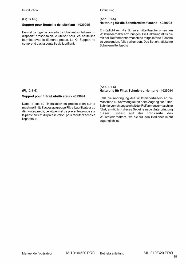
(Fig. 3.1-5)
Lubricant Bottle Support - 4029095
Holds the lubricant bottle at the base of the bead presserdevice. Use for the bottle supplied with the tire changer,if present. The Kit does not include the Lubricant bottle.
(Fig. 3.1-6)
Filter/Lubricant Support - 4029094
If fitting the bead presser on the machine means limitingaccess to the tire changer Filter – Lubricating unit, thisKit allows you to position the unit at the back of thebead presser, where it is easily accessible.
19
Einführung
Betriebsanleitung
Introduction
Manuel de l'opérateur MH 310/320 PRO MH 310/320 PRO
(Abb. 3.1-5)Halterung für die Schmiermittelflasche - 4029095
Ermöglicht es, die Schmiermittelflasche unten amWulstniederhalter anzubringen. Die Halterung ist für diemit der Reifenmontiermaschine mitgelieferte Flaschezu verwenden, falls vorhanden. Das Set enthält keineSchmiermittelflasche.
(Abb. 3.1-6)Halterung für Filter/Schmiervorrichtung - 4029094
Falls die Anbringung des Wulstniederhalters an dieMaschine zu Schwierigkeiten beim Zugang zur Filter-Schmiervorrichtungseinheit der Reifenmontiermaschineführt, ermöglicht dieses Set eine neue Unterbringungdieser Einheit auf der Rückseite desWulstniederhalters, wo sie für den Bediener leichtzugänglich ist.
(Fig. 3.1-5)
Support pour Bouteille de lubrifiant - 4029095
Permet de loger la bouteille de lubrifiant sur la base dudispositif presse-talon. A utiliser pour les bouteillesfournies avec le démonte-pneus. Le Kit Support necomprend pas la bouteille de lubrifiant.
(Fig. 3.1-6)
Support pour Filtre/Lubrificateur - 4029094
Dans le cas où l’installation du presse-talon sur lamachine limite l’accès au groupe Filtre-Lubrificateur dudémonte-pneus, ce kit permet de placer le groupe surla partie arrière du presse-talon, pour faciliter l’accès àl’opérateur.

20
Layout
Operator’s Manual MH 310/320 PRO
2-1
4-2
4-1
4. LayoutBefore installing and using the mounting/demountinghelp, it is suggested that you become familiar with thenomenclature of the machine components (Fig. 4-1).
1. Rise/fall control lever2. Roller3. Horizontal arm4. Lower beadholder disk5. Mobile drive6. Bead pusher arm7. Fixing plate8. Bead pusher tool
4.1 ControlsBefore operating the device, ensure that you have wellunderstood the operation and function of all the controls.
A. Operate the lever upwards (#1 Fig. 4-1) to raise themobile drive and consequently the roller and the lowerdisk.B. Operate the lever downwards (#1 Fig. 4-1) to lowerthe mobile drive and consequently the roller and thelower disk.
4.2 Applied plates (Fig. 4-2)
A Cod.EAL0383G02A. Indicates a crushing hazardwhenever the correct use of the bead pusher arm orthe horizontal arm instructions are not followed.
B Cod.EAL0383G05A. Reccomends reading this usermanual prior to starting.
C Cod.EAL0383G01A. Indicates the direction (upwardsor downwards) of the hydraulic bead pusher operatedwith the special lever of the command valve.

21
Layout
Betriebsanleitung
Description
Manuel de l'opérateur MH 310/320 PRO MH 310/320 PRO
4. LayoutVor Aufstellung und Inbetriebnahme desWulstniederhalters sollten Sie sich mit denBezeichnungen der Gerätefunktionsteile vertrautmachen (Abb.4-1).
1. Steuerhebel Aufwärts/Abwärts2. Walze3. Walzenstange4. Wulstniederhalter5. Bewegliche Führung6. Wulstniederhalter-Arm7. Wulstniederhalter-Werkzeug8. Grundplatte
4.1 MaschinenbedienungVor Inbetriebnahme des Vorrichtung sollten Sie sichmit der Lage und Funktionsweise aller Steuerteilevertraut machen.
A. Den Steuerknopf für die Aufwärtsbewegung (#1 Abb.4-1) betäti-gen, um die bewegliche Führung und damitdie Walze und den Wulstniederhalter nach oben zubewegen.B. Den Steuerknopf für die Abwärtsbewegung (#1 Abb.4-1) betätigen, um die bewegliche Führung und damitdie Walze und den Wulstniederhalter nach unten zubewegen.
4.2 Angebrachte Schilder (Abb. 4-2)
A Cod.EAL0383G02A. Indica pericolo di schiaccia-mento qualora non vengano rispettate le istruzioni dicorretto uso del braccio premitallone e dell’astaorizzontale.
B Cod.EAL0383G05A. Suggerisce la lettura delpresente manuale d’uso prima di procedere con lamessa in marcia.
C Cod.EAL0383G01A. Indica il senso di direzione (inalto o in basso) dello stallonatore idraulico azionabiledalla apposita leva della valvola di comando.
4. DescriptionAvant d’installer et d’utiliser le presse-talon, onconseille de se familiariser avec la terminologie de lamachine (Fig. 4-1).
1. Levier de commande montée/descente2. Rouleau3. Tige horizontale4. Disque presse-tallon inférieur5. Guide mobile6. Bras presse-talon7. Base de fixage8. Outil presse-talon
4.1 CommandesAvant d’utiliser le dispositif, s’assurer d’avoir biencompris la position et les fonctions des commandes.
A. Agir sur le levier vers le haut (#1 Fig. 4-1) pour fairemonter la guide mobile et par conséquent le rouleauet le disque inférieur.B. Agir sur le levier vers le bas (#1 Fig. 4-1) pour fairedescendre la guide mobile et par conséquent lerouleau et le disque inférieur.
4.2 Plaquettes signalétiques (Fig. 4-2)
A Code EAL0383G02A. Ce symbole indique un dangerd’écrasement en cas de non respect desinstructions sur l’emploi correct de l’outil qui décollele talon de la jante et de la tringle horizontale.
B Code EAL0383G05A. Ce symbole recommande lalecture de ce manuel d’utilisation avant d’utiliser lamachine.
C Code EAL0383G01A. Cette flèche indique ladirection (vers le haut et vers le bas) du dispositifhydraulique commandé par le levier de la commandequi permet de décoller le talon de la jante.
22
Utilisation
Operator’s Manual MH 310/320 PRO
5-1
5-2
5-3
5-4
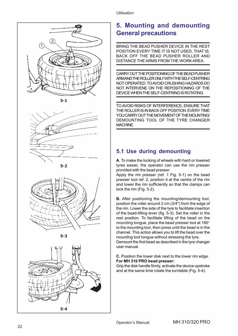
5.1 Use during demountingA. To make the locking of wheels with hard or loweredtyres easier, the operator can use the rim presserprovided with the bead presser.Apply the rim presser (ref. 1 Fig. 5-1) on the beadpresser tool ref. 2, position it at the centre of the rimand lower the rim sufficiently so that the clamps canlock the rim (Fig. 5-2).
B. After positioning the mounting/demounting tool,position the roller around 2 cm (3/4") from the edge ofthe rim. Lower the side of the tyre to facilitate insertionof the bead-lifting lever (fig. 5-3). Set the roller in therest position. To facilitate lifting of the bead on themounting tongue, place the bead presser tool at 180°to the mounting tool, then press until the bead is in thechannel. This action allows you to lift the bead over themounting tool tongue without stressing the tyre.Demount the first bead as described in the tyre changeruser manual.
C. Position the lower disk next to the lower rim edge.For MH 310 PRO bead presser:Grip the disk handle firmly, activate the device upstrokeand at the same time rotate the turntable (Fig. 5-4).
5. Mounting and demountingGeneral precautions
BRING THE BEAD PUSHER DEVICE IN THE RESTPOSITION EVERY TIME IT IS NOT USED, THAT IS,BACK OFF THE BEAD PUSHER ROLLER ANDDISTANCE THE ARMS FROM THE WORK AREA.
CARRY OUT THE POSITIONING OF THE BEAD PUSHERARM AND THE ROLLER ONLY WITH THE SELF-CENTRINGNOT OPERATED. TO AVOID CRUSHING HAZARDS DONOT INTERVENE ON THE REPOSITIONING OF THEDEVICE WHEN THE SELF-CENTRING IS ROTATING.
TO AVOID RISKS OF INTERFERENCE, ENSURE THATTHE ROLLER IS IN BACK OFF POSITION EVERY TIMEYOU CARRY OUT THE MOVEMENT OF THE MOUNTING/DEMOUNTING TOOL OF THE TYRE CHANGERMACHINE.

23
Betrieb
Betriebsanleitung
Utilisation
Manuel de l'opérateur MH 310/320 PRO MH 310/320 PRO
5.1 Einsatz bei derReifendemontageA. Zum erleichterten Aufspannen von harten oderabgeflachten Reifen kann der Wulstniederhalter zu Hilfegenommen werden. Dabei wird der spezielleFelgenniederhalter verwendet. Den Felgenniederhalter(Bez. 1 Abb. 5-1) an das Wulstniederhalter-WerkzeugBez. 2 anbringen, in der Felgenmitte positionieren unddie Felge so weit nach unten drücken, dass die Keiledie Felge spannen können (Abb. 5-2).B. Nach dem Positionieren des Werkzeugs für dasAufziehen/Abziehen die Rolle ca. 2 cm (3/4") vom Randder Felge positionieren. Die Flanke des Reifensabsenken, um das Einführen des Wulstheberhebels(Abb. 5-3) zu vereinfachen. Die Rolle in die Ruhestellungbringen. Zur Vereinfachung des Anhebens des Wulstesauf die Montageschiene den Wulstniederhalter um 180°zum Montiergerät gedreht ansetzen und drücken, bisder Wulst in der Rinne ist. Dies ermöglicht es, denWulst über die Montageschiene zu heben, ohne denReifen zu beanspruchen.Den ersten Wulst abziehen, wie in derBedienungsanleitung des Reifenabziehers beschrieben.
C. Die untere Scheibe in der Nähe des unterenFelgenrandes in Stellung bringen.
Beim Wulstniederhalter MH 310 PRO :Den Griff der Scheibe gut festhalten, denSteuerknopf für die Aufwärtsbewegung derVorrichtung drücken und gleichzeitig dieSpannvorrichtung der Reifenmontiermaschine inDrehung versetzen (Abb.5-4).
5. Benutzung undVorsichtsmaßnahmen für dieBenutzung
DAS WULSTNIEDERHALTER-WERKZEUG IMMER INRUHESTELLUNG BRINGEN, WENN ES NICHT BENUTZTWIRD, DAS HEISST DIE ROLLE DESWULSTNIEDERHALTERS ARRETIEREN UND DIE ARMEAUS DEM ARBEITSBEREICH BRINGEN.
DIE POSITIONIERUNG DES WULSTNIEDERHALTERARMSUND DER ROLLE AUSSCHLIESSLICH VORNEHMEN, WENNDIE SELBSTZENTRIERUNG NICHT BETÄTIGT IST. ZURVERMEIDUNG VON QUETSCHGEFAHR NICHT DIENEUPOSITIONIERUNG DES GERÄTS VORNEHMEN, WENNSICH DIE SELBSTZENTRIERUNG IN ROTATION BEFINDET.
ZUR VERMEIDUNG VON INTERFERRENZGEFAHRSICHERSTELLEN, DASS DIE ROLLE IN DERARRETIERTEN POSITION IST, WENN DIE BEWEGUNGDES WERKZEUGS FÜR DAS AUFZIEHEN/ABZIEHENDER REIFENABZIEHMASCHINE VORGENOMMEN WIRD.
5.1 Utilisation pendant la phase dedémontageA. Afin de faciliter le blocage des roues avec pneusdurs ou rabaissés, il est possible d’utiliser le presse-jante du presse-talon.Appliquer le presse-jante (réf. 1 Fig. 5-1) sur l’outilpresse-talon réf. 2, le positionner au centre de la janteet descendre la jante jusqu’à quand l’on permet auxcoins de bloquer la jante (Fig. 5-2).
B. Après avoir placé l’outil de montage/démontage,placer le rouleau à environ 2 cm (3/4'’) du bord de lajante. Appuyer sur le bord du pneu pour faciliter lapénétration de l’outil qui décollera le talon du pneu dela jante (fig. 5-3). Placer le rouleau en position de repos.Pour faciliter la levée du talon sur la languette demontage, placer l’outil presse-talon à 180° par rapportà l’outil de montage, presser pour faire pénétrer le talondans le canal. Cette action permettra de soulever letalon au-dessus de la languette de l’outil de montagesans stresser le pneu. Démonter le premier taloncomme le décrit le manuel d’utilisation du démonte-pneus.
C. Positionner le disque inférieur près du bord de lajante inférieur.
Pour presse-talon MH 310 PRO :Tenir fermement la poignée du disque puis commanderla montée du dispositif et, en même temps, tournerl’autocentrant (Fig. 5-4).
5. Utilisation et précautions
PLACEZ LE DISPOSITIF QUI DECOLLE LE TALON DE LAJANTE EN POSITION DE REPOS CHAQUE FOIS QU'ILN'EST PAS UTILISE C'EST-A-DIRE RECULER LEROULEAU PRESSEUR ET ECARTER LES LEVIERS DELA ZONE DE TRAVAIL
EFFECTUER LE POSITIONNEMENT DE L'OUTIL QUIDECOLLE LE TALON DE LA JANTE ET LE ROULEAUEXCLUSIVEMENT AVEC L'AUTOCENTRANT NONACTIONNE. POUR EVITER LE RISQUE D'ECRASEMENT,N'INTERVENEZ PAS SUR LE REPOSITIONNEMENT DUDISPOSITIF QUAND L'AUTOCENTRANT SE MET ENROTATION.
POUR EVITER LE RISQUE DE COLLISION, VERIFIEZ SILE ROULEAU EST EN RECUL CHAQUE FOIS QUEL'OUTIL DE MONTAGE/DEMONTAGE DE LA MACHINEDEMONTE-PNEUS EST EN MOUVEMENT.

24
Utilisation
Operator’s Manual MH 310/320 PRO
5-5
5-7
5-8
5-6
For MH 320 PRO bead presser:Grip the lower disk firmly, inserting the bead breakerlever in the slot in the disk supporting arm, activate thedevice upstroke and at the same time rotate theturntable (Fig. 5-5).
This operation allows you to detach the bead if it isstuck and helps lift the cover. Distance the lower diskfrom the work area.
NOTE: A CERTAIN PRESSURE IN THE RADIALDIRECTION ON THE LOWER DISK GRIP IS NORMALTO COUNTERACT THE ACTION OF THE TURNTABLEWHOSE ROTATION TENDS TO PUSH THE DISKOUTWARDS. THE LOWER DISK CANNOT BELOCKED FOR SAFETY REASONS.
5.1.1 Using the roller to demount thesecond bead
In many cases you can speed up demounting bydirectly using only the bead presser roller to removethe second bead.Ne:To get the second bead out:
• Place the roller under the lower side of the tyre.• Rotate the turntable and gradually bring the roller
upwards, so that the bead is pushed upwards untilthe tyre comes out of the rim completely (Fig. 5-6).
5.2 Use as a mounting help device
A. Mount the first bead. After having positioned themounting/demounting tool, position the roller (ref. 1) andthe tool (ref. 2) as shown in Fig. 5-7.B. Lower the bead pusher so that the roller and thebead pusher tool on the tire help keeping the bead intothe drop center (Fig. 5-8).
Before distancing the mounting/demounting tool fromthe tyre changer machine, set the roller and the toolpusher in the rest position.

25
Betrieb
Betriebsanleitung
Utilisation
Manuel de l'opérateur MH 310/320 PRO MH 310/320 PRO
Beim Wulstniederhalter MH 320 PRO:Die untere Scheibe gut festhalten, indem man denWulstentfernerhebel in die Öse des Halterarms derScheibe schiebt, den Steuerknopf für dieAufwärtsbewegung der Vorrichtung drücken undgleichzeitig die Spannvorrichtung derReifenmontiermaschine in Drehung versetzen(Abb.5-5).
Durch dieses Vorgehen kann der Wulst abgelöstwerden, falls er sich erneut an die Felge angepassthaben sollte, und es hilft, den Reifen anzuheben. Dieuntere Scheibe aus dem Arbeitsbereich entfernen.
ANM.: EINE GEWISSE BEANSPRUCHUNG INRADIALER RICHTUNG AM GRIFF DERUNTEREN SCHEIBE IST NORMAL, UMDER WIRKUNG DERSPANNVORRICHTUNG ENTGEGEN ZUWIRKEN, DIE AUFGRUND DERDREHUNG DAZU NEIGT, DIE SCHEIBENACH AUSSEN ZU DRÜCKEN. DIEUNTERE SCHEIBE KANN AUSSICHERHEITSGRÜNDEN NICHTARRETIERT WERDEN.
5.1.1 Einsatz der Rolle beim Demontierender zweiten Wulst
In vielen Fällen ist es möglich, die Demontage zubeschleunigen, indem man beim Entfernen der zweitenWulst direkt und nur die Rolle des Wulstniederhaltersverwendet.
Zum Herausziehen der zweiten Wulst:
Positionieren Sie die Rolle unter die untere Flanke desReifens.Aktivieren Sie die Drehung der Spannvorrichtung undbewegen Sie die Rolle nach und nach nach oben. Dadurchentsteht ein Druck nach oben auf die Wulst, bis der Reifenvollständig aus der Felge austritt (Abb. 5-6).
5.2 Einsatz wahrend derReifenmontageA. Den ersten Wulst aufziehen. Nach dem Positionierendes Werkzeugs für das Aufziehen/Abziehen die Rolle(Rif.1) und das Werkzeug (Rif. 2) wie auf Abb. 5-7 gezeigtpositionieren.B. Den Niederhalter so nach unten drücken, daß derDruck der Walze und des Wulstniederhalter-Werkzeugsauf den Reifen dazu beiträgt, daß der Wulst im Tiefbettbleibt (Abb. 5-8).
Vor dem Entfernen des Werkzeugs für das Aufziehen/Abziehen der Reifenabziehmaschine dasNiederhalterwerkzeug in die Ruhestellung bringen.
Pour presse-talon MH 320 PRO:Tenir fermement le disque inférieur en enfilant l’outil
qui décolle le pneu de la jante dans l’orificeoblong du bras porte-disque ; commander lamontée du dispositif et en même temps fairetourner l’autocentrant (Fig. 5-5).
Cette manœuvre permet de décoller le talon s’il seremet sur la jante et aide à soulever le pneu.Ecarter le disque inférieur de la zone de travail.
NOTA BENE : UN CERTAIN EFFORT DANS LESENS RADIAL SUR LA POIGNEE DUDISQUE INFERIEUR EST NORMALPOUR CONTRASTER L’ACTION DEL’AUTOCENTRANT QUI, SOUS L’EFFETDE LA ROTATION, TEND A POUSSER LEDISQUE VERS L’EXTERIEUR. LEDISQUE INFERIEUR NE PEUT PASETRE BLOQUE POUR DES RAISONSDE SECURITE.
5.1.1 Utilisation du rouleau dans ledémontage du second talon
Dans de nombreux cas, il est possible d’accélérer laphase de démontage en utilisant directement etuniquement le rouleau du presse-talon, pour enlever lesecond talon.
Pour décoller le second talon :
Placer le rouleau en dessous du côté inférieur du pneu.Commander la rotation de l’autocentrant puis fairemonter le rouleau progressivement pour provoquer unepoussée vers le haut du talon et le déjantercomplètement (Fig. 5-6).
5.2 Utilisation pendant la phase demontageA. Montez le premier talon. Après avoir placé l'outil demontage/démontage, placez le rouleau (réf. 1) et l'outil(réf. 2) comme l'indique la Fig. 5-7.B. Descendre le presse talon de façon que la pressiondu rouleau et de l’outil presseur sur le pneu aident àgarder le talon dans le canal de la jante (Fig. 5-8).
Avant d'écarter l'outil de montage/démontage de lamachine démonte-pneus, placez le rouleau et l'outilpresseur en position de repos.

26
Maintenance
Operator’s Manual MH 310/320 PRO
6. Maintenance
BEFORE STARTING ANY MAINTENANCEOPERATION ENSURE THE MACHINE ON WHICHTHE DEVICE IS INSTALLED IS DISCONNECTEDFROM THE ELECTRICAL AND COMPRESSED AIRSUPPLY.
A. Periodically clean and lubricate with oil the horizontalroller arm.B. Grease every month the pivots of the roller swingarm and of the lower disk device and the sliding guidesof the mobile drive.
6.1 StorageIn case the machine is not to be used for a long periodof time (6 months or more) it is necessary to disconnectall power sources, protect all parts that may be damaged,protect the air hoses that may be damaged by the dryingprocess.When putting the machine back in operation, checkfirst the condition of all previously protected parts andcheck for the correct functioning of all devices beforeusing the machine again.

27
Wartung
Betriebsanleitung
Entretien
Manuel de l'opérateur MH 310/320 PRO MH 310/320 PRO
6. Wartung
VOR JEDER WARTUNGS- ODERREPARATURMASSNAHME SICHER-STELLEN,DASS DIE MASCHINE, AN DER DIEHALTEVORRICHTUNG INSTALLIERT IST,ELEKTRISCH UND PNEUMATISCH VON DERZUFUHR ENTFERNT IST.
A. Regelmäßig den Walzenarm reinigen und mit Ölschmieren.B. Jeden Monat die Gelenke des Walzenarms und desunteren Wulst-niederhalters sowie die Gleitschienender beweglichen Führung schmieren.
6.1 LagerungFalls die Masschine für einen längeren Zeitraum (6Monate) nicht benutzt wird, ist es erfordrlicg, dass sievon den Energiequellen abgeklemmt wird, dass der Tankentleert wird und dass die Bauteile geschützt werden,die beschädigt werden könnten und dassDruckluftschläuche geschützt werden, die durchAustrocknung beschädigt werden könnten.Vor der Wiederinbetriebnahme der Maschine vorab dieFunktionstauglichkeit der zuvor geschützten Bauteilesowie aller anderen Vorrichtungen überprüfen.
6. Entretien
AVANT TOUTE OPÉRATION D’ENTRETIEN OU DERÉPARATION, VÉRIFIER QUE LA MACHINE SURLAQUELLE A ÉTÉ INSTALLÉ LE DISPOSITIF SOITDÉTACHÉE DU RÉSEAU ÉLECTRIQUE ET DE LALIGNE PNEUMATIQUE.
A. Nettoyer et graisser périodiquement la tigehorizontale du rouleau.B. Graisser tous les mois les joints du bras porte-rouleau et du disque inférieur et les chemins deglissement de la guide mobile.
6.1 StockageSi la machine doit rester inutilisée pendant longtemps(6 mois), il est vivement recommandé de la débrancherde ses sources d'alimentation en énergie, protéger lespièces délicates qui pourraient s'abîmer avec le tempscomme par exemple les tubes pneumatiques quipeuvent se dessécher.Avant de remettre la machine en service, contrôlezd'abord l'état des pièces délicates puis vérifiez lefonctionnement de tous les dispositifs.
28
Trouble shooting
Operator’s Manual MH 310/320 PRO
7. Trouble shootingIf a problem with the pneumatic electric device appear,proceed in the following order to solve the problem:
1. Rethink the last steps taken.Did you work according to the manual?Did the balancer work as described and expected?
2. Check the balancer according to the list in this chapter.
3. Call your local sales agent or Accuturn for technicalassistance.
The format of this section is:Problem1. Possible cause #1· Possible solution(s)2. Possible cause #2· Possible solution(s)
Operating the raise/descent lever (the device doesnot move).
1. Lack of air pressure.
• Check the machine onto which the device isinstalled is properly supplied with air.
2. Air hose damaged or kinking.
• Call the authorized service center.

29
Fehlerbeseitigung
Betriebsanleitung
Dépannage
Manuel de l'opérateur MH 310/320 PRO MH 310/320 PRO
7. FehlerbeseitigungSollte ein Problem mit der PneumatischerWulstniederhalter, gehen Sie bitte in der nachfolgendbeschriebenen Reihenfolge vor, um das Problem zulösen:1. Versuchen Sie sich an die letzten Schritte zu
erinnern, die sie durchgeführt haben. Sind Sie inÜbereinstimmung mit den Handbuchvorgegangen? Hat sich das Gerät wie beschriebenund erwartet verhalten?
2. Überprüfen Sie das Gerät nach der in diesem Kapitelangegebenen Liste.
3. Bitten Sie ihren örtlichen Vertreter um technischenKundendienst.
Diese Kapitel ist folgendermaßen aufgebaut:Problem1. Mögliche Ursache #1• Mögliche Lösung(en)2. Mögliche Ursache #2• Mögliche Lösung(en)
Bei Betätigung des Steuerknopfes für die Aufwärts-oder Abwärts-bewegung funktioniert das Gerätnicht.
1. Keine Druckluftzufuhr.
• Sicherstellen, dass die Druckluftzufuhr zurReifenmaschine, an der der Wulstniederhalterbefestigt ist, korrekt funktioniert.
2. Zufuhrschlauch undicht oder defekt.
• Den Kundendienst rufen.
7. DépannageEn cas de problème avec le démonte-pneus électro-pneumatique, procéder comme suit pour résoudre leproblème:
1. Se remémorer les dernières actions effectuées.Le travail a-t-il été effectué selon les instructions dumanuel?Est-ce que la machine fonctionnait selon lesdescriptions et les normes?
2. Vérifier la machine selon la liste de ce chapitre.
3. Appeler votre service après-vente pour une révisiontechnique.
Ce chapitre se divise en:Problème1. Cause possible #1• Solution(s) possible(s)2. Cause possible #2• Solution(s) possible(s)
En agissant sur le levier de commande montée/descente, le dispositif ne bouge pas.
1. Manque d’alimentation dans la ligne de l’aircomprimé.
• Contrôler si l’alimentation de l’air comprimé de lamachine à laquelle le dispositif est fixé est correcte.
2. Tuyau d’alimentation bouché ou cassé.
• Appeler le centre de service après-vente autorisé.

30
Disposal
Operator’s Manual MH 310/320 PRO
8. DisposalWhen you decide to dispose of the unit, contact yourdealer for a quote or the disposal regulations whichapply to the unit.

31
Entsorgung
Betriebsanleitung
Vente de la machine
Manuel de l'opérateur MH 310/320 PRO MH 310/320 PRO
8. EntsorgungWenn das Gerät entsorgt werden soll, setzen Sie sichbitte mit Ihrem Händler in Verbindung und fragen Sieihn nach einem Preisangebot oder nach denBestimmungen zur Entsorgung des Geräts.
8. Vente De La MachineLorsque vous décidez de vendre la machine, contactezvotre revendeur pour obtenir le prix offert ou lesrèglements appropriés pour la revente de la machine.

32Operator’s Manual MH 310/320 PRO

33BetriebsanleitungManuel de l'opérateur MH 310/320 PRO MH 310/320 PRO
Anhang: Installationsanweisungen
Annexe: Instructions pour l’Installation
Appendix: Installation Instructions

34Operator’s Manual MH 310/320 PRO
ii-1
ii-2
i. Installation requirements
THE INSTALLATION SHALL BE CARRIED OUT ONLYBY QUALIFIED PERSONNEL AND WITHIN THESCOPE OF THE INSTRUCTIONS PROVIDED INTHIS MANUAL.
Install the machine in a covered and dry area.
Make sure that from the operating position the usercan see all of the machine and the surrounding area.The operator shall forbid, in such an area, thepresence of non authorized persons and of objectswhich may create possible hazards.
ii. Carriage instructions – Uncrating instructions -Moving the machine
Carriage instructionsThe machine is crated in a corrugated box ofappropriate strength. The box is mounted on a pallet.Handling of the machine must be made with anappropriate lifting device (fork lift) (Fig.ii-1).
Uncrating instructions
ALWAYS WEAR GLOVES WHEN UNCRATING THEMACHINE TO PREVENT SCRATCHES ORABRASIONS DUE TO CONTACT WITH PACKINGMATERIALS.
Uncrate the machine paying attention when cutting theplastic straps or during any other operation which maybe hazardous.After removing the carton check for any visible damageto the machine and its components.In case of doubt call qualified personnel for assistance.The packing materials (plastic bags, polystyrene, nails,screws, wood etc.) must be properly disposed of.Place the above mentioned materials into a trashcontainer and dispose per local regulations.
Moving the machineThe device can be moved only with the machine that itis fitted to. Ensure that all the mobile elements of thedevice are blocked.Follow all the indications provided on the user manualof the relative tyre changer.Ensure that there is sufficient space in order to avoidcrushing and entrapment conditions (Fig. ii-2).Ensure that from the operating position the user cansee all of the machine and the surrounding.The operator shall forbid, in such an area, the presenceof non authorized persons and of objects which maycreate possible hazards.

35BetriebsanleitungManuel de l'opérateur MH 310/320 PRO MH 310/320 PRO
i. Installationsanforderungen
DIE INSTALLATION IST VON FACHPERSONALUNTER STRENGER EINHALTUNG DER HIERAUFGEFÜHRTEN ANWEISUNGEN DURCH-ZUFÜHREN.
Die Maschine an einem trockenen und überdachten,möglichst geschlossenen Ort aufstellen.Sicherstellen, daß der Bediener von der Bedienpositionaus das gesamte Gerät und das Umfeld einsehen kann.Der Bediener muss in diesem Bereich das BetretenUnbefugter verhindern, und Gegenstände welcheGefahrenquellen darstellen beseitigen.
ii. Transport – Auspacken - Innerbetrieblicheumsetzung der maschineTransportDie Maschine wird in einem ausreichend stabilenVerpackungskarton ausgeliefert, der auf einerTransportpalette befestigt ist. Der Transport des soverpackten Geräts muß mittels einer geeignetenHebevorrichtung erfolgen (Gabelstapler - Abb.ii-1).
Auspacken
BEIM AUSPACKEN IMMER HANDSCHUHE TRAGEN,UM KRATZER UND SCHÜRFUNGEN DURCH DENKONTAKT MIT DEM VERPACKUNGSMATERIALZU VERMEIDEN.
Beim Auspacken ist dem Durch-schneiden derUmreifungsbänder und all den Vorgängen besondereAufmerksamkeit zu widmen, die das Auftreten vonGefahren in sich bergen können. Nach dem Entfernendes Verpackungsmaterials sich davon überzeugen,daß das Gerät und seine Bestandteile unversehrt sind,soweit dies durch eine Sichtkontrolle möglich ist. ImZweifelsfall das Gerät nicht in Betrieb nehmen undFachpersonal hinzuziehen.Das Verpackungsmaterial (Plastiktü-ten, Polystyrol,Nägel, Schrauben, Holz usw.) nicht verstreuen undgemäß den jeweilig geltendenAbfallbeseitigungsvorschriften entsorgen.
Innerbetriebliche umsetzung der maschineDie Vorrichtung kann nur zusammen mit der Maschinebewegt werden, auf der sie befestigt ist. Sicherstellen,dass alle beweglichen Elemente der Vorrichtung arretiertwerden. Alle Anweisungen in der Bedienungsanleitungder betreffenden Reifenabziehmaschine beachten.Sicherstellen, dass ausreichend Platz bleibt, sodasskeine Quetsch- und Erfassungsgefahr entsteht (Abb. ii-2). Sicherstellen, dass der Bediener aus derArbeitsposition in der Lage ist, das gesamte Gerät undden umgebenden Bereich zu sehen.Der Bediener muss verhindern, dass sich in diesemBereich unbefugte Personen oder Gegenständebefinden, die eine Gefahrenquelle darstellen könnten.
i. Conditions requises pour l’installation
L’INSTALLATION DOIT ÊTRE EFFECTUÉE PAR DUPERSONNEL QUALIFIÉ DANS LE RESPECTDES INSTRUCTIONS DONNÉES.
Installer la machine dans un lieu couvert et sec.
S’assurer que l’opérateur soit à même de visualisertout l’appareil et la zone environnante de sa positionde travail.L’opérateur doit interdire, dans cette zone, la présencede personnes non autorisée et d’objets qui pourraientêtre une source de danger.
ii. Transport – Déballage - Déplacement de la machine
TransportLa machine est emballée dans une boîte de cartonde robustesse adéquate. Cette boîte est montée surune palette pour le transport. Le transport de lamachine emballée doit être effectué avec un dispositifde levage spécial (chariot élévateur) (Fig.ii-1).
Déballage
METTRE TOUJOURS DES GANTS PENDANT LEDÉBALLAGE POUR ÉVITER DES GRIFFURES OUDES ÉGRATIGNURES DUES AU CONTACT AVECLE MATÉRIEL DE L’EMBALLAGE.
Il faut effectuer l’opération de déballage on faisantparticulièrment attention au découpage des feuillardsou à toute autre opération qui puisse être dangereuse.Après avoir enlevé l’emballage, s’assurer de l’intégritéde la machine et de ses pièces, en contrôlant s’il y ades dommages visibles. En cas de doutes, ne pasutiliser la machine et s’adresser au person.nel professionnellement qualifié.Les éléments de l’emballage (sachets en plastique,polystyrène expansé, clous, vis, bois, etc.) ne doiventpas être abandonnés. Mettre les matériauxsusmentionnés dans les lieux de ramassage spéciauxet les éliminer selon les règles locales en vigueur.
Déplacement de la machineCe dispositif ne peut être soumis à un levage qu'avec lamachine sur laquelle il est fixé. Vérifiez si tous lesorganes mobiles du dispositif sont bloqués. Suiveztoutes les consignes du manuel d'utilisation du démonte-pneus.Vérifiez si l'espace autour de la machine est suffisantpour travailler dans des conditions de sécurité (Fig. ii-2). Vérifiez si l'opérateur est en mesure de voir, de sonposte de travail, tout l'appareillage et la zoneenvironnante.Dans cette zone, l'opérateur doit interdire l'accès auxpersonnes non autorisées et la présence d'objets quipourraient être une source de danger pour le levage.

36Operator’s Manual MH 310/320 PRO
iii-1
iii-2
iii-3
iii. Installation proceduresFor fitting and start up on tyre changers, proceed asfollows:
BEFORE FITTING AND START UP, THE MACHINE ONWHICH THE DEVICE IS FIXED MUST BEDISCONNECTED FROM THE COMPRESSED AIRSUPPLY.
ENSURE THAT THE MACHINE ON WHICH THEDEVICE IS TO BE FITTED IS FIXED TO THE FLOORAS INDICATED IN USER MANUAL.
MAKE SURE THAT THERE ARE NO OBSTACLES INTHE AREA AROUND THE DEVICE, INACCORDANCE WITH THE INFORMATION INSECTION II, FIGURE II-2.
CHECK THAT NONE OF THE TYRE CHANGERACCESSORIES (E.G.: LUBRICANT CONTAINERS,INFLATING UNIT) CAN INTERFERE WITH THEDEVICE DURING ITS OPERATION ORINSTALLATION.
A. Disconnect the tyre changer from the electricity andcompressed air supplies.B. When fitting on a tyre changer with casing as shownin figure iii-1 (high casing, standard beam), use the drilledplate, supplied, as a spacer between the device andthe bead breaker arm support. The drilled plate mustbe positioned in order to align the holes of the beadbreaker arm support with the corresponding holes inthe casing. The drilled plate is not necessary to fit thedevice on a tyre changer with casing as shown in figureiii-2 (lowered casing, sloping large beam).C. Immobilise the moving parts of the device.D. Lift the device with appropriate lifting gear (crane,fork lift truck) and a band with sufficient load-bearingcapacity (100 kg-220 lbs.).E. Fix the device to the bead breaker arm support withthe screws, washers and nuts supplied.
Only for MH 310 PRO:
F. insert the hexagonal rod with the roller in the lowerseat of the mobile guide, as shown figure iii-3.
WARNING: INCORRECT ROD INSTALLATION CANDAMAGE THE TYRE.

37BetriebsanleitungManuel de l'opérateur MH 310/320 PRO MH 310/320 PRO
iii. Installationsvorgang
Zur Montage und Inbetriebnahme beiReifenmontiermaschinen, gehen Sie folgendermaßen vor:
VOR DEM EINBAU UND DER INBETRIEBNAHMEMUSS DIE DRUCKLUFTZUFUHR DERREIFENMONTIERMASCHINE, AN DER DIEVORRICHTUNG BEFESTIGT WERDEN SOLL,ABGESCHALTET WERDEN.
SICHERSTELLEN, DASS DIE ZUM EINBAUVORGESEHENE MONTIERMASCHINE GEMÄSSDEN ANWEISUNGEN IN DER ENTSPRECHENDENBETRIEBSANLEITUNG AM BODEN BEFESTIGT IST.
SICHERSTELLEN, DASS IN DEM BEREICH UM DIEVORRICHTUNG HERUM KEINE HINDERNISSESIND, ENTSPRECHEND DEN INFORMATIONEN IMKAPITEL ii, ABBILDUNG ii-2.
SICHERSTELLEN, DASS KEINE TEILE DESZUBEHÖRS DER REIFENMONTIERMASCHINE(WIE ZUM BEISPIEL BEHÄLTER FÜRSCHMIERMITTEL, AUFPUMPEINHEIT) BEI DERARBEIT ODER DER INSTALLATION DIEVORRICHTUNG BEHINDERN KÖNNEN.
A. Die Druckluft und Stromzufuhr derReifenmontiermaschine unterbrechen.B. Bei der Montage auf Reifenabziehern mit Kasten vomin der Abbildung iii-1 gezeigten Typ (Kasten oben,Standardträger) die mitgelieferte Lochplatte alsDistanzstück zwischen der Vorrichtung und der Halterungdes Wulstabzieharms benutzen. Die Lochplatte muss soeingesetzt werden, dass die Bohrungen der Halterung desWulstabzieharms mit den entsprechenden Bohrungen desKastens überein stimmen. Die Lochplatte ist nichterforderlich für die Montage der Vorrichtung aufReifenabziehern mit Kasten vom in der Abbildung iii-2gezeigten Typ (gekippter Kasten, breiter, geneigter Träger).C. Die beweglichen Bauteile der Vorrichtung arretieren.D. Die Vorrichtung mit einer geeigneten Hebevorrichtung(Kran, Hubwagen) und einem Gurt mit ausreichenderTragkraft (100 kg – 220 lbs) anheben.E. Das Gerät mit den mitgelieferten Schrauben, Scheibenund Muttern an der Halterung des Wulstabzieharmsbefestigen.
Nur für MH 310 PRO:
F. Den Sechskantstab mit Rolle in den unteren Sitz derbeweglichen Führung einsetzen und wie in der Abbildungiii-3 gezeigt ausrichten.
ACHTUNG: EINE FALSCHE MONTAGE DES STABKANN ZUR BESCHÄDIGUNG DES REIFENSFÜHREN.
iii. Procédures d’installationPour le montage et la mise en service sur des démonte-pneus, procédez de la façon suivante:
AVANT LE MONTAGE ET LA MISE EN OEUVRE, LAMACHINE SUR LAQUELLE ON FIXE CEDISPOSITIF DOIT ÊTRÉ DEBRANCHÉE DE LALIGNE ELECTRIQUE ET DE LA LIGNE DE L’AIRCOMPRIMÉ.
VÉRIFIER QUE LA MACHINE SUR LAQUELLE ESTMONTÉ LE DISPOSITIF SOIT FIXÉE AU SOLSELON LES INDICATIONS DU MANUEL D’EMPLOICORRESPONDANT.
VERIFIER S’IL EXISTE TOUT AUTOUR DU DISPOSITIFUN ESPACE SUFFISANT, CONFORMEMENT AUXINSTRUCTIONS DE LA RUBRIQUE ii, FIGURE ii-2.
VERIFIER SI AUCUN ACCESSOIRE DU DEMONTE-PNEUS (EXEMPLE : LES BIDONS DELUBRIFIANT, L’UNITE DE GONGLAGE) NE PEUTINTERFERER AVEC LE DISPOSITIF PENDANTLES OPERATIONS DE TRAVAIL OU AU COURSDE SON INSTALLATION.
A. Débrancher le démonte-pneus de l’alimentationélectrique et pneumatique.B. Dans le cas de montage sur démonte-pneus avec uncorps machine du type indiqué dans la figure iii-1 (corpsmachine haut, poutre standard), utiliser la plaque percéecomprise dans le kit comme entretoise entre le dispositifet le support de l’outil qui décolle le talon de la jante. Laplaque percée devra être placée de manière à avoir lesorifices du support de l’outil alignés sur les orificescorrespondants présents sur le corps de la machine. Laplaque percée n’est pas nécessaire pour le montage dudispositif sur le démonte-pneus avec corps de machinedu type indiqué dans la figure iii-2 (corps de machinerabaissé, poutre large inclinée).C. Immobiliser les organes mobiles du dispositif.D. Soulever le dispositif avec un moyen de levage approprié(grue, chariot élévateur) et une sangle ayant une charged’utilisation appropriée (100 kg-220lbs).E. Fixer le dispositif sur le support de l’outil qui décolle letalon de la jante avec des vis, des rondelles et les écrousfournis par le fabricant.
Uniquement pour MH 310 PRO :
F. Introduire la tringle hexagonale avec le rouleau dans lelogement inférieur du guide mobile, en l’orientant commel’indique la figure iii-3.
ATTENTION : UN MAUVAIS MONTAGE DE LATRINGLE POURRAIT ABIMER LE PNEU.

38Operator’s Manual MH 310/320 PRO
iii-4
Compressed air connection(fig. iii-4)
THE COMPRESSED AIR SUPPLY MUST BECONNECTED UP BY SPECIALISED PERSONNEL.
Check that the line pressure is within the limits requiredby the machine.
If the air pressure is lower than the minimum requiredof 8 bar (110 psi) the force of the device may beinsufficient for certain types of tyres.
After checking all the above proceed as follows:
A. Remove the left-hand side panel.B. Inside the casing, cut the air hose extending fromthe filter or supply block (ref. 1 Fig. iii-4) to the pedals.C. Insert the connector (ref. 2 Fig. iii-4) in the cut hoseand connect the device air hose (ref. 3 Fig. iii-4) to it,passing into the casing through one of the free holesclose to the filter.D. Replace the tyre changer side panel.
iv. Testing proceduresNot fitted to this machine.
v. Instructing the operator(Following applies only if a unit is installed by a serviceTechnician)
• Show the operator the first use of the equipment.

39BetriebsanleitungManuel de l'opérateur MH 310/320 PRO MH 310/320 PRO
Druckluftanschluss(Abb. iii-4)
DER DRUCKLUFTANSCHLUSS DARF NUR VONEINER FACHKRAFT VORGENOMMEN WERDEN.
Zunächst sicherstellen, dass sich der Druck der Leitunginnerhalb des für das Gerät vorgeschriebenenLeistungsbereichs befindet.
Sollte der Druck niedriger als die Mindestanforderungvon 8 bar (110 psi) sein, kann sich die Presskraft derVorrichtung bei einigen Reifen als unzureichenderweisen.
Nach Durchführung der oben genanntenKontrollvorgänge wie folgt weiter verfahren:
A. Die linke Seitenwand abnehmen.B. Im Inneren des Kastens den Luftschlauch, der ausdem Filter bzw. vom Versorgungsblock kommt (Bez. 1Abb. iii-4) und zu den Pedalen geht, abschneiden.C. Den Anschluss (Bez. 2 Abb. ii i-4) in denabgeschnittenen Schlauch schieben und denLuftschlauch der Vorrichtung daran anschließen (Bez.3 Abb. iii-4). Dazu muss man ihn durch den Kastenund durch eine der freien Bohrungen in der Nähe desFilters führen.D. Die Seitenwand wieder anbringen.
iv. TestverfahrenIn dieser Maschine nicht vorhanden.
v. Einweisung des Bedieners(Nachfolgendes gilt nur, wenn das Gerät von einemKundendienstingenieur installiert wurde.)
• Dem Bediener die erste Benutzung des Gerätserklären.
Branchement pneumatique(fig. iii-4)
L’INSTALLATION PNEUMATIQUE DOIT ÊTREEFFECTUÉE PAR DU PERSONNELPROFESSIONNELLEMENT QUALIFIÉ.
Contrôler si la pression de la ligne est dans les limitesdemandées par la machine.
Si la pression de l’air est plus basse que le minimumdemandé de 8 bar (110 psi), la puissance du dispositifpourrait être insuffisante pour certains types de pneu.
Après avoir effectué tous les contrôles susmentionnés,procéder comme il suit:
A. Enlever le flanc gauche.B. A l’intérieur du corps machine, couper le tuyau airqui sort du filtre ou du plot d’alimentation (#1 Fig. iii-4)vers le pédalier.C. Insérer le raccord (#2 Fig. iii-4) dans le tuyau coupéet relier le tuyau air du dispositif (#3 Fig. iii-4) en passantà travers le corps machine par les orifices libres prèsdu filtre.D. Refermer le flanc du démonte-pneus.
iv. Procédure de testNon installé sur cette machine.
v. Formation de l’Opérateur(Cela s’applique seulement si la machine est installéepar un technicien de service)
• La première fois, expliquez à l'opérateur comment ildoit se servir de l'appareillage.

ZEAA0329G33A03February 2005 Rel.AMH 310/320 PRO
Snap-on Equipment Srl a unico socio
Via Provinciale per Carpi, 3342015 CORREGGIO (RE) ITALYTel. +39-(0)522-733489 Fax +39-(0)522-733610E-mail: [email protected]: http://www.gsboxer.com