User Manual - Snap-On
87
User Manual February 2011 ZEESC310K Rev. B
-
Upload
khangminh22 -
Category
Documents
-
view
6 -
download
0
Transcript of User Manual - Snap-On

User Manual
February 2011
ZEESC310K Rev. B

Trademarks
SOLUS and Scanner are trademarks of Snap-on Incorporated.
All other marks are trademarks or registered trademarks of their respective holders.
Copyright Information
©2011 Snap-on Incorporated. All rights reserved.
Disclaimer
The information, specifications and illustrations in this manual are based on the latest information available at the time of printing.
Snap-on reserves the right to make changes at any time without notice.
Visit our website at:
http://diagnostics.snapon.com (North America)
snapondiag.com (Europe)
sun-diagnostics.com (Europe)
For Technical Assistance
CALL 1-800-424-7226 (North America)
CALL +44 (0) 845 601 4736 (United Kingdom)
E-mail [email protected] (United Kingdom)
For technical assistance in all other markets, contact your selling agent.
ii

Safety Information
For your own safety and the safety of others, and to prevent damage to the equipment and vehicles upon which it is used, it is important that the accompanying Important Safety Instructions be read and understood by all persons operating, or coming into contact with, the equipment. We suggest you store a copy near the unit in sight of the operator.
This product is intended for use by properly trained and skilled professional automotive technicians. The safety messages presented throughout this manual are reminders to the operator to exercise extreme care when using this test instrument.
There are many variations in procedures, techniques, tools, and parts for servicing vehicles, as well as in the skill of the individual doing the work. Because of the vast number of test applications and variations in the products that can be tested with this instrument, we cannot possibly anticipate or provide advice or safety messages to cover every situation. It is the automotive technician’s responsibility to be knowledgeable of the system being tested. It is essential to use proper service methods and test procedures. It is important to perform tests in an appropriate and acceptable manner that does not endanger your safety, the safety of others in the work area, the equipment being used, or the vehicle being tested.
It is assumed that the operator has a thorough understanding of vehicle systems before using this product. Understanding of these system principles and operating theories is necessary for competent, safe and accurate use of this instrument.
Before using the equipment, always refer to and follow the safety messages and applicable test procedures provided by the manufacturer of the vehicle or equipment being tested. Use the equipment only as described in this manual.
Read, understand and follow all safety messages and instructions in this manual, the accompanying safety manual, and on the test equipment.
Safety Message ConventionsSafety messages are provided to help prevent personal injury and equipment damage. All safety messages are introduced by a signal word indicating the hazard level.
! DANGERIndicates an imminently hazardous situation which, if not avoided, will result in death or serious injury to the operator or to bystanders.
! WARNINGIndicates a potentially hazardous situation which, if not avoided, could result in death or serious injury to the operator or to bystanders.
! CAUTIONIndicates a potentially hazardous situation which, if not avoided, may result in moderate or minor injury to the operator or to bystanders.
iii

Safety Information Important Safety Instructions
Safety messages contain three different type styles.
• Normal type states the hazard.
• Bold type states how to avoid the hazard.
• Italic type states the possible consequences of not avoiding the hazard.
An icon, when present, gives a graphical description of the potential hazard.
Example:
! WARNINGRisk of unexpected vehicle movement.
• Block drive wheels before performing a test with engine running.A moving vehicle can cause injury.
Important Safety InstructionsFor a complete list of safety messages, refer to the accompanying safety information.
SAVE THESE INSTRUCTIONS
iv
Table of Contents
Safety Information ..................................................................................................................... iii
Table of Contents ....................................................................................................................... v
Chapter 1: Using This Manual ................................................................................................... 1
Conventions.................................................................................................................................. 1Bold Text ................................................................................................................................ 1Symbols ................................................................................................................................. 1Terminology ........................................................................................................................... 2Notes and Important Messages ............................................................................................. 2Procedures............................................................................................................................. 2
Additional Manuals ....................................................................................................................... 3Tool Help ...................................................................................................................................... 3
Chapter 2: Introduction.............................................................................................................. 4
Functional Description .................................................................................................................. 4Technical Specifications ............................................................................................................... 6The Stand ..................................................................................................................................... 7Control Buttons............................................................................................................................. 8
N/X Button.............................................................................................................................. 8Y/a Button.............................................................................................................................. 8Thumb Pad ............................................................................................................................ 9Brightness/Contrast Button .................................................................................................... 9S Button ................................................................................................................................. 9Power Button ......................................................................................................................... 9
Connections.................................................................................................................................. 9DC Power Input...................................................................................................................... 9USB Port ................................................................................................................................ 9IR Output.............................................................................................................................. 10Data Cable Connector ......................................................................................................... 10
Power Supply ............................................................................................................................. 10Vehicle Power ...................................................................................................................... 10Battery Power ...................................................................................................................... 10AC/DC Power Supply........................................................................................................... 11
Cables ........................................................................................................................................ 11Data Cable ........................................................................................................................... 11Auxiliary Power Cables ........................................................................................................ 12
Chapter 3: Getting Started....................................................................................................... 13
Supplying Power......................................................................................................................... 13Demonstration Mode .................................................................................................................. 13Connecting to Vehicle Power ..................................................................................................... 14Installing the Batteries ................................................................................................................ 15Connecting an AC/DC Power Supply ......................................................................................... 16Powering On the Unit ................................................................................................................. 17
v

Table of Contents
Setting Up to Print ...................................................................................................................... 17Connecting to a Computer.......................................................................................................... 17Powering Off the Unit ................................................................................................................. 17Adjusting Brightness and Contrast ............................................................................................. 18
Chapter 4: Navigation .............................................................................................................. 19
Screen Layout ............................................................................................................................ 19Upper Toolbar ...................................................................................................................... 20Buffer Bar ............................................................................................................................. 21Main Body ............................................................................................................................ 22LED Indicators ..................................................................................................................... 22
Making Selections ...................................................................................................................... 22Using Easy Scroll ....................................................................................................................... 22Screen Messages....................................................................................................................... 23
Confirmation Messages ....................................................................................................... 23Warning Messages .............................................................................................................. 23Error Messages.................................................................................................................... 23
Chapter 5: Operations.............................................................................................................. 24
Selecting the Manufacturer......................................................................................................... 25Identifying the Vehicle ................................................................................................................ 25Selecting a System..................................................................................................................... 26Connecting to a Vehicle.............................................................................................................. 26Selecting from the System Main Menu....................................................................................... 27Using the Scanner Functions ..................................................................................................... 27
Data Display......................................................................................................................... 28Codes Menu......................................................................................................................... 28Functional Tests................................................................................................................... 30Troubleshooter ..................................................................................................................... 30Generic Functions................................................................................................................ 31
Terminating Vehicle Communication.......................................................................................... 31Exiting Scanner Mode.......................................................................................................... 32
Viewing Data Graphically ........................................................................................................... 33Changing Screen Views....................................................................................................... 33Pausing Data ....................................................................................................................... 41Clearing the Data Buffer ...................................................................................................... 42Sorting the Data ................................................................................................................... 42Using Cursors ...................................................................................................................... 42Using Zoom.......................................................................................................................... 43
Saving Captured Data ................................................................................................................ 44Viewing Saved Data ................................................................................................................... 46
Identifying Saved Files ......................................................................................................... 47Loading Saved Files ............................................................................................................ 48Editing Saved Files .............................................................................................................. 48Reviewing Saved Data......................................................................................................... 48Deleting Saved Files ............................................................................................................ 49Copying and Moving Saved Data ........................................................................................ 49Selecting All Files................................................................................................................. 50Viewing Saved Data Information.......................................................................................... 50Setting a Destination for Saved Data................................................................................... 50
vi
Table of Contents
Printing ....................................................................................................................................... 51Tools Button ............................................................................................................................... 51
Custom Setup ...................................................................................................................... 52Save Data ............................................................................................................................ 53Custom Data List ................................................................................................................. 53LED Setup............................................................................................................................ 54
Utilities ........................................................................................................................................ 54Tool Setup............................................................................................................................ 55System Tools ....................................................................................................................... 61Legacy Software .................................................................................................................. 61Tool Help.............................................................................................................................. 61Easy Scroll ........................................................................................................................... 62Connect to PC...................................................................................................................... 62Run ...................................................................................................................................... 62System Info .......................................................................................................................... 63
Chapter 6: Maintenance ........................................................................................................... 64
Cleaning and Damage Inspection .............................................................................................. 64Replacing the Batteries .............................................................................................................. 64Storage Tips ............................................................................................................................... 65Disposing of the Batteries........................................................................................................... 65
Appendix A: Frequently Asked Questions............................................................................. 66
When I first turn on the scan tool, why does it beep but nothing appears on-screen? ............... 66Can I use my other Snap-on® test adapters with this scan tool?............................................... 66Why do my batteries drain so quickly? ....................................................................................... 66What should I do if my printer is not responding? ...................................................................... 67What should I do if the unit doesn’t respond as expected when I press the Power button? ...... 67Why does my unit shut down unexpectedly? ............................................................................. 67
Appendix B: Troubleshooting ................................................................................................. 68
No Communication Message ..................................................................................................... 68Unit Will Not Power On............................................................................................................... 68Emergency Restart..................................................................................................................... 69
Appendix C: Downloading and Installing Software Updates ............................................... 70
Check for Service Upgrades Before Use.................................................................................... 70Verifying Minimum PC Requirements......................................................................................... 70
Verifying PC System Properties........................................................................................... 71Downloading and Installing ShopStream Connect ..................................................................... 72Downloading Service Upgrades ................................................................................................. 74
Before You Begin ................................................................................................................. 74Installing a Service Upgrade ................................................................................................ 74
Index .......................................................................................................................................... 77
vii
Chapter 1 Using This Manual
This manual contains tool usage instructions.
Some of the illustrations shown in this manual may contain modules and optional equipment that are not included on your system. Contact your sales representative for availability of other modules and optional equipment.
1.1 ConventionsThe following conventions are used.
1.1.1 Bold Text
Bold emphasis is used in procedures to highlight selectable items such as buttons and menu options.
Example:
• Press the Y/a button.
1.1.2 Symbols
Different types of arrows are used.
The “greater than” arrow (>) indicates an abbreviated set of selection instructions.
Example:
• Select Utilities > Tool Setup > Date.
The example statement abbreviates the following procedure:
1. Navigate to the Utilities button.
2. Use the Thumb Pad to navigate to and highlight the Tool Setup submenu.
3. Use the Thumb Pad to navigate to and highlight the Date option from the submenu.
4. Press Y/a to confirm the selection.
The solid arrows (e, c, d, b) are navigational instructions referring to the four directions of the Thumb Pad.
Example:
• Press the down d arrow.
1
Using This Manual Conventions
1.1.3 Terminology
The term “select” means highlighting a button or menu item using the Thumb Pad and pressing the Y/a button to confirm the selection.
Example:
• Select Reset.
The above statement abbreviates the following procedure:
1. Navigate to and highlight the Reset button.
2. Press the Y/a button.
1.1.4 Notes and Important Messages
The following messages are used.
Notes
A NOTE provides helpful information such as additional explanations, tips, and comments.
Example:
NOTE:i For additional information refer to...
Important
IMPORTANT indicates a situation which, if not avoided, may result in damage to the test equipment or vehicle.
Example:
IMPORTANT:Do not force the CompactFlash® card into the slot.
1.1.5 Procedures
An arrow icon indicates a procedure.
Example:
z To change screen views:
1. Select the View button.
The drop-down menu displays.
2. Select an option from the menu.
The screen layout changes to the format you selected.
2

Using This Manual Additional Manuals
1.2 Additional ManualsThis tool works in conjunction with other software products, which have their own manuals. See the appropriate manual for information regarding these products.
1.3 Tool HelpTool Help, which contains reference and procedural information found in this manual, is available on the scan tool. See “Tool Help” on page 61 for details.
3

Chapter 2 Introduction
The SOLUS™ scan tool uses Vehicle Communication Software and Fast Track® Troubleshooter software to provide vehicle-specific trouble codes for various vehicle control systems such as engine, transmission, antilock brake system (ABS) and more, selected functional tests, and troubleshooting information. The scan tool can also graph live data parameters on-screen.
Figure 2-1 SOLUS™
2.1 Functional DescriptionFigure 2-2, Figure 2-3, and Figure 2-4 show the external features of the scan tool.
4

Introduction Functional Description
1— Liquid Crystal Display (LCD)
2— N/X (No) and Y/a (Yes) buttons
3— Thumb Pad
4— Right handgrip
5— Brightness/Contrast button
6— S button
7— Power button
8— Left handgripFigure 2-2 Front view
1— DC power supply input
2— USB port
3— Infrared (IR) output
4— CompactFlash® (CF) Card Slot 1
5— CF Card Slot 2
6— Data cable connectorFigure 2-3 Top view
1 2 3
8 7 6 5 4
1 2 3 4 5 6
5
Introduction Technical Specifications
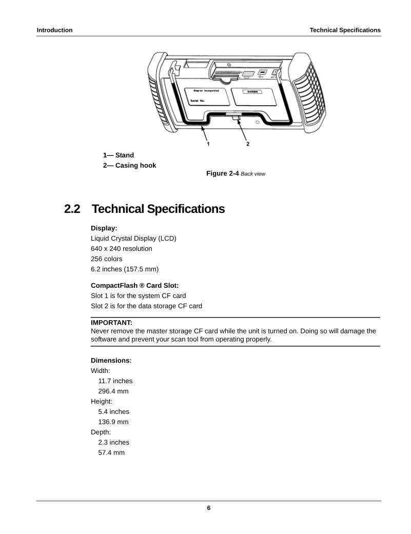
1— Stand
2— Casing hookFigure 2-4 Back view
2.2 Technical Specifications
Display:
Liquid Crystal Display (LCD)
640 x 240 resolution
256 colors
6.2 inches (157.5 mm)
CompactFlash ® Card Slot:
Slot 1 is for the system CF card
Slot 2 is for the data storage CF card
IMPORTANT:Never remove the master storage CF card while the unit is turned on. Doing so will damage the software and prevent your scan tool from operating properly.
Dimensions:
Width:
11.7 inches
296.4 mm
Height:
5.4 inches
136.9 mm
Depth:
2.3 inches
57.4 mm
21
6

Introduction The Stand
Weight:
2.5 lbs
1,134 g
Operating Temperature Range:
14 to 104°F
-10 to 40°C
Storage Temperature Range:
-4 to 149°F
-20 to 65°C
Batteries:
(6) 1.5V AA
2.3 The StandThe scan tool has a built-in, metal stand attached to the back. When the stand is not in use, it is secured to the back of the unit by an integrated casing hook (Figure 2-4 on page 6).
When extended, the stand allows the unit to rest at a 45° angle for hands-free viewing (Figure 2-5).
Figure 2-5 Stand extended
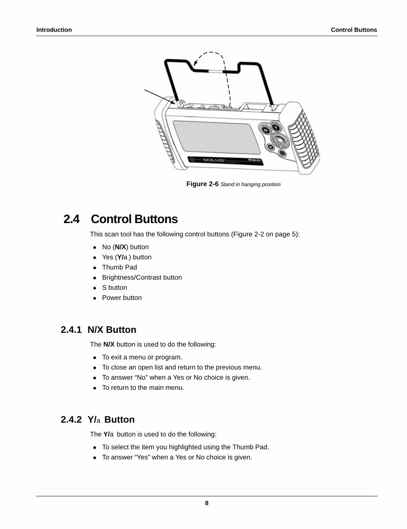
The stand can also be extended to a hanging position by pressing the left side towards the right and rotating forward (Figure 2-6).
7
Introduction Control Buttons
Figure 2-6 Stand in hanging position
2.4 Control ButtonsThis scan tool has the following control buttons (Figure 2-2 on page 5):
• No (N/X) button
• Yes (Y/a) button
• Thumb Pad
• Brightness/Contrast button
• S button
• Power button
2.4.1 N/X Button
The N/X button is used to do the following:
• To exit a menu or program.
• To close an open list and return to the previous menu.
• To answer “No” when a Yes or No choice is given.
• To return to the main menu.
2.4.2 Y/a Button
The Y/a button is used to do the following:
• To select the item you highlighted using the Thumb Pad.
• To answer “Yes” when a Yes or No choice is given.
8
Introduction Connections
2.4.3 Thumb Pad
The Thumb Pad moves the highlight, allowing vertical and horizontal on-screen movement. The Thumb Pad is typically used in combination with the Y/a and N/X buttons.
2.4.4 Brightness/Contrast Button
The Brightness/Contrast button opens the dialog box that allows you to adjust the screen for optimum viewing. See “Adjusting Brightness and Contrast” on page 18 for details.
2.4.5 S Button
The S button can be customized to perform different functions from the Utilities > Tool Setup menu. See “S Button” on page 59 for details.
2.4.6 Power Button
The Power button powers on and powers off this scan tool. See “Powering On the Unit” on page 17 and “Powering Off the Unit” on page 17 for details.
2.5 ConnectionsThis scan tool uses the following connections (Figure 2-3 on page 5):
• DC power adapter input
• USB port
• IR output
• Data cable connector
2.5.1 DC Power Input
The AC/DC power supply provides power to the scan tool through the DC power input on top of the unit (Figure 2-3 on page 5). For related information, see the following sections:
• “AC/DC Power Supply” on page 11
• “Connecting an AC/DC Power Supply” on page 16
2.5.2 USB Port
This scan tool has a USB port for connecting to a PC.
9

Introduction Power Supply
2.5.3 IR Output
The IR output is for printing data.
For related information, see the following sections:
• “Setting Up to Print” on page 17
• “Printing” on page 51
2.5.4 Data Cable Connector
The connector on the data cable fits to adapters that connect the scan tool to a vehicle for testing.
For related information, see the following sections:
• “Cables” on page 11
• “Connecting to Vehicle Power” on page 14
2.6 Power SupplyThis scan tool can receive power from three sources:
• Vehicle power
• Battery power
• AC/DC power supply
For related information, see “Supplying Power” on page 13.
2.6.1 Vehicle Power
This scan tool can receive 12V vehicle power via the data cable either by itself or in conjunction with the auxiliary power cables included with this scan tool.
For related information, see the following sections:
• “Data Cable Connector” on page 10
• “Cables” on page 11
• “Connecting to Vehicle Power” on page 14
2.6.2 Battery Power
This scan tool can receive power from six internal AA batteries, which maintain the time, date, and other custom settings but should not be the primary source of power. Vehicle power should be the primary source of power during testing.
For related information, see the following sections:
10

Introduction Cables
• “Installing the Batteries” on page 15
• “Power Management” on page 55
• “Replacing the Batteries” on page 64
2.6.3 AC/DC Power Supply
This scan tool can be powered from a wall socket using the optional AC/DC power supply (Figure 2-7).
Figure 2-7 AC/DC power supply
For related information, see the following sections:
• “DC Power Input” on page 9
• “Connecting an AC/DC Power Supply” on page 16
2.7 CablesThis scan tool uses the following cables:
• Data cable
• Power cables (cigarette lighter and battery)
2.7.1 Data Cable
The data cable (Figure 2-8) is included with your scan tool and uses interchangeable test adapters for connecting to vehicle diagnostic connectors.Captive screws secure both data cable ends.
Figure 2-8 Data Cable
11
Introduction Cables
An optional data cable extension is available. Refer to the Accessory Guide, included with your kit, for a complete listing of accessories and replacement parts.
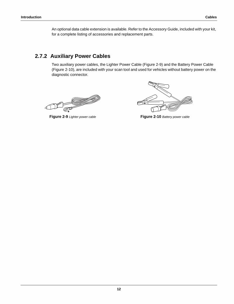
2.7.2 Auxiliary Power Cables
Two auxiliary power cables, the Lighter Power Cable (Figure 2-9) and the Battery Power Cable (Figure 2-10), are included with your scan tool and used for vehicles without battery power on the diagnostic connector.
Figure 2-9 Lighter power cable Figure 2-10 Battery power cable
12
Chapter 3 Getting Started
The following steps get you started using the scan tool:
1. Familiarize yourself with SOLUS controls and connections. Refer to “Control Buttons” on page 8 for details
2. Supply power to the scan tool
3. Press the Power button to turn the scan tool on
3.1 Supplying PowerThere are three ways to supply power to the scan tool:
• Connect to vehicle power
• Install batteries
• Connect to an AC adapter
For related information, see “Power Supply” on page 10.
NOTE:i To conserve batteries, we recommend always powering the unit from vehicle power or from the
AC adapter. The internal battteries are not intended to be used as the primary power source. The batteries are intended to maintain the time, date, and custom settings. They also power the unit during the vehicle identification process.
3.2 Demonstration ModeThe scan tool contains programs to demonstrate scan tool test capabilities without actually connecting to a vehicle. A sample vehicle with mock test results is provided to help you become familiar with menus, navigation, and basic operations.
z To use the demonstration:
1. Connect the plug end of the AC/DC power supply to a wall socket and connect the jack end to the DC Power Supply Input port on the tool.
2. Press the Power button to turn the scan tool on.
3. From the Scanner menu, select Vehicle Comm > Scanner Demo > Y/a.
4. Press Y/a to open the GM Database.
A series of VIN and vehicle equipment requests display.
5. Press Y/a to accept the default setting for each screen request until you reach the Select System menu.
6. Highlight any of the systems on the menu, and Press Y/a to select.
The vehicle connection message displays.
13
Getting Started Connecting to Vehicle Power
7. Press Y/a to confirm and open the system Main Menu.
8. To begin the demonstration, select from any of the menu options (example: Data Display, Codes Menu, Functional Tests, Troubleshooter).
NOTE:i The Demonstration contains actual data captured while driving a 2001 Chevrolet Tahoe. Look for
the throttle position (TP) sensor dropout while analyzing the data in Graphing mode.
9. To exit the demonstration, press N/X until you return to the system Main Menu.
10. To return to the Main Menu, highlight the View button on the upper toolbar and press N/X.
3.3 Connecting to Vehicle PowerYou need the following to connect the scan tool unit to vehicle power:
• Data cable
• Test adapter
• Auxiliary power cables (see below)
For related information, see the following sections:
• “Data Cable Connector” on page 10
• “Vehicle Power” on page 10
• “Connecting to a Vehicle” on page 26
z To connect to vehicle power:
1. Connect one end of the data cable to the data cable connector on top of the scan tool.
2. Connect the other end of the data cable to the appropriate test adapter. The scan tool displays relevant adapter and key usage for the identified vehicle.
3. Connect the test adapter to the vehicle diagnostic connector. The scan tool displays the location of the diagnostic connector.
4. Turn the ignition on.
For vehicles that do not supply power through the diagnostic connector, you must use the optional auxiliary power cables (see “Auxiliary Power Cables” on page 12).
NOTE:i Do not plug the Lighter Power Cable into the DC power input port on the top of the unit. Vehicle
power must be supplied to the test adapter for the scan tool to communicate with the vehicle.
z To use auxiliary power cables:
1. Connect the required test adapter to the data cable.
2. Plug the small end of the Lighter Power Cable into the port on the test adapter.
3. Plug the large end of the Lighter Power Cable into the socket of the Battery Power Cable.
4. Connect the clamps of the Battery Power Cable to the vehicle battery. Be sure to observe correct polarity when connecting to the vehicle battery.
14
Getting Started Installing the Batteries
3.4 Installing the BatteriesThe scan tool comes with six alkaline AA batteries.
For related information, see the following sections:
• “Battery Power” on page 10
• “Power Management” on page 55
• “Replacing the Batteries” on page 64
IMPORTANT:Your scan tool will be damaged if the battery polarity is incorrect. Refer to the diagram on the rear cover of the scan tool for correct battery polarity.
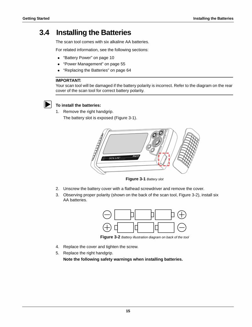
z To install the batteries:
1. Remove the right handgrip.
The battery slot is exposed (Figure 3-1).
Figure 3-1 Battery slot
2. Unscrew the battery cover with a flathead screwdriver and remove the cover.
3. Observing proper polarity (shown on the back of the scan tool, Figure 3-2), install six AA batteries.
Figure 3-2 Battery illustration diagram on back of the tool
4. Replace the cover and tighten the screw.
5. Replace the right handgrip.
Note the following safety warnings when installing batteries.
15

Getting Started Connecting an AC/DC Power Supply
! WARNINGRisk of expelling battery acid.
• Do not let any material leaked from a battery come in contact with eyes or skin.• Always make sure the battery polarities (“+” and “-”) are correct when installing.• Have plenty of fresh water and soap nearby. If battery acid contacts skin, clothing, or
eyes, flush exposed area with soap and water for 10 minutes.Any battery may leak harmful chemicals which may damage eyes, skin, and clothing.
Risk of personal injury or harm.
• Do not expose batteries to excessive heat.• Use batteries from a reputable manufacturer only.• When replacing batteries, always replace the whole set.• Do not use different brands of batteries together.• Do not try to recharge batteries that are not specifically designed to be recharged.• Do not allow children to install batteries unsupervised.• Follow the battery manufacturer's instructions as to proper handling, storage, and
disposal of batteries.Improper use of batteries can result in personal harm.
3.5 Connecting an AC/DC Power SupplyThe optional AC/DC power supply provides power from a wall socket.
For related information, see the following sections:
• “DC Power Input” on page 9
• “AC/DC Power Supply” on page 11
z To connect an AC/DC power supply:
1. Plug the 2.5 mm end of the AC/DC power supply cord into the DC power adapter input on the top of your scan tool (Figure 3-3).
Figure 3-3 DC power supply input
2. Plug the other end of the power adapter into an appropriate wall socket.
16
Getting Started Powering On the Unit
3.6 Powering On the UnitWhen a master storage CF card is installed and power is supplied, power on your scan tool.
z To power on the scan tool:
• Press the Power button (Figure 2-2 on page 5).
The unit beeps and the main menu screen displays after a few seconds.
3.7 Setting Up to PrintThis scan tool prints wirelessly from infrared (IR) enabled, PCL 3 printers.
Before you can use the PRINT button in the upper toolbar, you must do the following:
1. Set up the printer.
2. Configure the scan tool to print.
z To set up the printer:
• Refer to your printer’s documentation for powering and paper loading instructions.
z To configure the scan tool to print:
• Select a printer manufacturer and port from the UTILITIES > Tool Setup > Printer dialog box. See “Printer” on page 57 for details.
3.8 Connecting to a ComputerConnecting your scan tool to a computer for file sharing requires the use of the optional ShopStream Connect™ software. ShopStream Connect is a free software program that can be downloaded from the Internet at software.snapon.com.
3.9 Powering Off the UnitUse the Power button (Figure 2-2 on page 5) to turn the scan tool off.
IMPORTANT:Do not use the Power options while using the Scanner software.
z To use the power options:
1. Terminate vehicle communication, see “Terminating Vehicle Communication” on page 31.
2. Exit Scanner mode, see “Exiting Scanner Mode” on page 32.
3. Press the Power button.
The Turn off dialog box displays (Figure 3-4).
17

Getting Started Adjusting Brightness and Contrast
Figure 3-4 Turn off dialog box
4. Select Turn off, or press N/X to cancel.
3.10 Adjusting Brightness and ContrastThe Brightness/Contrast button(Figure 3-5) lets you to adjust the screen for optimum viewing.
Figure 3-5 Set Brightness/Contrast dialog box
1— Brightness slider control
2— Contrast slider control
z To adjust screen brightness and contrast:
1. Press the Brightness/Contrast button.
The Set Brightness/Contrast dialog box displays (Figure 3-5).
2. Select a slider control using the right c or left e arrow.
3. Press the up b or down d arrow to increase or decrease Brightness and Contrast.
4. Press N/X to close the Set Brightness/Contrast dialog box when you are finished.
1 2
18
Chapter 4 Navigation
The following sections provide general scan tool navigation information.
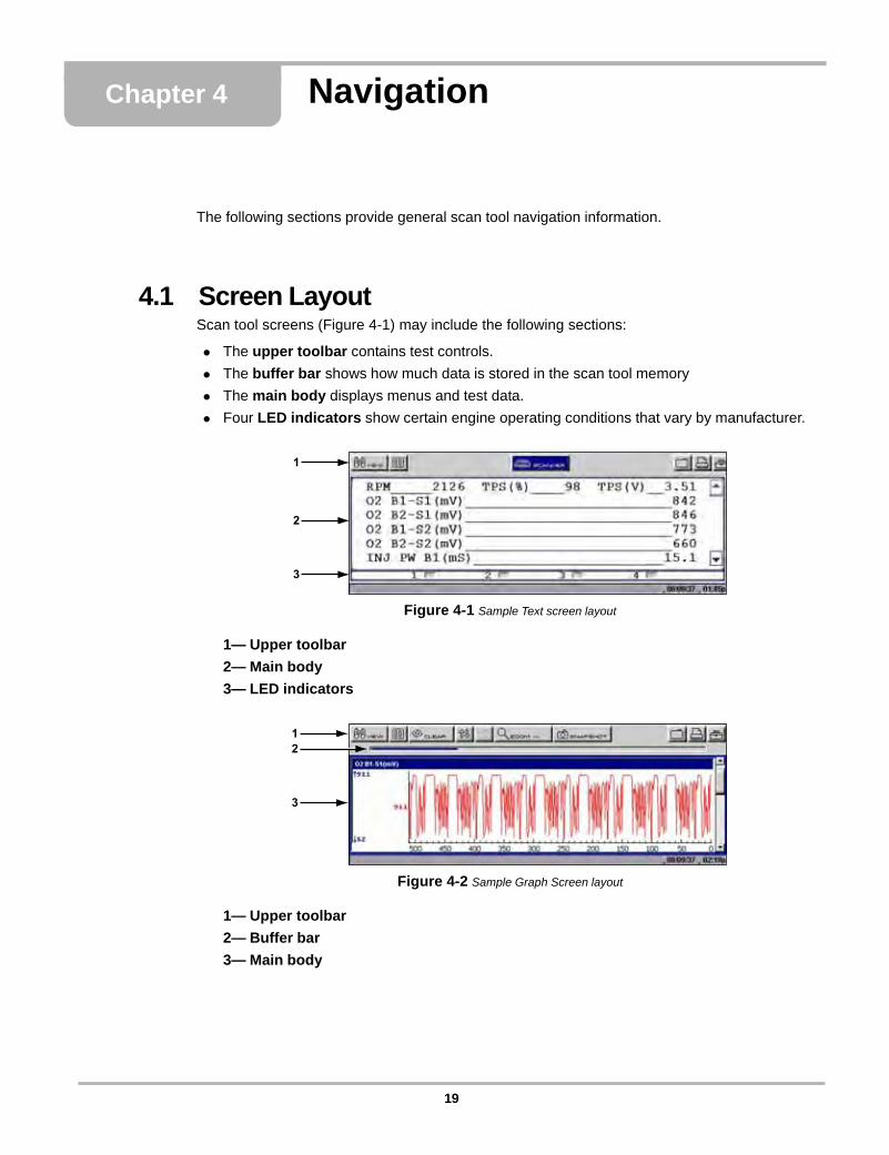
4.1 Screen LayoutScan tool screens (Figure 4-1) may include the following sections:
• The upper toolbar contains test controls.
• The buffer bar shows how much data is stored in the scan tool memory
• The main body displays menus and test data.
• Four LED indicators show certain engine operating conditions that vary by manufacturer.
Figure 4-1 Sample Text screen layout
1— Upper toolbar
2— Main body
3— LED indicators
Figure 4-2 Sample Graph Screen layout
1— Upper toolbar
2— Buffer bar
3— Main body
1
2
3
12
3
19
Navigation Screen Layout
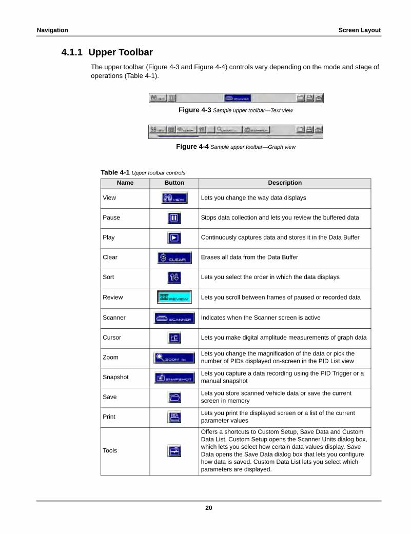
4.1.1 Upper Toolbar
The upper toolbar (Figure 4-3 and Figure 4-4) controls vary depending on the mode and stage of operations (Table 4-1).
Figure 4-3 Sample upper toolbar—Text view
Figure 4-4 Sample upper toolbar—Graph view
Table 4-1 Upper toolbar controls
Name Button Description
View Lets you change the way data displays
Pause Stops data collection and lets you review the buffered data
Play Continuously captures data and stores it in the Data Buffer
Clear Erases all data from the Data Buffer
Sort Lets you select the order in which the data displays
Review Lets you scroll between frames of paused or recorded data
Scanner Indicates when the Scanner screen is active
Cursor Lets you make digital amplitude measurements of graph data
ZoomLets you change the magnification of the data or pick the number of PIDs displayed on-screen in the PID List view
SnapshotLets you capture a data recording using the PID Trigger or a manual snapshot
SaveLets you store scanned vehicle data or save the current screen in memory
PrintLets you print the displayed screen or a list of the current parameter values
Tools
Offers a shortcuts to Custom Setup, Save Data and Custom Data List. Custom Setup opens the Scanner Units dialog box, which lets you select how certain data values display. Save Data opens the Save Data dialog box that lets you configure how data is saved. Custom Data List lets you select which parameters are displayed.
20
Navigation Screen Layout
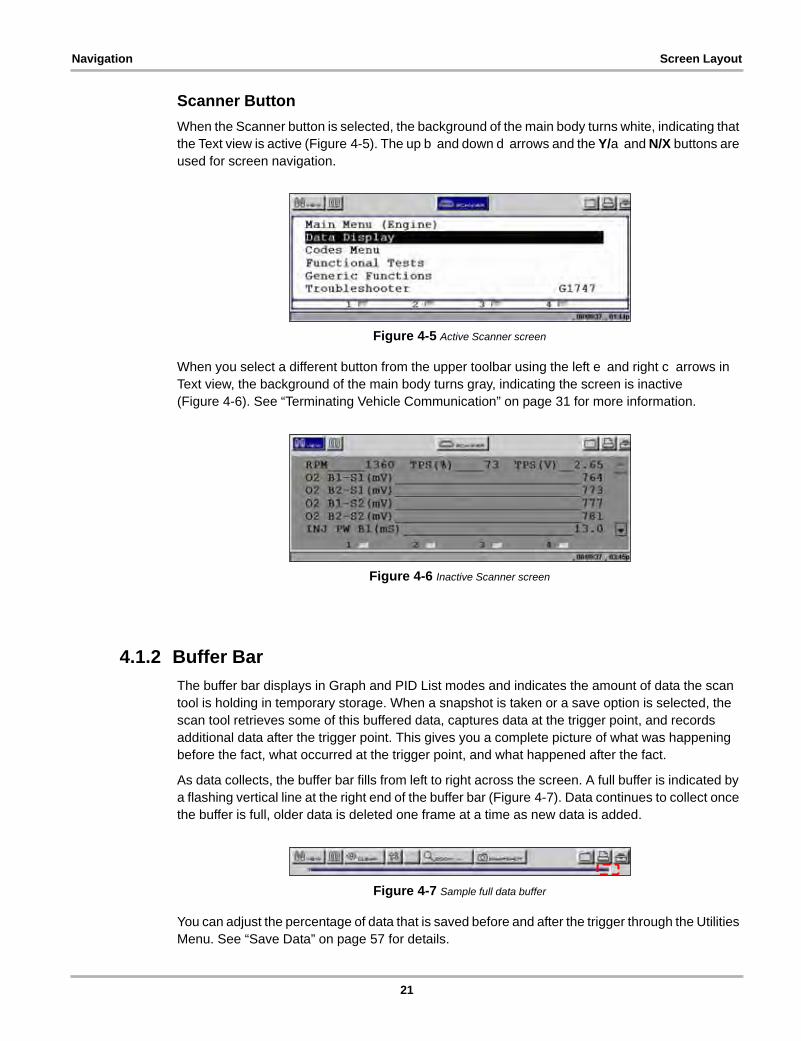
Scanner Button
When the Scanner button is selected, the background of the main body turns white, indicating that the Text view is active (Figure 4-5). The up b and down d arrows and the Y/a and N/X buttons are used for screen navigation.
Figure 4-5 Active Scanner screen
When you select a different button from the upper toolbar using the left e and right c arrows in Text view, the background of the main body turns gray, indicating the screen is inactive (Figure 4-6). See “Terminating Vehicle Communication” on page 31 for more information.
Figure 4-6 Inactive Scanner screen
4.1.2 Buffer Bar
The buffer bar displays in Graph and PID List modes and indicates the amount of data the scan tool is holding in temporary storage. When a snapshot is taken or a save option is selected, the scan tool retrieves some of this buffered data, captures data at the trigger point, and records additional data after the trigger point. This gives you a complete picture of what was happening before the fact, what occurred at the trigger point, and what happened after the fact.
As data collects, the buffer bar fills from left to right across the screen. A full buffer is indicated by a flashing vertical line at the right end of the buffer bar (Figure 4-7). Data continues to collect once the buffer is full, older data is deleted one frame at a time as new data is added.
Figure 4-7 Sample full data buffer
You can adjust the percentage of data that is saved before and after the trigger through the Utilities Menu. See “Save Data” on page 57 for details.
21

Navigation Making Selections
4.1.3 Main Body
The main body (Figure 4-8) of the screen provides prompts. The prompts guide you through vehicle identification and task selection. Once communication is established with an ECM, parameter information can be displayed.
Figure 4-8 Sample Scanner main body in text view
4.1.4 LED Indicators
Four LED indicators appear at the bottom of the screen and show designated operating conditions. The LEDs can be programmed to show change of state for certain digital parameters, which vary by manufacturer.
4.2 Making SelectionsUse the following instructions to navigate the interface and make selections.
z To navigate the upper toolbar:
• Press the left e and right c arrows of the Thumb Pad.
z To navigate the main body:
• Press the up b and down d arrows of the Thumb Pad.
z To make selections:
1. Highlight a button or menu option.
2. Press Y/a to confirm the selection.
4.3 Using Easy ScrollInstead of using the Thumb Pad to highlight an item and the Y/a button to select it, Easy Scroll lets you use only the Thumb Pad arrows to highlight and select items.
Easy Scroll works in the following ways:
• The up b and down d arrows navigate menus.
22

Navigation Screen Messages
• The right c arrow works like the Y/a button to confirm the selection of menu items.
• The left e arrow works like the N/X button for cancelling, exiting, and closing menus.
See “Easy Scroll” on page 62 for information on activating Easy Scroll.
4.4 Screen MessagesThere are three types of on-screen messages:
• Confirmations
• Warnings
• Errors
z To manage on-screen messages:
• Press Y/a or N/X as indicated in the message.
4.4.1 Confirmation Messages
Confirmation messages inform you when you are about to perform an action that cannot be reversed or when an action has been initiated and your confirmation is needed to continue.
When a user-response is not required, the message displays briefly before automatically disappearing.
4.4.2 Warning Messages
Warning messages inform you when completing the selected action may result in an irreversible change or loss of data.
4.4.3 Error Messages
Error messages inform you when a system or procedural error has occurred.
Examples of possible errors include:
• A cable is disconnected.
• A peripheral, such as a printer is powered off.
• A CompactFlash® card is inserted improperly.
23
Chapter 5 Operations
This section explains general scan tool operations and offers instructions for customizing certain tool functions.
The following is an outline of basic operations.
NOTE:i The sequence of steps may vary depending on manufacturer or model of the test vehicle. See the
Vehicle Communication Software manuals for detailed procedures.
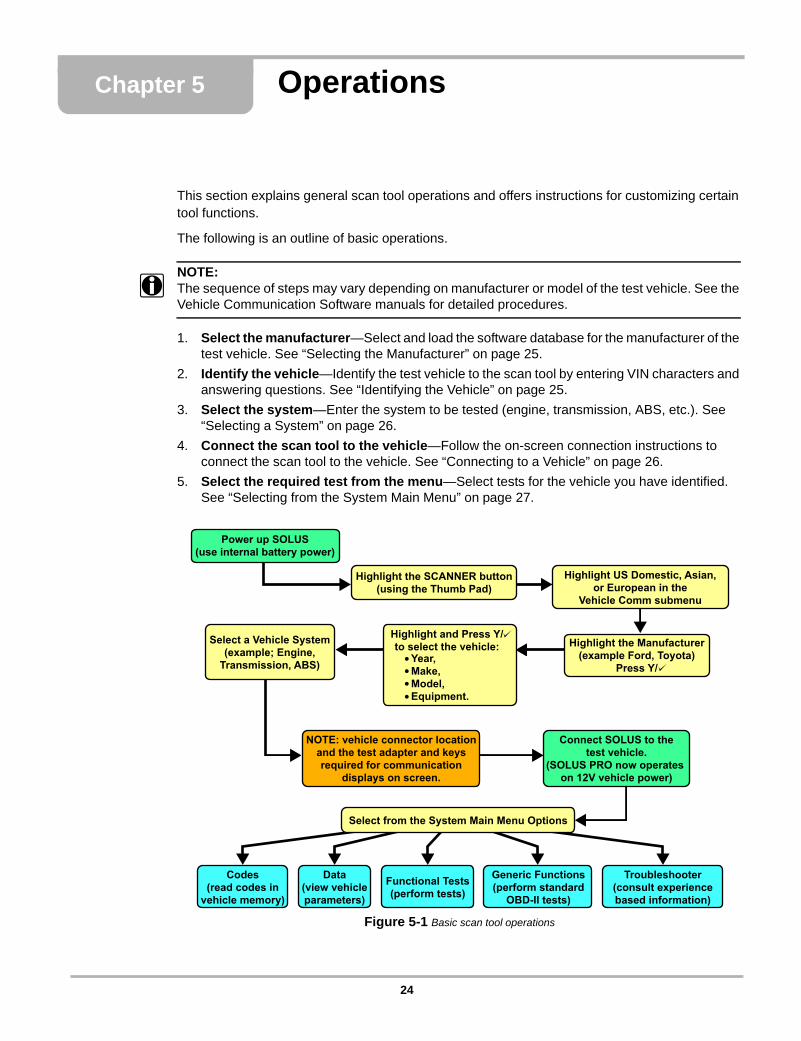
1. Select the manufacturer—Select and load the software database for the manufacturer of the test vehicle. See “Selecting the Manufacturer” on page 25.
2. Identify the vehicle—Identify the test vehicle to the scan tool by entering VIN characters and answering questions. See “Identifying the Vehicle” on page 25.
3. Select the system—Enter the system to be tested (engine, transmission, ABS, etc.). See “Selecting a System” on page 26.
4. Connect the scan tool to the vehicle—Follow the on-screen connection instructions to connect the scan tool to the vehicle. See “Connecting to a Vehicle” on page 26.
5. Select the required test from the menu—Select tests for the vehicle you have identified. See “Selecting from the System Main Menu” on page 27.
Figure 5-1 Basic scan tool operations
Highlight the SCANNER button(using the Thumb Pad)
Highlight US Domestic, Asian,or European in the
Vehicle Comm submenu
Highlight the Manufacturer(example Ford, Toyota)
Press Y/
Select a Vehicle System(example; Engine,
Transmission, ABS)
NOTE: vehicle connector locationand the test adapter and keysrequired for communication
displays on screen.
Connect SOLUS to thetest vehicle.
(SOLUS PRO now operateson 12V vehicle power)
Highlight and Press Y/to select the vehicle:
Year,Make,Model,Equipment.
Troubleshooter(consult experiencebased information)
Functional Tests(perform tests)
Data(view vehicleparameters)
Codes(read codes in
vehicle memory)
Select from the System Main Menu Options
Generic Functions(perform standard
OBD-II tests)
Power up SOLUS(use internal battery power)
24

Operations Selecting the Manufacturer
5.1 Selecting the ManufacturerVehicle manufacturers are organized into categories:
• Previous Vehicles—for recently tested vehicles
• US Domestic—for vehicles produced by US manufacturers
• Asian—for vehicles produced by Japanese and Korean manufacturers
• European—for vehicles produced by European manufacturers
• Global OBDII—for any OBD-II/EOBD vehicle
• OBD Health Check—for any OBD-II/EOBD vehicle
• Scanner Demo—lets you experience the tool without connecting to a vehicle
Each category represents a software database that includes information for a group of manufacturers. For example, select Asian to test a Nissan, even if the model being tested is produced in the United States.
1— Scanner function
2— Vehicle Communication menu
3— SubmenuFigure 5-2 Scanner main menu software selection
z To select the manufacturer:
1. From the main menu, select Scanner.
The Vehicle Communication menu displays (Figure 5-2):
2. Select from the submenus as necessary.
The database loads, then a confirmation screen displays.
3. Press Y/a to continue.
5.2 Identifying the VehicleAfter you select the manufacturer, you are ready to identify the specific vehicle to be tested.
NOTE:i The exact procedure varies depending on the manufacturer. Screen prompts will guide you
through the procedure.
1 2 3
25
Operations Selecting a System
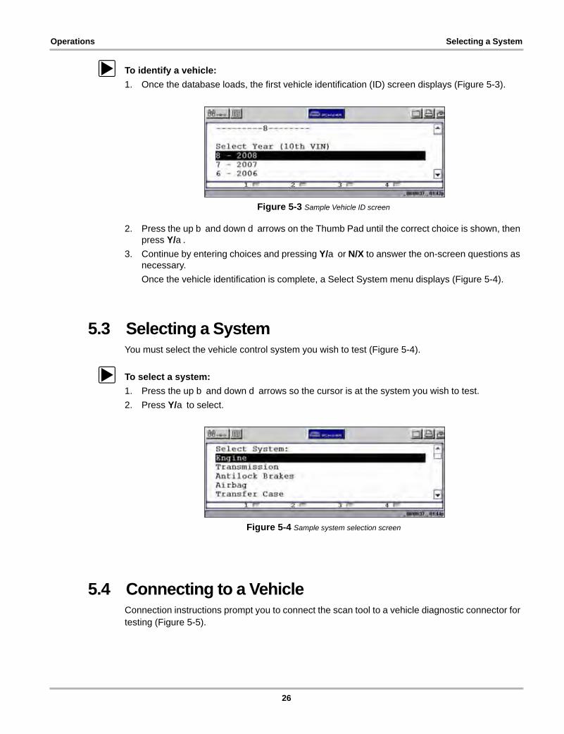
z To identify a vehicle:
1. Once the database loads, the first vehicle identification (ID) screen displays (Figure 5-3).
Figure 5-3 Sample Vehicle ID screen
2. Press the up b and down d arrows on the Thumb Pad until the correct choice is shown, then press Y/a.
3. Continue by entering choices and pressing Y/a or N/X to answer the on-screen questions as necessary.
Once the vehicle identification is complete, a Select System menu displays (Figure 5-4).
5.3 Selecting a SystemYou must select the vehicle control system you wish to test (Figure 5-4).
z To select a system:
1. Press the up b and down d arrows so the cursor is at the system you wish to test.
2. Press Y/a to select.
Figure 5-4 Sample system selection screen
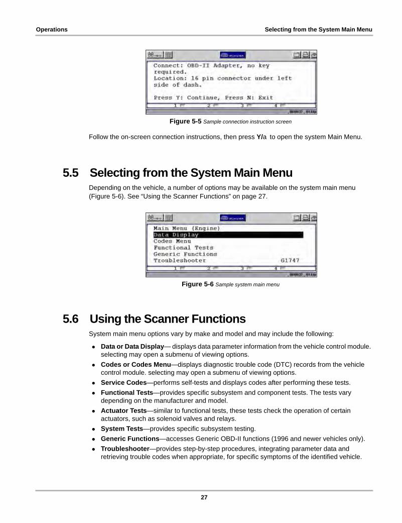
5.4 Connecting to a VehicleConnection instructions prompt you to connect the scan tool to a vehicle diagnostic connector for testing (Figure 5-5).
26
Operations Selecting from the System Main Menu
Figure 5-5 Sample connection instruction screen
Follow the on-screen connection instructions, then press Y/a to open the system Main Menu.
5.5 Selecting from the System Main MenuDepending on the vehicle, a number of options may be available on the system main menu (Figure 5-6). See “Using the Scanner Functions” on page 27.
Figure 5-6 Sample system main menu
5.6 Using the Scanner FunctionsSystem main menu options vary by make and model and may include the following:
• Data or Data Display— displays data parameter information from the vehicle control module. selecting may open a submenu of viewing options.
• Codes or Codes Menu—displays diagnostic trouble code (DTC) records from the vehicle control module. selecting may open a submenu of viewing options.
• Service Codes—performs self-tests and displays codes after performing these tests.
• Functional Tests—provides specific subsystem and component tests. The tests vary depending on the manufacturer and model.
• Actuator Tests—similar to functional tests, these tests check the operation of certain actuators, such as solenoid valves and relays.
• System Tests—provides specific subsystem testing.
• Generic Functions—accesses Generic OBD-II functions (1996 and newer vehicles only).
• Troubleshooter—provides step-by-step procedures, integrating parameter data and retrieving trouble codes when appropriate, for specific symptoms of the identified vehicle.
27
Operations Using the Scanner Functions
5.6.1 Data Display
Selecting Data or Data Display on the system Main Menu has one of the following results:
• A submenu of data viewing choices displays.
• Vehicle data displays.
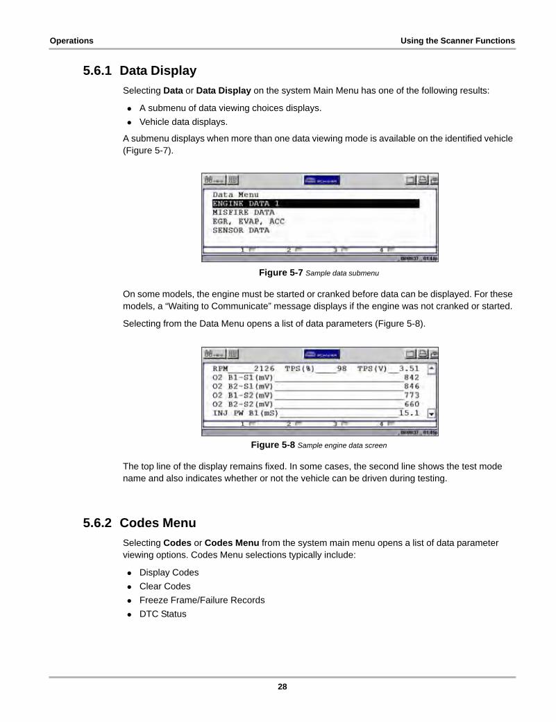
A submenu displays when more than one data viewing mode is available on the identified vehicle (Figure 5-7).
Figure 5-7 Sample data submenu
On some models, the engine must be started or cranked before data can be displayed. For these models, a “Waiting to Communicate” message displays if the engine was not cranked or started.
Selecting from the Data Menu opens a list of data parameters (Figure 5-8).
Figure 5-8 Sample engine data screen
The top line of the display remains fixed. In some cases, the second line shows the test mode name and also indicates whether or not the vehicle can be driven during testing.
5.6.2 Codes Menu
Selecting Codes or Codes Menu from the system main menu opens a list of data parameter viewing options. Codes Menu selections typically include:
• Display Codes
• Clear Codes
• Freeze Frame/Failure Records
• DTC Status
28
Operations Using the Scanner Functions
Trouble Codes
Trouble Codes displays a list of diagnostic trouble codes (DTCs) stored in the selected electronic control module (ECM). Selecting opens a submenu of DTC viewing options on some models. Submenu options allow you to view more detailed DTC information.
Clear Codes
The scan tool clears trouble codes from the control module memory on some vehicles. If this function is not available on the test vehicle, Clear Codes does not appear as a menu option.
Freeze Frame/Failure Records
This selection displays the DTC that was set, along with corresponding data, when the ECM commanded the malfunction indicator lamp (MIL) to turn on.
DTC Status
This selection allows you to see if a particular DTC caused the MIL to turn on.
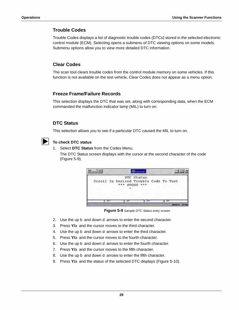
z To check DTC status
1. Select DTC Status from the Codes Menu.
The DTC Status screen displays with the cursor at the second character of the code (Figure 5-9).
Figure 5-9 Sample DTC Status entry screen
2. Use the up b and down d arrows to enter the second character.
3. Press Y/a and the cursor moves to the third character.
4. Use the up b and down d arrows to enter the third character.
5. Press Y/a and the cursor moves to the fourth character.
6. Use the up b and down d arrows to enter the fourth character.
7. Press Y/a and the cursor moves to the fifth character.
8. Use the up b and down d arrows to enter the fifth character.
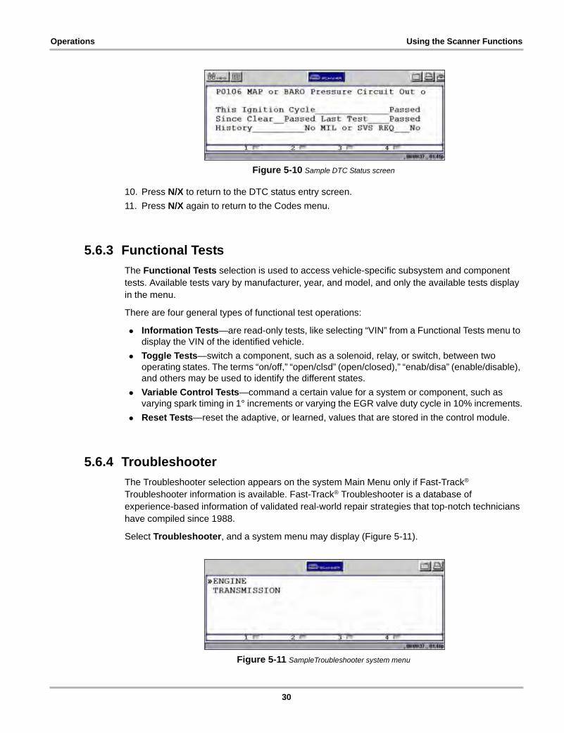
9. Press Y/a and the status of the selected DTC displays (Figure 5-10).
29
Operations Using the Scanner Functions
Figure 5-10 Sample DTC Status screen
10. Press N/X to return to the DTC status entry screen.
11. Press N/X again to return to the Codes menu.
5.6.3 Functional Tests
The Functional Tests selection is used to access vehicle-specific subsystem and component tests. Available tests vary by manufacturer, year, and model, and only the available tests display in the menu.
There are four general types of functional test operations:
• Information Tests—are read-only tests, like selecting “VIN” from a Functional Tests menu to display the VIN of the identified vehicle.
• Toggle Tests—switch a component, such as a solenoid, relay, or switch, between two operating states. The terms “on/off,” “open/clsd” (open/closed),” “enab/disa” (enable/disable), and others may be used to identify the different states.
• Variable Control Tests—command a certain value for a system or component, such as varying spark timing in 1° increments or varying the EGR valve duty cycle in 10% increments.
• Reset Tests—reset the adaptive, or learned, values that are stored in the control module.
5.6.4 Troubleshooter
The Troubleshooter selection appears on the system Main Menu only if Fast-Track® Troubleshooter information is available. Fast-Track® Troubleshooter is a database of experience-based information of validated real-world repair strategies that top-notch technicians have compiled since 1988.
Select Troubleshooter, and a system menu may display (Figure 5-11).
Figure 5-11 SampleTroubleshooter system menu
30

Operations Terminating Vehicle Communication
Select a system and a Troubleshooter Menu similar to Figure 5-12 displays.
Figure 5-12 Sample Troubleshooter Menu
Troubleshooter menus vary by make, model, and system.
Certain information available from a Troubleshooter tip, such as circuit and connector diagrams, may not display properly on the scan tool screen. In this case, the Troubleshooter tip directs you to a numbered reference. These References, which allow you to access more information about the vehicle in the Fast-Track Reference database, are available on line. Simply open your web browser to www.askatech.com and click on Fast-Track Reference.
5.6.5 Generic Functions
The Generic Functions selection opens a menu of available OBD-II functions on 1996 and newer vehicles. Menu options typically include:
• Freeze Frame—displays data stored in ECM memory when a DTC is set
• Readiness Monitors—displays the status of the OBD-II/EOBD required monitors
• Mode 6 Non Cont—displays the status of non-continuous OBD-II/EOBD monitors
• Mode 9 Calib. ID—displays the calibration identification numbers of the vehicle ECMs
• Mode 9 (CVN)—displays the calibration verification numbers of the vehicle ECM
• Mode 9 (VIN)—displays the vehicle identification number
5.7 Terminating Vehicle CommunicationOnce you have established communication with a vehicle, you must terminate communication with the vehicle control module in order to safely shut down the scan tool. Use the following procedures to terminate correctly.
IMPORTANT:Damage to the vehicle may occur if communication is abruptly terminated.
z To terminate communication from a manufacturer or Global OBD-II database:
• Press N/X until you reach the main menu (Figure 5-13).
A “stopping communication” message appears briefly before the main menu displays.
31
Operations Terminating Vehicle Communication
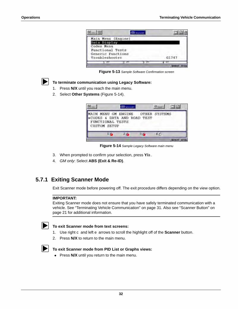
Figure 5-13 Sample Software Confirmation screen
z To terminate communication using Legacy Software:
1. Press N/X until you reach the main menu.
2. Select Other Systems (Figure 5-14).
Figure 5-14 Sample Legacy Software main menu
3. When prompted to confirm your selection, press Y/a.
4. GM only: Select ABS (Exit & Re-ID).
5.7.1 Exiting Scanner Mode
Exit Scanner mode before powering off. The exit procedure differs depending on the view option.
IMPORTANT:Exiting Scanner mode does not ensure that you have safely terminated communication with a vehicle. See “Terminating Vehicle Communication” on page 31. Also see “Scanner Button” on page 21 for additional information.
z To exit Scanner mode from text screens:
1. Use right c and left e arrows to scroll the highlight off of the Scanner button.
2. Press N/X to return to the main menu.
z To exit Scanner mode from PID List or Graphs views:
• Press N/X until you return to the main menu.
32
Operations Viewing Data Graphically
5.8 Viewing Data GraphicallyThe scan tool provides multiple options for viewing and sorting collected data.
Figure 5-15 Sample View menu
5.8.1 Changing Screen Views
Data can be viewed in the following formats:
– Listed by PID
– Text view
– Graph view
z To change screen views:
1. Select the View button.
A drop-down menu displays (Figure 5-15).
2. Select an option from the menu.
The screen layout changes to the selected format.
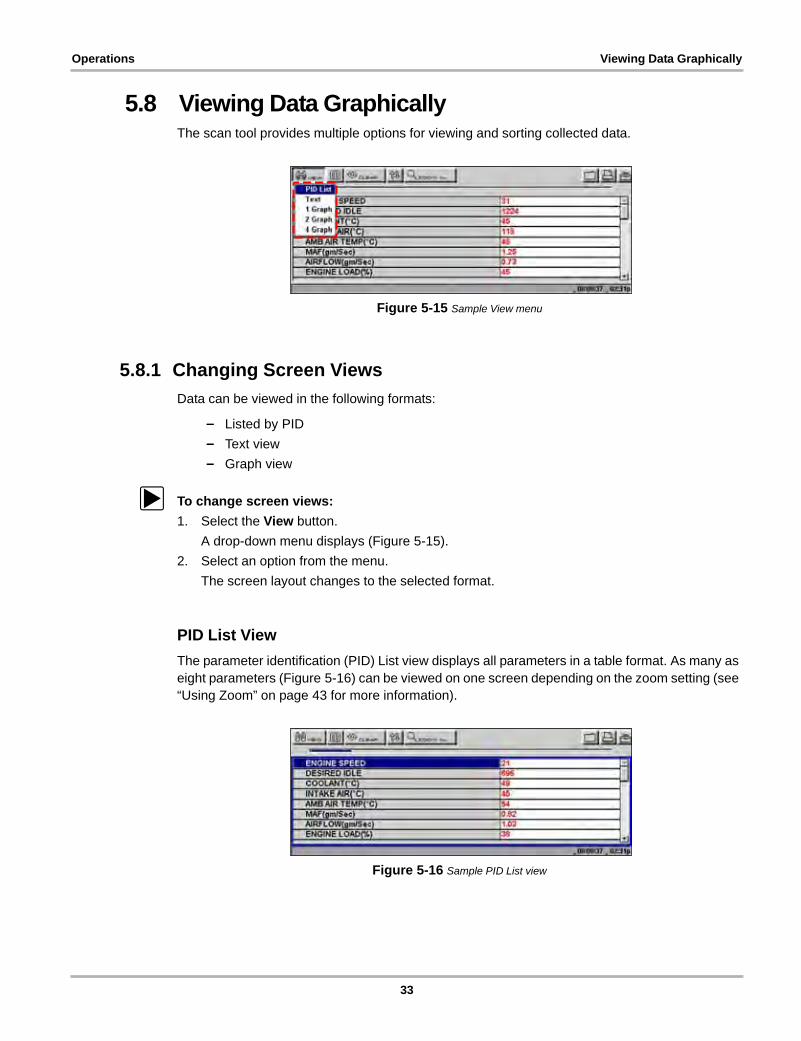
PID List View
The parameter identification (PID) List view displays all parameters in a table format. As many as eight parameters (Figure 5-16) can be viewed on one screen depending on the zoom setting (see “Using Zoom” on page 43 for more information).
Figure 5-16 Sample PID List view
33
Operations Viewing Data Graphically
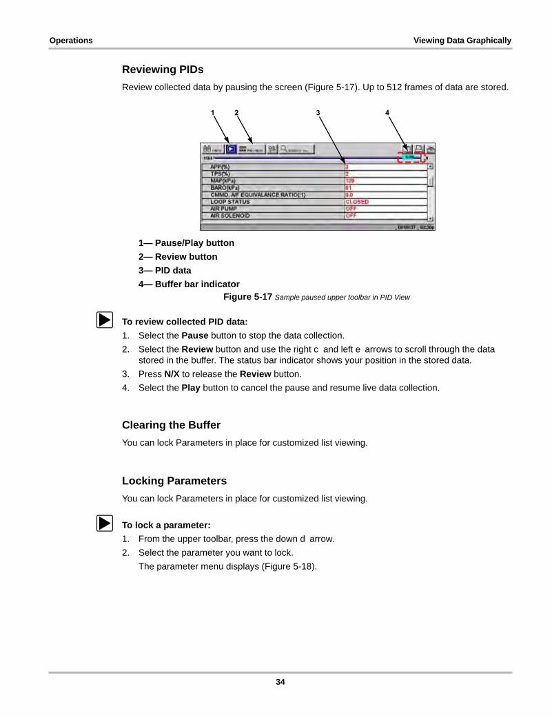
Reviewing PIDs
Review collected data by pausing the screen (Figure 5-17). Up to 512 frames of data are stored.
1— Pause/Play button
2— Review button
3— PID data
4— Buffer bar indicatorFigure 5-17 Sample paused upper toolbar in PID View
z To review collected PID data:
1. Select the Pause button to stop the data collection.
2. Select the Review button and use the right c and left e arrows to scroll through the data stored in the buffer. The status bar indicator shows your position in the stored data.
3. Press N/X to release the Review button.
4. Select the Play button to cancel the pause and resume live data collection.
Clearing the Buffer
You can lock Parameters in place for customized list viewing.
Locking Parameters
You can lock Parameters in place for customized list viewing.
z To lock a parameter:
1. From the upper toolbar, press the down d arrow.
2. Select the parameter you want to lock.
The parameter menu displays (Figure 5-18).
1 2 3 4
34

Operations Viewing Data Graphically
Figure 5-18 Sample parameter menu
3. Select Lock.
A lock icon displays by the parameter, which now stays in place when you scroll (Figure 5-19).
Figure 5-19 Sample locked PID
4. Repeat the above steps to lock multiple parameters.
5. Press N/X to return to the upper toolbar.
z To unlock parameters:
• Select a locked parameter and select Unlock when the parameter menu displays.
The lock icon disappears and the parameter can be scrolled as before.
NOTE:i Select Unlock All to release all of the locked parameters at once.
Text View
Text view displays parameters as plain text (Figure 5-20).
Figure 5-20 Sample Text view
35
Operations Viewing Data Graphically
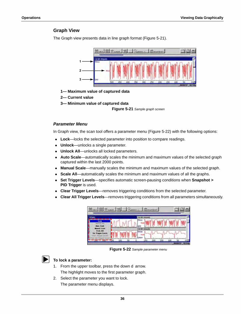
Graph View
The Graph view presents data in line graph format (Figure 5-21).
1— Maximum value of captured data
2— Current value
3— Minimum value of captured dataFigure 5-21 Sample graph screen
Parameter Menu
In Graph view, the scan tool offers a parameter menu (Figure 5-22) with the following options:
• Lock—locks the selected parameter into position to compare readings.
• Unlock—unlocks a single parameter.
• Unlock All—unlocks all locked parameters.
• Auto Scale—automatically scales the minimum and maximum values of the selected graph captured within the last 2000 points.
• Manual Scale—manually scales the minimum and maximum values of the selected graph.
• Scale All—automatically scales the minimum and maximum values of all the graphs.
• Set Trigger Levels—specifies automatic screen-pausing conditions when Snapshot > PID Trigger is used.
• Clear Trigger Levels—removes triggering conditions from the selected parameter.
• Clear All Trigger Levels—removes triggering conditions from all parameters simultaneously.
Figure 5-22 Sample parameter menu
z To lock a parameter:
1. From the upper toolbar, press the down d arrow.
The highlight moves to the first parameter graph.
2. Select the parameter you want to lock.
The parameter menu displays.
1
2
3
36

Operations Viewing Data Graphically
3. Select Lock.
A lock icon displays (Figure 5-21). The locked graph will not move when you scroll through the remaining graphs.
Figure 5-23 Lock icon indicating a locked parameter
4. Scroll other parameters into place to compare readings.
z To unlock a parameter:
1. Select the locked parameter.
The parameter menu displays.
2. Select Unlock.
The lock icon disappears and the parameter can be scrolled as before.
z To unlock all parameters:
1. When a PID is locked on-screen, select any parameter.
The parameter menu displays.
2. Select Unlock All.
All of the lock icons disappear and all of the locked parameters can now be scrolled.
z To scale a parameter:
1. Select a parameter.
The parameter menu displays.
2. Select Auto Scale.
The minimum and maximum graph values are reset for the selected parameter.
z To manually scale a parameter:
1. Select a parameter.
The parameter menu displays.
2. Select Manual Scale.
A line displays across the top of the graph along with a box that displays the maximum recorded value (Figure 5-24).
37
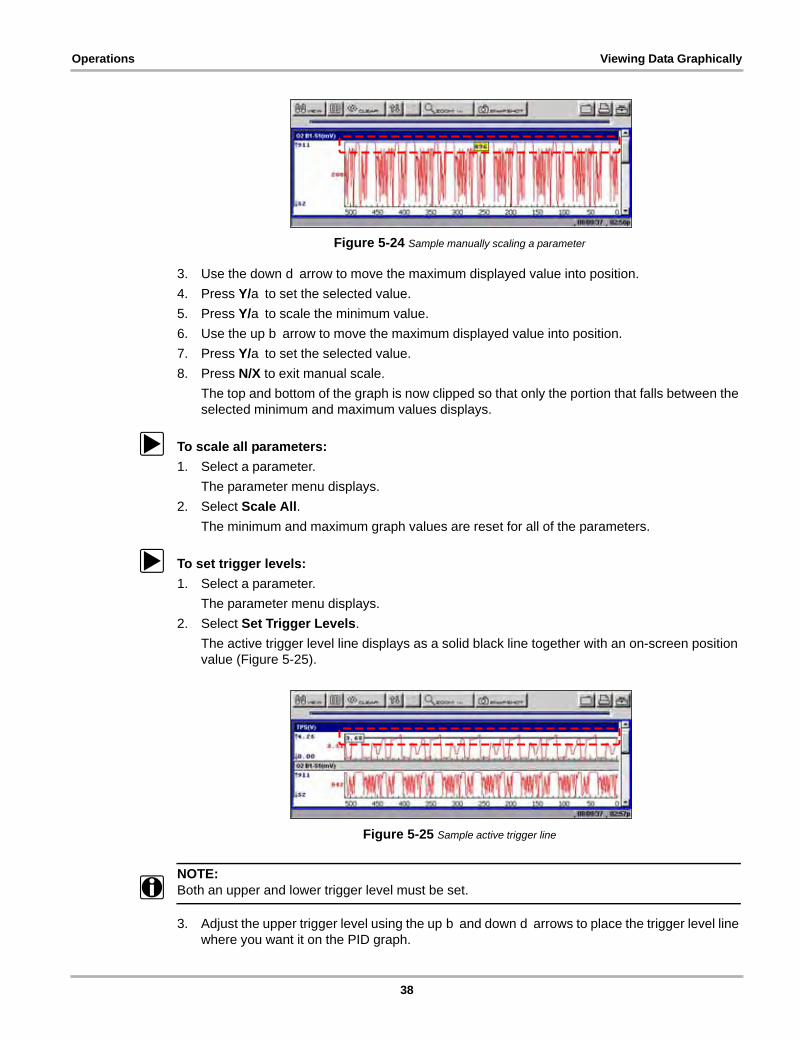
Operations Viewing Data Graphically
Figure 5-24 Sample manually scaling a parameter
3. Use the down d arrow to move the maximum displayed value into position.
4. Press Y/a to set the selected value.
5. Press Y/a to scale the minimum value.
6. Use the up b arrow to move the maximum displayed value into position.
7. Press Y/a to set the selected value.
8. Press N/X to exit manual scale.
The top and bottom of the graph is now clipped so that only the portion that falls between the selected minimum and maximum values displays.
z To scale all parameters:
1. Select a parameter.
The parameter menu displays.
2. Select Scale All.
The minimum and maximum graph values are reset for all of the parameters.
z To set trigger levels:
1. Select a parameter.
The parameter menu displays.
2. Select Set Trigger Levels.
The active trigger level line displays as a solid black line together with an on-screen position value (Figure 5-25).
Figure 5-25 Sample active trigger line
NOTE:i Both an upper and lower trigger level must be set.
3. Adjust the upper trigger level using the up b and down d arrows to place the trigger level line where you want it on the PID graph.
38
Operations Viewing Data Graphically
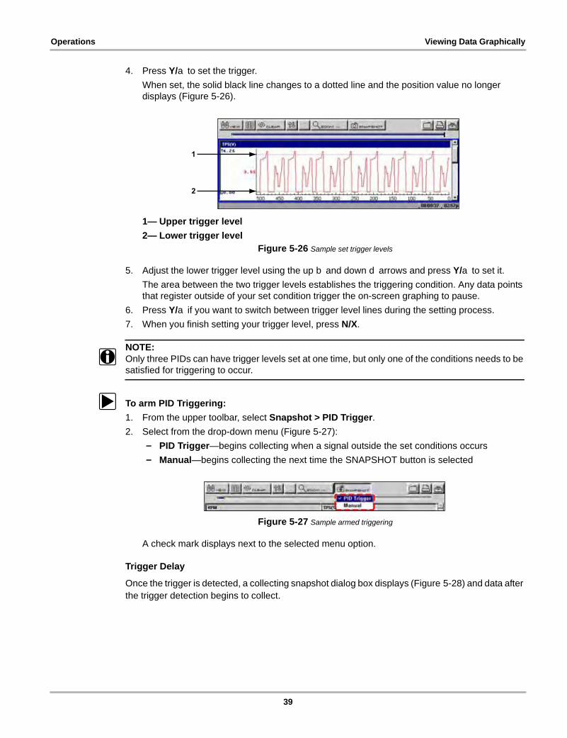
4. Press Y/a to set the trigger.
When set, the solid black line changes to a dotted line and the position value no longer displays (Figure 5-26).
1— Upper trigger level
2— Lower trigger levelFigure 5-26 Sample set trigger levels
5. Adjust the lower trigger level using the up b and down d arrows and press Y/a to set it.
The area between the two trigger levels establishes the triggering condition. Any data points that register outside of your set condition trigger the on-screen graphing to pause.
6. Press Y/a if you want to switch between trigger level lines during the setting process.
7. When you finish setting your trigger level, press N/X.
NOTE:i Only three PIDs can have trigger levels set at one time, but only one of the conditions needs to be
satisfied for triggering to occur.
z To arm PID Triggering:
1. From the upper toolbar, select Snapshot > PID Trigger.
2. Select from the drop-down menu (Figure 5-27):
– PID Trigger—begins collecting when a signal outside the set conditions occurs
– Manual—begins collecting the next time the SNAPSHOT button is selected
Figure 5-27 Sample armed triggering
A check mark displays next to the selected menu option.
Trigger Delay
Once the trigger is detected, a collecting snapshot dialog box displays (Figure 5-28) and data after the trigger detection begins to collect.
1
2
39
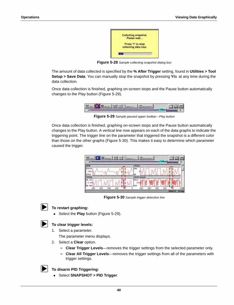
Operations Viewing Data Graphically
Figure 5-28 Sample collecting snapshot dialog box
The amount of data collected is specified by the % After Trigger setting, found in Utilities > Tool Setup > Save Data. You can manually stop the snapshot by pressing Y/a at any time during the data collection.
Once data collection is finished, graphing on-screen stops and the Pause button automatically changes to the Play button (Figure 5-29).
Figure 5-29 Sample paused upper toolbar—Play button
Once data collection is finished, graphing on-screen stops and the Pause button automatically changes to the Play button. A vertical line now appears on each of the data graphs to indicate the triggering point. The trigger line on the parameter that triggered the snapshot is a different color than those on the other graphs (Figure 5-30). This makes it easy to determine which parameter caused the trigger.
Figure 5-30 Sample trigger detection line
z To restart graphing:
• Select the Play button (Figure 5-29).
z To clear trigger levels:
1. Select a parameter.
The parameter menu displays.
2. Select a Clear option.
– Clear Trigger Levels—removes the trigger settings from the selected parameter only.
– Clear All Trigger Levels—removes the trigger settings from all of the parameters with trigger settings.
z To disarm PID Triggering:
• Select SNAPSHOT > PID Trigger.
40
Operations Viewing Data Graphically
The check mark next to the menu option disappears.
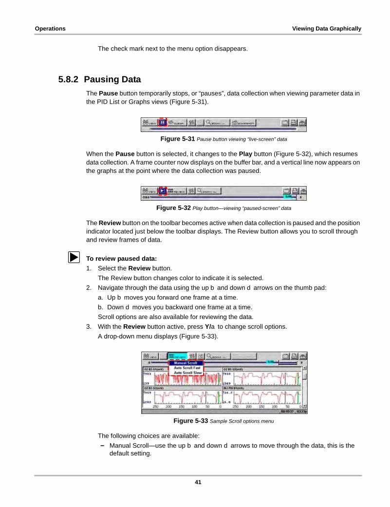
5.8.2 Pausing Data
The Pause button temporarily stops, or “pauses”, data collection when viewing parameter data in the PID List or Graphs views (Figure 5-31).
Figure 5-31 Pause button viewing “live-screen” data
When the Pause button is selected, it changes to the Play button (Figure 5-32), which resumes data collection. A frame counter now displays on the buffer bar, and a vertical line now appears on the graphs at the point where the data collection was paused.
Figure 5-32 Play button—viewing “paused-screen” data
The Review button on the toolbar becomes active when data collection is paused and the position indicator located just below the toolbar displays. The Review button allows you to scroll through and review frames of data.
z To review paused data:
1. Select the Review button.
The Review button changes color to indicate it is selected.
2. Navigate through the data using the up b and down d arrows on the thumb pad:
a. Up b moves you forward one frame at a time.
b. Down d moves you backward one frame at a time.
Scroll options are also available for reviewing the data.
3. With the Review button active, press Y/a to change scroll options.
A drop-down menu displays (Figure 5-33).
Figure 5-33 Sample Scroll options menu
The following choices are available:
– Manual Scroll—use the up b and down d arrows to move through the data, this is the default setting.
41
Operations Viewing Data Graphically
– Auto Scroll Fast—automatically advances data in a continuous loop at normal speed. This is the recording speed, which is the transmission speed of the ECM.
– Auto Scroll Slow—automatically advances data in a continuous loop at half speed.
4. Press N/X to deactivate the Review button.
5.8.3 Clearing the Data Buffer
The Clear button on the toolbar erases all of the data in the buffer. A confirmation screen displays when the Clear button is selected.
New data begins saving after the buffer has been cleared.
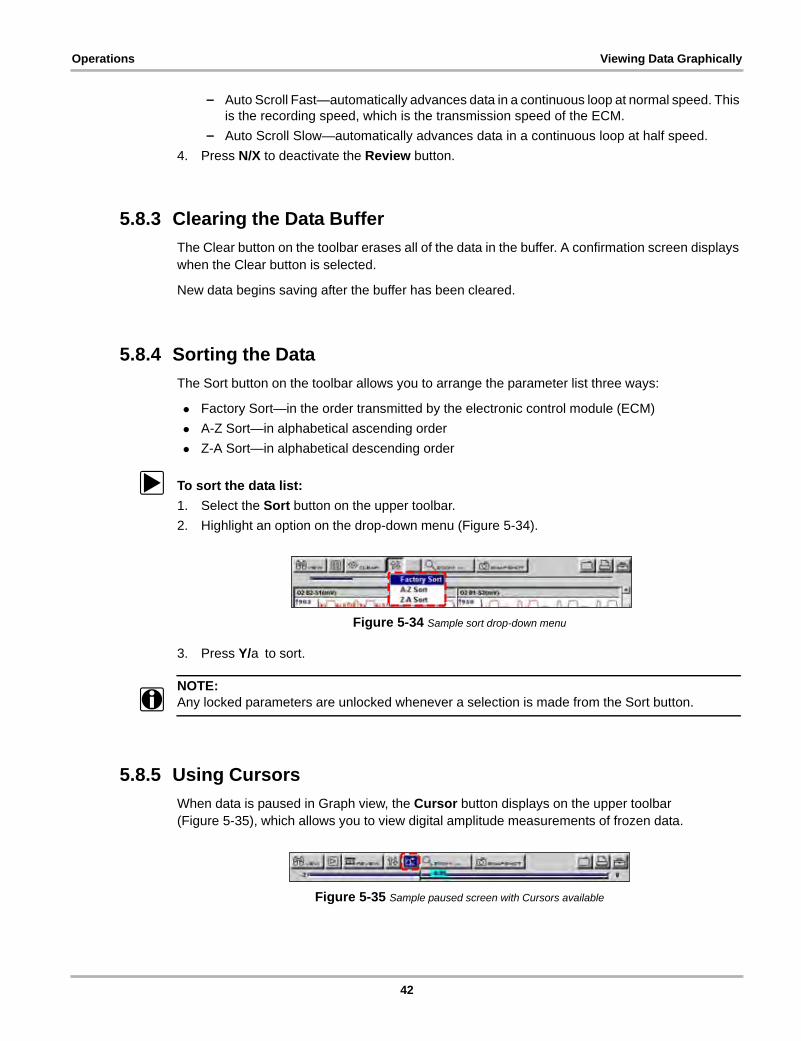
5.8.4 Sorting the Data
The Sort button on the toolbar allows you to arrange the parameter list three ways:
• Factory Sort—in the order transmitted by the electronic control module (ECM)
• A-Z Sort—in alphabetical ascending order
• Z-A Sort—in alphabetical descending order
z To sort the data list:
1. Select the Sort button on the upper toolbar.
2. Highlight an option on the drop-down menu (Figure 5-34).
Figure 5-34 Sample sort drop-down menu
3. Press Y/a to sort.
NOTE:i Any locked parameters are unlocked whenever a selection is made from the Sort button.
5.8.5 Using Cursors
When data is paused in Graph view, the Cursor button displays on the upper toolbar (Figure 5-35), which allows you to view digital amplitude measurements of frozen data.
Figure 5-35 Sample paused screen with Cursors available
42
Operations Viewing Data Graphically
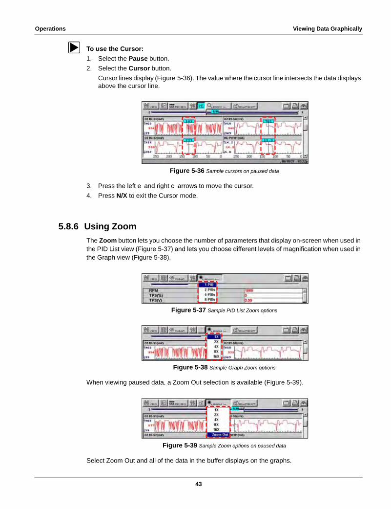
z To use the Cursor:
1. Select the Pause button.
2. Select the Cursor button.
Cursor lines display (Figure 5-36). The value where the cursor line intersects the data displays above the cursor line.
Figure 5-36 Sample cursors on paused data
3. Press the left e and right c arrows to move the cursor.
4. Press N/X to exit the Cursor mode.
5.8.6 Using Zoom
The Zoom button lets you choose the number of parameters that display on-screen when used in the PID List view (Figure 5-37) and lets you choose different levels of magnification when used in the Graph view (Figure 5-38).
Figure 5-37 Sample PID List Zoom options
Figure 5-38 Sample Graph Zoom options
When viewing paused data, a Zoom Out selection is available (Figure 5-39).
Figure 5-39 Sample Zoom options on paused data
Select Zoom Out and all of the data in the buffer displays on the graphs.
43
Operations Saving Captured Data
5.9 Saving Captured DataThe scan tool provides multiple options for saving and reviewing captured data:
• Save Movie—This feature allows you to save up to 2000 frames of data (buffered data plus data transmitted after triggering) for each available parameter. Files can be saved from the Text, PID, and Graph views, but can only be replayed in the Graph view.
• Save Frame—This feature allows you to save up to 512 frames of buffered data (data held in scan tool memory) for each parameter. Pages can be saved from the Text, PID, and Graph views, but can only be replayed in the Graph view.
• Save Image—This feature allows you to capture a single screen as an image. Image files can be opened with common computer programs, such as Microsoft Paint.
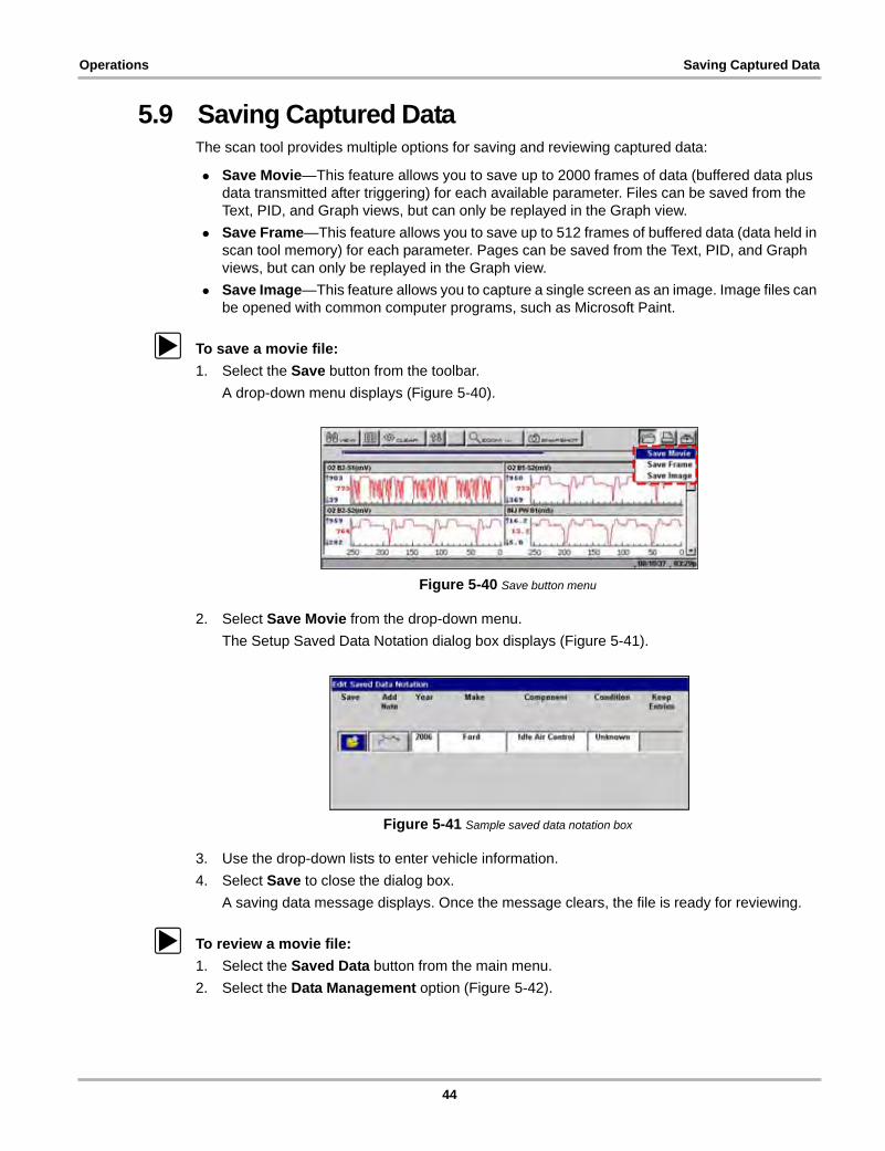
z To save a movie file:
1. Select the Save button from the toolbar.
A drop-down menu displays (Figure 5-40).
Figure 5-40 Save button menu
2. Select Save Movie from the drop-down menu.
The Setup Saved Data Notation dialog box displays (Figure 5-41).
Figure 5-41 Sample saved data notation box
3. Use the drop-down lists to enter vehicle information.
4. Select Save to close the dialog box.
A saving data message displays. Once the message clears, the file is ready for reviewing.
z To review a movie file:
1. Select the Saved Data button from the main menu.
2. Select the Data Management option (Figure 5-42).
44

Operations Saving Captured Data
Figure 5-42 Data Management menu option
A list of all saved files displays.
3. Select the file that you would like to review (Figure 5-43).
Figure 5-43 Sample saved data list
NOTE:i Movie files are saved with a SC(M) file type designation.
4. Select the Review button to set the data viewing speed.
z To save a frame file:
1. Select the Save button from the toolbar.
A drop-down menu displays (Figure 5-40).
NOTE:i The Setup button in the far right corner of the toolbar provides a shortcut to the Save Data menu
(Utilities > Tool Setup > Save Data) so you can quickly reconfigure where and how the data is saved. See “Save Data” on page 57 for details.
2. Select Save Frame from the menu.
The Setup Saved Data Notation dialog box displays (Figure 5-41).
3. Use the drop-down lists to enter vehicle information.
4. Select Save to close the dialog box.
A saving data message displays. Once the message clears, the file is ready for reviewing.
z To review a frame file:
1. Select the Saved Data button from the main menu.
2. Select the Data Management option (Figure 5-42).
A list of all saved files displays.
3. Select the file that you would like to review (Figure 5-43).
45
Operations Viewing Saved Data
NOTE:i Frame files are saved with a SC(S) file type designation.
z To save an image file:
1. Select the Save button from the toolbar.
A drop-down menu displays (Figure 5-40).
2. Select Save Image from the drop-down menu.
The Saving screen image... message displays.
NOTE:i The S button can be set to save an image file, see “S Button” on page 59 for details.
z To review an image file:
1. Select the Saved Data button from the main menu.
2. Select the Data Management option (Figure 5-42).
3. A list of all saved files displays.
4. Select the file that you would like to review.
NOTE:i Image files are saved with either a BMP or JPG file type designation.
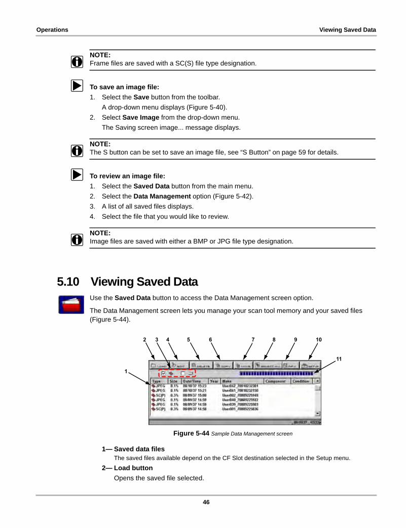
5.10 Viewing Saved DataUse the Saved Data button to access the Data Management screen option.
The Data Management screen lets you manage your scan tool memory and your saved files (Figure 5-44).
Figure 5-44 Sample Data Management screen
1— Saved data filesThe saved files available depend on the CF Slot destination selected in the Setup menu.
2— Load button
Opens the saved file selected.
1
2 3 4 5 6 7 8 9 10
11
46
Operations Viewing Saved Data
3— CF Slot indicators
Displays which CF Slot is selected in Setup. The left icon is CF Slot 2 and the right icon is CF Slot 1. The CF Slot 2 icon will be crossed out if there is no card in the slot when CF Slot 2 is the selected destination.
4— Edit button
Lets you edit data notations for selected files.
5— Delete button
Erases the selected file(s) from storage memory.
6— Copy button
Copies the selected file(s) from one CF slot to the other.
7— Move button
Moves the selected file(s) from one CF slot to the other.
8— Select All button
Selects all files.
9— Info (information) button
Displays the number of files saved and the amount of memory used and available.
10—Setup button
Configures how and where files are saved.
11—CF memory indicator
Displays the amount of CF card memory available.
5.10.1 Identifying Saved FilesSaved files have the following characteristics:
– Type identifies the kind of saved data file:
– SC(M)—file saved from the Save Movie option on the toolbar.
– SC(S)—file saved from the Save Frame option on the toolbar.
– SC(P)—file saved from the Snapshot button on the toolbar.
– BMP—file saved from the Save Image option on the toolbar.
– JPG—file saved from the Save Image option on the toolbar.
– SPS—designates bitmap files saved prior to the 7.2 software update.
• Size is the percentage of available storage space used.
• Date/Time is the date and time that the data was saved.
• Year is the vehicle model year.
• Make is the vehicle manufacturer.
• Component is the component tested.
• Condition is for good, bad, or unknown status options.
z To exit Data Management:
• Press N/X.
47
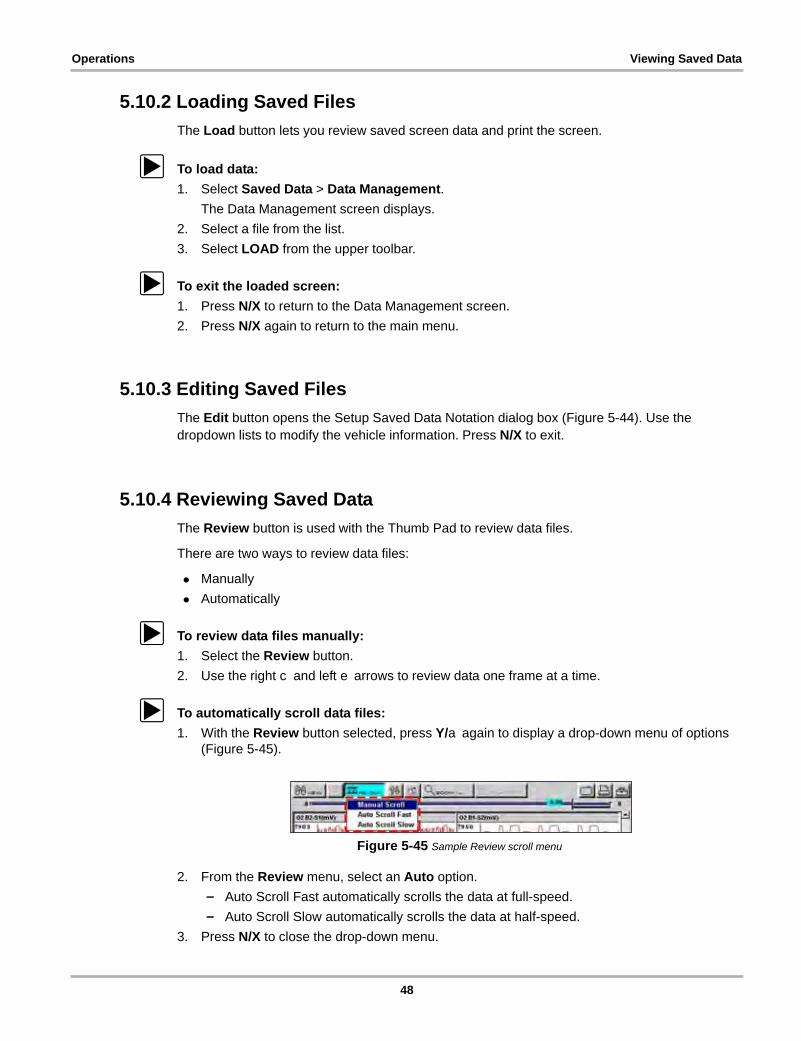
Operations Viewing Saved Data
5.10.2 Loading Saved Files
The Load button lets you review saved screen data and print the screen.
z To load data:
1. Select Saved Data > Data Management.
The Data Management screen displays.
2. Select a file from the list.
3. Select LOAD from the upper toolbar.
z To exit the loaded screen:
1. Press N/X to return to the Data Management screen.
2. Press N/X again to return to the main menu.
5.10.3 Editing Saved Files
The Edit button opens the Setup Saved Data Notation dialog box (Figure 5-44). Use the dropdown lists to modify the vehicle information. Press N/X to exit.
5.10.4 Reviewing Saved Data
The Review button is used with the Thumb Pad to review data files.
There are two ways to review data files:
• Manually
• Automatically
z To review data files manually:
1. Select the Review button.
2. Use the right c and left e arrows to review data one frame at a time.
z To automatically scroll data files:
1. With the Review button selected, press Y/a again to display a drop-down menu of options (Figure 5-45).
Figure 5-45 Sample Review scroll menu
2. From the Review menu, select an Auto option.
– Auto Scroll Fast automatically scrolls the data at full-speed.
– Auto Scroll Slow automatically scrolls the data at half-speed.
3. Press N/X to close the drop-down menu.
48

Operations Viewing Saved Data
5.10.5 Deleting Saved Files
The Delete button lets you remove saved files from memory.
NOTE:i Factory-installed files cannot be deleted.
z To delete files:
1. Select Saved Data > Data Management.
2. Select a file from the list.
3. Select Delete from the toolbar.
A confirmation message displays (Figure 5-46).
Figure 5-46 Sample Delete file confirmation message
4. To remove the data permanently from memory, press Y/a, or press N/X to keep the data and close the dialog box.
Selected files are deleted, then the Data Management screen displays.
5.10.6 Copying and Moving Saved Data
The Copy and Move functions let you transfer your files from one CF card to the other.
z To copy or move data:
1. From the main menu, select Saved Data > Data Management.
The Data Management screen displays.
2. Select Setup from the toolbar.
The Save Data dialog box displays.
3. Set CF 1 as the Save To option and press N/X to close the dialog box.
The test data saved to CF 1 displays.
4. Use the up b and down d arrows to highlight a file from the list on-screen.
5. Use right c and left e arrows to select Copy or Move from the upper toolbar.
A confirmation message displays.
6. Press Y/a to close the message box.
The Data Management screen displays.
NOTE:i Factory installed files cannot be deleted, copied or moved.
49

Operations Viewing Saved Data
5.10.7 Selecting All Files
Use the Select All button to highlight all files on-screen so you can delete, copy, or move the files as needed (Figure 5-47).
Figure 5-47 Sample Select All screen
5.10.8 Viewing Saved Data Information
Selecting the Info button on the toolbar opens a window that provides detailed information about the saved data files, such as the amount of storage memory used and the capacity of the memory storage media (Figure 5-48). Only details for the selected “Save to” destination display.
Figure 5-48 Sample Info button window
5.10.9 Setting a Destination for Saved Data
Use the Setup button to set the destination for saved files (Figure 5-49).
Figure 5-49 Sample Save Data dialog box
z To change the destination for saved files:
1. Select Saved Data > Data Management.
The Data Management screen displays.
50
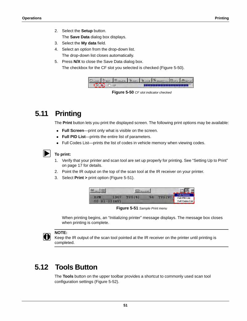
Operations Printing
2. Select the Setup button.
The Save Data dialog box displays.
3. Select the My data field.
4. Select an option from the drop-down list.
The drop-down list closes automatically.
5. Press N/X to close the Save Data dialog box.
The checkbox for the CF slot you selected is checked (Figure 5-50).
Figure 5-50 CF slot indicator checked
5.11 PrintingThe Print button lets you print the displayed screen. The following print options may be available:
• Full Screen—print only what is visible on the screen.
• Full PID List—prints the entire list of parameters.
• Full Codes List—prints the list of codes in vehicle memory when viewing codes.
z To print:
1. Verify that your printer and scan tool are set up properly for printing. See “Setting Up to Print” on page 17 for details.
2. Point the IR output on the top of the scan tool at the IR receiver on your printer.
3. Select Print > print option (Figure 5-51).
Figure 5-51 Sample Print menu
When printing begins, an “Initializing printer” message displays. The message box closes when printing is complete.
NOTE:i Keep the IR output of the scan tool pointed at the IR receiver on the printer until printing is
completed.
5.12 Tools ButtonThe Tools button on the upper toolbar provides a shortcut to commonly used scan tool configuration settings (Figure 5-52).
51

Operations Tools Button
Figure 5-52 Sample Tools button menu
The following choices are available on a dropdown menu:
• Custom Setup
• Save Data
• Custom Data List
• LED Setup
NOTE:i The Custom Data List and LED Setup selections are only available when in the Text view mode,
these menu selections do not display when in Graph or PID List modes.
5.12.1 Custom Setup
Selecting Custom Setup opens the Scanner Units dialog box. Scanner Units is used to change the units of measurement for certain parameters. You can choose between US Customary or metric units of measure for available data parameters.
All measurement units return to their default values when the internal batteries are disconnected or a different software database is selected.
z To change a setting:
1. On the upper toolbar, select Tools > Custom Setup.
The Scanner Units dialog box displays (Figure 5-59).
Table 5-1 Units of measurement—defaults and options
SETTING DEFAULT OPTION
Temperature degrees Celsius (°C) degrees Fahrenheit (°F)
Air Pressure (including manifold pressure)
kilopascals (kPa) inches of mercury (“Hg)
Speed kilometers per hour (kph) miles per hour (mph)
Other Pressures kilopascals (kPa) pounds per square inch (psi)
52
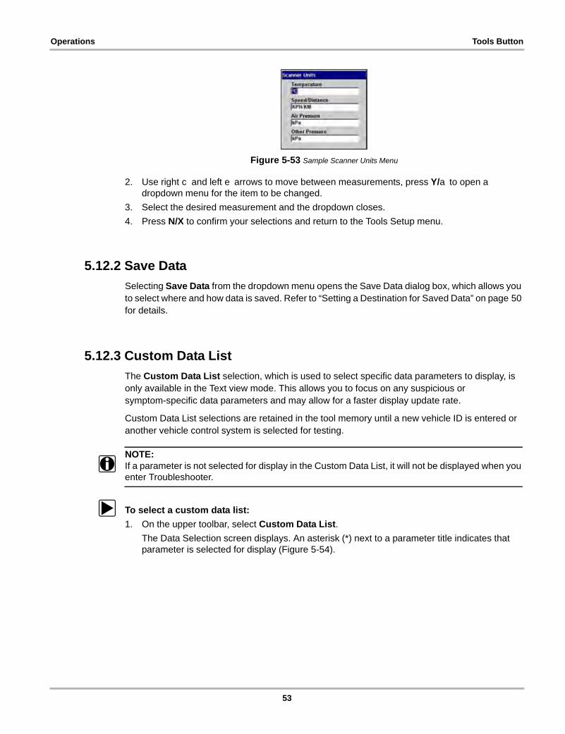
Operations Tools Button
Figure 5-53 Sample Scanner Units Menu
2. Use right c and left e arrows to move between measurements, press Y/a to open a dropdown menu for the item to be changed.
3. Select the desired measurement and the dropdown closes.
4. Press N/X to confirm your selections and return to the Tools Setup menu.
5.12.2 Save Data
Selecting Save Data from the dropdown menu opens the Save Data dialog box, which allows you to select where and how data is saved. Refer to “Setting a Destination for Saved Data” on page 50 for details.
5.12.3 Custom Data List
The Custom Data List selection, which is used to select specific data parameters to display, is only available in the Text view mode. This allows you to focus on any suspicious or symptom-specific data parameters and may allow for a faster display update rate.
Custom Data List selections are retained in the tool memory until a new vehicle ID is entered or another vehicle control system is selected for testing.
NOTE:i If a parameter is not selected for display in the Custom Data List, it will not be displayed when you
enter Troubleshooter.
z To select a custom data list:
1. On the upper toolbar, select Custom Data List.
The Data Selection screen displays. An asterisk (*) next to a parameter title indicates that parameter is selected for display (Figure 5-54).
53
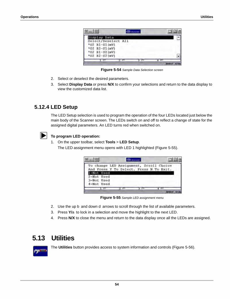
Operations Utilities
Figure 5-54 Sample Data Selection screen
2. Select or deselect the desired parameters.
3. Select Display Data or press N/X to confirm your selections and return to the data display to view the customized data list.
5.12.4 LED Setup
The LED Setup selection is used to program the operation of the four LEDs located just below the main body of the Scanner screen. The LEDs switch on and off to reflect a change of state for the assigned digital parameters. An LED turns red when switched on.
z To program LED operation:
1. On the upper toolbar, select Tools > LED Setup.
The LED assignment menu opens with LED 1 highlighted (Figure 5-55).
Figure 5-55 Sample LED assignment menu
2. Use the up b and down d arrows to scroll through the list of available parameters.
3. Press Y/a to lock in a selection and move the highlight to the next LED.
4. Press N/X to close the menu and return to the data display once all the LEDs are assigned.
5.13 UtilitiesThe Utilities button provides access to system information and controls (Figure 5-56).
54
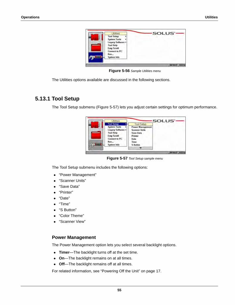
Operations Utilities
Figure 5-56 Sample Utilities menu
The Utilities options available are discussed in the following sections.
5.13.1 Tool Setup
The Tool Setup submenu (Figure 5-57) lets you adjust certain settings for optimum performance.
Figure 5-57 Tool Setup sample menu
The Tool Setup submenu includes the following options:
• “Power Management”
• “Scanner Units”
• “Save Data”
• “Printer”
• “Date”
• “Time”
• “S Button”
• “Color Theme”
• “Scanner View”
Power Management
The Power Management option lets you select several backlight options.
• Timer—The backlight turns off at the set time.
• On—The backlight remains on at all times.
• Off—The backlight remains off at all times.
For related information, see “Powering Off the Unit” on page 17.
55
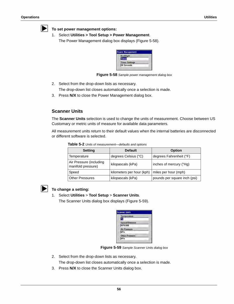
Operations Utilities
z To set power management options:
1. Select Utilities > Tool Setup > Power Management.
The Power Management dialog box displays (Figure 5-58).
Figure 5-58 Sample power management dialog box
2. Select from the drop-down lists as necessary.
The drop-down list closes automatically once a selection is made.
3. Press N/X to close the Power Management dialog box.
Scanner Units
The Scanner Units selection is used to change the units of measurement. Choose between US Customary or metric units of measure for available data parameters.
All measurement units return to their default values when the internal batteries are disconnected or different software is selected.
z To change a setting:
1. Select Utilities > Tool Setup > Scanner Units.
The Scanner Units dialog box displays (Figure 5-59).
Figure 5-59 Sample Scanner Units dialog box
2. Select from the drop-down lists as necessary.
The drop-down list closes automatically once a selection is made.
3. Press N/X to close the Scanner Units dialog box.
Table 5-2 Units of measurement—defaults and options
Setting Default Option
Temperature degrees Celsius (°C) degrees Fahrenheit (°F)
Air Pressure (including manifold pressure)
kilopascals (kPa) inches of mercury (“Hg)
Speed kilometers per hour (kph) miles per hour (mph)
Other Pressures kilopascals (kPa) pounds per square inch (psi)
56
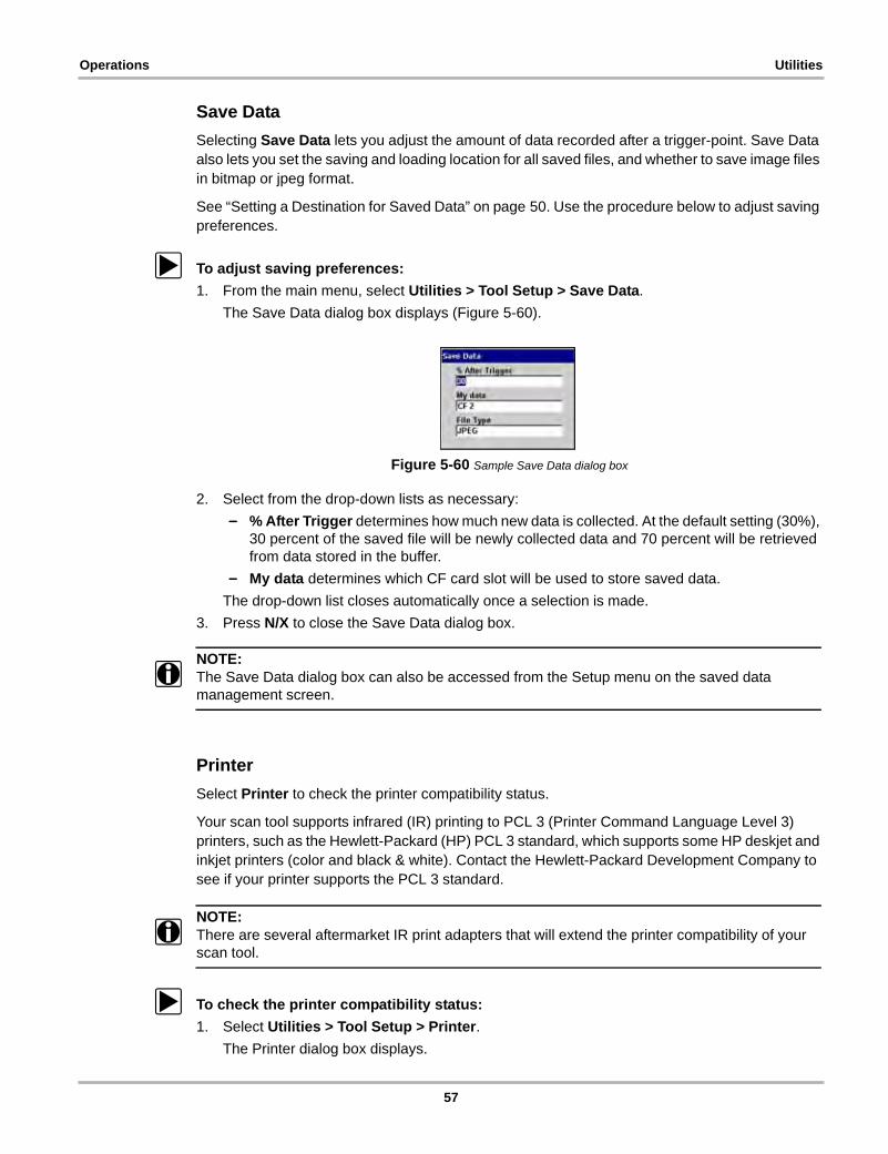
Operations Utilities
Save Data
Selecting Save Data lets you adjust the amount of data recorded after a trigger-point. Save Data also lets you set the saving and loading location for all saved files, and whether to save image files in bitmap or jpeg format.
See “Setting a Destination for Saved Data” on page 50. Use the procedure below to adjust saving preferences.
z To adjust saving preferences:
1. From the main menu, select Utilities > Tool Setup > Save Data.
The Save Data dialog box displays (Figure 5-60).
Figure 5-60 Sample Save Data dialog box
2. Select from the drop-down lists as necessary:
– % After Trigger determines how much new data is collected. At the default setting (30%), 30 percent of the saved file will be newly collected data and 70 percent will be retrieved from data stored in the buffer.
– My data determines which CF card slot will be used to store saved data.
The drop-down list closes automatically once a selection is made.
3. Press N/X to close the Save Data dialog box.
NOTE:i The Save Data dialog box can also be accessed from the Setup menu on the saved data
management screen.
Printer
Select Printer to check the printer compatibility status.
Your scan tool supports infrared (IR) printing to PCL 3 (Printer Command Language Level 3) printers, such as the Hewlett-Packard (HP) PCL 3 standard, which supports some HP deskjet and inkjet printers (color and black & white). Contact the Hewlett-Packard Development Company to see if your printer supports the PCL 3 standard.
NOTE:i There are several aftermarket IR print adapters that will extend the printer compatibility of your
scan tool.
z To check the printer compatibility status:
1. Select Utilities > Tool Setup > Printer.
The Printer dialog box displays.
57
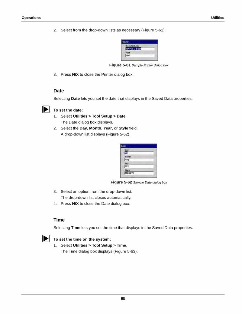
Operations Utilities
2. Select from the drop-down lists as necessary (Figure 5-61).
Figure 5-61 Sample Printer dialog box
3. Press N/X to close the Printer dialog box.
Date
Selecting Date lets you set the date that displays in the Saved Data properties.
z To set the date:
1. Select Utilities > Tool Setup > Date.
The Date dialog box displays.
2. Select the Day, Month, Year, or Style field.
A drop-down list displays (Figure 5-62).
Figure 5-62 Sample Date dialog box
3. Select an option from the drop-down list.
The drop-down list closes automatically.
4. Press N/X to close the Date dialog box.
Time
Selecting Time lets you set the time that displays in the Saved Data properties.
z To set the time on the system:
1. Select Utilities > Tool Setup > Time.
The Time dialog box displays (Figure 5-63).
58

Operations Utilities
Figure 5-63 Sample Time dialog box
2. Select the Hour, Minutes, or 12/24 field.
A drop-down list displays.
3. Select an option from the drop-down list.
The drop-down list closes automatically.
4. Press N/X to close the Time dialog box.
S Button
Selecting S Button allows you to change the functionality of the S button. Possible function assignments include:
• Save Image—is the default and takes a snapshot of the current screen. The snapshot is saved as either a bitmap or a jpeg image, which can be opened using standard Internet browsers or graphics applications. This feature works anywhere in scan tool operations.
• Freeze/Run—works as the Pause/Play button when viewing data in the Graphs or PID List views. See “Pausing Data” on page 41 for details.
• Save Frame—works as the Save Frame selection from the Save button in the upper toolbar when this option is available. See “Saving Captured Data” on page 44 for details.
• Print List—works like the Full PID List selection from the Print button in the upper toolbar. See “Printing” on page 51 for details.
• Print Page—works like the Full Screen selection from the Print button in the upper toolbar. See “Printing” on page 51 for details.
• S Button Popup—opens the menu when the button is pressed so you can quickly select from any of the available functions.
NOTE:i The S button can only perform print functions when the Print button is visible in the upper toolbar.
z To assign a function to the S button:
1. Select Utilities > Tool Setup > S Button.
The S Button dialog box displays.
2. Press Y/a to open the drop-down list (Figure 5-64).
Figure 5-64 Sample S Button dialog box
3. Select a function from the drop-down list.
59
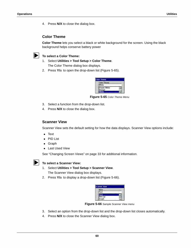
Operations Utilities
4. Press N/X to close the dialog box.
Color Theme
Color Theme lets you select a black or white background for the screen. Using the black background helps conserve battery power
z To select a Color Theme:
1. Select Utilities > Tool Setup > Color Theme.
The Color Theme dialog box displays.
2. Press Y/a to open the drop-down list (Figure 5-65).
Figure 5-65 Color Theme Menu
3. Select a function from the drop-down list.
4. Press N/X to close the dialog box.
Scanner View
Scanner View sets the default setting for how the data displays. Scanner View options include:
• Text
• PID List
• Graph
• Last Used View
See “Changing Screen Views” on page 33 for additional information.
z To select a Scanner View:
1. Select Utilities > Tool Setup > Scanner View.
The Scanner View dialog box displays.
2. Press Y/a to display a drop-down list (Figure 5-66).
Figure 5-66 Sample Scanner View menu
3. Select an option from the drop-down list and the drop-down list closes automatically.
4. Press N/X to close the Scanner View dialog box.
60
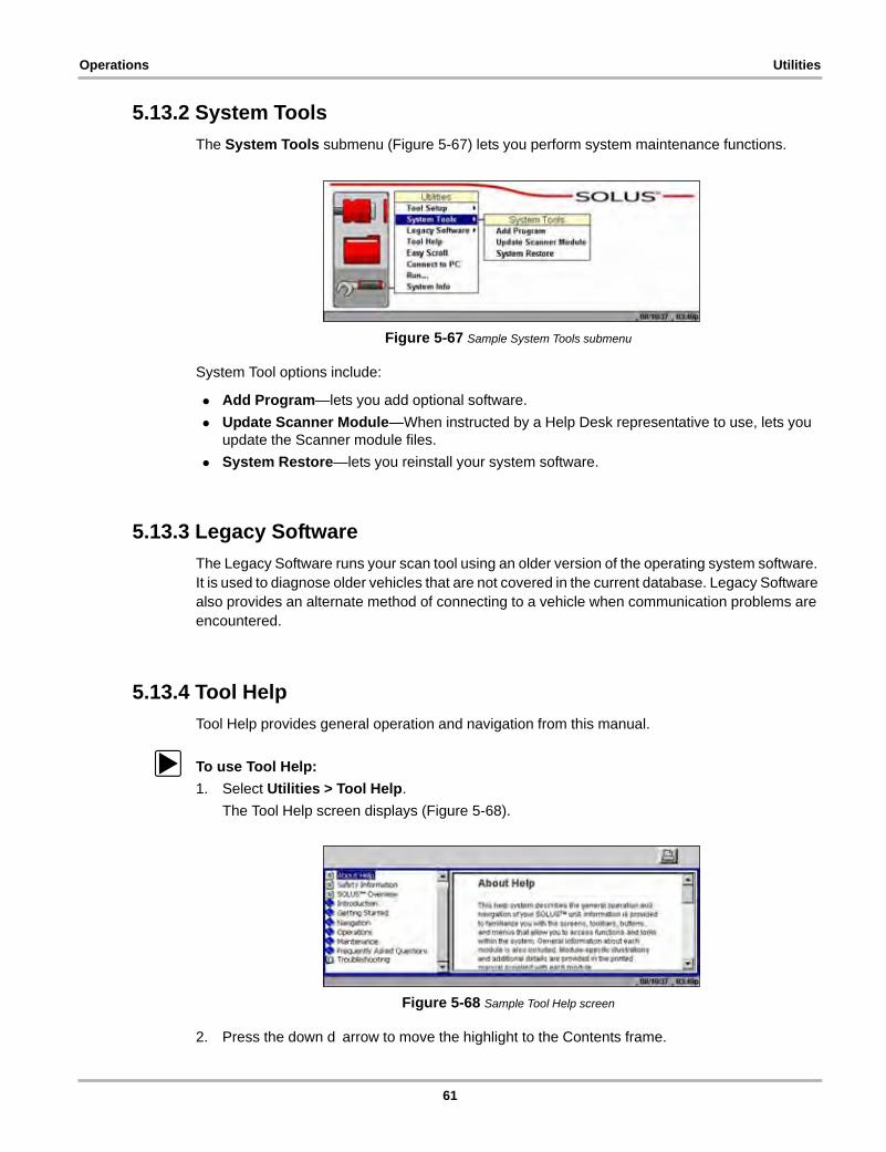
Operations Utilities
5.13.2 System Tools
The System Tools submenu (Figure 5-67) lets you perform system maintenance functions.
Figure 5-67 Sample System Tools submenu
System Tool options include:
• Add Program—lets you add optional software.
• Update Scanner Module—When instructed by a Help Desk representative to use, lets you update the Scanner module files.
• System Restore—lets you reinstall your system software.
5.13.3 Legacy Software
The Legacy Software runs your scan tool using an older version of the operating system software. It is used to diagnose older vehicles that are not covered in the current database. Legacy Software also provides an alternate method of connecting to a vehicle when communication problems are encountered.
5.13.4 Tool Help
Tool Help provides general operation and navigation from this manual.
z To use Tool Help:
1. Select Utilities > Tool Help.
The Tool Help screen displays (Figure 5-68).
Figure 5-68 Sample Tool Help screen
2. Press the down d arrow to move the highlight to the Contents frame.
61
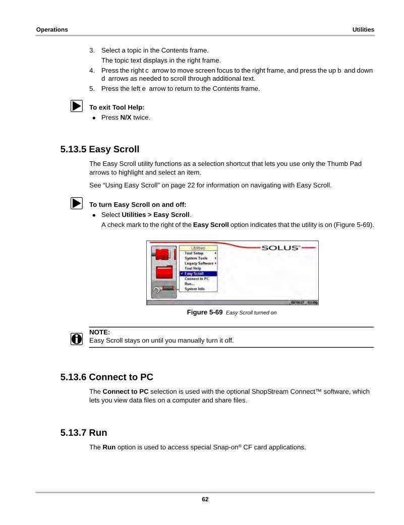
Operations Utilities
3. Select a topic in the Contents frame.
The topic text displays in the right frame.
4. Press the right c arrow to move screen focus to the right frame, and press the up b and down d arrows as needed to scroll through additional text.
5. Press the left e arrow to return to the Contents frame.
z To exit Tool Help:
• Press N/X twice.
5.13.5 Easy Scroll
The Easy Scroll utility functions as a selection shortcut that lets you use only the Thumb Pad arrows to highlight and select an item.
See “Using Easy Scroll” on page 22 for information on navigating with Easy Scroll.
z To turn Easy Scroll on and off:
• Select Utilities > Easy Scroll.
A check mark to the right of the Easy Scroll option indicates that the utility is on (Figure 5-69).
Figure 5-69 Easy Scroll turned on
NOTE:i Easy Scroll stays on until you manually turn it off.
5.13.6 Connect to PC
The Connect to PC selection is used with the optional ShopStream Connect™ software, which lets you view data files on a computer and share files.
5.13.7 Run
The Run option is used to access special Snap-on® CF card applications.
62
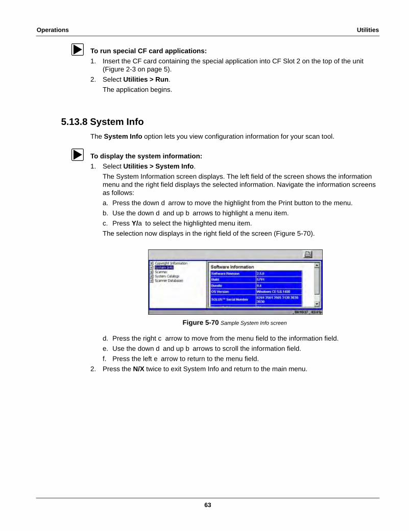
Operations Utilities
z To run special CF card applications:
1. Insert the CF card containing the special application into CF Slot 2 on the top of the unit (Figure 2-3 on page 5).
2. Select Utilities > Run.
The application begins.
5.13.8 System Info
The System Info option lets you view configuration information for your scan tool.
z To display the system information:
1. Select Utilities > System Info.
The System Information screen displays. The left field of the screen shows the information menu and the right field displays the selected information. Navigate the information screens as follows:
a. Press the down d arrow to move the highlight from the Print button to the menu.
b. Use the down d and up b arrows to highlight a menu item.
c. Press Y/a to select the highlighted menu item.
The selection now displays in the right field of the screen (Figure 5-70).
Figure 5-70 Sample System Info screen
d. Press the right c arrow to move from the menu field to the information field.
e. Use the down d and up b arrows to scroll the information field.
f. Press the left e arrow to return to the menu field.
2. Press the N/X twice to exit System Info and return to the main menu.
63

Chapter 6 Maintenance
This section covers the following maintenance issues:
• Cleaning and damage inspection
• Battery replacement
• Storage tips
• Disposal requirements (environmental hazards)
6.1 Cleaning and Damage InspectionWhen using the scan tool, make sure to do the following:
• Before and after each use, check the housing, wiring, and connectors for dirt and damage.
• At the end of each working day, clean the scan tool housing, wiring, and connectors with a clean damp cloth.
6.2 Replacing the BatteriesWhen the AA batteries no longer provide enough charge to power the scan tool, use the following procedure to replace them.
NOTE:i We recommend connecting an alternate power source to the scan tool while changing batteries to
retain the clock and custom settings. See “Power Supply” on page 10 for options.
z To replace the batteries:
1. Remove the right handgrip.
The battery slot is exposed (Figure 6-1).
Figure 6-1 Battery slot
2. Unscrew the battery cover with a flathead screwdriver and remove the cover.
64
Maintenance Storage Tips
3. Observing proper polarity (shown on the back of the scan tool), install six AA batteries.
IMPORTANT:Your scan tool will be damaged if the battery polarity is incorrect. Refer to the diagram on the rear cover of the scan tool for correct battery polarity.
4. Replace the cover and tighten the screw.
5. Replace the handgrip.
6.3 Storage TipsWhen storing your scan tool, remember the following:
• Always turn the scan tool off. See “Powering Off the Unit” on page 17 for details.
• Keep in mind the storage temperature range. See “Technical Specifications” on page 6 for additional information.
6.4 Disposing of the BatteriesAlways dispose of materials according to local regulations.
65
Appendix A Frequently Asked Questions
The following frequently asked questions provide solutions to common problems.
• “When I first turn on the scan tool, why does it beep but nothing appears on-screen?” on page 66
• “Can I use my other Snap-on® test adapters with this scan tool?” on page 66
• “Why do my batteries drain so quickly?” on page 66
• “What should I do if my printer is not responding?” on page 67
• “What should I do if the unit doesn’t respond as expected when I press the Power button?” on page 67
• “Why does my unit shut down unexpectedly?” on page 67
A.1 When I first turn on the scan tool, why does it beep but nothing appears on-screen?The master storage CF card that came with your scan tool must be installed in CF Slot 1 for the unit to operate.
A.2 Can I use my other Snap-on® test adapters with this scan tool?Yes.
A.3 Why do my batteries drain so quickly?The internal AA batteries are not intended as the scan tool’s primary power source. The internal batteries are intended to maintain the time, date, and custom settings, as well as to power the unit during the vehicle identification process.
During testing, the unit should receive power from a vehicle diagnostic connector or the AC/DC power supply.
For related information, see the following sections:
• “Battery Power” on page 10
• “Installing the Batteries” on page 15
• “Power Management” on page 55
66

Frequently Asked Questions What should I do if my printer is not responding?
A.4 What should I do if my printer is not responding?It may take a minute or two before the printer receives the print request.
If there is still no response after a few minutes, make sure the following conditions are met:
• The printer is receiving power and is turned on.
• The printer has paper.
• The infrared output on top of the scan tool is pointed at the infrared input on the printer.
• The scan tool is less than a few feet from the printer.
For related information, see the following sections:
• “IR Output” on page 10
• “Setting Up to Print” on page 17
• “Printing” on page 51
A.5 What should I do if the unit doesn’t respond as expected when I press the Power button?An emergency reset button on the back of the unit under the left hand grip will shut down and then restart the unit. See “Emergency Restart” on page 69 for details.
If the emergency reset button fails to correct the problem, remove all sources of power for at least two minutes, then reconnect the power sources and press the Power button.
A.6 Why does my unit shut down unexpectedly?Your internal batteries could be low. We recommend that you check all power sources.
See “Supplying Power” on page 13 for more information.
67
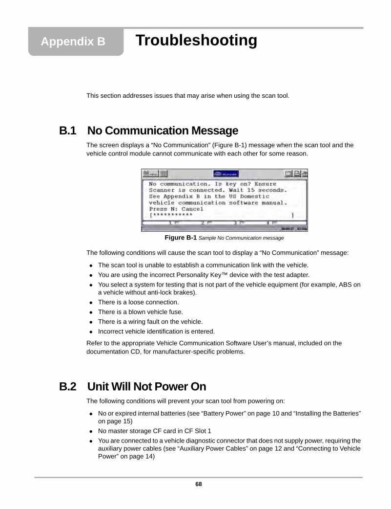
Appendix B Troubleshooting
This section addresses issues that may arise when using the scan tool.
B.1 No Communication MessageThe screen displays a “No Communication” (Figure B-1) message when the scan tool and the vehicle control module cannot communicate with each other for some reason.
Figure B-1 Sample No Communication message
The following conditions will cause the scan tool to display a “No Communication” message:
• The scan tool is unable to establish a communication link with the vehicle.
• You are using the incorrect Personality Key™ device with the test adapter.
• You select a system for testing that is not part of the vehicle equipment (for example, ABS on a vehicle without anti-lock brakes).
• There is a loose connection.
• There is a blown vehicle fuse.
• There is a wiring fault on the vehicle.
• Incorrect vehicle identification is entered.
Refer to the appropriate Vehicle Communication Software User’s manual, included on the documentation CD, for manufacturer-specific problems.
B.2 Unit Will Not Power OnThe following conditions will prevent your scan tool from powering on:
• No or expired internal batteries (see “Battery Power” on page 10 and “Installing the Batteries” on page 15)
• No master storage CF card in CF Slot 1
• You are connected to a vehicle diagnostic connector that does not supply power, requiring the auxiliary power cables (see “Auxiliary Power Cables” on page 12 and “Connecting to Vehicle Power” on page 14)
68

Troubleshooting Emergency Restart
B.3 Emergency RestartIf your scan tool freezes or will not power off, you can perform an emergency restart.
z To perform an emergency restart:
1. Remove the left handgrip.
2. Locate the emergency restart button on the back of the unit (Figure B-2).
Figure B-2 Emergency restart button location
3. Gently insert a toothpick or some other non-metallic item into the opening and depress the emergency restart button slot.
The unit restarts.
69

Appendix C Downloading and Installing Software Updates
Following are instructions for downloading software updates from the internet and installing the updates onto the SOLUS™ scan tool.
C.1 Check for Service Upgrades Before UseTo download and install software service upgrades you need a personal computer (PC) running ShopStream Connect™ software, which is a free downloadable program.
Improved versions of the operating system software for your handheld diagnostic tool periodically become available at no cost to you. These “service upgrades”, which are the result of an ongoing research and development program, are available through the internet. It is important to check for available upgrades before using your diagnostic tool for the first time, and on a regular basis after that, to ensure you have the latest version of the software.
Following are procedures for:
• Verifying your PC meets the minimum requirements for ShopStream Connect™ software
• Downloading and Installing ShopStream Connect™ software on your PC
• Downloading service upgrades to your SOLUS scan tool
C.2 Verifying Minimum PC Requirements
IMPORTANT:If your PC does not meet the minimum requirements, do not attempt to install the ShopStream Connect software.
Before installing the software, verify your PC meets the following requirements:
• System Properties:
– Operating system—Microsoft Windows 2000 Service Pack 4, Windows XP, or Vista. The system must be upgraded to Microsoft .NET Framework Version 2.
– Processor—Pentium 4 or later, or equivalent
– Memory—256 MB minimum, 512 MB recommended
• Hard Drive—50 MB free space
• CD-ROM, DVD, or DVD-ROM drive
• USB 2.0 or later
• Internet Explorer 6.0 or higher
• Internet connection
• Adobe Reader software (free download at www.adobe.com/products/reader)
A type A/B USB cable is also needed to connect the SOLUS scan tool to the PC.
70

Downloading and Installing Software Updates Verifying Minimum PC Requirements
C.2.1 Verifying PC System Properties
Follow the procedures below to check your PC system properties and to determine how much free space is available on your hard drive.
z To check your PC system properties:
1. On the Desktop, right-click My Computer to open the menu.
2. Select Properties from the menu.
The System Properties dialog box displays with your system information (Figure C-1).
1— System property information
2— Hard drive informationFigure C-1 Sample Windows XP System Properties dialog box
z To check PC hard drive free space:
1. On the Desktop, double-click My Computer.
2. Select View > Details (Figure C-2).
Figure C-2 Sample PC hard drive free space details
1
2
71

Downloading and Installing Software Updates Downloading and Installing ShopStream Connect
C.3 Downloading and Installing ShopStream ConnectFollow the procedure below to download the ShopStream Connect software.
z To download the software:
1. From your PC, go to http://diagnostics.snapon.com/scc using your Internet browser.
2. Locate the ShopStream Connect software download.
3. Follow the on-screen instructions.
After downloading, follow the procedures below to install the ShopStream Connect software onto your PC.
z To install the ShopStream Connect software:
1. Locate the ShopStream Connect software installer on the PC and double-click ShopStreamConnect.exe
NOTE:i C:\Program Files\ShopStream Connect is the default download location.
2. When the welcome screen displays (Figure C-3), select Next.
Figure C-3 Sample Welcome screen
The License Agreement screen displays (Figure C-4).
3. Highlight I accept the terms of the license agreement and select Next to continue.
Figure C-4 Sample License Agreement screen
72

Downloading and Installing Software Updates Downloading and Installing ShopStream Connect
The Choose Destination Location screen displays. It is highly recommended to allow the software to install in the default location.
4. Select Next to continue.
5. Select Install when the Ready to Install the Program screen displays to begin the installation.
The Setup Status screen tracks progress as the program installs (Figure C-5).
Figure C-5 Sample Setup Status screen
6. When the Complete screen displays, select Finish to close the Install Wizard (Figure C-6).
Figure C-6 Sample Complete screen
A ShopStream Connect shortcut icon is added to your desktop (Figure C-7), double-click the icon to launch the ShopStream Connect software.
Figure C-7 Sample ShopStream Connect Desktop icon
73
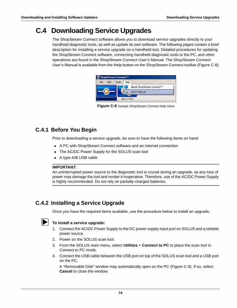
Downloading and Installing Software Updates Downloading Service Upgrades
C.4 Downloading Service UpgradesThe ShopStream Connect software allows you to download service upgrades directly to your handheld diagnostic tools, as well as update its own software. The following pages contain a brief description for installing a service upgrade on a handheld tool. Detailed procedures for updating the ShopStream Connect software, connecting handheld diagnostic tools to the PC, and other operations are found in the ShopStream Connect User’s Manual. The ShopStream Connect User’s Manual is available from the Help button on the ShopStream Connect toolbar (Figure C-8).
Figure C-8 Sample ShopStream Connect help menu
C.4.1 Before You Begin
Prior to downloading a service upgrade, be sure to have the following items on hand:
• A PC with ShopStream Connect software and an internet connection
• The AC/DC Power Supply for the SOLUS scan tool
• A type A/B USB cable
IMPORTANT:An uninterrupted power source to the diagnostic tool is crucial during an upgrade, as any loss of power may damage the tool and render it inoperative. Therefore, use of the AC/DC Power Supply is highly recommended. Do not rely on partially-charged batteries.
C.4.2 Installing a Service Upgrade
Once you have the required items available, use the procedure below to install an upgrade.
z To install a service upgrade:
1. Connect the AC/DC Power Supply to the DC power supply input port on SOLUS and a reliable power source.
2. Power on the SOLUS scan tool.
3. From the SOLUS main menu, select Utilities > Connect to PC to place the scan tool in Connect to PC mode.
4. Connect the USB cable between the USB port on top of the SOLUS scan tool and a USB port on the PC.
A “Removable Disk” window may automatically open on the PC (Figure C-9). If so, select Cancel to close the window.
74
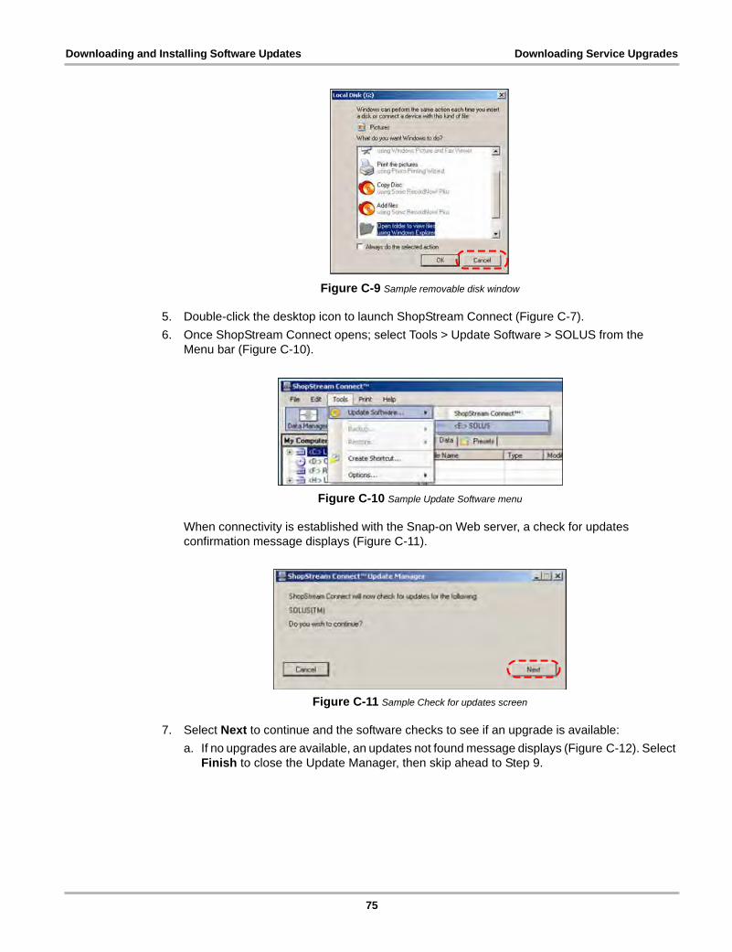
Downloading and Installing Software Updates Downloading Service Upgrades
Figure C-9 Sample removable disk window
5. Double-click the desktop icon to launch ShopStream Connect (Figure C-7).
6. Once ShopStream Connect opens; select Tools > Update Software > SOLUS from the Menu bar (Figure C-10).
Figure C-10 Sample Update Software menu
When connectivity is established with the Snap-on Web server, a check for updates confirmation message displays (Figure C-11).
Figure C-11 Sample Check for updates screen
7. Select Next to continue and the software checks to see if an upgrade is available:
a. If no upgrades are available, an updates not found message displays (Figure C-12). Select Finish to close the Update Manager, then skip ahead to Step 9.
75
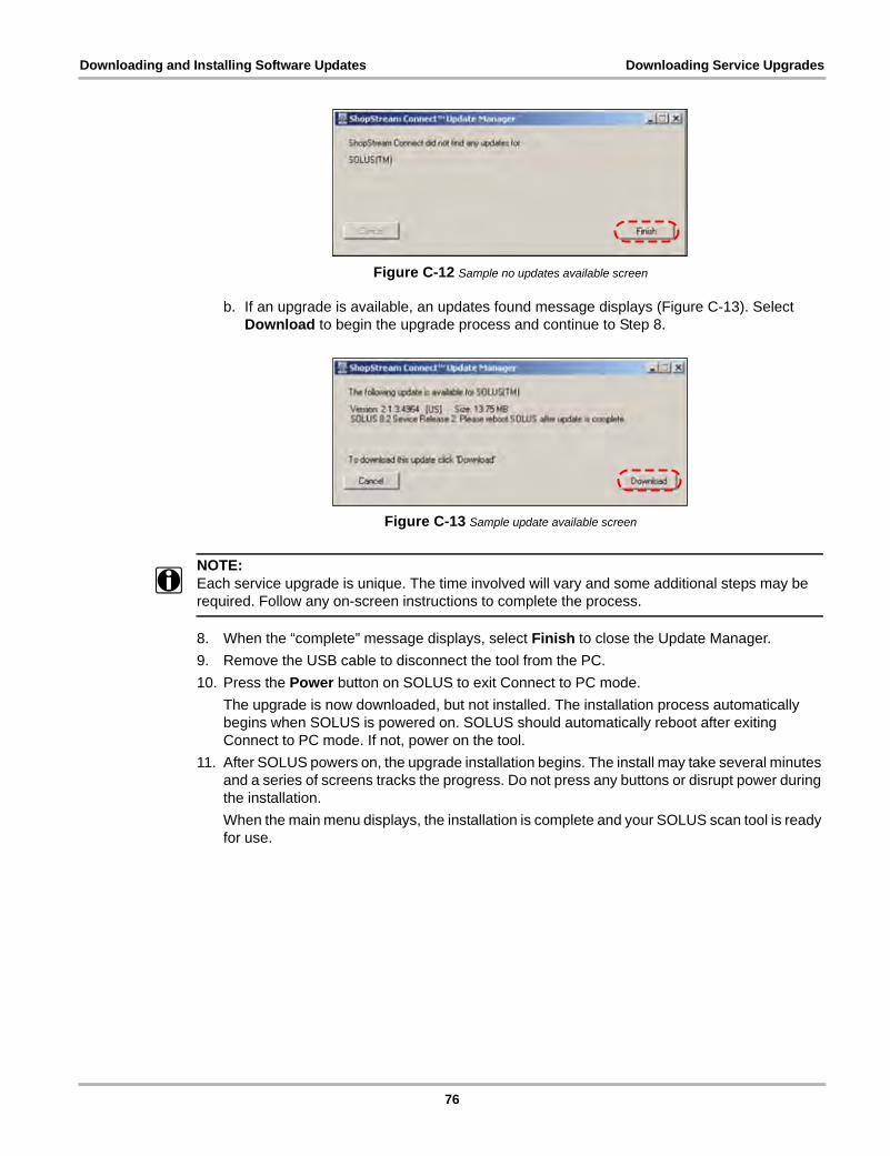
Downloading and Installing Software Updates Downloading Service Upgrades
Figure C-12 Sample no updates available screen
b. If an upgrade is available, an updates found message displays (Figure C-13). Select Download to begin the upgrade process and continue to Step 8.
Figure C-13 Sample update available screen
NOTE:i Each service upgrade is unique. The time involved will vary and some additional steps may be
required. Follow any on-screen instructions to complete the process.
8. When the “complete” message displays, select Finish to close the Update Manager.
9. Remove the USB cable to disconnect the tool from the PC.
10. Press the Power button on SOLUS to exit Connect to PC mode.
The upgrade is now downloaded, but not installed. The installation process automatically begins when SOLUS is powered on. SOLUS should automatically reboot after exiting Connect to PC mode. If not, power on the tool.
11. After SOLUS powers on, the upgrade installation begins. The install may take several minutes and a series of screens tracks the progress. Do not press any buttons or disrupt power during the installation.
When the main menu displays, the installation is complete and your SOLUS scan tool is ready for use.
76
Index
AAA batteries
installing 15replacing 64technical specifications 7time, date, and custom settings 10
AC power adapter 11adapters. See test adaptersAuto scale 37auxiliary power cables
battery power cable 12lighter power cable 12vehicle power 10, 14
Bbatteries. See AA batteriesbattery cover
removing 15, 64battery power cable. See auxiliary power cablesbrightness/contrast 5, 18
See also buttonsbuffer bar 19, 21buttons 5, 8
Ccables 11casing hook 6changing screen views 33–38
See also upper toolbarcleaning the unit 64clearing codes 29clearing data 42Codes Menu 28–30Color Theme 60CompactFlash® cards
slot locations 5slot technical specs 6
component tests 30confirmation messages 23Connect to PC 62connecting to a vehicle 24, 26connecting to vehicle power 14Custom Setup 52customizing a data list 53
Ddamage inspection 64
data cable 11See also power supply
data cable connector 5, 10data cable extension
accessory 12Data Display 28data parameters
customizing list 53displaying 28Graph views 36pausing 41PID List view 33reviewing 34Text view 35
data storage CF card 6Date 58DC power jack
AC adapter 9location 5
disposal requirements 64DTC status 29
EEasy Scroll 22, 62error messages 23exiting Scanner mode 32
FFreeze Frame/Failure Records 29frequently asked questions 66functional tests 30
GGeneric Functions 31getting started 13graphing data
Graph mode 36–50parameter menu 36
Hhandgrips 5
removing 15, 64, 69hanging position. See stand
Iidentifying a test vehicle 24, 25information tests 30
77

Index
infrared (IR) portlocation 5
inspecting unit for damage 64installing batteries 15internal batteries. See AA batteries
LLCD screen 5LED indicators 19Legacy Software 61lighter power cable. See auxiliary power cableslocking a parameter 34locking data parameters 36
Mmain body 22maintenance tips 64making selections 22manual conventions
description 1notes 2
Manual scale 37manuals, software 3manufacturer
selecting 25manufacturer selection (vehicle) 24
Nnavigating 19
Ooperating temperature range 7operations 24
connecting to a vehicle 24, 26identifying a test vehicle 24, 25selecting a system to test 24, 26selecting software 24selecting tests 24, 27
optional accessories 12
Pparameter menu 36
clear all trigger levels 36clear trigger levels 36lock 36scale 36set trigger levels 36
parametersclearing data 34locking 34
Pause/Play button. See upper toolbarpausing data 34, 41Personality Key™ 68
PID triggering 39Play button. See upper toolbarPower button. See buttonspower cables. See auxiliary power cablesPower Management 55power options 17power supply
connecting to 13–16connecting to vehicle power 14types 10–11
powering up the unit 17Printer 57printer setup 17printing 51
Rreplacing the batteries. See AA batteriesreset tests 30restarting 69review PID 34Run 62
SS Button 59S button 9
location 5See also Utilities
Safety iii–ivsafety
information iiimessage conventions iii
safety messages iii–ivSave Data 57Saved Data
capturing 44copying and moving 49deleting files 49identifying files 47loading 48reviewing 48viewing 46
saved data 46–50saving data 44–46saving preferences, adjusting 57Scale all 38scanner button 21Scanner mode
exiting 32power options unavailable 17
Scanner Units 56Scanner units 52–53Scanner View 60screen layout 19screen messages 23
78
Index
selecting a system to test 24, 26selecting tests 24selecting the manufacturer 25set trigger levels 38–39ShopStream Connect 17shutting down the unit 9, 17software
exiting 31selecting 24Troubleshooter 4Vehicle Communication 4
software manuals 3sorting data 42stand 6, 7–8storage temperature range 7storage tips 65subsystem tests 30supplying power. See power supplysystem CF card 6System Info 63system information
displaying 63System Main Menu 27system tests 30System Tools 61
Ttechnical specifications 6temperature range specifications 7terminating vehicle communication 31test adapters 11, 14, 68tests
component 30functional 30selecting 24, 27subsystem 30system 30
Thumb Pad 5, 8See also buttons
Time 58toggle tests 30Tool Help 3, 61Tool Setup 55toolbar. See upper toolbarTools Button 51trigger
clearing levels 40condition 39delay 39disarming 40
Trouble Codes 29Troubleshooter 30troubleshooting tips 68turning off the unit 17
Uunit operations. See operationsunlock all 36unlock all PIDs 37unlock PIDS 37unlocking a parameter 35upper toolbar
buttons and functions 20navigating 22Pause/Play button 34test controls 19Tools button 51
USB portconnecting to PC 9location 5
using cursors 42–43using zoom 43Utilities menu 54–63
Color Theme 60Connect to PC 62Date 58Easy Scroll 62Legacy Software 61Power Management 55Printer 57Run... 62S Button 59Save Data 57Scanner Units 56Scanner View 60System Info 63System Tools 61Time 58Tool Help 61Tool Setup 55
Vvariable control tests 30Vehicle Communication menu 25vehicle diagnostic connectors 11, 12, 14, 26vehicle identification. See identifying a test vehiclevehicle power. See power supply
Wwarning messages 23
YY button. See buttons
79

Index
80