DOCSIS 1.1 for the Cisco CMTS Routers
40
DOCSIS 1.1 for the Cisco CMTS Routers This document describes how to configure the Cisco CMTS router for Data-over-Cable Service Interface Specifications (DOCSIS) 1.1 operations. Finding Feature Information Your software release may not support all the features that are documented in this module. For the latest feature information and caveats, see the release notes for your platform and software release. The Feature Information Table at the end of this document provides information about the documented features and lists the releases in which each feature is supported. Use Cisco Feature Navigator to find information about the platform support and Cisco software image support. To access Cisco Feature Navigator, go to the link http://tools.cisco.com/ITDIT/CFN/. An account at the http://www.cisco.com/ site is not required. Contents • Hardware Compatibility Matrix for the Cisco cBR Series Routers, on page 1 • Prerequisites for DOCSIS 1.1 Operations, on page 2 • Restrictions for DOCSIS 1.1 Operations, on page 3 • Information about DOCSIS 1.1, on page 5 • How to Configure the Cisco CMTS for DOCSIS 1.1 Operations, on page 18 • Monitoring DOCSIS Operations, on page 30 • Configuration Examples for DOCSIS 1.1 Operations, on page 36 • Additional References, on page 40 • Feature Information for DOCSIS 1.1 for Cisco CMTS Routers, on page 40 Hardware Compatibility Matrix for the Cisco cBR Series Routers The hardware components that are introduced in a given Cisco IOS-XE Release are supported in all subsequent releases unless otherwise specified. Note DOCSIS 1.1 for the Cisco CMTS Routers 1
-
Upload
khangminh22 -
Category
Documents
-
view
0 -
download
0
Transcript of DOCSIS 1.1 for the Cisco CMTS Routers

DOCSIS 1.1 for the Cisco CMTS Routers
This document describes how to configure the Cisco CMTS router for Data-over-Cable Service InterfaceSpecifications (DOCSIS) 1.1 operations.
Finding Feature Information
Your software release may not support all the features that are documented in this module. For the latestfeature information and caveats, see the release notes for your platform and software release. The FeatureInformation Table at the end of this document provides information about the documented features and liststhe releases in which each feature is supported.
Use Cisco Feature Navigator to find information about the platform support and Cisco software image support.To access Cisco Feature Navigator, go to the link http://tools.cisco.com/ITDIT/CFN/. An account at thehttp://www.cisco.com/ site is not required.
Contents
• Hardware Compatibility Matrix for the Cisco cBR Series Routers, on page 1• Prerequisites for DOCSIS 1.1 Operations, on page 2• Restrictions for DOCSIS 1.1 Operations, on page 3• Information about DOCSIS 1.1, on page 5• How to Configure the Cisco CMTS for DOCSIS 1.1 Operations, on page 18• Monitoring DOCSIS Operations, on page 30• Configuration Examples for DOCSIS 1.1 Operations, on page 36• Additional References, on page 40• Feature Information for DOCSIS 1.1 for Cisco CMTS Routers, on page 40
HardwareCompatibilityMatrixfor theCiscocBRSeriesRouters
The hardware components that are introduced in a given Cisco IOS-XERelease are supported in all subsequentreleases unless otherwise specified.
Note
DOCSIS 1.1 for the Cisco CMTS Routers1

Table 1: Hardware Compatibility Matrix for the Cisco cBR Series Routers
Interface CardsProcessor EngineCisco CMTS Platform
Cisco IOS-XE Release 16.5.1 andLater Releases
Cisco cBR-8 CCAP Line Cards:
• PID—CBR-LC-8D30-16U30
• PID—CBR-LC-8D31-16U30
• PID—CBR-RF-PIC
• PID—CBR-RF-PROT-PIC
• PID—CBR-CCAP-LC-40G
• PID—CBR-CCAP-LC-40G-R
• PID—CBR-SUP-8X10G-PIC
• PID—CBR-2X100G-PIC
Digital PICs:
• PID—CBR-DPIC-8X10G
• PID—CBR-DPIC-2X100G
Cisco cBR-8 Downstream PHYModule:
• PID—CBR-D31-DS-MOD
Cisco cBR-8 Upstream PHYModules:
• PID—CBR-D31-US-MOD
Cisco IOS-XE Release 16.5.1 andLater Releases
Cisco cBR-8 Supervisor:
• PID—CBR-SUP-250G
• PID—CBR-CCAP-SUP-160G
• PID—CBR-CCAP-SUP-60G
Cisco cBR-8ConvergedBroadbandRouter
Prerequisites for DOCSIS 1.1 OperationsTo support DOCSIS 1.1 operations, the cable modem must also support the DOCSIS 1.1 feature set. Inaddition, before you power on and configure the Cisco CMTS, check the following points:
• Ensure that your network supports reliable broadband data transmission. Your plant must be swept,balanced, and certified, based on NTSC or appropriate international cable plant recommendations. Ensurethat your plant meets all DOCSIS downstream and upstream RF requirements.
• Ensure that your Cisco CMTS is installed according to the instructions provided in the appropriateHardware Installation Guide. The chassis must contain at least one port adapter to provide backboneconnectivity and one Cisco cable line card to serve as the RF cable TV interface.
• Ensure that all other required headend or distribution hub routing and network interface equipment isinstalled, configured, and operational, based on the services to support. This includes all routers, servers(DHCP, TFTP, and ToD), network management systems, and other configuration or billing systems.
DOCSIS 1.1 for the Cisco CMTS Routers2
DOCSIS 1.1 for the Cisco CMTS RoutersPrerequisites for DOCSIS 1.1 Operations

This includes IP telephony equipment including gatekeepers and gateways; backbone and other equipmentif supporting virtual private networks (VPNs); and dialup access servers, telephone circuits and connectionsand other equipment if supporting telco return.
• Ensure that DHCP and DOCSIS configuration files have been created and pushed to appropriate serverssuch that each cable modem, when initialized, can transmit a DHCP request, receive an IP address, obtainTFTP and ToD server addresses, and download DOCSIS configuration files. Optionally, ensure that yourservers can also download updated software images to DOCSIS 1.0 and DOCSIS 1.1 cable modems.
• Ensure that customer premises equipment (CPE)—cable modems or set-top boxes, PCs, telephones, orfacsimile machines—meet the requirements for your network and service offerings.
• Familiarize yourself with your channel plan to ensure assigning of appropriate frequencies. Outline yourstrategies for setting up bundling or VPN solution sets, if applicable, to your headend or distribution hub.Know your dial plan if using H.323 for VoIP services and setting up VoIP-enabled cable modemconfiguration files. Obtain passwords, IP addresses, subnet masks, and device names, as appropriate.
• Ensure that the system clocks on the Cisco CMTS and on the time-of-day (ToD) servers are synchronized.If this does not occur, the clocks on the CMs will not match the clocks on the Cisco CMTS, which couldinterfere with BPI+ operations. In particular, this could prevent the proper verification of the digitalcertificates on the cable modem (CM).
After these prerequisites are met, you are ready to configure the Cisco CMTS. This includes, at a minimum,configuring a host name and password for the Cisco CMTS and configuring the Cisco CMTS to support IPover the cable plant and network backbone.
If you plan to use service-class-based provisioning, the service classes must be configured at the Cisco CMTSbefore cable modems attempt to make a connection. Use the cable service class command to configure serviceclasses.
Caution
Restrictions for DOCSIS 1.1 OperationsDOCSIS 1.1 operations includes the following restrictions:
Baseline Privacy Interface Plus Requirements
BPI+ encryption and authentication must be supported and enabled by both the cable modem and CMTS. Inaddition, the cable modem must contain a digital certificate that conforms to the DOCSIS 1.1 and BPI+specifications.
Also, ensure that the system clocks on the CMTS and on the time-of-day (ToD) servers are synchronized. Ifthis does not occur, the clocks on the CMs will not match the clocks on the CMTS, which could interfere withBPI+ operations. In particular, this could prevent the proper verification of the digital certificates on the CM.
Ensure that the system clocks on the CMTS and on the time-of-day (ToD) servers are synchronized. If thisdoes not occur, the clocks on the CMs will not match the clocks on the CMTS, which could interfere withBPI+ operations. In particular, this could prevent the proper verification of the digital certificates on the CM.
Note
DOCSIS 1.1 for the Cisco CMTS Routers3
DOCSIS 1.1 for the Cisco CMTS RoutersRestrictions for DOCSIS 1.1 Operations

BPI+-Encrypted Multicast Not Supported with Bundled Subinterfaces on the Cisco cBR-8 Router
The current Cisco IOS-XE releases do not support using BPI+ encrypted multicast on bundled cablesubinterfaces on the Cisco cBR-8 router. Encrypted multicast is supported on bundled cable interfaces or onnon-bundled cable subinterfaces, but not when a subinterface is bundled on the Cisco cBR-8 router.
BPI+ Not Supported with High Availability Configurations
The current Cisco IOS-XE releases do not support using BPI+ encrypted multicast on a cable interface whenthe interface has also been configured for N+1 (1:n) High Availability or Remote Processor Redundancy Plus(RPR+) High Availability redundancy.
In addition, BPI+ is not automatically supported after a switchover from the Working cable interface to theProtect cable interface, because the cable interface configurations that are required for BPI+ encryption arenot automatically synchronized between the two interfaces. A workaround for this is to manually configurethe Protect cable interfaces with the required configurations.
DOCSIS Root Certificates
The Cisco CMTS supports only one DOCSIS Root CA certificate.
Maximum Burst Size
Previously, the maximum concatenated burst size parameter could be set to zero to specify an unlimited value.In a DOCSIS 1.1 environment, this parameter should be set to a nonzero value, with a maximum value of1522 bytes for DOCSIS 1.0 cable modems.
If a cable modem attempts to register with a maximum concatenation burst size of zero, the DOCSIS 1.1CMTS refuses to allow the cable modem to come online. This avoids the possibility that a DOCSIS 1.0 cablemodem could interfere with voice traffic on the upstream by sending extremely large data packets. SinceDOCSIS 1.0 does not support fragmentation, transmitting such data packets could result in unwanted jitterin the voice traffic.
In addition, DOCSIS 1.1 requires that the maximum transmit burst size be set to either 1522 bytes or themaximum concatenated burst size, whichever is larger. Do not set the maximum concatenation burst size tovalues larger than 1522 bytes for DOCSIS 1.0 cable modems.
This change requires you to change any DOCSIS configuration files that specify a zero value for the maximumconcatenation burst size. This limitation does not exist for DOCSIS 1.1 cable modems unless fragmentationhas been disabled.
Note
Performance
DOCSIS 1.0 cablemodems lack the ability to explicitly request and provide scheduling parameters for advancedDOCSIS 1.1 scheduling mechanisms, such as unsolicited grants and real-time polling. DOCSIS 1.1 cablemodems on the same upstream channel can benefit from the advanced scheduling mechanisms and a DOCSIS1.1 CMTS can still adequately support voice traffic from DOCSIS 1.1 cable modems with DOCSIS 1.0 cablemodems on the same upstream channel.
DOCSIS 1.1 for the Cisco CMTS Routers4
DOCSIS 1.1 for the Cisco CMTS RoutersRestrictions for DOCSIS 1.1 Operations

Provisioning
The format and content of the TFTP configuration file for a DOCSIS 1.1 cable modem are significantlydifferent from the file for a DOCSIS 1.0 cable modem. A dual-mode configuration file editor is used togenerate a DOCSIS 1.0 style configuration file for DOCSIS 1.0 cable modems and a DOCSIS 1.1 configurationfile for DOCSIS 1.1 cable modems.
Registration
A DOCSIS 1.1 CMTS must handle the existing registration Type/Length/Value parameters from DOCSIS1.0 cable modems as well as the new type TLVs fromDOCSIS 1.1 cable modems. ADOCSIS 1.0 and DOCSIS1.1 cable modem can successfully register with the same DOCSIS 1.1 CMTS.
A DOCSIS 1.1 cable modem can be configured to make an indirect reference to a service class that has beenstatically defined at the CMTS instead of explicitly asking for the service class parameters. When thisregistration request is received by a DOCSIS 1.1 CMTS, it encodes the actual parameters of the service classin the registration response and expects a DOCSIS 1.1-specific registration-acknowledgeMACmessage fromthe cable modem.
When a DOCSIS 1.0 cable modem registers with a DOCSIS 1.1 CMTS, the registration request explicitlyrequests all nondefault service-class parameters in the registration. The absence of an indirect service classreference eliminates the need for the DOCSIS 1.1 TLVs and eliminates the need to establish a local registrationacknowledge wait state.
When a DOCSIS 1.1 CMTS receives a registration request from a DOCSIS 1.0 cable modem, it respondswith the DOCSIS 1.0 style registration response and does not expect the cable modem to send theregistration-acknowledge MAC message.
Information about DOCSIS 1.1DOCSIS 1.1 is the first major revision of the initial DOCSIS 1.0 standard for cable networks. Although theinitial standard provided quality data traffic over the coaxial cable network, the demands of real-time trafficsuch as voice and video required many changes to the DOCSIS specification.
The DOCSIS 1.1 specification provides the following feature enhancements over DOCSIS 1.0 networks:
Baseline Privacy Interface PlusDOCSIS 1.0 introduced a Baseline Privacy Interface (BPI) to protect user data privacy across the shared-mediumcable network and to prevent unauthorized access to DOCSIS-based data transport services across the cablenetwork. BPI encrypts traffic across the RF interface between the cable modem and CMTS, and also includesauthentication, authorization, and accounting (AAA) features.
BPI supports access control lists (ACLs), tunnels, filtering, protection against spoofing, and commands toconfigure source IP filtering on RF subnets to prevent subscribers from using source IP addresses that are notvalid. DOCSIS 1.1 enhances these security features with BPI Plus (BPI+), which includes the followingenhancements:
• X.509 Digital certificates provide secure user identification and authentication. The Cisco CMTS supportsboth self-signed manufacturer’s certificates and certificates that are chained to the DOCSIS Root CAcertificate.
• Key encryption uses 168-bit Triple DES (3DES) encryption that is suitable for the most sensitiveapplications.
DOCSIS 1.1 for the Cisco CMTS Routers5
DOCSIS 1.1 for the Cisco CMTS RoutersInformation about DOCSIS 1.1
• 1024-bit public key with Pkcs#1 Version 2.0 encryption.• Support for encrypted multicast broadcasts, so that only authorized service flows receive a particularmulticast broadcast.
• Secure software download allows a service provider to upgrade a cable modem’s software remotely,without the risk of interception, interference, or alteration.
ConcatenationConcatenation allows a cable modem to make a single time-slice request for multiple upstream packets,sending all of the packets in a single large burst on the upstream. Concatenation can send multiple upstreampackets as part of one larger MAC data frame, allowing the cable modem to make only one time-slot requestfor the entire concatenatedMAC frame, reducing the delay in transmitting the packets on the upstream channel.This avoids wasting upstream bandwidth when sending a number of very small packets, such as TCPacknowledgement packets.
Dynamic MAC MessagesDynamic Service MAC messages allow the cable modem to dynamically create service flows on demand.These messages are DOCSIS link layer equivalents of the higher layer messages that create, tear down, andmodify a service flow.
The DOCSIS 1.1 dynamic services state machine supports the following messages:
• Dynamic Service Add (DSA)—This message is used to create a new service flow.• Dynamic Service Change (DSC)—This message is used to change the attributes of an existing serviceflow.
• Dynamic Service Deletion (DSD)—This message is used to delete an existing service flow.
These messages are collectively known as DSX messages.Note
Enhanced Quality of ServiceDOCSIS 1.1 provides enhanced quality of service (QoS) capabilities to give priority for real-time traffic suchas voice and video:
• The DOCSIS 1.0 QoS model (a service ID (SID) associated with a QoS profile) has been replaced witha service flow and service class model that allows greater flexibility in assigning QoS parameters todifferent types of traffic and in responding to changing bandwidth conditions.
• Support for multiple service flows per cable modem allows a single cable modem to support a combinationof data, voice, and video traffic.
• Greater granularity in QoS per cable modem in either direction, using unidirectional service flows.• Upstream service flows can be assigned one of the following QoS scheduling types, depending on thetype of traffic and application being used:
• Best-effort—Data traffic sent on a non-guaranteed best-effort basis. This type of service flow issimilar to the method used in DOCSIS 1.0 networks.
• Real-time polling (rtPS)—Real-time service flows, such as video, that produce unicast, variablesize packets at fixed intervals.
DOCSIS 1.1 for the Cisco CMTS Routers6
DOCSIS 1.1 for the Cisco CMTS RoutersConcatenation

• Non-real-time polling service (nrtPS)—Similar to the rtPS type, in that the cablemodem is guaranteedregular opportunities to request data bursts of varying length, except that the CMTS can vary thetime between its polling of the cable modem depending on the amount of traffic and congestion onthe network.
• Unsolicited grants (UGS)—Constant bit rate (CBR) or committed information rate (CIR) traffic,such as voice, that is characterized by fixed-size packets at fixed intervals, providing a guaranteedminimum data rate.
• Unsolicited grants with activity detection (USG-AD)—Combination of UGS and rtPS, toaccommodate real-time traffic that might have periods of inactivity (such as voice using silencesuppression). The service flow uses UGS fixed grants while active, but switches to rtPS pollingduring periods of inactivity to avoid wasting unused bandwidth.
FragmentationDOCSIS fragmentation allows the upstreamMAC scheduler to slice large data requests to fit into the schedulinggaps between UGS (voice slots). This prevents large data packets from affecting real-time traffic, such asvoice and video.
Fragmentation reduces the run-time jitter experienced by the UGS slots when large data grants preempt theUGS slots. Disabling fragmentation increases the run-time jitter, but also reduces the fragmentation reassemblyoverhead for fragmented MAC frames.
DOCSIS fragmentation should not be confused with the fragmentation of IP packets, which is done to fit thepackets on network segments with smaller maximum transmission unit (MTU) size. DOCSIS Fragmentationis Layer 2 fragmentation that is primarily concerned with efficiently transmitting lower-priority packets withoutinterfering with high-priority real-time traffic, such as voice calls. IP fragmentation is done at Layer 3 and isprimarily intended to accommodate routers that use different maximum packet sizes.
Note
InteroperabilityDOCSIS 1.1 cable modems can coexist with DOCSIS 1.0 and 1.0+ cable modems in the same network. TheCisco CMTS provides the levels of service that are appropriate for each cable modem.
Payload Header SuppressionPayload header suppression (PHS) conserves link-layer bandwidth by suppressing repetitive or redundantpacket headers on both upstream and downstream service flows. PHS is enabled or disabled per service flow,and each service flow can support a separate set of PHS rules that determine which parts of the header aresuppressed. This ensures that PHS is done in the most efficient manner for each service flow and its particulartype of application.
Downstream ToS OverwriteDownstream ToS Overwrite is supported in DOCSIS 1.1. It can be used in IPv4 and IPv6 environment. Youcan use CLI command cable service class class-index tos-overwrite and-mask or-mask or the cable modemconfiguration file to configure downstream ToS overwrite.
DOCSIS 1.1 for the Cisco CMTS Routers7
DOCSIS 1.1 for the Cisco CMTS RoutersFragmentation

To display the ToS value, use the show cable modem qos verbose command as shown in the followingexample:Router# show cable modem 30.140.0.41 qos verboseLoad for five secs: 5%/0%; one minute: 4%; five minutes: 4%Time source is NTP, 15:22:46.911 CST Wed Apr 25 2018
Sfid: 29Current State: ActiveSid: 8Service Class Name:Traffic Priority: 0Maximum Sustained rate: 0 bits/secMaximum Burst: 3044 bytesMinimum Reserved rate: 0 bits/secMinimum Packet Size: 0 bytesAdmitted QoS Timeout: 200 secondsActive QoS Timeout: 0 secondsMaximum Concatenated Burst: 1522 bytesScheduling Type: Best EffortRequest/Transmission policy: 0x0IP ToS Overwrite[AND-mask, OR-mask]: 0xFF, 0x0Peak Rate: 0 bits/secCurrent Throughput: 545 bits/sec, 0 packets/sec
Sfid: 30Current State: ActiveSid: N/ALow Latency App: NoService Class Name:Traffic Priority: 0Maximum Sustained rate: 0 bits/secMaximum Burst: 3044 bytesMinimum Reserved rate: 0 bits/secMinimum Packet Size: 0 bytesAdmitted QoS Timeout: 200 secondsActive QoS Timeout: 0 secondsMaximum Latency: 0 usecsIP ToS Overwrite[AND-mask, OR-mask]: 0xFF, 0x0Peak Rate: 0 bits/secCurrent Throughput: 446 bits/sec, 0 packets/sec
DOCSIS 1.1 Quality of ServiceThe DOCSIS 1.1 QoS framework is based on the following objects:
• Service flow—A unidirectional sequence of packets on the DOCSIS link. Separate service flows areused for upstream and downstream traffic, and define the QoS parameters for that traffic.
• Service class—A collection of settings maintained by the CMTS that provide a specific QoS service tierto a cable modem that has been assigned a service flow associated with that service class.
• Packet classifier—A set of packet header fields used to classify packets onto a service flow to which theclassifier belongs. The CMTS uses the packet classifiers to match the packet to the appropriate serviceflow.
• Payload header suppression (PHS) rule—A set of packet header fields that are suppressed by the sendingentity before transmitting on the link, and are restored by the receiving entity after receiving aheader-suppressed frame transmission. PHS increases the bandwidth efficiency by removing repeatedpacket headers before transmission.
See the following sections for more information on these components.
DOCSIS 1.1 for the Cisco CMTS Routers8
DOCSIS 1.1 for the Cisco CMTS RoutersDOCSIS 1.1 Quality of Service
Service FlowIn DOCSIS 1.1, the basic unit of QoS is the service flow, which is a unidirectional sequence of packetstransported across the RF interface between the cable modem and CMTS. A service flow defines a set of QoSparameters such as latency, jitter, and throughput assurances, and these parameters can be applied independentlyto the upstream and downstream traffic flows. This is a major difference from DOCSIS 1.0 networks, wherethe same QoS parameters were applied to both the downstream and upstream flows.
DOCSIS 1.0 networks used service IDs (SIDs) to identify the QoS parameter set for a particular flow. DOCSIS1.1 networks use the service flow ID (SFID) to identify the service flows that have been assigned to a particularupstream or downstream. DOCSIS 1.1 networks still use the term SID, but it applies exclusively to upstreamservice flows.
Note
Every cable modem establishes primary service flows for the upstream and downstream directions, with aseparate SFID for the upstream and the downstream flows. The primary flows maintain connectivity betweenthe cable modem and CMTS, allowing the CMTS to send MAC management messages at all times to thecable modem.
In addition, a DOCSIS 1.1 cable modem can establish multiple secondary service flows. The secondary serviceflows either can be permanently created (by configuring them in the DOCSIS configuration file that isdownloaded to the cable modem), or the service flows can be created dynamically to meet the needs of theon-demand traffic, such as voice calls. Permanent service flows remain in effect, even if they are not beingused, while dynamic service flows are deleted when they are no longer needed.
At any given time, a service flowmight be in one of three states (provisioned, admitted, or active). Only activeflows are allowed to pass traffic on the DOCSIS network. Every service flow is identified by an SFID, whileupstream service flows in the admitted and active state have an extra Layer 2 SID associated with them. TheSID is the identifier used by the MAC scheduler when specifying time-slot scheduling for different serviceflows.
Service ClassEach service flow is associated with a service class, which defines a particular class of service and its QoScharacteristics, such as the maximum bandwidth for the service flow and the priority of its traffic. The serviceclass attributes can be inherited from a preconfigured CMTS local service class (class-based flows), or theycan be individually specified when a cable modem dynamically requests a service flow and the CMTS createsit.
The DOCSIS 1.1 service class also defines the MAC-layer scheduling type for the service flow. The scheduletype defines the type of data burst requests that the cable modem can make, and how often it can make thoserequests. The following types of schedule types are supported:
• Best-effort (BE)—A cable modem competes with the other cable modems in making bandwidth requestsand must wait for the CMTS to grant those requests before transmitting data. This type of service flowis similar to the method used in DOCSIS 1.0 networks.
• Real-time polling service (rtPS)—A cable modem is given a periodic time slot in which it can makebandwidth requests without competing with other cable modems. This allows real-time transmissionswith data bursts of varying length.
• Non-real-time polling service (nrtPS)—A cable modem is given regular opportunities to make bandwidthrequests for data bursts of varying size. This type of flow is similar to the rtPS type, in that the cablemodem is guaranteed regular opportunities to request data bursts of varying length, except that the CMTS
DOCSIS 1.1 for the Cisco CMTS Routers9
DOCSIS 1.1 for the Cisco CMTS RoutersService Flow

can vary the time between its polling of the cable modem, depending on the amount of traffic andcongestion on the network.
• Unsolicited grant service (UGS)—A cable modem can transmit fixed data bursts at a guaranteedminimumdata rate and with a guaranteed maximum level of jitter. This type of service flow is suitable for trafficthat requires a Committed Information Rate (CIR), such as Voice-over-IP (VoIP) calls.
• Unsolicited grant service with activity detection (UGS-AD)—Similar to the UGS type, except that theCMTS monitors the traffic to detect when the cable modem is not using the service flow (such as voicecalls when nobody is speaking). When the CMTS detects silence on the service flow, the CMTStemporarily switches the service flow to an rtPS type. When the cable modem begins using the flowagain, the CMTS switches the flow back to the UGS type. This allows the CMTS to more efficientlysupport VoIP calls.
Each service flow is assigned a single service class, but the same service class can be assigned to multipleservice flows. Also, a cable modem can be assigned multiple service flows, allowing it to have multiple trafficflows that use different service classes.
Packet ClassifiersIn DOCSIS 1.0 networks, a cable modem used only one set of QoS parameters for all of its traffic, so theCMTS simply had to route packets to and from the appropriate cable modems. In DOCSIS 1.1 networks,however, cable modems can be using multiple service flows, and each service flow can be given a differentlevel of service. To quickly assign upstream and downstream packets to their proper service flows, the CMTSuses the concept of packet classifiers.
Each packet classifier specifies one or more packet header attributes, such as sourceMAC address, destinationIP address, or protocol type. The classifier also specifies the service flow to be used when a packet matchesthis particular combination of headers. Separate classifiers are used for downstream and upstream serviceflows.
When the CMTS receives downstream and upstream packets, it compares each packet’s headers to the contentsof each packet classifier. When the CMTSmatches the packet to a classifier, the CMTS then assigns the properSFID to the packet and transmits the packet to or from the cable modem. This ensures that the packet isassigned its proper service flow, and thus its proper QoS parameters.
Figure below illustrates the mapping of packet classifiers.
DOCSIS 1.1 for the Cisco CMTS Routers10
DOCSIS 1.1 for the Cisco CMTS RoutersPacket Classifiers

Figure 1: Classification Within the MAC Layer
Packet Header Suppression RulesBecause many data and real-time applications may use fixed values in their packet header fields, DOCSIS1.1 supports PHS to suppress the duplicate portions of the packet headers when a group of packets is transmittedduring a session. Each service flow can support a separate set of PHS rules that determine which parts of theheader are suppressed.
When PHS is being used, the transmitting CMTS suppresses the specified headers in all the packets for thatservice flow. The receiving CMTS then restores the missing headers before forwarding the packets on to theirultimate destination.
Proper use of PHS can increase the efficiency of packetized transmissions, especially for real-time data thatis encapsulated by other protocols, such as VoIP traffic.
Quality of Service ComparisonThis section summarizes the differences in QoS between DOCSIS 1.0, DOCSIS 1.0+, and DOCSIS 1.1networks.
DOCSIS 1.1 for the Cisco CMTS Routers11
DOCSIS 1.1 for the Cisco CMTS RoutersPacket Header Suppression Rules

Cisco CMTS routers can transparently interoperate with cable modems running DOCSIS 1.0, DOCSIS 1.0+extensions, or DOCSIS 1.1. If a cable modem indicates at system initialization that it is DOCSIS 1.1-capable,the Cisco CMTS router uses the DOCSIS 1.1 features. If the cable modem is not DOCSIS 1.1-capable, butdoes support the DOCSIS 1.0+ QoS extensions, the Cisco CMTS automatically supports the cable modem'srequests for dynamic services. Otherwise, the cable modem is treated as a DOCSIS 1.0 device.
Note
DOCSIS 1.0
DOCSIS1.0 uses a static QoS model that is based on a class of service (CoS) that is preprovisioned in theDOCSIS configuration file that is downloaded to the cable modem. The CoS is a bidirectional QoS profilethat applies to both the upstream and downstream directions, and that has limited control, such as peak ratelimits in either direction, and relative priority on the upstream.
DOCSIS 1.0 defines the concept of a service identifier (SID), which identifies the cable modems that areallowed to transmit on the network. In DOCSIS 1.0 networks, each cable modem is assigned only one SIDfor both the upstream and downstream directions, creating a one-to-one correspondence between a cablemodem and its SID. All traffic originating from, or destined for, a cable modem is mapped to that particularSID.
Typically, a DOCSIS 1.0 cable modem has one CoS and treats all traffic the same, which means that datatraffic on a cable modem can interfere with the quality of a voice call in progress. The CMTS, however, hasa limited ability to prioritize downstream traffic based on IP precedent type-of-service (ToS) bits.
For example, voice calls using higher IP precedence bits receive a higher queueing priority (but without aguaranteed bandwidth or rate of service). A DOCSIS 1.0 cable modem could increase voice call quality bypermanently reserving bandwidth for voice calls, but then that bandwidth would be wasted whenever a voicecall is not in progress.
DOCSIS 1.0+
In response to the limitations of DOCSIS 1.0 networks in handling real-time traffic, such as voice calls, Ciscocreated the DOCSIS 1.0+ extensions to provide the more important QoS enhancements that were expectedin DOCSIS 1.1. In particular, the DOCSIS 1.0+ enhancements provide basic Voice-over-IP (VoIP) serviceover the DOCSIS link.
Cisco’s DOCSIS 1.0+ extensions include the following DOCSIS 1.1 features:
• Multiple SIDs per cable modem, creating separate service flows for voice and data traffic. This allowsthe CMTS and cable modem to give higher priority for voice traffic, preventing the data traffic fromaffecting the quality of the voice calls.
• Cable modem-initiated dynamic MAC messages—Dynamic Service Addition (DSA) and DynamicService Deletion (DSD). These messages allow dynamic SIDs to be created and deleted on demand, sothat the bandwidth required for a voice call can be allocated at the time a call is placed and then freedup for other uses when the call is over.
• Unsolicited grant service (CBR-scheduling) on the upstream—This helps provide a higher-quality channelfor upstream VoIP packets from an Integrated Telephony Cable Modem (ITCM) such as the CiscouBR925 cable access router.
• Ability to provide separate downstream rates for any given cable modem, based on the IP-precedencevalue in the packet. This helps separate voice signaling and data traffic that goes to the same ITCM toaddress rate shaping purposes.
DOCSIS 1.1 for the Cisco CMTS Routers12
DOCSIS 1.1 for the Cisco CMTS RoutersDOCSIS 1.0

• Concatenation allows a cable modem to send several packets in one large burst, instead of having tomake a separate grant request for each.
All DOCSIS 1.0 extensions are available only when using a cable modem and CMTS that supports theseextensions. The cablemodem activates the use of the extensions by sending a dynamicMACmessage. DOCSIS1.0 cable modems continue to receive DOCSIS 1.0 treatment from the CMTS.
Caution
Interoperability with Different Versions of DOCSIS Networks
DOCSIS 1.1 cable modems have additional features and better performance than earlier DOCSIS 1.0 and1.0+ models, but all three models can coexist in the same network. DOCSIS 1.0 and 1.0+ cable modems willnot hamper the performance of a DOCSIS 1.1 CMTS, nor will they interfere with operation of DOCSIS 1.1features.
Table below shows the interoperability of a DOCSIS 1.1 CMTS with different versions of cable modems.
Table 2: DOCSIS 1.1 Interoperability
The result is...For this configuration...
DOCSIS 1.0 cablemodems receiveDOCSIS 1.0 features and capabilities.BPI is supported if available and enabled on the CMTS.
DOCSIS 1.1 CMTS with DOCSIS1.0 cable modems
DOCSIS 1.0+ cable modems receive basic DOCSIS 1.0 support. BPI issupported if available and enabled on the CMTS. In addition, DOCSIS1.0+ cable modems also receive the following DOCSIS 1.1 features:
• Multiple SIDs per cable modem• Dynamic service MAC messaging initiated by the cable modem• Unsolicited grant service (UGS, CBR-scheduling) on the upstream• Separate downstream rates for any given cable modem, based onthe IP-precedence value
• Concatenation
DOCSIS 1.1 CMTS with DOCSIS1.0+ cable modems
DOCSIS 1.1 cable modems receive all the DOCSIS 1.1 features listedin this document. BPI+ is supported if available and enabled on theCMTS.
DOCSIS 1.1 CMTS with DOCSIS1.1 cable modems
Enhanced Rate Bandwidth Allocation (ERBA) Support for DOCSIS 1.0 CableModems
To define ERBA on the downstream for DOCSIS 1.0 cable modems, use the cable qos promax-ds-burstcommand in global configuration mode.
The ERBA feature is characterized by the following enhancements:
• Enables support for the DOCSIS1.1 Downstream Maximum Transmit Burst parameter on the CiscoCMTS by using the cable ds-max-burst configuration command.
• AllowsDOCSIS1.0modems to support the DOCSIS1.1 DownstreamMaximumTransmit Burst parameterbymappingDOCSIS1.0modems to overridingDOCSIS 1.1 QoS profile parameters on the Cisco CMTS.
DOCSIS 1.1 for the Cisco CMTS Routers13
DOCSIS 1.1 for the Cisco CMTS RoutersInteroperability with Different Versions of DOCSIS Networks

ERBA allows DOCSIS1.0 modems to burst their temporary transmission rate up to the full line rate for shortdurations of time. This capability provides higher bandwidth for instantaneous bandwidth requests, such asthose in Internet downloads, without having to make changes to existing service levels in the QoS Profile.
This feature allows you to set the DOCSIS 1.0 cable modems burst transmissions, with mapping to overridingDOCSIS 1.1 QoS profile parameters on the Cisco CMTS. DOCSIS 1.0 cable modems require DOCSIS 1.0parameters when registering to a matching QoS profile. This feature enables maximum downstream line rates,and the ERBA setting applies to all cable modems that register to the corresponding QoS profile.
QoS definitions must previously exist on the Cisco CMTS headend to support this feature.Note
ERBA for DOCSIS 1.0 cable modems is supported with these new or enhanced commands or keywords:
• cable qos pro max-ds-burst burst-size• show cable qos profile n [verbose]
DOCSIS 3.0 Downstream Peak Traffic Rate TLV Support for ERBAThe DOCSISWFQ Scheduler allows each service flow to have one dedicated queue. When ERBA is enabledfor the service flow, the peak rate is implemented as the queue shape rate within the scheduler, while themaximum sustained rate is set as the token bucket refill rate. When ERBA is turned off, the burst size and thepeak rate value are not used.
Themaximum traffic burst parameter is used to control a service flow burst duration, to burst up to the channelline rate or a configured peak rate, when it is within its maximum burst size allowance. On the Cisco cBR-8Converged Broadband Router, the cable ds-max-burst command is used to control this behavior explicitly.
The peak-rate keyword is introduced to specify the peak rate an ERBA-enabled service flow can use. Thepeak rate value is applied to a specific service flow created after the configuration of the cable ds-max-burstcommand.
If the DOCSIS 3.0 TLV 25.27 is specified for a service flow, the peak rate value is set as the TLV value.However, if ERBA is not turned on for a service flow, the peak rate value is ignored.
During modem registration or Dynamic Service Addition (DSA) operation, the service class name TLV 25.4is sent to create the static or dynamic downstream service flow that matches the service class template. Thesedownstream service flows are created with a specific peak rate.
Some of the DOCSIS 1.x an DOCSIS 2.0 cable modems, which are not fully DOCSIS 1.x or DOCSIS 2.0compliant, may fail to come online when the downstream peak rate TLV 25.27 is received from the CMTSduring registration. To overcome this failure, you can configure the cable service attribute withhold-TLVscommand to restrict sending of the peak traffic rate TLVs to DOCSIS1.x and DOCSIS 2.0 cable modems.For more information on how to suppress peak rate TLVs, see Suppressing Upstream and Downstream PeakRate TLVs for pre DOCSIS 3.0 Cable Modems, on page 15.
The ERBA feature is not applicable for high priority service flows and multicast service flows.Note
Table below summarizes the ERBA support for the Cisco cBR-8 router.
DOCSIS 1.1 for the Cisco CMTS Routers14
DOCSIS 1.1 for the Cisco CMTS RoutersDOCSIS 3.0 Downstream Peak Traffic Rate TLV Support for ERBA

Table 3: Enhanced Rate Bandwidth Allocation Support for the Cisco cBR-8 Router
Queue Shape RatePolicer Token BucketSize
Policer ExceedAction
Policer Rate
MaximumSustainedTraffic Rate
A value computedinternally by CMTS(unused)
TransmitMaximum SustainedTraffic Rate (unused)
TraditionalService Flow
Peak Traffic RateMaximum Traffic BurstTLV
DropMaximum SustainedTraffic Rate
ERBA-EnabledService Flow
In Cisco cBR-8 routers, the dual token bucket-based shaper is used to support ERBA on the Cisco cBR-8CCAP line card (the ERBA feature is always enabled on the Cisco cBR-8 CCAP line card). The dual tokenbucket shaper has two independent token buckets for each service flow. The maximum rate of one bucket isconfigured to MSR and the maximum tokens are set to maximum traffic burst. The other bucket is configuredwith the refilling rate of the peak rate and the maximum tokens are set to the default level of 4 milliseconds.Packets are shaped if any of the two buckets are exhausted.
Table below summarizes the ERBA dual token bucket configuration for the Cisco cBR-8 routers.
Table 4: ERBA Dual Token Bucket Configuration
Token BucketSize (Two)
Token BucketRate (Two)
Token Bucket Size(One)
Token Bucket Rate (One)
N/AN/A4ms * MSRMaximum SustainedTraffic Rate
Traditional ServiceFlow
4ms * Peak RatePeak RateMaximum TrafficBurst or 4ms * MSR
Maximum SustainedTraffic Rate
ERBA-enabledService Flow
Suppressing Upstream and Downstream Peak Rate TLVs for pre DOCSIS 3.0Cable Modems
The DOCSIS 3.0 upstream (US) peak rate TLV 24.27 and downstream (DS) peak rate TLV 25.27 are enabledon the Cisco CMTS through the cable service class command or the CM configuration file. The DOCSIS 1.xand DOCSIS 2.0 CMs do not support these TLVs. Ideally, if a DOCSIS 1.x or DOCSIS 2.0 CM receives peakrate TLVs during registration, it should ignore these TLVs and proceed with the registration. However thereare a few old non-compliant pre DOCSIS 3.0 CMs, which may fail to come online when peak-rate TLVs arereceived in the registration response from the Cisco CMTS. To overcome this, the Cisco CMTS enablessuppression of the DOCSIS 3.0 peak rate TLVs for the pre-DOCSIS3.0 CMs.
To suppress the DOCSIS 3.0 US and DS peak rate TLVs, use the cable service attribute withhold-TLVscommand with the peak-rate keyword in global configuration mode. When configured, this commandrestricts the Cisco CMTS from sending US and DS peak rate TLVs to the DOCSIS 1.x and DOCSIS 2.0 CMs.The decision to send the TLVs is based on the DOCSIS version of the CM received during registration. If theregistration request is from a pre DOCSIS 3.0 CM, the peak rate TLVs are not sent in the registration response.However this command does not restrict sending of DOCSIS 3.0 peak-rate TLVs to DOCSIS 3.0 CMs.
DOCSIS 1.1 for the Cisco CMTS Routers15
DOCSIS 1.1 for the Cisco CMTS RoutersSuppressing Upstream and Downstream Peak Rate TLVs for pre DOCSIS 3.0 Cable Modems

Downstream Classification Enhancement with MAC AddressesDownstream classifiers, specified in the cable modem configuration file, are used to map packets to serviceflows based on DOCSIS specifications. New combinations of downstream classifiers with a destinationMACaddress are supported. This enhancement enables service providers to better manage high priority serviceflows associated with a downstream classifier. For example, a single User Datagram Protocol (UDP) port canbe shared by high priority and low priority traffic.
Downstream classification is automatically enabled on the Cisco CMTS router. The downstream classifiercombinations that are supported on the router are listed below:
Without Combination
• IP (IPv4)• IPv6• TCP/UDP• Destination MAC
With Combination
• IPv4 + TCP/UDP• IPv6 + TCP/UDP• Destination MAC + IPv4 (with the exception of a destination IP address)• Destination MAC + IPv6 (with the exception of a destination IPv6 address)• Destination MAC + TCP/UDP• Destination MAC + IPv4 + TCP/UDP (with the exception of a destination IP address)• Destination MAC + IPv6 + TCP/UDP (with the exception of a destination IPv6 address)
BenefitsDOCSIS 1.1 includes a rich set of features that provide advanced and flexible QoS capabilities for varioustypes of traffic (voice, data, and video) over the cable network. It also provides enhanced security andauthentication features.
Baseline Privacy Interface Plus Enhancement
The Plus (+) version of the Baseline Privacy Interface (BPI+) in DOCSIS 1.1 provides a set of extendedservices within the MAC sublayer that increase performance and system security. Digital certificates providesecure authentication for each cable modem, to prevent identity theft on the basis of MAC and IP addresses.Advanced encryption provides a secure channel between the cable modem and CMTS, and secure softwaredownload allows a service provider to upgrade the software on cable modems, without the threat of interception,interference, or alteration of the software code.
Dynamic Service Flows
The dynamic creation, modification, and deletion of service flows allows for on-demand reservation on Layer2 bandwidth resources. The CMTS can now provide special QoS to the cable modem dynamically for theduration of a voice call or video session, as opposed to the static provisioning and reservation of resources atthe time of cable modem registration. This provides a more efficient use of the available bandwidth.
DOCSIS 1.1 for the Cisco CMTS Routers16
DOCSIS 1.1 for the Cisco CMTS RoutersDownstream Classification Enhancement with MAC Addresses
Concatenation
The cable modem concatenates multiple upstream packets into one largerMAC data frame, allowing the cablemodem to make only one time-slot request for the entire concatenated MAC frame, as opposed to requestinga time slot for each packet. This reduces the delay in transferring the packet burst upstream.
Enhanced QoS
Extensive scheduling parameters allow the CMTS and the cable modem to communicate QoS requirementsand achieve more sophisticated QoS on a per service-flow level.
Different new time-slot scheduling disciplines help in providing guaranteed delay and jitter bound on sharedupstream. Activity detection helps to conserve link bandwidth by not issuing time slots for an inactive serviceflow. The conserved bandwidth can then be reused for other best-effort data slots.
Packet classification helps the CMTS and cable modem to isolate different types of traffic into differentDOCSIS service flows. Each flow could be receiving a different QoS service from CMTS.
Fragmentation
Fragmentation splits large data packets so that they fit into the smaller time slots inbetween UGS slots. Thisreduces the jitter experienced by voice packets when large data packets are transmitted on the shared upstreamchannel and preempt the UGS slots used for voice.
Multiple Subflows per SID
This feature allows the cable modem to have multiple calls on a single hardware queue. This approach scalesmuch better than requiring a separate SID hardware queue on the cable modem for each voice call.
Payload Header Suppression
Payload Header Suppression (PHS) allows the CMTS and cable modem to suppress repetitive or redundantportions in packet headers before transmitting on the DOCSIS link. This conserves link bandwidth, especiallywith types of traffic such as voice, where the header size tends to be as large as the size of the actual packet.
Service Classes
The use of the service class provides the following benefits for a DOCSIS 1.1 network:
• It allows operators to move the burden of configuring service flows from the provisioning server to theCMTS. Operators provision the modems with the service class name; the implementation of the nameis configured at the CMTS. This allows operators to modify the implementation of a given service tolocal circumstances without changing modem provisioning. For example, some scheduling parametersmight need to be set differently for two different CMTSs to provide the same service. As another example,service profiles could be changed by time of day.
• It allows CMTS vendors to provide class-based-queuing if they choose, where service flows competewithin their class and classes compete with each other for bandwidth.
• It allows higher-layer protocols to create a service flow by its service class name. For example, telephonysignaling might direct the cable modem to instantiate any available provisioned service flow of classG.711.
DOCSIS 1.1 for the Cisco CMTS Routers17
DOCSIS 1.1 for the Cisco CMTS RoutersBenefits

The service class is optional. The flow scheduling specification may always be provided in full; a service flowmay belong to no service class whatsoever. CMTS implementationsmay treat such unclassed flows differentlyfrom classed flows with equivalent parameters.
Note
How to Configure the Cisco CMTS for DOCSIS 1.1 OperationsSee the following sections for the configuration tasks for DOCSIS 1.1 operations. Each task in the list isidentified as either required or optional.
This section describes only the configuration tasks that are specific for DOCSIS 1.1 operations.Note
Configuring Baseline Privacy InterfaceBPI+ encryption is by default enabled for 56-bit DES encryption on all cable interfaces. If BPI+ encryptionhas been previously disabled, or if you want to reconfigure BPI+ encryption on a cable interface on the CMTS,use the following procedure.
If you have disabled BPI+ encryption on a cable interface, and a cable modem attempts to register on thatinterface using BPI+ encryption, the CMTS will reject its registration request, displaying a%CBR-4-SERVICE_PERMANENTLY_UNAVAILABLE error message. The show cable modem commandwill also show that this cable modem has been rejected with a MAC status of reject(c).
Note
Before you begin
BPI+ encryption is supported on all Cisco CMTS images that include “k1”, “k8”, or “k9” in its file name orBPI in the feature set description. All BPI images support 40-bit and 56-bit DES encryption.
By default, BPI+ encryption is enabled for 56-bit DES encryption. Also, when a cable modem is runningDOCSIS 1.1 software, BPI+ encryption is enabled by default, unless the service provider has disabled it bysetting the Privacy Enable field (TLV 29) in the DOCSIS configuration file to 0. Therefore, both the CMTSand cable modem are set to use BPI+ encryption when using the default configurations.
Procedure
PurposeCommand or Action
Enables privileged EXEC mode. Enter yourpassword if prompted.
enable
Example:
Step 1
Router> enableRouter#
DOCSIS 1.1 for the Cisco CMTS Routers18
DOCSIS 1.1 for the Cisco CMTS RoutersHow to Configure the Cisco CMTS for DOCSIS 1.1 Operations

PurposeCommand or Action
Enters global configuration mode.configure terminal
Example:
Step 2
Router# configure terminalRouter(config)#
Enters interface configuration mode for thecable interface line card at this particular slot.
interface cableslot /subslot /port
Example:
Step 3
Router(config)# interface cable 6/0/0Router(config-if)#
(Optional) Enables BPI+ 56-bit DESencryption on the cable interface (default).
cable privacy
Example:
Step 4
Router(config-if)# cable privacyRouter(config-if)#
(Optional) Allows cable modems to registerusing self-signed manufacturer certificates, as
cable privacyaccept-self-signed-certificate
Example:
Step 5
opposed to the default of allowing only
Router(config-if)# cable privacymanufacturer’s certificates that are chained tothe DOCSIS root certificate.accept-self-signed-certificate
Router(config-if)# Use the above command sparingly,as it bypasses DOCSIS BPI+certificates. Otherwise, self-signedcertificates provide workaroundregistration for cable modems thatare not compliant with DOCSISBPI+ certificates. This functionalityis strictly intended fortroubleshooting of a short durationor in the context of additionalsecurity measures.
Caution
By default, the CMTS does notaccept self-signed certificates. Inthe default configuration, if a cablemodem attempts to register withself-signed certificates, the CMTSwill refuse to allow the cablemodem to register.
Note
(Optional) Enables BPI+ encryption on thecable interface and uses AAA protocols to
cable privacy authorize-multicast
Example:
Step 6
authorize all multicast stream (IGMP) joinrequests.
Router(config-if)# cable privacy
DOCSIS 1.1 for the Cisco CMTS Routers19
DOCSIS 1.1 for the Cisco CMTS RoutersConfiguring Baseline Privacy Interface

PurposeCommand or Actionauthorize-multicastRouter(config-if)#
If you use this command toauthorize multicast streams, youmust also use the cable privacyauthenticate-modem command toenable AAA services on the cableinterface.
Note
(Optional) Requires baseline privacy be activefor all CMs with BPI/BPI+ enabled in the
cable privacy mandatory
Example:
Step 7
DOCSIS configuration files, else the CMs areforced to go offline.
Router(config-if)# cable privacymandatoryRouter(config-if)#
If a CM does not have BPI enabled in itsDOCSIS configuration file, it will be allowedto come online without BPI.
(Optional) Enables BPI+ encryption on thecable interface and enables Optimal
cable privacy oaep-support
Example:
Step 8
Asymmetric Encryption Padding (OAEP). This
Router(config-if)# cable privacyoption is enabled by default. Disabling thisoption could have a performance impact.oaep-support
Router(config-if)#
(Optional) Configures the life-time values forthe key encryption keys (KEKs) for BPI+operations on all cable interfaces.
cable privacy kek {life-time seconds }
Example:
Router(config-if)# cable privacy kek
Step 9
life-time 302400Router(config-if)#
(Optional) Configures the life-time values forthe traffic encryption keys (TEKs) for BPI+operations on all cable interfaces.
cable privacy tek {life-time seconds}
Example:
Router(config-if)# cable privacy tek
Step 10
life-time 86400Router(config-if)#
Exits interface configuration mode.exitStep 11
Example: Repeat steps Step 3, on page 19through Step 11, on page 20 foreach cable interface.
Note
Router(config-if)# exitRouter(config)#
Exits global configuration mode.exit
Example:
Step 12
DOCSIS 1.1 for the Cisco CMTS Routers20
DOCSIS 1.1 for the Cisco CMTS RoutersConfiguring Baseline Privacy Interface

PurposeCommand or Action
Router(config)# exitRouter#
What to do next
You can also configure the following additional timers for BPI+ operations in the DOCSIS configuration filefor each cable modem. As a general rule, you do not need to specify these timers in the DOCSIS configurationfile unless you have a specific reason for changing them from their default values.
Table 5: Individual Cable Modem BPI+ Timer Values
DescriptionTimer
The amount of time a cable modem will wait for a response from a CMTSwhen negotiating a KEK for the first time.
Authorize Wait Timeout
The amount of time a cable modem will wait for a response from a CMTSwhen negotiating a newKEKbecause the AuthorizationKey (KEK) lifetimeis about to expire.
Reauthorize Wait Timeout
The amount of time a cable modemmust wait before attempting to negotiatea new KEK if the CMTS rejects its first attempt to negotiate a KEK.
Authorize Reject Wait Timeout
The amount of time a cable modem will wait for a response from a CMTSwhen negotiating a TEK for the first time.
Operational Wait Timeout
The amount of time a cable modem will wait for a response from a CMTSwhen negotiating a new TEK because the TEK lifetime is about to expire.
Rekey Wait Timeout
Downloading the DOCSIS Root Certificate to the CMTSDOCSIS 1.1 allows cable modems to identify themselves using a manufacturer’s chained X.509 digitalcertificate that is chained to the DOCSIS root certificate. The DOCSIS root certificate is already installed onthe bootflash of the CMTS router. However, if you want to install another root certificate, for example, theEuro-DOCSIS certificate, download the certificate and save it on the bootflash as "euro-root-cert".
For more information about the DOCSIS root certificate provided by Verisign, see the information at thefollowing URL: http://www.verisign.com/products-services/index.html
Tip
You may load the DOCSIS root certificate and a EuroDOCSIS or PacketCable root certificate. Ciscorecommends that the EuroDOCSIS PacketCable root certificates be copied into bootflash.
Note
To download the DOCSIS root certificate to the Cisco CMTS, which is required if any cable modems on thenetwork are using chained certificates, use the following procedure:
DOCSIS 1.1 for the Cisco CMTS Routers21
DOCSIS 1.1 for the Cisco CMTS RoutersDownloading the DOCSIS Root Certificate to the CMTS

Procedure
Step 1 Download the DOCSIS root certificate from the DOCSIS certificate signer, Verisign. At the time of thisdocument’s printing, the DOCSIS root certificate is available for download at the following URL:http://www.verisign.com/products-services/index.html
Step 2 Verisign distributes the DOCSIS root certificate in a compressed ZIP archive file. Extract the DOCSIS rootcertificate from the archive and copy the certificate to a TFTP server that the CMTS can access.
To avoid possible confusion with other certificates, keep the file’s original filename of“CableLabs_DOCSIS.509” when saving it to the TFTP server.
Tip
Step 3 Log in to the Cisco CMTS using either a serial port connection or a Telnet connection. Enter the enablecommand and password to enter Privileged EXEC mode:
Example:
Router> enable
Password: <password>Router#
Step 4 Use the dir bootflash command to verify that the bootflash has sufficient space for the DOCSIS root certificate(approximately 1,000 bytes of disk space):
Example:
Router# dir bootflash:
Directory of bootflash:/1 -rw- 3229188 Dec 30 2002 15:53:23
cbrsup-universalk9.2015-03-18_03.30_johuynh.SSA.bin3407872 bytes total (250824 bytes free)Router#
If you delete files from the bootflash to make room for the DOCSIS root certificate, remember touse the squeeze command to reclaim the free space from the deleted files.
Tip
Step 5 Use the copy tftp bootflash command to copy the DOCSIS root certificate to the router’s bootflash memory.(The file must be named “root-cert” on the bootflash for the CMTS to recognize it as the root certificate.)
Example:
Router# copy tftp bootflash:
Address or name of remote host []? tftp-server-ip-address
Source filename []? CableLabs_DOCSIS.509
Destination filename [CableLabs_DOCSIS.509]? root-cert
Loading CableLabs_DOCSIS.509 from tftp-server-ip-address (via FastEthernet0/0): ![OK - 996/1024 bytes]996 bytes copied in 4.104 secs (249 bytes/sec)Router#
DOCSIS 1.1 for the Cisco CMTS Routers22
DOCSIS 1.1 for the Cisco CMTS RoutersDownloading the DOCSIS Root Certificate to the CMTS

You can also copy the root certificate to a PCMCIA Flash Disk (disk0 or disk1). However, becauseFlash Disks are not secure and easily removed from the router, we recommend that you keep theroot certificate in the bootflash for both operational and security reasons.
Tip
Step 6 Verify that the DOCSIS root certificate has been successfully copied to the bootflash memory:
Example:
Router# dir bootflash:
Directory of bootflash:/1 -rw- 3229188 Dec 30 2002 15:53:23
cbrsup-universalk9.2015-03-18_03.30_johuynh.SSA.bin2 -rw- 996 Mar 06 2002 16:03:46 root-cert
3408876 bytes total (248696 zxbytes free)Router#
Step 7 (Optional) After the first cable modem has registered using BPI+, you can use the show crypto ca trustpointscommand to display the Root certificate that the CMTS has learned:
The show crypto ca trustpoints command does not display the root certificate until after at leastone cable modem has registered with the CMTS using BPI+ encryption. Alternatively, you can usethe unsupported command test cable generate in privileged EXEC mode to force the CMTS toregister the root certificate.
Note
Example:
Router# show crypto ca trustpointsRoot certificateStatus: AvailableCertificate Serial Number: D54BB68FE934324F6B8FD0E41A65D867Key Usage: General PurposeIssuer:CN = DOCSIS Cable Modem Root Certificate AuthorityOU = Cable ModemsO = Data Over Cable Service Interface SpecificationsC = US
Subject Name:CN = "BPI Cable Modem Root Certificate Authority "OU = DOCSISO = BPIC = US
Validity Date:start date: 07:00:00 UTC Mar 27 2001end date: 06:59:59 UTC Jan 1 2007
What to do next
To display all certificates (Root, Manufacturers, CM) that the CMTS has learned, use the show crypto cacertificates command.
Tip
DOCSIS 1.1 for the Cisco CMTS Routers23
DOCSIS 1.1 for the Cisco CMTS RoutersDownloading the DOCSIS Root Certificate to the CMTS

Adding a Manufacturer’s Certificate as a Trusted CertificateThe DOCSIS specifications allow operators to control which manufacturer’s and CM certificates are allowedon each CMTS by marking them as either trusted or untrusted. You can add a certificate to the list of trustedcertificates on the Cisco CMTS using SNMP commands, as described in the following section:
Adding a Certificate as a Trusted Certificate Using SNMP CommandsYou can also use an SNMP manager to create and add certificates to the CMTS list of trusted certificates bymanipulating the tables and attributes in the DOCS-BPI-PLUS-MIB . To add a manufacturer’s certificate,add an entry to the docsBpi2CmtsCACertTable table. Specify the following attributes for each entry:
• docsBpi2CmtsCACertStatus—Set to 4 to create the row entry.• docsBpi2CmtsCACert—The hexadecimal data, as an X509Certificate value, for the actual X.509certificate.
• docsBpi2CmtsCACertTrust—An Integer value from 1 to 4 specifying the certificate’s trust status:1=trusted, 2=untrusted, 3= chained, 4=root. Specify 1 for certificates that should be trusted and 3 forchained certificates that should be verified with the root certificate.
Similarly, to add a CM certificate to the list of trusted certificates, add an entry to thedocsBpi2CmtsProvisionedCmCertTable table. Specify the following attributes for each entry:
• docsBpi2CmtsProvisionedCmCertStatus—Set to 4 to create the row entry.• docsBpi2CmtsProvisionedCmCert—The hexadecimal data, as an X509Certificate value, for the actualX.509 certificate.
• docsBpi2CmtsProvisionedCmCertTrust—An Integer value from 1 to 2 specifying the certificate’s truststatus: 1=trusted, 2=untrusted. Specify 1 for CM certificates that should be trusted.
Always set the CertStatus attributes before loading the actual certificate data, because otherwise the CMTSwill assume the certificate is chained and will immediately attempt to verify it with the manufacturers androot certificates.
Tip
For example, to use the Unix command-line SNMP utility to add a manufacturer’s certificate to the list oftrusted certificates on the CMTS at IP address 192.168.100.134, enter the following command (be sure tosubstitute a valid index pointer for the table entry for the <index> value).
% setany -v2c 192.168.100.134 private docsBpi2CmtsCACertStatus.<index>-i 4docsBpi2CmtsCACert.<index>-o'<hex_data>' docsBpi2CmtsCACertTrust.<index>-i 1
To do the same thing for a CM certificate, use the following command:
% setany -v2c 192.168.100.134 private docsBpi2CmtsProvisionedCmCertStatus.<index>-i 4 docsBpi2CmtsProvisionedCmCert.<index>-o
DOCSIS 1.1 for the Cisco CMTS Routers24
DOCSIS 1.1 for the Cisco CMTS RoutersAdding a Manufacturer’s Certificate as a Trusted Certificate

'<hex_data>' docsBpi2CmtsProvisionedCmCertTrust.<index>-i 1
Most operating systems cannot accept input lines that are as long as needed to input the hexadecimal decimalstring that specifies a certificate. For this reason, you should use a graphical SNMP manager to set theseattributes. For a number of certificates, you can also use a script file, if more convenient.
Tip
If you are adding self-signed certificates, you must also use the cable privacy accept-self-signed-certificatecommand before the CMTS will accept the certificates.
Note
Adding a Manufacturer’s or CM Certificate to the HotlistThe DOCSIS specifications allow operators to add a digital manufacturer’s or CM certificate to a hotlist (alsoknown as the certificate revocation list, or CRL) on the CMTS, to indicate that this particular certificate shouldno longer be accepted. This might be done when a user reports that their cable modem has been stolen, orwhen the service provider decides not to support a particular manufacturer’s brand of cable modems.
Adding a Certificate to the Hotlist Using SNMP CommandsYou can also use an SNMP manager to create and add certificates to the hotlist by manipulating the tablesand attributes in the DOCS-BPI-PLUS-MIB . To add a manufacturer’s certificate, add an entry to thedocsBpi2CmtsCACertTable table. Specify the following attributes for each entry:
• docsBpi2CmtsCACertStatus—Set to 4 to create the row entry.• docsBpi2CmtsCACert—The hexadecimal data, as an X509Certificate value, for the actual X.509certificate.
• docsBpi2CmtsCACertTrust—An Integer value from 1 to 4 specifying the certificate’s trust status:1=trusted, 2=untrusted, 3= chained, 4=root. When adding a certificate to the hotlist, set this attribute to2 for untrusted.
Similarly, to add a CM certificate to the hotlist, add an entry to the docsBpi2CmtsProvisionedCmCertTabletable. Specify the following attributes for each entry:
• docsBpi2CmtsProvisionedCmCertStatus—Set to 4 to create the row entry.• docsBpi2CmtsProvisionedCmCert—The hexadecimal data, as an X509Certificate value, for the actualX.509 certificate.
• docsBpi2CmtsProvisionedCmCertTrust—An Integer value from 1 to 2 specifying the certificate’s truststatus: 1=trusted, 2=untrusted.When adding a certificate to the hotlist, set this attribute to 2 for untrusted.
Always set the CertStatus attributes before loading the actual certificate data, because otherwise the CMTSwill assume the certificate is chained and will immediately attempt to verify it with the manufacturers androot certificates.
Tip
DOCSIS 1.1 for the Cisco CMTS Routers25
DOCSIS 1.1 for the Cisco CMTS RoutersAdding a Manufacturer’s or CM Certificate to the Hotlist

This procedure is identical to the one given for adding a certificate as a trusted certificate in the Adding aCertificate as a Trusted Certificate Using SNMP Commands, on page 24, except that thedocsBpi2CmtsProvisionedCmCertTrust attribute is set to 2 instead of 1.
Note
For example, to use the Unix command-line SNMP utility to add a manufacturer’s certificate to the hotlist onthe CMTS at IP address 192.168.100.113, enter the following command (be sure to substitute a valid indexpointer for the table entry for the <index> value).
% setany -v2c 192.168.100.113 private docsBpi2CmtsCACertStatus.<index>-i 4docsBpi2CmtsCACert.<index>-o'<hex_data>' docsBpi2CmtsCACertTrust.<index>-i 2
To do the same thing for a CM certificate, use the following command:
% setany -v2c 192.168.100.113 private docsBpi2CmtsProvisionedCmCertStatus.<index>-i 4docsBpi2CmtsProvisionedCmCert.<index>-o'<hex_data>' docsBpi2CmtsProvisionedCmCertTrust.<index>-i 2
Most operating systems cannot accept input lines that are as long as needed to input the hexadecimal decimalstring that specifies a certificate. For this reason, you should use a graphical SNMP manager to set theseattributes. For a number of certificates, you can also use a script file, if more convenient.
Tip
Enabling ConcatenationTo enable concatenation for one or more upstreams on a cable interface (which is the default configuration),use the following procedure:
Procedure
PurposeCommand or Action
Enables privileged EXEC mode. Enter yourpassword if prompted.
enable
Example:
Step 1
Router> enableRouter#
DOCSIS 1.1 for the Cisco CMTS Routers26
DOCSIS 1.1 for the Cisco CMTS RoutersEnabling Concatenation

PurposeCommand or Action
Enters global configuration mode.configure terminal
Example:
Step 2
Router# configure terminalRouter(config)#
Enters interface configuration mode for thecable interface line card at this particular slot.
interface cableslot / port
Example:
Step 3
Router(config)# interface cable 6/0Router(config-if)#
Enables concatenation for the specifiedupstream on the cable interface.
cable upstream n concatenation
Example:
Step 4
Repeat this command for eachupstream on the interface.
NoteRouter(config-if)# cable upstream 0concatenationRouter(config-if)# cable upstream 1concatenationRouter(config-if)#
Exits interface configuration mode.exit
Example:
Step 5
Router(config-if)# exitRouter(config)#
Exits global configuration mode.exit
Example:
Step 6
Router(config)# exitRouter#
Enabling DOCSIS FragmentationTo enable DOCSIS fragmentation for one or more upstreams on a cable interface (which is the defaultconfiguration), use the following procedure:
Procedure
PurposeCommand or Action
Enables privileged EXEC mode. Enter yourpassword if prompted.
enable
Example:
Step 1
Router> enable
Example:
DOCSIS 1.1 for the Cisco CMTS Routers27
DOCSIS 1.1 for the Cisco CMTS RoutersEnabling DOCSIS Fragmentation

PurposeCommand or Action
Router#
Enters global configuration mode.configure terminal
Example:
Step 2
Router# configure terminalRouter(config)#
Enters interface configuration mode for thecable interface line card at this particular slot.
interface cableslot /port
Example:
Step 3
Router(config)# interface cable 6/0Router(config-if)#
Enables fragmentation for the specifiedupstream on the cable interface.
cable upstreamn fragmentation
Example:
Step 4
Repeat this command for eachupstream on the interface.
NoteRouter(config-if)# cable upstream 2fragmentationRouter(config-if)# cable upstream 3fragmentationRouter(config-if)#
(Optional) Specifies the amount of jitter thatcan be tolerated on the upstream due to
cable upstream n unfrag-slot-jitter [limitjitter| cac-enforce]
Step 5
unfragmentable slots. The limit option specifiesExample: the allowable jitter limit in microseconds (0 to
Router(config-if)# cable upstream 04,294,967,295. The cac-enforce optionconfigures the upstream so that it rejects serviceunfrag-slot-jitter limit 2000 cac-enforce
Router(config-if)# flows requesting jitter less than the fragmentableslot jitter.
By default, jitter is set to a limit of0 microseconds, and the cac-enforceoption is enabled.
Note
Exits interface configuration mode.exit
Example:
Step 6
Router(config-if)# exitRouter(config)#
Exits global configuration mode.exit
Example:
Step 7
Router(config)# exitRouter#
DOCSIS 1.1 for the Cisco CMTS Routers28
DOCSIS 1.1 for the Cisco CMTS RoutersEnabling DOCSIS Fragmentation

Example
The following example of the show cable qos profile command illustrates that the maximumdownstream burst has been defined, and is a management-created QoS profile:
Router# show cable qos profileID Prio Max Guarantee Max Max TOS TOS Create B IP prec.
upstream upstream downstream tx mask value by priv ratebandwidth bandwidth bandwidth burst enab enab
1 0 0 0 0 0 0xFF 0x0 cmts(r) no no2 0 64000 0 1000000 0 0xFF 0x0 cmts(r) no no3 7 31200 31200 0 0 0xFF 0x0 cmts yes no4 7 87200 87200 0 0 0xFF 0x0 cmts yes no6 1 90000 0 90000 1522 0xFF 0x0 mgmt yes no10 1 90000 0 90000 1522 0x1 0xA0 mgmt no no50 0 0 0 96000 0 0xFF 0x0 mgmt no no51 0 0 0 97000 0 0xFF 0x0 mgmt no no
The following example illustrates the maximum downstream burst size in sample QoS profile 10with the show cable qos profileverbose command in privileged EXEC mode:
Router# show cable qos profile 10 verboseProfile Index 10NameUpstream Traffic Priority 1Upstream Maximum Rate (bps) 90000Upstream Guaranteed Rate (bps) 0Unsolicited Grant Size (bytes) 0Unsolicited Grant Interval (usecs) 0Upstream Maximum Transmit Burst (bytes) 1522Downstreamam Maximum Transmit Burst (bytes) 100000IP Type of Service Overwrite Mask 0x1IP Type of Service Overwrite Value 0xA0Downstream Maximum Rate (bps) 90000Created By mgmtBaseline Privacy Enabled no
Enabling DOCSIS 1.1 Downstream Maximum Transmit Burst on the Cisco cBR-8Router
Perform the following steps to configure ERBA on the Cisco cBR-8 router. This procedure and the associatedcommands are subject to the guidelines and restrictions cited in this document.
Procedure
PurposeCommand or Action
Enables privileged EXEC mode.enableStep 1
Example: • Enter your password if prompted.
Router> enable
DOCSIS 1.1 for the Cisco CMTS Routers29
DOCSIS 1.1 for the Cisco CMTS RoutersEnabling DOCSIS 1.1 Downstream Maximum Transmit Burst on the Cisco cBR-8 Router

PurposeCommand or Action
Enters global configuration mode.configure terminal
Example:
Step 2
Router# configure terminalRouter(config)#
Enables the support for DOCSIS 1.1downstream max burst. To remove thisconfiguration, use the no form of this command.
[no] cable ds-max-burst burst-thresholdthreshold
Example:
Step 3
Router(config)# cable ds-max-burstburst-threshold 2048
Set the peak-rate value of a specific serviceclass.
cable service class class-index peak-ratepeak-rate
Example:
Step 4
Router(config)# cable service class 1peak-rate 1000
Returns to privileged EXEC mode.Ctrl^Z
Example:
Step 5
Router(config)# Ctrl^ZRouter#
Example
When this feature is enabled, new service flows with burst size larger than the burst threshold aresupported. However, the existing service flows are not affected.
When this feature is disabled, no new service flows are configured with the Downstream MaximumTransmit Burst parameter—the cable ds-max-burst command settings. However, the existing serviceflows are not affected.
Monitoring DOCSIS OperationsThe following sections describe the commands that provide information about the DOCSIS network and itscable modems, the RF network and cable interfaces on the CMTS, and BPI+ operations.
DOCSIS 1.1 for the Cisco CMTS Routers30
DOCSIS 1.1 for the Cisco CMTS RoutersMonitoring DOCSIS Operations

Monitoring the DOCSIS NetworkThe show cable modem command is the primary command to display the current state of cable modems andthe DOCSIS network. This command has many options that provide information on different aspects ofDOCSIS operations.
Displaying the Status of Cable ModemsTo display a list of known cable modems and their current status, use the show cable modem command.
You can also display a particular cable modem by specifying its MAC address or IP address with the showcable modem command. If you specify the MAC address or IP address for a CPE device, the command willdisplay the information for the cable modem that is associated with that device.
If the CPE IP address is no longer associated with a cable modem, the show cable modem command mightnot display information about the cable modem. To display the IP address of the CPE device for the cablemodem, use the clear cable host ip-address command to clear the IP address of the modem from the routerdatabase, and then enter the ping docsis mac-address command, which resolves theMAC address by sendingthe DOCSIS ping to the CM.
Note
To display a list of cable modems sorted by their manufacturer, use the vendor option.
The MAC state field in each of these displays shows the current state of the cable modem:
Table 6: Descriptions for the MAC State Field
DescriptionMAC State Value
Registration and Provisioning Status Conditions
The CM sent initial ranging.init(r1)
The CM is ranging. The CMTS received initial ranging from the Cm and has sentRF power, timing offset, and frequency adjustments to the CM.
init(r2)
Ranging has completed.init(rc)
The DHCP request was received. This also indicates that the first IP broadcastpacket has been received from the CM.
init(d)
The DHCP reply was received and the IP address has been assigned, but the CMhas not yet replied with an IP packet.
init(i)
The CM has begun to download the option file (DOCSIS configuration file) usingthe Trivial File Transfer Protocol (TFTP), as specified in the DHCP response. Ifthe CM remains in this state, it indicates that the download has failed.
init(o)
Time-of-day (TOD) exchange has started.init(t)
The CM is being reset and will shortly restart the registration process.resetting
Non-error Status Conditions
DOCSIS 1.1 for the Cisco CMTS Routers31
DOCSIS 1.1 for the Cisco CMTS RoutersMonitoring the DOCSIS Network

DescriptionMAC State Value
The CM is considered offline (disconnected or powered down).offline
The CM has registered and is enabled to pass data on the network.online
The CM registered, but network access for the CM has been disabled through theDOCSIS configuration file.
online(d)
The CM registered, BPI is enabled and KEK is assigned.online(pk)
The CM registered, BPI is enabled and TEK is assigned. BPI encryption is nowbeing performed.
online(pt)
The Cm registered, BPI is enabled, KEK was assigned but has since expired.expire(pk)
The Cm registered, BPI is enabled, TEK was assigned but has since expired.expire(pt)
Error Status Conditions
The CM attempted to register but registration was refused due to a bad MessageIntegrity Check (MIC) value. This also could indicate that the shared secret in theDOCSIS configuration file does not match the value configured on the CMTSwiththe cable shared-secret command.
It can also indicate that the cable tftp-enforce command has been used to requirethat a CM attempt a TFTP download of the DOCSIS configuration file beforeregistering, but the CM did not do so.
reject(m)
The CM attempted to register, but registration was refused due to a a number ofpossible errors:
• The CM attempted to register with aminimum guaranteed upstream bandwidththat would exceed the limits imposed by the cable upstreamadmission-control command.
• The CM has been disabled because of a security violation.• A bad class of service (COS) value in the DOCSIS configuration file.• The CM attempted to create a new COS configuration but the CMTS isconfigured to not permit such changes.
reject(c)
KEK key assignment is rejected, BPI encryption has not been established.reject(pk)
TEK key assignment is rejected, BPI encryption has not been established.reject(pt)
The CM attempted to register, but registration failed because the TFTP servertimestamp in the CM registration request did not match the timestamp maintainedby the CMTS. This might indicate that the CM attempted to register by replayingan old DOCSIS configuration file used during a prior registration attempt.
reject(ts)
The CM attempted to register, but registration failed because the IP address in theCM request did not match the IP address that the TFTP server recorded when itsent the DOCSIS configuration file to the CM. IP spoofing could be occurring.
reject(ip)
DOCSIS 1.1 for the Cisco CMTS Routers32
DOCSIS 1.1 for the Cisco CMTS RoutersDisplaying the Status of Cable Modems

DescriptionMAC State Value
The CM attempted to register, but registration failed because the CM did not senda Registration-Acknowledgement (REG-ACK) message in reply to theRegistration-Response (REG-RSP) message sent by the CMTS. ARegistration-NonAcknowledgement (REG-NACK) is assumed.
reject(na)
Displaying a Summary Report for the Cable ModemsThe show cable modem command also can provide a summary report of the cable modems by using thesummary and total options.
You can also use the summary and total options to display information for a single interface or a range ofinterfaces.
Displaying the Capabilities of the Cable ModemsTo display the capabilities and current DOCSIS provisioning for cable modems, use the mac option.
To get a summary report of the cable modems and their capabilities, use the mac option with the summaryand total options.
Displaying Detailed Information About a Particular Cable ModemSeveral options for the show cable modem command display detailed information about a particular cablemodem (as identified by its MAC address). The verbose option displays the most comprehensive output.
The connectivity and maintenance options also provide information that can be useful in troubleshootingproblems with a particular cable modem.
Monitoring the RF Network and Cable InterfacesYou can use the show interface cable command to display information about the operation of the RF networkand the cable interfaces on the CMTS.
For a complete description of the show cable interface command and its options, see the “Cisco CableModemTermination System Commands” chapter in the Cisco Broadband Cable Command Reference Guide (seehttp://www.cisco.com/c/en/us/td/docs/cable/cbr/configuration/guide/b_cmts_quality_of_services/docsis_1_1.html#ref_1239231).
Tip
Displaying Information About Cloned Cable ModemsTo display the list of cable modems detected as cloned, use the privacy hotlist option with the show interfacecable command.
Denying RF Access For Cable ModemsTo deny radio frequency (RF) access for cable modems during ranging, use the cable privacy hotlist cmmac-address command.
The following example shows how to block cloned cable modems using their own MAC address:
DOCSIS 1.1 for the Cisco CMTS Routers33
DOCSIS 1.1 for the Cisco CMTS RoutersDisplaying a Summary Report for the Cable Modems

Router(config)# cable privacy hotlist cm 00C0.0102.0304Router(config)#
When an operator identifies a modem’s MAC address that should not be registered on a specific CMTS, theoperator can add this MAC address to the CMTS using the above command. This command ensures that themodem will not be allowed to come online on any interface on that CMTS.
Displaying Information About the Mac SchedulerTo display information about the DOCSIS MAC layer scheduler that is operating on each cable interface, usethe mac-scheduler option with the show cable interface command. You can display information for all ofthe upstreams on an interface, or you can display information for a single upstream on an interface.
Displaying Information About QoS Parameter SetsTo display information about the DOCSIS 1.1 QoS parameter sets that have been defined on a cable interface,use the qos paramset option with the show cable interface command.
You can also display detailed information for a particular parameter set by specifying the index number forits Class of Service along with the verbose option.
Displaying Information About Service FlowsTo display the service flows and their QoS parameter sets that are configured on a cable interface, use theservice-flow option with the show interface cable command.
To display the major QoS parameters for each service flow, add the qos option to this command.
To display the complete QoS parameters for a particular service flow, use the qos and verbose options. Youcan use these options separately or together.
Displaying Information About Service IDsTo display information about Service IDs (SIDs), which are assigned to only upstreams in DOCSIS 1.1networks, use the sid option with the show interface cable command.
Add the qos option to display the major QoS parameters associated with each SID.
To display detailed information about a particular SID and its QoS parameters, use both the qos and verboseoptions.
Monitoring BPI+ OperationsSee the following sections to monitor the state of BPI operations on the CMTS and its connected cable modems:
Displaying the Current BPI+ State of Cable ModemsTo display the current BPI+ state of cable modems, use the show cable modem command. If used withoutany options, this command displays the status for cable modems on all interfaces. You can also specify aparticular cable interface on the CMTS, or the IP address or MAC address for a specific cable modem:
Router# show cable modem[ip-address
DOCSIS 1.1 for the Cisco CMTS Routers34
DOCSIS 1.1 for the Cisco CMTS RoutersDisplaying Information About the Mac Scheduler

| interface| mac-address
The MAC State column in the output of the show cable modem command displays the current status of eachcable modem. The following are the possible BPI-related values for this field:
Table 7: Possible show cable modem BPI+ States
DescriptionState
A cable modem has come online and, if configured to use BPI+, is negotiating its privacyparameters for the session. If the modem remains in this state for more than a couple of minutes,it is online but not using BPI+. Check that the cable modem is running DOCSIS-certified softwareand is using a DOCSIS configuration file that enables BPI+.
online
The cable modem is online and has negotiated a Key Encryption Key(KEK) with the CMTS. IfBPI+ negotiation is successful, this state will be shortly followed by online(pt).
online(pk)
The cable modem is online and has negotiated a Traffic Encryption Key (TEK) with the CMTS.The BPI+ session has been established, and the cable modem is encrypting all user traffic withthe CMTS using the specified privacy parameters.
online(pt)
The cable modem failed to negotiate a KEKwith the CMTS, typically because the cable modemfailed authentication. Check that the cable modem is properly configured for BPI+ and is usingvalid digital certificates. If the CMTS requires BPI+ for registration, the cable modem will gooffline and have to reregister. Check that the cable modem is properly registered in the CMTSprovisioning system.
If a cable modem fails BPI+ authentication, a message similar to the following appearsin the CMTS log:
Note
%CBR-5-UNAUTHSIDTIMEOUT: CMTS deleted BPI unauthorized Cable Modem 00c0.abcd.ef01
In cBR-8, if the CM status has a * (asterisk) as prefix, the router does not apply ACLto block the Layer 3 traffic of the CM. While in Cisco uBR10000, the router willapply ACL.
Note
reject(pk)
The cable modem failed to successfully negotiate a TEK with the CMTS. If the CMTS requiresBPI+ for registration, the cable modem will have to reregister.
reject(pt)
Displaying the BPI+ Timer Values on the CMTSTo display the values for the KEK and TEK lifetime timers on a particular cable interface, use the showinterface cable x/y privacy [kek | tek] command.
Displaying the Certificate List on the CMTSUse the show crypt ca certificates command to display the list of known certificates on the CMTS. Forexample:
Router# show crypto ca certificates
CertificateStatus: Available
DOCSIS 1.1 for the Cisco CMTS Routers35
DOCSIS 1.1 for the Cisco CMTS RoutersDisplaying the BPI+ Timer Values on the CMTS

Certificate Serial Number: 7DBF85DDDD8358546BB1C67A16B3D832Key Usage: General PurposeSubject NameName: Cisco Systems
Validity Date:start date: 00:00:00 UTC Sep 12 2001end date: 23:59:59 UTC Sep 11 2021
Root certificateStatus: AvailableCertificate Serial Number: 5853648728A44DC0335F0CDB33849C19Key Usage: General PurposeCN = DOCSIS Cable Modem Root Certificate AuthorityOU = Cable ModemsO = Data Over Cable Service Interface SpecificationsC = US
Validity Date:start date: 00:00:00 UTC Feb 1 2001end date: 23:59:59 UTC Jan 31 2031
Configuration Examples for DOCSIS 1.1 OperationsThis section lists the following sample configurations for DOCSIS 1.1 operations on the Cisco CMTS:
Example: DOCSIS 1.1 Configuration for Cisco cBR-8 Router (with BPI+)
version 12.2service timestamps log datetime msec localtimeservice password-encryption!hostname cBR-8!redundancymain-cpuauto-sync standard
logging queue-limit 100no logging bufferedno logging rate-limitenable password my-enable-password!ipc cache 5000card 1/1 2cable-tccpluscard 2/0 1gigethernet-1card 2/1 2cable-tccpluscard 3/0 1gigethernet-1card 4/0 1oc12pos-1card 8/0 5cable-mc520scard 8/1 5cable-mc520scable flap-list insertion-time 60cable flap-list power-adjust threshold 4cable flap-list aging 86400cable modem vendor 00.50.F1 TIcable spectrum-group 2 band 11000000 16000000cable spectrum-group 21 band 17000000 25000000cable spectrum-group 32 sharedcable spectrum-group 32 band 5000000 42000000cable modulation-profile 2 request 0 16 0 8 qpsk scrambler 152 no-diff 64 fixed uw16cable modulation-profile 2 initial 5 34 0 48 qpsk scrambler 152 no-diff 128 fixed uw16cable modulation-profile 2 station 5 34 0 48 qpsk scrambler 152 no-diff 128 fixed uw16cable modulation-profile 2 short 6 75 6 8 16qam scrambler 152 no-diff 144 shortened uw8
DOCSIS 1.1 for the Cisco CMTS Routers36
DOCSIS 1.1 for the Cisco CMTS RoutersConfiguration Examples for DOCSIS 1.1 Operations

cable modulation-profile 2 long 8 220 0 8 16qam scrambler 152 no-diff 160 shortened uw8cable modulation-profile 21 request 0 16 0 22 qpsk scrambler 152 no-diff 32 fixedcable modulation-profile 21 initial 5 34 0 48 qpsk scrambler 152 no-diff 64 fixedcable modulation-profile 21 station 5 34 0 48 qpsk scrambler 152 no-diff 64 fixedcable modulation-profile 21 short 3 76 12 22 qpsk scrambler 152 no-diff 64 shortenedcable modulation-profile 21 long 7 231 0 22 qpsk scrambler 152 no-diff 64 shortenedcable modulation-profile 22 request 0 16 0 22 qpsk scrambler 152 no-diff 32 fixedcable modulation-profile 22 initial 5 34 0 48 qpsk scrambler 152 no-diff 64 fixedcable modulation-profile 22 station 5 34 0 48 qpsk scrambler 152 no-diff 64 fixedcable modulation-profile 22 short 4 76 7 22 16qam scrambler 152 no-diff 128 shortenedcable modulation-profile 22 long 7 231 0 22 16qam scrambler 152 no-diff 128 shortenedcable modulation-profile 23 request 0 16 0 22 qpsk scrambler 152 no-diff 32 fixedcable modulation-profile 23 initial 5 34 0 48 qpsk scrambler 152 no-diff 64 fixedcable modulation-profile 23 station 5 34 0 48 qpsk scrambler 152 no-diff 64 fixedcable modulation-profile 23 short 4 76 7 22 16qam scrambler 152 no-diff 128 shortenedcable modulation-profile 23 long 7 231 0 22 16qam scrambler 152 no-diff 128 shortenedcable qos profile 5 max-downstream 10000cable qos profile 5 max-upstream 1000cable qos profile 5 priority 7cable qos profile 5 tos-overwrite 0x3 0x0cable qos profile 5 name cm_no_prioritycable qos profile 6 max-downstream 10000cable qos profile 6 max-upstream 5000cable qos profile 6 priority 7cable qos profile 6 tos-overwrite 0x3 0x0cable qos profile 6 name qos6cable qos profile 7 max-downstream 128cable qos profile 7 max-upstream 128cable qos profile 7 priority 7cable qos profile 8 max-downstream 10000cable qos profile 8 max-upstream 1000cable qos profile 8 priority 3cable qos profile 8 tos-overwrite 0x3 0x0cable qos profile 8 name qos8no cable qos permission createno cable qos permission updatecable qos permission modemscable event syslog-server 10.10.10.131ip subnet-zero!!interface FastEthernet0/0/0ip address 10.10.32.21 255.255.0.0no cdp enable!interface GigabitEthernet2/0/0ip address 10.10.31.2 255.0.0.0no ip redirectsno ip unreachablesno ip proxy-arpload-interval 30negotiation autono cdp enable!interface GigabitEthernet3/0/0no ip addressip pim sparse-modeno ip route-cache cefload-interval 30shutdownnegotiation autono cdp enable!interface POS4/0/0
DOCSIS 1.1 for the Cisco CMTS Routers37
DOCSIS 1.1 for the Cisco CMTS RoutersExample: DOCSIS 1.1 Configuration for Cisco cBR-8 Router (with BPI+)

no ip addresscrc 32no cdp enablepos ais-shut!!interface Cable8/0/0ip address 10.10.10.28 255.255.255.0ip helper-address 1.10.10.133cable bundle 2 mastercable downstream annex Bcable downstream modulation 64qamcable downstream interleave-depth 32cable downstream frequency 669000000cable downstream channel-id 0no cable downstream rf-shutdowncable downstream rf-power 45cable upstream 0 connector 0cable upstream 0 spectrum-group 32cable upstream 0 power-level 0cable upstream 0 channel-width 1600000cable upstream 0 minislot-size 4cable upstream 0 range-backoff 3 6cable upstream 0 data-backoff 0 6cable upstream 0 modulation-profile 23no cable upstream 0 rate-limitno cable upstream 0 shutdowncable upstream 1 connector 1cable upstream 1 spectrum-group 32cable upstream 1 power-level 0cable upstream 1 channel-width 1600000cable upstream 1 minislot-size 4cable upstream 1 data-backoff 0 6cable upstream 1 modulation-profile 23no cable upstream 1 shutdowncable upstream 2 connector 2cable upstream 2 spectrum-group 32cable upstream 2 power-level 0cable upstream 2 channel-width 1600000cable upstream 2 minislot-size 4cable upstream 2 data-backoff 3 6cable upstream 2 modulation-profile 23no cable upstream 2 shutdowncable upstream 3 connector 3cable upstream 3 spectrum-group 32cable upstream 3 channel-width 1600000cable upstream 3 minislot-size 4cable upstream 3 modulation-profile 21no cable upstream 3 shutdowncable source-verifycable privacy kek life-time 300cable privacy tek life-time 180no keepalive!interface Cable8/0/1ip address 10.10.11.121cable bundle 2cable downstream annex Bcable downstream modulation 64qamcable downstream interleave-depth 32cable downstream frequency 453000000cable downstream channel-id 0no cable downstream rf-shutdowncable upstream max-ports 6
DOCSIS 1.1 for the Cisco CMTS Routers38
DOCSIS 1.1 for the Cisco CMTS RoutersExample: DOCSIS 1.1 Configuration for Cisco cBR-8 Router (with BPI+)
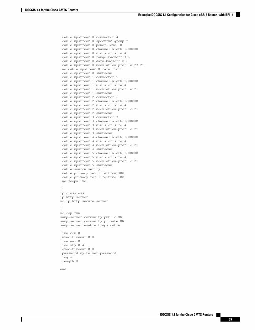
cable upstream 0 connector 4cable upstream 0 spectrum-group 2cable upstream 0 power-level 0cable upstream 0 channel-width 1600000cable upstream 0 minislot-size 4cable upstream 0 range-backoff 3 6cable upstream 0 data-backoff 0 6cable upstream 0 modulation-profile 23 21no cable upstream 0 rate-limitcable upstream 0 shutdowncable upstream 1 connector 5cable upstream 1 channel-width 1600000cable upstream 1 minislot-size 4cable upstream 1 modulation-profile 21cable upstream 1 shutdowncable upstream 2 connector 6cable upstream 2 channel-width 1600000cable upstream 2 minislot-size 4cable upstream 2 modulation-profile 21cable upstream 2 shutdowncable upstream 3 connector 7cable upstream 3 channel-width 1600000cable upstream 3 minislot-size 4cable upstream 3 modulation-profile 21cable upstream 3 shutdowncable upstream 4 channel-width 1600000cable upstream 4 minislot-size 4cable upstream 4 modulation-profile 21cable upstream 4 shutdowncable upstream 5 channel-width 1600000cable upstream 5 minislot-size 4cable upstream 5 modulation-profile 21cable upstream 5 shutdowncable source-verifycable privacy kek life-time 300cable privacy tek life-time 180no keepalive!!ip classlessip http serverno ip http secure-server!!no cdp runsnmp-server community public RWsnmp-server community private RWsnmp-server enable traps cable!line con 0exec-timeout 0 0line aux 0line vty 0 4exec-timeout 0 0password my-telnet-passwordloginlength 0!end
DOCSIS 1.1 for the Cisco CMTS Routers39
DOCSIS 1.1 for the Cisco CMTS RoutersExample: DOCSIS 1.1 Configuration for Cisco cBR-8 Router (with BPI+)

Additional ReferencesFor additional information related to DOCSIS 1.1 operations, refer to the following references:
Technical Assistance
LinkDescription
http://www.cisco.com/cisco/web/support/index.htmlTheCisco Support andDocumentationwebsite providesonline resources to download documentation, software,and tools. Use these resources to install and configurethe software and to troubleshoot and resolve technicalissues with Cisco products and technologies. Access tomost tools on the Cisco Support and Documentationwebsite requires a Cisco.com user ID and password.
Feature Information for DOCSIS 1.1 for Cisco CMTS RoutersUse Cisco Feature Navigator to find information about the platform support and software image support.Cisco Feature Navigator enables you to determine which software images support a specific software release,feature set, or platform. To access Cisco Feature Navigator, go to the www.cisco.com/go/cfn link. An accounton the Cisco.com page is not required.
The following table lists the software release in which a given feature is introduced. Unless noted otherwise,subsequent releases of that software release train also support that feature.
Note
Table 8: Feature Information for DOCSIS 1.1 for the Cisco CMTS Routers
Feature InformationReleasesFeature Name
This feature was integrated into Cisco IOS XEEverest 16.6.1 on Cisco cBR Series ConvergedBroadband Routers.
Cisco IOS XE Everest16.6.1
DOCSIS 1.1 for the CiscoCMTS Routers
DOCSIS 1.1 for the Cisco CMTS Routers40
DOCSIS 1.1 for the Cisco CMTS RoutersAdditional References