Installation Industrial Ethernet Workgroup Switch MACH102 ...
Upload
khangminh22Category
view
6download
0
5910 Ethernet Gateway Module Hardware Manual
2/24/2017

5910 Ethernet Gateway Module
Document (Version 2.27.1.197) 2/24/2017 2 2
Copyright © 2014 - 2017 Schneider Electric Canada Inc.
All rights reserved.
The information provided in this documentation contains general descriptions and/or technical characteristics of the performance of the products contained herein. This documentation is not intended as a substitute for and is not to be used for determining suitability or reliability of these products for specific user applications. It is the duty of any such user or integrator to perform the appropriate and complete risk analysis, evaluation and testing of the products with respect to the relevant specific application or use thereof. Neither Schneider Electric nor any of its affiliates or subsidiaries shall be responsible or liable for misuse of the information contained herein. If you have any suggestions for improvements or amendments or have found errors in this publication, please notify us.
No part of this document may be reproduced in any form or by any means, electronic or mechanical, including photocopying, without express written permission of Schneider Electric.
All pertinent state, regional, and local safety regulations must be observed when installing and using this product. For reasons of safety and to help ensure compliance with documented system data, only the manufacturer should perform repairs to components.
Trademarks
Schneider Electric, ClearSCADA, SCADAPack, Solarpack, Realflo, Telepace, Telebus, SCADAServer, and Modbus are trademarks and the property of Schneider Electric SE, its subsidiaries and affiliated companies. All other trademarks are the property of their respective owners.
Microsoft and Windows are registered trademarks or trademarks of Microsoft Corporation in the United States and/or other countries.
Address
Schneider Electric Telemetry & Remote SCADA Solutions 415 Legget Drive, Suite 101, Kanata, Ontario K2K 3R1 Canada Direct Worldwide: +1 (613) 591-1943 Fax: +1 (613) 591-1022 Toll Free within North America: 1 (888) 267-2232 www.schneider-electric.com

5910 Ethernet Gateway Module
Document (Version 2.27.1.197) 2/24/2017 3 3
Table of Contents
Technical Support..........................................................................5
Technical Support: Americas, Europe, Middle East, Asia ..................................... 5 Technical Support: Australia .................................................................................. 5
Safety Information .........................................................................6
Important Information ............................................................................................. 6 Please Note ............................................................................................................ 7 Before You Begin ................................................................................................... 7 Operation and Adjustments ................................................................................... 7 Acceptable Use ...................................................................................................... 8
About the Book ..............................................................................9
At a Glance ............................................................................................................ 9
Overview ....................................................................................... 10
Installation .................................................................................... 11
Field Wiring .......................................................................................................... 12 Ethernet Connection ............................................................................................ 13 Power Connections .............................................................................................. 13 I/O Bus Connection .............................................................................................. 13 External Power Connection using an AC adapter ............................................... 13 External Power Connection using an external power source .............................. 14 Configuration Jumpers ......................................................................................... 14 LED Indicators ...................................................................................................... 15
Operation ...................................................................................... 16
Maintenance ................................................................................. 17
Troubleshooting ................................................................................................... 17
Specifications .............................................................................. 18
Approvals and Certifications ...................................................... 19

5910 Ethernet Gateway Module
Document (Version 2.27.1.197) 2/24/2017 4 4
Index of Figures
Figure 1: 5910 Ethernet Gateway Module ......................................................... 10
Figure 2: 5910 Module Layout ........................................................................... 11
Figure 3: 5910 Ethernet RJ-45 Connection ........................................................ 13

5910 Ethernet Gateway Module
Document (Version 2.27.1.197) 2/24/2017 5 5
Technical Support
Questions and requests related to any part of this documentation can be directed to one of the following support centers:
Technical Support: Americas, Europe, Middle East, Asia
Available Monday to Friday 8:00am – 6:30pm Eastern Time
Toll free within North America 1-888-226-6876
Direct Worldwide +1-613-591-1943
Email [email protected]
Technical Support: Australia
Inside Australia 1300 369 233
Email [email protected]

5910 Ethernet Gateway Module
Document (Version 2.27.1.197) 2/24/2017 6 6
Safety Information
Important Information
Read these instructions carefully and look at the equipment to become familiar with the device before trying to install, operate, service, or maintain it. The following special messages may appear throughout this documentation or on the equipment to warn of potential hazards or to call attention to information that clarifies or simplifies a procedure.
The addition of this symbol to a Danger or Warning safety message indicates that an electrical hazard exists, which will result in personal injury if the instructions are not followed.
This is the safety alert symbol. It is used to alert you to potential personal injury hazards. Obey all safety messages that follow this symbol to avoid possible injury or death.
DANGER DANGER indicates a hazardous situation which, if not avoided, will result in death or serious injury.
WARNING WARNING indicates a hazardous situation which, if not avoided, can result in death or serious injury.
CAUTION CAUTION indicates a potentially hazardous situation which, if not avoided, can result in minor or moderate injury.
NOTICE
NOTICE is used to address practices not related to physical injury.

5910 Ethernet Gateway Module
Document (Version 2.27.1.197) 2/24/2017 7 7
Please Note
Electrical equipment should be installed, operated, serviced, and maintained only by qualified personnel. No responsibility is assumed by Schneider Electric for any consequences arising out of the use of this material.
A qualified person is one who has skills and knowledge related to the construction, installation and operation of electrical equipment and has received safety training to recognize and avoid the hazards involved.
Before You Begin
Do not use this product on machinery lacking effective point-of-operation guarding. Lack of effective point-of-operation guarding on a machine can result in serious injury to the operator of that machine.
WARNING
EQUIPMENT OPERATION HAZARD
Verify that all installation and set up procedures have been completed.
Before operational tests are performed, remove all blocks or other temporary holding means used for shipment from all component devices.
Remove tools, meters, and debris from equipment.
Failure to follow these instructions can result in death or serious injury.
Follow all start-up tests recommended in the equipment documentation. Store all equipment documentation for future reference.
Test all software in both simulated and real environments.
Verify that the completed system is free from all short circuits and grounds, except those grounds installed according to local regulations (according to the National Electrical Code in the U.S.A, for instance). If high-potential voltage testing is necessary, follow recommendations in equipment documentation to help prevent accidental equipment damage.
Operation and Adjustments
The following precautions are from the NEMA Standards Publication ICS 7.1-1995 (English version prevails):
Regardless of the care exercised in the design and manufacture of equipment or in the selection and ratings of components, there are hazards that can be encountered if such equipment is improperly operated.
It is sometimes possible to misadjust the equipment and thus produce unsatisfactory or unsafe operation. Always use the manufacturer’s instructions as a guide for functional adjustments. Personnel who have

5910 Ethernet Gateway Module
Document (Version 2.27.1.197) 2/24/2017 8 8
access to these adjustments should be familiar with the equipment manufacturer’s instructions and the machinery used with the electrical equipment.
Only those operational adjustments actually required by the operator should be accessible to the operator. Access to other controls should be restricted to help prevent unauthorized changes in operating characteristics.
Acceptable Use
SCADAPack controllers and expansion modules are intended for use in monitoring and controlling non-critical equipment only. They are not intended for safety-critical applications.
WARNING
UNACCEPTABLE USE
Do not use SCADAPack controllers and expansion modules as an integral part of a safety system. These devices are not safety products.
Failure to follow these instructions can result in death or serious injury.
CAUTION
EQUIPMENT OPERATION HAZARD
When devices are used for applications with technical safety requirements, the relevant instructions must be followed. Use only Schneider Electric software or approved software with Schneider Electric hardware products.
Failure to follow these instructions can result in minor or moderate injury.

5910 Ethernet Gateway Module
Document (Version 2.27.1.197) 2/24/2017 9 9
About the Book
At a Glance
Document Scope
This manual describes the operation and maintenance of the 5910 Ethernet Gateway module.
Validity Notes
This document is valid for all versions of the 5910 Ethernet Gateway module.
Product Related Information
WARNING UNINTENDED EQUIPMENT OPERATION
The application of this product requires expertise in the design and programming of control systems. Only persons with such expertise should be allowed to program, install, alter and apply this product.
Follow all local and national safety codes and standards.
Failure to follow these instructions can result in death or serious injury.
User Comments
We welcome your comments about this document. You can reach us by e-mail at [email protected].

5910 Ethernet Gateway Module
Document (Version 2.27.1.197) 2/24/2017 10 10
Overview
The Model 5910 Ethernet Switch is a five port unmanaged switch used to route Ethernet messages. It is easy to install and operate as no configuration is necessary. Once the Ethernet connections are made and the unit is powered up, the 5910 will begin to operate.
The 5910 mounts on a DIN rail and is powered from the 5V available in SCADAPack controllers and other 5000 systems. The 5910 can also be powered from 11-30Vdc sources such as 12Vdc batteries, 24Vdc power supplies or AC adapters. The 5910 is available with a desktop mounting option.
Applications include in-plant I/O and connectivity between SCADAPack controllers and operator workstations, other PLC devices and SCADA systems communications that uses 10BaseT (10 Mbps) or 100BaseT (100 Mbps) in an industrial environment.
Figure 1: 5910 Ethernet Gateway Module

5910 Ethernet Gateway Module
Document (Version 2.27.1.197) 2/24/2017 11 11
Installation
The 5910 Ethernet Switch is available in two standard versions, the model 5910 and the model 5910SA. The model 5910 is a standard 5000 module that connects to the system I/O Bus as an integrated part of a Schneider Electric system. The model 5910SA is a stand-alone version of the 5910 and is used with other devices such as personal computers. Both versions of the modem are identical in every respect except that the 5910SA has rubber feet for desktop mounting.
Link/Act
Speed
Port1 Port2 Port3 Port4 Port5 Power
External Power11-30Vdc
Bus Power 5V
P8
Port1 Port2 Port3 Port4 Port5
J1
P2P1
P7P3
11-30Vdc
+ --
Power Input
4 3 2 1
Figure 2: 5910 Module Layout

5910 Ethernet Gateway Module
Document (Version 2.27.1.197) 2/24/2017 12 12
Field Wiring
WARNING - SUBSTITUTION OF COMPONENTS MAY IMPAIR SUITABILITY FOR USE IN HAZARDOUS LOCATIONS. AVERTISSEMENT - LA SUBSTITUTION DE COMPOSANTS PEUT AFFECTER LA CONVENANCE POUR UNE UTILISATION DANS DES EMPLACEMENTS DANGEREUX.
WARNING - EXPLOSION HAZARD - WHEN IN HAZARDOUS LOCATIONS, TURN OFF POWER BEFORE REPLACING OR WIRING MODULES. AVERTISSEMENT – RISQUE D'EXPLOSION – DANS DES EMPLACEMENTS DANGEREUX, COUPEZ L'ALIMENTATION AVANT DE REMPLACER OU DE CÂBLER DES MODULES.
WARNING - do not connect/disconnect circuits unless area is known to be non-hazardous. AVERTISSEMENT - Ne connectez/déconnectez pas les circuits à moins que la zone soit considérée non dangereuse.
Power, input and output (I/O) wiring must be in accordance with Class I, Division 2 wiring methods Article 501-4 (b) of the National Electrical Code, NFPA 70 for installations in the U.S. or as specified in Section 18-1J2 of the Canadian Electrical Code for installations within Canada and in accordance with the authority having jurisdiction.
The 5910 module has six connectors for field wiring. Refer to Figure 2: 5910 Module Layout for the location of these connectors.
The five Ethernet connections are terminated at the RJ-45 modular jacks labeled Ports1 through 5. The RJ-45 modular jack pin-out is compatible with straight-through Ethernet cables and cross-over Ethernet cables. See the

5910 Ethernet Gateway Module
Document (Version 2.27.1.197) 2/24/2017 13 13
Ethernet Connection section for more information.
External power in the range of 11 to 30Vdc in maybe connected to pins 1 and 2 of P8. External power may come from any DC power source such as a 12V battery, 12Vdc AC adapter or 24Vdc power supply. See the Configuration Jumpers section for setting J1 and the Specifications for the current requirements.
An AC adapter cannot be used in Hazardous Locations.

5910 Ethernet Gateway Module
Document (Version 2.27.1.197) 2/24/2017 14 14
Ethernet Connection
The Ethernet network connects to the RJ-45 modular jacks labeled Port1 through Port5. The RJ-45 jack mates with 8-pin connector and cable assemblies common to Ethernet 100Base-T applications. Use data quality, shielded, twisted pair cable.
Pins 1,2,3 and 6 are used. Pins 4,5,7, and 8 are not used. See Figure 3: 5910 Ethernet RJ-45 Connection for pin connections. The Ethernet RJ-45 ports are MDI/MDIX Auto crossover compatible. The allows the use of straight-through or cross-over cables.
RJ-45 1: TD/RD+ 2: TD/RD- 3: RD/TD+ 4: nc 5: nc 6: RD/TD- 7: nc 8: nc
3 4 5 2 6 7 8 1
Figure 3: 5910 Ethernet RJ-45 Connection
Power Connections
The 5910 module may be powered in any one of the following ways:
5Vdc applied to the 5910 from the I/O Bus.
11-30Vdc applied to the 5910 on P8.
The 5910 module is for use with Class 2 output power supplies only.
I/O Bus Connection
The 5910 module is normally powered through the connection to the system I/O Bus. The 5910 module is connected to the system I/O Bus using a cable connected to P1 or P2. Refer to the System Configuration Guide for complete information on the system I/O Bus cabling. A jumper link is installed in the bottom or “Bus power 5V” position on J1.
External Power Connection using an AC adapter
The 5910 Ethernet Switch can be powered using a 12Vdc AC adapter (Schneider Electric part number: TBUM297240). The AC adapter plugs into a 120Vac supply and provides 12Vdc to the 5910. A jumper link must be installed in the upper or “External Power 11-30V” position on J1.
Check that the AC adapter is not connected to the 120Vac supply.
5910 Ethernet Gateway Module
Document (Version 2.27.1.197) 2/24/2017 15 15
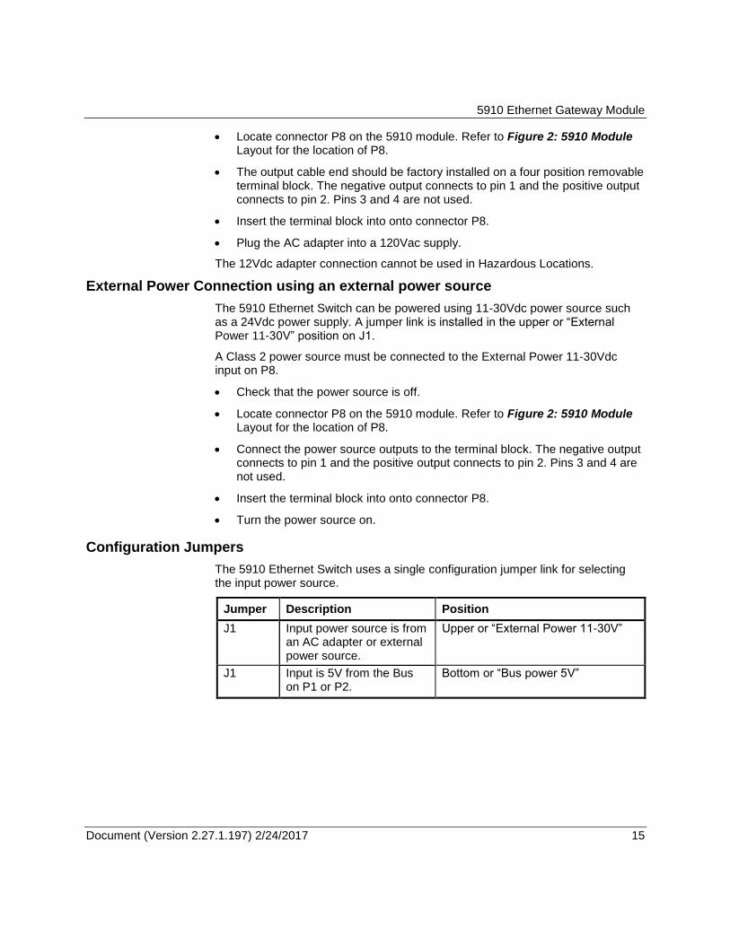
Locate connector P8 on the 5910 module. Refer to Figure 2: 5910 Module Layout for the location of P8.
The output cable end should be factory installed on a four position removable terminal block. The negative output connects to pin 1 and the positive output connects to pin 2. Pins 3 and 4 are not used.
Insert the terminal block into onto connector P8.
Plug the AC adapter into a 120Vac supply.
The 12Vdc adapter connection cannot be used in Hazardous Locations.
External Power Connection using an external power source
The 5910 Ethernet Switch can be powered using 11-30Vdc power source such as a 24Vdc power supply. A jumper link is installed in the upper or “External Power 11-30V” position on J1.
A Class 2 power source must be connected to the External Power 11-30Vdc input on P8.
Check that the power source is off.
Locate connector P8 on the 5910 module. Refer to Figure 2: 5910 Module Layout for the location of P8.
Connect the power source outputs to the terminal block. The negative output connects to pin 1 and the positive output connects to pin 2. Pins 3 and 4 are not used.
Insert the terminal block into onto connector P8.
Turn the power source on.
Configuration Jumpers
The 5910 Ethernet Switch uses a single configuration jumper link for selecting the input power source.
Jumper Description Position
J1 Input power source is from an AC adapter or external power source.
Upper or “External Power 11-30V”
J1 Input is 5V from the Bus on P1 or P2.
Bottom or “Bus power 5V”

5910 Ethernet Gateway Module
Document (Version 2.27.1.197) 2/24/2017 16 16
LED Indicators
The 5910 module has 11 LEDs to indicate module operation and status. The SCADAPack controllers cannot disable the power to these LEDs.
LED Function
Power On when power is applied to the module. Power source can be Bus or External.
Link/Activity One LED for each port. On when a link (proper Ethernet connection) has been established. Flickers when data is being transmitted or received.
Speed Off for 10 Mbps operation. On for 100 Mbps operation.
5910 Ethernet Gateway Module
Document (Version 2.27.1.197) 2/24/2017 17 17
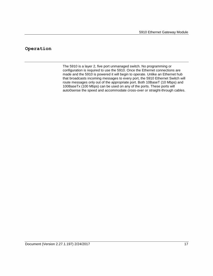
Operation
The 5910 is a layer 2, five port unmanaged switch. No programming or configuration is required to use the 5910. Once the Ethernet connections are made and the 5910 is powered it will begin to operate. Unlike an Ethernet hub that broadcasts incoming messages to every port, the 5910 Ethernet Switch will route messages only out of the appropriate port. Both 10BaseT (10 Mbps) and 100BaseTx (100 Mbps) can be used on any of the ports. These ports will auto0sense the speed and accommodate cross-over or straight-through cables.

5910 Ethernet Gateway Module
Document (Version 2.27.1.197) 2/24/2017 18 18
Maintenance
This module requires no routine maintenance. If the module is not functioning correctly, contact Schneider Electric Technical Support for more information and instructions for returning the module for repair.
Troubleshooting
Condition Solutions
Power LED is not on. Check power source. If the input is 5V from the Bus on P1 or P2 then the J1 jumper should be in the bottom or “Bus power 5V” position. If the input is 11-30Vdc from P8 then the J1 jumper should be in the upper or “External Power 11-30V” position.

5910 Ethernet Gateway Module
Document (Version 2.27.1.197) 2/24/2017 19 19
Specifications
Disclaimer: Schneider Electric reserves the right to change product specifications. For more information, visit http://www.schneider-electric.com.
Ethernet switch type
5 ports, unmanaged, store & forward, 10/100BaseT
Ethernet Terminations
RJ45 ports (shielded)
Protocols IEEE 802.3, IEEE 802.3u (TBC), IEEE802.3x
Speed and connection
Auto-detecting 10/100 Mbps operation
MDI/MDIX Auto crossover (no need for cross-wired cables)
Broadcast storm protection
Yes. 1% of bandwidth.
Memory bandwidth
1.4 Gbps
Full or half duplex operation
Full duplex IEEE802.3x and half duplex back pressure flow control
MAC addresses supported
Dedicated lookup engine with 1K MAC addresses. Learning, aging and migration.
Ethernet isolation
1500Vrms
Visual Indicators Each port - ACT/LINK and 10/100 (Speed).
Power
Input Power External Power: 11-30Vdc
1.8W at 12Vdc
2.2W at 30Vdc
Bus Power: 5V at 375mA
Input Power Terminations
4 pole terminal strip and removable terminal block
12 to 22 AWG (0.33 to 3.3 mm²)
Dimensions 4.25 inch (144 mm) wide
4.625 inch (118 mm) high
2.00 inch (51 mm) deep
Mounting desktop, rubber feet or 7.5 x 35 DIN rail
Packaging corrosion resistant zinc plated steel with black enamel paint
Environment 5% RH to 95% RH, non-condensing
–40oC to 70
oC
–40oF to 158
oF

5910 Ethernet Gateway Module
Document (Version 2.27.1.197) 2/24/2017 20 20
Approvals and Certifications
Safety Non-Incendive Electrical Equipment for Use in Class I, Division 2 Groups A, B, C and D Hazardous Locations.
UL Listed to the following standards:
CSA Std. C22.2 No. 213-M1987 - Hazardous Locations.
CSA Std. C22.2 No. 142-M1987 - Process Control Equipment.
UL Std. No. 508 - Industrial Control Equipment.
Digital Emissions
FCC Part 15, Subpart B, Class A Verification
EN61000-6-4: Electromagnetic Compatibility Generic Emission Standard Part2: Industrial Environment
C-Tick compliance. Registration number N15744.
Immunity EN61000-6-2: Electromagnetic Compatibility Generic Standards Immunity for Industrial Environments
Declaration This product conforms to the above Emissions and Immunity Standards and therefore conforms with the requirements of Council Directive 2004/108/EC (as amended) relating to electromagnetic compatibility and is eligible to bear the CE mark.
The Low Voltage Directive is not applicable to this product.
Copyright © 2022 FDOKUMEN