Keysight D9010ETHC Ethernet Compliance Test Application
222
Keysight D9010ETHC Ethernet Compliance Test Application Methods of Implementation
-
Upload
khangminh22 -
Category
Documents
-
view
1 -
download
0
Transcript of Keysight D9010ETHC Ethernet Compliance Test Application

Keysight D9010ETHC Ethernet Compliance Test Application
Methods of Implementation

2
Notices© Keysight Technologies 2015 - 2021
No part of this manual may be reproduced in any form or by any means (including elec-tronic storage and retrieval or translation into a foreign language) without prior agree-ment and written consent from Keysight Technologies as governed by United States and international copyright laws.
Software VersionVersion 2.72.0.0
Edition
July 2021
Available in electronic format only
Keysight Technologies1900 Garden of the Gods Road Colorado Springs, CO 80907 USA
Warranty
THE MATERIAL CONTAINED IN THIS DOCUMENT IS PROVIDED "AS IS," AND IS SUBJECT TO BEING CHANGED, WITHOUT NOTICE, IN FUTURE EDITIONS. FURTHER, TO THE MAXIMUM EXTENT PERMITTED BY APPLICABLE LAW, KEYSIGHT DISCLAIMS ALL WARRANTIES, EITHER EXPRESS OR IMPLIED WITH REGARD TO THIS MANUAL AND ANY INFORMATION CONTAINED HEREIN, INCLUDING BUT NOT LIMITED TO THE IMPLIED WARRANTIES OF MERCHANTABILITY AND FITNESS FOR A PARTICULAR PURPOSE. KEYSIGHT SHALL NOT BE LIABLE FOR ERRORS OR FOR INCIDENTAL OR CONSEQUENTIAL DAMAGES IN CONNECTION WITH THE FURNISHING, USE, OR PERFORMANCE OF THIS DOCUMENT OR ANY INFORMATION CONTAINED HEREIN. SHOULD KEYSIGHT AND THE USER HAVE A SEPARATE WRITTEN AGREEMENT WITH WARRANTY TERMS COVERING THE MATERIAL IN THIS DOCUMENT THAT CONFLICT WITH THESE
TERMS, THE WARRANTY TERMS IN THE SEPARATE AGREEMENT WILL CONTROL.
Technology LicensesThe hardware and/or software described in this document are furnished under a license and may be used or copied only in accor-dance with the terms of such license.
U.S. Government Rights
The Software is "commercial computer soft-ware," as defined by Federal Acquisition Regulation ("FAR") 2.101. Pursuant to FAR 12.212 and 27.405-3 and Department of Defense FAR Supplement ("DFARS") 227.7202, the U.S. government acquires commercial computer software under the same terms by which the software is cus-tomarily provided to the public. Accordingly, Keysight provides the Software to U.S. gov-ernment customers under its standard com-mercial license, which is embodied in its End User License Agreement (EULA), a copy of which can be found at http://www.key-sight.com/find/sweula. The license set forth in the EULA represents the exclusive author-ity by which the U.S. government may use, modify, distribute, or disclose the Software. The EULA and the license set forth therein, does not require or permit, among other things, that Keysight: (1) Furnish technical information related to commercial computer software or commercial computer software documentation that is not customarily pro-vided to the public; or (2) Relinquish to, or otherwise provide, the government rights in excess of these rights customarily provided to the public to use, modify, reproduce, release, perform, display, or disclose com-mercial computer software or commercial computer software documentation. No addi-tional government requirements beyond those set forth in the EULA shall apply, except to the extent that those terms, rights, or licenses are explicitly required from all providers of commercial computer software pursuant to the FAR and the DFARS and are set forth specifically in writing elsewhere in the EULA. Keysight shall be under no obliga-tion to update, revise or otherwise modify the Software. With respect to any technical data as defined by FAR 2.101, pursuant to FAR 12.211 and 27.404.2 and DFARS 227.7102, the U.S. government acquires no
greater than Limited Rights as defined in FAR 27.401 or DFAR 227.7103-5 (c), as applicable in any technical data.
Safety Notices
CAUTIONA CAUTION notice denotes a hazard. It calls attention to an operating proce-dure, practice, or the like that, if not correctly performed or adhered to, could result in damage to the product or loss of important data. Do not pro-ceed beyond a CAUTION notice until the indicated conditions are fully understood and met.
WARNINGA WARNING notice denotes a hazard. It calls attention to an operating pro-cedure, practice, or the like that, if not correctly performed or adhered to, could result in personal injury or death. Do not proceed beyond a WARNING notice until the indicated conditions are fully understood and met.

Ethernet Compliance Testing Methods of Implementation 3
Ethernet Automated Testing — At a GlanceThe Keysight D9010ETHC Ethernet Compliance Test Application helps you verify Ethernet transmitter device under test (DUT) compliance to specifications using the Keysight Infiniium oscilloscopes.
This automated Ethernet test application offers:
• Capability for testing the DUT for 10 Base-T, 100 Base-TX, and 1000 Base-T transmitter electrical compliance.
• Capability for additional testing for Energy-Efficient Ethernet (EEE) compliance, which is defined in IEEE 802.3az. 10 Base-Te, 100 Base-T EEE mode, and 1000 Base-T EEE mode.
The Ethernet Compliance Test Application:
• Lets you select individual or multiple tests to run.
• Lets you identify the device being tested and its configuration.
• Shows you how to make oscilloscope connections to the device under test.
• Automatically checks for proper oscilloscope configuration.
• Automatically sets up the oscilloscope for each test.
• Allows you to determine the number of trials for each test with the multi-trial run capability.
• Provides detailed information for each test that has been run, and lets you specify the thresholds at which marginal or critical warnings appear.
• Creates a printable HTML report of the tests that have been run.
Compliance test measurements are described in the IEEE 802.3-2018 Standard, IEEE 802.3az Standard, and ANSI X3.263-1995 Standard. For more information, see the IEEE 802 Standards Web site at www.ieee802.org.
Required Equipment and Software
In order to run the Ethernet Compliance Test Application, you need the following equipment and software:
• D9010ETHC Ethernet Compliance Test Application software.
• Use one of the following oscilloscope models:
• Keysight 9000-series, S-series, 90000-series, 90000 X-series, 90000 Q-series and Z-series Infiniium Oscilloscopes
• Keysight UXR Oscilloscopes (13GHz – 33GHz)
• Keysight MXR Oscilloscopes (4 channels with channels 1-3 and 2-4 pairing support, sampling rate upto 16GSa/s)
• The minimum version of Infiniium oscilloscope software (see the D9010ETHC test application release notes).
• Keysight N5395C and Wilder Technologies 110-1089-000 Ethernet electrical compliance test fixtures.
• InfiniiMax probe amplifiers.
• E2678A/B differential socket probe head.
• E2677A/B differential solder-in probe head.
• BNC cables.
NOTEThe tests performed by the Ethernet Compliance Test Application are intended to provide a quick check of the electrical health of the DUT. These testing are not a replacement for an exhaustive test validation plan.

4 Ethernet Compliance Testing Methods of Implementation
• Keyboard, quantity = 1 (provided with the Keysight Infiniium oscilloscope).
• Mouse, quantity = 1 (provided with the Keysight Infiniium oscilloscope).
• Keysight also recommends using a second monitor to view the automated test application.
For more details on the required and recommended equipment, please refer to "Required and Recommended Equipment" on page 24.
For the information regarding required licenses to use this application, refer to the Data Sheet for this application.
Additionally, for the jitter and distortion test, at least 8M points of memory is required. Hence, Memory Upgrade Option 001 is recommended for the 54850 and 80000 Series oscilloscopes for best performance. Option 080 is recommended for the 54830 and 8000 Series oscilloscopes.

Ethernet Compliance Testing Methods of Implementation 5
In This BookThis manual describes the tests that are performed by the Ethernet Compliance Test Application in more detail; it contains information from (and refers to) the IEEE 802.3-2018 Standard, IEEE 802.3az Standard, and ANSI X3.263-1995 Standard, and it describes how the tests are performed.
• Chapter 1, “Overview describes the tests supported by the Ethernet Compliance Test Application and the standard references.
• Chapter 2, “Installing the Ethernet Compliance Test Application shows how to install and license the automated test application software (if it was purchased separately).
• Chapter 3, “Preparing to Take Measurements shows how to start the Ethernet Compliance Test Application and gives a brief overview of how it is used.
• Chapter 4, “1000 Base-T Tests contains more information on the 1000 Base-T tests.
• Chapter 5, “100 Base-TX Tests contains more information on the 100 Base-TX tests.
• Chapter 6, “10 Base-T Tests contains more information on the 10 Base-T tests.
• Chapter 7, “1000 Base-T EEE Tests contains more information on the 1000 Base-T EEE tests.
• Chapter 8, “100 Base-TX EEE Tests contains more information on the 100 Base-TX EEE tests.
• Chapter 9, “10 Base-Te Tests contains more information on the 10 Base-Te tests.
• Appendix 10, “InfiniiMax Probing describes the InfiniiMax probe amplifiers and probe head recommendations for Ethernet testing.
See Also
• The Ethernet Compliance Test Application’s online help, which describes:
• Starting the Ethernet compliance test application.
• Creating or opening a test project.
• Setting up the Ethernet test environment.
• Setting up InfiniiSim.
• Setting up the precision probe/cable.
• Selecting tests.
• Configuring selected tests.
• Connecting the oscilloscope to the DUT.
• Running tests.
• Viewing test results.
• Viewing/exporting/printing the HTML test report.
• Understanding the HTML test report.
• Saving test projects.
• Installing/removing add-ins.
• Controlling the application via a remote PC.
• Using a second monitor for the application.

6 Ethernet Compliance Testing Methods of Implementation

Ethernet Compliance Testing Methods of Implementation 7
ContentsEthernet Automated Testing — At a Glance 3
In This Book 5
1 Overview
2 Installing the Ethernet Compliance Test Application
Installing the Software 18
Installing the License Key 19Using Keysight License Manager 5 19Using Keysight License Manager 6 20
3 Preparing to Take Measurements
Required and Recommended Equipment 24Test Fixtures 24Tests Supported by the Wilder Technologies 110-1089-000 EEE Test Fixture 26Oscilloscope Compatibility and Recommended Probe Amplifiers 27Number of Probes and BNC Cables Required 27Supported Vector Network Analyzers for Return Loss Tests 28Recommended Accessories 28Recommended Infiniium Oscilloscope for Jitter and Distortion Test 28Required Software 28
Calibrating the Oscilloscope 29
Starting the Ethernet Compliance Test Application 30Online Help Topics 31
Selecting the Probe Head 33

8 Ethernet Compliance Testing Methods of Implementation
Contents
4 1000 Base-T Tests
Probing for Test Mode 1 and Test Mode 4 38Without Disturbing Signal Probing for Test Mode 1 and Test Mode 4 38Calibration Setup for the 33612A Disturbing Signal Source 39Calibration Setup for the 81150A Disturbing Signal Source 40Calibration Setup for the 33250A Disturbing Signal Source 41Disturbing Signal Probing Setup for Test Mode 1 and Test Mode 4 Using the 33250A Signal Generators 43Jumper Positions for Test Fixture Section 11 45Disturbing Signal Probing Setup for Test Mode 1 and Test Mode 4 Using Non-33250A Signal Generators 47
Test Mode 1 48Peak Output Voltage Tests 48Templates Tests 54Droop Tests 55
Test Mode 4 57
MDI Common Mode Output Voltage 59
Jitter Tests with TX_TCLK, DUT in MASTER Mode 63MASTER Mode JTxOut 63Jitter MASTER Unfiltered 66Jitter MASTER Filtered 69
Jitter Tests with TX_TCLK, DUT in SLAVE Mode 71SLAVE Mode JTxOut 71Jitter SLAVE Unfiltered 73Jitter SLAVE Filtered 76
Jitter Tests Without TX_TCLK 79
Jitter Tests Without TX_TCLK, DUT in MASTER Mode 79Jitter MASTER Unfiltered 80Jitter MASTER Filtered 83
Jitter Tests Without TX_TCLK, DUT in SLAVE Mode 85Jitter SLAVE Unfiltered 85Jitter SLAVE Filtered 88
MDI Return Loss 90
5 100 Base-TX Tests
Probing for 100 Base-TX Tests 96Probing for 100 Base-TX Tests, Without Link Partner 96Probing for 100 Base-TX Tests, With Link Partner 98

Ethernet Compliance Testing Methods of Implementation 9
Contents
Peak Voltage Tests 99UTP +Vout Differential Output Voltage 99UTP -Vout Differential Output Voltage 99Signal Amplitude Symmetry 100
Overshoot Tests 102+Vout Overshoot 102-Vout Overshoot 102
Template Tests 104UTP AOI Template 104
Rise and Fall Time Tests 106AOI +Vout Rise Time 106AOI +Vout Fall Time 106AOI +Vout Rise/Fall Symmetry 106AOI -Vout Rise Time 106AOI -Vout Fall Time 106AOI -Vout Rise/Fall Symmetry 106AOI Overall Rise/Fall Symmetry 106
DCD/Jitter Tests 108Transmit Jitter 108Duty Cycle Distortion 109
Transmitter Return Loss 113
Receiver Return Loss 118
6 10 Base-T Tests
Test Loads 124
Measurements with TPM, Template Tests 125Probing for 10 Base-T Tests With the TPM and Link Partner 125Link Test Pulse, with TPM 126TP_IDL Template, with TPM (Last Bit CD0) 129TP_IDL Template, with TPM (Last Bit CD1) 131MAU Template 133
Measurements with TPM, Parametric Tests 136Jitter with TPM 136
Measurements without TPM, Template Tests 139Probing for 10 Base-T Tests Without the TPM, With Link Partner 139Link Test Pulse, without TPM 140TP_IDL Template, without TPM (Last Bit CD0) 143TP_IDL Template, without TPM (Last Bit CD1) 145

10 Ethernet Compliance Testing Methods of Implementation
Contents
Measurements without TPM, Parametric Tests 148Jitter without TPM 148Peak Differential Voltage 150Harmonic Content 151
Common Mode Voltage Tests 153Common Mode Output Voltage 153
Configuring 10 Base-T Device Output 156Configuring a 10 Base-T Device to Output Random Data 156Configuring a 10 Base-T Device to Output Manchester Encoded Harmonic Ones 157
Transmitter Return Loss 158
Receiver Return Loss 163
7 1000 Base-T EEE Tests
1000 Base-T EEE Mode 170
Probing for 1000 Base-T EEE Tests 171
LPI Tests 172Quiet Time 172Refresh Time (Master) 172Refresh Time (Slave) 173Transmitter Timing Jitter 174
8 100 Base-TX EEE Tests
100 Base-TX EEE Mode 178
Probing for 100 Base-TX EEE Tests 179
LPI Tests 180Quiet Time 180Refresh Time 180Transmitter Timing Jitter 181
Sleep Time Tests 182Sleep Time 182
Wake Time Tests 183Wake Time 183
9 10 Base-Te Tests
Test Loads 186

Ethernet Compliance Testing Methods of Implementation 11
Contents
Measurements with TPM, Template Tests 187Probing for 10 Base-Te Tests with TPM and Link Partner 187Link Test Pulse, with TPM 189TP_IDL Template, with TPM (Last Bit CD0) 190TP_IDL Template, with TPM (Last Bit CD1) 193MAU Template 195
Measurements with TPM, Parametric Tests 197Jitter with TPM 197
Measurements Without TPM, Template Tests 200Probing for 10 Base-Te Tests Without TPM, With Link Partner 200Link Test Pulse, Without TPM 201TP_IDL Template, Without TPM (Last Bit CD0) 203TP_IDL Template, Without TPM (Last Bit CD1) 206
Measurements Without TPM, Parametric Tests 209Jitter Without TPM 209Peak Differential Voltage 211Harmonic Content 212
Common Mode Voltage Tests 214Common Mode Output Voltage 214
Configuring 10 Base-Te Device Output 217Configuring a 10 Base-Te Device to Output Random Data 217Configuring a 10 Base-Te Device to Output Manchester-Encoded Harmonic Ones 218
10 InfiniiMax Probing
Index

12 Ethernet Compliance Testing Methods of Implementation
Contents
Keysight D9010ETHC Ethernet Compliance Test Application
Methods of Implementation
1 Overview
1000 Base-T Tests by Standard Reference / 14100 Base-TX Tests by Standard Reference / 1410 Base-T Tests by Standard Reference / 151000 Base-T EEE Tests by Standard Reference / 15100 Base-TX EEE Tests by Standard Reference / 1510 Base-T Tests by Standard Reference / 16
The Ethernet Compliance Test Application performs the following tests as per the IEEE 802.3-2018, IEEE 802.3az, and ANSI X3.263-1995 standards.

1 Overview
14 Ethernet Compliance Testing Methods of Implementation
Table 1 1000 Base-T Tests by Standard Reference
Standard Reference Description See
IEEE 802.3-2018 Subclause 40.6.1.2.1 Output voltage page 48
IEEE 802.3-2018 Subclause 40.6.1.2.3 Template test page 54
IEEE 802.3-2018 Subclause 40.6.1.2.2 Droop test page 55
IEEE 802.3-2018 Subclause 40.6.1.2.4 Transmitter distortion test page 63
IEEE 802.3-2018 Subclause 40.6.1.2.5 Jitter master unfiltered page 66
IEEE 802.3-2018 Subclause 40.6.1.2.5 Jitter master filtered page 69
IEEE 802.3-2018 Subclause 40.6.1.2.5 Jitter slave unfiltered page 73
IEEE 802.3-2018 Subclause 40.6.1.2.5 Jitter slave filtered page 76
IEEE 802.3-2018 Subclause 40.8.3.3 MDI common mode output voltage page 59
IEEE 802.3-2018 Subclause 40.8.3.1 MDI return loss page 90
Table 2 100 Base-TX Tests by Standard Reference
Standard Reference Description See
ANSI X3.263-1995, Section 9.1.2.2 UTP +Vout differential output voltage page 99
ANSI X3.263-1995, Section 9.1.2.2 UTP -Vout differential output voltage page 99
ANSI X3.263-1995, Section 9.1.4 Signal amplitude symmetry page 100
ANSI X3.263-1995, Section 9.1.3 +Vout overshoot page 102
ANSI X3.263-1995, Section 9.1.3 -Vout overshoot page 102
ANSI X3.263-1995, Annex J UTP AOI template page 104
ANSI X3.263-1995, Section 9.1.8 Duty cycle distortion page 109
ANSI X3.263-1995, Section 9.1.9 Transmit jitter page 108
ANSI X3.263-1995, Section 9.1.6 AOI +Vout rise time page 106
ANSI X3.263-1995, Section 9.1.6 AOI +Vout fall time page 106
ANSI X3.263-1995, Section 9.1.6 AOI +Vout rise/full-time symmetry page 106
ANSI X3.263-1995, Section 9.1.6 AOI -Vout rise time page 106
ANSI X3.263-1995, Section 9.1.6 AOI -Vout fall time page 106
ANSI X3.263-1995, Section 9.1.6 AOI -Vout rise/fall time symmetry page 106
ANSI X3.263-1995, Section 9.1.5 Transmitter return loss page 113
ANSI X3.263-1995, Section 9.2.2 Receiver return loss page 118

Ethernet Compliance Testing Methods of Implementation 15
Overview 1
Table 3 10 Base-T Tests by Standard Reference
Standard Reference Description See
IEEE 802.3-2018 Subclause 14.3.1.2.1, Figure 14-12 Template Link Pulse with TPM page 126
IEEE 802.3-2018 Subclause 14.3.1.2.1, Figure 14-10 Template TP_IDL with TPM page 129
IEEE 802.3-2018 Subclause 14.3.1.2.1, Figure 14-9, Table 14-1 Template MAU page 133
IEEE 802.3-2018 Subclause 14.3.1.2.3 and Annex B.4.1 and B.4.3.3
Jitter with TPM page 136
IEEE 802.3-2018 Subclause 14.3.1.2.1, Figure 14-12 Template Link Pulse without TPM page 140
IEEE 802.3-2018 Subclause 14.3.1.2.1, Figure 14-10 Template TP_IDL without TPM page 143
IEEE 802.3-2018 Subclause 14.3.1.2.3 and Annex B.4.1 and B.4.3.3
Jitter without TPM page 148
IEEE 802.3-2018 Subclause 14.3.1.2.1 Peak differential output voltage page 150
IEEE 802.3-2018 Subclause 14.3.1.2.1 Harmonic content page 151
IEEE 802.3-2018 Subclause 14.3.1.2.5 Common mode output voltage page 153
IEEE 802.3-2018 Subclause 14.3.1.3.4 and Annex B.4.3.5 Receiver return loss page 163
Table 4 1000 Base-T EEE Tests by Standard Reference
Standard Reference Description See
IEEE 802.3az, Subclause 78.2, Table 78-2 and Subclause 40.4.5.2 Quiet time page 172
IEEE 802.3az, Subclause 40.4.6.1, Figure 40-15b and Subclause 40.4.5.2
Refresh time page 172
IEEE 802.3az, Subclause 40.6.1.2.5 Transmitter timing jitter page 174
Table 5 100 Base-TX EEE Tests by Standard Reference
Standard Reference Description See
IEEE 802.3az, Subclause 78.2, Table 78-2 and Subclause 24.8.3.5 Quiet time page 180
IEEE 802.3az, Subclause 78.2, Table 78-2 and Subclause 24.8.3.5 Refresh time page 180
IEEE 802.3az, Subclause 25.4.6 Transmitter timing jitter page 181
IEEE 802.3az, Subclause 78.2, Table 78-2, Subclause 24.2.2.1.1, and Subclause 24.8.3.5
Sleep time page 182
IEEE 802.3az, Subclause 78.3, Figure 78-4 and Subclause 78.5, Table 78-4
Wake time page 183

1 Overview
16 Ethernet Compliance Testing Methods of Implementation
Table 6 10 Base-T Tests by Standard Reference
Standard Reference Description See
IEEE 802.3az, Subclause 14.3.1.2.1 and IEEE 802.3-2018, Subclause 14.3.1.2.2
Link test pulse, with TPM page 189
IEEE 802.3-2018, Subclause 14.3.1.2.1 TP_IDL template, with TPM (last bit CD0) page 190
IEEE 802.3-2018, Subclause 14.3.1.2.1 TP_IDL Template, with TPM (last bit CD1) page 193
IEEE 802.3-2018, Subclause 14.3.1.2.1 MAU template page 195
IEEE 802.3-2018, Subclause 14.3.1.2.3, Annex B.4.3.3, and Annex B.4.1 “System Jitter budget”
Jitter with TPM page 197
IEEE 802.3-2018, Subclause 14.3.1.2.1 and Subclause 14.3.1.2.2
Link test pulse, without TPM page 201
IEEE 802.3-2018, Subclause 14.3.1.2.1 TP_IDL template, without TPM page 203
IEEE 802.3-2018, Subclause 14.3.1.2.3, Annex B.4.3.3, and Annex B.4.1 "System Jitter Budget"
Jitter without TPM page 209
IEEE 802.3az, Subclause 14.3.1.2.1 Peak differential voltage page 211
IEEE 802.3-2018, Subclause 14.3.1.2.1 Harmonic content page 212
IEEE 802.3-2018, Subclause 14.3.1.2.7 Common mode output voltage page 214

Keysight D9010ETHC Ethernet Compliance Test Application
Methods of Implementation
2 Installing the Ethernet Compliance Test Application
Installing the Software / 18Installing the License Key / 19
If you purchased the D9010ETHC Ethernet Compliance Test Application separately, you must install the software and license key.

2 Installing the Ethernet Compliance Test Application
18 Ethernet Compliance Testing Methods of Implementation
Installing the Software
1 Make sure you have the required version of the Infiniium oscilloscope software:
a See the compliance test application release notes for the required minimum version of the software.
b To check the software version on the oscilloscope, choose Help>About Infiniium... from the main menu.
2 To obtain the Ethernet Compliance Test Application, go to the Keysight Web site: http://www.keysight.com/en/pc-1152185/oscilloscope-software.
3 Navigate to the D9010ETHC Ethernet Compliance software download.
4 Follow the instructions to download and install the application software.
Ethernet Compliance Testing Methods of Implementation 19
Installing the Ethernet Compliance Test Application 2
Installing the License Key
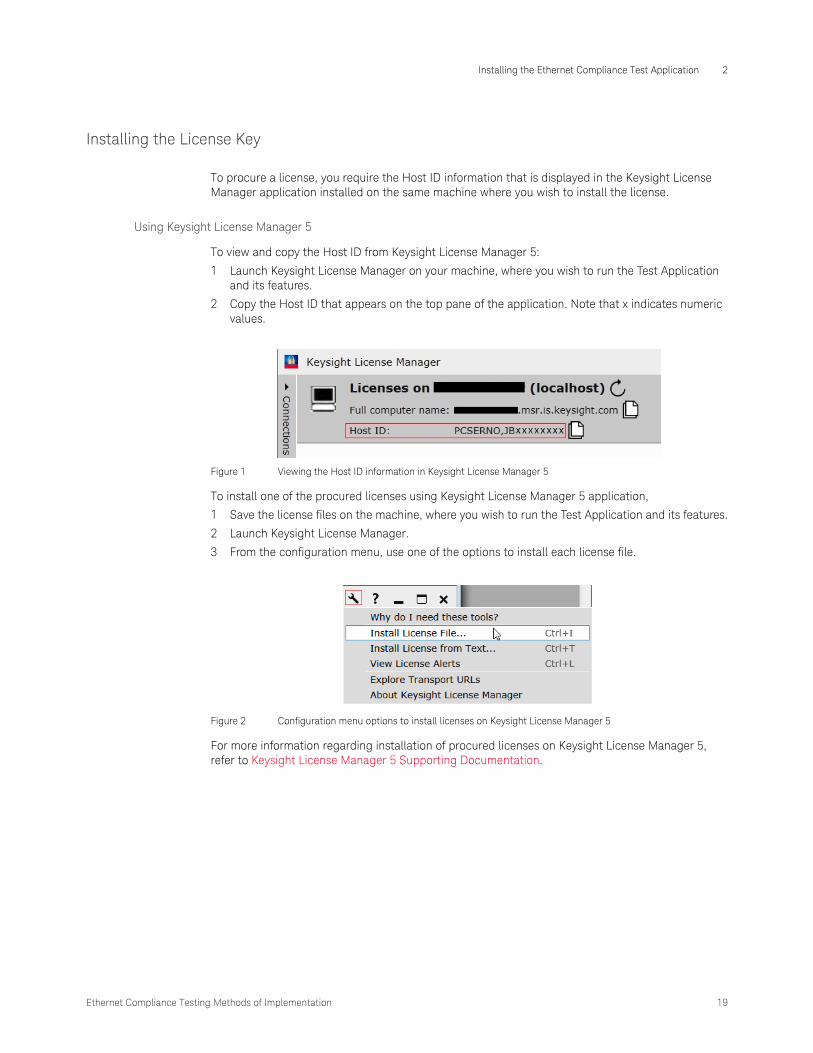
To procure a license, you require the Host ID information that is displayed in the Keysight License Manager application installed on the same machine where you wish to install the license.
Using Keysight License Manager 5
To view and copy the Host ID from Keysight License Manager 5:
1 Launch Keysight License Manager on your machine, where you wish to run the Test Application and its features.
2 Copy the Host ID that appears on the top pane of the application. Note that x indicates numeric values.
Figure 1 Viewing the Host ID information in Keysight License Manager 5
To install one of the procured licenses using Keysight License Manager 5 application,
1 Save the license files on the machine, where you wish to run the Test Application and its features.
2 Launch Keysight License Manager.
3 From the configuration menu, use one of the options to install each license file.
Figure 2 Configuration menu options to install licenses on Keysight License Manager 5
For more information regarding installation of procured licenses on Keysight License Manager 5, refer to Keysight License Manager 5 Supporting Documentation.

2 Installing the Ethernet Compliance Test Application
20 Ethernet Compliance Testing Methods of Implementation
Using Keysight License Manager 6
To view and copy the Host ID from Keysight License Manager 6:
1 Launch Keysight License Manager 6 on your machine, where you wish to run the Test Application and its features.
2 Copy the Host ID, which is the first set of alphanumeric value (as highlighted in Figure 3) that appears in the Environment tab of the application. Note that x indicates numeric values.
Figure 3 Viewing the Host ID information in Keysight License Manager 6
Ethernet Compliance Testing Methods of Implementation 21
Installing the Ethernet Compliance Test Application 2
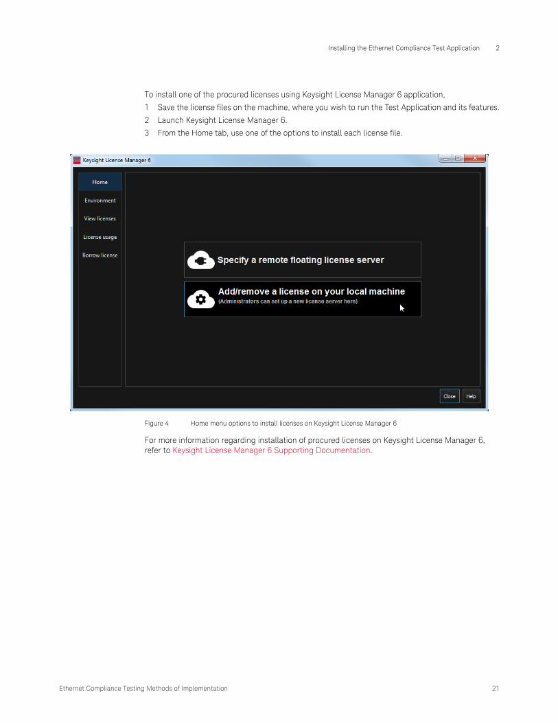
To install one of the procured licenses using Keysight License Manager 6 application,
1 Save the license files on the machine, where you wish to run the Test Application and its features.
2 Launch Keysight License Manager 6.
3 From the Home tab, use one of the options to install each license file.
Figure 4 Home menu options to install licenses on Keysight License Manager 6
For more information regarding installation of procured licenses on Keysight License Manager 6, refer to Keysight License Manager 6 Supporting Documentation.

2 Installing the Ethernet Compliance Test Application
22 Ethernet Compliance Testing Methods of Implementation

Keysight D9010ETHC Ethernet Compliance Test Application
Methods of Implementation
3 Preparing to Take Measurements
Required and Recommended Equipment / 24Calibrating the Oscilloscope / 29Starting the Ethernet Compliance Test Application / 30Selecting the Probe Head / 33
Before running the Ethernet automated tests, you need to acquire the appropriate test fixtures, and you should calibrate the oscilloscope. After the oscilloscope has been calibrated, you are ready to start the Ethernet Compliance Test Application and perform the measurements.
3 Preparing to Take Measurements
24 Ethernet Compliance Testing Methods of Implementation
Required and Recommended Equipment
Test Fixtures
N5395C Ethernet Electrical Compliance Test Fixture
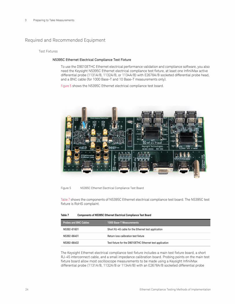
To use the D9010ETHC Ethernet electrical performance validation and compliance software, you also need the Keysight N5395C Ethernet electrical compliance test fixture, at least one InfiniiMax active differential probe (1131A/B, 1132A/B, or 1134A/B) with E2678A/B socketed differential probe head, and a BNC cable (for 1000 Base-T and 10 Base-T measurements only).
Figure 5 shows the N5395C Ethernet electrical compliance test board.
Table 7 shows the components of N5395C Ethernet electrical compliance test board. The N5395C test fixture is RoHS complaint.
The Keysight Ethernet electrical compliance test fixture includes a main test fixture board, a short RJ-45 interconnect cable, and a small impedance calibration board. Probing points on the main test fixture board allow most oscilloscope measurements to be made using a Keysight InfiniiMax differential probe (1131A/B, 1132A/B or 1134A/B) with an E2678A/B socketed differential probe
Figure 5 N5395C Ethernet Electrical Compliance Test Board
Table 7 Components of N5395C Ethernet Electrical Compliance Test Board
Probes and BNC Cables 1000 Base-T Measurements
N5392-61601 Short RJ-45 cable for the Ethernet test application
N5392-66401 Return loss calibration test fixture
N5392-66402 Test fixture for the D9010ETHC Ethernet test application

Ethernet Compliance Testing Methods of Implementation 25
Preparing to Take Measurements 3
head. Some measurements are made using a BNC cable. The 1000 Base-T jitter measurements are best made using two Keysight InfiniiMax active differential probes with E2677A/B solder-in differential probe heads.
Wilder Technologies 110-1089-000 EEE Electrical Compliance Test Fixture
To use the Ethernet electrical performance validation and compliance software for EEE compliance testing, you also need the Wilder Technologies 110-1089-000 EEE electrical compliance test fixture, at least one InfiniiMax active differential probe with E2678A/B socketed differential probe head, SMA cables, and a BNC cable. For the complete EEE fixture kit which includes fixture, two short Ethernet cables, and fourteen 50 Ω terminators, order part number 640-0581-001 (EEE-TPA-ERK).
N5396A Gigabit Ethernet Jitter Test Cable
To make jitter measurements for 1000 Base-T, you need to use the N5396A Gigabit Ethernet jitter test cable along with the Ethernet test fixture, a second InfiniiMax active differential probe, and two E2677A/B solder-in differential probe heads.
The N5396A Gigabit Ethernet jitter test cable allows you to make 1000 Base-T jitter measurements with the Ethernet electrical compliance test fixture. The 103-m cable has a RJ-45 connector on one end to connect to a Link Partner, and a DB9 connector on the other end to connect to the Ethernet test fixture board.
Figure 6 Wilder Technologies EEE Electrical Compliance Test Board

3 Preparing to Take Measurements
26 Ethernet Compliance Testing Methods of Implementation
Tests Supported by the Wilder Technologies 110-1089-000 EEE Test Fixture
The Wilder Technologies 110-1089-000 EEE electrical compliance test fixture provides some testing capability that is currently not automated by the Ethernet electrical performance validation and compliance software. Some of these tests require other equipment. The following tables list the tests supported by each section of the test fixture, the tests that are automated/supported by the D9010ETHC software, and other hardware requirements.
• VNA = Vector Network Analyzer required.
• LP = Link Partner Required.
Table 8 1000 Base-T EEE Tests Supported by the 110-1089-000 EEE Test Fixture
Test Name EEE Test Fixture Section LP
2
LPI Tests X X
Sleep Time Tests X X
Wake Time Tests X X
Table 9 100 Base-TX EEE Tests Supported by the 110-1089-000 EEE Test Fixture
Test Name EEE Test Fixture Section LP
4
LPI Tests X X
Sleep Time Tests X X
Wake Time Tests X X
Table 10 10 Base-Te Tests Supported by the 110-1089-000 EEE Test Fixture
Test Name Ethernet Test Fixture Section EEE Test Fixture Section LP VNA
1 4 6 10 11 1
Differential Output Voltage X
MAU Template X
TP_IDL/Link Pulse Template w/ TPM X
TP_IDL/Link Pulse Template w/o TPM X
Jitter, w/ TPM X
Jitter, w/o TPM X
Harmonic Content X
Common Mode Output Voltage X
Return Loss X X X

Ethernet Compliance Testing Methods of Implementation 27
Preparing to Take Measurements 3
Oscilloscope Compatibility and Recommended Probe Amplifiers
Number of Probes and BNC Cables Required
Table 11 Recommended Oscilloscopes and Recommended Probe Amplifiers
Standard Data Rate Recommended Oscilloscope
Oscilloscope Bandwidth
Recommended Probe
Probe Bandwidth
10 Base-T 10 Mb/s Infiniium ≥ 600 MHz 113xA/B Series ≥ 3.5 GHz
100 Base-TX 100 Mb/s Infiniium ≥ 600 Mhz 113xA/B Series ≥ 3.5 GHz
1000 Base-T Gigabit Ethernet (4x250 Mb/s)
Infiniium ≥ 1 GHz 113xA/B Series ≥ 3.5 GHz
Table 12 Number of Probes and BNC Cables Required
Probes and BNC Cables 1000 Base-T Measurements
100 Base-TX Measurements
10 Base-T Measurements
InfiniiMax active differential probe 2 1 1
E2677A/B solder-in differential probe head 2
E2678A/B socketed differential probe head 1 1 1
BNC cable 4 1

3 Preparing to Take Measurements
28 Ethernet Compliance Testing Methods of Implementation
Supported Vector Network Analyzers for Return Loss Tests
• 8752x/3x Models
• 4395x/6x Models
• E5070x/71x Models
• E5061x/62x Models
• N5230A Model
• N9917A Model
Note: Before using the Vector Network Analyzers (VNA), it has to be calibrated and configured. The VNA should support a minimum of 1 MHz usable power range. For more details on VNA calibration, please refer to these chapters: “MDI Return Loss,” starting on page 90, “Transmitter Return Loss,” starting on page 113, “Receiver Return Loss,” starting on page 118, “Transmitter Return Loss,” starting on page 158 and “Receiver Return Loss,” starting on page 163.
Recommended Accessories
Recommended Infiniium Oscilloscope for Jitter and Distortion Test
For jitter and distortion test, it is recommended to have at least 8M points of memory. Hence, option 001 is recommended for the 54850 and 80000 Series oscilloscopes for best performance. Option 080 is recommended for the 54830 and 8000 Series oscilloscopes.
Required Software
The minimum version of Infiniium oscilloscope software (see the D9010ETHC test application release notes).
Table 13 Recommended Test Accessories
Keysight Part Number Description
8120-1839 BNC cable (61 cm, 2 ft.)
8120-4948 SMA cable (90 cm, 3 ft.)
82357A/B USB to GPIB Convertor
33250A Function/Arbitrary Waveform Generator, Qty 2
Not available Optional push on SMA connectors for most efficient connection. Order 33SMA-Q50-0-4 from S.M. Electronics, Qty 6.

Ethernet Compliance Testing Methods of Implementation 29
Preparing to Take Measurements 3
Calibrating the Oscilloscope
If you have not already calibrated the oscilloscope, refer to the documentation for your oscilloscope and probes for the relevant procedures.
NOTEIf the ambient temperature changes more than 5 degrees Celsius from the calibration temperature, internal calibration should be performed again. The delta between the calibration temperature and the present operating temperature is shown in the Utilities>Calibration menu.
NOTEIf you switch cables or probes between channels or other oscilloscopes, it is necessary to perform cable and probe calibration again. Keysight recommends that, once calibration is performed, you label the cables with the channel for which they were calibrated.

3 Preparing to Take Measurements
30 Ethernet Compliance Testing Methods of Implementation
Starting the Ethernet Compliance Test Application
1 From the Infiniium oscilloscope’s main menu, choose Analyze>Automated Test Apps>D9010ETHC Ethernet Test App.
Figure 7 The Ethernet Compliance Test Application

Ethernet Compliance Testing Methods of Implementation 31
Preparing to Take Measurements 3
Figure 7 shows the Ethernet Compliance Test Application main window. The task flow pane and the tabs in the main pane show the steps you take in running the automated tests:
Online Help Topics
For information on using the Ethernet Compliance Test Application, see its online help (which you can access by choosing Help>Contents... from the application’s main menu).
The Ethernet Compliance Test Application’s online help describes the following:
• Starting the Ethernet Compliance Test Application
• Creating or Opening a Test Project
• Setting Up the Test Environment
• Setting Up InfiniiSim
• Setting Up the Precision Probe/Cable
• Selecting Tests
• Configuring Tests
• Connecting the Oscilloscope to the DUT
• Running Tests
• Automating the Application
• Viewing Results
• Viewing/Exporting/Printing the HTML Test Report
NOTEIf Ethernet does not appear in the Automated Test Apps menu, the Ethernet Compliance Test Application has not been installed (see Chapter 2, “Installing the Ethernet Compliance Test Application). Or, one or more licenses required to run the Ethernet Test Application are not installed on the Oscilloscope. You may also discover missing license information by launching the Test Application under the Analyze > Unlicensed Apps menu of the Infiniium Application. During startup, the Test Application displays a detailed license message.
Tab Description
Set Up Lets you select the Ethernet standards being tested. Lets you select whether or not a disturbing signal is used for testing 1000 Base-T. Lets you configure and calibrate external equipment. Lets you select the type of return loss test to run.
Select Tests Lets you select the tests you want to run. The tests are organized hierarchically so you can select all tests in a group. After tests are run, status indicators show which tests have passed, failed, or not been run, and there are indicators for the test groups.
Configure Lets you configure test parameters. The information appears in the HTML report.
Connect Shows you how to connect the oscilloscope to the device under test for the tests to be run.
Run Tests Starts the automated tests. If the connections to the device under test need to be changed while multiple tests are running, the tests pause, show you how to change the connection, and wait for you to confirm that the connections have been changed before continuing.
Automation Lets you construct scripts of commands that drive execution of the application.
Results Contains more detailed information about the tests that have been run. You can change the thresholds at which marginal or critical warnings appear.
HTML Report Shows a compliance test report that can be printed.

3 Preparing to Take Measurements
32 Ethernet Compliance Testing Methods of Implementation
• Understanding the Report
• Saving Test Projects
• User-Defined Add-Ins
• Controlling the Application via a Remote PC

Ethernet Compliance Testing Methods of Implementation 33
Preparing to Take Measurements 3
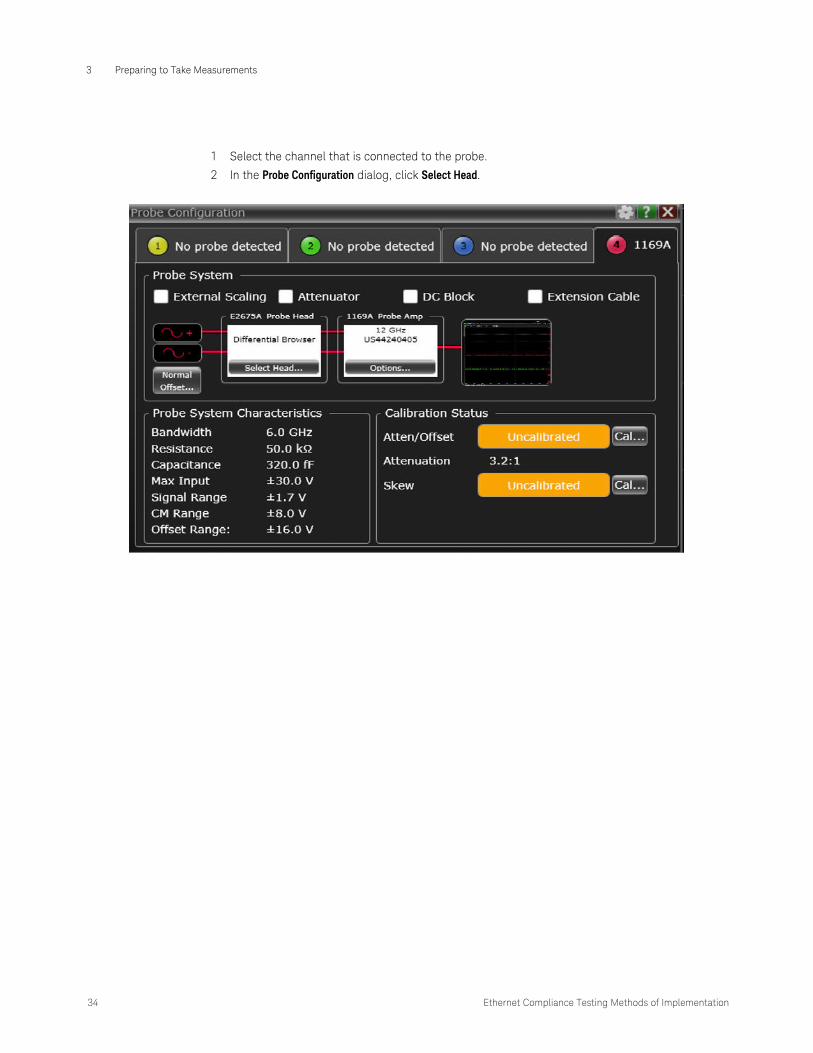
Selecting the Probe Head
Probes are generally detected automatically, but most probe heads are not. Therefore, you must set up probe heads manually most of the time. Before running the tests ensure that the probe head is selected correctly.
Perform the steps on the next page to manually configure the probe head.
3 Preparing to Take Measurements
34 Ethernet Compliance Testing Methods of Implementation
1 Select the channel that is connected to the probe.
2 In the Probe Configuration dialog, click Select Head.

Ethernet Compliance Testing Methods of Implementation 35
Preparing to Take Measurements 3
3 Select the correct probe head.

3 Preparing to Take Measurements
36 Ethernet Compliance Testing Methods of Implementation
Keysight D9010ETHC Ethernet Compliance Test Application
Methods of Implementation
4 1000 Base-T Tests
Probing for Test Mode 1 and Test Mode 4 / 38Test Mode 1 / 48Test Mode 4 / 57MDI Common Mode Output Voltage / 59Jitter Tests with TX_TCLK, DUT in MASTER Mode / 63Jitter Tests with TX_TCLK, DUT in SLAVE Mode / 71MDI Return Loss / 90
This section provides the Methods of Implementation (MOIs) for 1000 Base-T tests using an Infiniium oscilloscope, InfiniiMax probes, and the Ethernet Compliance Test Application.

4 1000 Base-T Tests
38 Ethernet Compliance Testing Methods of Implementation
Probing for Test Mode 1 and Test Mode 4
Without Disturbing Signal Probing for Test Mode 1 and Test Mode 4
When performing 1000 Base-T Mode 1 tests, the Ethernet Compliance Test Application will prompt you to make the proper connections (also shown in Figure 8).
1 Connect the DUT to the RJ45 connector on section 1 of the Ethernet test fixture using a short straight-through UTP cable.
2 Connect an InfiniiMax probe with the E2678A/B socketed probe head to the test point for the pair you are testing (A, B, C, or D), and to the oscilloscope channel which is selected as the “DUT Data” channel in the user interface’s “Configure” tab.
3 Ensure correct polarity of the probe head.
Figure 8 Probing for 1000 Base-T Test Mode 1 Tests
DUT
Section 2 of test fixture
InfiniiMax probe and E2678A/B socketed probe head
RJ45

Ethernet Compliance Testing Methods of Implementation 39
1000 Base-T Tests 4
4 Ensure that the DUT is transmitting the appropriate “Test Mode 1” signal as indicated in the user interface.
You can use any oscilloscope channel for the DUT Data probe connection. You identify the channel used for DUT Data in the “Configure” tab of the Ethernet Compliance Test Application. (The channel shown in Figure 8 is just an example.)
For more information on the InfiniiMax probe amplifiers and differential probe heads, see Appendix 10, “InfiniiMax Probing,” starting on page 219.
Calibration Setup for the 33612A Disturbing Signal Source
Before running disturbing signal tests, the 33612A generators must be calibrated. Connect the equipment as shown in Figure 9.
Figure 9 Calibration Setup for the 33612A Disturbing Signal Source

4 1000 Base-T Tests
40 Ethernet Compliance Testing Methods of Implementation
Performing the Calibration for the 33612A Disturbing Signal Source
1 Click the Set Up tab.
2 Click the Calibrate Sources button to start the calibration process.
3 If the system is not physically configured to perform the calibration, the application prompts you to change the physical configuration.
Calibration Setup for the 81150A Disturbing Signal Source
Before running disturbing signal tests, the 81150A generators must be calibrated. Connect the equipment as shown in Figure 10.
Performing the Calibration for the 81150A Disturbing Signal Source
1 Click the Set Up tab.
2 Click the Calibrate Sources button to start the calibration process.
Figure 10 Calibration Setup for the 81150A Disturbing Signal Source
Ethernet Compliance Testing Methods of Implementation 41
1000 Base-T Tests 4
3 If the system is not physically configured to perform the calibration, the application prompts you to change the physical configuration.
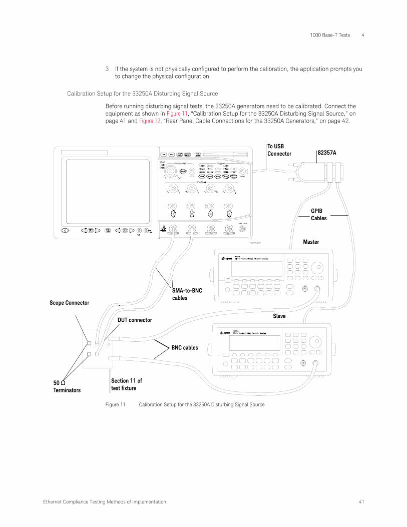
Calibration Setup for the 33250A Disturbing Signal Source
Before running disturbing signal tests, the 33250A generators need to be calibrated. Connect the equipment as shown in Figure 11, “Calibration Setup for the 33250A Disturbing Signal Source,” on page 41 and Figure 12, “Rear Panel Cable Connections for the 33250A Generators,” on page 42.
Figure 11 Calibration Setup for the 33250A Disturbing Signal Source
BNC cables
Section 11 of test fixture
50 Ω Terminators
Master
SlaveDUT connector
SMA-to-BNC cables
To USB Connector 82357A
GPIB Cables
Scope Connector

4 1000 Base-T Tests
42 Ethernet Compliance Testing Methods of Implementation
33250A Generator Setup
Performing the Calibration
1 Click the Set Up tab.
2 Click the Calibrate Sources button to start the calibration process.
3 If the system is not physically configured to perform the calibration, the application prompts you to change the physical configuration.
Figure 12 Rear Panel Cable Connections for the 33250A Generators
BNC cables
Master Slave

Ethernet Compliance Testing Methods of Implementation 43
1000 Base-T Tests 4
Disturbing Signal Probing Setup for Test Mode 1 and Test Mode 4 Using the 33250A Signal Generators
Figure 13 Probing and Cable Connections for Test Mode 1 and Test Mode 4 Using the 33250A Signal Generators
DUT
Section 1 of test fixture
BNC cables
RJ45
Section 11 of test fixture
SMA cables
Master
SlaveDUT connector
SMA-to-BNC cables
To USB Connector 82357A
GPIB Cables

4 1000 Base-T Tests
44 Ethernet Compliance Testing Methods of Implementation
33250A Generator Setup
Figure 14 Rear Panel Cable Connections for the 33250A Generators
BNC cables
Master Slave

Ethernet Compliance Testing Methods of Implementation 45
1000 Base-T Tests 4
Jumper Positions for Test Fixture Section 11
Filter Bandwidth Jumper Locations
25 MHz
35 MHz
102 MHz
P6
P7
P8
P9
P6
P7
P8
P9
P6
P7
P8
P9

4 1000 Base-T Tests
46 Ethernet Compliance Testing Methods of Implementation
Before running disturbing signal tests, the disturbing signals need to be calibrated. Connect the equipment as shown in Figure 15, “Calibration Setup the for Non-33250A Disturbing Signal Source,” on page 46 and calibrate the source for Test Mode 1 and Test Mode 4 tests.
Performing the Calibration
1 Select the appropriate filter configuration. Refer to Table 14, “Disturbing Signal Source Settings,” on page 47.
2 Set the source to output a differential signal with an amplitude of Vd and a frequency of Fd. Refer to Table 14 on page 47.
3 Use autoscale feature of the oscilloscope to display the signal.
4 Use the oscilloscope to measure the amplitude and frequency, adjust the disturbing signal source, if needed, to generate an output signal with an amplitude of Vd and a frequency of Fd. Refer to Table 14 on page 47.
5 Phase difference between the differential signal must be exactly 180 degrees. Adjust the phase if required.
6 Save the source configuration for later use.
Figure 15 Calibration Setup the for Non-33250A Disturbing Signal Source
Section 11 of test fixtures
50 Terminators
Scope Connectors
DUT connector
BNC cables
SMA-to-BNC cables
BNC cables
Section 11 of thetest fixture
DUT connector
SMA-to-BNCcables

Ethernet Compliance Testing Methods of Implementation 47
1000 Base-T Tests 4
k
Note: Vd is denoted as the amplitude at each channel
Disturbing Signal Probing Setup for Test Mode 1 and Test Mode 4 Using Non-33250A Signal Generators
Recall the configuration that you have saved during the previous calibration steps, for each test mode. Run the test.
Table 14 Disturbing Signal Source Settings
Test Mode Filter configuration Fd Vd
Test Mode 1 35 Mhz (see page 44) 31.25 Mhz 1.4 V
Test Mode 4 25 Mhz (see page 44) 20.833 Mhz 2.7 V
Figure 16 Probing and Cable Connections for Test Mode 1 and Test Mode 4 Using the Non-33250A Signal Generators
Rj45
SMA cables Section 11 of test fixture
DUT
Section 1 of the test fixture
SMA to BNCcables
DUT connector
BNC cablesBNC cables
DUT SMA-to-BNCcables
DUT connector
Section 11 of test fixtureSMA cables
RJ45
Section 1 of thetest fixture

4 1000 Base-T Tests
48 Ethernet Compliance Testing Methods of Implementation
Test Mode 1
Peak Output Voltage Tests
These tests measure the output voltage of points A, B, C, and D of the Test Mode 1 signal at the MDI. This test uses section 2 of the Ethernet test fixture, and applies a 2 MHz high-pass filter in software after acquiring the data. These measurement are made for all 4 pairs (A, B, C and D)
The allowable ranges for these measurements are as follows:
Reference
[1] IEEE 802.3-2018, Subclause 40.6.1.2.1.
Probing Setup
Refer to “Without Disturbing Signal Probing for Test Mode 1 and Test Mode 4" on page 38. This probing configuration is used for all 1000 Base-T Test Mode 1 Signal Tests.
Device Configuration
1 Configure the DUT to output the Test Mode 1 signal.
Using your PHY vendor's provided method, set the DUT's GMII register bits 9.15, 9.14, 9.13 to the values 0, 0, 1 respectively.
2 Ensure that the DUT is transmitting the proper signal as indicated in the connection instructions provided in the user interface.
Performing the Test
1 Ensure this test is checked to run in the “Select Tests” tab.
2 Run the test.
Table 15 Allowable Ranges for Peak Output Voltage Measurements
Point on Test Mode 1 Signal
Allowable Range Description
Point A 0.67 V to 0.82 V Absolute value of Peak A is 0.75 V +/- 0.83 dB
Point B |Peak B| between 0.67 V and 0.82 V Absolute value of Peak B is 0.75 V +/- 0.83 dB
Difference A,B 100*[abs((|Peak B|- ½*(|Peak A|+ |Peak B|)))/(½*(|Peak A|+ |Peak B|))]
The absolute value of the peak of the waveforms at points A and B shall differ by less than 1% from the average of the absolute values of the peaks of the waveform at points A and B.
[1]
Point C <2% of ½* (|Peak A|+|Peak B|)/2 Absolute value of Peak C is within 2% of ½ the average amplitude of Peaks A and B
[1]
Point D <2% of ½* (|Peak A|+|Peak B|)/2 Absolute value of Peak D is within 2% of ½ the average amplitude of Peaks A and B
[1]
[1] NOTE: The specified tolerance for this measurement is extremely tight. If this test fails, consult the vertical gain accuracy of your oscilloscope before you draw any conclusions about conformance.

Ethernet Compliance Testing Methods of Implementation 49
1000 Base-T Tests 4
3 If the system is not physically configured to perform this test, the application will prompt you to change the physical configuration. When you have completed these instructions, click the “Connection Completed” button and resume the test run.
4 The test will:
• Verify that the correct test signal is present on the configured “DUT Data” channel
• Capture the waveform around Point A, B, C, or D depending on the Test
• Apply a 2 MHz high-pass filter to this waveform
• Measure the Peak voltage of the waveform at this point.
Algorithm Discussion
Reference [1] defines the peak differential output voltage and level accuracy specifications for a 1000 Base-T device at the physical medium attachment (PMA) sublayer to Media Dependent Interface (MDI). The Peak Voltage tests verify that the Peak Voltages of points A, B, C, and D of the Test Mode 1 signal at the MDI are within the specified range.
The oscilloscope triggers on the appropriate point (A, B, C, D) of the Test Mode 1 signal, as defined in Figure 17. The tests verify that the absolute value of the peak voltage at A and B are in the range of 0.67 V to 0.82 V (0.75 V +/- 0.83 dB). Additionally, the ideal value for the absolute value of the peak voltage at points C and D is one half the average of the peak voltage at points A and B. We measure the absolute value of the peak voltage at points C and D and ensure that they deviate no more than 2% from this ideal voltage.
NOTEIf you have selected “ALL” as the 1000 Base-T, Test Pair (in the “Configure” tab), all 4 pairs will be tested in sequence. You will be prompted to move the probe to the test point for each test pair in turn, and this measurement will be repeated at each of these test points. If you want to debug a particular pair, select the individual pair you wish to test. Note that for full compliance testing, the specification requires testing all 4 pairs. At the result screen, 4 trials tabs are shown at the bottom left of the screen. Each trial tab shows the result of each test pair. For example, Trial 1 contains Test Pair BI_DA result, Trial 2 contains Test Pair BI_DB result and so on.
Figure 17 Example of Transmitter Test Mode 1 Waveform (1 Cycle)

4 1000 Base-T Tests
50 Ethernet Compliance Testing Methods of Implementation
Trigger Averaging Notes
Reference [1] allows the use of trigger averaging to reduce measurement noise and increase measurement resolution; however, the specification does not provide any constraints on how much averaging may be used.
A user-configurable amount of averaging is used. One hundred twenty-eight (128) averages are used by default to reduce the effect of noise on the measurement. You may wish to decrease this number to increase the effects of random signal variations. You may also wish to increase this number to further reduce the effects of noise and increase measurement resolution.
Performing Automated versus Manual Measurements for Peak Output Voltage
When you perform the Peak Output Voltage Measurements of points A, B, C, and D of the Test Mode 1 signal on a 1000 Base-T device, you will note the following differences when running Automated measurements (using the Keysight D9010ETHC Ethernet Compliance Test Application) versus performing Manual measurements (using the Keysight Infiniium Application on the Oscilloscope):
1 Observation — When performing Automated measurements, the Oscilloscope does not display the averaging process on the waveform whereas during Manual measurements, you can visualize the averaging process running on the Oscilloscope screen.
• During Automated measurements using the Keysight D9010ETHC Ethernet Compliance Test Application, the Test Application sends a :DIGitize command to the Oscilloscope, which invokes a special mode of data acquisition. This command (similar to repeatedly using the SINGLE button on the Oscilloscope as shown in Figure 18) initializes the selected channels or functions, then acquires them according to the current oscilloscope settings. When all waveforms are completely acquired, the oscilloscope is stopped. When averaging, it is necessary to know when the average count has been reached. The :SINGle command (or pressing the SINGLE button) does not average. The Keysight D9010ETHC Ethernet Compliance Test Application triggers the :DIGitize command to acquire and perform the complete number of averages required for the measurements. This operation of averaging runs in the background and the Oscilloscope screen is not updated until all the averaged waveforms are acquired.
• During Manual measurements using the Keysight Infiniium Application, when you click the Run button on the Oscilloscope, as shown in Figure 18, you can visualize the entire process of averaging being performed on the Oscilloscope screen.
Figure 18 Manual Measurement Control buttons on the Infiniium Application
Refer to the Keysight Infiniium Oscilloscopes Programmer's Guide for detailed information about the Oscilloscope commands mentioned above.
2 Applying Bandwidth limit for averaging — When performing Automated measurements, the Keysight D9010ETHC Ethernet Compliance Test Application applies a default Bandwidth Reduction Low-Pass Filter of 1GHz limit to reduce noise whereas during Manual measurements,
NOTEIn general, averaging may also reduce the effects of real signal variations.

Ethernet Compliance Testing Methods of Implementation 51
1000 Base-T Tests 4
no default bandwidth limit is applied, which means that any noise in the signal is also factored in for the measurements performed manually on the Keysight Infiniium Application. This may result in mismatch of resulting average values in the Automated and Manual methods.
To avoid any mismatch in averaging results between Automated versus Manual methods, you may do one of the following:
• Disable the Bandwidth Reduction option on the Ethernet Compliance Test Application to match with the Bandwidth Limit setting on the Keysight Infiniium Application.
i In the Ethernet Compliance Test Application, click the Configure tab.
ii Select Bandwidth Reduction. Notice that by default, the limit is set to 1GHz.
iii From the drop-down options that appear on the right pane, select NONE to disable noise reduction.
Figure 19 Configuration option for Bandwidth Reduction

4 1000 Base-T Tests
52 Ethernet Compliance Testing Methods of Implementation
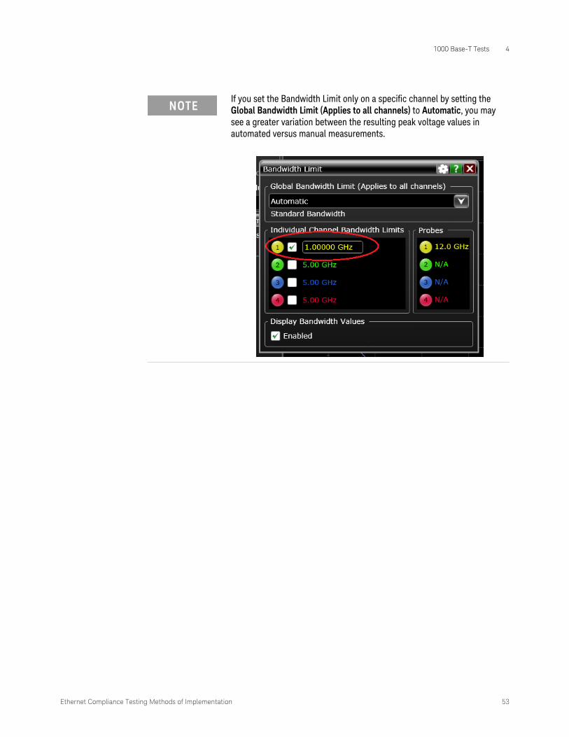
• Modify the Bandwidth Limit setting on the Keysight Infiniium Application to match the value configured for the Bandwidth Reduction option in the Ethernet Compliance Test Application (which is set to the default limit of 1 GHz or you may change the value as shown in Figure 19 for performing automated measurements).
i In the Infiniium Application, click Setup > Bandwidth Limit....
ii Set the Global Bandwidth Limit (Applies to all channels) to Manual.
iii Set the frequency value to match the value set for the Bandwidth Reduction option in the Compliance Test Application.
Figure 20 Setting Global Bandwidth Limit on Infiniium Application for noise reduction
Ethernet Compliance Testing Methods of Implementation 53
1000 Base-T Tests 4
NOTEIf you set the Bandwidth Limit only on a specific channel by setting the Global Bandwidth Limit (Applies to all channels) to Automatic, you may see a greater variation between the resulting peak voltage values in automated versus manual measurements.

4 1000 Base-T Tests
54 Ethernet Compliance Testing Methods of Implementation
Templates Tests
These tests ensure that the normalized waveform of the Test Mode 1 signal at points A, B, C, D, F, and H as measured at the MDI after being filtered by a 2 MHz high-pass filter, lies within the time domain template defined in Figure 40-26 of Reference [1]. This test uses section 2 of the Ethernet test fixture, and applies a 2 MHz high-pass filter in software after acquiring the data. These measurement are made for all 4 pairs (A, B, C, and D).
Reference
[1] IEEE 802.3-2018, Subclause 40.6.1.2.3.
Probing Setup
Refer to “Without Disturbing Signal Probing for Test Mode 1 and Test Mode 4" on page 38. This probing configuration is used for all 1000 Base-T Test Mode 1 Signal Tests.
Performing the Test
1 Ensure this test is checked to run in the “Select Tests” tab.
2 Run the test.
3 If the system is not physically configured to perform this test, the application will prompt you to change the physical configuration. When you have completed these instructions, click the “Connection Completed” button and resume the test run.
4 The test will:
• Verify that the correct test signal is present on the configured “DUT Data” channel.
• Capture the waveform around Point A, B, C, D, F, or H depending on the Test.
• Apply a 2 MHz high-pass filter to this waveform.
• Normalize the waveform as indicated in Table 16. NOTE: No other vertical adjustments are allowed as per the specification.
• Shift the waveform in time for the best fit to the specified mask.
• Capture a number of waveforms (user configurable in the “Configure” tab), testing each waveform against the specified mask, recording failures when they occur.
Algorithm Discussion
Reference [1] describes the differential output template specifications for a 1000 Base-T device at the physical medium attachment (PMA) sublayer to Media Dependent Interface (MDI). These tests ensure that the normalized waveform of the Test Mode 1 signal at points A, B, C, D, F, or H as measured at the MDI after being filtered by a 2 MHz high-pass Filter, lies within the time domain template defined in Figure 40-26 of Reference [1].
The oscilloscope triggers on the appropriate point (A, B, C, D, F, H) of the Test Mode 1 signal, as defined in Figure 17. The software applies a 2 MHz high-pass filter to this waveform. The waveform is then normalized as follows:
NOTEIf you have selected "ALL" as the 1000 Base-T, Test Pair (under the "Configure" tab), all 4 pairs will be tested in sequence. You will be prompted to move the probe to the test point for each test pair in turn, and this measurement will be repeated at each of these test points. If you want to debug a particular pair, select the individual pair you wish to test. For full compliance testing, the specification requires testing all 4 pairs. At the result screen, 4 trials tabs are shown at the bottom left of the screen. Each trial tab shows the result of each test pair. For example, Trial 1 contains Test Pair BI_DA result, Trial 2 contains Test Pair BI_DB result and so on.
Ethernet Compliance Testing Methods of Implementation 55
1000 Base-T Tests 4
The waveform is shifted in time for the best fit to the specified mask. A number of waveforms are captured, testing each waveform against the specified mask, and recording failures when they occur. There should be no failures for a compliant DUT.
These tests are to be performed on all 4 pairs.
Note that a user configurable amount of trigger averaging is used to reduce measurement noise and increase measurement resolution. See “Trigger Averaging Notes" on page 50” for a discussion of the effects of trigger averaging.
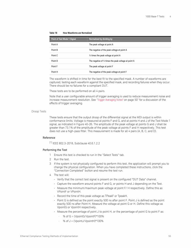
Droop Tests
These tests ensure that the output droop of the differential signal at the MDI output is within conformance limits. Voltage is measured at points F and G, and at points H and J of the Test Mode 1 signal, as indicated in Figure 40-26. The amplitude of the peak voltage at points G and J shall be greater than 73.1% of the amplitude of the peak voltage at points F and H respectively. This test does not use a high-pass filter. This measurement is made for all 4 pairs (A, B, C, and D).
Reference
[1] IEEE 802.3-2018, Subclause 40.6.1.2.2
Performing the Test
1 Ensure this test is checked to run in the “Select Tests” tab.
2 Run the test.
3 If the system is not physically configured to perform this test, the application will prompt you to change the physical configuration. When you have completed these instructions, click the “Connection Completed” button and resume the test run.
4 The test will:
• Verify that the correct test signal is present on the configured "DUT Data" channel.
• Capture the waveform around points F and G, or points H and J depending on the Test.
• Measure the minimum/maximum peak voltage at point F/ H respectively. Define this as VPointF or VPointH.
• Record the time of this peak voltage as TPeakF or TpeakH.
• Point G is defined as the point exactly 500 ns after point F. Point J is defined as the point exactly 500 ns after Point H. Measure the voltage at point G or H. Define this voltage as VpointG or VpointH respectively.
• Measure the percentage of point J to point H, or the percentage of point G to point F as:
• % of G = (VpointG/VpointF)*100%
• % of J = (VpointJ/VpointH)*100%
Table 16 How Waveforms are Normalized
Point of Test Mode 1 Signal Normalized by dividing by
Point A The peak voltage at point A
Point B The negative of the peak voltage at point A
Point C ½ times the peak voltage at point A
Point D The negative of ½ times the peak voltage at point A
Point F The peak voltage at point F
Point H The negative of the peak voltage at point F

4 1000 Base-T Tests
56 Ethernet Compliance Testing Methods of Implementation
Algorithm Discussion
Reference [1] describes the maximum output droop specifications for a 1000 Base-T device at the physical medium attachment (PMA) sublayer to Media Dependent Interface (MDI). These tests ensure that the output droop of the differential signal at the MDI output is within conformance limits.
Voltage is measured at points F and G, and at points H and J of the Test Mode 1 signal, as indicated in Figure 40-26. The amplitude of the peak voltage at points G and J shall be greater than 73.1% of the amplitude of the peak voltage at points F and H respectively. This test does not use a high-pass filter. This measurement is made for all 4 pairs (A, B, C, and D). The algorithm is described in “Performing the Test" on page 55.
NOTEIf you have selected "ALL" as the 1000 Base-T, Test Pair (under the "Configure" tab), all 4 pairs will be tested in sequence. You will be prompted to move the probe to the test point for each test pair in turn, and this measurement will be repeated at each of these test points. If you want to debug a particular pair, select the individual pair you wish to test. For full compliance testing, the specification requires testing all 4 pairs. At the result screen, 4 trials tabs are shown at the bottom left of the screen. Each trial tab shows the result of each test pair. For example, Trial 1 contains Test Pair BI_DA result, Trial 2 contains Test Pair BI_DB result and so on.
NOTEA user configurable amount of trigger averaging is used to reduce measurement noise and increase measurement resolution. See “Trigger Averaging Notes" on page 50 for a discussion of the effects of trigger averaging.

Ethernet Compliance Testing Methods of Implementation 57
1000 Base-T Tests 4
Test Mode 4
This section describes the 1000 Base-T transmitter distortion tests as per IEEE 802.3-2018, Subclause 40.6.1.2.4. The test procedures described in this section cover distortion measurements required by the specification.
When in test mode 4 and observing the differential signal output at the MDI using transmitter test fixture 3, for each pair, with no intervening cable, the peak distortion as defined below shall be less than 10 mV. The peak distortion is determined by sampling the differential signal output with the symbol rate TX_TCLK at an arbitrary phase and processing a block of any 2047 consecutive samples with the MATLAB (see 1.3) code listed below or equivalent. Note that this code assumes that the differential signal has already been filtered by the test filter.
Reference
[1] IEEE 802.3-2018, Subclause 40.6.1.2.4
Device Configuration
1 Configure the DUT to output the Test Mode 4 signal (MASTER timing mode).
Using your PHY vendor's provided method, set the DUT's GMII register bits 9.15, 9.14, 9.13 to the values 1, 0, 0 respectively.
2 Ensure that the DUT is transmitting the proper signal as indicated in the connection instructions provided in the user interface.
Performing the Test
1 Ensure this test is checked to run in the "Select Tests" tab.
2 Run the test.
3 If the system is not physically configured to perform this test, the application will prompt you to change the physical configuration. When you have completed these instructions, click the “Connection Completed” button and resume the test run.
4 The test will:
• Verify that the correct test signal is present on the configured "DUT Data" channel.
• Capture the signal for n length of time, where n depends on the number of configured averages.
• Analyze the signal and calculate the distortion.
Algorithm Discussion
Reference [1] describes how transmitter distortion can be measured by analyzing TM4 signal from a DUT.
NOTEIf you have selected "ALL" as the 1000 Base-T, Test Pair (under the "Configure" tab), all 4 pairs will be tested in sequence. You will be prompted to move the probe to the test point for each test pair in turn, and this measurement will be repeated at each of these test points. If you want to debug a particular pair, select the individual pair you wish to test. For full compliance testing, the specification requires testing all 4 pairs. At the result screen, 4 trials tabs are shown at the bottom left of the screen. Each trial tab shows the result of each test pair. For example, Trial 1 contains Test Pair BI_DA result, Trial 2 contains Test Pair BI_DB result and so on.

4 1000 Base-T Tests
58 Ethernet Compliance Testing Methods of Implementation
The test will analyze the signal using the following steps.
1 Remove the disturbing signal (if it exists).
2 Compensate for fixture losses.
3 Apply 2 MHz test high-pass filter.
4 Extract the clock.
5 Calculate the transmitter distortion.
NOTEA user configurable amount of averaging is used to reduce measurement noise and increase measurement resolution. The default average factor is 150. The average factor also represents the length of data needed to be analyzed, using the following calculation.
Length of sampling time 2047 #Averages×
125 6×10-------------------------------------------=

Ethernet Compliance Testing Methods of Implementation 59
1000 Base-T Tests 4
MDI Common Mode Output Voltage
This test ensures that peak-to-peak common mode output voltage at the MDI is within conformance limits. Common Mode voltage is measured over a period of time and the peak-to-peak common mode output voltage is measured as the worst case minimum to worst case maximum common mode output voltage. This test does not use a high-pass filter. This measurement is made for all 4 pairs (A, B, C, and D).
Reference
[1] IEEE 802.3-2018, Subclause 40.8.3.3.
Probing Setup
NOTEBefore starting a test, you can view these connection instructions in the application’s Connect tab. If connection changes are necessary while tests are running, the application automatically prompts you with new connection instructions.

4 1000 Base-T Tests
60 Ethernet Compliance Testing Methods of Implementation
1 Connect the DUT to the RJ45 connector on fixture 4 using a short straight-through UTP cable.
2 Using a single jumper, short the appropriate pins for the pair you are testing on fixture 4 (Pair A, B, C or D).
3 Using a short BNC cable, connect the BNC connector on fixture 4 to the oscilloscope channel selected in the "Configure" tab for “Common Mode BNC”.
4 Connect the ground point of the DUT to the ground point on the fixture with a cable.
Figure 21 Probing for 1000 Base-T MDI Common Mode Output Voltage
DUT
ND
GND
Jumper Storage
RJ45
BNC cable
Section 4 of test fixture (4)
(7)
(3)
(6)

Ethernet Compliance Testing Methods of Implementation 61
1000 Base-T Tests 4
Device Configuration
1 Configure the DUT to output the Test Mode 4 signal. An example of this waveform is shown in Figure 22.
Using your PHY vendor's provided method, set the DUT's GMII register bits 9.15, 9.14, 9.13 to the values 1, 0, 0 respectively.
2 Ensure that the DUT is transmitting the proper signal as indicated in the connection instructions provided in the user interface.
Performing the Test
1 Ensure this test is checked to run in the "Select Tests" tab.
2 Run the test.
3 If the system is not physically configured to perform this test, the application will prompt you to change the physical configuration. When you have completed these instructions, click the “Connection Completed” button and resume the test run.
4 The test will:
• Verify that the correct test signal is present on the configured "Common Mode" channel
• Capture multiple acquisitions totaling 100 ms of the common mode output voltage signal Ecm_out test point as shown in figure 40-32. Display this signal as a color-graded persistence waveform.
• Record the worst case minimum and maximum voltage encountered over all acquired data.
• Compute the worst case peak-to-peak common mode output voltage as the worst case maximum voltage minus the worst case minimum voltage.
Figure 22 Example of Transmitter Test Mode 4 Waveform (1 Cycle)

4 1000 Base-T Tests
62 Ethernet Compliance Testing Methods of Implementation
Algorithm Discussion
Reference [1] describes the maximum transmitter common mode voltage specifications for a 1000 Base-T device at the Media Dependent Interface (MDI). The total Common Mode voltage Ecm_out as indicated in Figure 23 is measured over a 100 ms duration and the peak-to-peak common mode output voltage is measured as the worst case minimum to worst case maximum common mode output voltage. This test does not use a high-pass filter. This measurement is made for all 4 pairs (A, B, C, and D).
NOTEIf you have selected "ALL" as the 1000 Base-T, Test Pair (under the "Configure" tab), all 4 pairs will be tested in sequence. You will be prompted to move the probe to the test point for each test pair in turn, and this measurement will be repeated at each of these test points. If you want to debug a particular pair, select the individual pair you wish to test. For full compliance testing, the specification requires testing all 4 pairs. At the result screen, 4 trials tabs are shown at the bottom left of the screen. Each trial tab shows the result of each test pair. For example, Trial 1 contains Test Pair BI_DA result, Trial 2 contains Test Pair BI_DB result and so on.
Figure 23 Common Mode Output Voltage Test Circuit
PG
47.5 Ω
MDI
47.5 Ω
49.9 Ω E cm_out
DeviceUnderTest

Ethernet Compliance Testing Methods of Implementation 63
1000 Base-T Tests 4
Jitter Tests with TX_TCLK, DUT in MASTER Mode
This section describes the 1000 Base-T jitter tests as per IEEE 802.3-2018, Subclause 40.6.1.2.5. The test procedures described in this section cover jitter measurements required by the specification.
The following jitter tests are performed for 1000 Base-T devices with the DUT in MASTER mode:
MASTER Mode JTxOut
Measures the jitter on the MDI data relative to the DUT transmit clock (TX_TCLK) for pair A,B,C and D, while in MASTER timing mode. Though these measurements indirectly impact conformance, there are no specific conformance limits. The results are reported for informative purposes.
Jitter MASTER Unfiltered
Measures the jitter on the DUT transmit clock (TX_TCLK) signal relative to an unjittered reference while in the MASTER timing mode.
Jitter MASTER Filtered
Measures the jitter on the DUT transmit clock (TX_TCLK) signal relative to an unjittered reference while in the MASTER timing mode, after being filtered by a 5 kHz high-pass filter. This test also uses the worst MASTER JTxOut measurement results.
MASTER Mode JTxOut
The MASTER mode JTxOut measurements are used to measure the jitter on the MDI signal relative to the transmit clock (TX_TCLK) of the DUT. Though these measurements indirectly impact conformance, there are no specific conformance limits specified. JTxOut is measured on pairs A, B, C, and D. This produces 4 distinct MASTER JTxOut results. The results are reported for informative purposes.
Reference
[1] IEEE 802.3-2018, Subclause 40.6.1.2.5.
Probing Setup
NOTEFor full conformance testing, unfiltered jitter measurements require 12.5 million edges. This can take up to about 8 minutes per unfiltered jitter measurement. For a quicker estimate of the health of a DUT, you may wish to reduce the number of unfiltered jitter edges in the "Configure" tab.
NOTEBefore starting a test, you can view these connection instructions under the application’s Connect tab. If connection changes are necessary while tests are running, the application automatically prompts you with new connection instructions.

4 1000 Base-T Tests
64 Ethernet Compliance Testing Methods of Implementation
1 Connect the DUT to the RJ45 connector on fixture 2 using a short straight-through UTP cable.
2 Connect an InfiniiMax differential probe with the E2678A/B differential socketed probe head to the test point for the pair you are testing (A, B, C, or D) on fixture 2, and to the configured “DUT Data” Channel on the oscilloscope.
3 Connect a second InfiniiMax probe with E2677A/B differential solder-in probe head to the transmit clock (TX_TCLK) on the DUT and to configured “DUT TX_TCLK Channel” on the oscilloscope.
Device Configuration
1 Configure the DUT to output the Test Mode 2 signal (MASTER timing mode).
Using your PHY vendor's provided method, set the DUT's GMII register bits 9.15, 9.14, 9.13 to the values 0, 1, 0 respectively.
Figure 24 Probing for 1000 Base-T MASTER JTxOut
Test Mode 2DUT
Section 2 of test fixture
InfiniiMax probe and E2678A/B socketed probe head
RJ45
InfiniiMax probe and E2677A/B solder-in probe head
TX_TCLK+
-

Ethernet Compliance Testing Methods of Implementation 65
1000 Base-T Tests 4
2 Ensure that the DUT is transmitting the proper signal as indicated in the connection instructions provided in the user interface.
Performing the Test
1 Ensure this test is checked to run in the "Select Tests" tab.
2 Run the test.
3 If the system is not physically configured to perform this test, the application will prompt you to change the physical configuration. When you have completed these instructions, click the “Connection Completed” button and resume the test run.
4 The test will:
• Verify that the correct test signals are present on the configured "DUT Data" channel and "DUT TX_TCLK" channel.
• Configure the oscilloscope and simultaneously capture 100 ms to 1 second of the MDI data of the current pair and DUT transmit clock (TX_TCLK) signal.
• Compute JTxOut as described in the Algorithm Discussion below.
Algorithm Discussion
Reference [1] describes all the transmitter timing jitter specifications for a 1000 Base-T device at the physical medium attachment (PMA) sublayer to Media Dependent Interface (MDI). JTxOut is defined as the peak-to-peak jitter of the zero crossings of the differential signal output at the MDI relative to the corresponding edge of the DUT transmit clock (TX_TCLK).
JTxOut is a basically a measurement of the jitter on the data signal at the MDI relative to the DUT’s transmit clock (TX_TCLK). The specification distinguishes MASTER (Test Mode 2) and SLAVE (Test Mode 3) timing mode JTxOut measurements. Because JTxOut must measure jitter on the data, we must measure JTxOut for all 4 pairs. This results in 4 MASTER mode JTxOut measurements.
Reference [1] does not define any conformance requirements for JTxOut. However, JTxOut is used to determine compliance when combined with filtered jitter measurements, and therefore ultimately affects conformance. The JTxOut measurement results are reported for informative purposes.
As indicated in Figure 24, both the DUT TX_TCLK signal and the MDI data signal are connected to the oscilloscope. Because JTxOut is an unfiltered jitter measurement, we must observe not less than 100 ms worth of data and not more than 1 second of data, as stated in Reference [1]. This corresponds to a minimum of 12.5 million symbol times. The algorithm proceeds as follows:
1 Simultaneously capture a long record with both signals (MDI data and DUT TX_TCLK).
2 Define reference edge times as the 50% threshold crossings of the selected edge (rising or falling) of the TX_TCLK signal.
3 Define a jitter quantity, measured from the reference edge time of TX_TCLK to the 0 V crossing of the selected edge of the MDI data signal. The jitter result for each edge on the MDI data signal is added to a jitter histogram for visualization purposes.
4 Steps 1 to 3 are repeated to acquire new data and accumulate the jitter histogram with each new acquisition until at least 100 ms of data has been analyzed.
NOTEIf you have selected "ALL" as the 1000 Base-T, Test Pair (under the "Configure" tab), all 4 pairs will be tested in sequence. You will be prompted to move the probe to the test point for each test pair in turn, and this measurement will be repeated at each of these test points. If you want to debug a particular pair, select the individual pair you wish to test. For full compliance testing, the specification requires testing all 4 pairs. At the result screen, 4 trials tabs are shown at the bottom left of the screen. Each trial tab shows the result of each test pair. For example, Trial 1 contains Test Pair BI_DA result, Trial 2 contains Test Pair BI_DB result and so on.

4 1000 Base-T Tests
66 Ethernet Compliance Testing Methods of Implementation
5 The peak-to-peak value over the entire multi-acquisition jitter population is recorded as JTxOut.
6 If ALL pairs are being tested steps 1-5 are repeated for each pair.
7 The worst-case JTxOut value (over all pairs) is recorded as the worst MASTER JTxOut value.
Jitter MASTER Unfiltered
The unfiltered DUT TX_TCLK Jitter test is used to ensure that the jitter on the DUT’s transmit clock (TX_TCLK) relative to an unjittered reference is less than 1.4 ns.
Reference
[1] IEEE 802.3-2018, Subclause 40.6.1.2.5
Probing Setup
NOTEThis worst-case value will be used later in the “Jitter Master Filtered” test to determine conformance.
NOTEBefore starting a test, you can view these connection instructions under the application’s Connect tab. If connection changes are necessary while tests are running, the application automatically prompts you with new connection instructions.

Ethernet Compliance Testing Methods of Implementation 67
1000 Base-T Tests 4
1 Connect the DUT to the Link Partner (LP) using a short straight-through UTP cable.
2 Connect an InfiniiMax differential probe with E2677A/B differential solder-in probe head to the transmit clock (TX_TCLK) on the DUT and to the configured “DUT TX_TCLK” channel on the Oscilloscope.
Device Configuration
1 Configure the DUT to operate normally in the MASTER timing mode.
a Reset both the DUT and the Link-Partner devices if necessary
b Using your PHY vendor's provided method, set the following GMII register bits:
• Set bit 9.12 to enable MASTER-SLAVE Manual Configuration.
• Set bit 9.11 to force the DUT to become the MASTER.
Figure 25 Probing for 1000 Base-T MASTER TX_TCLK Jitter (Filtered and Unfiltered)
Master ModeDUT
InfiniiMax probe amplifier and E2677A differential solder-in probe head
TX_TCLK
LinkPartner
Slave Mode

4 1000 Base-T Tests
68 Ethernet Compliance Testing Methods of Implementation
2 Ensure that the Link Partner is properly receiving data from the DUT by verifying that the Link Partner has set its GMII register bit 10.13 is set to 1.
3 Ensure that the DUT is transmitting the proper signal as indicated in the connection instructions provided in the user interface.
Performing the Test
1 Ensure this test is checked to run in the "Select Tests" tab.
2 Run the test.
3 If the system is not physically configured to perform this test, the application will prompt you to change the physical configuration. When you have completed these instructions, click the “Connection Completed” button and resume the test run.
4 The test will:
• Verify that the correct test signal is present on the configured "DUT TX_TCLK" channel.
• Capture 100 ms to 1 second of the DUT TX_TCLK signal.
• Compute the peak-to-peak unfiltered MASTER TX_TCLK jitter as described in the Algorithm Discussion below, and confirm that this value is less than 1.4 ns.
Algorithm Discussion
Reference [1] describes all the transmitter timing jitter specifications for a 1000 Base-T device at the physical medium attachment (PMA) sublayer to Media Dependent Interface (MDI). This section states that when in the normal mode of operation as the MASTER, the peak-to-peak value of the MASTER TX_TCLK jitter relative to an unjittered reference shall be less than 1.4 ns.
This test is a measurement of the jitter on the DUT’s transmit clock (TX_TCLK) relative to an unjittered reference. The unjittered reference is a assumed to be a computed ideal clock waveform with no jitter. The method for computing this unjittered reference is described in the algorithm procedure below.
The specification does not define the term unjittered reference. We define a derived unjittered reference from the actual TX_TCLK signal as follows:
• Measure all timing instants (at the 50% crossing points) of the actual clock signal over a long record.
• Compute the mean frequency of this measured clock signal over the entire record.
• An ideal clock signal is constructed as a jitterless clock signal with the frequency of the computed mean frequency of the actual clock signal. The phase of this clock is chosen to minimize the difference from the timing instants of the ideal clock to the actual timing instants of the measured clock.
• The jitter of each measured timing instant of the actual clock signal is computed as the deviation from the corresponding timing instant of the computed ideal clock.
Reference [1] states that all peak-to-peak unfiltered jitter measurements shall be made over an interval not less than 100 ms and not more than 1 second. This corresponds to a minimum of 12.5 million symbol times.
As indicated in Figure 25, only the DUT TX_TCLK signal is connected to the oscilloscope. The algorithm proceeds as follows:
1 Capture a long record of the DUT TX_TCLK signal.
2 Compute ideal clock instants as discussed above.
3 Define a jitter quantity, for each measured timing instant of DUT TX_TCLK signal, as the deviation of the 50% crossing of the TX_TCLK signal to the its corresponding ideal clock edge.
4 The jitter value for each edge on DUT TX_TCLK signal is added to a jitter histogram for purposes of understanding and visualizing the distribution of jitter.

Ethernet Compliance Testing Methods of Implementation 69
1000 Base-T Tests 4
5 Steps 1 to 4 are repeated to acquire new data and accumulate the jitter histogram with each new acquisition until at least 100 ms of data has been analyzed.
6 The peak-to-peak value over the entire multi-acquisition jitter population is recorded as the unfiltered MASTER TX_TCLK jitter.
Jitter MASTER Filtered
Reference [1] describes all the transmitter timing jitter specifications for a 1000 Base-T device at the physical medium attachment (PMA) sublayer to Media Dependent Interface (MDI). This section states that when the jitter waveform on TX_TCLK is filtered by a high-pass filter, Hjf1(f), having the transfer function below, the peak-to-peak value of the resulting filtered timing jitter plus JTxOut shall be less than 0.3 ns.
The "jitter waveform on TX_TCLK" is defined as the jitter of the MASTER TX_TCLK signal relative to an unjittered reference as defined in the algorithm section for MASTER Unfiltered DUT TX_TCLK Jitter.
The filtered DUT TX_TCLK Jitter test ensures that the filtered jitter on the DUT’s transmit clock (TX_TCLK) relative to an unjittered reference plus the worst case MASTER mode JTxOut (over all pairs) is less than 0.3 ns.
Reference
[1] IEEE 802.3-2018, Subclause 40.6.1.2.5.
Probing Setup
Same as for Jitter MASTER Unfiltered, see “Probing Setup" on page 66.
Device Configuration
Same as for Jitter MASTER Unfiltered, see “Device Configuration" on page 67.
Performing the Test
1 Ensure this test is checked to run in the "Select Tests" tab.
2 Run the test.
3 If the system is not physically configured to perform this test, the application will prompt you to change the physical configuration. When you have completed these instructions, click the “Connection Completed” button and resume the test run.
4 The test will:
• Verify that the correct test signal is present on the configured "DUT TX_TCLK" channel
• Capture at least 100,000 edges of the DUT TX_TCLK signal.
• Compute a user-configurable jitter waveform of the DUT TX_TCLK relative to an unjittered reference as described in the algorithm discussion for MASTER Unfiltered DUT TX_TCLK Jitter.
• Filter the jitter waveform with a 5 kHz high-pass filter.
• Compute the peak-to-peak value of the filter jitter waveform. For purposes of this section, call this the 5 kHz-filtered MASTER clock jitter.
• Confirm that the 5 kHz-filtered MASTER clock jitter plus the worst case MASTER mode JTxOut is less than 0.3 ns.
• See Algorithm Discussion below for further detail.
Hjf1 f( ) jfjf 5000+---------------------- f in Hz= =

4 1000 Base-T Tests
70 Ethernet Compliance Testing Methods of Implementation
Algorithm Discussion
Reference [1] describes jitter specifications for a 1000 Base-T device. This section discusses algorithms for measuring filtered DUT TX_TCLK MASTER mode jitter. The unfiltered DUT TX_TCLK MASTER mode jitter is a measurement of the jitter on the DUT’s transmit clock (TX_TCLK) relative to an unjittered reference. This is a single clock jitter measurement made while the DUT is operating in MASTER timing mode. The unfiltered jitter measurement produces a jitter waveform. The filtered DUT TX_TCLK measurement is a peak-to-peak jitter measurement made on this jitter waveform, after it is filtered with a 5 kHz high-pass filter.
Reference [1] states that all peak-to-peak filtered jitter measurements shall be made over an unbiased sample of at least 100,000 clock edges.
As indicated in Figure 25, only the DUT TX_TCLK signal is connected to the oscilloscope. The algorithm proceeds as follows:
1 Capture at least 100,000 edges of the DUT TX_TCLK signal in one long record.
2 Compute the jitter waveform of the DUT TX_TCLK relative to an unjittered reference. The unfiltered jitter waveform is defined as J-DUT-TX_TCLK-MASTER and the method for computing it is described in the “Algorithm Discussion" on page 68.
3 Filter this jitter waveform with a 5 kHz high-pass filter to produce a filtered jitter waveform. For discussion purposes, call this J-DUT-TX_TCLK-MASTER-5K.
4 Ensure that the peak-to-peak value of the filter jitter waveform J-DUT-TX_TCLK-MASTER-5K plus the worst case MASTER mode JTxOut is less than 0.3 ns.
Ethernet Compliance Testing Methods of Implementation 71
1000 Base-T Tests 4
Jitter Tests with TX_TCLK, DUT in SLAVE Mode
This section describes the 1000 Base-T jitter tests as per IEEE 802.3-2018, Subclause 40.6.1.2.5. The tests procedures described in this section cover jitter measurements required by the specification.
The following jitter tests are performed for 1000 Base-T devices with the DUT in SLAVE mode:
SLAVE Mode JTxOut
Measures the jitter on the MDI data relative to the DUT transmit clock (TX_TCLK) for pair A,B,C and D, while in SLAVE timing mode. Though these measurements indirectly impact conformance, there are no specific conformance limits. The results are reported for informative purposes
Jitter SLAVE Unfiltered
Measures the unfiltered jitter on the DUT transmit clock (TX_TCLK) signal relative to a link-partner’s MASTER transmit clock (TX_TCLK). This test is performed while the DUT is operating normally as the SLAVE, connected to a link partner operating as the MASTER via the Test Channel.
Jitter SLAVE Filtered
Measures the same jitter quantity (DUT SLAVE TX_TCLK relative to MASTER TX_TCLK) after filtering the jitter with a 32 kHz high-pass filter. This test also simultaneously measures the jitter on the MASTER TX_TCLK relative to an unjittered reference after filtering this jitter with a 5 kHz high-pass filter. This test also uses the worst SLAVE JTxOut measurement to determine compliance.
SLAVE Mode JTxOut
The SLAVE mode JTxOut measurements are used to measure the jitter on the MDI signal relative to the transmit clock (TX_TCLK) of the DUT. Though these measurements indirectly impact conformance, there are no specific conformance limits specified. JTxOut is measured on pairs A, B, C, and D. This produces 4 distinct SLAVE JTxOut results. The results are reported for informative purposes.
Reference
[1] IEEE 802.3-2018, Subclause 40.6.1.2.5.
Probing Setup
NOTEBefore starting a test, you can view these connection instructions under the application’s Connect tab. If connection changes are necessary while tests are running, the application automatically prompts you with new connection instructions.

4 1000 Base-T Tests
72 Ethernet Compliance Testing Methods of Implementation
Device Configuration
1 Configure the DUT to output the Test Mode 3 signal (SLAVE timing mode).
Using your PHY vendor's provided method, set the DUT's GMII register bits 9.15, 9.14, 9.13 to the values 0, 1, 1 respectively.
2 Ensure that the DUT is transmitting the proper signal as indicated in the connection instructions provided in the user interface.
Performing the Test
1 Ensure this test is checked to run in the "Select Tests" tab.
2 Run the test.
Figure 26 Probing for 1000 Base-T SLAVE JTxOut
Test Mode 3DUT
Section 2 of test fixture
InfiniiMax probe and E2678A/B socketed probe head
RJ45
InfiniiMax probe and E2677A/B solder-in probe head
TX_TCLK+
-

Ethernet Compliance Testing Methods of Implementation 73
1000 Base-T Tests 4
3 If the system is not physically configured to perform this test, the application will prompt you to change the physical configuration. When you have completed these instructions, click the “Connection Completed” button and resume the test run.
4 The test will:
• Verify that the correct test signals are present on the configured "DUT Data" channel and "DUT TX_TCLK" channel.
• Configure the oscilloscope and simultaneously capture 100 ms to 1 second of the MDI data of the current pair and DUT TX_TCLK signal.
• Compute JTxOut as described in the Algorithm Discussion below.
Algorithm Discussion
The algorithm for this measurement is identical to the algorithm for MASTER JTxOut measurements, with the exception that the DUT is set to operate in SLAVE timing mode (Test Mode 3).
Jitter SLAVE Unfiltered
The unfiltered DUT TX_TCLK Jitter test is used to ensure that, while operating in the SLAVE timing mode, the jitter on the DUT’s transmit clock (TX_TCLK) relative to the transmit clock (TX_TCLK) of a Link-Partner operating in the MASTER timing mode is less than 1.4 ns.
Reference
[1] IEEE 802.3-2018, Subclause 40.6.1.2.5.
Probing Setup
NOTEIf you have selected "ALL" in the 1000 Base-T, Test Pair configuration option, all 4 pairs will be tested in sequence. You will be prompted to move the probe to each test point in turn, and this measurement will be repeated for each pair. If you are debugging a particular pair, select the individual pair you wish to test. At the result screen, 4 trials tabs are shown at the bottom left of the screen. Each trial tab shows the result of each test pair. For example, Trial 1 contains Test Pair BI_DA result, Trial 2 contains Test Pair BI_DB result and so on.
NOTEBefore starting a test, you can view these connection instructions under the application’s Connect tab. If connection changes are necessary while tests are running, the application automatically prompts you with new connection instructions.

4 1000 Base-T Tests
74 Ethernet Compliance Testing Methods of Implementation
1 Connect the DUT to the RJ45 connector on fixture 3 using a short straight-through UTP cable.
2 Connect the Link Partner to the DB9 connector on fixture 3 with the Test Channel.
3 Connect an InfiniiMax differential probe with E2677A/B differential solder-in probe head to the transmit clock (TX_TCLK) on the DUT and to the configured “DUT TX_TCLK” channel on the oscilloscope.
Figure 27 Probing for 1000 Base-T SLAVE TX_TCLK Jitter (Filtered and Unfiltered)
Slave ModeDUT
Section 3 of test fixture
RJ45
InfiniiMax probe and E2677A/B soldier-in probe head
TX_TCLK
+
-
DB9
TestSpool
LinkPartnerMaster Mode
TX_TCLK
+
-

Ethernet Compliance Testing Methods of Implementation 75
1000 Base-T Tests 4
4 Connect a second InfiniiMax probe with E2677A differential solder-in probe head to the transmit clock (TX_TCLK) on the Link Partner and to the configured “LP TX_TCLK” channel on the oscilloscope.
Device Configuration
1 Reset both the DUT and the Link-Partner devices if necessary.
2 Ensure that a valid link exists between the DUT and the Link Partner.
3 Configure the Link Partner to operate normally in the MASTER timing mode.
Using your PHY vendor's provided method, set the following GMII register bits:
• Set bit 9.12 to enable MASTER-SLAVE Manual Configuration.
• Set bit 9.11 (to 1) to force the Link Partner to become the Master.
4 Configure the DUT to operate normally in the SLAVE timing mode.
• Reset both the DUT and the Link-Partner devices if necessary.
• Using your PHY vendor's provided method, set the following GMII register bits:
• Set bit 9.12 to enable MASTER-SLAVE Manual Configuration.
• Clear bit 9.11 (to 0) to force the DUT to become the SLAVE.
5 Ensure that the DUT is properly receiving data from the Link Partner by verifying that the DUT has set its GMII register bit 10.13 is set to 1.
6 Ensure that both TX_TCLK signals (DUT and Link-Partner) are being captured and that their phase relationship is relatively stable over multiple acquisitions. This indicates that the SLAVE clock is tracking the MASTER.
Performing the Test
1 Ensure this test is checked to run in the "Select Tests" tab.
2 Run the test.
3 If the system is not physically configured to perform this test, the application will prompt you to change the physical configuration. When you have completed these instructions, click the “Connection Completed” button and resume the test run.
4 The test will:
• Verify that a worst-case value for SLAVE mode JTxOut has been computed. If this is not the case, the application will prompt you to change the connection and will make these measurements first.
• Verify that the correct test signals are present on the configured "DUT TX_TCLK" and "LP TX_TCLK" channels.
• Simultaneously capture 100 ms to 1 second of the DUT TX_TCLK and Link Partner TX_TCLK signals.
• Compute the peak-to-peak jitter on the SLAVE (DUT) TX_TCLK relative to the MASTER (Link Partner) TX_TCLK as described in the algorithm discussion. Ensure that this value is less than 1.4 ns.
Algorithm Discussion
Reference [1] describes jitter specifications for a 1000 Base-T device. This section discusses algorithms for measuring unfiltered SLAVE mode TX_TCLK jitter of the DUT. This test is carried out while the DUT is operating in SLAVE timing mode, connected to a link partner operating in MASTER timing mode with the jitter test channel. The test measures the peak-to-peak jitter on the DUT’s transmit clock (TX_TCLK) relative to the MASTER transmit clock (TX_TCLK). This is a two clock jitter measurement.

4 1000 Base-T Tests
76 Ethernet Compliance Testing Methods of Implementation
Reference [1] states that all peak-to-peak unfiltered jitter measurements shall be made over an interval not less than 100 ms and not more than 1 second. This corresponds to 12.5 million clock periods.
Though the connectivity of this test is quite complex, the measurement algorithm is relatively simple. We define ideal reference edges as the 50% threshold crossings of the MASTER (link partner) TX_TCLK signal. For each rising edge of the DUT TX_TCLK, we compute the difference between the 50% crossing of the DUT TX_TCLK signal and its reference edge.
As indicated in Figure 27, both the DUT TX_TCLK and the link partner TX_TCLK signals are connected to the oscilloscope. The algorithm proceeds as follows:
1 Simultaneously capture a long record of the DUT TX_TCLK and the link partner TX_TCLK signals.
2 Define reference edges for a jitter measurement as the 50% threshold crossing times of the MASTER (link-partner) TX_TCLK signal.
3 Define a jitter quantity, measured for each rising edge of DUT TX_TCLK signal, as the time difference between the 50% crossing of the TX_TCLK signal to the time of its corresponding reference edge. The jitter result for each rising edge on DUT TX_TCLK signal is added to a jitter histogram.
4 Steps 1 to 3 are repeated to acquire new data and accumulate the jitter histogram with each new acquisition until at least 100 ms of data has been analyzed.
5 The peak-to-peak value over the entire jitter population is recorded as J-DUT-TX-TCLK-SLAVE.
6 Ensure that this value is less than 1.4 ns.
Jitter SLAVE Filtered
With the DUT operating in the SLAVE timing mode and a Link-Partner operating in the MASTER timing mode, the filtered DUT TX_TCLK Jitter test is used to ensure that the jitter on the DUT’s transmit clock (TX_TCLK, after being filtered with a 32 kHz high-pass filter) is no more than 0.4 ns greater than the simultaneously measured peak-to-peak jitter on the Link-Partner’s transmit clock (TX_TCLK, after being filtered by a 5 kHz high-pass filter).
Reference
[1] IEEE 802.3-2018, Subclause 40.6.1.2.5.
Probing Setup
Same as for Jitter SLAVE Unfiltered, see “Probing Setup" on page 73.
Device Configuration
Same as for Jitter SLAVE Unfiltered, see “Device Configuration" on page 75.
Performing the Test
1 Ensure this test is checked to run in the "Select Tests" tab.
2 Run the test.
3 If the system is not physically configured to perform this test, the application will prompt you to change the physical configuration. When you have completed these instructions, click the “Connection Completed” button and resume the test run.
4 The test will:
• Verify that a worst-case value for SLAVE mode JTxOut has been computed. If this is not the case, the application will prompt you to change the connection and will make these measurements first.
• Verify that the correct test signals are present on the configured "DUT TX_TCLK" and "LP TX_TCLK" channels.

Ethernet Compliance Testing Methods of Implementation 77
1000 Base-T Tests 4
• Simultaneously capture at least 100,000 edges of the DUT TX_TCLK and Link Partner TX_TCLK signals.
• Compute a jitter waveform of the SLAVE (DUT) TX_TCLK signal relative to the MASTER (link partner) TX_TCLK signal as described in the algorithm discussion for SLAVE Unfiltered DUT TX_TCLK Jitter.
• Filter this jitter waveform with a 32 kHz high-pass filter. Call the filtered waveform J-DUT-TX-TCLK-SLAVE-32K
• Compute a jitter waveform of the MASTER (link-partner) TX_TCLK signal relative to an unjittered reference as described previously in this document.
• Filter this jitter waveform with a 5 kHz high-pass filter. Call the resulting filtered jitter waveform J-LP-TX-TCLK-MASTER-5K.
• Confirm that the worst case SLAVE mode JTxOut plus peak-to-peak (J-DUT-TX-TCLK-SLAVE-32K) minus peak-to-peak (J-LP-TX-TCLK-MASTER-5K) is less than 0.4 ns.
• See Algorithm Discussion below for further detail.
Algorithm Discussion
Reference [1] describes jitter specifications for a 1000 Base-T device. This section discusses algorithms for measuring filtered SLAVE mode TX_TCLK jitter of the DUT. This test is carried out while the DUT is operating in SLAVE timing mode, connected to a link partner operating in MASTER timing mode with the jitter test channel. The test measures a number of parameters as described below. One measurement is the filtered jitter on the MASTER (link partner) TX_TCLK itself relative to an unjittered reference. Another measurement is the filtered peak-to-peak jitter on the DUT’s transmit clock (TX_TCLK) relative to the MASTER transmit clock (TX_TCLK).
Reference [1] states that all peak-to-peak filtered jitter measurements shall be made over an unbiased sample of at least 100,000 clock edges.
Section “Jitter SLAVE Unfiltered" on page 73 discusses the computation of an unfiltered jitter waveform of the SLAVE (DUT) TX_TCLK relative to the MASTER (link partner) TX_TCLK signal. We simultaneously capture the DUT TX_TCLK and the link-partner TX_TCLK signals and compute such a jitter waveform. We filter this jitter waveform with a 32 kHz high-pass filter to produce a filtered jitter waveform called J-DUT-TX-TCLK-SLAVE-32K.
We also compute another jitter waveform from the simultaneously captured MASTER (link partner) TX_TCLK signal. This jitter waveform is computed relative to an unjittered reference (using the mean frequency of the same clock signal, as described elsewhere in this document). We filter this jitter waveform with a 5 kHz high-pass filter to produce a filtered jitter waveform called J-LP-TX-TCLK-MASTER-5K.
As we have defined the jitter waveform names here, the terms of the conformance specification are that J-DUT-TX_TCLK-SLAVE-32K plus the worst SLAVE mode JTxOut must be less than 0.4 ns plus J-LP-TX-TCLK-MASTER-5K.
This constraint can also be expressed as follows, and we do so in this application: J-DUT-TX-TCLK-SLAVE-32K plus the worst SLAVE mode JTxOut minus J-LP-TX-TCLK-MASTER-5K must be less than 0.4 ns.
As indicated in Figure 27, both the DUT TX_TCLK and the link partner TX_TCLK signals are connected to the oscilloscope. The algorithm proceeds as follows:
1 Simultaneously capture a long record of at least 100,000 edges of the DUT TX_TCLK and the link partner TX_TCLK signals.
2 Define reference edges for a jitter measurement as the 50% threshold crossing times of the MASTER (link-partner) TX_TCLK signal.
3 Define a jitter quantity, measured for each rising edge of DUT TX_TCLK signal, as the time difference between the 50% crossing of the TX_TCLK signal to the time of its corresponding

4 1000 Base-T Tests
78 Ethernet Compliance Testing Methods of Implementation
reference edge. The jitter result for each rising edge on DUT TX_TCLK signal is added to a jitter histogram.
4 Compute a jitter waveform of the simultaneously captured MASTER (link partner) TX_TCLK signal relative to an unjittered reference.
5 Filter this jitter waveform with a 5 kHz high-pass filter to produce filtered jitter waveform JLP-TX-TCLK-MASTER-5K.
6 Ensure that the worst case SLAVE mode JTxOut (over all pairs) plus J-DUT-TX-TCLK-SLAVE-32K minus J-LP-TX-TCLK-MASTER-5K is less than 0.4 ns.

Ethernet Compliance Testing Methods of Implementation 79
1000 Base-T Tests 4
Jitter Tests Without TX_TCLK
Not all DUT provide access to TX_TCLK. Hence, in the case where your DUT does not provide access to TX_TCLK, it might be possible to perform an alternative and simpler version of the full jitter test procedure which could present some helpful information for the tests under this section.
The test procedures were published by University Of New Hampshire InterOperability Lab and can be found from their “Gigabit Ethernet Consortium Clause 40 PMA Test Suite”, version 2.4. According to the document, this procedure was yet to include in IEEE 802.3-2018 because it states “the procedure deviates from the specifications outlined in Clause 40.6.1.2.5, it is not intended to serve as a legitimate substitute for the clause…”. Thus, the following tests, based on this document, are rather as informal tests that the reported results are acted as extra information for users. For your information, all of the four jitter tests without the exposure of TX_TCLK are single clock jitter measurements.
Jitter Tests Without TX_TCLK, DUT in MASTER Mode
The formal MASTER jitter test procedure in Clause 40.6.1.2.5 of IEEE 802.3-2018 stated that JTxOut has to be measured before running the filtered jitter test as the result of the filtered jitter test is the summation of the filtered TX_TCLK jitter plus the unfiltered JTxOut. This test does not require the JTxOut measurement for the reason that it should assume JTxOut is small compared to the filtered TX_TCLK jitter in actual systems. Therefore, access to the internal TX_TCLK could become in vain when the JTxOut is assumed to be zero as the MASTER jitter at the MDI is identical to the jitter on the internal TX_TCLK.
Jitter MASTER Unfiltered
Computes the unfiltered jitter on the MASTER output at the MDI relative to an unjittered reference while in the MASTER timing mode.
Jitter MASTER Filtered
Computes the unfiltered jitter on the MASTER output at the MDI relative to an unjittered reference while in the MASTER timing mode and filtered by a 5 kHz high-pass filter.
NOTEFor full conformance testing, unfiltered jitter measurements require 12.5 million edges. This can take up to about eight minutes per unfiltered jitter measurement. For quicker estimate of the health of a DUT, you may want to reduce the number of the unfiltered jitter edges in the “Configure” tab.

4 1000 Base-T Tests
80 Ethernet Compliance Testing Methods of Implementation
Jitter MASTER Unfiltered
The unfiltered jitter test is used to ensure that the jitter on the MASTER output at the MDI relative to the unjittered reference is less than 1.4 ns. This test will be inconclusive if the peak-to-peak result is greater than 1.4 ns.
Reference
[1] Appendix 40.B of the Gigabit Ethernet Consortium, Clause 40 PMA Test Suite Version 2.6 from University of New Hampshire InterOperability Laboratory
[2] IEEE 802.3-2018, Subclause 40.6.1.2.5
Probing Setup
NOTEWhen performing 1000 Base-T jitter tests for the DUT without providing access to the internal TX_TCLK, you can view the connection setup under the application’s “Connection” tab (also shown in Figure 28).

Ethernet Compliance Testing Methods of Implementation 81
1000 Base-T Tests 4
1 Connect the DUT to the RJ45 connector in section 1 of the test fixture with a short straight-through UTP cable.
2 Connect one end of two short SMA-SMA cables to the SMA test points for the pair you are testing (A, B, C, or D) on fixture 1 and the other end to the Channel 3 and Channel 4 of the oscilloscope. (The channel shown in Figure 28 is just an example.)
Device Configuration
1 Configure the DUT to output the Test Mode 2 signal (MASTER timing mode).Using your PHY vendor’s provided method, set the following GMII register bits:
a Set bit 9.12 to enable MASTER-SLAVE Manual Configuration.
b Set bit 9.11 to force the DUT to become the MASTER.
c Set bit 9.15, 9.14 and bit 9.13 to the values of 0, 1, 0 to enable Test Mode 2.
2 As shown in Figure 28, configure the "DB+" to Channel 2 and "DB-" to Channel 3 (this channel mapping will vary as per the selected test pair).
Figure 28 Probing for 1000 Base-T Jitter MASTER Unfiltered without access to TX_TCLK

4 1000 Base-T Tests
82 Ethernet Compliance Testing Methods of Implementation
3 Ensure that the DUT is transmitting the proper signal as indicated in the connection setup on the user interface.
Performing the Test
1 Ensure this test is checked to run in the “Select Tests” tab.
2 Run the test.
3 If the system is not physically configured to perform this test, the application will prompt you to change the physical configuration. When you have completed these instructions, click the “Connection Completed” button and resume the test run.
4 The test will:
• Verify that the correct test signals are present on the configured "Dx+" and "Dx-" channels.
• Capture 100 ms to 1 second of the signal at MDI of the current pair.
• Compute the peak-to-peak unfiltered MASTER without TX_TCLK jitter as described in the Algorithm Discussion below, and confirm that this value is less than 1.4 ns.
Algorithm Discussion
Since the DUT is not providing access to TX_TCLK and the MASTER jitter at MDI is identical to the jitter on the internal TX_TCLK, it is reasonable to measure the peak-to-peak jitter at MDI.
In the formal jitter test procedures [2], an unfiltered jitter which measures on the TX_TCLK relative to an unjittered reference must be less than 1.4 ns. For this case, the measurement is also valid to apply the same conformance limit as this test is more difficult to pass because the signal on MDI includes JTxOut. Yet, it is not possible to decide whether this test has passed or failed if the results are greater than 1.4 ns as the value of JTxOut is an unknown variable and hence, the measurement result is reported for informative purpose only.
The method to compute the unjittered reference is the same as described previously in this document.
Reference [2] states that unfiltered jitter measurements shall be made in between 100 ms and 1 second. This corresponds to 12.5 million clock periods.
As indicated in Figure 28, only the MDI data signal is connected to the oscilloscope. The algorithm proceeds as follows:
1 Capture a long record of the signal at MDI.
2 Compute ideal clock instants as discussed in the previous section.
3 Define a jitter quantity for each measured timing instant of the signal at MDI as the deviation of the 50% crossing of the signal to its corresponding ideal clock edge.
4 The jitter value for each edge on the signal at MDI is added to a jitter histogram for visualization purposes.
5 Steps 1 to 4 are repeated to acquire new data and accumulate the jitter histogram with each new acquisition until at least 100 ms of data has been analyzed.
6 The peak-to-peak value over the entire multi-acquisition jitter population is recorded as the unfiltered MASTER without TX_TCLK jitter.
NOTEIf you have selected “ALL” as the 1000 Base-T, Test Pair (under the “Configure” tab), all four pairs will be tested in sequence. You will be prompted to move the SMA cable to the test point for each test pair in turn, and this measurement will be repeated at each of these test points. If you want to debug a particular pair, select the individual pair you want to test. Note that for full compliance testing, the specification requires testing for all four pairs. At the result screen, four trial tabs are shown at the bottom left of the screen. Each trial tab contains the Test Pair BI_DB result and so on.

Ethernet Compliance Testing Methods of Implementation 83
1000 Base-T Tests 4
Jitter MASTER Filtered
The filtered jitter test is used to ensure that the jitter on the MASTER output at the MDI relative to the unjittered reference fails if the result is greater than 0.3 ns. This test will be inconclusive if the peak-to-peak result is less than 0.3 ns.
Reference
[1] Appendix 40.B of the Gigabit Ethernet Consortium, Clause 40 PMA Test Suite Version 2.6 from University of New Hampshire InterOperability Laboratory
[2] IEEE 802.3-2018, Subclause 40.6.1.2.5
Probing Setup
Same as for Jitter MASTER Unfiltered, see “Probing Setup" on page 80.
Device Configuration
Same as for Jitter MASTER Unfiltered, see “Device Configuration" on page 81.
Performing the Test
1 Ensure this test is checked to run in the "Select Tests" tab.
2 Run the test.
3 If the system is not physically configured to perform this test, the application will prompt you to change the physical configuration. When you have completed these instructions, click the “Connection Completed” button and resume the test run.
4 The test will:
• Verify that the correct test signal is present on the configured "Dx+" and "Dx-" channels.
• Capture at least 100,000 edges of the signal at MDI.
• Compute a user-configurable jitter waveform of the signal at MDI relative to an unjittered reference as described on the algorithm discussion for Unfiltered MASTER Jitter without access to TX_TCLK.
• Filter the jitter waveform with a 5 kHz high-pass filter.
• Compute the peak-to-peak value of the filter jitter waveform.
• Confirm that the 5 kHz-filtered MDI data MASTER jitter fails if the result is greater than 0.3 ns.
Algorithm Discussion
This section discusses algorithms for measuring the filtered MDI data MASTER Mode jitter. In reference [2], the unfiltered JTxOut (it is the jitter between DUT TX_TCLK and the MDI data signal) is added into the filtered Master jitter test. But for the method proposed in reference [1], the JTxOut is being filtered together with the signal at MDI. Hence, this test should be easier to pass compared to the test stated in reference [2]. Thus, if the DUT produces a value greater than 0.3 ns, we can say that the test has failed.
Remember that the results obtained using this approach are inconclusive when the peak-to-peak jitter is less than 0.3 ns. By applying the same logic mentioned in unfiltered jitter case without access to TX_TCLK, it is not possible to know how much of this value is contributed by JTxOut, unlike the formal test which measures the JTxOut prior being added to the filtered TX_TCLK MASTER Mode jitter that is exposed to TX_TCLK.
The measurement for this test is separated into two parts. The first part is to compute the jitter waveform of the MDI data signal relative to an unjittered reference which is the same as mentioned in Jitter MASTER Unfiltered without TX_TCLK. Then, filter the unfiltered jitter waveform with a 5 kHz high-pass filter.

4 1000 Base-T Tests
84 Ethernet Compliance Testing Methods of Implementation
Reference [1] states that all peak-to-peak filtered jitter measurements shall be made over an unbiased sample of at least 100,000 clock edges.
As indicated in Figure 28, only the signal at MDI is connected to the oscilloscope. The algorithm proceeds as follows:
1 Capture at least 100,000 edges of the signal at MDI in a long record.
2 Compute the jitter waveform of the signal at MDI relative to an unjittered reference as described in “Algorithm Discussion" on page 82.
3 Filter this jitter waveform with a 5 kHz high-pass filter to produce a filtered MASTER jitter waveform.
4 The jitter value for each edge on the signal at MDI is added to a jitter histogram for visualization purposes.
5 The peak-to-peak value over the entire multi-acquisition jitter population is recorded as the filtered MASTER without TX_TCLK_5K jitter.

Ethernet Compliance Testing Methods of Implementation 85
1000 Base-T Tests 4
Jitter Tests Without TX_TCLK, DUT in SLAVE Mode
Since the formal procedure for 1000Base-T SLAVE jitter is implemented to conduct the test using two DUTs operating normally and connecting to each other through their MDI ports, it has become a barrier for [1] to gain access to the internal TX_TCLK merely through MDI on fixture 1. Apart from that, a SLAVE DUT needs a PHY to provide a signal at the MDI and uses it to recover the TX_TCLK which is not possible to measure the jitter at the SLAVE’s output due to the fact that each MDI wire pair is bi-directional. Thus, this section assumes that a DUT with one MDI port is put in the SLAVE timing mode and recovers its own MASTER clock which then generates the Test Mode 3 signal that complies with the standard in Clause 40.6.1.1.2.
There are two significant differences between the formal test in reference [2] and the proposed procedure in reference [1]. Firstly, it is not feasible to insert the jitter test channel between the source clock and the recovered clock in reference [1]. Secondly, when the DUT is operated in MASTER mode of the formal procedure, the jitter between the TX_TCLK and the source is also fed into the jitter test channel. However, both of these differences cause the DUT to recover a clock more easily and hence, the same SLAVE mode conformance limits cannot be applied. Because of that, the procedures suggested below are not perfect enough to judge these tests on a pass/fail basis but rather report as informative purposes only.
The following jitter tests are performed for 1000Base-T without gaining access to TX_TCLK with the DUT in SLAVE mode:
Prerequisite
Compute the unfiltered jitter on the MASTER output at = MDI relative to an unjittered reference, filter with a 5 kHz high-pass filter while in the MASTER timing mode, and record both unfiltered and filtered peak-to-peak values as unfiltered MASTER without TX_TCLK jitter and filtered MASTER without TX_TCLK_5K jitter respectively.
Jitter SLAVE Unfiltered
Compute the unfiltered jitter on the SLAVE output at MDI relative to an unjittered reference and record as unfiltered SLAVE. Subtract unfiltered SLAVE with unfiltered MASTER without TX_TCLK jitter.
Jitter SLAVE Filtered
Filter the unfiltered SLAVE jitter by a 32 kHz high-pass filter and record as unfiltered SLAVE_32K. Subtract unfiltered SLAVE_32K with filtered MASTER without TX_TCLK_5K jitter.
Jitter SLAVE Unfiltered
The unfiltered jitter test is used to compute the jitter on the SLAVE output at MDI relative to the unjittered reference. The result is reported for informative purpose only.
Reference
[1] Appendix 40.B of the Gigabit Ethernet Consortium, Clause 40 PMA Test Suite Version 2.6 from University of New Hampshire InterOperability Laboratory
[2] IEEE 802.3-2018, Subclause 40.6.1.2.5
Probing Setup
Same as for Jitter MASTER Unfiltered, see “Probing Setup" on page 80.
NOTEBefore starting the test, make sure you have already run the MASTER jitter test on the wire pair that you want to measure slave jitter. This is because the two results from the MASTER jitter test without access to TX_TCLK are needed for the following tests.

4 1000 Base-T Tests
86 Ethernet Compliance Testing Methods of Implementation
Device Configuration
1 Configure the DUT to output the Test Mode 3 signal (SLAVE timing mode).Using your PHY vendor’s provided method, set the following GMII register bits:
• Set bit 9.12 to enable MASTER-SLAVE Manual Configuration.
• Clear bit 9.11 to force the DUT to become the SLAVE.
• Set bit 9.15, 9.14 and bit 9.13 to values 0, 1, 1 respectively to enable Test Mode 3.
2 As shown in Figure 28, configure the "DB+" to Channel 2 and "DB-" to Channel 3 (this channel mapping will vary as per the selected test pair).
3 Ensure that the DUT is transmitting the proper signal as indicated in the connection setup on the user interface.
Performing the Test
1 Ensure this test is checked to run in the "Select Tests" tab.
2 Run the test.
3 If the system is not physically configured to perform this test, the application will prompt you to change the physical configuration. When you have completed these instructions, click the “Connection Completed” button and resume the test run.
4 The test will:
• Verify that the Jitter MASTER unfiltered test has been run and the results recorded as unfiltered MASTER without TX_TCLK jitter.
• Verify that the correct test signals are present on the configured "Dx+" and "Dx-" channels.
• Configure the oscilloscope and capture 100 ms to 1 second of the SLAVE signal at MDI of the current pair.
• Compute the jitter waveform of the signal at MDI relative to an unjittered reference as described in “Algorithm Discussion" on page 82.
• Record the unfiltered jitter as unfiltered SLAVE.
• Subtract unfiltered SLAVE with unfiltered MASTER without TX_TCLK jitter.
NOTEIf you have selected “ALL” as the 1000 Base-T, Test Pair (under the “Configure” tab), all four pairs will be tested in sequence. You will be prompted to move the SMA cable to the test point for each test pair in turn, and this measurement will be repeated at each of these test points. If you want to debug a particular pair, select the individual pair you want to test. Note that for full compliance testing, the specification requires testing for all four pairs. At the result screen, four trial tabs are shown at the bottom left of the screen. Each trial tab contains the Test Pair BI_DB result and so on.

Ethernet Compliance Testing Methods of Implementation 87
1000 Base-T Tests 4
Algorithm Discussion
This section discusses the algorithm for measuring the unfiltered SLAVE mode jitter without access to the TX_TCLK of the DUT. This test is carried out while the DUT is operating in the SLAVE timing mode without the existence of a link partner or jitter test channel which simplifies the test procedures compared to the formal Jitter SLAVE step. The only requirement for the test proposed in reference [2] is this test must only be done after the Jitter MASTER unfiltered without TX_TCLK test has been run on the wire pair which you are concerned.
Reference [2] states that unfiltered jitter measurements shall be made in between 100 ms and 1 second. This corresponds to 12.5 million clock periods.
After running the Jitter MASTER unfiltered test, we compute another jitter waveform from the captured SLAVE signal at MDI. This jitter waveform is also computed relative to an unjittered reference and the result is named as unfiltered SLAVE. Next, the unfiltered SLAVE is subtracted with unfiltered MASTER without TX_TCLK jitter and the unfiltered SLAVE jitter waveform is produced as unfiltered SLAVE without TX_TCLK jitter.
The test neither passes nor fails because there is no conformance limit that can be applied yet.
As indicated in Figure 28, only the signal at MDI is connected to the oscilloscope. The algorithm proceeds as follows:
1 Verify if the Jitter MASTER filtered test has been run prior to this test.
2 Capture a long record of the signal at MDI.
3 Compute ideal clock instants as discussed in the previous section.
4 Define a jitter quantity for each measured timing instant of the signal at MDI as the deviation of the 50% crossing of the signal to its corresponding ideal clock edge.
5 Compute the unfiltered jitter on the SLAVE output at MDI relative to an unjittered reference and record as unfiltered SLAVE.
6 Subtract unfiltered SLAVE with unfiltered MASTER without TX_TCLK jitter.
7 Steps 1 to 4 are repeated to acquire new data and accumulate the jitter histogram with each new acquisition until at least 100 ms of data has been analyzed.
8 The peak-to-peak value over the entire multi-acquisition jitter population is recorded as the unfiltered SLAVE without TX_TCLK jitter.

4 1000 Base-T Tests
88 Ethernet Compliance Testing Methods of Implementation
Jitter SLAVE Filtered
The filtered jitter test is used to compute the jitter on the SLAVE output at MDI relative to the unjittered reference, filter the jitter waveform with a 32 kHz high-pass filter and measure the peak-to-peak jitter value called filtered SLAVE_32K. Then, subtract the filtered SLAVE_32K with the filtered MASTER without TX_TCLK_5K jitter. The result is reported for informative purpose only.
Reference
[1] Appendix 40.B of the Gigabit Ethernet Consortium, Clause 40 PMA Test Suite Version 2.6 from University of New Hampshire InterOperability Laboratory
[2] IEEE 802.3-2018, Subclause 40.6.1.2.5
Probing Setup
Same as for Jitter MASTER Unfiltered, see “Probing Setup" on page 80.
Device Configuration
Same as for Jitter SLAVE Unfiltered, see “Device Configuration" on page 86.
Performing the Test
1 Ensure this test is checked to run in the "Select Tests" tab.
2 Run the test.
3 If the system is not physically configured to perform this test, the application will prompt you to change the physical configuration. When you have completed these instructions, click the “Connection Completed” button and resume the test run.
4 The test will:
• Verify that the Jitter MASTER filtered test has been run and the results recorded as filtered MASTER without TX_TCLK_5K jitter.
• Verify that the correct test signals are present on the configured "Dx+" and "Dx-" channels.
• Capture at least 100,000 edges of the signal at MDI in one long record.
• Compute the jitter waveform of the signal at MDI relative to an unjittered reference as described in “Algorithm Discussion" on page 82.
• Filter this jitter waveform with a 32 kHz high-pass filter then subtract the jitter waveform with filtered MASTER without TX_TCLK_5K jitter.
• Refer to the “Algorithm Discussion below for further details.
Algorithm Discussion
This section discusses the algorithm for measuring the filtered SLAVE mode jitter without access to the TX_TCLK of the DUT. This test is carried out while the DUT is operating in the SLAVE timing mode without the existence of a link partner or jitter test channel as well. The only requirement for the test proposed in reference [2] is this test must only be done after the Jitter MASTER filtered without TX_TCLK test has been run on the wire pair you are concerned with.
Reference [2] states that all peak-to-peak filtered jitter measurements shall be made over an unbiased sample of at least 100,000 edges.
Section “Jitter Slave Unfiltered without TX_TCLK” discusses the computation of an unfiltered jitter waveform of the SLAVE signal on MDI relative to the unjittered reference. We then filter this jitter waveform with a 32 kHz high-pass filter to produce a filtered jitter waveform called filtered SLAVE_32K.
We also need the filtered MASTER without TX_TCLK_5K jitter from the Jitter MASTER filtered without TX_TCLK test to subtract by the filtered SLAVE_32K and record the result as filtered SLAVE without TX_TCLK_32K jitter.

Ethernet Compliance Testing Methods of Implementation 89
1000 Base-T Tests 4
The test neither passes nor fails because there is no conformance limit yet to apply for this section.
As indicated in Figure 28, only the signal at MDI is connected to the oscilloscope. The algorithm proceeds as follows:
1 Verify if the Jitter MASTER filtered test has been run prior to this test.
2 Verify that the correct test signals are present on the configured "Dx+" and "Dx-" channels.
3 Capture at least 100,000 edges of the signal at MDI in one long record.
4 Compute the jitter waveform of the signal at MDI relative to an unjittered reference.
5 Filter this jitter waveform with a 32 kHz high-pass filter to produce a filtered SLAVE jitter waveform and record as filtered SLAVE_32K.
6 Subtract filtered SLAVE_32K with filtered MASTER without TX_TCLK_5K jitter.
7 The peak-to-peak value over the entire multi-acquisition jitter population is recorded as the filtered SLAVE without TX_TCLK_32K jitter.

4 1000 Base-T Tests
90 Ethernet Compliance Testing Methods of Implementation
MDI Return Loss
This section describes the 1000 Base-T MDI return loss test as per IEEE 802.3-2018, Subclause 40.8.3.1. The test procedures described in this section cover the MDI return loss measurement required by the specification.
Reference
[1] IEEE 802.3-2018, Subclause 40.8.3.1
Calibrating the VNA
Before using the VNA, it must be calibrated using the Return Loss Calibration board. See Figure 29 for the connection diagram.
NOTEThis section shows the use of a Vector Network Analyzer (VNA) used for testing MDI Return Loss. However, you can use in place of the VNA an exported VNA file in either the Touchstore or CITI file format.

Ethernet Compliance Testing Methods of Implementation 91
1000 Base-T Tests 4
1 Connect the Return Loss Calibration board RJ45 connector labeled OPEN to the RJ45 connector on fixture 1 using a short straight-through UTP cable.
2 Connect one end of two short SMA-to-SMA cables to the SMA test points for the pair you are testing (A, B, C, or D) on fixture 1, and the other end to the two SMA (X97 and X98) test points on fixture 10.
3 Connect a VNA input to the SMA (X99) test point on fixture 10.
Figure 29 VNA Calibration
Section 10 of test fixture
Section 1 of test fixture
Return Loss Calibration board
RJ45
Short SMA cables
SMA cable
VNA
OPEN
SHORT
LOAD

4 1000 Base-T Tests
92 Ethernet Compliance Testing Methods of Implementation
4 Calibrate the VNA using the instructions in the VNA’s User’s Guide. The following is a list of setup requirements.
• Set Meas to Ref1 Fwd S11.
• Set Start to 1 MHz.
• Set Stop to 100 MHz.
• Set Format to Log Mag.
• Set Scale Div to 5.
• Set Scale Ref to reference line position 9.
5 Run the calibration for the OPEN, SHORT, and LOAD connections.
Probing Setup for MDI Return Loss
NOTEBefore starting a test, you can view these connection instructions under the application’s Connect tab. If connection changes are necessary while tests are running, the application automatically prompts you with new connection instructions.

Ethernet Compliance Testing Methods of Implementation 93
1000 Base-T Tests 4
1 Connect the DUT to the RJ45 connector on fixture 1 using a short straight-through UTP cable.
2 Connect one end of two short SMA-to-SMA cables to the SMA test points for the pair you are testing (A, B, C, or D) on fixture 1, and the other end to the two SMA (X97 and X98) test points on fixture 10.
3 Connect a VNA input to the SMA (X99) test point on fixture 10.
4 Connect a GPIB cable to the 82357A GPIB port and to the GPIB port on the VNA.
5 Connect the 82357A USB connector to a USB port on the scope.
Device Configuration
1 Configure the DUT to output the Test Mode 4 signal (MASTER timing mode).
Using your PHY vendor's provided method, set the DUT's GMII register bits 9.15, 9.14, 9.13 to the values 1, 0, 0 respectively.
2 Ensure that the DUT is transmitting the proper signal as indicated in the connection instructions provided in the user interface.
Figure 30 Probing for 1000 Base-T MDI Return Loss
Section 10 of test fixture
Section 1 of test fixture
DUT
RJ45
Short SMA cables
SMA cable
To USB Connector 82357A
GPIB Cable
VNA
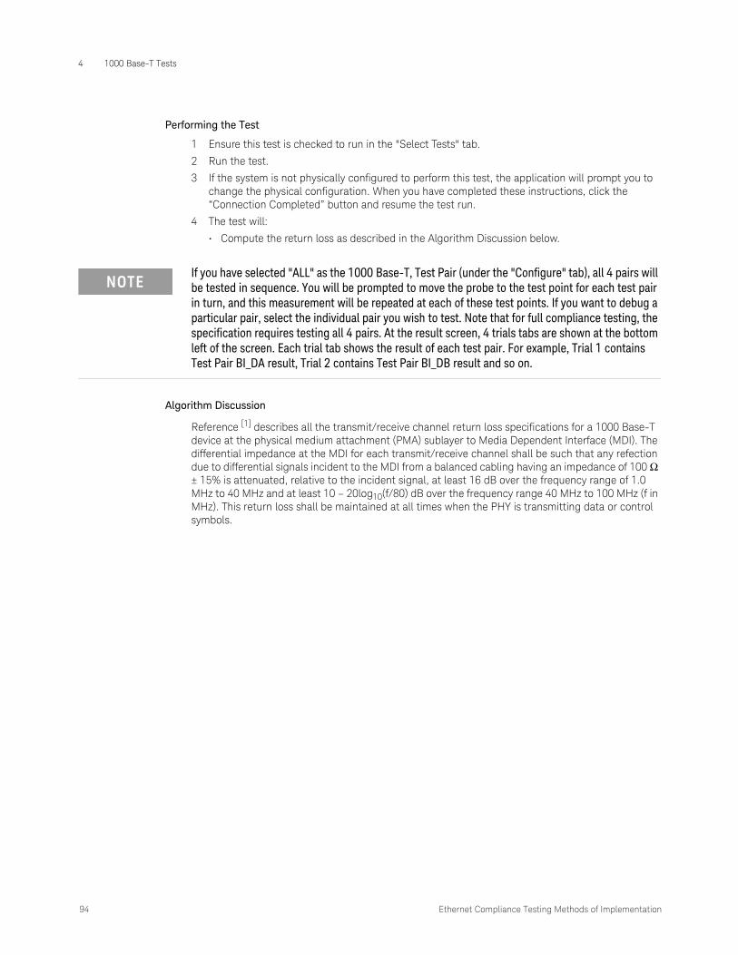
4 1000 Base-T Tests
94 Ethernet Compliance Testing Methods of Implementation
Performing the Test
1 Ensure this test is checked to run in the "Select Tests" tab.
2 Run the test.
3 If the system is not physically configured to perform this test, the application will prompt you to change the physical configuration. When you have completed these instructions, click the “Connection Completed” button and resume the test run.
4 The test will:
• Compute the return loss as described in the Algorithm Discussion below.
Algorithm Discussion
Reference [1] describes all the transmit/receive channel return loss specifications for a 1000 Base-T device at the physical medium attachment (PMA) sublayer to Media Dependent Interface (MDI). The differential impedance at the MDI for each transmit/receive channel shall be such that any refection due to differential signals incident to the MDI from a balanced cabling having an impedance of 100 Ω ± 15% is attenuated, relative to the incident signal, at least 16 dB over the frequency range of 1.0 MHz to 40 MHz and at least 10 – 20log10(f/80) dB over the frequency range 40 MHz to 100 MHz (f in MHz). This return loss shall be maintained at all times when the PHY is transmitting data or control symbols.
NOTEIf you have selected "ALL" as the 1000 Base-T, Test Pair (under the "Configure" tab), all 4 pairs will be tested in sequence. You will be prompted to move the probe to the test point for each test pair in turn, and this measurement will be repeated at each of these test points. If you want to debug a particular pair, select the individual pair you wish to test. Note that for full compliance testing, the specification requires testing all 4 pairs. At the result screen, 4 trials tabs are shown at the bottom left of the screen. Each trial tab shows the result of each test pair. For example, Trial 1 contains Test Pair BI_DA result, Trial 2 contains Test Pair BI_DB result and so on.

Keysight D9010ETHC Ethernet Compliance Test Application
Methods of Implementation
5 100 Base-TX Tests
Probing for 100 Base-TX Tests / 96Peak Voltage Tests / 99Overshoot Tests / 102Template Tests / 104Rise and Fall Time Tests / 106DCD/Jitter Tests / 108Transmitter Return Loss / 113Receiver Return Loss / 118
This section provides the Methods of Implementation (MOIs) for 100 Base-TX tests using a Keysight Infiniium oscilloscope, probes, and the Ethernet Compliance Test Application.

5 100 Base-TX Tests
96 Ethernet Compliance Testing Methods of Implementation
Probing for 100 Base-TX Tests
Connectivity for 100 Base-TX tests depends on whether you need a link partner to obtain the scrambled /idle/ sequence. If your device does not require a link partner, see “Probing for 100 Base-TX Tests, Without Link Partner. Otherwise, if your device does require a link partner, see “Probing for 100 Base-TX Tests, With Link Partner.
Probing for 100 Base-TX Tests, Without Link Partner
When performing the 100 Base-TX tests without a link partner, the Ethernet Compliance Test Application will prompt you to make the proper connections (also shown in Figure 31).

Ethernet Compliance Testing Methods of Implementation 97
100 Base-TX Tests 5
1 Connect the DUT to the RJ45 connector on section 2 of the Ethernet test fixture (load and probes) using a short UTP cable.
2 Connect an InfiniiMax probe with differential socketed probe head to test point TP4, and to the configured “Data” channel of the oscilloscope.
3 Ensure correct polarity of the probe head.
You can use any of the oscilloscope channels for probing the test point. You can identify the channel used in the Configure tab of the Ethernet Compliance Test Application. (The channel shown in Figure 31 is just for example.)
Figure 31 Probing for 100 Base-TX Tests, Without Link Partner
DUT
Section 2 of test fixture
InfiniiMax probe and E2678A/B socketed probe head
RJ45

5 100 Base-TX Tests
98 Ethernet Compliance Testing Methods of Implementation
Probing for 100 Base-TX Tests, With Link Partner
When performing the 100 Base-TX tests with a link partner, the Ethernet Compliance Test Application will prompt you to make the proper connections (also shown in Figure 32).
1 Connect the DUT to the RJ45 connector on fixture 6 marked DUT (J9) using a short UTP cable.
2 Connect a 100 Base-TX link partner to the RJ45 connector on fixture 6 marked LP (J8) using a short UTP cable.
3 Connect an InfiniiMax differential probe with E2678A/B differential socketed probe head to TP12 and to the configured “DUT Data” channel on the oscilloscope.
4 Using two jumpers, short the 100Ω load on fixture 6.
You can use any of the oscilloscope channels for probing the test point. You can identify the channel used in the Configure tab of the Ethernet Compliance Test Application. (The channel shown in Figure 32 is just for example.)
Figure 32 Probing for 100 Base-TX Tests, With Link Partner
InfiniiMax probe and E2678A/B socketed probe head
RJ45
TP12
DUT
Section 6 of test fixture
Link Partners

Ethernet Compliance Testing Methods of Implementation 99
100 Base-TX Tests 5
Peak Voltage Tests
UTP +Vout Differential Output Voltage
UTP -Vout Differential Output Voltage
The UTP +/-Vout Differential Output Voltage tests are to verify that the differential output voltage of the device under test (DUT) is within the conformance limits.
References
[1] IEEE 802.3-2018, clause 25.
[2] ANSI X3.263-1995, Section 9.1.2.2.
Probing Setup
Refer to “Probing for 100 Base-TX Tests" on page 96. This probing configuration is used for all 100 Base-TX tests.
Device Configuration
1 Configure the DUT for 100 Base-TX operation.
2 Ensure that the DUT is sending scrambled, MLT-3 encoded /I/ code-groups (this is a 3-level pseudo-random bit sequence).
Performing the Test
1 Ensure this test is checked to run in the “Select Tests” tab.
2 Run the test.
3 If the system is not physically configured to perform this test, the application will prompt you to change the physical configuration. When you have completed these instructions, click the “Connection Completed” button and resume the test run.
4 The test will:
• Verify that the correct test signal is present on the configured Data channel.
• Configure the oscilloscope to capture a 96 ns pulse.
• Test the signal against conformance parameters, recording the result.
Algorithm Discussion
Reference [1] describes the operation of the Physical Medium Dependent (PMD) sublayer for 100 Base-TX devices. This clause incorporates ANSI X3.263-1995, by reference, with the exceptions listed in 25.4. Reference [2] defines the differential output voltage at the Active Output Interface (AOI) for operation over unshielded twisted pair (UTP).
The reference for this measurement is defined by the standard as an output waveform consisting of 14 bit times of no transition preceded by a transition from 0 V to Vout. This reference waveform was chosen under the assumption that the DUT would be sending scrambled, MLT-3 encoded /H/ code-groups. While this is normal for an FDDI device, it is not straightforward to get a 100 Base-TX device to generate this sequence. A 100 Base-TX device normally generates scrambled, MLT-3 encoded /I/ code-groups in which one may find 12 bit times (96 ns) of no transition preceded by a transition from 0 V to Vout. Thus, a 96 ns pulse is used as the reference for our measurement.
This algorithm measures Vout as the mean voltage over the time range defined in Figure 33. This time range extends from 8 ns after the signal rise crosses 50% of Vout to 8 ns before the signal fall crosses 50% of Vout. The figure depicts +Vout. A similar measurement is made for -Vout considering the negative going pulse.

5 100 Base-TX Tests
100 Ethernet Compliance Testing Methods of Implementation
In compliance mode, averaging is used for enhanced accuracy. Note that other 100 Base-TX measurements depend on the accurate measurement of Vout.
Signal Amplitude Symmetry
The Signal Amplitude Symmetry test is to verify that the differential output signal amplitude symmetry of the device under test (DUT) is within the conformance limits.
References
[1] IEEE 802.3-2018, clause 25.
[2] ANSI X3.263-1995, Section 9.1.2.2.
Probing Setup
Refer to “Probing for 100 Base-TX Tests" on page 96. This probing configuration is used for all 100 Base-TX tests.
Device Under Test Configuration
1 Configure the DUT for 100 Base-TX operation.
2 Ensure that the DUT is sending scrambled, MLT-3 encoded /I/ code-groups (this is a 3-level pseudo-random bit sequence).
Figure 33 Mean Voltage Over the Time Range
+Vout
-Vout
0
8 ns 8 ns
96 ns
Vout is the mean voltage over this range

Ethernet Compliance Testing Methods of Implementation 101
100 Base-TX Tests 5
Performing the Test
1 Ensure this test is checked to run in the “Select Tests” tab.
2 Run the test.
3 If the system is not physically configured to perform this test, the application will prompt you to change the physical configuration. When you have completed these instructions, click the “Connection Completed” button and resume the test run.
4 The test computes its results entirely from the results of the following prerequisite tests:
• UTP +Vout Differential Output Voltage.
• UTP -Vout Differential Output Voltage.
5 If the prerequisite tests have not yet been run, they are first run.
6 The test will compute the symmetry as follows:
Symmetry = | +Vout/ -Vout |
The allowable range is 0.98V to 1.020V.
NOTEThe specified constraints for this measurement are extremely tight. If this test fails, please consult the vertical gain specifications for your oscilloscope before drawing any conclusions about conformance.

5 100 Base-TX Tests
102 Ethernet Compliance Testing Methods of Implementation
Overshoot Tests
+Vout Overshoot
-Vout Overshoot
The UTP +/-Vout Differential Output Voltage tests are to verify that the waveform overshoot of the device under test (DUT) is within the conformance limits.
References
[1] IEEE 802.3-2018, clause 25.
[2] ANSI X3.263-1995, Section 9.1.3.
Probing Setup
Refer to “Probing for 100 Base-TX Tests" on page 96. This probing configuration is used for all 100 Base-TX tests.
Device Configuration
1 Configure the DUT for 100 Base-TX operation.
2 Ensure that the DUT is sending scrambled, MLT-3 encoded /I/ code-groups (this is a 3-level pseudo-random bit sequence).
Performing the Test
1 Ensure this test is checked to run in the "Select Tests" tab.
2 Run the test.
3 If the system is not physically configured to perform this test, the application will prompt you to change the physical configuration. When you have completed these instructions, click the “Connection Completed” button and resume the test run.
4 The test will:
• Verify that the correct test signal is present on the configured "DUT Data" channel.
• Configure the oscilloscope to capture a 96 ns pulse.
• Compute the waveform overshoot as described in the Algorithm Discussion below, compare this value against conformance parameters, recording the result.
Algorithm Discussion
Reference [1] describes the operation of the Physical Medium Dependent (PMD) sublayer for 100 Base-TX devices. This clause incorporates ANSI X3.263-1995, by reference, with the exceptions listed in 25.4. Reference [2] defines the waveform overshoot at the Active Output Interface (AOI).
The specification does not define a reference waveform for this measurement. We adopt the same reference waveform used in +/-Vout Differential Output voltage waveforms (a 96 ns pulse). See “Peak Voltage Tests" on page 99.
Waveform overshoot is defined as the relative percentage of the worst excursion of the signal transition beyond its final adjusted value. Accurately determining the end of the signal transition may be difficult.
This algorithm determines the waveform overshoot as follows:
• Measure the peak voltage over the waveform from the time of the 50% crossing point to a time 8 ns after this point. Define this worst excursion as Vpeak.
• Compute the waveform overshoot as (Vpeak - Vout)/Vout * 100%.

Ethernet Compliance Testing Methods of Implementation 103
100 Base-TX Tests 5
• Note that this measurement requires the Vout measurement (a separate test).
The waveform overshoot must be less than 5%. Waveform overshoot is computed using the above method for both positive going and negative going transitions. In compliance mode, averaging is used to reduce measurement noise and increase measurement resolution.
Figure 34 Waveform Overshoot Reference Waveform
+Vout
-Vout
0
8 ns
96 ns
+Vpeak

5 100 Base-TX Tests
104 Ethernet Compliance Testing Methods of Implementation
Template Tests
UTP AOI Template
The UTP AOI Template test is provided for informative purposes. The specification does not require that this test be run, but it may be useful in providing insight of potential signal quality issues.
References
[1] IEEE 802.3-2018, clause 25.
[2] ANSI X3.263-1995, Annex J.
Probing Setup
Refer to “Probing for 100 Base-TX Tests" on page 96. This probing configuration is used for all 100 Base-TX tests.
Device Configuration
1 Configure the DUT for 100 Base-TX operation.
2 Ensure that the DUT is sending scrambled, MLT-3 encoded /I/ code-groups (this is a 3-level pseudo-random bit sequence).
Performing the Test
1 Ensure this test is checked to run in the "Select Tests" tab.
2 Run the test.
3 If the system is not physically configured to perform this test, the application will prompt you to change the physical configuration. When you have completed these instructions, click the “Connection Completed” button and resume the test run.
4 The test will:
• Verify that the correct test signal is present on the configured "DUT Data" channel.
• Configures the oscilloscope to trigger the signal.
• Automatically aligns the mask to the waveform as indicated in the Algorithm Discussion.
• Window the signal in order to test the top part of the mask.
• Acquire a number of waveforms as configured by the user, testing each waveform against the mask. The total number of failures on the top part of the mask is recorded.
• Window the signal in order to test the bottom part of the mask.
• Acquire a number of waveforms as configured by the user, testing each waveform against the mask. The total number of failures on the bottom part of the mask is recorded.
• The total number of failures (top + bottom) is recorded.
NOTEIf alignment fails you can either retry automatic alignment or go to the oscilloscope and manually align the mask to the signal before pressing "Next" to continue.

Ethernet Compliance Testing Methods of Implementation 105
100 Base-TX Tests 5
Algorithm Discussion
Reference [1] describes the operation of the Physical Medium Dependent (PMD) sublayer for 100 Base-TX devices. This clause incorporates ANSI X3.263-1995, by reference, with the exceptions listed in 25.4. Reference [2] defines the informative only AOI Template test at the Active Output Interface (AOI).
The specification does not require this test. It is provided for informative purposes. The template in Figure J.1 of Reference[2] is first centered vertically on the eye pattern baseline. It is then translated horizontally and scaled in amplitude for the best fit to the eye pattern. The scaling range is limited to the range specified in Reference[2] (0.95 and 1.05 for UTP).
Once the mask is aligned to the signal, the software analyzes the top portion of the mask. This reduces the contribution of vertical noise error to the measurement. The application acquires a configurable number of waveforms. Each waveform is tested against the mask. The total number of failures for the top half of the mask is recorded.
The above procedure is repeated for the bottom half of the mask, recording the number of failures for the bottom as well. The total number of failures is reported. Ideally, the total number of failures should be zero, though this is not a requirement for conformance.

5 100 Base-TX Tests
106 Ethernet Compliance Testing Methods of Implementation
Rise and Fall Time Tests
This section deals with all the 100 Base-TX Rise and Fall time measurements. The following tests are covered:
AOI +Vout Rise Time
AOI +Vout Fall Time
AOI +Vout Rise/Fall Symmetry
AOI -Vout Rise Time
AOI -Vout Fall Time
AOI -Vout Rise/Fall Symmetry
AOI Overall Rise/Fall Symmetry
Test Purpose
References
[1] IEEE 802.3-2018, clause 25.
[2] ANSI X3.263-1995, Subclause 9.1.6.
Table 17 100 Base-TX Rise and Fall time Tests
Test Purpose
AOI +Vout Rise Time To verify that the signal rise of the positive pulse (0 to +Vout) of the device under test (DUT) is within the conformance limits (3 to 5 ns).
AOI +Vout Fall Time To verify that the signal fall of the positive pulse (+Vout to 0) of the device under test (DUT) is within the conformance limits (3 to 5 ns).
AOI +Vout Rise/Fall Symmetry To verify that the difference between all measured rise and fall times of the positive pulse (+Vout) of the device under test (DUT) is within the conformance limits (500 ps).
AOI -Vout Rise Time To verify that the signal rise of the negative pulse (0 to -Vout) of the device under test (DUT) is within the conformance limits (3 to 5 ns).
AOI -Vout Fall Time To verify that the signal fall of the negative pulse (-Vout to 0) of the device under test (DUT) is within the conformance limits (3 to 5 ns).
AOI -Vout Rise/Fall Symmetry To verify that the difference between all measured rise and fall times of the positive pulse (+Vout) of the device under test (DUT) is within the conformance limits (500 ps).
AOI Overall Rise/Fall Symmetry To verify that the difference between the maximum and minimum value from all the measured rise and fall times of the positive pulse (+Vout) and negative pulse (-Vout) of the device under test (DUT) is within the conformance limits (500 ps).

Ethernet Compliance Testing Methods of Implementation 107
100 Base-TX Tests 5
Probing Setup
Refer to “Probing for 100 Base-TX Tests" on page 96. This probing configuration is used for all 100 Base-TX tests.
Device Configuration
1 Configure the DUT for 100 Base-TX operation.
2 Ensure that the DUT is sending scrambled, MLT-3 encoded /I/ code-groups (this is a 3-level pseudo-random bit sequence).
Performing the Test
1 Ensure this test is checked to run in the "Select Tests" tab.
2 Run the test.
3 If the system is not physically configured to perform this test, the application will prompt you to change the physical configuration. When you have completed these instructions, click the “Connection Completed” button and resume the test run.
4 The test will:
• Verify that the correct test signal is present on the configured "DUT Data" channel.
• Configure the oscilloscope to capture a 96 ns pulse.
• Compute the waveform overshoot as described in the Algorithm Discussion below, compare this value against conformance parameters, recording the result.
Algorithm Discussion
Figure 35 Rise and Falltime Reference Waveform
+Vout
-Vout
0
24 ns 16 ns80 ns

5 100 Base-TX Tests
108 Ethernet Compliance Testing Methods of Implementation
DCD/Jitter Tests
Transmit Jitter
The 100 Base-TX Transmit Jitter test ensures that the total transmit jitter of the signal at the Active Output Interface (AOI) is within conformance limits.
References
[1] IEEE 802.3-2018, clause 25.
[2] ANSI X3.263-1995, Subclause 9.1.9.
Probing Setup
Refer to “Probing for 100 Base-TX Tests" on page 96. This probing configuration is used for all 100 Base-TX tests.
Device Configuration
1 Configure the DUT for 100 Base-TX operation.
2 Ensure that the device is sending scrambled, MLT-3 encoded /I/ code-groups (this is a 3-level pseudo-random bit sequence).
Performing the Test
1 Ensure this test is checked to run in the "Select Tests" tab.
2 Run the test.
3 If the system is not physically configured to perform this test, the application will prompt you to change the physical configuration. When you have completed these instructions, click the “Connection Completed” button and resume the test run.
4 The test will:
• Verify that the correct test signal is present on the configured "DUT Data" channel.
• Configure the oscilloscope to capture the waveform.
• Use a software implemented 125 MHz PLL to recover the clock from the data, and synchronize the oscilloscope to the recovered clock.
• The application acquires a number of waveforms to achieve the user-configurable total number of UI. Note that the number of actual crossings measured will be less than the total number of UI acquired, because not every UI results in a crossing at the threshold.
• Window the signal to the top crossing. Acquire half of the total requested UI, measuring the width of the top crossing.
• Window the signal to the bottom crossing. Acquire half of the total requested UI, measuring the width of the bottom crossing.
• Compute the peak-to-peak jitter as the maximum width crossing (top or bottom).
NOTEYou can also have the device send scrambled, MLT-3 encoded /H/ code-groups for this test.

Ethernet Compliance Testing Methods of Implementation 109
100 Base-TX Tests 5
Algorithm Discussion
Reference [1] describes the operation of the Physical Medium Dependent (PMD) sublayer for 100 Base-TX devices. This clause incorporates ANSI X3.263-1995, by reference, with the exceptions listed in 25.4. Reference [2] defines the total transmit jitter at the Active Output Interface (AOI).
Reference[2] indicates that the measurement should be performed on scrambled, MLT-3 encoded /H/ code-groups. Reference [1] which supersedes the ANSI specification states that this measurement may alternatively be made on scrambled, MLT-3 encoded /I/ code-groups.
Note that the specification does not provide any requirements or suggestions as to the population over which to compute total jitter, or the BER at which to measure jitter. Because jitter is a statistical phenomenon, with some random components, measuring jitter over a larger population will provide increasingly larger peak-to-peak values (the tails of a Gaussian distribution are infinitely long).
In general, in order to accurately determine peak-to-peak jitter, we recommend that the jitter be measured over 100M UI. This corresponds to a BER of 10^8. However, measuring jitter over such a large population is often impractical. The user can configure the number of UI over which to measure jitter in the Configure tab of the application. The default value of 100,000 UI is a trade off of statistical confidence for runtime efficiency. However, the user may wish to run this measurement over a smaller population, to decrease runtime, or a larger population, to increase statistical confidence.
The specification does not provide any specific constraints on the size of the jitter population or statistical confidence of the measurement.
It is clear from Reference [2] that the jitter measurement should include contributions from duty cycle distortion and baseline wander. Note that there are two crossing (top and bottom) at which we must measure jitter. While the specification provides no explicit instructions for choosing thresholds, we must choose voltage thresholds at which to measure the crossing points.
Figure 14 of Subclause 9.1.8 of the ANSI specification clearly defines the positive 50% crossing threshold as +Vout/2. However, the specification does not clearly indicate whether the bottom threshold should be -(+Vout/2) or (-Vout)/2. Because this measurement is to include the effects of duty cycle distortion and baseline wander, we choose the bottom threshold as -(+Vout/2).
Figure 36 illustrates the effects of choosing -(+Vout/2) as the bottom crossing threshold. The reference waveform is redrawn with exaggerated baseline wander. Note that the choice of -(+Vout/2) as the bottom threshold results in worse duty cycle distortion value than if -Vout/2 were chosen as the negative threshold.
Jitter is measured as the deviation of measured timing instants from an ideal timing reference. It is not clear from the specification whether the transmit clock or a recovered clock is to be used for a timing reference. To simplify the test setup, we assume the recovered clock as the timing reference for jitter. The recovered clock is derived from the data signal by applying the software equivalent of a 125 MHz phase locked loop (PLL) phase locked to the data signal.
The application windows the signal at the top crossing point and bottom crossing point in two steps. This is done in order to minimize the effects of vertical noise on the measurement. Half the requested number of jitter UI are acquired at the top crossing, and the other half are acquired at the bottom crossing. The crossing widths of the top and bottom crossings are recorded, and the peak-to-peak jitter is computed as the largest of these two crossing widths. For a compliant device, the peak-to-peak jitter must not exceed 1.4 ns.
Duty Cycle Distortion
The 100 Base-TX Duty Cycle Distortion test ensures that the peak-to-peak Duty Cycle Distortion of the signal at the Active Output Interface (AOI) is within conformance limits.

5 100 Base-TX Tests
110 Ethernet Compliance Testing Methods of Implementation
References
[1] IEEE 802.3-2018, clause 25.
[2] ANSI X3.263-1995, Subclause 9.1.8.
Probing Setup
Refer to “Probing for 100 Base-TX Tests" on page 96. This probing configuration is used for all 100 Base-TX tests.
Device Configuration
1 Configure the DUT for 100 Base-TX operation.
2 Ensure that the DUT is sending the MLT-3 encoded 01010101 NRZ bit sequence as shown in Figure 36.
Performing the Test
1 Ensure this test is checked to run in the "Select Tests" tab.
2 Run the test.
3 If the system is not physically configured to perform this test, the application will prompt you to change the physical configuration. When you have completed these instructions, click the “Connection Completed” button and resume the test run.
4 The test will:
• Verify that the correct test signal is present on the configured "DUT Data" channel.
• Configure the oscilloscope to capture the waveform.
• Measure the edge times of the 4 edges t0-t3 as indicated in the Algorithm Discussion.
• Compute the edge differences as indicated in the Algorithm Discussion. Differences are computed for:
• t1-t0 (nominally 16 ns)
• t2-t1 (nominally 16 ns)
• t3-t2 (nominally 16 ns)
• t2-t0 (nominally 32 ns)
• t3-t1 (nominally 32 ns)
• t3-t0 (nominally 48 ns)
• Compute the worst case peak-to-peak Duty Cycle Distortion as the largest deviation from the nominal distance.
NOTEYou may send maximum length packets with a payload of 010101...
NOTEAlternatively, you may have the device send scrambled, MLT-3 encoded /I/ code-groups (this is a 3-level pseudo-random bit sequence).

Ethernet Compliance Testing Methods of Implementation 111
100 Base-TX Tests 5
Algorithm Discussion
Reference [1] describes the operation of the Physical Medium Dependent (PMD) sublayer for 100 Base-TX devices. This clause incorporates ANSI X3.263-1995, by reference, with the exceptions listed in 25.4. Reference [2] defines duty cycle distortion (DCD) at the Active Output Interface (AOI).
Reference[2] indicates a reference waveform of 4 successive MLT-3 transitions generated by the MLT-3 encoded NRZ bit sequence 01010101. We further distinguish our reference waveform as one that is preceded and followed by at least two symbols at the baseline voltage (the exact sequence chosen as the reference waveform is 000101010100). This choice of a reference waveform reduces the effects of intersymbol interference (ISI).
It is clear from Figure 14 in Reference[2] that the threshold for measuring the 50% crossing of positive-going pulses should be (+Vout)/2. Note that figure 14 in Reference [2] depicts an ideal waveform, so it is not explicitly clear whether the bottom threshold should be chosen as (-Vout)/2 or -(+Vout/2).
It is clear from clause 9.1.9 that the jitter measurement should include contributions from duty cycle distortion and baseline wander. It is therefore assumed that the duty cycle distortion measurement should include effects of baseline wander. Therefore, we choose the bottom threshold for the 50% crossing times as -(+Vout/2), that is, the negative of +Vout/2.
Figure 36 illustrates the effects of choosing -(+Vout/2) as the bottom crossing threshold. The reference waveform is redrawn with exaggerated baseline wander. Note that the choice of -(+Vout/2) as the bottom threshold causes a worst peak-to-peak duty cycle distortion value than if -Vout/2 were chosen as the negative threshold.
As indicated in Figure 36, the 4 successive 50% crossing times are measured. These are named t0, t1, t2, and t3 respectively. The specification states that the deviations of the 50% crossing times from a best fit grid of 16 ns shall not exceed +/- 250 ps. We validate this specification in terms of the peak-to-peak duty cycle distortion requirement of 500 ps. This is done as follows:
Measure t0, t1, t2, and t3. Then Measure the following time differences between edges, and record the deviation of the actual difference from the expected value:
Figure 36 Bottom Threshold
0 Volts
Time (us)t0 t1 t2
+Vout/2
-(Vout/2)
-Vout
+Vout

5 100 Base-TX Tests
112 Ethernet Compliance Testing Methods of Implementation
The largest deviation of these measurements from its expected value is the worst case peak-to-peak duty cycle distortion. For a compliant DUT this worst case DCD must not exceed 500 ps.
Table 18 Time Differences Between Edges
Measurement Expected Value
t1-t0 16 ns
t2-t1 16 ns
t3-t2 16 ns
t2-t0 32 ns
t3-t1 32 ns
t3-t0 48 ns

Ethernet Compliance Testing Methods of Implementation 113
100 Base-TX Tests 5
Transmitter Return Loss
This section describes the 100 Base-TX Transmitter Return Loss test as per ANSI X3.263-1995, Subclause 9.1.5. The test procedures described in this section cover the Transmitter Return Loss measurement required by the specification.
Reference
[1] ANSI X3.263-1995, Subclause 9.1.5
NOTEThis section shows the use of a Vector Network Analyzer (VNA) used for testing Transmitter Return Loss. However, you can use in place of the VNA an exported VNA file in either the Touchstore or CITI file format.

5 100 Base-TX Tests
114 Ethernet Compliance Testing Methods of Implementation
Calibrating the VNA
Before using the VNA, it must be calibrated using the Return Loss Calibration board. See Figure 37 for the connection diagram.
1 Connect the Return Loss Calibration board RJ45 connector labeled OPEN to the RJ45 connector on fixture 1 using a short straight-through UTP cable.
2 Connect one end of two short SMA-to-SMA cables to the SMA test points for the pair A you are testing on fixture 1, and the other end to the two SMA (X97 and X98) test points on fixture 10.
3 Connect a VNA input to the SMA (X99) test point on fixture 10.
Figure 37 VNA Calibration
Section 10 of test fixture
Section 1 of test fixture
Return Loss Calibration board
RJ45
Short SMA cables
SMA cable
VNA
OPEN
SHORT
LOAD

Ethernet Compliance Testing Methods of Implementation 115
100 Base-TX Tests 5
4 Calibrate the VNA using the instructions in the VNA’s User’s Guide. The following is a list of setup requirements.
• Set Meas to Ref1 Fwd S11.
• Set Start to 2 MHz.
• Set Stop to 80 MHz.
• Set Format to Log Mag.
• Set Scale Div to 5.
• Set Scale Ref to reference line position 9.
5 Run the calibration for the OPEN, SHORT, and LOAD connections.
Probing Setup for Transmitter Return Loss
NOTEBefore starting a test, you can view these connection instructions under the application’s Connect tab. If connection changes are necessary while tests are running, the application automatically prompts you with new connection instructions.

5 100 Base-TX Tests
116 Ethernet Compliance Testing Methods of Implementation
1 Connect the DUT to the RJ45 connector on fixture 1 using a short straight-through UTP cable.
2 Connect one end of two short SMA-to-SMA cables to the SMA test points for testing the pair A on fixture 1, and the other end to the two SMA (X97 and X98) test points on fixture 10.
3 Connect a VNA input to the SMA (X99) test point on fixture 10.
4 Connect a GPIB cable to the 82357A GPIB port and to the GPIB port on the VNA.
5 Connect the 82357A USB connector to a USB port on the scope.
Device Configuration
1 Configure the DUT for 100 Base-TX operation. Ensure that the DUT is sending scrambled, MLT-3 encoded /I/ code-groups.
Performing the Test
1 Ensure this test is checked to run in the "Select Tests" tab.
2 Run the test.
Figure 38 Probing for 100 Base-TX Transmitter Return Loss
Section 10 of test fixture
Section 1 of test fixture
DUT
RJ45
Short SMA cables
SMA cable
To USB Connector 82357A
GPIB Cable
VNA

Ethernet Compliance Testing Methods of Implementation 117
100 Base-TX Tests 5
3 If the system is not physically configured to perform this test, the application will prompt you to change the physical configuration. When you have completed these instructions, click the “Connection Completed” button and resume the test run.
4 The test will:
• Compute the return loss as described in the Algorithm Discussion below.
Algorithm Discussion
Reference [1] describes all the receive channel return loss specifications for a 100 Base-T device at the physical medium attachment (PMA). The UTP and STP Active Output Interface shall be implemented such that the following return loss characteristics are satisfied for each of the specified line impedances.
• Greater than 16 dB from 2 MHz to 30 MHz
• Greater than (16 – 20log10(f/30 MHz)) dB from 30 MHz to 60 MHz
• Greater than 10 dB from 60 MHz to 80 MHz
The impedance environment for the measurement of the UTP AOI return loss shall be 100 Ω ± 15 Ω; the environment for the STP AOI return loss shall be 150 Ω ± 15 Ω. The impedance environments shall be nominally resistive, with a magnitude of phase angle less than 3° over the specified measurement frequency range.
5 100 Base-TX Tests
118 Ethernet Compliance Testing Methods of Implementation
Receiver Return Loss
This section describes the 100 Base-TX Receiver Return Loss test as per ANSI X3.263-1995, Subclause 9.2.2. The test procedures described in this section cover the Receiver Return Loss measurement required by the specification.
Reference
[1] ANSI X3.263-1995, Subclause 9.2.2
NOTEThis section shows the use of a Vector Network Analyzer (VNA) used for testing Receiver Return Loss. However, you can use in place of the VNA an exported VNA file in either the Touchstore or CITI file format.

Ethernet Compliance Testing Methods of Implementation 119
100 Base-TX Tests 5
Calibrating the VNA
Before using the VNA, it must be calibrated using the Return Loss Calibration board. See Figure 39 for the connection diagram.
1 Connect the Return Loss Calibration board RJ45 connector labeled OPEN to the RJ45 connector on fixture 1 using a short straight-through UTP cable.
2 Connect one end of two short SMA-to-SMA cables to the SMA test points for the pair B you are testing on fixture 1, and the other end to the two SMA (X97 and X98) test points on fixture 10.
3 Connect a VNA input to the SMA (X99) test point on fixture 10.
Figure 39 VNA Calibration
Return Loss Calibration board
SMA cable
VNA
Section 1 of test fixture
LOAD
SHORT
OPEN
Section 10 of test fixture
Short SMAcables
RJ45

5 100 Base-TX Tests
120 Ethernet Compliance Testing Methods of Implementation
4 Calibrate the VNA using the instructions in the VNA’s User’s Guide. The following is a list of setup requirements.
• Set Meas to Ref1 Fwd S11.
• Set Start to 2 MHz.
• Set Stop to 80 MHz.
• Set Format to Log Mag.
• Set Scale Div to 5.
• Set Scale Ref to reference line position 9.
5 Run the calibration for the OPEN, SHORT, and LOAD connections.
Probing Setup for Receiver Return Loss
NOTEBefore starting a test, you can view these connection instructions under the application’s Connect tab. If connection changes are necessary while tests are running, the application automatically prompts you with new connection instructions.

Ethernet Compliance Testing Methods of Implementation 121
100 Base-TX Tests 5
1 Connect the DUT to the RJ45 connector on fixture 1 using a short straight-through UTP cable.
2 Connect one end of two short SMA-to-SMA cables to the SMA test points for testing the pair B on fixture 1, and the other end to the two SMA (X97 and X98) test points on fixture 10.
3 Connect a VNA input to the SMA (X99) test point on fixture 10.
4 Connect a GPIB cable to the 82357A GPIB port and to the GPIB port on the VNA.
5 Connect the 82357A USB connector to a USB port on the scope.
Device Configuration
1 The DUT for 100 Base-TX operation does not require any particular configuration. Simply turn on the DUT and set the DUT to operate in 100 Base-TX to perform the test.
Performing the Test
1 Ensure this test is checked to run in the "Select Tests" tab.
2 Run the test.
Figure 40 Probing for 100 Base-TX Receiver Return Loss
VNA
Section 10 oftest fixture
SMA cable
DUT
Section 1 of test fixture
Short SMA cables
RJ45

5 100 Base-TX Tests
122 Ethernet Compliance Testing Methods of Implementation
3 If the system is not physically configured to perform this test, the application will prompt you to change the physical configuration. When you have completed these instructions, click the “Connection Completed” button and resume the test run.
4 The test will:
• Compute the return loss as described in the Algorithm Discussion below.
Algorithm Discussion
Reference [1] describes all the receive channel return loss specifications for a 100 Base-T device at the physical medium attachment (PMA). The differential input impedance shall be such that the return loss is shown below. The requirement is specified for any reflection due to differential signals incident upon RX+/- from a twisted pair having any impedance within the range specified in ANSI X3.263-1995 Subclause 11.1.1. The return loss shall be maintained when the receiver circuit is powered.
• Greater than 16 dB from 2 MHz to 30 MHz
• Greater than (16 – 20log10(f/30 MHz)) dB from 30 MHz to 60 MHz
• Greater than 10 dB from 60 MHz to 80 MHz

Keysight D9010ETHC Ethernet Compliance Test Application
Methods of Implementation
6 10 Base-T Tests
Measurements with TPM, Template Tests / 125Measurements with TPM, Parametric Tests / 136Measurements without TPM, Template Tests / 139Measurements without TPM, Parametric Tests / 148Common Mode Voltage Tests / 153Configuring 10 Base-T Device Output / 156Transmitter Return Loss / 158Receiver Return Loss / 163

6 10 Base-T Tests
124 Ethernet Compliance Testing Methods of Implementation
Test Loads
Some of the 10 Base-T tests require the use of special loads. Three different loads are defined. Load 1 and Load 2 are defined in Figure 14-11 of IEEE 802.3-2018, subclause 14.3.1.2.2. Load 3 (100 Ω) is defined as a 100 Ω resistive load.

Ethernet Compliance Testing Methods of Implementation 125
10 Base-T Tests 6
Measurements with TPM, Template Tests
Subclause 14.3.1.2 of IEEE 802.3-2018 defines the transmitter specifications for a 10 Base-T Medium Access Unit (MAU) the MAU-to-MDI interface. Some of these tests require the use of an equivalent circuit that models the distortion of a simplex link segment. This is called the Twisted Pair Model (or TPM). The specifications for the TPM are listed in figure 14-7 of IEEE 802.3-2018, subclause 14.3.1.2. These tests use section 7 of the Ethernet Electrical Compliance Test Fixture (“10BT with TP Model”). To simplify test setup, tests requiring the TPM (section 7 of the test fixture) are organized in one section.
Probing for 10 Base-T Tests With the TPM and Link Partner
These probing instructions apply to tests that use the twisted pair model (TPM) and a link partner. Note that some tests (link test pulse template) do not require the use of a link partner. Instructions for those tests are provided in the section for the test.
NOTEBefore starting a test, you can view these connection instructions under the application’s Connect tab. If connection changes are necessary while tests are running, the application automatically prompts you with new connection instructions.

6 10 Base-T Tests
126 Ethernet Compliance Testing Methods of Implementation
1 Connect the DUT to the RJ45 connector on fixture 7 marked DUT (J9) using a short UTP cable.
2 Connect a 10 Base-T link partner to the RJ45 connector on fixture 7 marked Link Port (J8) using a short UTP cable.
3 Connect an InfiniiMax differential probe with E2678A/B differential socketed probe head to TP14 and to the configured “DUT Data” channel on the oscilloscope. This setting is shown in the Configure tab.
4 Using two jumpers, short the appropriate load on fixture 7. This setting is shown in the Configure tab and the loads are labeled on the fixture 7.
Link Test Pulse, with TPM
This test ensures that the link test pulse falls within the shaded area of figure 14-10 of IEEE 802.3-2018, subclause 14.3.1.2.1. This measurement is to be made with the 3 different loads as defined in “Test Loads" on page 124. This test measures the signal across the appropriate load, with the load connected through the twisted pair model (TPM) as defined in figures 14-7 and 14-8 of IEEE 802.3-2018, subclause 14.3.1.2.
Figure 41 Probing for 10 Base-T Tests With the TPM and Link Partner
DUT
Section 7 of test fixture
InfiniiMax probe and E2678A/B socketed probe head
RJ45
Link Partner
TP14

Ethernet Compliance Testing Methods of Implementation 127
10 Base-T Tests 6
References
[1] IEEE 802.3-2018, Subclause 14.3.1.2.1.
[2] IEEE 802.3-2018, Subclause 14.3.1.2.2.
Probing Setup
1 Connect the DUT to the RJ45 connector on fixture 7 marked DUT (J9) using a short UTP cable.
2 Connect a 10 Base-T link partner to the RJ45 connector on fixture 7 marked Link Port (J8) using a short UTP cable.
3 Connect an InfiniiMax differential probe with E2678A/B differential socketed probe head to TP14 with the plus (+) side of the probe head connected to the plus (+) side of TP14. Connect the other end of the probe to the oscilloscope channel selected for “DUT Data” as shown in the Connect tab.
4 Using two jumpers, short the appropriate load on fixture 7. This setting is shown in the Configure tab and the loads are labeled on the fixture 7.
Figure 42 Probing for 10 Base-T Tests With the TPM and Link Partner
DUT
Section 7 of test fixture
InfiniiMax probe and E2678A/B socketed probe head
RJ45
Link Partner
TP14

6 10 Base-T Tests
128 Ethernet Compliance Testing Methods of Implementation
Configuring the Device Under Test (DUT)
1 Reset the DUT if necessary.
2 Ensure that the DUT is transmitting the proper Link Test Pulse as indicated in the connection instructions provided in the user interface.
Performing the Test
1 Ensure this test is checked to run in the "Select Tests" tab.
2 Run the test.
3 If the system is not physically configured to perform this test, the application will prompt you to change the physical configuration. When you have completed these instructions, click the “Connection Completed” button and resume the test run.
4 The test will:
• Verify that the correct test signal is present on the configured "DUT Data" channel.
• Configure the oscilloscope to capture the link test pulse.
• Load the mask for the start of the link test pulse.
• Capture a (user configurable) number of pulses (with user defined amount of averaging), testing each pulse against start of the mask.
• Record the number of mask failures for the start of the link test pulse.
• Load the mask for the end of the link test pulse.
• Capture a (user configurable) number of pulses (with user defined amount of averaging), testing each pulse against the end of the mask.
• Record the number of mask failures for the end of the link test pulse.
• Compute the total number of failures (start + end).
Algorithm Discussion
Reference [1] defines the link-test pulse template specifications a 10 Base-T Medium Access Unit (MAU) at the MAU-to-MDI interface. This test requires the use of the twisted pair model (TPM) as defined in figure 14-7 of IEEE 802.3-2018, subclause 14.3.1.2.
This test ensures that the link test pulse falls within the shaded area of figure 14-12 of Reference [1]. This measurement is to be made with the 3 different loads as defined in “Test Loads" on page 124. This test measures the signal with across the appropriate load, with the load connected through the twisted pair model (TPM).
NOTEBefore starting a test, you can view these connection instructions under the application’s Connect tab. If connection changes are necessary while tests are running, the application automatically prompts you with new connection instructions.
NOTEIf you have selected "ALL" as the "10 Base-T LTP/TP_IDL Loads" (under the Configure tab), the 3 required loads will be tested in sequence. You will be prompted to short each load (with jumpers) in turn, and this measurement will be repeated with each load. If you want to debug a particular load, select "Debug Mode" in the Configure tab, and select the individual load you wish to test. Note that for full compliance testing, you should test all 3 loads. At the result screen, 3 trials tabs are shown at the bottom left of the screen. Each trial tab shows the result of each test pair. For example, Trial 1 contains Load 1 result, Trial 2 contains Load 2 result and so on.

Ethernet Compliance Testing Methods of Implementation 129
10 Base-T Tests 6
Because the mask is defined over a large number of bits, measurement performance is improved by testing the signal against the mask in two sections. We test the start of the link-test pulse separately from the end of the link test pulse.
A user configurable number of waveforms are tested against the mask. Note that if the MAU implements the auto negotiation algorithm defined in IEEE 802.3-2018, clause 28, the FLP (fast link pulse) burst sequence will consist of multiple link test pulses. All link test pulses in the FLP burst sequence should pass the template requirements. Keysight recommends testing a large number of pulses to ensure that all link-test pulses in the FLP burst sequence have been observed. The default number of waveforms tested is 100 for this test. The default number of averages is 512.
A user configurable amount of averaging is also utilized to reduce vertical noise errors. The algorithm proceeds as described in the above section "Performing the Test".
TP_IDL Template, with TPM (Last Bit CD0)
This test ensures that the TP_IDL signal falls within the shaded area of figure 14-10 of IEEE 802.3-2018, subclause 14.3.1.2.1. This measurement uses the TP_IDL generated when the last bit transmitted is 0. This measurement is to be made with the 3 different loads as defined in “Test Loads" on page 124. This test measures the signal across the appropriate load, with the load connected through the twisted pair model (TPM) as defined in figures 14-7 and 14-8 of IEEE 802.3-2018, subclause 14.3.1.2.
References
[1] IEEE 802.3-2018, Subclause 14.3.1.2.1.
Probing Setup
Refer to “Probing for 10 Base-T Tests With the TPM and Link Partner" on page 125.
1 Ensure that you short the appropriate load, as indicated in the connectivity instructions in the user interface.
2 Ensure the correct probe polarity.
Device Configuration
1 Reset the DUT if necessary
2 Configure the DUT to output 10 Base-T random data (see “Configuring a 10 Base-T Device to Output Random Data" on page 156).
3 Ensure that the oscilloscope is capturing proper signal (TP_IDL) as indicated in the connection instructions provided in the user interface.
NOTEThe template requirements for this test are specified in such a way that testing with a digital oscilloscope is often impractical. Specifically, the large vertical and horizontal range of the masks will often result in failures when applying automated template test techniques. Specifically, you should exercise your own judgement when failures are marginal to determine if the signal shape is satisfactory.
NOTEBefore starting a test, you can view these connection instructions under the application’s Connect tab. If connection changes are necessary while tests are running, the application automatically prompts you with new connection instructions.

6 10 Base-T Tests
130 Ethernet Compliance Testing Methods of Implementation
Performing the Test
1 Ensure this test is checked to run in the "Select Tests" tab.
2 Run the test.
3 If the system is not physically configured to perform this test, the application will prompt you to change the physical configuration. When you have completed these instructions, click the “Connection Completed” button and resume the test run.
4 The test will:
• Determine the widths of the different TP_IDL pulses. (For a given device, there are two different TP_IDL pulse widths, depending on the value of the last bit in the packet.)
• Using the TP_IDL transmitted when the last bit transmitted is 0, the test will:
• Verify that the correct test signal is present on the configured "DUT Data" channel.
• Configure the oscilloscope to capture this TP_IDL signal width using a user-configurable amount of averaging. This reduces measurement noise and increases measurement accuracy.
• Load the mask for the start of the TP_IDL signal.
• Capture a (user configurable) number of pulses (with user defined amount of averaging), testing each pulse against start of the mask.
• Record the number of mask failures for the start of the TP_IDL signal.
• Load the mask for the end of the TP_IDL signal.
• Capture a (user configurable) number of pulses testing each pulse against the end of the mask.
• Record the number of mask failures for the end of the TP_IDL signal.
• Compute the total number of failures (start + end).
Algorithm Discussion
Reference [1] defines the TP_IDL template specifications of a 10 Base-T Medium Access Unit (MAU) at the MAU-to-MDI interface. This test requires the use of the twisted pair model (TPM) as defined in figure 14-7 of IEEE 802.3-2018, subclause 14.3.1.2.
This test ensures that the TP_IDL signal falls within the shaded area of figure 14-10 of Reference [1]. This measurement is to be made with the 3 different loads as defined in “Test Loads" on page 124. This test measures the signal across the appropriate load, with the load connected through the twisted pair model (TPM).
NOTEAveraging here is only valid because we are isolating the different pulse widths before averaging.
NOTEIf you have selected "ALL" as the "10 Base-T LTP/TP_IDL Loads" (under the Configure tab), the 3 required loads will be tested in sequence. You will be prompted to short each load (with jumpers) in turn, and this measurement will be repeated with each load. If you want to debug a particular load, select "Debug Mode" in the Configure tab, and select the individual load you wish to test. Note that for full compliance testing, you should test all 3 loads. At the result screen, 3 trials tabs are shown at the bottom left of the screen. Each trial tab shows the result of each test pair. For example, Trial 1 contains Load 1 result, Trial 2 contains Load 2 result and so on.

Ethernet Compliance Testing Methods of Implementation 131
10 Base-T Tests 6
Because the mask is defined over a large number of bits, measurement performance is improved by testing the signal against the mask in two sections. We test the start of the TP_IDL separately from the end of the TP_IDL.
The TP_IDL signal indicates the end of a transmitted data sequence. As stated in Reference [1], if the last bit transmitted was a CD1, the last transition will be at the bit cell center of the CD1. If the last bit transmitted was a CD0, the PLS will generate an additional transition at the bit cell boundary following the CD0. After the zero crossing of the last transition, the differential voltage shall remain within the shaded area of Figure 14-10 of Reference [1].
This test will only be triggering the TP_IDL generated when the last bit transmitted is CD0.
A user configurable number of waveforms are tested against the mask. The default number of waveforms tested is 100 for this test. The default number of averages is 512. The algorithm proceeds as described in the above section "Performing the Test".
TP_IDL Template, with TPM (Last Bit CD1)
This test ensures that the TP_IDL signal falls within the shaded area of figure 14-10 of IEEE 802.3-2018, subclause 14.3.1.2.1. This measurement uses the TP_IDL generated when the last bit transmitted is 1. This measurement is to be made with the 3 different loads as defined in “Test Loads" on page 124. This test measures the signal across the appropriate load, with the load connected through the twisted pair model (TPM) as defined in figures 14-7 and 14-8 of IEEE 802.3-2018, subclause 14.3.1.2.
References
[1] IEEE 802.3-2018, Subclause 14.3.1.2.1.
Probing Setup
Refer to “Probing for 10 Base-T Tests With the TPM and Link Partner" on page 125.
1 Ensure that you short the appropriate load, as indicated in the connectivity instructions in the user interface.
2 Ensure the correct probe polarity.
NOTEThe template requirements for this test are specified in such a way that testing with a digital oscilloscope is often impractical. Specifically, the large vertical and horizontal range of the masks will often result in failures when applying automated template test techniques. Specifically, you should exercise your own judgement when failures are marginal to determine if the signal shape is satisfactory.
NOTEBecause the oscilloscope uses special triggering capabilities to qualify both variants of TP_IDL, this test can run slowly. One way to significantly speed up this test is to send very short packets so that the TP_IDL signal occurs frequently.
NOTEBefore starting a test, you can view these connection instructions under the application’s Connect tab. If connection changes are necessary while tests are running, the application automatically prompts you with new connection instructions.

6 10 Base-T Tests
132 Ethernet Compliance Testing Methods of Implementation
Device Configuration
1 Reset the DUT if necessary
2 Configure the DUT to output 10 Base-T random data (see “Configuring a 10 Base-T Device to Output Random Data" on page 156).
3 Ensure that the oscilloscope is capturing proper signal (TP_IDL) as indicated in the connection instructions provided in the user interface.
Performing the Test
1 Ensure this test is checked to run in the "Select Tests" tab.
2 Run the test.
3 If the system is not physically configured to perform this test, the application will prompt you to change the physical configuration. When you have completed these instructions, click the “Connection Completed” button and resume the test run.
4 The test will:
• Determine the widths of the different TP_IDL pulses. (For a given device, there are two different TP_IDL pulse widths, depending on the value of the last bit in the packet.)
• Using the TP_IDL transmitted when the last bit transmitted is 1, the test will:
• Verify that the correct test signal is present on the configured "DUT Data" channel.
• Configure the oscilloscope to capture this TP_IDL signal width using a user-configurable amount of averaging. This reduces measurement noise and increases measurement accuracy.
• Load the mask for the start of the TP_IDL signal.
• Capture a (user configurable) number of pulses (with user defined amount of averaging), testing each pulse against start of the mask.
• Record the number of mask failures for the start of the TP_IDL signal.
• Load the mask for the end of the TP_IDL signal.
• Capture a (user configurable) number of pulses testing each pulse against the end of the mask.
• Record the number of mask failures for the end of the TP_IDL signal.
• Compute the total number of failures (start + end).
NOTEAveraging here is only valid because we are isolating the different pulse widths before averaging.
NOTEIf you have selected "ALL" as the "10 Base-T LTP/TP_IDL Loads" (under the Configure tab), the 3 required loads will be tested in sequence. You will be prompted to short each load (with jumpers) in turn, and this measurement will be repeated with each load. If you want to debug a particular load, select "Debug Mode" in the Configure tab, and select the individual load you wish to test. Note that for full compliance testing, you should test all 3 loads. At the result screen, 3 trials tabs are shown at the bottom left of the screen. Each trial tab shows the result of each test pair. For example, Trial 1 contains Load 1 result, Trial 2 contains Load 2 result and so on.
Ethernet Compliance Testing Methods of Implementation 133
10 Base-T Tests 6
Algorithm Discussion
Reference [1] defines the TP_IDL template specifications of a 10 Base-T Medium Access Unit (MAU) at the MAU-to-MDI interface. This test requires the use of the twisted pair model (TPM) as defined in figure 14-7 of IEEE 802.3-2018, subclause 14.3.1.2.
This test ensures that the TP_IDL signal falls within the shaded area of figure 14-10 of Reference [1]. This measurement is to be made with the 3 different loads as defined in “Test Loads" on page 124. This test measures the signal across the appropriate load, with the load connected through the twisted pair model (TPM).
Because the mask is defined over a large number of bits, measurement performance is improved by testing the signal against the mask in two sections. We test the start of the TP_IDL separately from the end of the TP_IDL.
The TP_IDL signal indicates the end of a transmitted data sequence. As stated in Reference [1], if the last bit transmitted was a CD1, the last transition will be at the bit cell center of the CD1. If the last bit transmitted was a CD0, the PLS will generate an additional transition at the bit cell boundary following the CD0. After the zero crossing of the last transition, the differential voltage shall remain within the shaded area of Figure 14-10 of Reference [1].
This test will only be triggering the TP_IDL generated when the last bit transmitted is CD1.
A user configurable number of waveforms are tested against the mask. The default number of waveforms tested is 100 for this test. The default number of averages is 512. The algorithm proceeds as described in the above section "Performing the Test".
MAU Template
This test ensures that the signal Vo, defined at the output of the twisted pair model (TPM), as defined in figure 14-8 of IEEE 802.3-2018, subclause 14.3.1.2.1, falls within the template defined in Figure 14-9 and Table 14-1 (integrated and external MAU) of IEEE 802.3-2018, subclause 14.3.1.2.1 for all data sequences. This measurement is to be made only with the TPM, and only with the 100 Ω load. This test measures the signal across the appropriate load, with the load connected through the twisted pair model (TPM) as defined in figures 14-7 and 14-8 if IEEE 802.3-2018, subclause 14.3.1.2. This test is run with the DUT configured to output 10 Base-T Random Data.
References
[1] IEEE 802.3-2018, Subclause 14.3.1.2.1.
NOTEThe template requirements for this test are specified in such a way that testing with a digital oscilloscope is often impractical. Specifically, the large vertical and horizontal range of the masks will often result in failures when applying automated template test techniques. Specifically, you should exercise your own judgement when failures are marginal to determine if the signal shape is satisfactory.
NOTEBecause the oscilloscope uses special triggering capabilities to qualify both variants of TP_IDL, this test can run slowly. One way to significantly speed up this test is to send very short packets so that the TP_IDL signal occurs frequently.

6 10 Base-T Tests
134 Ethernet Compliance Testing Methods of Implementation
Probing Setup
Refer to “Probing for 10 Base-T Tests With the TPM and Link Partner" on page 125.
1 Ensure that you short the appropriate load, as indicated in the connectivity instructions in the user interface.
2 Ensure the correct probe polarity.
Device Configuration
1 Reset the DUT if necessary.
2 Configure the DUT to output 10 Base-T random data (see “Configuring a 10 Base-T Device to Output Random Data" on page 156).
3 Ensure that the oscilloscope is capturing proper signal (10 Base-T Random Data) as indicated in the connection instructions provided in the user interface.
Performing the Test
1 Ensure this test is checked to run in the "Select Tests" tab.
2 Run the test.
3 If the system is not physically configured to perform this test, the application will prompt you to change the physical configuration. When you have completed these instructions, click the “Connection Completed” button and resume the test run.
4 The test will:
• Verify that the correct test signal is present on the configured "DUT Data" channel.
• Configure the oscilloscope to capture the 10 Base-T Random Data signal, triggering on the rising edge of the data.
• Load the appropriate mask for the rising data edge:
• Two masks are supported. Depending on the MAU Type (Integrated or External) MAU, as defined in Table 14-1 of Reference [1]. You can select the 10 Base-T MAU type under the Configure tab.
• Scale the mask for the best fit. The template voltage may be scaled by a factor of 0.9 to 1.1, but any scaling below 0.9 or above 1.1 is not allowed.
• Capture a (user configurable) number of waveforms, testing each waveform against the mask.
• Record the number of mask failures for the rising data edge mask.
• Configure the oscilloscope to capture the 10 Base-T Random Data signal, triggering on the rising edge of the data.
• Invert the rising edge data mask about the time axis
• Scale the mask for the best fit. The template voltage may be scaled by a factor of 0.9 to 1.1, but any scaling below 0.9 or above 1.1 is not allowed.
• Capture a (user configurable) number of waveforms, testing each waveform against the mask.
• Record the number of mask failures for the falling data edge mask.
• Compute the total number of failures (rising + falling).
NOTEBefore starting a test, you can view these connection instructions under the application’s Connect tab. If connection changes are necessary while tests are running, the application automatically prompts you with new connection instructions.

Ethernet Compliance Testing Methods of Implementation 135
10 Base-T Tests 6
Algorithm Discussion
Reference [1] defines the internal and external MAU template specifications a 10 Base-T Medium Access Unit (MAU) at the MAU-to-MDI interface. This test requires the use of the twisted pair model (TPM) as defined in figure 14-7 of IEEE 802.3-2018, subclause 14.3.1.2.
This test ensures that the signal Vo, defined at the output of the twisted pair model (TPM), as defined in figure 14-18 of Reference [1], falls within the template defined in Figure 14-9 and Table 14-1 (integrated and external MAU) of Reference [1] for all data sequences. During the test the TPM is terminated in 100 Ω and driven by a transmitter with a Manchester-encoded pseudo-random sequence with a minimum repetition period of 511 bits.
Mask normalization is performed by scaling the mask relative to the signal. Scaling below 0.9 or above 1.1 is not allowed. Two types of MAU masks are supported: integrated and external. The user should select the MAU type in the Configure tab under 10 Base-T MAU Type. The appropriate mask is loaded for the MAU Type selected.
The test is run for data sequences starting with rising and falling edges. These two tests are conducted separately with the mask inverted about the time axis for the falling edge test. The total number of failures should be zero for a compliant device.
A user configurable number of waveforms are tested against the mask. The default number of waveforms is 100 for this test. You may wish to increase this number for more complete validation. The algorithm proceeds as described in the above section "Performing the Test".
NOTEThe template requirements for this test are specified in such a way that testing with a digital oscilloscope is often impractical. Specifically, the large vertical and horizontal range of the masks will often result in failures when applying automated template test techniques. Specifically, you should exercise your own judgment when failures are marginal to determine if the signal shape is satisfactory.

6 10 Base-T Tests
136 Ethernet Compliance Testing Methods of Implementation
Measurements with TPM, Parametric Tests
Subclause 14.3.1.2 of IEEE 802.3-2018 defines the transmitter specifications a 10 Base-T Medium Access Unit (MAU) the MAU-to-MDI interface. Some of these tests require the use of an equivalent circuit that models the distortion of a simplex link segment. This is called the Twisted Pair Model (or TPM). The specifications for the TPM are listed in figure 14-7 of IEEE 802.3-2018, subclause 14.3.1.2. These tests utilize section 7 of the Ethernet Electrical Compliance Test Fixture (“10BT with TP Model”). To simplify test setup, tests requiring the TPM (section 7 of the test fixture) are organized in one section.
Jitter with TPM
This test ensures that the transmitter output jitter measured at the output of the twisted pair model (TPM), as defined in figure 14-18 of IEEE 802.3-2018, subclause 14.3.1.2.1, is within conformance limits. Jitter is measured with and without the TPM. This test measures jitter with the TPM. The jitter measurement is made with the TPM terminated in the 100 Ω resistive load. This test is run with the DUT configured to output 10 Base-T Random Data.
References
[1] IEEE 802.3-2018, Subclause 14.3.1.2.3.
[2] IEEE 802.3-2018, Annex B.4.3.3.
[3] IEEE 802.3-2018, Annex B.4.1 “System Jitter budget”.
Probing Setup
Refer to “Probing for 10 Base-T Tests With the TPM and Link Partner" on page 125.
1 Ensure that you short the appropriate load, as indicated in the connectivity instructions in the user interface.
2 Ensure the correct probe polarity.
Device Configuration
1 Reset the DUT if necessary
2 Configure the DUT to output 10 Base-T random data (see “Configuring a 10 Base-T Device to Output Random Data" on page 156).
3 Ensure that the oscilloscope is capturing proper signal (10 Base-T Random Data) as indicated in the connection instructions provided in the user interface.
Performing the Test
1 Ensure this test is checked to run in the "Select Tests" tab.
2 Run the test.
3 If the system is not physically configured to perform this test, the application will prompt you to change the physical configuration. When you have completed these instructions, click the “Connection Completed” button and resume the test run.
NOTEBefore starting a test, you can view these connection instructions under the application’s Connect tab. If connection changes are necessary while tests are running, the application automatically prompts you with new connection instructions.

Ethernet Compliance Testing Methods of Implementation 137
10 Base-T Tests 6
4 The test will:
• Verify that the correct test signal is present on the configured "DUT Data" channel.
• Configure the oscilloscope to capture the 10 Base-T Random Data signal.
• Attempt, if Jitter Trigger Method is configured as “Automatic”, to determine the packet size and establish a stable trigger on a rising edge in the middle of the packet. If Jitter Trigger Method is configured as “Manual”, it will prompt you to configure the trigger system appropriately.
• Render the zero crossings at 8.0 BT or 8.5 BT, depending on the user selection for “10 Base-T Jitter Measurement” in the Configure tab.
• Continue to acquire and displaying waveforms until a user configurable number of jitter waveforms have been observed.
• Place a waveform histogram at the 0 V level, and measure the minimum and maximum deviation from the ideal edge location (8.0 BT or 8.5 BT).
• Ensure that the worst deviation is within conformance limits as listed in the Algorithm Discussion.
Algorithm Discussion
Reference [1] defines the integrated and external jitter specifications a 10 Base-T Medium Access Unit (MAU) at the MAU-to-MDI interface. This test requires the use of the twisted pair model (TPM) as defined in figure 14-7 of IEEE 802.3-2018, subclause 14.3.1.2.
Testing with the TPM (cable) validates the maximum-length twisted-pair link as defined in annex B.4.1 System jitter budget. During the test the TPM is terminated in 100 Ω and driven by a transmitter with a Manchester-encoded pseudorandom sequence with a minimum repetition period of 511 bits.
In accordance with Annex B.4.3.3, An external MAU with a jitterless source driving DO is compliant when all zero crossings fall within the time ranges listed in Table 19. Two constraints are required: 8.0 bit time crossings and 8.5 bit time crossings. According to annex B.4.3.3 Note for 14.3.1.2.3 on output timing jitter, these two constraints completely determine compliance or noncompliance.
NOTEIf you have selected "ALL" as the "10 Base-T Jitter Measurement" (under the Configure tab), this test will be run at 8.0 BT and 8.5 BT. If you want to debug the 8.0 BT or 8.5 BT separately, select "Debug Mode" in the Configure tab, and select the individual test you wish to run. Note that for full compliance testing, you should test at both 8.0 BT and 8.5 BT as described in Reference[2]. At the result screen, 2 trials tabs are shown at the bottom left of the screen. Each trial tab shows the result of each test pair. For example, Trial 1 contains 8.0 BT result, Trial 2 contains 8.5 BT result and so on.
Table 19 Jitter Measurements* with TPM (cable)
MAU Type Measurement Limits
External 8.0 BT 8.0 BT +/- 7.0 ns
External 8.5 BT 8.5 BT +/- 7.0 ns
Internal 8.0 BT 8.0 BT +/- 11.0 ns
Internal 8.5 BT 8.5 BT +/- 11.0 ns
*The Jitter constraints are as per Reference[3]
.

6 10 Base-T Tests
138 Ethernet Compliance Testing Methods of Implementation
A user configurable number of waveforms are acquired/analyzed for each measurement. The default number of waveforms is 10,000 for this test. You may wish to increase this number for more complete validation, or decrease it to speed up test time. The algorithm proceeds as described in the above section "Performing the Test".

Ethernet Compliance Testing Methods of Implementation 139
10 Base-T Tests 6
Measurements without TPM, Template Tests
Subclause 14.3.1.2 of IEEE 802.3-2018 defines the transmitter specifications a 10 Base-T Medium Access Unit (MAU) the MAU-to-MDI interface. Some of these tests require the use of an equivalent circuit that models the distortion of a simplex link segment. This is called the Twisted Pair Model (or TPM). There are also a number of tests that do not utilize the twisted pair model. To simplify test setup, tests performed without the TPM (section 6 of the test fixture, marked “10BT without TP Model”) are organized in one section.
Probing for 10 Base-T Tests Without the TPM, With Link Partner
These probing instructions apply to tests that do not use the twisted pair model (TPM), and typically require a link partner. Note that some tests (link test pulse template) do not require the use of a link partner. Instructions for those tests are provided in the section for the test.
NOTEBefore starting a test, you can view these connection instructions under the application’s Connect tab. If connection changes are necessary while tests are running, the application automatically prompts you with new connection instructions.

6 10 Base-T Tests
140 Ethernet Compliance Testing Methods of Implementation
1 Connect the DUT to the RJ45 connector on fixture 6 marked DUT (J6) using a short UTP cable.
2 Connect a 10 Base-T link partner to the RJ45 connector on fixture 6 marked LP (J7) using a short UTP cable.
3 Connect an InfiniiMax differential probe with E2678A/B differential socketed probe head to TP12 and to the configured “DUT Data” channel on the oscilloscope.
4 Using two jumpers, short the appropriate load on fixture 6. The loads are labeled on the fixture.
Link Test Pulse, without TPM
This test ensures that the link test pulse falls within the shaded area of figure 14-12 of IEEE 802.3-2018, subclause 14.3.1.2.1. This measurement is to be made with the 3 different loads as defined in “Test Loads" on page 124. This test measures the signal across the appropriate load, with the load connected directly to the TD circuit as defined in figure 14-8 of IEEE 802.3-2018, subclause 14.3.1.2.
Figure 43 Probing for 10 Base-T Tests Without the TPM, With Link Partner
DUT
Section 6 of test fixture
InfiniiMax probe and E2678A/B socketed probe head
RJ45
Link Partner
TP12
NOTEDo not place shorting jumpers across JP40 or JP39 as this can case the test to fail.

Ethernet Compliance Testing Methods of Implementation 141
10 Base-T Tests 6
References
[1] IEEE 802.3-2018, Subclause 14.3.1.2.1.
[2] IEEE 802.3-2018, Subclause 14.3.1.2.2.
Probing Setup
1 Connect the DUT to the RJ45 connector on fixture 6 marked DUT (J6) using a short UTP cable.
2 Connect an InfiniiMax differential probe with E2678A differential socketed probe head to TP12 and to the configured “DUT Data” channel on the oscilloscope.
3 Using two jumpers, short the appropriate load on fixture 6.
NOTEBefore starting a test, you can view these connection instructions under the application’s Connect tab. If connection changes are necessary while tests are running, the application automatically prompts you with new connection instructions.
Figure 44 Probing for 10 Base-T Link Test Pulse, Without TPM
DUT
Section 6 of test fixture
InfiniiMax probe and E2678A/B socketed probe head
RJ45TP12
NOTEDo not place shorting jumpers across JP40 or JP39 as this can case the test to fail.

6 10 Base-T Tests
142 Ethernet Compliance Testing Methods of Implementation
Device Configuration
1 Reset the DUT if necessary.
2 Ensure that the DUT is transmitting the proper signal (link test pulse) as indicated in the connection instructions provided in the user interface.
Performing the Test
1 Ensure this test is checked to run in the "Select Tests" tab.
2 Run the test.
3 If the system is not physically configured to perform this test, the application will prompt you to change the physical configuration. When you have completed these instructions, click the “Connection Completed” button and resume the test run.
4 The test will:
• Verify that the correct test signal is present on the configured "DUT Data" channel.
• Configure the oscilloscope to capture the link test pulse.
• Load the mask for the start of the link test pulse.
• Capture a (user configurable) number of pulses (with user defined amount of averaging), testing each pulse against start of the mask.
• Record the number of mask failures for the start of the link test pulse.
• Load the mask for the end of the link test pulse.
• Capture a (user configurable) number of pulses (with user defined amount of averaging), testing each pulse against the end of the mask.
• Record the number of mask failures for the end of the link test pulse.
• Compute the total number of failures (start + end).
Algorithm Discussion
Reference [1] defines the link-test pulse template specifications a 10 Base-T Medium Access Unit (MAU) at the MAU-to-MDI interface. This test is performed without the twisted pair model (TPM). This test ensures that the link test pulse falls within the shaded area of figure 14-12 of Reference [1]. This measurement is to be made with the 3 different loads as defined in “Test Loads" on page 124. This test measures the signal with across the appropriate load, with the load connected directly to the TD circuit as defined in Figure 14-8 of Reference [1].
Because the mask is defined over a large number of bits, measurement performance is improved by testing the signal against the mask in two sections. We test the start of the link-test pulse separately from the end of the link test pulse.
A user configurable number of waveforms are tested against the mask. Note that if the MAU implements the auto negotiation algorithm defined in IEEE 802.3-2018, clause 28, the FLP (fast link pulse) burst sequence will consist of multiple link test pulses. All link test pulses in the FLP burst sequence should pass the template requirements. Keysight recommends testing a large number of pulses to ensure that all link-test pulses in the FLP burst sequence have been observed. The default number of waveforms tested is 100 for this test. The default number of averages is 512.
NOTEIf you have selected "ALL" as the "10 Base-T LTP/TP_IDL Loads" (under the Configure tab), the 3 required loads will be tested in sequence. You will be prompted to short each load (with jumpers) in turn, and this measurement will be repeated with each load. If you want to debug a particular load, select "Debug Mode" in the Configure tab, and select the individual load you wish to test. Note that for full compliance testing, you should test all 3 loads. At the result screen, 3 trials tabs are shown at the bottom left of the screen. Each trial tab shows the result of each test pair. For example, Trial 1 contains Load 1 result, Trial 2 contains Load 2 result and so on.
Ethernet Compliance Testing Methods of Implementation 143
10 Base-T Tests 6
A user configurable amount of averaging is also utilized to reduce vertical noise errors. The algorithm proceeds as described in the above section "Performing the Test".
TP_IDL Template, without TPM (Last Bit CD0)
This test ensures that the TP_IDL signal falls within the shaded area of figure 14-10 of IEEE 802.3-2018, subclause 14.3.1.2.1. This measurement uses the TP_IDL generated when the last bit transmitted is 0. This measurement is to be made with the 3 different loads as defined in “Test Loads" on page 124. This test measures the signal across the appropriate load, with the load connected directly to the TD circuit as defined in figure 14-8 of IEEE 802.3-2018, subclause 14.3.1.2.1.
References
[1] IEEE 802.3-2018, Subclause 14.3.1.2.1.
Probing Setup
Refer to “Probing for 10 Base-T Tests Without the TPM, With Link Partner" on page 139.
1 Ensure that you short the appropriate load, as indicated in the connectivity instructions in the user interface.
2 Ensure the correct probe polarity.
Device Configuration
1 Reset the DUT if necessary
2 Configure the DUT to output 10 Base-T random data (see “Configuring a 10 Base-T Device to Output Random Data" on page 156).
3 Ensure that the oscilloscope is capturing proper signal (TP_IDL) as indicated in the connection instructions provided in the user interface.
Performing the Test
1 Ensure this test is checked to run in the "Select Tests" tab.
2 Run the test.
3 If the system is not physically configured to perform this test, the application will prompt you to change the physical configuration. When you have completed these instructions, click the “Connection Completed” button and resume the test run.
4 The test will:
• Determine the widths of the different TP_IDL pulses. (For a given device, there are two different TP_IDL pulse widths, depending on the value of the last bit in the packet.)
• Using the TP_IDL transmitted when the last bit transmitted is 0, the test will:
NOTEThe template requirements for this test are specified in such a way that testing with a digital oscilloscope is often impractical. Specifically, the large vertical and horizontal range of the masks will often result in failures when applying automated template test techniques. Specifically, you should exercise your own judgement when failures are marginal to determine if the signal shape is satisfactory.
NOTEBefore starting a test, you can view these connection instructions under the application’s Connect tab. If connection changes are necessary while tests are running, the application automatically prompts you with new connection instructions.
6 10 Base-T Tests
144 Ethernet Compliance Testing Methods of Implementation
• Verify that the correct test signal is present on the configured "DUT Data" channel.
• Configure the oscilloscope to capture this TP_IDL signal width using a user-configurable amount of averaging. This reduces measurement noise and increases measurement accuracy.
• Load the mask for the start of the TP_IDL signal.
• Capture a (user configurable) number of pulses (with user defined amount of averaging), testing each pulse against start of the mask.
• Record the number of mask failures for the start of the TP_IDL signal.
• Load the mask for the end of the TP_IDL signal.
• Capture a (user configurable) number of pulses testing each pulse against the end of the mask.
• Record the number of mask failures for the end of the TP_IDL signal.
• Compute the total number of failures (start + end).
Algorithm Discussion
Reference [1] defines the TP_IDL template specifications a 10 Base-T Medium Access Unit (MAU) at the MAU-to-MDI interface. This test is performed without the twisted pair model (TPM).
This test ensures that the TP_IDL signal falls within the shaded area of figure 14-10 of Reference [1]. This measurement is to be made with the 3 different loads as defined in “Test Loads" on page 124. This test measures the signal across the appropriate load, with the load connected directly to the TD circuit as defined in figure 14-8 of Reference [1].
Because the mask is defined over a large number of bits, measurement performance is improved by testing the signal against the mask in two sections. We test the start of the TP_IDL separately from the end of the TP_IDL.
The TP_IDL signal indicates the end of a transmitted data sequence. As stated in Reference [1], if the last bit transmitted was a CD1, the last transition will be at the bit cell center of the CD1. If the last bit transmitted was a CD0, the PLS will generate an additional transition at the bit cell boundary following the CD0. After the zero crossing of the last transition, the differential voltage shall remain within the shaded area of Figure 14-10 of Reference [1].
NOTEAveraging here is only valid because we are isolating the different pulse widths before averaging.
NOTEIf you have selected "ALL" as the "10 Base-T LTP/TP_IDL Loads" (under the Configure tab), the 3 required loads will be tested in sequence. You will be prompted to short each load (with jumpers) in turn, and this measurement will be repeated with each load. If you want to debug a particular load, select "Debug Mode" in the Configure tab, and select the individual load you wish to test. Note that for full compliance testing, you should test all 3 loads. At the result screen, 3 trials tabs are shown at the bottom left of the screen. Each trial tab shows the result of each test pair. For example, Trial 1 contains Load 1 result, Trial 2 contains Load 2 result and so on.

Ethernet Compliance Testing Methods of Implementation 145
10 Base-T Tests 6
A user configurable number of waveforms are tested against the mask. The default number of waveforms tested is 100 for this test. The default number of averages is 512. The algorithm proceeds as described in the above section "Performing the Test".
TP_IDL Template, without TPM (Last Bit CD1)
This test ensures that the TP_IDL signal falls within the shaded area of figure 14-10 of IEEE 802.3-2018, subclause 14.3.1.2.1. This measurement uses the TP_IDL generated when the last bit transmitted is 1. This measurement is to be made with the 3 different loads as defined in “Test Loads" on page 124. This test measures the signal across the appropriate load, with the load connected directly to the TD circuit as defined in figure 14-8 of IEEE 802.3-2018, subclause 14.3.1.2.1.
References
[1] IEEE 802.3-2018, Subclause 14.3.1.2.1.
Probing Setup
Refer to “Probing for 10 Base-T Tests Without the TPM, With Link Partner" on page 139.
1 Ensure that you short the appropriate load, as indicated in the connectivity instructions in the user interface.
2 Ensure the correct probe polarity.
NOTEBecause there are two distinct TP_IDL pulses of different widths (depending on the last bit transmitted), signal averaging would produce an invalid edge between the two real TP_IDL pulses. Averaging these two pulses would produce a signal that is not representative of either of the real TP_IDL pulses, so averaging is generally not a valid technique. The Ethernet compliance test application overcomes this problem by isolating the different TP_IDL pulses and averaging together only pulses of that width. This increases the amount of waveform captures required to make a pass/fail determination, but it greatly improves the measurement accuracy.
NOTEThe template requirements for this test are specified in such a way that testing with a digital oscilloscope is often impractical. Specifically, the large vertical and horizontal range of the masks will often result in failures when applying automated template test techniques. Specifically, you should exercise your own judgement when failures are marginal to determine if the signal shape is satisfactory.
NOTEBecause the oscilloscope uses special triggering capabilities to qualify both variants of TP_IDL, this test can run slowly. One way to significantly speed up this test is to send very short packets so that the TP_IDL signal occurs frequently.
NOTEBefore starting a test, you can view these connection instructions under the application’s Connect tab. If connection changes are necessary while tests are running, the application automatically prompts you with new connection instructions.

6 10 Base-T Tests
146 Ethernet Compliance Testing Methods of Implementation
Device Configuration
1 Reset the DUT if necessary
2 Configure the DUT to output 10 Base-T random data (see “Configuring a 10 Base-T Device to Output Random Data" on page 156).
3 Ensure that the oscilloscope is capturing proper signal (TP_IDL) as indicated in the connection instructions provided in the user interface.
Performing the Test
1 Ensure this test is checked to run in the "Select Tests" tab.
2 Run the test.
3 If the system is not physically configured to perform this test, the application will prompt you to change the physical configuration. When you have completed these instructions, click the “Connection Completed” button and resume the test run.
4 The test will:
• Determine the widths of the different TP_IDL pulses. (For a given device, there are two different TP_IDL pulse widths, depending on the value of the last bit in the packet.)
• Using the TP_IDL transmitted when the last bit transmitted is 1, the test will:
• Verify that the correct test signal is present on the configured "DUT Data" channel.
• Configure the oscilloscope to capture this TP_IDL signal width using a user-configurable amount of averaging. This reduces measurement noise and increases measurement accuracy.
• Load the mask for the start of the TP_IDL signal.
• Capture a (user configurable) number of pulses (with user defined amount of averaging), testing each pulse against start of the mask.
• Record the number of mask failures for the start of the TP_IDL signal.
• Load the mask for the end of the TP_IDL signal.
• Capture a (user configurable) number of pulses testing each pulse against the end of the mask.
• Record the number of mask failures for the end of the TP_IDL signal.
• Compute the total number of failures (start + end).
NOTEAveraging here is only valid because we are isolating the different pulse widths before averaging.
NOTEIf you have selected "ALL" as the "10 Base-T LTP/TP_IDL Loads" (under the Configure tab), the 3 required loads will be tested in sequence. You will be prompted to short each load (with jumpers) in turn, and this measurement will be repeated with each load. If you want to debug a particular load, select "Debug Mode" in the Configure tab, and select the individual load you wish to test. Note that for full compliance testing, you should test all 3 loads. At the result screen, 3 trials tabs are shown at the bottom left of the screen. Each trial tab shows the result of each test pair. For example, Trial 1 contains Load 1 result, Trial 2 contains Load 2 result and so on.

Ethernet Compliance Testing Methods of Implementation 147
10 Base-T Tests 6
Algorithm Discussion
Reference [1] defines the TP_IDL template specifications a 10 Base-T Medium Access Unit (MAU) at the MAU-to-MDI interface. This test is performed without the twisted pair model (TPM).
This test ensures that the TP_IDL signal falls within the shaded area of figure 14-10 of Reference [1]. This measurement is to be made with the 3 different loads as defined in “Test Loads" on page 124. This test measures the signal across the appropriate load, with the load connected directly to the TD circuit as defined in figure 14-8 of Reference [1].
Because the mask is defined over a large number of bits, measurement performance is improved by testing the signal against the mask in two sections. We test the start of the TP_IDL separately from the end of the TP_IDL.
The TP_IDL signal indicates the end of a transmitted data sequence. As stated in Reference [1], if the last bit transmitted was a CD1, the last transition will be at the bit cell center of the CD1. If the last bit transmitted was a CD0, the PLS will generate an additional transition at the bit cell boundary following the CD0. After the zero crossing of the last transition, the differential voltage shall remain within the shaded area of Figure 14-10 of Reference [1].
A user configurable number of waveforms are tested against the mask. The default number of waveforms tested is 100 for this test. The default number of averages is 512. The algorithm proceeds as described in the above section "Performing the Test".
NOTEBecause there are two distinct TP_IDL pulses of different widths (depending on the last bit transmitted), signal averaging would produce an invalid edge between the two real TP_IDL pulses. Averaging these two pulses would produce a signal that is not representative of either of the real TP_IDL pulses, so averaging is generally not a valid technique. The Ethernet compliance test application overcomes this problem by isolating the different TP_IDL pulses and averaging together only pulses of that width. This increases the amount of waveform captures required to make a pass/fail determination, but it greatly improves the measurement accuracy.
NOTEThe template requirements for this test are specified in such a way that testing with a digital oscilloscope is often impractical. Specifically, the large vertical and horizontal range of the masks will often result in failures when applying automated template test techniques. Specifically, you should exercise your own judgement when failures are marginal to determine if the signal shape is satisfactory.
NOTEBecause the oscilloscope uses special triggering capabilities to qualify both variants of TP_IDL, this test can run slowly. One way to significantly speed up this test is to send very short packets so that the TP_IDL signal occurs frequently.

6 10 Base-T Tests
148 Ethernet Compliance Testing Methods of Implementation
Measurements without TPM, Parametric Tests
Subclause 14.3.1.2 of IEEE 802.3-2018 defines the transmitter specifications a 10 Base-T Medium Access Unit (MAU) the MAU-to-MDI interface. Some of these tests require the use of an equivalent circuit that models the distortion of a simplex link segment. This is called the Twisted Pair Model (or TPM). There are also a number of tests that do not utilize the twisted pair model. To simplify test setup, tests performed without the TPM (section 6 of the test fixture, marked “10BT without TP Model”) are organized in one section.
Jitter without TPM
This test ensures that the transmitter output jitter measured at the output of the twisted pair model (TPM), as defined in figure 14-18 of IEEE 802.3-2018, subclause 14.3.1.2.1, is within conformance limits. Jitter is measured with and without the TPM. This test measures jitter without the TPM. The jitter measurement is made with the TD circuit directly driving a 100 Ω resistive load.
References
[1] IEEE 802.3-2018, Subclause 14.3.1.2.3.
[2] IEEE 802.3-2018, Annex B.4.3.3.
[3] IEEE 802.3-2018, Annex B.4.1 “System Jitter budget”.
Probing Setup
Refer to “Probing for 10 Base-T Tests Without the TPM, With Link Partner" on page 139.
1 Ensure that you short the appropriate load, as indicated in the connectivity instructions in the user interface.
2 Ensure the correct probe polarity.
Device Configuration
1 Reset the DUT if necessary
2 Configure the DUT to output 10 Base-T random data (see “Configuring a 10 Base-T Device to Output Random Data" on page 156).
3 Ensure that the oscilloscope is capturing proper signal (10 Base-T Random Data) as indicated in the connection instructions provided in the user interface.
Performing the Test
1 Ensure this test is checked to run in the "Select Tests" tab.
2 Run the test.
3 If the system is not physically configured to perform this test, the application will prompt you to change the physical configuration. When you have completed these instructions, click the “Connection Completed” button and resume the test run.
4 The test will:
• Verify that the correct test signal is present on the configured "DUT Data" channel.
• Configure the oscilloscope to capture the 10 Base-T Random Data signal.
NOTEBefore starting a test, you can view these connection instructions under the application’s Connect tab. If connection changes are necessary while tests are running, the application automatically prompts you with new connection instructions.

Ethernet Compliance Testing Methods of Implementation 149
10 Base-T Tests 6
• Attempt, if Jitter Trigger Method is configured as “Automatic”, to determine the packet size and establish a stable trigger on a rising edge in the middle of the packet. If Jitter Trigger Method is configured as “Manual”, it will prompt you to configure the trigger system appropriately.
• Render the zero crossings at 8.0 BT or 8.5 BT, depending on the user selection for "10 Base-T Jitter Measurement" in the Configure tab.
• Continue to acquire and displaying waveforms until a user configurable number of jitter waveforms have been observed.
• Place a waveform histogram at the 0 V level, and measure the minimum and maximum deviation from the ideal edge location (8.0 BT or 8.5 BT).
• Ensure that the worst deviation is within conformance limits as listed in the Algorithm Discussion.
Algorithm Discussion
Reference [1] defines the integrated and external jitter specifications a 10 Base-T Medium Access Unit (MAU) at the MAU-to-MDI interface. This test does not use the twisted pair model (TPM). During the test the TPM is terminated in 100 Ω and driven by a transmitter with a Manchester-encoded pseudo-random sequence with a minimum repetition period of 511 bits.
In accordance with Annex B.4.3.3, An external MAU with a jitterless source driving DO is compliant when all zero crossings fall within the time ranges listed in Table 20. Two constraints are required: 8.0 bit time crossings and 8.5 bit time crossings. According to annex B.4.3.3 Note for 14.3.1.2.3 on output timing jitter, these two constraints completely determine compliance or noncompliance.
A user configurable number of waveforms are acquired/analyzed for each measurement. The default number of waveforms is 10,000 for this test. You may wish to increase this number for more complete validation, or decrease it to speed up test time. The algorithm proceeds as described in the above section "Performing the Test".
NOTEIf you have selected "ALL" as the "10 Base-T Jitter Measurement" (under the Configure tab), this test will be run at 8.0 BT and 8.5 BT. If you want to debug the 8.0 BT or 8.5 BT separately, select "Debug Mode" in the Configure tab, and select the individual test you wish to run. Note that for full compliance testing, you should test at both 8.0 BT and 8.5 BT as described in Reference[2]. At the result screen, 2 trials tabs are shown at the bottom left of the screen. Each trial tab shows the result of each test pair. For example, Trial 1 contains 8.0 BT result, Trial 2 contains 8.5 BT result and so on.
Table 20 Jitter Measurements* without TPM (cable)
MAU Type Measurement Limits
External 8.0 BT 8.0 BT +/- 16.0 ns
External 8.5 BT 8.5 BT +/- 16.0 ns
Internal 8.0 BT 8.0 BT +/- 20.0 ns
Internal 8.5 BT 8.5 BT +/- 20.0 ns
*The Jitter constraints are as per Reference[3].

6 10 Base-T Tests
150 Ethernet Compliance Testing Methods of Implementation
Peak Differential Voltage
This test ensures that the peak differential output voltage on the TD circuit, as defined in Figure 14-8 of IEEE 802.3-2018, subclause 14.3.1.2.1, when terminated with a 100 Ω resistive load, is within conformance limits. This test does not utilize the twisted pair model. This measurement is made while the DUT is transmitting 10 Base-T Random Data.
References
[1] IEEE 802.3-2018, Subclause 14.3.1.2.1.
Probing Setup
Refer to “Probing for 10 Base-T Tests Without the TPM, With Link Partner" on page 139.
1 Ensure that you short the appropriate load, as indicated in the connectivity instructions in the user interface.
2 Ensure the correct probe polarity.
Device Configuration
1 Reset the DUT if necessary.
2 Configure the DUT to output 10 Base-T random data (see “Configuring a 10 Base-T Device to Output Random Data" on page 156).
3 Ensure that the oscilloscope is capturing proper signal (10 Base-T Random Data) as indicated in the connection instructions provided in the user interface.
Performing the Test
1 Ensure this test is checked to run in the "Select Tests" tab.
2 Run the test.
3 If the system is not physically configured to perform this test, the application will prompt you to change the physical configuration. When you have completed these instructions, click the “Connection Completed” button and resume the test run.
4 The test will:
• Verify that the correct test signal is present on the configured "DUT Data" channel.
• Configure the oscilloscope to capture the 10 Base-T Random Data signal, triggering on the rising edge of the data.
• Capture 1000 positive pulses, measuring the peak voltage of each waveform. Record the minimum and maximum peak voltage of all positive pulses.
• Configure the oscilloscope to capture the 10 Base-T Random Data signal, triggering on the falling edge of the data.
• Capture 1000 negative pulses, measuring the peak voltage of each waveform. Record the minimum and maximum peak voltage of all positive pulses.
• Ensure that the absolute value of the minimum and maximum of all peak voltages measured is between 2.2 and 2.8 V.
NOTEBefore starting a test, you can view these connection instructions under the application’s Connect tab. If connection changes are necessary while tests are running, the application automatically prompts you with new connection instructions.

Ethernet Compliance Testing Methods of Implementation 151
10 Base-T Tests 6
Algorithm Discussion
Reference [1] defines the differential output voltage specifications for a 10 Base-T Medium Access Unit (MAU) at the MAU-to-MDI interface. This test ensures that the peak differential output voltage on the TD circuit, as defined in Figure 14-8 of IEEE 802.3-2018, subclause 14.3.1.2.1, when terminated with a 100 Ω resistive load, is within conformance limits. This test does not utilize the twisted pair model. This measurement is made while the DUT is transmitting 10 Base-T Random Data.
The algorithm captures 1000 positive and 1000 negative pulses, measuring the peak voltage of each pulse. The minimum and maximum of both positive and negative pulses are recorded. For a compliant device, the worst case peak voltage measured must be between 2.2 and 2.8 V. The algorithm proceeds as described in the above section “Performing the Test”.
Harmonic Content
This test ensures that the when the DO circuit is driven either by “all ones Manchester-encoded signal”, by “no-header signal” or by “continuous signal”; any harmonic measured on the TD circuit, as defined in Figure 14-8 of IEEE 802.3-2018, subclause 14.3.1.2.1, is at least 27 dB below the fundamental. This test does not utilize the twisted pair model. This measurement is made while the DUT is transmitting either an “all ones Manchester-encoded signal (1010101010…)”, “no-header signal” or “continuous” signal.
References
[1] IEEE 802.3-2018, Subclause 14.3.1.2.1.
Probing Setup
Refer to “Probing for 10 Base-T Tests Without the TPM, With Link Partner" on page 139.
1 Ensure that you short the appropriate load, as indicated in the connectivity instructions in the user interface.
2 Ensure the correct probe polarity.
Device Configuration
1 Reset the DUT if necessary.
2 Configure the DUT to output either 10 Base-T Manchester-Encoded harmonic ones, no-header or continuous data (see “Configuring a 10 Base-T Device to Output Manchester Encoded Harmonic Ones" on page 157).
NOTEYou must configure the Harmonic Test Pattern Type option according to the device transmitted pattern in Debug Mode under the Configure tab of the Compliance Test Application. By default, Harmonic Test Pattern Type is set to “Standard”.
NOTEBefore starting a test, you can view these connection instructions under the application’s Connect tab. If connection changes are necessary while tests are running, the application automatically prompts you with new connection instructions.

6 10 Base-T Tests
152 Ethernet Compliance Testing Methods of Implementation
3 Ensure that the oscilloscope is capturing proper signal (either 10 Base-T Manchester Encoded harmonic ones, no-header or continuous) as indicated in the connection instructions provided in the user interface.
Performing the Test
1 Ensure this test is checked to run in the “Select Tests” tab.
2 Run the test.
3 If the system is not physically configured to perform this test, the application will prompt you to change the physical configuration. When you have completed these instructions, click the “Connection Completed” button and resume the test run.
4 The test will:
• Verify that the correct test signal is present on the configured “DUT Data” channel.
• Configure the oscilloscope to capture the either the 10 Base-T all ones Manchester-Encoded signal, no-header signal or continuous signal.
• Capture 100 microseconds of data.
• Perform a FFT on the data to measure spectral power.
• Measure the power at the fundamental (10 MHz).
• Measure the power at each harmonic that has at a peak level of at least -40 dB.
• Ensure that each harmonic is at least 27 dB down from the fundamental.
Algorithm Discussion
Reference [1] defines the harmonic content specifications for a 10 Base-T Medium Access Unit (MAU) at the MAU-to-MDI interface. This test ensures that the when the DO circuit is driven either by an all ones Manchester-encoded signal, by no-header signal or by continuous signal; any harmonic measured on the TD circuit, as defined in Figure 14-8 of IEEE 802.3-2018, subclause 14.3.1.2.1, is at least 27 dB below the fundamental. This test does not utilize the twisted pair model. This measurement is made while the DUT is transmitting either an “all ones Manchester-encoded signal (1010101010…)”, “no-header signal” or “continuous” signal.
This test captures 100 microseconds of either alternating all ones Manchester-encoded signal (1010101010…) data”, “no-header” data or “continuous” data, and computes an FFT of the data signal. The algorithm proceeds as described in the above section “Performing the Test”.
NOTEAn alternate method, allowed by reference [1], is to configure the DUT to send maximum length packets with a payload of all ones.

Ethernet Compliance Testing Methods of Implementation 153
10 Base-T Tests 6
Common Mode Voltage Tests
Common Mode Output Voltage
This test ensures that magnitude of the total common-mode output voltage of the transmitter, Ecm, measured as shown in Figure 14-14 of IEEE 802.3-2018, subclause 14.3.1.2.7 is less than 50 mV peak. Common Mode voltage is measured over a period of time and the peak-to-peak common mode output voltage is measured as the largest absolute value of the worst case minimum or worst case maximum common mode output voltage.
References
[1] IEEE 802.3-2018, Subclause 14.3.1.2.7.
Probing Setup
NOTEBefore starting a test, you can view these connection instructions under the application’s Connect tab. If connection changes are necessary while tests are running, the application automatically prompts you with new connection instructions.

6 10 Base-T Tests
154 Ethernet Compliance Testing Methods of Implementation
1 Connect the DUT to the RJ45 connector on fixture 4 using a short UTP cable.
2 Using a single jumper, short the appropriate pins for pair A on fixture 4.
3 Using a short BNC cable, connect the BNC connector on fixture 4 to the configured “Common Mode” channel on the oscilloscope.
Device Configuration
1 Configure the DUT to output 10 Base-T Random Data. Contact your PHY vendor for instructions on configuring the DUT to transmit 10 Base-T Random data without a link partner.
2 Ensure that the DUT is transmitting the proper signal as indicated in the connection instructions provided in the user interface.
Figure 45 Probing for 10 Base-T Common Mode Output Voltage
DUT
Section 4 of test fixture
BNC cable
RJ45
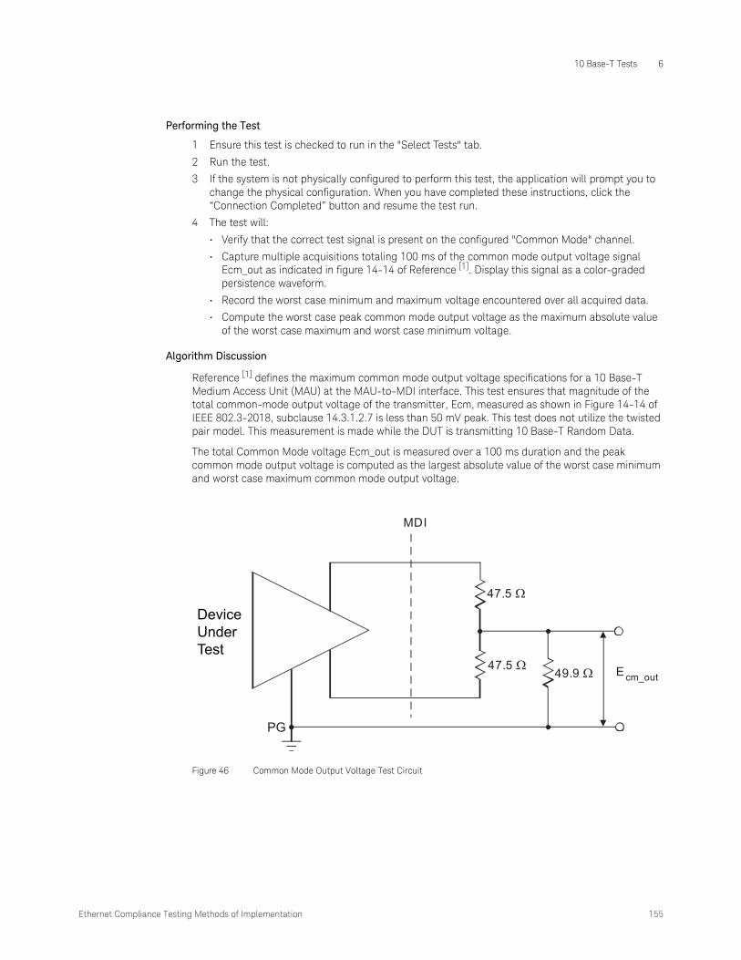
Ethernet Compliance Testing Methods of Implementation 155
10 Base-T Tests 6
Performing the Test
1 Ensure this test is checked to run in the "Select Tests" tab.
2 Run the test.
3 If the system is not physically configured to perform this test, the application will prompt you to change the physical configuration. When you have completed these instructions, click the “Connection Completed” button and resume the test run.
4 The test will:
• Verify that the correct test signal is present on the configured "Common Mode" channel.
• Capture multiple acquisitions totaling 100 ms of the common mode output voltage signal Ecm_out as indicated in figure 14-14 of Reference [1]. Display this signal as a color-graded persistence waveform.
• Record the worst case minimum and maximum voltage encountered over all acquired data.
• Compute the worst case peak common mode output voltage as the maximum absolute value of the worst case maximum and worst case minimum voltage.
Algorithm Discussion
Reference [1] defines the maximum common mode output voltage specifications for a 10 Base-T Medium Access Unit (MAU) at the MAU-to-MDI interface. This test ensures that magnitude of the total common-mode output voltage of the transmitter, Ecm, measured as shown in Figure 14-14 of IEEE 802.3-2018, subclause 14.3.1.2.7 is less than 50 mV peak. This test does not utilize the twisted pair model. This measurement is made while the DUT is transmitting 10 Base-T Random Data.
The total Common Mode voltage Ecm_out is measured over a 100 ms duration and the peak common mode output voltage is computed as the largest absolute value of the worst case minimum and worst case maximum common mode output voltage.
Figure 46 Common Mode Output Voltage Test Circuit
PG
47.5 Ω
MDI
47.5 Ω
49.9 Ω E cm_out
DeviceUnderTest

6 10 Base-T Tests
156 Ethernet Compliance Testing Methods of Implementation
Configuring 10 Base-T Device Output
Configuring a 10 Base-T Device to Output Random Data
A random data signal is required for some 10 Base-T tests. This section provides some commonly used methods to configure a DUT to output random data.
• If you have a 10 Base-T link-partner transmitting idle pulses, connect the link partner to the same fixture using the RJ45 port marked “LP”.
• You may also be able to configure the DUT to output 10 Base-T random data using special boot software (in some cases a link partner is still required).
• If custom boot software is available, the PHY vendor should provide instructions. However, you may be able to configure the DUT to output Random data with some combination of the following steps:
• Disable link speed negotiation.
• Force the link-speed to 10-BASE-T.
• Configure the device to transmit data.
• In most cases, with special boot software, you can control the output data. Configure the output data as “random”.
• If no custom boot software is available, you may be able to use high-level software programs like “ipsend” (UNIX) or “pktsend” (DOS) to specify the packet payload.
NOTESpecial boot software and/or a link partner may be required to obtain 10 Base-T Random data. Contact your PHY vendor for boot software or specific instructions on configuring the DUT to output random data.
NOTEIf you are performing MAU Template or Jitter tests, the DUT should be configured to output packets of random data of sufficient length. The data must be random in order to capture all possible data sequences. A minimum packet length of 300 bytes is recommended for the Automatic Jitter Trigger method.

Ethernet Compliance Testing Methods of Implementation 157
10 Base-T Tests 6
Configuring a 10 Base-T Device to Output Manchester Encoded Harmonic Ones
A Manchester encoded all ones signal (0101010…) is required for the 10 Base-T Harmonic Test. This section provides some commonly used methods to configure a DUT to output this signal.
• If you have a 10 Base-T link-partner, you may need to connect the link partner to the same fixture using the RJ45 port marked “LP”.
• You may also be able to configure the DUT to output 10 Base-T Harmonic Ones signal using special boot software (in some cases a link partner is still required).
• If custom boot software is available, the PHY vendor should provide instructions. However, you may be able to configure the DUT to output the appropriate signal with some combination of the following steps:
• Disable link speed negotiation.
• Force the link-speed to 10-BASE-T.
• Configure the device to transmit data.
• In most cases, with special boot software, you can control the output data. Configure the output data as all FF or all ones (remember that the signal is Manchester Encoded, so 11111 is encoded as 101010 on the wire.
• If no custom boot software is available, you may be able to use high-level software programs like “ipsend” (UNIX) or “pktsend” (DOS) to specify the packet payload.
NOTESpecial boot software and/or a link partner may be required to obtain 10 Base-T Harmonic Ones signal. Contact your PHY vendor for boot software or specific instructions on configuring the DUT to output this signal.

6 10 Base-T Tests
158 Ethernet Compliance Testing Methods of Implementation
Transmitter Return Loss
This section describes the 10 Base-T Transmitter Return Loss test as per IEEE802.3-2018, Subclause 14.3.1.2.2 and Annex B.4.3.2. The test procedures described in this section cover the Transmitter Return Loss measurement required by the specification.
Reference
[1] IEEE802.3-2018, Subclause 14.3.1.2.2 and Annex B.4.3.2.
NOTEThis section shows the use of a Vector Network Analyzer (VNA) used for testing Transmitter Return Loss. However, you can use in place of the VNA an exported VNA file in either the Touchstore or CITI file format.

Ethernet Compliance Testing Methods of Implementation 159
10 Base-T Tests 6
Calibrating the VNA
Before using the VNA, it must be calibrated using the Return Loss Calibration board. See Figure 47 for the connection diagram.
1 Connect the Return Loss Calibration board RJ45 connector labeled OPEN to the RJ45 connector on fixture 1 using a short straight-through UTP cable.
2 Connect one end of two short SMA-to-SMA cables to the SMA test points for the pair A you are testing on fixture 1, and the other end to the two SMA (X97 and X98) test points on fixture 10.
3 Connect a VNA input to the SMA (X99) test point on fixture 10.
Figure 47 VNA Calibration
Section 10 of test fixture
Section 1 of test fixture
Return Loss Calibration board
RJ45
Short SMA cables
SMA cable
VNA
OPEN
SHORT
LOAD

6 10 Base-T Tests
160 Ethernet Compliance Testing Methods of Implementation
4 Calibrate the VNA using the instructions in the VNA’s User’s Guide. The following is a list of setup requirements.
• Set Meas to Ref1 Fwd S11.
• Set Start to 5.0 MHz.
• Set Stop to 10 MHz.
• Set Format to Log Mag.
• Set Scale Div to 5.
• Set Scale Ref to reference line position 9.
5 Run the calibration for the OPEN, SHORT, and LOAD connections.
Probing Setup for Transmitter Return Loss
NOTEBefore starting a test, you can view these connection instructions under the application’s Connect tab. If connection changes are necessary while tests are running, the application automatically prompts you with new connection instructions.

Ethernet Compliance Testing Methods of Implementation 161
10 Base-T Tests 6
1 Connect the DUT to the RJ45 connector on fixture 1 using a short straight-through UTP cable.
2 Connect one end of two short SMA-to-SMA cables to the SMA test points for testing the pair A on fixture 1, and the other end to the two SMA (X97 and X98) test points on fixture 10.
3 Connect a VNA input to the SMA (X99) test point on fixture 10.
4 Connect a GPIB cable to the 82357A GPIB port and to the GPIB port on the VNA.
5 Connect the 82357A USB connector to a USB port on the scope.
Device Configuration
1 Configure the DUT to output 10Base-T random data.
Performing the Test
1 Ensure this test is checked to run in the "Select Tests" tab.
2 Run the test.
Figure 48 Probing for 10 Base-T Transmitter Return Loss
Section 10 of test fixture
Section 1 of test fixture
DUT
RJ45
Short SMA cables
SMA cable
To USB Connector 82357A
GPIB Cable
VNA

6 10 Base-T Tests
162 Ethernet Compliance Testing Methods of Implementation
3 If the system is not physically configured to perform this test, the application will prompt you to change the physical configuration. When you have completed these instructions, click the “Connection Completed” button and resume the test run.
4 The test will compute the return loss as described in the Algorithm Discussion below.
Algorithm Discussion
Reference [1] describes all the receive channel return loss specifications for a 10 Base-T device at the physical medium attachment (PMA). The differential output impedance as measured on the TD circuit shall be such that any reflection, due to differential signals incident upon the TD circuit from a simplex link segment having any impedance within the range specified in 14.4.2.2, shall be at least 15 dB below the incident, over the frequency range of 5.0 MHz to 10 MHz. This return loss shall be maintained at all times when the MAU is powered, including when the TD circuit is sending TP_IDL.
Ethernet Compliance Testing Methods of Implementation 163
10 Base-T Tests 6
Receiver Return Loss
This section describes the 10 Base-T Receiver Return Loss test as per IEEE 802.3-2018, Subclause 14.3.1.3.4 and Anex B.4.3.5. The test procedures described in this section cover the Receiver Return Loss measurement required by the specification.
Reference
[1] IEEE 802.3-2018, Subclause 14.3.1.3.4 and Anex B.4.3.5
NOTEThis section shows the use of a Vector Network Analyzer (VNA) used for testing Receiver Return Loss. However, you can use in place of the VNA an exported VNA file in either the Touchstore or CITI file format.

6 10 Base-T Tests
164 Ethernet Compliance Testing Methods of Implementation
Calibrating the VNA
Before using the VNA, it must be calibrated using the Return Loss Calibration board. See Figure 49 for the connection diagram.
1 Connect the Return Loss Calibration board RJ45 connector labeled OPEN to the RJ45 connector on fixture 1 using a short straight-through UTP cable.
2 Connect one end of two short SMA-to-SMA cables to the SMA test points for the pair B you are testing on fixture 1, and the other end to the two SMA (X97 and X98) test points on fixture 10.
3 Connect a VNA input to the SMA (X99) test point on fixture 10.
Figure 49 VNA Calibration
Return Loss Calibration board
SMA cable
VNA
Section 1 of test fixture
LOAD
SHORT
OPEN
Section 10 of test fixture
Short SMAcables
RJ45

Ethernet Compliance Testing Methods of Implementation 165
10 Base-T Tests 6
4 Calibrate the VNA using the instructions in the VNA’s User’s Guide. The following is a list of setup requirements.
• Set Meas to Ref1 Fwd S11.
• Set Start to 5.0 MHz.
• Set Stop to 10 MHz.
• Set Format to Log Mag.
• Set Scale Div to 5.
• Set Scale Ref to reference line position 9.
5 Run the calibration for the OPEN, SHORT, and LOAD connections.
Probing Setup for Receiver Return Loss
NOTEBefore starting a test, you can view these connection instructions under the application’s Connect tab. If connection changes are necessary while tests are running, the application automatically prompts you with new connection instructions.

6 10 Base-T Tests
166 Ethernet Compliance Testing Methods of Implementation
1 Connect the DUT to the RJ45 connector on fixture 1 using a short straight-through UTP cable.
2 Connect one end of two short SMA-to-SMA cables to the SMA test points for testing the pair B on fixture 1, and the other end to the two SMA (X97 and X98) test points on fixture 10.
3 Connect a VNA input to the SMA (X99) test point on fixture 10.
4 Connect a GPIB cable to the 82357A GPIB port and to the GPIB port on the VNA.
5 Connect the 82357A USB connector to a USB port on the scope.
Device Configuration
1 The DUT for 10 Base-T operation does not require any particular configuration. Simply turn on the DUT and set the DUT to operate in 10 Base-T to perform the test.
Performing the Test
1 Ensure this test is checked to run in the "Select Tests" tab.
2 Run the test.
Figure 50 Probing for 10 Base-T Receiver Return Loss
VNA
Section 10 oftest fixture
SMA cable
DUT
Section 1 of test fixture
Short SMA cables
RJ45

Ethernet Compliance Testing Methods of Implementation 167
10 Base-T Tests 6
3 If the system is not physically configured to perform this test, the application will prompt you to change the physical configuration. When you have completed these instructions, click the “Connection Completed” button and resume the test run.
4 The test will compute the return loss as described in the Algorithm Discussion below.
Algorithm Discussion
Reference [1] describes all the receive channel return loss specifications for a 10 Base-T device at the physical medium attachment (PMA). The differential input impedance shall be such that any reflection, due to differential signals incident upon the RD circuit from a twisted pair having any impedance within the range specified in 14.4.2.2, shall be at least 15 dB below the incident, over the frequency range of 5.0 MHz to 10 MHz. This return loss shall be maintained at all times when the MAU is powered.

6 10 Base-T Tests
168 Ethernet Compliance Testing Methods of Implementation

Keysight D9010ETHC Ethernet Compliance Test Application
Methods of Implementation
7 1000 Base-T EEE Tests
1000 Base-T EEE Mode / 170Probing for 1000 Base-T EEE Tests / 171LPI Tests / 172
This section provides the Methods of Implementation (MOIs) for 1000 Base-T EEE tests using an Infiniium oscilloscope and the Ethernet Compliance Test Application.

7 1000 Base-T EEE Tests
170 Ethernet Compliance Testing Methods of Implementation
1000 Base-T EEE Mode
The IEEE 802.3az specification defines an EEE mode for 1000 Base-T that is intended to save power for idle devices by putting a device into a state known as Low Power Idle (LPI). When LPI signaling is simultaneously transmitted and received, an EEE-compliant 1000 Base-T PHY ceases transmission and deactivates transmit and receive functions to conserve energy. The PHY periodically transmits during this quiet period to allow the remote PHY to refresh its receiver state (such as timing recovery and adaptive filter coefficients) and thereby track long-term variation in the timing of the link or the underlying channel characteristics. If, during the quiet or refresh periods, normal interframe is asserted at the GMII, the PHY reactivates transmit and receive functions and initiates transmission. This transmission will be detected by the remote PHY, causing it to also exit the LPI mode.

Ethernet Compliance Testing Methods of Implementation 171
1000 Base-T EEE Tests 7
Probing for 1000 Base-T EEE Tests
When performing 1000 Base-T EEE tests, the Ethernet Compliance Test Application will prompt you to make the proper connections (also shown in Figure 51).
1 Connect the DUT to the RJ45 connector on the fixture marked “DUT” (J10) using a short straight-through UTP cable.
2 Connect a 1000 Base-T EEE compatible link partner to the RJ45 connector marked “Link Partner” (J11) using a short straight-through UTP cable.
3 Connect one SMA cable to the X1 connector and to the D+ channel on the oscilloscope.
4 Connect one SMA cable to the X9 connector and to the D– channel on the oscilloscope.
Figure 51 Probing for 1000 Base-T EEE Tests
DUT
Test fixture
SMA cables
RJ45X1
X9
Link Partner

7 1000 Base-T EEE Tests
172 Ethernet Compliance Testing Methods of Implementation
LPI Tests
Quiet Time
This test ensures that the quiet time is within conformance limits.
References
[1] IEEE 802.3az, Subclause 78.2, Table 78-2
[2] IEEE 802.3az, Subclause 40.4.5.2
Device Configuration
1 Set up a 1000 Base-T EEE link between the DUT and link partner.
2 Force the DUT into LPI mode.
Performing the Test
1 Ensure this test is checked to run in the "Select Tests” tab.
2 Run the test.
3 If the system is not physically configured to perform this test, the application will prompt you to change the physical configuration. When you have completed these instructions, click the “Connection Completed” button and resume the test run.
4 The test will measure the quiet time of the DUT.
Algorithm Discussion
The quiet time is the duration the PHY stays in the Quiet state before it expects a refresh signal. Reference [1] specifies the quiet time Tq, for a 1000 Base-T EEE capable PHY. The quiet time of the PHY as measured on the medium will be the sum of the lpi_waitwq_timer and lpi_quiet_timer.
The lpi_quiet_timer defines the maximum amount of time the PHY will remain quiet. This timer is measured as the amount of time in-between the refresh signals. Since 1000 Base-T uses a wake transient at the beginning of refresh signals, let the beginning of the wake transient signal be defined as the beginning of the WAKE state. As the PHY will remain quiet during both WAIT_QUIET and QUIET, there is no way to distinguish between them at the medium. For this reason, the total quiet time is measured as the sum of the two timers.
The measured time should be greater than (20 ms + 10 μs) and less than (24 ms + 12 μs).
Refresh Time (Master)
This test ensures that the refresh time is within conformance limits.
References
[1] IEEE 802.3az, Subclause 40.4.6.1, Figure 40-15b
[2] IEEE 802.3az, Subclause 40.4.5.2
NOTEThe LPI mode is entered when no data is transmitted. Ensure that no data is transmitted by the DUT so that the link can enter the LPI mode.
Ethernet Compliance Testing Methods of Implementation 173
1000 Base-T EEE Tests 7
Device Configuration
1 Set up a 1000 Base-T EEE link between the DUT and link partner. Ensure that the DUT is operating in Master mode.
2 Force the DUT into LPI mode.
Performing the Test
1 Ensure this test is checked to run in the "Select Tests" tab.
2 Run the test.
3 If the system is not physically configured to perform this test, the application will prompt you to change the physical configuration. When you have completed these instructions, click the “Connection Completed” button and resume the test run.
4 The test will measure the refresh time of the DUT.
Algorithm Discussion
Reference [1] provides the state diagram for the operation of an EEE capable PHY in the LPI mode. The refresh time is measured from the start of the WAKE transient to the entry into the WAIT_QUIET state. The time measured in this test is the lpi_wake_timer, the lpi_update_timer, and the lpi_postupdate_timer.
The lpi_wake_timer defines the expected time for the PHY to transition from the LPI mode to normal operation. It is started during the WAKE state, and stopped upon entry into the UPDATE state. The lpi_wake_timer is used instead of the lpi_waketx_timer and lpi_wakemz_timer as the WAKE_TRAINING period is not defined.
The lpi_update_timer defines the time the PHY dwells in the UPDATE state. In this state, the PHY transmits to allow the remote PHY to refresh its receiver state (such as timing recovery and adaptive filter coefficients) and thereby track long-term variation in the timing of the link or the underlying channel characteristics.
The lpi_postupdate_timer defines the maximum time the PHY dwells in the POST_UPDATE state before proceeding to the WAIT_QUIET state.
The refresh time for a DUT operating in Master mode should be between 248.5 μs and 269.7 μs.
Refresh Time (Slave)
This test ensures that the refresh time is within conformance limits.
References
[1] IEEE 802.3az, Subclause 40.4.6.1, Figure 40-15b
[2] IEEE 802.3az, Subclause 40.4.5.2
Device Configuration
1 Set up a 1000 Base-T EEE link between the DUT and link partner. Ensure that the DUT is operating in Slave mode.
2 Force the DUT into LPI mode.
NOTEThe LPI mode is entered when no data is transmitted. Ensure that no data is transmitted by the DUT so that the link can enter the LPI mode.

7 1000 Base-T EEE Tests
174 Ethernet Compliance Testing Methods of Implementation
Performing the Test
1 Ensure this test is checked to run in the "Select Tests" tab.
2 Run the test.
3 If the system is not physically configured to perform this test, the application will prompt you to change the physical configuration. When you have completed these instructions, click the “Connection Completed” button and resume the test run.
4 The test will measure the refresh time of the DUT.
Algorithm Discussion
Reference [1] provides the state diagram for the operation of an EEE-capable PHY in the LPI mode. The refresh time is measured from the start of the WAKE transient to the entry into the WAIT_QUIET state. The time measured in this test is the lpi_wake_timer, the lpi_update_timer, and the lpi_postupdate_timer.
The lpi_wake_timer defines the expected time for the PHY to transition from LPI mode to normal operation. It is started during the WAKE state, and stopped upon entry into the UPDATE state. The lpi_wake_timer is used instead of the lpi_waketx_timer and lpi_wakemz_timer as the WAKE_TRAINING period is not defined.
The lpi_update_timer defines the time the PHY dwells in the UPDATE state. In this state, the PHY transmits to allow the remote PHY to refresh its receiver state (such as timing recovery and adaptive filter coefficients) and thereby track long-term variation in the timing of the link or the underlying channel characteristics.
The lpi_postupdate_timer defines the maximum time the PHY dwells in the POST_UPDATE state before proceeding to the WAIT_QUIET state.
The refresh time for a DUT operating in Slave mode should be between 198.5 μs and 219.7 μs.
Transmitter Timing Jitter
This test ensures that the transmit jitter is within conformance limits.
Reference
[1] IEEE 802.3az, Subclause 40.6.1.2.5
Device Configuration
1 Set up a 1000 Base-T EEE link between the DUT and link partner.
2 Force the DUT into LPI mode.
Performing the Test
1 Ensure this test is checked to run in the "Select Tests" tab.
2 Run the test.
NOTEThe LPI mode is entered when no data is transmitted. Ensure that no data is transmitted by the DUT so that the link can enter the LPI mode.
NOTEThe LPI mode is entered when no data is transmitted. Ensure that no data is transmitted by the DUT so that the link can enter the LPI mode.

Ethernet Compliance Testing Methods of Implementation 175
1000 Base-T EEE Tests 7
3 If the system is not physically configured to perform this test, the application will prompt you to change the physical configuration. When you have completed these instructions, click the “Connection Completed” button and resume the test run.
4 The test will measure the transmit jitter of the DUT.
Algorithm Discussion
Reference [1] specifies the jitter requirements for an EEE-capable PHY. The unfiltered jitter requirements of an EEE-capable PHY shall be satisfied during the LPI mode, with the exception that clock edges corresponding to the WAIT_QUIET, QUIET, WAKE, and WAKE_SILENT states are not considered in the measurement. It is possible that the PHY may turn off the TX_TCLK during these states, to conserve additional power. For a Master PHY operating in the LPI mode, the unjittered reference shall be continuous.
As the TX_TCLK may be turned off, it may not prove to be a reliable method for jitter measurements, so instead, the timing information used for jitter measurement is directly extracted from the sleep signal. The data is then referenced to an unjittered reference to determine the jitter of the PHY in the LPI mode.

7 1000 Base-T EEE Tests
176 Ethernet Compliance Testing Methods of Implementation

Keysight D9010ETHC Ethernet Compliance Test Application
Methods of Implementation
8 100 Base-TX EEE Tests
100 Base-TX EEE Mode / 178Probing for 100 Base-TX EEE Tests / 179LPI Tests / 180Sleep Time Tests / 182Wake Time Tests / 183
This section provides the Methods of Implementation (MOIs) for 100 Base-TX EEE tests using an Infiniium oscilloscope, probes, and the Ethernet Compliance Test Application.

8 100 Base-TX EEE Tests
178 Ethernet Compliance Testing Methods of Implementation
100 Base-TX EEE Mode
The IEEE 802.3az specification defines an EEE mode for 100 Base-TX that is intended to save power for idle devices by putting a device into a state known as Low Power Idle (LPI). An EEE-compatible transmitter can request an EEE-compatible link partner to enter the LPI mode by sending the appropriate symbols. An EEE-compatible device can then enter a low power state to save power. The transmit and receive paths of the 100 Base-TX device may enter and exit the low power states independently.
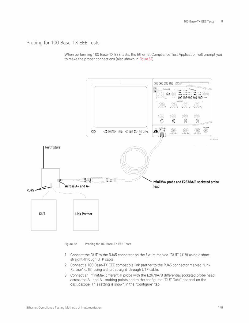
Ethernet Compliance Testing Methods of Implementation 179
100 Base-TX EEE Tests 8
Probing for 100 Base-TX EEE Tests
When performing 100 Base-TX EEE tests, the Ethernet Compliance Test Application will prompt you to make the proper connections (also shown in Figure 52).
1 Connect the DUT to the RJ45 connector on the fixture marked “DUT” (J18) using a short straight-through UTP cable.
2 Connect a 100 Base-TX EEE compatible link partner to the RJ45 connector marked “Link Partner” (J19) using a short straight-through UTP cable.
3 Connect an InfiniiMax differential probe with the E2678A/B differential socketed probe head across the A+ and A– probing points and to the configured “DUT Data” channel on the oscilloscope. This setting is shown in the “Configure” tab.
Figure 52 Probing for 100 Base-TX EEE Tests
DUT
Test fixture
InfiniiMax probe and E2678A/B socketed probe head
RJ45
Link Partner
Across A+ and A–

8 100 Base-TX EEE Tests
180 Ethernet Compliance Testing Methods of Implementation
LPI Tests
Quiet Time
This test ensures that the quiet time is within conformance limits.
References
[1] IEEE 802.3az, Subclause 78.2, Table 78-2
[2] IEEE 802.3az, Subclause 24.8.3.5
Device Configuration
1 Set up a 100 Base-TX EEE link between the DUT and link partner.
2 Force the DUT into LPI mode.
Performing the Test
1 Ensure this test is checked to run in the "Select Tests” tab.
2 Run the test.
3 If the system is not physically configured to perform this test, the application will prompt you to change the physical configuration. When you have completed these instructions, click the “Connection Completed” button and resume the test run.
4 The test will measure the quiet time of the DUT.
Algorithm Discussion
The quiet time is the duration the PHY stays in the Quiet state before it expects a refresh signal. Reference [1] specifies the quiet time Tq, for a 100 Base-TX EEE capable PHY. The quiet time of the PHY is determined by the lpi_tx_tq_timer. The timer should have a duration of 20 to 22 ms.
The quiet time is measured from the time the signal crosses the Signal Detect de-assertion threshold to when the refresh signal crosses the Signal Detect assertion threshold.
Refresh Time
This test ensures that the refresh time is within conformance limits.
References
[1] IEEE 802.3az, Subclause 78.2, Table 78-2
[2] IEEE 802.3az, Subclause 24.8.3.5
Device Configuration
1 Set up a 100 Base-TX EEE link between the DUT and link partner.
2 Force the DUT into LPI mode.
NOTEThe LPI mode is entered when no data is transmitted. Ensure that no data is transmitted by the DUT so that the link can enter the LPI mode.
NOTEThe LPI mode is entered when no data is transmitted. Ensure that no data is transmitted by the DUT so that the link can enter the LPI mode.

Ethernet Compliance Testing Methods of Implementation 181
100 Base-TX EEE Tests 8
Performing the Test
1 Ensure this test is checked to run in the "Select Tests" tab.
2 Run the test.
3 If the system is not physically configured to perform this test, the application will prompt you to change the physical configuration. When you have completed these instructions, click the “Connection Completed” button and resume the test run.
4 The test will measure the refresh time of the DUT.
Algorithm Discussion
The refresh time is the duration the PHY is sending continuous SLEEP symbols in the Sleep state before going into the quiet state. Reference [1] specifies the refresh time Tr, for a 100 Base-TX EEE capable PHY, which should be between 200 to 220 μs.
The refresh time is measured from the time the sleep signal crosses the Signal Detect assertion threshold to when the refresh signal crosses the Signal Detect de-assertion threshold.
Transmitter Timing Jitter
This test ensures that the transmit jitter is within conformance limits.
Reference
[1] IEEE 802.3az, Subclause 25.4.6
Device Configuration
1 Set up a 100 Base-TX EEE link between the DUT and link partner.
2 Force the DUT into LPI mode.
Performing the Test
1 Ensure this test is checked to run in the "Select Tests" tab.
2 Run the test.
3 If the system is not physically configured to perform this test, the application will prompt you to change the physical configuration. When you have completed these instructions, click the “Connection Completed” button and resume the test run.
4 The test will measure the transmit jitter of the DUT.
Algorithm Discussion
Reference [1] specifies the jitter requirements for an EEE-capable PHY. The jitter for an EEE-capable PHY in LPI is measured using scrambled SLEEP code-groups transmitted during the TX_SLEEP state. The jitter contributed during the TX_QUIET state and the first 5 μs of the TX_SLEEP state are ignored. The data used for this measurement must not be less than 100 ms and not greater than 1 s. The total peak-to-peak jitter measured shall be less than 1.4 ns.
NOTEThe LPI mode is entered when no data is transmitted. Ensure that no data is transmitted by the DUT so that the link can enter the LPI mode.

8 100 Base-TX EEE Tests
182 Ethernet Compliance Testing Methods of Implementation
Sleep Time Tests
Sleep Time
This test ensures that the sleep time is within conformance limits.
References
[1] IEEE 802.3az, Subclause 78.2, Table 78-2
[2] IEEE 802.3az, Subclause 24.2.2.1.1
[3] IEEE 802.3az, Subclause 24.8.3.5
Device Configuration
Set up a 100 Base-TX EEE link between the DUT and link partner.
Performing the Test
1 Ensure this test is checked to run in the "Select Tests" tab.
2 Run the test.
3 If the system is not physically configured to perform this test, the application will prompt you to change the physical configuration. When you have completed these instructions, click the “Connection Completed” button and resume the test run.
4 The test will measure the sleep time of the DUT.
Algorithm Discussion
The sleep time is the duration the PHY is sending continuous SLEEP symbols before shutting down all transmitters and going into the quiet state. Reference [1] specifies the sleep time Ts, for a 100 Base-TX EEE capable PHY. The sleep time of the PHY is determined by the lpi_tx_ts_timer. The timer should have a duration of 200 to 220 μs.
The sleep time is measured by descrambling the stream just before the quiet state and measuring continuous stream of the SLEEP sequence, /P/, which is sent as 00000.
NOTEYou will need to put the DUT into the LPI mode when prompted by the application.

Ethernet Compliance Testing Methods of Implementation 183
100 Base-TX EEE Tests 8
Wake Time Tests
Wake Time
This test ensures that the wake time is within conformance limits.
References
[1] IEEE 802.3az, Subclause 78.3, Figure 78-4
[2] IEEE 802.3az, Subclause 78.5, Table 78-4
Device Configuration
1 Set up a 100 Base-TX EEE link between the DUT and link partner.
2 Force the DUT into LPI mode.
Performing the Test
1 Ensure this test is checked to run in the "Select Tests" tab.
2 Run the test.
3 If the system is not physically configured to perform this test, the application will prompt you to change the physical configuration. When you have completed these instructions, click the “Connection Completed” button and resume the test run.
4 The test will measure the wake time of the DUT.
Algorithm Discussion
Reference [1] specifies the relationship between the wake time measured on the medium and the xMII. The minimum wake time as measured on the medium, Tphy_wake (min), is given by the equation:
Tphy_wake (min) = Tw_phy (min) – Tphy_shrink_tx
The wake time measured should be greater than 15.5 μs.
NOTEThe LPI mode is entered when no data is transmitted. Ensure that no data is transmitted by the DUT so that the link can enter the LPI mode.
When prompted by the application, you will need to exit the LPI mode by resuming normal transmission.

8 100 Base-TX EEE Tests
184 Ethernet Compliance Testing Methods of Implementation

Keysight D9010ETHC Ethernet Compliance Test Application
Methods of Implementation
9 10 Base-Te Tests
Measurements with TPM, Template Tests / 187Measurements with TPM, Parametric Tests / 197Measurements Without TPM, Template Tests / 200Measurements Without TPM, Parametric Tests / 209Common Mode Voltage Tests / 214Configuring 10 Base-Te Device Output / 217

9 10 Base-Te Tests
186 Ethernet Compliance Testing Methods of Implementation
Test Loads
Some of the 10 Base-Te tests require the use of special loads. The test loads of 10 Base-Te are the same as the test loads of 10 Base-T. Load 1 and Load 2 are defined in Figure 14-11 of IEEE 802.3-2018, subclause 14.3.1.2.2. Load 3 (100 Ω) is defined as a 100 Ω resistive load.

Ethernet Compliance Testing Methods of Implementation 187
10 Base-Te Tests 9
Measurements with TPM, Template Tests
Subclause 14.3.1.2 of IEEE 802.3az defines the transmitter specifications for a 10 Base-Te Medium Attachment Unit (MAU) and the MAU-to-MDI interface. 10 Base-Te tests will require a new Twisted Pair Model (TPM), which is listed in Figure 14-7a of IEEE 802.3az, subclause 14.3.1.2. These tests utilize Test Section 1 of the Energy-Efficient Ethernet (EEE) Test Fixture. To simplify test setup, tests requiring the TPM (Test Section 1 of the test fixture) are organized in one section.
Probing for 10 Base-Te Tests with TPM and Link Partner
These probing instructions apply to tests that use the twisted pair model (TPM) and a link partner. Note that some tests (link test pulse template) do not require the use of a link partner. Instructions for those tests are provided in the section for the test.
NOTEBefore starting a test, you can view these connection instructions under the application’s Connect tab. If connection changes are necessary while tests are running, the application automatically prompts you with new connection instructions.

9 10 Base-Te Tests
188 Ethernet Compliance Testing Methods of Implementation
1 Connect the DUT to the RJ45 connector on the EEE Test Fixture, Test Section 1 marked “DUT” (J9) using a short UTP cable.
2 Connect a 10 Base-T/Te link partner to the RJ45 connector on the EEE Test Fixture, Test Section 1 marked “Link Partner” (J8) using a short UTP cable.
3 Connect an InfiniiMax differential probe with the E2678A/B differential socketed probe head to TP1 and to the configured “DUT Data” channel on the oscilloscope. This setting is shown in the “Configure” tab.
4 Using two jumpers, short the appropriate load on Test Section 1. This setting is shown in the “Configure” tab and the loads are labeled on Test Section 1.
Figure 53 Probing for 10 Base-Te Tests With the TPM and Link Partner
DUT
Section 1 of test fixture
InfiniiMax probe and E2678A socketed probe head
RJ45
Link Partner
TP1
NOTEIEEE 802.3, subclause 14.1.1.1 requires a 10 Base-Te MAU to interoperate with a 10 Base-T MAU if the minimum cabling requirements of a 10 Base-Te MAU are met. Therefore, both 10 Base-T and 10 Base-Te devices could be used as a link partner.

Ethernet Compliance Testing Methods of Implementation 189
10 Base-Te Tests 9
Link Test Pulse, with TPM
This test ensures that the link test pulse falls within the shaded area of Figure 14-10 of IEEE 802.3-2018, subclause 14.3.1.2.1. This measurement is to be made with the three different loads as defined in “Test Loads" on page 186. This test measures the signal across the appropriate load, with the load connected through the twisted pair model (TPM) as defined in Figures 14-7a and 14-8 of IEEE 802.3az, subclause 14.3.1.2.
References
[1] IEEE 802.3az, Subclause 14.3.1.2.1
[2] IEEE 802.3-2018, Subclause 14.3.1.2.2
Probing Setup
Refer to “Probing for 10 Base-Te Tests with TPM and Link Partner" on page 187.
1 Ensure that you short the appropriate load as indicated in the connection instructions provided in the user interface.
2 Ensure the correct probe polarity.
Device Configuration
1 Reset the DUT if necessary.
2 Ensure that the DUT is transmitting the proper Link Test Pulse as indicated in the connection instructions provided in the user interface.
Performing the Test
1 Ensure this test is checked to run in the "Select Tests" tab.
2 Run the test.
3 If the system is not physically configured to perform this test, the application will prompt you to change the physical configuration. When you have completed these instructions, click the “Connection Completed” button and resume the test run.
4 The test will:
• Verify that the correct test signal is present on the configured “DUT Data” channel.
• Configure the oscilloscope to capture the link test pulse.
• Load the mask for the start of the link test pulse.
• Capture a (user-configurable) number of pulses (with a user-defined amount of averaging), testing each pulse against the start of the mask.
• Record the number of mask failures for the start of the link test pulse.
• Load the mask for the end of the link test pulse.
• Capture a (user-configurable) number of pulses (with a user-defined amount of averaging), testing each pulse against the end of the mask.
• Record the number of mask failures for the end of the link test pulse.
• Compute the total number of failures (start + end).
NOTEBefore starting a test, you can view the connection instructions under the application's “Connect” tab. If connection changes are necessary while tests are running, the application automatically prompts you with new connection instructions.

9 10 Base-Te Tests
190 Ethernet Compliance Testing Methods of Implementation
Algorithm Discussion
Reference [1] defines the link-test pulse template specifications of a 10 Base-Te Medium Attachment Unit (MAU) at the MAU-to-MDI interface. This test requires the use of the twisted pair model (TPM) as defined in Figure 14-7a of IEEE 802.3az, subclause 14.3.1.2.
This test ensures that the link test pulse falls within the shaded area of Figure 14-12 of Reference [2]. This measurement is to be made with the three different loads as defined in “Test Loads" on page 186. This test measures the signal across the appropriate load, with the load connected through the twisted pair model (TPM).
Because the mask is defined over a large number of bits, measurement performance is improved by testing the signal against the mask in two sections. We test the start of the link test pulse separately from the end of the link test pulse.
A user-configurable number of waveforms are tested against the mask. Note that if the MAU implements the auto-negotiation algorithm defined in IEEE 802.3-2018, clause 28, the fast link pulse (FLP) burst sequence will consist of multiple link test pulses. All link test pulses in the FLP burst sequence should pass the template requirements. Keysight recommends testing a large number of pulses to ensure that all link test pulses in the FLP burst sequence have been observed. The default number of waveforms tested is 100 for this test. The default number of averages is 512.
A user-configurable amount of averaging is also utilized to reduce vertical noise errors. The algorithm proceeds as described in the above section “Performing the Test”.
TP_IDL Template, with TPM (Last Bit CD0)
This test ensures that the TP_IDL signal falls within the shaded area of Figure 14-10 of IEEE 802.3-2018, subclause 14.3.1.2.1. This measurement uses the TP_IDL generated when the last bit transmitted is 0. This measurement is to be made with the three different loads as defined in “Test Loads" on page 186.
Reference
[1] IEEE 802.3-2018, Subclause 14.3.1.2.1
NOTEIf you have selected “ALL” as the “10 Base-T/Te LTP/TP_IDL Loads” (under the “Configure” tab), the three required loads will be tested in sequence. You will be prompted to short each load (with jumpers) in turn, and this measurement will be repeated with each load. If you want to debug a particular load, select “Debug Mode” in the “Configure” tab, and select the individual load you wish to test. Note that for full compliance testing, you should test all three loads. At the result screen, three trial tabs are shown at the bottom left of the screen. Each trial tab shows the result of each test pair. For example, Trial 1 contains the Load 1 result, Trial 2 contains the Load 2 result, and so on.
NOTEThe template requirements for this test are specified in such a way that testing with a digital oscilloscope is often impractical. Specifically, the large vertical and horizontal range of the masks will often result in failures when applying automated template test techniques. Specifically, you should exercise your own judgement when failures are marginal to determine if the signal shape is satisfactory.

Ethernet Compliance Testing Methods of Implementation 191
10 Base-Te Tests 9
Probing Setup
Refer to “Probing for 10 Base-Te Tests with TPM and Link Partner" on page 187.
1 Ensure that you short the appropriate load, as indicated in the connection instructions provided in the user interface.
2 Ensure the correct probe polarity.
Device Configuration
1 Reset the DUT if necessary.
2 Configure the DUT to output 10 Base-Te random data (see “Configuring a 10 Base-Te Device to Output Random Data" on page 217).
3 Ensure that the oscilloscope is capturing the proper signal (TP_IDL) as indicated in the connection instructions provided in the user interface.
Performing the Test
1 Ensure this test is checked to run in the "Select Tests" tab.
2 Run the test.
3 If the system is not physically configured to perform this test, the application will prompt you to change the physical configuration. When you have completed these instructions, click the “Connection Completed” button and resume the test run.
4 The test will:
• Determine the widths of the different TP_IDL pulses. (For a given device, there are two different TP_IDL pulse widths, depending on the value of the last bit in the packet.)
• Using the TP_IDL transmitted when the last bit transmitted is 0, the test will:
• Verify that the correct test signal is present on the configured “DUT Data” channel.
• Configure the oscilloscope to capture this TP_IDL signal width using a user-configurable amount of averaging. This reduces measurement noise and increases measurement accuracy.
• Load the mask for the start of the TP_IDL signal.
• Capture a (user-configurable) number of pulses (with a user-defined amount of averaging), testing each pulse against the start of the mask.
• Record the number of mask failures for the start of the TP_IDL signal.
• Load the mask for the end of the TP_IDL signal.
• Capture a (user-configurable) number of pulses testing each pulse against the end of the mask.
• Record the number of mask failures for the end of the TP_IDL signal.
• Compute the total number of failures (start + end).
NOTEBefore starting a test, you can view the connection instructions under the application’s “Connect” tab. If connection changes are necessary while tests are running, the application automatically prompts you with new connection instructions.

9 10 Base-Te Tests
192 Ethernet Compliance Testing Methods of Implementation
Algorithm Discussion
Reference [1] defines the TP_IDL template specifications of a 10 Base-Te Medium Attachment Unit (MAU) at the MAU-to-MDI interface. This test requires the use of the twisted pair model (TPM) as defined in Figure 14-7a of IEEE 802.3az, subclause 14.3.1.2.
This test ensures that the TP_IDL signal falls within the shaded area of Figure 14-10 of Reference [1]. This measurement is to be made with the three different loads as defined in “Test Loads" on page 186. This test measures the signal across the appropriate load, with the load connected through the twisted pair model (TPM).
Because the mask is defined over a large number of bits, measurement performance is improved by testing the signal against the mask in two sections. We test the start of the TP_IDL separately from the end of the TP_IDL.
The TP_IDL signal indicates the end of a transmitted data sequence. As stated in Reference [1], if the last bit transmitted was a CD1, the last transition will be at the bit cell center of the CD1. If the last bit transmitted was a CD0, the PLS will generate an additional transition at the bit cell boundary following the CD0. After the zero crossing of the last transition, the differential voltage shall remain within the shaded area of Figure 14-10 of Reference [1].
This test will only be triggering the TP_IDL generated when the last bit transmitted is CD0.
A user-configurable number of waveforms are tested against the mask. The default number of waveforms tested is 100 for this test. The default number of averages is 512. The algorithm proceeds as described in the above section “Performing the Test”.
NOTEIf you have selected “ALL” as the “10 Base-T/Te LTP/TP_IDL Loads” (under the “Configure” tab), the three required loads will be tested in sequence. You will be prompted to short each load (with jumpers) in turn, and this measurement will be repeated with each load. If you want to debug a particular load, select “Debug Mode” in the “Configure” tab, and select the individual load you wish to test. Note that for full compliance testing, you should test all three loads. At the result screen, three trial tabs are shown at the bottom left of the screen. Each trial tab shows the result of each test pair. For example, Trial 1 contains the Load 1 result, Trial 2 contains the Load 2 result, and so on.
NOTEThe template requirements for this test are specified in such a way that testing with a digital oscilloscope is often impractical. Specifically, the large vertical and horizontal range of the masks will often result in failures when applying automated template test techniques. Specifically, you should exercise your own judgement when failures are marginal to determine if the signal shape is satisfactory.
NOTEBecause the oscilloscope uses special triggering capabilities to qualify both variants of TP_IDL, this test can run slowly. One way to significantly speed up this test is to send very short packets so that the TP_IDL signal occurs frequently.

Ethernet Compliance Testing Methods of Implementation 193
10 Base-Te Tests 9
TP_IDL Template, with TPM (Last Bit CD1)
This test ensures that the TP_IDL signal falls within the shaded area of Figure 14-10 of IEEE 802.3-2018, subclause 14.3.1.2.1. This measurement uses the TP_IDL generated when the last bit transmitted is 1. This measurement is to be made with the three different loads as defined in “Test Loads" on page 186.
Reference
[1] IEEE 802.3-2018, Subclause 14.3.1.2.1
Probing Setup
Refer to “Probing for 10 Base-Te Tests with TPM and Link Partner" on page 187.
1 Ensure that you short the appropriate load, as indicated in the connection instructions provided in the user interface.
2 Ensure the correct probe polarity.
Device Configuration
1 Reset the DUT if necessary.
2 Configure the DUT to output 10 Base-Te random data (see “Configuring a 10 Base-Te Device to Output Random Data" on page 217).
3 Ensure that the oscilloscope is capturing the proper signal (TP_IDL) as indicated in the connection instructions provided in the user interface.
Performing the Test
1 Ensure this test is checked to run in the "Select Tests" tab.
2 Run the test.
3 If the system is not physically configured to perform this test, the application will prompt you to change the physical configuration. When you have completed these instructions, click the “Connection Completed” button and resume the test run.
4 The test will:
• Determine the widths of the different TP_IDL pulses. (For a given device, there are two different TP_IDL pulse widths, depending on the value of the last bit in the packet.)
• Using the TP_IDL transmitted when the last bit transmitted is 1, the test will:
• Verify that the correct test signal is present on the configured “DUT Data” channel.
• Configure the oscilloscope to capture this TP_IDL signal width using a user-configurable amount of averaging. This reduces measurement noise and increases measurement accuracy.
• Load the mask for the start of the TP_IDL signal.
• Capture a (user-configurable) number of pulses (with a user-defined amount of averaging), testing each pulse against the start of the mask.
• Record the number of mask failures for the start of the TP_IDL signal.
• Load the mask for the end of the TP_IDL signal.
NOTEBefore starting a test, you can view the connection instructions under the application’s “Connect” tab. If connection changes are necessary while tests are running, the application automatically prompts you with new connection instructions.

9 10 Base-Te Tests
194 Ethernet Compliance Testing Methods of Implementation
• Capture a (user-configurable) number of pulses testing each pulse against the end of the mask.
• Record the number of mask failures for the end of the TP_IDL signal.
• Compute the total number of failures (start + end).
Algorithm Discussion
Reference [1] defines the TP_IDL template specifications of a 10 Base-Te Medium Attachment Unit (MAU) at the MAU-to-MDI interface. This test requires the use of the twisted pair model (TPM) as defined in Figure 14-7a of IEEE 802.3az, subclause 14.3.1.2.
This test ensures that the TP_IDL signal falls within the shaded area of Figure 14-10 of Reference [1]. This measurement is to be made with the three different loads as defined in “Test Loads" on page 186. This test measures the signal across the appropriate load, with the load connected through the twisted pair model (TPM).
Because the mask is defined over a large number of bits, measurement performance is improved by testing the signal against the mask in two sections. We test the start of the TP_IDL separately from the end of the TP_IDL.
The TP_IDL signal indicates the end of a transmitted data sequence. As stated in Reference [1], if the last bit transmitted was a CD1, the last transition will be at the bit cell center of the CD1. If the last bit transmitted was a CD0, the PLS will generate an additional transition at the bit cell boundary following the CD0. After the zero crossing of the last transition, the differential voltage shall remain within the shaded area of Figure 14-10 of Reference [1].
This test will only be triggering the TP_IDL generated when the last bit transmitted is CD1.
A user-configurable number of waveforms are tested against the mask. The default number of waveforms tested is 100 for this test. The default number of averages is 512. The algorithm proceeds as described in the above section “Performing the Test”.
NOTEIf you have selected “ALL” as the “10 Base-T/Te LTP/TP_IDL Loads” (under the “Configure” tab), the three required loads will be tested in sequence. You will be prompted to short each load (with jumpers) in turn, and this measurement will be repeated with each load. If you want to debug a particular load, select “Debug Mode” in the “Configure” tab, and select the individual load you wish to test. Note that for full compliance testing, you should test all three loads. At the result screen, three trial tabs are shown at the bottom left of the screen. Each trial tab shows the result of each test pair. For example, Trial 1 contains the Load 1 result, Trial 2 contains the Load 2 result, and so on.
NOTEThe template requirements for this test are specified in such a way that testing with a digital oscilloscope is often impractical. Specifically, the large vertical and horizontal range of the masks will often result in failures when applying automated template test techniques. Specifically, you should exercise your own judgement when failures are marginal to determine if the signal shape is satisfactory.
NOTEBecause the oscilloscope uses special triggering capabilities to qualify both variants of TP_IDL, this test can run slowly. One way to significantly speed up this test is to send very short packets so that the TP_IDL signal occurs frequently.

Ethernet Compliance Testing Methods of Implementation 195
10 Base-Te Tests 9
MAU Template
This test ensures that the signal Vo, defined at the output of the twisted pair model (TPM), as defined in Figure 14-7a of IEEE 802.3az, subclause 14.3.1.2.1, falls within the template defined in Figure 14-9 and Table 14-1 (integrated and external MAU) of IEEE 802.3-2018, subclause 14.3.1.2.1 for all data sequences. This measurement is to be made only with the TPM, and only with the 100 Ω load. This test is run with the DUT configured to output 10 Base-Te Random Data.
Reference
[1] IEEE 802.3-2018, Subclause 14.3.1.2.1
Probing Setup
Refer to “Probing for 10 Base-Te Tests with TPM and Link Partner" on page 187.
1 Ensure that you short the appropriate load, as indicated in the connection instructions provided in the user interface.
2 Ensure the correct probe polarity.
Device Configuration
1 Reset the DUT if necessary.
2 Configure the DUT to output 10 Base-Te random data (see “Configuring a 10 Base-Te Device to Output Random Data" on page 217).
3 Ensure that the oscilloscope is capturing the proper signal (10 Base-Te Random Data) as indicated in the connection instructions provided in the user interface.
Performing the Test
1 Ensure this test is checked to run in the "Select Tests" tab.
2 Run the test.
3 If the system is not physically configured to perform this test, the application will prompt you to change the physical configuration. When you have completed these instructions, click the “Connection Completed” button and resume the test run.
4 The test will:
• Verify that the correct test signal is present on the configured “DUT Data” channel.
• Configure the oscilloscope to capture the 10 Base-Te Random Data signal, triggering on the rising edge of the data.
• Load the appropriate mask for the rising data edge:
• Two masks are supported, depending on the MAU Type (Integrated or External MAU), as defined in Table 14-1 of Reference [1]. You can select the 10 Base-Te MAU type under the “Configure” tab.
• Scale the mask for the best fit. The template voltage may be scaled by a factor of 0.9 to 1.1, but any scaling below 0.9 or above 1.1 is not allowed.
• Capture a (user-configurable) number of waveforms, testing each waveform against the mask.
• Record the number of mask failures for the rising data edge mask.
• Configure the oscilloscope to capture the 10 Base-Te Random Data signal, triggering on the rising edge of the data.
NOTEBefore starting a test, you can view the connection instructions under the application’s “Connect” tab. If connection changes are necessary while tests are running, the application automatically prompts you with new connection instructions.

9 10 Base-Te Tests
196 Ethernet Compliance Testing Methods of Implementation
• Invert the rising edge data mask about the time axis.
• Scale the mask for the best fit. The template voltage may be scaled by a factor of 0.9 to 1.1, but any scaling below 0.9 or above 1.1 is not allowed.
• Capture a (user-configurable) number of waveforms, testing each waveform against the mask.
• Record the number of mask failures for the falling data edge mask.
• Compute the total number of failures (rising + falling).
Algorithm Discussion
Reference [1] defines the internal and external MAU template specifications of a 10 Base-Te Medium Attachment Unit (MAU) at the MAU-to-MDI interface. This test requires the use of the twisted pair model (TPM) as defined in Figure 14-7a of IEEE 802.3az, subclause 14.3.1.2.
This test ensures that the signal Vo, defined at the output of the twisted pair model (TPM), as defined in Figure 14-18 of Reference [1], falls within the template defined in Figure 14-9 and Table 14-1 (integrated and external MAU) of Reference [1] for all data sequences. During the test, the TPM is terminated in 100 Ω and driven by a transmitter with a Manchester-encoded pseudo-random sequence with a minimum repetition period of 511 bits.
Mask normalization is performed by scaling the mask relative to the signal. Scaling below 0.9 or above 1.1 is not allowed. Two types of MAU masks are supported: integrated and external. You should select the MAU type in the “Configure” tab under the 10 Base-Te MAU Type. The appropriate mask is loaded for the MAU Type selected.
The test is run for data sequences starting with rising and falling edges. These two tests are conducted separately with the mask inverted about the time axis for the falling edge test. The total number of failures should be zero for a compliant device.
A user-configurable number of waveforms are tested against the mask. The default number of waveforms is 100 for this test. You may wish to increase this number for a more complete validation. The algorithm proceeds as described in the above section “Performing the Test”.
NOTEThe template requirements for this test are specified in such a way that testing with a digital oscilloscope is often impractical. Specifically, the large vertical and horizontal range of the masks will often result in failures when applying automated template test techniques. Specifically, you should exercise your own judgement when failures are marginal to determine if the signal shape is satisfactory.

Ethernet Compliance Testing Methods of Implementation 197
10 Base-Te Tests 9
Measurements with TPM, Parametric Tests
Subclause 14.3.1.2 of IEEE 802.3-2018 defines the transmitter specifications of a 10 Base-Te Medium Attachment Unit (MAU) and the MAU-to-MDI interface. Some of these tests require the use of an equivalent circuit that models the distortion of a simplex link segment. This is called the Twisted Pair Model (or TPM). The specifications for the TPM are listed in Figure 14-7a of IEEE 802.3az, subclause 14.3.1.2. These tests utilize Test Section 1 of the Energy-Efficient Ethernet (EEE) Test Fixture. To simplify test setup, tests requiring the TPM (Test Section 1 of the test fixture) are organized in one section.
Jitter with TPM
This test ensures that the transmitter output jitter measured at the output of the twisted pair model (TPM), as defined in Figure 14-7a of IEEE 802.3az, subclause 14.3.1.2.1, is within conformance limits. Jitter is measured with and without the TPM. This test measures jitter with the TPM. The jitter measurement is made with the TPM terminated in the 100 Ω resistive load. This test is run with the DUT configured to output 10 Base-Te Random Data.
References
[1] IEEE 802.3-2018, Subclause 14.3.1.2.3
[2] IEEE 802.3-2018, Annex B.4.3.3
[3] IEEE 802.3-2018, Annex B.4.1 “System Jitter budget”
Probing Setup
Refer to “Probing for 10 Base-Te Tests with TPM and Link Partner" on page 187.
1 Ensure that you short the appropriate load, as indicated in the connection instructions provided in the user interface.
2 Ensure the correct probe polarity.
Device Configuration
1 Reset the DUT if necessary.
2 Configure the DUT to output 10 Base-Te random data (see “Configuring a 10 Base-Te Device to Output Random Data" on page 217).
3 Ensure that the oscilloscope is capturing the proper signal (10 Base-Te Random Data) as indicated in the connection instructions provided in the user interface.
Performing the Test
1 Ensure this test is checked to run in the "Select Tests" tab.
2 Run the test.
3 If the system is not physically configured to perform this test, the application will prompt you to change the physical configuration. When you have completed these instructions, click the “Connection Completed” button and resume the test run.
NOTEBefore starting a test, you can view the connection instructions under the application’s “Connect” tab. If connection changes are necessary while tests are running, the application automatically prompts you with new connection instructions.

9 10 Base-Te Tests
198 Ethernet Compliance Testing Methods of Implementation
4 The test will:
• Verify that the correct test signal is present on the configured “DUT Data” channel.
• Configure the oscilloscope to capture the 10 Base-Te Random Data signal.
• Attempt, if the Jitter Trigger Method is configured as “Automatic”, to determine the packet size and establish a stable trigger on a rising edge in the middle of the packet. If the Jitter Trigger Method is configured as “Manual”, it will prompt you to configure the trigger system appropriately.
• Render the zero crossings at 8.0 BT or 8.5 BT, depending on the user selection for "10 Base-Te Jitter Measurement" in the “Configure” tab.
• Continue to acquire and display waveforms until a user-configurable number of jitter waveforms have been observed.
• Place a waveform histogram at the 0 V level, and measure the minimum and maximum deviation from the ideal edge location (8.0 BT or 8.5 BT).
• Ensure that the worst deviation is within conformance limits as listed in the Algorithm Discussion.
Algorithm Discussion
Reference [1] defines the integrated and external jitter specifications of a 10 Base-Te Medium Attachment Unit (MAU) at the MAU-to-MDI interface. This test requires the use of the twisted pair model (TPM) as defined in Figure 14-7a of IEEE 802.3-az, subclause 14.3.1.2.
Testing with the TPM (cable) validates the maximum-length twisted-pair link as defined in Annex B.4.1 System jitter budget. During the test, the TPM is terminated in 100 Ω and driven by a transmitter with a Manchester-encoded pseudo-random sequence with a minimum repetition period of 511 bits.
In accordance with Annex B.4.3.3, an external MAU with a jitterless source driving DO is compliant when all zero crossings fall within the time ranges listed in Table 21. Two constraints are required: 8.0 bit time crossings and 8.5 bit time crossings. According to Annex B.4.3.3 Note for 14.3.1.2.3 on output timing jitter, these two constraints completely determine compliance or noncompliance.
NOTEIf you have selected “ALL” as the “10 Base-Te Jitter Measurement” (under the “Configure” tab), this test will be run at 8.0 BT and 8.5 BT. If you want to debug the 8.0 BT or 8.5 BT separately, select “Debug Mode” in the “Configure” tab, and select the individual test you wish to run. Note that for full compliance testing, you should test at both 8.0 BT and 8.5 BT as described in Reference[2]. At the result screen, two trial tabs are shown at the bottom left of the screen. Each trial tab shows the result of each test pair. For example, Trial 1 contains the 8.0 BT result, Trial 2 contains the 8.5 BT result, and so on.
Table 21 Jitter Measurements* with TPM (Cable)
MAU Type Measurement Limits
External 8.0 BT 8.0 BT +/- 7.0 ns
External 8.5 BT 8.5 BT +/- 7.0 ns
Internal 8.0 BT 8.0 BT +/- 11.0 ns
Internal 8.5 BT 8.5 BT +/- 11.0 ns
*The Jitter constraints are as per Reference[3]
.

Ethernet Compliance Testing Methods of Implementation 199
10 Base-Te Tests 9
A user-configurable number of waveforms are acquired/analyzed for each measurement. The default number of waveforms is 10000 for this test. You may wish to increase this number for a more complete validation, or decrease it to speed up test time. The algorithm proceeds as described in the above section “Performing the Test”.

9 10 Base-Te Tests
200 Ethernet Compliance Testing Methods of Implementation
Measurements Without TPM, Template Tests
Subclause 14.3.1.2 of IEEE 802.3az defines the transmitter specifications of a 10 Base-Te Medium Attachment Unit (MAU) and the MAU-to-MDI interface. Some of these tests require the use of an equivalent circuit that models the distortion of a simplex link segment. This is called the Twisted Pair Model (or TPM). There are also a number of tests that do not utilize the twisted pair model. To simplify test setup, tests performed without the TPM (section 6 of the test fixture, marked “10BT without TP Model”) are organized in one section.
Probing for 10 Base-Te Tests Without TPM, With Link Partner
These probing instructions apply to tests that do not use the twisted pair model (TPM), and typically require a link partner. Note that some tests (link test pulse template) do not require the use of a link partner. Instructions for those tests are provided in the section for the test.
NOTEBefore starting a test, you can view the connection instructions under the application’s “Connect” tab. If connection changes are necessary while tests are running, the application automatically prompts you with new connection instructions.

Ethernet Compliance Testing Methods of Implementation 201
10 Base-Te Tests 9
1 Connect the DUT to the RJ45 connector on fixture 6 marked “DUT” (J6) using a short UTP cable.
2 Connect a 10 Base-Te link partner to the RJ45 connector on fixture 6 marked “LP” (J7) using a short UTP cable.
3 Connect an InfiniiMax differential probe with the E2678A/B differential socketed probe head to TP12 and to the configured “DUT Data” channel on the oscilloscope.
4 Using two jumpers, short the appropriate load on fixture 6. The loads are labeled on the fixture.
Link Test Pulse, Without TPM
This test ensures that the link test pulse falls within the shaded area of Figure 14-12 of IEEE 802.3-2018, subclause 14.3.1.2.1. This measurement is to be made with the three different loads as defined in “Test Loads" on page 186. This test measures the signal across the appropriate load, with the load connected directly to the TD circuit as defined in Figure 14-8 of IEEE 802.3-2018, subclause 14.3.1.2.
Figure 54 Probing for 10 Base-Te Tests Without TPM, With Link Partner
DUT
Section 6 of test fixture
InfiniiMax probe and E2678A/B socketed probe head
RJ45
Link Partner
TP12
NOTEDo not place shorting jumpers across JP40 or JP39 as this can cause the test to fail.

9 10 Base-Te Tests
202 Ethernet Compliance Testing Methods of Implementation
References
[1] IEEE 802.3-2018, Subclause 14.3.1.2.1
[2] IEEE 802.3-2018, Subclause 14.3.1.2.2
Probing Setup
1 Connect the DUT to the RJ45 connector on fixture 6 marked “DUT” (J6) using a short UTP cable.
2 Connect an InfiniiMax differential probe with the E2678A differential socketed probe head to TP12 and to the configured “DUT Data” channel on the oscilloscope.
3 Using two jumpers, short the appropriate load on fixture 6.
Device Configuration
1 Reset the DUT if necessary.
2 Ensure that the DUT is transmitting the proper signal (link test pulse) as indicated in the connection instructions provided in the user interface.
Performing the Test
1 Ensure this test is checked to run in the "Select Tests" tab.
2 Run the test.
3 If the system is not physically configured to perform this test, the application will prompt you to change the physical configuration. When you have completed these instructions, click the “Connection Completed” button and resume the test run.
4 The test will:
• Verify that the correct test signal is present on the configured “DUT Data” channel.
• Configure the oscilloscope to capture the link test pulse.
• Load the mask for the start of the link test pulse.
• Capture a (user-configurable) number of pulses (with a user-defined amount of averaging), testing each pulse against the start of the mask.
• Record the number of mask failures for the start of the link test pulse.
• Load the mask for the end of the link test pulse.
• Capture a (user-configurable) number of pulses (with a user-defined amount of averaging), testing each pulse against the end of the mask.
• Record the number of mask failures for the end of the link test pulse.
• Compute the total number of failures (start + end).
NOTEBefore starting a test, you can view the connection instructions under the application’s “Connect” tab. If connection changes are necessary while tests are running, the application automatically prompts you with new connection instructions.
NOTEDo not place shorting jumpers across JP40 or JP39 as this can cause the test to fail.

Ethernet Compliance Testing Methods of Implementation 203
10 Base-Te Tests 9
Algorithm Discussion
Reference [1] defines the link-test pulse template specifications of a 10 Base-Te Medium Attachment Unit (MAU) at the MAU-to-MDI interface. This test is performed without the twisted pair model (TPM). This test ensures that the link test pulse falls within the shaded area of Figure 14-12 of Reference [1]. This measurement is to be made with the three different loads as defined in “Test Loads" on page 186. This test measures the signal across the appropriate load, with the load connected directly to the TD circuit as defined in Figure 14-8 of Reference [1].
Because the mask is defined over a large number of bits, measurement performance is improved by testing the signal against the mask in two sections. We test the start of the link-test pulse separately from the end of the link test pulse.
A user-configurable number of waveforms are tested against the mask. Note that if the MAU implements the auto-negotiation algorithm defined in IEEE 802.3-2018, clause 28, the fast link pulse (FLP) burst sequence will consist of multiple link test pulses. All link test pulses in the FLP burst sequence should pass the template requirements. Keysight recommends testing a large number of pulses to ensure that all link-test pulses in the FLP burst sequence have been observed. The default number of waveforms tested is 100 for this test. The default number of averages is 512.
A user-configurable amount of averaging is also utilized to reduce vertical noise errors. The algorithm proceeds as described in the above section “Performing the Test”.
TP_IDL Template, Without TPM (Last Bit CD0)
This test ensures that the TP_IDL signal falls within the shaded area of figure 14-10 of IEEE 802.3-2018, subclause 14.3.1.2.1. This measurement uses the TP_IDL generated when the last bit transmitted is 0. This measurement is to be made with the three different loads as defined in “Test Loads" on page 186. This test measures the signal across the appropriate load, with the load connected directly to the TD circuit as defined in Figure 14-8 of IEEE 802.3-2018, subclause 14.3.1.2.1.
Reference
[1] IEEE 802.3-2018, Subclause 14.3.1.2.1
NOTEIf you have selected “ALL” as the "10 Base-T/Te LTP/TP_IDL Loads” (under the “Configure” tab), the three required loads will be tested in sequence. You will be prompted to short each load (with jumpers) in turn, and this measurement will be repeated with each load. If you want to debug a particular load, select “Debug Mode” in the “Configure tab”, and select the individual load you wish to test. Note that for full compliance testing, you should test all three loads. At the result screen, three trial tabs are shown at the bottom left of the screen. Each trial tab shows the result of each test pair. For example, Trial 1 contains the Load 1 result, Trial 2 contains the Load 2 result, and so on.
NOTEThe template requirements for this test are specified in such a way that testing with a digital oscilloscope is often impractical. Specifically, the large vertical and horizontal range of the masks will often result in failures when applying automated template test techniques. Specifically, you should exercise your own judgement when failures are marginal to determine if the signal shape is satisfactory.

9 10 Base-Te Tests
204 Ethernet Compliance Testing Methods of Implementation
Probing Setup
Refer to “Probing for 10 Base-Te Tests Without TPM, With Link Partner" on page 200.
1 Ensure that you short the appropriate load, as indicated in the connection instructions provided in the user interface.
2 Ensure the correct probe polarity.
Device Configuration
1 Reset the DUT if necessary.
2 Configure the DUT to output 10 Base-Te random data (see “Configuring a 10 Base-Te Device to Output Random Data" on page 217).
3 Ensure that the oscilloscope is capturing the proper signal (TP_IDL) as indicated in the connection instructions provided in the user interface.
Performing the Test
1 Ensure this test is checked to run in the "Select Tests" tab.
2 Run the test.
3 If the system is not physically configured to perform this test, the application will prompt you to change the physical configuration. When you have completed these instructions, click the “Connection Completed” button and resume the test run.
4 The test will:
• Determine the widths of the different TP_IDL pulses. (For a given device, there are two different TP_IDL pulse widths, depending on the value of the last bit in the packet.)
• Using the TP_IDL transmitted when the last bit transmitted is 0, the test will:
• Verify that the correct test signal is present on the configured “DUT Data” channel.
• Configure the oscilloscope to capture this TP_IDL signal width using a user-configurable amount of averaging. This reduces measurement noise and increases measurement accuracy.
• Load the mask for the start of the TP_IDL signal.
• Capture a (user-configurable) number of pulses (with user-defined amount of averaging) testing each pulse against the start of the mask.
• Record the number of mask failures for the start of the TP_IDL signal.
• Load the mask for the end of the TP_IDL signal.
• Capture a (user-configurable) number of pulses testing each pulse against the end of the mask.
• Record the number of mask failures for the end of the TP_IDL signal.
• Compute the total number of failures (start + end).
NOTEBefore starting a test, you can view the connection instructions under the application’s “Connect” tab. If connection changes are necessary while tests are running, the application automatically prompts you with new connection instructions.
Ethernet Compliance Testing Methods of Implementation 205
10 Base-Te Tests 9
Algorithm Discussion
Reference [1] defines the TP_IDL template specifications of a 10 Base-Te Medium Attachment Unit (MAU) at the MAU-to-MDI interface. This test is performed without the twisted pair model (TPM).
This test ensures that the TP_IDL signal falls within the shaded area of Figure 14-10 of Reference [1]. This measurement is to be made with the three different loads as defined in “Test Loads" on page 186. This test measures the signal across the appropriate load, with the load connected directly to the TD circuit as defined in Figure 14-8 of Reference [1].
Because the mask is defined over a large number of bits, measurement performance is improved by testing the signal against the mask in two sections. We test the start of the TP_IDL separately from the end of the TP_IDL.
The TP_IDL signal indicates the end of a transmitted data sequence. As stated in Reference [1], if the last bit transmitted was a CD1, the last transition will be at the bit cell center of the CD1. If the last bit transmitted was a CD0, the PLS will generate an additional transition at the bit cell boundary following the CD0. After the zero crossing of the last transition, the differential voltage shall remain within the shaded area of Figure 14-10 of Reference [1].
A user-configurable number of waveforms are tested against the mask. The default number of waveforms tested is 100 for this test. The default number of averages is 512. The algorithm proceeds as described in the above section “Performing the Test”.
NOTEIf you have selected “ALL” as the “10 Base-T/Te LTP/TP_IDL Loads” (under the “Configure” tab), the three required loads will be tested in sequence. You will be prompted to short each load (with jumpers) in turn, and this measurement will be repeated with each load. If you want to debug a particular load, select “Debug Mode” in the “Configure” tab, and select the individual load you wish to test. Note that for full compliance testing, you should test all three loads. At the result screen, three trial tabs are shown at the bottom left of the screen. Each trial tab shows the result of each test pair. For example, Trial 1 contains the Load 1 result, Trial 2 contains the Load 2 result, and so on.
NOTEBecause there are two distinct TP_IDL pulses of different widths (depending on the last bit transmitted), signal averaging would produce an invalid edge between the two real TP_IDL pulses. Averaging these two pulses would produce a signal that is not representative of either of the real TP_IDL pulses, so averaging is generally not a valid technique. The Ethernet compliance test application overcomes this problem by isolating the different TP_IDL pulses and averaging together only pulses of that width. This increases the amount of waveform captures required to make a pass/fail determination, but it greatly improves the measurement accuracy.
NOTEThe template requirements for this test are specified in such a way that testing with a digital oscilloscope is often impractical. Specifically, the large vertical and horizontal range of the masks will often result in failures when applying automated template test techniques. Specifically, you should exercise your own judgement when failures are marginal to determine if the signal shape is satisfactory.

9 10 Base-Te Tests
206 Ethernet Compliance Testing Methods of Implementation
TP_IDL Template, Without TPM (Last Bit CD1)
This test ensures that the TP_IDL signal falls within the shaded area of figure 14-10 of IEEE 802.3-2018, subclause 14.3.1.2.1. This measurement uses the TP_IDL generated when the last bit transmitted is 1. This measurement is to be made with the three different loads as defined in “Test Loads" on page 186. This test measures the signal across the appropriate load, with the load connected directly to the TD circuit as defined in Figure 14-8 of IEEE 802.3-2018, subclause 14.3.1.2.1.
Reference
[1] IEEE 802.3-2018, Subclause 14.3.1.2.1
Probing Setup
Refer to “Probing for 10 Base-Te Tests Without TPM, With Link Partner" on page 200.
1 Ensure that you short the appropriate load, as indicated in the connection instructions provided in the user interface.
2 Ensure the correct probe polarity.
Device Configuration
1 Reset the DUT if necessary.
2 Configure the DUT to output 10 Base-Te random data (see “Configuring a 10 Base-Te Device to Output Random Data" on page 217).
3 Ensure that the oscilloscope is capturing the proper signal (TP_IDL) as indicated in the connection instructions provided in the user interface.
Performing the Test
1 Ensure this test is checked to run in the "Select Tests" tab.
2 Run the test.
3 If the system is not physically configured to perform this test, the application will prompt you to change the physical configuration. When you have completed these instructions, click the “Connection Completed” button and resume the test run.
4 The test will:
• Determine the widths of the different TP_IDL pulses. (For a given device, there are two different TP_IDL pulse widths, depending on the value of the last bit in the packet.)
• Using the TP_IDL transmitted when the last bit transmitted is 1, the test will:
• Verify that the correct test signal is present on the configured “DUT Data” channel.
NOTEBecause the oscilloscope uses special triggering capabilities to qualify both variants of TP_IDL, this test can run slowly. One way to significantly speed up this test is to send very short packets so that the TP_IDL signal occurs frequently.
NOTEBefore starting a test, you can view the connection instructions under the application’s “Connect” tab. If connection changes are necessary while tests are running, the application automatically prompts you with new connection instructions.

Ethernet Compliance Testing Methods of Implementation 207
10 Base-Te Tests 9
• Configure the oscilloscope to capture this TP_IDL signal width using a user-configurable amount of averaging. This reduces measurement noise and increases measurement accuracy.
• Load the mask for the start of the TP_IDL signal.
• Capture a (user-configurable) number of pulses (with user-defined amount of averaging) testing each pulse against the start of the mask.
• Record the number of mask failures for the start of the TP_IDL signal.
• Load the mask for the end of the TP_IDL signal.
• Capture a (user-configurable) number of pulses testing each pulse against the end of the mask.
• Record the number of mask failures for the end of the TP_IDL signal.
• Compute the total number of failures (start + end).
Algorithm Discussion
Reference [1] defines the TP_IDL template specifications of a 10 Base-Te Medium Attachment Unit (MAU) at the MAU-to-MDI interface. This test is performed without the twisted pair model (TPM).
This test ensures that the TP_IDL signal falls within the shaded area of Figure 14-10 of Reference [1]. This measurement is to be made with the three different loads as defined in “Test Loads" on page 186. This test measures the signal across the appropriate load, with the load connected directly to the TD circuit as defined in Figure 14-8 of Reference [1].
Because the mask is defined over a large number of bits, measurement performance is improved by testing the signal against the mask in two sections. We test the start of the TP_IDL separately from the end of the TP_IDL.
The TP_IDL signal indicates the end of a transmitted data sequence. As stated in Reference [1], if the last bit transmitted was a CD1, the last transition will be at the bit cell center of the CD1. If the last bit transmitted was a CD0, the PLS will generate an additional transition at the bit cell boundary following the CD0. After the zero crossing of the last transition, the differential voltage shall remain within the shaded area of Figure 14-10 of Reference [1].
NOTEIf you have selected “ALL” as the “10 Base-T/Te LTP/TP_IDL Loads” (under the “Configure” tab), the three required loads will be tested in sequence. You will be prompted to short each load (with jumpers) in turn, and this measurement will be repeated with each load. If you want to debug a particular load, select “Debug Mode” in the “Configure” tab, and select the individual load you wish to test. Note that for full compliance testing, you should test all three loads. At the result screen, three trial tabs are shown at the bottom left of the screen. Each trial tab shows the result of each test pair. For example, Trial 1 contains the Load 1 result, Trial 2 contains the Load 2 result, and so on.
NOTEBecause there are two distinct TP_IDL pulses of different widths (depending on the last bit transmitted), signal averaging would produce an invalid edge between the two real TP_IDL pulses. Averaging these two pulses would produce a signal that is not representative of either of the real TP_IDL pulses, so averaging is generally not a valid technique. The Ethernet compliance test application overcomes this problem by isolating the different TP_IDL pulses and averaging together only pulses of that width. This increases the amount of waveform captures required to make a pass/fail determination, but it greatly improves the measurement accuracy.

9 10 Base-Te Tests
208 Ethernet Compliance Testing Methods of Implementation
A user-configurable number of waveforms are tested against the mask. The default number of waveforms tested is 100 for this test. The default number of averages is 512. The algorithm proceeds as described in the above section “Performing the Test”.
NOTEThe template requirements for this test are specified in such a way that testing with a digital oscilloscope is often impractical. Specifically, the large vertical and horizontal range of the masks will often result in failures when applying automated template test techniques. Specifically, you should exercise your own judgement when failures are marginal to determine if the signal shape is satisfactory.
NOTEBecause the oscilloscope uses special triggering capabilities to qualify both variants of TP_IDL, this test can run slowly. One way to significantly speed up this test is to send very short packets so that the TP_IDL signal occurs frequently.

Ethernet Compliance Testing Methods of Implementation 209
10 Base-Te Tests 9
Measurements Without TPM, Parametric Tests
Subclause 14.3.1.2 of IEEE 802.3az defines the transmitter specifications of a 10 Base-Te Medium Attachment Unit (MAU) and the MAU-to-MDI interface. Some of these tests require the use of an equivalent circuit that models the distortion of a simplex link segment. This is called the Twisted Pair Model (or TPM). There are also a number of tests that do not utilize the twisted pair model. To simplify test setup, tests performed without the TPM (section 6 of the test fixture, marked “10BT without TP Model”) are organized in one section.
Jitter Without TPM
This test ensures that the transmitter output jitter measured at the output without the twisted pair model is within conformance limits. The jitter measurement is made with the TD circuit directly driving a 100 Ω resistive load.
References
[1] IEEE 802.3-2018, Subclause 14.3.1.2.3
[2] IEEE 802.3-2018, Annex B.4.3.3
[3] IEEE 802.3-2018, Annex B.4.1 "System Jitter Budget"
Probing Setup
Refer to “Probing for 10 Base-Te Tests Without TPM, With Link Partner" on page 200.
1 Ensure that you short the appropriate load, as indicated in the connection instructions provided in the user interface.
2 Ensure the correct probe polarity.
Device Configuration
1 Reset the DUT if necessary.
2 Configure the DUT to output 10 Base-Te random data (see “Configuring a 10 Base-Te Device to Output Random Data" on page 217).
3 Ensure that the oscilloscope is capturing the proper signal (10 Base-Te Random Data) as indicated in the connection instructions provided in the user interface.
Performing the Test
1 Ensure this test is checked to run in the "Select Tests" tab.
2 Run the test.
3 If the system is not physically configured to perform this test, the application will prompt you to change the physical configuration. When you have completed these instructions, click the “Connection Completed” button and resume the test run.
4 The test will:
• Verify that the correct test signal is present on the configured “DUT Data” channel.
• Configure the oscilloscope to capture the 10 Base-Te Random Data signal.
NOTEBefore starting a test, you can view the connection instructions under the application’s “Connect” tab. If connection changes are necessary while tests are running, the application automatically prompts you with new connection instructions.
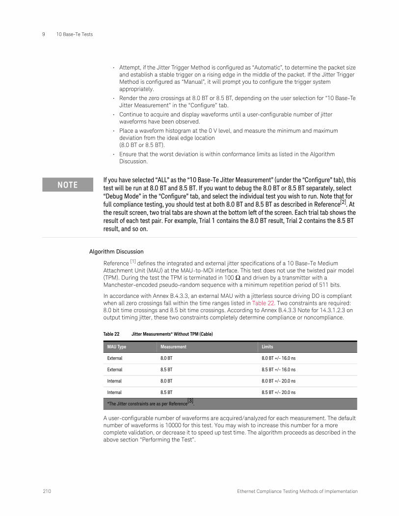
9 10 Base-Te Tests
210 Ethernet Compliance Testing Methods of Implementation
• Attempt, if the Jitter Trigger Method is configured as “Automatic”, to determine the packet size and establish a stable trigger on a rising edge in the middle of the packet. If the Jitter Trigger Method is configured as “Manual”, it will prompt you to configure the trigger system appropriately.
• Render the zero crossings at 8.0 BT or 8.5 BT, depending on the user selection for “10 Base-Te Jitter Measurement” in the “Configure” tab.
• Continue to acquire and display waveforms until a user-configurable number of jitter waveforms have been observed.
• Place a waveform histogram at the 0 V level, and measure the minimum and maximum deviation from the ideal edge location (8.0 BT or 8.5 BT).
• Ensure that the worst deviation is within conformance limits as listed in the Algorithm Discussion.
Algorithm Discussion
Reference [1] defines the integrated and external jitter specifications of a 10 Base-Te Medium Attachment Unit (MAU) at the MAU-to-MDI interface. This test does not use the twisted pair model (TPM). During the test the TPM is terminated in 100 Ω and driven by a transmitter with a Manchester-encoded pseudo-random sequence with a minimum repetition period of 511 bits.
In accordance with Annex B.4.3.3, an external MAU with a jitterless source driving DO is compliant when all zero crossings fall within the time ranges listed in Table 22. Two constraints are required: 8.0 bit time crossings and 8.5 bit time crossings. According to Annex B.4.3.3 Note for 14.3.1.2.3 on output timing jitter, these two constraints completely determine compliance or noncompliance.
A user-configurable number of waveforms are acquired/analyzed for each measurement. The default number of waveforms is 10000 for this test. You may wish to increase this number for a more complete validation, or decrease it to speed up test time. The algorithm proceeds as described in the above section “Performing the Test”.
NOTEIf you have selected “ALL” as the “10 Base-Te Jitter Measurement” (under the “Configure” tab), this test will be run at 8.0 BT and 8.5 BT. If you want to debug the 8.0 BT or 8.5 BT separately, select “Debug Mode” in the “Configure” tab, and select the individual test you wish to run. Note that for full compliance testing, you should test at both 8.0 BT and 8.5 BT as described in Reference[2]. At the result screen, two trial tabs are shown at the bottom left of the screen. Each trial tab shows the result of each test pair. For example, Trial 1 contains the 8.0 BT result, Trial 2 contains the 8.5 BT result, and so on.
Table 22 Jitter Measurements* Without TPM (Cable)
MAU Type Measurement Limits
External 8.0 BT 8.0 BT +/- 16.0 ns
External 8.5 BT 8.5 BT +/- 16.0 ns
Internal 8.0 BT 8.0 BT +/- 20.0 ns
Internal 8.5 BT 8.5 BT +/- 20.0 ns
*The Jitter constraints are as per Reference[3]
.
Ethernet Compliance Testing Methods of Implementation 211
10 Base-Te Tests 9
Peak Differential Voltage
This test ensures that the peak differential output voltage on the TD circuit, as defined in Figure 14-8 of IEEE 802.3az, subclause 14.3.1.2.1, when terminated with a 100 Ω resistive load, is within conformance limits. This test does not utilize the twisted pair model. This measurement is made while the DUT is transmitting 10 Base-Te Random Data.
Reference
[1] IEEE 802.3az, Subclause 14.3.1.2.1
Probing Setup
Refer to “Probing for 10 Base-Te Tests Without TPM, With Link Partner" on page 200.
1 Ensure that you short the appropriate load, as indicated in the connection instructions provided in the user interface.
2 Ensure the correct probe polarity.
Device Configuration
1 Reset the DUT if necessary.
2 Configure the DUT to output 10 Base-Te random data (see “Configuring a 10 Base-Te Device to Output Random Data" on page 217).
3 Ensure that the oscilloscope is capturing the proper signal (10 Base-Te Random Data) as indicated in the connection instructions provided in the user interface.
Performing the Test
1 Ensure this test is checked to run in the "Select Tests" tab.
2 Run the test.
3 If the system is not physically configured to perform this test, the application will prompt you to change the physical configuration. When you have completed these instructions, click the “Connection Completed” button and resume the test run.
4 The test will:
• Verify that the correct test signal is present on the configured “DUT Data” channel.
• Configure the oscilloscope to capture the 10 Base-Te Random Data signal, triggering on the rising edge of the data.
• Capture 1000 positive pulses, measuring the peak voltage of each waveform. Record the minimum and maximum peak voltage of all positive pulses.
• Configure the oscilloscope to capture the 10 Base-Te Random Data signal, triggering on the falling edge of the data.
• Capture 1000 negative pulses, measuring the peak voltage of each waveform. Record the minimum and maximum peak voltage of all positive pulses.
• Ensure that the absolute value of the minimum and maximum of all peak voltages measured is between 1.54 V and 1.96 V.
NOTEBefore starting a test, you can view the connection instructions under the application’s “Connect” tab. If connection changes are necessary while tests are running, the application automatically prompts you with new connection instructions.

9 10 Base-Te Tests
212 Ethernet Compliance Testing Methods of Implementation
Algorithm Discussion
Reference [1] defines the differential output voltage specifications for a 10 Base-Te Medium Attachment Unit (MAU) at the MAU-to-MDI interface. This test ensures that the peak differential output voltage on the TD circuit, as defined in Figure 14-8 of IEEE 802.3-2018, subclause 14.3.1.2.1, when terminated with a 100 Ω resistive load, is within conformance limits. This test does not utilize the twisted pair model. This measurement is made while the DUT is transmitting 10 Base-Te Random Data.
The algorithm captures 1000 positive and 1000 negative pulses, measuring the peak voltage of each pulse. The minimum and maximum of both positive and negative pulses are recorded. For a compliant device, the worst case peak voltage measured must be between 1.54 V and 1.96 V. The algorithm proceeds as described in the above section “Performing the Test”.
Harmonic Content
This test ensures that when the DO circuit is driven by an all ones Manchester encoded signal, any harmonic measured on the TD circuit, as defined in Figure 14-8 of IEEE 802.3-2018, subclause 14.3.1.2.1, is at least 27 dB below the fundamental. This test does not utilize the twisted pair model. This measurement is made while the DUT is transmitting an all ones Manchester-encoded signal (1010101010…).
Reference
[1] IEEE 802.3-2018, Subclause 14.3.1.2.1
Probing Setup
Refer to “Probing for 10 Base-Te Tests Without TPM, With Link Partner" on page 200.
1 Ensure that you short the appropriate load, as indicated in the connection instructions provided in the user interface.
2 Ensure the correct probe polarity.
Device Configuration
1 Reset the DUT if necessary.
2 Configure the DUT to output 10 Base-Te Manchester-encoded harmonic ones data (see “Configuring a 10 Base-Te Device to Output Manchester-Encoded Harmonic Ones" on page 218).
3 Ensure that the oscilloscope is capturing the proper signal (10 Base-Te Manchester-encoded harmonic ones) as indicated in the connection instructions provided in the user interface.
Performing the Test
1 Ensure this test is checked to run in the "Select Tests" tab.
2 Run the test.
NOTEBefore starting a test, you can view the connection instructions under the application’s Connect tab. If connection changes are necessary while tests are running, the application automatically prompts you with new connection instructions.
NOTEAn alternate method, allowed by Reference [1], is to configure the DUT to send maximum length packets with a payload of all ones.
Ethernet Compliance Testing Methods of Implementation 213
10 Base-Te Tests 9
3 If the system is not physically configured to perform this test, the application will prompt you to change the physical configuration. When you have completed these instructions, click the “Connection Completed” button and resume the test run.
4 The test will:
• Verify that the correct test signal is present on the configured “DUT Data” channel.
• Configure the oscilloscope to capture the 10 Base-Te all ones Manchester-encoded signal.
• Capture 100 microseconds of data.
• Perform an FFT on the data to measure spectral power.
• Measure the power at the fundamental (10 MHz).
• Measure the power at each harmonic that has a peak level of at least –40 dB.
• Ensure that each harmonic is at least 27 dB below the fundamental.
Algorithm Discussion
Reference [1] defines the harmonic content specifications for a 10 Base-Te Medium Attachment Unit (MAU) at the MAU-to-MDI interface. This test ensures that when the DO circuit is driven by an all ones Manchester-encoded signal, any harmonic measured on the TD circuit, as defined in Figure 14-8 of IEEE 802.3-2018, subclause 14.3.1.2.1, is at least 27 dB below the fundamental. This test does not utilize the twisted pair model. This measurement is made while the DUT is transmitting an all ones Manchester-encoded signal (1010101010…).
This test captures 100 microseconds of alternating 10101010 data, and computes an FFT of the data signal. The algorithm proceeds as described in the above section “Performing the Test”.

9 10 Base-Te Tests
214 Ethernet Compliance Testing Methods of Implementation
Common Mode Voltage Tests
Common Mode Output Voltage
This test ensures that the magnitude of the total common mode output voltage of the transmitter, Ecm, measured as shown in Figure 14-14 of IEEE 802.3-2018, subclause 14.3.1.2.7 is less than 50 mV peak. Common mode voltage is measured over a period of time and the peak-to-peak common mode output voltage is measured as the largest absolute value of the worst case minimum or worst case maximum common mode output voltage.
Reference
[1] IEEE 802.3-2018, Subclause 14.3.1.2.7
Probing Setup
NOTEBefore starting a test, you can view the connection instructions under the application’s “Connect” tab. If connection changes are necessary while tests are running, the application automatically prompts you with new connection instructions.

Ethernet Compliance Testing Methods of Implementation 215
10 Base-Te Tests 9
1 Connect the DUT to the RJ45 connector on fixture 4 using a short UTP cable.
2 Using a single jumper, short the appropriate pins for pair A on fixture 4.
3 Using a short BNC cable, connect the BNC connector on fixture 4 to the configured “Common Mode” channel on the oscilloscope.
Device Configuration
1 Configure the DUT to output 10 Base-Te Random Data. Contact your PHY vendor for instructions on configuring the DUT to transmit 10 Base-Te Random data without a link partner.
2 Ensure that the DUT is transmitting the proper signal as indicated in the connection instructions provided in the user interface.
Figure 55 Probing for 10 Base-Te Common Mode Output Voltage
DUT
Section 4 of test fixture
BNC cable
RJ45

9 10 Base-Te Tests
216 Ethernet Compliance Testing Methods of Implementation
Performing the Test
1 Ensure this test is checked to run in the "Select Tests" tab.
2 Run the test.
3 If the system is not physically configured to perform this test, the application will prompt you to change the physical configuration. When you have completed these instructions, click the “Connection Completed” button and resume the test run.
4 The test will:
• Verify that the correct test signal is present on the configured "Common Mode" channel.
• Capture multiple acquisitions totaling 100 ms of the common mode output voltage signal Ecm_out as indicated in Figure 14-14 of Reference [1]. Display this signal as a color-graded persistence waveform.
• Record the worst case minimum and maximum voltage encountered over all acquired data.
• Compute the worst case peak common mode output voltage as the maximum absolute value of the worst case maximum and worst case minimum voltage.
Algorithm Discussion
Reference [1] defines the maximum common mode output voltage specifications for a 10 Base-Te Medium Attachment Unit (MAU) at the MAU-to-MDI interface. This test ensures that the magnitude of the total common mode output voltage of the transmitter, Ecm, measured as shown in Figure 14-14 of IEEE 802.3-2018, subclause 14.3.1.2.7 is less than 50 mV peak. This test does not utilize the twisted pair model. This measurement is made while the DUT is transmitting 10 Base-Te Random Data.
The total Common Mode voltage Ecm_out is measured over a 100 ms duration and the peak common mode output voltage is computed as the largest absolute value of the worst case minimum and worst case maximum common mode output voltage.
Figure 56 Common Mode Output Voltage Test Circuit
PG
47.5 Ω
MDI
47.5 Ω
49.9 Ω E cm_out
DeviceUnderTest

Ethernet Compliance Testing Methods of Implementation 217
10 Base-Te Tests 9
Configuring 10 Base-Te Device Output
Configuring a 10 Base-Te Device to Output Random Data
A random data signal is required for some 10 Base-Te tests. This section provides some commonly used methods to configure a DUT to output random data.
• If you have a 10 Base-T/Te link partner transmitting idle pulses, connect the link partner to the same fixture using the RJ45 port marked “LP”.
• You may also be able to configure the DUT to output 10 Base-Te random data using special boot software (in some cases, a link partner is still required).
• If custom boot software is available, the PHY vendor should provide instructions. However, you may be able to configure the DUT to output random data with some combination of the following steps:
• Disable link speed negotiation.
• Force the link speed to 10-BASE-Te.
• Configure the device to transmit data.
• In most cases, with special boot software, you can control the output data. Configure the output data as “random”.
• If no custom boot software is available, you may be able to use high-level software programs like “ipsend” (UNIX) or “pktsend” (DOS) to specify the packet payload.
NOTESpecial boot software and/or a link partner may be required to obtain 10 Base-Te Random data. Contact your PHY vendor for boot software or specific instructions on configuring the DUT to output random data.
NOTEIf you are performing MAU Template or Jitter tests, the DUT should be configured to output packets of random data of sufficient length. The data must be random in order to capture all possible data sequences. A minimum packet length of 300 bytes is recommended for the Automatic Jitter Trigger method.

9 10 Base-Te Tests
218 Ethernet Compliance Testing Methods of Implementation
Configuring a 10 Base-Te Device to Output Manchester-Encoded Harmonic Ones
A Manchester-encoded all ones signal (0101010…) is required for the 10 Base-Te Harmonic Test. This section provides some commonly used methods to configure a DUT to output this signal.
• If you have a 10 Base-T/Te link partner, you may need to connect the link partner to the same fixture using the RJ45 port marked “LP”.
• You may also be able to configure the DUT to output 10 Base-Te Harmonic Ones signal using special boot software (in some cases, a link partner is still required).
• If custom boot software is available, the PHY vendor should provide instructions. However, you may be able to configure the DUT to output the appropriate signal with some combination of the following steps:
• Disable link speed negotiation.
• Force the link speed to 10-BASE-Te.
• Configure the device to transmit data.
• In most cases, with special boot software, you can control the output data. Configure the output data as all FF or all ones (remember that the signal is Manchester-Encoded, so 11111 is encoded as 101010 on the wire.
• If no custom boot software is available, you may be able to use high-level software programs like “ipsend” (UNIX) or “pktsend” (DOS) to specify the packet payload.
NOTESpecial boot software and/or a link partner may be required to obtain 10 Base-Te Harmonic Ones signal. Contact your PHY vendor for boot software or specific instructions on configuring the DUT to output this signal.

Keysight D9010ETHC Ethernet Compliance Test Application
Methods of Implementation
10 InfiniiMax Probing
Keysight recommends the E2678A/B differential socket probe head and E2677A/B solder-in differential probe head. All InfiniiMax active differential probes can be used with the Ethernet Compliance Test Application.
Figure 57 Recommended Probe Head for the Ethernet Compliance Test Application
Table 23 Probe Head Characteristics
Probe Head Model Number
Differential Measurement(BW, input C, input R)
Single-Ended Measurement(BW, input C, input R)
Differential socketed E2678A/B 7 GHz, 0.34 pF, 50 kW 7 GHz, 0.56 pF, 25 kW
Differential solder-in E2677A/B 12 GHz, 0.27 pF, 50 kW 12 GHz, 0.44 pF, 25 kW

10 InfiniiMax Probing
220 Ethernet Compliance Testing Methods of Implementation

Ethernet Compliance Testing Methods of Implementation 221
Index
Cconfigure, 31connect, 31
DD9010ETHC Ethernet electrical
performance validation and compliance software, 3
EEthernet automated testing—at a
glance, 3
HHTML report, 31
Iin this book, 5
Jjitter tests, 95, 177
Llicense key, installing, 19
Pprobing the link for data eye pattern
tests, 38probing the link for jitter tests, 96, 179probing the link for transition time
tests, 125, 187
Rreport, 31results, 31run tests, 31running clock jitter test, 99, 180running data eye pattern tests, 38, 171
Sselect tests, 31starting the Ethernet automated test
application, 30
Ttransition time tests, 123, 185

Index
222 Ethernet Compliance Testing Methods of Implementation