Keysight M9391A and M9381A Programming Guide
144
Programming Guide Keysight M9391A PXIe Vector Signal Analyzer & M9381A PXIe Vector Signal Generator Notice: This document contains references to Agilent. Please note that Agilent’s Test and Measurement business has become Keysight Technologies. For more information, go to www.keysight.com.
-
Upload
khangminh22 -
Category
Documents
-
view
0 -
download
0
Transcript of Keysight M9391A and M9381A Programming Guide
ProgrammingGuide
Keysight M9391A PXIeVector Signal Analyzer &M9381A PXIeVector Signal Generator
Notice: This document contains references to Agilent. Please note that Agilent’s Test and Measurementbusiness has become Keysight Technologies. For more information, go to www.keysight.com.


Notices
Copyright Notice©Keysight Technologies 2013 - 2015
No part of this manual may bereproduced in any form or by anymeans (including electronic storageand retrieval or translation into a foreignlanguage) without prior agreement andwritten consent from KeysightTechnologies, Inc. as governed byUnited States and internationalcopyright laws.
Manual Part NumberM9300-90080
Published ByKeysight TechnologiesGround Floor and Second Floor, CP-11Sector-8, IMT Manesar – 122051Gurgaon, Haryana, India
EditionEdition 2.1, July, 2015
Regulatory ComplianceThis product has been designed andtested in accordance with acceptedindustry standards, and has beensupplied in a safe condition. To reviewthe Declaration of Conformity, go tohttp://www.keysight.com/go/conformity.
WarrantyTHE MATERIAL CONTAINED IN THISDOCUMENT IS PROVIDED “AS IS,” ANDIS SUBJECT TO BEING CHANGED,WITHOUT NOTICE, IN FUTUREEDITIONS. FURTHER, TO THEMAXIMUM EXTENT PERMITTED BYAPPLICABLE LAW, KEYSIGHTDISCLAIMS ALL WARRANTIES, EITHEREXPRESS OR IMPLIED, WITH REGARDTO THIS MANUAL AND ANYINFORMATION CONTAINED HEREIN,INCLUDING BUT NOT LIMITED TO THEIMPLIED WARRANTIES OFMERCHANTABILITY AND FITNESS FORA PARTICULAR PURPOSE. KEYSIGHTSHALL NOT BE LIABLE FOR ERRORSOR FOR INCIDENTAL ORCONSEQUENTIAL DAMAGES INCONNECTION WITH THEFURNISHING, USE, OR
PERFORMANCE OF THIS DOCUMENTOR OF ANY INFORMATION CONTAINEDHEREIN. SHOULD KEYSIGHT AND THEUSER HAVE A SEPARATE WRITTENAGREEMENT WITH WARRANTY TERMSCOVERING THE MATERIAL IN THISDOCUMENT THAT CONFLICT WITHTHESE TERMS, THE WARRANTYTERMS IN THE SEPARATEAGREEMENT SHALL CONTROL.
KEYSIGHT TECHNOLOGIES DOES NOTWARRANT THIRD-PARTY SYSTEM-LEVEL (COMBINATION OF CHASSIS,CONTROLLERS, MODULES, ETC.)PERFORMANCE, SAFETY, ORREGULATORY COMPLIANCE, UNLESSSPECIFICALLY STATED.
Technology LicensesThe hardware and/or softwaredescribed in this document arefurnished under a license and may beused or copied only in accordance withthe terms of such license.
U.S. Government RightsThe Software is “commercial computersoftware,” as defined by FederalAcquisition Regulation (“FAR”) 2.101.Pursuant to FAR 12.212 and 27.405-3and Department of Defense FARSupplement (“DFARS”) 227.7202, theU.S. government acquires commercialcomputer software under the sameterms by which the software iscustomarily provided to the public.Accordingly, Keysight provides theSoftware to U.S. government customersunder its standard commercial license,which is embodied in its End UserLicense Agreement (EULA), a copy ofwhich can be found athttp://www.keysight.com/find/sweula. Thelicense set forth in the EULA representsthe exclusive authority by which theU.S. government may use, modify,distribute, or disclose the Software. TheEULA and the license set forth therein,does not require or permit, among otherthings, that Keysight: (1) Furnishtechnical information related tocommercial computer software orcommercial computer softwaredocumentation that is not customarilyprovided to the public; or (2) Relinquishto, or otherwise provide, the
government rights in excess of theserights customarily provided to thepublic to use, modify, reproduce,release, perform, display, or disclosecommercial computer software orcommercial computer softwaredocumentation. No additionalgovernment requirements beyondthose set forth in the EULA shall apply,except to the extent that those terms,rights, or licenses are explicitly requiredfrom all providers of commercialcomputer software pursuant to the FARand the DFARS and are set forthspecifically in writing elsewhere in theEULA. Keysight shall be under noobligation to update, revise or otherwisemodify the Software. With respect toany technical data as defined by FAR2.101, pursuant to FAR 12.211 and27.404.2 and DFARS 227.7102, the U.S.government acquires no greater thanLimited Rights as defined in FAR 27.401or DFAR 227.7103-5 (c), as applicable inany technical data.
Safety Notices
A CAUTION notice denotes a hazard. Itcalls attention to an operatingprocedure, practice, or the like that, ifnot correctly performed or adhered to,could result in damage to the productor loss of important data. Do notproceed beyond a CAUTION notice untilthe indicated conditions are fullyunderstood and met.
A WARNING notice denotes a hazard. Itcalls attention to an operatingprocedure, practice, or the like that, ifnot correctly performed or adhered to,could result in personal injury or death.Do not proceed beyond a WARNINGnotice until the indicated conditions arefully understood and met.
The following safety precautions shouldbe observed before using this productand any associated instrumentation.
This product is intended for use byqualified personnel who recognizeshock hazards and are familiar with the
iii

safety precautions required to avoidpossible injury. Read and follow allinstallation, operation, andmaintenance information carefullybefore using the product.
If this product is not used as specified,the protection provided by theequipment could be impaired. Thisproduct must be used in a normalcondition (in which all means forprotection are intact) only.
The types of product users are:
Responsible body is the individual orgroup responsible for the use and main-tenance of equipment, for ensuring thatthe equipment is operated within its spe-cifications and operating limits, and forensuring operators are adequately trained.
Operators use the product for its intendedfunction. They must be trained in electricalsafety procedures and proper use of theinstrument. They must be protected fromelectric shock and contactwith hazardouslive circuits.
Maintenancepersonnel perform routineprocedures on the product to keep it oper-ating properly (for example, setting the linevoltage or replacing consumablemater-ials). Maintenanceprocedures aredescribed in the user documentation. Theprocedures explicitly state if the operatormay perform them. Otherwise, they shouldbeperformed only by service personnel.
Service personnel are trained to work onlive circuits, perform safe installations, andrepair products. Only properly trained ser-vice personnel may perform installationand service procedures.
Operator is responsible to maintain safeoperating conditions. To ensure safeoperating conditions, modules shouldnot be operated beyond the fulltemperature range specified in theEnvironmental and physicalspecification. Exceeding safe operatingconditions can result in shorterlifespans, improper moduleperformance and user safety issues.
When the modules are in use andoperation within the specified fulltemperature range is not maintained,module surface temperatures mayexceed safe handling conditions whichcan cause discomfort or burns iftouched. In the event of a moduleexceeding the full temperature range,always allow the module to cool beforetouching or removing modules fromchassis.
Keysight products are designed for usewith electrical signals that are ratedMeasurement Category I andMeasurement Category II, as describedin the International ElectrotechnicalCommission (IEC) Standard IEC 60664.Most measurement, control, and dataI/O signals are Measurement Category Iand must not be directly connected tomains voltage or to voltage sources withhigh transient over-voltages.Measurement Category II connectionsrequire protection for high transientover-voltages often associated withlocal AC mains connections. Assume allmeasurement, control, and data I/Oconnections are for connection toCategory I sources unless otherwisemarked or described in the userdocumentation.
Exercise extreme caution when a shockhazard is present. Lethal voltage maybe present on cable connector jacks ortest fixtures. The American NationalStandards Institute (ANSI) states that ashock hazard exists when voltage levelsgreater than 30V RMS, 42.4V peak, or60VDC are present. A good safetypractice is to expect that hazardousvoltage is present in any unknowncircuit before measuring.
Operators of this product must beprotected from electric shock at alltimes. The responsible body mustensure that operators are preventedaccess and/or insulated from everyconnection point. In some cases,connections must be exposed topotential human contact. Productoperators in these circumstances mustbe trained to protect themselves fromthe risk of electric shock. If the circuit iscapable of operating at or above 1000V,no conductive part of the circuit may beexposed.
Do not connect switching cards directlyto unlimited power circuits. They areintended to be used with impedance-limited sources. NEVER connectswitching cards directly to AC mains.When connecting sources to switchingcards, install protective devices to limitfault current and voltage to the card.
Before operating an instrument, ensurethat the line cord is connected to aproperly-grounded power receptacle.Inspect the connecting cables, testleads, and jumpers for possible wear,cracks, or breaks before each use.
When installing equipment whereaccess to the main power cord isrestricted, such as rack mounting, aseparate main input power disconnectdevice must be provided in closeproximity to the equipment and withineasy reach of the operator.
For maximum safety, do not touch theproduct, test cables, or any otherinstruments while power is applied tothe circuit under test. ALWAYS removepower from the entire test system anddischarge any capacitors before:connecting or disconnecting cables orjumpers, installing or removingswitching cards, or making internalchanges, such as installing or removingjumpers.
Do not touch any object that couldprovide a current path to the commonside of the circuit under test or powerline (earth) ground. Always makemeasurements with dry hands whilestanding on a dry, insulated surfacecapable of withstanding the voltagebeing measured.
The instrument and accessories mustbe used in accordance with itsspecifications and operatinginstructions, or the safety of theequipment may be impaired.
Do not exceed the maximum signallevels of the instruments andaccessories, as defined in thespecifications and operatinginformation, and as shown on theinstrument or test fixture panels, orswitching card.
When fuses are used in a product,replace with the same type and rating
iv

for continued protection against firehazard.
Chassis connections must only be usedas shield connections for measuringcircuits, NOT as safety earth groundconnections.
If you are using a test fixture, keep thelid closed while power is applied to thedevice under test. Safe operationrequires the use of a lid interlock.
Instrumentation and accessories shallnot be connected to humans.
Before performing any maintenance,disconnect the line cord and all testcables.
To maintain protection from electricshock and fire, replacementcomponents in mains circuits –including the power transformer, testleads, and input jacks – must bepurchased from Keysight. Standardfuses with applicable national safetyapprovals may be used if the rating andtype are the same. Other componentsthat are not safety-related may bepurchased from other suppliers as longas they are equivalent to the originalcomponent (note that selected partsshould be purchased only throughKeysight to maintain accuracy andfunctionality of the product). If you areunsure about the applicability of areplacement component, call anKeysight office for information.
No operator serviceable parts inside.Refer servicing to qualified personnel.To prevent electrical shock do notremove covers. For continuedprotection against fire hazard, replacefuse with same type and rating.
PRODUCT MARKINGS:
The CE mark is a registered trademarkof the European Community.
Australian Communication and MediaAuthority mark to indicate regulatorycompliance as a registered supplier.
This symbol indicates productcompliance with the CanadianInterference-Causing EquipmentStandard (ICES-001). It also identifiesthe product is an Industrial Scientificand Medical Group 1 Class A product(CISPR 11, Clause 4).
South Korean Class A EMC Declaration.This equipment is Class A suitable forprofessional use and is for use inelectromagnetic environments outsideof the home. A급 기기 ( 업무용 방송통신기자재 )이 기기는 업무용 (A급 )전자파적합기기로서 판 매자 또는 사용자는
이 점을 주 의하시기 바라 며 ,가정외의지역에서 사용하는 것을 목적으 로 합니
다 .
This product complies with the WEEEDirective marketing requirement. Theaffixed product label (above) indicatesthat you must not discard thiselectrical/electronic product indomestic household waste. ProductCategory: With reference to theequipment types in the WEEE directiveAnnex 1, this product is classified as“Monitoring and Controlinstrumentation” product. Do notdispose in domestic household waste.To return unwanted products, contactyour local Keysight office, or for moreinformation seehttp://about.keysight.com/en/companyinfo/environment/takeback.shtml.
This symbol indicates the instrument issensitive to electrostatic discharge(ESD). ESD can damage the highlysensitive components in yourinstrument. ESD damage is most likelyto occur as the module is beinginstalled or when cables are connectedor disconnected. Protect the circuitsfrom ESD damage by wearing agrounding strap that provides a highresistance path to ground. Alternatively,ground yourself to discharge any built-up static charge by touching the outershell of any grounded instrumentchassis before touching the portconnectors.
This symbol on an instrument meanscaution, risk of danger. You should referto the operating instructions located inthe user documentation in all caseswhere the symbol is marked on theinstrument.
This symbol indicates the time periodduring which no hazardous or toxicsubstance elements are expected toleak or deteriorate during normal use.Forty years is the expected useful life ofthe product.
CLEANING PRECAUTIONS:
To prevent electrical shock, disconnectthe Keysight Technologies instrumentfrom mains before cleaning. Use a drycloth or one slightly dampened withwater to clean the external case parts.Do not attempt to clean internally. Toclean the connectors, use alcohol in awell-ventilated area. Allow all residualalcohol moisture to evaporate, and thefumes to dissipate prior to energizingthe instrument.
v

vi

vii
Contents
What You Will Learn in This Programming Guide 11
Related Websites 12
Related Documentation 12
Overall Process Flow 15
Documentation Map 16
Installing Hardware, Software, and Licenses 17
APIs for the M9391A PXIe VSA and M938xA PXIe VSG 19
IVI Compliant or IVI Class Compliant 19
IVI Driver Types 20
IVI Driver Hierarchy 21
Instrument-Specific Hierarchies for the M9391A and M938xA 22
When Using Visual Studio 23
Naming Conventions Used to Program IVI Drivers 24
General IVI Naming Conventions 24
IVI-COM Naming Conventions 24
Creating a Project with IVI-COM Using C-Sharp 27
Step 1 - Create a Console Application 27
Step 2 - Add References 27
Step 3 - Add Using Statements 29
To Access the IVI Drivers Without Specifying or Typing The Full Path 29
Step 4 - Create Instances of the IVI-COM Drivers 30
To Create Driver Instances 30
Step 5 - Initialize the Driver Instances 30
Resource Names 30
Initialize() Parameters 32
Initialize() Options 33
M9300A Reference Sharing 36
Example: M9300A PXIe Reference with M9381A PXIe VSG 36
Example: M9300A PXIe Reference with M9391A PXIe VSA 37
Example: M9300A PXIe Reference Shared With Both Modules 37
Step 6 - Write the Program Steps 38
Using the Soft Front Panel to Write Program Commands 38
Step 7 - Close the Driver 39
Step 8 - Building and Running a Complete Program Using Visual C-Sharp 40
Example Program 1- Code Structure 40
Example Program 1- How to Print Driver Properties, Check for Errors, and CloseDriver Sessions 41
Working with PA_FEM Measurements 45

Test Challenges Faced by Power Amplifier Testing 45
Performing a Channel Power Measurement, Using Immediate Trigger 47
Example Program 2 - Code Structure 47
Example Program 2 - Pseudo-code 48
Example Program 2 - Channel Power Measurement Using Immediate Trigger 49
Performing a WCDMA Power Servo and ACPR Measurement 51
Example Program 3 - Code Structure 52
Example Program 3 - Pseudo-code 53
Example Program 3 - WCDMA Power Servo and ACPR Measurement 55
Disclaimer 60
Working with 802.11ac MIMO RnD and DVT Tests 61
Preparing the Hardware and Software for 802.11ac MIMO RnD DVT Tests 62
Example Program 4 - How to Perform Transmitter Tests with 89600 VSA Software 64
Example Program4 - Pseudo-Code 65
Step 1 : Create a Console Application 67
Step 2 : Add References 67
Step 3 : Add Using Statements 68
Step 4 - Create Driver Instances 68
To create driver instances 68
Step 5 - Initialize Driver Instances and Check for Errors 69
To Establish a Communication Link, get the Resource Name Addresses 69
Step 6 - Route Backplane Triggers and Bus Segments on the M9018A PXIe Chassis 70
Routing an External Trigger Input and ALC Hold on each M9381A PXIe VSG 70
Routing a Synchronization Playback Trigger from the M9300A PXIe Reference toeach M9381A PXIe VSG 71
Routing MASTER_SLAVE Backplane Triggers for each M9391A PXIe VSA 71
2x2 MIMO 72
3x3 MIMO 73
4x4 MIMO 75
Step 7 - Set Up the M9381A PXIe VSGs for WLAN Rx Testing 79
Disable ALC for WLAN waveforms to achieve best Residual EVM 79
Enable Pulse Blanking - Achieve Best Off Time Rejection 79
Set PLL MODE to Best Wide Offset 79
Set RF Frequency 80
Set Amplitude (Power_Level) 80
Enable Modulation 80
Enable RF Output 80
Step 8 - Start Continuous Waveform Playback without Power Search or IQ DCCalibration 81
Overview of the Process to Start Continuous Waveform Playback without PowerSearch or IQ DC Cal 81
viii

ix
1. Specify a Waveform File to Upload and Play 81
2. Upload the Specified Waveform File 81
3. Set Up M9300A PXIe Reference to Generate a User-Defined Trigger on PXI TRIG0 82
4. Configure all M9381A PXIe VSGs to Listen for an External Trigger on PXI TRIG 0 82
5. Arm All M9381A PXIe VSGs and Prepare for Playing the Specified Waveform filewhen an External Trigger is Received on PXI TRIG 0 83
6. Generate a Sync Pulse from the M9300A PXIe Reference on PXI TRIG 0 to StartWaveform Playback on all of the M9381A PXIe VSGs 83
(Optional) Step 8 - Start Continuous or Sequence waveform Playback with PowerSearch and IQ DC Cal 83
Overview of Starting Continuous Waveform Playback with Power Search and IQDC Cal 84
Overview of Starting Sequence Waveform Playback with Power Search and IQ DCCal 88
Step 9 - Create an N-Channel Analyzer Hardware Configuration with 89600 VSASoftware 92
Create a 2-Channel Analyzer of M9391A PXIe VSAs 92
Step 10 - Start 89600 VSA Software to Analyze M9381A PXIe VSGs WaveformOutput 94
Step 11 - Optimize 89600 VSA Settings for WLAN Demodulation 94
Using Shared LO for Phase-Coherent Signal Generation and Signal Acquisition 97
Using a Shared LO 97
Implementation of Shared LO 97
Prerequisites for Using a Shared LO 98
LO Level Field Alignment 98
Cabling of Instruments When Sharing Local Oscillator 98
Initialization Settings for Shared LO 98
Initialization Steps 99
LO Level Field Alignment 100
Example Programs 100
Assumptions for Example Programs 101
Example Program 5 - Pseudo-Code 101
Example Program 5 - Program Steps with Code Snippets 103
Example Program 6 - Pseudo-Code 113
Example Program 6 - Program Steps with Code Snippets 115
Hints for Various Configuration Tasks 125
Restarting an Already Playing Waveform in M9381A VSG 125
Use Case 125
Description 125
Program Steps 126
Appendix - Determining Resource Name Address Strings 127
Appendix - Verify Instruments Connect, Pass Self-Test, and are Updated 131
Verify that VSG 1 is Connected, Passes Self-Test, and Contains Up to Date Firmware 131
Verify that VSG 2 is Connected, Passes Self-Test, and Contains Up to Date Firmware 132
Verify that VSA 1 is Connected, Passes Self-Test, and Contains Up to Date Firmware 133
Verify that VSA 2 is Connected, Passes Self-Test, and Contains Up to Date Firmware 133
Appendix - Using LO Distribution Network in Multi-Channel Systems 135
Initialization Settings for LO Distribution Network 135
LO Level Field Alignment 135
VSG Code Snippet 136
VSA Code Snippet 136
References 139
Glossary 141
x

What You Will Learn in This Programming Guide
M9391A and M9381A Programming Guide 11
What You Will Learn in This Programming GuideThis programming guide is intended for individuals who write and run programs tocontrol test-and-measurement instruments. Specifically, in this programming guide,you will learn how to use Visual Studio 2010 with the .NET Framework to write IVI-COM Console Applications in Visual C#. Knowledge of Visual Studio 2010 with the.NET Framework and knowledge of the programming syntax for Visual C# is required.
Our basic user programming model uses the IVI-COM driver directly and allowscustomer code to:
Access the IVI-COM driver at the lowest level
Access IQ Acquisition Mode, Power Acquisition Mode, and Spectrum AcquisitionMode
Control the Keysight M9391A PXIe Vector Signal Analyzer (VSA) and KeysightM9381A PXIe Vector Signal Generator (VSG) while performing PA/FEM PowerMeasurement Production Tests
Generate waveforms created by Signal Studio software (licenses are required)
The Working with 802.11ac MIMO RnD and DVT Tests (page 61) section focuses on802.11ac MIMO R&D/DVT Tests related to Rx/Tx PHY Layer characterization. Thissection shows how IVI-COM Console Applications are used to route backplanetriggers on the M9018A PXIe Chassis for the M9381A PXIe VSGs, M9300A PXIeReferences, and M9391A PXIe VSAs. It then sets the controls for multiple M9381APXIe VSGs and starts them playing a waveform file. The results of these waveformfiles are analyzed with Keysight 89600 VSA Software that is used to control M9391APXIe VSAs while performing transmitter tests for PHY Layer characterization.
The Using Shared LO for Phase-Coherent Signal Generation and Signal Acquisition(page 97) section focuses on creating programs for multichannel operations forM9381A PXIe VSGs and M391A PXIe VSAs using shared local oscillator (LO) for eachset of transmitters (M9381A) and receivers (M9391A).
Example Program 1: How to Print Driver Properties, Check for Errors, and CloseDriver Sessions

What You Will Learn in This Programming Guide
Related Websites
Example Program 2: How to Perform a Channel Power Measurement UsingImmediate Trigger
Example Program 3: How to Perform a WCDMA Power Servo and ACPRMeasurement
Example Program 4: How to Perform Transmitter Tests with 89600 VSASoftware,(Playing Waveforms on M9381A PXIe VSGs Using External Trigger)
Example Program 5: How to Perform Multi-Channel Synchronous ModulatedSignal Generation Using Shared LO
Example Program 6: How to Perform Multi-Channel IQ Acquisition UsingShared LO
Related Websites
Keysight Technologies PXI and AXIe Modular ProductsM9391A PXIe Vector Signal Analyzer
M9381A PXIe Vector Signal Generator
Keysight TechnologiesIVI Drivers & Components Downloads
Keysight I/O Libraries Suite
GPIB, USB, & Instrument Control Products
Keysight VEE Pro
Technical Support, Manuals, & Downloads
Contact Keysight Test & Measurement
IVI Foundation - Usage Guides, Specifications, Shared Components Downloads
MSDN Online
Related Documentation
To access documentation related to the Keysight M9391A PXIe Vector SignalAnalyzer and M9381A PXIe Vector Signal Generator Programming Guide , use one ofthe following methods:
If the product software is installed on your PC, the related documents are alsoavailable in the software installation directory.
Document DescriptionDefault Location on 64-bitWindowssystem
Format
StartupGuide
Includesprocedures tohelp you tounpack,
For M9381: C:/Program Files (x86)/Agilent/M938x/Help\M9391_and_M9381_StartupGuide.pdf
For M9391A:C:\Program Files (x86)
12 M9391A and M9381A Programming Guide

What You Will Learn in This Programming Guide
RelatedDocumentation
M9391A and M9381A Programming Guide 13
Document DescriptionDefault Location on 64-bitWindowssystem
Format
inspect, install(software andhardware),performinstrumentconnections,verifyoperability, andtroubleshootyour product.
Also includesan annotatedblock diagram.
\Agilent\M9391\Help\M9391_and_M9381_StartupGuide.pdf
IVI Driverreference(helpsystem)
Providesdetaileddocumentationof the IVI-COMand IVI-Cdriver APIfunctions, aswell asinformation tohelp you getstarted withusing the IVIdrivers in yourapplicationdevelopmentenvironment.
For M9381: C:/Program Files (x86)/Agilent/M938x/Help\AgM938x.chm
For M9391A:C:\Program Files (x86)\Agilent\M9391\Help\AgM9391.chm
CHM(Microsoft
HelpFormat)
DataSheet
In addition to adetailedproductintroduction,the data sheetsupplies fullproductspecifications.
For M9381: C:/Program Files (x86)/Agilent/M938x/Help\M9381_DataSheet_5991-0279EN.pdf
For M9391A:C:\Program Files (x86)\Agilent\M9391\Help\M9391_DataSheet_5991-2603EN.pdf
LabVIEWDriver
Providesdetailed
For M9381: C:/Program Files (x86)/Agilent/M938x/Help\AgM938x_
CHM(Microsoft

What You Will Learn in This Programming Guide
RelatedDocumentation
Document DescriptionDefault Location on 64-bitWindowssystem
Format
Reference documentationof the LabVIEWG Driver APIfunctions.
LabVIEW_Help.chm
For M9391A:C:\Program Files (x86)\Agilent\M9391\Help\AgM9391_LabVIEW_Help.chm
HelpFormat)
SCPIReference
Describes theSCPIcommandssupported bythe M9381APXIe VectorSignalGenerator.
C:/Program Files (x86)/Agilent/M938x/Help\M938x_SCPI_Reference.chm
CHM(Microsoft
HelpFormat)
SoftwareReleaseNotes
Includesrecentchanges,enhancements,and bugfixesin thecurrentrelease.
For M9381: C:/Program Files (x86)/Agilent/M938x/Help\M938x_SoftwareReleaseNotes.pdf
For M9391A:C:\Program Files (x86)\Agilent\M9391\Help\M9391_SoftwareReleaseNotes.pdf
Alternatively, you can find these documents under:
Start > All Programs > Keysight >M938x.
Start > All Programs > Keysight >M9391.
The documentation listed above is also available on the product CD.
To understand the available user documentation in context to your workflow,Documentation Map (page 16).
To find the very latest versions of the user documentation, go to the productweb site ( www.keysight.com/find/M9381A or www.keysight.com/find/M9391A) and download the files from the Manuals support page (go to DocumentLibrary > Manuals):
14 M9391A and M9381A Programming Guide

What You Will Learn in This Programming Guide
Overall ProcessFlow
M9391A and M9381A Programming Guide 15
Overall Process Flow
Perform the following steps:
1. Write source code using Microsoft Visual Studio 2010 with .NET Visual C#running on Windows 7.
2. Compile source code using the .NET Framework Library.
3. Produce an Assembly.exe file – this file can run directly from Microsoft Windowswithout the need for any other programs.
When using the Visual Studio Integrated Development Environment(IDE), the Console Applications you write are stored in conceptualcontainers called Solutions and Projects.
You can view and access Solutions and Projects using the SolutionExplorer window (View > Solution Explorer).

What You Will Learn in This Programming Guide
Documentation Map
Documentation Map
16 M9391A and M9381A Programming Guide

Installing Hardware, Software, and Licenses
M9391A and M9381A Programming Guide 17
Installing Hardware, Software, and LicensesPerform the following steps:
1. Unpack and inspect all hardware.
2. Verify the shipment contents.
3. Install the software. Note the following order when installing software.
a. Install Microsoft Visual Studio 2010 with .NET Visual C# running onWindows 7.
You can also use a free version of Visual Studio Express 2010 tools from:http://www.microsoft.com/visualstudio/eng/products/visual-studio-2010-express
The following steps, defined in the Keysight M9391A PXIe VSA andM9381A PXIe VSG Startup Guide, M9300-90090, but repeated heremust be completed before programmatically controlling the M9391APXIe VSA and M9381A PXIe VSG hardware with their IVI drivers.
b. Install Agilent/Keysight IO Libraries Suite (IOLS), Version 16.3.16603.3 ornewer;this installation includes Agilent/Keysight Connection Expert.
c. (Required for MIMO) Install Agilent/Keysight 89600 Vector SignalAnalyzer Software, Version 16.2 or newer.
d. Install the M9391A PXIe VSA driver software, Version 1.1.228.0 ornewer.
e. Install the M938xA PXIe VSG driver software, Version 1.3.105.0 ornewer.
f. Install the M9018A PXIe Chassis driver software, Version 1.3.443.1 ornewer.
Driver software includes all IVI-COM, IVI-C, and LabVIEW G Driversalong with Soft Front Panel (SFP) programs and documentation. All ofthese items may be downloaded from the Keysight product websites:
http://www.keysight.com/find/iosuite > Select Technical Support> Select the Drivers, Firmware & Software tab > Download theKeysight IO Libraries Suite Recommended
http://www.keysight.com/find/89600 (Required for MIMO) >Select Technical Support > Select the Drivers, Firmware &Software tab > Download the Instrument Driver that correspondsto "89600 VSA software".

Installing Hardware, Software, and Licenses
http://www.keysight.com/find/m9391a > Select TechnicalSupport > Select the Drivers, Firmware & Software tab >Download the Instrument Driver.
http://www.keysight.com/find/m9381a > Select TechnicalSupport > Select the Drivers, Firmware & Software tab >Download the Instrument Driver.
http://www.keysight.com/find/m9018a > Select TechnicalSupport > Select the Drivers, Firmware & Software tab >Download the Instrument Driver.
http://www.keysight.com/find/ivi - download other installers forKeysight IVI-COM drivers
4. Install the hardware modules and make cable connections.
5. Verify operation of the modules (or the system that the modules create).
Before programming ormakingmeasurements, conduct aSelf-Test on eachM9391A PXIe VSA and eachM9381A PXIeVSG to make sure there are no problems with the modules,cabling, or backplane trigger mapping.
Running Self-Test will fail if the modules that form anM9381APXIe VSG or anM9391A PXIe VSA spans across slot 6 or slot12 of the M9018A PXIe Chassis; if they do span across slot 6 orslot 12, the backplane triggers and bus segments must berouted properly. For details, see Step 6 - Route BackplaneTriggers and Bus Segments on the M9018A PXIe Chassis(page 70).
Once the software and hardware are installed and Self-Test has beenperformed, they are ready to be programmatically controlled.
18 M9391A and M9381A Programming Guide
APIs for the M9391A PXIe VSA and M938xA PXIe VSG
IVI Compliant or IVI Class Compliant
M9391A and M9381A Programming Guide 19
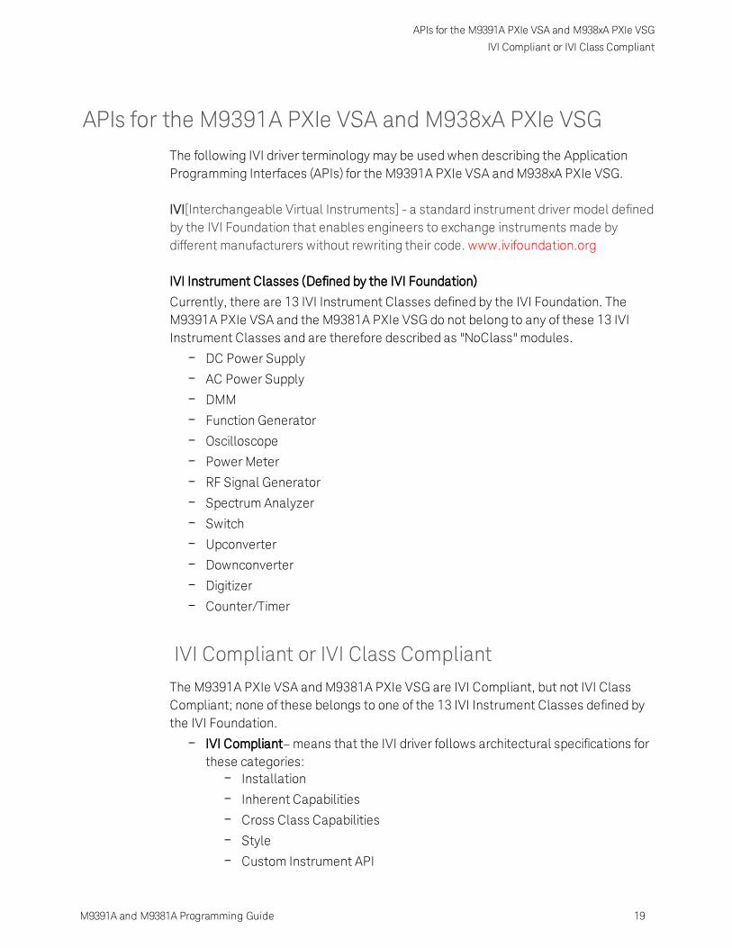
APIs for the M9391A PXIe VSA and M938xA PXIe VSGThe following IVI driver terminology may be used when describing the ApplicationProgramming Interfaces (APIs) for the M9391A PXIe VSA and M938xA PXIe VSG.
IVI[Interchangeable Virtual Instruments] - a standard instrument driver model definedby the IVI Foundation that enables engineers to exchange instruments made bydifferent manufacturers without rewriting their code. www.ivifoundation.org
IVI Instrument Classes (Defined by the IVI Foundation)
Currently, there are 13 IVI Instrument Classes defined by the IVI Foundation. TheM9391A PXIe VSA and the M9381A PXIe VSG do not belong to any of these 13 IVIInstrument Classes and are therefore described as "NoClass" modules.
DC Power Supply
AC Power Supply
DMM
Function Generator
Oscilloscope
Power Meter
RF Signal Generator
Spectrum Analyzer
Switch
Upconverter
Downconverter
Digitizer
Counter/Timer
IVI Compliant or IVI Class Compliant
The M9391A PXIe VSA and M9381A PXIe VSG are IVI Compliant, but not IVI ClassCompliant; none of these belongs to one of the 13 IVI Instrument Classes defined bythe IVI Foundation.
IVI Compliant– means that the IVI driver follows architectural specifications forthese categories:
Installation
Inherent Capabilities
Cross Class Capabilities
Style
Custom Instrument API

APIs for the M9391A PXIe VSA and M938xA PXIe VSG
IVI Driver Types
IVI Class Compliant– means that the IVI driver implements one of the 13 IVIInstrument Classes
If an instrument is IVI Class Compliant, it is also IVI Compliant
Provides one of the 13 IVI Instrument Class APIs in addition to a CustomAPI
Custom API may be omitted (unusual)
Simplifies exchanging instruments
IVI Driver Types
IVI Driver
Implements the Inherent Capabilities Specification
Complies with all of the architecture specifications
May or may not comply with one of the 13 IVI Instrument Classes
Is either an IVI Specific Driver or an IVI Class Driver
IVI Class DriverIs an IVI Driver needed only for interchangeability in IVI-C environments
The IVI Class may be IVI-defined or customer-defined
IVI Specific DriverIs an IVI Driver that is written for a particular instrument such as theM9391A PXIe VSA or M938xA PXIe VSG
20 M9391A and M9381A Programming Guide

APIs for the M9391A PXIe VSA and M938xA PXIe VSG
IVI DriverHierarchy
M9391A and M9381A Programming Guide 21
IVI Class-Compliant Specific DriverIVI Specific Driver that complies with one (or more) of the IVIdefined class specifications
Used when hardware independence is desired
IVI Custom Specific DriverIs an IVI Specific Driver that is not compliant with any one of the 13IVI defined class specifications
Not interchangeable
This release is not binary compatible with prior releases of the IVI-Cdriver. Programs using the C/C++ IVI-C driver must be recompiled forthis version of the driver. Similarly, programs compiledwith thisversion of the driver will not be compatible with older versions of theIVI-C driver. This incompatibility is due to renumbering of attributeconstants defined in the AgM9391.h include file.
IVI Driver Hierarchy
When writing programs, you will be using the interfaces (APIs) available to the IVI-COM driver.
The core of every IVI-COM driver is a single object with many interfaces.
These interfaces are organized into two hierarchies: Class-CompliantHierarchy and Instrument-Specific Hierarchy – and both include the IIviDriverinterfaces.
Class-Compliant Hierarchy - Since the M9391A PXIe VSA and M9381APXIe VSG do not belong to one of the 13 IVI Classes, there is noClass-Compliant Hierarchy in their IVI Driver.
Instrument-Specific HierarchyThe M9391A PXIe VSA's instrument-specific hierarchy hasIAgM9391 at the root (where AgM9391 is the driver name).
IAgM9391 is the root interface and contains references tochild interfaces, which in turn contain references to otherchild interfaces. Collectively, these interfaces define theInstrument-Specific Hierarchy.
The M938xA PXIe VSG's instrument-specific hierarchy hasIAgM938x at the root (where AgM938x is the driver name).
IAgM938x is the root interface and contains references tochild interfaces, which in turn contain references to otherchild interfaces. Collectively, these interfaces define theInstrument-Specific Hierarchy.
The IIviDriver interfaces are incorporated into both hierarchies: Class-Compliant Hierarchy and Instrument-Specific Hierarchy.
The IIviDriver is the root interface for IVI Inherent Capabilities which are

APIs for the M9391A PXIe VSA and M938xA PXIe VSG
Instrument-Specific Hierarchies for the M9391A and M938xA
what the IVI Foundation has established as a set of functions andattributes that all IVI drivers must include – irrespective of which IVIinstrument class the driver supports. These common functions andattributes are called IVI inherent capabilities and they are documented inIVI-3.2 – Inherent Capabilities Specification. Drivers that do not supportany IVI instrument class such as the M9391A PXIe VSA or M938xA PXIeVSG must still include these IVI inherent capabilities.
| | IiviDriverCloseDriverOperationIdentityInitializeInitializedUtility |
Instrument-Specific Hierarchies for the M9391A andM938xA
The following table lists the instrument-specific hierarchy interfaces for M9391A PXIeVSA and M938xA PXIe VSG.
Keysight M9391A PXIe VSA Instrument-Specific Hierarchy
Keysight M938xA PXIe VSG Instrument-Specific Hierarchy
AgM9391 is the driver name AgM938x is the driver name
IAgM9391Ex is the root interface IAgM938xEx is the root interface
22 M9391A and M9381A Programming Guide

APIs for the M9391A PXIe VSA and M938xA PXIe VSG
Instrument-Specific Hierarchies for the M9391A and M938xA
M9391A and M9381A Programming Guide 23
Keysight M9391A PXIe VSA Instrument-Specific Hierarchy
Keysight M938xA PXIe VSG Instrument-Specific Hierarchy
All new code being created should use the IAgM9391Ex andIAgM938xEx extended interfaces in place of the IAgM9391 andIAgM938x interfaces. New functionalities have been added to theIAgM9391Ex and IAgM938xEx extended interfaces. These newfunctionalities were not available in the original IAgM9391 andIAgM938x interfaces, and have been left unchanged to supportpreviously written code; this helps support backward codecompatibility.
When Using Visual Studio
To view the interfaces available in the M9381A PXIe VSG, right-clickAgM938xLib library file, in the References folder, from the Solution Explorer

APIs for the M9391A PXIe VSA and M938xA PXIe VSG
Naming Conventions Used to Program IVI Drivers
window and select View in Object Browser.
To view interfaces available in the M9391A PXIe VSA, right-click AgM9391Liblibrary file, in the References folder, from the Solution Explorer window andselect View in Object Browser.
Naming Conventions Used to Program IVI Drivers
General IVI Naming Conventions
All instrument class names start with "Ivi"Example: IviScope, IviDmm
Function namesOne or more words use PascalCasing
First word should be a verb
IVI-COM Naming Conventions
Interface namingClass compliant: Starts with "IIvi"
I<ClassName>
Example: IIviScope, IIviDmm
Sub-interfaces add words to the base name that match the C hierarchy asclose as possible
Examples: IIviFgenArbitrary, IIviFgenArbitraryWaveform
Defined valuesEnumerations and enum values are used to represent discrete values inIVI-COM
24 M9391A and M9381A Programming Guide

APIs for the M9391A PXIe VSA and M938xA PXIe VSG
Naming Conventions Used to Program IVI Drivers
M9391A and M9381A Programming Guide 25
<ClassName><descriptive words>Enum
Example: IviScopeTriggerCouplingEnum
Enum values don't end in "Enum" but use the last word to differentiateExamples: IviScopeTriggerCouplingAC and IviScopeTriggerCouplingDC

26 M9391A and M9381A Programming Guide

Creating a Project with IVI-COM Using C-Sharp
Step 1 - Create a Console Application
M9391A and M9381A Programming Guide 27
Creating a Project with IVI-COM Using C-SharpThis tutorial will walk through the various steps required to create a consoleapplication using Visual Studio and C#. It demonstrates how to instantiate two driverinstances, set the resource names and various initialization values, initialize the twodriver instances, print various driver properties to a console for each driver instance,check drivers for errors and report the errors if any occur, and close both drivers.
Step 1. - Create a "Console Application"Step 2. - Add ReferencesStep 3. - Add using StatementsStep 4. - Create an InstanceStep 5. - Initialize the InstanceStep 6. - Write the Program Steps (Create a Signal or Perform a Measurement)Step 7. - Close the Instance
At the end of this tutorial is a complete example program that shows what theconsole application looks like if you follow all of these steps.
Step 1 - Create a Console Application
Projects that use a Console Application do not show a Graphical UserInterface (GUI) display.
1. Launch Visual Studio and create a new Console Application in Visual C# byselecting: File > New > Project and select a Visual C# Console Application.
2. Enter "VsaVsgProperties" as the Name of the project and click OK.
When you select New, Visual Studio will create anemptyProgram.csfile that includes some necessary code,including using statements. This code is required, so do notdelete it.
3. Select Project and click Add Reference. The Add Reference dialog appears.For this step, Solution Explorer must be visible (View > Solution Explorer) andthe "Program.cs" editor window must be visible; select the Program.cs tab tobring it to the front view.
Step 2 - Add References
In order to access the M9391A PXIe VSA and M9381A PXIe VSG driver interfaces,references to their drivers (DLL) must be created.
1. In Solution Explorer, right-click on References and select Add Reference.
2. From the Add Reference dialog, select the COM tab.

Creating a Project with IVI-COM Using C-Sharp
Step 2 - AddReferences
3. Click on any of the type libraries under the "Component Name" heading andenter the letter "I".(All IVI drivers begin with IVI so this will move down the list oftype libraries that begin with "I".)
If you have not installed the IVI driver for the M9391A PXIe VSAandM9381A PXIe VSG products (as listed in the previoussection titled "Before Programming, Install Hardware,Software, and Software Licenses"), their IVI drivers will notappear in this list.
Also, the TypeLib Version that appears will depend on the version of the IVIdriver that is installed. The version numbers change over time and typicallyincrease as new drivers are released.If the TypeLib Version that is displayed on your system is higher than the onesshown in this example, your system simply has newer versions – newerversions may have additional commands available.To get the IVI drivers to appear in this list, you must close this Add Referencedialog, install the IVI drivers, and come back to this section and repeat "Step 2 –Add References".
4. Scroll to IVI section and, using Shift-Ctrl, select the following type librariesthen select OK.IVI AgM938x 1.2 Type LibraryIVI AgM9391 1.0 Type Library
When any of the references for the AgM9391A or AgM938x areadded, the IVIDriver 1.0 Type Library is also automaticallyadded. This is visible as IviDriverLib under the projectReference; this reference houses the interface definitions forIVI inherent capabilities which are located in the fileIviDriverTypeLib.dll (dynamically linked library).
5. These selected type libraries appear under the References node, in SolutionExplorer, as:
28 M9391A and M9381A Programming Guide

Creating a Project with IVI-COM Using C-Sharp
Step 3 -Add Using Statements
M9391A and M9381A Programming Guide 29
The program looks same as before you added the References,with the difference that the IVI drivers that are referenced arenow available for use.
To allow your program to access the IVI drivers without specifying full pathnames of each interface or enum, you need to add using statements to yourprogram.
Step 3 - Add Using Statements
All data types (interfaces and enums) are contained within namespaces. (Anamespace is a hierarchical naming scheme for grouping types into logical categoriesof related functionality. Design tools, such as Visual Studio, can use namespaceswhich makes it easier to browse and reference types in your code.)The C# usingstatement allows the type name to be used directly. Without the using statement, thecomplete namespace-qualified name must be used. To allow your program to accessthe IVI driver without having to type the full path of each interface or enum, type thefollowing using statements immediately below the other using statements. Thefollowing example illustrates how to add using statements.
To Access the IVI Drivers Without Specifying or Typing The Full Path
These using statements should be added to your program:using Ivi.Driver.Interop;using Agilent.AgM938x.Interop;using Agilent.AgM9391.Interop;
You can create sections of code in your program that can beexpanded and collapsed by surrounding the code with #region and#endregion keywords. Select – or + symbol to collapse or expand theregion.

Creating a Project with IVI-COM Using C-Sharp
Step 4 - Create Instances of the IVI-COM Drivers
Step 4 - Create Instances of the IVI-COM Drivers
There are two ways to instantiate (create an instance of) the IVI-COM drivers:
Direct Instantiation
COMSession Factory
Since the M9391A PXIe VSA and M9381A PXIe VSG are both considered NoClassmodules(because they do not belong to one of the 13 IVI Classes), the COM SessionFactory is not used to create instances of their IVI-COM drivers. So, the M9391A PXIeVSA and M938xA PXIe VSG IVI-COM drivers use direct instantiation. Because directinstantiation is used, their IVI-COM drivers may not be interchangeable with otherVSA and VSG modules.
To Create Driver Instances
The new operator is used in C# to create an instance of the driver.
IAgM9391 VsaDriver = new AgM9391(); IAgM9381 VsgDriver = new AgM9381();
Step 5 - Initialize the Driver Instances
The Initialize()method is required when using any IVI driver. It establishes acommunication link (an "I/O session") with an instrument and it must be called beforethe program can do anything with an instrument or work in simulation mode.
The Initialize()method has a number of options that can be defined. In thisexample, we prepare the Initialize()method by defining only a few of theparameters, then we call the Initialize()method with these parameters:
Resource Names
If you are using Simulate Mode, you can set the Resource Name address stringto:string VsaResourceName = "%";string VsgResourceName = "%";
If you are actually establishing a communication link (an "I/O session") with aninstrument, you need to determine the Resource Name address string (VISAaddress string) that is needed.You can use an IO application such asAgilent/Keysight Connection Expert, Agilent/Keysight Command Expert,National Instruments Measurement and Automation Explorer (MAX), or you canuse the Keysight product's Soft Front Panel (SFP) to get the physical ResourceName string.
Using the M938xA Soft Front Panel, you might get the following Resource
30 M9391A and M9381A Programming Guide

Creating a Project with IVI-COM Using C-Sharp
Step 5 - Initialize the Driver Instances
M9391A and M9381A Programming Guide 31
Name address string.
ModuleName
M9311A PXIeModulator
M9310A PXIeSource Output
M9301A PXIeSynthesizer
M9300A PXIeReference
SlotNumber
2 4 5 6
VISAAddress PXI8::0::0::INST
R;PXI11::0::0::INSTR;
PXI12::0::0::INSTR;
PXI13::0::0::INSTR;
string VsgResourceName ="PXI8::0::0::INSTR;PXI11::0::0::INSTR;PXI12::0::0::INSTR;PXI13::0::0::INSTR";
Using the M9391A Soft Front Panel, you might get the following ResourceName address string.
ModuleNameM9301A PXIeSynthesizer
M9350A PXIeDownconverter
M9214A PXIe IFDigitizer
SlotNumber
7 8 9
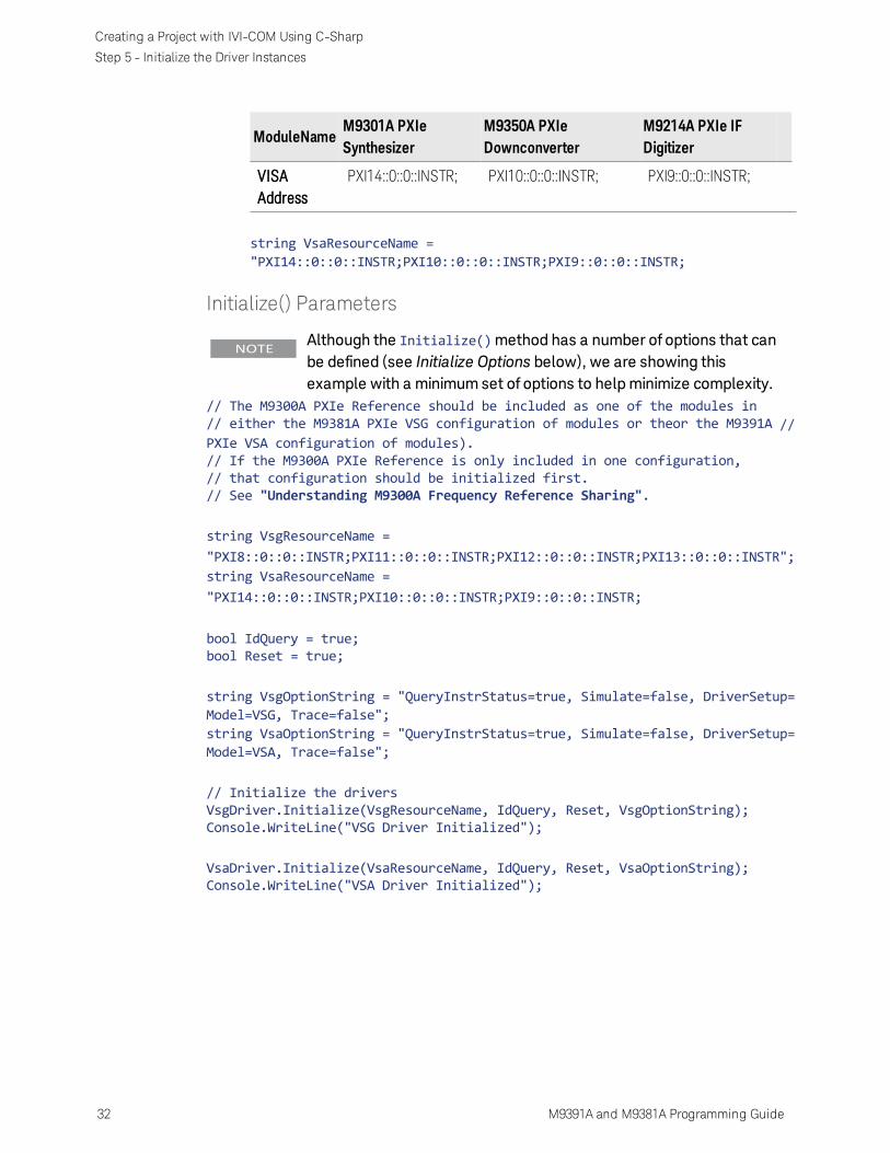
Creating a Project with IVI-COM Using C-Sharp
Step 5 - Initialize the Driver Instances
ModuleNameM9301A PXIeSynthesizer
M9350A PXIeDownconverter
M9214A PXIe IFDigitizer
VISAAddress
PXI14::0::0::INSTR; PXI10::0::0::INSTR; PXI9::0::0::INSTR;
string VsaResourceName ="PXI14::0::0::INSTR;PXI10::0::0::INSTR;PXI9::0::0::INSTR;
Initialize() Parameters
Although the Initialize()method has a number of options that canbe defined (see Initialize Options below), we are showing thisexample with a minimum set of options to helpminimize complexity.
// The M9300A PXIe Reference should be included as one of the modules in// either the M9381A PXIe VSG configuration of modules or theor the M9391A //PXIe VSA configuration of modules).// If the M9300A PXIe Reference is only included in one configuration,// that configuration should be initialized first.// See "Understanding M9300A Frequency Reference Sharing".
string VsgResourceName ="PXI8::0::0::INSTR;PXI11::0::0::INSTR;PXI12::0::0::INSTR;PXI13::0::0::INSTR";string VsaResourceName ="PXI14::0::0::INSTR;PXI10::0::0::INSTR;PXI9::0::0::INSTR;
bool IdQuery = true;bool Reset = true;
string VsgOptionString = "QueryInstrStatus=true, Simulate=false, DriverSetup=Model=VSG, Trace=false";string VsaOptionString = "QueryInstrStatus=true, Simulate=false, DriverSetup=Model=VSA, Trace=false";
// Initialize the driversVsgDriver.Initialize(VsgResourceName, IdQuery, Reset, VsgOptionString);Console.WriteLine("VSG Driver Initialized");
VsaDriver.Initialize(VsaResourceName, IdQuery, Reset, VsaOptionString);Console.WriteLine("VSA Driver Initialized");
32 M9391A and M9381A Programming Guide

Creating a Project with IVI-COM Using C-Sharp
Step 5 - Initialize the Driver Instances
M9391A and M9381A Programming Guide 33
The above example shows how IntelliSense is invoked by simply rolling the cursorover the word "Initialize".
One of the key advantages of using C# in the Microsoft Visual StudioIntegrated Development Environment (IDE) is IntelliSense.IntelliSense is a form of auto-completion for variable names andfunctions and a convenient way to access parameter lists and ensurecorrect syntax. This feature also enhances software development byreducing the amount of keyboard input required.
Initialize() Options
The following table describes options that are most commonly used with theInitialize()method.
Property Type and Example Value Description of Property
string ResourceName = PXI[bus]::device[::function][::INSTR]
string ResourceName ="PXI13::0::0::INSTR;PXI14::0::0::INSTR;PXI15::0::0::INSTR;PXI16::0::0::INSTR";
VsgResourceName orVsaResourceName – Thedriver is typically initializedusing a physical resourcename descriptor, often aVISA resource descriptor.
See the procedure in theResource Names section.
bool IdQuery = true; Setting the ID query tofalse prevents the driverfrom verifying that theconnected instrument isthe one the driver waswritten for because if

Creating a Project with IVI-COM Using C-Sharp
Step 5 - Initialize the Driver Instances
Property Type and Example Value Description of Property
IdQuery is set to true, thiswill query the instrumentmodel and fail initializationif the model is notsupported by the driver.
bool Reset = true; Setting Reset to trueinstructs the driver toinitially reset theinstrument.
string OptionString = "QueryInstrStatus=true, Simulate=true, OptionString - Setup thefollowing initializationoptions:
QueryInstrStatus=true (Specifieswhether the IVIspecific driverqueries theinstrument status atthe end of eachuser operation.)
Simulate=true(Setting Simulate totrue instructs thedriver to not toattempt to connectto a physicalinstrument, but usea simulation of theinstrumentinstead.)
Cache=false(Specifies whetheror not to cache thevalue ofproperties.)
InterchangeCheck=false (Specifieswhether the IVIspecific driverperformsinterchangeability
34 M9391A and M9381A Programming Guide

Creating a Project with IVI-COM Using C-Sharp
Step 5 - Initialize the Driver Instances
M9391A and M9381A Programming Guide 35
Property Type and Example Value Description of Property
checking.)
RangeCheck=false(Specifies whetherthe IVI specificdriver validatesattribute values andfunctionparameters.)
RecordCoercions=false (Specifieswhether the IVIspecific driverkeeps a list of thevalue coercions itmakes for ViInt32and ViReal64attributes.)
DriverSetup= Trace=false"; DriverSetup= (Thisis used to specifysettings that aresupported by thedriver, but notdefined by IVI. If theOptions Stringparameter(OptionString inthis example)contains anassignment for theDriver Setupattribute, theInitialize functionassumes thateverythingfollowing'DriverSetup=' ispart of theassignment.)
Model=VSG orModel=VSA(Instrument modelto use during

Creating a Project with IVI-COM Using C-Sharp
Step 5 - Initialize the Driver Instances
Property Type and Example Value Description of Property
simulation.)
Trace=false (If false,an output trace logof all driver calls isnot saved in an XMLfile.)
If these drivers were installed, additional information can be found under Initializingthe IVI-COMDriver from the following:
AgM938x IVI Driver ReferenceStart > All Programs > Keysight Instrument Drivers > IVI-COM-C Drivers > AgM938xSource > AgM938x IVI Driver Help
AgM9391 IVI Driver ReferenceStart > All Programs > Keysight Instrument Drivers > IVI-COM-C Drivers > AgM9391AVSA > AgM9391 IVI Driver Help
M9300A Reference Sharing
The M9300A PXIe Reference can be shared by up to five configurations of modulesthat can be made up of the M9391A PXIe VSA or the M9381A PXIe VSG or both. TheM9300A PXIe Reference must be included as one of the modules in at least one ofthese configurations. The configuration of modules that is initialized first must includethe M9300A PXIe Reference so that the other configurations that depend on thereference signal get the signal they are expecting. If the configuration of modules thatis initialized first does not include the M9300A PXIe Reference, unlock errors willoccur.
Example: M9300A PXIe Reference with M9381A PXIe VSG
The M9381A PXIe VSG should be initialized first before initializing the VSA if:
M9381A PXIe VSG configuration of modules includes:M9311A PXIe Modulator
M9310A PXIe Source Output
M9301A PXIe Synthesizer
M9300A PXIe Reference // Note that the M9300A PXIe Reference is partof the M9381A PXIe VSG configuration of modules.
string VsgResourceName ="PXI8::0::0::INSTR;PXI11::0::0::INSTR;PXI12::0::0::INSTR;PXI13::0::0::INSTR";
36 M9391A and M9381A Programming Guide

Creating a Project with IVI-COM Using C-Sharp
Step 5 - Initialize the Driver Instances
M9391A and M9381A Programming Guide 37
M9391A PXIe VSA configuration of modules includes:M9301A PXIe Synthesizer
M9350A PXIe Downconverter
M9214A PXIe IF Digitizer
string VsaResourceName ="PXI14::0::0::INSTR;PXI10::0::0::INSTR;PXI9::0::0::INSTR";
Example: M9300A PXIe Reference with M9391A PXIe VSA
The M9391A PXIe VSA should be initialized first before initializing the M9381A PXIeVSG if:
M9381A PXIe VSG configuration of modules includes:M9311A PXIe Modulator
M9310A PXIe Source Output
M9301A PXIe Synthesizer
string VsgResourceName ="PXI8::0::0::INSTR;PXI11::0::0::INSTR;PXI12::0::0::INSTR";
M9391A PXIe VSA configuration of modules includes:M9300A PXIe Reference* // Note that the M9300A PXIe Reference is partof the M9391A PXIe VSA configuration of modules.
M9301A PXIe Synthesizer
M9350A PXIe Downconverter
M9214A PXIe IF Digitizer
string VsaResourceName ="PXI14::0::0::INSTR;PXI10::0::0::INSTR;PXI9::0::0::INSTR;PXI13::0::0::INSTR;
Example: M9300A PXIe Reference Shared With Both Modules
The M9391A PXIe VSA or the M9381A PXIe VSG can be initialized first since theM9300A PXIe Reference is included in both configurations of modules:
M9381A PXIe VSG configuration of modules includes:M9311A PXIe Modulator
M9310A PXIe Source Output
M9301A PXIe Synthesizer
M9300A PXIe Reference* // Note that the M9300A PXIe Reference is partof the M9381A PXIe VSG configuration of modules.
string VsgResourceName ="PXI8::0::0::INSTR;PXI11::0::0::INSTR;PXI12::0::0::INSTR";PXI13::0::0::INSTR;

Creating a Project with IVI-COM Using C-Sharp
Step6 - Write the Program Steps
M9391A PXIe VSA configuration of modules includes:M9300A PXIe Reference* // Note that the M9300A PXIe Reference is partof the M9391A PXIe VSA configuration of modules.
M9301A PXIe Synthesizer
M9350A PXIe Downconverter
M9214A PXIe IF Digitizer
string VsaResourceName ="PXI14::0::0::INSTR;PXI10::0::0::INSTR;PXI9::0::0::INSTR;PXI13::0::0::INSTR;
Step 6 - Write the Program Steps
At this point, you can add program steps that use the driver instances to performtasks.
Using the Soft Front Panel to Write Program Commands
In this example, open the Soft Front Panel for the M938xA PXIe VSG and perform thefollowing steps:
1. Set the output frequency to 1 GHz.
2. Set the output level to 0 dBm.
3. Enable the ALC.
4. Enable the RF Output.
The illustration below shows the Driver Call Log created by the steps above.
Below is the corresponding code in C#:
38 M9391A and M9381A Programming Guide

Creating a Project with IVI-COM Using C-Sharp
Step 7 - Closethe Driver
M9391A and M9381A Programming Guide 39
AgM938x is the driver name used by the SFP.
VsgDriver is the instance of the driver that is used in this example. This instancewould have been created in, "Step 4 – Create Instances of the M9381A PXIeVSG and M9391A PXIe VSA".
IAgM938x VsgDriver = new AgM938x();
// Set the output frequency to 1 GHzVsgDriver.RF.Frequency = 1000000000;// Set the output level to 0 dBmVsgDriver.RF.Level = 0;// Enables the ALCVsgDriver.ALC.Enabled = true;// Enables the RF OutputVsgDriver.RF.OutputEnabled = true;// Waits until the list is finished or the specified time passesbool retval = VsgDriver.List.WaitUntilComplete();
//...or you could use the following:
// Waits 100 ms until output is settled before producing signalbool retval = VsgDriver.RF.WaitUntilSettled(100);
Step 7 - Close the Driver
Calling Close() at the end of the program is required by the IVI specification whenusing any IVI driver.
Important! Close() may be the most commonly missed step when using an IVI driver.Failing to do this could mean that system resources are not freed up and yourprogram may behave unexpectedly on subsequent executions.
{ if(VsaDriver!= null && VsaDriver.Initialized){
// Close the VSA driver{color}VsaDriver.Close();Console.WriteLine("VSA Driver Closed\n");
}
if(VsgDriver != null && VsgDriver.Initialized){
// Close the VSG driver

Creating a Project with IVI-COM Using C-Sharp
Step 8 - Building and Running a Complete Program Using VisualC-Sharp
VsgDriver.Close();Console.WriteLine("VSG Driver Closed");
}}
Step 8 - Building and Running a Complete ProgramUsing Visual C-Sharp
Build your console application and run it to verify it works properly.
1. Open the solution file SolutionNameThatYouUsed.sln in Visual Studio 2010.
2. Set the appropriate platform target for your project.In many cases, the default platform target (Any CPU) is appropriate.
However, if you are using a 64-bit PC (such as Windows 7) to build a .NETapplication that uses a 32-bit IVI-COM driver, you may need to specifyyour project's platform target as x86.
3. Choose Project > ProjectNameThatYouUsed Properties and select Build |Rebuild Solution.
Tip: You can also do the same thing from the Debug menu by clickingStart Debugging or pressing the F5 key.
Example programs may be found by selecting: C:\Program Files (x86)\Agilent\M9391\Help\Examples
Example Program 1- Code Structure
The following example code builds on the previously presented Tutorial: Creating aProject with IVI-COMUsing C# and demonstrates how to instantiate two driverinstances, set the resource names and various initialization values, initialize the twodriver instances, print various driver properties for each driver instance, check driversfor errors and report the errors if any occur, and close the drivers.
Example programs may be found in C:\Program Files (x86)\Agilent\M9391\Help\Examples
40 M9391A and M9381A Programming Guide

Creating a Project with IVI-COM Using C-Sharp
Step 8 - Building and Running a Complete Program Using VisualC-Sharp
M9391A and M9381A Programming Guide 41
Example Program 1- How to Print Driver Properties, Check forErrors, and Close Driver Sessions
// Copy the following example code and compile it as a C# Console Application// Example__VsaVsgProperties.cs#region Specify using Directivesusing System;using System.Collections.Generic;using System.Linq;using System.Text;using Ivi.Driver.Interop;using Agilent.AgM938x.Interop;using Agilent.AgM9391.Interop;#endregion
namespace VsaVsgProperties{

Creating a Project with IVI-COM Using C-Sharp
Step 8 - Building and Running a Complete Program Using VisualC-Sharp
class Program{
static void Main(string[] args){
// Create driver instancesIAgM938x VsgDriver = new AgM938x();IAgM9391 VsaDriver = new AgM9391();
try{#region Initialize Driver Instancesstring VsgResourceName =
"PXI8::0::0::INSTR;PXI11::0::0::INSTR;PXI12::0::0::INSTR;PXI13::0::0::INSTR";string VsaResourceName =
"PXI14::0::0::INSTR;PXI10::0::0::INSTR;PXI9::0::0::INSTR";
bool IdQuery = true;bool Reset = true;
string VsgOptionString = "QueryInstrStatus=true, Simulate=false,DriverSetup= Model=VSG, Trace=false";
string VsaOptionString = "QueryInstrStatus=true, Simulate=false,DriverSetup= Model=VSA, Trace=false";
VsgDriver.Initialize(VsgResourceName, IdQuery, Reset,VsgOptionString);
Console.WriteLine("VSG Driver Initialized");
VsaDriver.Initialize(VsaResourceName, IdQuery, Reset,VsaOptionString);
Console.WriteLine("VSA Driver Initialized\n\n");#endregion
#region Print Driver Properties// Print IviDriverIdentity properties for the PXIe VSGConsole.WriteLine("Identifier: {0}", VsgDriver.Identity.Identifier);Console.WriteLine("Revision: {0}", VsgDriver.Identity.Revision);Console.WriteLine("Vendor: {0}", VsgDriver.Identity.Vendor);Console.WriteLine("Description: {0}",
VsgDriver.Identity.Description);Console.WriteLine("Model: {0}",
VsgDriver.Identity.InstrumentModel);Console.WriteLine("FirmwareRev: {0}",
VsgDriver.Identity.InstrumentFirmwareRevision);Console.WriteLine("Simulate: {0}\n",
VsgDriver.DriverOperation.Simulate);
// Print IviDriverIdentity properties for the PXIe VSAConsole.WriteLine("Identifier: {0}", VsaDriver.Identity.Identifier);Console.WriteLine("Revision: {0}", VsaDriver.Identity.Revision);
42 M9391A and M9381A Programming Guide

Creating a Project with IVI-COM Using C-Sharp
Step 8 - Building and Running a Complete Program Using VisualC-Sharp
M9391A and M9381A Programming Guide 43
Console.WriteLine("Vendor: {0}", VsaDriver.Identity.Vendor);Console.WriteLine("Description: {0}",
VsaDriver.Identity.Description);Console.WriteLine("Model: {0}",
VsaDriver.Identity.InstrumentModel);Console.WriteLine("FirmwareRev: {0}",
VsaDriver.Identity.InstrumentFirmwareRevision);Console.WriteLine("Simulate: {0}\n",
VsaDriver.DriverOperation.Simulate);#endregion
#region Perform Tasks// TO DO: Exercise driver methods and properties.// Put your code here to perform tasks with PXIe VSG and PXIe VSA.#endregion
#region Check for Errors// Check VSG instrument for errorsint VsgErrorNum = -1;string VsgErrorMsg = null;while (VsgErrorNum != 0){
VsgDriver.Utility.ErrorQuery(ref VsgErrorNum, ref VsgErrorMsg);Console.WriteLine("VSG ErrorQuery: {0}, {1}\n", VsgErrorNum,
VsgErrorMsg);}
// Check VSA instrument for errorsint VsaErrorNum = -1;string VsaErrorMsg = null;while (VsaErrorNum != 0){
VsaDriver.Utility.ErrorQuery(ref VsaErrorNum, ref VsaErrorMsg);Console.WriteLine("VSA ErrorQuery: {0}, {1}\n", VsaErrorNum,
VsaErrorMsg);}#endregion
}catch (Exception ex){Console.WriteLine(ex.Message);
}finally{if (VsgDriver != null && VsgDriver.Initialized){// Close the driverVsgDriver.Close();Console.WriteLine("VSG Driver Closed");
}

Creating a Project with IVI-COM Using C-Sharp
Step 8 - Building and Running a Complete Program Using VisualC-Sharp
if (VsaDriver != null && VsaDriver.Initialized){
// Close the driverVsaDriver.Close();Console.WriteLine("VSA Driver Closed\n");
}}
Console.WriteLine("Done - Press Enter to Exit");Console.ReadLine();
}}
}
44 M9391A and M9381A Programming Guide

Working with PA_FEM Measurements
Test Challenges Faced by Power Amplifier Testing
M9391A and M9381A Programming Guide 45
Working with PA_FEM MeasurementsThe RF front end of a product includes all of the components between an antenna andthe baseband device. The purpose of an RF front end is to upconvert a basebandsignal to RF that can be used for transmission by an antenna. An RF front end can alsobe used to downconvert an RF signal that can be processed with ADC circuitry. As anexample, the RF signal that is received by a cellular phone is the input into the frontend circuitry and the output is a down-converted analog signal in the intermediatefrequency (IF) range. This down-converted signal is the input to a baseband device, anADC. For the transmit side, a DAC generates the signal to be up-converted, amplified,and sent to the antenna for transmission. Depending on whether the system is a Wi-Fi, GPS, or cellular radio will require different characteristics of the front end devices.
RF front end devices fall into a few major categories: RF Power Amplifiers, RF Filtersand Switches, and FEMs [Front End Modules].
RF Power Amplifiers and RF Filters and Switches typically require the following:PA[Power Amplifier] – Production Tests which include:
Channel Power - Power Acquisition Mode is used to return onevalue back through the API.
ACPR [Adjacent Channel Power Ratio] – When making fast ACPRmeasurements, "Baseband Tuning" is used to digitally tune thecenter frequency in order to make channel power measurements,at multiple offsets, using the Power Acquisition interface.
Servo Loop- When measuring a power amplifier, one of the keymeasurements is performing a Servo Loop because when youmeasure a power amplifier:
it is typically specified at a specific output power
there is a need to adjust the source input level until youmeasure the exact power level - to do this, you willcontinually adjust the source until you achieve the specifiedoutput power then you make all of the ACPR and harmonicparametric measurements at that level.
FEMs [Front End Modules] – which could be a combination of multiple front endfunctions in a single module or even a "Switch Matrix" that switches variousradios (such as Wi-Fi, GSM, PCS, Bluetooth, etc.) to the antenna.
Test Challenges Faced by Power Amplifier Testing
The following are the test challenges faced by Power Amplifier Testing:

Working with PA_FEM Measurements
Test Challenges Faced by Power Amplifier Testing
The need to quickly adjust power level inputs to the device under test (DUT).
The need to assess modulation performance (i.e., ACPR and EVM) at highoutput power levels.
The figure below shows a simplified block diagram for the M9381A PXIe VSG andM9391A PXIe VSA in a typical PA / FEM test system.
Typical power amplifier modules require an input power level of 0 to + 5 dBm, digitallymodulated according to communication standards such as WCDMA or LTE. Thespecified performance of the power amplifier or front end module is normally set at aspecific output level of the DUT. If the devices have small variations in gain, it may benecessary to adjust the power level from the M9381A PXIe VSG to get the correctoutput level of the DUT. Only after the DUT output level is set at the correct value canthe specified parameters be tested. The time spent adjusting the M9381A PXIe VSGto get the correct DUT output power can be a major contributor to the test time andthe overall cost of test.
The M9381A PXIe VSG is connected to the DUT using a cable and switches. Theswitching may be used to support testing of multi-band modules or multi-site testing.The complexity of the switching depends on the number of bands in the devices andthe number of test sites supported by the system. The DUTs are typically inserted intothe test fixture using an automated part handler. In some cases, several feet of cableis required between the M9381A PXIe VSG and the input of the DUT.
The combination of the RF cables and the switching network can add several dB ofloss between the output of the M9381A PXIe VSG and the input of the DUT, whichrequires higher output levels from the M9381A PXIe VSG. Since the tests areperformed with a modulated signal, the M9381A PXIe VSG must also have adequatemodulation performance at the higher power levels.
46 M9391A and M9381A Programming Guide

Working with PA_FEM Measurements
Performing a Channel Power Measurement, Using ImmediateTrigger
M9391A and M9381A Programming Guide 47
Performing a Channel Power Measurement, UsingImmediate Trigger
StandardSampleRate
Channel FilterType
Channel FilterParameter
Channel FilterBandwidth
ChannelOffsets
WCDMA 5 MHz RRC 0.22 3.84 MHz 5, 10MHz
LTE 10 MHz FDD 11.25MHz
Rectangular N/A 9 MHz 10, 20MHz
LTE 10 MHz TDD 11.25MHz
Rectangular N/A 9 MHz 10, 20MHz
1xEV-DO 2 MHz RRC 0.22 1.23 MHz 1.25, 2.5MHz
TD-SCDMA 2 MHz RRC 0.22 1.28 MHz 1.6, 3.2MHz
GSM/EDGEChannel
1.25MHz
Gaussian 0.3 271 kHz
GSM/EDGEORFS 1.25MHz
TBD TBD 30 kHz 400,600kHz
Example Program 2 - Code Structure
The following example code demonstrates how to instantiate a driver instance, setthe resource name and various initialization values, initialize the driver instances, andperform other relevant tasks:
1. Send RF and Power Acquisition commands to the M9391A PXIe VSA driver andApply changes to hardware,
2. Check the instrument queue for errors.
3. Perform a Channel Power Measurement,
4. Report errors if any occur, and close the drivers.
Example programs may be found at C:\Program Files (x86)\Agilent\M9391\Help\Examples

Working with PA_FEM Measurements
Performing a Channel Power Measurement, Using ImmediateTrigger
Example Program 2 - Pseudo-code
Initialize Driver for VSA, Check for Errors
Send RF Settings to VSA Driver:Frequency
Level
Peak to Average Ratio
Conversion Mode
IF Bandwidth
Set Acquisition Mode to "Power"
48 M9391A and M9381A Programming Guide

Working with PA_FEM Measurements
Performing a Channel Power Measurement, Using ImmediateTrigger
M9391A and M9381A Programming Guide 49
Send Power Acquisition Setting to VSA Driver:Sample Rate
Duration
Channel Filter
Apply Method to Send Changes to HardwareWait for Hardware to Settle
Send Arm Method to VSA
Send Read Power Method to VSA
Close Driver for VSA
Example Program 2 - Channel Power Measurement UsingImmediate Trigger
// Copy the following example code and compile it as a C# Console Application// Example__ChannelPowerImmediateTrigger.cs#region Specify using Directives
using System;using System.Collections.Generic;using System.Linq;using System.Text;using Ivi.Driver.Interop;using Agilent.AgM9391.Interop;
#endregion
namespace ChannelPowerImmTrigger{
class Program{
static void Main(string[] args){
// Create driver instancesVsaDriver = new AgM9391();
try{ #region Initialize Driver Instances
string VSAResourceName ="PXI14::0::0::INSTR;PXI10::0::0::INSTR;PXI9::0::0::INSTR;PXI13::0::0::INSTR";
bool IdQuery = true;bool Reset = true;
string VSAOptionString = "QueryInstrStatus=true, Simulate=false,DriverSetup= Model=M9391A, Trace=false";
VsaDriver.Initialize(VSAResourceName, IdQuery, Reset,VSAOptionString);

Working with PA_FEM Measurements
Performing a Channel Power Measurement, Using ImmediateTrigger
Console.WriteLine("VSA Driver Initialized\n");#endregion
#region Check Instrument Queue for Errors// Check VSA instrument for errorsint VsaErrorNum = -1;string VsaErrorMsg = null;while (VsaErrorNum != 0){
VsaDriver.Utility.ErrorQuery(ref VsaErrorNum, refVsaErrorMsg);
Console.WriteLine("VSA ErrorQuery: {0}, {1}\n", VsaErrorNum,VsaErrorMsg);
}#endregion
#region Receiver Settings// Receiver Settingsdouble Frequency = 2000000000.0;double Level = 5;double RmsValue = 5;double ChannelTime = 0.0001;double MeasureBW = 5000000.0;AgM9391ChannelFilterShapeEnum FilterType =
AgM9391ChannelFilterShapeEnum.AgM9391ChannelFilterShapeRootRaisedCosine;double FilterAlpha = 0.22;double FilterBw = 3840000.0;double MeasuredPower = 0;bool Overload = true;
#endregion
#region Run Commands// Setup the RF Path in the ReceiverVsaDriver.RF.Frequency = Frequency;VsaDriver.RF.Power = Level;VsaDriver.RF.Conversion =
AgM9391ConversionEnum.AgM9391VsaConversionAuto;VsaDriver.RF.PeakToAverage = RmsValue;VsaDriver.RF.IFBandwidth = 40000000.0; // Use IF filter wide
enough for all adjacent channels// Configure the AcquisitionVsaDriver.AcquisitionMode =
AgM9391AcquisitionModeEnum.AgM9391AcquisitionModePower;VsaDriver.PowerAcquisition.Bandwidth = MeasureBW; // 5 MHzVsaDriver.PowerAcquisition.Duration = ChannelTime; // 100 usVsaDriver.PowerAcquisition.ChannelFilter.Configure(FilterType,
FilterAlpha, FilterBw);// Send Changes to hardwareVsaDriver.Apply();VsaDriver.WaitUntilSettled(100);
50 M9391A and M9381A Programming Guide
Working with PA_FEM Measurements
Performing a WCDMA Power Servo and ACPR Measurement
M9391A and M9381A Programming Guide 51
string response = "y";while (string.Compare(response, "y") == 0) {
Console.WriteLine("Press Enter to Run Test");Console.ReadLine();
VsaDriver.Arm();VsaDriver.PowerAcquisition.ReadPower(0,
AgM9391PowerUnitsEnum.AgM9391PowerUnitsdBm, ref MeasuredPower, ref Overload);Console.WriteLine("Measured Power: " + MeasuredPower + "
dBm");Console.WriteLine(String.Format("Overload = {0}", Overload ?
"true" : "false"));Console.WriteLine("Repeat? y/n");response = Console.ReadLine();
}#endregion
}catch (Exception ex){
Console.WriteLine("Exceptions for the drivers:\n");Console.WriteLine(ex.Message);
}finally#region Close Driver Instances{ if (VsaDriver != null && VsaDriver.Initialized){
// Close the driverVsaDriver.Close();Console.WriteLine("VSA Driver Closed\n");
}}#endregion
Console.WriteLine("Done - Press Enter to Exit");Console.ReadLine();
}}
}
Performing a WCDMA Power Servo and ACPRMeasurement
When making a WCDMA Power Servo and ACPR measurement, Servo is performedusing "Baseband Tuning" to adjust the source amplitude and then "Baseband Tuning"is used to digitally tune the center frequency in order to make channel power

Working with PA_FEM Measurements
Performing a WCDMA Power Servo and ACPR Measurement
measurements, at multiple offsets, using the Power Acquisition interface of theM9391A PXIe VSA.
The M9391A PXIe VSA and the M9381A PXIe VSG offers two modes for adjustingfrequency and amplitude:
RF Tuning – allows the M9381A PXIe VSG to be set across the completeoperating frequency and amplitude range.
Baseband Tuning – allows the frequency and amplitude to be adjusted withinthe IF bandwidth (160 MHz) and over a range of the output level.
Example Program 3 - Code Structure
The following example code demonstrates how to instantiate two driver instances,set the resource names and various initialization values, initialize the two driverinstances, and perform the other relevant tasks:
1. Send RF and Modulation commands to the M9381A PXIe VSG driver and Applychanges to hardware,
2. Send RF and Power Acquisition commands to the M9391A PXIe VSA driver andApply changes to hardware,
3. Run a Servo Loop until it is at the required output power from DUT,
4. Perform an ACPR Measurement for each Adjacent Channel to be measured,
5. Check drivers for errors and report the errors, if any, and close the drivers.
52 M9391A and M9381A Programming Guide

Working with PA_FEM Measurements
Performing a WCDMA Power Servo and ACPR Measurement
M9391A and M9381A Programming Guide 53
Example programs are available at C:\Program Files (x86)\Agilent\M9391\Help\Examples
Example Program 3 - Pseudo-code
Initialize Drivers for VSG and VSA and check for errors
Send RF Settings to VSG Driver:Frequency
RF Level to Maximum Needed
RF Enable On
ALC Enable Off (for baseband power changes)

Working with PA_FEM Measurements
Performing a WCDMA Power Servo and ACPR Measurement
Send Modulation Commands to VSG Driver:Load WCDMA Signal Studio File
Enable Modulation
Play ARB File
Set ARB Scale to 0.5
Set Baseband Power Offset to -10 dB
Apply Method to Send Changes to HardwareWait for Hardware to Settle
Send RF Settings to VSA Driver:Frequency
Level
Peak to Average Ratio
Conversion Mode
IF Bandwidth
Set Acquisition Mode to "Power"
Send Power Acquisition Setting to VSA Driver:Sample Rate
Duration
Channel Filter
Apply Method to Send Changes to HardwareWait for Hardware to Settle
Servo Loop:
Set Baseband Power Offset on VSG to expected value
Send Apply Method to VSG
Send Arm Method to VSA
Send ReadPower Method to VSA
Repeat Until at Required Output Power from DUT
Last Reading is Channel Power Measurement
ACPR Measurement:
Set Acquisition Duration Property on VSA to Value for Adjacent ChannelMeasurements
Set Frequency Offset Property on VSA to Channel Offset Frequency
Send Apply Method to VSA
Send Arm Method to VSA
Send ReadPower Method to VSA
Repeat for each Adjacent Channel to be Measured
54 M9391A and M9381A Programming Guide

Working with PA_FEM Measurements
Performing a WCDMA Power Servo and ACPR Measurement
M9391A and M9381A Programming Guide 55
Example Program 3 - WCDMA Power Servo and ACPRMeasurement
// Copy the following example code and compile it as a C# Console Application// Example__PaServoAcpr.cs// WCDMA Power Servo and ACPR Measurement#region Specify using Directives
using System;using System.Collections.Generic;using System.Linq;using System.Text;using Ivi.Driver.Interop;using Agilent.AgM938x.Interop;using Agilent.AgM9391.Interop;
#endregion
namespace PaServoAcpr{
class Program{
static void Main(string[] args){
// Create driver instancesIAgM938x VsgDriver = new AgM938x();IAgM9391 VsaDriver = new AgM9391();
try{ #region Initialize Driver Instances
string VsgResourceName ="PXI8::0::0::INSTR;PXI11::0::0::INSTR;PXI12::0::0::INSTR;PXI13::0::0::INSTR";
string VsaResourceName ="PXI14::0::0::INSTR;PXI10::0::0::INSTR;PXI9::0::0::INSTR";
bool IdQuery = true;bool Reset = true;
string VsgOptionString = "QueryInstrStatus=true, Simulate=false,DriverSetup= Model=VSG, Trace=false";
string VsaOptionString = "QueryInstrStatus=true, Simulate=false,DriverSetup= Model=VSA, Trace=false";
VsaDriver.Initialize(VsaResourceName, IdQuery, Reset,VsaOptionString);
Console.WriteLine("VSA Driver Initialized\n");
VsgDriver.Initialize(VsgResourceName, IdQuery, Reset,VsgOptionString);

Working with PA_FEM Measurements
Performing a WCDMA Power Servo and ACPR Measurement
Console.WriteLine("VSG Driver Initialized");
#endregion
#region Check Instrument Queue for Errors// Check VSG instrument for errorsint VsgErrorNum = -1;string VsgErrorMsg = null;while (VsgErrorNum != 0){
VsgDriver.Utility.ErrorQuery(ref VsgErrorNum, refVsgErrorMsg);
Console.WriteLine("VSG ErrorQuery: {0}, {1}", VsgErrorNum,VsgErrorMsg);
}
// Check VSA instrument for errorsint VsaErrorNum = -1;string VsaErrorMsg = null;while (VsaErrorNum != 0){
VsaDriver.Utility.ErrorQuery(ref VsaErrorNum, refVsaErrorMsg);
Console.WriteLine("VSA ErrorQuery: {0}, {1}\n", VsaErrorNum,VsaErrorMsg);
}#endregion
#region Create Default Settings for WCDMA Uplink Signal// Source Settingsdouble Frequency = 1000000000.0;double Level = 3;// If a Signal Studio waveform file is used, it may require a
software// license.
string ExamplesFolder = "C:Program Files (x86)AgilentM938xExampleWaveforms";
string WaveformFile = "WCDMA_UL_DPCHH_2DPDCH_1C.wfm";string FileName = ExamplesFolder + WaveformFile;string ArbRef = "Mod Waveform";
// Receiver Settingsdouble ChannelTime = 0.0001;double AdjacentTime = 0.0005;double IfBandwidth = 40000000.0;double PowerOffset = 0;double MeasureBW = 5000000.0;AgM9391ChannelFilterShapeEnum FilterType =
AgM9391ChannelFilterShapeEnum.AgM9391ChannelFilterShapeRootRaisedCosine;double FilterAlpha = 0.22;
56 M9391A and M9381A Programming Guide

Working with PA_FEM Measurements
Performing a WCDMA Power Servo and ACPR Measurement
M9391A and M9381A Programming Guide 57
double FilterBw = 3840000.0;double[] FreqOffset = new double[] {-5000000.0, 5000000.0, -
10000000.0, 10000000.0};
double MeasuredPower = 0;bool Overload = true;double MeasuredChannelPower;bool ChannelPowerOverload;double[] MeasuredACPR = new double[4];double SampleRate = 0;double RmsValue = 0;double ScaleFactor = 0;
#endregion
#region Run Commands// These commands are sent to the VSG Driver, "Apply" or
"PlayArb"// methods send to hardware
VsgDriver.RF.Frequency = Frequency;VsgDriver.RF.Level = Level;VsgDriver.RF.OutputEnabled = true;VsgDriver.ALC.Enabled = false;VsgDriver.Modulation.IQ.UploadArbAgilentFile(ArbRef, FileName);VsgDriver.Modulation.Enabled = true;VsgDriver.Modulation.BasebandPower = -10;// Play the ARB, sending all changes to hardwareVsgDriver.Modulation.PlayArb(ArbRef,
AgM938xStartEventEnum.AgM938xStartEventImmediate);VsgDriver.Modulation.Scale = 0.5;VsgDriver.Apply();
// Get the Sample Rate and RMS Value (Peak to Average Ratio) of// the Current Waveform
AgM938xMarkerEnum RfBlankMarker =AgM938xMarkerEnum.AgM938xMarkerNone;
AgM938xMarkerEnum AlcHoldMarker =AgM938xMarkerEnum.AgM938xMarkerNone;
VsgDriver.Modulation.IQ.ArbInformation(ArbRef, ref SampleRate,ref RmsValue, ref ScaleFactor, ref RfBlankMarker, ref AlcHoldMarker);
// Setup the RF Path in the ReceiverVsaDriver.RF.Frequency = Frequency;VsaDriver.RF.Power = Level + PowerOffset;VsaDriver.RF.Conversion =
AgM9391ConversionEnum.AgM9391ConversionAuto;VsaDriver.RF.PeakToAverage = RmsValue;VsaDriver.RF.IFBandwidth = IfBandwidth;// Configure the AcquisitionVsaDriver.AcquisitionMode =
AgM9391AcquisitionModeEnum.AgM9391AcquisitionModePower;

Working with PA_FEM Measurements
Performing a WCDMA Power Servo and ACPR Measurement
VsaDriver.PowerAcquisition.Bandwidth = MeasureBW;VsaDriver.PowerAcquisition.Duration = ChannelTime;VsaDriver.PowerAcquisition.ChannelFilter.Configure(FilterType,
FilterAlpha, FilterBw);// Send Changes to hardwareVsaDriver.Apply();VsaDriver.WaitUntilSettled(100);
string response = "y";while (string.Compare(response, "y") == 0) {
Console.WriteLine("Press Enter to Run Test");Console.ReadLine();
// Run a group of baseband power commands to change thesource
// level and make a power measurement at eachstep.
// Simulates Servo loop timing, but does not use the measured// power to adjust the next source level
VsaDriver.PowerAcquisition.Duration = ChannelTime;VsaDriver.Apply();double[] LevelOffset = new double[] {-3, -2, -1, -0.5, -
0.75};for (int Index = 0;Index < LevelOffset.Length - 1;Index++) {
VsgDriver.Modulation.BasebandPower = LevelOffset[Index];VsgDriver.Apply();VsaDriver.Arm();VsaDriver.PowerAcquisition.ReadPower(0,
AgM9391PowerUnitsEnum.AgM9391PowerUnitsdBm, ref MeasuredPower, ref Overload);}
// Loop Through the channel offset frequencies for an// ACPR measurement
// Use the last value of the servo loop for the channel powerMeasuredChannelPower = MeasuredPower;ChannelPowerOverload = Overload;VsaDriver.PowerAcquisition.Duration = AdjacentTime;for (int Index = 0;Index < FreqOffset.Length;Index++) {
VsaDriver.PowerAcquisition.OffsetFrequency = FreqOffset[Index];
VsaDriver.Apply();VsaDriver.Arm();VsaDriver.PowerAcquisition.ReadPower(0,
AgM9391PowerUnitsEnum.AgM9391PowerUnitsdBm, ref MeasuredPower, ref Overload);MeasuredACPR[Index] = MeasuredPower -
MeasuredChannelPower;}
// Make sure the VSA frequency offset is back to 0 (onrepeat)
58 M9391A and M9381A Programming Guide

Working with PA_FEM Measurements
Performing a WCDMA Power Servo and ACPR Measurement
M9391A and M9381A Programming Guide 59
VsaDriver.PowerAcquisition.OffsetFrequency = 0;VsaDriver.Apply();if (ChannelPowerOverload == true) {
Console.WriteLine("Channel Power Measurement Overload");}Console.WriteLine("Channel Power: {0} dBm",
MeasuredChannelPower);Console.WriteLine("ACPR1 L: {0} dBc", MeasuredACPR[0]);Console.WriteLine("ACPR1 U: {0} dBc", MeasuredACPR[1]);Console.WriteLine("ACPR2 L: {0} dBc", MeasuredACPR[2]);Console.WriteLine("ACPR2 U: {0} dBc", MeasuredACPR[3]);
Console.WriteLine("Repeat? y/n");response = Console.ReadLine();
}#endregion
}catch (Exception ex){
Console.WriteLine("Exceptions for the drivers:\n");Console.WriteLine(ex.Message);
}finally#region Close Driver Instances{if (VsgDriver != null && VsgDriver.Initialized){// Close the driverVsgDriver.Close();Console.WriteLine("VSG Driver Closed");
}
if (VsaDriver != null && VsaDriver.Initialized){
// Close the driverVsaDriver.Close();Console.WriteLine("VSA Driver Closed\n");
}
}#endregion
Console.WriteLine("Done - Press Enter to Exit");Console.ReadLine();
}}
}

Working with PA_FEM Measurements
Performing a WCDMA Power Servo and ACPR Measurement
Disclaimer
© 2013-2015 Keysight Technologies Inc. All rights reserved.
You have a royalty-free right to use, modify, reproduce and distribute this SampleApplication (and/or any modified version) in any way you find useful, provided that youagree that Keysight Technologies has no warranty, obligations or liability for anySample Application Files.
Keysight Technologies provides programming examples for illustration only. Thissample program assumes that you are familiar with the programming language beingdemonstrated and the tools used to create and debug procedures. KeysightTechnologies support engineers can help explain the functionality of KeysightTechnologies software components and associated commands, but they will notmodify these samples to provide added functionality or construct procedures to meetyour specific needs.
60 M9391A and M9381A Programming Guide

Working with 802.11ac MIMO RnD and DVT Tests
M9391A and M9381A Programming Guide 61
Working with 802.11ac MIMO RnD and DVT TestsThis section of the programming guide focuses on performing 802.11ac MIMOR&D/DVT Tests related to Receiver and Transmitter (Rx/Tx) Physical Layerperformance characterization.
This programming guide may also be usedwhen creating programsfor 802.11a,b,g and n.
Receiver Tests, with IVI-COM controlling M9381A PXIe VSGs and M9018A PXIeChassis
In this section, you will learn how to use VisualStudio 2010 to write source code for an IVI-COMConsole Application in Visual C#. You will compilethe source code using the .NET FrameworkLibrary and produce an Assembly.exe file thatroutes backplane triggers on the M9018A PXIeChassis for the M9381A PXIe VSGs, M9300A PXIeReferences, and M9391A PXIe VSAs. It then setsthe controls for the M9381A PXIe VSGs and startsthem playing a waveform file.
Knowledge of Visual Studio 2010 with the .NETFramework, knowledge of the programmingsyntax for Visual C#, and knowledge of 802.11acPHY Layer receiver tests is required.
Transmitter Tests, with 89600 VSA Software controlling M9391A PXIe Vector SignalAnalyzers
Also, you will learn how to use Keysight 89600VSA Software to control M9391A PXIe VSAs thatperform transmitter tests for PHY Layercharacterization.
Knowledge of 89600 VSA Software andknowledge of 802.11ac PHY Layer transmittertests is required.
The following 802.11ac MIMO R&D/DVT Testsrelated to Rx/Tx PHY Layer characterization arecovered:

Working with 802.11ac MIMO RnD and DVT Tests
Preparing the Hardware and Software for 802.11ac MIMO RnD DVTTests
Example Program 4: How to Perform TransmitterTests with 89600 VSA Software(PlayingWaveforms on M9381A PXIe VSGs, UsingExternal Trigger)
Preparing the Hardware and Software for 802.11acMIMO RnD DVT Tests
1. Select and Configure a Hardware Configuration for 802.11ac MIMO R&D/DVTTest
An overview of all hardware modules and their cable connections are shownhere for convenience, but detailed steps on each of the followingconfigurations, as well as configurations with external controllers, are definedin the Keysight MIMO PXI Test Solution Startup Guide, Y1299-90001–complete all hardware configuration steps before trying to programmaticallycontrol M9381A PXIe VSGs and M9018A PXIe Chassis hardware with an IVIdriver or to control M9391A PXIe VSAs with 89600 VSA Software.
Configuration Description
2x2 MIMO in One M9018A PXIe Chassis This configuration (occupying16 slots) consists of twoM9381A PXIe VSGs and twoM9391A PXIe VSAs in a singleM9018A PXIe Chassis - with orwithout an M9036A PXIeEmbedded Controller (theconfiguration shown includesan M9036A PXIe EmbeddedController).A single M9300APXIe Reference is sharedacross both M9381A PXIeVSGs and both M9391A PXIeVSAs.
3x3 MIMO in Two M9018A PXIe Chassis The top of this configuration(occupying 14 slots) consists ofthree M9381A PXIe VSGs in asingle M9018A PXIe Chassis –with an M9021A PCIe CableInterface. A single M9300APXIe Reference, in slot 10, is
62 M9391A and M9381A Programming Guide

Working with 802.11ac MIMO RnD and DVT Tests
Preparing the Hardware and Software for 802.11ac MIMO RnD DVTTests
M9391A and M9381A Programming Guide 63
Configuration Description
shared across all threeM9381A PXIe VSGs.
The bottom of thisconfiguration (occupying 11slots) consists of three M9391APXIe VSAs in a single M9018APXIe Chassis – with an M9021APCIe Cable Interface and anM9036A PXIe EmbeddedController.A single M9300APXIe Reference, in slot 10, isshared across all threeM9391A PXIe VSAs.
4x4 MIMOin Two M9018A PXIe Chassis The top of this configuration(occupying 18 slots) consists offour M9381A PXIe VSGs in asingleM9018A PXIe Chassis –with an M9021A PCIe CableInterface.A single M9300APXIe Reference, in slot 10, isshared across all four M9381APXIe VSGs.
The bottom of thisconfiguration (occupying 14slots) consists of four M9391APXIe VSAs in a single M9018AChassis – with an M9021APCIe Cable Interface and anM9036A PXIe EmbeddedController.A single M9300APXIe Reference, in slot 10, isshared across all four M9391APXIe VSAs.
2. Install / Verify Software for 802.11ac MIMO R&D/DVT TestRefer to the Installing Hardware, Software, and Licenses section for a list ofsoftware that is needed as well as the order that software must be installed.
3. Programmatically control M9381A PXIe VSGs with C# Console Application
4. Create driver instances, set resource names and various initialization values.

Working with 802.11ac MIMO RnD and DVT Tests
Preparing the Hardware and Software for 802.11ac MIMO RnD DVTTests
5. Add references, initialize drivers, and clear the error queues for an M9018APXIe Chassis, an M9300A PXIe Reference, and two, three, or four M9381A PXIeVSG driver instances.
6. Route/Configure a number of backplane triggers on the M9018A PXIe Chassis.
Running Self-Test will fail if the modules that form anM9381APXIe VSG or anM9391A PXIe VSA spans across slot 6 or slot12 of the M9018A PXIe Chassis; if they do span across slot 6 orslot 12, the backplane triggers and bus segments must berouted properly. For details, see Step 6 – Route BackplaneTriggers and Bus Segments on the M9018A PXIe Chassis.
7. On each M9381A PXIe VSG in the selected configuration:Set up some initial values on each M9381A PXIe VSG.
Load and start playing a waveform file on each M9381A PXIe VSG.
The waveform file continues playing until the console application isclosed.
8. Create an N-Channel M9391A PXIe VSA Configuration in the 89600 VSASoftware.Include the M9300A PXIe Reference module in Channel 1, but not insubsequent channels.
When creating Channel 1, 2, 3, and 4 configurations with89600 VSA software, note the order in which you addM9391channels to the hardware configuration. This is needed later todetermine which channel is used to receive an external,software or magnitude trigger, and it will be needed for triggerallocation on the PXI backplane as well.
9. Use 89600 VSA Software to Control M9391A PXIe VSAs and PerformTransmitter Tests
For each M9391A PXIe VSA, M9381A PXIe VSG, and M9018A PXIe Chassis usedin the configuration, use their soft front panels to verify that they have the mostup to date FPGA bits, and after routing backplane triggers and bus segments, runself-test on each M9391A PXIe VSA, M9381A PXIe VSG, M9300A PXIeReference, and M9018A PXIe Chassis - one at a time.
Example Program 4 - How to Perform Transmitter Tests with 89600VSA Software
The following example code builds on the previously presented Tutorial: Creating aProject with IVI-COMUsing C#. It demonstrates how to instantiate two, three, or fourM9381A PXIe VSG driver instances, set resource names and various initializationvalues, initialize and clear the error queues for the M9018A PXIe Chassis, an M9300APXIe Reference, and two, three, or four M9381A PXIe VSG driver instances.
Once initialized, a number of backplane triggers on the M9018A PXIe Chassis are
64 M9391A and M9381A Programming Guide

Working with 802.11ac MIMO RnD and DVT Tests
Preparing the Hardware and Software for 802.11ac MIMO RnD DVTTests
M9391A and M9381A Programming Guide 65
configured, initial values are set on each M9381A PXIe VSG, and a waveform file isloaded and played on each M9381A PXIe VSG – this waveform can then be analyzedwith 89600 VSA Software that is controlling two, three, or four M9391A PXIe VSAs.
The console application window that is running remains open while the waveform fileis playing – if the console application window is closed by selecting the Enter key, thewaveform file will stop playing and all of the M9381A PXIe VSG drivers will be closed.
This example program can be accessed from C:\Program Files (x86)
\Agilent\M9391\Help\Examples\Example__MIMOConsoleApp.cs and C:\Program Files(x86)\Agilent\M938x\Help\Examples\Example__MIMOConsoleApp.cs.
Example Program4 - Pseudo-Code
Initialize Drivers for M9300A, M9018A, M9381A Channel 1 and Channel 2 // Fora 2x2 MIMO Configuration
Initialize Drivers for M9300A, M9018A, M9381A Channel 1, Channel 2, andChannel 3 // For a 3x3 MIMO Configuration
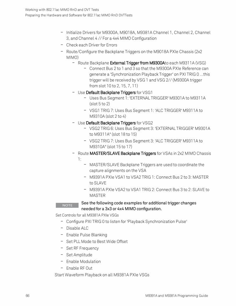
Working with 802.11ac MIMO RnD and DVT Tests
Preparing the Hardware and Software for 802.11ac MIMO RnD DVTTests
Initialize Drivers for M9300A, M9018A, M9381A Channel 1, Channel 2, Channel3, and Channel 4 // For a 4x4 MIMO Configuration
Check each Driver for Errors
Route/Configure the Backplane Triggers on the M9018A PXIe Chassis (2x2MIMO)
Route Backplane External Trigger from M9300Ato each M9311A (VSG)Connect Bus 2 to 1 and 3 so that the M9300A PXIe Reference cangenerate a 'Synchronization Playback Trigger' on PXI TRIG 0 ...thistrigger will be received by VSG 1 and VSG 2// (M9300A triggerfrom slot 10 to 2, 15, 7, 11)
Use Default Backplane Triggers for VSG1Uses Bus Segment 1: 'EXTERNAL TRIGGER' M9301A to M9311A(slot 5 to 2)
VSG1 TRIG 7: Uses Bus Segment 1: 'ALC TRIGGER' M9311A toM9310A (slot 2 to 4)
Use Default Backplane Triggers for VSG2VSG2 TRIG 6: Uses Bus Segment 3: 'EXTERNAL TRIGGER' M9301Ato M9311A" (slot 18 to 15)
VSG2 TRIG 7: Uses Bus Segment 3: 'ALC TRIGGER' M9311A toM9310A" (slot 15 to 17)
Route MASTER/SLAVE Backplane Triggers for VSAs in 2x2 MIMO Chassis1:
MASTER/SLAVE Backplane Triggers are used to coordinate thecapture alignments on the VSA
M9391A PXIe VSA1 to VSA2 TRIG 1: Connect Bus 2 to 3: MASTERto SLAVE
M9391A PXIe VSA2 to VSA1 TRIG 2: Connect Bus 3 to 2: SLAVE toMASTER
See the following code examples for additional trigger changesneeded for a 3x3 or 4x4MIMO configuration.
Set Controls for all M9381A PXIe VSGs
Configure PXI TRIG 0 to listen for 'Playback Synchronization Pulse'
Disable ALC
Enable Pulse Blanking
Set PLL Mode to Best Wide Offset
Set RF Frequency
Set Amplitude
Enable Modulation
Enable RF Out
Start Waveform Playback on all M9381A PXIe VSGs
66 M9391A and M9381A Programming Guide
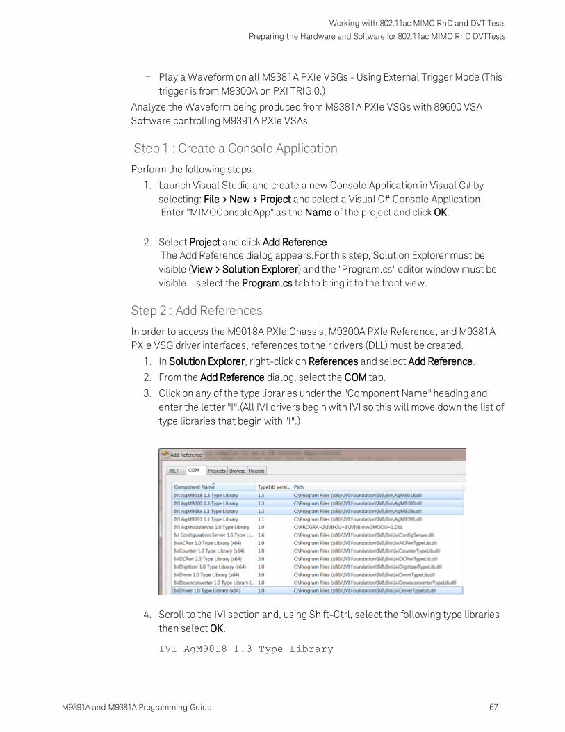
Working with 802.11ac MIMO RnD and DVT Tests
Preparing the Hardware and Software for 802.11ac MIMO RnD DVTTests
M9391A and M9381A Programming Guide 67
Play a Waveform on all M9381A PXIe VSGs - Using External Trigger Mode (Thistrigger is from M9300A on PXI TRIG 0.)
Analyze the Waveform being produced from M9381A PXIe VSGs with 89600 VSASoftware controlling M9391A PXIe VSAs.
Step 1 : Create a Console Application
Perform the following steps:
1. Launch Visual Studio and create a new Console Application in Visual C# byselecting: File > New > Project and select a Visual C# Console Application.Enter "MIMOConsoleApp" as the Name of the project and click OK.
2. Select Project and click Add Reference.The Add Reference dialog appears.For this step, Solution Explorer must bevisible (View > Solution Explorer) and the "Program.cs" editor window must bevisible – select the Program.cs tab to bring it to the front view.
Step 2 : Add References
In order to access the M9018A PXIe Chassis, M9300A PXIe Reference, and M9381APXIe VSG driver interfaces, references to their drivers (DLL) must be created.
1. In Solution Explorer, right-click on References and select Add Reference.
2. From the Add Reference dialog, select the COM tab.
3. Click on any of the type libraries under the "Component Name" heading andenter the letter "I".(All IVI drivers begin with IVI so this will move down the list oftype libraries that begin with "I".)
4. Scroll to the IVI section and, using Shift-Ctrl, select the following type librariesthen select OK.
IVI AgM9018 1.3 Type Library

Working with 802.11ac MIMO RnD and DVT Tests
Preparing the Hardware and Software for 802.11ac MIMO RnD DVTTests
IVI AgM9300 1.3 Type LibraryIVI AgM938x 1.3 Type Library
When any of the references for AgM9018, AgM9300, orAgM938x are added, the IVIDriver 1.0 Type Library is alsoautomatically added. This reference houses the interfacedefinitions for IVI inherent capabilities which are located in thefile IviDriverTypeLib.dll (dynamically linked library).
Step 3 : Add Using Statements
To allow your program to access the IVI drivers without specifying full path names ofeach interface or enum, you need to add using statements to your program.
Step 4 - Create Driver Instances
Change the value of numChannels to either: 2, 3, or 4 depending on the number ofchannels you would like to control with the console application.
To create driver instances
When creating driver instances for the M9381A PXI VSG, note that the IAgM938xExinterface is needed for MIMO in place of the IAgM938x interface. The IAgM938xExinterface is an "extended" interface and includes additional commands that areneeded for MIMO that were not previously available in IAgM938x.
68 M9391A and M9381A Programming Guide

Working with 802.11ac MIMO RnD and DVT Tests
Preparing the Hardware and Software for 802.11ac MIMO RnD DVTTests
M9391A and M9381A Programming Guide 69
Step 5 - Initialize Driver Instances and Check for Errors
To Establish a Communication Link, get the Resource Name Addresses
Use either Agilent/Keysight Connection Expert or see "Appendix – DeterminingResource Name Address Strings".
The above is a partial view of code that shows how to initialize each of the driversneeded. The complete example program can be accessed from C:\Program Files (x86)

Working with 802.11ac MIMO RnD and DVT Tests
Preparing the Hardware and Software for 802.11ac MIMO RnD DVTTests
\Agilent\M9391\Help\Examples\Example__MIMOConsoleApp.cs and C:\Program Files(x86)\Agilent\M938x\Help\Examples\Example__MIMOConsoleApp.cs.
Step 6 - Route Backplane Triggers and Bus Segments on theM9018A PXIe Chassis
In a MIMO configuration, there are a number of backplane triggers that are requiredfor each M9381A PXIe VSG and they must be routed properly across backplanetrigger bus segments on the M9018A PXIe Chassis.
The M9018A PXIe Chassis contains three PXI Trigger Bus Segments:Bus Segment 1 is used by Slots 1 to 6
Bus Segment 2 is used by Slots 7 to 12
Bus Segment 3 is used by Slots 13 to 18
By default, each Bus Segment is isolated from the other two Bus Segments.
Also, each Bus Segment has its own set of PXI Trigger lines named:PXI TRIG 0,PXI TRIG 1, PXI TRIG 2, PXI TRIG 3, PXI TRIG 4, PXI TRIG 5, PXI TRIG 6, PXI TRIG7.
Routing an External Trigger Input and ALC Hold on each M9381A PXIeVSG
There are three requirements for each M9381A PXIe VSG in the system:
1. There must be a PXI trigger fromM9301A to M9311A for front panelExternal Trigger Input (Default: PXITRIG 6).
2. There must be a PXI trigger fromM9311A to M9310A for ALC Hold(Default: PXI TRIG 7).
3. None of these triggers can conflictwith each other. For example, ifthere are two or more M9381APXIe VSGs (or portions of aM9381A PXIe VSG) occupying asingle Bus Segment, they cannotall use the default trigger lines.
To satisfy the requirements for each M9381A PXIe VSG in the system, listed above:
1. Route triggers between bus segments on the M9018A PXIe Chassis
2. Redefine the triggers used by the M9381A PXIe VSGs.
If a hardware configuration withM9381A PXIe VSGmodules spansacross anM9018A PXIe Chassis bus segment (slot 6 or slot 12), it isnecessary to route/configure the backplane triggers on the M9018A
70 M9391A and M9381A Programming Guide

Working with 802.11ac MIMO RnD and DVT Tests
Preparing the Hardware and Software for 802.11ac MIMO RnD DVTTests
M9391A and M9381A Programming Guide 71
PXIe Chassis for External Trigger Input (Default: PXI TRIG 6) and ALCHold (Default: PXI TRIG 7) – this routing/configuringmust beperformed prior to verifying that eachM9381A PXIe VSG can connectand run self-test.
Routing a Synchronization Playback Trigger from the M9300A PXIeReference to each M9381A PXIe VSG
Because the M9018A PXIe Chassis has three isolated Bus Segments, a PXI TRIG linemust be selected to deliver a 'Synchronization Playback Trigger' that will be sent toeach M9381A PXIe VSG in the system – in order for each M9381A PXIe VSG to receivethis trigger, the Bus Segments must be connected when coming from the M9300APXIe Reference.
Since the M9300A PXIe Reference is located in slot 10, which is in Bus Segment 2,the Bus Segment 1 and Bus Segment 3 must be connected on the PXI TRIG line thatwill be used; in our examples, PXI TRIG 0 has been selected to be this PXI TRIG line.
So, the following command allows the 'Synchronization Playback Trigger' to be sentfrom the M9300A PXIe Reference to each M9381A PXIe VSG in the system.M9018A_CHASSIS1.TriggerBus.Connect(0,Agilent.AgM9018.Interop.AgM9018TrigBusEnum.AgM9018TrigBus2To1And3);
Routing MASTER_SLAVE Backplane Triggers for each M9391A PXIe VSA
The MASTER/SLAVE Backplane Triggers are used to coordinate the capturealignments on the M9391A PXIe VSAs. In each system, one of the M9391A PXIe VSAsmust be designated as the MASTER and each of the other M9391A PXIe VSAs in asystem must be designated as a SLAVE to this MASTER.
Because the M9018A PXIe Chassis has three isolated Bus Segments, a PXI TRIG linemust be selected to deliver MASTER/SLAVE Backplane Triggers that will be sent fromthe MASTER to the last SLAVE in each system – and each SLAVE must also be able tosend back a signal to the MASTER.
Each of these MASTER/SLAVE Backplane Triggers must be on a separate PXI TRIGline and must be able to propagate from one Bus Segment to the other.
2x2 MIMO Configuration
In our example, PXI TRIG 1 is used to send the MASTER/SLAVE Backplane Triggersfrom the MASTER to the SLAVE and the Bus Segments must be connected comingfrom Bus Segment 2 to Bus Segment 3.In order for the MASTER/SLAVE Backplane Triggers to be sent between the MASTERand each SLAVE:

Working with 802.11ac MIMO RnD and DVT Tests
Preparing the Hardware and Software for 802.11ac MIMO RnD DVTTests
M9018A_CHASSIS1.TriggerBus.Connect(1,Agilent.AgM9018.Interop.AgM9018TrigBusEnum.AgM9018TrigBus2To3);Console.WriteLine("\tVSA1 to VSA2 TRIG 1: Connect Bus 2 to 3: MASTER toSLAVE");
M9018A_CHASSIS1.TriggerBus.Connect(2,Agilent.AgM9018.Interop.AgM9018TrigBusEnum.AgM9018TrigBus3To2);Console.WriteLine"\tVSA2 to VSA1 TRIG 2: Connect Bus 3 to 2: SLAVE toMASTER");
Examples with a 3x3 and 4x4 MIMO configuration are shown in the following codeexamples. The complete example program can be accessed from C:\Program Files(x86)\Agilent\M9391\Help\Examples\Example__MIMOConsoleApp.cs andC:\Program Files (x86)\Agilent\M938x\Help\Examples\Example__MIMOConsoleApp.cs.
The following code examples show the backplane trigger routings for:
2x2 MIMO
3x3 MIMO
4x4 MIMO
2x2 MIMO
//(numChannels == 2){// Two M9381A PXIe VSGs and Two M9391A PXIe VSAs in one M9018A PXIe Chassis// /--------:-----------------:-----------------:-----------------// | : : : :// | :<-Bus Segment 1->:<-Bus Segment 2->:<-Bus Segment 3->:// | : : : :// | : 1| 2--3| 4| 5| 6: 7| 8| 9|10|11|12:13|14|15-16|17|18:// | : %<---VSG1-->% %<-VSA1->%R %<-VSA2->% %<---VSG2-->%// | : : e : :// | : : f : :// | : : : :// \--------------------------------------------------------------///Console.WriteLine("\nRoute Backplane Triggers for VSGs in 2x2 MIMO Chassis1:");// Route Backplane External Trigger from M9300A to each M9311A (VSG) for// Playback synchronization (slot 10 to 2, 15, 7, 11)M9018A_CHASSIS1.TriggerBus.Connect(0,
72 M9391A and M9381A Programming Guide

Working with 802.11ac MIMO RnD and DVT Tests
Preparing the Hardware and Software for 802.11ac MIMO RnD DVTTests
M9391A and M9381A Programming Guide 73
Agilent.AgM9018.Interop.AgM9018TrigBusEnum.AgM9018TrigBus2To1And3);Console.WriteLine("\tVSGs TRIG 0: Connect Bus 2 to 1 and 3: \n\tso that theM9300A PXIe Reference can generate a \n\t\'Synchronization Playback Trigger\'on PXI TRIG 0 \n\t...this trigger will be received by VSG 1 and VSG 2.\n");
// Use Default Backplane Triggers for VSG1Console.WriteLine("\tVSG1 TRIG 6: Uses Bus Segment 1: 'EXTERNAL TRIGGER'M9301A to M9311A"); // (slot 5 to 2)Console.WriteLine("\tVSG1 TRIG 7: Uses Bus Segment 1: 'ALC HOLD TRIGGER'M9311A to M9310A"); // (slot 2 to 4)
// Use Default Backplane Triggers for VSG2Console.WriteLine("\tVSG2 TRIG 6: Uses Bus Segment 3: 'EXTERNAL TRIGGER'M9301A to M9311A"); // (slot 18 to 15)Console.WriteLine("\tVSG2 TRIG 7: Uses Bus Segment 3: 'ALC HOLD TRIGGER'M9311A to M9310A"); // (slot 15 to 17)
Console.WriteLine("\nRoute MASTER/SLAVE Backplane Triggers for VSAs in 2x2MIMO Chassis 1:");// MASTER/SLAVE Backplane Triggers are used to coordinate the// capture alignments on the VSAsM9018A_CHASSIS1.TriggerBus.Connect(1,Agilent.AgM9018.Interop.AgM9018TrigBusEnum.AgM9018TrigBus2To3);Console.WriteLine("\tVSA1 to VSA2 TRIG 1: Connect Bus 2 to 3: MASTER toSLAVE");
M9018A_CHASSIS1.TriggerBus.Connect(2,Agilent.AgM9018.Interop.AgM9018TrigBusEnum.AgM9018TrigBus3To2);Console.WriteLine("\tVSA2 to VSA1 TRIG 2: Connect Bus 3 to 2: SLAVE toMASTER");}
3x3 MIMO
// (numChannels == 3){// Three M9381A PXIe VSGs in Chassis 1 (Chassis 2 holds Three M9391A PXIeVSAs)// /--------:-----------------:-----------------:-----------------// | : : : :// | :<-Bus Segment 1->:<-Bus Segment 2->:<-Bus Segment 3->:// | : : : :// | : 1| 2--3| 4| 5| 6--7| 8| 9|10|11-12:13|14|15|16|17|18:// | : %<---VSG1-->%<---VSG2-->%R %<---VSG3-->%<--Blank-->%// | : : e : :// | : : f : :// \--------------------------------------------------------------///

Working with 802.11ac MIMO RnD and DVT Tests
Preparing the Hardware and Software for 802.11ac MIMO RnD DVTTests
// M9381A PXIe VSG1 in slots 2-5, VSG2 in 6-9, and VSG3 in 11-14// M9300A PXIe Reference in slot 10// To assure the ALC Hold and front panel External Trigger routings withineach VSG// don't conflict with adjacent VSGs, assign a trigger to use for the usergenerated// backplane trigger, from the M9300A PXIe Reference to all M9311As (VSGs),// that does not conflict with any other trigger and then route itappropriately on// the chassis backplane.//// VSG1 and VSG3 use default triggers, PXI TRIG 6 for front panel 'EXTERNALTRIGGER'// and PXI TRIG 7 for 'ALC HOLD'.// VSG2 uses PXI TRIG 4 for front panel 'EXTERNAL TRIGGER' and PXI TRIG 5 for// 'ALC HOLD'.// Use PXI TRIG 0 for the Backplane External Trigger for playbacksynchronization.//Console.WriteLine("\nRoute Backplane Triggers for VSGs in 3x3 MIMO Chassis1:");// Route Backplane External Trigger from M9300A to each M9311A (VSG) for// Playback synchronization (slot 10 to 2, 6, 11)M9018A_CHASSIS1.TriggerBus.Connect(0,Agilent.AgM9018.Interop.AgM9018TrigBusEnum.AgM9018TrigBus2To1And3);Console.WriteLine("\tVSGs TRIG 0: Connect Bus 2 to 1 and 3: \n\tso that theM9300A PXIe Reference can generate a \n\t\'Synchronization Playback Trigger\'on PXI TRIG 0 \n\t...this trigger will be received by VSG 1, VSG 2, and VSG3.\n");// Use Default Backplane Triggers for VSG1Console.WriteLine("\tVSG1 TRIG 6: Uses Bus Segment 1: 'EXTERNAL TRIGGER'M9301A to M9311A"); // (slot 5 to 2)Console.WriteLine("\tVSG1 TRIG 7: Uses Bus Segment 1: 'ALC TRIGGER' M9311A toM9310A"); // (slot 2 to 4)
// Redefine Backplane Triggers for VSG2M9018A_CHASSIS1.TriggerBus.Connect(4, AgM9018TrigBusEnum.AgM9018TrigBus2To1);// 'EXTERNAL TRIGGER' from M9301A to M9311A (slot 9 to 6)
M9381A_VSG2.System.PXIResources.AddHint("M9301A", "M9311A", "EXTERNALTRIGGER",Agilent.AgM938x.Interop.AgM938xPXIResourceTypeEnum.AgM938xPXIResourceTypeTTL_TRIGGER,Agilent.AgM938x.Interop.AgM938xPXIResourcesEnum.AgM938xPXIResourcesTTL_TRIGGER_4);Console.WriteLine("\tVSG2 TRIG 4: Connect Bus 2 to 1: 'EXTERNAL TRIGGER'M9301A to M9311A");
M9018A_CHASSIS1.TriggerBus.Connect(5, AgM9018TrigBusEnum.AgM9018TrigBus1To2);// 'ALC HOLD' from M9311A to M9310A (slot 6 to 8)
74 M9391A and M9381A Programming Guide

Working with 802.11ac MIMO RnD and DVT Tests
Preparing the Hardware and Software for 802.11ac MIMO RnD DVTTests
M9391A and M9381A Programming Guide 75
M9381A_VSG2.System.PXIResources.AddHint("M9311A", "M9310A", "ALC HOLD",Agilent.AgM938x.Interop.AgM938xPXIResourceTypeEnum.AgM938xPXIResourceTypeTTL_TRIGGER,Agilent.AgM938x.Interop.AgM938xPXIResourcesEnum.AgM938xPXIResourcesTTL_TRIGGER_5);Console.WriteLine("\tVSG2 TRIG 5: Connect Bus 1 to 2: 'ALC HOLD' M9311A toM9310A");
// Use Default Backplane Triggers for VSG3, but have to connect Bus Segment 2and 3M9018A_CHASSIS1.TriggerBus.Connect(6, AgM9018TrigBusEnum.AgM9018TrigBus3To2);// 'EXTERNAL TRIGGER' from M9301A to M9311A (slot 14 to 11)
Console.WriteLine("\tVSG3 TRIG 6: Connect Bus 3 to 2: 'EXTERNAL TRIGGER'M9301A to M9311A");M9018A_CHASSIS1.TriggerBus.Connect(7, AgM9018TrigBusEnum.AgM9018TrigBus2To3);// 'ALC HOLD' from M9311A to M9310A (slot 11 to 13)Console.WriteLine("\tVSG3 TRIG 7: Connect Bus 2 to 3: 'ALC HOLD' M9311A toM9310A");
// Since VSA Chassis 2 is required for a 3x3 MIMO, set up its triggers aswell.if ( M9018A_CHASSIS2 != null && M9018A_CHASSIS2.Initialized ){Console.WriteLine("\nRoute MASTER/SLAVE Backplane Triggers for VSAs in 3x3MIMO Chassis 2:");// MASTER/SLAVE Backplane Triggers are used to coordinate the capturealignments on the VSAsM9018A_CHASSIS2.TriggerBus.Connect(1,Agilent.AgM9018.Interop.AgM9018TrigBusEnum.AgM9018TrigBus1To2To3);Console.WriteLine("\tVSA1 to VSA3 TRIG 1: Connect Bus 1 to 2 to 3: MASTER toSLAVE 2");M9018A_CHASSIS2.TriggerBus.Connect(2,Agilent.AgM9018.Interop.AgM9018TrigBusEnum.AgM9018TrigBus2To1);Console.WriteLine("\tVSA2 to VSA1 TRIG 2: Connect Bus 2 to 1: SLAVE 1 toMASTER");M9018A_CHASSIS2.TriggerBus.Connect(3,Agilent.AgM9018.Interop.AgM9018TrigBusEnum.AgM9018TrigBus3To2To1);Console.WriteLine("\tVSA3 to VSA1 TRIG 3: Connect Bus 3 to 2 to 1: SLAVE 2 toMASTER");}}
4x4 MIMO
// (numChannels == 4){// Four M9381A PXIe VSGs in Chassis 1 (Chassis 2 holds Four M9391A PXIe

Working with 802.11ac MIMO RnD and DVT Tests
Preparing the Hardware and Software for 802.11ac MIMO RnD DVTTests
VSAs)// /--------:-----------------:-----------------:-----------------// | : : : :// | :<-Bus Segment 1->:<-Bus Segment 2->:<-Bus Segment 3->:// | : : : :// | : 1| 2--3| 4| 5| 6--7| 8| 9|10|11-12:13|14|15-16|17|18:// | : %<---VSG1-->%<---VSG2-->%R %<---VSG3-->%<---VSG4-->%// | : : e : :// | Four M9381A PXIe VSGs : f : :// \--------------------------------------------------------------///// M9381A PXIe VSG1 in slots 2-5, VSG2 in 6-9, VSG3 in 11-14, and VSG4 in 15-18// M9300A PXIe Reference in slot 10// To assure the ALC Hold and front panel External Trigger routings withineach// VSG do not conflict with adjacent VSGs, assign a trigger to use for theuser// generated backplane trigger, from the M9300A PXIe Reference to all M9311As// (VSGs), that does not conflict with any other trigger and then route it// appropriately on the chassis backplane.//// VSG1 and VSG3 use default triggers, PXI TRIG 6 for front panel 'EXTERNAL// TRIGGER' and PXI TRIG 7 for 'ALC HOLD'.// VSG2 and VSG4 uses PXI TRIG 4 for front panel 'EXTERNAL TRIGGER' and PXI// TRIG 5 for 'ALC HOLD'.// Use PXI TRIG 0 for the Backplane External Trigger for playbacksynchronization.//
Console.WriteLine("\nRoute Backplane Triggers for VSGs in 4x4 MIMO Chassis1:");// Route Backplane External Trigger from M9300A to each M9311A (VSG) forPlayback// synchronization (slot 10 to 2, 6, 11, 15)M9018A_CHASSIS1.TriggerBus.Connect(0,Agilent.AgM9018.Interop.AgM9018TrigBusEnum.AgM9018TrigBus2To1And3);Console.WriteLine("\tVSGs TRIG 0: Connect Bus 2 to 1 and 3: \n\tso that theM9300A PXIe Reference can generate a \n\t\'Synchronization Playback Trigger\'on PXI TRIG 0 \n\t...this trigger will be received by VSG 1, VSG 2, VSG 3,and VSG 4.\n");
// Use Default Backplane Triggers for VSG1Console.WriteLine("\tVSG1 TRIG 6: Uses Bus Segment 1: 'EXTERNAL TRIGGER'M9301A to M9311A"); // (slot 5 to 2)Console.WriteLine("\tVSG1 TRIG 7: Uses Bus Segment 1: 'ALC TRIGGER' M9311A toM9310A"); // (slot 2 to 4)
// Redefine Backplane Triggers for VSG2M9018A_CHASSIS1.TriggerBus.Connect(4, AgM9018TrigBusEnum.AgM9018TrigBus2To1);
76 M9391A and M9381A Programming Guide

Working with 802.11ac MIMO RnD and DVT Tests
Preparing the Hardware and Software for 802.11ac MIMO RnD DVTTests
M9391A and M9381A Programming Guide 77
// 'EXTERNAL TRIGGER' from M9301A to M9311A (slot 9 to 6)M9381A_VSG2.System.PXIResources.AddHint("M9301A", "M9311A", "EXTERNAL
TRIGGER",
Agilent.AgM938x.Interop.AgM938xPXIResourceTypeEnum.AgM938xPXIResourceTypeTTL_TRIGGER,Agilent.AgM938x.Interop.AgM938xPXIResourcesEnum.AgM938xPXIResourcesTTL_TRIGGER_4);Console.WriteLine("\tVSG2 TRIG 4: Connect Bus 2 to 1: 'EXTERNAL TRIGGER'M9301A to M9311A");
M9018A_CHASSIS1.TriggerBus.Connect(5, AgM9018TrigBusEnum.AgM9018TrigBus1To2);// 'ALC HOLD' from M9311A to M9310A (slot 6 to 8)M9381A_VSG2.System.PXIResources.AddHint("M9311A", "M9310A", "ALC HOLD",Agilent.AgM938x.Interop.AgM938xPXIResourceTypeEnum.AgM938xPXIResourceTypeTTL_TRIGGER,Agilent.AgM938x.Interop.AgM938xPXIResourcesEnum.AgM938xPXIResourcesTTL_TRIGGER_5);Console.WriteLine("\tVSG2 TRIG 5: Connect Bus 1 to 2: 'ALC HOLD' M9311A toM9310A");
// Use Default Backplane Triggers for VSG3, but have to connect Bus Segment 2and 3M9018A_CHASSIS1.TriggerBus.Connect(6, AgM9018TrigBusEnum.AgM9018TrigBus3To2);// 'EXTERNAL TRIGGER' from M9301A to M9311A (slot 14 to 11)
M9381A_VSG3.System.PXIResources.AddHint("M9301A", "M9311A", "EXTERNALTRIGGER",Agilent.AgM938x.Interop.AgM938xPXIResourceTypeEnum.AgM938xPXIResourceTypeTTL_TRIGGER,Agilent.AgM938x.Interop.AgM938xPXIResourcesEnum.AgM938xPXIResourcesTTL_TRIGGER_6);Console.WriteLine("\tVSG3 TRIG 6: Connect Bus 3 to 2: 'EXTERNAL TRIGGER'M9301A to M9311A");
M9018A_CHASSIS1.TriggerBus.Connect(7, AgM9018TrigBusEnum.AgM9018TrigBus2To3);// 'ALC HOLD' from M9311A to M9310A (slot 11 to 13)M9381A_VSG3.System.PXIResources.AddHint("M9311A", "M9310A", "ALC HOLD",Agilent.AgM938x.Interop.AgM938xPXIResourceTypeEnum.AgM938xPXIResourceTypeTTL_TRIGGER,Agilent.AgM938x.Interop.AgM938xPXIResourcesEnum.AgM938xPXIResourcesTTL_TRIGGER_7);Console.WriteLine("\tVSG3 TRIG 7: Connect Bus 2 to 3: 'ALC HOLD' M9311A toM9310A");
// Redefine Backplane Triggers for VSG4// 'EXTERNAL TRIGGER' from M9301A to M9311A (slot 9 to 6)
M9381A_VSG4.System.PXIResources.AddHint("M9301A", "M9311A", "EXTERNAL

Working with 802.11ac MIMO RnD and DVT Tests
Preparing the Hardware and Software for 802.11ac MIMO RnD DVTTests
TRIGGER",Agilent.AgM938x.Interop.AgM938xPXIResourceTypeEnum.AgM938xPXIResourceTypeTTL_TRIGGER,Agilent.AgM938x.Interop.AgM938xPXIResourcesEnum.AgM938xPXIResourcesTTL_TRIGGER_4);Console.WriteLine("\tVSG4 TRIG 4: Uses Bus Segment 3: 'EXTERNAL TRIGGER'M9301A to M9311A");
// 'ALC HOLD' from M9311A to M9310A (slot 6 to 8)M9381A_VSG4.System.PXIResources.AddHint("M9311A", "M9310A", "ALC HOLD",Agilent.AgM938x.Interop.AgM938xPXIResourceTypeEnum.AgM938xPXIResourceTypeTTL_TRIGGER,Agilent.AgM938x.Interop.AgM938xPXIResourcesEnum.AgM938xPXIResourcesTTL_TRIGGER_5);Console.WriteLine("\tVSG4 TRIG 5: Uses Bus Segment 3: 'ALC HOLD' M9311A toM9310A");
// Since VSA Chassis 2 is required for a 4x4 MIMO, set up its triggers aswell.if ( M9018A_CHASSIS2 != null && M9018A_CHASSIS2.Initialized ){// M9391A PXIe VSAs in slots 2-4, 6-8, 12-14, 16-18// Route PXI TRIG 1 from the MASTER M9214A to the last SLAVE 3 M9214A.// Route PXI TRIG 2 from SLAVE 1 to MASTER// Route PXI TRIG 3 from SLAVE 2 to MASTER// Route PXI TRIG 4 from SLAVE 3 to MASTERConsole.WriteLine("\nRoute MASTER/SLAVE Backplane Triggers for VSAs in 4x4MIMO Chassis 2:");// MASTER/SLAVE Backplane Triggers are used to coordinate the capturealignments// on the VSAsM9018A_CHASSIS2.TriggerBus.Connect(1,Agilent.AgM9018.Interop.AgM9018TrigBusEnum.AgM9018TrigBus1To2To3);Console.WriteLine("\tVSA1 to VSA4 TRIG 1: Connect Bus 1 to 2 to 3: MASTER toSLAVE 3");M9018A_CHASSIS2.TriggerBus.Connect(2,Agilent.AgM9018.Interop.AgM9018TrigBusEnum.AgM9018TrigBus2To1);Console.WriteLine("\tVSA2 to VSA1 TRIG 2: Connect Bus 2 to 1: SLAVE 1 toMASTER");M9018A_CHASSIS2.TriggerBus.Connect(3,Agilent.AgM9018.Interop.AgM9018TrigBusEnum.AgM9018TrigBus3To2To1);Console.WriteLine("\tVSA3 to VSA1 TRIG 3: Connect Bus 3 to 2 to 1: SLAVE 2 toMASTER");M9018A_CHASSIS2.TriggerBus.Connect(4,Agilent.AgM9018.Interop.AgM9018TrigBusEnum.AgM9018TrigBus3To2To1);Console.WriteLine("\tVSA4 to VSA1 TRIG 4: Connect Bus 3 to 2 to 1: SLAVE 3 toMASTER");}}
78 M9391A and M9381A Programming Guide

Working with 802.11ac MIMO RnD and DVT Tests
Preparing the Hardware and Software for 802.11ac MIMO RnD DVTTests
M9391A and M9381A Programming Guide 79
Step 7 - Set Up the M9381A PXIe VSGs for WLAN Rx Testing
This section covers all of the settings needed to set up the M9381A PXIe VSGs – codesnippets are shown for a 2x2 MIMO configuration, but the code needed for 2x2, 3x3,and 4x4 are available in an example file.
The complete example program can be accessed from C:\Program Files (x86)\Agilent\M9391\Help\Examples\Example__MIMOConsoleApp.cs and C:\ProgramFiles (x86)\Agilent\M938x\Help\Examples\Example__MIMOConsoleApp.cs.
Disable ALC for WLAN waveforms to achieve best Residual EVM
M9381A_VSG1.ALC.Enabled = false;... on VSG 1M9381A_VSG2.ALC.Enabled = false;... on VSG 2
Enable Pulse Blanking - Achieve Best Off Time Rejection
NOTE The following commands are dependent on whether or not the waveform beingused contains pulse blanking markers. Notice the logic is shown for a waveform thatcontains pulse blanking markers.
if ( waveform being played contains pulse blanking markers ){Enable Pulse Blanking to achieve Best Off Time Rejection:M9381A_VSG1.RF.OutputPulseMode =AgM938xOutputPulseModeEnum.AgM938xOutputPulseModePulseOnWithTrigger;... on VSG 1M9381A_VSG2.RF.OutputPulseMode =AgM938xOutputPulseModeEnum.AgM938xOutputPulseModePulseOnWithTrigger;... on VSG 2}else // Waveform being played DOES NOT CONTAIN pulse blanking// markers, and must do one of the following:{
( Disable Pulse Blanking ) || ( Define Pulse Blanking MarkersUsing Commands from the M938x API )}
Set PLL MODE to Best Wide Offset
Set PLL MODE to Best Wide Offset:M9381A_VSG1.Modules.Synthesizer.PLLMode =

Working with 802.11ac MIMO RnD and DVT Tests
Preparing the Hardware and Software for 802.11ac MIMO RnD DVTTests
AgM938xSynthesizerPLLModeEnum.AgM938xSynthesizerPLLModeBestWideOffset;... on VSG 1M9381A_VSG2.Modules.Synthesizer.PLLMode =AgM938xSynthesizerPLLModeEnum.AgM938xSynthesizerPLLModeBestWideOffset;... on VSG 2"
Set RF Frequency
double Frequency = 5.2e9; // Use 5.2 GHz for testing 802.11ac WLANSet RF Frequency:M9381A_VSG1.RF.Frequency = Frequency;... on VSG 1M9381A_VSG2.RF.Frequency = Frequency;... on VSG 2
Set Amplitude (Power_Level)
double Level = -2;Set the amplitude (power/level) of the RF output signal in dBm:M9381A_VSG1.RF.Level = Level;... on VSG 1M9381A_VSG2.RF.Level = Level;... on VSG 2
Enable Modulation
Enable Modulation:M9381A_VSG1.Modulation.Enabled = true;... on VSG 1M9381A_VSG2.Modulation.Enabled = true;... on VSG 2
Enable RF Output
Enable RF Output:M9381A_VSG1.RF.OutputEnabled = true;... on VSG 1M9381A_VSG2.RF.OutputEnabled = true;... on VSG 2
80 M9391A and M9381A Programming Guide

Working with 802.11ac MIMO RnD and DVT Tests
Preparing the Hardware and Software for 802.11ac MIMO RnD DVTTests
M9391A and M9381A Programming Guide 81
Step 8 - Start Continuous Waveform Playback without PowerSearch or IQ DC Calibration
A waveform file can be played on the M9381A PXIe VSGs in Continuous Mode orSequence Mode.It can also be played with or without performing a Power Search oran IQ DC Calibration.Running a Power Search can improve amplitude accuracy andrunning an IQ DC Calibration can improve carrier feed-through.
To learn more, refer to the next topic titled (Optional) Step 8 – Start Continuous orSequence Waveform Playback with Power Search and IQ DC Cal
Overview of the Process to Start Continuous Waveform Playback withoutPower Search or IQ DC Cal
Perform the following steps:
1. Specify a waveform file to upload and play.
2. Upload the SpecifiedWaveform File.
3. Set up M9300A PXIe Reference to generate a user-defined Trigger on PXI TRIG0.
4. Configure all M9381A PXIe VSGs to listen for an External Trigger on PXI TRIG 0.
5. Arm all M9381A PXIe VSGs and prepare for playing the SpecifiedWaveformFile when an External Trigger is received on PXI TRIG 0.
6. Generate a Sync Pulse from the M9300A PXIe Reference on PXI TRIG 0 to startwaveform playback on all of the M9381A PXIe VSGs.
1. Specify a Waveform File to Upload and Play
If a Signal Studio waveform file is used, it may require a softwarelicense.
string ExamplesFolder = "C:Program Files (x86)AgilentM938xExample Waveforms";string WaveformFile = "WLAN_11ac_256QAM_80MHz.wfm";string ArbFileName = ExamplesFolder + WaveformFile;string mWaveformHandle = "Mod Waveform";
2. Upload the Specified Waveform File
M9381A_VSG1.Modulation.IQ.UploadArbAgilentFile(mWaveformHandle, ArbFileName);// ... VSG 1M9381A_VSG2.Modulation.IQ.UploadArbAgilentFile(mWaveformHandle, ArbFileName);// ... VSG 2

Working with 802.11ac MIMO RnD and DVT Tests
Preparing the Hardware and Software for 802.11ac MIMO RnD DVTTests
3. Set Up M9300A PXIe Reference to Generate a User-Defined Triggeron PXI TRIG 0
This user-defined trigger (Playback Synchronization Trigger) on PXI TRIG 0 is used toinitiate waveform playback. The M9300A PXIe Reference hasProgrammableOutputTrigger2.Destination, which specifies the destination of theprogrammable output trigger. This had a default valueAgM9300TriggerFrontPanelTrigger2 (which was Trig 2 on the M9300A front panel), butits default value is being reassigned in this code so that the M9300A PXIe Referencebackplane trigger is on PXI TRIG 0.This ProgrammableOutputTrigger2.Destinationthen comes from AgM9300TriggerEnum.AgM9300TriggerPXITrigger0. Later, when tryingto play a waveform, the trigger is generated inside the M9300A and comes out on PXITRIG 0; this triggers the VSGs to start playing the specified waveform.
// Define that the 'Playback Synchronization Trigger', from the M9300A PXIe// Reference, is to come out on PXI TRIG 0 - this backplane trigger// line will then be used to// start waveform playback on all M9381A PXIe VSGs.M9300A_REF1.ReferenceBase2.ProgrammableOutputTrigger2.Destination =AgM9300TriggerEnum.AgM9300TriggerPXITrigger0;M9300A_REF1.Apply();
Every time waveform playback is started, the trigger destination onthe M9300A PXIe Reference must be configured. This is to avoid apotential conflict with other processes, such as the 89600 VSASoftware or other software, whichmay be sharing the M9300A PXIeReference and could reset this setting.
4. Configure all M9381A PXIe VSGs to Listen for an External Trigger onPXI TRIG 0
This External Trigger will be generated by the M9300A PXIe Reference and output onthe chassis backplane PXI TRIG 0 line and is used to start Waveform Playback oneach M9381A PXIe VSG.
// Configure the 'External Trigger' on the backplane PXI TRIG 0 line todeliver a// 'Synchronization Playback Trigger' from the M9300A PXIe Reference:M9381A_VSG1.Triggers.ExternalTrigger.Configure(true, 0.01, 0.5,AgM938xTriggerSlopeEnum.AgM938xTriggerSlopePositive,AgM938xTriggerEnum.AgM938xTriggerPXITrigger0,AgM938xTriggerTerminationEnum.AgM938xTriggerTermination50Ohm, 10000,AgM938xTimeoutModeEnum.AgM938xTimeoutModeTimeoutAbort); // ...to VSG 1M9381A_VSG2.Triggers.ExternalTrigger.Configure(true, 0.01, 0.5,AgM938xTriggerSlopeEnum.AgM938xTriggerSlopePositive,
82 M9391A and M9381A Programming Guide

Working with 802.11ac MIMO RnD and DVT Tests
Preparing the Hardware and Software for 802.11ac MIMO RnD DVTTests
M9391A and M9381A Programming Guide 83
AgM938xTriggerEnum.AgM938xTriggerPXITrigger0,AgM938xTriggerTerminationEnum.AgM938xTriggerTermination50Ohm, 10000,AgM938xTimeoutModeEnum.AgM938xTimeoutModeTimeoutAbort); // ...to VSG 2
5. Arm All M9381A PXIe VSGs and Prepare for Playing the SpecifiedWaveform file when an External Trigger is Received on PXI TRIG 0
// Play the uploaded waveform file:M9381A_VSG1.Modulation.PlayArb(mWaveformHandle,AgM938xStartEventEnum.AgM938xStartEventExternalTrigger);// ...using VSG 1M9381A_VSG2.Modulation.PlayArb(mWaveformHandle,AgM938xStartEventEnum.AgM938xStartEventExternalTrigger);// ...using VSG 2
6. Generate a Sync Pulse from the M9300A PXIe Reference on PXI TRIG 0to Start Waveform Playback on all of the M9381A PXIe VSGs
This sync pulse is a user-defined trigger (Playback Synchronization Trigger) on PXITRIG 0 that is used to initiate waveform playback.
M9300A_REF1.ReferenceBase2.ProgrammableOutputTrigger2.GenerateTrigger();
Once a Sync Pluse has been triggered from the M9300A PXIe Reference and awaveform is playing, use 89600 VSA Software to control all M9391A PXIe VSAs andperform Transmitter Tests.
(Optional) Step 8 - Start Continuous or Sequence waveformPlayback with Power Search and IQ DC Cal
A waveform file can be played on the M9381A PXIe VSGs in Continuous Mode orSequence Mode. Improvements of repeatability and accuracy to the output powercan be achieved by including an optional Power Search and an optional IQ DCCalibration (that improves carrier feedthrough).
Continuous Waveform Playback – the same waveform is played repeatedlyuntil stopped.
Sequence Waveform Playback – the same waveform repeated for a specifiednumber of times and then the Zeros Waveform File is played until the sequenceis stopped.
Power Search – is a calibration routine which is used to set an accurate RF levelwith the ALC off. During a power search cycle, modulation is temporarilyswitched off, the ALC system is temporarily switched on (just long enough todetermine and store the ALC modulator value). This value gives the correct RFlevel (gain), then the modulation is switched back on. The gain of the RF system

Working with 802.11ac MIMO RnD and DVT Tests
Preparing the Hardware and Software for 802.11ac MIMO RnD DVTTests
is held constant so that the RF level is accurate even though there is no closed-loop feedback from the ALC. Power Search is useful for running a quickcalibration that can help determine a power offset – this power offset can refinethe output power level to more closely match the desired output power. PowerSearch could be thought of as an "open loop" power correction, compared tothe use of the ALC which would be a "closed-loop" power correction.
Overview of Starting Continuous Waveform Playback with Power Searchand IQ DC Cal
1. Specify a Waveform File to upload and play.
2. Upload the SpecifiedWaveform File.
3. Create a Zeros Waveform File with the same Sample Rate and RMS Value asthe SpecifiedWaveform File. When creating the Zeros Waveform File, recoverthe Sample Rate and RMS Value from the SpecifiedWaveform File that isloaded (with the reference name that is stored in the string variablemWaveformHandle).
4. Perform Power Search to obtain power offsets to the SpecifiedWaveform File,then play the SpecifiedWaveform Filewith offsets in Continuous or SequenceMode.
a. Play the Zeros Waveform File in Immediate Trigger mode.
b. Turn on RF Blanking - to prevent unwanted signals from coming outduring Power Search.
c. Perform Power Search; obtain offsets to the SpecifiedWaveform File.
d. (Optional) Cache the Power Search offset data.
e. (Optional) Perform IQ DC Calibration to improve carrier feedthrough.
f. Stop the Zeros Waveform File playback.
5. Apply the Power Search offsets to the SpecifiedWaveform File.
6. Continuously play the SpecifiedWaveform File with Power Search Offsetsapplied.
7. Set up an M9300A PXIe Reference to generate a user-defined trigger on PXITRIG 0.
8. Configure all M9381A PXIe VSGs to listen for an External Trigger on PXI TRIG 0.
9. Arm all M9381A PXIe VSGs and Prepare for continuously playing the SpecifiedWaveform File in External Trigger mode, that have had the Power Searchoffsets applied when an External Trigger is Received on PXI TRIG 0.
10. Generate a Sync Pulse from the M9300A PXIe Reference on PXI TRIG 0 to startwaveform playback on all of the M9381A PXIe VSGs.
1 Specify a Waveform File to Upload and Play
If a Signal Studio waveform file is used, it may require a softwarelicense.
84 M9391A and M9381A Programming Guide

Working with 802.11ac MIMO RnD and DVT Tests
Preparing the Hardware and Software for 802.11ac MIMO RnD DVTTests
M9391A and M9381A Programming Guide 85
string ExamplesFolder = "C:Program Files (x86)AgilentM938xExample Waveforms";string WaveformFile = "WLAN_11ac_256QAM_80MHz.wfm";string ArbFileName = ExamplesFolder + WaveformFile;string mWaveformHandle = "Mod Waveform";
2 Upload the Specified Waveform File
M9381A_VSG1.Modulation.IQ.UploadArbAgilentFile(mWaveformHandle, ArbFileName);// ... VSG 1M9381A_VSG2.Modulation.IQ.UploadArbAgilentFile(mWaveformHandle, ArbFileName);// ... VSG 2
3. Create a Zeros Waveform File with Same Sample Rate and RMS Value asthe Specified Waveform File
This Zeros Waveform File is for use with Power Search and for ending a SequenceWaveform Playback.
When creating the Zeros Waveform File, recover the Sample Rate and RMS Valuefrom the SpecifiedWaveform File that is loaded (with the reference name that isstored in the string variable mWaveformHandle); in order to reuse the Power Searchresult, the SpecifiedWaveform File and the Power Search result must have the sameRMS Value.
The ArbInformationmethod is used to get the Sample Rate, RMS Value, and otherparameters from the desired waveform:
// Create a zeros waveform file with zeros to end a sequence waveformplayback// Create file w/ zeros at same Sample Rate and RMS Values as SpecifiedWaveform Filedouble[] ArbData = { 0, 0, 0, 0, 0, 0, 0, 0, 0 };double sampleRateVSG1 = 0;double sampleRateVSG2 = 0;double rmsValueVSG1 = 0;double rmsValueVSG2 = 0;double scaleFactor = 0;AgM938xMarkerEnum alcMarker = AgM938xMarkerEnum.AgM938xMarkerNone;AgM938xMarkerEnum blankingMarker = AgM938xMarkerEnum.AgM938xMarkerNone;
// Remove the sequence if it already existsM9381A_VSG1.Modulation.Sequence.Remove("Seq");M9381A_VSG2.Modulation.Sequence.Remove("Seq");

Working with 802.11ac MIMO RnD and DVT Tests
Preparing the Hardware and Software for 802.11ac MIMO RnD DVTTests
// Remove the zeros waveform if it already existsM9381A_VSG1.Modulation.IQ.RemoveArb("zeros");M9381A_VSG2.Modulation.IQ.RemoveArb("zeros");
// Recover the Sample Rate and RMS Value from the waveform
4. Perform Power Search to Obtain Offsets to the Specified Waveform File
Performing a Power Search improves amplitude accuracy. The SpecifiedWaveformFile can then be played with offsets applied in continuous or sequence mode.Play the Zeros Waveform File in Immediate Trigger Mode
M9381A_VSG1.Modulation.PlayArb("zeros",AgM938xStartEventEnum.AgM938xStartEventImmediate);M9381A_VSG2.Modulation.PlayArb("zeros",AgM938xStartEventEnum.AgM938xStartEventImmediate);
// Allow some time for all waveforms to start playingSystem.Threading.Thread.Sleep(100);
Turn on RF Blanking to prevent unwanted signals from coming out during PowerSearch.
M9381A_VSG1.Calibration.PowerSearch.BlankRFDuringSearch = true;M9381A_VSG2.Calibration.PowerSearch.BlankRFDuringSearch = true;
Perform Power Search and Obtain Offsets to the Specified Waveform File
double powOffsetVSG1;double scaleOffsetVSG1;double powOffsetVSG2;double scaleOffsetVSG2;M9381A_VSG1.Calibration.PowerSearch.DoPowerSearch(ref powOffsetVSG1,ref scaleOffsetVSG1);M9381A_VSG2.Calibration.PowerSearch.DoPowerSearch(ref powOffsetVSG2,ref scaleOffsetVSG2);
(Optional) Cache the Power Search Data
// Store these values for future use - they are not used in this routine.double cachepowOffsetVSG1 = powOffsetVSG1;double cachescaleOffsetVSG1 = scaleOffsetVSG1;double cachepowOffsetVSG2 = powOffsetVSG2;double cachescaleOffsetVSG2 = scaleOffsetVSG2;
(Optional) Perform IQ DC Calibration - Improves Carrier Feedthrough
M9381A_VSG1.Calibration.IQAlignment.AlignIQAtDC();
86 M9391A and M9381A Programming Guide

Working with 802.11ac MIMO RnD and DVT Tests
Preparing the Hardware and Software for 802.11ac MIMO RnD DVTTests
M9391A and M9381A Programming Guide 87
M9381A_VSG2.Calibration.IQAlignment.AlignIQAtDC();
Stop the Zeros Waveform File playback
M9381A_VSG1.Modulation.Stop();M9381A_VSG2.Modulation.Stop();
// Allow some time for all waveforms to stop playingSystem.Threading.Thread.Sleep(100);
5. Apply the Power Search Offsets to the Specified Waveform File
// Must apply the result we measured in power search previously when wereplayM9381A_VSG1.Calibration.PowerSearch.UsePowerSearchResult(powOffsetVSG1,scaleOffsetVSG1);M9381A_VSG2.Calibration.PowerSearch.UsePowerSearchResult(powOffsetVSG2,scaleOffsetVSG2);
6. Continuously Play the Specified Waveform File with Power Search OffsetsApplied
Set Up M9300A PXIe Reference to Generate a User-Defined Trigger on PXI TRIG 0
// Define that the 'Playback Synchronization Trigger', from the// M9300A PXIe Reference, is to come out on PXI TRIG 0 - this backplanetrigger// line will then be used to start waveform playback on all M9381A PXIe VSGs.M9300A_REF1.ReferenceBase2.ProgrammableOutputTrigger2.Destination =AgM9300TriggerEnum.AgM9300TriggerPXITrigger0; M9300A_REF1.Apply();
Every time waveform playback is started, the trigger destination onthe M9300A PXIe Reference must be configured. This is to avoid apotential conflict with other processes, such as the 89600 VSASoftware or other software, whichmay be sharing the M9300A PXIeReference and could reset this setting.
Configure all M9381A PXIe VSGs to Listen for an External Trigger on PXI TRIG 0
This External Trigger will be generated by the M9300A PXIe Reference and output onthe chassis backplane PXI TRIG 0 line and is used to start Waveform Playback oneach M9381A PXIe VSG.

Working with 802.11ac MIMO RnD and DVT Tests
Preparing the Hardware and Software for 802.11ac MIMO RnD DVTTests
// Configure the 'External Trigger' on the backplane PXI TRIG 0 line todeliver // a 'Synchronization Playback Trigger' from the M9300A PXIeReference:M9381A_VSG1.Triggers.ExternalTrigger.Configure(true, 0.01, 0.5,AgM938xTriggerSlopeEnum.AgM938xTriggerSlopePositive,AgM938xTriggerEnum.AgM938xTriggerPXITrigger0,AgM938xTriggerTerminationEnum.AgM938xTriggerTermination50Ohm, 10000,AgM938xTimeoutModeEnum.AgM938xTimeoutModeTimeoutAbort);// ...to VSG 1M9381A_VSG2.Triggers.ExternalTrigger.Configure(true, 0.01, 0.5,AgM938xTriggerSlopeEnum.AgM938xTriggerSlopePositive,AgM938xTriggerEnum.AgM938xTriggerPXITrigger0,AgM938xTriggerTerminationEnum.AgM938xTriggerTermination50Ohm, 10000,AgM938xTimeoutModeEnum.AgM938xTimeoutModeTimeoutAbort);// ...to VSG 2
Arm All M9381A PXIe VSGs and Prepare for Continuosly Playing the SpecifiedWaveform File when an External Trigger is Received on PXI TRIG 0
M9381A_VSG1.Modulation.PlayArb(mWaveformHandle,AgM938xStartEventEnum.AgM938xStartEventExternalTrigger);// ...using VSG 1M9381A_VSG2.Modulation.PlayArb(mWaveformHandle,AgM938xStartEventEnum.AgM938xStartEventExternalTrigger);// ...using VSG 2
Generate a Sync Pulse from the M9300A PXIe Reference on PXI TRIG 0 to StartWaveform Playback on all of the M9381A PXIe VSGs
// Generate a Sync Pulse on the M9300A PXIe Reference, on PXI TRIG 0,// and use it to initiate waveform playback.M9300A_REF1.ReferenceBase2.ProgrammableOutputTrigger2.GenerateTrigger();
Once a Sync Pulse has been triggered from the M9300A PXIe Reference and awaveform is playing, use 89600 VSA Software to control all M9391A PXIe VSAs andperform Transmitter Tests.
Overview of Starting Sequence Waveform Playback with Power Searchand IQ DC Cal
1. Specify a Waveform File to upload and play.
2. Upload the SpecifiedWaveform File.
3. Create a Zeros Waveform File with the same Sample Rate and RMS Value asthe SpecifiedWaveform File. When creating the Zeros Waveform File, recoverthe Sample Rate and RMS Value from the SpecifiedWaveform File that isloaded (with the reference name that is stored in the string variablemWaveformHandle).
88 M9391A and M9381A Programming Guide

Working with 802.11ac MIMO RnD and DVT Tests
Preparing the Hardware and Software for 802.11ac MIMO RnD DVTTests
M9391A and M9381A Programming Guide 89
4. Perform Power Search to obtain power offsets to the SpecifiedWaveform File,then play the SpecifiedWaveform File with offsets in Sequence Mode.
a. Play the Zeros Waveform File in Immediate Trigger mode.
b. Turn on RF Blanking to prevent unwanted signals from coming out duringPower Search.
c. Perform Power Search; obtain offsets to the SpecifiedWaveform File.
d. (Optional) Cache the Power Search offset data.
e. (Optional) Perform IQ DC Calibration to improve carrier feedthrough.
f. Stop the Zeros Waveform File playback.
5. Apply the Power Search offsets to the SpecifiedWaveform File.
TheZeros Waveform Filecreation was described in the abovesection.
6. Create a Sequence that is made up of two steps. The first step in the sequenceis the SpecifiedWaveform File (that is played a specified number of times); thesecond step in the sequence is the Zeros Waveform File (that essentially turnsoff the RF output). This Zeros Waveform File is played until a Sequence.Endcommand is issued.Sequence = Specified Waveform File repeated X times + Zeros Waveform Filerepeated until end
Create a Sequence.
Set the RMS power in the Sequence definition.
Add the SpecifiedWaveform File as Step 1 in the Sequence.
Set the number of times to repeat the SpecifiedWaveform File in theSequence.
Add the Zeros Waveform File as Step 2 in the Sequence.
Set the number of times to repeat the Zeros Waveform File in theSequence to continue forever until a "Stop" command is issued.
a. Set up an M9300A PXIe Reference to Generate a User-Defined Triggeron PXI TRIG 0.
b. Configure all M9381A PXIe VSGs to Listen for an External Trigger on PXITRIG 0.
c. Arm all M9381A PXIe VSGs and Prepare for Playing a Sequence inExternal Trigger mode that have had the Power Search offsets appliedwhen an External Trigger is Received on PXI TRIG 0.
d. Generate a Sync Pulse from the M9300A PXIe Reference on PXI TRIG 0to start waveform playback on all of the M9381A PXIe VSGs.
6. Create a Sequence that is Made Up of Two Steps
The RMS value must be set during theSequencedefinition or the power levelwill be in error.
Working with 802.11ac MIMO RnD and DVT Tests
Preparing the Hardware and Software for 802.11ac MIMO RnD DVTTests
// Create the sequenceM9381A_VSG1.Modulation.Sequence.Create("Seq");M9381A_VSG2.Modulation.Sequence.Create("Seq");
// RMS power must be set in the sequence definition.M9381A_VSG1.Modulation.RmsPower = rmsValueVSG1;M9381A_VSG2.Modulation.RmsPower = rmsValueVSG2;
M9381A_VSG1.Modulation.Sequence.AddStep("Step1");M9381A_VSG2.Modulation.Sequence.AddStep("Step1");
// Add a segment with the waveform we want to playM9381A_VSG1.Modulation.Sequence.AddSegment(mWaveformHandle);M9381A_VSG2.Modulation.Sequence.AddSegment(mWaveformHandle);
// Specify how many times to play this waveformM9381A_VSG1.Modulation.Sequence.StepRepetitions = (int)repetitionsControl.Value;M9381A_VSG2.Modulation.Sequence.StepRepetitions = (int)repetitionsControl.Value;
M9381A_VSG1.Modulation.Sequence.AddStep("Step2");M9381A_VSG2.Modulation.Sequence.AddStep("Step2");
// After the Specified Waveform File, play a waveform that is all 0's// to turn off RF outputM9381A_VSG1.Modulation.Sequence.AddSegment("zeros");M9381A_VSG2.Modulation.Sequence.AddSegment("zeros");
M9381A_VSG1.Modulation.Sequence.StepRepetitions = 1;M9381A_VSG2.Modulation.Sequence.StepRepetitions = 1;
// Play Step 2, with the zeros, forever, until the "Stop" command is issuedM9381A_VSG1.Modulation.Sequence.NextStep("Step2");M9381A_VSG2.Modulation.Sequence.NextStep("Step2");
M9381A_VSG1.Modulation.Sequence.End();M9381A_VSG2.Modulation.Sequence.End();
// Scale factor must be set in order to avoid modulation quality issues.// Scale factor is not automatically set from the waveform settings// for a sequence.M9381A_VSG1.Modulation.Scale = scaleFactor;M9381A_VSG2.Modulation.Scale = scaleFactor;
Set Up M9300A PXIe Reference to Generate a User-Defined Trigger on PXI TRIG 00
// Define that the 'Playback Synchronization Trigger', from the// M9300A PXIe Reference, is to come out on PXI TRIG 0 - this backplanetrigger// line will then be used to start waveform playback on all M9381A PXIe VSGs.
90 M9391A and M9381A Programming Guide

Working with 802.11ac MIMO RnD and DVT Tests
Preparing the Hardware and Software for 802.11ac MIMO RnD DVTTests
M9391A and M9381A Programming Guide 91
M9300A_REF1.ReferenceBase2.ProgrammableOutputTrigger2.Destination =AgM9300TriggerEnum.AgM9300TriggerPXITrigger0;M9300A_REF1.Apply();
Every time waveform playback is started, the trigger destination onthe M9300A PXIe Reference must be configured. This is to avoid apotential conflict with other processes, such as the 89600 VSASoftware or other software, whichmay be sharing the M9300A PXIeReference and could reset this setting.
Configure all M9381A PXIe VSGs to Listen for an External Trigger on PXI TRIG 00
This External Trigger will be generated by the M9300A PXIe Reference and output onthe chassis backplane PXI TRIG 0 line and is used to start Sequence Playback on eachM9381A PXIe VSG.
// Configure the 'External Trigger' on the backplane PXI TRIG 0 line todeliver// a 'Synchronization Playback Trigger' from the M9300A PXIe Reference:M9381A_VSG1.Triggers.ExternalTrigger.Configure(true, 0.01, 0.5,AgM938xTriggerSlopeEnum.AgM938xTriggerSlopePositive,AgM938xTriggerEnum.AgM938xTriggerPXITrigger0,AgM938xTriggerTerminationEnum.AgM938xTriggerTermination50Ohm, 10000,AgM938xTimeoutModeEnum.AgM938xTimeoutModeTimeoutAbort); // ...to VSG 1
M9381A_VSG2.Triggers.ExternalTrigger.Configure(true, 0.01, 0.5,AgM938xTriggerSlopeEnum.AgM938xTriggerSlopePositive,AgM938xTriggerEnum.AgM938xTriggerPXITrigger0,AgM938xTriggerTerminationEnum.AgM938xTriggerTermination50Ohm, 10000,AgM938xTimeoutModeEnum.AgM938xTimeoutModeTimeoutAbort); // ...to VSG 2
Arm All M9381A PXIe VSGs and Prepare for Playing the Sequence when an ExternalTrigger is Received on PXI TRIG 0
M9381A_VSG1.Modulation.Sequence.Play("Seq",AgM938xStartEventEnum.AgM938xStartEventExternalTrigger); // ...using VSG 1M9381A_VSG2.Modulation.Sequence.Play("Seq",AgM938xStartEventEnum.AgM938xStartEventExternalTrigger); // ...using VSG 2System.Threading.Thread.Sleep(100);
Generate a Sync Pulse from the M9300A PXIe Reference on PXI TRIG 0 to StartSequence Playback on all of the M9381A PXIe VSGs
// Generate a Sync Pulse on the M9300A PXIe Reference, on PXI TRIG 0,// and use it to initiate sequence playback.M9300A_REF1.ReferenceBase2.ProgrammableOutputTrigger2.GenerateTrigger();
Once a Sync Pluse has been triggered from the M9300A PXIe Reference and asequence is playing, use 89600 VSA Software to control all M9391A PXIe VSAs andperform Transmitter Tests.

Working with 802.11ac MIMO RnD and DVT Tests
Preparing the Hardware and Software for 802.11ac MIMO RnD DVTTests
Step 9 - Create an N-Channel Analyzer Hardware Configurationwith 89600 VSA Software
Create a 2-Channel Analyzer of M9391A PXIe VSAs
Channel 1 Configuration
1. Select Start > AllPrograms >Agilent/Keysight >Agilent/Keysight 89600VSA 16.2 or newer.
2. Select Utilities >Hardware >Configurations. Select(green plus icon) Add newconfiguration.
3. Add the Agilent/KeysightM9391 Analyzer twotimes with the > arrowbutton – this will create atwo channel analyzer.
4. Select the first"Agilent/Keysight M9391Analyzer" under theConfiguration group.
5. Select the Synthesizer,Reference,Downconverter, andADC/Digitizer that formthe Channel 1configuration; include theM9300A Referencemodule in Channel 1, butnot in Channel 2.
If you are using the"Recommended"configuration for a 2x2MIMO Configuration inOne M9018A PXIeChassis, the Synthesizer,
92 M9391A and M9381A Programming Guide

Working with 802.11ac MIMO RnD and DVT Tests
Preparing the Hardware and Software for 802.11ac MIMO RnD DVTTests
M9391A and M9381A Programming Guide 93
Reference,Downconverter, andADC/Digitizer will look asshown in the abovescreen capture.
Note the order in whichthe Agilent/KeysightM9391 Analyzers(channels) are added tothe hardwareconfiguration. In thisexample, it is the first (top)configuration. Thisinformation will be neededlater to determine whichchannel is used to receivean external, software ormagnitude trigger, and itis also needed for triggerallocation on the PXIbackplane.
Channel 2 Configuration
1. Select the second"Agilent/Keysight M9391Analyzer" under theConfiguration group.
2. Select the Synthesizer,Reference,Downconverter, andADC/Digitizer that formthe Channel 2configuration – do notinclude the M9300AReference in this Channel2 configuration.
3. Connect to the newhardware configuration.
4. Exit the 89600 VSASoftware to ensure allsettings are saved.

Working with 802.11ac MIMO RnD and DVT Tests
Preparing the Hardware and Software for 802.11ac MIMO RnD DVTTests
After completing the previoussteps, the system should beproperly configured and is readyto make measurements.
Step 10 - Start 89600 VSA Software to Analyze M9381A PXIe VSGsWaveform Output
1. Click Start > All Programs > Agilent/Keysight 89600 Software 16.2 or newer >Agilent/Keysight 89600 VSA 16.2 (64-bit).
2. Click File > Recall / Recall Setup and select 80211ac_MCS8_1SS_80MHzBW.setx. A display similar to the following should appear.
Step 11 - Optimize 89600 VSA Settings for WLAN Demodulation
The Input / Extensions menu on the 89600 VSA contains several settings that areneeded for optimizing WLAN EVM performance.
94 M9391A and M9381A Programming Guide

Working with 802.11ac MIMO RnD and DVT Tests
Preparing the Hardware and Software for 802.11ac MIMO RnD DVTTests
M9391A and M9381A Programming Guide 95
Phase Noise Optimization should always be set to BestWideOffset for WLANdemodulation.
Peak to Average (dB) should be set as close as possible to the actual PAR ofthe signal, to optimize mixer drive level and IF attenuation. This should be usedin conjunction with the Range setting in Analog settings.
Additionally, the Mixer Level Offset (dB) can be used to provide additionaladjustment to mixer drive level.
Conversion mode should always be set to Auto or SingleHighSide orSingleLowSide for best WLAN EVM performance.
The peak to average settingmust be set for EACH channel, while thePLLmode is "shared" andwill automatically be set on all channelswhen you change it for one.

Working with 802.11ac MIMO RnD and DVT Tests
Preparing the Hardware and Software for 802.11ac MIMO RnD DVTTests
Once all measurements have been made with the 89600 VSA software, you canclose all driver instances by pressing the Enter key on the Console Application.
96 M9391A and M9381A Programming Guide

Using Shared LO for Phase-Coherent Signal Generation and SignalAcquisition
Using a Shared LO
M9391A and M9381A Programming Guide 97
Using Shared LO for Phase-Coherent Signal Generationand Signal Acquisition
This section of the Programming Guide focuses on creating programs for multichannel(MIMO) operations for M9381A PXIe VSGs and M9391A PXIe VSAs when using ashared local oscillator (LO) for each set of transmitters (M9381A) and receivers(M9391A).
Using a Shared LO
Sharing the LO (M9301A Synthesizer) between sets of M9381A or M9391Ainstruments enables you to build multi-channel phase-coherent measurementsystems.
Multi-channel signal generation and signal acquisition has conventionally beenperformed using independent LOs for each set of M9381A and M9391A instruments.Such setups yield less than 1 degree phase jitter. This, however, does not serve thepurpose of several applications in the wireless communication domain that requirephase stability and coherence, for example, phased array and beam steeringapplications. Since using separate LOs in a multi-channel environment cansubstantially contribute to phase incoherence, more robust techniques must beadopted for these applications. Sharing the M9301A Synthesizer between sets ofM9381A or M9391A instruments minimizes phase drifts and ensures constant phaserelationships between the channels. Phase noise affects all the channels of such atest system in a consistent manner, thus, its effect is considerably minimized.
Implementation of Shared LO
You can use the four output ports of an M9301A Synthesizer to provide an LO signalfor up to four M9381 VSGs or M9391 VSAs in a single chassis. For more than fourinstruments, you can use a single output port routed through a V2802A LO distributionunit to split the signal. For more information, refer to Sharing the M9301ASynthesizer's LO topic in the Keysight M9391A andM9381A Startup Guide.
Sharing the M9300A Frequency Reference between the drivers is different fromsharing the M9301A Synthesizer Module. When the M9300A Frequency Reference isshared by multiple instances of M9381A or M9391A drivers, the latest instance of thedriver, by default, takes full control of the M9300A Frequency Reference. In case ofshared M9301A Synthesizer Module, a single instance of the M9381A or M9391Adriver is designated as Master while the other drivers are specified as Slaves. Only theMaster driver can tune the shared LO; the slaves have read-only access to thehardware registers to query the state of the hardware. Instruments designated as
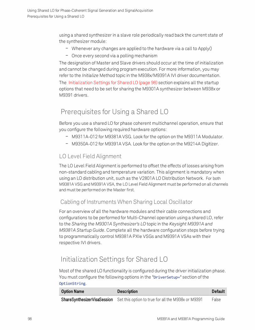
Using Shared LO for Phase-Coherent Signal Generation and SignalAcquisition
Prerequisites for Using a Shared LO
using a shared synthesizer in a slave role periodically read back the current state ofthe synthesizer module:
Whenever any changes are applied to the hardware via a call to Apply()
Once every second via a polling mechanism
The designation of Master and Slave drivers should occur at the time of initializationand cannot be changed during program execution. For more information, you mayrefer to the Initialize Method topic in the M938x/M9391A IVI driver documentation.
The Initialization Settings for Shared LO (page 98) section explains all the startupoptions that need to be set for sharing the M9301A synthesizer between M938x orM9391 drivers.
Prerequisites for Using a Shared LO
Before you use a shared LO for phase coherent multichannel operation, ensure thatyou configure the following required hardware options:
M9311A-012 for M9381A VSG. Look for the option on the M9311A Modulator.
M9350A-012 for M9391A VSA. Look for the option on the M9214A Digitizer.
LO Level Field Alignment
The LO Level Field Alignment is performed to offset the effects of losses arising fromnon-standard cabling and temperature variation. This alignment is mandatory whenusing an LO distribution unit, such as the V2801A LO Distribution Network. For bothM9381A VSG and M9391A VSA, the LO Level Field Alignment must be performed on all channelsand must be performed on the Master first.
Cabling of Instruments When Sharing Local Oscillator
For an overview of all the hardware modules and their cable connections andconfigurations to be performed for Multi-Channel operation using a shared LO, referto the Sharing the M9301A Synthesizer's LO topic in the Keysight M9391A andM9381A Startup Guide. Complete all the hardware configuration steps before tryingto programmatically control M9381A PXIe VSGs and M9391A VSAs with theirrespective IVI drivers.
Initialization Settings for Shared LO
Most of the shared LO functionality is configured during the driver initialization phase.You must configure the following options in the "DriverSetup=" section of theOptionString.
Option Name Description Default
ShareSynthesizerVisaSession Set this option to true for all the M938x or M9391 False
98 M9391A and M9381A Programming Guide

Using Shared LO for Phase-Coherent Signal Generation and SignalAcquisition
Initialization Settings for Shared LO
M9391A and M9381A Programming Guide 99
drivers that need to share a synthesizer module.
An instrument that tries to connect to a synthesizermodule that is already a part of a session withoutsetting this option to true encounters an error andinitialization fails.
SynthesizerRole By default, an instrument driver in the Shared LOmodel assumes the role of a Master. Declare oneinstrument as Master and all the other instrumentsas slaves by setting the optionSynthesizerRole=slave.
1. After initialization, youcannot change therole of a driver withinthe session.
2. If you set aninstrument as slavewithout having theoptionM9311A-012present for VSG oroptionM9350A-012present for VSA, anerror is generatedwhen the Apply()method is called.
Master
SynthesizerOutputPort The M9301A synthesizer has four output ports. Eachoutput port has been individually calibrated, and youcan declare which output port the instrument isconnected to for the highest accuracy. The outputport is declared by setting the optionSynthesizerOutputPort=XXwhere XX is thename of the port (1a, 1b, 2a, or 2b).You can change the value for this option within asession.
1a
For more information, refer to the Initialize Method topic in the M938x/M9391A IVI driverdocumentation.
Initialization Steps
Perform the following steps to configure the shared LO functionality in the"DriverSetup=" section of the OptionString:

Using Shared LO for Phase-Coherent Signal Generation and SignalAcquisition
Example Programs
1. Set the ShareSynthesizerVisaSession option to true or 1.
2. By default, SynthesizerRole is set to Master. So, for the Master driver, you neednot configure any settings. For all the slave drivers, set SynthesizerRole=slave.
3. By default, SynthesizerOutputPort is set to port 1A. Any instrument connectedto a different port must set SynthesizerOutputPort=XXwhere XX is the name ofthe port (1a, 1b, 2a, or 2b).
The following code snippet depicts a typical driver construction when using shared LOfor a set of M9381A drivers.
string masterOptions = "DriverSetup=ShareSynthesizerVisaSession=true";string slaveOptions = "DriverSetup=ShareSynthesizerVisaSession=true,SynthesizerRole=slave,SynthesizerOutputPort=1b";
IAgM938xEx2 driver1 = new AgM938xClass();IAgM938xEx2 driver2 = new AgM938xClass();
driver1.Initialize( resources, idquery, reset, masterOptions);driver2.Initialize( resources, idquery, reset, slaveOptions);
LO Level Field Alignment
When using an LO Distribution unit, set the ExtLoDistributionUnit option to 1. Thisinforms the driver to prepare itself for use with the unit by loading the LO Level fieldalignment data. For more information, see Appendix - Using LO Distribution Networkin Multi-Channel Systems (page 135).
Example Programs
In this section, you will learn how to write IVI-COM Console Applications that makeuse of the multi-channel capability of M9381A and M9391A using shared LO.
For M9381A, the example programs may be found in:C:\Program Files (x86)\IVIFoundation\IVI\Drivers\AgM938x\Examples.For M9391A, example programs may befound in: C:\Program Files (x86)\IVI Foundation\IVI\Drivers\AgM9391\Examples
To understand and write these example programs, you require knowledge of thefollowing:
Visual Studio 2010 with the .NET framework
Programming syntax for Visual C#
Multi-channel capability of M9381A VSG and M9391A VSA using shared LO
100 M9391A and M9381A Programming Guide

Using Shared LO for Phase-Coherent Signal Generation and SignalAcquisition
Example Programs
M9391A and M9381A Programming Guide 101
To compile your program, use the .NET Framework library and produce an Assembly.exe file.
Example Program 5: Transmitter program to demonstrate how to perform a multi-channel synchronous modulated signal generation using M9381A IVI commands. Useof shared M9301A Synthesizer is also demonstrated.
Example Program 6: Receiver program to demonstrate how to perform a multi-channel IQ acquisition using M9391A IVI commands. Use of shared M9301ASynthesizer is also demonstrated.
These example programs demonstrate a two channel system. One channel is theMaster, the other a Slave. The example programs can be extended to add more Slavechannels.
Assumptions for Example Programs
The example programs make the following assumptions:
There are two predefined IVI connection aliases for both M9381A and M9391A,"M9381A-Master" and "M9381A-Slave", and "M9391A-Master" and "M9391A-Slave", respectively.
At least one of the channels includes the M9300 Reference module and it is located in thechassis System Timing Slot. For simplicity, the Master is assumed to include an M9300Reference module, while the Slave is assumed to not include an M9300 Referencemodule. For most situations, this is adequate and recommended to avoid additionalconsiderations of Reference sharing between instances, for example, 1 second latencyfor settings to propagate between shared Reference instances.
Information for scenarios in which slave also shares the M9300A Reference hasalso been provided in the programming example.
For the use of a shared M9301A Synthesizer module for phase-coherent multi-channel systems, the following are the assumptions:
Hardware option M9311A-012 is available for M9381A and M9350A-012 forM9391A.
The Master channel uses Output Port 1A of the M9301A Synthesizer module,and the Slave channel uses Output Port 1B.
Example Program 5 - Pseudo-Code
This section presents the flow of the program. Code snippets are provided in the nextsection.
1. Create a Visual C# Console Application.
2. Add References.a. Add reference to IVI AgM938x 2.0 Type Library.
3. Add Using Statements.
4. Prepare for creation and initialization of drivers.

Using Shared LO for Phase-Coherent Signal Generation and SignalAcquisition
Example Programs
a. Declare master and slave drivers as instances of IAgM938xEx2.
b. Specify the mode of operation (simulation or non-simulation) and theresource descriptor.
c. Set the initialization properties for the shared synthesizer.
5. Create and initialize driver instances.
a. Create Master and Slave drivers.
b. Initialize the Master driver.
c. Clear startup messages and warnings, if any, on Master.
d. Print Ivi Driver Identity and Shared Synthesizer properties for Master.
e. Initialize the Slave driver.
f. Clear startup messages and warnings, if any, on Slave.
g. Print Ivi Driver Identity and Shared Synthesizer properties for Slave.
6. Enable an external reference, if planned.
7. Multichannel Sync Setup
a. Set up the Reference module to drive the 10 MHz backplane clock.
b. Initialize synchronization clocks for all source channels.
c. Set up the master/slave roles. Exactly one system must be theSystemMaster.
d. On the Master channel, configure the GroupSynchronizationSignal whichis used to trigger slave channels.
e. On each Slave channel set the SlaveSynchronizationSignal handshakingline to a unique PXI backplane trigger line.
f. On each Slave channel, set the GroupSynchronizationSignal to themaster's GroupSynchronizationSignal.
g. On the Master channel, set GroupSynchronizationMask to the sum (or"or'ing") of all the values (2^SlaveSyncSignal)for the slaves it will trigger.
8. Set up and print the RF properties.
9. Play an ARB waveform file.
a. Set up and load the encrypted ARB file.
i. An encrypted ARB file is loaded into a catalog where it isreferenced by a unique string key value.
ii. Get the path of the executing assembly to prepend it to thewaveform filename.
iii. Load the ARB sequences into the modulator.
b. To ensure power accuracy, turn off MIMO synchronization, play the ARBand use the DoPowerSearch method to do a power search.
c. Play encrypted ARB file.
10. Disable the Modulation and RF Output.
11. Close all the drivers.
102 M9391A and M9381A Programming Guide

Using Shared LO for Phase-Coherent Signal Generation and SignalAcquisition
Example Programs
M9391A and M9381A Programming Guide 103
12. Close the Console Application.
Example programs may be found in: C:\Program Files (x86)\IVIFoundation\IVI\Drivers\AgM938x\Examples
Example Program 5 - Program Steps with Code Snippets
Step 1: Create a Visual C# Console Application
1. Launch Visual Studio and create a new Console Application in Visual C# byselecting: File > New > Project. Select a Visual C# Console Application.Enter "CS_MultiChannel" as the Name of the project and click OK .
2. Select Project and click Add Reference .The Add Reference dialog appears. For this step, Solution Explorer must bevisible (View > Solution Explorer) and the "Program.cs" editor window must bevisible; select the Program.cs tab to bring it to the front view.
Step 2: Add References
In order to access the M9381A PXIe VSG driver interfaces, reference to its driver (DLL)must be created.
1. In Solution Explorer, right-click on References and select Add Reference.
2. From the Add Reference dialog, select the COM tab.
3. Click on any of the type libraries under the "Component Name" heading andenter the letter "I".(All IVI drivers begin with IVI so this will move down the list oftype libraries that begin with "I".)
4. Scroll to the IVI section and select the following type library; then select OK.IVI AgM938x 2.0 Type Library.
When a reference for the AgM938x is added, the IVIDriver 2.0Type Library is also automatically added. This referencehouses the interface definitions for IVI inherent capabilitieswhich are located in the file IviDriverTypeLib.dll (dynamicallylinked library).
Step 3: Add Using Statements
To allow your program to access the IVI drivers without specifying full path names ofeach interface or enum, you need to add using statements to your program.
using System;using System.IO;using System.Reflection;using Agilent.AgM938x.Interop;

Using Shared LO for Phase-Coherent Signal Generation and SignalAcquisition
Example Programs
Step 4: Prepare for Creation and Initialization of Drivers
1. If an external reference signal can be supplied to the M9300A "Ref In" port, thenconnect it and set this property to true. It will yield better results.
private const Boolean USE_EXTERNAL_REFERENCE = false;
2. Declare master and slave drivers as instances of IAgM938xEx2.
IAgM938xEx2 driverMaster = null;IAgM938xEx2 driverSlave = null;
When creating driver instances for the M9381A PXI VSG, note that theIAgM938xEx2 interface is needed for multi-channel operation in place of theIAgM938x interface. The IAgM938xEx2 interface is an "extended" interface andincludes additional commands that are needed for multi-channel capabilitythat were not previously available in IAgM938x. This interface also exposes theShared Synthesizer properties.
3. Specify the mode of operation (simulation or non-simulation) and the resourcedescriptor.The resource descriptor is the same value as the "Selected Instrument" field ofthe SFP's (Soft Front Panel) connection dialog. This can be a comma orsemicolon separated list of module addresses such asPXI10::15::0::INSTR;PXI10::16::0::INSTR;PXI10::17::0::INSTR;PXI10::18::0::INSTR or the name of a saved "Instrument Connection" created by the SFP such asM9381A. Refer to the SFP Help topic Connect to Instruments andModules for moredetails.You have two options to specify the resource descriptor and mode of operation:
Change the code to modify the default values, if required. Hard-codeyour resource descriptor and set the simulation mode to true or false.
string resourceMaster = "M9381A-Master"; // Use the hardwareassociated with the connection named "M9381A-Master"string resourceSlave = "M9381A-Slave"; // Use the hardwareassociated with the connection named "M9381A-Slave"resourceSlave = "M9301A;M9310A;M9311A"; // Simulation mode:Initial Slave M9381A without M9300A
bool simulated = true;
Pass the resource descriptor in the command line when you run theexample program to use that hardware in non-simulated mode. Thefollowing program code takes care of the command-line arguments:
if (args.Length > 1)
104 M9391A and M9381A Programming Guide
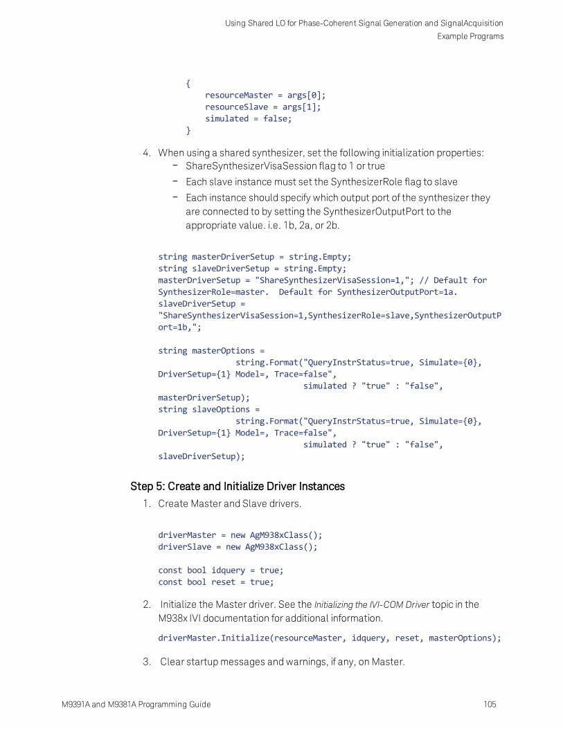
Using Shared LO for Phase-Coherent Signal Generation and SignalAcquisition
Example Programs
M9391A and M9381A Programming Guide 105
{resourceMaster = args[0];resourceSlave = args[1];simulated = false;
}
4. When using a shared synthesizer, set the following initialization properties:ShareSynthesizerVisaSession flag to 1 or true
Each slave instance must set the SynthesizerRole flag to slave
Each instance should specify which output port of the synthesizer theyare connected to by setting the SynthesizerOutputPort to theappropriate value. i.e. 1b, 2a, or 2b.
string masterDriverSetup = string.Empty;string slaveDriverSetup = string.Empty;masterDriverSetup = "ShareSynthesizerVisaSession=1,"; // Default forSynthesizerRole=master. Default for SynthesizerOutputPort=1a.slaveDriverSetup ="ShareSynthesizerVisaSession=1,SynthesizerRole=slave,SynthesizerOutputPort=1b,";
string masterOptions =string.Format("QueryInstrStatus=true, Simulate={0},
DriverSetup={1} Model=, Trace=false",simulated ? "true" : "false",
masterDriverSetup);string slaveOptions =
string.Format("QueryInstrStatus=true, Simulate={0},DriverSetup={1} Model=, Trace=false",
simulated ? "true" : "false",slaveDriverSetup);
Step 5: Create and Initialize Driver Instances
1. Create Master and Slave drivers.
driverMaster = new AgM938xClass();driverSlave = new AgM938xClass();
const bool idquery = true;const bool reset = true;
2. Initialize the Master driver. See the Initializing the IVI-COM Driver topic in theM938x IVI documentation for additional information.
driverMaster.Initialize(resourceMaster, idquery, reset, masterOptions);
3. Clear startup messages and warnings, if any, on Master.

Using Shared LO for Phase-Coherent Signal Generation and SignalAcquisition
Example Programs
int errorcode = 0;string message = string.Empty;do{
driverMaster.Utility.ErrorQuery(ref errorcode, ref message);if (errorcode != 0){
Console.WriteLine(message);}
} while (errorcode != 0);
Console.WriteLine("Master Driver Initialized");
4. You may also want to print IVI Driver Identity and Shared Synthesizerproperties.
Console.WriteLine("Identifier: {0}", driverMaster.Identity.Identifier);Console.WriteLine("Revision: {0}", driverMaster.Identity.Revision);Console.WriteLine("Vendor: {0}", driverMaster.Identity.Vendor);Console.WriteLine("Description: {0}",driverMaster.Identity.Description);Console.WriteLine("Model: {0}", driverMaster.Identity.InstrumentModel);Console.WriteLine("FirmwareRev: {0}",driverMaster.Identity.InstrumentFirmwareRevision);Console.WriteLine("Serial #: {0}", driverMaster.System.SerialNumber);Console.WriteLine("Simulate: {0}",driverMaster.DriverOperation.Simulate);Console.WriteLine();
Console.WriteLine("Shared Synthesizer Role: {0}",driverMaster.Modules3.Synthesizer3.SharedRole);Console.WriteLine("Synthesizer Output Port: {0}",driverMaster.Modules3.Synthesizer3.OutputPort);Console.WriteLine();
5. Similarly, initialize the Slave Driver, clear startup messages and warnings, andprint its properties.
driverSlave.Initialize(resourceSlave, idquery, reset, slaveOptions);
errorcode = 0;message = string.Empty;do{
driverSlave.Utility.ErrorQuery(ref errorcode, ref message);if (errorcode != 0){
Console.WriteLine(message);
106 M9391A and M9381A Programming Guide

Using Shared LO for Phase-Coherent Signal Generation and SignalAcquisition
Example Programs
M9391A and M9381A Programming Guide 107
}} while (errorcode != 0);
Console.WriteLine("Slave Driver Initialized");
Console.WriteLine("Identifier: {0}", driverSlave.Identity.Identifier);Console.WriteLine("Revision: {0}", driverSlave.Identity.Revision);Console.WriteLine("Vendor: {0}", driverSlave.Identity.Vendor);Console.WriteLine("Description: {0}",driverSlave.Identity.Description);Console.WriteLine("Model: {0}", driverSlave.Identity.InstrumentModel);Console.WriteLine("FirmwareRev: {0}",driverSlave.Identity.InstrumentFirmwareRevision);Console.WriteLine("Serial #: {0}", driverSlave.System.SerialNumber);Console.WriteLine("Simulate: {0}",driverSlave.DriverOperation.Simulate);Console.WriteLine();
Console.WriteLine("Shared Synthesizer Role: {0}",driverSlave.Modules3.Synthesizer3.SharedRole);Console.WriteLine("Synthesizer Output Port: {0}",driverSlave.Modules3.Synthesizer3.OutputPort);Console.WriteLine();
When initializing the instruments, create the master first, followed byall the slaves.
Step 6: Enable an External Reference, if plannedIf the Master driver uses an external reference then enable it.
driverMaster.Modules.Reference.ExternalReferenceEnabled = USE_EXTERNAL_REFERENCE;
If the Slave uses an external reference then enable it.
driverSlave.Modules.Reference.ExternalReferenceEnabled = USE_EXTERNAL_REFERENCE;
Step 7: Multichannel Sync Setup
You need to perform the following steps to configure the system for multi-channeloperations.
1. The Reference module must be in the System Timing Slot. Set it up to drive the10 MHz backplane clock. Usually, you can configure the Reference module tobe in just one channel, for example, the Master.
driverMaster.Modules2.Reference2.BackPlaneReferenceEnabled = true;
If the Slave contains the Reference module, set it to drive the 10MHz

Using Shared LO for Phase-Coherent Signal Generation and SignalAcquisition
Example Programs
backplane.
driverSlave.Modules2.Reference2.BackPlaneReferenceEnabled = true;
2. Initialize synchronization clocks for all source channels.
driverMaster.MultiChannelSync.InitializeSynchronizationClocks();driverSlave.MultiChannelSync.InitializeSynchronizationClocks();
3. Set up the master/slave roles. Exactly one system must be the SystemMaster.
driverMaster.MultiChannelSync.SynchronizationRole =AgM938xMultiChannelSyncRoleEnum.AgM938xMultiChannelSyncRoleSystemMaster;driverSlave.MultiChannelSync.SynchronizationRole =AgM938xMultiChannelSyncRoleEnum.AgM938xMultiChannelSyncRoleSlave;
4. On the Master channel, configure the GroupSynchronizationSignal which isused to trigger slave channels.
driverMaster.MultiChannelSync.GroupSynchronizationSignal =AgM938xPXIResourcesEnum.AgM938xPXIResourcesTTL_TRIGGER_1;
5. On each Slave channel set the SlaveSynchronizationSignal handshaking lineto a unique PXI backplane trigger line.
driverSlave.MultiChannelSync.SlaveSynchronizationSignal =AgM938xPXIResourcesEnum.AgM938xPXIResourcesTTL_TRIGGER_2;
6. On each Slave channel, set the GroupSynchronizationSignal to the master'sGroupSynchronizationSignal.
driverSlave.MultiChannelSync.GroupSynchronizationSignal =AgM938xPXIResourcesEnum.AgM938xPXIResourcesTTL_TRIGGER_1;
7. On the Master channel, set GroupSynchronizationMask to the sum (or "or'ing")of all the values (2^SlaveSyncSignal)for the slaves it will trigger. Theexponentiation (2^SlaveSyncSignal) can be accomplished via Pow(2,SlaveSyncSignal) or as below.
driverMaster.MultiChannelSync.GroupSynchronizationMask = 1 << (int)driverSlave.MultiChannelSync.SlaveSynchronizationSignal;
After these steps, you can use the chassis interface and configure the chassis toproperly route trigger lines between trigger segments. This step is critical for propermulti-channel operation when source channels span different bus segments.
Step 8: Set Up the RF Properties
To ensure that you have control over the drivers, print the RF properties of the drivers,change the values for these properties, and again display these properties.
const double frequency = 2.4e9; // 2.4 GHz
108 M9391A and M9381A Programming Guide

Using Shared LO for Phase-Coherent Signal Generation and SignalAcquisition
Example Programs
M9391A and M9381A Programming Guide 109
const double level = -3; // -3 dBm
Console.WriteLine("\t* Initial Master Frequency: {0:###0.#} MHz",driverMaster.RF.Frequency / 1e6);Console.WriteLine("\t* Initial Master Level: {0:0.#} dBm",driverMaster.RF.Level);Console.WriteLine("\t* Initial Slave Frequency: {0:###0.#} MHz",driverSlave.RF.Frequency / 1e6);Console.WriteLine("\t* Initial Slave Level: {0:0.#} dBm",driverSlave.RF.Level);Console.WriteLine();
driverMaster.RF.Frequency = frequency;driverMaster.RF.Level = level;driverMaster.RF.OutputEnabled = true;driverMaster.Apply();
driverSlave.RF.Frequency = frequency;driverSlave.RF.Level = level;driverSlave.RF.OutputEnabled = true;driverSlave.Apply();
Console.WriteLine("\t* New Master Frequency: {0:###0.#} MHz",driverMaster.RF.Frequency / 1e6);Console.WriteLine("\t* New Master Level: {0:0.#} dBm",driverMaster.RF.Level);Console.WriteLine("\t* New Slave Frequency: {0:###0.#} MHz",driverSlave.RF.Frequency / 1e6);Console.WriteLine("\t* New Slave Level: {0:0.#} dBm", driverSlave.RF.Level);
Step 9: Play an ARB Waveform File
This step involves creating the proper setup for loading an ARB file, performing apower search to ensure power accuracy, and playing the encrypted ARB file.
1. Set up and Load the Encrypted ARB file.1You need to perform the following steps to create the proper setup for loadingan ARB file:
a. An encrypted ARB file is loaded into a catalog where it is referenced by aunique string key value:
const string catalogReferenceName = "ExampleArb";
const string encryptedArbFileName = "12TONE.wfm";Console.WriteLine("\t* Catalog Reference Name = {0}",catalogReferenceName);Console.WriteLine("\t* Encrypted ARB filename = {0}",encryptedArbFileName);Console.WriteLine("\t* Upload encrypted ARB file.");
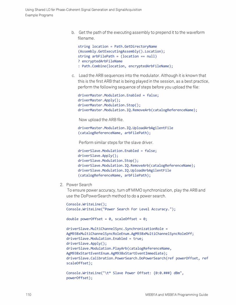
Using Shared LO for Phase-Coherent Signal Generation and SignalAcquisition
Example Programs
b. Get the path of the executing assembly to prepend it to the waveformfilename.
string location = Path.GetDirectoryName(Assembly.GetExecutingAssembly().Location);string arbFilePath = (location == null)? encryptedArbFileName: Path.Combine(location, encryptedArbFileName);
c. Load the ARB sequences into the modulator. Although it is known thatthis is the first ARB that is being played in the session, as a best practice,perform the following sequence of steps before you upload the file:
driverMaster.Modulation.Enabled = false;driverMaster.Apply();driverMaster.Modulation.Stop();driverMaster.Modulation.IQ.RemoveArb(catalogReferenceName);
Now upload the ARB file.
driverMaster.Modulation.IQ.UploadArbAgilentFile(catalogReferenceName, arbFilePath);
Perform similar steps for the slave driver.
driverSlave.Modulation.Enabled = false;driverSlave.Apply();driverSlave.Modulation.Stop();driverSlave.Modulation.IQ.RemoveArb(catalogReferenceName);driverSlave.Modulation.IQ.UploadArbAgilentFile(catalogReferenceName, arbFilePath);
2. Power SearchTo ensure power accuracy, turn off MIMO synchronization, play the ARB anduse the DoPowerSearch method to do a power search.
Console.WriteLine();Console.WriteLine("Power Search For Level Accuracy.");
double powerOffset = 0, scaleOffset = 0;
driverSlave.MultiChannelSync.SynchronizationRole =AgM938xMultiChannelSyncRoleEnum.AgM938xMultiChannelSyncRoleOff;driverSlave.Modulation.Enabled = true;driverSlave.Apply();driverSlave.Modulation.PlayArb(catalogReferenceName,AgM938xStartEventEnum.AgM938xStartEventImmediate);driverSlave.Calibration.PowerSearch.DoPowerSearch(ref powerOffset, refscaleOffset);
Console.WriteLine("\t* Slave Power Offset: {0:0.###} dBm",powerOffset);
110 M9391A and M9381A Programming Guide

Using Shared LO for Phase-Coherent Signal Generation and SignalAcquisition
Example Programs
M9391A and M9381A Programming Guide 111
Console.WriteLine("\t* Slave Scale Offset: {0:0.###}", scaleOffset);
powerOffset = 0; scaleOffset = 0;
driverMaster.MultiChannelSync.SynchronizationRole =AgM938xMultiChannelSyncRoleEnum.AgM938xMultiChannelSyncRoleOff;driverMaster.Modulation.Enabled = true;driverMaster.Apply();driverMaster.Modulation.PlayArb(catalogReferenceName,AgM938xStartEventEnum.AgM938xStartEventImmediate);driverMaster.Calibration.PowerSearch.DoPowerSearch(ref powerOffset, refscaleOffset);
Console.WriteLine("\t* Master Power Offset: {0:0.###} dBm",powerOffset);Console.WriteLine("\t* Master Scale Offset: {0:0.###}", scaleOffset);
3. Play Encrypted ARB file.Re-enable MIMO synchronization and start a synchronous ARB playback.Always play the ARB on the slave channels first. This is analogous to the Arm()sequence for Multi-Channel PXIe VSAs.
Console.WriteLine();Console.WriteLine("Play Synchronous ARB file.");
driverSlave.MultiChannelSync.SynchronizationRole =AgM938xMultiChannelSyncRoleEnum.AgM938xMultiChannelSyncRoleSlave;driverSlave.Modulation.Enabled = true;driverSlave.Apply();driverSlave.Modulation.PlayArb(catalogReferenceName,AgM938xStartEventEnum.AgM938xStartEventImmediate);
driverMaster.MultiChannelSync.SynchronizationRole =AgM938xMultiChannelSyncRoleEnum.AgM938xMultiChannelSyncRoleSystemMaster;driverMaster.Modulation.Enabled = true;driverMaster.Apply();driverMaster.Modulation.PlayArb(catalogReferenceName,AgM938xStartEventEnum.AgM938xStartEventImmediate);
Step 10: Disable the Modulation and RF Output
driverMaster.Modulation.Enabled = false;driverMaster.RF.OutputEnabled = false;driverMaster.Apply();
driverSlave.Modulation.Enabled = false;driverSlave.RF.OutputEnabled = false;driverSlave.Apply();

Using Shared LO for Phase-Coherent Signal Generation and SignalAcquisition
Example Programs
Step 11: Close all the drivers
When closing the instruments it is recommended that you close all the slaves firstand then close the master. Although no errors will be encountered if any other orderis used, but this helps ensure that the "owner" of the synthesizer can cleanlyshutdown the module. Note the use of the finally syntax, which implies that thepreceding code was wrapped in a try/catch block.
finally{
if (driverSlave != null && driverSlave.Initialized){
driverSlave.Close();Console.WriteLine();Console.WriteLine("M9381A Slave driver closed.");
}
if (driverMaster != null && driverMaster.Initialized){
driverMaster.Close();Console.WriteLine();Console.WriteLine("M9381A Master driver closed.");
}}
Step 12: Close the Console Application
Prompt the user to press the Enter key to close the application.
Console.WriteLine();Console.WriteLine("Done - Press Enter to Exit");Console.ReadLine();
112 M9391A and M9381A Programming Guide

Using Shared LO for Phase-Coherent Signal Generation and SignalAcquisition
Example Programs
M9391A and M9381A Programming Guide 113
Example Program 6 - Pseudo-Code
This section presents the flow of the program. Code snippets are provided in the nextsection.

Using Shared LO for Phase-Coherent Signal Generation and SignalAcquisition
Example Programs
1. Create a Visual C# Console Application.
2. Add References. Add reference to IVI AgM9391 2.0 Type Library.
3. Add Using Statements.
4. Prepare for creation and initialization of drivers.a. Declare and set values for some configurable parameters to be used in
the example.
b. If an external reference signal can be supplied to the M9300A "Ref In"port, then connect it and set this property to true.
c. Declare master and slave drivers as instances of AgM9391.
d. Specify the mode of operation (simulation or non-simulation) and theresource descriptor.
e. Set the initialization properties for the shared synthesizer.
5. Create and initialize driver instances.
a. Create Master and Slave drivers.
b. Initialize the Master driver.
c. Clear startup messages and warnings, if any, on Master.
d. Print Ivi Driver Identity and Shared Synthesizer properties for Master.
e. Initialize the Slave driver.
f. Clear startup messages and warnings, if any, on Slave.
g. Print Ivi Driver Identity and Shared Synthesizer properties for Slave.
6. Enable an external reference, if planned.
7. Multichannel Sync Setup
a. Set up the Reference module to drive the 10 MHz backplane clock.
b. Initialize synchronization clocks for all source channels.
c. Set up the master/slave roles. Exactly one system must be theSystemMaster.
d. On the Master channel, configure the GroupSynchronizationSignal whichis used to trigger slave channels.
e. On each Slave channel set the SlaveSynchronizationSignal handshakingline to a unique PXI backplane trigger line.
f. On each Slave channel, set the GroupSynchronizationSignal to themaster's GroupSynchronizationSignal.
g. On the Master channel, set GroupSynchronizationMask to the sum (or"or'ing") of all the values (2^SlaveSyncSignal)for the slaves it will trigger.
h. Using the chassis interface, configure the chassis to properly routetrigger lines between trigger segments.
8. Set the RF parameters.
9. Set up the receiver to make IQ measurements for a 40 MHz bursted signal.
10. Set up the triggering properties.
114 M9391A and M9381A Programming Guide

Using Shared LO for Phase-Coherent Signal Generation and SignalAcquisition
Example Programs
M9391A and M9381A Programming Guide 115
a. Set up for a magnitude triggered mode acquisition.
b. The triggering has to happen on the rising edge of the trigger and ithappens when the signal crosses through the trigger level. Configure themaster for the same.
c. If unable to detect a burst, try a lower magnitude level or increase theoutput power level on the signal generator.
d. Set up a bit of "off" time before the signal burst ramps up so that you candetect the beginning of the burst.
e. Auto trigger on 10 second timeout if you never see a burst.
11. Apply the changes to the hardware.
12. Arm the receivers.
13. Set the timeout value on WaitForData.
14. Retrieve the IQ data.
15. Perform some actions on the interleaved IQ vector.
16. Close all the drivers.
17. Close the Console Application.
Example programs may be found in: C:\Program Files (x86)\IVIFoundation\IVI\Drivers\AgM9391\Examples
Example Program 6 - Program Steps with Code Snippets
Step 1: Create a Visual C# Console Application
1. Launch Visual Studio and create a new Console Application in Visual C# byselecting: File > New > Project. Select a Visual C# Console Application.Enter "CS_MultiChannel" as the Name of the project and click OK .
2. Select Project and click Add Reference.The Add Reference dialog appears. For this step, Solution Explorer must bevisible (View > Solution Explorer) and the "Program.cs" editor window must bevisible; select the Program.cs tab to bring it to the front view.
Step 2: Add References
In order to access the M9391A PXIe VSA driver interfaces, reference to its driver (DLL)must be created.
1. In Solution Explorer, right-click on References and select Add Reference.
2. From the Add Reference dialog, select the COM tab.
3. Click on any of the type libraries under the "Component Name" heading andenter the letter "I".(All IVI drivers begin with IVI so this will move down the list oftype libraries that begin with "I".)
4. Scroll to the IVI section, select the following type library, and then select OK.IVI AgM9391 2.0 Type Library

Using Shared LO for Phase-Coherent Signal Generation and SignalAcquisition
Example Programs
When a reference for the AgM9391 is added, the IVIDriver 2.0Type Library is also automatically added. This referencehouses the interface definitions for IVI inherent capabilitieswhich are located in the file IviDriverTypeLib.dll (dynamicallylinked library).
Step 3: Add Using Statements
To allow your program to access the IVI drivers without specifying full path names ofeach interface or enum, you need to add using statements to your program.
using System;using Agilent.AgM9391.Interop;
Step 4: Prepare for Creation and Initialization of Drivers
Perform the following steps.
1. Declare and set values for some configurable parameters to be used in theexample.
private const Double CENTER_FREQUENCY = 1000000000.0;private const Double EXPECTED_POWER = 2;private const Double IF_BANDWIDTH = 40000000.0;
private const Double SAMPLE_RATE = 50000000.0;private const Double DURATION = 640e-6;
private const Double MAGNITUDE_TRIGGER_LEVEL = -20.0;
2. If an external reference signal can be supplied to the M9300A "Ref In" port, thenconnect it and set this property to true. It will yield better results.
private const Boolean USE_EXTERNAL_REFERENCE = false;
3. Declare the drivers.
AgM9391 driverMaster = null;AgM9391 driverSlave = null;
4. Specify the mode of operation (simulation or non-simulation) and the resourcedescriptor.The resource descriptor is the same value as the "Selected Instrument" field ofthe SFP's (Soft Front Panel) connection dialog. This can be a comma orsemicolon separated list of module addresses such asPXI10::15::0::INSTR;PXI10::16::0::INSTR;PXI10::17::0::INSTR;PXI10::18::0::INSTR or the name of a saved "Instrument Connection" created by the SFP such asM9391A. Refer to the SFP Help topic "Connect to Instruments and Modules" formore details.You have two options to specify the resource descriptor and mode of operation:
116 M9391A and M9381A Programming Guide

Using Shared LO for Phase-Coherent Signal Generation and SignalAcquisition
Example Programs
M9391A and M9381A Programming Guide 117
Change the code to modify the default values, if required. Hard-codeyour resource descriptor and set the simulation mode to true or false.
string resourceMaster = "M9391A-Master"; // Use the hardwareassociated with the connection named "M9391A-Master"string resourceSlave = "M9391A-Slave"; // Use the hardwareassociated with the connection named "M9391A-Slave"resourceSlave = "M9301A;M9214A;M9350A"; // Simulation mode:Initial Slave M9391A without M9300A
bool simulated = true;
Pass the resource descriptor in the command line when you run theexample program to use that hardware in non-simulated mode.
if (args.Length > 1){
resourceMaster = args[0];resourceSlave = args[1];simulated = false;
}
5. When using a shared synthesizer, set the following initialization properties:ShareSynthesizerVisaSession flag to 1 or true
Each slave instance must set the SynthesizerRole flag to slave
Each instance should specify which output port of the synthesizer theyare connected to by setting the SynthesizerOutputPort to theappropriate value. i.e. 1b, 2a,, or 2b.
string masterDriverSetup = string.Empty;string slaveDriverSetup = string.Empty;
masterDriverSetup = "ShareSynthesizerVisaSession=1,"; // Defaultfor SynthesizerRole=master. Default for SynthesizerOutputPort=1a.slaveDriverSetup ="ShareSynthesizerVisaSession=1,SynthesizerRole=slave,SynthesizerOutputPort=1b,";string masterOptions =string.Format("QueryInstrStatus=true, Simulate={0}, DriverSetup={1} Model=, Trace=false",simulated ? "true" : "false", masterDriverSetup);string slaveOptions =string.Format("QueryInstrStatus=true, Simulate={0}, DriverSetup={1} Model=, Trace=false",simulated ? "true" : "false", slaveDriverSetup);
Step 5: Create and Initialize Drivers
Perform the following steps.

Using Shared LO for Phase-Coherent Signal Generation and SignalAcquisition
Example Programs
1. Create Master and Slave Drivers.
driverMaster = new AgM9391Class();driverSlave = new AgM9391Class();
const bool idquery = true;const bool reset = true;
2. Initialize the Master driver. See driver help topic "Initializing the IVI-COM Driver"for additional information.
driverMaster.Initialize(resourceMaster, idquery, reset, masterOptions);
3. Clear startup messages & warnings if any, on Master.
int errorcode = 0;string message = string.Empty;
do{
driverMaster.Utility.ErrorQuery(ref errorcode, ref message);if (errorcode != 0){
Console.WriteLine(message);}
} while (errorcode != 0);
Console.WriteLine("Master Driver Initialized");
4. You may also want to print IVI Driver Identity and Shared Synthesizerproperties.
Console.WriteLine("Identifier: {0}", driverMaster.Identity.Identifier);Console.WriteLine("Revision: {0}", driverMaster.Identity.Revision);Console.WriteLine("Vendor: {0}", driverMaster.Identity.Vendor);Console.WriteLine("Description: {0}",driverMaster.Identity.Description);Console.WriteLine("Model: {0}", driverMaster.Identity.InstrumentModel);Console.WriteLine("FirmwareRev: {0}",driverMaster.Identity.InstrumentFirmwareRevision);Console.WriteLine("Serial #: {0}", driverMaster.System.SerialNumber);Console.WriteLine("Simulate: {0}",driverMaster.DriverOperation.Simulate);Console.WriteLine();
Console.WriteLine("Shared Synthesizer Role: {0}",driverMaster.Modules3.Synthesizer2.SharedRole);Console.WriteLine("Synthesizer Output Port: {0}",driverMaster.Modules3.Synthesizer2.OutputPort);Console.WriteLine();
5. Similarly, initialize the Slave Driver, clear startup messages and warnings, and
118 M9391A and M9381A Programming Guide

Using Shared LO for Phase-Coherent Signal Generation and SignalAcquisition
Example Programs
M9391A and M9381A Programming Guide 119
print its properties.
driverSlave.Initialize(resourceSlave, idquery, reset, slaveOptions);
errorcode = 0;message = string.Empty;
do{
driverSlave.Utility.ErrorQuery(ref errorcode, ref message);if (errorcode != 0){
Console.WriteLine(message);}
} while (errorcode != 0);
Console.WriteLine("Slave Driver Initialized");
Console.WriteLine("Identifier: {0}", driverSlave.Identity.Identifier);Console.WriteLine("Revision: {0}", driverSlave.Identity.Revision);Console.WriteLine("Vendor: {0}", driverSlave.Identity.Vendor);Console.WriteLine("Description: {0}",driverSlave.Identity.Description);Console.WriteLine("Model: {0}", driverSlave.Identity.InstrumentModel);Console.WriteLine("FirmwareRev: {0}",driverSlave.Identity.InstrumentFirmwareRevision);Console.WriteLine("Serial #: {0}", driverSlave.System.SerialNumber);Console.WriteLine("Simulate: {0}",driverSlave.DriverOperation.Simulate);Console.WriteLine();
Console.WriteLine("Shared Synthesizer Role: {0}",driverSlave.Modules3.Synthesizer2.SharedRole);Console.WriteLine("Synthesizer Output Port: {0}",driverSlave.Modules3.Synthesizer2.OutputPort);Console.WriteLine();
When initializing the instruments it is recommended that the masterbe created first, followed by all the slaves.
Step 6: Enable an External Reference, if planned
If the Master driver uses an external reference then enable it.
driverMaster.Modules.Reference.ExternalReferenceEnabled = USE_EXTERNAL_REFERENCE;
If the Slave driver uses an external reference then enable it.
driverSlave.Modules.Reference.ExternalReferenceEnabled = USE_EXTERNAL_REFERENCE;

Using Shared LO for Phase-Coherent Signal Generation and SignalAcquisition
Example Programs
Step 7: Multichannel Sync Setup
Configure the system for multi-channel.
1. The Reference module must be in the System Timing Slot. Set it up to drive the10 MHz backplane clock.
driverMaster.Modules2.Reference2.BackPlaneReferenceEnabled = true;
If the Slave contains the Reference module, you need to set it to drive the10MHz backplane too.
driverSlave.Modules2.Reference2.BackPlaneReferenceEnabled = true;
2. Initialize synchronization clocks for all receiver channels.
driverMaster.MultiChannelSync.InitializeSynchronizationClocks();driverSlave.MultiChannelSync.InitializeSynchronizationClocks();
3. Set up the Master/Slave roles. Exactly one system must be the SystemMaster.
driverMaster.MultiChannelSync.SynchronizationRole =AgM9391MultiChannelSyncRoleEnum.AgM9391MultiChannelSyncRoleSystemMaster;driverSlave.MultiChannelSync.SynchronizationRole =AgM9391MultiChannelSyncRoleEnum.AgM9391MultiChannelSyncRoleSlave;
4. On the Master channel, configure the GroupSynchronizationSignal which isused to trigger slave channels.
driverMaster.MultiChannelSync.GroupSynchronizationSignal =AgM9391PXIResourcesEnum.AgM9391PXIResourcesTTL_TRIGGER_1;
5. On each Slave channel set the SlaveSynchronizationSignal handshaking line toa unique PXI backplane trigger line.
driverSlave.MultiChannelSync.SlaveSynchronizationSignal =AgM9391PXIResourcesEnum.AgM9391PXIResourcesTTL_TRIGGER_2;
6. On each Slave channel, set the GroupSynchronizationSignal to the master'sGroupSynchronizationSignal.
driverSlave.MultiChannelSync.GroupSynchronizationSignal =AgM9391PXIResourcesEnum.AgM9391PXIResourcesTTL_TRIGGER_1;
7. On the Master channel, set GroupSynchronizationMask to the sum (or "or'ing")of all the values (2^SlaveSyncSignal) for the slaves it will trigger. Theexponentiation (2^SlaveSyncSignal) can be accomplished via Pow(2,SlaveSyncSignal) or as below.
driverMaster.MultiChannelSync.GroupSynchronizationMask = 1 << (int)driverSlave.MultiChannelSync.SlaveSynchronizationSignal;
120 M9391A and M9381A Programming Guide

Using Shared LO for Phase-Coherent Signal Generation and SignalAcquisition
Example Programs
M9391A and M9381A Programming Guide 121
8. Using the chassis interface, configure the chassis to properly route trigger linesbetween trigger segments. This step is critical for proper multi-channeloperation when receiver channels span different bus segments.
Step 8: Set the RF parameters
Set the measurement at the center frequency. Set a low power and we will search foran optimum power level where the receiver is not overloaded. Let the receiver pickthe suggested conversion mode for the frequency. Use the largest IF bandwidthsupported by the hardware.
driverMaster.RF.Frequency = CENTER_FREQUENCY;driverMaster.RF.Power = EXPECTED_POWER;driverMaster.RF.Conversion = AgM9391ConversionEnum.AgM9391ConversionAuto;driverMaster.RF.IFBandwidth = IF_BANDWIDTH;
driverSlave.RF.Frequency = CENTER_FREQUENCY;driverSlave.RF.Power = EXPECTED_POWER;driverSlave.RF.Conversion = AgM9391ConversionEnum.AgM9391ConversionAuto;driverSlave.RF.IFBandwidth = IF_BANDWIDTH;
Step 9: Set up the receiver to make IQ measurements for a 40 MHz burstedsignal with which we will use a magnitude trigger
driverMaster.AcquisitionMode =AgM9391AcquisitionModeEnum.AgM9391AcquisitionModeIQ;driverMaster.IQAcquisition.SampleRate = SAMPLE_RATE;driverMaster.IQAcquisition.SampleSize =AgM9391SampleSizeEnum.AgM9391SampleSize64Bits;driverMaster.IQAcquisition.Samples = (int)(DURATION * SAMPLE_RATE);
driverSlave.AcquisitionMode =AgM9391AcquisitionModeEnum.AgM9391AcquisitionModeIQ;driverSlave.IQAcquisition.SampleRate = SAMPLE_RATE;driverSlave.IQAcquisition.SampleSize =AgM9391SampleSizeEnum.AgM9391SampleSize64Bits;driverSlave.IQAcquisition.Samples = (int)(DURATION * SAMPLE_RATE);
Step 10: Set up the triggering properties
Perform the following steps.
1. Since we anticipate a bursted signal we will set for a magnitude triggered modeacquisition.
driverMaster.Triggers.AcquisitionTrigger.Mode =AgM9391AcquisitionTriggerModeEnum.AgM9391AcquisitionTriggerModeMagnitude;

Using Shared LO for Phase-Coherent Signal Generation and SignalAcquisition
Example Programs
2. The Slave channel also needs to know what triggering mode is set.
driverSlave.Triggers.AcquisitionTrigger.Mode =AgM9391AcquisitionTriggerModeEnum.AgM9391AcquisitionTriggerModeMagnitude;
3. The triggering has to happen on the rising edge of the trigger and it happenswhen the signal crosses through the trigger level. If triggering is to be used,only the master is configured for the trigger. The master will hold off the slavesuntil trigger is received.
IAgM9391TriggersAcquisitionTrigger acqTriggerMaster =driverMaster.Triggers.AcquisitionTrigger;
acqTriggerMaster.MagnitudeTrigger.Slope =AgM9391TriggerSlopeEnum.AgM9391TriggerSlopePositive;
4. If unable to detect a burst, try a lower magnitude level or increase the outputpower level on the signal generator.
acqTriggerMaster.MagnitudeTrigger.Level = MAGNITUDE_TRIGGER_LEVEL;
5. A bit of "off" time is required before the signal burst ramps up so we can detectthe beginning of the burst.
acqTriggerMaster.MagnitudeTrigger.PulseOffTime = 1e-6; // 1 usec shouldbe enough.
6. You need to decide what to do if you never see a burst. As an example, you canauto trigger on 10 second timeout if no burst meets the criteria and just acquirewhat you can.
acqTriggerMaster.TimeoutMode =AgM9391TriggerTimeoutModeEnum.AgM9391TriggerTimeoutModeAutoTriggerOnTimeout;acqTriggerMaster.Timeout = 10000; // ms
Step 11: Apply the changes to hardware
Apply changes to the Master first, then the Slave(s).
The MultichannelSync.DelayAdjust property must be copied from theMaster (after Master Apply()) to the Slave(s) (before Slave Apply()).
driverMaster.Apply();driverSlave.MultiChannelSync.DelayAdjust =driverMaster.MultiChannelSync.DelayAdjust;driverSlave.Apply();
Step 12: Arm the receivers
The Slave(s) must be Armed before the Master.
122 M9391A and M9381A Programming Guide

Using Shared LO for Phase-Coherent Signal Generation and SignalAcquisition
Example Programs
M9391A and M9381A Programming Guide 123
driverSlave.Arm();driverMaster.Arm();
bool overloaded = false;
Step 13: Set the timeout value on WaitForData
When trigger time out mode is set to auto trigger on time out, the timeout value onWaitForData should be longer than the auto trigger timeout and long enough to allowdata acquisition to complete. This example waits 10 seconds before auto triggering ifno magnitude trigger has occurred and waits for 11 seconds for data acquisition tocomplete.
int waitForDataTimeout = (int)( acqTriggerMaster.Timeout * 1.1 );if( !driverMaster.WaitForData( waitForDataTimeout ) ) // in milliseconds{
throw new ApplicationException( "WaitForData failed. No acquisition wasmade." );}
Step 14: Retrieve the IQ data
double[] interleavedIQBlockMaster = new double[driverMaster.IQAcquisition.Samples * 2];double[] interleavedIQBlockSlave = new double[driverSlave.IQAcquisition.Samples * 2];
driverMaster.IQAcquisition.ReadIQData( 0,
AgM9391IQUnitsEnum.AgM9391IQUnitsSquareRootMilliWatts,0,driverMaster.IQAcquisition.Samples,ref interleavedIQBlockMaster,ref overloaded );
driverSlave.IQAcquisition.ReadIQData( 0,
AgM9391IQUnitsEnum.AgM9391IQUnitsSquareRootMilliWatts,0,driverSlave.IQAcquisition.Samples,ref interleavedIQBlockSlave,ref overloaded );
Step 15: Perform some action on the interleaved IQ vector
Here, you can enter your own program logic.

Using Shared LO for Phase-Coherent Signal Generation and SignalAcquisition
Example Programs
Step 16: Close all the drivers
When closing the instruments it is recommended that you close all the slaves firstand then close the master. Although no errors will be encountered if any other orderis used, but this helps ensure that the "owner" of the synthesizer can cleanlyshutdown the module. Note the use of the finally syntax, which implies that precedingcode was wrapped in a try/catch block.
finally{
if (driverMaster != null && driverMaster.Initialized){
driverMaster.Close();Console.WriteLine();Console.WriteLine("M9391A Master driver closed.");
}if (driverSlave != null && driverSlave.Initialized){
driverSlave.Close();Console.WriteLine();Console.WriteLine("M9391A Slave driver closed.");
}}
Step 17: Close the Console Application
Prompt the user to press the Enter key to close the application.
Console.WriteLine();Console.WriteLine("Done - Press Enter to Exit");Console.ReadLine();
124 M9391A and M9381A Programming Guide

Hints for Various Configuration Tasks
Restartingan Already Playing Waveform in M9381A VSG
M9391A and M9381A Programming Guide 125
Hints for Various Configuration TasksThis section focuses on providing helpful pointers for programmatically performingsome configuration tasks for M9391A VSG and M9381A VSG.
Restarting an Already Playing Waveform in M9381A VSG (page 125)
Restarting an Already Playing Waveform in M9381AVSG
You can configure an already playing arbitrary waveform on the M9381A VSG torestart in response to an external trigger.
Use Case
You might need to synchronize the meta information between a base station and anM9381A VSG emulating a mobile handset. For example, in an LTE system,infrequently changing information like cell identity and frequency plan is nottransmitted in every 10 ms frame. However, the base station and mobile unit arerequired to be in sync on where they are in the frame sequence to agree upon thingslike the Master Information Block (MIB) and various types of System InformationBlocks (SIB). The frame sequence is 1024 frames long and there is a counter calledthe System Frame Number (SFN) from 0 to 1023 frames. So, the base station issues async command on its SFN zero, and the mobile device transmits back a frame at itsSFN zero. Once this agreement is reached, the user equipment can keep transmittingthe same block of 1024 frames. Hence, the VSG must reset its System Frame Numberwhen the base station issues an external trigger.
Description
This external trigger can be applied on the Trig 1 port of the Synthesizer (M9301A)module. Once the trigger is received, playback restarts in less than 14 usec of thetrigger being received. During this time, a continuous waveform is played with thesame RMS power as that of the original arbitrary waveform.This feature is supported for both single channel and multi-channel synchronizationoperation for up to four channels contained in a single chassis. For multi-channeloperation, there is an additional 0-100ns latency which varies on each restart due tothe internal multi-channel synchronization mechanism.
The initial waveform playback starts immediately; there is noprovision for the initial waveform playback to start on receiving anexternal trigger.
The Arb Restart feature is not supported in the List Mode.

Hints for Various Configuration Tasks
Restartingan Already Playing Waveform in M9381A VSG
Program Steps
The following is the sequence of steps to be followed:
1. Configure the External Trigger using the External Trigger IVI commands. Referto the IVI documentation for more information about the External Trigger IVIcommands. The following is an example:
driver.Triggers3.ExternalTrigger3.Configure(true, 1.6e-8, 0.5,AgM938xTriggerSlopeEnum.AgM938xTriggerSlopePositive,AgM938xTriggerEnum.AgM938xTriggerFrontPanelTrigger1,AgM938xTriggerTerminationEnum.AgM938xTriggerTermination50Ohm, timeout,AgM938xTimeoutModeEnum.AgM938xTimeoutModeWaitInfinite);
Applying an external trigger in a multi-channel setupFor a multi-channel setup, the external trigger must be routed to all thechannels (master and slaves). The master channel receives the trigger from thefront panel Trig1 on the Synthesizer module. The slave channel(s) can sharethe backplane trigger that routes the front panel Trig1 from the master channelSynthesizer to the master channel Digital Vector Modulator (M9311A). Bydefault, the backplane trigger line Trig6 is used. Configure the chassis so Trig6is routed to all the trigger segments, radiating out from the master Synthesizer.Set the master External Trigger source to FrontPanelTrigger1 and configure theslave modules to use PXITriggerTrig6 as the External Trigger Source. Ensurethat Ext Trig is enabled on the slave.
2. Enable the ArbRestart feature by setting the ExternalTrigger3.ArbRestartproperty to true and calling the Applymethod.
driver.Triggers3.ExternalTrigger3.ArbRestart = true;driver.Apply();
For a multi-channel setup, perform this step for all masters and slaves.
The Arb Restart is generally enabled before playing the Arbwaveform, but can also be enabled or disabled after thearbitrary waveform has started playing.
3. Play an arbitrary waveform using the PlayArb() function, specifying StartEventas immediate.
driver.Modulation.PlayArb(catalogReferenceName,AgM938xStartEventEnum.AgM938xStartEventImmediate);
where catalogReferenceName is the name used to reference the uploadedwaveform.The playback starts immediately.For a multi-channel setup, perform this step on all the slaves first, followed bythe master.
126 M9391A and M9381A Programming Guide

Appendix - Determining Resource Name Address Strings
M9391A and M9381A Programming Guide 127
Appendix - Determining Resource Name Address StringsThe following information is for 2x2 MIMO in one M9018A PXIe Chassis.
Using the M9381A PXIe VSG #1 Soft Front Panel to get a Resource Name addressstring:string VsgResourceName ="PXI8::0::0::INSTR;PXI11::0::0::INSTR;PXI12::0::0::INSTR;PXI20::0::0::INSTR";
Slot Model/Module Name VISA Address
2 M9311A PXIe Modulator PXI8::0::0::INSTR;
4 M9310A PXIe SourceOutput
PXI11::0::0::INSTR;
5 M9301A PXIe Synthesizer PXI12::0::0::INSTR;
10 M9300A PXIe Reference PXI20::0::0::INSTR;
Using the M9391A PXIe VSA #1 Soft Front Panel to get a Resource Name addressstring:string VsaResourceName ="PXI14::0::0::INSTR;PXI10::0::0::INSTR;PXI9::0::0::INSTR;PXI20::0::0::INSTR";
Slot Model/Module Name VISA Address
7 M9301A PXIe Synthesizer PXI14::0::0::INSTR;
8 M9350A PXIeDownconverter
PXI10::0::0::INSTR;
9 M9214A PXIe IF Digitizer PXI9::0::0::INSTR;

Appendix - Determining Resource Name Address Strings
10 M9300A PXIe Reference PXI20::0::0::INSTR;
Using the M9300A PXIe Reference Soft Front Panel to get a Resource Name addressstring:string ReferenceResourceName = "PXI20::0::0::INSTR";
Slot Model/Module Name VISA Address
10 M9300A PXIe Reference PXI20::0::0::INSTR;
Using the M9391A PXIe VSA #2 Soft Front Panel to get a Resource Name addressstring:string VsaResourceName ="PXI24::0::0::INSTR;PXI25::0::0::INSTR;PXI28::0::0::INSTR";
Slot Model/Module Name VISA Address
11 M9301A PXIeSynthesizer
PXI24::0::0::INSTR;
12 M9350A PXIeDownconverter
PXI25::0::0::INSTR;
13 M9214A PXIe IFDigitizer
PXI28:0::0::INSTR;
Using the M9381A PXIe VSG #2 Soft Front Panel to get a Resource Name addressstring:string VsgResourceName ="PXI23::0::0::INSTR;PXI21::0::0::INSTR;PXI22::0::0::INSTR";
128 M9391A and M9381A Programming Guide

Appendix - Determining Resource Name Address Strings
M9391A and M9381A Programming Guide 129
Slot Model/Module Name VISA Address
15 M9311A PXIeModulator
PXI23::0::0::INSTR;
17 M9310A PXIe SourceOutput
PXI21::0::0::INSTR;
18 M9301A PXIeSynthesizer
PXI22::0::0::INSTR;

130 M9391A and M9381A Programming Guide

Appendix - Verify Instruments Connect, Pass Self-Test, and areUpdated
Verify that VSG 1 is Connected, Passes Self-Test, and Contains Upto Date Firmware
M9391A and M9381A Programming Guide 131
Appendix - Verify Instruments Connect, Pass Self-Test,and are Updated
Before you attempt to programmatically control any hardware and make 802.11acMIMO R&D/DVT Test measurements, connect to each of the instrument soft frontpanels, one at a time, perform self-test, and verify their FPGA firmware is fullyupdated. If any firmware updates are made, perform the self-test again.
Running Self-Test will fail if the modules that form anM9381A PXIeVSG or anM9391A PXIe VSA spans across slot 6 or slot 12 of theM9018A PXIe Chassis; if they do span across slot 6 or slot 12, thebackplane triggers and bus segments must be routed properly. Fordetails, see "Step 6 – Route Backplane Triggers and Bus Segmentson the M9018A PXIe Chassis" on page 61.
In the following procedures, each instrument connection must be verified, eachinstrument must pass self-test, and each instrument's firmware version should bechecked and updated if needed.
Verify that VSG 1 is Connected, Passes Self-Test, andContains Up to Date Firmware
1. Select Start > All Programs > Keysight >M938x >M9381 SFP and run the soft frontpanel of the M9381A PXIe VSG - connect toVSG #1 and the M9300A PXIe Reference.
2. Run self-test.

Appendix - Verify Instruments Connect, Pass Self-Test, and areUpdated
Verify that VSG 2 is Connected, Passes Self-Test, and Contains Upto Date Firmware
3. Check firmware and update if necessary.
4. Close the Firmware Update dialog box ifno firmware updates are necessary.Iffirmware updates are required, install theupdates, shut down the computer, cyclepower on the M9018A PXIe Chassis, andrepeat this procedure to verify connection,perform self-test, and verify that no furtherfirmware updates are necessary.
Verify that VSG 2 is Connected, Passes Self-Test, andContains Up to Date Firmware
1. Select Start > All Programs > Keysight> M938x >M9381 SFP and run the softfront panel of the M9381A PXIe VSG -connect to VSG #2 and the M9300APXIe Reference.
2. Run self-test.
3. Check firmware and update ifnecessary.
4. Close the Firmware Update dialog boxif no firmware updates are necessary.Iffirmware updates are required, installthe updates, shut down the computer,cycle power on the M9018A PXIeChassis, and repeat this procedure toverify connection, perform self-test,and verify that no further firmwareupdates are necessary.
132 M9391A and M9381A Programming Guide

Appendix - Verify Instruments Connect, Pass Self-Test, and areUpdated
Verify that VSA 1 is Connected, Passes Self-Test, and Contains Upto Date Firmware
M9391A and M9381A Programming Guide 133
Verify that VSA 1 is Connected, Passes Self-Test, andContains Up to Date Firmware
1. Select Start > All Programs > Keysight> M9391 >M9391 SFP and run thesoft front panel of the M9391A PXIeVSA - connect to VSA #1 and theM9300A.
2. Run self-test.
3. Check firmware and update ifnecessary.
4. Close the Firmware Update dialogbox if no firmware updates arenecessary.If required, install theupdates, shut down the computer,cycle power on the M9018A PXIeChassis, and repeat this procedure toverify connection, perform self-test,and verify that no further firmwareupdates are necessary.
Verify that VSA 2 is Connected, Passes Self-Test, andContains Up to Date Firmware
1. Select Start > All Programs > Keysight> M9391 >M9391 SFP and run thesoft front panel of the M9391A PXIeVSA - connect to VSA #2 and theM9300A.
2. Run self-test.
3. Check firmware and update ifnecessary.
4. Close the Firmware Update dialogbox if no firmware updates arenecessary.If firmware updates arerequired, install the updates, shutdown the computer, cycle power onthe M9018A PXIe Chassis, and repeatthis procedure to verify connection,

Appendix - Verify Instruments Connect, Pass Self-Test, and areUpdated
Verify that VSA 2 is Connected, Passes Self-Test, and Contains Upto Date Firmware
perform self-test, and verify that nofurther firmware updates arenecessary.
134 M9391A and M9381A Programming Guide

Appendix - Using LO Distribution Network in Multi-Channel Systems
Initialization Settings for LO Distribution Network
M9391A and M9381A Programming Guide 135
Appendix - Using LO Distribution Network in Multi-Channel Systems
You can use the four output ports of an M9301A Synthesizer to provide an LO signalfor up to four M9381A Vector Signal Generators or M9391A Vector Signal Analyzers.For more than four VSGs or VSAs, you can use a single output port of the M301ASynthesizer routed through a V2802A LO Distribution Network to split the signal. Formore information, refer to the Sharing the M9301A Synthesizer's LO topic in theKeysight M9391A andM9381A Startup Guide.
Initialization Settings for LO Distribution Network
When using an LO Distribution Network you must configure the following option in the"DriverSetup=" section of theOptionString during the initialization process:
Option Name Description Default
ExtLoDistributionUnit Set this option to true, or use a supported model numbersuch as V2802A. Setting this option prepares the driver foruse with the LO Distribution Network by loading the LO Levelfield alignment data.
The V2802A LO Distribution Networkhas approximately +4 dBmofnominal gain across its range ofoperation. The M9311AModulatormodule is highly sensitive toexcessive power levels at the LOinput port. Therefore, be sure to setthe ExtLoDistributionUnit option totrue at initialization whenever thesystem is configuredwith an LODistribution Network to preventpossible damage to the module(s).
False
LO Level Field Alignment
The LO Level field alignment adjusts the signal level from a shared M9301ASynthesizer module to offset the effects of additional loss from non-standard cabling,additional gain from V2802A LO Distribution Network, and temperature variation. Thisalignment should be performed on all the instrument drivers sharing a M9301ASynthesizer module following configuration changes, such as LO cable changes, or

Appendix - Using LO Distribution Network in Multi-Channel Systems
LO Level Field Alignment
selecting a different M9301A Synthesizer module to use as the shared synthesizer ina system.
This alignment must be performed on the Master channel first, followed by all theslave channels in the system and is invoked viatheLOLevelAlignment.AlignLoLevelmethod for M9381A VSG and theAlignmethodwith theAgM9391AlignmentTypeLOLeveloption for M9391A VSA.
VSG Code Snippet
mMaster.Calibration.LOLevelAlignment.AlignLoLevel();foreach( var slave in mSlaves ){
slave.Calibration.LOLevelAlignment.AlignLoLevel();}
VSA Code Snippet
mMaster.Calibration.Align( AgM9391AlignmentTypeEnum.AgM9391AlignmentTypeLOLevel );foreach( var slave in mSlaves ){
slave.Calibration.Align( AgM9391AlignmentTypeEnum.AgM9391AlignmentTypeLOLevel );}
When performing alignments, the LO level alignment should be thefirst alignment invokedwhenever an LO distribution Network is beingused in the system. All subsequent alignments rely on the proper LOsignal level to be present at the LO input port. For the M9391A VSA,this alignment will automatically be performed first when theAlignmethodwith the AgM9391AlignmentTypeComprehensiveoption isinvoked, or if the user is performing a Keysight 89600 VSA fullcalibration.
The results of the alignment are retained on the host controller and are used insubsequent sessions. The alignment data is unique to the M9301A Synthesizermodule used as the shared synthesizer, and the M9311A Modulator module, orM9350A Downconverter module that was used during the alignment. Reconfiguringthe system to use a different M9301A Synthesizer module as the shared synthesizer,or changing the shared roles of the instruments in the system causes the driver toreport an error and recommend the user to rerun the alignment.
After the first alignment, a series of validations are performed at startup to verify thatthe appropriate alignment data exists when operating in shared LO configuration.
The validations include:
136 M9391A and M9381A Programming Guide

Appendix - Using LO Distribution Network in Multi-Channel Systems
LO Level Field Alignment
M9391A and M9381A Programming Guide 137
Alignment data exists for the Master as well as the Slave channels.
The time elapsed since the last alignment is less than 30 days. Further, it isverified that the Slave alignment and Master alignment were performed at thesame time, i.e., the user did not just perform the alignment on the Master whichwould invalidate the Slave alignment data.
The temperature of the Modulator/Downconverter is within 10 deg. of the lastalignment.
The driver version matches the version used during the alignment.

138 M9391A and M9381A Programming Guide

References
M9391A and M9381A Programming Guide 139
ReferencesUnderstanding Drivers and Direct I/O, Application Note 1465-3 (Agilent PartNumber: 5989-0110EN)
Digital Baseband Tuning Technique Speeds Up Testing, by Bill Anklam, VictorGrothen and Doug Olney, Agilent Technologies, Santa Clara, CA, April 15,2013, Microwave Journal
Accelerate Development of Next Generation 802.11ac Wireless LANTransmitters-Overview, Application Note (Agilent Part Number: 5990-9872EN)
www.ivifoundation.org

140 M9391A and M9381A Programming Guide

Glossary
M9391A and M9381A Programming Guide 141
GlossaryADE (application development environment) — An integrated suite of softwaredevelopment programs. ADEs may include a text editor, compiler, anddebugger, as well as other tools used in creating, maintaining, and debuggingapplication programs. Example: Microsoft Visual Studio.
API (application programming interface) — An API is a well-defined set of set ofsoftware routines through which application program can access the functionsand services provided by an underlying operating system or library. Example:IVI Drivers
C# (pronounced "C sharp") — C-like, component-oriented language thateliminates much of the difficulty associated with C/C++.
Direct I/O — commands sent directly to an instrument, without the benefit of, orinterference from a driver. SCPI Example: SENSe:VOLTage:RANGe:AUTO Driver(or device driver) — a collection of functions resident on a computer and used tocontrol a peripheral device.
DLL (dynamic link library) — An executable program or data file bound to anapplication program and loaded only when needed, thereby reducing memoryrequirements. The functions or data in a DLL can be simultaneously shared byseveral applications.
Input/Output (I/O) layer — The software that collects data from and issuescommands to peripheral devices. The VISA function library is an example of anI/O layer that allows application programs and drivers to access peripheralinstrumentation.
IVI (Interchangeable Virtual Instruments) — a standard instrument driver modeldefined by the IVI Foundation that enables engineers to exchange instrumentsmade by different manufacturers without rewriting their code.www.ivifoundation.org
IVI COM drivers (also known as IVI Component drivers) — IVI COM presents theIVI driver as a COM object in Visual Basic. You get all the intelligence and all thebenefits of the development environment because IVI COM does things in asmart way and presents an easier, more consistent way to send commands toan instrument. It is similar across multiple instruments.
Microsoft COM (Component Object Model) — The concept of softwarecomponents is analogous to that of hardware components: as long ascomponents present the same interface and perform the same functions, theyare interchangeable. Software components are the natural extension of DLLs.Microsoft developed the COM standard to allow software manufacturers tocreate new software components that can be used with an existing applicationprogram, without requiring that the application be rebuilt. It is this capability

Glossary
that allows T&M instruments and their COM-based IVI-Component drivers tobe interchanged.
.NET Framework — The .NET Framework is an object-oriented API thatsimplifies application development in a Windows environment. The .NETFramework has two main components: the common language runtime and the.NET Framework class library.
VISA (Virtual Instrument Software Architecture) — The VISA standard wascreated by the VXIplug&play Foundation. Drivers that conform to theVXIplug&play standards always perform I/O through the VISA library. Thereforeif you are using Plug and Play drivers, you will need the VISA I/O library. TheVISA standard was intended to provide a common set of function calls that aresimilar across physical interfaces. In practice, VISA libraries tend to be specificto the vendor's interface.
VISA-COM — The VISA-COM library is a COM interface for I/O that wasdeveloped as a companion to the VISA specification. VISA-COM I/O providesthe services of VISA in a COM-based API. VISA-COM includes some higher-level services that are not available in VISA, but in terms of low-level I/Ocommunication capabilities, VISA-COM is a subset of VISA. Agilent VISA-COMis used by its IVI-Component drivers and requires that Agilent VISA also beinstalled.
142 M9391A and M9381A Programming Guide

This Page Intentionally Left Blank
M9391A and M9381A Programming Guide 143

This information is subject to changewithout notice.© Keysight Technologies 2013 - 2015Edition 2.1, July, 2015
M9300-90080www.keysight.com