Programming Guide - VLT® AutomationDrive - Galco
207
MAKING MODERN LIVING POSSIBLE Programming Guide VLT ® AutomationDrive
-
Upload
khangminh22 -
Category
Documents
-
view
1 -
download
0
Transcript of Programming Guide - VLT® AutomationDrive - Galco

MAKING MODERN LIVING POSSIBLE
Programming GuideVLT® AutomationDrive

Contents
1 Introduction 3
1.1.1 Approvals 3
1.1.2 Symbols 3
1.1.3 Definitions 3
1.1.4 Electrical Wiring - Control Cables 8
2 How to Programme 11
2.1 The Graphical and Numerical Local Control Panels 11
2.1.1 The LCD-Display 12
2.1.3 Display Mode 14
2.1.4 Display Mode - Selection of Read-Outs 14
2.1.5 Parameter Set-Up 15
2.1.6 Quick Menu Key Functions 15
2.1.8 Main Menu Mode 18
2.1.9 Parameter Selection 18
2.1.10 Changing Data 19
2.1.11 Changing a Text Value 19
2.1.12 Changing 19
2.1.13 Infinitely Variable Change of Numeric Data Value 19
2.1.14 Value, Step-by-Step 19
2.1.15 Read-out and Programming of Indexed Parameters 20
2.1.16 Local Control Keys 21
2.1.17 Initialisation to Default Settings 21
3 Parameter Descriptions 23
3.2 Parameters: 0-** Operation and Display 24
3.3 Parameters: 1-** Load and Motor 34
3.4 Parameters: 2-** Brakes 52
3.5 Parameters: 3-** Reference/Ramps 57
3.6 Parameters: 4-** Limits/Warnings 67
3.7 Parameters: 5-** Digital In/Out 72
3.8 Parameters: 6-** Analog In/Out 91
3.9 Parameters: 7-** Controllers 100
3.10 Parameters: 8-** Communications and Options 106
3.11 Parameters: 9-** Profibus 112
3.12 Parameters: 10-** DeviceNet CAN Fieldbus 112
3.13 Parameters: 12-** Ethernet 112
3.14 Parameters: 13-** Smart Logic Control 112
3.15 Parameters: 14-** Special Functions 125
3.16 Parameters: 15-** Drive Information 133
Contents VLT® AutomationDrive Programming Guide
MG33MF02 - VLT® is a registered Danfoss trademark 1

3.17 Parameters: 16-** Data Read-outs 138
3.18 Parameters: 17-** Motor Feedb. Option 145
3.19 Parameters: 18-** Data Readouts 2 147
3.20 Parameters: 30-** Special Features 148
3.21 Parameters: 35-** Sensor Input Option 151
4 Parameter Lists 153
4.1.1 Conversion 154
4.1.2 Active/Inactive Parameters in Different Drive Control Modes 154
5 Troubleshooting 192
5.1.1 Warnings/Alarm Messages 192
Index 204
Contents VLT® AutomationDrive Programming Guide
2 MG33MF02 - VLT® is a registered Danfoss trademark

1 Introduction
Programming GuideSoftware version: 6.7x
This Programming Guide can be used for all FC 300 frequencyconverters with software version 6.7x.The software version number can be seen from 15-43 SoftwareVersion.
Table 1.1
1.1.1 Approvals
Table 1.2
1.1.2 Symbols
The following symbols are used in this manual.
WARNINGIndicates a potentially hazardous situation which, if notavoided, could result in death or serious injury.
CAUTIONIndicates a potentially hazardous situation which, if notavoided, may result in minor or moderate injury. It mayalso be used to alert against unsafe practices.
CAUTIONIndicates a situation that may result in equipment orproperty-damage-only accidents.
NOTEIndicates highlighted information that should be regardedwith attention to avoid mistakes or operate equipment atless than optimal performance.
1.1.3 Definitions
Frequency converterIVLT, MAX
Maximum output current.
IVLT ,N
Rated output current supplied by the frequency converter.
UVLT, MAX
Maximum output voltage.
InputControl commandStart and stop the connected motor by means of LCP anddigital inputs.Functions are divided into two groups.
Functions in group 1 have higher priority than functions ingroup 2.
Group 1 Reset, Coasting stop, Reset and Coasting stop,Quick-stop, DC braking, Stop and the [OFF] key.
Group 2 Start, Pulse start, Reversing, Start reversing, Jogand Freeze output
Table 1.3
MotorMotor RunningTorque generated on output shaft and speed from zerorpm to max. speed on motor.
fJOG
Motor frequency when the jog function is activated (viadigital terminals).
fM
Motor frequency.
fMAX
Maximum motor frequency.
fMIN
Minimum motor frequency.
fM,N
Rated motor frequency (nameplate data).
IM
Motor current (actual).
IM,N
Rated motor current (nameplate data).
nM,N
Rated motor speed (nameplate data).
ns
Synchronous motor speed
ns = 2 × par. 1 − 23 × 60 spar. 1 − 39
nslip
Motor slip.
PM,N
Rated motor power (nameplate data in kW or HP).
Introduction VLT® AutomationDrive Programming Guide
MG33MF02 - VLT® is a registered Danfoss trademark 3
1 1

TM,N
Rated torque (motor).
UM
Instantaneous motor voltage.
UM,N
Rated motor voltage (nameplate data).
Break-away torque
175Z
A07
8.10
Pull-out
rpm
Torque
Illustration 1.1
ηVLT
The efficiency of the frequency converter is defined as theratio between the power output and the power input.
Start-disable commandA stop command belonging to the group 1 controlcommands - see this group.
Stop commandSee Control commands.
ReferencesAnalog ReferenceA signal transmitted to the analog inputs 53 or 54, can bevoltage or current.
Binary ReferenceA signal transmitted to the serial communication port.
Preset ReferenceA defined preset reference to be set from -100% to +100%of the reference range. Selection of eight preset referencesvia the digital terminals.
Pulse ReferenceA pulse frequency signal transmitted to the digital inputs(terminal 29 or 33).
RefMAX
Determines the relationship between the reference inputat 100% full scale value (typically 10 V, 20 mA) and theresulting reference. The maximum reference value set in 3-03 Maximum Reference.
RefMIN
Determines the relationship between the reference inputat 0% value (typically 0 V, 0 mA, 4 mA) and the resultingreference. The minimum reference value set in 3-02 Minimum Reference.
MiscellaneousAnalog InputsThe analog inputs are used for controlling variousfunctions of the frequency converter.There are two types of analog inputs:Current input, 0-20 mA and 4-20 mAVoltage input, -10 to +10 V DC.
Analog OutputsThe analog outputs can supply a signal of 0-20 mA, 4-20mA.
Automatic Motor Adaptation, AMAAMA algorithm determines the electrical parameters forthe connected motor at standstill.
Brake ResistorThe brake resistor is a module capable of absorbing thebrake power generated in regenerative braking. Thisregenerative braking power increases the intermediatecircuit voltage and a brake chopper ensures that thepower is transmitted to the brake resistor.
CT CharacteristicsConstant torque characteristics used for all applicationssuch as conveyor belts, displacement pumps and cranes.
Digital InputsThe digital inputs can be used for controlling variousfunctions of the frequency converter.
Digital OutputsThe frequency converter features two Solid State outputsthat can supply a 24 V DC (max. 40 mA) signal.
DSPDigital Signal Processor.
ETRElectronic Thermal Relay is a thermal load calculationbased on present load and time. Its purpose is to estimatethe motor temperature.
Hiperface®
Hiperface® is a registered trademark by Stegmann.
Introduction VLT® AutomationDrive Programming Guide
4 MG33MF02 - VLT® is a registered Danfoss trademark
11

InitialisingIf initialising is carried out (14-22 Operation Mode), thefrequency converter returns to the default setting.
Intermittent Duty CycleAn intermittent duty rating refers to a sequence of dutycycles. Each cycle consists of an on-load and an off-loadperiod. The operation can be either periodic duty or non-periodic duty.
LCPThe Local Control Panel makes up a complete interface forcontrol and programming of the frequency converter. Thecontrol panel is detachable and can be installed up to 3 mfrom the frequency converter, i.e. in a front panel with theinstallation kit option.
lsbLeast significant bit.
msbMost significant bit.
MCMShort for Mille Circular Mil, an American measuring unit forcable cross-section. 1 MCM = 0.5067mm2.
On-line/Off-line ParametersChanges to on-line parameters are activated immediatelyafter the data value is changed. Changes to off-lineparameters are not activated until you enter [OK] on theLCP.
Process PIDThe PID control maintains the desired speed, pressure,temperature, etc. by adjusting the output frequency tomatch the varying load.
PCDProcess Control Data
Power CycleSwitch off the mains until display (LCP) is dark – then turnpower on again.
Pulse Input/Incremental EncoderAn external, digital pulse transmitter used for feeding backinformation on motor speed. The encoder is used inapplications where great accuracy in speed control isrequired.
RCDResidual Current Device.
Set-upYou can save parameter settings in four Set-ups. Changebetween the four parameter Set-ups and edit one Set-up,while another Set-up is active.
SFAVMSwitching pattern called Stator Flux oriented AsynchronousVector Modulation (14-00 Switching Pattern).
Slip CompensationThe frequency converter compensates for the motor slipby giving the frequency a supplement that follows themeasured motor load keeping the motor speed almostconstant.
Smart Logic Control (SLC)The SLC is a sequence of user defined actions executedwhen the associated user defined events are evaluated astrue by the Smart Logic Controller. (Parameter group 13-**Smart Logic Control (SLC).
STWStatus Word
FC Standard BusIncludes RS-485 bus with FC protocol or MC protocol. See8-30 Protocol.
ThermistorA temperature-dependent resistor placed where thetemperature is to be monitored (frequency converter ormotor).
TripA state entered in fault situations, e.g. if the frequencyconverter is subject to an over-temperature or when thefrequency converter is protecting the motor, process ormechanism. Restart is prevented until the cause of thefault has disappeared and the trip state is cancelled byactivating reset or, in some cases, by being programmedto reset automatically. Trip may not be used for personalsafety.
Trip LockedA state entered in fault situations when the frequencyconverter is protecting itself and requiring physicalintervention, e.g. if the frequency converter is subject to ashort circuit on the output. A locked trip can only becancelled by cutting off mains, removing the cause of thefault, and reconnecting the frequency converter. Restart isprevented until the trip state is cancelled by activatingreset or, in some cases, by being programmed to resetautomatically. Trip may not be used for personal safety.
VT CharacteristicsVariable torque characteristics used for pumps and fans.
VVCplus
If compared with standard voltage/frequency ratio control,Voltage Vector Control (VVCplus) improves the dynamicsand the stability, both when the speed reference ischanged and in relation to the load torque.
60° AVMSwitching pattern called 60° Asynchronous VectorModulation (14-00 Switching Pattern).
Power FactorThe power factor is the relation between I1 and IRMS.
Introduction VLT® AutomationDrive Programming Guide
MG33MF02 - VLT® is a registered Danfoss trademark 5
1 1

Power factor = 3 x U x I1 cosϕ
3 x U x IRMSThe power factor for 3-phase control:
= I1 x cosϕ1IRMS
= I1
IRMS since cosϕ1 = 1
The power factor indicates to which extent the frequencyconverter imposes a load on the mains supply.The lower the power factor, the higher the IRMS for thesame kW performance.
IRMS = I12 + I5
2 + I72 + .. + In
2
In addition, a high power factor indicates that the differentharmonic currents are low.The frequency converters' built-in DC coils produce a highpower factor, which minimizes the imposed load on themains supply.
WARNINGThe voltage of the frequency converter is dangerouswhenever connected to mains. Incorrect installation of themotor, frequency converter or fieldbus may cause death,serious personal injury or damage to the equipment.Consequently, the instructions in this manual, as well asnational and local rules and safety regulations, must becomplied with.
Safety Regulations1. The mains supply to the frequency converter
must be disconnected whenever repair work is tobe carried out. Check that the mains supply hasbeen disconnected and that the necessary timehas elapsed before removing motor and mainssupply plugs.
2. [Off] does not disconnect the mains supply andconsequently it must not be used as a safetyswitch.
3. The equipment must be properly earthed, theuser must be protected against supply voltageand the motor must be protected againstoverload in accordance with applicable nationaland local regulations.
4. The earth leakage current exceeds 3.5 mA.
5. Protection against motor overload is not includedin the factory setting. If this function is desired,set 1-90 Motor Thermal Protection to data valueETR trip 1 [4] or data value ETR warning 1 [3].
6. Do not remove the plugs for the motor andmains supply while the frequency converter isconnected to mains. Check that the mains supplyhas been disconnected and that the necessarytime has elapsed before removing motor andmains plugs.
7. Please note that the frequency converter hasmore voltage sources than L1, L2 and L3, whenload sharing (linking of DC intermediate circuit)or external 24 V DC are installed. Check that allvoltage sources have been disconnected and thatthe necessary time has elapsed beforecommencing repair work.
Warning against unintended start1. The motor can be brought to a stop by means of
digital commands, bus commands, references ora local stop, while the frequency converter isconnected to mains. If personal safety consider-ations (e.g. risk of personal injury caused bycontact with moving machine parts following anunintentional start) make it necessary to ensurethat no unintended start occurs, these stopfunctions are not sufficient. In such cases themains supply must be disconnected or the SafeStop function must be activated.
2. The motor may start while setting theparameters. If this means that personal safetymay be compromised (e.g. personal injury causedby contact with moving machine parts), motorstarting must be prevented, for instance by useof the Safe Stop function or secure disconnectionof the motor connection.
3. A motor that has been stopped with the mainssupply connected, may start if faults occur in theelectronics of the frequency converter, throughtemporary overload or if a fault in the powersupply grid or motor connection is remedied. Ifunintended start must be prevented for personalsafety reasons (e.g. risk of injury caused bycontact with moving machine parts), the normalstop functions of the frequency converter are notsufficient. In such cases the mains supply must bedisconnected or the Safe Stop function must beactivated.
NOTEWhen using the Safe Stop function, always follow theinstructions in the section Safe Stop of the Design Guide.
4. Control signals from, or internally within, thefrequency converter may in rare cases beactivated in error, be delayed or fail to occurentirely. When used in situations where safety iscritical, e.g. when controlling the electromagneticbrake function of a hoist application, thesecontrol signals must not be relied on exclusively.
Introduction VLT® AutomationDrive Programming Guide
6 MG33MF02 - VLT® is a registered Danfoss trademark
11

WARNINGHigh VoltageTouching the electrical parts may be fatal - even after theequipment has been disconnected from mains.Also make sure that other voltage inputs have beendisconnected, such as external 24 V DC, load sharing(linkage of DC intermediate circuit), as well as the motorconnection for kinetic back up.Systems where frequency converters are installed must, ifnecessary, be equipped with additional monitoring andprotective devices according to the valid safety regulations,e.g law on mechanical tools, regulations for the preventionof accidents etc. Modifications on the frequency convertersby means of the operating software are allowed.
NOTEHazardous situations shall be identified by the machinebuilder/ integrator who is responsible for taking necessarypreventive means into consideration. Additionalmonitoring and protective devices may be included, alwaysaccording to valid national safety regulations, e.g. law onmechanical tools, regulations for the prevention ofaccidents.
NOTECrane, Lifts and Hoists:The controlling of external brakes must always have aredundant system. The frequency converter can in nocircumstances be the primary safety circuit. Comply withrelevant standards, e.g.Hoists and cranes: IEC 60204-32Lifts: EN 81
Protection ModeOnce a hardware limit on motor current or dc-link voltageis exceeded the frequency converter will enter “Protectionmode”. “Protection mode” means a change of the PWMmodulation strategy and a low switching frequency tominimize losses. This continues 10 s after the last fault andincreases the reliability and the robustness of thefrequency converter while re-establishing full control of themotor.In hoist applications “Protection mode” is not usablebecause the frequency converter will usually not be able toleave this mode again and therefore it will extend the timebefore activating the brake – which is not recommendable.The “Protection mode” can be disabled by setting 14-26 Trip Delay at Inverter Fault to zero which means thatthe frequency converter will trip immediately if one of thehardware limits is exceeded.
NOTEIt is recommended to disable protection mode in hoistingapplications (14-26 Trip Delay at Inverter Fault = 0)
Introduction VLT® AutomationDrive Programming Guide
MG33MF02 - VLT® is a registered Danfoss trademark 7
1 1

1.1.4 Electrical Wiring - Control Cables
3 Phasepowerinput
DC bus Switch ModePower Supply
Motor
Analog Output
Interface
relay1
* relay2
ON=TerminatedOFF=Open
Brakeresistor
130B
C93
1.10
91 (L1)92 (L2)93 (L3)
PE
88 (-)89 (+)
50 (+10 V OUT)
53 (A IN)
54 (A IN)
55 (COM A IN)0/4-20 mA
12 (+24V OUT)
13 (+24V OUT)
37 (D IN)
18 (D IN)
20 (COM D IN)
10Vdc15mA 130/200mA
+ - + -
(U) 96(V) 97(W) 98(PE) 99
(COM A OUT) 39
(A OUT) 42
(P RS-485) 68
(N RS-485) 69
(COM RS-485) 61
0V
5V
S801
0/4-20 mA
RS-485RS-485
03
+10Vdc0/-10Vdc -
+10Vdc
+10Vdc0/4-20 mA
0/-10Vdc -
240Vac, 2A
24Vdc
02
01
05
04
06240Vac, 2A
24V (NPN) 0V (PNP)
0V (PNP)24V (NPN)
19 (D IN)
24V (NPN) 0V (PNP)27
24V
0V
(D IN/OUT)
0V (PNP)24V (NPN)
(D IN/OUT)
0V
24V29
24V (NPN) 0V (PNP)
0V (PNP)24V (NPN)
33 (D IN)
32 (D IN)
12
ON
S201
ON2
1S202ON=0/4-20mAOFF=0/-10Vdc - +10Vdc
95
400Vac, 2AP 5-00
21 O
N
S801
(R+) 82
(R-) 81
*
*
: Chassis
: Earth
**
Illustration 1.2 Basic Wiring Schematic Drawing.
A=Analog, D=DigitalTerminal 37 is used for Safe Stop. For Safe Stop installation instructions, refer to the Design Guide.* Terminal 37 is not included in FC 301 (except frame size A1). Relay 2 and terminal 29 have no function in FC 301.** Do not connect cable screen.
Very long control cables and analog signals may in rare cases and depending on installation result in 50/60 Hz earth loopsdue to noise from mains supply cables.
If this occurs, it may be necessary to break the screen or insert a 100 nF capacitor between screen and chassis.
The digital and analog inputs and outputs must be connected separately to the common inputs (terminal 20, 55, 39) of thefrequency converter to avoid ground currents from both groups to affect other groups. For example, switching on thedigital input may disturb the analog input signal.
Introduction VLT® AutomationDrive Programming Guide
8 MG33MF02 - VLT® is a registered Danfoss trademark
11

Input polarity of control terminals
12 13 18 19 27 29 32 33 20 37
+24
VDC
0 VD
C
130B
T106
.10PNP (Source)
Digital input wiring
Illustration 1.3
NPN (Sink)Digital input wiring
12 13 18 19 27 29 32 33 20 37
+24
VDC
0 VD
C
130B
T107
.11
Illustration 1.4
NOTEControl cables must be screened/armoured.
See section on earthing of screened/armoured controlcables in the Design Guide for the correct termination ofcontrol cables.
130B
A68
1.10
Illustration 1.5
1.1.5 Start/Stop
Terminal 18 = 5-10 Terminal 18 Digital Input [8] StartTerminal 27 = 5-12 Terminal 27 Digital Input [0] Nooperation (Default coast inverse)Terminal 37 = Safe stop (where available)
12 13 18 37 130B
A15
5.12
322719 29 33 20
P 5-
12 [0
]
P 5-
10 [8
]
Start/Stop
+24V
Speed
Safe Stop
Start/Stop[18]
Illustration 1.6
Introduction VLT® AutomationDrive Programming Guide
MG33MF02 - VLT® is a registered Danfoss trademark 9
1 1

1.1.6 Pulse Start/Stop
Terminal 18 = 5-10 Terminal 18 Digital InputLatched start,[9]Terminal 27= 5-12 Terminal 27 Digital InputStop inverse, [6]Terminal 37 = Safe stop (where available)
12 13 18 37
130B
A15
6.12
322719 29 33 20
P 5
- 12
[6]
P 5
- 10[
9]
+24V
Speed
Start Stop inverse Safe Stop
Start (18)
Start (27)
Illustration 1.7
1.1.7 Speed Up/Down
Terminals 29/32 = Speed up/downTerminal 18 = 5-10 Terminal 18 Digital Input Start[9] (default)
Terminal 27 = 5-12 Terminal 27 Digital InputFreeze reference [19]
Terminal 29 = 5-13 Terminal 29 Digital InputSpeed up [21]
Terminal 32 = 5-14 Terminal 32 Digital InputSpeed down [22]
NOTETerminal 29 only in FC x02 (x=series type).
12
18
27
29
32
37
+24V
Par. 5-10
Par. 5-12
Par. 5-13
Par. 5-14
130B
A02
1.12
Illustration 1.8
1.1.8 Potentiometer Reference
Voltage reference via a potentiometerReference Source 1 = [1] Analog input 53 (default)
Terminal 53, Low Voltage = 0 V
Terminal 53, High Voltage = 10 V
Terminal 53, Low Ref./Feedback = 0 RPM
Terminal 53, High Ref./Feedback = 1500 RPM
Switch S201 = OFF (U)
130B
A15
4.11
555039 42 53 54Speed RPMP 6-15
1 kΩ
+10V
/30m
A
Ref. voltageP 6-11 10V
Illustration 1.9
Introduction VLT® AutomationDrive Programming Guide
10 MG33MF02 - VLT® is a registered Danfoss trademark
11

2 How to Programme
2.1 The Graphical and Numerical LocalControl Panels
The easiest programming of the frequency converter isperformed by the Graphical LCP (LCP 102). It is necessaryto consult the frequency converter Design Guide, whenusing the Numeric Local Control Panel (LCP 101).
The control panel is divided into four functional groups1. Graphical display with Status lines.
2. Menu keys and indicator lights - changingparameters and switching between displayfunctions.
3. Navigation keys and indicator lights (LEDs).
4. Operation keys and indicator lights (LEDs).
All data is displayed in a graphical LCP display, which canshow up to five items of operating data while displaying[Status].
Display linesa. Status line: Status messages displaying icons and
graphic.
b. Line 1-2: Operator data lines displaying datadefined or chosen by the user. By pressing[Status], up to one extra line can be added.
c. Status line: Status messages displaying text.Auto
on ResetHand
on O
StatusQuickMenu
MainMenu
AlarmLog
Back
Cancel
InfoOK
Status 1(0)
1234rpm 10,4A 43,5Hz
Run OK
43,5Hz
On
Alarm
Warn.
130B
A01
8.13
1
2
3
4
b
a
c
Illustration 2.1
How to Programme VLT® AutomationDrive Programming Guide
MG33MF02 - VLT® is a registered Danfoss trademark 11
2 2

2.1.1 The LCD-Display
The LCD-display has back light and a total of 6 alpha-numeric lines. The display lines show the direction ofrotation (arrow), the chosen Set-up as well as theprogramming Set-up. The display is divided into 3 sections.
Top section shows up to 2 measurements in normaloperating status.
The top line in the Middle section shows up to 5measurements with related unit, regardless of status(except in the case of alarm/warning).
Bottom section always shows the state of the frequencyconverter in Status mode.
Top section
Middle section
Bottom section
Status
43 RPM
1.4 Hz
Auto Remote Running
! Pwr.card temp (W29)
2.9%
5.44 A 25.3kW
1(1)
130B
P074
.10
!
Illustration 2.2
The Active Set-up (selected as the Active Set-up in 0-10 Active Set-up) is shown. When programming anotherSet-up than the Active Set-up, the number of theprogrammed Set-up appears to the right.
Display contrast adjustment
Press [Status] and [] for darker displayPress [Status] and [] for brighter display
Most parameter set-ups can be changed immediately viathe LCP, unless a password has been created via 0-60 MainMenu Password or via 0-65 Quick Menu Password.
Indicator lights (LEDs)
If certain threshold values are exceeded, the alarm and/orwarning LED lights up. A status and alarm text appear onthe LCP.The ON LED is activated when the frequency converterreceives mains voltage or via a DC bus terminal or 24 Vexternal supply. At the same time, the back light is on.
• Green LED/On: Control section is working.
• Yellow LED/Warn.: Indicates a warning.
• Flashing Red LED/Alarm: Indicates an alarm.
On
Warn.
Alarm
130B
P044
.10
Illustration 2.3
LCP Keys
The control keys are divided into functions. The keysbelow the display and indicator lamps are used forparameter Set-up, including choice of display indicationduring normal operation.
130B
P045
.10
Status QuickMenu
MainMenu
AlarmLog
Illustration 2.4
[Status] indicates the status of the frequency converterand/or the motor. Choose between 3 different readouts bypressing the [Status] key: 5 line readouts, 4 line readoutsor Smart Logic Control.Use [Status] for selecting the mode of display or forchanging back to Display mode from either the QuickMenu mode, the Main Menu mode or Alarm mode. Alsouse the [Status] key to toggle single or double read-outmode.
[Quick Menu] allows quick access to different Quick Menussuch as
• My Personal Menu
• Quick Set-up
• Changes Made
• Loggings
Use [Quick Menu] for programming the parametersbelonging to the Quick Menu. It is possible to switchdirectly between Quick Menu mode and Main Menu mode.
[Main Menu] is used for programming all parameters.It is possible to switch directly between Main Menu modeand Quick Menu mode.Parameter shortcut can be carried out by pressing downthe [Main Menu] key for 3 seconds. The parameter shortcutallows direct access to any parameter.
How to Programme VLT® AutomationDrive Programming Guide
12 MG33MF02 - VLT® is a registered Danfoss trademark
22

[Alarm Log] displays an Alarm list of the five latest alarms(numbered A1-A5). To obtain additional details about analarm, use the arrow keys to manoeuvre to the alarmnumber and press [OK]. Information is displayed about thecondition of the frequency converter before it enters thealarm mode.
[Back] reverts to the previous step or layer in thenavigation structure.
[Cancel] last change or command will be cancelled as longas the display has not been changed.
[Info] supplies information about a command, parameter,or function in any display window. [Info] provides detailedinformation whenever help is needed.Exit info mode by pressing either [Info], [Back], or [Cancel].
Back
Illustration 2.5
Cancel
Illustration 2.6
Info
Illustration 2.7
Navigation KeysThe four navigation keys are used to navigate between thedifferent choices available in [Quick Menu], [Main Menu]and [Alarm Log]. Use the keys to move the cursor.
[OK] is used for choosing a parameter marked by thecursor and for enabling the change of a parameter.
Local Control Key for local control are found at the bottomof the LCP.
130B
P046
.10
Handon O Auto
on Reset
Illustration 2.8
[Hand On] enables control of the frequency converter viathe LCP. [Hand On] also starts the motor, and it is nowpossible to enter the motor speed data by means of thearrow keys. The key can be selected as [1] Enable or [0]Disable via 0-40 [Hand on] Key on LCPExternal stop signals activated by means of control signalsor a serial bus will override a “start” command via the LCP.The following control signals will still be active when[Hand On] is activated
• [Hand on] - [Off] - [Auto On]
• Reset
• Coasting stop inverse
• Reversing
• Set-up select bit 0- Set-up select bit 1
• Stop command from serial communication
• Quick stop
• DC brake
[Off] stops the connected motor. The key can be selectedas [1] Enable or [0] Disable via 0-41 [Off] Key on LCP. If noexternal stop function is selected and the [Off] key isinactive the motor can be stopped by disconnecting thevoltage.
[Auto On] enables the frequency converter to becontrolled via the control terminals and/or serial communi-cation. When a start signal is applied on the controlterminals and/or the bus, the frequency converter willstart. The key can be selected as [1] Enable or [0] Disablevia 0-42 [Auto on] Key on LCP.
NOTEAn active HAND-OFF-AUTO signal via the digital inputs hashigher priority than the control keys [Hand On] – [AutoOn].
[Reset] is used for resetting the frequency converter afteran alarm (trip). It can be selected as [1] Enable or [0]Disable via 0-43 [Reset] Key on LCP.
The parameter shortcut can be carried out by holdingdown the [Main Menu] key for 3 seconds. The parametershortcut allows direct access to any parameter.
2.1.2 Quick Transfer of Parameter Settingsbetween Multiple FrequencyConverters
Once the set-up of a frequency converter is complete, werecommend that you store the data in the LCP or on a PCvia MCT 10 Set-up Software Tool.
How to Programme VLT® AutomationDrive Programming Guide
MG33MF02 - VLT® is a registered Danfoss trademark 13
2 2

Autoon ResetHand
onO
StatusQuickMenu
MainMenu
AlarmLog
Back
Cancel
InfoOKOn
Alarm
Warn.
130B
A02
7.10
Illustration 2.9
Data storage in LCP1. Go to 0-50 LCP Copy
2. Press the [OK] key
3. Select “All to LCP”
4. Press the [OK] key
All parameter settings are now stored in the LCP indicatedby the progress bar. When 100% is reached, press [OK].
NOTEStop the motor before performing this operation.
Connect the LCP to another frequency converter and copythe parameter settings to this frequency converter as well.
Data transfer from LCP to frequency converter1. Go to 0-50 LCP Copy
2. Press the [OK] key
3. Select “All from LCP”
4. Press the [OK] key
The parameter settings stored in the LCP are nowtransferred to the frequency converter indicated by theprogress bar. When 100% is reached, press [OK].
NOTEStop the motor before performing this operation.
2.1.3 Display Mode
In normal operation, up to 5 different operating variablescan be indicated continuously in the middle section: 1.1,1.2, and 1.3 as well as 2 and 3.
2.1.4 Display Mode - Selection of Read-Outs
It is possible to toggle between three status read-outscreens by pressing the [Status] key.Operating variables with different formatting are shown ineach status screen - see below.
Table 2.1 shows the measurements you can link to each ofthe operating variables. When Options are mounted,additional measurements are available. Define the links via 0-20 Display Line 1.1 Small, 0-21 Display Line 1.2 Small,0-22 Display Line 1.3 Small, 0-23 Display Line 2 Large, and0-24 Display Line 3 Large.
Each readout parameter selected in 0-20 Display Line 1.1Small to 0-24 Display Line 3 Large has its own scale anddigits after a possible decimal point. By larger numericvalue of a parameter fewer digits are displayed after thedecimal point.Ex.: Current readout 5.25A; 15.2A 105A.
Operating variable Unit16-00 Control Word hex
16-01 Reference [Unit] [unit]
16-02 Reference [%] %
16-03 Status Word hex
16-05 Main Actual Value [%] %
16-10 Power [kW] [kW]
16-11 Power [hp] [HP]
16-12 Motor Voltage [V]
16-13 Frequency [Hz]
16-14 Motor Current [A]
16-16 Torque [Nm] Nm
16-17 Speed [RPM] [RPM]
16-18 Motor Thermal %
16-20 Motor Angle
16-30 DC Link Voltage V
16-32 Brake Energy /s kW
16-33 Brake Energy /2 min kW
16-34 Heatsink Temp. C
16-35 Inverter Thermal %
16-36 Inv. Nom. Current A
16-37 Inv. Max. Current A
16-38 SL Controller State
16-39 Control Card Temp. C
16-40 Logging Buffer Full
16-50 External Reference
How to Programme VLT® AutomationDrive Programming Guide
14 MG33MF02 - VLT® is a registered Danfoss trademark
22

Operating variable Unit16-51 Pulse Reference
16-52 Feedback [Unit] [Unit]
16-53 Digi Pot Reference
16-60 Digital Input bin
16-61 Terminal 53 Switch Setting V
16-62 Analog Input 53
16-63 Terminal 54 Switch Setting V
16-64 Analog Input 54
16-65 Analog Output 42 [mA] [mA]
16-66 Digital Output [bin] [bin]
16-67 Pulse Input #29 [Hz] [Hz]
16-68 Freq. Input #33 [Hz] [Hz]
16-69 Pulse Output #27 [Hz] [Hz]
16-70 Pulse Output #29 [Hz] [Hz]
16-71 Relay Output [bin]
16-72 Counter A
16-73 Counter B
16-80 Fieldbus CTW 1 hex
16-82 Fieldbus REF 1 hex
16-84 Comm. Option STW hex
16-85 FC Port CTW 1 hex
16-86 FC Port REF 1 hex
16-90 Alarm Word
16-92 Warning Word
16-94 Ext. Status Word
Table 2.1
Status screen IThis read-out state is standard after start-up or initiali-zation.Use [INFO] to obtain information about the measurementlinks to the displayed operating variables (1.1, 1.2, 1.3, 2and 3).See the operating variables shown in the screen below.
1.1
2
3 1.3
1.2
130B
P041
.10
799 RPM
Auto Remote Ramping
1 (1)36.4 kw7.83 A
0.000
53.2 %
Status
Illustration 2.10
Status screen IISee the operating variables (1.1, 1.2, 1.3 and 2) shown inthe screen below.In the example, Speed, Motor current, Motor power andFrequency are selected as variables in the first and second.
1.1
1.2
2
1.3
130B
P062
.10
207RPM
Auto Remote Running
1 (1)
24.4 kW5.25A
6.9Hz
Status
Illustration 2.11
Status screen IIIThis state displays the event and action of the Smart LogicControl. For further information, see section Smart LogicControl.
130B
P063
.10
778 RPM
Auto Remote Running
1 (1)
4.0 kW0.86 A
State: 0 o 0 (o)When: - Do: -
Status
Illustration 2.12
2.1.5 Parameter Set-Up
The frequency converter can be used for practically allassignments, which is why the number of parameters isquite large. The frequency converter offers a choicebetween two programming modes - a Main Menu and aQuick Menu mode.The former provides access to all parameters. The lattertakes the user through a few parameters making itpossible to start operating the frequency converter.Regardless of the mode of programming, you can changea parameter both in the Main Menu mode and in theQuick Menu mode.
2.1.6 Quick Menu Key Functions
Pressing [Quick Menus] The list indicates the differentareas contained in the Quick menu.Select My Personal Menu to display the chosen personalparameters. These parameters are selected in 0-25 MyPersonal Menu. Up to 50 different parameters can beadded in this menu.
How to Programme VLT® AutomationDrive Programming Guide
MG33MF02 - VLT® is a registered Danfoss trademark 15
2 2

130B
C916
.10
Q1 My Personal MenuQ2 Quick SetupQ4 Smart SetupQ5 Changes Made
0RPM 0.00A 1(1)Quick Menus
Illustration 2.13
Select Quick setup to go through a limited amount ofparameters to get the motor running almost optimally. Thedefault setting for the other parameters considers thedesired control functions and the configuration of signalinputs/outputs (control terminals).
The selection of parameter is effected by means of thearrow keys. The parameters in the following table areaccessible.
Parameter Setting
0-01 Language
1-20 Motor Power [kW] [kW]
1-22 Motor Voltage [V]
1-23 Motor Frequency [Hz]
1-24 Motor Current [A]
1-25 Motor Nominal Speed [rpm]
5-12 Terminal 27 Digital Input [0] No function*
1-29 Automatic Motor Adaptation (AMA) [1] Enable completeAMA
3-02 Minimum Reference [rpm]
3-03 Maximum Reference [rpm]
3-41 Ramp 1 Ramp up Time [sec]
3-42 Ramp 1 Ramp Down Time [sec]
3-13 Reference Site
Table 2.2
* If terminal 27 is set to “no function”, no connection to+24 V on terminal 27 is necessary.
Select Changes made to get information about:
• the last 10 changes. Use the [] [] navigationkeys to scroll between the last 10 changedparameters.
• the changes made since default setting.
Select Loggings to get information about the display lineread-outs. The information is shown as graphs.Only display parameters selected in 0-20 Display Line 1.1Small and 0-24 Display Line 3 Large can be viewed. It ispossible to store up to 120 samples in the memory forlater reference.
How to Programme VLT® AutomationDrive Programming Guide
16 MG33MF02 - VLT® is a registered Danfoss trademark
22
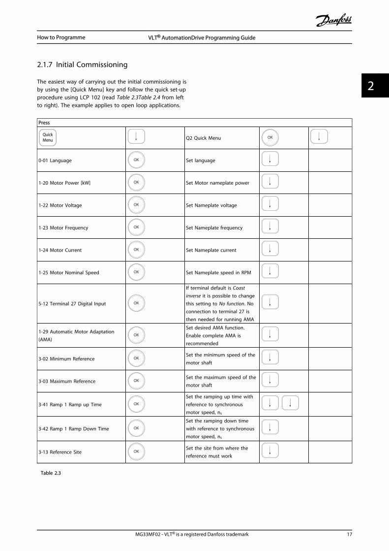
2.1.7 Initial Commissioning
The easiest way of carrying out the initial commissioning isby using the [Quick Menu] key and follow the quick set-upprocedure using LCP 102 (read Table 2.3Table 2.4 from leftto right). The example applies to open loop applications.
Press
QuickMenu Q2 Quick Menu OK
0-01 Language OK Set language
1-20 Motor Power [kW] OK Set Motor nameplate power
1-22 Motor Voltage OK Set Nameplate voltage
1-23 Motor Frequency OK Set Nameplate frequency
1-24 Motor Current OK Set Nameplate current
1-25 Motor Nominal Speed OK Set Nameplate speed in RPM
5-12 Terminal 27 Digital Input OK
If terminal default is Coastinverse it is possible to changethis setting to No function. Noconnection to terminal 27 isthen needed for running AMA
1-29 Automatic Motor Adaptation(AMA)
OK
Set desired AMA function.Enable complete AMA isrecommended
3-02 Minimum Reference OKSet the minimum speed of themotor shaft
3-03 Maximum Reference OKSet the maximum speed of themotor shaft
3-41 Ramp 1 Ramp up Time OK
Set the ramping up time withreference to synchronousmotor speed, ns
3-42 Ramp 1 Ramp Down Time OK
Set the ramping down timewith reference to synchronousmotor speed, ns
3-13 Reference Site OKSet the site from where thereference must work
Table 2.3
How to Programme VLT® AutomationDrive Programming Guide
MG33MF02 - VLT® is a registered Danfoss trademark 17
2 2

Another easy way of commissioning the drive is by usingthe Smart Application Setup (SAS), which can also befound under the Quick Menu. Follow the indications onthe successive screens for setting-up the applicationslisted.
[Info] can be used throughout the SAS to see helpinformation for various selections, settings, and messages.The following three applications are included:
• Mechanical Brake
• Conveyor
• Pump/Fan
The following four field-busses can be selected:
• Profibus
• Profinet
• DeviceNet
• EthernetIP
NOTEThe start conditions will be ignored while in the wizard.
NOTEThe Smart Setup runs automatically on the first power-upof the frequency converter or after a reset to factorysettings. If no action is taken, the SAS screen will automat-ically disappear after 10 min.
2.1.8 Main Menu Mode
Start the Main Menu mode by pressing [Main Menu]. Theread-out shown below appears on the display.The middle and bottom sections on the display show a listof parameter groups which can be chosen by toggling []and [] keys.
130B
P066
.10
1107 RPM
0 - ** Operation/Display
1 - ** Load/Motor
2 - ** Brakes
3 - ** Reference / Ramps
3.84 A 1 (1)
Main menu
Illustration 2.14
Each parameter has a name and number which remain thesame regardless of the programming mode. In the MainMenu mode, the parameters are divided into groups. Thefirst digit of the parameter number (from the left) indicatesthe parameter group number.
All parameters can be changed in the Main Menu.However, depending on the choice of configuration(1-00 Configuration Mode), some parameters can be"missing". E.g. open loop hides all the PID parameters, andother enabled options make more parameter groupsvisible.
2.1.9 Parameter Selection
In the Main menu mode, the parameters are divided intogroups. Select a parameter group with the navigation keys.The following parameter groups are accessible:
Group no. Parameter group0-** Operation/Display
1-** Load/Motor
2-** Brakes
3-** References/Ramps
4-** Limits/Warnings
5-** Digital In/Out
6-** Analog In/Out
7-** Controls
8-** Comm. and Options
9-** Profibus
10-** CAN Fieldbus
11-** Reserved Com. 1
12-** Reserved Com. 2
13-** Smart Logic
14-** Special Functions
15-** Drive Information
16-** Data Readouts
17-** Motor Feedb. Option
18-** Data Readouts 2
30-** Special Features
32-** MCO Basic Settings
33-** MCO Adv. Settings
34-** MCO Data Readouts
Table 2.4
After selecting a parameter group, choose a parameter bymeans of the navigation keys.The middle section on the display shows the parameternumber and name as well as the selected parameter value.
130B
P067
.10
740RPM
0 -01 Language
[0] English
10.64A 1 [1]0-0*Basic Settings
Illustration 2.15
How to Programme VLT® AutomationDrive Programming Guide
18 MG33MF02 - VLT® is a registered Danfoss trademark
22

2.1.10 Changing Data
The procedure for changing data is the same in the Quickmenu and the Main menu mode. Press [OK] to change theselected parameter.The procedure for changing data depends on whether theselected parameter represents a numerical data value or atext value.
2.1.11 Changing a Text Value
If the selected parameter is a text value, change the textvalue with the [] [] keys.Place the cursor on the value to save and press [OK].
130B
P068
.10
740RPM
0 -01 Language
[0] English
10.64 A 1 [1]0-0*Basic Settings
Illustration 2.16
2.1.12 Changing
If the chosen parameter represents a numeric data value,change the chosen data value by means of the [] []navigation keys as well as the [] [] navigation keys. Press[] [] keys to move the cursor horizontally.
130B
P069
.10
1- 6*
113 RPM 1.78 A 1(1)
Load depen. setting
1 - 60 Low speed load
compensation
100%
Illustration 2.17
Press [] [] keys to change the data value. [] increasesthe data value, and [] decreases the data value. Place thecursor on the value to save and press [OK].
130B
P070
.10
1 - 60 Low speed load compensation
1 0%
Load depen. setting 1- 6*
729RPM 6.21A 1(1)
6
Illustration 2.18
2.1.13 Infinitely Variable Change ofNumeric Data Value
If the chosen parameter represents a numeric data value,select a digit with [] [].
130B
P073
.10
635 RPM
1 - 71 Start Delay
00.0s
0.44 A 1 (1)1- 7*Start Adjustments
Illustration 2.19
Change the selected digit infinitely variably with [] [].The chosen digit is indicated by the cursor. Place thecursor on the digit to save and press [OK].
130B
P072
.10
957RPM
1-71 High starting torque time
0. s
11.58A 1 (1)
1-7*Start Adjustments
4
Illustration 2.20
2.1.14 Value, Step-by-Step
Certain parameters can be changed step by step orinfinitely varying. This applies to 1-20 Motor Power [kW],1-22 Motor Voltage and 1-23 Motor Frequency.The parameters are changed both as a group of numericdata values and as numeric data values infinitely varying.
How to Programme VLT® AutomationDrive Programming Guide
MG33MF02 - VLT® is a registered Danfoss trademark 19
2 2

2.1.15 Read-out and Programming ofIndexed Parameters
Parameters are indexed when placed in a rolling stack.15-30 Fault Log: Error Code to 15-32 Alarm Log: Time containa fault log which can be read out. Choose a parameter,press [OK], and use [] [] to scroll through the value log.
Use 3-10 Preset Reference as another example:Choose the parameter, press [OK], and use [] [] to scrollthrough the indexed values. To change the parametervalue, select the indexed value and press [OK]. Change thevalue by pressing [] []. Press [OK] to accept the newsetting. Press [Cancel] to abort. Press [Back] to leave theparameter.
The following instructions are valid for the Numerical LCP(LCP 101).The control panel is divided into four functional groups:
1. Numerical display.
2. Menu keys and indicator lights - changingparameters and switching between displayfunctions.
3. Navigation keys and indicator lights (LEDs).
4. Operation keys and indicator lights (LEDs).
Display line: Status messages displaying icons and numericvalue.
Indicator lights (LEDs)
• Green LED/On: Indicates if control section is on.
• Yellow LED/Wrn.: Indicates a warning.
• Flashing red LED/Alarm: Indicates an alarm.
LCP keys[Menu] Select one of the following modes:
• Status
• Quick Setup
• Main Menu
130B
A19
1.10
1
Auto on
ResetHand on
O
Menu
Status QuickSetup
MainMenu
Back
2
3
4
OKOn
Alarm
Warn.
Setup
Illustration 2.21
Status ModeDisplays the status of the frequency converter or themotor.If an alarm occurs the NLCP automatically switches tostatus mode.A number of alarms can be displayed.
NOTEParameter copy is not possible with LCP 101 NumericalLocal Control Panel.
130B
P077
.10
22.8 rpm
Setup 1
Illustration 2.22
How to Programme VLT® AutomationDrive Programming Guide
20 MG33MF02 - VLT® is a registered Danfoss trademark
22

Setup 1
130B
P078
.10
A 17Illustration 2.23
Main Menu/Quick Setup is used for programming allparameters or only the parameters in the Quick Menu (seealso description of the LCP 102 earlier in ).The parameter values can be changed by pressing [] or[] when the value is flashing.Select Main Menu by pressing [Menu] a number of times.Select the parameter group [xx-__] and press [OK]Select the parameter [__-xx] and press [OK]If the parameter is an array parameter select the arraynumber and press [OK]Select the wanted data value and press [OK]Parameters with functional choices display values such as[1], [2], etc. For a description of the different choices, seethe individual description of the parameters in 3 ParameterDescriptions
[Back] for stepping backwards[] [] are used for manoeuvring between commands andwithin parameters.
130B
P079
.10
MenuStatus Quick
SetupMainMenu
P 2-03 Setup 1
Illustration 2.24
2.1.16 Local Control Keys
Keys for local control are found at the bottom of the LCP.
130B
P046
.10
Handon O Auto
on Reset
Illustration 2.25
[Hand On] enables control of the frequency converter viathe LCP. [Hand On] also starts the motor and it is now
possible to enter the motor speed data by means of thearrow keys. The key can be selected as [1] Enable or [0]Disable via 0-40 [Hand on] Key on LCP.External stop signals activated by means of control signalsor a serial bus will override a 'start' command via the LCP.The following control signals are still active when [HandOn] is activated:
• [Hand On] - [Off] - [Auto On]
• Reset
• Coasting stop inverse
• Reversing
• Set-up select lsb - Set-up select msb
• Stop command from serial communication
• Quick stop
• DC brake
[Off] stops the connected motor. The key can be selectedas [1] Enable or [0] Disable via 0-41 [Off] Key on LCP.If no external stop function is selected and the [Off] key isinactive the motor can be stopped by disconnecting thevoltage.
[Auto On] enables the frequency converter to becontrolled via the control terminals and/or serial communi-cation. When a start signal is applied on the controlterminals and/or the bus, the frequency converter willstart. The key can be selected as [1] Enable or [0] Disablevia 0-42 [Auto on] Key on LCP.
NOTEAn active HAND-OFF-AUTO signal via the digital inputs hashigher priority than the control keys [Hand On] [Auto On].
[Reset] is used for resetting the frequency converter afteran alarm (trip). It can be selected as [1] Enable or [0]Disable via 0-43 [Reset] Key on LCP.
2.1.17 Initialisation to Default Settings
Initialise the frequency converter to default settings in twoways.
Recommended initialisation (via 14-22 Operation Mode)
1. Select 14-22 Operation Mode
2. Press [OK]
3. Select “Initialisation”
4. Press [OK]
5. Cut off the mains supply and wait until thedisplay turns off.
How to Programme VLT® AutomationDrive Programming Guide
MG33MF02 - VLT® is a registered Danfoss trademark 21
2 2

6. Reconnect the mains supply - the frequencyconverter is now reset.
14-22 Operation Mode initialises all except:14-50 RFI Filter
8-30 Protocol
8-31 Address
8-32 FC Port Baud Rate
8-35 Minimum Response Delay
8-36 Max Response Delay
8-37 Max Inter-Char Delay
15-00 Operating Hours to 15-05 Over Volt's
15-20 Historic Log: Event to 15-22 Historic Log:Time
15-30 Fault Log: Error Code to 15-32 Alarm Log:Time
Manual initialisation
1. Disconnect from mains and wait until the displayturns off.
2. 2a Press [Status] - [Main Menu] - [OK] atthe same time while power up for LCP102, Graphical Display
2b Press [Menu] while power up for LCP101, Numerical Display
3. Release the keys after 5 s.
4. The frequency converter is now programmedaccording to default settings.
This procedure initialises all except:15-00 Operating Hours
15-03 Power Up's
15-04 Over Temp's
15-05 Over Volt's
NOTEA manual initialisation also resets serial communication, RFIfilter settings (14-50 RFI Filter) and fault log settings.
How to Programme VLT® AutomationDrive Programming Guide
22 MG33MF02 - VLT® is a registered Danfoss trademark
22

3 Parameter Descriptions
3.1 Parameter Selection
Parameters for FC 300 are grouped into various parametergroups for easy selection of the correct parameters foroptimized operation of the frequency converter.0-** Operation and Display parameters
• Basic Settings, set-up handling
• Display and Local Control Panel parameters forchoosing readouts, setting up selections andcopying functions
1-** Load and Motor parameters includes all load andmotor related parameters
2-** Brake parameters
• DC brake
• Dynamic brake (Resistor brake)
• Mechanical brake
• Over Voltage Control
3-** References and ramping parameters includes DigiPotfunction
4-** Limits Warnings; setting of limits and warningparameters
5-** Digital inputs and outputs includes relay controls
6-** Analog inputs and outputs
7-** Controls; Setting parameters for speed and processcontrols
8-** Communication and option parameters for setting ofFC RS485 and FC USB port parameters.
9-** Profibus parameters
10-** DeviceNet and CAN Fieldbus parameters
12-** Ethernet parameters
13-** Smart Logic Control parameters
14-** Special function parameters
15-** Drive information parameters
16-** Readout parameters
17-** Encoder Option parameters
18-** Readout 2 parameters
30-** Special Features
32-** MCO Basic Settings parameters
33-** MCO Adv. Settings parameters
34-** MCO Data Readouts
35-** Sensor Input Option parameters
Too see if a parameter can be used in a specific controlmode, use the table in 4.1.2 Active/Inactive Parameters inDifferent Drive Control Modes.
Parameter Descriptions VLT® AutomationDrive Programming Guide
MG33MF02 - VLT® is a registered Danfoss trademark 23
3 3

3.2 Parameters: 0-** Operation and Display
Parameters related to the fundamental functions of thefrequency converter, function of the LCP keys and configu-ration of the LCP display.
3.2.1 0-0* Basic Settings
0-01 Language
Option: Function:
Defines the language to be used in thedisplay. The frequency converter can bedelivered with 4 different languagepackages. English and German areincluded in all packages. English cannotbe erased or manipulated.
[0] * English Part of Language packages 1 - 4
[1] Deutsch Part of Language packages 1 - 4
[2] Francais Part of Language package 1
[3] Dansk Part of Language package 1
[4] Spanish Part of Language package 1
[5] Italiano Part of Language package 1
[6] Svenska Part of Language package 1
[7] Nederlands Part of Language package 1
[10] Chinese Part of Language package 2
[20] Suomi Part of Language package 1
[22] English US Part of Language package 4
[27] Greek Part of Language package 4
[28] Bras.port Part of Language package 4
[36] Slovenian Part of Language package 3
[39] Korean Part of Language package 2
[40] Japanese Part of Language package 2
[41] Turkish Part of Language package 4
[42] Trad.Chinese Part of Language package 2
[43] Bulgarian Part of Language package 3
[44] Srpski Part of Language package 3
[45] Romanian Part of Language package 3
[46] Magyar Part of Language package 3
[47] Czech Part of Language package 3
[48] Polski Part of Language package 4
[49] Russian Part of Language package 3
[50] Thai Part of Language package 2
0-01 Language
Option: Function:
[51] Bahasa Indonesia Part of Language package 2
[52] Hrvatski Part of Language package 3
0-02 Motor Speed Unit
Option: Function:
The display showing depends on settings in 0-02 Motor Speed Unit and 0-03 Regional Settings. Thedefault setting of 0-02 Motor Speed Unit and0-03 Regional Settings depends on which region ofthe world the frequency converter is supplied to, butcan be re-programmed as required.
NOTEChanging the Motor Speed Unit will reset certainparameters to their initial value. It isrecommended to select the motor speed unitfirst, before modifying other parameters.
[0] RPM Selects display of motor speed variables andparameters (i.e. references, feedbacks and limits) interms of motor speed (RPM).
[1] * Hz Selects display of motor speed variables andparameters (i.e. references, feedbacks and limits) interms of output frequency to the motor (Hz).
NOTEThis parameter cannot be adjusted while the motor isrunning.
0-03 Regional Settings
Option: Function:
[0] * Interna-tional
Activates 1-20 Motor Power [kW] for settingthe motor power in kW and sets the defaultvalue of 1-23 Motor Frequency to 50Hz.
[1] US Activates 1-20 Motor Power [kW] for settingthe motor power in HP and sets the defaultvalue of 1-23 Motor Frequency to 60Hz.
NOTEThis parameter cannot be adjusted while the motor isrunning.
0-04 Operating State at Power-up (Hand)
Option: Function:
Selects the operating mode uponreconnection of the frequency converter tomains voltage after power down in Hand(local) operation mode.
[0] Resume Restarts the frequency converter, maintainingthe same and the same start/stop settings
Parameter Descriptions VLT® AutomationDrive Programming Guide
24 MG33MF02 - VLT® is a registered Danfoss trademark
33

0-04 Operating State at Power-up (Hand)
Option: Function:(applied by [Hand On/Off]) as before thefrequency converter was powered down.
[1] * Forced stop,ref=old
Restarts the frequency converter with asaved local reference, after mains voltagereappears and after pressing [Hand On].
[2] Forced stop,ref=0
Resets the local reference to 0 uponrestarting the frequency converter.
3.2.2 0-1* Set-up Operations
Define and control the individual parameter setups.The frequency converter has four parameter setups thatcan be programmed independently of each other. Thismakes the frequency converter very flexible and able tosolve advanced control functionality problems, oftensaving the cost of external control equipment. For examplethese can be used to program the frequency converter tooperate according to one control scheme in one setup(e.g. motor 1 for horizontal movement) and anothercontrol scheme in another setup (e.g. motor 2 for verticalmovement). Alternatively they can be used by an OEMmachine builder to identically program all their factoryfitted frequency converters for different machine typeswithin a range to have the same parameters and thenduring production/commissioning simply select a specificsetup depending on which machine the frequencyconverter is installed on.The active setup (i.e. the setup in which the frequencyconverter is currently operating) can be selected in 0-10 Active Set-up and is displayed in the LCP. Using Multiset-up it is possible to switch between setups with thefrequency converter running or stopped, via digital inputor serial communication commands. If it is necessary tochange setups whilst running, ensure 0-12 This Set-upLinked to is programmed as required. Using 0-11 Edit Set-upit is possible to edit parameters within any of the setupswhilst continuing the frequency converter operation in itsActive Setup which can be a different setup to that beingedited. Using 0-51 Set-up Copy it is possible to copyparameter settings between the setups to enable quickercommissioning if similar parameter settings are required indifferent setups.
0-10 Active Set-up
Option: Function:
Select the set-up to control the frequencyconverter functions.
[0] Factory setup Cannot be changed. It contains the Danfossdata set, and can be used as a data sourcewhen returning the other set-ups to aknown state.
0-10 Active Set-up
Option: Function:
[1] * Set-up 1 [1] Set-up 1 to [4] Set-up 4 are the fourseparate parameter set-ups within which allparameters can be programmed.
[2] Set-up 2
[3] Set-up 3
[4] Set-up 4
[9] Multi Set-up Remote selection of set-ups using digitalinputs and the serial communication port.This set-up uses the settings from 0-12 ThisSet-up Linked to. Stop the frequencyconverter before making changes to open-and closed loop functions
Use 0-51 Set-up Copy to copy a set-up to one or all otherset-ups. Stop the frequency converter before switchingbetween set-ups where parameters marked ‘notchangeable during operation’ have different values. Toavoid conflicting settings of the same parameter withintwo different set-ups, link the set-ups together using 0-12 This Set-up Linked to. Parameters which are ‘notchangeable during operation’ are marked FALSE in theparameter lists in 4 Parameter Lists.
0-11 Edit Set-up
Option: Function:
Select the set-up to be edited (i.e.programmed) during operation; either theactive set-up or one of the inactive set-ups.
[0] Factory setup Cannot be edited but it is useful as a datasource to return the other set-ups to aknown state.
[1] * Set-up 1 [1] Set-up 1 to [4] Set-up 4 can be editedfreely during operation, independently ofthe active set-up.
[2] Set-up 2
[3] Set-up 3
[4] Set-up 4
[9] Active Set-up Can also be edited during operation. Editthe chosen set-up from a range of sources:LCP, FC RS-485, FC USB or up to five fieldbussites.
Parameter Descriptions VLT® AutomationDrive Programming Guide
MG33MF02 - VLT® is a registered Danfoss trademark 25
3 3

130B
A19
9.10
1
2
3
4
1
2
3
4
1
2
3
4
1
2
3
4
P 0-11
P 0-11
P 0-11
P 0-11
Set-up
Set-up
Set-up
Set-up
PLC Fieldbus
Illustration 3.1
0-12 This Set-up Linked to
Option: Function:
To enable conflict-free changes from one set-upto another during operation, link set-upscontaining parameters which are notchangeable during operation. The link willensure synchronising of the ‘not changeableduring operation’ parameter values whenmoving from one set-up to another duringoperation. ‘Not changeable during operation’parameters can be identified by the label FALSEin the parameter lists in the section ParameterLists.
0-12 This Set-up Linked to is used by Multi set-up in 0-10 Active Set-up. Multi set-up is used tomove from one set-up to another duringoperation (i.e. while the motor is running).Example:Use Multi set-up to shift from Set-up 1 to Set-up 2 whilst the motor is running. Programme inSet-up 1 first, then ensure that Set-up 1 and
0-12 This Set-up Linked to
Option: Function:Set-up 2 are synchronised (or ‘linked’). Synchro-nisation can be performed in two ways:1. Change the edit set-up to Set-up 2 [2] in 0-11 Edit Set-up and set 0-12 This Set-up Linkedto to Set-up 1 [1]. This will start the linking(synchronising) process.
130B
P075
.10
0-12 This Set-up Linked to
0 RPM 0.00A 1(1)Set-up Handling 0-1*
[1] Setup 1
Illustration 3.2
OR
2. While still in Set-up 1, copy Set-up 1 to Set-up 2. Then set 0-12 This Set-up Linked to to Set-up 2 [2]. This will start the linking process.
130B
P076
.10
0-12 This Set-up Linked to
0 RPM 0.00A 1(1)Set-up Handling 0-1*
[2] Setup 2
Illustration 3.3
After the link is complete, 0-13 Readout: LinkedSet-ups will read 1,2 to indicate that all ‘notchangeable during operation’ parameters arenow the same in Set-up 1 and Set-up 2. If thereare changes to a ‘not changeable duringoperation’ parameter, e.g. 1-30 Stator Resistance(Rs), in Set-up 2, they will also be changedautomatically in Set-up 1. A switch betweenSet-up 1 and Set-up 2 during operation is nowpossible.
[0] * Not linked
[1] Set-up 1
[2] Set-up 2
[3] Set-up 3
[4] Set-up 4
Parameter Descriptions VLT® AutomationDrive Programming Guide
26 MG33MF02 - VLT® is a registered Danfoss trademark
33
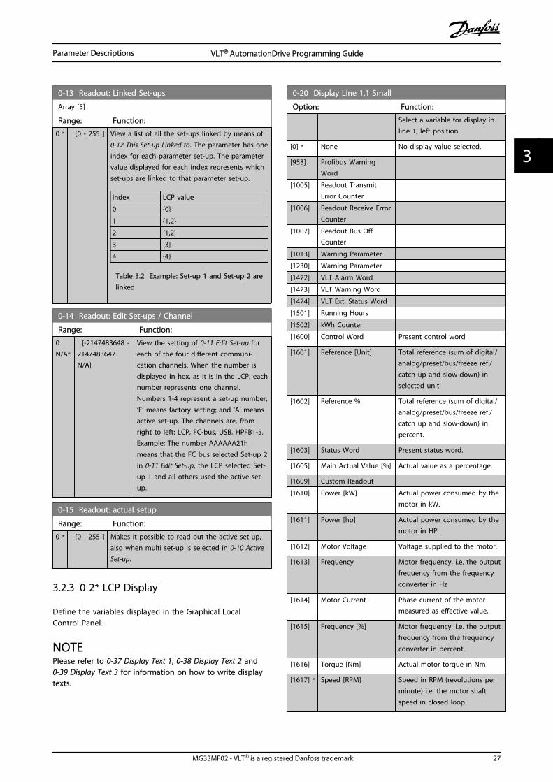
0-13 Readout: Linked Set-ups
Array [5]
Range: Function:
0 * [0 - 255 ] View a list of all the set-ups linked by means of0-12 This Set-up Linked to. The parameter has oneindex for each parameter set-up. The parametervalue displayed for each index represents whichset-ups are linked to that parameter set-up.
Index LCP value
0 0
1 1,2
2 1,2
3 3
4 4
Table 3.2 Example: Set-up 1 and Set-up 2 arelinked
0-14 Readout: Edit Set-ups / Channel
Range: Function:
0N/A*
[-2147483648 -2147483647N/A]
View the setting of 0-11 Edit Set-up foreach of the four different communi-cation channels. When the number isdisplayed in hex, as it is in the LCP, eachnumber represents one channel.Numbers 1-4 represent a set-up number;‘F’ means factory setting; and ‘A’ meansactive set-up. The channels are, fromright to left: LCP, FC-bus, USB, HPFB1-5.Example: The number AAAAAA21hmeans that the FC bus selected Set-up 2in 0-11 Edit Set-up, the LCP selected Set-up 1 and all others used the active set-up.
0-15 Readout: actual setup
Range: Function:
0 * [0 - 255 ] Makes it possible to read out the active set-up,also when multi set-up is selected in 0-10 ActiveSet-up.
3.2.3 0-2* LCP Display
Define the variables displayed in the Graphical LocalControl Panel.
NOTEPlease refer to 0-37 Display Text 1, 0-38 Display Text 2 and0-39 Display Text 3 for information on how to write displaytexts.
0-20 Display Line 1.1 Small
Option: Function:
Select a variable for display inline 1, left position.
[0] * None No display value selected.
[953] Profibus WarningWord
[1005] Readout TransmitError Counter
[1006] Readout Receive ErrorCounter
[1007] Readout Bus OffCounter
[1013] Warning Parameter
[1230] Warning Parameter
[1472] VLT Alarm Word
[1473] VLT Warning Word
[1474] VLT Ext. Status Word
[1501] Running Hours
[1502] kWh Counter
[1600] Control Word Present control word
[1601] Reference [Unit] Total reference (sum of digital/analog/preset/bus/freeze ref./catch up and slow-down) inselected unit.
[1602] Reference % Total reference (sum of digital/analog/preset/bus/freeze ref./catch up and slow-down) inpercent.
[1603] Status Word Present status word.
[1605] Main Actual Value [%] Actual value as a percentage.
[1609] Custom Readout
[1610] Power [kW] Actual power consumed by themotor in kW.
[1611] Power [hp] Actual power consumed by themotor in HP.
[1612] Motor Voltage Voltage supplied to the motor.
[1613] Frequency Motor frequency, i.e. the outputfrequency from the frequencyconverter in Hz
[1614] Motor Current Phase current of the motormeasured as effective value.
[1615] Frequency [%] Motor frequency, i.e. the outputfrequency from the frequencyconverter in percent.
[1616] Torque [Nm] Actual motor torque in Nm
[1617] * Speed [RPM] Speed in RPM (revolutions perminute) i.e. the motor shaftspeed in closed loop.
Parameter Descriptions VLT® AutomationDrive Programming Guide
MG33MF02 - VLT® is a registered Danfoss trademark 27
3 3

0-20 Display Line 1.1 Small
Option: Function:
[1618] Motor Thermal Thermal load on the motor,calculated by the ETR function.
[1619] KTY sensortemperature
[1620] Motor Angle
[1622] Torque [%] Present motor load as apercentage of the rated motortorque.
[1625] Torque [Nm] High
[1630] DC Link Voltage Intermediate circuit voltage inthe frequency converter.
[1632] Brake Energy /s Present brake power transferredto an external brake resistor.Stated as an instantaneousvalue.
[1633] Brake Energy /2 min Brake power transferred to anexternal brake resistor. Themean power is calculatedcontinuously for the mostrecent 120 s.
[1634] Heatsink Temp. Present heat sink temperatureof the frequency converter. The
cut-out limit is 95 ±5 °C; cutting
back in occurs at 70 ±5 °C.
[1635] Inverter Thermal Percentage load of the inverters.
[1636] Inv. Nom. Current Nominal current of thefrequency converter.
[1637] Inv. Max. Current Maximum current of thefrequency converter.
[1638] SL Controller State State of the event executed bythe control.
[1639] Control Card Temp. Temperature of the control card.
[1650] External Reference Sum of the external reference asa percentage, i.e. the sum ofanalog/pulse/bus.
[1651] Pulse Reference Frequency in Hz connected tothe digital inputs (18, 19 or 32,33).
[1652] Feedback [Unit] Reference value fromprogrammed digital input(s).
[1653] Digi Pot Reference
[1660] Digital Input Signal states form the 6 digitalterminals (18, 19, 27, 29, 32 and33). There are 16 bits in total,but only six of them are used.Input 18 corresponds to theleftmost of the used bits. Signallow = 0; Signal high = 1.
0-20 Display Line 1.1 Small
Option: Function:
[1661] Terminal 53 SwitchSetting
Setting of input terminal 54.Current = 0; Voltage = 1.
[1662] Analog Input 53 Actual value at input 53 eitheras a reference or protectionvalue.
[1663] Terminal 54 SwitchSetting
Setting of input terminal 54.Current = 0; Voltage = 1.
[1664] Analog Input 54 Actual value at input 54 eitheras reference or protection value.
[1665] Analog Output 42[mA]
Actual value at output 42 inmA. Use 6-50 Terminal 42 Outputto select the value to be shown.
[1666] Digital Output [bin] Binary value of all digitaloutputs.
[1667] Freq. Input #29 [Hz] Actual value of the frequencyapplied at terminal 29 as animpulse input.
[1668] Freq. Input #33 [Hz] Actual value of the frequencyapplied at terminal 33 as animpulse input.
[1669] Pulse Output #27 [Hz] Actual value of impulses appliedto terminal 27 in digital outputmode.
[1670] Pulse Output #29 [Hz] Actual value of impulses appliedto terminal 29 in digital outputmode.
[1671] Relay Output [bin]
[1672] Counter A Application dependent (e.g. SLCControl)
[1673] Counter B Application dependent (e.g. SLCControl)
[1674] Prec. Stop Counter Display the actual counter value.
[1675] Analog In X30/11 Actual value at input X30/11either as reference or protectionvalue.
[1676] Analog In X30/12 Actual value at input X30/12either as reference or protectionvalue.
[1677] Analog Out X30/8[mA]
Actual value at output X30/8 inmA. Use 6-60 Terminal X30/8Output to select the value to beshown.
[1678] Analog Out X45/1[mA]
[1679] Analog Out X45/3[mA]
[1680] Fieldbus CTW 1 Control word (CTW) receivedfrom the Bus Master.
Parameter Descriptions VLT® AutomationDrive Programming Guide
28 MG33MF02 - VLT® is a registered Danfoss trademark
33

0-20 Display Line 1.1 Small
Option: Function:
[1682] Fieldbus REF 1 Main reference value sent withcontrol word from the BusMaster.
[1684] Comm. Option STW Extended fieldbus communi-cation option status word.
[1685] FC Port CTW 1 Control word (CTW) receivedfrom the Bus Master.
[1686] FC Port REF 1 Status word (STW) sent to theBus Master.
[1690] Alarm Word One or more alarms in a Hexcode.
[1691] Alarm Word 2 One or more alarms in a Hexcode.
[1692] Warning Word One or more warnings in a Hexcode.
[1693] Warning Word 2 One or more warnings in a Hexcode.
[1694] Ext. Status Word One or more status conditionsin a Hex code.
[3401] PCD 1 Write to MCO
[3402] PCD 2 Write to MCO
[3403] PCD 3 Write to MCO
[3404] PCD 4 Write to MCO
[3405] PCD 5 Write to MCO
[3406] PCD 6 Write to MCO
[3407] PCD 7 Write to MCO
[3408] PCD 8 Write to MCO
[3409] PCD 9 Write to MCO
[3410] PCD 10 Write to MCO
[3421] PCD 1 Read fromMCO
[3422] PCD 2 Read fromMCO
[3423] PCD 3 Read fromMCO
[3424] PCD 4 Read fromMCO
[3425] PCD 5 Read fromMCO
[3426] PCD 6 Read fromMCO
[3427] PCD 7 Read fromMCO
[3428] PCD 8 Read fromMCO
[3429] PCD 9 Read fromMCO
[3430] PCD 10 Read fromMCO
[3440] Digital Inputs
0-20 Display Line 1.1 Small
Option: Function:
[3441] Digital Outputs
[3450] Actual Position
[3451] Commanded Position
[3452] Actual Master Position
[3453] Slave Index Position
[3454] Master Index Position
[3455] Curve Position
[3456] Track Error
[3457] Synchronizing Error
[3458] Actual Velocity
[3459] Actual Master Velocity
[3460] Synchronizing Status
[3461] Axis Status
[3462] Program Status
[3470] MCO Alarm Word 1
[3471] MCO Alarm Word 2
[9913] Idle time
[9914] Paramdb requests inqueue
[9920] HS Temp. (PC1)
[9921] HS Temp. (PC2)
[9922] HS Temp. (PC3)
[9923] HS Temp. (PC4)
[9924] HS Temp. (PC5)
[9925] HS Temp. (PC6)
[9926] HS Temp. (PC7)
[9927] HS Temp. (PC8)
0-21 Display Line 1.2 Small
Option: Function:
[0] * None Select a variable for display in line 1, middleposition. The options are the same as listed for 0-20 Display Line 1.1 Small.
0-22 Display Line 1.3 Small
Option: Function:
[30120] * Mains Current[A]
Select a variable for display in line 1,right position. The options are thesame as listed for 0-20 Display Line 1.1Small.
0-23 Display Line 2 Large
Option: Function:
[30100] * Output Current[A]
Select a variable for display in line 2.The options are the same as listed for0-20 Display Line 1.1 Small.
0-24 Display Line 3 Large
Select a variable for display in line 3.
Option: Function:
[30121] * Mains Frequency The options are the same as thoselisted in 0-20 Display Line 1.1 Small.
Parameter Descriptions VLT® AutomationDrive Programming Guide
MG33MF02 - VLT® is a registered Danfoss trademark 29
3 3
0-25 My Personal Menu
Range: Function:
0N/A*
[0 -9999N/A]
Define up to 50 parameters to appear in the Q1Personal Menu, accessible via the [Quick Menu]key on the LCP. The parameters will bedisplayed in the Q1 Personal Menu in the orderthey are programmed into this array parameter.Delete parameters by setting the value to ‘0000’.For example, this can be used to provide quick,simple access to just one or up to 50 parameterswhich require changing on a regular basis (e.g.for plant maintenance reasons) or by an OEM toenable simple commissioning of theirequipment.
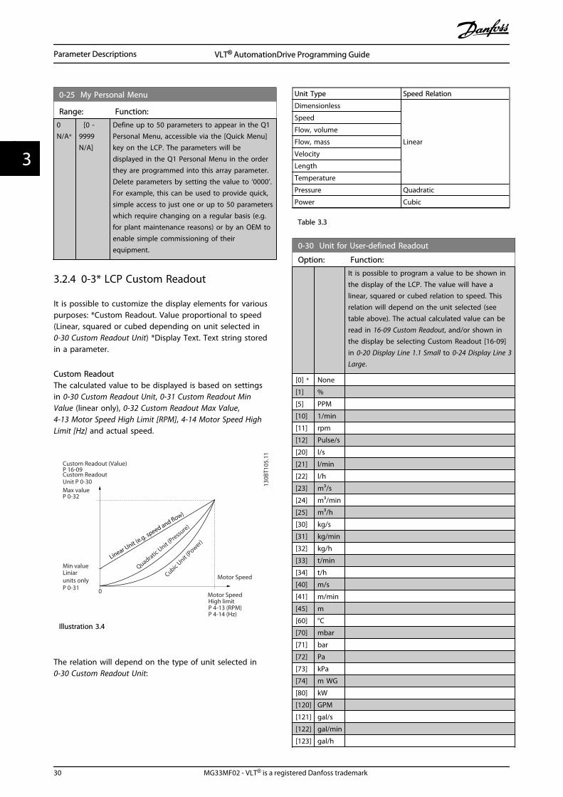
3.2.4 0-3* LCP Custom Readout
It is possible to customize the display elements for variouspurposes: *Custom Readout. Value proportional to speed(Linear, squared or cubed depending on unit selected in0-30 Custom Readout Unit) *Display Text. Text string storedin a parameter.
Custom ReadoutThe calculated value to be displayed is based on settingsin 0-30 Custom Readout Unit, 0-31 Custom Readout MinValue (linear only), 0-32 Custom Readout Max Value,4-13 Motor Speed High Limit [RPM], 4-14 Motor Speed HighLimit [Hz] and actual speed.
130B
T105
.11
0
Custom Readout (Value)P 16-09Custom ReadoutUnit P 0-30Max valueP 0-32
Min value
P 0-31
Motor Speed
Motor SpeedHigh limitP 4-13 (RPM)P 4-14 (Hz)
Quadratic Unit (
Pressure)
Cubic Unit (Power)
Liniarunits only
Linear Unit (e
.g. speed and flow)
Illustration 3.4
The relation will depend on the type of unit selected in0-30 Custom Readout Unit:
Unit Type Speed Relation
Dimensionless
Linear
Speed
Flow, volume
Flow, mass
Velocity
Length
Temperature
Pressure Quadratic
Power Cubic
Table 3.3
0-30 Unit for User-defined Readout
Option: Function:
It is possible to program a value to be shown inthe display of the LCP. The value will have alinear, squared or cubed relation to speed. Thisrelation will depend on the unit selected (seetable above). The actual calculated value can beread in 16-09 Custom Readout, and/or shown inthe display be selecting Custom Readout [16-09]in 0-20 Display Line 1.1 Small to 0-24 Display Line 3Large.
[0] * None
[1] %
[5] PPM
[10] 1/min
[11] rpm
[12] Pulse/s
[20] l/s
[21] l/min
[22] l/h
[23] m³/s
[24] m³/min
[25] m³/h
[30] kg/s
[31] kg/min
[32] kg/h
[33] t/min
[34] t/h
[40] m/s
[41] m/min
[45] m
[60] °C
[70] mbar
[71] bar
[72] Pa
[73] kPa
[74] m WG
[80] kW
[120] GPM
[121] gal/s
[122] gal/min
[123] gal/h
Parameter Descriptions VLT® AutomationDrive Programming Guide
30 MG33MF02 - VLT® is a registered Danfoss trademark
33

0-30 Unit for User-defined Readout
Option: Function:
[124] CFM
[125] ft³/s
[126] ft³/min
[127] ft³/h
[130] lb/s
[131] lb/min
[132] lb/h
[140] ft/s
[141] ft/min
[145] ft
[160] °F
[170] psi
[171] lb/in²
[172] in WG
[173] ft WG
[180] HP
0-31 Min Value of User-defined Readout
Range: Function:
0.00 Custom-ReadoutUnit*
[-999999.99 -par. 0-32CustomRea-doutUnit]
This parameter sets themin. value of the customdefined readout (occurs atzero speed). Only possibleto set different from 0 iswhen selecting a linear unitin 0-30 Unit for User-definedReadout. For Quadratic andCubic units the minimumvalue will be 0.
0-32 Custom Readout Max Value
Range: Function:
100.00 Custom-ReadoutUnit*
[ par. 0-31 -999999.99CustomRea-doutUnit]
This parameter sets the maxvalue to be shown whenthe speed of the motor hasreached the set value for4-13 Motor Speed High Limit[RPM] or 4-14 Motor SpeedHigh Limit [Hz] (depends onsetting in 0-02 Motor SpeedUnit).
0-37 Display Text 1
Range: Function:
0 * [0 - 0 ] Enter a text which can be viewed in the graphicaldisplay by selecting Display Text 1 [37] in 0-20 Display Line 1.1 Small, 0-21 Display Line 1.2Small, 0-22 Display Line 1.3 Small, 0-23 Display Line 2Large or 0-24 Display Line 3 Large.
0-38 Display Text 2
Range: Function:
0 * [0 - 0 ] Enter a text which can be viewed in the graphicaldisplay by selecting Display Text 2 [38] in 0-20 Display Line 1.1 Small, 0-21 Display Line 1.2Small, 0-22 Display Line 1.3 Small, 0-23 Display Line 2Large or 0-24 Display Line 3 Large.
0-39 Display Text 3
Range: Function:
0 * [0 - 0 ] Enter a text which can be viewed in the graphicaldisplay by selecting Display Text 3 [39] in 0-20 Display Line 1.1 Small, 0-21 Display Line 1.2Small, 0-22 Display Line 1.3 Small, 0-23 Display Line 2Large or 0-24 Display Line 3 Large.
3.2.5 0-4* LCP Keypad
Enable, disable and password protect individual keys onthe LCP.
0-40 [Hand on] Key on LCP
Option: Function:
[0] * Disabled No effect when [Hand On] is pressed. Select [0]Disabled to avoid accidental start of thefrequency converter in Hand on mode.
[1] * Enabled The LCP switches to Hand on mode directlywhen [Hand on] is pressed.
[2] Password After pressing [Hand on] a password is required.If 0-40 [Hand on] Key on LCP is in included in MyPersonal Menu, define the password in 0-65 QuickMenu Password. Otherwise define the passwordin 0-60 Main Menu Password.
0-41 [Off] Key on LCP
Option: Function:
[0] * Disabled Avoids accidental stop of the frequencyconverter.
[1] * Enabled
[2] Password Avoids unauthorised stop. If 0-41 [Off] Key on LCPis included in the Quick Menu, then define thepassword in 0-65 Quick Menu Password.
0-42 [Auto on] Key on LCP
Option: Function:
[0] * Disabled Avoid accidental start of the frequency converterin Auto mode.
[1] * Enabled
[2] Password Avoids unauthorised start in Auto mode. If 0-42 [Auto on] Key on LCP is included in theQuick Menu, then define the password in 0-65 Quick Menu Password.
Parameter Descriptions VLT® AutomationDrive Programming Guide
MG33MF02 - VLT® is a registered Danfoss trademark 31
3 3

0-43 [Reset] Key on LCP
Option: Function:
[0] * Disabled No effect when [Reset] is pressed. Avoidsaccidental alarm reset.
[1] * Enabled
[2] Password Avoids unauthorised resetting. If 0-43 [Reset] Keyon LCP is included in the Quick Menu, thendefine the password in 0-65 Quick MenuPassword.
3.2.6 0-5* Copy/Save
Copy parameter settings between set-ups and to/from theLCP.
0-50 LCP Copy
Option: Function:
[0] * No copy
[1] All to LCP Copies all parameters in all set-ups fromthe frequency converter memory to theLCP memory.
[2] All from LCP Copies all parameters in all set-ups fromthe LCP memory to the frequencyconverter memory.
[3] Size indep. fromLCP
Copy only the parameters that areindependent of the motor size. The latterselection can be used to programmeseveral frequency converters with thesame function without disturbing motordata.
[4] File from MCOto LCP
[5] File from LCP toMCO
NOTEThis parameter cannot be adjusted while the motor isrunning.
0-51 Set-up Copy
Option: Function:
[0] * No copy No function
[1] Copy to set-up 1
Copies all parameters in the presentProgramming Set-up (defined in0-11 Programming Set-up) to Set-up 1.
[2] Copy to set-up 2
Copies all parameters in the presentProgramming Set-up (defined in0-11 Programming Set-up) to Set-up 2.
[3] Copy to set-up 3
Copies all parameters in the presentProgramming Set-up (defined in0-11 Programming Set-up) to Set-up 3.
0-51 Set-up Copy
Option: Function:
[4] Copy to set-up 4
Copies all parameters in the presentProgramming Set-up (defined in0-11 Programming Set-up) to Set-up 4.
[9] Copy to all Copies the parameters in the present set-upover to each of the set-ups 1 to 4.
3.2.7 0-6* Password
0-60 Main Menu Password
Range: Function:
100 * [0 - 999 ] Define the password for access to the MainMenu via the [Main Menu] key. If 0-61 Accessto Main Menu w/o Password is set to [0] Fullaccess, this parameter will be ignored.
0-61 Access to Main Menu w/o Password
Option: Function:
[0] * Full access Disables password defined in 0-60 MainMenu Password.
[1] LCP: Read only Prevent unauthorized editing of Main Menuparameters.
[2] LCP: No access Prevent unauthorized viewing and editingof Main Menu parameters.
[3] Bus: Read only Read-only functions for parameters onFieldbus and/or FC standard bus.
[4] Bus: No access No access to parameters is allowed viaFieldbus and/or FC standard bus.
[5] All: Read only Read-only function for parameters on LCP,Fieldbus or FC standard bus.
[6] All: No access No access from LCP, Fieldbus or FCstandard bus is allowed.
If Full access [0] is selected then 0-60 Main Menu Password,0-65 Personal Menu Password and 0-66 Access to PersonalMenu w/o Password will be ignored.
NOTEA more complex Password protection is available for OEMsupon request.
0-65 Quick Menu Password
Range: Function:
200 N/A* [-9999 -9999 N/A]
Define the password for access to theQuick Menu via the [Quick Menu] key.If 0-66 Access to Quick Menu w/oPassword is set to [0] Full access, thisparameter will be ignored.
Parameter Descriptions VLT® AutomationDrive Programming Guide
32 MG33MF02 - VLT® is a registered Danfoss trademark
33

0-66 Access to Quick Menu w/o Password
Option: Function:
[0] * Full access Disables the password defined in 0-65 Quick Menu Password.
[1] LCP: Read only Prevents unauthorised editing of QuickMenu parameters.
[2] LCP: No access Prevents unauthorised viewing and editingof Quick Menu parameters.
[3] Bus: Read only Read only functions for Quick Menuparameters on Fieldbus and/ or FCstandard bus.
[4] Bus: No access No access to Quick Menu parameters isallowed via Fieldbus and/ or FC standardbus.
[5] All: Read only read only function for Quick Menuparameters on LCP, Fieldbus or FC standardbus.
[6] All: No access No access from LCP, Fieldbus or FCstandard bus is allowed.
If 0-61 Access to Main Menu w/o Password is set to [0] Fullaccess then this parameter will be ignored.
0-67 Bus Password Access
Range: Function:
0 N/A* [0 - 9999 N/A] Writing to this parameter enables usersto unlock the frequency converter frombus/MCT 10 Set-up Software.
Parameter Descriptions VLT® AutomationDrive Programming Guide
MG33MF02 - VLT® is a registered Danfoss trademark 33
3 3

3.3 Parameters: 1-** Load and Motor
3.3.1 1-0* General Settings
Define whether the frequency converter operates in speedmode or torque mode; and whether the internal PIDcontrol should be active or not.
1-00 Configuration Mode
Option: Function:
Select the application control principle to beused when a Remote Reference (i.e. via analoginput or fieldbus) is active. A Remote Referencecan only be active when 3-13 Reference Site isset to [0] or [1].
[0] * Speedopenloop
Enables speed control (without feedback signalfrom motor) with automatic slip compensationfor almost constant speed at varying loads.Compensations are active but can be disabledin the Load/Motor parameter group 1-0*. Thespeed control parameters are set in parametergroup 7-0*.
[1] Speedclosedloop
Enables Speed closed loop control with feed-back. Obtain full holding torque at 0 RPM.For increased speed accuracy, provide afeedback signal and set the speed PID control.The speed control parameters are set inparameter group 7-0*.
[2] Torque Enables torque closed loop control with feed-back. Only possible with “Flux with motorfeedback” option, 1-01 Motor Control Principle.FC 302 only.
[3] Process Enables the use of process control in thefrequency converter. The process controlparameters are set in parameter groups 7-2*and 7-3*.
[4] Torqueopenloop
Enables the use of torque open loop in VVC+
mode (1-01 Motor Control Principle). The torquePID parameters are set in parameter group 7-1*.
1-01 Motor Control Principle
Option: Function:
Select which motor control principle toemploy.
[0] * U/f special motor mode, for parallel connectedmotors in special motor applications. WhenU/f is selected the characteristic of thecontrol principle can be edited in 1-55 U/fCharacteristic - U and 1-56 U/f Characteristic -F.
[1] * VVC+ Voltage Vector Control principle suitable formost applications. The main benefit of
VVCplus operation is that it uses a robustmotor model.
1-01 Motor Control Principle
Option: Function:
[2] Fluxsensorless
Flux Vector control without encoderfeedback, for simple installation androbustness against sudden load changes. FC302 only.
[3] Flux w/motor feedb
very high accuracy speed and torquecontrol, suitable for the most demandingapplications. FC 302 only.
The best shaft performance is normally achieved usingeither of the two Flux Vector control modes [2] Fluxsensorless and [3] Flux with encoder feedback.
NOTEThis parameter cannot be adjusted while the motor isrunning.
NOTEAn overview of possible combinations of the settings in 1-00 Configuration Mode and 1-01 Motor Control Principlecan be found in 4.1.2 Active/Inactive Parameters in DifferentDrive Control Modes.
1-02 Flux Motor Feedback Source
Option: Function:
Select the interface at which to receivefeedback from the motor.
[0] Motor feedb. P1-02
[1] * 24V encoder A and B channel encoder, which canbe connected to the digital inputterminals 32/33 only. Terminals 32/33must be programmed to No operation.
[2] MCB 102 Encoder module option which can beconfigured in parameter group 17-1*FC 302 only.
[3] MCB 103 Optional resolver interface modulewhich can be configured in parametergroup 17-5*
[5] MCO Encoder 2 encoder interface 2 of the optionalprogrammable motion controller MCO305.
[6] Analog input 53
[7] Analog input 54
[8] Frequency input29
[9] Frequency input33
NOTEThis parameter cannot be adjusted while the motor isrunning.
Parameter Descriptions VLT® AutomationDrive Programming Guide
34 MG33MF02 - VLT® is a registered Danfoss trademark
33

1-03 Torque Characteristics
Option: Function:
Select the torque characteristic required.VT and AEO are both energy savingoperations.
[0] * Constanttorque
Motor shaft output provides constant torqueunder variable speed control.
[1] Variabletorque
Motor shaft output provides variable torqueunder variable speed control. Set thevariable torque level in 14-40 VT Level.
[2] Auto EnergyOptim.
Automatically optimises energy consumptionby minimising magnetisation and frequencyvia 14-41 AEO Minimum Magnetisation and 14-42 Minimum AEO Frequency.
NOTEThis parameter cannot be adjusted while the motor isrunning.
1-04 Overload Mode
Option: Function:
[0] * High torque Allows up to 160% over torque.
[1] Normal torque For oversized motor - allows up to 110%over torque.
NOTEThis parameter cannot be adjusted while the motor isrunning.
1-05 Local Mode Configuration
Option: Function:
Select which application configurationmode (1-00 Configuration Mode), i.e.application control principle, to use when aLocal (LCP) Reference is active. A LocalReference can be active only when 3-13 Reference Site is set to [0] or [2]. Bydefault the local reference is active in HandMode only.
[0] Speed openloop
[1] Speed closedloop
[2] * As mode par1-00
1-06 Clockwise Direction
This parameter defines the term “Clockwise” corresponding tothe LCP direction arrow. Used for easy change of direction ofshaft rotation without swapping motor wires.
Option: Function:
[0] * Normal Motor shaft will turn in clockwisedirection when the frequency
1-06 Clockwise Direction
This parameter defines the term “Clockwise” corresponding tothe LCP direction arrow. Used for easy change of direction ofshaft rotation without swapping motor wires.
Option: Function:
converter is connected U ⇒ U;
V⇒V, and W ⇒ W to motor.
[1] Inverse Motor shaft will turn in counterclockwise direction when thefrequency converter is connected
U⇒U; V⇒V, and W⇒ W to motor.
NOTEThis parameter cannot be adjusted while the motor isrunning.
1-07 Motor Angle Offset Adjust
This parameter will adjust the motor angle offset for an absoluteposition feedback device mounted on the motor.
Option: Function:
[0] Manual The frequency converter will use the motor angleoffset entered in 1-41 Motor Angle Offset.
[1] Auto The frequency converter will automatically adjustthe motor angle offset by running a determinedprocedure.
NOTEThis parameter is only valid when PM motors in Flux withmotor feedback are used and for FC 302 only.
3.3.2 1-1* Special Settings
NOTEThe parameters within this parameter group cannot beadjusted while the motor is running.
1-10 Motor Construction
Option: Function:
Select the motor design type.
[0] * Asynchron For asynchronous motors.
[1] PM, non salientSPM
For salient or non-salient PM motors.PM motors are divided into two groups,with either surface mounted (non salient)or interior (salient) magnets.
Parameter Descriptions VLT® AutomationDrive Programming Guide
MG33MF02 - VLT® is a registered Danfoss trademark 35
3 3

1-11 Motor Model
Automatically sets the manufacturer’s values for the selectedmotor. If the default value [1] is used, settings must to bedetermined manually, according to the choice in 1-10 MotorConstruction.This parameter is FC 302 only.
Option: Function:
[1] Std. Asynchron Default motor model when [0]*Asynchron is selected in 1-10 MotorConstruction. Enter motor parametermanually.
[2] Std. PM, non salient Selectable when [1] PM, non salientSPM is selected in 1-10 MotorConstruction. Enter motor parametermanually.
[10] Danfoss OGD LA10 Selectable when [1] PM, non salientSPM is selected in 1-10 MotorConstruction. Only available for T4, T5in 1.5-3 kW. Settings are loadedautomatically for this specific motor.See table for details.
NOTEThis parameter is FC 302 only.
1-14 Damping Gain
Range: Function:
140%*
[0 -250 %]
The damping gain will stabilize the PM machinein order to run the PM machine smooth andstable. The value of Damping gain will controlthe dynamic performance of the PM machine.High damping gain will give high dynamicperformance and low damping gain will give lowdynamic performance. The dynamic performanceis related to the machine data and load type. Ifthe damping gain is too high or low the controlwill become unstable.
1-15 Low Speed Filter Time Const.
Range: Function:
Size related* [0.01 - 20 s] This time constant is used below10% rated speed. Obtain quickcontrol through a short dampingtime constant. However, if this valueis too short, the control getsunstable.
1-16 High Speed Filter Time Const.
Range: Function:
Size related* [0.01 - 20 s] This time constant is used above10% rated speed. Obtain quickcontrol through a short dampingtime constant. However, if this value
1-16 High Speed Filter Time Const.
Range: Function:is too short, the control getsunstable.
1-17 Voltage filter time const.
Range: Function:
Size related* [0.001 - 1s]
Reduces the influence of highfrequency ripple and systemresonance in the calculation ofsupply voltage. Without this filter, theripples in the currents can distort thecalculated voltage and affect thestability of the system.
3.3.3 1-2* Motor Data
Parameter group 1-2* comprises input data from thenameplate on the connected motor.
NOTEChanging the value of these parameters affects the settingof other parameters.
NOTE1-20 Motor Power [kW], 1-21 Motor Power [HP], 1-22 MotorVoltage and 1-23 Motor Frequency will not have effectwhen 1-10 Motor Construction = [1] PM, non salient SPM.
1-20 Motor Power [kW]
Range: Function:
4.00kW*
[0.09 -3000.00kW]
Enter the nominal motor power in kWaccording to the motor nameplate data.The default value corresponds to thenominal rated output of the unit.This parameter cannot be adjusted whilethe motor is running. This parameter isvisible in LCP if 0-03 Regional Settings is [0]International.
NOTEFour sizes down, one size up fromnominal unit rating.
1-21 Motor Power [HP]
Range: Function:
4.00hp*
[0.09 -3000.00 hp]
Enter the nominal motor power in HPaccording to the motor nameplate data.The default value corresponds to thenominal rated output of the unit. Thisparameter is visible in LCP if 0-03 Regional Settings is [1] US
Parameter Descriptions VLT® AutomationDrive Programming Guide
36 MG33MF02 - VLT® is a registered Danfoss trademark
33

1-22 Motor Voltage
Range: Function:
500. V* [10. - 1000.V]
Enter the nominal motor voltageaccording to the motor nameplate data.The default value corresponds to thenominal rated output of the unit.
1-23 Motor Frequency
Range: Function:
50.Hz*
[20 -1000Hz]
Min - Max motor frequency: 20-1000 Hz.Select the motor frequency value from themotor nameplate data. If a value different from50 Hz or 60 Hz is selected, it is necessary toadapt the load independent settings in 1-50 Motor Magnetisation at Zero Speed to 1-53 Model Shift Frequency. For 87 Hz operationwith 230/400 V motors, set the nameplate datafor 230 V/50 Hz. Adapt 4-13 Motor Speed HighLimit [RPM] and 3-03 Maximum Reference to the87 Hz application.
1-24 Motor Current
Range: Function:
7.20 A* [0.10 - 10000.00A]
Enter the nominal motor currentvalue from the motor nameplatedata. The data are used forcalculating torque, motor protectionetc.
1-25 Motor Nominal Speed
Range: Function:
1420.RPM*
[10 - 60000RPM]
Enter the nominal motor speed valuefrom the motor nameplate data. Thedata are used for calculating motorcompensations. nm,n = ns - nslip.
1-26 Motor Cont. Rated Torque
Range: Function:
0 Nm* [0.1 -10000.0 Nm]
Enter the value from the motor nameplatedata. The default value corresponds to thenominal rated output. This parameter isavailable when 1-10 Motor Construction isset to [1] PM, non salient SPM, i.e. theparameter is valid for PM and non-salientSPM motors only.
1-29 Automatic Motor Adaptation (AMA)
Option: Function:
The AMA function optimises dynamic motorperformance by automatically optimising theadvanced motor parameters (1-30 StatorResistance (Rs) to 1-35 Main Reactance (Xh)) atmotor standstill.
1-29 Automatic Motor Adaptation (AMA)
Option: Function:Activate the AMA function by pressing [Handon] after selecting [1] or [2]. See also thesection Automatic Motor Adaptation in theDesign Guide. After a normal sequence, thedisplay will read: "Press [OK] to finish AMA".After pressing the [OK] key the frequencyconverter is ready for operation.
[0]*
Off
[1] EnablecompleteAMA
Performs AMA of the stator resistance RS, the
rotor resistance Rr, the stator leakage reactance
X1, the rotor leakage reactance X2 and the
main reactance Xh. Do not select this option if
an LC filter is used between the frequencyconverter and the motor.FC 301: The Complete AMA does not includeXh measurement for FC 301. Instead, the Xh
value is determined from the motor database.RS is the best adjustment method (see 1-3*
Adv. Motor Data).T4/T5 E and F Frames, T7 D, E and F Frameswill only run a Reduced AMA when thecomplete AMA is selected. It is recommendedto obtain the Advanced Motor Data from themotor manufacturer to enter into 1-31 RotorResistance (Rr) through 1-36 Iron Loss Resistance(Rfe) for best performance.
[2] EnablereducedAMA
Performs a reduced AMA of the statorresistance Rs in the system only.
Note:
• For the best adaptation of the frequencyconverter, run AMA on a cold motor.
• AMA cannot be performed while the motor isrunning.
• AMA cannot be performed on permanent magnetmotors.
NOTEThis parameter cannot be adjusted while the motor isrunning.
NOTEIt is important to set motor parameter group 1-2* MotorData correctly, since these form part of the AMA algorithm.An AMA must be performed to achieve optimum dynamicmotor performance. It may take up to 10 min, dependingon the power rating of the motor.
NOTEAvoid generating external torque during AMA.
Parameter Descriptions VLT® AutomationDrive Programming Guide
MG33MF02 - VLT® is a registered Danfoss trademark 37
3 3

NOTEIf one of the settings in parameter group 1-2* Motor Datais changed, 1-30 Stator Resistance (Rs) to 1-39 Motor Poles,the advanced motor parameters, will return to defaultsetting.
NOTEAMA will work problem-free on 1 motor size down,typically work on 2 motor sizes down, rarely work on 3sizes down and never work on 4 sizes down. Keep in mindthat the accuracy of the measured motor data will bepoorer when operating on motors smaller than nominalfrequency converter size.
3.3.4 1-3* Adv. Motor Data
Parameters for advanced motor data. The motor data in 1-30 Stator Resistance (Rs) to 1-39 Motor Poles must matchthe relevant motor in order to run the motor optimally.The default settings are figures based on common motorparameter values from standard motors. If the motorparameters are not set correctly, a malfunction of thefrequency converter system may occur. If the motor data isnot known, running an AMA (Automatic Motor Adaptation)is recommended. See the Automatic Motor Adaptationsection in the Design Guide. The AMA sequence will adjustall motor parameters except the moment of inertia of therotor and the iron loss resistance (1-36 Iron Loss Resistance(Rfe)).Parameter groups 1-3* and 1-4* cannot be adjusted whilethe motor is running.
130B
A06
5.12P 1-30
RFe Xh R'r
Rs
U1
I1P 1-33 P 1-34
P 1-31P 1-35P 1-36
X'2δX1δ
Illustration 3.6 Motor equivalent diagram for an asynchronousmotor
NOTEA simple check of the X1 + Xh sum value is to divide theline to line motor voltage by the sqrt(3) and divide thisvalue by the motor no load current. [VL-L/sqrt(3)]/INL = X1+ Xh. These values are important to properly magnetizethe motor. For high pole motors it is highly recommendedto perform this check.
1-30 Stator Resistance (Rs)
Range: Function:
1.4000Ohm*
[0.0140 -140.0000 Ohm]
Set the stator resistance value.Enter the value from a motordata sheet or perform an AMAon a cold motor.
1-31 Rotor Resistance (Rr)
Range: Function:
1.0000Ohm*
[0.0100 -100.0000Ohm]
Fine-tuning Rr will improve shaft
performance. Set the rotor resistance valueusing one of these methods:
1. Run an AMA on a cold motor.The frequency converter willmeasure the value from themotor. All compensations arereset to 100%.
2. Enter the Rr value manually.
Obtain the value from the motorsupplier.
3. Use the Rr default setting. The
frequency converter establishesthe setting on the basis of themotor nameplate data.
NOTE1-31 Rotor Resistance (Rr) will not have effect when1-10 Motor Construction = [1] PM, non salient SPM.
1-33 Stator Leakage Reactance (X1)
Range: Function:
4.0000Ohm*
[0.0400 -400.0000Ohm]
Set the stator leakage reactance of themotor using one of these methods:
1. Run an AMA on a cold motor.The frequency converter willmeasure the value from themotor.
2. Enter the X1 value manually.
Obtain the value from themotor supplier.
3. Use the X1 default setting. The
frequency converter establishesthe setting on the basis of themotor name plate data.
See Illustration 3.6.
NOTE1-33 Stator Leakage Reactance (X1) will not have effectwhen 1-10 Motor Construction = [1] PM, non salient SPM.
Parameter Descriptions VLT® AutomationDrive Programming Guide
38 MG33MF02 - VLT® is a registered Danfoss trademark
33

1-34 Rotor Leakage Reactance (X2)
Range: Function:
4.0000Ohm*
[0.0400 -400.0000Ohm]
Set the rotor leakage reactance of themotor using one of these methods:
1. Run an AMA on a cold motor.The frequency converter willmeasure the value from themotor.
2. Enter the X2 value manually.
Obtain the value from themotor supplier.
3. Use the X2 default setting. The
frequency converter establishesthe setting on the basis of themotor name plate data.
See Illustration 3.6.
NOTE1-34 Rotor Leakage Reactance (X2) will not have effect when1-10 Motor Construction = [1] PM, non salient SPM.
1-35 Main Reactance (Xh)
Range: Function:
100.0000Ohm*
[1.0000 -10000.0000Ohm]
Set the main reactance of the motorusing one of these methods:
1. Run an AMA on a coldmotor. The frequencyconverter will measure thevalue from the motor.
2. Enter the Xh value manually.
Obtain the value from themotor supplier.
3. Use the Xh default setting.
The frequency converterestablishes the setting onthe basis of the motor nameplate data.
1-36 Iron Loss Resistance (Rfe)
Range: Function:
10000.000Ohm*
[0 -10000.000Ohm]
Enter the equivalent iron lossresistance (RFe) value to
compensate for iron loss in themotor.The RFe value cannot be found by
performing an AMA.The RFe value is especially
important in torque controlapplications. If RFe is unknown,
leave 1-36 Iron Loss Resistance (Rfe)on default setting.
1-37 d-axis Inductance (Ld)
Range: Function:
0 mH* [0 - 0mH]
Enter the value of the d-axis inductance.Obtain the value from the permanent magnetmotor data sheet.This parameter is only active when 1-10 MotorConstruction has the value [1] PM, non-salientSPM (Permanent Magnet Motor).For a selection with one decimal, use thisparameter. For a selection with three decimals,use 30-80 d-axis Inductance (Ld).FC 302 only.
1-38 q-axis Inductance (Lq)
Range: Function:
Size related* [0.000 - 1000mH]
Set the value of the q-axisinductance. See a motor datasheet.
Parameter Descriptions VLT® AutomationDrive Programming Guide
MG33MF02 - VLT® is a registered Danfoss trademark 39
3 3

1-39 Motor Poles
Range: Function:
4. N/A* [2 - 100 N/A] Enter the number of motor poles.
Poles ~nn@ 50Hz ~nn@60Hz
2 2700-2880 3250-3460
4 1350-1450 1625-1730
6 700-960 840-1153
Table 3.4
The table shows the number of poles for normal speedranges of various motor types. Define motors designed forother frequencies separately. The motor pole value isalways an even number, because it refers to the totalnumber of poles, not pairs of poles. The frequencyconverter creates the initial setting of 1-39 Motor Polesbased on 1-23 Motor Frequency and 1-25 Motor NominalSpeed.
1-40 Back EMF at 1000 RPM
Range: Function:
500. V* [10. -9000 V]
Set the nominal back EMF for the motorwhen running at 1000 RPM. This parameteris only active when 1-10 Motor Constructionis set to [1] PM motor (Permanent MagnetMotor).FC 302 only.
NOTEWhen using PM motors, it isrecommended to use brake resistors.
1-41 Motor Angle Offset
Range: Function:
0N/A*
[-32768 -32767 N/A]
Enter the correct offset angle between thePM motor and the index position (single-turn)of the attached encoder or resolver. Thevalue range of 0 - 32768 corresponds to 0 - 2* pi (radians). To obtain the offset anglevalue: After frequency converter start-upapply DC-hold and enter the value of 16-20 Motor Angle into this parameter.This parameter is only active when 1-10 Motor Construction is set to [1] PM, non-salient SPM (Permanent Magnet Motor).
1-46 Position Detection Gain
Range: Function:
100 %* [20 - 200 %] Adjusts the amplitude of the test pulseduring position detection at start. Adjustthis parameter to improve the positionmeasurement.
1-47 Low Speed Torque Calibration
This parameter is used to optimize the torque estimate at lowspeed. When running open loop flux at low speed the estimated
torque is based on shaft power, Pshaft = Pm - Rs * I2. This means
that it is important to have the correct Rs. The Rs in this formula
must be equal to the loss in both motor, cable and frequencyconverter. Sometimes it is not possible to adjust 1-30 StatorResistance (Rs) on each frequency converter to compensate forcable length, frequency converter losses and temperaturedeviation on motor. Therefore the frequency converter must beable to calculate Rs when starting.
The parameter is only active when running PM motor in FluxOpen Loop.
Option: Function:
[0] Off
[1] 1st start after pwr-up
Calibrates at the first start-up after power up andkeeps this value until resetby a power cycle.
[2] Every start Calibrates at every start-up,compensating for a possiblechange in motortemperature since last start-up.
3.3.5 1-5* Load Indep. Setting
1-50 Motor Magnetisation at Zero Speed
Range: Function:
100%*
[0 -300%]
Use this parameter along with 1-51 Min SpeedNormal Magnetising [RPM] to obtain a differentthermal load on the motor when running at lowspeed.Enter a value which is a percentage of the ratedmagnetizing current. If the setting is too low, thetorque on the motor shaft may be reduced.
Magn. current
130B
A04
5.11
Hz
Par.1-50
Par.1-51
100%
Par.1-52 RPM
Illustration 3.7
NOTE1-50 Motor Magnetisation at Zero Speed will not have effectwhen 1-10 Motor Construction = [1] PM, non salient SPM.
Parameter Descriptions VLT® AutomationDrive Programming Guide
40 MG33MF02 - VLT® is a registered Danfoss trademark
33

1-51 Min Speed Normal Magnetising [RPM]
Range: Function:
Sizerelated*
[10 - 300RPM]
Set the required speed for normalmagnetising current. If the speed is setlower than the motor slip speed, 1-50 Motor Magnetisation at Zero Speedand 1-51 Min Speed Normal Magnetising[RPM] are of no significance.Use this parameter along with 1-50 Motor Magnetisation at Zero Speed.See Table 3.4.
NOTE1-51 Min Speed Normal Magnetising [RPM] will not haveeffect when 1-10 Motor Construction = [1] PM, non salientSPM.
1-52 Min Speed Normal Magnetising [Hz]
Range: Function:
12.5 Hz* [0 - 250.0Hz]
Set the required frequency for normalmagnetising current. If the frequency is setlower than the motor slip frequency, 1-50 Motor Magnetisation at Zero Speed isinactive.Use this parameter along with 1-50 MotorMagnetisation at Zero Speed. See drawingfor 1-50 Motor Magnetisation at Zero Speed.
1-53 Model Shift Frequency
Range: Function:
0Hz*
[4.0- 0Hz]
Flux Model shiftEnter the frequency value for shift between twomodels for determining motor speed. Choose thevalue based on settings in 1-00 Configuration Modeand 1-01 Motor Control Principle. There are twooptions: shift between Flux model 1 and Fluxmodel 2; or shift between Variable Current modeand Flux model 2.FC 302 only.This parameter cannot be adjusted while themotor is running.
Flux Model 1 – Flux model 2This model is used when 1-00 Configuration Modeis set to Speed closed loop [1] or Torque [2] and 1-01 Motor Control Principle is set to Flux w/motorfeedback [3]. With this parameter it is possible tomake an adjustment of the shifting point whereFC 302 changes between Flux model 1 and Fluxmodel 2, which is useful in some sensitive speedand torque control applications.
1-53 Model Shift Frequency
Range: Function:
P 1-53
130B
A14
6.11
fout
fN,M x 0.125 fN,M x 0.1
Flux model 2Flux model 1
Illustration 3.8 1-00 Configuration Mode = [1]Speed closed loop or [2] Torque and 1-01 MotorControl Principle = [3] Flux w/motor feedback
Variable Current - Flux model - SensorlessThis model is used when 1-00 Configuration Modeis set to Speed open loop [0] and 1-01 MotorControl Principle is set to Flux sensorless [2].In speed open loop in flux mode, the speed isdetermined from the current measurement.Below fnorm x 0.1, the frequency converter runs on
a Variable Current model. Above fnorm x 0.125 the
frequency converter runs on a Flux model.
P 1-53
130B
A14
7.10x 0.1
Variablecurrentmodel
Flux model 2
fout
fN,MfN,M x 0.125
Illustration 3.9 1-00 Configuration Mode = [0]Speed open loop, 1-01 Motor Control Principle =[2] Flux sensorless
1-54 Voltage reduction in fieldweakening
Range: Function:
0 V* [0 - 100V]
The value of this parameter will reduce themaximal voltage available for the flux of themotor in fieldweakning, giving more voltageavailable for torque. Be aware that too highvalue may give stall problems at high speed.
Parameter Descriptions VLT® AutomationDrive Programming Guide
MG33MF02 - VLT® is a registered Danfoss trademark 41
3 3

1-55 U/f Characteristic - U
Range: Function:
0 V* [0.0 -1000.0 V]
Enter the voltage at each frequency point tomanually form a U/f characteristic matchingthe motor.The frequency points are defined in 1-56 U/fCharacteristic - F.This parameter is an array parameter [0-5]and is only accessible when 1-01 MotorControl Principle is set to [0] U/f.
1-56 U/f Characteristic - F
Range: Function:
0 Hz* [0 - 1000.0Hz]
Enter the frequency points to manuallyform a U/f-characteristic matching themotor.The voltage at each point is defined in 1-55 U/f Characteristic - U.This parameter is an array parameter [0-5]and is only accessible when 1-01 MotorControl Principle is set to [0] U/f.
Motor VoltagePar 1-55 [x]
Output FrequencyPar 1-56 [x]
1-55[5]
1-55[4]
1-55[3]
1-55[2]
1-55[1]1-55[0]
1-56[0]
1-56[1]
1-56[2]
1-56[3]
1-56[4]
1-56[5]
130B
A16
6.10
Illustration 3.10
1-58 Flystart Test Pulses Current
Range: Function:
Sizerelated*
[ 0 -0 %]
Sets the current level for the flystart testpulses that are used to detect the motordirection. 100% means Im,n. Adjust the value to
be big enough to avoid noise influence butlow enough to avoid affecting the accuracy(current must be able to drop to zero beforethe next pulse). Reduce the value to reducethe generated torque.Default is 30% for asynchronous motors, butmay vary for PM motors. For PM motorsadjusting the value will tune for back EMF andd-axis inductance of the motor.
This parameter is only available in VVCplus.
1-59 Flystart Test Pulses Frequency
Range: Function:
Sizerelated*
[ 0 -0 %]
Sets the frequency of the flystart test pulsesthat are used to detect the motor direction.100% means means 2 x fslip. Increase thisvalue to reduce the generated torque. ForPM motors this value is the percentagenm,n of the free running PM motor. Abovethis value flystart is always performed. Belowthis value, the start mode is selected in 1-70 PM Start Mode
This parameter is only available in VVCplus.
3.3.6 1-6* Load Depend. Setting
1-60 Low Speed Load Compensation
Range: Function:
100 %* [0 - 300%]
Enter the % value to compensate voltage inrelation to load when the motor is runningat low speed and obtain the optimum U/fcharacteristic. The motor size determinesthe frequency range within which thisparameter is active.
Motor size Change over
0.25 kW - 7.5 kW < 10 Hz
Table 3.5
130B
A04
6.11
60%
0%
100%
Um
Changeoverfout
Par.1-60 Par.1-61
Illustration 3.11
1-61 High Speed Load Compensation
Range: Function:
100 %* [0 - 300%]
Enter the % value to compensate voltage inrelation to load when the motor is runningat high speed and obtain the optimum U/fcharacteristic. The motor size determinesthe frequency range within which thisparameter is active.
Parameter Descriptions VLT® AutomationDrive Programming Guide
42 MG33MF02 - VLT® is a registered Danfoss trademark
33

Motor size Change-over
0.25 kW - 7.5 kW > 10 Hz
Table 3.6
1-62 Slip Compensation
Range: Function:
100.%*
[-500 -500 %]
Enter the % value for slip compensation, tocompensate for tolerances in the value ofnM,N. Slip compensation is calculated automat-
ically, i.e. on the basis of the rated motorspeed nM,N.
This function is not active when 1-00 Configu-ration Mode is set to [1] Speed closed loop or[2] Torque Torque control with speed feedbackor when 1-01 Motor Control Principle is set to[0] U/f special motor mode.
1-63 Slip Compensation Time Constant
Range: Function:
Size related* [0.05 - 5.00s]
Enter the slip compensation reactionspeed. A high value results in slowreaction, and a low value results inquick reaction. If low-frequencyresonance problems arise, use alonger time setting.
NOTE1-63 Slip Compensation Time Constant will not have effectwhen 1-10 Motor Construction = [1] PM, non salient SPM.
1-64 Resonance Dampening
Range: Function:
100 %* [0 - 500%]
Enter the resonance dampening value. Set 1-64 Resonance Dampening and 1-65 Resonance Dampening Time Constant tohelp eliminate high-frequency resonanceproblems. To reduce resonance oscillation,increase the value of 1-64 ResonanceDampening.
NOTE1-64 Resonance Dampening will not have effect when1-10 Motor Construction = [1] PM, non salient SPM.
1-65 Resonance Dampening Time Constant
Range: Function:
5 ms* [5 - 50 ms] Set 1-64 Resonance Dampening and 1-65 Resonance Dampening Time Constant tohelp eliminate high-frequency resonanceproblems. Enter the time constant thatprovides the best dampening.
NOTE1-65 Resonance Dampening Time Constant will not haveeffect when 1-10 Motor Construction = [1] PM, non salientSPM.
1-66 Min. Current at Low Speed
Range: Function:
100%*
[1. -200. %]
Enter the minimum motor current at low speed,see 1-53 Model Shift Frequency. Increasing thiscurrent improves motor torque at low speed.1-66 Min. Current at Low Speed is enabled when 1-00 Configuration Mode [0] Speed open loop only.The frequency converter runs with constantcurrent through motor for speeds below 10æHz.For speeds above 10æHz, the motor flux modelin the frequency converter controls the motor. 4-16 Torque Limit Motor Mode andæ/æor 4-17 Torque Limit Generator Mode automaticallyadjust 1-66 Min. Current at Low Speed. Theparameter with the highest value adjusts 1-66 Min. Current at Low Speed. The currentsetting in 1-66 Min. Current at Low Speed iscomposed of the torque generating current andthe magnetizing current.Example: Set 4-16 Torque Limit Motor Mode to100% and set 4-17 Torque Limit Generator Modeto 60%. 1-66 Min. Current at Low Speed automat-ically adjusts to about 127%, depending on themotor size.FC 302 only.
1-67 Load Type
Option: Function:
[0] * Passive load For conveyers, fan and pump applications.
[1] Active load For hoisting applications, used in slipcompensation at low speed. When Active Load[1] is selected, set 1-66 Min. Current at LowSpeed to a level which corresponds tomaximum torque.
FC 302 only.
1-68 Minimum Inertia
Range: Function:
0.0048kgm²*
[0.0001 -par. 1-69kgm²]
Needed for average inertia calculation.Enter the minimum moment of inertia ofthe mechanical system. 1-68 MinimumInertia and 1-69 Maximum Inertia areused for pre-adjustment of the Propor-tional Gain in the speed control, see 30-83 Speed PID Proportional Gain.FC 302 only.
NOTEThis parameter cannot be adjusted while motor is running.
Parameter Descriptions VLT® AutomationDrive Programming Guide
MG33MF02 - VLT® is a registered Danfoss trademark 43
3 3

1-69 Maximum Inertia
Range: Function:
0.0048kgm²*
[par. 1-68 -0.4800 kgm²]
Active in Flux Open Loop only. Usedto compute the acceleration torqueat low speed. Used in the torquelimit controller.FC 302 only.
NOTEThis parameter cannot be adjusted while motor is running.
3.3.7 1-7* Start Adjustments
1-70 PM Start Mode
Select the PM motor start-up mode. This is done to initialize the
VVCplus control core for previously free running PM motor. Bothselections will estimate the speed and angle. Active for PM
motors in VVCplus only.
Option: Function:
[0] Rotor Detection Estimates the electrical angleof the rotor and uses this as astarting point. Standardselection for AutomationDriveapplications.
[1] Parking The Parking function appliesDC current across the statorwinding and rotates the rotorto electrical zero position(typically selected for HVACapplications).
1-71 Start Delay
Range: Function:
0.0 s* [0.0 - 10.0 s] This parameter refers to the start functionselected in 1-72 Start Function.Enter the time delay required beforecommencing acceleration.
1-72 Start Function
Option: Function:
Select the start function during start delay.This parameter is linked to 1-71 Start Delay.
[0] DC Hold/delay time
Energizes motor with a DC holding current(2-00 DC Hold Current) during the start delaytime.
[1] DC Brake/delay time
Energizes motor with a DC braking current(2-01 DC Brake Current) during the start delaytime.
[2]*
Coast/delaytime
Motor coasted during the start delay time(inverter off).
[3] Start speedcw
Only possible with VVCplus.
1-72 Start Function
Option: Function:Connect the function described in 1-74 StartSpeed [RPM] and 1-76 Start Current in the startdelay time.Regardless of the value applied by thereference signal, the output speed applies thesetting of the start speed in 1-74 Start Speed[RPM] or 1-75 Start Speed [Hz] and the outputcurrent corresponds to the setting of the startcurrent in 1-76 Start Current. This function istypically used in hoisting applications withoutcounterweight and especially in applicationswith a Cone-motor, where the start isclockwise, followed by rotation in thereference direction.
[4] Horizontaloperation
Only possible with VVCplus.For obtaining the function described in 1-74 Start Speed [RPM] and 1-76 Start Currentduring the start delay time. The motor rotatesin the reference direction. If the referencesignal equals zero (0), 1-74 Start Speed [RPM]is ignored and the output speed equals zero(0). The output current corresponds to thesetting of the start current in 1-76 StartCurrent.
[5] VVC+/Fluxclockwise
for the function described in 1-74 Start Speed[RPM] only. The start current is calculatedautomatically. This function uses the startspeed in the start delay time only. Regardlessof the value set by the reference signal, theoutput speed equals the setting of the startspeed in 1-74 Start Speed [RPM].Start speed/
current clockwise [3] and VVCplus/Flux clockwise[5] are typically used in hoisting applications.Start speed/current in reference direction [4] isparticularly used in applications with counter-weight and horizontal movement.
[6] Hoist Mech.Brake Rel
For utilizing mechanical brake controlfunctions, 2-24 Stop Delay to 2-28 Gain BoostFactor. This parameter is only active when 1-01 Motor Control Principle is set to [3] Fluxw/ motor feedback (FC 302 only).
1-73 Flying Start
Option: Function:
This function makes it possible to catch a motorwhich is spinning freely due to a mains drop-out.
[0] * Disabled No function
[1] Enabled Enables the frequency converter to “catch” andcontrol a spinning motor.When 1-73 Flying Start is enabled, 1-71 Start Delayand 1-72 Start Function have no function.
Parameter Descriptions VLT® AutomationDrive Programming Guide
44 MG33MF02 - VLT® is a registered Danfoss trademark
33

NOTEThis parameter cannot be adjusted while motor is running.
NOTEThis function is not recommended for hoistingapplications.For power levels above 55 kW, flux mode must be used toachieve the best performance.
NOTETo obtain the best flying start performance the advancedmotor data, 1-30 Stator Resistance (Rs) through 1-35 MainReactance (Xh), must be correct.
1-74 Start Speed [RPM]
Range: Function:
0 RPM* [0 - 600RPM]
Set a motor start speed. After the startsignal, the output speed leaps to set value.Set the start function in 1-72 Start Functionto [3], [4] or [5], and set a start delay timein 1-71 Start Delay.
1-75 Start Speed [Hz]
Range: Function:
0 Hz* [0.0 -500.0 Hz]
This parameter can be used for hoistapplications (cone rotor). Set a motor startspeed. After the start signal, the outputspeed leaps to set value. Set the startfunction in 1-72 Start Function to [3], [4] or[5], and set a start delay time in 1-71 StartDelay.
1-76 Start Current
Range: Function:
0.00A*
[0.00 -par. 1-24A]
Some motors, e.g. cone rotor motors, needextra current/starting speed to disengage therotor. To obtain this boost, set the requiredcurrent in 1-76 Start Current. Set 1-74 StartSpeed [RPM]. Set 1-72 Start Function to [3] or[4], and set a start delay time in 1-71 StartDelay.
This parameter can be used for hoistapplications (cone rotor).
3.3.8 1-8* Stop Adjustments
1-80 Function at Stop
Option: Function:
Select the frequency converter function aftera stop command or after the speed isramped down to the settings in 1-81 MinSpeed for Function at Stop [RPM].
1-80 Function at Stop
Option: Function:
[0]*
Coast Leaves motor in free mode. The motor isdisconnected from the frequency converter.
[1] DC hold Energizes motor with a DC holding current(see 2-00 DC Hold Current).
[2] Motor check Checks if a motor has been connected.
[3] Pre-magnetizing
Builds up a magnetic field while the motoris stopped. This allows the motor to producetorque quickly at subsequent startcommands (asynchronous motors only). ThisPre-magnetizing function does not help thevery first start command. Two differentsolutions are available to pre-magnetize themachine for the first start command:
1. Start the frequency converterwith a 0 RPM reference and wait 2to 4 rotor time constants (seebelow) before increasing the speedreference.
2a. Set 1-71 Start Delay to thedesired pre-mag time (2 to 4 rotortime constants - see below).
2b. Set 1-72 Start Function to either[0] DC-hold or [1] DC-Brake.
Set the DC-hold or DC-brakecurrent magnitude (2-00 DC HoldCurrent or 2-01 DC Brake Current) tobe equal to I_pre-mag = Unom/(1.73 x Xh)
Sample rotor time constants =(Xh+X2)/(6.3*Freq_nom*Rr)1 kW = 0.2 s10 kW = 0.5 s100 kW = 1.7 s1000 kW = 2.5 s
[4] DC VoltageU0
When the motor is stopped, the 1-55 U/fCharacteristic - U [0] parameter defines thevoltage at 0 Hz.
1-81 Min Speed for Function at Stop [RPM]
Range: Function:
Size related* [0 - 600 RPM] Set the speed at which to activate1-80 Function at Stop.
1-82 Min Speed for Function at Stop [Hz]
Range: Function:
Size related* [ 0.0 - 20.0 Hz] Set the output frequency at whichto activate 1-80 Function at Stop.
Parameter Descriptions VLT® AutomationDrive Programming Guide
MG33MF02 - VLT® is a registered Danfoss trademark 45
3 3

1-83 Precise Stop Function
FC 302 only.
Option: Function:
[0]*
Preciseramp stop
Only optimal when the operational speed - ofe.g. the conveyor belt - is constant. This is anopen loop control. Achieves high repetitiveprecision at the stopping point.
[1] Cnt stopwith reset
Counts the number of pulses, typically from anencoder and generates a stop signal after a pre-programmed number of pulses - 1-84 PreciseStop Counter Value - has been received at T29or T33 [30].This is a direct feedback with one-way closedloop control.The counter function is activated (starts timing)at the edge of the start signal (when it changesfrom stop to start). After each precise stop thenumber of pulses counted during ramp downto 0 RPM is reset.
[2] Cnt stopw/o reset
Same as [1] but the number of pulses countedduring ramp down to 0 rpm is deducted fromthe counter value entered in 1-84 Precise StopCounter Value.This reset function can for example be used tocompensate for the extra distance done duringramping down and to reduce the impacts ofgradual wear of mechanical parts.
[3] Speedcompstop
Stops at precisely the same point, regardless ofthe present speed, the stop signal is delayedinternally when the present speed is lower thanthe maximum speed (set in 4-19 Max OutputFrequency).The delay is calculated on the basis of thereference speed of the frequency converter andnot on the basis of the actual speed. Pleasetherefore make sure that the frequencyconverter has ramped up before you activatethe speed compensated stop.
[4] Com cntstop w/rst
Same as [3] but after each precise stop thenumber of pulses counted during ramp downto 0 rpm is reset.
[5] Comp cntstop w/or
Same as [3] but the number of pulses countedduring ramp down to 0 rpm is deducted fromthe counter value entered in 1-84 Precise StopCounter Value.This reset function can for example be used tocompensate for the extra distance done duringramping down and to reduce the impacts ofgradual wear of mechanical parts.
The Precise Stop Functions are advantageous inapplications where high precision is required.If you use a standard stop command the accuracy isdetermined by the internal task time. That is not the case
when using the precise stop function; it eliminates the tasktime dependence and increases the accuracy substantially.The frequency converter tolerance is normally given by itstask time. However, by using its special precise stopfunction the tolerance is independent of the task timebecause the stop signal immediately interrupts theexecution of the frequency converter program. The precisestop function gives a highly reproducible delay from thestop signal is given until the ramping down starts. A testmust be done to find this delay as it is a sum of sensor,PLC, frequency converter and mechanical parts.To ensure optimum accuracy there should be at least 10cycles during ramping down, see 3-42 Ramp 1 Ramp DownTime, 3-52 Ramp 2 Ramp down Time, 3-62 Ramp 3 Rampdown Time and 3-72 Ramp 4 Ramp Down Time.The Precise Stop Function is set up here and enabled fromDI T29 or T33.
NOTEThis parameter cannot be adjusted while the motor isrunning.
1-84 Precise Stop Counter Value
Range: Function:
100000N/A*
[0 - 999999999N/A]
Enter the counter value to beused in the integrated precisestop function, 1-83 Precise StopFunction.The maximum permissiblefrequency at terminal 29 or 33 is110 kHz.
Not used for selection [0] and [3]in 1-83 Precise Stop Function
1-85 Precise Stop Speed Compensation Delay
Range: Function:
10 ms* [0 - 100ms]
Enter the delay time for sensors, PLCs, etc.for use in 1-83 Precise Stop Function. Inspeed compensated stop mode, the delaytime at different frequencies has a majorinfluence on the stop function.
Not used for selection [0], [1] and [2] in 1-83 Precise Stop Function
3.3.9 1-9* Motor Temperature
1-90 Motor Thermal Protection
Option: Function:
Thermal motor protection can beimplemented using a range of techniques:
Parameter Descriptions VLT® AutomationDrive Programming Guide
46 MG33MF02 - VLT® is a registered Danfoss trademark
33
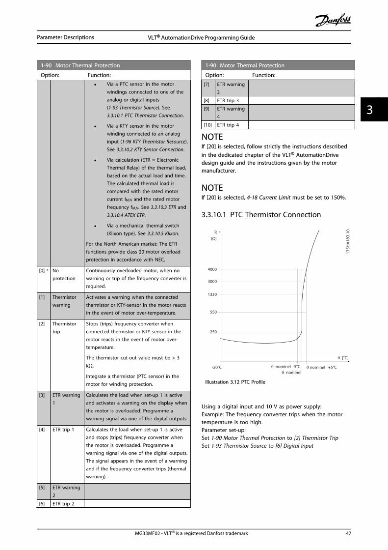
1-90 Motor Thermal Protection
Option: Function:
• Via a PTC sensor in the motorwindings connected to one of theanalog or digital inputs(1-93 Thermistor Source). See3.3.10.1 PTC Thermistor Connection.
• Via a KTY sensor in the motorwinding connected to an analoginput (1-96 KTY Thermistor Resource).See 3.3.10.2 KTY Sensor Connection.
• Via calculation (ETR = ElectronicThermal Relay) of the thermal load,based on the actual load and time.The calculated thermal load iscompared with the rated motorcurrent IM,N and the rated motor
frequency fM,N. See 3.3.10.3 ETR and
3.3.10.4 ATEX ETR.
• Via a mechanical thermal switch(Klixon type). See 3.3.10.5 Klixon.
For the North American market: The ETRfunctions provide class 20 motor overloadprotection in accordance with NEC.
[0] * Noprotection
Continuously overloaded motor, when nowarning or trip of the frequency converter isrequired.
[1] Thermistorwarning
Activates a warning when the connectedthermistor or KTY-sensor in the motor reactsin the event of motor over-temperature.
[2] Thermistortrip
Stops (trips) frequency converter whenconnected thermistor or KTY sensor in themotor reacts in the event of motor over-temperature.
The thermistor cut-out value must be > 3
kΩ.
Integrate a thermistor (PTC sensor) in themotor for winding protection.
[3] ETR warning1
Calculates the load when set-up 1 is activeand activates a warning on the display whenthe motor is overloaded. Programme awarning signal via one of the digital outputs.
[4] ETR trip 1 Calculates the load when set-up 1 is activeand stops (trips) frequency converter whenthe motor is overloaded. Programme awarning signal via one of the digital outputs.The signal appears in the event of a warningand if the frequency converter trips (thermalwarning).
[5] ETR warning2
[6] ETR trip 2
1-90 Motor Thermal Protection
Option: Function:
[7] ETR warning3
[8] ETR trip 3
[9] ETR warning4
[10] ETR trip 4
NOTEIf [20] is selected, follow strictly the instructions describedin the dedicated chapter of the VLT® AutomationDrivedesign guide and the instructions given by the motormanufacturer.
NOTEIf [20] is selected, 4-18 Current Limit must be set to 150%.
3.3.10.1 PTC Thermistor Connection
1330
550
250
-20°C
175H
A18
3.10
4000
3000
R(Ω)
nominel nominel -5°C nominel +5°C
[°C]
Illustration 3.12 PTC Profile
Using a digital input and 10 V as power supply:Example: The frequency converter trips when the motortemperature is too high.Parameter set-up:Set 1-90 Motor Thermal Protection to [2] Thermistor TripSet 1-93 Thermistor Source to [6] Digital Input
Parameter Descriptions VLT® AutomationDrive Programming Guide
MG33MF02 - VLT® is a registered Danfoss trademark 47
3 3

PTC / Thermistor R
OFF
ON
<800 Ω
+10V
130B
A15
2.10
>2.7 kΩ
12 13 18 37322719 29 33 20
555039 42 53 54
Illustration 3.13
Using an analog input and 10 V as power supply:Example: The frequency converter trips when the motortemperature is too high.Parameter set-up:Set 1-90 Motor Thermal Protection to [2] Thermistor TripSet 1-93 Thermistor Source to [2] Analog Input 54
555039 42 53 54
R<3.0 k Ω>3.0 k Ω
+10V
130B
A15
3.11
PTC / Thermistor
OFF
ON
Illustration 3.14
InputDigital/analog
Supply Voltage ThresholdCut-out Values
Digital 10 V < 800 Ω - > 2.7 kΩAnalog 10 V < 3.0 kΩ - > 3.0 kΩ
Table 3.7
NOTECheck that the chosen supply voltage follows the specifi-cation of the used thermistor element.
3.3.10.2 KTY Sensor Connection
(FC 302 only)
KTY sensors are used especially in Permanent MagnetServo Motors (PM motors) for dynamic adjusting of motorparameters as stator resistance (1-30 Stator Resistance (Rs))for PM motors and also rotor resistance (1-31 RotorResistance (Rr)) for asynchronous motors, depending onwinding temperature. The calculation is:
Rs = Rs20° C x (1 + αcu x ΔT ) Ω where αcu = 0.00393
KTY sensors can be used for motor protecting (1-97 KTYThreshold level).
FC 302 can handle three types of KTY sensors, defined in 1-95 KTY Sensor Type. The actual sensor temperature can beread out from 16-19 KTY sensor temperature.
0
500
1000
1500
2000
2500
3000
3500
4000
4500
-25 0 25 50 75 100 125 150
Temperature [°C]
Res
ista
nce
[Ohm
]
KTY type 1 KTY type 2 KTY type 3
130B
B917
.10
Illustration 3.15 KTY Type Selection
KTY Sensor 1: 1 kΩ at 100 °C (e.g. Philips KTY 84-1)KTY Sensor 2: 1 kΩ at 25 °C (e.g. Philips KTY 83-1)KTY Sensor 3: 2 kΩ at 25 °C (e.g. Infineon KTY-10
NOTEIf the temperature of the motor is utilized through athermistor or KTY sensor the PELV is not complied with incase of short circuits between motor windings and sensor.In order to comply with PELV the sensor must be extraisolated.
Parameter Descriptions VLT® AutomationDrive Programming Guide
48 MG33MF02 - VLT® is a registered Danfoss trademark
33

3.3.10.3 ETR
The calculations estimate the need for a lower load atlower speed due to less cooling from the fan incorporatedin the motor.
1.21.0 1.4
30
1020
10060
4050
1.81.6 2.0
2000
500
200
400300
1000600
t [s]
175Z
A05
2.12
fOUT = 2 x f M,N
fOUT = 0.2 x f M,N
fOUT = 1 x f M,N(par. 1-23)
IMN(par. 1-24)IM
Illustration 3.16 ETR Profile
3.3.10.4 ATEX ETR
The B-option MCB 112 PTC Thermistor option offers ATEXapproved monitoring of motor temperature. Alternatively,an external ATEX approved PTC protection device can beused.
NOTEOnly ATEX Ex-e approved motors may be used for thisfunction. See motor nameplate, approval certificate, datasheet or contact motor supplier.
When controlling an Ex-e motor with “Increased Safety”, itis important to ensure certain limitations. The parametersthat must be programmed are presented in the followingapplication example.
Function Setting
1-90 Motor ThermalProtection
[20] ATEX ETR
1-94 ATEX ETR cur.lim. speedreduction
20%
1-98 ATEX ETR interpol.points freq.
Motor name plate1-99 ATEX ETR interpolpoints current
1-23 Motor Frequency Enter the same value as for 4-19 Max Output Frequency
4-19 Max Output Frequency Motor name plate, possiblyreduced for long motor cables,sinus filter or reduced supplyvoltage
4-18 Current Limit Forced to 150% by 1-90 [20]
5-15 Terminal 33 DigitalInput
[80] PTC Card 1
5-19 Terminal 37 Safe Stop [4] PTC 1 Alarm
14-01 Switching Frequency Check that the default value fulfilsthe requirement from Motor nameplate. If not -use sine wave filter.
14-26 Trip Delay at InverterFault
0
Table 3.8 Parameters
CAUTIONIt is mandatory to compare the minimum switchingfrequency requirement stated by the motor manufacturerto the minimum switching frequency of the frequencyconverter, the default value in 14-01 Switching Frequency. Ifthe frequency converter does not meet this requirement, asine wave filter must be used.
More information about ATEX ETR Thermal Monitoring canbe found in the Application Note MN33G.
3.3.10.5 Klixon
The Klixon type thermal circuit breaker uses a KLIXON®
metal dish. At a predetermined overload, the heat causedby the current through the disc causes a trip.
Using a digital input and 24 V as power supply:Example: The frequency converter trips when the motortemperature is too highParameter set-up:Set 1-90 Motor Thermal Protection to [2] Thermistor TripSet 1-93 Thermistor Source to [6] Digital Input
Parameter Descriptions VLT® AutomationDrive Programming Guide
MG33MF02 - VLT® is a registered Danfoss trademark 49
3 3

PTC / Thermistor
OFF
ON
+24V
12 13 18 3732A
2719 29 33
B
20
GN
D
R<6.6 k Ω >10.8 k Ω
130B
A15
1.11
Illustration 3.17
1-91 Motor External Fan
Option: Function:
[0] * No No external fan is required, i.e. the motor is derated atlow speed.
[1] Yes Applies an external motor fan (external ventilation), sono derating of the motor is required at low speed. Theupper curve in graph above (fout = 1 x fM,N) isfollowed if the motor current is lower than nominalmotor current (see 1-24 Motor Current). If the motorcurrent exceeds nominal current, the operation timestill decreases as if no fan were installed.
1-93 Thermistor Source
Option: Function:
Select the input to which the thermistor(PTC sensor) should be connected. Ananalog input option [1] or [2] cannot beselected if the analog input is already inuse as a reference source (selected in3-15 Reference 1 Source, 3-16 Reference 2Source or 3-17 Reference 3 Source).When using MCB 112, choice [0] Nonemust always be selected.
[0] * None
[1] Analog input 53
[2] Analog input 54
[3] Digital input 18
[4] Digital input 19
[5] Digital input 32
[6] Digital input 33
NOTEThis parameter cannot be adjusted while the motor isrunning.
NOTEDigital input should be set to [0] PNP - Active at 24 V in5-00 Digital I/O Mode.
1-94 ATEX ETR cur.lim. speed reduction
FC 302 only.Only visible if 1-90 Motor Thermal Protection is set to [20].
Range: Function:
0 %* [0 - 100 %]
The reaction for operating in Ex-e current limit must beconfigured.0%: The frequency converter does not change anythingbesides issuing warning 163 ATEX ETR cur.lim.warning.>0%: The frequency converter issuing warning 163 andreduces motor speed following ramp 2 (parameter group3-5* Ramp 2).
Example:Actual reference = 50 RPM1-94 ATEX ETR cur.lim. speed reduction = 20%Resulting reference = 40 RPM
1-95 KTY Sensor Type
Option: Function:
Select the used type of KTY sensor. FC 302only.
[0] * KTY Sensor 1 1 kΩ at 100 °C
[1] KTY Sensor 2 1 kΩ at 25 °C
[2] KTY Sensor 3 2 kΩ at 25 °C
1-96 KTY Thermistor Resource
Option: Function:
Selecting analog input terminal 54 to be usedas KTY sensor input. Terminal 54 cannot beselected as KTY source if otherwise used asreference (see 3-15 Reference Resource 1 to 3-17 Reference Resource 3).
FC 302 only.
NOTEConnection of KTY-sensor between term.54 and 55 (GND). See Illustration 3.15.
[0] * None
[2] Analoginput 54
1-97 KTY Threshold level
Range: Function:
80 °C* [-40 - 140 °C] Select the KTY sensor threshold level formotor thermal protection.FC 302 only.
1-98 ATEX ETR interpol. points freq.
FC 302 only.Only visible if 1-90 Motor Thermal Protection is set to [20].
Range: Function:
Size related* [ 0 - 1000.0 Hz]
Enter the four frequency points [Hz] from the motor nameplate into this array. Together with 1-99 ATEX ETR interpolpoints current, these make up a table (f [Hz],I [%]).
Parameter Descriptions VLT® AutomationDrive Programming Guide
50 MG33MF02 - VLT® is a registered Danfoss trademark
33

NOTEAll frequency/current limit points from the motor nameplate or motor data sheet must be programmed.
1 0 0 % 8 0 % 4 0 %
5 Hz 15 Hz 25 Hz 50 Hz 13
0BB9
09.1
0
Illustration 3.18 Example of ATEX ETR thermal limitation curve.x-axis: fm [Hz]
y-axis: Im/Im,n x 100 [%]
1-98 ATEX ETR interpol. pointsfreq.
1-99 ATEX ETR interpolpoints current
[0] = 5 Hz [0] = 40%
[1] = 15 Hz [1] = 80%
[2] = 25 Hz [2] = 100%
[3] = 50 Hz [3] = 100%
Table 3.9
All operating points underneath the curve are allowedcontinuously. Above the line, however, only for a limitedtime calculated as a function of the overload. In the eventof a machine current greater than 1.5 times the ratedcurrent, shut down is immediate.
1-99 ATEX ETR interpol points current
FC 302 only.Only visible if 1-90 Motor Thermal Protection is set to [20] or [21].
Range: Function:
Size related* [0 - 100 %] Definition of thermal limitation curve.For example, see 1-98 ATEX ETRinterpol. points freq.
Use the four current points [A] from the motor name plate.Calculate the values as percentage of nominal motorcurrent, Im/Im,n x 100 [%], and enter into this array.
Together with 1-98 ATEX ETR interpol. points freq., thesemake up a table (f [Hz],I [%]).
NOTEAll frequency/current limit points from the motor nameplate or motor data sheet must be programmed.
Parameter Descriptions VLT® AutomationDrive Programming Guide
MG33MF02 - VLT® is a registered Danfoss trademark 51
3 3

3.4 Parameters: 2-** Brakes
3.4.1 2-0* DC-Brakes
Parameter group for configuring the DC brake and DChold functions.
2-00 DC Hold Current
Range: Function:
50 %* [0 -160. %]
Enter a value for holding current as apercentage of the rated motor current IM,N set
in 1-24 Motor Current. 100% DC holding currentcorresponds to IM,N.
This parameter holds the motor function(holding torque) or pre-heats the motor.This parameter is active if DC hold is selectedin 1-72 Start Function [0] or 1-80 Function atStop [1].
NOTEThe maximum value depends on the rated motor current.Avoid 100 % current for too long. It may damage themotor.Low values of DC hold will produce larger than expectedcurrents with larger motor power sizes. This error willincrease as the motor power increases.
2-01 DC Brake Current
Range: Function:
50%*
[0 -1000. %]
Enter a value for current as a percentage of therated motor current IM,N, see 1-24 Motor Current.
100% DC braking current corresponds to IM,N.
DC brake current is applied on a stopcommand, when the speed is lower than thelimit set in 2-03 DC Brake Cut In Speed [RPM];when the DC Brake Inverse function is active; orvia the serial communication port. The brakingcurrent is active during the time period set in 2-02 DC Braking Time.
NOTEThe maximum value depends on the rated motor current.Avoid 100 % current for too long. It may damage themotor.
2-02 DC Braking Time
Range: Function:
10.0 s* [0.0 - 60.0 s] Set the duration of the DC brakingcurrent set in 2-01 DC Brake Current, onceactivated.
2-03 DC Brake Cut In Speed [RPM]
Range: Function:
0 RPM* [0 - par. 4-13RPM]
Set the DC brake cut-in speed foractivation of the DC braking current
2-03 DC Brake Cut In Speed [RPM]
Range: Function:set in 2-01 DC Brake Current, upon astop command.
2-04 DC Brake Cut In Speed [Hz]
Range: Function:
0.0 Hz* [0.0 - par. 4-14Hz]
Set the DC brake cut-in speed foractivation of the DC braking currentset in 2-01 DC Brake Current, upon astop command.
NOTE2-04 DC Brake Cut In Speed [Hz] will not have effect when1-10 Motor Construction = [1] PM, non salient SPM.
2-06 Parking Current
Range: Function:
50 %* [ 0 - 1000 %] Set current as percentage of rated motorcurrent, 1-24 Motor Current. Will be usedwhen enabled in 1-70 PM Start Mode.
2-07 Parking Time
Range: Function:
3 s* [0.1 - 60 s] Set the duration of the Parking Current set in 2-06 Parking Current, once activated.
3.4.2 2-1* Brake Energy Funct.
Parameter group for selecting dynamic braking parameters.Only valid for frequency converters with brake chopper.
2-10 Brake Function
Option: Function:
[0] * Off No brake resistor is installed.
[1] Resistorbrake
A brake resistor is incorporated in the system,for dissipation of surplus brake energy as heat.Connecting a brake resistor allows a higher DClink voltage during braking (generatingoperation). The Resistor brake function is onlyactive in frequency converters with an integraldynamic brake.
[2] AC brake Is selected to improve braking without using abrake resistor. This parameter controls anovermagnetization of the motor when runningwith a generatoric load. This function canimprove the OVC-function. Increasing theelectrical losses in the motor allows the OVCfunction to increase the braking torque withoutexceeding the over voltage limit. Please notethat AC brake is not as effective as dynamicbreaking with resistor.
AC brake is for VVCplus and flux mode in bothopen and closed loop.
Parameter Descriptions VLT® AutomationDrive Programming Guide
52 MG33MF02 - VLT® is a registered Danfoss trademark
33

2-11 Brake Resistor (ohm)
Range: Function:
Sizerelated*
[ 5.00 -65535.00Ohm]
Set the brake resistor value in Ohms.This value is used for monitoring thepower to the brake resistor in2-13 Brake Power Monitoring. Thisparameter is only active in frequencyconverters with an integral dynamicbrake.Use this parameter for values withoutdecimals. For a selection with twodecimals, use 30-81 Brake Resistor(ohm).
2-12 Brake Power Limit (kW)
Range: Function:
Sizerelated*
[ 0.001 -2000.000kW]
2-12 Brake Power Limit (kW) is the expectedaverage power dissipated in the brakeresistor over a period of 120 s. It is used asthe monitoring limit for 16-33 BrakeEnergy /2 min and thereby specifies when awarning/ alarm is to be given.To calculate 2-12 Brake Power Limit (kW),the following formula can be used.
Pbr,avg W =Ubr
2 V × tbr sRbr Ω × Tbr s
Pbr,avg is the average power dissipated in
the brake resistor, Rbr is the resistance of
the brake resistor. tbr is the active breaking
time within the 120 s period, Tbr.
Ubr is the DC voltage where the brake
resistor is active. This depends on the unitas follows:T2 units: 390 VT4 units: 778 VT5 units: 810 VT6 units: 943 V/1099 V for D – F framesT7 units: 1099 V
NOTEIf Rbr is not known or if Tbr is differentfrom 120 s, the practical approach isto run the brake application, readout16-33 Brake Energy /2 min and thenenter this + 20% in 2-12 Brake PowerLimit (kW).
2-13 Brake Power Monitoring
Option: Function:
This parameter is only active in frequencyconverters with an integral dynamic brake.This parameter enables monitoring of thepower to the brake resistor. The power iscalculated on the basis of the resistance
2-13 Brake Power Monitoring
Option: Function:(2-11 Brake Resistor (ohm)), the DC link voltage,and the resistor duty time.
[0] * Off No brake power monitoring required.
[1] Warning Activates a warning on the display when thepower transmitted over 120 s exceeds 100% ofthe monitoring limit (2-12 Brake Power Limit(kW) ).The warning disappears when the transmittedpower falls below 80% of the monitoring limit.
[2] Trip Trips frequency converter and displays analarm when the calculated power exceeds100% of the monitoring limit.
[3] Warningand trip
Activates both of the above, includingwarning, trip and alarm.
If power monitoring is set to [0] Off or [1] Warning, thebrake function remains active, even if the monitoring limitis exceeded. This may lead to thermal overload of theresistor. It is also possible to generate a warning via arelay/digital outputs. The measuring accuracy of the powermonitoring depends on the accuracy of the resistance ofthe resistor (better than ±20%).
2-15 Brake Check
Option: Function:
Select type of test and monitoring function tocheck the connection to the brake resistor, orwhether a brake resistor is present, and thendisplay a warning or an alarm in the event of afault.
NOTEThe brake resistor disconnection function istested during power-up. However the brakeIGBT test is performed when there is nobraking. A warning or trip disconnects thebrake function.
The testing sequence is as follows:
1. The DC link ripple amplitude ismeasured for 300 ms without braking.
2. The DC link ripple amplitude ismeasured for 300 ms with the braketurned on.
3. If the DC link ripple amplitude whilebraking is lower than the DC link rippleamplitude before braking + 1%: Brakecheck has failed by returning a warningor alarm.
4. If the DC link ripple amplitude whilebraking is higher than the DC link ripple
Parameter Descriptions VLT® AutomationDrive Programming Guide
MG33MF02 - VLT® is a registered Danfoss trademark 53
3 3

2-15 Brake Check
Option: Function:amplitude before braking + 1%: Brakecheck is OK.
[0]*
Off Monitors brake resistor and brake IGBT for ashort-circuit during operation. If a short-circuitoccurs, warning 25 appears.
[1] Warning Monitors brake resistor and brake IGBT for ashort-circuit, and runs a test for brake resistordisconnection during power-up.
[2] Trip Monitors for a short-circuit or disconnection ofthe brake resistor, or a short-circuit of the brakeIGBT. If a fault occurs, the frequency convertercuts out while displaying an alarm (trip locked).
[3] Stop andtrip
Monitors for a short-circuit or disconnection ofthe brake resistor, or a short-circuit of the brakeIGBT. If a fault occurs, the frequency converterramps down to coast and then trips. A trip lockalarm is displayed (e.g. warning 25, 27 or 28).
[4] AC brake Monitors for a short-circuit or disconnection ofthe brake resistor, or a short-circuit of the brakeIGBT. If a fault occurs, the frequency converterperforms a controlled ramp-down. This option isavailable for FC 302 only.
NOTERemove a warning arising in connection with [0] Off or [1]Warning by cycling the mains supply. The fault must becorrected first. For [0] Off or [1] Warning, the frequencyconverter keeps running even if a fault is located.
This parameter is only active in frequency converters withan integral dynamic brake.
2-16 AC brake Max. Current
Range: Function:
100.0 %* [0.0 - 1000.0 %] Enter the maximum permissiblecurrent when using AC brake toavoid overheating of motorwindings.
NOTE2-16 AC brake Max. Current will not have effect when1-10 Motor Construction = [1] PM, non salient SPM.
2-17 Over-voltage Control
Option: Function:
Over-voltage control (OVC) reduces the riskof the frequency converter tripping due to
2-17 Over-voltage Control
Option: Function:an over voltage on the DC link caused bygenerative power from the load.
[0] * Disabled No OVC required.
[1] Enabled (notat stop)
Activates OVC except when using a stopsignal to stop the frequency converter.
[2] Enabled Activates OVC.
NOTEOVC must not be enabled in hoisting applications.
2-18 Brake Check Condition
Range: Function:
[0] * At Power Up Brake check will be performed at power up
2-19 Over-voltage Gain
Range: Function:
100 %* [0 - 200 %] Select over-voltage gain.
3.4.3 2-2* Mechanical Brake
Parameters for controlling operation of an electro-magnetic (mechanical) brake, typically required in hoistingapplications.To control a mechanical brake, a relay output (relay 01 orrelay 02) or a programmed digital output (terminal 27 or29) is required. Normally this output must be closed duringperiods when the frequency converter is unable to ‘hold’the motor, e.g. due to an excessive load. Select [32]Mechanical Brake Control for applications with an electro-magnetic brake in 5-40 Function Relay, 5-30 Terminal 27Digital Output, or 5-31 Terminal 29 Digital Output. Whenselecting [32] Mechanical brake control, the mechanicalbrake is closed from start up until the output current isabove the level selected in 2-20 Release Brake Current.During stop, the mechanical brake activates when thespeed falls below the level specified in 2-21 Activate BrakeSpeed [RPM]. If the frequency converter enters an alarmcondition or an over-current or over-voltage situation, themechanical brake immediately cuts in. This is also the caseduring safe stop.
NOTEProtection mode and trip delay features (14-25 Trip Delayat Torque Limit and 14-26 Trip Delay at Inverter Fault) maydelay the activation of the mechanical brake in an alarmcondition. These features must be disabled in hoistingapplications.
Parameter Descriptions VLT® AutomationDrive Programming Guide
54 MG33MF02 - VLT® is a registered Danfoss trademark
33

Startterm.18
1=on
0=o
Shaft speed
Start delay time
on
o
Brake delay time
Time
Output current
Relay 01
Pre-magnetizingcurrent orDC hold current
Reaction time EMK brake
Par 2-20Release brake currentPar 1-76 Start current/
Par 2-00 DC hold current
Par 1-74Start speed
Par 2-21Activate brake speed
Mechanical brakelocked
Mechanical brakefree
Par 1-71
Par 2-23
130B
A07
4.12
Illustration 3.19 Mechanical Brake
2-20 Release Brake Current
Range: Function:
par.16-37 A*
[0.00 -par. 16-37A]
Set the motor current for release of themechanical brake, when a start condition ispresent. The default value is the maximumcurrent the inverter can provide for theparticular power size. The upper limit isspecified in 16-37 Inv. Max. Current.
NOTEWhen Mechanical brake control outputis selected but no mechanical brake isconnected, the function will not workby default setting due to too lowmotor current.
2-21 Activate Brake Speed [RPM]
Range: Function:
0 RPM* [0 - 30000RPM]
Set the motor speed for activation ofthe mechanical brake, when a stopcondition is present. The upper speedlimit is specified in 4-53 Warning SpeedHigh.
2-22 Activate Brake Speed [Hz]
Range: Function:
0 Hz* [0.0 - 5000.0 Hz] Set the motor frequency for activationof the mechanical brake, when a stopcondition is present.
2-23 Activate Brake Delay
Range: Function:
0.0 s* [0.0 -5.0 s]
Enter the brake delay time of the coast afterramp-down time. The shaft is held at zerospeed with full holding torque. Ensure that themechanical brake has locked the load beforethe motor enters coast mode. See MechanicalBrake Control section in the Design Guide.
2-24 Stop Delay
Range: Function:
0.0 s* [0.0 - 5.0 s] Set the time interval from the momentwhen the motor is stopped until the brakecloses. This parameter is a part of thestopping function.
2-25 Brake Release Time
Range: Function:
0.20 s* [0.00 - 5.00s]
This value defines the time it takes forthe mechanical brake to open. Thisparameter must act as a time-out whenbrake feedback is activated.
2-26 Torque Ref
Range: Function:
0.00 %* [0 - 0 %] The value defines the torque applied againstthe closed mechanical brake, before release
Parameter Descriptions VLT® AutomationDrive Programming Guide
MG33MF02 - VLT® is a registered Danfoss trademark 55
3 3
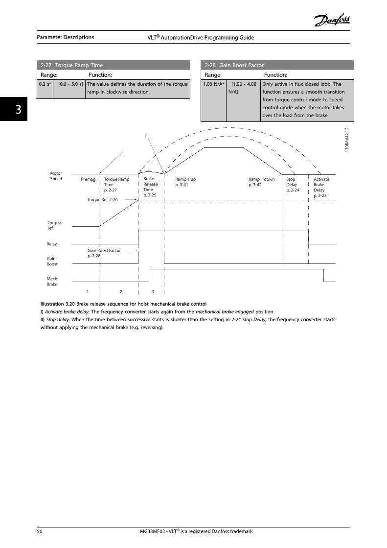
2-27 Torque Ramp Time
Range: Function:
0.2 s* [0.0 - 5.0 s] The value defines the duration of the torqueramp in clockwise direction.
2-28 Gain Boost Factor
Range: Function:
1.00 N/A* [1.00 - 4.00N/A]
Only active in flux closed loop. Thefunction ensures a smooth transitionfrom torque control mode to speedcontrol mode when the motor takesover the load from the brake.
Mech.Brake
GainBoost
Relay
Torqueref.
MotorSpeed Premag Torque Ramp
Timep. 2-27
Torque Ref. 2-26
Gain Boost Factorp. 2-28
BrakeReleaseTimep. 2-25
Ramp 1 upp. 3-41
Ramp 1 downp. 3-42
StopDelayp. 2-24
ActivateBrakeDelayp. 2-23
1 2 3
130B
A64
2.12
II
I
Illustration 3.20 Brake release sequence for hoist mechanical brake controlI) Activate brake delay: The frequency converter starts again from the mechanical brake engaged position.II) Stop delay: When the time between successive starts is shorter than the setting in 2-24 Stop Delay, the frequency converter startswithout applying the mechanical brake (e.g. reversing).
Parameter Descriptions VLT® AutomationDrive Programming Guide
56 MG33MF02 - VLT® is a registered Danfoss trademark
33

3.5 Parameters: 3-** Reference/Ramps
Parameters for reference handling, definition of limitations,and configuration of the reaction of the frequencyconverter to changes.
3.5.1 3-0* Reference Limits
3-00 Reference Range
Option: Function:
Select the range of the reference signal and thefeedback signal. Signal values can be positiveonly, or positive and negative. The minimumlimit may have a negative value, unless [1] Speedclosed loop control or [3] Process is selected in 1-00 Configuration Mode.
[0] Min -Max
Select the range of the reference signal and thefeedback signal. Signal values can be positiveonly, or positive and negative. The minimumlimit may have a negative value, unless [1] Speedclosed loop control or [3] Process is selected in 1-00 Configuration Mode.
[1] * -Max -+Max
For both positive and negative values (bothdirections, relative to 4-10 Motor Speed Direction).
3-01 Reference/Feedback Unit
Option: Function:
Select the unit to be used in Process PID Controlreferences and feedbacks. 1-00 ConfigurationMode must be either [3] Process or [8] ExtendedPID Control.
[0] * None
[1] %
[2] RPM
[3] Hz
[4] Nm
[5] PPM
[10] 1/min
[12] Pulse/s
[20] l/s
[21] l/min
[22] l/h
[23] m³/s
[24] m³/min
[25] m³/h
[30] kg/s
[31] kg/min
[32] kg/h
[33] t/min
[34] t/h
[40] m/s
[41] m/min
[45] m
[60] °C
3-01 Reference/Feedback Unit
Option: Function:
[70] mbar
[71] bar
[72] Pa
[73] kPa
[74] m WG
[80] kW
[120] GPM
[121] gal/s
[122] gal/min
[123] gal/h
[124] CFM
[125] ft³/s
[126] ft³/min
[127] ft³/h
[130] lb/s
[131] lb/min
[132] lb/h
[140] ft/s
[141] ft/min
[145] ft
[150] lb ft
[160] °F
[170] psi
[171] lb/in²
[172] in WG
[173] ft WG
[180] HP
3-02 Minimum Reference
Range: Function:
0 Reference-FeedbackUnit*
[-999999.999 -par. 3-03ReferenceFeed-backUnit]
Enter the MinimumReference. The MinimumReference is the lowestvalue obtainable bysumming all references.Minimum Reference is activeonly when 3-00 ReferenceRange is set to [0] Min.- Max.The Minimum Referenceunit matches:
• The choice ofconfiguration in 1-00 ConfigurationMode ConfigurationMode: for [1] Speedclosed loop, RPM;for [2] Torque, Nm.
• The unit selectedin 3-01 Reference/Feedback Unit.
Parameter Descriptions VLT® AutomationDrive Programming Guide
MG33MF02 - VLT® is a registered Danfoss trademark 57
3 3

3-03 Maximum Reference
Range: Function:
1500.000ReferenceFeed-backUnit*
[par. 3-02 -999999.999ReferenceFeed-backUnit]
Enter the MaximumReference. The MaximumReference is the highestvalue obtainable bysumming all references.
The Maximum Referenceunit matches:
• The choice ofconfiguration in 1-00 ConfigurationMode: for [1] Speedclosed loop, RPM;for [2] Torque, Nm.
• The unit selectedin 3-00 ReferenceRange.
3-04 Reference Function
Option: Function:
[0] * Sum Sums both external and preset referencesources.
[1] External/Preset Use either the preset or the externalreference source.Shift between external and preset via acommand or a digital input.
3.5.2 3-1* References
Select the preset reference(s). Select Preset ref. bit 0/1/2[16], [17] or [18] for the corresponding digital inputs inparameter group 5-1*.
3-10 Preset Reference
Array [8]Range: 0-7
Range: Function:
0.00%*
[-100.00 -100.00 %]
Enter up to eight different preset references(0-7) in this parameter, using arrayprogramming. The preset reference is statedas a percentage of the value RefMAX
(3-03 Maximum Reference) If a RefMIN
different from 0 (3-02 Minimum Reference) isprogrammed, the preset reference iscalculated as a percentage of the fullreference range, i.e. on the basis of thedifference between RefMAX and RefMIN.
Afterwards, the value is added to RefMIN.
When using preset references, select Presetref. bit 0/1/2 [16], [17] or [18] for thecorresponding digital inputs in parametergroup 5-1*.
[P 5-13=Preset ref. bit 0]
Preset
[P 5-14=Preset ref. bit 1]
[P 5-15=Preset ref. bit 2]
10101010
76543210
29
12 (+24V)
11001100 32
11110000 33
130B
A14
9.10
Illustration 3.21
Preset ref. bit 2 1 0
Preset ref. 0 0 0 0
Preset ref. 1 0 0 1
Preset ref. 2 0 1 0
Preset ref. 3 0 1 1
Preset ref. 4 1 0 0
Preset ref. 5 1 0 1
Preset ref. 6 1 1 0
Preset ref. 7 1 1 1
Table 3.10 Preset Ref. Bit
3-11 Jog Speed [Hz]
Range: Function:
0 Hz* [0.0 - par.4-14 Hz]
The jog speed is a fixed output speed atwhich the frequency converter is runningwhen the jog function is activated.See also 3-80 Jog Ramp Time.
3-12 Catch up/slow Down Value
Range: Function:
0.00%*
[0.00 -100.00 %]
Enter a percentage (relative) value to beeither added to or deducted from the actualreference for Catch up or Slow down respec-tively. If Catch up is selected via one of thedigital inputs (5-10 Terminal 18 Digital Input to5-15 Terminal 33 Digital Input), the percentage(relative) value is added to the total reference.If Slow down is selected via one of the digitalinputs (5-10 Terminal 18 Digital Input to5-15 Terminal 33 Digital Input), the percentage(relative) value is deducted from the totalreference. Obtain extended functionality withthe DigiPot function. See parameter group3-9* Digital Potentiometer.
Parameter Descriptions VLT® AutomationDrive Programming Guide
58 MG33MF02 - VLT® is a registered Danfoss trademark
33

3-13 Reference Site
Option: Function:
Select which reference site to activate.
[0] * Linked toHand / Auto
Use local reference when in Hand mode; orremote reference when in Auto mode.
[1] Remote Use remote reference in both Hand modeand Auto mode.
[2] Local Use local reference in both Hand mode andAuto mode.
NOTEWhen set to [2] Local, the frequencyconverter will start with this settingagain following a 'power down'.
3-14 Preset Relative Reference
Range: Function:
0.00%*
[-100.00 -100.00 %]
The actual reference, X, is increased ordecreased with the percentage Y, set in 3-14 Preset Relative Reference. This resultsin the actual reference Z. Actual reference(X) is the sum of the inputs selected in3-15 Reference 1 Source, 3-16 Reference 2Source, 3-17 Reference 3 Source and8-02 Control Source.
RelativeZ=X+X*Y/100
Resultingactualreference
Y
X
130B
A05
9.12
Z
Illustration 3.22
X
100 %0-100
Z
Y
X+X*Y/100
P 3-14
130B
A27
8.10
Illustration 3.23
3-15 Reference Resource 1
Option: Function:
Select the reference input to be usedfor the first reference signal. 3-15 Reference Resource 1, 3-16 Reference Resource 2 and 3-17 Reference Resource 3 define up tothree different reference signals. The
3-15 Reference Resource 1
Option: Function:sum of these reference signalsdefines the actual reference.
[0] No function
[1] * Analog input 53
[2] Analog input 54
[7] Frequency input 29
[8] Frequency input 33
[11] Local bus reference
[20] Digital pot.meter
[21] Analog input X30-11 (General Purpose I/O Option Module)
[22] Analog input X30-12 (General Purpose I/O Option Module)
3-16 Reference Resource 2
Option: Function:
Select the reference input to beused for the second referencesignal. 3-15 Reference Resource 1, 3-16 Reference Resource 2 and 3-17 Reference Resource 3 define upto three different reference signals.The sum of these reference signalsdefines the actual reference.
[0] No function
[1] Analog input 53
[2] Analog input 54
[7] Frequency input 29
[8] Frequency input 33
[11] Local bus reference
[20] * Digital pot.meter
[21] Analog input X30-11
[22] Analog input X30-12
3-17 Reference Resource 3
Option: Function:
Select the reference input to beused for the third reference signal. 3-15 Reference Resource 1, 3-16 Reference Resource 2 and 3-17 Reference Resource 3 define upto three different reference signals.The sum of these reference signalsdefines the actual reference.
[0] No function
[1] Analog input 53
[2] Analog input 54
[7] Frequency input 29
[8] Frequency input 33
[11] * Local bus reference
[20] Digital pot.meter
[21] Analog input X30-11
[22] Analog input X30-12
Parameter Descriptions VLT® AutomationDrive Programming Guide
MG33MF02 - VLT® is a registered Danfoss trademark 59
3 3

3-18 Relative Scaling Reference Resource
Option: Function:
Select a variable value to be added to thefixed value (defined in 3-14 Preset RelativeReference). The sum of the fixed andvariable values (labelled Y in the illustrationbelow) is multiplied with the actualreference (labelled X in the illustrationbelow). This product is then added to theactual reference (X+X*Y/100) to give theresultant actual reference.
RelativeZ=X+X*Y/100
Resultingactualreference
Y
X13
0BA
059.
12
Z
Illustration 3.24
[0] * No function
[1] Analog input53
[2] Analog input54
[7] Frequencyinput 29
[8] Frequencyinput 33
[11] Local busreference
[20] Digitalpot.meter
[21] Analog inputX30-11
[22] Analog inputX30-12
NOTEThis parameter cannot be adjusted while the motor isrunning.
3-19 Jog Speed [RPM]
Range: Function:
150.RPM*
[0 - par.4-13 RPM]
Enter a value for the jog speed nJOG,
which is a fixed output speed. Thefrequency converter runs at this speedwhen the jog function is activated. Themaximum limit is defined in 4-13 MotorSpeed High Limit [RPM].See also 3-80 Jog Ramp Time.
3.5.3 Ramps3-4* Ramp 1
For each of four ramps (parameter groups 3-4*, 3-5*, 3-6*and 3-7*) configure the ramp parameters: ramp type,ramping times (duration of acceleration and deceleration)and level of jerk compensation for S ramps.
Start by setting the linear ramping times corresponding tothe figures.
P 3-*2Ramp (X) DownTime (Dec)
P 4-13
High-limit
RPM
Referencens
P 4-11Low limit
tdec
TimeP 3-*1Ramp (X)UpTime (Acc)
tacc
130B
A87
2.10
Illustration 3.25
If S-ramps are selected then set the level of non-linear jerkcompensation required. Set jerk compensation by definingthe proportion of ramp-up and ramp-down times whereacceleration and deceleration are variable (i.e. increasing ordecreasing). The S-ramp acceleration and decelerationsettings are defined as a percentage of the actual ramptime.
130B
A16
8.10Ramp (X) S-RampRatio at Accel.End
Jerk compensated
Ramp (X)Up Time
Ramp (X)S-RampRatio atAccel.End
Linear
Speed
Ramp (X)Down Time
Ramp (X)S-RampRatio atDec.End
Ramp (X) S-RampRatio at Dec.End
Illustration 3.26
Parameter Descriptions VLT® AutomationDrive Programming Guide
60 MG33MF02 - VLT® is a registered Danfoss trademark
33

3-40 Ramp 1 Type
Option: Function:
Select the ramp type, depending onrequirements for acceleration/deceleration.A linear ramp will give constant accelerationduring ramping. An S-ramp will give non-linear acceleration, compensating for jerk inthe application.
[0] * Linear
[1] S-rampConst Jerk
Acceleration with lowest possible jerk.
[2] S-rampConst Time
S-ramp based on the values set in 3-41 Ramp1 Ramp up Time and 3-42 Ramp 1 Ramp DownTime.
NOTEIf [1] S-ramp Const Jerk is selected and the reference duringramping is changed the ramp time may be prolonged inorder to realize a jerk free movement which may result ina longer start or stop time.Additional adjustment of the S-ramp ratios or switchinginitiators may be necessary.
3-41 Ramp 1 Ramp up Time
Range: Function:
3.00s*
[0.01 -3600.00 s]
Enter the ramp-up time, i.e. the accelerationtime from 0 RPM to the synchronous motorspeed nS. Choose a ramp-up time such that
the output current does not exceed thecurrent limit in 4-18 Current Limit duringramping. The value 0.00 corresponds to 0.01 sin speed mode. See ramp-down time in 3-42 Ramp 1 Ramp Down Time.
Par. 3 − 41 = tacc s x ns RPM
ref RPM
3-42 Ramp 1 Ramp Down Time
Range: Function:
3.00s*
[0.01 -3600.00s]
Enter the ramp-down time, that is, thedeceleration time from the synchronous motorspeed ns to 0 RPM. Choose a ramp-down time
such that no over-voltage arises in the inverterdue to regenerative operation of the motor,and such that the generated current does notexceed the current limit set in 4-18 CurrentLimit. The value 0.00 corresponds to 0.01 s inspeed mode. See ramp-up time in 3-41 Ramp 1Ramp up Time.
Par. 3 − 42 = tdec s x ns RPM
ref RPM
3-45 Ramp 1 S-ramp Ratio at Accel. Start
Range: Function:
50 %* [1 - 99.%]
Enter the proportion of the total ramp-uptime (3-41 Ramp 1 Ramp up Time) in which
3-45 Ramp 1 S-ramp Ratio at Accel. Start
Range: Function:the acceleration torque increases. The largerthe percentage value, the greater the jerkcompensation achieved, and thus the lowerthe torque jerks occurring in the application.
3-46 Ramp 1 S-ramp Ratio at Accel. End
Range: Function:
50 %* [1 - 99. %] Enter the proportion of the total ramp-uptime (3-41 Ramp 1 Ramp up Time) in whichthe acceleration torque decreases. The largerthe percentage value, the greater the jerkcompensation achieved, and thus the lowerthe torque jerks in the application.
3-47 Ramp 1 S-ramp Ratio at Decel. Start
Range: Function:
50 %* [1 - 99. %] Enter the proportion of the total ramp-downtime (3-42 Ramp 1 Ramp Down Time) wherethe deceleration torque increases. The largerthe percentage value, the greater the jerkcompensation achieved, and thus the lowerthe torque jerks in the application.
3-48 Ramp 1 S-ramp Ratio at Decel. End
Range: Function:
50 %* [1 - 99. %] Enter the proportion of the total ramp-downtime (3-42 Ramp 1 Ramp Down Time) wherethe deceleration torque decreases. The largerthe percentage value, the greater the jerkcompensation achieved, and thus the lowerthe torque jerks in the application.
3.5.4 3-5* Ramp 2
Choosing ramp parameters, see parameter group 3-4*.
3-50 Ramp 2 Type
Option: Function:
Select the ramp type, depending onrequirements for acceleration/deceleration. Alinear ramp will give constant accelerationduring ramping. An S-ramp will give non-linear acceleration, compensating for jerk inthe application.
[0] * Linear
[1] S-rampConst Jerk
Acceleration with lowest possible jerk
[2] S-rampConst Time
S-ramp based on the values set in 3-51 Ramp2 Ramp up Time and 3-52 Ramp 2 Ramp downTime
Parameter Descriptions VLT® AutomationDrive Programming Guide
MG33MF02 - VLT® is a registered Danfoss trademark 61
3 3

NOTEIf [1] S-ramp Const Jerk is selected and the reference duringramping is changed the ramp time may be prolonged inorder to realize a jerk free movement which may result ina longer start or stop time.Additional adjustment of the S-ramp ratios or switchinginitiators may be necessary.
3-51 Ramp 2 Ramp up Time
Range: Function:
3.00s*
[0.01 -3600.00 s]
Enter the ramp-up time, i.e. the accelerationtime from 0 RPM to the rated motor speed ns.
Choose a ramp-up time such that the outputcurrent does not exceed the current limit in 4-18 Current Limit during ramping. The value0.00 corresponds to 0.01 s in speed mode.See ramp-down time in 3-52 Ramp 2 Rampdown Time.
Par. 3 − 51 = tacc s x ns RPM
ref RPM
3-52 Ramp 2 Ramp down Time
Range: Function:
3.00s*
[0.01 -3600.00s]
Enter the ramp-down time, i.e. thedeceleration time from the rated motor speedns to 0 RPM. Choose a ramp-down time such
that no over-voltage arises in the inverter dueto regenerative operation of the motor, andsuch that the generated current does notexceed the current limit set in 4-18 CurrentLimit. The value 0.00 corresponds to 0.01 s inspeed mode. See ramp-up time in 3-51 Ramp 2Ramp up Time.
Par. 3 − 52 = tdec s x ns RPM
ref RPM
3-55 Ramp 2 S-ramp Ratio at Accel. Start
Range: Function:
50 %* [1 - 99. %] Enter the proportion of the total ramp-uptime (3-51 Ramp 2 Ramp up Time) in whichthe acceleration torque increases. The largerthe percentage value, the greater the jerkcompensation achieved, and thus the lowerthe torque jerks in the application.
3-56 Ramp 2 S-ramp Ratio at Accel. End
Range: Function:
50 %* [1 - 99. %] Enter the proportion of the total ramp-uptime (3-51 Ramp 2 Ramp up Time) in whichthe acceleration torque decreases. The largerthe percentage value, the greater the jerkcompensation achieved, and thus the lowerthe torque jerks in the application.
3-57 Ramp 2 S-ramp Ratio at Decel. Start
Range: Function:
50 %* [1 - 99. %] Enter the proportion of the total ramp-downtime (3-52 Ramp 2 Ramp down Time) wherethe deceleration torque increases The largerthe percentage value, the greater the jerkcompensation achieved, and thus the lowerthe torque jerks in the application.
3-58 Ramp 2 S-ramp Ratio at Decel. End
Range: Function:
50 %* [1 - 99. %] Enter the proportion of the total ramp-downtime (3-52 Ramp 2 Ramp down Time) wherethe deceleration torque decreases. The largerthe percentage value, the greater the jerkcompensation achieved, and thus the lowerthe torque jerks in the application.
3.5.5 3-6* Ramp 3
Configure ramp parameters, see 3-4*.
3-60 Ramp 3 Type
Option: Function:
Select the ramp type, depending onrequirements for acceleration anddeceleration. A linear ramp will give constantacceleration during ramping. An S-ramp willgive non-linear acceleration, compensatingfor jerk in the application.
[0] * Linear
[1] S-rampConst Jerk
Accelerates with lowest possible jerk.
[2] S-rampConst Time
S-ramp based on the values set in 3-61 Ramp3 Ramp up Time and 3-62 Ramp 3 Ramp downTime
NOTEIf [1] S-ramp Const Jerk is selected and the reference duringramping is changed the ramp time may be prolonged inorder to realize a jerk free movement which may result ina longer start or stop time.Additional adjustment of the S-ramp ratios or switchinginitiators may be necessary.
3-61 Ramp 3 Ramp up Time
Range: Function:
3.00 s* [0.01 -3600.00 s]
Enter the ramp-up time, i.e. theacceleration time from 0 RPM to the ratedmotor speed ns. Choose a ramp-up time
such that the output current does notexceed the current limit in 4-18 CurrentLimit during ramping. The value 0.00corresponds to 0.01 s in speed mode. See
Parameter Descriptions VLT® AutomationDrive Programming Guide
62 MG33MF02 - VLT® is a registered Danfoss trademark
33

3-61 Ramp 3 Ramp up Time
Range: Function:ramp-down time in 3-62 Ramp 3 Rampdown Time.
3-62 Ramp 3 Ramp down Time
Range: Function:
3.00s*
[0.01 -3600.00s]
Enter the ramp-down time, i.e. thedeceleration time from the rated motor speedns to 0 RPM. Choose a ramp-down time such
that no over-voltage arises in the inverter dueto regenerative operation of the motor, andsuch that the generated current does notexceed the current limit set in 4-18 CurrentLimit. The value 0.00 corresponds to 0.01 s inspeed mode. See ramp-up time in 3-61 Ramp 3Ramp up Time.
Par. 3 − 62 = tdec s x ns RPM
ref RPM
3-65 Ramp 3 S-ramp Ratio at Accel. Start
Range: Function:
50 %* [1 - 99. %] Enter the proportion of the total ramp-uptime (3-61 Ramp 3 Ramp up Time) in whichthe acceleration torque increases. The largerthe percentage value, the greater the jerkcompensation achieved, and thus the lowerthe torque jerks in the application.
3-66 Ramp 3 S-ramp Ratio at Accel. End
Range: Function:
50 %* [1 - 99. %] Enter the proportion of the total ramp-uptime (3-61 Ramp 3 Ramp up Time) in whichthe acceleration torque decreases. The largerthe percentage value, the greater the jerkcompensation achieved, and thus the lowerthe torque jerks in the application.
3-67 Ramp 3 S-ramp Ratio at Decel. Start
Range: Function:
50 %* [1 - 99. %] Enter the proportion of the total ramp-downtime (3-62 Ramp 3 Ramp down Time) wherethe deceleration torque increases. The largerthe percentage value, the greater the jerkcompensation achieved, and thus the lowerthe torque jerks in the application.
3-68 Ramp 3 S-ramp Ratio at Decel. End
Range: Function:
50 %* [1 - 99. %] Enter the proportion of the total ramp-downdecel time (3-62 Ramp 3 Ramp downTime) where the deceleration torquedecreases. The larger the percentage value,the greater the jerk compensation achieved,and thus the lower the torque jerks in theapplication.
3.5.6 3-7* Ramp 4
Configure ramp parameters, see parameter group 3-4*.
3-70 Ramp 4 Type
Option: Function:
Select the ramp type, depending onrequirements for acceleration anddeceleration. A linear ramp will give constantacceleration during ramping. An S-ramp willgive non-linear acceleration, compensatingfor jerk in the application
[0] * Linear
[1] S-rampConst Jerk
Accelerates with lowest possible jerk.
[2] S-rampConst Time
S-ramp based on the values set in 3-71 Ramp4 Ramp up Time and 3-72 Ramp 4 Ramp DownTime.
NOTEIf [1] S-ramp Const Jerk is selected and the reference duringramping is changed the ramp time may be prolonged inorder to realize a jerk free movement which may result ina longer start or stop time.Additional adjustment of the S-ramp ratios or switchinginitiators may be necessary.
3-71 Ramp 4 Ramp up Time
Range: Function:
3.00s*
[0.01 -3600.00 s]
Enter the ramp-up time, i.e. the accelerationtime from 0 RPM to the rated motor speed ns.
Choose a ramp-up time such that the outputcurrent does not exceed the current limit in 4-18 Current Limit during ramping. The value0.00 corresponds to 0.01 s in speed mode.See ramp-down time in 3-72 Ramp 4 RampDown Time.
Par. 3 − 71 = tacc s x ns RPM
ref RPM
3-72 Ramp 4 Ramp Down Time
Range: Function:
3.00s*
[0.01 -3600.00s]
Enter the ramp-down time, i.e. thedeceleration time from the rated motor speedns to 0 RPM. Choose a ramp-down time such
Parameter Descriptions VLT® AutomationDrive Programming Guide
MG33MF02 - VLT® is a registered Danfoss trademark 63
3 3

3-72 Ramp 4 Ramp Down Time
Range: Function:that no over-voltage arises in the inverter dueto regenerative operation of the motor, andsuch that the generated current does notexceed the current limit set in 4-18 CurrentLimit. The value 0.00 corresponds to 0.01 s inspeed mode. See ramp-up time in 3-71 Ramp 4Ramp up Time.
Par. 3 − 72 = tdec s x ns RPM
ref RPM
3-75 Ramp 4 S-ramp Ratio at Accel. Start
Range: Function:
50 %* [1 - 99. %] Enter the proportion of the total ramp-uptime (3-71 Ramp 4 Ramp up Time) in whichthe acceleration torque increases. The largerthe percentage value, the greater the jerkcompensation achieved, and thus the lowerthe torque jerks in the application.
3-76 Ramp 4 S-ramp Ratio at Accel. End
Range: Function:
50 %* [1 - 99. %] Enter the proportion of the total ramp-uptime (3-71 Ramp 4 Ramp up Time) in whichthe acceleration torque decreases. The largerthe percentage value, the greater the jerkcompensation achieved, and thus the lowerthe torque jerks in the application.
3-77 Ramp 4 S-ramp Ratio at Decel. Start
Range: Function:
50 %* [1 - 99. %] Enter the proportion of the total ramp-downtime (3-72 Ramp 4 Ramp Down Time) wherethe deceleration torque increases. The largerthe percentage value, the greater the jerkcompensation achieved, and thus the lowerthe torque jerks in the application.
3-78 Ramp 4 S-ramp Ratio at Decel. End
Range: Function:
50 %* [1 - 99. %] Enter the proportion of the total ramp-downtime (3-72 Ramp 4 Ramp Down Time) wherethe deceleration torque decreases. The largerthe percentage value, the greater the jerkcompensation achieved, and thus the lowerthe torque jerks in the application.
3.5.7 3-8* Other Ramps
3-80 Jog Ramp Time
Range: Function:
3.00s*
[0.01 -3600.00 s]
Enter the jog ramp time, i.e. theacceleration/deceleration time between 0
3-80 Jog Ramp Time
Range: Function:RPM and the rated motor frequency ns.
Ensure that the resultant output currentrequired for the given jog ramp time doesnot exceed the current limit in 4-18 CurrentLimit. The jog ramp time starts uponactivation of a jog signal via the LCP, aselected digital input, or the serial communi-cation port. When jog state is disabled thenthe normal ramping times are valid.
130B
A07
0.10
Time
P 3-80
RPM
P 4-13 RPMhigh limit
P 1-25Motor speed
Jog speedP 3-19
P 3-80Ramp up(acc)
Ramp down(dec)
t jog t jog
P 4-11 RPMlow limit
Illustration 3.27
Par. 3 − 80 = tjog s x ns RPM
Δ jog speed (par. 3 − 19) RPM
3-81 Quick Stop Ramp Time
Range: Function:
3.00s*
[0.01 -3600.00 s]
Enter the quick–stop ramp-down time, i.e.the deceleration time from the synchronousmotor speed to 0 RPM. Ensure that noresultant over-voltage will arise in theinverter due to regenerative operation of themotor required to achieve the given ramp-down time. Ensure also that the generatedcurrent required to achieve the given ramp-down time does not exceed the current limit(set in 4-18 Current Limit). Quick-stop isactivated by means of a signal on a selecteddigital input, or via the serial communicationport.
Parameter Descriptions VLT® AutomationDrive Programming Guide
64 MG33MF02 - VLT® is a registered Danfoss trademark
33

130B
A06
9.10
Time
RPM
P 4-13 RPMhigh limit
Reference
P 1-25Motor speed
low limitP 4-11 RPM
P 3-81Qramp
Qstop
Illustration 3.28
3-82 Quick Stop Ramp Type
Option: Function:
Select the ramp type, depending onrequirements for acceleration anddeceleration. A linear ramp will giveconstant acceleration during ramping. AnS-ramp will give non-linear acceleration,compensating for jerk in the application.
[0] * Linear
[1] S-ramp ConstJerk
[2] S-ramp ConstTime
3-83 Quick Stop S-ramp Ratio at Decel. Start
Range: Function:
50 %* [ 1 - 99%]
Enter the proportion of the total ramp-downtime (3-42 Ramp 1 Ramp Down Time) wherethe deceleration torque increases. The largerthe percentage value, the greater the jerkcompensation achieved, and thus the lowerthe torque jerks in the application.
3-84 Quick Stop S-ramp Ratio at Decel. End
Range: Function:
50 %* [ 1 - 99 %] Enter the proportion of the total ramp-downtime (3-42 Ramp 1 Ramp Down Time) wherethe deceleration torque decreases. The largerthe percentage value, the greater the jerkcompensation achieved, and thus the lowerthe torque jerks in the application.
3.5.8 3-9* Digital Pot.Meter
The digital potentiometer function allows the user toincrease or decrease the actual reference by adjusting theset-up of the digital inputs using the functions Increase,Decrease or Clear. To activate the function, at least onedigital input must be set up to Increase or Decrease.
Speed
Time (s)
Inc
130B
A15
8.11
P 3-95
Illustration 3.29
Speed
Time (s)Dec
Inc
130B
A15
9.11
P 3-95
Illustration 3.30
3-90 Step Size
Range: Function:
0.10 %* [0.01 -200.00 %]
Enter the increment size required forINCREASE/DECREASE, as a percentage ofthe synchronous motor speed, ns. If
INCREASE/DECREASE is activated theresulting reference will be increased/decreased by the amount set in thisparameter.
3-91 Ramp Time
Range: Function:
1.00s*
[0.00 -3600.00 s]
Enter the ramp time, i.e. the time foradjustment of the reference from 0% to100% of the specified digital potentiometerfunction (Increase, Decrease or Clear).If Increase/ Decrease is activated for longerthan the ramp delay period specified in 3-95 Ramp Delay the actual reference will beramped up / down according to this ramptime. The ramp time is defined as the timeused to adjust the reference by the step sizespecified in 3-90 Step Size.
Parameter Descriptions VLT® AutomationDrive Programming Guide
MG33MF02 - VLT® is a registered Danfoss trademark 65
3 3

3-92 Power Restore
Option: Function:
[0] * Off Resets the Digital Potentiometer reference to 0% afterpower up.
[1] On Restores the most recent Digital Potentiometerreference at power up.
3-93 Maximum Limit
Range: Function:
100 %* [-200 - 200%]
Set the maximum permissible value forthe resultant reference. This is advisable ifthe Digital Potentiometer is used for finetuning of the resulting reference.
3-94 Minimum Limit
Range: Function:
-100 %* [-200 - 200%]
Set the minimum permissible value forthe resultant reference. This is advisableif the Digital Potentiometer is used forfine tuning of the resulting reference.
3-95 Ramp Delay
Range: Function:
0 N/A* [0 - 0N/A]
Enter the delay required from activation ofthe digital potentiometer function until thefrequency converter starts to ramp thereference. With a delay of 0 ms, the referencestarts to ramp as soon as INCREASE/DECREASE is activated. See also 3-91 RampTime.
Parameter Descriptions VLT® AutomationDrive Programming Guide
66 MG33MF02 - VLT® is a registered Danfoss trademark
33

3.6 Parameters: 4-** Limits/Warnings
3.6.1 4-1* Motor Limits
Define torque, current and speed limits for the motor, andthe reaction of the frequency converter when the limits areexceeded.A limit may generate a message on the display. A warningwill always generate a message on the display or on thefieldbus. A monitoring function may initiate a warning or atrip, upon which the frequency converter will stop andgenerate an alarm message.
4-10 Motor Speed Direction
Option: Function:
Select the motor speed direction(s) required.Use this parameter to prevent unwantedreversing. When 1-00 Configuration Mode isset to Process [3], 4-10 Motor Speed Direction isset to Clockwise [0] as default. The setting in 4-10 Motor Speed Direction does not limitoptions for setting 4-13 Motor Speed HighLimit [RPM].
[0] * Clockwise The reference is set to CW rotation. Reversinginput (Default term 19) must be open.
[1] Counterclockwise
The reference is set to CCW rotation.Reversing input (Default term 19) must beclosed. If Reversing is required with ‘Reverse’input is open the motor direction can bechanged by 1-06 Clockwise Direction
[2] Bothdirections
Allows the motor to rotate in both directions.
NOTEThis parameter cannot be adjusted while the motor isrunning.
4-11 Motor Speed Low Limit [RPM]
Range: Function:
0 RPM* [0 - par.4-13 RPM]
Enter the minimum limit for motor speed.The Motor Speed Low Limit can be set tocorrespond to the manufacturer’srecommended minimum motor speed. TheMotor Speed Low Limit must not exceedthe setting in 4-13 Motor Speed High Limit[RPM].
4-12 Motor Speed Low Limit [Hz]
Range: Function:
0 Hz* [0.0 - par.4-14 Hz]
Enter the minimum limit for motor speed.The Motor Speed Low Limit can be set tocorrespond to the minimum outputfrequency of the motor shaft. The MotorSpeed Low Limit must not exceed thesetting in 4-14 Motor Speed High Limit [Hz].
4-13 Motor Speed High Limit [RPM]
Range: Function:
3600.RPM*
[par. 4-11 -60000. RPM]
Enter the maximum limit for motorspeed. The Motor Speed High Limit canbe set to correspond to themanufacturer’s maximum rated motorspeed. The Motor Speed High Limitmust exceed the setting in 4-11 MotorSpeed Low Limit [RPM].
NOTEMax. output frequency cannot exceed 10% of the inverterswitching frequency (14-01 Switching Frequency).
4-14 Motor Speed High Limit [Hz]
Range: Function:
Sizerelated*
[ par.4-12 -par. 4-19Hz]
Enter the maximum limit for motor speed.The Motor Speed High Limit can be set tocorrespond to the manufacturer’srecommended maximum of the motorshaft. The Motor Speed High Limit mustexceed the in 4-12 Motor Speed Low Limit[Hz]. Only 4-13 Motor Speed High Limit[RPM] or 4-14 Motor Speed High Limit [Hz]will be displayed depending on otherparameters in the Main Menu anddepending on default settings dependanton global location.
NOTEMax. output frequency cannot exceed 10% of the inverterswitching frequency (14-01 Switching Frequency).
4-16 Torque Limit Motor Mode
Range: Function:
160.0 %*
Applicationdependent*
[0.0 - 1000.0 %] [Applicationdependant]
This function limits thetorque on the shaft toprotect the mechanicalinstallation.
NOTEChanging 4-16 Torque Limit Motor Mode when 1-00 Configu-ration Mode is set to Speed open loop [0], 1-66 Min. Currentat Low Speed is automatically readjusted.
NOTEThe torque limit reacts on the actual, non-filtrated torque,including torque spikes. This is not the torque that is seenfrom the or the as that is filtered.
Parameter Descriptions VLT® AutomationDrive Programming Guide
MG33MF02 - VLT® is a registered Danfoss trademark 67
3 3
4-17 Torque Limit Generator Mode
Range: Function:
100.0 %* [0.0 - 1000.0 %] This function limits the torque onthe shaft to protect the mechanicalinstallation.
NOTEThe torque limit reacts on the actual, non-filtrated torque,including torque spikes. This is not the torque that is seenfrom the or the as that is filtered.
4-18 Current Limit
Range: Function:
160.0%*
[1.0 -1000.0 %]
This is a true current limit function thatcontinues in the oversynchronous range,however due to field weakening themotor torque at current limit will dropaccordingly when the voltage increasestops above the synchronised speed ofthe motor.
NOTEIf [20] is selected in 1-90 Motor Thermal Protection, 4-18 Current Limit current limit must be set to 150%.
4-19 Max Output Frequency
Range: Function:
132.0Hz*
[1.0 -1000.0 Hz]
Provides a final limit on the outputfrequency for improved safety inapplications where you want to avoidaccidental over-speeding. This limit isfinal in all configurations (independentof the setting in 1-00 ConfigurationMode).
NOTEThis parameter cannot be adjusted while the motor isrunning.
NOTEMax. output frequency cannot exceed 10% of the inverterswitching frequency (14-01 Switching Frequency).
4-20 Torque Limit Factor Source
Option: Function:
Select an analog input for scaling thesettings in 4-16 Torque Limit MotorMode and 4-17 Torque Limit GeneratorMode from 0% to 100% (or inverse).The signal levels corresponding to0% and 100% are defined in theanalog input scaling, e.g. parametergroup 6-1*. This parameter is onlyactive when 1-00 Configuration Mode
4-20 Torque Limit Factor Source
Option: Function:is in Speed Open Loop or Speed ClosedLoop.
[0] * No function
[2] Analog in 53
[4] Analog in 53 inv
[6] Analog in 54
[8] Analog in 54 inv
[10] Analog in X30-11
[12] Analog in X30-11inv
[14] Analog in X30-12
[16] Analog in X30-12inv
4-21 Speed Limit Factor SourceOption
Option: Function:
Select an analog input for scalingthe settings in 4-19 Max OutputFrequency from 0% to 100% (or viceversa). The signal levelscorresponding to 0% and 100% aredefined in the analog input scaling,e.g. parameter group 6-1*. Thisparameter is only active when 1-00 Configuration Mode is in TorqueMode.
[0] * No function
[2] Analog input 53
[4] Analog input 53 inv
[6] Analog input 54
[8] Analog input 54 inv
[10] Analog input X30-11
[12] Analog input X30-11inv
[14] Analog input X30-12
[16] Analog input X30-12inv
3.6.2 4-3* Motor Feedback Monitoring
The parameter group includes monitoring and handling ofmotor feedback devices as encoders, resolvers etc.
4-30 Motor Feedback Loss Function
Option: Function:
This function is used to monitor forconsistency in feedback signal, i.e. ifthe feedback signal is available.Select which reaction the frequencyconverter should take if a feedbackfault is detected. The selected actionis to take place when the feedbacksignal differs from the output speed
Parameter Descriptions VLT® AutomationDrive Programming Guide
68 MG33MF02 - VLT® is a registered Danfoss trademark
33

4-30 Motor Feedback Loss Function
Option: Function:by the value set in 4-31 MotorFeedback Speed Error for longer thanthe value set in4-32 Motor FeedbackLoss Timeout.
[0] Disabled
[1] Warning
[2] * Trip
[3] Jog
[4] Freeze Output
[5] Max Speed
[6] Switch to OpenLoop
[7] Select Setup 1
[8] Select Setup 2
[9] Select Setup 3
[10] Select Setup 4
[11] stop & trip
Warning 90 is active as soon as the value in 4-31 MotorFeedback Speed Error is exceeded, regardless of the settingof 4-32 Motor Feedback Loss Timeout. Warning/Alarm 61Feedback Error is related to the Motor Feedback LossFunction.
4-31 Motor Feedback Speed Error
Range: Function:
300 RPM* [1 - 600 RPM] Select the max allowed error in speed(output speed vs. feedback).
Time[sec]
Speed [rpm]
ncalc
nactual
P 4-32
130B
A22
1.10
P 4-31
Illustration 3.31
4-32 Motor Feedback Loss Timeout
Range: Function:
0.05 s* [0.00 - 60.00s]
Set the timeout value allowing thespeed error set in 4-31 Motor FeedbackSpeed Error to be exceeded before
4-32 Motor Feedback Loss Timeout
Range: Function:enabling the function selected in 4-30 Motor Feedback Loss Function.
4-34 Tracking Error Function
Option: Function:
This function is used to monitor that theapplication follows the expected speed profile.In Closed loop the speed reference to the PIDis compared to the encoder feedback (filtered)In open loop the speed reference to the PID iscompensated for slip and compared to thefrequency that is sent to the motor(16-13 Frequency).The reaction will be activated if the measureddifference is more than specified in 4-35 Tracking Error for the time specified in 4-36 Tracking Error Timeout.A tracking error in closed loop does not implythat there is a problem with the feedbacksignal! A tracking error can be the result oftorque limit at too big loads.
[0] * Disable
[1] Warning
[2] Trip
[3] Trip afterstop
Warning/Alarm 78 Tracking Error is related to the TrackingError Function.
4-35 Tracking Error
Range: Function:
10 RPM* [1 - 600RPM]
Enter the maximum permissible speederror between the motor speed and theoutput of the ramp when not ramping. Inopen loop the motor speed is estimatedand in closed loop it is the feedback fromencoder/resolver.
4-36 Tracking Error Timeout
Range: Function:
1 s* [0 - 60 s] Enter the time-out period during which an errorgreater than the value set in 4-35 Tracking Erroris permissible.
4-37 Tracking Error Ramping
Range: Function:
100 RPM* [1 - 600RPM]
Enter the maximum permissible speederror between the motor speed and theoutput of the ramp when ramping. Inopen loop the motor speed is estimatedand in closed loop it is the feedbackfrom encoder/resolver.
Parameter Descriptions VLT® AutomationDrive Programming Guide
MG33MF02 - VLT® is a registered Danfoss trademark 69
3 3

4-38 Tracking Error Ramping Timeout
Range: Function:
1 s* [0 - 60 s] Enter the time-out period during which an errorgreater than the value set in 4-37 Tracking ErrorRamping while Ramping is permissible.
4-39 Tracking Error After Ramping Timeout
Range: Function:
5 s* [0 - 60 s] Enter the time-out period after ramping where 4-37 Tracking Error Ramping and 4-38 TrackingError Ramping Timeout are still active.
3.6.3 4-5* Adjustable Warnings
Use these parameters to adjust warning limits for current,speed, reference and feedback.
Warnings are shown on the LCP, and can be programmedto be outputs or to be read out via serial bus in theExtended Status Word.
130B
A06
4.10
(P 4-18)
(P 4-51)
(P 4-50)
(P 4-11) (P 4-53)(P 4-52) (P 4-13)
IHIGH
ILOW
nLOW nHIGH
nmotor
Imotor
REF
ON REF
IN RANGE
ILIM
nMAXnMIN
[RPM]
Illustration 3.32 Adjustable Warnings
4-50 Warning Current Low
Range: Function:
0.00 A* [0.00 -par. 4-51A]
Enter the ILOW value. When the motor
current falls below this limit, the displayreads Current Low. The signal outputs can beprogrammed to produce a status signal onterminal 27 or 29 (FC 302 only) and on relayoutput 01 or 02 (FC 302 only). Refer toIllustration 3.32.
4-51 Warning Current High
Range: Function:
par.16-37 A*
[par. 4-50- par.16-37 A]
Enter the IHIGH value. When the motor
current exceeds this limit, the displayreads Current High. The signal outputs canbe programmed to produce a status
4-51 Warning Current High
Range: Function:signal on terminal 27 or 29 (FC 302 only)and on relay output 01 or 02 (FC 302only). Refer to Illustration 3.32.
4-52 Warning Speed Low
Range: Function:
0 RPM* [0 - par.4-53 RPM]
Enter the nLOW value. When the motor
speed exceeds this limit, the display readsSpeed Low. The signal outputs can beprogrammed to produce a status signal onterminal 27 or 29 (FC 302 only) and onrelay output 01 or 02 (FC 302 only).
4-53 Warning Speed High
Range: Function:
par.4-13RPM*
[par.4-52 -par. 4-13RPM]
Enter the nHIGH value. When the motor
speed exceeds this limit, the display readsSpeed High. The signal outputs can beprogrammed to produce a status signal onterminal 27 or 29 and on relay output 01 or02. Programme the upper signal limit of themotor speed, nHIGH, within the normal
working range of the frequency converter.Refer to Illustration 3.32.
4-54 Warning Reference Low
Range: Function:
-999999.999N/A*
[-999999.999 -par. 4-55 N/A]
Enter the lower reference limit.When the actual reference fallsbelow this limit, the displayindicates RefLOW. The signal
outputs can be programmedto produce a status signal onterminal 27 or 29 (FC 302 only)and on relay output 01 or 02(FC 302 only).
4-55 Warning Reference High
Range: Function:
999999.999N/A*
[par. 4-54 -999999.999N/A]
Enter the upper reference limit.When the actual referenceexceeds this limit, the displayreads Ref High. The signaloutputs can be programmed toproduce a status signal onterminal 27 or 29 (FC 302 only)and on relay output 01 or 02 (FC302 only).
Parameter Descriptions VLT® AutomationDrive Programming Guide
70 MG33MF02 - VLT® is a registered Danfoss trademark
33

4-56 Warning Feedback Low
Range: Function:
-999999.999ReferenceFeed-backUnit*
[-999999.999 -par. 4-57ReferenceFeed-backUnit]
Enter the lower feedbacklimit. When the feedbackfalls below this limit, thedisplay reads Feedb Low.The signal outputs canbe programmed toproduce a status signalon terminal 27 or 29 (FC302 only) and on relayoutput 01 or 02 (FC 302only).
4-57 Warning Feedback High
Range: Function:
999999.999ReferenceFeed-backUnit*
[par. 4-56 -999999.999ReferenceFeed-backUnit]
Enter the upperfeedback limit. When thefeedback exceeds thislimit, the display readsFeedb High. The signaloutputs can beprogrammed to producea status signal onterminal 27 or 29 (FC302 only) and on relayoutput 01 or 02 (FC 302only).
4-58 Missing Motor Phase Function
Displays alarm 30, 31 or 32 in the event of a missing motorphase. It is strongly recommended to enable to avoid motordamage.
Option: Function:
[0] * Disabled The frequency converter does not issue amissing motor phase alarm. Notrecommended due to risk of motor damage.
[1] Trip 100 ms For a quick detection time and alarm in theevent of a missing motor phase.
[2] Trip 1000 ms For a slow detection time and alarm in theevent of a missing motor phase.
NOTEThis parameter cannot be adjusted while the motor isrunning.
3.6.4 4-6* Speed Bypass
Some systems call for avoiding certain output frequenciesor speeds, due to resonance problems in the system. Amaximum of four frequency or speed ranges can beavoided.
4-60 Bypass Speed From [RPM]
Array [4]
Range: Function:
0 RPM* [0 - par. 4-13RPM]
Some systems call for avoiding certainoutput speeds due to resonanceproblems in the system. Enter thelower limits of the speeds to beavoided.
4-61 Bypass Speed From [Hz]
Array [4]
Range: Function:
Size related* [ 0.0 - par.4-14 Hz]
Some systems call for avoidingcertain output speeds due toresonance problems in the system.Enter the lower limits of the speedsto be avoided.
4-62 Bypass Speed To [RPM]
Array [4]
Range: Function:
0 RPM* [0 - par. 4-13RPM]
Some systems call for avoiding certainoutput speeds due to resonanceproblems in the system. Enter theupper limits of the speeds to beavoided.
4-63 Bypass Speed To [Hz]
Array [4]
Range: Function:
0 Hz* [0.0 - par. 4-14Hz]
Some systems call for avoiding certainoutput speeds due to resonanceproblems in the system. Enter the upperlimits of the speeds to be avoided.
Parameter Descriptions VLT® AutomationDrive Programming Guide
MG33MF02 - VLT® is a registered Danfoss trademark 71
3 3

3.7 Parameters: 5-** Digital In/Out
3.7.1 5-0* Digital I/O Mode
Parameters for configuring the input and output usingNPN and PNP.
5-00 Digital I/O Mode
Option: Function:
Digital inputs and programmed digital outputs arepre-programmable for operation either in PNP or NPNsystems.
[0] * PNP Action on positive directional pulses (). PNP systemsare pulled down to GND.
[1] NPN Action on negative directional pulses (). NPNsystems are pulled up to + 24 V, internally in thefrequency converter.
NOTEOnce this parameter has been changed, it must beactivated by performing a power cycle.
5-01 Terminal 27 Mode
Option: Function:
[0] * Input Defines terminal 27 as a digital input.
[1] Output Defines terminal 27 as a digital output.
NOTEThis parameter cannot be adjusted while the motor isrunning.
5-02 Terminal 29 Mode
Option: Function:
[0] * Input Defines terminal 29 as a digital input.
[1] Output Defines terminal 29 as a digital output.
This parameter is available for FC 302 only.
3.7.2 Digital Inputs
The digital inputs are used for selecting various functionsin the frequency converter. All digital inputs can be set tothe following functions:
Digital input function Select TerminalNo operation [0] All *term 32, 33
Reset [1] All
Coast inverse [2] All *term 27
Coast and reset inverse [3] All
Quick stop inverse [4] All
DC-brake inverse [5] All
Stop inverse [6] All
Start [8] All *term 18
Digital input function Select TerminalLatched start [9] All
Reversing [10] All *term 19
Start reversing [11] All
Enable start forward [12] All
Enable start reverse [13] All
Jog [14] All *term 29
Preset reference on [15] All
Preset ref bit 0 [16] All
Preset ref bit 1 [17] All
Preset ref bit 2 [18] All
Freeze reference [19] All
Freeze output [20] All
Speed up [21] All
Speed down [22] All
Set-up select bit 0 [23] All
Set-up select bit 1 [24] All
Precise stop inverse [26] 18, 19
Precises start, stop [27] 18, 19
Catch up [28] All
Slow down [29] All
Counter input [30] 29, 33
Pulse input Edge Trigged [31] 29, 33
Pulse input Time Based [32] 29, 33
Ramp bit 0 [34] All
Ramp bit 1 [35] All
Latched precise start [40] 18, 19
Latched precise stopinverse
[41] 18, 19
External interlock [51]
DigiPot Increase [55] All
DigiPot Decrease [56] All
DigiPot Clear [57] All
Digipot Hoist [58] All
Counter A (up) [60] 29, 33
Counter A (down) [61] 29, 33
Reset Counter A [62] All
Counter B (up) [63] 29, 33
Counter B (down) [64] 29, 33
Reset Counter B [65] All
Mech. Brake Feedb. [70] All
Mech. Brake Feedb. Inv. [71] All
PID Error Inv. [72] All
PID Reset I-part [73] All
PID enable [74] All
MCO Specific [75]
PTC Card 1 [80] All
Profidrive OFF2 [91]
Profidrive OFF3 [92]
Start edge triggered [98]
Safe Option Reset [100]
Table 3.11 Digital Input Function
Parameter Descriptions VLT® AutomationDrive Programming Guide
72 MG33MF02 - VLT® is a registered Danfoss trademark
33

FC 300 standard terminals are 18, 19, 27, 29, 32 and 33.MCB 101 terminals are X30/2, X30/3 and X30/4.Terminal 29 functions as an output only in FC 302.
Functions dedicated to only one digital input are stated inthe associated parameter.
All digital inputs can be programmed to these functions:
[0] Nooperation
No reaction to signals transmitted to theterminal.
[1] Reset Resets frequency converter after a TRIP/ALARM. Not all alarms can be reset.
[2] Coastinverse
(Default Digital input 27): Coasting stop,inverted input (NC). The frequency converterleaves the motor in free mode. Logic ‘0’
⇒coasting stop.
[3] Coast andreset inverse
Reset and coasting stop Inverted input (NC).Leaves motor in free mode and resets
frequency converter. Logic ‘0’ ⇒ coasting stopand reset.
[4] Quick stopinverse
Inverted input (NC). Generates a stop inaccordance with quick-stop ramp time set in 3-81 Quick Stop Ramp Time. When motor
stops, the shaft is in free mode. Logic ‘0’ ⇒Quick-stop.
[5] DC-brakeinverse
Inverted input for DC braking (NC). Stopsmotor by energizing it with a DC current fora certain time period. See 2-01 DC BrakeCurrent to 2-03 DC Brake Cut In Speed [RPM].The function is only active when the value in 2-02 DC Braking Time is different from 0.Logic ’0’ => DC braking.
[6] Stop inverse Stop Inverted function. Generates a stopfunction when the selected terminal goesfrom logical level ‘1’ to ‘0’. The stop isperformed according to the selected ramptime (3-42 Ramp 1 Ramp Down Time, 3-52 Ramp 2 Ramp down Time, 3-62 Ramp 3Ramp down Time, 3-72 Ramp 4 Ramp DownTime).
NOTEWhen the frequency converter is at thetorque limit and has received a stopcommand, it may not stop by itself. Toensure that the frequency converterstops, configure a digital output toTorque limit & stop [27] and connect thisdigital output to a digital input that isconfigured as coast.
[8] Start (Default Digital input 18): Select start for astart/stop command. Logic ‘1’ = start, logic ‘0’= stop.
[9] Latchedstart
The motor starts, if a pulse is applied for min.2ms. The motor stops when Stop inverse isactivated or a reset command (via DI) isgiven.
[10] Reversing (Default Digital input 19). Change thedirection of motor shaft rotation. Select Logic‘1’ to reverse. The reversing signal onlychanges the direction of rotation. It does notactivate the start function. Select bothdirections in 4-10 Motor Speed Direction. Thefunction is not active in process closed loop.
[11] Startreversing
Used for start/stop and for reversing on thesame wire. Signals on start are not allowed atthe same time.
[12] Enable startforward
Disengages the counterclockwise movementand allows for the clockwise direction.
[13] Enable startreverse
Disengages the clockwise movement andallows for the counterclockwise direction.
[14] Jog (Default Digital input 29): Use to activate jogspeed. See 3-11 Jog Speed [Hz].
[15] Presetreference on
Shifts between external reference and presetreference. It is assumed that [1] External/presethas been selected in 3-04 Reference Function.Logic '0' = external reference active; logic '1'= one of the eight preset references is active.
[16] Preset refbit 0
Preset ref. bit 0,1, and 2 enables a choicebetween one of the eight preset referencesaccording to Table 3.12.
[17] Preset refbit 1
Same as Preset ref bit 0 [16].
[18] Preset refbit 2
Same as Preset ref bit 0 [16].
Preset ref. bit 2 1 0
Preset ref. 0 0 0 0
Preset ref. 1 0 0 1
Preset ref. 2 0 1 0
Preset ref. 3 0 1 1
Preset ref. 4 1 0 0
Preset ref. 5 1 0 1
Preset ref. 6 1 1 0
Preset ref. 7 1 1 1
Table 3.12 Preset Ref. Bit
[19] Freezeref
Freezes the actual reference, which is now thepoint of enable/condition for Speed up and Speeddown to be used. If Speed up/down is used, thespeed change always follows ramp 2 (3-51 Ramp 2Ramp up Time and 3-52 Ramp 2 Ramp down Time)in the range 0 - 3-03 Maximum Reference.
[20] Freezeoutput
Freezes the actual motor frequency (Hz), which isnow the point of enable/condition for Speed upand Speed down to be used. If Speed up/down isused, the speed change always follows ramp 2(3-51 Ramp 2 Ramp up Time and 3-52 Ramp 2Ramp down Time) in the range 0 - 1-23 MotorFrequency.
Parameter Descriptions VLT® AutomationDrive Programming Guide
MG33MF02 - VLT® is a registered Danfoss trademark 73
3 3

NOTEWhen Freeze output is active, the frequencyconverter cannot be stopped via a low ‘start[8]’ signal. Stop the frequency converter via aterminal programmed for Coasting inverse [2]or Coast and reset, inverse.
[21] Speedup
Select Speed up and Speed down if digital controlof the up/down speed is desired (motor potenti-ometer). Activate this function by selecting eitherFreeze reference or Freeze output. When Speedup/down is activated for less than 400 msec. theresulting reference will be increased/ decreased by0.1 %. If Speed up/down is activated for more than400 msec. the resulting reference will follow thesetting in ramping up/ down parameter 3-x1/ 3-x2.
Shut down Catch up
Unchanged speed 0 0
Reduced by %-value 1 0
Increased by %-value 0 1
Reduced by %-value 1 1
Table 3.13
[22] Speeddown
Same as [21] Speed up.
[23] Set-upselect bit0
Select Set-up select bit 0 or Select Set-up selectbit 1 to select one of the four set-ups. Set 0-10 Active Set-up to Multi Set-up.
[24] Set-upselect bit1
(Default Digital input 32): Same as [23] Set-upselect bit 0.
[26] Precisestop inv.
Sends an inverted stop signal when the precisestop function is activated in 1-83 Precise StopFunction.Precise stop inverse function is available forterminals 18 or 19.
[27] Precisestart, stop
Use when Precise ramp stop [0] is selected in 1-83 Precise Stop Function.Precise start, stop is available for terminals 18and 19.Precise start makes sure that the angle that therotor turns from standing still to reference is thesame for each start (for same ramp time, sameset-point). This is the equivalent to the precisestop where the angle that the rotor turns fromreference to standing still is the same for eachstop.When using for 1-83 Precise Stop Function [1] or[2]:The frequency converter needs a Precise Stopsignal before the value of 1-84 Precise StopCounter Value is reached. If this is not supplied,the frequency converter will not stop when thevalue in 1-84 Precise Stop Counter Value isreached.Precise start, stop must be triggered by a DigitalInput and is available for terminals 18 and 19.
[28] Catch up Increases reference value by percentage(relative) set in 3-12 Catch up/slow Down Value.
[29] Slowdown
Reduces reference value by percentage (relative)set in 3-12 Catch up/slow Down Value.
[30] Counterinput
Precise stop function in 1-83 Precise StopFunction acts as Counter stop or speedcompensated counter stop with or withoutreset. The counter value must be set in 1-84 Precise Stop Counter Value.
[31] Pulseedgetriggered
Counts the number of pulse flanks per sampletime. This gives a higher resolution at highfrequencies, but is not as precise at lowerfrequencies. Use this pulse principle forencoders with very low resolution (e.g. 30 ppr).
Pulse
Sample time
130B
B463
.10
Illustration 3.33
[32] Pulse timebased
Measures the duration between pulse flanks.This gives a higher resolution at lowerfrequencies, but is not as precise at higherfrequencies. This principle has a cut-offfrequency which makes it unsuited for encoderswith very low resolutions (e.g. 30 ppr) at lowspeeds.
Parameter Descriptions VLT® AutomationDrive Programming Guide
74 MG33MF02 - VLT® is a registered Danfoss trademark
33

Speed [rpm] Speed [rpm]
Time[sec] Time[sec]a b 130B
B462
.10
a: very low encoderresolution
b: standard encoderresolution
Table 3.14
Read Timer:20 timer tides
Read Timer:20 timer tides
Time StartTime counterSample timeTimerPulse
130B
B464
.10
Illustration 3.34
[34] Ramp bit0
Enables a choice between one of the 4 rampsavailable, according to the table below.
[35] Ramp bit1
Same as Ramp bit 0.
Preset ramp bit 1 0
Ramp 1 0 0
Ramp 2 0 1
Ramp 3 1 0
Ramp 4 1 1
Table 3.15 Preset Ramp Bit
[40] LatchedPrecise Start
A latched Precise Start only requires a pulseof 3ms on T18 or T19.When using for 1-83 [1] or [2]:When the reference is reached, thefrequency converter will internally enablethe Precise Stop signal. This means that thefrequency converter will do the PreciseStop when the counter value of 1-84 PreciseStop Counter Value is reached.
[41] LatchedPrecise Stopinverse
Sends a latched stop signal when theprecise stop function is activated in 1-83 Precise Stop Function. The LatchedPrecise stop inverse function is available forterminals 18 or 19.
[51] Externalinterlock
This function makes it possible to give anexternal fault to the drive. This fault istreated in the same way as an internallygenerated alarm.
[55] DigiPotIncrease
INCREASE signal to the Digital Potenti-ometer function described in parametergroup 3-9*
[56] DigiPotDecrease
DECREASE signal to the Digital Potenti-ometer function described in parametergroup 3-9*
[57] DigiPot Clear Clears the Digital Potentiometer referencedescribed in parameter group 3-9*
[60] Counter A (Terminal 29 or 33 only) Input forincrement counting in the SLC counter.
[61] Counter A (Terminal 29 or 33 only) Input fordecrement counting in the SLC counter.
[62] ResetCounter A
Input for reset of counter A.
[63] Counter B (Terminal 29 or 33 only) Input forincrement counting in the SLC counter.
[64] Counter B (Terminal 29 or 33 only) Input fordecrement counting in the SLC counter.
[65] ResetCounter B
Input for reset of counter B.
[70] Mech. BrakeFeedback
Brake feedback for hoisting applications:Set 1-01 Motor Control Principle to [3] flux w/motor feedback; set 1-72 Start Function to[6] Hoist mech brake Ref.
[71] Mech. BrakeFeedback inv.
Inverted brake feedback for hoistingapplications
[72] PID errorinverse
When enabled, it inverts the resulting errorfrom the process PID controller. Availableonly if "Configuration Mode" is set to"Surface Winder", "Extended PID Speed OL"or "Extended PID Speed CL".
[73] PID reset I-part
When enabled, resets the I-part of theProcess PID controller. Equivalent to 7-40 Process PID I-part Reset. Available onlyif "Configuration Mode" is set to "SurfaceWinder", "Extended PID Speed OL" or"Extended PID Speed CL".
[74] PID enable When enabled, enables the extendedprocess PID controller. Equivalent to 7-50 Process PID Extended PID. Available onlyif "Configuration Mode" is set "ExtendedPID Speed OL" or "Extended PID Speed CL".
[80] PTC Card 1 All Digital Inputs can be set to PTC Card 1[80]. However, only one Digital Input mustbe set to this choice.
[91] ProfidriveOFF2
The functionality is the same as theaccording control word bit of the Profibus/Profinet option.
[92] ProfidriveOFF3
The functionality is the same as theaccording control word bit of the Profibus/Profinet option.
[98] Start edgetriggered
Edge triggered start command. Keeps thestart command alive, even if the input isgoing back to low - can be used for a startpush-button.
[100] Safe OptionReset
5-10 Terminal 18 Digital Input
Option: Function:
[8] * Start Functions are described under parameter group 5-1*Digital Inputs
Parameter Descriptions VLT® AutomationDrive Programming Guide
MG33MF02 - VLT® is a registered Danfoss trademark 75
3 3

5-11 Terminal 19 Digital Input
Option: Function:
[10] * Reversing Functions are described under parameter group5-1* Digital Inputs
5-12 Terminal 27 Digital Input
Option: Function:
[2] * Coast inverse Functions are described under parametergroup 5-1* Digital Inputs
5-13 Terminal 29 Digital Input
Option: Function:
Select the function from the available digital inputrange and the additional options [60], [61], [63] and[64]. Counters are used in Smart Logic Controlfunctions.This parameter is available for FC 302 only.
[14] * Jog Functions are described under parameter group 5-1*Digital Inputs
5-14 Terminal 32 Digital Input
Option: Function:
Select the function from the available digitalinput range.
[0] * No operation Functions are described under 5-1* DigitalInputs
5-15 Terminal 33 Digital Input
Option: Function:
Select the function from the available digitalinput range and the additional options [60],[61], [63] and [64]. Counters are used inSmart Logic Control functions.
[0] * No operation Functions are described under 5-1* DigitalInputs
5-16 Terminal X30/2 Digital Input
Option: Function:
[0] * No operation This parameter is active when option moduleMCB101 is installed in the frequencyconverter. Functions are described under5-1* Digital Inputs
5-17 Terminal X30/3 Digital Input
Option: Function:
[0] * No operation This parameter is active when option moduleMCB101 is installed in the frequencyconverter. Functions are described under5-1* Digital Inputs
5-18 Terminal X30/4 Digital Input
Option: Function:
[0] * No operation This parameter is active when option moduleMCB101 is installed in the frequencyconverter. Functions are described under5-1* Digital Inputs
5-19 Terminal 37 Safe Stop
Option: Function:
[1]*
Safe StopAlarm
Coasts frequency converter when safe stop isactivated. Manual reset from LCP, digitalinput or fieldbus.
[3] Safe StopWarning
Coasts frequency converter when safe stop isactivated (T-37 off). When safe stop circuit isreestablished, the frequency converter willcontinue without manual reset.
[4] PTC 1 Alarm Coasts frequency converter when safe stop isactivated. Manual reset from LCP, digitalinput or fieldbus. Choice 4 is only availablewhen the MCB 112 PTC Thermistor Card isconnected.
[5] PTC 1Warning
Coasts frequency converter when safe stop isactivated (T-37 off). When safe stop circuit isreestablished, the frequency converter willcontinue without manual reset, unless aDigital Input set to PTC Card 1 [80] is stillenabled. Choice 5 is only available when theMCB 112 PTC Thermistor Card is connected.
[6] PTC 1 &Relay A
This choice is used when the PTC option isgated together with a Stop button through aSafety relay to T-37. Coasts frequencyconverter when safe stop is activated. Manualreset from LCP, digital input or fieldbus.Choice 6 is only available when the MCB 112PTC Thermistor Card is connected.
[7] PTC 1 &Relay W
This choice is used when the PTC option isgated together with a Stop button through aSafety relay to T-37. Coasts frequencyconverter when safe stop is activated (T-37off). When safe stop circuit is reestablished,the frequency converter will continue withoutmanual reset, unless a Digital Input set toPTC Card 1 [80] is (still) enabled. Choice 7 isonly available when the MCB 112 PTCThermistor Card is connected.
[8] PTC 1 &Relay A/W
This choice makes it possible to use acombination of Alarm and Warning. Choice 8is only available when the MCB 112 PTCThermistor Card is connected.
[9] PTC 1 &Relay W/A
This choice makes it possible to use acombination of Alarm and Warning. Choice 9is only available when the MCB 112 PTCThermistor Card is connected.
Choises 4 - 9 are only available when the MCB 112 PTCThermistor Card is connected.
Parameter Descriptions VLT® AutomationDrive Programming Guide
76 MG33MF02 - VLT® is a registered Danfoss trademark
33

NOTEWhen Auto Reset/Warning is selected the frequencyconverter opens up for automatic restart.
Function No. PTC Relay
No Function [0] - -
Safe Stop Alarm [1]* - Safe Stop [A68]
Safe Stop Warning [3] - Safe Stop [W68]
PTC 1 Alarm [4] PTC 1 Safe Stop[A71]
-
PTC 1 Warning [5] PTC 1 Safe Stop[W71]
-
PTC 1 & Relay A [6] PTC 1 Safe Stop[A71]
Safe Stop [A68]
PTC 1 & Relay W [7] PTC 1 Safe Stop[W71]
Safe Stop [W68]
PTC 1 & Relay A/W [8] PTC 1 Safe Stop[A71]
Safe Stop [W68]
PTC 1 & Relay W/A [9] PTC 1 Safe Stop[W71]
Safe Stop [A68]
Table 3.16 Overview of Functions, Alarms and Warnings
W means warning and A means alarm. For further information, seeAlarms and Warnings in section Troubleshooting in the Design Guideor the Operating Instructions
A dangerous failure related to Safe Stop will give Alarm:Dangerous Failure [A72].
Refer to in Table 5.3.
5-20 Terminal X46/1 Digital Input
Option: Function:
[0] * No operation This parameter is active when option moduleMCB 113 is installed in the frequencyconverter. Functions are described underparameter group 5-1* Digital Inputs
5-21 Terminal X46/3 Digital Input
Option: Function:
[0] * No operation This parameter is active when optionmoduleMCB 113 is installed in the frequencyconverter. Functions are described underparameter group 5-1* Digital Inputs
5-22 Terminal X46/5 Digital Input
Option: Function:
[0] * No operation This parameter is active when optionmoduleMCB 113 is installed in the frequencyconverter. Functions are described underparameter group 5-1* Digital Inputs
5-23 Terminal X46/7 Digital Input
Option: Function:
[0] * No operation This parameter is active when optionmoduleMCB 113 is installed in the frequencyconverter. Functions are described underparameter group 5-1* Digital Inputs
5-24 Terminal X46/9 Digital Input
Option: Function:
[0] * No operation This parameter is active when option moduleMCB 113 is installed in the frequencyconverter. Functions are described underparameter group 5-1* Digital Inputs
5-25 Terminal X46/11 Digital Input
Option: Function:
[0] * No operation This parameter is active when optionmoduleMCB 113 is installed in the frequencyconverter. Functions are described underparameter group 5-1* Digital Inputs
5-26 Terminal X46/13 Digital Input
Option: Function:
[0] * No operation This parameter is active when option moduleMCB 113 is installed in the frequencyconverter. Functions are described underparameter group 5-1* Digital Inputs
3.7.3 5-3* Digital Outputs
The 2 solid-state digital outputs are common for terminals27 and 29. Set the I/O function for terminal 27 in 5-01 Terminal 27 Mode, and set the I/O function forterminal 29 in 5-02 Terminal 29 Mode.
NOTEThese parameters cannot be adjusted while the motor isrunning.
[0] No operation Default for all digital outputs and relayoutputs
[1] Control ready The control card is ready. E.g.: Feedbackfrom a frequency converter where thecontrol is supplied by an external 24 V(MCB 107) and the main power to theunit is not detected.
[2] Drive ready The frequency converter is ready foroperation and applies a supply signal onthe control board.
[3] Drive ready /remote control
The frequency converter is ready foroperation and is in [Auto On] mode.
[4] Enable / nowarning
Ready for operation. No start or stopcommand is been given (start/disable).No warnings are active.
[5] VLT running Motor is running and shaft torquepresent.
Parameter Descriptions VLT® AutomationDrive Programming Guide
MG33MF02 - VLT® is a registered Danfoss trademark 77
3 3

[6] Running / nowarning
Output speed is higher than the speedset in 1-81 Min Speed for Function at Stop[RPM]. The motor is running and thereare no warnings.
[7] Run in range /no warning
Motor is running within the programmedcurrent and speed ranges set in 4-50 Warning Current Low to 4-53 WarningSpeed High. There are no warnings.
[8] Run onreference / nowarning
Motor runs at reference speed. Nowarnings.
[9] Alarm An alarm activates the output. There areno warnings.
[10] Alarm orwarning
An alarm or a warning activates theoutput.
[11] At torque limit The torque limit set in 4-16 Torque LimitMotor Mode or 4-17 Torque LimitGenerator Mode has been exceeded.
[12] Out of currentrange
The motor current is outside the rangeset in 4-18 Current Limit.
[13] Below current,low
Motor current is lower than set in 4-50 Warning Current Low.
[14] Above current,high
Motor current is higher than set in 4-51 Warning Current High.
[15] Out of range Output frequency is outside thefrequency range set in 4-52 WarningSpeed Low and 4-53 Warning Speed High.
[16] Below speed,low
Output speed is lower than the setting in 4-52 Warning Speed Low.
[17] Above speed,high
Output speed is higher than the settingin 4-53 Warning Speed High.
[18] Out offeedback range
Feedback is outside the range set in 4-56 Warning Feedback Low and 4-57 Warning Feedback High.
[19] Below feedbacklow
Feedback is below the limit set in 4-56 Warning Feedback Low.
[20] Above feedbackhigh
Feedback is above the limit set in 4-57 Warning Feedback High.
[21] Thermalwarning
The thermal warning turns on when thetemperature exceeds the limit in themotor, the frequency converter, thebrake resistor, or the thermistor.
[22] Ready, nothermalwarning
Frequency converter is ready foroperation and there is no over-temperature warning.
[23] Remote, ready,no thermalwarning
Frequency converter is ready foroperation and is in [Auto On] mode.There is no over-temperature warning.
[24] Ready, noover-/ undervoltage
Frequency converter is ready foroperation and the mains voltage is withinthe specified voltage range (see GeneralSpecifications section in the DesignGuide).
[25] Reverse The motor runs (or is ready to run)clockwise when logic=0 and counterclockwise when logic=1. The output
changes as soon as the reversing signal isapplied.
[26] Bus OK Active communication (no time-out) viathe serial communication port.
[27] Torque limitand stop
Use in performing a coasting stop and intorque limit condition. If the frequencyconverter has received a stop signal andis at the torque limit, the signal is Logic‘0’.
[28] Brake, no brakewarning
Brake is active and there are nowarnings.
[29] Brake ready, nofault
Brake is ready for operation and thereare no faults.
[30] Brake fault(IGBT)
Output is Logic ‘1’ when the brake IGBTis short-circuited. Use this function toprotect the frequency converter if thereis a fault on the brake modules. Use theoutput/relay to cut out the main voltagefrom the frequency converter.
[31] Relay 123 Relay is activated when Control Word [0]is selected in parameter group 8-**.
[32] Mechanicalbrake control
Enables control of an external mechanicalbrake, see description in the sectionControl of Mechanical Brake, andparameter group 2-2*
[33] Safe stopactivated (FC302 only)
Indicates that the safe stop on terminal37 has been activated.
[40] Out of refrange
Active when the actual speed is outsidesettings in 4-52 Warning Speed Low to 4-55 Warning Reference High.
[41] Below referencelow
Active when actual speed is below speedreference setting.
[42] Abovereference high
Active when actual speed is above speedreference setting
[43] Extended PIDLimit
[45] Bus Ctrl Controls output via bus. The state of theoutput is set in 5-90 Digital & Relay BusControl. The output state is retained inthe event of bus time-out.
[46] Bus Ctrl On attimeout
Controls output via bus. The state of theoutput is set in 5-90 Digital & Relay BusControl. In the event of bus time-out theoutput state is set high (On).
[47] Bus Ctrl Off attimeout
Controls output via bus. The state of theoutput is set in 5-90 Digital & Relay BusControl. In the event of bus time-out theoutput state is set low (Off).
[51] MCO controlled Active when a MCO 302 or MCO 305 isconnected. The output is controlled fromoption.
[55] Pulse output
[60] Comparator 0 See parameter group 13-1*. IfComparator 0 is evaluated as TRUE, theoutput will go high. Otherwise, it will below.
Parameter Descriptions VLT® AutomationDrive Programming Guide
78 MG33MF02 - VLT® is a registered Danfoss trademark
33

[61] Comparator 1 See parameter group 13-1*. IfComparator 1 is evaluated as TRUE, theoutput will go high. Otherwise, it will below.
[62] Comparator 2 See parameter group 13-1*. IfComparator 2 is evaluated as TRUE, theoutput will go high. Otherwise, it will below.
[63] Comparator 3 See parameter group 13-1*. IfComparator 3 is evaluated as TRUE, theoutput will go high. Otherwise, it will below.
[64] Comparator 4 See parameter group 13-1*. IfComparator 4 is evaluated as TRUE, theoutput will go high. Otherwise, it will below.
[65] Comparator 5 See parameter group 13-1*. IfComparator 5 is evaluated as TRUE, theoutput will go high. Otherwise, it will below.
[70] Logic Rule 0 See parameter group 13-4*. If Logic Rule0 is evaluated as TRUE, the output willgo high. Otherwise, it will be low.
[71] Logic Rule 1 See parameter group 13-4*. If Logic Rule1 is evaluated as TRUE, the output willgo high. Otherwise, it will be low.
[72] Logic Rule 2 See parameter group 13-4*. If Logic Rule2 is evaluated as TRUE, the output willgo high. Otherwise, it will be low.
[73] Logic Rule 3 See parameter group 13-4*. If Logic Rule3 is evaluated as TRUE, the output willgo high. Otherwise, it will be low.
[74] Logic Rule 4 See parameter group 13-4*. If Logic Rule4 is evaluated as TRUE, the output willgo high. Otherwise, it will be low.
[75] Logic Rule 5 See parameter group 13-4*. If Logic Rule5 is evaluated as TRUE, the output willgo high. Otherwise, it will be low.
[80] SL DigitalOutput A
See 13-52 SL Controller Action. The outputwill go high whenever the Smart LogicAction [38] Set dig. out. A high isexecuted. The output will go lowwhenever the Smart Logic Action [32] Setdig. out. A low is executed.
[81] SL DigitalOutput B
See 13-52 SL Controller Action. The inputwill go high whenever the Smart LogicAction [39] Set dig. out. B high isexecuted. The input will go lowwhenever the Smart Logic Action [33] Setdig. out. B low is executed.
[82] SL DigitalOutput C
See 13-52 SL Controller Action. The inputwill go high whenever the Smart LogicAction [40] Set dig. out. C high isexecuted. The input will go lowwhenever the Smart Logic Action [34] Setdig. out. C low is executed.
[83] SL DigitalOutput D
See 13-52 SL Controller Action. The inputwill go high whenever the Smart LogicAction [41] Set dig. out. D high isexecuted. The input will go lowwhenever the Smart Logic Action [35] Setdig. out. D low is executed.
[84] SL DigitalOutput E
See 13-52 SL Controller Action. The inputwill go high whenever the Smart LogicAction [42] Set dig. out. E high isexecuted. The input will go lowwhenever the Smart Logic Action [36] Setdig. out. E low is executed.
[85] SL DigitalOutput F
See 13-52 SL Controller Action. The inputwill go high whenever the Smart LogicAction [43] Set dig. out. F high isexecuted. The input will go lowwhenever the Smart Logic Action [37] Setdig. out. F low is executed.
[120] Local referenceactive
Output is high when 3-13 Reference Site =[2] Local or when 3-13 Reference Site = [0]Linked to hand auto at the same time asthe LCP is in [Hand On] mode.
Reference siteset in 3-13 ReferenceSite
Localreferen
ceactive[120]
Remotereference
active[121]
Reference site:Local 3-13 Reference Site[2]
1 0
Reference site:Remote 3-13 Reference Site[1]
0 1
Reference site:Linked to Hand/Auto
Hand 1 0
Hand -> off 1 0
Auto -> off 0 0
Auto 0 1
Table 3.17
[121] Remotereference active
Output is high when 3-13 Reference Site =Remote [1] or Linked to hand/auto [0]while the LCP is in [Auto on] mode. Seeabove.
[122] No alarm Output is high when no alarm is present.
[123] Start commandactive
Output is high when there is an activeStart command (i.e. via digital input busconnection or [Hand on] or [Auto on]),and no Stop or Start command is active.
Parameter Descriptions VLT® AutomationDrive Programming Guide
MG33MF02 - VLT® is a registered Danfoss trademark 79
3 3

[124] Runningreverse
Output is high when the frequencyconverter is running counter clockwise(the logical product of the status bits‘running’ AND ‘reverse’).
[125] Drive in handmode
Output is high when the frequencyconverter is in [Hand on] mode (asindicated by the LED light above [Handon]).
[126] Drive in automode
Output is high when the frequencyconverter is in [Hand on] mode (asindicated by the LED light above [Autoon]).
[151] ATEX ETR cur.alarm
Selectable if 1-90 Motor ThermalProtection is set to [20] or [21]. If thealarm 164 ATEX ETR cur.lim.alarm isactive, the output will be 1.
[152] ATEX ETR freq.alarm
Selectable if 1-90 Motor ThermalProtection is set to [20] or [21]. If thealarm 166 ATEX ETR freq.lim.alarm isactive, the output will be 1.
[153] ATEX ETR cur.warning
Selectable if1-90 Motor Thermal Protectionis set to [20] or [21] ]. If the alarm 163ATEX ETR cur.lim.warning is active, theoutput will be 1.
[154] ATEX ETR freq.warning
Selectable if 1-90 Motor ThermalProtection is set to [20] or [21]. If thewarning 165 ATEX ETR freq.lim.warning isactive, the output will be 1.
[188] AHF CapacitorConnect
The capacitors will be turned on at 20%(hysteresis of 50% gives an interval of10% - 30%). The capacitors will bedisconnected below 10%. The off delay is10s and will restart if the nominal powergoes above 10% during the delay. 5-80 AHF Cap Reconnect Delay is used toguarantee a minimum off-time for thecapacitors.
[189] External fancontrol
The internal logics for the internal fancontrol is transferred to this output tomake it possible to control an externalfan (relevant for HP duct cooling).
[190] Safe Functionactive
[191] Safe Opt. Resetreq.
[192] RS Flipflop 0 See parameter group 13-1* Comparators
[193] RS Flipflop 1 See parameter group 13-1* Comparators
[194] RS Flipflop 2 See parameter group 13-1* Comparators
[195] RS Flipflop 3 See parameter group 13-1* Comparators
[196] RS Flipflop 4 See parameter group 13-1* Comparators
[197] RS Flipflop 5 See parameter group 13-1* Comparators
[198] RS Flipflop 6 See parameter group 13-1* Comparators
[199] RS Flipflop 7 See parameter group 13-1* Comparators
5-30 Terminal 27 Digital Output
Option: Function:
[0] * No operation Functions are described under parametergroup 5-3* Digital Outputs
5-31 Terminal 29 Digital Output
Option: Function:
[0] * No operation Functions are described under parametergroup 5-3* Digital OutputsThis parameter only applies to FC 302
5-32 Term X30/6 Digi Out (MCB 101)
Option: Function:
[0] * No operation This parameter is active whenoption module MCB 101 ismounted in the frequencyconverter. Functions are describedunder parameter group 5-3* DigitalOutputs
[1] Control ready
[2] Drive ready
[3] Drive rdy/rem ctrl
[4] Enable / no warning
[5] VLT running
[6] Running / no warning
[7] Run in range/no warn
[8] Run on ref/no warn
[9] Alarm
[10] Alarm or warning
[11] At torque limit
[12] Out of current range
[13] Below current, low
[14] Above current, high
[15] Out of speed range
[16] Below speed, low
[17] Above speed, high
[18] Out of feedb. range
[19] Below feedback, low
[20] Above feedback, high
[21] Thermal warning
[22] Ready,no thermal W
[23] Remote,ready,no TW
[24] Ready, Voltage OK
[25] Reverse
[26] Bus OK
[27] Torque limit & stop
[28] Brake, no brake war
[29] Brake ready, no fault
[30] Brake fault (IGBT)
[31] Relay 123
[32] Mech brake ctrl
[33] Safe stop active
[40] Out of ref range
[41] Below reference, low
[42] Above ref, high
Parameter Descriptions VLT® AutomationDrive Programming Guide
80 MG33MF02 - VLT® is a registered Danfoss trademark
33

5-32 Term X30/6 Digi Out (MCB 101)
Option: Function:
[45] Bus ctrl.
[46] Bus ctrl, 1 if timeout
[47] Bus ctrl, 0 if timeout
[51] MCO controlled
[55] Pulse output
[60] Comparator 0
[61] Comparator 1
[62] Comparator 2
[63] Comparator 3
[64] Comparator 4
[65] Comparator 5
[70] Logic rule 0
[71] Logic rule 1
[72] Logic rule 2
[73] Logic rule 3
[74] Logic rule 4
[75] Logic rule 5
[80] SL digital output A
[81] SL digital output B
[82] SL digital output C
[83] SL digital output D
[84] SL digital output E
[85] SL digital output F
[120] Local ref active
[121] Remote ref active
[122] No alarm
[123] Start command activ
[124] Running reverse
[125] Drive in hand mode
[126] Drive in auto mode
5-33 Term X30/7 Digi Out (MCB 101)
Option: Function:
[0] * No operation This parameter is active whenoption module option module MCB101 is mounted in the frequencyconverter. Functions are describedunder parameter group 5-3* DigitalOutputs
[1] Control ready
[2] Drive ready
[3] Drive rdy/rem ctrl
[4] Enable / no warning
[5] VLT running
[6] Running / no warning
[7] Run in range/no warn
[8] Run on ref/no warn
[9] Alarm
[10] Alarm or warning
[11] At torque limit
[12] Out of current range
[13] Below current, low
[14] Above current, high
5-33 Term X30/7 Digi Out (MCB 101)
Option: Function:
[15] Out of speed range
[16] Below speed, low
[17] Above speed, high
[18] Out of feedb. range
[19] Below feedback, low
[20] Above feedback, high
[21] Thermal warning
[22] Ready,no thermal W
[23] Remote,ready,no TW
[24] Ready, Voltage OK
[25] Reverse
[26] Bus OK
[27] Torque limit & stop
[28] Brake, no brake war
[29] Brake ready, no fault
[30] Brake fault (IGBT)
[31] Relay 123
[32] Mech brake ctrl
[33] Safe stop active
[40] Out of ref range
[41] Below reference, low
[42] Above ref, high
[45] Bus ctrl.
[46] Bus ctrl, 1 if timeout
[47] Bus ctrl, 0 if timeout
[51] MCO controlled
[55] Pulse output
[60] Comparator 0
[61] Comparator 1
[62] Comparator 2
[63] Comparator 3
[64] Comparator 4
[65] Comparator 5
[70] Logic rule 0
[71] Logic rule 1
[72] Logic rule 2
[73] Logic rule 3
[74] Logic rule 4
[75] Logic rule 5
[80] SL digital output A
[81] SL digital output B
[82] SL digital output C
[83] SL digital output D
[84] SL digital output E
[85] SL digital output F
[120] Local ref active
[121] Remote ref active
[122] No alarm
[123] Start command activ
[124] Running reverse
[125] Drive in hand mode
[126] Drive in auto mode
Parameter Descriptions VLT® AutomationDrive Programming Guide
MG33MF02 - VLT® is a registered Danfoss trademark 81
3 3

3.7.4 5-4* Relays
Parameters for configuring the timing and the outputfunctions for the relays.
5-40 Function Relay
Array [9](Relay 1 [0], Relay 2 [1], Relay 3 [2] (MCB 113), Relay 4 [3] (MCB113), Relay 5 [4] (MCB 113), Relay 6 [5] (MCB 113), Relay 7 [6](MCB 105), Relay 8 [7] (MCB 105), Relay 9 [8] (MCB 105))
Option: Function:
[0] * No operation All digital and relay outputs aredefault set to “No Operation”.
[1] Control ready The control card is ready. E.g.:Feedback from a drive where thecontrol is supplied by an external 24V (MCB 107) and the main power todrive is not detected.
[2] Drive ready Drive is ready to operate. Mains andcontrol supplies are OK.
[3] Drive rdy/rem ctrl The frequency converter is ready foroperation and is in Auto On mode
[4] Enable / no warning Ready for operation. No start or stopcommands have been applied (start/disable). No warnings are active.
[5] VLT running Motor is running, and shaft torquepresent.
[6] Running / nowarning
Output speed is higher than thespeed set in 1-81 Min Speed forFunction at Stop [RPM] Min Speed forFunction at Stop [RPM]. The motor isrunning and no warnings.
[7] Run in range/nowarn
Motor is running within theprogrammed current and speedranges set in 4-50 Warning CurrentLow and 4-53 Warning Speed High.No warnings.
[8] Run on ref/no warn Motor runs at reference speed. Nowarnings.
[9] Alarm An alarm activates the output. Nowarnings
[10] Alarm or warning An alarm or a warning activates theoutput.
[11] At torque limit The torque limit set in 4-16 TorqueLimit Motor Mode or 4-17 TorqueLimit Generator Mode has beenexceeded.
[12] Out of currentrange
The motor current is outside therange set in 4-18 Current Limit.
[13] Below current, low Motor current is lower than set in 4-50 Warning Current Low.
5-40 Function Relay
Array [9](Relay 1 [0], Relay 2 [1], Relay 3 [2] (MCB 113), Relay 4 [3] (MCB113), Relay 5 [4] (MCB 113), Relay 6 [5] (MCB 113), Relay 7 [6](MCB 105), Relay 8 [7] (MCB 105), Relay 9 [8] (MCB 105))
Option: Function:
[14] Above current, high Motor current is higher than set in 4-51 Warning Current High.
[15] Out of speed range Output speed/frequency is outsidethe frequency range set in 4-52 Warning Speed Low and 4-53 Warning Speed High.
[16] Below speed, low Output speed is lower than thesetting in 4-52 Warning Speed Low
[17] Above speed, high Output speed is higher than thesetting in 4-53 Warning Speed High.
[18] Out of feedb. range Feedback is outside the range set in 4-56 Warning Feedback Low and 4-57 Warning Feedback High.
[19] Below feedback, low Feedback is below the limit set in 4-56 Warning Feedback Low.
[20] Above feedback,high
Feedback is above the limit set in 4-57 Warning Feedback High.
[21] Thermal warning Thermal warning turns on when thetemperature exceeds the limit eitherin motor, frequency converter, brakeresistor, or connected thermistor.
[22] Ready,no thermal W Frequency converter is ready foroperation and there is no over-temperature warning.
[23] Remote,ready,no TW Frequency converter is ready foroperation and is in Auto On mode.There is no over-temperaturewarning.
[24] Ready, Voltage OK Frequency converter is ready foroperation and the mains voltage iswithin the specified voltage range(see General Specifications section inDesign Guide).
[25] Reverse The motor runs (or is ready to run)clockwise when logic=0 and counterclockwise when logic=1. The outputchanges as soon as the reversingsignal is applied.
[26] Bus OK Active communication (no time-out)via the serial communication port.
[27] Torque limit & stop Use in performing a coasted stopand frequency converter in torquelimit condition. If the frequencyconverter has received a stop signal
Parameter Descriptions VLT® AutomationDrive Programming Guide
82 MG33MF02 - VLT® is a registered Danfoss trademark
33
5-40 Function Relay
Array [9](Relay 1 [0], Relay 2 [1], Relay 3 [2] (MCB 113), Relay 4 [3] (MCB113), Relay 5 [4] (MCB 113), Relay 6 [5] (MCB 113), Relay 7 [6](MCB 105), Relay 8 [7] (MCB 105), Relay 9 [8] (MCB 105))
Option: Function:and is in torque limit, the signal isLogic ‘0’.
[28] Brake, no brake war Brake is active and there are nowarnings.
[29] Brake ready, nofault
Brake is ready for operation andthere are no faults.
[30] Brake fault (IGBT) Output is Logic ‘1’ when the brakeIGBT is short-circuited. Use thisfunction to protect the frequencyconverter if there is a fault on thebrake module. Use the digitaloutput/relay to cut out the mainvoltage from the frequencyconverter.
[31] Relay 123 Digital output/relay is activatedwhen Control Word [0] is selected inparameter group 8-**.
[32] Mech brake ctrl Selection of mechanical brakecontrol. When selected parameters inparameter group 2-2* are active. Theoutput must be reinforced to carrythe current for the coil in the brake.Usually solved by connecting anexternal relay to the selected digitaloutput.
[33] Safe stop active (FC 302 only) Indicates that the safestop on terminal 37 has beenactivated.
[36] Control word bit 11 Activate relay 1 by control wordfrom fieldbus. No other functionalimpact in the frequency converter.Typical application: controllingauxiliary device from fieldbus. Thefunction is valid when FC profile [0]in 8-10 Control Word Profile isselected.
[37] Control word bit 12 Activate relay 2 FC 302 only) bycontrol word from fieldbus. No otherfunctional impact in the frequencyconverter. Typical application:controlling auxiliary device fromfieldbus. The function is valid whenFC profile [0] in 8-10 Control WordProfile is selected.
[40] Out of ref range Active when the actual speed isoutside settings in 4-52 Warning
5-40 Function Relay
Array [9](Relay 1 [0], Relay 2 [1], Relay 3 [2] (MCB 113), Relay 4 [3] (MCB113), Relay 5 [4] (MCB 113), Relay 6 [5] (MCB 113), Relay 7 [6](MCB 105), Relay 8 [7] (MCB 105), Relay 9 [8] (MCB 105))
Option: Function:Speed Low to 4-55 Warning ReferenceHigh.
[41] Below reference,low
Active when actual speed is belowspeed reference setting.
[42] Above ref, high Active when actual speed is abovespeed reference setting.
[45] Bus ctrl. Controls digital output/relay via bus.The state of the output is set in 5-90 Digital & Relay Bus Control. Theoutput state is retained in the eventof bus time-out.
[46] Bus ctrl, 1 if timeout Controls output via bus. The state ofthe output is set in 5-90 Digital &Relay Bus Control. In the event of bustime-out the output state is set high(On).
[47] Bus ctrl, 0 if timeout Controls output via bus. The state ofthe output is set in 5-90 Digital &Relay Bus Control. In the event of bustime-out the output state is set low(Off).
[51] MCO controlled Active when a MCO 302 or MCO 305is connected. The output iscontrolled from option.
[60] Comparator 0 See parameter group 13-1* (SmartLogic Control). If Comparator 0 inSLC is TRUE, the output will go high.Otherwise, it will be low.
[61] Comparator 1 See parameter group 13-1* (SmartLogic Control). If Comparator 1 inSLC is TRUE, the output will go high.Otherwise, it will be low.
[62] Comparator 2 See parameter group 13-1* (SmartLogic Control). If Comparator 2 inSLC is TRUE, the output will go high.Otherwise, it will be low.
[63] Comparator 3 See parameter group 13-1* (SmartLogic Control). If Comparator 3 inSLC is TRUE, the output will go high.Otherwise, it will be low.
[64] Comparator 4 See parameter group 13-1* (SmartLogic Control). If Comparator 4 inSLC is TRUE, the output will go high.Otherwise, it will be low.
[65] Comparator 5 See parameter group 13-1* SmartLogic Control. If Comparator 5 in SLC
Parameter Descriptions VLT® AutomationDrive Programming Guide
MG33MF02 - VLT® is a registered Danfoss trademark 83
3 3

5-40 Function Relay
Array [9](Relay 1 [0], Relay 2 [1], Relay 3 [2] (MCB 113), Relay 4 [3] (MCB113), Relay 5 [4] (MCB 113), Relay 6 [5] (MCB 113), Relay 7 [6](MCB 105), Relay 8 [7] (MCB 105), Relay 9 [8] (MCB 105))
Option: Function:is TRUE, the output will go high.Otherwise, it will be low.
[70] Logic rule 0 See parameter group 13-4* SmartLogic Control. If Logic Rule 0 in SLCis TRUE, the output will go high.Otherwise, it will be low.
[71] Logic rule 1 See parameter group 13-4* SmartLogic Control. If Logic Rule 1 in SLCis TRUE, the output will go high.Otherwise, it will be low.
[72] Logic rule 2 See parameter group 13-4* SmartLogic Control. If Logic Rule 2 in SLCis TRUE, the output will go high.Otherwise, it will be low.
[73] Logic rule 3 See parameter group 13-4* SmartLogic Control. If Logic Rule 3 in SLCis TRUE, the output will go high.Otherwise, it will be low.
[74] Logic rule 4 See parameter group 13-4* SmartLogic Control. If Logic Rule 4 in SLCis TRUE, the output will go high.Otherwise, it will be low.
[75] Logic rule 5 See parameter group 13-4* SmartLogic Control. If Logic Rule 5 in SLCis TRUE, the output will go high.Otherwise, it will be low.
[80] SL digital output A See 13-52 SL Controller Action.Output A is low on Smart LogicAction [32]. Output A is high onSmart Logic Action [38].
[81] SL digital output B See 13-52 SL Controller Action.Output B is low on Smart LogicAction [33]. Output B is high onSmart Logic Action [39].
[82] SL digital output C See 13-52 SL Controller Action.Output C is low on Smart LogicAction [34]. Output C is high onSmart Logic Action [40].
[83] SL digital output D See 13-52 SL Controller Action.Output D is low on Smart LogicAction [35]. Output D is high onSmart Logic Action [41]
[84] SL digital output E See 13-52 SL Controller Action.Output E is low on Smart LogicAction [36]. Output E is high onSmart Logic Action [42].
5-40 Function Relay
Array [9](Relay 1 [0], Relay 2 [1], Relay 3 [2] (MCB 113), Relay 4 [3] (MCB113), Relay 5 [4] (MCB 113), Relay 6 [5] (MCB 113), Relay 7 [6](MCB 105), Relay 8 [7] (MCB 105), Relay 9 [8] (MCB 105))
Option: Function:
[85] SL digital output F See 13-52 SL Controller Action.Output F is low on Smart LogicAction [37]. Output F is high onSmart Logic Action [43].
[120] Local ref active Output is high when 3-13 ReferenceSite = [2] Local or when3-13 Reference Site = [0] Linked tohand auto at the same time as theLCP is in [Hand on] mode.
Reference siteset in3-13 ReferenceSite
Localreferen
ceactive[120]
Remotereference
active[121]
Reference site:Local3-13 ReferenceSite [2]
1 0
Reference site:Remote3-13 ReferenceSite [1]
0 1
Reference site:Linked toHand/ Auto
Hand 1 0
Hand -> off 1 0
Auto -> off 0 0
Auto 0 1
Table 3.18
[121] Remote ref active Output is high when 3-13 ReferenceSite = Remote [1] or Linked to hand/auto [0] while the LCP is in [Autoon] mode. See above.
[122] No alarm Output is high when no alarm ispresent.
[123] Start commandactiv
Output is high when the Startcommand high (i.e. via digital input,bus connection or [Hand On] or[Auto On] ), and a Stop has beenlast command.
[124] Running reverse Output is high when the frequencyconverter is running counterclockwise (the logical product of thestatus bits ‘running’ AND ‘reverse’).
Parameter Descriptions VLT® AutomationDrive Programming Guide
84 MG33MF02 - VLT® is a registered Danfoss trademark
33

5-40 Function Relay
Array [9](Relay 1 [0], Relay 2 [1], Relay 3 [2] (MCB 113), Relay 4 [3] (MCB113), Relay 5 [4] (MCB 113), Relay 6 [5] (MCB 113), Relay 7 [6](MCB 105), Relay 8 [7] (MCB 105), Relay 9 [8] (MCB 105))
Option: Function:
[125] Drive in hand mode Output is high when the frequencyconverter is in [Hand on] mode (asindicated by the LED light above[Hand on]).
[126] Drive in auto mode Output is high when the frequencyconverter is in ‘Auto’ mode (asindicated by LED on above [Autoon] ).
5-41 On Delay, Relay
Array [9], (Relay 1 [0], Relay 2 [1], Relay 3 [2], Relay 4 [3], Relay 5[4], Relay 6 [5], Relay 7 [6], Relay 8 [7], Relay 9 [8])
Range: Function:
0.01 s* [0.01 - 600.00 s] Enter the delay of the relay cut-intime. The relay will only cut in if thecondition in 5-40 Function Relay isuninterrupted during the specifiedtime. Select one of availablemechanical relays and MCB 105 in anarray function. See 5-40 Function Relay.Relay 3-6 are included in MCB 113.
Selected Event
Relayoutput
Selected Event
Relayoutput
On DelayP 5-41
On DelayP 5-41
O DelayP 5-42
130B
A17
1.10
Illustration 3.35
5-42 Off Delay, Relay
Array[2]: Relay1[0], Relay2[1]
Range: Function:
0.01 s* [0.01 - 600.00s]
Enter the delay of the relay cut-outtime. Select one of availablemechanical relays and MCB 105 in anarray function. See 5-40 Function Relay.
SelectedEvent
Relayoutput
On DelayP 5-41
O DelayP 5-42
130B
A17
2.10
Illustration 3.36
If the selected Event condition changes before the on- oroff delay timer expires, the relay output is unaffected.
3.7.5 5-5* Pulse Input
The pulse input parameters are used to define anappropriate window for the impulse reference area byconfiguring the scaling and filter settings for the pulseinputs. Input terminals 29 or 33 act as frequency referenceinputs. Set terminal 29 (5-13 Terminal 29 Digital Input) orterminal 33 (5-15 Terminal 33 Digital Input) to [32] Pulseinput . If terminal 29 is used as an input, then set 5-01 Terminal 27 Mode to [0] Input.
130B
A07
6.10
(RPM)Ref.
Low freq.P 5-50/P 5-55
Input(Hz)
Highref.valueP 5-53/p 5-58
High freq.P 5-51/P 5-56
Lowref.valueP 5-52/p 5-57
Illustration 3.37
5-50 Term. 29 Low Frequency
Range: Function:
100 Hz* [0 - 110000Hz]
Enter the low frequency limitcorresponding to the low motor shaftspeed (i.e. low reference value) in 5-52 Term. 29 Low Ref./Feedb. Value. Referto the diagram in this section.This parameter is available for FC 302only.
Parameter Descriptions VLT® AutomationDrive Programming Guide
MG33MF02 - VLT® is a registered Danfoss trademark 85
3 3

5-51 Term. 29 High Frequency
Range: Function:
100 Hz* [0 - 110000Hz]
Enter the high frequency limitcorresponding to the high motor shaftspeed (i.e. high reference value) in 5-53 Term. 29 High Ref./Feedb. Value.This parameter is available for FC 302only.
5-52 Term. 29 Low Ref./Feedb. Value
Range: Function:
0.000 Reference-FeedbackUnit*
[-999999.999 -999999.999ReferenceFeed-backUnit]
Enter the low referencevalue limit for the motorshaft speed [RPM]. This isalso the lowest feedbackvalue, see also 5-57 Term.33 Low Ref./Feedb. Value.Set terminal 29 to digitalinput (5-02 Terminal 29Mode =input [0] (default)and 5-13 Terminal 29Digital Input = applicablevalue).This parameter isavailable for FC 302 only.
5-53 Term. 29 High Ref./Feedb. Value
Range: Function:
1500.000 Referen-ceFeedbackUnit*
[-999999.999 -999999.999ReferenceFeed-backUnit]
Enter the high referencevalue [RPM] for themotor shaft speed andthe high feedback value,see also 5-58 Term. 33High Ref./Feedb. Value.Select terminal 29 as adigital input(5-02 Terminal 29 Mode =[0] input (default) and5-13 Terminal 29 DigitalInput = applicable value).This parameter isavailable for FC 302 only.
5-54 Pulse Filter Time Constant #29
Range: Function:
100ms*
[1 -1000 ms]
Enter the pulse filter time constant. Thepulse filter dampens oscillations of thefeedback signal, which is an advantage ifthere is a lot of noise in the system. A hightime constant value results in betterdampening but also increases the time delaythrough the filter. This parameter is availablefor FC 302 only.This parameter cannot be adjusted while themotor is running.
5-55 Term. 33 Low Frequency
Range: Function:
100 Hz* [0 - 110000Hz]
Enter the low frequencycorresponding to the low motor shaftspeed (i.e. low reference value) in 5-57 Term. 33 Low Ref./Feedb. Value.
5-56 Term. 33 High Frequency
Range: Function:
100 Hz* [0 - 110000Hz]
Enter the high frequencycorresponding to the high motor shaftspeed (i.e. high reference value) in5-58 Term. 33 High Ref./Feedb. Value.
5-57 Term. 33 Low Ref./Feedb. Value
Range: Function:
0.000 * [-999999.999 -999999.999 ]
Enter the low reference value[RPM] for the motor shaft speed.This is also the low feedbackvalue, see also 5-52 Term. 29 LowRef./Feedb. Value.
5-58 Term. 33 High Ref./Feedb. Value
Range: Function:
1500.000 Reference-FeedbackUnit*
[-999999.999 -999999.999ReferenceFeed-backUnit]
Enter the highreference value[RPM] for the motorshaft speed. Seealso 5-53 Term. 29High Ref./Feedb.Value.
5-59 Pulse Filter Time Constant #33
Range: Function:
100 ms* [1 - 1000ms]
Enter the pulse filter time constant. Thelow-pass filter reduces the influence onand dampens oscillations on the feedbacksignal from the control.This is an advantage, e.g. if there is agreat amount on noise in the system.
NOTEThis parameter cannot be adjusted while the motor isrunning.
3.7.6 5-6* Pulse Outputs
These parameters are to configure pulse outputs with theirfunctions and scaling. Terminal 27 and 29 are allocated topulse output via 5-01 Terminal 27 Mode and 5-02 Terminal29 Mode, respectively.
Parameter Descriptions VLT® AutomationDrive Programming Guide
86 MG33MF02 - VLT® is a registered Danfoss trademark
33

NOTEThese parameters cannot be adjusted while the motor isrunning.
Output value
Output(Hz)
High outputvalueP 5-60(term27)P 5-63(term29)
High freq.P 5-62(term27)P 5-65(term29)
130B
A08
9.11
Illustration 3.38
Options for readout output variables:
Parameters for configuring thescaling and output functions ofpulse outputs. The pulse outputsare designated to terminals 27 or29. Select terminal 27 output in 5-01 Terminal 27 Mode andterminal 29 output in 5-02 Terminal 29 Mode.
[0] No operation
[45] Bus control
[48] Bus control time-out
[51] MCO controlled
[100] Output frequency
[101] Reference
[102] Feedback
[103] Motor current
[104] Torque relative to limit
[105] Torque relative to rated
[106] Power
[107] Speed
[108] Torque
[109] Max Out Freq
5-60 Terminal 27 Pulse Output Variable
Option: Function:
[0] * No operation Select the desired display output forterminal 27.
[45] Bus ctrl.
[48] Bus ctrl., timeout
[51] MCO controlled
[100] Output frequency
[101] Reference
[102] Feedback
5-60 Terminal 27 Pulse Output Variable
Option: Function:
[103] Motor current
[104] Torque rel to limit
[105] Torq relate to rated
[106] Power
[107] Speed
[108] Torque
[109] Max Out Freq
[119] Torque % lim
5-62 Pulse Output Max Freq #27
Range: Function:
5000. Hz* [0 - 32000 Hz] Set the maximum frequency forterminal 27, corresponding to theoutput variable selected in 5-60 Terminal 27 Pulse OutputVariable.
5-63 Terminal 29 Pulse Output Variable
Option: Function:
[0] * No operation Select the desired display output forterminal 29. This parameter isavailable for FC 302 only.
[45] Bus ctrl.
[48] Bus ctrl., timeout
[51] MCO controlled
[100] Output frequency
[101] Reference
[102] Feedback
[103] Motor current
[104] Torque rel to limit
[105] Torq relate to rated
[106] Power
[107] Speed
[108] Torque
[109] Max Out Freq
[119] Torque % lim
5-65 Pulse Output Max Freq #29
Set the maximum frequency for terminal 29 corresponding to theoutput variable set in 5-63 Terminal 29 Pulse Output Variable.
Range: Function:
5000 Hz* [0 - 32000 Hz]
5-66 Terminal X30/6 Pulse Output Variable
Select the variable for read-out on terminal X30/6.This parameter is active when option module MCB 101 isinstalled in the frequency converter.Same options and functions as parameter group 5-6*.
Option: Function:
[0] * No operation
[45] Bus ctrl.
[48] Bus ctrl., timeout
Parameter Descriptions VLT® AutomationDrive Programming Guide
MG33MF02 - VLT® is a registered Danfoss trademark 87
3 3

5-66 Terminal X30/6 Pulse Output Variable
Select the variable for read-out on terminal X30/6.This parameter is active when option module MCB 101 isinstalled in the frequency converter.Same options and functions as parameter group 5-6*.
Option: Function:
[51] MCO controlled
[100] Output frequency
[101] Reference
[102] Feedback
[103] Motor current
[104] Torque rel to limit
[105] Torq relate to rated
[106] Power
[107] Speed
[108] Torque
[109] Max Out Freq
[119] Torque % lim
NOTEThis parameter cannot be adjusted while the motor isrunning.
5-68 Pulse Output Max Freq #X30/6
Select the maximum frequency on terminal X30/6 referring tothe output variable in 5-66 Terminal X30/6 Pulse Output Variable.This parameter is active when option module MCB 101 ismounted in the frequency converter.
Range: Function:
5000. Hz* [0 - 32000 Hz]
3.7.7 5-7* 24 V Encoder Input
Connect the 24 V encoder to terminal 12 (24 V DC supply),terminal 32 (Channel A), terminal 33 (Channel B), andterminal 20 (GND). The digital inputs 32/33 are active forencoder inputs when [1] 24 V encoder is selected in 1-02 Flux Motor Feedback Source and 7-00 Speed PIDFeedback Source. The encoder used is a dual channel (Aand B) 24 V type. Max input frequency: 110 kHz.
Encoder Connection to the frequency converter24 V incremental encoder. Max. cable length 5 m.
130B
A09
0.11
+24V
DC
A B GN
D
1312 18 37322719 29 33 20
24V or 10-30V encoder
Illustration 3.39
B
A
B
A
130B
A64
6.10
CW
CCW
Illustration 3.40
5-70 Term 32/33 Pulses per Revolution
Range: Function:
1024 N/A* [1 - 4096 N/A] Set the encoder pulses perrevolution on the motor shaft. Readthe correct value from the encoder.
Parameter Descriptions VLT® AutomationDrive Programming Guide
88 MG33MF02 - VLT® is a registered Danfoss trademark
33
NOTEThis parameter cannot be adjusted while the motor isrunning.
5-71 Term 32/33 Encoder Direction
Option: Function:
Change the detected encoder rotationdirection without changing the wiring tothe encoder.
[0] * Clockwise Sets channel A 90° (electrical degrees)behind channel B upon clockwise rotationof the encoder shaft.
[1] Counterclockwise
Sets channel A 90° (electrical degrees)ahead of channel B upon clockwiserotation of the encoder shaft.
NOTEThis parameter cannot be adjusted while the motor isrunning.
3.7.8 5-8* I/O Options
5-80 AHF Cap Reconnect Delay
Range: Function:
25 s* [1 - 120s]
Guarantees a minimum off-time for thecapacitors. The timer starts once the AHFcapacitor disconnects and needs to expirebefore the output is allowed to be on again. Itwill only turn on again if the drive power isbetween 20% and 30%.
3.7.9 5-9*
This parameter group selects digital and relay outputs viaa fieldbus setting.
5-90 Digital & Relay Bus Control
Range: Function:
0 N/A* [0 - 2147483647N/A]
This parameter holds the state ofthe digital outputs and relays that iscontrolled by bus.A logical '1' indicates that theoutput is high or active.A logical '0' indicates that theoutput is low or inactive.
Bit 0 Digital Output Terminal 27
Bit 1 Digital Output Terminal 29
Bit 2 Digital Output Terminal X 30/6
Bit 3 Digital Output Terminal X 30/7
Bit 4 Relay 1 output terminal
Bit 5 Relay 2 output terminal
Bit 6 Option B Relay 1 output terminal
Bit 7 Option B Relay 2 output terminal
Bit 8 Option B Relay 3 output terminal
Bit 9-15 Reserved for future terminals
Bit 16 Option C Relay 1 output terminal
Bit 17 Option C Relay 2 output terminal
Bit 18 Option C Relay 3 output terminal
Bit 19 Option C Relay 4 output terminal
Bit 20 Option C Relay 5 output terminal
Bit 21 Option C Relay 6 output terminal
Bit 22 Option C Relay 7 output terminal
Bit 23 Option C Relay 8 output terminal
Bit 24-31 Reserved for future terminals
Table 3.19
5-93 Pulse Out #27 Bus Control
Range: Function:
0.00 %* [0.00 - 100.00%]
Set the output frequency transferred tothe output terminal 27 when theterminal is configured as [45] BusControlled in 5-60 Terminal 27 PulseOutput Variable.
5-94 Pulse Out #27 Timeout Preset
Range: Function:
0.00 %* [0.00 -100.00 %]
Set the output frequency transferred tothe output terminal 27 when theterminal is configured as [48] Bus CtrlTimeout in 5-60 Terminal 27 Pulse OutputVariable. And a time-out is detected.
5-95 Pulse Out #29 Bus Control
Range: Function:
0.00 %* [0.00 -100.00 %]
Set the output frequency transferred tothe output terminal 29 when theterminal is configured as [45] BusControlled in 5-63 Terminal 29 PulseOutput Variable.This parameter only applies for FC 302.
5-96 Pulse Out #29 Timeout Preset
Range: Function:
0.00 %* [0.00 -100.00 %]
Set the output frequency transferred tothe output terminal 29 when theterminal is configured as [48] Bus CtrlTimeout in 5-63 Terminal 29 Pulse OutputVariable. And a time-out is detected.This parameter only applies for FC 302.
Parameter Descriptions VLT® AutomationDrive Programming Guide
MG33MF02 - VLT® is a registered Danfoss trademark 89
3 3

5-97 Pulse Out #X30/6 Bus Control
Range: Function:
0 %* [0 - 100 %] Set the output frequency transferred to theoutput terminal X30/6 when the terminal isconfigured as 'Bus Controlled' in 5-66 Terminal X30/6 Pulse Output Variable,Terminal X30/6 Pulse Output Variable [45].
5-98 Pulse Out #X30/6 Timeout Preset
Range: Function:
0 %* [0 - 100 %] Set the output frequency transferred to theoutput terminal X30/6 when the terminal isconfigured as [48] Bus Ctrl Timeout in 5-66 Terminal X30/6 Pulse Output Variable.And a time-out is detected.
Parameter Descriptions VLT® AutomationDrive Programming Guide
90 MG33MF02 - VLT® is a registered Danfoss trademark
33

3.8 Parameters: 6-** Analog In/Out
3.8.1 6-0* Analog I/O Mode
The analog inputs can freely be allocated to be eithervoltage (FC 301: 0..10 V, FC 302: 0..± 10 V) or current (FC301/FC 302: 0/4..20 mA) input.
NOTEThermistors may be connected to either an analog or adigital input.
6-00 Live Zero Timeout Time
Range: Function:
10 s* [1 -99 s]
Enter the Live Zero Time-out time period. LiveZero Time-out Time is active for analog inputs, i.e.terminal 53 or terminal 54, used as reference orfeedback sources. If the reference signal valueassociated with the selected current input fallsbelow 50% of the value set in 6-10 Terminal 53Low Voltage, 6-12 Terminal 53 Low Current,6-20 Terminal 54 Low Voltage or 6-22 Terminal 54Low Current for a time period longer than the timeset in 6-00 Live Zero Timeout Time, the functionselected in 6-01 Live Zero Timeout Function will beactivated.
6-01 Live Zero Timeout Function
Option: Function:
Select the time-out function. The function setin 6-01 Live Zero Timeout Function will beactivated if the input signal on terminal 53 or54 is below 50% of the value in 6-10 Terminal53 Low Voltage, 6-12 Terminal 53 Low Current, 6-20 Terminal 54 Low Voltage or 6-22 Terminal54 Low Current for a time period defined in 6-00 Live Zero Timeout Time. If several time-outs occur simultaneously, the frequencyconverter prioritises the time-out functions asfollows:
1. 6-01 Live Zero Timeout Function
2. 8-04 Control Word Timeout Function
[0] * Off
[1] Freezeoutput
Frozen at the present value
[2] Stop Overruled to stop
[3] Jogging Overruled to jog speed
[4] Max. speed Overruled to max. speed
[5] Stop andtrip
Overruled to stop with subsequent trip
[20] Coast
[21] Coast andtrip
3.8.2 6-1* Analog Input 1
Parameters for configuring the scaling and limits foranalog input 1 (terminal 53).
Ex. 5 V 10 V
300
600
900
1200
1500
150
130B
T103
.10
1 V
Par 6-xx'Low Voltage'or'Low Current'
Par 6-xx'High Voltage'or'High Current'
Analog input
Ref./Feedback[RPM]
Par 6-xx'High Ref./Feedb. Value'
Par 6-xx'Low Ref./Feedb. Value'
Illustration 3.41
6-10 Terminal 53 Low Voltage
Range: Function:
0.07 V* [-10.00 - par.6-11 V]
Enter the low voltage value. This analoginput scaling value should correspondto the minimum reference value, set in 6-14 Terminal 53 Low Ref./Feedb. Value.See also the section Reference Handling.
6-11 Terminal 53 High Voltage
Range: Function:
10.00 V* [ par. 6-10 -10.00 V]
Enter the high voltage value. Thisanalog input scaling value shouldcorrespond to the high reference/feedback value set in 6-15 Terminal 53High Ref./Feedb. Value.
6-12 Terminal 53 Low Current
Range: Function:
0.14mA*
[0.00 -par. 6-13mA]
Enter the low current value. This referencesignal should correspond to the minimumreference value, set in 3-02 MinimumReference. The value must be set at >2 mAin order to activate the Live Zero Time-outFunction in 6-01 Live Zero TimeoutFunction.
6-13 Terminal 53 High Current
Range: Function:
20.00 mA* [ par. 6-12 -20.00 mA]
Enter the high current valuecorresponding to the highreference/feedback set in6-15 Terminal 53 High Ref./Feedb.Value.
Parameter Descriptions VLT® AutomationDrive Programming Guide
MG33MF02 - VLT® is a registered Danfoss trademark 91
3 3

6-14 Terminal 53 Low Ref./Feedb. Value
Range: Function:
0.000 * [-999999.999 -999999.999 ]
Enter the analog input scalingvalue that corresponds to the lowvoltage/low current set in6-10 Terminal 53 Low Voltage and6-12 Terminal 53 Low Current.
6-15 Terminal 53 High Ref./Feedb. Value
Range: Function:
1500.000 Referen-ceFeedbackUnit*
[-999999.999 -999999.999ReferenceFeed-backUnit]
Enter the analog inputscaling value thatcorresponds to themaximum referencefeedback value set in 6-11 Terminal 53 HighVoltage and 6-13 Terminal 53 HighCurrent.
6-16 Terminal 53 Filter Time Constant
Range: Function:
0.001 s* [0.001 -10.000 s]
Enter the time constant. This is a first-order digital low pass filter timeconstant for suppressing electrical noisein terminal 53. A high time constantvalue improves dampening but alsoincreases the time delay through thefilter.
NOTEThis parameter cannot be adjusted while the motor isrunning.
3.8.3 6-2* Analog Input 2
Parameters for configuring the scaling and limits foranalog input 2 (terminal 54).
6-20 Terminal 54 Low Voltage
Range: Function:
0.07 V* [-10.00 - par.6-21 V]
Enter the low voltage value. This analoginput scaling value should correspondto the minimum reference value, set in 3-02 Minimum Reference. See also3.5 Parameters: 3-** Reference/Ramps.
6-21 Terminal 54 High Voltage
Range: Function:
10.00 V* [ par. 6-20 -10.00 V]
Enter the high voltage value. Thisanalog input scaling value shouldcorrespond to the high reference/feedback value set in 6-25 Terminal 54High Ref./Feedb. Value.
6-22 Terminal 54 Low Current
Range: Function:
0.14mA*
[0.00 -par. 6-23mA]
Enter the low current value. This referencesignal should correspond to the minimumreference value, set in 3-02 MinimumReference. The value must be set at >2 mAin order to activate the Live Zero Time-outFunction in 6-01 Live Zero TimeoutFunction.
6-23 Terminal 54 High Current
Range: Function:
20.00 mA* [ par. 6-22 -20.00 mA]
Enter the high current valuecorresponding to the high reference/feedback value set in 6-25 Terminal54 High Ref./Feedb. Value.
6-24 Terminal 54 Low Ref./Feedb. Value
Range: Function:
0 ReferenceFeed-backUnit*
[-999999.999 -999999.999ReferenceFeed-backUnit]
Enter the analoginput scaling valuethat corresponds tothe minimumreference feedbackvalue set in 3-02 MinimumReference.
6-25 Terminal 54 High Ref./Feedb. Value
Range: Function:
1500.000 Referen-ceFeedbackUnit*
[-999999.999 -999999.999ReferenceFeed-backUnit]
Enter the analog inputscaling value thatcorresponds to themaximum referencefeedback value set in 3-03 MaximumReference.
6-26 Terminal 54 Filter Time Constant
Range: Function:
0.001 s* [0.001 -10.000 s]
Enter the time constant. This is a first-order digital low pass filter timeconstant for suppressing electrical noisein terminal 54. A high time constantvalue improves dampening but alsoincreases the time delay through thefilter.
NOTEThis parameter cannot be adjusted while the motor isrunning.
Parameter Descriptions VLT® AutomationDrive Programming Guide
92 MG33MF02 - VLT® is a registered Danfoss trademark
33

3.8.4 6-3* Analog Input 3 MCB 101
Parameter group for configuring the scale and limits foranalog input 3 (X30/11) placed on option module MCB101.
6-30 Terminal X30/11 Low Voltage
Range: Function:
0.07 V* [ 0.00 - par.6-31 V]
Sets the analog input scaling value tocorrespond to the low reference/feedback value (set in 6-34 Term.X30/11 Low Ref./Feedb. Value).
6-31 Terminal X30/11 High Voltage
Range: Function:
10.00 V* [ par. 6-30 -10.00 V]
Sets the analog input scaling value tocorrespond to the high reference/feedback value (set in 6-35 Term.X30/11 High Ref./Feedb. Value).
6-34 Term. X30/11 Low Ref./Feedb. Value
Range: Function:
0.000 * [-999999.999 -999999.999 ]
Sets the analog input scalingvalue to correspond to the lowvoltage value (set in 6-30 TerminalX30/11 Low Voltage).
6-35 Term. X30/11 High Ref./Feedb. Value
Range: Function:
100.000 * [-999999.999 -999999.999 ]
Sets the analog input scalingvalue to correspond to the highvoltage value (set in 6-31 Terminal X30/11 HighVoltage).
6-36 Term. X30/11 Filter Time Constant
Range: Function:
0.001 s* [0.001 - 10.000 s] A 1st order digital low pass filtertime constant for suppressingelectrical noise on terminal X30/11.
NOTEThis parameter cannot be adjusted while the motor isrunning.
3.8.5 6-4* Analog Input 4 MCB 101
Parameter group for configuring the scale and limits foranalog input 4 (X30/12) placed on option module MCB101.
6-40 Terminal X30/12 Low Voltage
Range: Function:
0.07 V* [ 0.00 - par.6-41 V]
Sets the analog input scaling value tocorrespond to the low reference/
6-40 Terminal X30/12 Low Voltage
Range: Function:feedback value set in 6-44 Term.X30/12 Low Ref./Feedb. Value.
6-41 Terminal X30/12 High Voltage
Range: Function:
10.00 V* [ par. 6-40 -10.00 V]
Sets the analog input scaling value tocorrespond to the high reference/feedback value set in 6-45 Term.X30/12 High Ref./Feedb. Value.
6-44 Term. X30/12 Low Ref./Feedb. Value
Range: Function:
0.000 * [-999999.999 -999999.999 ]
Sets the analog output scalingvalue to correspond to the lowvoltage value set in 6-40 TerminalX30/12 Low Voltage.
6-45 Term. X30/12 High Ref./Feedb. Value
Range: Function:
100.000 * [-999999.999 -999999.999 ]
Sets the analog input scalingvalue to correspond to the highvoltage value set in 6-41 Terminal X30/12 HighVoltage.
6-46 Term. X30/12 Filter Time Constant
Range: Function:
0.001 s* [0.001 - 10.000 s] A 1st order digital low pass filtertime constant for suppressingelectrical noise on terminal X30/12.
NOTEThis parameter cannot be adjusted while the motor isrunning.
3.8.6 6-5* Analog Output 1
Parameters for configuring the scaling and limits foranalog output 1, i.e. Terminal 42. Analog outputs arecurrent outputs: 0/4 to 20 mA. Common terminal (terminal39) is the same terminal and has the same electricalpotential for analog common and digital commonconnection. Resolution on analog output is 12 bit.
6-50 Terminal 42 Output
Option: Function:
Select the function of Terminal 42 as ananalog current output. Depending on theselection the output is either a 0-20 mA or4-20 mA output. The current value can beread out in LCP in 16-65 Analog Output 42[mA].
Parameter Descriptions VLT® AutomationDrive Programming Guide
MG33MF02 - VLT® is a registered Danfoss trademark 93
3 3

6-50 Terminal 42 Output
Option: Function:
[0] * Nooperation
When no signal on the analog output.
[52] MCO0-20mA
[53] MCO4-20mA
[100] Outputfrequency
0 Hz = 0 mA; 100 Hz = 20 mA.
[101] Reference 3-00 Reference Range [Min - Max] 0% = 0 mA;100% = 20 mA3-00 Reference Range [-Max - Max] -100% = 0mA; 0% = 10 mA; +100% = 20 mA
[102] Feedback
[103] Motorcurrent
Value is taken from 16-37 Inv. Max. Current.Inverter max. current (160% current) is equalto 20 mA.
Example: Inverter norm current (11 kW) = 24A. 160% = 38.4 A. Motor norm current = 22 ARead-out 11.46 mA.
20 mA x 22 A38.4 A = 11.46 mA
In case the norm motor current is equal to 20mA, the output setting of 6-52 Terminal 42Output Max Scale is:
IVLTMax x 100
IMotorNorm= 38.4 x 100
22 = 175 %
[104] Torque relto limit
The torque setting is related to setting in 4-16 Torque Limit Motor Mode
[105] Torq relateto rated
The torque is related to the motor torquesetting.
[106] Power Taken from 1-20 Motor Power [kW].
[107] Speed Taken from 3-03 Maximum Reference. 20 mA =value in 3-03 Maximum Reference
[108] Torque Torque reference related to 160% torque.
[109] Max OutFreq
0 Hz = 0 mA,4-19 Max Output Frequency = 20mA.
[119] Torque %lim
[130] Outputfreq.4-20mA
0 Hz = 4 mA, 100 Hz = 20 mA
[131] Reference4-20mA
3-00 Reference Range [Min-Max] 0% = 4 mA;100% = 20 mA3-00 Reference Range [-Max-Max] -100% = 4mA; 0% = 12 mA; +100% = 20 mA
[132] Feedback4-20mA
[133] Motor cur.4-20mA
Value is taken from 16-37 Inv. Max. Current.Inverter max. current (160% current) is equalto 20 mA.
6-50 Terminal 42 Output
Option: Function:Example: Inverter norm current (11 kW) = 24A. 160% = 38.4 A. Motor norm current = 22 ARead-out 11.46 mA.
16 mA x 22 A38.4 A + 4 mA = 13.17 mA
In case the norm motor current is equal to 20mA, the output setting of 6-62 Terminal X30/8Max. Scale is:
IVLTMax x 100
IMotorNorm= 38.4 x 100
22 = 175 %
[134] Torq.% lim4-20 mA
The torque setting is related to setting in 4-16 Torque Limit Motor Mode.
[135] Torq.%nom 4-20mA
The torque setting is related to the motortorque setting.
[136] Power4-20mA
Taken from 1-20 Motor Power [kW]
[137] Speed4-20mA
Taken from 3-03 Maximum Reference. 20 mA =Value in 3-03 Maximum Reference.
[138] Torque4-20mA
Torque reference related to 160% torque.
[139] Bus ctrl.0-20 mA
An output value set from fieldbus processdata. The output will work independently ofinternal functions in the frequency converter.
[140] Bus ctrl.4-20 mA
An output value set from fieldbus processdata. The output will work independently ofinternal functions in the frequency converter.
[141] Bus ctrl0-20mA t.o.
4-54 Warning Reference Low defines thebehaviour of the analog output in case of bustime-out.
[142] Bus ctrl4-20mA t.o.
4-54 Warning Reference Low defines thebehaviour of the analog output in case of bustime-out.
[149] Torque %lim 4-20mA
Analog output at zero torque = 12 mA.Motoric torque will increase the outputcurrent to max torque limit 20 mA (set in 4-16 Torque Limit Motor Mode).Generative torque will decrease the output totorque limit Generator Mode (set in 4-17 Torque Limit Generator Mode)Ex: 4-16 Torque Limit Motor Mode: 200% and 4-17 Torque Limit Generator Mode: 200%. 20mA = 200% Motoric and 4 mA = 200%Generatoric.
0mA 12 mA 20 mA 4mA
Par 4-17(200%)
Par 4-16(200%)
0% Torque
130B
B372
.10
Illustration 3.42
Parameter Descriptions VLT® AutomationDrive Programming Guide
94 MG33MF02 - VLT® is a registered Danfoss trademark
33

6-50 Terminal 42 Output
Option: Function:
[150] Max Out Fr4-20mA
0 Hz = 0 mA,4-19 Max Output Frequency = 20mA.
6-51 Terminal 42 Output Min Scale
Range: Function:
0.00 %* [0.00 -200.00 %]
Scale for the minimum output (0 or 4mA) of the analog signal at terminal 42.Set the value to be the percentage ofthe full range of the variable selected in6-50 Terminal 42 Output.
6-52 Terminal 42 Output Max Scale
Range: Function:
100.00%*
[0.00 -200.00 %]
Scale the maximum output of the selectedanalog signal at terminal 42. Set the valueto the maximum value of the current signaloutput. Scale the output to give a currentlower than 20 mA at full scale; or 20 mA atan output below 100% of the maximumsignal value. If 20 mA is the desired outputcurrent at a value between 0 - 100% of thefull-scale output, programme thepercentage value in the parameter, i.e. 50%= 20 mA. If a current between 4 and 20 mAis desired at maximum output (100%),calculate the percentage value as follows:
20 mA / desired maximum current x 100 %
i.e. 10 mA : 2010 x 100 = 200 %
130B
A07
5.12
(mA)
0%
20
0/4
100%
Current
Analogue output Min Scale par. 6-93
Variablefor output example: Speed (RPM)
Analogue Output Max Scale par. 6-94
Illustration 3.43
6-53 Terminal 42 Output Bus Control
Range: Function:
0.00 %* [0.00 - 100.00 %] Holds the level of Output 42 ifcontrolled by bus.
6-54 Terminal 42 Output Timeout Preset
Range: Function:
0.00 %* [0.00 -100.00 %]
Holds the preset level of Output 42.In case of a bus timeout and a timeoutfunction is selected in 6-50 Terminal 42
6-54 Terminal 42 Output Timeout Preset
Range: Function:Output the output will preset to thislevel.
6-55 Analog Output Filter
Option: Function:
The following readout analog parameters fromselection in 6-50 Terminal 42 Output have a filterselected when 6-55 Analog Output Filter is on:
Selection 0-20 mA 4-20 mA
Motor current (0 - Imax) [103] [133]
Torque limit (0 - Tlim) [104] [134]
Rated torque (0 - Tnom) [105] [135]
Power (0 - Pnom) [106] [136]
Speed (0 - Speedmax) [107] [137]
Table 3.20
[0] * Off Filter off
[1] On Filter on
3.8.7 6-6* Analog Output 2 MCB 101
Analog outputs are current outputs: 0/4 - 20 mA. Commonterminal (terminal X30/8) is the same terminal andelectrical potential for analog common connection.Resolution on analog output is 12 bit.
6-60 Terminal X30/8 Output
Option: Function:
Select the function of Terminal X30/8 as ananalog current output. Depending on theselection the output is either a 0-20 mA or4-20 mA output. The current value can beread out in LCP in 16-65 Analog Output 42[mA].
[0] * Nooperation
When no signal on the analog output.
[52] MCO0-20mA
[53] MCO4-20mA
[100] Outputfrequency
0 Hz = 0 mA; 100 Hz = 20 mA.
[101] Reference 3-00 Reference Range [Min - Max] 0% = 0 mA;100% = 20 mA3-00 Reference Range [-Max - Max] -100% = 0mA; 0% = 10 mA; +100% = 20 mA
[102] Feedback
[103] Motorcurrent
Value is taken from 16-37 Inv. Max. Current.Inverter max. current (160% current) is equalto 20 mA.
Parameter Descriptions VLT® AutomationDrive Programming Guide
MG33MF02 - VLT® is a registered Danfoss trademark 95
3 3

6-60 Terminal X30/8 Output
Option: Function:Example: Inverter norm current (11 kW) = 24A. 160% = 38.4 A. Motor norm current = 22 ARead-out 11.46 mA.
20 mA x 22 A38.4 A = 11.46 mA
In case the norm motor current is equal to 20mA, the output setting of 6-62 Terminal X30/8Max. Scale is:
IVLTMax x 100
IMotorNorm= 38.4 x 100
22 = 175 %
[104] Torque relto limit
The torque setting is related to setting in 4-16 Torque Limit Motor Mode.
[105] Torq relateto rated
The torque is related to the motor torquesetting.
[106] Power Taken from 1-20 Motor Power [kW].
[107] Speed Taken from 3-03 Maximum Reference. 20 mA= value in 3-03 Maximum Reference
[108] Torque Torque reference related to 160% torque.
[109] Max OutFreq
In relation to 4-19 Max Output Frequency.
[119] Torque %lim
[130] Outputfreq.4-20mA
0 Hz = 4 mA, 100 Hz = 20 mA
[131] Reference4-20mA
3-00 Reference Range [Min-Max] 0% = 4 mA;100% = 20 mA3-00 Reference Range [-Max-Max] -100% = 4mA; 0% = 12 mA; +100% = 20 mA
[132] Feedback4-20mA
[133] Motor cur.4-20mA
Value is taken from 16-37 Inv. Max. Current.Inverter max. current (160% current) is equalto 20 mA.
Example: Inverter norm current (11 kW) = 24A. 160% = 38.4 A. Motor norm current = 22 ARead-out 11.46 mA.
16 mA x 22 A38.4 A = 9.17 mA
In case the norm motor current is equal to 20mA, the output setting of 6-62 Terminal X30/8Max. Scale is:
IVLTMax x 100
IMotorNorm= 38.4 x 100
22 = 175 %
[134] Torq.% lim4-20 mA
The torque setting is related to setting in 4-16 Torque Limit Motor Mode.
[135] Torq.%nom 4-20mA
The torque setting is related to the motortorque setting.
6-60 Terminal X30/8 Output
Option: Function:
[136] Power4-20mA
Taken from 1-20 Motor Power [kW]
[137] Speed4-20mA
Taken from 3-03 Maximum Reference. 20 mA= Value in 3-03 Maximum Reference.
[138] Torque4-20mA
Torque reference related to 160% torque.
[139] Bus ctrl.0-20 mA
An output value set from fieldbus processdata. The output will work independently ofinternal functions in the frequency converter.
[140] Bus ctrl.4-20 mA
An output value set from fieldbus processdata. The output will work independently ofinternal functions in the frequency converter.
[141] Bus ctrl0-20mA t.o.
4-54 Warning Reference Low defines thebehaviour of the analog output in case ofbus time-out.
[142] Bus ctrl4-20mA t.o.
4-54 Warning Reference Low defines thebehaviour of the analog output in case ofbus time-out.
[149] Torque %lim 4-20mA
Torque% Lim 4-20 mA: Torque reference. 3-00 Reference Range [Min-Max] 0% = 4 mA;100% = 20 mA3-00 Reference Range [-Max - Max] -100% = 4mA; 0% = 12 mA; +100% = 20 mA
[150] Max Out Fr4-20mA
In relation to 4-19 Max Output Frequency.
6-61 Terminal X30/8 Min. Scale
Range: Function:
0.00%*
[0.00 -200.00 %]
Scales the minimum output of the selectedanalog signal on terminal X30/8. Scale theminimum value as a percentage of themaximum signal value, i.e. 0 mA (or 0 Hz) isdesired at 25% of the maximum output valueand 25% is programmed. The value cannever be higher than the correspondingsetting in 6-62 Terminal X30/8 Max. Scale ifvalue is below 100%.This parameter is active when option moduleMCB 101 is mounted in the frequencyconverter.
6-62 Terminal X30/8 Max. Scale
Range: Function:
100.00%*
[0.00 -200.00%]
Scales the maximum output of the selectedanalog signal on terminal X30/8. Scale thevalue to the desired maximum value of thecurrent signal output. Scale the output togive a lower current than 20 mA at fullscale or 20 mA at an output below 100% ofthe maximum signal value. If 20 mA is thedesired output current at a value between 0- 100% of the ful-scale output, program the
Parameter Descriptions VLT® AutomationDrive Programming Guide
96 MG33MF02 - VLT® is a registered Danfoss trademark
33

6-62 Terminal X30/8 Max. Scale
Range: Function:percentage value in the parameter, i.e. 50%= 20 mA. If a current between 4 and 20 mAis desired at maximum output (100%),calculate the percentage value as follows:
20 mA / desired maximum current x 100 %
i.e. 10 mA : 20 − 410 x 100 = 160 %
6-63 Terminal X30/8 Bus Control
Range: Function:
0 %* [0 - 100 %] Holds the level of Output X30/8 if controlledby bus.
6-64 Terminal X30/8 Output Timeout Preset
Range: Function:
0 %* [0 - 100 %] Holds the preset level of Output X30/8.In case of a bus timeout and a timeoutfunction is selected in 6-60 Terminal X30/8Output, the output will preset to this level.
3.8.8 6-7* Analog Output 3 MCB 113
Parameters for configuring the scaling and limits foranalog output 3, Terminal X45/1 and X45/2. Analogoutputs are current outputs: 0/4–20 mA. Resolution onanalog output is 11 bit.
6-70 Terminal X45/1 Output
Option: Function:
Select the function of Terminal X45/1 as ananalog current output.
[0] Nooperation
When no signal on the analog output.
[52] MCO 3050-20 mA
[53] MCO 3054-20 mA
[100] Outputfrequency0-20 mA
0 Hz = 0 mA; 100 Hz = 20 mA.
[101] Reference0-20 mA
3-00 Reference Range [Min - Max] 0% = 0mA; 100% = 20 mA3-00 Reference Range [-Max - Max] -100% = 0mA; 0% = 10 mA; +100% = 20 mA
[102] Feedback
[103] Motorcurrent 0-20mA
Value is taken from 16-37 Inv. Max. Current.Inverter max. current (160% current) is equalto 20 mA.Example: Inverter norm current (11 kW) = 24A. 160% = 38.4 A. Motor norm current = 22A Read-out 11.46 mA.20 mA x 22 A
38.4 A = 11.46 mA
6-70 Terminal X45/1 Output
Option: Function:In case the norm motor current is equal to20 mA, the output setting of 6-52 Terminal42 Output Max Scale is:IVLTMax
x 100
IMotorNorm= 38.4 x 100
22 = 175 %
[104] Torque relto lim 0-20mA
The torque setting is related to setting in 4-16 Torque Limit Motor Mode
[105] Torque relto ratedmotortorque 0-20mA
The torque is related to the motor torquesetting.
[106] Power 0-20mA
Taken from 1-20 Motor Power [kW].
[107] Speed 0-20mA
Taken from 3-03 Maximum Reference. 20 mA= value in 3-03 Maximum Reference
[108] Torque ref.0-20 mA
Torque reference related to 160% torque.
[109] Max OutFreq 0-20mA
In relation to 4-19 Max Output Frequency.
[130] Output freq.4-20 mA
0 Hz = 4 mA, 100 Hz = 20 mA
[131] Reference4-20 mA
3-00 Reference Range [Min-Max] 0% = 4 mA;100% = 20 mA3-00 Reference Range [-Max-Max] -100% = 4mA; 0% = 12 mA; +100% = 20 mA
[132] Feedback4-20 mA
[133] Motor cur.4-20 mA
Value is taken from 16-37 Inv. Max. Current.Inverter max. current (160% current) is equalto 20 mA.Example: Inverter norm current (11 kW) = 24A. 160% = 38.4 A. Motor norm current = 22A Read-out 11.46 mA.16 mA x 22 A
38.4 A = 9.17 mA
In case the norm motor current is equal to20 mA, the output setting of 6-52 Terminal42 Output Max Scale is:IVLTMax
x 100
IMotorNorm= 38.4 x 100
22 = 175 %
[134] Torque%lim. 4-20mA
The torque setting is related to setting in 4-16 Torque Limit Motor Mode.
[135] Torque%nom 4-20mA
The torque setting is related to the motortorque setting.
[136] Power 4-20mA
Taken from 1-20 Motor Power [kW]
[137] Speed 4-20mA
Taken from 3-03 Maximum Reference. 20 mA= Value in 3-03 Maximum Reference.
Parameter Descriptions VLT® AutomationDrive Programming Guide
MG33MF02 - VLT® is a registered Danfoss trademark 97
3 3

6-70 Terminal X45/1 Output
Option: Function:
[138] Torque 4-20mA
Torque reference related to 160% torque.
[139] Bus ctrl.0-20 mA
An output value set from fieldbus processdata. The output will work independently ofinternal functions in the frequency converter.
[140] Bus ctrl.4-20 mA
An output value set from fieldbus processdata. The output will work independently ofinternal functions in the frequency converter.
[141] Bus ctrl.0-20 mA,timeout
4-54 Warning Reference Low defines thebehaviour of the analog output in case ofbus time-out.
[142] Bus ctrl.4-20 mA,timeout
4-54 Warning Reference Low defines thebehaviour of the analog output in case ofbus time-out.
[150] Max OutFreq 4-20mA
In relation to 4-19 Max Output Frequency.
6-71 Terminal X45/1 Output Min Scale
Range: Function:
0.00%* [0.00 -200.00%]
Scale the minimum output of the selectedanalog signal at terminal X45/1, as apercentage of the maximum signal value.E.g. if 0 mA (or 0 Hz) is desired at 25% ofthe maximum output value, thenprogramme 25%. Scaling values up to100% can never be higher than thecorresponding setting in 6-72 TerminalX45/1 Max. Scale.
6-72 Terminal X45/1 Output Max Scale
Range: Function:
100%* [0.00 -200.00%]
Scale the maximum output of the selectedanalog signal at terminal X45/1. Set the valueto the maximum value of the current signaloutput. Scale the output to give a currentlower than 20 mA at full scale; or 20 mA atan output below 100% of the maximumsignal value. If 20 mA is the desired outputcurrent at a value between 0 - 100% of thefull-scale output, programme the percentagevalue in the parameter, i.e. 50% = 20 mA. If acurrent between 4 and 20 mA is desired atmaximum output (100%), calculate thepercentage value as follows (example wheredesired max. output is 10 mA):
IRANGE mAIDESIRED MAX mA x 100 %
= 20 − 4 mA10 mA x 100 % = 160 %
130B
A87
7.10
[mA]
0%
20
0/4
100%
Current
Analogueoutput Min Scalepar. 6-71
Variable for output example:Speed[RPM]
AnalogueOutput Max Scalepar. 6-72
Illustration 3.44
6-73 Terminal X45/1 Output Bus Control
Range: Function:
0.00%* [0.00 - 100.00%] Holds the level of Analog Output 3(terminal X45/1) if controlled by bus.
6-74 Terminal X45/1 Output Timeout Preset
Range: Function:
0.00%* [0.00 -100.00%]
Holds the preset level of Analog Output3 (terminal X45/1).In case of a bus timeout and a timeoutfunction is selected in 6-70 TerminalX45/1 Output the output will preset tothis level.
3.8.9 6-8* Analog Output 4 MCB 113
Parameters for configuring the scaling and limits foranalog output 4. Terminal X45/3 and X45/4. Analogoutputs are current outputs: 0/4 to 20 mA. Resolution onanalog output is 11 bit.
6-80 Terminal X45/3 Output
Option: Function:
Select the function of Terminal X45/3 as ananalog current output.
[0] * No operation Same selections available as for 6-70 TerminalX45/1 Output
Parameter Descriptions VLT® AutomationDrive Programming Guide
98 MG33MF02 - VLT® is a registered Danfoss trademark
33

6-81 Terminal X45/3 Output Min Scale
Option: Function:
[0.00%] * 0.00 -200.00%
Scales the minimum output of theselected analog signal on terminal X45/3.Scale the minimum value as a percentageof the maximum signal value, i.e. 0 mA(or 0 Hz) is desired at 25% of themaximum output value and 25% isprogrammed. The value can never behigher than the corresponding setting in6-82 Terminal X45/3 Max. Scale if value isbelow 100%.This parameter is active when optionmodule MCB 113 is mounted in thefrequency converter.
6-82 Terminal X45/3 Output Max Scale
Option: Function:
[0.00%]*
0.00 -200.00%
Scales the maximum output of the selectedanalog signal on terminal X45/3. Scale thevalue to the desired maximum value of thecurrent signal output. Scale the output togive a lower current than 20 mA at full scaleor 20 mA at an output below 100% of themaximum signal value. If 20 mA is thedesired output current at a value between 0- 100% of the ful-scale output, program thepercentage value in the parameter, i.e. 50%= 20 mA. If a current between 4 and 20 mAis desired at maximum output (100%),calculate the percentage value as follows(example where desired max. output is 10mA):
IRANGE mAIDESIRED MAX mA x 100 %
= 20 − 4 mA10 mA x 100 % = 160 %
6-83 Terminal X45/3 Output Bus Control
Option: Function:
[0.00%] * 0.00 - 100.00% Holds the level of output 4 (X45/3) ifcontrolled by bus.
6-84 Terminal X45/3 Output Timeout Preset
Option: Function:
[0.00%] * 0.00 - 100.00% Holds the present level of output 4(X45/3). In case of a bus timeout and atimeout function is selected in6-80 Terminal X45/3 Output the outputwill preset to this level.
Parameter Descriptions VLT® AutomationDrive Programming Guide
MG33MF02 - VLT® is a registered Danfoss trademark 99
3 3

3.9 Parameters: 7-** Controllers
3.9.1 7-0* Speed PID Ctrl.
7-00 Speed PID Feedback Source
Option: Function:
Select the encoder for closed loopfeedback.The feedback may come from adifferent encoder (typically mountedon the application itself) than themotor mounted encoder feedbackselected in 1-02 Flux Motor FeedbackSource.
[0] * Motor feedb. P1-02
[1] 24V encoder
[2] MCB 102
[3] MCB 103
[5] MCO Encoder 2
[6] Analog input 53
[7] Analog input 54
[8] Frequency input 29
[9] Frequency input 33
NOTEThis parameter cannot be adjusted while the motor isrunning.
NOTEIf separate encoders are used (FC 302 only) the rampsettings parameters in the following parameter groups:3-4*, 3-5*, 3-6*, 3-7* and 3-8* must be adjusted accordingto the gear ratio between the two encoders.
7-02 Speed PID Proportional Gain
Range: Function:
0N/A*
[0.000 -1.000N/A]
Enter the speed controller proportional gain.The proportional gain amplifies the error (i.e.the deviation between the feedback signaland the set-point). This parameter is usedwith 1-00 Configuration Mode [0] Speed openloop and [1] Speed closed loop control. Quickcontrol is obtained at high amplification.However if the amplification is too great, theprocess may become unstable.Use this parameter for values with threedecimals. For a selection with four decimals,use 3-83 Quick Stop S-ramp Ratio at Decel.Start.
7-03 Speed PID Integral Time
Range: Function:
8.0ms*
[2.0 -20000.0ms]
Enter the speed controller integral time, whichdetermines the time the internal PID controltakes to correct errors. The greater the error,the more quickly the gain increases. Theintegral time causes a delay of the signal andtherefore a dampening effect, and can beused to eliminate steady state speed error.Obtain quick control through a short integraltime, though if the integral time is too short,the process becomes unstable. An excessivelylong integral time disables the integral action,leading to major deviations from the requiredreference, since the process regulator takestoo long to regulate errors. This parameter isused with [0] Speed open loop and [1] Speedclosed loop control, set in 1-00 ConfigurationMode.
7-04 Speed PID Differentiation Time
Range: Function:
30.0ms*
[0.0 -200.0 ms]
Enter the speed controller differentiationtime. The differentiator does not react toconstant error. It provides gain proportionalto the rate of change of the speed feedback.The quicker the error changes, the strongerthe gain from the differentiator. The gain isproportional with the speed at which errorschange. Setting this parameter to zerodisables the differentiator. This parameter isused with 1-00 Configuration Mode [1] Speedclosed loop control.
7-05 Speed PID Diff. Gain Limit
Range: Function:
5.0N/A*
[1.0 -20.0 N/A]
Set a limit for the gain provided by thedifferentiator. Since the differential gainincreases at higher frequencies, limiting thegain may be useful. For example, set up apure D-link at low frequencies and aconstant D-link at higher frequencies. Thisparameter is used with 1-00 ConfigurationMode [1] Speed closed loop control.
7-06 Speed PID Lowpass Filter Time
Range: Function:
10.0ms*
[1.0 -100.0ms]
Set a time constant for the speed control low-pass filter. The low-pass filter improves steady-state performance and dampens oscillations onthe feedback signal. This is an advantage ifthere is a great amount on noise in the system,see Illustration 3.45. For example, if a timeconstant (τ) of 100 ms is programmed, the cut-off frequency for the low-pass filter will be1/0.1= 10 RAD/s., corresponding to (10/2 x π) =
Parameter Descriptions VLT® AutomationDrive Programming Guide
100 MG33MF02 - VLT® is a registered Danfoss trademark
33

7-06 Speed PID Lowpass Filter Time
Range: Function:1.6 Hz. The PID regulator only regulates afeedback signal that varies by a frequency ofless than 1.6 Hz. If the feedback signal varies bya higher frequency than 1.6 Hz, the PIDregulator does not react.Practical settings of 7-06 Speed PID LowpassFilter Time taken from the number of pulses perrevolutions from encoder:
Encoder PPR 7-06 Speed PIDLowpass Filter Time
512 10 ms
1024 5 ms
2048 2 ms
4096 1 ms
Table 3.21
NOTESevere filtering can be detrimental to dynamicperformance.This parameter is used with 1-00 Configuration Mode [1]Speed closed loop and [2] Torque control.The filter time in flux sensorless must be adjusted to3-5 ms.
0.6
0.6
fg = 10 Hz
175Z
A29
3.11Feedback
Disturbed feedback signal
t (Sec.)
t (Sec.)
Filtered feedback signal
Lowpass lter
Feedback
Illustration 3.45
Parameter Descriptions VLT® AutomationDrive Programming Guide
MG33MF02 - VLT® is a registered Danfoss trademark 101
3 3

7-07 Speed PID Feedback Gear Ratio
Range: Function:
1.0000 N/A* [0.0001 - 32.0000 N/A]
Par 7-07=1.00 Par 7-07=n1/n2
130B
A87
1.10
Motor
n1 n2
Illustration 3.46
7-08 Speed PID Feed Forward Factor
Range: Function:
0 %* [0 - 500 %] The reference signal bypasses the speedcontroller by the amount specified. Thisfeature increases the dynamic performanceof the speed control loop.
7-09 Speed PID Error Correction w/ Ramp
Range: Function:
300 RPM* [10 - 100000RPM]
The speed error between ramp andactual speed is held up against thesetting in this parameter. If the speederror exceeds this parameter entry,the speed error will be corrected viaramping in a controlled way.
Motor
Time
7-09
TorqueLimit
Speed
130B
C02
6.10
Motor
TimeTorqueLimit
Speed
Ramp Motor Speed
7-09
Illustration 3.47
3.9.2 7-1* Torque PI Control
Parameters for configuring the torque PI control in torqueopen loop (1-00 Configuration Mode).
7-12 Torque PI Proportional Gain
Range: Function:
100 %* [0 - 500 %] Enter the proportional gain value for thetorque controller. Selection of a high valuemakes the controller react faster. Too higha setting leads to controller instability.
7-13 Torque PI Integration Time
Range: Function:
0.020 s* [0.002 - 2.000s]
Enter the integration time for thetorque controller. Selection of a lowvalue makes the controller react faster.Too low a setting leads to controlinstability.
3.9.3 7-2* Process Ctrl. Feedb.
Select the feedback sources for the Process PID Control,and how this feedback should be handled.
7-20 Process CL Feedback 1 Resource
Option: Function:
The effective feedback signal is madeup of the sum of up to two differentinput signals.Select which input should be treatedas the source of the first of thesesignals. The second input signal isdefined in 7-22 Process CL Feedback 2Resource.
[0] * No function
[1] Analog input 53
[2] Analog input 54
[3] Frequency input 29
[4] Frequency input 33
[7] Analog input X30/11
[8] Analog input X30/12
7-22 Process CL Feedback 2 Resource
Option: Function:
The effective feedback signal is madeup of the sum of up to two differentinput signals. Select which inputshould be treated as the source ofthe second of these signals. The firstinput signal is defined in 7-20 ProcessCL Feedback 1 Resource.
[0] * No function
[1] Analog input 53
[2] Analog input 54
Parameter Descriptions VLT® AutomationDrive Programming Guide
102 MG33MF02 - VLT® is a registered Danfoss trademark
33

7-22 Process CL Feedback 2 Resource
Option: Function:
[3] Frequency input 29
[4] Frequency input 33
[7] Analog input X30/11
[8] Analog input X30/12
3.9.4 7-3* Process PID Ctrl.
7-30 Process PID Normal/ Inverse Control
Option: Function:
Normal and inverse control are implemented byintroducing a difference between the referencesignal and the feedback signal.
[0] * Normal Sets process control to increase the outputfrequency.
[1] Inverse Sets process control to reduce the outputfrequency.
7-31 Process PID Anti Windup
Option: Function:
[0] Off Continues regulation of an error even when theoutput frequency cannot be increased or decreased.
[1] * On Ceases regulation of an error when the outputfrequency can no longer be adjusted.
7-32 Process PID Start Speed
Range: Function:
0 RPM* [0 -6000RPM]
Enter the motor speed to be attained as astart signal for commencement of PIDcontrol. When the power is switched on, the will commence ramping and then operateunder speed open loop control. Thereafter,when the Process PID start speed is reached,the will change over to Process PID control.
7-33 Process PID Proportional Gain
Range: Function:
0.01 N/A* [0.00 - 10.00N/A]
Enter the PID proportional gain. Theproportional gain multiplies theerror between the set point and thefeedback signal.
7-34 Process PID Integral Time
Range: Function:
10000.00 s* [0.01 -10000.00 s]
Enter the PID integral time. Theintegrator provides an increasinggain at a constant error between theset point and the feedback signal.The integral time is the time neededby the integrator to reach the samegain as the proportional gain.
7-35 Process PID Differentiation Time
Range: Function:
0.00 s* [0.00 -10.00 s]
Enter the PID differentiation time. Thedifferentiator does not react to a constanterror, but provides a gain only when theerror changes. The shorter the PID differ-entiation time, the stronger the gain fromthe differentiator.
7-36 Process PID Diff. Gain Limit
Range: Function:
5.0 N/A* [1.0 - 50.0N/A]
Enter a limit for the differentiator gain(DG). If there is no limit, the DG willincrease when there are fast changes.Limit the DG to obtain a pure differen-tiator gain at slow changes and a constantdifferentiator gain where fast changesoccur.
7-38 Process PID Feed Forward Factor
Range: Function:
0 %* [0 -500 %]
Enter the PID feed forward (FF) factor. The FFfactor sends a constant fraction of the referencesignal to bypass the PID control, so the PIDcontrol only affects the remaining fraction of thecontrol signal. Any change to this parameter willthus affect the motor speed. When the FF factoris activated it provides less overshoot, and highdynamics when changing the set point. 7-38 Process PID Feed Forward Factor is activewhen 1-00 Configuration Mode is set to [3]Process.
7-39 On Reference Bandwidth
Range: Function:
5 %* [0 - 200%]
Enter the On Reference bandwidth. When thePID Control Error (the difference between thereference and the feedback) is less than theset value of this parameter the On Referencestatus bit is high, i.e. =1.
3.9.5 7-4* Advanced Process PID Ctrl.
Parameter group 7-4* is only used if 1-00 ConfigurationMode is set to [7] Extended PID speed CL or [8] Extended PIDSpeed OL.
7-40 Process PID I-part Reset
Option: Function:
[0] * No
[1] Yes Select [1] Yes to reset the I-part of the process PIDcontroller. The selection will automatically revert to [0]No. Resetting the I-part makes it possible to start froma welldefined point after changing something in theprocess, e.g. changing a textile roll.
Parameter Descriptions VLT® AutomationDrive Programming Guide
MG33MF02 - VLT® is a registered Danfoss trademark 103
3 3

7-41 Process PID Output Neg. Clamp
Range: Function:
-100 %* [ -100 - par. 7-42 %] Enter a negative limit for theprocess PID controller output.
7-42 Process PID Output Pos. Clamp
Range: Function:
100 %* [ par. 7-41 - 100 %] Enter a positive limit for theprocess PID controller output.
7-43 Process PID Gain Scale at Min. Ref.
Range: Function:
100 %* [0 - 100%]
Enter a scaling percentage to apply to theprocess PID output when operating at theminimum reference. The scaling percentagewill be adjusted linearly between the scaleat min. ref. (7-43 Process PID Gain Scale atMin. Ref.) and the scale at max. ref.(7-44 Process PID Gain Scale at Max. Ref.).
7-44 Process PID Gain Scale at Max. Ref.
Range: Function:
100 %* [0 - 100%]
Enter a scaling percentage to apply to theprocess PID output when operating at themaximum reference. The scaling percentagewill be adjusted linearly between the scaleat min. ref. (7-43 Process PID Gain Scale atMin. Ref.) and the scale at max. ref.(7-44 Process PID Gain Scale at Max. Ref.).
7-45 Process PID Feed Fwd Resource
Option: Function:
[0] * No function Select which drive input should beused as the feed forward factor. TheFF factor is added directly to theoutput of the PID controller. Thisincreases dynamic performance.
[1] Analog Input 53
[2] Analog Input 54
[7] Frequency input 29
[8] Frequency input 33
[11] Local bus reference
[20] Digital pot.meter
[21] Analog input X30-11
[22] Analog input X30-12
[29] Analog Input X48/2
[32] Bus PCD Selects a bus reference configured by 8-02 Control Word Source. Change 8-42 PCD Write Configuration for thebus used in order to make the feed-forward available in 7-48 PCD FeedForward. Use index 1 for feed-forward[748] (and index 2 for reference[1682]).
7-46 Process PID Feed Fwd Normal/ Inv. Ctrl.
Option: Function:
[0] * Normal Select [0] Normal to set the feed forward factor totreat the FF resource as a positive value.
[1] Inverse Select [1]Inverse to treat the FF resource as anegative value.
7-48 PCD Feed Forward
Range: Function:
0 * [0 - 65535 ] Read-out parameter where the bus 7-45 Process PID Feed Fwd Resource [32]) canbe read.
7-49 Process PID Output Normal/ Inv. Ctrl.
Option: Function:
[0] * Normal Select [0] Normal to use the resulting output fromthe process PID controller as is.
[1] Inverse Select [1] Inverse to invert the resulting outputfrom the process PID controller. This operation isperformed after the feed forward factor is applied.
3.9.6 7-5*Ext. Process PID Ctrl.
Parameter group 7-5* is only used if 1-00 ConfigurationMode is set to [7] Extended PID speed CL or [8] Extended PIDSpeed OL.
7-50 Process PID Extended PID
Option: Function:
[0] Disabled Disables the extended parts of the process PIDcontroller.
[1] * Enabled Enables the extended parts of the PID controller.
7-51 Process PID Feed Fwd Gain
Range: Function:
1 * [0 -100 ]
The feed forward is used to obtain the desiredlevel, based on a well-known signal available. ThePID controller then only takes care of the smalerpart of the control, necessary because ofunknown characters. The standard feed fwd factorin 7-38 Process PID Feed Forward Factor is alwaysrelated to the reference whereas 7-51 Process PIDFeed Fwd Gain has more choices. In winderapplications, the feed fwd factor will typically bethe line speed of the system.
7-52 Process PID Feed Fwd Ramp up
Range: Function:
0.01 s* [0.01 - 10 s] Controls the dynamics of the feed forwardsignal when ramping up.
Parameter Descriptions VLT® AutomationDrive Programming Guide
104 MG33MF02 - VLT® is a registered Danfoss trademark
33

7-53 Process PID Feed Fwd Ramp down
Range: Function:
0.01 s* [0.01 - 10 s] Controls the dynamics of the feed forwardsignal when ramping down.
7-56 Process PID Ref. Filter Time
Range: Function:
0.001 s* [0.001 - 1 s] Set a time constant for the reference firstorder low-pass filter. The low-pass filterimproves steady-state performance anddampens oscillations on the reference/feedback signals. However severe filteringcan be detrimental to dynamicperformance.
7-57 Process PID Fb. Filter Time
Range: Function:
0.001 s* [0.001 - 1 s] Set a time constant for the feedback firstorder low-pass filter. The low-pass filterimproves steady-state performance anddampens oscillations on the reference/feedback signals. However severe filteringcan be detrimental to dynamicperformance.
Parameter Descriptions VLT® AutomationDrive Programming Guide
MG33MF02 - VLT® is a registered Danfoss trademark 105
3 3

3.10 Parameters: 8-** Communications andOptions
3.10.1 8-0* General Settings
8-01 Control Site
Option: Function:
The setting in this parameter overridesthe settings in 8-50 Coasting Select to 8-56 Preset Reference Select.
[0] * Digital andctrl.word
Control by using both digital input andcontrol word.
[1] Digital only Control by using digital inputs only.
[2] Controlword only Control by using control word only.
8-02 Control Word Source
Select the source of the control word: one of two serial interfacesor four installed options. During initial power-up, the frequencyconverter automatically sets this parameter to [3] Option A if itdetects a valid fieldbus option installed in slot A. If the option isremoved, the frequency converter detects a change in theconfiguration, sets 8-02 Control Word Source back to defaultsetting RS-485, and the frequency converter trips. If an option isinstalled after initial power-up, the setting of 8-02 Control WordSource does not change, but the frequency converter trips anddisplays: Alarm 67 Option Changed.When retrofitting a bus option into a frequency converter, thatdid not have a bus option installed to begin with, take anACTIVE decision to move the control to Bus based. This is donefor safety reasons to avoid an accidental change.
Option: Function:
[0] None
[1] * FC RS485
[2] FC USB
[3] * Option A
[4] Option B
[5] Option C0
[6] Option C1
[30] External Can
NOTEThis parameter cannot be adjusted while the motor isrunning.
8-03 Control Word Timeout Time
Range: Function:
[1.0 s] 0.1-18000.0 s Enter the maximum time expected topass between the reception of twoconsecutive telegrams. If this time isexceeded, it indicates that the serialcommunication has stopped. Thefunction selected in 8-04 Control WordTimeout Function is then carried out. A
8-03 Control Word Timeout Time
Range: Function:valid control word triggers the time-outcounter.
20 s* [ 0.1 -18000.0 s]
Enter the maximum time expected topass between the reception of twoconsecutive telegrams. If this time isexceeded, it indicates that the serialcommunication has stopped. Thefunction selected in 8-04 Control WordTimeout Functionis then carried out. Avalid control word triggers the time-outcounter.
8-04 Control Word Timeout Function
Select the time-out function. The time-out function activateswhen the control word fails to be updated within the timeperiod specified in 8-03 Control Word Timeout Time.
Option: Function:
[0] * Off Resumes control via serial bus (fieldbus orstandard) using the most recent controlword.
[1] Freeze output Freezes output frequency until communi-cation resumes.
[2] Stop Stops with auto restart when communi-cation resumes.
[3] Jogging Runs the motor at JOG frequency untilcommunication resumes.
[4] Max. speed Runs the motor at maximum frequencyuntil communication resumes.
[5] Stop and trip Stops the motor, then resets the frequencyconverter to restart: via the fieldbus, via[Reset], or via a digital input.
[7] Select setup 1 Changes the set-up upon reestablishment ofcommunication following a control wordtime-out. If communication resumes after atime-out, 8-05 End-of-Timeout Functiondefines whether to resume the set-up usedbefore the time-out, or to retain the set-upendorsed by the time-out function.
[8] Select setup 2 See [7] Select setup 1
[9] Select setup 3 See [7] Select setup 1
[10] Select setup 4 See [7] Select setup 1
NOTETo change the set-up after a time-out, the followingconfiguration is required:Set 0-10 Active Set-up to [9] Multi set-up and select therelevant link in 0-12 This Set-up Linked to.
Parameter Descriptions VLT® AutomationDrive Programming Guide
106 MG33MF02 - VLT® is a registered Danfoss trademark
33

8-05 End-of-Timeout Function
Option: Function:
Select the action after receiving a validcontrol word following a time-out. Thisparameter is active only when 8-04 ControlTimeout Function is set to [7] Set-up 1, [8] Set-up 2, [9] Set-up 3 or [10] Set-up 4.
[0] Hold set-up Retains the set-up selected in 8-04 ControlTimeout Function and displays a warning, until8-06 Reset Control Timeout toggles. Then thefrequency converter resumes its original set-up.
[1] * Resume set-up
Resumes the set-up active before the time-out.
8-06 Reset Control Word Timeout
This parameter is active only when [0] Hold set-up has beenselected in 8-05 End-of-Timeout Function.
Option: Function:
[0] * Do not reset Retains the set-up specified in 8-04 ControlWord Timeout Function, following a controlword time-out.
[1] Do reset Returns the frequency converter to theoriginal set-up following a control word time-out. The frequency converter performs thereset and then immediately reverts to the [0]Do not reset setting
3.10.2 8-1* Ctrl. Word Settings
8-10 Control Word Profile
Select the interpretation of the control and status wordscorresponding to the installed fieldbus. Only the selections validfor the fieldbus installed in slot A will be visible in the LCPdisplay.For guidelines in selection of [0] FC profile and [1] PROFIdriveprofile please refer to the Serial communication via RS-485Interface section in the Design Guide.For additional guidelines in the selection of [1] PROFIdrive profile,please refer to the Operating Instructions for the installedfieldbus.
Option: Function:
[0] * FC profile
[1] PROFIdrive profile
8-13 Configurable Status Word STW
Option: Function:
[0] No function The input is always low.
[1] * Profile Default Depended on the profile set in8-10 Control Profile.
[2] Alarm 68 Only The input goes high whenever Alarm 68is active and goes low whenever noalarm 68 is actived
8-13 Configurable Status Word STW
Option: Function:
[3] Trip excl Alarm 68
[16] T37 DI status The input goes high whenever T37 has0 V and goes low whenever T37 has 24V
8-14 Configurable Control Word CTW
Option: Function:
Selection of control word bit 10 if itis active low or active high.
[0] None
[1] * Profile default
[2] CTW Valid, active low
8-19 Product Code
Range: Function:
Sizerelated*
[0 - 2147483647 ] Select [0] to readout the actualfieldbus product codeaccording to the mountedfieldbus option. Select [1] toreadout the actual Vendor ID.
3.10.3 8-3* FC Port Settings
8-30 Protocol
Option: Function:
Select the protocol to be used. Changingprotocol will not be effective until afterpowering off the frequency converter.
[0] * FC
[1] FC MC
[2] Modbus RTU
8-31 Address
Range: Function:
Size related* [ 1. - 255. ] Enter the address for the FC(standard) port.Valid range: 1-126.
8-32 FC Port Baud Rate
Option: Function:
[0] 2400 Baud Baud rate selection for the FC (standard)port.
[1] 4800 Baud
[2] * 9600 Baud
[3] 19200 Baud
[4] 38400 Baud
[5] 57600 Baud
[6] 76800 Baud
[7] 115200 Baud
Parameter Descriptions VLT® AutomationDrive Programming Guide
MG33MF02 - VLT® is a registered Danfoss trademark 107
3 3

8-33 Parity / Stop Bits
Option: Function:
[0] * Even Parity, 1 Stop Bit
[1] Odd Parity, 1 Stop Bit
[2] No Parity, 1 Stop Bit
[3] No Parity, 2 Stop Bits
8-35 Minimum Response Delay
Range: Function:
10 ms* [1 - 10000.ms]
Specify the minimum delay timebetween receiving a request andtransmitting a response. This is usedfor overcoming modem turnarounddelays.
8-36 Max Response Delay
Range: Function:
10001. ms* [11. -10001 ms]
Specify the maximum permissibledelay time between transmitting arequest and receiving a response. If aresponse from the frequency converteris exceeding the time setting then itwill be discarded.
8-37 Max Inter-Char Delay
Range: Function:
25.00 ms* [0.00 -35.00 ms]
Specify the maximum permissible timeinterval between receipt of two bytes.This parameter activates time-out iftransmission is interrupted.This parameter is active only when8-30 Protocol is set to [1] FC MCprotocol.
3.10.4 8-4* FC MC Protocol Set
8-40 Telegram selection
Option: Function:
[1] * Standard telegram 1 Enables use of freely configurabletelegrams or standard telegrams forthe FC port.
[101] PPO 1
[102] PPO 2
[103] PPO 3
[104] PPO 4
[105] PPO 5
[106] PPO 6
[107] PPO 7
[108] PPO 8
[200] Custom telegram 1 Enables use of freely configurabletelegrams or standard telegrams forthe FC port.
8-41 Parameters for Signals
Option: Function:
[0] * None This parameter contains alist of signals available forselection in 8-42 PCDWrite Configuration and 8-43 PCD Read Configu-ration.
[15] Readout: actual setup
[302] Minimum Reference
[303] Maximum Reference
[312] Catch up/slow Down Value
[341] Ramp 1 Ramp Up Time
[342] Ramp 1 Ramp Down Time
[351] Ramp 2 Ramp Up Time
[352] Ramp 2 Ramp Down Time
[380] Jog Ramp Time
[381] Quick Stop Ramp Time
[411] Motor Speed Low Limit [RPM]
[412] Motor Speed Low Limit [Hz]
[413] Motor Speed High Limit [RPM]
[414] Motor Speed High Limit [Hz]
[416] Torque Limit Motor Mode
[417] Torque Limit Generator Mode
[590] Digital & Relay Bus Control
[593] Pulse Out #27 Bus Control
[595] Pulse Out #29 Bus Control
[597] Pulse Out #X30/6 Bus Control
[653] Term 42 Output Bus Ctrl
[663] Terminal X30/8 Bus Control
[673] Terminal X45/1 Bus Control
[683] Terminal X45/3 Bus Control
[748] PCD Feed Forward
[890] Bus Jog 1 Speed
[891] Bus Jog 2 Speed
[1472] Legacy Alarm Word
[1473] Legacy Warning Word
[1474] Leg. Ext. Status Word
[1500] Operating hours
[1501] Running Hours
[1502] kWh Counter
[1600] Control Word
[1601] Reference [Unit]
[1602] Reference %
[1603] Status Word
[1605] Main Actual Value [%]
[1609] Custom Readout
[1610] Power [kW]
[1611] Power [hp]
[1612] Motor Voltage
[1613] Frequency
[1614] Motor current
[1615] Frequency [%]
[1616] Torque [Nm]
Parameter Descriptions VLT® AutomationDrive Programming Guide
108 MG33MF02 - VLT® is a registered Danfoss trademark
33

8-41 Parameters for Signals
Option: Function:
[1617] Speed [RPM]
[1618] Motor Thermal
[1619] KTY sensor temperature
[1620] Motor Angle
[1621] Torque [%] High Res.
[1622] Torque [%]
[1625] Torque [Nm] High
[1630] DC Link Voltage
[1632] Brake Energy /s
[1633] Brake Energy /2 min
[1634] Heatsink Temp.
[1635] Inverter Thermal
[1638] SL Controller State
[1639] Control Card Temp.
[1648] Speed Ref. After Ramp [RPM]
[1650] External Reference
[1651] Pulse Reference
[1652] Feedback[Unit]
[1653] Digi Pot Reference
[1657] Feedback [RPM]
[1660] Digital Input
[1661] Terminal 53 Switch Setting
[1662] Analog Input 53
[1663] Terminal 54 Switch Setting
[1664] Analog Input 54
[1665] Analog Output 42 [mA]
[1666] Digital Output [bin]
[1667] Freq. Input #29 [Hz]
[1668] Freq. Input #33 [Hz]
[1669] Pulse Output #27 [Hz]
[1670] Pulse Output #29 [Hz]
[1671] Relay Output [bin]
[1672] Counter A
[1673] Counter B
[1674] Prec. Stop Counter
[1675] Analog In X30/11
[1676] Analog In X30/12
[1677] Analog Out X30/8 [mA]
[1678] Analog Out X45/1 [mA]
[1679] Analog Out X45/3 [mA]
[1680] Fieldbus CTW 1
[1682] Fieldbus REF 1
[1684] Comm. Option STW
[1685] FC Port CTW 1
[1686] FC Port REF 1
[1687] Bus Readout Alarm/Warning
[1690] Alarm Word
[1691] Alarm Word 2
[1692] Warning Word
[1693] Warning Word 2
[1694] Ext. Status Word
[1860] Digital Input 2
8-41 Parameters for Signals
Option: Function:
[3310] Sync Factor Master
[3311] Sync Factor Slave
[3401] PCD 1 Write to MCO
[3402] PCD 2 Write to MCO
[3403] PCD 3 Write to MCO
[3404] PCD 4 Write to MCO
[3405] PCD 5 Write to MCO
[3406] PCD 6 Write to MCO
[3407] PCD 7 Write to MCO
[3408] PCD 8 Write to MCO
[3409] PCD 9 Write to MCO
[3410] PCD 10 Write to MCO
[3421] PCD 1 Read from MCO
[3422] PCD 2 Read from MCO
[3423] PCD 3 Read from MCO
[3424] PCD 4 Read from MCO
[3425] PCD 5 Read from MCO
[3426] PCD 6 Read from MCO
[3427] PCD 7 Read from MCO
[3428] PCD 8 Read from MCO
[3429] PCD 9 Read from MCO
[3430] PCD 10 Read from MCO
[3440] Digital Inputs
[3441] Digital Outputs
[3450] Actual Position
[3451] Commanded Position
[3452] Actual Master Position
[3453] Slave Index Position
[3454] Master Index Position
[3455] Curve Position
[3456] Track Error
[3457] Synchronizing Error
[3458] Actual Velocity
[3459] Actual Master Velocity
[3460] Synchronizing Status
[3461] Axis Status
[3462] Program Status
[3464] MCO 302 Status
[3465] MCO 302 Control
[3470] MCO Alarm Word 1
[3471] MCO Alarm Word 2
[4280] Safe Option Status
[4285] Active Safe Func.
[4286] Safe Option Info
8-42 PCD Write Configuration
Range: Function:
Size related* [0 - 9999 ] Select the parameters to be assignedto PCD's telegrams. The number ofavailable PCDs depends on thetelegram type. The values in PCD's
Parameter Descriptions VLT® AutomationDrive Programming Guide
MG33MF02 - VLT® is a registered Danfoss trademark 109
3 3
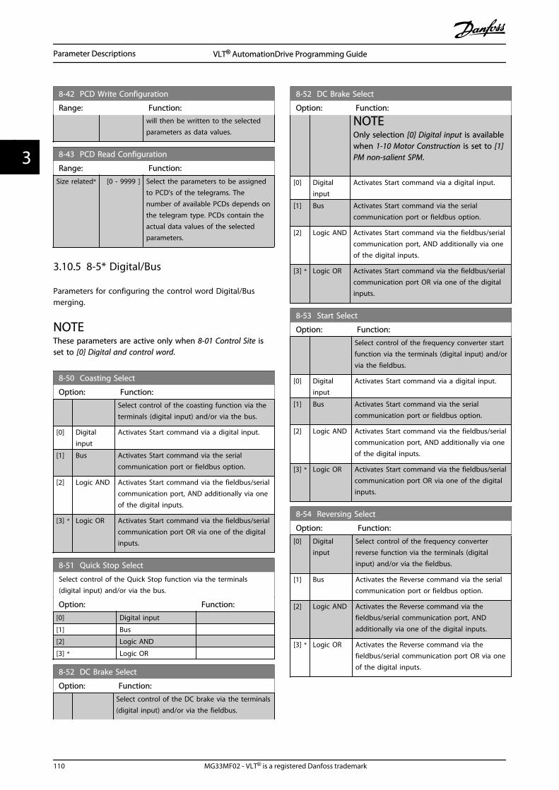
8-42 PCD Write Configuration
Range: Function:will then be written to the selectedparameters as data values.
8-43 PCD Read Configuration
Range: Function:
Size related* [0 - 9999 ] Select the parameters to be assignedto PCD's of the telegrams. Thenumber of available PCDs depends onthe telegram type. PCDs contain theactual data values of the selectedparameters.
3.10.5 8-5* Digital/Bus
Parameters for configuring the control word Digital/Busmerging.
NOTEThese parameters are active only when 8-01 Control Site isset to [0] Digital and control word.
8-50 Coasting Select
Option: Function:
Select control of the coasting function via theterminals (digital input) and/or via the bus.
[0] Digitalinput
Activates Start command via a digital input.
[1] Bus Activates Start command via the serialcommunication port or fieldbus option.
[2] Logic AND Activates Start command via the fieldbus/serialcommunication port, AND additionally via oneof the digital inputs.
[3] * Logic OR Activates Start command via the fieldbus/serialcommunication port OR via one of the digitalinputs.
8-51 Quick Stop Select
Select control of the Quick Stop function via the terminals(digital input) and/or via the bus.
Option: Function:
[0] Digital input
[1] Bus
[2] Logic AND
[3] * Logic OR
8-52 DC Brake Select
Option: Function:
Select control of the DC brake via the terminals(digital input) and/or via the fieldbus.
8-52 DC Brake Select
Option: Function:
NOTEOnly selection [0] Digital input is availablewhen 1-10 Motor Construction is set to [1]PM non-salient SPM.
[0] Digitalinput
Activates Start command via a digital input.
[1] Bus Activates Start command via the serialcommunication port or fieldbus option.
[2] Logic AND Activates Start command via the fieldbus/serialcommunication port, AND additionally via oneof the digital inputs.
[3] * Logic OR Activates Start command via the fieldbus/serialcommunication port OR via one of the digitalinputs.
8-53 Start Select
Option: Function:
Select control of the frequency converter startfunction via the terminals (digital input) and/orvia the fieldbus.
[0] Digitalinput
Activates Start command via a digital input.
[1] Bus Activates Start command via the serialcommunication port or fieldbus option.
[2] Logic AND Activates Start command via the fieldbus/serialcommunication port, AND additionally via oneof the digital inputs.
[3] * Logic OR Activates Start command via the fieldbus/serialcommunication port OR via one of the digitalinputs.
8-54 Reversing Select
Option: Function:
[0] Digitalinput
Select control of the frequency converterreverse function via the terminals (digitalinput) and/or via the fieldbus.
[1] Bus Activates the Reverse command via the serialcommunication port or fieldbus option.
[2] Logic AND Activates the Reverse command via thefieldbus/serial communication port, ANDadditionally via one of the digital inputs.
[3] * Logic OR Activates the Reverse command via thefieldbus/serial communication port OR via oneof the digital inputs.
Parameter Descriptions VLT® AutomationDrive Programming Guide
110 MG33MF02 - VLT® is a registered Danfoss trademark
33

8-55 Set-up Select
Option: Function:
Select control of the frequency converter set-up selection via the terminals (digital input)and/or via the fieldbus.
[0] Digitalinput
Activates the set-up selection via a digitalinput.
[1] Bus Activates the set-up selection via the serialcommunication port or fieldbus option.
[2] Logic AND Activates the set-up selection via the fieldbus/serial communication port, AND additionallyvia one of the digital inputs.
[3] * Logic OR Activate the set-up selection via the fieldbus/serial communication port OR via one of thedigital inputs.
8-56 Preset Reference Select
Option: Function:
Select control of the frequency converterPreset Reference selection via the terminals(digital input) and/or via the fieldbus.
[0] Digitalinput
Activates Preset Reference selection via adigital input.
[1] Bus Activates Preset Reference selection via theserial communication port or fieldbus option.
[2] Logic AND Activates Preset Reference selection via thefieldbus/serial communication port, ANDadditionally via one of the digital inputs.
[3] * Logic OR Activates the Preset Reference selection via thefieldbus/serial communication port OR via oneof the digital inputs.
8-57 Profidrive OFF2 Select
Select control of the OFF2 selection via the terminals (digitalinput) and/or via the fieldbus. This parameter is active only whenpar. 8-01 Control Site is set to [0] Digital and ctrl. word and par.8-10 is set to [1] Profidrive profile.
Option: Function:
[0] Digital input
[1] Bus
[2] Logic AND
[3] * Logic OR
8-58 Profidrive OFF3 Select
Select control of the OFF3 selection via the terminals (digitalinput) and/or via the fieldbus. This parameter is active only whenpar. 8-01 Control Site is set to [0] Digital and control word andpar. 8-10 is set to [1] Profidrive profile.
Option: Function:
[0] Digital input
[1] Bus
[2] Logic AND
8-58 Profidrive OFF3 Select
Select control of the OFF3 selection via the terminals (digitalinput) and/or via the fieldbus. This parameter is active only whenpar. 8-01 Control Site is set to [0] Digital and control word andpar. 8-10 is set to [1] Profidrive profile.
Option: Function:
[3] * Logic OR
3.10.6 8-8* FC Port Diagnostics
These parameters are used for monitoring the Buscommunication via the FC Port.
8-80 Bus Message Count
Range: Function:
0 * [0 - 0 ] This parameter shows the number of validtelegrams detected on the bus.
8-81 Bus Error Count
Range: Function:
0 * [0 - 0 ] This parameter shows the number of telegramswith faults (e.g. CRC fault), detected on the bus.
8-82 Slave Messages Rcvd
Range: Function:
0 * [0 - 0 ] This parameter shows the number of validtelegrams addressed to the slave, sent by thefrequency converter.
8-83 Slave Error Count
Range: Function:
0 * [0 - 0 ] This parameter shows the number of errortelegrams, which could not be executed by thefrequency converter.
3.10.7 8-9* Bus Jog
8-90 Bus Jog 1 Speed
Range: Function:
100 RPM* [ 0 - par. 4-13RPM]
Enter the jog speed. Activate thisfixed jog speed via the serial portor fieldbus option.
8-91 Bus Jog 2 Speed
Range: Function:
200 RPM* [ 0 - par. 4-13RPM]
Enter the jog speed. Activate thisfixed jog speed via the serial portor fieldbus option.
Parameter Descriptions VLT® AutomationDrive Programming Guide
MG33MF02 - VLT® is a registered Danfoss trademark 111
3 3

3.11 Parameters: 9-** Profibus
For Profibus parameter descriptions, see the ProfibusOperating Instructions.
3.12 Parameters: 10-** DeviceNet CANFieldbus
For Devicenet parameter descriptions, see the DevicenetOperating Instructions.
3.13 Parameters: 12-** Ethernet
For Ethernet parameter descriptions, see the EthernetOperating Instructions.
3.14 Parameters: 13-** Smart Logic Control
3.14.1 Prog. Features
Smart Logic Control (SLC) is essentially a sequence of userdefined actions (see 13-52 SL Controller Action [x]) executedby the SLC when the associated user defined event (see 13-51 SL Controller Event [x]) is evaluated as TRUE by theSLC.The condition for an event can be a particular status orthat the output from a Logic Rule or a ComparatorOperand becomes TRUE. That will lead to an associatedAction as illustrated:
. . .
. . .
Par. 13-43Comparator Operator
Par. 13-43Logic Rule Operator 2
Par. 13-51SL Controller Event
Par. 13-51SL Controller Action
130B
B671
.10
CoastStart timerSet Do X lowSelect set-up 2. . .
RunningWarningTorque limitDigital inpute X 30/2. . .
=TRUE longer than..
. . .
. . .
Illustration 3.48
Events and actions are each numbered and linked togetherin pairs (states). This means that when event [0] is fulfilled(attains the value TRUE), action [0] is executed. After this,the conditions of event [1] will be evaluated and ifevaluated TRUE, action [1] will be executed and so on.Only one event will be evaluated at any time. If an event isevaluated as FALSE, nothing happens (in the SLC) duringthe current scan interval and no other events will beevaluated. This means that when the SLC starts, itevaluates event [0] (and only event [0]) each scan interval.Only when event [0] is evaluated TRUE, will the SLCexecute action [0] and start evaluating event [1]. It ispossible to programme from 1 to 20 events and actions.When the last event/action has been executed, thesequence starts over again from event [0]/action [0]. Theillustration shows an example with three event / actions:
130B
A06
2.13
State 1Event 1/Action 1 State 2
Event 2/Action 2
Startevent P13-01
State 3Event 3/Action 3
State 4Event 4/Action 4
Stopevent P13-02
Stopevent P13-02
Stopevent P13-02
Illustration 3.49
Starting and stopping the SLC:Starting and stopping the SLC can be done byselecting .On [1]. or .Off [0]. in 13-00 SL Controller Mode.The SLC always starts in state 0 (where it evaluates event[0]). The SLC starts when the Start Event (defined in 13-01 Start Event) is evaluated as TRUE (provided that On[1] is selected in 13-00 SL Controller Mode). The SLC stopswhen the Stop Event (13-02 Stop Event) is TRUE. 13-03 ResetSLC resets all SLC parameters and start programming fromscratch.
NOTESLC is only active in AUTO mode, not Hand On mode
3.14.2 13-0* SLC Settings
Use the SLC settings to activate, deactivate and reset theSmart Logic Control sequence. The logic functions andcomtors are always running in the background, whichopens for sete control of digital inputs and outputs.
Parameter Descriptions VLT® AutomationDrive Programming Guide
112 MG33MF02 - VLT® is a registered Danfoss trademark
33

13-00 SL Controller Mode
Option: Function:
[0] Off Disables the -**Smart Logic Controller.
[1] On Enables the Smart Logic Controller.
13-01 Start Event
Select the boolean (TRUE or FALSE) input to activate Smart LogicControl.
Option: Function:
[0] * False Select the boolean (TRUE or FALSE)input to activate Smart Logic Control.Enters the fixed value - FALSE
[1] True Enters the fixed value - TRUE.
[2] Running The motor is running.
[3] In range The motor is running within theprogrammed current and speed rangesset in 4-50 Warning Current Low to 4-53 Warning Speed High.
[4] On reference The motor is running on reference.
[5] Torque limit The torque limit, set in 4-16 TorqueLimit Motor Mode or 4-17 Torque LimitGenerator Mode, has been exceeded.
[6] Current limit The motor current limit, set in 4-18 Current Limit, has been exceeded.
[7] Out of currentrange
The motor current is outside the rangeset in 4-18 Current Limit.
[8] Below I low The motor current is lower than set in 4-50 Warning Current Low.
[9] Above I high The motor current is higher than set in4-51 Warning Current High.
[10] Out of speedrange
The speed is outside the range set in 4-52 Warning Speed Low and 4-53 Warning Speed High.
[11] Below speed low The output speed is lower than thesetting in 4-52 Warning Speed Low.
[12] Above speed high The output speed is higher than thesetting in 4-53 Warning Speed High.
[13] Out of feedb.range
The feedback is outside the range setin 4-56 Warning Feedback Low and 4-57 Warning Feedback High.
[14] Below feedb. low The feedback is below the limit set in 4-56 Warning Feedback Low.
[15] Above feedb. high The feedback is above the limit set in 4-57 Warning Feedback High.
[16] Thermal warning The thermal warning turns on whenthe temperature exceeds the limit inthe motor, the frequency converter,the brake resistor or the thermistor.
13-01 Start Event
Select the boolean (TRUE or FALSE) input to activate Smart LogicControl.
Option: Function:
[17] Mains out of range The mains voltage is outside thespecified voltage range.
[18] Reversing The output is high when thefrequency converter is running counterclockwise (the logical product of thestatus bits “running” AND “reverse”).
[19] Warning A warning is active.
[20] Alarm (trip) A (trip) alarm is active.
[21] Alarm (trip lock) A (Trip lock) alarm is active.
[22] Comparator 0 Use the result of comparator 0.
[23] Comparator 1 Use the result of comparator 1.
[24] Comparator 2 Use the result of comparator 2.
[25] Comparator 3 Use the result of comparator 3.
[26] Logic rule 0 Use the result of logic rule 0.
[27] Logic rule 1 Use the result of logic rule 1.
[28] Logic rule 2 Use the result of logic rule 2.
[29] Logic rule 3 Use the result of logic rule 3.
[33] Digital input DI18 Use the result of digital input 18.
[34] Digital input DI19 Use the result of digital input 19.
[35] Digital input DI27 Use the result of digital input 27.
[36] Digital input DI29 Use the result of digital input 29.
[37] Digital input DI32 Use the result of digital input 32.
[38] Digital input DI33 Use the result of digital input 33.
[39] Start command A start command is issued.
[40] Drive stopped A stop command (Jog, Stop, Qstop,Coast) is issued – and not from theSLC itself.
[41] Reset Trip A reset is issued
[42] Auto-reset Trip An Auto reset is performed.
[43] Ok key The [OK] key is pressed.
[44] Reset key The [Reset] key is pressed.
[45] Left key The [] key is pressed.
[46] Right key The [] key is pressed.
[47] Up key The [] key is pressed.
[48] Down key The [] key is pressed.
[50] Comparator 4 Use the result of comparator 4.
[51] Comparator 5 Use the result of comparator 5.
[60] Logic rule 4 Use the result of logic rule 4.
[61] Logic rule 5 Use the result of logic rule 5.
Parameter Descriptions VLT® AutomationDrive Programming Guide
MG33MF02 - VLT® is a registered Danfoss trademark 113
3 3

13-02 Stop Event
Select the boolean (TRUE or FALSE) input to deactivate SmartLogic Control.
Option: Function:
[0] * False For descriptions [0]-[61], see 13-01 Start Event Start Event
[1] True
[2] Running
[3] In range
[4] On reference
[5] Torque limit
[6] Current limit
[7] Out of current range
[8] Below I low
[9] Above I high
[10] Out of speed range
[11] Below speed low
[12] Above speed high
[13] Out of feedb. range
[14] Below feedb. low
[15] Above feedb. high
[16] Thermal warning
[17] Mains out of range
[18] Reversing
[19] Warning
[20] Alarm (trip)
[21] Alarm (trip lock)
[22] Comparator 0
[23] Comparator 1
[24] Comparator 2
[25] Comparator 3
[26] Logic rule 0
[27] Logic rule 1
[28] Logic rule 2
[29] Logic rule 3
[30] SL Time-out 0
[31] SL Time-out 1
[32] SL Time-out 2
[33] Digital input DI18
[34] Digital input DI19
[35] Digital input DI27
[36] Digital input DI29
[37] Digital input DI32
[38] Digital input DI33
[39] Start command
[40] Drive stopped
[41] Reset Trip
[42] Auto-reset Trip
[43] Ok key
[44] Reset key
[45] Left key
[46] Right key
[47] Up key
[48] Down key
13-02 Stop Event
Select the boolean (TRUE or FALSE) input to deactivate SmartLogic Control.
Option: Function:
[50] Comparator 4
[51] Comparator 5
[60] Logic rule 4
[61] Logic rule 5
[70] SL Time-out 3 Smart Logic Controller timer 3 istimed out.
[71] SL Time-out 4 Smart Logic Controller timer 4 istimed out.
[72] SL Time-out 5 Smart Logic Controller timer 5 istimed out.
[73] SL Time-out 6 Smart Logic Controller timer 6 istimed out.
[74] SL Time-out 7 Smart Logic Controller timer 7 istimed out.
[75] Start command given
13-03 Reset SLC
Option: Function:
[0] * Do not resetSLC
Retains programmed settings in allparameter group 13-** Smart Logic Control.
[1] Reset SLC Resets all parameters in parameter group13-** Smart Logic Control to defaultsettings.
3.14.3 13-1* Comparators
Comparators are used for comparing continuous variables(i.e. output frequency, output current, analog input etc.) tofixed preset values.
Par. 13-11Comparator Operator
=
TRUE longer than.
. . .
. . .
Par. 13-10Comparator Operand
Par. 13-12Comparator Value
130B
B672
.10
Illustration 3.50
In addition, there are digital values that will be comparedto fixed time values. See explanation in 13-10 ComparatorOperand. Comparators are evaluated once in each scaninterval. Use the result (TRUE or FALSE) directly. Allparameters in this parameter group are array parameterswith index 0 to 5. Select index 0 to programmeComparator 0, select index 1 to programme Comparator 1,and so on.
Parameter Descriptions VLT® AutomationDrive Programming Guide
114 MG33MF02 - VLT® is a registered Danfoss trademark
33

13-10 Comparator Operand
Array [6]
Option: Function:
Choices [1] to [31] are variables whichwill be compared based on theirvalues. Choices [50] to [186] are digitalvalues (TRUE/FALSE) where thecomparison is based on the amount oftime during which they are set toTRUE or FALSE, respectively. See 13-11 Comparator Operator.Select the variable to be monitored bythe comparator.
[0] * DISABLED The comparator is disabled.
[1] Reference The resulting remote reference (notlocal) as a percentage.
[2] Feedback In the unit [RPM] or [Hz]
[3] Motor speed [RPM] or [Hz]
[4] Motor current [A]
[5] Motor torque [Nm]
[6] Motor power [kW] or [hp]
[7] Motor voltage [V]
[8] DC-link voltage [V]
[9] Motor thermal Expressed as a percentage.
[10] VLT thermal Expressed as a percentage.
[11] Heat sink temp. Expressed as a percentage.
[12] Analog input AI53 Expressed as a percentage.
[13] Analog input AI54 Expressed as a percentage.
[14] Analog inputAIFB10
[V]. AIFB10 is internal 10 V supply.
[15] Analog inputAIS24V
[V] Analog input AICCT [17] [°]. AIS24Vis switch mode power supply: SMPS24V.
[17] Analog inputAICCT
[°]. AICCT is control card temperature.
[18] Pulse input FI29 Expressed as a percentage.
[19] Pulse input FI33 Expressed as a percentage.
[20] Alarm number The error number.
[30] Counter A Number of counts
[31] Counter B Number of counts
[50] FALSE Enters the fixed value of false in thecomparator.
[51] TRUE Enters the fixed value of true in thecomparator.
[52] Control ready The control board receives supplyvoltage
13-10 Comparator Operand
Array [6]
Option: Function:
[53] Drive ready The frequency converter is ready foroperation and applies a supply signalon the control board.
[54] Running The motor is running.
[55] Reversing The output is high when thefrequency converter is running counterclockwise (the logical product of thestatus bits “running” AND “reverse”)
[56] In range The motor is running within theprogrammed current and speed rangesset in 4-50 Warning Current Low to 4-53 Warning Speed High.
[60] On reference The motor is running on reference.
[61] Below reference,low
The motor is running below the valuegiven in 4-54 Warning Reference Low
[62] Above ref, high The motor is running above the valuegiven in 4-55 Warning Reference High
[65] Torque limit The torque limit, set in 4-16 TorqueLimit Motor Mode or 4-17 Torque LimitGenerator Mode, has been exceeded.
[66] Current limit The motor current limit, set in 4-18 Current Limit, has been exceeded.
[67] Out of currentrange
The motor current is outside the rangeset in 4-18 Current Limit.
[68] Below I low The motor current is lower than set in 4-50 Warning Current Low.
[69] Above I high The motor current is higher than set in4-51 Warning Current High.
[70] Out of speedrange
The speed is outside the range set in 4-52 Warning Speed Low and 4-53 Warning Speed High.
[71] Below speed low The output speed is lower than thesetting in 4-52 Warning Speed Low.
[72] Above speed high The output speed is higher than thesetting in 4-53 Warning Speed High.
[75] Out of feedb.range
The feedback is outside the range setin 4-56 Warning Feedback Low and 4-57 Warning Feedback High.
[76] Below feedb. low The feedback is below the limit set in 4-56 Warning Feedback Low.
[77] Above feedb. high The feedback is above the limit set in 4-57 Warning Feedback High.
[80] Thermal warning The thermal warning turns on whenthe temperature exceeds the limit inthe motor, the frequency converter,the brake resistor or thermistor.
Parameter Descriptions VLT® AutomationDrive Programming Guide
MG33MF02 - VLT® is a registered Danfoss trademark 115
3 3

13-10 Comparator Operand
Array [6]
Option: Function:
[82] Mains out ofrange
The mains voltage is outside thespecified voltage range.
[85] Warning A warning is active.
[86] Alarm (trip) A (trip) alarm is active.
[87] Alarm (trip lock) A (Trip lock) alarm is active.
[90] Bus OK Active communication (no time-out)via the serial communication port.
[91] Torque limit &stop
If the frequency converter has receiveda stop signal and is at the torque limit,the signal is logic “0”.
[92] Brake fault (IGBT) The brake IGBT is short circuited.
[93] Mech. brakecontrol
The mechanical brake is active.
[94] Safe stop active
[100] Comparator 0 The result of comparator 0.
[101] Comparator 1 The result of comparator 1.
[102] Comparator 2 The result of comparator 2.
[103] Comparator 3 The result of comparator 3.
[104] Comparator 4 The result of comparator 4.
[105] Comparator 5 The result of comparator 5.
[110] Logic rule 0 The result of Logic rule 0.
[111] Logic rule 1 The result of Logic rule 1.
[112] Logic rule 2 The result of Logic rule 2.
[113] Logic rule 3 The result of Logic rule 3.
[114] Logic rule 4 The result of Logic rule 4.
[115] Logic rule 5 The result of Logic rule 5.
[120] SL Time-out 0 The result of SLC timer 0.
[121] SL Time-out 1 The result of SLC timer 1.
[122] SL Time-out 2 The result of SLC timer 2.
[123] SL Time-out 3 The result of SLC timer 3.
[124] SL Time-out 4 The result of SLC timer 4.
[125] SL Time-out 5 The result of SLC timer 5.
[126] SL Time-out 6 The result of SLC timer 6.
[127] SL Time-out 7 The result of SLC timer 7.
[130] Digital input DI18 Digital input 18. High = True.
[131] Digital input DI19 Digital input 19. High = True.
[132] Digital input DI27 Digital input 27. High = True.
[133] Digital input DI29 Digital input 29. High = True.
[134] Digital input DI32 Digital input 32. High = True.
[135] Digital input DI33 Digital input 33. High = True.
13-10 Comparator Operand
Array [6]
Option: Function:
[150] SL digital outputA
Use the result of the SLC output A.
[151] SL digital outputB
Use the result of the SLC output B.
[152] SL digital outputC
Use the result of the SLC output C.
[153] SL digital outputD
Use the result of the SLC output D.
[154] SL digital output E Use the result of the SLC output E.
[155] SL digital output F Use the result of the SLC output F.
[160] Relay 1 Relay 1 is active
[161] Relay 2 Relay 2 is active
[180] Local ref. active High when 3-13 Reference Site = [2]Local or when 3-13 Reference Site is [0]Linked to hand Auto, at the same timeas the LCP is in Hand On mode.
[181] Remote ref. active High when 3-13 Reference Site= [1]Remote or [0] Linked to hand/auto,while the LCP is in Auto On mode.
[182] Start command High when there is an active startcommand, and no stop command.
[183] Drive stopped A stop command (Jog, Stop, Qstop,Coast) is issued – and not from theSLC itself.
[185] Drive in handmode
High when the frequency converter isin hand mode.
[186] Drive in automode
High when the frequency converter isin auto mode.
[187] Start commandgiven
13-11 Comparator Operator
Array [6]
Option: Function:
Select the operator to be used in thecomparison. This is an array parametercontaining comparator operators 0 to 5.
[0] < The result of the evaluation is TRUE, whenthe variable selected in 13-10 ComparatorOperand is smaller than the fixed value in13-12 Comparator Value. The result is FALSE,if the variable selected in 13-10 ComparatorOperand is greater than the fixed value in13-12 Comparator Value.
[1] * ≈ (equal) The result of the evaluation is TRUE, whenthe variable selected in 13-10 ComparatorOperand is approximately equal to the fixedvalue in 13-12 Comparator Value.
Parameter Descriptions VLT® AutomationDrive Programming Guide
116 MG33MF02 - VLT® is a registered Danfoss trademark
33

13-11 Comparator Operator
Array [6]
Option: Function:
[2] > Inverse logic of option < [0].
[5] TRUE longerthan..
[6] FALSElonger than..
[7] TRUE shorterthan..
[8] FALSEshorterthan..
13-12 Comparator Value
Array [6]
Range: Function:
Size related* [-100000.000 -100000.000 ]
Enter the ‘trigger level’ for thevariable that is monitored bythis comtor. This is an arrayparameter containing comtorvalues 0 to 5.
3.14.4 13-1* RS Flip Flops
The Reset-Set Flip Flops hold the signal until set/reset.
Par. 13-15RS-FF Operand S
Par. 13-16RS-FF Operand R
130B
B959
.10
Illustration 3.51
Two parameters are used and the output can be used inthe logic rules and as events.
R
S
Flip Flop Output
130B
B960
.10
Illustration 3.52
The two operators can be selected from a long list. As aspecial case, the same digital input can be used as bothSet and Reset, making it possible to use the same digitalinput as start/stop. The following settings can be used toset up the same digital input as start/stop (example givenwith DI32 but is not a requirement).
Parameter Setting Notes13-00 SL Controller Mode On
13-01 Start Event TRUE
13-02 Stop Event FALSE
13-40 Logic Rule Boolean 1 [0][37] DigitalInput DI32
13-42 Logic Rule Boolean 2 [0] [2] Running
13-41 Logic Rule Operator 1[0]
[3] ANDNOT
13-40 Logic Rule Boolean 1 [1][37] DigitalInput DI32
13-42 Logic Rule Boolean 2 [1] [2] Running
13-41 Logic Rule Operator 1[1]
[1] AND
13-15 RS-FF Operand S [0][26]Logicrule 0
Output from 13-41[0]
13-16 RS-FF Operand R [0][27]Logicrule 1
Output from 13-41[1]
13-51 SL Controller Event [0][94] RSFlipflop 0
Output fromevaluating 13-15and 13-16
13-52 SL Controller Action [0] [22] Run
13-51 SL Controller Event [1][27]Logicrule 1
13-52 SL Controller Action [1] [24] Stop
Table 3.22
13-15 RS-FF Operand S
Option: Function:
[0] False
[1] True
[2] Running
[3] In range
[4] On reference
[5] Torque limit
[6] Current Limit
[7] Out of current range
[8] Below I low
[9] Above I high
[10] Out of speed range
[11] Below speed low
[12] Above speed high
[13] Out of feedb. range
[14] Below feedb. low
[15] Above feedb. high
[16] Thermal warning
[17] Mains out of range
[18] Reversing
[19] Warning
Parameter Descriptions VLT® AutomationDrive Programming Guide
MG33MF02 - VLT® is a registered Danfoss trademark 117
3 3

13-15 RS-FF Operand S
Option: Function:
[20] Alarm (trip)
[21] Alarm (trip lock)
[22] Comparator 0
[23] Comparator 1
[24] Comparator 2
[25] Comparator 3
[26] Logic rule 0
[27] Logic rule 1
[28] Logic rule 2
[29] Logic rule 3
[30] SL Time-out 0
[31] SL Time-out 1
[32] SL Time-out 2
[33] Digital input DI18
[34] Digital input DI19
[35] Digital input DI27
[36] Digital input DI29
[37] Digital input DI32
[38] Digital input DI33
[39] Start command
[40] Drive stopped
[41] Reset Trip
[42] Auto-reset Trip
[43] Ok key
[44] Reset key
[45] Left key
[46] Right key
[47] Up key
[48] Down key
[50] Comparator 4
[51] Comparator 5
[60] Logic rule 4
[61] Logic rule 5
[70] SL Time-out 3
[71] SL Time-out 4
[72] SL Time-out 5
[73] SL Time-out 6
[74] SL Time-out 7
[75] Start command given
[76] Digital input x30/2
[77] Digital input x30/3
[78] Digital input x30/4
[79] Digital input x46/1
[80] Digital input x46/3
[81] Digital input x46/5
[82] Digital input x46/7
[83] Digital input x46/9
[84] Digital input x46/11
[85] Digital input x46/13
[90] ATEX ETR cur. warning
[91] ATEX ETR cur. alarm
[92] ATEX ETR freq. warning
13-15 RS-FF Operand S
Option: Function:
[93] ATEX ETR freq. alarm
[94] RS Flipflop 0
[95] RS Flipflop 1
[96] RS Flipflop 2
[97] RS Flipflop 3
[98] RS Flipflop 4
[99] RS Flipflop 5
[100] RS Flipflop 6
[101] RS Flipflop 7
13-16 RS-FF Operand R
Option: Function:
[0] False
[1] True
[2] Running
[3] In range
[4] On reference
[5] Torque limit
[6] Current Limit
[7] Out of current range
[8] Below I low
[9] Above I high
[10] Out of speed range
[11] Below speed low
[12] Above speed high
[13] Out of feedb. range
[14] Below feedb. low
[15] Above feedb. high
[16] Thermal warning
[17] Mains out of range
[18] Reversing
[19] Warning
[20] Alarm (trip)
[21] Alarm (trip lock)
[22] Comparator 0
[23] Comparator 1
[24] Comparator 2
[25] Comparator 3
[26] Logic rule 0
[27] Logic rule 1
[28] Logic rule 2
[29] Logic rule 3
[30] SL Time-out 0
[31] SL Time-out 1
[32] SL Time-out 2
[33] Digital input DI18
[34] Digital input DI19
[35] Digital input DI27
[36] Digital input DI29
[37] Digital input DI32
[38] Digital input DI33
[39] Start command
Parameter Descriptions VLT® AutomationDrive Programming Guide
118 MG33MF02 - VLT® is a registered Danfoss trademark
33

13-16 RS-FF Operand R
Option: Function:
[40] Drive stopped
[41] Reset Trip
[42] Auto-reset Trip
[43] Ok key
[44] Reset key
[45] Left key
[46] Right key
[47] Up key
[48] Down key
[50] Comparator 4
[51] Comparator 5
[60] Logic rule 4
[61] Logic rule 5
[70] SL Time-out 3
[71] SL Time-out 4
[72] SL Time-out 5
[73] SL Time-out 6
[74] SL Time-out 7
[75] Start command given
[76] Digital input x30/2
[77] Digital input x30/3
[78] Digital input x30/4
[79] Digital input x46/1
[80] Digital input x46/3
[81] Digital input x46/5
[82] Digital input x46/7
[83] Digital input x46/9
[84] Digital input x46/11
[85] Digital input x46/13
[90] ATEX ETR cur. warning
[91] ATEX ETR cur. alarm
[92] ATEX ETR freq. warning
[93] ATEX ETR freq. alarm
[94] RS Flipflop 0
[95] RS Flipflop 1
[96] RS Flipflop 2
[97] RS Flipflop 3
[98] RS Flipflop 4
[99] RS Flipflop 5
[100] RS Flipflop 6
[101] RS Flipflop 7
3.14.5 13-2* Timers
Use the result (TRUE or FALSE) from timers directly todefine an event (see 13-51 SL Controller Event), or asboolean input in a logic rule (see 13-40 Logic Rule Boolean1, 13-42 Logic Rule Boolean 2 or 13-44 Logic Rule Boolean 3).A timer is only FALSE when started by an action (i.e. [29]Start timer 1) until the timer value entered in thisparameter is elapsed. Then it becomes TRUE again.
All parameters in this parameter group are arrayparameters with index 0 to 2. Select index 0 to programTimer 0, select index 1 to program Timer 1, and so on.
13-20 SL Controller Timer
Range: Function:
0.000N/A*
[0.000 -0.000 N/A]
Enter the value to define the duration ofthe FALSE output from the programmedtimer. A timer is only FALSE if it isstarted by an action (i.e. Start timer 1[29]) and until the given timer value haselapsed.
3.14.6 13-4* Logic Rules
Combine up to three boolean inputs (TRUE/FALSE inputs)from timers, comtors, digital inputs, status bits and eventsusing the logical operators AND, OR, and NOT. Selectboolean inputs for the calculation in 13-40 Logic RuleBoolean 1, 13-42 Logic Rule Boolean 2 and 13-44 Logic RuleBoolean 3. Define the operators used to logically combinethe selected inputs in 13-41 Logic Rule Operator 1 and 13-43 Logic Rule Operator 2.
. . .
. . . . . .. . .
Par. 13-43Logic Rule Operator 2
Par. 13-41Logic Rule Operator 1
Par. 13-40Logic Rule Boolean 1
Par. 13-42Logic Rule Boolean 2
Par. 13-44Logic Rule Boolean 3
130B
B673
.10
Illustration 3.53
Priority of calculationThe results of 13-40 Logic Rule Boolean 1, 13-41 Logic RuleOperator 1 and 13-42 Logic Rule Boolean 2 are calculatedfirst. The outcome (TRUE/FALSE) of this calculation iscombined with the settings of 13-43 Logic Rule Operator 2and 13-44 Logic Rule Boolean 3, yielding the final result(TRUE/FALSE) of the logic rule.
13-40 Logic Rule Boolean 1
Array [6]
Option: Function:
[0] * False Select the first boolean (TRUE orFALSE) input for the selected logicrule.See 13-01 Start Event ([0] - [61]) and 13-02 Stop Event ([70] - [75]) forfurther description.
[1] True
[2] Running
[3] In range
[4] On reference
Parameter Descriptions VLT® AutomationDrive Programming Guide
MG33MF02 - VLT® is a registered Danfoss trademark 119
3 3

13-40 Logic Rule Boolean 1
Array [6]
Option: Function:
[5] Torque limit
[6] Current limit
[7] Out of current range
[8] Below I low
[9] Above I high
[10] Out of speed range
[11] Below speed low
[12] Above speed high
[13] Out of feedb. range
[14] Below feedb. low
[15] Above feedb. high
[16] Thermal warning
[17] Mains out of range
[18] Reversing
[19] Warning
[20] Alarm (trip)
[21] Alarm (trip lock)
[22] Comparator 0
[23] Comparator 1
[24] Comparator 2
[25] Comparator 3
[26] Logic rule 0
[27] Logic rule 1
[28] Logic rule 2
[29] Logic rule 3
[30] SL Time-out 0
[31] SL Time-out 1
[32] SL Time-out 2
[33] Digital input DI18
[34] Digital input DI19
[35] Digital input DI27
[36] Digital input DI29
[37] Digital input DI32
[38] Digital input DI33
[39] Start command
[40] Drive stopped
[41] Reset Trip
[42] Auto-reset Trip
[43] Ok key
[44] Reset key
[45] Left key
[46] Right key
[47] Up key
[48] Down key
[50] Comparator 4
[51] Comparator 5
[60] Logic rule 4
[61] Logic rule 5
[70] SL Time-out 3
[71] SL Time-out 4
[72] SL Time-out 5
13-40 Logic Rule Boolean 1
Array [6]
Option: Function:
[73] SL Time-out 6
[74] SL Time-out 7
[75] Start command given
13-41 Logic Rule Operator 1
Array [6]
Option: Function:
Select the first logical operator to use onthe Boolean inputs from 13-40 Logic RuleBoolean 1 and 13-42 Logic Rule Boolean 2.[13-**] signifies the boolean input ofparameter group 13-** Smart Logic Control.
[0] * DISABLED Ignores 13-42 Logic Rule Boolean 2, 13-43 Logic Rule Operator 2, and 13-44 LogicRule Boolean 3.
[1] AND Evaluates the expression [13-40] AND[13-42].
[2] OR Evaluates the expression [13-40] OR [13-42].
[3] AND NOT Evaluates the expression [13-40] AND NOT[13-42].
[4] OR NOT Evaluates the expression [13-40] OR NOT[13-42].
[5] NOT AND Evaluates the expression NOT [13-40] AND[13-42].
[6] NOT OR Evaluates the expression NOT [13-40] OR[13-42].
[7] NOT AND NOT Evaluates the expression NOT [13-40] ANDNOT [13-42].
[8] NOT OR NOT Evaluates the expression NOT [13-40] ORNOT [13-42].
13-42 Logic Rule Boolean 2
Array [6]
Option: Function:
[0] * False Select the second boolean (TRUE orFALSE) input for the selected logicrule. See 13-01 Start Event ([0] - [61])and 13-02 Stop Event ([70] - [75]) forfurther description.
[1] True
[2] Running
[3] In range
[4] On reference
[5] Torque limit
[6] Current limit
[7] Out of current range
[8] Below I low
[9] Above I high
Parameter Descriptions VLT® AutomationDrive Programming Guide
120 MG33MF02 - VLT® is a registered Danfoss trademark
33

13-42 Logic Rule Boolean 2
Array [6]
Option: Function:
[10] Out of speed range
[11] Below speed low
[12] Above speed high
[13] Out of feedb. range
[14] Below feedb. low
[15] Above feedb. high
[16] Thermal warning
[17] Mains out of range
[18] Reversing
[19] Warning
[20] Alarm (trip)
[21] Alarm (trip lock)
[22] Comparator 0
[23] Comparator 1
[24] Comparator 2
[25] Comparator 3
[26] Logic rule 0
[27] Logic rule 1
[28] Logic rule 2
[29] Logic rule 3
[30] SL Time-out 0
[31] SL Time-out 1
[32] SL Time-out 2
[33] Digital input DI18
[34] Digital input DI19
[35] Digital input DI27
[36] Digital input DI29
[37] Digital input DI32
[38] Digital input DI33
[39] Start command
[40] Drive stopped
[41] Reset Trip
[42] Auto-reset Trip
[43] Ok key
[44] Reset key
[45] Left key
[46] Right key
[47] Up key
[48] Down key
[50] Comparator 4
[51] Comparator 5
[60] Logic rule 4
[61] Logic rule 5
[70] SL Time-out 3
[71] SL Time-out 4
[72] SL Time-out 5
[73] SL Time-out 6
[74] SL Time-out 7
[75] Start command given
13-43 Logic Rule Operator 2
Array [6]
Option: Function:
Select the second logical operator to beused on the boolean input calculated in13-40 Logic Rule Boolean 1, 13-41 Logic RuleOperator 1, and 13-42 Logic Rule Boolean 2,and the boolean input coming from13-42 Logic Rule Boolean 2.[13-44] signifies the boolean input of13-44 Logic Rule Boolean 3.[13-40/13-42] signifies the boolean inputcalculated in 13-40 Logic Rule Boolean 1, 13-41 Logic Rule Operator 1, and 13-42 LogicRule Boolean 2. [0] DISABLED (factorysetting). select this option to ignore13-44 Logic Rule Boolean 3.
[0] * DISABLED
[1] AND
[2] OR
[3] AND NOT
[4] OR NOT
[5] NOT AND
[6] NOT OR
[7] NOT AND NOT
[8] NOT OR NOT
13-44 Logic Rule Boolean 3
Array [6]
Option: Function:
[0] * False Select the third boolean (TRUE orFALSE) input for the selected logicrule. See 13-01 Start Event ([0] - [61])and 13-02 Stop Event ([70] - [75]) forfurther description.
[1] True
[2] Running
[3] In range
[4] On reference
[5] Torque limit
[6] Current limit
[7] Out of current range
[8] Below I low
[9] Above I high
[10] Out of speed range
[11] Below speed low
[12] Above speed high
[13] Out of feedb. range
[14] Below feedb. low
[15] Above feedb. high
[16] Thermal warning
[17] Mains out of range
[18] Reversing
[19] Warning
Parameter Descriptions VLT® AutomationDrive Programming Guide
MG33MF02 - VLT® is a registered Danfoss trademark 121
3 3
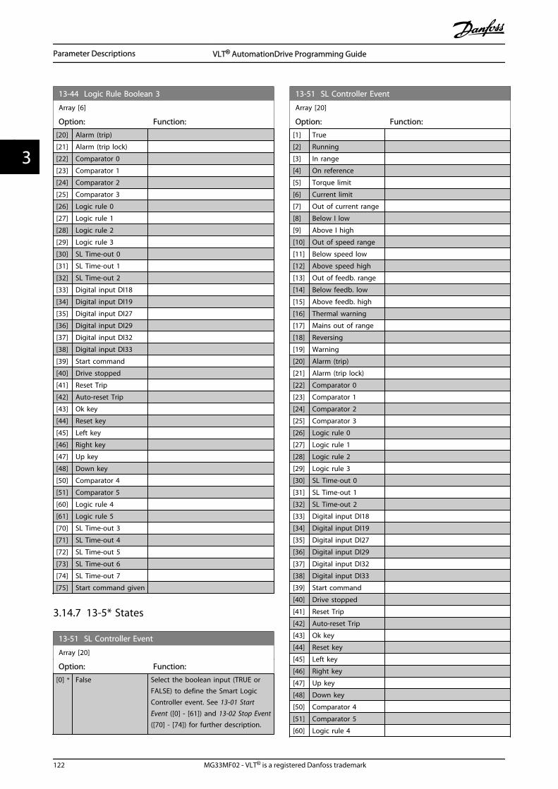
13-44 Logic Rule Boolean 3
Array [6]
Option: Function:
[20] Alarm (trip)
[21] Alarm (trip lock)
[22] Comparator 0
[23] Comparator 1
[24] Comparator 2
[25] Comparator 3
[26] Logic rule 0
[27] Logic rule 1
[28] Logic rule 2
[29] Logic rule 3
[30] SL Time-out 0
[31] SL Time-out 1
[32] SL Time-out 2
[33] Digital input DI18
[34] Digital input DI19
[35] Digital input DI27
[36] Digital input DI29
[37] Digital input DI32
[38] Digital input DI33
[39] Start command
[40] Drive stopped
[41] Reset Trip
[42] Auto-reset Trip
[43] Ok key
[44] Reset key
[45] Left key
[46] Right key
[47] Up key
[48] Down key
[50] Comparator 4
[51] Comparator 5
[60] Logic rule 4
[61] Logic rule 5
[70] SL Time-out 3
[71] SL Time-out 4
[72] SL Time-out 5
[73] SL Time-out 6
[74] SL Time-out 7
[75] Start command given
3.14.7 13-5* States
13-51 SL Controller Event
Array [20]
Option: Function:
[0] * False Select the boolean input (TRUE orFALSE) to define the Smart LogicController event. See 13-01 StartEvent ([0] - [61]) and 13-02 Stop Event([70] - [74]) for further description.
13-51 SL Controller Event
Array [20]
Option: Function:
[1] True
[2] Running
[3] In range
[4] On reference
[5] Torque limit
[6] Current limit
[7] Out of current range
[8] Below I low
[9] Above I high
[10] Out of speed range
[11] Below speed low
[12] Above speed high
[13] Out of feedb. range
[14] Below feedb. low
[15] Above feedb. high
[16] Thermal warning
[17] Mains out of range
[18] Reversing
[19] Warning
[20] Alarm (trip)
[21] Alarm (trip lock)
[22] Comparator 0
[23] Comparator 1
[24] Comparator 2
[25] Comparator 3
[26] Logic rule 0
[27] Logic rule 1
[28] Logic rule 2
[29] Logic rule 3
[30] SL Time-out 0
[31] SL Time-out 1
[32] SL Time-out 2
[33] Digital input DI18
[34] Digital input DI19
[35] Digital input DI27
[36] Digital input DI29
[37] Digital input DI32
[38] Digital input DI33
[39] Start command
[40] Drive stopped
[41] Reset Trip
[42] Auto-reset Trip
[43] Ok key
[44] Reset key
[45] Left key
[46] Right key
[47] Up key
[48] Down key
[50] Comparator 4
[51] Comparator 5
[60] Logic rule 4
Parameter Descriptions VLT® AutomationDrive Programming Guide
122 MG33MF02 - VLT® is a registered Danfoss trademark
33

13-51 SL Controller Event
Array [20]
Option: Function:
[61] Logic rule 5
[70] SL Time-out 3
[71] SL Time-out 4
[72] SL Time-out 5
[73] SL Time-out 6
[74] SL Time-out 7
[75] Start command given
13-52 SL Controller Action
Array [20]
Option: Function:
[0] * DISABLED Select the action corresponding to theSLC event. Actions are executed whenthe corresponding event (defined in 13-51 SL Controller Event) is evaluated astrue. The following actions are availablefor selection:
[0] *DISABLED
[1] No action
[2] Select set-up 1 Changes the active set-up (0-10 Active Set-up) to ‘1’.If the set-up is changed, it will mergewith other set-up commands comingfrom either the digital inputs or via afieldbus.
[3] Select set-up 2 Changes the active set-up 0-10 Active Set-up) to ‘2’.If the set-up is changed, it will mergewith other set-up commands comingfrom either the digital inputs or via afieldbus.
[4] Select set-up 3 Changes the active set-up (0-10 Active Set-up) to ‘3’.If the set-up is changed, it will mergewith other set-up commands comingfrom either the digital inputs or via afieldbus.
[5] Select set-up 4 Changes the active set-up (0-10 Active Set-up) to ‘4’.If the set-up is changed, it will mergewith other set-up commands comingfrom either the digital inputs or via afieldbus.
[10] Select preset ref0
Selects preset reference 0.If the active preset reference is changed,it will merge with other preset referencecommands coming from either the digitalinputs or via a fieldbus.
[11] Select preset ref1
Selects preset reference 1.
13-52 SL Controller Action
Array [20]
Option: Function:If the active preset reference is changed,it will merge with other preset referencecommands coming from either the digitalinputs or via a fieldbus.
[12] Select preset ref2
Selects preset reference 2.If the active preset reference is changed,it will merge with other preset referencecommands coming from either the digitalinputs or via a fieldbus.
[13] Select preset ref3
Selects preset reference 3.If the active preset reference is changed,it will merge with other preset referencecommands coming from either the digitalinputs or via a fieldbus.
[14] Select preset ref4
Selects preset reference 4.If the active preset reference is changed,it will merge with other preset referencecommands coming from either the digitalinputs or via a fieldbus.
[15] Select preset ref5
Selects preset reference 5.If the active preset reference is changed,it will merge with other preset referencecommands coming from either the digitalinputs or via a fieldbus.
[16] Select preset ref6
Selects preset reference 6.If the active preset reference is changed,it will merge with other preset referencecommands coming from either the digitalinputs or via a fieldbus.
[17] Select preset ref7
Selects preset reference 7.If the active preset reference is changed,it will merge with other preset referencecommands coming from either the digitalinputs or via a fieldbus.
[18] Select ramp 1 Selects ramp 1.
[19] Select ramp 2 Selects ramp 2.
[20] Select ramp 3 Selects ramp 3.
[21] Select ramp 4 Selects ramp 4.
[22] Run Issues a start command to the frequencyconverter.
[23] Run reverse Issues a start reverse command to thefrequency converter.
[24] Stop Issues a stop command to the frequencyconverter.
[25] Qstop Issues a quick stop command to thefrequency converter.
[26] Dcstop Issues a DC stop command to thefrequency converter.
Parameter Descriptions VLT® AutomationDrive Programming Guide
MG33MF02 - VLT® is a registered Danfoss trademark 123
3 3

13-52 SL Controller Action
Array [20]
Option: Function:
[27] Coast The frequency converter coastsimmediately. All stop commandsincluding the coast command stop theSLC.
[28] Freeze output Freezes the output frequency of thefrequency converter.
[29] Start timer 0 Starts timer 0, see 13-20 SL ControllerTimer for further description.
[30] Start timer 1 Starts timer 1, see 13-20 SL ControllerTimer for further description.
[31] Start timer 2 Starts timer 2, see 13-20 SL ControllerTimer for further description.
[32] Set digital out Alow
Any output with SL output A will be low.
[33] Set digital out Blow
Any output with SL output B will be low.
[34] Set digital out Clow
Any output with SL output Cwill be low.
[35] Set digital outD low
Any output with SL output D will be low.
[36] Set digital out Elow
Any output with SL output E will be low.
[37] Set digital out Flow
Any output with SL output F will be low.
[38] Set digital out Ahigh
Any output with SL output A will be high.
[39] Set digital out Bhigh
Any output with SL output B will be high.
[40] Set digital out Chigh
Any output with SL output C will be high.
[41] Set digital outD high
Any output with SL output D will behigh.
[42] Set digital out Ehigh
Any output with SL output E will be high.
[43] Set digital out Fhigh
Any output with SL output Fwill be high.
[60] Reset Counter A Resets Counter A to zero.
[61] Reset Counter B Resets Counter B to zero.
[70] Start timer 3 Start Timer 3, see 13-20 SL ControllerTimer for further description.
[71] Start timer 4 Start Timer 4, see 13-20 SL ControllerTimer for further description.
[72] Start timer 5 Start Timer 5, see 13-20 SL ControllerTimer for further description.
[73] Start timer 6 Start Timer 6, see 13-20 SL ControllerTimer for further description.
[74] Start timer 7 Start Timer 7, see p13-20 SL ControllerTimer for further description.
Parameter Descriptions VLT® AutomationDrive Programming Guide
124 MG33MF02 - VLT® is a registered Danfoss trademark
33

3.15 Parameters: 14-** Special Functions
3.15.1 14-0* Inverter Switching
14-00 Switching Pattern
Option: Function:
Select the switching pattern: 60° AVM or SFAVM.
[0] 60 AVM
[1] * SFAVM
NOTEThe switching pattern may be automatically adapted bythe frequency converter in order to avoid a trip. Seeapplication note on derating for more details.
14-01 Switching Frequency
Select the inverter switching frequency. Changing the switchingfrequency can help to reduce acoustic noise from the motor.Default depends on power size.
Option: Function:
[0] 1.0 kHz
[1] 1.5 kHz Default switching frequency for355-1200 kW, 690 V
[2] 2.0 kHz Default switching frequency for250-800 kW, 400 V and 37-315kW, 690 V
[3] 2.5 kHz
[4] 3.0 kHz Default switching frequency for18.5-37 kW, 200 V and 37-200kW, 400 V
[5] 3.5 kHz
[6] 4.0 kHz Default switching frequency for5.5–15 kW, 200 V and 11-30kW, 400 V
[7] * 5.0 kHz Default switching frequency for0.25–3,7 kW, 200 V and0.37-7.5 kW, 400 V
[8] 6.0 kHz
[9] 7.0 kHz
[10] 8.0 kHz
[11] 10.0 kHz
[12] 12.0 kHz
[13] 14.0 kHz
[14] 16.0 kHz
NOTEThe output frequency value of the frequency convertermust never exceed 1/10 of the switching frequency. Whenthe motor is running, adjust the switching frequency in 14-01 Switching Frequency until the motor is as noiseless aspossible.
NOTEThe switching frequency may be automatically adapted bythe frequency converter in order to avoid a trip. Seeapplication note on derating for more details.
14-03 Overmodulation
Option: Function:
[0] Off Select [0] Off for no overmodulation of the outputvoltage, in order to avoid torque ripple on the motorshaft. This feature may be useful for applications suchas grinding machines.
[1] * On Select [1] On to enable the overmodulation functionfor the output voltage. This is the right choice when itis required that the output voltage is higher than 95%of the input voltage (typical when running over-synchronously). The output voltage is increasedaccording to the degree of overmodulation.
Overmodulation leads to increased torque ripple asharmonics are increased.
Control in FLUX mode provides an output current ofup to 98% of the input current, regardless of 14-03 Overmodulation.
14-04 PWM Random
Option: Function:
[0] * Off No change of the acoustic motor switching noise.
[1] On Transforms the acoustic motor switching noise from aclear ringing tone to a less noticeable ‘white’ noise.This is achieved by slightly and randomly altering thesynchronism of the pulse width modulated outputphases.
14-06 Dead Time Compensation
Option: Function:
[0] Off No compensation.
[1] * On Activates dead time compensation.
3.15.2 14-1* Mains On/Off
Parameters for configuring mains failure monitoring andhandling. If a mains failure appears, the frequencyconverter will try to continue in a controlled way until thepower in the DC link has been exhausted.
14-10 Mains Failure
Option: Function:
14-10 Mains Failure is typically used where veryshort mains interruptions (voltage dips) arepresent. At 100% load and a short voltageinterruption, the DC voltage on the maincapacitors drops quickly. For larger drives it onlytakes a few milliseconds before the DC level is
Parameter Descriptions VLT® AutomationDrive Programming Guide
MG33MF02 - VLT® is a registered Danfoss trademark 125
3 3

14-10 Mains Failure
Option: Function:down to about 373 V DC and the IGBTs cut offand looses the control over the motor. When themains is restored, and the IGBTs start again, theoutput frequency and voltage vector does notcorrespond to the speed/frequency of the motor,and the result is normally an overvoltage orovercurrent, mostly resulting in a trip lock. 14-10 Mains Failure can be programmed to avoidthis situation.
Select the function to which the frequencyconverter must act when the threshold in 14-11 Mains Voltage at Mains Fault has beenreached.14-10 Mains Failure cannot be changed whilemotor is running.
[0]*
Nofunction
The frequency converter will not compensate for amains interruption. The voltage on the DC-link willdrop quickly and motor control will be lost withinmilliseconds to seconds. Trip lock will be theresult.
[1] Ctrl.ramp-down
The frequency converter will remain control of themotor and do a controlled ramp down from 14-11 Mains Voltage at Mains Fault level. If 2-10 Brake Function is [0] Off or [2] AC brake, theramp will follow the Over Voltage Ramping. If 2-10 Brake Function is [1] Resistor Brake the rampwill follow the setting in 3-81 Quick Stop RampTime. This selection is particularly useful in pumpapplications, where the inertia is low and thefriction is high. When the mains is restored, theoutput frequency will ramp the motor up to thereference speed (if the mains interruption isprolonged, the controlled ramp down might takethe output frequency all the way down to 0 RPM,and when the mains is restored, the application isramped up from 0rpm to the previous referencespeed via the normal ramp up). If the energy inthe DC-link disappears before the motor isramped to zero the motor will be coasted.
[2] Ctrl.ramp-down,trip
This selection is similar to selection [1] except thatin [2] a reset is necessary for starting up afterpower-up.
[3] Coasting Centrifuges can run for an hour without powersupply. In those situations it is possible to select acoast function at mains interruption, together witha flying start which occurs when the mains isrestored.
[4] Kineticback-up
Kinetic back-up ensures that the frequencyconverter keeps running as long as there isenergy in the system due to the inertia frommotor and load. This is done by converting themechanical energy to the DC-link and thereby
14-10 Mains Failure
Option: Function:maintaining control of the drive and motor. Thiscan extend the controlled operation, dependingon the inertia in the system. For fans it is typicallyseveral seconds, for pumps up to 2 seconds andfor compressors only for a fraction of a second.Many industry applications can extend controlledoperation for many seconds, which is oftenenough time for the mains to return.
130B
C918
.10
U
14-11*1.35
Ref
n [RPM]
t [S]
A B C D E ADC
UDC
[V]
t [S]
Illustration 3.57
A = Normal Operation D = Mains return
B = Mains failure E = Normal Operation:ramping
C = Kinetic back-upa
Table 3.26
The DC-level during [4] Kinetic back-up is 14-11 Mains Voltage at Mains Fault* 1,35.If the mains do not return UDC is maintained as
long as possible by ramping the speed downtowards 0 RPM. Finally the frequency convertercoasts.
If the mains return while in kinetic back-up UDC
will increase above 14-11 Mains Voltage at MainsFault*1.35. This is detected in one of the followingways.
1. If UDC > 14-11 Mains Voltage at Mains
Fault*1.35*1.05
2. If the speed is above the reference. Thisis relevant if the mains come back at alower level than before, e.g. 14-11 MainsVoltage at Mains Fault*1.35*1.02. Thisdoes not fulfil the criterion in point oneand the frequency converter will try toreduce UDC to 14-11 Mains Voltage at
Mains Fault*1.35 by increasing the speed.This will not succeed as the mainscannot be lowered.
3. If running motoric. The same mechanismas in point two, but where the inertiawill prevent that the speed goes abovethe reference speed. This will lead to the
Parameter Descriptions VLT® AutomationDrive Programming Guide
126 MG33MF02 - VLT® is a registered Danfoss trademark
33

14-10 Mains Failure
Option: Function:motor running motoric until the speed isabove the reference speed and thesituation in point two occurs. Instead ofwaiting for that criterion three isintroduced.
[5] Kineticback-up,trip
The difference between kinetic back-up with andwithout trip is that the latter will always rampdown to 0 RPM and trip, regardless of whethermains return or not.The function is made so that it will not evendetect if mains return, this is the reason for therelatively high level on the DC-link during rampdown.
14-11*1.35
Ref
790 V
0
A B C D
130B
C92
0.10U
n [RPM]
t [S]
DC
UDC
[V]
t [S]
Illustration 3.58
A = Normal Operation C = Kinetic back-up
B = Mains failure D = Trip
Table 3.27
[6] Alarm
14-11 Mains Voltage at Mains Fault
Range: Function:
Sizerelated*
[180 -600 V]
This parameter defines the threshold voltageat which the selected function in14-10 Mains Failure should be activated. Itmay be considered to choose 90% of thenominal mains as the detection level,depending on the supply quality. For asupply of 380 V 14-11 Mains Voltage at MainsFault should thus be set to 342 V. Thisresults in a DC detection level of 462 V(14-11 * 1.35)
14-11 Mains Voltage at Mains Fault
Range: Function:
NOTENote for converting between VLT 5000and FC 300:Even though the setting of the MainsVoltage at Mains Fault is the same forVLT 5000 and FC 300, the detectionlevel is different. Use the followingformula to obtain the same detectionlevel as in VLT 5000: 14-11 MainsVoltage at Mains Fault (VLT 5000 level) =Value used in VLT 5000 * 1,35/sqrt(2).
14-12 Function at Mains Imbalance
Operation under severe main imbalance conditions reduces thelifetime of the motor. Conditions are considered severe if themotor is operated continuously near nominal load (e.g. a pumpor fan running near full speed).
Option: Function:
[0] * Trip Trips the frequencyconverter
[1] Warning Issues a warning
[2] Disabled No action
14-14 Kin. Backup Time Out
Range: Function:
60 s* [0 - 60s]
This parameter defines the Kinetic Backup TimeOut in flux mode when running on low voltagegrids. If the supply voltage does not increaseabove the value defined in 14-11 Mains Voltageat Mains Fault +5% within the specified time,the drive will then automatically run acontrolled ramp-down profile prior to stop.
14-15 Kin. Backup Trip Recovery Level
Range: Function:
Size related* [ 0 - 60000.000ReferenceFeedbackUnit]
This parameter specifiesthe Kinetic Backup TripRecovery Level. The unitis defined in 0-02 MotorSpeed Unit.
Parameters for configuring auto reset handling, special triphandling and control card self test or initialisation.
14-20 Reset Mode
Option: Function:
Select the reset function aftertripping. Once reset, the frequencyconverter can be restarted.
Parameter Descriptions VLT® AutomationDrive Programming Guide
MG33MF02 - VLT® is a registered Danfoss trademark 127
3 3

14-20 Reset Mode
Option: Function:
[0] * Manual reset Select [0] Manual reset, to perform areset via [RESET] or via the digitalinputs.
[1] Automatic reset x 1 Select [1]-[12] Automatic reset x 1…x20 to perform between one andtwenty automatic resets aftertripping.
[2] Automatic reset x 2
[3] Automatic reset x 3
[4] Automatic reset x 4
[5] Automatic reset x 5
[6] Automatic reset x 6
[7] Automatic reset x 7
[8] Automatic reset x 8
[9] Automatic reset x 9
[10] Automatic reset x 10
[11] Automatic reset x 15
[12] Automatic reset x 20
[13] Infinite auto reset Select [13] Infinite Automatic Reset forcontinuous resetting after tripping.
[14] Reset at power-up
NOTEThe motor may start without warning. If the specifiednumber of AUTOMATIC RESETs is reached within 10minutes, the frequency converter enters Manual reset [0]mode. After the Manual reset is performed, the setting of14-20 Reset Mode reverts to the original selection. If thenumber of automatic resets is not reached within 10minutes, or when a Manual reset is performed, the internalAUTOMATIC RESET counter returns to zero.
NOTEAutomatic reset will also be active for resetting safe stopfunction in firmware version < 4.3x.
14-21 Automatic Restart Time
Range: Function:
10 s* [0 - 600 s] Enter the time interval from trip to start ofthe automatic reset function. This parameteris active when 14-20 Reset Mode is set to [1] -[13] Automatic reset.
NOTERemember to set switches S201 (A53) and S202 (A54) asspecified below when performing a control card test in 14-22 Operation Mode [1]. Otherwise, the test will fail!
14-22 Operation Mode
Option: Function:
Use this parameter to specify normaloperation; to perform tests; or to initialise allparameters except 15-03 Power Up's, 15-04 Over Temp's and 15-05 Over Volt's. Thisfunction is active only when the power iscycled to the frequency converter.Select [0] Normal operation for normaloperation of the frequency converter with themotor in the selected application.Select [1] Control card test to test the analogand digital inputs and outputs and the +10 Vcontrol voltage. The test requires a testconnector with internal connections. Use thefollowing procedure for the control card test:
1. Select [1] Control card test.
2. Disconnect the mains supply andwait for the light in the display to goout.
3. Set switches S201 (A53) and S202(A54) = ‘ON’/I.
4. Insert the test plug (seeIllustration 3.59).
5. Connect to mains supply.
6. Carry out various tests.
7. The results are displayed on the LCPand the frequency converter movesinto an infinite loop.
8. 14-22 Operation Mode is automat-ically set to Normal operation. Carryout a power cycle to start up inNormal operation after a controlcard test.
If the test is OKLCP read-out: Control Card OK.Disconnect the mains supply and remove thetest plug. The green LED on the Control Cardwill light up.
If the test failsLCP read-out: Control Card I/O failure.Replace the frequency converter or Controlcard. The red LED on the Control Card isturned on. Test plugs (connect the followingterminals to each other): 18 - 27 - 32; 19 - 29- 33; 42 - 53 - 54
Parameter Descriptions VLT® AutomationDrive Programming Guide
128 MG33MF02 - VLT® is a registered Danfoss trademark
33
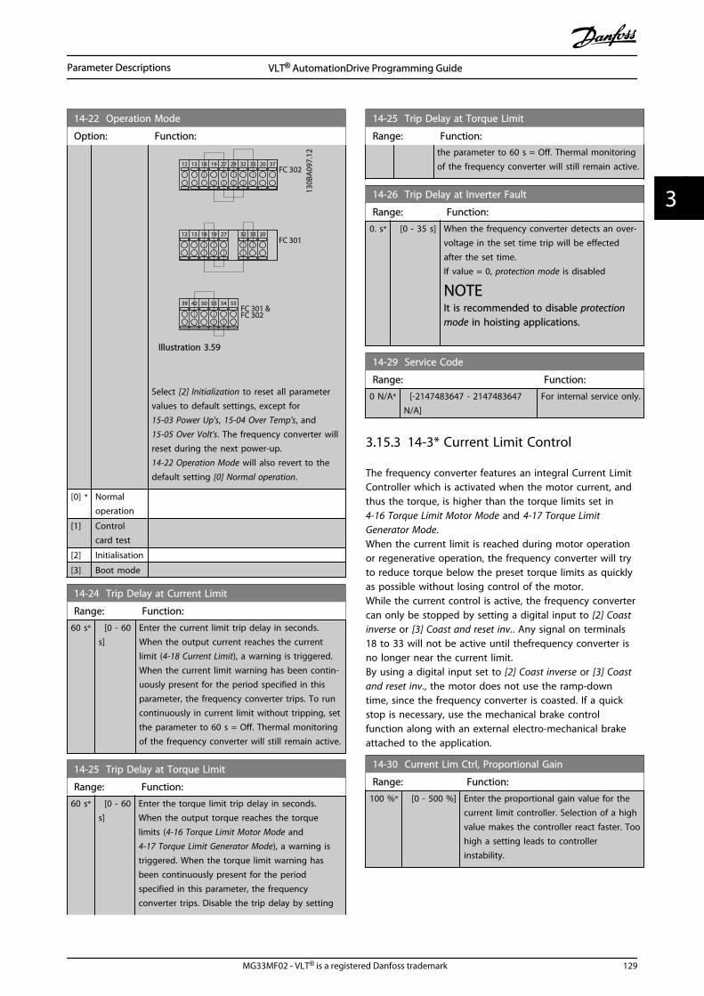
14-22 Operation Mode
Option: Function:
130B
A09
7.12
FC 302
FC 301
FC 301 &FC 302
1312 18 37322719 29 33 20
5039 42 5453 55
191812 13 203327 32
Illustration 3.59
Select [2] Initialization to reset all parametervalues to default settings, except for 15-03 Power Up's, 15-04 Over Temp's, and 15-05 Over Volt's. The frequency converter willreset during the next power-up.14-22 Operation Mode will also revert to thedefault setting [0] Normal operation.
[0] * Normaloperation
[1] Controlcard test
[2] Initialisation
[3] Boot mode
14-24 Trip Delay at Current Limit
Range: Function:
60 s* [0 - 60s]
Enter the current limit trip delay in seconds.When the output current reaches the currentlimit (4-18 Current Limit), a warning is triggered.When the current limit warning has been contin-uously present for the period specified in thisparameter, the frequency converter trips. To runcontinuously in current limit without tripping, setthe parameter to 60 s = Off. Thermal monitoringof the frequency converter will still remain active.
14-25 Trip Delay at Torque Limit
Range: Function:
60 s* [0 - 60s]
Enter the torque limit trip delay in seconds.When the output torque reaches the torquelimits (4-16 Torque Limit Motor Mode and 4-17 Torque Limit Generator Mode), a warning istriggered. When the torque limit warning hasbeen continuously present for the periodspecified in this parameter, the frequencyconverter trips. Disable the trip delay by setting
14-25 Trip Delay at Torque Limit
Range: Function:the parameter to 60 s = Off. Thermal monitoringof the frequency converter will still remain active.
14-26 Trip Delay at Inverter Fault
Range: Function:
0. s* [0 - 35 s] When the frequency converter detects an over-voltage in the set time trip will be effectedafter the set time.If value = 0, protection mode is disabled
NOTEIt is recommended to disable protectionmode in hoisting applications.
14-29 Service Code
Range: Function:
0 N/A* [-2147483647 - 2147483647N/A]
For internal service only.
3.15.3 14-3* Current Limit Control
The frequency converter features an integral Current LimitController which is activated when the motor current, andthus the torque, is higher than the torque limits set in 4-16 Torque Limit Motor Mode and 4-17 Torque LimitGenerator Mode.When the current limit is reached during motor operationor regenerative operation, the frequency converter will tryto reduce torque below the preset torque limits as quicklyas possible without losing control of the motor.While the current control is active, the frequency convertercan only be stopped by setting a digital input to [2] Coastinverse or [3] Coast and reset inv.. Any signal on terminals18 to 33 will not be active until thefrequency converter isno longer near the current limit.By using a digital input set to [2] Coast inverse or [3] Coastand reset inv., the motor does not use the ramp-downtime, since the frequency converter is coasted. If a quickstop is necessary, use the mechanical brake controlfunction along with an external electro-mechanical brakeattached to the application.
14-30 Current Lim Ctrl, Proportional Gain
Range: Function:
100 %* [0 - 500 %] Enter the proportional gain value for thecurrent limit controller. Selection of a highvalue makes the controller react faster. Toohigh a setting leads to controllerinstability.
Parameter Descriptions VLT® AutomationDrive Programming Guide
MG33MF02 - VLT® is a registered Danfoss trademark 129
3 3

14-31 Current Lim Ctrl, Integration Time
Range: Function:
Size related* [0.002 -2.000 s]
Controls the current limit controlintegration time. Setting it to alower value makes it react faster. Asetting too low leads to controlinstability.
14-32 Current Lim Ctrl, Filter Time
Range: Function:
Size related* [1 - 100 ms]
14-35 Stall Protection
Option: Function:
Select Enable [1] to enable the stall protection infield-weakening in flux mode. Select [0] Disabledif you desire to disable it. This might cause themotor to be lost. 14-35 Stall Protection is active inFlux mode only.
[0] Disabled
[1] * Enabled
3.15.4 14-4* Energy Optimising
Parameters for adjusting the energy optimisation level inboth Variable Torque (VT) and Automatic Energy Optimi-zation (AEO) mode in 1-03 Torque Characteristics.
14-40 VT Level
Range: Function:
66 %* [40 - 90 %] Enter the level of motor magnetisation atlow speed. Selection of a low value reducesenergy loss in the motor, but also reducesload capability.
NOTEThis parameter cannot be adjusted while the motor isrunning.
NOTEThis parameter is not active when 1-10 Motor Constructionis set to [1] PM non salient SPM.
14-41 AEO Minimum Magnetisation
Range: Function:
Size related* [40 - 75%]
Enter the minimum allowable magnet-isation for AEO. Selection of a lowvalue reduces energy loss in themotor, but can also reduce resistanceto sudden load changes.
NOTEThis parameter is not active when 1-10 Motor Constructionis set to [1] PM non salient SPM.
14-42 Minimum AEO Frequency
Range: Function:
10 Hz* [5 - 40 Hz] Enter the minimum frequency at which theAutomatic Energy Optimisation (AEO) is tobe active.
NOTEThis parameter is not active when 1-10 Motor Constructionis set to [1] PM non salient SPM.
14-43 Motor Cosphi
Range: Function:
0.66N/A*
[0.40 -0.95 N/A]
The Cos(phi) setpoint is automatically setfor optimum AEO performance. Thisparameter should normally not bealtered. However in some situations itmay be necessary to enter a new value tofine-tune.
3.15.5 14-5* Environment
These parameters help the frequency converter to operateunder special environmental conditions.
14-50 RFI Filter
This parameter is only available for FC 302. It is not relevant toFC301 due to different design and shorter motor cables.
Option: Function:
[0] Off Select [0] Off if the frequency converter is fed by anisolated mains source (IT mains).If a filter is used, select Off [0] during charging toprevent a high leakage current making the RCDswitch.In this mode, the internal RFI filter capacitors betweenchassis and the mains RFI filter circuit are cut-out toreduce the ground capacity currents.
[1] * On Select [1] On to ensure that the frequency convertercomplies with EMC standards.
130B
B908
.10
Illustration 3.60
Parameter Descriptions VLT® AutomationDrive Programming Guide
130 MG33MF02 - VLT® is a registered Danfoss trademark
33

14-51 DC Link Compensation
Option: Function:
The rectified AC-DC voltage at the frequencyconverter's DC link is associated with voltage ripples.These ripples can increase in magnitude withincreased load. These ripples are undesirable becausethey can generate current and torque ripples. Acompensation method is used to reduce these voltageripples at DC link. In general, DC link compensation isrecommended for most applications, but care must betaken when operating in field weakening as it cangenerate speed oscillations at the motor shaft. In fieldweakening, it is recommended to turn DC linkcompensation off.
[0] Off Disables DC Link Compensation.
[1] * On Enables DC Link Compensation.
14-52 Fan Control
Select minimum speed of the main fan.
Option: Function:
[0] * Auto Select [0] Auto to run fan only when internaltemperature in frequency converter is in range
35 °C to approx. 55 °C.
Fan will run at low speed below 35 °C, and at
full speed at approx. 55 °C.
[1] On 50% The fan will always run at 50% speed or above.
The fan will run at 50% speed at 35 °C, and at
full speed at approx. 55 °C.
[2] On 75% The fan will always run at 75% speed or above.
The fan will run at 75% speed at 35 °C, and at
full speed at approx. 55 °C.
[3] On 100% The fan will run at 100% speed always.
14-53 Fan Monitor
Option: Function:
Select which reaction the frequency convertershould take in case a fan fault is detected.
[0] Disabled
[1] * Warning
[2] Trip
14-55 Output Filter
Option: Function:
Select the type of output filter connected. Thisparameter cannot be adjusted while motor isrunning.
[0] * NoFilter
This is the default setting and should be usedwith dU/dt filters or high-frequency common-mode (HF-CM) filters.
[1] Sine-WaveFilter
This setting is only for backwards compatibility. Itenables operation with FLUX control principlewhen the parameters 14-56 Capacitance Output
14-55 Output Filter
Option: Function:Filter and 14-57 Inductance Output Filter areprogrammed with the output filter capacitanceand inductance. It DOES NOT limit the range ofthe switching frequency.
14-56 Capacitance Output Filter
Compensation function of the LC-filter requires the per phaseequivalent star connected capacitance of the filter (3 times thecapacity between two phases when capacitance is ’Delta’connection).
Range: Function:
2.0 uF* [0.1 - 6500.0 uF] Set the capacitance of the outputfilter. The value can be found on thefilter label.
NOTEThis is required for correctcompensation in Flux mode(1-01 Motor Control Principle)
14-57 Inductance Output Filter
Range: Function:
7.000mH*
[0.001 -65.000 mH]
Set the inductance of the outputfilter. The value can be found on thefilter label.
NOTEThis is required for correctcompensation in Flux mode(1-01 Motor Control Principle)
3.15.6 14-7* Compatibility
The parameters in this group are for setting of compati-bility for VLT 3000, VLT 5000 to FC 300.
14-72 VLT Alarm Word
Option: Function:
[0] 0 - 4294967295 Read out the alarm word corresponding toVLT 5000.
14-73 VLT Warning Word
Option: Function:
[0] 0 - 4294967295 Read out the warning word correspondingto VLT 5000.
14-74 VLT Ext. Status Word
Range: Function:
0 N/A* [0 - 4294967295 N/A] Read out the ext. status wordcorresponding to VLT 5000
Parameter Descriptions VLT® AutomationDrive Programming Guide
MG33MF02 - VLT® is a registered Danfoss trademark 131
3 3

3.15.7 14-8* Options
14-80 Option Supplied by External 24VDC
Option: Function:
[0] No Select [0] No to use the frequency converter's 24 V DCsupply.
[1] * Yes Select [1] Yes if an external 24 V DC supply will beused to power the option. Inputs/Outputs will begalvanically isolated from the drive when operatedfrom an external supply.
NOTEThis parameter is only changing function by performing apower cycle.
14-89 Option Detection
Selects the behaviour of the frequency converter when a changein the option configuration is detected.
Option: Function:
[0] * Protect OptionConfig.
Freezes the current settings andprevents unwanted changes whenmissing or defective options aredetected.
14-89 Option Detection
Selects the behaviour of the frequency converter when a changein the option configuration is detected.
Option: Function:
[1] Enable OptionChange
Changes drive settings and is usedwhen modifying the system configu-ration. This Parameter setting willreturn to [0] after an Option Change.
14-90 Fault Level
Option: Function:
[0] * Off Use this parameter to customize Fault levels. Use[0] Off with caution as it will ignore all Warnings& Alarms for the chosen source.
[1] Warning
[2] Trip
[3] Trip Lock
Failure Alarm Off Warning Trip Trip Lock
10 V low 1 X D
24 V low 47 X D
1.8 V supply low 48 X D
Voltage limit 64 X D
Earth fault during ramping 14 D X
Earth fault 2 during cont. operation 45 D X
Torque Limit 12 X D
Over Current 13 X D
Short Circuit 16 X D
Heatsink temperature 29 X D
Heatsink sensor 39 X D
Control card temperature 65 X D
Power card temperature 6 2) X D
Heatsink temperature1) 244 X D
Heatsink sensor 1) 245 X D
Power card temperature 1) 247
Table 3.28 Table for Selection of Choice of Action when Selected Alarm Appears
D = Default setting. x = possible selection.1) Only high power drivesIn FC small and medium A69 is only a warning
Parameter Descriptions VLT® AutomationDrive Programming Guide
132 MG33MF02 - VLT® is a registered Danfoss trademark
33

3.16 Parameters: 15-** Drive Information
3.16.1 15-0* Operating Data
15-00 Operating Hours
Range: Function:
0 h* [0 - 2147483647 h] View how many hours the frequencyconverter has run. The value is savedwhen the frequency converter isturned off.
15-01 Running Hours
Range: Function:
0 h* [0 - 2147483647h]
View how many hours the motor hasrun. Reset the counter in 15-07 ResetRunning Hours Counter. The value issaved when the frequency converter isturned off.
15-02 kWh Counter
Range: Function:
0 kWh* [0 - 2147483647kWh]
Registering the power consumptionof the motor as a mean value overone hour. Reset the counter in 15-06 Reset kWh Counter.
15-03 Power Up's
Range: Function:
0 * [0 - 2147483647 ] View the number of times the frequencyconverter has been powered up.
15-04 Over Temp's
Range: Function:
0 * [0 - 65535 ] View the number of frequency convertertemperature faults which have occurred.
15-05 Over Volt's
Range: Function:
0 * [0 - 65535 ] View the number of frequency converterovervoltages which have occurred.
15-06 Reset kWh Counter
Option: Function:
[0] * Do not reset Nno reset of the kWh counter is desired.
[1] Reset counter Press [OK] to reset the kWh counter to zero(see 15-02 kWh Counter).
NOTEThe reset is carried out by pressing [OK].
15-07 Reset Running Hours Counter
Option: Function:
[0] * Do not reset
[1] Reset counter Select [1] Reset and press [OK] to reset theRunning Hours counter to zero (see 15-01 Running Hours). This parameter cannotbe selected via the serial port, RS-485.Select [0] Do not reset if no reset of theRunning Hours counter is desired.
3.16.2 15-1* Data Log Settings
The Data Log enables continuous logging of up to 4 datasources (15-10 Logging Source) at individual rates(15-11 Logging Interval). A trigger event (15-12 TriggerEvent) and window (15-14 Samples Before Trigger) are usedto start and stop the logging conditionally.
15-10 Logging Source
Array [4]
Option: Function:
Select which variables are to belogged.
[0] * None
[1472] VLT Alarm Word
[1473] VLT Warning Word
[1474] VLT Ext. Status Word
[1600] Control Word
[1601] Reference [Unit]
[1602] Reference %
[1603] Status Word
[1610] Power [kW]
[1611] Power [hp]
[1612] Motor Voltage
[1613] Frequency
[1614] Motor Current
[1616] Torque [Nm]
[1617] Speed [RPM]
[1618] Motor Thermal
[1622] Torque [%]
[1625] Torque [Nm] High
[1630] DC Link Voltage
[1632] Brake Energy /s
[1633] Brake Energy /2 min
[1634] Heatsink Temp.
[1635] Inverter Thermal
[1650] External Reference
[1651] Pulse Reference
[1652] Feedback [Unit]
[1660] Digital Input
[1662] Analog Input 53
[1664] Analog Input 54
[1665] Analog Output 42 [mA]
[1666] Digital Output [bin]
Parameter Descriptions VLT® AutomationDrive Programming Guide
MG33MF02 - VLT® is a registered Danfoss trademark 133
3 3

15-10 Logging Source
Array [4]
Option: Function:
[1675] Analog In X30/11
[1676] Analog In X30/12
[1677] Analog Out X30/8 [mA]
[1690] Alarm Word
[1692] Warning Word
[1694] Ext. Status Word
[3470] MCO Alarm Word 1
[3471] MCO Alarm Word 2
15-11 Logging Interval
Array [4]
Range: Function:
Size related* [ 0.000 -0.000 ]
Enter the interval in millisecondsbetween each sampling of thevariables to be logged.
15-12 Trigger Event
Select the trigger event. When the trigger event occurs, awindow is applied to freeze the log. The log will then retain aspecified percentage of samples before the occurrence of thetrigger event (15-14 Samples Before Trigger).
Option: Function:
[0] * False
[1] True
[2] Running
[3] In range
[4] On reference
[5] Torque limit
[6] Current limit
[7] Out of current range
[8] Below I low
[9] Above I high
[10] Out of speed range
[11] Below speed low
[12] Above speed high
[13] Out of feedb. range
[14] Below feedb. low
[15] Above feedb. high
[16] Thermal warning
[17] Mains out of range
[18] Reversing
[19] Warning
[20] Alarm (trip)
[21] Alarm (trip lock)
[22] Comparator 0
[23] Comparator 1
[24] Comparator 2
[25] Comparator 3
[26] Logic rule 0
[27] Logic rule 1
[28] Logic rule 2
15-12 Trigger Event
Select the trigger event. When the trigger event occurs, awindow is applied to freeze the log. The log will then retain aspecified percentage of samples before the occurrence of thetrigger event (15-14 Samples Before Trigger).
Option: Function:
[29] Logic rule 3
[33] Digital input DI18
[34] Digital input DI19
[35] Digital input DI27
[36] Digital input DI29
[37] Digital input DI32
[38] Digital input DI33
[50] Comparator 4
[51] Comparator 5
[60] Logic rule 4
[61] Logic rule 5
15-13 Logging Mode
Option: Function:
[0] * Log always Select [0] Log always for continuouslogging.
[1] Log once ontrigger
Select [1] Log once on trigger toconditionally start and stop logging using15-12 Trigger Event and 15-14 SamplesBefore Trigger.
15-14 Samples Before Trigger
Range: Function:
50 N/A* [0 - 100N/A]
Enter the percentage of all samples priorto a trigger event which are to beretained in the log. See also 15-12 TriggerEvent and 15-13 Logging Mode.
3.16.3 15-2* Historic Log
View up to 50 logged data items via the array parametersin this parameter group. For all parameters in the group,[0] is the most recent data and [49] the oldest data. Data islogged every time an event occurs (not to be confusedwith SLC events). Events in this context are defined as achange in one of the following areas
1. Digital input
2. Digital outputs (not monitored in this SW release)
3. Warning word
4. Alarm word
5. Status word
6. Control word
7. Extended status word
Events are logged with value, and time stamp in ms. Thetime interval between two events depends on how often
Parameter Descriptions VLT® AutomationDrive Programming Guide
134 MG33MF02 - VLT® is a registered Danfoss trademark
33
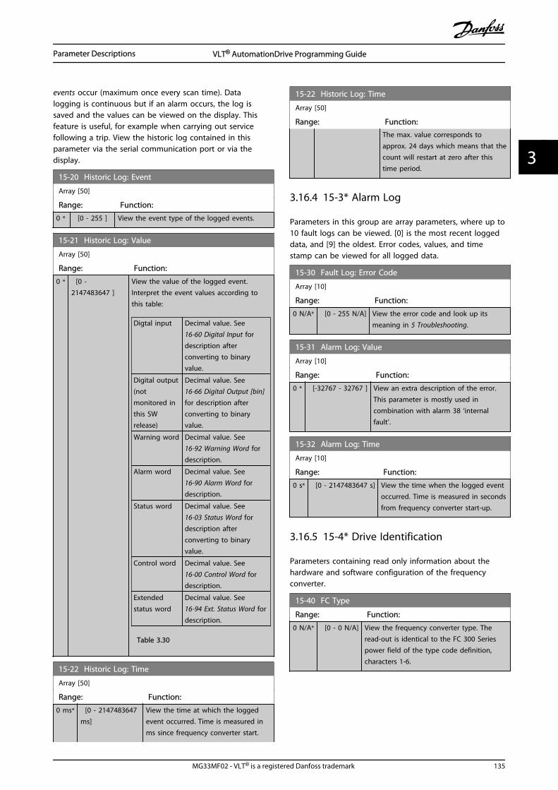
events occur (maximum once every scan time). Datalogging is continuous but if an alarm occurs, the log issaved and the values can be viewed on the display. Thisfeature is useful, for example when carrying out servicefollowing a trip. View the historic log contained in thisparameter via the serial communication port or via thedisplay.
15-20 Historic Log: Event
Array [50]
Range: Function:
0 * [0 - 255 ] View the event type of the logged events.
15-21 Historic Log: Value
Array [50]
Range: Function:
0 * [0 -2147483647 ]
View the value of the logged event.Interpret the event values according tothis table:
Digtal input Decimal value. See 16-60 Digital Input fordescription afterconverting to binaryvalue.
Digital output(notmonitored inthis SWrelease)
Decimal value. See 16-66 Digital Output [bin]for description afterconverting to binaryvalue.
Warning word Decimal value. See16-92 Warning Word fordescription.
Alarm word Decimal value. See16-90 Alarm Word fordescription.
Status word Decimal value. See 16-03 Status Word fordescription afterconverting to binaryvalue.
Control word Decimal value. See 16-00 Control Word fordescription.
Extendedstatus word
Decimal value. See 16-94 Ext. Status Word fordescription.
Table 3.30
15-22 Historic Log: Time
Array [50]
Range: Function:
0 ms* [0 - 2147483647ms]
View the time at which the loggedevent occurred. Time is measured inms since frequency converter start.
15-22 Historic Log: Time
Array [50]
Range: Function:The max. value corresponds toapprox. 24 days which means that thecount will restart at zero after thistime period.
3.16.4 15-3* Alarm Log
Parameters in this group are array parameters, where up to10 fault logs can be viewed. [0] is the most recent loggeddata, and [9] the oldest. Error codes, values, and timestamp can be viewed for all logged data.
15-30 Fault Log: Error Code
Array [10]
Range: Function:
0 N/A* [0 - 255 N/A] View the error code and look up itsmeaning in 5 Troubleshooting.
15-31 Alarm Log: Value
Array [10]
Range: Function:
0 * [-32767 - 32767 ] View an extra description of the error.This parameter is mostly used incombination with alarm 38 ‘internalfault’.
15-32 Alarm Log: Time
Array [10]
Range: Function:
0 s* [0 - 2147483647 s] View the time when the logged eventoccurred. Time is measured in secondsfrom frequency converter start-up.
3.16.5 15-4* Drive Identification
Parameters containing read only information about thehardware and software configuration of the frequencyconverter.
15-40 FC Type
Range: Function:
0 N/A* [0 - 0 N/A] View the frequency converter type. Theread-out is identical to the FC 300 Seriespower field of the type code definition,characters 1-6.
Parameter Descriptions VLT® AutomationDrive Programming Guide
MG33MF02 - VLT® is a registered Danfoss trademark 135
3 3

15-41 Power Section
Range: Function:
0 N/A* [0 - 0 N/A] View the FC type. The read-out is identicalto the FC 300 Series power field of the typecode definition, characters 7-10.
15-42 Voltage
Range: Function:
0 N/A* [0 - 0 N/A] View the FC type. The read-out is identicalto the FC 300 Series power field of the typecode definition, characters 11-12.
15-43 Software Version
Range: Function:
0 * [0 - 0 ] View the combined SW version (or ‘packageversion’) consisting of power SW and control SW.
15-44 Ordered Typecode String
Range: Function:
0 * [0 - 0 ] View the type code string used for re-ordering thefrequency converter in its original configuration.
15-45 Actual Typecode String
Range: Function:
0 * [0 - 0 ] View the actual type code string.
15-46 Frequency Converter Ordering No
Range: Function:
0 * [0 - 0 ] View the 8-digit ordering number used for re-ordering the frequency converter in its originalconfiguration.
15-47 Power Card Ordering No
Range: Function:
0 * [0 - 0 ] View the power card ordering number.
15-48 LCP Id No
Range: Function:
0 * [0 - 0 ] View the LCP ID number.
15-49 SW ID Control Card
Range: Function:
0 * [0 - 0 ] View the control card software version number.
15-50 SW ID Power Card
Range: Function:
0 * [0 - 0 ] View the power card software version number.
15-51 Frequency Converter Serial Number
Range: Function:
0 * [0 - 0 ] View the frequency converter serial number.
15-53 Power Card Serial Number
Range: Function:
0 * [0 - 0 ] View the power card serial number.
15-58 Smart Setup Filename
Range: Function:
Size related* [0 - 0 ] Shows the currently used smartapplication setup filename.
15-59 CSIV Filename
Range: Function:
Size related* [0 - 0 ] Shows the currently used CSIV (CostumerSpecific Initial Values) filename.
3.16.6 15-6* Option Ident.
This read-only parameter group contains information aboutthe hardware and software configuration of the optionsinstalled in slots A, B, C0 and C1.
15-60 Option Mounted
Array [8]
Range: Function:
0 * [0 - 0 ] View the installed option type.
15-61 Option SW Version
Array [8]
Range: Function:
0 * [0 - 0 ] View the installed option software version.
15-62 Option Ordering No
Array [8]
Range: Function:
0 * [0 - 0 ] Shows the ordering number for the installedoptions.
15-63 Option Serial No
Array [8]
Range: Function:
0 * [0 - 0 ] View the installed option serial number.
15-80 Fan Running Hours
Range: Function:
0 h* [0 - 2147483647 h] View how many hours the heatsinkfan has run (increments for eachhour). The value is saved when thedrive is turned off.
Parameter Descriptions VLT® AutomationDrive Programming Guide
136 MG33MF02 - VLT® is a registered Danfoss trademark
33

15-92 Defined Parameters
Array [1000]
Range: Function:
0 * [0 - 9999 ] View a list of all defined parameters in thefrequency converter. The list ends with 0.
15-93 Modified Parameters
Array [1000]
Range: Function:
0 * [0 - 9999 ] View a list of the parameters that have beenchanged from their default setting. The listends with 0. Changes may not be visible untilup to 30 s after implementation.
15-99 Parameter Metadata
Array [30]
Range: Function:
0 N/A* [0 - 9999 N/A] This parameter contains data used bythe MCT 10 Set-up Software.
Parameter Descriptions VLT® AutomationDrive Programming Guide
MG33MF02 - VLT® is a registered Danfoss trademark 137
3 3
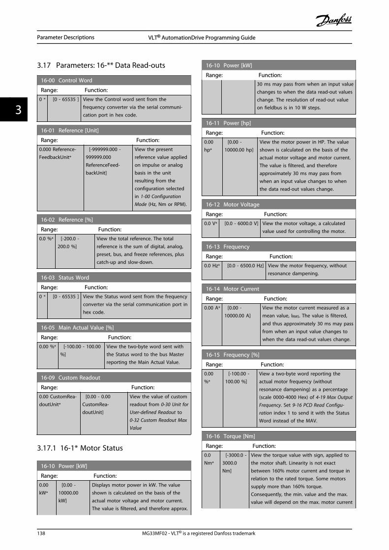
3.17 Parameters: 16-** Data Read-outs
16-00 Control Word
Range: Function:
0 * [0 - 65535 ] View the Control word sent from thefrequency converter via the serial communi-cation port in hex code.
16-01 Reference [Unit]
Range: Function:
0.000 Reference-FeedbackUnit*
[-999999.000 -999999.000ReferenceFeed-backUnit]
View the presentreference value appliedon impulse or analogbasis in the unitresulting from theconfiguration selectedin 1-00 ConfigurationMode (Hz, Nm or RPM).
16-02 Reference [%]
Range: Function:
0.0 %* [-200.0 -200.0 %]
View the total reference. The totalreference is the sum of digital, analog,preset, bus, and freeze references, pluscatch-up and slow-down.
16-03 Status Word
Range: Function:
0 * [0 - 65535 ] View the Status word sent from the frequencyconverter via the serial communication port inhex code.
16-05 Main Actual Value [%]
Range: Function:
0.00 %* [-100.00 - 100.00%]
View the two-byte word sent withthe Status word to the bus Masterreporting the Main Actual Value.
16-09 Custom Readout
Range: Function:
0.00 CustomRea-doutUnit*
[0.00 - 0.00CustomRea-doutUnit]
View the value of customreadout from 0-30 Unit forUser-defined Readout to 0-32 Custom Readout MaxValue
3.17.1 16-1* Motor Status
16-10 Power [kW]
Range: Function:
0.00kW*
[0.00 -10000.00kW]
Displays motor power in kW. The valueshown is calculated on the basis of theactual motor voltage and motor current.The value is filtered, and therefore approx.
16-10 Power [kW]
Range: Function:30 ms may pass from when an input valuechanges to when the data read-out valueschange. The resolution of read-out valueon fieldbus is in 10 W steps.
16-11 Power [hp]
Range: Function:
0.00hp*
[0.00 -10000.00 hp]
View the motor power in HP. The valueshown is calculated on the basis of theactual motor voltage and motor current.The value is filtered, and thereforeapproximately 30 ms may pass fromwhen an input value changes to whenthe data read-out values change.
16-12 Motor Voltage
Range: Function:
0.0 V* [0.0 - 6000.0 V] View the motor voltage, a calculatedvalue used for controlling the motor.
16-13 Frequency
Range: Function:
0.0 Hz* [0.0 - 6500.0 Hz] View the motor frequency, withoutresonance dampening.
16-14 Motor Current
Range: Function:
0.00 A* [0.00 -10000.00 A]
View the motor current measured as amean value, IRMS. The value is filtered,
and thus approximately 30 ms may passfrom when an input value changes towhen the data read-out values change.
16-15 Frequency [%]
Range: Function:
0.00%*
[-100.00 -100.00 %]
View a two-byte word reporting theactual motor frequency (withoutresonance dampening) as a percentage(scale 0000-4000 Hex) of 4-19 Max OutputFrequency. Set 9-16 PCD Read Configu-ration index 1 to send it with the StatusWord instead of the MAV.
16-16 Torque [Nm]
Range: Function:
0.0Nm*
[-3000.0 -3000.0Nm]
View the torque value with sign, applied tothe motor shaft. Linearity is not exactbetween 160% motor current and torque inrelation to the rated torque. Some motorssupply more than 160% torque.Consequently, the min. value and the max.value will depend on the max. motor current
Parameter Descriptions VLT® AutomationDrive Programming Guide
138 MG33MF02 - VLT® is a registered Danfoss trademark
33

16-16 Torque [Nm]
Range: Function:as well as the motor used. The value isfiltered, and thus approx. 30 ms may passfrom when an input changes value to whenthe data read-out values change.
16-17 Speed [RPM]
Range: Function:
0 RPM* [-30000 -30000 RPM]
View the actual motor RPM. In openloop or closed loop process control themotor RPM is estimated. In speedclosed loop modes the motor RPM ismeasured.
16-18 Motor Thermal
Range: Function:
0 %* [0 - 100 %] View the calculated thermal load on themotor. The cut-out limit is 100%. The basisfor calculation is the ETR function selected in1-90 Motor Thermal Protection.
16-19 KTY sensor temperature
Range: Function:
0 °C* [0 - 0 °C] Returning the actual temperature on KTYsensor buil into the motor.See parameter group 1-9* Motor Temperature.
16-20 Motor Angle
Range: Function:
0 N/A* [0 - 65535N/A]
View the current encoder/resolverangle offset relative to the indexposition. The value range of 0-65535corresponds to 0-2*pi (radians).
16-21 Torque [%] High Res.
Range: Function:
0 %* [-200 - 200 %] The value shown is the torque in percentof nominal torque, with sign and 0.1%resolution, applied to the motor shaft.
16-22 Torque [%]
Range: Function:
0 %* [-200 - 200 %] Value shown is the torque in percent ofnominal torque, with sign, applied to themotor shaft.
16-25 Torque [Nm] High
Range: Function:
0.0Nm*
[-200000000.0 -200000000.0Nm]
View the torque value with sign,applied to the motor shaft. Somemotors supply more than 160%torque. Consequently, the min. valueand the max. value will depend onthe max. motor current as well as the
16-25 Torque [Nm] High
Range: Function:motor used. This specific readout hasbeen adapted to be able to showhigher values than the standardreadout in 16-16 Torque [Nm].
3.17.2 16-3* Drive Status
16-30 DC Link Voltage
Range: Function:
0 V* [0 - 10000 V] View a measured value. The value is filteredwith an 30 ms time constant.
16-32 Brake Energy /s
Range: Function:
0.000 kW* [0.000 - 10000.000kW]
View the brake powertransmitted to an external brakeresistor, stated as an instan-taneous value.
16-33 Brake Energy /2 min
Range: Function:
0.000 kW* [0.000 -10000.000 kW]
View the brake power transmittedto an external brake resistor. Themean power is calculated on anaverage basis for the most recent120 s.
16-34 Heatsink Temp.
Range: Function:
0 °C* [0 - 255 °C] View the frequency converter heatsink
temperature. The cut-out limit is 90 ±5 °C,
and the motor cuts back in at 60 ±5 °C.
16-35 Inverter Thermal
Range: Function:
0 %* [0 - 100 %] View the percentage load on the inverter.
16-36 Inv. Nom. Current
Range: Function:
10.00 A* [0.01 -10000.00 A]
View the inverter nominal current,which should match the nameplatedata on the connected motor. Thedata are used for calculation oftorque, motor protection, etc.
16-37 Inv. Max. Current
Range: Function:
16.00 A* [0.01 -10000.00 A]
View the inverter maximum current,which should match the nameplatedata on the connected motor. The
Parameter Descriptions VLT® AutomationDrive Programming Guide
MG33MF02 - VLT® is a registered Danfoss trademark 139
3 3

16-37 Inv. Max. Current
Range: Function:data are used for calculation oftorque, motor protection, etc.
16-38 SL Controller State
Range: Function:
0 N/A* [0 - 100 N/A] View the state of the event underexecution by the SL controller.
16-39 Control Card Temp.
Range: Function:
0 °C* [0 - 100 °C] View the temperature on the control card,
stated in °C
16-40 Logging Buffer Full
Option: Function:
View whether the logging buffer is full (see parametergroup 15-1* Data Log Settings). The logging buffer willnever be full when 15-13 Logging Mode is set to [0]Log always.
[0] * No
[1] Yes
16-48 Speed Ref. After Ramp [RPM]
Range: Function:
0 RPM* [-30000 - 30000RPM]
This parameter specifies thereference given to the drive afterthe speed ramp.
16-49 Current Fault Source
Range: Function:
0 * [0 - 8 ] Value indicates source of current faults includingshort circuit, over current, and phase imbalance(from left):1-4 Inverter5-8 Rectifier0 No fault recorded
3.17.3 16-5* Ref. & Feedb.
16-50 External Reference
Range: Function:
0.0 N/A* [-200.0 - 200.0N/A]
View the total reference, the sum ofdigital, analog, preset, bus and freezereferences, plus catch-up and slow-down.
16-51 Pulse Reference
Range: Function:
0.0 N/A* [-200.0 - 200.0N/A]
View the reference value fromprogrammed digital input(s). The
16-51 Pulse Reference
Range: Function:read-out can also reflect the impulsesfrom an incremental encoder.
16-52 Feedback [Unit]
Range: Function:
0.000 Reference-FeedbackUnit*
[-999999.999 -999999.999ReferenceFeed-backUnit]
View the feedback unitresulting from theselection of unit andscaling in 3-00 ReferenceRange, 3-01 Reference/Feedback Unit, 3-02 Minimum Referenceand 3-03 MaximumReference.
16-53 Digi Pot Reference
Range: Function:
0.00 N/A* [-200.00 - 200.00N/A]
View the contribution of theDigital Potentiometer to theactual reference.
16-57 Feedback [RPM]
Range: Function:
0 RPM* [-30000 -30000 RPM]
Read-out parameter where the actualmotor RPM from the feed-back sourcecan be read in both closed loop andopen loop. The feed-back source isselected by 7-00 Speed PID FeedbackSource.
Parameter Descriptions VLT® AutomationDrive Programming Guide
140 MG33MF02 - VLT® is a registered Danfoss trademark
33
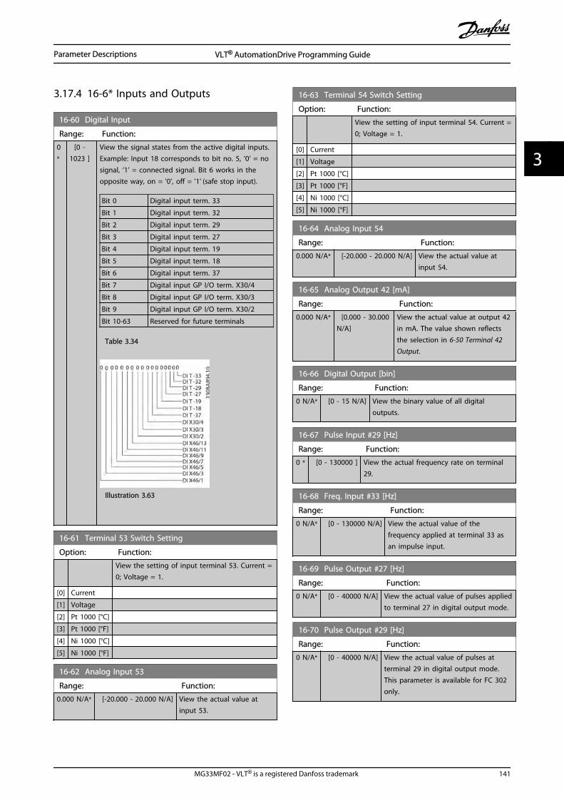
3.17.4 16-6* Inputs and Outputs
16-60 Digital Input
Range: Function:
0*
[0 -1023 ]
View the signal states from the active digital inputs.Example: Input 18 corresponds to bit no. 5, ‘0’ = nosignal, ‘1’ = connected signal. Bit 6 works in theopposite way, on = '0', off = '1' (safe stop input).
Bit 0 Digital input term. 33
Bit 1 Digital input term. 32
Bit 2 Digital input term. 29
Bit 3 Digital input term. 27
Bit 4 Digital input term. 19
Bit 5 Digital input term. 18
Bit 6 Digital input term. 37
Bit 7 Digital input GP I/O term. X30/4
Bit 8 Digital input GP I/O term. X30/3
Bit 9 Digital input GP I/O term. X30/2
Bit 10-63 Reserved for future terminals
Table 3.34
Illustration 3.63
16-61 Terminal 53 Switch Setting
Option: Function:
View the setting of input terminal 53. Current =0; Voltage = 1.
[0] Current
[1] Voltage
[2] Pt 1000 [°C]
[3] Pt 1000 [°F]
[4] Ni 1000 [°C]
[5] Ni 1000 [°F]
16-62 Analog Input 53
Range: Function:
0.000 N/A* [-20.000 - 20.000 N/A] View the actual value atinput 53.
16-63 Terminal 54 Switch Setting
Option: Function:
View the setting of input terminal 54. Current =0; Voltage = 1.
[0] Current
[1] Voltage
[2] Pt 1000 [°C]
[3] Pt 1000 [°F]
[4] Ni 1000 [°C]
[5] Ni 1000 [°F]
16-64 Analog Input 54
Range: Function:
0.000 N/A* [-20.000 - 20.000 N/A] View the actual value atinput 54.
16-65 Analog Output 42 [mA]
Range: Function:
0.000 N/A* [0.000 - 30.000N/A]
View the actual value at output 42in mA. The value shown reflectsthe selection in 6-50 Terminal 42Output.
16-66 Digital Output [bin]
Range: Function:
0 N/A* [0 - 15 N/A] View the binary value of all digitaloutputs.
16-67 Pulse Input #29 [Hz]
Range: Function:
0 * [0 - 130000 ] View the actual frequency rate on terminal29.
16-68 Freq. Input #33 [Hz]
Range: Function:
0 N/A* [0 - 130000 N/A] View the actual value of thefrequency applied at terminal 33 asan impulse input.
16-69 Pulse Output #27 [Hz]
Range: Function:
0 N/A* [0 - 40000 N/A] View the actual value of pulses appliedto terminal 27 in digital output mode.
16-70 Pulse Output #29 [Hz]
Range: Function:
0 N/A* [0 - 40000 N/A] View the actual value of pulses atterminal 29 in digital output mode.This parameter is available for FC 302only.
Parameter Descriptions VLT® AutomationDrive Programming Guide
MG33MF02 - VLT® is a registered Danfoss trademark 141
3 3

16-71 Relay Output [bin]
Range: Function:
0 * [0 - 511 ] View the settings of all relays.
Illustration 3.65
16-72 Counter A
Range: Function:
0N/A*
[-2147483648 -2147483647 N/A]
View the present value of Counter A.Counters are useful as comparatoroperands, see 13-10 ComparatorOperand.The value can be reset or changedeither via digital inputs (parametergroup 5-1* Digital Inputs) or by usingan SLC action (13-52 SL ControllerAction).
16-73 Counter B
Range: Function:
0N/A*
[-2147483648 -2147483647 N/A]
View the present value of Counter B.Counters are useful as comparatoroperands (13-10 Comparator Operand).The value can be reset or changedeither via digital inputs (parametergroup 5-1*) or by using an SLC action(13-52 SL Controller Action).
16-74 Prec. Stop Counter
Range: Function:
0 N/A* [0 - 2147483647 N/A] Returns the actual counter valueof precise counter (1-84 PreciseStop Counter Value).
16-75 Analog In X30/11
Range: Function:
0.000 * [-20.000 - 20.000 ] View the actual value at inputX30/11 of MCB 101.
16-76 Analog In X30/12
Range: Function:
0.000 * [-20.000 - 20.000 ] View the actual value at inputX30/12 of MCB 101.
16-77 Analog Out X30/8 [mA]
Range: Function:
0.000 * [0.000 - 30.000 ] View the actual value at input X30/8in mA.
16-78 Analog Out X45/1 [mA]
Range: Function:
0.000 N/A* [0.000 - 30.000N/A]
View the actual value at outputX45/1. The value shown reflectsthe selection in 6-70 TerminalX45/1 Output.
16-79 Analog Out X45/3 [mA]
Range: Function:
0.000 N/A* [0.000 - 30.000N/A]
View the actual value at outputX45/3. The value shown reflectsthe selection in 6-80 TerminalX45/3 Output.
3.17.5 16-8* Fieldbus & FC Port
Parameters for reporting the BUS references and controlwords.
16-80 Fieldbus CTW 1
Range: Function:
0 * [0 - 65535 ] View the two-byte Control word (CTW)received from the Bus-Master. Interpretation ofthe Control word depends on the Fieldbusoption installed and the Control word profileselected in 8-10 Control Profile.For more information, refer to the relevantFieldbus manual.
16-82 Fieldbus REF 1
Range: Function:
0 * [-200 -200 ]
View the two-byte word sent with the controlword form the Bus-Master to set thereference value.For more information, refer to the relevantfieldbus manual.
16-84 Comm. Option STW
Range: Function:
0 * [0 - 65535 ] View the extended Fieldbus comm. optionstatus word.For more information, refer to the relevantFieldbus manual.
Parameter Descriptions VLT® AutomationDrive Programming Guide
142 MG33MF02 - VLT® is a registered Danfoss trademark
33

16-85 FC Port CTW 1
Range: Function:
0 * [0 - 65535 ] View the two-byte Control word (CTW)received from the Bus-Master. Interpretation ofthe control word depends on the Fieldbusoption installed and the Control word profileselected in 8-10 Control Profile.
16-86 FC Port REF 1
Range: Function:
0 * [-200 -200 ]
View the two-byte Status word (STW) sent tothe Bus-Master. Interpretation of the Statusword depends on the fieldbus option installedand the Control word profile selected in8-10 Control Profile.
16-87 Bus Readout Alarm/Warning
Range: Function:
0 * [0 - 65535 ] Alarm and Warning numbers in hex asdisplayed in the Alarm log. The High bytecontains the Alarm, the Low byte the Warning.The Alarm number is the first one thatoccurred after the last reset.
3.17.6 16-9* Diagnosis Read-Outs
When using MCT-10, the read-out parameters can only beread online, i.e. as the actual status. This means that thestatus is not stored in the MCT-10 file.
16-90 Alarm Word
Range: Function:
0 * [0 - 4294967295 ] View the alarm word sent via the serialcommunication port in hex code.
16-91 Alarm Word 2
Range: Function:
0 N/A* [0 - 4294967295 N/A] View the alarm word sent via theserial communication port in hexcode.
16-92 Warning Word
Range: Function:
0 * [0 - 4294967295 ] View the warning word sent via theserial communication port in hex code.
16-93 Warning Word 2
Range: Function:
0 N/A* [0 - 4294967295 N/A] View the warning word sent viathe serial communication port inhex code.
16-94 Ext. Status Word
Range: Function:
0 N/A* [0 - 4294967295 N/A] Returns the extended warningword sent via the serialcommunication port in hex code.
16-96 Maintenance Word
Range: Function:
0*
[0 -4294967295 ]
Readout of the Preventive MaintenanceWord. The bits reflect the status for theprogrammed Preventive Maintenance Eventsin parameter group 23-1*. 13 bits representcombinations of all the possible items:
• Bit 0: Motor bearings
• Bit 1: Pump bearings
• Bit 2: Fan bearings
• Bit 3: Valve
• Bit 4: Pressure transmitter
• Bit 5: Flow transmitter
• Bit 6: Temperature transmitter
• Bit 7: Pump seals
• Bit 8: Fan belt
• Bit 9: Filter
• Bit 10: Drive cooling fan
• Bit 11: Drive system health check
• Bit 12: Warranty
• Bit 13: Maintenance Text 0
• Bit 14: Maintenance Text 1
• Bit 15: Maintenance Text 2
• Bit 16: Maintenance Text 3
• Bit 17: Maintenance Text 4
Parameter Descriptions VLT® AutomationDrive Programming Guide
MG33MF02 - VLT® is a registered Danfoss trademark 143
3 3

16-96 Maintenance Word
Range: Function:
Positio
n 4⇒Valve Fan
bea-rings
Pumpbea-rings
Motorbea-rings
Positio
n 3 ⇒Pumpseals
Tempe-rature
transmitter
Flowtrans-mitter
Pressure
transmitter
Positio
n 2 ⇒Drive
systemhealthcheck
Drivecooling
fan
Filter Fanbelt
Positio
n 1⇒Warrant
y
0hex - - - -
1hex - - - +
2hex - - + -
3hex - - + +
4hex - + - -
5hex - + - +
6hex - + + -
7hex - + + +
8hex + - - -
9hex + - - +
Ahex + - + -
Bhex + - + +
Chex + + - -
Dhex + + - +
Ehex + + + -
Fhex + + + +
Table 3.37
Example:The Preventive Maintenance Word shows040Ahex.
Position 1 2 3 4
hex-value 0 4 0 A
Table 3.38
The first digit 0 indicates that no items fromthe fourth row requires maintenanceThe second digit 4 refers to the third rowindicating that the Drive Cooling Fan requiresmaintenanceThe third digit 0 indicates that no items fromthe second row requires maintenanceThe fourth digit A refers to the top rowindicating that the Valve and the PumpBearings require maintenance
Parameter Descriptions VLT® AutomationDrive Programming Guide
144 MG33MF02 - VLT® is a registered Danfoss trademark
33
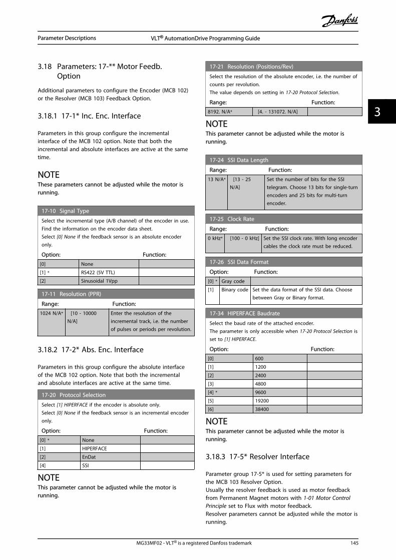
3.18 Parameters: 17-** Motor Feedb.Option
Additional parameters to configure the Encoder (MCB 102)or the Resolver (MCB 103) Feedback Option.
3.18.1 17-1* Inc. Enc. Interface
Parameters in this group configure the incrementalinterface of the MCB 102 option. Note that both theincremental and absolute interfaces are active at the sametime.
NOTEThese parameters cannot be adjusted while the motor isrunning.
17-10 Signal Type
Select the incremental type (A/B channel) of the encoder in use.Find the information on the encoder data sheet.Select [0] None if the feedback sensor is an absolute encoderonly.
Option: Function:
[0] None
[1] * RS422 (5V TTL)
[2] Sinusoidal 1Vpp
17-11 Resolution (PPR)
Range: Function:
1024 N/A* [10 - 10000N/A]
Enter the resolution of theincremental track, i.e. the numberof pulses or periods per revolution.
3.18.2 17-2* Abs. Enc. Interface
Parameters in this group configure the absolute interfaceof the MCB 102 option. Note that both the incrementaland absolute interfaces are active at the same time.
17-20 Protocol Selection
Select [1] HIPERFACE if the encoder is absolute only.Select [0] None if the feedback sensor is an incremental encoderonly.
Option: Function:
[0] * None
[1] HIPERFACE
[2] EnDat
[4] SSI
NOTEThis parameter cannot be adjusted while the motor isrunning.
17-21 Resolution (Positions/Rev)
Select the resolution of the absolute encoder, i.e. the number ofcounts per revolution.The value depends on setting in 17-20 Protocol Selection.
Range: Function:
8192. N/A* [4. - 131072. N/A]
NOTEThis parameter cannot be adjusted while the motor isrunning.
17-24 SSI Data Length
Range: Function:
13 N/A* [13 - 25N/A]
Set the number of bits for the SSItelegram. Choose 13 bits for single-turnencoders and 25 bits for multi-turnencoder.
17-25 Clock Rate
Range: Function:
0 kHz* [100 - 0 kHz] Set the SSI clock rate. With long encodercables the clock rate must be reduced.
17-26 SSI Data Format
Option: Function:
[0] * Gray code
[1] Binary code Set the data format of the SSI data. Choosebetween Gray or Binary format.
17-34 HIPERFACE Baudrate
Select the baud rate of the attached encoder.The parameter is only accessible when 17-20 Protocol Selection isset to [1] HIPERFACE.
Option: Function:
[0] 600
[1] 1200
[2] 2400
[3] 4800
[4] * 9600
[5] 19200
[6] 38400
NOTEThis parameter cannot be adjusted while the motor isrunning.
3.18.3 17-5* Resolver Interface
Parameter group 17-5* is used for setting parameters forthe MCB 103 Resolver Option.Usually the resolver feedback is used as motor feedbackfrom Permanent Magnet motors with 1-01 Motor ControlPrinciple set to Flux with motor feedback.Resolver parameters cannot be adjusted while the motor isrunning.
Parameter Descriptions VLT® AutomationDrive Programming Guide
MG33MF02 - VLT® is a registered Danfoss trademark 145
3 3
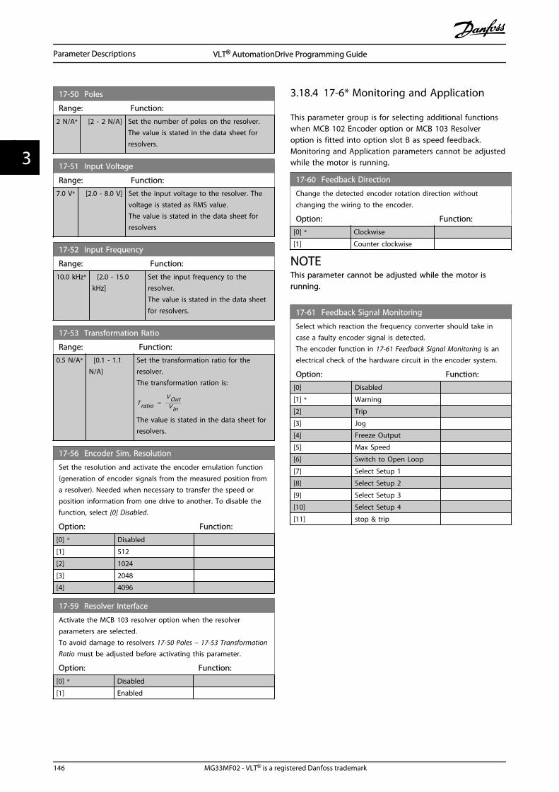
17-50 Poles
Range: Function:
2 N/A* [2 - 2 N/A] Set the number of poles on the resolver.The value is stated in the data sheet forresolvers.
17-51 Input Voltage
Range: Function:
7.0 V* [2.0 - 8.0 V] Set the input voltage to the resolver. Thevoltage is stated as RMS value.The value is stated in the data sheet forresolvers
17-52 Input Frequency
Range: Function:
10.0 kHz* [2.0 - 15.0kHz]
Set the input frequency to theresolver.The value is stated in the data sheetfor resolvers.
17-53 Transformation Ratio
Range: Function:
0.5 N/A* [0.1 - 1.1N/A]
Set the transformation ratio for theresolver.The transformation ration is:
Tratio = VOutVIn
The value is stated in the data sheet forresolvers.
17-56 Encoder Sim. Resolution
Set the resolution and activate the encoder emulation function(generation of encoder signals from the measured position froma resolver). Needed when necessary to transfer the speed orposition information from one drive to another. To disable thefunction, select [0] Disabled.
Option: Function:
[0] * Disabled
[1] 512
[2] 1024
[3] 2048
[4] 4096
17-59 Resolver Interface
Activate the MCB 103 resolver option when the resolverparameters are selected.To avoid damage to resolvers 17-50 Poles – 17-53 TransformationRatio must be adjusted before activating this parameter.
Option: Function:
[0] * Disabled
[1] Enabled
3.18.4 17-6* Monitoring and Application
This parameter group is for selecting additional functionswhen MCB 102 Encoder option or MCB 103 Resolveroption is fitted into option slot B as speed feedback.Monitoring and Application parameters cannot be adjustedwhile the motor is running.
17-60 Feedback Direction
Change the detected encoder rotation direction withoutchanging the wiring to the encoder.
Option: Function:
[0] * Clockwise
[1] Counter clockwise
NOTEThis parameter cannot be adjusted while the motor isrunning.
17-61 Feedback Signal Monitoring
Select which reaction the frequency converter should take incase a faulty encoder signal is detected.The encoder function in 17-61 Feedback Signal Monitoring is anelectrical check of the hardware circuit in the encoder system.
Option: Function:
[0] Disabled
[1] * Warning
[2] Trip
[3] Jog
[4] Freeze Output
[5] Max Speed
[6] Switch to Open Loop
[7] Select Setup 1
[8] Select Setup 2
[9] Select Setup 3
[10] Select Setup 4
[11] stop & trip
Parameter Descriptions VLT® AutomationDrive Programming Guide
146 MG33MF02 - VLT® is a registered Danfoss trademark
33

3.19 Parameters: 18-** Data Readouts 2
18-36 Analog Input X48/2 [mA]
Range: Function:
0 * [-20 - 20 ] View the actual current measured at inputX48/2.
18-37 Temp. Input X48/4
Range: Function:
0 * [-500 - 500 ] View the actual temperature measured atinput X48/4. The temperature unit is basedon the selection in 35-00 Term. X48/4Temperature Unit.
18-38 Temp. Input X48/7
Range: Function:
0 * [-500 - 500 ] View the actual temperature measured atinput X48/7. The temperature unit is basedon the selection in 35-02 Term. X48/7Temperature Unit.
18-39 Temp. Input X48/10
Range: Function:
0 * [-500 - 500 ] View the actual temperature measured atinput X48/10. The temperature unit is basedon the selection in 35-04 Term. X48/10Temperature Unit.
18-60 Digital Input 2
Range: Function:
0 * [0 - 65535 ] View the signal states from the active digitalinputs. '0' = no signal, '1' = connected signal.
18-90 Process PID Error
Range: Function:
0 %* [-200 - 200 %]
18-91 Process PID Output
Range: Function:
0 %* [-200 - 200 %]
18-92 Process PID Clamped Output
Range: Function:
0 %* [-200 - 200 %]
18-93 Process PID Gain Scaled Output
Range: Function:
0 %* [-200 - 200 %]
Parameter Descriptions VLT® AutomationDrive Programming Guide
MG33MF02 - VLT® is a registered Danfoss trademark 147
3 3

3.20 Parameters: 30-** Special Features
3.20.1 30-0* Wobble Function
The wobble function is primarily used for synthetic yarnwinding applications. The wobble option is to be installedin the frequency converter controlling the traverse drive.The traverse drive frequency converter will move the yarnback and forth in a diamond pattern across the surface ofthe yarn package. To prevent a buildup of yarn at thesame points at the surface, this pattern must be altered.The wobble option can accomplish this by continuouslyvarying the traverse velocity in a programmable cycle. Thewobble function is created by superimposing a deltafrequency around a center frequency. To compensate forthe inertia in the system a quick frequency jump can beincluded. Especially suitable for elastic yarn applicationsthe option features a randomized wobble ratio.
175Z
B001
.10
Par. 30-09: RANDOM FUNCPar 30-11: RANDOM MAXPar 30-12: RANDOM MIN
TDOWN TUP
Par. 30-06: JUMP TIMEPar. 30-04 [Hz]: JUMP FREQPar. 30-09 [%] : JUMP FREQ
CENTER FREQ
Par. 30-07: WOBB TIMEFrequency[Hz]
Time [s]
Par. 30-01 [Hz]: DELTA FREQ.Par. 30-02 [%]: DELTA FREQ.(Par. 30-03)
Par. 30-01 [Hz]Par. 30-02 [%](Par. 30-03:)Par. 30-*1: RAMP UP
Par. 30-10: [RATIO TUP/ TDOWN ]Par. 30-08: [INDEPENDENT UP and DOWN]
Illustration 3.66
30-00 Wobble Mode
Option: Function:
The standard speed open loop mode in 1-00 Configuration Mode is extended with awobble function. In this parameter it ispossible to select which method to be usedfor the wobbler. The parameters can be setas absolute values (direct frequencies) or asrelative values (percentage of otherparameter). The wobble cycle time can beset as an absolute alue or as independentup- and down times. When using anabsolute cycle time, the up- and down timesare configured through the wobble ratio.
[0] * Abs. Freq.,Abs. Time
[1] Abs. Freq.,Up/ DownTime
[2] Rel. Freq.,Abs. Time
[3] Rel. Freq.,Up/ DownTime
NOTEThis parameter cannot be adjusted while running.
NOTEThe setting of “Center Frequency” takes place via thenormal reference handling parameter group, 3-1*
30-01 Wobble Delta Frequency [Hz]
Range: Function:
5 Hz* [0 -25 Hz]
The delta frequency is determining themagnitude of the wobble frequency. The deltafrequency is superimposed on the centerfrequency. 30-01 Wobble Delta Frequency [Hz] isselecting both the positive and negative deltafrequency. The setting of 30-01 Wobble DeltaFrequency [Hz] must thus not be higher than thesetting of the center frequency. The initial rampup time from standstill until the wobblesequence is running is determined by parametergroup 3-1*.
30-02 Wobble Delta Frequency [%]
Range: Function:
25 %* [0 - 100 %] The delta frequency can also be expressedas percentage of the center frequency andcan thus be maximum 100%. The functionis the same as for 30-01 Wobble DeltaFrequency [Hz].
30-03 Wobble Delta Freq. Scaling Resource
Option: Function:
Select which drive input should beused to scale the delta frequencysetting.
[0] * No function
[1] Analog Input 53
[2] Analog Input 54
[3] Frequency input 29 FC 302 only
[4] Frequency input 33
[7] Analog Input X30/11
[8] Analog Input X30/12
[15] Analog Input X48/2
30-04 Wobble Jump Frequency [Hz]
Range: Function:
0 Hz* [ 0 -20.0 Hz]
The jump frequency is used to compensate forthe inertia in the traverse system. If a jump inthe output frequency is required in the top andin the bottom of the wobble sequence, thefrequency jump is set in this parameter. If thetraverse system has a very high inertia a highjump frequency may create a torque limitwarning or trip (warning/alarm 12) or an over
Parameter Descriptions VLT® AutomationDrive Programming Guide
148 MG33MF02 - VLT® is a registered Danfoss trademark
33

30-04 Wobble Jump Frequency [Hz]
Range: Function:voltage warning or trip (warning/alarm 7). Thisparameter can only be changed in stop-mode
30-05 Wobble Jump Frequency [%]
Range: Function:
0 %* [0 - 100 %] The jump frequency can also be expressed aspercentage of the center frequency. Thefunction is the same as for 30-04 WobbleJump Frequency [Hz].
30-06 Wobble Jump Time
Range: Function:
Size related* [ 0.005 - 5.000 s]
30-07 Wobble Sequence Time
Range: Function:
10 s* [1 - 1000 s] This parameter determines the wobblesequence period. This parameter can only bechanged in stop-mode.Wobble time = tup + tdown
30-08 Wobble Up/ Down Time
Range: Function:
5 s* [0.1 - 1000 s] Defines the individual up- and down timesfor each wobble cycle.
30-09 Wobble Random Function
Option: Function:
[0] * Off
[1] On
30-10 Wobble Ratio
Range: Function:
1 * [0.1 - 10 ] If the ratio 0.1 is selected: tdown is 10 times
greater than tup.
If the ratio 10 is selected: tup is 10 times greater
than tdown.
30-11 Wobble Random Ratio Max.
Range: Function:
10 * [ par. 17-53 - 10 ] Enter the maximum allowed wobbleratio.
30-12 Wobble Random Ratio Min.
Range: Function:
0.1 * [ 0.1 - par. 30-11 ] Enter the minimum allowed wobbleratio.
30-19 Wobble Delta Freq. Scaled
Range: Function:
0 Hz* [0 - 1000 Hz] Readout parameter. View the actualwobble delta frequency after scaling hasbeen applied.
3.20.2 30-2* Adv. Start Adjust
30-20 High Starting Torque Time [s]
Range: Function:
Size related* [0 - 60 s] High starting torque time for PM-Motorin Flux mode without feedback. Thisparameter is available for FC 302 only.
30-21 High Starting Torque Current [%]
Range: Function:
Size related* [ 0 - 200.0 %]
30-22 Locked Rotor Protection
Locked Rotor Protection for PM-Motor in Flux mode withoutfeedback. This parameter is available for FC 302 only.
Option: Function:
[0] * Off
[1] On
30-23 Locked Rotor Detection Time [s]
Locked Rotor Detection Time for PM-Motor in Flux mode withoutfeedback. This parameter is available for FC 302 only.
Range: Function:
Size related* [0.05 - 1 s]
3.20.3 30-8* Compatibility
30-80 d-axis Inductance (Ld)
Range: Function:
0 mH* [0 - 0.000mH]
Enter the value of the d-axis inductance.Obtain the value from the permanentmagnet motor data sheet. The d-axisinductance cannot be found byperforming an AMA.
30-81 Brake Resistor (ohm)
Range: Function:
50. Ohm* [5. - 32000.0 Ohm]
30-83 Speed PID Proportional Gain
Range: Function:
0 N/A* [0.0000 - 1.0000N/A]
Enter the speed controller propor-tional gain. Quick control is obtainedat high amplification. However ifamplification is too great, the processmay become unstable.
Parameter Descriptions VLT® AutomationDrive Programming Guide
MG33MF02 - VLT® is a registered Danfoss trademark 149
3 3

30-84 Process PID Proportional Gain
Range: Function:
0.100 * [0 - 10 ] Enter the process controller proportional gain.Quick control is obtained at high amplifi-cation. However if amplification is too great,the process may become unstable.
Parameter Descriptions VLT® AutomationDrive Programming Guide
150 MG33MF02 - VLT® is a registered Danfoss trademark
33

3.21 Parameters: 35-** Sensor Input Option
3.21.1 35-0* Temp. Input Mode (MCB 114)
35-00 Term. X48/4 Temperature Unit
Select the unit to be used with temperature input X48/4 settingsand readouts:
Option: Function:
[60] * °C
[160] °F
35-01 Term. X48/4 Input Type
View the temperature sensor type detected at input X48/4:
Option: Function:
[0] * Not Connected
[1] PT100 2-wire
[3] PT1000 2-wire
[5] PT100 3-wire
[7] PT1000 3-wire
35-02 Term. X48/7 Temperature Unit
Select the unit to be used with temperature input X48/7 settingsand readouts:
Option: Function:
[60] * °C
[160] °F
35-03 Term. X48/7 Input Type
View the temperature sensor type detected at input X48/7:
Option: Function:
[0] * Not Connected
[1] PT100 2-wire
[3] PT1000 2-wire
[5] PT100 3-wire
[7] PT1000 3-wire
35-04 Term. X48/10 Temperature Unit
Select the unit to be used with temperature input X48/10settings and readouts:
Option: Function:
[60] * °C
[160] °F
35-05 Term. X48/10 Input Type
View the temperature sensor type detected at input X48/10:
Option: Function:
[0] * Not Connected
[1] PT100 2-wire
[3] PT1000 2-wire
[5] PT100 3-wire
[7] PT1000 3-wire
35-06 Temperature Sensor Alarm Function
Select the alarm function:
Option: Function:
[0] Off
[2] Stop
[5] * Stop and trip
3.21.2 35-1* Temp. Input X48/4 (MCB 114)
35-14 Term. X48/4 Filter Time Constant
Range: Function:
0.001 s* [0.001 - 10s]
Enter the filter time constant. This is afirst-order digital low pass filter timeconstant for suppressing electrical noisein terminal X48/4. A high time constantvalue improves dampening but alsoincreases the time delay through thefilter.
35-15 Term. X48/4 Temp. Monitor
This parameter gives the possibility of enabling or disabling thetemperature monitor for terminal X48/4. The temperature limitscan be set in 35-16 Term. X48/4 Low Temp. Limit and 35-17 Term.X48/4 High Temp. Limit.
Option: Function:
[0] * Disabled
[1] Enabled
35-16 Term. X48/4 Low Temp. Limit
Range: Function:
Size related* [ -50 - par.35-17 ]
Enter the minimum temperaturereading that is expected fornormal operation of thetemperature sensor at terminalX48/4.
35-17 Term. X48/4 High Temp. Limit
Range: Function:
Size related* [ par. 35-16 -204 ]
Enter the maximum temperaturereading that is expected fornormal operation of thetemperature sensor at terminalX48/4.
3.21.3 35-2* Temp. Input X48/7 (MCB 114)
35-24 Term. X48/7 Filter Time Constant
Range: Function:
0.001 s* [0.001 - 10s]
Enter the filter time constant. This is afirst-order digital low pass filter timeconstant for suppressing electrical noisein terminal X48/7. A high time constantvalue improves dampening but also
Parameter Descriptions VLT® AutomationDrive Programming Guide
MG33MF02 - VLT® is a registered Danfoss trademark 151
3 3

35-24 Term. X48/7 Filter Time Constant
Range: Function:increases the time delay through thefilter.
35-25 Term. X48/7 Temp. Monitor
This parameter gives the possibility of enabling or disabling thetemperature monitor for terminal X48/7. The temperature limitscan be set in 35-26 Term. X48/7 Low Temp. Limit and 35-27 Term.X48/7 High Temp. Limit.
Option: Function:
[0] * Disabled
[1] Enabled
35-26 Term. X48/7 Low Temp. Limit
Range: Function:
Size related* [ -50 - par. 35-27 ]
35-27 Term. X48/7 High Temp. Limit
Range: Function:
Size related* [ par. 35-26 - 204 ]
3.21.4 35-3* Temp. Input X48/10 (MCB 114)
35-34 Term. X48/10 Filter Time Constant
Range: Function:
0.001 s* [0.001 - 10s]
Enter the filter time constant. This is afirst-order digital low pass filter timeconstant for suppressing electrical noisein terminal X48/10. A high time constantvalue improves dampening but alsoincreases the time delay through thefilter.
35-35 Term. X48/10 Temp. Monitor
This parameter gives the possibility of enabling or disabling thetemperature monitor for terminal X48/10. The temperature limitscan be set in 35-36 Term. X48/10 Low Temp. Limit/35-37 Term.X48/10 High Temp. Limit.
Option: Function:
[0] * Disabled
[1] Enabled
35-36 Term. X48/10 Low Temp. Limit
Range: Function:
Size related* [ -50 - par.35-37 ]
Enter the minimum temperaturereading that is expected fornormal operation of thetemperature sensor at terminalX48/10.
35-37 Term. X48/10 High Temp. Limit
Range: Function:
Size related* [ par. 35-36 -204 ]
Enter the maximum temperaturereading that is expected fornormal operation of thetemperature sensor at terminalX48/10.
3.21.5 35-4* Analog Input X48/2 (MCB 114)
35-42 Term. X48/2 Low Current
Range: Function:
4 mA* [ 0 - par.35-43 mA]
Enter the current (mA) that corresponds tothe low reference value, set in 35-44 Term.X48/2 Low Ref./Feedb. Value. The value mustbe set at >2 mA in order to activate theLive Zero Time-out Function in 6-01 LiveZero Timeout Function.
35-43 Term. X48/2 High Current
Range: Function:
20 mA* [ par. 35-42 - 20mA]
Enter the current (mA) thatcorresponds to the high referencevalue (set in 35-45 Term. X48/2 HighRef./Feedb. Value).
35-44 Term. X48/2 Low Ref./Feedb. Value
Range: Function:
0 * [-999999.999 -999999.999 ]
Enter the reference or feedback value(in RPM, Hz, bar, etc.) thatcorresponds to the voltage or currentset in 35-42 Term. X48/2 Low Current.
35-45 Term. X48/2 High Ref./Feedb. Value
Range: Function:
100 * [-999999.999 -999999.999 ]
Enter the reference or feedbackvalue (in RPM, Hz, bar, etc.) thatcorresponds to the voltage orcurrent set in 35-43 Term. X48/2High Current.
35-46 Term. X48/2 Filter Time Constant
Range: Function:
0.001 s* [0.001 - 10s]
Enter the filter time constant. This is afirst-order digital low pass filter timeconstant for suppressing electrical noisein terminal X48/2. A high time constantvalue improves dampening but alsoincreases the time delay through thefilter.
Parameter Descriptions VLT® AutomationDrive Programming Guide
152 MG33MF02 - VLT® is a registered Danfoss trademark
33

4 Parameter Lists
Frequency converter seriesAll = valid for FC 301 and FC 302 series01 = valid for FC 301 only02 = valid for FC 302 only
Changes during operation”TRUE” means that the parameter can be changed whilethe frequency converter is in operation and “FALSE” meansthat the frequency converter must be stopped before achange can be made.
4-Set-up'All set-ups': the parameter can be set individually in eachof the four set-ups, i. e. one single parameter can havefour different data values.’1 set-up’: data value will be the same in all set-ups.
Datatype
Description Type
2 Integer 8 Int8
3 Integer 16 Int16
4 Integer 32 Int32
5 Unsigned 8 Uint8
6 Unsigned 16 Uint16
7 Unsigned 32 Uint32
9 Visible String VisStr
33 Normalized value 2 bytes N2
35 Bit sequence of 16 boolean variables V2
54 Time difference w/o date TimD
Table 4.1
Parameter Lists VLT® AutomationDrive Programming Guide
MG33MF02 - VLT® is a registered Danfoss trademark 153
4 4

4.1.1 Conversion
The various attributes of each parameter are displayed inFactory Setting. Parameter values are transferred as wholenumbers only. Conversion factors are therefore used totransfer decimals.
4-12 Motor Speed Low Limit [Hz] has a conversion factor of0.1. To preset the minimum frequency to 10 Hz, transferthe value 100. A conversion factor of 0.1 means that thevalue transferred is multiplied by 0.1. The value 100 istherefore read as 10.0.
Examples:0s ⇒ conversion index 00.00s ⇒ conversion index -20ms ⇒ conversion index -30.00ms ⇒ conversion index -5
Conversion index Conversion factor
100
75
74
67
6 1000000
5 100000
4 10000
3 1000
2 100
1 10
0 1
-1 0.1
-2 0.01
-3 0.001
-4 0.0001
-5 0.00001
-6 0.000001
-7 0.0000001
Table 4.2 Conversion Table
4.1.2 Active/Inactive Parameters in Different Drive Control Modes
+ = active- = not active
1-10 Motor Construction AC motor PM Non salient Motor1-01 Motor Control Principle
U/f mode VVCplus Fluxsensorless
Flux w/motor
feedback
U/fmode
VVCplusFlux
sensorless
Flux w/motor
feedback
0-** Operation and Display (allparameters)
+ + + +
1-00 Configuration Mode
[0] Speed Open Loop + + + -
[1] Speed Closed Loop - + - +
[2] Torque - - - +
[3] Process + + + -
[4] Torque Open Loop - + - -
[5] Wobble + + + +
[6] Surface Winder + + + -
[7] Ext. PID Open Loop + + + -
[8] Ext. PID Closed Loop - + - +
1-02 Flux Motor FeedbackSource
- - - +
1-03 Torque Characteristics-
+see 1, 2, 3)
+see 1, 3, 4)
+see 1, 3, 4)
1-04 Overload Mode + + + + + + +
1-05 Local Mode Configuration + + + + + + +
1-06 Clockwise Direction + + + + + + +
1-20 Motor Power [kW](Par. 023 = International)
+ + + +
Parameter Lists VLT® AutomationDrive Programming Guide
154 MG33MF02 - VLT® is a registered Danfoss trademark
44

1-10 Motor Construction AC motor PM Non salient Motor1-01 Motor Control Principle
U/f mode VVCplus Fluxsensorless
Flux w/motor
feedback
U/fmode
VVCplusFlux
sensorless
Flux w/motor
feedback
1-21 Motor Power [HP](Par. 023 = US)
+ + + +
1-22 Motor Voltage + + + +
1-23 Motor Frequency + + + +
1-24 Motor Current + + + +
1-25 Motor Nominal Speed + + + +
1-26 Motor Cont. Rated Torque - - - - + + +
1-29 Automatic MotorAdaptation (AMA)
+ + + +
1-30 Stator Resistance (Rs) + + + + +
1-31 Rotor Resistance (Rr)-
+see 5)
+ +
1-33 Stator Leakage Reactance(X1)
+ + + + +
1-34 Rotor Leakage Reactance(X2)
-+
see 5)+ +
1-35 Main Reactance (Xh) + + + + +
1-36 Iron Loss Resistance (Rfe) - - + + - - -
1-37 d-axis Inductance (Ld) - - - - + +
1-39 Motor Poles + + + +
1-40 Back EMF at 1000 RPM - - - - + + +
1-41 Motor Angle Offset - - - - +
1-50 Motor Magnetisation atZero Speed
- + - - - - -
1-51 Min Speed NormalMagnetising [RPM](Par. 002 =rmp)
- + - - - - -
1-52 Min Speed NormalMagnetising [Hz](Par. 002 = Hz)
- + - - - - -
1-53 Model Shift Frequency - - + + - + +
1-54 Voltage reduction infieldweakening
- -+
see 6)+ - - -
1-55 U/f Characteristic - U + - - - + - -
1-56 U/f Characteristic - F + - - - + - -
1-58 Flystart Test Pulses Current - + - - - - -
1-59 Flystart Test PulsesFrequency
- + - - - - -
1-60 Low Speed Load Compen-sation
- + - - - - -
1-61 High Speed Load Compen-sation
- + - - - - -
1-62 Slip Compensation-
+see 7)
+ - - - -
1-63 Slip Compensation TimeConstant
+see 8)
++
see 8)-
+see 8)
+see 8)
-
1-64 Resonance Dampening + + + - + + -
1-65 Resonance DampeningTime Constant
+ + + - + + -
1-66 Min. Current at Low Speed - - + + - + +
1-67 Load Type - - + - - - -
Parameter Lists VLT® AutomationDrive Programming Guide
MG33MF02 - VLT® is a registered Danfoss trademark 155
4 4

1-10 Motor Construction AC motor PM Non salient Motor1-01 Motor Control Principle
U/f mode VVCplus Fluxsensorless
Flux w/motor
feedback
U/fmode
VVCplusFlux
sensorless
Flux w/motor
feedback
1-68 Minimum Inertia - - + - - - -
1-69 Maximum Inertia - - + - - - -
1-71 Start Delay + + + + + + +
1-72 Start Function + + + + + + +
1-73 Flying Start - + + + - - -
1-74 Start Speed [RPM](Par. 002= rmp)
- + - - - - -
1-75 Start Speed [Hz](Par. 002 =Hz)
- + - - - - -
1-76 Start Current - + - - - - -
1-80 Function at Stop + + + + + + +
1-81 Min Speed for Function atStop [RPM](Par. 002 = rpm)
+ + + + + + +
1-82 Min Speed for Function atStop [Hz](Par. 002 = Hz)
+ + + + + + +
1-83 Precise Stop Function + + + + + + +
1-84 Precise Stop Counter Value + + + + + + +
1-85 Precise Stop SpeedCompensation Delay
+ + + + + + +
1-90 Motor Thermal Protection + + + +
1-91 Motor External Fan + + + +
1-93 Thermistor Resource + + + +
1-95 KTY Sensor Type + + + +
1-96 KTY Thermistor Resource + + + +
1-97 KTY Threshold level + + + +
1-98 ATEX ETR interpol. pointsfreq.
+ + + +
1-99 ATEX ETR interpol pointscurrent
+ + + +
2-00 DC Hold Current + + + +
2-01 DC Brake Current + + + +
2-02 DC Braking Time + + + +
2-03 DC Brake Cut In Speed[RPM]
+ + + +
2-04 DC Brake Cut In Speed [Hz] + + + +
2-05 Maximum Reference + + + +
2-10 Brake Function +see 9)
+ + +
2-11 Brake Resistor (ohm) + + + +
2-12 Brake Power Limit (kW) + + + +
2-13 Brake Power Monitoring + + + +
2-15 Brake Check +see 9)
+ + +
2-16 AC brake Max. Current - + + +
2-17 Over-voltage Control + + + +
2-18 Brake Check Condition + + + +
2-19 Over-voltage Gain + + + -
2-20 Release Brake Current + + + +
Parameter Lists VLT® AutomationDrive Programming Guide
156 MG33MF02 - VLT® is a registered Danfoss trademark
44

1-10 Motor Construction AC motor PM Non salient Motor1-01 Motor Control Principle
U/f mode VVCplus Fluxsensorless
Flux w/motor
feedback
U/fmode
VVCplusFlux
sensorless
Flux w/motor
feedback
2-21 Activate Brake Speed [RPM] + + + +
2-22 Activate Brake Speed [Hz] + + + +
2-23 Activate Brake Delay + + + +
2-24 Stop Delay - - - +
2-25 Brake Release Time - - - +
2-26 Torque Ref - - - +
2-27 Torque Ramp Time - - - +
2-28 Gain Boost Factor - - - +
3-** Reference/Ramps (allparameters)
+ + + +
4-10 Motor Speed Direction + + + +
4-11 Motor Speed Low Limit[RPM]
+ + + +
4-12 Motor Speed Low Limit [Hz] + + + +
4-13 Motor Speed High Limit[RPM]
+ + + +
4-14 Motor Speed High Limit[Hz]
+ + + +
4-16 Torque Limit Motor Mode + + + +
4-17 Torque Limit GeneratorMode
+ + + +
4-18 Current Limit + + + +
4-19 Max Output Frequency + + + +
4-20 Torque Limit Factor Source + + + +
4-21 Speed Limit Factor Source - + see 10) - + see 11)
4-30 Motor Feedback LossFunction
- + see 12) - + see 12)
4-31 Motor Feedback SpeedError
- + see 12) - + see 12)
4-32 Motor Feedback LossTimeout
- + see 12) - + see 12)
4-34 Tracking Error Function + + + +
4-35 Tracking Error + + + +
4-36 Tracking Error Timeout + + + +
4-37 Tracking Error Ramping + + + +
4-38 Tracking Error RampingTimeout
+ + + +
4-39 Tracking Error AfterRamping Timeout
+ + + +
4-50 Warning Current Low + + + +
4-51 Warning Current High + + + +
4-52 Warning Speed Low + + + +
4-53 Warning Speed High + + + +
4-54 Warning Reference Low + + + +
4-55 Warning Reference High + + + +
4-56 Warning Feedback Low + + + +
4-57 Warning Feedback High + + + +
4-58 Missing Motor PhaseFunction
+ + + +
Parameter Lists VLT® AutomationDrive Programming Guide
MG33MF02 - VLT® is a registered Danfoss trademark 157
4 4

1-10 Motor Construction AC motor PM Non salient Motor1-01 Motor Control Principle
U/f mode VVCplus Fluxsensorless
Flux w/motor
feedback
U/fmode
VVCplusFlux
sensorless
Flux w/motor
feedback
4-60 Bypass Speed From [RPM] + + + +
4-61 Bypass Speed From [Hz] + + + +
4-62 Bypass Speed To [RPM] + + + +
4-63 Bypass Speed To [Hz] + + + +
5-** Digital In/Out (allparameters except 5-70 and 71)
+ + + +
5-70 Term 32/33 Pulses perRevolution
- + see 12) - +
5-71 Term 32/33 EncoderDirection
- + see 12) - +
6-** Analog In/Out (allparameters)
+ + + +
7-00 Speed PID Feedback Source - + see 12) - +
7-02 Speed PID ProportionalGain
- + see 12) + +
7-03 Speed PID Integral Time - + see 12) + +
7-04 Speed PID DifferentiationTime
- + see 12) + +
7-05 Speed PID Diff. Gain Limit - + see 12) + +
7-06 Speed PID Lowpass FilterTime
- + see 12) + +
7-07 Speed PID Feedback GearRatio
- + see 12) - +
7-08 Speed PID Feed ForwardFactor
- + see 12) - -
7-12 Torque PI Proportional Gain - + see 10) - -
7-13 Torque PI Integration Time - + see 10) - -
7-20 Process CL Feedback 1Resource
+ + + +
7-22 Process CL Feedback 2Resource
+ + + +
7-30 Process PID Normal/ InverseControl
+ + + +
7-31 Process PID Anti Windup + + + +
7-32 Process PID Start Speed + + + +
7-33 Process PID ProportionalGain
+ + + +
7-34 Process PID Integral Time + + + +
7-35 Process PID DifferentiationTime
+ + + +
7-36 Process PID Diff. Gain Limit + + + +
7-38 Process PID Feed ForwardFactor
+ + + +
7-39 On Reference Bandwidth + + + +
7-40 Process PID I-part Reset + + + +
7-41 Process PID Output Neg.Clamp
+ + + +
7-42 Process PID Output Pos.Clamp
+ + + +
Parameter Lists VLT® AutomationDrive Programming Guide
158 MG33MF02 - VLT® is a registered Danfoss trademark
44

1-10 Motor Construction AC motor PM Non salient Motor1-01 Motor Control Principle
U/f mode VVCplus Fluxsensorless
Flux w/motor
feedback
U/fmode
VVCplusFlux
sensorless
Flux w/motor
feedback
7-43 Process PID Gain Scale atMin. Ref.
+ + + +
7-44 Process PID Gain Scale atMax. Ref.
+ + + +
7-45 Process PID Feed FwdResource
+ + + +
7-46 Process PID Feed FwdNormal/ Inv. Ctrl.
+ + + +
7-48 PCD Feed Forward + + + +
7-49 Process PID Output Normal/Inv. Ctrl.
+ + + +
7-50 Process PID Extended PID + + + +
7-51 Process PID Feed Fwd Gain + + + +
7-52 Process PID Feed FwdRamp up
+ + + +
7-53 Process PID Feed FwdRamp down
+ + + +
7-56 Process PID Ref. Filter Time + + + +
7-57 Process PID Fb. Filter Time + + + +
8-** Communications andOptions (all parameters)
+ + + +
13-** Smart Logic Control (allparameters)
+ + + +
14-00 Switching Pattern + + + +
14-01 Switching Frequency + + + +
14-03 Overmodulation + + + +
14-04 PWM Random + + + +
14-06 Dead Time Compensation + + + +
14-10 Mains Failure
[0] No function + + + +
[1] Ctrl. rampdown - + + +
[2] Ctrl. rampdown, trip - + + +
[3] Coasting + + + +
[4] Kinetic back-up - + + +
[5] Kinetic back-up, trip - + + +
[6] Alarm + + + +
14-11 Mains Voltage at MainsFault
+ + + +
14-12 Function at MainsImbalance
+ + + +
14-14 Kin. Backup Time Out - - + +
14-15 Kin. Backup Trip RecoveryLevel
+ + + +
14-20 Reset Mode + + + +
14-21 Automatic Restart Time + + + +
14-22 Operation Mode + + + +
14-24 Trip Delay at Current Limit + + + +
14-25 Trip Delay at Torque Limit + + + +
14-26 Trip Delay at Inverter Fault + + + +
14-29 Service Code + + + +
Parameter Lists VLT® AutomationDrive Programming Guide
MG33MF02 - VLT® is a registered Danfoss trademark 159
4 4

1-10 Motor Construction AC motor PM Non salient Motor1-01 Motor Control Principle
U/f mode VVCplus Fluxsensorless
Flux w/motor
feedback
U/fmode
VVCplusFlux
sensorless
Flux w/motor
feedback
14-30 Current Lim Ctrl, Propor-tional Gain
+ + + +
14-31 Current Lim Ctrl,Integration Time
+ + + +
14-32 Current Lim Ctrl, FilterTime
+ + + +
14-35 Stall Protection - - + +
14-40 VT Level - + + +
14-41 AEO Minimum Magneti-sation
- + + +
14-42 Minimum AEO Frequency - + + +
14-43 Motor Cosphi - + + +
14-50 RFI Filter + + + +
14-51 DC Link Compensation + + + +
14-52 Fan Control + + + +
14-53 Fan Monitor + + + +
14-55 Output Filter + + + +
14-56 Capacitance Output Filter - - + +
14-57 Inductance Output Filter - - + +
14-74 VLT Ext. Status Word + + + +
14-80 Option Supplied byExternal 24VDC
+ + + +
14-89 Option Detection + + + +
14-90 Fault Level + + + +
Table 4.3
1) Constant torque2) Variable torque3) AEO4) Constant power5) Used in flystart6) Used when 1-03 Torque Characteristics is constant power7) Not used when 1-03 Torque Characteristics = VT8) Part of resonance damping9) Not AC brake10) Torque open loop11) Torque12) Speed closed loop
Parameter Lists VLT® AutomationDrive Programming Guide
160 MG33MF02 - VLT® is a registered Danfoss trademark
44

4.1.3 0-** Operation/Display
Par.No. #
Parameter description Default value 4-set-up FC 302only
Changeduring
operation
Conver-sion index
Type
0-0* Basic Settings
0-01 Language [0] English 1 set-up TRUE - Uint8
0-02 Motor Speed Unit [0] RPM 2 set-ups FALSE - Uint8
0-03 Regional Settings [0] International 2 set-ups FALSE - Uint8
0-04 Operating State at Power-up (Hand) [1] Forced stop, ref=old All set-ups TRUE - Uint8
0-09 Performance Monitor 0.0 % All set-ups TRUE -1 Uint16
0-1* Set-up Operations
0-10 Active Set-up [1] Set-up 1 1 set-up TRUE - Uint8
0-11 Edit Set-up [1] Set-up 1 All set-ups TRUE - Uint8
0-12 This Set-up Linked to [0] Not linked All set-ups FALSE - Uint8
0-13 Readout: Linked Set-ups 0 N/A All set-ups FALSE 0 Uint16
0-14 Readout: Edit Set-ups / Channel 0 N/A All set-ups TRUE 0 Int32
0-15 Readout: actual setup 0 N/A All set-ups FALSE 0 Uint8
0-2* LCP Display
0-20 Display Line 1.1 Small 1617 All set-ups TRUE - Uint16
0-21 Display Line 1.2 Small 1614 All set-ups TRUE - Uint16
0-22 Display Line 1.3 Small 1610 All set-ups TRUE - Uint16
0-23 Display Line 2 Large 1613 All set-ups TRUE - Uint16
0-24 Display Line 3 Large 1602 All set-ups TRUE - Uint16
0-25 My Personal Menu App.Dependent 1 set-up TRUE 0 Uint16
0-3* LCP Custom Readout
0-30 Unit for User-defined Readout [0] None All set-ups TRUE - Uint8
0-31 Min Value of User-defined Readout 0.00 CustomReadoutUnit All set-ups TRUE -2 Int32
0-32 Max Value of User-defined Readout100.00 CustomRea-
doutUnit All set-ups TRUE -2 Int32
0-37 Display Text 1 0 N/A 1 set-up TRUE 0 VisStr[25]
0-38 Display Text 2 0 N/A 1 set-up TRUE 0 VisStr[25]
0-39 Display Text 3 0 N/A 1 set-up TRUE 0 VisStr[25]
0-4* LCP Keypad
0-40 [Hand on] Key on LCP null All set-ups TRUE - Uint8
0-41 [Off] Key on LCP null All set-ups TRUE - Uint8
0-42 [Auto on] Key on LCP null All set-ups TRUE - Uint8
0-43 [Reset] Key on LCP null All set-ups TRUE - Uint8
0-44 [Off/Reset] Key on LCP null All set-ups TRUE - Uint8
0-45 [Drive Bypass] Key on LCP null All set-ups TRUE - Uint8
0-5* Copy/Save
0-50 LCP Copy [0] No copy All set-ups FALSE - Uint8
0-51 Set-up Copy [0] No copy All set-ups FALSE - Uint8
0-6* Password
0-60 Main Menu Password 100 N/A 1 set-up TRUE 0 Int16
0-61 Access to Main Menu w/o Password [0] Full access 1 set-up TRUE - Uint8
0-65 Quick Menu Password 200 N/A 1 set-up TRUE 0 Int16
0-66 Access to Quick Menu w/o Password [0] Full access 1 set-up TRUE - Uint8
0-67 Bus Password Access 0 N/A All set-ups TRUE 0 Uint16
Table 4.4
Parameter Lists VLT® AutomationDrive Programming Guide
MG33MF02 - VLT® is a registered Danfoss trademark 161
4 4

4.1.4 1-** Load/Motor
Par.No. #
Parameter description Default value 4-set-up Changeduring
operation
Conver-sion index
Type
1-0* General Settings
1-00 Configuration Mode App.Dependent All set-ups TRUE - Uint8
1-01 Motor Control Principle App.Dependent All set-ups FALSE - Uint8
1-02 Flux Motor Feedback Source [1] 24 V encoder All set-ups FALSE - Uint8
1-03 Torque Characteristics [0] Constant torque All set-ups TRUE - Uint8
1-04 Overload Mode [0] High torque All set-ups FALSE - Uint8
1-05 Local Mode Configuration [2] As mode par 1-00 All set-ups TRUE - Uint8
1-06 Clockwise Direction [0] Normal All set-ups FALSE - Uint8
1-07 Motor Angle Offset Adjust [0] Manual All set-ups FALSE - Uint8
1-1* Motor Selection
1-10 Motor Construction App.Dependent All set-ups FALSE - Uint8
1-11 Motor Model App.Dependent All set-ups FALSE - Uint8
1-14 Damping Gain 140% All set-ups TRUE 0 Int16
1-15 Low Speed Filter Time Const. App.Dependent All set-ups TRUE -2 Uint16
1-16 High Speed Filter Time Const. App.Dependent All set-ups TRUE -2 Uint16
1-17 Voltage filter time const. App.Dependent All set-ups TRUE -3 Uint16
1-2* Motor Data
1-20 Motor Power [kW] App.Dependent All set-ups FALSE 1 Uint32
1-21 Motor Power [HP] App.Dependent All set-ups FALSE -2 Uint32
1-22 Motor Voltage App.Dependent All set-ups FALSE 0 Uint16
1-23 Motor Frequency App.Dependent All set-ups FALSE 0 Uint16
1-24 Motor Current App.Dependent All set-ups FALSE -2 Uint32
1-25 Motor Nominal Speed App.Dependent All set-ups FALSE 67 Uint16
1-26 Motor Cont. Rated Torque App.Dependent All set-ups FALSE -1 Uint32
1-29 Automatic Motor Adaptation (AMA) [0] Off All set-ups FALSE - Uint8
1-3* Adv. Motor Data
1-30 Stator Resistance (Rs) App.Dependent All set-ups FALSE -4 Uint32
1-31 Rotor Resistance (Rr) App.Dependent All set-ups FALSE -4 Uint32
1-33 Stator Leakage Reactance (X1) App.Dependent All set-ups FALSE -4 Uint32
1-34 Rotor Leakage Reactance (X2) App.Dependent All set-ups FALSE -4 Uint32
1-35 Main Reactance (Xh) App.Dependent All set-ups FALSE -4 Uint32
1-36 Iron Loss Resistance (Rfe) App.Dependent All set-ups FALSE -3 Uint32
1-37 d-axis Inductance (Ld) App.Dependent All set-ups FALSE -4 Int32
1-39 Motor Poles App.Dependent All set-ups FALSE 0 Uint8
1-40 Back EMF at 1000 RPM App.Dependent All set-ups FALSE 0 Uint16
1-41 Motor Angle Offset 0 N/A All set-ups FALSE 0 Int16
1-46 Position Detection Gain 100% All set-ups TRUE 0 Uint16
1-47 Low Speed Torque Calibration App.Dependent All set-ups TRUE - Uint8
1-5* Load Indep. Setting
1-50 Motor Magnetisation at Zero Speed 100% All set-ups TRUE 0 Uint16
1-51 Min Speed Normal Magnetising [RPM] App.Dependent All set-ups TRUE 67 Uint16
1-52 Min Speed Normal Magnetising [Hz] App.Dependent All set-ups TRUE -1 Uint16
1-53 Model Shift Frequency App.Dependent All set-ups FALSE -1 Uint16
1-54 Voltage reduction in fieldweakening 0 V All set-ups FALSE 0 Uint8
1-55 U/f Characteristic - U App.Dependent All set-ups TRUE -1 Uint16
1-56 U/f Characteristic - F App.Dependent All set-ups TRUE -1 Uint16
1-58 Flystart Test Pulses Current App.Dependent All set-ups FALSE 0 Uint16
1-59 Flystart Test Pulses Frequency App.Dependent All set-ups FALSE 0 Uint16
1-6* Load Depen. Setting
Parameter Lists VLT® AutomationDrive Programming Guide
162 MG33MF02 - VLT® is a registered Danfoss trademark
44

Par.No. #
Parameter description Default value 4-set-up Changeduring
operation
Conver-sion index
Type
1-60 Low Speed Load Compensation 100% All set-ups TRUE 0 Int16
1-61 High Speed Load Compensation 100% All set-ups TRUE 0 Int16
1-62 Slip Compensation App.Dependent All set-ups TRUE 0 Int16
1-63 Slip Compensation Time Constant App.Dependent All set-ups TRUE -2 Uint16
1-64 Resonance Dampening 100% All set-ups TRUE 0 Uint16
1-65 Resonance Dampening Time Constant 5 ms All set-ups TRUE -3 Uint8
1-66 Min. Current at Low Speed 100% All set-ups TRUE 0 Uint8
1-67 Load Type [0] Passive load All set-ups TRUE - Uint8
1-68 Minimum Inertia App.Dependent All set-ups FALSE -4 Uint32
1-69 Maximum Inertia App.Dependent All set-ups FALSE -4 Uint32
1-7* Start Adjustments
1-70 PM Start Mode [0] Rotor Detection All set-ups TRUE - Uint8
1-71 Start Delay 0.0 s All set-ups TRUE -1 Uint8
1-72 Start Function [2] Coast/delay time All set-ups TRUE - Uint8
1-73 Flying Start null All set-ups FALSE - Uint8
1-74 Start Speed [RPM] App.Dependent All set-ups TRUE 67 Uint16
1-75 Start Speed [Hz] App.Dependent All set-ups TRUE -1 Uint16
1-76 Start Current 0.00 A All set-ups TRUE -2 Uint32
1-8* Stop Adjustments
1-80 Function at Stop [0] Coast All set-ups TRUE - Uint8
1-81 Min Speed for Function at Stop [RPM] App.Dependent All set-ups TRUE 67 Uint16
1-82 Min Speed for Function at Stop [Hz] App.Dependent All set-ups TRUE -1 Uint16
1-83 Precise Stop Function [0] Precise ramp stop All set-ups FALSE - Uint8
1-84 Precise Stop Counter Value 100000 N/A All set-ups TRUE 0 Uint32
1-85 Precise Stop Speed Compensation Delay 10 ms All set-ups TRUE -3 Uint8
1-9* Motor Temperature
1-90 Motor Thermal Protection [0] No protection All set-ups TRUE - Uint8
1-91 Motor External Fan [0] No All set-ups TRUE - Uint16
1-93 Thermistor Resource [0] None All set-ups TRUE - Uint8
1-94 ATEX ETR cur.lim. speed reduction 0.0% 2 set-ups TRUE -1 Uint16
1-95 KTY Sensor Type [0] KTY Sensor 1 All set-ups TRUE - Uint8
1-96 KTY Thermistor Resource [0] None All set-ups TRUE - Uint8
1-97 KTY Threshold level 80 ºC 1 set-up TRUE 100 Int16
1-98 ATEX ETR interpol. points freq. App.Dependent 1 set-up TRUE -1 Int16
1-99 ATEX ETR interpol points current App.Dependent 2 set-ups TRUE 0 Int16
Table 4.5
Parameter Lists VLT® AutomationDrive Programming Guide
MG33MF02 - VLT® is a registered Danfoss trademark 163
4 4
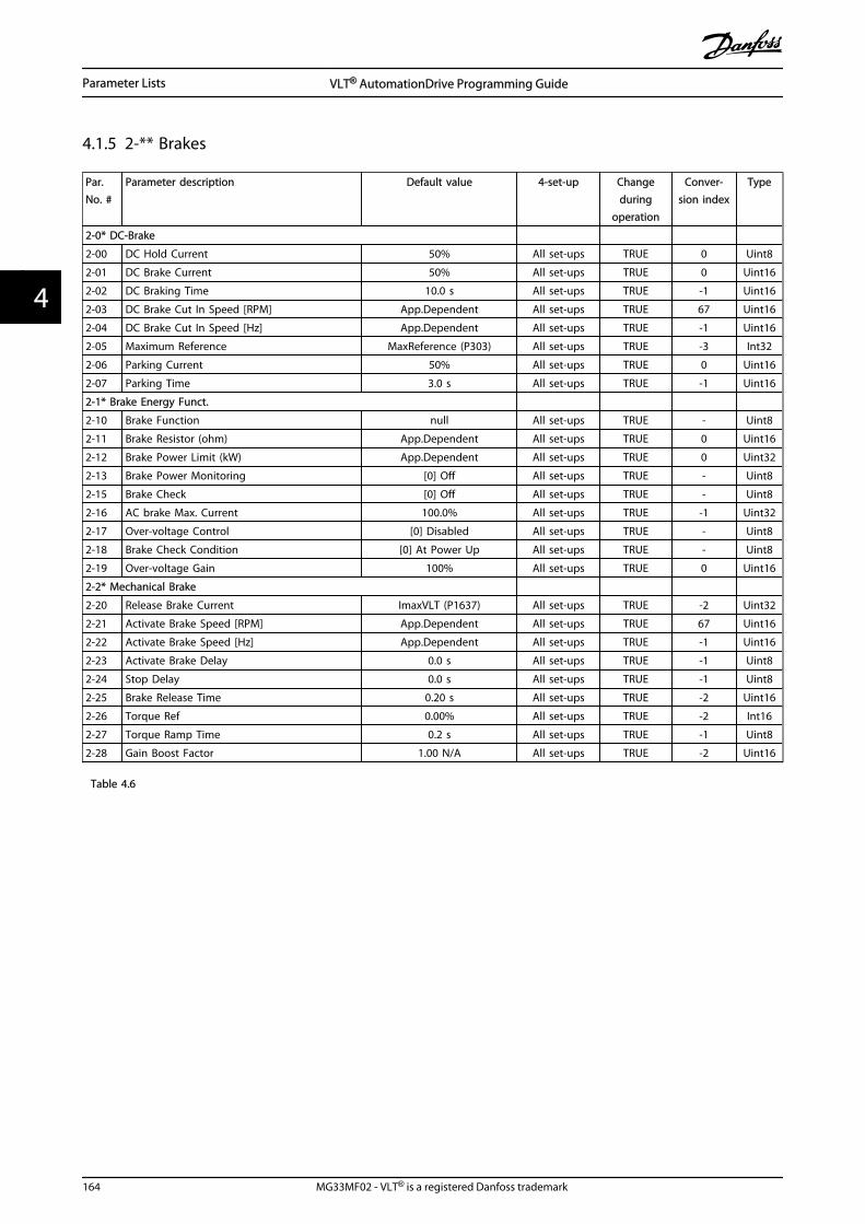
4.1.5 2-** Brakes
Par.No. #
Parameter description Default value 4-set-up Changeduring
operation
Conver-sion index
Type
2-0* DC-Brake
2-00 DC Hold Current 50% All set-ups TRUE 0 Uint8
2-01 DC Brake Current 50% All set-ups TRUE 0 Uint16
2-02 DC Braking Time 10.0 s All set-ups TRUE -1 Uint16
2-03 DC Brake Cut In Speed [RPM] App.Dependent All set-ups TRUE 67 Uint16
2-04 DC Brake Cut In Speed [Hz] App.Dependent All set-ups TRUE -1 Uint16
2-05 Maximum Reference MaxReference (P303) All set-ups TRUE -3 Int32
2-06 Parking Current 50% All set-ups TRUE 0 Uint16
2-07 Parking Time 3.0 s All set-ups TRUE -1 Uint16
2-1* Brake Energy Funct.
2-10 Brake Function null All set-ups TRUE - Uint8
2-11 Brake Resistor (ohm) App.Dependent All set-ups TRUE 0 Uint16
2-12 Brake Power Limit (kW) App.Dependent All set-ups TRUE 0 Uint32
2-13 Brake Power Monitoring [0] Off All set-ups TRUE - Uint8
2-15 Brake Check [0] Off All set-ups TRUE - Uint8
2-16 AC brake Max. Current 100.0% All set-ups TRUE -1 Uint32
2-17 Over-voltage Control [0] Disabled All set-ups TRUE - Uint8
2-18 Brake Check Condition [0] At Power Up All set-ups TRUE - Uint8
2-19 Over-voltage Gain 100% All set-ups TRUE 0 Uint16
2-2* Mechanical Brake
2-20 Release Brake Current ImaxVLT (P1637) All set-ups TRUE -2 Uint32
2-21 Activate Brake Speed [RPM] App.Dependent All set-ups TRUE 67 Uint16
2-22 Activate Brake Speed [Hz] App.Dependent All set-ups TRUE -1 Uint16
2-23 Activate Brake Delay 0.0 s All set-ups TRUE -1 Uint8
2-24 Stop Delay 0.0 s All set-ups TRUE -1 Uint8
2-25 Brake Release Time 0.20 s All set-ups TRUE -2 Uint16
2-26 Torque Ref 0.00% All set-ups TRUE -2 Int16
2-27 Torque Ramp Time 0.2 s All set-ups TRUE -1 Uint8
2-28 Gain Boost Factor 1.00 N/A All set-ups TRUE -2 Uint16
Table 4.6
Parameter Lists VLT® AutomationDrive Programming Guide
164 MG33MF02 - VLT® is a registered Danfoss trademark
44
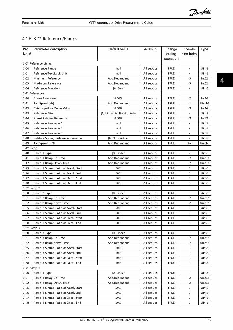
4.1.6 3-** Reference/Ramps
Par.No. #
Parameter description Default value 4-set-up Changeduring
operation
Conver-sion index
Type
3-0* Reference Limits
3-00 Reference Range null All set-ups TRUE - Uint8
3-01 Reference/Feedback Unit null All set-ups TRUE - Uint8
3-02 Minimum Reference App.Dependent All set-ups TRUE -3 Int32
3-03 Maximum Reference App.Dependent All set-ups TRUE -3 Int32
3-04 Reference Function [0] Sum All set-ups TRUE - Uint8
3-1* References
3-10 Preset Reference 0.00% All set-ups TRUE -2 Int16
3-11 Jog Speed [Hz] App.Dependent All set-ups TRUE -1 Uint16
3-12 Catch up/slow Down Value 0.00% All set-ups TRUE -2 Int16
3-13 Reference Site [0] Linked to Hand / Auto All set-ups TRUE - Uint8
3-14 Preset Relative Reference 0.00% All set-ups TRUE -2 Int32
3-15 Reference Resource 1 null All set-ups TRUE - Uint8
3-16 Reference Resource 2 null All set-ups TRUE - Uint8
3-17 Reference Resource 3 null All set-ups TRUE - Uint8
3-18 Relative Scaling Reference Resource [0] No function All set-ups TRUE - Uint8
3-19 Jog Speed [RPM] App.Dependent All set-ups TRUE 67 Uint16
3-4* Ramp 1
3-40 Ramp 1 Type [0] Linear All set-ups TRUE - Uint8
3-41 Ramp 1 Ramp up Time App.Dependent All set-ups TRUE -2 Uint32
3-42 Ramp 1 Ramp Down Time App.Dependent All set-ups TRUE -2 Uint32
3-45 Ramp 1 S-ramp Ratio at Accel. Start 50% All set-ups TRUE 0 Uint8
3-46 Ramp 1 S-ramp Ratio at Accel. End 50% All set-ups TRUE 0 Uint8
3-47 Ramp 1 S-ramp Ratio at Decel. Start 50% All set-ups TRUE 0 Uint8
3-48 Ramp 1 S-ramp Ratio at Decel. End 50% All set-ups TRUE 0 Uint8
3-5* Ramp 2
3-50 Ramp 2 Type [0] Linear All set-ups TRUE - Uint8
3-51 Ramp 2 Ramp up Time App.Dependent All set-ups TRUE -2 Uint32
3-52 Ramp 2 Ramp down Time App.Dependent All set-ups TRUE -2 Uint32
3-55 Ramp 2 S-ramp Ratio at Accel. Start 50% All set-ups TRUE 0 Uint8
3-56 Ramp 2 S-ramp Ratio at Accel. End 50% All set-ups TRUE 0 Uint8
3-57 Ramp 2 S-ramp Ratio at Decel. Start 50% All set-ups TRUE 0 Uint8
3-58 Ramp 2 S-ramp Ratio at Decel. End 50% All set-ups TRUE 0 Uint8
3-6* Ramp 3
3-60 Ramp 3 Type [0] Linear All set-ups TRUE - Uint8
3-61 Ramp 3 Ramp up Time App.Dependent All set-ups TRUE -2 Uint32
3-62 Ramp 3 Ramp down Time App.Dependent All set-ups TRUE -2 Uint32
3-65 Ramp 3 S-ramp Ratio at Accel. Start 50% All set-ups TRUE 0 Uint8
3-66 Ramp 3 S-ramp Ratio at Accel. End 50% All set-ups TRUE 0 Uint8
3-67 Ramp 3 S-ramp Ratio at Decel. Start 50% All set-ups TRUE 0 Uint8
3-68 Ramp 3 S-ramp Ratio at Decel. End 50% All set-ups TRUE 0 Uint8
3-7* Ramp 4
3-70 Ramp 4 Type [0] Linear All set-ups TRUE - Uint8
3-71 Ramp 4 Ramp up Time App.Dependent All set-ups TRUE -2 Uint32
3-72 Ramp 4 Ramp Down Time App.Dependent All set-ups TRUE -2 Uint32
3-75 Ramp 4 S-ramp Ratio at Accel. Start 50% All set-ups TRUE 0 Uint8
3-76 Ramp 4 S-ramp Ratio at Accel. End 50% All set-ups TRUE 0 Uint8
3-77 Ramp 4 S-ramp Ratio at Decel. Start 50% All set-ups TRUE 0 Uint8
3-78 Ramp 4 S-ramp Ratio at Decel. End 50% All set-ups TRUE 0 Uint8
Parameter Lists VLT® AutomationDrive Programming Guide
MG33MF02 - VLT® is a registered Danfoss trademark 165
4 4

Par.No. #
Parameter description Default value 4-set-up Changeduring
operation
Conver-sion index
Type
3-80 Jog Ramp Time App.Dependent All set-ups TRUE -2 Uint32
3-81 Quick Stop Ramp Time App.Dependent 2 set-ups TRUE -2 Uint32
3-82 Quick Stop Ramp Type [0] Linear All set-ups TRUE - Uint8
3-83 Quick Stop S-ramp Ratio at Decel. Start 50% All set-ups TRUE 0 Uint8
3-84 Quick Stop S-ramp Ratio at Decel. End 50% All set-ups TRUE 0 Uint8
3-9* Digital Pot.Meter
3-90 Step Size 0.10% All set-ups TRUE -2 Uint16
3-91 Ramp Time 1.00 s All set-ups TRUE -2 Uint32
3-92 Power Restore [0] Off All set-ups TRUE - Uint8
3-93 Maximum Limit 100% All set-ups TRUE 0 Int16
3-94 Minimum Limit -100% All set-ups TRUE 0 Int16
3-95 Ramp Delay App.Dependent All set-ups TRUE -3 TimD
Table 4.7
Parameter Lists VLT® AutomationDrive Programming Guide
166 MG33MF02 - VLT® is a registered Danfoss trademark
44

4.1.7 4-** Limits / Warnings
Par.No. #
Parameter description Default value 4-set-up Changeduring
operation
Conver-sion index
Type
4-1* Motor Limits
4-10 Motor Speed Direction null All set-ups FALSE - Uint8
4-11 Motor Speed Low Limit [RPM] App.Dependent All set-ups TRUE 67 Uint16
4-12 Motor Speed Low Limit [Hz] App.Dependent All set-ups TRUE -1 Uint16
4-13 Motor Speed High Limit [RPM] App.Dependent All set-ups TRUE 67 Uint16
4-14 Motor Speed High Limit [Hz] App.Dependent All set-ups TRUE -1 Uint16
4-16 Torque Limit Motor Mode App.Dependent All set-ups TRUE -1 Uint16
4-17 Torque Limit Generator Mode 100.0% All set-ups TRUE -1 Uint16
4-18 Current Limit App.Dependent All set-ups TRUE -1 Uint32
4-19 Max Output Frequency 132.0 Hz All set-ups FALSE -1 Uint16
4-2* Limit Factors
4-20 Torque Limit Factor Source [0] No function All set-ups TRUE - Uint8
4-21 Speed Limit Factor Source [0] No function All set-ups TRUE - Uint8
4-3* Motor Speed Mon.
4-30 Motor Feedback Loss Function [2] Trip All set-ups TRUE - Uint8
4-31 Motor Feedback Speed Error 300 RPM All set-ups TRUE 67 Uint16
4-32 Motor Feedback Loss Timeout 0.05 s All set-ups TRUE -2 Uint16
4-34 Tracking Error Function null All set-ups TRUE - Uint8
4-35 Tracking Error 10 RPM All set-ups TRUE 67 Uint16
4-36 Tracking Error Timeout 1.00 s All set-ups TRUE -2 Uint16
4-37 Tracking Error Ramping 100 RPM All set-ups TRUE 67 Uint16
4-38 Tracking Error Ramping Timeout 1.00 s All set-ups TRUE -2 Uint16
4-39 Tracking Error After Ramping Timeout 5.00 s All set-ups TRUE -2 Uint16
4-5* Adj. Warnings
4-50 Warning Current Low 0.00 A All set-ups TRUE -2 Uint32
4-51 Warning Current High ImaxVLT (P1637) All set-ups TRUE -2 Uint32
4-52 Warning Speed Low 0 RPM All set-ups TRUE 67 Uint16
4-53 Warning Speed High outputSpeedHighLimit (P413) All set-ups TRUE 67 Uint16
4-54 Warning Reference Low -999999.999 N/A All set-ups TRUE -3 Int32
4-55 Warning Reference High 999999.999 N/A All set-ups TRUE -3 Int32
4-56 Warning Feedback Low-999999.999 ReferenceFeed-
backUnit All set-ups TRUE -3 Int32
4-57 Warning Feedback High999999.999 ReferenceFeed-
backUnit All set-ups TRUE -3 Int32
4-58 Missing Motor Phase Function null All set-ups TRUE - Uint8
4-6* Speed Bypass
4-60 Bypass Speed From [RPM] App.Dependent All set-ups TRUE 67 Uint16
4-61 Bypass Speed From [Hz] App.Dependent All set-ups TRUE -1 Uint16
4-62 Bypass Speed To [RPM] App.Dependent All set-ups TRUE 67 Uint16
4-63 Bypass Speed To [Hz] App.Dependent All set-ups TRUE -1 Uint16
Table 4.8
Parameter Lists VLT® AutomationDrive Programming Guide
MG33MF02 - VLT® is a registered Danfoss trademark 167
4 4

4.1.8 5-** Digital In/Out
Par.No. #
Parameter description Default value 4-set-up Changeduring
operation
Conver-sion index
Type
5-0* Digital I/O mode
5-00 Digital I/O Mode [0] PNP All set-ups FALSE - Uint8
5-01 Terminal 27 Mode [0] Input All set-ups TRUE - Uint8
5-02 Terminal 29 Mode [0] Input All set-ups TRUE - Uint8
5-1* Digital Inputs
5-10 Terminal 18 Digital Input null All set-ups TRUE - Uint8
5-11 Terminal 19 Digital Input null All set-ups TRUE - Uint8
5-12 Terminal 27 Digital Input null All set-ups TRUE - Uint8
5-13 Terminal 29 Digital Input null All set-ups TRUE - Uint8
5-14 Terminal 32 Digital Input null All set-ups TRUE - Uint8
5-15 Terminal 33 Digital Input null All set-ups TRUE - Uint8
5-19 Terminal 37 Safe Stop [1] Safe Stop Alarm 1 set-up TRUE - Uint8
5-3* Digital Outputs
5-30 Terminal 27 Digital Output null All set-ups TRUE - Uint8
5-31 Terminal 29 Digital Output null All set-ups TRUE - Uint8
5-4* Relays
5-40 Function Relay null All set-ups TRUE - Uint8
5-41 On Delay, Relay 0.01 s All set-ups TRUE -2 Uint16
5-42 Off Delay, Relay 0.01 s All set-ups TRUE -2 Uint16
5-5* Pulse Input
5-50 Term. 29 Low Frequency 100 Hz All set-ups TRUE 0 Uint32
5-51 Term. 29 High Frequency 100 Hz All set-ups TRUE 0 Uint32
5-52 Term. 29 Low Ref./Feedb. Value 0.000 ReferenceFeedbackUnit All set-ups TRUE -3 Int32
5-53 Term. 29 High Ref./Feedb. Value App.Dependent All set-ups TRUE -3 Int32
5-54 Pulse Filter Time Constant #29 100 ms All set-ups FALSE -3 Uint16
5-55 Term. 33 Low Frequency 100 Hz All set-ups TRUE 0 Uint32
5-56 Term. 33 High Frequency 100 Hz All set-ups TRUE 0 Uint32
5-57 Term. 33 Low Ref./Feedb. Value 0.000 ReferenceFeedbackUnit All set-ups TRUE -3 Int32
5-58 Term. 33 High Ref./Feedb. Value App.Dependent All set-ups TRUE -3 Int32
5-59 Pulse Filter Time Constant #33 100 ms All set-ups FALSE -3 Uint16
5-6* Pulse Output
5-60 Terminal 27 Pulse Output Variable null All set-ups TRUE - Uint8
5-62 Pulse Output Max Freq #27 App.Dependent All set-ups TRUE 0 Uint32
5-63 Terminal 29 Pulse Output Variable null All set-ups TRUE - Uint8
5-65 Pulse Output Max Freq #29 App.Dependent All set-ups TRUE 0 Uint32
5-7* 24V Encoder Input
5-70 Term 32/33 Pulses per Revolution 1024 N/A All set-ups FALSE 0 Uint16
5-71 Term 32/33 Encoder Direction [0] Clockwise All set-ups FALSE - Uint8
5-8* I/O Options
5-80 AHF Cap Reconnect Delay 25 s 2 set-ups TRUE 0 Uint16
5-9* Bus Controlled
5-90 Digital & Relay Bus Control 0 N/A All set-ups TRUE 0 Uint32
5-93 Pulse Out #27 Bus Control 0.00% All set-ups TRUE -2 N2
5-94 Pulse Out #27 Timeout Preset 0.00% 1 set-up TRUE -2 Uint16
5-95 Pulse Out #29 Bus Control 0.00% All set-ups TRUE -2 N2
5-96 Pulse Out #29 Timeout Preset 0.00% 1 set-up TRUE -2 Uint16
Table 4.9
Parameter Lists VLT® AutomationDrive Programming Guide
168 MG33MF02 - VLT® is a registered Danfoss trademark
44

4.1.9 6-** Analog In/Out
Par.No. #
Parameter description Default value 4-set-up Changeduring
operation
Conver-sion index
Type
6-0* Analog I/O Mode
6-00 Live Zero Timeout Time 10 s All set-ups TRUE 0 Uint8
6-01 Live Zero Timeout Function [0] Off All set-ups TRUE - Uint8
6-1* Analog Input 1
6-10 Terminal 53 Low Voltage 0.07 V All set-ups TRUE -2 Int16
6-11 Terminal 53 High Voltage 10.00 V All set-ups TRUE -2 Int16
6-12 Terminal 53 Low Current 0.14 mA All set-ups TRUE -5 Int16
6-13 Terminal 53 High Current 20.00 mA All set-ups TRUE -5 Int16
6-14 Terminal 53 Low Ref./Feedb. Value 0 ReferenceFeedbackUnit All set-ups TRUE -3 Int32
6-15 Terminal 53 High Ref./Feedb. Value App.Dependent All set-ups TRUE -3 Int32
6-16 Terminal 53 Filter Time Constant 0.001 s All set-ups TRUE -3 Uint16
6-2* Analog Input 2
6-20 Terminal 54 Low Voltage 0.07 V All set-ups TRUE -2 Int16
6-21 Terminal 54 High Voltage 10.00 V All set-ups TRUE -2 Int16
6-22 Terminal 54 Low Current 0.14 mA All set-ups TRUE -5 Int16
6-23 Terminal 54 High Current 20.00 mA All set-ups TRUE -5 Int16
6-24 Terminal 54 Low Ref./Feedb. Value 0 ReferenceFeedbackUnit All set-ups TRUE -3 Int32
6-25 Terminal 54 High Ref./Feedb. Value App.Dependent All set-ups TRUE -3 Int32
6-26 Terminal 54 Filter Time Constant 0.001 s All set-ups TRUE -3 Uint16
6-5* Analog Output 1
6-50 Terminal 42 Output null All set-ups TRUE - Uint8
6-51 Terminal 42 Output Min Scale 0.00% All set-ups TRUE -2 Int16
6-52 Terminal 42 Output Max Scale 100.00% All set-ups TRUE -2 Int16
6-53 Term 42 Output Bus Ctrl 0.00% All set-ups TRUE -2 N2
6-54 Terminal 42 Output Timeout Preset 0.00% 1 set-up TRUE -2 Uint16
6-55 Analog Output Filter [0] Off 1 set-up TRUE - Uint8
Table 4.10
Parameter Lists VLT® AutomationDrive Programming Guide
MG33MF02 - VLT® is a registered Danfoss trademark 169
4 4

4.1.10 7-** Controllers
Par.No. #
Parameter description Default value 4-set-up Changeduring
operation
Conver-sion index
Type
7-0* Speed PID Ctrl.
7-00 Speed PID Feedback Source null All set-ups FALSE - Uint8
7-02 Speed PID Proportional Gain App.Dependent All set-ups TRUE -3 Uint16
7-03 Speed PID Integral Time App.Dependent All set-ups TRUE -4 Uint32
7-04 Speed PID Differentiation Time App.Dependent All set-ups TRUE -4 Uint16
7-05 Speed PID Diff. Gain Limit 5.0 N/A All set-ups TRUE -1 Uint16
7-06 Speed PID Lowpass Filter Time App.Dependent All set-ups TRUE -4 Uint16
7-07 Speed PID Feedback Gear Ratio 1.0000 N/A All set-ups FALSE -4 Uint32
7-08 Speed PID Feed Forward Factor 0% All set-ups FALSE 0 Uint16
7-09 Speed PID Error Correction w/ Ramp 300RPM All set-ups TRUE 67 Uint32
7-1* Torque PI Ctrl.
7-12 Torque PI Proportional Gain 100% All set-ups TRUE 0 Uint16
7-13 Torque PI Integration Time 0.020 s All set-ups TRUE -3 Uint16
7-2* Process Ctrl. Feedb
7-20 Process CL Feedback 1 Resource [0] No function All set-ups TRUE - Uint8
7-22 Process CL Feedback 2 Resource [0] No function All set-ups TRUE - Uint8
7-3* Process PID Ctrl.
7-30 Process PID Normal/ Inverse Control [0] Normal All set-ups TRUE - Uint8
7-31 Process PID Anti Windup [1] On All set-ups TRUE - Uint8
7-32 Process PID Start Speed 0 RPM All set-ups TRUE 67 Uint16
7-33 Process PID Proportional Gain 0.01 N/A All set-ups TRUE -2 Uint16
7-34 Process PID Integral Time 10000.00 s All set-ups TRUE -2 Uint32
7-35 Process PID Differentiation Time 0.00 s All set-ups TRUE -2 Uint16
7-36 Process PID Diff. Gain Limit 5.0 N/A All set-ups TRUE -1 Uint16
7-38 Process PID Feed Forward Factor 0% All set-ups TRUE 0 Uint16
7-39 On Reference Bandwidth 5% All set-ups TRUE 0 Uint8
7-4* Adv. Process PID I
7-40 Process PID I-part Reset [0] No All set-ups TRUE - Uint8
7-41 Process PID Output Neg. Clamp -100% All set-ups TRUE 0 Int16
7-42 Process PID Output Pos. Clamp 100% All set-ups TRUE 0 Int16
7-43 Process PID Gain Scale at Min. Ref. 100% All set-ups TRUE 0 Int16
7-44 Process PID Gain Scale at Max. Ref. 100% All set-ups TRUE 0 Int16
7-45 Process PID Feed Fwd Resource [0] No function All set-ups TRUE - Uint8
7-46 Process PID Feed Fwd Normal/ Inv. Ctrl. [0] Normal All set-ups TRUE - Uint8
7-48 PCD Feed Forward 0 N/A All set-ups TRUE 0 Uint16
7-49 Process PID Output Normal/ Inv. Ctrl. [0] Normal All set-ups TRUE - Uint8
7-5* Adv. Process PID II
7-50 Process PID Extended PID [1] Enabled All set-ups TRUE - Uint8
7-51 Process PID Feed Fwd Gain 1.00 N/A All set-ups TRUE -2 Uint16
7-52 Process PID Feed Fwd Ramp up 0.01 s All set-ups TRUE -2 Uint32
7-53 Process PID Feed Fwd Ramp down 0.01 s All set-ups TRUE -2 Uint32
7-56 Process PID Ref. Filter Time 0.001 s All set-ups TRUE -3 Uint16
7-57 Process PID Fb. Filter Time 0.001 s All set-ups TRUE -3 Uint16
Table 4.11
Parameter Lists VLT® AutomationDrive Programming Guide
170 MG33MF02 - VLT® is a registered Danfoss trademark
44

4.1.11 8-** Comm. and Options
Par.No. #
Parameter description Default value 4-set-up Changeduring
operation
Conver-sion index
Type
8-0* General Settings
8-01 Control Site [0] Digital and ctrl.word All set-ups TRUE - Uint8
8-02 Control Word Source null All set-ups TRUE - Uint8
8-03 Control Word Timeout Time 1.0 s 1 set-up TRUE -1 Uint32
8-04 Control Word Timeout Function null 1 set-up TRUE - Uint8
8-05 End-of-Timeout Function [1] Resume set-up 1 set-up TRUE - Uint8
8-06 Reset Control Word Timeout [0] Do not reset All set-ups TRUE - Uint8
8-07 Diagnosis Trigger [0] Disable 2 set-ups TRUE - Uint8
8-08 Readout Filtering null All set-ups TRUE - Uint8
8-1* Ctrl. Word Settings
8-10 Control Word Profile [0] FC profile All set-ups TRUE - Uint8
8-13 Configurable Status Word STW null All set-ups TRUE - Uint8
8-14 Configurable Control Word CTW [1] Profile default All set-ups TRUE - Uint8
8-19 Product Code App. Dependent 1 set-up TRUE 0 Uint32
8-3* FC Port Settings
8-30 Protocol [0] FC 1 set-up TRUE - Uint8
8-31 Address 1 N/A 1 set-up TRUE 0 Uint8
8-32 FC Port Baud Rate null 1 set-up TRUE - Uint8
8-33 Parity / Stop Bits [0] Even Parity, 1 Stop Bit 1 set-up TRUE - Uint8
8-34 Estimated cycle time 0 ms 2 set-ups TRUE -3 Uint32
8-35 Minimum Response Delay 10 ms All set-ups TRUE -3 Uint16
8-36 Max Response Delay App.Dependent 1 set-up TRUE -3 Uint16
8-37 Max Inter-Char Delay App.Dependent 1 set-up TRUE -5 Uint16
8-4* FC MC protocol set
8-40 Telegram selection [1] Standard telegram 1 2 set-ups TRUE - Uint8
8-41 Parameters for signals 0 All set-ups FALSE - Uint16
8-42 PCD write configuration App.Dependent All set-ups TRUE - Uint16
8-43 PCD read configuration App.Dependent All set-ups TRUE - Uint16
8-5* Digital/Bus
8-50 Coasting Select [3] Logic OR All set-ups TRUE - Uint8
8-51 Quick Stop Select [3] Logic OR All set-ups TRUE - Uint8
8-52 DC Brake Select [3] Logic OR All set-ups TRUE - Uint8
8-53 Start Select [3] Logic OR All set-ups TRUE - Uint8
8-54 Reversing Select [3] Logic OR All set-ups TRUE - Uint8
8-55 Set-up Select [3] Logic OR All set-ups TRUE - Uint8
8-56 Preset Reference Select [3] Logic OR All set-ups TRUE - Uint8
8-57 Profidrive OFF2 Select [3] Logic OR All set-ups TRUE - Uint8
8-58 Profidrive OFF3 Select [3] Logic OR All set-ups TRUE - Uint8
8-8* FC Port Diagnostics
8-80 Bus Message Count 0 N/A All set-ups TRUE 0 Uint32
8-81 Bus Error Count 0 N/A All set-ups TRUE 0 Uint32
8-82 Slave Messages Rcvd 0 N/A All set-ups TRUE 0 Uint32
8-83 Slave Error Count 0 N/A All set-ups TRUE 0 Uint32
8-9* Bus Jog
8-90 Bus Jog 1 Speed 100 RPM All set-ups TRUE 67 Uint16
8-91 Bus Jog 2 Speed App.Dependent All set-ups TRUE 67 Uint16
Table 4.12
Parameter Lists VLT® AutomationDrive Programming Guide
MG33MF02 - VLT® is a registered Danfoss trademark 171
4 4

4.1.12 9-** Profibus
Par.No. #
Parameter description Default value 4-set-up Change duringoperation
Conver-sion index
Type
9-00 Setpoint 0 N/A All set-ups TRUE 0 Uint16
9-07 Actual Value 0 N/A All set-ups FALSE 0 Uint16
9-15 PCD Write Configuration App.Dependent 1 set-up TRUE - Uint16
9-16 PCD Read Configuration App.Dependent 2 set-ups TRUE - Uint16
9-18 Node Address 126 N/A 1 set-up TRUE 0 Uint8
9-22 Telegram Selection [100] None 1 set-up TRUE - Uint8
9-23 Parameters for Signals 0 All set-ups TRUE - Uint16
9-27 Parameter Edit [1] Enabled 2 set-ups FALSE - Uint16
9-28 Process Control [1] Enable cyclic master 2 set-ups FALSE - Uint8
9-44 Fault Message Counter 0 N/A All set-ups TRUE 0 Uint16
9-45 Fault Code 0 N/A All set-ups TRUE 0 Uint16
9-47 Fault Number 0 N/A All set-ups TRUE 0 Uint16
9-52 Fault Situation Counter 0 N/A All set-ups TRUE 0 Uint16
9-53 Profibus Warning Word 0 N/A All set-ups TRUE 0 V2
9-63 Actual Baud Rate[255] No baudrate
found All set-ups TRUE - Uint8
9-64 Device Identification 0 N/A All set-ups TRUE 0 Uint16
9-65 Profile Number 0 N/A All set-ups TRUE 0 OctStr[2]
9-67 Control Word 1 0 N/A All set-ups TRUE 0 V2
9-68 Status Word 1 0 N/A All set-ups TRUE 0 V2
9-71 Profibus Save Data Values [0] Off All set-ups TRUE - Uint8
9-72 ProfibusDriveReset [0] No action 1 set-up FALSE - Uint8
9-75 DO Identification 0 N/A All set-ups TRUE 0 Uint16
9-80 Defined Parameters (1) 0 N/A All set-ups FALSE 0 Uint16
9-81 Defined Parameters (2) 0 N/A All set-ups FALSE 0 Uint16
9-82 Defined Parameters (3) 0 N/A All set-ups FALSE 0 Uint16
9-83 Defined Parameters (4) 0 N/A All set-ups FALSE 0 Uint16
9-84 Defined Parameters (5) 0 N/A All set-ups FALSE 0 Uint16
9-90 Changed Parameters (1) 0 N/A All set-ups FALSE 0 Uint16
9-91 Changed Parameters (2) 0 N/A All set-ups FALSE 0 Uint16
9-92 Changed Parameters (3) 0 N/A All set-ups FALSE 0 Uint16
9-93 Changed parameters (4) 0 N/A All set-ups FALSE 0 Uint16
9-94 Changed parameters (5) 0 N/A All set-ups FALSE 0 Uint16
9-99 Profibus Revision Counter 0 N/A All set-ups TRUE 0 Uint16
Table 4.13
Parameter Lists VLT® AutomationDrive Programming Guide
172 MG33MF02 - VLT® is a registered Danfoss trademark
44

4.1.13 10-** CAN Fieldbus
Par.No. #
Parameter description Default value 4-set-up FC 302only
Changeduring
operation
Conver-sion
index
Type
10-0* Common Settings
10-00 CAN Protocol null 2 set-ups FALSE - Uint8
10-01 Baud Rate Select null 2 set-ups TRUE - Uint8
10-02 MAC ID App.Dependent 2 set-ups TRUE 0 Uint8
10-05 Readout Transmit Error Counter 0 N/A All set-ups TRUE 0 Uint8
10-06 Readout Receive Error Counter 0 N/A All set-ups TRUE 0 Uint8
10-07 Readout Bus Off Counter 0 N/A All set-ups TRUE 0 Uint8
10-1* DeviceNet
10-10 Process Data Type Selection null All set-ups TRUE - Uint8
10-11 Process Data Config Write App.Dependent All set-ups TRUE - Uint16
10-12 Process Data Config Read App.Dependent All set-ups TRUE - Uint16
10-13 Warning Parameter 0 N/A All set-ups TRUE 0 Uint16
10-14 Net Reference [0] Off 2 set-ups TRUE - Uint8
10-15 Net Control [0] Off 2 set-ups TRUE - Uint8
10-2* COS Filters
10-20 COS Filter 1 0 N/A All set-ups FALSE 0 Uint16
10-21 COS Filter 2 0 N/A All set-ups FALSE 0 Uint16
10-22 COS Filter 3 0 N/A All set-ups FALSE 0 Uint16
10-23 COS Filter 4 0 N/A All set-ups FALSE 0 Uint16
10-3* Parameter Access
10-30 Array Index 0 N/A 2 set-ups TRUE 0 Uint8
10-31 Store Data Values [0] Off All set-ups TRUE - Uint8
10-32 Devicenet Revision App.Dependent All set-ups TRUE 0 Uint16
10-33 Store Always [0] Off 1 set-up TRUE - Uint8
10-34 DeviceNet Product Code App.Dependent 1 set-up TRUE 0 Uint16
10-39 Devicenet F Parameters 0 N/A All set-ups TRUE 0 Uint32
10-5* CANopen
10-50 Process Data Config Write. App.Dependent 2 set-ups TRUE - Uint16
10-51 Process Data Config Read. App.Dependent 2 set-ups TRUE - Uint16
Table 4.14
Parameter Lists VLT® AutomationDrive Programming Guide
MG33MF02 - VLT® is a registered Danfoss trademark 173
4 4

4.1.14 12-** Ethernet
Par.No. #
Parameter description Default value 4-set-up FC 302only
Changeduring
operation
Conver-sion index
Type
12-0* IP Settings
12-00 IP Address Assignment null 2 set-ups TRUE - Uint8
12-01 IP Address 0 N/A 1 set-up TRUE 0 OctStr[4]
12-02 Subnet Mask 0 N/A 1 set-up TRUE 0 OctStr[4]
12-03 Default Gateway 0 N/A 1 set-up TRUE 0 OctStr[4]
12-04 DHCP Server 0 N/A 2 set-ups TRUE 0 OctStr[4]
12-05 Lease Expires App.Dependent All set-ups TRUE 0 TimD
12-06 Name Servers 0 N/A 1 set-up TRUE 0 OctStr[4]
12-07 Domain Name 0 N/A 1 set-up TRUE 0 VisStr[48]
12-08 Host Name 0 N/A 1 set-up TRUE 0 VisStr[48]
12-09 Physical Address 0 N/A 1 set-up TRUE 0 VisStr[17]
12-1* Ethernet Link Parameters
12-10 Link Status [0] No Link 1 set-up TRUE - Uint8
12-11 Link Duration App.Dependent All set-ups TRUE 0 TimD
12-12 Auto Negotiation [1] On 2 set-ups TRUE - Uint8
12-13 Link Speed [0] None 2 set-ups TRUE - Uint8
12-14 Link Duplex [1] Full Duplex 2 set-ups TRUE - Uint8
12-2* Process Data
12-20 Control Instance App.Dependent 1 set-up TRUE 0 Uint8
12-21 Process Data Config Write App.Dependent All set-ups TRUE - Uint16
12-22 Process Data Config Read App.Dependent All set-ups TRUE - Uint16
12-23 Process Data Config Write Size 16 N/A All set-ups TRUE 0 Uint32
12-24 Process Data Config Read Size 16 N/A All set-ups TRUE 0 Uint32
12-27 Primary Master 0 N/A 1 set-up FALSE 0
12-28 Store Data Values [0] Off All set-ups TRUE - Uint8
12-29 Store Always [0] Off 1 set-up TRUE - Uint8
12-3* EtherNet/IP
12-30 Warning Parameter 0 N/A All set-ups TRUE 0 Uint16
12-31 Net Reference [0] Off 2 set-ups TRUE - Uint8
12-32 Net Control [0] Off 2 set-ups TRUE - Uint8
12-33 CIP Revision App.Dependent All set-ups TRUE 0 Uint16
12-34 CIP Product Code App.Dependent 1 set-up TRUE 0 Uint16
12-35 EDS Parameter 0 N/A All set-ups TRUE 0 Uint32
12-37 COS Inhibit Timer 0 N/A All set-ups TRUE 0 Uint16
12-38 COS Filter 0 N/A All set-ups TRUE 0 Uint16
12-4* Modbus TCP
12-40 Status Parameter 0 N/A All set-ups TRUE 0 Uint16
12-41 Slave Message Count 0 N/A All set-ups TRUE 0 Uint32
12-42 Slave Exception Message Count 0 N/A All set-ups TRUE 0 Uint32
12-5* EtherCAT
12-50 Configured Station Alias 0 N/A 1 set-up FALSE 0 Uint16
12-51 Configured Station Address 0 N/A All set-ups TRUE 0 Uint16
12-59 EtherCAT Status 0 N/A All set-ups TRUE 0 Uint32
Table 4.15
Parameter Lists VLT® AutomationDrive Programming Guide
174 MG33MF02 - VLT® is a registered Danfoss trademark
44

Par.No. #
Parameter description Default value 4-set-up FC 302only
Changeduring
operation
Conver-sion index
Type
12-8* Other Ethernet Services
12-80 FTP Server [0] Disabled 2 set-ups TRUE - Uint8
12-81 HTTP Server [0] Disabled 2 set-ups TRUE - Uint8
12-82 SMTP Service [0] Disabled 2 set-ups TRUE - Uint8
12-89 Transparent Socket Channel Port App.Dependent 2 set-ups TRUE 0 Uint16
12-9* Advanced Ethernet Services
12-90 Cable Diagnostic [0] Disabled 2 set-ups TRUE - Uint8
12-91 MDI-X [1] Enabled 2 set-ups TRUE - Uint8
12-92 IGMP Snooping [1] Enabled 2 set-ups TRUE - Uint8
12-93 Cable Error Length 0 N/A 1 set-up TRUE 0 Uint16
12-94 Broadcast Storm Protection -1 % 2 set-ups TRUE 0 Int8
12-95 Broadcast Storm Filter [0] Broadcast only 2 set-ups TRUE - Uint8
12-96 Port Mirroring null 2 set-ups TRUE - Uint8
12-98 Interface Counters 4000 N/A All set-ups TRUE 0 Uint32
12-99 Media Counters 0 N/A All set-ups TRUE 0 Uint32
Table 4.16
Parameter Lists VLT® AutomationDrive Programming Guide
MG33MF02 - VLT® is a registered Danfoss trademark 175
4 4

4.1.15 13-** Smart Logic
Par.No. #
Parameter description Default value 4-set-up Changeduring
operation
Conver-sion index
Type
13-0* SLC Settings
13-00 SL Controller Mode null 2 set-ups TRUE - Uint8
13-01 Start Event null 2 set-ups TRUE - Uint8
13-02 Stop Event null 2 set-ups TRUE - Uint8
13-03 Reset SLC [0] Do not reset SLC All set-ups TRUE - Uint8
13-1* Comparators
13-10 Comparator Operand null 2 set-ups TRUE - Uint8
13-11 Comparator Operator null 2 set-ups TRUE - Uint8
13-12 Comparator Value App.Dependent 2 set-ups TRUE -3 Int32
13-1* RS Flip Flops
13-15 RS-FF Operand S null 2 set-ups TRUE - Uint8
13-16 RS-FF Operand R null 2 set-ups TRUE - Uint8
13-2* Timers
13-20 SL Controller Timer App.Dependent 1 set-up TRUE -3 TimD
13-4* Logic Rules
13-40 Logic Rule Boolean 1 null 2 set-ups TRUE - Uint8
13-41 Logic Rule Operator 1 null 2 set-ups TRUE - Uint8
13-42 Logic Rule Boolean 2 null 2 set-ups TRUE - Uint8
13-43 Logic Rule Operator 2 null 2 set-ups TRUE - Uint8
13-44 Logic Rule Boolean 3 null 2 set-ups TRUE - Uint8
13-5* States
13-51 SL Controller Event null 2 set-ups TRUE - Uint8
13-52 SL Controller Action null 2 set-ups TRUE - Uint8
Table 4.17
Parameter Lists VLT® AutomationDrive Programming Guide
176 MG33MF02 - VLT® is a registered Danfoss trademark
44

4.1.16 14-** Special Functions
Par.No. #
Parameter description Default value 4-set-up Changeduring
operation
Conver-sion index
Type
14-0* Inverter Switching
14-00 Switching Pattern null All set-ups TRUE - Uint8
14-01 Switching Frequency null All set-ups TRUE - Uint8
14-03 Overmodulation [1] On All set-ups FALSE - Uint8
14-04 PWM Random [0] Off All set-ups TRUE - Uint8
14-06 Dead Time Compensation [1] On All set-ups TRUE - Uint8
14-1* Mains On/Off
14-10 Mains Failure [0] No function All set-ups FALSE - Uint8
14-11 Mains Voltage at Mains Fault App.Dependent All set-ups TRUE 0 Uint16
14-12 Function at Mains Imbalance [0] Trip All set-ups TRUE - Uint8
14-13 Mains Failure Step Factor 1.0 N/A All set-ups TRUE -1 Uint8
14-14 Kin. Backup Time Out 60 s All set-ups TRUE 0 Uint8
14-15 Kin. Backup Trip Recovery Level App.Dependent All set-ups TRUE -3 Uint32
14-2* Trip Reset
14-20 Reset Mode [0] Manual reset All set-ups TRUE - Uint8
14-21 Automatic Restart Time App.Dependent All set-ups TRUE 0 Uint16
14-22 Operation Mode [0] Normal operation All set-ups TRUE - Uint8
14-24 Trip Delay at Current Limit 60 s All set-ups TRUE 0 Uint8
14-25 Trip Delay at Torque Limit 60 s All set-ups TRUE 0 Uint8
14-26 Trip Delay at Inverter Fault App.Dependent All set-ups TRUE 0 Uint8
14-28 Production Settings [0] No action All set-ups TRUE - Uint8
14-29 Service Code 0 N/A All set-ups TRUE 0 Int32
14-3* Current Limit Ctrl.
14-30 Current Lim Ctrl, Proportional Gain 100% All set-ups FALSE 0 Uint16
14-31 Current Lim Ctrl, Integration Time 0.020 s All set-ups FALSE -3 Uint16
14-32 Current Lim Ctrl, Filter Time 1.0 ms All set-ups TRUE -4 Uint16
14-35 Stall Protection [1] Enabled All set-ups FALSE - Uint8
14-4* Energy Optimising
14-40 VT Level 66% All set-ups FALSE 0 Uint8
14-41 AEO Minimum Magnetisation App.Dependent All set-ups TRUE 0 Uint8
14-42 Minimum AEO Frequency 10 Hz All set-ups TRUE 0 Uint8
14-43 Motor Cosphi App.Dependent All set-ups TRUE -2 Uint16
14-5* Environment
14-50 RFI Filter [1] On 1 set-up FALSE - Uint8
14-51 DC Link Compensation [1] On 1 set-up TRUE - Uint8
14-52 Fan Control [0] Auto All set-ups TRUE - Uint8
14-53 Fan Monitor [1] Warning All set-ups TRUE - Uint8
14-55 Output Filter [0] No Filter All set-ups FALSE - Uint8
14-56 Capacitance Output Filter App.Dependent All set-ups FALSE -7 Uint16
14-57 Inductance Output Filter App.Dependent All set-ups FALSE -6 Uint16
14-59 Actual Number of Inverter Units App.Dependent 1 set-up FALSE 0 Uint8
14-7* Compatibility
14-72 Legacy Alarm Word 0 N/A All set-ups FALSE 0 Uint32
14-73 Legacy Warning Word 0 N/A All set-ups FALSE 0 Uint32
14-74 Leg. Ext. Status Word 0 N/A All set-ups FALSE 0 Uint32
14-8* Options
14-80 Option Supplied by External 24VDC [1] Yes 2 set-ups FALSE - Uint8
14-89 Option Detection [0] Protect Option Config. 1 set-up TRUE - Uint8
14-9* Fault Settings
Parameter Lists VLT® AutomationDrive Programming Guide
MG33MF02 - VLT® is a registered Danfoss trademark 177
4 4
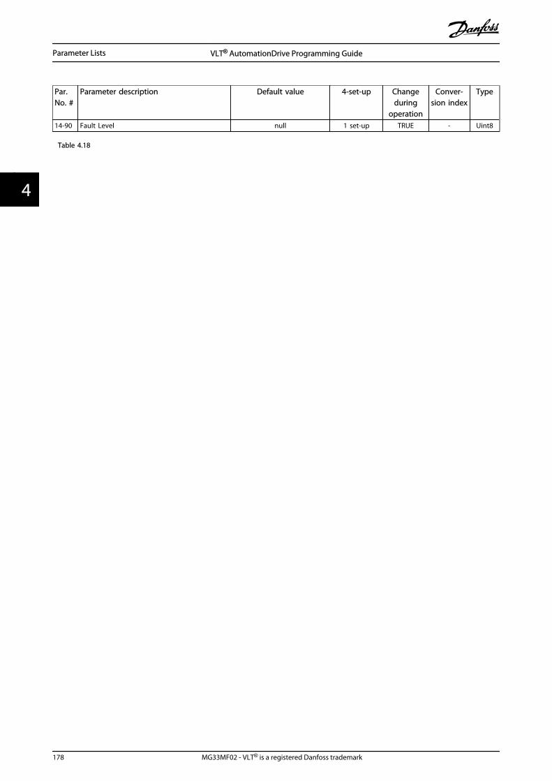
Par.No. #
Parameter description Default value 4-set-up Changeduring
operation
Conver-sion index
Type
14-90 Fault Level null 1 set-up TRUE - Uint8
Table 4.18
Parameter Lists VLT® AutomationDrive Programming Guide
178 MG33MF02 - VLT® is a registered Danfoss trademark
44

4.1.17 15-** Drive Information
Par.No. #
Parameter description Default value 4-set-up Changeduring
operation
Conver-sion index
Type
15-0* Operating Data
15-00 Operating Hours 0 h All set-ups FALSE 74 Uint32
15-01 Running Hours 0 h All set-ups FALSE 74 Uint32
15-02 kWh Counter 0 kWh All set-ups FALSE 75 Uint32
15-03 Power Up's 0 N/A All set-ups FALSE 0 Uint32
15-04 Over Temp's 0 N/A All set-ups FALSE 0 Uint16
15-05 Over Volt's 0 N/A All set-ups FALSE 0 Uint16
15-06 Reset kWh Counter [0] Do not reset All set-ups TRUE - Uint8
15-07 Reset Running Hours Counter [0] Do not reset All set-ups TRUE - Uint8
15-1* Data Log Settings
15-10 Logging Source 0 2 set-ups TRUE - Uint16
15-11 Logging Interval App.Dependent 2 set-ups TRUE -3 TimD
15-12 Trigger Event [0] False 1 set-up TRUE - Uint8
15-13 Logging Mode [0] Log always 2 set-ups TRUE - Uint8
15-14 Samples Before Trigger 50 N/A 2 set-ups TRUE 0 Uint8
15-2* Historic Log
15-20 Historic Log: Event 0 N/A All set-ups FALSE 0 Uint8
15-21 Historic Log: Value 0 N/A All set-ups FALSE 0 Uint32
15-22 Historic Log: Time 0 ms All set-ups FALSE -3 Uint32
15-3* Fault Log
15-30 Fault Log: Error Code 0 N/A All set-ups FALSE 0 Uint8
15-31 Fault Log: Value 0 N/A All set-ups FALSE 0 Int16
15-32 Fault Log: Time 0 s All set-ups FALSE 0 Uint32
15-4* Drive Identification
15-40 FC Type 0 N/A All set-ups FALSE 0 VisStr[6]
15-41 Power Section 0 N/A All set-ups FALSE 0 VisStr[20]
15-42 Voltage 0 N/A All set-ups FALSE 0 VisStr[20]
15-43 Software Version 0 N/A All set-ups FALSE 0 VisStr[5]
15-44 Ordered Typecode String 0 N/A All set-ups FALSE 0 VisStr[40]
15-45 Actual Typecode String 0 N/A All set-ups FALSE 0 VisStr[40]
15-46 Frequency Converter Ordering No 0 N/A All set-ups FALSE 0 VisStr[8]
15-47 Power Card Ordering No 0 N/A All set-ups FALSE 0 VisStr[8]
15-48 LCP Id No 0 N/A All set-ups FALSE 0 VisStr[20]
15-49 SW ID Control Card 0 N/A All set-ups FALSE 0 VisStr[20]
15-50 SW ID Power Card 0 N/A All set-ups FALSE 0 VisStr[20]
15-51 Frequency Converter Serial Number 0 N/A All set-ups FALSE 0 VisStr[10]
15-53 Power Card Serial Number 0 N/A All set-ups FALSE 0 VisStr[19]
15-58 Smart Setup Filename App.Dependent 1 set-up FALSE 0 VisStr[16]
15-59 CSIV Filename App.Dependent 1 set-up FALSE 0 VisStr[16]
15-6* Option Ident
15-60 Option Mounted 0 N/A All set-ups FALSE 0 VisStr[30]
15-61 Option SW Version 0 N/A All set-ups FALSE 0 VisStr[20]
15-62 Option Ordering No 0 N/A All set-ups FALSE 0 VisStr[8]
15-63 Option Serial No 0 N/A All set-ups FALSE 0 VisStr[18]
15-70 Option in Slot A 0 N/A All set-ups FALSE 0 VisStr[30]
15-71 Slot A Option SW Version 0 N/A All set-ups FALSE 0 VisStr[20]
15-72 Option in Slot B 0 N/A All set-ups FALSE 0 VisStr[30]
15-73 Slot B Option SW Version 0 N/A All set-ups FALSE 0 VisStr[20]
15-74 Option in Slot C0 0 N/A All set-ups FALSE 0 VisStr[30]
Parameter Lists VLT® AutomationDrive Programming Guide
MG33MF02 - VLT® is a registered Danfoss trademark 179
4 4

Par.No. #
Parameter description Default value 4-set-up Changeduring
operation
Conver-sion index
Type
15-75 Slot C0 Option SW Version 0 N/A All set-ups FALSE 0 VisStr[20]
15-76 Option in Slot C1 0 N/A All set-ups FALSE 0 VisStr[30]
15-77 Slot C1 Option SW Version 0 N/A All set-ups FALSE 0 VisStr[20]
15-9* Operating Data II
15-80 Fan Running Hours 0 h All set-ups TRUE 74 Uint32
15-9* Parameter Info
15-92 Defined Parameters 0 N/A All set-ups FALSE 0 Uint16
15-93 Modified Parameters 0 N/A All set-ups FALSE 0 Uint16
15-98 Drive Identification 0 N/A All set-ups FALSE 0 VisStr[40]
15-99 Parameter Metadata 0 N/A All set-ups FALSE 0 Uint16
Table 4.19
Parameter Lists VLT® AutomationDrive Programming Guide
180 MG33MF02 - VLT® is a registered Danfoss trademark
44

4.1.18 16-** Data Readouts
Par.No. #
Parameter description Default value 4-set-up Changeduring
operation
Conver-sion index
Type
16-0* General Status
16-00 Control Word 0 N/A All set-ups FALSE 0 V2
16-01 Reference [Unit] 0.000 ReferenceFeedbackUnit All set-ups FALSE -3 Int32
16-02 Reference % 0.0% All set-ups FALSE -1 Int16
16-03 Status Word 0 N/A All set-ups FALSE 0 V2
16-05 Main Actual Value [%] 0.00% All set-ups FALSE -2 N2
16-09 Custom Readout 0.00 CustomReadoutUnit All set-ups FALSE -2 Int32
16-1* Motor Status
16-10 Power [kW] 0.00 kW All set-ups FALSE 1 Int32
16-11 Power [hp] 0.00 hp All set-ups FALSE -2 Int32
16-12 Motor Voltage 0.0 V All set-ups FALSE -1 Uint16
16-13 Frequency 0.0 Hz All set-ups FALSE -1 Uint16
16-14 Motor Current 0.00 A All set-ups FALSE -2 Int32
16-15 Frequency [%] 0.00% All set-ups FALSE -2 N2
16-16 Torque [Nm] 0.0 Nm All set-ups FALSE -1 Int16
16-17 Speed [RPM] 0 RPM All set-ups FALSE 67 Int32
16-18 Motor Thermal 0% All set-ups FALSE 0 Uint8
16-19 KTY sensor temperature 0 ºC All set-ups FALSE 100 Int16
16-20 Motor Angle 0 N/A All set-ups TRUE 0 Uint16
16-21 Torque [%] High Res. 0.0% All set-ups FALSE -1 Int16
16-22 Torque [%] 0% All set-ups FALSE 0 Int16
16-25 Torque [Nm] High 0.0 Nm All set-ups FALSE -1 Int32
16-3* Drive Status
16-30 DC Link Voltage 0 V All set-ups FALSE 0 Uint16
16-32 Brake Energy /s 0.000 kW All set-ups FALSE 0 Uint32
16-33 Brake Energy /2 min 0.000 kW All set-ups FALSE 0 Uint32
16-34 Heatsink Temp. 0 ºC All set-ups FALSE 100 Uint8
16-35 Inverter Thermal 0% All set-ups FALSE 0 Uint8
16-36 Inv. Nom. Current App.Dependent All set-ups FALSE -2 Uint32
16-37 Inv. Max. Current App.Dependent All set-ups FALSE -2 Uint32
16-38 SL Controller State 0 N/A All set-ups FALSE 0 Uint8
16-39 Control Card Temp. 0 ºC All set-ups FALSE 100 Uint8
16-40 Logging Buffer Full [0] No All set-ups TRUE - Uint8
16-41 LCP Bottom Statusline 0 N/A All set-ups TRUE 0VisStr[5
0]
16-48 Speed Ref. After Ramp [RPM] 0 RPM All set-ups FALSE 67 Int32
16-49 Current Fault Source 0 N/A All set-ups TRUE 0 Uint8
16-5* Ref. & Feedb.
16-50 External Reference 0.0 N/A All set-ups FALSE -1 Int16
16-51 Pulse Reference 0.0 N/A All set-ups FALSE -1 Int16
16-52 Feedback [Unit] 0.000 ReferenceFeedbackUnit All set-ups FALSE -3 Int32
16-53 Digi Pot Reference 0.00 N/A All set-ups FALSE -2 Int16
16-57 Feedback [RPM] 0 RPM All set-ups FALSE 67 Int32
16-6* Inputs & Outputs
16-60 Digital Input 0 N/A All set-ups FALSE 0 Uint16
16-61 Terminal 53 Switch Setting [0] Current All set-ups FALSE - Uint8
16-62 Analog Input 53 0.000 N/A All set-ups FALSE -3 Int32
16-63 Terminal 54 Switch Setting [0] Current All set-ups FALSE - Uint8
16-64 Analog Input 54 0.000 N/A All set-ups FALSE -3 Int32
Parameter Lists VLT® AutomationDrive Programming Guide
MG33MF02 - VLT® is a registered Danfoss trademark 181
4 4

Par.No. #
Parameter description Default value 4-set-up Changeduring
operation
Conver-sion index
Type
16-65 Analog Output 42 [mA] 0.000 N/A All set-ups FALSE -3 Int16
16-66 Digital Output [bin] 0 N/A All set-ups FALSE 0 Int16
16-67 Freq. Input #29 [Hz] 0 N/A All set-ups FALSE 0 Int32
16-68 Freq. Input #33 [Hz] 0 N/A All set-ups FALSE 0 Int32
16-69 Pulse Output #27 [Hz] 0 N/A All set-ups FALSE 0 Int32
16-70 Pulse Output #29 [Hz] 0 N/A All set-ups FALSE 0 Int32
16-71 Relay Output [bin] 0 N/A All set-ups FALSE 0 Int16
16-72 Counter A 0 N/A All set-ups TRUE 0 Int32
16-73 Counter B 0 N/A All set-ups TRUE 0 Int32
16-74 Prec. Stop Counter 0 N/A All set-ups TRUE 0 Uint32
16-75 Analog In X30/11 0.000 N/A All set-ups FALSE -3 Int32
16-76 Analog In X30/12 0.000 N/A All set-ups FALSE -3 Int32
16-77 Analog Out X30/8 [mA] 0.000 N/A All set-ups FALSE -3 Int16
16-78 Analog Out X45/1 [mA] 0.000 N/A All set-ups FALSE -3 Int16
16-79 Analog Out X45/3 [mA] 0.000 N/A All set-ups FALSE -3 Int16
16-8* Fieldbus & FC Port
16-80 Fieldbus CTW 1 0 N/A All set-ups FALSE 0 V2
16-82 Fieldbus REF 1 0 N/A All set-ups FALSE 0 N2
16-84 Comm. Option STW 0 N/A All set-ups FALSE 0 V2
16-85 FC Port CTW 1 0 N/A All set-ups FALSE 0 V2
16-86 FC Port REF 1 0 N/A All set-ups FALSE 0 N2
16-87 Bus Readout Alarm/Warning 0 N/A All set-ups FALSE 0 Uint16
16-9* Diagnosis Readouts
16-90 Alarm Word 0 N/A All set-ups FALSE 0 Uint32
16-91 Alarm Word 2 0 N/A All set-ups FALSE 0 Uint32
16-92 Warning Word 0 N/A All set-ups FALSE 0 Uint32
16-93 Warning Word 2 0 N/A All set-ups FALSE 0 Uint32
16-94 Ext. Status Word 0 N/A All set-ups FALSE 0 Uint32
Table 4.20
Parameter Lists VLT® AutomationDrive Programming Guide
182 MG33MF02 - VLT® is a registered Danfoss trademark
44

4.1.19 17-** Motor Feedb.Option
Par.No. #
Parameter description Default value 4-set-up Changeduring
operation
Conver-sion index
Type
17-1* Inc. Enc. Interface
17-10 Signal Type [1] RS422 (5V TTL) All set-ups FALSE - Uint8
17-11 Resolution (PPR) 1024 N/A All set-ups FALSE 0 Uint16
17-2* Abs. Enc. Interface
17-20 Protocol Selection [0] None All set-ups FALSE - Uint8
17-21 Resolution (Positions/Rev) App.Dependent All set-ups FALSE 0 Uint32
17-24 SSI Data Length 13 N/A All set-ups FALSE 0 Uint8
17-25 Clock Rate App.Dependent All set-ups FALSE 3 Uint16
17-26 SSI Data Format [0] Gray code All set-ups FALSE - Uint8
17-34 HIPERFACE Baudrate [4] 9600 All set-ups FALSE - Uint8
17-5* Resolver Interface
17-50 Poles 2 N/A 1 set-up FALSE 0 Uint8
17-51 Input Voltage 7.0 V 1 set-up FALSE -1 Uint8
17-52 Input Frequency 10.0 kHz 1 set-up FALSE 2 Uint8
17-53 Transformation Ratio 0.5 N/A 1 set-up FALSE -1 Uint8
17-56 Encoder Sim. Resolution [0] Disabled 1 set-up FALSE - Uint8
17-59 Resolver Interface [0] Disabled All set-ups FALSE - Uint8
17-6* Monitoring and App.
17-60 Feedback Direction [0] Clockwise All set-ups FALSE - Uint8
17-61 Feedback Signal Monitoring [1] Warning All set-ups TRUE - Uint8
Table 4.21
Parameter Lists VLT® AutomationDrive Programming Guide
MG33MF02 - VLT® is a registered Danfoss trademark 183
4 4

4.1.20 18-** Data Readouts 2
Par.No. #
Parameter description Default value 4-set-up FC 302only
Changeduring
operation
Conver-sion
index
Type
18-3* Analog Readouts
18-36 Analog Input X48/2 [mA] 0.000 N/A All set-ups TRUE -3 Int32
18-37 Temp. Input X48/4 0 N/A All set-ups TRUE 0 Int16
18-38 Temp. Input X48/7 0 N/A All set-ups TRUE 0 Int16
18-39 Temp. Input X48/10 0 N/A All set-ups TRUE 0 Int16
18-6* Inputs & Outputs 2
18-60 Digital Input 2 0 N/A All set-ups FALSE 0 Uint16
18-90 PID Readouts
18-90 Process PID Error 0.0 % All set-ups FALSE -1 Int16
18-91 Process PID Output 0.0 % All set-ups FALSE -1 Int16
18-92 Process PID Clamped Output 0.0 % All set-ups FALSE -1 Int16
18-93 Process PID Gain Scaled Output 0.0 % All set-ups FALSE -1 Int16
Table 4.22
Parameter Lists VLT® AutomationDrive Programming Guide
184 MG33MF02 - VLT® is a registered Danfoss trademark
44

4.1.21 30-** Special Features
Par.No. #
Parameter description Default value 4-set-up Changeduring
operation
Conver-sion index
Type
30-0* Wobbler
30-00 Wobble Mode [0] Abs. Freq., Abs. Time All set-ups FALSE - Uint8
30-01 Wobble Delta Frequency [Hz] 5.0 Hz All set-ups TRUE -1 Uint8
30-02 Wobble Delta Frequency [%] 25% All set-ups TRUE 0 Uint8
30-03 Wobble Delta Freq. Scaling Resource [0] No function All set-ups TRUE - Uint8
30-04 Wobble Jump Frequency [Hz] 0.0 Hz All set-ups TRUE -1 Uint8
30-05 Wobble Jump Frequency [%] 0% All set-ups TRUE 0 Uint8
30-06 Wobble Jump Time App.Dependent All set-ups TRUE -3 Uint16
30-07 Wobble Sequence Time 10.0 s All set-ups TRUE -1 Uint16
30-08 Wobble Up/ Down Time 5.0 s All set-ups TRUE -1 Uint16
30-09 Wobble Random Function [0] Off All set-ups TRUE - Uint8
30-10 Wobble Ratio 1.0 N/A All set-ups TRUE -1 Uint8
30-11 Wobble Random Ratio Max. 10.0 N/A All set-ups TRUE -1 Uint8
30-12 Wobble Random Ratio Min. 0.1 N/A All set-ups TRUE -1 Uint8
30-19 Wobble Delta Freq. Scaled 0.0 Hz All set-ups FALSE -1 Uint16
30-2* Adv. Start Adjust
30-20 High Starting Torque Time [s] 0.00 s All set-ups TRUE -2 Uint8
30-21 High Starting Torque Current [%] 100.0% All set-ups TRUE -1 Uint32
30-22 Locked Rotor Protection [0] Off All set-ups TRUE - Uint8
30-23 Locked Rotor Detection Time [s] 0.10 s All set-ups TRUE -2 Uint8
30-8* Compatibility (I)
30-80 d-axis Inductance (Ld) App.Dependent All set-ups FALSE -6 Int32
30-81 Brake Resistor (ohm) App.Dependent 1 set-up TRUE -2 Uint32
30-83 Speed PID Proportional Gain App.Dependent All set-ups TRUE -4 Uint32
30-84 Process PID Proportional Gain 0.100 N/A All set-ups TRUE -3 Uint16
Table 4.23
Parameter Lists VLT® AutomationDrive Programming Guide
MG33MF02 - VLT® is a registered Danfoss trademark 185
4 4

4.1.22 32-** MCO Basic Settings
Par.No.#
Parameter description Default value 4-set-up FC 302only
Changeduring
operation
Conver-sion
index
Type
32-0* Encoder 2
32-00 Incremental Signal Type [1] RS422 (5V TTL) 2 set-ups TRUE - Uint8
32-01 Incremental Resolution 1024 N/A 2 set-ups TRUE 0 Uint32
32-02 Absolute Protocol [0] None 2 set-ups TRUE - Uint8
32-03 Absolute Resolution 8192 N/A 2 set-ups TRUE 0 Uint32
32-04 Absolute Encoder Baudrate X55 [4] 9600 All set-ups FALSE - Uint8
32-05 Absolute Encoder Data Length 25 N/A 2 set-ups TRUE 0 Uint8
32-06 Absolute Encoder Clock Frequency 262.000 kHz 2 set-ups TRUE 0 Uint32
32-07 Absolute Encoder Clock Generation [1] On 2 set-ups TRUE - Uint8
32-08 Absolute Encoder Cable Length 0 m 2 set-ups TRUE 0 Uint16
32-09 Encoder Monitoring [0] Off 2 set-ups TRUE - Uint8
32-10 Rotational Direction [1] No action 2 set-ups TRUE - Uint8
32-11 User Unit Denominator 1 N/A 2 set-ups TRUE 0 Uint32
32-12 User Unit Numerator 1 N/A 2 set-ups TRUE 0 Uint32
32-13 Enc.2 Control [0] No soft changing 2 set-ups TRUE - Uint8
32-14 Enc.2 node ID 127 N/A 2 set-ups TRUE 0 Uint8
32-15 Enc.2 CAN guard null 2 set-ups TRUE - Uint8
32-3* Encoder 1
32-30 Incremental Signal Type [1] RS422 (5V TTL) 2 set-ups TRUE - Uint8
32-31 Incremental Resolution 1024 N/A 2 set-ups TRUE 0 Uint32
32-32 Absolute Protocol [0] None 2 set-ups TRUE - Uint8
32-33 Absolute Resolution 8192 N/A 2 set-ups TRUE 0 Uint32
32-35 Absolute Encoder Data Length 25 N/A 2 set-ups TRUE 0 Uint8
32-36 Absolute Encoder Clock Frequency 262.000 kHz 2 set-ups TRUE 0 Uint32
32-37 Absolute Encoder Clock Generation [1] On 2 set-ups TRUE - Uint8
32-38 Absolute Encoder Cable Length 0 m 2 set-ups TRUE 0 Uint16
32-39 Encoder Monitoring [0] Off 2 set-ups TRUE - Uint8
32-40 Encoder Termination [1] On 2 set-ups TRUE - Uint8
32-43 Enc.1 Control [0] No soft changing 2 set-ups TRUE - Uint8
32-44 Enc.1 node ID 127 N/A 2 set-ups TRUE 0 Uint8
32-45 Enc.1 CAN guard null 2 set-ups TRUE - Uint8
32-5* Feedback Source
32-50 Source Slave [2] Encoder 2 2 set-ups TRUE - Uint8
32-51 MCO 302 Last Will [1] Trip 2 set-ups TRUE - Uint8
32-52 Source Master [1] Encoder 1 X56 2 set-ups TRUE - Uint8
32-6* PID Controller
32-60 Proportional factor 30 N/A 2 set-ups TRUE 0 Uint32
32-61 Derivative factor 0 N/A 2 set-ups TRUE 0 Uint32
32-62 Integral factor 0 N/A 2 set-ups TRUE 0 Uint32
32-63 Limit Value for Integral Sum 1000 N/A 2 set-ups TRUE 0 Uint16
32-64 PID Bandwidth 1000 N/A 2 set-ups TRUE 0 Uint16
32-65 Velocity Feed-Forward 0 N/A 2 set-ups TRUE 0 Uint32
32-66 Acceleration Feed-Forward 0 N/A 2 set-ups TRUE 0 Uint32
32-67 Max. Tolerated Position Error 20000 N/A 2 set-ups TRUE 0 Uint32
32-68 Reverse Behavior for Slave [0] Reversing allowed 2 set-ups TRUE - Uint8
32-69 Sampling Time for PID Control 1 ms 2 set-ups TRUE -3 Uint16
32-70 Scan Time for Profile Generator 1 ms 2 set-ups TRUE -3 Uint8
32-71 Size of the Control Window (Activation) 0 N/A 2 set-ups TRUE 0 Uint32
32-72 Size of the Control Window (Deactiv.) 0 N/A 2 set-ups TRUE 0 Uint32
Parameter Lists VLT® AutomationDrive Programming Guide
186 MG33MF02 - VLT® is a registered Danfoss trademark
44

Par.No.#
Parameter description Default value 4-set-up FC 302only
Changeduring
operation
Conver-sion
index
Type
32-73 Integral limit filter time 0 ms 2 set-ups TRUE -3 Int16
32-74 Position error filter time 0 ms 2 set-ups TRUE -3 Int16
32-8* Velocity & Accel.
32-80 Maximum Velocity (Encoder) 1500 RPM 2 set-ups TRUE 67 Uint32
32-81 Shortest Ramp 1.000 s 2 set-ups TRUE -3 Uint32
32-82 Ramp Type [0] Linear 2 set-ups TRUE - Uint8
32-83 Velocity Resolution 100 N/A 2 set-ups TRUE 0 Uint32
32-84 Default Velocity 50 N/A 2 set-ups TRUE 0 Uint32
32-85 Default Acceleration 50 N/A 2 set-ups TRUE 0 Uint32
32-86 Acc. up for limited jerk 100 ms 2 set-ups TRUE -3 Uint32
32-87 Acc. down for limited jerk 0 ms 2 set-ups TRUE -3 Uint32
32-88 Dec. up for limited jerk 0 ms 2 set-ups TRUE -3 Uint32
32-89 Dec. down for limited jerk 0 ms 2 set-ups TRUE -3 Uint32
32-9* Development
32-90 Debug Source [0] Controlcard 2 set-ups TRUE - Uint8
Table 4.24
Parameter Lists VLT® AutomationDrive Programming Guide
MG33MF02 - VLT® is a registered Danfoss trademark 187
4 4

4.1.23 33-** MCO Adv. Settings
Par.No.#
Parameter description Default value 4-set-up FC 302only
Changeduring
operation
Conver-sion
index
Type
33-0* Home Motion
33-00 Force HOME [0] Home not forced 2 set-ups TRUE - Uint8
33-01 Zero Point Offset from Home Pos. 0 N/A 2 set-ups TRUE 0 Int32
33-02 Ramp for Home Motion 10 N/A 2 set-ups TRUE 0 Uint32
33-03 Velocity of Home Motion 10 N/A 2 set-ups TRUE 0 Int32
33-04 Behaviour during HomeMotion [0] Revers and index 2 set-ups TRUE - Uint8
33-1* Synchronization
33-10 Sync Factor Master 1 N/A 2 set-ups TRUE 0 Int32
33-11 Sync Factor Slave 1 N/A 2 set-ups TRUE 0 Int32
33-12 Position Offset for Synchronization 0 N/A 2 set-ups TRUE 0 Int32
33-13 Accuracy Window for Position Sync. 1000 N/A 2 set-ups TRUE 0 Int32
33-14 Relative Slave Velocity Limit 0 % 2 set-ups TRUE 0 Uint8
33-15 Marker Number for Master 1 N/A 2 set-ups TRUE 0 Uint16
33-16 Marker Number for Slave 1 N/A 2 set-ups TRUE 0 Uint16
33-17 Master Marker Distance 4096 N/A 2 set-ups TRUE 0 Uint32
33-18 Slave Marker Distance 4096 N/A 2 set-ups TRUE 0 Uint32
33-19 Master Marker Type [0] Encoder Z positive 2 set-ups TRUE - Uint8
33-20 Slave Marker Type [0] Encoder Z positive 2 set-ups TRUE - Uint8
33-21 Master Marker Tolerance Window 0 N/A 2 set-ups TRUE 0 Uint32
33-22 Slave Marker Tolerance Window 0 N/A 2 set-ups TRUE 0 Uint32
33-23 Start Behaviour for Marker Sync [0] Start Function 1 2 set-ups TRUE - Uint16
33-24 Marker Number for Fault 10 N/A 2 set-ups TRUE 0 Uint16
33-25 Marker Number for Ready 1 N/A 2 set-ups TRUE 0 Uint16
33-26 Velocity Filter 0 us 2 set-ups TRUE -6 Int32
33-27 Offset Filter Time 0 ms 2 set-ups TRUE -3 Uint32
33-28 Marker Filter Configuration [0] Marker filter 1 2 set-ups TRUE - Uint8
33-29 Filter Time for Marker Filter 0 ms 2 set-ups TRUE -3 Int32
33-30 Maximum Marker Correction 0 N/A 2 set-ups TRUE 0 Uint32
33-31 Synchronisation Type [0] Standard 2 set-ups TRUE - Uint8
33-32 Feed Forward Velocity Adaptation 0 N/A 2 set-ups TRUE 0 Uint32
33-33 Velocity Filter Window 0 N/A 2 set-ups TRUE 0 Uint32
33-34 Slave Marker filter time 0 ms 2 set-ups TRUE -3 Uint32
33-4* Limit Handling
33-40 Behaviour at End Limit Switch [0] Call error handler 2 set-ups TRUE - Uint8
33-41 Negative Software End Limit -500000 N/A 2 set-ups TRUE 0 Int32
33-42 Positive Software End Limit 500000 N/A 2 set-ups TRUE 0 Int32
33-43 Negative Software End Limit Active [0] Inactive 2 set-ups TRUE - Uint8
33-44 Positive Software End Limit Active [0] Inactive 2 set-ups TRUE - Uint8
33-45 Time in Target Window 0 ms 2 set-ups TRUE -3 Uint8
33-46 Target Window LimitValue 1 N/A 2 set-ups TRUE 0 Uint16
33-47 Size of Target Window 0 N/A 2 set-ups TRUE 0 Uint16
33-5* I/O Configuration
33-50 Terminal X57/1 Digital Input [0] No function 2 set-ups TRUE - Uint8
33-51 Terminal X57/2 Digital Input [0] No function 2 set-ups TRUE - Uint8
33-52 Terminal X57/3 Digital Input [0] No function 2 set-ups TRUE - Uint8
33-53 Terminal X57/4 Digital Input [0] No function 2 set-ups TRUE - Uint8
33-54 Terminal X57/5 Digital Input [0] No function 2 set-ups TRUE - Uint8
33-55 Terminal X57/6 Digital Input [0] No function 2 set-ups TRUE - Uint8
33-56 Terminal X57/7 Digital Input [0] No function 2 set-ups TRUE - Uint8
Parameter Lists VLT® AutomationDrive Programming Guide
188 MG33MF02 - VLT® is a registered Danfoss trademark
44

Par.No.#
Parameter description Default value 4-set-up FC 302only
Changeduring
operation
Conver-sion
index
Type
33-57 Terminal X57/8 Digital Input [0] No function 2 set-ups TRUE - Uint8
33-58 Terminal X57/9 Digital Input [0] No function 2 set-ups TRUE - Uint8
33-59 Terminal X57/10 Digital Input [0] No function 2 set-ups TRUE - Uint8
33-60 Terminal X59/1 and X59/2 Mode [1] Output 2 set-ups FALSE - Uint8
33-61 Terminal X59/1 Digital Input [0] No function 2 set-ups TRUE - Uint8
33-62 Terminal X59/2 Digital Input [0] No function 2 set-ups TRUE - Uint8
33-63 Terminal X59/1 Digital Output [0] No function 2 set-ups TRUE - Uint8
33-64 Terminal X59/2 Digital Output [0] No function 2 set-ups TRUE - Uint8
33-65 Terminal X59/3 Digital Output [0] No function 2 set-ups TRUE - Uint8
33-66 Terminal X59/4 Digital Output [0] No function 2 set-ups TRUE - Uint8
33-67 Terminal X59/5 Digital Output [0] No function 2 set-ups TRUE - Uint8
33-68 Terminal X59/6 Digital Output [0] No function 2 set-ups TRUE - Uint8
33-69 Terminal X59/7 Digital Output [0] No function 2 set-ups TRUE - Uint8
33-70 Terminal X59/8 Digital Output [0] No function 2 set-ups TRUE - Uint8
33-8* Global Parameters
33-80 Activated Program Number -1 N/A 2 set-ups TRUE 0 Int8
33-81 Power-up State [1] Motor on 2 set-ups TRUE - Uint8
33-82 Drive Status Monitoring [1] On 2 set-ups TRUE - Uint8
33-83 Behaviour afterError [0] Coast 2 set-ups TRUE - Uint8
33-84 Behaviour afterEsc. [0] Controlled stop 2 set-ups TRUE - Uint8
33-85 MCO Supplied by External 24VDC [0] No 2 set-ups TRUE - Uint8
33-86 Terminal at alarm [0] Relay 1 2 set-ups TRUE - Uint8
33-87 Terminal state at alarm [0] Do nothing 2 set-ups TRUE - Uint8
33-88 Status word at alarm 0 N/A 2 set-ups TRUE 0 Uint16
33-9* MCO Port Settings
33-90 X62 MCO CAN node ID 127 N/A 2 set-ups TRUE 0 Uint8
33-91 X62 MCO CAN baud rate [20] 125 Kbps 2 set-ups TRUE - Uint8
33-94 X60 MCO RS485 serial termination [0] Off 2 set-ups TRUE - Uint8
33-95 X60 MCO RS485 serial baud rate [2] 9600 Baud 2 set-ups TRUE - Uint8
Table 4.25
Parameter Lists VLT® AutomationDrive Programming Guide
MG33MF02 - VLT® is a registered Danfoss trademark 189
4 4
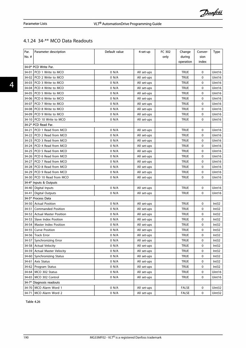
4.1.24 34-** MCO Data Readouts
Par.No. #
Parameter description Default value 4-set-up FC 302only
Changeduring
operation
Conver-sion
index
Type
34-0* PCD Write Par.
34-01 PCD 1 Write to MCO 0 N/A All set-ups TRUE 0 Uint16
34-02 PCD 2 Write to MCO 0 N/A All set-ups TRUE 0 Uint16
34-03 PCD 3 Write to MCO 0 N/A All set-ups TRUE 0 Uint16
34-04 PCD 4 Write to MCO 0 N/A All set-ups TRUE 0 Uint16
34-05 PCD 5 Write to MCO 0 N/A All set-ups TRUE 0 Uint16
34-06 PCD 6 Write to MCO 0 N/A All set-ups TRUE 0 Uint16
34-07 PCD 7 Write to MCO 0 N/A All set-ups TRUE 0 Uint16
34-08 PCD 8 Write to MCO 0 N/A All set-ups TRUE 0 Uint16
34-09 PCD 9 Write to MCO 0 N/A All set-ups TRUE 0 Uint16
34-10 PCD 10 Write to MCO 0 N/A All set-ups TRUE 0 Uint16
34-2* PCD Read Par.
34-21 PCD 1 Read from MCO 0 N/A All set-ups TRUE 0 Uint16
34-22 PCD 2 Read from MCO 0 N/A All set-ups TRUE 0 Uint16
34-23 PCD 3 Read from MCO 0 N/A All set-ups TRUE 0 Uint16
34-24 PCD 4 Read from MCO 0 N/A All set-ups TRUE 0 Uint16
34-25 PCD 5 Read from MCO 0 N/A All set-ups TRUE 0 Uint16
34-26 PCD 6 Read from MCO 0 N/A All set-ups TRUE 0 Uint16
34-27 PCD 7 Read from MCO 0 N/A All set-ups TRUE 0 Uint16
34-28 PCD 8 Read from MCO 0 N/A All set-ups TRUE 0 Uint16
34-29 PCD 9 Read from MCO 0 N/A All set-ups TRUE 0 Uint16
34-30 PCD 10 Read from MCO 0 N/A All set-ups TRUE 0 Uint16
34-4* Inputs & Outputs
34-40 Digital Inputs 0 N/A All set-ups TRUE 0 Uint16
34-41 Digital Outputs 0 N/A All set-ups TRUE 0 Uint16
34-5* Process Data
34-50 Actual Position 0 N/A All set-ups TRUE 0 Int32
34-51 Commanded Position 0 N/A All set-ups TRUE 0 Int32
34-52 Actual Master Position 0 N/A All set-ups TRUE 0 Int32
34-53 Slave Index Position 0 N/A All set-ups TRUE 0 Int32
34-54 Master Index Position 0 N/A All set-ups TRUE 0 Int32
34-55 Curve Position 0 N/A All set-ups TRUE 0 Int32
34-56 Track Error 0 N/A All set-ups TRUE 0 Int32
34-57 Synchronizing Error 0 N/A All set-ups TRUE 0 Int32
34-58 Actual Velocity 0 N/A All set-ups TRUE 0 Int32
34-59 Actual Master Velocity 0 N/A All set-ups TRUE 0 Int32
34-60 Synchronizing Status 0 N/A All set-ups TRUE 0 Int32
34-61 Axis Status 0 N/A All set-ups TRUE 0 Int32
34-62 Program Status 0 N/A All set-ups TRUE 0 Int32
34-64 MCO 302 Status 0 N/A All set-ups TRUE 0 Uint16
34-65 MCO 302 Control 0 N/A All set-ups TRUE 0 Uint16
34-7* Diagnosis readouts
34-70 MCO Alarm Word 1 0 N/A All set-ups FALSE 0 Uint32
34-71 MCO Alarm Word 2 0 N/A All set-ups FALSE 0 Uint32
Table 4.26
Parameter Lists VLT® AutomationDrive Programming Guide
190 MG33MF02 - VLT® is a registered Danfoss trademark
44

4.1.25 35-** Sensor Input Option
Par.No. #
Parameter description Default value 4-set-up FC 302only
Changeduring
operation
Conver-sion
index
Type
35-0* Temp. Input Mode
35-00 Term. X48/4 Temp. Unit [60] °C All set-ups TRUE - Uint8
35-01 Term. X48/4 Input Type [0] Not Connected All set-ups TRUE - Uint8
35-02 Term. X48/7 Temp. Unit [60] °C All set-ups TRUE - Uint8
35-03 Term. X48/7 Input Type [0] Not Connected All set-ups TRUE - Uint8
35-04 Term. X48/10 Temp. Unit [60] °C All set-ups TRUE - Uint8
35-05 Term. X48/10 Input Type [0] Not Connected All set-ups TRUE - Uint8
35-06 Temperature Sensor Alarm Function [5] Stop and trip All set-ups TRUE - Uint8
35-1* Temp. Input X48/4
35-14 Term. X48/4 Filter Time Constant 0.001 s All set-ups TRUE -3 Uint16
35-15 Term. X48/4 Temp. Monitor [0] Disabled All set-ups TRUE - Uint8
35-16 Term. X48/4 Low Temp. Limit App.Dependent All set-ups TRUE 0 Int16
35-17 Term. X48/4 High Temp. Limit App.Dependent All set-ups TRUE 0 Int16
35-2* Temp. Input X48/7
35-24 Term. X48/7 Filter Time Constant 0.001 s All set-ups TRUE -3 Uint16
35-25 Term. X48/7 Temp. Monitor [0] Disabled All set-ups TRUE - Uint8
35-26 Term. X48/7 Low Temp. Limit App.Dependent All set-ups TRUE 0 Int16
35-27 Term. X48/7 High Temp. Limit App.Dependent All set-ups TRUE 0 Int16
35-3* Temp. Input X48/10
35-34 Term. X48/10 Filter Time Constant 0.001 s All set-ups TRUE -3 Uint16
35-35 Term. X48/10 Temp. Monitor [0] Disabled All set-ups TRUE - Uint8
35-36 Term. X48/10 Low Temp. Limit App.Dependent All set-ups TRUE 0 Int16
35-37 Term. X48/10 High Temp. Limit App.Dependent All set-ups TRUE 0 Int16
35-4* Analog Input X48/2
35-42 Term. X48/2 Low Current 4.00 mA All set-ups TRUE -5 Int16
35-43 Term. X48/2 High Current 20.00 mA All set-ups TRUE -5 Int16
35-44 Term. X48/2 Low Ref./Feedb. Value 0.000 N/A All set-ups TRUE -3 Int32
35-45 Term. X48/2 High Ref./Feedb. Value 100.000 N/A All set-ups TRUE -3 Int32
35-46 Term. X48/2 Filter Time Constant 0.001 s All set-ups TRUE -3 Uint16
Table 4.27
Parameter Lists VLT® AutomationDrive Programming Guide
MG33MF02 - VLT® is a registered Danfoss trademark 191
4 4

5 Troubleshooting
5.1.1 Warnings/Alarm Messages
A warning or an alarm is signalled by the relevant LED onthe front of the frequency converter and indicated by acode on the display.
A warning remains active until its cause is no longerpresent. Under certain circumstances, operation of themotor may still be continued. Warning messages may becritical, but are not necessarily so.
In the event of an alarm, the frequency converter trips.Reset the alarm to resume operation once the cause hasbeen rectified.
Three ways to reset:
• Press [Reset].
• Via a digital input with the “Reset” function.
• Via serial communication/optional fieldbus.
NOTEAfter a manual reset pressing [Reset] press [Auto On] torestart the motor.
If an alarm cannot be reset, the reason may be that itscause has not been rectified, or the alarm is trip-locked(see also Table 5.1).
Alarms that are trip-locked offer additional protection,meaning that the mains supply must be switched offbefore the alarm can be reset. After being switched backon, the frequency converter is no longer blocked and canbe reset as described above once the cause has beenrectified.
Alarms that are not trip-locked can also be reset using theautomatic reset function in 14-20 Reset Mode (Warning:automatic wake-up is possible!)
If a warning or alarm is marked against a code in Table 5.1,this means that either a warning occurs before an alarm,or else that it is possible to specify whether a warning oran alarm should be displayed for a given fault.
This is possible, for instance, in 1-90 Motor ThermalProtection. After an alarm or trip, the motor carries oncoasting, and the alarm and warning flash. Once theproblem has been rectified, only the alarm continuesflashing until the frequency converter is reset.
NOTENo missing motor phase detection (numbers 30-32) and nostall detection is active when 1-10 Motor Construction is setto [1] PM non salient SPM.
No. Description Warning Alarm/Trip Alarm/Trip Lock ParameterReference
1 10 Volts low X
2 Live zero error (X) (X) 6-01 Live Zero TimeoutFunction
3 No motor (X) 1-80 Function at Stop
4 Mains phase loss (X) (X) (X) 14-12 Function atMains Imbalance
5 DC link voltage high X
6 DC link voltage low X
7 DC over-voltage X X
8 DC under voltage X X
9 Inverter overloaded X X
10 Motor ETR over temperature (X) (X) 1-90 Motor ThermalProtection
11 Motor thermistor over temperature (X) (X) 1-90 Motor ThermalProtection
12 Torque limit X X
13 Over Current X X X
14 Earth Fault X X
Troubleshooting VLT® AutomationDrive Programming Guide
192 MG33MF02 - VLT® is a registered Danfoss trademark
55

No. Description Warning Alarm/Trip Alarm/Trip Lock ParameterReference
15 Hardware mismatch X X
16 Short Circuit X X
17 Control word time-out (X) (X) 8-04 Control WordTimeout Function
18 Start Failed X 1-77 Compressor StartMax Speed [RPM] and1-79 Compressor Start
Max Time to Trip
19 Discharge Temp. High X X 28-2x Discharge Temp.Monitor
20 Temp. Input Error
21 Param Error
22 Hoist Mech. Brake (X) (X) Parameter group 2-2*
23 Internal Fans X
24 External Fans X
25 Brake resistor short-circuited X
26 Brake resistor power limit (X) (X) 2-13 Brake PowerMonitoring
27 Brake chopper short-circuited X X
28 Brake check (X) (X) 2-15 Brake Check
29 Heatsink temp X X X
30 Motor phase U missing (X) (X) (X) 4-58 Missing MotorPhase Function
31 Motor phase V missing (X) (X) (X) 4-58 Missing MotorPhase Function
32 Motor phase W missing (X) (X) (X) 4-58 Missing MotorPhase Function
33 Inrush Fault X X
34 Fieldbus communication fault X X
35 Option Fault
36 Mains failure X X
37 Phase imbalance X
38 Internal Fault X X
39 Heatsink sensor X X
40 Overload of Digital Output Terminal 27 (X) 5-00 Digital I/O Mode, 5-01 Terminal 27 Mode
41 Overload of Digital Output Terminal 29 (X) 5-00 Digital I/O Mode, 5-02 Terminal 29 Mode
42 Ovrld X30/6-7 (X)
43 Ext. Supply (option)
45 Earth Fault 2 X X
46 Pwr. card supply X X
47 24 V supply low X X X
48 1.8 V supply low X X
49 Speed limit X 1-86 Trip Speed Low[RPM]
50 AMA calibration failed X
51 AMA check Unom and Inom X
52 AMA low Inom X
53 AMA motor too big X
54 AMA motor too small X
55 AMA parameter out of range X
Troubleshooting VLT® AutomationDrive Programming Guide
MG33MF02 - VLT® is a registered Danfoss trademark 193
5 5

No. Description Warning Alarm/Trip Alarm/Trip Lock ParameterReference
56 AMA interrupted by user X
57 AMA time-out X
58 AMA internal fault X X
59 Current limit X
60 External Interlock X X
61 Feedback Error (X) (X) 4-30 Motor FeedbackLoss Function
62 Output Frequency at Maximum Limit X
63 Mechanical Brake Low (X) 2-20 Release BrakeCurrent
64 Voltage Limit X
65 Control Board Over-temperature X X X
66 Heat sink Temperature Low X
67 Option Configuration has Changed X
68 Safe Stop (X) (X)1) 5-19 Terminal 37 SafeStop
69 Pwr. Card Temp X X
70 Illegal FC configuration X
71 PTC 1 Safe Stop
72 Dangerous failure
73 Safe Stop Auto Restart (X) (X) 5-19 Terminal 37 SafeStop
74 PTC Thermistor X
75 Illegal Profile Sel. X
76 Power Unit Setup X
77 Reduced power mode X 14-59 Actual Number ofInverter Units
78 Tracking Error (X) (X) 4-34 Tracking ErrorFunction
79 Illegal PS config X X
80 Drive Initialized to Default Value X
81 CSIV corrupt X
82 CSIV parameter error X
83 Illegal Option Combination X
84 No Safety Option X
88 Option Detection X
89 Mechanical Brake Sliding X
90 Feedback Monitor (X) (X) 17-61 Feedback SignalMonitoring
91 Analog input 54 wrong settings X S202
163 ATEX ETR cur.lim.warning X
164 ATEX ETR cur.lim.alarm X
165 ATEX ETR freq.lim.warning X
166 ATEX ETR freq.lim.alarm X
246 Pwr.card supply
250 New spare parts X
251 New Type Code X X
Table 5.1 Alarm/Warning Code List
(X) Dependent on parameter1) Cannot be Auto reset via 14-20 Reset Mode
A trip is the action when an alarm has appeared. The tripcoasts the motor and is reset by pressing [Reset] or by adigital input (parameter group 5-1* [1]). The origin event
Troubleshooting VLT® AutomationDrive Programming Guide
194 MG33MF02 - VLT® is a registered Danfoss trademark
55

that caused an alarm cannot damage the frequencyconverter or cause dangerous conditions. A trip lock is anaction when an alarm occurs, which could damage thefrequency converter or connected parts. A Trip Locksituation can only be reset by a power cycling.
Warning yellow
Alarm flashing red
Trip locked yellow and red
Table 5.2 LED Indication
Bit Hex Dec Alarm Word Alarm Word 2 Warning Word WarningWord 2
ExtendedStatus Word
ExtendedStatus Word 2
Alarm Word Extended Status Word
0 00000001
1 Brake Check(A28)
ServiceTrip,Read/Write
Brake Check (W28) StartDelayed
Ramping Off
1 00000002
2 Pwr.card temp(A69)
ServiceTrip,(reserved)
Pwr.card temp (A69) StopDelayed
AMA Running Hand/Auto
2 00000004
4 Earth Fault (A14) ServiceTrip,Typecode/Sparepart
Earth Fault (W14) reserved Start CW/CCWstart_possible isactive, when theDI selections [12]OR [13] are activeand the requesteddirection matchesthe reference sign
Profibus OFF1active
3 00000008
8 Ctrl.Card Temp(A65)
ServiceTrip,(reserved)
Ctrl.Card Temp (W65) reserved Slow Downslow downcommand active,e.g. via CTW bit11 or DI
Profibus OFF2active
4 00000010
16 Ctrl. Word TO(A17)
ServiceTrip,(reserved)
Ctrl. Word TO (W17) Catch Upcatch upcommand active,e.g. via CTW bit12 or DI
Profibus OFF3active
5 00000020
32 Over Current(A13)
reserved Over Current (W13) reserved Feedback Highfeedback > 4-57
Relay 123 active
6 00000040
64 Torque Limit(A12)
reserved Torque Limit (W12) reserved Feedback Lowfeedback < 4-56
Start Prevented
7 00000080
128 Motor Th Over(A11)
reserved Motor Th Over (W11) reserved Output CurrentHighcurrent > 4-51
Control Ready
8 00000100
256 Motor ETR Over(A10)
reserved Motor ETR Over (W10) reserved Output CurrentLowcurrent < 4-50
Drive Ready
9 00000200
512 Inverter Overld.(A9)
Discharge High Inverter Overld (W9) DischargeHigh
Output Freq Highspeed > 4-53
Quick Stop
10 00000400
1024 DC under Volt(A8)
Start Failed DC under Volt (W8) Multi-motorunderload
Output Freq Lowspeed < 4-52
DC Brake
11 00000800
2048 DC over Volt(A7)
Speed Limit DC over Volt (W7) Multi-motorOverload
Brake Check OKbrake test NOT ok
Stop
12 00001000
4096 Short Circuit(A16)
ExternalInterlock
DC Voltage Low (W6) CompressorInterlock
Braking MaxBrakePower >BrakePowerLimit(2-12)
Stand by
13 00002000
8192 Inrush Fault(A33)
Illegal OptionCombi.
DC Voltage High (W5) Mechanical BrakeSliding
Braking Freeze OutputRequest
Troubleshooting VLT® AutomationDrive Programming Guide
MG33MF02 - VLT® is a registered Danfoss trademark 195
5 5

Bit Hex Dec Alarm Word Alarm Word 2 Warning Word WarningWord 2
ExtendedStatus Word
ExtendedStatus Word 2
14 00004000
16384 Mains ph. Loss(A4)
No SafetyOption
Mains ph. Loss (W4) SafeOptionWarning
Out of SpeedRange
Freeze Output
15 00008000
32768 AMA Not OK reserved No Motor (W3) Auto DCBraking
OVC Active Jog Request
16 00010000
65536 Live Zero Error(A2)
reserved Live Zero Error (W2) AC Brake Jog
17 00020000
131072 Internal Fault(A38)
KTY error 10V Low (W1) KTY Warn PasswordTimelocknumber ofallowed passwordtrials exceeded -timelock active
Start Request
18 00040000
262144 Brake Overload(A26)
Fans error Brake Overload (W26) FansWarn
PasswordProtection0-61 =ALL_NO_ACCESSORBUS_NO_ACCESSORBUS_READONLY
Start
19 00080000
524288 U phase Loss(A30)
ECB error Brake Resistor (W25) ECB Warn Reference Highreference > 4-55
Start Applied
20 00100000
1048576 V phase Loss(A31)
reserved Brake IGBT (W27) reserved Reference Lowreference < 4-54
Start delay
21 00200000
2097152 W phase Loss(A32)
reserved Speed Limit (W49) reserved Local Referencereference site =REMOTE -> autoon pressed &active
Sleep
22 00400000
4194304 Fieldbus Fault(A34)
reserved Fieldbus Fault (W34) reserved Protection modenotifikation
Sleep Boost
23 00800000
8388608 24 V SupplyLow (A47)
reserved 24V Supply Low (W47) reserved Unused Running
24 01000000
16777216 Mains Failure(A36)
reserved Mains Failure (W36) reserved Unused Drive Bypass
25 02000000
33554432 1.8V Supply Low(A48)
Current Limit(A59)
Current Limit (W59) reserved Unused Fire Mode
26 04000000
67108864 Brake Resistor(A25)
reserved Low Temp (W66) reserved Unused External Interlock
27 08000000
134217728 Brake IGBT (A27) reserved Voltage Limit (W64) reserved Unused Firemode LimitExceed
28 10000000
268435456 Option Change(A67)
reserved Encoder loss (W90) reserved Unused FlyStart active
29 20000000
536870912 DriveInitialized(A80)
Encoder loss(A90)
Output freq. lim.(W62)
BackEMFtoo High
Unused
30 40000000
1073741824
Safe Stop (A68) PTC Thermistor(A74)
Safe Stop (W68) PTCThermistor (W74)
Unused
31 80000000
2147483648
Mech. brake low(A63)
Dangerousfailure (A72)
Extended Status Word Protection Mode
Table 5.3 Description of Alarm Word, Warning Word and Extended Status Word
Troubleshooting VLT® AutomationDrive Programming Guide
196 MG33MF02 - VLT® is a registered Danfoss trademark
55

The alarm words, warning words and extended statuswords can be read out via serial bus or optional fieldbusfor diagnostics. See also 16-94 Ext. Status Word.
WARNING 1, 10 Volts lowThe control card voltage is below 10 V from terminal 50.Remove some of the load from terminal 50, as the 10 Vsupply is overloaded. Max. 15 mA or minimum 590 Ω.
This condition can be caused by a short in a connectedpotentiometer or improper wiring of the potentiometer.
TroubleshootingRemove the wiring from terminal 50. If the warning clears,the problem is with the customer wiring. If the warningdoes not clear, replace the control card.
WARNING/ALARM 2, Live zero errorThis warning or alarm only appears if programmed by theuser in 6-01 Live Zero Timeout Function. The signal on oneof the analog inputs is less than 50% of the minimumvalue programmed for that input. Broken wiring or faultydevice sending the signal can cause this condition.
TroubleshootingCheck connections on all the analog inputterminals. Control card terminals 53 and 54 forsignals, terminal 55 common. MCB 101 terminals11 and 12 for signals, terminal 10 common. MCB109 terminals 1, 3, 5 for signals, terminals 2, 4, 6common).
Check that the frequency converter programmingand switch settings match the analog signal type.
Perform Input Terminal Signal Test.
WARNING/ALARM 3, No motorNo motor has been connected to the output of thefrequency converter.
WARNING/ALARM 4, Mains phase lossA phase is missing on the supply side, or the mainsvoltage imbalance is too high. This message also appearsfor a fault in the input rectifier on the frequency converter.Options are programmed at 14-12 Function at MainsImbalance.
TroubleshootingCheck the supply voltage and supply currents to thefrequency converter.
WARNING 5, DC link voltage highThe intermediate circuit voltage (DC) is higher than thehigh voltage warning limit. The limit is dependent on thefrequency converter voltage rating. The unit is still active.
WARNING 6, DC link voltage lowThe intermediate circuit voltage (DC) is lower than the lowvoltage warning limit. The limit is dependent on thefrequency converter voltage rating. The unit is still active.
WARNING/ALARM 7, DC overvoltageIf the intermediate circuit voltage exceeds the limit, thefrequency converter trips after a time.
TroubleshootingConnect a brake resistor
Extend the ramp time
Change the ramp type
Activate the functions in 2-10 Brake Function
Increase 14-26 Trip Delay at Inverter Fault
If the alarm/warning occurs during a power sagthe solution is to use kinetic back-up (14-10 MainsFailure)
WARNING/ALARM 8, DC under voltageIf the intermediate circuit voltage (DC link) drops belowthe under voltage limit, the frequency converter checks if a24 V DC backup supply is connected. If no 24 V DC backupsupply is connected, the frequency converter trips after afixed time delay. The time delay varies with unit size.
TroubleshootingCheck that the supply voltage matches thefrequency converter voltage.
Perform input voltage test.
Perform soft charge circuit test.
WARNING/ALARM 9, Inverter overloadThe frequency converter is about to cut out because of anoverload (too high current for too long). The counter forelectronic, thermal inverter protection issues a warning at98% and trips at 100%, while giving an alarm. Thefrequency converter cannot be reset until the counter isbelow 90%. The fault is that the frequency converter has run withmore than 100% overload for too long.
TroubleshootingCompare the output current shown on the LCPwith the frequency converter rated current.
Compare the output current shown on the LCPwith measured motor current.
Display the Thermal Drive Load on the LCP andmonitor the value. When running above thefrequency converter continuous current rating,the counter increases. When running below thefrequency converter continuous current rating,the counter decreases.
WARNING/ALARM 10, Motor overload temperatureAccording to the electronic thermal protection (ETR), themotor is too hot. Select whether the frequency converterissues a warning or an alarm when the counter reaches100% in 1-90 Motor Thermal Protection. The fault occurswhen the motor runs with more than 100% overload fortoo long.
TroubleshootingCheck for motor overheating.
Check if the motor is mechanically overloaded
Troubleshooting VLT® AutomationDrive Programming Guide
MG33MF02 - VLT® is a registered Danfoss trademark 197
5 5

Check that the motor current set in 1-24 MotorCurrent is correct.
Ensure that Motor data in parameters 1-20through 1-25 are set correctly.
If an external fan is in use, check in 1-91 MotorExternal Fan that it is selected.
Running AMA in 1-29 Automatic Motor Adaptation(AMA) tunes the frequency converter to themotor more accurately and reduces thermalloading.
WARNING/ALARM 11, Motor thermistor over tempCheck whether the thermistor is disconnected. Selectwhether the frequency converter issues a warning or analarm in 1-90 Motor Thermal Protection.
TroubleshootingCheck for motor overheating.
Check if the motor is mechanically overloaded.
When using terminal 53 or 54, check that thethermistor is connected correctly between eitherterminal 53 or 54 (analog voltage input) andterminal 50 (+10 V supply). Also check that theterminal switch for 53 or 54 is set for voltage.Check 1-93 Thermistor Source selects terminal 53or 54.
When using digital inputs 18 or 19, check thatthe thermistor is connected correctly betweeneither terminal 18 or 19 (digital input PNP only)and terminal 50. Check 1-93 Thermistor Sourceselects terminal 18 or 19.
WARNING/ALARM 12, Torque limitThe torque has exceeded the value in 4-16 Torque LimitMotor Mode or the value in 4-17 Torque Limit GeneratorMode. 14-25 Trip Delay at Torque Limit can change this froma warning only condition to a warning followed by analarm.
TroubleshootingIf the motor torque limit is exceeded during rampup, extend the ramp up time.
If the generator torque limit is exceeded duringramp down, extend the ramp down time.
If torque limit occurs while running, possiblyincrease the torque limit. Make sure that thesystem can operate safely at a higher torque.
Check the application for excessive current drawon the motor.
WARNING/ALARM 13, Over currentThe inverter peak current limit (approximately 200% of therated current) is exceeded. The warning lasts about 1.5 s,then the frequency converter trips and issues an alarm.This fault can be caused by shock loading or quick
acceleration with high inertia loads. It can also appear afterkinetic back-up if the acceleration during ramp up is quick.If extended mechanical brake control is selected, trip canbe reset externally.
Troubleshooting
Remove power and check if the motor shaft canbe turned.
Check that the motor size matches the frequencyconverter.
Check parameters 1-20 to 1-25 for correct motordata.
ALARM 14, Earth (ground) faultThere is current from the output phases to earth, either inthe cable between the frequency converter and the motoror in the motor itself.
Troubleshooting:Remove power to the frequency converter andrepair the earth fault.
Check for earth faults in the motor by measuringthe resistance to ground of the motor leads andthe motor with a megohmmeter.
ALARM 15, Hardware mismatchA fitted option is not operational with the present controlboard hardware or software.
Record the value of the following parameters and contactyour Danfoss supplier:
15-40 FC Type
15-41 Power Section
15-42 Voltage
15-43 Software Version
15-45 Actual Typecode String
15-49 SW ID Control Card
15-50 SW ID Power Card
15-60 Option Mounted
15-61 Option SW Version (for each option slot)
ALARM 16, Short circuitThere is short-circuiting in the motor or motor wiring.
Remove power to the frequency converter and repair theshort circuit.
WARNING/ALARM 17, Control word timeoutThere is no communication to the frequency converter.The warning is only active when 8-04 Control Word TimeoutFunction is NOT set to [0] Off.If 8-04 Control Word Timeout Function is set to [5] Stop andTrip, a warning appears and the frequency converter rampsdown until it stops then displays an alarm.
Troubleshooting VLT® AutomationDrive Programming Guide
198 MG33MF02 - VLT® is a registered Danfoss trademark
55

Troubleshooting:Check connections on the serial communicationcable.
Increase 8-03 Control Word Timeout Time
Check the operation of the communicationequipment.
Verify a proper installation based on EMCrequirements.
ALARM 18, Start failedThe speed has not been able to exceed 1-77 CompressorStart Max Speed [RPM] during start within the allowed time.(set in 1-79 Compressor Start Max Time to Trip). This may becaused by a blocked motor.
Warning/ Alarm 19, Discharge Temperature HighWarning:The discharge temperature exceeds the level programmedin 28-25 Warning Level.
Alarm:The discharge temperature exceeds the level programmedin 28-26 Emergency Level.
WARNING/ALARM 20, Temp. input errorThe temperature sensor is not connected.
WARNING/ALARM 21, Parameter errorThe parameter is out of range. The parameter number isreported in the LCP. The affected parameter must be set toa valid value.
WARNING/ALARM 22, Hoist mechanical brakeReport value shows what kind it is.0 = The torque ref. was not reached before timeout.1 = There was no brake feedback before timeout.
WARNING 23, Internal fan faultThe fan warning function is an extra protective functionthat checks if the fan is running/mounted. The fan warningcan be disabled in 14-53 Fan Monitor ([0] Disabled).
For the D, E, and F Frame filters, the regulated voltage tothe fans is monitored.
TroubleshootingCheck for proper fan operation.
Cycle power to the frequency converter andcheck that the fan operates briefly at start-up.
Check the sensors on the heatsink and controlcard.
WARNING 24, External fan faultThe fan warning function is an extra protective functionthat checks if the fan is running/mounted. The fan warningcan be disabled in 14-53 Fan Monitor ([0] Disabled).
TroubleshootingCheck for proper fan operation.
Cycle power to the frequency converter andcheck that the fan operates briefly at start-up.
Check the sensors on the heatsink and controlcard.
WARNING 25, Brake resistor short circuitThe brake resistor is monitored during operation. If a shortcircuit occurs, the brake function is disabled and thewarning appears. The frequency converter is stilloperational but without the brake function. Remove powerto the frequency converter and replace the brake resistor(see 2-15 Brake Check).
WARNING/ALARM 26, Brake resistor power limitThe power transmitted to the brake resistor is calculated asa mean value over the last 120 seconds of run time. Thecalculation is based on the intermediate circuit voltage andthe brake resistance value set in 2-16 AC brake Max.Current. The warning is active when the dissipated brakingis higher than 90% of the brake resistance power. If [2] Tripis selected in 2-13 Brake Power Monitoring, the frequencyconverter trips when the dissipated braking power reaches100%.
WARNING/ALARM 27, Brake chopper faultThe brake transistor is monitored during operation and if ashort circuit occurs, the brake function is disabled and awarning is issued. The frequency converter is stilloperational but, since the brake transistor has short-circuited, substantial power is transmitted to the brakeresistor, even if it is inactive.Remove power to the frequency converter and remove thebrake resistor.
WARNING/ALARM 28, Brake check failedThe brake resistor is not connected or not working.Check 2-15 Brake Check.
ALARM 29, Heatsink tempThe maximum temperature of the heatsink has beenexceeded. The temperature fault will not reset until thetemperature falls below a defined heatsink temperature.The trip and reset points are different based on thefrequency converter power size.
TroubleshootingCheck for the following conditions.
Ambient temperature too high.
Motor cable too long.
Incorrect airflow clearance above and below thefrequency converter.
Blocked airflow around the frequency converter.
Damaged heatsink fan.
Dirty heatsink.
ALARM 30, Motor phase U missingMotor phase U between the frequency converter and themotor is missing.
Remove power from the frequency converter and checkmotor phase U.
Troubleshooting VLT® AutomationDrive Programming Guide
MG33MF02 - VLT® is a registered Danfoss trademark 199
5 5

ALARM 31, Motor phase V missingMotor phase V between the frequency converter and themotor is missing.
Remove power from the frequency converter and checkmotor phase V.
ALARM 32, Motor phase W missingMotor phase W between the frequency converter and themotor is missing.
Remove power from the frequency converter and checkmotor phase W.
ALARM 33, Inrush faultToo many power-ups have occurred within a short timeperiod. Let the unit cool to operating temperature.
WARNING/ALARM 34, Fieldbus communication faultThe fieldbus on the communication option card is notworking.
WARNING/ALARM 35, Option faultAn option alarm is received. The alarm is option-specific.The most likely cause is a power-up or a communicationfault.
WARNING/ALARM 36, Mains failureThis warning/alarm is only active if the supply voltage tothe frequency converter is lost and 14-10 Mains Failure isNOT set to [0] No Function. Check the fuses to thefrequency converter and mains power supply to the unit.
ALARM 37, Phase imbalanceThere is a current imbalance between the power units
ALARM 38, Internal faultWhen an internal fault occurs, a code number defined inTable 5.4 is displayed.
TroubleshootingCycle power
Check that the option is properly installed
Check for loose or missing wiring
It may be necessary to contact your Danfoss supplier orservice department. Note the code number for furthertroubleshooting directions.
No. Text0 Serial port cannot be initialised. Contact your
Danfoss supplier or Danfoss Service Department.
256-258 Power EEPROM data is defective or too old.Replace power card.
512-519 Internal fault. Contact your Danfoss supplier orDanfoss Service Department.
783 Parameter value outside of min/max limits
1024-1284 Internal fault. Contact your Danfoss supplier or theDanfoss Service Department.
1299 Option SW in slot A is too old
1300 Option SW in slot B is too old
1302 Option SW in slot C1 is too old
1315 Option SW in slot A is not supported (not allowed)
No. Text1316 Option SW in slot B is not supported (not allowed)
1318 Option SW in slot C1 is not supported (notallowed)
1379-2819 Internal fault. Contact your Danfoss supplier orDanfoss Service Department.
2561 Replace control card
2820 LCP stack overflow
2821 Serial port overflow
2822 USB port overflow
3072-5122 Parameter value is outside its limits
5123 Option in slot A: Hardware incompatible withcontrol board hardware
5124 Option in slot B: Hardware incompatible withcontrol board hardware
5125 Option in slot C0: Hardware incompatible withcontrol board hardware
5126 Option in slot C1: Hardware incompatible withcontrol board hardware
5376-6231 Internal fault. Contact your Danfoss supplier orDanfoss Service Department.
Table 5.4 Internal Fault Codes
ALARM 39, Heatsink sensorNo feedback from the heatsink temperature sensor.
The signal from the IGBT thermal sensor is not available onthe power card. The problem could be on the power card,on the gate drive card, or the ribbon cable between thepower card and gate drive card.
WARNING 40, Overload of digital output terminal 27Check the load connected to terminal 27 or remove short-circuit connection. Check 5-00 Digital I/O Mode and 5-01 Terminal 27 Mode.
WARNING 41, Overload of digital output terminal 29Check the load connected to terminal 29 or remove short-circuit connection. Check 5-00 Digital I/O Mode and5-02 Terminal 29 Mode.
WARNING 42, Overload of digital output on X30/6 oroverload of digital output on X30/7For X30/6, check the load connected to X30/6 or removethe short-circuit connection. Check 5-32 Term X30/6 DigiOut (MCB 101).
For X30/7, check the load connected to X30/7 or removethe short-circuit connection. Check 5-33 Term X30/7 DigiOut (MCB 101).
ALARM 43, Ext. supplyMCB 113 Ext. Relay Option is mounted without ext. 24VDC. Either connect an ext. 24V DC supply or specify thatno external supply is used via 14-80 Option Supplied byExternal 24VDC [0]. A change in 14-80 Option Supplied byExternal 24VDC requires a power cycle.
ALARM 45, Earth fault 2Earth (ground) fault on start-up.
Troubleshooting VLT® AutomationDrive Programming Guide
200 MG33MF02 - VLT® is a registered Danfoss trademark
55

TroubleshootingCheck for proper earthing (grounding) and looseconnections.
Check for proper wire size.
Check motor cables for short-circuits or leakagecurrents.
ALARM 46, Power card supplyThe supply on the power card is out of range.
There are three power supplies generated by the switchmode power supply (SMPS) on the power card: 24 V, 5 V,±18 V. When powered with 24 V DC with the MCB 107option, only the 24 V and 5 V supplies are monitored.When powered with three phase mains voltage, all threesupplies are monitored.
TroubleshootingCheck for a defective power card.
Check for a defective control card.
Check for a defective option card.
If a 24 V DC power supply is used, verify propersupply power.
WARNING 47, 24 V supply lowThe 24 V DC is measured on the control card. The external24 V DC backup power supply may be overloaded,otherwise contact the Danfoss supplier.
WARNING 48, 1.8 V supply lowThe 1.8 V DC supply used on the control card is outside ofallowable limits. The power supply is measured on thecontrol card. Check for a defective control card. If anoption card is present, check for an overvoltage condition.
WARNING 49, Speed limitWhen the speed is not within the specified range in4-11 Motor Speed Low Limit [RPM] and 4-13 Motor SpeedHigh Limit [RPM], the frequency converter shows a warning.When the speed is below the specified limit in 1-86 TripSpeed Low [RPM] (except when starting or stopping) thefrequency converter will trip.
ALARM 50, AMA calibration failedContact your Danfoss supplier or Danfoss ServiceDepartment.
ALARM 51, AMA check Unom and Inom
The settings for motor voltage, motor current and motorpower are wrong. Check the settings in parameters 1-20 to1-25.
ALARM 52, AMA low Inom
The motor current is too low. Check the settings.
ALARM 53, AMA motor too bigThe motor is too big for the AMA to operate.
ALARM 54, AMA motor too smallThe motor is too small for the AMA to operate.
ALARM 55, AMA Parameter out of rangeThe parameter values of the motor are outside of theacceptable range. AMA will not run.
ALARM 56, AMA interrupted by userThe user has interrupted the AMA.
ALARM 57, AMA internal faultTry to restart AMA again. Repeated restarts can over heatthe motor.
ALARM 58, AMA internal faultContact your Danfoss supplier.
WARNING 59, Current limitThe current is higher than the value in 4-18 Current Limit.Ensure that Motor data in parameters 1-20 to 1-25 are setcorrectly. Possibly increase the current limit. Be sure thatthe system can operate safely at a higher limit.
WARNING 60, External interlockA digital input signal is indicating a fault condition externalto the frequency converter. An external interlock hascommanded the frequency converter to trip. Clear theexternal fault condition. To resume normal operation,apply 24 V DC to the terminal programmed for externalinterlock. Reset the frequency converter.
WARNING/ALARM 61, Feedback errorAn error between calculated speed and speedmeasurement from feedback device. The function Warning/Alarm/Disabling setting is in 4-30 Motor Feedback LossFunction. Accepted error setting in 4-31 Motor FeedbackSpeed Error and the allowed time the error occur setting in 4-32 Motor Feedback Loss Timeout. During a commissioningprocedure the function may be effective.
WARNING 62, Output frequency at maximum limitThe output frequency has reached the value set in4-19 Max Output Frequency. Check the application todetermine the cause. Possibly increase the outputfrequency limit. Be sure the system can operate safely at ahigher output frequency. The warning will clear when theoutput drops below the maximum limit.
ALARM 63, Mechanical brake lowThe actual motor current has not exceeded the “releasebrake” current within the “Start delay” time window.
WARNING/ALARM 65, Control card over temperatureThe cutout temperature of the control card is 80 °C.
Troubleshooting
• Check that the ambient operating temperature iswithin limits
• Check for clogged filters
• Check fan operation
• Check the control card
WARNING 66, Heatsink temperature lowThe frequency converter is too cold to operate. Thiswarning is based on the temperature sensor in the IGBTmodule.
Troubleshooting VLT® AutomationDrive Programming Guide
MG33MF02 - VLT® is a registered Danfoss trademark 201
5 5

Increase the ambient temperature of the unit. Also, atrickle amount of current can be supplied to the frequencyconverter whenever the motor is stopped by setting2-00 DC Hold/Preheat Current at 5% and 1-80 Function atStop
ALARM 67, Option module configuration has changedOne or more options have either been added or removedsince the last power-down. Check that the configurationchange is intentional and reset the unit.
ALARM 68, Safe Stop activatedLoss of the 24 V DC signal on terminal 37 has caused thefilter to trip. To resume normal operation, apply 24 V DC toterminal 37 and reset the filter.
ALARM 69, Power card temperatureThe temperature sensor on the power card is either toohot or too cold.
TroubleshootingCheck that the ambient operating temperature iswithin limits.
Check for clogged filters.
Check fan operation.
Check the power card.
ALARM 70, Illegal frequency converter configurationThe control card and power card are incompatible. Contactyour supplier with the type code of the unit from thenameplate and the part numbers of the cards to checkcompatibility.
ALARM 71, PTC 1 safe stopSafe Stop has been activated from the MCB 112 PTCThermistor Card (motor too warm). Normal operation canbe resumed when the MCB 112 applies 24 V DC to T-37again (when the motor temperature reaches an acceptablelevel) and when the Digital Input from the MCB 112 isdeactivated. When that happens, a reset signal must be isbe sent (via Bus, Digital I/O, or by pressing [Reset]).
ALARM 72, Dangerous failureSafe Stop with Trip Lock. The Dangerous Failure Alarm isissued if the combination of safe stop commands isunexpected. This is the case if the MCB 112 VLT PTCThermistor Card enables X44/10 but safe stop is somehownot enabled. Furthermore, if the MCB 112 is the onlydevice using safe stop (specified through selection [4] or[5] in 5-19 Terminal 37 Safe Stop), an unexpectedcombination is activation of safe stop without the X44/10being activated. The following table summarizes theunexpected combinations that lead to Alarm 72. Note thatif X44/10 is activated in selection 2 or 3, this signal isignored! However, the MCB 112 will still be able to activateSafe Stop.
WARNING 73, Safe stop auto restartSafe stopped. With automatic restart enabled, the motormay start when the fault is cleared.
ALARM 74, PTC ThermistorAlarm related to the ATEX option. The PTC is not working.
ALARM 75, Illegal profile sel.Parameter value must not be written while motor isrunning. Stop motor before writing MCO profile to8-10 Control Word Profile for instance.
WARNING 76, Power unit setupThe required number of power units does not match thedetected number of active power units.
Troubleshooting:When replacing an F-frame module, this will occur if thepower specific data in the module power card does notmatch the rest of the frequency converter. Confirm thespare part and its power card are the correct part number.
WARNING 77, Reduced power modeThis warning indicates that the frequency converter isoperating in reduced power mode (i.e. less than theallowed number of inverter sections). This warning will begenerated on power cycle when the frequency converter isset to run with fewer inverters and will remain on.
ALARM 78, Tracking errorThe difference between set point value and actual valuehas exceeded the value in 4-35 Tracking Error. Disable thefunction by 4-34 Tracking Error Function or select an alarm/warning also in 4-34 Tracking Error Function. Investigate themechanics around the load and motor, Check feedbackconnections from motor – encoder – to frequencyconverter. Select motor feedback function in 4-30 MotorFeedback Loss Function. Adjust tracking error band in 4-35 Tracking Error and 4-37 Tracking Error Ramping.
ALARM 79, Illegal power section configurationThe scaling card is the incorrect part number or notinstalled. Also MK102 connector on the power card couldnot be installed.
ALARM 80, Drive initialised to default valueParameter settings are initialised to default settings after amanual reset. Reset the unit to clear the alarm.
ALARM 81, CSIV corruptCSIV file has syntax errors.
ALARM 82, CSIV parameter errorCSIV failed to init a parameter.
ALARM 83, Illegal option combinationThe mounted options are not supported to work together.
ALARM 84, No safety optionThe safety option was removed without applying a generalreset. Reconnect the safety option.
ALARM 88, Option detectionA change in the option layout has been detected. Thisalarm occurs when 14-89 Option Detection is set to [0]Frozen configuration and the option layout for some reasonhas changed. An option layout change has to be enabledin 14-89 Option Detection before the change is accepted. Ifthe change of configuration is not accepted, it is only
Troubleshooting VLT® AutomationDrive Programming Guide
202 MG33MF02 - VLT® is a registered Danfoss trademark
55

possible to reset Alarm 88 (Trip-lock) when the optionconfiguration has been re-established/corrected.
WARNING 89, Mechanical brake slidingThe hoist brake monitor has detected a motor speed > 10RPM.
ALARM 90, Feedback monitorCheck the connection to encoder/resolver option andeventually replace the MCB 102 or MCB 103.
ALARM 91, Analog input 54 wrong settingsSwitch S202 has to be set in position OFF (voltage input)when a KTY sensor is connected to analog input terminal54.
WARNING/ALARM 104, Mixing fan faultThe fan monitor checks that the fan is spinning at power-up or whenever the mixing fan is turned on. If the fan isnot operating, then the fault is annunciated. The mixing-fan fault can be configured as a warning or an alarm tripby 14-53 Fan Monitor.
Troubleshooting Cycle power to the frequency converterto determine if the warning/alarm returns.
WARNING 163, ATEX ETR cur.lim.warningThe frequency converter has run above the the charac-teristic curve for more than 50 s. The warning is activatedat 83% and de-activated at 65% of the permitted thermaloverload.
ALARM 164, ATEX ETR cur.lim.alarmOperating above the characteristic curve for more than 60s within a period of 600 s activates the alarm and thefrequency converter trips.
WARNING 165, ATEX ETR freq.lim.warningThe frequency converter is running more than 50 s belowthe permitted minimum frequency (1-98 ATEX ETR interpol.points freq. [0]).
ALARM 166, ATEX ETR freq.lim.alarmThe frequency converter has operated more than 60 s (in aperiod of 600 s) below the permitted minimum frequency(1-98 ATEX ETR interpol. points freq. [0]).
ALARM 246, Power card supplyThis alarm is only for F Frame frequency converters. It isequivalent to Alarm 46. The report value in the alarm logindicates which power module generated the alarm:
1 = left most inverter module.
2 = middle inverter module in F2 or F4 frequencyconverter.
2 = right inverter module in F1 or F3 frequencyconverter.
3 = right inverter module in F2 or F4 frequencyconverter.
5 = rectifier module.
WARNING 250, New spare partA component in the frequency converter has beenreplaced. Reset the frequency converter for normaloperation.
WARNING 251, New typecodeThe power card or other components have been replacedand the typecode changed. Reset to remove the warningand resume normal operation.
Troubleshooting VLT® AutomationDrive Programming Guide
MG33MF02 - VLT® is a registered Danfoss trademark 203
5 5

Index
AAbs. Enc. Interface, 17-2*................................................................. 145
Adjustable Warnings, 4-5*................................................................. 70
Adv.Motor Data, 1-3*............................................................................... 38Start Adjust, 30-2*......................................................................... 149
Advanced Process PID Ctrl., 7-4*.................................................. 103
AlarmLog, 15-3*......................................................................................... 135Messages.......................................................................................... 192
AMA............................................................................................... 198, 201
AnalogI/O Mode, 6-0*................................................................................... 91Input................................................................................................... 197Input 1, 6-1*....................................................................................... 91Input 2, 6-2*....................................................................................... 92Input 3 MCB 101............................................................................... 93Input 4 MCB 101............................................................................... 93Input X48/2 (MCB 114), 35-4*.................................................... 152Inputs...................................................................................................... 4Output 1, 6-5*.................................................................................... 93Output 2 MCB 101........................................................................... 95Output 3 MCB 113, 6-7*................................................................. 97Output 4 MCB 113, 6-8*................................................................. 98Signal................................................................................................. 197
BBrake
Energy Funct...................................................................................... 52Power...................................................................................................... 4
Braking................................................................................................... 199
Break-away Torque................................................................................. 4
BusControlled, 5-9*................................................................................ 89Jog, 8-9*............................................................................................ 111
CCatch Up.................................................................................................. 74
Clockwise................................................................................................. 44
Coasting.............................................................................................. 3, 13
Communication Option................................................................... 200
Comparators, 13-1*........................................................................... 114
Compatibility,14-7*................................................................................................... 13130-8*................................................................................................... 149
Configuration...................................................................................... 106
ControlCables..................................................................................................... 9Card.................................................................................................... 197Principle............................................................................................... 34
Cooling..................................................................................................... 49
Copy/Save, 0-5*..................................................................................... 32
Ctrl. Word Settings, 8-1*.................................................................. 107
CurrentLimit Control, 14-3*...................................................................... 129Rating................................................................................................. 197
DData
Log Settings..................................................................................... 133Readouts 2, 18-**........................................................................... 147Readouts, 16-**.............................................................................. 138
DC Link................................................................................................... 197
DC-Brakes................................................................................................ 52
Default Settings.............................................................................. 1, 153
Definitions................................................................................................. 3
DeviceNet CAN Fieldbus, 10-**..................................................... 112
Diagnosis Read-Outs, 16-9*............................................................ 143
DigitalI/O Mode, 5-0*................................................................................... 72Input................................................................................................... 198Inputs................................................................................................... 72Pot.Meter, 3-9*.................................................................................. 65
Digital/Bus, 8-5*.................................................................................. 110
Display Mode......................................................................................... 14
DriveIdentification................................................................................... 135Status, 16-3*.................................................................................... 139
EEncoder Pulses....................................................................................... 88
Energy Optimising, 14-4*................................................................ 130
Environment, 14-5*........................................................................... 130
Ethernet, 12-**.................................................................................... 112
ETR........................................................................................................... 139
Ext. Process PID Ctrl., 7-5*............................................................... 104
FFC
MC Protocol Set, 8-4*................................................................... 108Port Diagnostics, 8-8*.................................................................. 111Port Settings, 8-3*......................................................................... 107
Feedback............................................................................................... 200
Fieldbus & FC Port, 16-8*................................................................. 142
Freeze Output.......................................................................................... 3
Fuses....................................................................................................... 200
GGeneral
Settings................................................................................................ 34Settings, 8-0*................................................................................... 106Status, 16-0*.................................................................................... 138
Graphical Display.................................................................................. 11
Index VLT® AutomationDrive Programming Guide
204 MG33MF02 - VLT® is a registered Danfoss trademark

HHistoric Log, 15-2*............................................................................. 134
II/O Options, 5-8*................................................................................... 89
Inc. Enc. Interface, 17-1*.................................................................. 145
Indexed Parameters............................................................................. 20
Indicator Lights..................................................................................... 12
Initialisation............................................................................................... 1
Input Terminal..................................................................................... 197
Inputs And Outputs........................................................................... 141
Inverter Switching, 14-0*................................................................. 125
JJog................................................................................................................ 3
LLanguage Package............................................................................... 24
LCPLCP.................................................................................. 3, 5, 11, 13, 20Custom Readout, 0-3*.................................................................... 30Display, 0-2*....................................................................................... 27Keypad, 0-4*....................................................................................... 31
LEDs........................................................................................................... 11
Load Depend. Setting, 1-6*............................................................... 42
LocalControl Keys......................................................................................... 1Reference............................................................................................ 25
Logic Rules, 13-4*............................................................................... 119
MMain
Menu..................................................................................................... 15Menu Mode................................................................................. 12, 18Reactance........................................................................................... 37
MainsOn/Off, 14-1*................................................................................... 125Supply..................................................................................................... 6
MCB113.................................................................................... 77, 82, 97, 98114...................................................................................................... 151
Mechanical Brake.................................................................................. 54
Monitoring And Application, 17-6*............................................. 146
MotorCurrent.............................................................................................. 201Data........................................................................................... 198, 201Data, 1-2*............................................................................................ 36Feedb. Option, 17-**.................................................................... 145Feedback Monitoring, 4-3*........................................................... 68Limits, 4-1*.......................................................................................... 67Power................................................................................................. 201Protection........................................................................................... 46Status................................................................................................. 138Temperature, 1-9*............................................................................ 46
NNumerical Local Control Panel........................................................ 20
OOperating
Data, 15-0*....................................................................................... 133Mode..................................................................................................... 24
Operation/Display, 0-**...................................................................... 24
Option Ident. , 15*6*......................................................................... 136
Options, 14-8*..................................................................................... 132
Other Ramps, 3-8*................................................................................ 64
OutputCurrent.............................................................................................. 197Speed.................................................................................................... 44
PParameter
Info...................................................................................................... 137Selection.............................................................................................. 18Set-Up.................................................................................................. 15
Password, 0-6*....................................................................................... 32
Phase Loss............................................................................................. 197
Potentiometer Reference.................................................................. 10
ProcessCtrl. Feedb., 7-2*............................................................................ 102PID Ctrl., 7-3*................................................................................... 103
Profibus, 9-**........................................................................................ 112
Programming...................................................................................... 197
Protection Mode..................................................................................... 7
PulseInput, 5-5*........................................................................................... 85Outputs, 5-6*..................................................................................... 86Start/Stop............................................................................................ 10
QQuick
Menu.............................................................................................. 12, 15Menu Mode................................................................................. 12, 15Transfer Of Parameter Settings Between Multiple Frequen-
cy Converters...... 13
Index VLT® AutomationDrive Programming Guide
MG33MF02 - VLT® is a registered Danfoss trademark 205

RRamp
2, 3-5*................................................................................................... 613, 3-6*................................................................................................... 624, 3-7*................................................................................................... 63
Ramps, 3-4* Ramp 1............................................................................ 60
Rated Motor Speed................................................................................ 3
RCD............................................................................................................... 5
Ref. & Feedb......................................................................................... 140
Reference Limits, 3-0*......................................................................... 57
Reference/Reference Limits/Ramps, 3-**.................................... 57
References, 3-1*.................................................................................... 58
Relay Outputs........................................................................................ 77
Relays, 5-4*.............................................................................................. 82
Reset....................................................................................... 197, 202, 13
Resolver Interface, 17-5*.................................................................. 145
RS Flip Flops, 13-1*............................................................................ 117
SSafety Precautions.................................................................................. 6
Screened/armoured............................................................................... 9
Sensor Input Option, 35-**............................................................. 151
Serial Communication........................................................................... 4
Set-up Operations, 0-1*...................................................................... 25
Short Circuit......................................................................................... 198
SmartApplication Setup (SAS)................................................................. 18Logic Control,.................................................................................. 112
SpecialFeatures, 30-**................................................................................ 148Settings, 1-1*..................................................................................... 35
SpeedBypass, 4-6*........................................................................................ 71PID Ctrl............................................................................................... 100Up/Down............................................................................................. 10
Start/Stop........................................................................................................ 9Adjustments....................................................................................... 44Delay..................................................................................................... 44Function.............................................................................................. 44
States, 13-5*......................................................................................... 122
Stator Leakage Reactance................................................................. 37
StatusStatus.................................................................................................... 12Messages............................................................................................. 11
Step-by-Step.......................................................................................... 19
Stop Adjustments, 1-8*...................................................................... 45
Supply Voltage.................................................................................... 200
Symbols...................................................................................................... 3
Synchronous Motor Speed.................................................................. 3
TTemp.
Input Mode (MCB 114), 35-0*.................................................... 151Input X48/10 (MCB 114), 35-3*................................................. 152Input X48/4 (MCB 114), 35-1*.................................................... 151Input X48/7 (MCB 114), 35-2*.................................................... 151
Terminal54......................................................................................................... 203X45/1 Output Min Scale, 6-71...................................................... 98X45/3 Output Min Scale, 6-81...................................................... 99
Thermal Load................................................................................ 40, 139
Thermistor.......................................................................................... 47, 5
Timers, 13-2*........................................................................................ 119
Torque PI Control, 7-1*..................................................................... 102
Trip Reset.............................................................................................. 127
VValue.......................................................................................................... 19
VoltageImbalance......................................................................................... 197Reference Via A Potentiometer................................................... 10
VVCplus....................................................................................................... 5
WWarnings............................................................................................... 192
Wobble Function, 30-0*................................................................... 148
Index VLT® AutomationDrive Programming Guide
206 MG33MF02 - VLT® is a registered Danfoss trademark