
nzmn3-ve600-na_cp.pdf - Galco
10
05/01/2012 HPL-ED2009 V1.0 EN (UX111) 1 / 10 CB 3p adjustable, selective Part no. NZMN3-VE600-NA Article no. 269334 Delivery programme Product range Circuit-breaker Protective function Systems, cable, selectivity and generator protection Standard/Approval UL/CSA, IEC Release system Electronic release Installation type Fixed Description Switches conform to UL/CSA as well as the IEC regulations. IEC switching performance values are contained on the rating plate. Adjustable overload releases Ir R.m.s. value measurement and “thermal memory” adjustable time delay setting to overcome current peaks tr: 2 – 20 s at 6 x Ir Adjustable delay time tsd: Steps: 0, 20, 60, 100, 200, 300, 500, 750, 1000 ms i 2 t constant function: switchable Frame size NZM3 Number of poles 3 pole Standard equipment Screw connection Switching capacity SCCR 480Y/277 V 60 Hz I cu kA 42 SCCR 480 V 60 Hz I cu kA 42 SCCR 600Y/347 V 60 Hz I cu kA 35 SCCR 600 V 60 Hz I cu kA 35 Rated current = rated uninterrupted current Rated current = rated uninterrupted current I n = I u A 600 Setting range Overload trip I r A 300 - 600 Short-circuit releases Non-delayed I i = I n x … 2 - 8 Delayed I sd = I r x … 1.5 - 7 Approbationen UL approval Yes CSA approval Yes Product Standards UL 489; CSA-C22.2 No. 5-09; IEC 60947-2; CE marking UL File No. E31593 UL CCN DIVQ CSA File No. 022086 CSA Class No. 1432-01 NA Certification UL listed, CSA certified Specially designed for NA Yes Suitable for Feeder circuits, branch circuits Current Limiting CB Yes Max. Voltage Rating 600 V Degree of Protection IEC: IP20; UL/CSA Type: - General Standards IEC/EN 60947 Protection against direct contact Finger and back of hand proof to VDE 0106 Part 100 Climatic proofing Damp heat, constant to IEC 60068-2-78 Damp heat, cyclic to IEC 60068-2-30 Ambient temperature °C Ambient temperature, storage °C - 40 - + 80 Operation °C - 25 … + 70 Mechanical shock resistance (10 ms half-sinusoidal shock) according to IEC 60068-2-27 g 20 (half-sinusoidal shock 20 ms) Safe isolation to VDE 0106 Part 101 and Part 101/A1
-
Upload
khangminh22 -
Category
Documents
-
view
1 -
download
0
Transcript of nzmn3-ve600-na_cp.pdf - Galco

05/01/2012 HPL-ED2009 V1.0 EN (UX111) 1 / 10
CB�3p�adjustable,�selective
Part�no. NZMN3-VE600-NAArticle�no. 269334
Delivery�programmeProduct range Circuit-breaker
Protective function Systems, cable, selectivity and generator protection
Standard/Approval UL/CSA, IEC
Release system Electronic release
Installation type Fixed
Description Switches conform to UL/CSA as well as the IEC regulations. IECswitching performance values are contained on the rating plate.Adjustable overload releases IrR.m.s. value measurement and “thermal memory”adjustable time delay setting to overcome current peaks tr: 2 – 20 s at 6x IrAdjustable delay time tsd: Steps: 0, 20, 60, 100, 200, 300, 500, 750, 1000 msi2t constant function: switchable
Frame size NZM3
Number of poles 3 pole
Standard equipment Screw connection
Switching capacity
SCCR 480Y/277 V 60 Hz Icu kA 42
SCCR 480 V 60 Hz Icu kA 42
SCCR 600Y/347 V 60 Hz Icu kA 35
SCCR 600 V 60 Hz Icu kA 35
Rated current = rated uninterrupted current
Rated current = rated uninterrupted current In = Iu A 600
Setting�range
Overload trip
Ir A 300 - 600
Short-circuit releases
Non-delayed Ii = In x…
2 - 8
Delayed Isd = Ir x…
1.5 - 7
ApprobationenUL approval YesCSA approval YesProduct Standards UL 489; CSA-C22.2 No. 5-09; IEC 60947-2; CE markingUL File No. E31593UL CCN DIVQCSA File No. 022086CSA Class No. 1432-01NA Certification UL listed, CSA certifiedSpecially designed for NA YesSuitable for Feeder circuits, branch circuitsCurrent Limiting CB YesMax. Voltage Rating 600 VDegree of Protection IEC: IP20; UL/CSA Type: -
GeneralStandards IEC/EN 60947
Protection against direct contact Finger and back of hand proof to VDE 0106 Part 100
Climatic proofing Damp heat, constant to IEC 60068-2-78Damp heat, cyclic to IEC 60068-2-30
Ambient temperature °C
Ambient temperature, storage °C - 40 - + 80
Operation °C - 25 … + 70
Mechanical shock resistance (10 ms half-sinusoidal shock) according toIEC 60068-2-27
g 20 (half-sinusoidal shock 20 ms)
Safe isolation to VDE 0106 Part 101 and Part 101/A1

05/01/2012 HPL-ED2009 V1.0 EN (UX111) 2 / 10
Between auxiliary contacts and main contacts VAC
500
between the auxiliary contacts VAC
300
Weight kg 6.34
Mounting position
Mounting position Vertical and 90° in all directionsWith residual-currentrelease XFI:- NZM1, N1, NZM2, N2:vertical and 90° in alldirectionswith plug-in adapterelements- NZM1, N1, NZM2, N2:vertical, 90° right/leftwith withdrawable unit:- NZM3, N3: vertical, 90 ° left- NZM4, N4: verticalwith remote operator:
- NZM2, N(S)2, NZM3, N(S)3,NZM4, N(S)4: vertical and90° in all directions
Direction of incoming supply as required
Degree of protection
Device In the operating controls area: IP20 (basic degree of protection)
Enclosures With insulating surround: IP40, with door coupling rotary handle: IP66
Terminations Tunnel terminal: IP10Phase isolator and strip terminal: IP00
Other technical data (sheet catalogue) Threshold and intermediate current, interrupting capacityWeightTemperature dependency, DeratingEffective power loss
Circuit-breakersRated surge voltage invariability Uimp
Main contacts V 8000
Auxiliary contacts V 6000
Rated operational voltage Ue VAC
690
Overvoltage category/pollution degree III/3
Rated insulation voltage Ui V 1000
Use in unearthed supply systems V690
Switching�capacityRated short-circuit making capacity Icm
240 V Icm kA 187
400/415 V Icm kA 105
440 V 50/60 Hz Icm kA 74
525 V 50/60 Hz Icm kA 53
690 V 50/60 H Ic kA 40
Rated short-circuit breaking capacity Icn Icn
Icu to IEC/EN 60947 test cycle O-t-CO Icu kA
240 V 50/60 Hz Icu kA 85
400/415 V 50/60 Hz Icu kA 50
440 V 50/60 Hz Icu kA 35
525 V 50/60 Hz Icu kA 25
690 V 50/60 Hz Icu kA 20
Ics to IEC/EN 60947 test cycle O-t-CO-t-CO Ics kA
240 V 50/60 Hz Ics kA 85
400/415 V 50/60 Hz Ics kA 50
440 V 50/60 Hz Ics kA 35
525 V 50/60 Hz Ics kA 13
690 V 50/60 Hz Ics kA 5
05/01/2012 HPL-ED2009 V1.0 EN (UX111) 3 / 10
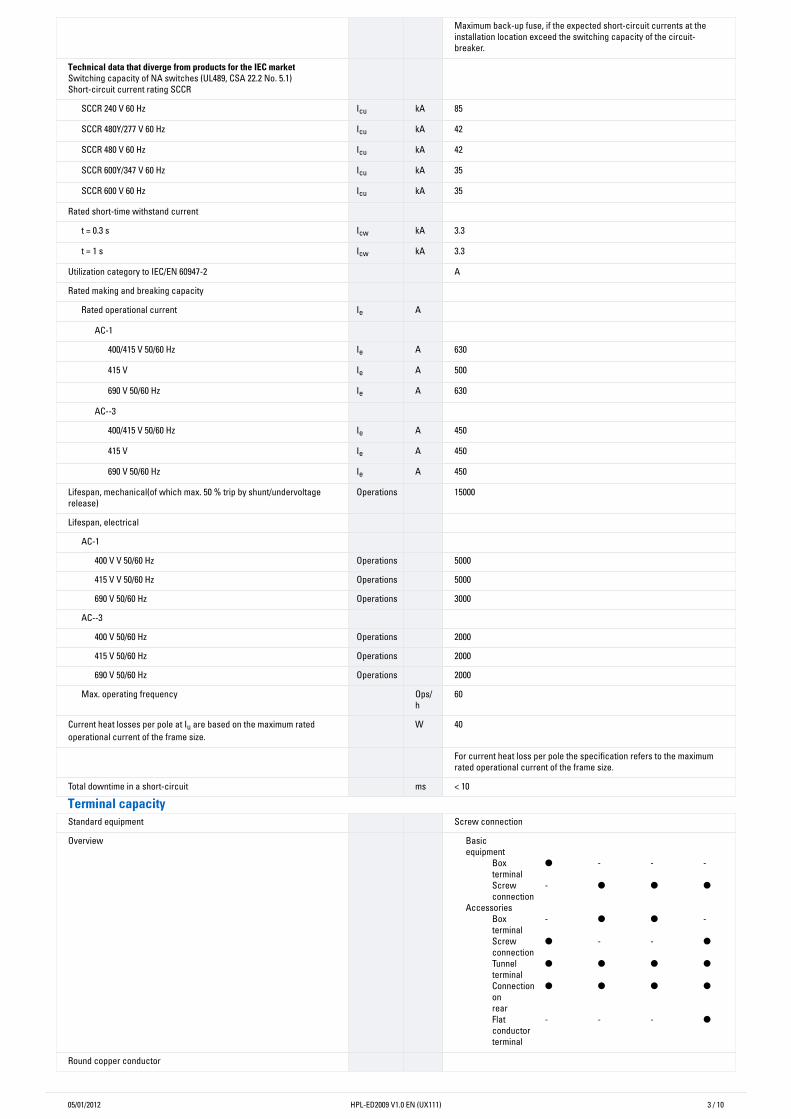
Maximum back-up fuse, if the expected short-circuit currents at theinstallation location exceed the switching capacity of the circuit-breaker.
Technical�data�that�diverge�from�products�for�the�IEC�marketSwitching capacity of NA switches (UL489, CSA 22.2 No. 5.1)Short-circuit current rating SCCR
SCCR 240 V 60 Hz Icu kA 85
SCCR 480Y/277 V 60 Hz Icu kA 42
SCCR 480 V 60 Hz Icu kA 42
SCCR 600Y/347 V 60 Hz Icu kA 35
SCCR 600 V 60 Hz Icu kA 35
Rated short-time withstand current
t = 0.3 s Icw kA 3.3
t = 1 s Icw kA 3.3
Utilization category to IEC/EN 60947-2 A
Rated making and breaking capacity
Rated operational current Ie A
AC-1
400/415 V 50/60 Hz Ie A 630
415 V Ie A 500
690 V 50/60 Hz Ie A 630
AC--3
400/415 V 50/60 Hz Ie A 450
415 V Ie A 450
690 V 50/60 Hz Ie A 450
Lifespan, mechanical(of which max. 50 % trip by shunt/undervoltagerelease)
Operations 15000
Lifespan, electrical
AC-1
400 V V 50/60 Hz Operations 5000
415 V V 50/60 Hz Operations 5000
690 V 50/60 Hz Operations 3000
AC--3
400 V 50/60 Hz Operations 2000
415 V 50/60 Hz Operations 2000
690 V 50/60 Hz Operations 2000
Max. operating frequency Ops/h
60
Current heat losses per pole at Iu are based on the maximum ratedoperational current of the frame size.
W 40
For current heat loss per pole the specification refers to the maximumrated operational current of the frame size.
Total downtime in a short-circuit ms < 10
Terminal�capacityStandard equipment Screw connection
Overview Basicequipment
Boxterminal
● - - -
Screwconnection
- ● ● ●
Accessories Box
terminal - ● ● -
Screwconnection
● - - ●
Tunnelterminal
● ● ● ●
Connectiononrear
● ● ● ●
Flatconductorterminal
- - - ●
Round copper conductor

05/01/2012 HPL-ED2009 V1.0 EN (UX111) 4 / 10
Box terminal
Stranded mm2 1 x (2 - 500)
Tunnel terminal
Solid mm2 1 x 6
Stranded mm2
Stranded mm2 1 x (4 - 350)
Double hole fitting mm2 1 x (0 - 500)2 x (0 - 500)
Bolt terminal and rear-side connection
Direct on the switch
Stranded mm2 1 x (4 - 350)2 x 350
Connection width extension mm2
Connection width extension mm2 2 x 500
Al conductors, Cu cable
Stranded mm2
Double hole fitting mm2 1 x (0 - 500)2 x (0 - 500)
Bolt terminal and rear-side connection
Flat copper strip, with holes min. mm 6 x 16 x 0.8
Flat copper strip, with holes max. mm 10 x 32 x 1.0 + 5 x 32 x 1.0
Connection width extension mm2 (2 x) 10 x 50 x 1.0
Cu strip (number of segments x width x segment thickness)
Box terminal
min. mm2 6 x 16 x 0.8
max. mm2 10 x 24 x 1.0+ 5 x 24 x 1.0(2 x) 8 x 24 x 1.0
Bolt terminal and rear-side connection
Flat copper strip, with holes min. mm 6 x 16 x 0.8
Flat copper strip, with holes max. mm 10 x 32 x 1.0 + 5 x 32 x 1.0
Connection width extension mm2 (2 x) 10 x 50 x 1.0
Copper busbar (width x thickness) mm
Bolt terminal and rear-side connection
Screw connection M10
Direct on the switch
min. mm2 20 x 5
max. mm2 30 x 10+ 30 x 5
Connection width extension mm2
Connection width extension max. mm2 2 x (10 x 50)
Control cables
mm2 1 x (18 - 14)2 x (18 - 16)
Technische�Daten�nach�ETIM�4.0Number of poles 3
Rated uninterrupted current Iu A 600
Number of auxiliary contacts as N/Cs 0
Number of auxiliary contacts as N/Os 0
Device construction Built-in device fixed built-in technique
With under voltage release No
Motor operator optional YES
Integrated earth fault protection No
Suitable for DIN rail (top hat rail) mounting No

05/01/2012 HPL-ED2009 V1.0 EN (UX111) 5 / 10
Setting range non-delayed short-circuit release A 4800
Setting range short-term delayed short-circuit release A 4200
Rated short-circuit breaking capacity lcu at 400 V, 50 Hz kA 50
Switched-off indicator available No
Type of control element Toggle lever
Connection type main current circuit Screw connection
Motor operator integrated No
Position of connection for main circuit Front connection
Protection type (IP) IP20
Number of auxiliary contacts as changeover contact 0
Setting range of overload releases A 600
Characteristics

05/01/2012 HPL-ED2009 V1.0 EN (UX111) 6 / 10

05/01/2012 HPL-ED2009 V1.0 EN (UX111) 7 / 10

05/01/2012 HPL-ED2009 V1.0 EN (UX111) 8 / 10
Dimensions

05/01/2012 HPL-ED2009 V1.0 EN (UX111) 9 / 10
Blow out area, minimum clearance to adjacent parts
Minimum clearance to adjacent parts

05/01/2012 10 / 10