PIT m4SEU - Galco
68
PIT m4SEU Operating Manual-1004648-EN-02 } Control and signal devices
-
Upload
khangminh22 -
Category
Documents
-
view
0 -
download
0
Transcript of PIT m4SEU - Galco

PIT m4SEU
Operating Manual-1004648-EN-02
} Control and signal devices

PrefaceThis document is the original document.
All rights to this documentation are reserved by Pilz GmbH & Co. KG. Copies may be madefor the user's internal purposes. Suggestions and comments for improving this documenta-tion will be gratefully received.
Source code from third-party manufacturers or open source software has been used forsome components. The relevant licence information is available on the Internet on the Pilzhomepage.
Pilz®, PIT®, PMI®, PNOZ®, Primo®, PSEN®, PSS®, PVIS®, SafetyBUS p®,SafetyEYE®, SafetyNET p®, the spirit of safety® are registered and protected trademarksof Pilz GmbH & Co. KG in some countries.
SD means Secure Digital

Contents
Operating Manual PIT m4SEU1004648-EN-02
| 3
1 Introduction ............................................................................................................................ 51.1 Validity of documentation.......................................................................................................... 51.2 Using the documentation .......................................................................................................... 51.3 Definition of symbols................................................................................................................. 5
2 Overview ................................................................................................................................. 72.1 Device features......................................................................................................................... 82.2 Device view............................................................................................................................... 9
3 Safety ...................................................................................................................................... 113.1 Intended use ............................................................................................................................. 113.2 Safety regulations ..................................................................................................................... 123.2.1 Use of qualified personnel ........................................................................................................ 123.2.2 Warranty and liability ................................................................................................................ 133.2.3 Disposal .................................................................................................................................... 13
4 Security ................................................................................................................................... 14
5 Function description ............................................................................................................. 165.1 Permissions .............................................................................................................................. 185.2 Inputs and signal outputs for operating mode selection or operating mode interface .............. 185.3 Configuration of functions ......................................................................................................... 195.4 Operating mode interface ......................................................................................................... 225.4.1 Switching behaviour after permission is removed .................................................................... 225.4.2 Control program requirements.................................................................................................. 225.5 Interface for status information ................................................................................................. 235.5.1 Timing diagrams ....................................................................................................................... 255.5.1.1 Operator actions ....................................................................................................................... 255.5.1.2 Device error .............................................................................................................................. 275.5.1.3 Application error: "No authorisation" ......................................................................................... 275.5.1.4 Application error: "Pushbutton operated incorrectly" ................................................................ 295.6 Key ID interface ........................................................................................................................ 315.6.1 Key ID number (serial number) of the transponder key............................................................ 315.6.2 Communication mode for downloading the Key ID number ..................................................... 325.6.2.1 Transmitter-controlled communication mode............................................................................ 335.6.2.2 Handshake-controlled communication mode............................................................................ 335.6.2.3 Advanced communication mode............................................................................................... 345.6.3 Evaluation by a controller ......................................................................................................... 355.6.3.1 Evaluation of the Key ID number with transmitter-controlled communication........................... 355.6.3.2 Evaluation of the Key ID number with handshake-controlled communication .......................... 385.6.3.3 Evaluation of the Key ID number with advanced communication............................................. 425.7 PITreader interface ................................................................................................................... 425.8 Operating mode lock and operating mode preselection ........................................................... 425.8.1 Operating mode lock................................................................................................................. 425.8.2 Operating mode preselection.................................................................................................... 44
6 Installation .............................................................................................................................. 476.1 General installation guidelines.................................................................................................. 47

Contents
Operating Manual PIT m4SEU1004648-EN-02
| 4
6.2 Dimensions in mm .................................................................................................................... 47
7 Wiring ...................................................................................................................................... 497.1 Terminal configuration .............................................................................................................. 497.2 Connecting the unit ................................................................................................................... 507.3 Connection to a controller ......................................................................................................... 51
8 Operation ................................................................................................................................ 558.1 Select operating modes OM1 ... OM4 ...................................................................................... 568.2 Select special mode (service)................................................................................................... 578.3 Monitoring of operating time ..................................................................................................... 588.4 Switchover time ........................................................................................................................ 588.5 Device status display ................................................................................................................ 588.6 Troubleshooting ........................................................................................................................ 598.6.1 Delete error............................................................................................................................... 598.7 Diagnostics ............................................................................................................................... 598.7.1 Status information about the interface for status information ................................................... 598.7.2 Status information about the signal outputs O1 ... O4 .............................................................. 60
9 Technical details .................................................................................................................... 629.1 Safety characteristic data ......................................................................................................... 64
10 Order reference ...................................................................................................................... 6710.1 Product ..................................................................................................................................... 6710.2 Accessories .............................................................................................................................. 67
11 EC declaration of conformity ................................................................................................ 68

Introduction
Operating Manual PIT m4SEU1004648-EN-02
| 5
1 Introduction
1.1 Validity of documentationThis documentation is valid for the product PIT m4SEU. It is valid until new documentationis published.
This operating manual explains the function and operation, describes the installation andprovides guidelines on how to connect the product.
1.2 Using the documentationThis document is intended for instruction. Only install and commission the product if youhave read and understood this document. The document should be retained for future ref-erence.
1.3 Definition of symbolsInformation that is particularly important is identified as follows:
DANGER!
This warning must be heeded! It warns of a hazardous situation that posesan immediate threat of serious injury and death and indicates preventivemeasures that can be taken.
WARNING!
This warning must be heeded! It warns of a hazardous situation that couldlead to serious injury and death and indicates preventive measures that canbe taken.
CAUTION!
This refers to a hazard that can lead to a less serious or minor injury plusmaterial damage, and also provides information on preventive measuresthat can be taken.
NOTICE
This describes a situation in which the product or devices could be dam-aged and also provides information on preventive measures that can betaken. It also highlights areas within the text that are of particular import-ance.

Introduction
Operating Manual PIT m4SEU1004648-EN-02
| 6
INFORMATION
This gives advice on applications and provides information on special fea-tures.

Overview
Operating Manual PIT m4SEU1004648-EN-02
| 7
2 OverviewThe product may only be used in conjunction with the following external components:} 24 VDC power supply for the supply voltage
} Authentication system PITreader (see Order reference [ 67]) to restrict access for op-erating mode selection
} Pushbutton for selecting the operating mode (one pushbutton per operating mode)} Display elements for the operating mode (one display element per operating mode)} Safety controller to activate the selected operating mode
In n
In n
+1
In n
+2
In n
+3
In n
+4
24 V DC
Higher-level processcontroller
PITreader Displayelements
Pushbutton
Safety controller
(e.g. PNOZ m B0) with "1oon" evaluation
Fig.: PIT m4SEU in an application (principle)
Overview
Operating Manual PIT m4SEU1004648-EN-02
| 8
2.1 Device featuresThe product has the following features:} Supply voltage 24 VDC} 4 operating modes OM1 ... OM4} 1 special mode OM5 (Service)} 5 monitored semiconductor outputs (24 V) in accordance with EN 61496-1;
1 semiconductor output per operating mode} 4 digital inputs (I1 … I4) in accordance with EN 61131-2 type 3 for connecting external
pushbuttons} 4 outputs (O1 … O4) for connecting external display elements} Access restriction for operating mode selection via the authentication system PITreader} Interface for status information, consisting of 4 signal outputs (24 V)} Status information is divided into information classes:
– Operator actions
- Insert transponder key
- Remove transponder key
- Select operating mode
– Messages (e.g. application error, malfunction)} Interface (Key ID interface) for downloading the Key ID number of the transponder key
you are using, consisting of
– 3 semiconductor outputs (24 V)
– 2 inputs
– 1 configurable input/outputcan be configured as- input (see Transmitter-controlled [ 33] and Handshake-controlled communica-tion mode [ 33])- output (see Advanced communication mode [ 34])
} Configurable communication mode for downloading the Key ID number
– Transmitter-controlled communication mode
– Handshake-controlled communication mode
– Advanced communication mode

Overview
Operating Manual PIT m4SEU1004648-EN-02
| 9
2.2 Device view
[1]
[3]
[4]
[2]
Fig.: Front view
Legend
X1 Operating mode interface MS01 ... MS05
X2 Supply voltage A1, A2Interface for status information SIo0 ... SIo3Key ID interface IDo0 ... IDo3 and IDi0 ... IDi1
X3 Inputs I1 ... I4Outputs O1 ... O4
X4 PITreader interface
[1] Device name and order number
[2] Serial number
[3] LEDs
[4] DIP switch for configuring the switching behaviour and configuring the communica-tion mode for downloading the Key ID number

Overview
Operating Manual PIT m4SEU1004648-EN-02
| 10
[4]
Fig.: Side view
Legend
[4] DIP switch for configuring the switching behaviour and configuring the communica-tion mode for downloading the Key ID number

Safety
Operating Manual PIT m4SEU1004648-EN-02
| 11
3 Safety
3.1 Intended useThe PIT m4SEU is suitable for machines that can be operated in multiple operating modeswith different safety functions and/or work procedures. It enables you to switch betweendefined operating modes, such as:} Set-up mode} Manual mode} Automatic mode} Service
The PIT m4SEU meets the following safety requirements:
1. Safety-related selection and switching of an operating mode
– Prevents unintentional switching The switch to a different operating mode is only recognised once the corresponding(selection) pushbutton has been operated for a defined period ("deliberate operatoraction"). Multiple operation of (selection) pushbuttons is detected.
– Safe "1oon" circuit for the operating mode outputs The PIT m4SEU only ever leads to one operating mode output "1" signal.
2. Safety-related switching-on of the operating mode after power-onIn the event of a cold start, the device will either be in OM1 or in the most recently se-lected operating mode, depending on the device configuration (see also Configurationof functions [ 19]).
The following access restriction requirements (security functions) for operating mode selec-tion are met with the accessory device PITreader:} Interlock to protect against unauthorised switching
To use the (selection) pushbutton to switch to an operating mode, contact with atransponder key is required on the PITreader.
} Access permissions are restricted to certain groups A transponder key with the relevant permission is required in order to switch to a certainoperating mode.
Depending on the application area and its respective regulations, the device can be usedup to SIL CL 2 (EN IEC 62061) and up to PL d (EN ISO 13849-1), if the operating modesare evaluated by a safety controller with safe "1oon" evaluation. The operating mode is ac-tivated (machine operation changed) via the control program on a safety controller.
NOTICE
The provisions of the type C standards (machinery safety standards) for therespective application must be observed with regard to operating mode se-lection, as described in section 5.2.4 of EN ISO 16090-1 for example.

Safety
Operating Manual PIT m4SEU1004648-EN-02
| 12
NOTICE
Faulty operation of the PIT m4SEU can lead to hazardous situations.Switching to an operating mode must not initiate a hazardous movement,nor may it cancel an existing control command.
In the event of an error that can lead to the loss of one of the safety functions, the PITm4SEU switches to a safe state and the operating mode that is currently selected is main-tained. The only way to return from the safe state is to switch the PIT m4SEU off and thenon again.
The following is deemed improper use in particular} Any component, technical or electrical modification to the product,} Use of the product outside the areas described in this manual,} Use of the product outside the technical details (see Technical details).
NOTICEEMC-compliant electrical installation
The product is designed for use in an industrial environment. The productmay cause interference if installed in other environments. If installed in otherenvironments, measures should be taken to comply with the applicablestandards and directives for the respective installation site with regard to in-terference.
3.2 Safety regulations
3.2.1 Use of qualified personnelThe products may only be assembled, installed, programmed, commissioned, operated,maintained and decommissioned by competent persons.
A competent person is a qualified and knowledgeable person who, because of their train-ing, experience and current professional activity, has the specialist knowledge required. Tobe able to inspect, assess and operate devices, systems and machines, the person has tobe informed of the state of the art and the applicable national, European and internationallaws, directives and standards.
It is the company’s responsibility only to employ personnel who} Are familiar with the basic regulations concerning health and safety / accident prevention,} Have read and understood the information provided in the section entitled Safety} Have a good knowledge of the generic and specialist standards applicable to the specific
application.

Safety
Operating Manual PIT m4SEU1004648-EN-02
| 13
3.2.2 Warranty and liabilityAll claims to warranty and liability will be rendered invalid if} The product was used contrary to the purpose for which it is intended,} Damage can be attributed to not having followed the guidelines in the manual,} Operating personnel are not suitably qualified,} Any type of modification has been made (e.g. exchanging components on the PCB
boards, soldering work etc.).
3.2.3 Disposal} In safety-related applications, please comply with the mission time TM in the safety-related
characteristic data.} When decommissioning, please comply with local regulations regarding the disposal of
electronic devices (e.g. Electrical and Electronic Equipment Act).

Security
Operating Manual PIT m4SEU1004648-EN-02
| 14
4 SecurityTo secure plants, systems, machines and networks against cyberthreats it is necessary toimplement (and continuously maintain) an overall industrial security concept that is state ofthe art. Perform a risk assessment in accordance with VDI/VDE 2182 or IEC 62443-3-2 and planthe security measures with care. If necessary, seek advice from Pilz Customer Support.} The product is not protected against physical manipulation. For this reason, both the
product and the authentication system PITreader, including the cable between the twodevices, should be installed in a lockable control cabinet.
} The computer that accesses the product has to be protected from attacks by a firewall orother suitable measures. We recommend that a virus scanner is used on this computerand updated regularly.
} If necessary, protect the computer and the product from unauthorised use by assigningpasswords and taking further measures if required. We also recommend that the loggedin user does not have administrator rights.
} Assign only safe passwords. When assigning passwords, please note:
– The password should have at least 8 characters.
– The password should contain upper and lower case characters, as well as specialcharacters and numbers.
– If possible, the password should not be available in dictionaries.
– The password should not be made up of standard variants and repetitions or key-board patterns (so not: 1234abcd).
– Use a password manager for optimum management of complex passwords.
– Language-independent characters are not available in every keyboard language.
– Make sure you regularly change the passwords of the user accounts on the systemand/or ask the users to change their passwords themselves.
– Make the users aware of the responsible use of their access data.} Assign different permissions for the various user groups (e.g. diagnostics - configuration).} As soon as possible, install firmware updates that Pilz provides for the product.} Check the log of the product for security-relevant entries on a regular basis.} Before disposal, the product must be safely decommissioned. To do this, all the data
must be deleted from the device.
– Set the configuration back to its default settings or delete the configuration.
– Switch off the product.
– If the product includes a removable data medium, remove it and format it at the com-puter. Do not carry out a quick formatting. Alternatively, you can use a program tosafely delete data or destroy the memory mechanically.

Security
Operating Manual PIT m4SEU1004648-EN-02
| 15
Company firewall Machine firewall
Company network Machine network
Internet
Configuration computer
Product
Fig.: Example network topology

Function description
Operating Manual PIT m4SEU1004648-EN-02
| 16
5 Function descriptionThe device enables you to switch between 5 different operating modes (operating modesOM1 … OM4 and special operating mode OM5 (Service)) and enables access restrictionvia the authentication system PITreader.
4 inputs are available for OM1 … OM4, for connecting external pushbuttons. For the spe-cial operating mode OM5 (Service), the pushbutton for OM1 must be operated for a certainperiod (see Monitoring of operating time [ 58]). Each input (pushbutton) is assigned amonitored semiconductor output (see Operating mode interface [ 22]). Operating thepushbutton switches the semiconductor output from a "0" signal to a "1" signal. The deviceguarantees that only one of the semiconductor outputs has a "1" signal at any one time.
INFORMATIONOM storage of operating mode
When configured with OM storage (see Configuration offunctions [ 19]), after a restart the unit will start with the last selectedoperating mode.
If OM storage is not configured, the unit always starts with OM1. For thisreason you should make sure that OM1 represents the safest operatingmode.

Function description
Operating Manual PIT m4SEU1004648-EN-02
| 17
PITreader
Power A2
A1
IDo3
IDo2
IDo0
IDi1
IDi0
Inputs
Terminals
MSO5
MSO4
MSO3
MSO2
MSO1
(Sa
fe)
Op
era
tin
g M
od
es
Inte
rfa
ce
Ke
y ID
In
terf
ace
SIo3
SIo2
SIo1
SIo0
Sta
tus In
form
atio
n
Inte
rfa
ce
Transponder Key
IDo1Configurable
Input/OutputOutputs
Inputs
I4
I3
I2
I1
O4
O3
O2
O1
PITreader
Interface
24V
0V
TxD
RxD
Fig.: Block diagram
Legend
Transponder Key Transponder key to enable a change of operatingmode
PITreader Authentication system
PITreader Interface0V, 24V, TxD, RxD
Interface for connecting the PITreader, for permissionto select the operating mode
I1 ... I4 Inputs for connecting external pushbuttons to selectthe operating mode
O1 ... O4 Operating mode outputs for connecting external dis-play elements
A1, A2 Supply voltage
MSO1 ... MSO5 Operating mode interfaceInterface for displaying the operating mode that is cur-rently selected, consisting of 5 monitored outputs

Function description
Operating Manual PIT m4SEU1004648-EN-02
| 18
IDo0 ... IDo3 and IDi0 ... IDi1 Key ID interfaceInterface for downloading the Key ID number to a con-troller, consisting of 3 outputs, 2 inputs and 1 configur-able input/output
SIo0 ... SIo3 Interface for status informationInterface for signalling status information, consistingof 4 signal outputs
The PIT m4SEU is protected against unauthorised operation. A switch between operatingmodes must be enabled via a transponder key on the PITreader.
5.1 PermissionsPermission Permission for operating mode
1 OM1
2 OM1 + OM2
3 OM1 + OM2 + OM3
4 OM1 + OM2 + OM3 + OM4
5 OM1 + OM2 + OM3 + OM4 + OM5 (Service)
Further information on permissions and transponder keys is available in the PITreader op-erating manual.
INFORMATION
Only the transponder key permissions 1-5, which are detected by the au-thentication system PITreader, enable operating mode selection on the PITm4SEU. All other permissions are locked on the PIT m4SEU.
5.2 Inputs and signal outputs for operating mode selection oroperating mode interface} 4 digital inputs type 3 in accordance with EN 61131-2 are available for connecting ex-
ternal pushbuttons.Features:
– Safe inputs with "1oon" evaluation and time monitoring. Faulty operations are detec-ted and rejected without error message.
– For further features see Technical details [ 62].} 4 signal outputs (O1 … O4) are available for connecting display elements. The selected
operating mode is displayed via a 1-signal at the signal output.Features:
– No bridging of supply interruptions.
– For further features see Technical details [ 62].

Function description
Operating Manual PIT m4SEU1004648-EN-02
| 19
} Allocation of signal outputs to inputs:
Pushbutton Input Signal output
Operating mode 1/5 I1 O1
Operating mode 2 I2 O2
Operating mode 3 I3 O3
Operating mode 4 I4 O4
5.3 Configuration of functionsThe PIT m4SEU has a DIP switch, which you can use to set the required communicationmode for downloading the Key ID number and the device's switching behaviour} after the transponder key is removed and} after the voltage reset
.
The communication modes have different functions. These functions are described in thefollowing subsections:
} Transmitter-controlled communication mode [ 33]
} Handshake-controlled communication mode [ 33]
} Advanced communication mode [ 34]
NOTICE
It is essential to note:
– The configuration may only be performed by a competent person.
– The configuration must be performed when the supply voltage isswitched off.
– The configuration is adopted as the device is started up, provided theswitch setting is valid. If not, the device switches to a "Device error"fault condition.
– During operation, the DIP switch setting is monitored for any change.If the switch setting is changed during operation, the device switchesto a "Device error" fault condition, remedy: Delete error [ 59].
– The communication mode changes when you change the DIP switchsetting from Pos. [D1]-[D4] to Pos. [D5]-[D8]. In this case you auto-matically switch to advanced communication mode.
Legend
1
Off
On
DIP switch in OFF position
1
Off
On
DIP switch in ON position
The sliders of the DIP switches are shown in black in the table.

Function description
Operating Manual PIT m4SEU1004648-EN-02
| 20
DIP switch setting Switching behaviourof operating mode(OM)
Communicationmodes
Operatingmode lockand operat-ing modepreselec-tion
[D1]: Default setting4 3 2 1
Off
On
OM1-OM4:OM retention
Transmitter or hand-shake-controlled com-munication modeOM5:
Service fallback
[D2]4 3 2 1
Off
On
OM retention Transmitter or hand-shake-controlled com-munication mode
[D3]4 3 2 1
Off
On
OM fallback Transmitter or hand-shake-controlled com-munication mode
[D4]4 3 2 1
Off
On
OM storage Transmitter or hand-shake-controlled com-munication mode
[D5]4 3 2 1
Off
On
OM1-OM4:OM retention
Advanced communica-tion mode
x
OM5:Service fallback
[D6]4 3 2 1
Off
On
OM retention Advanced communica-tion mode
x
[D7]4 3 2 1
Off
On
OM fallback Advanced communica-tion mode
x
[D8]4 3 2 1
Off
On
OM storage Advanced communica-tion mode
x
DIP configuration
NOTICE
It is essential to note that only the DIP switch settings described above willbe assessed as valid. With all other DIP switch settings, the device switchesto a "Device error" fault condition.

Function description
Operating Manual PIT m4SEU1004648-EN-02
| 21
Explanation of the switching behaviour
When the transponder key is re-moved
After a voltage reset
OM retention } the operating mode currently se-lected is retained,
} the assigned display element islit or all the display elementsflash (OM5),
} the assigned semiconductor out-put has a "1" signal.
} the operating mode OM1 is activ-ated,
} the display element 1 is lit,} OM1 has a "1" signal.
OM fallback } the operating mode switches toOM1,
} the display element 1 is lit,} OM1 has a "1" signal.
} the operating mode OM1 is activ-ated,
} the display element 1 is lit,} OM1 has a "1" signal.
Service fall-back (OM5must be act-ive)
} the operating mode switches toOM1,
} the display element 1 is lit,} OM1 has a "1" signal.
} the operating mode OM1 is activ-ated,
} the display element 1 is lit,} OM1 has a "1" signal.
OM storage } the operating mode currently se-lected is retained,
} the assigned display element islit or all the display elementsflash (OM5),
} the assigned semiconductor out-put has a "1" signal.
} the operating mode selected mostrecently is activated,
} the assigned display element is litor all the display elements flash(OM5),
} the assigned semiconductor outputhas a "1" signal.
NOTICE
Changing the operating mode to OM1 by removing the transponder key isnot a safety-related function. Switching of the operating mode must be val-idated in accordance with the safety requirements.

Function description
Operating Manual PIT m4SEU1004648-EN-02
| 22
5.4 Operating mode interfaceThe operating mode interface consists of the monitored outputs MSO1 … MSO5 (see Blockdiagram [ 16]). The designation "MSO" stands for "mode of safe operation". Outputs areassigned inputs, which can be used to select an operating mode if they have the relevantpermission (transponder key):
Input Output Operating mode
I1 MSO1 OM1 The operating mode OM1/OM5 is selectedbased on the operating time of input 1 (seeMonitoring of operating time [ 58])
MSO5 OM5
I2 MSO2 OM2
I3 MSO3 OM3
I4 MSO4 OM4
5.4.1 Switching behaviour after permission is removedIf permission is removed after changing to a different operating mode, it is possible to con-figure the subsequent switching behaviour of MSO1 … MSO5. A DIP switch is available forthis purpose (see Control elements [ 9]).
The individual switch settings and the resulting switching behaviour are described in thechapter entitled Configuration of functions [ 19].
5.4.2 Control program requirementsIn order to achieve SIL CL 2 (EN IEC 62061)/PL d (EN ISO 13849-1) in an application, theevaluation must be carried out by a safety-related function block. The safety-related func-tion block must meet the following requirements:} The function block must enable safe "1oon" evaluation of the output signals at MSO1 ...
MSO5.} If two or more operating modes are present at the same time, this must be detected as an
error.
INFORMATION
At the moment the device is switched on and during the switchover time t1,the function block must bridge a "0" signal at all outputs on the operatingmode interface (see Switchover time t1 [ 58]). If a Pilz safety controller (e.g. PNOZ m1p) is used in conjunction with an"operating mode selector switch" function element, then this requirement ismet automatically.

Function description
Operating Manual PIT m4SEU1004648-EN-02
| 23
5.5 Interface for status informationVarious status information can be signalled via the interface for status information (seeBlock diagram [ 16]). The status information can be evaluated through a controller.
The status information is subdivided into the following information classes:} Operator actions
– Insert transponder key
– Remove transponder key
– Select operating mode} Messages (e.g. application error, malfunction, response)
NOTICE
When the operating mode is selected (SIo0 … SIo3 = 3h, 8h ... Bh) andwhen there is a device error (Dh), the information remains present indefin-itely. All other information stays active for just 200 ms. After that time theselected operating mode is again displayed.
Status information Information class SIo3(MSB)
SIo2 SIo1 SIo0 (LSB)
Value (inHex)
Operating mode preselection isswitched [5]
Response 0 0 0 0 0h
Reserve - - - 0 0 0 1 1h
Transponder key 5 – Inserted [1] Operator action 0 0 1 0 2h
OM5 selected Operator action 0 0 1 1 3h
Transponder key 1 – Inserted [1] Operator action 0 1 0 0 4h
Transponder key 2 – Inserted [1] Operator action 0 1 0 1 5h
Transponder key 3 – Inserted [1] Operator action 0 1 1 0 6h
Transponder key 4 – Inserted [1] Operator action 0 1 1 1 7h
OM1 selected Operator action 1 0 0 0 8h
OM2 selected Operator action 1 0 0 1 9h
OM3 selected Operator action 1 0 1 0 Ah
OM4 selected Operator action 1 0 1 1 Bh
No permission [2] Application error 1 1 0 0 Ch
Device error [3] Error 1 1 0 1 Dh
Pushbutton operated incorrectly [4] Application error 1 1 1 0 Eh
Transponder key removed Operator action 1 1 1 1 Fh

Function description
Operating Manual PIT m4SEU1004648-EN-02
| 24
[1] When a pushbutton is released, information as to which transponder key is used will bedisplayed for 200 ms (see Status information 2h and 4h … 7h). The selected operatingmode is then displayed (see Status information 3h and 8h … Bh). Please refer to the timing diagrams for Operator actions [ 25].
[2] The error "No permission" (Ch) is registered in the following cases:} Operating mode selected without transponder key} Operating mode selected with a transponder key that does not have permission for the
selected operating mode} Use of a transponder key that does not have permission for the active operating mode} Transponder key is not inserted in time before the operating mode is selected} A pushbutton is operated during the operating mode lock
The remedy is described in the section entitled Troubleshooting [ 59].
Please refer to the timing diagrams for Application error: "No authorisation" [ 27].
[3] A "Device error" (Dh) is registered,
} if the DIP switch setting is changed during operation (see Delete error [ 59]) or} if one of the operating mode outputs MSO1 ... MSO5 is stuck because of external voltage
(stuck-at-1 or stuck-at-0) or} if there is an internal device error.
The remedy is described in the section entitled Troubleshooting [ 59].
[4] The error "Pushbutton operated incorrectly" (Eh) is displayed in the following cases:} Multiple pushbuttons operated} Pushbutton operated for too long (timeout for OM1 to OM4 = 5 s and timeout for OM5 =
10 s) Note: If a pushbutton is operated for < 50 ms this will not be evaluated, so there will beno reaction.
} Pushbutton was released after the transponder key was removed
The remedy is described in the section entitled Troubleshooting [ 59].
Please refer to the timing diagrams for Application error: "Pushbutton operatedincorrectly" [ 29].
[5] In configurations with DIP switch settings [5] … [8], with operating mode preselection theswitching of operating mode outputs to the preselected operating mode is displayed for 200ms. This is used as a feedback for the controller.

Function description
Operating Manual PIT m4SEU1004648-EN-02
| 25
5.5.1 Timing diagrams
5.5.1.1 Operator actionsThe following timing diagrams show how status information is registered at outputs SIo0 ...SIo3, based on operator actions.
INFORMATION
The signal changes at the outputs without delay. Use a software filter toavoid read-in errors.
Key:
Message is displayed constantly
Message is displayed briefly (200 ms)
OM Operating mode
Select operating mode
1. Start position:
– OM1 selected
– DIP switch in default setting
2. Operator action: Insert transponder key on the PITreader (e.g. permission 2)
3. Operator action: Select operating mode (e.g. Press pushbutton on input I2 for OM2)
4. Operator action: Remove transponder key
SIo0 ... SIo3
Pushbutton "2"
Key Mode 02
OM1 sele
cted
Transp
onde
r Key
2 ins
erted
OM1 sele
cted
Transp
onde
r Key
2 ins
erted
OM2 sele
cted
Transp
onde
r Key
remov
ed
OM2 sele
cted
8h 5h 8h 5h 9h Fh 9h
t
t
Fig.: Timing diagram for "Select operating mode" with DIP switch setting [D1] (default setting) and[D5]

Function description
Operating Manual PIT m4SEU1004648-EN-02
| 26
Remove transponder key
1. Start position:a OM5 is selected and the transponder key with permission 5 is inserted on the
PITreaderora One of the operating modes OM1 ... OM4 is selected and a transponder key with
the relevant permission is inserted on the PITreader2. Operator action: Remove transponder key on the PITreader
SIo0 ... SIo3
Key Service
OM5 sele
cted
Transp
onde
r Key
remov
ed
OM1 sele
cted
OM1 ... O
M4 sele
cted
Transp
onde
r Key
remov
ed
8h3h 8h ... Bh as beforeFhFh
t tKey Mode 01 ... 04
SIo0 ... SIo3
Fig.: Timing diagram for "Remove transponder key" with DIP switch setting [D1] (default setting) and[D5]
SIo0 ... SIo3
Key Service
OM5 sele
cted
Transp
onde
r Key
remov
ed
OM1 ... O
M4 sele
cted
Transp
onde
r Key
remov
ed
3h 8h ... Bh as beforeFhFh
t tKey Mode 01 ... 04
SIo0 ... SIo3as before
Fig.: Timing diagram for "Remove transponder key" with DIP switch setting [D2], [D4], [D6] and [D8]
Function description
Operating Manual PIT m4SEU1004648-EN-02
| 27
SIo0 ... SIo3
Key Service
OM5 sele
cted
Transp
onde
r Key
remov
ed
OM1 ... O
M4 sele
cted
Transp
onde
r Key
remov
ed
3h 8h ... Bh 8hFhFh
t tKey Mode 01 ... 04
SIo0 ... SIo38h
OM1 sele
cted
OM1 sele
cted
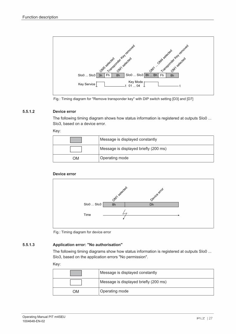
Fig.: Timing diagram for "Remove transponder key" with DIP switch setting [D3] and [D7]
5.5.1.2 Device errorThe following timing diagram shows how status information is registered at outputs SIo0 ...SIo3, based on a device error.
Key:
Message is displayed constantly
Message is displayed briefly (200 ms)
OM Operating mode
Device error
SIo0 ... SIo3
Time
Device
error
Dh8h
OM1 sele
cted
Fig.: Timing diagram for device error
5.5.1.3 Application error: "No authorisation"The following timing diagrams show how status information is registered at outputs SIo0 ...SIo3, based on the application errors "No permission".
Key:
Message is displayed constantly
Message is displayed briefly (200 ms)
OM Operating mode

Function description
Operating Manual PIT m4SEU1004648-EN-02
| 28
Operating mode selected without transponder key
SIo0 ... SIo3
Any pushbutton
No auth
orisa
tion
Ch8h
OM1 sele
cted
No transponderkey
8h
OM1 sele
cted
t
t
Fig.: Timing diagram for "Operating mode selected without transponder key"
Operating mode selected with a transponder key that does not have permission forthe selected operating mode
SIo0 ... SIo3
Pushbutton "2"
No auth
orisa
tion
Ch8h
OM1 sele
cted
Key mode 01
8h
OM1 sele
cted
t
t
Fig.: Timing diagram for operating mode selection with insufficient permission for the desired operat-ing mode

Function description
Operating Manual PIT m4SEU1004648-EN-02
| 29
Operating mode selected with a transponder key that does not have permission forthe active operating mode
SIo0 ... SIo3
Pushbutton
No auth
orisa
tion
Ch9h
OM2 sele
cted
Key mode 01
9h
OM2 sele
cted
t
t
4h
Transp
onde
r Key
1 ins
erted
Fig.: Timing diagram for operating mode selection with insufficient permission for the active operatingmode
Transponder key is not inserted in time before the operating mode is selected
SIo0 ... SIo3
Pushbutton "2"
No auth
orisa
tion
Ch8h
OM1 sele
cted
Key mode 02
8h
OM1 sele
cted
t
t
5h
Transp
onde
r Key
2 ins
erted
8h
OM1 sele
cted
Fig.: Timing diagram for selecting the operating mode before the transponder key is inserted
5.5.1.4 Application error: "Pushbutton operated incorrectly"The following timing diagrams show how status information is registered at outputs SIo0 ...SIo3, based on the application errors "Pushbutton operated incorrectly".
Key:
Message is displayed constantly
Message is displayed briefly (200 ms)
OM Operating mode
Function description
Operating Manual PIT m4SEU1004648-EN-02
| 30
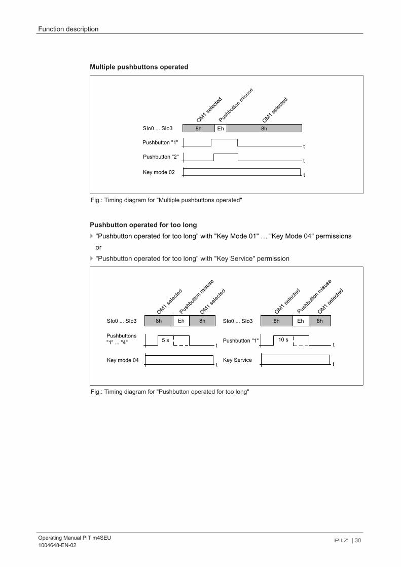
Multiple pushbuttons operated
SIo0 ... SIo3
Pushbutton "2"
Pushb
utton
misu
se
Eh8h
OM1 sele
cted
Key mode 02
t
t
8h
OM1 sele
cted
Pushbutton "1"
t
Fig.: Timing diagram for "Multiple pushbuttons operated"
Pushbutton operated for too long } "Pushbutton operated for too long" with "Key Mode 01" … "Key Mode 04" permissions
or} "Pushbutton operated for too long" with "Key Service" permission
SIo0 ... SIo3
Pushb
utton
misu
se
Eh8h
OM1 sele
cted
Key mode 04
t
t
8h
OM1 sele
cted
Pushbuttons"1" ... "4" t
8h 8hEhSIo0 ... SIo3
Pushbutton "1"
Key Servicet
OM1 sele
cted
Pushb
utton
misu
se
OM1 sele
cted
5 s 10 s
Fig.: Timing diagram for "Pushbutton operated for too long"

Function description
Operating Manual PIT m4SEU1004648-EN-02
| 31
Pushbutton was released after the transponder key was removed
SIo0 ... SIo3
Transp
onde
r Key
remov
ed
Fh8h
OM1 sele
cted
Key Service
t
t
8h
OM1 sele
cted
Pushbutton "2"
Eh
Pushb
utton
misu
se
Fig.: Timing diagram for application errors when the pushbutton is released
5.6 Key ID interfaceThe Key ID interface (see Block diagram [ 16]) is used to download the Key ID numberto a controller.
5.6.1 Key ID number (serial number) of the transponder keyThe Key ID number (serial number) is used to clearly identify the transponder key and isunique. It is a 9-digit decimal number and can be read via the PITreader's web application.
NOTICE
Please note:The Key ID number is not printed on the transponder key or on thetransponder key packaging.
If the transponder key is lost, it is impossible to supply a replacementtransponder key with an identical Key ID number.
The Key ID number consists of two parts:} Bit 27 = 24: Key Mode (0 … 15D)} Bit 23 = 00: Consecutive number (0 … 9999999D)

Function description
Operating Manual PIT m4SEU1004648-EN-02
| 32
Bit27 ... Bit24 Bit23 ... Bit16 Bit07 ... Bit00
Consecutive number
Key Mode Bit27 Bit26 Bit25 Bit24
01 0 0 0 1 1D
02 0 0 1 0 2D
03 0 0 1 1 3D
04 0 1 0 0 4D
Service 1 1 0 1 13D
Bit15 ... Bit08
0 ... 15D
0 ... 9999999D
Fig.: Structure of the Key ID number
Examples:
1101 0000 0000 0010 1100
Consecutive number: 44D
0000 0000
Key Mode Service
Key-ID-Number: 130000044
0010 0000 0000 1111 1110
Consecutive number: 510D
0000 0001
Key Mode 02
Key-ID-Number: 020000510
5.6.2 Communication mode for downloading the Key ID numberThe unique Key ID number for the relevant transponder key is downloaded to the higher-level process controller using a defined protocol, depending on the coded communicationmode. The communication mode is coded on the Key ID interface of the PIT m4SEU (jump-ers available/not available). The PIT m4SEU detects the coded communication mode at each power-on. As long asvoltage is applied to the PIT m4SEU, the coded communication mode will be active; i.e. thechange in communication mode does not come into effect until the supply voltage isswitched off and then on again. It is possible to choose between the following communication modes:} Transmitter-controlled communication mode} Handshake-controlled communication mode} Advanced communication mode

Function description
Operating Manual PIT m4SEU1004648-EN-02
| 33
5.6.2.1 Transmitter-controlled communication modeWith transmitter-controlled communication mode, the PIT m4SEU (= transmitter) starts thedownload of the Key ID number.Features of this communication mode:} Download of Key ID number starts once the transponder key is inserted} Constant bit rate (100 ms)} Download on 2 data lines} Constant download time (typ. 1.8 s)} Monitored data download} Input/outputs required on the controller: 4 inputs and 2 outputs} Download is repeated by re-inserting the transponder key
No special coding is required on the Key ID interface in order to download the Key ID num-ber of a transponder key to the controller in transmitter-controlled communication mode.The terminals (see also Terminal assignment [ 49]) on the Key ID interface are used asfollows:
Key ID interface Brief description of ap-plication
Assignment control sys-tem
Coding
IDo0 IDsync Input No coding required
IDo1 IDclock Input
IDo2 IDout0 Input
IDo3 IDout1 Input
IDi0 IDin0 Output
IDi1 IDin1 Output
5.6.2.2 Handshake-controlled communication modeWith handshake-controlled communication mode, the download of the Key ID number isstarted by the controller (Request). Features of this communication mode:} Download starts via a request from the controller, once the transponder key is inserted} Download is repeated by a renewed request from the controller} Variable bit rate (min. 2 PLC cycles per bit)} Download on 1 data line} Min. download time: 28 Bit * (20 ms + 2 * PLC cycle)} Identifier for ID end for plausibility check} Input/outputs required on the controller: 3 inputs and 1 output
The Key ID interface must be coded with a jumper between IDo3 and IDi1 in order to down-load the Key ID number of a transponder key to the controller in handshake-controlled com-munication mode. The terminals (see also Terminal assignment [ 49]) on the Key ID in-terface are used as follows:

Function description
Operating Manual PIT m4SEU1004648-EN-02
| 34
Key ID interface Brief description of ap-plication
Assignment on controller Coding
IDo0 IDsync Input Coding via jumpers
IDi1 Coding: IN
IDo3 Coding: OUT
IDo1 IDresponse Input
IDo2 IDdata Input
IDo3 Coding: OUT n. c.
IDi0 IDrequest Output
IDi1 Coding: IN n. c.
In handshake-controlled communication mode, the PIT m4SEU can be operated in a func-tional variant. In this case the Key ID number of the transponder key is not downloaded tothe controller. The controller is only used to evaluate IDsync on the Key ID interface. In thiscase IDsync is used as a signal output, enabling the controller to recognise whether thetransponder key is valid/invalid. With this functional variant, only 1 input is required on thecontroller. The unused terminals on the Key ID interface (IDresponse, IDdata and IDre-quest) may remain unwired ("open").
5.6.2.3 Advanced communication modeIn advanced communication mode, the download of the Key ID number behaves in thesame way as the handshake-controlled mode. It differs from the handshake-controlled com-munication mode in so far that inputs are available for an operating mode lock and operat-ing mode pre-selection (see Operating mode lock [ 42] and Operating mode pre-selection [ 44]).
Features of this communication mode:} Download starts via a request from the controller, once the transponder key is inserted} Download is repeated by a renewed request from the controller} Variable bit rate (min. 2 PLC cycles per bit)} Download on 1 data line} Min. download time: 28 Bit * (20 ms + 2 * PLC cycle)} Identifier for ID end for plausibility check} 2 inputs for operating mode lock and operating mode selection} Input/outputs required on the controller: 3 inputs and 3 outputs
To enable the Key-ID number of a transponder key to be downloaded to the controller inadvanced communication mode, the DIP switch must be set accordingly (see Switching be-haviour after permission is removed [ 22]). The terminals (see also Terminalassignment [ 49]) on the Key ID interface are used as follows:

Function description
Operating Manual PIT m4SEU1004648-EN-02
| 35
Key ID interface Brief description of ap-plication
Assignment on controller Coding
IDo0 IDresponse Input Configuration via DIP switchsettingIDo1 IDrequest Output
IDo2 IDdata Input
IDo3 IDsync Input
IDi0 keylock Output
IDi1 ack Output
5.6.3 Evaluation by a controller
5.6.3.1 Evaluation of the Key ID number with transmitter-controlled communication
IDsync
Bit 27 Bit 25 … Bit 16 Bit 15 Bit 14IDout0 Bit 26
[c] [d]
ten
IDclock
[b]
max. 100 ms
Bit 13 Bit 11 … Bit 02 Bit 11 Bit 00IDout1 Bit 12
Bit 27 Bit 25 … Bit 16 Bit 15 Bit 14IDin0 Bit 26
Bit 13 Bit 11 … Bit 02 Bit 11 Bit 00IDin1 Bit 12
T
[a] min. 60 ms [f][e]
Fig.: Timing diagram for transmitter-controlled signal download
Legend
To assign the terminal designations to the short descriptions, please note the table inTransmitter-controlled communication mode [ 33].IDsync Control line
The signal is generated by the PIT m4SEU."0" signal No transponder key is inserted or the transponder key that is
inserted is invalid."1" signal A valid transponder key is inserted. The PIT m4SEU signals
to the controller when the download starts. The signal ispresent for 100 ms.

Function description
Operating Manual PIT m4SEU1004648-EN-02
| 36
IDclock Test pulse line The signal is generated by the PIT m4SEU and indicates the validity of thedata bits at IDout0 and IDout1.} T = 100 ms} Duty cycle = 50%
IDout0, IDout1 Data lines for downloading the Key ID numberThe PIT m4SEU sends the Key ID number to the controller via these twodata lines.Each download starts with the MSB.IDout0: Send Bit 27 … Bit 14IDout2 Send Bit 13 … Bit 00
IDin0, IDin1 Data line for reading back the Key ID numberThe controller sends the previously received Key ID number back to thePIT m4SEU via these two data lines.IDin0: Receive Bit 27 … Bit 14IDin1 Receive Bit 13 … Bit 00
Download procedure
[a] The PIT m4SEU sets the signal at IDsync (control line) to "1" for 100 ms,thereby signalling to the controller that download has started.
[b] A rising edge at IDclock (test pulse line) indicates that the data at data linesIDout0 and IDout1 is present and valid and can be read by the controller.
[c] By the falling edge at IDclock (test pulse line), the controller must send thepreviously read bit back to the PIT m4SEU via the data lines IDi0 and IDi1.
[d] Before the rising edge at IDclock (test pulse line), the PIT m4SEU reads thebits sent back to IDi0 and IDi1 by the controller and checks them for equival-ence.
[e] At least 60 ms after the falling edge at IDclock (test pulse line), the last bitsent back by the controller must be present at data lines IDin0 and IDin1.
[f] A maximum of 100 ms after the falling edge at IDclock (test pulse line), thelast bit sent back by the controller must be present at data lines IDin0 andIDin1; in other words, by this point at the latest, the data download must becompleted and the data lines must have a "0" signal.
INFORMATION
If the controller does not feed back the previously read bits correctly, thedownload is aborted and restarted. The "IDsync" signal is set once again.The download is repeated until the Key ID number is downloaded in full.
It typically takes 1.8 s to download the Key ID number.

Function description
Operating Manual PIT m4SEU1004648-EN-02
| 37
Flowchart for evaluating the Key ID interface
<IDsync> = 1
Start
<IDsync> = 0No
<IDclock> = 1
Read
<IDout0> AND <IDout1>
Increment Bit Counter
Set <IDin0> = <IDout0>
Set <IDin1> = <IDout1>
<IDclock> = 0No
Bit Counter = 14
End
No
Clear Bit Counter
Last Bit Timer >= 60ms
Start Last Bit Timer
No
[b]
[c]
[d]
[e]
[a]
See Fig. „Timing Diagramm
of sender controlled signal
transfer“
<IDsync> = 1
Store ID-Number
Clear
<IDin0> AND <IDin1> [f]
No
No
Yes
Fig.: Evaluation of the Key ID number via a controller (principle)

Function description
Operating Manual PIT m4SEU1004648-EN-02
| 38
5.6.3.2 Evaluation of the Key ID number with handshake-controlled communication
IDsync
Bit 27 Bit 25 … Bit 02 Bit 01 Bit 00IDdata Bit 26
tV
[b]
[c]
[d]
[f]
thten
IDresponse
IDrequest
[e][a]
ta
tIDend
200 ms[g]
Fig.: Timing diagram for handshake-controlled signal download
Legend
To assign the terminal designations to the short descriptions, please note the table inHandshake-controlled communication mode [ 33].IDsync Control line
The signal is generated by the PIT m4SEU."0" signal No transponder key is inserted or the transponder key that is inser-
ted is invalid. The controller cannot request the Key ID number."1" signal A valid transponder key is inserted and the controller can request
the Key ID number.IDre-sponse
Handshake line (Response)The signal is generated by the PIT m4SEU and indicates whether a data bit atIDdata is valid/invalid."0" signal The data bit at IDdata is invalid and may not be evaluated."1" signal The data bit at IDdata is valid and may be evaluated.
IDdata Data line for downloading the Key ID numberThe Key ID number (28 Bit) is generated by the PIT m4SEU. The download be-gins with the MSB (Bit27 … Bit00).
IDreqest Handshake line (Request) The signal is generated by the controller."0" signal No bit is requested at IDdata"1" signal A new bit is requested at IDdata.
ten IDsync Enable Time (min. 0 ms)tv Data Output Valid Time (max. 10 ms)th Data Output Hold Time (min. 0 ms)ta Data Output Access Time (max. 10 ms)tIDend End of Key ID Number Transfer (200 ms)
After the last falling edge at IDrequest, the PIT m4SEU still has a "1" signal atoutput IDresponse for 200 ms. In this way, the end of the Key ID number andtherefore the end of the download (End of Key ID Number Transfer) is displayed.This can be used for the plausibility check.

Function description
Operating Manual PIT m4SEU1004648-EN-02
| 39
Download procedure
[a] "1" signal at IDsync (control line):A valid transponder key is present at the PITreader.
[b] "1" signal at IDrequest (handshake line):The controller requests a data bit at data line IDdata.
[c] "1" signal at IDresponse (handshake line):The PIT m4SEU confirms the validity of the data bit at data line IDdata.
[d] "0" signal at IDrequest (handshake line): The controller confirms that it has read the requested data bit without error.
[e] "0" signal at IDresponse (handshake line):The PIT m4SEU is ready to issue a new data bit at data line IDdata.
[f] "0" signal at IDsync (control line):The transponder key was removed.
[g] The controller must request all the data bits of a Key ID number (Bit27 … Bit00).Only then is it possible to start downloading a new Key ID number. The end ofthe download is indicated by the signal extension (tIDend) at IDresponse.

Function description
Operating Manual PIT m4SEU1004648-EN-02
| 40
Status diagram for handshake-controlled signal download
Fig.: Status diagram for handshake-controlled signal download

Function description
Operating Manual PIT m4SEU1004648-EN-02
| 41
Flowchart for evaluating the Key ID interface
<IDsync> = 1
AND<IDresponse> = 0
Increment Bit Counter
Set <IDrequest> = 0
Read Bit <IDdata>
Start Timer
Set <IDrequest>= 1
Set Bit Counter = 0
Store ID Number
<IDresponse> = 1
No
<IDresponse> = 0
Time Control
<tIDend> >= 200ms
No
Bit Counter = 28
Start
[a]
[b]
[c]
[d]
[e]
Last Bit Control
Data Read and
Acknowledge
Bit Request
RequirementSee Fig. „Timing diagram
of handshake controlled
signal transfer“:
See Fig. „State diagram
of handshake controlled
signal transfer“:
<IDsync> = 0
[g]
No
Yes
No
No
[f]
Fig.: Evaluation of the Key ID number via a controller (principle)

Function description
Operating Manual PIT m4SEU1004648-EN-02
| 42
5.6.3.3 Evaluation of the Key ID number with advanced communicationEvaluation of the Key ID number in advanced communication mode is identical to the hand-shake-controlled communication mode. Please refer to the timing diagram and the flow-chart from the previous section Handshake-controlled communication mode [ 33].
In advanced communication mode, two control signals are also available:} ack → to adopt the preselected operating mode} keylock → to disable the change of operating mode
Both signals are sent from the controller to the PIT m4SEU. These are standard inputs thatdo not affect the safety function of the PIT m4SEU.
5.7 PITreader interfaceThe PITreader interface contains an internal interface for communication with the authentic-ation system PITreader and a voltage output for its supply voltage. The following informa-tion is downloaded via a defined protocol:} Permission is received
} Status information is sent, in accordance with the Interface for status information [ 23]
Only transponder keys with permission 1-5 are registered on the PIT m4SEU. With anyother permissions, the PIT m4SEU does not receive any information via the insertedtransponder key.After the transponder key is removed, permission to select operating modes is locked afterthe reaction time t (see Technical details [ 62]).
The voltage output may only be used for the supply voltage for the authentication systemPITreader.
5.8 Operating mode lock and operating mode preselection
5.8.1 Operating mode lockThe function of the operating mode lock is to enable and disable the request for a changeof operating mode via a digital input.
A change of operating mode can be triggered by:} Operating the pushbutton} Removing the transponder key with OM fallback and service fallback
When a change of operating mode is requested during the operating mode lock,} the corresponding display element flashes briefly,} the interface for status information signals "No permission" and} the operating mode outputs do not switch.
You can deactivate the function, although it is configured. To do this, connect a "1" signal toinput IDi0.

Function description
Operating Manual PIT m4SEU1004648-EN-02
| 43
NOTICE
The operating mode lock is not a safety-related function. Switching of theoperating mode has to be validated in accordance with the requirements.
OutputSIo0 ... SIo3
relea
se ke
ylock
2
chan
ge no
t relea
sed
ack ack
ackn
owled
ge M
SO pre-
selec
tion
keylock
User c
hang
e MSO re
ques
t
KeyKey 2 inserted
Push button
OutputMSO
displayMSO
releasetack
2
MSO1MSO1
MSO2MSO1
MSO1MSO2
MSO2
MSO1 selected [8h] MSO1 selected [8h] MSO2 selected [9h] MSO2 selected [9h]
MSO1 MSO2
[5h] [Ch] [5h] [0h]
Fig.: Changing the operating mode after operating the pushbutton, with DIP switch settings [D5] to [D8]
OutputSIo0 ... SIo3
relea
se ke
ylock
Key re
moved
ackack
ackn
owled
ge M
SO pre-
selec
tion
keylock
KeyKey 2
Push button
OutputMSO
displayMSO
tack
MSO1MSO1MSO2
MSO2
MSO1
MSO2MSO2
MSO2 selected [9h] MSO2 selected [9h] MSO1 selected [8h]
MSO1MSO2
[Fh] [Ch] [0h] MSO1 selected [8h]
Fig.: Changing the operating mode after removing the transponder key, with DIP switch settings [D7]

Function description
Operating Manual PIT m4SEU1004648-EN-02
| 44
Legend
To assign the terminal designations to the short descriptions, please refer to the table inAdvanced communication mode [ 34].
tack Acknowledge Time min. 120 ms.keylock Control signal is generated by the controller and must be present for at
least 20 ms for the signal state to be adopted"0" signal Locking the change of operating mode and/or ending an oper-
ating mode preselection"1" signal Enabling the change of operating mode and/or resuming an
operating mode preselection
ack Control signal is generated by the controller. "0" signal must be present forat least 20 ms for the signal state to be adopted."0" signal Preventing the switching of operating mode outputs"1" signal Enabling the switching of operating mode outputs
display MSO Display element is litOutput SIo0 ... SIo3
Interface for control information
Output MSO Operating mode outputs
5.8.2 Operating mode preselectionThe function of operating mode preselection is to use a digital input to prevent or confirmthe switching of the operating mode during an operating mode change, depending on theprocess requirement. Only the last operating mode preselection is confirmed by the control-ler.
You can deactivate the function, although it is configured. To do this, connect a "1" signal toinput IDi1.
Display during operating mode preselection} The display element indicates the selected operating mode by being lit continuously. The
flashing of a display element indicates a preselected operating mode (see Status informa-tion via the signal outputs [ 60]).
} The interface for status information displays the preselected operating mode (see Inter-face for status information [ 23]).
} The operating mode outputs display the selected operating mode (see Operating modeinterface [ 22]).
When OM storage is configured, the last confirmed operating mode is adopted when thedevice is restarted. The operating mode preselection is not stored.
Display after operating mode selection, when it has been confirmed} Operating mode outputs switch to the preselected operating mode.} The interface for status information still displays the same operating mode and confirms
the transfer of the preselected operating mode to the selected operating mode with thestatus information "Operating mode preselection switched" (see Interface for statusinformation [ 23])

Function description
Operating Manual PIT m4SEU1004648-EN-02
| 45
} The display element for the newly selected operating mode is lit constantly and the dis-play element for the last confirmed operating mode goes out.
Undoing an operating mode preselectionBy the user:} Operate the pushbutton for the selected operating mode (corresponding display element
is lit continuously)} Insert the transponder key in the event of OM fallback and service fallback; permission
must be equal to or higher than the previously removed permission.
By the controller:} "0" signal at the keylock input
Please note that removing the transponder key on the PITreader does not reset the operat-ing mode preselection.
NOTICE
The operating mode preselection is not a safety-related function. Switchingof the operating mode has to be validated in accordance with the require-ments.
OutputSIo0 ... SIo3
Stop M
SO pre-
selec
tion
User c
hang
e
MSO requ
est
ackack
ackn
owled
ge M
SO pre-
selec
tion
keylock
KeyKey 2 inserted
Push button
OutputMSO
displayMSO
tack
MSO1 MSO1MSO2
MSO1
2
MSO1 selected [8h] MSO2 selected [9h][5h] MSO1 selected [8h]
MSO1
Fig.: Exiting the operating mode preselection after the pushbutton has been operated, with DIP switch setting [D5] to[D8]

Function description
Operating Manual PIT m4SEU1004648-EN-02
| 46
OutputSIo0 ... SIo3
Stop M
SO pre-
selec
tion
Key re
moved
ack
Resum
ption
MSO pr
e-
selec
tion
keylock
Key Key 2
Push button
OutputMSO
displayMSO MSO2MSO2
MSO2
MSO1 selected [8h]MSO2 selected [9h]
MSO2
[Fh] MSO1 selected [8h]
MSO1
MSO2
[9h] [Ch] MSO2 selected [9h]
MSO1200 ms [1]
Fig.: Exiting the operating mode preselection after the transponder key has been removed, with DIP switch setting [D7]
Legend
To assign the terminal designations to the short descriptions, please refer to the table inAdvanced communication mode [ 34].
tack Acknowledge Time min. 120 ms.keylock Control signal is generated by the controller and must be present for at
least 20 ms for the signal state to be adopted"0" signal Locking the change of operating mode and/or ending an oper-
ating mode preselection"1" signal Enabling the change of operating mode and/or resuming an
operating mode preselection
ack Control signal is generated by the controller. "0" signal must be present forat least 20 ms for the signal state to be adopted."0" signal Preventing the switching of operating mode outputs"1" signal Enabling the switching of operating mode outputs
display MSO Display element is litOutput SIo0 ... SIo3
Interface for control information
Output MSO Operating mode outputs

Installation
Operating Manual PIT m4SEU1004648-EN-02
| 47
6 Installation
6.1 General installation guidelines} Install the device in a control cabinet or control console.} Use the notch on the rear of the device to attach it to a mounting rail (35 mm).} When installed vertically: Secure the device by using a fixing element (e.g. retaining
bracket or end angle).
6.2 Dimensions in mm
90
86
90.5
Fig.: Front view (installed on top-hat rail)

Installation
Operating Manual PIT m4SEU1004648-EN-02
| 48
252
9.5 37.2
80.266
Fig.: View from below

Wiring
Operating Manual PIT m4SEU1004648-EN-02
| 49
7 Wiring
7.1 Terminal configuration
INFORMATION
The connection terminals are not supplied with the unit.
+24 V DC
0 V
Fig.: Terminal configuration
Legend
X1 MS01 ... MS05 Operating mode interface: Monitored semiconductor outputsfor the operating modes OM1 … OM5
X2 A1, A2 Terminals for connecting the supply voltage
SIo0 ... SIo3 Interface for status information: Evaluation of status informa-tion
IDi0 ... IDi1 Key ID interface: Inputs for receiving the input signals fromthe controllerThe function of the terminals depends on the communicationmode that has been configured
IDo0 ... IDo3 Key ID interface: Semiconductor outputs for sending the out-put signals to the controllerThe function of the terminals depends on the communicationmode that has been configured.

Wiring
Operating Manual PIT m4SEU1004648-EN-02
| 50
X3 I1 ... I4 Inputs for connecting external pushbuttons to select the op-erating mode
O1 ... O4 Operating mode outputs for connecting external display ele-ments
X4 24V, 0V, TxD, RxD PITreader interface
7.2 Connecting the unitFollow the instructions below:
1. Connecting the supply voltagea Connect the supply voltage to (A1, A2).
NOTICE
The power supply must meet the regulations for extra low voltages with pro-tective separation (SELV, PELV). The cables for the device's supply voltage (A1, A2) must be fitted with a 4 Afuse, characteristic B/C.
NOTICE
Guideline for UL certification: The device shall be supplied from an isolating transformer having a second-ary Listed fuse rated either:
– max 5 amps for voltages 0~20 V (0~28.3 Vp), or
– 100/Vp for voltages of 20~30 V (28.3~42.4 Vp).
2. Connect PITreadera Connect the PITreader via the PITreader interface.
The PITreader is supplied from the 24V/0V voltage outputs on the PIT m4SEU inorder to avoid potential differences. The connections of RxD and TxD on the PITm4SEU should be crossed. The cable length between the two devices may be max.10 m.
3. Connect pushbuttona At the inputs I1 … I4, connect external pushbuttons with N/O contact to select the
operating mode (for details of the allocation of the pushbutton inputs Ix to the out-puts MSOx see Operating mode interface [ 22]). You only need to assign thepushbutton inputs for the operating modes you require; the rest can remain unas-signed.
4. Connect display elementsa At the signal outputs O1 … O4, connect external display elements to display the se-
lected operating mode (for details of the allocation of the signal outputs Ox to thepushbutton inputs Ix see Inputs and signal outputs for operating mode selection oroperating mode interface [ 18]. You only need to assign the signal outputs forthe operating modes you require; the rest can remain unassigned.
5. Connecting the operating mode interface's semiconductor outputs

Wiring
Operating Manual PIT m4SEU1004648-EN-02
| 51
a Connect the operating mode interface's semiconductor outputs to a control systemthat supports "1 from n" evaluation. You must read the information concerning intended use (see Intendeduse [ 11]).
6. Connecting the terminals for the interface for status informationa Connect the terminals (SIo0 ... SIo3) to a controller that supports evaluation of the
status information.7. Use jumpers to code the communication mode for downloading the Key ID number (al-
ternative configuration via DIP switch settings, see Configuration of functions [ 19])
– Coding via jumpers is not required for the transmitter-controlled communicationmode.
– To download the Key-ID number in handshake-controlled communication mode,code the Key-ID interface via a jumper between terminals IDo3 and IDi1.
– Coding via jumpers is not required for advanced communication mode.
8. Connect the terminals of the Key ID interfacea Depending on the selected communication mode, connect the terminals of the Key
ID interface to a controller that supports the download of the Key ID number.ora Connect IDsync to a controller, if all you wish to do in handshake-controlled com-
munication mode is evaluate whether the transponder key is valid/invalid. In thiscase you will only use IDsync as a signal output. The unused terminals on the KeyID interface (IDresponse, IDdata and IDrequest) may remain unwired ("open").
7.3 Connection to a controllerThe examples below meet the following conditions:} A PNOZmulti 2 base unit is used as a safety controller.} An "operating mode selector switch" function element is configured in the PNOZmulti
Configurator for safe "1oon" evaluation.} The Key ID interface and the interface for status information are evaluated via a higher-
level process controller.} The cables for the device's supply voltage (A1, A2) contain a 4 A fuse, characteristic B/C.
NOTICE
After wiring, the PIT m4SEU must be subjected to a full function test in theplant.
INFORMATION
The inputs on the FS-PLC operating mode evaluation module cannot beconfigured with test pulse monitoring.

Wiring
Operating Manual PIT m4SEU1004648-EN-02
| 52
Connection for transmitter-controlled communication mode
Fig.: Connection for transmitter-controlled communication mode (example)
Wiring
Operating Manual PIT m4SEU1004648-EN-02
| 53
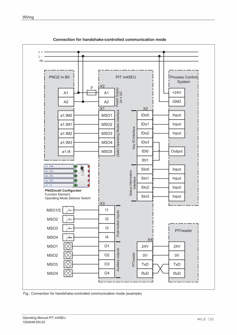
Connection for handshake-controlled communication mode
Fig.: Connection for handshake-controlled communication mode (example)

Wiring
Operating Manual PIT m4SEU1004648-EN-02
| 54
Connection for advanced communication mode
Fig.: Connection for advanced communication mode (example)

Operation
Operating Manual PIT m4SEU1004648-EN-02
| 55
8 OperationSwitch-on behaviour
INFORMATION
After the PIT m4SEU is switched on (power-on) or after supply voltage is re-turned (reset), operating mode OM1 or the most recently selected operatingmode is selected automatically, depending on the device configuration. Thisalso applies if no transponder key is inserted or if a transponder key is de-tected but is invalid.The corresponding display signal output is switched on simultaneously andthe status interface SIo0 … SIo3 displays the selected operating mode.
Behaviour in the event of an error at switch-on
NOTICE
In the event of an error, no active operating mode is displayed at the corres-ponding display element and no semiconductor output has a "1" signal.
Behaviour in the event of an error in operating modes OM1 … OM4
NOTICE
In the event of an error, the device does not change operating mode. Theactive operating mode (OM1, OM2, OM3 or OM4) is displayed at the relev-ant display element and the assigned semiconductor output has a "1" sig-nal.
Behaviour in the event of an error in special operating mode OM5 (Service)
NOTICE
In the event of an error, the device does not change operating mode. Faultyoperation is indicated by the fact that all the display elements are either alllit or all out. The assigned semiconductor output has a "1" signal.

Operation
Operating Manual PIT m4SEU1004648-EN-02
| 56
Requirements of the user
NOTICE
The user must check
– whether he has sufficient training and permission for the operatingmode he has selected.
– that the operating mode displayed after the selection matches the op-erating mode he selected.
– that the expected operating mode is preselected after power-on.
– that the safety controller is displaying the activated operating modecorrectly.
8.1 Select operating modes OM1 ... OM4
Prerequisites} A transponder key with the corresponding permission must be inserted on the PITreader.} The PITreader must recognise the transponder key as valid.} The transponder key must be inserted on the PITreader for the whole time the pushbut-
ton is operated.} Several pushbuttons may not be operated simultaneously when selecting an operating
mode.
Procedure1. Establish the connection with the transponder key
a Insert a transponder key into the slot on the PITreader. Note: The transponder key must have permission for the operating mode into whichyou wish to switch. The permission can be identified via the imprint on the transpon-der key or via the (visualisation) display on the Key-ID interface.
2. Select operating modea Select the required operating mode by pressing the relevant pushbutton.
Please note the required operating time (see Monitoring of operatingtime [ 58]). The operating mode has been selected correctly if the correspond-ing display element is lit once the pushbutton is released.
3. Complete operating mode selectiona Complete the operating mode selection by removing the transponder key.
Once you have removed the transponder key, the PIT m4SEU behaves in accord-ance with the configuration (see Switching behaviour after permission isremoved [ 22]).

Operation
Operating Manual PIT m4SEU1004648-EN-02
| 57
INFORMATION
You can switch at will between the individual operating modes OM1, OM2,OM3 and OM4; i.e. it is possible to switch from OM1 to OM3 or from OM4 toOM2, for example.
8.2 Select special mode (service)
Prerequisites} A transponder key must be inserted with permission for special operating mode OM5
(Service).} The PITreader must recognise the transponder key as valid.} The transponder key must be inserted on the PITreader for the whole time the pushbut-
ton is operated.} Several pushbuttons may not be operated simultaneously when selecting an operating
mode.
Procedure1. Establish the connection with the transponder key
a Insert the transponder key "Key Service" into the slot.2. Select special mode OM5 (Service)
a Press pushbutton 1 (OM1).Please note the required operating time (see Monitoring of operatingtime [ 58]). The operating mode has been selected correctly if all the displayelements flash when pushbutton 1 is released. The display elements flash for aslong as they are in special operating mode OM5 (Service).
3. Complete operating mode selectiona Complete the operating mode selection by removing the transponder key.
Once you have removed the transponder key, the PIT m4SEU behaves in accord-ance with the configuration (see Switching behaviour after a transponder key isremoved [ 22]).
INFORMATION
Special operating mode OM5 (Service) can be selected from any of the op-erating modes.

Operation
Operating Manual PIT m4SEU1004648-EN-02
| 58
8.3 Monitoring of operating timeA change of operating modes is only detected if the relevant pushbutton has been operatedfor a defined time period.
Pushbutton's operating time
Input Operating mode Output Operating time
I1 OM1 MSO1 > 50 ms and< 5 sI2 OM2 MSO2
I3 OM3 MSO3
I4 OM4 MSO4
I1 OM5 (Service) MSO5 > 5 s and< 10 s
8.4 Switchover timeOnce a pushbutton has been released, the assigned output on the operating mode inter-face switches to a "1" signal after the reaction time t2 has elapsed (see Technicaldetails [ 62]). A defined switchover time t1 guarantees that only one operating mode ata time has a "1" signal at the assigned output.
MSO1
MSO2
MSO3
MSO4
MSO5
t1 t1
Fig.: Time behaviour when switching operating mode
8.5 Device status displayTwo LEDs are available on the top of the device to display the device status.
LED Colour State Meaning
Power/Fault Green Voltage supply connected, the device is in a RUN state
Red The device is in a STOP state
Access Yellow Valid permission has been transferred from the PITreader

Operation
Operating Manual PIT m4SEU1004648-EN-02
| 59
8.6 TroubleshootingIf an error occurs on the PIT m4SEU, the last operating mode to be set will be retained.
Error Possible cause Remedy
Unable to switch the op-erating mode
Multiple pushbuttons oper-ated
Make sure that only one push-button is operated
Operating time too long ortoo short
Make sure that the period of op-eration is observed
Transponder key is not de-tected
Make sure that the transponderkey on the PITreader is insertedcorrectly
No valid permission Make sure that you use atransponder key that has the re-quired permission.Ensure that the PITreader inter-face is connected correctly.See also the PITreader operat-ing manual.
Device error - The DIP switch setting waschanged during operation- Invalid configuration via theDIP switch setting
Delete error
Please refer to the timing diagram for Device error [ 27].
8.6.1 Delete errorProcedure:} Switch off device (power off)} Configure DIP switch setting as shown (all switches to ON)
4 3 2 1
Off
On
} Device restart → device error is still displayed} Switch off device} Configure required DIP switch position} Device restart → Error deleted
8.7 DiagnosticsStatus information is sent to the interface for status information (SIo0 … SIo3) and to thePITreader.
8.7.1 Status information about the interface for status informationVarious status information can be signalled via the interface for status information (seeBlock diagram [ 16]). The status information can be evaluated through a control system(see Interface for status information [ 23]).

Operation
Operating Manual PIT m4SEU1004648-EN-02
| 60
8.7.2 Status information about the signal outputs O1 ... O4Display elements can be connected to the signal outputs; these elements display which op-erating mode is active, i.e. which output (MSO1 … MSO5) has a "1" signal.
Evaluation of the display elementsLegend
Display on
Display flashes with Ti = 500 ms, Tp = 500 ms
Display flashes 3 times with Ti = 50 ms, Tp = 950 ms
Display off
Display forpushbutton 1
Display forpushbutton 2
Display forpushbutton 3
Display forpushbutton 4
Meaning
} No supply voltage
} OM5 (Service) is active} MSO5 has a "1" signal
} OM1 is active} MSO1 has a "1" signal
} OM2 is active} MSO2 has a "1" signal
} OM3 is active} MSO3 has a "1" signal
} OM4 is active} MSO4 has a "1" signal
* } No permission for OM1 or} Operating mode lock active
* } No permission for OM2 or} Operating mode lock active
* } No permission for OM3 or} Operating mode lock active
* } No permission for OM4 or} Operating mode lock active
* } Only when operating mode ispreselected
} OM2 is preselected, but OM1 is stillactive
} MSO1 has a "1" signal

Operation
Operating Manual PIT m4SEU1004648-EN-02
| 61
Display forpushbutton 1
Display forpushbutton 2
Display forpushbutton 3
Display forpushbutton 4
Meaning
} Only when operating mode ispreselected
} OM5 is preselected, but OM1 is stillactive
} MSO1 has a "1" signal
** ** ** **
} Only when operating mode ispreselected
} OM1 is preselected, but OM5 is stillactive
} MSO5 has a "1" signal
* OM serves only as an example. One of the operating modes must always light or flash.
** Display element for the newly selected operating mode and all other display elementsflash alternately

Technical details
Operating Manual PIT m4SEU1004648-EN-02
| 62
9 Technical details
GeneralCertifications CE, TÜVElectrical dataSupply voltage
Voltage 24 VKind DCType of power supply SELV/PELVVoltage tolerance -15 %/+20 %Output of external power supply (DC) at no load 3,5 WExternal unit fuse protection F1 4 A, circuit breaker 24 V DC, characteristic B/C
Duty cycle 100 %Status indicator LEDInputsNumber of safe inputs 4Number of standard inputs 3Signal level at "0" -3 - +5 V DCSignal level at "1" 15 - 30 V DCInput current, safe inputs 5 mAInput current, standard inputs 3 mAVoltage at inputs 24 V DCInput current range 5 mAGalvanic isolation NoSemiconductor outputsOverall performance ext. loading, semiconductor 12 WNumber of positive-switching single-pole semicon-ductor outputs 17Switching capability
Voltage 24 VCurrent 50 mA
Signal level at "1" UB - 0.5 VDCResidual current at "0" 0,5 mAGalvanic isolation NoShort circuit-proof yesTimesReaction time t 1 sSwitch-on delay
after UB is applied 1 sSupply interruption before de-energisation 20 msSwitchover time 50 msReaction time change of operating mode dependingon the request t2 200 msOperating time button 1 ... 4 50 ms ... 5 sOperating time, service button 5 s ... 10 s

Technical details
Operating Manual PIT m4SEU1004648-EN-02
| 63
Environmental dataAmbient temperature
In accordance with the standard EN 60068-2-14Temperature range -20 - 60 °C
Storage temperatureIn accordance with the standard EN 60068-2-1/-2Temperature range -25 - 70 °C
Climatic suitabilityIn accordance with the standard EN 60068-2-78Humidity 93 % r. h. at 40 °C
Condensation during operation Not permittedMax. operating height above sea level 2000 mEMC EN 61131-2Vibration
In accordance with the standard EN 60068-2-6Frequency 5 - 8,4 Hz, 8,4 - 150 HzAmplitude 3,5 mmAcceleration 1g
Shock stressIn accordance with the standard EN 60068-2-27Acceleration 15gDuration 11 ms
Airgap creepageIn accordance with the standard EN 61131-2Overvoltage category IIPollution degree 2
Rated insulation voltage 60 VRated impulse withstand voltage 0,8 kVProtection type
In accordance with the standard EN 60529Housing IP20Terminals IP20Mounting area (e.g. control cabinet) IP54
Mechanical dataMounting position AnyDIN rail
Top hat rail 35 x 15 EN 50022, 35 x 7,5 EN 50022Max. cable length 1000 mMaterial
Bottom PCFront PC
Connection type Spring-loaded terminal, plug-inMounting type plug-inConductor cross section with spring-loaded terminals:Flexible with/without crimp connector 0,2 - 2,5 mm², 24 - 12 AWG

Technical details
Operating Manual PIT m4SEU1004648-EN-02
| 64
Mechanical dataSpring-loaded terminals: Terminal points per connec-tion 1Stripping length with spring-loaded terminals 9 mmDimensions
Height 90,5 mmWidth 90 mmDepth 25 mm
Weight 83 g
Where standards are undated, the 2018-09 latest editions shall apply.
9.1 Safety characteristic data
NOTICE
You must comply with the safety characteristic data in order to achieve therequired safety level for your plant/machine.
Operatingmode
EN ISO13849-1:2015
PL
EN ISO13849-1:2015
Category
EN 62061
SIL CL
EN 62061
PFHD [1/h]
IEC 61511
SIL
IEC 61511
PFD
EN ISO13849-1:2015
TM [year]– PL d Cat. 3 SIL CL 2 6,49E-09 SIL 2 3,99E-04 20
Explanatory notes for the safety-related characteristic data:} The SIL CL value in accordance with EN 62061 corresponds to the SIL value in accord-
ance with EN 61508.} TM is the maximum mission time in accordance with EN ISO 13849-1. The value also ap-
plies as the retest interval in accordance with EN 61508-6 and IEC 61511 and as theproof test interval and mission time in accordance with EN 62061.
All the units used within a safety function must be considered when calculating the safetycharacteristic data.
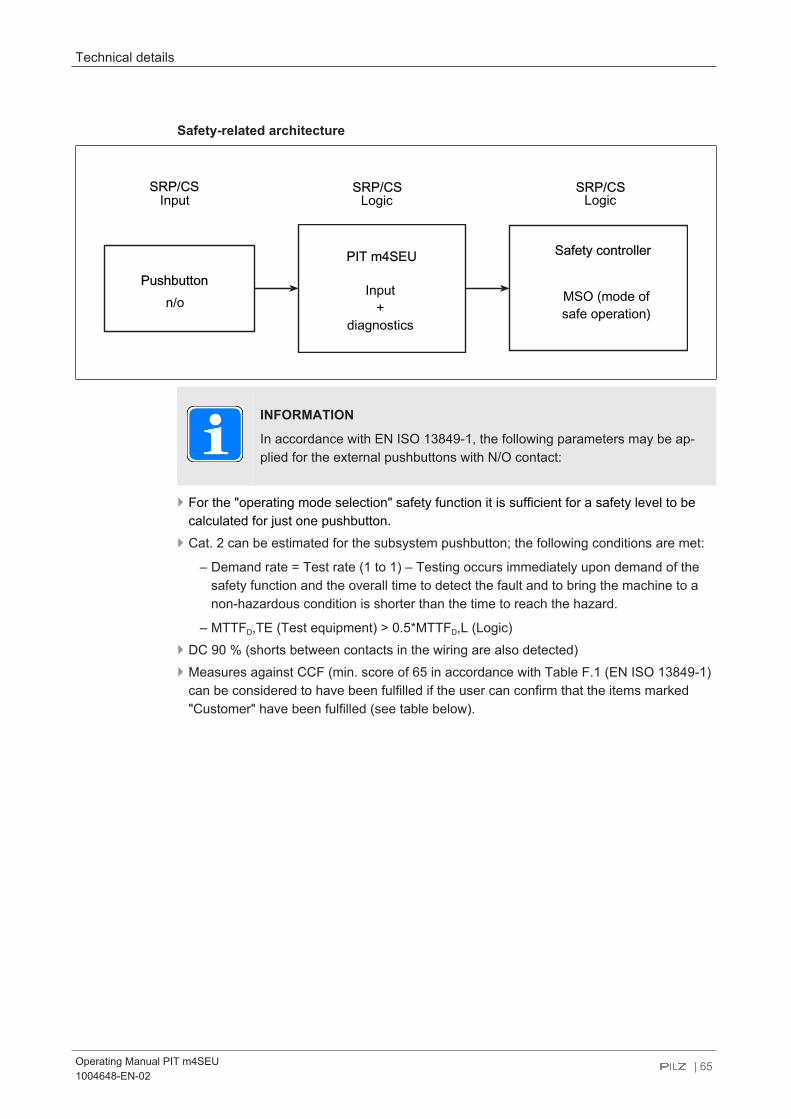
Technical details
Operating Manual PIT m4SEU1004648-EN-02
| 65
Safety-related architecture
SRP/CS SRP/CS SRP/CSInput Logic Logic
Pushbutton
PIT m4SEU
n/oInput
+diagnostics
MSO (mode ofsafe operation)
Safety controller
INFORMATION
In accordance with EN ISO 13849-1, the following parameters may be ap-plied for the external pushbuttons with N/O contact:
} For the "operating mode selection" safety function it is sufficient for a safety level to becalculated for just one pushbutton.
} Cat. 2 can be estimated for the subsystem pushbutton; the following conditions are met:
– Demand rate = Test rate (1 to 1) – Testing occurs immediately upon demand of thesafety function and the overall time to detect the fault and to bring the machine to anon-hazardous condition is shorter than the time to reach the hazard.
– MTTFD,TE (Test equipment) > 0.5*MTTFD,L (Logic)} DC 90 % (shorts between contacts in the wiring are also detected)} Measures against CCF (min. score of 65 in accordance with Table F.1 (EN ISO 13849-1)
can be considered to have been fulfilled if the user can confirm that the items marked"Customer" have been fulfilled (see table below).
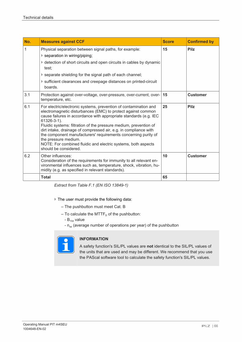
Technical details
Operating Manual PIT m4SEU1004648-EN-02
| 66
No. Measures against CCF Score Confirmed by
1 Physical separation between signal paths, for example:} separation in wiring/piping;} detection of short circuits and open circuits in cables by dynamic
test;} separate shielding for the signal path of each channel;} sufficient clearances and creepage distances on printed-circuit
boards.
15 Pilz
3.1 Protection against over-voltage, over-pressure, over-current, over-temperature, etc.
15 Customer
6.1 For electric/electronic systems, prevention of contamination andelectromagnetic disturbances (EMC) to protect against commoncause failures in accordance with appropriate standards (e.g. IEC61326-3-1).Fluidic systems: filtration of the pressure medium, prevention ofdirt intake, drainage of compressed air, e.g. in compliance withthe component manufacturers' requirements concerning purity ofthe pressure medium.NOTE: For combined fluidic and electric systems, both aspectsshould be considered.
25 Pilz
6.2 Other influences:Consideration of the requirements for immunity to all relevant en-vironmental influences such as, temperature, shock, vibration, hu-midity (e.g. as specified in relevant standards).
10 Customer
Total 65
Extract from Table F.1 (EN ISO 13849-1)
} The user must provide the following data:
– The pushbutton must meet Cat. B
– To calculate the MTTFD of the pushbutton:- B10d value- nop (average number of operations per year) of the pushbutton
INFORMATION
A safety function's SIL/PL values are not identical to the SIL/PL values ofthe units that are used and may be different. We recommend that you usethe PAScal software tool to calculate the safety function's SIL/PL values.

Order reference
Operating Manual PIT m4SEU1004648-EN-02
| 67
10 Order reference
10.1 ProductProduct type Features Order no.
PIT m4SEU PITmode safe evaluation unit 402 250
10.2 AccessoriesProduct type Features Order no.
PITreader base unit RFID authentication system, base unit. Required accessories:PITreader key adapter
402 255
PITreader key ad-apter h
1x PITreader key adapter horizontal + 1x nut for PITreader baseunit
402 308
PIT m4SEU terminalset spring load
1 set of spring-loaded terminals for PIT m4SEU (1 x 4-pin, 1 x 8-pinand 1 x 12-pin), straight cable outlet
402 306

EC declaration of conformity
Operating Manual PIT m4SEU1004648-EN-02
| 68
11 EC declaration of conformityThis product/these products meet the requirements of the directive 2006/42/EC for ma-chinery of the European Parliament and of the Council. The complete EC Declaration ofConformity is available on the Internet at www.pilz.com/downloads.Authorised representative: Norbert Fröhlich, Pilz GmbH & Co. KG, Felix-Wankel-Str. 2,73760 Ostfildern, Germany