ADDITION OF LIME TO IMPROVE SLUDGE SETTLING HELPS DEFER CAPITAL SPENDING
Upload
khangminh22Category
view
0download
0
The first pit (settling pit) facilitates the sedimentation that is started in the channel. Its volumeis 0.2 m3 (0.6 x 0.6 x 0.6 m).
The axis of the second channel must be offset from that of the first one, so as to deflect andattenuate the flow to facilitate settling.
The second pit (pumping pit) is a reservoir from which the drilling mud is pumped to be injec-ted into the drill string; its volume is about 1 m3 (1.5 x 0.8 x 0.8 m). The pits and channels are regu-larly scraped out and cleaned of sediments formed in the course of the drilling process.
5.2.3 PREPARATION OF DRILLING MUD
In clay formations, it is preferable to drill with water only, to avoid blocking the aquifer. Thewater will become loaded with clay from the ground as drilling proceeds.
If there is no reliable information about the nature of the formations to be drilled, the drillingwater must be mixed with bentonite or polycol to increase its density and to prepare drilling mudwhich can be thickened or thinned, as follows:
– polycol is a polymer which is very widely used in rotary drilling. It must be mixed in a pro-portion of 2.5 to 5 kg per m3 of water. The water-polycol mixture is more homogenous than the mix-ture of water and bentonite, and it needs less attention in its use. There are many types of polycol withdifferent characteristics, suitable for different contexts (biodegradable, anti-colloidal, suitable for asaline environment, suitable for different climates etc.);
– bentonite is a powdered clay which must be mixed in a proportion of 15-30 kg per m3 ofwater. It risks sealing the aquifer, but this sealing property makes it better for very permeable forma-tions (gravels, sands), where the losses of drilling mud and the risk of collapse can be significant.
Clean water should be used for drilling mud. It is essential to have a 5 – 10 m3 water store(bladder or water barrel) for the site, to be able to make up any loss of drilling mud as quickly aspossible.
The density of the drilling mud must be adjusted as the drilling advances. With experience, anddepending on the formation being drilled, the driller adjusts the density according to the feel of themud. Clay has the effect of thickening the mud, therefore it is necessary to thin it by adding water. Inloose or sandy formations, it is necessary to use quite dense mud, as ingress of groundwater can thinit excessively.
To obtain a homogenous mixture, the polycol or bentonite must be sprinkled over the water jetwhile filling the pit. A mixer can be made with some fittings: a venturi tube is made, and then connec-ted to the bypass on the discharge side of the mud pumps (Figure 8.14).
The drilling mud is circulated from pit to pit so that it remains homogenous before the effec-tive start of drilling.
8A. Boreholes. Borehole drilling 289
Figure 8.14: Venturi mixer made from PVC fittings.

5.2.4 REMOVAL OF CUTTINGSIN THE DTH TECHNIQUE
The cuttings (and the water withfoam) are raised to the surface by blowingcompressed air, and then channelled to allowsampling (and the estimation of the flow).
When the machine is installed on avehicle, the mixture of water and cuttingsstrikes the underside of the deck. It is neces-sary to create a circular area on the groundwhich directs the flow towards a drain. Inpractice, the most effective means of chan-nelling the cuttings and avoiding splashing isto place 1-2 m of casing (Figure 8.15) underthe drilling table. A bucket is placed underthe shower of cuttings.
5.3 Rotary drilling
5.3.1 STARTING
It is absolutely essential to follow the procedures given in Figure 8.16.
5.3.2 ADVANCE: ADDING A DRILL PIPE
Drilling progress is regulated by the rotational torque and pressure on the drill bit controlled fromthe control panel. The possible solutions to drilling problems are explained in detail in paragraph 5.3.4.
The borehole must be drilled down to the end of the drill pipe passage in order to create a spacebetween the bottom of the hole and the drill bit when the drill pipe has to be changed. When the end of adrill pipe is reached, it is raised and lowered by its full length in order to check the hole and clear the bore-hole sides. A drill pipe can be added as long as the drilling mud is not too full of cuttings (Figure 8.17).
290 III. Water supply
Figure 8.15: Collection of cuttings.
Figure 8.16: Fitting the first drill-pipe.

After switching over the mud-pump outlet to circulate mud from pit to pit (slowing the motor),it is possible to change the drill pipe. Stopping and restarting the flow of mud must be done assmoothly as possible in order to avoid any destabilisation of the borehole sides.
The locking shoe holds the drill pipes suspended in the borehole during the addition or remo-val of drill pipes: it engages at the level of the drill pipe flats (Figure 8.18).
5.3.3 REMOVAL OF A DRILL PIPE
The drive head is lifted into the high position and the shoe engaged on the flat of the lowerdrill pipe. To remove a drill pipe, it is necessary to unscrew the upper thread using the drive head first,then the spanner, and then to unscrew the lower thread (Figure 8.19).
8A. Boreholes. Borehole drilling 291
Figure 8.17: Unscrewing a drill pipe.
Figure 8.18: Locking drill pipes in suspension.

5.3.4 COMMON PROBLEMS
Many difficulties may appear in the course of the drilling process, but most of them are simpleto overcome with a little experience (Table 8.XVII). Success depends on constant monitoring of allthe factors which may influence the progress of the operations, on precise observation of the cuttings,and on ‘listening’ to the machine: experienced drillers are very attentive during the key phases of thedrilling process, to detect the slightest problem.
292 III. Water supply
Figure 8.19: Removing a drill pipe.
Table 8.XVII: Frequently-encountered problems in rotary drilling and recommended solutions.––––––––––––––––––––––––––––––––––––––––––––––––––––––––––––––––––––––––––––––––Observations – difficulties Recommended solutions
––––––––––––––––––––––––––––––––––––––––––––––––––––––––––––––––––––––––––––––––Significant losses Increase the density of the drilling mudand/or dilution of drilling mud Use bentonite rather than polycol
Install pre-casing
Thickening of drilling mud Empty and clean pitsAdd clean water
Sides of borehole not stabilised Increase density of drilling mudand collapsing, Reduce fluid circulation rateerosion of sides Reduce cleaning and circulation time
Case immediatelyInstall pre-casing
Sides collapsing, Increase pressure and flow of drilling mudcirculation stopped, Lift drill string until circulation returns to normalrotation blockage Install pre-casing
Sealing of aquifer Clean with water to break the cakeUse polycol rather than bentonite
––––––––––––––––––––––––––––––––––––––––––––––––––––––––––––––––––––––––––––––––
5.3.5 ANALYSIS OF CUTTINGS AND SIGNS OF WATER
The geological section of the ground being drilled is established by the hydrogeologists ortheir assistants as the borehole goes along, and described in detail in the borehole report. The cuttingswhich come to the surface with the drilling mud are a source of essential information: their geologi-cal analysis helps to identify the formations traversed, and to know their nature, whether they are per-meable (indicating a reservoir) and capable of providing water. Samples are taken with each changeof drill pipe and formation, by hand, just at the borehole outlet, and placed in a box with differentcompartments in order to visualise the geological section. They are then preserved in plastic bags mar-ked with the name of the borehole and the depth at which the sample was taken. The samples arealways covered in drilling mud, which makes them difficult to interpret, so they have to be rinsed withclean water.
In rotary drilling, there is nothing that clearly indicates the presence or absence of water duringthe drilling process: only water tests (direct blowing) and pumping tests, carried out once the bore-hole has been equipped, allow the presence of water to be confirmed, and the exploitation flow to beevaluated. Nevertheless, during the drilling process, there are several signs of water that allow anaquifer area to be located:
– analysis of the cuttings, as noted before, indicates the presence of an aquifer by revealinglayers of permeable material (sands, gravels), supported by cross-checking with the informa-tion gathered in other boreholes drilled in the same area and which have turned out to be posi-tive;– loss of drilling mud, which means leakage of drilling mud into the surrounding ground,becomes evident from rapid decrease in the levels in the pits during circulation, or in the bore-hole after the circulation has stopped (for example, while a drill pipe is being changed). Thesephenomena indicate that the borehole is passing through layers of permeable material;– traces of oxidation and visible alterations on the grains of quartz and feldspar (ochre/rustyaspect) are signs of groundwater movement. However, these may be old signs, relating towater movements in the past, and they may not reflect the current situation (e.g. if the staticlevel has dropped);– thinning (i.e. dilution) of drilling mud indicates groundwater ingress. But this phenomenonis rarely detected, because the pressure of the drilling mud is usually higher than that of theaquifer, and the aquifer is usually plugged by the cake.
5.4 DTH percussion drilling
5.4.1 ADJUSTMENT AND LUBRICATION OF THE DTH HAMMER
The DTH hammer is a precision tool, consisting of a piston which slides in a cylinder due tothe passage of compressed air through a set of cavities. The piston strikes the drill bit during the per-cussion phase and releases compressed air during the blowing phase (Figure 8.20).
It is essential to keep the hammer lubricated, and so the injected air must itself be lubricatedthroughout the length of the drilling. A lubricator is located between the compressor and the air-admission valve of the drilling rig, injecting biodegradable drilling oil. The operation is checked byblowing the lubricated air onto a small board placed under a suspended drill pipe. Optimum flow(0.2 l/h) occurs when the board is lightly and evenly sprayed. Adjustment is carried out with the screwsituated on the lubricator: the screw at the base is turned fully to the right (closed), then unscrewed aquarter turn to the left. If foam is added, the quantity of oil used must be higher. Every time a drillpipe is changed, it is essential to check the presence of oil in the air coming out of the drill head.Finally, when the hammer is completely dismantled, it is necessary to oil it (by direct introduction ofhydraulic oil) and to grease all the threads (with copper grease).
8A. Boreholes. Borehole drilling 293

5.4.2 INSTALLATION OF THE HAMMER
In bedrock areas, weathered layers are drilled in rotary mode using either air or drilling muduntil the bedrock is reached, when drilling continues using a hammer (Figures 8.21 and 8.10).
Certain precautions must be taken for the installation and lowering of the hammer to the bot-tom of the borehole:
– all drill pipes must be cleaned with air from the compressor to remove all drilling mud resi-due before the hammer is connected (to avoid damage to the hammer);– before storage, all dry drilling-mud residue must be cleaned from the drill pipes used forrotary drilling, with water from with the foam pump in high-pressure washer position;– before lowering the DTH hammer, the depth of the borehole must be measured (with a dip-per) in order to check for possible collapse;– when each drill pipe is added, it is cleaned after being screwed to the drive head and beforebeing connected to the drill string (place a board on the drill pipe locked in the shoe and blastwith air to flush out contaminants);– drilling mud contained in the borehole is regularly flushed (by air blowing) as the hammerdescends. If the hole is pre-cased and the space between the casing and the drill bit is small(just a few millimetres), there is always a risk of putting the hammer into percussion mode ifit rubs against the sides of the casing, which would damage it.
5.4.3 DRILLING PROCESS
Before starting percussion, clockwise rotation is commenced and then maintained during rai-sing or lowering of the drill string. It is only stopped when all other operations cease.
294 III. Water supply
Figure 8.20: Hammer function.

Any anticlockwise rotation can unscrew the drill string or the hammer completely, causingthem to fall to the bottom of the borehole; this can be aggravated by the vibrations caused by percus-sion. The recovery of a drill bit or part of the drill string requires specific tools and is a delicate ope-ration. Anticlockwise rotation during percussion is therefore to be avoided at all costs.
5.4.3.1 Starting the hole
With the air flow shut off, the drill bit is placed several centimetres above the ground to bedrilled, and clockwise rotation is started. The air is turned on, and the hammer is gradually pressedonto the ground until percussion starts.
Initially, air flow is opened half way, percussion is relatively weak, and rotation slow, until thedrill bit penetrates the ground. The air valves are progressively opened to increase percussion.
Pressure and rotation are then controlled to give regular advance.
5.4.3.2 Advance
Good drilling involves a balance between pressure and rotation, giving constant penetrationspeed and regular, smooth rotation (Figure 8.3).
The borehole is regularly purged (every 50 cm) by blowing in order to remove cuttings andavoid blockage. Large cuttings tend to remain in suspension above the DTH hammer during thedrilling process. If air circulation stops, cuttings can fall back onto the hammer and block it.
To purge the borehole, the hammer is slightly withdrawn (stopping percussion) and set to the blo-wing position. The total air flow provided by the compressor must allow the borehole to be purged of allcuttings. It may be necessary to sweep up the height of the drill pipe to purge the borehole thoroughly.
5.4.3.3 Addition and removal of drill pipes
The procedure explained in Sections 5.3.2 and 5.3.3 for rotary drilling can also be consulted.Before unscrewing the drill pipes, the residual pressure in the drill string is checked with a
manometer. This pressure remains high if a plug of cuttings is formed in the annular space (see Sec-tion 5.4.4 for precautions to be taken to avoid this): in this case the drill pipes must be unscrewed care-fully to release pressure gradually.
Air lubrication is checked with the addition of each drill pipe.
8A. Boreholes. Borehole drilling 295
Figure 8.21: Fitting the hammer.

5.4.4 DIFFICULTIES AND POSSIBLE SOLUTIONS
Air drilling of formations covered by unconsolidated material that has not been pre-cased canpresent difficulties:
– in the first stages of drilling, the pressurised air can erode and undermine the soil around theborehole, thus endangering the stability of the drilling rig;– during the drilling process, the movement of cuttings to the surface erodes the sides of theborehole, which may cause collapse and block the drill string;– air losses in very loose formations can lower the rise-rate of the cuttings.If the surface formation does not have a minimum of stability, and if the cuttings do not rise
to the surface correctly and so create a blockage, the rotary technique, using drilling mud rather thanair must be used. If the surface formation collapses, pre-casing is essential before continuing drillingwith the hammer.
For the problems usually encountered during the drilling process, there are several solutions,as recommended in Table 8.XVIII. The addition of foam (polymer) appreciably modifies the charac-teristics of the circulating air, and solves a certain number of problems (return of cuttings, filling andair losses in the ground).
5.4.5 ANALYSIS OF CUTTINGS, SIGNS OF WATER AND FLOW CALCULATION
As the fluid used in DTH drilling is air, the cuttings will be clean and not mixed with drillingmud, facilitating analysis. Even the use of foam doesn’t hamper the observation of the cuttings. Gene-rally, the bigger the cuttings, the more friable the drilled formation is, and the finer they are (dust), theharder the drilled rock is. The presence of fractures is usually identified by larger cuttings. Additio-nally, any signs of erosion on these cuttings could indicate a water flow (current or historic).
296 III. Water supply
Table 8.XVIII: Frequently-encountered problems in DTH-hammer drilling and recommended solutions.––––––––––––––––––––––––––––––––––––––––––––––––––––––––––––––––––––––––––––––––Observations – difficulties Recommended solutions––––––––––––––––––––––––––––––––––––––––––––––––––––––––––––––––––––––––––––––––Poor rise of cuttings to the surface Longer blowing time
Injection of foam and water
Decrease in air flow at the Injection of foam and waterborehole exit – blockage of cuttings Care while unscrewing drill pipesHigh residual pressure in drill pipes
Air losses in surface formations Injection of foamPre-casing if necessary
Blockage with dry Injection of water and foam if necessaryor slightly damp cuttings Frequent high-pressure blowingFormation of small balls Pulling up drill string
Erosion of the borehole sides due to air flow Decrease in air flowand return of cuttings to surface Use of foam
Pre-casing
Formation of a large cavity Stop drillingImmediate casing, or pre-casing
Drill bit blockage by falling debris Sharp rotation, raising and lowering to crush the debrisHigh-pressure blowing with water and foam
Blockage of rotation Percussion and sharp restart of rotationLight anticlockwise unscrewing to increase amplitude of jolts
Drilling in a cavity Left to the drillers’ judgement––––––––––––––––––––––––––––––––––––––––––––––––––––––––––––––––––––––––––––––––

In drilling with air, ingress of water is visible and quantifiable in most cases (return of a mix-ture of water and cuttings when blowing). However, some water ingress may not be noticed becauseit is blocked by the cuttings that form a cake on the sides of the borehole.
It is easy to estimate water flow during the drilling process to decide when it should be stop-ped, and the borehole equipped. Flow measurements are taken at each significant water ingress (blo-wing). In addition, all water emerging from the borehole is channelled to an outlet equipped with apipe to facilitate measurement using a bucket.
Ingress of water in the finished borehole must be regular and continuous. The measured flowis generally less than the borehole capacity, because the cuttings block some supply zones, and theborehole is still not fully developed. Nevertheless, ingress of water is generally progressive: it appearsfirst in the form of traces of dampness, and then, as the borehole advances, in the form of a cumula-tive flow coming from various fissures or fractures. In some cases, crossing a well-supplied majorfracture causes a sharp increase in flow.
6 Borehole equippingEquipping the borehole (installing casing and screen) is an essential stage in the construction
of a water borehole. The casing plan and the position of the screen have a great influence on the yieldof the borehole, as well as its longevity. The aquifer must be protected from surface pollution whichcan enter down the side of the casing by the surface works and the cement plug (Figure 8.22).
6.1 Permanent casing6.1.1 CHOICE OF CASING AND SCREEN
PVC is the most suitable material for shallow boreholes. It is preferable to use proper reinfor-ced casing with screw joints. The mechanical strength of the casing can be calculated (Box 8.4). Itmust be strong enough to avoid pipe deformation during installation, as holes are not always circular,and during pumping, which applies pressure on the pipe.
Strictly speaking, the screen slot size depends on the grain size of the aquifer (Table 8.XIX).Before drilling starts this is not always known, but usually the slots should be between 0.5 and 2 mm wide.
8A. Boreholes. Borehole drilling 297
Figure 8.22: Borehole equipment(based on ACF, Uganda, 1997).

During drilling of the first boreholes, the grain size of the aquifer can be easily identified byanalysing the cuttings with a sieve. Table 8.XIX gives the grain size of gravel pack and the screen slotsize recommended for different aquifer grain sizes encountered underground.
6.1.2 CASING FITTING
The risk of collapse could be high, and the casing is therefore fitted as quickly as possible. Theborehole must not remain unprotected for any length of time, because there is always the risk of losingthe borehole through collapse of the sides.
298 III. Water supply
Box 8.4Resistance of the casing to crushing.
For water boreholes, an important mechanical characteristic of the casing is its crush resistance. Sometimesthis information is provided by the suppliers, but it can be calculated using the following simplified formula:
Re = K . E . (e/D)3
where Re is the crushing resistance (bar), K a non-dimensional coefficient (for PVC K = 2.43 (Tubafor®),for steel K = 2.2), E the modulus of elasticity (bar) of the material at 20°C (for PVC 3 x 10⁴, for steel 2 x10⁶), e the thickness of the casing wall, and D its external diameter.For slotted casing (screen), calculated values should be multiplied by the coefficient (1 – F), where F is thefraction of voids. For particular cases, consult the supplier.The forces, i.e. the lateral pressure on the casing, are generally calculated from:– the specific weight of the ground, with the lateral forces equal to half the vertical forces, which are them-selves equal to the weight of the unconsolidated, dry or saturated ground above (specific weight of 2 to 2.5).Therefore, it is usually considered that hard formations do not exert any lateral pressure;– the pressure due to the presence of water or drilling mud in the borehole (hydrostatic pressure in barP = H d/10).For example, if the static level is near the surface and the formation is unconsolidated, the horizontal pres-sure is then 20 bars for each 100 m of depth (weight of the ground divided by 2 + 10 bars of hydrostaticpressure).However, bearing in mind the small cross-sectional area of the boreholes, the vault effect of their sides pro-tects the casing from lateral ground pressure. In practice, only the static and dynamic hydrostatic pressuresare taken into account. These pressures are increased during pouring of cement grout, lowering the casing,and sharp reduction of water level during development.For shallow boreholes in hard bedrock, experience has shown that it is enough to consider a horizontal pres-sure of 0.75 bars per 10 m section. Therefore, casing with a strength of 7.5 bars can be installed in a 100 mborehole.
Table 8.XIX: Choice of screen slot and gravel pack per aquifer grain size.––––––––––––––––––––––––––––––––––––––––––––––––––––––––––––––––––––––––––––––––Aquifer grain size Gravel pack grain size Screen slot size
––––––––––––––––––––––––––––––––––––––––––––––––––––––––––––––––––––––––––––––––0.1 to 0.6 mm 0.7 to 1.2 mm 0.50 mm0.2 to 0.8 mm 0.1 to 0.5 mm 0.75 mm0.3 to 1.2 mm 1.5 to 2.0 mm 1.00 mm0.4 to 2.0 mm 1.7 to 2.5 mm 1.50 mm0.5 to 3.0 mm 3.0 to 4.0 mm 2.00 mm
––––––––––––––––––––––––––––––––––––––––––––––––––––––––––––––––––––––––––––––––

The casing plan (length and position of casing and screen) is established according to the geo-logical profile of the borehole where the different strata and points of ingress of water are noted. Dia-graphy’s tests (electrical resistance, gamma ray, neutron) can be carried out before casing to improvethe casing plan, especially in sedimentary formations, with the use of rotary drilling, where it is some-times difficult to identify the aquifer horizons (see Chapter 5).
The screen is placed so that its bottom is level with the bottom of the aquifer or zone of wateringress, with its length chosen according the following rules:
– confined aquifer: 80 to 90% of the thickness of the aquifer– unconfined aquifer: 30 to 60% of the thickness of the aquiferThe issue is to find a good compromise between having screens long enough to reduce the velo-
city of the water moving towards the borehole, and short enough to allow the installation of the pumpabove the screen, to avoid draw-down of the water table below the level of the screen.
Placing the pump within the screen itself can damage the screen: the high velocity of watercauses erosion of the slots, and the pump hits the screen when starting. The gravel pack and the aqui-fer around the screen are also destabilised in the long term. The pump may also be damaged by dra-wing fine material into it and by causing cooling problems (water flow must arrive down the pump tocool the motor; a shroud can be used to orient the flow).
The de-watering of the screen presents several risks; oxygenation of the aquifer can favour theprecipitation of metals (Fe, Mg etc.) that clogs up the screens and encourages the development of bac-teria (see Chapter 8B). It also accelerates the compaction of the aquifer.
These rules have to be strictly applied for a motorised borehole (the pump should be installedabove the screen or should have a shroud if installed below it). For handpumps the velocity of thewater is lower and the longevity of the borehole is not so affected by having the pump within thescreen (in this case, centralisers around the pipe of the pump must be used to avoid the pump cylin-der hitting the screen during pumping).
Moreover:– the bottom section of the casing must be a length of unslotted casing of about 0.5 m, plug-ged at the bottom (settling pipe);– since the casing does not always reach the bottom of the borehole (cuttings suspended in thedrilling mud falling back when circulation stops, or collapse of the material from the boreholesides), it is necessary to reduce the length of the casing by 0.5 to 1 m in relation to the actual
8A. Boreholes. Borehole drilling 299
Figure 8.23 Centralisers.A: commercial model. B: in Angola, centralisers were made by fixing small pieces of PVC pipe securedwith fasteners around the casing. One centraliser was installed on each screen section, and one per twoor three casing sections.
A B
depth drilled (after drilling several boreholes in the same area, the driller should be able to esti-mate the height lost during drilling and adapt accordingly);– the top of the casing must extend to about 0.5 m above the surface of the ground.The lengths of casing could vary with the joint threading, so it is advisable to measure each length.The casing must pass freely down the borehole under its own weight. If the borehole is not
vertical, friction between the casing and the borehole sides can block the installation. Light pressureon the casing can facilitate its descent, otherwise it is necessary to return it to the surface and reborethe hole.
An alternative method consists of lowering the casing without a bottom plug so that it canscrape down the sides. In this case, it is recommended to seal the bottom of the borehole with cementgrout pumped down from the surface once the casing is in place.
In order to guarantee correct positioning of the casing in the borehole and an even gravel packaround the screen, it is recommended to install centralisers. Various suppliers produce centralisers, butthey can be easily made in the field (Figure 8.23).
6.2 Gravel pack and grouting
6.2.1 GRAVEL PACK
The gravel pack allows for a larger screen slot size to be used, increasing the yield from theborehole by reducing the velocity of the water entering the screen (therefore reducing head-loss). Thegravel pack also helps in the stabilisation of the surrounding aquifer.
The gravel pack must be reasonably uniform, calibrated, clean, round and preferably siliceous,to guarantee good porosity and longevity. It must not be calcareous, lateritic or crushed.
In practice, the gravel pack grain size is defined by the grain size of the aquifer and the slotsize of the screen: the gravel must be as fine as possible without passing through the screen (Table8.XIX).
The gravel is passed down through the annular space between the casing and the sides of theborehole. The use of a funnel (sheet metal, plastic sheet or pipe) facilitates its introduction.
If the falling gravel blocks the annular space, circulation of water can clear it.Mud rising up through the casing indicates that the gravel is falling correctly. When the level of
gravel reaches the top of the screen, the mud no longer comes up through the casing, but through theannular space. The gravel filter must then go on a few metres beyond the height of the screen (com-paction may occur after installation). This level can be checked with a dipper in shallow boreholes.
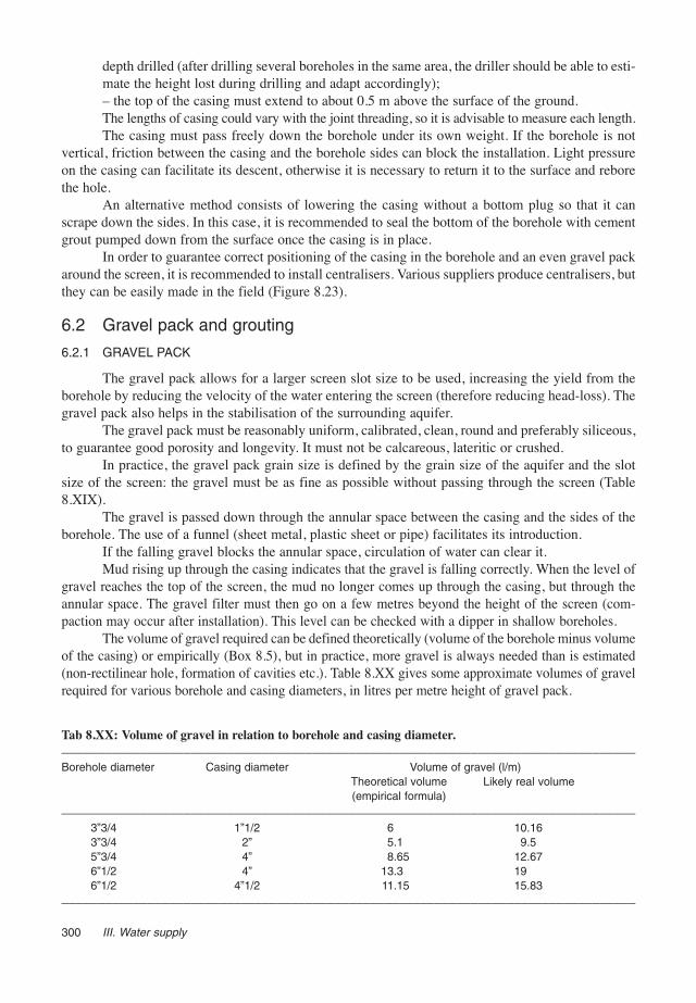
The volume of gravel required can be defined theoretically (volume of the borehole minus volumeof the casing) or empirically (Box 8.5), but in practice, more gravel is always needed than is estimated(non-rectilinear hole, formation of cavities etc.). Table 8.XX gives some approximate volumes of gravelrequired for various borehole and casing diameters, in litres per metre height of gravel pack.
300 III. Water supply
Tab 8.XX: Volume of gravel in relation to borehole and casing diameter.––––––––––––––––––––––––––––––––––––––––––––––––––––––––––––––––––––––––––––––––Borehole diameter Casing diameter Volume of gravel (l/m)
Theoretical volume Likely real volume(empirical formula)
––––––––––––––––––––––––––––––––––––––––––––––––––––––––––––––––––––––––––––––––3”3/4 1”1/2 6 10.163”3/4 2” 5.1 9.55”3/4 4” 8.65 12.676”1/2 4” 13.3 196”1/2 4”1/2 11.15 15.83
––––––––––––––––––––––––––––––––––––––––––––––––––––––––––––––––––––––––––––––––

6.2.2 GROUTING
Grouting is an essential operation which protects the borehole from external pollution; even ifa slab is cast around the casing, only proper grouting can prevent water filtering down the side of thecasing. Grouting can be done with clay or with a mixture of bentonite and cement.
A clay plug must be placed on top of the gravel pack in order to stop the grout from pluggingthe gravel pack. The bentonite continues to swell over time, guaranteeing the seal even if the groutbecomes damaged.
6.2.2.1 Preparation of the grout
The operation consists of filling the annular space above the gravel filter with a mixture ofwater and cement (grout) up to ground level. When the borehole is deep, one plug can be put abovethe gravel pack with another in the last two metres, the intermediate space being filled with clay(cuttings).
The proportion is about 50 l of water for 100 kg of cement, which gives 75 l of grout. If ben-tonite is available, the following mixture is used: 70 l of water, 4 kg of bentonite and 100 kg ofcement. This second mixture stops the water from filtering out of the grout, but its setting time isslightly longer.
6.2.2.2 Placing the grout
The procedure involves filling the annular space up to ground level, and then leaving to set fora minimum of 12 h before starting development and pumping tests.
Generally, grouting must be carried out before pumping tests. Nevertheless, if it is not possibleto wait for 12 h, it can take place after the development operations and pumping tests, as long as aclay plug has been placed above the gravel filter.
7 DevelopmentThe development of a borehole is a very important step, which removes the majority of fine
particles from the aquifer and gravel pack that have entered the borehole, as well as the remainingdrilling-mud cake, and sorts the aquifer around the screen in order to increase its permeability.
This operation allows borehole yield to be increased significantly. The aquifer is progressivelybrought into production and freed from fine particles, with a consequent increase in permeability andwater flow.
As the maximum yield of a borehole in use should be around two thirds of the yield obtainedat the end of the development process, it is important to estimate maximum yield during development.If the yield during use is higher than the maximum obtained during development, there is a danger ofdrawing fine material into the borehole and damaging the pump.
8A. Boreholes. Borehole drilling 301
Box 8.5Volume of gravel.
Empirical calculation of the volume of the gravel filter:V = h x π x (D2 – d2) x 0.16
where V is the volume of gravel (l), h the height of the gravel filter (m), D the diameter of the borehole(inches) and d the diameter of the casing (inches), π = 3.14. The factor 0.16 is here to correct the differenceof units.

7.1 Borehole cleaningIn rotary drilling using mud, cleaning consists of washing the sides of the borehole with clear
water to eliminate the cake. It is best to make the drilling mud as thin as possible without risking acollapse of the borehole, at the end of the drilling phase, before casing. Once the casing has beenintroduced, the injection of clean water from the surface thoroughly rinses the screen and the gravelpack blocked with drilling mud. The phases of rinsing and air-lift pumping are alternated in the bore-hole until clear water emerges.
DTH-hammer drilling does not seal the aquifer. On the contrary, the borehole is developed bysuccessive blowing while it is being drilled. However, it is still possible to suck in a great deal of sand,damaging the pumping equipment and causing the ground around the screen to sink. It is thereforenecessary to carry out the development of the borehole.
7.2 Development processes7.2.1 AIR-LIFT DEVELOPMENT
Air-lift development is the most effective and widely used process of development. Its mainadvantage is avoiding damaging pumps with sand. At the intake level, quite strong pressure and suc-tion forces are created by the introduction of large volumes of air. Through alternate phases of air-liftpumping and direct blowing of air at the screen level, sand bridges are destroyed. Air lift is the mosteffective development technique for destroying sand bridges.
In practice, two pipes are introduced in the borehole (Figure 8.24):– a 11/2” PVC or G.I. pipe, called the water pipe, through which the pumped water returns tothe surface;– a polyethylene pipe with a smaller diameter, mounted on a drum and called the air pipe, intro-duced into the water pipe, which allows compressed air to be injected. Depending on its positioninside the water pipe, it pumps water out of the borehole water, or blows on the inside the casing.The different phases of development are given in Table 8.XXI. The method consists of blo-
wing from the base of the borehole, in successive phases, to just above the screen. Development isnot finished until the water coming out of the borehole is perfectly clear: this operation can last forseveral hours, and sometimes more than one day. To verify whether the water is clear, it should becollected in buckets and checked for any suspended matter (bucket or stain test). By spinning thewater one can observe the suspended particles concentrated in the centre of the bucket. If the circlecreated is as big as a coin then the development must be continued.
302 III. Water supply
Box 8.6Self-development of the aquifer.
An aquifer put into production via a borehole is automatically developed by pumping.Lowering of the water table is a maximum at the borehole, but decreases with distance from the boreholeaxis, forming a depression cone. The size of this cone depends on the nature of the ground and the supplyof the aquifer or its limits, as well as on pumping time and flow.It has been demonstrated that the speed of the water decreases with distance from the borehole (accordingto Darcy’s law) and therefore that the materials around the borehole are sorted under the influence of thepumping. The coarser materials settle around the screen, and the finer ones settle at the limit of the areaaffected. Fine particles are therefore drawn into the screen over time by a slow process which causes pumpsto deteriorate.‘Sand bridges’ are also formed, fine materials which accumulate under the effect of the flow. To break them,it is necessary to reverse the flow, through the development operation, which involves causing suction fol-lowed by pressure (Figure 8.25B).

8A. Boreholes. Borehole drilling 303
Table 8.XXI: Air-lift development process.––––––––––––––––––––––––––––––––––––––––––––––––––––––––––––––––––––––––––––––––Pumping Lower the water pipe foot to about 0.6 m from the borehole bottom
Introduce the air pipe into the water pipe, locking with a self-grip wrench when its bottom endis about 0.3 m above the bottom of the water pipe (pumping position)Install a tee at the exit of the water pipe to channel the jetEnsure a seal between the two pipes with a rag or a piece of rubber compressed by theweight of the air pipeOpen the air valve and let the pumped water flow until it is clear
Blowing Shut off the air and lower the bottom end of the air pipe to about 0.3 m below the bottom endof the water pipe, i.e. 0.6 m lower than previously (air-cleaning position)Open the air valve, which expels the water contained in the casingClose and reopen the air valve sharply and repeatedly
Pumping Raise the air pipe 0.3 m inside the water pipe: eject very cloudy water (reversal of flow withconsequent turbulence around the screen)
Renewal Clarify the water, raise water pipe by 1 m and restart operations (alternating pumping andblowing) up all the height of the screenRestart from the base, and continue the process until the water is totally clear
Cleaning Once above the screen, lower the device to the bottom of the borehole and pumpthe casing out the sand deposited there
Borehole Position the pipes at the bottom of the borehole, in blowing position (air pipe belowplugged by clay water pipe)or bentonite Connect the mud-pump delivery pipe to the water pipe
Pump air and clean water into the borehole at the same time that the air is being blownThe flow created rinses the borehole: the water descends through the water pipe and returnsthrough the casing
––––––––––––––––––––––––––––––––––––––––––––––––––––––––––––––––––––––––––––––––
Figure 8.24: Air-lift development.A: pumping phase. B: blowing phase.
A B

For small-diameter boreholes (11/2” or 2”), a simple blowing test allows the presence orabsence of water to be confirmed.
Note. – If the water column isn’t high enough then the air-lift won’t be able to elevate thewater, for physical reasons. Approximately, the system will function efficiently if BC ≥ 0.60 x AC(Figure 8.25A).
7.2.2 OTHER DEVELOPMENT TECHNIQUES
Other development techniques can be used, depending on the characteristics of the boreholesand the equipment available. These different methods can be also combined with each other:
– Over-pumping: this is the easiest method and consists of pumping at a higher rate than theplanned exploitation yield. It complements the air-lift method and is necessary when the planned abs-traction rate is greater than the one obtained by air-lift. This method can also be coupled with the‘alternating pumping’ or ‘pistoning’ (surging) methods. Used alone, it has no effect on sand-bridges.
– Alternating pumping: the objective is to create pressure variations within the installation byalternating phases of pumping and resting. A high pressure is created by the water column fallingdown in the rising main when the pumping stops.
– Pistoning: this consists of moving a piston vertically within the casing to create, alternately,suction (water and fines move from the aquifer to inside the casing) and compression (water and finesare pushed out of the casing); this destroys sand-bridges. The borehole can be emptied with a baileror scoop.
– Pressurised washing: this consists of injecting pressurised water within the borehole. It canbe useful and fast especially in sandstone formations where the drilling operation often obstructs theporosity. This cheap method can be coupled with the action of chemicals for cleaning the boreholeand its surroundings (see Chapter 8B).
304 III. Water supply
Figure 8.25: Air-lift.A: design. B: sand-bridge destruction.
A B

7.2.3 PUMPING
Carrying out pumping tests (see Chapter 6) after development with air lift generally allows thedevelopment of the borehole to be completed, through alternating pumping (see Section 7.2.2).
Note. – The yield of the pumping test must be higher than the planned exploitation yield.
7.3 Instantaneous flowThe characteristics of the aquifer are defined by long-term pumping tests, which are usually
difficult to carry out. When equipped with non-motorised pumps, the characteristics of the boreholeare determined by pumping tests in flow steps, which are easier to carry out in ACF programmes (seeChapter 6).
In order to prepare the pumping test steps, the instantaneous flow of the borehole and corres-ponding drop in water level are measured at the end of development:
– the flow is estimated when the air-lift device is in pumping position (note: the size of thedevice influences the flow of water blown);– then the water level is lowered (avoiding de-watering the borehole), and a fairly long periodis allowed for the flow to stabilise;– finally, the flow (time to fill a 20 l bucket) and the corresponding lowering of water level aremeasured.
8 Monitoring and borehole reportMonitoring borehole construction does not necessarily have to be carried out by a hydrogeo-
logist. Experience has shown that a rigorous site manager can very well be in charge of this job aftera training period with the hydrogeologist responsible for the borehole programme. Afterwards, thesite manager technician will regularly (daily, by radio if necessary) provide the hydrogeologist withall the major information and important decisions taken during the drilling process. The monitoringcards and borehole report are given in Annexes 11B to D.
All information related to the borehole must be noted:– name of the site or village, GPS coordinates whenever possible;– working dates, starting, stopping and restarting times;– name of the drilling firm and, where necessary, of the driller;– time counters of the machines (compressor, engine);– technique used, progress by drill pipe or metre, drill-pipe addition;– any major incidents or important operations such as pulling up a drill string, stopping machi-nery, equipping the borehole;– estimated yield and drawdown through development– casing plan, with the exact lengths of casing and screen, their diameters, the position of thegravel pack, clay and cement plugs.Essential geological information is also included, e.g. nature of the ground drilled, signs of
water and flow estimated after each ingress of water. Finally, the driller keeps an up-to-date log bookwhich collates all information on consumption of materials (cement, casing, bentonite), fuel and lubri-cants, machinery maintenance, mechanical problems encountered, and their solutions.
When the borehole is completed, essential information is summarised in the borehole report,whether the borehole is dry or wet. The hydrogeologist in charge is responsible for writing this docu-ment. These reports are an invaluable source of information for the project, and also provide a hydro-geological data bank. They must therefore be centralised at project level and also delivered to the rele-vant local authorities, who may, in certain cases, recommend a common approach for all organisationsinvolved in the same area.
8A. Boreholes. Borehole drilling 305

These reports are filed with all the technical information on the water point: field surveys, dataand interpretations of geophysical exploration tests, pumping-test data, site plan etc.
9 Surface worksAn example of a borehole equipped with a handpump is given in Figure 8.26. Construction
details are given in Annex 14.
306 III. Water supply
Figure 8.26: Borehole surface works (ACF, Kampala, Uganda, 1996).

B BOREHOLE REHABILITATION
1 IntroductionA borehole is a structure that is submitted to physical, chemical and biological processes that
depend on the quality of its construction, the way it is operated and the characteristics of the aquifer.The deterioration of a borehole is unavoidable but its intensity and its velocity will depend on theabove factors and will be characterised by decreasing productivity (falling ratio of yield to draw-down) and water quality. It can lead to the borehole being abandoned. In many cases rehabilitationcan reduce the deterioration or successfully repair the borehole.
Rehabilitating a borehole can be more economical than constructing a new one. It is simplerand faster, and can be an appropriate solution in an emergency situation (it doesn’t require the mobi-lisation of a drilling rig); however if the rehabilitated borehole is to be used for a long time, it is impor-tant to estimate its life expectancy (the rehabilitation of damaged boreholes is not necessarily a longterm solution).
In practice the need to rehabilitate a borehole arises when:– a functioning borehole presents usage problems (low productivity, contamination of the water);– carrying out a borehole programme (rehabilitation and drilling new boreholes are usuallycomplementary); and– carrying out a pump-maintenance project (small rehabilitation works, such as development,are often carried out at the same time).The rehabilitation option chosen depends on the conditions of the existing borehole, the causes
of the damage, the technical and logistic options, the existing alternatives (construction of other waterpoints) and the opinion of the users (consumers and operators).
According to the severity of the borehole problems, the work required may vary from a simplerepair at the surface to unclogging operations or re-equipment.
2 Description of the causes of borehole deteriorationThe problems found depend on the age of the borehole, the quality of its construction, the way
it has been used and the geological context (Table 8.XXII).
8B. Boreholes. Borehole rehabilitation 307
1 Introduction 3072 Description of the causes of borehole
deterioration 3072.1 Electrochemical and bacterial
corrosion 3082.2 Mechanical, chemical and biological
clogging 3082.2.1 Mechanical clogging 3082.2.2 Chemical clogging 3092.2.3 Biological clogging 3092.3 Erosion 309
3 Diagnosis 3093.1 Methodology 3093.2 Data analysis 3104 Intervention techniques 3104.1 Development 3124.2 Bailing and over-drilling 3124.3 Re-equipment 3124.4 Unclogging 3124.5 Rehabilitation of surface works 3135 Preventive maintenance 3146 Condemning a borehole 314

2.1 Electrochemical and bacterial corrosion
Corrosion is a chemical phenomenon that tends to destroy a material in a medium with whichit is not in equilibrium. Metallic pipes are unstable in water and will corrode because of migration ofpositive ions from the metal into the water. Certain chemical reactions are frequently catalysed bybacterial activity.
In boreholes, corrosion may affect all the metallic and non-metallic parts (such as reinforcedconcrete and mortar). Only the plastics, the bituminous facing, and the stainless steel parts are notsusceptible.
2.2 Mechanical, chemical and biological clogging
Clogging is a mechanical, chemical or biological phenomenon that causes a reduction in thepermeability of the medium and increases the head-losses at the intake level. Chemical and biologi-cal clogging is directly related to corrosion phenomena.
The clogging of a borehole reduces its performance. It is accompanied by deposits whosenature is related to the type of clogging.
2.2.1 MECHANICAL CLOGGING
This consists of:– Sand intrusion and silting up: a significant entry of fine materials into the borehole which
may extend to the partial filling of the intake section. This is caused by poor installation of the bore-hole (screens not properly centred, gravel not properly distributed, large gravel pack grains and over-sized slots), inappropriate operation of the borehole (insufficient development, an exploitation yieldlarger than the yield determined by the pumping test, dewatering of screens), wearing out (or brea-king) of the screens or of other pipes.
– Clogging of the gravel pack: accumulation of materials on the outside of the gravel pack(external clogging due to suspended matter larger than the pores of the gravel pack), or on the inside(internal clogging of a gravel pack by layered grains due to suspended matter larger than certain poresof the gravel pack). This type of clogging is caused by an insufficient development, by over-pumpingor by a gravel pack of bad quality (inhomogeneous grain size, gravel that is too angular etc.).
308 III. Water supply
Table 8.XXII: Common problems and frequency of occurrence according to the geological context.––––––––––––––––––––––––––––––––––––––––––––––––––––––––––––––––––––––––––––––––Aquifer Frequent problems Frequency of occurrence
(frequency of maintenance required)
––––––––––––––––––––––––––––––––––––––––––––––––––––––––––––––––––––––––––––––––Alluvia Clay-sand clogging 2 to 8 years
Iron precipitationIncrustationBiological clogging
Sandstone Clogging of the fissures 6 to 10 yearsCorrosionSand intrusion and silting up
Calcaneous Clogging by clays 6 to 12 yearsPrecipitation of carbonates
Basalts Clogging by clays 6 to 12 years
Metamorphic Clogging by clays 12 to 15 yearsMineralisation of the fissures
––––––––––––––––––––––––––––––––––––––––––––––––––––––––––––––––––––––––––––––––

2.2.2 CHEMICAL CLOGGING
This consists of the precipitation of insoluble salts that obstructs the slots of the screens. It iscaused essentially by the dewatering of the screen and provokes:
– incrustation or scaling: precipitation of carbonates by degassing of CO2.– iron deposits: precipitation of iron (II) hydroxides (Fe(OH)2) due to the degassing of CO2 orprecipitation of iron (III) hydroxides (Fe(OH)3) by addition of oxygen.
2.2.3 BIOLOGICAL CLOGGING
This type of clogging develops more often in alluvial or shallow layers and is caused by thedevelopment of bacteria that creates a compact sticky film that obstructs the screen slots.
Bacterial clogging may be caused by natural changes (e.g. drought, or flooding with nutrient-richsurface water) and by man-made changes (organic pollution, raised water table due to the construction ofdams). They are also a consequence of screen-dewatering. However, iron and manganese bacteria are oftennaturally present in the water and soils, and develop significantly after the changes brought about by theborehole, namely the addition of nutrients brought in by the water during pumping.
The development of bacteria, and hence clogging, that may follow concern the gravel pack,the screen and also the surrounding formations within an area of several meters.
2.3 Erosion
Wearing out of the screen may occur by abrasion when the entry velocity of the water is veryhigh (over 3 cm/s). This is essentially due to a insufficient open area of the screen (incorrect relationsbetween slot openings, grain size of the gravel pack and grain size of the aquifer), an insufficientscreen length or incorrect positioning of the pump within the screen (high water velocity at the levelof the pump and vibration of the pump when it starts, thereby colliding against the screen).
3 DiagnosisThe diagnosis of the borehole is the first step in a rehabilitation programme and must be carried
out with care. The objective is to analyse the degradation that affects the correct functioning of the bore-hole in order to understand the causes and to estimate the relevance of proceeding with rehabilitation.
3.1 Methodology
The different steps of diagnosis are described below:1) Preliminary information collection
This determines the characteristics of the borehole when it was commissioned and how it hasbeen used:
– review of the borehole log sheet: date of construction, geological conditions, drilling tech-nique, problems at the time of drilling, casing plan (to check the position and type of screen),nature and positioning of the gravel pack, technique of development used and results of thepumping test and water analysis;– general information from operators and users: depth of the pump installation, yields andtime schedule of pumping, change of the performance of the borehole and of the quality of thepumped water (including taste, odour and colour);– in case of abandonment: research into the cause and date of abandonment.This data is not always easy to obtain, but a rapid examination of the borehole allows the pre-
liminary information to be complemented (and verified).
8B. Boreholes. Borehole rehabilitation 309

2) Rapid examinationSeveral elements may be swiftly verified:– Condition of the equipment and depth of pump installation.– Quality of the water:
• turbidity;• faecal contamination;• conductivity;• taste, odour, colour;• presence of sediments (bucket test, see Chapter 8A, Section 7.2.1).
– Analysis of the borehole:• lowering of the static level;• decrease in borehole depth;• decrease in performance (estimation of the yield and of the water level during pumping).
– State of the surface works.This field information and its comparison with the initial data on the borehole allow a rapid
initial diagnosis of the borehole condition and actions to be taken.At this stage, the necessity to proceed with an in-depth diagnosis must be questioned and jus-
tified, because the work involved is costly and time-consuming, requiring highly specialised andexpensive instruments, laboratory analyses, and mobilisation of human and material resources. Thedecision will be taken according to the cost and feasibility of the operations to be undertaken and afterconsidering the relevance of rehabilitation rather than other alternatives.3) Use of inspection tools
The most commonly used tools are video cameras (only used in clear water), that allow thedetection of zones where pipes are damaged and where screens are clogged, as well as the presenceof incrustations, and diagraphy*, that allows an estimation of the pipe condition, of the cementationand, in certain contexts, of the aquifer.
Note. – In the absence of data about the borehole, it is important to identify where the screen ispositioned, since this constrains the installation of the pump, the determination of the exploitation yieldand the development process. The utilisation of diagraphy or a video camera allows this to be determined.4) Pumping test and water analysis
A pumping test allows precise measurement of the hydrodynamic parameters of the boreholeand calculation of head-losses, to determine the efficiency of the borehole (see Chapter 6).
In parallel with the pumping test, it is important to perform a water analysis as complete as pos-sible, including nature and size of the suspended particles and physicochemical analyses (see Chapter 4).
3.2 Data analysisTable 8.XXIII summarises the data to collect and analyse, and the corresponding activities to
plan, when designing a rehabilitation operation.
4 Intervention techniquesOnce the diagnosis is ready, it is necessary to estimate the feasibility and cost of the rehabili-
tation. The decision to rehabilitate or abandon the borehole must be taken in view of what the reha-bilitation involves and the alternatives are.
310 III. Water supply
–––––––––––––––* Diagraphy: recording of physical parameters, established by survey techniques, that enable the production ofinformation on the nature and structure of rocks and their contents.

8B. Boreholes. Borehole rehabilitation 311
Table 8.XXIII: Analysis, diagnosis and techniques for borehole rehabilitation.––––––––––––––––––––––––––––––––––––––––––––––––––––––––––––––––––––––––––––––––Data Diagnosis Rehabilitation techniques––––––––––––––––––––––––––––––––––––––––––––––––––––––––––––––––––––––––––––––––ANALYSIS OF YIELD AND LEVELS (PUMPING TESTS)
Decrease Sand intrusion Analysis of depositsof the borehole depth to finalise the diagnosisDecrease of specific yield Clogging Analysis of deposits(yield / dynamic level) Sand intrusion to finalise the diagnosisLowering of the static level Aquifer drying up (long-term trend If the aquifer allows:
or seasonal fluctuation) Reinstallation of the pump(depth and/or model)Over-drilling and re-equipmentor abandoning
Calculation of the quadratic These values must be considered Analysis of depositshead-losses (C) in m/m3/s: as orders of magnitude to finalise the diagnosis
and they will only make sensewhen compared with each other
→ C < 5 x 10⁻³ There is no clogging→ 5 x 10⁻³< C < 1 x 10⁻⁴ Possible clogging→ 1 x 10⁻⁴< C < 4 x 10⁻⁴ Clogged well→ C > 4 x 10⁻⁴ Unrecoverable well
WATER ANALYSIS
Conductivity increase Perforation of the pipes Re-equipment or abandoningModification of a parameter: Cementation fault Re-do the cementationtemperature, sulphate, nitrate etc.Increasing bacterial presence Corrosion Re-equipment or abandoningHigh turbidity Incorrect equipment Analysis of deposits
Perforation of the pipe to finalise the diagnosisFaecal contamination Problem on the superstructure Rehabilitation of surface works
Grouting/concreting fault
ANALYSIS OF DEPOSITS
Sand of diameter smaller Incorrect development Bailing and developmentthan the screen slots Incorrect equipment Bailing and re-equipmentSand of diameter larger Wearing/rupture of the screen Bailing and re-equipmentthan the slots of the screen Rupture of the casing or abandoningPresence of calcites Scaling by precipitation of calcite See Section 4.4in the form of grains or flakes (may be accompanied by corrosion)Presence of iron Corrosion of the screens Re-equipmentin the form of oxide (may be accompanied by clogging, The methodology for protection
precipitation of iron) against corrosion is difficult to beused in humanitarian interventioncontexts
Presence of gels, mud, Clogging due to bacteria See Section 4.4flocs and smells (may be accompanied by corrosion)
DIAGRAPHY
Video camera Clogging See Section 4.4Rupture of the casing Re-equipment or abandoning
Acoustic images Scaling See Section 4.4Corrosion Re-equipment or abandoning
Electric log allows determination of the casing plan (positioning of the screens)––––––––––––––––––––––––––––––––––––––––––––––––––––––––––––––––––––––––––––––––

4.1 DevelopmentDevelopment is done at the beginning and at the end of each rehabilitation. It allows the bore-
hole to be cleaned, certain clogging problems to be solved, and the efficiency of the rehabilitationwork to be evaluated. The best techniques are air-lift, pistoning (surging) and jetting, see Chapter 8ASection 7.
4.2 Bailing and over-drilling
The bailing operation aims to remove all the accumulated deposits at the bottom of the bore-hole that can’t be extracted by development (clay, sand, rock debris etc.). The operation consists oflowering a bailer into the borehole, that will trap the materials with a flap-valve system. It is a dan-gerous process for the casing.
Over-drilling is used if the borehole is filled with materials that cannot be removed by bailing.The technique used depends on whether or not the borehole has a screen.
If the borehole has no screen, drilling is performed inside the borehole with a diameter smal-ler or identical to the initial one. If the borehole is blocked by large-diameter debris, it is possible todrill by cable-tool or down-the-hole hammer (DTH).
If the borehole has a screen, it is necessary to drill (rotary or cable-tool) with a small diameterinside the existing borehole. A low progression velocity is used in order to extract all of the sediments.These operations damage the casing and screen, and it is often necessary to re-equip the borehole.
4.3 Re-equipment
Re-equipment consists of placing new casing inside the existing one. The new casing has a dia-meter at least 4 to 6 centimetres less than the existing one, to allow installation of a sufficiently thickgravel pack.
This operation reduces the diameter of the borehole and increases the head-losses (creation ofnew interfaces with the aquifer). Grouting is done as for a new borehole.
4.4 Unclogging
Development may partially solve certain clogging problems, but nevertheless, chemical treat-ments are often required (treatment with acids or with chlorine). In general, for various reasons, it willbe necessary to use different solutions (mixed treatment), see Table 8.XXIV.
The principle is to introduce into the borehole a solution that will act upon the screen, the gra-vel pack and the surrounding aquifer, for a certain time. During a contact period the water is agitatedin order to improve the efficiency of the treatment. At the end of the treatment a long pumping stepis performed in order to eliminate all traces of the chemical product used. The process is summarisedin Table 8.XXV.
312 III. Water supply
Table 8.XXIV: Treatments for clogged boreholes.––––––––––––––––––––––––––––––––––––––––––––––––––––––––––––––––––––––––––––––––Treatment with acids Treatment with polyphoshates Treatment with chlorine Development
Deposits of carbonates Precipitation of compounds Clogging by matter created Clogging by finesand sulphates of iron and manganese by bacteria (bio-fouling)
––––––––––––––––––––––––––––––––––––––––––––––––––––––––––––––––––––––––––––––––

Treatment with acidsThe acids normally used are hydrochloric acid and sulphamic acid. Note that hydrochloric acid
is strongly advised against for metallic screens (namely zinc and galvanised steel). Furthermore, sul-phamic acid is normally more efficient than hydrochloric acid.
For hydrochloric acid, the form commonly used is a 30% w/w. Sulphamic acid, which is soldas a solid in crystals, needs to be dissolved in water (at 15°C: 200 grams of crystals for 1 litre of water;at 30°C: 260 g of crystals for 1 litre of water).
Note. – Acids must be used with extreme care (gloves, appropriate clothes, glasses, mask) andaccording to local regulations.Treatment with polyphosphates
Polyphosphates used are derived from sodium phosphates in solid or dust form. The dose is 2to 4 kg of product in 100 litres of water. Note that it is effective to add chlorine to the polyphosphatesolution, at the rate of 120 to 150 grams of HTH per 100 litres of water, in order to combine the effectsof both products.Treatment with chlorine
The concentrations of these products range from 1 000 to 2 000 mg/l of active chlorine, and thevolumes of solutions used depend on the volume of water to be treated in the aquifer. It is assumed that thisvolume is at least 5 times higher than the volume of the water in the borehole. The chlorine products andthe water to be treated must be thoroughly mixed and there must be a minimum contact time of 12 hours.
4.5 Rehabilitation of surface worksThe rehabilitation of surface works may be considered if they are in bad condition or were
poorly constructed. Depending on their condition, it may be better to destroy them than to repair them– a new layer of concrete over a structure that is not in a proper condition is not solid and will be dete-riorated very fast. If repairs are carried out to concrete structures, the surface to be repaired should beroughened to ensure cohesion, and holes should be made to anchor new mortar or concrete.
Rehabilitation is done according to normal procedures for constructing borehole surface works(see Chapter 8A, Section 9), taking into consideration the causes of the observed deterioration (naturalerosion, animal or human wear and tear, unsuitability to the needs and habits of the population etc.).
8B. Boreholes. Borehole rehabilitation 313
Table 8.XXV: Chemical treatment process.––––––––––––––––––––––––––––––––––––––––––––––––––––––––––––––––––––––––––––––––Steps Treatment with acids Treatment Treatment
with polyphosphates with chlorine––––––––––––––––––––––––––––––––––––––––––––––––––––––––––––––––––––––––––––––––Measure initial pH X X
Prepare the stock solution X X X(1.5 to 2 times the volume of the screen)
Pour the solution into the borehole via a PVC pipe X X X(one half at the top part of the screenand one half at the bottom part)
Agitate the solution for 2 hours by blowing X
Perform a development process (air-lift or piston) X Xfor 12 to 24 hours
Pump in order to remove all the chemical products X X X
Check that the water returns to the initial pH X Xor residual chlorine level
Measure the residual chlorine level X––––––––––––––––––––––––––––––––––––––––––––––––––––––––––––––––––––––––––––––––

5 Preventive maintenanceIt is preferable to prevent the problems of ageing in order to retard the deterioration of bore-
holes. In addition to the issues concerning the construction of the borehole (choice of materials, posi-tioning of the pipes, quality of grouting), reasonable use and regular maintenance diminish and mini-mize the problems of deterioration:Use
In order to obtain maximum longevity and to retard the appearance of ageing phenomena, it isnecessary to follow the following rules:
– Avoid frequent start-ups and continuous pumping 24h/24.– Do not exceed the maximum exploitation yield.– Do not decrease the water level below the top of the screen.– Periodical maintenance and monitoring: maintenance of the pumping system and of thesurface works.– Annually: complete analysis of the water (bacteriological and physicochemical), monitoringof the pumping system.– Every 3 to 5 years: a pumping test, withdrawal and complete inspection of the rising mainand measurement of the total depth of the borehole.
6 Condemning a boreholeWhen the rehabilitation of a borehole is not feasible (for technical or economic reasons), it is
necessary to block it in an impermeable manner in order to avoid any contamination of the aquifer. Inorder to achieve this it is necessary to plug the whole of the borehole column (not only at the surface)with cement grout. In order to guarantee its integrity, and hence its impermeability, the grout must bepoured through a pipe, starting at the bottom of the borehole and withdrawing the pipe gradually aswork proceeds, rather than simply pouring it in at the top of the borehole and allowing it to fall to thebottom. This technique should be also used to condemn a new negative borehole (non exploitable)that has penetrated the aquifer zone.
Note. – The decision to condemn a borehole permanently should not be taken only on the basisof current conditions, but should also take into consideration the technical and financial possibilitiesof rehabilitation in the future. In particular, deep boreholes or boreholes in isolated areas should notbe condemned without a lot of thought. In any case, this operation must not be done without the fullagreement of the users and operators.
314 III. Water supply

C FIELD EXAMPLES
1 Planning a drilling programmeCreating a borehole involves siting the borehole, drilling and equipping the borehole, construc-
ting the surface works, pumping tests and pump installation.Depending on the context, more or less time will be devoted to groundwater prospection and
siting of the borehole, and the percentage of positive boreholes which may be equipped with hand-pumps will vary. A success rate of 75 to 80% is the optimum level to be reached in a bedrock context.
When higher yields are sought (more than 3 m3/h), the prospection studies are more thoroughand are complemented by drilling exploration boreholes (see Chapter 5).
The time required for drilling a borehole depends on several factors apart from its depth anddiameter, such as the drilling technique and the rig used, geological conditions (ease of removal ofcuttings, stability of the borehole sides), and technical problems with the drilling rig. Experienceshows that on average about one week is necessary to complete a borehole.
The timetables of the exploration teams and the surface-works construction team are based on theprogress of the drilling team. Likewise, the timetable of the drilling team must take account of the pre-paratory work carried out by the hygiene education team. A timetable similar to the one shown in Table8XXVI, extrapolated to the duration of the programme, can be used to plan the activities involved.
During the rainy season, when access to sites is usually limited, and geo-electrical tests are dif-ficult to carry out, it is advisable to stop drilling and make use of the time to repair and maintain theequipment.
1 Planning a drilling programme 3152 Resources to be mobilised 3162.1 Human resources 3162.2 Drilling costs 316
3 Overview of selected programmes 3193.1 Non-consolidated sedimentary area 3193.2 Bedrock area 322
Table 8 XXVI: Borehole-drilling plan.––––––––––––––––––––––––––––––––––––––––––––––––––––––––––––––––––––––––––––––––Days 1 2 3 4 5 6 7 8 9 10 11 12 13
––––––––––––––––––––––––––––––––––––––––––––––––––––––––––––––––––––––––––––––––TEAM 1(geophysical exploration) ....................TEAM 2(drilling and equipment, .......................................................cleaning and development)
TEAM 3(pumping test, water analysis, .......................test interpretation)
TEAM 4(surface works, ..........................….........pump installation)
––––––––––––––––––––––––––––––––––––––––––––––––––––––––––––––––––––––––––––––––8C. Boreholes. Field examples 315

2 Resources to be mobilised2.1 Human resources
Human resources required are listed in Table 8.XXVII.
2.2 Drilling costs
The cost of a borehole depends on numerous factors: depth and diameter, type of drilling rigused, price of consumables etc., but also on the method used for calculating costs. The costs of consu-mables for a borehole in East Africa are listed in Tables 8.XXVIIIA and B, and Table 8.XXIX showsthe total cost of a borehole in South-East Asia. The cost of the work is clearly lower in Asia, becausethe consumables are less expensive, although the estimation methods are also different. When talkingof drilling costs, especially to compare different areas or different agencies, it is necessary to know whatis being assessed: only consumables, logistics, human resources, depreciation of the equipment etc.
316 III. Water supply
Table 8.XXVII: Personnel necessary for drilling a borehole.––––––––––––––––––––––––––––––––––––––––––––––––––––––––––––––––––––––––––––––––MANAGEMENT1 hydrogeologist project manager Borehole siting, team management
Contacts with the local partners1 logistician Supplies to the sites
PROSPECTION TEAM1 geophysics technician Tests and their interpretation3 assistants Test preparation
DRILLING TEAM1 driller Managing borehole drilling and equipping (casing plan), report writing1 mechanic Maintenance of drilling rig and compressor4 labourers Site installation, pit cleaning, drill-pipe changing, water supply,
borehole equipping etc.
SURFACE-WORKS TEAM1 builder Site manager, supervision of construction of apron1 pump technician Pump installation, borehole disinfection3 labourers Reinforcement, concrete mixing etc.
––––––––––––––––––––––––––––––––––––––––––––––––––––––––––––––––––––––––––––––––

8C. Boreholes. Field examples 317
Table 8.XXVIII A: Example of cost of a borehole in Uganda (ACF, 1997).Depth 50 m, rotary drilling 8”1/2 and then 6” DTH hammer (ACF-PAT 301).––––––––––––––––––––––––––––––––––––––––––––––––––––––––––––––––––––––––––––––––Items Quantity Unit cost Total cost
(US$) (US$)
––––––––––––––––––––––––––––––––––––––––––––––––––––––––––––––––––––––––––––––––BoreholePVC 103 x 113 mm (2.9 m) casing 13 12 156PVC 103 x 113 mm (2.9 m) screen 6 18 108PVC 167 x 180 mm (2 m) pre-casing 10 27 270base plug 1 6 6filter gravel (l) 600 0.05 30diesel (l) 500 1 500petrol (l) 150 1 150polycol (kg) 10 10 100drilling foam (l) 20 5 100drilling oil (l) 5 5 25grease (l) 10 5 50
2.5 x 2.5 m aproncement (50-kg bag) 12 12 144sand (m3) 0.6 12 7.2gravel (m3) 0.3 30 9stone (m3) 3 15 45weld-mesh (m2) 6 3.5 21
3 x 3 m washing areacement (50-kg bag) 14 12 168sand (m3) 2 12 24gravel (m3) 1 30 30stone (m3) 3 15 45weld-mesh (m2) 9 4 36
Pumping testpetrol (l) 50 1 50bacteriological water analysis 20 5 100physicochemical analysis 10 10 100
PumpU2 (India Mark II) pump 1 000 1 1 000
Depreciation of the equipmentACF-PAT 301 1 800 800
TOTAL 4 074
––––––––––––––––––––––––––––––––––––––––––––––––––––––––––––––––––––––––––––––––

318 III. Water supply
Table 8.XXVIII B: Example of cost of a borehole in Liberia (ACF, 2003).Depth 35 m, rotary drilling 8”1/2 and then 6” DTH hammer (ACF-PAT 301). Duration of task: 1 weekincluding development and handpump installation.––––––––––––––––––––––––––––––––––––––––––––––––––––––––––––––––––––––––––––––––Items Quantity Unit cost Total cost
(US$) (US$)
––––––––––––––––––––––––––––––––––––––––––––––––––––––––––––––––––––––––––––––––BoreholePVC screen 2 m x 125 mmslot 1 mm 3 20 60PVC casing 125 mm x 2 m 10 15 150PVC casing 125 mm x 1 m 2 8 16PVC pre-casing 6m x 150 mm 3 33 99base plug 1 5 5PVC glue (can 500 ml) 1 30 30filter gravel (50 kg) 23 1 23polycol (50 kg) 1 50 50diesel for compressor (gallon) 40 3 120petrol (gallon) 15 3 45
Aproncement (50 kg-bag) 14 7 98sand (ton) 2 10 20gravel (m3) 0.3 30 9stone (m3) 3 15 45reinforcement bars 3 m x 6 mm 10 2 20
PumpAfridev (15 m depth) 1 500 500
Depreciation of the equipmentACF-PAT 301 1 500 500
Drilling team(a drilling coordinator supervises the different machines)drilling supervisor 1 70* 70mechanical drilling assistant 1 40 40drilling technician 3 30 90labourers 3 20 60
Apron constructionsupervisor 1 70 70mason 2 30 60
TOTAL 2 110
––––––––––––––––––––––––––––––––––––––––––––––––––––––––––––––––––––––––––––––––* Cost per borehole for 1 week of work.
––––––––––––––––––––––––––––––––––––––––––––––––––––––––––––––––––––––––––––––––

3 Overview of selected programmes3.1 Non-consolidated sedimentary area
The programme summarised in the following tables deals with a non-consolidated sedimen-tary area (sand and clay) in Central Africa. In this inaccessible context, light rotary drilling with anACF-PAT 201 machine was chosen. The objective was to complete 40 boreholes of 40 m averagedepth using two rigs over a total period of 12 months:
– 1 month for purchase and transport of material;– 1 month for organisation and training of teams;– 8 months for drilling;– 2 months for follow-up of water committees in charge of pump maintenance.Table 8.XXX presents the total budget for the operation.
8C. Boreholes. Field examples 319
Table 8.XXIX: Example of cost of a borehole in Cambodia (ACF, 2003).Depth 56 m, 6”1/2 (ACF-PAT 301).––––––––––––––––––––––––––––––––––––––––––––––––––––––––––––––––––––––––––––––––
Unit cost (US$)
––––––––––––––––––––––––––––––––––––––––––––––––––––––––––––––––––––––––––––––––56 m borehole, fully equipped 590Apron 238Afridev pump 390ACF-PAT 301spares 300Depreciation of the ACF-PAT 301 drilling rig 120Sub-total 1 638
Drilling team 90Surface-works team 62Hygiene-education team 180Supervisor 48Sub-total 380
ACF expatriate 212Sub-total 212
4x4 vehicle 350Truck rental 50Sub-total 400
8% administrative charges 216
TOTAL 2 846––––––––––––––––––––––––––––––––––––––––––––––––––––––––––––––––––––––––––––––––

320 III. Water supply
Table 8.XXX: Total budget for an ACF-PAT 201 drilling programme (ACF, 1996).––––––––––––––––––––––––––––––––––––––––––––––––––––––––––––––––––––––––––––––––SUMMARY Total amount (US$)1. Local staff 65 6002. Equipment 96 2823. Logistics 95 0644. Administrative costs 4 000Grand total 260 946
––––––––––––––––––––––––––––––––––––––––––––––––––––––––––––––––––––––––––––––––1. LOCAL STAFF Number Salary Duration Total
(US$) (months) (US$)
––––––––––––––––––––––––––––––––––––––––––––––––––––––––––––––––––––––––––––––––Supervisor 1 800 12 9 600Drilling team (2 groups) 10 200 10 20 000Builder/pump technician (2 groups) 6 150 12 10 800Geophysical team 4 150 10 6 000Logistics 1 300 12 3 600Community workers 5 100 12 6 000Labourers 6 50 12 3 600Others 5 100 12 6 000Total 38 65 600
––––––––––––––––––––––––––––––––––––––––––––––––––––––––––––––––––––––––––––––––2. EQUIPMENT Number Total cost (US$)
––––––––––––––––––––––––––––––––––––––––––––––––––––––––––––––––––––––––––––––––Water equipment 1 45 400Tools and consumables 1 11 882Equipment for 40 boreholes 1 39 000Total 96 282
––––––––––––––––––––––––––––––––––––––––––––––––––––––––––––––––––––––––––––––––3. LOGISTICS Quantity Unit cost Total
/month (US$) (US$)
––––––––––––––––––––––––––––––––––––––––––––––––––––––––––––––––––––––––––––––––Warehouse 2 3 000 6 000Vehicle 24 2 400 57 600Motor-cycle 3 1 938 5 814Bicycle 3 100 300Fuel and maintenance 24 400 9 600International transport (tons) 3.5 4 500 15 750Total 95 064
––––––––––––––––––––––––––––––––––––––––––––––––––––––––––––––––––––––––––––––––4. ADMINISTRATIVE COSTS Duration Unit cost Total
(months) (US$) (US$)
––––––––––––––––––––––––––––––––––––––––––––––––––––––––––––––––––––––––––––––––Educational materials 10 300 3 000Communications costs 10 100 1 000Total 4 000
––––––––––––––––––––––––––––––––––––––––––––––––––––––––––––––––––––––––––––––––

Table 8.XXXI shows costs of drilling equipment.Table 8.XXXII shows costs of consumables for 40 boreholes.
8C. Boreholes. Field examples 321
Table 8.XXXI: Cost of drilling equipment.––––––––––––––––––––––––––––––––––––––––––––––––––––––––––––––––––––––––––––––––Description Quantity Unit cost Total
(US$) (US$)
––––––––––––––––––––––––––––––––––––––––––––––––––––––––––––––––––––––––––––––––Complete kit ACF-PAT201 2 10 500 21 000Pumping-test kit 1 3 000 3 00050 m water-level dipper 2 600 1 200Water-analysis kit 1 1 000 1 000Bacteriological-analysis kit 1 3 000 3 000Conductivity meter 1 700 700Ωmega+ resistivity meter 1 5 500 5 500Computer 1 2 000 2 000Motor-pump & accessories 1 3 000 3 000Spares 1 5 000 5 000
TOTAL 45 400
––––––––––––––––––––––––––––––––––––––––––––––––––––––––––––––––––––––––––––––––
Table 8.XXXII: Costs of consumables for 40 boreholes.––––––––––––––––––––––––––––––––––––––––––––––––––––––––––––––––––––––––––––––––Description Quantity Unit cost Cost
(US$) (US$)
––––––––––––––––––––––––––––––––––––––––––––––––––––––––––––––––––––––––––––––––Borehole103x113 mm casing (10/borehole) 400 12 4 800103x113 mm screen(4/borehole) 160 18 2 880167x180 mm pre-casing (2/borehole) 80 27 2 160filter gravel (600 l/borehole) 24 000 0.05 1 200diesel (20 l/borehole) 800 0.85 680petrol (30 l/borehole) 1 200 1 1 200
Aproncement (8 bags/borehole) 320 12 3 840sand (0.5 m3/borehole) 20 12 240bricks (500/borehole) 20 000 1 20 000weld-mesh(1 sheet/borehole) 40 20 800stone (2 m3/borehole) 80 15 1 200handpump 40 donation
TOTAL 39 000
––––––––––––––––––––––––––––––––––––––––––––––––––––––––––––––––––––––––––––––––

3.2 Bedrock area
This example of a programme deals with the purchase of an ACF-PAT 301 drilling rig capableof drilling in rotary and in DTH-hammer mode in an African bedrock area. The 6-month projectincludes drilling 10 boreholes of an average depth of 50 m (Table 8.XXXIII to Table 8.XXXVI).
322 III. Water supply
Table 8.XXXIII: Total budget for an ACF-PAT 301 drilling programme.––––––––––––––––––––––––––––––––––––––––––––––––––––––––––––––––––––––––––––––––Summary Total amount (US$)
––––––––––––––––––––––––––––––––––––––––––––––––––––––––––––––––––––––––––––––––1. Local staff 11 1003. Equipment 106 3064. Logistics 83 5215. Administrative costs 2 400GRAND TOTAL 203 327
––––––––––––––––––––––––––––––––––––––––––––––––––––––––––––––––––––––––––––––––1. LOCAL STAFF Number Salary Duration Total
(US$) (months) (US$)
––––––––––––––––––––––––––––––––––––––––––––––––––––––––––––––––––––––––––––––––Supervisor 1 300 6 1 800Driller 1 50 6 300Driller assistant 5 30 6 900Builder 1 40 6 240Builder assistant 4 30 6 720Geophysics technician 3 30 6 540Driver 3 200 6 3 600Labourer 5 50 6 1 500Others 5 50 6 1 500Total 23 11 100
––––––––––––––––––––––––––––––––––––––––––––––––––––––––––––––––––––––––––––––––2. EQUIPMENT Quantity Total cost (US$)
––––––––––––––––––––––––––––––––––––––––––––––––––––––––––––––––––––––––––––––––Drilling rig and equipment 1 88 050Drilling tools and consumables 1 7 391Equipment for 10 boreholes 1 10 865Total 106 306
––––––––––––––––––––––––––––––––––––––––––––––––––––––––––––––––––––––––––––––––3. LOGISTICS Quantity Unit cost Total
/month (US$) (US$)
––––––––––––––––––––––––––––––––––––––––––––––––––––––––––––––––––––––––––––––––4x4 vehicle 1 30 000Drilling truck 1 15 000Truck maintenance & fuel (month) 6 778.5 4 671Light vehicle maintenance & fuel (month) 6 1 100 6 600Road transport (month) 2 3 500 7 000International transport (t) 4.5 4 500 20 250Total 83 521
––––––––––––––––––––––––––––––––––––––––––––––––––––––––––––––––––––––––––––––––4. ADMINISTRATIVE COSTS Duration Unit cost Total
(month) (US$) (US$)
––––––––––––––––––––––––––––––––––––––––––––––––––––––––––––––––––––––––––––––––Stationery 6 200 1 200Communications costs 6 200 1 200Total 2 400
––––––––––––––––––––––––––––––––––––––––––––––––––––––––––––––––––––––––––––––––

8C. Boreholes. Field examples 323
Table 8.XXXIV: Cost of equipment.––––––––––––––––––––––––––––––––––––––––––––––––––––––––––––––––––––––––––––––––
Quantity Unit cost Total(US$) (US$)
––––––––––––––––––––––––––––––––––––––––––––––––––––––––––––––––––––––––––––––––Complete ACF-PAT 301 RT kit 1 26 000 26 000Atlas Copco XAHS 175 compressor 1 40 000 40 000Rotary drilling tools 1 1 900 1 9008”1/2 three-bladed bit (216 mm) 26”1/2 three-bladed bit (165 mm) 23”7/8 three-bladed bit (99 mm) 2F 2”3/8 PAI REG x F 2”3/8 API REG adaptor 2F 2”3/8 API REG x F 3”1/2 adaptor 2
DTH hammer tools 1 6 800 6 800Stenuick Challenger 4 hammer 1150-mm drilling bit 4105-mm drilling bit 2assembly spanners for 150 & 105-mm drilling bits
Pumping-test kit 1 2 500 2 500Resistivity meter 1 5 000 5 000Water-level dipper 50 m 1 1 000 1 000Water-analysis kit 1 500 500iron (ref. 11136C) 1 150 150manganese (ref. 14768) 1 200 200
Computer and printer for reportand monitoring of drilling 1 3 000 3 000GPS 1 1 000 1 000
TOTAL 88 050
––––––––––––––––––––––––––––––––––––––––––––––––––––––––––––––––––––––––––––––––
Table 8.XXXV: Cost of drilling consumables.––––––––––––––––––––––––––––––––––––––––––––––––––––––––––––––––––––––––––––––––Item Quantity Unit cost Total
(US$) (US$)
––––––––––––––––––––––––––––––––––––––––––––––––––––––––––––––––––––––––––––––––Borehole103 x 113 mm casing (10/borehole) 100 12 1 200103 x 113 mm screen (6/borehole) 60 18 1 080167 x 180 mm pre-casing (4/borehole) 40 27 1 080plug 10 5 50filter gravel (600 l/borehole) 6 000 0.05 300diesel (500 l/borehole) 5 000 0.85 4 250petrol (150 l/borehole) 1 500 1 1 500
Washing areacement (11 bags/washing area) 55 12 660sand (1 m3/washing area) 5 12 60gravel (2 m3/washing area) 10 30 300weld-mesh(1.5 sheets/washing area) 8 20 160stone (3 m3/washing area) 15 15 225
TOTAL 10 865
––––––––––––––––––––––––––––––––––––––––––––––––––––––––––––––––––––––––––––––––

324 III. Water supply
Table 8.XXXVI: Costs of tools and minor consumables.––––––––––––––––––––––––––––––––––––––––––––––––––––––––––––––––––––––––––––––––Item Quantity Unit cost Total
(US$) (US$)
––––––––––––––––––––––––––––––––––––––––––––––––––––––––––––––––––––––––––––––––Water tank 1 1 500 1 500Metal shuttering mould 1 1 000 1 000Toolkit 1 1 200 1 200Bolt cutter for reinforcement bars 1 480 480Measuring tape (100 m) 4 30 120Pickaxe 10 3 30Shovel 10 3 30Hoe 10 3 30Spirit level 2 30 60Measuring tape (5 m) 10 6 60Bucket 10 5 50Wheelbarrow 2 20 40Wood saw 2 10 20Hammer 5 5 25)Sledgehammer (5 kg) 2 8 16Hydraulic oil (l) 50 3 150Drilling oil (Azolla) (l) 50 5 250Motor oil (l) 50 2.5 125Grease (kg) 30 5 150Polycol (kg) 50 10 500Drilling foam (l) 100 3 300PVC 2” dia. screwed pipe (3 m) 20 15 300PVC 2” dia. screwed pipe (1 m) 3 15 45PVC screwed elbow for 2” PVC pipes 2 10 20Rubber boots 15 10 150Gloves 20 8 160Waterproof coats 10 30 300
TOTAL 7 391
––––––––––––––––––––––––––––––––––––––––––––––––––––––––––––––––––––––––––––––––

D COMBINED WELLS
A combined well is a well supplied by a borehole reaching a confined aquifer. This allowsexploitation of a deep aquifer with a static level near the surface, without digging a very deep well.The well therefore acts only as a storage tank, which is refilled when not in use (see Chapter 8A). Thissolution can be useful when the borehole yield is low, because the well acts as a water tank fromwhich it is possible to draw a higher flow than that of the borehole. Finally, combined wells do notrequire the installation of any pump when local social end economic conditions do not allow it, butthey nevertheless provide good-quality water.
It is relatively simple to carry out this type of work, by digging the well either around the bore-hole casing (‘central combined well’) or beside it (‘lateral combined well’).
Many wells have been dug on boreholes drilled with ACF-PAT 201 and 301 rigs in Asia, insedimentary formations presenting confined aquifers with static levels near the surface. The combi-ned wells are then equipped with VN6 handpumps (static level above 6 m) or left uncovered (extrac-tion with a bucket) or with a shaduf (see Chapter 7A Section 1.2.2). The technical and financialaspects of this type of programme, drawn from the programmes which ACF has been carrying out inCambodia and Myanmar for several years, are shown below.
Since 1996, ACF has also built combined wells in the North of Mali. These are equipped withtraditional water-drawing systems that allow pastoral populations to exploit deep water resourceswithout being dependent on motorised pumps. The boreholes reach 110 m on average and the wells,built beside the boreholes, are 50 to 70 m deep.
1 Central combined well1.1 Implementation
1.1.1 DRILLING THE BOREHOLE
The borehole is equipped with a 2” (Myanmar) or 4” (Cambodia) casing. Gravel pack is installedaround the screens, topped by a clay plug and cement grout to prevent any pollution from the surface.
The average depth of these boreholes is 15 to 30 m. They are drilled with an ACF-PAT 201 rigin non-consolidated formations, or with a 301 rig in harder formations (sandstone, compact clays).
1.1.2 DIGGING THE WELL
The well is dug around the borehole, with a 1.2 m diameter, down to a minimum depth of 2.5m below the static water level measured in the borehole (the lowest during the low-water period). Fora given well diameter, the depth is chosen on the basis of technical criteria (obtained by pumping tests– see Chapter 6) and human criteria (daily needs, water-drawing rate).
8D. Boreholes. Combined wells 325
1 Central combined wells 3251.1 Implementation 3251.1.1 Drilling the borehole 3251.1.2 Digging the well 3251.1.3 Planning 326
1.2 Resources required 3271.2.1 Human resources 3271.2.2 Cost of a borehole and a well 3272 Lateral combined well 3282.1 Implementation 328

In Myanmar, well rings with an internal diameter of 1 m (height 0.5 m) are pre-cast on site oneweek before use. A bottom slab for the well is cast in reinforced concrete (thickness 10 cm) on a hard-core foundation, to support the well-ring column which is then built up to the surface. To ensureimpermeability in cases where a large quantity of water comes in to the well along the boreholecasing, quick-setting cement is used to grout around the borehole casing (see Figure 8.27).
In Cambodia, the well is built using the bottom-up in-situ lining technique (see Chapter 7A).The borehole casing is then cut 0.5 m above the bottom slab. To avoid leaving the casing openingfacing upwards and to limit any intrusion into the borehole, a tee is fitted at the top of it. Surfaceworks (headwall, apron and drain) are then built.
1.1.3 PLANNING
An example of building time is given in Table 8.XXXVII.
326 III. Water supply
Figure 8.27: Central combined well(ACF, Cambodia, 1998).
Table 8.XXXVII: Time required for construction of a central combined well.––––––––––––––––––––––––––––––––––––––––––––––––––––––––––––––––––––––––––––––––
Week 1 Week 2 Week 3
––––––––––––––––––––––––––––––––––––––––––––––––––––––––––––––––––––––––––––––––Drilling and development ....................Pre-casting of well rings ..................................Digging of the well ..............................Bottom slab and lining ...........................Surface works ................––––––––––––––––––––––––––––––––––––––––––––––––––––––––––––––––––––––––––––––––

1.2 Resources required
1.2.1 HUMAN RESOURCES
The human resources required are the same as those required for digging a well and drilling aborehole, Table 8.XXXVIII. (see also Chapters 7B and 8C).
1.2.2 COST OF A BOREHOLE AND A WELL
An example of the cost of materials necessary for the construction of a combined well isshown in Table 8.XXXIX.
8D. Boreholes. Combined wells 327
Table 8.XXXVIII: Human resources (ACF, Myanmar, 1997).––––––––––––––––––––––––––––––––––––––––––––––––––––––––––––––––––––––––––––––––
Indicative monthly salary (US$)––––––––––––––––––––––––––––––––––––––––––––––––––––––––––––––––––––––––––––––––Borehole team1 geologist 200-2501 driller 150-2501 driller assistant 100-1501 mechanic 100-1503 labourers 40-801 driver 60-80
Well team1 site manager 150-2001 assistant 100-1505 labourers 40-801 driver 60-80
––––––––––––––––––––––––––––––––––––––––––––––––––––––––––––––––––––––––––––––––
Table 8.XXXIX: Cost of materials for a combined well (ACF, Cambodia, 1997).––––––––––––––––––––––––––––––––––––––––––––––––––––––––––––––––––––––––––––––––Description Units Quantity Unit cost Total cost
(US$) (US$)––––––––––––––––––––––––––––––––––––––––––––––––––––––––––––––––––––––––––––––––25 m boreholePVC 2” casing (63 mm ext.) pcs 3 m 7 8 562” screen pcs 3 m 1 9 92” plug pcs 1 1 1Tee pcs 1 2 22” sockets pcs 10 1 10Gravel filter m3 0.3 20 6Cement 50-kg bags 3 7 21Quick-setting cement kg 3 1.5 4.5Diesel l 90 0.5 45Petrol l 10 0.4 4Total cost per borehole 158.5Well with a 1 m internal diameter, 6 m deepCement 50-kg bags 62 7 434Sand m3 4 5.5 22Gravel m3 6 5.5 33Stone m3 3 7 21Bricks (apron, drain) pcs 200 0.04 88-mm reinforcement bar m 200 0.4 806-mm reinforcement bar m 400 0.3 120Iron wire kg 7 2 14Total cost per well 732
GENERAL TOTAL 990.5––––––––––––––––––––––––––––––––––––––––––––––––––––––––––––––––––––––––––––––––

2 Lateral combined wellAnother design involves digging the well beside the borehole (see Figure 8.28). This can be a
little bit more complicated to build, but has the following advantages:– it provides two distinct water sources; one potable water source for human consumption (waterpumped from the borehole) and another one for livestock (water drawn by traditional methodsfrom the well);– in the case of deep wells and a risk of sand intrusion (due to traditional water-drawing, wind-blown sand etc.), it is possible to use a derrick to clean out the well with a bailer, which is impos-sible in the case of a well around a borehole without damaging the connection between the two;– the borehole remains accessible for maintenance and development.In the Sahel, the well is usually connected to the borehole with lateral connections, but this
connection can only be made if the ground is stable enough for horizontal digging (up to 2 m).
2.1 ImplementationIn order to facilitate the connection, the well must be dug approximately 1 m from the bore-
hole. Knowing the vertical deviation of the borehole will help to define exactly where to dig. Thisinformation can be obtained from the drilling files.
The pumping test will determine the yield and dynamic levels, that will allow the establish-ment of the depth of the connection (see Chapter 6). The study of the geological log obtained duringdrilling will confirm the feasibility of constructing the connection at that depth (stable ground, notsandy). In the case of instability, the connection should be done deeper (if economically acceptable)or the well should be dug around the borehole, see Section 1.
When the depth of the connection is decided, the well can be dug using the normal method, upto 1.50 m below the level of the connection, in order to enable settlement of any solids in the waterto below the level of the connection, to protect it from obstruction by sediment.
The connection to the borehole is the crucial part of the construction. This connection must bemade with great care, in order to ensure the longevity of the combined well. The levelling is carriedout in the well, vertically using a plumb-line, and horizontally, taking distance estimation and geolo-gical factors into account.
A tunnel 1 m long and 0.6 m high must then be dug horizontally, in order to clear a space aroundthe casing to be able to make the connection. Once the casing has been reached, there are several pos-sible solutions, the objective being to make the connection between the borehole and the well com-pletely water-tight, to protect it from outside elements that could contaminate it, or cause blockage.
In Mali the connection is made with pre-fabricated reinforced concrete box sections 0.60 x0.40 x 0.20 m (L x H x D), 5 cm thick. This solution has the advantage of using ready-made elements,given that it can be difficult to pour concrete in a tunnel where water runs in. The pre-cast box sec-tions are laid going backwards from the borehole, with the first one closed behind the borehole to gua-rantee water-tightness. The box sections are attached to each other with ‘pins’ and then a fine layer ofconcrete is applied on the lower part and on the inside for solidity and water-tightness. The tunnel isalso coated with a fine layer of mortar going backwards. The last box section has protruding reinfor-cement bars that allow it to be tied to the reinforcement bars of the well lining. The main concern isalways the water-tightness of the structure. It is also possible to pour the concrete with wooden shut-tering. The use of an accelerator such as Sicalatex can increase the quality of the concrete.
Another solution is to connect the borehole casing to another pipe that carries the waterdirectly to the well without a tunnel.
When the connection is finished, it is preferable to wait several days before allowing water to flow,in order to let the concrete set. There are two options for opening the connection; either perforating thecasing directly (with a special tool), or installing a saddle clamp (or ferrule strap) with a valve.
328 III. Water supply

8D. Boreholes. Combined wells 329
Figure 8.28: Lateral combined well (ACF, Mali, 2003).


CHAPTER 9
Pumping systems
The choice of a pumping system must be made bearing in mind not only the technicalconstraints (pump type, energy, head, flow, turbidity), but also the constraints of the socio-economiccontext (appropriate pumping system, availability of spares, ease of maintenance). This chapter pre-sents the theoretical background for the choice and installation of pumps for medium and long-terminterventions, illustrated by practical examples.
1 GeneralTable 9.I shows the pump types most widely used. All pumps are made up of three different parts:– the motor, which provides the power necessary for pumping;– the transmission, which conveys the power to the hydraulic component;
9. Pumping systems 331
1 General 3312 Motorised pumps 3322.1 Working principles
of centrifugal pumps 3322.2 Centrifugal pump sealing 3333 Pumping hydraulics 3343.1 Power 3343.2 Suction head 3343.3 Flow and Total Manometric Head
(TMH) 3353.3.1 Characteristic curve of a pump 3353.3.2 Head losses 3353.4 Working point in a pipe system 3373.5 Particular characteristic curves 3373.5.1 Effect of rotor speed 3373.5.2 Throttling delivery pipes 3383.5.3 Mounting two identical pumps in series 3383.5.4 Mounting two identical pumps
in parallel 3393.5.5 Mounting two different pumps 3404 Choosing a motorised pump 3404.1 Surface centrifugal motorised pump 3404.2 Submersible electrical pump 3425 Electricity supply 3435.1 Power and current 3445.1.1 Performance 3445.1.2 Electrical power 3445.1.3 Current and voltage 344
5.1.3.1 Nominal current absorbedby the motor 344
5.1.3.2 Starting currentand power required 3445.1.3.3 Voltage drop 345
5.2 Generator choice 3455.2.1 Theoretical power calcultion
(motor and generator) 3465.2.2 Empirical calculation 3466 Dewatering pumps 3466.1 Principle and material 3466.2 Electric dewatering pumps 3466.3 Pneumatic water pumps 3477 Renewable energy pumps 3477.1 Solar pumping 3487.1.1 Solar energy 3487.1.2 Solar pumping station design 349
7.1.2.1 Principle 3497.1.2.2 Example of a pumping station 350
7.2 Hydraulic energy 3507.2.1 Rotary speed of the pump 3527.2.2 Performance test 3527.2.3 Components of a Garman pump 3538 Handpumps 3538.1 Main types of handpump 3538.2 Piston pumps 3548.2.1 Submerged pumps 3548.2.2 Suction pumps 3568.3 Hydraulic pumps 3568.4 Helical rotary pump 3588.5 Rope-and-washer pump 3598.6 Treadle pump 360

– the hydraulic component, which transmits the power to the water in order to move it (topump it in or out).Table 9. II shows the working principle of the different types of pump.
2 Motorised pumpsThere are two main types of motorised pump: centrifugal and volumetric. The latter are sui-
table for lifting small water flows at high pressure (e.g. high-pressure washers).For drinking water, the only volumetric pumps commonly in use are handpumps (see Section 8).
2.1 Working principles of centrifugal pumps
Centrifugal pumps belong to the turbo-pump family (Figure 9.1). In a turbo-pump, a rotor, fit-ted with blades or paddles driven by rotary movement, transmits kinetic energy to the fluid, some ofwhich is transformed into pressure by reduction of velocity in a component known as the stator. Dif-ferent types of turbo-pumps have different shaped rotors (Figures 9.2 and 9.3).
332 III. Water supply
Table 9.I: Types of pump.––––––––––––––––––––––––––––––––––––––––––––––––––––––––––––––––––––––––––––––––Type of pump Normal application Technology––––––––––––––––––––––––––––––––––––––––––––––––––––––––––––––––––––––––––––––––Manual Wells and boreholes Surface suction pump
→ pistonMedium and high-lift pump with the hydrauliccomponent submerged (also existas motorised models)→ piston→ hydraulic balloon→ screw (also exist as motorised models)
Submersible electric Wells and boreholes Lift pumpfor flows > 2m3/h → multi-stage centrifugalPumping tests
Dewatering pump Pumping out excavations Lift or suction-lift(digging wells below water table) → centrifugalPumping surface water → pneumatic membrane
Surface motorised pump Pumping surface water Suction-lift (suction head limited to 7 m)Pumping from reservoir → centrifugalto network or other reservoir
––––––––––––––––––––––––––––––––––––––––––––––––––––––––––––––––––––––––––––––––
Table 9.II: Working principles of commonly-used pumps.––––––––––––––––––––––––––––––––––––––––––––––––––––––––––––––––––––––––––––––––
Drive Transmission Hydraulic component––––––––––––––––––––––––––––––––––––––––––––––––––––––––––––––––––––––––––––––––Manual Hand Mechanical (rod and lever) Volumetric pump (with submerged
Foot Hydraulic (water pipe) or non-submerged piston, or balloon)
Motorised pump Internal combustion Shaft and bearings Centrifugal pump(surface) engine (diesel, petrol)
Direct drive or viagenerator & motor
Electric pump Electric motor Shaft Multi-stage(submersible) centrifugal pump
Dewatering pump Compressor Compressed-air line Volumetric pump (membrane)(pneumatic)––––––––––––––––––––––––––––––––––––––––––––––––––––––––––––––––––––––––––––––––

The driving force to the shaft can be supplied by an internal combustion engine, an electricmotor (either submersible or surface-mounted), or by any other force, such as a turbine in a river.
2.2 Centrifugal pump sealing
The drive shaft passes into the pump casing in which the rotor turns, through a sealing systemconsisting of packing (graphite), wrapped around the shaft and retained by a gland.
The packing seal is not perfect: it always leaks a little and so lubricates and cools the shaft.Therefore the gland should not be tightened too much, because that would wear out the packingquickly. Once the packing is worn out, it can be added to without removing the old one.
9. Pumping systems 333
Figure 9.1: Electric centrifugal pump (surface).
Figure 9.2: Rotor designs in turbopumps.
Figure 9.3: Rotor designs in centrifugal pumps.

3 Pumping hydraulics3.1 Power
In order to transfer a certain quantity of water from one point to another, the pump must trans-mit energy to it. This quantity of energy is the same whatever the pumping technology, and is gene-rated by the pump drive. This energy is calculated using Bernoulli’s theorem (see Annex 12A), takinginto account all the parameters of the energy balance of the system, such as pump altitude, head,length and diameter of the pipes. However, in order to simplify calculations in practice, two parame-ters that characterise any pumping system are used: the flow (Q) and the Total Manometric Head(TMH), (see Section 3.3 for definition of TMH). The power absorbed at the pump shaft is thereforegiven by the following equation (the specific gravity of water is 1):
Q x TMHPef = ––––––––––367 x η
where Pef is the effective power (kW, 1 kW = 1.36 HP), TMH the total manometric head (mWG(metres water gauge)), Q the flow (m3/h) and η the pump efficiency. The optimum efficiency (between0.8 and 0.9) lies in the working range of the pump (efficiency curve provided by the manufacturer).
The motive power necessary to drive the hydraulic section is always higher than the powerabsorbed by the shaft, bearing in mind various losses due to transmission, calculation uncertainties,head-losses at the pump level, and starting torque.
3.2 Suction headThe suction head is theoretically limited to 10.33 m, which corresponds to the suction pressure
necessary to create a vacuum (expressed in water column height at normal atmospheric pressure)inside a pipe and to lift water.
In practice, however, suction head is less than that, because some of the pressure is requiredto transfer the required velocity to the water, and some is absorbed by head-losses in the suction pipe.
Furthermore, the suction pressure inside the pipe must not be less than the value at which thewater vapour pressure is reached (water evaporation). For drinking-water pumps (temperature lessthan 20°C), the water vapour pressure is around 0.20 m head: beyond that point there is a risk ofentraining water vapour. The water vapour bubbles thus formed in the suction pipe are re-compressedin the hydraulic section, which causes excessive rotor wear. This phenomenon, known as cavitation,reduces pump efficiency, and makes a characteristic noise caused by the implosion of the watervapour bubbles. Theoretically, at the pressure necessary to move water (at 20°C):
Suction head = 10.33 – 0.2 J (head-losses)Generally, the suction potential of a surface pump, depending on its characteristics and installationconditions, are determined by the NPSH (net positive suction head). This parameter is given by the
334 III. Water supply
Figure 9.4: Packing.

manufacturer depending on the pump output and installation conditions. The static suction head(Table 9.III) plus the head-losses must always be lower than the NPSH required for the pump.
In order to raise water beyond that height, it is necessary to use a submersible lift pump, ratherthan a suction pump.
All things being equal, the suction head also affects the total pressure head of the pump.Suction pumps with a hydroejector are a particular kind of surface suction pump that can lift
water beyond the theoretical suction head. One part of the water supplied by the pump is in fact pum-ped back into the hydroejector (2nd tube in the borehole) in order to be able to attain heights of watergreater than 10 m; the pump efficiency is however somewhat reduced.
3.3 Flow and Total Manometric Head (TMH)
These two parameters are related directly to the usable flow and the height to which the pumpcan lift. This height, plus head-losses and the residual pressure at the end of the pipe, is expressed asfollows:
TMH = (hs + hd) + J + Prwhere TMH is the total manometric head (mWG), hs + hd is the suction head + the delivery head (m),J (m) is the head-loss due to piping and accessories (valves, bends) and Pr the residual pressure(mWG), i.e. the pressure at the outlet from the delivery pipe.
3.3.1 CHARACTERISTIC CURVE OF A PUMP
For a given pump, the higher the TMH, the less the flow provided by the pump. The variouspairs of points (TMH-flow) form the characteristic curve of the pump. Outside this curve, the pumpis not within its optimum configuration, which causes a drop in efficiency (Figure 9.5).
3.3.2 HEAD-LOSSES
The equation used to calculate head-losses (friction of the liquid against the walls, and changeof section or direction) is the Colebrook-White formula (see Annex 12A).
In the majority of cases, the head-losses J are functions of linear head-losses (total pipe lengthLs + Ld) and secondary head-losses (strainers, bends, valves). The latter can be estimated at 10% ofthe linear head-losses, except for surface pumps, where the secondary head-losses are calculated pre-cisely in order to determine the maximum suction head (limited by the NPSH ).
9. Pumping systems 335
Table 9.III: Suction head depending on the pump type.––––––––––––––––––––––––––––––––––––––––––––––––––––––––––––––––––––––––––––––––Types of surface pump Maximum suction head Examples of pumps
––––––––––––––––––––––––––––––––––––––––––––––––––––––––––––––––––––––––––––––––Surface-mounted manual piston pumps 7 – 10 m depending on model Type VN6
Small electric centrifugal pumps 8 m maximum All makes, all origins
Large electric centrifugal pumps See NPSH All makes Grundfos, KSB, Voguel
Surface-mounted centrifugal Up to 10 m with careful use Robin, Tsurumi, Honda enginesmotor-driven pumps (petrol)
Large surface-mounted See NPSH Pumps with Lister enginescentrifugal pumps (diesel) Max 7 m
––––––––––––––––––––––––––––––––––––––––––––––––––––––––––––––––––––––––––––––––

336 III. Water supply
Figure 9.5: Characteristic curve for the Grundfos SP8A range of pumps, and efficiency curves whereQ = flow, H = TMH, and η = efficiency.
Copyright © 2022 FDOKUMEN