PHYSICAL STUDIES OF DENTAL PIT AND FISSURE ...
195
PHYSICAL STUDIES OF DENTAL PIT AND FISSURE SEALANTS A Thesis submitted to the University of Glasgow for the degree of Doctor of Philosophy By Kenneth Charles Young XBJ3c* Honours) Carried out at Dental Materials Science Laboratory and Department of Oral Medicine and Pathology, University of Glasgow Dental Hospital and School, and Department of Clinical Physics and Bio-Enginesring, West of Scotland Health Boards, Glasgow, March, 1977.
-
Upload
khangminh22 -
Category
Documents
-
view
0 -
download
0
Transcript of PHYSICAL STUDIES OF DENTAL PIT AND FISSURE ...

PHYSICAL STUDIES
OF
DENTAL PIT AND FISSURE SEALANTS
A Thesis submitted to the University of Glasgow for the degree of Doctor of Philosophy
By
Kenneth Charles Young XBJ3c* Honours)
Carried out at
Dental Materials Science Laboratory and
Department of Oral Medicine and Pathology, University of Glasgow Dental Hospital and School,
and
Department of Clinical Physics and Bio-Enginesring, West of Scotland Health Boards,
Glasgow,
March, 1977.

ProQuest Number: 13804123
All rights reserved
INFORMATION TO ALL USERS The quality of this reproduction is dependent upon the quality of the copy submitted.
In the unlikely event that the author did not send a com p le te manuscript and there are missing pages, these will be noted. Also, if material had to be removed,
a note will indicate the deletion.
uestProQuest 13804123
Published by ProQuest LLC(2018). Copyright of the Dissertation is held by the Author.
All rights reserved.This work is protected against unauthorized copying under Title 17, United States C ode
Microform Edition © ProQuest LLC.
ProQuest LLC.789 East Eisenhower Parkway
P.O. Box 1346 Ann Arbor, Ml 48106- 1346

2TABLE OF CONTENTS
PageTITLE . .......................................................j l
TABLE OF CONTENTS............................... . ........... 2
LIST OF TABLES . . . . . . ................................... 6
ACKNOWLEDGEMENTS............... 7
SUMMARY............................................... 9
CHAPTER ONE : LITERATURE REVIEW AND AIMS OF PRESENTINVESTIGATION
1.1 Introduction.......... 121.2 Caries Susceptibility of Occlusal Pits and Fissures . . . . 13
1.3 The Effect of Fluoride on Pit and Fissure C a r i e s .. 141.4 The Acid Etch Technique.............. 14
1.5 Remineralisation After Acid Etching . . . . . . . . . . . . 17
1.6 Microleakage Studies on Fissure Sealants ................ 181.7 Bacteriological Studies on Fissure Sealants .............. 211.8 Clinical Trials of Sealants........................ 24
1.8.1 Early attempts at fissure sealing ................ 241.8.2 Cyanoacrylate sealant systems .................... 251.8.3 Diacrylate fissure sealants . ................. 261.8.4 Other sealants................................... 30
1.9 Clinical Trials with Nuva-seal ..................... . 31
1.9.1 Caries susceptibility according to retentionstatus of sealant . . . . . . .................... 31
1.9.2 Variation in sealant retention from one trialto another ........... 32
1.9.3 Retention by tooth type ....................... 321.9.4 Duration of sealant applications . . . . . . . . . . 331.9.5 Retention by age of subject......... 331.9.6 Retention in permanent and deciduous teeth ........ 341.9.7 Retention in fluoridated and non-fluoridated areas <, 34

3Page
1.10 Aims of Present Investigation............................. 35
CHAPTER TWO : IN VITRO STUDIES OF PHYSICAL FACTORS AFFECTINGADHESION OF FISSURE SEALANT TO ENAMEL
2 .1 Introduction............................................ 36
2.2 Materials and Methods............ 382.3 Investigation of Experimental Factors..................... 40
2.3.1 Effect of the wax lining.......................... 402.3.2 Type of enamel................................... 402.3.3 Effect of variation between different teeth . . . . 41
2.4 Physical Factors of Clinical Importance .................. 412.4*1 Moisture contamination . . . . . . ................ 412.4.2 Intensity of u.v. radiation .......... 422.4.3 Concentration of etching a c i d ......... 43
2.5 Conclusions...................... 46
CHAPTER THREE : EMISSION FROM ULTRA-VIOLET SOURCES USED TO POLYMERISE FISSURE SEALANTS
3.1 Introduction . . . . . . . . ............................ 473.2 Materials and Methods.......... 46
3*3 Results .............. 493.3*1 Total outputs and average intensities ............ 493.3.2 Intensity distribution . . . . .................... 493*3*3 Variation of intensity distributions with distance
along the u.v. b e a m .............................. 51
3 .4 Discussion............ .............................. .' 53
CHAPTER FOUR : ' MICROHARDNESS STUDIES ON THE SETTING CHARACTERISTICS OF FISSURE SEALANTS
4.1 Introduction .............................. 564.2 Materials and Methods .................. . . . . . . . . . 564.3 Results . . . . . . . . . . . ............................ 584.4 Discussion . . . . . . . . . . . . . . . . . . . . . . . . 6l

4Page
CHAPTER FIVE : ULTRA-VIOLET ABSORPTION BY NUVA-SEALAMD ALPHASEAL
5.1 Introduction............................................ 65
5.2 Materials and Me t h o d s................................... 65
5*3 Results....................... ....................... 67
5.4 Discussion.............................................. £8
CHAPTER SIX : STUDIES ON THE SETTING BEHAVIOUR OF SEALANTSUSING A NEW ACOUSTIC METHOD OF DETERMINING SET
v6.1 Introduction .................. 71
6.2 Materials and Methods ................... 71
6.3 Results .............. 726.4 Discussion.............................................. 76
CHAPTER SEVEN : STUDIES ON THE SEALANT RETENTION USINGAN IN VIVO REPLICATION TECHNIQUE
7.1 Introduction..................................... 78
7.2 Materials and Methods ................................ 78
7.3 R e s u l t s .................. 79
7.4 Discussion... ............................ 83
CHAPTER EIGHT : CLINICAL TRIALS USING A MODIFIED SEALINGTECHNIQUE
8.1 Introduction .......................... . . . . . 858.2 Fissure Sealing Technique ........................ . . . 85
8.2.1 Tooth cleaning ......................... 858.2.2 Tooth isolation . ............................. 858.2.3 Acid etching........... 86
8.2.4 Tooth drying . . ............................... 86
8.-2.5 Application of sealant ......... 86
8.2.6 Application of u.v. radiation.............. 87

Page8.3 Design of Clinical Trials ................................. gy
8.4 Results........................ 33
8.4*1 Pilot t r i a l ..................................... 338.4.2 Second trial ................. 39
8.5 Discussion . . . . . . . . . . . . . . . . 9^8 .6 Conclusions.................. 95
APPENDIX I POLYMERISATION MECHANISMS OF U.V.ACTIVATED SEALANTS.........‘................. 97
APPENDIX II TRANSMISSION OF ACOUSTIC VIBRATIONS THROUGHFISSURE SEALANTS DURING POLYMERISATION . . . . . 103
REFERENCES ............................ . . . . . . . . . . . . 106

6LIST OF TABLES
E&bs1, A comparison of tensile bond tests on dental adhesives . . . 37
2. U.V. outputs and intensities from 12 Nuva-lites,1 Quart zlite and 3 Alp ha l i t e s ........................ 50
3* Microhardness of chemically polymerised fissuresealants....................................... 60
4. . A comparison of the setting rates of u.v. activatedsealants on exposure to an u.v. intensity of 100 mW/cm . . 75
5. Retention of Nuva-seal on different tooth sites, onupper and lower first permanent molars and premolars sealed during the pilot trial, and examined at times
indicated ................. 90
6. Retention of Nuva-seal on all first permanent molarocclusal sites at examination times indicated ............ 91
7. Retention of Nuva-seal on ’mesial1 and ’distal1
aspects of upper, and occlusal surfaces of lower first permanent molars at examination times indicated .......... 92
8 . Number of first permanent molar sites showing different categories of sealant retention for the various age-groups at examination times indicated.................... 93

ACKNOWLEDGEMENTS7
I should like' to thank all the many colleagues in the University of Glasgow Dental Hospital and the Department of Clinical Physics and Bio-Engineering who have assisted in these studies. In particular I am grateful to:-
Mr. K.W. Stephen and Professor D.K. Mason for jointly supervising the project, and for providing support and encouragement during the research studies and in preparation of this thesis,
Professor J.M.A. Lenihan for the facilities of the Department of Clinical Physics and Bio-Engineering,
Professor A.R. MacGregor for allowing the use of the equipment in the Dental Materials Science Laboratory,
Professor R.J. Scothorne for the use of the Scanning Electron Microscope in the Department of Anatomy,
Dr. N. Orr for the provision of sound level monitoring apparatus,Dr. M. Hussey, Dr. C. Main and Dr. F.C. Gillespie for discussion and
advice on physical aspects of the study,Mr. A. Cummings for technical assistance in the microhardness
measurements of fissure sealants,Dr. Kate Carr for instruction on the use of the Scanning Electron
Microscope,Miss Eithne MacFadyen for carrying out initial sealant treatments in
the development of the application technique,Miss Marjory Kirkwood for carrying out all the sealant treatments
reported in the study, and for clinically applying silicone impressions as described,
Mr. D. Campbell of the Eastern District Community Dental Service, and the Staff and Pupils of Garnetbank Primary School for their co
operation in the clinical trials,

Mr. John Davies and the Staff of the Department of Medical Illustration
for the photographing and printing of illustrations,Miss Ruth Swan for her careful preparation of line diagrams,Miss Margaret Finlayson for printing many of the photographs from the
Scanning Electron Microscope,Mrs. Margaret Riach for preparing rough drafts of part of the thesis, Mrs. Jeanette Mackinnon for her expert final typing,Mr. T. Prodger of the Amalgamated Dental Company for supplies of
TP2206 and Alphaseal I am also indebted to the Medical Research Council for the provision
of financial support during the study.

SUMMARY
The application of sealants to pits and fissures on occlusal surfaces of teeth as a caries preventive measure has been evaluated in numerous clinical studies, However, the duration of sealant cover and the caries reductions found in these different trials were extremely variable, even where the same materials, and ostensibly the same techniques, had been used. The primary objective of this study was to investigate physical factors involved in applying sealants and to devise changes in materials and application procedures to ensure long term sealant retention and caries reduction. A second objective was to explain the very poor retention found by Stephen, Sutherland and Trainer (1976) for the TP2206 (Alphaseal) fissure sealant system.
The effects of various clinical factors, including moisture contamination and surface treatments, on the adhesion between sealant and enamel were assessed using a new tensile testing technique. These tests also indicated the importance of applying sufficient u.v. radiation to set the resins. A subsequent investigation of the output and distribution of radiation from u.v. sources supplied for clinical use, showed a wide range in performance for different units of the same type. In particular, one of the sources used by Stephen et al.(1976)
had a very low output.Studies with microhardness measurements showed that Nuva-seal set
more rapidly and to a greater final hardness when higher u.v. intensities were used. Alphaseal set more slowly than Nuva-seal, and did not set readily in depth. U.V. absorption measurements indicated that the transmission through Nuva-seal was sufficient to allow setting to the depths normally expected of fissure sealants. Alphaseal showed much stronger absorption, which was partly due to a fluorescent dye incorporated to aid long term sealant detection, and partly due to the

10
high concentration of catalyst used (5% w/w).
The setting behaviours of three u.v. activated sealants (Nuva- seal, Alphaseal and Nuva-cote) were compared using a new method, which relied on the passage of acoustic vibrations to determine the set. The nature of the dependence of the rate of set on the u.v. intensity was similar for all three materials. However at any given intensity Nuva- seal set faster than Nuva-cote and Alphaseal by factors of about 4 and 13, respectively. The slow setting of Alphaseal was largely due to the strong absorption of the u.v. radiation in the surface layers. Removing the fluorescent dye and reducing the catalyst concentration to w/w, resulted in an increase in the rate of set of Alphaseal by a factor of 1°.
Thus it was concluded that the poor retention found by Stephen et al. (1976), was probably due to the low output of the u.v. sources used, and the inadequate setting of the TP2206 resin, due to the strong absorption of the polymerising radiation in the surface layers.
A replication technique for use with the Scanning Electron Microscope was developed to study in vivo changes in sealant morphology on selected teeth. In an eight month study of the retention of Nuva- seal, material was observed to be lost by abrasion over the entire sealant surface, and by occasional brittle fracture which resulted in the loss of relatively large fragments. Retention of thick layers of sealant appeared to be superior to thinner applications, and premolar
surfaces retained the sealant better than molars.Based on all these studies, an improved protocol for sealant
application was developed and its effectiveness confirmed by a clinical trial using the Nuva System. Here, a dental auxiliary achieved sealant retention, over one year, which was superior to that found in all previous trials except that reported by Helle (l9?5). Blind

examinations after 6 and 12 months revealed 9&% and 93% complete retention in first permanent molars, which have been shown to be the
most difficult, yet most desirable, to seal.

12CHAPTER ONE
LITERATURE REVIEW AND AIMS OF PRESENT INVESTIGATION
1.1 Intro duction
Increasingly, preventive techniques are sought as an alternative approach to the problem of dental caries. Various methods of fluoride treatment have demonstrated considerable success in preventing caries.
However, a number of studies have shown that such fluoride treatments are least effective in preventing the development of pit and fissure caries in molars and premolars. (Ast et al., 1956; Backer-Dirks, Houwink and Kwant, 1961; Blayney and Hill, 1967). However, pit and fissure lesions represent a significant portion of observed carious sites, particularly in the first permanent molars of six to nine-year- old children. Thus the extremely rapid development of fissure caries in first permanent molars following their eruption in six-year-olds, has been recognised as a major problem in the dental care of young children (Hargreaves, 1964).
The complex morphology of pits and fissures prevents an adequate self-cleansing process and cleaning with a toothbrush is quite ineffective. Hence these sites form havens for the accumulation of debris and micro-organisms. Fed with nutrients from our high sucrose diets, some intra-oral bacteria produce acids which cause the carious destruction of adjacent enamel. It has long been appreciated that the sealing of pits and fissures from the oral environment might prevent occlusal caries. Not only would the accumulation of bacteria be prevented, but any organisms accidentally sealed into the fissures would be isolated from their supply of dietary nutrients.
131.2 Caries Susceptibility of Occlusal Pits and Fissure_s
In a review of the dental literature Ilyatt (1930) noted that pits and fissures had been associated with a high incidence of occlusal caries as early as the 19th century. Since then the high incidence and rapid development of occlusal caries has been well documented (Day and
Sedwick, 1935; Grainger and Reid, 1954; Parfitt, 1955; Barr, Diodatti and Stephens, 1957; Backer Dirks, 1961; Hargreaves, 1964; Berman and
Slack, 1973).Parfitt (1955) examined the caries distribution in children aged
from 2 to 15 years. The greatest proportion of caries in the permanent dentition was found on occlusal surfaces of first and second molars.The two most commonly found carious sites for children of 8 years and over were the occlusal surfaces of upper and lower first permanent molars, which represented at least 30$ of the caries present in any of the age groups.
Day and Sedwick (1935) stated that occlusal decay in 13 year old children represented 45$ of the caries in the permanent dentition. Hargreaves (1964) found that up to 12 years, the first molar was the main tooth affected by caries in the permanent dentition, with the initial attack in the pits and fissures, approximal lesions occurring later.
The incidence of caries in different tooth sites was studied by Backer Dirks (I96l) in a longitudinal study of a group of children
from 9 to 15 years of age. The distribution of caries at age nine is shown in Fig. 1.1. Here, pit and fissure lesions had developed in 85$ of the upper and 70$ of the lower first permanent molars.
Berman and Slack (1973) concluded that the occlusal surfaces of all teeth, with the possible exception of the lower first premolar, showed a high degree of susceptibility and rapidly developed caries in advance of approximal and smooth surfaces.
Thus the dental needs of primary school children over the age of

CARES IN 9 YEAR OLDSiooy0
501
507
1007„
H L
UPPER
______. r~~if/7/SA p r f /cH pTI P2LOWER
PROXIMAL LESIONS
PIT AND FISSURE LESIONS
857
M i
707
Fig. 1.1 The incidence of proximal and fissure carious lesions in a
group of nine-year-old children is shown for upper and lower incisors (1^,1^), canines (C) premolars (P^,Pp) and first permanent molars (M^) (Backer Dirks, 1961).
99

six and dominated by the rapid development of fissure caries in first permanent molars. Lev/is and Hargreaves (1975) emphasised that fissure sealants should be applied to first permanent molars as soon as possible after eruption.
1.3 The Effect of Fluoride on Pit and Fissure Caries
Fluoride is now widely used in a variety of forms for theprevention of caries, and its effectiveness has been well established. Therefore one may ask whether there is a role for fissure sealants to play in preventive dentistry. However, the most successful trials have indicated that sealants have the potential to completely prevent occlusal caries - albeit with regular re-applications of sealant. Such a potential has never been claimed for fluoride treatments, where one
might expect a reduction of about 50% in the overall caries levels, fluoride has also been shorn to be less effective in preventing caries of pits and fissures than on smooth surfaces and interproximal areas. Ripa (1975) noted that this effect has been demonstrated where the fluoride was present in toothpaste (Muhler et al., 1954)* in table salt (iferthaler and Schenardi, 1962), in tablet form (Marthaler, 1967 and 1969), in a topical gel (Englander et al., 1969) in prophylactic paste (Peterson et al., 1969) or in the community water supply (Ast et al., 19565 Backer Dirks et al., 1961; Blayney and Hill, 1971). Therefore many authors have stressed that sealants should be used in conjunction with other preventive systems such as fluoride treatments, since there would be little benefit in preserving the occlusal surface while
allowing the others to decay (Buonocore, 1975; Ripa, 1976).
1.4 The Acid Etch TechniqueThe use of an acid conditioning treatment to improve adhesion to
enamel was first advocated by Buonocore (1955). An. 85% concentration of phosphoric acid was applied to aiamel for 30 seconds prior to being

15
washed off. The increased adhesion following such an acid treatment
has been attributed to a number of factors:
(a) a tremendous increase in the surface area due to etching;(b) exposure of the organic material of enamel to which the resin can
adhere;
(c) removal of old, fully reacted and inert enamel surface to expose a more reactive surface;
(d) adsorption of highly polar phosphate groups from the acid;(e) increase in the wettability of the surface (Gwinnett and
Buonocore, 1965).It was about ten years after the pioneering work of Buonocore
(1955) that materials were developed to take advantage of the "acid -etch technique". These are now used in a wide range of adhesive dental procedures including composite restorative materials, direct orthodontic bonding systems and pit and fissure sealants. Current systems employ a variety of acid etch procedures, the Nuva-System
(L.D. Caulk Co.) using a one minute application of 50% w/w phosphoric acid buffered by 7% by weight zinc oxide. A similar time with 30$ w/w phosphoric acid is recommended for the Alphaseal system (Amalgamated Dental Co.) whereas Epoxylite 9075 (Lee Pharmaceuticals) requires the enamel to be exposed to a 50% w/w phosphoric acid solution for only 30 seconds, and Concise Enamel Bond (3M Co.) uses a 37$ w/w concentration of phosphoric acid applied for one minute. Such a wide range in acid etching techniques suggests that there is little agreement
on which is the best method.Prism-like tags of sealant penetrating into acid conditioned enamel
surfaces have been observed in sections of sealed teeth by many research
workers (Gwinnett and Matsui, 1967; Buonocore, Matsui and Gwinnett,1968; Sharp and Grenoble, 1971; Sheykholeslam and Buonocore, 1972;
Gwinnett and Ripa, 1973; Retief, 1973; Silverstone, 1974; Jorgenson

16
and Shimokobe, 1975; Soetopo, 1975).. Reports on the lengths of these tags have varied from about 9 i-im (Jorgenson and Shimokobe, 1975) up to 60 pm (Silverstone, 1974)* A wide range of enamel adhesives have been found to penetrate acid-conditioned enamel, although Dogon (1976) showed that the length of tags formed depended on the viscosity of the resin. Sealant penetration has also been shown to vary from one tooth to another and from one site to another on the same surface (Gwinnett
and Matsui, 1967)* The duration of exposure, concentration and type of acid used to condition the enamel also affects the sealant
penetration (Silverstone, 1974; Soetopo, 1975)•The extent of sealant penetration into partially decalcified
enamel was demonstrated at the microscopic level with a Transmission Electron Microscope (T.E.M.) by Simmelink, Nygaard and Scott (1974)* who concluded that the network of resin not only surrounded the crystals of hydroxyapatite but penetrated and polymerised in their dissolved
cores.The Scanning Electron Microscope (S.E.M.) has been used to examine
the appearance of enamel following acid conditioning, and the undersurface of sealant after demineralisation of the enamel (Gwinnett, 1971a; Gwinnett and Buonocore, 1972; Hoffman, 1972; Gwinnett and Ripa,
1973; Myers, Rossi and Cartz, 1974; Silverstone et al., 1975;Marshall, Olsen and Lee, 1975; Jorgenson, 1975; Jorgenson and Shimokobe, 1975; Kochavi, Gedalia and Anaise, 1975). In particular this technique has been used to compare the etching of different concentrations of phosphoric acid (Ohsawa et al. 1972; Silverstone, 1974; Soetopo, 1975). At low concentrations the degree of etching was found to increase with increasing concentrations of phosphoric acid up to 20 - 40$ w/w. Thereafter, further increases resulted in a decreased
etching effect.This phenomenon has been explained by Chow and Brown (1973) us
being due to the deposition of salts on the enamel surface when higher concentrations of phosphoric acid are employed. Marshall et al. (1975) used a scanning electron microscope to show variations in the etching pattern on the occlusal surfaces of individual teeth and between molarsand premolars. Enamel was not found to be etched in the region of thepits and fissures, and premolars were more readily etched than molars.
Many authors have presumed that it is possible to deduce the degree of adhesion which an adhesive attains on the basis of the degree of penetration into the enamel. Therefore the presence and
length of penetrating tags of sealant has been taken as a measure of the extent of the adhesion attained. In addition, some authors have tried to relate the different degrees of porosity present in surface enamel to the resultant adhesion achieved in vivo. Since there have been very few direct studies to prove these assumptions, the results of tests of sealant adhesion to enamel, using various acid etch procedures, are presented in Chapter Two.
1.5 Remineralisation After Acid EtchingThe use of acids to promote adhesion to enamel has caused concern
that etched surfaces might be more susceptible to caries. When sealants are applied not all of the etched enamel will be covered with sealant.It has been suggested, however, that these etched surfaces are able to ‘'remineralise" using constituents in the saliva. . In a review of the
literature, Wei (1967) concluded that although there was much evidence for the existence of ''remineralisation" the nature of the process was not fully understood. The recovery of enamel following the use of an acid etch to promote adhesion has been studied by Retief, Dreyer and Gavron
(1970), Albert and Grenoble (l97l)> Arana (1974) and Meurman and Asikainen (1976). Retief et al. (1970) reported that enamel treated with 50$ phosphoric acid showed a normal appearance after one week. Albert and

Grenoble (1971) reported that four teeth etched with 50% phosphoric acid for one minute regained their normal appearance after 96 hours, when examined on the Scanning Electron Microscope. Although Meurman and Asikainen (1976) agreed that etched enamel regained its normal appearance within the mouth, they found that it was only rehardened up to 84$ of its original value. Closer examination with the Scanning Electron Microscope showed that the enamel surface did not fully regain its intact, non-porous nature since micropores and defects remained in the surface topography during the three week study period. They concluded that rehardening was due to the calcification of salivary deposits in the microspaces left after etching, but pointed out that this renewed enamel surface was not necessarily less resistant to bacterial attacks since it may have an enhanced fluoride content and therefore be more resistant to further decalcification.
It should also be noted that examination of the occlusal surfaces of teeth after acid conditioning has shown that the etch is confined to the cuspal slopes and does not penetrate into the pits and fissures,
where occlusal caries usually develops (Marshall et al., 1975)*Further evidence that acid etching does not promote occlusal caries is provided by clinical trials with sealants, which show no increase in caries even after the loss of the sealant (Horowitz, Heifetz and
Poulsen, 1976).
1.6 Microleakage Studies on Fissure SealantsSealants may be regarded as a barrier between occlusal pits and
fissures and the oral environment, preventing the accumulation of bacteria in the fissures and eliminating the supply of nutrients to any bacteria already present. If sealants allow significant
microleakage from the oral environment their caries preventive effect
may be lost. Therefore a variety of techniques, which have previously
19been used to assess the marginal leakage of restorative dental
materials, have been used to determine the microleakage allowed by fissure sealants. Although the significance of the microleakage levels observed has been difficult to assess, it has been assumed that the lower it is the better, and different materials compared on that basis.
In a review of the literature on the microleakage permitted by restorative materials, Kidd (1976) listed a wide variety of techniques, including the use of dyes, radioactive isotopes, air pressure, bacteria, neutron activation analysis, artificial caries and scanning electron microscopy. Many of these methods have now been adapted for the study of fissure sealants. The first study of fissure sealant microleakage was by Khowassah and Sahs (1966), when methyl-2-cyanoacrylate adhesive was shown to have superior sealing ability than three dental cements using an in vitro dye penetration technique.
The sealing effectiveness of cyanoacrylate adhesives was confirmed by Buonocore, Matsui and Gwinnett (1968) using a dye and radioactive sulphate to compare the sealing effectiveness of a cyanoacrylate adhesive, a self-curing methyl methacrylate resin, and silicate and zinc phosphate cements. After storage for 6 and 12 months neither of the two cements remained bonded to enamel specimens, but both the cyanoacrylate and methyl methacrylate materials prevented the penetration of the radio-isotope and the dye along the adhesive/enamel interface where an acid conditioning treatment had been used.
Lee and Swartz (l97l) investigated the sealing effectiveness of a polyurethane resin by examining radioautographs of 30 sectioned teeth which had been stored at 37°C for 7 days after sealing and immersed in a solution of Calcium 45. Although the isotope was detected beneath the fissures in seven specimens, this was attributed to improper
technique.Woody, Moffa and McCune (1972) used a similar method to show that

microleakage was prevented by a u.v. activated dimethacrylate
(presumably Nuva-seal), but not by the polyurethane, cyanoacrylate and polycarboxylate materials which they tested. Rudolph, Phillips and Swartz (1974) demonstrated sealing effectiveness of two commercial sealants (Nuva-seal and Epoxylite 9075) and one experimental diacrylate sealant. Sixty teeth sealed with each material exhibited little or no leakage of isotope, even when stored for three months and thermally cycled. Martinez, Cooley and Greener (1974) compared the sealing effectiveness of three sealants by a scanning electron microscope examination and a resistance test, on teeth sealed in the laboratory. They found that Nuva-seal and Epoxylite 9075 failed in 25 out of 100 cases immediately after placement, with subsequent temperature cycling and toothbrushing producing no further failures. Dennison et al. (1974) tested three sealant materials for their ability to reduce the uptake of dysprosium, detected by neutron activation analysis. The authors did not state that leakage was prohibited, but asserted that the fluid exchange detected was minimal for all the materials (a bis-GMA resin, a- cyanoacrylate and polyurethane).
Williams, Fraunhofer and Winter (1975a) used dye penetration and zero resistance current measurements to study the microleakage of five fissure sealants. They found that the polymeric materials (Nuva-seal, Epoxylite 9075 and Espe 717) resisted microleakage through the body of the sealant, and when leakage did occur it was along the sealant/enamel interface. However, Aspa and Poly F cement-like sealants showed microleakage through the body of the material as well as at the
sealant/enamel interface.Thus the studies carried out with dyes and isotopes found that
diacrylate fissure sealants did not generally allow microleakage, while other adhesives showed poorer sealing ability. Only Martinez et al. (1974) observed leakage with the diacrylates, which they attributed to

incomplete polymerisation of Nuva-seal and shrinkage of Epoxylite 9075*
Although microleakage experiments have been able to compare the sealing effectiveness of different materials in the laboratory, the difficulties involved in realistically simulating an oral environment limit any deductions about clinical performance.
1.7 Bacteriological Studies on Fissure SealantsSealing is normally applied to caries free occlusal surfaces.
However, because of the difficulty in detecting early caries development it is likely that many incipient lesions are inadvertently sealed. Bacteria may also enter the fissures by penetrating between sealant and enamel. Therefore it is important to determine whether bacteria can survive under fissure sealants, and whether they retain the capacity to promote caries.
Pink (1972) demonstrated bacterial penetration around fissure sealants using an in vitro technique. Handelman (1976) has suggested that the leakage observed by Pink may have been due to cracks in the enamel produced at the time of extraction. However, Mednick, Loesche
and Corpron (1974) found bacterial leakage around sealants using an in vivo technique. Sterile paper points which were sealed into cavities with Nuva-seal were found to be contaminated in 10 of the 19 teeth which were sealed for periods of 21 to 116 days. Although noprecise estimate was made, Mednick and hi3 co-workers concluded that the
magnitude of bacterial leakage around sealants was rather small.Since bacterial leakage seems to occur, and bacteria may well be
sealed into fissures, the viability of any retained organisms isimportant. Handelman, Buonocore and Heseck (1972) made a quantitative estimate of the fate of bacteria under sealants. Six teeth with fissure caries were sealed with Nuva-seal and the lesions bacteriologically sampled one month later. The count of viable

bacteria in the carious dentine of sealed teeth was reduced fifty-fold
below that of nine unsealed control teeth. These preliminary findings
were confirmed in later studies of teeth which were sealed for periods up to two years. After an initially rapid fall in the first few weeks the organism count fell gradually until after two years, a thousandfold reduction was noted (Handelman, Buonocore and Schoute, 1973; Handelman, Washburn and Wopperer, 1975; Handelman, 1976).
Mednick et al. (1974) also evaluated the viability of organisms under sealants by placing paper points contaminated with bacteria into cavities in primary molars and covering with Nuva-seal. An examination
of IB teeth which were extracted after having been sealed for 30 to 73 days, revealed that half the paper points had increased their bacterial content and half had decreased, although details of the numbers involved were not specified. Nevertheless, Mednick and his co-workers concluded that the viability of bacteria under sealants was seriously impaired by the inadequacy of the nutrient supply.
Jeronimus, Till and Sveen (1975) assessed the viability of microorganisms in carious lesions of teeth which were sealed with three commercial pit and fissure sealants. The lesions were classified as being incipient, moderate or deep and bacteriologically sampled within 10 minutes of sealing and after two, three and four weeks. The retention of the three sealants employed varied considerably, with Nuva-seal being retained in all of the teeth treated, while considerable losses were observed with Epoxylite 9075 and 3M Caries Preventive Treatment. The majority of incipient lesions contained cultivable micro-organisms 10 minutes after the placement of the sealant, although in three instances negative cultures were obtained suggesting that the acid treatments used may have affected the bacteria, later examinations after two, three and four weeks resulted in negative cultures from the dentine of these incipient lesions whenever the sealant was well

retained, Where sealant was lost the cultures were generally positive.
Micro-organisms were found in almost all cases where moderately deep and deep lesions were sealed. However, there was no assessment of any reduction in the number of organisms present, as had been demonstrated
by Handelman et al. (1972, 1973, 1975 and 1976).Thus, current knowledge indicates that fissure sealing will
greatly impair the viability of micro-organisms, particularly in superficial lesions. Where deep or moderately deep lesions are sealed the survival of bacteria remains debatable. However, by closing the lesions from the oral environment one expects the supply of fermentable substrates to be greatly reduced, thus perhaps slowing the progress of caries. The arresting of caries lesions deep in the dentine by closure from the oral environment has already been demonstrated by Besic (1943) for amalgam cavities. He concluded that: "It appears as though (a) the carious process in dentine definitely stops or gradually ceases as soon as the lesion is closed from the oral environment even when the organisms remain alive; (b) the bacteria have a tendency to die out; but (c) in 30% of the cases studied positive cultures of streptococci persisted after being sealed for more
than a year."Jeronimus et al. (1975) and Handelman (1976) observed that
dentinal caries sealed from the oral environment became dry, dark in colour and of leathery appearance suggesting that this was consistent with the arrestment of the lesion. Micik (1972) demonstrated the arrestment of caries-like lesions with fissure sealants using an in vitro method. Further evidence that caries does not progress under sealants is provided by the numerous clinical trials in which caries development under transparent sealant, such as Nuva-seal, has not been
observed.

24
1,8 Clinical Trials of Sealants
1,8.1 Early attempts at fissure sealing
Although the desirability of sealing fissures has long been appreciated, early attempts to achieve this were unsuccessful. Miller (1905) was the first to put the concept into practice, by applying silver nitrate to close off pits and fissures. Later Hyatt (1923) recommended the preventive application of dental cement immediately following eruption, with later application of amalgam restorations. However, this process of "prophylactic odontotomy" met with protest due to the removal of healthy tissue. Bodecker (1924) proposed an initial application of oxyphosphate cement, and subsequent eradication of the fissures without placement of an amalgam filling. However the dental profession remained unconvinced and declined such radical procedures. Prime (1937) returned to the use of silver nitrate and claimed some success in reducing occlusal caries, but Klein and Knutsen (1942) failed to reproduce this. The use of nitrocellulose to penetrate naturally decalcified areas as proposed by Gore (l939)> was not successful. Gottlieb (1948) employed zinc chloride treatments to impregnate occlusal surfaces soon after eruption with some success, but not enough to gain widespread popularity. Less successful was the
application of copper cement by Miller (1950).Thus between 1905 and 1950, numerous materials were tried but
none were really successful. The fundamental concept of sealing was
valid but the right materials not yet available. However, since 1950 a vast array of synthetic resins and adhesives has been developed in industry, and it seemed that eventually such advances might solve the problem of adhesion to enamel.
Buonocore (1955) improved these prospects when he showed that a phosphoric acid etch enhanced the bonding of methyl methacrylate to enamel. Nonetheless it was twelve years before Cueto and Buonocore

(1967) reported the results of a pit and fissure sealant trial using
such an acid etch technique. This trial marked the start of a revival
of attempts to seal occlusal pits and fissures in the United States,
although the first adhesive sealants to be tested clinically were the cyanoacrylate resins, already under investigation in Japan.
1.8.2 Cyanoacrylate sealant systemsTakeuchi (1964) first reported the use of a cyanoacrylate resin
to prevent occlusal caries. He described a method whereby ethyl-2- cyanoacrylate was applied to the tooth and powdered polymethyl methacrylate added to the liquid, and the mixture pushed into fissures. By re-applying the sealant every six months a 90*5a> reduction in caries was established over a_five year period (Takeuchi et al., 1971)* However, Lee and Orlowsld. (1975) reported that while Ninomiya et al.(1968) also found a considerable reduction in occlusal caries,
Nakagaki et al. (1971) failed to confirm Takeuchi’s success.Gwinnett and Buonocore (1965) reported the development of a
sealant system in which methyl-2-cyanoacrylate was blended with polymethyl methacrylate powder before being applied to tooth surfaces which had received a treatment with phosphoric acid. Cueto and Buonocore (1967) used this technique to produce an 86*3% reduction in occlusal caries after one year, and Ripa and Cole (1970) confirmed its effectiveness. However, Parkhouse and ‘Winter ( l9 7 l ) failed to reproduce the early success of the American clinical trials. A lively debate ensued in the pages of the British Dental Journal with both Ripa (1971) and Gwinnett (1971b) suggesting that the changes which Parkhouse and Winter had made in the application technique, explained
their poor results.Although these studies with cyanoacrylate resins confirmed the
potential of pit and fissure sealants for preventing occlusal caries,

26
their success was limited by deterioration on exposure to moisture in
the mouth and these materials have been superceded by diacrylate sealants.
1.8,3 Diacrylate fissure sealantsBowen (1963) described the preparation of a monomer comprising
the adjunct of bisphenol-A and glycidyl methacrylate (bis-GMA). This monomer has played a major part in the development of new adhesives in dentistry, and is now a major constituent in most of the currently available fissure sealants and composite restorative materials.Roydhouse (1968) reported the first use of a diacrylate fissure sealant, consisting of the bis-GMA monomer diluted 20$ by methyl methacrylate (MMA) and cured with benzoyl peroxide. The sealant was applied in a thin layer to the occlusal surfaces, without using acid etching to promote adhesion. A 29$ caries reduction was observed 3 years after the initial application, although little bulk retention was apparent,
Buonocore (1970) modified the diacrylate system used by Roydhouse to allow rapid polymerisation on exposure to ultra-violet radiation. Here, three parts by weight bis-GMA, diluted one part by weight MMA was initiated by the addition of 2% benzoin methyl ether.The resin was applied with a brush to enamel surfaces pre-conditioned with a 50$ phosphoric acid etch for 60s. After one year 99$ of the sealant applications remained intact and occlusal caries was completely prevented. Later, Buonocore (l97l) reported that 87$ of the permanent teeth and 50$ of the deciduous teeth remained covered after 2 years, and 99$ and 87$ caries reductions were observed, respectively. These successful results represented a considerable advance over all previous trials, both in terms of sealant retention and caries reduction. Using the same system, Rock (1972) could not fully reproduce Buonocore's
success with only .54$ of treated teeth covered after one year, and a

65$ reduction in occlusal caries. However, the initial studies were
sufficiently encouraging that the system was marketed as the pit and fissure sealant Nuva-seal (L.D. Caulk Co., Milford, Delaware, U.S.A.).A compact Nuva-lite u.v. source replaced the bulky Spectoline lamp which Buonocore had adopted for his first clinical trial.
The Nuva-seal system has now been evaluated in over 28 independent clinical trials, and is by far the best tested and most popular system in use today. More recently developed materials have yet to exceed it in either popularity or in successful application in clinical trials.The results of these Nuva-seal trials are examined in detail in the next section of this chapter.
Another diacrylate fissure sealant "Epoxylite 9075” (Lee Pharmaceuticals Co. Ltd.) is now available. This system is similar to the formulation used by Roydhouse (1968), with the material being applied in two layers. The first layer contains a peroxide catalyst and the second, an accelerator. The subsequent diffusion of the two layers results in polymerisation and any excess monomer is wiped off. Robb and Garcia (1972) reported complete prevention of occlusal caries one year
following the application of the material, with 97$ of unfluoridated teeth remaining completely covered. However, Rock (1973) found only 59$ retention after six months and 53$ after one year. By two years, Rock (1974a) found. that 52$ of these teeth were still totally covered with an 84$ reduction in occlusal caries. Williams and Winter (1976) reported that 49$ of pits and fissures treated with Epo;xylite 9075 were still covered after one year, and 44$ at two years. Both Rock (1974a)and Williams and Winter (1976) found poorer retention than that claimed by Robb and Garcia (1972). In addition to the published trials of
Epo:xylite 9075# Lee and Orlowski (1975) summarised the findings of a number of research reports by the manufacturers indicating successful

2Gretention of sealant and claiming significant caries reduction. In
general, Epoxylite 9075 has not achieved the same degree of success as Nuva-seal and has therefore not been the subject of as many clinical and laboratory studies.
Alphaseal is an u.v. polymerised fissure sealant recently developed by the Amalgamated Dental Company, London. This material was originally studied as the experimental product TP2206 in vitro by Silverstone (1974) and in vivo by Rock (1974a) and Stephen, Sutherland and Trainer (1976). The main resin component is the reaction product of an aliphatic chain di-isocyanate and a hydroxy alkyl methacrylate, diluted with a cross-linking monomer, the dimethacrylate of 1, 3, butanediol and a fluorescent dye. After the addition of the catalyst (Trigonal 14, Akzo Chemie Ltd., Wandsworth, London) polymerisation is activated by exposure to u.v. radiation in the 365 nm region, from a quartz fibre-optic u.v. source, described by Rock (1974b) and Stephen et al. (1976) as the Quartzlite, prior to marketing as the Alphalite.The fluorescence of the sealant on exposure to the radiation is designed to facilitate detection after long periods in the mouth.Using this system Rock (1974a) found 82% of the treated teeth completely covered after one year, and noted an 85% reduction in caries. The only other published trial found as little as 2*3$ of TP2206 applications intact the following year, although a 43$ reduction in occlusal caries was noted (Stephen et al., 1976).
Williams, Casson and Winter (1974) studied another u.v. polymerised fissure sealant Espe 717 (Espe GnbH, Germany). They reported disappointingly poor sealant retention with a correspondingly low caries reduction. A modified version of the material, Espe 71729, failed to improve on these results, with poorer retention and caries reduction than the original formulation (Williams and Winter, 1976). As yet no other trials of this material have been reported in the dental

29
literature.
The Concise Enamel Bond System (3M Co*, St. Paul, Minnesota,U.S.A.) is used by mixing equal parts of resin and catalyst. The tooth surface is preconditioned for 60s with a 37$ concentration of phosphoric acid. Helle (1975) compared the performance of this system ■with Nuva-seal and found poorer retention of Concise Enamel Bond than with Nuva-seal, but the difference was not claimed to be significant.
Ulvestad (1976) evaluated a diluted form of the Concise composite material and found sealant retained on 95$ of all treated surfaces of first permanent molars, and on 100$ of all premolar surfaces, after a two year period.
Delton pit and fissure sealant is marketed in the United States by Johnson & Johnson Ltd. Bojanini et al. (1976) carried out a clinical trial on a number of formulations of this material and reported that the best of these (SF-119) was completely retained after one year on 91*6$ of treated first permanent molars, and the incidence of occlusal caries was reduced by 90$. Brooks et al. (1976) compared Delton with Nuva-seal. After one year, complete sealant retention was found in 95$ of the first permanent molar teeth treated with Delton and 84$ of the teeth treated with Nuva-seal. Thus these two recent studies suggest that Delton may give better caries reduction than Nuva-seal because of its improved retention. However, Delton pit and fissure sealant requires further evaluation before the merits of the two systems can be
properly compared.Kerr pit and fissure sealant is a filled bis-GMA resin which is
available, as yet, only in the United States. Dennison, Charbeneau and Byge (1975) and (1976) used this sealant to treat first permanent molars in five to nine year old children. After six months, sealant retention was 91$ with an effective caries reduction of 83$. After 18 months complete retention was found in 74$ of the teeth with a
30
corresponding caries reduction of 76$. As with Delton, the Kerr
system has demonstrated some results which compare favourably with those of Nuva-seal but further evaluation by other researchers will be required before any firm conclusions can be reached.
1.8.4- Other sealantsEpoxylite 9070 (Lee Pharmaceuticals, California, U.S.A.) was a
polyurethane sealant which relied on the release of fluoride for caries prevention. McCune and Cvar (1971) reported a caries reduction of 59$ at six months but found poor sealant retention. Rock (1972) confirmed the early loss of this sealant with only 1*4$ of fissures fully sealed by Epoxylite 9070 after six months, and even these were uncovered at the one year examination. However, Rock did report a 43$ reduction in occlusal caries, although the number of teeth tested was rather small. Despite this limited degree of success, Epoxylite 9070 is no longer available, since it has been superceded by the more successful diacrylate formulation, Epoxylite 9075*
Aspa is a glass-ionomer cement marketed by the Amalgamated Dental Co., London, and developed by the Laboratory of the Government Chemist for sealing dental pit and fissures. McLean and Wilson (1974) reported encouraging results with 84$ of fissures treated with Aspa cement, still fully covered after one year, and 78$ fully covered after two years. Caries was observed to develop solely where the sealant was lost. The only other trial with Aspa found poor results (Williams and Winter, 1976). However, Williams and Winter neglected to use the cavity varnish which the originators of the technique (McLean and
Wilson) had stated was essential.The effect of a methyl methacrylate and tri-n-butylboron
(MMA-TBB) sealant in preventing occlusal caries was studied by Ohmori et al. (1976). Sealant retention was not quoted but a caries reduction

31
of 57$ was observed in first permanent molars after two years.
The use of silico-phosphate cement (Petralit, Dental FillingLtd., London) to fill fissures was tested by Wallis (1973). Only 41$of the 7& treated fissures remained covered after six months, and although a caries reduction of 60$ was observed, it was not found to be statistically significant.
1.9 Clinical Trials with Nuva-SealIn view of the many clinical trials which have been carried out
with Nuva-seal, a comprehensive review of fissure sealing with this system is now possible. In these trials, sealant has generally been assessed as being wholly present, or partially or completely absent at regular intervals after application, while the caries incidence in control and treated groups of teeth have allowed the caries reduction for the treated group to be calculated. Comparisons of the results found in the different trials are complicated by the different age- groups treated, different types of teeth involved, and inevitable variations in the methods of assessment used. However, a number of trends can be confirmed from an overall view of these studies.
1.9.1 Caries susceptibility according to retention status of sealant Nearly all of the trials with Nuva-seal have found that caries
does not develop where sealant is wholly retained. Horowitz, Heifetzand Poulsen (1976) studied the caries incidence in paired sites according to the retention status of the sealant after four years.
Only 1 of the 465 sites in which sealant was fully retained became carious, while 87$ of the 465 paired, untreated sites had developed caries. Where sealant was only partially retained, 6 out of 149 sites were carious, while 60 of the 149 paired sites had developed caries.Where sealant was lost entirely, 57$ of sites were carious compared to

60% in the paired unsealed sites. Thus one can assert that there is no
increase in caries where sealant is wholly or partially lost. Indeed, caries incidence appears to be reduced where sealant is partially
retained. However, these results do not confirm suggestions that caries prevention may continue after sealant is lost in bulk, due to the retention of microscopic tags of resin.
1.9.2 Variation in sealant retention from one trial to anotherEven after allowing for differences in the types of teeth treated,
large variations in sealant retention sill emerge between the various trials. Fig. 1,2 shows the retention found in first permanent molars for a number of different studies. Thus while Helle (1975) was able to claim complete retention in almost all the teeth which he sealed, other studies showed much poorer retention. This suggests that the results obtained depended on some unknown factors in the application technique.
1*2*2. Retention by tooth typeIt has generally been found that premolars retain the sealant
better than molars (Rock, 1972; Rock, 1974a; Graves, Bagramian and Bhat, 1975; Horowitz et al,, 1976; Meurman and Helminen, 1976). To a lesser extent first premolars show better retention than second premolars (Rock, 1973; Rock, 1974a; Horowitz et al., 1976) and first molars show better retention than second molars (Rock 1972; Rock,1974a; Graves et al., 1975; Burt et al., 1975; Horowitz et al., 1974;
Bagramian and Graves, 1976).These trends seem stronger than any differences between maxillary
and mandibular arches, for although individual trials have sometimes shown distinct differences no consistent trend has emerged. Thus, while
Risager and Poulsen (1974) found better retention in lower than upper first permanent molars, Horowitz et al. (1976) observed no difference.

Retention of Nuva-Seal in First Permanent Molars
100%
40%
12m 18m 24m
Time after Sealing ( months )
Fig. 1.2 Percentage of first permanent molars completely covered ty Nuva-seal at various times following application in eight clinical trials.
1. Helle (1975)2. Rock (1974a)3* Cons, Pollard and Leske (1976)4. Horowitz, Heifetz and McCune (1974)5. Bagramian and Graves (1976) - 13 year olds6. Bagramian and Graves (1976) - 7 year olds
7. Rock (1972)8. Burt et al. (1975)
33Cons, Pollard and Leske (1976) treated a very large number of first
permanent molars in about 1800 children and assessed retention in four sites in these teeth; the mesial fossa and disto-palatal groove of the upper molar and the occlusal surface and buccal pit of the lower molars. Retention was markedly worse in the buccal pit,
1,9>4 Duration of sealant applicationsThe pattern of sealant loss after sealing is an important factor
in determining when sealant should be re-applied. Where sealant has generally been well retained (e.g. in excess of 70$ after one year) losses tended to occur steadily during the trial period. Thus if 20%
of the seals are no longer complete at one year 1+0% will be "lost" or "partial" after 2 years, and it may therefore be useful to express sealant losses in terms of a rate of loss per year. Thus Helle found
a loss rate of about Going et al. (1976) about 22$/annum and
others found as much as 50%/annum* When sealant was less well retained, there was sometimes a very rapid loss of sealant initially, followed by a more gradual loss (e.g. Rock, 1972 and Burt et al., 1975). It may be that the incorrect application to some teeth results in very early loss of sealant, while successfully applied layers are lost only in the long term due to other factors.
1.9.5 Retention by age of subjectMany authors have pointed to the difficulties in sealing teeth in
very young children, in particular the first permanent molar in six-year- olds (e.g. Burt et al., 1975 and Stephen et al., 1976). However, few studies have made direct comparisons of the retention achieved in the same tooth type in children of different ages. However, Graves et al.(1975) and Bagramian and Graves (1976) found 55% complete retention in first permanent molars of 13-year-olds, but only 29$ complete retention

in the same teeth of 7-year-olds after one year. Such a result may be
explained by the difficulty of access to this tooth in the younger children.
1.9*6 Retention in permanent and deciduous teethSome clinical trials in which Nuva-seal has been evaluated on
both deciduous and permanent teeth have shown poorer sealant retention on the former. (Buonocore, 1970 and 1971)* It has been suggested that this may be due to the occurrence of a layer of prismless enamel on deciduous teeth, which does not allow the usual penetration of sealant into the enamel (Gwinnett, 1973). Consequently, Gourley (1974* 1975) used an etching period increased from 60 to 90s for deciduous teeth, and found better retention in deciduous than permanent teeth. However, Graves et al. (1975) also found better retention in primary molars than in the first permanent molar, although they did not specify whether an increased etching period had been used or not. The effect on sealant retention of possible differences in adhesion to permanent and deciduous enamel may have been masked in all these trials by morphological effects and differences in the ages of subjects.
1.9.7 Retention in fluoridated and non-fluoridated areasRetention of sealant in fluoridated areas might be expected to be
poorer than in non-fluoridated areas due to the increased resistance of teeth to acid etching. Laboratory studies have demonstrated that adhesion of sealant can be affected by the presence of fluoride in the enamel (Lee et al., 1972; Low, Fraunhofer and Winter, 1975 and 1976). However, there is little clinical evidence to indicate the effect of fluoride in the water-supply on sealant retention. Although Cons et al (1976) and Bagramian, and Graves (1976) carried out sealing in fluoridated communities, it is not clear whether their results would ha

35been better in a non-fluoridated community. Stephen et al. (1976)
found the surprising result that TP2206 retention was better in fluoridated than non-fluoridated areas. However since the retention in both areas was very low, this difference may have been caused by other factors. Clearly further clinical studies will be required before this issue can be clarified.
1.10 Aims of Present InvestigationNumerous studies on fissure sealants have shown that effective
caries prevention depends on successful retention of the sealant.Provided the sealant cover is maintained occlusal caries can be completely prevented. However, a major problem with sealants has been the variable retention found from one trial to another. Before such materials can be adopted in a community programme of preventive dentistry the reasons for failures in sealant retention need to be understood so that corrective measures can be taken. Therefore, factors affecting the retention of the most widely used material, Nuva-seal, and the more recently developed sealant, Alphaseal, have been studied. In particular, the role of u.v. radiation in polymerising these materials, has been examined. The objective of these studies was the development of a detailed clinical protocol to ensure optimum sealant retention with the available materials and equipment. The effectiveness of such a protocol has been evaluated in a clinical trial with the Nuva System.An explanation is also sought for the very poor retention found in the trial of Alphaseal (TP2206) carried out in Galloway by Stephen et al.(1976), so that modifications to the materials and equipment can be made to ensure more successful results in the future.

CHAPTER W O
IN VITRO STUDIES OF PHYSICAL FACTORS AFFECTING ADHESION OF FISSURE SEALANT TO ENAMEL
2.1 Introduction
In the early stages of the development of dental adhesives, test methods were employed which simply determined whether or not a bond was formed with enamel. However with the gradual improvement of these materials more quantitative tests became necessary. The two basic types now in common use are the tensile and shear tests. In the tensile test a uniform tensile stress is applied perpendicularly to a flat adhesive/enamel interface, and the maximum sustained stress recorded. In a shear test the stress is applied parallel to the adhesive/enamel interface and is not generally uniformly distributed. More elaborate testing methods have also been used with dental adhesives, such as the pin-hole test (Williams, De Vries and Despain, 1973) and punch shear test (Patrick and Kaplan, 1965)* In addition special set-ups have been designed to simulate the oral loading experienced by directly bonded orthodontic brackets (Mizrahi and Smith, 1969a and 1969b; Cohl, Green and Eick, 1972; Bishara, Khowassah and Oesterle, 1975; Rich, Leinfelder and Hershey, 1975)*
A number of tensile test methods found in the dental literature are compared in Table 1. A wide variety of dental adhesives have been
tested including methyl methacrylate based direct filling resins, composites, cyanoacrylates, and diacrylate fissure sealants. The substrate used was generally either bovine or human enamel or dentine. Bovine incisors have the advantage of being more readily available than human teeth, and provide larger areas of flat enamel. The tensil< strengths quoted in Table 1 are typical of the results found in each

37
TABLE 1 ii A comparison of tensile bond testa on dental adhesives
Reference Adhesive Substrate Tensile Strength Coeff. of Vor(kgf/cm2)
Bowen (1965) Me thy line thacryl a te Human enamel and dentine
80 17$
Mulholland and Deshazer (1968) Addent restorative resin
Human enamel 60 50$
Lee, Swartz and Culp (1969) Epoxylite 8985 Bovine enamel and dentine
93 50$
Eden, Craig and Peyton (1970) Various commercial restorative resins
Bovine enamel and dentine
90 20$ - 40$
Phillips, Swartz and Rhodes (1970) Polycarboxylate and zinc phosphate cement
Bovine enamel and dentine
21 25$ - 45$
Khowassah and Shippy (1971) Cyanoacrylates and zinc phosphate
Human enamel 42 15$
Laswell, Welk and Regenos (1971) Sevriton restorative resin
Bovine enamel 140 30$
Lee, Phillips and Swartz (1971) Methyl methacrylate Bovine enamel 75 25$Beech (1972) Cyanoacrylates Human enamel 70 20$Brauer and Termini (1972) Otsuki et al. (1973)
Kadon restorative resinCyanoacrylate
Bovine enamel Bovine enamel
54140
20$ - 50$ 20$, 3G$
Vright and Beck (1973) Kuva-seal Human enamel 36 61$
Jenkins (1974) Commercial composite resins
Human enamel 135-175 27$ - 50$
Rock (1974c) Nuva-seal and Epoxylite 9075
Human enamel 30-45 13$ - 255'
Williams, Fraunhofer and Winter (1974) Nuva-seal ) Epoxylite 9075)
Human enamel 3°)42) S3
Breakspeare, Tranter and Weldon (1975) Nuva-seal Human enamel 9

3Bcase, and have reached a maximum of about 130 kgf/cm • The coefficient of variation provides a measure of the reproducibility of each test method, and was generally rather large.
Test procedures which have been used previously with dental adhesives are generally unsuitable for the sealants studied here, since they do not allow for the application of u.v. radiation. Although Wright and Beck (1973) described a simple test for measuring the bond strength between u.v. polymerised sealants and enamel, reproducibility was poor, with a coefficient of variation of about 60%, Williams, Fraunhofer and Winter (1974) obtained better results, but their method did not permit a uniform application of u.v. radiation. A new procedure was therefore developed to provide reproducible results and permit uniform irradiation of the resin.
2.2 Materials and MethodsEnamel specimens were taken from extracted human or bovine teeth
which were mounted horizontally in small plastic boxes using selfcuring acrylic resin. Each box was fitted securely to the working table of a vertical drill, as shown in Fig. 2 ,1 , For each tooth a fresh disc of 600 grit, self-adhesive silicon carbide paper was pressed firmly to an attachment set in the drill chuck. The rotating abrasive was then applied to the embedded tooth, until a sufficiently large area of flat enamel was prepared. Cylinders of enamel, 2 *8 mm in diameter, were cut perpendicular to this flat surface using diamond-tipped core drills
fitted in the chuck, as shown in Fig. 2.2.The enamel surface was etched by totally immersing each specimen
in a dappen’s glass of the recommended acid for one minute. To wash the acid thoroughly from the enamel, the specimen was transferred to a beaker of distilled water which was stirred for at least 1 min. The enamel specimen was dried for 3s in a jet of dry, hospital air

39maintained at a flew of 3 l/min. The tooth cylinder was placed in a
"non-stick" PT FE mould as shown in Fig. 2.3, care being taken to ensure that the cylinder formed a tight fit to prevent leakage of sealant down the side of the specimen. Nuva-seal was then brushed
slowly over the etched enamel to avoid trapping air bubbles. The quartz u.v. guide of the Nuva-lite was fitted directly over the sealant, and maintained at a fixed distance of 2 mm by a brass washer. In early experiments, an exposure time of 45 s was found sufficient to completely polymerise Nuva-seal, but later a thin layer of Nuva-seal was polymerised before applying the bulk of the sealant.
The shape of the polymerised sealant in the completed specimen allowed for a direct pull without the need for a second adherend.Thus no attachments were necessary, which could have blocked the u.v. radiation thereby impeding the polymerisation process and reducing the strength of the bond.
Completed specimens were stored in distilled water at 37°C for about 24 hours prior to testing. A universal tester (instron Ltd.,High Wycombe, Bucks., U.K.) was used to pull the sealant from theenamel at a constant rate of 002 cm/min and the tensile load at whichthe bond failed was registered on a paper chart recorder.
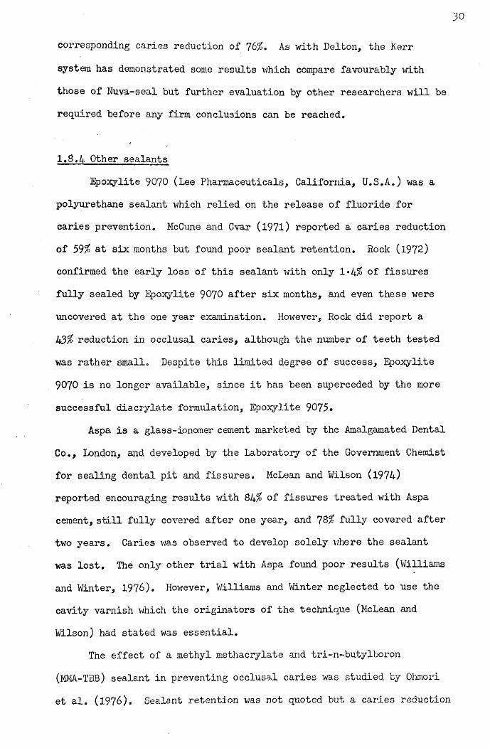
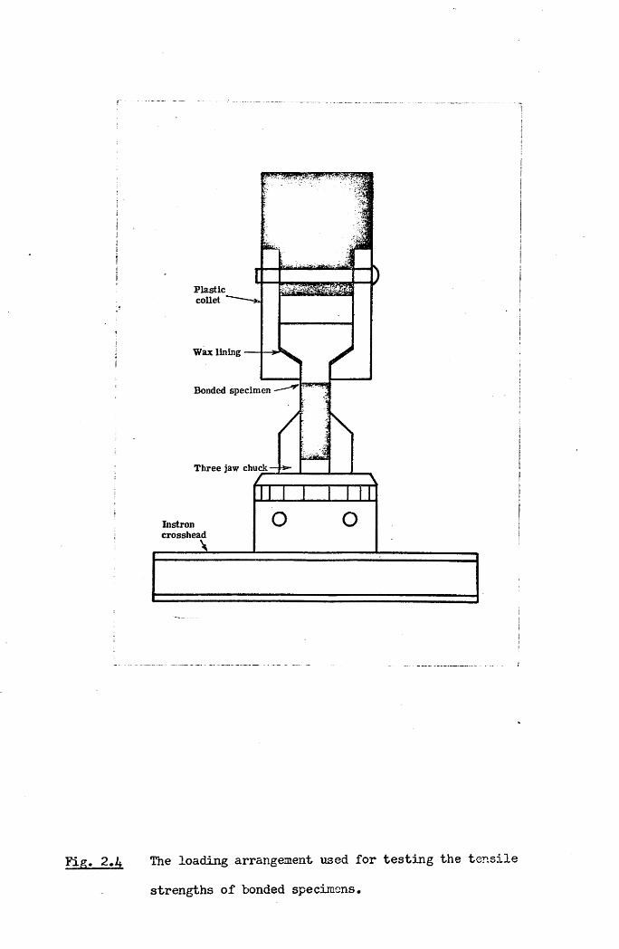
The loading arrangement shown in Fig. 2.4 was designed to apply a uniform force perpendicular to the bond surface. The bonded specimen was fitted into a plastic collet, and the protruding enamel cylinder firmly gripped in a three jaw chuck fixed to the Instron crosshead. Awax lining between the attached sealant and the plastic collet ensured a good fit. When a load was applied to the rig, the wax helped to distribute the stress more uniformly over the load bearing surface of
the sealant.

vertical drill chuck
abrasive disc
bovine tooth
water supply
«. .-.-y i
Fig. 2.1 Arrangement for preparing a flat enamel surface on a tooth mounted in a plastic box, 'with selfcuring acrylic resin.
vertical drill chuck
TOOTH CORE
a • • « • •• ••••• * • • • • •» • • • r • 0,9 0 0 0 0 0 0• • • • • •
diamond tipped core drill bovine tooth
Fig. 2.2 Arrangement for cutting a tooth cylinder ■with a diamond tipped core drill.

BOND FORMATION
U. V. LightBrasswasher
P . T . F . E .Mould —
Sealant
Enamel
COMPLETED BOND
Fig, 2.3 The formation of a bond between an enamel cylinder and sealant polymerised by u.v. radiation.
Plasticcollet
Wax lining
Bonded specimen
Three jaw chuck
Instroncrosshead
l
Fie;, 2.4 The loading arrangement used for testing the tensile
strengths of bonded specimens.
402.3 Investigation of Experimental Factors
A number of experimental factors which might influence the measured values of tensile bond strength between sealant and enamel were investigated using the above bond testing technique with the Nuva-seal system.
2.3.1 Effect of the wax liningTo assess the effect of using a wax lining in the testing rig to
distribute the load more evenly, 18 bonded specimens were prepared.The bond strengths found when 9 specimens were tested with the wax lining, and 9 without the wax lining revealed two immediate benefits (Fig. 2.5). Firstly, it reduced the spread in the measured values, as evidenced by the reduction in the coefficient of variation from 51% to 16% (Coeff. of Var. = Standard Dev./Mean) and secondly, it produced an increase in the mean measured bond strength from 81+ to 124 kgf/cm .
2.3.2 Type of enamelOf the 16 tensile bond testing arrangements listed in Table 1,
9 were performed on human enamel and 7 on bovine enamel. Bovine enamel is not, however, the same as human enamel, as shown in the scanning electron microscope study of Yamamoto et al. (l97l) but it is available in virtually unlimited quantities and a large area of flat enamel on the labial surface of bovine incisors is an advantage. Therefore, tests were performed on both types of enamel to see whether the differences between them would affect the tensile bond strength.For this, 22 human enamel and 56 bovine enamel specimens were prepared.
The mean tensile bond strength attained for the human samples was 94*7 t 5*9 kgf/cm , and for the bovine samples 96*4 "1 4*2 kgf/cm .Both types of enamel demonstrated high bond strengths close to
p100 kgf/cm-, representing about 25% of the claimed tensile strength of

EFFECT OF WAX LINING
Tensile Bond Strength
150
kgf/cm
100
50
with withoutwax waxpad pad
Coefficient 16% 51%of variation
Fig. 2.5 The effect on measured bond strengths of incorporating a wax lining into the loading arrangement showii in
Fig. 2.4.

41
the Nuva-seal resin itself (Caulk, 1974)* Since the two mean bond
strengths were not found to be significantly different using Student's t-test (P ]>0»4) all subsequent tests used the more convenient bovine specimens.
2.3«3 Effect of variation between different teethBond tests with dental adhesives have invariably shown poor
reproducibility. While the best systems achieved coefficients of variation of about 15$, very high values ranging up to 60% were often found. This large variability has generally been attributed to anatomical variations between teeth used to provide experimental specimens. Therefore, an investigation was carried out to evaluate differences in measured bond strength from one tooth to another.
Three specimen cylinders were cut from each of eight bovine incisors and the resulting bond strengths are displayed in Fig. 2.6.The coefficient of variation of the three bond strengths appropriate to each tooth was generally much smaller than the coefficient of variation in the values of bond strengths found when specimens were taken from a number of different teeth. Therefore, steps were taken in all subsequent experim ents to allow for variations between individual teeth, by ensuring that any comparative tests were carried out between paired enamel specimens from the same tooth. Having evaluated these three basic criteria for the reliability of the tensile bond testing technique, attention was next focussed on a number of physical factors of clinical relevance in order to assess their effects on measured bond
strengths.
2.4 Physical Factors of Clinical Importance
2.4.1 Moisture contaminationTo investigate the effect of moisture at the bond surface three

ANATOMICAL VARIATIONS BETWEEN TCETH
Tensile Bond Strength
1501
2kgf/cm
100-
50-
Tooth Number 1Coefficientof Variation 23%
3
5%
4
17%
5 6
5% 18%
8
7%
Fig. 2.6 Tensile bond strengths for the adhesion of Nuva-seal to three enamel cylinders cut from each of eight bovine incisors from different animals.

42moisture conditions were established:
(a) EhXl The normal "dry" condition used a 5s drying periodwith compressed hospital air after a preliminary wipe with a dry
tissue; the air flow being maintained at a constant 5 l/min.(b) Extra Dry: The "extra dry" condition had a drying period of 60s.
Wet: The "wet" condition was established by placing 0*5 (j1of distilled water directly on to a "dry" enamel surface. This
. amount of water formed a small spot in the centre of the enamel. Once sealant was applied to this "wet" surface, the sealant resin was brushed thoroughly into the enamel.
To allow for possible variations between teeth, pairs of bonds were formed with specimens from each tooth; one bond formed under the control "dry" condition and the other at either "extra dry" or "wet".Fig. 2.7 compares the bond strengths found under these three moisture conditions. Under the "wet" condition the bond strength was drastically reduced (p^OOOl), but between 14 pairs of "dry" and "extra dry" bonds there was no significant difference (p>0*4)> using
Student’s t-test.
2.4*2 Intensity of u.v. radiationIn the course of laboratory e:xperiments using a Nuva-lite u.v.
source, tensile bond strengths were found to be much lower than had previously been observed and the variability in the measured values much greater than before. In was eventually determined that a reduction in the output of the u.v. source was the cause. Considerable visible radiation was still being emitted but insufficient u.v. radiation was present to provide adequate polymerisation. A new bulb was obtained and a dramatic Improvement resulted. Tensile bond tests, prepared using an old and new bulb, showed that the greater intensity of u.v. radiation frcm the new bulb produced higher and more consistent bond

EFFECT OF MOISTURE ON BOND STRENGTH
kgf/cm*
Tensile Bond Strength
125-
100-
75
5 0 -
2 5 -
Number of TestsDry(10)
Wet(10)
Dry(14)
Extra Dry(14)
Significance p<-001 p>*04
Fig. 2.7 Tensile bond strengths of Nuva-seal bonded to pairs of
enamel cylinders, with one specimen's surface "dry"and the other's either "wet" or extra "dry".
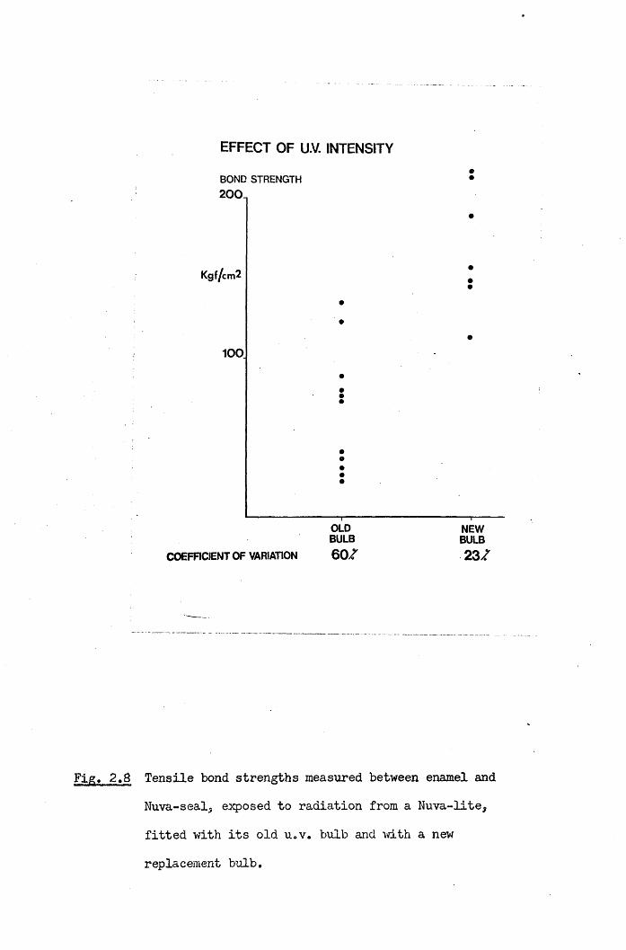
EFFECT OF U.V. INTENSITY
BOND STRENGTH 200.
Kgf/cm2
100
COEFFICIENT OF VARIATION
OLDBULB6 0 7
NEWBULB2 3 7
Fig, 2.8 Tensile bond strengths measured between enamel and Nuva-seal, exposed to radiation from a Nuva-lite, fitted with its old u.v. bulb and with a new
replacement bulb.

43strengths, as shown in Fig. 2.8. A visual examination of the two bulbs
used in the experiment revealed that the older bulb had developed an opaque deposition on the inside of its quartz window, which may explain its reduced output. These findings prompted an investigation of the emission of u.v, radiation from the two commercial sources currently in clinical use; namely the Nuva-lite and Alphalite sources (Amalgamated Dental Go. Ltd., London, U.K.). The results of these studies are presented in the next chapter.
2.4*3 Concentration of etching acidSilverstone (1974) has investigated the effect of different
concentrations of phosphoric acid (l-LPO. ) on the depth of etchedJ 4surface enamel. He showed that between concentrations of 20$ and 70$,the depth of surface etch and depth of histological change decreasedsteadily with increasing acid concentration. Some of his results areshown in Fig. 2.9. The greatest depth of surface etch was caused bythe 20$ and 30$ HoP0. solutions, while at higher concentrations the J 4etch produced in the remaining surface layer was very much reduced.
Scanning electron micrographs of four neighbouring areas of a 4 mm x 4 mm surface of bovine enamel are shown in Fig. 2.10. Each area was etched for 60s with one of the phosphoric acid concentrations, 10, 30, 50 and 70$ w/w. The 30 and 50$ solutions produced the greatest change in the enamel surface while the 70$ etchant appears to have had only a limited effect. Four corresponding sealant bond surfaces were exposed by dissolving the enamel in 10$ hydrochloric acid for 24 hours. Scanning electron micrographs of these surfaces are shown in Fig. 2.11. The degree of sealant penetration appears to correspond to the degree of etching produced by the different etchants. Thus the 10, 30 and 50$ solutions resulted in a "honeycomb'1 pattern of sealant penetration over large areas of the enamel surface, while the enamel treated with

DEPTH OF ENAMEL ALTERED BY AC ID ETCH INGCONCENTRATION OF PHOSPHORIC ACID
20% 30% 40% 50% 60% 70%
10
20
30
40 LOSS IN SURFACE CONTOUR (ETCH)
DEPTH >7771OF HISTOLOGICAL CHANGE IN TISSUEETCH(pm)
Fig. 2.9 Depth of etch and histological change in enamelfollowing a one minute exposure to various concentrations
of phosphoric acid (Silverstone, 1974)*

44the 70$ solution, showed no evidence of such penetration by the resin.
• The appearance of the enamel at areas of interfacial failure following tensile destruction of the four types of bond are shown in Fig. 2.12. Any penetrating tags of sealant have been torn off near the interface, so that the deeply etched patterns shown on the enamel surfaces in Fig. 2.10 are no longer apparent. The appearance of sealant surfaces at areas of interfacial failure for the four types of bond, are shown in Fig. 2.13. The original "honeycombs” of penetrating sealant have been pulled off the bulk of the resin leaving a smoother surface than observed in Fig. 2.11. This difference was particularly marked for the bonds formed using the 30 and 50$ solutions, where sealant penetration vras greatest.
Tensile strengths of bonds formed using the same four concentrations of phosphoric acid etchant are presented in Fig. 2.14. While there was a tendency towards higher bond strengths for the more severely etched surfaces, the 30 and 50% H^PO^ solutions did not produce significantly different results. This may be surprising since Silverstone (1974) showed that the lower of these two concentrations permitted greater sealant penetration. Although the 70$ solution achieved lower values, the recorded bond strengths were quite high, at 125 kgf/cm . Assuming a mechanical theory of retention, relying on "tags" of penetrating sealant for adhesion, one would expect the 70$ solution to result in much lower bond strengths than the 30$ etchant, since the depth of etch found by Silverstone (1974) and the surface appearance and sealant penetration shown here, were all dramatically different for the two etchants.
The "tags" of penetrating sealant which have frequently been referred to in the dental literature (cf. Chapter One), are normally those v/hich occupy the spaces left by dissolution of enamel prism cores. Consequently they have diameters of about 4 Hlru However it has been

Fig. 2.10 Scanning electron micrographs of four neighbouring
areas of a surface of bovine enamel etched with
10, 30, 50 and 70$ w/w for 60s.

Fig. 2.11 Scanning electron micrographs of sealant surfaces
penetrating bovine enamel etched for 6 0s with 10,
30, 50 and 70% w/v H^PO^, exposed by dissolving the enamel in 10$ w/w KC1 for 24 hours.

10|I

Fig, 2.12 Scanning electron micrographs of enamel surfaces
at areas of interfacial failure, where 10, 30, 50
and 70$ w/w h i'O had been used to condition the enamel for 60s, prior to the application of Suva-seal.


Scanning electron micrographs of sealant surfaces atareas of interfacial failure after tensile testingof adhesion to enamel, pre-conditioned for 60s v,rith
10, 30, 50 and 70# w/w HoP0, .^ /+
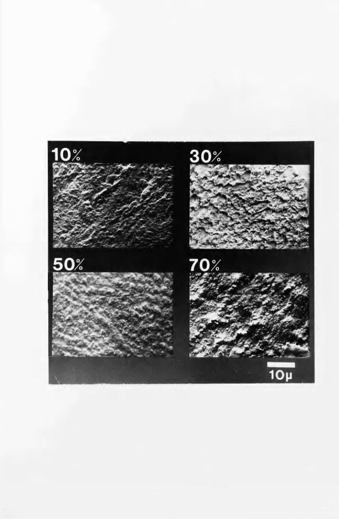
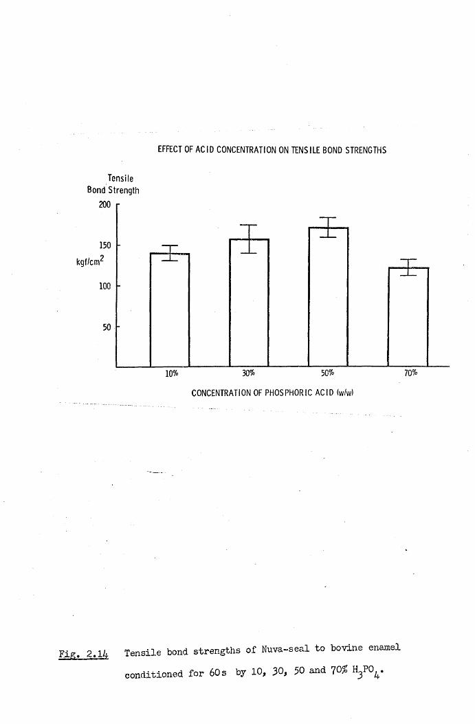
EFFECT OF ACID CONCENTRATION ON TENSILE BOND STRENGTHS
Tensile Bond Strength
200
150kgf/cm1
100
50% 70%30%10%CONCENTRATION OF PHOSPHORIC ACID (w/w)
Fig. 2.14 Tensile bond strengths of Nuva-seal to bovine enamel conditioned for 60s by 10, 30, 30 and 70#

45
shov/n by Simmelink et al. (1974) that sealant also penetra tes partially-
decalcified enamel on a more microscopic level. Using a transmission electron microscope they showed that not only did the sealant network penetrate the enamel at the prism level., but that the resin surrounded the crystals of hydroxyapatite, and penetrated and polymerised in their dissolved cores. Such microscopic penetration may be no less important to adhesion to etched enamel than the larger sealant “tags'1 which have been readily observed by optical and scanning electron microscopy.
Thus the high bond strengths found using a 70% w/w concentration of phosphoric acid may be explained, in the absence of the usual penetrating sealant "tags",by a more microscopic sealant network within the enamel surface. The presence of sealant’tags"when the loi/er
concentrations of phosphoric acid were used, further enhanced the adhesion already possible in the absence of the tags. Under a tensile load these “tags" transfer stress from the sealant into the enamel via shear stresses along the “tag"/enamel interfaces. Since enamel has a much higher elastic modulus than sealant, most of the stress may be transferred from the "tag" into the enamel within a short distance from the main sealant/enamel bond surface. In this case, increasing the length of penetrating sealant "tags" would not necessarily affect the stress distribution near the bond surface, and consequently v/ould not improve the bond strength. Thus using a J,Q% w/w concentration of phosphoric acid as proposed by Silverstone (1974)* to increase the depth of sealant penetration into etched enamel may not greatly affect
the adhesion attained.Soetopo (1975) also concluded that high bond strengths were
possible in the absence of "tags", following a series of tensile bond tests of adhesion to enamel etched by various concentrations of phosphoric acid. Williams, Fraunhofer and Winter (197&) confirmed that the use of 30, 50 and 10% w/w HoP0 achieved similar adhesion

46
with Nuva-seal and Epoxylite 9075* although bond strengths were lower than reported here.
2.5 Conclusions
In this chapter physical factors relevant to the retention of fissure sealant in the clinical situation have been discussed* While the importance of macroscopic moisture contamination has been demonstrated, results suggest that prolonged drying of the etched tooth surface, may in fact, be unnecessary.
In the studies on the use of different concentrations of phosphoric acid etchant it was intended, not merely to discover the optimum concentration, but to understand why such an etched surface should result in greater adhesion. From the previous literature one would have expected that the more severely etched the surface the higher the bond strength. Although such a tendency was observed, even the more lightly etched surfaces achieved very high bond strengths. It is therefore suggested that the role of long "tags" of penetrating sealant into the etched enamel surface has been over-estimated. In particular one may question whether the presence of longer “tags" due to a greater degree of etching should be expected to result in
better retention of the sealant.As the mode of failure of u.v. sources may take the form of a
prolonged period of gradually reducing intensity rather than a sudden failure, some objective monitoring procedure is necessary for checking the output of sources in clinical use to determine when replacement bulbs are required. Such a procedure is described in the next
chapter.

CHAPTER THREE
EMISSION FROM ULTRA-VIOLET SOURCES USED TO POLYMERISE FISSURE SEALANTS
3«1 Introduction
The use of u.v. radiation to polymerise a pit and fissure sealant was first described by Buonocore (1970). A number of advantages over chemically initiated sealants were claimed. After the addition of 2% by weight benzoin methyl ether, the resin remained fluid indefinitely, allowing ample time for placement on pre-treated tooth surfaces. Application of u.v. radiation then produced a rapid set, in less than 3 0s.
The source used initially by Buonocore (1970) was a Spectroline lamp, with which the radiation from a 100W high pressure mercury discharge lamp was directed on to the tooth surface being treated by means of an intra-oral mirror. The u.v. source presently marketed with the Nuva-seal. system is the Nuva-lite, with which filtered radiation from a 50W medium, pressure mercury lamp is conducted to the tooth along a fused quartz light guide. The Alphaseal fissure sealant system uses a u.v. source, called the Alphalite, shown in Fig. 3*1* Here, the radiation from a 100W super-high pressure mercury discharge lamp is directed to the tooth along a bundle of quartz fibre-optics. This system was originally described in its prototype form by Rock (1974b) and Stephen et al. (1976) as TP2206 resin and the Quartzlite,
shown in Fig. 3*2.The tips of a Nuva-lite and Quartzlite are illustrated in Fig. 3*3
The fused quartz guide attached to the Nuva-lite has a diameter of approximately 10 mm, while the iibre-optic bundle supplied with the Quartzlite has an active diameter of 2*5 Eim* and is protected by a

Fig. 3*1 The Alphalite u.v. source provided for use with the u.v.
sensitized resin Alphaseal by the Amalgamated Dental Co.,
London.)
Fig. 3.2 The Quartzlite u.v. source. This was the prototype for
the Alphalite, and was originally used in conjunction
with the resin TP2206, later called Alphaseal.

Alpha Lite
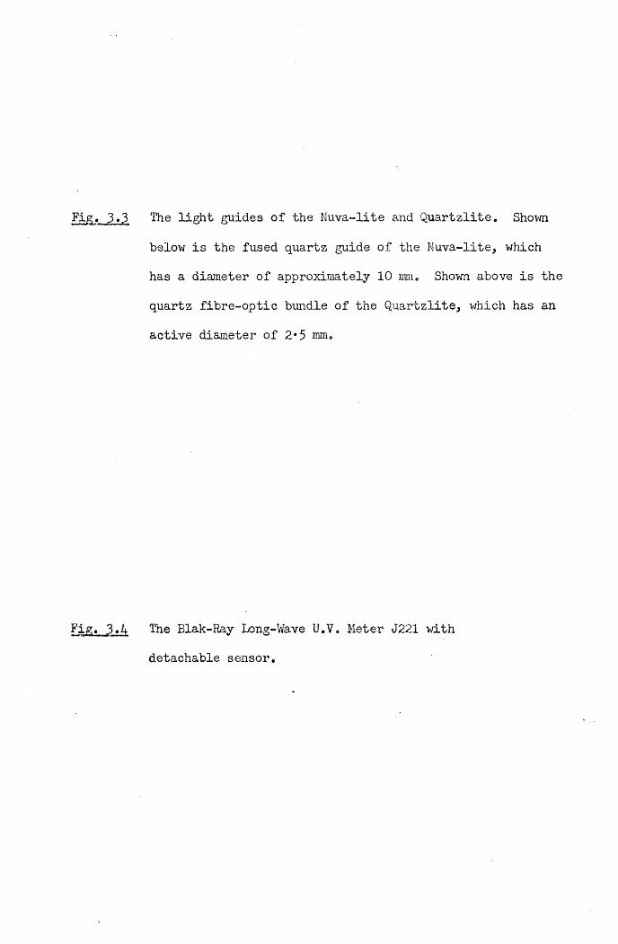
Fig. 3>3 The light guides of the Nuva-lite and Quartzlite. Shown
below is the fused quartz guide of the Nuva-lite, which
has a diameter of approximately 10 mm. Shown above is the
quartz fibre-optic bundle of the Quartzlite, which has an
active diameter of 2*5 mm.
Fig. 3«4 The Blak-Ray Long-Wave U.V. Meter J221 with
detachable sensor.

^ODUCTJ

metal sheath of diameter 4*5 mm at its tip.
3.2 Materials and Methods
U.V. intensity measurements were made with a Blak-Ray u.v. meter shown in Fig. 3.4 (J221, UVP International, Inc.). A detachable sensor detected u.v. radiation of wavelengths between 300 and 400 mn, with a relative spectral response as shown in Fig. 3*5d. A comparison
with Fig. 3*5a, b and c indicates that the peak sensitivity at 365 nm corresponds with the main u.v. emission from the Nuva-lite, Quartzlite and Spectroline sources, as given by Rock (1974b). Although a 13%
tolerance is quoted by the manufacturers for the absolute value of the meter readings, the relative results reported here are more precise since all measurements were made with the same instrument.
The total output from each Nuva-lite was measured by locating the tip of its quartz guide in a circular aperture of diameter 10 mm cut in an aluminium screen covering the sensitive surface of the meter (Fig. 3.6). The output of u.v. radiation from the Quartzlite was found similarly, and the average intensity calculated on the basis of the illumination of a circular area of diameter 2*5 mm.
In order to measure the intensity distribution of radiation from the Nuva-lite, the u.v. sensor was fixed to the surface of the mechanical stage of a microscope and an aluminium screen with an aperture of diameter 1 mm fitted over the sensitive surface, as shown in Fig. 3*6. Using the calibrated controls of the stage to shift the sensor, intensity measurements were made across parallel planes, at various distances below the tip of a Nuva-lite guide. Ihus the intensity distribution just below the guide, and the change in this distribution with distance from the guide's tip, were both investigated, bimilar measurements were made on the distribution of u.v. radiation mom the Quartzlite. However, because of the smaller area illuminated, an

1
i
i
Fig. 3.5nMwVfrt-i. nin. in f iir r t t *sa
(a) Nuva-lite
4 0 0 ( n m )
(b)
(c)
(d)
SpectrclineLU>§-ILfclK
3 0 0 4 0 0 ( n m )
>•»-»nii&i>§UIa
4 0 0 ( n m )
WAVELENGTH
The emission spectra of Nuva-lite, Quartzlite and Spectroline sources are shown in a, b and c resp. (Rock, 1974b). The relative spectral response quoted by the manufacturers for the ELak-Ray U.V. Meter J221
is compared in d.
Quartzlite
4 0 0 ( n m )

alum inium screen 1mm diam . a p ertu re
aluminium screen K )m m diam . a p e rtu re
u.v.photocell (plan view)
sensitive surface a rea
AMMETER WSjEtku.v.photocell (in
— m echanical
x control
y control z control
section)stage o f microscope
3.6 The experimental arrangement used for making u.v. intensity measurements. The sensor of the Blak-Ray u.v. meter was fixed onto the mechanical stage of a microscope, and aluminium screens with circular apertures used to limit the area of the sensitive surface exposed.

49aluminium screen with a smaller aperture (diameter 0*5 mm) was placed over the sensor.
3.3 Results
3.3.1 Total outputs and average intensities
The u.v. outputs from 12 Nuva-Lites, 1 Quartzlite and 3
Alphalites are shown in Table 2 . Also shown are the calculated averageintensities over the 10 mm diameter tips of fused quartz guides of theNuva-lites, and over the 2*3 mm diameter tips of the quartz fibre opticbundles of the Quartzlite and Alphalites.
The outputs from the Nuva-lites were observed to range from 6 to220 mW, resulting in a range in average intensities from 8 to 26nM/cjii .
The effect of removing the visible light filters, incorporated during safety modifications by the manufacturers in Spring 197&, was to increase the total u.v. outputs by amounts ranging from 10 to 62 , as given in Table 2. The first measurement of the radiation from the Quartzlite showed an output of 1*64 mW, with a calculated intensity of
p33*4 mW/cm . A second measurement, after cleaning and re-aligning the lens system, showed an increased output of 3*02 mW, and an intensity of
p6l*5 mW/cm . The Alphalites had u.v. outputs which were similar to those from the various Nuva-lites, but the corresponding intensities
were much greater.
3.3.2 Intensity distributionThe distribution of u.v. radiation within the circular areas
illuminated, 1 mm below the tips of the Nuva-lite and Quartzlite, are shown in Fig. 3.7* The radiation from the huva—lite was mainly concentrated in a horse-shoe shaped band in the front half of the illuminated area, with the rear hall receiving a much lower int^n^ity. This general pattern was common to all Nuva-lites tested, although the
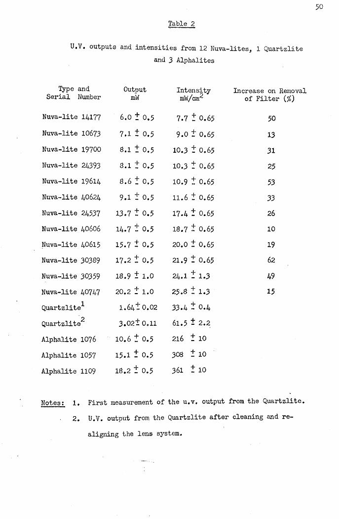
Table 2
50
U.V. outputs and Intensities from 12 Nuva-lites, 1 Quartzlite
Type and OutputSerial Number mW
Nuva-lite 14177 6.0 + 0.5Nuva-lite 10673 7.1 + 0.5Nuva-lite 19700 8.1 + 0.5Nuva-lite 24393 8.1 + 0.5Nuva-lite 19614 8.6 + 0.5Nuva-lite 40624 9.1 + 0.5Nuva-lite 24537 13.7 + 0.5Nuva-lite 40606 14.7 + 0.5Nuva-lite 40615 15.7 + 0.5Nuva-lite 30389 17.2 + 0.5Nuva-lite 30359 18.9 + 1.0
Nuva-lite 40747 20.2 + 1.0
Quartzlite^- 1.64! 0.022Quartzlite 3 .021 0.11
Alphalite 1076 10.6 + 0.5Alphalite 1057 15.1 + 0.5Alphalite 1109 18.2 + 0.5
3 Alphalites
Intensity Increase on RemovalmW/cirr of Filter (%)
7.7 t 0.65 50
9.0 t 0.65 13
10.3 t 0.65 31
10.3 t 0.65 25
10.9 t 0.65 53
11.6 t 0.65 33
17.4 t 0.65 26
18.7 t 0.65 10
20.0 t 0.65 19
21.9 t 0.65 62
24.1 t 1.3 49
25.8 t 1.3 15
33.4 t 0.4
61.5 t 2.2
216 t 10
308 t 10
361 t 10
Notes t le First measurement of the u.v. output from the Quartzlite. 2. U.V. output from the Quartzlite after cleaning and re
aligning the lens system.

Fig. 3.7 The distributions of u.v, radiation over planes 1 mmbelow and parallel to the tips of the guides of a Nuva- lite and Quartzlite are represented by squares with different degrees of shading. The circles denote the
extent of the visible radiation with the top and bottom of the circles corresponding to the leading and trailing edges of the guides, respectively.

NUVA-LITE QUARTZLITE
i i i i— i— i— i— i— i— 1— i
- 5 - 4 - 3 - 2 - 1 0 * 1 *2 * 3 * 4 * 5
POSITION ACROSS DIAMETER (mm)
- 2 -1 0 *1 *2 POSITION ACROSS DIAMETER (m m)
KEY FOR U.V INTENSITIES
0-15 mV\/cm2
15-30 mW/cm2
30~45 m W /cm 2
45 -60 m W /cm 2
60-75 m W /cm 2
extent of the asymmetry observed between front and rear halves varied
from one unit to another. The intensity distribution of the improvedu.v. emission from the Quartzlite was also found to be asymmetrical, at 1 mm below the tip (Fig. 3.7).
1.3«3- Variation of intensity distributions with distance along the u.v.beam
The distribution of u.v. radiation over surfaces at 0, 2, 5 and 10 mm below and parallel to the tips of a Nuva-lite and Quartzlite werecompared. The intensities, measured along diameters of the twoilluminated circles, from the leading edges to the rear edges, are shown in Fig. 3.8.
The concentration of radiation towards the front half of the area illuminated by the Nuva-lite was again observed, with this being particularly marked at 0 and 2 mm below the tip of the guide. However, at 5 and 10 mm below the tip this asymmetry was reduced as the radiation spread out more evenly over the illuminated area. The u.v. intensities measured were less the greater the distance from the guide tip. For example, the peak intensities measured along the diameters at
0, 2, 5 and 10 ram below the tip were 45, 40, 30 and 20 mW/cm ,
respectively.Immediately below the tip of the fibre-optic guide attached to
the Quartzlite the u.v. radiation was concentrated in a circular area2of diameter 2*5 mm, with an intensity of about 50 mW/cm . At 2 mm
below the tip, the diameter of the circular area illuminated was' slightly larger at about 3*25 mm diameter, but the radiation remained concentrated at the centre with an intensity of approximately 40 mW/cm . At 5 and 10 mm below the tip, the circular areas illuminated were considerably larger, with diameters of about 4 and 6 mm respectively, and at both these distances the radiation was symmetrically distributed

about a central peak. Overall, the average intensity in the central2area fell from approximately 50 mW/cm immediately below the tip, to
2only 20 mW/cm , at a distance of 10 mm.

ULTR
A-VIO
LET
INTE
NSITY
(m
W/c
m2)
NUVA-LITE QUARTZLITE
Om m bebw tip
2m m below tip
5m m below tip
. TL
10m m bebw tip
1 0 m m 25m m
8 The intensity distribution of u.v. radiation acrossdiameters of the circular areas illuminated by the Nuva- lite and Quartzlite at 0, 2, 5 and 10 mm below the tips of their guides. The leading and trailing edges of the guides are represented by vertical lines marked a and b
respectively.

5 33>4 Discussion
The effect of using different u.v. intensities to polymerise fissure sealants will be examined in detail in later chapters. The effectiveness of a particular u.v. source depends on the manner in which it is used, and on the setting characteristics of the resin being polymerised. Thus the performances of the Nuva-lites examined here have to be considered with regard to the u.v. exposure required to set Nuva-seal, and the performances of the Quartzlite and Alphalites with regard to the setting characteristics of TP2206 and Alphaseal.However, the wavelength of u.v. radiation from the different sources is essentially the same, so that they can be used to polymerise either sealant. Thus one can compare the outputs from different sources on the assumption that the greater the intensity to which the resin is exposed the better. That this assumption is borne out in practice
will be apparent in subsequent chapters.One of the most notable results was the wide variation in output
from different Nuva-lite units. An observed range in average intensities from 8 to 26 mW/cm could be part of the explanation for the inconsistent results which different operators have found in clinical trials with Nuva-seal. One reason for this large range in output is the gradual aging process which occurs in the u.v. sources used in Nuva-lites. This can result in units being used which emit considerable quantities of visible light but only low levels of u.v. radiation. In such a situation it would not be readily apparent to the operator that insufficient u.v. radiation was present.
Another factor noted to affect the performance of individual Nuva-lites was the angle of the bend in the quartz guide. This was by no means the same for all Nuva-lites examined and guides with more gradual bends were more etficieno at transmitting the radiation.Indeed the output from one unit was increased by so much as 50/} when.

a guide with a particularly sharp bend was replaced by another with a more gradual bend.
Another factor of clinical relevance relating to the output from Nuva-lite units is the reduction due to the gradual accumulation of polymerised sealant on the tip of the quartz guide. Even seemingly insignificant quantities of cured resin on the tip of a guide were found to reduce the u.v. output by as much as 36^.
The first measurement of the u.v. output of the Quartzlite was made following its use in a clinical trial of TP2206 by Stephen et al. (1976). Further examination of this unit revealed some factors contributing to the low output. The lens system which directed theu.v. beam into the fibre optic was off alignment, and one of the lenses was partially obscured by a coating of red dust. Cleaning and re-aligning the lenses nearly doubled the u.v. output. Although the average intensity from the Quartzlite was greater than from Nuva-lites, the power emitted was considerably less, even after the lens system was corrected. The three Alphalites, which were examined at a later date, emitted as much radiation as the higher output Nuva-lites, and far more than their Quartzlite prototype. As a result of the smaller area illuminated, the intensities from Alphalites were much greater
than from Nuva-lites.To assess the effectiveness of the two types of u.v. sources
in polymerising fissure sealants one has to take account of the distribution of the radiation emitted. In the clinical situation the asymmetrical distribution of radiation from the Nuva-lite would result in different areas of sealant receiving different intensities of radiation. Wien using a Quartzlite or Alphalite, the extent to which the different areas of sealant would receive different exposures to u.v
radiation would depend primarily on the particular scanning motion used rather than on the intensity distribution. Each part of the sealant

55
would receive radiation only intermittently, and unless the source v/as sufficiently intense some sealant could receive inadequate exposure.
The distance maintained between the sealant and u.v. source also affects the intensity to which the resin is exposed* Moving away from the Nuva-lite, the u.v. intensity falls off as shown in Fig. 3*8. Therefore, when using this system it would be desirable to keep the tip of the guide as close to the sealant surface as possible. When using one of the fibre-optic units only a part of the sealant can be illuminated at a given time. Thus by holding the tip of the guide further from the sealant surface, the area illuminated may be usefully increased, since the amount of scanning motion required would be reduced. Hence the distance from the sealant surface may be less critical when using the fibre optic systems.
The results of investigations into the role of u.v. radiation in the setting of fissure sealants are presented in the following chapters,
and polymerisation mechanisms of u.v. activated sealants are discussed
in Appendix I.

would receive radiation only intermittently, and unless the source was
sufficiently intense some sealant could receive inadequate exposure*The distance maintained between the sealant and u.v. source also
affects the intensity to which the resin is exposed* Moving away from, the Nuva-lite, the u.v. intensity falls off as shown in Fig*Therefore, when using this system it would be desirable to keep the tip of the guide as close to the sealant surface as possible* When using one of the fibre-optic units only a part of the sealant can be illuminated at a given time. Thus by holding the tip of the guide further from the sealant surface, the area illuminated may be usefully increased, since the amount of scanning motion required would be reduced. Hence the distance from the sealant surface may be less
critical when using the fibre optic systems*The results of investigations into the role of u.v* radiation in
the setting of fissure sealants are presented in the following chapters, and polymerisation mechanisms of u.v* activated sealants are discussed
in Appendix I.

5 6
CHAPTER FOUR
MICROHARDNESS STUDIES ON THE SETTING CHARACTERISTICS OF FISSURE SEALANTS
4.1 Introduction
Since the rate of set of u.v. activated sealants may depend on the u.v. intensity applied, the variation in the outputs of u.v. sources noted in the previous chapter, may be a factor contributing to the variable retention reported in different clinical trials. In this chapter the setting characteristics of Nuva-seal and Alphaseal are assessed using microhardness measurements after various exposure times to different u.v. intensities. For comparison, the setting behaviours of three chemically curing sealants were also investigated.
4.2 Materials and MethodsThe microhardness of pit and fissure sealants was measured with
a Wallace Micro Indentation Tester (H.W. Wallace Co. Ltd., Croydon,
Surrey) suitable for assessing the hardness of rigid and semi-rigid plastics and the state of cure of synthetic resins. The use of this instrument and the effect of various testing parameters has been
discussed in detail by Huggett (1975).Each test specimen was mounted on a glass slide, as illustrated
in. Fig. 4.1. A circular hole of diameter 8 mm was cut in a square sheet of modelling wax, which was pressed on to one end of a glass slide, providing a 1*5 mm deep well which was filled with freshly prepared resin. A glass slip was placed over the sealant and pressed against the upper surface of the wax, providing a flat face for the
sealant.Samples of the u.v. polymerised sealants were set by exposure
to radiation at 365 rim wavelength from a Blak-ray u.v. source (U.V.

WAX
SLIDE
SEALANT COVER SLIP
GLASS SLIDE
Sample preparation for microhardness measurements on
fissure sealants*
Products Inc., San Gabriel, California, U.S.A.) at intensities measured on a Blak-Ray Long Wave U.V. Meter J221 (U.V. Products Inc.). Nuva- seal samples were polymerised by exposure, for periods of 10, 20, 30, 40, 50 and 60s, to intensities of 5, 10 and 20 mW/cnT. Since initial tests showed that Alphaseal required more u.v. radiation to set to a measurable hardness, longer exposure times of 30, 60, 90 and 120s at intensities of 20 and 30 mW/cm were selected.
Four samples of the resins were set using each exposure time and intensity. Four samples each of Epoxylite 9075 (Lee Pharmaceuticals Co. Ltd.), Concise Enamel Bond (3M Co. Ltd.) and Aspa Cement (Amalgamated Dental Co. Ltd., London) were prepared by mixing the materials according to the manufacturers’ instructions and filling wax
moulds as shown in Fig. 4»1«Nuva-seal and Alphaseal samples were tested immediately following
exposure to u.v. radiation, while Epoxylite 9075 and Enamel Bond were maintained for 10 min, and Aspa Cement for 30 min at 37°C before the first test. To assess each sample the cover slip was first removed
with a blade to expose the sealant.A primary load of 0*001 kg was applied, and the increase in
surface penetration by a standard Vickers diamond indentor, on adding a further load of 0*3 kg for 30 s, was measured to a precision of 0*25 pm. Ten such indentation measurements were made and the mean value used in the following formula to calculate the Woxen Hardness
Number (Woxen, 1944)*

where,QHw = Woxen Hardness (kg/mm )
= Initial load (kg)P2 = Final load (kg)
= Indentation under initial load (pm)
h2 = Indentation under final load (pm)
. The specimens were stored dry at 37°C. Further measurements of the microhardness of the same samples were made at 1 hour, 24 hours,
1 day, 1 month and 3 months after the initial set.
Since it became apparent from initial tests that Alphaseal was
not setting uniformly, a further series of samples of differingthickness was prepared to determine the effect of u.v. absorption on thesetting of Alphaseal in depth. By inverting these samples, sealant in contact with the cover slip received an intensity reduced by absorption in passing through the depth of the sealant sample. After performing ten indentation measurements, the thickness of each sample was determined with a micrometer. Thus the variation in hardness with distance below the exposed sealant surface could be plotted. The reflection and absorption of radiation by the glass slide was measured with the Blak-Ray meter described in Chapter Three and intensity values
adjusted to compensate.
4.3 ResultsShown in Fig. 4.2 is the microhardness reached by samples of
pNuva-seal exposed to 5 mW/cm for periods from 10 to 60s, where each point represents the mean of four samples. For a. pOs exposure, a

5 9p
hardness of 5 kg/inrn was initially recorded. Longer exposure up to 60s
produced no increase in this initial hardness. Also shown is the increased hardness of the same samples stored for 1 hour, 1 day, 1 week,1 month and 3 months after the u.v. exposure.
The corresponding results when the u.v. intensity was doubled to 2
10 mW/cm , are given in Fig. 4*3 which shows that the increased intensity resulted in a more rapid set, with a measurable hardness after only 15 s. Samples exposed for longer periods were found to be slightly harder, and all samples showed considerable hardening over the 3 month test period.
The data in Fig. 4*4 illustrate the effect of doubling the intensity again, to 20 mW/cm . Here, the sealant set after only 10 s, with samples being slightly harder after longer exposures. Once more, polymerisation continued throughout the 3 month period.
Compared in Fig. 4*5 is the microhardness recorded immediately after exposure to the three intensities, 5> 10 and 20 mW/cm , showing that the higher the intensity used, the faster was the set, and the
greater the resulting hardness.The data in Fig.4.6 detail the initial setting hardness of
2Alphaseal after exposure to a u.v. intensity of 20 mW/cm for periods2of 30, 60, 90 and 120 s. Increasing the applied intensity to 30 mW/cm
produced little increase in the rate set of this material as shown in Fig. 4.7. For both intensities Alphaseal exhibited greater hardness as the exposure was continued up to 120 s. All the specimens showed a marked increase in hardness during storage, with those which were initially softest hardening the most, so that after the first week, samples tended toward similar values, and showed only slight hardening
with further storage up to 3 months.Microhardness values for the undersurfaces of samples of
Alphaseal of different thicknesses, exposed to 30 mw'/crn for 120 s,
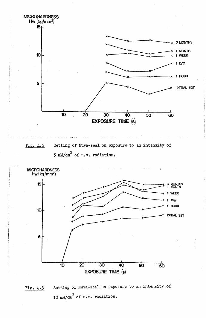
WSCROHARDNESS H w (kg/mm2)
15 h
X— - x 3 MONTHS
x 1 MONTH x 1 WEEK10
5■x INITIAL SET
30EXPOSURE TIME (s)
50 60
Fig. 4.2 Setting of Nuva-seal on closure to an intensity of25 mW/cm of u.v. radiation.
MICRQHARDNESSHw(kg/mm2)
+ 1 WEEK
+ 1 HOUR
■+ INITIAL SET
20' 30EXPOSURE TIME (s)
40 50 60
Setting of Nuva-seal on exposure to an intensity ofp10 mW/cm of u.v. radiation.

MICROHARDNESS Hw (kg I mm2)
■x 1 HOUR ■x INITIAL SET
30 40EXPOSURE TIME (s)
50 60
Fig, 4.4 Setting of Nuva-seal on exposure to an intensity of220 mW/cm of u.v. radiation.
MICROHARDNESSHw(kg/mm2)
15
10
5
604030 502010
20mw/cm2
10 mW/cm
| 5 mw/crrv
EXPOSURE TIME (s)Fig, 4.5 A comparison of the initial hardness of Nuva-seal after
2exposure to intensities of 5, 10 and 20 mW/cm of u.v.
radiation.
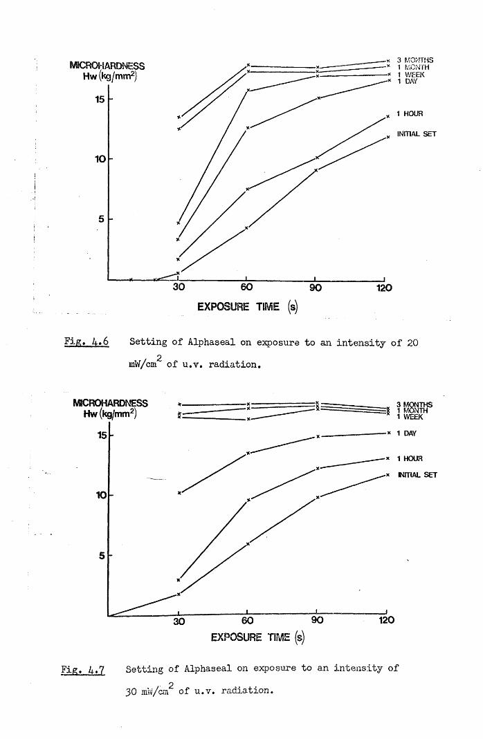
X 3 MONTHS •* 1 P/iONTH -* 1 WEEK
WSCROHARDNESS Hw (kg/mm2)
INITIAL SET
30 60 90 120
EXPOSURE TIME s
Fig. 4*6 Setting of Alphaseal on exposure to an intensity of 20 2mW/cm of u.v. radiation.
MSCROHARDTvESS Hw (kg/mm2) =8 1 MONTH 1 WEEK
* 1 DAY
* 1 HOUR
x NFTIAL SET
90 12030
Fig. A.7 Setting of Alphaseal on exposure to an intensity of
30 mw/cm of u.v. radiation,

SETTING OF ALPHASEAL IN DEPTH ON EXPOSURE TO 30mW/cm2 FOR 120s
WBCROHARDNESSHw(kg/mm2)
XX
0 05 10 1-5DEPTH BELOW EXPOSED SURFACE OF SEALANT (mm)
L
Fig. A.8 Setting of Alphaseal in depth on exposure to an intensityOof 30 mW/cm of u.v. radiation for 120s. ,

60
Table 3
Microhardness of chemically polymerised fissure sealants.
Epoxylite9075
kg/mm2
Concise Enamel Bond
kg/mm2
AspaCementkg/mm2
In it ia l set 10.93 t 1.15 7.51 t .62 4.78 1 .52
1 Hour 11.65 t 1.26 11.02 1 .26 20.71 t 3.32
24 Hours 13.19 t .75 14.35 t .08 45.41 t 2.63
1 Week 13.50 t -54 15.83 t .09 54.76 1 1.33
1 Month 14.49 t .81 16.40 t .16 55.80 t .863 Months 14.49 t .97 16.49 t .29 55.28 1 1.31

are plotted in Fig. 4*8. At a depth of 0*5 mm the sealant had a
hardness similar to that at the surface. However, samples of greater thickness revealed that the hardness of Alphaseal decreased with depth, beyond 0*5 mm, until at over 1»5 mm, only negligible values were recorded.
The microhardness values recorded over the three month test period, for the three chemically polymerising sealants are compared in Table 3•
4*4 DiscussionThe results reported have confirmed the findings of Williams,
Fraunhofer and Winter (1975b) and Watkins (1975) that sealants continue to increase in hardness long after their initial setting. Nuva-seal, Alphaseal, Epoxylite 9075 and Concise Enamel Bond tended towards similar values in the range 10 - 20 kg/mm during the three month test period. Aspa Cement differed from the other sealants in having an initially slower set and higher final hardness of about 55 kg/mm .Such a relatively high value requires careful interpretation. In the Wallace Test used here the indentation was recorded while the sample remained under load, so that both plastic and elastic deformation of the test materials was detected. Due to the high elastic modulus of Aspa Cement, most of the indentation on this material arose from plastic deformation. The four other sealants have lower elastic moduli so that additional indentation resulted from their elastic deformation.
Previous microhardness studies on fissure sealants have not investigated the effect of varying the u.v. exposure used to set sealants. In these tests on Nuva-seal, the use of higher intensities of u.v. radiation produced both a more rapid set and greater microhardness. For the two higher intensities used, a rapid initial increase was followed by more gradual hardening with continued exposure
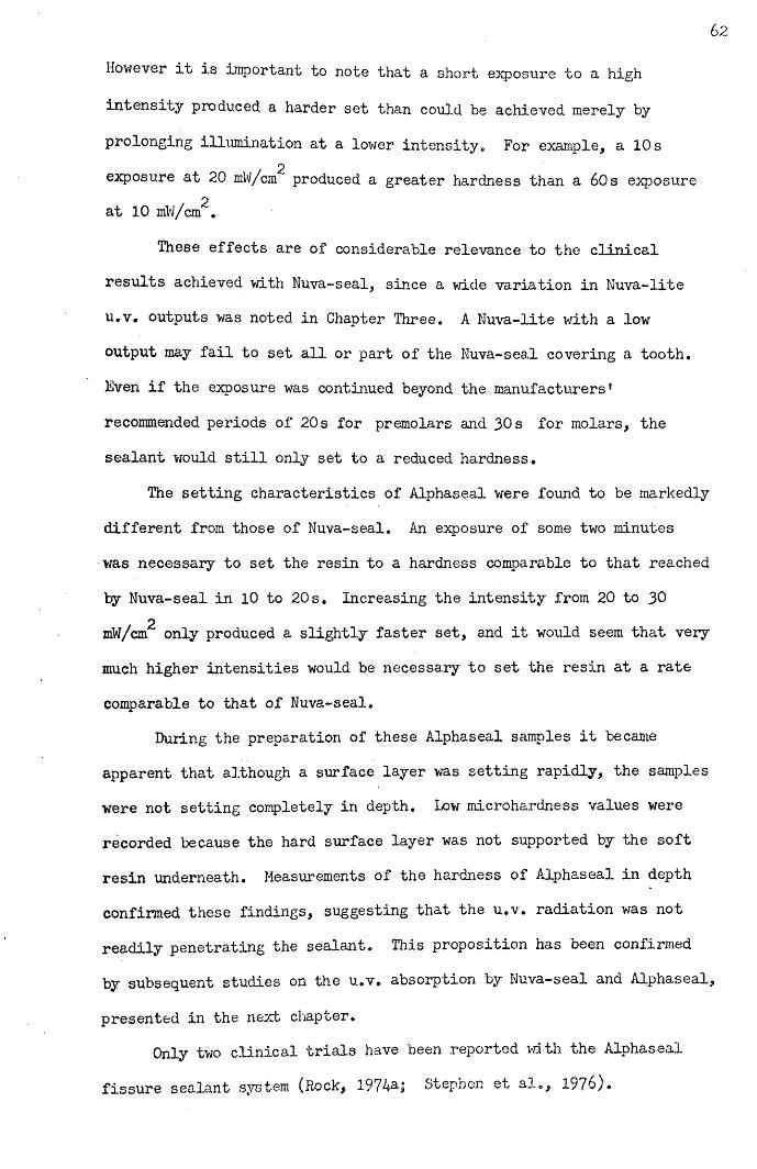
62
However it is important to note that a short exposure to a high
intensity produced a harder set than could be achieved merely by
prolonging illumination at a lower intensity. For example, a 10 s2exposure at 20 mW/cm produced a greater hardness than a 60s exposure
at 10 mW/cm^.
These effects are of considerable relevance to the clinicalresults achieved with Nuva-seal, since a wide variation in Nuva-liteu.v, outputs was noted in Chapter Three. A Nuva-lite with a lowoutput may fail to set all or part of the Nuva-seal covering a tooth.Even if the exposure was continued beyond the manufacturers'recommended periods of 20 s for premolars and 30 s for molars, thesealant would still only set to a reduced hardness.
The setting characteristics of Alphaseal were found to be markedlydifferent from those of Nuva-seal. An exposure of some two minuteswas necessary to set the resin to a hardness comparable to that reachedby Nuva-seal in 10 to 20 s. Increasing the intensity from 20 to 30
2mW/cm only produced a slightly faster set, and it would seem that very much higher intensities would be necessary to set the resin at a rate
comparable to that of Nuva-seal.During the preparation of these Alphaseal samples it became
apparent that although a surface layer was setting rapidly, the samples were not setting completely in depth. Low microhardness values were recorded because the hard surface layer was not supported by the soft resin underneath. Measurements of the hardness of Alphaseal in depth confirmed these findings, suggesting that the u.v. radiation was not readily penetrating the sealant. This proposition has been confirmed by subsequent studies on the u.v. absorption by Nuva-seal and Alphaseal,
presented in the next chapter.Only two clinical trials have been reported with the Alphaseal
fissure sealant system (Rock, Stepnen e^ al», 1976).

Both research workers used prototypes of the Alphalite called a
Quartzlite and the resin was then known as TP2206. Rock found very promising results with &2% of the sealed teeth being completely sealed after one year. However, Stephen et al. found only 2«3/> of the TP2206 applications were intact after one year. This second trial used two
different Quartzlite units, one of which has since been exandned and
found to have an output of only 1*6 mW. This would have provided an
average intensity of about 33 mW/cm over a 2*5 mrn diameter circle
immediately below the tip of the quartz fibre-optic bundle used to transmit the radiation. It was shown in Chapter Three that the radiation from this fibre-optic diverges rapidly so that an intensity of about 15 mW/crn would more likely have been applied in practice. Since a scanning procedure was necessary to cover the entire area of sealant during clinical application, each part of the sealant layer would have received this low intensity of radiation only intermittently, When one takes into account the manufacturer's suggestion that a 15 to 20 s exposure time should be sufficient to set the resin, it seems hardly surprising that Stephen et al. (1976) found such poor sealant retention. In view of the low output from one of the Quartzlite units used in this trial, a scanning period well in excess of two minutes would have been necessary to achieve a hard set of the
resin.Later production models of the Alphalite discussed in Chapter
Three had outputs far in excess of at least one of the units used by Stephen et al. (1976). The intensities produced by these new models are about 300 mW/cm2 over the 2*5 mm diameter circular area immediately below the fibre-optic tip. Even arter allowing for the spread in radiation below the guide tip and intermittent exposure due
to the scanning procedure employed, Alphaseal may sec sufficiently
rapidly on exposure to these new Alphalites,

Tlius the very poor sealant retention reported by Stephen et al.
(1976) is probably explained by the extremely low output of the
particular u.v. source used. Fortunately, the high outputs available
from the new Alphalites should allow this problem to be overcome.

65
CHAPTER FIVE
ULTRA-VIOLET ABSORPTION BY NUVA-SEAL AND ALPHASEAL
5.1 Introduction
In the previous chapter microhardness measurements on Alphaseal demonstrated that surface layers set rapidly, but that setting in depth was slow* To assess whether this was due to the failure of the u.v* radiation to penetrate deeply into Alphaseal, the u.v. absorption characteristics of Nuva-seal and Alphaseal have been compared, and the contributions of the different constituents to the absorption by Alphaseal examined.
5.2 Materials and MethodsThe absorption coefficients of Nuva-seal and Alphaseal were
found by measuring the transmission of u.v. radiation at 365 nm wavelength through different depths of sealant. The radiation source used was an Alphalite with an output of 15 mW, and an u.v. emission primarily at 365 nm wavelength. The Blak-Ray U.V. Meter, described in Chapter Three, was used to measure the incident and transmitted
intensities of radiation.The measurement technique is illustrated in Fig. 5.1. A circular
hole of diameter 8 mm was cut in a square sheet of model casting wax, and the wax pressed against a glass cover slip to provide a well into which sealant was poured. A second cover slip was then placed over the sealant and pressed against the wax. The intensity of u.v. radiation passing through a 5 mm diameter aperture in a steel screen over the sensitive surface of the u.v. meter was first measured. The prepared sealant sample was then placed over the aperture and the fraction of incident radiation passing through the sample recorded.

u.v. radiation
wax-----------steel screen-u.v. meter— ■
u.v.sensitivesurface
sealant
Fig. 5.1 Experimental arrangement for measuring the u.v. absorption by fissure sealants.
qlass coven slips
ammeter

The absorption coefficients were calculated from the initial absorption
on first exposure to the u.v. radiation and the change in transmission during polymerisation was also observed. Depths of sealant over 0.2 mm
were produced using different thicknesses of wax, and for depths less than 0.2 mm one or more layers of adhesive tape were used in place of the wax. The depth of each sample was determined by removing the cover slips and measuring the thickness of the polymerised disc with a micrometer. After correcting for background infra-red radiation which was not absorbed by the sealant but was detected by the meter, and for reflections at the interfaces and absorption in the cover slips the transmitted intensities were plotted on a log scale, against the sample thickness in mm. The absorption coefficients were then calculated from the gradients of the resulting straight lines.
The absorption coefficient of Nuva-seal prepared according to the manufacturer’s instructions, was first obtained, while that of Alphaseal was measured at catalyst concentrations of 1, 3 and 5$ w/w, using normal resin which contains a u.v. absorbing fluorescent dye, and a
batch of resin without this additive. For each catalyst concentration, approximately 250 mg of resin was dispensed into a P.T.F.E. mixing pot, and the exact weight of resin measured on a precision balance. The volume of catalyst necessary to obtain the required concentration was calculated, using the known density of the catalyst, and dispensed into the mixing pot from a micrometer syringe to a precision of 0*2 jil. The catalyst and resin were then mixed using a plastic spatula. The same batch of Alphaseal resin and catalyst was used throughout the study and all measurements of the transmission through different depths of sealant for a particular concentration of catalyst were earned out wuth the same i esan mix. ine change m
absorption during polymerisation, at intensities typical of those used clinically was determined by measuring, over a period of 60s, the

transmission through 0*55 mm thick samples of Nuva-seal and Alphaseal using u.v. intensities of 20 and 250 mW/cm^, respectively.
5.3 Results
Absorption by the Nuva-seal resin at 365 nm wavelength was not detected in the absence of the initiator. The transmission of the radiation through various depths of initiated Nuva-seal resin is shown in Fig. 5.2. The straight line fitted to the data indicates that the intensity l(x) at a depth x(mm) into the sealant is represented by the equation,
l(x) = IQ e~aX
where, I = intensity of radiation entering the surface of sealant, and, a = absorption coefficient (mnf*).
+The absorption coefficient of Nuva-seal was calculated to be 0*l65- -1•005 mm , from the gradient and the error in the gradient for the
straight line best fitting the data in Fig. 5.2, using a least squares fit. The transmission of radiation through Alphaseal at catalyst to resin concentrations of 1, 3 and 5^ w/w, with a u.v. fluorescent dye, is shown in Fig. 5.3. The increased transmission through samples of Alphaseal at the same catalyst concentrations where no fluorescent dye was present, is shown in Fig. 5.4. The absorption coefficients were calculated from the gradients of the straight lines best fitting the data in Figs. 5.3 and 5.4 and are shown as a function of the catalyst concentration in Fig. 5.5. The fluorescent dye made a constant ' contribution to the absorption coefficient of about 2*5 mm"1, and the remainder of the absorption coefficient was proportional to the catalys concentration, while the basic resin did not significantly absorb the
radiation in its unpolymerised state. The absorption of both Nuva-seal
and Alphaseal changed during polymerisation0 The gradual reduction in

Tran
smiss
ion
thro
ugh
seal
ant 100 — *— *
0-50Absorption coefficient = 0-165 ± -005 m rrf1 of Nuva-seal
010 0-5 10 1-5 2-0 2-5Depth of sealant (mm)
Fig. 5.2 Transmission of u.v. radiation at 365 nm ■wavelength through Nuva-seal.

Tran
smis
sion
th
roug
h se
alan
t
100
0-50
010
005Catalyst concentrations
— 1% w /w— 3% w /w* 5% W/W
001
Depth of sealant Cm m)
Transmission of u.v. radiation at 365 nm
wavelength through Alphaseal containing
1, 3 and 5% w/w catalyst, and a fluorescent dye.

100
030
4-3c_cgCDCDCDxCD13OC_X4-J 010coCD.CDE 005CDc:CDl*=
Catalyst concentrations
i% w/w ° 3% w/w
*—** 5% w/w
001
Depth of sealant (mm)
' -Fig* 5.4 Transmission of u.v. radiation at 365 nm wavelength through Alphaseal containing 1, 3 and 5$ w/w catalyst, and without a fluorescent dye.
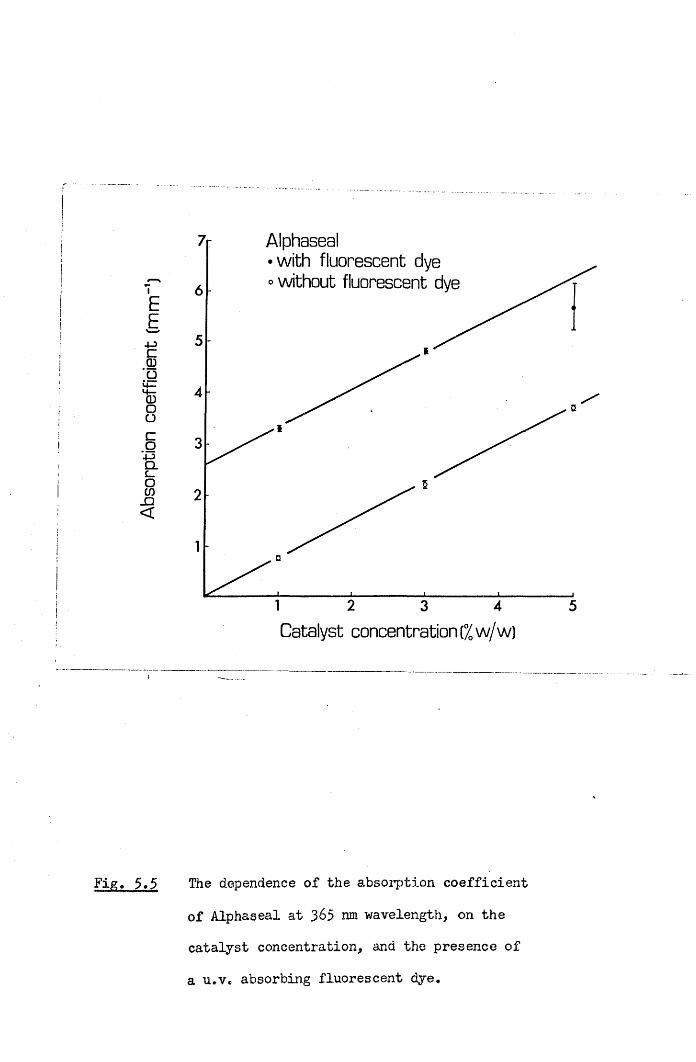
Abso
rptio
n co
effic
ient
[m
m"1
)
Alphaseal• with fluorescent dye o without fluorescent d
2 43 5
Catalyst concentration (% w/w)
Fig. 5.5 The dependence of the absorption coefficient of Alphaseal at 365 nm wavelength, on the catalyst concentration, and the presence of a u.v. absorbing fluorescent dye.

1 0
*— * Nuva-seal
*^ -X- «_____— * — * — *.
i Jai i— i i * m — — m— r aaat r m r n r m i PT rTrrA itmmMm^frtmmmmmaawumaxJ
10 20 30Exposure time Cs)
The transmission of u.v. radiation at 365 nm wavelength, through a 0.55 mm thick sample of Nuva-seal, during exposure to an intensity

10
40c_CDCOCDCD
SZCODOL_
JZ40CoCDCD
CDCCD,c_
•8
•7
•6
•5
•4
Alphaseal with fluorescent dye at catalyst concentrations
+—+ o/ w /w1% w /w
— 3% w /w* 5% W / W
• — ••
10 20 30 40 50 60Exposure time(s)
Fig. 5.7 The transmission of u.v. radiation at 365 nm wavelength, through 0.55 mm thick samples of Alphaseal, containing a fluorescent dye, and at catalyst concentrations of 0, 1, 3 and % w/w, during exposure to an intensity of
250 mW/cm^.

1-0
4-3cjroCDCDCD
JOCD=3Oc_-C
4-3
co'CDCD
\
Alphaseal w ithou t fluorescent dye a t cata lyst concentrations
1% w /w°-D 3% W/W
W/W
CDOCD
\
V
10 20 30 40 50 60Exposure tim e(s)
Fig. 5»& The transmission of u.v. radiation at 365 nm wavelength, through 0.55 mm thick samples of Alphaseal, without a fluorescent dye, and at catalyst concentrations of 1, 3 and 5% w/w, during exposure to an intensity of 250 mW/cm .

6$
transmission through a 0*55 mm thick Nuva-seal sample during a 60s2exposure to a 20 mW/cm intensity of radiation is plotted in Fig. 5.6.
The transmission through the same thickness of Alphaseal exposed to
250 mW/cm also changed during polymerisation, as shown for samples with and without the fluorescent dye in Figs. 5,9 and 5.8. In the absence of the fluorescer the absorption increased during polymerisation for each of the three catalyst concentrations tested. Where only the fluorescer was present in the resin the transmission increased steadily during the u.v. exposure. The addition of a 1% w/w concentration of catalyst still resulted in an increasing transmission during polymerisation. However at catalyst concentrations of 3 and 5^ w/w the transmission decreased during polymerisation.
5.4 Discussion
Radiation at 365 nm wavelength has been found to penetrate Nuva- seal readily up to the depths normally required of fissure sealants.For example the intensity of radiation penetrating Nuva-seal to a depth of 2 mm is about 10% of that at the surface layer, and only a slight reduction in transmission was observed during polymerisation.Since the basic resin did not significantly absorb the radiation, the initial absorption coefficient of Nuva-seal was proportional to the catalyst concentration present. Although variations in the size of the catalyst drop used, would result in variations in the absorption of different bottles of mixed sealant, this would not greatly affect the
clinical performance of Nuva-seal.In the previous chapter microhardness measurements on Alphaseal
showed that the hardness decreased below the exposed sealant surface.This effect can be explained by the strong absorption which prevents the activating radiation from penetrating Alphaseal to the depths normally required of sealants. For example the intensity at a depth

of 0«5 nun was only 6/d of that- at the surface. The u.v. fluorescent
dye, incorporated to facilitate sealant detection after long periods in the mouth, accounts for a significant proportion of the absorption,
while the remainder was attributed to the high concentration of catalyst present. Thus the removal of the fluorescent dye, or the substitution of one which does not absorb at 365 nm wavelength, and a reduction in the catalyst concentration could enable Alphaseal to set better in depth. (This assertion is confirmed in the next chapter).
The changes in transmission which occurred during the polymerisation of Alphaseal appeared to result from a combination of two
effects. The polymerisation of the resin by the catalyst produced an increase in the absorption, while the presence of the u.v. fluorescent dye tended to increase transmission during u.v. exposure. The steady increase in transmission, where no catalyst was present suggested that the radiation was dissociating the fluorescent molecules. The concentration of catalyst added to the fluorescent resin determined whether the transmission rose or fell during polymerisation. In its standard preparation, at 5% w/w catalyst concentration, transmission declined during exposure to the u.v. radiation.
While radiation cannot penetrate deeply into Alphaseal the creation of a high concentration of free radicals at the surface may result in the diffusion of these radicals into the sealant where they may initiate polymerisation in regions where the intensity of u.v. radiation is low. In addition the polymer network can be expected to
extend down into the bulk of the resin from the surfa.ce. Such extensions of polymerisation can have only a limited range, and the use
of very high intensity u.v. sources would .further extend the depth of
set achieved.The ultimate test of any sealant is its clinical performance. As
yet only two studies of Alphaseal (TP2206) have been reported. The

70
degree of success achieved by Rock (1974a) suggests that Alphaseal is atleast potentially effective. However the poor results found withTP2206 in Galloway by Stephen et al. (1976) require explanation. Theprototype Quartzlite supplied for this latter trial had an output of
o1*5 mW producing a peak intensity of about 30 mb'/cm which would not
have been sufficient to adequately set the sealant. Currently available Alphalites however have outputs in excess of 15 mW, producing peak intensities over 300 mW/cm . By using such a high output source and applying only thin layers of Alphaseal, clinical results comparable to Nuva-seal might be achieved.

CHAPTER SIX71
STUDIES OF,THE SETTING BEHAVIOUR OF SEALANTS USING A NEW ACOUSTIC METHOD OP DETERMINING SET
6.1 Introduction
Microhardness tests described in Chapter Four were used to study the setting of fissure sealants, when polymerisation was well advanced.
However, a great many measurements would be required to build up a complete picture of the setting of u.v. activated sealants by this method. Therefore, a new procedure for assessing the setting of photosensitive resins was devised, using the transmission of acoustic vibrations. The setting characteristics of different sealants have been compared, and the dependence of the setting of u.v. activated sealants on the applied intensity of radiation, examined. The rate of set of Alphaseal, prepared at different catalyst concentrations, has been examined, in view of the varied absorption of radiation by the resin, for the different formulations discussed in Chapter Five.
6.2 Materials and MethodsA new method for measuring the setting characteristics of pit and
fissure sealant resins was devised, using the transmission of audio
frequency vibrations. A schematic diagram of the system used is shown in Fig. 6.1, and the physical factors which determine the acoustic transmission across sealant samples are discussed in Appendix II. A photograph of the apparatus, with two steel cylinders aligned using retort stands, is shown in Fig. 6.2. The opposing end faces of the cylinders had flat headed steel pins fitted in holes cut in their centres. The two pin~heads were of 2 mm diameter and separated by a 1 mm gap. A vibration generator was bonded to the other end of one steel cylinder, and received a sinusoidal signal at 1 kHz from, an audio freouency signal generator. A vibration transducer (accelerator type

u.v. radiation
vibration transducer
X M m
m rn m
resin
steel pins
steel cylinders
retort stands
amplifiergenerator
rectifier
chartrecorder
vibrationgenerator
Fig. 6.1 Experimental arrangement for monitoring the setting of fissure sealants using the transmission of acoustic
vibrations.

Fig, 6.2 Photograph of the arrangement of steel cylinders and pins
shown schematically in Fig. 6.1. The vibration generator is bonded to the end of the left hand cylinder, and the vibration transducer is magnetically clamped to the end of the right hand cylinder.


4332, Bruel & Kjaer DK-2S50, Naerum, Denmark) was magnetically clamped to the far end of the other steel cylinder. When the air space between the pin-heads was filled with resin the passage of vibrations could be detected by the transducer. The signal from the transducer was amplified by a sound level meter (type 2204, Bruel & Kjaer) and filtered at 1 kHz to eliminate background noise before being rectified and recorded on a paper chart recorder. The setting characteristics of three chemically initiated sealants were measured from the time of first mixing the resin, a few seconds before applying a drop of the mixture to the gap between the pin-heads. When u.v. sensitive sealants were tested the chart recorder was activated at the moment of exposing the resin between the pin-heads to a pre-arranged u.v. intensity from either a Nuva-lite, Alphalite or Blak-Ray 100W u.v. source (UVP International Inc., San Gabriel, California, U.S.A.). In all cases identical gain settings were used, and the chart record monitored the increase in the transmitted sound signal through the resin during the polymerisation process. To investigate the setting characteristics of the u.v. activated materials, sealant was placed between the pin-heads and the distance from the tip of an Alphalite adjusted to produce intensities from 5 to 120 mW/cm . From the setting curves obtained at each intensity, the initial rate of increase in acoustic transmission was measured in mV/s. The effect of varying the catalyst concentration and removing the fluorescent dye, on the setting of Alphaseal, was also
investigated.
6.3 ResultsThe amplitudes of the transmitted vibrations recorded for 5 tests
on each of five fissure sealants are compared in Fig. 6.3. The setting curves have been normalised to show the same transmission 10 minutes after the initial mixing of two of the chemically setting materials

Acou
stic
trans
mis
sion
10
a: Nuva-seal+AlphaSte0-5
b: Nuva-seal+Nuva-lite
1-0
c: Alphaseal+Alphalite
d: Alphaseal+Quartzlite05
1-0e: Epoxylite 9075
f: Concise enamel bond
g= Kerr sealant0*5
Setting time (minutes)
Fig, 6.3 Normalised acoustic transmissions through various fissure sealants during setting.(a) Five Nuva-seal samples irradiated at an intensity of
2about 200-300 mW/cm , from an Alphalite with an output
of 15 mW.(b) Five Nuva-seal samples irradiated at an intensity of
2about 20-30 mW/cm , from a Nuva-lite.(c) Five Alphaseal samples irradiated at an intensity of
2about 200-300 mW/cm , from an Alphalite with an output of 15 mW,
(d) Five Alphaseal samples irradiated at an intensity of2about 40-60 mW/cm , from a Quartzlite with an output
of 3 mW.(e) Five Epoxylite 9075 sarrples.(f) Five Concise Enamel Bond samples,(g) Five Kerr Pit and Fissure Sealant samples.

73
(Epoxylite 9075 and Enamel Bond), and 10 minutes after beginning the
exposure of Nuva-seal and Alphaseal to radiation* The transmission
through Kerr Pit and Fissure Sealant (Sybron Corp., Romulus, Michigan, U.S.A.) was not normalised since the setting was not complete after 10 minutes.
Acoustic setting curves for Nuva-seal exposed to various intensities of u.v. radiation are shown in Fig. 6.4* The setting characteristics of an experimental filled fissure sealant Nuva-cote (L.D. Caulk Co.) are shown in Fig. 6.5. Corresponding setting curves for Alphaseal, prepared at 1% w/w catalyst concentration, without the fluorescent dye, are shown in Fig. 6.6. The peak gradients occurring at the start of these curves were used to determine the dependence of the initial rates of set of the three u.v. activated sealants on the u.v. intensity applied, and are plotted in Fig. 6.7* For all three sealants straight lines fitted to the data of Fig. 6.7 indicate that, the rate of set was proportional to (Intensity )^*^. From the relative positions of the straight lines in Fig. 6.7, it can be deduced that, for a given intensity, the rate of set of Nuva-seal m s 3*5 times the
rate of set of Nuva-cote and 1*9 times the rate of set of this preparation of Alphaseal. The initial rates of set of Alphaseal exposed to an u.v. intensity of 100 mW/cm , at various concentrations of catalyst and with and without the fluorescent dye are plotted in Fig.6.8. The removal of the fluorescent dye resulted in an increase in the rate of set of Alphaseal at all catalyst concentrations, and a maximum rate was achieved in the absence of the dye at catalyst concentrations
in the range .0*5 to 1*0$ w/w*The setting behaviour of the u.v. activated sealants when
2exposed to the same intensity (100 mW/cm ) are compared in Table 4. The initial rates of increase in the acoustic transmission were obtained from Figs. 6.7 and 6,8, and the "final” acoustic transmissions were
7 4
estimated from setting curves in Figs. 6.4, 6.5 and 6.6. From this information the initial rates of set for the different materials were expressed in terms of percentages of the final transmissions and are presented in the third column of Table 4« Thus, at this intensity Nuva- seal set nearly 4 times as fast as Nuva-cote, and 13 times as fast as the usual preparation of Alphaseal. However, by preparing Alphaseal in the absence of the fluorescent dye and at a lower catalyst concentration, its setting rate was increased by a factor of 10.

Setting Characteristics of Nuva-seal
05 400cpb 300
i 200ZJI 100
u.v. intensity mW/cm2
10 20 50 6030 40
exposure time (s)
Fig. 6.4 Acoustic transmissions through samples of Nuva-sealexposed to different u.v. intensities in the range 11*5- 115 m¥/cm^.
Setting Characteristics of Nuva-cote~ 700 >£, 600
-Q 500 coCOE 400COCO 3004-3
.y 200CO
8 100 CD
u.v intensity mW/cm:
exposure time (mins)
Fig. 6.5 Acoustic transmissions through samples of Nuva-coteexposed to different u.v. intensities in the range
2

acou
stic
trans
miss
ion
(mV) Setting Characteristics of Alphaseal
500
400
300u. v intensity mW /cm2200
100
exposure time (mins)
Fig. 6.6 Acoustic transmissions through samples of Alphaseal,prepared at a 1% w/w catalyst concentration without the fluorescent dye, on exposure to different u.v. intensitiesin the range 10-100 mW/cm .
100
50
jo
CDCOId0toL_
’c
10
5
1
o— o Nuva-seal •— • Nuva-cote D— D Alphaseal
i 1 / w / w catalyst conc.* without fluorescent dye
i * i i i i i 11
Fig. 6.7
1 5 10 50 100 200
u.v. intensity (mW/cm2)Initial rates of set (i.e. initial peak acoustic transmissions) of Nuva-seal, Nuva-cote and Alphaseal {!% w/w cat. conc., no fluorescent dye) on exposure to different
u.v. intensities.

initia
l rate
of
set
(mV/
s)
40 Alphaseal (u.v. intensity =100mV\ cm2) o—owithout fluorescent dye •—with fluorescent dye
21 3 4 5
catalyst concentration Kw/w)
Initial rate of set of Alphaseal prepared at variouscatalyst concentrations, with and without the fluorescent
2dye, on exposure to an u.v. intensity of 100 mW/cm .

75
Table
A comparison of the setting rates of u.v. activated sealants on exposure to an u.v. intensity of 100 mW/cm^.
SealantInitial rate of increase in acoustic transmission
(mV.s"*)Final acoustic transmission
(mV)
Initial rate of set %*s~1
Nuva-seal 78 600* 13Nuva-cote 23 700+ 3.3Alphaseal* 4 4*
400 1.02Alphaseal 42 400+ 10.5
Notes: 1. Prepared at a catalyst concentration of 5% w/w andcontaining a fluorescent dye.
2. Prepared at a catalyst concentration of 1% w/w without the
fluorescent dye.* Approximate value attained after one minute.+ Approximate value attained after five minutes.

6.4 Discussion
This new method for assessing the setting of fissure sealants has yet to prove its full potential, and the limitations of the technique are still to be discovered. Consequently, some caution must be exercised when interpreting the results. The method by which the system worked was apparently straightforward. As the resins set, either by chemical initiation or through u.v. activation, their physical properties changed and the increased "stiffness" of the samples permitted vibrations to be transmitted across the resin gap between the pins. Thus the arrangement described, provided a continuous record of the changing physical state of the resins as they set. (This is discussed further in Appendix II). /
The delayed setting of chemically initiated sealants (Concise Enamel Bond, Epoxylite 9075 and Kerr pit and fissure sealant) was apparent in Fig. 6.3. Concise Enamel Bond and Epoxylite 9075 set following a two to three minute delay, designed to allow placement of the sealant prior to viscosity changes due to polymerisation. However, the very long delay in the setting of Kerr pit and fissure sealant was greater than indicated by the manufacturers, suggesting that the batch of sealant tested was faulty. The more rapid setting behaviour of u.v. activated sealants on exposure to various u.v. sources was also demonstrated. The setting of Alphaseal immediately below the tip of an Alphalite (Fig. 6.3c) was similar to the setting of Nuva-seal when exposed to u.v. intensities of 20-30 mW/cm below a Nuva-lite.However, when the u.v. radiation from an Alphalite, at intensities of 200-300 mW/cm2, was used to set Nuva-seal it demonstrated a more rapid setting behaviour than Alphaseal (cf. Figs. 6*3a and c). The rate of set of Alphaseal under a high output Alphalite (15 mW), as shown in
Fig. 6.2c, was much more rapid than when illuminated by the Quartzlite,
with a 3 mW output, as shown in Fig. 6.3d, It was, therefore, apparent

from these preliminary findings that the rate of set of u.v. activated
sealants depended on the u.v. intensity applied. Furthermore, Nuva- seal set more rapidly than Alphaseal for a given u.v. intensity.
Subsequent experiments examined in more detail the setting of these two u.v. activated sealants and also Nuva-cote, showing that while there were considerable differences in their rates of set at any given intensity, all three materials had a similar dependence on the u.v. intensity.
The slower setting of Nuva-cote compared with Nuva-seal was
probably due to the reduced penetration of u.v. radiation into Nuva-cote because of the incorporation of filler particles. The slow setting of Alphaseal in its usual constitution seemed also to stem from the high absorption of the radiation by the fluorescent dye and the high catalyst concentrations normally used. Removal of the dye from Alphaseal produced considerable increases in the rate of set at all catalyst concentrations tested, and was particularly marked at catalyst concentrations from 0*5 to 1*0% w/w, where peak setting rates were
observed.

78
CHAPTER SEVEN
STUDIES ON SEALANT RETENTION USING AN IN VIVO REPLICATION TECHNIQUE
7.1 Introduction
When this project commenced it was thought desirable to prolong sealant retention in pits and fissures for as long as possible.However no attempt had then been made to study the mechanisms of sealant loss, which once understood might enable modifications in materials and application techniques to improve retention. As clinical trials normally only provide minimal information about sealant condition, an
-in-vivo replication technique was developed to provide a more detailed picture of the sealant at re-examination. This procedure was based on the methods employed by Saxton (1973) to study plaque formation. A low viscosity silicone impression material was used to produce epoxy resin replicas of the occlusal surfaces of teeth, at various times after sealing, and these models examined on a Scanning Electron Microscope.A similar technique has also now been reported by Douglas and Tranter
(1975).
7.2 Materials and MethodsDuring the pilot study of Nuva-seal retention, discussed in the
following chapter, impressions were taken at regular intervals from selected teeth. A small quantity of a low viscosity silicone resin (Silflo, Flexico Developments Limited, England) was placed on the dried occlusal surface of a sealed tooth and blown into a thin bubble- free layer. The bulk of the liquid silicone rubber was then applied via a single tooth impression tray, removed after four minutes and stored in a polythene bag. Within 24 hours the impression was rinsed

with distilled water, dried, and excess rubber trimmed off with a
blade. The impression was then fitted inside a 10 mm length of
polythene tubing of internal diameter 13 mm, and mounted on a card
with a silicone adhesive (Silcoset 151> ICI Limited, U.K.), and stored at 50°C for 24 hours, Pre-mixed epoxy resin (Fluorochem Ltd,, Glossop, Derbyshire) was then applied with a disposable syringe, and the sample stored for a further 48 hours at $0°C, The polythene tubing was removed and the epoxy resin copy of the sealed tooth mounted on a 13 mm diameter S.E.M. stub with conducting paint (Silver Dag, Acheson Colloids Company, Prince Rock, Plymouth), Prior to examination on a Phillips Stereoscan S.E.M,, tooth models were coated with a 20 nm thick layer of gold, using a sputter coater. The models were also examined under optical microscopy, but photographic records were superior with the S.E.M., due to the better depth of field.
Under normal conditions, magnifications of up to 2000 times were readily obtained. Incorporated into the display screen of the S.E.M. was a bar indicating the scale, which is included in the photographic records presented here.
7.3 ResultsThe condition of some selected teeth sealed during a pilot study
of the retention of Nuva-seal was examined using the in-vivo replication procedure outlined. Fig. 7.1 shows the appearance of the distal part of the occlusal surface of an upper right first permanent molar before sealing, immediately after sealing and 16, 41 and 250 days later. The deep distal groove running towards the palatal surface of the tooth is evident in Fig. 7.1a. While sealing totally occluded this fissure from the oral environment as shown in Fig. 7.1b, after 16 days
abrasion had made the appearance of the sealant rougher than the adjacent enamel, so that the two surfaces are easily distinguished in

Fig* 7.1c. After 41 days the extent of sealant cover was little reduced by further abrasion (Fig. 7.Id), but at 250 days the palatal extension of the sealant had been completely lost, with sealant remaining in only part of the distal fissure (Fig. 7,le). This retained material is shown from the palatal side of the tooth, at the original magnification (Fig. 7*lf) and at higher magnifications in Figs. 7*lg and 7*lh. At these higher magnifications sealant is seen to be poorly adapted to enamel, and the entire palatal extension appears to have been lost by sealant fracture, rather than by gradual abrasion.
The condition of this tooth, 16 days after sealing, is seen in more detail in Figs. 7.2 and 7*3. Sealant cover on the distal fissure shows good marginal adaptation at this time, even under examination at the higher magnifications of Figs. 7*2b and 7*2c. The mesial part of the occlusal surface is shown at two different magnifications in Fig.7.3 where a triangular block of raised sealant is an unusual feature only observed on this tooth. By the 12 month examination this tooth had lost all sealant cover and had an amalgam filling in the occlusal surface.
Fig. 7*4 shows the appearance of sealant on the distal and palatal fissures of an upper left first permanent molar, 14* 39* 140
and 249 days following application. Although the area covering the distal fissure was gradually reduced through abrasion, the sealant remained intact after 249 days (Figs. 7.4a, b, c and d). The palatal extension showed considerable abrasion losses, but still maintained an effective seal after 249 days (Figs. 7*4e, f, g and h). The mesial occlusal fossa of this tooth is shown for the same examination times in Figs. 7.5e, f, g and h. Again sealant was virtually intact at 249 days, with only slight loss from the mesial marginal grooves. After 12 months a mirror and probe examination judged sealant cover to be

8 1
complete on all surfaces of this tooth.
The distal fissure of another upper left first permanent molar is
shown, 15, 39, 140 and 249 days after sealing in Figs. 7«5a, b, c and d. Here, sealant has been thickly applied and appears to have been hardly affected by abrasion. By contrast the mesial pit of this occlusal surface was only thinly coated with sealant, and Figs. 7.6a, b and c show its condition after 39, 140 and 249 days. Considerable loss was noted from the mesial marginal grooves, although the mesial pit remained sealed. However, after 12 months mirror and probe examination determined this tooth to be completely sealed on all sites.
Figs. 7.7a, b and c show the entire occlusal surface of an upper right first permanent molar, 14, 38 and 248 days after sealing. Resin was only thinly applied so that after the first few days abrasion it occupied only the bases of occlusal grooves. In Fig. 7.7a the sealant can be seen to be poorly adapted at the buccal extremity of the distal fissure. Sealant was found to be lost from this region after 38 days, and fragments of sealant were also lost from the mesial part of the occlusal surface (Figs. 7*7b and c). After 12 months sealant was graded as completely lost from this tooth by mirror and probe examination.
The condition of sealant on the mesial part of the occlusal
surface of an upper right first permanent molar, after 31 days, is shown in Fig. 7.8. Incomplete sealant cover is shown in Fig. 7.8a at a nominal magnification of 20 times. The sealant fracture surface in a mesial marginal groove is examined at higher magnifications in Fig. 7.8b, c and d. The spherical globules observed are probably caused by air bubbles, trapped when the impression was taken. Sealant attachment to the enamel is studied on another part of this tooth in Fig. 7.Be, f, g and h at increasing magnifications. Poor adaptation to enamel is apparent with gaps of approximately 20 jxm being observed (Fig. 7cSh).

82The distal fissure of this tooth is depicted at different
magnifications in Fig. 7.9e> f, g and h, and very poor adaptation is again apparent with the sealant edge being separated from the enamel in some regions, by as much as 40 [im.
The condition of sealant applied to premolar surfaces was generally much superior to that found on molars. An instance of
sealant detachment from the surface of a premolar is shown in Figs.7.9a, b, c and d. After 38 days in the mouth, a small length of sealant edge had separated from the enamel by about 10 |jm (Fig. 7.9d).
However adaptation over the rest of the tooth surface was excellent.The condition of the sealant on this upper left first premolar is shown in Fig. 7.10> after 16, 38, 142 and 251 days in the mouth. The mesial aspect of the tooth is depicted in Figs. 7.10a, b, c and d,while the distal aspect is seen in Figs. 7.10e, f and g. Although therehas been slight loss from the surface of the sealant, the fissures remained well covered after 251 days. That the depth of sealant over the central fissure has been little reduced by wear, during the eight month study period, is apparent from the mesial profiles of this tooth in Fig. 7.11.
The second premolar adjacent to this first premolar has also been examined and the condition of its sealant cover after 38, 142 and 251days is shown in Figs. 7.12a, b and c. Although some of the sealantbulk has been lost through abrasion, it continues to provide excellent cover after 251 days. No premolar was judged to have lost any sealant cover at the annual mirror and probe examination.

Fig- 7
( a )
(b)
(e)
(*)
(c) (g)
(d) (h)
rl The distal fissure of an upper right first permanent molar is
shown before sealing, immediately after sealing, and 16, 41
and 2.50 days after sealing in a, b, e, d and e, resp. A
palatal view of the remaining sealant is shown, after 250
days, at nominal magnifications of 20, 50 and 100 times, in f, g and h, resp.


(a)
(b)
(c)
Fig0 7*2 The sealant on the distal fissure of the tooth studied in
Fig* r/,l5 is shown 16 days after sealing, at nominal magnifications of 20, .50 and 100 times, and a, b and c resp e


( a )
S£i_Z.
( b )
2 The appearance of sealant, after 16 days, in the mesial part
of the occlusal surface of the tooth studied in Figs, 7.1 and 7,2, is shown at nominal magnifications of 20 and 50 times, in a and b, resp.


Fig. 7
(a) ( e )
(b) (f)
(<=> (g)
(d) (h)
■ />. The appearance of sealant in the distal fissure of an upper
left first permanent molar, 14, 39, 140 and 249 days after sealing, is shown in a, b, c and d, resp* Sealant in the
palatal fisstire of the same tooth, 14, 39, 140 &nd 249 days after sealing, is show in s, i, g and h, resp*

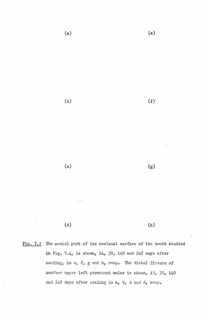
( a ) ( e )
(b) (f)
(o) (g)
(d) (h)
Fig, 7*5 The mesial part of the occlusal surface of the tooth studied
in Fig, 7.4* is shown, 14* 39* 140 and 249 days after
sealing, in e, f, g and h, resp. The distal fissure of
another upper left permanent molar is shown, 15, 39* 140
and 249 days after sealing in a, b, c and d* resp.

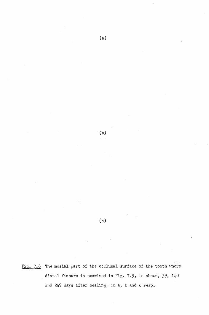
( a )
(b)
(c)
Fig. 7r6 The mesial part of the occlusal surface of the tooth v/here
distal fissure is examined in Fig. 7.5, is shown* 39* 1/+0 and 249 days after sealing, in a* b and c resp.


( a )
Fig. 7
(b)
(o)
2 The occlusal surface of an upper right first permanent
molar* 14.? 38 and 248 days after sealing, is shown in a,
b and c, resp9


( a ) (e)
(b) (f)
(c) (g)
(d) (h)
Fig. 7»8 Sealant in a mesial marginal groove of an upper right first
permanent molar is shown, 31 days after sealing, and at nominal magnifications of 20, 50, 100 and 200 times, in a, b, c and d, resp. Sealant, at the same time after application to this tooth is shown, on the mesial side of the oblique ridge, at nominal magnifications of 50, 200,500 and 10C0 tines in e, f, g and h, resp*


(a) (e)
(b) (f)
(c) (g)
(d) (h)
Fig. 7.9 An upper left first premolar is shov/n, 38 days after sealing,
and at nominal magnifications of 20, 50, 200 and 1000times, in a, b, c and d, resp* The distal fissure of the tooth
ex-mined in Fig* 7*8 is shown, 31 days after sealing, and at
nominal magnifications of 20, 50, 100 and 500 times, in e, f, g and h, resp,


( a ) (e)
(b)
(o) (f)
(d) (g)
Fig, 7*10 The mesial aspect of the upper left first premolar studied
in Fig, 7,9* is shown, 16, 38, 142 and 2.51 days after sealing, in a, b, c and d, resp. The distal aspect is shown, 16, 142 and 251 days after sealing in e, f and g, resp*


( a )
( b )
M
Fig,. 7>11 The upper left premolar shown in Figs* 7«9 and 7el0,
is shown in mesial profile, 16, 142 and 251 days after
sealing, in a, b and c, resp„


( a )
0>>
(o)
FiZ ^ J L H The second premolar proximal to the first premolarstudied in Fig. 7,9, 7,10 and 7.11, is shovm 33, 142 and 251 days after sealing, in a., b and c, reap.
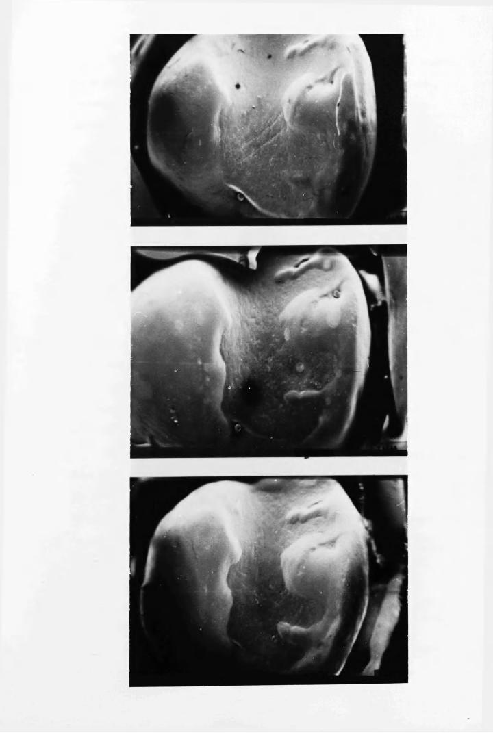

S3
7.4 Discussion
The photographs shown here were selected from replication studies on a total of 28 teeth. While it cannot be claimed that the teeth selected were necessarily typical, they provide some insight to the prevailing mechanisms of sealant loss.
One striking feature of the study was the different condition of sealant applied to premolars and molars. This may be due to the different occlusal forces and abrasion to which these two types of
teeth are subjected. The better retention of sealant on premolars than molars has been frequently observed in previous clinical trials, as has already been discussed in Chapter One.
A second feature of the results was that more thickly applied -sealant appeared to survive occlusal forces better than thinner layers, although the evidence for this assertion was not conclusive. Certainly the amount of sealant initially placed on the teeth varied greatly from one tooth to another, although it was applied by the same operator. One would also expect that considerable variations would occur between operators, so that the retention of sealant in different clinical trials
could be affected.One mechanism of sealant loss was the gradual removal of sealant
from the exposed surface by abrasion. This appeared to be the main factor which would affect the retention of sealant on premolars.However, on molars, substantial fragments of sealant were also lost due to fractures, which in seme instances may have been related to the separation of part of the sealant from the enamel* Such a lack of adhesion could have been caused by a faulty application technique, which permitted moisture contamination or incomplete polymerisation at the sealant/enamel interface.
One may conclude that provided a correct application technique is used, sealant retention could be greatly improved by altering the
bulk physical properties without necessarily improving adhesion at the
sealant/enamel interface. Improved abrasion resistance would clearly be beneficial, as would an increase in the mechanical strength of the
material, to prevent fracturing under occlusal forces.

S5
CHAPTER EIGHT
CLINICAL TRIALS USING A MODIFIED SEALING TECHNIQUE
8.1 Introduction
A -wide variation in the retention of Nuva-seal in different clinical trials was shown in Chapter One. Examination of the caries
incidence in teeth which had lost all or part of their sealant covering showed that good sealant retention was essential for long term caries prevention. A major objective of this project has been to determine the causes of sealant failure and to outline improvements in sealing technique to optimise retention. Information which has been gathered on the adhesion of sealant to etched enamel, the exposure required for u.v. setting sealants and experience with the materials and equipment resulted in a number of modifications to the standard application procedure. To validate these laboratory conclusions, a detailed clinical technique was outlined and its effectiveness evaluated in
clinical trials.
8.2 Fissure Sealing Technique
8.2.1 Tooth cleaningTeeth were thoroughly cleaned with a non-fluoride prophylactic
paste and a rotary brush. The paste was washed off with a 3-in-l syringe, and a sharp probe used to remove traces of paste from fissures.
8.2.2 Tooth isolationUpper teeth were isolated by placing No.l cotton wool rolls in
the buccal sulcus while an assistant used a high velocity aspirator to remove water and saliva. Lower teeth were isolated using No.l cotton wool rolls in the buccal and lingual sulci and a child size flanged

86
saliva ejector. These smaller cotton wool rolls were more comfortable
for the patient and allowed a clear view of the tooth during treatment.
8.2.3 Acid etching
Fresh acid was placed in a dappen's glass for each patient and applied with cotton pellets for a timed period of 60s. To remove acid and dissolved enamel following etching, a jet of water squeezed from a polythene bottle by hand pressure, was used to soak the tooth surface. This water was removed with an aspirator, and the procedure repeated until six separate rinses of the etched tooth surface had been completed. Soaking the tooth in this manner was more acceptable to the patient than the conventional 3-in-l water spray which tended to irritate the throat and interrupted the procedure, with consequent contamination of the etched surface. Once rinsing was completed dry cotton rolls were placed over the original rolls, which were then
removed from beneath.
8.2.4 Tooth drying ■The etched tooth was dried for about 20s with an air jet, free
from either oil or water contamination. Great care was exercised at this stage to avoid salivary contamination, by guarding the tooth with a mouth mirror to prevent lingual contact, while the assistant continued aspiration. Should saliva contact the etched enamel a rapid deposition of protein could have taken place which might not be removed by washing or re-etching (Meurman, 1976). If any salivary contamination was observed, sealing was postponed to a later date.
8.2.5 Application of sealantIn developing the application technique in the laboratory air
bubbles were found to be accidentally incorporated into the sealant.

6 7
Since it was believed that these could adversely affect sealant
retention, a technique was devised to avoid their incorporation. The
initiated sealant was mixed slowly for 30 s, producing as few air
bubbles as possible. A drop of sealant was then applied to the tooth surface using a flat, plastic instrument instead of the camel hair brush supplied by the manufacturers. A probe was then run along the fissures prior to activation with u.v. radiation in an attempt to remove any trapped air. The latter process has also been used by Ulvestad (1973). Further sealant was added to produce the maximum thickness which would not interfere with the occlusion, since studies on sealant loss in Chapter Seven had indicated that a thicker layer would be better retained than a thin layer.
8.2.6 Application of u.v. radiationTo ensure optimum polymerisation, the output of the Nuva-lite
was checked prior to the trial, using the Blak-Ray U.V. Meter asdescribed in Chapter Three. Throughout the trial further measurementsdetermined that the output was always sufficient to supply an average
2intensity in excess of 20 mW/cm . The sealant was exposed to the u.v. radiation for a timed period of 45 s, by moving the tip of the Nuva- lite across the tooth surface, as close to the sealant as possible.This process maximised the u.v. intensity and compensated for the uneven distribution of radiation at the quartz tip. Following each treatment the quartz guide was cleaned with chloroform to prevent the accumulation of polymerised sealant.
8.3 Design of Clinical TrialsTo assess the technique outlined above, permission was obtained
for a clinical trial using children from Garnetbank Primary School adjacent to Glasgow Dental Hospital. Sealing was carried out by a dental

auxiliary aided, by her regular dental assistant. Since neither operato
had any previous experience with sealants, they were able to learn the procedure outlined above without having to modify pre-conceived ideas.
Both received laboratory instruction and sealing practice on extracted teeth during the first few days of training. Twelve children of the staff of the Department of Clinical Physics and Bio-Engineering were then treated during a supervised two week practice session.
A small pilot study was initiated, in which 16 ten-year-old and 6 six-year-old children had 54 caries-free first permanent molars and 20 caries-free premolars treated. These teeth were examined by a probe and mirror within a few days of sealing and subsequently at 1, 41 6 and 12 months after sealing using a blind examination technique. Retention of sealant was assessed separately for the occlusal and buccal surfaces of lower first permanent molars, and for the mesial fossa, distal fissure, and the palatal extension of the distal fissure in upper first permanent molars. Premolars were assessed for the coverage of pits and fissures on their occlusal surfaces as a whole. Each site was
recorded as having 'complete,1 'partial' or 'no sealant' retention.If any part of the fissure pattern was uncovered, then that site was recorded as having partial retention, even if the majority of the
fissures remained sealed.When the pilot study showed that this sealing technique resulted
in good retention, a larger clinical trial was initiated. Here, 76
children aged from six to ten years had any caries-free permanent molars sealed over a three week period. Re-examinations were completed at 1, 2, 4, 6, 9 and 12 months after the sealing period.
6,4 Results8.4.1 Pilot- trial
Sealant retention, up to 12 months, on the different surfaces

89sealed in the pilot trial are shown in Table 5- After one year 88$ of
occlusal surfaces examined in lower first permanent molars were wholly covered by sealant, while 82$ of the mesial fossae and 79$ of distal pits in upper first permanent molars were found to be completely sealed.
The few buccal and palatal sites treated showed poorer retention.Sealant was completely retained in all premolars during the study.
8.4.2 Second trial
The retention of sealant in the 241 sites treated on 157 first permanent molars in 78 children is shown, for examinations up to 12 months, in Table 6. Due to children leaving the area the number of sites available for examination fell from 241 at the one month reexamination to only 194 at the end of the study year. After one month all the sealant was intact. Subsequent examinations revealed that a few tooth surfaces gradually lost some sealant covering with 93*3$ o f
treated surfaces fully covered after 12 months. At that time only 3*1$ of sites examined had totally lost their sealant, while the remaining 3*6$ had partial coverage. In most cases these had lost
sealant from only a small fraction of the total fissure pattern.Table 7 shows the pattern of retention for the different tooth
sites. At the one month examinations all the surfaces were intact.Mesial and distal sites which were later found to have only partial retention, were generally completely uncovered at subsequent examination.
However, none of the occlusal sites in lower first permanent molars had lost all of their sealant covering after 12 months, although 5 sites were
found to have partial loss.The sealant status on surfaces of first permanent molars for the
different age groups of children is shown in Table 8. Although there was little difference with regard to sealant loss in the first 6 months, by the 9 month examination the loss sustained by the 6 and 7 year-olds

Retention
of Nuva-seal
on different
tooth
sites, on
upper
and
lower
first
permanent
molars and
premolars
90
ptooHd
d cd•rH r—{
Cd(0 (D 0) CO
•9 HP P I
do•HPda>p<dd
rHcd•HtcdftIIftdo
•rHPd<D
p<Dd
<DP<DH&O
• oa -4 LA CM CM I 1 vO(0 PI rHx?pd • CA CM 1 rH 1 i 1 sOQ f ta
cm • ca <N sO CM CA CM vO -4rH o CM CM CM rH O
• CM rH CA 1 CM 1 1 to(0 P I
x :pd ■ • 1—1 CA 1 CM 1 1 I sOQ CL,ato • LA -4 CO CA CA CM sO rH
o CM CM CM rH OrH
• H rH CM 1 rH 1 1 «A(0 PI
X! . \fS • CM CM rH rH 1 1 1 vOQ CL,a-4 • LA LA CO - 4 - 4 CA t> v£>
o CM CM CM rH OrH
• 1 1 CM 1 1 1 1 CMPI
XJpd • 1 1 1 1 1 1 1 1o f tarH • <0 CO On LA LA CA LA
o CM CM CM rH rHrH
• 1 1 rH 1 1 1 1 rHPI(0
<D • 1 1 1 1 1 1 1 1© CL,£
CV CO CO o LA LA CA t> sOo CM CM tH CM rH rHrH
a><D o d
© d cd d cdd d tH cd H
to <rt d CO d rH Q(I) (0 to to d Q ap (0 to •rH to p a <D•rH o •H f t •H CD d CO(0 Cm ft rH CL d ft 0
rH cd ft Pd i—I rH cd CO rH rd •rH© cd cd P d cd P d COi—f •rH P cd rH o to ocd (0 to H O o d o rHa> <D •H cd O d •H o rH
CO n ft O ft ft co <4

91
(05§CM
O '
to
V i. V?.VO r - t• •CA OA
'O
to£flo&
O '
^ c*O ' V?.• o •O ' oa
vO<0
V i .UA
(043•Pc§
'O
t>-O '
orHcm
VItorH
Vi.UA
NO<DH40rrtH
(0•Pa§
'bRCM
toO '
UArHCM
Vi.torH
(043•p*3§
CM
V i .CM•O 'O '
toOACM
Vi.to
CM
43P
i
oo
o

Rete
ntio
n of
Nuva
-sea
l on
’mes
ial1
and
’dis
tal1
aspe
cts
of up
per,
and
occl
usal
su
rface
s of
lowe
r fi
rst
perm
anen
t m
olar
s at
exam
inat
ion
times
in
dica
ted.
9 2
-pCOorH
dctJrHnJ<DCO
co•H
0)-Pa)J-rrH
•H-PUAh(X,
Go•H-P£3d)-PQ)JHa) -p a) •—l0ooIIo
V i VI.IV rH• • • 1 1
HI 0~\ 4 U A
(043 Vi Vi VI-p NO 4 NOpi * • « •
iOh rH rH cm o*s -4 Us
CM V i Vi VirH V us - 4
• • •• O n 0>~\ 4 rH 4
O U A ON UA ON NO O n
Vi VS.cm tv• • • i 1
H I CM CO, rH rH
CO V i VS. v i43 NO tv to• « . •£3 Oh rH rH rH rH Us NOOrtn Vi Vi ViO n CM NO CSI♦ • •• O U A {V NO ON c*\
o NO O n U A ON NO ON
Vi4« • 1 1 1 fHI rH rH
CO vs. V *.43 US tv-p • 1 1 • #£3 <u rH rH cno0 "be. VI V?.
NO NO us C*\* * •
• CO CO 4 CO CO NOo NO ON vO O n £> ON
• 1 f 1 t i fHI
CO Vi Vi v i4 Us Us
-p • « « .£3 Ah H rH rH rH cm CMo0 Vi VI Vi■ 4 NO U s Us
» •• o CO NO CO O n V
O tv ON NO O n V * O n
• 1 t 1 I 1 1H I
1043 V i V i•P cn rH£3 • 1 i • •g Ah rH »H rH rH
cm Vi ViV i f- ON
• CO 8#
CO IV«■
toO v rH IV ON co 0 N
• i 1 1 1 1 143-P(3 • i 1 1 1 1 1p Ah0
Vi V L Vi* CO 8 U N 8 CO 8
O L— T"f t- r H *-#
£3 Vi S3 V i S3rH0} rH
T? e> sS01 Af « r lrH r H © S3c 5 o P J 3© O * H 2 3
4>m•rin.m o to
$5;5o©o

Number
of fir
st permanent
molar
sites
showing
different
categories of
sealant
retention
for
the various
age-groups
at examination
times
indicated*
93
CO
1
•PI•
rH -4- 1 1 rH NO
§ Ps -4- rH 1 1 CM c-CM rH -4 rH cv ca rHrH •
OCA CA ~4 ca -4 to
rH
-pCOorH-P§aa)CO
•*<Go•H-P£Q>■PQ)GH•H-PGdP - .
P -
COXi-PG§O
COX!-PG§
VO
coX5■g§
p i
Ph
o
PI
%p.
o
PI
Pu
o
p”\
c\ ua ca
cvO r- -4- ca
Ia
c--4-
ca
i i
CNCA
CV
vO
cv cv
ON t- CA toCA CA -41 *4- -4-
CA
nOto
orHCM
W\rHCV
• •XGO•H•PGCD-Pa>g<D■gi—(Oo
o
COXl-pG§CV
XI-pGi
PI
P - .
o
PI
PH
N lA N ^ OQ-4- UA -4-
I 1 I I I
I I I I I
CM
<0cacv
o tX) CA NO ON4 4 ia 4 4
0)b0NO On 3<c

94
was found to vary significantly, using a chi-square test, from that of
the 8, 9 and 10 year-olds (P < 0*05) and this pattern was more noticeable after one year (P < 0*001), with 10 of the 13 sites which had partially or totally lost sealant cover to be found in the younger age group.
8.5 DiscussionIn these trials, which were initiated to determine whether Nuva-
seal could be successfully applied to first permanent molars of young children using an optimised sealing technique, exceptionally high retention rates have been found. Retention in premolars and the occlusal sites of lower first permanent molars and the mesial and distal sites in upper first permanent molars was good in the pilot trial and better in the second trial. However, in both studies the few buccal and palatal sites treated showed poor retention, confirming
findings in previous trials (Cons et al., 1976).The second trial was carried out to confirm the indication from
the pilot study that first permanent molars could be sealed effectively
with this technique, even under the more difficult conditions prevailing in the small mouths of six to seven-year-old children. The method used was essentially that employed in the pilot trial, but particular emphasis was placed on applying as thick a layer of sealant as possible. Here, sealant retention was higher than in the pilot study, but retention in younger children was slightly worse than in older children. Good retention in the teeth of these young children is important, since the rapid onset of caries in first permanent molars after eruption makes it very desirable to seal these teeth as early as
possible (Lewis and Hargreaves, 1975; Stephen et al., 1976; Crabb,1976). However, it is generally recognised that first permanent molars in young children are the most difficult sites to seal, due to problems

95
of isolating these teeth in their confined position at the rear of a small mouth.
The advantage gained by following the technique described here can be judged by a comparison with the retention of Nuva-seal in other clinical trials. Twelve out of thirty trials with Nuva-seal which were
studied, specified retention data in first permanent molars using a comparable assessment technique. The percentage of teeth in these trials which were wholly covered at various times after sealing were discussed in Chapter One and plotted in Fig. 1.2. Only Helle (1975) has reported better retention than found in the second trial, with all the other studies revealing a greater rate of loss. Many reports on Nuva-seal trials have not specified the retention of sealant in the first permanent molars, and were therefore not suitable for direct comparison with results found here. However, in some cases the retention was poor in both premolars and molars as a whole, indicating that molar retention was probably much worse. For example, Stiles et
al. (1976) reported 6l$ retention after 6 months, Harris et al. (1976) found as little as 19$ complete retention in one treated populationafter one year, and Whitehurst and Soni (1976) found less than 5$ o f
the treated sites remained covered after one year.
S. 6 ConclusionsIt has been shown that by following a careful application
procedure it is possible to obtain excellent retention of Nuva-seal
even in first permanent molars in six-year-old children. Previous trials may have achieved less success because of,(a) inadequate isolation(b) inadequate washing of the etched tooth(c) oil or water contamination from the air supply
96
(d) incomplete polymerisation due to exposure to too low an intensity
of u0v. radiation, or for too short a period(e) use of faulty materials
( f ) use of thin layers of sealant(g) incorporation of air bubbles into the sealant
A successful sealing technique requires meticulous care and attention to detail. However, it is also important that knowledge of the properties of the sealant materials and equipment should be used to train operators to use the best techniques possible. Further improvements on results reported here will probably not stem from new advances in the application technique, but from the development of
sealants with better bulk physical properties.

97
APPENDIX I
POLYMERISATION MECHANISMS OF U.V. ACTIVATED SEALANTSt
Photosensitizers have been added to fissure sealant resins to allow rapid polymerisation on exposure to long-wave length u.v, radiation. Three systems employing u.v. activation have been mentioned in the dental literature (c.f. Chapter One)* Nuva-seal, Alphaseal and the experimental products ESPE 717 and 71729. Only Nuva-seal and Alphaseal were initially included in these studies, since supplies of ESPE products were not available from the manufacturers. During the final year of the project an experimental u.v. activated sealant containing filler particles (Nuva-cote, L.D. Caulk Co. Ltd.) became available for study. The u.v. emission from Nuva-lite and Alphalite sources has already been discussed in Chapter Three. However, the significance of the results found there can only be assessed in the light of the setting behaviours of the two corresponding materials Nuva-seal and Alphaseal, which have been investigated using two new techniques. In Chapter Four, the microhardness of Nuva-seal and Alphaseal on exposure to various u.v. intensities was presented. In Chapter Six a new method was described which relied on the passage of
vibrations to assess the set.However, the setting behaviour of an u.v. activated resin can be
predicted from theoretical considerations, and in this appendix the
effect of the u.v. intensity on the polymerisation of such resins is
discussed.

Kinetics of photopolymerisation
The polymerisation of u.v. activated resins, such as the fissure
sealants Nuva-seal and Alphaseal, can be considered as proceeding by four distinct steps,
(a) the production of primary radicals,(b) the initiation of chain radicals,(c) the propagation of chain radicals,
(d) The termination of chain radicals*Each of these steps are discussed in turn using the following symbols
(M) = concentration of monomer
(P) = free radical polymer chain concentration(A) = concentration of initiator(A*-) = concentration of primary radicalsI = u.v. intensity absorbedRp = rate of polymerisationK = activation constant aK. = initiation constantiKp = propagation constant Kj. = termination constant
The primary radicals are produced by the absorption of photons of sufficient energy to dissociate initiator Molecules into free radicals,
at a rate given byactivation rate — K (A)I (1)0> 4»
The remaining stages of the polymerisaticm process cam be described by the Mass Action tow, which states that the rates of reaction are proportional to the concentrations of the reading species* Ttas the primary radicals c«bim© with monosser Molecules to imittota dsaim
radicals at a rate given by,
rate of imitation — (p)
I f i t is assumed that the rate o f of a ghala rad ical to

9 9
independent of its length, a single propagation constant is applicable,
and (?) represents the sum of the concentrations of the different
lengths of growing polymer chains. Thus
propagation rate = K (P)(M) (3)PThe growth of the radical chains may be terminated by the interaction of two growing radical chains, so that
termination rate = K .(P) (4)This may represent either the combination of the radicals or disproportionation. In addition to these processes termination could also occur by the interaction of chain radicals with primary radicals, or by direct combination of primary radicals. However the simplestsituation is assumed, here, with termination occurring by theinteraction of chain radicals. Of one assumes a steady state condition, where the rate of change of the concentrations of radicals
is much less than their rates of production and destruction, then
Sgfl - 0 (5)a t L - 0 (6)
To maintain condition (5) the rates of activation and initiation must be equal (neglecting the recombination of primary radicals). To maintain condition (6) the rates of initiation and termination must be equal, .
Hence,Ka(A) Ia = Ki(A*)(M) = Kt(P)2 (7)
P = (8)Substituting equation (8) into equation (3)
1_ „ K K 2 j !P -^4- (M)(a )2 I * (9)
K.2 aT,
Thus the rate of polymerisation in a photosensitized reaction can be

100
expected to have a direct dependence on the monomer concentration and a
square root dependence on the initiator concentration and the radiation intensity. The form of the dependence on the initiator concentration and radiation intensity has been confirmed experimentally by Chinmayanandam and Melville (1954) for benzoin-sensitized photopolymerisation of methyl methacrylate using radiation at 360 run ■wavelength, Chen and Huang (1969) also used benzoin to polymerise methyl methacrylate with radiation at 297* 313 and 365 nm wavelength, confirming the results found by Chinmayanandam and Melville for the rate dependence
on initiator concentration and intensity, as well as finding a square root dependence on the monomer concentration.
Chain lifetimesThis approach can also be used to determine free radical chain
lifetimes, whereT = average lifetime of radicals
= concentration of active radicals/rate of their disappearance
= (p) _ i
Now using the expression for (P) in equation (8), one finds
(10)Thus the lifetime of chain radicals is expected to be inversely proportional to the square roots of the intensity and initiator
concentration.
Molecular weight of productsThe molecular weight (M.W.) of the products can be predicted
using expressions (3) &nd (4) t so that

101
M,w' - x ra’ where ra = moleoular wei£ht ofmonomer,. KP (?) M Kp(«)" if(?)2-m= i§pjm
Now substituting for the expression for (P) in equation (6)
M*W.= x ^ x m (n)(Kt Ka)^ m a*
Thus the molecular weight and therefore the mechanical properties of the polymer structure can be expected to depend on both the intensity and the initiator concentration.
The gel effectOnce a large proportion of the monomer has been incorporated into
polymer chains, polymerisation might be expected to continue at a reduced rate due to the reducing concentration of monomer. However polymerisation also produces an increase in viscosity which reduces the mobility of the free radical polymer chains, so that a "gel'1 effect reduces the termination rate. In terms of the above theory, this represents a reduction in the value of K^. From equations (9)> (10) and (11) the rate of polymerisation, chain lifetimes and molecular weight can all be expected to increase due to the "gel" effect.
One consequence of this is that in the early stages of
polymerisation chain lifetimes are quite short. Thus polymerisation comes to a rapid halt if illumination is interrupted. However, once the viscosity rises, the gel effect increases chain lifetimes, so that polymerisation may continue for some time after illumination is cut off. This has particular relevance to the setting of Alphaseal in the clinical situation where illumination is applied only intermittently, due to the scanning motion of the Alphalite. Thus polymerisation may continue during the periods when the resin is not being irradiated.

102
Conclusions
The theory presented here can be expected to apply in detail,
only for the early stages of polymerisation where steady state conditions would be applicable, and it is in this region that it has been verified experimentally. However with fissure sealants one is concerned with the progress of polymerisation beyond this region. Thus any predictions about the setting of sealants using the above theoretical approach require experimental confirmation. Nonetheless this simple theory provides an insight into the chemical processes
involved, and illustrates that the u.v. intensity can be expected to affect both the rate of set and final physical properties of u.v.
activated sealants.
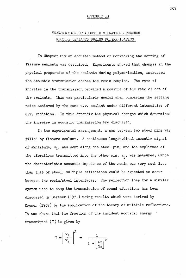
103APPENDIX II
TRANSMISSION OF ACOUSTIC VIBRATIONS THROUGH
FISSURE SEALANTS DURING POLYMERISATION
In Chapter Six an acoustic method of monitoring the setting of fissure sealants was described. Experiments showed that changes in the physical properties of the sealants during polymerisation, increased the acoustic transmission across the resin samples. The rate of increase in the transmission provided a measure of the rate of set of the sealants. This was particularly useful when comparing the setting rates achieved by the same u.v. sealant under different intensities of u.v. radiation. In this Appendix the physical changes which determined the increase in acoustic transmission are discussed.
In the experimental arrangement, a gap between two steel pins was filled by fissure sealant. A continuous longitudinal acoustic signal of amplitude, v^, was sent along one steel pin, and the amplitude of the vibrations transmitted into the other pin, v^, was measured. Since the characteristic acoustic impedence of the resin was very much less than that of steel, multiple reflections could be expected to occur between the resin/steel interfaces. The reflection loss for a similar system used to damp the transmission of sound vibrations has been discussed by Beranek (1971) using results which were derived by Cremer (1967) by the application of the theory of multiple reflections. It was shown that the fraction of the incident acoustic energy transmitted (T) is given by
21

104Where, for this arrangement v^ = incident amplitude of vibration
v^ = transmitted amplitude of vibration w = frequencyZ = acoustic impedence of steel s = stiffness of resin sample
= EA/dA = cross-section area of resin d = -width of resin gap E = elastic modulus of resin
If reflection losses are large, so that T is much less than unity, then
ZaZa
2s 2 ~2EA~wZ wdZ
oc S OC E
Hence under these circumstances the fraction of the incident amplitude which is transmitted is proportional to the stiffness of the resin sample, and also therefore to the elastic modulus for a given sample length. Thus in the liquid state the stiffness of the resin would be virtually zero, so that the transmission would be negligible. In practice this was confirmed, since the acoustic signal across the liquid sealant was not detectible above the background noise. As the resin set the stiffness of the resin sample increased so that the transmission also increased. This change was readily detected by the apparatus described,
in Chapter Six.However, this simple one dimensional model does not fully explain
the behaviour of the experimental system. Despite the fact that the resin has a much lower acoustic impedence than steel, the theory predicts complete transmission once the resin is set, due to the shortness of the gap compared to the wavelengths involved. In practice
105the experiments discussed in Chapter Six showed that the transmission
was certainly less than unity for Nuva-seal and Alphaseal since higher
transmissions were noted with Nuva-cote. This is probably explained
by the greater stiffness of Nuva-cote, due to the incorporation of
filler particles.

106
REFERENCES
Albert, M. & Grenoble, D.E. (1971) An in vivo study of enamel remineralisation after acid etching. Journal of the Southern
California Dental Association, 39, 747-751.Arana, E,M, (1974) Clinical observations of enamel after acid-etch
procedure. Journal of the American Dental Association, 89, 1102-1106,Ast, D.B., Smith, D.J., Wachs, E, & Cantwell, K.T. (1956) Newburgh-
Kingston caries-fluorine study XIV. Combined clinical and
roentgenographic dental findings after ten years of fluoride experience. Journal of the American Dental Association, 52,
314-325.Backer Dirks, 0. (l96l) Longitudinal dental caries study in children
9-15 years of age. Archives of Oral Biology, 6, 94-108.Backer Dirks, 0., Houwink, B. & Kwant, G.W. (1961) The results of
years of artificial fluoridation of drinking water in the Netherlands. Archives of Oral Biology, 5, 284-300.
Bagramian, R. & Graves, R. (1976) Sealant effectiveness for children in a fluoridated community. Journal of Dental Research, 55, B238,
abst. 705.Barr, J.H., Diodatti, R.R. & Stephens, R.G. (1957) Incidence of caries
at different locations on the teeth. Journal of Dental Research,
36, 536-545.Beech, D.R. (1972) Bonding of Alkyl-2-cyanoacrylates to human dentin
and enamel. Journal of Dental Research, 51, 1436-1442.Beranek, L.L. (1971) Noise and Vibration Control, pp. 352-357*
New York : McGraw-Hill.Berman, D.S. & Slack, G.L, (1973) Susceptibility of tooth surfaces to
carious attack : a longitudinal study. British Dental Journal,
134, 135-139.

10?
Besic, F.C. (1943) The fate of bacteria sealed in dental cavities.
' Journal of Dental Research. 22, 349-354*Bishara, S.E., Khowassah, M.A. & Oesterle, L.J. (1975) Effect of
humidity and temperature changes on orthodontic direct bonding adhesive systems. Journal of Dental Research, 54, 751-758.
Blayney, J.R. & Hill, I.N. (1967) Fluorine and dental caries.Journal of the American Dental Association, 74, 222-302.
Bodecker, C.F. (1924) Microscopic study of enamel fissures with reference to their operative treatment. Dental Cosmos, 66, 1054-
1067.Bojanini, J., Garces, H., McCune, R.J. & Pineda, A. (1976) Efficacy of
fissure sealant in prevention of occlusal caries. Journal of Dental
Research, 55, B236, abst. 700.Bowen, R.L. (1963) Properties of a silica-reinforced polymer for
dental restorations. Journal of the American Dental Association,
66, 57-64*
Bowen, R.L. (1965) Adhesive bonding of various materials to hard tooth tissues; 1. Method of determining bond strength. Journal of Dental
Research, 44, 690-695.Brauer, G.M. & Termini, D.S. (1972) Bonding of bovine enamel to
restorative resin : effect of pretreatment of enamel. Journal of
Dental Research, 51, 151-160.Breakspeare, R.J., Tranter, T.C. 8c Weldon, L.H.P. (1975) Apparatus for
measuring the adhesion of polymers to tooth enamel. Laboratory
Practice, 26, 347-348.Brooks, J.D., Della-Giustina, V.E., Fairhurst, C.W., Mertz-Fairhurst,
E.J. 8c Williams, J.E. (1976) Retention and efficacy of two pit and fissure sealants. Journal of Dental Research, 55, B237, abst. 702.
1 0 8
Buonocore, M.G. (1955) A simple method, of increasing the adhesion of
acrylic filling materials to enamel surfaces. Journal of Dental Research. 34, 849-853.
Buonocore, M. (1970) Adhesive sealing of pits and fissures for caries prevention, with use of ultra-violet light. JournaJ. of the American Dental Association. 80, 324-328.
Buonocore, M.G. (1971) Caries prevention in pits and fissures sealed with an adhesive resin polymerized by ultra-violet light : a two year study of a single adhesive application. Journal of the American
Dental Association, 82, 1090-1093.Buonocore, M.G. (1975) The Use of Adhesives in Dentistry. Illinois :
Thomas•Buonocore, M.G., Matsui, A, & Gwinnett, A.J. (1968) Penetration of
resin dental materials into enamel surfaces. Archives of Oral
Burt, B.A., Berman, D.S., Gelbier, S. & Silverstone, L.M. (1975)Retention of a fissure sealant six months after application,British Dental Journal, 138, 96-100.
Caulk (1974) Personal communication from the L.D. Caulk Co.Chen, C.T. & Huang, W.D. (1969) Kinetics of photosensitized
polymerization of methyl methacrylate with benzoin. Journal of the
Chinese Chemical Society, 16, 46-54*Chinmayanandam, B.R. & Melville, H.W. (1954) Photosensitization of
polymerization reactions. Transactions of the Faraday Society, 50,
73-62.Chow, L.C. & Brown, W.E. (1973) Phosphoric acid conditioning of teeth
for pit and fissure sealants. Journal of Dental Research, 52, 1158.
Cohl, M.E., Green, L.J. & Eick, J.D. (1972) Bonding of clear plastic
orthodontic brackets using an ultraviolet-sensitive adhesive.American Journal of Orthodontics, 62, 400-411.

Cons, N.C., Pollard, S.T. & Leske, G.S. (1976) Adhesive sealant
clinical trial : results of a three-year study in a fluoridated
area. Journal of Preventive Dentistry, 3, No.3* 14-20.Crabb, H.S.M. (1976) Fissures at risk. British Dental Journal, 140,
303-307.Cremer, L. & Heckl, M. (1967) Korperschall. pp. 328-333* Berlin :
Springer-Verlag.
Cueto, E., & Buonocore, M.G. (1967) Sealing of pits and fissures with adhesive resin : its use in caries prevention. Journal of the
American Dental Association, 75, 121-128.Day, C.D.M. & Sedwick, H.J. (1935) Studies on the incidence of dental
caries. Dental Cosmos, 77, 442-452.Dennison, J.B., Charbeneau, G.T. & Ryge, G. (1975) Clinical
evaluation of a filled bis-gma sealant utilising a primer. Journal of Dental Research. 54* A90, abst. 182.
Dennison, J.B., Charbeneau, G.T. & Ryge, G. (1976) Clinicalevaluation of an autopolymerizing filled resin pit and fissure sealant. Journal of Dental Research, 55, B236, abst. 699.
Dennison, J.B., Meyer, J.M., Birnholtz, S.B. & Craig, R.G. (1974) Initial leakage under pit and fissure sealants assessed by neutron activation. Journal of Dental Research, 53, 1439-1444.
Dogon, I.L. (1976) The influence of viscosity on the penetration of resin into acid etched enamel. Journal of Dental Research, 55,
Special Issue B, abst. 306.Douglas, W.H. & Tranter, T.C. (1975) A clinical trial of a fissure
sealant : results after two years. Proceedings of the British
Paedodontic Society, 5, 17-28.Eden, G.T., Craig, R.G. & Peyton, F.A. (1970) Evaluation of a tensile
test for direct filling resins. Journal of Dental Research, 49,
428-434.

110
Englander, H.R., Carlos, J.P., Senning, R.S. & Mellberg, J.R. (1969)
- Residual anticaries effect of repeated topical sodium fluoride applications by mouthpieces. Journal of the American Dental Association. 78, 783-787.
Going, R.E., Haugh, L.D., Grainger, D.A. & Conti, A.J. (1976) Two year clinical evaluation of a pit and fissure sealant. Part 1 : Retention and loss of substance. Journal of the American Dental Association,
92, 388-397.Gore, J.T. (1939) Etiology of dental caries enamel immunization
experiments. Journal of the American Dental Association, 26,
958-959.Gottleib, B. (1948) Technique of impregnation for caries prophylaxis.
Journal of the Missouri State Dental Association. 28, 366-367*Gourley, J.M. (1974) A one year study of a fissure sealant in two
Nova Scotia communities. Journal of the Canadian Dental Association.
40, 549-552.Gourley, J.M. (1975) A two-year study of a fissure sealant in two
Nova Scotia communities. Journal of Public Health Dentistry, 35,
132-137.Grainger, R.M. & Reid, D.B.W. (1954) Distribution of dental caries in
children. Journal of Dental Research, 33, 613-623.Graves, R.C., Bagramian, R.A. & Bhat, M. (1975) Pattern of sealant
retention in primary and permanent teeth : one year's findings.Journal of Dental Research, 54, Special Issue A, 90, abst. 183.
Gwinnett, A.J. (1971a) Morphology of the interface between adhesive resins and treated human enamel fissures as seen by scanning electron microscopy. Archives of Oral Biology, 16, 237-238.
Gwinnett, A.J. (1971b) Letters to the Editor. British Dental Journal,
130, 322-333.

Gwinnett, A.J, (1973) Human prismless enamel and its influence on sealant penetration. Archives of Oral Biology, 18, 441-444.
Gwinnett, A.J. & Buonocore, M.G. (1965) Adhesives and caries prevention, a preliminary report. British Dental Journal, 119, 77-BO.
Gwinnett, A.J. & Buonocore, M.G. (1972) A scanning electron microscope study of pit and fissure surfaces conditioned for adhesive sealing. Archives of Oral Biology. 17, 415-423.
Gwinnett, A.J. & Matsui, A. (1967) A study of enamel adhesives : the physical relationship between enamel and adhesive. Archives of Oral Biology, 12, 1615-1620.
Gwinnett, A.J. & Ripa, L.W. (1973) Penetration of pit and fissure sealants into conditioned human enamel in vivo. Archives of Oral
Biology, 18, 435-439.Handelman, S.L. (1976) Microbiological aspects of sealing carious
lesions. Journal of Preventive Dentistry, 3, No.2, 29-32.Handelman, S.L,, Buonocore, M.G. & Heseck, D.J. (1972) A preliminary
report on the effect of fissure sealant on bacteria in dental caries. Journal of Prosthetic Dentistry, 27, 390-392.
Handelman, S.L., Buonocore, M.G. & Schoute, P.C. (1973) Progress report on the effect of a fissure sealant on bacteria in dental caries. Journal of the American Dental Association, 87, 1189-1191.
Handelman, S.L., Washburn, F. & Wopperer, P.C. (1975) Two year report: sealant effect on bacteria in dental caries. Journal of
Dental Research, Special Issue A, 54$ abst. 407*Hargreaves, J.A. (1964) The problem of caries in child dental health.
British Dental Journal, 116, 386-390.
Harris, N.O., Moolenaar, L., Homberger, N., Knight, G.H. & Frew, R.A. (1976) Adhesive sealant clinical trial : effectiveness in a school population of the U.S. Virgin Islands. Journal of Preventive
Dentistry, 3> No.3$ 27-37.

112Helle, A. (1975) Two fi ssure sealants tested for retention and caries
reduction in Finnish children. Proceedings of the Finnish Dental
Society, 71, 91-95.Hoffman, S. (1972) Variations in surface resistance to enamel
etching. Journal of Dental Research, 51$ 795-799*Horowitz, H.S. Heifetz, S.B. & McCune, R.J. (1974) The effectiveness
of an adhesive sealant in preventing occlusal caries : findings after two years in Kalispell, Montana. Journal of the American Dental Association, 89, 885-890.
Horowitz, H.S., Heifetz, S.B. & Poulsen, S. (1976) Adhesive sealant clinical trial : an overview of results after four years in Kalispell, Montana. Journal of Preventive Dentistry, 3, No.3,
38-49.Huggett, R. (1975) Studies on the measurement of hardness of some . dental acrylic resins. Journal of the British Institute of Surgical
Technicians, 1, 36-58..Hyatt, T.P. (1923) Prophylactic odontotomy : the cutting into the tooth
for prevention of disease. Dental Cosmos, 65, 234-241.Hyatt, T.P. (1930) A review of the dental literature on pits and
fissures. Journal of Dental Research, 10, 659-673*Jenkins, C.B.G. (1974) Personal communication.Jeronimus, D.J., Till, M.J. & Sveen, O.B. (1975) Reduced viability
of microorganisms under dental sealants. Journal of dentistry for
Children, 42, 275-280.Jorgensen, K.D. (1975) Contralateral symmetry of acid etched enamel
surfaces. Scandinavian Journal of Dental Research, 83, 26-30.Jorgensen, K.D. & Shimokobe, H. (1975) Adaptation of resinous
restorative materials to acid etched enamel surfaces. Scandinavian
Journal of Dental Research, 83, 31-36.

Khowassah, M.A.F. & Sahs, E.A. (1966) The sealing properties of
methyl-2-cyanoacrylate as an adhesive in dentistry. Journal of Dental Research. 45, 376-378.
Khowassah, M.A. & Shippy, R.L. (l97l) In vitro investigations of the adhesive strength of cyanoacrylate bonds to human hard tooth structures. Journal of Biomedical Materials Research, 5, 159-168,
Kidd. E.A.M, (1976) Microleakage : a review. Journal of Dentistry,4, 199-206.
Klein, H. & Knutson, J.W. (1942) Studies in dental caries : effect of ammoniacal silver nitrate on caries in the first permanent molar. Journal of the American Dental Association, 29, 1420-1426.
Kochavi, D., Gedalia, I. & Anaise, J. (1975) Effect of conditioning with fluoride and phosphoric acid on enamel surfaces as evaluated by scanning electron microscopy and fluoride incorporation.
Journal of Dental Research, 54, 304-309.Laswell, H.R., Welk, D.A. & Regenos, J.W. (1971) Attachment of resin
restorations to acid pretreated enamel. Journal of the American
Dental Association, 82, 558-563.Lee, B.D., Phillips, R.W. & Swartz, M.L. (l97l) The influence of
phosphoric acid etching on retention of acrylic resin to bovine enamel. Journal of the American Dental Association, 82, 1381-1386.
Lee, H. & Orlowski, J. (1975) Fissure sealants. In ScientificAspects of Dental Materials, ed. Fraunhofer, J.A. Von Ch.3 London :
Butterworth,Lee, H., Stoffey, D., Orlowski, J,, Swartz, M.L., Occumpaugh, D. &
Neville, K. (1972). Sealing of developmental pits and fissures : III. Effects of fluoride on adhesion of rigid and flexible sealers.
Journal of Dental Research, 51, 191-201.

Lee, H.L. & Swartz, M.L. (l97l) Sealing of developmental pits and
fissures : I. In vitro study. Journal, of Dental Research, 50,
133-140,
Lee, H.L., Swartz, M.L., & Culp, G. (1969) Static load testing of dental adhesives. Journal of Dental Research, 48, 211-216.
Lewis, D.W. & Hargreaves, J.A. (1975) Epidemiology of dental caries in relation to pits and fissures. British Dental Journal, 138,
345-348.Low, T., Fraunhofer, J.A. Von & Winter, G.B. (1975) The bonding of a
polymeric fissure sealant to topical fluoride coated teeth. Journal of Oral Rehabilitation, 2, 303-308.
Low, T., Fraunhofer, J.A. Von & Winter, G.B. (1976) The long term bonding of a polymeric fissure sealant to stannous fluoride treated
enamel. Journal of Oral Rehabilitation, 3, 311-314.Marshall, G.W., Olson, L.M. & Lee, C.V. (1975) S.E.M. investigation
of the variability of enamel surfaces after simulated clinical acid etching for pit and fissure sealants. Journal of Dental Research,
54, 1222-1231.Marthaler, T.M. (1967) The value in caries prevention of other methods
of increasing fluoride ingestion, apart from fluoridated water. International Dental Journal, 17, 606-618.
Marthaler, T.M. (1969) Caries-inhibiting effect of fluoride tablets. Helvetica Odontologica Acta, 13, 1-13.
Marthaler, T.M. & Schenardi, C. (1962) Inhibition of caries after 5j years of fluoridated table salt.
Martinez, C.R., Cooley, R.O. & Greener, E.H. (1974) In vitro sealing efficacy of three pit and fissure sealants. Journal of Dental
Research, 53 > Special Issue, abst. 394.McCune, R.J. & Cvar, J.F. (l97l) Fit and fissure sealants :
preliminary results. International Association of Dental. Research,
Chicago Meeting, abst. 745.
1 1 5McLean, J.W. & Wilson, A.D. (1974) Fissure sealing and filling with an
adhesive glass-ionomer cement. British Dental Journal, 136,269-276.
Mednick, G.A,, Loesche, W.J. & Corpron, R.E. (1974) A bacterial evaluation of an occlusal sealant as a barrier system in humans. Journal of Dentistry for Children, 41* 356-360.
Meurman, J.H. (1976) Detrimental effect of in vitro salivarycontamination on acid etched enamel. Proceedings of the Finnish Dental Society, 72, 30-32.
Meurman, J.K. & Asikainen, M. (1976) Rehardening of acid-etched enamel. Proceedings of the Finnish Dental Society, 72, 120-126.
Meurman, J.H. & Helminen, S.K.J. (1976) Effectiveness of fissure sealant 3 years after application. Scandinavian Journal of Dental
Research, 84, 218-223.Micik, R.E. (1972) Fate of in vitro caries-like lesions sealed within
tooth structure. International Association of Dental Research,
abst. 710.Miller, J. (1950) Clinical investigations in preventive dentistry,
British Dental Journal, 91, 92-98.Miller, W.D. (1905) Preventive treatment of the teeth, with special
reference to silver nitrate. Dental. Cosmos, 47, 913-922.Mizrahi, E. & Smith, D.C. (1969a) Direct cementation of orthodontic
brackets to dental enamel : an investigation using a zinc polycarboxylate cement. British Dental Journal., 127, 371-375.
Mizrahi, E. & Smith, D.C. (1969b) The bond strength of a zinc polycarboxylate cement : investigation into the behaviour under
varying conditions. British Dental Journal, 127, 410-414*Muhler, J.C., Radike, A.W., Nebergall, W.H. & Day, H.G. (1954) The
effect of a stannous fluoride containing dentifrice on caries reduction in children. Journal of Dental Research, 33, 606-612.

Mulholland, R.D. & Deshazer, D.O. (1968) The effect of acid
pretreatment solutions on the direct bonding of orthodontic bracket to enamel. The Angle Orthodontist, 38, 236-243-
Mfy'ers, C.L., Rossi, F. & Cartz, L. (1974) Adhesive tag-like extensions into acid-etched tooth enamel. Journal of Dental
Research, 53, 435-441.Nakagaki, Y. et al. (l97l) Clinical study on single application with
cyanoacrylate sealant. Japanese Journal of Dental Health, 20,
276-279.Ninomiya, Y. et al. (1968) A clinical evaluation of the efficacy of
ethylcyanomethacrylate and methyl methacrylate polymer as filling material for the prevention of tooth caries. Journal of the Kyushu
Dental Society, 22, 239-243.. Ohmori, I., Kikuchi, K., Masuhara, E. & Tanaka, S. (1976) Effect of
the MMA-TBB sealant in preventing occlusal caries. Journal of
Dental Research, 55, B237, abst. 704*Ohsawa, T. (1972) Studies on solubility and adhesion of the enamel
in pretreatment for caries preventive sealing. Bulletin of Tokyo
Dental College, 13, 65-82.Otsuki, A., Takeyama, K., Ohsawa, S. & Takeuchi, M. (1973) A simple
tensile test apparatus of dental adhesives for testing machine. Bulletin of the Tokyo Dental College, 14, 141-146.
Parfitt, G.J. (1955) The distribution of caries on different sites of the teeth in English children from the age of 2-15 years. British
Dental Journal, 99, 423-427.Parkhouse, R.C. & Winter, G.B. (l97l) A fissure sealant containing
methyl-2-cyanoacrylate as a caries preventive agent : a clinical
evaluation. British Dental Journal, 130, 16-19.

1 1 7Patrick, R.L. & Kaplan, C.M. (1965) Rubbery polymers as intermediate
layers between tooth structure and restorative materials. In
Adhesive Dental Restorative Materials II, ed. Phillips, R.W., pp. 156-186. U.S. Public Health Service Publication.
Peterson, J.K., Horowitz, H.S., Jordan, W.A. & Pugnier, V. (1969) Effectiveness of an acidulated phosphate fluoride-pumice prophylactic paste : a two year report. Journal of Dental Research,
48, 346-350.Phillips, R.W., Swartz, M. & Rhodes, B. (1970) An evaluation of
carboxylate adhesive cement. Journal of the American Dental
Association, 81, 1353-1359.Pink, T.C. (1972) In vitro evaluation of bacterial penetration at the
-margins of a commercial occlusal sealant. M.Sc. Thesis, University
of Michigan, U.S.A.Prime, J.M. (1937) Controlling dental caries. Journal of the American
Dental Association, 24, 1950-1961.Retief, D.H. (1973) Effect of conditioning the enamel surface with
phosphoric acid. Journal of Dental Research, 52, 333-341.Retief, D.H., Dreyer, C.J. & Gavron, G. (1970) The direct bonding of
orthodontic attachments to teeth by means of an epoxy resin adhesive. American Journal of Orthodontics, 58. 21-40.
Rich, J.M., Leinfelder, K.F. & Hershey, H.G. (1975) An in vitro study of cement retention as related to orthodontics. The Angle
Orthodontist, 45, 219-225.Ripa, L.W. (1971) Letters to the Editor. British Dentel Journal,
130, 322.Ripa, L.W. (1975) Studies of pits and fissures. In The Use of
Adhesives in Dentistry, ed. Buonocore, M.G. Ch.5. Illinois :
Thomas,Ripa, L.W. (1976) The current status of occlusal sealants. Journal
of Preventive Dentistry, 3, No,2, 6-14.

Ripa, L.W. & Cole, W.W. (1970) Occlusal sealing and caries prevention
results 12 months after a single application of adhesive resin.
Journal of Dental Research, 49* 171-173*Risager, J. & Poulsen, S. (1974) Fissure sealing vdth Nuva-seal in a
public health program for Danish school children after 12 months observation. Scandinavian Journal of Dental Research, 82, 570-573*
Robb, R.G. & Garcia, R. (1972) Clinical observations on fissure sealers in fluoridated and non-fluoridated areas. International
Association of Dental Research, abst. 687.Rock, W.P. (1972) Fissure sealants : results obtained with two
different sealants after one year. British Dental Journal, 133,
146-151.-Rock, W.P. (1973) Fissure sealants : results obtained with two
different bis-GMA type sealants after one year. British Dental.
Journal, 134* 193-196.Rock, W.P. (1974a) Fissure sealants : further results of clinical
trials. British Dental Journal, 136, 317-321.Rock, W.P. (1974b) The use of ultra-violet radiation in dentistry.
British Dental Journal, 136, 455-458.Rock, W.P. (l974c) The effect of etching human enamel upon bond
strengths vdth fissure sealant resins. Archives Oral Biology, 19,
873-877.Roydhouse, R.H. (1968) Prevention of occlusal fissure caries by use
of a sealant : a pilot study. Journal of Dentistry for Children,
35, 253-262.Rudolph, J.J., Phillips, R.W. & Swartz, M.L. (1974) In vitro
assessment of microleakage of pit and fissure sealants. Journal
of Prosthetic Dentistry, 32, 62-65.
Saxton, C.A. (1973) Scanning electron microscope study of the formation of dental plaque. Caries Research, 7, 102-119.

Sharp, E.C. & Grenoble, D.E. (l97l) Dental resin penetration into acid etched subsurface enamel. Journal of the Southern California Dental
Association. 39, 741-746.Sheykholeslam, Z. & Buonocore, M.G. (1972) Bonding of resins to
phosphoric acid-etched enamel surfaces of permanent and deciduous teeth. Journal of Dental Research, 51, 1572-1576.
Silverstone, L.M. (1974) Fissure sealants : laboratory studies.Caries Research, 8, 2-26.
Silverstone, L.M., Saxton, C.A., Dogon, I.L. & Fejerskov, 0. (1975) Variation in the pattern of acid etching of human dental enamel examined by scanning electron microscopy. Caries Research, 9,
373-387.Simmelink, J.W., Nygaard, V.K. & Scott, D.B. (1974) Penetration of
resins into partially decalcified enamel, in vitro. Journal of Dental Research, 53, special issue, abst. 396.
Soetopo, A. (l975) An in vitro investigation into the value ofcomposite resins combined with acid etching techniques for restoring
teeth. M.Sc. Thesis ManChester University.Stephen, K.W., Sutherland, D.A. & Trainer, J. (1976) Fissure sealing
by practitioners : first year retention data in Scottish 6-year-old children. British Dental Journal, 140, 45-51
Stiles, H.M., Ward, G.T., Woolridge, E.D. & Meyers, R. (1976)Adhesive sealant clinical trial : comparative results of application by a dentist or dental auxiliaries. Journal of Preventive Dentistry,
3, No.3, 8-11.Takeuchi, M. (1964) On caries controlling methods. Shikwa Gakuho,
63, 170-184.Takeuchi, M., Shimizu, T., Kizu, T., Eto, M., Nakagawa, M., Ohsawa, T.
& Oishi, T. (1971) Sealing of the pit and fissure with resin adhesive : IV. Results of five-year field work for caries prevention.

Ulvestad, H. (1973) Fissurforsegling med lakkmaterialer : praktiske
resultater. Den Norske Tannlaegeforenings Tidende, 83, 129-132.Ulvestad, H. (1976) A 24-month evaluation of fissure sealing with a
diluted composite material. Scandinavian Journal of Dental Research,
84, 51-55.Wallis, C.P. (1973) Preventive treatment of fissure caries. Journal of
Dentistry, 1, 207-210.
Watkins, J.J. (l975) The surface hardness of three bisphenol-A and glycidyl methacrylate fissure sealants. Journal of Dentistry, 3, 68-72.
Wei, S.H.Y. (1967) Remineralization of enamel and dentine, a review.
Journal of Dentistry for Children, 34, 444-451.~Whitehurst, V. & Soni, N.N. (1976) Adhesive sealant clinical trial :
results eighteen months after one application. Journal of Preventive
Dentistry, 3, No.3, 20-22.Williams, B., Casson, M.H. & Winter, G.B. (1974) A clinical study using
a new ultra-violet light polymerized fissure sealant. Journal of
Dentistry, 2, 101-105.Williams, B.F., Fraunhofer, J.A. Von & Winter, G.B. (1974) Tensile
strength between fissure sealants and enamel. Journal of Dental
Research, 53, 23-27.Williams, B., Fraunhofer, J.A. Von & Winter, G.B. (1975a) Microleakage
in fissure sealants as determined by dye penetration and zero
resistance current measurement studies. British Dental Journal,
139, 237-241.Williams, B., Fraunhofer, J.A. Von & Winter, G.B. (1975b) A
comparative evaluation of the microhardness, water solubility and water absorption of fissure sealants. Journal of Dentistry, 3, 1-8.

121
Williams, B., Fraunhofer, J.A. Von & Winter, G.B. (1976) Etching
of enamel prior to application of fissure sealants. Journal of Oral Rehabilitation, 3, 185-188.
Williams, B. & Winter, G.B. (1976) Fissure Sealants ; a 2-year clinical trial. British Dental Journal, 141, 15-18.
Williams, M.L. De Vries, K.L. & Despain, R.R. (1973) A technique for evaluating dental adhesives. Journal of Dental Research, 52, 517-
521.Woody, R.D., Moffa, J.P. & McCune, R.J. (1972) Assessment of leakage
of four pit and fissure sealant materials by Ca45. International
Association of Dental Research, abst. 717*Woxen, R. (1944) A new microhardness tester. Industrial Diamond
Review, 4, -241-249.Wright, F.A.C. & Beck, D.J. (1973) Prevention of pit and fissure caries
: III Fluoride and resin-enamel bonding. New Zealand Dental
Journal, 69, 77-84Yamamoto, K., Kajiura, K., Satoru, T., Nodo, Y. & Kato, K. (1971).
Discrimination between human and animal teeth by means of scanning electron microscopy. Bulletin of the Tokyo Dental College, 12,
317-332.