An Open Stratiform Pit Design System for Orebodies - SAIMM
6
An Open Stratiform Pit Design System for Orebodies By L. A. J. PRQNK "AN HOOGEVEEN,· M.Se. (Delfi), J. R. CUTLAND, t BSc. (Lomkm), A.R.CS., MA. (Lamaster), and M. WEIR,t D.Se. (LonOOn). SYNOPSIS A computer sy:rtcm for the design of open pits to mioe stratirorID orebodies has been developed for use at Nchanga Consolidated Copper Mines, Ltd. The particular requirements of such a system, for example, the accuracy of rcpL'CS(:ntation of geological detail and the ability to follow footwaHs, arc dewribcd in this paper, together with the methods that have been adopted to satisfy them. A modified venion of the Open Pit Design Program of Rio Tinto Zinc Consultants, Ltd. is incorporated in the system and the geological data are converted into a form usable b:r. tbe computer by means of a pencil follower. Somo of the uses which have been made of the system are • with reference to the 1011g- and medium-term piannma of the Nchanga Open Pit, the major producing pit at Chingola Division. INTRODU CTION The Chingola Division of Nchanga Consolidated Copper Mines. Limited, currently operates five open pits, with several more scheduled for future production. Some of the orebodies being mined, and in particular the orebodies of the Nchanga Open Pit, are of a dipping, stratiform oature. The use of computer programs for the de..'Jign and evaluation of pits to mine such orebodies raises problems that are not usuall y met when massiveorebociies are considered. Dne major problem is that it is essential to represent the Ihin orebodies in coosiderable detail, but the high stripping ratio then implies that a large amount of homogeneous overburden is also represented in tbe same detail, with attendant problems of preparation of geological data input and computer storage requirements, Pits designed to mine stratiform orebodics will usually follow a geological or assay footwal1 in some areas, and the pit desiao program ha$ to do this with a minimum of human control. A system. has. been developed for use by N.C.C.M., Ltd., which satisfactorily haudles the designing of pits in stratiform orebodies. It incorporates a specially modified version of the Rio Tinto Zine Consultants' open pit design program, with an ore reserve preparation system written by N.C.C.M., Ltd., and incorporating the use of a D-Mac pencil follower. While the system has been used in the design of sl!veral pits at Chingola, this paper is concerned only with its application to the Nchanga Open Pit. 'The main use of the system is for tbe development of medium- and lons:-range plans (from two to fifteen years) for an ex.isting pit within the framewo rk of tbe 'final' pit design. No pretence is made that 'optimal' designs are obtained, although it is ex.pected that the faci li ty that the system provides to evaluate many alternative pit designs wiU lead to Unproved plans. NCHANGA OPEN PIT The geology of the Nchanga Open P it (N.O.P.) is ilhlstrated by a typical section through the orebodics, Fig. 1, and a bench plan, Fig. 2. Too orebodics lie in strata on the southern limb of the Nchanga syncline, aL1d dip to the north at about There are throo orebodies which can be treated by current metallurgical methods: the upper, intermediate and lower orebodics. The lower orebody has its sub-outcrop at a depth of about 200 m and extends down dip to a depth of over 600 m. In the area of N,Q.P. its thickness averages around 20 m and the total copper grade four per cent, 40 per cent 1<, of which is acid-soluble. The intermediate orebody is very thin, being only about s:.ix metres thick and assays about 3.5 percent total Cu, at an average acid-soluble ratio of 55 per cent. These orebodies extend over a strike length of some 1 200 to 1 III iD the wcstem part of the N. D.P. area. The major orebody. and the only one that is currently mined in N.D.P., is the upper orebody. which extends ovec a total strike length of some 4 800 m and down to a depth of over 350 m. The average thickness is abo ut 30 m. the grade about 3.5 per cent total Cu and the acid·soluble ratio is abou t SS per cent. As wi th the other two or ebodies, the thickness, grade and acid·solubJe rat io vary considerably from 000 part of the orebody to auotber. The upper orebody can be divided along strike into three main parts, a Western, a Central and an Eastern part. In the Western part, With a strike length of about 1 200 m, the ore extends front close to surface to a depth of over 350 m. The orebody is thick and the grades high throughout this part. The main parts of the intermediate and lower orebodies lie under this Western area. In the Central area, again with a strike length of about 1 200 m, the ore starts at a greater depth and does not extend as deeply as it does in the Western part. The up-dip section of the orebody is thin but the width increases with depth and the overall grade is fairly high. There is very little intermediate or lower orcbody under this part. The ore in the Eastern part, with a strike length of about 2400 m, starts close to surface but does not exteud as deeply as in the Western part. The orebody is thick b ut the average grade is lower than in the other parts. There is no intermediate or lower orebody under this Eastern part of th.e uppec orebody, The total volumetric stripping ralio for the whole pit is ill the region of 18 (0 I. T he rock types separatiog the three main orebodies, averagin g 10 to IS m in thickness. are mineralized, in places up 10 two per cent tota] copper, but the mi neralization is of a refractory micaceous nature and can ll ot be treated by current metaUurgica.l processes. However, this material, together with that iD other areas of low-grade mineralization on the hangingwal\ side of the orebodies, is stockpiled for future treatment wherever the mining of the main orebodies neces- sitates its extraction. The overburden overlying the upper orebody is composed mainly of dolomites and argillites. *Assistant Open Pit Maoager, Advanced "Planning, Chingola Division, Nchanga Consolidated CoppeJ.· Mines, Ltd., Zambia. tAssistant Head, Operat!on81 Research, Centralized Services Division, Nchanga Conso lid ated Copper Mines, Ltd., Zambia. tSenior Systellls Analyst, Centralized Services Division, Nchanga Consolidated Copper Mines, Ltd., Zambia. , ,
-
Upload
khangminh22 -
Category
Documents
-
view
2 -
download
0
Transcript of An Open Stratiform Pit Design System for Orebodies - SAIMM
An Open Stratiform
Pit Design System for Orebodies
By L. A. J. PRQNK "AN HOOGEVEEN,· M.Se. (Delfi), J . R. CUTLAND, t BSc. (Lomkm), A.R.CS., MA. (Lamaster), and M. WEIR,t D.Se. (LonOOn).
SYNOPSIS
A computer sy:rtcm for the design of open pits to mioe stratirorID orebodies has been developed for use at Nchanga Consolidated Copper Mines, Ltd. The particular requirements of such a system, for example, the accuracy of rcpL'CS(:ntation of geological detail and the ability to follow footwaHs, arc dewribcd in this paper, together with the methods that have been adopted to satisfy them.
A modified venion of the Open Pit Design Program of Rio Tinto Zinc Consultants, Ltd. is incorporated in the system and the geological data are converted into a form usable b:r. tbe computer by means of a pencil follower. Somo of the uses which have been made of the system are ~ribo • with reference to the 1011g- and medium-term piannma of the Nchanga Open Pit, the major producing pit at Chingola Division.
INTRODUCTION
The Chingola Division of Nchanga Consolidated Copper Mines. Limited, currently operates five open pits, with several more scheduled for future production. Some of the orebodies being mined, and in particular the orebodies of the Nchanga Open Pit, are of a dipping, stratiform oature.
The use of computer programs for the de..'Jign and evaluation of pits to mine such orebodies raises problems that are not usually met when massiveorebociies are considered. Dne major problem is that it is essential to represent the Ihin orebodies in coosiderable detail, but the high stripping ratio then implies that a large amount of homogeneous overburden is also represented in tbe same detail, with attendant problems of preparation of geological data input and computer storage requirements, Pits designed to mine stratiform orebodics will usually follow a geological or assay footwal1 in some areas, and the pit desiao program ha$ to do this with a minimum of human control.
A system. has. been developed for use by N.C.C.M., Ltd., which satisfactorily haudles the designing of pits in stratiform orebodies. It incorporates a specially modified version of the Rio Tinto Zine Consultants' open pit design program, with an ore reserve preparation system written by N.C.C.M., Ltd., and incorporating the use of a D-Mac pencil follower. While the system has been used in the design of sl!veral pits at Chingola, this paper is concerned only with its application to the Nchanga Open Pit.
'The main use of the system is for tbe development of medium- and lons:-range plans (from two to fifteen years) for an ex.isting pit within the framework of tbe 'final' pit design. No pretence is made that 'optimal' designs are obtained, although it is ex.pected that the faci lity that the system provides to evaluate many alternative pit designs wiU lead to Unproved plans.
NCHANGA OPEN PIT
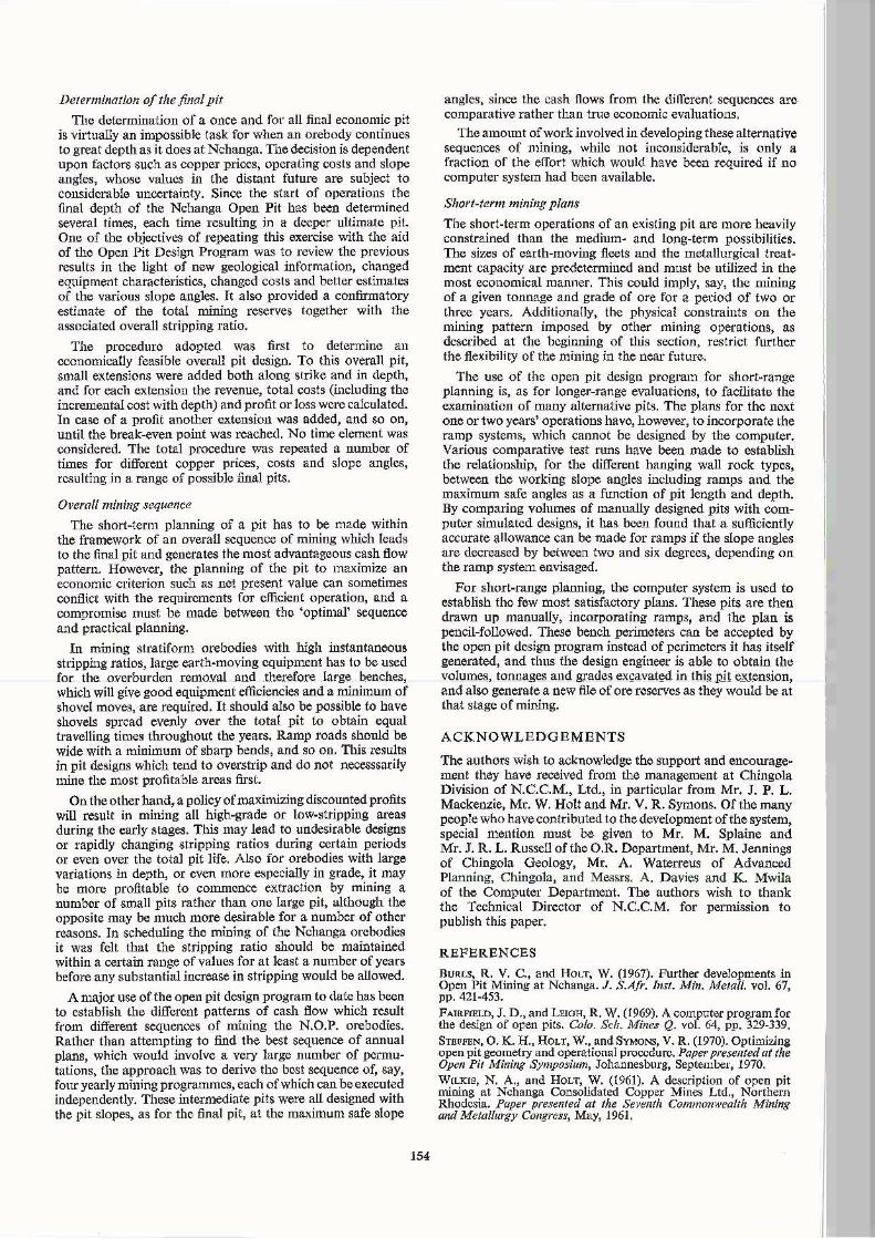
The geology of the Nchanga Open P it (N.O.P.) is ilhlstrated by a typical section through the orebodics, Fig. 1, and a bench plan, Fig. 2. Too orebodics lie in strata on the southern limb of the Nchanga syncline, aL1d dip to the north at about 30deg~.
There are throo orebodies which can be treated by current metallurgical methods: the upper, intermediate and lower orebodics. The lower orebody has its sub-outcrop at a depth of about 200 m and extends down dip to a depth of over 600 m. In the area of N,Q.P. its thickness averages around 20 m and the total copper grade four per cent, 40 per cent
1<,
of which is acid-soluble. The intermediate orebody is very thin, being only about s:.ix metres thick and assays about 3.5 percent total Cu, at an average acid-soluble ratio of 55 per cent. These orebodies extend over a strike length of some 1 200 to 1 ~OO III iD the wcstem part of the N.D.P. area.
The major orebody. and the only one that is currently mined in N.D.P., is the upper orebody. which extends ovec a total strike length of some 4 800 m and down to a depth of over 350 m. The average thickness is about 30 m. the grade about 3.5 per cent total Cu and the acid·soluble ratio is about SS per cent. As with the other two orebodies, the thickness, grade and acid·solubJe ratio vary considerably from 000 part of the orebody to auotber.
The upper orebody can be divided along strike into three main parts, a Western, a Central and an Eastern part. In the Western part, With a s trike length of about 1 200 m, the ore extends front close to surface to a depth of over 350 m. The orebody is thick and the grades high throughout this part. The main parts of the intermediate and lower orebodies lie under this Western area.
In the Central area, again with a strike length of about 1 200 m, the ore starts at a greater depth and does not extend as deeply as it does in the Western part. The up-dip section of the orebody is thin but the width increases with depth and the overall grade is fairly high. There is very little intermediate or lower orcbody under this part. The ore in the Eastern part, with a strike length of about 2400 m, starts close to surface but does not exteud as deeply as in the Western part. The orebody is thick but the average grade is lower than in the other parts. There is no intermediate or lower orebody under this Eastern part of th.e uppec orebody, The total volumetric stripping ralio for the whole pit is ill the region of 18 (0 I.
The rock types separatiog the three main orebodies, averaging 10 to IS m in thickness. are mineralized, in places up 10 two per cent tota] copper, but the mineralization is of a refractory micaceous nature and canllot be treated by current metaUurgica.l processes. However, this material, together with that iD other areas of low-grade mineralization on the hangingwal\ side of the orebodies, is stockpiled for future treatment wherever the mining of the main orebodies necessitates its extraction. The overburden overlying the upper orebody is composed mainly of dolomites and argillites.
*Assistant Open Pit Maoager, Advanced "Planning, Chingola Division, Nchanga Consolidated CoppeJ.· Mines, Ltd., Zambia.
tAssistant Head, Operat!on81 Research, Centralized Services Division, Nchanga Consolidated Copper Mines, Ltd., Zambia.
tSenior Systellls Analyst, Centralized Services Division, Nchanga Consolidated Copper Mines, Ltd., Zambia.
, ,
~

=-63 ==-85 ==-H17 --,a --~151
--173 --195 --217 --- ---- ---- --.,.,'" !\i~'" -t------fioOm D~=---
LEGEND
~ upp~r ore-body
• intermediate oubody
lIT] tower ore-body
--272
--294 --,,6 --'38 --360'
-.-----------------------.-- :"~"".--__;:~:__;:_ .. ,,,.__,H_
Fig. 1. Typical section through Nchollga Open Pit.
.. . ,.,
LEGEND
.' ..... '
• upper ore-body
• inhrmediate oreb\ldy
D lower otebody
Fig. 2. Portion of a bench plall of the Ncha/llfo Open Pit.
150
I ,

When iI was decided in 19S5 to mine the upper orcbody by open pit methods, tbe initia] pit was planned in the Western part This dccision was influenced not only by thc economic advantages of good grades and volumes near surface, but also by the fact that a pit in that area would be situated close to the existing underground mine, which could provide a good means for dewatering the pit area to a level below the final pit bottom, and also because the haulage distance to an existing mill would be short. Descriptions of previous operations at N.D.P. have beell given by Wilkie, et al (1961) and Burls, et al (1967).
Currenlly ore is mioed f!'Om N.O.P. at the rate of about 380 000 I/month, using 4.6-mll shovels and 45-too Irucks. O verburden is removed at the ra te of about 2.S million bank mS{montb mainLy by 7.6 and II. 5-m3 shovels and 6S- and lOO-ton trucks, with somc material 011 the upper benches beillg ex.cavated by bucket wheel excavator and belt conveyor.
PREPARATION OF ORE RESERVES
Form 0/ the ore reserve data
The Open Pit Design Program is a version of that written by RTZ Consul tants a nd is described in more detail later. The program requires that thc ore reserves be represented in the form of rectangular blocks of ground, each identified by its rock type, there being a matrix of these blocks for each bench of the pit.
As can be seen from the bench plan in Fig. 2, to obtain a reasonabJerepresentation of the fairly thin strata, it is necessary to use a small block size. A rectangular block of 12 m along strike by 6 m by 11 ill high (that is, the beDch height) is used for N.D.P., giving a matrix. size of 300 by 300 blocks. This is rather large for most computen if, as is the case with tbe open pit design program, the whole matrix representing one levd is held io core at the same time.
Geologico l Pencil Trons-
B ~ n c l1 Pions formotion Faltowar '
Progrom
r Bor ehole I Grade Dota r
PI0B:J Transformed I Data
Grad ~ Contour
Plans
I Printer Oulput Plolt!!r Output Output of Or~
of Re-c reote d
An added complication is that the extreme variability of the copper grade and the acid-soluble ra tio cannot casily be described by the usual method of specifying different grades as inclividual rock types. Instead, it is necessary to assign a total and acid-soluble copper grade to each individual 12 m by 6 m block within the orebodies, although in practice a group of four contiguous blocks may have tbe same grades. This detailed information regarding grades is required for blocks in the ore horiwns only, whieh will be considerably less th.an 20 per cent of the total rock matrix. The remainder of the matrix will consist of large areas of undiffecentiatOO waste above and below the orebodies.
1lUs problem of Ihe vast amount of computcr space required 10 represent the ore reserves to a satisfactory degree of accuracy has beeo overcome by 'packing' the rock matrix. This meaos that each column of the matrix (or a given bench lcvel is represented in the fonn:
nh RI; n2' R 2; no, 0; n3' Ra; etc. where n l is the number of contiguous blocks of rock type Ri' and, in this case, no is the number of blocks containing the ore horizons, denoted by tbe rock type number O. The blocks within the ore horizon are then expanded and contained, block by block, in two separate matrices, 000 for tbe rock type and one for the grades. By this method, it has proved possible to contain the origioalJOO by 300 rock matrix (without grades) ror N .O.P. within a packed matrix of 3oo by 60. (All tbematrix elements are in half-word integers.) The grades for each block are calculated to the nearest 0.1 per ccnt, and are then packed as an integer ill thc form: (256 " %ASCu " 10 + %TCu "'10)
Method of gel/eration of ore reserves
The preparation of the ore reserves in the form described above falls into two separate parts, firs tly, the generation of the rock matrices, and, secondly, the assignrucllt of grades to the blocks in the orebodies. An o utline diagram of the system is given in Fig. 3.
Rock Motri x Rock GeMrotion Matrix -
Prog ram File POl;king :- Pro gram
ContOl.lring Grade f-
P r-ogrom File
/Ore ( Rlsem: )
t.last~r
C h~ (. ki n g
I ,Fi le - Programs
Sase P!!rim!!t!!rs Open Pi t and Control Doh I D!!si:ln Program
I I of RQck 'i Grode Rl!ser ... ~s by Matrices Banc.h Plans B!!neh-5ec1j~ Volumes.Tonnes Pi t ...- Per imeter
an d Gradl!$ Plot s Of Pit. ~
-Fig. J. Outline of ore re.rerre generatlOIl (md Optll pit desigll system.
151
i

The basic information that is used for the input of the rock data is the bench plan produced by the geologist, giving lithological and assay contacts at the mid-bench position. These bench plans have then to be converted into a form which can be handled by the computer. This conversion is made using a D-Mac pencil follower, which punches the coordinates of points along the contacts onto cards. The pencil follower at Chingola consists of a reading table, an electronics console and a card punch. The plan is laid on the reading table, and the line traced with the 'pencil'. The 'pencil' consists basically of a transparent viewer with crosswires, encircled by a coil which is coupled inductively with a detector mechanism on a trolley under the reading surface. The trolley is kept in position under the 'pencil' by means of servoamplifiers and servo-motors, and the location of the trolley is recorded by means of encoders attached to the servo systems. The position of the pencil can then be communicated via the electronics console for output on the card punch. The co-ordinates output from the pencil follower are relative to its own original plan. One problem encountered during the initial stages was that of uni-directional stretching of the paper on which the plans were printed. This was overcome by calculating the scale transformation parameters in two orthogonal directions.
The method that has been adopted at Chingola for the coding of the rock matrix is to pencil-follow each of the separate rock areas as closed polygons and to code the blocks contained in the polygon with the relevant rock type. This set of coded blocks is then written in to the master matrix, overwriting whatever else is there. By utilizing this overwriting facility and by keeping careful control over the order of the input of the rock type areas, it is possible to reduce the pencil following to a minimum, with each contact having to be input accurately only once. The procedure used is, firstly, to code all the matrix to the 'footwall' rock type, and then to work towards the hanging wall side, assigning all rock above each contact with the appropriate rock type code. The next area input then overlays all but the area between the successive contacts. 'This method is able to handle satisfactorily even the most complex geological areas, as well as being able to merge togelh_cr the rock information from the several parts that make up one bench plan.
The grades of blocks within the orebodies are currently assigned by grade contouring, using a computer contouring package. For each orebody, the average grade of the borehole intersection between assay hanging wall and assay footwall is contoured for total and acid-soluble copper grades. Grades are assigned to the ore blocks on the basis of the grade values that the contouring package calculates for each point of its interpolation grid before the contours are drawn. Each of these grid points is then taken to have a 'zone of influence' and each ore block is assigned the grade of the grid point nearest to it. In N.O.P. each grid value is assigned to the 2 x 2 set of blocks adjoining it. The grade contours are produced on the plotter to provide a visual check on the grade data being generated.
Mter the rock matrix and the grade data have been generated, they are 'packed' into the form described above and stored on magnetic tape for use by the Open Pit Design Program. Various programs have been written to enable the input data to be validated and to allow the final set of ore reserves to be checked. For example, the input from the pencil follower is checked by the computer program to ensure that there are no major mistakes, and the lines are plotted after transformation.
The main checking, however, is done on the final ore reserve tape and produces three types of output. Firstly, the rock and grade matrices are printed on the line printer, an alphameric code being used for each rock type or range of
152
grades. This is a fairly coarse check and enables major errors, like the omission of a rock type area, to be seen easily. Secondly, the bench plans are recreated from the rock matrix, and plotted to the original scale in block form. This permits a detailed assessment of the accuracy of representation of the geology by the ore reserve file. Thirdly, the ore reserves are calculated in such a way as to facilitate direct comparison with the current manually-produced ore reserves. This form gives the tonnes and grade of the ore for each orebody by a bench-section, that is, the ore on the given bench and between two section lines. The form of representation is described more fully by Steff'en, et al (1970).
THE OPEN PIT DESIGN PROGRAM
The RTZC Open Pit Design Program is described in detail by Fairfleld, et at (1969). This basic program, which was developed for the evaluation of massive deposits, was modified by RTZC to enable it to be used on stratiform orebodies like N.O.P. The major modifications made were the incorporation of the packed matrix concept, the assignment of grades to individual blocks, and routines to enable the pit to follow user-specified footwalIs in given areas. The program is, however, still able to handle massive or lenticular orebodies and to assign uniform grades to individual rock types.
The pits are generated by the program from a base perimeter supplied as a series of points by the pit designer. The program then works up bench by bench to the surface, projecting this perimeter upwards and outwards, the pit slopes being specified by the user for each rock type and the perimeter being adjusted, if necessary, to satisfy specified conditions imposed on the lengths of the chords and angles. between adjacent chords. At each bench level the program evaluates the tonnage and grade of ore and waste that is within the excavation.
The input of the base perimeter can be by one of two methods, either by manually coding tbe co-ordinates of the points, or by pencil~following the base perimeter and inputting these cards together with the calibration cards necessary to permit conversion of the pencil follower co-ordinates to real co-ordinates.
For the area within which footwalls are to be followed a rectangular area is specified by maximum and minimum X and Y co-ordinates for every level. Each perimeter point is checked to see if it is within the specified area for that bench and also within one of the set of rock types specified. If it is, then the perimeter point is projected outwards in increments, but not exceeding a specitied distance. After a complete circuit of the perimeter, it is adjusted to satisfy the conditions imposed on chord lengths and angles between adjacent chords. The pel'imeter is again projected if possible and the above process repeated for either a maximum given number of circuits, or until no increase in the number of points is obtained. The method works satisfactorily, producing pit perimeters that follow the desired contacts within the discrimination allowed by the blocks, and allowing the pit to step out along strike for specified distances, as is described in the next section.
Many of the runs of the program aJ'e for the evaluation of different extensions to existing 01' future pits. It is therefore desirable for the design engineer to be able to see a plan of the total pit resulting from the previous pit combined with the extensions. The piotting routine developed for use with the program allows him to specify which combinations of pits from a set of runs he wishes to see plotted together as composite pits. The method of merging the perimeters makes use of the fact that the angles subtended at a point by the chords of a polygon will sum to 360 degrees if the point is inside the polygon (anglcs gencrated clockwise and anti-
"

clockwise have opposite signs) and 0 decrees ir the point is outside. This permits the program to establish. which points of perimetcr A arc inside perimeter IJ, and vice versa, and thus find the intersection points and the new joint perimeter.
One of the major considerations during the development of the system has been that it should be easily usable by pit design engineers who arc unfamiliar with computers, with minimal involvement of computer personnel. While the generation of the ore reserve files requires programmer assistance, the peocil-following and the design of pits are handled routinely by the pit planning department.
The computing facil iti~ available for use by the program are an IBM System/360 model 65 with 512K bytes of store, plus 2 314 discs aod tape units. The fWlS for N.O.P. designs, with typically 30 benches, are done in a 194K partition and require around 15 minutes per pit design. Plotting is done on an off-line tape-controlled plotter. As presently written, some of the data-preparation programs, notably the program which codes the rock matrix from the pencil follower input, are run in a 400K partition, although this could be reduced, if necessary, at the expense of running time.
U SES OP THE SYSTEM
The use of the open p it design program for the planning of N.O.P. was divided into three phases:
(i) the determination of the depth and limits of the finaJ pit, (ii) the determination of the best sequence of mining within
the final pit, and (iii) the establishment of the short-term mining program.
Before describing these phases in more detail, it is worth noting SOme of the constraints on the pl:lOning of N.O.P. as it is now, after several years of mining.
The initial Nchanga Open Pit was approximately roctangular in plan and was sleadily deepened without much development
I I I I 200 150 100 50 0
SCALE IN METRES
along strike. In the near fulure underground working will expand to go under the western cod of tile pit. This neccs3itates the exhaustion of all ecollomically mineable ore in tllat area of the pit before it is affected by cave cracks, and also the mining of a sump in a safe area or a level below this exhausted part. Because of this, during the last few years the pit has been deepened mainly in its western end, while being extended eastwards along strike.
Most of the recent designs for the Nchtlnga Opcn Pit show an approximately triangular shape both in plan and in section along strike. The bouom of the pit is rorated by a ramp which descends from east 10 west along the hanging wall of the orebody until it meets the sump. This kind of design gives a 'stepped' type of ore exposure diagonally across the orebody. The pit design engineer is able to emulate this type of pit design by using the feature of the open pit design progra m which allows the pit to foHow-up a specified contact or assay footwall when the angle of dip of the orebody is less than the safe slope angle. By increasing the limits, from one bench to the next one above, within which the perimeter is projected to the footwall, the perimeter will step out along strike within the given rock types to the new limit. An example of a computer-produced pit design, showing this footwalt foUowiog and projection along strike, is given in Fig. 4.
Duritlg the use of the system for the planning of Nchanga Open Pit, two furthec constraints were obeyed. Firstly, it was decided to maintain the ore production at its current annual rate of about 4.6 million tonnes per annum. The effect of variations in this tonnage on tho total profitability would be meaningless without considering at the same time changes in the mining rates of other operations both at Chingola and the other Divisions of N.C.C.M. Secondly, tbe effect of varying the cut-off grade has not yet been considered. In N.O.P. the current cutoQff grade of 1.5 per cent total Cu is more or less the 'natural' cut-olf grade, since very little trcatabJe material with grades below this value is available.
129 107
96
200 400 '00
Fig. of. Example 0/ computtr-deligntd pit, :hrJWillK following of foo/wall on soutll side, and $teJ!Pi1~ OUI nlong strike.
153
Determination of the final pit
The determination of a once and for all final economic pit is virtually an impossible task for when an OIebody continues to great depth as it does at Nchanga. The decision is dependent upon factors such as copper prices, operating costs and slope angles, whose values in the distant future are subject to considerable uncertainty. Since the start of operations the final depth of the Nchanga Open Pit has been determined several times, each time resulting in a deeper ultimate pit. One of the objectives of repeating this exercise with the aid of the Opcn Pit Design Program was to review the previous results in the light of new geological information, changed equipment characteristics, changed costs and better estimates of the various slope angles. It also provided a confirmatory estimate of the total mining reserves together with the associated overall stripping ratio.
The procedure adopted was first to determine an economically feasible overall pit design. To this overall pit, small extensions were added both along strike and in depth, and for each extension the revenue, total costs (including the incremental cost with depth) and profit or loss were calculated. In case of a profit another extension was added, and so on, until the break-even point was reached. No time element was considered. The total procedure was repeated a number of times for different copper prices, costs and slope angles, resulting in a range of possible final pits.
Overall mining sequence
The short-term planning of a pit has to be made within the framework of an overall sequence of mining which leads to the final pit and generates the most advantageous cash flow pattern. However, the planning of the pit to maximize an economic criterion such as net present value can sometimes conflict with the requirements for efficient operation, and a compromise must be made between the 'optimal' sequence and practical planning.
In mining stratiform orebodies with high instantaneous stripping ratios, large earth-moving equipment has to be used for the. overburden removal .andtherefore large benches, which will give good equipment efficiencies and a minimum of shovel moves, are required. It should also be possible to have shovels spread evenly over the total pit to obtain equal travelling times throughout the years. Ramp roads should be wide with a minimum of sharp bends, and so on. This results in pit designs which tend to overstrip and do not necesssarily mine the most profitable areas first.
On the other hand, a policy of maximizing discounted profits will result in mining all high~grade or low-stripping areas during the early stages. This may lead to undesirable designs or rapidly changing stripping ratios during certain periods or even over the total pit life. Also for orebodies with large variations in depth, or even more especially in grade, it may be more profitable to commence extraction by mining a number of small pits rather than one large pit, although the opposite may be much more desirable for a number of other reasons. In scheduling the mining of the Nchanga oreborues it was felt that the stripping ratio should be maintained within a certain range of values for at least a number of years before any substantial increase in stripping would be allowed.
A major use of the open pit design program to date has been to establish the different patterns of cash flow which result from different sequences of mining the N.O.P. orebodies. Rather than attempting to find the best sequence of annual plans, which would involve a very large number of permutations, the approach was to derive thc best sequence of, say, four yearly mining programmes, each of which can be executed independently. These intermediate pits were all designed with the pit slopes, as for the final pit, at the maximum safe slope
154
angles, since the cash flows from the dilTerent sequences arc comparative rather than true economic evaluations.
The amount of work involved in developing these alternative sequences of mining, while not inconsiderable, is only a fraction of the effort which would have been required if no computer system had been available.
Short-term mining plans
The short-term operations of an existing pit are more heavily constrained than the medium- and long-term possibilities. The sizes of earth-moving fleets and the metallurgical treatment capacity are predetermined and must be utilized in the most economical manner. This could imply, say, thc mining of a given tonnage and grade of ore for a period of two or three years. Additionally, the physical constraints on the mining pattern imposed by other mining operations, as described at the beginning of tlns section, restrict further the flexibility of the mining in the near future.
The use of the open pit design program for short-range planning is, as for longer-range evaluations, to facilitate the examination of many alternative pits. The plans for the next one or two years' operations have, however, to incorporate the ramp systems, which cannot be designed by the computer. Various comparative test runs have been made to establish the relationship, for the different hanging wall rock types, between the working slope angles including mmps and the maximum safe angles as a function of pit length and depth. By comparing volumes of manually designed pits with computer simulated designs, it has been found that a sufficiently accurate allowance can be made for ramps if the slope angles are decreased by between two and six degrees, depending on the ramp system envisaged.
For short-range planning, the computer system is used to establish thc few most satisfactory plans. These pits are then drawn up manually, incorporating ramps, and the plan is pencil-followed. These bench perimeters can be accepted by the open pit design program instead of perimetcrs it has itSelf generated, and thus the design engineer is able to obtain the volumes, tonnages and grades excavated in thispjt extension, and also generate a new file of ore reserves as they would be at that stage of mining.
ACKNOWLEDGEMENTS
The authors wish to acknowledge the support and encourageM ment they have received from the management at Chingola Division of N.C.C.M., Ltd., in particular from Mr. J. P. L. Mackenzie, Mr. W. Holt and Mr. V. R. Symons. Of the many people who have contributed to the development of the system, special mention must be given to Mr. M. Splaine and Mr. J. R. L. Russell ofthe O.R. Department, Mr. M. Jennings of Chingola Geology, Mr. A. Waterreus of Advanced Planning, Chingola, and Messrs. A. Davies and K. Mwila of the Computer Department. The authors wish to thank the Technical Director of N.C.C.M. for permission to publish this paper.
REFERENCES
BUR.LS, R. Y. C., and HOLX, W. (1967). Further developments in Open Pit Mining at Nchanga. J. S.Afr. Inst. Min. Me/all. vol. 67, pp. 421-453. FAIRFlELD, J. D., and LEloH, R. W. (1969). A computer program for the design of open pits. Colo. Scll. Mines Q. vol. 64, pp. 329-339. STE~FEN, O. K. H., HOLT, W., andSYMoNS, V. R. (1970). Optimizing open pit geometry and operational procedure. Paper presel/led at the Open Pit Mining Symposium, Johannesburg, September, 1970. W(LKlE, N. A., and HOLT, W. (1961). A description of open pit mining at Nchanga Consolidated Copper Mines Ltd., Northern Rhodcsia. Paper presented at the Seventh Commonwealth Mining and Metallurgy Congress, May, 1961.