FC302 Instruction Manual - Danfoss AC Drives - Galco
108
MAKING MODERN LIVING POSSIBLE Instruction Manual VLT ® AutomationDrive FC 300, 0.25–75 kW
-
Upload
khangminh22 -
Category
Documents
-
view
2 -
download
0
Transcript of FC302 Instruction Manual - Danfoss AC Drives - Galco

MAKING MODERN LIVING POSSIBLE
Instruction ManualVLT® AutomationDrive FC 300, 0.25–75 kW

Safety
WARNINGHIGH VOLTAGE!Adjustable frequency drives contain high voltage whenconnected to AC line power. Installation, startup, andmaintenance should be performed by qualified personnelonly. Failure to perform installation, startup, andmaintenance by qualified personnel could result in deathor serious injury.
High VoltageAdjustable frequency drives are connected to hazardousAC line voltage. Extreme care should be taken to protectagainst shock. Only trained personnel familiar withelectronic equipment should install, start, or maintain thisequipment.
WARNINGUNINTENDED START!When the adjustable frequency drive is connected to ACline power, the motor may start at any time. Theadjustable frequency drive, motor, and any drivenequipment must be in operational readiness. Failure to bein operational readiness when the adjustable frequencydrive is connected to AC line power could result in death,serious injury, equipment, or property damage.
Unintended StartWhen the adjustable frequency drive is connected to ACline power, the motor may be started with an externalswitch, a serial bus command, an input reference signal, ora cleared fault condition. Use appropriate caution to guardagainst an unintended start.
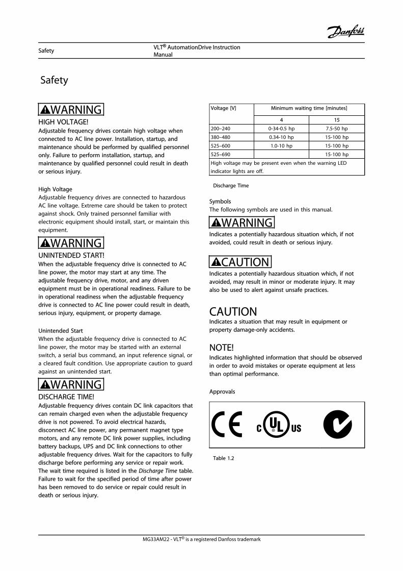
WARNINGDISCHARGE TIME!Adjustable frequency drives contain DC link capacitors thatcan remain charged even when the adjustable frequencydrive is not powered. To avoid electrical hazards,disconnect AC line power, any permanent magnet typemotors, and any remote DC link power supplies, includingbattery backups, UPS and DC link connections to otheradjustable frequency drives. Wait for the capacitors to fullydischarge before performing any service or repair work.The wait time required is listed in the Discharge Time table.Failure to wait for the specified period of time after powerhas been removed to do service or repair could result indeath or serious injury.
Voltage [V] Minimum waiting time [minutes]
4 15
200–240 0-34-0.5 hp 7.5-50 hp
380–480 0.34-10 hp 15-100 hp
525–600 1.0-10 hp 15-100 hp
525–690 15-100 hp
High voltage may be present even when the warning LEDindicator lights are off.
Discharge Time
SymbolsThe following symbols are used in this manual.
WARNINGIndicates a potentially hazardous situation which, if notavoided, could result in death or serious injury.
CAUTIONIndicates a potentially hazardous situation which, if notavoided, may result in minor or moderate injury. It mayalso be used to alert against unsafe practices.
CAUTIONIndicates a situation that may result in equipment orproperty damage-only accidents.
NOTE!Indicates highlighted information that should be observedin order to avoid mistakes or operate equipment at lessthan optimal performance.
Approvals
Table 1.2
Safety VLT® AutomationDrive InstructionManual
MG33AM22 - VLT® is a registered Danfoss trademark

NOTE!Imposed limitations on the output frequency(due to export control regulations):From software version 6.72, the output frequency of theadjustable frequency drive is limited to 590 Hz. Softwareversions 6x.xx also limit the maximum output frequency to590 Hz, but these versions cannot be flashed, i.e., neitherdowngraded nor upgraded.
Safety VLT® AutomationDrive InstructionManual
MG33AM22 - VLT® is a registered Danfoss trademark

Contents
1 Introduction 2-1
1.1 Purpose of the Manual 2-2
1.2 Additional Resources 2-3
1.3 Product Overview 2-3
1.4 Internal Controller Functions 2-3
1.5 Frame Sizes and Power Ratings 2-5
2 Installation 3-1
2.1 Installation Site Checklist 3-1
2.2 Adjustable Frequency Drive and Motor Pre-installation Checklist 3-1
2.3 Mechanical Installation 3-1
2.3.1 Cooling 3-1
2.3.2 Lifting 3-2
2.3.3 Mounting 3-2
2.3.4 Tightening Torques 3-2
2.4 Electrical Installation 3-3
2.4.1 Requirements 3-5
2.4.2 Grounding Requirements 3-5
2.4.2.1 Leakage Current (>3.5 mA) 3-6
2.4.2.2 Grounding Using Shielded Cable 3-6
2.4.3 Motor Connection 3-6
2.4.4 AC Line Input Connection 3-7
2.4.5 Control Wiring 3-7
2.4.5.1 Access 3-7
2.4.5.2 Control Terminal Types 3-8
2.4.5.3 Wiring to Control Terminals 3-9
2.4.5.4 Using Shielded Control Cables 3-10
2.4.5.5 Control Terminal Functions 3-10
2.4.5.6 Jumper Terminals 12 and 27 3-10
2.4.5.7 Terminal 53 and 54 Switches 3-11
2.4.5.8 Mechanical Brake Control 3-11
2.4.6 Serial Communication 3-12
2.5 Safe Stop 3-12
2.5.1 Terminal 37 Safe Stop Function 3-13
2.5.2 Safe Stop Commissioning Test 3-16
3 Start-up and Functional Testing 4-1
3.1 Pre-start 4-1
Contents VLT® AutomationDrive InstructionManual
MG33AM22 - VLT® is a registered Danfoss trademark

3.1.1 Safety Inspection 4-1
3.2 Applying Power 4-3
3.3 Basic Operational Programming 4-3
3.4 Asynchronous Motor Set-up 4-4
3.5 PM Motor Set-up in VVCplus 4-5
3.6 Automatic Motor Adaptation 4-5
3.7 Check Motor Rotation 4-6
3.8 Check Encoder Rotation 4-6
3.9 Local Control Test 4-7
3.10 System Start-up 4-7
4 User Interface 5-1
4.1 Local Control Panel 5-1
4.1.1 LCP Layout 5-1
4.1.2 Setting LCP Display Values 5-2
4.1.3 Display Menu Keys 5-2
4.1.4 Navigation Keys 5-3
4.1.5 Operation Keys 5-3
4.2 Backup and Copying Parameter Settings 5-3
4.2.1 Uploading Data to the LCP 5-4
4.2.2 Downloading Data from the LCP 5-4
4.3 Restoring Default Settings 5-4
4.3.1 Recommended Initialization 5-4
4.3.2 Manual Initialization 5-4
5 About Adjustable Frequency Drive Programming 6-1
5.1 Introduction 6-1
5.2 Programming Example 6-1
5.3 Control Terminal Programming Examples 6-2
5.4 International/North American Default Parameter Settings 6-3
5.5 Parameter Menu Structure 6-4
5.5.1 Main menu structure 6-5
5.6 Remote Programming with MCT 10 Set-up Software 6-9
6 Application Examples 7-1
6.1 Introduction 7-1
6.2 Application Examples 7-1
7 Status Messages 8-1
7.1 Status Display 8-1
Contents VLT® AutomationDrive InstructionManual
MG33AM22 - VLT® is a registered Danfoss trademark

7.2 Status Message Definitions Table 8-1
8 Warnings and Alarms 9-1
8.1 System Monitoring 9-1
8.2 Warning and Alarm Types 9-1
8.3 Warning and Alarm Displays 9-1
8.4 Warning and Alarm Definitions 9-2
9 Basic Troubleshooting 10-1
9.1 Start Up and Operation 10-1
10 Specifications 11-1
10.1 Power-dependent Specifications 11-1
10.2 General Technical Data 11-14
10.3 Fuse Specifications 11-19
10.3.2 Recommendations 11-19
10.3.3 CE Compliance 11-19
10.4 Connection Tightening Torques 11-28
12 Index 12-1
Contents VLT® AutomationDrive InstructionManual
MG33AM22 - VLT® is a registered Danfoss trademark

Contents VLT® AutomationDrive InstructionManual
MG33AM22 - VLT® is a registered Danfoss trademark

1 Introduction
1
23
4
5
6
7
8
9
10
11
1213
14
8
15
16
17
18
130B
B492
.10
Figure 1.1 Exploded View A1-A3, IP20
1 LCP 10 Motor output terminals 96 (U), 97 (V), 98 (W)
2 RS-485 serial bus connector (+68, -69) 11 Relay 1 (01, 02, 03)
3 Analog I/O connector 12 Relay 2 (04, 05, 06)
4 LCP input plug 13 Brake (-81, +82) and load sharing (-88, +89) terminals
5 Analog switches (A53), (A54) 14 Line power input terminals 91 (L1), 92 (L2), 93 (L3)
6 Cable strain relief/PE ground 15 USB connector
7 Decoupling plate 16 Serial bus terminal switch
8 Grounding clamp (PE) 17 Digital I/O and 24 V power supply
9 Shielded cable grounding clamp and strain relief 18 Control cable cover plate
Table 1.1 Legend to Figure 1.1
Introduction VLT® AutomationDrive InstructionManual
MG33AM22 - VLT® is a registered Danfoss trademark 1-1
1 1

1
2
3
4
5
6
7
8
9
10
11
12 13
1617
1819
1415
FAN MOUNTING
QDF-30
DC- DC+
Remove jumper to activate Safe StopMax. 24 Volt !
12 13 18 19 27 29 32 33 20
61 6839 42 50 53 54
0605
0403
0201
130B
B493
.10
Figure 1.2 Exploded View B and C Sizes, IP55/66
1 LCP 11 Relay 2 (04, 05, 06)
2 Cover 12 Lifting ring
3 RS-485 serial bus connector 13 Mounting slot
4 Digital I/O and 24 V power supply 14 Grounding clamp (PE)
5 Analog I/O connector 15 Cable strain relief/PE ground
6 Cable strain relief/PE ground 16 Brake terminal (-81, +82)
7 USB connector 17 Load sharing terminal (DC bus) (-88, +89)
8 Serial bus terminal switch 18 Motor output terminals 96 (U), 97 (V), 98 (W)
9 Analog switches (A53), (A54) 19 Line power input terminals 91 (L1), 92 (L2), 93 (L3)
10 Relay 1 (01, 02, 03)
Table 1.2 Legend to Figure 1.2
1.1 Purpose of the Manual
This manual is intended to provide detailed information forthe installation and startup of the adjustable frequencydrive. provides requirements for mechanical and electricalinstallation, including input, motor, control and serialcommunications wiring and control terminal functions. provides detailed procedures for startup, basic operational
programming, and functional testing. The remainingchapters provide supplementary details. These detailsinclude user interface, detailed programming, applicationexamples, startup troubleshooting, and specifications.
Introduction VLT® AutomationDrive InstructionManual
1-2 MG33AM22 - VLT® is a registered Danfoss trademark
11

1.2 Additional Resources
Other resources are available to understand advancedadjustable frequency drive functions and programming.
• The VLT® Programming Guide provides greaterdetail on working with parameters and manyapplication examples.
• The VLT® Design Guide is intended to providedetailed capabilities and functionality to designmotor control systems.
• Supplementary publications and manuals areavailable from Danfoss.See http://www.danfoss.com/BusinessAreas/Drives-Solutions/Documentations/Technical+Documentation.htm for listings.
• Optional equipment is available that may changesome of the procedures described. Reference theinstructions supplied with those options forspecific requirements. Contact the local Danfosssupplier or visit the Danfoss website: http://www.danfoss.com/BusinessAreas/DrivesSolutions/Documentations/Technical+Documentation.htm, fordownloads or additional information.
1.3 Product Overview
An adjustable frequency drive is an electronic motorcontroller that converts AC line power input into a variableAC waveform output. The frequency and voltage of theoutput are regulated to control the motor speed or torque.The adjustable frequency drive can vary the speed of themotor in response to system feedback, such as positionsensors on a conveyor belt. The adjustable frequency drivecan also regulate the motor by responding to remotecommands from external controllers.
In addition, the adjustable frequency drive monitors thesystem and motor status, issues warnings or alarms forfault conditions, starts and stops the motor, optimizesenergy efficiency, and offers many more control,monitoring, and efficiency functions. Operation andmonitoring functions are available as status indications toan outside control system or serial communicationnetwork.
1.4 Internal Controller Functions
Figure 1.3 is a block diagram of the adjustable frequencydrive's internal components. See Table 1.3 for theirfunctions.
Figure 1.3 Adjustable Frequency Drive Block Diagram
Introduction VLT® AutomationDrive InstructionManual
MG33AM22 - VLT® is a registered Danfoss trademark 1-3
1 1

Area Title Functions1 Mains input • Three-phase AC line power
supply to the adjustablefrequency drive
2 Rectifier • The rectifier bridge convertsthe AC input to DC current tosupply inverter power
3 DC bus • Intermediate DC bus circuithandles the DC current
4 DC reactors • Filter the intermediate DCcircuit voltage
• Prove line transient protection
• Reduce RMS current
• Raise the power factorreflected back to the line
• Reduce harmonics on the ACinput
5 Capacitor bank • Stores the DC power
• Provides ride-throughprotection for short powerlosses
6 Inverter • Converts the DC into acontrolled PWM AC waveformfor a controlled variableoutput to the motor
7 Output to motor • Regulated three-phase outputpower to the motor
8 Control circuitry • Input power, internalprocessing, output, and motorcurrent are monitored toprovide efficient operationand control
• User interface and externalcommands are monitored andperformed
• Status output and control canbe provided
Table 1.3 Legend to Figure 1.3
Introduction VLT® AutomationDrive InstructionManual
1-4 MG33AM22 - VLT® is a registered Danfoss trademark
11
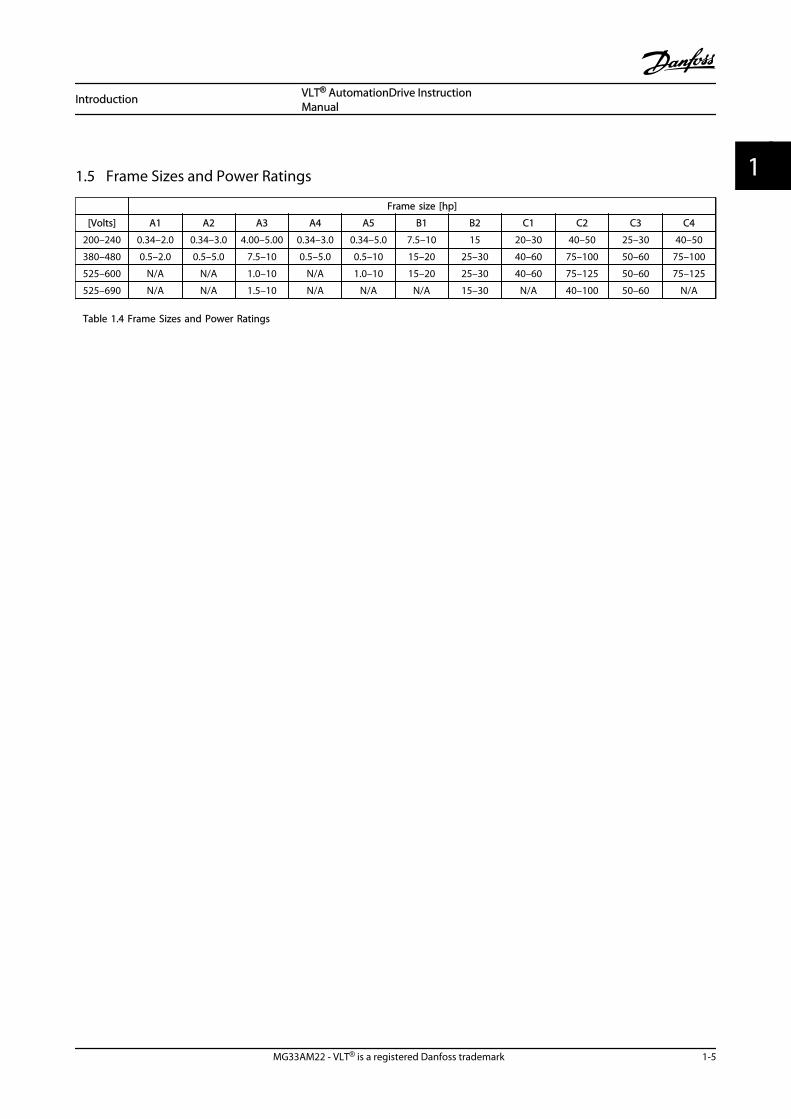
1.5 Frame Sizes and Power Ratings
Frame size [hp]
[Volts] A1 A2 A3 A4 A5 B1 B2 C1 C2 C3 C4
200–240 0.34–2.0 0.34–3.0 4.00–5.00 0.34–3.0 0.34–5.0 7.5–10 15 20–30 40–50 25–30 40–50
380–480 0.5–2.0 0.5–5.0 7.5–10 0.5–5.0 0.5–10 15–20 25–30 40–60 75–100 50–60 75–100
525–600 N/A N/A 1.0–10 N/A 1.0–10 15–20 25–30 40–60 75–125 50–60 75–125
525–690 N/A N/A 1.5–10 N/A N/A N/A 15–30 N/A 40–100 50–60 N/A
Table 1.4 Frame Sizes and Power Ratings
Introduction VLT® AutomationDrive InstructionManual
MG33AM22 - VLT® is a registered Danfoss trademark 1-5
1 1

Introduction VLT® AutomationDrive InstructionManual
1-6 MG33AM22 - VLT® is a registered Danfoss trademark
11
2 Installation
2.1 Installation Site Checklist
• The adjustable frequency drive relies on theambient air for cooling. Observe the limitationson ambient air temperature for optimal operation
• Ensure that the installation location has sufficientsupport strength to mount the adjustablefrequency drive
• Keep the manual, drawings, and diagramsaccessible for detailed installation and operationinstructions. It is important that the manual isavailable for equipment operators.
• Locate equipment as near to the motor aspossible. Keep motor cables as short as possible.Check the motor characteristics for actualtolerances. Do not exceed
• 1,000 ft [300 m] for unshielded motorleads
• 500 ft [150 m] for shielded cable.
• Ensure that the ingress protection rating of theadjustable frequency drive is suitable for theinstallation environment. IP55 (NEMA 12) or IP66(NEMA 4) enclosures may be necessary.
CAUTIONIngress protectionIP54, IP55 and IP66 ratings can only be guaranteed if theunit is properly closed.
• Ensure that all cable connectors and unusedholes for connectors are properly sealed.
• Ensure that the unit cover is properly closed
CAUTIONDevice damage through contaminationDo not leave the adjustable frequency drive uncovered.
For “spark-free” installations according to EuropeanAgreement concerning International Carriage of DangerousGoods by Inland Waterways (ADN_2011 ###), refer to VLT®
AutomationDrive FC 300 Design Guide.
2.2 Adjustable Frequency Drive and MotorPre-installation Checklist
• Compare the model number of unit on thenameplate to what was ordered to verify theproper equipment
• Ensure each of the following are rated for thesame voltage:
Line power
Adjustable frequency drive
Motor
• Ensure that the adjustable frequency drive outputcurrent rating is equal to or greater than motorfull load current for peak motor performance.
Motor size and adjustable frequencydrive power must match for properoverload protection
If adjustable frequency drive rating isless than motor, full motor outputcannot be achieved
2.3 Mechanical Installation
2.3.1 Cooling
• To provide cooling airflow, mount the unit to asolid flat surface or to the optional backplate (see2.3.3 Mounting)
• Top and bottom clearance for air cooling must beprovided. Generally, 100–225 mm (4–10 in) isrequired. See Figure 2.1 for clearancerequirements
• Improper mounting can result in overheating andreduced performance
• Derating for temperatures starting between 104°F [40 °C] and 122 °F [50 °C] and elevation 3,300ft [1,000 m] above sea level must be considered.See the equipment Design Guide for detailedinformation.
Installation VLT® AutomationDrive InstructionManual
MG33AM22 - VLT® is a registered Danfoss trademark 2-1
2 2
a
b
130B
A41
9.10
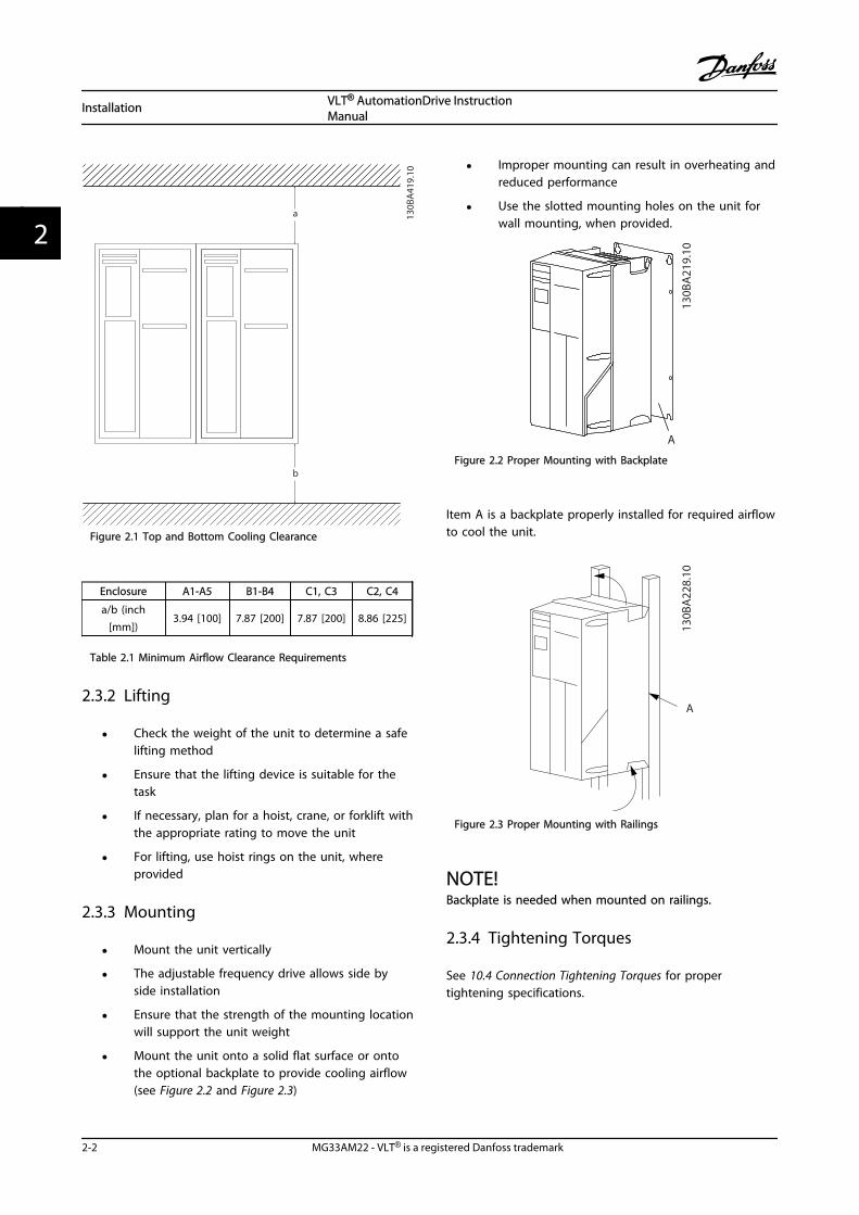
Figure 2.1 Top and Bottom Cooling Clearance
Enclosure A1-A5 B1-B4 C1, C3 C2, C4
a/b (inch[mm])
3.94 [100] 7.87 [200] 7.87 [200] 8.86 [225]
Table 2.1 Minimum Airflow Clearance Requirements
2.3.2 Lifting
• Check the weight of the unit to determine a safelifting method
• Ensure that the lifting device is suitable for thetask
• If necessary, plan for a hoist, crane, or forklift withthe appropriate rating to move the unit
• For lifting, use hoist rings on the unit, whereprovided
2.3.3 Mounting
• Mount the unit vertically
• The adjustable frequency drive allows side byside installation
• Ensure that the strength of the mounting locationwill support the unit weight
• Mount the unit onto a solid flat surface or ontothe optional backplate to provide cooling airflow(see Figure 2.2 and Figure 2.3)
• Improper mounting can result in overheating andreduced performance
• Use the slotted mounting holes on the unit forwall mounting, when provided.
130B
A21
9.10
A
Figure 2.2 Proper Mounting with Backplate
Item A is a backplate properly installed for required airflowto cool the unit.
130B
A22
8.10
A
Figure 2.3 Proper Mounting with Railings
NOTE!Backplate is needed when mounted on railings.
2.3.4 Tightening Torques
See 10.4 Connection Tightening Torques for propertightening specifications.
Installation VLT® AutomationDrive InstructionManual
2-2 MG33AM22 - VLT® is a registered Danfoss trademark
22

2.4 Electrical Installation
This section contains detailed instructions for wiring theadjustable frequency drive. The following tasks aredescribed.
• Wiring the motor to the adjustable frequency drive output terminals
• Wiring the AC line power to the adjustable frequency drive input terminals
• Connecting control and serial communication wiring
• After power has been applied, checking input and motor power; programming control terminals for their intendedfunctions
3 Phasepowerinput
DC bus Switch ModePower Supply
Motor
Analog Output
Interface
relay1
* relay2
ON=TerminatedOFF=Open
Brakeresistor
130B
C93
1.10
91 (L1)92 (L2)93 (L3)
PE
88 (-)89 (+)
50 (+10 V OUT)
53 (A IN)
54 (A IN)
55 (COM A IN)0/4-20 mA
12 (+24V OUT)
13 (+24V OUT)
37 (D IN)
18 (D IN)
20 (COM D IN)
10Vdc15mA 130/200mA
+ - + -
(U) 96(V) 97(W) 98(PE) 99
(COM A OUT) 39
(A OUT) 42
(P RS-485) 68
(N RS-485) 69
(COM RS-485) 61
0V
5V
S801
0/4-20 mA
RS-485RS-485
03
+10Vdc0/-10Vdc -
+10Vdc
+10Vdc0/4-20 mA
0/-10Vdc -
240Vac, 2A
24Vdc
02
01
05
04
06240Vac, 2A
24V (NPN) 0V (PNP)
0V (PNP)24V (NPN)
19 (D IN)
24V (NPN) 0V (PNP)27
24V
0V
(D IN/OUT)
0V (PNP)24V (NPN)
(D IN/OUT)
0V
24V29
24V (NPN) 0V (PNP)
0V (PNP)24V (NPN)
33 (D IN)
32 (D IN)
12
ON
S201O
N21S202
ON=0/4-20mAOFF=0/-10Vdc - +10Vdc
95
400Vac, 2AP 5-00
21 O
N
S801
(R+) 82
(R-) 81
*
*
: Chassis
: Earth
**
Figure 2.4 Basic Wiring Schematic Drawing
A=Analog, D=Digital Terminal 37 is used for Safe Stop. For Safe Stop installationinstructions, refer to the Design Guide.
Installation VLT® AutomationDrive InstructionManual
MG33AM22 - VLT® is a registered Danfoss trademark 2-3
2 2

* Terminal 37 is not included in FC 301 (except frame sizeA1). Relay 2 and terminal 29 have no function in FC 301.
** Do not connect cable screen.
1
2
3
4
5
6
7
8
PE
UVW
9
L1L2L3PE
130B
B607
.10
10
Figure 2.5 Typical Electrical Connection
1 PLC 6 Min. 200 mm (7.9 in) between control cables, motor and linepower
2 Adjustable frequency drive 7 Motor, 3-phase and PE
3 Output contactor (Generally not recommended) 8 Line power, 3-phase and reinforced PE
4 Grounding rail (PE) 9 Control wiring
5 Cable insulation (stripped) 10 Equalizing min. 16 mm2 (0.025 in2)
Table 2.2 Legend to Figure 2.5
Installation VLT® AutomationDrive InstructionManual
2-4 MG33AM22 - VLT® is a registered Danfoss trademark
22

2.4.1 Requirements
WARNINGEQUIPMENT HAZARD!Rotating shafts and electrical equipment can be hazardous.All electrical work must conform to national and localelectrical codes. It is strongly recommended that instal-lation, start-up, and maintenance be performed only bytrained and qualified personnel. Failure to follow theseguidelines could result in death or serious injury.
CAUTIONWIRING ISOLATION!Run input power, motor wiring and control wiring in threeseparate metallic conduits or use separated shielded cablefor high frequency noise isolation. Failure to isolate power,motor and control wiring could result in less thanoptimum adjustable frequency drive and associatedequipment performance.
For your safety, comply with the following requirements.
• Electronic controls equipment is connected tohazardous AC line voltage. Extreme care shouldbe taken to protect against electrical hazardswhen applying power to the unit.
• Run motor cables from multiple adjustablefrequency drives separately. Induced voltage fromoutput motor cables run together can chargeequipment capacitors even with the equipmentturned off and locked out.
Overload and Equipment Protection
• An electronically activated function within theadjustable frequency drive provides overloadprotection for the motor. The overload calculatesthe level of increase to activate timing for the trip(controller output stop) function. The higher thecurrent draw, the quicker the trip response. Theoverload provides Class 20 motor protection. See8 Warnings and Alarms for details on the tripfunction.
• Because the motor wiring carries high frequencycurrent, it is important that wiring for line power,motor power, and control is run separately. Usemetallic conduit or separated shielded wire.Failure to isolate power, motor, and controlwiring could result in less than optimumequipment performance.
• All adjustable frequency drives must be providedwith short-circuit and overcurrent protection.
Input fusing is required to provide thisprotection, see Figure 2.6. If not factory supplied,fuses must be provided by the installer as part ofinstallation. See maximum fuse ratings in10.3 Fuse Specifications.
L1
L1
L2
L2
L3
L3
GND
91 92 93Fuses
130B
B460
.10
Figure 2.6 Adjustable Frequency Drive Fuses
Wire Type and Ratings
• All wiring must comply with local and nationalregulations regarding cross-section and ambienttemperature requirements.
• Danfoss recommends that all power connectionsbe made with a minimum 167 °F [75 °C] ratedcopper wire.
• See 10.1 Power-dependent Specifications forrecommended wire sizes.
2.4.2 Grounding Requirements
WARNINGGROUNDING HAZARD!For operator safety, it is important to ground theadjustable frequency drive properly in accordance withnational and local electrical codes, as well as instructionscontained within these instructions. Ground currents arehigher than 3.5 mA. Failure to ground the adjustablefrequency drive properly could result in death or seriousinjury.
NOTE!It is the responsibility of the user or certified electricalinstaller to ensure correct grounding of the equipment inaccordance with national and local electrical codes andstandards.
Installation VLT® AutomationDrive InstructionManual
MG33AM22 - VLT® is a registered Danfoss trademark 2-5
2 2

• Follow all local and national electrical codes toground electrical equipment properly.
• Proper protective grounding for equipment withground currents higher than 3.5 mA must beestablished, see Leakage Current (>3,5 mA)
• A dedicated ground wire is required for inputpower, motor power and control wiring
• Use the clamps provided with the equipment forproper ground connections
• Do not ground one adjustable frequency drive toanother in a “daisy chain” fashion
• Keep the ground wire connections as short aspossible
• Use of high strand wire to reduce electrical noiseis recommended
• Follow the motor manufacturer wiringrequirements
2.4.2.1 Leakage Current (>3.5 mA)
Follow national and local codes regarding protectivegrounding of equipment with a leakage current > 3.5 mA.Adjustable frequency drive technology implies highfrequency switching at high power. This will generate aleakage current in the ground connection. A fault currentin the adjustable frequency drive at the output powerterminals might contain a DC component which cancharge the filter capacitors and cause a transient groundcurrent. The ground leakage current depends on varioussystem configurations including RFI filtering, shieldedmotor cables, and adjustable frequency drive power.
EN/IEC61800-5-1 (Power Drive System Product Standard)requires special care if the leakage current exceeds 3.5 mA.Grounding must be reinforced in one of the followingways:
• Ground wire of at least 0.0155 in2 [10 mm2]
• Two separate ground wires both complying withthe dimensioning rules
See EN 60364-5-54 § 543.7 for further information.
Using RCDsWhere residual current devices (RCDs), also known asground leakage circuit breakers (GLCBs), are used, complywith the following:
Use RCDs of type B only which are capable ofdetecting AC and DC currents
Use RCDs with an inrush delay to prevent faultsdue to transient ground currents
Dimension RCDs according to the system configu-ration and environmental considerations
2.4.2.2 Grounding Using Shielded Cable
Grounding clamps are provided for motor wiring (seeFigure 2.7).
130B
A26
6.10
+DC BR- B
MA
IN
S
L1 L2 L391 92 93
REL
AY
1
REL
AY
2
99
- LC -
U V W
MOTOR
Figure 2.7 Grounding with Shielded Cable
2.4.3 Motor Connection
WARNINGINDUCED VOLTAGE!Run output motor cables from multiple adjustablefrequency drives separately. Induced voltage from outputmotor cables run together can charge equipmentcapacitors even with the equipment turned off and lockedout. Failure to run output motor cables separately couldresult in death or serious injury.
• For maximum wire sizes, see 10.1 Power-dependent Specifications
• Comply with local and national electrical codesfor cable sizes.
• Motor wiring knockouts or access panels areprovided at the base of IP21 and higher(NEMA1/12) units
• Do not install power factor correction capacitorsbetween the adjustable frequency drive and themotor
• Do not wire a starting or pole-changing devicebetween the adjustable frequency drive and themotor.
• Connect the 3-phase motor wiring to terminals96 (U), 97 (V), and 98 (W).
Installation VLT® AutomationDrive InstructionManual
2-6 MG33AM22 - VLT® is a registered Danfoss trademark
22
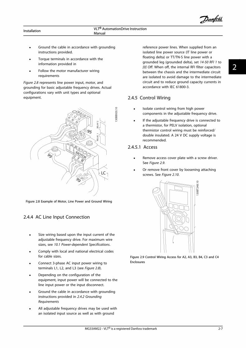
• Ground the cable in accordance with groundinginstructions provided.
• Torque terminals in accordance with theinformation provided in
• Follow the motor manufacturer wiringrequirements
Figure 2.8 represents line power input, motor, andgrounding for basic adjustable frequency drives. Actualconfigurations vary with unit types and optionalequipment.
95
130B
B920
.10
+DC BR- B
MA
IN
S
L1 L2 L391 92 93
REL
AY
1
REL
AY
2
99
- LC -
U V W
MOTOR
99
Figure 2.8 Example of Motor, Line Power and Ground Wiring
2.4.4 AC Line Input Connection
• Size wiring based upon the input current of theadjustable frequency drive. For maximum wiresizes, see 10.1 Power-dependent Specifications.
• Comply with local and national electrical codesfor cable sizes.
• Connect 3-phase AC input power wiring toterminals L1, L2, and L3 (see Figure 2.8).
• Depending on the configuration of theequipment, input power will be connected to theline input power or the input disconnect.
• Ground the cable in accordance with groundinginstructions provided in 2.4.2 GroundingRequirements
• All adjustable frequency drives may be used withan isolated input source as well as with ground
reference power lines. When supplied from anisolated line power source (IT line power orfloating delta) or TT/TN-S line power with agrounded leg (grounded delta), set 14-50 RFI 1 to[0] Off. When off, the internal RFI filter capacitorsbetween the chassis and the intermediate circuitare isolated to avoid damage to the intermediatecircuit and to reduce ground capacity currents inaccordance with IEC 61800-3.
2.4.5 Control Wiring
• Isolate control wiring from high powercomponents in the adjustable frequency drive.
• If the adjustable frequency drive is connected toa thermistor, for PELV isolation, optionalthermistor control wiring must be reinforced/double insulated. A 24 V DC supply voltage isrecommended.
2.4.5.1 Access
• Remove access cover plate with a screw driver.See Figure 2.9.
• Or remove front cover by loosening attachingscrews. See Figure 2.10.
130B
T248
.10
Figure 2.9 Control Wiring Access for A2, A3, B3, B4, C3 and C4Enclosures
Installation VLT® AutomationDrive InstructionManual
MG33AM22 - VLT® is a registered Danfoss trademark 2-7
2 2
130B
T334
.10
Figure 2.10 Control Wiring Access for A4, A5, B1, B2, C1 and C2Enclosures
See Table 2.3 before tightening the covers.
Frame IP20 IP21 IP55 IP66
A3/A4/A5 - - 2 2
B1/B2 - * 2.2 2.2
C1/C2/C3/C4 - * 2.2 2.2
* No screws to tighten- Does not exist
Table 2.3 Tightening Torques for Covers (Nm)
2.4.5.2 Control Terminal Types
Figure 2.11 and shows the removable adjustable frequencydrive connectors. Terminal functions and default settingsare summarized in Table 2.5.
23
4
1
130B
B921
.11
Figure 2.11 Control Terminal Locations
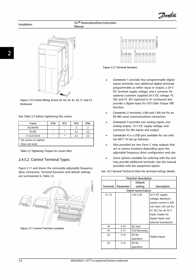
12 13 18 19 27 29 32 33 20 37
39 42 50 53 54 5561 68 69
130B
B931
.101
2 3
Figure 2.12 Terminal Numbers
• Connector 1 provides four programmable digitalinputs terminals, two additional digital terminalsprogrammable as either input or output, a 24 VDC terminal supply voltage, and a common foroptional customer supplied 24 V DC voltage. FC302 and FC 301 (optional in A1 enclosure) alsoprovide a digital input for STO (Safe Torque Off)function.
• Connector 2 terminals (+)68 and (-)69 are for anRS-485 serial communications connection
• Connector 3 provides two analog inputs, oneanalog output, 10 V DC supply voltage, andcommons for the inputs and output
• Connector 4 is a USB port available for use withthe MCT 10 Set-up Software
• Also provided are two Form C relay outputs thatare in various locations depending upon theadjustable frequency drive configuration and size
• Some options available for ordering with the unitmay provide additional terminals. See the manualprovided with the equipment option.
See 10.2 General Technical Data for terminal ratings details.
Terminal description
Terminal ParameterDefaultsetting Description
Digital inputs/outputs
12, 13 - +24 V DC 24 V DC supplyvoltage. Maximumoutput current is 200mA total (130 mA forFC 301) for all 24 Vloads. Usable fordigital inputs andexternal transducers.
18 5-10 [8] Start
Digital inputs.
19 5-11 [10] Reversing
32 5-14 [0] Nooperation
33 5-15 [0] Nooperation
Installation VLT® AutomationDrive InstructionManual
2-8 MG33AM22 - VLT® is a registered Danfoss trademark
22

Terminal description
Terminal ParameterDefaultsetting Description
27 5-12 [2] Coastinverse
Selectable for eitherdigital input oroutput. Default settingis input.
29 5-13 [14] JOG
20 - Common for digitalinputs and 0 Vpotential for 24 Vsupply.
37 - Safe TorqueOff (STO)
Safe input. Used forSTO.
Analog inputs/outputs
39 -
Common for analogoutput
42 6-50 [0] Nooperation
Programmable analogoutput. The analogsignal is 0–20 mA or4–20 mA at a
maximum of 500 Ω50 - +10 V DC 10 V DC analog
supply voltage. 15 mAmaximum commonlyused for potenti-ometer or thermistor.
53 6-1* Reference Analog input.Selectable for voltageor current. SwitchesA53 and A54 selectmA or V.
54 6-2* Feedback
55 -
Common for analoginput
Table 2.4 Terminal Description Digital Inputs/Outputs, Analog Inputs/Outputs
Terminal description
Terminal ParameterDefaultsetting Description
Serial communication
61 -
Integrated RC filter forcable screen. ONLY forconnecting the shieldwhen experiencingEMC problems.
68 (+) 8-3* RS-485 Interface. Acontrol card switch isprovided fortermination resistance.
69 (-) 8-3*
Relays
Terminal description
Terminal ParameterDefaultsetting Description
01, 02, 03 5-40 [0][0] Nooperation
Form C relay output.Usable for AC or DCvoltage and resistiveor inductive loads.
04, 05, 06 5-40 [1] [0] Nooperation
Table 2.5 Terminal Description Serial Communication
2.4.5.3 Wiring to Control Terminals
Control terminal connectors can be unplugged from theadjustable frequency drive for ease of installation, asshown in Figure 2.11.
1. Open the contact by inserting a small screwdriverinto the slot above or below the contact, asshown in Figure 2.13.
2. Insert the bared control wire into the contact.
3. Remove the screwdriver to fasten the control wireinto the contact.
4. Ensure the contact is firmly established and notloose. Loose control wiring can be the source ofequipment faults or less than optimal operation.
See 10.1 Power-dependent Specifications for control terminalwiring sizes.
See 6 Application Examples for typical control wiringconnections.
2
1
10 m
m
130B
A31
0.10
12 13 18 19 27 29 32 33
Figure 2.13 Connecting Control Wiring
Installation VLT® AutomationDrive InstructionManual
MG33AM22 - VLT® is a registered Danfoss trademark 2-9
2 2

2.4.5.4 Using Shielded Control Cables
Correct shieldingThe preferred method in most cases is to secure controland serial communication cables with shielding clampsprovided at both ends to ensure best possible highfrequency cable contact.If the ground potential between the adjustable frequencydrive and the PLC is different, electrical noise may occurthat will disturb the entire system. Solve this problem byfitting an equalizing cable next to the control cable.Minimum cable cross-section: 0.025 in2 [16 mm2].
12
PE
FC
PE
PLC
130B
B922
.12
PE PE<10 mm
Figure 2.14 Correct Shielding
1 Min. 0.025 in2 [16 mm2]
2 Equalizing cable
Table 2.6 Legend to Figure 2.14
50/60 Hz ground loopsWith very long control cables, ground loops may occur. Toeliminate ground loops, connect one end of the shield-to-ground with a 100 nF capacitor (keeping leads short).
100nF
FC
PEPE
PLC
<10 mm 130B
B609
.12
Figure 2.15 50/60 Hz Ground Loops
Avoid EMC noise on serial communicationThis terminal is grounded via an internal RC link. Usetwisted-pair cables to reduce interference betweenconductors. The recommended method is shown below:
PE
FC
PE
FC
130B
B923
.12
PE PE
696861
696861
12
<10 mm
Figure 2.16 Twisted-pair Cables
1 Min. 0.025 in2 [16 mm2]
2 Equalizing cable
Table 2.7 Legend to Figure 2.16
Alternatively, the connection to terminal 61 can beomitted:
PE
FC
PE
FC
130B
B924
.12
PE PE
69696868
12
<10 mm
Figure 2.17 Twisted-pair Cables without Terminal 61
1 Min. 0.025 in2 [16 mm2]
2 Equalizing cable
Table 2.8 Legend to Figure 2.17
2.4.5.5 Control Terminal Functions
Adjustable frequency drive functions are commanded byreceiving control input signals.
• Each terminal must be programmed for thefunction it will be supporting in the parametersassociated with that terminal. See Table 2.5 forterminals and associated parameters.
• It is important to confirm that the controlterminal is programmed for the correct function.See 4 User Interface for details on accessingparameters and 5 About Adjustable FrequencyDrive Programming for details on programming.
• The default terminal programming is intended toinitiate adjustable frequency drive functioning ina typical operational mode.
2.4.5.6 Jumper Terminals 12 and 27
A jumper wire may be required between terminal 12 (or13) and terminal 27 for the adjustable frequency drive tooperate when using factory default programming values.
• Digital input terminal 27 is designed to receive an24 V DC external interlock command. In manyapplications, the user wires an external interlockdevice to terminal 27
• When no interlock device is used, wire a jumperbetween control terminal 12 (recommended) or13 to terminal 27. This provides an internal 24 Vsignal on terminal 27.
Installation VLT® AutomationDrive InstructionManual
2-10 MG33AM22 - VLT® is a registered Danfoss trademark
22

• No signal present prevents the unit fromoperating.
• When the status line at the bottom of the LCPreads AUTO REMOTE COAST, this indicates thatthe unit is ready to operate but is missing aninput signal on terminal 27.
• When factory installed optional equipment iswired to terminal 27, do not remove that wiring
2.4.5.7 Terminal 53 and 54 Switches
• Analog input terminals 53 and 54 can selecteither voltage (-10 to 10 V) or current (0/4–20mA) input signals
• Remove power to the adjustable frequency drivebefore changing switch positions.
• Set switches A53 and A54 to select the signaltype. U selects voltage, I selects current.
• The switches are accessible when the LCP hasbeen removed (see Figure 2.18).
NOTE!Some option cards available for the unit may cover theseswitches and must be removed to change switch settings.Always remove power to the unit before removing optioncards.
• Terminal 53 default is for a speed reference signalin open-loop set in 16-61 Terminal 53 SwitchSetting
• Terminal 54 default is for a feedback signal inclosed-loop set in 16-63 Terminal 54 Switch Setting
130B
T310
.10
12 N
O
VLT
BUS TER.OFF-ON
A53 A54U- I U- I
Figure 2.18 Location of Terminals 53 and 54 Switches and BusTermination Switch
2.4.5.8 Mechanical Brake Control
In hoisting/lowering applications, it is necessary to be ableto control an electro-mechanical brake:
• Control the brake using any relay output ordigital output (terminal 27 or 29).
• Keep the output closed (voltage-free) as long asthe adjustable frequency drive is unable to‘support’ the motor, such as when the load is tooheavy, for example.
• Select [32] Mechanical brake control in parametergroup 5-4* for applications with an electro-mechanical brake.
• The brake is released when the motor currentexceeds the preset value in 2-20 Release BrakeCurrent.
• The brake is engaged when the output frequencyis less than the frequency set in 2-21 ActivateBrake Speed [RPM] or 2-22 Activate Brake Speed[Hz], and only if the adjustable frequency drivecarries out a stop command.
Installation VLT® AutomationDrive InstructionManual
MG33AM22 - VLT® is a registered Danfoss trademark 2-11
2 2
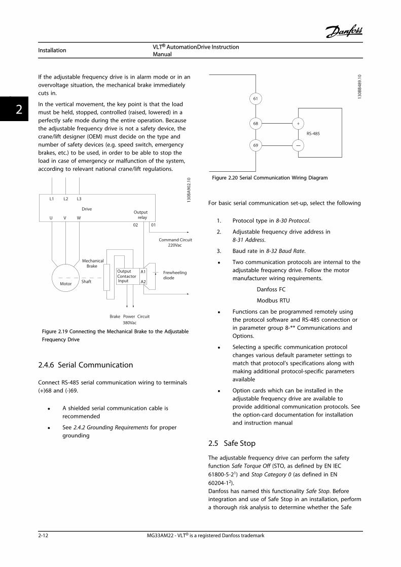
If the adjustable frequency drive is in alarm mode or in anovervoltage situation, the mechanical brake immediatelycuts in.
In the vertical movement, the key point is that the loadmust be held, stopped, controlled (raised, lowered) in aperfectly safe mode during the entire operation. Becausethe adjustable frequency drive is not a safety device, thecrane/lift designer (OEM) must decide on the type andnumber of safety devices (e.g. speed switch, emergencybrakes, etc.) to be used, in order to be able to stop theload in case of emergency or malfunction of the system,according to relevant national crane/lift regulations.
L1 L2 L3
U V W
02 01
A1
A2
130B
A90
2.10
DriveOutput
relay
Command Circuit220Vac
MechanicalBrake
ShaftMotor
Frewheelingdiode
Brake380Vac
OutputContactorInput
Power Circuit
Figure 2.19 Connecting the Mechanical Brake to the AdjustableFrequency Drive
2.4.6 Serial Communication
Connect RS-485 serial communication wiring to terminals(+)68 and (-)69.
• A shielded serial communication cable isrecommended
• See 2.4.2 Grounding Requirements for propergrounding
61
68
69
+
130B
B489
.10
RS-485
Figure 2.20 Serial Communication Wiring Diagram
For basic serial communication set-up, select the following
1. Protocol type in 8-30 Protocol.
2. Adjustable frequency drive address in8-31 Address.
3. Baud rate in 8-32 Baud Rate.
• Two communication protocols are internal to theadjustable frequency drive. Follow the motormanufacturer wiring requirements.
Danfoss FC
Modbus RTU
• Functions can be programmed remotely usingthe protocol software and RS-485 connection orin parameter group 8-** Communications andOptions.
• Selecting a specific communication protocolchanges various default parameter settings tomatch that protocol’s specifications along withmaking additional protocol-specific parametersavailable
• Option cards which can be installed in theadjustable frequency drive are available toprovide additional communication protocols. Seethe option-card documentation for installationand instruction manual
2.5 Safe Stop
The adjustable frequency drive can perform the safetyfunction Safe Torque Off (STO, as defined by EN IEC61800-5-21) and Stop Category 0 (as defined in EN60204-12).Danfoss has named this functionality Safe Stop. Beforeintegration and use of Safe Stop in an installation, performa thorough risk analysis to determine whether the Safe
Installation VLT® AutomationDrive InstructionManual
2-12 MG33AM22 - VLT® is a registered Danfoss trademark
22
Stop functionality and safety levels are appropriate andsufficient. Safe Stop is designed and approved suitable forthe requirements of:
- Safety Category 3 according to EN ISO 13849-1
- Performance Level "d" according to EN ISO13849-1:2008
- SIL 2 Capability according to IEC 61508 and EN61800-5-2
- SILCL 2 according to EN 62061
1) Refer to EN IEC 61800-5-2 for details of Safe torque off(STO) function.2) Refer to EN IEC 60204-1 for details of stop category 0and 1.Activation and Termination of Safe StopThe Safe Stop (STO) function is activated by removing thevoltage at Terminal 37 of the Safe Inverter. By connectingthe Safe Inverter to external safety devices providing a safedelay, an installation for a safe Stop Category 1 can beobtained. The Safe Stop function can be used forasynchronous, synchronous, and permanent magnetmotors.
WARNINGAfter installation of Safe Stop (STO), a commissioning testas specified in 2.5.2 Safe Stop Commissioning Test must beperformed. A passed commissioning test is mandatoryafter first installation and after each change to the safetyinstallation.
Safe Stop Technical DataThe following values are associated to the different typesof safety levels:
Reaction time for T37- Maximum reaction time: 10 ms
Reaction time = delay between de-energizing the STOinput and switching off the adjustable frequency driveoutput bridge.
Data for EN ISO 13849-1- Performance Level "d"
- MTTFd (Mean Time To Dangerous Failure): 14,000years
- DC (Diagnostic Coverage): 90%
- Category 3
- Lifetime 20 years
Data for EN IEC 62061, EN IEC 61508, EN IEC 61800-5-2- SIL 2 Capability, SILCL 2
- PFH (Probability of Dangerous failure perHour)=1e-10FIT=7e-19/h-9/h>90%
- SFF (Safe Failure Fraction) >99%
- HFT (Hardware Fault Tolerance)=0 (1001architecture)
- Lifetime 20 years
Data for EN IEC 61508 low demand- PFDavg for one year proof test: 1E-10
- PFDavg for three year proof test: 1E-10
- PFDavg for five year proof test: 1E-10
No maintenance of the STO functionality is needed.
Security measures have to be taken by the user, e.g.,installation in a closed cabinet that is only accessible forskilled personnel.
SISTEMA DataFunctional safety data is available via a data library for usewith the SISTEMA calculation tool from the IFA (Institutefor Occupational Safety and Health of the German SocialAccident Insurance) and data for manual calculation. Thelibrary is complete and continually extended.
2.5.1 Terminal 37 Safe Stop Function
The adjustable frequency drive is available with safe stopfunctionality via control terminal 37. Safe stop disables thecontrol voltage of the power semiconductors of theadjustable frequency drive output stage. This in turnprevents generating the voltage required to rotate themotor. When the Safe Stop (T37) is activated, theadjustable frequency drive issues an alarm, trips the unit,and coasts the motor to a stop. Manual restart is required.The safe stop function can be used as an emergency stopfor the adjustable frequency drive. In normal operatingmode when safe stop is not required, use the regular stopfunction instead. When automatic restart is used, ensurethe requirements of ISO 12100-2 paragraph 5.3.2.5 arefulfilled.
Liability ConditionsIt is the responsibility of the user to ensure that qualifiedpersonnel installs and operates the safe stop function:
• Read and understand the safety regulationsconcerning health and safety/accident prevention
• Understand the generic and safety guidelinesgiven in this description and the extendeddescription in the relevant Design Guide
• Have a good knowledge of the generic and safetystandards applicable to the specific application
Installation VLT® AutomationDrive InstructionManual
MG33AM22 - VLT® is a registered Danfoss trademark 2-13
2 2

User is defined as: integrator, operator, service technician,maintenance technician.
StandardsUse of safe stop on terminal 37 requires that the usersatisfies all provisions for safety including relevant laws,regulations and guidelines. The optional safe stop functioncomplies with the following standards.
• IEC 60204-1: 2005 category 0 – uncontrolled stop
• IEC 61508: 1998 SIL2
• IEC 61800-5-2: 2007 – safe torque off (STO)function
• IEC 62061: 2005 SIL CL2
• ISO 13849-1: 2006 Category 3 PL d
• ISO 14118: 2000 (EN 1037) – prevention ofunexpected start-up
The information and instructions of the instruction manualare not sufficient for a proper and safe use of the safe stopfunctionality. The related information and instructions ofthe relevant Design Guide must be followed.
Protective Measures
• Qualified and skilled personnel are required forinstallation and commissioning of safetyengineering systems
• The unit must be installed in an IP54 cabinet orin an equivalent environment. In specialapplications, a higher IP degree is required
• The cable between terminal 37 and the externalsafety device must be short circuit protectedaccording to ISO 13849-2 table D.4
• When external forces influence the motor axis (forexample, suspended loads), additional measuresare required (for example, a safety holding brake)to eliminate potential hazards
Safe Stop Installation and Set-up
WARNINGSAFE STOP FUNCTION!The safe stop function does NOT isolate AC line voltage tothe adjustable frequency drive or auxiliary circuits. Performwork on electrical parts of the adjustable frequency driveor the motor only after isolating the AC line voltage supplyand waiting the length of time specified in Table 1.1.Failure to isolate the AC line voltage supply from the unitand waiting the time specified could result in death orserious injury.
• It is not recommended to stop the adjustablefrequency drive by using the Safe Torque Offfunction. If a running adjustable frequency driveis stopped by using the function, the unit tripsand stops by coasting. If unacceptable ordangerous, use another stopping mode to stopthe adjustable frequency drive and machinery,before using this function. Depending on theapplication, a mechanical brake can be required.
• For synchronous and permanent magnet motoradjustable frequency drives, in a multiple IGBTpower semiconductor failure: In spite of theactivation of the Safe Torque Off function, thesystem can produce an alignment torque whichmaximally rotates the motor shaft by 180/pdegrees. p denotes the pole pair number.
• This function is suitable for performingmechanical work on the system or affected areaof a machine only. It does not provide electricalsafety. Do not use this function as a control forstarting and/or stopping the adjustable frequencydrive.
Follow these steps to perform a safe installation of theadjustable frequency drive:
1. Remove the jumper wire between controlterminals 37 and 12 or 13. Cutting or breakingthe jumper is not sufficient to avoid short-circuiting. (See jumper on Figure 2.21.)
2. Connect an external Safety monitoring relay via aNO safety function to terminal 37 (safe stop) andeither terminal 12 or 13 (24 V DC). Follow theinstructions for the safety device. The Safetymonitoring relay must comply with Category3 /PL “d” (ISO 13849-1) or SIL 2 (EN 62061).
Installation VLT® AutomationDrive InstructionManual
2-14 MG33AM22 - VLT® is a registered Danfoss trademark
22

12/13 37
130B
A87
4.10
Figure 2.21 Jumper between Terminal 12/13 (24 V) and 37
130B
C971
.10
12
2
4
1
5
3
37
Figure 2.22 Installation to Achieve a Stopping Category 0 (EN60204-1) with Cat. 3 /PL “d” (ISO 13849-1) or SIL 2 (EN 62061).
1 Adjustable frequency drive
2 [Reset] key
3 Safety relay (cat. 3, PL d or SIL2
4 Emergency stop button
5 Short-circuit protected cable (if not inside installation IP54cabinet)
Table 2.9 Legend to Figure 2.22
Safe Stop Commissioning TestAfter installation and before first operation, perform acommissioning test of the installation using safe stop. Also,perform the test after each modification of the installation.
WARNINGSafe Stop activation (that is removal of 24 V DC voltagesupply to terminal 37) does not provide electrical safety.The Safe Stop function itself is therefore not sufficient toimplement the Emergency-Off function as defined by EN60204-1. Emergency-Off requires measures of electricalisolation, for example, by switching off line power via anadditional contactor.
1. Activate the Safe Stop function by removing the24 V DC voltage supply to the terminal 37.
2. After activation of Safe Stop (that is, after theresponse time), the adjustable frequency drivecoasts (stops creating a rotational field in themotor). The response time is typically less than 10ms.
The adjustable frequency drive is guaranteed not to restartcreation of a rotational field by an internal fault (inaccordance with Cat. 3 PL d acc. EN ISO 13849-1 and SIL 2acc. EN 62061). After activation of Safe Stop, the displayshows the text ”Safe Stop activated”. The associated helptext says, "Safe Stop has been activated”. This means thatthe Safe Stop has been activated, or that normal operationhas not been resumed yet after Safe Stop activation.
NOTE!The requirements of Cat. 3 /PL “d” (ISO 13849-1) are onlyfulfilled while 24 V DC supply to terminal 37 is keptremoved or low by a safety device which itself fulfills Cat.3 PL “d” (ISO 13849-1). If external forces act on the motor,it must not operate without additional measures for fallprotection. External forces can arise for example, in theevent of vertical axis (suspended loads) where anunwanted movement, for example caused by gravity, couldcause a hazard. Fall protection measures can be additionalmechanical brakes.
By default the Safe Stop function is set to an UnintendedRestart Prevention behavior. Therefore, to resumeoperation after activation of Safe Stop,
1. reapply 24 V DC voltage to terminal 37 (text SafeStop activated is still displayed)
2. create a reset signal (via bus, digital I/O, or[Reset] key.
The Safe Stop function can be set to an Automatic Restartbehavior. Set the value of 5-19 Terminal 37 Safe Stop fromdefault value [1] to value [3].Automatic Restart means that Safe Stop is terminated, andnormal operation is resumed, as soon as the 24 V DC areapplied to Terminal 37. No Reset signal is required.
Installation VLT® AutomationDrive InstructionManual
MG33AM22 - VLT® is a registered Danfoss trademark 2-15
2 2

WARNINGAutomatic Restart Behavior is permitted in one of the twosituations:
1. Unintended restart prevention is implemented byother parts of the safe stop installation.
2. A presence in the hazard zone can be physicallyexcluded when safe stop is not activated. Inparticular, paragraph 5.3.2.5 of ISO 12100-2 2003must be observed
2.5.2 Safe Stop Commissioning Test
After installation and before first operation, perform acommissioning test of an installation or application, usingSafe Stop.Perform the test again after each modification of theinstallation or application involving the Safe Stop.
NOTE!A passed commissioning test is mandatory after first instal-lation and after each change to the safety installation.
The commissioning test (select one of cases 1 or 2 asapplicable):
Case 1: Restart prevention for Safe Stop is required (that isSafe Stop only where 5-19 Terminal 37 Safe Stop is set todefault value [1], or combined Safe Stop and MCB 112where 5-19 Terminal 37 Safe Stop is set to [6] PTC 1 & RelayA or [9] PTC 1 & Relay W/A):
1.1 Remove the 24 V DC voltage supply toterminal 37 using the interrupt device while theadjustable frequency drive drives the motor (thatis line power supply is not interrupted). The teststep is passed when
• the motor reacts with a coast, and
• the mechanical brake is activated (ifconnected)
• the alarm “Safe Stop [A68]” is displayedin the LCP, if mounted
1.2 Send Reset signal (via bus, digital I/O, or[Reset] key). The test step is passed if the motorremains in the safe stop state, and themechanical brake (if connected) remainsactivated.
1.3 Reapply 24 V DC to terminal 37. The test stepis passed if the motor remains in the coastedstate, and the mechanical brake (if connected)remains activated.
1.4 Send Reset signal (via bus, digital I/O, or[Reset] key). The test step is passed when themotor becomes operational again.
The commissioning test is passed if all four test steps 1.1,1.2, 1.3 and 1.4 are passed.
Case 2: Automatic Restart of Safe Stop is wanted andallowed (that is, Safe Stop only where 5-19 Terminal 37Safe Stop is set to [3], or combined Safe Stop and MCB112 where 5-19 Terminal 37 Safe Stop is set to [7] PTC 1 &Relay W or [8] PTC 1 & Relay A/W):
2.1 Remove the 24 V DC voltage supply toterminal 37 by the interrupt device while theadjustable frequency drive drives the motor (thatis line power supply is not interrupted). The teststep is passed when
• the motor reacts with a coast, and
• the mechanical brake is activated (ifconnected)
• the alarm “Safe Stop [A68]” is displayedin the LCP, if mounted
2.2 Reapply 24 V DC to terminal 37.
The test step is passed if the motor becomes operationalagain. The commissioning test is passed if both test steps2.1 and 2.2 are passed.
NOTE!See warning on the restart behavior in 2.5.1 Terminal 37Safe Stop Function
WARNINGThe Safe Stop function can be used for asynchronous,synchronous and permanent magnet motors. Two faultscan occur in the power semiconductor of the adjustablefrequency drive. When using synchronous or permanentmagnet motors a residual rotation can result from thefaults. The rotation can be calculated to Angle = 360/(Number of Poles). The application using synchronous orpermanent magnet motors must take this residual rotationinto consideration and ensure that it does not pose asafety risk. This situation is not relevant for asynchronousmotors.
Installation VLT® AutomationDrive InstructionManual
2-16 MG33AM22 - VLT® is a registered Danfoss trademark
22
3 Start-up and Functional Testing
3.1 Pre-start
3.1.1 Safety Inspection
WARNINGHIGH VOLTAGE!If input and output connections have been connectedimproperly, there is potential for high voltage on theseterminals. If power leads for multiple motors areimproperly run in same conduit, there is potential forleakage current to charge capacitors within the adjustablefrequency drive, even when disconnected from line powerinput. For initial start-up, make no assumptions aboutpower components. Follow pre-start procedures. Failure tofollow pre-start procedures could result in personal injuryor damage to equipment.
1. Input power to the unit must be OFF and lockedout. Do not rely on the adjustable frequencydrive disconnect switches for input powerisolation.
2. Verify that there is no voltage on input terminalsL1 (91), L2 (92), and L3 (93), phase-to-phase andphase-to-ground,
3. Verify that there is no voltage on outputterminals 96 (U), 97 (V), and 98 (W), phase-to-phase and phase-to-ground.
4. Confirm continuity of the motor by measuringohm values on U-V (96-97), V-W (97-98), and W-U(98-96).
5. Check for proper grounding of the adjustablefrequency drive as well as the motor.
6. Inspect the adjustable frequency drive for looseconnections on terminals.
7. Record the following motor nameplate data:power, voltage, frequency, full load current, andnominal speed. These values are needed toprogram motor nameplate data later.
8. Confirm that the supply voltage matches voltageof adjustable frequency drive and motor.
Start-up and Functional Tes... VLT® AutomationDrive InstructionManual
MG33AM22 - VLT® is a registered Danfoss trademark 3-1
3 3

CAUTIONBefore applying power to the unit, inspect the entireinstallation as detailed in Table 3.1. Check mark those itemswhen completed.
Inspect for Description Auxiliary equipment • Look for auxiliary equipment, switches, disconnects, or input fuses/circuit breakers that may reside
on the input power side of the adjustable frequency drive or output side to the motor. Ensure thatthey are ready for full speed operation.
• Check function and installation of any sensors used for feedback to the adjustable frequency drive
• Remove power factor correction caps on motor(s), if present
Cable routing • Ensure that input power, motor wiring and control wiring are separated or in three separate metallicconduits for high frequency noise isolation
Control wiring • Check for broken or damaged wires and loose connections.
• Check that control wiring is isolated from power and motor wiring for noise immunity.
• Check the voltage source of the signals, if necessary.
• The use of shielded cable or twisted pair is recommended. Ensure that the shield is terminatedcorrectly
Cooling clearance • Make sure that the top and bottom clearance is adequate to ensure proper airflow for cooling.
EMC considerations • Check for proper installation regarding electromagnetic compatibility.
Environmental consider-ations
• See equipment label for the maximum ambient operating temperature limits.
• Humidity levels must be 5%–95% non-condensing.
Fusing and circuitbreakers
• Check for proper fusing or circuit breakers.
• Check that all fuses are inserted firmly and in operational condition and that all circuit breakers arein the open position.
Grounding • The unit requires a ground wire from its chassis to the building ground
• Check for good ground connections that are tight and free of oxidation
• Grounding to conduit or mounting the back panel to a metal surface is not a suitable ground
Input and output powerwiring
• Check for loose connections.
• Check that motor and line power are in separate conduits or separated shielded cables
Panel interior • Make sure that the unit interior is free of dirt, metal chips, moisture, and corrosion.
Switches • Ensure that all switch and disconnect settings are in the proper positions
Vibration • Check that the unit is mounted solidly or that shock mounts are used, as necessary.
• Check for an unusual amount of vibration
Table 3.1 Start-up Check List
Start-up and Functional Tes... VLT® AutomationDrive InstructionManual
3-2 MG33AM22 - VLT® is a registered Danfoss trademark
33

3.2 Applying Power
WARNINGHIGH VOLTAGE!Adjustable frequency drives contain high voltage whenconnected to AC line power. Installation, start-up andmaintenance should be performed by qualified personnelonly. Failure to perform installation, start-up andmaintenance by qualified personnel could result in deathor serious injury.
WARNINGUNINTENDED START!When the adjustable frequency drive is connected to ACline power, the motor may start at any time. Theadjustable frequency drive, motor, and any drivenequipment must be in operational readiness. Failure to bein operational readiness when the adjustable frequencydrive is connected to AC line power could result in death,serious injury, equipment, or property damage.
1. Confirm input voltage is balanced within 3%. Ifnot, correct input voltage imbalance beforeproceeding. Repeat procedure after voltagecorrection.
2. Ensure optional equipment wiring, if present,matches installation application.
3. Ensure that all operator devices are in the OFFposition. Panel doors closed or cover mounted.
4. Apply power to the unit. DO NOT start theadjustable frequency drive at this time. For unitswith a disconnect switch, turn to the ON positionto apply power to the adjustable frequency drive.
NOTE!If the status line at the bottom of the LCP reads AUTOREMOTE COAST, this indicates that the unit is ready tooperate but is missing an input signal on terminal 27.
3.3 Basic Operational Programming
ProgrammingFor best performance, adjustable frequency drives requirebasic operational programming before running. Basicoperational programming requires entering motornameplate data for the motor being operated and theminimum and maximum motor speeds. The recommendedparameter settings are intended for start-up and checkoutpurposes. Application settings may vary. See 4.1 LocalControl Panel for detailed instructions on entering datathrough the LCP.
Enter data with power ON, but before operating theadjustable frequency drive. There are two ways ofprogramming the adjustable frequency drive: either byusing the Smart Application Set-up (SAS) or by using theprocedure described further down. The SAS is a quickwizard for setting up the most commonly usedapplications. At first power-up and after a reset, the SASappears on the LCP. Follow the instructions that appear onthe successive screens for setting up the applicationslisted. SAS can also be found under the Quick Menu. [Info]can be used throughout the Smart Set-up to see helpinformation for various selections, settings and messages.
NOTE!The start conditions will be ignored while in the wizard.
NOTE!If no action is taken after first power-up or reset, the SASscreen will automatically disappear after 10 minutes.
When not using the SAS, enter data in accordance withthe following procedure.
1. Press [Main Menu] twice on the LCP.
2. Press the navigation keys to scroll to parametergroup Q2 Quick Set-up and press [OK].
130B
P066
.10
1107 RPM
0 - ** Operation/Display
1 - ** Load/Motor
2 - ** Brakes
3 - ** Reference / Ramps
3.84 A 1 (1)
Main Menu
Figure 3.1 0-** Operation/Display
Start-up and Functional Tes... VLT® AutomationDrive InstructionManual
MG33AM22 - VLT® is a registered Danfoss trademark 3-3
3 3

3. Press the navigation keys to scroll to parametergroup 0-0* Basic Settings and press [OK].
0-**Operation / Display0.0%
0-0* Basic Settings
0-1* Set-up Opperations
0-2* LCP Display
0-3* LCP Custom Readout
0.00A 1(1)
130B
P087
.10
Figure 3.2 0-0* Basic Settings
4. Press the navigation keys to scroll to0-03 Regional Settings and press [OK].
0-0*Basic Settings0.0%
0-03 Regional Settings
[0] International
0.00A 1(1)
130B
P088
.10
Figure 3.3 0-03 Regional Settings
5. Press the navigation keys to select Internationalor North America as appropriate and press [OK].(This changes the default settings for a numberof basic parameters. See for a complete list.)
6. Press [Quick Menu] on the LCP.
7. Press the navigation keys to scroll to parametergroup Q2 Quick Set-up and press [OK].
130B
B847
.10
Q1 My Personal Menu
Q2 Quick Setup
Q5 Changes Made
Q6 Loggings
13.7% 13.0A 1(1)
Quick Menus
Figure 3.4 Q2 Quick Set-up
8. Select language and press [OK].
130B
T772
.10
Q2
0.0 Hz 0.00kW 1(1)
Motor Setup
1 - 21 Motor Power [kW]
4.0 kW
Figure 3.5 Select Language
9. A jumper wire should be in place betweencontrol terminals 12 and 27. If this is the case,leave 5-12 Terminal 27 Digital Input at factorydefault. Otherwise select No Operation. Foradjustable frequency drives with an optionalbypass, no jumper wire is required.
10. 3-02 Minimum Reference
11. 3-03 Maximum Reference
12. 3-41 Ramp 1 Ramp-up Time
13. 3-42 Ramp 1 Ramp-down Time
14. 3-13 Reference Site. Linked to Hand/Auto* LocalRemote.
3.4 Asynchronous Motor Set-up
Enter the motor data in parameters 1-20/1-21 to 1-25. Theinformation can be found on the motor nameplate.
1. 1-20 Motor Power [kW] or 1-21 MotorPower [HP]
1-22 Motor Voltage
1-23 Motor Frequency
1-24 Motor Current
1-25 Motor Nominal Speed
130B
T772
.10
Q2
0.0 Hz 0.00kW 1(1)
Motor Setup
1 - 21 Motor Power [kW]
4.0 kW
Figure 3.6 Motor Setup
Start-up and Functional Tes... VLT® AutomationDrive InstructionManual
3-4 MG33AM22 - VLT® is a registered Danfoss trademark
33
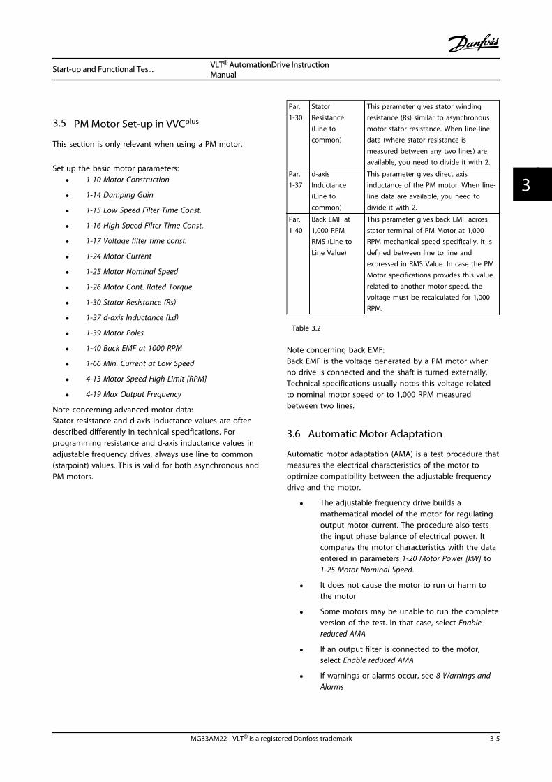
3.5 PM Motor Set-up in VVCplus
This section is only relevant when using a PM motor.
Set up the basic motor parameters:
• 1-10 Motor Construction
• 1-14 Damping Gain
• 1-15 Low Speed Filter Time Const.
• 1-16 High Speed Filter Time Const.
• 1-17 Voltage filter time const.
• 1-24 Motor Current
• 1-25 Motor Nominal Speed
• 1-26 Motor Cont. Rated Torque
• 1-30 Stator Resistance (Rs)
• 1-37 d-axis Inductance (Ld)
• 1-39 Motor Poles
• 1-40 Back EMF at 1000 RPM
• 1-66 Min. Current at Low Speed
• 4-13 Motor Speed High Limit [RPM]
• 4-19 Max Output Frequency
Note concerning advanced motor data:Stator resistance and d-axis inductance values are oftendescribed differently in technical specifications. Forprogramming resistance and d-axis inductance values inadjustable frequency drives, always use line to common(starpoint) values. This is valid for both asynchronous andPM motors.
Par.1-30
StatorResistance(Line tocommon)
This parameter gives stator windingresistance (Rs) similar to asynchronousmotor stator resistance. When line-linedata (where stator resistance ismeasured between any two lines) areavailable, you need to divide it with 2.
Par.1-37
d-axisInductance(Line tocommon)
This parameter gives direct axisinductance of the PM motor. When line-line data are available, you need todivide it with 2.
Par.1-40
Back EMF at1,000 RPMRMS (Line toLine Value)
This parameter gives back EMF acrossstator terminal of PM Motor at 1,000RPM mechanical speed specifically. It isdefined between line to line andexpressed in RMS Value. In case the PMMotor specifications provides this valuerelated to another motor speed, thevoltage must be recalculated for 1,000RPM.
Table 3.2
Note concerning back EMF:Back EMF is the voltage generated by a PM motor whenno drive is connected and the shaft is turned externally.Technical specifications usually notes this voltage relatedto nominal motor speed or to 1,000 RPM measuredbetween two lines.
3.6 Automatic Motor Adaptation
Automatic motor adaptation (AMA) is a test procedure thatmeasures the electrical characteristics of the motor tooptimize compatibility between the adjustable frequencydrive and the motor.
• The adjustable frequency drive builds amathematical model of the motor for regulatingoutput motor current. The procedure also teststhe input phase balance of electrical power. Itcompares the motor characteristics with the dataentered in parameters 1-20 Motor Power [kW] to1-25 Motor Nominal Speed.
• It does not cause the motor to run or harm tothe motor
• Some motors may be unable to run the completeversion of the test. In that case, select Enablereduced AMA
• If an output filter is connected to the motor,select Enable reduced AMA
• If warnings or alarms occur, see 8 Warnings andAlarms
Start-up and Functional Tes... VLT® AutomationDrive InstructionManual
MG33AM22 - VLT® is a registered Danfoss trademark 3-5
3 3

• Run this procedure on a cold motor for bestresults
To run AMA1. Press [Main Menu] to access parameters.
2. Scroll to parameter group 1-** Load and Motor.
3. Press [OK].
4. Scroll to parameter group 1-2* Motor Data.
5. Press [OK].
6. Scroll to 1-29 Automatic Motor Adaptation (AMA).
7. Press [OK].
8. Select Enable complete AMA.
9. Press [OK].
10. Follow on-screen instructions.
11. The test will run automatically and indicate whenit is complete.
3.7 Check Motor Rotation
Before running the adjustable frequency drive, check themotor rotation.
1. Press [Hand On].
2. Press [] for positive speed reference.
3. Check that the speed displayed is positive.
When 1-06 Clockwise Direction is set to [0] Normal (defaultclockwise):
4a. Verify that the motor turns clockwise.
5a. Verify that the LCP direction arrow isclockwise.
When 1-06 Clockwise Direction is set to [1] Inverse (counter-clockwise):
4b. Verify that the motor turns counter-clockwise.
5b. Verify that the LCP direction arrow is counter-clockwise.
3.8 Check Encoder Rotation
Check encoder rotation only if encoder feedback is used.Check encoder rotation in default open-loop control.
1. Verify that the encoder connection is accordingto Figure 3.7:
Figure 3.7 Wiring Diagram
NOTE!When using an encoder option, refer to the option manual.
2. Enter the speed PID feedback source in7-00 Speed PID Feedback Source.
3. Press [Hand On].
4. Press [] for positive speed reference(1-06 Clockwise Direction at [0] Normal).
5. Check in 16-57 Feedback [RPM] that the feedbackis positive.
NOTE!If the feedback is negative, the encoder connection iswrong!
Start-up and Functional Tes... VLT® AutomationDrive InstructionManual
3-6 MG33AM22 - VLT® is a registered Danfoss trademark
33

3.9 Local Control Test
CAUTIONMOTOR START!Ensure that the motor, system, and any attachedequipment are ready for start. It is the responsibility of theuser to ensure safe operation under any operationalcondition. Failure to ensure that the motor, system, andany attached equipment are ready for start could result inpersonal injury or equipment damage.
NOTE!The Hand on key on the LCP provides a local startcommand to the adjustable frequency drive. The [Off] keyprovides the stop function.When operating in local mode, the up and down arrowson the LCP increase and decrease the speed output of theLCP. The left and right arrow keys move the display cursorin the numeric display.
1. Press [Hand On].
2. Accelerate the adjustable frequency drive bypressing [] to full speed. Moving the cursor leftof the decimal point provides quicker inputchanges.
3. Note any acceleration problems.
4. Press [Off].
5. Note any deceleration problems.
If acceleration problems were encountered
• If warnings or alarms occur, see 8 Warnings andAlarms
• Check that motor data is entered correctly
• Increase the ramp-up time in 3-41 Ramp 1 Ramp-up Time
• Increase current limit in 4-18 Current Limit
• Increase torque limit in 4-16 Torque Limit MotorMode
If deceleration problems were encountered
• If warnings or alarms occur, see 8 Warnings andAlarms
• Check that motor data is entered correctly
• Increase the ramp-down time in 3-42 Ramp 1Ramp-down Time
• Enable overvoltage control in 2-17 Over-voltageControl
See 8.4 Warning and Alarm Definitions for resetting theadjustable frequency drive after a trip.
NOTE!3.1 Pre-start through 3.9 Local Control Test in this chapterconclude the procedures for applying power to theadjustable frequency drive, basic programming, set-up, andfunctional testing.
3.10 System Start-up
The procedure in this section requires user-wiring andapplication programming to be completed. 6 ApplicationExamples is intended to help with this task. Other aids toapplication set-up are listed in 1.2 Additional Resources. Thefollowing procedure is recommended after application set-up by the user is completed.
CAUTIONMOTOR START!Ensure that the motor, system, and any attachedequipment are ready for start. It is the responsibility of theuser to ensure safe operation under any operationalcondition. Failure to ensure that the motor, system, andany attached equipment are ready for start could result inpersonal injury or equipment damage.
1. Press [Auto On].
2. Ensure that external control functions areproperly wired to the adjustable frequency driveand all programming completed.
3. Apply an external run command.
4. Adjust the speed reference throughout the speedrange.
5. Remove the external run command.
6. Note any problems.
If warnings or alarms occur, see 8 Warnings and Alarms.
Start-up and Functional Tes... VLT® AutomationDrive InstructionManual
MG33AM22 - VLT® is a registered Danfoss trademark 3-7
3 3

Start-up and Functional Tes... VLT® AutomationDrive InstructionManual
3-8 MG33AM22 - VLT® is a registered Danfoss trademark
33

4 User Interface
4.1 Local Control Panel
The local control panel (LCP) is the combined display andkeypad on the front of the unit. The LCP is the userinterface to the adjustable frequency drive.
The LCP has several user functions.
• Start, stop, and control speed when in localcontrol
• Display operational data, status, warnings andcautions
• Programming adjustable frequency drivefunctions
• Manually reset the adjustable frequency driveafter a fault when auto-reset is inactive
An optional numeric LCP (NLCP) is also available. The NLCPoperates in a manner similar to the LCP. See theProgramming Guide for details on use of the NLCP.
NOTE!The display contrast can be adjusted by pressing [Status]and []/[] key.
4.1.1 LCP Layout
The LCP is divided into four functional groups (seeFigure 4.1).
Autoon ResetHand
onO
StatusQuickMenu
MainMenu
AlarmLog
Cancel
Info
Status 1(1)1234rpm
Back
OK
43,5Hz
Run OK
43,5Hz
On
Alarm
Warn.
130B
C362
.10
a
b
c
d
1.0 A
Figure 4.1 LCP
a. Display area.
b. Display menu keys for changing the display toshow status options, programming, or errormessage history.
c. Navigation keys for programming functions,moving the display cursor, and speed control inlocal operation. Also included are the statusindicator lights.
d. Operational mode keys and reset.
User Interface VLT® AutomationDrive InstructionManual
MG33AM22 - VLT® is a registered Danfoss trademark 4-1
4 4

4.1.2 Setting LCP Display Values
The display area is activated when the adjustablefrequency drive receives power from AC line voltage, a DCbus terminal, or an external 24 V supply.
The information displayed on the LCP can be customizedfor user application.
• Each display readout has a parameter associatedwith it.
• Options are selected in main menu 0-2* LCPDisplay
• The adjustable frequency drive status at thebottom line of the display is generated automat-ically and is not selectable. See 7 Status Messagesfor definitions and details.
1.1
2
3 1.3
1.2
130B
P041
.10
799 RPM
Auto Remote Ramping
1 (1)36.4 kW7.83 A
0.000
53.2%
Status
Figure 4.2 Display Readouts
1.1
1.2
2
1.3
130B
P062
.10
207RPM
Auto Remote Running
1 (1)
24.4 kW5.25A
6.9Hz
Status
Figure 4.3 Display Readouts
Display Parameter number Default setting
1.1 0-20 Speed [RPM]
1.2 0-21 Motor Current
1.3 0-22 Power [kW]
2 0-23 Frequency
3 0-24 Reference [%]
Table 4.1 Legend to Figure 4.2 and Figure 4.3
4.1.3 Display Menu Keys
Menu keys are used for menu access for parameter set-up,toggling through status display modes during normaloperation, and viewing fault log data.
130B
P045
.10
Status QuickMenu
MainMenu
AlarmLog
Figure 4.4 Menu Keys
Key Function
Status Press to show operational information.
• In Auto mode, press and hold to togglebetween status readout displays
• Press repeatedly to scroll through eachstatus display.
• Press and hold [Status] plus [] or [] to
adjust the display brightness
• The symbol in the upper right corner of thedisplay shows the direction of motorrotation and which set-up is active. This isnot programmable.
Quick Menu Allows access to programming parameters forinitial set-up instructions and many detailedapplication instructions.
• Press to access Q2 Quick Setup forsequenced instructions to program the basicfrequency controller set up
• Follow the sequence of parameters aspresented for the function set-up
Main Menu Allows access to all programming parameters.
• Press twice to access top-level index
• Press once to return to the last locationaccessed.
• Press and hold to enter a parameternumber for direct access to that parameter.
Alarm Log Displays a list of current warnings, the last 5alarms, and the maintenance log.
• For details about the adjustable frequencydrive before it entered the alarm mode,select the alarm number using thenavigation keys and press [OK].
Table 4.2 Legend to Figure 4.4
User Interface VLT® AutomationDrive InstructionManual
4-2 MG33AM22 - VLT® is a registered Danfoss trademark
44
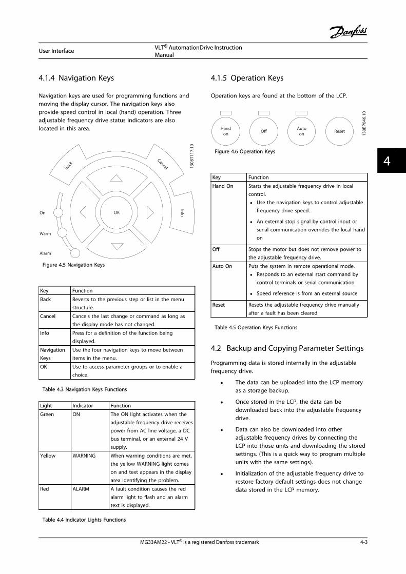
4.1.4 Navigation Keys
Navigation keys are used for programming functions andmoving the display cursor. The navigation keys alsoprovide speed control in local (hand) operation. Threeadjustable frequency drive status indicators are alsolocated in this area.
130B
T117
.10
OK
Back
Info
Warm
Alarm
On
Cancel
Figure 4.5 Navigation Keys
Key Function
Back Reverts to the previous step or list in the menustructure.
Cancel Cancels the last change or command as long asthe display mode has not changed.
Info Press for a definition of the function beingdisplayed.
NavigationKeys
Use the four navigation keys to move betweenitems in the menu.
OK Use to access parameter groups or to enable achoice.
Table 4.3 Navigation Keys Functions
Light Indicator Function
Green ON The ON light activates when theadjustable frequency drive receivespower from AC line voltage, a DCbus terminal, or an external 24 Vsupply.
Yellow WARNING When warning conditions are met,the yellow WARNING light comeson and text appears in the displayarea identifying the problem.
Red ALARM A fault condition causes the redalarm light to flash and an alarmtext is displayed.
Table 4.4 Indicator Lights Functions
4.1.5 Operation Keys
Operation keys are found at the bottom of the LCP.
130B
P046
.10
Handon O Auto
on Reset
Figure 4.6 Operation Keys
Key Function
Hand On Starts the adjustable frequency drive in localcontrol.
• Use the navigation keys to control adjustablefrequency drive speed.
• An external stop signal by control input orserial communication overrides the local handon
Off Stops the motor but does not remove power tothe adjustable frequency drive.
Auto On Puts the system in remote operational mode.
• Responds to an external start command bycontrol terminals or serial communication
• Speed reference is from an external source
Reset Resets the adjustable frequency drive manuallyafter a fault has been cleared.
Table 4.5 Operation Keys Functions
4.2 Backup and Copying Parameter Settings
Programming data is stored internally in the adjustablefrequency drive.
• The data can be uploaded into the LCP memoryas a storage backup.
• Once stored in the LCP, the data can bedownloaded back into the adjustable frequencydrive.
• Data can also be downloaded into otheradjustable frequency drives by connecting theLCP into those units and downloading the storedsettings. (This is a quick way to program multipleunits with the same settings).
• Initialization of the adjustable frequency drive torestore factory default settings does not changedata stored in the LCP memory.
User Interface VLT® AutomationDrive InstructionManual
MG33AM22 - VLT® is a registered Danfoss trademark 4-3
4 4

WARNINGUNINTENDED START!When the adjustable frequency drive is connected to ACline power, the motor may start at any time. Theadjustable frequency drive, motor, and any drivenequipment must be in operational readiness. Failure to bein operational readiness when the adjustable frequencydrive is connected to AC line power could result in death,serious injury, or equipment or property damage.
4.2.1 Uploading Data to the LCP
1. Press [Off] to stop the motor before uploading ordownloading data.
2. Go to 0-50 LCP Copy.
3. Press [OK].
4. Select All to LCP.
5. Press [OK]. A progress bar shows the uploadingprocess.
6. Press [Hand On] or [Auto On] to return to normaloperation.
4.2.2 Downloading Data from the LCP
1. Press [Off] to stop the motor before uploading ordownloading data.
2. Go to 0-50 LCP Copy.
3. Press [OK].
4. Select All from LCP.
5. Press [OK]. A progress bar shows thedownloading process.
6. Press [Hand On] or [Auto On] to return to normaloperation.
4.3 Restoring Default Settings
CAUTIONInitialization restores the unit to factory default settings.Any programming, motor data, localization, andmonitoring records will be lost. Uploading data to the LCPprovides a backup before initialization.
Restoring the adjustable frequency drive parametersettings back to default values is done by initialization ofthe adjustable frequency drive. Initialization can bethrough 14-22 Operation Mode or manually.
• Initialization using 14-22 Operation Mode does notchange adjustable frequency drive data such asoperating hours, serial communication selections,personal menu settings, fault log, alarm log, andother monitoring functions
• Using 14-22 Operation Mode is generallyrecommended.
• Manual initialization erases all motor,programming, localization, and monitoring dataand restores factory default settings.
4.3.1 Recommended Initialization
1. Press [Main Menu] twice to access parameters.
2. Scroll to 14-22 Operation Mode.
3. Press [OK].
4. Scroll to Initialization.
5. Press [OK].
6. Remove power to the unit and wait for thedisplay to turn off.
7. Apply power to the unit.
Default parameter settings are restored during start-up.This may take slightly longer than normal.
8. Alarm 80 is displayed.
9. Press [Reset] to return to operation mode.
4.3.2 Manual Initialization
1. Remove power to the unit and wait for thedisplay to turn off.
2. Press and hold [Status], [Main Menu], and [OK] atthe same time and apply power to the unit.
Factory default parameter settings are restored duringstartup. This may take slightly longer than normal.
Manual initialization does not change the followingadjustable frequency drive information
• 15-00 Operating Hours
• 15-03 Power-ups
• 15-04 Over Temps
• 15-05 Over Volts
User Interface VLT® AutomationDrive InstructionManual
4-4 MG33AM22 - VLT® is a registered Danfoss trademark
44
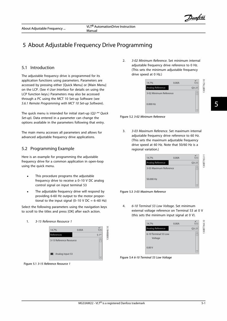
5 About Adjustable Frequency Drive Programming
5.1 Introduction
The adjustable frequency drive is programmed for itsapplication functions using parameters. Parameters areaccessed by pressing either [Quick Menu] or [Main Menu]on the LCP. (See 4 User Interface for details on using theLCP function keys.) Parameters may also be accessedthrough a PC using the MCT 10 Set-up Software (see5.6.1 Remote Programming with MCT 10 Set-up Software).
The quick menu is intended for initial start-up (Q2-** QuickSet-up). Data entered in a parameter can change theoptions available in the parameters following that entry.
The main menu accesses all parameters and allows foradvanced adjustable frequency drive applications.
5.2 Programming Example
Here is an example for programming the adjustablefrequency drive for a common application in open-loopusing the quick menu.
• This procedure programs the adjustablefrequency drive to receive a 0–10 V DC analogcontrol signal on input terminal 53
• The adjustable frequency drive will respond byproviding 6-60 Hz output to the motor propor-tional to the input signal (0–10 V DC = 6–60 Hz)
Select the following parameters using the navigation keysto scroll to the titles and press [OK] after each action.
1. 3-15 Reference Resource 1
5-1*
130B
B848
.10
3-15 Reference Resource
[1]] Analog input 53
14.7% 0.00A 1(1)
References
Figure 5.1 3-15 Reference Resource 1
2. 3-02 Minimum Reference. Set minimum internaladjustable frequency drive reference to 0 Hz.(This sets the minimum adjustable frequencydrive speed at 0 Hz.)
Q3-21
130B
T762
.10
3-02 Minimum Reference
0.000 Hz
14.7% 0.00A 1(1)
Analog Reference
Figure 5.2 3-02 Minimum Reference
3. 3-03 Maximum Reference. Set maximum internaladjustable frequency drive reference to 60 Hz.(This sets the maximum adjustable frequencydrive speed at 60 Hz. Note that 50/60 Hz is aregional variation.)
Q3-21
130B
T763
.11
3-03 Maximum Reference
50.000 Hz
14.7% 0.00A 1(1)
Analog Reference
Figure 5.3 3-03 Maximum Reference
4. 6-10 Terminal 53 Low Voltage. Set minimumexternal voltage reference on Terminal 53 at 0 V(this sets the minimum input signal at 0 V).
Q3-21
130B
T764
.10
6-10 Terminal 53 Low
Voltage
0.00 V
14.7% 0.00A 1(1)
Analog Reference
Figure 5.4 6-10 Terminal 53 Low Voltage
About Adjustable Frequency ... VLT® AutomationDrive InstructionManual
MG33AM22 - VLT® is a registered Danfoss trademark 5-1
5 5

5. 6-11 Terminal 53 High Voltage. Set maximumexternal voltage reference on Terminal 53 at 10 V(this sets the maximum input signal at 10 V).
Q3-21
130B
T765
.10
6-11 Terminal 53 High
Voltage
10.00 V
14.7% 0.00A 1(1)
Analog Reference
Figure 5.5 6-11 Terminal 53 High Voltage
6. 6-14 Terminal 53 Low Ref./Feedb. Value. Setminimum speed reference on Terminal 53 at 6 Hz(this tells the adjustable frequency drive that theminimum voltage received on Terminal 53 (0 V)equals 6 Hz output).
130B
T773
.11
Q3-21
14.7 % 0.00 A 1(1)
Analog Reference
6 - 14 Terminal 53 Low Ref./Feedb. Value
000020.000
Figure 5.6 6-14 Terminal 53 Low Ref./Feedb. Value
7. 6-15 Terminal 53 High Ref./Feedb. Value. Setmaximum speed reference on Terminal 53 at 60Hz (this tells the adjustable frequency drive thatthe maximum voltage received on Terminal 53(10 V) equals 60 Hz output).
130B
T774
.11
Q3-21
14.7 % 0.00 A 1(1)
Analog Reference
6 - 15 Terminal 53 High Ref./Feedb. Value
50.000
Figure 5.7 6-15 Terminal 53 High Ref./Feedb. Value
With an external device providing a 0–10 V control signalconnected to adjustable frequency drive terminal 53, thesystem is now ready for operation.
NOTE!When the procedure is complete, the scroll bar is at thebottom.
Figure 5.8 shows the wiring connections used to enablethis set-up.
53
55
6-1* +
A53
U - I
130B
B482
.10
0-10V
Figure 5.8 Wiring Example for External Device Providing 0–10 VControl Signal (adjustable frequency drive left, external deviceright)
5.3 Control Terminal ProgrammingExamples
Control terminals can be programmed.
• Each terminal has specified functions it is capableof performing.
• Parameters associated with the terminal enablethe function.
See Table 2.5 for control terminal parameter number anddefault setting. (Default setting can change based on theselection in 0-03 Regional Settings.)
The following example shows accessing Terminal 18 to seethe default setting.
1. Press [Main Menu] twice, scroll to parametergroup 5-** Digital In/Out and press [OK].
130B
T768
.10
2-** Brakes
3-** Reference / Ramps
4-** Limits / Warnings
5-** Digital In/Out
14.6% 0.00A 1(1)
Main Menu
Figure 5.9
About Adjustable Frequency ... VLT® AutomationDrive InstructionManual
5-2 MG33AM22 - VLT® is a registered Danfoss trademark
55
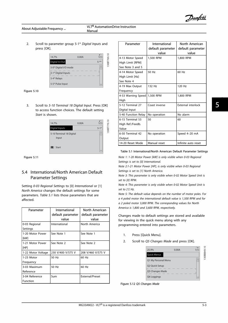
2. Scroll to parameter group 5-1* Digital Inputs andpress [OK].
130B
T769
.10
5-0* Digital I/O mode
5-1* Digital Inputs
5-4* Relays
5-5* Pulse Input
14.7% 0.00A 1(1)
Digital In/Out 5-**
Figure 5.10
3. Scroll to 5-10 Terminal 18 Digital Input. Press [OK]to access function choices. The default settingStart is shown.
5-1*
130B
T770
.10
5-10 Terminal 18 Digital
Input
[8]] Start
14.7% 0.00A 1(1)
Digital Inputs
Figure 5.11
5.4 International/North American DefaultParameter Settings
Setting 0-03 Regional Settings to [0] International or [1]North America changes the default settings for someparameters. Table 5.1 lists those parameters that areaffected.
Parameter Internationaldefault parameter
value
North Americandefault parameter
value0-03 RegionalSettings
International North America
1-20 Motor Power[kW]
See Note 1 See Note 1
1-21 Motor Power[HP]
See Note 2 See Note 2
1-22 Motor Voltage 230 V/400 V/575 V 208 V/460 V/575 V
1-23 MotorFrequency
50 Hz 60 Hz
3-03 MaximumReference
50 Hz 60 Hz
3-04 ReferenceFunction
Sum External/Preset
Parameter Internationaldefault parameter
value
North Americandefault parameter
value4-13 Motor SpeedHigh Limit [RPM]See Note 3 and 5
1,500 RPM 1,800 RPM
4-14 Motor SpeedHigh Limit [Hz]See Note 4
50 Hz 60 Hz
4-19 Max OutputFrequency
132 Hz 120 Hz
4-53 Warning SpeedHigh
1,500 RPM 1,800 RPM
5-12 Terminal 27Digital Input
Coast inverse External interlock
5-40 Function Relay No operation No alarm
6-15 Terminal 53High Ref./Feedb.Value
50 60
6-50 Terminal 42Output
No operation Speed 4–20 mA
14-20 Reset Mode Manual reset Infinite auto reset
Table 5.1 International/North American Default Parameter Settings
Note 1: 1-20 Motor Power [kW] is only visible when 0-03 RegionalSettings is set to [0] International.Note 2:1-21 Motor Power [HP], is only visible when 0-03 RegionalSettings is set to [1] North America.Note 3: This parameter is only visible when 0-02 Motor Speed Unit isset to [0] RPM.Note 4: This parameter is only visible when 0-02 Motor Speed Unit isset to [1] Hz.Note 5: The default value depends on the number of motor poles. Fora 4 poled motor the international default value is 1,500 RPM and fora 2 poled motor 3,000 RPM. The corresponding values for NorthAmerica is 1,800 and 3,600 RPM, respectively.
Changes made to default settings are stored and availablefor viewing in the quick menu along with anyprogramming entered into parameters.
1. Press [Quick Menu].
2. Scroll to Q5 Changes Made and press [OK].
130B
B849
.10
Q1 My Personal Menu
Q2 Quick Setup
Q5 Changes Made
Q6 Loggings
25.9% 0.00A 1(1)
Quick Menus
Figure 5.12 Q5 Changes Made
About Adjustable Frequency ... VLT® AutomationDrive InstructionManual
MG33AM22 - VLT® is a registered Danfoss trademark 5-3
5 5

3. Select Q5-2 Since Factory Setting to view allprogramming changes or Q5-1 Last 10 Changesfor the most recent.
Q5
130B
B850
.10
Q5-1 Last 10 Changes
Q5-2 Since Factory Setti...
25.9% 0.00A 1(1)
Changes Made
Figure 5.13 Q5-2 Since Factory Setting
5.5 Parameter Menu Structure
Establishing the correct programming for applicationsoften requires setting functions in several relatedparameters. These parameter settings provide theadjustable frequency drive with system details for theadjustable frequency drive to operate properly. Systemdetails may include such things as input and output signaltypes, programming terminals, minimum and maximumsignal ranges, custom displays, automatic restart, and otherfeatures.
• See the LCP display to view detailed parameterprogramming and setting options.
• Press [Info] in any menu location to viewadditional details for that function.
• Press and hold [Main Menu] to enter a parameternumber for direct access to that parameter.
• Details for common application set-ups areprovided in 6 Application Examples.
About Adjustable Frequency ... VLT® AutomationDrive InstructionManual
5-4 MG33AM22 - VLT® is a registered Danfoss trademark
55

5.5.
1M
ain
men
ust
ruct
ure
0-**
Ope
ratio
n/D
ispl
ay0-
0*Ba
sic
Sett
ings
0-01
Lang
uage
0-02
Mot
or S
peed
Uni
t0-
03Re
gion
al S
ettin
gs0-
04O
pera
ting
Sta
te a
t Po
wer
-up
(Han
d)0-
09Pe
rfor
man
ce M
onito
r0-
1*Se
t-up
Ope
ratio
ns0-
10A
ctiv
e Se
t-up
0-11
Edit
Set
-up
0-12
This
Set
-up
Lin
ked
to
0-13
Read
out:
Lin
ked
Set
-ups
0-14
Read
out:
Edi
t Se
t-up
s /
Chan
nel
0-15
Read
out:
act
ual s
etup
0-2*
LCP
Dis
play
0-20
Dis
play
Lin
e 1.
1 Sm
all
0-21
Dis
play
Lin
e 1.
2 Sm
all
0-22
Dis
play
Lin
e 1.
3 Sm
all
0-23
Dis
play
Lin
e 2
Larg
e0-
24D
ispl
ay L
ine
3 La
rge
0-25
My
Pers
onal
Men
u0-
3*LC
P C
ust.
Rea
dout
0-30
Uni
t fo
r U
ser-
defin
ed R
eado
ut0-
31M
in V
alue
of
Use
r-de
fined
Rea
dout
0-32
Max
Val
ue o
f U
ser-
defin
ed R
eado
ut0-
37D
ispl
ay T
ext
10-
38D
ispl
ay T
ext
20-
39D
ispl
ay T
ext
30-
4*LC
P K
eypa
d0-
40[H
and
on]
Key
on
LCP
0-41
[Off]
Key
on
LCP
0-42
[Aut
o o
n] K
ey o
n L
CP0-
43[R
eset
] Ke
y on
LCP
0-44
[Off/
Rese
t] K
ey o
n L
CP0-
45[D
rive
Bypa
ss]
Key
on L
CP0-
5*Co
py/S
ave
0-50
LCP
Cop
y0-
51Se
t-up
Cop
y0-
6*Pa
ssw
ord
0-60
Mai
n M
enu
Pas
swor
d0-
61A
cces
s to
Mai
n M
enu
w/o
Pas
swor
d0-
65Q
uick
Men
u P
assw
ord
0-66
Acc
ess
to Q
uick
Men
u w
/o P
assw
ord
0-67
Bus
Pass
wor
d A
cces
s0-
68Sa
fety
Par
amet
ers
Pass
wor
d0-
69Pa
ssw
ord
Pro
tect
ion
of
Safe
tyPa
ram
eter
s1-
**Lo
ad a
nd M
otor
1-0*
Gen
eral
Set
tings
1-00
Conf
igur
atio
n M
ode
1-01
Mot
or C
ontr
ol P
rinci
ple
1-02
Flux
Mot
or F
eedb
ack
Sour
ce1-
03To
rque
Cha
ract
eris
tics
1-04
Ove
rload
Mod
e1-
05Lo
cal M
ode
Conf
igur
atio
n
1-06
Cloc
kwis
e D
irect
ion
1-07
Mot
or A
ngle
Offs
et A
djus
t1-
1*Sp
ecia
l Set
tings
1-10
Mot
or C
onst
ruct
ion
1-11
Mot
or M
odel
1-14
Dam
ping
Gai
n1-
15Lo
w S
peed
Filt
er T
ime
Cons
t.1-
16H
igh
Spe
ed F
ilter
Tim
e Co
nst.
1-17
Volta
ge fi
lter
time
cons
t.1-
2*M
otor
Dat
a1-
20M
otor
Pow
er [k
W]
1-21
Mot
or P
ower
[HP]
1-22
Mot
or V
olta
ge1-
23M
otor
Fre
quen
cy1-
24M
otor
Cur
rent
1-25
Mot
or N
omin
al S
peed
1-26
Mot
or C
ont.
Rat
ed T
orqu
e1-
29A
utom
atic
Mot
or A
dapt
atio
n (A
MA
)1-
3*A
ddl.
Mot
or D
ata
1-30
Stat
or R
esis
tanc
e (R
s)1-
31Ro
tor
Resi
stan
ce (R
r)1-
33St
ator
Lea
kage
Rea
ctan
ce (X
1)1-
34Ro
tor
Leak
age
Reac
tanc
e (X
2)1-
35M
ain
Rea
ctan
ce (X
h)1-
36Iro
n L
oss
Resi
stan
ce (R
fe)
1-37
d-ax
is In
duct
ance
(Ld)
1-38
q-ax
is In
duct
ance
(Lq)
1-39
Mot
or P
oles
1-40
Back
EM
F at
100
0 RP
M1-
41M
otor
Ang
le O
ffset
1-44
d-ax
is In
duct
ance
Sat
. (Ld
Sat)
1-45
q-ax
is In
duct
ance
Sat
. (Lq
Sat)
1-46
Posi
tion
Det
ectio
n G
ain
1-47
Low
Spe
ed T
orqu
e Ca
libra
tion
1-48
Indu
ctan
ce S
at. P
oint
1-5*
Load
-Inde
p. S
ettin
g1-
50M
otor
Mag
netiz
atio
n a
t Ze
ro S
peed
1-51
Min
Spe
ed N
orm
al M
agne
tizin
g[R
PM]
1-52
Min
Spe
ed N
orm
al M
agne
tizin
g [H
z]1-
53M
odel
Shi
ft F
requ
ency
1-54
Volta
ge r
educ
tion
in fi
eldw
eake
ning
1-55
U/f
Cha
ract
eris
tic -
U1-
56U
/f C
hara
cter
istic
- F
1-58
Flys
tart
Tes
t Pu
lses
Cur
rent
1-59
Flys
tart
Tes
t Pu
lses
Fre
quen
cy1-
6*Lo
ad-D
epen
d. S
ettg
.1-
60Lo
w S
peed
Loa
d C
ompe
nsat
ion
1-61
Hig
h S
peed
Loa
d C
ompe
nsat
ion
1-62
Slip
Com
pens
atio
n1-
63Sl
ip C
ompe
nsat
ion
Tim
e Co
nsta
nt1-
64Re
sona
nce
Dam
peni
ng1-
65Re
sona
nce
Dam
peni
ng T
ime
Cons
tant
1-66
Min
. Cur
rent
at
Low
Spe
ed1-
67Lo
ad T
ype
1-68
Min
imum
Iner
tia1-
69M
axim
um In
ertia
1-7*
Star
t A
djus
tmen
ts
1-70
PM S
tart
Mod
e1-
71St
art
Del
ay1-
72St
art
Func
tion
1-73
Flyi
ng S
tart
1-74
Star
t Sp
eed
[RPM
]1-
75St
art
Spee
d [H
z]1-
76St
art
Curr
ent
1-8*
Stop
Adj
ustm
ents
1-80
Func
tion
at
Stop
1-81
Min
Spe
ed fo
r Fu
nctio
n a
t St
op[R
PM]
1-82
Min
Spe
ed fo
r Fu
nctio
n a
t St
op [H
z]1-
83Pr
ecis
e St
op F
unct
ion
1-84
Prec
ise
Stop
Cou
nter
Val
ue1-
85Pr
ecis
e St
op S
peed
Com
pens
atio
nD
elay
1-9*
Mot
or T
empe
ratu
re1-
90M
otor
The
rmal
Pro
tect
ion
1-91
Mot
or E
xter
nal F
an1-
93Th
erm
isto
r Re
sour
ce1-
94A
TEX
ETR
cur
.lim
. spe
ed r
educ
tion
1-95
KTY
Sen
sor
Type
1-96
KTY
The
rmis
tor
Reso
urce
1-97
KTY
Thr
esho
ld le
vel
1-98
ATE
X E
TR in
terp
ol. p
oint
s fr
eq.
1-99
ATE
X E
TR in
terp
ol p
oint
s cu
rren
t2-
**Br
akes
2-0*
DC
Bra
ke2-
00D
C H
old
Cur
rent
2-01
DC
Bra
ke C
urre
nt2-
02D
C B
raki
ng T
ime
2-03
DC
Bra
ke C
ut-in
Spe
ed [R
PM]
2-04
DC
Bra
ke C
ut-in
Spe
ed [H
z]2-
05M
axim
um R
efer
ence
2-06
Park
ing
Cur
rent
2-07
Park
ing
Tim
e2-
1*Br
ake
Ener
gy F
unct
.2-
10Br
ake
Func
tion
2-11
Brak
e Re
sist
or (o
hm)
2-12
Brak
e Po
wer
Lim
it (k
W)
2-13
Brak
e Po
wer
Mon
itorin
g2-
15Br
ake
Chec
k2-
16A
C B
rake
Max
. Cur
rent
2-17
Ove
r-vo
ltage
Con
trol
2-18
Brak
e Ch
eck
Cond
ition
2-19
Ove
r-vo
ltage
Gai
n2-
2*M
echa
nica
l Bra
ke2-
20Re
leas
e Br
ake
Curr
ent
2-21
Act
ivat
e Br
ake
Spee
d [R
PM]
2-22
Act
ivat
e Br
ake
Spee
d [H
z]2-
23A
ctiv
ate
Brak
e D
elay
2-24
Stop
Del
ay2-
25Br
ake
Rele
ase
Tim
e2-
26To
rque
Ref
2-27
Torq
ue R
amp
Tim
e2-
28G
ain
Boo
st F
acto
r3-
**Re
fere
nce
/ Ra
mps
3-0*
Refe
renc
e Li
mits
3-00
Refe
renc
e Ra
nge
3-01
Refe
renc
e/Fe
edba
ck U
nit
3-02
Min
imum
Ref
eren
ce3-
03M
axim
um R
efer
ence
3-04
Refe
renc
e Fu
nctio
n3-
1*Re
fere
nces
3-10
Pres
et R
efer
ence
3-11
Jog
Spe
ed [H
z]3-
12Ca
tch
up/
slow
-dow
n v
alue
3-13
Refe
renc
e Si
te3-
14Pr
eset
Rel
ativ
e Re
fere
nce
3-15
Refe
renc
e Re
sour
ce 1
3-16
Refe
renc
e Re
sour
ce 2
3-17
Refe
renc
e Re
sour
ce 3
3-18
Rela
tive
Scal
ing
Ref
eren
ce R
esou
rce
3-19
Jog
Spe
ed [R
PM]
3-4*
Ram
p 1
3-40
Ram
p 1
Typ
e3-
41Ra
mp
1 R
amp-
up T
ime
3-42
Ram
p 1
Ram
p-do
wn
Tim
e3-
45Ra
mp
1 S
-ram
p R
atio
at
Acc
el. S
tart
3-46
Ram
p 1
S-r
amp
Rat
io a
t A
ccel
. End
3-47
Ram
p 1
S-r
amp
Rat
io a
t D
ecel
. Sta
rt3-
48Ra
mp
1 S
-ram
p R
atio
at
Dec
el. E
nd3-
5*Ra
mp
23-
50Ra
mp
2 T
ype
3-51
Ram
p 2
Ram
p-up
Tim
e3-
52Ra
mp
2 R
amp-
dow
n T
ime
3-55
Ram
p 2
S-r
amp
Rat
io a
t A
ccel
. Sta
rt3-
56Ra
mp
2 S
-ram
p R
atio
at
Acc
el. E
nd3-
57Ra
mp
2 S
-ram
p R
atio
at
Dec
el. S
tart
3-58
Ram
p 2
S-r
amp
Rat
io a
t D
ecel
. End
3-6*
Ram
p 3
3-60
Ram
p 3
Typ
e3-
61Ra
mp
3 R
amp-
up T
ime
3-62
Ram
p 3
Ram
p-do
wn
Tim
e3-
65Ra
mp
3 S
-ram
p R
atio
at
Acc
el. S
tart
3-66
Ram
p 3
S-r
amp
Rat
io a
t A
ccel
. End
3-67
Ram
p 3
S-r
amp
Rat
io a
t D
ecel
. Sta
rt3-
68Ra
mp
3 S
-ram
p R
atio
at
Dec
el. E
nd3-
7*Ra
mp
43-
70Ra
mp
4 T
ype
3-71
Ram
p 4
Ram
p-up
Tim
e3-
72Ra
mp
4 R
amp-
dow
n T
ime
3-75
Ram
p 4
S-r
amp
Rat
io a
t A
ccel
. Sta
rt3-
76Ra
mp
4 S
-ram
p R
atio
at
Acc
el. E
nd3-
77Ra
mp
4 S
-ram
p R
atio
at
Dec
el. S
tart
3-78
Ram
p 4
S-r
amp
Rat
io a
t D
ecel
. End
3-8*
Oth
er R
amps
3-80
Jog
Ram
p T
ime
3-81
Qui
ck S
top
Ram
p T
ime
3-82
Qui
ck S
top
Ram
p T
ype
3-83
Qui
ck S
top
S-r
amp
Rat
io a
t D
ecel
.St
art
3-84
Qui
ck S
top
S-r
amp
Rat
io a
t D
ecel
.En
d3-
9*D
igita
l Pot
. met
er3-
90St
ep S
ize
3-91
Ram
p T
ime
3-92
Pow
er R
esto
re
3-93
Max
imum
Lim
it3-
94M
inim
um L
imit
3-95
Ram
p D
elay
4-**
Lim
its /
War
ning
s4-
1*M
otor
Lim
its4-
10M
otor
Spe
ed D
irect
ion
4-11
Mot
or S
peed
Low
Lim
it [R
PM]
4-12
Mot
or S
peed
Low
Lim
it [H
z]4-
13M
otor
Spe
ed H
igh
Lim
it [R
PM]
4-14
Mot
or S
peed
Hig
h L
imit
[Hz]
4-16
Torq
ue L
imit
Mot
or M
ode
4-17
Torq
ue L
imit
Gen
erat
or M
ode
4-18
Curr
ent
Lim
it4-
19M
ax O
utpu
t Fr
eque
ncy
4-2*
Lim
it F
acto
rs4-
20To
rque
Lim
it F
acto
r So
urce
4-21
Spee
d L
imit
Fac
tor
Sour
ce4-
3*M
otor
Spe
ed M
on.
4-30
Mot
or F
eedb
ack
Loss
Fun
ctio
n4-
31M
otor
Fee
dbac
k Sp
eed
Err
or4-
32M
otor
Fee
dbac
k Lo
ss T
imeo
ut4-
34Tr
acki
ng E
rror
Fun
ctio
n4-
35Tr
acki
ng E
rror
4-36
Trac
king
Err
or T
imeo
ut4-
37Tr
acki
ng E
rror
Ram
ping
4-38
Trac
king
Err
or R
ampi
ng T
imeo
ut4-
39Tr
acki
ng E
rror
Aft
er R
ampi
ngTi
meo
ut4-
5*A
dj. W
arni
ngs
4-50
War
ning
Cur
rent
Low
4-51
War
ning
Cur
rent
Hig
h4-
52W
arni
ng S
peed
Low
4-53
War
ning
Spe
ed H
igh
4-54
War
ning
Ref
eren
ce L
ow4-
55W
arni
ng R
efer
ence
Hig
h4-
56W
arni
ng F
eedb
ack
Low
4-57
War
ning
Fee
dbac
k H
igh
4-58
Mis
sing
Mot
or P
hase
Fun
ctio
n4-
6*Sp
eed
Byp
ass
4-60
Bypa
ss S
peed
Fro
m [R
PM]
4-61
Bypa
ss S
peed
Fro
m [H
z]4-
62By
pass
Spe
ed t
o [R
PM]
4-63
Bypa
ss S
peed
To
[Hz]
5-**
Dig
ital I
n/O
ut5-
0*D
igita
l I/O
mod
e5-
00D
igita
l I/O
Mod
e5-
01Te
rmin
al 2
7 M
ode
5-02
Term
inal
29
Mod
e5-
1*D
igita
l Inp
uts
5-10
Term
inal
18
Dig
ital I
nput
5-11
Term
inal
19
Dig
ital I
nput
5-12
Term
inal
27
Dig
ital I
nput
5-13
Term
inal
29
Dig
ital I
nput
5-14
Term
inal
32
Dig
ital I
nput
5-15
Term
inal
33
Dig
ital I
nput
5-16
Term
inal
X30
/2 D
igita
l Inp
ut5-
17Te
rmin
al X
30/3
Dig
ital I
nput
5-18
Term
inal
X30
/4 D
igita
l Inp
ut5-
19Te
rmin
al 3
7 Sa
fe S
top
About Adjustable Frequency ... VLT® AutomationDrive InstructionManual
MG33AM22 - VLT® is a registered Danfoss trademark 5-5
5 5

5-20
Term
inal
X46
/1 D
igita
l Inp
ut5-
21Te
rmin
al X
46/3
Dig
ital I
nput
5-22
Term
inal
X46
/5 D
igita
l Inp
ut5-
23Te
rmin
al X
46/7
Dig
ital I
nput
5-24
Term
inal
X46
/9 D
igita
l Inp
ut5-
25Te
rmin
al X
46/1
1 D
igita
l Inp
ut5-
26Te
rmin
al X
46/1
3 D
igita
l Inp
ut5-
3*D
igita
l Out
puts
5-30
Term
inal
27
Dig
ital O
utpu
t5-
31Te
rmin
al 2
9 D
igita
l Out
put
5-32
Term
X30
/6 D
igi O
ut (M
CB 1
01)
5-33
Term
X30
/7 D
igi O
ut (M
CB 1
01)
5-4*
Rela
ys5-
40Fu
nctio
n R
elay
5-41
On
Del
ay, R
elay
5-42
Off
Del
ay, R
elay
5-5*
Puls
e In
put
5-50
Term
. 29
Low
Fre
quen
cy5-
51Te
rm. 2
9 H
igh
Fre
quen
cy5-
52Te
rm. 2
9 Lo
w R
ef./F
eedb
. Val
ue5-
53Te
rm. 2
9 H
igh
Ref
./Fee
db. V
alue
5-54
Puls
e Fi
lter
Tim
e Co
nsta
nt #
295-
55Te
rm. 3
3 Lo
w F
requ
ency
5-56
Term
. 33
Hig
h F
requ
ency
5-57
Term
. 33
Low
Ref
./Fee
db. V
alue
5-58
Term
. 33
Hig
h R
ef./F
eedb
. Val
ue5-
59Pu
lse
Filte
r Ti
me
Cons
tant
#33
5-6*
Puls
e O
utpu
t5-
60Te
rmin
al 2
7 Pu
lse
Out
put
Varia
ble
5-62
Puls
e O
utpu
t M
ax F
req
#27
5-63
Term
inal
29
Puls
e O
utpu
t Va
riabl
e5-
65Pu
lse
Out
put
Max
Fre
q #
295-
66Te
rmin
al X
30/6
Pul
se O
utpu
t Va
riabl
e5-
68Pu
lse
Out
put
Max
Fre
q #
X30/
65-
7*24
V E
ncod
er In
put
5-70
Term
32/
33 P
ulse
s Pe
r Re
volu
tion
5-71
Term
32/
33 E
ncod
er D
irect
ion
5-8*
I/O O
ptio
ns5-
80A
HF
Cap
Rec
onne
ct D
elay
5-9*
Bus
Cont
rolle
d5-
90D
igita
l & R
elay
Bus
Con
trol
5-93
Puls
e O
ut #
27 B
us C
ontr
ol5-
94Pu
lse
Out
#27
Tim
eout
Pre
set
5-95
Puls
e O
ut #
29 B
us C
ontr
ol5-
96Pu
lse
Out
#29
Tim
eout
Pre
set
5-97
Puls
e O
ut #
X30/
6 Bu
s Co
ntro
l5-
98Pu
lse
Out
#X3
0/6
Tim
eout
Pre
set
6-**
Ana
log
In/O
ut6-
0*A
nalo
g I/
O M
ode
6-00
Live
Zer
o T
imeo
ut T
ime
6-01
Live
Zer
o T
imeo
ut F
unct
ion
6-1*
Ana
log
Inpu
t 1
6-10
Term
inal
53
Low
Vol
tage
6-11
Term
inal
53
Hig
h V
olta
ge6-
12Te
rmin
al 5
3 Lo
w C
urre
nt6-
13Te
rmin
al 5
3 H
igh
Cur
rent
6-14
Term
inal
53
Low
Ref
./Fee
db. V
alue
6-15
Term
inal
53
Hig
h R
ef./F
eedb
. Val
ue6-
16Te
rmin
al 5
3 Fi
lter
Tim
e Co
nsta
nt
6-2*
Ana
log
Inpu
t 2
6-20
Term
inal
54
Low
Vol
tage
6-21
Term
inal
54
Hig
h V
olta
ge6-
22Te
rmin
al 5
4 Lo
w C
urre
nt6-
23Te
rmin
al 5
4 H
igh
Cur
rent
6-24
Term
inal
54
Low
Ref
./Fee
db. V
alue
6-25
Term
inal
54
Hig
h R
ef./F
eedb
. Val
ue6-
26Te
rmin
al 5
4 Fi
lter
Tim
e Co
nsta
nt6-
3*A
nalo
g In
put
536-
30Te
rmin
al X
30/1
1 Lo
w V
olta
ge6-
31Te
rmin
al X
30/1
1 H
igh
Vol
tage
6-34
Term
. X30
/11
Low
Ref
./Fee
db. V
alue
6-35
Term
. X30
/11
Hig
h R
ef./F
eedb
. Val
ue6-
36Te
rm. X
30/1
1 Fi
lter
Tim
e Co
nsta
nt6-
4*A
nalo
g In
put
46-
40Te
rmin
al X
30/1
2 Lo
w V
olta
ge6-
41Te
rmin
al X
30/1
2 H
igh
Vol
tage
6-44
Term
. X30
/12
Low
Ref
./Fee
db. V
alue
6-45
Term
. X30
/12
Hig
h R
ef./F
eedb
. Val
ue6-
46Te
rm. X
30/1
2 Fi
lter
Tim
e Co
nsta
nt6-
5*A
nalo
g O
utpu
t 1
6-50
Term
inal
42
Out
put
6-51
Term
inal
42
Out
put
Min
Sca
le6-
52Te
rmin
al 4
2 O
utpu
t M
ax S
cale
6-53
Term
42
Out
put
Bus
Ctrl
6-54
Term
inal
42
Out
put
Tim
eout
Pre
set
6-55
Ana
log
Out
put
Filte
r6-
6*A
nalo
g O
utpu
t 2
6-60
Term
inal
X30
/8 O
utpu
t6-
61Te
rmin
al X
30/8
Min
. Sca
le6-
62Te
rmin
al X
30/8
Max
. Sca
le6-
63Te
rmin
al X
30/8
Bus
Con
trol
6-64
Term
inal
X30
/8 O
utpu
t Ti
meo
utPr
eset
6-7*
Ana
log
Out
put
36-
70Te
rmin
al X
45/1
Out
put
6-71
Term
inal
X45
/1 M
in. S
cale
6-72
Term
inal
X45
/1 M
ax. S
cale
6-73
Term
inal
X45
/1 B
us C
ontr
ol6-
74Te
rmin
al X
45/1
Out
put
Tim
eout
Pres
et6-
8*A
nalo
g O
utpu
t 4
6-80
Term
inal
X45
/3 O
utpu
t6-
81Te
rmin
al X
45/3
Min
. Sca
le6-
82Te
rmin
al X
45/3
Max
. Sca
le6-
83Te
rmin
al X
45/3
Bus
Con
trol
6-84
Term
inal
X45
/3 O
utpu
t Ti
meo
utPr
eset
7-**
Cont
rolle
rs7-
0*Sp
eed
PID
Ctr
l.7-
00Sp
eed
PID
Fee
dbac
k So
urce
7-02
Spee
d P
ID P
ropo
rtio
nal G
ain
7-03
Spee
d P
ID In
tegr
al T
ime
7-04
Spee
d P
ID D
iffer
entia
tion
Tim
e7-
05Sp
eed
PID
Diff
. Gai
n L
imit
7-06
Spee
d P
ID L
owpa
ss F
ilter
Tim
e7-
07Sp
eed
PID
Fee
dbac
k G
ear
Ratio
7-08
Spee
d P
ID F
eed
For
war
d F
acto
r7-
09Sp
eed
PID
Err
or C
orre
ctio
n w
/ Ra
mp
7-1*
Torq
ue P
I Ctr
l.7-
12To
rque
PI P
ropo
rtio
nal G
ain
7-13
Torq
ue P
I Int
egra
tion
Tim
e7-
2*Pr
oces
s Ct
rl. F
eedb
7-20
Proc
ess
CL F
eedb
ack
1 Re
sour
ce7-
22Pr
oces
s CL
Fee
dbac
k 2
Reso
urce
7-3*
Proc
ess
PID
Ctr
l.7-
30Pr
oces
s PI
D N
orm
al/In
vers
e Co
ntro
l7-
31Pr
oces
s PI
D A
nti W
indu
p7-
32Pr
oces
s PI
D C
ontr
olle
r St
art
Valu
e7-
33Pr
oces
s PI
D P
ropo
rtio
nal G
ain
7-34
Proc
ess
PID
Inte
gral
Tim
e7-
35Pr
oces
s PI
D D
iffer
entia
tion
Tim
e7-
36Pr
oces
s PI
D D
iffer
entia
tion
Gai
n L
imit
7-38
Proc
ess
PID
Fee
d F
orw
ard
Fac
tor
7-39
On
Ref
eren
ce B
andw
idth
7-4*
Adv
. Pro
cess
PID
I7-
40Pr
oces
s PI
D I-
part
Res
et7-
41Pr
oces
s PI
D O
utpu
t N
eg. C
lam
p7-
42Pr
oces
s PI
D O
utpu
t Po
s. C
lam
p7-
43Pr
oces
s PI
D G
ain
Sca
le a
t M
in. R
ef.
7-44
Proc
ess
PID
Gai
n S
cale
at
Max
. Ref
.7-
45Pr
oces
s PI
D F
eed
Fw
d R
esou
rce
7-46
Proc
ess
PID
Fee
d F
wd
Nor
mal
/ In
v.Ct
rl.7-
48PC
D F
eed
For
war
d7-
49Pr
oces
s PI
D O
utpu
t N
orm
al/
Inv.
Ctr
l.7-
5*A
dv. P
roce
ss P
ID II
7-50
Proc
ess
PID
Ext
ende
d P
ID7-
51Pr
oces
s PI
D F
eed
Fw
d G
ain
7-52
Proc
ess
PID
Fee
d F
wd
Ram
p-up
7-53
Proc
ess
PID
Fee
d F
wd
Ram
p-do
wn
7-56
Proc
ess
PID
Ref
. Filt
er T
ime
7-57
Proc
ess
PID
Fb.
Filt
er T
ime
8-**
Com
m. a
nd O
ptio
ns8-
0*G
ener
al S
ettin
gs8-
01Co
ntro
l Site
8-02
Cont
rol W
ord
Sou
rce
8-03
Cont
rol W
ord
Tim
eout
Tim
e8-
04Co
ntro
l Wor
d T
imeo
ut F
unct
ion
8-05
End-
of-T
imeo
ut F
unct
ion
8-06
Rese
t Co
ntro
l Wor
d T
imeo
ut8-
07D
iagn
osis
Trig
ger
8-08
Read
out
Filte
ring
8-1*
Ctrl.
Wor
d S
ettin
gs8-
10Co
ntro
l Wor
d P
rofil
e8-
13Co
nfig
urab
le S
tatu
s W
ord
STW
8-14
Conf
igur
able
Con
trol
Wor
d C
TW8-
19Pr
oduc
t Co
de8-
3*FC
Por
t Se
ttin
gs8-
30Pr
otoc
ol8-
31A
ddre
ss8-
32FC
Por
t Ba
ud R
ate
8-33
Parit
y /
Stop
Bits
8-34
Estim
ated
cyc
le t
ime
8-35
Min
imum
Res
pons
e D
elay
8-36
Max
Res
pons
e D
elay
8-37
Max
Inte
r-Ch
ar D
elay
8-4*
FC M
C p
roto
col s
et
8-40
Tele
gram
sel
ectio
n8-
41Pa
ram
eter
s fo
r Si
gnal
s8-
42PC
D W
rite
Conf
igur
atio
n8-
43PC
D R
ead
Con
figur
atio
n8-
5*D
igita
l/Bus
8-50
Coas
ting
Sel
ect
8-51
Qui
ck S
top
Sel
ect
8-52
DC
Bra
ke S
elec
t8-
53St
art
Sele
ct8-
54Re
vers
e Se
lect
8-55
Set-
up S
elec
t8-
56Pr
eset
Ref
eren
ce S
elec
t8-
57Pr
ofid
rive
OFF
2 Se
lect
8-58
Prof
idriv
e O
FF3
Sele
ct8-
8*A
FD P
ort
Dia
gnos
tics
8-80
Bus
Mes
sage
Cou
nt8-
81Bu
s Er
ror
Coun
t8-
82Sl
ave
Mes
sage
s Rc
vd8-
83Sl
ave
Erro
r Co
unt
8-9*
Bus
Jog
8-90
Bus
Jog
1 S
peed
8-91
Bus
Jog
2 S
peed
9-**
PRO
FIdr
ive
9-00
Setp
oint
9-07
Act
ual V
alue
9-15
PCD
Writ
e Co
nfig
urat
ion
9-16
PCD
Rea
d C
onfig
urat
ion
9-18
Nod
e A
ddre
ss9-
22Te
legr
am S
elec
tion
9-23
Para
met
ers
for
Sign
als
9-27
Para
met
er E
dit
9-28
Proc
ess
Cont
rol
9-44
Faul
t M
essa
ge C
ount
er9-
45Fa
ult
Code
9-47
Faul
t N
umbe
r9-
52Fa
ult
Situ
atio
n C
ount
er9-
53Pr
ofib
us W
arni
ng W
ord
9-63
Act
ual B
aud
Rat
e9-
64D
evic
e Id
entif
icat
ion
9-65
Prof
ile N
umbe
r9-
67Co
ntro
l Wor
d 1
9-68
Stat
us W
ord
19-
71Pr
ofib
us S
ave
Dat
a Va
lues
9-72
Prof
ibus
Driv
eRes
et9-
75D
O Id
entif
icat
ion
9-80
Def
ined
Par
amet
ers
(1)
9-81
Def
ined
Par
amet
ers
(2)
9-82
Def
ined
Par
amet
ers
(3)
9-83
Def
ined
Par
amet
ers
(4)
9-84
Def
ined
Par
amet
ers
(5)
9-90
Chan
ged
Par
amet
ers
(1)
9-91
Chan
ged
Par
amet
ers
(2)
9-92
Chan
ged
Par
amet
ers
(3)
9-93
Chan
ged
par
amet
ers
(4)
9-94
Chan
ged
par
amet
ers
(5)
9-99
Prof
ibus
Rev
isio
n C
ount
er10
-**
CAN
Fie
ldbu
s10
-0*
Com
mon
Set
tings
10-0
0CA
N P
roto
col
10-0
1Ba
ud R
ate
Sele
ct10
-02
MA
C ID
10-0
5Re
adou
t Tr
ansm
it E
rror
Cou
nter
10-0
6Re
adou
t Re
ceiv
e Er
ror
Coun
ter
10-0
7Re
adou
t Bu
s O
ff C
ount
er10
-1*
Dev
iceN
et10
-10
Proc
ess
Dat
a Ty
pe S
elec
tion
10-1
1Pr
oces
s D
ata
Conf
ig W
rite
10-1
2Pr
oces
s D
ata
Conf
ig R
ead
10-1
3W
arni
ng P
aram
eter
10-1
4N
et R
efer
ence
10-1
5N
et C
ontr
ol10
-2*
COS
Filte
rs10
-20
COS
Filte
r 1
10-2
1CO
S Fi
lter
210
-22
COS
Filte
r 3
10-2
3CO
S Fi
lter
410
-3*
Para
met
er A
cces
s10
-30
Arr
ay In
dex
10-3
1St
ore
Dat
a Va
lues
10-3
2D
evic
enet
Rev
isio
n10
-33
Stor
e A
lway
s10
-34
Dev
iceN
et P
rodu
ct C
ode
10-3
9D
evic
enet
F P
aram
eter
s10
-5*
CAN
open
10-5
0Pr
oces
s D
ata
Conf
ig W
rite.
10-5
1Pr
oces
s D
ata
Conf
ig R
ead.
12-*
*Et
hern
et12
-0*
IP S
ettin
gs12
-00
IP A
ddre
ss A
ssig
nmen
t12
-01
IP A
ddre
ss12
-02
Subn
et M
ask
12-0
3D
efau
lt G
atew
ay12
-04
DH
CP S
erve
r12
-05
Leas
e Ex
pire
s12
-06
Nam
e Se
rver
s12
-07
Dom
ain
Nam
e12
-08
Hos
t N
ame
12-0
9Ph
ysic
al A
ddre
ss12
-1*
Eth
link
par
12-1
0Li
nk S
tatu
s12
-11
Link
Dur
atio
n12
-12
Aut
o N
egot
iatio
n12
-13
Link
Spe
ed12
-14
Link
Dup
lex
12-2
*Pr
oces
s D
ata
12-2
0Co
ntro
l Ins
tanc
e12
-21
Proc
ess
Dat
a Co
nfig
Writ
e12
-22
Proc
ess
Dat
a Co
nfig
Rea
d12
-23
Proc
ess
Dat
a Co
nfig
Writ
e Si
ze12
-24
Proc
ess
Dat
a Co
nfig
Rea
d S
ize
12-2
7M
aste
r A
ddre
ss12
-28
Stor
e D
ata
Valu
es12
-29
Stor
e A
lway
s12
-3*
Ethe
rNet
/IP12
-30
War
ning
Par
amet
er12
-31
Net
Ref
eren
ce12
-32
Net
Con
trol
12-3
3CI
P R
evis
ion
About Adjustable Frequency ... VLT® AutomationDrive InstructionManual
5-6 MG33AM22 - VLT® is a registered Danfoss trademark
55

12-3
4CI
P P
rodu
ct C
ode
12-3
5ED
S Pa
ram
eter
12-3
7CO
S In
hibi
t Ti
mer
12-3
8CO
S Fi
lter
12-4
*M
odbu
s TC
P12
-40
Stat
us P
aram
eter
12-4
1Sl
ave
Mes
sage
Cou
nt12
-42
Slav
e Ex
cept
ion
Mes
sage
Cou
nt12
-5*
Ethe
rCA
T12
-50
Conf
igur
ed S
tatio
n A
lias
12-5
1Co
nfig
ured
Sta
tion
Add
ress
12-5
9Et
herC
AT
Stat
us12
-6*
Ethe
rnet
Pow
erLi
nk12
-60
Nod
e ID
12-6
2SD
O T
imeo
ut12
-63
Basi
c Et
hern
et T
imeo
ut12
-66
Thre
shol
d12
-67
Thre
shol
d C
ount
ers
12-6
8Cu
mul
ativ
e Co
unte
rs12
-69
Ethe
rnet
Pow
erLi
nk S
tatu
s12
-8*
Oth
. Eth
erne
t se
rvic
es12
-80
FTP
Ser
ver
12-8
1H
TTP
Ser
ver
12-8
2SM
TP S
ervi
ce12
-89
Tran
spar
ent
Sock
et C
hann
el P
ort
12-9
*A
dv. E
th. s
ervi
ces
12-9
0Ca
ble
Dia
gnos
tic12
-91
Aut
o C
ross
Ove
r12
-92
IGM
P S
noop
ing
12-9
3Ca
ble
Erro
r Le
ngth
12-9
4Br
oadc
ast
Stor
m P
rote
ctio
n12
-95
Broa
dcas
t St
orm
Filt
er12
-96
Port
Con
fig12
-98
Inte
rfac
e Co
unte
rs12
-99
Med
ia C
ount
ers
13-*
*Sm
art
Logi
c13
-0*
SLC
Set
tings
13-0
0SL
Con
trol
ler
Mod
e13
-01
Star
t Ev
ent
13-0
2St
op E
vent
13-0
3Re
set
SLC
13-1
*Co
mpa
rato
rs13
-10
Com
para
tor
Ope
rand
13-1
1Co
mpa
rato
r O
pera
tor
13-1
2Co
mpa
rato
r Va
lue
13-1
*RS
Flip
Flo
ps13
-15
RS-F
F O
pera
nd S
13-1
6RS
-FF
Ope
rand
R13
-2*
Tim
ers
13-2
0SL
Con
trol
ler
Tim
er13
-4*
Logi
c Ru
les
13-4
0Lo
gic
Rule
Boo
lean
113
-41
Logi
c Ru
le O
pera
tor
113
-42
Logi
c Ru
le B
oole
an 2
13-4
3Lo
gic
Rule
Ope
rato
r 2
13-4
4Lo
gic
Rule
Boo
lean
313
-5*
Stat
es13
-51
SL C
ontr
olle
r Ev
ent
13-5
2SL
Con
trol
ler
Act
ion
14-*
*Sp
ecia
l Fun
ctio
ns14
-0*
Inve
rter
Sw
itchi
ng14
-00
Switc
hing
Pat
tern
14-0
1Sw
itchi
ng F
requ
ency
14-0
3O
verm
odul
atio
n14
-04
PWM
Ran
dom
14-0
6D
ead
Tim
e Co
mpe
nsat
ion
14-1
*M
ains
On/
Off
14-1
0Li
ne F
ailu
re14
-11
Line
Vol
tage
at
Line
Fau
lt14
-12
Func
tion
at
Mai
ns Im
bala
nce
14-1
3Li
ne F
ailu
re S
tep
Fac
tor
14-1
4Ki
n. B
acku
p T
ime
Out
14-1
5Ki
n. B
acku
p T
rip R
ecov
ery
Leve
l14
-2*
Trip
Res
et14
-20
Rese
t M
ode
14-2
1A
utom
atic
Res
tart
Tim
e14
-22
Ope
ratio
n M
ode
14-2
3Ty
peco
de S
ettin
g14
-24
Trip
Del
ay a
t Cu
rren
t Li
mit
14-2
5Tr
ip D
elay
at
Torq
ue L
imit
14-2
6Tr
ip D
elay
at
Inve
rter
Fau
lt14
-28
Prod
uctio
n S
ettin
gs14
-29
Serv
ice
Code
14-3
*Cu
rren
t Li
mit
Ctr
l.14
-30
Curr
ent
Lim
Ctr
l, Pr
opor
tiona
l Gai
n14
-31
Curr
ent
Lim
Ctr
l, In
tegr
atio
n T
ime
14-3
2Cu
rren
t Li
m C
trl,
Filte
r Ti
me
14-3
5St
all P
rote
ctio
n14
-4*
Ener
gy O
ptim
izin
g14
-40
VT L
evel
14-4
1A
EO M
inim
um M
agne
tizat
ion
14-4
2M
inim
um A
EO F
requ
ency
14-4
3M
otor
Cos
-Phi
14-5
*En
viro
nmen
t14
-50
RFI 1
14-5
1D
C L
ink
Com
pens
atio
n14
-52
Fan
Con
trol
14-5
3Fa
n M
onito
r14
-55
Out
put
Filte
r14
-56
Capa
cita
nce
Out
put
Filte
r14
-57
Indu
ctan
ce O
utpu
t Fi
lter
14-5
9A
ctua
l Num
ber
of In
vert
er U
nits
14-7
*Co
mpa
tibili
ty14
-72
VLT
Ala
rm W
ord
14-7
3VL
T W
arni
ng W
ord
14-7
4Le
g. E
xt. S
tatu
s W
ord
14-8
*O
ptio
ns14
-80
Opt
ion
Sup
plie
d b
y Ex
tern
al 2
4VD
C14
-89
Opt
ion
Det
ectio
n14
-9*
Faul
t Se
ttin
gs14
-90
Faul
t Le
vel
15-*
*D
rive
Info
rmat
ion
15-0
*O
pera
ting
Dat
a15
-00
Ope
ratin
g h
ours
15-0
1Ru
nnin
g H
ours
15-0
2kW
h C
ount
er15
-03
Pow
er-u
ps15
-04
Ove
r Te
mps
15-0
5O
ver
Volts
15-0
6Re
set
kWh
Cou
nter
15-0
7Re
set
Runn
ing
Hou
rs C
ount
er15
-1*
Dat
a Lo
g S
ettin
gs15
-10
Logg
ing
Sou
rce
15-1
1Lo
ggin
g In
terv
al15
-12
Trig
ger
Even
t15
-13
Logg
ing
Mod
e15
-14
Sam
ples
Bef
ore
Trig
ger
15-2
*H
isto
ric L
og15
-20
His
toric
Log
: Eve
nt15
-21
His
toric
Log
: Val
ue15
-22
His
toric
Log
: Tim
e15
-3*
Faul
t Lo
g15
-30
Faul
t Lo
g: E
rror
Cod
e15
-31
Faul
t Lo
g: V
alue
15-3
2Fa
ult
Log:
Tim
e15
-4*
Driv
e Id
entif
icat
ion
15-4
0FC
Typ
e15
-41
Pow
er S
ectio
n15
-42
Volta
ge15
-43
Soft
war
e Ve
rsio
n15
-44
Ord
ered
Typ
ecod
e St
ring
15-4
5A
ctua
l Typ
ecod
e St
ring
15-4
6A
dj F
req
Dr
Ord
erin
g N
o.15
-47
Pow
er C
ard
Ord
erin
g N
o.15
-48
LCP
ID N
um.
15-4
9SW
ID C
ontr
ol C
ard
15-5
0SW
ID P
ower
Car
d15
-51
Adj
Fre
q D
r Se
rial N
o.15
-53
Pow
er C
ard
Ser
ial N
umbe
r15
-58
Smar
t Se
tup
File
nam
e15
-59
CSIV
File
nam
e15
-6*
Opt
ion
Iden
t15
-60
Opt
ion
Mou
nted
15-6
1O
ptio
n S
W V
ersi
on15
-62
Opt
ion
Ord
erin
g N
o15
-63
Opt
ion
Ser
ial N
o15
-70
Opt
ion
in S
lot
A15
-71
Slot
A O
ptio
n S
W V
ersi
on15
-72
Opt
ion
in S
lot
B15
-73
Slot
B O
ptio
n S
W V
ersi
on15
-74
Opt
ion
in S
lot
C015
-75
Slot
C0/
E0 O
ptio
n S
W V
ersi
on15
-76
Opt
ion
in S
lot
C115
-77
Slot
C1/
E1 O
ptio
n S
W V
ersi
on15
-8*
Ope
ratin
g D
ata
II15
-80
Fan
Run
ning
Hou
rs15
-81
Pres
et F
an R
unni
ng H
ours
15-8
9Co
nfig
urat
ion
Cha
nge
Coun
ter
15-9
*Pa
ram
eter
Info
15-9
2D
efin
ed P
aram
eter
s15
-93
Mod
ified
Par
amet
ers
15-9
8D
rive
Iden
tific
atio
n15
-99
Para
met
er M
etad
ata
16-*
*D
ata
Read
outs
16-0
*G
ener
al S
tatu
s16
-00
Cont
rol W
ord
16-0
1Re
fere
nce
[Uni
t]
16-0
2Re
fere
nce
%16
-03
Stat
us W
ord
16-0
5M
ain
Act
ual V
alue
[%]
16-0
9Cu
stom
Rea
dout
16-1
*M
otor
Sta
tus
16-1
0Po
wer
[kW
]16
-11
Pow
er [h
p]16
-12
Mot
or v
olta
ge16
-13
Freq
uenc
y16
-14
Mot
or c
urre
nt16
-15
Freq
uenc
y [%
]16
-16
Torq
ue [N
m]
16-1
7Sp
eed
[RPM
]16
-18
Mot
or T
herm
al16
-19
KTY
sen
sor
tem
pera
ture
16-2
0M
otor
Ang
le16
-21
Torq
ue [%
] H
igh
Res
.16
-22
Torq
ue [%
]16
-25
Torq
ue [N
m]
Hig
h16
-3*
Driv
e St
atus
16-3
0D
C L
ink
Volta
ge16
-32
Brak
e En
ergy
/s
16-3
3Br
ake
Ener
gy /
2 m
in16
-34
Hea
tsin
k Te
mp.
16-3
5In
vert
er T
herm
al16
-36
Inv.
Nom
. Cur
rent
16-3
7In
v. M
ax. C
urre
nt16
-38
SL C
ontr
olle
r St
ate
16-3
9Co
ntro
l Car
d T
emp.
16-4
0Lo
ggin
g B
uffe
r Fu
ll16
-41
LCP
Bot
tom
Sta
tusl
ine
16-4
8Sp
eed
Ref
. Aft
er R
amp
[RPM
]16
-49
Curr
ent
Faul
t So
urce
16-5
*Re
f. &
Fee
db.
16-5
0Ex
tern
al R
efer
ence
16-5
1Pu
lse
Refe
renc
e16
-52
Feed
back
[Uni
t]16
-53
Dig
i Pot
Ref
eren
ce16
-57
Feed
back
[RPM
]16
-6*
Inpu
ts &
Out
puts
16-6
0D
igita
l Inp
ut16
-61
Term
inal
53
Switc
h S
ettin
g16
-62
Ana
log
Inpu
t 53
16-6
3Te
rmin
al 5
4 Sw
itch
Set
ting
16-6
4A
nalo
g In
put
5416
-65
Ana
log
Out
put
42 [m
A]
16-6
6D
igita
l Out
put
[bin
]16
-67
Freq
. Inp
ut #
29 [H
z]16
-68
Freq
. Inp
ut #
33 [H
z]16
-69
Puls
e O
utpu
t #2
7 [H
z]16
-70
Puls
e O
utpu
t #2
9 [H
z]16
-71
Rela
y O
utpu
t [b
in]
16-7
2Co
unte
r A
16-7
3Co
unte
r B
16-7
4Pr
ec. S
top
Cou
nter
16-7
5A
nalo
g In
X30
/11
16-7
6A
nalo
g In
X30
/12
16-7
7A
nalo
g O
ut X
30/8
[mA
]16
-78
Ana
log
Out
X45
/1 [m
A]
16-7
9A
nalo
g O
ut X
45/3
[mA
]16
-8*
Fiel
dbus
& F
C P
ort
16-8
0Fi
eldb
us C
TW 1
16-8
2Fi
eldb
us R
EF 1
16-8
4Co
mm
. Opt
ion
Sta
tus
16-8
5FC
Por
t CT
W 1
16-8
6FC
Por
t RE
F 1
16-8
7Co
mm
. Opt
ion
Sta
tus
16-9
*D
iagn
osis
Rea
dout
s16
-90
Ala
rm W
ord
16-9
1A
larm
Wor
d 2
16-9
2W
arni
ng W
ord
16-9
3W
arni
ng W
ord
216
-94
Ext.
Sta
tus
Wor
d17
-**
Feed
back
Opt
ion
17-1
*In
c. E
nc. I
nter
face
17-1
0Si
gnal
Typ
e17
-11
Reso
lutio
n (P
PR)
17-2
*A
bs. E
nc. I
nter
face
17-2
0Pr
otoc
ol S
elec
tion
17-2
1Re
solu
tion
(Pos
ition
s/Re
v)17
-24
SSI D
ata
Leng
th17
-25
Cloc
k Ra
te17
-26
SSI D
ata
Form
at17
-34
HIP
ERFA
CE B
aud
rat
e17
-5*
Reso
lver
Inte
rfac
e17
-50
Pole
s17
-51
Inpu
t Vo
ltage
17-5
2In
put
Freq
uenc
y17
-53
Tran
sfor
mat
ion
Rat
io17
-56
Enco
der
Sim
. Res
olut
ion
17-5
9Re
solv
er In
terf
ace
17-6
*M
onito
ring
and
App
.17
-60
Feed
back
Dire
ctio
n17
-61
Feed
back
Sig
nal M
onito
ring
18-*
*D
ata
Read
outs
218
-3*
Ana
log
Rea
dout
s18
-36
Ana
log
Inpu
t X4
8/2
[mA
]18
-37
Tem
p. In
put
X48/
418
-38
Tem
p. In
put
X48/
718
-39
Tem
p. In
put
X48/
1018
-6*
Inpu
ts &
Out
puts
218
-60
Dig
ital I
nput
218
-9*
PID
Rea
dout
s18
-90
Proc
ess
PID
Err
or18
-91
Proc
ess
PID
Out
put
18-9
2Pr
oces
s PI
D C
lam
ped
Out
put
18-9
3Pr
oces
s PI
D G
ain
Sca
led
Out
put
30-*
*Sp
ecia
l Fea
ture
s30
-0*
Wob
bler
30-0
0W
obbl
e M
ode
30-0
1W
obbl
e D
elta
Fre
quen
cy [H
z]30
-02
Wob
ble
Del
ta F
requ
ency
[%]
30-0
3W
obbl
e D
elta
Fre
q. S
calin
g R
esou
rce
30-0
4W
obbl
e Ju
mp
Fre
quen
cy [H
z]30
-05
Wob
ble
Jum
p F
requ
ency
[%]
30-0
6W
obbl
e Ju
mp
Tim
e30
-07
Wob
ble
Sequ
ence
Tim
e30
-08
Wob
ble
Up/
Dow
n T
ime
About Adjustable Frequency ... VLT® AutomationDrive InstructionManual
MG33AM22 - VLT® is a registered Danfoss trademark 5-7
5 5

30-0
9W
obbl
e Ra
ndom
Fun
ctio
n30
-10
Wob
ble
Ratio
30-1
1W
obbl
e Ra
ndom
Rat
io M
ax.
30-1
2W
obbl
e Ra
ndom
Rat
io M
in.
30-1
9W
obbl
e D
elta
Fre
q. S
cale
d30
-2*
Adv
. Sta
rt A
djus
t30
-20
Hig
h S
tart
ing
Tor
que
Tim
e [s
]30
-21
Hig
h S
tart
ing
Tor
que
Curr
ent
[%]
30-2
2Lo
cked
Rot
or P
rote
ctio
n30
-23
Lock
ed R
otor
Det
ectio
n T
ime
[s]
30-8
*Co
mpa
tibili
ty (I
)30
-80
d-ax
is in
duct
ance
(Ld)
30-8
1Br
ake
Resi
stor
(ohm
)30
-83
Spee
d P
ID P
ropo
rtio
nal G
ain
30-8
4Pr
oces
s PI
D P
ropo
rtio
nal G
ain
31-*
*By
pass
Opt
ion
31-0
0By
pass
Mod
e31
-01
Bypa
ss S
tart
Tim
e D
elay
31-0
2By
pass
Trip
Tim
e D
elay
31-0
3Te
st M
ode
Act
ivat
ion
31-1
0By
pass
Sta
tus
Wor
d31
-11
Bypa
ss R
unni
ng H
ours
31-1
9Re
mot
e By
pass
Act
ivat
ion
32-*
*M
CO B
asic
Set
tings
32-0
*En
code
r 2
32-0
0In
crem
enta
l Sig
nal T
ype
32-0
1In
crem
enta
l Res
olut
ion
32-0
2A
bsol
ute
Prot
ocol
32-0
3A
bsol
ute
Reso
lutio
n32
-04
Abs
olut
e En
code
r Ba
udra
te X
5532
-05
Abs
olut
e En
code
r D
ata
Leng
th32
-06
Abs
olut
e En
code
r Cl
ock
Freq
uenc
y32
-07
Abs
olut
e En
code
r Cl
ock
Gen
erat
ion
32-0
8A
bsol
ute
Enco
der
Cabl
e Le
ngth
32-0
9En
code
r M
onito
ring
32-1
0Ro
tatio
nal D
irect
ion
32-1
1U
ser
Uni
t D
enom
inat
or32
-12
Use
r U
nit
Num
erat
or32
-13
Enc.
2 Co
ntro
l32
-14
Enc.
2 no
de ID
32-1
5En
c.2
CAN
gua
rd32
-3*
Enco
der
132
-30
Incr
emen
tal S
igna
l Typ
e32
-31
Incr
emen
tal R
esol
utio
n32
-32
Abs
olut
e Pr
otoc
ol32
-33
Abs
olut
e Re
solu
tion
32-3
5A
bsol
ute
Enco
der
Dat
a Le
ngth
32-3
6A
bsol
ute
Enco
der
Cloc
k Fr
eque
ncy
32-3
7A
bsol
ute
Enco
der
Cloc
k G
ener
atio
n32
-38
Abs
olut
e En
code
r Ca
ble
Leng
th32
-39
Enco
der
Mon
itorin
g32
-40
Enco
der
Term
inat
ion
32-4
3En
c.1
Cont
rol
32-4
4En
c.1
node
ID32
-45
Enc.
1 CA
N g
uard
32-5
*Fe
edba
ck S
ourc
e32
-50
Sour
ce S
lave
32-5
1M
CO 3
02 L
ast
Will
32-5
2So
urce
Mas
ter
32-6
*PI
D C
ontr
olle
r32
-60
Prop
ortio
nal f
acto
r32
-61
Der
ivat
ive
fact
or32
-62
Inte
gral
fact
or32
-63
Lim
it V
alue
for
Inte
gral
Sum
32-6
4PI
D B
andw
idth
32-6
5Ve
loci
ty F
eed-
Forw
ard
32-6
6A
ccel
erat
ion
Fee
d-Fo
rwar
d32
-67
Max
. Tol
erat
ed P
ositi
on E
rror
32-6
8Re
vers
e Be
havi
or fo
r Sl
ave
32-6
9Sa
mpl
ing
Tim
e fo
r PI
D C
ontr
ol32
-70
Scan
Tim
e fo
r Pr
ofile
Gen
erat
or32
-71
Size
of
the
Cont
rol W
indo
w(A
ctiv
atio
n)32
-72
Size
of
the
Cont
rol W
indo
w (D
eact
iv.)
32-7
3In
tegr
al li
mit
filte
r tim
e32
-74
Posi
tion
err
or fi
lter
time
32-8
*Ve
loci
ty &
Acc
el.
32-8
0M
axim
um V
eloc
ity (E
ncod
er)
32-8
1Sh
orte
st R
amp
32-8
2Ra
mp
Typ
e32
-83
Velo
city
Res
olut
ion
32-8
4D
efau
lt V
eloc
ity32
-85
Def
ault
Acc
eler
atio
n32
-86
Acc
. up
for
limite
d je
rk32
-87
Acc
. dow
n fo
r lim
ited
jerk
32-8
8D
ec. u
p fo
r lim
ited
jerk
32-8
9D
ec. d
own
for
limite
d je
rk32
-9*
Dev
elop
men
t32
-90
Deb
ug S
ourc
e33
-**
MCO
Adv
. Set
tings
33-0
*H
ome
Mot
ion
33-0
0Fo
rce
HO
ME
33-0
1Ze
ro P
oint
Offs
et fr
om H
ome
Pos.
33-0
2Ra
mp
for
Hom
e M
otio
n33
-03
Velo
city
of
Hom
e M
otio
n33
-04
Beha
vior
dur
ing
Hom
e M
otio
n33
-1*
Sync
hron
izat
ion
33-1
0Sy
nc F
acto
r M
aste
r33
-11
Sync
Fac
tor
Slav
e33
-12
Posi
tion
Offs
et fo
r Sy
nchr
oniz
atio
n33
-13
Acc
urac
y W
indo
w fo
r Po
sitio
n S
ync.
33-1
4Re
lativ
e Sl
ave
Velo
city
Lim
it33
-15
Mar
ker
Num
ber
for
Mas
ter
33-1
6M
arke
r N
umbe
r fo
r Sl
ave
33-1
7M
aste
r M
arke
r D
ista
nce
33-1
8Sl
ave
Mar
ker
Dis
tanc
e33
-19
Mas
ter
Mar
ker
Type
33-2
0Sl
ave
Mar
ker
Type
33-2
1M
aste
r M
arke
r To
lera
nce
Win
dow
33-2
2Sl
ave
Mar
ker
Tole
ranc
e W
indo
w33
-23
Star
t Be
havi
or fo
r M
arke
r Sy
nc33
-24
Mar
ker
Num
ber
for
Faul
t33
-25
Mar
ker
Num
ber
for
Read
y33
-26
Velo
city
Filt
er33
-27
Offs
et F
ilter
Tim
e33
-28
Mar
ker
Filte
r Co
nfig
urat
ion
33-2
9Fi
lter
Tim
e fo
r M
arke
r Fi
lter
33-3
0M
axim
um M
arke
r Co
rrec
tion
33-3
1Sy
nchr
oniz
atio
n T
ype
33-3
2Fe
ed F
orw
ard
Vel
ocity
Ada
ptat
ion
33-3
3Ve
loci
ty F
ilter
Win
dow
33-3
4Sl
ave
Mar
ker
filte
r tim
e33
-4*
Lim
it H
andl
ing
33-4
0Be
havi
or a
t En
d L
imit
Sw
itch
33-4
1N
egat
ive
Soft
war
e En
d L
imit
33-4
2Po
sitiv
e So
ftw
are
End
Lim
it33
-43
Neg
ativ
e So
ftw
are
End
Lim
it A
ctiv
e33
-44
Posi
tive
Soft
war
e En
d L
imit
Act
ive
33-4
5Ti
me
in T
arge
t W
indo
w33
-46
Targ
et W
indo
w L
imitV
alue
33-4
7Si
ze o
f Ta
rget
Win
dow
33-5
*I/O
Con
figur
atio
n33
-50
Term
inal
X57
/1 D
igita
l Inp
ut33
-51
Term
inal
X57
/2 D
igita
l Inp
ut33
-52
Term
inal
X57
/3 D
igita
l Inp
ut33
-53
Term
inal
X57
/4 D
igita
l Inp
ut33
-54
Term
inal
X57
/5 D
igita
l Inp
ut33
-55
Term
inal
X57
/6 D
igita
l Inp
ut33
-56
Term
inal
X57
/7 D
igita
l Inp
ut33
-57
Term
inal
X57
/8 D
igita
l Inp
ut33
-58
Term
inal
X57
/9 D
igita
l Inp
ut33
-59
Term
inal
X57
/10
Dig
ital I
nput
33-6
0Te
rmin
al X
59/1
and
X59
/2 M
ode
33-6
1Te
rmin
al X
59/1
Dig
ital I
nput
33-6
2Te
rmin
al X
59/2
Dig
ital I
nput
33-6
3Te
rmin
al X
59/1
Dig
ital O
utpu
t33
-64
Term
inal
X59
/2 D
igita
l Out
put
33-6
5Te
rmin
al X
59/3
Dig
ital O
utpu
t33
-66
Term
inal
X59
/4 D
igita
l Out
put
33-6
7Te
rmin
al X
59/5
Dig
ital O
utpu
t33
-68
Term
inal
X59
/6 D
igita
l Out
put
33-6
9Te
rmin
al X
59/7
Dig
ital O
utpu
t33
-70
Term
inal
X59
/8 D
igita
l Out
put
33-8
*G
loba
l Par
amet
ers
33-8
0A
ctiv
ated
Pro
gram
Num
ber
33-8
1Po
wer
-up
Sta
te33
-82
Driv
e St
atus
Mon
itorin
g33
-83
Beha
vior
Aft
er E
rror
33-8
4Be
havi
or a
fter
Esc.
33-8
5M
CO S
uppl
ied
by
Exte
rnal
24V
DC
33-8
6Te
rmin
al a
t al
arm
33-8
7Te
rmin
al s
tate
at
alar
m33
-88
Stat
us w
ord
at
alar
m33
-9*
MCO
Por
t Se
ttin
gs33
-90
X62
MCO
CA
N n
ode
ID33
-91
X62
MCO
CA
N b
aud
rat
e33
-94
X60
MCO
RS4
85 s
eria
l ter
min
atio
n33
-95
X60
MCO
RS4
85 s
eria
l bau
d r
ate
34-*
*M
CO D
ata
Read
outs
34-0
*PC
D W
rite
Par.
34-0
1PC
D 1
Writ
e to
MCO
34-0
2PC
D 2
Writ
e to
MCO
34-0
3PC
D 3
Writ
e to
MCO
34-0
4PC
D 4
Writ
e to
MCO
34-0
5PC
D 5
Writ
e to
MCO
34-0
6PC
D 6
Writ
e to
MCO
34-0
7PC
D 7
Writ
e to
MCO
34-0
8PC
D 8
Writ
e to
MCO
34-0
9PC
D 9
Writ
e to
MCO
34-1
0PC
D 1
0 W
rite
to M
CO34
-2*
PCD
Rea
d P
ar.
34-2
1PC
D 1
Rea
d fr
om M
CO34
-22
PCD
2 R
ead
from
MCO
34-2
3PC
D 3
Rea
d fr
om M
CO34
-24
PCD
4 R
ead
from
MCO
34-2
5PC
D 5
Rea
d fr
om M
CO34
-26
PCD
6 R
ead
from
MCO
34-2
7PC
D 7
Rea
d fr
om M
CO34
-28
PCD
8 R
ead
from
MCO
34-2
9PC
D 9
Rea
d fr
om M
CO34
-30
PCD
10
Read
from
MCO
34-4
*In
puts
& O
utpu
ts34
-40
Dig
ital I
nput
s34
-41
Dig
ital O
utpu
ts34
-5*
Proc
ess
Dat
a34
-50
Act
ual P
ositi
on34
-51
Com
man
ded
Pos
ition
34-5
2A
ctua
l Mas
ter
Posi
tion
34-5
3Sl
ave
Inde
x Po
sitio
n34
-54
Mas
ter
Inde
x Po
sitio
n34
-55
Curv
e Po
sitio
n34
-56
Trac
k Er
ror
34-5
7Sy
nchr
oniz
ing
Err
or34
-58
Act
ual V
eloc
ity34
-59
Act
ual M
aste
r Ve
loci
ty34
-60
Sync
hron
izin
g S
tatu
s34
-61
Axi
s St
atus
34-6
2Pr
ogra
m S
tatu
s34
-64
MCO
302
Sta
tus
34-6
5M
CO 3
02 C
ontr
ol34
-7*
Dia
gnos
is r
eado
uts
34-7
0M
CO A
larm
Wor
d 1
34-7
1M
CO A
larm
Wor
d 2
35-*
*Se
nsor
Inpu
t O
ptio
n35
-0*
Tem
p. In
put
Mod
e35
-00
Term
. X48
/4 T
emp.
Uni
t35
-01
Term
. X48
/4 In
put
Type
35-0
2Te
rm. X
48/7
Tem
p. U
nit
35-0
3Te
rm. X
48/7
Inpu
t Ty
pe35
-04
Term
. X48
/10
Tem
p. U
nit
35-0
5Te
rm. X
48/1
0 In
put
Type
35-0
6Te
mpe
ratu
re S
enso
r A
larm
Fun
ctio
n35
-1*
Tem
p. In
put
X48/
435
-14
Term
. X48
/4 F
ilter
Tim
e Co
nsta
nt35
-15
Term
. X48
/4 T
emp.
Mon
itor
35-1
6Te
rm. X
48/4
Low
Tem
p. L
imit
35-1
7Te
rm. X
48/4
Hig
h T
emp.
Lim
it35
-2*
Tem
p. In
put
X48/
735
-24
Term
. X48
/7 F
ilter
Tim
e Co
nsta
nt35
-25
Term
. X48
/7 T
emp.
Mon
itor
35-2
6Te
rm. X
48/7
Low
Tem
p. L
imit
35-2
7Te
rm. X
48/7
Hig
h T
emp.
Lim
it35
-3*
Tem
p. In
put
X48/
1035
-34
Term
. X48
/10
Filte
r Ti
me
Cons
tant
35-3
5Te
rm. X
48/1
0 Te
mp.
Mon
itor
35-3
6Te
rm. X
48/1
0 Lo
w T
emp.
Lim
it
35-3
7Te
rm. X
48/1
0 H
igh
Tem
p. L
imit
35-4
*A
nalo
g In
put
X48/
235
-42
Term
. X48
/2 L
ow C
urre
nt35
-43
Term
. X48
/2 H
igh
Cur
rent
35-4
4Te
rm. X
48/2
Low
Ref
./Fee
db. V
alue
35-4
5Te
rm. X
48/2
Hig
h R
ef./F
eedb
. Val
ue35
-46
Term
. X48
/2 F
ilter
Tim
e Co
nsta
nt42
-**
Safe
ty F
unct
ions
42-1
*Sp
eed
Mon
itorin
g42
-10
Mea
sure
d S
peed
Sou
rce
42-1
1En
code
r Re
solu
tion
42-1
2En
code
r D
irect
ion
42-1
3G
ear
Ratio
42-1
4Fe
edba
ck T
ype
42-1
5Fe
edba
ck F
ilter
42-1
7To
lera
nce
Erro
r42
-18
Zero
Spe
ed T
imer
42-1
9Ze
ro S
peed
Lim
it42
-2*
Safe
Inpu
t42
-20
Safe
Fun
ctio
n42
-21
Type
42-2
2D
iscr
epan
cy T
ime
42-2
3St
able
Sig
nal T
ime
42-2
4Re
star
t Be
havi
our
42-3
*G
ener
al42
-30
Exte
rnal
Fai
lure
Rea
ctio
n42
-31
Rese
t So
urce
42-3
3Pa
ram
eter
Set
Nam
e42
-35
S-CR
C V
alue
42-3
6Le
vel 1
Pas
swor
d42
-4*
SS1
42-4
0Ty
pe42
-41
Ram
p P
rofil
e42
-42
Del
ay T
ime
42-4
3D
elta
T42
-44
Dec
eler
atio
n R
ate
42-4
5D
elta
V42
-46
Zero
Spe
ed42
-47
Ram
p T
ime
42-4
8S-
ram
p R
atio
at
Dec
el. S
tart
42-4
9S-
ram
p R
atio
at
Dec
el. E
nd42
-5*
SLS
42-5
0Cu
t O
ff S
peed
42-5
1Sp
eed
Lim
it42
-52
Fail
Safe
Rea
ctio
n42
-53
Star
t Ra
mp
42-5
4Ra
mp
Dow
n T
ime
42-8
*St
atus
42-8
0Sa
fe O
ptio
n S
tatu
s42
-81
Safe
Opt
ion
Sta
tus
242
-85
Act
ive
Safe
Fun
c.42
-86
Safe
Opt
ion
Info
42-8
9Cu
stom
izat
ion
File
Ver
sion
42-9
*Sp
ecia
l42
-90
Rest
art
Safe
Opt
ion
About Adjustable Frequency ... VLT® AutomationDrive InstructionManual
5-8 MG33AM22 - VLT® is a registered Danfoss trademark
55

5.6 Remote Programming with MCT 10 Set-up Software
Danfoss has a software program available for developing,storing, and transferring adjustable frequency driveprogramming. The MCT 10 Set-up Software allows the userto connect a PC to the adjustable frequency drive andperform live programming rather than using the LCP.Additionally, all adjustable frequency drive programmingcan be done off-line and simply downloaded to theadjustable frequency drive. Or the entire adjustablefrequency drive profile can be loaded onto the PC forbackup storage or analysis.
The USB connector or RS-485 terminal is available forconnecting to the adjustable frequency drive.
MCT 10 Set-up Software is available for free download atwww.VLT-software.com. A CD is also available byrequesting part number 130B1000. For further information,see the Instruction Manual.
About Adjustable Frequency ... VLT® AutomationDrive InstructionManual
MG33AM22 - VLT® is a registered Danfoss trademark 5-9
5 5

About Adjustable Frequency ... VLT® AutomationDrive InstructionManual
5-10 MG33AM22 - VLT® is a registered Danfoss trademark
55

6 Application Examples
6.1 Introduction
NOTE!A jumper wire may be required between terminal 12 (or13) and terminal 37 for the adjustable frequency drive tooperate when using factory default programming values.
The examples in this section are intended as a quickreference for common applications.
• Parameter settings are the regional default valuesunless otherwise indicated (selected in0-03 Regional Settings)
• Parameters associated with the terminals andtheir settings are shown next to the drawings.
• Where switch settings for analog terminals A53 orA54 are required, these are also shown.
6.2 Application Examples
CAUTIONThermistors must use reinforced or double insulation tomeet PELV insulation requirements.
Parameters
FC
+24 V
+24 V
D IN
D IN
D IN
COM
D IN
D IN
D IN
D IN
+10 V
A IN
A IN
COM
A OUT
COM
12
13
18
19
20
27
29
32
33
37
50
53
54
55
42
39
130B
B929
.10 Function Setting
1-29 AutomaticMotorAdaptation(AMA)
[1] EnablecompleteAMA
5-12 Terminal 27Digital Input
[2]* Coastinverse
*=Default Value
Notes/comments: Parametergroup 1-2* Motor Data must beset according to motor
Table 6.1 AMA with T27 Connected
Parameters
FC
+24 V
+24 V
D IN
D IN
D IN
COM
D IN
D IN
D IN
D IN
+10 V
A IN
A IN
COM
A OUT
COM
12
13
18
19
20
27
29
32
33
37
50
53
54
55
42
39
130B
B930
.10 Function Setting
1-29 AutomaticMotorAdaptation(AMA)
[1] EnablecompleteAMA
5-12 Terminal 27Digital Input
[0] Nooperation
*=Default Value
Notes/comments: Parametergroup 1-2* Motor Data must beset according to motor
Table 6.2 AMA without T27 Connected
Parameters
FC
+24 V
+24 V
D IN
D IN
D IN
COM
D IN
D IN
D IN
D IN
+10 V
A IN
A IN
COM
A OUT
COM
12
13
18
19
20
27
29
32
33
37
50
53
54
55
42
39
A53
U - I
-10 - +10V
+
-
130B
B926
.10 Function Setting
6-10 Terminal 53Low Voltage 0.07 V*
6-11 Terminal 53High Voltage
10 V*
6-14 Terminal 53Low Ref./Feedb.Value
0 RPM
6-15 Terminal 53High Ref./Feedb.Value
1,500 RPM
*=Default Value
Notes/comments:
Table 6.3 Analog Speed Reference (Voltage)
Application Examples VLT® AutomationDrive InstructionManual
MG33AM22 - VLT® is a registered Danfoss trademark 6-1
6 6

Parameters
FC
+24 V
+24 V
D IN
D IN
D IN
COM
D IN
D IN
D IN
D IN
+10 V
A IN
A IN
COM
A OUT
COM
12
13
18
19
20
27
29
32
33
37
50
53
54
55
42
39
A53
U - I
4 - 20mA
+
-
130B
B927
.10 Function Setting
6-12 Terminal 53Low Current
4 mA*
6-13 Terminal 53High Current
20 mA*
6-14 Terminal 53Low Ref./Feedb.Value
0 RPM
6-15 Terminal 53High Ref./Feedb.Value
1,500 RPM
*=Default Value
Notes/comments:
Table 6.4 Analog Speed Reference (Current)
Parameters
FC
+24 V
+24 V
D IN
D IN
D IN
COM
D IN
D IN
D IN
D IN
+10
A IN
A IN
COM
A OUT
COM
12
13
18
19
20
27
29
32
33
37
50
53
54
55
42
39
130B
B802
.10 Function Setting
5-10 Terminal 18Digital Input
[8] Start*
5-12 Terminal 27Digital Input
[0] Nooperation
5-19 Terminal 37Safe Stop
[1] Safe StopAlarm
*=Default Value
Notes/comments:If 5-12 Terminal 27 Digital Inputis set to [0] No operation, ajumper wire to terminal 27 isnot needed.
Table 6.5 Start/Stop Command with Safe Stop
130B
B805
.11
Speed
Start (18)
Figure 6.1 Start/Stop with Safe Stop
Parameters
FC
+24 V
+24 V
D IN
D IN
D IN
COM
D IN
D IN
D IN
D IN
+10 V
A IN
A IN
COM
A OUT
COM
12
13
18
19
20
27
29
32
33
37
50
53
54
55
42
39
130B
B803
.10 Function Setting
5-10 Terminal 18Digital Input
[9] LatchedStart
5-12 Terminal 27Digital Input
[6] StopInverse
*=Default Value
Notes/comments:If 5-12 Terminal 27 Digital Inputis set to [0] No operation, ajumper wire to terminal 27 isnot needed.
Table 6.6 Pulse Start/Stop
Speed13
0BB8
06.1
0
Latched Start (18)
Stop Inverse (27)
Figure 6.2 Latched Start/Stop Inverse
Application Examples VLT® AutomationDrive InstructionManual
6-2 MG33AM22 - VLT® is a registered Danfoss trademark
66

Parameters
FC
+24 V
+24 V
D IN
D IN
D IN
COM
D IN
D IN
D IN
D IN
+10 V
A IN
A IN
COM
A OUT
COM
12
13
18
19
20
27
29
32
33
37
50
53
54
55
42
39
130B
B934
.10 Function Setting
5-10 Terminal 18Digital Input
[8] Start
5-11 Terminal 19Digital Input
[10]Reversing*
5-12 Terminal 27Digital Input
[0] Nooperation
5-14 Terminal 32Digital Input
[16] Presetref bit 0
5-15 Terminal 33Digital Input
[17] Presetref bit 1
3-10 PresetReference
Preset ref. 0Preset ref. 1Preset ref. 2Preset ref. 3
25%50%75%100%
*=Default Value
Notes/comments:
Table 6.7 Start/Stop with Reversing and Four Preset Speeds
Parameters
FC
+24 V
+24 V
D IN
D IN
D IN
COM
D IN
D IN
D IN
D IN
+10 V
A IN
A IN
COM
A OUT
COM
12
13
18
19
20
27
29
32
33
37
50
53
54
55
42
39
130B
B928
.10 Function Setting
5-11 Terminal 19Digital Input
[1] Reset
*=Default Value
Notes/comments:
Table 6.8 External Alarm Reset
Parameters
FC
+24 V
+24 V
D IN
D IN
D IN
COM
D IN
D IN
D IN
D IN
+10 V
A IN
A IN
COM
A OUT
COM
12
13
18
19
20
27
29
32
33
37
50
53
54
55
42
39
A53
U - I
≈ 5kΩ
130B
B683
.10 Function Setting
6-10 Terminal 53Low Voltage 0.07 V*
6-11 Terminal 53High Voltage
10 V*
6-14 Terminal 53Low Ref./Feedb.Value
0 RPM
6-15 Terminal 53High Ref./Feedb.Value
1,500 RPM
*=Default Value
Notes/comments:
Table 6.9 Speed Reference (using a Manual Potentiometer)
Parameters
FC
+24 V
+24 V
D IN
D IN
D IN
COM
D IN
D IN
D IN
D IN
+10 V
A IN
A IN
COM
A OUT
COM
12
13
18
19
20
27
29
32
33
37
50
53
54
55
42
39
130B
B804
.10 Function Setting
5-10 Terminal 18Digital Input
[8] Start*
5-12 Terminal 27Digital Input
[19] FreezeReference
5-13 Terminal 29Digital Input
[21] SpeedUp
5-14 Terminal 32Digital Input
[22] Slow
*=Default Value
Notes/comments:
Table 6.10 Speed Up/Down
Application Examples VLT® AutomationDrive InstructionManual
MG33AM22 - VLT® is a registered Danfoss trademark 6-3
6 6

S t a r t ( 1 8 )
F r e e z e r e f ( 2 7 )
S p e e d u p ( 2 9 )
S p e e d d o w n ( 3 2 )
S p e e d
R e f e r e n c e
130B
B840
.10
Figure 6.3 Speed Up/Down
Parameters
FC
+24 V
+24 V
D IN
D IN
D IN
COM
D IN
D IN
D IN
D IN
+10 V
A IN
A IN
COM
A OUT
COM
R1R2
12
13
18
19
20
27
29
32
33
37
50
53
54
55
42
39
01
02
03
04
05
06
-
616869
RS-485
+
130B
B685
.10 Function Setting
8-30 Protocol FC*
8-31 Address 1*
8-32 Baud Rate 9600*
*=Default Value
Notes/comments:Select protocol, address andbaud rate in the abovementioned parameters.
Table 6.11 RS-485 Network Connection
Parameters
FC
+24 V
+24 V
D IN
D IN
D IN
COM
D IN
D IN
D IN
D IN
+10 V
A IN
A IN
COM
A OUT
COM
12
13
18
19
20
27
29
32
33
37
50
53
54
55
42
39
A53
U - I
130B
B686
.11 Function Setting
1-90 MotorThermalProtection
[2]Thermistortrip
1-93 ThermistorSource
[1] Analoginput 53
*=Default Value
Notes/comments:If only a warning is desired,1-90 Motor Thermal Protectionshould be set to [1] Thermistorwarning.
Table 6.12 Motor Thermistor
Application Examples VLT® AutomationDrive InstructionManual
6-4 MG33AM22 - VLT® is a registered Danfoss trademark
66

Parameters
FC
+24 V
+24 V
D IN
D IN
D IN
COM
D IN
D IN
D IN
D IN
+10 V
A IN
A IN
COM
A OUT
COM
R1R2
12
13
18
19
20
27
29
32
33
37
50
53
54
55
42
39
01
02
03
04
05
06
130B
B839
.10 Function Setting
4-30 MotorFeedback LossFunction [1] Warning
4-31 MotorFeedback SpeedError
100 RPM
4-32 MotorFeedback LossTimeout
5 s
7-00 Speed PIDFeedback Source
[2] MCB 102
17-11 Resolution(PPR)
1024*
13-00 SLController Mode
[1] On
13-01 StartEvent
[19] Warning
13-02 StopEvent
[44] Resetkey
13-10 Comparator Operand
[21] Warningno.
13-11 Comparator Operator
[1] ≈*
13-12 Comparator Value
90
13-51 SLController Event
[22]Comparator 0
13-52 SLController Action
[32] Setdigital out Alow
5-40 FunctionRelay
[80] SL digitaloutput A
*=Default Value
Notes/comments:If the limit in the feedbackmonitor is exceeded, Warning90 will be issued. The SLCmonitors Warning 90 and ifWarning 90 becomes TRUE,then Relay 1 is triggered.External equipment may thenindicate that service may berequired. If the feedback errorgoes below the limit againwithin 5 sec then theadjustable frequency drivecontinues and the warningdisappears. But Relay 1 will stillbe triggered until [Reset] onthe LCP.
Table 6.13 Using SLC to Set a Relay
Parameters
FC
+24 V
+24 V
D IN
D IN
D IN
COM
D IN
D IN
D IN
D IN
+10 V
A IN
A IN
COM
A OUT
COM
R1R2
12
13
18
19
20
27
29
32
33
37
50
53
54
55
42
39
01
02
03
04
05
0613
0BB8
41.1
0 Function Setting
5-40 FunctionRelay
[32] Mech.brake ctrl.
5-10 Terminal 18Digital Input
[8] Start*
5-11 Terminal 19Digital Input
[11] Startreversing
1-71 Start Delay 0.2
1-72 StartFunction
[5] VVCplus/FLUXClockwise
1-76 StartCurrent
Im,n
2-20 ReleaseBrake Current
App.dependent
2-21 ActivateBrake Speed[RPM]
Half ofnominal slipof the motor
*=Default Value
Notes/comments:
Table 6.14 Mechanical Brake Control
Start (18)
Start reversing (19)
Relay output
Speed
Time
Current
1-71 1-712-21 2-21
1-76
OpenClosed
130B
B842
.10
Figure 6.4 Mechanical Brake Control
Application Examples VLT® AutomationDrive InstructionManual
MG33AM22 - VLT® is a registered Danfoss trademark 6-5
6 6
Application Examples VLT® AutomationDrive InstructionManual
6-6 MG33AM22 - VLT® is a registered Danfoss trademark
66

7 Status Messages
7.1 Status Display
When the adjustable frequency drive is in status mode,status messages are generated automatically from withinthe adjustable frequency drive and appear in the bottomline of the display (see Figure 7.1.)
Status799RPM 7.83A 36.4kW
0.000
53.2%
1(1)
AutoHandO
RemoteLocal
RampingStopRunningJogging...Stand by
130B
B037
.11
1 2 3
Figure 7.1 Status Display
a. The first part of the status line indicates wherethe stop/start command originates.
b. The second part of the status line indicates wherethe speed control originates.
c. The last part of the status line gives the presentadjustable frequency drive status. These show theoperational mode the adjustable frequency driveis in.
NOTE!In auto/remote mode, the adjustable frequency driverequires external commands to execute functions.
7.2 Status Message Definitions Table
Table 7.1, Table 7.2 and Table 7.3 define the meaning of thestatus message display words.
Off The adjustable frequency drive does not reactto any control signal until [Auto On] or [HandOn] is pressed.
Auto on The adjustable frequency drive is controlledfrom the control terminals and/or the serialcommunication.
Hand on The adjustable frequency drive can becontrolled by the navigation keys on the LCP.Stop commands, reset, reversing, DC brake,and other signals applied to the controlterminals can override local control.
Table 7.1 Operation Mode
Remote The speed reference is given from externalsignals, serial communication, or internalpreset references.
Local The adjustable frequency drive uses [Hand On]control or reference values from the LCP.
Table 7.2 Reference Site
AC Brake AC Brake was selected in 2-10 Brake Function.The AC brake over-magnetizes the motor toachieve a controlled slow-down.
AMA finish OK Automatic motor adaptation (AMA) wascarried out successfully.
AMA ready AMA is ready to start. Press [Hand On] to start.
AMA running AMA process is in progress.
Braking The brake chopper is in operation. Generativeenergy is absorbed by the brake resistor.
Braking max. The brake chopper is in operation. The powerlimit for the brake resistor defined in2-12 Brake Power Limit (kW) is reached.
Coast • Coast inverse was selected as a functionfor a digital input (parameter group 5-1*Digital Inputs). The corresponding terminalis not connected.
• Coast activated by serial communication
Status Messages VLT® AutomationDrive InstructionManual
MG33AM22 - VLT® is a registered Danfoss trademark 7-1
7 7

Ctrl. Ramp-down Control Ramp-down was selected in14-10 Mains Failure.
• The AC line voltage is below thevalue set in 14-11 Mains Voltage atMains Fault at line power fault.
• The adjustable frequency driveramps down the motor using acontrolled ramp-down.
Current High The adjustable frequency drive output currentis above the limit set in 4-51 Warning CurrentHigh.
Current Low The adjustable frequency drive output currentis below the limit set in 4-52 Warning SpeedLow
DC Hold DC hold is selected in 1-80 Function at Stopand a stop command is active. The motor isheld by a DC current set in 2-00 DC Hold/Preheat Current.
DC Stop The motor is held with a DC current (2-01 DCBrake Current) for a specified time (2-02 DCBraking Time).
• DC Brake is activated in 2-03 DC Brake Cut-in Speed [RPM] and a Stop command isactive
• DC Brake (inverse) is selected as a functionfor a digital input (parameter group 5-1*Digital Inputs). The corresponding terminalis not active.
• The DC Brake is activated via serialcommunication
Feedback high The sum of all active feedbacks is above thefeedback limit set in 4-57 Warning FeedbackHigh.
Feedback low The sum of all active feedbacks is below thefeedback limit set in 4-56 Warning FeedbackLow.
Freeze output The remote reference is active, which holdsthe present speed.
• Freeze output was selected as a functionfor a digital input (parameter group 5-1*Digital Inputs). The corresponding terminalis active. Speed control is only possible viathe terminal functions speed up and slow.
• Hold ramp is activated via serial communi-cation
Freeze outputrequest
A freeze output command has been given,but the motor will remain stopped until a runpermissive signal is received.
Freeze ref. Freeze Reference was chosen as a function fora digital input (parameter group 5-1* DigitalInputs). The corresponding terminal is active.The adjustable frequency drive saves theactual reference. Changing the reference isnow only possible via terminal functionsspeed up and slow.
Jog request A jog command has been given, but themotor will be stopped until a run permissivesignal is received via a digital input.
Jogging The motor is running as programmed in3-19 Jog Speed [RPM].
• Jog was selected as function for a digitalinput (parameter group 5-1* Digital Inputs).The corresponding terminal (e.g., Terminal29) is active.
• The Jog function is activated via the serialcommunication
• The Jog function was selected as areaction for a monitoring function (e.g., Nosignal). The monitoring function is active
Motor check In 1-80 Function at Stop, Motor Check wasselected. A stop command is active. To ensurethat a motor is connected to the adjustablefrequency drive, a permanent test current isapplied to the motor.
Over VoltageControl (OVC)
Overvoltage control was activated in 2-17 Over-voltage Control. The connected motor issupplying the adjustable frequency drive withgenerative energy. Overvoltage control adjuststhe V/Hz ratio to run the motor in controlledmode and to prevent the adjustablefrequency drive from tripping.
PowerUnit Off (For adjustable frequency drives with anexternal 24 V power supply installed only).Line power supply to the adjustable frequencydrive is removed, but the control card issupplied by the external 24 V.
Protection md Protection mode is active. The unit hasdetected a critical status (an overcurrent orovervoltage).
• To avoid tripping, switching frequency isreduced to 4 kHz
• If possible, Protection mode ends afterapproximately 10 s
• Protection mode can be restricted in14-26 Trip Delay at Inverter Fault
Status Messages VLT® AutomationDrive InstructionManual
7-2 MG33AM22 - VLT® is a registered Danfoss trademark
77

QStop The motor is decelerating using 3-81 QuickStop Ramp Time.
• Quick stop inverse was chosen as a functionfor a digital input (parameter group 5-1*Digital Inputs). The corresponding terminalis not active.
• The quick stop function was activated viaserial communication
Ramping The motor is accelerating/decelerating usingthe active ramp-up/down. The reference, alimit value or a standstill is not yet reached.
Ref. high The sum of all active references is above thereference limit set in 4-55 Warning ReferenceHigh.
Ref. low The sum of all active references is below thereference limit set in 4-54 Warning ReferenceLow.
Run on ref. The adjustable frequency drive is running inthe reference range. The feedback valuematches the setpoint value.
Run request A start command has been given, but themotor is stopped until a run permissive signalis received via digital input.
Running The motor is driven by the adjustablefrequency drive.
Speed high Motor speed is above the value set in4-53 Warning Speed High.
Speed low Motor speed is below the value set in4-52 Warning Speed Low.
Standby In Auto On Auto mode, the adjustablefrequency drive will start the motor with astart signal from a digital input or serialcommunication.
Start delay In 1-71 Start Delay, a delay starting time wasset. A start command is activated and themotor will start after the start delay timeexpires.
Start fwd/rev Start forward and start reverse were selectedas functions for two different digital inputs(parameter group 5-1* Digital Inputs). Themotor will start in forward or reversedepending on which corresponding terminalis activated.
Stop The adjustable frequency drive has received astop command from the LCP, digital input orserial communication.
Trip An alarm occurred and the motor is stopped.Once the cause of the alarm is cleared, theadjustable frequency drive can be resetmanually by pressing [Reset] or remotely bycontrol terminals or serial communication.
Trip lock An alarm occurred and the motor is stopped.Once the cause of the alarm is cleared, powermust be cycled to the adjustable frequencydrive. The adjustable frequency drive can thenbe reset manually by pressing [Reset] orremotely by control terminals or serialcommunication.
Table 7.3 Operation Status
Status Messages VLT® AutomationDrive InstructionManual
MG33AM22 - VLT® is a registered Danfoss trademark 7-3
7 7

Status Messages VLT® AutomationDrive InstructionManual
7-4 MG33AM22 - VLT® is a registered Danfoss trademark
77

8 Warnings and Alarms
8.1 System Monitoring
The adjustable frequency drive monitors the condition ofits input power, output, and motor factors as well as othersystem performance indicators. A warning or alarm maynot necessarily indicate a problem internal to theadjustable frequency drive itself. In many cases, it indicatesfailure conditions from input voltage, motor load ortemperature, external signals, or other areas monitored bythe adjustable frequency drive’s internal logic. Be sure toinvestigate those areas exterior to the adjustable frequencydrive as indicated in the alarm or warning.
8.2 Warning and Alarm Types
WarningsA warning is issued when an alarm condition is impendingor when an abnormal operating condition is present andmay result in the adjustable frequency drive issuing analarm. A warning clears by itself when the abnormalcondition is removed.
AlarmsTripAn alarm is issued when the adjustable frequency drive istripped, that is, the adjustable frequency drive suspendsoperation to prevent adjustable frequency drive or systemdamage. The motor will coast to a stop. The adjustablefrequency drive logic will continue to operate and monitorthe adjustable frequency drive status. After the faultcondition is remedied, the adjustable frequency drive canbe reset. It will then be ready to start operation again.
A trip can be reset in any of four ways
• Press [Reset] on the LCP
• Digital reset input command
• Serial communication reset input command
• Auto reset
An alarm that causes the adjustable frequency drive totrip-lock requires that input power is cycled. The motor willcoast to a stop. The adjustable frequency drive logic willcontinue to operate and monitor the adjustable frequencydrive status. Remove input power to the adjustablefrequency drive and correct the cause of the fault, thenrestore power. This action puts the adjustable frequencydrive into a trip condition as described above and may bereset in any of those four ways.
8.3 Warning and Alarm Displays
130B
P085
.11
Status0.0Hz 0.000psi 0.00A
0.0Hz1:0 - Off
!Live zero error [W2]Off Remote Stop
!1(1)
Figure 8.1 Warning Display
An alarm or trip lock alarm will flash on display along withthe alarm number.
130B
P086
.11
Status0.0Hz 0.000kW 0.00A
0.0Hz0
Earth Fault [A14]Auto Remote Trip
1(1)
Figure 8.2 Alarm Display
In addition to the text and alarm code on the adjustablefrequency drive LCP, there are three status indicator lights.
Autoon Reset
Handon Off
Back
Cancel
InfoOKOn
Alarm
Warn.
130B
B467
.10
Figure 8.3 Status Indicator Lights
Warnings and Alarms VLT® AutomationDrive InstructionManual
MG33AM22 - VLT® is a registered Danfoss trademark 8-1
8 8

Warning LED Alarm LED
Warning On Off
Alarm Off On (Flashing)
Trip Lock On On (Flashing)
Table 8.1 Status Indicator Lights Explanations
8.4 Warning and Alarm Definitions
The warning/alarm information below defines eachwarning/alarm condition, provides the probable cause forthe condition, and details a remedy or troubleshootingprocedure.
WARNING 1, 10 Volts lowThe control card voltage is below 10 V from terminal 50.Remove some of the load from terminal 50, as the 10 Vsupply is overloaded. Max. 15 mA or minimum 590 Ω.
This condition can be caused by a short in a connectedpotentiometer or improper wiring of the potentiometer.
TroubleshootingRemove the wiring from terminal 50. If the warning clears,the problem is with the customer wiring. If the warningdoes not clear, replace the control card.
WARNING/ALARM 2, Live zero errorThis warning or alarm only appears if programmed by theuser in 6-01 Live Zero Timeout Function. The signal on oneof the analog inputs is less than 50% of the minimumvalue programmed for that input. Broken wiring or faultydevice sending the signal can cause this condition.
TroubleshootingCheck connections on all the analog inputterminals. Control card terminals 53 and 54 forsignals, terminal 55 common. MCB 101 terminals11 and 12 for signals, terminal 10 common. MCB109 terminals 1, 3, 5 for signals, terminals 2, 4, 6common).
Check that the adjustable frequency driveprogramming and switch settings match theanalog signal type.
Perform Input Terminal Signal Test.
WARNING/ALARM 3, No motorNo motor has been connected to the output of theadjustable frequency drive.
WARNING/ALARM 4, Mains phase lossA phase is missing on the supply side, or the line voltageimbalance is too high. This message also appears for afault in the input rectifier on the adjustable frequencydrive. Options are programmed at 14-12 Function at MainsImbalance.
TroubleshootingCheck the supply voltage and supply currents to theadjustable frequency drive.
WARNING 5, DC link voltage highThe intermediate circuit voltage (DC) is higher than thehigh voltage warning limit. The limit is dependent on theadjustable frequency drive voltage rating. The unit is stillactive.
WARNING 6, DC link voltage lowThe intermediate circuit voltage (DC) is lower than the lowvoltage warning limit. The limit is dependent on theadjustable frequency drive voltage rating. The unit is stillactive.
WARNING/ALARM 7, DC overvoltageIf the intermediate circuit voltage exceeds the limit, theadjustable frequency drive trips after a time.
TroubleshootingConnect a brake resistor
Extend the ramp time
Change the ramp type
Activate the functions in 2-10 Brake Function
Increase 14-26 Trip Delay at Inverter Fault
If the alarm/warning occurs during a power sag,the solution is to use kinetic backup (14-10 LineFailure)
WARNING/ALARM 8, DC undervoltageIf the intermediate circuit voltage (DC link) drops belowthe undervoltage limit, the adjustable frequency drivechecks if a 24 V DC backup supply is connected. If no 24 VDC backup supply is connected, the adjustable frequencydrive trips after a fixed time delay. The time delay varieswith unit size.
TroubleshootingMake sure that the supply voltage matches theadjustable frequency drive voltage.
Perform input voltage test.
Perform soft charge circuit test.
WARNING/ALARM 9, Inverter overloadThe adjustable frequency drive is about to cut out becauseof an overload (current too high for too long). The counterfor electronic, thermal inverter protection issues a warningat 98% and trips at 100%, while giving an alarm. Theadjustable frequency drive cannot be reset until thecounter is below 90%. The fault is that the adjustable frequency drive has runwith more than 100% overload for too long.
Warnings and Alarms VLT® AutomationDrive InstructionManual
8-2 MG33AM22 - VLT® is a registered Danfoss trademark
88

TroubleshootingCompare the output current shown on the LCPwith the adjustable frequency drive rated current.
Compare the output current shown on the LCPwith measured motor current.
Display the Thermal Drive Load on the LCP andmonitor the value. When running above theadjustable frequency drive continuous currentrating, the counter increases. When runningbelow the adjustable frequency drive continuouscurrent rating, the counter decreases.
WARNING/ALARM 10, Motor overload temperatureAccording to the electronic thermal protection (ETR), themotor is too hot. Select whether the adjustable frequencydrive issues a warning or an alarm when the counterreaches 100% in 1-90 Motor Thermal Protection. The faultoccurs when the motor runs with more than 100%overload for too long.
TroubleshootingCheck for motor overheating.
Check if the motor is mechanically overloaded.
Check that the motor current set in 1-24 MotorCurrent is correct.
Ensure that motor data in parameters 1-20through 1-25 are set correctly.
If an external fan is in use, check in 1-91 MotorExternal Fan that it is selected.
Running AMA in 1-29 Automatic Motor Adaptation(AMA) tunes the adjustable frequency drive to themotor more accurately and reduces thermalloading.
WARNING/ALARM 11, Motor thermistor overtempThe thermistor might be disconnected. Select whether theadjustable frequency drive gives a warning or an alarm in1-90 Motor Thermal Protection.
TroubleshootingCheck for motor overheating.
Check if the motor is mechanically overloaded.
Check that the thermistor is connected correctlybetween either terminal 53 or 54 (analog voltageinput) and terminal 50 (+10 V supply) and thatthe terminal switch for 53 or 54 is set for voltage.Check 1-93 Thermistor Source selects terminal 53or 54.
When using digital inputs 18 or 19, check thatthe thermistor is connected correctly between
either terminal 18 or 19 (digital input PNP only)and terminal 50.
If a KTY sensor is used, check for correctconnection between terminals 54 and 55
If using a thermal switch or thermistor, check thatthe programming if 1-93 Thermistor Resourcematches sensor wiring.
If using a KTY sensor, check the programming of1-95 KTY Sensor Type, 1-96 KTY ThermistorResource, and 1-97 KTY Threshold level matchsensor wiring.
WARNING/ALARM 12, Torque limitThe torque has exceeded the value in 4-16 Torque LimitMotor Mode or the value in 4-17 Torque Limit GeneratorMode. 14-25 Trip Delay at Torque Limit can change this froma warning only condition to a warning followed by analarm.
TroubleshootingIf the motor torque limit is exceeded duringramp-up, extend the ramp-up time.
If the generator torque limit is exceeded duringramp-down, extend the ramp-down time.
If torque limit occurs while running, possiblyincrease the torque limit. Make sure that thesystem can operate safely at a higher torque.
Check the application for excessive current drawon the motor.
WARNING/ALARM 13, OvercurrentThe inverter peak current limit (approximately 200% of therated current) is exceeded. The warning lasts about 1.5 s,then the adjustable frequency drive trips and issues analarm. This fault can be caused by shock loading or quickacceleration with high inertia loads. It can also appear afterkinetic backup if the acceleration during ramp-up is quick.If extended mechanical brake control is selected, trip canbe reset externally.
TroubleshootingRemove power and check if the motor shaft canbe turned.
Make sure that the motor size matches theadjustable frequency drive.
Check parameters 1-20 to 1-25 for correct motordata.
ALARM 14, Ground faultThere is current from the output phases to ground, eitherin the cable between the adjustable frequency drive andthe motor or in the motor itself.
Warnings and Alarms VLT® AutomationDrive InstructionManual
MG33AM22 - VLT® is a registered Danfoss trademark 8-3
8 8

TroubleshootingRemove power to the adjustable frequency driveand repair the ground fault.
Check for ground faults in the motor bymeasuring the resistance to ground of the motorleads and the motor with a megohmmeter.
Perform current sensor test.
ALARM 15, Hardware mismatchA fitted option is not operational with the present controlboard hardware or software.
Record the value of the following parameters and contactyour Danfoss supplier:
15-40 FC Type
15-41 Power Section
15-42 Voltage
15-43 Software Version
15-45 Actual Typecode String
15-49 SW ID Control Card
15-50 SW ID Power Card
15-60 Option Mounted
15-61 Option SW Version (for each option slot)
ALARM 16, Short-circuitThere is short-circuiting in the motor or motor wiring.
Remove power to the adjustable frequency drive andrepair the short circuit.
WARNING/ALARM 17, Control word timeoutThere is no communication to the adjustable frequencydrive.The warning will only be active when 8-04 Control WordTimeout Function is NOT set to [Off].If 8-04 Control Word Timeout Function is set to Stop andTrip, a warning appears and the adjustable frequency driveramps down until it trips then displays an alarm.
Troubleshooting:Check connections on the serial communicationcable.
Increase 8-03 Control Word Timeout Time
Check the operation of the communicationequipment.
Verify a proper installation based on EMCrequirements.
WARNING/ALARM 22, Hoist mechanical brakeReport value shows what kind it is.0 = The torque ref. was not reached before timeout.1 = There was no brake feedback before timeout.
WARNING 23, Internal fan faultThe fan warning function is an extra protective functionthat checks if the fan is running/mounted. The fan warningcan be disabled in 14-53 Fan Monitor ([0] Disabled).
TroubleshootingCheck fan resistance.
Check soft charge fuses.
WARNING 24, External fan faultThe fan warning function is an extra protective functionthat checks if the fan is running/mounted. The fan warningcan be disabled in 14-53 Fan Monitor ([0] Disabled).
TroubleshootingCheck fan resistance.
Check soft charge fuses.
WARNING 25, Brake resistor short-circuitThe brake resistor is monitored during operation. If a shortcircuit occurs, the brake function is disabled and thewarning appears. The adjustable frequency drive is stilloperational but without the brake function. Remove powerto the adjustable frequency drive and replace the brakeresistor (see 2-15 Brake Check).
WARNING/ALARM 26, Brake resistor power limitThe power transmitted to the brake resistor is calculated asa mean value over the last 120 s of run time. Thecalculation is based on the intermediate circuit voltage andthe brake resistance value set in 2-16 AC Brake Max.Current. The warning is active when the dissipated brakingis higher than 90% of the brake resistance power. If [2] Tripis selected in 2-13 Brake Power Monitoring, the adjustablefrequency drive will trip when the dissipated brakingenergy reaches 100%.
WARNINGThere is a risk of substantial power being transmitted tothe brake resistor if the brake transistor is short-circuited.
WARNING/ALARM 27, Brake chopper faultThe brake transistor is monitored during operation and if ashort circuit occurs, the brake function is disabled and awarning is issued. The adjustable frequency drive is stilloperational but, since the brake transistor has short-circuited, substantial power is transmitted to the brakeresistor, even if it is inactive.Remove power to the adjustable frequency drive andremove the brake resistor.
This alarm/warning could also occur should the brakeresistor overheat. Terminals 104 and 106 are available asbrake resistors Klixon inputs, see section Brake ResistorTemperature Switch in the Design Guide.
Warnings and Alarms VLT® AutomationDrive InstructionManual
8-4 MG33AM22 - VLT® is a registered Danfoss trademark
88

WARNING/ALARM 28, Brake check failedThe brake resistor is not connected or not working.Check 2-15 Brake Check.
ALARM 29, Heatsink tempThe maximum temperature of the heatsink has beenexceeded. The temperature fault will not reset until thetemperature falls below a defined heatsink temperature.The trip and reset points are different based on theadjustable frequency drive power size.
TroubleshootingCheck for the following conditions.
Ambient temperature too high.
Motor cable too long.
Incorrect airflow clearance above and below theadjustable frequency drive
Blocked airflow around the adjustable frequencydrive.
Damaged heatsink fan.
Dirty heatsink.
For the D, E, and F Frame sizes, this alarm is based on thetemperature measured by the heatsink sensor mountedinside the IGBT modules. For the F Frame sizes, this alarmcan also be caused by the thermal sensor in the rectifiermodule.
TroubleshootingCheck fan resistance.
Check soft charge fuses.
IGBT thermal sensor.
ALARM 30, Motor phase U missingMotor phase U between the adjustable frequency driveand the motor is missing.
Remove power from the adjustable frequency drive andcheck motor phase U.
ALARM 31, Motor phase V missingMotor phase V between the adjustable frequency driveand the motor is missing.
Remove power from the adjustable frequency drive andcheck motor phase V.
ALARM 32, Motor phase W missingMotor phase W between the adjustable frequency driveand the motor is missing.
Remove power from the adjustable frequency drive andcheck motor phase W.
ALARM 33, Inrush faultToo many power-ups have occurred within a short timeperiod. Let the unit cool to operating temperature.
WARNING/ALARM 34, Fieldbus communication faultThe serial communication bus on the communicationoption card is not working.
WARNING/ALARM 36, Mains FailureThis warning/alarm is only active if the supply voltage tothe adjustable frequency drive is lost and 14-10 MainsFailure is NOT set to [0] No Function. Check the fuses to theadjustable frequency drive and line power supply to theunit.
ALARM 38, Internal faultWhen an internal fault occurs, a code number defined inTable 8.2 is displayed.
TroubleshootingCycle power
Check that the option is properly installed
Check for loose or missing wiring
It may be necessary to contact your Danfoss supplier orservice department. Note the code number for furthertroubleshooting directions.
No. Text0 Serial port cannot be initialized. Contact your
Danfoss supplier or Danfoss Service Department.
256-258 Power EEPROM data is defective or too old
512 Control board EEPROM data is defective or tooold.
513 Communication time out reading EEPROM data
514 Communication time out reading EEPROM data
515 Application oriented control cannot recognize theEEPROM data.
516 Cannot write to the EEPROM because a writecommand is on progress.
517 Write command is under timeout
518 Failure in the EEPROM
519 Missing or invalid barcode data in EEPROM
783 Parameter value outside of min/max limits
1024-1279 A CAN message that has to be sent couldn't besent.
1281 Digital signal processor flash timeout
1282 Power micro software version mismatch
1283 Power EEPROM data version mismatch
1284 Cannot read digital signal processor softwareversion
1299 Option SW in slot A is too old
1300 Option SW in slot B is too old
1301 Option SW in slot C0 is too old
1302 Option SW in slot C1 is too old
1315 Option SW in slot A is not supported (not allowed)
1316 Option SW in slot B is not supported (not allowed)
1317 Option SW in slot C0 is not supported (notallowed)
Warnings and Alarms VLT® AutomationDrive InstructionManual
MG33AM22 - VLT® is a registered Danfoss trademark 8-5
8 8
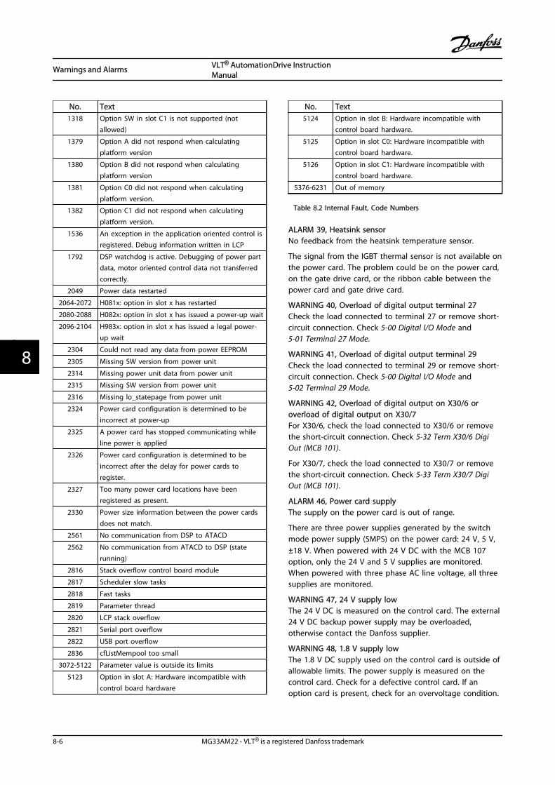
No. Text1318 Option SW in slot C1 is not supported (not
allowed)
1379 Option A did not respond when calculatingplatform version
1380 Option B did not respond when calculatingplatform version
1381 Option C0 did not respond when calculatingplatform version.
1382 Option C1 did not respond when calculatingplatform version.
1536 An exception in the application oriented control isregistered. Debug information written in LCP
1792 DSP watchdog is active. Debugging of power partdata, motor oriented control data not transferredcorrectly.
2049 Power data restarted
2064-2072 H081x: option in slot x has restarted
2080-2088 H082x: option in slot x has issued a power-up wait
2096-2104 H983x: option in slot x has issued a legal power-up wait
2304 Could not read any data from power EEPROM
2305 Missing SW version from power unit
2314 Missing power unit data from power unit
2315 Missing SW version from power unit
2316 Missing lo_statepage from power unit
2324 Power card configuration is determined to beincorrect at power-up
2325 A power card has stopped communicating whileline power is applied
2326 Power card configuration is determined to beincorrect after the delay for power cards toregister.
2327 Too many power card locations have beenregistered as present.
2330 Power size information between the power cardsdoes not match.
2561 No communication from DSP to ATACD
2562 No communication from ATACD to DSP (staterunning)
2816 Stack overflow control board module
2817 Scheduler slow tasks
2818 Fast tasks
2819 Parameter thread
2820 LCP stack overflow
2821 Serial port overflow
2822 USB port overflow
2836 cfListMempool too small
3072-5122 Parameter value is outside its limits
5123 Option in slot A: Hardware incompatible withcontrol board hardware
No. Text5124 Option in slot B: Hardware incompatible with
control board hardware.
5125 Option in slot C0: Hardware incompatible withcontrol board hardware.
5126 Option in slot C1: Hardware incompatible withcontrol board hardware.
5376-6231 Out of memory
Table 8.2 Internal Fault, Code Numbers
ALARM 39, Heatsink sensorNo feedback from the heatsink temperature sensor.
The signal from the IGBT thermal sensor is not available onthe power card. The problem could be on the power card,on the gate drive card, or the ribbon cable between thepower card and gate drive card.
WARNING 40, Overload of digital output terminal 27Check the load connected to terminal 27 or remove short-circuit connection. Check 5-00 Digital I/O Mode and5-01 Terminal 27 Mode.
WARNING 41, Overload of digital output terminal 29Check the load connected to terminal 29 or remove short-circuit connection. Check 5-00 Digital I/O Mode and5-02 Terminal 29 Mode.
WARNING 42, Overload of digital output on X30/6 oroverload of digital output on X30/7For X30/6, check the load connected to X30/6 or removethe short-circuit connection. Check 5-32 Term X30/6 DigiOut (MCB 101).
For X30/7, check the load connected to X30/7 or removethe short-circuit connection. Check 5-33 Term X30/7 DigiOut (MCB 101).
ALARM 46, Power card supplyThe supply on the power card is out of range.
There are three power supplies generated by the switchmode power supply (SMPS) on the power card: 24 V, 5 V,±18 V. When powered with 24 V DC with the MCB 107option, only the 24 V and 5 V supplies are monitored.When powered with three phase AC line voltage, all threesupplies are monitored.
WARNING 47, 24 V supply lowThe 24 V DC is measured on the control card. The external24 V DC backup power supply may be overloaded,otherwise contact the Danfoss supplier.
WARNING 48, 1.8 V supply lowThe 1.8 V DC supply used on the control card is outside ofallowable limits. The power supply is measured on thecontrol card. Check for a defective control card. If anoption card is present, check for an overvoltage condition.
Warnings and Alarms VLT® AutomationDrive InstructionManual
8-6 MG33AM22 - VLT® is a registered Danfoss trademark
88
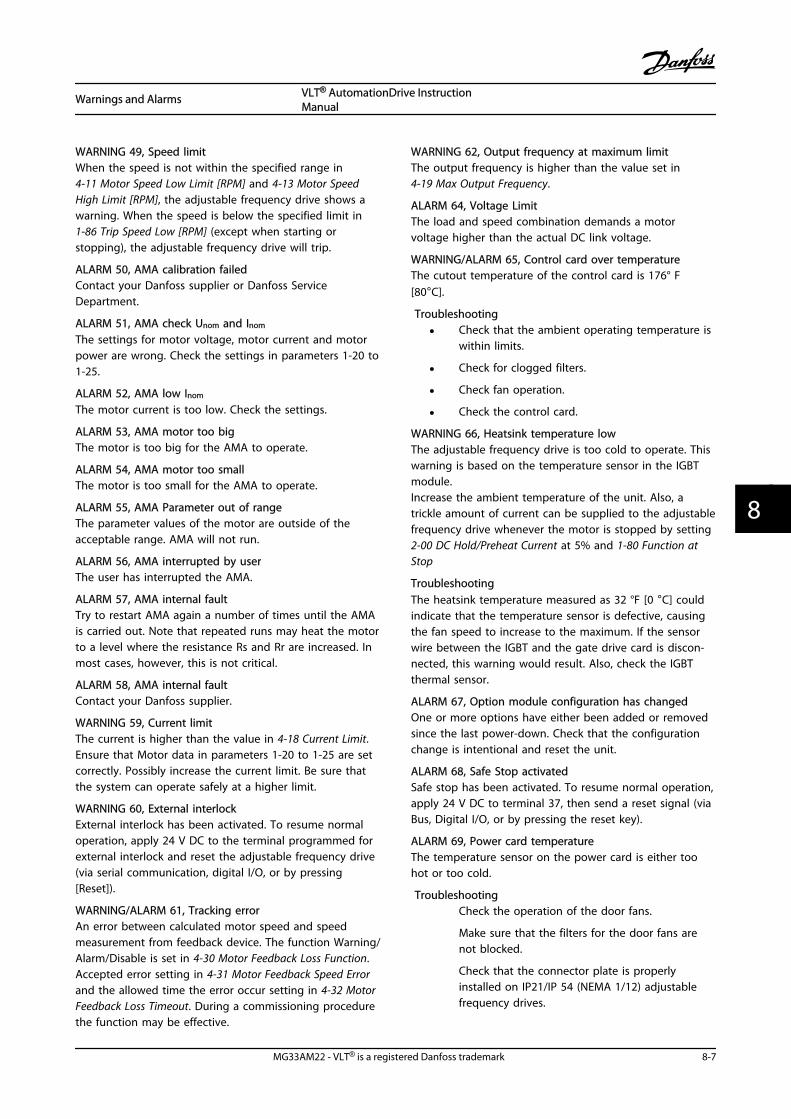
WARNING 49, Speed limitWhen the speed is not within the specified range in4-11 Motor Speed Low Limit [RPM] and 4-13 Motor SpeedHigh Limit [RPM], the adjustable frequency drive shows awarning. When the speed is below the specified limit in1-86 Trip Speed Low [RPM] (except when starting orstopping), the adjustable frequency drive will trip.
ALARM 50, AMA calibration failedContact your Danfoss supplier or Danfoss ServiceDepartment.
ALARM 51, AMA check Unom and Inom
The settings for motor voltage, motor current and motorpower are wrong. Check the settings in parameters 1-20 to1-25.
ALARM 52, AMA low Inom
The motor current is too low. Check the settings.
ALARM 53, AMA motor too bigThe motor is too big for the AMA to operate.
ALARM 54, AMA motor too smallThe motor is too small for the AMA to operate.
ALARM 55, AMA Parameter out of rangeThe parameter values of the motor are outside of theacceptable range. AMA will not run.
ALARM 56, AMA interrupted by userThe user has interrupted the AMA.
ALARM 57, AMA internal faultTry to restart AMA again a number of times until the AMAis carried out. Note that repeated runs may heat the motorto a level where the resistance Rs and Rr are increased. Inmost cases, however, this is not critical.
ALARM 58, AMA internal faultContact your Danfoss supplier.
WARNING 59, Current limitThe current is higher than the value in 4-18 Current Limit.Ensure that Motor data in parameters 1-20 to 1-25 are setcorrectly. Possibly increase the current limit. Be sure thatthe system can operate safely at a higher limit.
WARNING 60, External interlockExternal interlock has been activated. To resume normaloperation, apply 24 V DC to the terminal programmed forexternal interlock and reset the adjustable frequency drive(via serial communication, digital I/O, or by pressing[Reset]).
WARNING/ALARM 61, Tracking errorAn error between calculated motor speed and speedmeasurement from feedback device. The function Warning/Alarm/Disable is set in 4-30 Motor Feedback Loss Function.Accepted error setting in 4-31 Motor Feedback Speed Errorand the allowed time the error occur setting in 4-32 MotorFeedback Loss Timeout. During a commissioning procedurethe function may be effective.
WARNING 62, Output frequency at maximum limitThe output frequency is higher than the value set in4-19 Max Output Frequency.
ALARM 64, Voltage LimitThe load and speed combination demands a motorvoltage higher than the actual DC link voltage.
WARNING/ALARM 65, Control card over temperatureThe cutout temperature of the control card is 176° F[80°C].
Troubleshooting
• Check that the ambient operating temperature iswithin limits.
• Check for clogged filters.
• Check fan operation.
• Check the control card.
WARNING 66, Heatsink temperature lowThe adjustable frequency drive is too cold to operate. Thiswarning is based on the temperature sensor in the IGBTmodule.Increase the ambient temperature of the unit. Also, atrickle amount of current can be supplied to the adjustablefrequency drive whenever the motor is stopped by setting2-00 DC Hold/Preheat Current at 5% and 1-80 Function atStop
TroubleshootingThe heatsink temperature measured as 32 °F [0 °C] couldindicate that the temperature sensor is defective, causingthe fan speed to increase to the maximum. If the sensorwire between the IGBT and the gate drive card is discon-nected, this warning would result. Also, check the IGBTthermal sensor.
ALARM 67, Option module configuration has changedOne or more options have either been added or removedsince the last power-down. Check that the configurationchange is intentional and reset the unit.
ALARM 68, Safe Stop activatedSafe stop has been activated. To resume normal operation,apply 24 V DC to terminal 37, then send a reset signal (viaBus, Digital I/O, or by pressing the reset key).
ALARM 69, Power card temperatureThe temperature sensor on the power card is either toohot or too cold.
TroubleshootingCheck the operation of the door fans.
Make sure that the filters for the door fans arenot blocked.
Check that the connector plate is properlyinstalled on IP21/IP 54 (NEMA 1/12) adjustablefrequency drives.
Warnings and Alarms VLT® AutomationDrive InstructionManual
MG33AM22 - VLT® is a registered Danfoss trademark 8-7
8 8
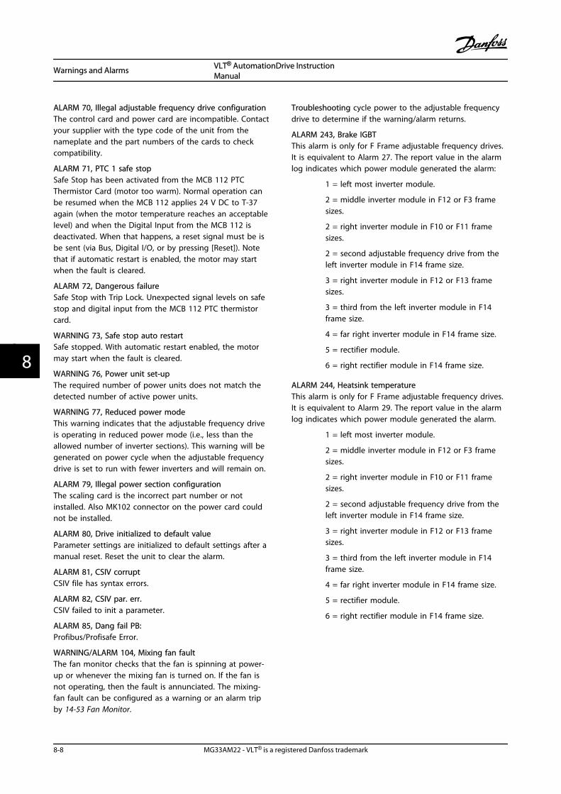
ALARM 70, Illegal adjustable frequency drive configurationThe control card and power card are incompatible. Contactyour supplier with the type code of the unit from thenameplate and the part numbers of the cards to checkcompatibility.
ALARM 71, PTC 1 safe stopSafe Stop has been activated from the MCB 112 PTCThermistor Card (motor too warm). Normal operation canbe resumed when the MCB 112 applies 24 V DC to T-37again (when the motor temperature reaches an acceptablelevel) and when the Digital Input from the MCB 112 isdeactivated. When that happens, a reset signal must be isbe sent (via Bus, Digital I/O, or by pressing [Reset]). Notethat if automatic restart is enabled, the motor may startwhen the fault is cleared.
ALARM 72, Dangerous failureSafe Stop with Trip Lock. Unexpected signal levels on safestop and digital input from the MCB 112 PTC thermistorcard.
WARNING 73, Safe stop auto restartSafe stopped. With automatic restart enabled, the motormay start when the fault is cleared.
WARNING 76, Power unit set-upThe required number of power units does not match thedetected number of active power units.
WARNING 77, Reduced power modeThis warning indicates that the adjustable frequency driveis operating in reduced power mode (i.e., less than theallowed number of inverter sections). This warning will begenerated on power cycle when the adjustable frequencydrive is set to run with fewer inverters and will remain on.
ALARM 79, Illegal power section configurationThe scaling card is the incorrect part number or notinstalled. Also MK102 connector on the power card couldnot be installed.
ALARM 80, Drive initialized to default valueParameter settings are initialized to default settings after amanual reset. Reset the unit to clear the alarm.
ALARM 81, CSIV corruptCSIV file has syntax errors.
ALARM 82, CSIV par. err.CSIV failed to init a parameter.
ALARM 85, Dang fail PB:Profibus/Profisafe Error.
WARNING/ALARM 104, Mixing fan faultThe fan monitor checks that the fan is spinning at power-up or whenever the mixing fan is turned on. If the fan isnot operating, then the fault is annunciated. The mixing-fan fault can be configured as a warning or an alarm tripby 14-53 Fan Monitor.
Troubleshooting cycle power to the adjustable frequencydrive to determine if the warning/alarm returns.
ALARM 243, Brake IGBTThis alarm is only for F Frame adjustable frequency drives.It is equivalent to Alarm 27. The report value in the alarmlog indicates which power module generated the alarm:
1 = left most inverter module.
2 = middle inverter module in F12 or F3 framesizes.
2 = right inverter module in F10 or F11 framesizes.
2 = second adjustable frequency drive from theleft inverter module in F14 frame size.
3 = right inverter module in F12 or F13 framesizes.
3 = third from the left inverter module in F14frame size.
4 = far right inverter module in F14 frame size.
5 = rectifier module.
6 = right rectifier module in F14 frame size.
ALARM 244, Heatsink temperatureThis alarm is only for F Frame adjustable frequency drives.It is equivalent to Alarm 29. The report value in the alarmlog indicates which power module generated the alarm.
1 = left most inverter module.
2 = middle inverter module in F12 or F3 framesizes.
2 = right inverter module in F10 or F11 framesizes.
2 = second adjustable frequency drive from theleft inverter module in F14 frame size.
3 = right inverter module in F12 or F13 framesizes.
3 = third from the left inverter module in F14frame size.
4 = far right inverter module in F14 frame size.
5 = rectifier module.
6 = right rectifier module in F14 frame size.
Warnings and Alarms VLT® AutomationDrive InstructionManual
8-8 MG33AM22 - VLT® is a registered Danfoss trademark
88

ALARM 245, Heatsink sensorThis alarm is only for F Frame adjustable frequency drives.It is equivalent to Alarm 39. The report value in the alarmlog indicates which power module generated the alarm.
1 = left most inverter module.
2 = middle inverter module in F12 or F3 framesizes.
2 = right inverter module in F10 or F11 framesizes.
2 = second adjustable frequency drive from theleft inverter module in F14 frame size.
3 = right inverter module in F12 or F13 framesizes.
3 = third from the left inverter module in F14frame size.
4 = far right inverter module in F14 frame size.
5 = rectifier module.
6 = right rectifier module in F14 frame size.
ALARM 246, Power card supplyThis alarm is only for F Frame adjustable frequency drive. Itis equivalent to Alarm 46. The report value in the alarmlog indicates which power module generated the alarm.
1 = left most inverter module.
2 = middle inverter module in F12 or F3 framesizes.
2 = right inverter module in F10 or F11 framesizes.
2 = second adjustable frequency drive from theleft inverter module in F14 frame size.
3 = right inverter module in F12 or F13 framesizes.
3 = third from the left inverter module in F14frame size.
4 = far right inverter module in F14 frame size.
5 = rectifier module.
6 = right rectifier module in F14 frame size.
ALARM 247, Power card temperatureThis alarm is only for F Frame adjustable frequency drive. Itis equivalent to Alarm 69. The report value in the alarmlog indicates which power module generated the alarm.
1 = left most inverter module.
2 = middle inverter module in F12 or F3 framesizes.
2 = right inverter module in F10 or F11 framesizes.
2 = second adjustable frequency drive from theleft inverter module in F14 frame size.
3 = right inverter module in F12 or F13 framesizes.
3 = third from the left inverter module in F14frame size.
4 = far right inverter module in F14 frame size.
5 = rectifier module.
6 = right rectifier module in F14 frame size.
ALARM 248, Illegal power section configurationThis alarm is only for F Frame adjustable frequency drives.It is equivalent to Alarm 79. The report value in the alarmlog indicates which power module generated the alarm:
1 = left most inverter module.
2 = middle inverter module in F12 or F3 framesizes.
2 = right inverter module in F10 or F11 framesizes.
2 = second adjustable frequency drive from theleft inverter module in F14 frame size.
3 = right inverter module in F12 or F13 framesizes.
3 = third from the left inverter module in F14frame size.
4 = far right inverter module in F14 frame size.
5 = rectifier module.
6 = right rectifier module in F14 frame size.
WARNING 250, New spare partA component in the adjustable frequency drive has beenreplaced. Reset the adjustable frequency drive for normaloperation.
WARNING 251, New type codeThe power card or other components have been replacedand the type code changed. Reset to remove the warningand resume normal operation.
Warnings and Alarms VLT® AutomationDrive InstructionManual
MG33AM22 - VLT® is a registered Danfoss trademark 8-9
8 8

Warnings and Alarms VLT® AutomationDrive InstructionManual
8-10 MG33AM22 - VLT® is a registered Danfoss trademark
88

9 Basic Troubleshooting
9.1 Start Up and Operation
NOTE!See Alarm Log in Table 4.2.
Symptom Possible Cause Test Solution
Display dark/No function
Missing input power See Table 3.1. Check the input power source.
Missing or open fuses or circuitbreaker tripped
See open fuses and tripped circuitbreaker in this table for possiblecauses.
Follow the recommendationsprovided.
No power to the LCP Check the LCP cable for properconnection or damage.
Replace the faulty LCP orconnection cable.
Shortcut on control voltage(terminal 12 or 50) or at controlterminals
Check the 24 V control voltagesupply for terminal 12/13 to 20–39or 10 V supply for terminal 50 to55.
Wire the terminals properly.
Wrong LCP (LCP from VLT® 2800or 5000/6000/8000/ FCD or FCM)
Use only LCP 101 (P/N 130B1124)or LCP 102 (P/N. 130B1107).
Wrong contrast setting Press [Status] + / to adjust the
contrast.
Display (LCP) is defective Test using a different LCP. Replace the faulty LCP orconnection cable.
Internal voltage supply fault orSMPS is defective
Contact supplier.
Intermittent display
Overloaded power supply (SMPS)due to improper control wiring ora fault within the adjustablefrequency drive.
To rule out a problem in thecontrol wiring, disconnect allcontrol wiring by removing theterminal blocks.
If the display stays lit, then theproblem is in the control wiring.Check the wiring for shorts orincorrect connections. If the displaycontinues to cut out, follow theprocedure for display dark.
Basic Troubleshooting VLT® AutomationDrive InstructionManual
MG33AM22 - VLT® is a registered Danfoss trademark 9-1
9 9

Symptom Possible Cause Test Solution
Motor not running
Service switch open or missingmotor connection
Check if the motor is connectedand the connection is notinterrupted (by a service switch orother device).
Connect the motor and check theservice switch.
No line power with 24 V DCoption card
If the display is functioning but nooutput, check that line power isapplied to the adjustable frequencydrive.
Apply line power to run the unit.
LCP Stop Check if [Off] has been pressed. Press [Auto On] or [Hand On](depending on your operationmode) to run the motor.
Missing start signal (Standby) Check 5-10 Terminal 18 Digital Inputfor correct setting for terminal 18(use default setting).
Apply a valid start signal to startthe motor.
Motor coast signal active(Coasting)
Check 5-12 Terminal 27 Digital Inputfor correct setting for terminal 27(use default setting).
Apply 24 V on terminal 27 orprogram this terminal to Nooperation.
Wrong reference signal source Check reference signal: Local,remote or bus reference? Presetreference active? Terminalconnection correct? Scaling ofterminals correct? Reference signalavailable?
Program correct settings Check3-13 Reference Site Set presetreference active in parametergroup 3-1* References. Check forcorrect wiring. Check scaling ofterminals. Check reference signal.
Motor running in wrongdirection
Motor rotation limit Check that 4-10 Motor SpeedDirection is programmed correctly.
Program correct settings.
Active reversing signal Check if a reversing command isprogrammed for the terminal inparameter group 5-1* Digital inputs.
Deactivate reversing signal.
Wrong motor phase connection See 3.7 Check Motor Rotation inthis manual.
Motor is not reachingmaximum speed
Frequency limits set wrong Check output limits in4-13 MotorSpeed High Limit [RPM], 4-14 MotorSpeed High Limit [Hz], and 4-19 MaxOutput Frequency
Program correct limits.
Reference input signal not scaledcorrectly
Check reference input signalscaling in parameter group 6-*Analog I/O mode and parametergroup 3-1* References.
Program correct settings.
Motor speed unstable
Possible incorrect parametersettings
Check the settings of all motorparameters, including all motorcompensation settings. For closed-loop operation, check PID settings.
Check settings in parameter group1-6* Analog I/O mode. For closed-loop operation, check settings inparameter group 20-0* Feedback.
Motor runs rough
Possible over-magnetization Check for incorrect motor settingsin all motor parameters.
Check motor settings in parametergroups 1-2* Motor data 1-3* Advmotor data, and 1-5* Load indep.setting.
Motor will not brakePossible incorrect settings in thebrake parameters. Possible tooshort ramp-down times.
Check brake parameters. Checkramp time settings.
Check parameter group 2-0* DCbrake and 3-0* Reference limits.
Basic Troubleshooting VLT® AutomationDrive InstructionManual
9-2 MG33AM22 - VLT® is a registered Danfoss trademark
99
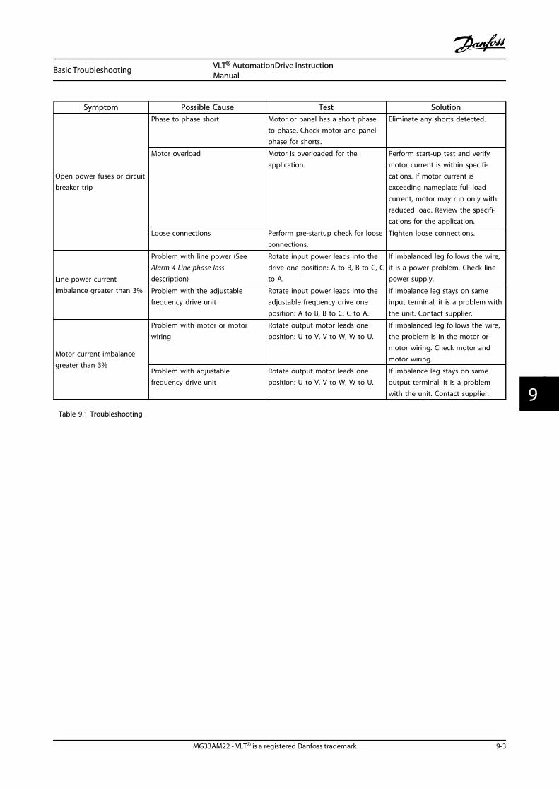
Symptom Possible Cause Test Solution
Open power fuses or circuitbreaker trip
Phase to phase short Motor or panel has a short phaseto phase. Check motor and panelphase for shorts.
Eliminate any shorts detected.
Motor overload Motor is overloaded for theapplication.
Perform start-up test and verifymotor current is within specifi-cations. If motor current isexceeding nameplate full loadcurrent, motor may run only withreduced load. Review the specifi-cations for the application.
Loose connections Perform pre-startup check for looseconnections.
Tighten loose connections.
Line power currentimbalance greater than 3%
Problem with line power (SeeAlarm 4 Line phase lossdescription)
Rotate input power leads into thedrive one position: A to B, B to C, Cto A.
If imbalanced leg follows the wire,it is a power problem. Check linepower supply.
Problem with the adjustablefrequency drive unit
Rotate input power leads into theadjustable frequency drive oneposition: A to B, B to C, C to A.
If imbalance leg stays on sameinput terminal, it is a problem withthe unit. Contact supplier.
Motor current imbalancegreater than 3%
Problem with motor or motorwiring
Rotate output motor leads oneposition: U to V, V to W, W to U.
If imbalanced leg follows the wire,the problem is in the motor ormotor wiring. Check motor andmotor wiring.
Problem with adjustablefrequency drive unit
Rotate output motor leads oneposition: U to V, V to W, W to U.
If imbalance leg stays on sameoutput terminal, it is a problemwith the unit. Contact supplier.
Table 9.1 Troubleshooting
Basic Troubleshooting VLT® AutomationDrive InstructionManual
MG33AM22 - VLT® is a registered Danfoss trademark 9-3
9 9

Basic Troubleshooting VLT® AutomationDrive InstructionManual
9-4 MG33AM22 - VLT® is a registered Danfoss trademark
99

10 Specifications
10.1 Power-dependent Specifications
PK25 PK37 PK55 PK75 P1K1 P1K5 P2K2 P3K0 P3K7
Typical Shaft Output (hp [kW])0.34
[0.25]0.5 [0.37]
0.75[0.55]
1 [0.75] 1.5 [1.1] 2 [1.5] 3 [2.2] 4 [3] 5 [3.7]
Enclosure IP20/IP21 A2 A2 A2 A2 A2 A2 A2 A3 A3
Enclosure IP20 (FC 301 only) A1 A1 A1 A1 A1 A1 - - -
Enclosure IP55, IP66 A4/A5 A4/A5 A4/A5 A4/A5 A4/A5 A4/A5 A4/A5 A5 A5
Output current
Continuous(3x200–240 V) [A]
1.8 2.4 3.5 4.6 6.6 7.5 10.6 12.5 16.7
Intermittent(3x200–240 V) [A]
2.9 3.8 5.6 7.4 10.6 12.0 17.0 20.0 26.7
ContinuouskVA (208 V AC) [kVA]
0.65 0.86 1.26 1.66 2.38 2.70 3.82 4.50 6.00
Max. input current
Continuous(3x200–240 V) [A]
1.6 2.2 3.2 4.1 5.9 6.8 9.5 11.3 15.0
Intermittent(3x200–240 V) [A]
2.6 3.5 5.1 6.6 9.4 10.9 15.2 18.1 24.0
Additional specifications
IP20, IP21 max. cable cross-section5) (linepower, motor, brake and load sharing)
[mm2 (AWG)]2)
4,4,4 (12,12,12)(min. 0.2 (24))
IP55, IP66 max. cable cross-section5) (linepower, motor, brake and load sharing)
[mm2 (AWG)]
4,4,4 (12,12,12)
Max. cable cross-section5) with disconnect 6,4,4 (10,12,12)
Estimated power loss
at rated max. load [W] 4)21 29 42 54 63 82 116 155 185
Weight, enclosure IP20 (lbs [kg]) 10.36[4.7]
10.36[4.7]
10.58[4.8]
10.58[4.8]
10.8 [4.9] 10.8 [4.9]10.8[4.9]
14.55[6.6]
14.55[6.6]
A1 (IP20) 2.7 2.7 2.7 2.7 2.7 2.7 - - -
A5 (IP55, IP66) 13.5 13.5 13.5 13.5 13.5 13.5 13.5 13.5 13.5
Efficiency 4) 0.94 0.94 0.95 0.95 0.96 0.96 0.96 0.96 0.96
0.34–5 hp [0.25–3.7 kW] only available as 160% high overload.
Table 10.1 Line Power Supply 3x200–240 V AC
Specifications VLT® AutomationDrive InstructionManual
MG33AM22 - VLT® is a registered Danfoss trademark 10-1
10 10

P5K5 P7K5 P11K
High/ Normal Load1) HO NO HO NO HO NO
Typical Shaft Output (hp [kW]) 7.5 [5.5] 10 [7.5] 10 [7.5] 15 [11] 15 [11] 20 [15]
Enclosure IP20 B3 B3 B4
Enclosure IP21 B1 B1 B2
Enclosure IP55, IP66 B1 B1 B2
Output current
Continuous (3x200–240 V) [A] 24.2 30.8 30.8 46.2 46.2 59.4
Intermittent (60 s overload)(3x200–240 V) [A]
38.7 33.9 49.3 50.8 73.9 65.3
Continuous kVA (208 V AC) [kVA] 8.7 11.1 11.1 16.6 16.6 21.4
Max. input current
Continuous (3x200–240 V) [A] 22 28 28 42 42 54
Intermittent (60 s overload)(3x200–240 V) [A]
35.2 30.8 44.8 46.2 67.2 59.4
Additional specifications
IP21 max. cable cross-section5) (line power,
brake, load sharing) [AWG (mm2)] 2)16,10, 16 (6,8,6) 16,10, 16 (6,8,6) 35,-,- (2,-,-)
IP21 max. cable cross-section5) (motor) [AWG
(mm2)] 2)10,10,- (8,8,-) 10,10,- (8,8,-) 35,25,25 (2,4,4)
IP20 max. cable cross-section5) (line power,brake, motor and load sharing)
10,10,- (8,8,-) 10,10,- (8,8,-) 35,-,- (2,-,-)
Max. cable cross-section with disconnect [AWG
(mm2)] 2)16,10,10 (6,8,8)
Estimated power loss
at rated max. load [W] 4) 239 310 371 514 463 602
Weight,enclosure IP21, IP55, IP66 (lbs [kg])
50.71 [23] 50.71 [23] 59.53 [27]
Efficiency4) 0.964 0.959 0.964
Table 10.2 Line Power Supply 3x200–240 V AC
Specifications VLT® AutomationDrive InstructionManual
10-2 MG33AM22 - VLT® is a registered Danfoss trademark
1010

P15K P18K P22K P30K P37K
High/Normal Load1) HO NO HO NO HO NO HO NO HO NO
Typical Shaft Output (hp [kW]) 20 [15] 25 [18.5] 25 [18.5] 30 [22] 30 [22] 40 [30] 40 [30] 50 [37] 50 [37] 60 [45]
Enclosure IP20 B4 C3 C3 C4 C4
Enclosure IP21 C1 C1 C1 C2 C2
Enclosure IP55, IP66 C1 C1 C1 C2 C2
Output current
Continuous (3x200–240 V) [A] 59.4 74.8 74.8 88 88 115 115 143 143 170
Intermittent(60 s overload)(3x200–240 V) [A]
89.1 82.3 112 96.8 132 127 173 157 215 187
Continuous kVA (208 V AC) [kVA] 21.4 26.9 26.9 31.7 31.7 41.4 41.4 51.5 51.5 61.2
Max. input current
Continuous (3x200–240 V) [A] 54 68 68 80 80 104 104 130 130 154
Intermittent(60 s overload)(3x200–240 V) [A]
81 74.8 102 88 120 114 156 143 195 169
Additional specifications
IP20 max. cable cross-section5)
(line power, brake, motor and loadsharing)
35 (2) 50 (1) 50 (1) 300MCM (150) 300MCM (150)
IP21, IP55, IP66 max. cable cross-
section5) (line power, motor) [mm2
(AWG)] 2)
50 (1) 50 (1) 50 (1) 300MCM (150) 300MCM (150)
IP21, IP55, IP66 max. cable cross-
section5) (brake, load sharing)
[mm2 (AWG)] 2)
50 (1) 50 (1) 50 (1) 95 (3/0) 95 (3/0)
Max. cable size with line power
disconnect [AWG (mm2)] 2) 50, 35, 35 (1, 2, 2)95, 70, 70
(3/0, 2/0, 2/0)
185, 150, 120(350MCM,
300MCM, 4/0)
Estimated power loss
at rated max. load [W] 4)624 737 740 845 874 1140 1143 1353 1400 1636
Weight, enclosure IP21, IP55/IP66(lbs [kg])
99.21 [45] 99.21 [45] 99.21 [45] 143.3 [65] 143.3 [65]
Efficiency4) 0.96 0.97 0.97 0.97 0.97
Table 10.3 Line Power Supply 3x200–240 V AC
For fuse ratings, see 10.3.1 Fuses
1) High overload = 160% torque during 60 s. Normal overload = 110% torque during 60 s.
2) American Wire Gauge.
3) Measured using 16.5 ft. [5 m] shielded motor cables at rated load and rated frequency.
4) The typical power loss is at nominal load conditions and expected to be within ±15% (tolerance relates to variances in voltage andcable conditions).Values are based on a typical motor efficiency (eff2/eff3 border line). Motors with lower efficiency will also add to the power loss in theadjustable frequency drive and vice-versa.If the switching frequency is increased compared to the default setting, the power losses may rise significantly.LCP and typical control card power consumption values are included. Further options and customer load may add up to 30 W to thelosses. (Though typical only 4 W extra for a fully loaded control card, or options for slot A or slot B, each).
Although measurements are made with state of the art equipment, some measurement inaccuracy must be allowed for (±5%).
Specifications VLT® AutomationDrive InstructionManual
MG33AM22 - VLT® is a registered Danfoss trademark 10-3
10 10

5) The three values for the max. cable cross-section are for single core, flexible wire and flexible wire with sleeve, respectively.
PK37 PK55 PK75 P1K1 P1K5 P2K2 P3K0 P4K0 P5K5 P7K5
Typical Shaft Output (hp [kW])0.5
[0.37]0.75
[0.55]1
[0.75]1.5 [1.1] 2 [1.5] 3 [2.2] 4 [3] 5 [4] 7.5 [5.5] 10 [7.5]
Enclosure IP20/IP21 A2 A2 A2 A2 A2 A2 A2 A2 A3 A3
Enclosure IP20 (FC 301 only) A1 A1 A1 A1 A1
Enclosure IP55, IP66 A4/A5 A4/A5 A4/A5 A4/A5 A4/A5 A4/A5 A4/A5 A4/A5 A5 A5
Output currentHigh overload 160% for 1 min.
Shaft output [hp, kW]0.5
[0.37]0.75
[0.55]1
[0.75] 1.5 [1.1] 2 [1.5] 3 [2.2] 4 [3] 5 [4] 7.5 [5.5] 10 [7.5]
Continuous (3x380–440 V) [A] 1.3 1.8 2.4 3 4.1 5.6 7.2 10 13 16
Intermittent (3x380–440 V) [A] 2.1 2.9 3.8 4.8 6.6 9.0 11.5 16 20.8 25.6
Continuous (3x441–500 V) [A] 1.2 1.6 2.1 2.7 3.4 4.8 6.3 8.2 11 14.5
Intermittent (3x441–500 V) [A] 1.9 2.6 3.4 4.3 5.4 7.7 10.1 13.1 17.6 23.2
Continuous kVA (400 V AC) [kVA] 0.9 1.3 1.7 2.1 2.8 3.9 5.0 6.9 9.0 11.0
Continuous kVA (460 V AC) [kVA] 0.9 1.3 1.7 2.4 2.7 3.8 5.0 6.5 8.8 11.6
Max. input current
Continuous (3x380–440 V) [A] 1.2 1.6 2.2 2.7 3.7 5.0 6.5 9.0 11.7 14.4
Intermittent (3x380–440 V) [A] 1.9 2.6 3.5 4.3 5.9 8.0 10.4 14.4 18.7 23.0
Continuous (3x441–500 V) [A] 1.0 1.4 1.9 2.7 3.1 4.3 5.7 7.4 9.9 13.0
Intermittent (3x441–500 V) [A] 1.6 2.2 3.0 4.3 5.0 6.9 9.1 11.8 15.8 20.8
Additional specifications
IP20, IP21 max. cable-cross section5)
(line power, motor, brake and load
sharing) [mm2 (AWG)]2)
4,4,4 (12,12,12)(min. 0.2(24))
IP55, IP66 max. cable cross-section5)
(line power, motor, brake and load
sharing) [mm2 (AWG)]
4,4,4 (12,12,12)
Max. cable cross-section5) withdisconnect
6,4,4 (10,12,12)
Estimated power loss
at rated max. load [W] 4)35 42 46 58 62 88 116 124 187 255
Weight, enclosure IP20 (lb [kg]) 10.36[4.7]
10.36[4.7]
10.58[4.8]
10.58[4.8]
10.8[4.9]
10.8[4.9]
10.8 [4.9]10.8[4.9]
14.55[6.6]
14.55[6.6]
Enclosure IP55, IP66 13.5 13.5 13.5 13.5 13.5 13.5 13.5 13.5 14.2 14.2
Efficiency 4) 0.93 0.95 0.96 0.96 0.97 0.97 0.97 0.97 0.97 0.97
0.5–10 hp [0.37–7.5 kW] only available as 160% high overload.
Table 10.4 Line Power Supply 3x380–500 V AC (FC 302), 3x380–480 V AC (FC 301)
Specifications VLT® AutomationDrive InstructionManual
10-4 MG33AM22 - VLT® is a registered Danfoss trademark
1010

P11K P15K P18K P22K
High/Normal Load1) HO NO HO NO HO NO HO NO
Typical Shaft output hp [kW] 15 [11] 20 [15] 20 [15] 25 [18.5] 25 [18.5] 30 [22.0] 30 [22.0] 40 [30.0]
Enclosure IP20 B3 B3 B4 B4
Enclosure IP21 B1 B1 B2 B2
Enclosure IP55, IP66 B1 B1 B2 B2
Output current
Continuous (3x380–440 V) [A] 24 32 32 37.5 37.5 44 44 61
Intermittent (60 s overload) (3x380–440V) [A]
38.4 35.2 51.2 41.3 60 48.4 70.4 67.1
Continuous (3x441–500 V) [A] 21 27 27 34 34 40 40 52
Intermittent (60 s overload)(3x441–500 V) [A]
33.6 29.7 43.2 37.4 54.4 44 64 57.2
Continuous kVA (400 V AC) [kVA] 16.6 22.2 22.2 26 26 30.5 30.5 42.3
Continuous kVA (460 V AC) [kVA] 21.5 27.1 31.9 41.4
Max. input current
Continuous (3x380–440 V) [A] 22 29 29 34 34 40 40 55
Intermittent (60 s overload)(3x380–440 V) [A]
35.2 31.9 46.4 37.4 54.4 44 64 60.5
Continuous (3x441–500 V) [A] 19 25 25 31 31 36 36 47
Intermittent (60 s overload)(3x441–500 V) [A]
30.4 27.5 40 34.1 49.6 39.6 57.6 51.7
Additional specifications
IP21, IP55, IP66 max. cable cross-
section5) (line power, brake, load
sharing) [mm2 (AWG)] 2)
16, 10, 16 (6, 8, 6) 16, 10, 16 (6, 8, 6) 35,-,-(2,-,-) 35,-,-(2,-,-)
IP21, IP55, IP66 max. cable cross-
section5) (motor) [mm2 (AWG)] 2)10, 10,- (8, 8,-) 10, 10,- (8, 8,-) 35, 25, 25 (2, 4, 4) 35, 25, 25 (2, 4, 4)
IP20 max. cable cross-section5) (linepower, brake, motor and load sharing)
10, 10,- (8, 8,-) 10, 10,- (8, 8,-) 35,-,-(2,-,-) 35,-,-(2,-,-)
Max. cable cross-section with
disconnect [AWG (mm2)] 2)16, 10, 10 (6, 8, 8)
Estimated power loss
at rated max. load [W] 4)291 392 379 465 444 525 547 739
Weight, enclosure IP20 (lbs [kg]) 26.46 [12] 26.46 [12] 51.81 [23.5] 51.81 [23.5]
Weight, enclosure IP21, IP55, 66 (lbs[kg])
50.71 [23] 50.71 [23] 59.53 [27] 59.53 [27]
Efficiency4) 0.98 0.98 0.98 0.98
Table 10.5 Line Power Supply 3x380–500 V AC (FC 302), 3x380–480 V AC (FC 301)
Specifications VLT® AutomationDrive InstructionManual
MG33AM22 - VLT® is a registered Danfoss trademark 10-5
10 10
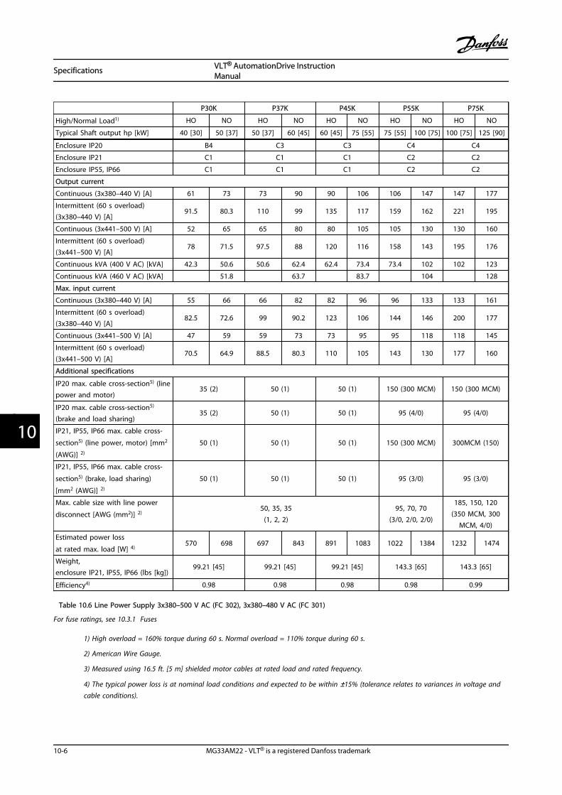
P30K P37K P45K P55K P75K
High/Normal Load1) HO NO HO NO HO NO HO NO HO NO
Typical Shaft output hp [kW] 40 [30] 50 [37] 50 [37] 60 [45] 60 [45] 75 [55] 75 [55] 100 [75] 100 [75] 125 [90]
Enclosure IP20 B4 C3 C3 C4 C4
Enclosure IP21 C1 C1 C1 C2 C2
Enclosure IP55, IP66 C1 C1 C1 C2 C2
Output current
Continuous (3x380–440 V) [A] 61 73 73 90 90 106 106 147 147 177
Intermittent (60 s overload)(3x380–440 V) [A]
91.5 80.3 110 99 135 117 159 162 221 195
Continuous (3x441–500 V) [A] 52 65 65 80 80 105 105 130 130 160
Intermittent (60 s overload)(3x441–500 V) [A]
78 71.5 97.5 88 120 116 158 143 195 176
Continuous kVA (400 V AC) [kVA] 42.3 50.6 50.6 62.4 62.4 73.4 73.4 102 102 123
Continuous kVA (460 V AC) [kVA] 51.8 63.7 83.7 104 128
Max. input current
Continuous (3x380–440 V) [A] 55 66 66 82 82 96 96 133 133 161
Intermittent (60 s overload)(3x380–440 V) [A]
82.5 72.6 99 90.2 123 106 144 146 200 177
Continuous (3x441–500 V) [A] 47 59 59 73 73 95 95 118 118 145
Intermittent (60 s overload)(3x441–500 V) [A]
70.5 64.9 88.5 80.3 110 105 143 130 177 160
Additional specifications
IP20 max. cable cross-section5) (linepower and motor)
35 (2) 50 (1) 50 (1) 150 (300 MCM) 150 (300 MCM)
IP20 max. cable cross-section5)
(brake and load sharing)35 (2) 50 (1) 50 (1) 95 (4/0) 95 (4/0)
IP21, IP55, IP66 max. cable cross-
section5) (line power, motor) [mm2
(AWG)] 2)
50 (1) 50 (1) 50 (1) 150 (300 MCM) 300MCM (150)
IP21, IP55, IP66 max. cable cross-
section5) (brake, load sharing)
[mm2 (AWG)] 2)
50 (1) 50 (1) 50 (1) 95 (3/0) 95 (3/0)
Max. cable size with line power
disconnect [AWG (mm2)] 2)50, 35, 35
(1, 2, 2)95, 70, 70
(3/0, 2/0, 2/0)
185, 150, 120(350 MCM, 300
MCM, 4/0)
Estimated power loss
at rated max. load [W] 4)570 698 697 843 891 1083 1022 1384 1232 1474
Weight,enclosure IP21, IP55, IP66 (lbs [kg])
99.21 [45] 99.21 [45] 99.21 [45] 143.3 [65] 143.3 [65]
Efficiency4) 0.98 0.98 0.98 0.98 0.99
Table 10.6 Line Power Supply 3x380–500 V AC (FC 302), 3x380–480 V AC (FC 301)
For fuse ratings, see 10.3.1 Fuses
1) High overload = 160% torque during 60 s. Normal overload = 110% torque during 60 s.
2) American Wire Gauge.
3) Measured using 16.5 ft. [5 m] shielded motor cables at rated load and rated frequency.
4) The typical power loss is at nominal load conditions and expected to be within ±15% (tolerance relates to variances in voltage andcable conditions).
Specifications VLT® AutomationDrive InstructionManual
10-6 MG33AM22 - VLT® is a registered Danfoss trademark
1010
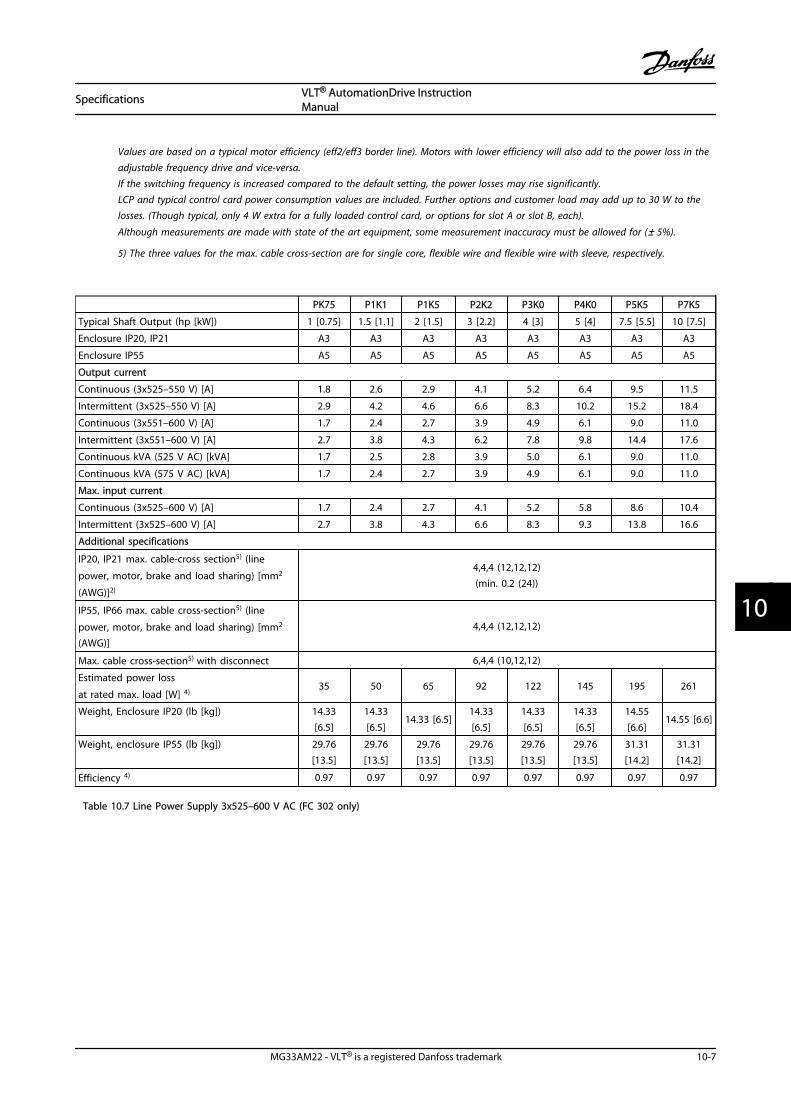
Values are based on a typical motor efficiency (eff2/eff3 border line). Motors with lower efficiency will also add to the power loss in theadjustable frequency drive and vice-versa.If the switching frequency is increased compared to the default setting, the power losses may rise significantly.LCP and typical control card power consumption values are included. Further options and customer load may add up to 30 W to thelosses. (Though typical, only 4 W extra for a fully loaded control card, or options for slot A or slot B, each).
Although measurements are made with state of the art equipment, some measurement inaccuracy must be allowed for (± 5%).
5) The three values for the max. cable cross-section are for single core, flexible wire and flexible wire with sleeve, respectively.
PK75 P1K1 P1K5 P2K2 P3K0 P4K0 P5K5 P7K5
Typical Shaft Output (hp [kW]) 1 [0.75] 1.5 [1.1] 2 [1.5] 3 [2.2] 4 [3] 5 [4] 7.5 [5.5] 10 [7.5]
Enclosure IP20, IP21 A3 A3 A3 A3 A3 A3 A3 A3
Enclosure IP55 A5 A5 A5 A5 A5 A5 A5 A5
Output current
Continuous (3x525–550 V) [A] 1.8 2.6 2.9 4.1 5.2 6.4 9.5 11.5
Intermittent (3x525–550 V) [A] 2.9 4.2 4.6 6.6 8.3 10.2 15.2 18.4
Continuous (3x551–600 V) [A] 1.7 2.4 2.7 3.9 4.9 6.1 9.0 11.0
Intermittent (3x551–600 V) [A] 2.7 3.8 4.3 6.2 7.8 9.8 14.4 17.6
Continuous kVA (525 V AC) [kVA] 1.7 2.5 2.8 3.9 5.0 6.1 9.0 11.0
Continuous kVA (575 V AC) [kVA] 1.7 2.4 2.7 3.9 4.9 6.1 9.0 11.0
Max. input current
Continuous (3x525–600 V) [A] 1.7 2.4 2.7 4.1 5.2 5.8 8.6 10.4
Intermittent (3x525–600 V) [A] 2.7 3.8 4.3 6.6 8.3 9.3 13.8 16.6
Additional specifications
IP20, IP21 max. cable-cross section5) (line
power, motor, brake and load sharing) [mm2
(AWG)]2)
4,4,4 (12,12,12)(min. 0.2 (24))
IP55, IP66 max. cable cross-section5) (line
power, motor, brake and load sharing) [mm2
(AWG)]
4,4,4 (12,12,12)
Max. cable cross-section5) with disconnect 6,4,4 (10,12,12)
Estimated power loss
at rated max. load [W] 4)35 50 65 92 122 145 195 261
Weight, Enclosure IP20 (lb [kg]) 14.33[6.5]
14.33[6.5]
14.33 [6.5]14.33[6.5]
14.33[6.5]
14.33[6.5]
14.55[6.6]
14.55 [6.6]
Weight, enclosure IP55 (lb [kg]) 29.76[13.5]
29.76[13.5]
29.76[13.5]
29.76[13.5]
29.76[13.5]
29.76[13.5]
31.31[14.2]
31.31[14.2]
Efficiency 4) 0.97 0.97 0.97 0.97 0.97 0.97 0.97 0.97
Table 10.7 Line Power Supply 3x525–600 V AC (FC 302 only)
Specifications VLT® AutomationDrive InstructionManual
MG33AM22 - VLT® is a registered Danfoss trademark 10-7
10 10

P11K P15K P18K P22K P30K
High/Normal Load1) HO NO HO NO HO NO HO NO HO NO
Typical Shaft Output (hp [kW]) 15 [11] 20 [15] 20 [15] 25 [18.5] 25 [18.5] 30 [22] 30 [22] 40 [30] 40 [30] 50 [37]
Enclosure IP21, IP55, IP66 B1 B1 B2 B2 C1
Enclosure IP20 B3 B3 B4 B4 B4
Output current
Continuous (3x525–550 V) [A] 19 23 23 28 28 36 36 43 43 54
Intermittent (3x525–550 V) [A] 30 25 37 31 45 40 58 47 65 59
Continuous (3x525–600 V) [A] 18 22 22 27 27 34 34 41 41 52
Intermittent (3x525–600 V) [A] 29 24 35 30 43 37 54 45 62 57
Continuous kVA (550 V AC) [kVA] 18.1 21.9 21.9 26.7 26.7 34.3 34.3 41.0 41.0 51.4
Continuous kVA (575 V AC) [kVA] 17.9 21.9 21.9 26.9 26.9 33.9 33.9 40.8 40.8 51.8
Max. input current
Continuous at 550 V [A] 17.2 20.9 20.9 25.4 25.4 32.7 32.7 39 39 49
Intermittent at 550 V [A] 28 23 33 28 41 36 52 43 59 54
Continuous at 575 V [A] 16 20 20 24 24 31 31 37 37 47
Intermittent at 575 V [A] 26 22 32 27 39 34 50 41 56 52
Additional specifications
IP21, IP55, IP66 max. cable cross-
section5) (line power, brake, load
sharing) [mm2 (AWG)] 2)
16, 10, 10 (6, 8, 8) 16, 10, 10 (6, 8, 8) 35,-,-(2,-,-) 35,-,-(2,-,-) 50,-,- (1,-,-)
IP21, IP55, IP66 max. cable cross-
section5) (motor) [mm2 (AWG)] 2)10, 10,- (8, 8,-) 10, 10,- (8, 8,-) 35, 25, 25 (2, 4, 4) 35, 25, 25 (2, 4, 4) 50,-,- (1,-,-)
IP20 max. cable cross-section5) (linepower, brake, motor and loadsharing) 10, 10,- (8, 8,-) 10, 10,- (8, 8,-) 35,-,-(2,-,-) 35,-,-(2,-,-) 35,-,-(2,-,-)
Max. cable cross-section with
disconnect [AWG (mm2)] 2)
16, 10, 10(6, 8, 8)
50, 35, 35(1,2, 2)
Estimated power loss
at rated max. load [W] 4)225 285 329 700 700
Weight, enclosure IP21, (lbs [kg]) 50.71 [23] 50.71 [23] 59.53 [27] 59.53 [27] 59.53 [27]
Weight, enclosure IP20 (lbs [kg]) 26.46 [12] 26.46 [12] 51.81 [23.5] 51.81 [23.5] 51.81 [23.5]
Efficiency 4) 0.98 0.98 0.98 0.98 0.98
Table 10.8 Line Power Supply 3x525–600 V AC (FC 302 only)
Specifications VLT® AutomationDrive InstructionManual
10-8 MG33AM22 - VLT® is a registered Danfoss trademark
1010

P37K P45K P55K P75K
High/Normal Load1) HO NO HO NO HO NO HO NO
Typical Shaft Output (hp [kW]) 50 [37] 60 [45] 60 [45] 75 [55] 75 [55] 100 [75] 100 [75] 125 [90]
Enclosure IP21, IP55, IP66 C1 C1 C1 C2 C2
Enclosure IP20 C3 C3 C3 C4 C4
Output current
Continuous (3x525–550 V) [A] 54 65 65 87 87 105 105 137
Intermittent (3x525–550 V) [A] 81 72 98 96 131 116 158 151
Continuous (3x525–600 V) [A] 52 62 62 83 83 100 100 131
Intermittent (3x525–600 V) [A] 78 68 93 91 125 110 150 144
Continuous kVA (550 V AC) [kVA] 51.4 61.9 61.9 82.9 82.9 100.0 100.0 130.5
Continuous kVA (575 V AC) [kVA] 51.8 61.7 61.7 82.7 82.7 99.6 99.6 130.5
Max. input current
Continuous at 550 V [A] 49 59 59 78.9 78.9 95.3 95.3 124.3
Intermittent at 550 V [A] 74 65 89 87 118 105 143 137
Continuous at 575 V [A] 47 56 56 75 75 91 91 119
Intermittent at 575 V [A] 70 62 85 83 113 100 137 131
Additional specifications
IP20 max. cable cross-section5) (line powerand motor)
50 (1) 150 (300 MCM)
IP20 max. cable cross-section5) (brake andload sharing)
50 (1) 95 (4/0)
IP21, IP55, IP66 max. cable cross-section5)
(line power, motor) [mm2 (AWG)] 2)50 (1) 150 (300 MCM)
IP21, IP55, IP66 max. cable cross-section5)
(brake, load sharing) [mm2 (AWG)] 2)50 (1) 95 (4/0)
Max. cable size with line power disconnect
[AWG (mm2)] 2)50, 35, 35
(1, 2, 2)95, 70, 70
(3/0, 2/0, 2/0)
185, 150, 120(350MCM, 300MCM,
4/0)
Estimated power loss at rated max. load
[W] 4)850 1100 1400 1500
Weight, enclosure IP20 (lbs [kg]) 77.16 [35] 77.16 [35] 165 [50] 165 [50]
Weight, enclosure IP21, IP55 (lbs [kg]) 99.21 [45] 99.21 [45] 143.3 [65] 143.3 [65]
Efficiency 4) 0.98 0.98 0.98 0.98
Table 10.9 Line Power Supply 3x525–600 V AC (FC 302 only)
Specifications VLT® AutomationDrive InstructionManual
MG33AM22 - VLT® is a registered Danfoss trademark 10-9
10 10

P1K1 P1K5 P2K2 P3K0 P4K0 P5K5 P7K5
Typical Shaft Output (hp [kW]) 1.5 [1.1] 2 [1.5] 3 [2.2] 4 [3] 5 [4] 7.5 [5.5] 10 [7.5]
Enclosure IP20 (only) A3 A3 A3 A3 A3 A3 A3
Output Current High Overload 160% for 1 min
Continuous (3x525–550 V) [A] 2.1 2.7 3.9 4.9 6.1 9 11
Intermittent (3x525–550 V) [A] 3.4 4.3 6.2 7.8 9.8 14.4 17.6
Continuous kVA (3x551–690 V) [A] 1.6 2.2 3.2 4.5 5.5 7.5 10
Intermittent kVA (3x551–690 V) [A] 2.6 3.5 5.1 7.2 8.8 12 16
Continuous kVA 525 V AC 1.9 2.5 3.5 4.5 5.5 8.2 10
Continuous kVA 690 V AC 1.9 2.6 3.8 5.4 6.6 9 12
Max. input current
Continuous (3x525–550 V) [A] 1.9 2.4 3.5 4.4 5.5 8 10
Intermittent (3x525–550 V) [A] 3.0 3.9 5.6 7.1 8.8 13 16
Continuous kVA (3x551–690 V) [A] 1.4 2.0 2.9 4.0 4.9 6.7 9
Intermittent kVA (3x551–690 V) [A] 2.3 3.2 4.6 6.5 7.9 10.8 14.4
Additional specifications
IP20 max. cable cross-section5) (line power,
motor, brake and load sharing) [mm2 (AWG)]0.2–4 (24–12)
Estimated power loss at rated max. load [W] 4) 44 60 88 120 160 220 300
Weight, enclosure IP20 (lbs [kg]) 14.55 [6.6] 14.55 [6.6] 14.55 [6.6] 14.55 [6.6] 14.55 [6.6] 14.55 [6.6] 14.55 [6.6]
Efficiency4) 0.96 0.96 0.96 0.96 0.96 0.96 0.96
Table 10.10 A3 Frame,Line Power Supply 3x525–690 V AC IP20/Protected Chassis
Specifications VLT® AutomationDrive InstructionManual
10-10 MG33AM22 - VLT® is a registered Danfoss trademark
1010

P11K P15K P18K P22K
High/Normal Load1) HO NO HO NO HO NO HO NO
Typical Shaft output at 550 V (hp [kW]) 10 [7.5] 15 [11] 15 [11] 20 [15] 20 [15] 25 [18.5] 25 [18.5] 30 [22]
Typical Shaft output at 575 V [hp] 11 15 15 20 20 25 25 30
Typical Shaft output at 690 V (hp [kW]) 15 [11] 20 [15] 20 [15] 25 [18.5] 25 [18.5] 30 [22] 30 [22] 40 [30]
Enclosure IP21, IP55 B2 B2 B2 B2
Output current
Continuous (3x525–550 V) [A] 14 19 19 23 23 28 28 36
Intermittent (60 s overload) (3x525–550V) [A]
22.4 20.9 30.4 25.3 36.8 30.8 44.8 39.6
Continuous (3x551–690 V) [A] 13 18 18 22 22 27 27 34
Intermittent (60 s overload) (3x551–690V) [A]
20.8 19.8 28.8 24.2 35.2 29.7 43.2 37.4
Continuous KVA (at 550 V) [KVA] 13.3 18.1 18.1 21.9 21.9 26.7 26.7 34.3
Continuous KVA (at 575 V) [KVA] 12.9 17.9 17.9 21.9 21.9 26.9 26.9 33.9
Continuous KVA (at 690 V) [KVA] 15.5 21.5 21.5 26.3 26.3 32.3 32.3 40.6
Max. input current
Continuous (3x525–690 V) [A] 15 19.5 19.5 24 24 29 29 36
Intermittent (60 s overload) (3x525–690V) [A]
23.2 21.5 31.2 26.4 38.4 31.9 46.4 39.6
Additional specifications
Max. cable cross-section (line power,
load share and brake) [AWG (mm2)]35,-,- (2,-,-)
Max. cable cross-section (motor) [AWG
(mm2)]35, 25, 25 (2, 4, 4)
Max. cable size with line power
disconnect [AWG (mm2)] 2)16,10,10 (6,8, 8)
Estimated power loss at rated max.
load [W]4)228 285 335 375
Weight, enclosure IP21, IP55 (lbs [kg]) 59.53 [27]
Efficiency4) 0.98 0.98 0.98 0.98
Table 10.11 B2 Frame,Line Power Supply 3x525–690 V AC IP21/IP55 - NEMA 1/NEMA 12 (FC 302 only)
Specifications VLT® AutomationDrive InstructionManual
MG33AM22 - VLT® is a registered Danfoss trademark 10-11
10 10
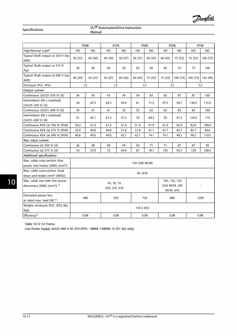
P30K P37K P45K P55K P75K
High/Normal Load* HO NO HO NO HO NO HO NO HO NO
Typical Shaft output at 550 V (hp[kW])
30 [22] 40 [30] 40 [30] 50 [37] 50 [37] 60 [45] 60 [45] 75 [55] 75 [55] 100 [75]
Typical Shaft output at 575 V[hp]
30 40 40 50 50 60 60 75 75 100
Typical Shaft output at 690 V (hp[kW])
40 [30] 50 [37] 50 [37] 60 [45] 60 [45] 75 [55] 75 [55] 100 [75] 100 [75] 125 [90]
Enclosure IP21, IP55 C2 C2 C2 C2 C2
Output current
Continuous (3x525–550 V) [A] 36 43 43 54 54 65 65 87 87 105
Intermittent (60 s overload)(3x525–550 V) [A]
54 47.3 64.5 59.4 81 71.5 97.5 95.7 130.5 115.5
Continuous (3x551–690 V) [A] 34 41 41 52 52 62 62 83 83 100
Intermittent (60 s overload)(3x551–690 V) [A]
51 45.1 61.5 57.2 78 68.2 93 91.3 124.5 110
Continuous KVA (at 550 V) [KVA] 34.3 41.0 41.0 51.4 51.4 61.9 61.9 82.9 82.9 100.0
Continuous KVA (at 575 V) [KVA] 33.9 40.8 40.8 51.8 51.8 61.7 61.7 82.7 82.7 99.6
Continuous KVA (at 690 V) [KVA] 40.6 49.0 49.0 62.1 62.1 74.1 74.1 99.2 99.2 119.5
Max. input current
Continuous (at 550 V) [A] 36 49 49 59 59 71 71 87 87 99
Continuous (at 575 V) [A] 54 53.9 72 64.9 87 78.1 105 95.7 129 108.9
Additional specifications
Max. cable cross-section (line
power and motor) [AWG (mm2)]150 (300 MCM)
Max. cable cross-section (load
share and brake) [mm2 (AWG)]95 (3/0)
Max. cable size with line power
disconnect [AWG (mm2)] 2)95, 70, 70
(3/0, 2/0, 2/0)
185, 150, 120(350 MCM, 300
MCM, 4/0)-
Estimated power loss
at rated max. load [W] 4)480 592 720 880 1200
Weight, enclosure IP21, IP55 (lbs[kg])
143.3 [65]
Efficiency4) 0.98 0.98 0.98 0.98 0.98
Table 10.12 C2 Frame,Line Power Supply 3x525–690 V AC IP21/IP55 - NEMA 1/NEMA 12 (FC 302 only)
Specifications VLT® AutomationDrive InstructionManual
10-12 MG33AM22 - VLT® is a registered Danfoss trademark
1010

P37K P45K
High/Normal Load1) HO NO HO NO
Typical Shaft output at 550 V (hp [kW]) 40 [30] 50 [37] 50 [37] 60 [45]
Typical Shaft output at 575 V [hp] 40 50 50 60
Typical Shaft output at 690 V (hp [kW]) 50 [37] 60 [45] 60 [45] 75 [55]
Enclosure IP20 only C3 C3
Output current 150% for 1 min (HO), 110% for 1 min (NO)
Continuous (3x525–550 V) [A] 43 54 54 65
Intermittent (60 s overload) (3x525–550 V) [A] 64.5 59.4 81 71.5
Continuous (3x551–690 V) [A] 41 52 52 62
Intermittent (60 s overload) (3x551–690 V) [A] 61.5 57.2 78 68.2
Continuous KVA (at 550 V) [KVA] 41 51.4 51.4 62
Continuous KVA (at 690 V) [KVA] 49 62.2 62.2 74.1
Max. input current
Continuous (at 550 V) [A] 41.5 52.1 52.1 62.7
Intermittent (at 550 V) [A] 62.2 57.3 78.1 68.9
Continuous (at 690 V) [A] 39.5 50.1 50.1 59.8
Intermittent (at 690 V) [A] 59.3 55.1 75.2 65.8
Additional specifications
Max. cable cross-section (line power, load share and brake)
[AWG (mm2)]50 (1)
Max. cable cross-section (motor) [AWG (mm2)] 50 (1)
Estimated power loss at rated max. load [W] 4) 592 720
Weight, enclosure IP20 (lbs [kg]) 77.16 [35] 77.16 [35]
Efficiency4) 0.98 0.98
Table 10.13 C3 Frame,Line Power Supply 3x525–690 V AC IP20/Protected Chassis (FC 302 only)
For fuse ratings, see 10.3.1 Fuses
1) High overload=160% torque during 60 s. Normal overload=110% torque during 60 s.
2) American Wire Gauge.
3) Measured using 16.5 ft. [5 m] shielded motor cables at rated load and rated frequency.
4) The typical power loss is at nominal load conditions and expected to be within ±15% (tolerance relates to variety in voltage andcable conditions).Values are based on a typical motor efficiency (eff2/eff3 border line). Motors with lower efficiency will also add to the power loss in theadjustable frequency drive and vice-versa.If the switching frequency is increased compared to the default setting, the power losses may rise significantly.LCP and typical control card power consumption values are included. Further options and customer load may add up to 30 W to thelosses. (Though typical only 4 W extra for a fully loaded control card, or options for slot A or slot B, each).
Although measurements are made with state of the art equipment, some measurement inaccuracy must be allowed for (± 5%).
5) The three values for the max. cable cross-section are for single core, flexible wire and flexible wire with sleeve, respectively.
Specifications VLT® AutomationDrive InstructionManual
MG33AM22 - VLT® is a registered Danfoss trademark 10-13
10 10

10.2 General Technical Data
Line power supplySupply Terminals (6-pulse) L1, L2, L3Supply Terminals (12-pulse) L1-1, L2-1, L3-1, L1-2, L2-2, L3-2Supply voltage 200–240 V ±10%Supply voltage FC 301: 380–480 V/FC 302: 380–500 V ±10%Supply voltage FC 302: 525–600 V ±10%Supply voltage FC 302: 525–690 V ±10%
AC line voltage low / line drop-out:During low AC line voltage or a line drop-out, the adjustable frequency drive continues until the intermediate circuit voltagedrops below the minimum stop level, which corresponds typically to 15% below the adjustable frequency drive's lowest ratedsupply voltage. Power-up and full torque cannot be expected at AC line voltage lower than 10% below the adjustable frequencydrive's lowest rated supply voltage.
Supply frequency 50/60 Hz ±5%Max. temporary imbalance between line phases 3.0% of rated supply voltageTrue Power Factor (λ) ≥ 0.9 nominal at rated loadDisplacement Power Factor (cos ϕ) near unity (> 0.98)Switching on input supply L1, L2, L3 (power-ups) ≤ 10 hp [7.5 kW] maximum 2 times/min.Switching on input supply L1, L2, L3 (power-ups) 15–100 hp [11–75 kW] maximum 1 time/min.Switching on input supply L1, L2, L3 (power-ups) ≥ 125 hp [90 kW] maximum 1 time/2 min.Environment according to EN60664-1 overvoltage category III/pollution degree 2
The unit is suitable for use on a circuit capable of delivering not more than 100,000 RMS symmetrical amperes, 240/500/600/ 690V maximum.
Motor output (U, V, W)Output voltage 0–100% of supply voltageOutput frequency (0.33–10 hp [0.25–75 kW]) FC 301: 0.2–590 Hz/FC 302: 0–590 HzOutput frequency (125–1,350 hp [90–1,000 kW]) 0–5901) HzOutput frequency in flux mode (FC 302 only) 0–300 HzSwitching on output UnlimitedRamp times 0.01–3,600 s
1) Voltage and power dependent
Torque characteristicsStarting torque (constant torque) maximum 160% for 60 s1)
Starting torque maximum 180% up to 0.5 s1)
Overload torque (constant torque) maximum 160% for 60 s1)
Starting torque (variable torque) maximum 110% for 60 s1)
Overload torque (variable torque) maximum 110% for 60 sTorque rise time in VVCplus (independent of fsw) 10 msTorque rise time in FLUX (for 5 kHz fsw) 1 ms
1) Percentage relates to the nominal torque.2) The torque response time depends on application and load but as a general rule, the torque step from 0 to reference is 4–5 xtorque rise time.
Digital inputsProgrammable digital inputs FC 301: 4 (5)1)/FC 302: 4 (6)1)
Terminal number 18, 19, 271), 291), 32, 33,Logic PNP or NPNVoltage level 0–24 V DCVoltage level, logic'0' PNP < 5 V DC
Specifications VLT® AutomationDrive InstructionManual
10-14 MG33AM22 - VLT® is a registered Danfoss trademark
1010

Voltage level, logic'1' PNP > 10 V DCVoltage level, logic '0' NPN2) > 19 V DCVoltage level, logic '1' NPN2) < 14 V DCMaximum voltage on input 28 V DCPulse frequency ranges 0–110 kHz(Duty cycle) Min. pulse width 4.5 msInput resistance, Ri approx. 4 kΩ
Safe stop Terminal 373, 4) (Terminal 37 is fixed PNP logic)Voltage level 0–24 V DCVoltage level, logic'0' PNP <4 V DCVoltage level, logic'1' PNP >20 V DCMaximum voltage on input 28 V DCTypical input current at 24 V 50 mA rmsTypical input current at 20 V 60 mA rmsInput capacitance 400 nF
All digital inputs are galvanically isolated from the supply voltage (PELV) and other high-voltage terminals.1) Terminals 27 and 29 can also be programmed as output.2) Except safe stop input Terminal 37.3) See 2.5 Safe Stop for further information about terminal 37 and Safe Stop.4) When using a contactor with a DC coil inside in combination with Safe Stop, it is important to make a return way for thecurrent from the coil when turning it off. This can be done by using a freewheel diode (or, alternatively, a 30 or 50 V MOV forquicker response time) across the coil. Typical contactors can be bought with this diode.
Analog inputsNumber of analog inputs 2Terminal number 53, 54Modes Voltage or currentMode select Switch S201 and switch S202Voltage mode Switch S201/switch S202 = OFF (U)Voltage level FC 301: 0 to +10/FC 302: -10 to +10 V (scaleable)Input resistance, Ri approx. 10 kΩMax. voltage ± 20 VCurrent mode Switch S201/switch S202 = ON (I)Current level 0/4 to 20 mA (scaleable)Input resistance, Ri approx. 200 ΩMax. current 30 mAResolution for analog inputs 10 bit (+ sign)Accuracy of analog inputs Max. error 0.5% of full scaleBandwidth FC 301: 20 Hz/FC 302: 100 Hz
The analog inputs are galvanically isolated from the supply voltage (PELV) and other high-voltage terminals.
Mains
Functionalisolation
PELV isolation
Motor
DC-Bus
Highvoltage
Control+24V
RS485
18
37
130B
A11
7.10
Figure 10.1
Specifications VLT® AutomationDrive InstructionManual
MG33AM22 - VLT® is a registered Danfoss trademark 10-15
10 10

Pulse/encoder inputsProgrammable pulse/encoder inputs 2/1Terminal number pulse/encoder 291), 332) / 323), 333)
Max. frequency at terminal 29, 32, 33 110 kHz (push-pull driven)Max. frequency at terminal 29, 32, 33 5 kHz (open collector)Min. frequency at terminal 29, 32, 33 4 HzVoltage level see section on Digital inputMaximum voltage on input 28 V DCInput resistance, Ri approx. 4 kΩPulse input accuracy (0.1–1 kHz) Max. error: 0.1% of full scaleEncoder input accuracy (1–11 kHz) Max. error: 0.05% of full scale
The pulse and encoder inputs (terminals 29, 32, 33) are galvanically isolated from the supply voltage (PELV) and other high-voltage terminals.1) FC 302 only2) Pulse inputs are 29 and 333) Encoder inputs: 32 = A, and 33 = B
Digital outputProgrammable digital/pulse outputs 2Terminal number 27, 29 1)
Voltage level at digital/frequency output 0–24 VMax. output current (sink or source) 40 mAMax. load at frequency output 1 kΩMax. capacitive load at frequency output 10 nFMinimum output frequency at frequency output 0 HzMaximum output frequency at frequency output 32 kHzAccuracy of frequency output Max. error: 0.1% of full scaleResolution of frequency outputs 12 bit
1) Terminal 27 and 29 can also be programmed as input.
The digital output is galvanically isolated from the supply voltage (PELV) and other high-voltage terminals.
Analog outputNumber of programmable analog outputs 1Terminal number 42Current range at analog output 0/4 to 20 mAMax. load GND - analog output less than 500 ΩAccuracy on analog output Max. error: 0.5% of full scaleResolution on analog output 12 bit
The analog output is galvanically isolated from the supply voltage (PELV) and other high-voltage terminals.
Control card, 24 V DC outputTerminal number 12, 13Output voltage 24 V +1, -3 VMax. load FC 301: 130mA/FC 302: 200 mA
The 24 V DC supply is galvanically isolated from the supply voltage (PELV), but has the same potential as the analog and digitalinputs and outputs.
Control card, 10 V DC outputTerminal number ±50Output voltage 10.5 V ±0.5 VMax. load 15 mA
The 10 V DC supply is galvanically isolated from the supply voltage (PELV) and other high-voltage terminals.
Specifications VLT® AutomationDrive InstructionManual
10-16 MG33AM22 - VLT® is a registered Danfoss trademark
1010

Control card, RS-485 serial communicationTerminal number 68 (P,TX+, RX+), 69 (N,TX-, RX-)Terminal number 61 Common for terminals 68 and 69
The RS-485 serial communication circuit is functionally separated from other central circuits and galvanically isolated from thesupply voltage (PELV).
Control card, USB serial communicationUSB standard 1.1 (Full speed)USB plug USB type B “device” plug
Connection to PC is carried out via a standard host/device USB cable.The USB connection is galvanically isolated from the supply voltage (PELV) and other high-voltage terminals.The USB ground connection is not galvanically isolated from protection ground. Use only an isolated laptop as PC connection tothe USB connector on the adjustable frequency drive.
Relay outputsProgrammable relay outputs FC 301all kW: 1/FC 302 all kW: 2Relay 01 Terminal number 1-3 (break), 1-2 (make)Max. terminal load (AC-1)1) on 1-3 (NC), 1-2 (NO) (Resistive load) 240 V AC, 2AMax. terminal load (AC-15)1) (Inductive load @ cosφ 0.4) 240 V AC, 0.2 AMax. terminal load (DC-1)1) on 1-2 (NO), 1-3 (NC) (Resistive load) 60 V DC, 1AMax. terminal load (DC-13)1) (Inductive load) 24 V DC, 0.1ARelay 02 (FC 302 only) Terminal number 4-6 (break), 4-5 (make)Max. terminal load (AC-1)1) on 4-5 (NO) (Resistive load)2)3) Overvoltage cat. II 400 V AC, 2AMax. terminal load (AC-15)1) on 4-5 (NO) (Inductive load @ cosφ 0.4) 240 V AC, 0.2 AMax. terminal load (DC-1)1) on 4-5 (NO) (resistive load) 80 V DC, 2AMax. terminal load (DC-13)1) on 4-5 (NO) (inductive load) 24 V DC, 0.1AMax. terminal load (AC-1)1) on 4-6 (NC) (resistive load) 240 V AC, 2AMax. terminal load (AC-15)1) on 4-6 (NC) (inductive load @ cosφ 0.4) 240 V AC, 0.2 AMax. terminal load (DC-1)1) on 4-6 (NC) (resistive load) 50 V DC, 2AMax. terminal load (DC-13)1) on 4-6 (NC) (inductive load) 24 V DC, 0.1AMin. terminal load on 1-3 (NC), 1-2 (NO), 4-6 (NC), 4-5 (NO) 24 V DC 10 mA, 24 V AC 20 mAEnvironment according to EN 60664-1 overvoltage category III/pollution degree 2
1) IEC 60947 part 4 and 5The relay contacts are galvanically isolated from the rest of the circuit by reinforced isolation (PELV).2) Overvoltage Category II3) UL applications 300 V AC2A
Cable lengths and cross-sections for control cables1)Max. motor cable length, shielded FC 301: 165 ft [50 m]/FC 301 (Frame size A1): 80 ft [25 m]/FC 302: 500 ft [150 m]Max. motor cable length, non-shielded FC 301: 250 ft [75 m]/FC 301 (Frame size A1): 165 ft [50 m]/FC 302: 1,000 ft [300 m]Maximum cross-section to control terminals, flexible/rigid wire without cable end sleeves 0.0023 in2 [1.5 mm2]/16 AWGMaximum cross-section to control terminals, flexible wire with cable end sleeves 0.0016 in2 [1 mm2]/18 AWGMaximum cross-section to control terminals, flexible wire with cable end sleeves with collar 0.0008 in2 [0.5 mm2]/20 AWGMinimum cross-section to control terminals 0.25 mm2/24 AWG
1)For power cables, see 10.1 Power-dependent Specifications.
Control card performanceScan interval FC 301: 5 ms/FC 302: 1 ms
Control characteristicsResolution of output frequency at 0–590 Hz ±0.003 HzRepeat accuracy of Precise start/stop (terminals 18, 19) ≤±0.1 msSystem response time (terminals 18, 19, 27, 29, 32, 33) ≤ 2 ms
Specifications VLT® AutomationDrive InstructionManual
MG33AM22 - VLT® is a registered Danfoss trademark 10-17
10 10

Speed control range (open-loop) 1:100 of synchronous speedSpeed control range (closed-loop) 1:1,000 of synchronous speedSpeed accuracy (open-loop) 30–4,000 rpm: error ±8 rpmSpeed accuracy (closed-loop), depending on resolution of feedback device 0–6,000 rpm: error ±0.15 rpmTorque control accuracy (speed feedback) max error ±5% of rated torque
All control characteristics are based on a 4-pole asynchronous motor
EnvironmentEnclosure IP201)/Type 1, IP212)/Type 1, IP55/Type 12, IP66Vibration test 1.0 gMax. THVD 10%Max. relative humidity 5%–93% (IEC 721-3-3; Class 3K3 (non-condensing) during operationAggressive environment (IEC 60068-2-43) H2S test class KdAmbient temperature3) Max. 122 °F [50 °C] (24-hour average maximum 113 °F [45 °C])
1) Only for ≤ 3.7 kW/5 HP (200–240 V), ≤ 7.5 kW/10 HP (400–480/500 V)2) As enclosure kit for ≤ 3.7 kW/5 HP (200–240 V), ≤ 7.5 kW/10 HP (400–480/500 V)3) Derating for high ambient temperature, see special conditions in the Design Guide
Minimum ambient temperature during full-scale operation 32 °F [0 °C]Minimum ambient temperature at reduced performance 14 °F [-10 °C]Temperature during storage/transport -13 to + 149/158 °F [-25 to +65/70 °C]Maximum altitude above sea level without derating 3,300 ft [1,000 m]
Derating for high altitude, see special conditions in the Design Guide.
EMC standards, Emission EN 61800-3, EN 61000-6-3/4, EN 55011
EMC standards, ImmunityEN 61800-3, EN 61000-6-1/2,
EN 61000-4-2, EN 61000-4-3, EN 61000-4-4, EN 61000-4-5, EN 61000-4-6
See section on special conditions in the Design Guide.
Specifications VLT® AutomationDrive InstructionManual
10-18 MG33AM22 - VLT® is a registered Danfoss trademark
1010
10.3 Fuse Specifications
10.3.1 Fuses
It is recommended to use fuses and/or circuit breakers onthe supply side as protection in case of component break-down inside the adjustable frequency drive (first fault).
NOTE!This is mandatory in order to ensure compliance with IEC60364 for CE or NEC 2009 for UL.
WARNINGPersonnel and property must be protected against theconsequence of component breakdown internally in theadjustable frequency drive.
Branch Circuit ProtectionIn order to protect the installation against electrical andfire hazard, all branch circuits in an installation, switchgear, machines etc., must be protected against short-circuitand overcurrent according to national/internationalregulations.
NOTE!The recommendations given do not cover branch circuitprotection for UL.
Short-circuit protectionDanfoss recommends using the fuses/circuit breakersmentioned below to protect service personnel andproperty in case of component breakdown in theadjustable frequency drive.
10.3.2 Recommendations
WARNINGIn case of malfunction, not following the recommendationmay result in risk to personnel and damage to theadjustable frequency drive and other equipment.
The following tables list the recommended rated current.Recommended fuses are of the type gG for small tomedium power sizes. For larger powers, aR fuses arerecommended. For circuit breakers, Moeller types havebeen tested to have a recommendation. Other types ofcircuit breakers may be used provided they limit theenergy into the adjustable frequency drive to a level equalto or lower than the Moeller types.
If fuses/circuit breakers according to recommendations arechosen, possible damage to the adjustable frequency drivewill mainly be limited to damage inside the unit.
For further information, please see Application Note Fusesand Circuit Breakers.
10.3.3 CE Compliance
Fuses or circuit breakers are mandatory to comply with IEC60364. Danfoss recommend using a selection of thefollowing.
The fuses below are suitable for use on a circuit capable ofdelivering 100,000 Arms (symmetrical), 240 V, 480 V, 500 V,600 V, or 690 V depending on the adjustable frequencydrive voltage rating. With the proper fusing the adjustablefrequency drive short circuit current rating (SCCR) is100,000 Arms.
The following UL-listed fuses are suitable:
• UL248-4 class CC fuses
• UL248-8 class J fuses
• UL248-12 class R fuses (RK1)
• UL248-15 class T fuses
The following max. fuse size and type have been tested:
Specifications VLT® AutomationDrive InstructionManual
MG33AM22 - VLT® is a registered Danfoss trademark 10-19
10 10

Enclosuresize
Power (hp [kW]) Recommendedfuse size
RecommendedMax. fuse
Recommended circuitbreakerMoeller
Max trip level [A]
A1 0.34–2 [0.25–1.5] gG-10 gG-25 PKZM0-16 16
A2 0.34–3 [0.25–2.2] gG-10 (0.25–1.5)gG-16 (2.2)
gG-25 PKZM0-25 25
A3 4–5 [3.0–3.7] gG-16 (3)gG-20 (3.7)
gG-32 PKZM0-25 25
B3 7.5 [5.5] gG-25 gG-63 PKZM4-50 50
B4 10–20 [7.5–15] gG-32 (7.5)gG-50 (11)gG-63 (15)
gG-125 NZMB1-A100 100
C3 25–30 [18.5–22] gG-80 (18.5)aR-125 (22)
gG-150 (18.5)aR-160 (22)
NZMB2-A200 150
C4 40–50 [30–37] aR-160 (30)aR-200 (37)
aR-200 (30)aR-250 (37)
NZMB2-A250 250
A4 0.34–3 [0.25–2.2] gG-10 (0.34-2) [0.25-1.5]gG-16 (3) [2.2]
gG-32 PKZM0-25 25
A5 0.34–5 [0.25–3.7] gG-10 (0.34-2) [0.25-1.5]gG-16 (3-4) [2.2-3]
gG-20 (5) [3.7]
gG-32 PKZM0-25 25
B1 7.5–10 [5.5–7.5] gG-25 (7.5) [5.5]gG-32 (10) [7.5]
gG-80 PKZM4-63 63
B2 15 [11] gG-50 gG-100 NZMB1-A100 100
C1 20–30 [15–22] gG-63 (20) [15]gG-80 (25) [18.5]gG-100 (30) [22]
gG-160 (20-25) [15-18.5]aR-160 (30) [22]
NZMB2-A200 160
C2 40–50 [30–37] aR-160 (40) [30]aR-200 (50) [37]
aR-200 (40) [30]aR-250 (50) [37]
NZMB2-A250 250
Table 10.14 200–240 V, Frame Sizes A, B and C
Specifications VLT® AutomationDrive InstructionManual
10-20 MG33AM22 - VLT® is a registered Danfoss trademark
1010

Enclosuresize
Power [kW] Recommendedfuse size
RecommendedMax. fuse
Recommended circuitbreaker Moeller
Max trip level [A]
A1 0.37–1.5 gG-10 gG-25 PKZM0-16 16
A2 0.37–4.0 gG-10 (0.37–3)gG-16 (4)
gG-25 PKZM0-25 25
A3 5.5–7.5 gG-16 gG-32 PKZM0-25 25
B3 11–15 gG-40 gG-63 PKZM4-50 50
B4 18.5–30 gG-50 (18.5)gG-63 (22)gG-80 (30)
gG-125 NZMB1-A100 100
C3 37–45 gG-100 (37)gG-160 (45)
gG-150 (37)gG-160 (45)
NZMB2-A200 150
C4 55–75 aR-200 (55)aR-250 (75)
aR-250 NZMB2-A250 250
A4 0.37–4 gG-10 (0.37–3)gG-16 (4)
gG-32 PKZM0-25 25
A5 0.37–7.5 gG-10 (0.37–3)gG-16 (4–7.5)
gG-32 PKZM0-25 25
B1 11–15 gG-40 gG-80 PKZM4-63 63
B2 18.5–22 gG-50 (18.5)gG-63 (22)
gG-100 NZMB1-A100 100
C1 30–45 gG-80 (30)gG-100 (37)gG-160 (45)
gG-160 NZMB2-A200 160
C2 55–75 aR-200 (55)aR-250 (75)
aR-250 NZMB2-A250 250
Table 10.15 380–500 V, Frame Sizes A, B and C
Specifications VLT® AutomationDrive InstructionManual
MG33AM22 - VLT® is a registered Danfoss trademark 10-21
10 10
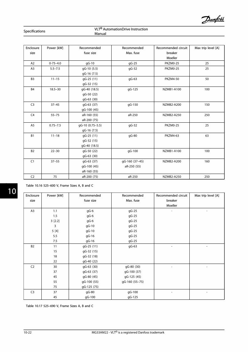
Enclosuresize
Power [kW] Recommendedfuse size
RecommendedMax. fuse
Recommended circuitbreakerMoeller
Max trip level [A]
A2 0-75–4.0 gG-10 gG-25 PKZM0-25 25
A3 5.5–7.5 gG-10 (5.5)gG-16 (7.5)
gG-32 PKZM0-25 25
B3 11–15 gG-25 (11)gG-32 (15)
gG-63 PKZM4-50 50
B4 18.5–30 gG-40 (18.5)gG-50 (22)gG-63 (30)
gG-125 NZMB1-A100 100
C3 37–45 gG-63 (37)gG-100 (45)
gG-150 NZMB2-A200 150
C4 55–75 aR-160 (55)aR-200 (75)
aR-250 NZMB2-A250 250
A5 0.75–7.5 gG-10 (0.75–5.5)gG-16 (7.5)
gG-32 PKZM0-25 25
B1 11–18 gG-25 (11)gG-32 (15)
gG-40 (18.5)
gG-80 PKZM4-63 63
B2 22–30 gG-50 (22)gG-63 (30)
gG-100 NZMB1-A100 100
C1 37–55 gG-63 (37)gG-100 (45)aR-160 (55)
gG-160 (37–45)aR-250 (55)
NZMB2-A200 160
C2 75 aR-200 (75) aR-250 NZMB2-A250 250
Table 10.16 525–600 V, Frame Sizes A, B and C
Enclosuresize
Power [kW] Recommendedfuse size
RecommendedMax. fuse
Recommended circuitbreakerMoeller
Max trip level [A]
A3 1.11.5
3 [2.2]3
5 [4]5.57.5
gG-6gG-6gG-6
gG-10gG-10gG-16gG-16
gG-25gG-25gG-25gG-25gG-25gG-25gG-25
- -
B2 11151822
gG-25 (11)gG-32 (15)gG-32 (18)gG-40 (22)
gG-63 - -
C2 3037455575
gG-63 (30)gG-63 (37)gG-80 (45)
gG-100 (55)gG-125 (75)
gG-80 (30)gG-100 (37)gG-125 (45)
gG-160 (55–75)
- -
C3 3745
gG-80gG-100
gG-100gG-125
- -
Table 10.17 525–690 V, Frame Sizes A, B and C
Specifications VLT® AutomationDrive InstructionManual
10-22 MG33AM22 - VLT® is a registered Danfoss trademark
1010

UL ComplianceFuses or Circuit Breakers must comply with NEC 2009.Danfoss recommends using a selection of the following
The fuses below are suitable for use on a circuit capable ofdelivering 100,000 Arms (symmetrical), 240 V, or 480 V, or
500 V, or 600 V depending on the adjustable frequencydrive voltage rating. With the proper fusing, the driveShort Circuit Current Rating (SCCR) is 100,000 Arms.
Recommended max. fuse
Power[kW]
Bussmann
Type RK1 1)
BussmannType J
BussmannType T
BussmannType CC
BussmannType CC
BussmannType CC
0.25–0.37 KTN-R-05 JKS-05 JJN-05 FNQ-R-5 KTK-R-5 LP-CC-5
0.55–1.1 KTN-R-10 JKS-10 JJN-10 FNQ-R-10 KTK-R-10 LP-CC-10
1.5 KTN-R-15 JKS-15 JJN-15 FNQ-R-15 KTK-R-15 LP-CC-15
2.2 KTN-R-20 JKS-20 JJN-20 FNQ-R-20 KTK-R-20 LP-CC-20
3.0 KTN-R-25 JKS-25 JJN-25 FNQ-R-25 KTK-R-25 LP-CC-25
3.7 KTN-R-30 JKS-30 JJN-30 FNQ-R-30 KTK-R-30 LP-CC-30
5.5 KTN-R-50 KS-50 JJN-50 - - -
7.5 KTN-R-60 JKS-60 JJN-60 - - -
11 KTN-R-80 JKS-80 JJN-80 - - -
15–18.5 KTN-R-125 JKS-125 JJN-125 - - -
22 KTN-R-150 JKS-150 JJN-150 - - -
30 KTN-R-200 JKS-200 JJN-200 - - -
37 KTN-R-250 JKS-250 JJN-250 - - -
Table 10.18 200–240 V, Frame Sizes A, B and C
Recommended max. fuse
Power[kW]
SIBAType RK1
Littel fuseType RK1
Ferraz-ShawmutType CC
Ferraz-Shawmut
Type RK13)
0.25–0.37 5017906-005 KLN-R-05 ATM-R-05 A2K-05-R
0.55–1.1 5017906-010 KLN-R-10 ATM-R-10 A2K-10-R
1.5 5017906-016 KLN-R-15 ATM-R-15 A2K-15-R
2.2 5017906-020 KLN-R-20 ATM-R-20 A2K-20-R
3.0 5017906-025 KLN-R-25 ATM-R-25 A2K-25-R
3.7 5012406-032 KLN-R-30 ATM-R-30 A2K-30-R
5.5 5014006-050 KLN-R-50 - A2K-50-R
7.5 5014006-063 KLN-R-60 - A2K-60-R
11 5014006-080 KLN-R-80 - A2K-80-R
15–18.5 2028220-125 KLN-R-125 - A2K-125-R
22 2028220-150 KLN-R-150 - A2K-150-R
30 2028220-200 KLN-R-200 - A2K-200-R
37 2028220-250 KLN-R-250 - A2K-250-R
Table 10.19 200–240 V, Frame Sizes A, B and C
Specifications VLT® AutomationDrive InstructionManual
MG33AM22 - VLT® is a registered Danfoss trademark 10-23
10 10
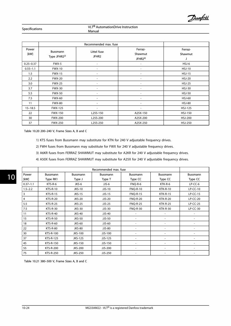
Recommended max. fuse
Power[kW]
Bussmann
Type JFHR22)
Littel fuseJFHR2
Ferraz-Shawmut
JFHR24)
Ferraz-Shawmut
J
0.25–0.37 FWX-5 - - HSJ-6
0.55–1.1 FWX-10 - - HSJ-10
1.5 FWX-15 - - HSJ-15
2.2 FWX-20 - - HSJ-20
3.0 FWX-25 - - HSJ-25
3.7 FWX-30 - - HSJ-30
5.5 FWX-50 - - HSJ-50
7.5 FWX-60 - - HSJ-60
11 FWX-80 - - HSJ-80
15–18.5 FWX-125 - - HSJ-125
22 FWX-150 L25S-150 A25X-150 HSJ-150
30 FWX-200 L25S-200 A25X-200 HSJ-200
37 FWX-250 L25S-250 A25X-250 HSJ-250
Table 10.20 200–240 V, Frame Sizes A, B and C
1) KTS fuses from Bussmann may substitute for KTN for 240 V adjustable frequency drives.
2) FWH fuses from Bussmann may substitute for FWX for 240 V adjustable frequency drives.
3) A6KR fuses from FERRAZ SHAWMUT may substitute for A2KR for 240 V adjustable frequency drives.
4) A50X fuses from FERRAZ SHAWMUT may substitute for A25X for 240 V adjustable frequency drives.
Recommended max. fuse
Power[kW]
BussmannType RK1
BussmannType J
BussmannType T
BussmannType CC
BussmannType CC
BussmannType CC
0.37–1.1 KTS-R-6 JKS-6 JJS-6 FNQ-R-6 KTK-R-6 LP-CC-6
1.5–2.2 KTS-R-10 JKS-10 JJS-10 FNQ-R-10 KTK-R-10 LP-CC-10
3 KTS-R-15 JKS-15 JJS-15 FNQ-R-15 KTK-R-15 LP-CC-15
4 KTS-R-20 JKS-20 JJS-20 FNQ-R-20 KTK-R-20 LP-CC-20
5.5 KTS-R-25 JKS-25 JJS-25 FNQ-R-25 KTK-R-25 LP-CC-25
7.5 KTS-R-30 JKS-30 JJS-30 FNQ-R-30 KTK-R-30 LP-CC-30
11 KTS-R-40 JKS-40 JJS-40 - - -
15 KTS-R-50 JKS-50 JJS-50 - - -
18 KTS-R-60 JKS-60 JJS-60 - - -
22 KTS-R-80 JKS-80 JJS-80 - - -
30 KTS-R-100 JKS-100 JJS-100 - - -
37 KTS-R-125 JKS-125 JJS-125 - - -
45 KTS-R-150 JKS-150 JJS-150 - - -
55 KTS-R-200 JKS-200 JJS-200 - - -
75 KTS-R-250 JKS-250 JJS-250 - - -
Table 10.21 380–500 V, Frame Sizes A, B and C
Specifications VLT® AutomationDrive InstructionManual
10-24 MG33AM22 - VLT® is a registered Danfoss trademark
1010

Recommended max. fuse
Power[kW]
SIBAType RK1
Littel fuseType RK1
Ferraz-ShawmutType CC
Ferraz-ShawmutType RK1
0.37–1.1 5017906-006 KLS-R-6 ATM-R-6 A6K-6-R
1.5–2.2 5017906-010 KLS-R-10 ATM-R-10 A6K-10-R
3 5017906-016 KLS-R-15 ATM-R-15 A6K-15-R
4 5017906-020 KLS-R-20 ATM-R-20 A6K-20-R
5.5 5017906-025 KLS-R-25 ATM-R-25 A6K-25-R
7.5 5012406-032 KLS-R-30 ATM-R-30 A6K-30-R
11 5014006-040 KLS-R-40 - A6K-40-R
15 5014006-050 KLS-R-50 - A6K-50-R
18 5014006-063 KLS-R-60 - A6K-60-R
22 2028220-100 KLS-R-80 - A6K-80-R
30 2028220-125 KLS-R-100 - A6K-100-R
37 2028220-125 KLS-R-125 - A6K-125-R
45 2028220-160 KLS-R-150 - A6K-150-R
55 2028220-200 KLS-R-200 - A6K-200-R
75 2028220-250 KLS-R-250 - A6K-250-R
Table 10.22 380–500 V, Frame Sizes A, B and C
Recommended max. fuse
Power[kW]
BussmannJFHR2
Ferraz-ShawmutJ
Ferraz-Shawmut
JFHR21)
Littel fuseJFHR2
0.37–1.1 FWH-6 HSJ-6 - -
1.5–2.2 FWH-10 HSJ-10 - -
3 FWH-15 HSJ-15 - -
4 FWH-20 HSJ-20 - -
5.5 FWH-25 HSJ-25 - -
7.5 FWH-30 HSJ-30 - -
11 FWH-40 HSJ-40 - -
15 FWH-50 HSJ-50 - -
18 FWH-60 HSJ-60 - -
22 FWH-80 HSJ-80 - -
30 FWH-100 HSJ-100 - -
37 FWH-125 HSJ-125 - -
45 FWH-150 HSJ-150 - -
55 FWH-200 HSJ-200 A50-P-225 L50-S-225
75 FWH-250 HSJ-250 A50-P-250 L50-S-250
Table 10.23 380–500 V, Frame Sizes A, B and C
1) Ferraz-Shawmut A50QS fuses may substitute for A50P fuses.
Specifications VLT® AutomationDrive InstructionManual
MG33AM22 - VLT® is a registered Danfoss trademark 10-25
10 10

Recommended max. fuse
Power[kW]
BussmannType RK1
BussmannType J
BussmannType T
BussmannType CC
BussmannType CC
BussmannType CC
0.75–1.1 KTS-R-5 JKS-5 JJS-6 FNQ-R-5 KTK-R-5 LP-CC-5
1.5–2.2 KTS-R-10 JKS-10 JJS-10 FNQ-R-10 KTK-R-10 LP-CC-10
3 KTS-R15 JKS-15 JJS-15 FNQ-R-15 KTK-R-15 LP-CC-15
4 KTS-R20 JKS-20 JJS-20 FNQ-R-20 KTK-R-20 LP-CC-20
5.5 KTS-R-25 JKS-25 JJS-25 FNQ-R-25 KTK-R-25 LP-CC-25
7.5 KTS-R-30 JKS-30 JJS-30 FNQ-R-30 KTK-R-30 LP-CC-30
11 KTS-R-35 JKS-35 JJS-35 - - -
15 KTS-R-45 JKS-45 JJS-45 - - -
18 KTS-R-50 JKS-50 JJS-50 - - -
22 KTS-R-60 JKS-60 JJS-60 - - -
30 KTS-R-80 JKS-80 JJS-80 - - -
37 KTS-R-100 JKS-100 JJS-100 - - -
45 KTS-R-125 JKS-125 JJS-125 - - -
55 KTS-R-150 JKS-150 JJS-150 - - -
75 KTS-R-175 JKS-175 JJS-175 - - -
Table 10.24 525–600 V, Frame Sizes A, B and C
Recommended max. fuse
Power [kW]SIBA
Type RK1Littel fuseType RK1
Ferraz-ShawmutType RK1
Ferraz-Shawmut
J
0.75–1.1 5017906-005 KLS-R-005 A6K-5-R HSJ-6
1.5–2.2 5017906-010 KLS-R-010 A6K-10-R HSJ-10
3 5017906-016 KLS-R-015 A6K-15-R HSJ-15
4 5017906-020 KLS-R-020 A6K-20-R HSJ-20
5.5 5017906-025 KLS-R-025 A6K-25-R HSJ-25
7.5 5017906-030 KLS-R-030 A6K-30-R HSJ-30
11 5014006-040 KLS-R-035 A6K-35-R HSJ-35
15 5014006-050 KLS-R-045 A6K-45-R HSJ-45
18 5014006-050 KLS-R-050 A6K-50-R HSJ-50
22 5014006-063 KLS-R-060 A6K-60-R HSJ-60
30 5014006-080 KLS-R-075 A6K-80-R HSJ-80
37 5014006-100 KLS-R-100 A6K-100-R HSJ-100
45 2028220-125 KLS-R-125 A6K-125-R HSJ-125
55 2028220-150 KLS-R-150 A6K-150-R HSJ-150
75 2028220-200 KLS-R-175 A6K-175-R HSJ-175
Table 10.25 525–600 V, Frame Sizes A, B and C
1) 170M fuses shown from Bussmann use the -/80 visual indicator. –TN/80 Type T, -/110 or TN/110 Type T indicatorfuses of the same size and amperage may be substituted.
Specifications VLT® AutomationDrive InstructionManual
10-26 MG33AM22 - VLT® is a registered Danfoss trademark
1010

Recommended max. fuse
Power[kW]
BussmannType RK1
BussmannType J
BussmannType T
BussmannType CC
BussmannType CC
BussmannType CC
[kW]
1.1 KTS-R-5 JKS-5 JJS-6 FNQ-R-5 KTK-R-5 LP-CC-5
1.5–2.2 KTS-R-10 JKS-10 JJS-10 FNQ-R-10 KTK-R-10 LP-CC-10
3 KTS-R15 JKS-15 JJS-15 FNQ-R-15 KTK-R-15 LP-CC-15
4 KTS-R20 JKS-20 JJS-20 FNQ-R-20 KTK-R-20 LP-CC-20
5.5 KTS-R-25 JKS-25 JJS-25 FNQ-R-25 KTK-R-25 LP-CC-25
7.5 KTS-R-30 JKS-30 JJS-30 FNQ-R-30 KTK-R-30 LP-CC-30
11 KTS-R-35 JKS-35 JJS-35 - - -
15 KTS-R-45 JKS-45 JJS-45 - - -
18 KTS-R-50 JKS-50 JJS-50 - - -
22 KTS-R-60 JKS-60 JJS-60 - - -
30 KTS-R-80 JKS-80 JJS-80 - - -
37 KTS-R-100 JKS-100 JJS-100 - - -
45 KTS-R-125 JKS-125 JJS-125 - - -
55 KTS-R-150 JKS-150 JJS-150 - - -
75 KTS-R-175 JKS-175 JJS-175 - - -
Table 10.26 525–690 V, Frame Sizes A, B and C
Recommended max. fuse
Power[kW]
Max.prefuse
BussmannE52273
RK1/JDDZ
BussmannE4273J/JDDZ
BussmannE4273
T/JDDZ
SIBAE180276
RK1/JDDZ
LittelFuseE81895
RK1/JDDZ
Ferraz-Shawmut
E163267/E2137RK1/JDDZ
Ferraz-Shawmut
E2137J/HSJ
11 30 A KTS-R-30 JKS-30 JKJS-30 5017906-030 KLS-R-030 A6K-30-R HST-30
15–18.5 45 A KTS-R-45 JKS-45 JJS-45 5014006-050 KLS-R-045 A6K-45-R HST-45
22 60 A KTS-R-60 JKS-60 JJS-60 5014006-063 KLS-R-060 A6K-60-R HST-60
30 80 A KTS-R-80 JKS-80 JJS-80 5014006-080 KLS-R-075 A6K-80-R HST-80
37 90 A KTS-R-90 JKS-90 JJS-90 5014006-100 KLS-R-090 A6K-90-R HST-90
45 100 A KTS-R-100 JKS-100 JJS-100 5014006-100 KLS-R-100 A6K-100-R HST-100
55 125 A KTS-R-125 JKS-125 JJS-125 2028220-125 KLS-150 A6K-125-R HST-125
75 150 A KTS-R-150 JKS-150 JJS-150 2028220-150 KLS-175 A6K-150-R HST-150
* UL compliance only 525–600 V
Table 10.27 525–690 V*, Frame Sizes B and C
Specifications VLT® AutomationDrive InstructionManual
MG33AM22 - VLT® is a registered Danfoss trademark 10-27
10 10

10.4 Connection Tightening Torques
Power hp [KW] Torque [Nm]
Enclo-sure
200–240 V 380–480/500 V 525–600 V 525–690 VLine
powerMotor
DCconnecti
onBrake Ground Relay
A20.34–3 [0.25–
2.2]0.5–5 [0.37–4.0] 1.8 1.8 1.8 1.8 3 0.6
A3 4–5 [3.0–3.7] 7.5–10 [5.5–7.5] 1–10 [0.75–7.5]1.5–10 [1.1–
7.5]1.8 1.8 1.8 1.8 3 0.6
A40.34–3 [0.25–
2.2]0.5–5 [0.37–4.0] 1.8 1.8 1.8 1.8 3 0.6
A50.34–5 [0.25–
3.7]0.5–10 [0.37–7.5] 1–10 [0.75–7.5] 1.8 1.8 1.8 1.8 3 0.6
B17.5–10 [5.5–
7.5]15–20 [11–15] 15–20 [11–15] 1.8 1.8 1.5 1.5 3 0.6
B2 111822
1822
1122
4.54.5
4.54.5
3.73.7
3.73.7
33
0.60.6
B37.5–10 [5.5–
7.5]15–20 [11–15] 15–20 [11–15] 1.8 1.8 1.8 1.8 3 0.6
B4 15–20 [11–15] 25–40 [18–30] 25–40 [18–30] 4.5 4.5 4.5 4.5 3 0.6
C1 20–30 [15–22] 40–60 [30–45] 40–60 [30–45] 10 10 10 10 3 0.6
C2 40–50 [30–37] 7.5–10 [5.5–7.5] 75–100 [55–75]40–100 [30–
75]14/241) 14/241) 14 14 3 0.6
C3 25–30 [18–22] 50–60 [37–45] 50–60 [37–45]50–75 [45–
55]10 10 10 10 3 0.6
C4 40–50 [30–37] 75–100 [55–75] 75–100 [55–75] 14/24 1)14/24
1)14 14 3 0.6
Table 10.28 Tightening of Terminals
1) For different cable dimensions x/y, where x ≤ 0.147 in² [95 mm²] and y ≥ 0.147 in² [95 mm²].
Specifications VLT® AutomationDrive InstructionManual
10-28 MG33AM22 - VLT® is a registered Danfoss trademark
1010
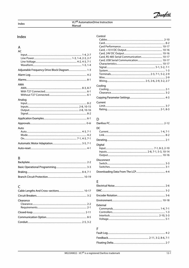
Index
AAC
Input........................................................................................... 1-4, 2-7Line Power............................................................... 1-3, 1-4, 2-3, 2-7Line Voltage..................................................................... 4-2, 4-3, 7-1Waveform................................................................................. 1-3, 1-4
Adjustable Frequency Drive Block Diagram............................. 1-3
Alarm Log............................................................................................... 4-2
Alarms..................................................................................................... 8-1
AMAAMA............................................................................................ 8-3, 8-7With T27 Connected...................................................................... 6-1Without T27 Connected............................................................... 6-1
AnalogInput.................................................................................................... 8-2Inputs..................................................................................... 2-8, 10-15Output................................................................................... 2-8, 10-16Signal.................................................................................................. 8-2
Application Examples........................................................................ 6-1
Approvals.............................................................................................. 0-iii
AutoAuto............................................................................................ 4-3, 7-1Mode................................................................................................... 4-2On........................................................................................ 7-1, 4-3, 7-1
Automatic Motor Adaptation................................................. 3-5, 7-1
Auto-reset.............................................................................................. 4-1
BBackplate................................................................................................ 2-2
Basic Operational Programming................................................... 3-3
Braking............................................................................................ 8-4, 7-1
Branch Circuit Protection............................................................ 10-19
CCable Lengths And Cross–sections......................................... 10-17
Circuit Breakers.................................................................................... 3-2
ClearanceClearance........................................................................................... 2-2Requirements................................................................................... 2-1
Closed-loop........................................................................................ 2-11
Communication Option.................................................................... 8-5
Conduit........................................................................................... 2-5, 3-2
ControlCables............................................................................................... 2-10Card..................................................................................................... 8-2Card Performance..................................................................... 10-17Card, +10 V DC Output............................................................ 10-16Card, 24V DC Output................................................................ 10-16Card, RS-485 Serial Communication................................... 10-17Card, USB Serial Communication......................................... 10-17Characteristics............................................................................ 10-17Signal................................................................................. 5-1, 5-2, 7-1System................................................................................................ 1-3Terminals.................................................................. 2-3, 7-1, 5-2, 2-9Wire..................................................................................................... 2-9Wiring................................................................ 2-5, 2-6, 2-9, 3-2, 2-7
CoolingCooling............................................................................................... 2-1Clearance........................................................................................... 3-2
Copying Parameter Settings........................................................... 4-3
CurrentLimit..................................................................................................... 3-7Rating......................................................................................... 2-1, 8-3
DDanfoss FC........................................................................................... 2-12
DCCurrent....................................................................................... 1-4, 7-1Link...................................................................................................... 8-2
Derating.................................................................................................. 2-1
DigitalInput................................................................................ 7-1, 8-3, 2-10Inputs.................................................................... 2-8, 7-1, 5-3, 10-14Output........................................................................................... 10-16
DisconnectSwitch................................................................................................. 3-3Switches............................................................................................. 3-1
Downloading Data From The LCP................................................ 4-4
EElectrical Noise..................................................................................... 2-6
EMC.......................................................................................................... 3-2
Encoder Rotation................................................................................ 3-6
Environment.................................................................................... 10-18
ExternalCommands............................................................................... 1-4, 7-1Controllers......................................................................................... 1-3Interlock.................................................................................. 2-10, 5-3Voltage............................................................................................... 5-1
FFault Log................................................................................................. 4-2
Feedback.................................................................... 2-11, 3-2, 8-6, 7-1
Floating Delta....................................................................................... 2-7
Index VLT® AutomationDrive InstructionManual
MG33AM22 - VLT® is a registered Danfoss trademark 12-1
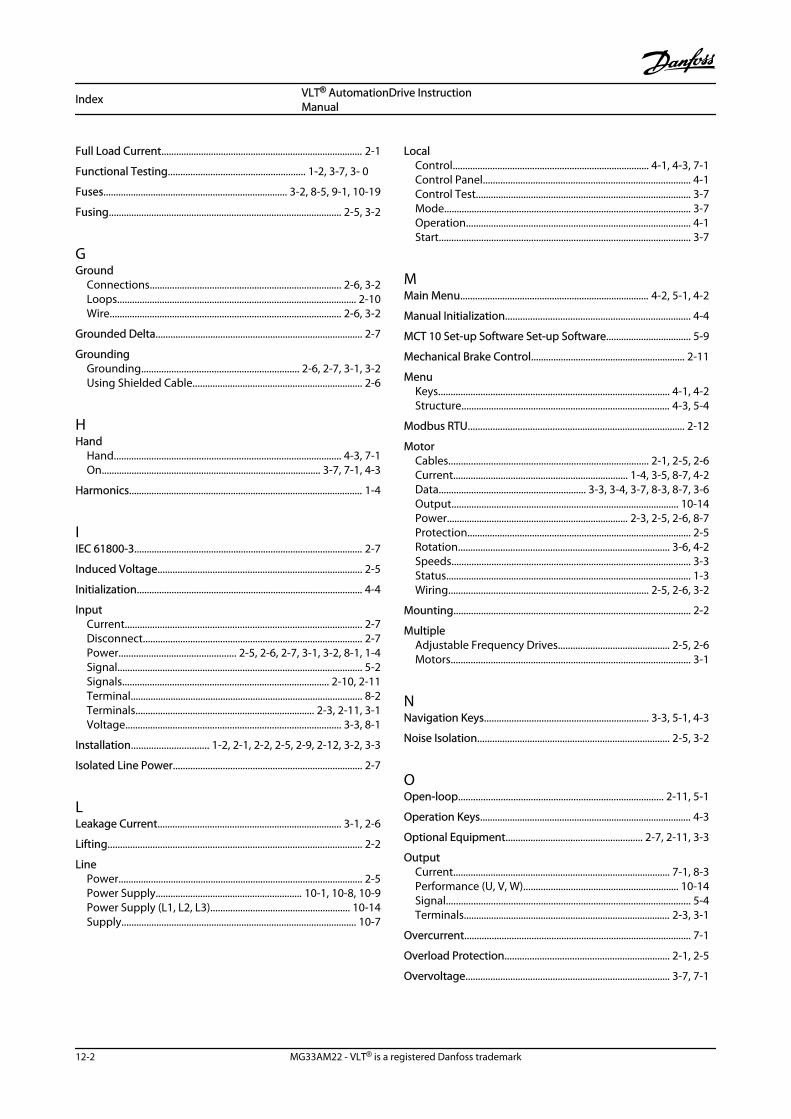
Full Load Current................................................................................. 2-1
Functional Testing....................................................... 1-2, 3-7, 3- 0
Fuses.......................................................................... 3-2, 8-5, 9-1, 10-19
Fusing............................................................................................. 2-5, 3-2
GGround
Connections............................................................................. 2-6, 3-2Loops................................................................................................ 2-10Wire............................................................................................. 2-6, 3-2
Grounded Delta................................................................................... 2-7
GroundingGrounding............................................................... 2-6, 2-7, 3-1, 3-2Using Shielded Cable.................................................................... 2-6
HHand
Hand........................................................................................... 4-3, 7-1On........................................................................................ 3-7, 7-1, 4-3
Harmonics.............................................................................................. 1-4
IIEC 61800-3............................................................................................ 2-7
Induced Voltage.................................................................................. 2-5
Initialization........................................................................................... 4-4
InputCurrent............................................................................................... 2-7Disconnect........................................................................................ 2-7Power............................................... 2-5, 2-6, 2-7, 3-1, 3-2, 8-1, 1-4Signal.................................................................................................. 5-2Signals................................................................................... 2-10, 2-11Terminal............................................................................................. 8-2Terminals........................................................................ 2-3, 2-11, 3-1Voltage....................................................................................... 3-3, 8-1
Installation............................... 1-2, 2-1, 2-2, 2-5, 2-9, 2-12, 3-2, 3-3
Isolated Line Power............................................................................ 2-7
LLeakage Current.......................................................................... 3-1, 2-6
Lifting...................................................................................................... 2-2
LinePower.................................................................................................. 2-5Power Supply........................................................... 10-1, 10-8, 10-9Power Supply (L1, L2, L3)........................................................ 10-14Supply.............................................................................................. 10-7
LocalControl............................................................................... 4-1, 4-3, 7-1Control Panel................................................................................... 4-1Control Test...................................................................................... 3-7Mode................................................................................................... 3-7Operation.......................................................................................... 4-1Start..................................................................................................... 3-7
MMain Menu............................................................................ 4-2, 5-1, 4-2
Manual Initialization.......................................................................... 4-4
MCT 10 Set-up Software Set-up Software.................................. 5-9
Mechanical Brake Control.............................................................. 2-11
MenuKeys............................................................................................. 4-1, 4-2Structure.................................................................................... 4-3, 5-4
Modbus RTU....................................................................................... 2-12
MotorCables................................................................................ 2-1, 2-5, 2-6Current...................................................................... 1-4, 3-5, 8-7, 4-2Data........................................................... 3-3, 3-4, 3-7, 8-3, 8-7, 3-6Output........................................................................................... 10-14Power......................................................................... 2-3, 2-5, 2-6, 8-7Protection.......................................................................................... 2-5Rotation..................................................................................... 3-6, 4-2Speeds................................................................................................ 3-3Status.................................................................................................. 1-3Wiring................................................................................ 2-5, 2-6, 3-2
Mounting............................................................................................... 2-2
MultipleAdjustable Frequency Drives............................................. 2-5, 2-6Motors................................................................................................ 3-1
NNavigation Keys.................................................................. 3-3, 5-1, 4-3
Noise Isolation............................................................................. 2-5, 3-2
OOpen-loop.................................................................................. 2-11, 5-1
Operation Keys..................................................................................... 4-3
Optional Equipment....................................................... 2-7, 2-11, 3-3
OutputCurrent....................................................................................... 7-1, 8-3Performance (U, V, W).............................................................. 10-14Signal.................................................................................................. 5-4Terminals................................................................................... 2-3, 3-1
Overcurrent........................................................................................... 7-1
Overload Protection.................................................................. 2-1, 2-5
Overvoltage.................................................................................. 3-7, 7-1
Index VLT® AutomationDrive InstructionManual
12-2 MG33AM22 - VLT® is a registered Danfoss trademark
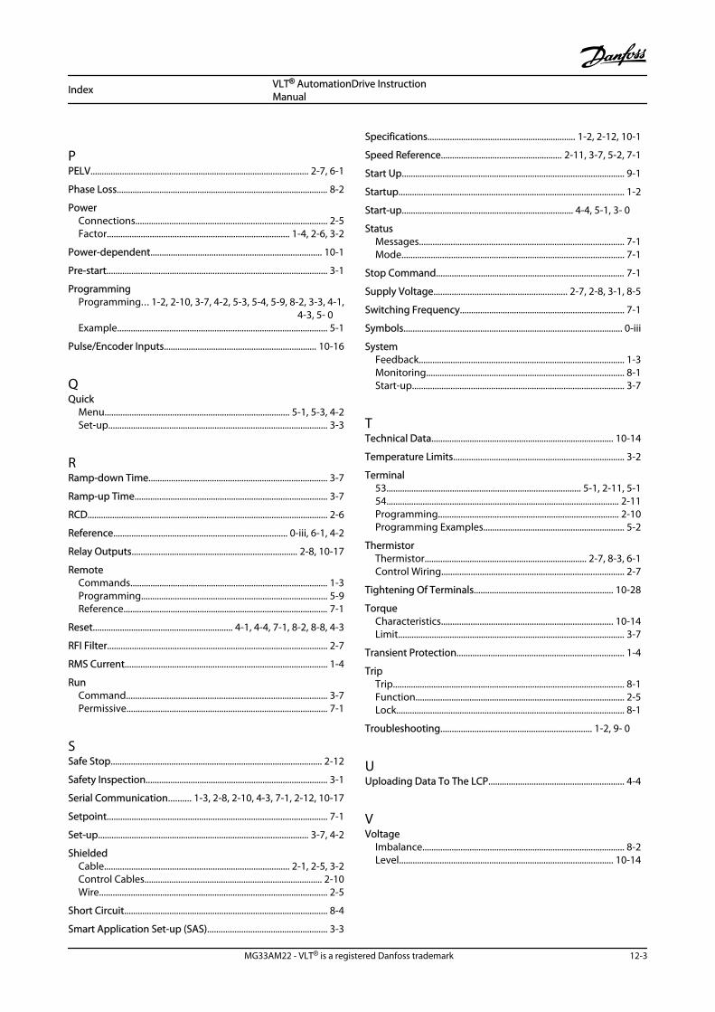
PPELV................................................................................................. 2-7, 6-1
Phase Loss.............................................................................................. 8-2
PowerConnections..................................................................................... 2-5Factor................................................................................. 1-4, 2-6, 3-2
Power-dependent............................................................................ 10-1
Pre-start.................................................................................................. 3-1
ProgrammingProgramming... 1-2, 2-10, 3-7, 4-2, 5-3, 5-4, 5-9, 8-2, 3-3, 4-1,
4-3, 5- 0Example............................................................................................. 5-1
Pulse/Encoder Inputs.................................................................... 10-16
QQuick
Menu.................................................................................. 5-1, 5-3, 4-2Set-up................................................................................................. 3-3
RRamp-down Time............................................................................... 3-7
Ramp-up Time...................................................................................... 3-7
RCD........................................................................................................... 2-6
Reference............................................................................. 0-iii, 6-1, 4-2
Relay Outputs.......................................................................... 2-8, 10-17
RemoteCommands........................................................................................ 1-3Programming................................................................................... 5-9Reference........................................................................................... 7-1
Reset.............................................................. 4-1, 4-4, 7-1, 8-2, 8-8, 4-3
RFI Filter.................................................................................................. 2-7
RMS Current.......................................................................................... 1-4
RunCommand......................................................................................... 3-7Permissive......................................................................................... 7-1
SSafe Stop.............................................................................................. 2-12
Safety Inspection................................................................................. 3-1
Serial Communication.......... 1-3, 2-8, 2-10, 4-3, 7-1, 2-12, 10-17
Setpoint.................................................................................................. 7-1
Set-up.............................................................................................. 3-7, 4-2
ShieldedCable.................................................................................. 2-1, 2-5, 3-2Control Cables............................................................................... 2-10Wire..................................................................................................... 2-5
Short Circuit.......................................................................................... 8-4
Smart Application Set-up (SAS)..................................................... 3-3
Specifications.................................................................. 1-2, 2-12, 10-1
Speed Reference...................................................... 2-11, 3-7, 5-2, 7-1
Start Up................................................................................................... 9-1
Startup.................................................................................................... 1-2
Start-up............................................................................ 4-4, 5-1, 3- 0
StatusMessages........................................................................................... 7-1Mode................................................................................................... 7-1
Stop Command.................................................................................... 7-1
Supply Voltage........................................................... 2-7, 2-8, 3-1, 8-5
Switching Frequency......................................................................... 7-1
Symbols................................................................................................. 0-iii
SystemFeedback........................................................................................... 1-3Monitoring........................................................................................ 8-1Start-up.............................................................................................. 3-7
TTechnical Data................................................................................. 10-14
Temperature Limits............................................................................ 3-2
Terminal53...................................................................................... 5-1, 2-11, 5-154....................................................................................................... 2-11Programming................................................................................ 2-10Programming Examples............................................................... 5-2
ThermistorThermistor........................................................................ 2-7, 8-3, 6-1Control Wiring................................................................................. 2-7
Tightening Of Terminals.............................................................. 10-28
TorqueCharacteristics............................................................................ 10-14Limit..................................................................................................... 3-7
Transient Protection.......................................................................... 1-4
TripTrip....................................................................................................... 8-1Function............................................................................................. 2-5Lock..................................................................................................... 8-1
Troubleshooting................................................................... 1-2, 9- 0
UUploading Data To The LCP............................................................ 4-4
VVoltage
Imbalance.......................................................................................... 8-2Level............................................................................................... 10-14
Index VLT® AutomationDrive InstructionManual
MG33AM22 - VLT® is a registered Danfoss trademark 12-3

WWarning
And Alarm Definitions.................................................................. 8-2And Alarm Displays........................................................................ 8-1And Alarm Types............................................................................. 8-1
Wire Sizes....................................................................................... 2-5, 2-6
Index VLT® AutomationDrive InstructionManual
12-4 MG33AM22 - VLT® is a registered Danfoss trademark