PSA Series Option 107 Audio Input - Keysight
20
Installation Note Part Number E4440-90318 Printed in USA June 2006 Agilent PSA Series Spectrum Analyzers Audio Input, Option 107
-
Upload
khangminh22 -
Category
Documents
-
view
2 -
download
0
Transcript of PSA Series Option 107 Audio Input - Keysight
Installation Note
Part Number E4440-90318Printed in USA June 2006
Agilent PSA Series Spectrum Analyzers
Audio Input, Option 107

Notice.
The information contained in this document is subject to change without notice.
Agilent Technologies makes no warranty of any kind with regard to this material, including but not limited to, the implied warranties of merchantability and fitness for a particular purpose. Agilent Technologies shall not be liable for errors contained herein or for incidental or consequential damages in connection with the furnishing, performance, or use of this material.
© Copyright 2006 Agilent Technologies, Inc.
Installation Note E4440-90318 3
Audio Input, Option 107
Audio Input, Option 107
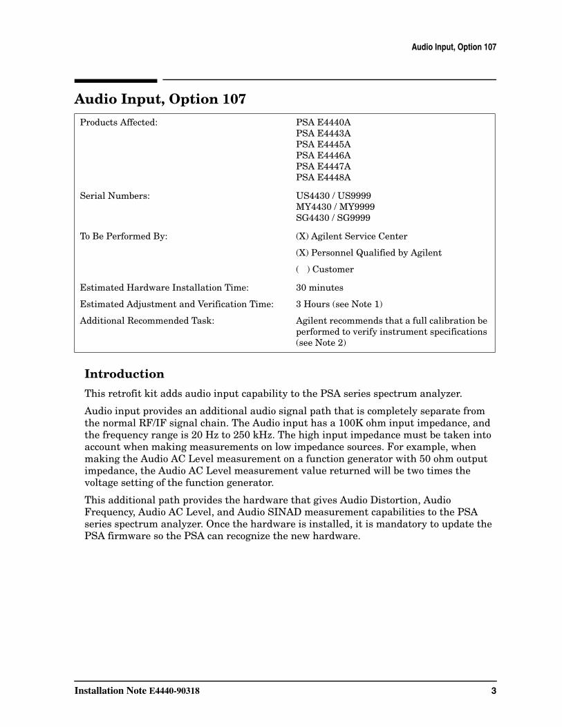
Introduction
This retrofit kit adds audio input capability to the PSA series spectrum analyzer.
Audio input provides an additional audio signal path that is completely separate from the normal RF/IF signal chain. The Audio input has a 100K ohm input impedance, and the frequency range is 20 Hz to 250 kHz. The high input impedance must be taken into account when making measurements on low impedance sources. For example, when making the Audio AC Level measurement on a function generator with 50 ohm output impedance, the Audio AC Level measurement value returned will be two times the voltage setting of the function generator.
This additional path provides the hardware that gives Audio Distortion, Audio Frequency, Audio AC Level, and Audio SINAD measurement capabilities to the PSA series spectrum analyzer. Once the hardware is installed, it is mandatory to update the PSA firmware so the PSA can recognize the new hardware.
Products Affected: PSA E4440APSA E4443APSA E4445APSA E4446APSA E4447APSA E4448A
Serial Numbers: US4430 / US9999MY4430 / MY9999SG4430 / SG9999
To Be Performed By: (X) Agilent Service Center
(X) Personnel Qualified by Agilent
( ) Customer
Estimated Hardware Installation Time:
Estimated Adjustment and Verification Time:
Additional Recommended Task:
30 minutes
3 Hours (see Note 1)
Agilent recommends that a full calibration be performed to verify instrument specifications (see Note 2)
4 Installation Note E4440-90318
Audio Input, Option 107
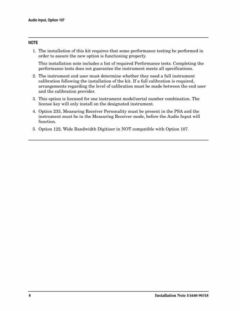
NOTE
1. The installation of this kit requires that some performance testing be performed in order to assure the new option is functioning properly.
This installation note includes a list of required Performance tests. Completing the performance tests does not guarantee the instrument meets all specifications.
2. The instrument end user must determine whether they need a full instrument calibration following the installation of the kit. If a full calibration is required, arrangements regarding the level of calibration must be made between the end user and the calibration provider.
3. This option is licensed for one instrument model/serial number combination. The license key will only install on the designated instrument.
4. Option 233, Measuring Receiver Personality must be present in the PSA and the instrument must be in the Measuring Receiver mode, before the Audio Input will function.
5. Option 122, Wide Bandwidth Digitizer in NOT compatible with Option 107.
Installation Note E4440-90318 5
Audio Input, Option 107
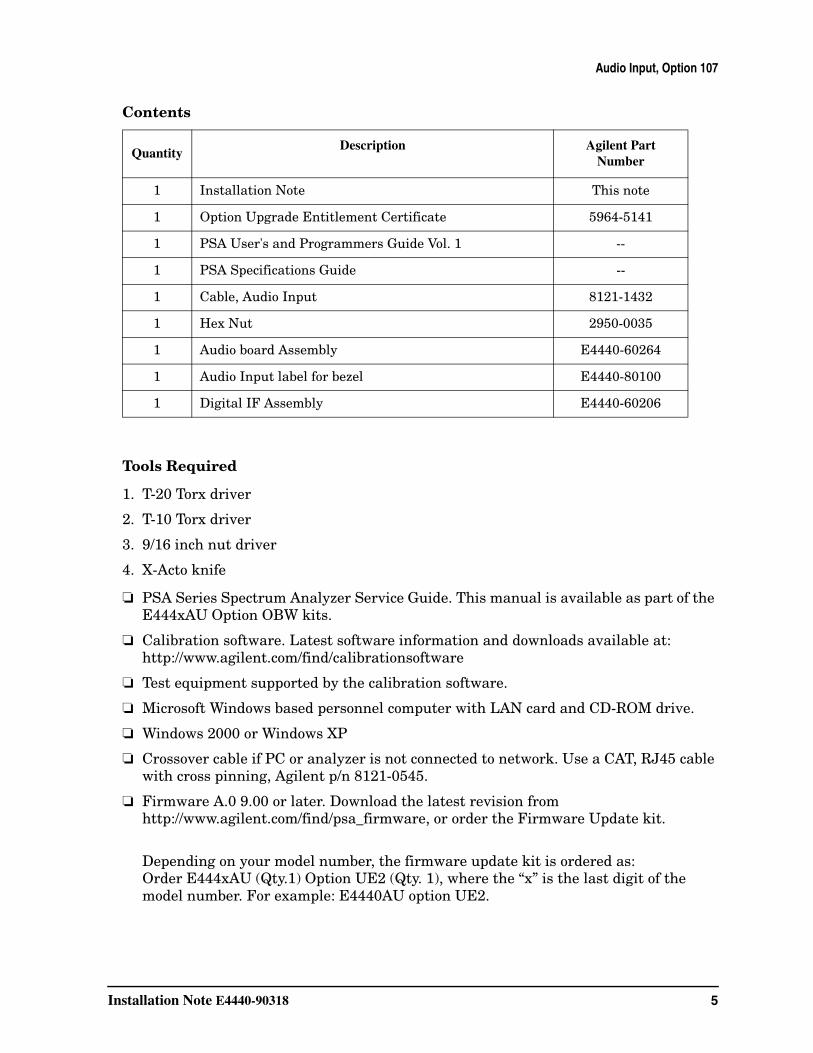
Contents
Tools Required
1. T-20 Torx driver
2. T-10 Torx driver
3. 9/16 inch nut driver
4. X-Acto knife
❏ PSA Series Spectrum Analyzer Service Guide. This manual is available as part of the E444xAU Option OBW kits.
❏ Calibration software. Latest software information and downloads available at:http://www.agilent.com/find/calibrationsoftware
❏ Test equipment supported by the calibration software.
❏ Microsoft Windows based personnel computer with LAN card and CD-ROM drive.
❏ Windows 2000 or Windows XP
❏ Crossover cable if PC or analyzer is not connected to network. Use a CAT, RJ45 cable with cross pinning, Agilent p/n 8121-0545.
❏ Firmware A.0 9.00 or later. Download the latest revision from http://www.agilent.com/find/psa_firmware, or order the Firmware Update kit.
Depending on your model number, the firmware update kit is ordered as: Order E444xAU (Qty.1) Option UE2 (Qty. 1), where the “x” is the last digit of the model number. For example: E4440AU option UE2.
QuantityDescription Agilent Part
Number
1 Installation Note This note
1 Option Upgrade Entitlement Certificate 5964-5141
1 PSA User's and Programmers Guide Vol. 1 --
1 PSA Specifications Guide --
1 Cable, Audio Input 8121-1432
1 Hex Nut 2950-0035
1 Audio board Assembly E4440-60264
1 Audio Input label for bezel E4440-80100
1 Digital IF Assembly E4440-60206
6 Installation Note E4440-90318
Installation Procedure
Installation Procedure
Preliminary Hardware Verification
1. Check for the presence of Option 233 by pressing System, Show System, and look at the option list.
• If Option 233 is present continue with installation of Option 107.
• If Option 233 is not present then install Option 233 before continuing with the installation of Option 107.
Option 233 is the Measuring Receiver Personality and is required for Option 107
2. Check the part number of the Digital IF Assembly installed in the instrument. Press System, More, Show Hdwr. Note the part number of the Digital IF Assembly.
3. Determine the part number of the Digital IF Assembly in the kit by looking at the part number silk-screened on the board assembly.
• If the part numbers match, you do not need to install the Digital IF Assembly from the kit.
• If the part numbers do not match, install the replacement Digital IF Assembly as outlined in this installation note.
Installation Note E4440-90318 7
Installation Procedure
Remove the Outer Case
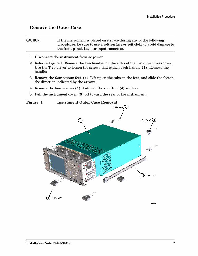
CAUTION If the instrument is placed on its face during any of the following procedures, be sure to use a soft surface or soft cloth to avoid damage to the front panel, keys, or input connector.
1. Disconnect the instrument from ac power.
2. Refer to Figure 1. Remove the two handles on the sides of the instrument as shown. Use the T-20 driver to loosen the screws that attach each handle (1). Remove the handles.
3. Remove the four bottom feet (2). Lift up on the tabs on the feet, and slide the feet in the direction indicated by the arrows.
4. Remove the four screws (3) that hold the rear feet (4) in place.
5. Pull the instrument cover (5) off toward the rear of the instrument.
Figure 1 Instrument Outer Case Removal
8 Installation Note E4440-90318
Installation Procedure
Remove the Top Brace
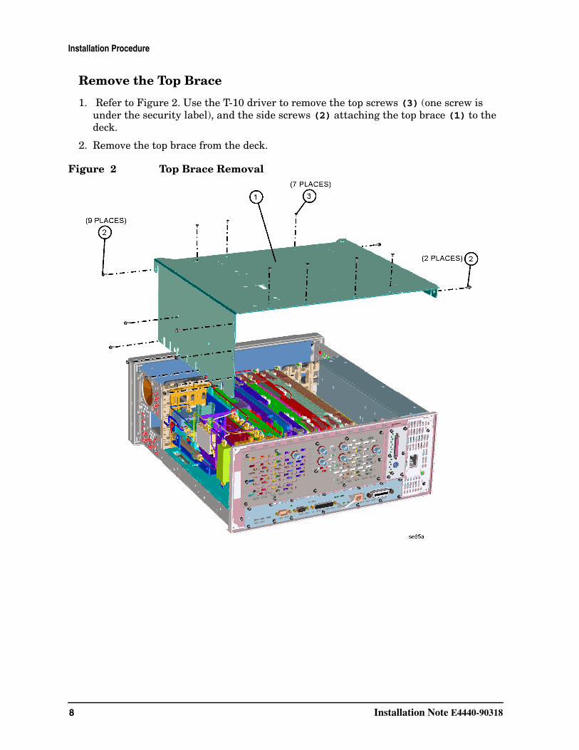
1. Refer to Figure 2. Use the T-10 driver to remove the top screws (3) (one screw is under the security label), and the side screws (2) attaching the top brace (1) to the deck.
2. Remove the top brace from the deck.
Figure 2 Top Brace Removal
Installation Note E4440-90318 9
Installation Procedure
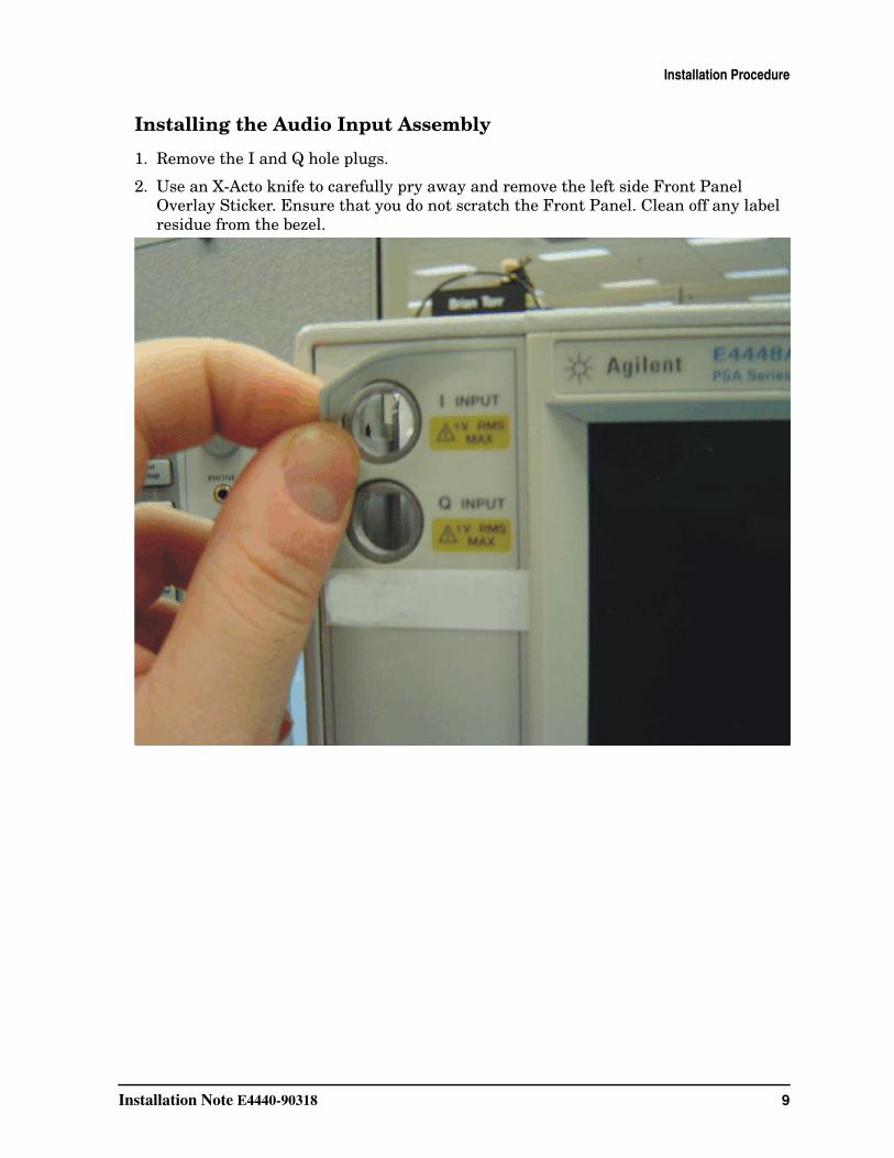
Installing the Audio Input Assembly
1. Remove the I and Q hole plugs.
2. Use an X-Acto knife to carefully pry away and remove the left side Front Panel Overlay Sticker. Ensure that you do not scratch the Front Panel. Clean off any label residue from the bezel.
10 Installation Note E4440-90318
Installation Procedure
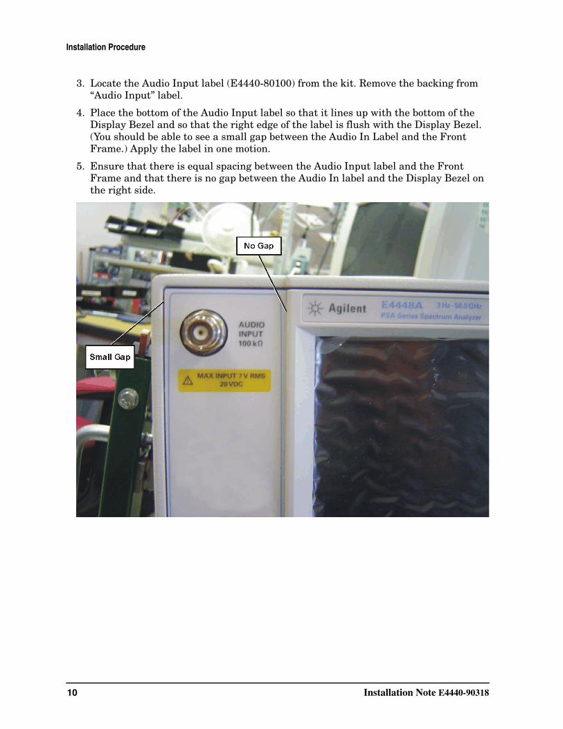
3. Locate the Audio Input label (E4440-80100) from the kit. Remove the backing from “Audio Input” label.
4. Place the bottom of the Audio Input label so that it lines up with the bottom of the Display Bezel and so that the right edge of the label is flush with the Display Bezel. (You should be able to see a small gap between the Audio In Label and the Front Frame.) Apply the label in one motion.
5. Ensure that there is equal spacing between the Audio Input label and the Front Frame and that there is no gap between the Audio In label and the Display Bezel on the right side.
Installation Note E4440-90318 11
Installation Procedure
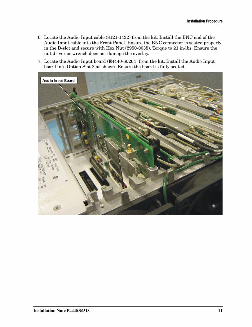
6. Locate the Audio Input cable (8121-1432) from the kit. Install the BNC end of the Audio Input cable into the Front Panel. Ensure the BNC connector is seated properly in the D-slot and secure with Hex Nut (2950-0035). Torque to 21 in-lbs. Ensure the nut driver or wrench does not damage the overlay.
7. Locate the Audio Input board (E4440-60264) from the kit. Install the Audio Input board into Option Slot 2 as shown. Ensure the board is fully seated.
12 Installation Note E4440-90318
Installation Procedure
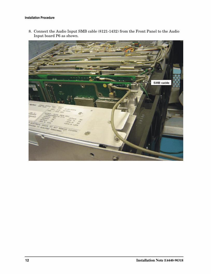
8. Connect the Audio Input SMB cable (8121-1432) from the Front Panel to the Audio Input board P6 as shown.
Installation Note E4440-90318 13
Installation Procedure
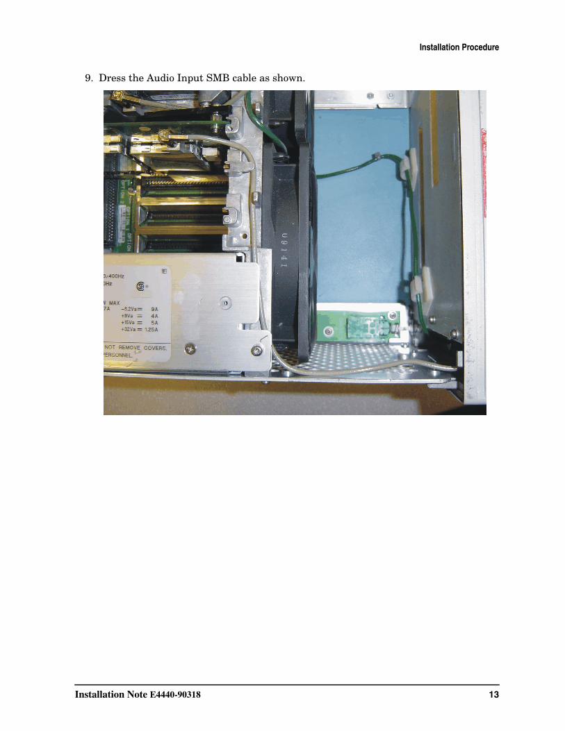
9. Dress the Audio Input SMB cable as shown.
14 Installation Note E4440-90318
Installation Procedure
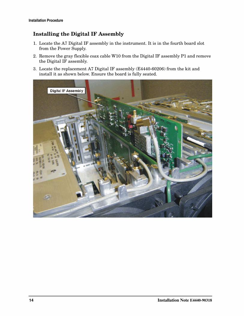
Installing the Digital IF Assembly
1. Locate the A7 Digital IF assembly in the instrument. It is in the fourth board slot from the Power Supply.
2. Remove the gray flexible coax cable W10 from the Digital IF assembly P1 and remove the Digital IF assembly.
3. Locate the replacement A7 Digital IF assembly (E4440-60206) from the kit and install it as shown below. Ensure the board is fully seated.
Installation Note E4440-90318 15
Installation Procedure
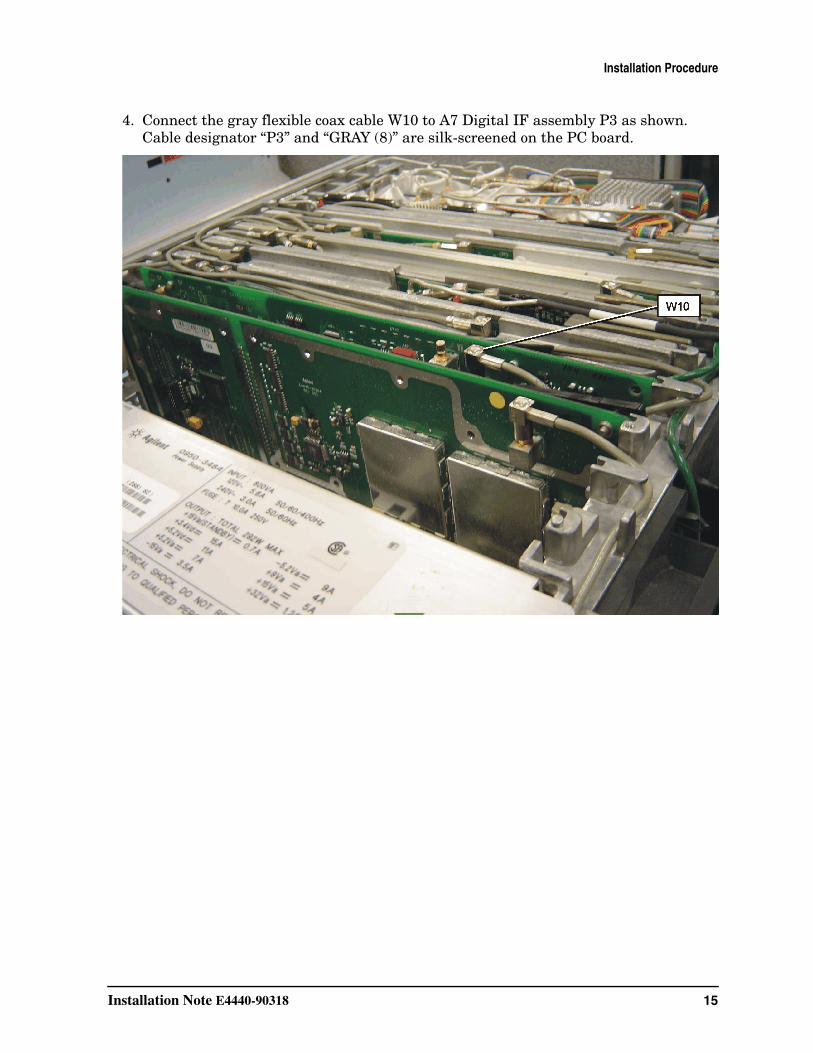
4. Connect the gray flexible coax cable W10 to A7 Digital IF assembly P3 as shown. Cable designator “P3” and “GRAY (8)” are silk-screened on the PC board.
16 Installation Note E4440-90318
Installation Procedure
Replace the Top Brace
1. Refer to Figure 2.
2. Carefully position the top brace on the deck. There is an alignment pin on the mid web/fan assembly that should match up with the alignment hole on the top brace. Make sure that no coaxial cables will get pinched underneath the brace.
3. Using the T-10 driver, replace the top screws first, and then the side screws after the top screws are tightened. Torque to 9 inch pounds.
Replace the Outer Case
1. Refer to Figure 1.
2. Slide the instrument cover back onto the deck from the rear. The seam on the cover should be on the bottom. Be sure the cover seats into the gasket groove in the front frame.
3. Replace the four rear feet onto the rear of the instrument. Torque to 236 Ncm (21 in-lb).
4. Use the T-20 driver to replace the handles. Torque to 236 Ncm (21 in-lb).
5. Replace the four bottom feet by pressing them into the holes in the case and sliding them in the opposite direction of the arrows until they click into place. Note that the feet at the front have the tilt stands.
Installation Note E4440-90318 17
Installation Procedure
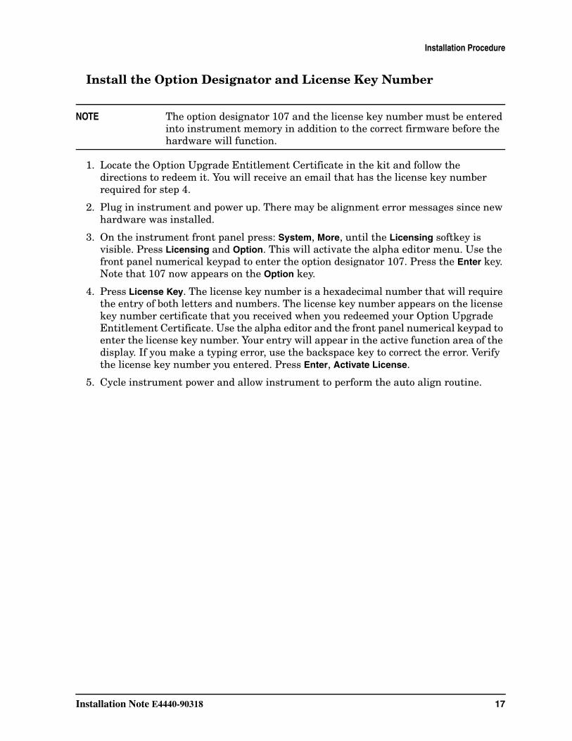
Install the Option Designator and License Key Number
NOTE The option designator 107 and the license key number must be entered into instrument memory in addition to the correct firmware before the hardware will function.
1. Locate the Option Upgrade Entitlement Certificate in the kit and follow the directions to redeem it. You will receive an email that has the license key number required for step 4.
2. Plug in instrument and power up. There may be alignment error messages since new hardware was installed.
3. On the instrument front panel press: System, More, until the Licensing softkey is visible. Press Licensing and Option. This will activate the alpha editor menu. Use the front panel numerical keypad to enter the option designator 107. Press the Enter key. Note that 107 now appears on the Option key.
4. Press License Key. The license key number is a hexadecimal number that will require the entry of both letters and numbers. The license key number appears on the license key number certificate that you received when you redeemed your Option Upgrade Entitlement Certificate. Use the alpha editor and the front panel numerical keypad to enter the license key number. Your entry will appear in the active function area of the display. If you make a typing error, use the backspace key to correct the error. Verify the license key number you entered. Press Enter, Activate License.
5. Cycle instrument power and allow instrument to perform the auto align routine.
18 Installation Note E4440-90318
Installation Procedure
Install New Instrument Firmware
Download the PSA Update Program and the PSA Firmware Procedure from
http://www.agilent.com/find/psa_firmware
Follow the directions to install the firmware.
Alternate method:Install the Firmware Upgrade Kit E4440AU Option UE2.
Verify the Option is enabled
Check for the presence of Option 107 by pressing System, More, Show System and looking for 107 in the Options section of the display.
Check for the recognition of new hardware by pressing System, More, Show Hardware and looking for Audio Input 100K Ohms.
Installation Note E4440-90318 19
Installation Procedure
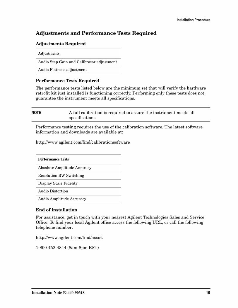
Adjustments and Performance Tests Required
Adjustments Required
Performance Tests Required
The performance tests listed below are the minimum set that will verify the hardware retrofit kit just installed is functioning correctly. Performing only these tests does not guarantee the instrument meets all specifications.
NOTE A full calibration is required to assure the instrument meets all specifications
Performance testing requires the use of the calibration software. The latest software information and downloads are available at:
http://www.agilent.com/find/calibrationsoftware
End of installation
For assistance, get in touch with your nearest Agilent Technologies Sales and Service Office. To find your local Agilent office access the following URL, or call the following telephone number:
http://www.agilent.com/find/assist
1-800-452-4844 (8am-8pm EST)
Adjustments
Audio Step Gain and Calibrator adjustment
Audio Flatness adjustment
Performance Tests
Absolute Amplitude Accuracy
Resolution BW Switching
Display Scale Fidelity
Audio Distortion
Audio Amplitude Accuracy

20 Installation Note E4440-90318
Installation Procedure