
Getting Started Guide - PSA Series Spectrum Analyzers
82
Getting Started Guide PSA Series Spectrum Analyzers This manual provides documentation for the following instruments: E4440A (3 Hz - 26.5 GHz) E4443A (3 Hz - 6.7 GHz) E4445A (3 Hz - 13.2 GHz) E4446A (3 Hz - 44 GHz) E4447A (3 Hz - 42.98 GHz) E4448A (3 Hz - 50 GHz) Manufacturing Part Number: E4440-90608 Supersedes: June 2008 Printed in USA November 2012 © Copyright 2001-2012 Agilent Technologies, Inc.
-
Upload
khangminh22 -
Category
Documents
-
view
0 -
download
0
Transcript of Getting Started Guide - PSA Series Spectrum Analyzers

Getting Started Guide
PSA Series Spectrum Analyzers
This manual provides documentation for the following instruments:
E4440A (3 Hz - 26.5 GHz)E4443A (3 Hz - 6.7 GHz)E4445A (3 Hz - 13.2 GHz)E4446A (3 Hz - 44 GHz)E4447A (3 Hz - 42.98 GHz)E4448A (3 Hz - 50 GHz)
Manufacturing Part Number: E4440-90608Supersedes: June 2008
Printed in USA
November 2012
© Copyright 2001-2012 Agilent Technologies, Inc.
NoticeThe information contained in this document is subject to change without notice.
Agilent Technologies makes no warranty of any kind with regard to this material, including but not limited to, the implied warranties of merchantability and fitness for a particular purpose. Agilent Technologies shall not be liable for errors contained herein or for incidental or consequential damages in connection with the furnishing, performance, or use of this material.
The following safety symbols are used throughout this manual. Familiarize yourself with the symbols and their meaning before operating this analyzer.
WARNING Warning denotes a hazard. It calls attention to a procedure which, if not correctly performed or adhered to, could result in injury or loss of life. Do not proceed beyond a warning note until the indicated conditions are fully understood and met.
CAUTION Caution denotes a hazard. It calls attention to a procedure that, if not correctly performed or adhered to, could result in damage to or destruction of the analyzer. Do not proceed beyond a caution sign until the indicated conditions are fully understood and met.
NOTE Note calls out special information for the user’s attention. It provides operational information or additional instructions of which the user should be aware.
General Safety InformationThe following general safety precautions must be observed during all phases of operation. Failure to comply with these precautions or with specific warnings elsewhere in this manual violates safety standards of design, manufacture, and intended use of the instrument. Agilent Technologies assumes no liability for the customer’s failure to comply with these requirements.
WARNING This is a Safety Class 1 Product (provided with a protective earthing ground incorporated in the power cord). The mains plug shall only be inserted in a socket outlet provided with a protective earth contact. Any interruption of the protective conductor inside or outside of the product is likely to make the product dangerous. Intentional interruption is prohibited. (IEC 348 clauses 17.3.3c & 17.3.4)
2
CAUTION This product is designed for use in Installation Category II and Pollution Degree 2 per IEC 61010 Second Edition and IEC 664 respectively.
WARNING If this product is not used as specified, the protection provided by the equipment could be impaired. This product must be used in a normal condition (in which all means for protection are intact) only.
WARNING No operator serviceable parts inside. Refer servicing to qualified personnel. To prevent electrical shock do not remove covers.
CAUTION The Mains wiring and connectors shall be compatible with the connector used in the premise electrical system. Failure, to ensure adequate earth grounding by not using the correct components may cause product damage, and serious injury
Additional InformationFor the latest information about this analyzer, including firmware upgrades, application information, and product information, see the following URL:
http://www.agilent.com/find/psa/
3

4
Contents
1. Installation and SetupInitial Inspection . . . . . . . . . . . . . . . . . . . . . . . . . . . . . . . . . . . . . . . . . . . . . . . . . . . . . . . . . . . . . . . . . . . . . . . 9Power Requirements . . . . . . . . . . . . . . . . . . . . . . . . . . . . . . . . . . . . . . . . . . . . . . . . . . . . . . . . . . . . . . . . . . . 11
AC Power Cord . . . . . . . . . . . . . . . . . . . . . . . . . . . . . . . . . . . . . . . . . . . . . . . . . . . . . . . . . . . . . . . . . . . . . 12Instrument Maintenance . . . . . . . . . . . . . . . . . . . . . . . . . . . . . . . . . . . . . . . . . . . . . . . . . . . . . . . . . . . . . . . . 13
Cleaning the Instrument . . . . . . . . . . . . . . . . . . . . . . . . . . . . . . . . . . . . . . . . . . . . . . . . . . . . . . . . . . . . . . 13Connector Care . . . . . . . . . . . . . . . . . . . . . . . . . . . . . . . . . . . . . . . . . . . . . . . . . . . . . . . . . . . . . . . . . . . . . 13Battery Information . . . . . . . . . . . . . . . . . . . . . . . . . . . . . . . . . . . . . . . . . . . . . . . . . . . . . . . . . . . . . . . . . . 13
Turning on the Analyzer for the First Time . . . . . . . . . . . . . . . . . . . . . . . . . . . . . . . . . . . . . . . . . . . . . . . . . 14Why Aren’t All the Personality Options Loaded in Memory? . . . . . . . . . . . . . . . . . . . . . . . . . . . . . . . . . 15If Option 117 is Loaded in Memory . . . . . . . . . . . . . . . . . . . . . . . . . . . . . . . . . . . . . . . . . . . . . . . . . . . . . 15Using an External Reference. . . . . . . . . . . . . . . . . . . . . . . . . . . . . . . . . . . . . . . . . . . . . . . . . . . . . . . . . . . 16
Firmware Revision . . . . . . . . . . . . . . . . . . . . . . . . . . . . . . . . . . . . . . . . . . . . . . . . . . . . . . . . . . . . . . . . . . . . 17Running Internal Alignments . . . . . . . . . . . . . . . . . . . . . . . . . . . . . . . . . . . . . . . . . . . . . . . . . . . . . . . . . . . . 18Printer Setup and Operation . . . . . . . . . . . . . . . . . . . . . . . . . . . . . . . . . . . . . . . . . . . . . . . . . . . . . . . . . . . . . 19Protecting Against Electrostatic Discharge . . . . . . . . . . . . . . . . . . . . . . . . . . . . . . . . . . . . . . . . . . . . . . . . . 21Safety Information . . . . . . . . . . . . . . . . . . . . . . . . . . . . . . . . . . . . . . . . . . . . . . . . . . . . . . . . . . . . . . . . . . . . 22
2. Front and Rear Panel FeaturesFront Panel Overview . . . . . . . . . . . . . . . . . . . . . . . . . . . . . . . . . . . . . . . . . . . . . . . . . . . . . . . . . . . . . . . . . . 24
Front-Panel Connectors and Keys. . . . . . . . . . . . . . . . . . . . . . . . . . . . . . . . . . . . . . . . . . . . . . . . . . . . . . . 24Display Annotations . . . . . . . . . . . . . . . . . . . . . . . . . . . . . . . . . . . . . . . . . . . . . . . . . . . . . . . . . . . . . . . . . 26
Rear-Panel Features . . . . . . . . . . . . . . . . . . . . . . . . . . . . . . . . . . . . . . . . . . . . . . . . . . . . . . . . . . . . . . . . . . . 29Key Overview . . . . . . . . . . . . . . . . . . . . . . . . . . . . . . . . . . . . . . . . . . . . . . . . . . . . . . . . . . . . . . . . . . . . . . . . 31Front and Rear Panel Symbols . . . . . . . . . . . . . . . . . . . . . . . . . . . . . . . . . . . . . . . . . . . . . . . . . . . . . . . . . . . 33
Packaging . . . . . . . . . . . . . . . . . . . . . . . . . . . . . . . . . . . . . . . . . . . . . . . . . . . . . . . . . . . . . . . . . . . . . . . . . 34
3. Making a Basic MeasurementUsing the Front Panel . . . . . . . . . . . . . . . . . . . . . . . . . . . . . . . . . . . . . . . . . . . . . . . . . . . . . . . . . . . . . . . . . . 37
Entering Data. . . . . . . . . . . . . . . . . . . . . . . . . . . . . . . . . . . . . . . . . . . . . . . . . . . . . . . . . . . . . . . . . . . . . . . 37Using Menu Keys . . . . . . . . . . . . . . . . . . . . . . . . . . . . . . . . . . . . . . . . . . . . . . . . . . . . . . . . . . . . . . . . . . . 37
Presetting the Spectrum Analyzer. . . . . . . . . . . . . . . . . . . . . . . . . . . . . . . . . . . . . . . . . . . . . . . . . . . . . . . . . 38Creating a User Preset . . . . . . . . . . . . . . . . . . . . . . . . . . . . . . . . . . . . . . . . . . . . . . . . . . . . . . . . . . . . . . . . 38
Viewing a Signal . . . . . . . . . . . . . . . . . . . . . . . . . . . . . . . . . . . . . . . . . . . . . . . . . . . . . . . . . . . . . . . . . . . . . . 39
4. Viewing Catalogs and Saving FilesFile Menu Functions . . . . . . . . . . . . . . . . . . . . . . . . . . . . . . . . . . . . . . . . . . . . . . . . . . . . . . . . . . . . . . . . . . . 47
Locating and viewing files in the catalog . . . . . . . . . . . . . . . . . . . . . . . . . . . . . . . . . . . . . . . . . . . . . . . . . 47Creating a directory. . . . . . . . . . . . . . . . . . . . . . . . . . . . . . . . . . . . . . . . . . . . . . . . . . . . . . . . . . . . . . . . . . 49
Saving a File . . . . . . . . . . . . . . . . . . . . . . . . . . . . . . . . . . . . . . . . . . . . . . . . . . . . . . . . . . . . . . . . . . . . . . . . . 51Step 1. Set up the analyzer trace . . . . . . . . . . . . . . . . . . . . . . . . . . . . . . . . . . . . . . . . . . . . . . . . . . . . . . . . 51Step 2. Save the file. . . . . . . . . . . . . . . . . . . . . . . . . . . . . . . . . . . . . . . . . . . . . . . . . . . . . . . . . . . . . . . . . . 53Loading a file . . . . . . . . . . . . . . . . . . . . . . . . . . . . . . . . . . . . . . . . . . . . . . . . . . . . . . . . . . . . . . . . . . . . . . 55Renaming a File . . . . . . . . . . . . . . . . . . . . . . . . . . . . . . . . . . . . . . . . . . . . . . . . . . . . . . . . . . . . . . . . . . . . 57Copying a File . . . . . . . . . . . . . . . . . . . . . . . . . . . . . . . . . . . . . . . . . . . . . . . . . . . . . . . . . . . . . . . . . . . . . . 58Deleting a File . . . . . . . . . . . . . . . . . . . . . . . . . . . . . . . . . . . . . . . . . . . . . . . . . . . . . . . . . . . . . . . . . . . . . . 59
Using the Alpha Editor . . . . . . . . . . . . . . . . . . . . . . . . . . . . . . . . . . . . . . . . . . . . . . . . . . . . . . . . . . . . . . . . . 60
5
Contents
5. Options and AccessoriesOrdering Options and Accessories . . . . . . . . . . . . . . . . . . . . . . . . . . . . . . . . . . . . . . . . . . . . . . . . . . . . . . . . 62Options . . . . . . . . . . . . . . . . . . . . . . . . . . . . . . . . . . . . . . . . . . . . . . . . . . . . . . . . . . . . . . . . . . . . . . . . . . . . . 63Accessories . . . . . . . . . . . . . . . . . . . . . . . . . . . . . . . . . . . . . . . . . . . . . . . . . . . . . . . . . . . . . . . . . . . . . . . . . . 69
50 Load . . . . . . . . . . . . . . . . . . . . . . . . . . . . . . . . . . . . . . . . . . . . . . . . . . . . . . . . . . . . . . . . . . . . . . . . . 6950 /75 Minimum Loss Pad. . . . . . . . . . . . . . . . . . . . . . . . . . . . . . . . . . . . . . . . . . . . . . . . . . . . . . . . . 69AC Probe. . . . . . . . . . . . . . . . . . . . . . . . . . . . . . . . . . . . . . . . . . . . . . . . . . . . . . . . . . . . . . . . . . . . . . . . . . 69AC Probe (Low Frequency) . . . . . . . . . . . . . . . . . . . . . . . . . . . . . . . . . . . . . . . . . . . . . . . . . . . . . . . . . . . 69Close-Field Probes (for EMC measurements with PSA) . . . . . . . . . . . . . . . . . . . . . . . . . . . . . . . . . . . . . 69Broadband Preamplifiers and Power Amplifiers . . . . . . . . . . . . . . . . . . . . . . . . . . . . . . . . . . . . . . . . . . . 70GPIB Cable . . . . . . . . . . . . . . . . . . . . . . . . . . . . . . . . . . . . . . . . . . . . . . . . . . . . . . . . . . . . . . . . . . . . . . . . 70USB/GPIB Interface . . . . . . . . . . . . . . . . . . . . . . . . . . . . . . . . . . . . . . . . . . . . . . . . . . . . . . . . . . . . . . . . . 70HP/Agilent 11970 Series Harmonic Mixers . . . . . . . . . . . . . . . . . . . . . . . . . . . . . . . . . . . . . . . . . . . . . . . 70HP/Agilent 11974 Series Preselected Millimeter Mixers . . . . . . . . . . . . . . . . . . . . . . . . . . . . . . . . . . . . . 71RF and Transient Limiters . . . . . . . . . . . . . . . . . . . . . . . . . . . . . . . . . . . . . . . . . . . . . . . . . . . . . . . . . . . . 71Power Splitters . . . . . . . . . . . . . . . . . . . . . . . . . . . . . . . . . . . . . . . . . . . . . . . . . . . . . . . . . . . . . . . . . . . . . 71RF Bridges . . . . . . . . . . . . . . . . . . . . . . . . . . . . . . . . . . . . . . . . . . . . . . . . . . . . . . . . . . . . . . . . . . . . . . . . 7250 Transmission/Reflection Test Kit . . . . . . . . . . . . . . . . . . . . . . . . . . . . . . . . . . . . . . . . . . . . . . . . . . 72Static Safe Accessories . . . . . . . . . . . . . . . . . . . . . . . . . . . . . . . . . . . . . . . . . . . . . . . . . . . . . . . . . . . . . . . 72Noise Sources (for use with PSA Option 219) . . . . . . . . . . . . . . . . . . . . . . . . . . . . . . . . . . . . . . . . . . . . . 72
6. In Case of DifficultyTypes of Spectrum Analyzer Messages . . . . . . . . . . . . . . . . . . . . . . . . . . . . . . . . . . . . . . . . . . . . . . . . . . . . 75Before Calling Agilent Technologies . . . . . . . . . . . . . . . . . . . . . . . . . . . . . . . . . . . . . . . . . . . . . . . . . . . . . . 76
Check the Basics. . . . . . . . . . . . . . . . . . . . . . . . . . . . . . . . . . . . . . . . . . . . . . . . . . . . . . . . . . . . . . . . . . . . 76Read the Warranty. . . . . . . . . . . . . . . . . . . . . . . . . . . . . . . . . . . . . . . . . . . . . . . . . . . . . . . . . . . . . . . . . . . 78Service Options. . . . . . . . . . . . . . . . . . . . . . . . . . . . . . . . . . . . . . . . . . . . . . . . . . . . . . . . . . . . . . . . . . . . . 78Calling Agilent Technologies . . . . . . . . . . . . . . . . . . . . . . . . . . . . . . . . . . . . . . . . . . . . . . . . . . . . . . . . . . 78
Returning an Analyzer for Service . . . . . . . . . . . . . . . . . . . . . . . . . . . . . . . . . . . . . . . . . . . . . . . . . . . . . . . . 79
6
1 Installation and Setup
7
Installation and Setup
This chapter provides the following information that you may need when you first receive your spectrum analyzer:
• “Initial Inspection” on page 9
• “Power Requirements” on page 11
• “Turning on the Analyzer for the First Time” on page 14
• “Running Internal Alignments” on page 18
• “Printer Setup and Operation” on page 19
• “Protecting Against Electrostatic Discharge” on page 21
• “Safety Information” on page 22
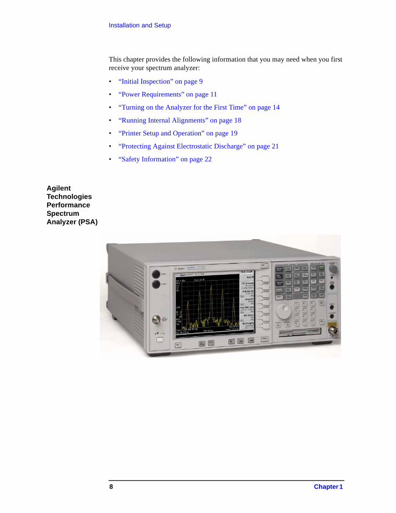
Agilent Technologies Performance Spectrum Analyzer (PSA)
8 Chapter 1
Installation and SetupInitial Inspection
Initial Inspection
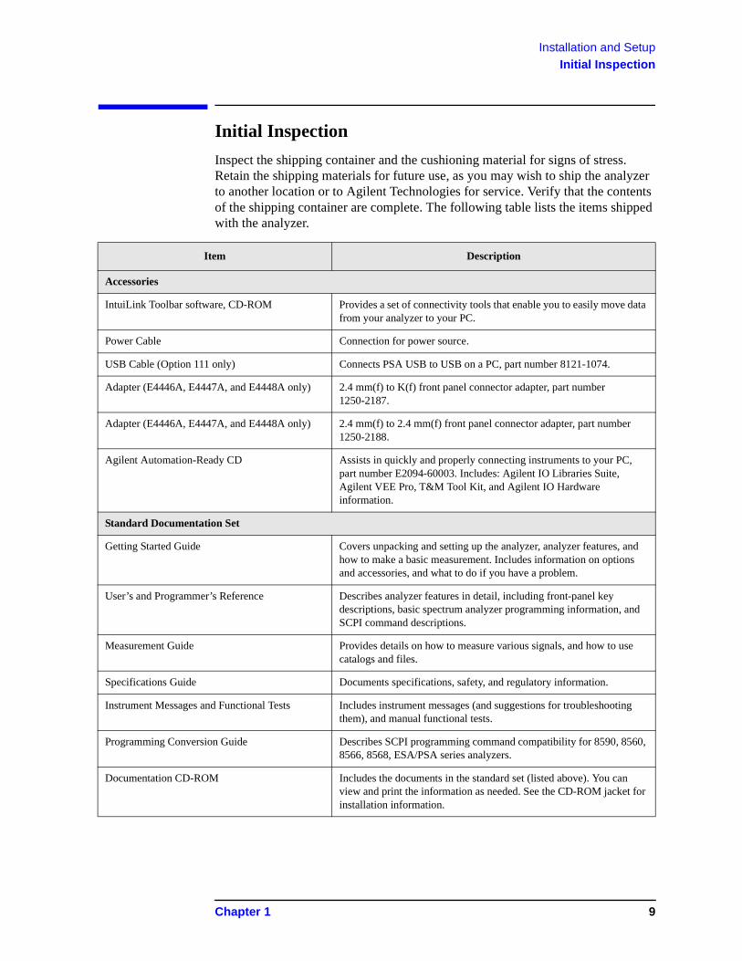
Inspect the shipping container and the cushioning material for signs of stress. Retain the shipping materials for future use, as you may wish to ship the analyzer to another location or to Agilent Technologies for service. Verify that the contents of the shipping container are complete. The following table lists the items shipped with the analyzer.
Item Description
Accessories
IntuiLink Toolbar software, CD-ROM Provides a set of connectivity tools that enable you to easily move data from your analyzer to your PC.
Power Cable Connection for power source.
USB Cable (Option 111 only) Connects PSA USB to USB on a PC, part number 8121-1074.
Adapter (E4446A, E4447A, and E4448A only) 2.4 mm(f) to K(f) front panel connector adapter, part number 1250-2187.
Adapter (E4446A, E4447A, and E4448A only) 2.4 mm(f) to 2.4 mm(f) front panel connector adapter, part number 1250-2188.
Agilent Automation-Ready CD Assists in quickly and properly connecting instruments to your PC, part number E2094-60003. Includes: Agilent IO Libraries Suite, Agilent VEE Pro, T&M Tool Kit, and Agilent IO Hardware information.
Standard Documentation Set
Getting Started Guide Covers unpacking and setting up the analyzer, analyzer features, and how to make a basic measurement. Includes information on options and accessories, and what to do if you have a problem.
User’s and Programmer’s Reference Describes analyzer features in detail, including front-panel key descriptions, basic spectrum analyzer programming information, and SCPI command descriptions.
Measurement Guide Provides details on how to measure various signals, and how to use catalogs and files.
Specifications Guide Documents specifications, safety, and regulatory information.
Instrument Messages and Functional Tests Includes instrument messages (and suggestions for troubleshooting them), and manual functional tests.
Programming Conversion Guide Describes SCPI programming command compatibility for 8590, 8560, 8566, 8568, ESA/PSA series analyzers.
Documentation CD-ROM Includes the documents in the standard set (listed above). You can view and print the information as needed. See the CD-ROM jacket for installation information.
Chapter 1 9
Installation and SetupInitial Inspection
NOTE If you purchased one or more optional measurement personalities, the related guides for the options you ordered are included.
Service documentation is not included in the standard documentation set. See “Options” on page 63 for information on ordering.
If There Is a Problem
If the shipping materials are damaged or the contents of the container are incomplete:
• Contact the nearest Agilent Technologies office to arrange for repair or replacement (see “Contacting Agilent Technologies” on page 78). You will not need to wait for a claim settlement.
• Keep the shipping materials for the carrier’s inspection.
• If you must return an analyzer to Agilent Technologies, use the original (or comparable) shipping materials (see “Returning an Analyzer for Service” on page 79).
10 Chapter 1
Installation and SetupPower Requirements
Power Requirements
The only physical installation of your Agilent spectrum analyzer is a connection to a power source.
Line voltage does not need to be selected.
This analyzer does not contain customer serviceable fuses.
WARNING Failure to ground the analyzer properly can result in personal injury. Before turning on the analyzer, you must connect its protective earth terminals to the protective conductor of the main power cable. Insert the main power cable plug into a socket outlet that has a protective earth contact only. DO NOT defeat the earth-grounding protection by using an extension cable, power cable, or autotransformer without a protective ground conductor.
If you are using an autotransformer, make sure its common terminal is connected to the protective earth contact of the power source outlet socket.
This is a Safety Class 1 Product (provided with a protective earthing ground incorporated in the power cord). The mains plug shall only be inserted in a socket outlet provided with a protective earth contact. Any interruption of the protective conductor inside or outside of the product is likely to make the product dangerous. Intentional interruption is prohibited.
WARNING To prevent electrical shock, disconnect the Agilent spectrum analyzer from mains before cleaning. Use a dry cloth or one slightly dampened with water to clean the external case parts. Do not attempt to clean internally.
CAUTION VENTILATION REQUIREMENTS: When installing the product in a cabinet, the convection into and out of the product must not be restricted. The ambient temperature (outside the cabinet) must be less than the maximum operating temperature of the product by 4C for every 100 watts dissipated in the cabinet. If the total power dissipated in the cabinet is greater than 800 watts, then forced convection must be used.
This analyzer has autoranging line voltage input. Be sure the supply voltage is within the specified range.
NOTE For detailed analyzer specifications, see the Specifications guide.
Chapter 1 11
Installation and SetupPower Requirements
AC Power Cord
The analyzer is equipped with a three-wire power cord, in accordance with international safety standards. This cable grounds the analyzer cabinet when connected to an appropriate power line outlet. The cable appropriate to the original shipping location is included with the analyzer.
NOTE The front panel switch is a standby switch only; it is not a LINE switch (power disconnecting device).
WARNING Install the product so that the detachable power cord is readily identifiable and easily reached by the operator. The detachable power cord is the product disconnecting device. It disconnects the mains circuits from the mains supply before other parts of the product. The front panel switch is only a standby switch and is not a LINE switch. Alternatively, an externally installed switch or circuit breaker (which is readily identifiable and is easily reached by the operator) may be used as a disconnecting device.
CAUTION Always use the three-prong AC power cord supplied with this product. Failure to ensure adequate earth grounding by not using this cord can cause product damage.
Table 1-1. Power Requirements
Description Specificationa
Voltage, Frequency 100 to 120 Vrms, 50/60/400 Hz
220 to 240 Vrms, 50/60 Hz
Power Consumption, On Base Fully Loaded< 260 W < 450 W
Power Consumption, Standby < 20 W
a. For greater detail, refer to the Specifications Guide.
12 Chapter 1
Installation and SetupInstrument Maintenance
Instrument Maintenance
Cleaning the Instrument
WARNING To prevent electrical shock, disconnect the Agilent Technologies E4440A Series from mains before cleaning. Use a dry cloth or one slightly dampened with water to clean the external case parts. Do not attempt to clean internally.
Connector Care
CAUTION Cleaning connectors with alcohol shall only be done with the instruments power cord removed, and in a well-ventilated area. Allow all residual alcohol moisture to evaporate, and the fumes to dissipate prior to energizing the instrument.
Battery Information
The analyzer uses a Lithium Polycarbon Monofloride battery to power the analyzer clock. The battery is located on the CPU board.
You can order the service documentation for Agilent spectrum analyzers through your Agilent Sales and Service office. The documentation is described under “Options” on page 63.
NOTE If the analyzer’s clock does not keep time when powered off, the problem is the battery. See “Returning an Analyzer for Service” on page 79.
WARNING Danger of explosion if battery is incorrectly replaced. Replace only with the same or equivalent type recommended. Discard used batteries according to the manufacturer’s instructions.
Chapter 1 13
Installation and SetupTurning on the Analyzer for the First Time
Turning on the Analyzer for the First Time
❏ Plug in the power cord.
WARNING If this product is to be energized through an external auto transformer for voltage reduction, make sure that its common terminal is connected to a neutral (earthed pole) of the power supply.
NOTE Do not connect anything else to the analyzer yet.
❏ Press the power switch (located in the lower left corner of the analyzer’s front panel) to turn the analyzer on. See “Front Panel Overview” on page 24.
NOTE The instrument requires >2 minutes to complete the start-up routine.
Information Screen
An information screen appears during the initialization process. The information screen contains the analyzer product number and a URL for accessing product support information on the Web. See “Additional Information” on page 3.
NOTE The information screen displays for approximately 10 seconds before the initialization process is complete.
Record the firmware revision and serial number, and keep it for reference. If you should ever need to call Agilent Technologies for service or with any questions regarding your analyzer, it will be helpful to have this information readily available. You can also obtain the firmware revision and serial number by pressing System, More, Show System.
❏ If using LAN, set the IP address of the analyzer to an appropriate number for your network; one that the network recognizes, but that is not yet in use. (Consult your local IT group):
— Press System, Config I/O, and note the IP address.
— If the current address is not appropriate, press IP Address and use the keypad to change it.
— Verify the subnet mask and gateway values. If necessary, change the values.
— Connect the LAN cable to the LAN connector located on the rear panel of your analyzer (see “Rear-Panel Features” on page 29).
— Cycle the analyzer power.
NOTE It is necessary to cycle the power to the analyzer after plugging in the LAN for the analyzer to recognize the network.
❏ Allow the spectrum analyzer to warm-up for 30 minutes before making a
14 Chapter 1
Installation and SetupTurning on the Analyzer for the First Time
calibrated measurement. To meet its specifications, the analyzer must meet operating temperature conditions.
NOTE It is normal to hear clicking when the Auto Alignment function is on. See “Running Internal Alignments” on page 18 for more information.
Why Aren’t All the Personality Options Loaded in Memory?
Many measurement personality options are available for use with this instrument. If the option is loaded in the instrument, you must also have a license key entered, to use it.
Some versions of instrument hardware may not have enough memory to accommodate all the options that you have ordered. If this is the case you will need to swap the applications in and out of memory, as needed. It may also be possible to upgrade your hardware to have more memory. Contact your local sales or service office.
If Option 117 is Loaded in Memory
If you ordered Option 117, the Secure Memory Erase option was loaded into the memory of your instrument and licensed at the factory but not enabled. DO NOT enable this option until you have fully configured your instrument (set the System, Config I/O settings as needed, added or removed options and licenses, and configured the power-up state you desire). After the security mode is enabled, the main Flash memory becomes read-only, rather than read/write memory. This makes it impossible to add or remove personalities or their license keys, or otherwise change the instrument’s configuration, unless you do a System, Security, Secure Erase All procedure. This procedure will render the instrument inoperable. You will then need to run the upgrade procedure (on the Agilent Web site) to reinstall the firmware and completely reconfigure your instrument. Refer to “Managing Security” in Chapter 4 of the “User’s and Programmer’s Reference, Volume 1.”
When you are satisfied with the configuration of your PSA analyzer, enable the Secure Memory Erase option by pressing System, Security, Security, Enabled. The security mode will then be enabled the next time the analyzer’s power is cycled.
NOTE When Option 117 is present, the number of personalities that can be loaded into memory is limited to 3 or 4.
Chapter 1 15
Installation and SetupTurning on the Analyzer for the First Time
Using an External Reference
1. To use an external frequency reference, connect it to the EXT REF IN connector on the rear panel (see “Rear-Panel Features” on page 29).
2. Enter the frequency of the external reference into the analyzer:
a. Press System, Reference, Freq Ref b. Select the Ext function. c. Use the keypad to enter the frequency of the external frequency reference.
16 Chapter 1
Installation and SetupFirmware Revision
Firmware Revision
To view the firmware revision of your analyzer, press System, More, Show System. If you call Agilent Technologies regarding your analyzer, it is helpful to have this revision and the analyzer serial number available.
TIP You can get automatic electronic notification of new firmware releases and other product updates/information by subscribing to the Agilent Technologies Test & Measurement E-Mail Notification Service for the PSA Series at http://www.agilent.com/find/notifyme
Chapter 1 17
Installation and SetupRunning Internal Alignments
Running Internal Alignments
Each time the analyzer is powered on, the internal alignment routine runs automatically.
The analyzer was shipped from the factory with the Alignments mode set to Auto. This setting enables the alignment routine to run automatically either every 24 hours, or when the internal analyzer temperature changes by 3C.
NOTE When the Alignment routine runs, you will hear the attenuator settings changing, which generates noise. This is not an indication of trouble.
Manually Performing an Alignment
If Auto Align, Off is selected, refer to the Specifications guide for the conditions required to maintain calibration.
NOTE For detailed information regarding the alignment routine (including how to run alignments, and how the analyzer can alert you when alignments are required) refer to the User’s guide for your analyzer.
18 Chapter 1
Installation and SetupPrinter Setup and Operation
Printer Setup and Operation
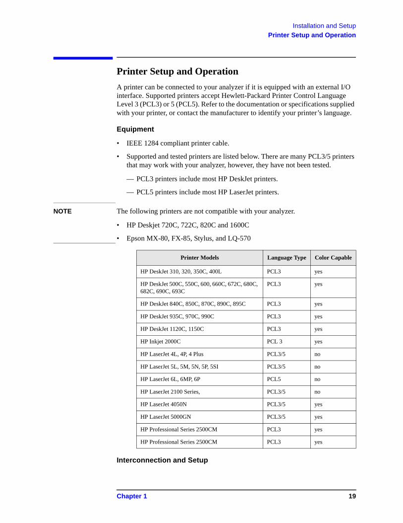
A printer can be connected to your analyzer if it is equipped with an external I/O interface. Supported printers accept Hewlett-Packard Printer Control Language Level 3 (PCL3) or 5 (PCL5). Refer to the documentation or specifications supplied with your printer, or contact the manufacturer to identify your printer’s language.
Equipment
• IEEE 1284 compliant printer cable.
• Supported and tested printers are listed below. There are many PCL3/5 printers that may work with your analyzer, however, they have not been tested.
— PCL3 printers include most HP DeskJet printers.
— PCL5 printers include most HP LaserJet printers.
NOTE The following printers are not compatible with your analyzer.
• HP Deskjet 720C, 722C, 820C and 1600C
• Epson MX-80, FX-85, Stylus, and LQ-570
Interconnection and Setup
Printer Models Language Type Color Capable
HP DeskJet 310, 320, 350C, 400L PCL3 yes
HP DeskJet 500C, 550C, 600, 660C, 672C, 680C, 682C, 690C, 693C
PCL3 yes
HP DeskJet 840C, 850C, 870C, 890C, 895C PCL3 yes
HP DeskJet 935C, 970C, 990C PCL3 yes
HP DeskJet 1120C, 1150C PCL3 yes
HP Inkjet 2000C PCL 3 yes
HP LaserJet 4L, 4P, 4 Plus PCL3/5 no
HP LaserJet 5L, 5M, 5N, 5P, 5SI PCL3/5 no
HP LaserJet 6L, 6MP, 6P PCL5 no
HP LaserJet 2100 Series, PCL3/5 no
HP LaserJet 4050N PCL3/5 yes
HP LaserJet 5000GN PCL3/5 yes
HP Professional Series 2500CM PCL3 yes
HP Professional Series 2500CM PCL3 yes
Chapter 1 19
Installation and SetupPrinter Setup and Operation
1. Turn off the printer and the analyzer.
2. Using an IEEE 1284 compliant parallel printer cable, connect the printer to the analyzer parallel I/O interface connector on the rear panel (see “Rear-Panel Features” on page 29).
3. Turn on the analyzer and printer.
4. On the front panel, press Print Setup, then press the Printer Setup menu key.
5. Select the printer language and color capability appropriate for your printer. See the table above this section for a list of some compatible printers.
Testing Printer Operation
When you have completed the printer setup for the analyzer, press the front panel Print key. If the printer is ready and the printer setup was successful, a printout of the analyzer display will be printed. If the printer is not ready, the message “Printer not responding” appears at the bottom of the screen.
NOTE There may be some small discrepancies in the color mapping of the analyzer display to your color printer. Due to differences in display and printer technologies, the default display colors do not map exactly to the printer colors. For example trace 1 is yellow on your analyzer display while it maps to green on your printer.
20 Chapter 1
Installation and SetupProtecting Against Electrostatic Discharge
Protecting Against Electrostatic Discharge
Electrostatic discharge (ESD) can damage or destroy electronic components (the possibility of unseen damage caused by ESD is present whenever components are transported, stored, or used).
Test Equipment and ESD
To help reduce ESD damage that can occur while using test equipment:
• Before connecting any coaxial cable to an analyzer connector for the first time each day, momentarily short the center and outer conductors of the cable together.
• Personnel should be grounded with a 1 M resistor-isolated wrist-strap before touching the center pin of any connector and before removing any assembly from the analyzer.
• Be sure that all instruments are properly earth-grounded to prevent build-up of static charge.
WARNING Do not use these first three techniques when working on circuitry with a voltage potential greater than 500 volts.
• Perform work on all components or assemblies at a static-safe workstation.
• Keep static-generating materials at least one meter away from all components.
• Store or transport components in static-shielding containers.
• Always handle printed circuit board assemblies by the edges. This reduces the possibility of ESD damage to components and prevent contamination of exposed plating.
For information on ordering static-safe accessories, see “Accessories” on page 69.
Additional Information about ESD
For more information about ESD and how to prevent ESD damage, contact the Electrostatic Discharge Association (http://www.esda.org). The ESD standards developed by this agency are sanctioned by the American National Standards Institute (ANSI).
Chapter 1 21
Installation and SetupSafety Information
Safety Information
WARNING This is a Safety Class 1 Product (provided with a protective earthing ground incorporated in the power cord). The mains plug shall be inserted only in a socket outlet provided with a protective earth contact. Any interruption of the protective conductor inside or outside of the product is likely to make the product dangerous. Intentional interruption is prohibited.
If this product is not used as specified, the protection provided by the equipment could be impaired. This product must be used in a normal condition (in which all means for protection are intact) only.
22 Chapter 1

2 Front and Rear Panel Features
This chapter gives you an overview of the front and rear panels of your analyzer. For details on analyzer keys and remote programming, refer to the User’s and Programmer’s Reference. For connector specifications (including input and output levels), see the Specifications guide.
23
Front and Rear Panel FeaturesFront Panel Overview
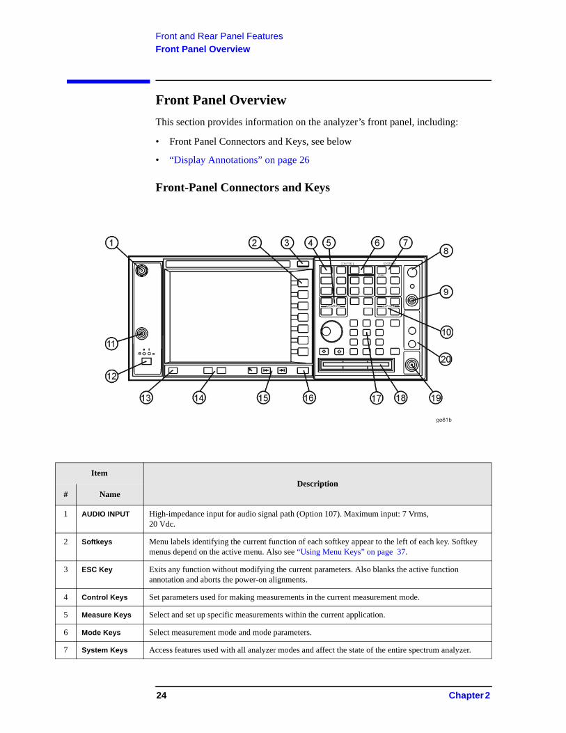
Front Panel Overview
This section provides information on the analyzer’s front panel, including:
• Front Panel Connectors and Keys, see below
• “Display Annotations” on page 26
Front-Panel Connectors and Keys
ItemDescription
# Name
1 AUDIO INPUT High-impedance input for audio signal path (Option 107). Maximum input: 7 Vrms,20 Vdc.
2 Softkeys Menu labels identifying the current function of each softkey appear to the left of each key. Softkey menus depend on the active menu. Also see “Using Menu Keys” on page 37.
3 ESC Key Exits any function without modifying the current parameters. Also blanks the active function annotation and aborts the power-on alignments.
4 Control Keys Set parameters used for making measurements in the current measurement mode.
5 Measure Keys Select and set up specific measurements within the current application.
6 Mode Keys Select measurement mode and mode parameters.
7 System Keys Access features used with all analyzer modes and affect the state of the entire spectrum analyzer.
24 Chapter 2
Front and Rear Panel FeaturesFront Panel Overview
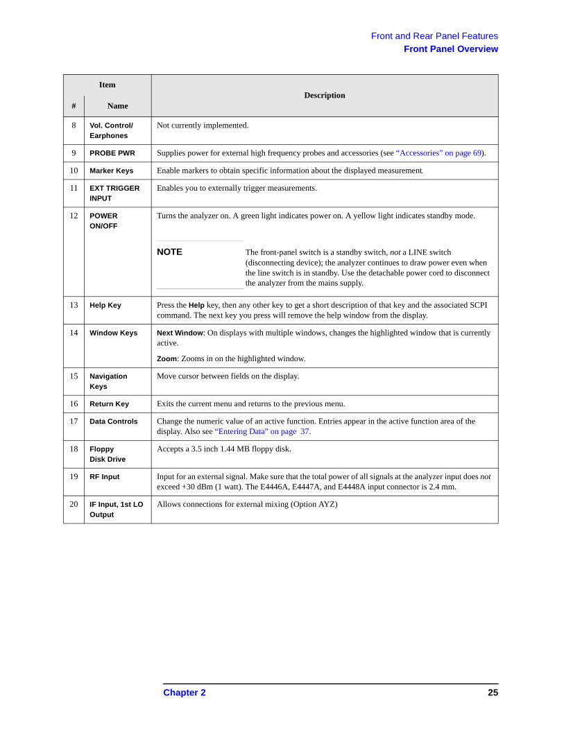
8 Vol. Control/Earphones
Not currently implemented.
9 PROBE PWR Supplies power for external high frequency probes and accessories (see “Accessories” on page 69).
10 Marker Keys Enable markers to obtain specific information about the displayed measurement
11 EXT TRIGGERINPUT
Enables you to externally trigger measurements.
12 POWERON/OFF
Turns the analyzer on. A green light indicates power on. A yellow light indicates standby mode.
NOTE The front-panel switch is a standby switch, not a LINE switch (disconnecting device); the analyzer continues to draw power even when the line switch is in standby. Use the detachable power cord to disconnect the analyzer from the mains supply.
13 Help Key Press the Help key, then any other key to get a short description of that key and the associated SCPI command. The next key you press will remove the help window from the display.
14 Window Keys Next Window: On displays with multiple windows, changes the highlighted window that is currently active.
Zoom: Zooms in on the highlighted window.
15 NavigationKeys
Move cursor between fields on the display.
16 Return Key Exits the current menu and returns to the previous menu.
17 Data Controls Change the numeric value of an active function. Entries appear in the active function area of the display. Also see “Entering Data” on page 37.
18 FloppyDisk Drive
Accepts a 3.5 inch 1.44 MB floppy disk.
19 RF Input Input for an external signal. Make sure that the total power of all signals at the analyzer input does not exceed +30 dBm (1 watt). The E4446A, E4447A, and E4448A input connector is 2.4 mm.
20 IF Input, 1st LO Output
Allows connections for external mixing (Option AYZ)
ItemDescription
# Name
Chapter 2 25
Front and Rear Panel FeaturesFront Panel Overview
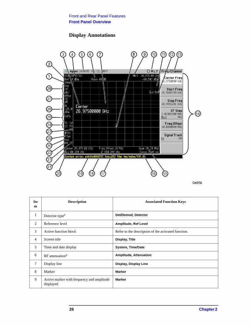
Display Annotations
Item
Description Associated Function Keys
1 Detector typea Det/Demod, Detector
2 Reference level Amplitude, Ref Level
3 Active function block Refer to the description of the activated function.
4 Screen title Display, Title
5 Time and date display System, Time/Date
6 RF attenuationa Amplitude, Attenuation
7 Display line Display, Display Line
8 Marker Marker
9 Active marker with frequency and amplitude displayed
Marker
26 Chapter 2
Front and Rear Panel FeaturesFront Panel Overview
10 Remote operation annunciators
O - indicates USB connected; flashing green center indicates bus activityR - remote operationL - GPIB listenT - GPIB talkS - GPIB SRQ
System [LOCAL] Also see programming documentation
11 Data invalid indicator Asterisk (*) means some or all trace data may not match annotation due to possible analyzer setting changes.
12 Status message area Displays status messages (see “Types of Spectrum Analyzer Messages” on page 75).
13 Key menu title Dependent on menu selection.
14 Softkey menu Softkey labels
15 Frequency span or stop frequency Span or Frequency, Stop Freq
16 Sweep timea Sweep, Sweep Time
17 Video bandwidtha BW, Video BW
18 Frequency offset Frequency, Freq Offset
19 Display status line Displays informational and error messages (see “Types of Spectrum Analyzer Messages” on page 75).
20 Resolution bandwidtha BW, Res BW
21 Center frequency or start frequency Frequency, Center Freq or Start Freq
22 Internal preamp Amplitude, Int Preamp
23 Auto alignment routine status System, Alignments, Auto align (If auto alignment is off, no indicator appears)
AA: auto alignment of all analyzer parameters.
AL: analyzer alerts you when alignment is needed.
24 Trigger or Trace Trig or Trace/Avg
Trigger & sweep modes:F: free-run trigger
X: external (front) trigger
R: external (rear) trigger
L: line trigger
V: video trigger
C: continuous sweep
S: single sweep
Trace modes:W: clear-write
S: store blank
m: minimum hold
M: maximum hold
V: view
1: trace 1
2: trace 2
3: trace 3
Item
Description Associated Function Keys
Chapter 2 27
Front and Rear Panel FeaturesFront Panel Overview
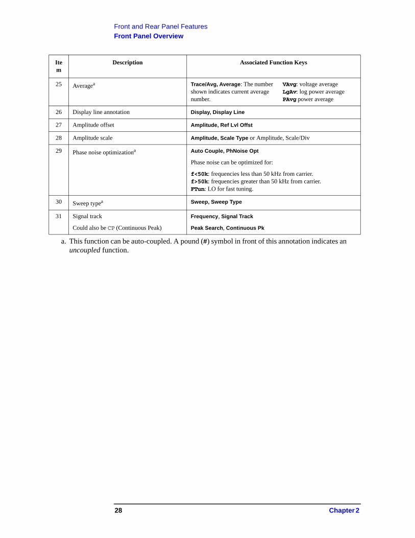
25 Averagea Trace/Avg, Average: The number shown indicates current average number.
VAvg: voltage averageLgAv: log power averagePAvg power average
26 Display line annotation Display, Display Line
27 Amplitude offset Amplitude, Ref Lvl Offst
28 Amplitude scale Amplitude, Scale Type or Amplitude, Scale/Div
29 Phase noise optimizationa Auto Couple, PhNoise Opt
Phase noise can be optimized for:
f<50k: frequencies less than 50 kHz from carrier.f>50k: frequencies greater than 50 kHz from carrier.FTun: LO for fast tuning.
30 Sweep typea Sweep, Sweep Type
31 Signal track
Could also be CP (Continuous Peak)
Frequency, Signal Track
Peak Search, Continuous Pk
a. This function can be auto-coupled. A pound (#) symbol in front of this annotation indicates an uncoupled function.
Item
Description Associated Function Keys
28 Chapter 2
Front and Rear Panel FeaturesRear-Panel Features
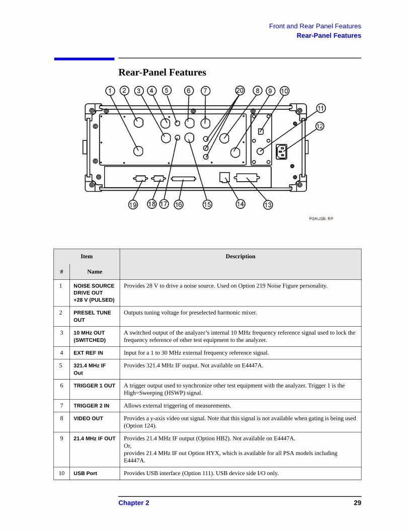
Rear-Panel Features
Item Description
# Name
1 NOISE SOURCE DRIVE OUT +28 V (PULSED)
Provides 28 V to drive a noise source. Used on Option 219 Noise Figure personality.
2 PRESEL TUNE OUT
Outputs tuning voltage for preselected harmonic mixer.
3 10 MHz OUT(SWITCHED)
A switched output of the analyzer’s internal 10 MHz frequency reference signal used to lock the frequency reference of other test equipment to the analyzer.
4 EXT REF IN Input for a 1 to 30 MHz external frequency reference signal.
5 321.4 MHz IF Out
Provides 321.4 MHz IF output. Not available on E4447A.
6 TRIGGER 1 OUT A trigger output used to synchronize other test equipment with the analyzer. Trigger 1 is the High=Sweeping (HSWP) signal.
7 TRIGGER 2 IN Allows external triggering of measurements.
8 VIDEO OUT Provides a y-axis video out signal. Note that this signal is not available when gating is being used (Option 124).
9 21.4 MHz IF OUT Provides 21.4 MHz IF output (Option HB2). Not available on E4447A.Or,provides 21.4 MHz IF out Option HYX, which is available for all PSA models including E4447A.
10 USB Port Provides USB interface (Option 111). USB device side I/O only.
Chapter 2 29
Front and Rear Panel FeaturesRear-Panel Features
11 KYBD Enables connection of an external PS-2 keyboard using a 6-pin mini-DIN connector. Always turn off power before plugging in keyboard.This feature not fully implemented. Currently used only for firmware upgrades.
12 Line power input
The AC power connection. Also see “Power Requirements” on page 5.
13 GPIB Allows the connection of a General Purpose Interface Bus (GPIB, IEEE 488.1) cable, which enables remote analyzer operation.
14 LAN A TCP/IP Interface.
Also see “Turning on the Analyzer for the First Time” on page 11 for information on setting the IP address.
For information on using the analyzer remotely, refer to the User’s and Programmer’s Reference.
15 TRIGGER 2 OUT A trigger output used to synchronize other test equipment with the analyzer. Reserved for future applications.
16 PARALLEL Supports remote printing (Printing is supported only from the parallel port).
17 70 MHZ IF OUT Provides 70 MHz IF output (Option H70). Not available on E4447A. Other IF output options may occupy this rear-panel location.
18 MONITOR Allows connection of an external VGA monitor.
19 RS-232 Allows connection of a PC, printer, or modem. This feature is not fully implemented.
20 HNQ INH7L INH70 IN
These features are only available when special options are installed.Requires a BNC jumper cable from the rear-panel “321.4 MHz IF Out” to one of these inputs, depending on the option. Not available on E4447A.
Item Description
# Name
30 Chapter 2
Front and Rear Panel FeaturesKey Overview
Key Overview
The keys labeled FREQUENCY Channel, System, and Marker are all examples of front-panel keys. The front-panel keys are dark gray, light gray, green, or white in color. Front-panel keys that are white perform an immediate action rather than bringing up a menu. The only green key is the Preset key, which performs an analyzer reset (A summary of all front panel keys and their related menu keys can be found in user’s guide for your analyzer). Pressing most of the dark or light gray front-panel keys accesses menus of functions that are displayed along the right side of the display. These are called menu keys.
Menu keys list functions other than those accessed directly by the front panel keys. To activate a menu key function, press the key immediately to the right of the annotation on the screen. The menu keys that are displayed depend on which front-panel key is pressed and which menu level is enabled.
If a menu key function’s value can be changed, it is called an active function. The function label of the active function is highlighted after that key has been selected. For example, press AMPLITUDE Y Scale. This calls up the menu of related amplitude functions. Note the function labeled Ref Level (the default selected key in the Amplitude menu) is highlighted. Ref Level also appears in the active function block, indicating that it is the active amplitude function and can now be changed using any of the data entry controls.
A menu key with On and Off in its label can be used to turn the menu key’s function on or off. To turn the function on, press the menu key so that On is underlined. To turn the function off, press the menu key so that Off is underlined. In the manual, when On should be underlined, it will be indicated as Function (On).
A function with Auto and Man in the label can either be auto-coupled or have its value manually changed. The value of the function can be changed manually using the numeric keypad, knob, or step keys. To auto-couple a function, press the menu key so that Auto is underlined.
In some key menus, one key label will always be highlighted to show which key has been selected. For example, when you press Marker, you will access a menu of keys in which some of the keys are grouped together by a blue bar on the left side of the menu. The Normal key, which is the Marker menu default key, will be highlighted. When you press another key within the blue bar region, such as Delta, the highlight will move to that key to show it has been selected.
Chapter 2 31
Front and Rear Panel FeaturesKey Overview
In other key menus, one key label will always be highlighted to show which key has been selected but the menu is immediately exited when a selection is made. For example, when you press the Orientation key (on the Print Setup menu), it will bring up its own menu of keys. The Portrait key, which is the Orientation menu default key, will be highlighted. When you press the Landscape key, the highlight will move to that key to show it has been selected and the screen will return to the Print Setup menu.
The arrow keys located below the analyzer display (sometimes referred to as Tab keys) can be used to navigate within tables, for example the Limit-Line table. These keys are used to move between rows. The Left-arrow key moves up, while the right-arrow key moves down. While navigating through the table, the cursor (inverse video highlight) stays in the same column. Navigating left or right in the table is accomplished by choosing the desired field using the front-panel keys.
32 Chapter 2
Front and Rear Panel FeaturesFront and Rear Panel Symbols
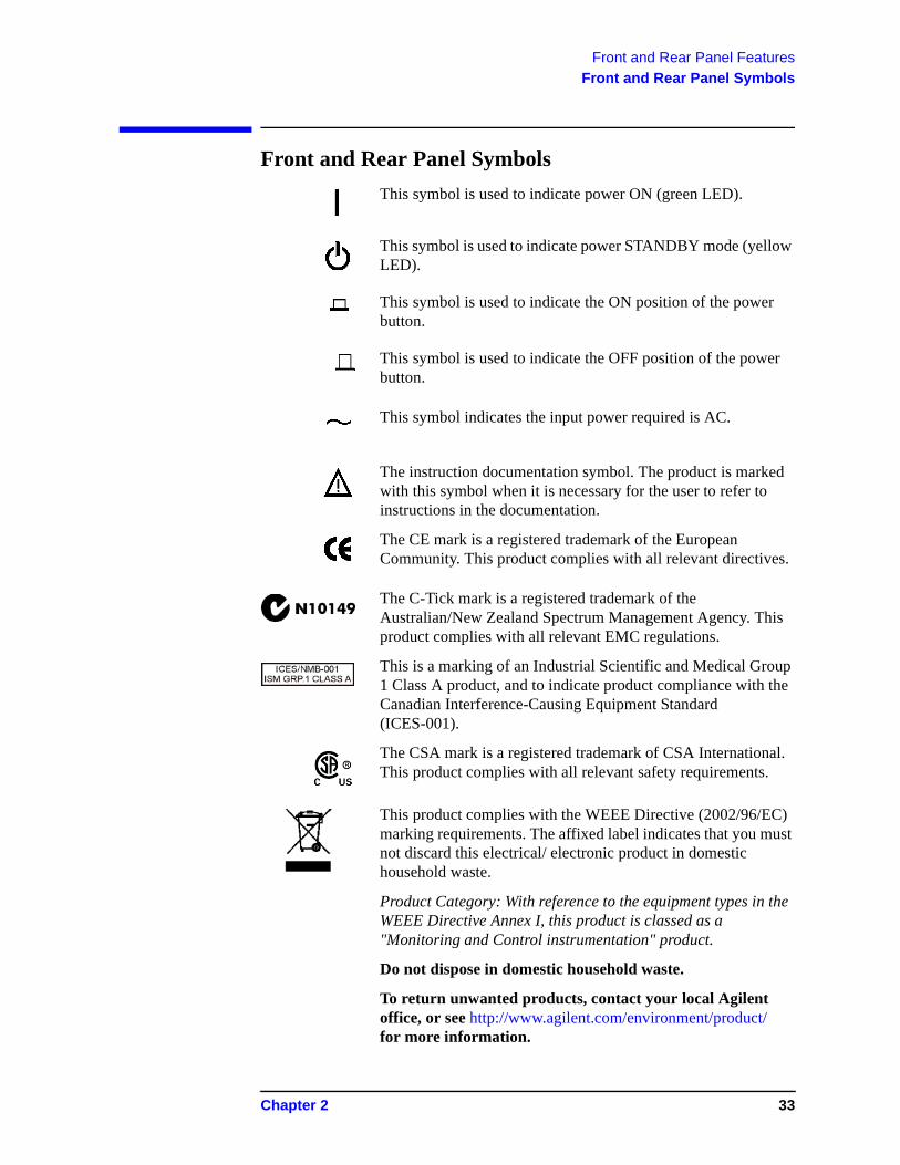
Front and Rear Panel Symbols
This symbol is used to indicate power ON (green LED).
This symbol is used to indicate power STANDBY mode (yellow LED).
This symbol is used to indicate the ON position of the power button.
This symbol is used to indicate the OFF position of the power button.
This symbol indicates the input power required is AC.
The instruction documentation symbol. The product is marked with this symbol when it is necessary for the user to refer to instructions in the documentation.
The CE mark is a registered trademark of the European Community. This product complies with all relevant directives.
The C-Tick mark is a registered trademark of the Australian/New Zealand Spectrum Management Agency. This product complies with all relevant EMC regulations.
This is a marking of an Industrial Scientific and Medical Group 1 Class A product, and to indicate product compliance with the Canadian Interference-Causing Equipment Standard (ICES-001).
The CSA mark is a registered trademark of CSA International. This product complies with all relevant safety requirements.
This product complies with the WEEE Directive (2002/96/EC) marking requirements. The affixed label indicates that you must not discard this electrical/ electronic product in domestic household waste.
Product Category: With reference to the equipment types in the WEEE Directive Annex I, this product is classed as a "Monitoring and Control instrumentation" product.
Do not dispose in domestic household waste.
To return unwanted products, contact your local Agilent office, or see http://www.agilent.com/environment/product/ for more information.
Chapter 2 33
Front and Rear Panel FeaturesFront and Rear Panel Symbols
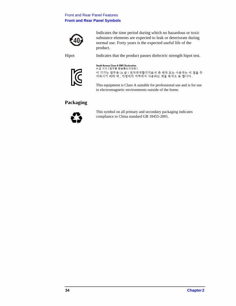
Indicates the time period during which no hazardous or toxic substance elements are expected to leak or deteriorate during normal use. Forty years is the expected useful life of the product.
Hipot Indicates that the product passes dielectric strength hipot test.
Packaging
This equipment is Class A suitable for professional use and is for use in electromagnetic environments outside of the home.
This symbol on all primary and secondary packaging indicates compliance to China standard GB 18455-2001.
34 Chapter 2

3 Making a Basic Measurement
This chapter provides information on basic analyzer operation. For more information on making measurements, see the measurement guide for your analyzer.
35
Making a Basic Measurement
This chapter is divided into the following sections:
• “Using the Front Panel” on page 37
• “Presetting the Spectrum Analyzer” on page 38
• “Viewing a Signal” on page 39
CAUTION Ensure that the total power of all signals at the analyzer RF input does not exceed +30 dBm (1 watt).
Basic Assumption
The material in this chapter is presented with the assumption that you understand the front and rear panel layout, and display annotations of your analyzer. If you do not, refer to “Front and Rear Panel Features” on page 23.
NOTE The display examples in this book are made using various analyzer models, you may see some variations depending upon your analyzer.
36 Chapter 3
Making a Basic MeasurementUsing the Front Panel
Using the Front Panel
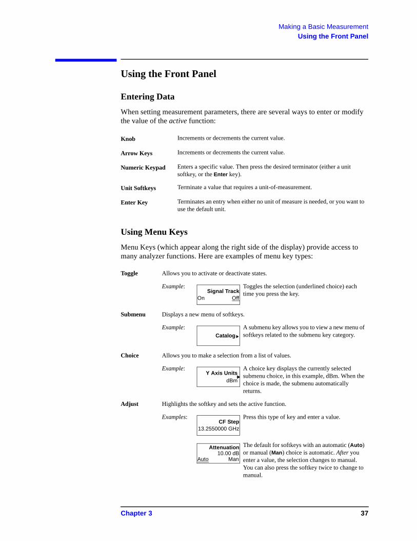
Entering Data
When setting measurement parameters, there are several ways to enter or modify the value of the active function:
Using Menu Keys
Menu Keys (which appear along the right side of the display) provide access to many analyzer functions. Here are examples of menu key types:
Knob Increments or decrements the current value.
Arrow Keys Increments or decrements the current value.
Numeric Keypad Enters a specific value. Then press the desired terminator (either a unit softkey, or the Enter key).
Unit Softkeys Terminate a value that requires a unit-of-measurement.
Enter Key Terminates an entry when either no unit of measure is needed, or you want to use the default unit.
Toggle Allows you to activate or deactivate states.
Example: Toggles the selection (underlined choice) each time you press the key.
Submenu Displays a new menu of softkeys.
Example: A submenu key allows you to view a new menu of softkeys related to the submenu key category.
Choice Allows you to make a selection from a list of values.
Example: A choice key displays the currently selected submenu choice, in this example, dBm. When the choice is made, the submenu automatically returns.
Adjust Highlights the softkey and sets the active function.
Examples: Press this type of key and enter a value.
The default for softkeys with an automatic (Auto) or manual (Man) choice is automatic. After you enter a value, the selection changes to manual. You can also press the softkey twice to change to manual.
On OffSignal Track
Catalog
dBmY Axis Units
13.2550000 GHzCF Step
10.00 dBAuto Man
Attenuation
Chapter 3 37
Making a Basic MeasurementPresetting the Spectrum Analyzer
Presetting the Spectrum Analyzer
Preset provides a known starting point for making measurements. The analyzer has three types of preset:
Factory Preset Restores the analyzer to its factory-defined state.
User Preset Restores the analyzer to a user-defined state.
Mode Preset This type of preset restores the currently selected mode to a known state.
For details, see the User’s and Programmer’s Reference.
When Preset Type is set to Factory, pressing the green Preset key triggers a factory preset. When Preset Type is set to User, pressing Preset displays the softkeys Factory Preset, User Preset, and Mode Preset (if applicable); you then select the preset you want. If Preset Type is set to Mode, but a personality is not installed, pressing Preset triggers a factory preset.
Creating a User Preset
If you constantly use settings which are not the factory defaults, use the following steps to create a user-defined preset:
1. Set analyzer parameters as desired.
2. Press System, Power On/Preset, Save User Preset to set the current parameters as the user preset state.
3. Press Preset to select User in the same softkey menu to enable user preset as an option.
Disabling User Preset
Go to the Power On/Preset menu (press System, Power On/Preset) and select a Preset Type of Factory or Mode.
38 Chapter 3
Making a Basic MeasurementViewing a Signal
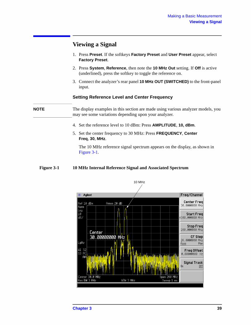
Viewing a Signal
1. Press Preset. If the softkeys Factory Preset and User Preset appear, select Factory Preset.
2. Press System, Reference, then note the 10 MHz Out setting. If Off is active (underlined), press the softkey to toggle the reference on.
3. Connect the analyzer’s rear panel 10 MHz OUT (SWITCHED) to the front-panel input.
Setting Reference Level and Center Frequency
NOTE The display examples in this section are made using various analyzer models, you may see some variations depending upon your analyzer.
4. Set the reference level to 10 dBm: Press AMPLITUDE, 10, dBm.
5. Set the center frequency to 30 MHz: Press FREQUENCY, Center Freq, 30, MHz.
The 10 MHz reference signal spectrum appears on the display, as shown in Figure 3-1.
Figure 3-1 10 MHz Internal Reference Signal and Associated Spectrum
10 MHz
Chapter 3 39
Making a Basic MeasurementViewing a Signal
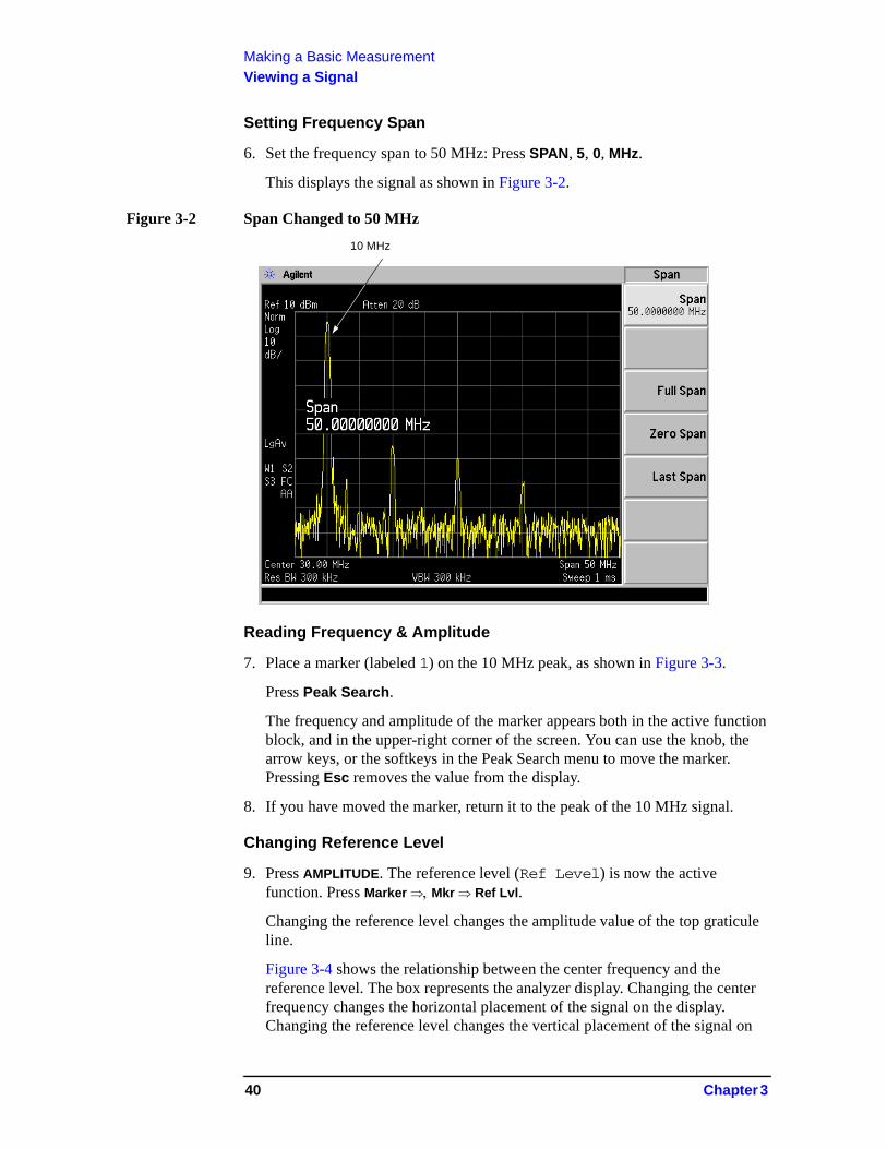
Setting Frequency Span
6. Set the frequency span to 50 MHz: Press SPAN, 5, 0, MHz.
This displays the signal as shown in Figure 3-2.
Figure 3-2 Span Changed to 50 MHz
Reading Frequency & Amplitude
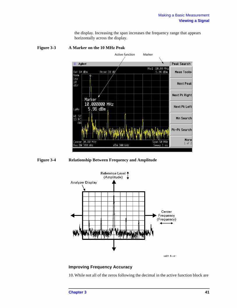
7. Place a marker (labeled 1) on the 10 MHz peak, as shown in Figure 3-3.
Press Peak Search.
The frequency and amplitude of the marker appears both in the active function block, and in the upper-right corner of the screen. You can use the knob, the arrow keys, or the softkeys in the Peak Search menu to move the marker. Pressing Esc removes the value from the display.
8. If you have moved the marker, return it to the peak of the 10 MHz signal.
Changing Reference Level
9. Press AMPLITUDE. The reference level (Ref Level) is now the active function. Press Marker Mkr Ref Lvl.
Changing the reference level changes the amplitude value of the top graticule line.
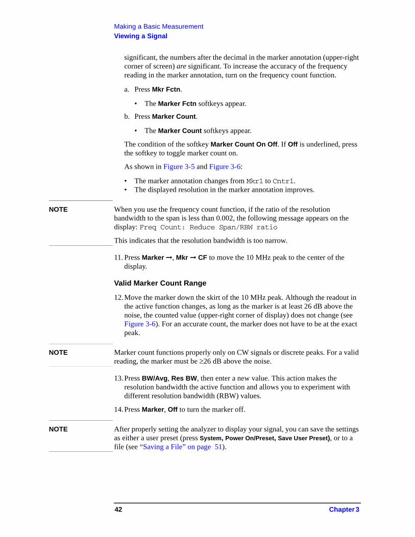
Figure 3-4 shows the relationship between the center frequency and the reference level. The box represents the analyzer display. Changing the center frequency changes the horizontal placement of the signal on the display. Changing the reference level changes the vertical placement of the signal on
10 MHz
40 Chapter 3
Making a Basic MeasurementViewing a Signal
the display. Increasing the span increases the frequency range that appears horizontally across the display.
Figure 3-3 A Marker on the 10 MHz Peak
Figure 3-4 Relationship Between Frequency and Amplitude
Improving Frequency Accuracy
10.While not all of the zeros following the decimal in the active function block are
Marker Active function
Chapter 3 41
Making a Basic MeasurementViewing a Signal
significant, the numbers after the decimal in the marker annotation (upper-right corner of screen) are significant. To increase the accuracy of the frequency reading in the marker annotation, turn on the frequency count function.
a. Press Mkr Fctn.
• The Marker Fctn softkeys appear.
b. Press Marker Count.
• The Marker Count softkeys appear.
The condition of the softkey Marker Count On Off. If Off is underlined, press the softkey to toggle marker count on.
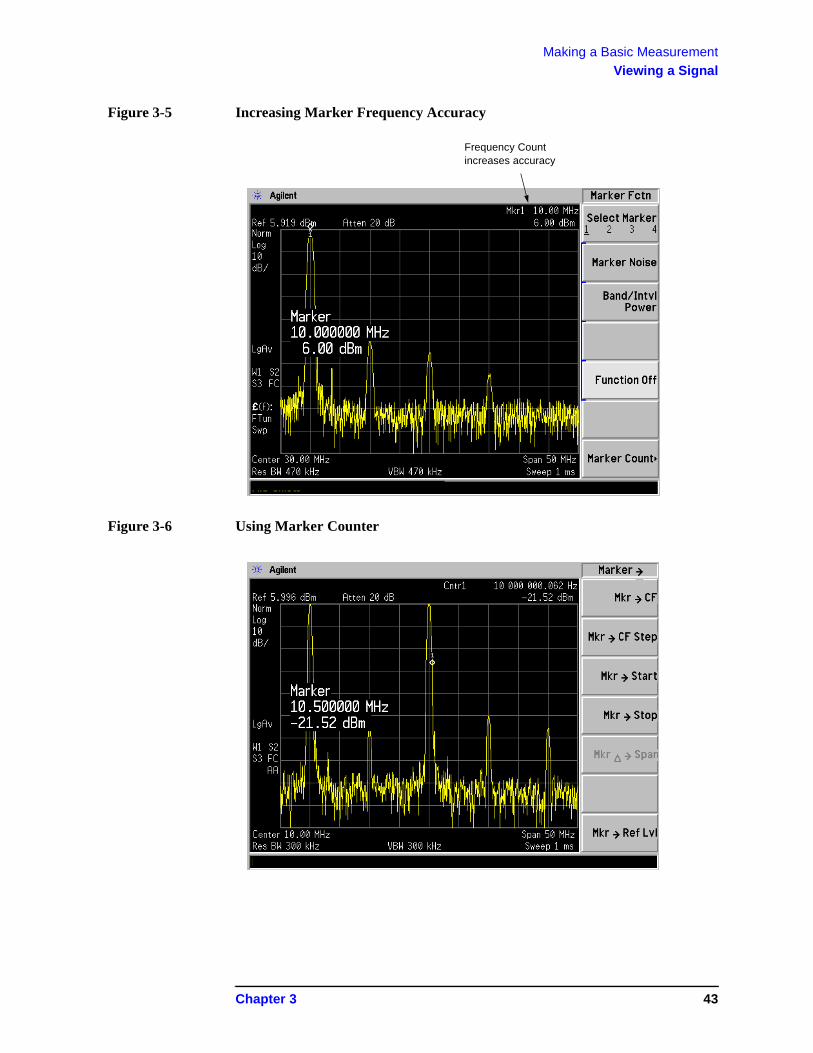
As shown in Figure 3-5 and Figure 3-6:
• The marker annotation changes from Mkr1 to Cntr1.• The displayed resolution in the marker annotation improves.
NOTE When you use the frequency count function, if the ratio of the resolution bandwidth to the span is less than 0.002, the following message appears on the display: Freq Count: Reduce Span/RBW ratio
This indicates that the resolution bandwidth is too narrow.
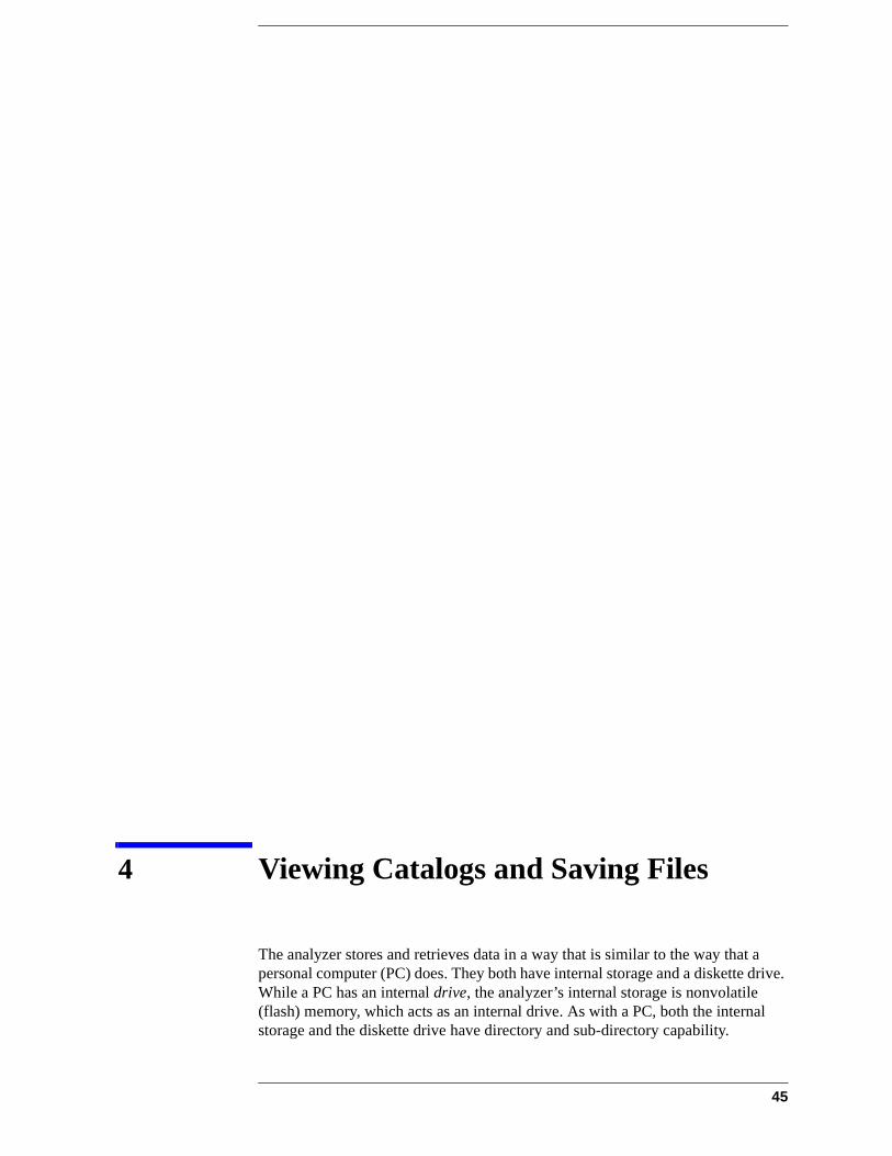
11. Press Marker ➞, Mkr ➞ CF to move the 10 MHz peak to the center of the display.
Valid Marker Count Range
12.Move the marker down the skirt of the 10 MHz peak. Although the readout in the active function changes, as long as the marker is at least 26 dB above the noise, the counted value (upper-right corner of display) does not change (see Figure 3-6). For an accurate count, the marker does not have to be at the exact peak.
NOTE Marker count functions properly only on CW signals or discrete peaks. For a valid reading, the marker must be 26 dB above the noise.
13.Press BW/Avg, Res BW, then enter a new value. This action makes the resolution bandwidth the active function and allows you to experiment with different resolution bandwidth (RBW) values.
14.Press Marker, Off to turn the marker off.
NOTE After properly setting the analyzer to display your signal, you can save the settings as either a user preset (press System, Power On/Preset, Save User Preset), or to a file (see “Saving a File” on page 51).
42 Chapter 3
Making a Basic MeasurementViewing a Signal
Figure 3-5 Increasing Marker Frequency Accuracy
Figure 3-6 Using Marker Counter
Frequency Count increases accuracy
Chapter 3 43

Making a Basic MeasurementViewing a Signal
44 Chapter 3
4 Viewing Catalogs and Saving Files
The analyzer stores and retrieves data in a way that is similar to the way that a personal computer (PC) does. They both have internal storage and a diskette drive. While a PC has an internal drive, the analyzer’s internal storage is nonvolatile (flash) memory, which acts as an internal drive. As with a PC, both the internal storage and the diskette drive have directory and sub-directory capability.
45

Viewing Catalogs and Saving Files
This chapter tells you how to:
• locate catalogs and view files, on page 47.
• save a file, on page 51.
For more information on catalogs and files, see the Measurement guide.
46 Chapter 4
Viewing Catalogs and Saving FilesFile Menu Functions
File Menu Functions
This chapter describes how to use the functions located under the front-panel File key. Data storage and retrieval are handled similarly to that of personal computers (PCs). Like PCs, these analyzers include an internal storage drive and a diskette drive, both of which have directory and sub-directory capability.
You will learn how to do all of the following:
• locate and view files in the catalog • save a file• load a file• rename a file• copy a file • delete a file
NOTE The display examples in this book are made using various analyzer models, you may see some variations depending upon your analyzer.
Locating and viewing files in the catalog
Techniques for locating files and directories are consistent throughout the various file menu functions. Although this section provides specific information about navigation in the catalog, you may wish to refer back to this section when performing other operations of the file menu.
NOTE Trace files are not bitmap files. Files saved as Trace cannot be imported into other applications or converted. If you require the use of other applications, for example Microsoft Word or Microsoft Excel, be sure to save your files as .gif or .wmf formats using Screen for your file Type. Comma separated value (csv) files can also be imported into Microsoft Excel.
Chapter 4 47
Viewing Catalogs and Saving FilesFile Menu Functions
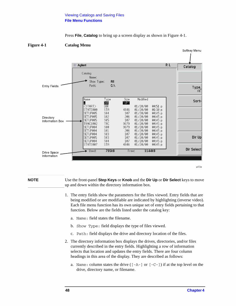
Press File, Catalog to bring up a screen display as shown in Figure 4-1.
Figure 4-1 Catalog Menu
NOTE Use the front-panel Step Keys or Knob and the Dir Up or Dir Select keys to move up and down within the directory information box.
1. The entry fields show the parameters for the files viewed. Entry fields that are being modified or are modifiable are indicated by highlighting (inverse video). Each file menu function has its own unique set of entry fields pertaining to that function. Below are the fields listed under the catalog key:
a. Name: field states the filename.
b. Show Type: field displays the type of files viewed.
c. Path: field displays the drive and directory location of the files.
2. The directory information box displays the drives, directories, and/or files currently described in the entry fields. Highlighting a row of information selects that location and updates the entry fields. There are four column headings in this area of the display. They are described as follows:
a. Name: column states the drive ([-A-] or [-C-]) if at the top level on the drive, directory name, or filename.
48 Chapter 4
Viewing Catalogs and Saving FilesFile Menu Functions
b. Type: column displays the extension of the filename, for example, .STA or .TRC. Directories are displayed as DIR and drives have nothing listed under Type:. They are only designated by the Name: column ([-A-] or [-C-]).
c. Size: column displays the size of the file in bytes.
d. Modified: column displays the date and time the last change occurred.
3. The softkey menu has four options:
a. Type: allows you to choose the type of file you wish to view. (You may view all types by using the All key under Type.
b. Sort: you can sort by any of the four columns and you can choose up (ascending) or down (descending).
c. Dir Up: moves you up one directory level. If you are already at the top level, this key moves you up to the drive level, displaying the available diskette drives.
d. Dir Select: moves you down into the highlighted directory or up into the next level (directory or drive) if the “. .” under the Name: column is highlighted.
NOTE Navigation keys: Use the front-panel Step Keys or Knob and the Dir Up or Dir Select keys to move around in the directory information box.
4. The drive space line shows the number of bytes used on the drive and the number of bytes still free on the drive.
Creating a directory
Directories and sub-directories can be created on both the A: diskette and the internal C: drive. This allows maximum flexibility in organizing files. For this example, we will create a directory on the C: drive.
1. Press File, More 1 of 2, Create Dir. Your screen should look similar to Figure 4-1except the entry fields will be Dir Name: and Path: and the Heading will read: Directories.
2. Navigate through the file system until the Path: field displays C:\. (Use the Step Keys, Knob, Dir Up, and/or Dir Select keys.)
3. Press Name and enter the name, “START” using the Alpha Editor. (The numeric keypad is also available for the filename.) Press Enter (hardkey) when the Dir Name: field contains this directory title. (Use the Bk Sp hardkey on the front panel to make corrections.)
Chapter 4 49
Viewing Catalogs and Saving FilesFile Menu Functions
4. Press Create Dir Now to execute the operation. The message: Creating Directory appears on the screen. Then the status bar displays: Directory C:\START created.
5. To make a sub-directory, scroll down to the START directory you just created and press Dir Select. The Path: field should now read: C:\START\. Repeat Steps 3 and 4 above, using a new name. The status bar now should read: Directory C:\START\new name created.
50 Chapter 4
Viewing Catalogs and Saving FilesSaving a File
Saving a File
You can save files (setups, states, traces, limits, corrections, measurement results, or screens) to a diskette (A:\), or the internal drive (C:\). In this example you will save a trace to the internal C: drive.
NOTE Trace files are not bitmap files. Files saved as Trace cannot be imported into other applications or converted. If you require the use of other applications, for example Microsoft Word or Microsoft Excel, be sure to save your files as .gif or .wmf formats using Screen for your file Type.
Step 1. Set up the analyzer trace
1. Perform a factory preset by pressing Preset, Factory Preset (if present).
2. Turn on the internal 50 MHz alignment signal of the analyzer as follows:
• Press Input/Output, Input Port, Amptd Ref.
3. Set the center frequency to 50 MHz by pressing FREQUENCY, Center Freq, 50, MHz.
4. Set the span to 75 MHz by pressing SPAN, Span, 75, MHz. The reference signal will appear on the display.
5. View trace 1 and put it into maximum hold by pressing View/Trace, Max Hold. (Trace 1 should already by underlined, but if not, press Trace 1 2 3 until 1 is underlined and then press Max Hold.) Your analyzer display should look similar to Figure 4-2.
Chapter 4 51
Viewing Catalogs and Saving FilesSaving a File
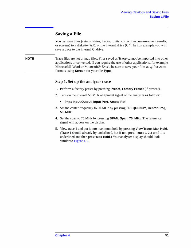
Figure 4-2 Viewing Trace 1
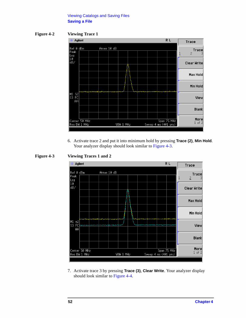
6. Activate trace 2 and put it into minimum hold by pressing Trace (2), Min Hold. Your analyzer display should look similar to Figure 4-3.
Figure 4-3 Viewing Traces 1 and 2
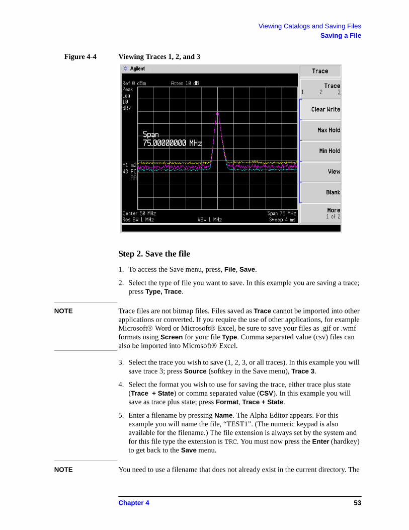
7. Activate trace 3 by pressing Trace (3), Clear Write. Your analyzer display should look similar to Figure 4-4.
52 Chapter 4
Viewing Catalogs and Saving FilesSaving a File
Figure 4-4 Viewing Traces 1, 2, and 3
Step 2. Save the file
1. To access the Save menu, press, File, Save.
2. Select the type of file you want to save. In this example you are saving a trace; press Type, Trace.
NOTE Trace files are not bitmap files. Files saved as Trace cannot be imported into other applications or converted. If you require the use of other applications, for example Microsoft Word or Microsoft Excel, be sure to save your files as .gif or .wmf formats using Screen for your file Type. Comma separated value (csv) files can also be imported into Microsoft Excel.
3. Select the trace you wish to save (1, 2, 3, or all traces). In this example you will save trace 3; press Source (softkey in the Save menu), Trace 3.
4. Select the format you wish to use for saving the trace, either trace plus state (Trace + State) or comma separated value (CSV). In this example you will save as trace plus state; press Format, Trace + State.
5. Enter a filename by pressing Name. The Alpha Editor appears. For this example you will name the file, “TEST1”. (The numeric keypad is also available for the filename.) The file extension is always set by the system and for this file type the extension is TRC. You must now press the Enter (hardkey) to get back to the Save menu.
NOTE You need to use a filename that does not already exist in the current directory. The
Chapter 4 53
Viewing Catalogs and Saving FilesSaving a File
filename is limited to eight characters, alpha (A-Z) or numeric (0-9) in any combination. The analyzer will not allow you to overwrite an existing file. If you select a filename that already exists, the status bar will display the message: File already exists. If you do not choose a filename, the analyzer will automatically generate a name based on the type of file you are saving (Setup: SETUP, State: STATE, Trace: TRACE, Limits: LIMIT, Corrections: COREC, Screen: SCREN). It also generates a three digit integer (starting at 000 and extending through 999, remembering the previously saved value through a power cycle) which it adds to the name, for example: TRACE056.TRC. This three digit integer increments upon each attempted save until a unique filename is created, without regard to the success of the save.
6. The destination for the saved file is shown in the Path: field. In this example, you will select the path as C:\START\. If the correct location is not listed in the Path: field, change directories as follows:
a. Press Dir Up or Dir Select and use the step keys or knob, to highlight the desired destination directory.
b. Press Dir Select and confirm your choice displayed in the Path: field.
7. Press Save Now or Save (hardkey) to save the file to the C:\Start\ location. The message Saving Now is displayed during this operation. For this example, the status line displays: C:\START\TEST1.TRC file saved.
NOTE When saving to drive (A:), never remove the diskette during the save operation. To do so could corrupt all data on the diskette.
54 Chapter 4
Viewing Catalogs and Saving FilesSaving a File
Loading a file
1. Reset the analyzer by pressing Preset, Factory Preset (if present).
2. To access the Load menu, press File, Load.
3. Select the type of file you want to load (setup, state, trace, limits, or corrections). In this example you are loading a trace file; press Type, Trace.
NOTE Not all file types can be loaded back into the analyzer. For example, Screen files and CSV (comma separated value) files cannot be loaded. CSV and Screen files are designed for use with a PC.
4. Select the directory where your file is located. In this example, select the C:\START\ directory. (Use the front-panel step keys, knob, Dir Up, and/or Dir Select keys to locate the directory.)
5. Select the file you want to load into the analyzer by moving the cursor with the front-panel knob to highlight the file name. In this example, the file is TEST1.TRC. Select the trace into which you wish to load the file. In this example, load it into Trace 2. (Destination, Trace 2).
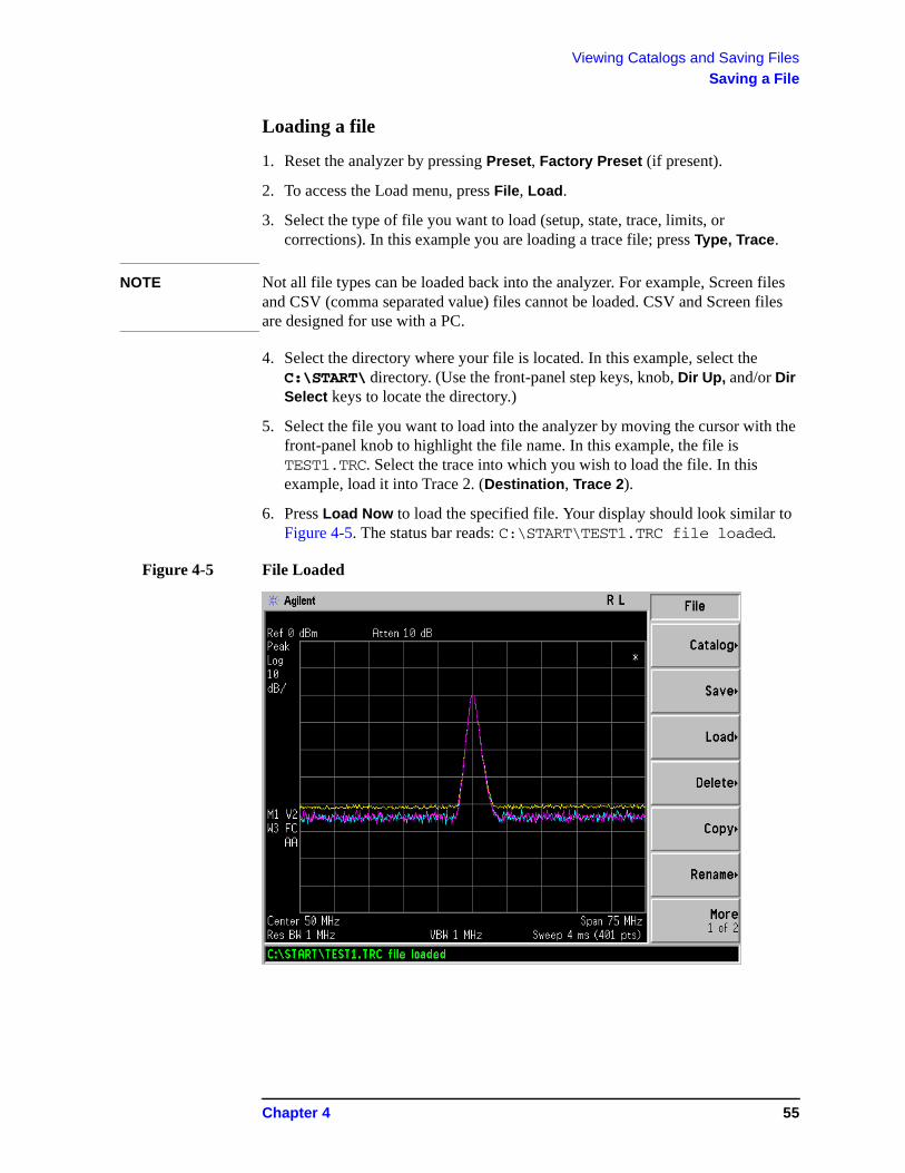
6. Press Load Now to load the specified file. Your display should look similar to Figure 4-5. The status bar reads: C:\START\TEST1.TRC file loaded.
Figure 4-5 File Loaded
Chapter 4 55
Viewing Catalogs and Saving FilesSaving a File
NOTE You should notice that the trace you saved, in this example trace 3, is loaded to trace 2. If you wish to verify this condition, remove the signal input. Press Input/Output, Input Port, Amptd Ref (Off).
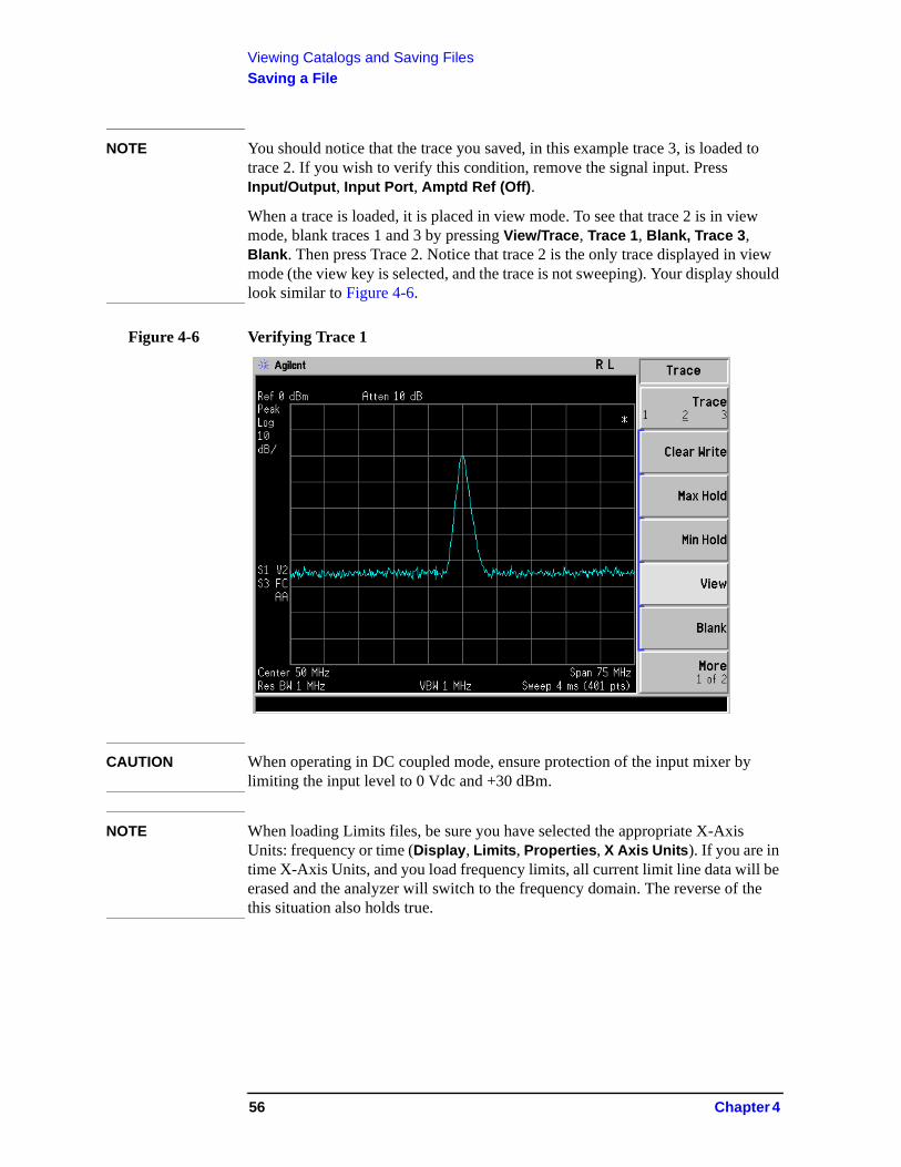
When a trace is loaded, it is placed in view mode. To see that trace 2 is in view mode, blank traces 1 and 3 by pressing View/Trace, Trace 1, Blank, Trace 3, Blank. Then press Trace 2. Notice that trace 2 is the only trace displayed in view mode (the view key is selected, and the trace is not sweeping). Your display should look similar to Figure 4-6.
Figure 4-6 Verifying Trace 1
CAUTION When operating in DC coupled mode, ensure protection of the input mixer by limiting the input level to 0 Vdc and +30 dBm.
NOTE When loading Limits files, be sure you have selected the appropriate X-Axis Units: frequency or time (Display, Limits, Properties, X Axis Units). If you are in time X-Axis Units, and you load frequency limits, all current limit line data will be erased and the analyzer will switch to the frequency domain. The reverse of the this situation also holds true.
56 Chapter 4
Viewing Catalogs and Saving FilesSaving a File
Renaming a File
1. To access the Rename menu, press File, Rename.
2. Select the type of file you want to rename (setup, state, trace, limits, screens, or corrections). In this example you are renaming a trace file; press Type, Trace.
3. Select the drive and directory where your file is located. In this example, choose drive C:\START.
4. Select the file you want to rename. In this example, choose the file TEST1.TRC.
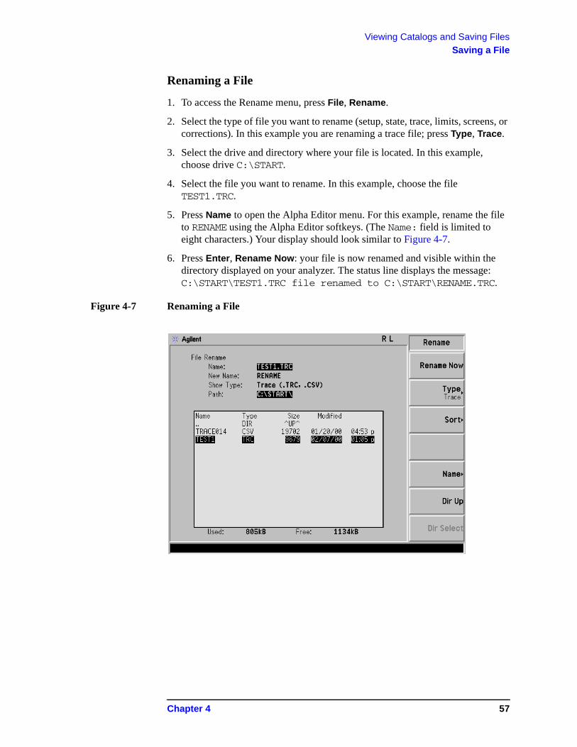
5. Press Name to open the Alpha Editor menu. For this example, rename the file to RENAME using the Alpha Editor softkeys. (The Name: field is limited to eight characters.) Your display should look similar to Figure 4-7.
6. Press Enter, Rename Now: your file is now renamed and visible within the directory displayed on your analyzer. The status line displays the message: C:\START\TEST1.TRC file renamed to C:\START\RENAME.TRC.
Figure 4-7 Renaming a File
Chapter 4 57
Viewing Catalogs and Saving FilesSaving a File
Copying a File
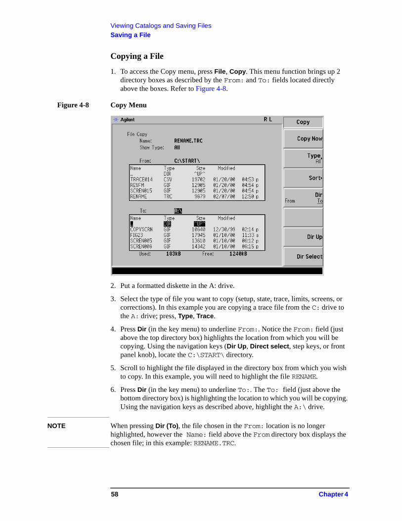
1. To access the Copy menu, press File, Copy. This menu function brings up 2 directory boxes as described by the From: and To: fields located directly above the boxes. Refer to Figure 4-8.
Figure 4-8 Copy Menu
2. Put a formatted diskette in the A: drive.
3. Select the type of file you want to copy (setup, state, trace, limits, screens, or corrections). In this example you are copying a trace file from the C: drive to the A: drive; press, Type, Trace.
4. Press Dir (in the key menu) to underline From:. Notice the From: field (just above the top directory box) highlights the location from which you will be copying. Using the navigation keys (Dir Up, Direct select, step keys, or front panel knob), locate the C:\START\ directory.
5. Scroll to highlight the file displayed in the directory box from which you wish to copy. In this example, you will need to highlight the file RENAME.
6. Press Dir (in the key menu) to underline To:. The To: field (just above the bottom directory box) is highlighting the location to which you will be copying. Using the navigation keys as described above, highlight the A:\ drive.
NOTE When pressing Dir (To), the file chosen in the From: location is no longer highlighted, however the Name: field above the From directory box displays the chosen file; in this example: RENAME.TRC.
58 Chapter 4
Viewing Catalogs and Saving FilesSaving a File
NOTE Highlighting a filename in the To: directory box has no significance. The file cannot be placed inside another file.
7. Press Copy Now to execute the operation. The message: “Copying file” is displayed during the copying process. Upon completion, the status bar reads: “C:\START\RENAME.TRC file copied”. You have now copied the file RENAME from the C: drive to the A: drive.
Deleting a File
1. To access the Delete menu, press File, Delete.
2. Select the type of file you want to delete (setup, state, trace, limits, screens, or corrections). In this example, you are deleting a trace file; press Type, Trace.
3. Select the drive and directory where the file you wish to delete is located. In this example, choose C:\START\. Use the navigation keys (Dir Up, Dir Select, step keys, front panel knob) to highlight this location in the Path: field. (Refer to “Locating and viewing files in the catalog” on page 47 for more instructions.)
4. Select the file you want to delete. In this example, choose the file RENAME.TRC. Move the cursor with the navigation keys to highlight the file name.
5. Press Delete Now. The message: Deleting file pops up on the display during the operation. Upon completion, the status bar reads: C:\START\RENAME.TRC file deleted. Your file is now deleted and is no longer visible in the directory displayed on your analyzer.
Chapter 4 59
Viewing Catalogs and Saving FilesUsing the Alpha Editor
Using the Alpha Editor
The Alpha Editor enables you to select letters to enter a name for a file or directory (File, Rename, for example).
1. Use the More keys to display the softkey that lists the character you want. Each softkey has several characters on it.
2. When you press a softkey, its characters are displayed on individual softkeys.
3. Select the one you want.
4. Digits are entered using the front panel numeric key pad.
60 Chapter 4

5 Options and Accessories
This chapter lists options and accessories available for your analyzer.
61
Options and AccessoriesOrdering Options and Accessories
Ordering Options and Accessories
Options and accessories help you configure the analyzer for your specific applications, and enable you to use the analyzer.
Options (see page 63)
Unless specified otherwise, all options are available when you order a spectrum analyzer; some options are also available as kits that you can order and install after you receive the analyzer. Order kits through your local Agilent Sales and Service Office.
For the latest information on Agilent Spectrum Analyzer options and upgrade kits, go to:
http://www.agilent.com/find/sa_upgrades
Accessories (see page 69)
Order accessories through your local Agilent Sales and Service Office.
62 Chapter 5
Options and AccessoriesOptions
Options
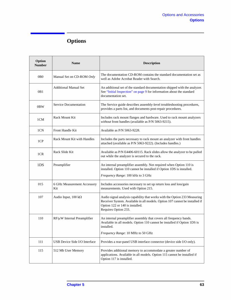
Option Number
Name Description
0B0 Manual Set on CD-ROM OnlyThe documentation CD-ROM contains the standard documentation set as well as Adobe Acrobat Reader with Search.
0B1Additional Manual Set An additional set of the standard documentation shipped with the analyzer.
See “Initial Inspection” on page 9 for information about the standard documentation set.
0BWService Documentation The Service guide describes assembly-level troubleshooting procedures,
provides a parts list, and documents post-repair procedures.
1CMRack Mount Kit Includes rack mount flanges and hardware. Used to rack mount analyzers
without front handles (available as P/N 5063-9215).
1CN Front Handle Kit Available as P/N 5063-9228.
1CPRack Mount Kit with Handles Includes the parts necessary to rack mount an analyzer with front handles
attached (available as P/N 5063-9222). (Includes handles.)
1CRRack Slide Kit Available as P/N E4406-60115. Rack slides allow the analyzer to be pulled
out while the analyzer is secured to the rack.
1DS Preamplifier An internal preamplifier assembly. Not required when Option 110 is installed. Option 110 cannot be installed if Option 1DS is installed.
Frequency Range: 100 kHz to 3 GHz
015 6 GHz Measurement Accessory Kit
Includes accessories necessary to set up return loss and loss/gain measurements. Used with Option 215.
107 Audio Input, 100 k Audio signal analysis capability that works with the Option 233 Measuring Receiver System. Available in all models. Option 107 cannot be installed if Option 122 or 140 is installed. Requires Option 233.
110 RF/W Internal Preamplifier An internal preamplifier assembly that covers all frequency bands. Available in all models. Option 110 cannot be installed if Option 1DS is installed.
Frequency Range: 10 MHz to 50 GHz
111 USB Device Side I/O Interface Provides a rear-panel USB interface connector (device side I/O only).
115 512 Mb User Memory Provides additional memory to accommodate a greater number of applications. Available in all models. Option 115 cannot be installed if Option 117 is installed.
Chapter 5 63
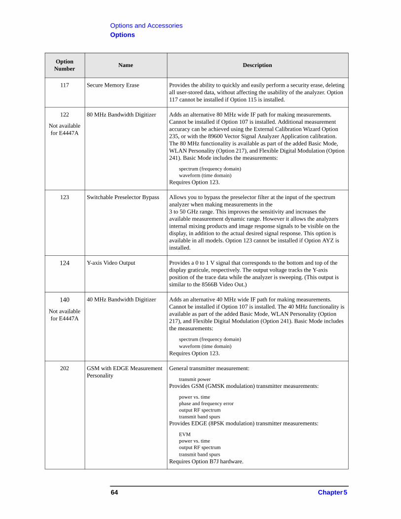
Options and AccessoriesOptions
117 Secure Memory Erase Provides the ability to quickly and easily perform a security erase, deleting all user-stored data, without affecting the usability of the analyzer. Option 117 cannot be installed if Option 115 is installed.
122
Not available for E4447A
80 MHz Bandwidth Digitizer Adds an alternative 80 MHz wide IF path for making measurements. Cannot be installed if Option 107 is installed. Additional measurement accuracy can be achieved using the External Calibration Wizard Option 235, or with the 89600 Vector Signal Analyzer Application calibration. The 80 MHz functionality is available as part of the added Basic Mode, WLAN Personality (Option 217), and Flexible Digital Modulation (Option 241). Basic Mode includes the measurements:
spectrum (frequency domain)waveform (time domain)
Requires Option 123.
123 Switchable Preselector Bypass Allows you to bypass the preselector filter at the input of the spectrum analyzer when making measurements in the3 to 50 GHz range. This improves the sensitivity and increases the available measurement dynamic range. However it allows the analyzers internal mixing products and image response signals to be visible on the display, in addition to the actual desired signal response. This option is available in all models. Option 123 cannot be installed if Option AYZ is installed.
124 Y-axis Video Output Provides a 0 to 1 V signal that corresponds to the bottom and top of the display graticule, respectively. The output voltage tracks the Y-axis position of the trace data while the analyzer is sweeping. (This output is similar to the 8566B Video Out.)
140
Not available for E4447A
40 MHz Bandwidth Digitizer Adds an alternative 40 MHz wide IF path for making measurements. Cannot be installed if Option 107 is installed. The 40 MHz functionality is available as part of the added Basic Mode, WLAN Personality (Option 217), and Flexible Digital Modulation (Option 241). Basic Mode includes the measurements:
spectrum (frequency domain)waveform (time domain)
Requires Option 123.
202 GSM with EDGE Measurement Personality
General transmitter measurement:
transmit powerProvides GSM (GMSK modulation) transmitter measurements:
power vs. timephase and frequency erroroutput RF spectrumtransmit band spurs
Provides EDGE (8PSK modulation) transmitter measurements:
EVMpower vs. timeoutput RF spectrumtransmit band spurs
Requires Option B7J hardware.
Option Number
Name Description
64 Chapter 5
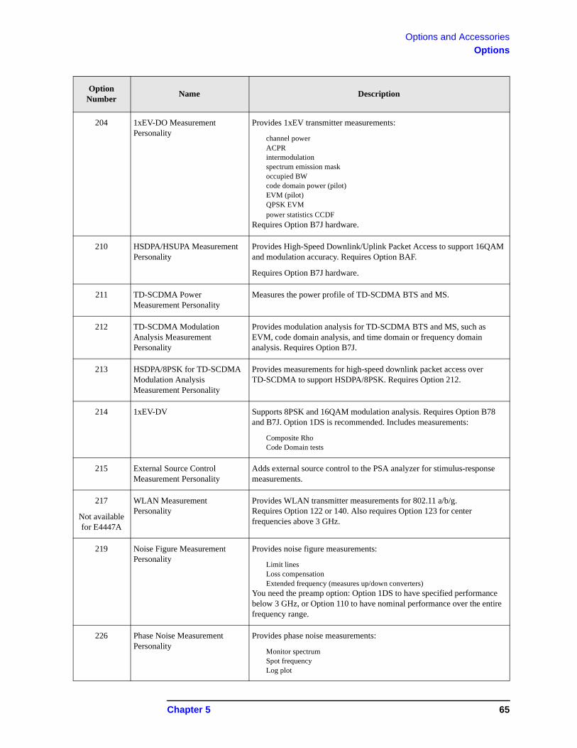
Options and AccessoriesOptions
204 1xEV-DO Measurement Personality
Provides 1xEV transmitter measurements:
channel powerACPRintermodulationspectrum emission maskoccupied BWcode domain power (pilot)EVM (pilot)QPSK EVMpower statistics CCDF
Requires Option B7J hardware.
210 HSDPA/HSUPA Measurement Personality
Provides High-Speed Downlink/Uplink Packet Access to support 16QAM and modulation accuracy. Requires Option BAF.
Requires Option B7J hardware.
211 TD-SCDMA Power Measurement Personality
Measures the power profile of TD-SCDMA BTS and MS.
212 TD-SCDMA Modulation Analysis Measurement Personality
Provides modulation analysis for TD-SCDMA BTS and MS, such as EVM, code domain analysis, and time domain or frequency domain analysis. Requires Option B7J.
213 HSDPA/8PSK for TD-SCDMA Modulation Analysis Measurement Personality
Provides measurements for high-speed downlink packet access over TD-SCDMA to support HSDPA/8PSK. Requires Option 212.
214 1xEV-DV Supports 8PSK and 16QAM modulation analysis. Requires Option B78 and B7J. Option 1DS is recommended. Includes measurements:
Composite RhoCode Domain tests
215 External Source Control Measurement Personality
Adds external source control to the PSA analyzer for stimulus-response measurements.
217
Not available for E4447A
WLAN Measurement Personality
Provides WLAN transmitter measurements for 802.11 a/b/g.Requires Option 122 or 140. Also requires Option 123 for center frequencies above 3 GHz.
219 Noise Figure Measurement Personality
Provides noise figure measurements:
Limit linesLoss compensationExtended frequency (measures up/down converters)
You need the preamp option: Option 1DS to have specified performance below 3 GHz, or Option 110 to have nominal performance over the entire frequency range.
226 Phase Noise Measurement Personality
Provides phase noise measurements:
Monitor spectrumSpot frequencyLog plot
Option Number
Name Description
Chapter 5 65
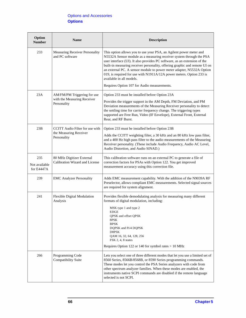
Options and AccessoriesOptions
233 Measuring Receiver Personality and PC software
This option allows you to use your PSA, an Agilent power meter and N5532A Sensor module as a measuring receiver system through the PSA user interface (UI). It also provides PC software, as an extension of the built-in measuring receiver personality, offering graphic and remote UI on an external PC. A sensor module to power meter adapter, N5532A Option 019, is required for use with N1911A/12A power meters. Option 233 is available in all models.
Requires Option 107 for Audio measurements.
23A AM/FM/PM Triggering for use with the Measuring Receiver Personality
Option 233 must be installed before Option 23A
Provides the trigger support in the AM Depth, FM Deviation, and PM Deviation measurements of the Measuring Receiver personality to detect the settling time for carrier frequency change. The triggering types supported are Free Run, Video (IF Envelope), External Front, External Rear, and RF Burst.
23B CCITT Audio Filter for use with the Measuring Receiver Personality
Option 233 must be installed before Option 23B
Adds the CCITT weighting filter, a 30 kHz and an 80 kHz low pass filter, and a 400 Hz high pass filter to the audio measurements of the Measuring Receiver personality. (These include Audio Frequency, Audio AC Level, Audio Distortion, and Audio SINAD.)
235
Not available for E4447A
80 MHz Digitizer External Calibration Wizard and License
This calibration software runs on an external PC to generate a file of correction factors for PSAs with Option 122. You get improved measurement accuracy using this correction file.
239 EMC Analyzer Personality Adds EMC measurement capability. With the addition of the N9039A RF Preselector, allows compliant EMC measurements. Selected signal sources are required for system alignment.
241 Flexible Digital Modulation Analysis
Provides flexible demodulating analysis for measuring many different formats of digital modulation, including:
MSK type 1 and type 2EDGEQPSK and offset QPSK8PSKBPSKDQPSK and Pi/4 DQPSKD8PSKQAM 16, 32, 64, 128, 256FSK 2, 4, 8 states
Requires Option 122 or 140 for symbol rates > 10 MHz
266 Programming Code Compatibility Suite
Lets you select one of three different modes that let you use a limited set of 8560 Series, 8566B/8568B, or 8590 Series programming commands. These modes let you control the PSA Series analyzers with code from other spectrum analyzer families. When these modes are enabled, the instruments native SCPI commands are disabled if the remote language selected is not SCPI.
Option Number
Name Description
66 Chapter 5
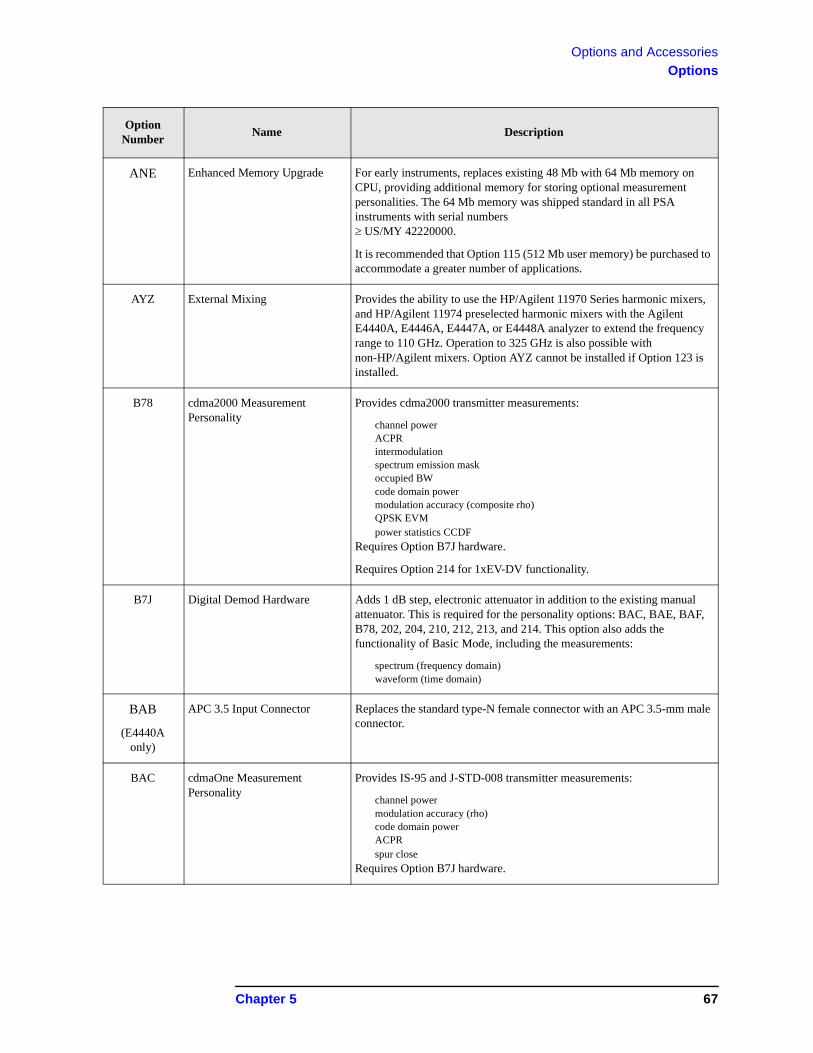
Options and AccessoriesOptions
ANE Enhanced Memory Upgrade For early instruments, replaces existing 48 Mb with 64 Mb memory on CPU, providing additional memory for storing optional measurement personalities. The 64 Mb memory was shipped standard in all PSA instruments with serial numbersUS/MY 42220000.
It is recommended that Option 115 (512 Mb user memory) be purchased to accommodate a greater number of applications.
AYZ External Mixing Provides the ability to use the HP/Agilent 11970 Series harmonic mixers, and HP/Agilent 11974 preselected harmonic mixers with the Agilent E4440A, E4446A, E4447A, or E4448A analyzer to extend the frequency range to 110 GHz. Operation to 325 GHz is also possible with non-HP/Agilent mixers. Option AYZ cannot be installed if Option 123 is installed.
B78 cdma2000 Measurement Personality
Provides cdma2000 transmitter measurements:
channel powerACPRintermodulationspectrum emission maskoccupied BWcode domain powermodulation accuracy (composite rho)QPSK EVMpower statistics CCDF
Requires Option B7J hardware.
Requires Option 214 for 1xEV-DV functionality.
B7J Digital Demod Hardware Adds 1 dB step, electronic attenuator in addition to the existing manual attenuator. This is required for the personality options: BAC, BAE, BAF, B78, 202, 204, 210, 212, 213, and 214. This option also adds the functionality of Basic Mode, including the measurements:
spectrum (frequency domain)waveform (time domain)
BAB
(E4440A only)
APC 3.5 Input Connector Replaces the standard type-N female connector with an APC 3.5-mm male connector.
BAC cdmaOne Measurement Personality
Provides IS-95 and J-STD-008 transmitter measurements:
channel powermodulation accuracy (rho)code domain powerACPRspur close
Requires Option B7J hardware.
Option Number
Name Description
Chapter 5 67
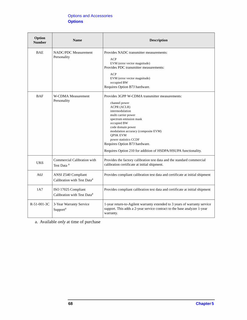
Options and AccessoriesOptions
BAE NADC/PDC Measurement Personality
Provides NADC transmitter measurements:
ACPEVM (error vector magnitude)
Provides PDC transmitter measurements:
ACPEVM (error vector magnitude)occupied BW
Requires Option B7J hardware.
BAF W-CDMA Measurement Personality
Provides 3GPP W-CDMA transmitter measurements:
channel powerACPR (ACLR)intermodulationmulti carrier powerspectrum emission maskoccupied BWcode domain powermodulation accuracy (composite EVM)QPSK EVMpower statistics CCDF
Requires Option B7J hardware.
Requires Option 210 for addition of HSDPA/HSUPA functionality.
UK6Commercial Calibration with
Test Data aProvides the factory calibration test data and the standard commercial calibration certificate at initial shipment.
A6J ANSI Z540 Compliant
Calibration with Test DataaProvides compliant calibration test data and certificate at initial shipment
1A7 ISO 17025 Compliant
Calibration with Test DataaProvides compliant calibration test data and certificate at initial shipment
R-51-001-3C 3-Year Warranty Service
Supporta1-year return-to-Agilent warranty extended to 3 years of warranty service support. This adds a 2-year service contract to the base analyzer 1-year warranty.
a. Available only at time of purchase
Option Number
Name Description
68 Chapter 5
Options and AccessoriesAccessories
Accessories
A number of accessories are available from Agilent Technologies to help you configure your analyzer for your specific applications. They can be ordered through your local Agilent Sales and Service Office and are listed below.
50 Load
The Agilent 909 series of loads come in several models and options providing a variety of frequency ranges and VSWRs. Also, they are available in either 50 or 75 . Some examples include the:
909A: DC to 18 GHz909C: DC to 2 GHz909D: DC to 26.5 GHz
50 /75 Minimum Loss Pad
The HP/Agilent 11852B is a low VSWR minimum loss pad that allows you to make measurements on 75 devices using an analyzer with a 50 input. It is effective over a frequency range of DC to 2 GHz.
AC Probe
The Agilent 85024A high frequency probe performs in-circuit measurements without adversely loading the circuit under test. The probe has an input capacitance of 0.7 pF shunted by 1 M of resistance and operates over a frequency range of 300 kHz to 3 GHz. High probe sensitivity and low distortion levels allow measurements to be made while taking advantage of the full dynamic range of the spectrum analyzer.
AC Probe (Low Frequency)
The Agilent 41800A low frequency probe has a low input capacitance and a frequency range of 5 Hz to 500 MHz.
Close-Field Probes (for EMC measurements with PSA)
These handheld probes are designed to measure magnetic-field radiation from surface currents, slots, cables, and ICs for EMC diagnostics and troubleshooting. Five antenna factors appear on each probe for calculating absolute magnetic-field strength from the analyzer reading.
11940A - 30 MHz to 1 GHz range
11941A - 9 kHz to 30 MHz range
11945A - Close-field probe set; includes both 11940A and 11941A probes for full coverage from 9 kHz to 1 GHz. Option E51 adds the 11909A preamplifier.
Chapter 5 69
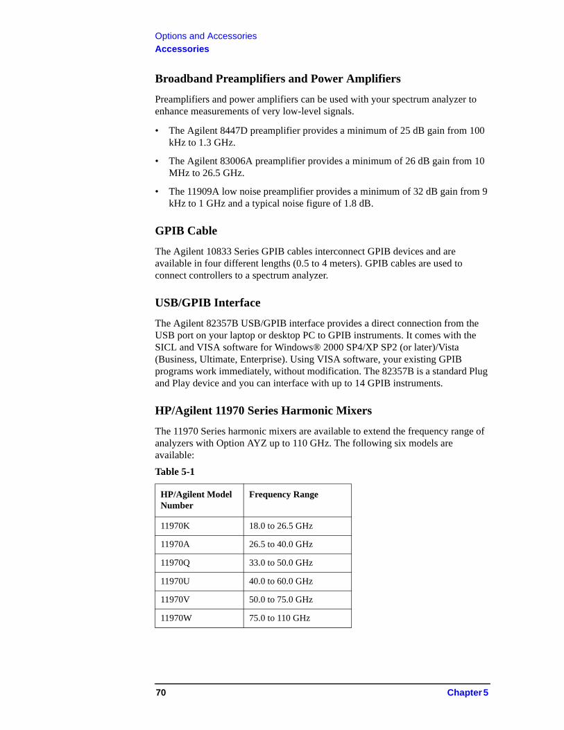
Options and AccessoriesAccessories
Broadband Preamplifiers and Power Amplifiers
Preamplifiers and power amplifiers can be used with your spectrum analyzer to enhance measurements of very low-level signals.
• The Agilent 8447D preamplifier provides a minimum of 25 dB gain from 100 kHz to 1.3 GHz.
• The Agilent 83006A preamplifier provides a minimum of 26 dB gain from 10 MHz to 26.5 GHz.
• The 11909A low noise preamplifier provides a minimum of 32 dB gain from 9 kHz to 1 GHz and a typical noise figure of 1.8 dB.
GPIB Cable
The Agilent 10833 Series GPIB cables interconnect GPIB devices and are available in four different lengths (0.5 to 4 meters). GPIB cables are used to connect controllers to a spectrum analyzer.
USB/GPIB Interface
The Agilent 82357B USB/GPIB interface provides a direct connection from the USB port on your laptop or desktop PC to GPIB instruments. It comes with the SICL and VISA software for Windows® 2000 SP4/XP SP2 (or later)/Vista (Business, Ultimate, Enterprise). Using VISA software, your existing GPIB programs work immediately, without modification. The 82357B is a standard Plug and Play device and you can interface with up to 14 GPIB instruments.
HP/Agilent 11970 Series Harmonic Mixers
The 11970 Series harmonic mixers are available to extend the frequency range of analyzers with Option AYZ up to 110 GHz. The following six models are available:
Table 5-1
HP/Agilent Model Number
Frequency Range
11970K 18.0 to 26.5 GHz
11970A 26.5 to 40.0 GHz
11970Q 33.0 to 50.0 GHz
11970U 40.0 to 60.0 GHz
11970V 50.0 to 75.0 GHz
11970W 75.0 to 110 GHz
70 Chapter 5
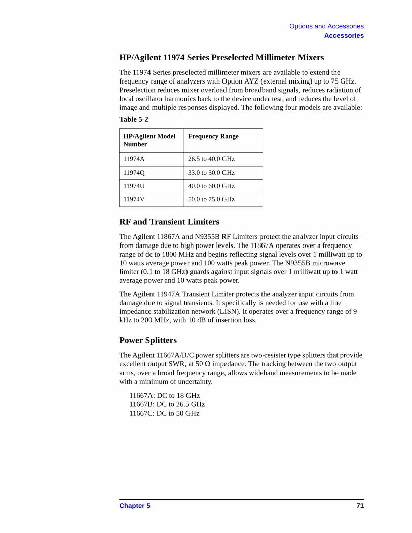
Options and AccessoriesAccessories
HP/Agilent 11974 Series Preselected Millimeter Mixers
The 11974 Series preselected millimeter mixers are available to extend the frequency range of analyzers with Option AYZ (external mixing) up to 75 GHz. Preselection reduces mixer overload from broadband signals, reduces radiation of local oscillator harmonics back to the device under test, and reduces the level of image and multiple responses displayed. The following four models are available:
RF and Transient Limiters
The Agilent 11867A and N9355B RF Limiters protect the analyzer input circuits from damage due to high power levels. The 11867A operates over a frequency range of dc to 1800 MHz and begins reflecting signal levels over 1 milliwatt up to 10 watts average power and 100 watts peak power. The N9355B microwave limiter (0.1 to 18 GHz) guards against input signals over 1 milliwatt up to 1 watt average power and 10 watts peak power.
The Agilent 11947A Transient Limiter protects the analyzer input circuits from damage due to signal transients. It specifically is needed for use with a line impedance stabilization network (LISN). It operates over a frequency range of 9 kHz to 200 MHz, with 10 dB of insertion loss.
Power Splitters
The Agilent 11667A/B/C power splitters are two-resister type splitters that provide excellent output SWR, at 50 impedance. The tracking between the two output arms, over a broad frequency range, allows wideband measurements to be made with a minimum of uncertainty.
11667A: DC to 18 GHz11667B: DC to 26.5 GHz11667C: DC to 50 GHz
Table 5-2
HP/Agilent Model Number
Frequency Range
11974A 26.5 to 40.0 GHz
11974Q 33.0 to 50.0 GHz
11974U 40.0 to 60.0 GHz
11974V 50.0 to 75.0 GHz
Chapter 5 71
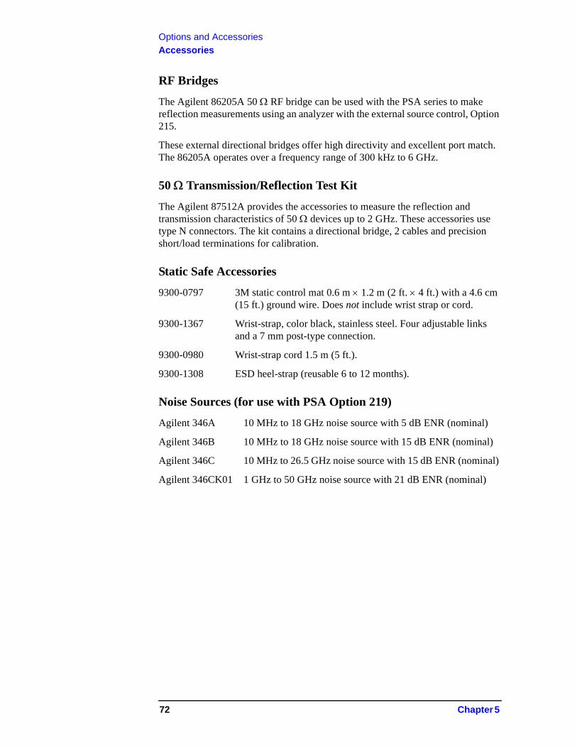
Options and AccessoriesAccessories
RF Bridges
The Agilent 86205A 50 RF bridge can be used with the PSA series to make reflection measurements using an analyzer with the external source control, Option 215.
These external directional bridges offer high directivity and excellent port match. The 86205A operates over a frequency range of 300 kHz to 6 GHz.
50 Transmission/Reflection Test Kit
The Agilent 87512A provides the accessories to measure the reflection and transmission characteristics of 50 devices up to 2 GHz. These accessories use type N connectors. The kit contains a directional bridge, 2 cables and precision short/load terminations for calibration.
Static Safe Accessories
9300-0797 3M static control mat 0.6 m 1.2 m (2 ft. 4 ft.) with a 4.6 cm (15 ft.) ground wire. Does not include wrist strap or cord.
9300-1367 Wrist-strap, color black, stainless steel. Four adjustable links and a 7 mm post-type connection.
9300-0980 Wrist-strap cord 1.5 m (5 ft.).
9300-1308 ESD heel-strap (reusable 6 to 12 months).
Noise Sources (for use with PSA Option 219)
Agilent 346A 10 MHz to 18 GHz noise source with 5 dB ENR (nominal)
Agilent 346B 10 MHz to 18 GHz noise source with 15 dB ENR (nominal)
Agilent 346C 10 MHz to 26.5 GHz noise source with 15 dB ENR (nominal)
Agilent 346CK01 1 GHz to 50 GHz noise source with 21 dB ENR (nominal)
72 Chapter 5

6 In Case of Difficulty
73
In Case of Difficulty
This chapter includes information on how to check for a problem with your Agilent Technologies spectrum analyzer, and how to return it for service.
If you experience a problem or would like additional information about your analyzer, Agilent Technologies’ worldwide organization is ready to provide the support you need. Before calling Agilent Technologies, however (or returning an analyzer for service), perform the quick checks listed in “Check the Basics” on page 76. This check may eliminate the problem.
If a problem persists, you may choose to:
• Repair the analyzer yourself. See “Service Options” on page 78.
• Return the analyzer to Agilent Technologies for repair. See “Returning an Analyzer for Service” on page 79, for more information.
WARNING No operator serviceable parts inside. Refer servicing to qualified personnel. To prevent electrical shock, do not remove covers.
NOTE If the analyzer is still under warranty or is covered by a maintenance contract, it will be repaired under the terms of the warranty or plan.
If the analyzer is no longer under warranty or is not covered by an Agilent Technologies maintenance plan, Agilent Technologies will notify you of the cost of the repair after examining the analyzer.
74 Chapter 6
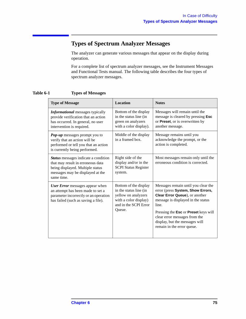
In Case of DifficultyTypes of Spectrum Analyzer Messages
Types of Spectrum Analyzer Messages
The analyzer can generate various messages that appear on the display during operation.
For a complete list of spectrum analyzer messages, see the Instrument Messages and Functional Tests manual. The following table describes the four types of spectrum analyzer messages.
Table 6-1 Types of Messages
Type of Message Location Notes
Informational messages typically provide verification that an action has occurred. In general, no user intervention is required.
Bottom of the display in the status line (in green on analyzers with a color display).
Messages will remain until the message is cleared by pressing Esc or Preset, or is overwritten by another message.
Pop-up messages prompt you to verify that an action will be performed or tell you that an action is currently being performed.
Middle of the display in a framed box.
Message remains until you acknowledge the prompt, or the action is completed.
Status messages indicate a condition that may result in erroneous data being displayed. Multiple status messages may be displayed at the same time.
Right side of the display and/or in the SCPI Status Register system.
Most messages remain only until the erroneous condition is corrected.
User Error messages appear when an attempt has been made to set a parameter incorrectly or an operation has failed (such as saving a file).
Bottom of the display in the status line (in yellow on analyzers with a color display) and in the SCPI Error Queue.
Messages remain until you clear the error (press System, Show Errors, Clear Error Queue), or another message is displayed in the status line.
Pressing the Esc or Preset keys will clear error messages from the display, but the messages will remain in the error queue.
Chapter 6 75
In Case of DifficultyBefore Calling Agilent Technologies
Before Calling Agilent Technologies
Check the Basics
❏ Is there power at the receptacle?
❏ Make sure there is no disk in the front-panel disk drive.
❏ Is the analyzer turned on? Check to see if the green LED above the power switch is on. Also, listen for internal fan noise to determine if the analyzer cooling fans are running.
❏ If other equipment, cables, and connectors are being used with your spectrum analyzer, make sure they are connected properly and operating correctly.
❏ Review the measurement procedures being performed when the problem first appeared. Are all of the settings correct?
❏ If the analyzer is not functioning as expected, return the analyzer to a known state by pressing Preset, and Factory Preset (if displayed).
NOTE Some analyzer settings are not affected by a Preset. If you wish to reset the analyzer configuration to the state it was in when it was originally sent from the factory, press System, Power On/Preset, Preset Type, Factory. Then press the green Preset key on the front panel.
❏ Is the measurement being performed, and the results that are expected, within the specifications and capabilities of the analyzer? Refer to the Specifications guide for your analyzer.
❏ If the analyzer is not communicating through the LAN connection, check for the presence of blinking yellow LEDs on the rear panel LAN connector. If the Rx (receive) LED is not blinking, check the LAN cable and LAN integrity.
NOTE The analyzer must be powered on with the LAN already connected in order to recognize the LAN port.
❏ To meet specifications, the analyzer must be aligned. Either the Auto Align (On) feature must be selected (press System, Alignments, Auto Align, On), or the analyzer must be manually aligned at least once every 24 hours, or whenever the temperature changes more than 3°C. When Auto Align, On is selected, the AA screen annotation appears on the left edge of the display.
❏ Perform an Alignment. Press System, Alignments, Align All Now.
❏ If the previously performed alignments did not resolve the problem, press System, Alignments, Restore Align Defaults. Then press System, Alignments, Align All Now.
❏ Is the analyzer displaying an error message? If so, refer to the Instrument Messages and Functional Tests manual.
76 Chapter 6
In Case of DifficultyBefore Calling Agilent Technologies
❏ If the necessary equipment is available, perform the functional tests in the Instrument Messages and Functional Tests document for your analyzer.
❏ If the 10 MHz output is not functioning, verify that it is turned on by pressing System, Reference, 10 MHz Out to select On.
TIP You can get automatic electronic notification of new firmware releases and other product updates/information by subscribing to the Agilent Technologies Test & Measurement E-Mail Notification Service for the PSA Series at:
http://www.agilent.com/find/notifyme‘
Chapter 6 77
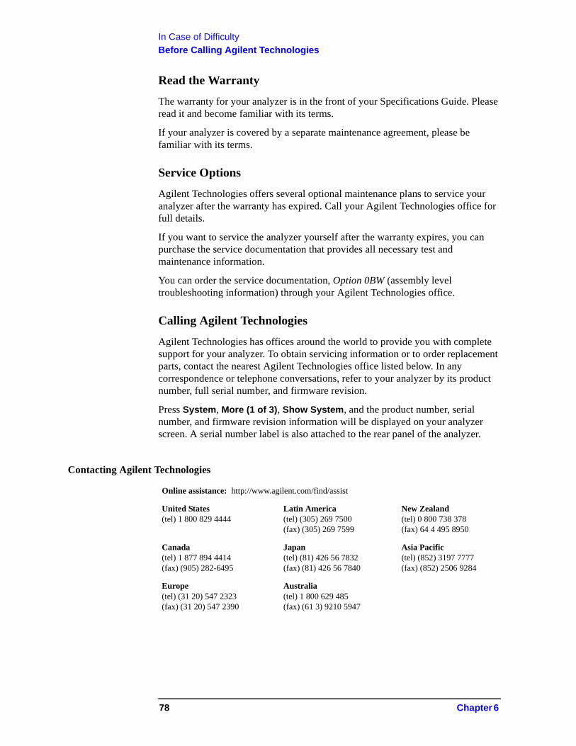
In Case of DifficultyBefore Calling Agilent Technologies
Read the Warranty
The warranty for your analyzer is in the front of your Specifications Guide. Please read it and become familiar with its terms.
If your analyzer is covered by a separate maintenance agreement, please be familiar with its terms.
Service Options
Agilent Technologies offers several optional maintenance plans to service your analyzer after the warranty has expired. Call your Agilent Technologies office for full details.
If you want to service the analyzer yourself after the warranty expires, you can purchase the service documentation that provides all necessary test and maintenance information.
You can order the service documentation, Option 0BW (assembly level troubleshooting information) through your Agilent Technologies office.
Calling Agilent Technologies
Agilent Technologies has offices around the world to provide you with complete support for your analyzer. To obtain servicing information or to order replacement parts, contact the nearest Agilent Technologies office listed below. In any correspondence or telephone conversations, refer to your analyzer by its product number, full serial number, and firmware revision.
Press System, More (1 of 3), Show System, and the product number, serial number, and firmware revision information will be displayed on your analyzer screen. A serial number label is also attached to the rear panel of the analyzer.
Contacting Agilent Technologies
Online assistance: http://www.agilent.com/find/assist
United States(tel) 1 800 829 4444
Latin America(tel) (305) 269 7500(fax) (305) 269 7599
New Zealand(tel) 0 800 738 378(fax) 64 4 495 8950
Canada(tel) 1 877 894 4414(fax) (905) 282-6495
Japan(tel) (81) 426 56 7832(fax) (81) 426 56 7840
Asia Pacific(tel) (852) 3197 7777(fax) (852) 2506 9284
Europe(tel) (31 20) 547 2323(fax) (31 20) 547 2390
Australia(tel) 1 800 629 485(fax) (61 3) 9210 5947
78 Chapter 6
In Case of DifficultyReturning an Analyzer for Service
Returning an Analyzer for Service
Original Packaging
Before shipping, pack the unit in the original factory packaging materials if they are available. If the original materials were not retained, see "Other Packaging" (below).
NOTE Install the transportation disk into the diskette drive to reduce the possibility of damage during transportation. If the original transportation diskette is not available, a blank diskette may be substituted.
Other Packaging
CAUTION Analyzer damage can result from using packaging materials other than those specified. Never use styrene pellets in any shape as packaging materials. They do not adequately cushion the equipment or prevent it from shifting in the carton. They cause equipment damage by generating static electricity and by lodging in the analyzer louvers, blocking airflow.
You can repackage the analyzer with commercially available materials, as follows:
1. Attach a completed service tag to the analyzer.
2. Install the transportation diskette or a blank diskette into the disk drive.
3. Wrap the analyzer in antistatic plastic to reduce the possibility of damage caused by electrostatic discharge.
4. Use a strong shipping container. The carton must be both large enough and strong enough to accommodate the analyzer. A double-walled, corrugated cardboard carton with 159 kg (350 lb) bursting strength is adequate. Allow at least 3 to 4 inches on all sides of the analyzer for packing material.
5. Surround the analyzer with three to four inches of packing material and prevent the analyzer from moving in the carton. If packing foam is not available, the best alternative is S.D.-240 Air Cap™ from Sealed Air Corporation (Hayward, California, 94545). Air Cap looks like a plastic sheet filled with 1-1/4 inch air bubbles. Use the pink-colored Air Cap to reduce static electricity. Wrapping the analyzer several times in this material should both protect the analyzer and prevent it from moving in the carton.
6. Seal the shipping container securely with strong nylon adhesive tape.
7. Mark the shipping container “FRAGILE, HANDLE WITH CARE” to assure careful handling.
8. Retain copies of all shipping papers.
Chapter 6 79

In Case of DifficultyReturning an Analyzer for Service
80 Chapter 6
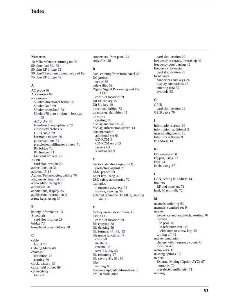
Index
Numerics
10 MHz reference, turning on 3950 ohm load 69, 7250 ohm RF bridge 7250 ohm/75 ohm minimum loss pad 6975 ohm RF bridge 72
A
AC probe 69Accessories 69accessories
50 ohm directional bridge 7250 ohm load 6950 ohm short/load 7250 ohm/75 ohm minimum loss pad
69AC probe 69broadband preamplifiers 70close-field probes 69GPIB cable 70harmonic mixers 70power splitters 71preselected millimeter mixers 71RF bridge 72RF limiters 71transient limiters 71
ACPRcard slot location 29
active function 31address, IP 14Agilent Technologies, calling 78alignments, internal 18alpha editor, using 60amplifiers 70annotations, display 26application information 3arrow keys, using 37
B
battery information 13Bluetooth
card slot location 29bridge 72broadband preamplifiers 70
C
cableGPIB 70
Catalog Menu 48catalogs
definition 45naming 60
clock, battery 13close-field probes 69connectivity
tools 9
connectors, front panel 24copy files 58
D
data, entering from front panel 37DC probes
use of 69delete files 59Digital Signal Processing and Fast
ADCcard slot location 29
Dir Select key 49Dir Up key 49directional bridge 72directories, definition 45directory
creating 49display annotations 26display, information screen 14documentation
additional set 63CD-ROM 9CD-ROM only 63service 63standard set 9
E
electrostatic discharge (ESD)protecting against 21
EMC probes 69Enter key, using 37ESD safety accessories 72examples
frequency accuracy 41signals, viewing 39
external reference (10 MHz), turning on 39
F
factory preset, description 38Fast ADC
card slot location 29file copying 58file deleting 59file formats 47, 51, 53file menu functions 47
copy 58delete 59rename 57save 51, 53, 55
file renaming 57file saving 51, 53, 55files
naming 60firmware upgrade information 3FM Demodulation
card slot location 29frequency accuracy, increasing 41frequency count, using 42Frequency Extension
card slot location 29front panel
connectors and keys 24display annotations 26entering data 37symbols 33
G
GPIBcard slot location 29
GPIB cable 70
I
information screen 14information, additional 3internal alignments 18IntuiLink software 9IP address 14
K
key overview 31keypad, using 37keys 24knob, using 37
L
LAN, setting IP address 14limiters
RF and transient 71load, 50 ohm 69, 72
M
manuals, ordering 63manuals, standard set 9marker
frequency and amplitude, reading 40moving
to peak 40to reference level 40with knob or arrow key 40
turning off 42marker annotation
change with frequency count 42location 40
menu keys 31missing options 15mixers
External Mixing (Option AYZ) 67harmonic 70preselected millimeter 71
moving
81
Index
data from analyzer 9data to PC 9
N
navigatingcatalogs 48files 48tables 32
Navigation keys 48, 49noise figure 72noise figure measurement accessories
72noise source 72numeric keypad, using 37
O
options not in instrument memory 15overview, keys and key menus 31
P
packaging 79packaging symbol 34parallel interface connector 30PC connectivity 9personality options not in instrument
15power amplifiers 70power splitters 71preamplifiers 70preset
factory 38types 38user, creating 38
printer setup 19probes
AC and DC 69product information 3
R
rear panelsymbols 33
rear panel features 29reference level, setting 40reference, turning on 10 MHz 39rename files 57RF bridge 72RF limiters 71RPG, using 37RS-232
card slot location 29RS-232 interface connector 30
S
save files 51, 53, 55saving
bitmaps 47, 51, 53trace files 47, 51, 53
screen annotation 26screen, information 14service options 78short, 50 ohm 72signals, increasing accuracy 41signals, viewing 39softkeys, auto and man mode 37softkeys, basic types 37software
IntuiLink 9splitters 71static safety accessories 72symbols in titles 60symbols, on front and rear panels 33
T
tab key 32table
navigation 32text, entering 60titles, editing 60transient limiter 71turning on the analyzer for the first time
14
U
unit softkeys, using 37URL, PSA analyzers 3URL, sales and service 78user preset
creating 38description 38disabling 38
W
warm-up time 14warranty 78
82