1000 Series Manual - Universal Analyzers
28
MAN.1000.REVI.07012015 Instruction Manual 5200 Convair Drive Carson City, NV 89706 • Phone: 775-883-2500 • Fax: 775-883-6388 • www.universalanalyzers.com
-
Upload
khangminh22 -
Category
Documents
-
view
3 -
download
0
Transcript of 1000 Series Manual - Universal Analyzers
MAN.1000.REVI.07012015
Instruction Manual1000 Series
Thermoelectric Gas Cooler
5200 Convair Drive Carson City, NV 89706 • Phone: 775-883-2500 • Fax: 775-883-6388 • www.universalanalyzers.com
Page 2 of 28 Page 3 of 28MAN.1000.REVI.07012015
ContentsReceiving and Storage 3
Definition of Symbols 4
Product Identification 5
Specifications 5
Description and Principle of Operation 7
Installation 9
Electrical Connections 10
Start-Up 15
Shutdown 15
Maintenance 16
Troubleshooting 17
Spare Parts 19
Drawings 21
Model 1040 21
Model 1050 22
Model 1060 23
Model 1080 24
Model 1090 25
Limited Warranty 26
Page 2 of 28 Page 3 of 28 MAN.1000.REVI.07012015
Receiving and Storage
The Universal Analyzers 1000 Series Thermoelectric Cooler is completely pre-assembled. No assembly is necessary when received on-site.
Carefully inspect the product and any special accessories included with it immediately on arrival by removing them from the packing and checking for missing articles against the packing list.
Check the items for any damage in transit and, if required, inform the shipping insurance company immediately of any damage found.
Storage Location should be protected from the elements. Although all components provided are designed to resist corrosion, additional protection from heat (>140°F/ 60°C) and humidity is recommended.
Page 4 of 28 Page 5 of 28MAN.1000.REVI.07012015
Definition of Symbols
WARNING - EXPLOSION HAZARD - DO NOT DISCONNECT EQUIPMENT UNLESS POWER HAS BEEN SWITCHED
OFF OR THE AREA IS KNOWN TO BE NON-HAZARDOUS.
WARNING - EXPLOSION HAZARD - SUBSTITUTION OF COMPONENTS MAY IMPAIR SUITABILITY FOR
HAZARDOUS AREA INSTALLATION.
THE SUPPLY POWER CIRCUIT MUST INCLUDE AN OVERPROTECTION DEVICE WITH A MAXIMUM RATING OF 20A. A DISCONNECT SWITCH MUST BE LOCATED IN CLOSE PROXIMITY TO THE PROBE.
IF THE EQUIPMENT IS USED IN A MANNER NOT SPECIFIED BY THE MANUFACTURER, THE PROTECTION PROVIDED BY THE EQUIPMENT MAY BE IMPAIRED PER CLAUSE 5.4.4(i) IN STANDARD EN 61010-1
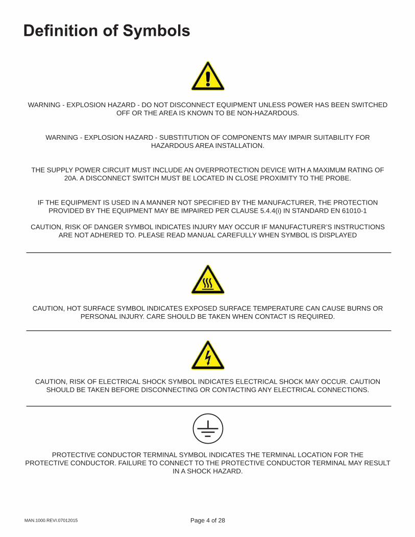
CAUTION, RISK OF DANGER SYMBOL INDICATES INJURY MAY OCCUR IF MANUFACTURER’S INSTRUCTIONS ARE NOT ADHERED TO. PLEASE READ MANUAL CAREFULLY WHEN SYMBOL IS DISPLAYED
CAUTION, HOT SURFACE SYMBOL INDICATES EXPOSED SURFACE TEMPERATURE CAN CAUSE BURNS OR PERSONAL INJURY. CARE SHOULD BE TAKEN WHEN CONTACT IS REQUIRED.
CAUTION, RISK OF ELECTRICAL SHOCK SYMBOL INDICATES ELECTRICAL SHOCK MAY OCCUR. CAUTION SHOULD BE TAKEN BEFORE DISCONNECTING OR CONTACTING ANY ELECTRICAL CONNECTIONS.
PROTECTIVE CONDUCTOR TERMINAL SYMBOL INDICATES THE TERMINAL LOCATION FOR THE PROTECTIVE CONDUCTOR. FAILURE TO CONNECT TO THE PROTECTIVE CONDUCTOR TERMINAL MAY RESULT
IN A SHOCK HAZARD.
Page 4 of 28 Page 5 of 28 MAN.1000.REVI.07012015
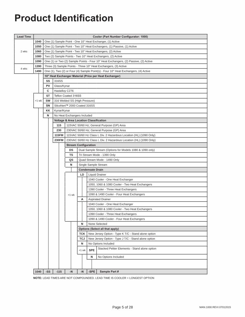
Lead Time Cooler (Part Number Configurator: 1000)
2 wks
1040 One (1) Sample Point - One 10" Heat Exchanger, (1) Active
1050 One (1) Sample Point - Two 10" Heat Exchangers, (1) Passive, (1) Active
1060 One (1) Sample Point - Two 10" Heat Exchangers, (2) Active
1080 Two (2) Sample Points - Two 10" Heat Exchangers, (2) Active
1090 One (1) or Two (2) Sample Points - Four 10" Heat Exchangers, (2) Passive, (2) Active
4 wks1390 Three (3) Sample Points - Three 10" Heat Exchangers, (3) Active
1490 One (1), Two (2) or Four (4) Sample Point(s) - Four 10" Heat Exchangers, (4) Active
10" Heat Exchanger Material (Price per Heat Exchanger)SS 316SS
PV Glass/Kynar
C Hastelloy C276
+1 wk
ST Teflon Coated 316SS
SW 316 Welded SS (High Pressure)
SN SilcoNert™ 2000 Coated 316SS
KK Kynar/Kynar
N No Heat Exchangers Included
Voltage & Area Location Classification115 115VAC 50/60 Hz; General Purpose (GP) Area
230 230VAC 50/60 Hz; General Purpose (GP) Area
115FM 115VAC 50/60 Hz Class I, Div. 2 Hazardous Location (HL) (1090 Only)
230FM 230VAC 50/60 Hz Class I, Div. 2 Hazardous Location (HL) (1090 Only)
Stream ConfigurationDS Dual Sample Stream (Options for Models 1080 & 1090 only)
TS Tri Stream Mode - 1390 Only
QS Quad Stream Mode - 1490 Only
N Single Sample Stream
Condensate Drain
+1 wk
LD Liquid Drainer
1040 Cooler - One Heat Exchanger
1050, 1060 & 1080 Cooler - Two Heat Exchangers
1390 Cooler - Three Heat Exchangers
1090 & 1490 Cooler - Four Heat Exchangers
A Aspirated Drainer
1040 Cooler - One Heat Exchanger
1050, 1060 & 1080 Cooler - Two Heat Exchangers
1390 Cooler - Three Heat Exchangers
1090 & 1490 Cooler - Four Heat Exchangers
N None Selected
Options (Select all that apply)TCK New Jersey Option - Type K T/C - Stand alone option
TCJ New Jersey Option - Type J T/C - Stand alone option
N No Options Included
+1 wk SPE Stacked Peltier Elements - Stand alone option
N No Options Included
1040 -SS -115 -N -N -SPE
Product Identification
NOTE: LEAD TIMES ARE NOT COMPOUNDED. LEAD TIME IS COOLER + LONGEST OPTION
Sample Part #
Page 6 of 28 Page 7 of 28MAN.1000.REVI.07012015
Specifications
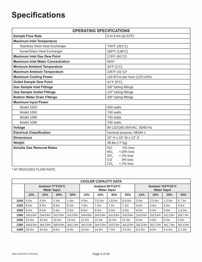
OPERATING SPECIFICATIONSSample Flow Rate 0 to 8 l/m (at STP)Maximum Inlet Temperature Stainless Steel Heat Exchanger 700°F (351°C) Kynar/Glass Heat Exchanger 280°F (138°C)Maximum Inlet Gas Dew Point 178°F (81°C)*Maximum Inlet Water Concentration 50%*Minimum Ambient Temperature 34°F (1°C)Maximum Ambient Temperature 105°F (41°C)*Maximum Cooling Power 126 BTUs per hour (120 kJ/hr)Outlet Sample Dew Point 41°F (5°C)Gas Sample Inlet Fittings 3/8" tubing fittingsGas Sample Outlet Fittings 1/4" tubing fittingsBottom Water Drain Fittings 3/8" tubing fittingsMaximum Input Power Model 1050 400 watts Model 1060 740 watts Model 1080 740 watts Model 1090 740 wattsVoltage 90-132/180-264VAC, 50/60 HzElectrical Classification General purpose, NEMA 1Dimensions 15" H x 10" W x 12" DWeight 38 lbs (17 kg)Soluble Gas Removal Rates NO 0% loss
NO2 <10% lossSO2 < 2% lossCO 0% lossCO2 < 2% loss
* AT REDUCED FLOW RATE.
COOLER CAPACITY DATAAmbient 77°F/25°C
Water VaporAmbient 90°F/25°C
Water VaporAmbient 105°F/25°C
Water Vapor12% 15% 30% 50% 12% 15% 30% 50% 12% 15% 30% 50%
1040 5 l/m 4 l/m 2 l/m 1 l/m 4 l/m 3.5 l/m 1.8 l/m 0.9 l/m 3 l/m 2.5 l/m 1.3 l/m 0.7 lm1050 8 l/m 8 l/m 8 l/m 8 l/m 7 l/m 7 l/m 7 lm 7 l/m 4 l/m 4 l/m 4 l/m 4 l/m1060 8 l/m 8 l/m 5 l/m 3 l/m 8 l/m 8 l/m 4 l/m 2 l/m 6 l/m 6 l/m 3 l/m 1.5 l/m1080 2x5.0 l/m 2x4.0 l/m 2x2.0 l/m 2x1.0 l/m 2x4.0 l/m 2x3.5 l/m 2x1.8 l/m 2x0.9 l/m 2x3.0 l/m 2x2.5 l/m 2x1.3 l/m 2x0.7 l/m1090 15 l/m 15 l/m 15 l/m 15 l/m 11 l/m 11 l/m 11 l/m 11 l/m 6 l/m 6 l/m 6 l/m 6 l/m1390 3x4.6 l/m 3x4.3 l/m 3x6.6 l/m 3x3.1 l/m 3x4.3 l/m 3x4.0 l/m 3x3.3 l/m 3x2.6 l/m 3x2.3 l/m 3x2.1 l/m 3x1.7 l/m 3x1.4 l/m1490 20 l/m 16 l/m 8 l/m 4 l/m 16 l/m 14 l/m 7 l/m 3.6 l/m 9.2 l/m 8 l/m 4.4 l/m 2.2 l/m

Page 6 of 28 Page 7 of 28 MAN.1000.REVI.07012015
Description and Principle of Operation
DESCRIPTION
The 1000 Series Gas Sample Coolers are Thermoelectric Coolers consisting of Peltier Elements, control electronics, a heatsink, and fan assembled as a NEMA 1 device. The optional equipment consists of certain drain options, voltage options, stream configurations, direct stream temperature sensors, as well as different materials for the impingers (water removal columns) depending on the application.
The 1000 Series Coolers operate by condensing the water from a wet gas sample to a dewpoint of 4°C with a minimal loss of water soluble gas fraction due to the design of the impingers. The impinger is composed of an insulated tube enclosed in a highly polished cylinder that is then cooled. The hot wet sample is brought to the bottom of the cylinder through the insulated tube and is then allowed to rise through a narrow annular area at a relatively high Reynolds number to insure the entire sample is influenced by the cold surface. The condensate falls down the cold polished surface in the form of a sheet (as opposed to droplets or the bubbling of the gas sample through the condensate) which minimizes the surface area in contact with the gas sample.
The temperature of the impinger is maintained through contact with a heat transfer block. Depending on the model the heat transfer block will either be ambient temperature or be actively cooled to 4°C through the use of Thermoelectric (Peltier) elements. A model 1040 has a single active transfer block with two thermoelectric elements, a model 1050 has an ambient temperature transfer block and an active transfer block with two thermoelectric elements, and a model 1060 has two active transfer blocks for a total of four thermoelectric elements. A model 1080 also has two active transfer blocks with a total of four thermoelectric elements, however it is designed to cool two independent streams at one time. Additionally the model 1090 is designed to have a pair of ambient temperature transfer blocks and a pair of active transfer blocks for a total of four thermoelectric elements. The 1090 can be configured to either be a single stream or for two independent streams. The model 1090 is the only model in the series to be certified for use in hazardous locations. The temperature is measured using a Type K thermocouple located in the transfer blocks. This temperature is controlled to 4°C with a variance of one degree.
APPLICATION
The Universal Analyzers 1000 Series Gas Sample Coolers are designed to be installed in a sample system where the gas sample contains moisture to be removed. The model 1090 has the option to be installed in hazardous locations or unclassified locations. The remainder of the models may only be installed in non-hazardous locations.
The 1000 Series Coolers are designed as standalone equipment that does not require integration onto a panel. However, many options do require integration. Standard integration options can be configured on plates or U-Brackets. The 1000 Series Gas Sample Coolers are also designed for minimal maintenance.
The 1000 Series Coolers have mounting holes for 1/4" hardware and may be installed into a protected shelter or enclosures that are designed to remove the exhaust heat. Ambient temperature, required flow rate, and moisture content will determine the specific model required for a specific application.
The use of a Heated Filter and Heated Sample Line are highly recommended to be installed between the sample extraction location and the input to the 1000 Series Gas Sample Cooler. They are recommended to keep the temperature of the sample above the boiling point of water or above the dew point of any chemical reactions that would skew the desired analytical results.
Page 8 of 28 Page 9 of 28MAN.1000.REVI.07012015
Description and Principle of OperationThe Thermoelectric Elements are devices that when power is supplied the element creates a temperature differential between the two sides of element. This creates a cool side that cools the impinger and a hot side where the heat is discharged through a heatsink with a fan forcing air through the heatsink for dissipation.
1000 Series Sample Coolers have a digital display on the front panel indicating the operating temperature (°C) of the heat exchangers. In addition, there are two green and one red LED lights to indicate the status of the cooler. The 'COOL' light will shine yellow when the operating temperature is between 0°C and 10°C (32°F and 50°F) and otherwise be unlit. The "DRY" light will shine if there is no moisture sensor installed or if the installed moisture sensor sees water carry over past the impingers. The T/C light will shine red if the thermocouple is broken or has a bad connection to the control board. On a dual stream cooler there are two sets of lights, one for each stream. There is also a switch that can be moved to trigger the display to show the current temperature of either stream 1 or stream 2.
There are four Type C alarm relays in the 1000 Series Gas Sample Coolers and eight Type C alarm relays in the dual stream 1000 Series Gas Sample Coolers. Two of the relays are activated when the temperature is above 10°C and the other two are activated when a moisture alarm is triggered. The dual stream has additional Type C alarm relays for the second stream that function in an identical fashion. In most applications one set of temperature and moisture alarms are wired together to turn off a sample pump when triggered. The other set of relays are wired to the data acquisition or control system.
The standard drain is a peristaltic pump is a positive displacement pump that allows for use in either a pressure or vacuum sample. However, it is not available as a standard option but instead needs to be part of a sample conditioning system or purchased separate. A secondary drain option is the use of a float drain trap. This can only be used if the heat exchangers are at a slight positive pressure in relation to atmosphere. Condensate collects in the trap until the float rises and allows for the condensate to drain. An eductor (aspirator) is another standard option for condensate removal. This option requires an instrument air source to create a vortex with the drain and draw the condensate out of the eductor.The direct stream temperature sensors, also referred to as 'New Jersey' option are thermocouples and available as Type J or Type K.
Universal Analyzers Sample Chillers are designed to interface with a condensate carry over sensor. The standard sensor is provided with a filter (which is referred to as a “CCSF”) or it can be ordered without a filter (“CCS”). This sensor is put in place as an early warning device to ensure that a clean, dry sample is presented to the analyzer(s), thereby minimizing future maintenance and/or costly repairs. Condensate sensor (CCS/CCSF) sold separately for 500/1000 series coolers.
The sensor is designed to operate with any current model Universal Analyzers sample chiller. If the sensor needs to be used as a standalone device then a 100A Moisture Detection Module must be used in conjunction with the moisture sensor.
The technology behind the CCSF is a capacitive proximity sensor – this is advantageous because the condensate does not need to be conductive to trigger an alarm. The sensor has an M12 connector on the bottom and uses the same 1 meter cable (Universal Analyzers Part No. 3907-1017) to interface between the CCS/CCSF and all chillers and the 100A Moisture Detection Module. In addition, there is an LED indicator on the sensor itself that illuminates upon detection of condensation or particulate.

Page 8 of 28 Page 9 of 28 MAN.1000.REVI.07012015
InstallationUniversal Analyzers 1000 Series Sample Coolers should be installed away from heat sources in a well ventilated area of an instrument rack or enclosure. The Cooler performance is proportional to ambient temperature, too high a temperature will degrade performance. Contact the factory for recommendations. Air purging an enclosure generally requires more flow than is available to remove the heat which will be generated internally by the sample chiller. There are air conditioners and vortex cabinet coolers designed to provide the necessary cooling for enclosing thermoelectric chillers.
The 1000 series sample cooler has mounting taps on the brackets extending to each side of the cooler. The mounting holes are located past the heat blocks to allow for ease of tool access when mounting.
Sample tubing should be brought to the back left heat exchanger. In most cases this will be an ambient impinger with no foam surrounding it. Dual Stream coolers will have one sample tube connected to the back left side and a second sample tube connected to the back right side. A 3/8” tubing fitting is provided at the top of the first heat exchanger as the sample inlet. The dry sample outlet from the cooler is the 1/4” Kynar tubing fitting coming out of the top of the exit heat exchanger at an angle.
A drain line from the peristaltic pump, eductor, or drain pot must be run to sewer, a container, or to the ground outside the instrument enclosure to avoid collecting water (condensate) on the floor.
If an eductor is utilized to remove the condensate, the outlet tube length should be no longer than two feet in order to keep too much back pressure from the outlet of the eductor. The outlet tube can be placed in a larger pipe to channel the condensate to a drain.
The electrical power, about 3 amps at 115VAC or 1.5 amps at 230VAC 50/60 Hz should be supplied. Installation shall be in accord with the manufacturer’s instructions and the National Electrical Code (ANSI/NFPA 70). Tampering and replacement with non-factory components may adversely affect the safe use of the system. For the 115VAC case, a power cord is supplied. It can be replaced with conduit wiring easily.
Page 10 of 28 Page 11 of 28MAN.1000.REVI.07012015
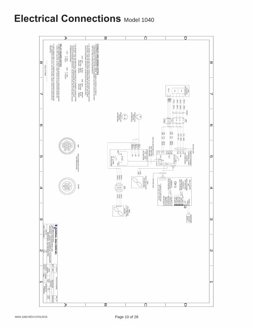
Electrical Connections Model 1040
A B C D
A B C
12
34
56
78
12
34
56
7
D
8
P00
12
02/05/1992
N/A
REVREVISIO
NS
FOR
PART NO.
E. MusselmanA
PV
D B
Y
DR
AW
N B
YDRAW
ING NO
.
DATE
NO
T IS
SU
ED
MO
DE
L 1
04
0 S
AM
PL
E C
OO
LE
RW
IRIN
G S
CH
EM
AT
IC
DATEDESCRIPTIO
NDW
NAPVD
SCALESIZE
SHEETNTS
D2 O
F 2
MW
UNIVERSAL ANALYZERS INC.5
20
0 C
on
va
ir Drive
Ca
rso
n C
ity, N
eva
da
8970
6 U
SA
DAF
01/27/10 Revised For M
odularity
T. Barben
(H)
(N)
(G)
TB1-G
TB1-4
TB1-1
15 VD
C+
-
+ VD
C- V
DC
US
E FO
LLWIN
G W
IRE
ON
LY:
RE
D 3900-0081
BLK
3900-0082
RE
DB
LK
PO
WE
R S
UP
PLY
P/S
1 250WP
/N 3600-0039
FAN1
15VD
C EN
CLO
SU
RE
P/N
4800-0005
RE
LAY
BO
ARD
RB
SIN
GLE
CH
AN
NE
LP
/N 3600-0006
F1 - 12 AM
PP
/N 3010-0006
FAN2
P/N
4800-00036" H
T. SIN
K FAN
120 VA
C
FAN
-H
1-A
CH
1 1-A (R
ED
)
T/C1 G
ND
T/C1 R
ED
T/C1 Y
EL
1-B
+-+-
1
SIN
GLE
CH
AN
NE
LC
ON
TR
OL C
AR
DC
/CA
RD
P/N
3600-0003
F1 - 2 AM
PP
/N 3010-0003
23
TB5
T/C1
TB5-2
TB5-1
TB5-3
NC
1 (WE
T)
AR
M (C
1)N
01 (DR
Y)* N
C2 (W
ET
)* A
RM
2 (C2)
* N02 (D
RY)
* NC
3 (HO
T)* A
RM
3 (C3)
*N03 (C
OLD
)N
C4 (H
OT)
AR
M4 (C
4)N
04 (CO
LD)
* CO
NTA
CTS
PR
OTE
CTE
DW
ITH 250 V
OLT M
OV
'S
SH
OW
N IN
DE
-ENE
RG
IZED
(WE
T) P
OS
ITION
SH
OW
N IN
DE
-ENE
RG
IZED
(HO
T) PO
SITIO
N
PR
OB
EC
OM
JA
CH
1
MO
ISTU
RE
SE
NS
OR
WC
OF 1
HNG
FAN2-H
FAN2-N
FAN2-G
PO
WE
R P
LUG
15A/125V
P/N
3905-0002
PO
WE
R P
LUG
10A/250V
P/N
3905-0005
CH
1P
ELTIE
RS
P/N
3016-0001TE
C1+ (R
ED
)
15V
DC
+-
- +TE
C1
+++---TE
C1
P/N
0320-1000
P/N
0320-1001
AM
PV
IKIN
G
1 3
7 2
5 4
6
12
34
56
78
910
1112
1314
1516
(SE
E C
ON
NE
CTO
R C
AV
ITYFO
R O
RIE
NTA
TION
)
FAN
-NFAN
-G
20AW
G
1256 3 24
161514
P/S
-HP
/S-N
P/S
-G
AM
P
CH
1 1-B (R
ED
)
CH
1 1-A (B
LK)
CH
1 1-B (B
LK)
TEC
1+ (RE
D)
TEC
1- (BLK
)
TEC
1- (BLK
)
VIK
ING
AM
P
CO
ND
UIT
AN
D W
IRIN
G N
OTES
1. ELE
CTR
ICA
L CLA
SS
IFICATIO
N : IN
SID
E - G
EN
ER
AL P
UR
PO
SE
SY
STEM
IS C
ON
FIGU
RE
D AT TH
E FA
CTO
RY
FOR
RE
QU
IRE
D V
OLTA
GE
. CO
NTA
CT FA
CTO
RY
FOR
VO
LTAG
E C
HA
NG
E R
EQ
UIR
EMEN
TS.
2. AC
WIR
ING
SH
ALL B
E IN
DIV
IDU
AL C
ON
DU
CTO
RS
OF STR
AN
DE
D TIN
NED
CO
PP
ER
WITH
300V, TY
PE
TFE IN
SULA
TION
. MIN
IMU
M W
IRE
SIZE
SH
ALL B
E 18 A
WG
UN
LES
S O
THE
RW
ISE
SP
EC
IFIED
. CO
LOR
CO
DE
SH
ALL B
E A
S FO
LLOW
S:
115V - H
OT - B
LAC
K 230V
- HO
T - BR
OW
N N
EU
TRA
L - WH
ITE N
EU
TRA
L - BLU
E G
RO
UN
D - G
RE
EN
GR
OU
ND
- GR
EE
N
3. DC
WIR
ING
SH
ALL B
E IN
DIV
IDU
AL C
ON
DU
CTO
RS
OF STR
AN
DE
D TIN
NED
CO
PP
ER
WITH
300V, TY
PE
TFE IN
SULA
TION
. MIN
IMU
M W
IRE
SIZE
SH
ALL B
E 22 A
WG
UN
LES
S O
THE
RW
ISE
SP
EC
IFIED
. CO
LOR
CO
DE
SH
ALL B
E A
S FO
LLOW
S, U
NLE
SS
OTH
ER
WIS
E S
PE
CIFIE
D:
115V +V
RE
D 230V
+V R
ED
-V B
LUE
-V B
LAC
K
RE
LAY
BO
AR
D N
OTE
S4. U
SE
R C
ON
NEC
TION
S TO
MO
ISTU
RE
SE
NS
OR
RE
LAY
EN
ER
GIZE
D W
HE
N S
EN
SO
R IS
DR
Y (D
RY
LED
ON
). RA
TING
: 1/10HP
120VA
C 5A
240VAC
/32VD
C R
ES
ISTIV
E.
5. US
ER
CO
NN
ECTIO
NS
TO "A
T TEM
PE
RATU
RE
" RE
LAY
EN
ER
GIZE
D W
HE
N B
ELO
W S
ET TE
MP
ER
ATUR
E (C
OO
L LED
ON
). RA
TING
: 1/10HP
120VA
C 5A
240VA
C/32V
DC
RE
SIS
ITVE
.
-- -- -- -- -- -- -- -- -- -- -- -- -- -- -- -- FIE
LD TO
WIR
E
Page 10 of 28 Page 11 of 28 MAN.1000.REVI.07012015
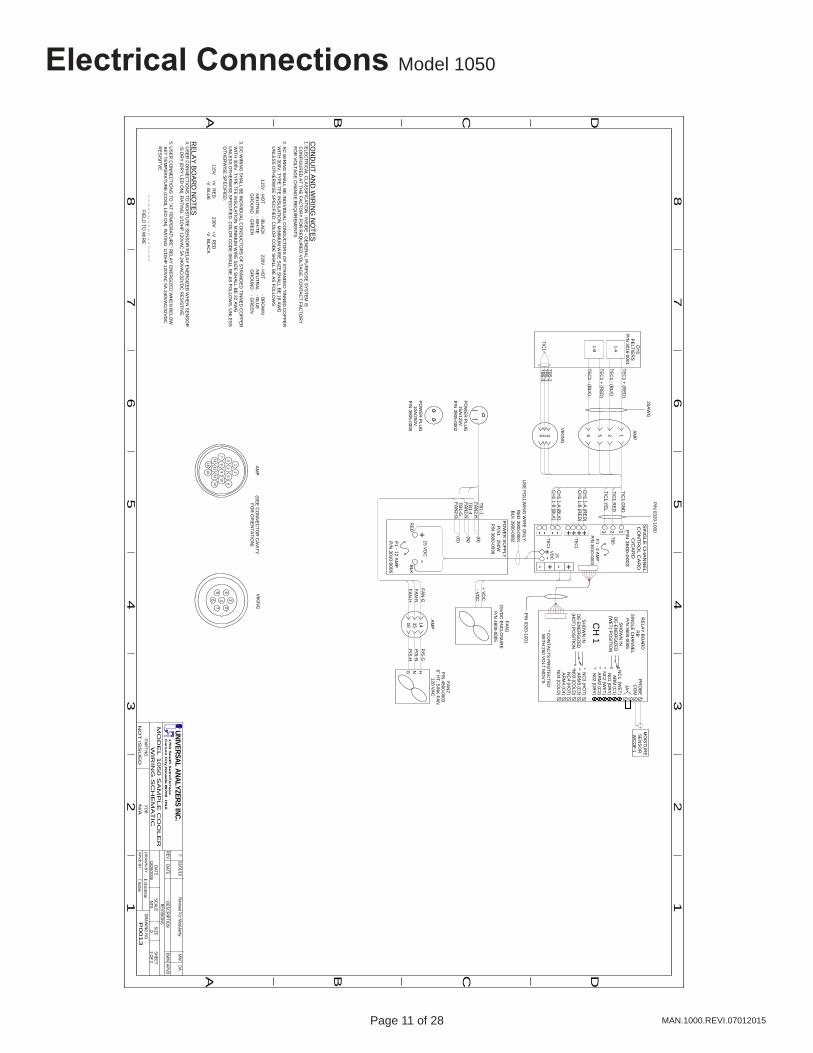
Electrical Connections Model 1050
A B C D
A B C
12
34
56
78
12
34
56
7
D
8
P00
13
10/28/2006
N/A
REVREVISIO
NS
FOR
PART NO.
E. MusselmanA
PV
D B
Y
DR
AW
N B
YDRAW
ING NO
.
DATE
NO
T IS
SU
ED
MO
DE
L 1
05
0 S
AM
PL
E C
OO
LE
RW
IRIN
G S
CH
EM
AT
IC
DATEDESCRIPTIO
NDW
NAPVD
SCALESIZE
SHEETNTS
D2 O
F 2
MW
UNIVERSAL ANALYZERS INC.1
70
1 S
ou
th S
utro
Te
rrac
eC
ars
on
City
, Ne
vad
a 89
70
6 U
SA
DAF
02/01/10 Revised For M
odularity
T. Barben
(H)
(N)
(G)
TB1-G
TB1-4
TB1-1
15 VD
C+
-
+ VD
C- V
DC
US
E FO
LLWIN
G W
IRE
ON
LY:
RE
D 3900-0081
BLK
3900-0082
RE
DB
LK
PO
WE
R S
UP
PLY
P/S
1 250WP
/N 3600-0039
FAN1
15VD
C EN
CLO
SU
RE
P/N
4800-0005
RE
LAY
BO
ARD
RB
SIN
GLE
CH
AN
NE
LP
/N 3600-0006
F1 - 12 AM
PP
/N 3010-0006
FAN
2P
/N 4800-0003
6" HT. S
INK
FAN120 V
AC
FAN-G
FAN-N
1-A
TEC
1 + (RE
D)
TEC
1 - (BLK
)
T/C1 G
ND
T/C1 R
ED
T/C1 Y
EL
1-B
TEC
1 + (RE
D)
TEC
1 - (BLK
)
+-+-
1
SIN
GLE
CH
AN
NE
LC
ON
TR
OL C
AR
DC
/CA
RD
P/N
3600-0003
F1 - 2 AM
PP
/N 3010-0003
23
TB5
T/C1
TB5-2
TB5-1
TB5-3
NC
1 (WE
T)
AR
M (C
1)N
01 (DR
Y)* N
C2 (W
ET
)* A
RM
2 (C2)
* N02 (D
RY)
* NC
3 (HO
T)* A
RM
3 (C3)
*N03 (C
OLD
)N
C4 (H
OT)
AR
M4 (C
4)N
04 (CO
LD)
* CO
NTA
CTS
PR
OTE
CTE
DW
ITH 250 V
OLT M
OV
'S
SH
OW
N IN
DE
-ENE
RG
IZED
(WE
T) P
OS
ITION
SH
OW
N IN
DE
-ENE
RG
IZED
(HO
T) PO
SITIO
N
PR
OB
EC
OM
JA
CH
1
MO
ISTU
RE
SE
NS
OR
WC
OF 1
HNFAN
-HG
FAN2-H
FAN2-N
FAN2-G
PO
WE
R P
LUG
15A/125V
P/N
3905-0002
PO
WE
R P
LUG
10A/250V
P/N
3905-0005
CH
1P
ELTIE
RS
P/N
3016-0001
CH
1 1-A (R
ED
)
CH
1 1-A (B
LK)
15V
DC
+-
- +TE
C1
+++---TE
C1
CH
1 1-B (R
ED
)
CH
1 1-B (B
LK)
P/N
0320-1001
P/N
0320-1000
AM
PV
IKIN
G
1 3
7 2
5 4
6
12
34
56
78
910
1112
1314
1516
(SE
E C
ON
NE
CTO
R C
AV
ITYFO
R O
RIE
NTA
TION
)
AM
P
141516
P/S
-GP
/S-N
P/S
-H
AM
P
20AW
G
1256324
VIK
ING
CO
ND
UIT
AN
D W
IRIN
G N
OTES
1. ELE
CTR
ICA
L CLA
SS
IFICATIO
N : IN
SID
E - G
EN
ER
AL P
UR
PO
SE
SY
STEM
IS C
ON
FIGU
RE
D AT TH
E FA
CTO
RY
FOR
RE
QU
IRE
D V
OLTA
GE
. CO
NTA
CT FA
CTO
RY
FOR
VO
LTAG
E C
HA
NG
E R
EQ
UIR
EMEN
TS.
2. AC
WIR
ING
SH
ALL B
E IN
DIV
IDU
AL C
ON
DU
CTO
RS
OF STR
AN
DE
D TIN
NED
CO
PP
ER
WITH
300V, TY
PE
TFE IN
SULA
TION
. MIN
IMU
M W
IRE
SIZE
SH
ALL B
E 18 A
WG
UN
LES
S O
THE
RW
ISE
SP
EC
IFIED
. CO
LOR
CO
DE
SH
ALL B
E A
S FO
LLOW
S:
115V - H
OT - B
LAC
K 230V
- HO
T - BR
OW
N N
EU
TRA
L - WH
ITE N
EU
TRA
L - BLU
E G
RO
UN
D - G
RE
EN
GR
OU
ND
- GR
EE
N
3. DC
WIR
ING
SH
ALL B
E IN
DIV
IDU
AL C
ON
DU
CTO
RS
OF STR
AN
DE
D TIN
NED
CO
PP
ER
WITH
300V, TY
PE
TFE IN
SULA
TION
. MIN
IMU
M W
IRE
SIZE
SH
ALL B
E 22 A
WG
UN
LES
S O
THE
RW
ISE
SP
EC
IFIED
. CO
LOR
CO
DE
SH
ALL B
E A
S FO
LLOW
S, U
NLE
SS
OTH
ER
WIS
E S
PE
CIFIE
D:
115V +V
RE
D 230V
+V R
ED
-V B
LUE
-V B
LAC
K
RE
LAY
BO
AR
D N
OTE
S4. U
SE
R C
ON
NEC
TION
S TO
MO
ISTU
RE
SE
NS
OR
RE
LAY
EN
ER
GIZE
D W
HE
N S
EN
SO
R IS
DR
Y (D
RY
LED
ON
). RA
TING
: 1/10HP
120VA
C 5A
240VAC
/32VD
C R
ES
ISTIV
E.
5. US
ER
CO
NN
ECTIO
NS
TO "A
T TEM
PE
RATU
RE
" RE
LAY
EN
ER
GIZE
D W
HE
N B
ELO
W S
ET TE
MP
ER
ATUR
E (C
OO
L LED
ON
). RA
TING
: 1/10HP
120VA
C 5A
240VA
C/32V
DC
RE
SIS
ITVE
.
-- -- -- -- -- -- -- -- -- -- -- -- -- -- -- -- FIE
LD TO
WIR
E
Page 12 of 28 Page 13 of 28MAN.1000.REVI.07012015
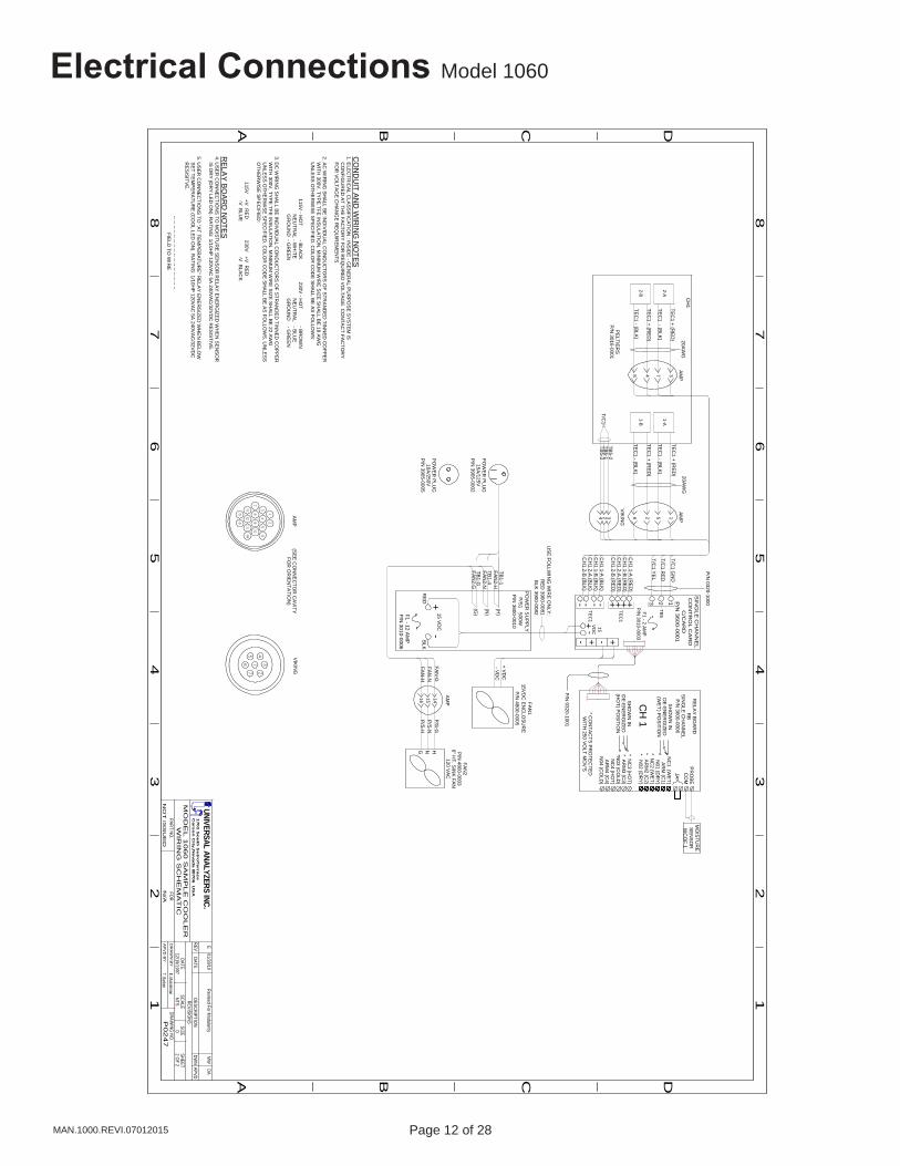
Electrical Connections Model 1060
A B C D
A B C
12
34
56
78
12
34
56
7
D
8
P02
47
12/19/1997
N/A
REVREVISIO
NS
FOR
PART NO.
E. MusselmanA
PV
D B
Y
DR
AW
N B
YDRAW
ING NO
.
DATE
NO
T IS
SU
ED
MO
DE
L 1
06
0 S
AM
PL
E C
OO
LE
RW
IRIN
G S
CH
EM
AT
IC
DATEDESCRIPTIO
NDW
NAPVD
SCALESIZE
SHEETNTS
D2 O
F 2
MW
UNIVERSAL ANALYZERS INC.1
70
1 S
ou
th S
utro
Te
rrac
eC
ars
on
City
, Ne
vad
a 89
70
6 U
SA
DAE
01/28/10 Revised For M
odularity
T. Barben
(H)
(N)
(G)
TB1-G
TB1-4
TB1-1
15 VD
C+
-
+ VD
C- VD
C
US
E FO
LLWIN
G W
IRE
ON
LY:
RE
D 3900-0081
BLK
3900-0082
RE
DB
LK
PO
WE
R S
UP
PLY
P/S
1 500WP
/N 3600-0010
FAN
115V
DC
ENC
LOSU
RE
P/N
4800-0005
RE
LAY
BO
ARD
RB
SIN
GLE
CH
AN
NE
LP
/N 3600-0006
F1 - 12 AM
PP
/N 3010-0006
FAN
2P
/N 4800-0003
6" HT. S
INK
FAN
120 VA
C
FAN
-GFAN
-N
1-A
TEC
1 + (RE
D)
TEC
1 - (BLK
)
T/C1 G
ND
T/C1 R
ED
T/C1 Y
EL
1-B
TEC
1 + (RE
D)
TEC
1 - (BLK
)
2-A
2-B
TEC
1 + (RE
D)
TEC
1 - (BLK
)
TEC
1 + (RE
D)
TEC
1 - (BLK
)
+-+-
1
SIN
GL
E C
HA
NN
EL
CO
NT
RO
L CA
RD
C/C
AR
DP
/N 3600-0001
F1 - 2 AMP
P/N
3010-0003
23
TB5
T/C1
TB5-1
TB5-3
NC
1 (WE
T)
AR
M (C
1)N
01 (DR
Y)* N
C2 (W
ET
)* A
RM
2 (C2)
* N02 (D
RY)
* NC
3 (HO
T)* A
RM
3 (C3)
*N03 (C
OLD
)N
C4 (H
OT)
AR
M4 (C
4)N
04 (CO
LD)
* CO
NTA
CTS
PR
OTE
CTE
DW
ITH 250 V
OLT M
OV
'S
SH
OW
N IN
DE
-ENE
RG
IZED
(WE
T) P
OS
ITION
SH
OW
N IN
DE
-ENE
RG
IZED
(HO
T) PO
SITIO
N
PR
OB
EC
OM
JA
CH
1
MO
ISTU
RE
SE
NS
OR
WC
OF 1
HNFAN
-HG
FAN
2-H
FAN
2-N
FAN
2-G
PO
WE
R P
LUG
15A/125V
P/N
3905-0002
PO
WE
R P
LUG
10A/250V
P/N
3905-0005
CH
1
PE
LTIER
SP
/N 3016-0001
CH
1 1-A (R
ED
)
CH
1 1-A (B
LK)
15V
DC
+-
- +TE
C1
+++---TE
C1
CH
1 1-B (R
ED
)
CH
1 1-B (B
LK)
CH
1 2-A (R
ED
)
CH
1 2-A (B
LK)
CH
1 2-B (R
ED
)
CH
1 2-B (B
LK)
P/N
0320-1001
P/N
0320-1000
AM
PV
IKIN
G
1 3
7 2
5 4
6
12
34
56
78
910
1112
1314
1516
(SE
E C
ON
NE
CTO
R C
AV
ITYFO
R O
RIE
NTA
TION
)
20AW
G
VIK
ING
AM
P20A
WG
3748
1526
AM
P
14
AM
P
1516
P/S
-GP
/S-N
P/S
-H
324
TB5-2
CO
ND
UIT
AN
D W
IRIN
G N
OTES
1. ELE
CTR
ICA
L CLA
SS
IFICATIO
N : IN
SID
E - G
EN
ER
AL P
UR
PO
SE
SY
STEM
IS C
ON
FIGU
RE
D AT TH
E FA
CTO
RY
FOR
RE
QU
IRE
D V
OLTA
GE
. CO
NTA
CT FA
CTO
RY
FOR
VO
LTAG
E C
HA
NG
E R
EQ
UIR
EMEN
TS.
2. AC
WIR
ING
SH
ALL B
E IN
DIV
IDU
AL C
ON
DU
CTO
RS
OF STR
AN
DE
D TIN
NED
CO
PP
ER
WITH
300V, TY
PE
TFE IN
SULA
TION
. MIN
IMU
M W
IRE
SIZE
SH
ALL B
E 18 A
WG
UN
LES
S O
THE
RW
ISE
SP
EC
IFIED
. CO
LOR
CO
DE
SH
ALL B
E A
S FO
LLOW
S:
115V - H
OT - B
LAC
K 230V
- HO
T - BR
OW
N N
EU
TRA
L - WH
ITE N
EU
TRA
L - BLU
E G
RO
UN
D - G
RE
EN
GR
OU
ND
- GR
EE
N
3. DC
WIR
ING
SH
ALL B
E IN
DIV
IDU
AL C
ON
DU
CTO
RS
OF STR
AN
DE
D TIN
NED
CO
PP
ER
WITH
300V, TY
PE
TFE IN
SULA
TION
. MIN
IMU
M W
IRE
SIZE
SH
ALL B
E 22 A
WG
UN
LES
S O
THE
RW
ISE
SP
EC
IFIED
. CO
LOR
CO
DE
SH
ALL B
E A
S FO
LLOW
S, U
NLE
SS
OTH
ER
WIS
E S
PE
CIFIE
D:
115V +V
RE
D 230V
+V R
ED
-V B
LUE
-V B
LAC
K
RE
LAY
BO
AR
D N
OTE
S4. U
SE
R C
ON
NEC
TION
S TO
MO
ISTU
RE
SE
NS
OR
RE
LAY
EN
ER
GIZE
D W
HE
N S
EN
SO
R IS
DR
Y (D
RY
LED
ON
). RA
TING
: 1/10HP
120VA
C 5A
240VAC
/32VD
C R
ES
ISTIV
E.
5. US
ER
CO
NN
ECTIO
NS
TO "A
T TEM
PE
RATU
RE
" RE
LAY
EN
ER
GIZE
D W
HE
N B
ELO
W S
ET TE
MP
ER
ATUR
E (C
OO
L LED
ON
). RA
TING
: 1/10HP
120VA
C 5A
240VA
C/32V
DC
RE
SIS
ITVE
.
-- -- -- -- -- -- -- -- -- -- -- -- -- -- -- -- FIE
LD TO
WIR
E
Page 12 of 28 Page 13 of 28 MAN.1000.REVI.07012015
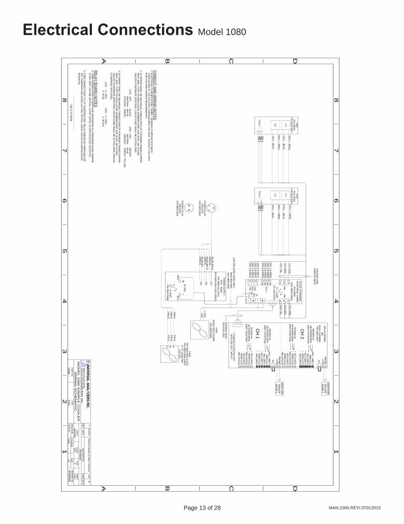
Electrical Connections Model 1080
A B C D
A B C
12
34
56
78
12
34
56
7
D
8
N/A
REVREVISIO
NS
FOR
PART NO.
E. MusselmanA
PV
D B
Y
DR
AW
N B
Y
DATE
1080 W
IRIN
G S
CH
EM
AT
IC
DATEDESCRIPTIO
NDW
NAPVD
SCALESIZE
SHEETNTS
D2 O
F 2
UNIVERSAL ANALYZERS INC.5
20
0 C
on
va
ir Drive
Ca
rso
n C
ity, N
eva
da
8970
6 U
SA
JHH
01/04/11 Rem
ove Impingers & M
olex ConnectorsM
W
09/10/1991M
OD
EL
10
80
SA
MP
LE
CO
OL
ER
T. Barben
(H)
(N)
(G)
PLU
G (G
)
PLU
G (N
/L2)
PLU
G (H
/L1)
15 VD
C+
-
+ VD
C- VD
C
US
E FO
LLWIN
G W
IRE
ON
LY:
RE
D 3900-0081
BLK
3900-0082
RE
DB
LK
PO
WE
R S
UP
PLY
P/S
1 500WP
/N 3600-10 (115V
)P
/N 3600-0010-230V
(230V)
FAN1
15VD
C EN
CLO
SUR
EP
/N 4800-0005
RE
LAY
BO
ARD
RB
DU
AL C
HA
NN
EL
P/N
3600-0007
F1 - 12 AM
PP
/N 3010-0006
FAN2
P/N
4800-0003 (115V)
P/N
4800-0009 (230V)
6" HT. S
INK
FAN
120 VA
C
FAN-H
FAN
-N
T/C2 G
ND
T/C2 R
ED
T/C2 Y
EL
1-A
TEC
1 + (RE
D)
TEC
1 - (BLK
)
T/C1 G
ND
T/C1 R
ED
T/C1 Y
EL
1-B
TEC
1 + (RE
D)
TEC
1 - (BLK
)
2-A
2-B
TEC
1 + (RE
D)
TEC
1 - (BLK
)
TEC
1 + (RE
D)
TEC
1 - (BLK
)
+-+-
1 DU
AL
CH
AN
NE
LC
ON
TR
OL C
AR
DC
/CA
RD
P/N
3600-0002
F1 - 2 AM
PP
/N 3010-0003
23
TB5
123
TB6
T/C2
TB6-2
TB6-1
TB6-3
T/C1
TB5-2
TB5-1
TB5-3
PR
OB
EC
OM
NC
1 (WE
T)
AR
M (C
1)N
01 (DR
Y)* N
C2 (W
ET
)* A
RM
2 (C2)
* N02 (D
RY)
* NC
3 (HO
T)* A
RM
3 (C3)
*N03 (C
OLD
)N
C4 (H
OT)
AR
M4 (C
4)N
04 (CO
LD)
JA
SH
OW
N IN
DE
-ENE
RG
IZED
(WE
T) P
OS
ITION
SH
OW
N IN
DE
-ENE
RG
IZED
(HO
T) PO
SITIO
N
NC
1 (WE
T)
AR
M (C
1)N
01 (DR
Y)* N
C2 (W
ET
)* A
RM
2 (C2)
* N02 (D
RY)
* NC
3 (HO
T)* A
RM
3 (C3)
*N03 (C
OLD
)N
C4 (H
OT)
AR
M4 (C
4)N
04 (CO
LD)
* CO
NTA
CTS
PR
OTE
CTE
DW
ITH 250 V
OLT M
OV
'S
SH
OW
N IN
DE
-ENE
RG
IZED
(WE
T) P
OS
ITION
SH
OW
N IN
DE
-ENE
RG
IZED
(HO
T) PO
SITIO
N
PR
OB
EC
OM
JA
CH
2
CH
1
MO
ISTU
RE
SE
NS
OR
WC
OF 2
MO
ISTU
RE
SE
NS
OR
WC
OF 1
HNFA
N-G
G
FAN2-H
FAN2-N
FAN2-G
PO
WE
R P
LUG
15A/125V
P/N
3905-0002
PO
WE
R P
LUG
10A/250V
P/N
3905-0005
CH
1P
ELTIE
RS
P/N
3016-0001
CH
2P
ELTIE
RS
P/N
3016-0001
CH
1 1-A (R
ED
)
CH
1 1-A (B
LK)
15V
DC
+-
- +TE
C1
+++---TE
C1
CH
1 1-B (R
ED
)
CH
1 1-B (B
LK)
CH
2 2-A (R
ED
)
CH
2 2-A (B
LK)
CH
2 2-B (R
ED
)
CH
2 2-B (B
LK)
FER
RITE
BE
AD
P/N
0320-1001
P/N
0320-1000FE
RR
ITE B
EA
D
P/S
-HP
/S-N
P/S
-G
CO
ND
UIT
AN
D W
IRIN
G N
OTES
1. ELE
CTR
ICA
L CLA
SS
IFICATIO
N : IN
SID
E - G
EN
ER
AL P
UR
PO
SE
SY
STEM
IS C
ON
FIGU
RE
D AT TH
E FA
CTO
RY
FOR
RE
QU
IRE
D V
OLTA
GE
. CO
NTA
CT FA
CTO
RY
FOR
VO
LTAG
E C
HA
NG
E R
EQ
UIR
EMEN
TS.
2. AC
WIR
ING
SH
ALL B
E IN
DIV
IDU
AL C
ON
DU
CTO
RS
OF STR
AN
DE
D TIN
NED
CO
PP
ER
WITH
300V, TY
PE
TFE IN
SULA
TION
. MIN
IMU
M W
IRE
SIZE
SH
ALL B
E 18 A
WG
UN
LES
S O
THE
RW
ISE
SP
EC
IFIED
. CO
LOR
CO
DE
SH
ALL B
E A
S FO
LLOW
S:
115V - H
OT - B
LAC
K 230V
- HO
T - BR
OW
N N
EU
TRA
L - WH
ITE N
EU
TRA
L - BLU
E G
RO
UN
D - G
RE
EN
GR
OU
ND
- GR
EE
N / Y
ELLO
W
3. DC
WIR
ING
SH
ALL B
E IN
DIV
IDU
AL C
ON
DU
CTO
RS
OF STR
AN
DE
D TIN
NED
CO
PP
ER
WITH
300V, TY
PE
TFE IN
SULA
TION
. MIN
IMU
M W
IRE
SIZE
SH
ALL B
E 22 A
WG
UN
LES
S O
THE
RW
ISE
SP
EC
IFIED
. CO
LOR
CO
DE
SH
ALL B
E A
S FO
LLOW
S, U
NLE
SS
OTH
ER
WIS
E S
PE
CIFIE
D:
115V +V
RE
D 230V
+V R
ED
-V B
LUE
-V B
LAC
K
RE
LAY
BO
AR
D N
OTE
S4. U
SE
R C
ON
NEC
TION
S TO
MO
ISTU
RE
SE
NS
OR
RE
LAY
EN
ER
GIZE
D W
HE
N S
EN
SO
R IS
DR
Y (D
RY
LED
ON
). RA
TING
: 1/10HP
120VA
C 5A
240VAC
/32VD
C R
ES
ISTIV
E.
5. US
ER
CO
NN
ECTIO
NS
TO "A
T TEM
PE
RATU
RE
" RE
LAY
EN
ER
GIZE
D W
HE
N B
ELO
W S
ET TE
MP
ER
ATUR
E (C
OO
L LED
ON
). RA
TING
: 1/10HP
120VA
C 5A
240VA
C/32V
DC
RE
SIS
ITVE
.
-- -- -- -- -- -- -- -- -- -- -- -- -- -- -- -- FIE
LD TO
WIR
E
CH
2
CH
1
P0
00
5DRAW
ING NO
.ECO#
557
Page 14 of 28 Page 15 of 28MAN.1000.REVI.07012015
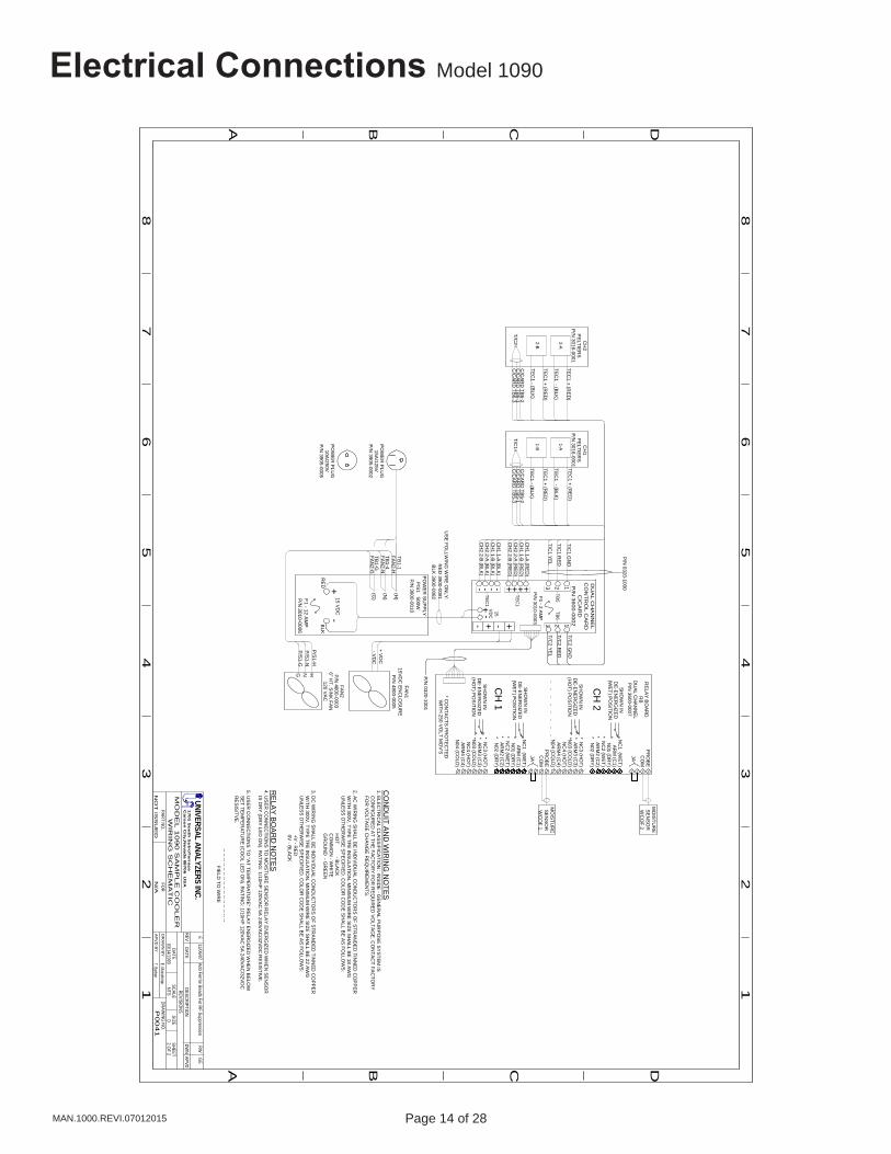
Electrical Connections Model 1090
A B C D
A B C
12
34
56
78
12
34
56
7
D
8
P00
41
03/14/1993
N/A
REVREVISIO
NS
FOR
PART NO.
E. MusselmanA
PV
D B
Y
DR
AW
N B
YDRAW
ING NO
.
DATE
NO
T IS
SU
ED
MO
DE
L 1
09
0 S
AM
PL
E C
OO
LE
RW
IRIN
G S
CH
EM
AT
IC
DATEDESCRIPTIO
NDW
NAPVD
SCALESIZE
SHEETNTS
D2 O
F 2
RWUNIVERSAL ANALYZERS INC.
170
1 S
ou
th S
utro
Te
rrac
eC
ars
on
City
, Ne
vad
a 89
70
6 U
SA
GE
E11/06/07
Add Ferrite Beads For RF Suppression
T. Barben
(H)
(N)
(G)
TB1-G
TB1-4
TB1-1
15 VD
C+
-
+ VD
C- VD
C
US
E FO
LLWIN
G W
IRE
ON
LY:
RE
D 3900-0081
BLK
3900-0082
RE
DB
LK
PO
WE
R S
UP
PLY
P/S
1 500WP
/N 3600-0010
FAN1
15VD
C EN
CLO
SUR
EP
/N 4800-0005
RE
LAY
BO
ARD
RB
DU
AL C
HA
NN
EL
P/N
3600-0007
F1 - 12 AM
PP
/N 3010-0006
FAN2
P/N
4800-00036" H
T. SIN
K FAN
120 VA
C
P/S
1-HP
/S1-N
T/C2 G
ND
T/C2 R
ED
T/C2 Y
EL
1-A
TEC
1 + (RE
D)
TEC
1 - (BLK
)
T/C1 G
ND
T/C1 R
ED
T/C1 Y
EL
1-B
TEC
1 + (RE
D)
TEC
1 - (BLK
)
2-A
2-B
TEC
1 + (RE
D)
TEC
1 - (BLK
)
TEC
1 + (RE
D)
TEC
1 - (BLK
)
+-+-
1 DU
AL
CH
AN
NE
LC
ON
TR
OL C
AR
DC
/CA
RD
P/N
3600-0002
F1 - 2 AM
PP
/N 3010-0003
23
TB5
123
TB6
T/C2
C/C
ARD
TB6-2
C/C
ARD
TB6-1
C/C
ARD
TB6-3
T/C1
C/C
ARD
TB5-2
C/C
ARD
TB5-1
C/C
ARD
TB5-3
PR
OB
EC
OM
NC
1 (WE
T)
AR
M (C
1)N
01 (DR
Y)* N
C2 (W
ET
)* A
RM
2 (C2)
* N02 (D
RY)
* NC
3 (HO
T)* A
RM
3 (C3)
*N03 (C
OLD
)N
C4 (H
OT)
AR
M4 (C
4)N
04 (CO
LD)
JA
SH
OW
N IN
DE
-ENE
RG
IZED
(WE
T) P
OS
ITION
SH
OW
N IN
DE
-ENE
RG
IZED
(HO
T) PO
SITIO
N
NC
1 (WE
T)
AR
M (C
1)N
01 (DR
Y)* N
C2 (W
ET
)* A
RM
2 (C2)
* N02 (D
RY)
* NC
3 (HO
T)* A
RM
3 (C3)
*N03 (C
OLD
)N
C4 (H
OT)
AR
M4 (C
4)N
04 (CO
LD)
* CO
NTA
CTS
PR
OTE
CTE
DW
ITH 250 V
OLT M
OV
'S
SH
OW
N IN
DE
-ENE
RG
IZED
(WE
T) P
OS
ITION
SH
OW
N IN
DE
-ENE
RG
IZED
(HO
T) PO
SITIO
N
PR
OB
EC
OM
JA
CH
2
CH
1
MO
ISTU
RE
SE
NS
OR
WC
OF 2
MO
ISTU
RE
SE
NS
OR
WC
OF 1
HNP
/S1-G
G
FAN
2-H
FAN
2-N
FAN
2-G
PO
WE
R P
LUG
15A/125V
P/N
3905-0002
PO
WE
R P
LUG
10A/250V
P/N
3905-0005
CH
1P
ELTIE
RS
P/N
3016-0001
CH
2P
ELTIE
RS
P/N
3016-0001
CH
1 1-A (R
ED
)
CH
1 1-A (B
LK)
15V
DC
+-
- +TE
C1
+++---TE
C1
CH
1 1-B (R
ED
)
CH
1 1-B (B
LK)
CH
2 2-A (R
ED
)
CH
2 2-A (B
LK)
CH
2 2-B (R
ED
)
CH
2 2-B (B
LK)
CO
ND
UIT
AN
D W
IRIN
G N
OTE
S1. E
LEC
TRIC
AL C
LAS
SIFIC
ATION
: INS
IDE
- GE
NE
RA
L PU
RP
OS
E S
YS
TEM IS
CO
NFIG
UR
ED
AT THE
FACTO
RY
FOR
RE
QU
IRE
D V
OLTA
GE
. CO
NTA
CT FA
CTO
RY
FOR
VO
LTAG
E C
HA
NG
E R
EQ
UIR
EMEN
TS.
2. AC
WIR
ING
SH
ALL B
E IN
DIV
IDU
AL C
ON
DU
CTO
RS
OF S
TRA
ND
ED
TINN
ED C
OP
PE
R W
ITH 300V
, TYP
E TFE
INS
ULA
TION
. MIN
IMU
M W
IRE
SIZE
SH
ALL B
E 18 A
WG
UN
LES
S O
THE
RW
ISE
SP
EC
IFIED. C
OLO
R C
OD
E S
HA
LL BE
AS
FOLLO
WS
: H
OT - B
LAC
K C
OM
MO
N - W
HITE
GR
OU
ND
- GR
EE
N
3. DC
WIR
ING
SH
ALL B
E IN
DIV
IDU
AL C
ON
DU
CTO
RS
OF S
TRA
ND
ED
TINN
ED C
OP
PE
R W
ITH 300V
, TYP
E TFE
INS
ULA
TION
. MIN
IMU
M W
IRE
SIZE
SH
ALL B
E 22 A
WG
UN
LES
S O
THE
RW
ISE
SP
EC
IFIED. C
OLO
R C
OD
E S
HA
LL BE
AS
FOLLO
WS
: +V
- RE
D 0V
- BLA
CK
RE
LAY
BO
AR
D N
OTE
S4. U
SE
R C
ON
NEC
TION
S TO
MO
ISTU
RE
SE
NS
OR
RE
LAY
EN
ER
GIZE
D W
HE
N S
EN
SO
R IS
DR
Y (D
RY
LED
ON
). RA
TING
: 1/10HP
120VA
C 5A
240VA
C/32V
DC
RE
SIS
TIVE
.
5. US
ER
CO
NN
ECTIO
NS
TO "A
T TEM
PE
RATU
RE
" RE
LAY
EN
ER
GIZE
D W
HE
N B
ELO
W S
ET TE
MP
ER
ATUR
E (C
OO
L LED
ON
). RA
TING
: 1/10HP
120VA
C 5A
240VAC
/32VD
C R
ES
ISITV
E.
-- -- -- -- -- -- -- -- -- -- -- -- -- -- -- -- FIE
LD TO
WIR
E
P/N
0320-1001
P/N
0320-1000
Page 14 of 28 Page 15 of 28 MAN.1000.REVI.07012015
Start-UpApply power to the sample cooler. The indicated temperature will start to drop immediately. It should be below the over-temperature set point in approximately four minutes and the “COOL” green LED lamp should light. When the temperature reaches the control point (set at 5°C), the rate at which the temperature drops will be reduced. It will stabilize between 4° and 5°C.
Start the sample gas flow. Water should be observed to be removed from the bottom of the heat exchanger when steady state conditions are established.
If moisture sensors are installed, the (DRY) light should remain on as dry gas is transported to the analyzer(s). Turn on the analyzer(s) and calibrate as required. If an eductor is utilized to remove the condensate, a strong flow of air should be felt to be flowing from the eductor outlet tube.
ShutdownStop sample gas flow to the cooler by turning off the sample pump. Allow the drain pump to run for several minutes to remove any remaining condensate from the heat exchangers. After all condensate has been drained, turn off power to the cooler.
Page 16 of 28 Page 17 of 28MAN.1000.REVI.07012015
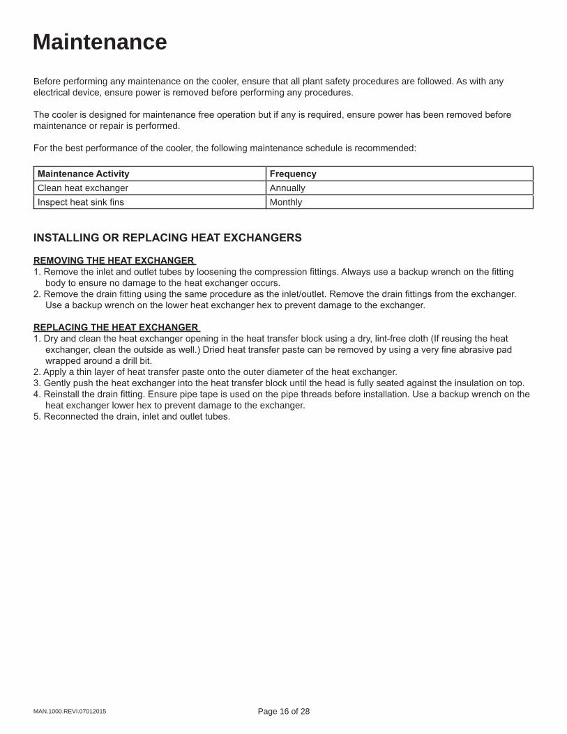
MaintenanceBefore performing any maintenance on the cooler, ensure that all plant safety procedures are followed. As with any electrical device, ensure power is removed before performing any procedures.
The cooler is designed for maintenance free operation but if any is required, ensure power has been removed before maintenance or repair is performed.
For the best performance of the cooler, the following maintenance schedule is recommended:
Maintenance Activity FrequencyClean heat exchanger AnnuallyInspect heat sink fins Monthly
INSTALLING OR REPLACING HEAT EXCHANGERS
REMOVING THE HEAT EXCHANGER 1. Remove the inlet and outlet tubes by loosening the compression fittings. Always use a backup wrench on the fitting
body to ensure no damage to the heat exchanger occurs. 2. Remove the drain fitting using the same procedure as the inlet/outlet. Remove the drain fittings from the exchanger.
Use a backup wrench on the lower heat exchanger hex to prevent damage to the exchanger.
REPLACING THE HEAT EXCHANGER 1. Dry and clean the heat exchanger opening in the heat transfer block using a dry, lint-free cloth (If reusing the heat
exchanger, clean the outside as well.) Dried heat transfer paste can be removed by using a very fine abrasive pad wrapped around a drill bit.
2. Apply a thin layer of heat transfer paste onto the outer diameter of the heat exchanger. 3. Gently push the heat exchanger into the heat transfer block until the head is fully seated against the insulation on top. 4. Reinstall the drain fitting. Ensure pipe tape is used on the pipe threads before installation. Use a backup wrench on the
heat exchanger lower hex to prevent damage to the exchanger. 5. Reconnected the drain, inlet and outlet tubes.
Page 16 of 28 Page 17 of 28 MAN.1000.REVI.07012015
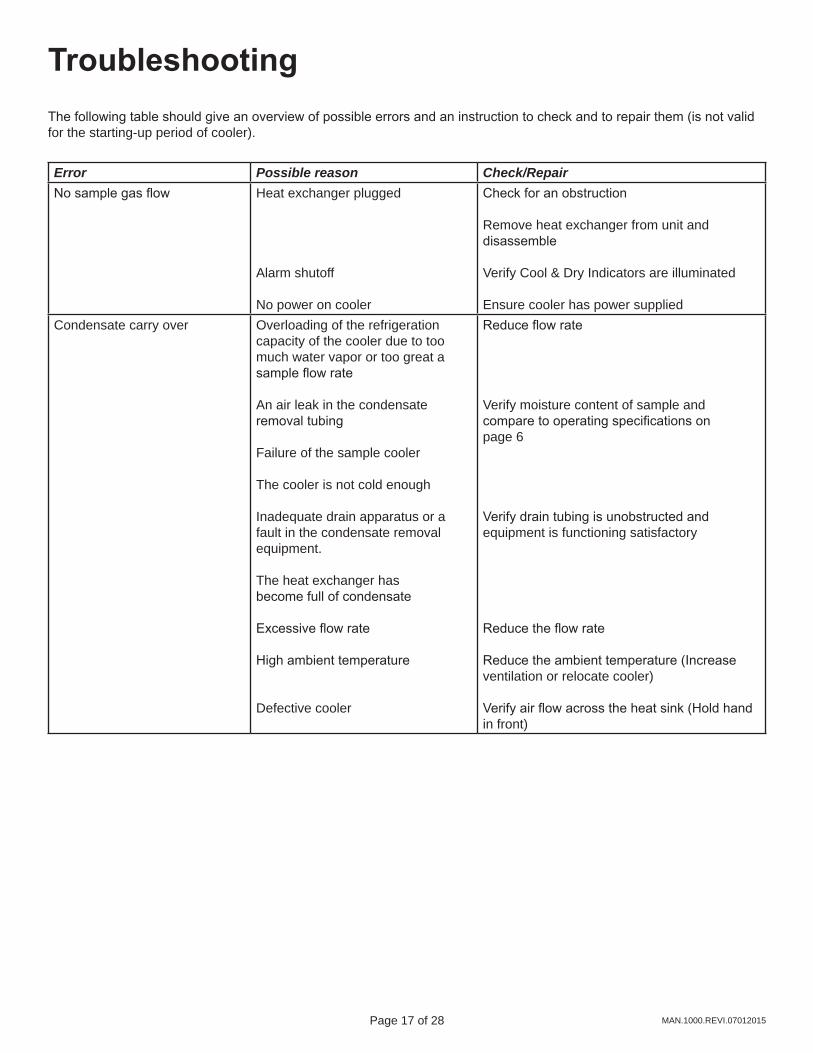
TroubleshootingThe following table should give an overview of possible errors and an instruction to check and to repair them (is not valid for the starting-up period of cooler).
Error Possible reason Check/RepairNo sample gas flow Heat exchanger plugged
Alarm shutoff
No power on cooler
Check for an obstruction
Remove heat exchanger from unit and disassemble
Verify Cool & Dry Indicators are illuminated
Ensure cooler has power suppliedCondensate carry over Overloading of the refrigeration
capacity of the cooler due to toomuch water vapor or too great asample flow rate
An air leak in the condensateremoval tubing
Failure of the sample cooler
The cooler is not cold enough
Inadequate drain apparatus or afault in the condensate removalequipment.
The heat exchanger hasbecome full of condensate
Excessive flow rate
High ambient temperature
Defective cooler
Reduce flow rate
Verify moisture content of sample andcompare to operating specifications onpage 6
Verify drain tubing is unobstructed andequipment is functioning satisfactory
Reduce the flow rate
Reduce the ambient temperature (Increaseventilation or relocate cooler) Verify air flow across the heat sink (Hold hand in front)
Page 18 of 28 Page 19 of 28MAN.1000.REVI.07012015
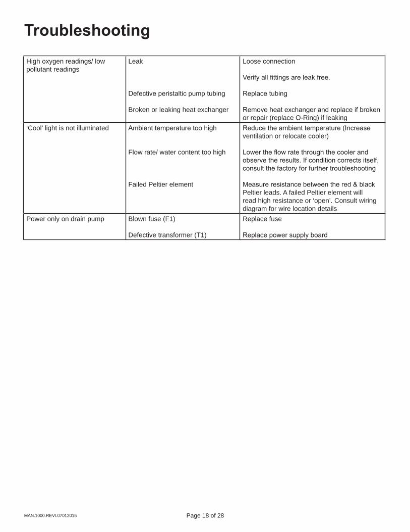
TroubleshootingHigh oxygen readings/ low pollutant readings
Leak
Defective peristaltic pump tubing
Broken or leaking heat exchanger
Loose connection
Verify all fittings are leak free.
Replace tubing
Remove heat exchanger and replace if broken or repair (replace O-Ring) if leaking
‘Cool’ light is not illuminated Ambient temperature too high
Flow rate/ water content too high
Failed Peltier element
Reduce the ambient temperature (Increase ventilation or relocate cooler)
Lower the flow rate through the cooler and observe the results. If condition corrects itself, consult the factory for further troubleshooting
Measure resistance between the red & black Peltier leads. A failed Peltier element will read high resistance or ‘open’. Consult wiring diagram for wire location details
Power only on drain pump Blown fuse (F1)
Defective transformer (T1)
Replace fuse
Replace power supply board
Page 18 of 28 Page 19 of 28 MAN.1000.REVI.07012015
Spare Parts
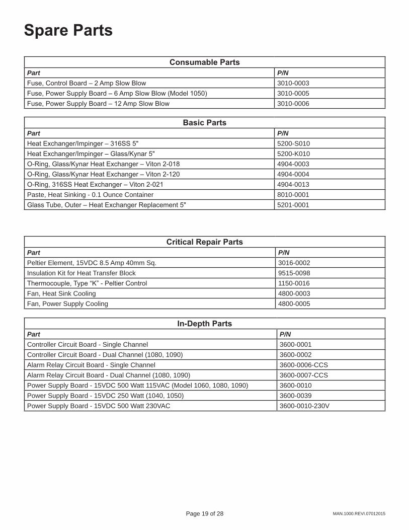
Critical Repair PartsPart P/NPeltier Element, 15VDC 8.5 Amp 40mm Sq. 3016-0002Insulation Kit for Heat Transfer Block 9515-0098Thermocouple, Type “K” - Peltier Control 1150-0016Fan, Heat Sink Cooling 4800-0003Fan, Power Supply Cooling 4800-0005
Consumable PartsPart P/NFuse, Control Board – 2 Amp Slow Blow 3010-0003Fuse, Power Supply Board – 6 Amp Slow Blow (Model 1050) 3010-0005Fuse, Power Supply Board – 12 Amp Slow Blow 3010-0006
Basic PartsPart P/NHeat Exchanger/Impinger – 316SS 5" 5200-S010Heat Exchanger/Impinger – Glass/Kynar 5" 5200-K010O-Ring, Glass/Kynar Heat Exchanger – Viton 2-018 4904-0003O-Ring, Glass/Kynar Heat Exchanger – Viton 2-120 4904-0004O-Ring, 316SS Heat Exchanger – Viton 2-021 4904-0013Paste, Heat Sinking - 0.1 Ounce Container 8010-0001Glass Tube, Outer – Heat Exchanger Replacement 5" 5201-0001
In-Depth PartsPart P/NController Circuit Board - Single Channel 3600-0001Controller Circuit Board - Dual Channel (1080, 1090) 3600-0002Alarm Relay Circuit Board - Single Channel 3600-0006-CCSAlarm Relay Circuit Board - Dual Channel (1080, 1090) 3600-0007-CCSPower Supply Board - 15VDC 500 Watt 115VAC (Model 1060, 1080, 1090) 3600-0010Power Supply Board - 15VDC 250 Watt (1040, 1050) 3600-0039Power Supply Board - 15VDC 500 Watt 230VAC 3600-0010-230V
Page 20 of 28 Page 21 of 28MAN.1000.REVI.07012015
Spare Parts
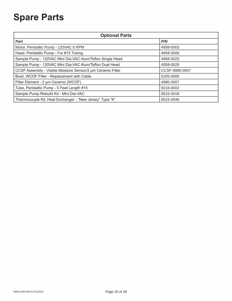
Optional PartsPart P/NMotor, Peristaltic Pump - 120VAC 6 RPM 4958-0003Head, Peristaltic Pump - For #15 Tubing 4958-0006Sample Pump - 120VAC Mini Dia-VAC Alum/Teflon Single Head 4958-0025Sample Pump - 120VAC Mini Dia-VAC Alum/Teflon Dual Head 4958-0026CCSF Assembly - Visible Moisture Sensor/2 μm Ceramic Filter CCSF-4980-0007Bowl, WCOF Filter - Replacement with Cable 5205-0006Filter Element - 2 μm Ceramic (WCOF) 4980-0007Tube, Peristaltic Pump - 5 Feet Length #15 9216-0002Sample Pump Rebuild Kit - Mini Dia-VAC 9515-0018Thermocouple Kit, Heat Exchanger - “New Jersey” Type “K” 9515-0046
Page 20 of 28 Page 21 of 28 MAN.1000.REVI.07012015
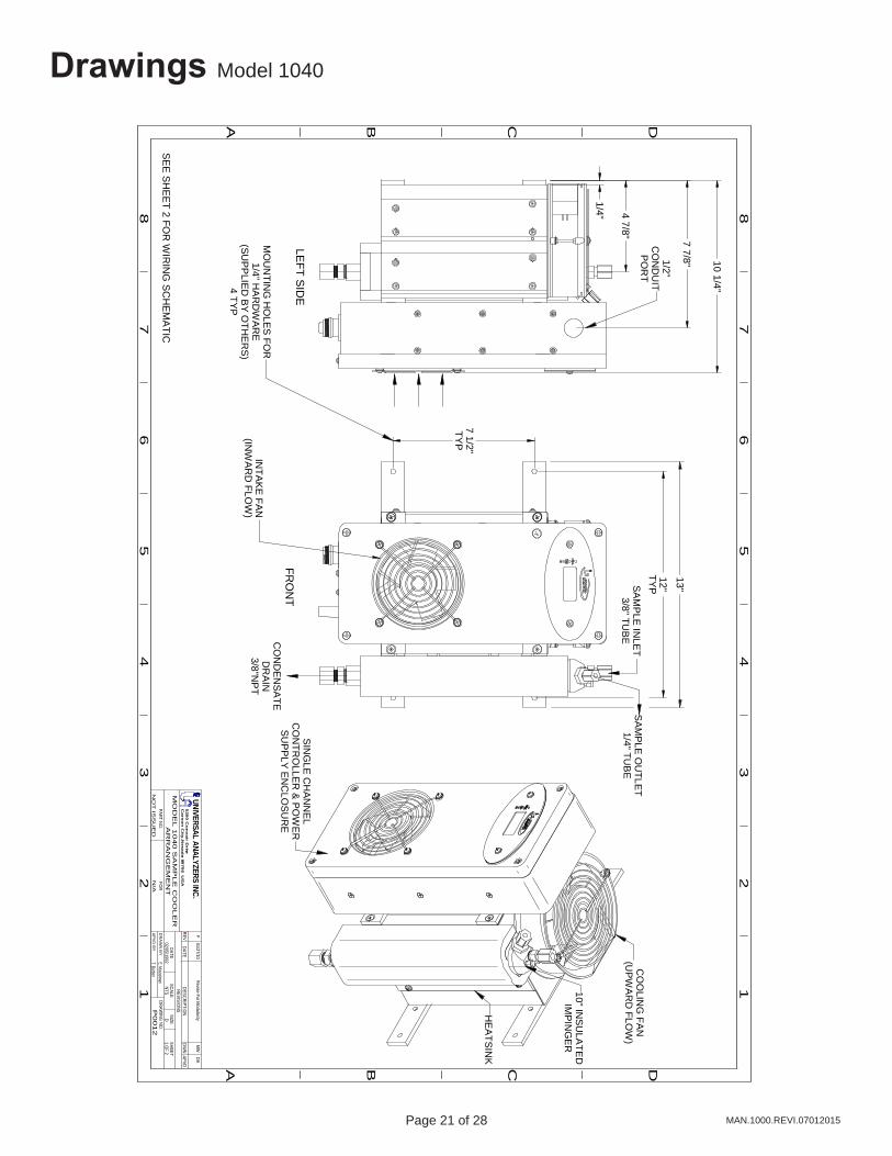
Drawings Model 1040
FRO
NT
LEFT S
IDE
1/4" 4 7/8" 7 7/8" 10 1/4"
7 1/2"TY
P
12"TY
P
13"SA
MP
LE IN
LET
3/8" TUB
E
MO
UN
TING
HO
LES
FOR
1/4" HA
RD
WA
RE
(SUP
PLIE
D B
Y OTH
ER
S)
4 TYP
CO
ND
EN
SA
TED
RA
IN3/8"N
PT
SIN
GLE
CH
AN
NE
LC
ON
TRO
LLER
& P
OW
ER
SU
PP
LY EN
CLO
SU
RE
CO
OLIN
G FA
N(U
PWAR
D FLO
W)
10" INS
ULATE
DIM
PIN
GE
R
HE
ATS
INK
SA
MP
LE O
UTLE
T1/4" TU
BE
1/2"C
ON
DU
ITP
OR
T
A B C D
A B C
12
34
56
78
12
34
56
7
D
8
P00
12
02/05/1992
N/A
REVREVISIO
NS
FOR
PART NO.
E. MusselmanA
PV
D B
Y
DR
AW
N B
YDRAW
ING NO
.
DATE
NO
T IS
SU
ED
MO
DE
L 1
04
0 S
AM
PL
E C
OO
LE
RA
RR
AN
GE
ME
NT
DATEDESCRIPTIO
NDW
NAPVD
SCALESIZE
SHEETNTS
D1 O
F 2
MW
UNIVERSAL ANALYZERS INC.5
20
0 C
on
va
ir Drive
Ca
rso
n C
ity, N
eva
da
8970
6 U
SA
DAF
01/27/10 Revise For M
odularity
T. Barben
SE
E S
HE
ET 2 FO
R W
IRIN
G S
CH
EMA
TIC
INTA
KE
FAN(IN
WA
RD
FLOW
)
Page 22 of 28 Page 23 of 28MAN.1000.REVI.07012015
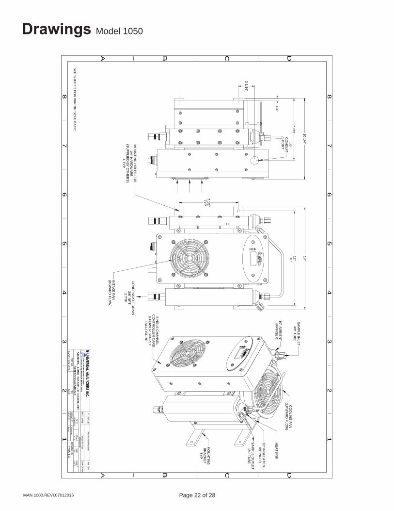
Drawings Model 1050
1/4"
1/2"C
ON
DU
ITP
OR
T
12"TYP
7 1/2"TYP
MO
UN
TING
HO
LES
FOR
1/4" HA
RD
WA
RE
(SU
PP
LIED
BY O
THE
RS
)4 TYP
SA
MP
LE IN
LET
3/8" TUBE
CO
OLIN
G FA
N(U
PW
AR
D FLO
W)
SIN
GLE
CH
AN
NE
LC
ON
TRO
LLER
CA
RD
& P
OW
ER
SU
PP
LYE
NC
LOS
UR
E
10" AM
BIE
NT
IMP
ING
ER
10" INS
ULA
TED
IMP
ING
ER
MO
UN
TING
BR
AC
KE
TTYP
SA
MP
LE O
UTLE
T1/4" TU
BE
7 7/8"
2 1/16"
HEA
TSIN
K
A B C D
A B C
12
34
56
78
12
34
56
7
D
8
P00
13
10/28/2006
N/A
REVREVISIO
NS
FOR
PART NO.
E. MusselmanA
PV
D B
Y
DR
AW
N B
YDRAW
ING NO
.
DATE
NO
T IS
SU
ED
MO
DE
L 1
05
0 S
AM
PL
E C
OO
LE
RA
RR
AN
GE
ME
NT
DATEDESCRIPTIO
NDW
NAPVD
SCALESIZE
SHEETNTS
D1 O
F 2
MW
UNIVERSAL ANALYZERS INC.1
70
1 S
ou
th S
utro
Te
rrac
eC
ars
on
City
, Ne
vad
a 89
70
6 U
SA
DAF
02/01/10 Revised For M
odularity
T. Barben
SE
E S
HE
ET 2 FO
R W
IRIN
G S
CH
EM
ATIC
.
10 1/4"
INTA
KE
FAN
(INW
AR
D FLO
W)
13"
CO
ND
EN
SA
TE D
RA
IN3/8" N
PT
2 TYP
Page 22 of 28 Page 23 of 28 MAN.1000.REVI.07012015
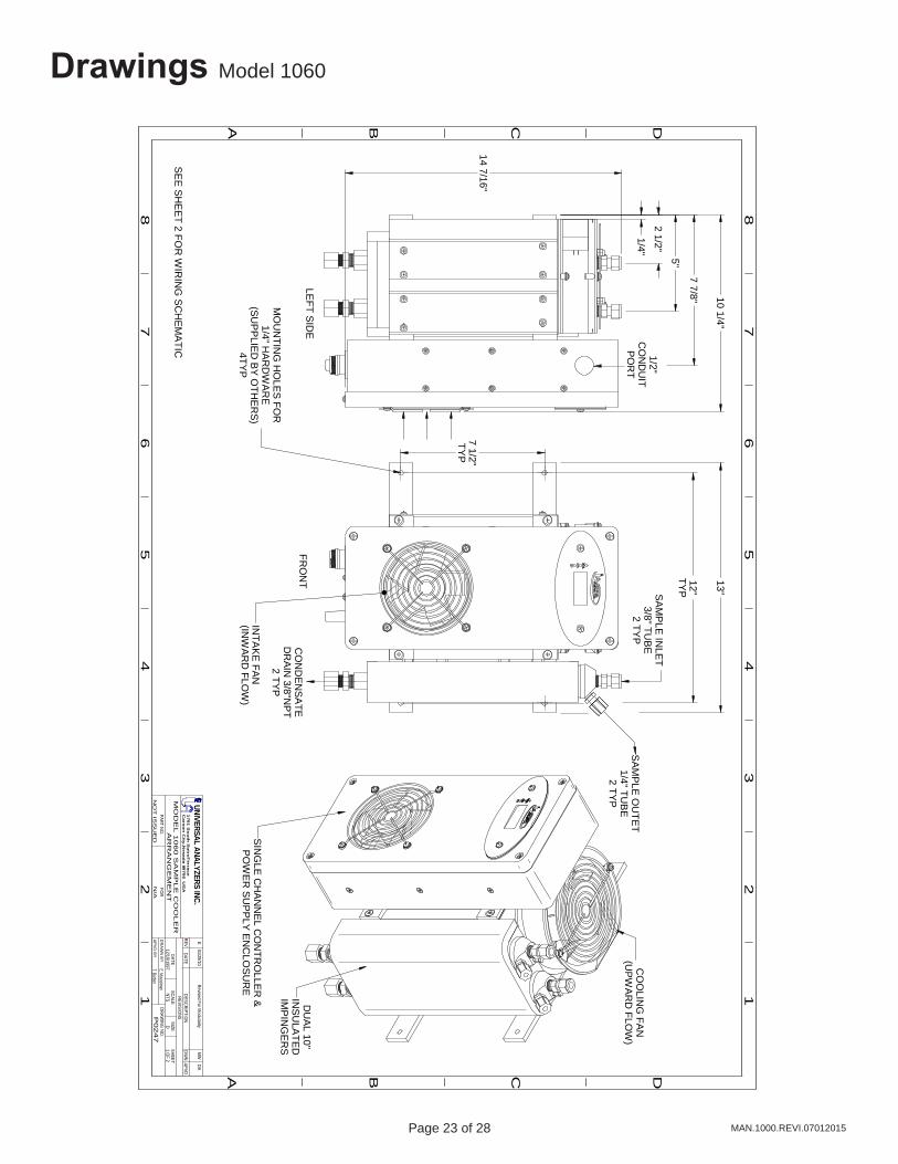
Drawings Model 1060
FRO
NT
LEFT S
IDE
1/4"
10 1/4"
1/2"C
ON
DU
ITP
OR
T
7 7/8"
7 1/2"TY
P
12"TY
P
13"
MO
UN
TING
HO
LES
FOR
1/4" HA
RD
WA
RE
(SUP
PLIE
D B
Y O
THE
RS
)4TY
P
SA
MP
LE IN
LET
3/8" TUB
E2 TY
PS
AM
PLE
OU
TET
1/4" TUB
E2 TY
P
CO
OLIN
G FAN
(UPW
ARD
FLOW
)
SIN
GLE
CH
AN
NE
L CO
NTR
OLLE
R &
PO
WE
R S
UP
PLY
EN
CLO
SU
RE
DU
AL 10"
INS
ULA
TEDIM
PIN
GE
RS
CO
ND
EN
SA
TED
RA
IN 3/8"N
PT2 TY
P
2 1/2"
5"
14 7/16"
A B C D
A B C
12
34
56
78
12
34
56
7
D
8
P02
47
12/19/1997
N/A
REVREVISIO
NS
FOR
PART NO.
E. MusselmanA
PV
D B
Y
DR
AW
N B
YDRAW
ING NO
.
DATE
NO
T IS
SU
ED
MO
DE
L 1
06
0 S
AM
PL
E C
OO
LE
RA
RR
AN
GE
ME
NT
DATEDESCRIPTIO
NDW
NAPVD
SCALESIZE
SHEETNTS
D1 O
F 2
MW
UNIVERSAL ANALYZERS INC.1
70
1 S
ou
th S
utro
Te
rrac
eC
ars
on
City
, Ne
vad
a 89
70
6 U
SA
DAE
01/28/10 Revised For M
odularity
T. Barben
SE
E S
HE
ET 2 FO
R W
IRIN
G S
CH
EM
ATIC
INTA
KE
FAN(IN
WA
RD
FLOW
)
Page 24 of 28 Page 25 of 28MAN.1000.REVI.07012015
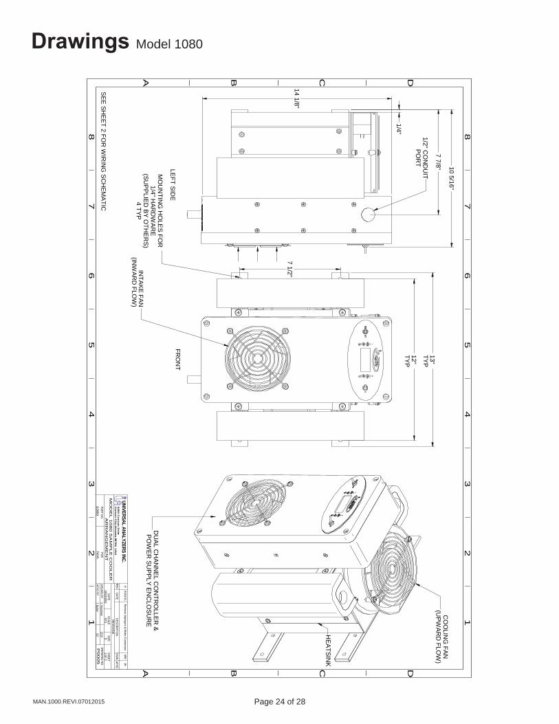
Drawings Model 1080
1/2" CO
ND
UIT
PO
RT
MO
UN
TING
HO
LES
FOR
1/4" HA
RD
WA
RE
(SUP
PLIE
D BY O
THE
RS
)4 TYP
CO
OLIN
G FA
N(U
PWA
RD
FLOW
)
DU
AL C
HAN
NE
L CO
NTR
OLLE
R &
PO
WE
R S
UP
PLY EN
CLO
SU
RE
HE
ATSINK
A B C D
A B C
12
34
56
78
12
34
56
7
D
8
P0
00
5
09/10/1991
N/A
REVREVISIO
NS
FOR
PART NO.
E. MusselmanA
PV
D B
Y
DR
AW
N B
YDRAW
ING NO
.
DATE
1080
MO
DE
L 1
08
0 S
AM
PL
E C
OO
LE
RA
RR
AN
GE
ME
NT
DATEDESCRIPTIO
NDW
NAPVD
SCALESIZE
SHEETNTS
D1 O
F 2
UNIVERSAL ANALYZERS INC.5
20
0 C
on
va
ir Drive
Ca
rso
n C
ity, N
eva
da
8970
6 U
SA
JHH
01/04/11 Rem
ove Impingers & M
olex ConnectorsM
W
SE
E SH
EE
T 2 FOR
WIR
ING
SC
HE
MA
TICT. Barben
FRO
NT
LEFT S
IDE
10 5/16"
7 7/8"
1/4"
7 1/2"
INTA
KE
FAN(IN
WA
RD
FLOW
)
14 1/8"
12"TY
P
13"TY
P
ECO#557
Page 24 of 28 Page 25 of 28 MAN.1000.REVI.07012015
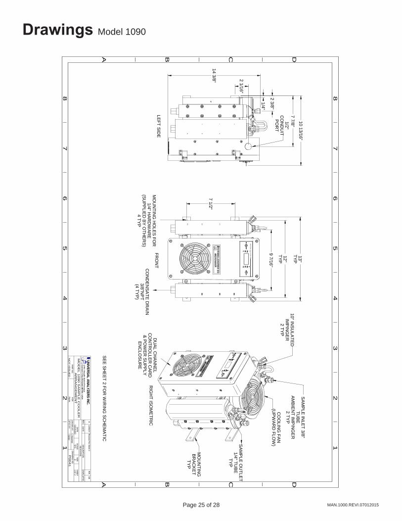
Drawings Model 1090
UN
IVE
RS
AL AN
ALY
ZER
S IN
C.
FRO
NT
LEFT S
IDE
RIG
HT IS
OM
ETR
IC
7 7/8"
1/4"
10 13/16"
7 1/2"
12"TY
P
13"TY
P
MO
UN
TING
HO
LES
FOR
1/4" HA
RD
WA
RE
(SUP
PLIE
D B
Y O
THE
RS
)4 TY
P
CO
ND
EN
SA
TE D
RA
IN3/8"N
PT
(4 TYP
)
SA
MP
LE O
UTLE
T1/4" TU
BE
TYP
1/2"C
ON
DU
ITP
OR
T
DU
AL C
HA
NN
EL
CO
NTR
OLLE
R C
ARD
& P
OW
ER S
UP
PLY
EN
CLO
SU
RE
CO
OLIN
G FAN
(UP
WA
RD
FLOW
)
SA
MP
LE IN
LET 3/8"
TUB
EA
MB
IEN
T IMP
ING
ER
2 TYP
10" INS
ULA
TED
IMP
ING
ER2 TY
P
9 7/16"2 3/8"
A B C D
A B C
12
34
56
78
12
34
56
7
D
8
P00
41
03/14/1993
N/A
REVREVISIO
NS
FOR
PART NO.
E. MusselmanA
PV
D B
Y
DR
AW
N B
YDRAW
ING NO
.
DATE
NO
T IS
SU
ED
MO
DE
L 1
09
0 S
AM
PL
E C
OO
LE
RA
RR
AN
GE
ME
NT
DATEDESCRIPTIO
NDW
NAPVD
SCALESIZE
SHEETNTS
D1 O
F 2
RWUNIVERSAL ANALYZERS INC.
170
1 S
ou
th S
utro
Te
rrac
eC
ars
on
City
, Ne
vad
a 89
70
6 U
SA
GE
E11/06/07
Revised Per Sheet 2
T. Barben
SE
E S
HE
ET 2 FO
R W
IRIN
G S
CH
EM
ATIC
2 1/16"
14 3/8"
MO
UN
TING
BRA
CK
ET
TYP
Page 26 of 28 Page 27 of 28MAN.1000.REVI.07012015
Limited WarrantyI. Limited Warranty
1. Limited Warranty. Universal Analyzers, Inc (UAI) offers a limited warranty on each of its products against failure due to defects in material and workmanship for a period ending the earlier of (i) fifteen (15) months from the date of the invoice relating to the sale of the product and (ii) twelve (12) months from the date of installation of the product (collectively, the “Initial Warranty”). During the Initial Warranty, UAI offers a limited warranty against failure due to defects in material and workmanship on each part of a product repaired or replaced by an authorized service person for a period ending the later of (a) the remaining term of the Initial Warranty of the product and (b) ninety (90) days from the date of such repair or replacement. After expiration of the Initial Warranty, UAI offers a limited warranty against failure due to defects in material and workmanship on each part of a product repaired or replaced by an authorized service person for a period ending ninety (90) days from the date of such repair or replacement. UAI further offers a limited warranty that the products and parts it sells will conform to UAI’s written specifications therefor. The foregoing limited warranties cover parts and labor only and UAI does not warrant and will not reimburse the buyer of its products (“Buyer”) for any costs relating to the access by service persons of UAI to the product at issue. The foregoing limited warranties cover only the repair or replacement of defective parts and such determination will be in the sole discretion of UAI. In its sole discretion, UAI may make repairs or replacements under these limited warranties with either new or refurbished parts. To the extent Buyer’s product cannot be remedied under these limited warranties through repair or replacement of parts, Buyer may return the product for a refund of the purchase price, less a reasonable reduction in such purchase price equal to the depreciation expense incurred by Buyer relating to such product. The limited warranties of this Section I.1. are further subject to those warranty exclusions set forth below in Section I.2.
2. Limited Warranty Exclusions. Excluding the warranties provided for in Section I.1., UAI provides all products to Buyer “as-is,” without any other warranty of any kind. UAI disclaims any and all express or implied warranties of merchantability, fitness for a particular purpose and non-infringement of the intellectual property of others. UAI makes no warranty, express or implied, as to the design, sale, installation or use of its products. UAI’s warranties will not be enlarged by, nor will any obligation or liability of UAI arise due to UAI providing technical advice, facilities or service in connection with any product. There is no warranty by UAI with respect to any product’s: (i) uninterrupted or error-free operation; (ii) actual performance, other than the product’s capability to meet UAI’s specifications therefor; (iii) removal or installation from a worksite or process; (iv) electronic components or associated accessories (including without limitation circuit boards and integrated circuits); (v) maintenance (including without limitation gasket and seal replacements, adjustments, minor repairs and other inspection requirements, preventative or otherwise); (vi) use under inappropriate conditions or not in accordance with operating instructions; or (vii) use in connection with the operation of a nuclear facility. There is no warranty for labor expenses associated with field repairs or the repair or replacement of defective parts in the engine or power unit of any product if such product has been in the possession of the owner or operator for greater than twelve (12) months. There is no warranty for products determined to be, in UAI’s sole discretion, damaged as a result of (a) misuse, neglect or accident; (b) improper application, installation, storage or use; (c) improper or inadequate maintenance or calibration; (d) operation outside of the published environmental specification; (e) improper site preparation or maintenance; (f) unauthorized repairs or replacements; (g) modifications negligently or otherwise improperly made or performed by persons other than UAI; (h) Buyer-supplied software or supplies; (i) use in conjunction with or interfacing with unapproved accessory equipment; (j) use of ABC-style or dry powder fire suppression agents; or (k) leaked sample materials. To the extent a UAI product is used in connection with the operation of a nuclear power facility, Buyer agrees to indemnify and hold UAI harmless from any and all actions, claims, suits, damages and expenses arising from such use. UAI provides no warranty on the oral representations made by its personnel while they are attempting to assist Buyer in the operation of a product. This Standard Limited Warranty does not apply to items consumed by the products during their ordinary use, including but not limited to fuses, batteries, paper, septa, fittings, screws, fuses, pyrolysis, dryer or scrubber tubes, sample boats, furnaces or UV lamps.
3. Non-UAI Products. UAI does not in any way warrant products it does not manufacture except to the extent the warranty of the manufacturer of the product at issue passes through or is otherwise assigned to UAI. If a manufacturer warranty is so assigned to UAI, UAI will only be bound to comply with the length of time associated with such warranty. All other terms of such warranty will be governed by this Standard Limited Warranty and UAI’s General Terms and Conditions incorporated herein by reference.
Page 26 of 28 Page 27 of 28 MAN.1000.REVI.07012015
Limited Warranty
4. Expenses on Non-Warranty Work. All repairs or replacements by UAI after the expiration of any applicable limited warranty period will be performed in accordance with UAI’s standard rate for parts and labor. Further, if upon UAI’s inspection and review, UAI determines the condition of the products is not caused by a defect in UAI’s material and workmanship, but is the result of some other condition, including but not limited to damage caused by any of the events or conditions set forth in Section I.2., Buyer shall be liable for all direct expenses incurred by UAI to conduct the inspection and review of the product.
5. Exclusive Remedy. The foregoing limited warranty constitutes Buyer’s exclusive remedy with respect to products sold by UAI and UAI’s liability shall be exclusively limited to the written limited warranty specified herein. No employee, representative or agent of UAI is authorized to either expressly or impliedly modify, extend, alter or change any of the limited warranties expressed herein to Buyer.
6. Procedure and Costs. All limited warranty claims must be made in writing promptly following discovery of any defect. Buyer must hold defective products for inspection by UAI. If requested by UAI, Buyer must send the product to UAI for inspection. Any such returns by Buyer will be at Buyer’s expense and Buyer will remain liable for any loss of or damage to the product during such product’s transportation to UAI. No products will be sent to UAI for inspection unless UAI has authorized Buyer to do so.
7. Terms and Conditions. UAI’s General Terms and Conditions are incorporated herein by reference and Buyer accordingly agrees to be bound by the terms thereof.
II. Limitations on UAI Liability
1. In General. Buyer agrees UAI shall not be liable for any direct, indirect, incidental, punitive or consequential damages, including lost profits, lost savings or loss of use, whether Buyer’s claim is based in contract, tort, warranty, strict liability or otherwise, which Buyer may suffer for any reason, including reasons attributable to UAI. Buyer agrees these limitations on UAI’s liability are reasonable and reflected in the amounts charged by UAI for its products.
2. Force Majeure. This Standard Limited Warranty does not cover and UAI shall not be liable for either direct or consequential damage caused, either directly or indirectly, as a result of: (i) any act of God, including but not limited to natural disaster, such as floods, earthquakes, or tornadoes; (ii) damages resulting from or under the conditions of strikes or riots, war, damages or improper operation due to intermittent power line voltage, frequency, electrical spikes or surges, unusual shock or electrical damage; or (iii) accident, fire or water damage, neglect, corrosive atmosphere or causes other than ordinary use.
3. Limitation on Warranty Claims. Prior to any obligation of UAI to perform any limited warranty service as set forth herein, Buyer must have: (i) paid all invoices to UAI in full, whether or not they are specifically related to the product at issue; and (ii) notified UAI of the limited warranty claim within sixty (60) days from the date Buyer knew or had reason to know of the defect

Page 28 of 28 Page PB of 1MAN.1000.REVI.07012015
5200 Convair Drive Carson City, NV 89706 • Phone: 775-883-2500 • Fax: 775-883-6388 • www.universalanalyzers.com