HP 8711C/12C/13C/14C RF Network Analyzers - xDevs.com
472
Programmer’s Guide HP 8711C/12C/13C/14C RF Network Analyzers
-
Upload
khangminh22 -
Category
Documents
-
view
2 -
download
0
Transcript of HP 8711C/12C/13C/14C RF Network Analyzers - xDevs.com

I-I -
Programmer’s Guide
HP 8711C/12C/13C/14CRF Network Analyzers

I- I -
Notice
HP part number: 08712-90057Printed in USA August 1998 Supersedes April 1998
The information contained in this document is subject to change withoutnotice.
Hewlett-Packard makes no warranty of any kind with regard to this material,including but not limited to, the implied warranties of merchantability andfitness for a particular purpose. Hewlett-Packard shall not be liable for errorscontained herein or for incidental or consequential damages in connectionwith the furnishing, performance, or use of this material.
Firmware Revision This manual documents analyzers with firmware revisions C. 04.52 or later.Some features will not be available or will require different keystrokesin analyzers with earlier firmware revisions. For full compatibility, youcan upgrade your firmware to the latest version. Contact your nearestHewlett-Packard sales or service office for information.
@Copyright 1996, 1997, 1998 Hewlett-Packard Company

I- I -
HP-IB Programming
This document is an introduction to programming your analyzer over theHewlett-Packard Interface Bus (HP-IB). Its purpose is to provide conciseinformation about the operation of the instrument under HP-II3 control.It provides some background information on the HP-IB and a tutorialintroduction using programming examples to demonstrate the remoteoperation of the analyzer. The examples are provided on two disks that areincluded with the analyzer. Both disks contain the same examples writtenmainly in HP BASIC; only the disk format is different. These programs canrun on the analyzer’s internal controller (Option lC2) or on an externalcontroller.
l Example Programs Disk - DOSFbvmat : part number 08712-10019
l ExammpLe Programs Disk - LIFRrrmat : part number 08712-10021
You should become familiar with the operation of your network analyzerbefore controlling it over HP-IB. This document is not intended to teachprogramming or to discuss HP-IB theory except at an introductory level.Related information can be found in the following references. Contact thenearest HP sales office for ordering information. A list of HP sales and serviceoffices can be found in the “Specifications and Characteristics” chapter of theUser’s Guide.
l Information on making measurements with the analyzer is available in theanalyzer’s User’s Guide.
l Information on HP Instrument BASIC is available in the HP InstrumentBASIC User’s Handbook.
0 Information on HP BASIC programming is available in the manual set forthe BASIC revision being used. For example: BASIC 7.0 ProgrammingRchniques and BASIC 7.0 Language Reference.
l Information on using the HP-IB is available in the Tutorial Description ofthe Hewlett-Packard Interface Bus (HP literature no. 5021-1927).
. . .111

I -

I- I -
Contents
1. Introduction to BP-IB ProgrammingBus Structure .................... l-4
Data Bus ..................... l-4Handshake Lines ................. l-4
Sending Commands ................. l-6HP-IB Requirements ................. l-7Interface Capabilities ................ 1-8Programming Fundamentals ............. l-9
Controller Capabilities ............... l-9Response to Bus Management Commands ...... l-10Message Exchange ................. 1-13
2. Synchronizing the Analyzer and a ControllerOverlapped Commands ............... 2-3The NPO Flag ................... 2-5
Usage of *WA1 and *OPC? ............. 2-7
3. Passing Control
4. Data Types and EncodingData Types ..................... 4-3
Numeric Data ................... 4-3Character Data .................. 4-4String Data .................... 4-4Expression Data .................. 4-4Block Data .................... 4-5
Data Encoding for Large Data Transfers ........ 4-7ASCII Encoding .................. 4-8Binary Encoding ................. 4-8Byte Swapping .................. 4-9
Contents-l

I- I -
Query Errors
5. Using Status RegistersGeneral Status Register Model ............
Condition Register ................Transition Registers ................Event Register ..................Enable Register ..................
How to Use Registers ..................The Service Request Process .............
Generating a Service Request ............The Analyzer’s Status Register Sets ..........
Status Byte ....................Device Status Register Set .............Limit Fail Register Set ...............Questionable Status Register Set ..........Standard Event Status Register Set .........Measuring Status Register Set ...........Averaging Status Register Set ............Operational Status Register Set ...........STATus:PRESet Settings ..............Analyzer Register Set Summary ...........
6. Trace Data TransfersQuerying the Measurement Trace Using BASIC .....
@Smith Chart and Polar Formats ..........
Querying the Measurement Trace Using SICL ......Using Binary Data Encoding .............
Trace Data Transfer SizesTransferring Data with IBASIC : : : : : : : : : : : :Taking Sweeps ...................CALC:DATA? versus TRACE:DATA? . . . . . . . . . . . .Querying Single Data Points Using Markers .......Accessing Other Measurement Arrays .........Applying Gain Correction Using the Memory Trace ...Performing Your Own Data Processing .........Downloading Trace Data Using Binary Encoding ....Internal Measurement Arrays .............
Raw Data Arrays .................Ratio Calculations .................Error Correction .................
5-35-45-45-45-55-65-75-8
5-105-125-155-165-195-205-235-235-245-255-26
6-36-4
6-56-76 - 9
6-106-11
6-126-136-146-166-186-206-216-226-236-23
Contents-2

I -
Query Errors
Error Coefficient Arrays .............. 6-23Averaging ...................... 6-25Corrected Data Arrays ............... 6-25Corrected Memory Arrays ............. 6-25Trace Math Operation ............... 6 - 2 6@ Electrical Delay ................. 6 - 2 6
Transform (Option 100 only) ............ 6 - 2 6Formatting .................... 6 - 2 7Formatted Arrays ................. 6 - 2 7Offset and Scale .................. 6 - 2 7
7. Using GraphicsWindow Geometry . . . . . . . . . . . . . . . . . 7 - 4The Graphics Buffer . . . . . . . . . . . . . . . . . 7 - 6
8. Example ProgramsConfiguring Measurements .............. 8 - 7
SETUP Example Program ............. 8-8LIMITEST Example Program ............ 8-11POWERSWP Example Program .......... 8-16
Transfer of Data to/from the Analyzer ......... 8-19MARKERS Example Program ........... S-20@SMITHMKR Example Program .......... 8 - 2 4
ASCDATA Example Program ............ 8 - 3 1REALDATA Example Program ........... 8 - 3 4INTDATA Example Program ............ 8 - 3 8FAST-C W Example Program ............ 8 - 4 2
Calibration ..................... 8 - 4 5TRANCAL Example Program ........... 8 - 4 6REFLCAL Example Program ............ 8-48LOADCALS Example Program ........... 8 - 5 3CALKIT Example Program . .
Instrument State and Save/Recall : : : : : : : : : . .S-608 - 6 2
LEARNSTR Example Program ........... 8 - 6 3SAVERCL Example Program ............ 8 - 6 6
Hardcopy Control .................. 8-69PRINTPLT Example Program ........... 8 - 7 0PASSCTRL Example Program ........... 8 - 7 3
Contents-3

I-
Query Errors
FAST-PRT Example Program ...........Service Request ....................
SRQ Example Program ..............SRQ-INT Example Program ............
File Transfer Over HP-IB ...............GETFILE Example Program ............PUTFILE Example Program ............
Customized Display .................GRAPHICS Example Program ...........GRAPH2 Example Program ............GETPLOT Example Program ...........
Annot ation .....................USERANOT Example Program ...........FREQBLNK Example Program ...........KEYCODES Example Program ...........
Marker Functions ..................MKR-MATH Example Program ..........
Marker Limit Testing ................LIM-FLAT Example Program ...........LIM-PEAK Example Program ...........LIM-MEAN Example Program ...........
SRL Measurements (Option 100 only) .........MEAS-SRL Example Program ...........SRL-SRQ Example Program ............
Fault Location Measurements (Option 100 only) .....FAULT Example Program .............USR-FLOC Example Program ...........
Multiport Test Set Measurements ...........PORT-SELection Example Program .........TSET-CAL Example Program ...........
TTL Output ....................TTL-IO Example Program .............
AM Delay .....................AMDELAY Example Program ...........
8-77S-808-818-85
S-102S-103S-105S-108S-1098-1168-1228-1258-1268-1298-1318-1348-1358-139S-1408-1438-1478-1518-1528-156S-1608-1618-1658-1688-1698-1828-1868-1868-1898-189
Contents-4

I -
Query Errors
9. Front Panel Keycodes
10. Introduction to SCPIThe Command Tree . . . . . .Sending Multiple Commands . .Command Abbreviation . . . .Implied Mnemonics . . . . . .Parameter Types . . . . . . . .
Numeric Parameters . . . . .Character Parameters . . . .Boolean Parameters . . . . .String Parameters . . . . . .Block Parameters . . . . . .
Syntax Summary . . . . . . .IEEE 488.2 Common Commands
11. Menu Map with SCPI Commands
12. SCPI Command Summary
13. SCPI Conformance InformationSCPI Standard Commands . . .Instrument Specific Commands .
14. SCPI Error MessagesCommand Errors . . . . . . . ........... 14-3Execution Errors . . . . . . . ........... 14-7Device-Specific Errors . . . . . ........... 14-12Query Errors . . . . . . . . . ........... 14-14
........... 10-3
........... 10-7
........... 10-S
........... 10-9........... 10-10........... 10-10........... 10-11........... 10-12........... 10-13........... 10-14........... 10-15........... 10-17
13-313-9
Index
Contents-5

I- I -
Figures
5-1. General Status Register Model . . . . . . . . . . . 5-35-2. Flow of information within a register set . . . . . . 5-55-3. Generating a Service Request . . . . . . . . . . . . . . . 5-85-4. Analyzer Register Sets . . . . . . . . . . . . 5-115-5. The Status Byte Register Set . . . . _ . . . . 5-125-6. The Limit Fail Register Set . . . . . . . . . . . . . . . 5-175-7. The Standard Event Status Register Set . . . . . . . . . 5-205-8. Analyzer Register Set Summary . . . . . . . . . . . . . . 5-266-1. Numeric Data Flow Through the Network Analyzer . . . 6-26-2. Numeric Data Flow Through the Network Analyzer . . . . . 6-146-3. Numeric Data Flow Through the Network Analyzer . . . 6-217-l. Pixel Dimensions with Available Display Partitions . . . . . 7-4
10-l. Measurement and Data Flow of the Analyzer . . . . . 10-310-2. Partial Diagram of the CALCulate Subsystem Command Tree . 10-610-3. SCPI Command Syntax . . . . . . . . . . . . lo-15
Contents-6

I -
lhbles
6-l. Typical Trace Transfer Times (ms) . . . . . . . . . . . . 6-76-2. Size of Trace Data Transfers (in Bytes) Using the TRACE:DATA
SCPI Command . . . . . . . . . . . . . . . . . . . 6-96-3. Typical Trace Transfer Times (ms) . . . . . . . . . . . . 6-106-4. Raw Data Arrays . . . . . . . . . . . . . . . . . . . . 6-226-5. Error Coefficient Arrays . . . . . . . . . . . . . . . . . 6-24
12-1. Writeable Ports . . . . . . . . . . . . . . . . . . . . . 12-1312-2. Readable Ports . . . . . . . . . . . . . . . . . . . . . 12-1414-1. SCPI Command Errors . . . . . . . . . . . . . . . . . . 14-414-2. SCPI Execution Errors . . . . . . . . . . . . . . . . . . 14-814-3. SCPI Device-Specilic Errors . . . . . . . . . . . . . . . . 14-1314-4. SCPI Query Errors . . . . . . . . . . . . . . . . . . . . 14-14
Contents-7

I-
Contents

I -
1
Introduction to HP-IBProgramming

I- I -
Introduction to HP-IB Programming
HP-IB - the Hewlett-Packard Interface Bus - is a high-performance busthat allows individual instruments and computers to be combined intointegrated test systems. The bus and its associated interface operations aredefined by the IEEE 488.1 standard. The IEEE 488.2 standard defines theinterface capabilities of instruments and controllers in a measurement system,including some frequently used commands.
HP-IB cables provide the physical link between devices on the bus. There areeight data lines on each cable that are used to send data from one device toanother. Devices that send data over these lines are called Talkers. Listenersare devices that receive data over the same lines. There are also five controllines on each cable that are used to manage trafhc on the data lines and tocontrol other interface operations. Controllers are devices that use thesecontrol lines to specify the talker and listener in a data exchange. When anHP-IB system contains more that one device with controller capabilities,only one of the devices is allowed to control data exchanges at any giventime. The device currently controlling data exchanges is called the ActiveController. Also, only one of the controller-capable devices can be designatedas the System Controller, the one device that can take control of the buseven if it is not the active controller. The network analyzer can act as atalker, listener, active controller or system controller at different times.
HP-IB addresses provide a way to identify devices on the bus. The activecontroller uses HP-IB addresses to specify which device talks and whichdevice listens during a data exchange. This means that each device’s addressmust be unique. A device’s address is set on the device itself, using either afront-panel key sequence or a rear-panel switch.
To set the HP-IB address on the analyzer use the softkeys located in the[SYSTEM OPTIONS) HP-IB menu. The factory default address for the analyzeris 16.
l-2

I- I -Introduction to HP-IB Programming
N O T E
Throughout this manual, the following conventions are used:
Square brackets Cc II are used to enclose a keyword that is optional or implied when
programming the command; that is, the instrument will process the command to have the same
effect whether the option node is omitted or not.
Parameter types (C >I are distinguished by enclosing the type name in angle brackets.
A vertical bar (I ) can be read as “or” and is used to separate alternative parameter options.
I I
l-3

I- I -
Bus Structure
Data Bus
The data bus consists of eight lines that are used to transfer data from onedevice to another. Programming commands and data sent on these lines istypically encoded in the ASCII format, although binary encoding is often usedto speed up the transfer of large arrays. Both ASCII and binary data formatsare available to the analyzer. In addition, every byte transferred over HP-IBundergoes a handshake to ensure valid data.
Handshake Lines
A three-line handshake scheme coordinates the transfer of data betweentalkers and listeners. This technique forces data transfers to occur at thespeed of the slowest device, and ensures data integrity in multiple listenertransfers. With most computing controllers and instruments, the handshake isperformed automatically, which makes it transparent to the programmer.
Control lines The data bus also has five control lines that the controller uses both to sendbus commands and to address devices:
IFC Interface Clear. Only the system controller uses this line.When this line is true (low) all devices (addressed or not)unaddress and go to an idle state.
ATN Attention. The active controller uses this line to definewhether the information on the data bus is a command or isdata. When this line is true (low) the bus is in the commandmode and the data lines carry bus commands. When thisline is false (high) the bus is in the data mode and the datalines carry device-dependent instructions or data.
l-4

I- I -
SRQ
REN
E O I
Introduction to HP-IB Programming
Bus Structure
Service Request. This line is set true (low) when adevice requests service: the active controller services therequesting device. The analyzer can be enabled to pull theSRQ line for a variety of reasons.
Remote Enable. Only the system controller uses this line.When this line is set true (low) the bus is in the remotemode and devices are addressed either to listen or talk.When the bus is in remote and a device is addressed, thedevice receives instructions from HP-IS rather than from itsfront panel (pressing the Beturn to Local softkey returnsthe device to front panel operation). When this line is setfalse (high) the bus and all devices return to local operation.
End or Identify. This line is used by a talker to indicate thelast data byte in a multiple byte transmission, or by anactive controller to initiate a parallel poll sequence. Theanalyzer recognizes the EOI line as a terminator and it pullsthe EOI line with the last byte of a message output (data,markers, plots, prints, error messages). The analyzer doesnot respond to parallel poll.
l-5

I- I -
Sending Commands
Commands are sent over the HP-IB via a controller’s language system,such as IBASIC, QuickBASIC or C. The keywords used by a controller tosend HP-IB commands vary among systems. When determining the correctkeywords to use, keep in mind that there are two different kinds of HP-IBcommands:
l Bus management commands, which control the HP-IB interface.
l Device commands, which control analyzer functions.
Language systems usually deal differently with these two kinds of HP-IBcommands. For example, HP BASIC uses a unique keyword to send each busmanagement command, but always uses the keyword OUTPUT to send devicecommands.
The following example shows how to send a typical device command:
OUTPUT 7 16 ; “CALCULATE : MARKER : MAXIMUM”
This sends the command within the quotes (CALCULATE : MARKER : MAXIMUM)to the HP-II3 device at address 716. If the device is an analyzer, the commandinstructs the analyzer to set a marker to the maximum point on the datatrace.
l-6

I- I -
HP-IB Requirements
Number of InterconnectedDevices:InterconnectionPath/Maximum Cable Length:
Message Transfer Scheme:
Data Rate:
Address Capability:
Multiple Controller Capability:
15 maximum
20 meters maximum or 2 meters per device,whichever is less.
Byte serial/ bit parallel asynchronous datatransfer using a 3-line handshake system.
Maximum of 1 megabyte per second overlimited distances with tri-state drivers.Actual data rate depends on the transfer rateof the slowest device involved.
Primary addresses: 31 talk, 31 listen. Amaximum of 1 talker and 14 listeners at onetime.
In systems with more than one controller(like the analyzer system), only one canbe active at a time. The active controllercan pass control to another controller, butonly the system controller can assumeunconditional control. Only one systemcontroller is allowed. The system controlleris hard-wired to assume bus control after apower failure.
l-7

I- I -
Interface Capabilities
The analyzer has the following interface capabilities, as defined by theIEEE 488.1 standard:
SHl full Source handshake capabil ity
AH1
T6
full Acceptor handshake capability
basic Talker, Serial Poll , no Talk Only, unaddress if MLA
T E O
L4
no Extended Talker capabil ity
basic Listener, no Listen Only, unaddress if MTA
I L E O I no Extended Listener capabil ity I
SRl full Service Request capabilityI
1 RLl 1 full Remote/local capabil ity
I OCI I full Device Clear caoabilitv ICl I System Controller capability I
c2 send IFC and take charge Controller capabil ity
I c3 send REN Controller capabil ity Ic4l
CB1
respond to SRC
send IFC, receive control , pass control , pass control to self
c122
E2
send IF messages, receive control , pass control
tri-state drivers
LIT1
PPO
full device trigger capability
no parallel poll capabil ity
1 only when an HP Instrument BASIC program is running
2 only when an HP Instrument BASIC program is not running
1-8

I- I -
Programming Fundamentals
This section includes specific information for programming your networkanalyzer. It includes how the analyzer interacts with a controller, how datais transferred between the analyzer and a controller, and how to use theanalyzer’s status register structure to generate service requests.
Controller Capabilities
The analyzer can be conEgured as an HP-IIl system controller or asa talker/listener on the bus. ‘Ib configure the analyzer, select eitherthe System Controller or the TalkerlListeaer softkey in the
@YSTEM 0PrloNs) HP-IB menu.
The analyzer is not usually conEgured as the system controller unless it is theonly controller on the bus. This setup would be used if the analyzer onlyneeded to control printers or plotters. It would also be used if HP InstrumentBASIC was being used to control other test equipment.
When the analyzer is used with another controller on the bus, it is usuallyconEgured as a talker/listener. In this conEguration, when the analyzer ispassed control it can function as the active controller.
l-9

I- I -
Introduction to HP-IR Programming
Programming Fundamentals
Response to Bus Management Commands
The HP-IB contains an attention (ATN) line that determines whetherthe interface is in command mode or data mode. When the interface isin command mode (ATN TRUE) a controller can send bus managementcommands over the bus. Bus management commands specify which deviceson the interface can talk (send data) and which can listen (receive data).They also instruct devices on the bus, either individually or collectively, toperform a particular interface operation.
This section describes how the analyzer responds to the HP-IB busmanagement commands. The commands themselves are defined by theIEEE 488.1 standard. Refer to the documentation for your controller’slanguage system to determine how to send these commands.
Device Clear (DC11 When the analyzer receives this command, it:
l Clears its input and output queues.l Resets its command parser (so it is ready to receive a new program
message).l Cancels any pending *OPC command or query.
The command does not affect:
l Front panel operation.l Any analyzer operations in progress (other than those already mentioned).l Any instrument settings or registers (although clearing the output queue
may indirectly affect the Status Byte’s Message Available (MAV) bit).
Go To local (GTLI This command returns the analyzer to local (front-panel) control. All keys onthe analyzer’s front-panel are enabled.
Interface Clear (IFC) This command causes the analyzer to halt all bus activity. It discontinuesany input or output, although the input and output queues are not cleared.If the analyzer is designated as the active controller when this command isreceived, it relinquishes control of the bus to the system controller. If theanalyzer is enabled to respond to a Serial Poll it becomes Serial Poll disabled.
l-10
-

I- I -
Introduction to HP-16 Programming
Programming Fundamentals
local lockout (1101 This command causes the analyzer to enter the local lockout mode, regardlessof whether it is in the local or remote mode. The analyzer only leaves thelocal lockout mode when the HP-IB’s Remote Enable (REN) line is set FALSE.
Local Lockout ensures that the analyzer’s remote softkey menu (including theRstunr ta LOCAL softkey) is disabled when the analyzer is in the remotemode. When the key is enabled, it allows a front-panel operator to return theanalyzer to local mode, enabling all other front-panel keys. When the key isdisabled, it does not allow the front-panel operator to return the analyzer tolocal mode.
Parallel Poll The analyzer ignores all of the following parallel poll commands:
l Parallel Poll ConEgure (PPC).l Parallel Poll UnconEgure (PPU).l Parallel Poll Enable (PPE).l Parallel Poll Disable (PPD).
Remote Enable (RENI REN is a single line on the HP-IR. When it is set TRUE, the analyzer willenter the remote mode when addressed to listen. It will remain in remotemode until it receives the Go to Local (GTL) command or until the REN line isset FALSE.
When the analyzer is in remote mode and local lockout mode, all front panelkeys are disabled. When the analyzer is in remote mode but not in locallockout mode, all front panel keys are disabled except for the softkeys. Theremote softkey menu includes seven keys that are available for use by aprogram. The eighth softkey is the Bet- to LOCAL key which allows afront-panel operator to return the analyzer to local mode, enabling all otherfront-panel keys.
l-11
I- I -
Introduction to HP-18 Programming
Programming Fundamentals
Selected Device Clear The analyzer responds to this command in the same way that it responds to(SDC) the Device Clear (DCL) command.
When the analyzer receives this command it:
l Clears its input and output queues.l Resets its command parser (so it is ready to receive a new program
message).l Cancels any pending *OPC command or query.
The command does not affect:
l Front-panel operation.l Any analyzer operations in progress (other than those already mentioned).l Any analyzer settings or registers (although clearing the output queue may
indirectly affect the Status Byte’s MAV bit).
Serial Poll The analyzer responds to both of the serial poll commands. The Serial PollEnable (SPE) command causes the analyzer to enter the serial poll mode.While the analyzer is in this mode, it sends the contents of its Status Byteregister to the controller when addressed to talk.
When the Status Byte is returned in response to a serial poll, bit 6 acts as theRequest Service (RQS) bit. If the bit is set, it will be cleared after the StatusByte is returned.
The Serial Poll Disable (SPD) command causes the analyzer to leave the serialpoll mode.
Take Control TalkerITCTI
If the analyzer is addressed to talk, this command causes it to take controlof the HP-IB. It becomes the active controller on the bus. The analyzerautomatically passes control back when it completes the operation thatrequired it to take control. Control is passed back to the address speciEed bythe *PCB command (which should be sent prior to passing control).
If the analyzer does not require control when this command is received, itimmediately passes control back.
1-12

I- I -
Introduction to HP-IB Programming
Programming Fundamentals
Message Exchange
The analyzer communicates with the controller and other devices on theHP-IB using program messages and response messages. Program messages areused to send commands, queries, and data to the analyzer.
Response messages are used to return data from the analyzer. The syntax forboth kinds of messages is discussed in Chapter 10.
There are two important things to remember about the message exchangesbetween the analyzer and other devices on the bus:
l The analyzer only talks after it receives a terminated query (see “QueryResponse Generation” later in this section).
l Once it receives a terminated query, the analyzer expects to talk before it istold to do something else.
HP-IB Queues Queues enhance the exchange of messages between the analyzer and otherdevices on the bus. The analyzer contains:
l An input queue.l An error queue.l An output queue.
Input Queue.
The input queue temporarily stores the following until they are read by theanalyzer’s command parser:
l Device commands and queries.l The HP-IB END message (EOI asserted while the last data byte is on the
bus).
The input queue also makes it possible for a controller to send multipleprogram messages to the analyzer without regard to the amount of timerequired to parse and execute those messages. The queue holds up to128 bytes. It is cleared when:
l The analyzer is turned on.l The Device Clear (DCL) or Selected Device Clear (SDC) command is
received.
1-13

I- I -
Introduction to HP-M Programming
Programming Fundamentals
Error Queue.
The error queue temporarily stores up to 20 error messages. Each timethe analyzer detects an error, it places a message in the queue. When yousend the SYST:ERR? query, one message is moved from the error queue tothe output queue so it can be read by the controller. Error messages aredelivered to the output queue in the order they were received.
The error queue is cleared when:
l All the error messages are read using the SYST : ERR? query.l The analyzer is turned on.l The *CLS command is received.
Output Queue.
The output queue temporarily stores a single response message until it is readby a controller. It is cleared when:
l The message is read by a controller.l The analyzer is turned on.l The Device Clear (DCL) or Selected Device Clear (SDC) command is
received.
Command Parser The command parser reads program messages from the input queue in theorder they were received from the bus. It analyzes the messages to determinewhat actions the analyzer should take.
One of the parser’s most important functions is to determine the position of aprogram message in the analyzer’s command tree (described in Chapter 10).When the command parser is reset, the next command it receives is expectedto arise from the base of the analyzer’s command tree.
The parser is reset when:
l The analyzer is turned on.
l The Device Clear (DCL) or Selected Device Clear (SDC) command isreceived.
l A colon immediately follows a semicolon in a program message. (For moreinformation see “Sending Multiple Commands” in Chapter 10.)
l A program message terminator is received. A program message terminatorcan be an ASCII carriage return (‘n) or newline character or the HP-ISEND message (EOI set true).
1-14

I- I -
Introduction to HP-IB Programming
Query ResponseGeneration
When the analyzer parses a query, the response to that query is placed inthe analyzer’s output queue. The response should be read immediately afterthe query is sent. This ensures that the response is not cleared before it isread. The response is cleared when one of the following message exchangeconditions occurs:
l Unterminated condition - the query is not properly terminated with anASCII carriage return character or the HP-IB END message (EOI set true)before the response is read.
l Interrupted condition - a second program message is sent before theresponse to the first is read.
l Buffer deadlock - a program message is sent that exceeds the length of theinput queue or that generates more response data than Ets in the outputqueue.
1-15

I-
Introduction to HP-IB Programming
I -
-

I-I -
2
Synchronizing theAnalyzerand a Controller
I- I -
Synchronizing the Analyzerand a Controller
The IEEE 488.2 standard provides tools that can be used to synchronize theanalyzer and a controller. Proper use of these tools ensures that the analyzeris in a known state when you send a particular command or query.
Device commands can be divided into two broad classes:
l Sequential commands.l Overlapped commands.
Most of the analyzer’s commands are processed sequentially. A sequentialcommand holds off the processing of subsequent commands until it has beencompletely processed.
Some commands do not hold off the processing of subsequent commands;they are called overlapped commands.
2-2
I-
I- I -
Overlapped Commands
Typically, overlapped commands takelongerto process than sequentialcommands. Forexample,the :INITIATE:IMMEDIATEcommandrestarts ameasurement. The command is not considered to have been completelyprocessed until the measurement is complete. This can take alongtime witha narrow or fine system bandwidth or when averaging is enabled.
The analyzer has the following overlapped commands:
ABORtCALibration:ZERO:AUTOCONFigure[ll21DIAGnostic:CCONstants:LOADDIAGnostic:CCONstants:STORe:DISKDIAGnostic:CCONstants:STORe:EEPRomDIAGnostic:DITHerDIAGnostic:SPUR:AVOidHCOPy[:IMMediate]INITiate[ll2]:CONTinuousINITiate[lI2][:IMMediate]MMEMory:LOAD:STATeOUTPut[:STATe]POWer[112l:MODEPROGram[:SELected]:EXECuteROUTE[ll2]:PATH:DEFine:PORT(foruse withmultiporttest sets)SENSeCll2l:AVERage:CLEarSENSeC112l:AVERage:COUNtSENSe[l I2l:AVERageC:STATelSENSe[ll2]:BWIDth[:RESolutionlSENSe[112]:CORRection:COLLect[:ACQuirelSENSe[1l2]:CORRection:COLLect:ISTate[:AUTOlSENSe[112]:CORRection:COLLect:METHodSENSe[ll2]:CORRection:COLLect:SAVESENSe[ll2]:CORRection:CSET[:SELect]SENSe[ll2]:CORRection[:STATelSENSe:COUPleSENSe[ll21:DETector[:FUNCtionlSENSe[ll2]:DISTance:STARt(Option 100 only)SENSe[ll2]:DISTance:STOP(Option lOOonly)
2-3
I- I -Synchronizing the Analyzer
and a Controller
Overlapped Commands
SENSeCl I2l:FREQuency:CENTerSENSe[ll2]:FREQuency:MODE(Option 100 only)SENSeCll21:FREQuency:SPANSENSeCll21:FREQuency:SPAN:MAXimumSENSeCll21:FREQuency:STARtSENSeCll21:FREQuency:STOPSENSeCl I2l:FUNCtionSENSe[1121:FUNCtion:SRL:SCANC:IMMediate](Option lOOonly)SENSe:ROSCillator:SOURceSENSeCll2l:STATeSENSe[ll21:SWEep:POINtsSENSe[ll2]:SWEep:TIMESENSe[112]:SWEep:TIME:AUTOSENSe:SWEep:TRIGger:SOURceSOURce[1l21:POWerC:LEVel] [:IMMediate] [:AMPLitude]SYSTem:PRESetTRACe[:DATA]TRIGger[:SEQuence]:SOURce
2-4
-I-

I- I -
The NPO Flag
The analyzer uses a No Pending Operation (NPO) flag to keep track ofoverlapped commands. The NPO flag is reset to 0 when an overlappedcommand has not completed (still pending). It is set to 1 when no overlappedcommands are pending. The NPO flag cannot be read directly but all of thefollowing common commands take some action based on the setting of theflag.
*WA1
*0PC?
*0PC
Holds off the processing of subsequent commands until the NPOflag is set to 1. This ensures that commands in the analyzer’s inputqueue are processed in the order received.
The program continues to run, and additional commands arereceived and parsed by the analyzer (but not executed), whilewaiting for the NPO flag to be set. Use of the *WA1 command isexplained later in this section and is demonstrated in the SETUPexample program.
Places a 1 in the analyzer’s output queue when the NPO flag is setto 1. lf the program is designed to read the output queue before itcontinues, this effectively pauses the controller until all pendingoverlapped commands are completed. Use of the *OPC? command isexplained later in this chapter and is demonstrated in the TRANCALand REFLCAL example programs.
Sets bit 0 of the Standard Event Status event register to 1 when theNPO flag is set to 1. The analyzer’s status registers can then beused to generate a service request when all pending overlappedcommands are completed. This synchronizes the controller to thecompletion of an overlapped command, but also leaves the controllerfree to perform other tasks while the command is executing.
N O T E
*OPC only informs you when the NPO flag is set to 1. It does not hold off the processing of
subsequent commands. No commands should be sent to the analyzer between sending the *OPCcommand and receiving the service request. Any command sent will be executed and may affect how
the instrument responds to the previously sent *OPC.
2 - 5

I- I -
Synchronizing the Analyzer
and a Controller
The NPO Flag
The *CLS and *RST commands cancel any preceding *OPC commandor query. Pending overlapped commands are still completed, but theircompletion is not reported in either the status register or the output queue.Two HP-H3 bus management commands - Device Clear (DCL) and SelectedDevice Clear (SDC) - also cancel any preceding *OPC command or query.
N O T E
Use *WAI, *OPC? or *OPC whenever overlapped commands are used. A recommended technique
is to send *OPC? at the end of each group of commands.
C A U T I O NALWAYS trigger an individual sweep (using *OPC? and waiting for thereply) before reading data over the bus or executing a marker function. Theanalyzer has the ability to process the commands it. receives faster than it canmake a measurement,. lf the measurement is not complete when the data isread or a marker search function is executed the results are invalid.
The command to use (in an IBASIC OUTPUT statement) is:
OUTPUT QHp87ll;“ABOR;:INIT:CONT OFF;:INIT;*OPC?”ENTER OHp87ll;Opc-done
or another form of the : INITiate Cl I21 C: IMMediateI command combinedwith the *OPC? query.
Refer to “%king Sweeps” in Chapter 6 for more information.
2-6
I-
I- I -
Synchronizing the Analyzer
and a Controller
The NPO Flag
Usage of *WA1 and *OPC?
l WAl The following example describes the use of the *WA1 command. For thisdiscussion, remember that a sequential command holds off the processing ofsubsequent commands until it has been completely processed. An overlappedcommand does not.
10 OUTPUT QRfna; “commandi”20 OUTPUT (PRf na; “command2 ; *WAI”30 OUTPUT QRfna;“command3;”40 OUTPUT QRf na; “command4”50 END
In the example above:
l Commands 1 through 4 are sent to the analyzer as fast as the HP-IB bustraffic will allow, and the program may very well end before any commandhas been completed.
l Command 1 begins execution first.
l The order in which commands 1 and 2 are completed depends on thecommand types. If both commands are overlapped commands (versussequentid commands), the order of completion is unknown.
l Commands 3 and 4 will not be parsed until commands 1 and 2 arecompleted.
l Command 3 will begin execution before command 4.
l The order in which commands 3 and 4 are ccnnpktm depends on thecommand types. If both commands are overlapped commands (versussequential commands), the order of completion is unknown.
2-7

I- I -
Synchronizing the Analyzer
and a Controller
*oPc? The following example describes the use of the *OPC? query and command.For this discussion, remember that a sequential command holds off theprocessing of subsequent commands until it has been completely processed.An overlapped command does not.
10 OUTPUT ORfna; “commandi”20 OUTPUT QRfna; “command2; *OPC?”30 ENTER ORfna;Opc-done40 OUTPUT (QRf na; “command3 ; I’50 OUTPUT QRfna; “command4; *OPC?”60 ENTER ORfna;Opc-done70 END
In the example above:
l Commands 1 and 2 are sent to the analyzer as fast as the HP-IB bus trafficwill allow.
l Command 1 will begin execution before command 2.
l The order in which commands 1 and 2 are cowzpktm! depends on thecommand types. If both commands are overlapped commands (versussequential commands), the order of completion is unknown.
l When commands 1 and 2 are completed, commands 3 and 4 will be sent tothe analyzer as fast as the HP-IB bus traffic will allow.
l Command 3 will begin execution before command 4.
l The order in which commands 3 and 4 are completed depends on thecommand types. If both commands are overlapped commands (versussequential commands), the order of completion is unknown.
l This program will not end until the OPC in line 60 is returned.
2 - 8

I -
3
Passing Control

I- I -
Passing Control
When an external controller is connected to the analyzer with an HP-IBcable, passing control may be needed to control devices such as printers andplotters that are also connected on the HP-IB. For some operations the activecontroller must pass control to the analyzer. When the analyzer completesthe operation, it automatically passes control of the bus back to the externalcontroller.
An example program, PASSCTRL, demonstrates passing control to theanalyzer. In this example program control is passed so the analyzer cancontrol a printer for hardcopy output. See Chapter 8, “Example Programs.”
N O T E
Pass Control is not needed to control peripherals connected to the serial, parallel, or LAN ports.
I I
For smooth passing of control, take steps that ensure the following conditionsare met:
l The analyzer must know the controller’s address so it can pass controlback.
l The controller must be informed when the analyzer passes control back.
3 - 2

I- I -
Passing Control
The following is a procedure for passing control:
1. Send the controller’s HP-IB address to the analyzer with the *PCBcommand.
2. Clear the analyzer’s status registers with the *CLS command.
3. Enable the analyzer’s status registers to generate a service request whenthe Operation Complete bit is set. (Send *ESE with a value of 1 and *SREwith a value of 32.)
4. Enable the controller to respond to the service request.
5. Send the command that requires control of the bus followed by the *OPCcommand.
6. Pass control to the analyzer and wait for the service request. The servicerequest indicates that the command has been completed and control hasbeen passed back to the controller.
N O T E
For this procedure to work properly, only the command that requires control of the bus should be
pending. Other overlapped commands should not. For more information on overlapped commands, see
Chapter 2, “Synchronizing the Analyzer and a Controller.”
-
3 - 3

I-
Passing Control
I -

I- I -
4
Data Types and Encoding
I-
Data Types and Encoding
Data is transferred between the analyzer and a controller via the HP-IB datalines, DIOl through DIOS. Such transfers occur in a byte-serial (one byteat a time), bit-parallel (8 bits at a time) manner. This section discusses thefollowing aspects of data transfer:
l The different data types used during data transfers.l Data encoding used during transfers of numeric block data.
4-2
I- I -
Data Types
The analyzer uses a number of different data types during data transfers.Data transfer occurs in response to a query. The data type used is determinedby the parameter being queried. The different parameter types are describedin the “Parameter Types” section of Chapter 10. Data types described in thissection are:
l Numeric Data.l Character Datal String Datal Expression Datal Block Data
Numeric Data
The analyzer returns three types of numeric data in response to queries:
NRl data Integers (such as + 1, 0, -1, 123, -12345). This is theresponse type for boolean parameters as weII as somenumeric parameters.
NR2 data Floating point numbers with an explicit decimal point (suchas 12.3, +1.234, -0.12345).
NR3 data Floating point numbers in scientific notation (such as+1.23E+5, +123.4E-3, -456.789E+6).
4 - 3

I- I -Data Types and Encoding
Data Types
Character Data
Character data consists of ASCII characters grouped together in mnemonicsthat represent specific instrument settings (such as MAXimum , MINimumor MLOGarithmic). The analyzer always returns the short form of themnemonic in upper-case alpha characters.
String Data
String data consists of ASCII characters. The string must be enclosed by adelimiter, either single quotes (‘This is string data. ‘) or double quotes(“This is also string data. ‘I). To include the delimiter as a character inthe string it must be typed twice without any characters in between. Theanalyzer always uses double quotes when it returns string data.
Expression Data
Expression data consists of mathematical expressions that use characterparameters. When expression data is sent to the analyzer it is alwaysenclosed in parentheses (such as (IMPL/CHlSMEM) or (IMPL)). The analyzerreturns expression data enclosed in double quotes.
4-4

I- I -Data Types and Encoding
Data Types
Block Data
Block data are typically used to transfer large quantities of related data (like adata trace). Blocks can be sent as deEnite length blocks or indefinite lengthblocks - the instrument will accept either form. The analyzer always returnsdefinite length block data in response to queries.
Definite Block length The general form for a definite block length transfer is:
#Q-mm-digits><num,bytes><data,bytes>
ln the definite length block, two numbers must be specified. The singledecimal digit <num,digits> speciEes how many digits are contained in<num,bytes>. The decimal number <num-bytes) speciEes how many databytes will follow in <data-bytes>. An example IBASIC (or HP BASIC)statement to send ABC+XYZ as a deEnite block length parameter is shown,note that the data block contains seven bytes (7) and only one digit is neededto describe the block length 1.
OUTPUT 716; “#17ABC+XYZ”
NOTE
This analyzer will send an additional cc~> with EOI asserted for definite block length transfers. The
definite length block form for your analyzer is:
#<num,digits><num,bytes><data-bytes><cn><EOI>
<num,bytes> is the number of <data-bytes> without counting <Cn><EOI>.
4 - 5
-

I- I -
Data Types and Encoding
Data Types
indefinite Block length The general form for an indefinite block length transfer is:
After the last data byte is sent, the indehnite length block must be terminatedby sending a carriage return or newline with EOI asserted. This forces thetermination of the program message. An example IBASIC (or HP BASIC)statement to send ABC+XYZ as an indeEnite block length parameter is shown,note that ,END is used to properly terminate the message.
OUTPUT 716; “#OABC+XYZ” ,END
4-6

I- I -
Data Encoding for Large Data Transfers
The FORMat :DATA command selects the type of data and the type of dataencoding that is used to transfer large blocks of numeric data between theanalyzer and a controller. There are two specifiers:
REAL specifies the block data type. Either the definite or indefinitelength syntax can be used. The block is transferred asa series of binary-encoded floating-point numbers. Datatransfers of the REAL, 64 data type are demonstrated in theREALDATA example program.
INTeger
ASCii
specifies the block data type. Either the detiite or indefinitelength syntax can be used. The block is transferred as anarray of binary-encoded data with each point representedby a set of three 16-bit integers. This is the instrument’sinternal format - it should only be used for data that will bereturned to the instrument for later use. Data transfers ofthe INTeger, 16 data type are demonstrated in the INTDATAand LOADCALS example programs.
specifies the numeric data type (NRl, NR2 or NR3 syntax).The data is transferred as a series of ASCX-encoded numbersseparated by commas. ASCii formatted data transfers aredemonstrated in the ASCDATA example program.
Blocks that contain mixed data - both numbers and ASCII characters -ignore the setting of FORMat :DATA. These blocks always transfer as eitherdefinite length or indefinite length block data. The following commandstransfer blocks of mixed data:
PROGram[:SELectedl :DEFineSYSTem:SET
4 - 7

I- I -
Data Types and Encoding
Data Encoding for large Data Transfers
ASCII Encoding
The ANSI X3.4-1977 standard dehnes the ASCII 7-bit code. When anASCII-encoded byte is sent over the HP-IB, bits 0 through 6 of the byte(bit 0 being the least signihcant bit) correspond to the HP-IB data lines DIOlthrough D107. D108 is ignored.
When ASCII encoding is used for large blocks of data, the number ofsignificant digits to be returned for each number in the block can be specitied.For example, the following command returns all numbers as NR3 data with 7significant digits.
FORMat:DATA ASCii,7
Binary Encoding
When binary encoding is used for large blocks of data, all numbers in theblock are transferred as 32-bit or 64-bit binary floating point numbers or asan array of 16-bit integers. The binary floating-point formats are defined inthe IEEE 754-1985 standard.
FORMat:DATA REAL,32 selects the IEEE 32&t format (not sup-ported by BASIC or HP BASIC).
FORMat:DATA REAL,64 selects the IEEE 64&t format.FORMat : DATA INTeger ,16 selects the 16&t integer format.
4-8
I- I -
Data Types and Encoding
Byte Swapping
PC compatibles frequently use a modification of the IEEE floating pointformats with the byte order reversed. To reverse the byte order for datatransfer into a PC, the FORMat :BORDer command should be used.
FORMat : BORDer SWAPped selects the byte-swapped formatFORMat : BORDer NORMal selects the standard format
4 - 9

I-
Data Types and Encoding
I -

I -
Using Status Registers

I -
Using Status Registers
The analyzer’s status registers contain information about the condition of thenetwork analyzer and its measurements. This section describes the registersand their use in HP-lB programming.
Example programs using the status registers are included in Chapter 8,“Example Programs. ’ These programs include SRQ and GRAPHICS whichuse service request interrupt routines, PASSCTRL which uses the status byteto request control of the HP-lB and LIMITEST which uses the Limit Failcondition register.
5-2
I- I -
General Status Register Model
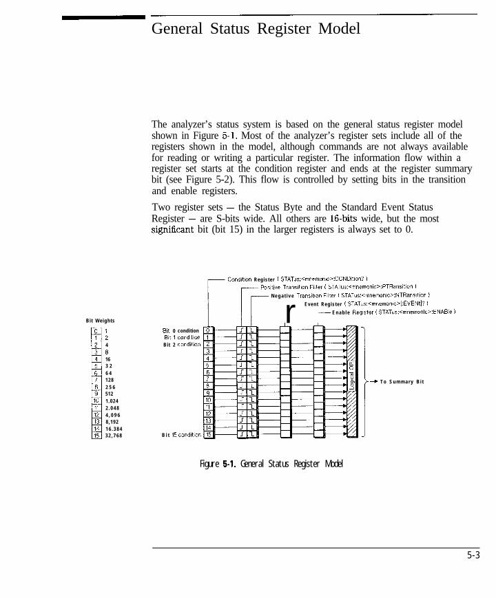
The analyzer’s status system is based on the general status register modelshown in Figure 5-l. Most of the analyzer’s register sets include all of theregisters shown in the model, although commands are not always availablefor reading or writing a particular register. The information flow within aregister set starts at the condition register and ends at the register summarybit (see Figure 5-2). This flow is controlled by setting bits in the transitionand enable registers.
Two register sets - the Status Byte and the Standard Event StatusRegister - are S-bits wide. All others are 16-bits wide, but the mostsignihcant bit (bit 15) in the larger registers is always set to 0.
Bit Weights
:4
8163 26 41282 5 65121.0242 . 0 4 84 , 0 9 68,1921 6 . 3 8 43 2 , 7 6 8
Bit 0 conditionBit 1 condltton
Bit 2 condltlon
B i t 15
Condition Register ( STATus:<mnemonw:CONDltion? )
Posltlve Transltlon Filter ( STATus:<mnemonlo:PTRansltlon 1
N e g a t i v e Transltlon Filter ( STATus:<mnemonlc>:NTRansltlon )
r Event Register ( STATus:<mnemonic>l:EVENtl? )
r E n a b l e Register 1 STATus:<mnemonG?ENABle )
Figure 5-l. General Status Register Model
>-+ T o S u m m a r y B i t
5 - 3

I- I -
Using Status Registers
General Status Register Model
Condition Register
Condition registers continuously monitor the instrument’s hardware andfirmware status. Bits in a condition register are not latched or buffered, theyare updated in real time. When the condition monitored by a specific bitbecomes true, the bit is set to 1. When the condition becomes false the bit isreset to 0. Condition registers are read-only.
Transition Registers
Transition registers control what type of change in a condition register willset the corresponding bit in the event register. Positive state transitions(0 to 1) are only reported to the event register if the corresponding positivetransition bit is set to 1. Negative state transitions (1 to 0) are only reportedif the corresponding negative transition bit is set to 1. Setting both transitionbits to 1 causes both positive and negative changes to be reported. Transitionregisters are read-write, and are unaffected by *CLS (clear status) or queries.They are reset to instrument default conditions at power up and after *RSTand SYSTem : PRESet commands.
Event Register
Event registers latch any reported condition changes. When a transition bitallows a condition change to be reported, the corresponding event bit is setto 1. Once set, an event bit is no longer affected by condition changes. Itremains set until the event register is cleared. Event registers are read-only.
An event register is cleared when you read it. All event registers are clearedwhen you send the *CLS (clear status) command.
5 - 4
-
I-Using Status Registers
General Status Register Model
Enable Register
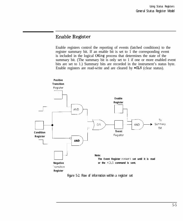
Enable registers control the reporting of events (latched conditions) to theregister summary bit. If an enable bit is set to 1 the corresponding eventis included in the logical ORing process that determines the state of thesummary bit. (The summary bit is only set to 1 if one or more enabled eventbits are set to 1.) Summary bits are recorded in the instrument’s status byte.Enable registers are read-write and are cleared by *CLS (clear status).
Positive
Transition
Register
c Enable
Register
rh
Condition
F
t v e n t
Register Register
I-AND
Note:
Negative
Transitton
Register
The Event Register remains set until it is read
or the *CLS command is sent.
Figure 5-2. Flow of information within a register set
5-5

I- I -
How to Use Registers
There are two methods of accessing the information in status registers:
l The direct-read method.
l The service request (SRQ) method
In the direct-read method the analyzer is passive. It only tells the controllerthat conditions have changed when the controller asks the right question. Inthe SRQ method, the analyzer is more active. It tells the controller whenthere has been a condition change without the controller asking. Eithermethod allows you to monitor one or more conditions.
The following steps are used to monitor a condition with the direct readmethod:
1. Determine which register contains the bit that monitors the condition.
2. Send the unique HP-IS query that reads that register.
3. Examine the bit to see if the condition has changed.
The direct-read method works well when it is not necessary to knowabout changes the moment they occur. It does not work well if immediateknowledge of the condition change is needed. A program that used thismethod to detect a change in a condition would need to continuously read theregisters at very short intervals. The SRQ method is better suited for thattype of need.
5-6

I- I -
The Service Request Process
The following steps are used to monitor a condition with the SRQ method:
1. Determine which bit monitors the condition.
2. Determine how that bit reports to the request service (RQS) bit of theStatus Byte.
3. Send HP-IB commands to enable the bit that monitors the condition and toenable the summary bits that report the condition to the RQS bit.
4. Enable the controller to respond to service requests.
When the condition changes, the analyzer sets its RQS bit and the HP-IB’sSRQ line. The controller is informed of the change as soon as it occurs. Thetune the controller would otherwise have used to monitor the condition cannow be used to perform other tasks. The controller’s response to the SRQ isdetermined by the program being run.


I- I -
Using Status Registers
The Service Request Process
The process of preparing the analyzer to generate a service request, and thehandling of that interrupt when it is received by a program, are demonstratedin the SRQ example program.
When a register set causes its summary bit in the Status Byte to change from0 to 1, the analyzer can initiate the service request (SRQ) process. If both thefollowing conditions are true the process is initiated:
l The corresponding bit of the Service Request enable register isalso set to 1.
l The analyzer does not have a service request pending. (A service request isconsidered to be pending between the time the analyzer’s SRQ process isinitiated and the time the controller reads the Status Byte register with aserial poll .)
The SRQ process sets the HP-IB’s SRQ line true and sets the Status Byte’srequest service (RQS) bit to 1. Both actions are necessary to inform thecontroller that the analyzer requires service. Setting the SRQ line informsthe controller that some device on the bus requires service. Setting the RQSbit allows the controller to determine that the analyzer was the device thatinitiated the request.
When a program enables a controller to detect and respond to servicerequests, it should instruct the controller to perform a serial poll when theHP-IB’s SRQ line is set true. Each device on the bus returns the contents ofits Status Byte register in response to this poll. The device whose RQS bit isset to 1 is the device that requested service.
N O T E
When the analyzer’s Status Byte is read with a serial poll, the RCIS bit is reset to 0. Other bits in the
register are not affected.
As implied in Figure 5-3, bit 6 of the Status Byte register serves twofunctions; the request service function (RQS) and the master summary statusfunction (MSS). Two different methods for reading the register allow you toaccess the two functions. Reading the register with a serial poll allows you toaccess the bit’s RQS function. Reading the register with *STB allows you toaccess the bit’s MSS function.
5 - 9

I- I -
The Analyzer’s Status Register Sets
The analyzer uses eight register sets to keep track of instrument status:
Status Byte *STB? and*SRE
Device Status STATus:DEVice
Limit Fail STATus:QUEStionable:LIMit
Questionable Status STATus:QUEStionable
Standard Event Status *ESR? and *ESE
Measuring Status STATus:OPERation:MEASuring
Averaging Status STATus:OPERation:AVERaging
Operational Status STATus:OPERation
Their reporting structure is summarized in Figure 5-4. They are described ingreater detail in the following section.
N O T E
5-10
Register bits not explicitly presented in the following sections are not used by the analyzer. A query to
one of these bits returns a value of 0.

I- I -
D e v i c e S t a t u s
S t a n d a r d E v e n t
S t a t u s R e g i s t e r
M e a s u r i n g
Using Status Registers
The Analyzer’s Status Register Sets
Q u e s t i o n a b l e S t a t u s ILimit Fall
O u t p u t Q u e u e , I I S t a t u s B&e
Figure 5-4. Analyzer Register Sets
5-11

I- I -
Using Status Registers
The Analyzer’s Status Register Sets
Bit Weights
Status Byte
The Status Byte register set summarizes the states of the other register setsand monitors the analyzer’s output queue. It is also responsible for generatingservice requests (see “Generating a Service Request” earlier in this chapter).See Figure 5-5.
serial poll (bit 6 - Request Service)
r-z -*SIB? (bit 6 Master Summary Status)
Device Status SummaryQuestionable Status Summary
Message AvailableStandard Event Summary
Request Service/Master Summary StatusOperatIonal Status Summary
Figure 5-5. The Status Byte Register Set
5 - 1 2
The Status Byte register set does not conform to the general status registermodel described at the beginning of this chapter. It contains only tworegisters: the Status Byte register and the Service Request enable register.The Status Byte register behaves like a condition register for all bits exceptbit 6. The Service Request enable register behaves like a standard enableregister except that bit 6 is always set to 0.

I- I -
Using Status Registers
The Analyzer’s Status Register Sets
Bits in the Status Byte register are set to 1 under the following conditions:
Device Status Summary (bit 2) is set to 1 when one or more enabledbits in the Device Status event register areset to 1.
Questionable Status Summary
Message Available
Standard Event StatusSummary
Master Summary Status
Request Service
Operational Status Summary
(bit 3) is set to 1 when one or more enabledbits in the Questionable Status event registerare set to 1.
(bit 4) is set to 1 when the output queuecontains a response message.
(bit 5) is set to 1 when one or more enabledbits in the Standard Event Status eventregister are set to 1.
(bit 6, when read by *STB) is set to 1 whenone or more enabled bits in the Status Byteregister are set to 1.
(bit 6, when read by serial poll) is setto 1 by the service request process (see“Generating a Service Request” earlier inthis chapter).
(bit 7) is set to 1 when one or more enabledbits in the Operational Status event registerare set to 1.
5-13
I -Using Status Registers
The Analyzer’s Status Register Sets
The commands used to read and write the Status Byte registers are listedbelow :
SPOLL an IBASIC (or HP BASIC) command used in the servicerequest process to determine which device on the bus isrequesting service.
*STB? reads the value of the instrument’s status byte. This is anon-destructive read, the Status Byte is cleared by the *CLScommand.
*SRE <num> sets bits in the Service Request Enable register. The currentsetting of the Service Request Enable register is stored innon-volatile memory. If *PSC has been set, it will be savedat power on.
*SRE? reads the current state of the Service Request Enableregister.
5-14

I -
Using Status Registers
The Analyzer’s Status Register Sets
Device Status Register Set
The Device Status register set monitors the state of device-specificparameters.
Bits in the Device Status condition register are set to 1 under the followingconditions:
Key Pressed (bit 0) is set to 1 when one of the analyzer’s front panelkeys has been pressed.
Any Softkey (bit 1) is set to 1 when one of the analyzer’s softkeys hasPressed been pressed.
Any External (bit 2) is set to 1 when a key has been pressed on anKeyboard Key external keyboard connected to the DIN KEYBOARDPressed connector on the rear panel of the analyzer.
Front Panel (bit 3) is set to 1 when the analyzer’s front panel knob isKnob Turned turned.
5-15

I- I -
Using Status Registers
The Analyzer’s Status Register Sets
Limit Fail Register Set
The Limit Fail register set monitors limit test results for both measurementchannels.
Bits in the Limit Fail condition register are set to 1 under the followingconditions (refer also to Figure 5-6.)
MeasurementChannel 1Limit Failed
MeasurementChannel 2Limit Failed
MeasurementChannel 1Marker LimitFailedMeasurementChannel 2Marker LimitFailed
(bit 0) is set to 1 when limit testing is enabled and any pointon measurement channel 1 fails the limit test, or when anyenabled marker limit on measurement channel 1 has failed.
(bit 1) is set to 1 when limit testing is enabled and any pointon measurement channel 2 fails the limit test, or when anyenabled marker limit on measurement channel 2 has failed.
(bit 2) is set to 1 when any enabled marker limit onmeasurement channel 1 has failed.
(bit 3) is set to 1 when any enabled marker limit onmeasurement channel 2 has failed.
5-16


I-
Using Status Registers
The Analyzer’s Status Register Sets
I -
5 - 1 8
I- I -
Using Status Registers
The Analyzer’s Status Register Sets
Questionable Status Register Set
The Questionable Status register set monitors conditions that affect thequality of measurement data.
Bits in the Questionable Status condition register are set to 1 under thefollowing conditions:
Limit Fail (bit 9) is set to 1 when one or more enabled bits in the LimitFail event register are set to 1.
Data (bit 10) is set to 1 when a change in the analyzer’sQuestionable configuration requires that new measurement data be taken.
5-19

I- I -
Using Status Registers
The Analyzer’s Status Register Sets
Standard Event Status Register Set
The Standard Event Status register set monitors HP-B errors andsynchronization conditions. See Figure 5-7.
Bit Wetghts
Operation CompleteRequest Control
Query ErrorDewce Dependent Error
Execution ErrorCommand Error
User RequestPower On
>+Bit 5
S t a t u s Byte
Figure 5-7. The Standard Event Status Register Set
The Standard Event Status register set does not conform to the general statusregister model described at the beginning of this section. It contains only tworegisters: the Standard Event Status event register and the Standard EventStatus enable register. The Standard Event Status event register is similarto other event registers, but behaves like a register set that has a positivetransition register with all bits set to 1. The Standard Event Status enableregister is the same as other enable registers.
OperationComplete
(bit 0) is set to one when the following two events occur(in the order listed):
l The *OPC command is sent to the analyzer.l The analyzer completes all pending overlapped
commands.
5-20

I- I -
Using Status Registers
The Analyzer’s Status Register Sets
Request Control (bit 1) .1s set to 1 when both of the following conditionsare true:
l The analyzer is configured as a talker/listener for HP-Boperation.
l The analyzer is instructed to do something (such asplotting or printing) that requires it to take control ofthe bus.
Query Error (bit 2) is set when the command parser detects a queryerror. A query error indicates:
1. an attempt to read data from the Output Queue whenno data was present.
2. that data in the Output Queue was lost. An exampleof this would be queue overflow.
Device Dependent (bit 3) is set to 1 when the command parser detects aError device-dependent error. A device-dependent error is any
analyzer operation that did not execute properly dueto some internal condition such as over-range. This bitindicates that the error was not a command, query, or anexecution error.
Execution Error (bit 4) is set to 1 when the command parser detects anexecution error. Execution errors occur when:
1. a <PROGRAM DATA> element received in a commandwas outside the legal range for the analyzer, orinconsistent with the operation of the analyzer.
2. the analyzer could not execute a valid command dueto some analyzer condition.
Command Error (bit 5) is set to 1 when the command parser detects acommand error. The following events cause a commanderror:
1. An IEEE 488.2 syntax error. This means that theanalyzer received a message that did not follow thesyntax defined by the 488.2 standard.
2. A semantic error occurred. For example, the analyzerreceived an incorrectly spelled command. Another
5-21

I- I -
Using Status Registers
The Analyzer’s Status Register Sets
example would be that the analyzer received anoptional 488.2 command that it does not implement.
Power On (bit 7) is set to 1 when you turn on the analyzer.
The commands used to read and write the Standard Event Status registers arelisted below:
*ESR? reads the value of the standard event status register.
*ESE <mm>
*ESE?
sets bits in the standard event status enable register. Thecurrent setting of the standard event statue enable registeris stored in non-volatile memory. If *PSC has been set, itwill be saved at power on.
reads the current state of the standard event status enableregister.
5-22
I- I -
Using Status Registers
The Analyzer’s Status Register Sets
Measuring Status Register Set
The Measuring Status register set monitors conditions in the analyzer’smeasurement process.
Bits in the Measuring Status condition register are set to 1 under thefollowing conditions:
Channel 1 Measuring (bit 0) is set to 1 while the analyzer is collectingmeasurement data on channel 1.
Channel 2 Measuring (bit 1) is set to 1 while the analyzer is collectingmeasurement data on channel 2.
Averaging Status Register Set
The Averaging Status register set monitors conditions in the analyzer’smeasurement process when the trace averaging function is in use.
Bits in the Averaging Status condition register are set to 1 under the followingconditions :
Measurement Channel (bit 0) is set to 1 while the analyzer is sweeping on1 Averaging measurement channel 1 and the number of sweeps
completed (since “average restart”) is less than theaveraging factor.
Measurement Channel (bit 1) is set to 1 while the analyzer is sweeping on2 Averaging measurement channel 2 and the number of sweeps
completed (since “average restart”) is less than theaveraging factor.
5-23

I- I -
Using Status Registers
The Analyzer’s Status Register Sets
Operational Status Register Set
The Operation Status register set monitors conditions in the analyzer’smeasurement process, disk operations, and printing/plotting operations. Italso monitors the state of the current HP Instrument BASIC program.
Bits in the Operational Status condition register are set to 1 under thefollowing conditions:
Calibrating (bit 0) is set to 1 while the instrument is zeroing thebroadband diode detectors.
Settling
Measuring
Correcting
Averaging
HardcopyRunning
Test Running
Program Running
(bit 1) is set to 1 while the measurement hardware issettling.
(bit 4) is set to 1 when one or more enabled bits in theMeasuring Status event register are set to 1.
(bit 7) is set to 1 while the analyzer is performing acalibration function.
(bit 8) is set to 1 when one or more enabled bits in theAveraging Status event register are set to 1.
(bit 9) is set to 1 while the analyzer is performing ahardcopy (print or plot) function.
(bit 10) is set to 1 when one of the analyzer’s internalservice tests is being run.
(bit 14) is set to 1 while an HP Instrument BASICprogram is running on the analyzer’s internal controller.
5-24

I- I -
Using Status Registers
The Analyzer’s Status Register Sets
STATus:PRESet Settings
Executing the STATUS : PRESet command changes the settings in the enable(ENAB), positive transition (PTR) and negative transition (NTR) registers. Thetable below shows the settings after the command is executed.
Resister Set
STATus:DEVice
STATus:qUEStionable:LIMit
STATus:CjUEStionable
STATus:OPERation:MEASuring
STATus:OPERation:AVERaging
STATus:OPERation
ENABle
a l l OS
a l l Is
a l l OS
a l l 1s
a l l i s
a l l 0s
PTRansition NTRansition
a l l i s
a l l Is
a l l i s
a l l OS
a l l OS
a l l Is
a l l OS
a l l OS
a l l OS
a l l 1s
a l l i s
a l l OS
5-25

I-
Using Status Registers
Analyzer Register Set Summary
D e v i c e S t a t u s
S e e F i g u r e 5 - 6Q u e s t i o n a b l e
S t a t u s---------_---------_
I@ L i m i t F a i I I
1 Measl L i m i t Fail 0I Meas L i m i t Foil II Meosl Mkr L i m i t Fail 2 %I hteosz Mkr Limit Foil WI!IIIIL----------------- O u t p u t Q u e u e
O p e r a t i o n Carydets
Request ControlQuery E r r o r
D e v i c e - D e p e n d e n t E r r o r
Execution ErrorCanmand Error
user Request
Power on J
S t a n d a r d E v e n tS t a t u s R e q i s t e r
1.
Measur i ngMeas, MeasuringMeas* Measuring
r Meas, SRL ScanMeas SRL Scan
A v e r a g i n g
I
ODer a i ona ISrarus
CaIibro,ing
Figure 5-8. Analyzer Register Set Summary
cd62c
5 - 2 6

I-
6
Trace Data Transfers
I -

I- I -
Trace Data Transfers
This chapter explains how to read (query) the measurement data trace fromthe analyzer into your program. It also describes how to send data from yourprogram to the analyzer’s measurement arrays. Accessing the measurementarrays is done using SCPI commands. If you are using IBASIC (Option lC2),you can also access the measurement arrays using high-speed subroutines.Refer to the HP Instrument BASIC User’s Handbook for more details.
Figure 6-l is a data processing flow diagram that represents the flow ofnumerical data. The data passes through several math operations, denoted inthe figure by single-line boxes. Most of these operations can be selected andcontrolled with the front panel CONFIGURE block menus. The data is storedin arrays along the way, denoted by double-line boxes. These arrays areplaces in the flow path where data is accessible via HP-IB. While only asingle flow path is shown, two identical paths are available, corresponding tomeasurement channels 1 and 2.
Raw Data1-IA,B,R... Ratio Averaqlng
i
Error1CoefficientArrays
Data Trace
Memory Trace
cs650
Figure 6-l. Numeric Data Flow Through the Network Analyzer
6 - 2
I-

I- I -
Querying the Measurement Trace Using BASIC
After making a measurement, you can read the resultant measurement traceout of the analyzer using the SCPI query
“TRACE : DATA? CHIFDATA”
The BASIC program segment below shows how to read the trace from theanalyzer into an array in your program.
10 REAL Trace(l:201)20 ASSIGN QHp8711 TO 71630 ! Take sweep here40 OUTPUT QHp871l;“FORM:DATA ASCII,5”50 OUTPUT @Hp871l;“TRACE:DATA? CHlFDATA”60 ENTER OHp87ll;Trace(*)70 DISP Trace(l) ,Trace(2) ,Trace(3) ,‘I. . . .I’
In this program, the TRACE:DATA? query returns all of the measurementpoints as a single block. The analyzer computes the value for each pointusing the measurement format selected by the [FORMAT] menu (CALC:FORMSCPI command), and returns a block of data called the formatted data array.The values of each point correspond to the values displayed on the screen, orthose shown in the marker readouts. The frequency stimulus value (X-axis) ofeach point is not returned by the TRACE:DATA? query; only the measurementresponse (Y-axis) values are returned.
When transferring the block of trace data, you may select either binary orASCII data encoding. This is explained in Chapter 4 in the section titled“Data Encoding for Large Data Transfers.” Notice that the terms “encodingformat” and “measurement format” are not the same. The encodingformat determines how the numbers are represented as bytes, while themeasurement format corresponds to the meaning of the value of the numbers.
The easiest way to transfer a measurement data trace is to use ASCII dataencoding.
In the example above, the array Trace(l:201) contains 201 real (floating point)numbers. The SCPI command “FORM:DATA ASCII ,5” specifies ASCII dataencoding, with 5 significant digits. The command “TRACE : DATA? CHIFDATA”instructs the analyzer to send the measurement trace. The ENTER statementreads the measurement data sent by the analyzer into the Trace(l:201) array.
6-3

I- I -Trace Data Transfers
Querying the Measurement Trace Using BASIC
It is important to make sure that the Trace array declared in your programis the same size as the measurement trace on the analyzer, or an error willoccur. The ENTER statement attempts to read data from the analyzer untilit completely fills the Trace array, at which point it expects to receive aend-of-data terminator from the analyzer. To be safe, your program shoulduse the “SENS : SWE :POIN” SCPI command to set the number of measurementdata points to the desired value.
Refer to the example program ASCDATA in Chapter 8 for a completeexample.
@Smith Chart and Polar Formats
Each measurement point is represented by a single floating point number.This is the case for all of the analyzer’s measurement formats except SmithChart and Polar in the HP 8712C and 8714C. When Smith Chart or Polarformat is selected, each point is represented by two numbers, the first onebeing the real portion and the second being the imaginary portion of thecomplex measurement value.
Below is a modified example program that will work when using Smith Chartor Polar formats.
1 0 REAL Trace(l:201,1:2)20 ASSIGN QHp8711 TO 71630 ! Take sweep here40 OUTPUT QHp8711;“FORM:DATA ASCII,5”50 OUTPUT QHp8711;“TRACE:DATA? CHIFDATA”60 ENTER OHp87ll;Trace(*)70 DISP Trace(l,l),Trace(l,2),“. . . .“,Trace(201,1),Trace(201,2)
6-4 @ indicates HP 8712C114C only

I- I -
Querying the Measurement Trace Using SICL
This section includes a complete SICL C program that shows how to read themeasurement trace from the analyzer.
/*************************************************************************** This program takes a sweep, reads the trace, and prints it.* It uses SICL (Standard Instrument Control Library) to talk* to the analyzer over HP-IB.** On HP-UX, compile using: cc -Aa -0 query-trace query,trace.c -1sicl**************************************************************************/
#include <sicl.h> /* For iopen(), iprintf0, iscanfo, INST, -*- *I#include Cstdio.h> /* For printfo */
int main(void)(
INST analyzer;float data-bufCl601);int num-trace-bytes;int pt;
/* Handle used to talk to analyzer *//* measurement trace. 32-bit floats */
num-trace-bytes = sizeof(data-buf); /* Set to max allowable bytes */
/* Open the network analyzer at address 16 */analyzer = iopen("hpib,l6");
/* Clear the bus */iclear(analyzer1;
/* Abort current sweep and put analyzer sweep in hold */iprintf(analyzer, "ABORT\n");iprintf(analyzer, “INIT : CONT OFF\n”) ;
/* Take one sweep, wait until done */iprintf(analyzer, "INITl\n");iprintf(analyzer, "*OPC?\n");
6-5
-I-

I- I -
Trace Data Transfers
Querying the Measurement Trace Using SIC1
iscanf(analyzer, "(/l*s");
/* Request the trace data in 32-bit floating point format */iprintfcanalyzer, "FORM:BORD NORM\n");iprintfcanalyzer, "FORM:DATA REAL,32\n");
/* Query the trace, read into data-buf Cl. */iprintfcanalyzer, "TRAC? CHlFDATA\n");iscanf(analyzer, "%#bX*c", &mm-trace-bytes, &data-buf COl>;
/* Print the trace values. */for (pt = 0; pt < mm-trace-bytes/sizeof(float); pt++) (
printf("X4d %g\n" , pt, data-buf[ptl);1
/* Close analyzer and exit. */iclose(analyzer);return 0;
1
6-6

I- I -
Using Binary Data Encoding
The previous section describes how to query the measurement trace, andtransfer it into your program using ASCII encoding. Binary encoding can beused for faster data transfers, as shown in the table below:
Table 6-l. Typical Trace Transfer Times (ms)
Points Binary
2 1
i
2 3
30
6 2
When using binary data transfers, the entire trace is sent from the analyzerto your program in a block called a definite length block. The details of blockdata are described in detail in Chapter 4. The delinite length block contains aheader and a data section. The header indicates how many bytes are in thedata section.
ln order to read the delinite length block, your program must first readthe header, and then read the data section. Refer to the example programREALDATA in Chapter 8 for an example of how to do this.
In the REALDATA program, you will notice the following lines which read thedefinite block header:
180 ENTER QHp8711 USING “%,A,D”;A$,Digits190 ENTER QHp8711 USING “%,“&VAL$(Digits)&“D” ;Bytes
and these lines which read the data section:
200 ASSIGN QHp8711;FORMAT OFF210 ENTER OHp87ll;Datal(*)
6-7

I- I -Trace Data Transfers
Using Binary Data Encoding
Each measurement point in the data section is represented as 4 or 8 bytes(32 or 64 bits), depending on whether single precision or double precisionnumbers are requested. When using HP BASIC or IBASIC, you must selectdouble precision numbers to match BASIC’s “REAL” data type. Do thisusing the SCPI command “FORM : DATA REAL, 64”. If you are using anotherlanguage that supports single precision data types, you can select singleprecision using the SCPI command “FORM : DATA REAL, 32”. Languages suchas QuickBASIC and C have support for both single and double precisionfloating point numbers.
When transferring data using binary encoding, you may need to reversethe order of the bytes in each measurement point, since PCs frequentlystore IEEE floating point numbers with the byte order reversed. To instructthe analyzer to reverse the byte order of the data, send the command“FORMAT:BORDer SWAPped” before querying the trace data.
6-8
-

I- I -
Trace Data Transfers
Using Binary Data Encoding
Trace Data Transfer Sizes
The following table shows how many bytes are transmitted during tracedata transfers. The left column shows the format of the data, which you canspecify using the SCPI command Format : DATA. As you can see, the size ofthe measurement point data and trace data varies as you change format.
Table 6-2. Size of Trace Data Transfers (in Bytes) Using the TRACESIATA SCPI Command
Format Type(FORMat:DATA)
REAL.32
REAL,64
ASCII,5
ASCII,3
INT,16
Type of Data I Single Measurement Point 201 Point Trace I
I E E E 32-bit
Floating Point
I E E E 64-bit
Floating Point
A S C I I n u m b e r s
A S C I I n u m b e r s
Internal Binary
Real
4
8
1 3
1 1
Complex
1 6 1 4
2 6 1 3
2 2 1 1
-
When transmitting data in “REAL” or “INT” format, a header is sent beforethe data block. The header indicates the size of the data block. The headersize varies in length from 3 to 11 bytes. Refer to Chapter 4 for details on theheader.
Transmitting ASCII data requires no header. The ASCII values are separatedby commas, and a linefeed is sent after the last value. The sizes shown in thetable include the size of the comma(s) and terminating linefeed. Typical datain ASCII,5 format:
-1.2254E+000,+5.0035E-001,+4.5226E-OOl,...
The analyzer stores its internal data with approximately 5 signitlcant digitsof resolution. Using REAL,32 or ASCII,5 format provides sufficient precisionfor data transfers. However, REAL,64 may be necessary when using aprogramming language which does not support IEEE 32-bit floating point.
6-9

I- I -
Transferring Data with IBASIC
If you are using BASIC, your BASIC program can avoid the overhead ofusing OUTPUT and ENTER to transfer trace data, and instead use theanalyzer’s built-in high-speed subprograms. These built-in subroutines letyou quickly move data between the analyzer’s measurement arrays and yourprogram’s data arrays. For example, to read the anaIyzer’s formatted dataarray, use the foIIowing:
10 DIM Fmt(l:201)20 INTEGER Ghan30 LOADSUH Read-f data FROM “XFER: MEM 0,O”4 0 Chan=l50 Read-fdata(Chan,Fmt(*))
Refer to the HP Instrument BASIC User’s Handbook for more details.
The table below compares the speed of IBASIC using high-speed transfersubroutines with that of a fast external controller using the SCPITRACE:DATA? CHlFDATAquery.
Table 6-3. Typical Trace Transfer Times (msl
1 Number of Points Controller Using Binary TRACE : DATA? 1 IBASIC Using Read-f data
5 15 1 2 12 1 77
201201 2323 I OI O
401401 3030 1 31 3
16011601 8 28 2 3 23 2
6 - 1 0

I -
T&king Sweeps
When making measurements and querying traces, your program shouldperform the following steps:
1. Place the analyzer’s sweep in hold
2. Initiate a single sweep
3. Wait for the sweep to complete
4. Query the measurement trace
Use the following program lines perform these steps:
10 OUTPUT QHp8711;“ABORT;:INITl:CONT OFF”20 OUTPUT QHp8711; “INITl”30 OUTPUT OHp8711; “*OPC?”35 ENTER OHp8711;Opc40 OUTPUT QHp8711; “TRACE : DATA? CHlFDATA”45 ENTER QHp8711;Fmt(*)
If you query the measurement trace while the analyzer is in continuoussweep, the query will still work, but the data may not be correct. Using INITand *OPC? ensures that a complete sweep has finished before you query themeasurement data. In many cases, you can also use the command “*WAY inplace of the “*OPC?” query, replacing lines 30 and 35 above with:
30 OUTPUT OHp8711; “*WAI”
However, there are cases where “*WAI” will produce incorrect results. Onecase is when using IBASIC’s high-speed subprograms to query the trace data.“*WAI” only ensures that the SCPI commands following the “*WAI” are notexecuted until the commands before the “*WAI” are complete. Since IBASICsubprograms don’t use SCPI commands to access the trace data, “*WAI” isineffective, and “*OPC?” should be used.
When using “*OPC?“, the ENTER statement following the “*OPC?” will waituntil the previous SCPI commands are complete, preventing your programfrom executing beyond the ENTER statement. When using “*WAI”, yourprogram can continue to run and send SCPI commands, and the analyzer willbuffer them and act upon them in order.
For more details, refer to Chapter 2, “Synchronizing the Analyzer and aController. ”
6-11
I- I -
CALC:DATA? versus TRACE:DATA?
The SCPI command “CALCl : DATA?” is functionally equivalent to thecommand “TRACE : DATA? CHIFDATA” . The two can be used interchangeablyfor trace queries of the formatted measurement data. The “TRACE:DATA”command is more flexible, allowing you to query other measurement arraysand to download data to measurement arrays.
6-12
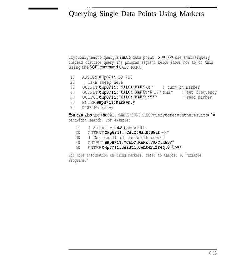
I- I -
Querying Single Data Points Using Markers
Ifyouonlyneedto query asingle data point, youcan use amarkerqueryinstead ofatrace query The program segment below shows how to do thisusing the SCPIcommand CALC:MARK.
10 ASSIGN QHp8711 TO 71620 ! Take sweep here30 OUTPUT OHp871l;"CALCl:MARK ON" ! turn on marker40 OUTPUT QHp871l;"CALCl:MARKl:X 177 MHz" ! set frequency50 OUTPUT OHp87ll;"CALCl:MARKl:Y?" ! read marker60 ENTER OHp87ll;Marker,y70 DISP Marker-y
Youcanalsousethe CALC:MARK:FUNC:RES?querytoreturntheresuits ofabandwidth search. For example:
10 ! Select -3 dB bandwidth20 OUTPUT QHp871l;"CALC:MARK:BWID -3"30 ! Get result of bandwidth search40 OUTPUT QHp8711; "CALC:MARK:FUNC:RES?"50 ENTER OHp87ll;Bwidth,Center,freq,Q,Loss
For more information on using markers, refer to Chapter 8, “ExamplePrograms."
6-13
I-

I- I -
Accessing Other Measurement Arrays
The preceding sections describe how to query the formatted data array usingthe TRACE:DATA? query with the argument CHlFDATA. The formatted arrayis the last array in the analyzer’s data processing chain, and is generally ofmost interest.
The analyzer also allows you to query other measurement arrays whichare earlier in its data processing chain. Figure 6-2, below, shows the dataprocessing chain.
Raw Data1-d RatioError
A.B.R... Correction
t
Error1CoefficientArrays
Offs.4 Dota TraceFormat
SCCll.5 Memory Trace
Markers
- Limit Testing
Figure 6.2. Numeric Data Flow Through the Network Analyzer
The first array is the Raw Data Array, which contains each of the separateinput components (A, B, R, B*, R*, X, Y, AUX) immediately after they aremeasured. These arrays can be queried and set, but doing so is of limiteduse, since the data values contained in the arrays are uncorrected, and arenot directly correlated to any meaningful reference, such as 0 dBm.
6-14

I-
Trace Data Transfers
Accessing Other Measurement Arrays
The Error Coefficient Arrays contain default correction values or valuescreated during a measurement calibration. These arrays can be queriedand set, but care should be exercised in setting them since incorrectmeasurements may result. If you wish to apply your own corrections inaddition to the analyzer’s current correction, the best technique is to use theCorrected Memory array and the Data/Memory feature, explained below.
The Corrected Data array contains the results of the currently selectedmeasurement (Transmission, Reflection, etc.) after error correction andaveraging have been applied. The measurement data in these arrays isrepresented as complex number pairs. When measuring the transmissionresponse of a through cable, the magnitude of the complex numbers will bevery close to 1 .O. When measuring an open circuit, the magnitude of thecomplex numbers will be very close to 0.0. When measuring an amplilier, themagnitude of the complex numbers will be greater than 1.0.
The Corrected Memory array is filled with a copy of the Corrected Data arraywhen the Data --> Memory operation is performed. It can be used to applya gain correction to the measured data. This is described in the followingsection.
The Formatted Data array contains the measurement data after it has beenformatted using the format selected by the [FORMAT] menu. Querying theFormatted Data array is described in detail at the beginning of this chapter.You can also download data to this array, and the analyzer will display thedata using the current Scale and Reference values.
6-15

I- I -
Applying Gain Correction Using theMemory Trace
The Corrected Memory array is Elled with a copy of the Corrected Data arraywhen the Data --> Memory operation is performed. By setting the analyzerto perform Data/Memory trace math, you can apply your own correctionfactor to the measurement data trace by filling the Corrected Memory arraywith the appropriate complex numbers.
In general, you should use the analyzer’s calibration feature to correct forerrors in your system. However, there may be cases where you wish tosimulate the effect of adding a cable in series with your DUT, and observehow this imaginary cable will attenuate the measured response versusfrequency. Or you may wish to apply an absolute offset to simulate the effectof adding or removing a pad from the measurement. These simulations areeasily accomplished using the Corrected Memory array and the Data/Memoryfeature.
The Corrected Data and Memory arrays contain complex linear data, asopposed to logged data. When displaying the traces using Lin Mag format,the result of the Data divided by Memory operation (Data/Mem) will beto divide each point of the data trace by each point of the memory trace.When displaying data in Log Mag format, the result of Data/Memory will beequivalent to subtracting the Log Mag value of the Memory trace from that ofthe Data trace.
6-16

I- I -
Trace Data Transfers
Applying Gain Correction Using the
Memory Trace
The following example BASIC code segment shows how to download acomplex array from your program to the analyzer’s Memory trace. Theprogram’s “Mem” array is initialized with the proper values such that whenthe analyzer computes Data divided by Memory, the desired increasing gainwill be applied.
1 0 0
110120130140150160170180190200210220230240250260270280290300310320
REAL Mem(l:201,1:2)ASSIGN QHp8711 TO 716! Fill memory array (denominator in Data/Mem)! with values that will result in an! upward sloping gain factor vs. frequency.! Used to compensate for cable loss vs. frequency! Adds 0 dB of gain at start freq; 3 dB at stop freqFOR Pt=l TO 201
Gain-factor-db=3.0*(Pt - 1)/200 ! 0..3 dB PowerGain,factor~lin=lO~(Gain~factor,db/20)Mem(Pt,l)=l.O/Gain-factor-lin ! realMem(Pt,2)=0.0 ! imag
NEXT Pt! Download to the memory traceOUTPUT OHp87ll;"FORM:DATA ASCII"OUTPUT QHp8711;"TRACE:DATA CHlSMEM"; ! Note the 'I;"FOR Pt=l TO 201
FOR I=1 TO 2OUTPUT QHp8711;",";Mem(Pt,I); ! Note the ";'I
NEXT INEXT PtOUTPUT OHp8711;"" ! Send linefeedOUTPUT OHp8711,*tVCALC1:MATH (IMPL/CHlSMEM)" ! Data/Mem
The example above downloads data to the corrected memory array. The datais sent by the program to the analyzer using ASCII encoding. The data issent as ASCII characters, separated by commas. The analyzer accepts thecomma separated list of numbers until it receives a linefeed to terminatethe command. The program uses semicolons at the end of some OUTPUTstatements to avoid sending a linefeed until all of the data has been sent.After the last number is sent, the program sends a linefeed, and the analyzeraccepts the data.
Remember, for faster transfers, use binary data encoding instead of ASCII.
6-17

I- I -
Performing Your Own Data Processing
After the analyzer has made a measurement, you can read the measurementtrace and perform your own post-processing on it, and display the result onthe screen. This is done using these steps:
1. Initiate a sweep
2. Wait for the sweep to Crush
3. Read the measurement data into an array in your program
4. Perform your post-processing on the measurement data
5. Write (download) the post-processed data to the analyzer’s memory trace.
You may want to instruct the analyzer to display only the memory trace andnot the data trace, so that only your post-processed data is seen.
6-18

I- I -
Trace Data Transfers
Performing Your Own Data Processing
The program below demonstrates how to perform data post-processing. Ittakes the measurement data and reverses it, such that the low frequencydata is displayed on the right end of the trace, and the high frequency data isdisplayed on the left.
1 0 0
1 1 0
120130140150160170180190200210220230235240250260270280290
! Display the measurement data backwardsREAL Fmt(l:201)ASSIGN OHp8711 TO 716IOUTPUT QHp871l;"FORM:DATA ASCII"OUTPUT QHp87ll;"ABOR;INIT:CONT OFF;*WAI"OUTPUT OHp87ll;"DISP:WIND:TRACl OFF;TRAC2 ON"LOOP
! Take sweepOUTPUT QHp8711;"INITl;*WAI"! Read the trace from the formatted data arrayOUTPUT OHp871l;"TRACE:DATA? CHlFDATA"ENTER QHp8711;Fmt(*)! Download the trace, backwards,! to the formatted memory arrayOUTPUT QHp87ll;"TRACE:DATA CHIFMEM"; ! Note the ";'IFOR Pt=l TO 201
OUTPUT OHp87ll;",";Fmt(202-Pt); ! Note the 'I;"NEXT PtOUTPUT (QHp8711;"" ! Send linefeed
END LOOP
6-19
This example program uses ASCII trace data transfers. Higher speed can beachieved using binary data transfers. If using BASIC, high-speed subroutinescan be used for even greater performance. Refer to the IBASIC Handbook fordetails.

I- I -
Downloading Trace Data UsingBinary Encoding
Data traces can be downloaded to the analyzer using binary encoding.Using binary encoding is faster than using ASCII encoding. As mentionedin Chapter 4, the binary encoded trace is transferred as a block; the blockcontaining a header and a data section. There are two different types ofblocks that can be used: a definite length block, and an indefinite lengthblock.
To send trace data using a definite length block, your program must calculatethe number of bytes in the data segment of the block, and create a blockheader which tells the analyzer how many bytes are in the data segment.
For example, if you are sending a trace with 201 data points and using 64-bitfloating point numbers for each data point (“FORM:DATA REAL,64”), theblock’s data segment will contain 1608 bytes (201 points * 8 bytes/point).The header characters for a 1608 byte block are: “#41608”. The lirst digitafter the “#“, “4” tells how many following digits are used to specify the size.In this case, 4 digits follow, and those digits are “ 1608”, meaning that theblock contains 1608 bytes.
For example :
TRAC CHlFDATA,#41608<binary_data_starts_here>
When you send a definite length block to the analyzer, the analyzer will willread the data segment bytes, stopping when it receives the number specifiedin the block header.
To send trace data using an indefinite length block, your program simplysends a block header of “#O”, followed by the data segment. After sendingthe data segment, your program must terminate the data block by sending anEOI. The analyzer will read the data segment bytes, stopping when it receivesan EOI. To send an EOI using BASIC, you can use the statement:
OUTPUT QHp871l;END
6-20

I- I -
Internal Measurement Arrays
The following sections describe the sequence of math operations and theresulting data arrays as the measurement information flows from the rawdata arrays to the display. This information explains the measurement arraysaccessible via HP-B
Figure 6-3 is a data processing flow diagram that represents the flow ofnumerical data. The data passes through several math operations, denoted inthe figure by single-line boxes. Most of these operations can be selected andcontrolled with the front panel CONFIGURE block menus. The data is storedin arrays along the way, denoted by double-line boxes. These arrays areplaces in the flow path where data is accessible via HP-IB. While only asingle flow path is shown, two identical paths are available, corresponding tomeasurement channels 1 and 2.
Averaging
Offset Data TraceFormat
Scale Memory Trace
Limit Testing
Figure 6-3. Numeric Data Flow Through the Network Analyzer
6-21

I- I -
Trace Data Transfers
Internal Measurement Arrays
Raw Data Arrays
These arrays are linear measurements of the inputs used in the selectedmeasurement. Note that these numbers are complex pairs. These arrays aredirectly accessible via HP-E3 and referenced as CH Cl I21 AFWD, CH Cl I21 BFWDand CH Cl I23 RFWD.
Table 6-4. Raw Data Arrays
Selected Measurement
Transmission IB/RJ
Reflection lA.Ffl
A
B
RPower 18”)
B - CH[lA = CH[lA - CH[lB - CH[lR - CH[lB’ = CH[:
C o n v e r s i o n loss IB”/R*l B” = CH[I12]BFWD, R” = CH[llZ]RFWDR” R” - CH[li21RFWDAM Delay (Y/XI Y - CH[ltZ]BFWD,X- CHCll21RFWDX X = CHC1121RFWDY Y - CH[ltZ]BFWDY/R” Y - CH[1121BFWD, R” - CHCll21RFWDY/X, XN Y = CH[1121BFWD,X = CHkl21RFWD
Raw Arrays
I21RFWD121RFWD
21BFWD, R - CHCl21AFWD. R - CH[l21AFWD21BFWD21RFWDlZ]BFWD
1 I
N O T E
Raw data far AUX INPUT is not available via HP-IB. Use the corrected data array to access AUX
INPUT data .
6 - 2 2

I- I -
Trace Data Transfers
Internal Measurement Arrays
Ratio Calculations
These are performed if the selected measurement is a ratio (e.g. A/R or B/R).This is simply a complex divide operation. If the selected measurement isabsolute (e.g. A or B), no operation is performed.
Error Correction
Error correction is performed next if correction is turned on. Error correctionremoves repeatable systematic errors (stored in the error coefficient arrays)from the raw arrays. The operations performed depend on the selectedmeasurement type.
Error Coefficient Arrays
The error coefficient arrays are either default values or are created duringa measurement calibration. These are used whenever correction is on.They contain complex number pairs, and are accessible via HP-IB and arereferenced as CH [l I21 SCORRl, CH [l I21 SCORR2, CH Cl I21 SCORR3 andCHClt21SCORR4.
6-23

I- I -
Trace Data Transfers
Internal Measurement Arrays
Table 6-5. Error Coefficient Arrays
Selected Measurement Error Coefficient Arrays
Transmission fB/R) Response CH [I f 21 SCORRI = Tracking
Transmission [B/RI Response & Isolation CH[ll2]SCORRI - Tracking
CH [l f 21 SCORRZ - Isolation Term
Transmission (B/RI Enhanced Response CH [l I21SCORRl - Directivity
CH [l f 21 SCORR2 = Source Match
CH [I I 21 SCORR3 - Reflection Tracking
CH [I I 21 SCORR4 - Transmission Tracking
Reflection [AIR] CH [I I 21 SCORRI = Diractivity
CH [I 121 SCORR2 - Source Match
CH[l I21 SCORR3 - Tracking
Broadband Internal CH[ll2]SCORRl - A” Response
N O T E
T h e s e arrays d o n o t a p p l y t o B r o a d b a n d E x t e r n a l m e a s u r e m e n t s .
6 - 2 4

I- I -
Trace Data Transfers
Internal Measurement Arrays
Averaging
Averaging is a noise reduction technique. This calculation involves takingthe complex exponential average of several consecutive sweeps. Thisaveraging calculation is different than the System Bandwidth setting. SystemBandwidth uses digital filtering, applying noise reduction to the measureddata before it is stored into the Raw Data Arrays.
Corrected Data Arrays
The combined results of the ratio, error correction and averaging operationsare stored in the corrected data arrays as complex number pairs. Thesearrays are accessible via HP-H3 and referenced as CH [l I 21 SDATA.
Corrected Memory Arrays
If the Data->Mem or Normalize operations are performed, the correcteddata arrays are copied into the corrected memory arrays. These arrays areaccessible via HP-IB and referenced as CH cl I 21 SMEM.
6 - 2 5
I-

I- I -
Trace Data Transfers
Internal Measurement Arrays
Trace Math Operation
This selects either the corrected data array, or the corrected memory array, orboth to continue flowing through the data processing path. In addition, thecomplex ratio of the two (Data/Memory) can also be selected. If memory isdisplayed, the data from the memory arrays goes through exactly the samedata processing flow path as the data from the data arrays.
@ Electrical Delay
This block adds or subtracts phase, based on the settings of Phase Offset,Electrical Delay, and Port Extension. The Electrical Delay and Port Extensionfeatures add or subtract phase in proportion to frequency. This is equivalentto “line stretching” or artihcially moving the measurement reference plane.(See the HP 8?‘12C//4C User’s Guide for more details on these features.)
Transform (Option 100 only)
This block converts frequency domain data into distance domain, or into anSRL impedance value when measuring fault location or SRL. The transformemploys an inverse fast Fourier transform (FFT) algorithm to accomplish theconversion.
6-26 @ indicates HP 8712Cl14C only

I -
Trace Data Transfers
Formatting
This converts the complex number pairs into a scalar representation fordisplay, according to the selected format (e.g. Log Mag, SWR, etc). Theseformats are often easier to interpret than the complex number representation.Note that after formatting, it is impossible to recover the complex data.
Formatted Arrays
The results so far are stored in the formatted data and formatted memoryarrays. It is important to note that marker values and marker functions areall derived from the formatted arrays. Limit testing is also performed on theformatted arrays. These arrays are accessible via HP-II3 and referenced asCH [ 1 I 21 FDATA and CH cl I 21 FMEM.
Offset and Scale
These operations prepare the formatted arrays for display. This is where thereference position, reference value, and scale calculations are performed, asappropriate for the format.
6-27
-

I-
Trace Data Transfers

I- I -
7
Using Graphics

I- I -
Using Graphics
The analyzer has a set of user graphics commands that can be used to creategraphics and messages on the display. The GRAPHICS example program usessome of these commands to draw a simple setup diagram. These commands,listed below, are of the form:
DISPlay:WINDow[ll21lOl:GRAPhics:<mnemonic>.
The number specified in the WINDOW part of the command selects where thegraphics are to be written.
WINDowl draws the graphics to the channel 1 measurement screen.(This is the default if no window is specified in themnemonic.)
WINDow
WINDowlO
draws the graphics to the channel 2 measurement screen.
draws the graphics to an IBASIC display partition. (Thiswindow is only available on instruments with IBASIC -Option lC2.)
N O T E
When graphics commands are used to write directly to a measurement screen they write to the static
graphics plane (the same plane where the graticule is drawn). There is no sweep-to-sweep speed
penalty once the graphics have been drawn.
7 - 2

I- I -
Using Graphics
Unless othemise specked, the graphics commands listedbelow start at thecurrent pen location. All sizes are dimensioned in pixels.
DISPlay:WINDow[ll2l1O]:GRAPhics:CIRCle <y-radius>
DISPlay:WINDow[ll2l1O]:GRAPhics:CLEar
DISPlay:WINDow[ll2llO]:GRAPhics:COLor <pen>
l color choices are: 0 for erase, 1 for bright, 2 for dim
DISPlay:WINDow[1l2l1Ol:GRAPhics[:DRAW] <new-x>,<new,y>
DISPlay:WINDowCll2~101:GRAPhics:LABel<string>
DISPlay:WINDow[ll2l1O]:GRAPhics:LABel:FONT <font>
l font choices are: SMALl, HSMall, NORMal, HNORmal, BOLD, HBOLd,SLANt,HSLaut(H as the first letter of the font name indicates highlighted text - inversevideo).
DISPlay:WINDow[ll2llOl:GRAPhics:MOVE <new-x>,Cnew,y>
DISPlay:WINDow[1l2l1O]:GRAPhics:RECTangle Cwidth>,Cheight>
DISPlay:WINDow[ll2llOl:GRAPhics:SCALe<xmin>,<xmax>,<ymin>,<ymax>
DISPlay:WINDow[l~211O]:GRAPhics:STATe?
7 - 3

I- I -
Window Geometry
Even though there are only three graphics windows, these windows can havedifferent sizes and locations.
The size and location of the graphics window are determined by the displayconfiguration currently in use - split screen measurements, full screenmeasurements, and full or partial IBASIC display partitions will affect thedimensions of the graphics window in use.
The sizes of the different graphics windows are listed below. Figure 7-lshows the IBASIC display partitions.
l Measurement channel 1 or 2 full screen measurement: width = 501 pixels,height = 401 pixels.
l Measurement channel 1 or 2 split screen measurement: width= 501 pixels,height = 201 pixels.
l IBASIC full screen display: width = 537 pixels, height = 439 pixels.
l IBASIC upper display: width = 537 pixels, height = 199 pixels.
l IBASIC lower display: width = 537 pixels, height = 197 pixels.
Figure 7-1. Pixel Dimensions with Available Display Partitions
There is a set of queries that can be used to determine the size and locationof the display window in use.
7-4

I- I -
Using Graphics
Window Geometry
These queries, listed below, return the width and height of the window or theabsolute location of its lower left or upper right corners. All the coordinatesand sizes are dimensioned in pixels.
DISPlay:WINDow[ll2l1O1 :GEOMetry:LLEFt?DISPlay:WINDow[ll2l1O]:GEOMetry:SIZE?DISPlay:WINDow[ll2l1O]:GEOMetry:URIGht?
N O T E
The origin of EVERY graphics window is its lower left corner. The locations returned in response to
the LLEFt and URIGht are relative to the ABSOLUTE origin of the entire display, NOT to the
graphics window
7-5
I-

I- I -
The Graphics Buffer
The analyzer has a graphics buffer that is used to refresh the graphics displayif needed. When the buffer is full, additional graphics can still be drawn -BUT they will not be refreshed. The graphics buffer can be turned on andoff using the following command (which is used in the GRAPHICS exampleprogram).
DISPlay:WINDow:GRAPhics:BUFFer[:STATe] <ONlOFF>
The graphics buffer will hold up to:
500 lines40 circles40 rectangles50 strings (60 characters long)
Use the following command to clear the graphics buffer and user-graphicsdisplay.
DISPlay:WINDow:GRAPhics:CLEar
N O T E
Only graphics that can be refreshed will be printed or plotted. If you intend to print or plot your
graphics, make sure they will fit within the graphics buffer.
7-6

I- I -
8
Example Programs

I- I -
Example Programs
Most of the example programs listed in this manual are written in HP BASIC.They are also compatible with IBASIC (HP Instrument BASIC). An optionalinternal controller can be purchased with your analyzer (Option lC2). Thiscontroller runs IBASIC directly on the analyzer. It controls the analyzer overan internal interface bus that operates the same way as the external HP-IBinterface. For more information about IBASIC refer to the HP InstrumentBASIC User’s Handbook.
The example programs are provided on two disks that are included with thenetwork analyzer. Both disks contain the same examples which are writtenmainly in HP BASIC; only the disk format is different. The analyzer’s internal3.5” disk drive is designed to be DOS compatible, however, it can read fromLIF formatted disks. Therefore, either disk can be used to supply programsfor the analyzer’s internal IBASIC controller.
Example Programs Disk - DOSFbrmat HP part number 08712-10019
Exumple Programs Disk - LIFRwmat HP part number 08712-10021
Because the examples are designed to run in different environments, thesetup at the beginning of each program must determine the operatingenvironment and properly set the analyzer’s HP-IB address. In theseexamples, the internal IBASIC controller uses the address 800 whencommunicating with the analyzer (the internal HP-IB is at select code 8).The default address of 716 is used when the programs are being run on anexternal controller.
A version of the following lines is included in most of the example programs.The use of the Internal (internal-controller) flag varies due to differences inthe programs needs.
8-2

I- I -
Example Programs
10 IF POS(SYSTEM$("SYSTEM ID">,"HP 87") THEN2 0 ASSIGN (OHp8711 TO 8003 0 Internal=14 0 ELSE
5 0 ASSIGN QHp8711 TO 7166 0 Internal=07 0 ABORT 7
8 0 CLEAR 716
9 0 END IF
Identify the operating system.If internal, set address to 800.Set internal-control jlag to 1.If external, set address to 716.
Set internal-controljlag to 0.Abort all bus transactions andgive active control of the bus to thecomputeSend a selected dewice clear (SDC)to the analyzer - this clears allHP-IB errors, resets the HP-IB in-terface and clears syntax errors.(It does not o$ect the status re-porting system.)
N O T E
The example programs on the disks that were shipped with your analyzer may not appear exactly as
listed in this chapter. The programs on the disks are the most up-to-date versions of each program.
Also, check your disk listings for new programs that may not be listed here.
8 - 3

I- I -
E x a m p l e P r o g r a m s
The following table shows the sections and example programs that arecontained in this chapter:
Section Title Example Program Program Description
Configuring Measurements S E T U P Sets up a basic measurement, demonstrates use of *WA1
LIMITEST Performs automatic pass/fail testing with limit lines
P O W E R S W P Performs a power sweep measurement
Transfer of Data to/from the M A R K E R S Transfers data using markers
4nalyzer
SMlTHMKRl Measures reflection of a fi lter in Smith chart and polar formats
ASCDATA Transfers data using ASCII format
REALDATA Transfers data using the IEEE 64bit floating point REAL format
INTDATA Transfers data using the l&bit INTEGER format
F A S T - C W Transfers marker data in CW sweep mode
Calibration T R A N C A L Performs a transmission calibration
REFLCAL Performs a reflection calibration
LOADCALS Uploads and downloads correction arrays
CALKIT This is nor a program, it is an instrument state fi le for downloading
user-defined cal kit definitions
n s t r u m e n t S t a t e a n d S a v e / R e c a l l L E A R N S T R Uses the learn string to upload and download instrument states
S A V E R C L Saves and recalls instrument states, calibrations and data
iardcopy Control PRINTPLT Uses the serial and parallel ports for hardcopy output
P A S S C T R L Uses pass control and the HP-18 for hardcopy output
FAST-PFTT Provides fast graph dumps to PCL5 printers
Service Request SRII Generates a service request interrupt
SRQ-INT Monitors the status report of the analyzer
Ye Transfer Over HP-16 GETFILE Transfers a file from the analyzer to an external controller
PUTFI LE Transfers a file from an external controller to the analyzer
1 For use with HP 8712C and 8714C only
8 - 4
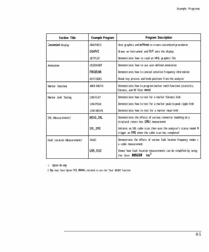
I- I -
E x a m p l e P r o g r a m s
Section Title
Customized D i s p l a y
Annotation
Marker Functions
Marker Limit Testing
S R L M e a s u r e m e n t s ’
Fault Location Measurements’
Example Program Program Description
G R A P H I C S Uses graphics and softkeys to create customized procedures
GRAPH2 Draws an instrument and OUT onto the display
G E T P L G T Demonstrates how to read an HPGL graphics fi le
U S E R A N O T Demonstrates how to use user-defined annotation
FREOBLNK Demonstrates how to conceal sensitive frequency information
K E Y C O O E S Reads key presses and knob positions from the analyzer
M K R - M A T H Demonstrates how to program marker math functions (statistics,
flatness, and RF fi lter stats1
L I M - F L A T Demonstrates how to test for a marker flatness l imit
L I M - P E A K Demonstrates how to test for a marker peak-to-peak ripple l imit
L I M - M E A N Demonstrates how to test for a marker mean l imit
MEAS-SRL Demonstrates the effects of various connector modeling on a
structural return loss ISRLI measurement
SRL-SRI1 Initiates an SRL cable scan, then uses the analyzer’s status model tc
trigger an SRG when the cable scan has completed
FAULT Demonstrates the effects of various fault location frequency modes c
a cable measurement
USR-FLGC Shows how fault location measurements can be simplified by using
t h e U s e r BEGf% key2
1 Option 100 only
2 VIU must have Option lC2, IBASIC, installed to use the “User BEGIN” function
8-5

I- I -
E x a m p l e P r o g r a m s
I Section Title I Example Program I Program Description I
M u l t i p o r t T e s t S e t M e a s u r e m e n t s ’ P O R T - S E L Uses graphics to show internal connections of the HP 87075C when
different ports are selected
T S E T - C A L Attempts to recall “TSET-CAL.CAL’ from non-volati le RAM or the
internal disk drive. If successful, invokes the recalled test set cal for
transmission and reflection of measurement channels 1 and 2
TTL o u t p u t T T L - I O Monitors the user TTL bit on rear panel
A M Delay2 AMDELAY Demonstrates the calibration and AM delay measurement of a
bandpass filter
L A N Usage3 See the Oprion IF7 User’s Guide for listings and information on example programs for LAN
usage.
1 For use with the HP 8707X multiport test set.
2 O p t i o n s I D A o r IDE o n l y
3 O p t i o n lF7 o n l y
8-6

I- I -
Configuring Measurements
SETUP Setting up a basic measurement. The example alsodemonstrates the use of the *WA1 command.
LIMITEST Performing automatic PASS/FAIL testing with limit lines.The example also demonstrates some methods of combiningmnemonics for more efficient programming.
POWERSWP Setting up a power sweep measurement.
8-7
-

I- I -
Example Programs
Configuring Measurements
SETUP Example Program
This program demonstrates how to setup the analyzer to make abasicmeasurement. The *WA1 command is used extensivelythroughoutthisprogram. This has the effect of making sure that the commands are executedin the order they are received. More information about making measurementswith the analyzer is available in your analyzer’s User’s Guide.
1000 !Filename: SETUP1010 !1020 ! Description:1030 ! Set Channel 1 to measure filter’s transmission.1040 ! Set Channel 2 to measure filter’s reflection1050 ! Prompt user for start and stop freq, and set them.1060 ! Take a sweep.1070 ! Set Scale and Reference levels.1080 !1090 !1100 COM /Sys-state/ OHp87xx,Scode1110 ! Identify I/O Port1120 CALL Iden,port1130 !1140 !1150 ! Preset the instrument.1160 OUTPUT OHp87xx;“SYST:PRES;*WAI”1170 !1180 ! Configure the analyzer to measure transmission1190 ! of a filter on channel 1. This is the command1200 ! for the BEGIN Filter Transmissn key sequence.1210 OUTPUT QHp87xx;“CONF ‘FILT:TRAN’;*WAI”1220 !1230 ! Put the instrument in trigger hold mode.1240 OUTPUT QHp87xx;“ABOR;:INIT:CONT OFF;*WAI”1250 !1260 ! Turn on channel 2.1270 OUTPUT OHp87xx;“SENS2:STAT ON;*WAI”1280 !1290 ! Configure channel 2 to measure reflection. This1300 ! is the command for the CHAN 2 Reflection key sequence.
8-8

I- I -
Example Programs
Configuring Measurements
1310 OUTPUT OHp87xx;"SENS2:FUNC 'XFR:POW:RAT l,O';DET NBAN"1320 !1330 ! Wait for the previous commands to complete execution1340 ! (respond to the *OPC?).1350 OUTPUT OHp87xx;"*OPC?"1360 ENTER QHp87xx;Opc1370 !1380 ! Input a start frequency.1390 INPUT "Enter Start Frequency (MHz):",Start-f1400 !1410 ! Input a stop frequency.1420 INPUT "Enter Stop Frequency (MHZ) :",Stop-f1430 !1440 ! Set the start and stop frequencies of the analyzer1450 ! to the values entered.1460 OUTPUT OHp87xx;" SENS2:FREQ:STAR";Start_f;"MHz;STOP";Stop-f;"MHz;*WAI~1470 !1480 ! Trigger a single sweep.1490 OUTPUT QHp87xx;"INIT;*OPC?"1500 !1510 ! Wait for the sweep to be completed.1520 ENTER OHp87xx;Opc1530 !1540 ! Set up the scale and reference parameters for channel 1.1550 OUTPUT QHp87xx,*"DISP:WINDl:TRAC:Y:PDIV 10 DB;RLEV 0 DB;RPOS 8"1560 !1570 ! Now for channel 2.1580 OUTPUT OHp87xx;"DISP:WIND2:TRAC:Y:PDIV 5 DB;RLEV 0 DB;RPOS 8"1590 !1600 ! Make channel 1 active (transmission)1610 OUTPUT OHp87xx;"SENSl:STAT ON"1620 !1630 ! Display the current start and stop frequencies.1640 DISP "Done measuring. Start ='I ;Start-f;"MHz Stop =";Stop-f;"MHz"1650 END1660 !
8 - 9

I- I -
Example Programs
Configuring Measurements
1670 !**************************************************************
1680 ! Iden,port: Identify io port to use.1690 ! Description: This routines sets up the I/O port address for1700 ! the SCPI interface. For "HP 87xx" instruments,1710 ! the address assigned to cPHp87xx = 800 otherwise,1720 ! 716.1730 !**************************************************************1740 SUB Iden,port1750 COM /Sys,state/ QHp87xx,Scode1760 !1770 IF POS(SYSTEM$("SYSTEM ID">,"HP 87")OO THEN1780 ASSIGN QHp87xx TO 8001790 Scode=81800 ELSE1810 ASSIGN QHp87xx TO 7161820 Scode=71830 END IF1840 !1850 SUBEND !Iden-port1860 !
B-10

I- I -
Example Programs
Configuring Measurements
LIMITEST Example Program
This program demonstrates how to set up and use limit lines over the HP-IB.The example device used in this program is the demonstration filter that isshipped with the analyzer. The program sets up the basic measurement,downloads the limit lines and uses the status registers to determine of thedevice passes its specifications. For more information about limit lines, referto the User’s Guide. For information about using the status registers, refer tothe previous section “Using the Status Registers.”
This example also demonstrates how multiple command mnemonics can becombined together. The easiest commands to combine are ones that areclosely related on the command tree (such as the start and stop frequencyof a limit segment). For more information of command mnemonics, refer toChapter 10, “Introduction to SCPI.”
1000 !Filename: LIMITEST1010 !1020 DIM Title$[3011030 !1040 !1050 COM /Sys,state/ OHp87xx,Scode1060 ! Identify I/O Port1070 CALL Iden-port1080 !1090 ! Perform a system preset; this clears the limit table.1100 OUTPUT OHp87xx;“SYST:PRES;*WAI”1110 !1120 ! Set up the source frequencies for the measurement.1130 OUTPUT QHp87xx;” SENS1:FREQ:STAR 10 MHZ;STOP 400 MHZ;*WAI”1140 !1150 ! Set up the receiver for the measurement parameters1160 ! (Transmission in this case).1170 OUTPUT @Hp87xx,*“SENSl:FUNC ‘XFR:POW:RAT 2,O’;DET NBAN;*WAI”1180 !1190 ! Configure the display so measurement1200 ! results are easy to see.1210 OUTPUT QHp87xx,.“DISP:WINDl:TRAC:Y:PDIV 10 DB;RLEV 0 DB;RPOS 9”1220 !
8-11

I- I -
Example Programs
Configuring Measurements
1230 ! Reduce the distractions on the display by1240 ! getting rid of notation that will not be1250 ! needed in this example.1260 OUTPUT QHp87xx;"DISP:ANN:YAX OFF"1270 !1280 ! Erase the graticule grid for the same reason.1290 OUTPUT OHp87xx;"DISP:WIND1:TRAC:GRAT:GRID OFF"1300 !1310 ! Create and turn on the first segment for1320 ! the new limit lines; this one is a maximum1330 ! limit.1340 OUTPUT QHp87xx; "CALCl:LIM:SEGMl:TYPE LMAX;STAT ON"1350 !1360 ! Set the amplitude limits for the first limit1370 ! segment.1380 OUTPUT OHp87xx;"CALCl:LIM:SEGMl:AMPL:STAR -7O;STOP -70"1390 !1400 ! Set the frequency of the first limit segment.1410 OUTPUT QHp87xx;" CALCl:LIM:SEGMl:FREQ:STAR 10 MHZ;STOP 75 MHZ"1420 !1430 ! Create and turn on a second maximum limit1440 ! segment.1450 OUTPUT QHp87xx;"CALCl:LIM:SEGM2:TYPE LMAX;STAT ON"1460 !1470 ! Set the amplitude limits for segment 2.1480 OUTPUT QHp87xx,*"CALCl:LIM:SEGM2:AMPL:STAR 0;STOP 0"1490 !1500 ! Set the frequency range for segment 2.1510 OUTPUT cPHp87xx;" CALCl:LIM:SEGM2:FREQ:STAR 145 MHZ;STOP 200 MHZ"1520 !1530 ! Create and turn on a third limit segment;1540 ! this one is a minimum limit.1550 OUTPUT QHp87xx,*"CALCl:LIM:SEGM3:TYPE LMIN;STAT ON"1560 !1570 ! Set the amplitude limits for segment 3.1580 OUTPUT OHp87xx;"CALCl:LIM:SEGM3:AMPL:STAR -6;STOP -6"1590 !1600 ! Set the frequency range for segment 3.1610 OUTPUT OHp87xx;"CALCl:LIM:SEGM3:FREQ:STAR 150 MHZ;STOP 195 MHZ"1620 !1630 ! Create and set parameters for segment 4.
8-12
I-

I- I -
Example Programs
Configuring Measurements
1640 OUTPUT @Hp87xx,*"CALCl:LIM:SEGM4:TYPE LMAX;STAT ON"1650 OUTPUT QHp87xx,*"CALCl:LIM:SEGM4:AMPL:STAR -60;STOP -60"1660 OUTPUT QHp87xx;"CALCl:LIM:SEGM4:FREQ:STAR 290 MHZ;STOP 400 MHZ"1670 !1680 ! Send an operation complete query to ensure that1690 ! all overlapped commands have been executed.1700 OUTPUT OHp87xx;"*OPC?"1710 !1720 ! Wait for the reply.1730 ENTER OHp87xx;Opc1740 !1750 ! Turn on the display of the limit lines.1760 OUTPUT OHp87xx;"CALCl:LIM:DISP ON"1770 !1780 ! Turn on the pass/fail testing; watch the1790 ! analyzer's display for the pass/fail indicator.1800 OUTPUT OHp87xx;"CALCl:LIM:STAT ON"1810 !1820 ! Take a controlled sweep to ensure that1830 ! there is real data present for the limit test.1840 OUTPUT QHp87xx,*"ABOR;:INITl:CONT OFF;:INITl;*WAI"1850 !1860 ! Query the limit fail condition register to see1870 ! if there is a failure.1880 OUTPUT @Hp87xx;"STAT:QUES:LIM:COND?"1890 !1900 ! Read the register's contents.1910 ENTER QHp87xx;Fail-flag1920 !1930 ! Bit 0 is the test result for channel 1 while1940 ! bit 1 is the results for channel 2 limit testing.1950 IF BIT(Fail-flag,O)=l THEN1960 !1970 ! In case of failure, give additional direction1980 ! to the operator using the title strings.1990 Title$="Limit Test FAIL - Tune device"2000 !2010 ! Turn on the title string.2020 OUTPUT QHp87xx;"DISP:ANN:TITLl:DATA "'&Title$&"';STAT ON"2030 !2040 ! Turn on continuous sweep mode for tuning.
8-13

I- I -
Example Programs
Configuring Measurements
2050 OUTPUT (PHp87xx; "1NITl:CONT ON;*WAI"2060 !2070 ! Loop while the tuning is taking place.2080 LOOP2090 !2100 ! Monitor the status of the limit fail2110 ! condition register.2120 OUTPUT OHp87xx; "STAT:QUES:LIM:COND?"2130 ENTER OHp87xx;Fail-flag2140 !2150 ! Check the limit fail bit. Exit if the2160 ! device has been tuned to pass the test.2170 EXIT IF BIT(Fail-flag,O)=O2180 END LOOP2190 END IF2200 !2210 ! Turn off the prompt to the operator and2220 ! return the analyzer to the continuously2230 ! sweeping mode.2240 OUTPUT OHp87xx;"DISP:ANN:TITLl 0FF;:INIT:CONT ON;*WAI"2250 END2260 !2270 !**************************************************************2280 ! Iden-port: Identify io port to use.2290 ! Description: This routines sets up the I/O port address for2300 ! the SCPI interface. For "HP 87xx" instruments,2310 ! the address assigned to (QHp87xx = 800 otherwise,2320 ! 716.2330 !**************************************************************
8-14

I- I -
Example Programs
Configuring Measurements
2340 SUB Iden,port2350 COM /Sys,state/ OHp87xx,Scode2360 !2370 IF POS(SYSTEM$("SYSTEM ID">,"HP 87")OO THEN2380 ASSIGN OHp87xx TO 8002390 Scode=82400 ELSE2410 ASSIGN (QHp87xx TO 7162420 Scode=72430 END IF2440 !2450 SUBEND !Iden-port2460 !
8-15

I- I -
Example Programs
Configuring Measurements
POWERSWP Example Program
This program demonstrates how to setup a power sweep. It shows how toquery the instrument to determine its power sweep ranges, how to place amarker at a given stimulus power value (x-axis), how to read the measuredpower at a marker(y-axis)and how to read an entire trace of power sweepdata.
1000 ! Filename: POWERSWEEP1010 ! _1020 !1030 ! Description: Query the power sweep ranges,1040 ! take a power sweep, and use markers to read1050 ! gain at marker. Then query the trace.1060 ! _1070 DIM Trace_pwr(l:201)1080 !1090 COM /Sys-state/ OHp87xx,Scode1100 ! Identify I/O Port1110 CALL Iden,port1120 !1130 !1140 !--------------------------------------------------1150 ! Initialize the 871x; set to power sweep mode.1160 ! Set CW mode and freq.1170 !1175 OUTPUT OHp87xx;"SYST:PRESET;*OPC?"1176 ENTER QHp87xx;Opc1180 OUTPUT OHp87xx;"SENSl:FUNC 'XFR:POW 2';DET BBAN;*WAI"1190 OUTPUT QHp87xx;"SENSl:FREQ:CENT 1 GHZ;*WAI"1200 ! Note that CW mode is set before Power-sweep mode1210 OUTPUT QHp87xx;"DISP:ANN:FREQl:MODE CW;:SENS:FREQ:SPAN 0 HZ;*WAI"1220 OUTPUT OHp87xx;"POWER:MODE SWEEP;*WAI"1230 !1240 ! ---------------------------------------------------1250 ! Determine the Min/Max power settings for each1260 ! attenuator range.1270 !1280 FOR Atten=O TO 60 STEP 10
8-16

I- I -
E x a m p l e P r o g r a m s
Configuring Measurements
1290 OUTPUT OHp87xx;"SOUR:POW:RANG ATT"&VAL$(Atten)t";*WAI"1300 OUTPUT OHp87xx;"SOUR:POW:STAR? MIN"1310 ENTER OHp87xx;Pwr-min1320 OUTPUT QHp87xx;"SOUR:POW:STAR? MAX"1330 ENTER OHp87xx;Pwr,max1340 PRINT "Atten: ";Atten;" Min: ";Pwr-min;" Max: ";Pwr-max1350 NEXT Atten1360 !1370 ! __-------------------------------------------------1380 ! Find the optimum power sweep range,139014001410142014251430
defined as being that range for which either:1) Both the desired Start and Stop Power levels may be set,2) The desired Start Power may be set and the
Power Range is maximized.Then, modify next 3 lines of code to get desired settings.------------------------------------------------------
1440 ! Set Start and Stop power levels for power sweep.1450 !1460 OUTPUT QHp87xx;"SOUR:POW:RANG ATTO;*WAI"1470 OUTPUT OHp87xx;"SOUR:POW:STAR -2 DBM;*WAI"1480 OUTPUT OHp87xx;"SOUR:POW:STOP 4 DBM;*WAI"1490 ! Take one sweep, wait till done1500 OUTPUT OHp87xx; "ABOR;:INITl:CONT OFF;:INITl;*OPC?"1510 ENTER OHp87xx;Opc1520 ! --------_------_____-------------------------- -------
1530 ! Read marker, display power in, power out, gain.1540 ! Note that the1550 ! X-axis is swept output power from the source,1560 ! Y-axis is power measured by the receiver.1570 !1580 OUTPUT OHp87xx;"CALCl:MARKl ON"1590 ! Set marker to start power, wait till done.1600 OUTPUT QHp87xx;"CALCl:MARK:X -2;*OPC?"1610 ENTER QHp87xx;Opc1620 ! Read Marker Source power level and measured power.1630 OUTPUT QHp87xx;"CALCl:MARKl:X?"1640 ENTER OHp87xx;Pwr,src1650 OUTPUT QHp87xx;"CALCl:MARKl:Y?"1660 ENTER OHp87xx;Pwr-meas1670 ! Read entire trace array.1680 OUTPUT OHp87xx;"FORM:DATA ASC,3"
8-17

I- I -
Example Programs
Configuring Measurements
1690 OUTPUT OHp87xx;"TRAC? CHlFDATA"1700 ENTER OHp87xx;Trace_pwr(*)1710 !1720 PRINT "Source Power Q Marker = "&VAL$(Pwr-src)&"dBm"1730 PRINT "Received Power (Q Marker = "&VAL$(Pwr-meas)t"dBm"1740 PRINT "Gain (D Marker = "&VAL$(Pwr,meas-Pwr,src)C"dB"1750 PRINT "Power Sweep Trace Point tl: "&VAL$(Trace-pwr(l))&"dBm"1760 END1770 !1780 !**************************************************************1790 ! Iden-port: Identify io port to use.1800 ! Description: This routines sets up the I/O port address for1810 ! the SCPI interface. For "HP 87xx" instruments,1820 ! the address assigned to 8Hp87xx = 800 otherwise,1830 ! 716.1840 !**************************************************************1850 SUB Iden-port1860 COM /Sys-state/ OHp87xx,Scode1870 !1880 IF POS(SYSTEM$("SYSTEM ID">,"HP 87")OO THEN1890 ASSIGN QHp87xx TO 8001900 Scode=81910 OUTPUT QHp87xx; "DISP:PROG Lower"1920 ELSE1930 ASSIGN QHp87xx TO 7161940 Scode=71950 END IF1960 !1970 SUBEND !Iden-port1980 !
8-18
-1

I- I -
Transfer of Data to/from the Analyzer
MARKERS Transferring data using markers. The example alsodemonstrates the use of the query form of commandmnemonics.
@ SMITHMKR Measures reflection of a filter in Smith chart and polarformats.
ASCDATA
REALDATA
Transferring data using the ASCII format.
Transferring data using the IEEE 64-bit floating point REALformat. The example also demonstrates block data transfersof both indefInite length and definite length syntax. Alsodemonstrated is access to the swapped-byte data formatdesigned for PCs.
INTDATA Transferring data using the 16-bit INTEGER format.
FASTXW Transferring marker data in CW measurement mode.
@ indicates HP 8712C114C only 8-19

I- I -
Example Programs
Transfer of Data to/from the Analyzer
MARKERS Example Program
This program demonstrates how to transfer measurement data by using themarkers. Before any data is read over the HP-IB a controlled sweep shouldbe taken. The analyzer has the ability to process and execute commandsvery quickly when they are received over the HP-IB. This speed can lead tocommands (such as marker searches) being executed before any data hasbeen taken. To ensure that the sweep has completed and the data is presentbefore it is read, the command for a single sweep is used before data isrequested. Note that *WA1 is sent with that command. More informationabout making measurements with the analyzer is available in the User’sGuide.
1000 !Filename: MARKERS1010 !1020 ! Description:1030 ! 1. Take sweep1040 ! 2. Set marker to 175 MHz, and query Y value1050 ! 3. Execute Marker -> Max, and query X and Y1060 ! 4. Turn on marker tracking1070 ! 5. Execute a 3 dB bandwidth search1080 ! 6. Query the result1090 !1100 COM /Sys-state/ QHp87xx,Scode1110 ! Identify I/O Port1120 CALL Iden-port1130 !1140 !1150 ! Turn on channel 1 and set up start and stop1160 ! frequencies for the example. These frequencies1170 ! were chosen for the demonstration filter that is1180 ! shipped with the analyzer.1190 OUTPUT QHp87xx;” SENSl:STAT 0N;FREQ:STAR 10 MHZ;STOP 400 MHZ;*WAI”1200 !1210 ! Configure a transmission measurement on channel 11220 ! using the narrowband detection mode.1230 OUTPUT OHp87xx;“SENSl:FUNC ‘XFR:POW:RAT 2,O’;DET NBAN;*WAI”1240 !1250 ! Take a single controlled sweep and have the
8-20

I- I -
Example Programs
Transfer of Data to/from the Analyzer
1260 ! analyzer wait until it has completed before1270 ! executing the next command.1280 OUTPUT (OHp87xx,*"ABOR;:INIT:CONT OFF;:INIT;*WAI"1290 !1300 ! Turn on the first marker.1310 OUTPUT OHp87xx;"CALCl:MARKl ON"1320 !1330 ! Set marker 1 to a frequency of 175 MHz.1340 OUTPUT OHp87xx;"CALCl:MARKl:X 175 MHZ"1350 !1360 ! Query the amplitude of the signal at 175 MHz.1370 OUTPUT QHp87xx;"CALCl:MARKl:Y?"1380 !1390 ! Read the data; the data is in the NR3 format.1400 ENTER QHp87xx;Data,11410 DISP "Marker 1 (175 MHz) = ";Data-11420 WAIT 51430 !1440 ! Turn on the second marker and use a marker1450 ! search function to find the maximum point1460 ! on the data trace.1470 OUTPUT OHp87xx;"CALCl:MARK2 ON;MARK2:MAX"1480 !1490 ! Query the frequency and amplitude of the1500 ! maximum point. Note that the two queries can1510 ! be combined into one command.1520 OUTPUT QHp87xx;"CALCl:MARK2:X?;Y?"1530 !1540 ! Read the data.1550 ENTER OHp87xx;Freq2,Data21560 !1570 ! Display the results of the marker search.1580 DISP "Max = ";Data2;"dB at";Freq2/l.E+6;"MHz"1590 !1600 ! Put the analyzer into its continuously1610 ! sweeping mode. This mode works well for1620 ! tuning applications.1630 OUTPUT OHp87xx;"INIT:CONT ON;*WAI"1640 !
8-21

I- I -
Example Programs
Transfer of Data to/from the Analyzer
1650 ! Turn on the marker search tracking function.1660 ! This function causes the marker 2 to track1670 ! the maximum value each time the analyzer takes1680 ! a sweep.1690 OUTPUT OHp87xx;"CALCl:MARK2:FUNC:TRAC ON"1700 WAIT 51710 !1720 ! Turn off marker 2.1730 OUTPUT QHp87xx;"CALCl:MARK2 OFF"1740 !1750 ! Take a single controlled sweep.1760 OUTPUT OHp87xx,."ABOR;:INIT:CONT OFF;:INIT;*WAI"1770 !1780 ! Perform a search for the -3 dB bandwidth of1790 ! the filter. This function uses several1800 ! markers to find four key values.1810 OUTPUT OHp87xx;"CALCl:MARK:BWID -3;FUNC:RES?"1820 !1830 ! Read the four values: the bandwidth, center1840 ! frequency, Q and the insertion loss.1850 ENTER OHp87xx;Bwid,Center_f,Q,Loss1860 !1870 ! Display the results.1880 DISP "BW.. ";Bwid1890 WAIT 51900 DISP "Center Freq: ";Center-f1910 WAIT 51920 DISP "Q: ";Q1930 WAIT 51940 DISP "Loss: ";Loss1950 !1960 ! Turn off all the markers.1970 OUTPUT @Hp87xx;"CALCl:MARK:AOFF"1980 END1990 !2000 !**************************************************************2010 ! Iden-port: Identify io port to use.2020 ! Description: This routines sets up the I/O port address for2030 ! the SCPI interface. For "HP 87xx" instruments,2040 ! the address assigned to (9Hp87xx = 800 otherwise,2050 ! 716.
8-22
I-

I- I -
Example Programs
Transfer of Date to/from the Analyzer
2060 !**************************************************************
2070 SUB Iden-port2080 COM /Sys-state/ QHp87xx,Scode2090 !2100 IF POS(SYSTEM$("SYSTEM ID">,"HP 87")OO THEN2110 ASSIGN (OHp87xx TO 8002120 Scode=82130 ELSE2140 ASSIGN (BHp87xx TO 7162150 Scode=72160 END IF2170 !2180 SUBEND !Iden,port2190 !
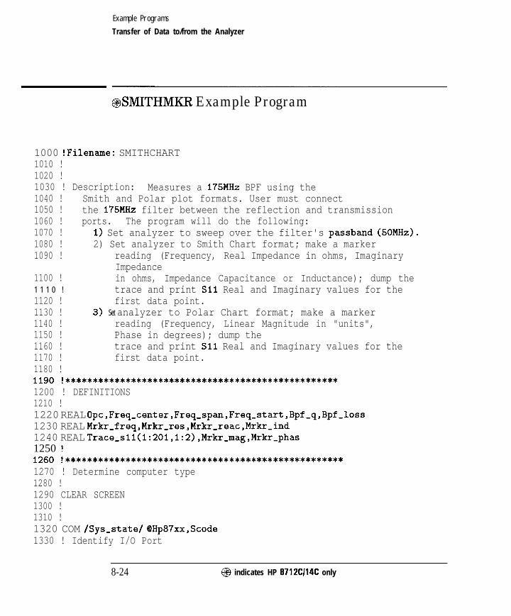
I- I -
Example Programs
Transfer of Data to/from the Analyzer
@SMITHMKR Example Program
1000 !Filename: SMITHCHART1010 !1020 !1030 ! Description: Measures a 175MHz BPF using the1040 ! Smith and Polar plot formats. User must connect1050 ! the 175MHz filter between the reflection and transmission1060 ! ports. The program will do the following:1070 ! 1) Set analyzer to sweep over the filter's passband (50MHz).1080 ! 2) Set analyzer to Smith Chart format; make a marker1090 ! reading (Frequency, Real Impedance in ohms, Imaginary
Impedance1100 ! in ohms, Impedance Capacitance or Inductance); dump the1 1 1 0 ! trace and print Sll Real and Imaginary values for the1120 ! first data point.1130 ! 3) Set analyzer to Polar Chart format; make a marker1140 ! reading (Frequency, Linear Magnitude in "units",1150 ! Phase in degrees); dump the1160 ! trace and print Sll Real and Imaginary values for the1170 ! first data point.1180 !1190 !**************************************************1200 ! DEFINITIONS1210 !1220 REAL Opc,Freq_center,Freq_span,Freq_start,Bpf-q,Bpf-loss1230 REAL Mrkr-freq,Mrkr-res,Mrkr_reac,Mrkr_ind1240 REAL Trace~sll(l:201,1:2),Mrkr_mag,Mrkr_phas1250 !1260 !***************************************************
1270 ! Determine computer type1280 !1290 CLEAR SCREEN1300 !1310 !1320 COM /Sys,state/ @Hp87xx,Scode1330 ! Identify I/O Port
8-24 @ indicates HP 8712Cl14C only

I-
Example Programs
Transfer of Data to/from the Analyzer
1340 CALL Iden,port1350 !1360 !1370 !---------------- ---------___---------------- -------
1380 ! Preset analyzer, set Center and Span frequencies1390 !1400 OUTPUT OHp87xx;"SYST:PRES;*OPC?" !preset instrument1410 ENTER OHp87xx;Opc !waits for PRESET to finish before
proceeding.1420 !1430 ! Center the filter's frequency response (to get an accurate Bandwidth
measurement).1440 !1450 DISP "Setting analyzer frequencies..." !message to user1460 OUTPUT @Hp87xx,*"ABOR;:INIT:CONT OFF;:INIT;*OPC?" !take a single sweep1470 ENTER QHp87xx;Opc !wait for sweep to
finish1480 OUTPUT OHp87xx;"CALCl:MARK:FUNC MAX;*WAI" !set Marker 1 to max1490 OUTPUT OHp87xx;"CALCl:MARK:X?;*WAI" !get Marker frequency
setting1500 ENTER QHp87xx;Mrkr-freq !read frequency of max
marker1510 OUTPUT @Hp87xx,."SENSl:FREQ:CENT "tVAL$(Mrkr,freq)&" HZ;*WAI" !set
Center Freq1520 OUTPUT (PHp87xx,*"SENSl:FREQ:SPAN 200 MHZ;*WAI" !set Span Freq = 200MHz1530 !1540 ! Measure Bandwidth, set Center to band center, Span to 50MHz1550 !1560 OUTPUT @Hp87xx,.t'ABOR;:INIT:CONT OFF;:INIT;*OPC?" !take a single sweep1570 ENTER OHp87xx;Opc !wait for sweep to
finish1580 OUTPUT QHp87xx;"CALCl:MARK:FUNC BWID;*OPC?" !search filter for -3dB
bandwidth1590 ENTER OHp87xx;Opc !wait for bandwidth to
be found1600 OUTPUT OHp87xx;"CALCl:MARK:FUNC:RES?" !read the bandwidth data1610 ENTER OHp87xx;Freq_span,Freq_center,Bpf_q,Bpf_loss !read
in data1620 OUTPUT QHp87xx,*"SENSl:FREQ:CENT "&VAL$(Freq-center)&" HZ;*WAI" !set
Center Freq
@ indicates HP 8712Cl14C only 8-25

I- I -
Example Programs
Transfer of Data to/from the Analyzer
1630
164016501660167016801690170017101720
1730
174017501760177017801790
1800
181018201830184018501860
1870
1880
189019001910
19201930
OUTPUT (PHp87xx;" SENSl:FREQ:SPAN 50 MHZ;*WAI" !set Span Freq to 50MHz(passband)I!---------------------------------------------------! Set marker 1 to beginning of trace.!OUTPUT OHp87xx;"CALCl:MARK:AOFF;*WAI" !clear all markersOUTPUT OHp87xx;"CALCl:MARKl ON" !turn on marker 1OUTPUT OHp87xx;"SENSl:FREQ:STAR?" !get start frequencyENTER OHp87xx;Freq-start !enter start freqOUTPUT QHp87xx;"CALCl:MARKl:X "&VAL$(Freq-start)t";*OPC?" !set markerto start freqENTER OHp87xx;Opc !wait for all previouscommands to finish!I-----------------,,,,,,,-------------------------------! Set to Reflection mode & Smith Chart format.!DISP "Setting to Smith Chart format..."OUTPUT OHp87xx;"ABOR;:INITl:CONT ON;*WAI" !set to Cont Sweep mode socan select reflectionOUTPUT OHp87xx;"SENSl:FUNC 'XFR:POW:RAT l,O';DET NBAN;*WAI"
!CHANl=reflectionOUTPUT QHp87xx;"CALCl:FORM SMIT;*WAI" !set smith chart format!I---------------------,,,,,,,,,,,,,-,---------------------------! Read marker information from Smith Chart.!OUTPUT @Hp87xx,*"ABOR;:INIT:CONT OFF;:INIT;*OPC?" !force one sweepbefore read markersENTER OHp87xx;Opc !wait for sweep tofinishOUTPUT OHp87xx;"ABOR;:INITl:CONT ON;*WAI" !set to Continuous SweepmodeOUTPUT OHp87xx;"CALCl:MARK:X?" !read marker frequencyENTER OHp87xx;Mrkr-freq !units are in HzOUTPUT OHp87xx;"CALCl:MARK:Y:RES?" !read real part ofmarker impedanceENTER OHp87xx;Mrkr,res !units are in ohmsOUTPUT OHp87xx;"CALCl:MARK:Y:REAC?" !read imaginary part ofmarker impedance
8 - 2 6 @ indicates HP 8712Cl14C only

I-Example Programs
Transfer of Data to/from the Analyzer
1940 ENTER QHp87xx;Mrkr,reac !units are in ohms1950 OUTPUT QHp87xx;"CALCl:MARK:Y:IND?" !read inductance (or
capacitance)1960 ENTER OHp87xx;Mrkr,ind !units are Henries if positive value, Farads
if negative1970 !1980 ! _____-_____---__-------------------------------------------1990 ! Display Smith Marker data.2000 !2010 Mrkr,freq=DROUND(Mrkr,freq,3) !round frequency
to 3 digits2020 DISP "Smith Marker Frequency = "&VAL$(Mrkr,freq)C"Hz" !display
frequency2030 WAIT 32040 !2050 Mrkr,res=DROUND(Mrkr_res,3) !round resistance
to 3 digits2060 DISP "Smith Marker Resistance = "&VAL$(Mrkr-r-es)&" ohms"2070 WAIT 32080 !2090 Mrkr_reac=DROUND(Mrkr_reac,3) !round reactance
to 3 digits2100 DISP "Smith Marker Reactance = "tVAL$(Mrkr-reac)&" ohms"2110 WAIT 32120 !2130 Mrkr_ind=DROUND(Mrkr_ind,3) !round inductance
to 3 digits2140 IF Mrkr,ind<O THEN !label as
capacitance if negative2150 DISP "Smith Marker Capacitance = "&VAL$(-Mrkr-ind)&"F"!label
capacitance2160 ELSE !label as
inductance if positive2170 DISP "Smith Marker Inductance = "tVAL$(Mrkr,ind)&"H" !label
inductance2180 END IF2190 WAIT 32200 !
@ indicates HP 87 12C114C only 8-27

I- I -
Example Programs
Transfer of Data to/from the Analyzer
2210 ! ----------------------------------------------------2220 ! Read Smith Chart formatted trace data, display first data point.2230 ! Data is transferred in ASCII format with 3 significant digits.2240 ! Sll trace data is read out as: Real data for point tl, Imaginary
data2250 ! for point #l, Real data for point %2, Imaginary data for point
#2...2260 ! Since instrument was preset, number of trace data points2270 ! defaults to 201.2280 !2290 OUTPUT @Hp87xx,-"FORM:DATA ASC,3;:TRAC? CHlFDATA" !set up to read
ASCII data, 3 digits2300 ENTER QHp87xx;Trace_sll(*) !read trace data,
real t imaginary pairs2310 !2320 ! Display data.2330 !2340 DISP "Smith Trace Point #l: Sll(REAL) = "&VAL$(Trace-sll(l,l))&"
Units" !display Real data2350 WAIT 32360 DISP "Smith Trace Point #1: Sll(IMAGINARY) = "&VAL$(Trace-sll(l,2))&"
Units" !display Imaginary data2370 WAIT 32380 !2390 !+++++++++++++++++++++++++++++++++++++++++++++++++++++++++++2400 ! Set to Polar Chart Format, read Polar Markers.2410 !2420 DISP "Setting to Polar Format..."2430 OUTPUT QHp87xx;"CALCl:FORM POL;*WAI" !set polar chart format2440 OUTPUT OHp87xx;"CALCl:MARK:X?" !read marker frequency2450 ENTER OHp87xx;Mrkr-freq !units are in Hz2460 OUTPUT OHp87xx;"CALCl:MARK:Y:MAGN?" !read magnitude marker
reflection coefficient2470 ENTER QHp87xx;Mrkr-mag !magnitude in "units"2480 OUTPUT QHp87xx;"CALCl:MARK:Y:PHAS?" !read phase of marker
reflection coefficient2490 ENTER OHp87xx;Mrkr,phas !units are in degrees2500 !
8-28 @ indicates HP 8712Cl14C only

I- I -
Example Programs
Transfer of Data to/from the Analyzer
2510 ! -----------------------------------------------------------
2520 ! Display Polar Marker data.2530 !2540 Mrkr,freq=DROUND(Mrkr_freq,3) !round frequency
to 3 digits2550 DISP "Polar Marker Frequency = "&VAL$(Mrkr-freq)&"Hz" !display
frequency2560 WAIT 32570 !2580 Mrkr_mag=DROUND(Mrkr,mag,3) !round magnitude
to 3 digits2590 DISP "Polar Marker Magnitude = "&VAL$(Mrkr-mag)t" Units" !display
magnitude2600 WAIT 32610 !2620 Mrkr_phas=DROUND(Mrkr_phas,3) !round phase to 3
digits2630 DISP "Polar Marker Phase = "&VAL$(Mrkr,phas)&" Degrees" !display
phase2640 WAIT 32650 !2660 !----------------------------------------------------2670 ! Read Polar Chart trace data, display first data point.2680 ! Sll trace data is read out as: Real data for point #l, Imaginary
data2690 ! for point #l, Real data for point #2, Imaginary data for point
#2...2700 !2710 OUTPUT QHp87xx,*"FORM:DATA ASC,3;:TRAC? CHIFDATA" !set up to read
ASCII data, 3 digits2720 ENTER QHp87xx;Trace_sll(*) !read trace data,
real 6 imaginary pairs2730 !2740 ! Display data2750 !2760 DISP "Polar Trace Point #l: Sll(REAL) = "%VAL$(Trace-sll(l,l))%"
Units" !display Real data2770 WAIT 32780 DISP "Polar Trace Point #1: Sll(IMAGINARY) = "%VAL$(Trace-sll(l,2))%"
Units" !display Imaginary data2790 WAIT 3
@indicates HP 8712Cl14C only 8 - 2 9

I- I -
Example Programs
Transfer of Data to/from the Analyzer
2800 DISP "'Iline
2810 !2820 STOP283028402850286028702880
!clear display
ND
**************************************************************Iden-port: Identify io port to use.Description: This routines sets up the I/O port address for
the SCPI interface. For "HP 87xx" instruments,2890 ! the address assigned to QHp87xx = 800 otherwise,2900 ! 716.2910 !**************************************************************2920 SUB Iden-port2930 COM /Sys-state/ QHp87xx,Scode2940 !2950 IF POS(SYSTEM$("SYSTEM ID">,"HP 87")OO THEN2960 ASSIGN cDHp87xx TO 8002970 Scode=82980 ELSE2990 ASSIGN (OHp87xx TO 7163000 Scode=73010 END IF3020 !3030 SUBEND !Iden,port3040 !
B-30 @ indicates HP 8712Cl14C only

- I -
Example Programs
Transfer of Data to/from the Analyzer
ASCDATA Example Program
This program demonstrates how to read data arrays from the analyzerand write them back again. The ASCii data format is being used with aresolution of 5 digits. More information about data transfer is availablein Chapter 4, “Data Types and Encoding,” and Chapter 6, “Trace DataTransfers. ”
In addition to the channel 1 formatted data array used in this example, thereare a number of arrays that can be accessed inside the instrument. Thesearrays and their corresponding mnemonics are listed in Chapter 6 in Table 6-4and Table 6-5.
1000 !Filename: ASCDATA1010 !1020 ! Description:1030 ! 1. Takes a sweep, and reads the formatted1040 ! data trace into an array. The trace1050 ! is read as a definite length block.1060 ! 2. Instructs you to remove DUT.1070 ! 3. Downloads the trace back to the analyzer1080 ! as an indefinite length block.1090 REAL Datal(l:51)1100 !1110 COM /Sys-state/ OHp87xx,Scode1120 ! Identify I/O Port1130 CALL Iden-port1140 !1150 !1160 ! Set the analyzer to measure 51 data points.1170 OUTPUT OHp87xx;"SENSl:SWE:POIN 51;*WAI"1180 !1190 ! Take a single sweep, leaving the analyzer1200 ! in trigger hold mode.1210 OUTPUT @Hp87xx,-"ABOR;:INITl:CONT OFF;:INITl;*WAI"1220 !1230 ! Set up the ASCII data format with 51240 ! significant digits1250 OUTPUT OHp87xx;"FORM:DATA ASC,5"
@ indicates HP 8712Cl14C only 8-31
I-

I- I -
Example Programs
Transfer of Data to/from the Analyzer
1260 !
1270 ! request the channel 1 formatted data array1280 ! from the instrument.1290 OUTPUT OHp87xx;"TRAC? CHlFDATA"1300 !1310 ! Get the data and put into data array Datal.1320 ENTER OHp87xx;Datal(*)1330 !1340 ! Display the first 3 numbers in the array.1350 DISP "Trace: 'I; Datal(l);Datal(2);Datal(3);"..."1360 !1370 ! Use the wait time to visually compare the1380 ! numbers to the visible data trace.1390 WAIT 51400 !1410 ! Prompt the operator to disconnect the test1420 ! device and then how to continue the program.1430 DISP "Disconnect the test device -- Press Continue"1440 PAUSE1450 !1460 ! Update the display line.1470 DISP "Taking a new sweep...";1480 !
1490 ! Take a sweep so the display shows new data.1500 OUTPUT QHp87xx;":INITl;*WAI"1510 DISP 'I Done."1520 WAIT 51530 !1540 ! Prepare the analyzer to receive the data.1550 ! Suppress the "end" character by using a1560 ! semicolon at end of output statement.1570 DISP "Downloading saved trace...";1580 OUTPUT OHp87xx;"TRAC CHlFDATA";1590 !1600 ! Send the data array one point at a time,1610 ! using the semicolon at the end of the1620 ! output statement to suppress the1630 ! end character.1640 FOR I=1 TO 511650 OUTPUT OHp87xx;", ";Datal(I);1660 NEXT I
8-32 @I indicates HP 8712Cl14C only

I-
Example Programs
Transfer of Data to/from the Analyzer
1670 !1680 ! Now send the end character.1690 OUTPUT (QHp87xx;""1700 DISP " Done!"1710 END1720 !1730 !**************************************************************1740 ! Iden,port: Identify io port to use.1750 ! Description: This routines sets up the I/O port address for1760 ! the SCPI interface. For "HP 87xx" instruments,1770 ! the address assigned to (SHp87xx = 800 otherwise,1780 ! 716.1790 !**************************************************************1800 SUB Iden-port1810 COM /Sys-state/ QHp87xx,Scode1820 !1830 IF POS(SYSTEM$("SYSTEM ID"),"HP 87")OO THEN1840 ASSIGN OHp87xx TO 8001850 Scode=81860 ELSE1870 ASSIGN (QHp87xx TO 7161880 Scode=71890 END IF1900 !1910 SUBEND !Iden-port1920 !
@ indicates HP 8712Cl14C only 8 - 3 3

I- I -
Example Programs
Transfer of Data to/from the Analyzer
REALDATA Example Program
This program demonstrates how to read data arrays from the analyzer andwrite them back again. The REAL, 64 data format is being used. Note thatthe analyzer outputs the data using the deEnite length block syntax. Thisexample uses the indefinite length block syntax when data is being writtenback to the analyzer. More information about data transfer is availablein Chapter 4, “Data Types and Encoding.” All of the arrays listed in theASCDATA example section can also be accessed using this data format.
1000 !Filename: REALDATA1010 !1020 ! Description:1030 ! 1. Takes a sweep, and reads the formatted1040 ! data trace into an array. The trace1050 ! is read as a definite length block.1060 ! 2. Instructs you to remove DUT.1070 ! 3. Downloads the trace back to the analyzer1080 ! as an indefinite length block.1090 DIM A$[101 ,Datal(l:51)1100 INTEGER Digits,Bytes1110 !1120 COM /Sys-state/ OHp87xx,Scode1130 ! Identify I/O Port1140 CALL Iden-port1150 !1160 !1170 ! Set up the analyzer to measure 51 data points.1180 OUTPUT OHp87xx;“SENSl:SWE:POIN 51;*WAI”1190 !1200 ! Take a single sweep, leaving the analyzer1210 ! in trigger hold mode.1220 OUTPUT QHp87xx;“ABOR;:INITl:CONT OFF;:INITl;*WAI”1230 !1240 ! Select binary block transfer.1250 OUTPUT OHp87xx;“FORM:DATA REAL,64”1260 !1270 ! Request the channel 1 formatted data array1280 ! from the analyzer.
8-34 @ indicates HP 8712Cl14C only

I- I -
Example Programs
Transfer of Data to/from the Analyzer
1290 OUTPUT QHp87xx;"TRAC? CHlFDATA"1300 !1310 ! Turn on ASCII formatting on the I/O path.1320 ! It is needed for reading the header1330 ! information.1340 ASSIGN OHp87xx;FORMAT ON1350 !1360 ! Get the data header. "A$" will contain the1370 ! "#" character indicating a block data transfer.1380 ! "Digits" will contain the number of characters1390 ! for the number of bytes value which follows.1400 ENTER (OHp87xx USING "%,A,D";A$,Digits1410 !1420 ! Get the rest of the header. The number of1430 ! bytes to capture in the data array will be1440 ! placed in "Bytes". Note the use of "Digits"1450 ! in the IMAGE string.1460 ENTER QHp87xx USING "%,"%VAL$(Digits)%"D";Bytes1470 !1480 ! Turn off ASCII formatting on the I/O path;1490 ! it is not needed for transferring binary1500 ! formatted data.1510 ASSIGN OHp87xx;FORMAT OFF1520 !1530 ! Get the data.1540 ENTER OHp87xx;Datal(*)1550 !1560 ! Turn on ASCII formatting again.1570 ASSIGN QHp87xx;FORMAT ON1580 !1590 ! Get the "end of data" character.1600 ENTER OHp87xx;A$1610 !1620 ! Display the first three numbers in the array.1630 DISP "Trace: ";Datal(l);Datal(2);Datal(3);"..."1640 !1650 ! Use this time to visually compare the1660 ! numbers to the visible data trace.1670 WAIT 51680 !1690 ! Prompt the operator to disconnect the test
@ indicates HP 8712Cl14C only 8-35

I- I -
Example Programs
Transfer of Data to/from the Analyzer
1980 !**************************************************************1990 ! Iden,port: Identify io port to use.2000 ! Description: This routines sets up the I/O port address for2010 ! the SCPI interface. For "HP 87xx" instruments,2020 I the address assigned to OHp87xx = 800 otherwise,
I 716.!**************************************************************
20302040
1700 ! device and how to continue the program.1710 DISP "Disconnect the test device -- Press Continue"1720 PAUSE1730 !1740 ! Update the display line.1750 DISP "Taking a new sweep...";1760 !1770 ! Take a sweep so the display shows new data.1780 OUTPUT OHp87xx;":INITl;*WAI"1790 DISP I' Done."1800 WAIT 51810 !1820 ! Send the header for an indefinite block length1830 ! data transfer.1840 DISP "Downloading saved trace...";1850 OUTPUT QHp87xx;"TRAC CHlFDATA, #O";1860 !1870 ! Turn off ASCII formatting.1880 ASSIGN QHp87xx;FORMAT OFF1890 !1900 ! Send the data array back to the analyzer.1910 OUTPUT OHp87xx;Datal(*),END1920 !1930 ! Turn on ASCII formatting again.1940 ASSIGN OHp87xx;FORMAT ON1950 DISP I' Done!"1960 END1970 !
8 - 3 6 @ indicates HP 8712Cl14C only
I-

I- I -
Example Programs
Transfer of Data to/from the Analyzer
2050 SUB Iden-port2060 COM /Sys,state/ OHp87xx,Scode2070 !2080 IF POS(SYSTEM$("SYSTEM ID">,"HP 87")OO THEN2090 ASSIGN (QHp87xx TO 8002100 Scode=82110 ELSE2120 ASSIGN QHp87xx TO 7162130 Scode=72140 END IF2150 !2160 SUBEND !Iden,port2170 !
@ indicates HP 8712Cl14C only 8-37
-1 I-

I- I -
Example Programs
Transfer of Data to/from the Analyzer
INTDATA Example Program
This program demonstrates how to read data arrays from the analyzer andwrite them back again. The INTeger ,16 data format is being used. This dataformat is the instrument’s internal format. It should only be used to readdata that will later be returned to the instrument.
The data array dimensioned in line 1100 is different from the arrays in eitherREAL, 64 or ASCii examples. This is because each data point is representedby a set of three 16-bit integers. Another difference in using this data formatis that all arrays cannot be accessed with it. The formatted data arraysCHlFDATA and CH2FDATA cannot be read using the INTEGER format.
Note that the analyzer outputs the data using the definite length blocksyntax. This example uses the indeEnite length block syntax when data isbeing written back to the analyzer. More information about data transfer isavailable in Chapter 4, “Data Types and Encoding. ’
1000 !Filename: INTDATA1010 !1020 ! Description:1030 ! 1. Takes a sweep, and reads the formatted1040 ! data trace into an array. The trace1050 ! is read as a definite length block.1060 ! 2. Instructs you to remove DUT.1070 ! 3. Downloads the trace back to the analyzer1080 ! as an indefinite length block.1090 DIM A$ [lo]1100 INTEGER Digits,Bytes,Datal(l:51,1:3)1110 !1120 COM /Sys-state/ QHp87xx,Scode1130 ! Identify I/O Port1140 CALL Iden-port1150 !1160 !1170 ! Set up the analyzer to measure 51 data points.1180 OUTPUT OHp87xx;“SENSl:SWE:POIN 51;*WAI”1190 !1200 ! Take a single sweep, leaving the analyzer1210 ! in trigger hold mode.
8 - 3 8 @ indicates HP 8712Cl14C only

I- I -
Example Programs
Transfer of Data to/from the Analyzer
1220 OUTPUT QHp87xx;"ABOR;:INITl:CONT OFF;:INITl;*WAI"1230 !1240 ! Select binary block transfer1250 OUTPUT OHp87xx;"FORM:DATA INT,lG"1260 !1270 ! Request the channel 1 unformatted data array1280 ! from the analyzer.1290 OUTPUT OHp87xx;"TRAC? CHISDATA"1300 !1310 ! Turn on ASCII formatting on the I/O path;1320 ! it is needed for reading the header information.1330 ASSIGN QHp87xx;FORMAT ON1340 !1350 ! Get the data header. "A$" will contain the1360 ! "t" character indicating a block data transfer.1370 ! " D i g i t s " will contain the number of characters1380 ! for the number of bytes value which follows.1390 ENTER QHp87xx USING "%,A,D";A$,Digits1400 !1410 ! Get the rest of the header. The number of1420 ! bytes to capture in the data array will be1430 ! placed in "Bytes". Note the use of "Digits"1440 ! in the IMAGE string.1450 ENTER (PHp87xx USING "%,"%VAL$(Digits)%"D";Bytes1460 !1470 ! Turn off ASCII formatting on the I/O path;1480 ! it is not needed for transferring binary1490 ! formatted data.1500 ASSIGN OHp87xx;FORMAT OFF1510 !1520 ! Get the data.1530 ENTER OHp87xx;Datal(*)1540 !1550 ! Turn on ASCII formatting again.1560 ASSIGN QHp87xx;FORMAT ON1570 !1580 ! Get the "end of data" character.1590 ENTER (OHp87xx;A$1600 !1610 ! Display the first 3 numbers; there will1620 ! be no visible similarity between these
@I indicates HP 8712Cl14C only 8 - 3 9

I -
Example Programs
Transfer of Data to/from the Analyzer
1630 ! numbers and the data displayed on the1640 ! analyzer.1650 DISP "Trace: ";Datal(l,l);Datal(1,2);Datal~l,3);"..."1660 WAIT 51670 !1680 ! Prompt the operator to disconnect the test1690 ! device and how to continue the program.1700 DISP "Disconnect the test device -- Press Continue"1710 PAUSE1720 !1730 ! Update the display line.1740 DISP "Taking a new sweep...";1750 !1760 ! Take a sweep so the display shows new data.1770 OUTPUT QHp87xx;":INITl;*WAI"1780 DISP " Done."1790 WAIT 51800 !1810 ! Send the header for an indefinite block length1820 ! data transfer.1830 DISP "Downloading saved trace...";1840 OUTPUT QHp87xx;"TRAC CHlSDATA, #O";1850 !1860 ! Turn off ASCII formatting.1870 ASSIGN OHp87xx;FORMAT OFF1880 !1890 ! Send the data back to the analyzer.1900 OUTPUT OHp87xx;Datal(*),END1910 !1920 ! Turn on ASCII formatting.1930 ASSIGN QHp87xx;FORMAT ON1940 DISP "Done!"1950 END1960 !1970 !**************************************************************1980 ! Iden-port: Identify io port to use.1990 ! Description: This routines sets up the I/O port address for2000 ! the SCPI interface. For "HP 87xx" instruments,2010 ! the address assigned to QHp87xx = 800 otherwise,2020 ! 716.2030 !**************************************************************
B-40 @ indicates HP 8712Cl14C only

I- I -
Example Programs
Transfer of Data to/from the Analyzer
2040 SUB Iden,port2050 COM /Sys-state/ QHp87xx,Scode2060 !2070 IF POS(SYSTEM$("SYSTEM ID">,"HP 87")OO THEN2080 ASSIGN (PHp87xx TO 8002090 Scode=82100 ELSE2110 ASSIGN (OHp87xx TO 7162120 Scode=72130 END IF2140 !2150 SUBEND !Iden-port2160 !
@ indicates HP 87 12CI14C only 8-41

I- I -
Example Programs
Transfer of Data to/from the Analyzer
FAST-CW Example Program
This program demonstrates how to setup a CW(fixed frequency)sweep withthe minimum number of trace points. Such a sweep allows measurementsto made very rapidly. The program also shows how to setup aloop whichuses a fast CW sweep, reads a marker value on the measurement trace, thenchanges the CW frequency.
1000 ! Filename: FAST-CW1010 !1020 ! Description:1030 ! Set sweep to CW, and select the1040 ! fewest number of points.1050 ! Change the frequency, take a sweep,1060 ! and use a marker to read the trace.1070 ! Repeat as quickly as possible.1080 !1090 DIM Freq_str$[20]1100 DIM Msg$[lOO]1110 !1120 !1130 COM /Sys-state/ OHp87xx,Scode1140 ! Identify I/O Port.1150 CALL Iden,port1160 !1170 !1180 ! PRESET, to ensure known state.1190 OUTPUT OHp87xx;“SYST:PRES;*WAI”1200 CLEAR SCREEN1210 !1220 ! Set up the analyzer to measure 3 data points.1230 OUTPUT QHp87xx;“SENSl:SWE:POIN 3;*WAI”1240 !1250 ! Select CW display and sweep.1260 OUTPUT QHp87xx;” DISP:ANN:FREQl:MODE CW”1270 OUTPUT QHp87xx;” SENSl:FREQ:SPAN 0 Hz;*WAI”1280 !1290 ! Take a single sweep, leaving the analyzer1300 ! in trigger hold mode.
8-42 @ indicates HP 8712Cl14C only

I -
Example Programs
Transfer of Data to/from the Analyzer
1310 OUTPUT OHp87xx;"ABOR;:INITl:CONT OFF;*WAI"1320 !1330 ! Turn on Marker 11340 OUTPUT OHp87xx;"CALC:MARKl ON"1350 !1360 Count=01370 TO=TIMEDATE1380 ! Step from 175 MHz 463 MHz by 6 MHz1390 FOR Freq=175 TO 463 STEP 61400 ! Take a sweep1410 Freq-str$=VAL$(Freq)t" MHz"1420 OUTPUT QHp87xx;"SENSl:FREQ:CENT ";Freq-str$1430 OUTPUT QHp87xx;"INITl;*WAI"1440 !1450 ! Set marker to frequency1460 OUTPUT QHp87xx;"CALC:MARK:X ";Freq-str$1470 !1480 ! Query the marker value1490 OUTPUT OHp87xx;"CALC:MARK:Y?"1500 ENTER OHp87xx;Response1510 !1520 ! Display the first three numbers in the array.1530 Msg$d’ ' "&Freq-str$&": "tVAL$(Response)&""'1540 OUTPUT OHp87xx;"DISP:ANN:MESS ";Msg$1550 PRINT Msg$1560 Count=Count+l1570 NEXT Freq1580 Tl=TIMEDATE1590 PRINT "Sweeps per second: ";Count/(Tl-TO)1600 DISP "Sweeps per second: ";Count/(Tl-TO)1610 END1620 !
@I indicates HP 8712Cl14C only 8 - 4 3

I- I -
Example Programs
Transfer of Data to/from the Analyzer
1630 !*******$******************************************************1640 ! Iden-port: Identify io port to use.1650 ! Description: This routines sets up the I/O port address for1660 ! the SCPI interface. For "HP 87xx" instruments,1670 ! the address assigned to OHp87xx = 800 otherwise,1680 ! 716.1690 !**************************************************************1700 SUB Iden-port1710 COM /Sys-state/ OHp87xx,Scode1720 !1730 IF POS(SYSTEM$("SYSTEM ID">,"HP 87")OO THEN1740 ASSIGN (PHp87xx TO 8001750 Scode=81760 ELSE1770 ASSIGN OHp87xx TO 7161780 Scode=71790 END IF1800 !1810 SUBEND !Iden-port1820 !
8 - 4 4 @ indicates HP 87 12Cl14C only

I- I -
Calibration
TRANCAL Performing a transmission calibration. The calibration isUser Defined (performed over the instruments currentsource settings). This example also demonstrates the use ofthe *OPC? command.
REFLCAL Performing a reflection calibration. The calibration is FullBand (performed over the instrument’s preset sourcesettings). This example also demonstrates the detection offront panel key presses, the use of softkeys, and the use ofthe *OPC? command.
LOADCALS Uploading and downloading correction arrays. The datatransfer is performed in the 16-bit integer format. Thearrays must be dimensioned properly for both the number ofdata points and the format of the data being transferred.
CALKIT Instrument state Ille for downloading User Defined calkit dehnitions. This example is NOT a program. It is aninstrument state file example. This type of file enables theuser to calibrate the analyzer for use with connector typesthat are not in the firmware. See “Writing and Editing YourOwn Cal Kit File” in Chapter 6 of the User’s Guide.
@I indicates HP 8712CI14C only 8-45

I- I -
Example Programs
Calibration
TRANCAL Example Program
This program demonstrates a transmission calibration performed overuser-defined source settings (frequency range, power and number of points).The operation complete query is used at each step in the process to makesure the steps are taken in the correct order. More information on calibrationis available in the User’s Guide.
1000 ! Filename: TRANCAL1010 !1020 ! Guide user through a transmission cal.1030 !1040 !1050 COM /Sys-state/ OHp87xx,Scode1060 ! Identify I/O Port1070 CALL Iden-port1080 !1090 !1100 ! Configure the analyzer to measure transmission1110 ! on channel 1.1120 OUTPUT QHp87xx;"SENSl:FUNC 'XFR:POW:RAT 2,O';DET NBAN;*WAI"1130 !1140 ! Select a calibration kit type.1150 OUTPUT OHp87xx;"SENS:CORR:COLL:CKIT 'COAX,7MM,TYPE-N,50,FEMALE"'1160 !1170 ! Select a transmission calibration for the current1180 ! analyzer settings. The "1ST:OFF" ensures that1190 ! the current settings will be used.1200 OUTPUT QHp87xx; “SENSl:CORR:COLL:IST 0FF;METH TRANl”1210 !1220 ! Prompt the operator to make a through1230 ! connection.1240 DISP "Connect THRU - Press Continue"1250 PAUSE1260 DISP "Measuring THRU"1270 !1280 ! Analyzer measures the through.1290 OUTPUT QHp87xx;"SENSl:CORR:COLL STANl;*OPC?"1300 !
8-46 @ indicates HP 87 12Cl14C only

I- I -
Example Programs
Calibration
1310 ! Wait until the measurement is complete.1320 ENTER OHp87xx;Opc1330 DISP "Calculating Error Coefficients"1340 !1350 ! Tell the analyzer to calculate the136013701380139014001410
error coefficients after the measurementis made, and then save for use duringsubsequent transmission measurements.Note that this is not the same as usingthe SAVE RECALL key functionality.UTPUT OHp87xx;"SENSl:CORR:COLL:SAVE;*OPC?"
1420 !1430 ! Wait for the calculations and save to be1440 ! completed.1450 ENTER OHp87xx;Opc1460 DISP "User Defined TRANSMISSION CAL COMPLETED!"1470 END1480 !1490 !**************************************************************1500 ! Iden-port: Identify io port to use.1510 ! Description: This routines sets up the I/O port address for1520 ! the SCPI interface. For "HP 87xx" instruments,1530 ! the address assigned to OHp87xx = 800 otherwise,1540 ! 716.1550 !**************************************************************1560 SUB Iden,port1570 COM /Sys,state/ OHp87xx,Scode1580 !1590 IF POS(SYSTEM$("SYSTEM ID">,"HP 87")OO THEN1600 ASSIGN OHp87xx TO 8001610 Scode=81620 ELSE1630 ASSIGN (QHp87xx TO 7161640 Scode=71650 END IF1660 !1670 SUBEND !Iden,port1680 !
@indicates HP 8712Cl14C only 8-47

I- I -
Example Programs
Calibration
REFLCAL Example Program
This program demonstrates a reflection calibration performed over thepreset source settings (frequency range, power and number of points). Theoperation complete query is used at each step in the process to make surethe steps are taken in the correct order. More information on calibration isavailable in the User's Guide.
1000 !Filename: REFLCAL1010 !1020 ! Guide user through a reflection cal.1030 !1040 DIM Msg$[50]1050 !1060 COM /Sys-state/ OHp87xx,Scode,Internal1070 ! Identify I/O Port1080 CALL Iden-port1090 !1100 !1110 ! Configure the analyzer to measure1120 ! reflection on channel 1.1130 OUTPUT OHp87xx;"SENSl:FUNC 'XFR:POW:RAT 1,O';DET NBAN;*WAI"1140 !1150 ! Select Calibration Kit for 50 ohm instruments.1160 OUTPUT QHp87xx,*"SENS:CORR:COLL:CKIT 'COAX,7MM,TYPE-N,SO,FEMALE"'1170 !1180 ! Select Calibration Kit for 75 ohm instruments.1190 ! (Comment out the 50 ohm line above and uncomment the line1200 ! below.)1210 ! OUTPUT @Hp87xx;"SENS:CORR:COLL:CKIT 'COAX,7MM,TYPE-N,75,FEMALE"'1220 !1230 ! Select a reflection calibration for the current1240 ! analyzer settings. The "1ST:OFF" ensures that1250 ! current settings will be used.1260 OUTPUT OHp87xx;"SENSl:CORR:COLL:IST 0FF;METH REFL3"1270 !1280 ! Prompt the operator to connect an open.1290 Msg$="Connect OPEN"1300 GOSUB Get-continue
8-48 @ indicates HP 87 12Cl14C only

I- I -
Example Programs
Calibration
1310 DISP "Measuring OPEN"1320 !1330 ! Measure the open.1340 OUTPUT OHp87xx;"SENSl:CORR:COLL STANl;*OPC?"1350 !1360 ! Wait until the measurement of the open1370 ! is complete.1380 ENTER QHp87xx;Opc1390 !1400 ! Prompt the operator to connect a short.1410 Msg$="Connect SHORT"1420 GOSUB Get-continue1430 DISP "Measuring SHORT"1440 !1450 ! Measure the short.1460 OUTPUT QHp87xx;"SENSl:CORR:COLL STAN2;*OPC?"1470 !1480 ! Wait until measurement of the short1490 ! is complete.1500 ENTER QHp87xx;Opc1510 !1520 ! Prompt operator to connect a load.1530 Msg$="Connect LOAD"1540 GOSUB Get-continue1550 DISP "Measuring LOAD"1560 !1570 ! Measure the load.1580 OUTPUT QHp87xx;"SENSl:CORR:COLL STANB;*OPC?"1590 ! Wait until measurement of the load1600 ! is complete.1610 ENTER QHp87xx;Opc1620 DISP "Calculating Error Coefficients"1630 !1640 ! Tell the analyzer to calculate the1650 ! error coefficients, and then save1660 ! for use during subsequent reflection1670 ! measurements. Note that this is not1680 ! the same as using the SAVE RECALL key1690 ! functionality.1700 OUTPUT OHp87xx;"SENSl:CORR:COLL:SAVE;*OPC?"1710 !
@ indicates HP 8712Cl14C only 8 - 4 9

I- I -
Example Programs
Calibration
1720 ! Wait for the calculations to be completed1730 ! and the calibration saved.1740 ENTER QHp87xx;Opc1750 DISP "Full Band REFLECTION CAL COMPLETED!"1760 STOP1770 !1780 Get-continue: ! Subroutine to handle operator prompts.1790 !1800 ! "Internal" is determined above based on the1810 ! controller.1820 IF Internal=1 THEN1830 !1840 ! If internal control, then use the display1850 ! line for the prompt.1860 DISP Msg$&" - Press Measure Standard"1870 !1880 ! Use the softkey 2 for the response; loop1890 ! while waiting for it to be pressed.1900 ON KEY 2 LABEL "Measure Standard" RECOVER Go-on1910 LOOP1920 END LOOP1930 ELSE1940 !1950 ! If external control, clear the key queue1960 ! so previous key presses will not interfere.1970 OUTPUT QHp87xx;"SYST:KEY:QUE:CLE"1980 !1990 ! Use the BEGIN key for the response.2000 DISP Msg$&" - Press BEGIN to continue"2010 !2020 ! Turn on the key queue to trap all key2030 ! presses.2040 OUTPUT (OHp87xx; "SYST:KEY:QUE ON"2050 !2060 ! Loop while waiting for a key to be2070 ! pressed.2080 LOOP2090 ! Query the device status condition2100 ! register.2110 OUTPUT OHp87xx;"STAT:DEV:COND?"2120 ENTER QHp87xx;Dev,cond
8-50 @ indicates HP 87 12Cl14C only
-1
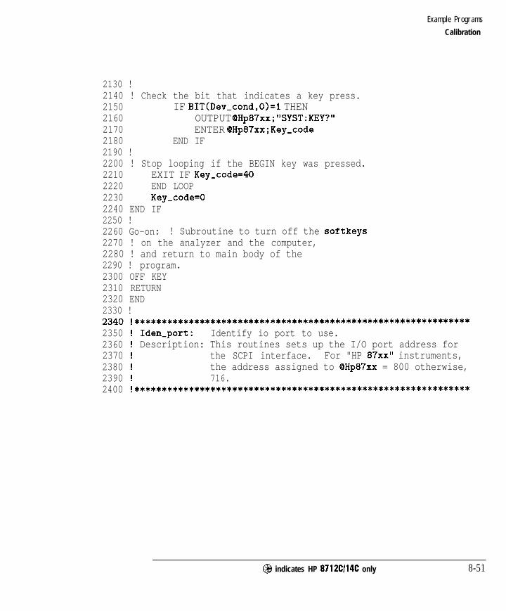
I- I -
Example Programs
Calibration
2130 !2140 ! Check the bit that indicates a key press.2150 IF BIT(Dev,cond,O)=l THEN2160 OUTPUT QHp87xx;"SYST:KEY?"2170 ENTER dHp87xx;Key-code2180 END IF2190 !2200 ! Stop looping if the BEGIN key was pressed.2210 EXIT IF Key-code=402220 END LOOP2230 Key-code=02240 END IF2250 !2260 Go-on: ! Subroutine to turn off the softkeys2270 ! on the analyzer and the computer,2280 ! and return to main body of the2290 ! program.2300 OFF KEY2310 RETURN2320 END2330 !2340 !**************************************************************235023602370238023902400
Iden-port: Identify io port to use.Description: This routines sets up the I/O port address for
the SCPI interface. For "HP 87xx" instruments,the address assigned to QHp87xx = 800 otherwise,716.
**************************************************************
@I indicates HP 8712Cl14C only 8-51

I- I -
Example Programs
Calibration
2410 SUB Iden,port2420 COM /Sys-state/ OHp87xx,Scode,Internal2430 !2440 IF POS(SYSTEM$("SYSTEM ID">,"HP 87")OO THEN2450 ASSIGN QHp87xx TO 8002460 Scode=82470 Internal=12480 ELSE2490 ASSIGN (QHp87xx TO 7162500 Scode=72510 Internal=02520 END IF2530 !2540 SUBEND !Iden,port2550 !
8-52 @ indicates HP 8712Cl14C only
I- I -
Example Programs
Calibration
LOADCALS Example Program
This program demonstrates how to read the correction arrays from theanalyzer and write them back again. The INTeger ,16 data format is beingused because the data does not need to be interpreted, only stored andretrieved. More information about calibration is available in the User’s Guide.
The size of the arrays into which the data is read is critical. If they are notdimensioned correctly the program will not work. Most correction arrays,including the factory default (DEF) and the full band (FULL, preset sourcesettings) arrays have 801 points. For user defined calibrations (USER) thenumber of points must be determined. If the number of points is other than801, lines 1110 and 1790 will need to be changed to allocate arrays for thecorrect number of points. The number of points can be found by reading thecorrection array’s header and determining the size as shown in the examplebelow.
@I indicates HP 8712Cl14C only 8-53

I- I -
Example Programs
Calibration
1000 !Filename: LOADCALS1010 !1020 ! Description:1030 ! 1. Query the calibration arrays, based on1040 ! the current measurement (trans/refl).1050 ! 2. Change number of points to 801.1060 ! 3. Download the calibration arrays back1070 ! into the analyzer.1080 !1090 DIM Func$[20],A$[lO]1100 INTEGER Swap,Arrays,Digits,Bytes,Points1110 INTEGER Corr1(1:801,1:3),Corr2(1:801,1:3),Corr3(1:801,1:3~1120 !1130 COM /Sys-state/ @Hp87xx,Scode1140 ! Identify I/O Port1150 CALL Iden-port1160 !1170 !1180 ! Query the measurement parameter.1190 OUTPUT QHp87xx;"SENSl:FUNC?"1200 !1210 ! Read the analyzer's response.1220 ENTER QHp87xx;Func$1230 !1240 ! Set up a SELECT/CASE depending on the1250 ! response.1260 SELECT Func$1270 !1280 ! This is the transmission case, a ratio of1290 ! the powers measured by detector 2 (B) and1300 ! detector 0 (RI.1310 CASE """XFR:POW:RAT 2, 0"""1320 !1330 ! The transmission calibration has only one1340 ! correction array.1350 Arrays=11360 !1370 ! This is the reflection case, a ratio of1380 ! the powers measured by detector 1 (A) and1390 ! detector 0 (RI.1400 CASE """XFR:POW:RAT 1, 0"""
8-54 @ indicates HP 8712Cl14C only
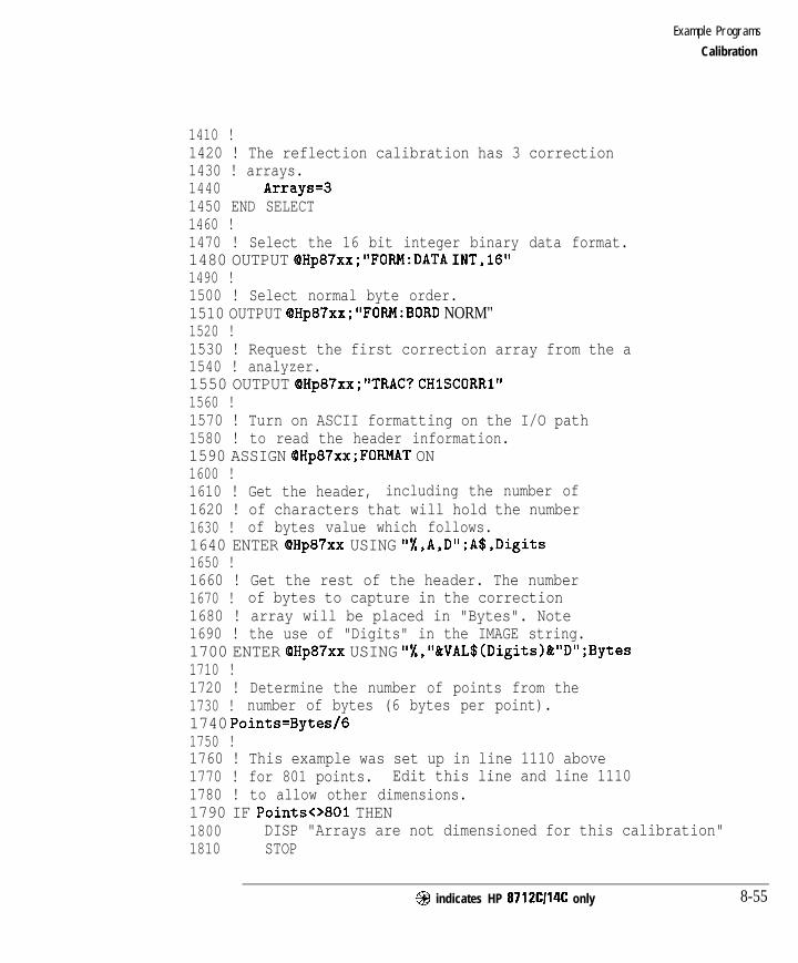
I- I -
Example Programs
Calibration
1410 !1420 ! The reflection calibration has 3 correction1430 ! arrays.1440 Arrays=31450 END SELECT1460 !1470 ! Select the 16 bit integer binary data format.1480 OUTPUT OHp87xx;"FORM:DATA INT,lG"1490 !1500 ! Select normal byte order.1510 OUTPUT OHp87xx;"FORM:BORD NORM"1520 !1530 ! Request the first correction array from the a1540 ! analyzer.1550 OUTPUT OHp87xx;"TRAC? CHlSCORRl"1560 !1570 ! Turn on ASCII formatting on the I/O path1580 ! to read the header information.1590 ASSIGN OHp87xx;FORMAT ON1600 !1610 ! Get the header, including the number of1620 ! of characters that will hold the number1630 ! of bytes value which follows.1640 ENTER QHp87xx USING "%,A,D";A$,Digits1650 !1660 ! Get the rest of the header. The number1670 ! of bytes to capture in the correction1680 ! array will be placed in "Bytes". Note1690 ! the use of "Digits" in the IMAGE string.1700 ENTER QHp87xx USING "%,"&VAL$(Digits)&"D";Bytes1710 !1720 ! Determine the number of points from the1730 ! number of bytes (6 bytes per point).1740 Points=Bytes/G1750 !1760 ! This example was set up in line 1110 above1770 ! for 801 points. Edit this line and line 11101780 ! to allow other dimensions.1790 IF Points<>801 THEN1800 DISP "Arrays are not dimensioned for this calibration"1810 STOP
@ indicates HP 8712Cl14C only 8-55
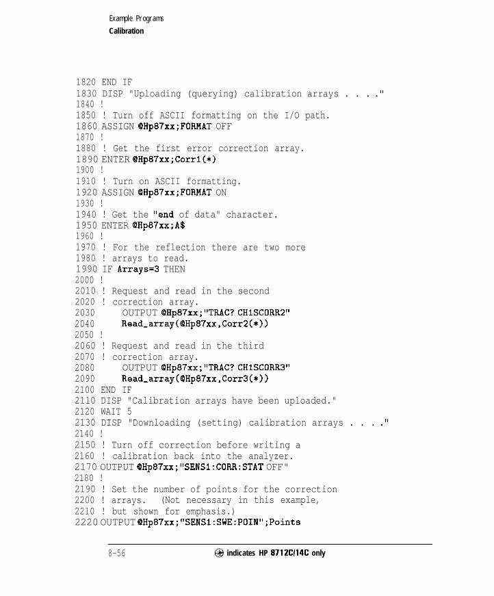
I- I -
Example Programs
Calibration
1820 END IF1830 DISP "Uploading (querying) calibration arrays . . . ."1840 !1850 ! Turn off ASCII formatting on the I/O path.1860 ASSIGN OHp87xx;FORMAT OFF1870 !1880 ! Get the first error correction array.1890 ENTER QHp87xx;Corrl(*)1900 !1910 ! Turn on ASCII formatting.1920 ASSIGN OHp87xx;FORMAT ON1930 !1940 ! Get the "end of data" character.1950 ENTER @Hp87xx;A$1960 !1970 ! For the reflection there are two more1980 ! arrays to read.1990 IF Arrays=3 THEN2000 !2010 ! Request and read in the second2020 ! correction array.2030 OUTPUT OHp87xx;"TRAC? CHlSCORR2"2040 Read_array(QHp87xx,Corr2(*))2050 !2060 ! Request and read in the third2070 ! correction array.2080 OUTPUT OHp87xx;"TRAC? CHlSCORR3"2090 Read_array(OHp87xx,Corr3(*))2100 END IF2110 DISP "Calibration arrays have been uploaded."2120 WAIT 52130 DISP "Downloading (setting) calibration arrays . . . .'I2140 !2150 ! Turn off correction before writing a2160 ! calibration back into the analyzer.2170 OUTPUT QHp87xx;"SENSl:CORR:STAT OFF"2180 !2190 ! Set the number of points for the correction2200 ! arrays. (Not necessary in this example,2210 ! but shown for emphasis.)2220 OUTPUT QHp87xx;"SENSl:SWE:POIN";Points
8-56 @ indicates HP 8712C114C only

I- I -
Example Programs
Calibration
2230 !2240 ! Prepare the analyzer to receive the first2250 ! correction array in the indefinite block2260 ! length format.2270 OUTPUT QHp87xx;"TRAC CHlSCORRI, #O";2280 !2290 ! Turn off ASCII formatting.2300 ASSIGN QHp87xx;FORMAT OFF2310 !2320 ! Send the first correction array to the2330 ! analyzer. The array transfer is2340 ! terminated with the "END" signal.2350 OUTPUT QHp87xx;Corrl(*),END2360 !2370 ! Turn on ASCII formatting.2380 ASSIGN OHp87xx;FORMAT ON2390 !2400 ! For a reflection array download, there2410 ! are two more arrays.2420 IF Arrays=3 THEN2430 !2440 ! Prepare the analyzer to receive the2450 ! 2nd array, then output it.2460 OUTPUT QHp87xx;"TRAC CHISCORR2, ";2470 Write,array(QHp87xx,Corr2(*))2480 !2490 ! Prepare the analyzer to receive the2500 ! 3rd array, then output it.2510 OUTPUT OHp87xx;"TRAC CHlSCORR3, ";2520 Write,array(OHp87xx,Corr3(*))2530 END IF2540 !2550 ! Turn on the calibration just downloaded.2560 OUTPUT QHp87xx;"SENSl:CORR:STAT ON;*WAI"2570 DISP "Calibration arrays have been downloaded."2580 END2590 !2600 ! Subprogram for reading binary data array from2610 ! the analyzer. The command requesting a specific2620 ! data array has already been sent prior to2630 ! calling this subprogram.
@ indicates HP 8712CI14C only 8-57

I- I -
Example Programs
Calibration
2640 !2650 SUB Read_array(OHp87xx,INTEGER Array(*))2660 DIM A$[1012670 INTEGER Digits,Bytes2680 ASSIGN OHp87xx;FORMAT ON2690 ENTER (OHp87xx USING "%,A,D";A$,Digits2700 ENTER QHp87xx USING "%,"&VAL$(Digits)&"D";Bytes2710 ASSIGN QHp87xx;FORMAT OFF2720 ENTER OHp87xx;Array(*)2730 ASSIGN OHp87xx;FORMAT ON2740 ENTER QHp87xx;A$2750 SUBEND2760 !2770 ! Subprogram for writing binary data array to2780 ! the analyzer. The command requesting a specific2790 ! data array has already been sent prior to2800 ! calling this subprogram.2810 !2820 SUB Write_array(QHp87xx,INTEGER Array(*))2830 OUTPUT OHp87xx;"#O";2840 ASSIGN QHp87xx;FORMAT OFF2850 OUTPUT QHp87xx;Array(*),END2860 ASSIGN OHp87xx;FORMAT ON2870 SUBEND2880 !2890 !**************************************************************2900 ! Iden-port: Identify io port to use.2910 ! Description: This routines sets up the I/O port address for2920 ! the SCPI interface. For "HP 87xx" instruments,2930 ! the address assigned to QHp87xx = 800 otherwise,2940 ! 716.2950 !**************************************************************
8-58 @ indicates HP 8712C114C only
I-
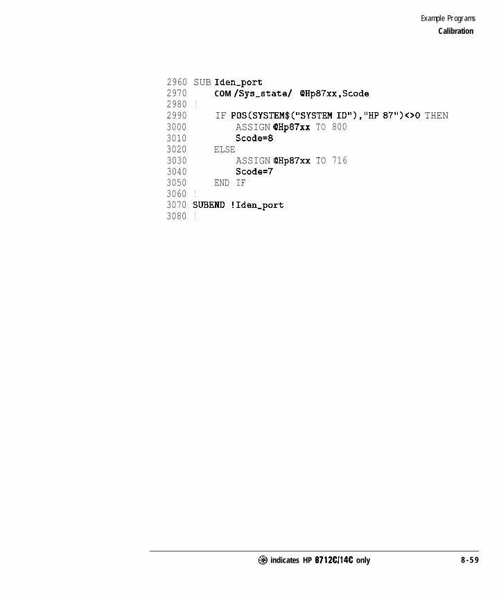
I- I -
Example Programs
Calibration
2960 SUB Iden,port2970 COM /Sys-state/ OHp87xx,Scode2980 !2990 IF POS(SYSTEM$("SYSTEM ID"),"HP 87")OO THEN3000 ASSIGN (QHp87xx TO 8003010 Scode=83020 ELSE3030 ASSIGN (SHp87xx TO 7163040 Scode=73050 END IF3060 !3070 SUBEND !Iden-port3080 !
@ indicates HP 8712C114C only 8 - 5 9

I- I -
Example Programs
Calibration
CALKIT Example Program
This instrument state file demonstrates the type of Gle required to downloaduser-defmed calibration kits. lb see an example of using this feature, refer to“Writing or Editing Your Own Cal Kit File”, in Chapter 6 of the User’s Guide.
10 !$
11 !12 !$13 !$14 !$15 !$16 !$17 !$18 !$20 !30 !$
40 !$50 !
Standard Definitions for HP 85054B PrecisionType-N Cal Kit.
This is a Cal Kit definition file, whichuses the same format as a BASIC program.Lines that contain ‘I! $‘I are comments.
Put your Cal Kit file on a disk, and use theanalyzer ’ s [SAVE/RECALL] [Recall St at el keysto load your custom Cal Kit into the analyzer.
Definitions for 50 Ohm jack (FEMALE centercontact) testports, plug (MALE center contact) standards.
60 ! OPEN: $ HP 85054-60027 Open Circuit Plug70 ! zo 50.0 $ ohms80 ! DELAY 57.993E-12 $ Set90 ! LOSS 0.8E+9 $ Ohms/Set100 ! CO 88.308E-15 $ Farads110 ! Cl 1667.2E-27 $ Farads/Hz120 ! C2 -146.6lE-36 $ Farads/Hz-2130 ! C3 9.7531E-45 $ Farads/Hz-3140 !150 ! SHORT: $ HP 85054-60025 Short Circuit Plug160 ! zo 50.0 $ ohms170 ! DELAY 63.078E-12 $ Set180 ! LOSS 8.E+8 $ Ohms/Set190 !200 ! LOAD: $ HP 00909-60011 Broadband Load Plug210 ! zo 50.0 $ ohms220 ! DELAY 0.0 $ Set230 ! LOSS 0.0 $ Ohms/Set
B-60 @ indicates HP 8712Cl14C only

I- I -
Example Programs
Calibration
240 !250 ! THRU: $ HP 85054-60038 Plug to Plug Adapter260 ! zo 50.0 $ ohms270 ! DELAY 196.OE-12 $ Set280 ! LOSS 2.2E+9 $ Ohms/Set290 !300 END
@ indicates HP 8712CI14C only 8-61

I- I -
Instrument State and Save/Recall
LEARNSTR Using the learn string to upload and download instrumentstates.
SAVERCL Saving and recalling instrument states, calibrations and data.The example also demonstrates saving data in an ASCII Elethat includes both magnitude and frequency information.
8-62 @I indicates HP 8712Cl14C only
I-
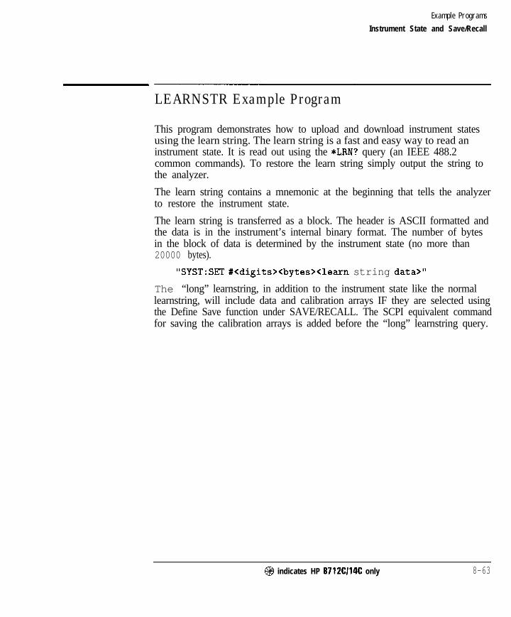
I- I -
Example Programs
Instrument State and Save/Recall
LEARNSTR Example Program
This program demonstrates how to upload and download instrument statesusing the learn string. The learn string is a fast and easy way to read aninstrument state. It is read out using the *LRN? query (an IEEE 488.2common commands). To restore the learn string simply output the string tothe analyzer.
The learn string contains a mnemonic at the beginning that tells the analyzerto restore the instrument state.
The learn string is transferred as a block. The header is ASCII formatted andthe data is in the instrument’s internal binary format. The number of bytesin the block of data is determined by the instrument state (no more than20000 bytes).
"SYST:SET #<digits><bytes><learn string data>"
The “long” learnstring, in addition to the instrument state like the normallearnstring, will include data and calibration arrays IF they are selected usingthe Define Save function under SAVE/RECALL. The SCPI equivalent commandfor saving the calibration arrays is added before the “long” learnstring query.
@ indicates HP 8712Cl14C only 8-63
-

I- I -
Example Programs
Instrument State and Save/Recall
1000 !Filename: LEARNSTR1010 !1020 ! Description:1030 ! 1. Query the learn string.1040 ! 2. Preset the analyzer.1050 ! 3. Send the learn string,1060 ! restoring the previous state.1070 !1080 DIM Learnstr$[20000]1090 !1100 COM /Sys-state/ OHp87xx,Scode1110 ! Identify I/O Port1120 CALL Iden,port1130 !1140 !1150 ! Request the learnstring. If the "long"1160 ! learnstring is desired, comment the line1170 ! below, and uncomment the line after it.1180 ! The "long" learnstring, in addition to1190 ! the instrument state like the normal1200 ! learnstring, will include data and1210 ! calibration arrays IF they are selected1220 ! using the Define Save function under1230 ! SAVE RECALL. The SCPI equivalent command1240 ! for saving the calibration arrays is1250 ! added before the "long" learnstring query.1260 OUTPUT OHp87xx;"*LRN?"1270 ! OUTPUT OHp87xx;"MMEM:STOR:STAT:CORR ON;:SYST:SET:LRNL?"1280 !1290 ! Read the learnstring from the analyzer.1300 ! The USING 'I-K" format allows the data1310 ! being transmitted to include characters1320 ! (such as the line feed character) that1330 ! would otherwise terminate the learnstring1340 ! request prematurely.1350 ENTER QHp87xx USING "-K";Learnstr$1360 DISP "Learn string has been read"1370 WAIT 51380 !1390 ! Preset the analyzer.1400 OUTPUT QHp87xx;"SYST:PRES;*OPC?"
8-64 @ indicates HP 8712Cl14C only

I- -
Example Programs
Instrument State and Save/Recall
1410 !1420 ! Wait for the preset operation to complete.1430 ENTER OHp87xx;Opc1440 DISP "Instrument has been PRESET"1450 WAIT 51460 !1470 ! Output the learnstring to the analyzer.1480 ! The mnemonic is included in the string,1490 ! so no command preceding "Learnstr$" is1500 ! necessary.1510 OUTPUT OHp87xx;Learnstr$1520 DISP "Instrument state has been restored"1530 END1540 !1550 !**************************************************************1560 ! Iden,port: Identify io port to use.1570 ! Description: This routines sets up the I/O port address for1580 ! the SCPI interface. For "HP 87xx" instruments,1590 ! the address assigned to (QHp87xx = 800 otherwise,1600 ! 716.1610 !**************************************************************1620 SUB Iden-port1630 COM /Sys-state/ OHp87xx,Scode1640 !1650 IF POS(SYSTEM$("SYSTEM ID"),"HP 87")OO THEN1660 ASSIGN OHp87xx TO 8001670 Scode=81680 ELSE1690 ASSIGN QHp87xx TO 7161700 Scode=71710 END IF1720 !1730 SUBEND !Iden,port1740 !
@ indicates HP 8712Cl14C only 8-65

I- I -
Example Programs
Instrument State and Save/Recall
SAVERCL Example Program
This program demonstrates, how to save instrument states, calibrationsand data to a mass storage device. The device used in this example is theanalyzer’s internal 3.5” disk drive. The only change needed to use thisprogram with the internal non-volatile memory is to change the mass storageunit specifier.
The three choices are the internal floppy disk drive (INT:), the internalnon-volatile memory, (MEM : ), and the internal volatile memory, (RAM :).
Lines 1110-1320 are an example of saving an instrument state andcalibration on the internal tloppy disk drive.
Lines 1460-1470 are an example ofrecallingthat instrument state andcalibration.
Lines 1510-1560 are an example of saving a data trace (magnitude andfrequency values) to an AXII formatted llle on the internal floppy disk drive.This file cannot be recalled into the instrument. It can, however, be importeddirectly into spreadsheets and word processors.
1000 !Filename: SAVERCL1010 !1020 !1030 COM /Sys-state/ OHp87xx,Scode1040 ! Identify I/O Port1050 CALL Iden-port1060 !1070 !1080 ! Select the internal floppy disk drive1090 ! as the mass storage device.1100 OUTPUT OHp87xx;"MMEM:MSIS 'INT:"'1110 !1120 ! Turn on the saving of the instrument state1130 ! as part of the "Define Save" function under1140 ! SAVE RECALL.1150 OUTPUT QHp87xx;"MMEM:STOR:STAT:IST ON"1160 !1170 ! Turn on the saving of the calibration1180 ! as part of the "Define Save" function under
8-66 @I indicates HP 8712Cl14C only

I- I -
Example Programs
Instrument State and Save/Recall
1190 ! SAVE RECALL.1200 OUTPUT QHp87xx;"MMEM:STOR:STAT:CORR ON"1210 !1220 ! Turn off the saving of the data1230 ! as part of the "Define Save" function under1240 ! SAVE RECALL.1250 OUTPUT QHp87xx;"MMEM:STOR:STAT:TRAC OFF"1260 !1270 ! Save the current defined state (STAT I) into1280 ! a file named "FILTER". Use *OPC? to make1290 ! sure the operation is completed before any1300 ! other operation begins.1310 OUTPUT QHp87xx;"MMEM:STOR:STAT I,'FILTER';*OPC?"1320 ENTER OHp87xx;Opc1330 DISP "Instrument state and calibration have been saved"1340 !1350 ! Preset the instrument so that the change in state1360 ! is easy to see when it is recalled.1370 OUTPUT QHp87xx;"SYST:PRES;*OPC?"1380 ENTER QHp87xx;Opc1390 DISP "Instrument has been PRESET"1400 WAIT 51410 !1420 ! Recall the file "FILTER" from the internal1430 ! floppy disk drive. This becomes the new instrument1440 ! state. Use of the *OPC query allows hold off of1450 ! further commands until the analyzer is reconfigured.1460 OUTPUT QHp87xx,."MMEM:LOAD:STAT l,'INT:FILTER';*OPC?"1470 ENTER OHp87xx;Opc1480 !1490 ! Take a single sweep to ensure that valid measurement1500 ! data is acquired.1510 OUTPUT OHp87xx;"ABOR;:INIT:CONT OFF;:INIT;*WAI"1520 DISP "Instrument state and calibration have been recalled"1530 !1540 ! Save that measurement data into an ASCII file.1550 ! called "DATAOOOI" on the internal floppy disk drive.1560 OUTPUT @Hp87xx,-"MMEM:STOR:TRAC CH1FDATA,'INT:DATA00Ol"'1570 DISP "Data has been saved (ASCII format)"1580 END1590 !
@I indicates HP 8712Cl14C only 8-67

I- I -
Example Programs
Instrument State and SavelRecall
1600 !**************************************************************
1610 ! Iden-port: Identify io port to use.1620 ! Description: This routines sets up the I/O port address for1630 ! the SCPI interface. For "HP 87xx" instruments,1640 ! the address assigned to QHp87xx = 800 otherwise,1650 ! 716.1660 !**************************************************************
1670 SUB Iden-port1680 COM /Sys-state/ OHp87xx,Scode1690 !1700 IF POS(SYSTEM$("SYSTEM ID"),"HP 87")OO THEN1710 ASSIGN QHp87xx TO 8001720 Scode=81730 ELSE1740 ASSIGN (OHp87xx TO 7161750 Scode=71760 END IF1770 !1780 SUBEND !Iden,port1790 !
8 - 6 8 @ indicates HP 8712Cl14C only

I- I -
Hardcopy Control
PRINTPLT Using the serial and parallel ports for hardcopy output. Theexample also demonstrates plotting test results to an HPGLfile.
PASSCTRL
FAST-PRT
Using pass control and the HP-II3 for hardcopy output. Theexample uses an HP-IB printer.
Provides fast graph dumps to PCL5 printers.
@ indicates HP 8712Cl14C only 8 - 6 9
_I

I- I -
Example Programs
Hardcopy Control
PRINTPLT Example Program
This program demonstrates how to send a hardcopy to a printer on the serialinterface. This is done by selecting the appropriate device, setting up thebaud rate and hardware handshaking, and sending the command to print orplot. The *OPC? query is used in this example to indicate when the printoutis complete. Another method of obtaining the same results is to monitor theHardcopy in Progress bit (bit 9 in the Operational Status Register). Moreinformation on printing or plotting is available in the User’s Guide.
Lines 1170-1400 demonstrate sending a hardcopy output to a printerconnected to the serial port. The same program could be used to sendhardcopy output to a device on the parallel port. The only changes would bedeleting lines 1230-1280 and changing line 1200 to read HCOP : DEV : PORTPAR.
Lines 1430-1680 demonstrate how to create an HPGL file (plotter language)and send it to the disk in the internal 3.5” disk drive.
1000 !Filename: PRINTPLT1010 !1020 ! Description:1030 ! 1 . Select ser ia l por t . Conf igure i t .1040 ! 2. Dump table of trace values.1050 ! 3. Re-configure hardcopy items to dump.1060 ! 4. Dump HP-GL file to internal floppy.1070 !1080 !1090 COM /Sys-state/ OHp87xx,Scode1100 ! Identify I/O Port1110 CALL Iden-port1120 !1130 !1140 ! Select the output language (PCL-Printer1150 ! Control Language) and the hardcopy port1160 ! to serial.1170 OUTPUT OHp87xx;"HCOP:DEV:LANG PCL;PORT SER"1180 !1190 ! Select baud rate to 19200.1200 OUTPUT OHp87xx;“SYST:COMM:SER:TRAN:BAUD 19200”
B-70 @ indicates HP 8712Cl14C only
I-

I- I -
Example Programs
Hardcopy Control
1210 !1220 ! Select the handshaking protocol to Xon/Xoff.1230 OUTPUT OHp87xx;"SYST:COMM:SER:TRAN:HAND XON"1240 !1250 ! Select the type of output to table, which1260 ! is the same as the softkey List Trace1270 ! Values under the Define Hardcopy menu.1280 OUTPUT OHp87xx;"HCOP:DEV:MODE TABL"1290 !1300 ! Send the command to start a hardcopy, and1310 ! use *OPC query to make sure the hardcopy is1320 ! complete before continuing.1330 OUTPUT @Hp87xx;"HCOP;*OPC?"1340 ENTER OHp87xx;Opc1350 DISP "Hardcopy to serial printer - COMPLETE!"1360 !1370 ! Select the HPGL language and the hardcopy1380 ! port to be the currently selected mass memory1390 ! device.1400 OUTPUT QHp87xx;"HCOP:DEV:LANG HPGL;PORT MMEM"1410 !1420 ! Include trace data in the plot.1430 OUTPUT OHp87xx;"HCOP:ITEM:TRAC:STAT ON"1440 !1450 ! Turn graticule off in the hardcopy dump.1460 OUTPUT OHp87xx;"HCOP:ITEM:GRAT:STAT OFF"1470 !1480 ! Include frequency and measurement1490 ! annotation.1500 OUTPUT OHp87xx;"HCOP:ITEM:ANN:STAT ON"1510 !1520 ! Include marker symbols.1530 OUTPUT OHp87xx;"HCOP:ITEM:MARK:STAT ON"1540 !1550 ! Include title (and/or time/date if1560 ! already selected).1570 OUTPUT OHp87xx;"HCOP:ITEM:TITL:STAT ON"1580 !1590 ! Define the hardcopy to be both the graph1600 ! and a marker table.1610 OUTPUT OHp87xx;"HCOP:DEV:MODE GMAR"
@ indicates HP 8712CI14C only 8-71

I -
Example Programs
Hardcopy Control
1620 !1630 ! Send the command to plot and use *OPC1640 ! query to wait for finish.1650 OUTPUT QHp87xx;"HCOP;*OPC?"1660 ENTER QHp87xx;Opc1670 DISP "Plot to floppy disk - COMPLETE!"1680 END1690 !1700 !**************************************************************1710 ! Iden,port: Identify io port to use.1720 ! Description: This routines sets up the I/O port address for1730 ! the SCPI interface. For "HP 87xx" instruments,1740 ! the address assigned to cSHp87xx = 800 otherwise,1750 ! 716.1760 !**************************************************************1770 SUB Iden-port1780 COM /Sys-state/ OHp87xx,Scode1790 !1800 IF POS(SYSTEM$("SYSTEM ID">,"HP 87")OO THEN1810 ASSIGN QHp87xx TO 8001820 Scode=81830 ELSE1840 ASSIGN (QHp87xx TO 7161850 Scode=71860 END IF1870 !1880 SUBEND !Iden-port1890 !
8-72 @ indicates HP 8712CI14C only
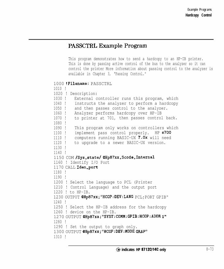
I- I -
Example Programs
Hardcopy Control
PASSCTRL Example Program
This program demonstrates how to send a hardcopy to an HP-IB printer.This is done by passing active control of the bus to the analyzer so it cancontrol the printer More information about passing control to the analyzer isavailable in Chapter 3, “Passing Control."
1000 !Filename: PASSCTRL1010 !1020 ! Description:1030 ! External controller runs this program, which1040 ! instructs the analyzer to perform a hardcopy1050 ! and then passes control to the analyzer.1060 ! Analyzer performs hardcopy over HP-IB1070 ! to printer at 701, then passes control back.1080 !1090 ! This program only works on controllers which1100 ! implement pass control properly. HP ~7001110 ! computers running BASIC-UX 7.0x will need1120 ! to upgrade to a newer BASIC-UX version.1130 !1140 !1150 COM /Sys-state/ QHp87xx,Scode,Internal1160 ! Identify I/O Port1170 CALL Iden-port1180 !1190 !1200 ! Select the language to PCL (Printer1210 ! Control Language) and the output port1220 ! to HP-IB.1230 OUTPUT OHp87xx;"HCOP:DEV:LANG PCL;PORT GPIB"1240 !1250 ! Select the HP-IB address for the hardcopy1260 ! device on the HP-IB.1270 OUTPUT OHp87xx;"SYST:COMM:GPIB:HCOP:ADDR 1"1280 !1290 ! Set the output to graph only.1300 OUTPUT OHp87xx;"HCOP:DEV:MODE GRAP"1310 !
@ indicates HP 8712C114C only 8-73
-1

I- I -
Example Programs
Hardcopy Control
1320 ! If the internal controller is being used...1330 IF Internal=1 THEN1340 !1350 ! then make it System Controller of HP-IB1360 OUTPUT QHp87xx;"SYST:COMM:GPIB:CONT ON"1370 END IF1380 !1390 ! Clear Status Registers1400 OUTPUT OHp87xx;"*CLS"1410 !1420 ! Enable the Request Control bit in the Event1430 ! Status Register.1440 OUTPUT OHp87xx;"*ESE 2"1450 !1460 ! Clear the Service Request enable register;1470 ! SRQ is not being used.1480 OUTPUT @Hp87xx;"*SRE 0"1490 !1500 ! Send the hardcopy command to start the1510 ! print.1520 OUTPUT QHp87xx;"HCOP"1530 LOOP1540 !1550 ! Read the status byte using Serial Poll.1560 Stat=SPOLL(OHp87xx)1570 !1580 ! Exit when the analyzer requests active control1590 ! of HP-IB from the system controller.1600 EXIT IF BIT(Stat,5)=11610 END LOOP1620 !1630 ! Now system controller passes control to1640 ! the analyzer.1650 PASS CONTROL QHp87xx1660 DISP "Hardcopy in Progress...";1670 IF Internal=1 THEN1680 ! If using the internal IBASIC controller,1690 ! then use the *OPC query method to wait1700 ! for hardcopy completion.1710 OUTPUT OHp87xx;"*OPC?"1720 ENTER OHp87xx;Opc
8-74 @ indicates HP 8712Cl14C only

I- I -
Example Programs
Hardcopy Control
1730 ELSE1740 ! If external computer control, then...1750 LOOP1760 !1770 ! Monitor the HP-IB status in the1780 ! external computer's HP-IB status1790 ! register. Here, the HP-IB interface1800 ! code 7 register 6 status is requested1810 ! and put into "Hpib".1820 DISP 'I.";1830 WAIT l! No need to poll rapidly1840 STATUS 7,6;Hpib1850 !1860 ! When active control is returned to the1870 ! system controller (bit 6 set), then exit.1880 ! (This fails on ~700s running BASIC 7.0x)1890 EXIT IF BIT(Hpib,G)=l1900 END LOOP1910 END IF1920 DISP "HARDCOPY COMPLETE!"1930 END1940 !1950 !**************************************************************196019701980199020002010
Iden,port: Identify io port to use.Description: This routines sets up the I/O port address for
the SCPI interface. For "HP 87xx" instruments,the address assigned to OHp87xx = 800 otherwise,716.
@ indicates HP 8712Cl14C only 8-75

I-
Example Programs
Hardcopy Control
2020 SUB Iden-port2030 COM /Sys,state/ OHp87xx,Scode,Internal2040 !2050 IF POS(SYSTEM$("SYSTEM ID">,"HP 87")OO THEN2060 ASSIGN OHp87xx TO 8002070 Scode=82080 Internal=12090 ELSE2100 ASSIGN OHp87xx TO 7162110 Scode=72120 Internal=02130 END IF2140 !2150 SUBEND !Iden,port2160 !
8-76 @ indicates HP 8712Cl14C only

I- I -
Example Programs
Hardcopy Control
FAST-PRT Example Program
This program configures a PCL5 printer to accept HP-GL graphics commandsfrom the analyzer. The program executes ahardcopy which causes theanalyzer to send HP-GL commands to the parallel port PCL5 printer. Providesup to 10x speed improvementofsome hardcopies.
1000 ! FAST-PRT1010 !1020 ! This program is designed to set up a PCL5 printer1030 ! connected to the parallel port of the analyzer to1040 ! accept HP-CL syntax. HP-GL gives fast graph dumps.1050 !1060 ! Connect your PCL5 printer to the parallel printer of the1070 ! analyzer, then run the program.1075 !1076 ! Note: Firmware hardcopy support for PCL5 for 871xCs can1077 ! can be enabled by selecting a PCL5 harcopy device.1078 ! This program may still be needed for the 871xBs.1080 !1090 ! Once the parallel printer has been configured to accept1100 ! HPGL commands, a hardcopy is done, the printer is1110 ! reset to normal mode, and the page is ejected.1120 !1130 DIM A$[5031140 !1150 !1160 COM /Sys-state/ OHp87xx,Scode1170 ! Identify I/O Port1180 CALL Iden-port1190 !1200 ! Define the hardcopy device1210 OUTPUT QHp87xx,."HCOP:DEV:LANG HPGL;PORT CENT"1220 !1230 ! Define PCL5 escape codes needed to set up HPGL commands:1240 DATA QE ! Reset, Eject page1250 DATA t(Q12A ! Page size 8.5 x 111260 DATA &0aOL&Oa4000MCQ10E ! No margins1270 DATA O*c74OOx565Oy ! 10.28 x 7.85 size 720/in
@ indicates HP 8712CI14C only 8-77
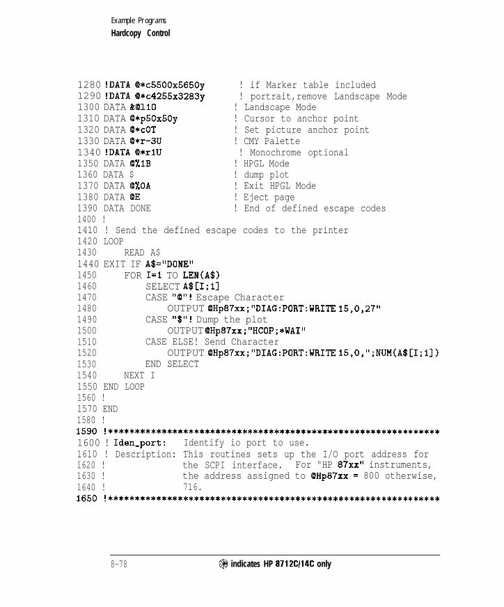
I- I -
Example Programs
Hardcopy Control
1280 !DATA @*c55OOx565Oy ! if Marker table included1290 !DATA O*c4255x3283y ! portrait,remove Landscape Mode1300 DATA &OllO ! Landscape Mode1310 DATA O*p5Ox5Oy ! Cursor to anchor point1320 DATA @*COT ! Set picture anchor point1330 DATA @*r-3U ! CMY Palette1340 !DATA O*rlU ! Monochrome optional1350 DATA 0%1B ! HPGL Mode1360 DATA $ ! dump plot1370 DATA @%OA ! Exit HPGL Mode1380 DATA QE ! Eject page1390 DATA DONE ! End of defined escape codes1400 !1410 ! Send the defined escape codes to the printer1420 LOOP1430 READ A$1440 EXIT IF A$="DONE"1450 FOR I=1 TO LEN(A$)1460 SELECT A$[I;ll1470 CASE "a"! Escape Character1480 OUTPUT QHp87xx;"DIAG:PORT:WRITE 15,0,27"1490 CASE "$"! Dump the plot1500 OUTPUT QHp87xx;"HCOP;*WAI"1510 CASE ELSE! Send Character1520 OUTPUT OHp87xx;"DIAG:PORT:WRITE 15,0,";NUM(A$[I;l])1530 END SELECT1540 NEXT I1550 END LOOP1560 !1570 END1580 !1590 !**************************************************************1600 ! Iden-port: Identify io port to use.1610 ! Description: This routines sets up the I/O port address for1620 ! the SCPI interface. For "HP 87xx" instruments,1630 ! the address assigned to QHp87xx = 800 otherwise,1640 ! 716.1650 !**************************************************************
8-78 @ indicates HP 8712CI14C only

I- I -
Example Programs
Hardcopy Control
1660 SUB Iden,port1670 COM /Sys,state/ OHp87xx,Scode1680 !1690 IF POS(SYSTEM$("SYSTEM ID">,"HP 87")OO THEN1700 ASSIGN (QHp87xx TO 8001710 Scode=81720 ELSE1730 ASSIGN QHp87xx TO 7161740 Scode=71750 END IF1760 !1770 SUBEND !Iden,port1780 !
@ indicates HP 8712Cl14C only 8-79
-1

I- I -
Service Request
SRQ
SRQ-INT
Generating a service request interrupt. The example usesthe status reporting structure to generate an interrupt assoon as averaging is complete.
Monitoring the status report of the analyzer.
B-80 @I indicates HP 8712Cl14C only

I- I -
Example Programs
Service Request
SRQ Example Program
This program demonstrates generating a service request interrupt. The SRQis used to indicate when averaging is complete. More information on servicerequests and the status registers is available in Chapter 5, “Using StatusRegisters. ”
In this program, the STATUS : PRESet executed in line 1250 has the effect ofsetting all bits in the averaging status transition registers (positive transitionsto 0, negative transitions to 1). It also sets up the operational statustransition registers (positive transitions to 1, negative transitions to 0). Theseare the states needed to generate an interrupt when averaging is complete.
1000 !Filename: SRQ1010 !1020 ! Description:1030 ! Set an SRQ to occur when averaging is complete.1040 ! Turn on averaging, and set to 8 averages.1050 ! Initiate sweeps. SRQ will occur after 8 sweeps.1060 ! Wait in a do-nothing loop, checking SRQ flag.1070 ! Display message after SRQ flag is set.1080 !1090 !1100 COM /Sys-state/ OHp87xx,Scode1110 ! Identify I/O Port1120 CALL Iden,port1130 !1140 !1150 ! Clear status registers.1160 OUTPUT OHp87xx; “*CLS”1170 !1180 ! Clear the Service Request Enable register.1190 OUTPUT QHp87xx; “*SRF 0”1200 !1210 ! Clear the Standard Event Status Enable register.1220 OUTPUT QHp87xx; “*ESE 0”1230 !1240 ! Preset the remaining status registers.1250 OUTPUT OHp87xx ; “STAT : PRES”
@ indicates HP 8712Cl14C only 8-81

I- I -
Example Programs
Service Request
1260 !1270 ! Set operation status register to report1280 ! to the status byte on POSITIVE transition of1290 ! the averaging bit.1300 OUTPUT OHp87xx;"STAT:OPER:ENAB 256"1310 !1320 ! Set averaging status register to report to1330 ! operational status register on NEGATIVE transition1340 ! of the averaging done bits. The NEGATIVE1350 ! transition needs to be detected because the1360 ! averaging bit 0 is set to 1 while the analyzer1370 ! is sweeping on channel 1 and the number of1380 ! sweeps completed since averaging restart is1390 ! less than the averaging factor. When the bit1400 ! goes back to 0, the averaging is done.1410 OUTPUT QHp87xx;"STAT:OPER:AVER:ENAB 1"1420 !1430 ! Enable the operational status bit in the status1440 ! byte to generate an SRQ.1450 OUTPUT OHp87xx;"*SRE 128"1460 !1470 ! On an interrupt from HP-IB "Scode" (Interface1480 ! Select Code) SRQ bit (21, branch to the interrupt1490 ! service routine "Srq-handler".1500 ON INTR Scode,2 GOSUB Srq-handler1510 !1520 ! Now enable the interrupt on SRQ (Service Request).1530 ENABLE INTR Scode;21540 !1550 ! Set averaging factor to 8.1560 OUTPUT OHp87xx;"SENSl:AVER:COUN 8;*WAI"1570 !1580 ! Turn on averaging and restart.1590 OUTPUT QHp87xx;"SENSl:AVER ON;AVER:CLE;*WAI"1600 !1610 ! Turn on continuous sweep trigger mode.1620 OUTPUT QHp87xx;"ABOR;:INITl:CONT ON;*WAI"1630 !1640 ! Initialize flag indicating when averaging done1650 ! to 0. Then loop continuously until the1660 ! interrupt is detected, and the interrupt
8-82 @I indicates HP 8712Cl14C only

I- I -
Example Programs
Service Request
1670 ! service routine acknowledges the1680 ! interrupt and sets the flag to 1.1690 Avg,done=O1700 DISP "Waiting for SRQ on averaging complete.";1710 LOOP1720 DISP 'I.";1730 WAIT .l! Slow down dots1740 EXIT IF Avg-done=11750 END LOOP1760 !1770 ! Display desired completion message.1780 DISP1790 DISP "Got SRQ. Averaging Complete!"1800 STOP1810 !1820 Srq-handler: ! Interrupt Service Routine1830 !1840 ! Determine that the analyzer was actually1850 ! the instrument that generated the1860 ! interrupt.1870 Stb=SPOLL(QHp87xx)1880 !1890 ! Determine if the operation status register1900 ! caused the interrupt by looking at bit 71910 ! of the result of the serial poll.1920 IF BINAND(Stb,l28)00 THEN1930 !1940 ! Read the operational status event register.1950 OUTPUT OHp87xx;"STAT:OPER:EVEN?"1960 ENTER OHp87xx;Op-event1970 !1980 ! Determine if the averaging status register1990 ! bit 8 is set.2000 IF BINAND(Op_event,256)<>0 THEN2010 !2020 ! If so, then set flag indicating2030 ! averaging done.2040 Avg-done=12050 END IF2060 END IF2070 RETURN
@ indicates HP 8712CI14C only 8-83

I- I -
Example Programs
Service Request
2080 END2090 !2100 !**************************************************************2110 ! Iden,port: Identify io port to use.2120 ! Description: This routines sets up the I/O port address for2130 ! the SCPI interface. For "HP 87xx" instruments,2140 ! the address assigned to (QHp87xx = 800 otherwise,2150 ! 716.2160 !**************************************************************2170 SUB Iden-port2180 COM /Sys,state/ QHp87xx,Scode2190 !2200 IF POS(SYSTEM$("SYSTEM ID">,"HP 87")OO THEN2210 ASSIGN (QHp87xx TO 8002220 Scode=82230 ELSE2240 ASSIGN QHp87xx TO 7162250 Scode=72260 END IF2270 !2280 SUBEND !Iden,port2290 !
8 - 8 4 @ indicates HP 8712CI14C only

I-
Example Programs
Service Request
1000 ! SRQ-INT1010 ! BASIC program:1020 !1030 !***************************************************************1040 ! Description: This program implements the interrupt handler1050 ! routine for SRQ status reports. It tries to decode all the1060 ! possible error bits by rippling it through the registers1070 ! and print out the appropriate messages for the status report.1080 ! Refer to the status model diagram for registers mapping.1090 !1100 ! Note: To setup additional states other than the status1110 ! model, add code to the subroutine “Setup-states”.1120 !***************************************************************1130 !
SRQ-INT Example Program
This program demonstrates how to monitor the status report of the networkanalyzer via an interrupt handler. It monitors all the status or error bits ofthe status register. Whenever an error or an event occurs, the analyzer willinterrupt this program. This program will then decode the error bits anddisplay the appropriate messages. For a detailed status report register map,refer to Chapter 5, “Using Status Registers.”
1140 !************ Main program **************1150 !1160 ! Make (PHp87xx common to all subroutines1170 COM /Sys,state/ @Hp87xx,Scode1180 ! Identify the computer we are running on1190 ! and assign the i/o port address to QHp87xx1200 CALL Iden-port1210 !1220 ! Setup all required SRQ registers1230 CALL Setup-srq,regs1240 !1250 ! This is required if user wants to detect either1260 ! “Any Ext. Keybd. Pressed” or “Front Panel Knob Turned”1270 ! of the Device Status Register.1280 OUTPUT (PHp87xx;” SYST:KEY:QUE:STATE ON”1290 !
@ indicates HP 8712Cl14C only 8-85

I- I -
Example Programs
Service Request
1300 ! Go to subroutine to setup any neccessary states1310 CALL Setup-states1320 !1330 Report-count=01340 ! Forever loop to wait for any failed events to happened1350 DISP "Waiting for any Failed Events.........Report Count =
";Report-count1360 Do-loop: !1370 GOSUB Set-userbit
variables! Read and display
1380 !1390 GOT0 Do-loop1400 STOP1410 !1420 i************ Subroutine Blocks *********************1430 !1440 !**************************************************************1450 ! Set-userbit: Setup user bit.1460 ! Description: This subroutine waits for an SRQ interrupt to1470 ! signal that a sweep has finished. It then clears the HP-IB1480 ! registers by reading them. Once that is done, the user bit1490 ! is toggled.1500 !**************************************************************1510 !1520 Set,userbit:!1530 !1540 ON INTR Scode GOT0 Read-results1550 ENABLE INTR Scode;21560 Suspend: !WAIT 51570 GOT0 Suspend1580 !
! Set up interrupt branching! Allow interrupt on SRQ! Use WAIT 'n' to suspend IBASIC
1590 ! Interrupt Service Routine1600 Read-results:1610 A=SPOLL(OHp87xx)1620 !
! Program has finishedI. and clear the SRQ
1630 ! This CLEAR command is for clearing out the bus just in case1640 ! this is a query error. Without this CLEAR command, the previous1650 ! Query would screw up the state of the instrument and the next1660 ! Query will get an error.1670 CLEAR QHp87xx1680 OUTPUT QHp87xx;"*STB?"
8-86 @ indicates HP 8712CI14C only

I- I -
Example Programs
Service Request
1690 ENTER OHp87xx;Stbr1700 WHILE Stbr<>O1710 CALL Decode-srq(Stbr)1720 Stb=Stbr1730 OUTPUT OHp87xx;"*STB?"1740 ENTER QHp87xx;Stbr1750 END WHILE1760 OUTPUT QHp87xx;"*CLS" ! Clear status byte1770 BEEP1780 Report-count=Report-count+11790 DISP "Waiting for any Failed Events.........Report Count =
";Report,cou.nt1800 !1810 RETURN1820 END1830 !1840 !*********** Status Report Decode Block *********************1850 !1860 !1870 !******************************************************************1880 ! Decode,srq: Decode status byte.1890 ! Description: Decode the Srq register and ripple through the1900 ! registers and decode the necessary failed registers.1910 ! The decoding is done with the Event registers. The1920 ! corresponding Condition Registers are only read and1930 ! display. The numbers are display in hex numbers1940 ! with a leading "Ox".1950 ! If any Event has failed, a message will be display1960 ! with the "Meas" Channel number and "Segment" number.1970 !******************************************************************1980 SUB Decode-srq(Reg)1990 COM /Sys-state/ OHp87xx,Scode2000 DIM Reg_name$(l:8)[4012010 !2020 !2030 ! Print out the Date of Time of this report2040 !2050 PRINT2060 PRINT2070 PRINT "Status Report: ";DATE$(TIMEDATE);" ";TIME$(TIMEDATE)2080 PRINT
@ indicates HP 8712CI14C only 8 - 8 7
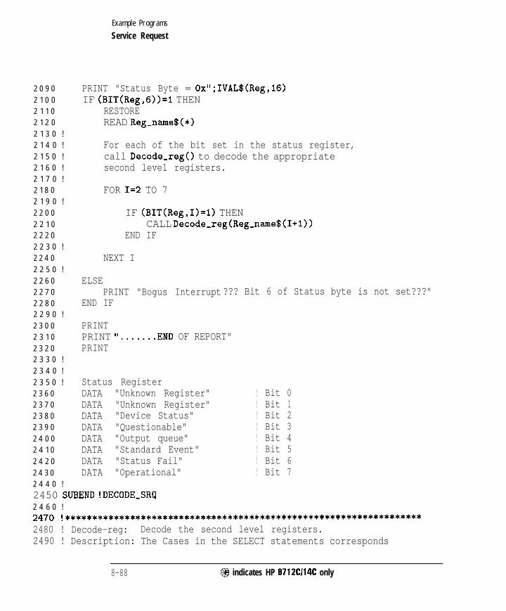
I- I -
Example Programs
Service Request
2 0 9 0
2 1 0 0
2 1 1 0
2 1 2 0
2 1 3 0 !
2 1 4 0 !
2 1 5 0 !
2 1 6 0 !
2 1 7 0 !
2 1 8 0
2 1 9 0 !
2 2 0 0
2 2 1 0
2 2 2 0
2 2 3 0 !
2 2 4 0
2 2 5 0 !
2 2 6 0
2 2 7 0
2 2 8 0
2 2 9 0 !
2 3 0 0
2 3 1 0
2 3 2 0
2 3 3 0 !
2 3 4 0 !
2 3 5 0 !
2 3 6 0
2 3 7 0
2 3 8 0
2 3 9 0
2 4 0 0
2 4 1 0
2 4 2 0
2 4 3 0
2 4 4 0 !
PRINT "Status Byte = Ox";IVAL$(Reg,lG)IF (BIT(Reg,G))=I THEN
RESTOREREAD Reg-name$(*)
For each of the bit set in the status register,call Decode-reg() to decode the appropriatesecond level registers.
FOR I=2 TO 7
IF (BIT(Reg,I)=l) THENCALL Decode-reg(Reg-name$(I+l))
END IF
NEXT I
ELSEPRINT "Bogus Interrupt??? Bit 6 of Status byte is not set???"
END IF
PRINTPRINT 'I...... .END OF REPORT"PRINT
Status RegisterDATA "Unknown Register"DATA "Unknown Register"DATA "Device Status"DATA "Questionable"DATA "Output queue"DATA "Standard Event"DATA "Status Fail"DATA "Operational"
! Bit 0! Bit 1! Bit 2! Bit 3! Bit 4! Bit 5! Bit 6! Bit 7
2450 SUBEND !DECODE-SRQ2 4 6 0 !2470 !*****************************$*************************************2480 ! Decode-reg: Decode the second level registers.2490 ! Description: The Cases in the SELECT statements corresponds
8-88 @ indicates HP 8712C114C only

I -
Example Programs
Service Request
250025102520253025402550256025702580259026002610262026302640265026602670268026902700271027202730274027502760
2770278027902800281028202830284028502860287028802890
to the bits supported by the instrument. Refer ,to the menu for the bit positions of these bits.For each failed event, the Event and Conditionregisters are read and Display. The Event registeris further used to decode the third level registers.
!******************************************************************!SUB Decode-reg(Reg-name$)
COM /Sys-state/ OHp87xx,Scode
SELECT Reg-name$
Device Status registerCASE "Device Status"! Bit 2
OUTPUT @Hp87xx;"STAT:DEV:EVEN?"ENTER QHp87xx;Dev-eventPRINT I Device Status Event Reg = Ox";IVAL$(Dev_event,16)OUTPUT QHp87xx;"STAT:DEV:COND?"ENTER OHp87xx;Dev-condPRINT ' Device Status Condition Reg = Ox";IVAL$(Dev_cond,16)CALL Decode-dev(Dev-event)
Questionable status registerCASE "Questionable"! Bit 3
OUTPUT QHp87xx; "STAT:QUES:EVEN?"! Read and clear QuestionalSTATUS reg.ENTER @Hp87xx;Ques_eventPRINT ' Questionable Event Reg = Ox";IVAL$(Cjues_event,l6)OUTPUT OHp87xx;"STAT:qUES:COND?"ENTER QHp87xx;Uues-condPRINT ' questionable Condition Reg = Ox";IVAL$(ques_cond,16)CALL Decode-ques(Ques,event)
CASE "Standard Event"! Bit 4
OUTPUT QHp87xx;"*ESR?"ENTER OHp87xx;Stand,eventPRINT ' Standard Event Reg = Ox";IVAL$(Stand_event,l6)
@I indicates HP 8712CI14C only 8-89

Example Programs
Service Request
29002910 !29202930 !29402950 !2960 !29702980 !2990 !3 0 0 0 !
3 0 1 0
3 0 2 0 !
3 0 3 0
3 0 4 0
3 0 5 0
3 0 6 0
3 0 7 0
3 0 8 0
3 0 9 0 !
3 1 0 0
3 1 1 0 !
3 1 2 0 !
3 1 3 0
3 1 4 0
3 1 5 0
3 1 6 0 !
3 1 7 0
CALL Decode-esr(Stand-event)
CASE "Output Queue"! Bit 5
PRINT II Message Available"
Latch bit of Status Byte registerCASE "Status Fail"! Bit 6
Do Nothing
Operational Status registerCASE "Operational"! Bit 7
OUTPUT OHp87xx;"STAT:OPER:EVEN?"!Read and clear OperationalSTATUS reg.ENTER OHp87xx;Oper,eventPRINT ' Operational Event Reg = Ox";IVAL$(Oper,event,16)OUTPUT OHp87xx;"STAT:OPER:COND?"ENTER QHp87xx;Oper-condPRINT ' Operational Condition Reg = Ox";IVAL$(Oper_cond,16)
CALL Decode-oper(Oper-event)
CASE ELSEPRINT " Unsupported Bit set in Status Byte or ";PRINT " Bogus interrupt. 'I
END SELECT3180 SUBEND !DECODE-REG3190 !3 2 0 0 !3210 !**************************************************************3220 ! Decode-l&es: Decode Questionable Fail register.3230 ! Description: Decode Questionable Fail register and Print out3 2 4 0 ! appropriate messages.3250 !**************************************************************3260 SUB Decode-ques(Reg)3 2 7 0 COM /Sys-state/ OHp87xx,Scode3 2 8 0 DIM Message$(0:15,0:1)[12013290 D I M Segment_event(4:7)
8-90 @I indicates HP 8712Cl14C only

I- I -
Example Programs
Service Request
3300 !33103320333033403350 !33603370338033903400
341034203430
344034503460 !3470348034903500
351035203530
354035503560357035803590 !3600 !3610 !3620 !3630 !3640 !36503660
READ Message$(*)FOR I=0 TO 15
IF Message$(I,O)="Enable" THENIF BIT(Reg,I)=I THEN
PRINT Message$(I,l)IF (1=9) THEN ! Check Limit Fail Register
OUTPUT (8Hp87xx;" STAT:QUES:LIM:EVEN?"ENTER QHp87xx;Lim-eventPRINT ' Limit Fail Event Reg =Ox";IVAL$(Lim_event,16)OUTPUT (OHp87xx;" STAT:QUES:LIM:COND?"ENTER @Hp87xx;Lim-condPRINT ' Limit Fail Condition Reg =Ox";IVAL$(Lim,cond,16)CALL Decode-lim(Lim-event)
END IF
IF (1=4) OR (1=5) OR (1=6) OR (1=7) THENOUTPUT @Hp87xx,."STAT:QUES:SEGM";VAL$(I-3);":EVEN?"ENTER OHp87xx;Segment,event(I)PRINT ' Segment ";VAL$(I-3);" Event Reg =Ox";IVAL$(Segment-event(I),l6)OUTPUT cQHp87xx;" STAT:iJJES:SEGM";VAL$(I-3);":COND?"ENTER OHp87xx;Segment-condPRINT ' Segment ";VAL$(I-3);" Condition Reg =Ox";IVAL$(Segment,cond,l6)CALL Decode,seg(Segment-event(I),I-3)
END IFEND IF
END IFNEXT I
This array has two fields:First Field - If Enable, Display the next string message
Else, ignore the next string message.Second Field - String message for the corresponding bits of
the Questionable register.DATA "Enable"," ALC UNLEVELED..............." ! Bit 0DATA 'Enable"," FREQ-ERROR.................." ! Bit 1
@ indicates HP 8712Cl14C only 8-91

I-
Example Programs
Service Request
3 6 7 0
3 6 8 0
3 6 9 0
3 7 0 0
3 7 1 0
3 7 2 0
3 7 3 0
3 7 4 0
3 7 5 0
3 7 6 0
3 7 7 0
3 7 8 0
3 7 9 0
3 8 0 0
DATA "Disable","DATA "Disable","DATA "Enable","! Bit 4DATA "Enable","! Bit 5DATA "Enable" 'I,! Bit 6DATA "Enable","! Bit 7DATA "Disable","DATA "Enable","DATA "Enable","DATA "Disable","DATA "Disable" "DATA "Disable":"DATA "Disable","DATA "Disable","
Bit 2 Unsupported" ! Bit 2Bit 3 Unsupported" ! Bit 3Segment 1 Limit Fail................."
Segment 2 Limit Fail................."
Segment 3 Limit Fail................."
Segment 4 Limit Fail................."
Bit 8 Unsupported" ! Bit 8Limit Fail................." ! Bit 9Stale Data(Data?).........." ! Bit 10Bit 11 Unsupported" ! Bit 11Bit 12 Unsupported" ! Bit 12Bit 13 Unsupported" ! Bit 13Bit 15 Unsupported" ! Bit 14Bit 15 Unsupported" ! Bit 15
3810 SUBEND !Decode-Ques3 8 2 0 !
3 8 3 0 !
3 8 4 0 !3 8 5 0 !**************************************************************
3860 ! Decode-lim: Decode Limit Fail register.3870 ! Description: Decode Limit Fail register and Print out the3 8 8 0 ! appropriate messages.3890 !**************************************************************3900 !3910 SUB Decode-lim(Reg)3920 COM /Sys-state/ OHp87xx,Scode3930 DIM Message$(0:3)[120]3940 !3950 READ Message$(*)
3 9 6 0 !
3 9 7 0 FOR I=0 TO 33980 IF BIT(Reg,I)=l THEN3990 PRINT Message$(I)4 0 0 0 END IF4 0 1 0 NEXT I4 0 2 0 !
4 0 3 0 ! Displaying message
8 - 9 2 @ indicates HP 8712Cl14C only
-

I- I -
Example Programs
Service Request
4040 DATA ' Limit Line Failed on Meas I" ! Bit 04050 DATA ' Limit Line Failed on Meas 2" ! Bit 14060 DATA ' Marker Limit Failed on Meas 1" ! Bit 24070 DATA ' Marker Limit Failed on Meas 2" ! Bit 34080 SUBEND !Decode-lim4090 !4100 !4110 !**************************************************************4120 ! Decode-seg: Decode Segment status registers.4130 ! Description: Decode Segment status registers and Print out the4140 ! appropriate messages.4150 !**************************************************************4160 !4170 SUB Decode-seg(Reg,Segment)418041904200 !42104220 !4230 !424042504260427042804290430043104320433043404350 !4360 !4370
4380
4390
4400
COM /Sys-&ate/ QHp87xx,ScodeDIM Message$ (0 : 9) [I201
READ Message$(*)
Check to see if bias regs need to be decoded.FOR I=0 TO 9
IF BIT(Reg,I)=l THENPRINT Message$(I);SegmentIF I=4 THEN ! Meas 1 has failed?
CALL Decode-bias("Meas l",Segment)END IFIF I=5 THEN ! Meas 2 has failed?
CALL Decode,bias("Meas 2",Segment)END IF
END IFNEXT I
Displaying messageDATA ' Limit Line Failed on Meas I, Segment"Bit 0DATA ' Limit Line Failed on Meas 2, Segment"Bit 1DATA ' Marker Limit Failed on Meas 1, Segment"Bit 2
!
DATA 'Bit 3
Marker Limit Failed on Meas 2, Segment" !
@indicates HP 8712Cl14C only 8-93

I- I -
Example Programs
Service Request
4410 DATA ' Bias Limit Failed on Meas 1, Segment"Bit 4
4420 DATA ' Bias Limit Failed on Meas 2, Segment"Bit 5
4430 DATA ' Gain Bar Limit Failed on Meas 1, Segment"Bit 6
4440 DATA ' Gain Bar Limit Failed on Meas 2, Segment"Bit 7
4450 DATA I IIc Ack Test Failed on Meas 1, Segment"Bit 8
4460 DATA ' IIc Ack Test Failed on Meas 2, Segment"Bit 9
4470 SUBEND !Decode-seg4480 !4490 !4500 !**************************************************************4510 ! Decode-dev: Decode Device status register.4520 ! Description: Decode Device status register and Print out the4530 ! appropriate messages.4540 !**************************************************************4550 !4560 SUB Decode-dev(Reg)4570 COM /Sys,state/ QHp87xx,Scode4580 DIM Message$(0:3)[12014590 !4600 READ Message$(*)4610 FOR I=0 TO 34620 IF BIT(Reg,I)=l THEN4630 PRINT Message$(I)4640 END IF4650 NEXT I4660 !4670 DATA ' Any Key Pressed"4680 DATA ' Any Softkey Pressed"4690 DATA ' Any Ext. Keybd. Pressed"4700 DATA I Front Panel Knob Turned"4710 SUBEND !Decode-dev-4720 !4730 !4740 !4750 !
8 - 9 4 @ indicates HP 8712Cl14C only

I- I -
Example Programs
Service Request
4760 !**************************************************************
4770 ! Decode,esr: Decode Standard Event register4780 ! Description: Decode Standard Event register and Print out the4790 ! appropriate messages4800 !**************************************************************
4810 !4820 SUB Decode-esr(Reg)483048404850 !4860487048804890490049104920493049404950 !49604970498049905000501050205030
COM /Sys-state/ QHp87xx,ScodeDIM Message$(O:7)[120]
READ Message$(*)FOR I=0 TO 7
IF BIT(Reg,I)=I THENPRINT Message$(I)IF I=4 THEN
CALL Disp-errEND IF
END IFNEXT I
DATA ' Operation Complete" ! Bit 0DATA ' Request Control" ! Bit 1DATA I Qeury Error" ! Bit 2DATA ' Device-Dependent Error" ! Bit 3DATA I Execution Error" ! Bit 4DATA ' Command Error" ! Bit 5DATA I) User Request" ! Bit 6DATA ' Power On" ! Bit 7
5040 SUBEND !Decode-esr5050 !5060 !5070 !**************************************************************5080 ! Decode-oper: Decode Operational register.5090 ! Description: Decode Operational register and Print out the5100 ! appropriate messages5110 !**************************************************************5120 !5130 SUB Decode-oper(Reg)5140 COM /Sys-state/ OHp87xx,Scode5150 DIM Message$(0:15,0:1)[12015160 !
@ indicates HP 8712Cl14C only 8-95
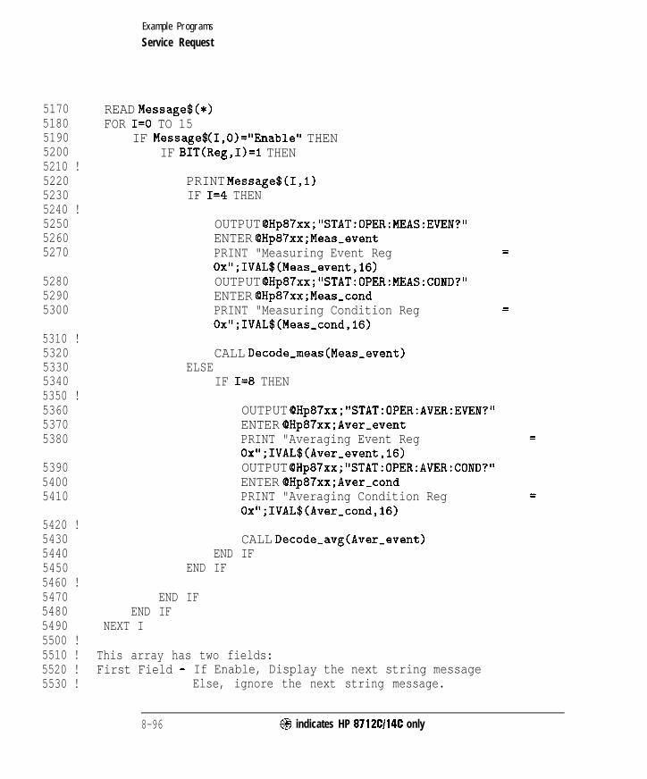
I- I -
Example Programs
Service Request
51705180519052005210 !522052305240 !525052605270
528052905300
5310 !5320533053405350 !536053705380
539054005410
5420 !5430544054505460 !5470548054905500 !5510 !5520 !5530 !
READ Message$(*)FOR I=0 TO 15
IF Message$ (I,O)="Enable" THENIF BIT(Reg,I):I THEN
PRINT Message$(I,l)IF I=4 THEN
OUTPUT OHp87xx;"STAT:OPER:MEAS:EVEN?"ENTER QHp87xx;Meas,eventPRINT "Measuring Event Reg =Ox";IVAL$(Meas_event,16)OUTPUT OHp87xx;"STAT:OPER:MEAS:COND?"ENTER OHp87xx;Meas-condPRINT "Measuring Condition Reg =Ox";IVAL$(Meas,cond,16)
CALL Decode-meas(Meas-event)ELSE
IF I=8 THEN
OUTPUT QHp87xx;"STAT:OPER:AVER:EVEN?"ENTER QHp87xx;Aver-eventPRINT "Averaging Event Reg =Ox";IVAL$(Aver_event,l6)OUTPUT OHp87xx;"STAT:OPER:AVER:COND?"ENTER @Hp87xx;Aver_condPRINT "Averaging Condition Reg =Ox";IVAL$(Aver_cond,16)
CALL Decode-avg(Aver-event)END IF
END IF
END IFEND IF
NEXT I
This array has two fields:First Field - If Enable, Display the next string message
Else, ignore the next string message.
8-96 @I indicates HP 8712Cl14C only

I- I -
Example Programs
Service Request
5540 ! Second Field - String message for the corresponding bits of5550 ! the Questionable register.5560 DATA "Enable"," Calibrating..............." ! Bit 05570 DATA "Enable"," Settling.................." ! Bit 15580 DATA "Disable"," Bit 2 Unsupported" ! Bit 25590 DATA "Disable"," Bit 3 Unsupported" ! Bit 35600 DATA "Enable"," Measuring................." ! Bit 45610 DATA "Disable"," Bit 5 Unsupported" ! Bit 55620 DATA "Disable"," Bit 6 Unsupported" ! Bit 65630 DATA "Enable"," Correcting................" ! Bit 75640 DATA "Enable"," Averaging................." ! Bit 85650 DATA "Enable"," Hardcopy In Progress......" ! Bit 95660 DATA "Enable"," Service Test In Progress.." ! Bit 105670 DATA "Disable"," Bit 11 Unsupported" ! Bit 115680 DATA "Disable"," Bit 12 Unsupported" ! Bit 125690 DATA "Disable"," Bit 13 Unsupported" ! Bit 135700 DATA "Enable"," Program Running..........." ! Bit 145710 DATA "Disable"," Bit 15 Unsupported" ! Bit 155720 SUBEND !Decode-oper5730 !5740 !5750 !**************************************************************5760 ! Decode-meas: Decode Measuring register.5770 ! Description: Decode Measuring register and Print out the5780 ! appropriate messages.5790 !**************************************************************5800 !5810 SUB Decode,meas(Reg)5820 COM /Sys,state/ QHp87xx,Scode5830 DIM Message$(O:l) [I2015840 !5850 READ Message$(*)5860 FOR I=0 TO 15870 IF BIT(Reg,I)=I THEN5880 PRINT Message$(I)5890 END IF5900 NEXT I5910 !5920 ! Displaying message5930 DATA ' Meas 1 Measuring........."5940 DATA ' Meas 2 Measuring........."
@ indicates HP 8712Cl14C only 8-97

I- I -
Example Programs
Service Request
5950 SUBEND !Decode,meas5960 !5970 !5980 !***************************************************************5990 ! Decode-avg: Decode Averaging registe.6000 ! Description: Decode Averaging register and Print out the6010 ! appropriate messages.6020 !***************************************************************6030 !6040 SUB Decode-avg(Reg)6050 COM /Sys,state/ OHp87xx,Scode6060 DIM Message$(O:l)C120]6070 !6080 READ Message$(*)6090 FOR I=0 TO 16100 IF BIT(Reg,I)=l THEN6110 PRINT Message$(I)6120 END IF6130 NEXT I6140 !6150 ! Displaying message6160 DATA ' Meas 1 Averaging........."6170 DATA ' Meas 2 Averaging........."6180 SUBEND !Decode-avg6190 !6200 !6210 !**************************************************************6220 ! Decode-bias: Decode Bias register.6230 ! Description: Decode Bias register and Print out the6240 ! appropriate messages.6250 !**************************************************************6260 !6270 SUB Decode-bias(Meas$,Segment)6280 COM /Sys-state/ QHp87xx,Scode6290 DIM Message$(O:ll)~l20~6300 !6310 READ Message$(*)6320 SELECT Meas$6330 CASE "Meas I"6340 Chan=l6350 CASE "Meas 2"
8 - 9 8 @ indicates HP 8712Cl14C only
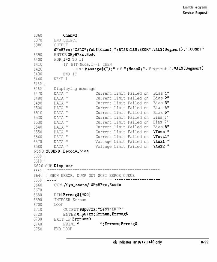
I -
Example Programs
Service Request
636063706380
6390640064106420643064406450 !6460 !647064806490650065106520653065406550656065706580
Chan=2END SELECTOUTPUTQHp87xx;"CALC";VAL$(Chan);" :BIAS:LIM:SEGM1~;VAL$(Segment);":COND?"ENTER OHp87xx;NodeFOR I=0 TO 11
IF BIT(Node,I)=l THENPRINT Message$(I);" of ";Meas$;", Segment ";VAL$(Segment)
END IFNEXT I
Displaying messageDATA I Current Limit Failed onDATA ' Current Limit Failed onDATA I Current Limit Failed onDATA ' Current Limit Failed onDATA ' Current Limit Failed onDATA ' Current Limit Failed onDATA ' Current Limit Failed onDATA ' Current Limit Failed onDATA ' Current Limit Failed onDATA ' Current Limit Failed onDATA I Voltage Limit Failed onDATA ' Voltage Limit Failed on
6590 SUBEND !Decode-bias6600 !6610 !6620 SUB Disp-err
Bias I"Bias 2"Bias 3"Bias 4"Bias 5"Bias 6"Bias 7"Bias 8"VTune I'VTotal"VAuxl 'VAux2 '
6630 ! -------------------------------------------------6640 ! SHOW ERROR, DUMP OUT SCPI ERROR QUEUE6650 ! ---_--____--____--__-----------------------------6660667066806690670067106720673067406750
COM /Sys-state/ OHp87xx,Scode
DIM Errmsg$[4001INTEGER ErrnumLOOP
OUTPUT OHp87xx;"SYST:ERR?"ENTER QHp87xx;Errnum,Errmsg$
EXIT IF Errnum=OPRINT ' ";Errnum;Errmsg$
END LOOP
@I indicates HP 8712Cl14C only 8-99

I- I -
Example Programs
Service Request
6760 SUBEND ! Disp,err6770 !6780 !6790 !**************************************************************6800 ! Iden-port: Identify io port to use.6810 !**************************************************************6820 SUB Iden,port6830 COM /Sys,state/ QHp87xx,Scode6840 !6850 IF POS(SYSTEM$("SYSTEM ID">,"HP 87")oO THEN6860 ASSIGN (8Hp87xx TO 8006870 Scode=86880 ELSE6890 ASSIGN (QHp87xx TO 7166900 Scode=76910 END IF6920 !6930 SUBEND ! Iden-port6940 !6950 !**************************************************************6960 ! Setup-states:6970 ! Note: Insert any setup routines or statements in here.....6980 ! This routine is execute before interrupt is enabled.6990 !**************************************************************7000 !7010 SUB Setup-states7020 !7030 !7040 SUBEND !Setup-states7050 !7060 !7070 !**************************************************************7080 ! Setup,srq-regs: Set up SRQ interrupt registers.7090 !**************************************************************7100 SUB Setup-srq-regs7110 COM /Sys-state/ OHp87xx,Scode7120 !7130 ! Initialize interrupt registers7140 !7150 OUTPUT QHp87xx;"*CLS"
register! Clear the STATUS BYTE
8 - 1 0 0 @ indicates HP 8712Cl14C only
-1 I-

I- I -
Example Programs
Service Request
7160
7170
71807190 !7200 !7210 !72207230
7240725072607270
72807290
73007310
73207330
734073507360 !7370 !7380
73907400
74107420 !
OUTPUT @Hp87xx;"*SRE 0"enable registerOUTPUT QHp87xx;"*ESE 0"registerOUTPUT OHp87xx;"STAT:PRES"
! Clear the service request
! Clear the std event enable
! Clears all other registers
Set up registers for interrupt on Measuring going false
OUTPUT QHp87xx; "STAT:QUES:PTR #H06F3" ! Positive TransitionOUTPUT (QHp87xx; "STAT:QUES:ENAB tH06F3 ."1 Enable QuestionableRegisterOUTPUT OHp87xx;"STAT:OPEFl:PTR tHFFFF" ! Positive TransitionOUTPUT QHp87xx;"STAT:OPER:ENAB #HO600 'I! Enable Operational RegisterOUTPUT (PHp87xx;" STAT:QUES:SEGMl:PTR #H03FF"! Positive TransitionOUTPUT QHp87xx;"STAT:QUES:SEGMl:ENAB #H03FF"! Enable Segment 1RegisterOUTPUT OHp87xx;"STAT:QUES:SEGM2:PTR #H03FF"! Positive TransitionOUTPUT (aHp87xx;" STAT:QUES:SEGM2:ENAB #H03FF"! Enable Segment 2RegisterOUTPUT (QHp87xx;" STAT:QUES:SEGM3:PTR #H03FF"! Positive TransitionOUTPUT (OHp87xx;" STAT:QUES:SEGM3:ENAB #H03FF"! Enable Segment 3RegisterOUTPUT QHp87xx;" STAT:QUES:SEGM4:PTR #H03FF"! Positive TransitionOUTPUT QHp87xx;"STAT:QUES:SEGM4:ENAB #H03FF"! Enable Segment 4RegisterOUTPUT QHp87xx;"STAT:DEV:PTR #HFF"OUTPUT QHp87xx;"STAT:DEV:ENAB #HFF"
OUTPUT QHp87xx;"*CLS"register
! Clear the STATUS BYTE
OUTPUT QHp87xx;"*SRE #HFF"OUTPUT OHp87xx;"*ESE #HFF"registersOUTPUT OHp87xx;"*PSC #HFFFF"
! Allow SRQ on all Registers! Enable standard event
7430 SUBEND ! Setup-srq,regs
@I indicates HP 8712Cl14C only 8-101

I- I -
File Transfer Over HP-IB
Two example programs demonstrate how to transfer files from the analyzer’smass memory to and from mass memory of an external controller via HP-IB.Instrument states and program fles may be transferred to or from theanalyzers internal non-volatile memory, (MEM : ), internal-volatile memory,(RAM:), and the internal 3.5” floppy disk, (INT:).
This can be a convenient method to archive data and programs to a centrallarge mass storage hard drive.
To run these programs, connect an external controller to the analyzer with anHP-IB cable.
GETFILE Transfers a file from the analyzer to an external controller.
PUTFILE Transfers a file from an external controller to the analyzer.
8-102 @ indicates HP 8712Cl14C only

I- I -
Example Programs
File Transfer Over HP-IB
GETFILE Example Program
Files are transferred from the analyzer to an external RMB controller. Runthis program on your external RMB controller. The program will prompt youto specify which analyzer program to transfer, the mass storage unit (MEM:),internal non-volatile memory, (RAM:), internal volatile memory, or (INT:),internal 3.5” floppy disk drive and the name of the file to be created on yourexternal controller mass storage. Transfers instrument state Rles or programfiles.
1000 !GETFILE1010 !1020 ! This program will get files from 871X specified mass storage to a
host1030 ! mass storage. The user specifies the mass storage unit, the
filename1040 ! of the 871X and the file on the host controller to be created.1050 !1060 !1070 DIM Blk$(l:lO)[32000] ! Max file size = 10 * 32000 = 320000 bytes1080 !1090 DIM Filename$ Cl51 ,Mass$ cl51 ,Dest$ cl511100 INTEGER Word11110 !1120 COM /Sys,state/ QHp87xx,Scode1130 ! Identify I/O Port1140 CALL Iden,port1150 !1160 BEEP1170 Mass$=“INT”1180 Dest$=“File871X”1190 INPUT “Enter the name of the 871X file to get. I’ ,Filename$1200 INPUT “Enter 871X Mass Storage (mem, INT ,ram) I’ ,Mass$1210 INPUT “Enter host filename (default=‘File871X’)“,Dest$1220 DISP “READING FILE “&Mass$k” : “tFilename$t” . . . ”1230 OUTPUT QHp87xx,-"MMEM:TRANSFER? ' “&Mass$t” :"&Filename$&""'1240 ENTER QHp87xx USING ‘I#, WI’ ; Word11250 ENTER (PHp87xx USING “1, -K” ; Blk$ (*>1260 FOR I=1 TO 6
@I indicates HP 8712C114C only 8-103

I- I -
Example Programs
File Transfer Over HP-IB
1270 Filelength=LEN(Blk$(I))+Filelength1280 NEXT I1290 BEEP1300 PRINT "Length",Filelength1310 DISP "Creating new file..."1320 ON ERROR GOT0 Save-file1330 PURGE Dest$1340 Save-file: !1350 OFF ERROR1360 CREATE Dest$,Filelength1370 ASSIGN @File TO Dest$;FORMAT ON1380 OUTPUT OFile;Blk$(*);1390 ASSIGN @File TO *1400 DISP "File "&Dest$t" created."1410 BEEP1420 END1430 !1440 !**************************************************************1450 ! Iden-port: Identify io port to use.1460 ! Description: This routines sets up the I/O port address for1470 ! the SCPI interface. For "HP 87xx" instruments,1480 ! the address assigned to OHp87xx = 800 otherwise,1490 ! 716.1500 !**************************************************************1510 SUB Iden,port1520 COM /Sys-state/ OHp87xx,Scode1530 !1540 IF POS(SYSTEM$("SYSTEM ID">,"HP 87")OO THEN1550 ASSIGN CQHp87xx TO 8001560 Scode=81570 ELSE1580 ASSIGN (OHp87xx TO 7161590 Scode=71600 END IF1610 !1620 SUBEND !Iden-port1630 !
8-104 @ indicates HP 8712Cl14C only

I- I -
Example Programs
File Transfer Over HP-IB
1 0 0 0
10101020103010401050106010701080109011001110112011301140115011601170118011901200121012201230124012501260127012801290
PUTFILE Example Program
PUTFILE - Files are transferred from the RMB mass storage to the analyzer.Run this programon your external RMB controller. The program will promptyou to specify the fle to transfer and wheretotransferthe file. BDATA orASCII files maybe transferred to the analyzer’s internal non-volatile memory,(MEM:), the internal volatile memory, (RAM:), or the internal built in 3.5”floppy disk, (INT:).
! PUTFILEI! This program will transfer files from RMB mass mem to the specified! 871X mass storage. The user specifies the 871X mass storage unit,I. the 871X file to be created, file type, and file to be transferred.!
AIM A$(l:4)[320003DIM Filename$[lS],Mass$[151,Source$Ci53INTEGER Word1ICOM /Sys-state/ OHp87xx,Scode! Identify I/O PortCALL Iden-port!Bdat$=“n”BEEPMass$=“INT”INPUT “Enter the name of the 871X file to create”,Filename$INPUT “File type BDAT? (y,n> Cnl “,Bdat$INPUT “Enter the 871X Mass Storage (mem,INT,ram)“,Mass$INPUT “Enter source filename”,Source$DISP “READING FILE “&Source$&” . ..”ASSIGN @File TO Source$;FORMAT OFFENTER @File USING ‘I%,-K”;A$(*)ASSIGN QFile TO *!PRINT A$BEEPLength=0FOR I=1 TO 4
@ indicates HP 8712CI14C only 8-105

I- I -
Example Programs
File Transfer Over HP-IB
1300 Length=LEN(A$(I))+Length1310 NEXT I1320 DISP "TRANSFERRING FILE = ",Length1330 IF Bdat$="y" OR Bdat$="Y" THEN1340135013601370138013901400141014201430144014501460147014801490150015101520153015401550
IF Length<10 THENBlk$="l"&VAL$(Length)
ELSEIF Length<100 THEN
Blk$="2"tVAL$(Length)ELSE
IF Length<1000 THENBlk$="3"tVAL$(Length)
ELSEIF Length<10000 THEN
Blk$="4"&VAL$(Length)ELSE
IF Length<100000 THENBlk$="5"tVAL$(Length)
ELSEBlk$="G"&VAL$(Length)
END IFEND IF
END IFEND IF
END IFOUTPUT OHp87xx;"MMEM:TRANSFER:BDAT"'&Mass$%": "%Filename$%"',#"&Blk$;
1560 ELSE1570 OUTPUT OHp87xx;"MMEM:TRANSFER "'%Mass$%":"%Filename$%"',#O";1580 END IF1590 OUTPUT OHp87xx;A$(*);END1600 DISP "871X file "%Mass$%":"%Filename$%" created."1610 BEEP1620 END1630 !
8-106 @I indicates HP 8712Cl14C only
-

I- I -
Example Programs
File Transfer Over HP-IB
1640 !****************************************~*********************1650 ! Iden-port: Identify io port to use.1660 ! Description: This routines sets up the I/O port address for1670 ! the SCPI interface. For "HP 87xx" instruments,1680 ! the address assigned to (OHp87xx = 800 otherwise,1690 ! 716.1700 !*******************************************************~******1710 SUB Iden,port1720 COM /Sys,state/ QHp87xx,Scode1730 !1740 IF POS(SYSTEM$("SYSTEM ID">,"HP 87")OO THEN1750 ASSIGN QHp87xx TO 8001760 Scode=81770 ELSE1780 ASSIGN OHp87xx TO 7161790 Scode=71800 END IF1810 !1820 SUBEND !Iden-port1830 !
@ indicates HP 87 12Cl14C only 8-107

I- I -
Customized Display
GRAPHICS Using graphics and softkeys to create customized procedures.The example demonstrates the use of some of the usergraphics commands including the one to erase a previouslydrawn line. It also demonstrates use of the softkeys anddetecting a front panel keypress with the service requestinterrupt process.
GRAPH2
GETPLOT
Using graphics to draw an instrument and DUT onto thedisplay.
Reading an HPGL graphics lile.
8-108 @I indicates HP 8712Cl14C only
-
I- I -
Example Programs
Customized Display
GRAPHICS Example Program
This program demonstrates how to use the analyzer’s user graphicscommands to draw setup diagrams. It also demonstrates generating a servicerequest in response to a keyboard interrupt. More information on usergraphics commands is available in Chapter 7, “Using Graphics,’ and inChapter 12, “SCPI Command Summary”. Information on generating a servicerequest and using the status reporting structure is in Chapter 5, “Using StatusRegisters. ”
Note that this program uses the analyzer’s user graphics commands. Ifthe IBASIC option is installed, graphics may sometimes be more easilyimplemented using BASIC commands such as POLYGON and RECTANGLE.For further information, see the “BARCODE” program description in theHP Instrument BASIC Users Handbook.
Lines 170-240 draw and label a representation of an HP 8711 for aconnection diagram. This example is a simple front view from the top.
Lines 250-450 draw the connection needed for a normalization. Theoperator is prompted to make this connection and to press a softkey on theinstrument. A flashing message is used to attract attention.
N O T E
This program works properly on/y when Option lC2, IBASIC, has been installed. Refer to program
GRAPH2 if your analyzer does nor have the IBASIC option installed.
@ indicates HP 8712Cl14C only 8-109
-
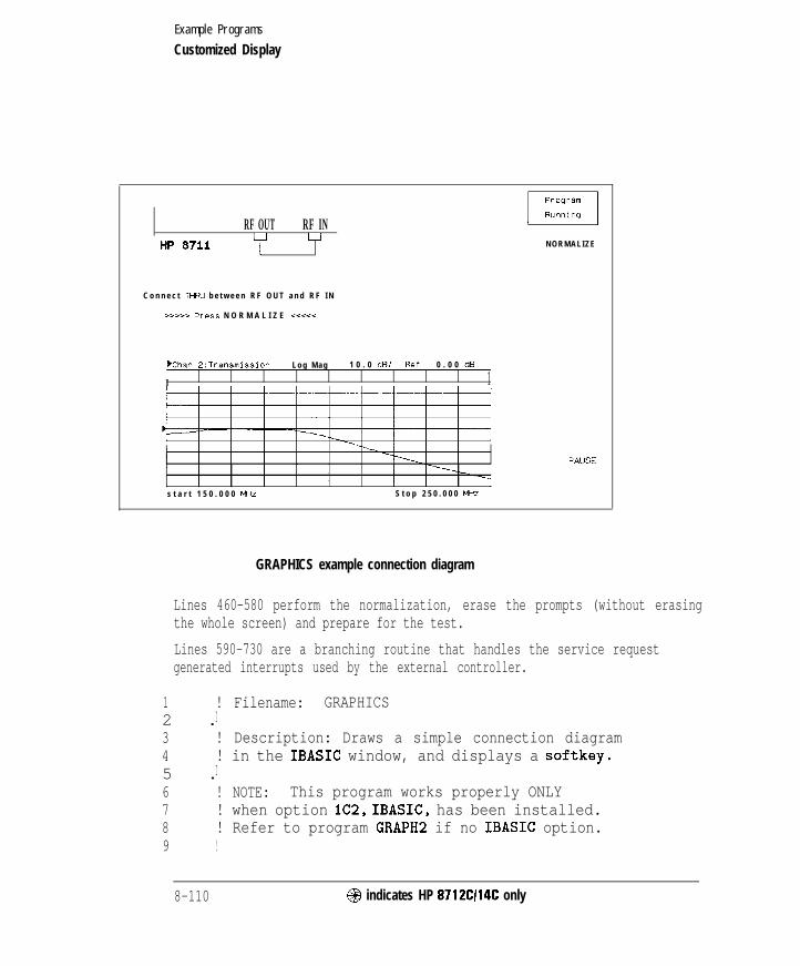
I- I -
Example Programs
Customized Display
RF OUT RF INu u
HP 8711 IN O R M A L I Z E
C o n n e c t TW b e t w e e n R F O U T a n d R F I N
>>>>L- Press N O R M A L I Z E <<<SC
bhan 2:Transmission L o g M a g 1 0 . 0 dB/ Ref 0 . 0 0 dB
I 1
s t a r t 1 5 0 . 0 0 0 MHZ S t o p 2 5 0 . 0 0 0 M+
=AUSE
GRAPHICS example connection diagram
Lines 460-580 perform the normalization, erase the prompts (without erasingthe whole screen) and prepare for the test.
Lines 590-730 are a branching routine that handles the service requestgenerated interrupts used by the external controller.
1 ! Filename: GRAPHICS2 .I3 ! Description: Draws a simple connection diagram4 ! in the IBASIC window, and displays a softkey.5 .I6 ! NOTE: This program works properly ONLY7 ! when option lC2, IBASIC, has been installed.8 ! Refer to program GRAPH2 if no IBASIC option.9 !
8-110 @$ indicates HP 8712C114C only

I- I -
Example Programs
Customized Display
1 0
2030405060708090100110111112113120121122130131132133134140141142143150160161162170171172173174175180
181182190
IF POS(SYSTEM$("SYSTEM ID">,"HP 871") THENASSIGN QHp8711 TO 800Internal=1Isc=8
ELSEASSIGN (QHp8711 TO 716Internal=0Isc=7ABORT 7CLEAR 716
END IF!! Allocate an IBASIC display partition! to show the graphics.OUTPUT QHp87ll;"DISP:PROG UPP"!! Clear the IBASIC display partition.OUTPUT OHp871l;"DISP:WINDlO:GRAP:CLE"I! Turn on channel 2 for measurements. The! lower part of the display is! devoted to display of measurements.OUTPUT QHp871l;"SENS2:STAT ON;*WAI"I! Take a single controlled sweep to ensure! a valid measurement using *OPC query.OUTPUT QHp8711;"ABOR;:INIT2:CONT OFF;:INITZ;*OPC?"ENTER OHp87ll;OpcI
! Select the bright "pen" and bold font.OUTPUT OHp87ll;"DISP:WINDlO:GRAP:COL 1;LAB:FONT BOLD"I
! Draw a label reading "HP 871lC" at 45 pixels! to the right and 120 pixels above the origin.! The origin is the lower left corner of the! current graphics window (upper half).OUTPUT OHp871l;"DISP:WINDlO:GRAP:MOVE 45,120;LAB 'HP 8711C"!! Draw a box to represent the analyzer.OUTPUT OHp871l;"DISP:WINDlO:GRAP:MOVE 30,175
@I indicates HP 8712C114C only 8-111
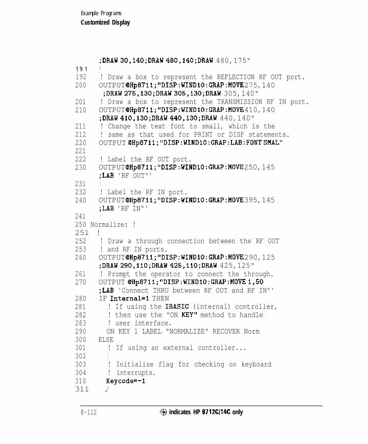
I- I -
Example Programs
Customized Display
1 9 1
192200
201210
211212220221222230
231232240
241
;DRAW 30,140;DRAW 480,140;DRAW 480,175"I
! Draw a box to represent the REFLECTION RF OUT port.OUTPUT OHp87l1;"DISP:WINDlO:GRAP:MOVE 275,140;DRAW 275,130;DRAW 305,130;DRAW 305,140"! Draw a box to represent the TRANSMISSION RF IN port.OUTPUT QHp87ll;"DISP:WINDlO:GRAP:MOVE 410,140;DRAW 410,130;DRAW 440,130;DRAW 440,140"! Change the text font to small, which is the! same as that used for PRINT or DISP statements.OUTPUT QHp8711;"DISP:WINDlO:GRAP:LAB:FONT SMAL"!! Label the RF OUT port.OUTPUT QHp871l;"DISP:WINDlO:GRAP:MOVE 250,145;LAB 'RF OUT"'!! Label the RF IN port.OUTPUT OHp871l;"DISP:WIND1O:GRAP:MOVE 395,145;LAB 'RF IN"'!
250 Normalize: !251 !252 ! Draw a through connection between the RF OUT253 ! and RF IN ports.260 OUTPUT QHp871l;"DISP:WINDlO:GRAP:MOVE 290,125
;DRAW 290,llO;DRAW 425,110;DRAW 425,125"261 ! Prompt the operator to connect the through.270 OUTPUT QHp871l;"DISP:WINDlO:GRAP:MOVE 1,50
;LAB 'Connect THRU between RF OUT and RF IN"'280 IF Internal=1 THEN281 ! If using the IBASIC (internal) controller,282 ! then use the "ON KEY" method to handle283 ! user interface.290 ON KEY 1 LABEL "NORMALIZE" RECOVER Norm300 ELSE301 ! If using an external controller...302 !303 ! Initialize flag for checking on keyboard304 ! interrupts.310 Keycode=-l311 .I
8-112 @I indicates HP 8712Cl14C only

I- I -
Example Programs
Customized Display
312320321322323330331332333334335336337338340341342343350351352353360370380381382390391392393394395396400410
420430
440
! Label softkey 1.OUTPUT QHp871l;"DISP:MENU:KEYl 'NORMALIZE"'!! Clear the status register and event status! register.OUTPUT OHp87ll;"*CLS;*ESE 0"!! Preset the other status registers.! Enable the Device Status register to report! to the Status Byte on positive transition! of bit 0 (key press). Enable the Status! Byte to generate an interrupt when the! Device Status register's summary bit! changes.OUTPUT QHp871l;"STAT:PRES;DEV:ENAB l;*SRE 4"!! Clear the key queue to ensure that previous! key presses do not generate an interrupt.OUTPUT OHp87ll;"SYST:KEY:QUE:CLE"!! Set up and enable the interrupt on the HP-IB! when a service request is received.ON INTR Isc,5 RECOVER SrqENABLE INTR Isc;2
END IFI
! Turn off the graphics buffer.OUTPUT OHp8711;"DISP:WINDlO:GRAP:BUFF OFF"!! Loop for waiting for press of the NORMALIZE key.! The two different output statements along with! the wait statements create a blinking effect.! There is not exit from this loop other than! a keyboard interrupt.LOOPOUTPUT OHp8711;"DISP:WINDlO:GRAP:MOVE 55,18;LAB '>>>>> Press NORMALIZE <<XC<"'WAIT .2OUTPUT QHp87ll;"DISP:WINDlO:GRAP:MOVE 55,18;LAB ' Press NORMALIZE , II
WAIT .2
@ indicates HP 8712C114C only 8 - 1 1 3

I- I -
Example Programs
Customized Display
450 END LOOP451 !460 Norm: ! Entry point to wait for a key press.461462470480481482483484485490491492493500
!
! If wrong key pressed, return to Normalize.IF Keycoded THEN GOT0 NormalizeOFF KEY!! The through should now be connected and! ready to measure.I
! Turn the graphics buffer back on.OUTPUT QHp871l;"DISP:WINDlO:GRAP:BUFF ON"!
510
520521522523530531532540541542550551552553560561562563570571572
! Select the "erase" pen (pen color 0) and! erase the prompts.OUTPUT OHp871l;"DISP:WINDlO:GRAP:COL 0;MOVE 55,18;LAB '>>>>> Press NORMALIZE <<<<<"'OUTPUT QHp871l;"DISP:WINDlO:GRAP:MOVE 1,50;LAB 'Connect THRU between RF OUT and RF IN"'OUTPUT QHp871l;"DISP:MENU:KEYl ' , II!! Display the active data trace only. Turn off! any previous normalization.OUTPUT OHp871l;"CALC2:MATH (IMPL)"I
! Take a single sweep on channel 2.OUTPUT OHp8711;"INIT2;*WAI"I
! Copy the new data trace into the memory array.OUTPUT QHp8711;"TRAC CH2SMEM,CH2SDATA"!! Normalize; that is, display the active data! relative to the memory trace.OUTPUT OHp871l;"CALC2:MATH (IMPL/CH2SMEM)"!! Display only one of the traces (the normalized! trace).OUTPUT QHp871l;"DISP:WIND2:TRACl 0N;TRACZ OFF"!! Erase the through connect and select pen color 1 again.
8-114 @ indicates HP 871261146 only
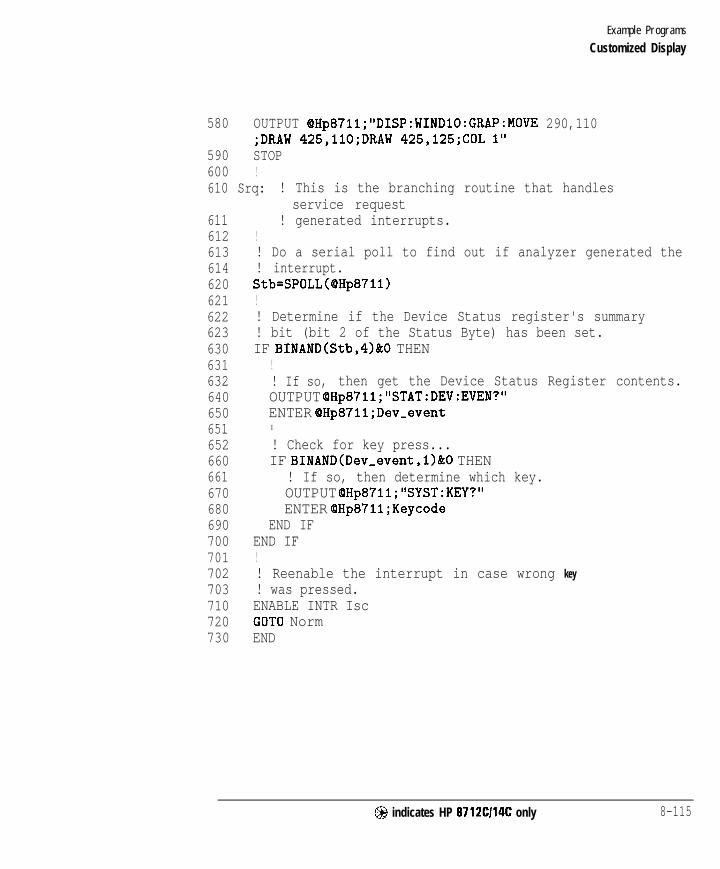
I- I -
Example Programs
Customized Display
580 OUTPUT OHp8711;"DISP:WINDlO:GRAP:MOVE 290,110;DRAW 425,llO;DRAW 425,125;COL 1"
590 STOP600 !610 Srq: ! This is the branching routine that handles
611612613614620621622623630631632640650651652660661670680690700701702703710720730
service request! generated interrupts.
!! Do a serial poll to find out if analyzer generated the! interrupt.Stb=SPOLL(@Hp8711)!! Determine if the Device Status register's summary! bit (bit 2 of the Status Byte) has been set.IF BINAND(Stb,4)&0 THEN
!! If so, then get the Device Status Register contents.OUTPUT OHp871l;"STAT:DEV:EVEN?"ENTER OHp8711;Dev-eventI
! Check for key press...IF BINAND(Dev-event,l)&O THEN
! If so, then determine which key.OUTPUT OHp8711;"SYST:KEY?"ENTER OHp87ll;Keycode
END IFEND IF!! Reenable the interrupt in case wrong key! was pressed.ENABLE INTR IscGOT0 NormEND
@ indicates HP 8712Cl14C only 8-115
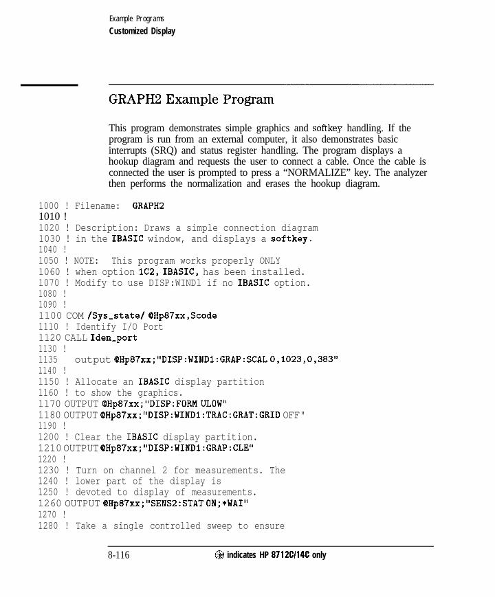
I- I -
Example Programs
Customized Display
GRAPH2 Example Program
This program demonstrates simple graphics and softkey handling. If theprogram is run from an external computer, it also demonstrates basicinterrupts (SRQ) and status register handling. The program displays ahookup diagram and requests the user to connect a cable. Once the cable isconnected the user is prompted to press a “NORMALIZE” key. The analyzerthen performs the normalization and erases the hookup diagram.
1000 ! Filename: GRAPH21010 !1020 ! Description: Draws a simple connection diagram1030 ! in the IBASIC window, and displays a softkey.1040 !1050 ! NOTE: This program works properly ONLY1060 ! when option lC2, IBASIC, has been installed.1070 ! Modify to use DISP:WINDl if no IBASIC option.1080 !1090 !1100 COM /Sys,state/ OHp87xx,Scode1110 ! Identify I/O Port1120 CALL Iden-port1130 !1135 output QHp87xx;"DISP:WINDl:GRAP:SCAL 0,1023,0,383"1140 !1150 ! Allocate an IBASIC display partition1160 ! to show the graphics.1170 OUTPUT OHp87xx;"DISP:FORM ULOW"1180 OUTPUT OHp87xx;"DISP:WINDl:TRAC:GRAT:GRID OFF"1190 !1200 ! Clear the IBASIC display partition.1210 OUTPUT OHp87xx;"DISP:WINDl:GRAP:CLE"1220 !1230 ! Turn on channel 2 for measurements. The1240 ! lower part of the display is1250 ! devoted to display of measurements.1260 OUTPUT OHp87xx;"SENS2:STAT ON;*WAI"1270 !1280 ! Take a single controlled sweep to ensure
8-116 @ indicates HP 8712Cl14C only

I- I -
Example Programs
Customized Display
1290 ! a valid measurement using *OPC query.1300 OUTPUT OHp87xx;"ABOR;:INIT2:CONT OFF;:INIT2;*OPC?"1310 ENTER OHp87xx;Opc1320 !1330 ! Select the bright "pen" and bold font.1340 OUTPUT QHp87xx; "DISP:WINDl:GRAP:COL 1;LAB:FONT BOLD"1350 !1360 ! Draw a label reading "HP 8711C" at 45 pixels1370 ! to the right and 120 pixels above the origin.1380 ! The origin is the lower left corner of the1390 ! current graphics window (upper half).1400 OUTPUT OHp87xx;"DISP:WINDl:GRAP:MOVE 45,120;LAB 'HP 8711C"'1410 !1420 ! Draw a box to represent the analyzer.1430 OUTPUT @Hp87xx;"DISP:WINDl:GRAP:MOVE 30,175;DRAW 30,140;DRAW
480,140;DRAW 480,175"1440 !1450 ! Draw a box to represent the REFLECTION RF OUT port.1460 OUTPUT OHp87xx;"DISP:WINDl:GRAP:MOVE 275,140;DRAW 275,130;DRAW
305,130;DRAW 305,140"1470 ! Draw a box to represent the TRANSMISSION RF IN port.1480 OUTPUT @Hp87xx,*"DISP:WINDl:GRAP:MOVE 410,140;DRAW 410,130;DRAW
440,130;DRAW 440,140"1490 ! Change the text font to small, which is the1500 ! same as that used for PRINT or DISP statements.1510 OUTPUT QHp87xx;"DISP:WINDl:GRAP:LAB:FONT SMAL"1520 !1530 ! Label the RF OUT port.1540 OUTPUT OHp87xx,*"DISP:WINDl:GRAP:MOVE 250,145;LAB 'RF OUT"'1550 !1560 ! Label the RF IN port.1570 OUTPUT (PHp87xx,*"DISP:WINDl:GRAP:MOVE 380,145;LAB 'RF IN"'1580 !1590 Normalize: !1600 !1610 ! Draw a through connection between the RF OUT1620 ! and RF IN ports.1630 OUTPUT (OHp87xx; "DISP:WINDl:GRAP:MOVE 290,125;DRAW 290,llO;DRAW
425,llO;DRAW 425,125"1640 ! Prompt the operator to connect the through.1650 OUTPUT @Hp87xx,*"DISP:WINDl:GRAP:MOVE 1,50;LAB 'Connect THRU between RF
@ indicates HP 8712Cl14C only 8-117

I-
Example Programs
Customized Display
OUT and RF IN"'1660 IF Internal=1 THEN1670 ! If using the IBASIC (internal) controller,1680 ! then use the "ON KEY" method to handle1690 ! user interface.1700 ON KEY 1 LABEL "NORMALIZE" RECOVER Norm1710 ELSE1720 ! If using an external controller...1730 !1740 ! Initialize flag for checking on keyboard1750 ! interrupts.1760 Keycode=-l1770 !1780 ! Label softkey 1.1790 OUTPUT OHp87xx;"DISP:MENU:KEYl 'NORMALIZE"'1800 !1810 ! Clear the status register and event status1820 ! register.1830 OUTPUT QHp87xx;"*CLS;*ESE 0"1840 !1850 ! Preset the other status registers.1860 ! Enable the Device Status register to report1870 ! to the Status Byte on positive transition1880 ! of bit 0 (key press). Enable the Status1890 ! Byte to generate an interrupt when the1900 ! Device Status register's summary bit1910 ! changes.1920 OUTPUT QHp87xx;"STAT:PRES;DEV:ENAB l;*SRE 4"1930 !1940 ! Clear the key queue to ensure that previous1950 ! key presses do not generate an interrupt.1960 OUTPUT QHp87xx;"SYST:KEY:QUE:CLE"1970 !1980 ! Set up and enable the interrupt on the HP-IB1990 ! when a service request is received.2000 ON INTR Scode,5 RECOVER Srq2010. ENABLE INTR Scode;:!2020 END IF2030 !2040 ! Turn off the graphics buffer.2050 OUTPUT QHp87xx;"DISP:WINDl:GRAP:BUFF OFF"
8-118 @I indicates HP 8712Cl14C only

I -
Example Programs
Customized Display
2060 !2070 ! Loop for waiting for press of the NORMALIZE key.2080 ! The two different output statements along with2090 ! the wait statements create a blinking effect.2100 ! There is not exit from this loop other than2110 ! a keyboard interrupt.2120 LOOP2130 OUTPUT QHp87xx,*"DISP:WINDl:GRAP:MOVE 55,18;LAB '>>>>> Press
NORMALIZE <<<<<"'2140 WAIT .22150 OUTPUT OHp87xx,-"DISP:WINDl:GRAP:MOVE 55,18;LAB '
NORMALIZE , II
2160 WAIT .22170 END LOOP2180 !2190 Norm: ! Entry point to wait for a key press.2200 !2210 ! If wrong key pressed, return to Normalize.2220 IF Keycode THEN GOT0 Normalize2230 OFF KEY2240 !
Press
2250 ! The through should now be connected and2260 ! ready to measure.2270 !2280 ! Turn the graphics buffer back on.2290 OUTPUT OHp87xx;"DISP:WINDl:GRAP:BUFF ON"2300 !2310 ! Select the "erase" pen (pen color 0) and2320 ! erase the prompts.2330 OUTPUT @Hp87xx,*"DISP:WINDl:GRAP:COL 0;MOVE 55,18;LAB '>>>>> Press
NORMALIZE <<<<<"'2340 OUTPUT OHp87xx;"DISP:WINDl:GRAP:MOVE 1,50;LAB 'Connect THRU between RF
OUT and RF IN"'2350 OUTPUT QHp87xx;"DISP:MENU:KEYl '2360 !
2 II
2370 ! Display the active data trace only. Turn off2380 ! any previous normalization.2390 OUTPUT OHp87xx;"CALC2:MATH (IMPL)"2400 !2410 ! Take a single sweep on channel 2.2420 OUTPUT QHp87xx;"INIT2;*WAI"
@I indicates HP 8712Cl14C only 8-119
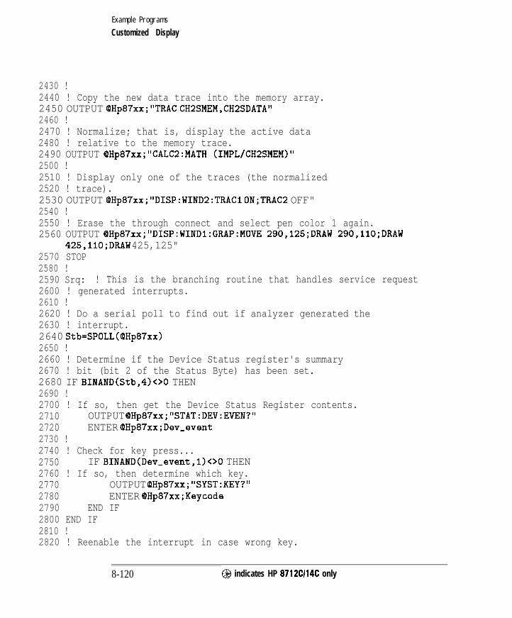
I- I -
Example Programs
Customized Display
2430 !2440 ! Copy the new data trace into the memory array.2450 OUTPUT OHp87xx;"TRAC CH2SMEM,CH2SDATA"2460 !2470 ! Normalize; that is, display the active data2480 ! relative to the memory trace.2490 OUTPUT OHp87xx,-"CALC2:MATH (IMPL/CH2SMEM)"2500 !2510 ! Display only one of the traces (the normalized2520 ! trace).2530 OUTPUT @Hp87xx;"DISP:WIND2:TRACl ON;TRAC2 OFF"2540 !2550 ! Erase the through connect and select pen color 1 again.2560 OUTPUT OHp87xx,-"DISP:WINDl:GRAP:MOVE 290,125;DRAW 290,llO;DRAW
425,llO;DRAW 425,125"2570 STOP2580 !2590 Srq: ! This is the branching routine that handles service request2600 ! generated interrupts.2610 !2620 ! Do a serial poll to find out if analyzer generated the2630 ! interrupt.2640 Stb=SPOLL(OHp87xx)2650 !2660 ! Determine if the Device Status register's summary2670 ! bit (bit 2 of the Status Byte) has been set.2680 IF BINAND(Stb,4)00 THEN2690 !2700 ! If so, then get the Device Status Register contents.2710 OUTPUT OHp87xx;"STAT:DEV:EVEN?"2720 ENTER QHp87xx;Dev-event2730 !2740 ! Check for key press...2750 IF BINAND(Dev-event,l)<>O THEN2760 ! If so, then determine which key.2770 OUTPUT OHp87xx;"SYST:KEY?"2780 ENTER QHp87xx;Keycode2790 END IF2800 END IF2810 !2820 ! Reenable the interrupt in case wrong key.
8-120 @ indicates HP 8712CI14C only

I- I -
Example Programs
Customized Display
2830 ! was pressed.2840 ENABLE INTR Scode2850 GOT0 Norm2860 END2870 !2880 !**************************************************************2890 ! Iden-port: Identify io port to use.2900 ! Description: This routines sets up the I/O port address for2910 ! the SCPI interface. For "HP 87xx" instruments,2920 ! the address assigned to (OHp87xx = 800 otherwise,2930 ! 716.2940 !**************************************************************2950 SUB Iden,port2960 COM /Sys-state/ OHp87xx,Scode2970 !2980 IF POS(SYSTEM$("SYSTEM ID"),"HP 87")OO THEN2990 ASSIGN (OHp87xx TO 8003000 Scode=83010 ELSE3020 ASSIGN (OHp87xx TO 7163030 Scode=73040 END IF3050 !3060 SUBEND !Iden-port3070 !
@j indicates HP 8712Cl14C only 8 - 1 2 1

I- I -
Example Programs
Customized Display
GETPLOT Example Program
This program shows how to capture a screen plot in “ .hgl” format andtransfer it to the floppy drive. Although this capability now exists infirmware, this program is still useful in demonstrating hle manipulation andstorage. This program also allows the user to specify any filename, whereasthe firmware will always choose a predehned name. This can also be used for“ .pcx” format by un-commenting line 280.
Because of BASIC limitations in any single array size, a four element arrayis used in line 170 to store the complete file. This allows a hle size up to128,000 bytes.
Lines 320 - 340 enter the screen capture data into the array Blk$.
Lines 360- 380 determine the total number of bytes to be saved.
Lines 410 - 480 save the Ele. In line 420, any previous file of the same nameis erased. If no file exists, this line is ignored due to the ON ERROR statementin line 410. The file is created in line 450 and the data stored in line 470.
100 !GETPLOT110 !120 ! This program will get a hardcopy screen dump in HP-GL format from130 ! the 8711, and store it locally.140 ! The user specifies the local filename (default = Plot87lx)150 !160 !170 DIM Blk$(l:4)[32000] ! Max file size = 4 * 32000 = 128000 bytes180 !190 DIM Filename$[64],Dest$[641200 INTEGER Word1210 !220 COM /Sys-state/ QHp87xx,Scode230 ! Identify I/O Port240 CALL Iden,port250 !260 BEEP270 Filename$=“DATA : screen. hgl" ! HP-GL format280 ! Filename$="DATA:screen.pcx" ! PCX format290 Dest$="Plot87lx"
8-122 @ indicates HP 8712Cl14C only

Example Programs
Customized Display
300 INPUT "Enter host filename (default='Plot87lx')",Dest$310 DISP "READING FILE "tFilename$&" . ..'I320 OUTPUT OHp87xx;"MMEM:TRANSFER? "'&Filename$&""330 ENTER (8Hp87xx USING "#,W";Wordl ! Assume indefinite block: #0 header340 ENTER (QHp87xx USING "%,-K";Blk$(*)350 ! Compute length of data we just ENTERed360 FOR I=1 TO 4370 Filelength=LEN(Blk$(I))+Filelength380 NEXT I390 ! Save data to local file400 DISP "Creating new file..."410 ON ERROR GOT0 Save-file420 PURGE Dest$430 Save-file: .I440 OFF ERROR450 CREATE Dest$,Filelength460 ASSIGN @File TO Dest$;FORMAT ON470 OUTPUT OFile;Blk$(*);480 ASSIGN @File TO *490 DISP "File "&Dest$&" created."500 BEEP510 END520 !530 !**************************************************************540 ! Iden-port: Identify io port to use.550 ! Description: This routines sets up the I/O port address for560 ! the SCPI interface. For "HP 87xx" instruments,570 ! the address assigned to OHp87xx = 800 otherwise,580 ! 716.590 !**************************************************************
@I indicates HP 8712Cl14C only 8 - 1 2 3

I- I -
Example Programs
Customized Display
600 SUB Iden,port610 COM /Sys-state/ QHp87xx,Scode620 !630 IF POS(SYSTEM$(~~~SYSTEM ID9,lfHp 87v>o THEN640 ASSIGN (PHp87xx TO 800650 Scode=8660 ELSE670 ASSIGN (BHp87xx TO 716680 Scode=7690 END IF700 !710 SUBEND !Iden-port720 !
8-124 @I indicates HP 8712Cl14C only

I- I -
Annotation
USERANOT Using user-deEned annotation.
FREQBLNK Concealing sensitive frequency information.
KEYCODES Reading key presses and knob positions from the analyzer.
@indicates HP 8712Cl14C only 8-125

I- I -
Example Programs
Annotation
USERANOT Example Program
This program demonstrates how to use user-deEned x-axis annotation. Withthis feature, you can set the analyzer to convert all x-axis information intoa user-detied scale. In this program, the Channel 1 x-axis is modified todisplay antenna angle in degrees while Channel 2 x-axis displays antennaheight in feet.
100 ! RE-SAVE “USERANOT”110 !BASIC program: An example program to draw user-defined annotation120 !$Revision: 1.1 $130 !$Date: 97/09/02 13:14:22 $140 !150 ! Demonstrate these SCPI commands:160 !170 ! DISPlay:ANNotation:CHANnel[ll2l:USER[:STATe] COFFIOiONIl~180 ! DISPlay:ANNotation:CHANnel[ll2]:USER:LABel[:DATA] <STRING>190 !200 ! DISPlay:ANNotation:FREQuency[ll2]:USER[:STATe] (OFFIOIONIi)210 ! DISPlay:ANNotation:FREQuency[ll2]:USER:STARt #-lOOOO"lOOOO#220 ! DISPlay:ANNotation:FREQuency[ll2]:USER:STOP X-10000'10000#230 ! DISPlay:ANNotation:FREQuency[ll2]:USER:SUFFix[:DATAl <STRING>240 ! DISPlay:ANNotation:FREQuency[ll2]:USER:LABel[:DATA] <STRING>250 !260 ! _-----------------_----------------------------------------------------270 !280 ! Determine select code (800 for IBASIC, 716 for external computer)290 !300 IF POS(SYSTEM$ (“SYSTEM ID”) , “HP 87”) THEN310 ASSIGN (QHp8711 TO 800320 ELSE330 ASSIGN QHp8711 TO 716340 ABORT 7350 CLEAR 716360 END IF370 !380 ! Preset390 OUTPUT OHp87ll;"SYST:PRES; *WAI"400 OUTPUT @Hp8711;"SENS2:STAT ON" ! So we can see markers
8-126 @ indicates HP 8712Cl14C only
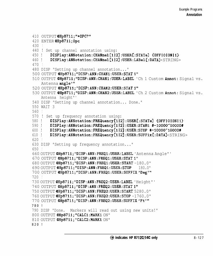
I- I -
Example Programs
Annotation
410 OUTPUT OHp87ll;"*OPC?"420 ENTER OHp87ll;Opc430 !440 ! Set up channel annotation using:450 ! DISPlay:ANNotation:CHANnel[ll2]:USER[:STATe] {OFFIOIONJI)460 ! DISPlay:ANNotation:CHANnel[ll2]:USER:LABel[:DATA] <STRING>470 !480 DISP "Setting up channel annotation..."500 OUTPUT OHp87ll;"DISP:ANN:CHANl:USER:STAT 1"510 OUTPUT OHp87ll;"DISP:ANN:CHANl:USER:LABEL 'Ch 1 Custom Annot: Signal vs.
Antenna angle"'520 OUTPUT QHp871l;"DISP:ANN:CHAN2:USER:STAT 1"530 OUTPUT OHp871l;"DISP:ANN:CHAN2:USER:LABEL 'Ch 2 Custom Annot: Signal vs.
Antenna height"'540 DISP "Setting up channel annotation... Done."550 WAIT 3560 !570 ! Set up frequency annotation using:580 ! DISPlay:ANNotation:FREQuency[ll2l:USER[:STATe] {OFFIOIONIl)590 ! DISPlay:ANNotation:FREQuency[ll2]:USER:STARt #-10000"10000#600 ! DISPlay:ANNotation:FREQuency[ll23:USER:STOP #-10000'10000#610 ! DISPlay:ANNotation:FREQuency[ll2]:USER:SUFFix[:DATA] <STRING>620 !630 DISP "Setting up frequency annotation..."650 !660 OUTPUT OHp871i;"DISP:ANN:FREQl:USER:LABEL 'Antenna Angle"'670 OUTPUT QHp8711;"DISP:ANN:FREQl:USER:STAT 1"680 OUTPUT @Hp8711;"DISP:ANN:FREQl:USER:START -180.0"690 OUTPUT OHp871l;"DISP:ANN:FREQl:USER:STOP 180.0"700 OUTPUT OHp8711;"DISP:ANN:FREQl:USER:SUFFIX 'Deg"'720 !730 OUTPUT OHp871l;"DISP:ANN:FREQ2:USER:LABEL 'Height"'740 OUTPUT OHp871l;"DISP:ANN:FREQ2:USER:STAT 1"750 OUTPUT OHp87ll;"DISP:ANN:FREQ2:USER:START 5280.0"760 OUTPUT OHp87ll;"DISP:ANN:FREQ2:USER:STOP -1760.0"770 OUTPUT OHp8711;"DISP:ANN:FREQ2:USER:SUFFIX 'Ft"'7 8 0 !
790 DISP "Done. Markers will read out using new units!"800 OUTPUT OHp871l;"CALCl:MARKl ON"810 OUTPUT OHp87ll;"CALC2:MARKl ON"8 2 0 !
@ indicates HP 8712Cl14C only 8 - 1 2 7

I-
Example Programs
Annotation
830 LOCAL (OHp8711840 !850 END
I -
!End of this program
8 - 1 2 8 @I indicates HP 8712Cl14C only

I- I -
Example Programs
Annotation
FREQBLNK Example Program
This program demonstrates how to use user-defined x-axis annotation toconceal (or “blank")sensitive frequency information.
100 !RE-SAVE "FREQBLNK"110 !BASIC program: An example program to overwrite frequency annotation120 !$Revision: 1.2 $130 !$Date: 97/09/02 13:17:25 $140 !150 ! Demonstrate using these SCPI commands to blank freq annotation.160 !170 ! DISPlay:ANNotation:FREQuency[ll2]:USER[:STATel (OFFIOIONIl)180 ! DISPlay:ANNotation:FREQuency[ll2]:USER:STARt #-10000"10000#190 ! DISPlay:ANNotation:FREQuency[ll2]:USER:STOP #-lOOOO"lOOOO#200 ! DISPlay:ANNotation:FREQuency[l~2l:USER:SUFFix[:DATAl <STRING>210 ! DISPlay:ANNotation:FREQuency[ll2]:USER:LABelC:DATAl <STRING>220 !230 ! -----------------------------------------------------------------------240 !250 ! Determine select code (800 for IBASIC, 716 for external computer)260 !270 IF POS(SYSTEM$("SYSTEM ID">,"HP 87") THEN280 ASSIGN QHp8711 TO 800290 ELSE300 ASSIGN QHp8711 TO 716310 ABORT 7320 CLEAR 716330 END IF340 !350 ! Preset360 OUTPUT OHp8711;"SYST:PRES; *WAI"370 OUTPUT QHp87ll;"SENS2:STAT ON" ! So we can see markers380 OUTPUT OHp8711;"*OPC?"390 ENTER QHp87ll;Opc400 !410 ! Set up frequency annotation using:420 ! DISPlay:ANNotation:FREQuency[ll2]:USER[:STATel COFFIOIONll~430 ! DISPlay:ANNotation:FREQuency[lj2]:USER:STARt #-lOOOO'lOOOO#
@ indicates HP 8712Cl14C only 8-129

I- I -
Example Programs
Annotation
440 ! DISPlay:ANNotation:FREQuency[ll2]:USER:STOP #-lOOOO~lOOOO#450 ! DISPlay:ANNotation:FREQuency[ll2]:USER:SUFFix[:DATA] <STRING>460 !470 DISP "Setting up frequency annotation..."480 !490 OUTPUT QHp871l;"DISP:ANN:FREQl:USER:LABEL 'Blank"'500 OUTPUT OHp87ll;"DISP:ANN:FREQl:USER:STAT 1"510 OUTPUT OHp871l;"DISP:ANN:FREQl:USER:START 0.0"520 OUTPUT OHp87ll;"DISP:ANN:FREQl:USER:STOP 100.0"530 OUTPUT OHp8711;"DISP:ANN:FREQl:USER:SUFFIX "'540 !550 OUTPUT QHp87ll;"DISP:ANN:FREQ2:USER:LABEL 'Blank"'560 OUTPUT QHp87ll;"DISP:ANN:FREQ2:USER:STAT 1"570 OUTPUT OHp8711;"DISP:ANN:FREQ2:USER:START 0.0"580 OUTPUT OHp871l;"DISP:ANN:FREQ2:USER:STOP 100.0"590 OUTPUT QHp871l;"DISP:ANN:FREQ2:USER:SUFFIX "'600 !610 DISP "Done. Markers will read out using new units!"620 OUTPUT OHp87ll;"CALCl:MARKl ON"630 OUTPUT OHp871l;"CALC2:MARKl ON"640 !650 LOCAL OHp87116 6 0 !6 7 0 END !End of this program
8 - 1 3 0 @ indicates HP 8712CI14C only

I- I -Example Programs
Annotation
KEYCODES Example Program
This program will detect any front panel input, determine if it is from akeystroke or the knob, and display the corresponding keycode or value. Eachkey has a unique keycode associated with it. The knob will return either apositive or negative number depending upon direction of rotation (clockwiseis positive). The program can be exited by pressing [j).
Lines 1290 - 1520 are continuously repeated to look for any front panelactivity.
Line 1370 - 1430 read the key type to determine if the activity came from akey press or from the knob. Also read is the value “Key-code.” If the activitycame from the knob, then the value “Key-code” represents how far the knobhas been turned, and in which direction. If the activity came from a keystroke, the value represents the key’s keycode.
Line 1510 determines if the (j-j key was pressed. If so, the programexits.
1000 ! Filename: KEYCODES1010 ! _1020 !1030 ! Demonstration of how to read the analyzer’s1040 ! front panel keys and knob, as well as external1050 ! PC keyboard, using the SCPI SYST:KEY commands.1060 ! This program reads key presses and knob turn1070 ! ticks and displays them on the screen.1080 ! _1090 !1100 DIM Msg$ [4011110 !1120 !1130 COM /Sys,state/ OHp87xx,Scode1140 ! Identify I/O Port1150 CALL Iden-port1160 !1170 !1180 ! Clear the key queue to ignore1190 ! previous key presses.
@ indicates HP 8712Cl14C only 8-131
I-

I- I -
Example Programs
Annotation
1200 OUTPUT OHp87xx;"SYST:KEY:QUE:CLE"1210 !1220 ! Turn on the key queue off to limit1230 ! maximum que size to one.1240 OUTPUT OHp87xx;"SYST:KEY:QUE OFF"1250 !1260 Msg$="' Press keys or turn knob. PRESET ends."'1270 OUTPUT OHp87xx;"DISP:ANN:MESS:DATA ";Msg$1280 !1290 LOOP1300 ! query device status condition register1310 OUTPUT QHp87xx;"STAT:DEV:COND?"1320 ENTER OHp87xx;Dev-cond1330 !1340 ! Check the bit that indicates a key press.1350 IF BIT(Dev,cond,O)=l THEN1360 ! Read the key type first1370 OUTPUT QHp87xx;"SYST:KEY:TYPE?"1380 ENTER QHp87xx;Key_type$1390 ! Read the key code last.1400 ! This removes it from the queue1410 OUTPUT @Hp87xx;"SYST:KEY?"1420 ENTER QHp87xx;Key-code1430 DISP "Keycode ";Key-code;" Type ";Key,type$;1440 ! See how many more keys are in the queue1450 OUTPUT QHp87xx;"SYST:KEY:qUEUE:COUNT?"1460 ENTER QHp87xx;Key-count1470 DISP 'I. Keys in queue:";Key-count1480 END IF1490 !1500 ! Stop looping if the PRESET key was pressed.1510 EXIT IF Key-code=56 AND Key-type$="KEY"1520 END LOOP1530 DISP "The end."1540 OUTPUT QHp87xx;"DISP:ANN:MESS:DATA 'The End."'1550 END1560 !
8-132 @ indicates HP 8712C114C only

I- I -
Example Programs
Annotation
1570 !**************************************************************1580 ! Iden-port: Identify io port to use.1590 ! Description: This routines sets up the I/O port address for1600 ! the SCPI interface. For "HP 87xx" instruments,1610 ! the address assigned to (OHp87xx = 800 otherwise,1620 ! 716.1630 !**************************************************************1640 SUB Iden,port1650 COM /Sys-state/ OHp87xx,Scode1660 !1670 IF POS(SYSTEM$("SYSTEM ID">,"HP 87")OO THEN1680 ASSIGN QHp87xx TO 8001690 Scode=81700 ELSE1710 ASSIGN QHp87xx TO 7161720 Scode=71730 END IF1740 !1750 SUBEND !Iden,port1760 !
@ indicates HP 8712Cl14C only 8 - 1 3 3
I-

I- I -
Marker Functions
MKR-MATH Marker math functions are used to calculate differentparameters on a user-deIined measurement trace segment.Frequency span, mean amplitude, amplitude standarddeviation, and peak-to-peak amplitude are calculated withthe Statistics function. Span, gain, slope and flatness arecalculated with the Flatness function. Insertion loss andpeak-to-peak ripple of the passband, and maximum signalamplitude in the stopband are calculated with the RF FilterStats function. This example program steps through themarker math functions and then reads and reports theresults.
8-134 @ indicates HP 8712C114C only

I -
Example Programs
Marker Functions
MKRAIATH Example Program
1000 !Filename: MKR-MATH1010 !1020 ! This example program demonstrates how to program marker math1030 ! functions. Marker Statistics, Marker Flatness, and RF Filter Stats.1040 !1050 ! Connect the demo filter between the RF out and RF in of the analyzer.1060 !1070 ! The program will step through various marker math measurements, then1080 ! read and report the results.1090 !1100 !1110 COM /Sys-state/ QHp87xx,Scode1120 ! Identify I/O Port1130 CALL Iden-port1140 !1150 !1160 ! Perform a system preset;1170 OUTPUT OHp87xx;"SYST:PRES;*WAI"1180 !1190 ! Set up the source frequencies for the measurement.1200 OUTPUT (PHp87xx;" SENSl:FREQ:STAR 10 MHZ;STOP 400 MHZ;*WAI"1210 !1220 ! Set up the receiver for the measurement parameters1230 ! (Transmission in this case).1240 OUTPUT QHp87xx;"SENSl:FUNC 'XFR:POW:RAT 2,O';DET NBAN;*WAI"1250 !1260 ! Configure the display so measurement1270 ! results are easy to see.1280 OUTPUT OHp87xx;"DISP:WIND1:TRAC:Y:PDIV 10 DB;RLEV 0 DB;RPOS 9"1290 !1300 ! Reduce the distractions on the display by1310 ! getting rid of notation that will not be1320 ! needed in this example.1330 OUTPUT OHp87xx;"DISP:ANN:YAX OFF"1340 !1350 ! Erase the graticule grid for the same reason.
@ indicates HP 8712Cl14C only 8-135

I- I -
Example Programs
Marker Functions
1360 OUTPUT QHp87xx;"DISP:WINDl:TRAC:GRAT:GRID OFF"1370 !1380 ! Set the markers for channel 11390 OUTPUT OHp87xx;"CALCl:MARKl ON"1400 OUTPUT OHp87xx;"CALCl:MARKl:X 152000000.000000"1410 OUTPUT QHp87xx;"CALCl:MARK2 ON"1420 OUTPUT QHp87xx; "CALCl:MARK2:X 200000000.000000"1430 OUTPUT OHp87xx;"CALCl:MARK3 ON"1440 OUTPUT (PHp87xx; "CALCl:MARK3:X 279000000.000000"1450 OUTPUT QHp87xx;"CALCl:MARK4 ON"1460 OUTPUT OHp87xx;"CALCl:MARK4:X 388000000.000000"1470 !1480 ! Turn on marker flatness1490 OUTPUT (8Hp87xx;" CALCl:MARK:FUNC FLATNESS"1500 DISP "Marker Flatness"1510 !1520 WAIT 51530 OUTPUT QHp87xx; "CALCl:MARK:FUNC:RES?"1540 ! Read the four values: the span, gain1550 ! the slope, and the flatness.1560 ENTER QHp87xx;Span,Gain,Slope,Flatness1570 !1580 ! Display the results.1590 BEEP1600 DISP "Span ";Span1610 !1620 WAIT 51630 BEEP1640 DISP "Gain ";Gain1650 !1660 WAIT 51670 BEEP1680 DISP "Slope ";Slope1690 !1700 WAIT 51710 BEEP1720 DISP "Flatness ";Flatness1730 !1740 WAIT 51750 ! Turn on marker statistics1760 OUTPUT (OHp87xx; "CALCl:MARK:FUNC STATISTICS"
8 - 1 3 6 @ indicates HP 8712Cl14C only

I-
Example Programs
Marker Functions
1770 DISP "Marker Statistics"1780 !1790 WAIT 51800 OUTPUT OHp87xx;"CALCl:MARK:FUNC:RES?"1810 ! Read the four values: the span,1820 ! the mean, the sdev, peak to peak.1830 ENTER OHp87xx;Span,Mean,Sdev,Peak1840 !1850 ! Display the results.1860 BEEP1870 DISP "Span ";Span1880 !1890 WAIT 51900 BEEP1910 DISP "Mean ";Mean1920 !1930 WAIT 51940 BEEP1950 DISP "Sdev ";Sdev1960 !1970 WAIT 51980 BEEP1990 DISP "Peak ";Peak2000 !2010 WAIT 52020 ! Turn on RF Filter Stats2030 OUTPUT OHp87xx;"CALCl:MARK:FUNC FST"2040 DISP "RF Filter Stats"2050 !2060 WAIT 52070 OUTPUT (QHp87xx; "CALCl:MARK:FUNC:RES?"2080 ! Read the three values: the loss,2090 ! the peak to peak, and the reject2100 ENTER OHp87xx;Loss,Peak,Reject2110 !2120 ! Display the results.2130 BEEP2140 DISP "Loss ";Loss2150 !2160 WAIT 52170 BEEP
@ indicates HP 8712Cl14C only 8-137
-1-
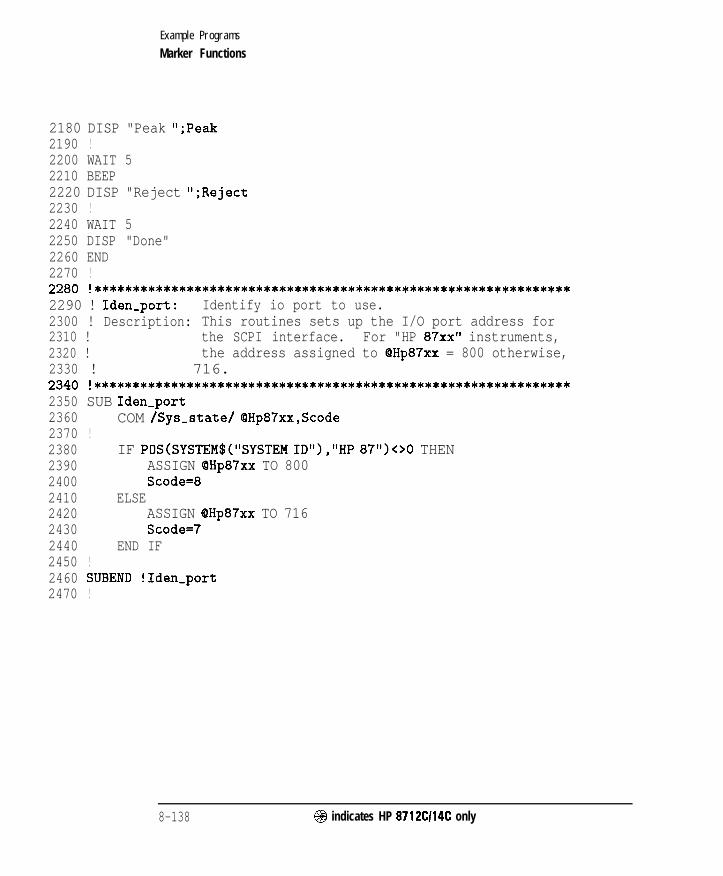
I-
Example Programs
Marker Functions
2180 DISP "Peak ";Peak2190 !2200 WAIT 52210 BEEP2220 DISP "Reject ";Reject2230 !2240 WAIT 52250 DISP "Done"2260 END2270 !2280 !**************************************************************2290 ! Iden-port: Identify io port to use.2300 ! Description: This routines sets up the I/O port address for2310 ! the SCPI interface. For "HP 87xx" instruments,2320 ! the address assigned to QHp87xx = 800 otherwise,2330 ! 716.2340 !**************************************************************2350 SUB Iden-port2360 COM /Sys-state/ QHp87xx,Scode2370 !2380 IF POS(SYSTEM$("SYSTEM ID">,"HP 87")OO THEN2390 ASSIGN QHp87xx TO 8002400 Scode=82410 ELSE2420 ASSIGN (OHp87xx TO 7162430 Scode=72440 END IF2450 !2460 SUBEND !Iden-port2470 !
8-138 @ indicates HP 8712CI14C only

I- I -
Marker Limit Testing
LIM-FLAT Limit testing can be performed on the flatness of auser-dehned measurement trace segment. This exampleprogram sets various flatness limits, then queries the statusto determine if the limit test passes or fails.
LIM-PEAK Limit testing can be performed on the peak-to-peak ripple ofa user-defined measurement trace segment. This exampleprogram sets various peak-to-peak limits, then queries thestatus to determine if the limit test passes or fails.
LIM-MEAN Limit testing can be performed on the mean amplitude of auser-defined measurement trace segment. This exampleprogram sets various mean limits, then queries the status todetermine if the limit test passes or fails.
@I indicates HP 8712Cl14C only 8-139
I-
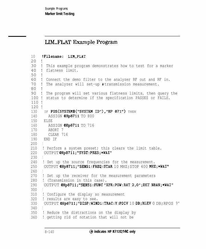
I- I -
Example Programs
Marker limit Testing
LIM-FLAT Example Program
10 !Filename: LIM-FLAT20 !30 !40 !50 !60 !70 !80 !90 !100 !110 !120 !
This example program demonstrates how to test for a markerflatness limit.
Connect the demo filter to the analyzer RF out and RF in.The analyzer will set-up a transmission measurement.
The program will set various flatness limits, then query thestatus to determine if the specification PASSES or FAILS.
130 IF POS(SYSTEM$(~SYSTEM ID~~>,I~HP 87ltl) THEN140 ASSIGN (PHp8711 TO 800150 ELSE160 ASSIGN (PHp8711 TO 716170 ABORT 7180 CLEAR 716190 END IF200 !210 ! Perform a system preset; this clears the limit table.220 OUTPUT OHp871l;"SYST:PRES;*WAI"230 !240 ! Set up the source frequencies for the measurement.250 OUTPUT OHp87ll;"SENSl:FRECj:STAR 10 MHZ;STOP 400 MHZ;*WAI"260 !270 ! Set up the receiver for the measurement parameters280 ! (Transmission in this case).290 OUTPUT QHp8711;"SENSl:FUNC 'XFR:POW:RAT 2,O';DET NBAN;*WAI"300 !310 ! Configure the display so measurement320 ! results are easy to see.330 OUTPUT QHp87ll;"DISP:WINDl:TRAC:Y:PDIV 10 DB;RLEV 0 DB;RPOS 9"340 !350 ! Reduce the distractions on the display by360 ! getting rid of notation that will not be
8-140 @ indicates HP 8712Cl14C only

I- I -
Example Programs
Marker limit Testing
370380390400410420430440450460470480490500510520530540550560570580590600610620630640650660670680690700710720730740750760770
! needed in this example.OUTPUT QHp8711;"DISP:ANN:YAX OFF"
!! Erase the graticule grid for the same reason.OUTPUT 9Hp8711;"DISP:WINDl:TRAC:GRAT:GRID OFF"
1! Set the markers for channel 1OUTPUT OHp87ll;"CALCl:MARKl ON"OUTPUT QHp87ll;"CALCl:MARKl:X 152000000.000000"OUTPUT OHp871l;"CALCl:MARK2 ON"OUTPUT OHp87ll;"CALCl:MARK2:X 200000000.000000"
!! Turn on marker flatnessOUTPUT OHp8711;"CALCl:MARK:FUNC FLATNESS"
!OUTPUT OHp87ll;"CALCl:MARK2 ON"OUTPUT 6Hp871l;"CALCl:LIM:DISP ON"OUTPUT OHp871l;"CALCl:LIM:MARK:FLATNESS ON"
!! Turn on the pass/fail testing; watch the! analyzer's display for the pass/fail indicator.OUTPUT QHp8711;"CALCl:LIM:STAT ON"
I! Set sweep hold modeOUTPUT QHp8711;"ABOR;:INITl:CONT OFF;:INITl;*WAI"
!! Send an operation complete query to ensure that! all overlapped commands have been executed.OUTPUT OHp871l;"*OPC?"
!! Wait for the reply.ENTER OHp87ll;Opc
!! Turn on a limit to be testedFOR Flatness=O. TO 3 STEP .lDISP "Flatness limit test =",VAL$(Flatness)&" dB"OUTPUT OHp8711;tCALC1:LIM:MARK:FLAT:MAX "&VAL$(Flatness)
!! Take a controlled sweep to ensure that! there is real data present for the limit test.
OUTPUT OHp871l;"INITl;*OPC?"
@ indicates HP 8712Cl14C only 8-141
I-

I- I -
Example Programs
Marker limit Testing
780790 !800 !810 !820830 !840 !850860 !870 !880 !890 !900 !910920 !930940950960970980 !
ENTER QHp8711;Opc
Query the limit fail condition register to seeif there is a failure.OUTPUT OHp871l;"STAT:QUES:LIM:COND?"
Read the register's contents.ENTER QHp87ll;Fail-flag
Bit 0 is the test result for channel 1 whileBit 1 is the results for channel 2 limit testing.Bit 2 is the result for channel 1 mkr limit testing.Bit 3 is the result for channel 2 mkr limit testing.IF BIT(Fail_flag,2)=1 THEN
This limit test failedELSEDISP "Flatness passed at "&VAL$(Flatness)&" dB"BEEPGOT0 Done
END IF
9 9 0 NEXT Flatness1000 Done:OUTPUT @Hp871l;"INIT:CONT ON;*WAI"1010 END
8-142 @ indicates HP 8712Cl14C only

I- I -
Example Programs
Marker limit Testing
LIM-PEAK Example Program
1000 !Filename: LIM-PEAK1010 !1020 ! This example program demonstrates how to test for a marker1030 ! statistics peak to peak ripple limit.1040 !1050 ! Connect the demo filter to the analyzer RF out and RF in.1060 ! The analyzer will set-up a transmission measurement.1070 !1080 ! The program will set various statistics peak to peak limits, then1090 ! query the status to determine if the specification PASSES or FAILS.1100 !1110 !1120 !1130 COM /Sys-state/ QHp87xx,Scode1140 ! Identify I/O Port1150 CALL Iden,port1160 !1170 !1180 ! Perform a system preset; this clears the limit table.1190 OUTPUT OHp87xx;"SYST:PRES;*WAI"1200 !1210 ! Set up the source frequencies for the measurement.1220 OUTPUT OHp87xx;"SENSl:FREQ:STAR 10 MHZ;STOP 400 MHZ;*WAI"1230 !1240 ! Set up the receiver for the measurement parameters1250 ! (Transmission in this case>.1260 OUTPUT QHp87xx,*"SENSl:FUNC 'XFR:POW:RAT 2,O';DET NBAN;*WAI"1270 !1280 ! Configure the display so measurement1290 ! results are easy to see.1300 OUTPUT QHp87xx,."DISP:WINDl:TRAC:Y:PDIV 10 DB;RLEV 0 DB;RPOS 9"1310 !1320 ! Reduce the distractions on the display by1330 ! getting rid of notation that will not be1340 ! needed in this example.1350 OUTPUT OHp87xx;"DISP:ANN:YAX OFF"
@ indicates HP 8712Cl14C only 8-143

I- I -
Example Programs
Marker limit Testing
1360 !1370 ! Erase the graticule grid for the same reason.1380 OUTPUT QHp87xx;" DISP:WINDl:TRAC:GRAT:GRID OFF"1390 !1400 ! Set the markers for channel 11410 OUTPUT OHp87xx;"CALCl:MARKl ON"1420 OUTPUT (PHp87xx;"CALCl:MARKl:X 152000000.000000"1430 OUTPUT OHp87xx;"CALCl:MARK2 ON"1440 OUTPUT (PHp87xx;" CALCl:MARK2:X 200000000.000000"1450 !1460 ! Turn on marker statistics1470 OUTPUT QHp87xx;" CALCl:MARK:FUNC STATISTICS"1480 !1490 OUTPUT OHp87xx;"CALCl:MARK2 ON"1500 OUTPUT QHp87xx;"CALCl:LIM:DISP ON"1510 OUTPUT CQHp87xx;" CALCl:LIM:MARK:STAT:PEAK ON"1520 !1530 ! Turn on the pass/fail testing; watch the1540 ! analyzer's display for the pass/fail indicator.1550 OUTPUT QHp87xx;"CALCl:LIM:STAT ON"1560 !1570 ! Set sweep hold mode1580 OUTPUT (PHp87xx;"ABOR;:INITl:CONT OFF;:INITl;*WAI"1590 !1600 ! Send an operation complete query to ensure that1610 ! all overlapped commands have been executed.1620 OUTPUT OHp87xx;"*OPC?"1630 !1640 ! Wait for the reply.1650 ENTER QHp87xx;Opc1660 !1670 ! Turn on a limit to be tested1680 FOR Peak-limit=O. TO 3 STEP .l1690 DISP "Peak limit test =",VAL$(Peak,limit)t" dB"1700 OUTPUT OH~~~XX;~'CALC~:LIM:MARK:STAT:PEAK:MAX "CVAL$(Peak-limit)1710 !1720 ! Send an operation complete query to ensure that1730 ! all overlapped commands have been executed.1740 OUTPUT QHp87xx;"*OPC?"1750 !1760 ! Wait for the reply.
8 - 1 4 4 @ indicates HP 8712Cl14C only
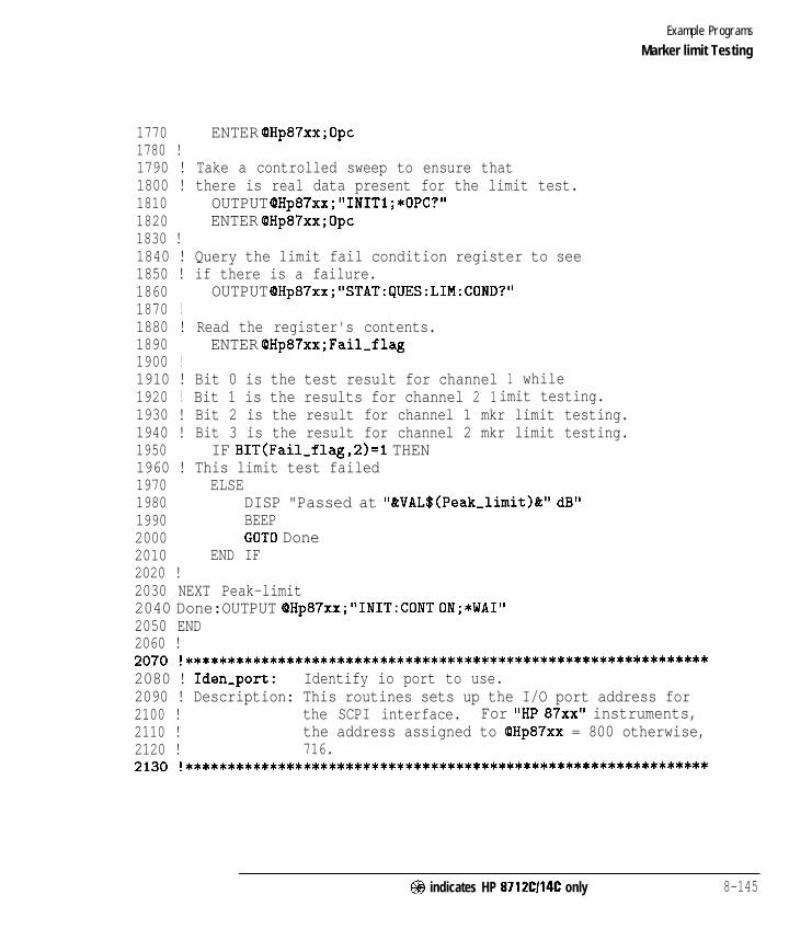
I- I -
Example Programs
Marker limit Testing
1770 ENTER OHp87xx;Opc1780 !1790 ! Take a controlled sweep to ensure that1800 ! there is real data present for the limit test.1810 OUTPUT OHp87xx;"INITl;*OPC?"1820 ENTER OHp87xx;Opc1830 !1840 ! Query the limit fail condition register to see1850 ! if there is a failure.1860 OUTPUT OHp87xx;"STAT:lJJES:LIM:COND?"1870 !1880 ! Read the register's contents.1890 ENTER QHp87xx;Fail-flag1900 !1910 ! Bit 0 is the test result for channel1920 ! Bit 1 is the results for channel 2 1
1 whileimit testing.
1930 ! Bit 2 is the result for channel 1 mkr limit testing.1940 ! Bit 3 is the result for channel 2 mkr limit testing.1950 IF BIT(Fail,flag,2)=1 THEN1960 ! This limit test failed1970 ELSE1980 DISP "Passed at "&VAL$(Peak-limit)&" dB"1990 BEEP2000 GOT0 Done2010 END IF2020 !2030 NEXT Peak-limit2040 Done:OUTPUT QHp87xx;"INIT:CONT ON;*WAI"2050 END2060 !2070 !**************************************************************2080 ! Iden,port: Identify io port to use.2090 ! Description: This routines sets up the I/O port address for2100 ! the SCPI interface. For "HP 87xx" instruments,2110 ! the address assigned to (QHp87xx = 800 otherwise,2120 ! 716.2130 !**************************************************************
@I indicates HP 8712Cl14C only 8-145

I- I -
Example Programs
Marker limit Testing
2140 SUB Iden-port2150 COM /Sys-state/ OHp87xx,Scode2160 !2170 IF POS(SYSTEM$("SYSTEM ID"),"HP 87")OO THEN2180 ASSIGN (QHp87xx TO 8002190 Scode=82200 ELSE2210 ASSIGN BHp87xx TO 7162220 Scode=72230 END IF2240 !2250 SUBEND !Iden-port2260 !
8-146 @ indicates HP 8712Cl14C only

I- I -
Example Programs
Marker limit Testing
LIM-MEAN Example Program
1000 !Filename: LIM,MEAN1010 !1020 ! This example program demonstrates how to test for a marker1030 ! statistics mean limit.1040 !1050 ! Connect the demo filter to the analyzer RF out and RF in.1060 ! The analyzer will set-up a transmission measurement.1070 !1080 ! The program will set various statistics mean limits, then query1090 ! the status to determine if the specification PASSES or FAILS.1100 !1110 !1120 !1130 COM /Sys-state/ OHp87xx,Scode1140 ! Identify I/O Port1150 CALL Iden,port1160 !1170 !1180 ! Perform a system preset; this clears the limit table.1190 OUTPUT QHp87xx;"SYST:PRES;*WAI"1200 !1210 ! Set up the source frequencies for the measurement.1220 OUTPUT OHp87xx;"SENSl:FREQ:STAR 10 MHZ;STOP 400 MHZ;*WAI"1230 !1240 ! Set up the receiver for the measurement parameters1250 ! (Transmission in this case).1260 OUTPUT OHp87xx; "SENSl:FUNC 'XFR:POW:RAT 2,O';DET NBAN;*WAI"1270 !1280 ! Configure the display so measurement1290 ! results are easy to see.1300 OUTPUT OHp87xx;"DISP:WIND1:TRAC:Y:PDIV 10 DB;RLEV 0 DB;RPOS 9"1310 !1320 ! Reduce the distractions on the display by1330 ! getting rid of notation that will not be1340 ! needed in this example.1350 OUTPUT OHp87xx;"DISP:ANN:YAX OFF"
@I indicates HP 8712Ci14C only 8-147

I-
Example Programs
Marker limit Testing
1360 !1370 ! Erase the graticule grid for the same reason.1380 OUTPUT OHp87xx; "DISP:WINDl:TRAC:GRAT:GRID OFF"1390 !1400 ! Set the markers for channel 11410 OUTPUT QHp87xx;"CALCl:MARKl ON"1420 OUTPUT OHp87xx;"CALCl:MARKl:X 152000000.000000"1430 OUTPUT QHp87xx;"CALCl:MARK2 ON"1440 OUTPUT QHp87xx;"CALCl:MARK2:X 200000000.000000"1450 !1460 ! Turn on marker statistics1470 OUTPUT (OHp87xx,*"CALCl:MARK:FUNC STATISTICS"1480 !1490 OUTPUT OHp87xx;"CALCl:MARK2 ON"1500 OUTPUT OHp87xx;"CALCl:LIM:DISP ON"1510 OUTPUT (PHp87xx; "CALCl:LIM:MARK:STAT:MEAN ON"1520 !1530 ! Turn on the pass/fail testing; watch the1540 ! analyzer's display for the pass/fail indicator.1550 OUTPUT QHp87xx;"CALCl:LIM:STAT ON"1560 !1570 ! Set sweep hold mode1580 OUTPUT OHp87xx;"ABOR;:INITl:CONT OFF;:INITl;*WAI"1590 !1600 ! Send an operation complete query to ensure that1610 ! all overlapped commands have been executed.1620 OUTPUT QHp87xx;"*OPC?"1630 !1640 ! Wait for the reply.1650 ENTER OHp87xx;Opc1660 !1670 ! Turn on a limit to be tested1680 FOR Mean,limit=O. TO -5 STEP -.l1690 DISP "Mean limit test =",VAL$(Mean-limit)&" dB"1700 OUTPUT OHp87xx;"CALCl:LIM:MARK:STAT:MEAN:MIN "tVAL$(Mean-limit)1710 !1720 ! Send an operation complete query to ensure that1730 ! all overlapped commands have been executed.1740 OUTPUT QHp87xx;"*OPC?"1750 !1760 ! Wait for the reply.
8-148 @ indicates HP 8712C114C only
I-

I- I -
Example Programs
Marker limit Testing
1770 ENTER OHp87xx;Opc1780 !1790 ! Take a controlled sweep to ensure that1800 ! there is real data present for the limit test.1810 OUTPUT @Hp87xx;"INITl;*OPC?"1820 ENTER QHp87xx;Opc1830 !1840 ! query the limit fail condition register to see1850 ! if there is a failure.1860 OUTPUT QHp87xx;" STAT:DUES:LIM:COND?"1870 !1880 ! Read the register's contents.1890 ENTER OHp87xx;Fail,flag1900 !1910 ! Bit 0 is the test result for channel 1 while1920 ! Bit 1 is the results for channel 2 limit testing.1930 ! Bit 2 is the result for channel 1 mkr limit testing.1940 ! Bit 3 is the result for channel 2 mkr limit testing.1950 IF BIT(Fail_flag,2)=1 THEN1960 ! This limit test failed1970 ELSE1980 DISP "Passed at "&VAL$(Mean-limit)&" dB"1990 BEEP2000 GOT0 Done2010 END IF2020 !2030 NEXT Mean-limit2040 Done:OUTPUT OHp87xx;"INIT:CONT ON;*WAI"2050 END2060 !2070 !**************************************************************2080 ! Iden-port: Identify io port to use.2090 ! Description: This routines sets up the I/O port address for2100 ! the SCPI interface. For "HP 87xx" instruments,2110 ! the address assigned to QHp87xx = 800 otherwise,2120 ! 716.2130 !**************************************************************
@ indicates HP 8712Cl14C only 8-149

I- I -
Example Programs
Marker limit Testing
2140 SUB Iden-port2150 COM /Sys-state/ QHp87xx,Scode2160 !2170 IF POS(SYSTEM$("SYSTEM ID">,"HP 87")OO THEN2180 ASSIGN QHp87xx TO 8002190 Scode=82200 ELSE2210 ASSIGN (PHp87xx TO 7162220 Scode=72230 END IF2240 !2250 SUBEND !Iden-port2260 !
8-150 @I indicates HP 8712C/14C only

- I -
SRL Measurements (Option 100 only)
MEAS-SRL This programs shows the effects of various connectormodeling parameters on an SRL measurement.
SRL-SRQ This program initiates an SRL cable scan and sets upthe analyzer to send an SRQ interrupt when the scan iscompleted.
@indicates HP 8712Cl14C only 8-151
I-
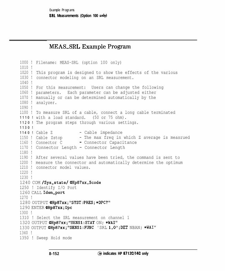
I- I -
Example Programs
SRL Measurements (Option 100 only)
1000 !1010 !1020 !1030 !1040 !1050 !1060 !1070 !1080 !1090 !1100 !1 1 1 0 !
1 1 2 0 !
1 1 3 0 !
1 1 4 0 !
1150 !1160 !1170 !1180 !1190 !1200 !1210 !1220 !1230 !
MEAS-SRL Example Program
1240 COM /Sys,state/ OHp87xx,Scode1250 ! Identify I/O Port1260 CALL Iden,port1270 !1280 OUTPUT QHp87xx;"SYST:PRES; *OPC?"1290 ENTER OHp87xx;Opc1300 !1310 ! Select the SRL measurement on channel 11320 OUTPUT QHp87xx;"SENSl:STAT ON; *WAI"1330 OUTPUT QHp87xx,*"SENSl:FUNC 'SRL 1,O';DET NBAN; *WAI"1340 !1350 ! Sweep Hold mode
Filename: MEAS-SRL (option 100 only)
This program is designed to show the effects of the variousconnector modeling on an SRL measurement.
For this measurement: Users can change the followingparameters. Each parameter can be adjusted eithermanually or can be determined automatically by theanalyzer.
To measure SRL of a cable, connect a long cable terminatedwith a load standard. (50 or 75 ohm).The program steps through various settings.
Cable Z - Cable impedanceCable Zstop - The max freq in which Z average is measruedConnector C - Connector CapacitanceConnector Length - Connector Length
After several values have been tried, the command is sent tomeasure the connector and automatically determine the optimumconnector model values.
8-152 @ indicates HP 8712Cl14C only
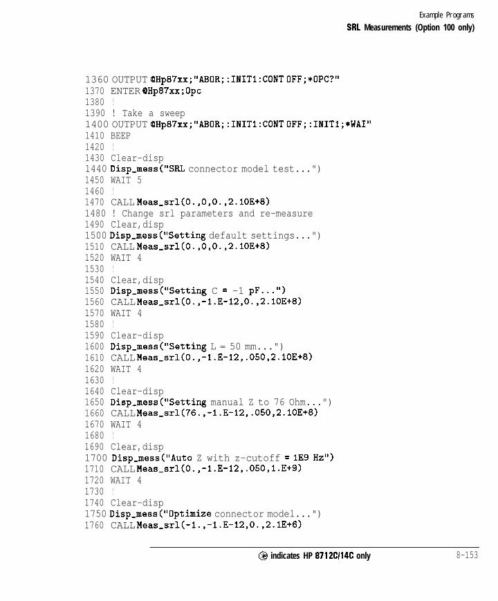
I- I -
Example Programs
SRL Measurements (Option 100 only)
1360 OUTPUT OHp87xx;"ABOR;:INITl:CONT OFF;*OPC?"1370 ENTER OHp87xx;Opc1380 !1390 ! Take a sweep1400 OUTPUT OHp87xx;"ABOR;:INITl:CONT OFF;:INITl;*WAI"1410 BEEP1420 !1430 Clear-disp1440 Disp-mess("SRL connector model test...")1450 WAIT 51460 !1470 CALL Meas-srl(0.,0,0.,2.1OE+8)1480 ! Change srl parameters and re-measure1490 Clear,disp1500 Disp-mess("Setting default settings...")1510 CALL Meas-srl(0.,0,0.,2.lOE+8)1520 WAIT 41530 !1540 Clear,disp1550 Disp-mess("Setting C = -1 pF...")1560 CALL Meas,srl(O.,-l.E-12,0.,2.lOE+8)1570 WAIT 41580 !1590 Clear-disp1600 Disp,mess("Setting L = 50 mm...")1610 CALL Meas-srl(O.,-l.E-12,.050,2.lOE+8)1620 WAIT 41630 !1640 Clear-disp1650 Disp,mess("Setting manual Z to 76 Ohm...")1660 CALL Meas-srl(76.,-l.E-12,.050,2.lOE+8)1670 WAIT 41680 !1690 Clear,disp1700 Disp,mess("Auto Z with z-cutoff = lE9 Hz")1710 CALL Meas-srl(O.,-l.E-12,.05O,l.E+9)1720 WAIT 41730 !1740 Clear-disp1750 Disp,mess("Optimize connector model...")1760 CALL Meas,srl(-l.,-l.E-12,0.,2.1E+6)
@ indicates HP 8712Cl14C only 8-153

I- I -
Example Programs
SRL Measurements (Option 100 only)
1770 WAIT 41780 !1790 Clear-disp1800 BEEP1810 END1820 !1830 SUB Meas,srl(REAL Z,REAL Cap,REAL Length,REAL Zstop)1840 COM /Sys-state/ QHp87xx,Scode -1850 DIM Msg$[80]1860 IF Z>=O THEN1870 WAIT 11880 OUTPUT OHp87xx;"SENSl:CORR:LENG:CONN "&VAL$(Length)1890 OUTPUT OHp87xx;"SENSl:CORR:CAP:CONN "tVAL$(Cap)1900 OUTPUT QHp87xx;"SENS:FREQ:ZST "tVAL$(Zstop)1910 IF Z>l. THEN1920 ! Set manual impedance mode1930 OUTPUT QHp87xx;"SENSl:FUNC:SRL:MODE MANUAL"1940 OUTPUT @Hp87xx,*"SENSl:FUNC:SRL:IMP "&VAL$(Z)1950 ELSE1960 ! Automatically measure the impedance1970 OUTPUT OHp87xx;"SENSl:FUNC:SRL:MODE AUTO"1980 END IF1990 ! Take a sweep2000 OUTPUT OHp87xx;"ABOR;:INITl:CONT OFF;:INITl;*OPC?"2010 ENTER OHp87xx;Opc2020 ELSE2030 ! Automatically determine the srl connector model2040 OUTPUT (PHp87xx; "SENSl:CORR:MODEL:CONN;*OPC?"2050 ENTER OHp87xx;Opc2060 END IF2070 BEEP2080 OUTPUT OHp87xx;"SENSl:CORR:LENG:CONN?"2090 ENTER OHp87xx;L2100 OUTPUT QHp87xx;"SENSl:CORR:CAP:CONN?"2110 ENTER OHp87xx;C2120 ! Read the impedance.2130 ! In AUTOMATIC-Z mode, the returned impedance is the measured Z.2140 ! In MANUAL Z mode, the returned impedance is the manually entered Z.2150 OUTPUT QHp87xx;"SENSl:FUNC:SRL:IMP?"2160 ENTER QHp87xx;Zmeas2170 Zmeas=DROUND(Zmeas,3)
8-154 @ indicates HP 87 12Cl14C only

I- I -
Example Programs
SRL Measurements (Option 100 only)
2180 Cnew=DROUND(C,3)2190 Lnew=DROUND(L,3)2200 Msg$="C="&VAL$(Cnew)t" F, L="&VAL$(Lnew)&" m, Z="&VAL$(Zmeas)&"
Ohm"2210 Clear-disp2220 Disp,mess(Msg$)2230 SUBEND2240 !2250 SUB Disp-mess(Message$)2260 COM /Sys,state/ QHp87xx,Scode2270 OUTPUT OHp87xx;"DISP:ANN:MESS:DATA '"tMessage$&""2280 SUBEND2290 !2300 SUB Clear-disp2310 COM /Sys-state/ OHp87xx,Scode2320 DIM Command$[4012330 OUTPUT OHp87xx;"DISP:ANN:MESS:CLE"2340 SUBEND2350 !2360 !**************************************************************2370 ! Iden,port: Identify io port to use.2380 ! Description: This routines sets up the I/O port address for2390 ! the SCPI interface. For "HP 87xx" instruments,2400 ! the address assigned to (SHp87xx = 800 otherwise,2410 ! 716.2420 !**************************************************************2430 SUB Iden,port2440 COM /Sys-state/ OHp87xx,Scode2450 !2460 IF POS(SYSTEM$("SYSTEM ID"),"HP 87")OO THEN2470 ASSIGN QHp87xx TO 8002480 Scode=82490 ELSE2500 ASSIGN OHp87xx TO 7162510 Scode=72520 END IF2530 !2540 SUBEND !Iden-port2550 !
@ indicates HP 8712Cl14C only 8-155

I- I -
Example Programs
SRL Measurements (Option 100 only)
SRL-SRQ Example Program
1000 !Filename: SRL-SRQ (option 100 only)1010 !1020 ! Description:1030 !1040 ! This example program demonstrates how to initiate an SRL1050 ! cable scan. The instrument is set-up to send a1060 ! SRQ interrupt when the scan has been completed.1070 !1080 ! Connect the cable to be tested to the RF out port on the1090 ! analyzer.1100 !1110 ! Set an SRQ to occur when the SRL scan is complete.1120 !1130 !1140 COM /Sys,state/ QHp87xx,Scode1150 ! Identify I/O Port1160 CALL Iden,port1170 !1180 !1190 ! Preset the instrument1200 OUTPUT OHp87xx;"SYST:PRES;*OPC?"1210 ENTER QHp87xx;Opc1220 !1230 ! Turn on SRL measurement1240 OUTPUT @Hp87xx,."SENSl:FUNC 'SRL 1,O';DET NBAN;*OPC?"1250 ENTER OHp87xx;Opc1260 !1270 ! Clear status registers.1280 OUTPUT OHp87xx;"*CLS"1290 !1300 ! Clear the Service Request Enable register.1310 OUTPUT OHp87xx;"*SRE 0"1320 !1330 ! Clear the Standard Event Status Enable register.1340 OUTPUT @Hp87xx;"*ESE 0"1350 !
8 - 1 5 6 @ indicates HP 8712CI14C only

I- I -
Example Programs
SRL Measurements (Option 100 only)
1360 ! Preset the remaining status registers.1370 OUTPUT OHp87xx;"STAT:PRES"1380 !1390 ! Set operation status register to report1400 ! to the status byte on NEGATIVE transition1410 ! the srl bit.1420 OUTPUT QHp87xx ;"STAT:OPER:ENAB 16"1430 OUTPUT (QHp87xx ;"STAT:OPER:MEAS:PTR #HOOOO"1440 OUTPUT QHp87xx ;"STAT:OPER:MEAS:NTR #HFFFF"1450 !1460 ! Set measuring status register to report to1470 ! operational status register on NEGATIVE transition1480 ! of the srl scan done bits. The NEGATIVE1490 ! transition needs to be detected because the1500 ! srl= bit 3 is set to 1 while the analyzer1510 ! is sweeping on channel 1 When the bit1520 ! goes back to 0, the srl scan is done.1530 OUTPUT OHp87xx;"STAT:OPER:MEAS:ENAB 4"1540 !1550 ! Enable the operational status bit in the status1560 ! byte to generate an SRq.1570 OUTPUT OHp87xx;"*SRE 128"1580 !1590 ! On an interrupt from HP-IB "Scode" (Interface1600 ! Select Code) SRq bit (2), branch to the interrupt1610 ! service routine "Srq,handler".1620 ON INTR Scode,2 GOSUB Srq-handler1630 !1640 ! Initialize flag indicating when srl scan done1650 ! to 0. Then loop continuously until the1660 ! interrupt is detected, and the interrupt1670 ! service routine acknowledges the1680 ! interrupt and sets the flag to 1.1690 !1700 Sri-done=01710 ! Now enable the interrupt on SRQ (Service Request).1720 ENABLE INTR Scode;21730 !1740 ! Initiate the SRL sweep1750 OUTPUT QHp87xx;"SENSl:FUNC:SRL:SCAN;*WAI"1760 !
@I indicates HP 8712Cl14C only 8-157

I- I -
Example Programs
SRL Measurements (Option 100 only)
1770 DISP "Waiting for SRQ on srl scan done.";1780 LOOP1790 DISP 'I.";1800 WAIT l! Slow down dots1810 EXIT IF Srl,done=l1820 END LOOP1830 !1840 ! Display desired completion message.1850 DISP1860 DISP "Got SRQ. SRL Scan!"1870 STOP1880 !1890 Srq-handler: ! Interrupt Service Routine1900 !1910 ! Determine that the analyzer was actually1920 ! the instrument that generated the1930 ! interrupt.1940 Stb=SPOLL(@Hp87xx)1950 !1960 ! Determine if the operation status register1970 ! caused the interrupt by looking at bit 71980 ! of the result of the serial poll.1990 IF BINAND(Stb,l28)00 THEN2000 !2010 ! Read the operational status event register.2020 OUTPUT QHp87xx;"STAT:OPER:EVEN?"2030 ENTER OHp87xx;Op,event2040 !2050 ! Determine if the srl status register2060 ! bit 4 is set.2070 IF BINAND(Op,event,lG)<>O THEN2080 !2090 ! If so, then set flag indicating2100 ! srl scan done.2110 Sri-done=12120 END IF2130 END IF2140 RETURN2150 END2160 !
8-158 @ indicates HP 8712C114C only

I- I -
Example Programs
SRL Measurements (Option 100 only1
2170 !**************************************************************
2180 ! Iden,port: Identify io port to use.2190 ! Description: This routines sets up the I/O port address for2200 ! the SCPI interface. For "HP 87xx" instruments,2210 ! the address assigned to QHp87xx = 800 otherwise,2220 ! 716.2230 !**************************************************************
2240 SUB Iden,port2250 COM /Sys,state/ QHp87xx,Scode2260 !2270 IF POS(SYSTEM$("SYSTEM ID~~>,I~HP 87")oo THEN2280 ASSIGN (QHp87xx TO 8002290 Scode=82300 ELSE2310 ASSIGN QHp87xx TO 7162320 Scode=72330 END IF2340 !2350 SUBEND !Iden,port2360 !
@indicates HP 8712C114C only 8-159
I-

I- I -
Fault Location Measurements (Option 100 only)
FAULT
USR-FLOC
This programs shows the effects of various fault locationfrequency modes on a cable measurement.
This program shows how to simplify fault locationmeasurements by using the User BEGIN key. (You musthave Option lC2, IBASIC, to use the User BEGIN key.)
S-160 @ indicates HP 8712Cl14C only

I- I -
Example Programs
Fault location Measurements (Option 100 only)
1000 !1010 !1020 !1030 !1040 !1050 !1060 !1070 !1080 !1090 !1100 !1 1 1 0 !
1120 !1130 !1140 !1150 !1160 !1170 !1180 !1190 !1200 !1210 !1220 !1230 !1240 !
FAULT Example Program
Filename: FAULT (Option 100 only)
This program is designed to show the affects of the variousfault location frequency modes on a cable measurement.
Connect a 50 m. (150ft) cable to the RF out of the analyzer.(if available).
The program steps through various settings.
Set Feet/MetersStart Distance 0 metersStop Distance 100 metersLow Pass modeBand Pass mode CF = 600 MHzBand Pass mode CF = 900 MHzLow Pass modeCable LossCable Velocity Factor
The commands which cause changes to frequency settings willcause the analyzer to automatically display a caution messageto verify Cable Loss and Velocity Factor.
1250 COM /Sys-state/ OHp87xx,Scode1260 ! Identify I/O Port1270 CALL Iden,port1280 !1290 ! Preset the analyzer1300 OUTPUT QHp87xx;"SYST:PRES; *OPC?"1310 ENTER OHp87xx;Opc1320 !1330 ! Enable fault location measurment on channel 11340 OUTPUT QHp87xx;"SENSl:STAT ON; *WAI"1350 OUTPUT QHp87xx,*"SENSl:FUNC 'FLOC 1,O';DET NBAN; *OPC?"
@ indicates HP 8712CI14C only 8 - 1 6 1

I- I -
Example Programs
Fault location Measurements (Option 100 only)
1360 ENTER QHp87xx;Opc1370 WAIT 21380 !1390 ! Autoscale the fault measurment1400 OUTPUT OHp87xx;"DISP:WINDl:TRAC:Y:AUTO ONCE"1410 !1420 Clear-disp1430 Disp,mess("Fault Location Demo...")1440 WAIT 31450 !1460 ! Reset the cable loss and velocity factor1470 OUTPUT (QHp87xx;" SENSl:CORR:LOSS:COAX .O"1480 OUTPUT QHp87xx;"SENSl:CORR:RVEL:COAX 1."1490 !1500 Clear-disp1510 Disp,mess("Setting units to Meters")1520 !1530 ! Set the units to read in METERS1540 OUTPUT @Hp87xx;"SENS:DIST:UNIT MET"1550 !OUTPUT QHp87xx;"SENS:DIST:UNIT FEET" ! Display units in feet1560 WAIT 51570 !1580 !1590 Clear,disp1600 Disp-mess("Setting Start and Stop Distance")1610 !1620 ! Set the start distance to 0.1630 OUTPUT OHp87xx;"SENSl:DIST:STAR 0; *WAI"1640 !1650 ! Set the stop distance to 100.1660 OUTPUT @Hp87xx;"SENSl:DIST:STOP 100; *WAI"1670 !1680 ! Send an operation complete query to ensure that1690 ! all overlapped commands have been executed.1700 OUTPUT OHp87xx;"*OPC?"1710 !1720 ! Wait for the reply.1730 ENTER OHp87xx;Opc1740 !1750 WAIT 101760 !
8-162 @I indicates HP 8712C114C only
-I-

I- I -
Example Programs
Fault location Measurements (Option 100 only)
1770 ! Change to Band pass mode1780 OUTPUT (PHp87xx;" SENS:FREQ:MODE CENT; *WAI"1790 !1800 Clear,disp1810 Disp-mess("Setting CF to 600 MHz. Band Pass")1820 !1830 ! Set Center Frequency to 600 MHz1840 OUTPUT OHp87xx;"SENSl:FREQ:CENT 600000000 HZ;*WAI"1850 WAIT 101860 !1870 Clear,disp1880 Disp,mess("Setting CF to 900 MHz. Band Pass")1890 !1900 ! Set Center Frequency to 900 MHz1910 OUTPUT @Hp87xx;"SENSl:FRED:CENT 900000000 HZ;*WAI"1920 WAIT 101930 !1940 Clear,disp1950 Disp-mess("Return to Low Pass Mode")1960 !1970 ! Return to Low Pass Mode1980 OUTPUT QHp87xx;" SENS:FREQ:MODE LOWP; *WAI"1990 WAIT 102000 !2010 Clear-disp2020 Disp,mess("Set Cable Loss to lOdB/lOO ft")2030 OUTPUT (QHp87xx; "SENSl:CORR:LOSS:COAX 10.0"2040 WAIT 102050 !2060 Clear-disp2070 Disp-mess("Set Velocity factor to .8">2080 OUTPUT OHp87xx;"SENSl:CORR:RVEL:COAX .8"2090 WAIT 102100 !2110 Clear,disp2120 Disp-mess("Set Cable Loss=O., VF=l.O")2130 OUTPUT OHp87xx;"SENSl:CORR:LOSS:COAX .O"2140 OUTPUT OHp87xx;"SENSl:CORR:RVEL:COAX 1."2150 WAIT 102160 !2170 DISP "Done"
&I indicates HP 8712Cl14C only 8 - 1 6 3
-

I- I -
Example Programs
Fault location Measurements (Option 100 only)
2180 BEEP2190 END2200 !2210 SUB Disp-mess(Message$)2220 COM /Sys-state/ OHp87xx,Scode2230 OUTPUT OHp87xx;"DISP:ANN:MESS:DATA "'&Message$&"'"2240 SUBEND2250 !2260 SUB Clear-disp2270 COM /Sys-state/ OHp87xx,Scode2280 DIM Command$[4012290 OUTPUT OHp87xx;"DISP:ANN:MESS:CLE"2300 SUBEND2310 !2320 !**************************************************************2330 ! Iden-port: Identify io port to use.2340 ! Description: This routines sets up the I/O port address for2350 ! the SCPI interface. For "HP 87xx" instruments,2360 ! the address assigned to (QHp87xx = 800 otherwise,2370 ! 716.2380 !**************************************************************2390 SUB Iden,port2400 COM /Sys,state/ QHp87xx,Scode2410 !2420 IF POS(SYSTEM$("SYSTEM ID">,"HP 87")OO THEN2430 ASSIGN OHp87xx TO 8002440 Scode=82450 ELSE2460 ASSIGN QHp87xx TO 7162470 Scode=72480 END IF2490 !2500 SUBEND !Iden-port2510 !
8-164 @ indicates HP 8712C114C only

I- I -
Example Programs
Fault location Measurements (Option 100 only)
USR-FLOC Example Program
10 ! -----------------------------------------------------------20 !30 ! BASIC program: USR,FLOC40 !50 ! Fault Location measurements require option 100.60 ! User BEGIN requires option lC2, IBASIC.70 !80 !90 ! This is an example user BEGIN program for fault location.100 !110 ! Load this program into the analyzer. Then press [BEGIN]120 ! [User BEGIN ON].130 !140 ! The following line is required. DO NOT REMOVE!150 User,begin:ASSIGN (ORfna TO 800 ! [User Begin] Program160 ASSIGN QHp8712 TO 800170 !180 ! To Modify:190 ! Use [IBASICICEDITI or CIBASIClCKey Record]200 !210 !220 ! Declare storage for variables.230 DIM Name$[6O],Strl$[6O],Str2$[6O],Str3$[60]240 !250 ! Clear the softkey labels260 OUTPUT ORfna;"DISP:MENU2:KEY8 ";*WAI"270 !280 ! Re-define softkey labels here.290 OUTPUT @Rfna;"DISP:MENU2:KEYl 'Test End of Cable';*WAI"300 OUTPUT QRfna;"DISP:MENU2:KEY2 '*';*WAI"310 OUTPUT QRfna;"DISP:MENU2:KEY3 'Mkr -> Max';*WAI"320 OUTPUT ORfna;"DISP:MENU2:KEY4 'Next Peak Left';*WAI"330 OUTPUT ORfna;"DISP:MENU2:KEY5 'Next Peak Right';*WAI"340 OUTPUT ORfna;"DISP:MENU2:KEY6 'Zoom on Marker';*WAI"350 OUTPUT QRfna;"DISP:MENU2:KEY7 '*';*WAI"360 !
@ indicates HP 8712CI14C only 8 - 1 6 5

I -
Example Programs
Fault location Measurements (Option 100 only)
370 !The following 2 lines are required. DO NOT REMOVE!380 User-pause:PAUSE390 GOT0 User-pause400 !410 User-keyl: ! Example Set Stop Distance to 1lOOft420 OUTPUT QHp8712;"SENSl:STAT ON; *WAI"430 OUTPUT OHp8712;"SENSl:FUNC 'FLOC 1,O';DET NBAN; *WAI"440 OUTPUT OHp8712;"SENSl:DIST:STOP 1100; *opt?"450 ENTER QHp8712;Opc460 OUTPUT OHp8712;"SENSl:CORR:RVEL:COAX 0.89"470 OUTPUT OHp8712;"DISP:WINDl:TRAC:Y:AUTO ONCE"480 GOT0 User-pause490 !500 User-key2: ! Define softkey 2 here.510 GOSUB Message ! Remove this line520 GOT0 User-pause530 !540 User-key3: ! Example Marker Function550 OUTPUT QRfna;"CALCl:MARKl ON"560 OUTPUT ORfna;"CALCl:MARK:FUNC MAX"570 GOT0 User-pause580 !590 User-key4: ! Define softkey 6 here.600 OUTPUT ORfna;"CALCl:MARKl ON"610 OUTPUT OHp8712;"CALCl:MARK:MAX:LEFT"620 GOT0 User-pause630 !640 User-key5: ! Define softkey 5 here.650 OUTPUT OHp8712;"CALCl:MARKl ON"660 OUTPUT OHp8712;"CALCl:MARK:MAX:RIGHT"670 GOT0 User-pause680 !690 User,key6: ! Zoom on Cable700 OUTPUT OHp8712;"SENSl:STAT ON; *WAI"710 OUTPUT OHp8712;"SENSl:FUNC 'FLOC 1,O';DET NBAN; *WAI"720 OUTPUT QHp8712;"calcl:markl:x?"730 ENTER 9Hp8712;Distance740 New-start=Distance-20750 IF (New,start<O) THEN New-start=0760 OUTPUT OHp8712;"sensl:dist:start "&VAL$(New-start)770 OUTPUT OHp8712;"sensl:dist:stop "tVAL$(Distance+20)
8 - 1 6 6 @ indicates HP 8712Cl14C only

I- I -
Example Programs
Fault location Measurements (Option 100 only)
780 OUTPUT QHp8712;"*opc?"790 ENTER QHp8712;Opc8 0 0 GOT0 User-pause810 !820 User,key7: ! Define softkey 7 here.8 3 0 GOSUB Message ! Remove this line.8 4 0 GOT0 User-pause8 5 0 !8 6 0 Message: !8 7 0 Strl$="This key is programmable."8 8 0 Str2$="To modify, select"890 Str3$="[System Options], [IBASIC], [Edit]."900 OUTPUT QRfna;"DISP:ANN:MESS
"'&Str1$&CHR$(10>&Str2$&CHR$(10~&Str3$&"', MEDIUM"910 RETURN920 !930 END
@ indicates HP 8712Cl14C only 8 - 1 6 7
-

I- I -
Multiport Test Set Measurements
PORT-SEL
TSET-CAL
Using graphics to show internal connectionsof the HP 87075C when different ports areselected.
Recalling “TSET-CAL.CAL” and performinga test set calibration.
8-168 @ indicates HP 8712Cl14C only

I- I -
Example Programs
Multiport Test Set Measurements
PORT-SELection Example Program
This program displays the internal connections of the HP 87075C multiporttest set when different ports are selected. The internal connections of themultiport test set are drawn on the IBASIC display. Whenever the userselects a different port on the multiport test set, the program will redraw theinternal connections.
This program also demonstrates how to use BASIC to draw a fairlycomplicated drawing on the network analyzer.
N O T E
This program only works with the HP 8707X multiport test set and IBASIC, Option lC2.
1000 ! Filename: PORT,SEL, 87075 Port Selection Example1010 !1020 ! Description:1030 ! This program demonstrate how the internal connections of 870751040 ! are carried out when the different ports for Reflection and1050 ! Transmission are selected. It intends to show as an example1060 ! of how to select the 87075 ports and how to draw draw graphics1070 ! on the IBASIC window.1080 !1090 !1100 ! NOTE: This program works properly ONLY1110 ! when option lC2, IBASIC, has been installed.1120 ! Modify to use DISP:WIND”;VAL$(Wind);” if no IBASIC option. I1130 !1140 !1150!---------------------------------- --------------------------------------
1160 ! Common Variables1170 COM /Sys,state/ OHp87xx,Scode,Keycode,Wind
@ indicates HP 8712Cl14C only 8-169

I- I -
Example Programs
Multiport Test Set Measurements
1180 COM /Hp87ll,coord/Orig~x,8711,0rig~y~87ll,Refl~x~87ll,Refl~y~87ll,Tr~~x~87llJTran-y-8711
1190 COM /Hp87075_coord/Orig~x~87075,0rig,y~87O75,Refl~x~87O75,Refl~y~87O75JTr~~x~87O75,Tran,y-87075
1200 COM /Hp87075_ports/ Port,x(l:12),Port,y(l:l2)1210 COM /Color/ Erase,Bright,Dim1220 COM /Sys-var/ Refl-port,Tran-port1230I-----------,,,,-------- - - - - - - - - - - - - - - - - - - - - - - - - - - - - - - - - - - - - - - - - - - - - - - - - -
1240 ! Identify I/O Port1250 CALL Iden-port1260 !1270 OUTPUT QHp87xx;"SYST:PRES; *WAI" ! Preset the system1280 CALL Setup-constant1290 !1300 ! Allocate an IBASIC display partition to show the graphics1310 !1320 OUTPUT OH~~~XX;"CONT~:~MULT:STATE ON" ! Make sure 87075 mode is
enabled1330 OUTPUT QHp87xx;"DISP:FORM SING"1340 OUTPUT QHp87xx;"DISP:PROG:MODE FULL"1350 OUTPUT (PHp87xx;" DISP:WIND";VAL$(Wind);":GRAP:SCAL 0,1023,0,383"1360 !1370 ! Clear the IBASIC display partition.1380 OUTPUT OHp87xx;"DISP:WIND";VAL$(Wind);":GRAP:CLE'1390 !1400 CALL Draw-analyzer1410 CALL Draw-870751420 !1430 ! Connect HP8711 to HP87075 for the Refl and Tran ports1440 CALL Connect(Refl~x~8711,Refl,y,87ll,Refl_x_87O75,Refl~y~87O75,Bright~1450 CALL Connect(Tran,x,87ll,Tran_y_87ll,Tran,x_8~y~87075,Bright~1460 CALL Set-refl(1)1470 CALL Set-tran(2)1480 !1490 ! Infinite loop to wait for softkey requests1500 Do-loop:!1510 GOSUB Setup-srq1520 !
B-170 @3 indicates HP 87 12Cl14C only

I- I -
Example Programs
Multiport Test Set Measurements
1530 GOT0 Do-loop1540 STOP1550 !1560 !-------------------------------- ________-----------------------------
1570 ! Setup interrupts1580 !1590 Setup,srq:!1600 ! If using an external controller...1610 !1620 ! Initialize flag for checking on keyboard1630 ! interrupts.1640 Keycode=-l1650 !1660 ! Label softkey 1.1670 OUTPUT OHp87xx,*"DISP:MENU:KEYl 'Reflection to Port t'"1680 OUTPUT QHp87xx;"DISP:MENU:KEY2 'Transmissn to Port t"'1690 OUTPUT OHp87xx;"DISP:MENU:KEYS 'Done"'1700 !1710 ! Clear the status register and event status1720 ! register.1730 OUTPUT QHp87xx;"*CLS;*ESE 0"1740 ! Preset the other status registers.1750 ! Enable the Device Status register to report1760 ! to the Status Byte on positive transition1770 ! of bit 0 (key press). Enable the Status1780 ! Byte to generate an interrupt when the1790 ! Device Status register's summary bit1800 ! changes.1810 OUTPUT QHp87xx;"STAT:PRES;DEV:ENAB l;*SRE 4"1820 !1830 ! Clear the key queue to ensure that previous1840 ! key presses do not generate an interrupt.1850 OUTPUT OHp87xx;"SYST:KEY:DUE:CLE"1860 !1870 ! Set up and enable the interrupt on the HP-IB1880 ! when a service request is received.1890 ON INTR Scode,S RECOVER Srq1900 ENABLE INTR Scode;21910 Suspend: !WAIT 5 ! Use WAIT 'n' to suspend IBASIC1920 GOT0 Suspend1930 !
!$$! indicates HP 87 12C114C only 8-171
-
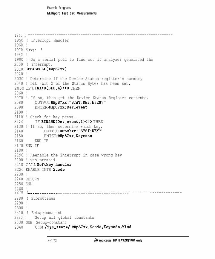
I- I -
Example Programs
Multiport Test Set Measurements
1940 ! ------------------------------------------------------------------1950 ! Interrupt Handler1960 !1970 Srq: !1980 !1990 ! Do a serial poll to find out if analyzer generated the2000 ! interrupt.2010 Stb=SPOLL(OHp87xx)2020 !2030 ! Determine if the Device Status register's summary2040 ! bit (bit 2 of the Status Byte) has been set.2050 IF BINAND(Stb,4)<>0 THEN2060 !2070 ! If so, then get the Device Status Register contents.2080 OUTPUT OHp87xx;"STAT:DEV:EVEN?"2090 ENTER @Hp87xx;Dev_event2100 !2110 ! Check for key press...2 1 2 0 IF BINAND(Dev,event,l)<>O THEN2130 ! If so, then determine which key.2140 OUTPUT OHp87xx;"SYST:KEY?"2150 ENTER OHp87xx;Keycode2160 END IF2170 END IF2180 !2190 ! Reenable the interrupt in case wrong key2200 ! was pressed.2210 CALL Softkey-handler2220 ENABLE INTR Scode2230 !2240 RETURN2250 END2260 !2270 ! ____________________-----------------------------------------------2280 ! Subroutines2290 !2300 !2310 ! Setup-constant2320 ! Setup all global constants2330 SUB Setup-constant2340 COM /Sys-state/ OHp87xx,Scode,Keycode,Wind
8-172 @ indicates HP 8712C114C only
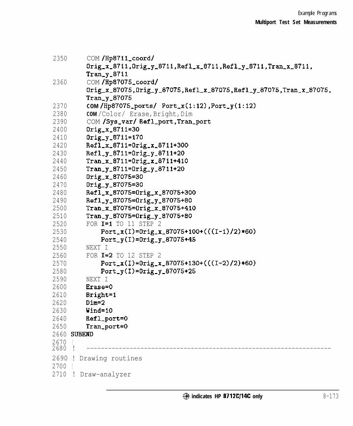
I- I -
Example Programs
Multiport Test Set Measurements
2350
2360
23702380239024002410242024302440245024602470248024902500251025202530254025502560257025802590260026102620263026402650
COM /Hp87ll,coord/Orig,x,87ll,Orig~y~87llJRefl~x~87ll,Refl~y~87ll,Tr~~x~87ll,Tran,y-8711COM /Hp87075,coord/0rig~x~87075,0rig~y~87075,Ref1~x~87075,Ref1~y~87075,Tr~~x~87075,Tran-y-87075COM /Hp87075,ports/ Port,x(l:l2),Port,y(l:l2)COM /Color/ Erase,Bright,DimCOM /Sys,var/ Refl,port,Tran-portOrig-x-8711=30Orig,y-8711=170Refl,x,8711=0rig-x-8711+300Refl,y-87ll=Orig-y-8711+20Tran-x-8711=0rig,x,8711+410Tran,y,8711=0rig-y-8711+20Orig-x-87075=30Orig-y-87075=30Refl,x,87075=0rig,x,87075+300Refl-y-87075=0rig,y-87075+80Tran-x-87075=0rig-x-87075+410Tran-y-87075=0rig,y-87075+80FOR I=1 TO 11 STEP 2
Port,x(I)=Orig,x-87075+100+(((1-1)/2)*60)Port-y(I)=Orig-y-87075+45
NEXT IFOR I=2 TO 12 STEP 2
Port,x(I)=Orig,x,87075+130+(((1-2)/2)*60)Port-y(I)=Orig-y-87075+25
NEXT IErase=0Bright=1Dim=2Wind=10Refl-port=0Tran-port=0
2660 SUBEND2670 !2680 ! --------------------------------------------------------------------2690 ! Drawing routines2700 !2710 ! Draw-analyzer
@ indicates HP 8712Cl14C only 8-173
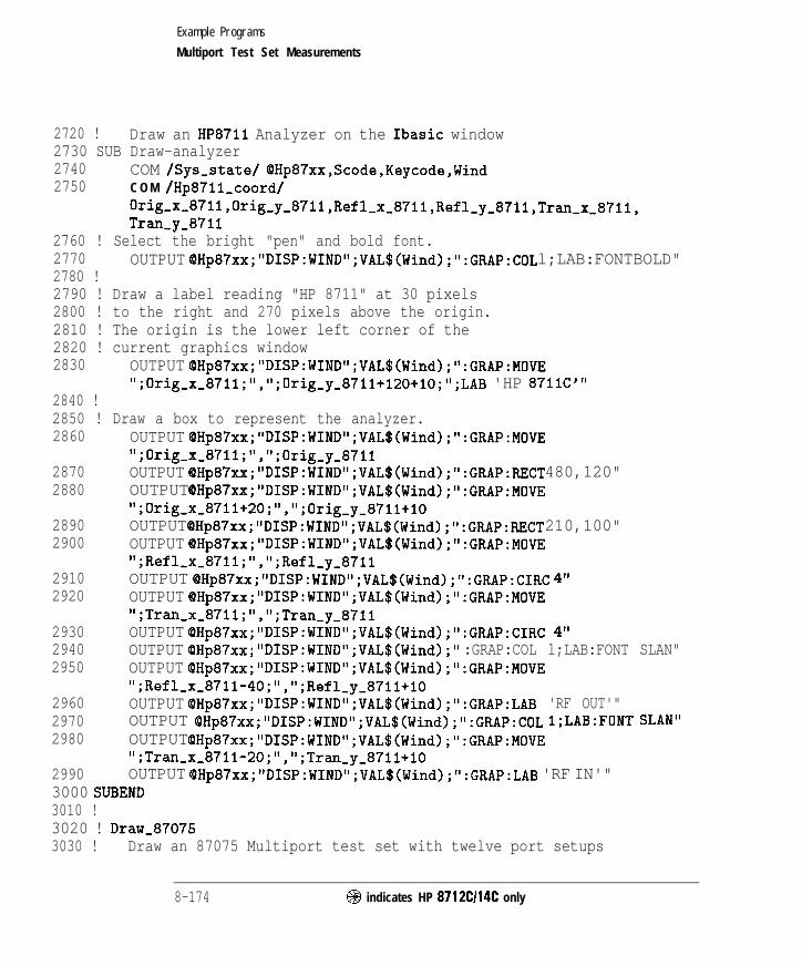
I- I -
Example Programs
Multiport Test Set Measurements
2720 ! Draw an HP8711 Analyzer on the Ibasic window2730 SUB Draw-analyzer2740 COM /Sys-state/ OHp87xx,Scode,Keycode,Wind2750 C O M /Hp87ll,coord/
Orig,x,87ll,Orig~y,87ll,Refl~x~87llJRefl~y~87ll,Tr~~x~87ll,Tran,y-8711
2760 ! Select the bright "pen" and bold font.2770 OUTPUT QHp87xx; "DISP:WIND";VAL$(Wind);":GRAP:COL l;LAB:FONT BOLD"2780 !2790 ! Draw a label reading "HP 8711" at 30 pixels2800 ! to the right and 270 pixels above the origin.2810 ! The origin is the lower left corner of the2820 ! current graphics window2830 OUTPUT (OHp87xx; "DISP:WIND";VAL$(Wind);":GRAP:MOVE
";Orig-x-8711;","; Orig-y_8711+120+10;";LAB 'HP 871lC"'2840 !2850 ! Draw a box to represent the analyzer.2860 OUTPUT OHp87xx;" DISP:WIND";VAL$(Wind);":GRAP:MOVE
";Orig-x,87ll;",";Orig_y,87112870 OUTPUT OHp87xx; "DISP:WIND";VAL$(Wind);":GRAP:RECT 480,120"2880 OUTPUT OHp87xx;"DISP:WIND";VAL$(Wind);":GRAP:MOVE
";0rig,x,8711+20;",";0rig_y_8711+102890 OUTPUT QHp87xx;"DISP:WIND";VAL$(Wind);":GRAP:RECT 210,100"2900 OUTPUT (PHp87xx; "DISP:WIND“;VAL$(Wind);":GRAP:MOVE
";Refl,x-87ll;",";Refl,y,87112910 OUTPUT QHp87xx;"DISP:WIND";VAL$(Wind);":GRAP:CIRC 4"2920 OUTPUT OHp87xx; "DISP:WIND";VAL$(Wind);":GRAP:MOVE
";Tran-x-87ll;",";Tran~y~87112930 OUTPUT (OHp87xx;" DISP:WIND";VAL$(Wind);":GRAP:CIRC 4"2940 OUTPUT (PHp87xx; "DISP:WIND";VAL$(Wind);" :GRAP:COL l;LAB:FONT SLAN"2950 OUTPUT QHp87xx;" DISP:WIND";VAL$(Wind);":GRAP:MOVE
";Ref1-x-8711-40;",";Refl_y_87ll+lO2960 OUTPUT OHp87xx;" DISP:WIND";VAL$(Wind);":GRAP:LAB 'RF OUT'"2970 OUTPUT QHp87xx;"DISP:WIND";VAL$(Wind);":GRAP:COL 1;LAB:FONT SLAN"2980 OUTPUT OHp87xx;"DISP:WIND";VAL$(Wind);":GRAP:MOVE
";Tran-x,8711-20;",";Tran_y_8711+102990 OUTPUT QHp87xx;"DISP:WIND";VAL$(Wind);":GRAP:LAB 'RF IN'"3000 SUBEND3010 !3020 ! Draw-870753030 ! Draw an 87075 Multiport test set with twelve port setups
8-174 @ indicates HP 8712Cl14C only

I- I -
Example Programs
Multiport Test Set Measurements
3040 SUB30503060
3070!3080
30903100311031203130314031503160
Draw-87075COM /Sys,state/ OHp87xx,Scode,Keycode,WindCOM /Hp87075_coord/0rig~x~87075,0rig~y~87075,Ref1~x~87075,Ref1~y~87075,Tr~~x~87075,Tran-y-87075COM /Hp87075_ports/ Port-x(l:l2),Port,y(l:l2)
Select the bright "pen" and bold font.OUTPUT QHp87xx;"DISP:WIND";VAL$(Wind);":GRAP:COL 1;LAB:FONT BOLD"
Draw a label reading "HP 87075" at 30 pixelsto the right and 110 pixels above the origin.The origin is the lower left corner of thecurrent graphics windowOUTPUT OHp87xx;"DISP:WIND";VAL$(Wind);":GRAP:MOVE";Orig-x,87075;"," ;Orig,y-87075+100+10;";LAB 'HP 87075"'
31703180
31903200
32103220
323032403250
326032703280
329033003310
33203330
3340
!
OUTPUT OHp87xx;"DISP:WIND";VAL$(Wind);":GRAP:MOVE";Orig-x-87075;",";Orig_y_87075OUTPUT QHp87xx;"DISP:WIND";VAL$(Wind);":GRAP:RECT 480,110"OUTPUT OHp87xx;"DISP:WIND";VAL$(Wind);":GRAP:MOVE";Refl,x,87075;",";Refl_y_87075OUTPUT QHp87xx;"DISP:WIND";VAL$(Wind);":GRAP:CIRC 4"OUTPUT OHp87xx;"DISP:WIND";VAL$(Wind);":GRAP:MOVE";Tran-x-87075;",";Tran-y-87075OUTPUT OHp87xx;"DISP:WIND";VAL$(Wind);":GRAP:CIRC 4"OUTPUT OHp87xx;"DISP:WIND";VAL$(Wind);":GRAP:COL l;LAB:FONT SLAN"OUTPUT OHp87xx;"DISP:WIND";VAL$(Wind);":GRAP:MOVE";Ref1,x-87075-40;",";Ref1_y_87075+10OUTPUT QHp87xx;"DISP:WIND";VAL$(Wind);":GRAP:LAB 'REFLY"OUTPUT QHp87xx;"DISP:WIND";VAL$(Wind);":GRAP:COL l;LAB:FONT SLAN"OUTPUT OHp87xx;"DISP:WIND";VAL$(Wind);":GRAP:MOVE";Tran,x,87075-2O;",";Tran,y,87075+10OUTPUT QHp87xx;"DISP:WIND";VAL$(Wind);":GRAP:LAB 'TRAN"'FOR I=1 TO 12
OUTPUT OHp87xx;"DISP:WIND";VAL$(Wind);":GRAP:MOVE";Port-x(I);",";Port,y(I)OUTPUT OHp87xx;"DISP:WIND";VAL$(Wind);":GRAP:CIRC 4"OUTPUT QHp87xx;"DISP:WIND";VAL$(Wind);":GRAP:COL 1;LAB:FONTSLAN"OUTPUT QHp87xx;"DISP:WIND";VAL$(Wind);":GRAP:MOVE
@ indicates HP 87 12Cl14C only 8 - 1 7 5

I- I -
Example Programs
Multiport Test Set Measurements
";Port,x(I)-8;",";Port,y(Ij-183350 OUTPUT OHp87xx;"DISP:WIND";VAL$(Wind);":GRAP:LAB "';VAL$(I);""'3360 NEXT I3370 SUBEND3380 !3 3 9 034003410342034303440
--------------------------------------------------------------------
Connection routines
ConnectConnect (xl,yl) to (x2,y2) with the specied color 'Cal'If Color = 0, it will be an erase command instead.
3450 SUB Connect(Xl,Yl,X2,Y2,Col)3460 COM /Sys-state/ OHp87xx,Scode,Keycode,Wind3470 OUTPUT OHp87xx;"DISP:WIND";VAL$(Wind);":GRAP:COL ";Col3480 OUTPUT OHp87xx;~~DISP:WIND";VAL$(Wind);":GRAP:MOVE ";Xl;",";Yl3490 OUTPUT OH~~~XX;~'DISP:WIND";VAL$(W~~~);":GRAP:DRAW ";X2;",";Y23500 SUBEND3510 !3520 ! Connect-refl3530 ! Connect the reflection port to the specified port index I with3540 ! color 'Cal'. Use Col=O to erase the connection. This routine3550 ! uses the port coordinates from Port-x(1:12) and Port-y(l:l2)3560 SUB Connect,refl(I,Col)3570 COM /Sys-state/ QHp87xx,Scode,Keycode,Wind3580 COM /Hp87ll,coord/
Orig~x~8711,0rig~y~87ll,Refl~x~87ll,Refl~y~87ll,Tr~~x~87ll,Tran-y-8711
3590 COM /Hp87075_coord/0rig,x,87075,0rig~y~87075,Ref1~x~87075,Ref1~y~87075,Tr~~x~87075,Tran-y-87075
3600 COM /Hp87075,ports/ Port-x(l:12),Port-y(l:l2)3610 !3620 Temp,y=Refl-y-87075-103630 Connect(Ref1,x,87075,Refl_y_87075,Refl~x~87O75,Temp~y,Col~3640 Connect(Refl-x-87075,Temp,y,Port-x(I),Temp-y,Col)3650 Connect(Port,x(I),Temp-y,Port-x(I),Port,y(I),CoI)3660 SUBEND3670 !3680 !3690 ! Connect-tran3700 ! Connect the transmission port to the specified port index I with
8 - 1 7 6 @ indicates HP 8712Cl14C only

I -
Example Programs
Multiport Test Set Measurements
3710 ! color 'Cal'. Use Col=O to erase the connection. This routine3720 ! uses the port coordinates from Port-x(1:12) and Port,y(l:l2)3730 SUB Connect,tran(I,Col)3740 COM /Sys,state/ OHp87xx,Scode,Keycode,Wind3750 COM lHp87ll_coord/
Orig,x~871l,0rig~y~87ll,Refl~x~87ll,Refl~y~87ll,Tr~~x~87ll,Tran,y-8711
3760 COM /Hp87075,coord/0rig,x~87075,0rig,y,87075,Ref1~x~87075,Ref1~y~87075,Tr~~x~87075,Tran-y-87075
3770 COM /Hp87075_ports/ Port,x(l:l2),Port,y(l:l2)3780 !3790 Temp-y=Refl,y,87075-203800 Connect(Tran_x_87075,Tran_y_87075,Tran_x-y,Col)3810 Connect(Tran-x-87075,Temp-y,Port-x(I),Temp-y,Col)3820 Connect(Port,x(I),Temp-y,Port-x(I),Port,y(I),Col)3830 SUBEND3840 !3850 ! __________-------___------------------------------------------------3860 ! Softkey handle routines3870 !3880 ! Select-refl3890 ! Select the reflection port by requesting a valid port number from3900 ! the user. The input port number is used to select the reflection3910 ! port accordingly. This routine will also update the drawing3920 ! connections on the Ibasic window. Any invalid number will be3930 ! ignored.3940 SUB Select-refl3950 COM /Sys,state/ OHp87xx,Scode,Keycode,Wind3960 COM /Hp87ll_coord/
Orig~x,8711,0rig~y~87ll,Refl~x~87ll,Refl~y~87ll,Tr~~x~87ll,Tran,y-8711
3970 COM /Hp87075_coord/Orig~x,87075,0rig~y,87075,Refl~x~87075,Refl~y~87O75,Tr~~x~87O75,Tran-y-87075
3980 COM /Color/ Erase,Bright,Dim3990 COM /Sys,var/ Refl,port,Tran,port4000 !4010 OUTPUT OHp87xx;"DISP:WIND";VAL$(Wind);":GRAP:COL ";Bright4020 OUTPUT OHp87xx;"*OPC?"4030 ENTER OHp87xx;Opc
@ indicates HP 8712C114C only 8-177

Example Programs
Multiport Test Set Measurements
4040 INPUT "Connect Reflection to Port #:",P4050 CALL Set-refl(P)4060 SUBEND4070 !4080 !4090 ! Set-refl4100 ! Update the currently selected reflection port with the specified4110 ! port 'P'. Update the connection drawing on the Ibasic window.4120 SUB Set-refl(P)4130 COM /Sys,state/ OHp87xx,Scode,Keycode,Wind4140 COM /Hp87ll_coord/
Orig~x~87ll,Orig~y~87ll,Refl~x~87ll,Refl~y~87ll,Tr~~x~87ll,Tran-y-8711
4150 COM /Hp87075_coord/0rig~x~87075,0rig~y~87075,Ref1~x~87075,Ref1~y~87075,Tr~~x~87075,Tran-y-87075
4160 COM /Color/ Erase,Bright,Dim4170 COM /Sys,var/ Refl,port,Tran-port4180 !4190 OUTPUT QHp87xx;"ROUT:REFL:PATH:DEFine:PORT ";P4200 OUTPUT QHp87xx;"ROUT:REFL:PATH:DEFine:PORT?"4210 ENTER OHp87xx;New,refl4220 OUTPUT OHp87xx;"ROUT:TRAN:PATH:DEFine:PORT?"4230 ENTER OHp87xx;New-tran4240 Update-ports(New-refl,New-tran)4250 SUBEND4260 !4270 !4280 !4290 ! Select-tran4300 ! Select the transmission port by requesting a valid port number from4310 ! the user. The input port number is used to select the transmission4320 ! port accordingly. This routine will also update the drawing4330 ! connections on the Ibasic window. Any invalid number will be4340 ! ignored.4350 SUB Select-tran4360 COM /Sys-state/ QHp87xx,Scode,Keycode,Wind4370 COM /Hp87ll_coord/
Orig~x~8711,0rig,y,87ll,Refl~x~87ll,Refl~y~87ll,Tr~~x~87ll,Tran,y-8711
4380 COM /Hp87075,coord/
8 - 1 7 8 @I indicates HP 8712Cl14C only

I- I -
Example Programs
Multiport Test Set Measurements
0rig,x,87075,0rig~y~87075,Ref1~x~87075,Ref1~y~87075,Tr~~x~87075,Tran-y-87075
4390 COM /Color/ Erase,Bright,Dim4400 COM /Sys,var/ Refl-port,Tran,port4410 !4420 OUTPUT QHp87xx;"DISP:WIND";VAL$(Wind);":GRAP:COL ";Bright4430 OUTPUT QHp87xx;"*OPC?"4440 ENTER OHp87xx;Opc4450 INPUT "Connect Transmission to Port t:",P4460 CALL Set-tran(P)4470 SUBEND4480 !4490 !4500 ! Set-tran4510 ! Update the currently selected transmission port with the specified4520 ! port 'P'. Update the connection drawing on the Ibasic window.4530 SUB Set-Q-an(P)4540 COM /Sys-state/ QHp87xx,Scode,Keycode,Wind4550 COM /Hp87ll_coord/
Orig,x,87l1,0rig~y~87ll,Refl~x~87ll,Refl~y~87ll,Tr~~x~87ll,Tran-y-8711
4560 C O M /Hp87075_coord/0rig~x~87075,0rig~y~87075,Ref1~x~87075,Ref1~y~87075,Tr~~x~87075,Tran-y-87075
4570 COM /Color/ Erase,Bright,Dim4580 COM /Sys-var/ Refl-port,Tran-port4590 !4600 OUTPUT OHp87xx;"ROUT:TRAN:PATH:DEFine:PORT ";P4610 OUTPUT QHp87xx;"ROUT:TRAN:PATH:DEFine:PORT?"4620 ENTER OHp87xx;New,tran4630 OUTPUT OHp87xx;"ROUT:REFL:PATH:DEFine:PORT?"4640 ENTER QHp87xx;New-refl4650 Update-ports(New,refl,New-tran)4660 SUBEND4670 !4680 ! Update-ports4690 ! Update the currently selected ports. Erase old connections.4700 ! Draw new connections.4710 SUB Update-ports(Refl,Tran)4720 COM /Color/ Erase,Bright,Dim4730 COM /Sys,var/ Refl-port,Tran,port
@ indicates HP 8712Cl14C only 8-179

I- I -
Example Programs
Multiport Test Set Measurements
4740 IF Tran-port=0 THEN4750 Tran-port=Tran4760 ELSE4770 IF TranC>Tran,port THEN4780 Connect-tran(Tran-port,Erase)4790 Tran,port=Tran4800 END IF4810 END IF4820 IF Refl-port=0 THEN4830 Refl-port=Refl4840 ELSE4850 IF RefloRefl,port THEN4860 Connect-refl(Refl-port,Erase)4870 Refl,port=Refl4880 END IF4890 END IF4900 Connect-tran(Tran-port,Dim)4910 Connect-refl(Refl-port,Dim)4920 SUBEND4930 !4940 ! Softkey,handler4950 ! Call from Srq to handler all softkey requests. Terminate program4960 ! when 'Done' is pressed.4970 SUB Softkey-handler4980 COM /Sys,state/ OHp87xx,Scode,Keycode,Wind4990 !5000 IF Keycode=O THEN5010 CALL Select-refl5020 ELSE5030 IF Keycode=l THEN5040 CALL Select-tran5050 ELSE5060 IF Keycode= THEN5070 OUTPUT QHp87xx;"SYST:PRES; *WAI" ! Preset the
system-M5080 STOP5090 END IF5100 END IF5110 END IF5120 SUBEND5130 !
S-180 @ indicates HP 8712Cl14C only

I- I -
Example Programs
Multiport Test Set Measurements
5140 ! - - - - - - - - - - - - - - - - - - - - - - - - - - - - - - - - - - - - - - - - - - - - - - - - - - - - - - - - - - - - - - - - - - - -
5150 ! Mist routines5160 !5170 !**************************************************************5180 ! Iden,port: Identify io port to use.5190 ! Description: This routines sets up the I/O port address for5200 ! the SCPI interface. For "HP 87xx" instruments,5210 ! the address assigned to (QHp87xx = 800 otherwise,5220 ! 716.5230 !**************************************************************5240 SUB Iden-port5250 COM /Sys,state/ QHp87xx,Scode,Keycode,Wind5260 !5270 IF POS(SYSTEM$("SYSTEM ID">,"HP 87")OO THEN5280 ASSIGN cPHp87xx TO 8005290 Scode=85300 ELSE5310 ASSIGN QHp87xx TO 7165320 Scode=75330 END IF5340 !5350 SUHEND!Iden-port5360 !
@I indicates HP 8712Cl14C only 8-181
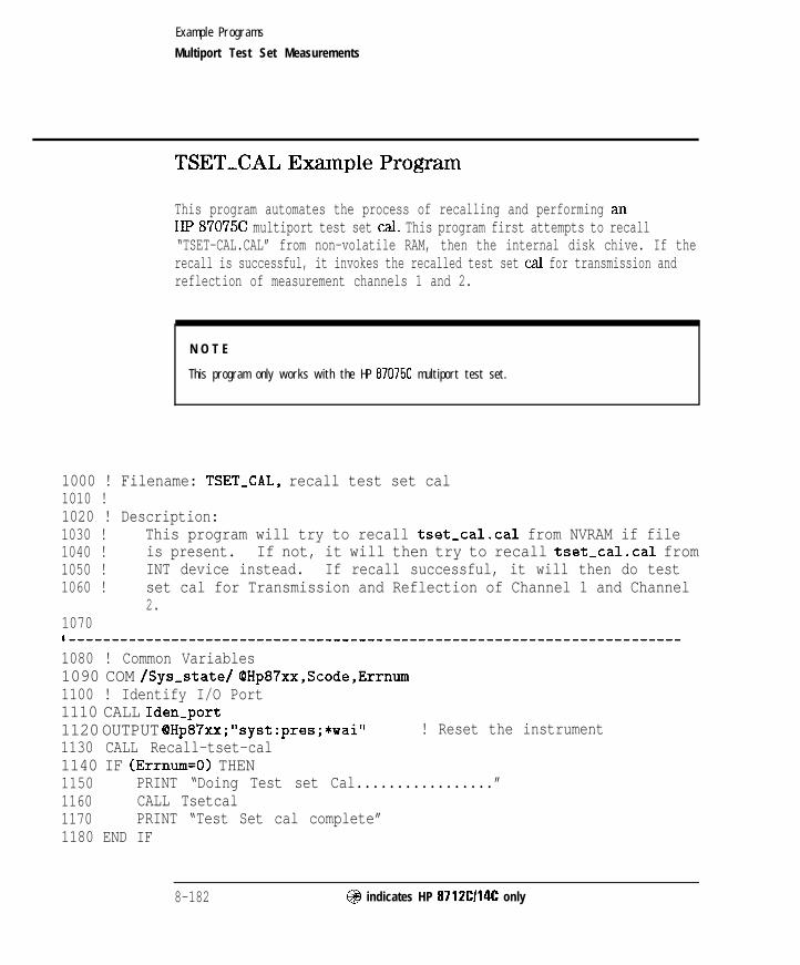
I -
Example Programs
Multiport Test Set Measurements
TSETXAL Example Program
This program automates the process of recalling and performing anHP 87075C multiport test set ml. This program first attempts to recall“TSET-CAL.CAL” from non-volatile RAM, then the internal disk chive. If therecall is successful, it invokes the recalled test set cal for transmission andreflection of measurement channels 1 and 2.
N O T E
This program only works with the HP 8707X multiport test set.
1000 ! Filename: TSET-CAL, recall test set cal1010 !1020 ! Description:1030 ! This program will try to recall tset-cal.cal from NVRAM if file1040 ! is present. If not, it will then try to recall tset-cal.cal from1050 ! INT device instead. If recall successful, it will then do test1060 ! set cal for Transmission and Reflection of Channel 1 and Channel
2.1070I------------------------------------------------------------------------1080 ! Common Variables1090 COM /Sys-state/ OHp87xx,Scode,Errnum1100 ! Identify I/O Port1110 CALL Iden-port1120 OUTPUT OHp87xx;“syst:pres;*wai” ! Reset the instrument1130 CALL Recall-tset-cal1140 IF (Errnum=O) THEN1150 PRINT “Doing Test set Cal.................”1160 CALL Tsetcal1170 PRINT “Test Set cal complete”1180 END IF
8-182 @ indicates HP 8712Cl14C only

I- I -
Example Programs
Multiport Test Set Measurements
1190 !1200 OUTPUT QHp87xx;"syst:pres;*wai"1210 !1220 STOP1230 END12401250126012701280
! Reset the instrument
**************************************************************TsetCal: Do Test set Cal.Description: This routine will do test set cal for both
Transmission and Reflection of Channel 1 and1290 ! Channel 2.1300 !**************************************************************1310 SUB Tsetcal13201330 !1340 !1350136013701380 !1390 !1400141014201430 !1440 !1450146014701480 !1490 !150015101520
COM /Sys-state/ OHp87xx,Scode,Errnum
Do Test set cal for channel 1 TransmissionOUTPUT OHp87xx;"sensl:stat ON; *wail'OUTPUT OHp87xx;"sensl:func 'xfr:pow:rat 2,O';det nban; *wail'OUTPUT QHp87xx; "sensl:corr:testset; *wail'
Do Test Set cal for channel 1 ReflectionOUTPUT QHp87xx;"sensl:stat ON; *wail'OUTPUT QHp87xx;"sensl:func 'xfr:pow:rat 1,O';det nban; *wail'OUTPUT QHp87xx;"sensl:corr:testset; *wail'
Do Test set cal for channel 2 TransmissionOUTPUT OHp87xx;"sens2:stat ON; *wail'OUTPUT (8Hp87xx; "sens2:func 'xfr:pow:rat 2,O';det nban; *wai"OUTPUT QHp87xx;"sens2:corr:testset; *wail'
Do Test Set cal for channel 2 ReflectionOUTPUT QHp87xx;"sens2:stat ON; *wail'OUTPUT QHp87xx;"sens2:func 'xfr:pow:rat 1,O';det nban; *wail'OUTPUT OHp87xx;"sens2:corr:testset; *wail'
1530 SUHEND1540 !
fI$$ indicates HP 8712Cl14C only 8 - 1 8 3

I- I -
Example Programs
Multiport Test Set Measurements
1550 !**************************************************************
1560 ! Recall-tset-cal: Recall Test Set Cal.1570 ! Description: This routine will try to recall tset-cal.cal1580 ! from NVRAM if available. If file not found,1590 I it will then try to recall tset,cal.cal from1600 ! INT device instead.1610 !**************************************************************1620 SUB Recall-tset-cal163016401650 !1660 !1670 !16801690170017101720173017401750176017701780179018001810182018301840185018601870 !
COM /Sys-state/ QHp87xx,Scode,ErrnumDIM E$[1201
Clear the status register and event statusregister.OUTPUT OHp87xx;"*cls;*ese 0"PRINT "Recalling tset-cal.cal from NVRAM device.........."OUTPUT OHp87xx;"mmem:load:stat l,'mem:tset-cal.cal"'OUTPUT OHp87xx;"syst:err?"ENTER QHp87xx;Errnum,E$IF (Errnum<>O) THEN
PRINT E$PRINT "Recalling tset-cal.cal from INT device.........."OUTPUT QHp87xx;"mmem:load:stat l,'int:tset-cal.cal"'OUTPUT OHp87xx;"syst:err?"ENTER OHp87xx;Errnum,E$IF (Errnum=O) THEN
PRINT "Recall complete"ELSE
PRINT "TSET-CAL.CAL is not present, recall aborted"END IF
ELSEPRINT "Recall complete"
END IF
1880 SUBEND!Recall-tset,cal1890 !1900 !1910 !
8 - 1 8 4 @I indicates HP 8712Cl14C only
I-

- I -
Example Programs
Multiport Test Set Measurements
1920 !**************************************************************
1930 ! Iden-port: Identify io port to use.1940 ! Description: This routines sets up the I/O port address for1950 ! the SCPI interface. For "HP 87xx" instruments,1960 ! the address assigned to (QHp87xx = 800 otherwise,1970 ! 716.1980 !**************************************************************1990 SUE! Iden,port2000 COM /Sys-state/ QHp87xx,Scode,Errnum2010 !2020 IF POS(SYSTEM$("SYSTEM ID">,"HP 87")OO THEN2030 ASSIGN (QHp87xx TO 8002040 Scode=82050 ELSE2060 ASSIGN QHp87xx TO 7162070 Scode=72080 END IF2090 !2100 SUBEND!Iden-port2110 !
@ indicates HP 87 12Cl14C only S- 185

I- I -
TTL Output
TTL-IO Example Program
This program continuously reads the USER TTL port and reports the numberof times the port has detected a closure (short) via an external switch. Thisprogram is useful in a production environment where a device must beproperly connected, either manually or by automated means, where theanalyzer must wait for a signal from the operator that the DUT is in place andis ready to be tested.
This program reads the user TTL port continuously until a short (0) isdetected. Once this has been detected, a message is displayed. It then waitsfor the switch to open (1) and displays another message. At this point, codecan be added to take a sweep and measure the DUT. The total number ofcycles is counted and is displayed.
1000 ! Filename: TTL-IO1010 !1020 ! This program reads the USER TTL IO1030 ! port, and counts how many times a1040 ! switch connected to the port is pressed.1050 !1060 DIM Msg$[200]1070 INTEGER X1080 !1090 !1100 COM /Sys,state/ OHp87xx,Scode1110 ! Identify I/O Port1120 CALL Iden,port1130 !1140 !1150 Pass-count=01160 Start: !1170 LOOP
8-186 @ indicates HP 8712Cl14C only
-1

Example Programs
TTL Output
1180 ! Display message1190 Msg$=" ' DUTs passed: "&VAL$(Pass-count)&CHR$(lO)1200 Msg$=Msg$C"Press button to measure next DUT."'1210 OUTPUT OHp87xx;"DISP:ANN:MESS ";Msg$1220 !1230 ! Wait for button to be pressed1240 REPEAT1250 OUTPUT OHp87xx;"DIAG:PORT:READ? 15,l"1260 ENTER OHp87xx;X1270 UNTIL X=01280 DISP "Button is now pressed."1290 OUTPUT (8Hp87xx; "DISP:ANN:MESS:CLEAR"1300 !1310 ! Wait for button to be released1320 REPEAT1330 OUTPUT OHp87xx;"DIAG:PORT:READ? 15,l"1340 ENTER QHp87xx;X1350 UNTIL X=11360 DISP "Button is now released."1370 !1380 OUTPUT OHp87xx;" DISP:ANN:MESS 'Measuring..."'1390 ! Add code here to take sweep1400 ! and measure DUT.1410 WAIT 11420 Pass,count=Pass-count+11430 END LOOP1440 END1450 !1460 !**************************************************************1470 ! Iden,port: Identify io port to use.1480 ! Description: This routines sets up the I/O port address for1490 ! the SCPI interface. For "HP 87xx" instruments,1500 ! the address assigned to OHp87xx = 800 otherwise,1510 ! 716.1520 !**************************************************************
@ indicates HP 8712Cl14C only 8 - 1 8 7

I- I -
Example Programs
TTL Output
1530 SUB Iden-port1540 COM /Sys,state/ OHp87xx,Scode1550 !1560 IF POS(SYSTEM$("SYSTEM ID"),"HP 87")OO THEN1570 ASSIGN QHp87xx TO 8001580 Scode=81590 ELSE1600 ASSIGN (PHp87xx TO 7161610 Scode=71620 END IF1630 !1640 SUBEND !Iden-port1650 !
8-188 @ indicates HP 8712Cl14C only
-1

I-
AM Delay
AMDELAY Example Program
This program demonstrates the calibration and AM delay measurement of abandpass titer.
1000 !Filename: AMDELAY1010 !1020 !1030 ! DESCRIPTION:1040 ! 1) The HP871x analyzer is Preset, CHl = Y/X, CH2 = AM Delay1050 I Pout=lOdBm, Fstart=50MHz, Fstop=400MHz, Display is scaled.1060 ! 2) User must connect splitter to RF Out port, connect1070 I External detector X to one splitter arm, connect1080 ! External detector Y to the other splitter arm.1090 ! 3) Analyzer performs an AM Delay calibration over 50-400MHz.1100 ! 4) User must connect the BPF test device between splitter1110 ! and the External Y detector.1120 ! 5) Analyzer finds the BPF's center frequency and -6dB bandwidth1130 ! using the Bandwidth marker function. Fcenter and Fspan1140 ! are set so the analyzer displays the -6dB bandwidth.1150 ! (Note: the analyzer also interpolates numbers for the1160 ! AM Delay calibration when the frequencies are changed.)1170 ! 6) The Y/X marker 1 is set to max (for maximum transmission.
N O T E
This program can only be used with Option 1DA or l&3.
@ indicates HP 8712Cl14C only 8-189

I- I -
Example Programs
AM Delay
1180 ! 7) The AM Delay marker 1 is read out and displayed.1190 ! 8) The AM Delay trace is read out, and the first data point1200 ! is displayed.1210 !1220 !**************************************************1230 ! DEFINITIONS1240 !1250 REAL Opc,Freq,center,Freq,span,9_bpf,Loss_bpf,I,Mrkr-freq1260 REAL Trace_delay(l:201),Mrkr_delay1270 !1280 !***************************************************1290 ! Determine computer type and assign i/o path1300 !1310 CLEAR SCREEN1320 !1330 COM /Sys-state/ QHp87xx,Scode1340 ! Identify I/O Port1350 CALL Iden-port1360 !1370 !1380 ! ---------------------------------------------------1390 ! Preset analyzer; CH2 = AM Delay; CHl = External Broadband Y/X; RF
Power = 10dBm.1400 ! Note that the Start and Stop frequencies are set before CH2 is set1410 ! to AM Delay mode. This is done because when both AM Delay and1420 ! Y/X are selected, the analyzer switches to alternate sweep mode, so1430 ! by selecting the frequencies first, the start and stop frequencies1440 ! will be the same for both channels.1450 !1460 OUTPUT QHp87xx;"SYST:PRES;*OPC?" !preset instrument1470 ENTER OHp87xx;Opc !waits for PRESET to finish before
proceeding1480 DISP "Setting up AM Delay and Y/X measurement..."1490 !1500 OUTPUT QHp87xx;"SENSl:FREQ:STAR 50 MHZ"
include test filter1510 OUTPUT QHp87xx;" SENSl:FREQ:STOP 400 MHZ"
include test filter
!set start freq to
!set stop freq to
1520 OUTPUT OHp87xx;"SOURl:POW 10 DBM"1OdBm
1530 !
!set Source Power to
S-190 @ indicates HP 8712Cl14C only
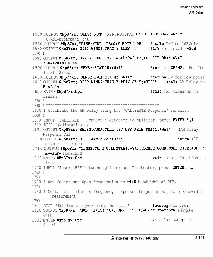
I- I -
Example Programs
AM Delay
1540 OUTPUT 6Hp87xx;"SENSl:FUNC 'XFR:POW:RAT 12,ll';DET BBAN;*WAI"!CHANl=broadband Y/X
1550 OUTPUT OHp87xx;"DISP:WINDl:TRAC:Y:PDIV 1 DB" !scale Y/X to ldB/div1560 OUTPUT OHp87xx;"DISP:WINDl:TRAC:Y:RLEV -3" !X/Y ref level =-3dB1570 !1580 OUTPUT @Hp87xx,*"SENS2:FUNC 'XFR:GDEL:RAT 12,ll';DET BBAN;*WAI"
!CHAN2=AM Delay1590 OUTPUT OHp87xx;"SENS2:STAT ON;*WAI" !turn on CHAN2. Results
in Alt Sweep.1600 OUTPUT QHp87xx;"SENS2:BWID 250 HZ;*WAI" !Narrow BW for low noise1610 OUTPUT cDHp87xx,*"DISP:WIND2:TRAC:Y:PDIV 5E-9;*OPC?" !scale AM Delay to
5ns/div1620 ENTER QHp87xx;Opc !wait for commands to
finish1630 !1640 ! --------------------------------------------------1650 ! Calibrate the AM Delay using the "CALIBRATE/Response" function1660 !1670 INPUT "CALIBRATE: Connect Y detector to splitter; press ENTER.",11680 DISP "Calibrating..."1690 OUTPUT @Hp87xx,."SENS2:CORR:COLL:IST 0FF;METH TRANl;*WAI" !AM Delay
Response Cal1700 OUTPUT OHp87xx;"DISP:ANN:MESS:AOFF" !turn off
message on screen1710 OUTPUT OHp87xx;"SENS2:CORR:COLL STANl;*WAI;:SENS2:CORR:COLL:SAVE;*OPC?"
!measure standard1720 ENTER QHp87xx;Opc !wait for calibration to
finish1730 INPUT "Insert BPF between splitter and Y detector; press ENTER.",11740 !1750 ! ----------------------------------------------------1760 ! Set Center and Span frequencies to -6dB bandwidth of BPF.1770 !1780 ! Center the filter's frequency response (to get an accurate Bandwidth
measurement)1790 !1800 DISP "Setting analyzer frequencies..." !message to user1810 OUTPUT cQHp87xx; "ABOR;:INITl:CONT OFF;:INITl;*OPC?" !perform single
sweep1820 ENTER OHp87xx;Opc !wait for sweep to
finish
@ indicates HP 8712Cl14C only 8-191
I-

I- I -
Example Programs
AM Delay
1830 OUTPUT OHp87xx;"CALCl:MARK:FUNC MAX;*OPC?" !set Marker to max1840 ENTER OHp87xx;Opc !wait for marker to move1850 OUTPUT OHp87xx;"CALCl:MARK:X?" !get Marker frequency
setting1860 ENTER @Hp87xx;Mrkr_freq !read frequency of max
marker1870 OUTPUT (OHp87xx;"SENSI:FREQ:CENT "tVAL$(Mrkr,freq)t" HZ;*WAI" !set
marker to Center Freq1880 OUTPUT QHp87xx;" SENSI:FREQ:SPAN 200 MHZ;*WAI" !set Span Freq = 200MHz1890 !1900 ! Measure Bandwidth: Center frequency and -6dB Span frequency1910 !1920 OUTPUT QHp87xx;"ABOR;:INITl:CONT OFF;:INITI;*OPC?" !restart sweep1930 ENTER QHp87xx;Opc !wait for sweep to
finish1940 OUTPUT OHp87xx;"CALCl:MARK:BWID -6;*WAI" !set bandwidth search to
-6dB1950 OUTPUT OHp87xx;"CALCl:MARK:FUNC BWID;*OPC?" !search filter for -6dB
bandwidth1960 ENTER QHp87xx;Opc !wait for bandwidth to
be found1970 OUTPUT OHp87xx;"CALCl:MARK:FUNC:RES?" !read the bandwidth data1980 ENTER OHp87xx;Freq-span,Freq,center,Q-bpf,Loss-bpf !read
in data1990 OUTPUT OHp87xx;"CALCl:MARK:AOFF;*WAI" !markers off2000 OUTPUT OHp87xx;"ABOR;:INITl:CONT ON;*WAI" !restart continuous
sweep2010 !2020 OUTPUT OHp87xx;"SENSl:FREQ:SPAN "tVAL$(Freq-span)&" HZ;*WAI" !set
Span Freq CHI2030 OUTPUT OHp87xx;"SENSl:FREQ:CENT "&VAL$(Freq-center)&" HZ;*WAI" !set
Center Freq CHI2040 OUTPUT OHp87xx;"SENS2:FREQ:SPAN "&VAL$(Freq,span)&" HZ;*WAI" !set
Span Freq CH22050 OUTPUT OHp87xx;"SENS2:FREQ:CENT "tVAL$(Freq-center)&" HZ;*WAI" !set
Center Freq CH22060 !2070 ! --------------------------------------------------2080 ! Read marker information (frequency and delay) and display.2090 ! Note that the X-axis is swept frequency and the Y-axis2100 ! is delay in seconds.
8-192 @I indicates HP 8712C114C only

I -
Example Programs
AM Delay
2110 !2120 OUTPUT OHp87xx;"CALCl:MARKl ON" !turn on marker 1 on Y/X trace2130 OUTPUT OHp87xx;"CALCl:MARK:FUNC MAX" !set marker to max
transmission2140 OUTPUT QHp87xx;"CALC2:MARKl ON"
trace!turn on marker 1 on AM Delay
2150 OUTPUT OHp87xx;"CALC2:MARKl:X?"2160 ENTER QHp87xx;Mrkr,freq2170 OUTPUT OHp87xx;"CALC2:MARKl:Y?"2180 ENTER OHp87xx;Mrkr,delay2190 !
!read frequency at marker
!read marker delay value
2200 DISP "Marker Frequency = "&VAL$(Mrkr-freq)&" Hz" !display frequency2210 WAIT 32220 DISP "Marker Delay = "tVAL$(Mrkr-delay)&" Seconds" !display delay2230 WAIT 32240 !2250 ! -----------------___------------------------------2260 ! Read AM Delay trace data, display first data point.2270 ! Data is transferred in ASCII format for simplicity.2280 ! Measured data is delay in seconds. Trace length=201 (default)2290 !2300 OUTPUT QHp87xx;"FORM:DATA ASC,S;:TRAC? CHZFDATA" !measure formatted
data2310 ENTER OHp87xx;Trace_delay(*) !read in data2320 !2330 DISP "Trace Point #I: AM Delay = "&VAL$(Trace-delay(l))&" Seconds"2340 WAIT 32350 !2360 DISP "'I !clear display line2370 !2380 STOP2390 END2400 !2410 !**************************************************************2420 ! Iden,port: Identify io port to use.2430 ! Description: This routines sets up the I/O port address for2440 ! the SCPI interface. For "HP 87xx" instruments,2450 ! the address assigned to (DHp87xx = 800 otherwise,2460 ! 716.2470 !**************************************************************
@ indicates HP 8712Cl14C only 8-193

I- I -
Example Programs
2480 SUB Iden-port2490 COM /Sys-state/ OHp87xx,Scode2500 !2510 IF POS(SYSTEM$(~~S~STEM ID~~),~#HP 87")oo THEN2520 ASSIGN QHp87xx TO 8002530 Scode=82540 ELSE2550 ASSIGN OHp87xx TO 7162560 Scode=72570 END IF2580 !2590 SUBEND !Iden-port2600 !
8-194 @I indicates HP 8712C114C only

I -
9
Front Panel Keycodes

I- I -
Your program can control or monitor the analyzer’s front panel with the useof the SCPI SYSTem:KEY commands.
Controlling the FrontPanel
The front panel can be controlled by sending commands to execute thefunction of specific keys. The SCPI command SYSTem:KEY <char> sendsa key name to the analyzer which executes the same function as thecorresponding front panel key. For example, SYSTem: KEY FREQ will executethe function of the (FREQ) hardkey.
Every hardkey and softkey have a unique key name. Refer to the last table inthis chapter for a list of all key names.
Monitoring the FrontPanel
The front panel can be monitored to determine when a key has been pressedor when the knob (RPG - rotary pulse generator) has been turned. Keypresses from an attached PC DIN keyboard can also be captured.
When keys are pressed or when the knob is turned, the analyzer detectsthis event, sets bit 0 of the Device Status Register (see Chapter 5, “UsingStatus Registers”) and stores the associated information in a key queue. Yourprogram can use the SCPI SYSTem: KEY commands to read the contents of thekey queue.
The SCPI query SYSTem: KEY : TYPE? returns a string indicating the type ofkey press event:
Return Value Meaning
N O N E No key has been pressed
K E Y A front panel key has been pressed
I R P G The analyzer’s knob has been turned
II I
A S C A key on the ASCII PC DIN keyboard has bean pressed
The SCPI query SYSTem : KEY [ : VALue] ? returns a number describing thetype of key press. The meaning of the number depends on the key typereturned by the SYSTem : KEY : TYPE? query:
9 - 2 @I indicates HP 8712Cl14C only
I-

I- I -
F r o n t P a n e l Keycodes
I SYST:KEY:TYPE
I N O N E
SYST : KEY : VALUE Meaning
N o m e a n i n g . R e t u r n s - 1 .
A number from 0 to 56 representing the “key coda’ of the front
panel key. See following table for l ist.
The number of knob “ticks. ’ Positive values indicate e clock-wise
turn; negative numbers indicate counterclockwise. Larger numbers
indicate the knob has been turned fester or further.
The ASCII value of the pressed key.
The SYSTem: KEY [ : VALueI ? query removes the key from the key queue,so that you can read the next key. For this reason, you must perform theSYSTem : KEY : TYPE? query before performing the SYSTem : KEY [ : VALueI?.
The queue that stores the key press events has a finite length. In firmwarerevision B.03.00, this length is 32. This means that after 32 key presses occurwithout being read (using SYSTem : KEY [ : VALue] ?), subsequent key pressesor knob ticks will be ignored.
Your program can query the queue length using the SCPI command:
SYSTem:KEY:QUEue:MAXimum?
You can clear the queue using:
SYSTem:KEY:QUEue:CLEar
You can check how many key presses or knob tick events have occurred using
SYSTem:KEY:QUEUE:COUNt?
Finally, you can turn the key queue on or off using
SYSTem:KEY:QUEUE[:STATe] <ONIOFF>
When the queue is turned off, your program must read each key before afollowing key is pressed, or information will be lost. It is generally best toleave the queue enabled.
For a complete example of how to read the front panel keys and knob, referto the KEYCODE example program.
@ indicates HP 8712CI14C only 9 - 3
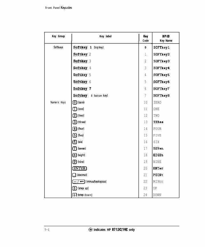
I- I -
F r o n t P a n e l Keycodes
I Key Group Key label KeyCode
I Softkeys
Numeric Keys
Softkey 1 (top key1
Softkey 2
Saftksy 3
Aibftkey 4
Softkey 5
saftksy 6
Softkey 7
Softkey 8 lbottom key1
(TJ Izerol
0 lone1
(-g ltwol
0 lthreel
@ lfourl
0 lfivel
(TJ lsixl
(TJ (seven1
a leightl
@ lninel
@mm)
0 Idecimal]
(Tj lminuslbackspacal
@) lstep up1
m [step d o w n ]
0
1
2
3
4
5
6
7
10
ii
12
13
14
15
16
17
18
19
20
21
22
23
24
HP-18Key Name
SOFTkeyl
SOFTkey
SOFTkey
SOFTkey
SOFTkey
SOFTkey
SOFTkey
SOFTkey
ZERO
ONE
TWO
THRee
FOUR
FIVE
SIX
SEVen
EIGHt
NINE
ENTer
POINt
MINUS
UP
DOWN
9-4 @ indicates HP 8712Cl14C only
I-

I- I -
Front Panel Keycodes
Key Group
Feature Keys
Key Label KOY HP-IB
Code Key Name
40
41
42
43
44
45
46
47
46
49
50
51
52
53
54
55
56
BEGin
MEASI
MEASZ
POWer
MENU
FREq
SWEep
CAL
DISPlay
SCALe
AVG
FORMat
MARKer
SAVE
SYSTem
HARDcopy
PRESet
@ indicates HP 8712Cl14C only 9 - 5

I-
Front Panel Keycodes

10
Introduction to SCPI

I- I -
Introduction to SCPI
This chapter is a guide to HP-IB control of the analyzer. Its purpose is toprovide concise information about the operation of the analyzer under HP-h3control. The reader should already be familiar with making measurementswith the analyzer and with the general operation of HP-IB.
Standard Commands for Programmable Instruments (SCPI) is a programminglanguage designed specifically for controlling instruments by Hewlett-Packardand other industry leaders. SCPI provides commands that are common fromone instrument to another. This elimination of “device specific” commandsfor common functions allows programs to be used on different instrumentswith very little modification.
SCPI was developed to conform to the IEEE 488.2 standard(replacing IEEE 7281982). The IEEE 488.2 standard defines the syntax anddata formats used to send data between devices, the structure of statusregisters, and the commands used for common tasks. For more information,refer to the IEEE standard itself. SCPI defines the commands used to controldevice-specific functions, the parameters accepted by these functions, and thevalues they return.
10-2 @ indicates HP 8712CI14C only


I- I -
Introduction to SCPI
The Command Tree
The analyzer’s major SCPI subsystems and their functions are describedbelow.
ABORt
CALCulate
Aborts any sweep in progress.
Configures post-measurement processing of the measureddata (such as marker and limit testing functions).
Controls zeroing the broadband diode detectors.
Controls the display of measurement data, annotation anduser graphics.
CALibrat ion
DISPlay
FORMat
HCOPy
INITiate
MMEMory
OUTPut
PROGram
SENSe
SOURce
Controls the format of data transfers over the HP-K%(For more information about HP-IB data transfer refer toChapter 4, “Data Types and Encoding.“)
Controls hardcopy (printer and plotter) output.
Controls the triggering of sweeps.
Controls mass storage of instrument states and data (diskand internal memory interface functions).
Turns on/off the source output power (power to the deviceunder test).
Interfaces IBASIC programs and commands with anexternal controller. (For more information on IBASICprogramming refer to HP Instrument BASIC User’sHandbook.)
Configures parameters (such as the frequency andmeasurement parameters) related to the sweep andthe measured signal (from the device under test). Thissubsystem also controls the narrowband calibrationroutines.
Controls the RF output power level of the source (power tothe device under test).
10-4 @ indicates HP 8712C114C only

-I -
Introduction to SCPI
The Commend Tree
STATUS Contains the commands for using the SCPI status registers.(For more information about using the status registers referto Chapter 5, “Using Status Registers.“)
SYSTem Contains miscellaneous system configuration commands(such as l/O port, clock and softkey control).
TRACe Interfaces with the internal data arrays (functions such asdata transfer and trace memory).
TRIGger Controls the source of the sweep triggering.
When many functions are grouped together on a particular branch, additionalbranching is used to organize these functions into groups that are even moreclosely related. The branching process continues until each analyzer functionis assigned to its own branch. For example, the function that turns on andoff the marker tracking feature is assigned to the TRACKING branch of theFUNCTION branch of the MARKER branch of the CALCULATE subsystem. Thecommand looks like this:
CALCULATE:MARKER:FUNCTION:TRACKING ON
NOTE
Colons are used to indicate branching points on the command tree. A parameter is separated from the
rest of the command by a space.
@ indicates HP 8712C114C only 10-5

I- I -
Introduction to SCPI
The Command Tree
CALCulate
IMARKe r
I I I I[ STATe ] MODE FUNCt ion MAXimum
COMMAND TREE-_-_
PARAMETERS
ON OFF ABSolute RELative ON OFF
Figure 1 O-2. Partial Diagram of the CALCulate Subsystem Command Tree
10-6 @ indicates HP 8712C114C only

I- I -
Sending Multiple Commands
Multiple commands can be sent within a single program message byseparating the commands with semicolons. For example, the followingprogram message - sent within an HP BASIC OUTPUT statement - turns onthe marker reference and moves the main marker to the highest peak on thetrace :
OUTPUT 716;“CALCULATE:MARKER:MODERELATIVE;:CALCULATE:MARKER:MAXIMUM”
One of the analyzer’s command parser main functions is to keep track of aprogram message’s position in the command tree. This allows the previousprogram message to be simplified. %king advantage of this parser function,the simpler equivalent program message is:
OUTPUT 716;“CALCULATE:MARKER:MODE RELATIVE;MAXIMUM”
In the Erst version of the program message, the semicolon that separates thetwo commands is followed by a colon. Whenever this occurs, the commandparser is reset to the base of the command tree. As a result, the nextcommand is only valid if it includes the entire mnemonic path from the baseof the tree.
ln the second version of the program message, the semicolon that separatesthe two commands is not followed by a colon. Whenever this occurs, thecommand parser assumes that the mnemonics of the second command arisefrom the same branch of the tree as the final mnemonic of the precedingcommand. MODE, the &ml mnemonic of the first command, arises from theMARKER branch. So MAXIMUM, the first mnemonic of the second command isalso assumed to arise from the MARKER branch.
The following is a longer series of commands - again sent within HP BASICOUTPUT statements - that can be combined into a single program message:
OUTPUT 716;“CALCULATE:MARKER:STATE ON”OUTPUT 716;“CALCULATE:MARKER:MODE RELATIVE”OUTPUT 716;“CALCULATE:MARKER:MAXIMUM”OUTPUT 716;“CALCULATE:MARKER:FUNCTION:TRACKING ON”
The single program message is:
OUTPUT 716;“CALCULATE:MARKER:STATE 0N;MODERELATIVE;MAXIMUM;FUNCTION:TRACKING ON”
@ indicates HP 8712C114C only 10-7
I-

I- I -
Command Abbreviation
a Each command mnemonic has a long form and a short form. The short formsof the mnemonics allow you to send abbreviated commands. Only the exactshort form or the exact long form is accepted.
The short form mnemonics are created according to the following rules:
l If the long form mnemonic has four characters or less, the short form is thesame as the long form. For example, DATA remains DATA.
l If the long form mnemonic has more than four characters and the fourthcharacter is a consonant, the short form consists of the lirst four charactersof the long form. For example, CALCULATE becomes CALC.
a If the long form mnemonic has more than four characters and the fourthcharacter is a vowel, the short form consists of the first three characters ofthe long form. For example, LIMIT becomes LIM.
N O T E
The short form of a particular mnemonic is indicated by the use of UPPER-CASE characters in this
manual.
SCPI is not case sensitive so any mix of upper- and lower-case lettering can be used when sending
commands to the analyzer.
If the rules listed in this section are applied to the last program message inthe preceding section, the statement:
OUTPUT 716;“CALCULATE:MARKER:STATE 0N;MODERELATIVE;MAXIMUM;FUNCTION:TRACKING ON”
becomes :
OUTPUT 716;“CALC:MARK:STAT 0N;MODE REL;MAX;FUNC:TRAC ON”
10-8 @ indicates HP 8712Cl14C only

I- I -
Implied Mnemonics
Some mnemonics can be omitted from HP-IB commands without changingthe effect of the command. These special mnemonics are called impliedmnemonics, and they are used in many subsystems. In addition to entiremnemonics, variable parts of some mnemonics may also be implied. Theseare usually a number indicating a particular measurement channel, marker, orsimilar choice.
N O T E
When a number is not supplied for an implied variable, a default choice is assumed; this choice is
a lways 1 .
The INITIATE subsystem contains both the implied mnemonic IMMEDIATEat its first branching point and an implied variable for the measurementchannel. The command to trigger a new sweep is shown in the “SCPICommand Srmunary” as:
OUTPUT 716; “INITiate Cl121 [: IMMediateI
Any of the following forms of the command can be sent to the analyzer (usingHP BASIC) to trigger a new sweep on measurement channel 1:
OUTPUT 7 16 ; “INITIATE1 : IMMEDIATE”OUTPUT 716 ; “INITIATE : IMMEDIATE”OUTPUT 716;“INITIATEl”OUTPUT 7 16 ; “INITIATE”
If the sweep is to be triggered for measurement channel 2, the channelnumber must be specified:
OUTPUT 716; “INITIATE2 : IMMEDIATE”OUTPUT 716; “INITIATE2”
@ indicates HP 8712Cl14C only 10-9
I-

I- I -
Parameter Types
Parameters are used in many commands. The analyzer uses several types ofparameters with different types of commands and queries. When a parameteris sent with a SCPI command it must be separated from the command by aspace. lf more than one parameter is sent they are separated from each otherby commas.
Numeric Parameters
Most subsystems use numeric parameters to specify physical quantities.Simple numeric parameters accept all commonly used decimal representationsof numbers, including optional signs, decimal points, and scientific notation.lf an instrument setting programmed with a numeric parameter can onlyassume a finite number of values, the instrument automatically rounds theparameter. In addition to numeric values, all numeric parameters acceptMAXimum and MINimum as values (note that MAXimum and MINimum can beused to set or query values).
<num> is used in this document to denote a numeric parameter.
An example is the command to set the stop frequency for a measurement.The hrst command below sets the stop frequency to a speciEc value. Thesecond command below sets the stop frequency to its maximum possiblevalue (1300 MHz for HP 8711C/12C or 3000 MHz for HP 8713CD4C).
OUTPUT 716;“SENSEl:FREQUENCY:STOP 1300 MHZ”
OUTPUT 716;“SENSEl:FREQUENCY:STOP MAX”
10-10 @I indicates HP 8712C114C only

I- I -
Introduction to SCPI
Parameter Types
Query Response When a numeric parameter is queried the number is returned in one of thethree numeric formats.
NRl Integers (such as +l, 0, -1, 123, -12345)
NR2 Floating point number with an explicit decimal point (such as12.3, + 1.234, -0.12345)
NR3 Floating point number in scientific notation (such as+1.23E+5, +123.43-3, -456.7893+6)
An example is the response to a query of the stop frequency after executingthe above commands (this response is of the NR3 type).
OUTPUT 716;"SENSEl:FREQUENCY:STOP?"
returns the value 1.3E+9.
Character Parameters
Character parameters (sometimes referred to as discrete parameters) consistof ASCII characters. They are typically used for program settings that have afinite number of values.
These parameters use mnemonics to represent each valid setting. They havea long and a short form which follow the same rules as command mnemonics.
<char> is used in this document to denote a character parameter.
An example of a command using a character parameter is the command thatselects the format in which the measurement data is displayed:
OUTPUT 716;"CALCULATEl:FORMAT MLOGARITHMIC"
Query Response When a character parameter is queried the response is always the short formof the mnemonic that represents the current setting. An example is theresponse to a query of the data format after executing the above command.
OUTPUT 716;"CALCULATEl:FORMAT?"
returns the value MLOG.
@ indicates HP 8712Cl14C only 10-11

I- I -Introduction to SCPI
Parameter Types
Boolean Parameters
Boolean parameters are used for program settings that can be represented bya single binary condition. Commands that use this type of parameter acceptthe values ON (or 1) and OFF (or 0).
<ON I OFF> is used in this document to denote a boolean parameter.
An example of a command that uses a boolean parameter is the commandthat makes the analyzer continuously trigger (or stop triggering)measurements.
OUTPUT 716;“INITIATE:CONTINUOUS ON”
A special group of commands uses boolean parameters to control automaticfunctions of the instrument, such as automatically selecting the fastestpossible sweep speed. With these automatic functions an additional value isavailable for the parameter. This value ONCE causes the function to executeonce before turning off.
Query Response The response when a boolean parameter is queried is a single NRl numberindicating the state 1 for on or 0 for off. An example is the response to aquery on the sweep trigger status after executing the above command.
OUTPUT 716; “INITIATE: CONTINUOUS?”
returns the value 1.
10-12 @ indicates HP 8712CI14C only
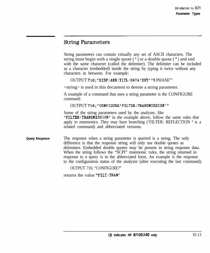
I- I -
Introduction to SCPI
Parameter Types
String Parameters
String parameters can contain virtually any set of ASCII characters. Thestring must begin with a single quote ( ) ) or a double quote ( ‘I ) and endwith the same character (called the delimiter). The delimiter can be includedas a character (embedded) inside the string by typing it twice without anycharacters in between. For example:
OUTPUT 716;“DISP:ANN:TITL:DATA ‘DUT”S PHASE”’
<string> is used in this document to denote a string parameter.
A example of a command that uses a string parameter is the CONFIGUREcommand:
OUTPUT 716;“CONFIGURE ‘FILTER:TFlANSMISSION”’
Some of the string parameters used by the analyzer, like‘FILTER:TRANSMISSION’ in the example above, follow the same rules thatapply to mnemonics. They may have branching (‘FILTER: REFLECTION ’ is arelated command) and abbreviated versions.
Query Response The response when a string parameter is queried is a string. The onlydifference is that the response string will only use double quotes asdelimiters. Embedded double quotes may be present in string response data.When the string follows the “SCPI” mnemonic rules, the string returned inresponse to a query is in the abbreviated form. An example is the responseto the configuration status of the analyzer (after executing the last command).
OUTPUT 716; “CONFIGURE?”
returns the value “FILT:TRAN”
@ indicates HP 8712C114C only 10-13

I- I -
Introduction to SCPI
Parameter Types
Block Parameters
Block parameters are typically used to transfer large quantities of related data(like a data trace). Blocks can be sent as definite length blocks or indefinitelength blocks - the instrument will accept either form. For more informationon block data transfers refer to Chapter 4, “Data Types and Encoding. ’
<block> is used in this document to denote a block parameter.
10-14 @I indicates HP 8712Cl14C only

I- I -
Syntax Summary
The following conventions are used throughout this manual whenever SCPImnemonics are being described.
angle brackets (< >) are used to enclose required parameters within acommand or query. The dehnition of the variable isusually explained in the accompanying text.
square brackets ([ 1) are used to enclose implied or optional parameterswithin a command or query.
UPPERlower case are used to indicate the short form (upper-case) of agiven mnemonic. The remaining (lower-case) lettersare the rest of the long form mnemonic.
J
Figure 1 O-3. SCPI Command Syntax
@ indicates HP 8712Cl14C only 10-15
-

I- I -
Introduction to SCPI
Syntax Summary
The following elements have special meanings within a SCPI programmessage (or combination or mnemonics).
colon (:) When a command or query contains a series ofmnemonics, they are separated by colons. A colonimmediately following a mnemonic tells the commandparser that the program message is proceeding to thenext level of the command tree. A colon immediatelyfollowing a semicolon tells the command parser thatthe program message is returning to the base of thecommand tree.
semicolon (;) When a program message contains more than onecommand or query, a semicolon is used to separate themfrom each other.
comma (,)
space ( >
A comma separates the data sent with a command orreturned with a response.
One space is required to separate a command or queryfrom its data (or parameters). Spaces are not allowedinside a command or query.
lo-16 @ indicates HP 8712CI14C only
I-

I-
IEEE 488.2 Common Commands
IEEE 488.2 defines a set of common commands. All instruments are requiredto implement a subset of these commands, specifically those commandsrelated to status reporting, synchronization and internal operations. The restof the common commands are optional. The following list details which ofthese IEEE 488.2 common commands are implemented in the analyzer andthe response of the analyzer when the command is received.
*cLs
*ESE <num>
*ESE?
Clears the instrument Status Byte by emptying the errorqueue and clearing all event registers, also cancels anypreceding *OPC command or query (does not change theenable registers or transition Elters).
Sets bits in the Standard Event Status Enable Register -current setting is saved in non-volatile memory.
Reads the current state of the Standard Event Status EnableRegister.
*ESR? Reads and clears the current state of the Standard EventStatus Register.
*IDN? Returns a string that uniquely identifies the analyzer. Thestring is of the form
“HEWLETT-PACKARD,87llC,<serial number>,<software revision>”
*LRN?
*opt
This returns a string of device specific characters that, whensent back to the analyzer will restore the instrument stateactive when *LRN? was sent. Data formatting (ENTER USING‘I-K” in HP BASIC) or a similar technique should be used toensure that the transfer does not terminate on a carriagereturn or line feed (both ‘n and Lr are present in the learnstring as part of the data).
Operation complete command. The analyzer will generatethe OPC message in the Standard Event Status Registerwhen all pending overlapped operations have beencompleted (e.g. a sweep, or a preset). For more informationabout overlapped operations refer to “OverlappedCommands” in Chapter 2.
@ indicates HP 8712C114C only 10-17
I-

I -
Introduction to SCPI
IEEE 488.2 Common Commands
*oPc?
*OPT?
Operation complete query. The analyzer will return anASCII “ 1’ when all pending overlapped operations havebeen completed.
Returns a string identifying the analyzer’s optionconfiguration. The string is of the form ‘I lEl,lC2”. Theoptions are identified by the following:
1EC 75 ohmlE1 60 dtl step attenuatorlC2 IBASIC1DA AM delay 150 nllD6 AM delay I75 nllF7 LAN100 SRL and Fault location
*PCB <mm> Sets the pass-control-back address (the address of thecontroller before a pass control is executed).
*PSC <num> Sets the state of the Power-on Status Clear flag - flag issaved in non-volatile memory. This flag determines whetheror not the Service Request enable register and the EventStatus enable register are cleared at power-up.
*RST Executes a device reset and cancels any pending *OPCcommand or query. The contents of the instrument’snonvolatile memory are not affected by this command.
This command is different from the front panel (%FZF1function in the state of the commands (and their resetstates) listed below.
The preset instrument state is described in the User’s Guide.
1NITiate:CONTinuous - OFFOUTPut[:STATe] - OFFCALibration:ZERO:AUTO = OFFSENSe:CORRection[:STATe] = OFFSENSe:SWEep:POINts = MAXSOURce:POWer - MIN
*SRE <mm> Sets bits in the Service Request Enable Register. Currentsetting is saved in non-volatile memory.
lo-18 @ indicates HP 8712CI14C only

I-
*SRE?
*STB?
*TRG
*TST?
*WA1
I -
Introduction to SCPI
Reads the current state of the Service Request EnableRegister.
Reads the value of the instrument Status Byte. This is anon-destructive read, the Status Byte is cleared by the *CLScommand.
Triggers a sweep on the active measurement channel whenin Trigger Hold mode. Ignored if in continuous sweep.
Returns the result of a complete self-test. An ASCII 0indicates no failures found. Any other character indicates aspecific self-test failure. Does not perform any self-tests. Seethe senvice Guide for further information.
Prohibits the instrument from executing any new commandsuntil all pending overlapped commands have beencompleted.
@ indicates HP 8712CI14C only 10-19

I -
Introduction to SCPI

I -
11
Menu Map ,with SCPICommands

I- I -
Menu Map with SCPI Commands
This chapter contains a map of all the softkey menu choices in the analyzer.There is a table for each major hardkey on the analyzer’s front panel. Thesoftkeys are shown with corresponding SCPI commands (if one exists).Hardkeys are indicated with the CHardkey) notation, softkeys are shown asSoftkeys . SCPI commands are all shown in their short form.
Some commands (such as source settings) have mnemonics that specify themeasurement channel in use. These mnemonics are shown as SENS Cl I21 : .. . indicating that either measurement channel could be used. The actualmnemonic entered would be SENSl : . . . for setting measurement channel 1orSENS2: . . . for measurement channel 2. Mnemonics for keys that togglebetween two states are shown as . . . ON I OFF.
<num> and <string> refer to parameter types described in the “ParameterTypes” section. <string> parameters are typically enclosed in single quotes(‘the string data’).
(-1 SCPI Command
KEYSTROKES SCPICOMMAND
SYST:PRES;*WAI
11-2
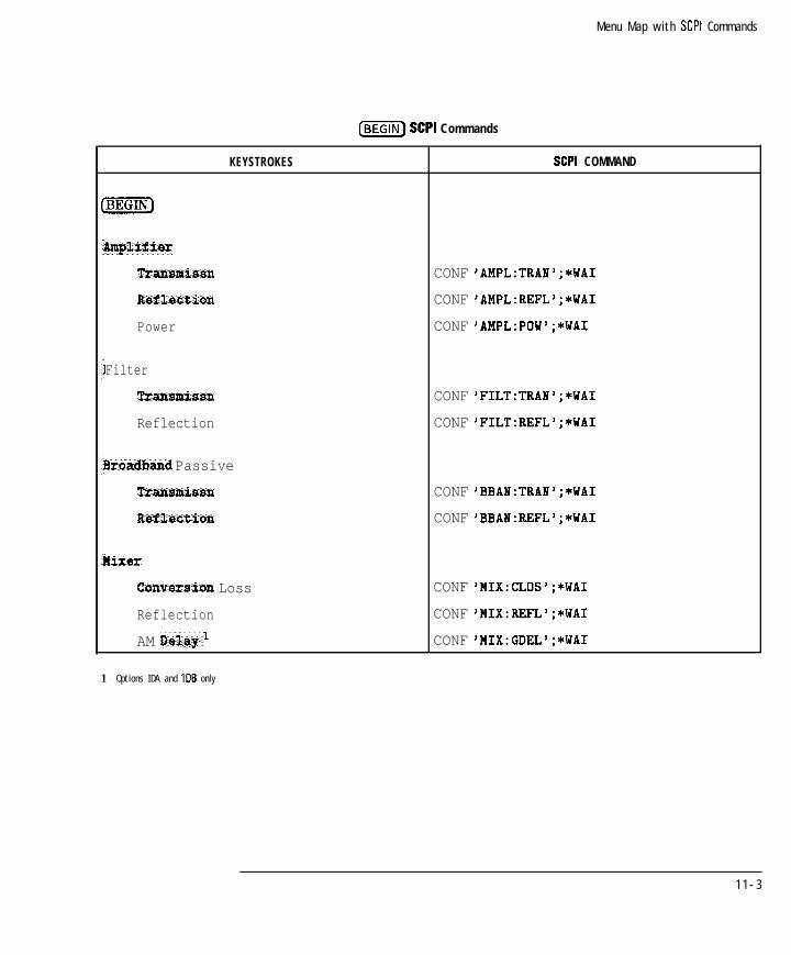
I- I -
Menu Map with SCPI Commands
IBEGIN] SCPI Commands
KEYSTROKES SCPI COMMAND
kmplifisr
Transmissn
Raflection
Power
Filter
Transmissn
Reflection
3raadkmnd Passive
Transmiasn
RsfXac*ion
Yixer
Convarsion Loss
Reflection
AM IMay
CONF 'AMPL:TRAN';*WAI
CONF 'AMPL:REFL';*WAI
CONF 'AMPL:POW';*WAI
CONF 'FILT:TRAI';*WAI
CONF 'FILT:REFL';*WAI
CONF 'BBAB:TRAN';*WAI
CONF 'BBAN:REFL';*WAI
CONF 'MIX:CLOS';*WAI
CONF 'MIX:REFL';*WAI
CONF 'MIX:GDEL';*WAI
1 Options IDA and IDB only
1 1 - 3

I- I -
Menu Map with SCPI Commands
(BEGINI) SCPI Commands (continued)
KEYSTROKES SCPI COMMAND
Zabls'
Tranmissn CONF[l12] 'CABL:TRAN';*WAI
Reflection CONF[l12] 'CABL:REFL';*WAI
Fault Location CONF[l12] 'CABL:FAULT';*WAI
Start Distance SENSC~I~I:DIST:STAR <nun0 CFEETIMETI;*WAI
Stop Distance SENS[~~~~:DIST:STOP <nun> CFEETIMETI;*WAI
Feet SENS:DIST:UNIT FEET
Metsrs SENS:DIST:UNIT MET
Law Pass SENS:FREQ:MODE LOWP;*WAI
Band Pass SENS:FREQ:MODE CENT;*WAI
Center Frequency DISP:ANN:FREq[I12l:MODE CSPAN
(Number) Units SENSCII~I:FRE~:CENT <nun> CMHZIKHZIHZI;*WA1
SRJd CONF[1121 'CABL:SRL';*WAI
Start Fxeq DISP:ANN:FREQ[112l:MODE SSTOP
@iRiEZE]U n i t s SENS[112]:FREq:STAR <nun0 CMHZIKHZIHZI;*WA1
Stop Freq DISP:ANN:FREQ[Il2l:MODE SSTOP
(Number_) Units SENSCIIZI:FREQ:STOP <nun> CMHZIKHZIHZI;*WA1
Connector Model
Measure Cmm3ctor SENS[i12]:CORR:MODEL:CONN
Connector Length
(Number)[mj SENS[I12]:CORR:LENG:CONN <nun>
Connector C [Number)[ENTER)SENS Cl 121: CORR:CAP:CONN <nun>
1 Option 100 only
11-4

I- I -
Menu Map with SCPI Commands
($FiFi) SCPI Commands (continued)
KEYSTROKES
1 O p t i o n lC2 o n l y
SCPI COMMAND
SENS:FREQ:ZST <mm> CHHZIKHZIHZI
SENS[Il21:FUNC:SRL:MODE <AUTOIMANUAL>
SENSCIi21
SENSCIi21
SENSCII21
No SCPI command
F'UNC:SRL:IMP <mm>
F'UNC:SRL:SCAN;*WAI
SWE:POIN <num>;*WAI
11-5

I- I -
Menu Map with SCPI Commands
@EXTiJ I [TiiEXFQ SCPI Commands
KEYSTROKES
LMEAs] 1 @TlTmq
Transmissn
Reflection
F a u l t Location1
SRLl
More
Power
Conversion Loss
SCPICOMMAND
SENS[lIZ]:STAT ON;*WAI
SENS[lIZ]:FUNC 'XFR:POW:RAT 2,O';DET NBAN;*WAI
SENS[IiZ]:FUNC 'XFR:POW:RAT 1,O';DET NBAN;*WAI
SENS[lIZ]:FUNC 'FLOC 1'0';DET NBAN;*WAI
SENS[lIZ]:FUNC 'SRL 1,O';DET NBAN;*WAI
SENSC1121:FUNC 'XFR:POW 2';DET BBAN;*WAI
SENS[ll2]:FUNC 'XFR:POW:RAT 2,O';DET BBAN;*WAI
AM Delay*
Detection Options
&rroaband Internal
A
0
R
AJR
BfR
SENS[lIZ]:FUNC 'XFR:GDEL:RAT 12,ll';DET BBAN;*WAI
SENS[l12]:FUNC 'XFR:POW I';DET NBAN;*WAI
SENS[IIZ]:FUNC 'XFR:POW 2';DET NBAN;*WAI
SENS[lIZ]:FUNC 'XFR:POW 0';DET NBAN;*WAI
SENS[IIZ]:FUNC 'XFR:POW:RAT 1,O';DET NBAN;*WAI
SENS[lIZ]:FUNC 'XFR:POW:RAT 2,O';DET NBAN;*WAI
1 O p t i o n 1 0 0 o n l y
2 O p t i o n s 1DA a n d IDB o n l y
1 1 - 6

I- I -
Menu Map with SCPI Commands
1For use with HP 87075C multiport test sets only
[MEAS] 1 [MEAS) SCPI Commands (continued)
KEYSTROKES
Broadband Internal
B*
IL*
B*/R*
Broadband External
x
Y
X / Y
YfX
Y&i*
SCPICOMMAND
SENS[lj2]:FUNC 'XFR:POW 2';DET BBAN;*WAI
SENS[ll2]:FUNC 'XFR:POW 0';DET BBAN;*WAI
SENS[il2]:FUNC 'XFR:POW:RAT 2,O';DET BBAN;*WAI
SENS[ll2]:FUNC 'XFR:POW 1l';DET BBAN;*WAI
SENS[ll2]:FUNC 'XFR:POW 12';DET BBAN;*WAI
SENS[112]:FUNC 'XFR:POW:RAT 11,12';DET BBAN;*WAI
SENS[ll2]:FUNC 'XFR:POW:RAT 12,ll';DET BBAN;*WAI
SENS[l12]:FUNC 'XFR:POW:RAT 12'0';DET BBAN;*WAI
AUX Input
Nsas OFF
Multiport Selection'
SENS[ll
SENS[ll
21:FUNC 'XFR:VOLT';*WAI
21:STAT OFF;*WAI
23:REFL:PATH:DEF:PORTROUT[ll(1121 . . . l12>
Transmiasn Port Hum ROUT[l12]:TRAN:PATH:DEF:PORT(1121 l12>
11-7
I-

I- I -
Menu Map with SCPI Commands
[FREQI SCPI Commands
KEYSTROKES
Start
(~j Units
[Nx] Units
Fault Lot Frsquencyl
Lo-3 Pass
Band Pass
Band Pass Max Span (W'jUnits
1 Option 100 only
SCPICOMMAND
DISP:ANN:FREq[Il21:MODE SSTOP
SENS[l12]:FREQ:STAR <num> CMHZIKHZIHZI;*WA1
DISP:ANN:FREq[llZ]:MODE SSTOP
s~~sCil23 :mq:sroP <num> CMHZIKHZIHZI;*WA1
DISP:ANN:FREq[ll21:MODE CSPAN
SENSCII~I: Fmq :CENT <nun> CMHZIKHZ*WA1
IHZI;
DISP:ANN:FREq[Il21:MODE CSPAN
SENSCIIZI :mq:sm <nun> CMHZIKHZIHZI;*WA1
DISP:ANN:FREq[ll21:MODE CW;:SENS[ll2]:FREq:SPAN O;*WAI
SENS[ll2]:FREQ:CENT <nun> CHHZIKHZIHZI;*WA1
SENS:FREq:MODE LOWP;*WAI
SENS:FREq:MODE CENT;*WAI
SENSCll21:FREq:SPAN:MAX <num>CMHZIKHZIHZI
11-8

I -
Menu Map with SCPI Commands
IFREQJ SCPI Commands (continued)
KEYSTROKES
Disp Fraq Resolution
M H Z
kHz
Hz
SCPICOMMAND
DISP:ANN:FREq:RES MHZ
DISP:ANN:FREQ:RES KHZ
DISP:ANN:FREQ:RES HZ
11-9

I- I -
Menu Map with SCPI Commands
(jj] SCPI Commands
KEYSTROKES
Lever @iiiiK)(~J
RF 08 off
start Povar (Number) [ENTER)
Par Sweep Range'
-13 to Max (d&i)
-23 to -8 (dBm)
-33 to -18 (dBm)
-43 to -28 (d3mj
-53 to -38 fd3m)
-6Q to -48 (d&a)
-60 to -58 (d&u)
Pwr Level at Preset (Number)IENTER]
SCPICOMMAND
SOUR[llZ]:POW <nun> [dBm] ;*WAI
OUTP <ONIOFF>;*WAI
SOUR:POW:STAR <nun> CdBml;*WAI
SOUR:POW:STOP <nun> CdBml;*WAI
SOUR:POW:RANG ATTO;*WAI
SOUR:POW:RANG ATTlO;*WAI
SOUR:POW:RANG ATTZO;*WAI
SOUR:POW:RANG ATT30;*WAI
SOUR:POW:RANG ATT40;*WAI
SOUR:POW:RANG ATT50;*WAI
SOUR:POW:RANG ATTGO;*WAI
SOUR:POW:PRESET <nun> [dBm]
1 The numbers shown on the range keys will depend on the options installed in the analyzer. Also, if the step attenuator option is not installed, these keys wdl not
appear.
11-10

I- I -
Menu Map with SCPI Commands
KEYSTROKES
(SWEEP] SCPI Commands
SCPI COMMAND
SENSCl I2l:SWE:TIME <nun>Caslfslpslnsluslmsls~l;*WAI
Sweep Time AUTO man SENS[112]:SWE:TIME:AUTO <ONIOFF>;*WAI
Alt Sweep on OFF SENS:COUP <NONEIALL>;*WAI
Frequency Sweep POW:MODE:FIX;*WAI
Power Sweep POW:MODE:SWE;*WAI
1 If using the microsecond suffbc WI, the letter %” must be used. Do not use the Greek character “p.’
11-11

I- I -Menu Map with SCPI Commands
@iii) SCPI Commands
KEYSTROKES
Trigger
Continuous
Hold
Single
Trigger Source
Internal
External Sweep
External Point
Nwnber of Points (Number)[ENTER)
Distance l
Start Distance (Numberl[ENTERI)
stop Distance [Number] [lmm)
Feet
Meters
3l.L Cable Scan'
SCPI COMMAND
ABOR;:INIT[I12]:CONT ON;*WAI
ABOR;:INIT[lI2]:CONT OFF;*WAI
ABOR;:INIT~I~2~:CONT OFF;:INIT[I~2];*WAI
rRIG:SOUR 1MM;:SENS:SWE:TRIG:SOURIMM;*WAI
I'RIG:SOUR EXT;:SENS:SWE:TRIG:SOURtMM;*WAI
rRIG:SOUR EXT;:SENS:SWE:TRIG:SOURZXT;*WAI
5ENS[IIZ]:SWE:POIN <nun>;*WAI
IENS[lIZ]:DIST:STAR <nun> CFEETIMETI;*WAI
jENS[ll2] :DIST:STOP <nun> CFEETIMETI;*WAI
IENS:DIST:UNIT FEET
;ENS:DIST:UNIT MET
;ENS[Il2]:FUNC:SRL:SCAN;*WAI
;ENS:ROSC:SOUR <EXT/INT>;*WAI
1 O p t i o n 1 0 0 o n l y
11-12

I-
fjjj SCPI Commands (continued)
I -
Menu Map with SCPI Commands
KEYSTROKES
Spur Amid Options
None
Dither
Smr Avoid
SCPICOMMAND
DIAG:SPUR:METH NONE;*WAI
DIAG:SPUR:#ETH DITH;*WAI
DIAG:SPUR:METH AVO;*WAI
1 1 - 1 3

I- I -
Menu Map with SCPI Commands
@?EiIEj SCPI Commands
1 If using the microsecond unit terminator, the letter “u” must be used. Do not use the Greek character “p.’
K E Y S T R O K E S
Autoscale
ScaleJDiv [Number)(m)
Reference Tracking
Off
Track Peak
Track Frequency
Set Track Frequency
@iii%G) units
g Phase Offset [Number)[ENTER)
SCPI C O M M A N D
DISP:WIND[I
DISP:WIND[l
DISP:WIND[l
2lIO]:TRAC:Y:AUTO ONCE
2l:TRAC:Y:PDIV <nun>
21:TRAC:Y:RLEV <nun>
DISP:WIND[1121:TRAC:Y:RPOS <nun0
DISP:WIND:TRAC[112]:Y:TRACK <OFF>
DISP:WIND:TRAC[Il2]:Y:TRACK PEAK
DISP:WIND:TRAC[Il2]:Y:TRACK FREQ
DISP:WIND:TRAC[Ii2]:Y:TRACK <nun>[MHZIKHZIHZI
SENS[l 121: CORR : OFFS : PHAS <nun> CDEGI
SENSCll21:CORR:EDEL:TIME Qmm>Caslfslpslnsluslmslsll
11-14 @ indicates HP 8712C114C only

I-
Menu Map with SCPI Commands
KEYSTROKES
[MARKER) SCPI Commands
SCPI COMMAND
X: o r XS
@iiYiSFj Units
2; o r 22
(JiiiSE)U n i t s
3 : o r 3>
[W)U n i t s
4 : o r 4>
(J-1U n i t s
More Markers
5; o r 5>
(JiiESF)Units
6 : o r 62
@iYZiEF)U n i t s
7 : o r 7>
(JiiSG) Units
8 : o r 8>
(+iiGF) Units
Activs Marker Off
CALC[ll2]:MARKl ON
CALC Cl I 21: MARKS :x <nun> [MHZ I KHZ I HZ]
CALC [l 123 : MARK2 ON
cALcC1/21 :MARK2:x Quun> CMHZIKHZIHZI
CALC[II 21:MARK3 ON
CALC Cl I 21: MARKB :x <mm> [MHZ I KHZ I HZ1
CALC [112]:MARK4 ON
CALCDIZI :MARK4:x <mm> [MHZIKHZIHZI
CALC [l 121 : MARK5 ON
c~LcE1121 :MARK5:x <nun> CMHZIKHZIHZI
CALC [I 121: MARK6 ON
CALC[ilZ] :MARKG:X <mm> CMHZIKHZIHZI
CALC [I 121: MARK7 ON
c~~cC1121 :MARK~:~ <nun> CMHZIKHZIHZI
CALC [l 123 : MARK8 ON
CALCCII~I :MARK8:x <nun> CMHZIKHZIHZI
CALC [l l21:MARK [1121-.8] OFF
I -
11 -15
-1 I-

I- I -
Menu Map with SCPI Commands
(jjj SCPI Commands (continued)
KEYSTROKES SCPI COMMAND
All Off CALC[l12]:MARK:AOFF
Marker Functions
Delta Nkr on OFF CALC[lIZ]:MARK:MODE <RELIABS>
Barker --> Center SENSCl12l:FREQ:CENT(CALC[l12]:MARK[I121 . . . 8]:X:ABS?);*WAI
Marker 4 Raf erence DISP:WIND[ll2]:TRAC:Y:RLEV(CALC[lIZ]:MARK[lIZl . 8]:Y?);*WAI
@ Marker --> Elec D e l a y SENS[ll2]:CORR:EDEL:TIME(CALC[lIZ]:MARK[lIZI 8]:GDEL?);*WAI
Marker Math
Statistics
Flatntrss
RF Filter Stats
Math Qff
Marker Search
Max Search
Mkr --> Max
Next Peak Left
Next Peak Right
Min Search
M a r k e r --> nin
Next Yin Left
Next Nin Right
CALC[l12]:MARK:FUNC STAT
CALC[lI2]:MARK:FUNC FLAT
CALC[lIZ]:MARK:FUNC FST
CALC[1121:MARK:FUNC OFF
CALC[112]:MARK:FUNC MAX
CALC[lIZ]:MARK:FUNC MAX
CALCC1121:MARK:MAX:LEFT
CALC[l123:MARK:MAX:RIGH
CALC[lIZ]:MARK:FUNC MIN
CALC[lIZ]:MARK:FUNC MIN
CALC[1121:MARK:MIN:LEFT
CALC[l121:MARK:MIN:RIGH
11-16 @ indicates HP 8712CI14C only

I-
(jMARKER_) SCPI Commands (continued)
I -
Menu Map with SCPI Commands
KEYSTROKES
Target Search
Target Valae [Number)(m)
Search left [NJ(=)
Search right (Number]Lm)
Bandwidth
(Number)(m)
Notch
@iIiiaa(ENTER)
Mora
Malti Peak
MultiNotch
Search Off
Tracking on OFF
SCPI COMMAND
CALC[l121:MARK:FUNC TARG
CALCCll21:MARK:TARG <LEFTIRIGH>,<num>CDBI
CALC[lIZ]:MARK:TARG LEFT,<nun> CDBI
CALC[llZ]:MARK:TARG RIGH,<num> CDBI
CALC[lIZ]:HARK:FUNC BWID
CALCCI I21 :MARK:BWID <nun> CDBI
CALC[l121:MARK:FUNC NOTC
CALC Ci I 21: MARK : NOTC <nun> CDBI
CALCCl123:MARK:FUNC MPE
CALC[lIZ]:MARK:FUNC MNOT
CALC[1123:MARK:FUNC OFF
CALC[1123:MARK:FUNC:TRAC <ONIOFF>
11-17
I-

I- I -
Menu Map with SCPI Commands
(jj) SCPI Commands
KEYSTROKES
Normalize
Data-Hfem
Data
Kemory
Data/?&m
Data and Memory
Limit Menu
Add Limit
Add Max Line
Add Mia Line
Add Max Point
Add Min Point
Delete Limit
Delete All Limits
SCPI COMMAND
TRAC CH[llZlSMEM ,CH [I 121SDATA;:CALC[l121:MATH (IMPL/CH[lIZ]SMEM);:DISP:WIND[l~21:TRACi 0N;TRACZ OFF
TRAC CH[l~21SMEM,CH[l~21SDATA
CALCC1121:MATH (IMPL);:DISP:WIND[1~21:TRACl 0N;TRACZ OFF
DISP:WIND[lI21:TRACl 0FF;TRACZ ON
CALCCIIZI:MATH (IMPL/CHC~ I ~IsMEM);:DISP:WIND[1~21:TRACl ON;TRAC2 OFF
CALC[lIZ]:MATH (IMPL);:DISP:WIND[l~21:TRACl 0N;TRACZ ON
CALC[lIZ]:LIM:DISP ON
CALC[lIZ]:LIM: SEGM [1121-.121:TYPE LMAX;STAT ON
CALC [II 21 :LIM:SEGM [IISTAT ON
CALC[l121:LIM:SEGM[lISTAT ON
CALC[ll21:LIM:SEGM[lISTAT ON
21...12]:TYPE LMIN;
21.-123:TYPE PMAX;
21...12]:TYPE PMIN;
CALC[1~2]:LIM:SEGM~l~2~~-121:STAT OFF
CALC[l12]:LIM:SEGM:AOFF
11-18

I- I -
Menu Map with SCPI Commands
(j-j SCPI Commands (continued)
KEYSTROKES SCPI COMMAND
Edit Limit
Begin Frequency (Number)IENTER)CALC[ilZ]:LIM:SEGM[l I2 I .-121:FREQ:STAR<rum> [MHZ I KHz I HZ1
End Freqveacy [Number)[mj CALC[l~2]:LIM:SEGM[l~2~-+12]:FREQ:STOP<nun> [MHZ I KHZ I HZ1
Begin Limit (?['I CALC[l121:LIM:SEGM[l121-.121:AMPL:STAR<nun>
End Limit [Number)(ENTER) CALC[1~2]:LIM:SEGM[1~2~-.121:AMPL:STOP<nun>
Marker
Limit Options
Limit tins ON off CALC[lIZ]:LIM:DISP <OIlOFF>
Limit Text ON off DISP:ANN:LIM:ICON[lI21:TEXT <ONIOFF>
Limit Icon ON off DISP:ANN:LIM:ICON[l~23:FLAG <ONIOFF>
Limit fcon X Position DISP:ANN:LIM:ICON~l~2~:POS:X <nun>
Limit Icon Y Position DISP:ANN:LIM:ICON~l~2~:POS:Y <nun>
Mkr Limits
Max Limit (Number)(ENTER) CALC[1123 :LIM:MARK:STAT:<MEANIPEAKIFLATITILTIFREQ>:MAX <nun>
tin Limit (&353[W] CALC[l123:LIM:MARK:STAT:-cMEANIPEAKIFLATITILTIFREQ>:MIN <nun>
Mkr Limit Ollt off CALC[l123:LIM:MARK:STAT:<MEANIPEAKIFLATITILTIFREQ> <ONIOFF>
Limit Test OR OFF CALC[l123:LIM:STAT <OIlOFF>
11-19

I- I -
Menu Map with SCPI Commands
@iFiYF] SCPI Commands (continued)
I KEYSTROKES I SCPICOMMAND
M o r e Ilisplay
Split Display FULL Split
Expand OR OFF
Title and Clock
Enter Line I
Enter Line 2
Show Clock on Line i
Show Clock on Line 2
Clock Off
Title + Clk ON off
Color Options
Factory Default
Default 2
Grey Scale
Inverse Video
Custom Calorsl
SelwGt ICml
Hue, Saturation, Luminance
fnt Disp Intensi%y
DISP : FORM [SING I ULOWI
DISP:FORM:EXPAND <ONIOFF>
DISP:ANN:TITLl:DATA <string>
DISP:ANN:TITL2:DATA <string>
DISP:ANN:CLOC:MODE LINE1
DISP:ANN:CLOC:MODE LINE2
DISP:ANN:CLOC:MODE OFF
DISP:ANN:TITL <ONIOFF>
DISP:CMAP:SCHEME DEF
DISP:CMAP:SCHEME DEF2
DISP:CMAP:SCHEME GREY
DISP:CMAP:SCHEME INV
DISP:CMAP:SCHEME CUST
DISP:CMAP:COL[1121 . . . 161:HSL<num>,<num>,<num>l
DISP:CMAP:COL[l/21 16l:GREY <nun>
1 Where <num>,<num>,<num> represents values for hue, saturation, and luminance, respectively Accepted valuas for each parameter are 0 to 1 .
11-20

I- I -
Menu Map with SCPI Commands
(Ei’FiX] SCPI Commands (continued) (continued)
KEYSTROKES SCPICOMMAND
Amutat ion Opt ices
Meas hllat ON off DISP:ANN:CHAN[I
Freq Ammt 019 off DISP:ANN:FREq[I
Mkx Amut olpi off DISP:ANN:MARK[I
Mkx ambar ON off DISP:ANN:MARK[I
23 <ONIOFF>
23 <ONIOFF>
21 <ONIOFF>
21:NUMB <ON IOFF>
Y-Axis Lb1 08 off
Y-Axis Lb1 ral AM
DISP:ANN:YAX <ONIOFF>
DISP:ANN:YAX:MODE <RELIABS>
I Graticule ON offIDISP:WIND[Il2]:TRAC:GRAT:GRID <OIlOFF>
11-21
_I
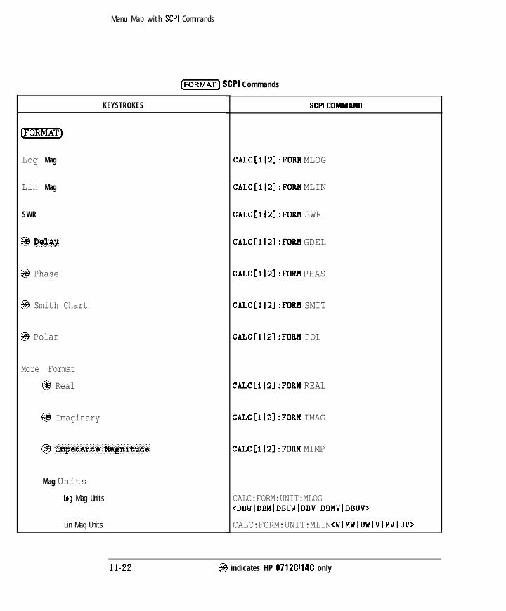
I-
Menu Map with SCPI Commands
CFORMAT) SCPI Commands
I -
KEYSTROKES
Log Mag
Lin Mag
SWR
SE3 Delay
$$3 Phase
3 Smith Chart
3 Polar
More Format
@I Real
@ Imaginary
Mag Units
Log Mag Units
Lin Mag Units
SCPICOMMAND
CALCCIl21:FORM MLOG
CALC[IIZ]:FORM MLIN
CALC[IIZ]:FORM SWR
CALC[lIZ]:FORM GDEL
CALC[ll21:FORM PHAS
CALC[l
CALC[l
CALC[l
CALC[l
CALC[l
21:FORM SMIT
21:FORM POL
21:FORM REAL
21:FORM IMAG
23:FORM MIMP
CALC:FORM:UNIT:MLOG<DBWIDBMIDBUWIDBVIDBMVIDBUV>
CALC:FORM:UNIT:MLIN <WIMWIUWIVlMVIUV>
@ indicates HP 8712C114C only
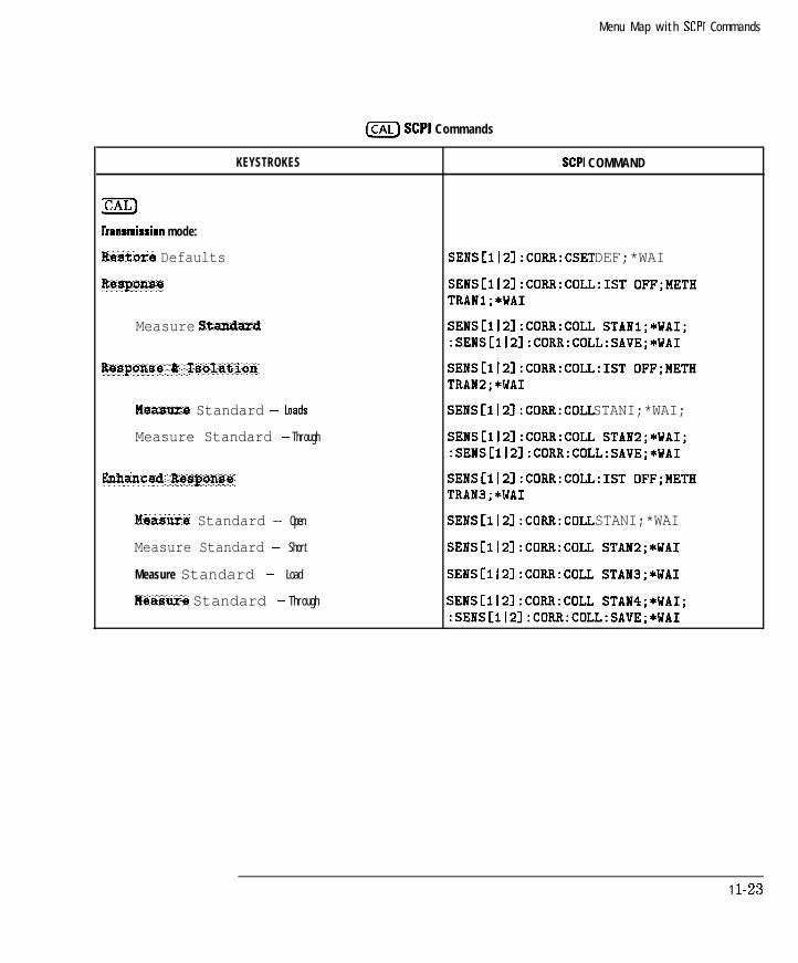
I-
ICALJ SCPI Commands
I -
Menu Map with SCPI Commands
KEYSTROKES
m
bansmission mode:
ftsstore Defaults
R+MpC?W3
Measure Standaxd
Meamrs Standard -
Measure Standard - Through
Measure Standard - Open
Measure Standard - Short
Measure Standard - Load
Measure Standard - Through
SCPI COMMAND
SENS[lIZ]:CORR:CSET DEF;*WAI
SENS[Ii2]:CORR:COLL:IST 0FF;METHTRANl;*WAI
SENS~I121:CORR:COLL STANl;*WAI;:SENS[Il2]:CORR:COLL:SAVE;*WAI
SENS[112]:CORR:COLL:IST 0FF;METHTRANZ;*WAI
SENS[112]:CORR:COLL STANI;*WAI;
SENS[lIZ]:CORR:COLL STANZ;*WAI;:SENS[112]:CORR:COLL:SAVE;*WAI
SENS[I~2]:CORR:COLL:IST 0FF;METHTRAN3;*WAI
SENS[I12]:CORR:COLL STANI;*WAI
SENS[llZ]:CORR:COLL STAN2;*WAI
SENS[Ii2]:CORR:COLL STAN3;*WAI
SENS[Il2]:CORR:COLL STAN4;*WAI;:SENS[Il2]:CORR:COLL:SAVE;*WAI
1 l-23

I- I -
Menu Map with SCPI Commands
ICAL) SCPI Commands (continued)
KEYSTROKES
krnsmission mode (continued):
rest Set Call
C r e a t e "TSET,CAL+"
xx Forts 2
teasers Opens
hasure Shorts
Mcxsure Loads
Measure Thrw
All Stds Done
Abort Cal
Periodic SelfCal
SelfCal once
SelfCal Timer
SelfCal All PorCs
1 For use with HP 87075C multiport test sets only
2 X X - n u m b e r o f p o r t s
SCPI COMMAND
SENS[1(2]:CORR:TESTSET;*WAI
SENS[1~2]:CORR:COLL:METHOD TEST;
SENS[Il2]:CORR:COLL:PORTS<2~4~6~8~10~12>
SENS[Il2]:CORR:COLL:MP:OPENGTANIISTANZI . . . ISTANIZ>;*WAI;
SENS[Il2]:CORR:COLL:MP:SHORT<STANIISTANZ( . . . ISTANIZ>;*WAI;
SENS[I~2]:CORR:COLL:MP:LOAD<STANIISTANZI . ISTANIZ>;*WAI;
SENS[112]:CORR:COLL:MP:THRUGTANIISTAN21 . . . ISTANG>;*WAI;
SENS[112]:CORR:COLL:SAVE;*WAI;
SENS~I~21:CORR:COLL:ABORT
CAL:SELF <ONIOFF>
CAL:SELF ONCE
CAL:SELF:TIMER <num>
CAL:SELF:ALL
1 1 - 2 4
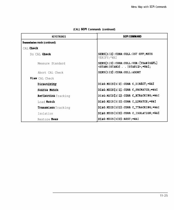
I- I -
Menu Map with SCPI Commands
(CAL) SCPI Commands (continued)
KEYSTROKES
bansmission mode (continued):
CAL Check
Do CAL Clmck
Measure Standard
Abort CAL Check
View CAL Check
Directivity
Sourca fa?xh
Ref leetion Tracking
Load Hatch
Transmissn Tracking
Isolation
Restore Meas
SCPICOMMAND
SENS[112]:CORR:COLL:IST 0FF;METHVERIFY;*WAI
SENSCI~~~:CORR:COLL:VER:~TRAN~REFL~<STANIISTANZI . . ISTANlZ>;*WAI;
SENS[I12]:CORR:COLL:ABORT
DIAG:MDIS[112]:CORR C-DIRECT;*WAI
DIAG:MDIS[lIZ]:CORR C-SRCMATCH;*WAI
DIAG:MDIS[I12]:CORR C-RTRACKING;*WAI
DIAG:MDIS[IIZ]:CORR C-LDMATCH;*WAI
DIAG:MDIS[IIZ]:CORR C-TTRACKING;*WAI
DIAG:MDIS[IIZ]:CORR C-ISOLATION;*WAI
DIAG:MDIS[Il2]:REST;*WAI
1 1 - 2 5

I-
Menu Map with SCPI Commands
LCAL) SCPI Commands (continued)
KEYSTROKES
Reflection mods:
Baatore Defaults
One Port
Measure Standard -Open
lhm~e Standard -Short
Measure Standard - Load
Test Set Call
Greats "TSET,CAL"
XX Ports 2
Measure Opens
Measure Shorts
Measura Loads
Measure Thxus
All Stds Done
Abort Cal
Periodic SelfCal
SelfCal O n c e
SelfCal. Timer
Self&l All Porte
1 For USB with HP 870751: multiport test sets only
2 X X - n u m b e r o f p o r t s
SCPICOMMAND
SENS[lIZ]:CORR:CSET DEF;*WAI
SENSCI~21:CORR:COLL:IST 0FF;METH REFL3;*WA1
SENS[lIZ]:CORR:COLL STANI;*WAI
SENSCI121:CORR:COLL STAN2;*WAI
SENS[lIZI:CORR:COLL STAN3;*WAI;:SENS[1~21:CORR:COLL:SAVE;*WAI
SENS[1121:CORR:TESTSET;*WAI
SENS[l~21:CORR:COLL:METHOD TEST;
SENSCl(21:CORR:COLL:PORTS<2~4~6~8~10~12>
SENS[l121:CORR:COLL:MP:OPENGTANlISTANZI ISTANlZ>;*WAI;
SENS[l~21:CORR:COLL:MP:SHORTGTANIISTANZI . . . tSTANIZ>;*WAI;
SENS[ll21:CORR:COLL:MP:LOAD<STANlISTANZI . . . ISTANlZ>;*WAI;
SENS[1121:CORR:COLL:MP:THRUGTANlISTANZI . . ISTANG>;*WAI;
SENS[l~21:CORR:COLL:SAVE;*WAI;
SENS[1121:CORR:COLL:ABORT
CAL:SELF <ONIOFF>
CAL:SELF ONCE
CAL:SELF:TIMER <nun0
CAL:SELF:ALL
I -
1 l-26

I-
a SCPI Commands (continued) (continued)
I -
Menu Map with SCPI Commands
KEYSTROKES
Irflection mode (continued):
CAL Check
Do CAL Check
Neasuxe Staudard
Abort CAL Check
Viea CAL Check
Directivity
Svurce Match
Reflection Tracking
Load Match
Transmiasn Tracking
Isolatian
Bestore Meas
SCPI COMMAND
SENS[112]:CORR:COLL:IST 0FF;METHVERIFY;*WAI
SENSC~~~~:CORR:COLL:VER:CTRAN~REFL~<STANIISTAN21 . ISTANl2>;*WAI;
SENS[l~2]:CORR:COLL:ABORT
DIAG:MDIS[l
DIAG:MDIS[l
DIAG:MDIS[l
23:CORR C-DIRECT;*WAI
23:CORR C-SRCMATCH;*WAI
23:CORR C-RTRACKING;*WAI
DIAG:MDIS[lIZ]:CORR CJDMATCH;*WAI
DIAG:MDIS[l.l2]:CORR C-TTRACKING;*WAI
DIAG:MDIS[lIZ]:CORR CmISOLATION;*WAI
DIAG:MDIS[I~2]:REST;*WAI
11-27

I- I -
Menu Map with SCPI Commands
ICAL] SCPI Commands (continued)
KEYSTROKES
Fault location mode:'
Default Cal
Full 3and Cal
Measure Standard -Open
Yeasure Standard -Short
Measure Standard -load
Velocity Factor
Cable Loss
Calibrate Cable
Specify Length
Measure Cable
Multi Peak
Multi Peak Corr on OFF
Multi Peak Threshold
Connector Values
Connector Length
connectox c
1 Option 100 only
SCPICOMMAND
SENS[ll21:CORR:CSET DEF;*WAI
SENS[1/2]:CORR:COLL:IST 0N;METH REFL3;*WA1
SENS[lIZ]:CORR:COLL STANl;*WAI
SENS[lIZ]:CORR:COLL STANZ;*WAI
SENS[lIZ]:CORR:COLL STAN3;*WAI;:SENS[l12]:CORR:COLL:SAVE;*WAI
SENS[112]:CORR:RVEL:COAX <mm>
SENS[ll2]:CORR:LOSS:COAX <nun0
SENSCll21:CORR:LENG:COAX Quun>[FEETIMET];*WAI
SENS[l I
SENS[l
SENSE1
23:CORR:RVEL;*WAI
21 :CORR:PEAK:COAX CONIOFFI
2l:CORR:THR:COAX <nun>
SENS[112]:CORR:LENG:CONN <nun>
SENS[112]:CORR:CAP:CONN <nun>
11-28
I-

I-
[CAL) SCPI Commands (continued)
I -
Menu Map with SCPI Commands
KEYSTROKES
SRL mode:’
Default Clstl
Full BandCal
Measure Standard -Open
Measure Standard - Short
Measure Staudard - Load
Connector Model
Msaauxe Connector
Measure
Connector Length
Connector C
2 cutoff Frequency
Auto Z ON off
ManualZ
I\M Delay mode::!
Restore Defaults
Response
Measure Standard
L O p t i o n 1 0 0 on&
! O p t i o n s IDA a n d 1DB o n l y
SCPI COMMAND
SENS[lIZ]:CORR:CSET DEF;*WAI
SENS[Il2]:CORR:COLL:IST 0N;METH REFL3;*WA1
SENS[lIZ]:CORR:COLL STANl;*WAI
SENS[lIZ]:CORR:COLL STAN2;*WAI
SENS[lIZ]:CORR:COLL STAN3;*WAI;:SENS[112]:CORR:COLL:SAVE;*WAI
SENS[112]:CORR:MODEL:CONN
SENSCll2l:CORR:LENG:CONN <mm>
SENS[l12]:CORR:CAP:CONN <nun0
SENS[llZ]:FREQ:ZST <nun>CGHZIMHZIKHZIHZI
SENSC~I~I:FUNC:SRL:MODE CAUTOIMANI
SENS[l12]:FUNC:SRL:IMP <nun>
SENS[llZ]:CORR:COLL:IST 0FF;METHTRANl;*WAI
SENS[I~2]:CORR:COLL:IST 0FF;METHTRANI;*WAI
SENS[112]:CORR:COLL STANl;*WAI;:SENS[l(2]:CORR:COLL:SAVE;*WAI
11-29

I- I -
Menu Map with SCPI Commands
ICALl SCPI Commands (continued)
KEYSTROKES SCPI COMMAND
Cal Kit
Default Type-H(f) SENS:CORR:COLL:CKIT 'COAX,7MM,TYPE-N,50,FEMALESENS:CORR:COLL:CKIT'COAX,7NM,TYPE-1,75,FEMALE' (Option 1EC)
Type-Nm) SENS:CORR:COLL:CKIT 'COAX,7MM,TYPE-N,50,MALE'SENS:CORR:COLL:CKIT'COAX,7MM,TYPE-N,75,MALE' (Option 1EC)
User Defined SENS:CORR:COLL:CKIT'USER,IMPLIED,IMPLIED, IMPLIED,IMPLIED'
3.5 mm1 SENS:CORR:COLL:CKIT'COAX,3.5MM,APC-3.5,5O,IMPLIED'
Type-F* SENS:CORR:COLL:CKIT'COAX,7MM,TYPE-F,75,IMPLIED'
System 20
50 a SENS[I12]:CORR:IMP:INP:MAGN:SEL 20-50
75 n SENS[I12]:CORR:IMP:INP:MAGN:SEL 20-75
Jower mode, Conversion Loss mode, broadband detection modes:
Autozero CAL:ZERO:AUTO ON;*WAI
Manual Zero CAL:ZERO:AUTO ONCE;*WAI
Jnratioed narrowband internal measurements:
Normalize TRAC CH[l12]SMEM,CJi[I12]SDATA;:CALC[1123:MATH (IMPL/CH[lIZlSMEM);:DISP:WIND[I~2]:TRACl ON;TRAC2 OFF
1 5OfI systems only
2 75f2 systems only
11-30

I- I -
Menu Map with SCPI Commands
gl M o r e C a l
(CAL) SCPI Commands (continued)
KEYSTROKES SCPICOMMANO
@ Velocity Factor (Number)(ENTERI) SENS[II2]:COFlFt:FlVEL:COAX <nun>
@ Smith Chart 223 (Number][~] SENSCII~I:CORR:IMP:INP:MAGN <nun> [OHM]
@ Port Ext 4 s on OFF SENS[ItZ]:CORR:EXT [ONlOFFl
@ Bei1 Port Extxnaion (Number)[m] SENSCI121:CORR:EXT:REFL:TIME Quun>Caslfslpslnsluslmslsll
@ Trans Port Extenaioa (Number)(m) SENS cl I2l:CORR:EXT:TRAN :TIME Quun>Caslfslpslnsluslmslsll
1 If using the microsecond unit terminator, the letter 7~” must be used. Do not use the Greek character ‘p.’
@I indicates HP 87 12Cl14C only 11-31

I- I -
Menu Map with SCPI Commands
KEYSTROKES
LAVG) SCPI Commands
SCPICOMMAND
Rvaraga on OFF
Restart Average
Average Factor l-Number] (ENTERI)
System Bandwidth
Wide
Med Wide
Medium
Msd NamOR
BlXlZOtif
Fine
?ault Window1
Minimum
tedium
Maximum
$$J Delay Aperture
SENS[112]:AVER <ONIOFF>;*WAI
SENS[I12]:AVER:CLE;*WAI
SENS[IIZ]:AVER:COUN <num>;*WAI
SENSC1121:BWID 6500 HZ;*WAI
SENS[I12]:BWID 4000 HZ;*WAI
SENS[1(2]:BWID 3700 HZ;*WAI
SENS[IIZ]:BWID 1200 HZ;*WAI
SENS[IIZ]:BWID 250 HZ;*WAI
SENS[112]:BWID 15 HZ;*WAI
SENS[lIZ]:WIND RECT
SENS[lIZ]:WIND HAMM
SENS[I12]:WIND KBES
'&I Aperture (Etz) (Number)(-) CALC[lIZ]:GDAP:SPAN <nun> [HZ];*WAI
@ Aperture (%) (Number)(m) CALCCIl2l:GDAP:APER <num>;*WAI
1 Option 100 only
1 l-32 @ indicates HP 8712Cl14C only
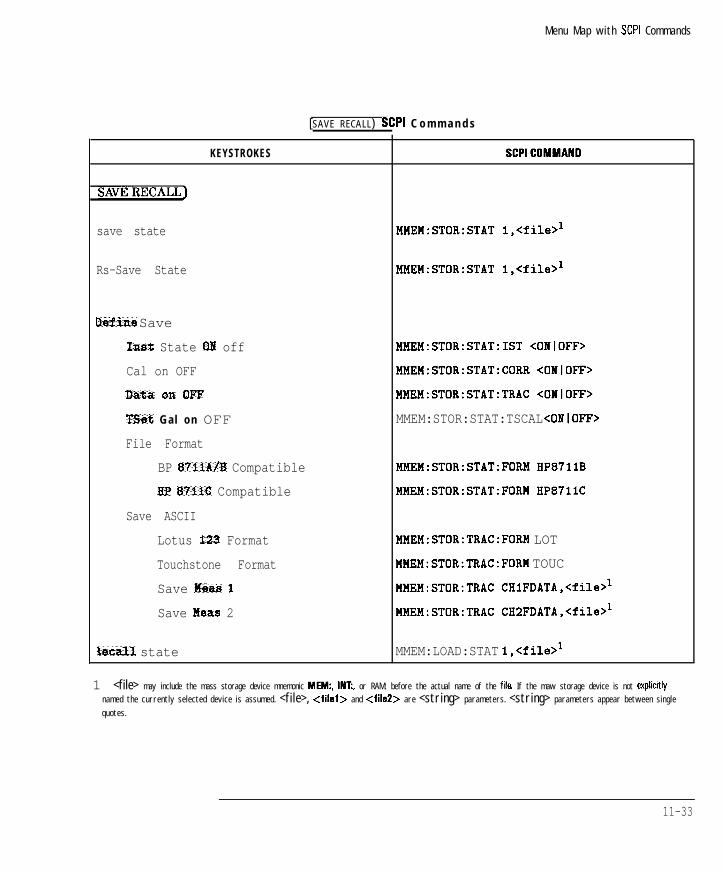
I- I -
Menu Map with SCPI Commands
[ S A V E R E C A L L ) SCPI C o m m a n d s
KEYSTROKES SCPICOMMAND
SAVERECALL]
save state MMEM:STOR:STAT l,<file>'
Rs-Save State MMEM:STOR:STAT l,<file>'
Dsfine Save
Inst State OH off
Cal on OFF
&kta QXI OFF
‘Bet Gal on OFF
File Format
BP 87118/B Compatible
BP 87iiC Compatible
Save ASCII
Lotus X23 Format
Touchstone Format
Save Meas 1
Save Meas 2
Eecall state
MMEM:STOR:STAT:IST <ONIOFF>
MMEM:STOR:STAT:CORR <OIlOFF>
MMEM:STOR:STAT:TRAC <ONIOFF>
MMEM:STOR:STAT:TSCAL <ONlOFF>
MMEM:STOR:STAT:FORM HP871lB
MMEM:STOR:STAT:FORM HP871iC
MMEM:STOR:TRAC:FORM LOT
MMEM:STOR:TRAC:FORM TOUC
MMEM:STOR:TRAC CHlFDATA,<file>'
MMEM:STOR:TRAC CH2FDATA,<file>'
MMEM:LOAD:STAT l,<file>'
1 <file> may include the mass storage device mnemonic MEW, INT:, or RAM: before the actual name of the fila If the maw storage device is not explicrtly
named the currently selected device is assumed. <file>, <filel> and <fileZ> are <string> parameters. <string> parameters appear between single
quotes.
11-33
I-

I- I -
Menu Map with SCPI Commands
[SAVE R E C A L L ] SCPI Commands (continued)
KEYSTROKES
Programs
Save Program
h-Save Program
File Type bin ASCII
Recall Program
Save AUTOST
IBASIC'
Select Disk
Non-V01 RAM Disk
Volatile BAM Disk
Internal 3 5" Disk.
Configure UOL,RAM
Restore Defaults
Modify Size
Current Size
The IBASIC menu is described under the SYSTEM OPTIONS key
SCPICOMMAND
!fMEM:MSIS 'MEM:'
!lMEM:MSIS 'RAM:'
YMEM:MSIS 'INT:'
lo SCPI command
tie SCPI command
Jo SCPI command
1 1 - 3 4
-1
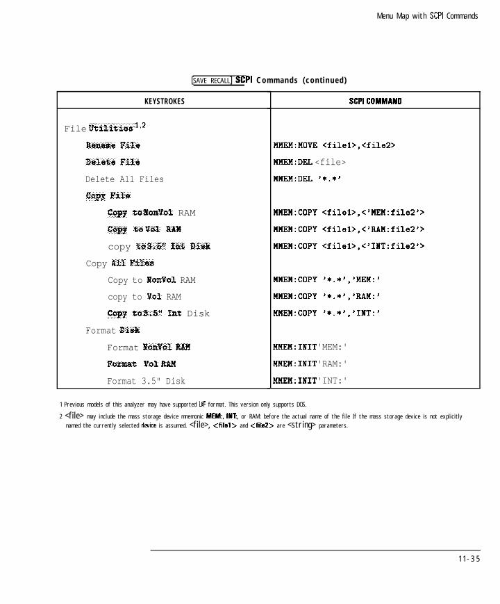
I- I -
Menu Map with SCPI Commands
[SAVE R E C A L L ] SCPI Commands (continued)
KEYSTROKES
File Utilities112
Rename File
Delste File
Delete All Files
Copy File
copy tQ Nanvol RAM
copy tQ VOX BAItI
copy tQ 3.5r' Int Disk
Copy All Files
Copy to NonVol RAM
copy to Vol RAM
copy tQ 395" Int Disk
Format &hk
Format gtonkl RAM
Format Oal BM
Format 3.5" Disk
SCPICOMMAND
MMEM:MOVE <filei>,<file2>
MMEM:DEL <file>
MMEM:DEL '*.*'
MMEM:COPY <filel>,<'MEM:file2'>
MMEM:COPY <filel>,<'RAM:file2'>
MMEM:COPY <filel>,<'INT:file2'>
MMEM:COPY '*.*'.'MEM:'
MMEM:COPY '*.*','RAM:'
MMEM:COPY '*.*','INT:'
MMEM:INIT 'MEM:'
MMEM:INIT 'RAM:'
MMEM:INIT 'INT:'
1 Previous models of this analyzer may have supported LIF format. This version only supports DOS.
2 <file> may include the mass storage device mnemonic MEW, INT:, or RAM: before the actual name of the fi le If the mass storage device is not explicitly
named the currently selected deice is assumed. <file>, <filed> and <fileZ> are <string> parameters.
1 1 - 3 5
I-

I-
Menu Map with SCPI Commands
[SAVE R E C A L L ] SCPI Commands (continued)
KEYSTROKES
Dixectory U t i l i t i e s
c h a n g e D i r e c t o r y
Make Directory
Removs D i r e c t o r y
SCPICOMMAND
MMEM:CDIR <directory>
MMEM:MDIR <directory>
MMEM:RDIR <directory>
FastRecall on OFF DISP:MENU:REC:FAST <ONIOFF>
1 1 - 3 6

I- I -
Menu Map with SCPI Commands
(j-COPY_) SCPI Commands
KEYSTROKES SCPICOMMAND
H A R D C O P Y )
&art HCOP;*WAI
lbort HCOP:ABOR
hlsct Copy Port
Restore Defatzlts
Select
LAN Printr" IP Addr
Printer Address [Number)(m)
Baud Bate [NumberlLm)
Xon/Xoff
DTR/DSR
Define PCL5
ReStQre Defaults
MO~O&XOttt~
Color
Auto Feed ON off
Portrait
Landscap
No SCPI Command
HCOP:DEV:LANG <PCLIHPGLIIBMIEPSONiPCX>;PORT <CENTISERIGPIBIMMEMILAN>
SYST:COMM:LAN:PRIN:HOST <string>
SYST:COMM:GPIB:HCOP:ADDR <mm>
SYST:COHM:SER:TRAN:BAUD QUIII>
SYST:COMM:SER:TRAN:HAND XON
SYST:COMM:SER:TRAN:HAND DTR
No SCPI Command
HCOP:DEV3:COL OFF
HCOP:DEV3:COL ON
HCOP:ITEM3:FFE:STAT <ONIOFF>
HCOP:DEV3:PAGE:ORI PORT
HCOP:DEV3:PAGE:ORI LAND
11-37
I-

I-
M e n u M a p w i t h SCPI C o m m a n d s
@iiEEYTj SCPI Commands (continued)
KEYSTROKES SCPI COMMAND
More PCL5
Restore Defaults N o SCPI C o m m a n d
Top Margin [-]L-) HCOP:DEV3:PAGE:MARG:TOP <nun0
Left Margin [Number)[~] HCOP:DEV3:PAGE:MARG:LEFT <num>
Print Width (Number)[m] HCOP:DEV3:PAGE:WIDT <nun>
Define Printer
Restore Defaults N o SCPI C o m m a n d
Monochronte HCOP:DEVl:COL OFF
Color HCOP:DEVl:COL ON
Portrait HCOP:PAGE:ORI PORT
Landscape HCOP:PAGE:ORI LAND
Auto Feed OIi off HCOP:ITEMl:FFE:STAT <ONIOFF>
tore Printer
Restore Defaults N o SCPI C o m m a n d
Printer Rasolution
(Number)(ENTER) HCOP:DEV:RES <nun>
Top Mwgin(-Numberl[-) HCOP:PAGE:MARG:TOP <num>
Left Margin @ZiK%)[~) HCOP:PAGE:MARG:LEFT <num>
Print Width [m)[ENTER) HCOP:PAGE:WIDT <nun>
Define Plotter
Restore Defaults N o SCPI C o m m a n d
MOItOChXOttt~ HCOP:DEVZ:COL OFF
Color HCOP:DEVZ:COL ON
11-38
I-

I- I -
M e n u M a p w i t h SCPI C o m m a n d s
CH A R D C O P Y ] SCPI Commands (continued)
KEYSTROKES SCPICOMMAND
Set Pen tumb%rs
MoIlochrom% Pen (Number)[ENTER) N o SCPI C o m m a n d
Default Pan Colors N o SCPI C o m m a n d
Traca 1 Pen [w)IENTERj N o SCPI C o m m a n d
Traca 2 Pan (Number][ENTERj N o SCPI C o m m a n d
Memory f Pen (Number)(ENTER_) N o SCPI C o m m a n d
Memory 2 Pen (Number)IENTER) N o SCPI C o m m a n d
Grat icu le Pm CNumber](mj N o SCPI C o m m a n d
Graphics Den [Numberl[ENTERJ N o SCPI C o m m a n d
Auto Feed on OFF HCOP:ITEM2:FFE:STAT <ONIOFF>
Define Hardcopy
Restor% Defaults N o SCPI C o m m a n d
Graph and Mkr Tabla HCOP:DEV:MODE GMAR
Graph Only HCOP:DEV:MODE GRAP
Mkr Table Only HCOP:DEV:MODE MARK
List Traca Values HCOP:DEV:MODE TABL
Define Graph
Restore Defaults N o SCPI C o m m a n d
Trace Data ON off HCOP:ITEM:TRAC:STAT <ONIOFF>
Graticule ON off HCOP:ITEM:GRAT:STAT <ONIOFF>
Annotation ON off HCOP:ITEM:ANN:STAT <OIlOFF>
J&r Symbol ON off HCOP:ITEM:MARK:STAT <OIlOFF>
Title + Clk Of off HCOP:ITEM:TITL:STAT <ONIOFF>
11-39
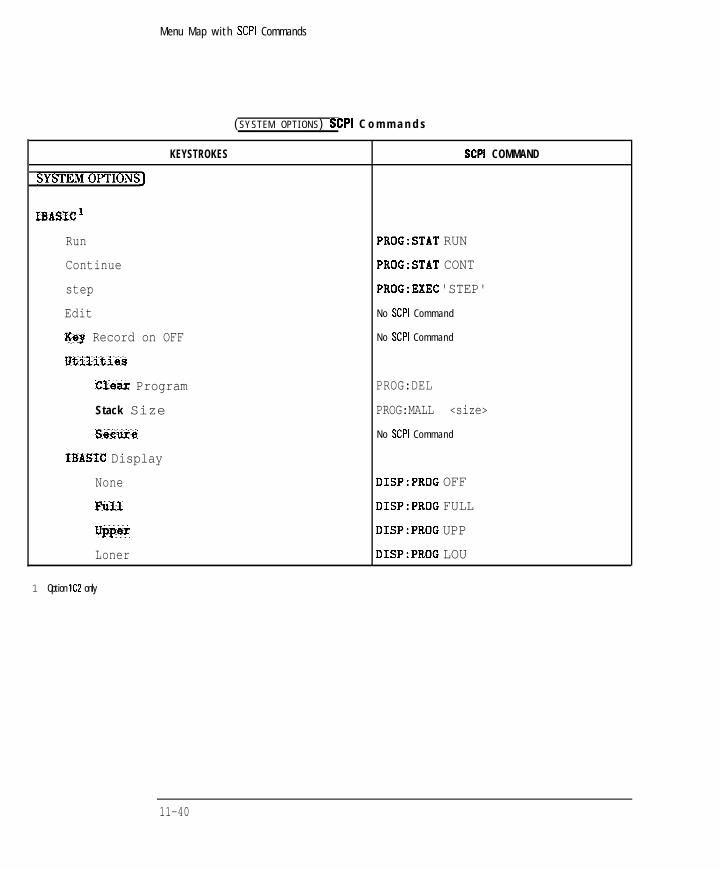
I- I -
Menu Map with SCPI Commands
( S Y S T E M O P T I O N S ) SCPI C o m m a n d s
KEYSTROKES SCPI COMMAND
SYSTEMOPTIONS]
IBASIC '
Run
Continue
step
Edit
Key Record on OFF
IItilities
Clear Program
Stack Size
sscnre
IBASIC Display
None
FStll
UPPer
Loner
PROG:STAT RUN
PROG:STAT CONT
PROG:EXEC 'STEP'
N o SCPI C o m m a n d
N o SCPI C o m m a n d
PROG:DEL
PROG:MALL <size>
N o SCPI C o m m a n d
DISP:PROG OFF
DISP:PROG FULL
DISP:PROG UPP
DISP:PROG LOU
1 Option lC2 only
11-40

I- I -
Menu Map with SCPI Commands
( S Y S T E M O P T I O N S ) SCPI Commands (con t inued )
KEYSTROKES
LAr?l
LAB State on OFF
LAB Port Setup
BP 8?X4C IP Address
Gateway XP Address
Subnet Mask
Diagnostic Utilities
IP Address to Ping
Perform Ping
Ethernet Address
Security Setup
SCPICOMMAND
SYST:COMM:LAN:STAT <ONlOFF>
SYST:COMM:LAN:IPAD <string>
SYST:COMM:LAN:ROUT:GAT <string>
SYST:COMM:LAN:ROUT:SMAS <string>
DIAG:COMM:LAN:PING:IPAD <string>
DIAG:COMM:LAN:PING:IMM
SYST:COMM:LAN:EADD?
HP-II
iiP 8714C Address [Number](ENTER)
Talker Listener
System Controller
HP-13 Echo on OFF
Operating Parameters
Hardcopy Scrsan
ffardcopJr All
Abort
SYST:COMM:GPIB:ADDR <nun>*
SYST:COMM:GPIB:CONT OFF3
SYST:COMM:GPIB:CONT ON3
SYST:COMM:GPIB:ECHO <ONIOFF>
No SCPI Command
HCOP:DEV:MODE ISET;:HCOP;*WAI
HCOP:ABOR
1 O p t i o n lF7 o n l y
2 A five second delay is required before a command is sent to the new address.
3 For use with IBASIC running on the analyzer’s internal controller - this command cannot be executed from an external controller. Use 'OPC? and wait for a reply
before sending any OUTPUT 7xx commands from IBASIC
11-41

- I -
Menu Map with SCPI Commands
CSYSTEM OPTIONS) SCPI Commands (continued)
KEYSTROKES SCPICOMMAND
System Config
Set Clock
S e t Y e a r ( N u m b e r ) [j?NEiT] SYST:DATE <year>,<month>,<day>l
Set Month (w)(m) SYST:DATE <year>,<month>,<day>'
S e t D a y ( N u m b e r ] [EmEiF] SYST:DATE <year>,<month>,<day>'
Set Hour (Number) (ENTER) SYST:TIME <hour>.<minute>.<second>f
Set Minuta (jj)(ENTER) SYST:TIME <hour>,<minuta>,<second>'
Rovnd Seconds SYST:TIME <hour>,<minute>,O'
Clock Format
ww-MM-DD HH : MM DISP:ANN:CLOC:DATE:FORM YMD
MM-DD-WYY HH : MM DISP:ANN:CLOC:DATE:FORM MDY
DD-MM-YYYY HH; MM DISP:ANN:CLOC:DATE:FORM DMY
Numeric DISP:ANN:CLOC:DATE:MODE NUM
Alpha DISP:ANN:CLOC:DATE:MODE ALPH
Seconds OH off DISP:ANN:CLOC:SEC <OWlOFF>
D o n s
Beeper Volume CNumber)[mj SYST:BEEP:VOL <num>*
1 <yaar>,<month>,<day>,<hour>,<minute > and <second> are all <num> parameters. Also, these keys do not generate keystroke recording BASIC
statements.
2 Number is a fraction, for example 90% would be expressed as 0.90
11-42

I- I -
M e n u M a p w i t h SCPI C o m m a n d s
CSYSTEM OPTIONS) SCPI Commands (continued)
KEYSTROKES SCPICOMMAND
CRT Adjust
&store Defaults N o SCPI C o m m a n d
Vertical Position N o SCPI C o m m a n d
Horimntal Position N o SCPI C o m m a n d
Sync Green on OFF N o SCPI C o m m a n d
R e m o v e Patt em. N o SCPI C o m m a n d
More
Restare Defaults N o SCPI C o m m a n d
Vertical Back Porch N o SCPI C o m m a n d
Vertical Frnt Porch N o SCPI C o m m a n d
Horizontal Back Porch N o SCPI C o m m a n d
Horizontal Frnt Porch N o SCPI C o m m a n d
options Setup
User TTL Config
nei! ault SYST:COMM:TTL:USER:FEED DEFAULT
Softkey Auto-Step SYST:COMM:TTL:USER:FEED KEY
Saeep Out SYST:COMM:TTL:USER:FEED SWEEP
Switching Test Set1
Multiport on OFF CONT[lIZ]:MULT:STATE <ONIOFF>
ssxvice 2
1 For use with HP 8707% multiport test sets only
2 The Service menu is described in the SeMe Guide.
11-43
I-

I-
Menu Map with SCPI Commands
I -

I- I -
12
SCPI Command Summary
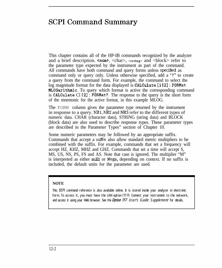
I- I -
SCPI Command Summary
This chapter contains all of the HP-IB commands recognized by the analyzerand a brief description. <mm>, <char>, <string> and <block> refer tothe parameter type expected by the instrument as part of the command.All commands have both command and query forms unless specihed ascommand only or query only. Unless otherwise specified, add a “?” to createa query from the command form. For example, the command to select thelog magnitude format for the data displayed is CALCulate [I 121 : FORMatMLOGarithmic. To query which format is active the corresponding commandis CALCulate Cl I21 : FORMat?. The response to the query is the short formof the mnemonic for the active format, in this example MLOG.
The FORM column gives the parameter type returned by the instrumentin response to a query. NRl, NR2 and NR3 refer to the different types ofnumeric data. CHAR (character data), STRING (string data) and BLOCK(block data) are also used to describe response types. These parameter typesare described in the Parameter Types” section of Chapter 10.
Some numeric parameters may be followed by an appropriate suffix.Commands that accept a suffix also allow standard metric multipliers to becombined with the suffix. For example, commands that set a frequency willaccept HZ, KHZ, MHZ and GHZ. Commands that set a time will accept S,MS, US, NS, PS, FS and AS. Note that case is ignored. The multiplier “M”is interpreted as either milli or Mega, depending on context. If no suffix isincluded, the default units for the parameter are used.
NOTE
This SCPI command reference is also available online. It is stored inside your analyzer in electronic
form. To access it, you must have the LAN option (lF71. Connect your instrument to the network,
and access it using your Web browser. See the Option IF7 User’s Guide Supplement for details.
12-2

I-SCPI C o m m a n d S u m m a r y
I -
SUBSYSTEM COMMANDS I FORM I DESCRIPTION
ABORt 7 c o m m a n d o n l y A b o r t a n d r e s e t t h e s w e e p i n p r o g r e s s .I ~ I
12-3

I-
SCPI C o m m a n d S u m m a r y
CALCulate
SUBSYSTEM COMMANDS
CALCulateC1121:DATA?1
CALCulateCil21:FORMat <char>
FORM DESCRIPTION
query only Ruery the formatted data trace - functionally equivalent to th
BlCCK or NFU2 command TRAC? CH<112>FDATA.
C H A R Select the display format for the measurement data - choose
from MLOGarithmiclMLINearlSWR
&-PHASeISMIThiPOLarIGDELayIREALIIMAGinarylMIMPedance.
CALCulate[il2]:FORMat:UNIT:MLIN <char> C H A R Selects l inear magnitude units for Y-axis display. Choose from
WlMWlUWlVlMVlUV.
CALCulate[il2]:FORMat:UNIT:MLOG <char> C H A R Selects log magnitude units for Y-axis display. Choose from
DBWlDBMlDBUWlDBViDBMVIDBUV.
@CALCulateCl121:GDAPerture:APERture<nun0
NR3 Set the group delay aperture es a ratio of desired aperture /
measured frequency span.
@CALCulate[il2]:GDAPerture:SPAN <num>
CALCulate[ll2]:LIMit:DISPlay <ONIOFF>3
CALCulate[ll2]:LIMit:MARKer:FLATness:MAXimum <mm>
NR3 Specifies the group delay aperture in Hertz.
NRl Turn on/off display of l imit l ines.
NR3 Set the maximum value for a flatness l imit test.
CALCulateCll2l:LIMit:MARKer:FLATness:MINimum <mm>
NR3 Set the minimum value for a flatness marker l imit test.
CALCulate[ll2]:LIMit:MARKer:FLATness:STATe <ONIOFF>3
NRl Turn on/off flatness marker limit test.
1 Refer to Chapter 6, “Trace Data Transfers,” and to the “ASCDATA” and ‘REALDATA” example programs in Chapter 8 for more information on this command.
2 The parameter type of the data is determined by the format selected - FORMet REAL usas BLOCK data, FORMat ASCii uses NR3 data separated by commas.
3 Binary parameters accept the values of I Ion1 and 0 (off) in addition to ON and OFF.
12-4 @ indicates HP B712B114B only

I- I -SCPI C o m m a n d S u m m a r y
CALCulate (continued)
SUBSYSTEM COMMANDS I FORM DESCRIPTION I
CALCulate[ll2]:LIMit:MAKKer:FREQuency:MAXimum <num>'
NR3
CALCulate[ll2]:LIMit:MARKer:FREQuency: MIIimum <num>'
NR3 Sets the minimum velue for delta frequency marker l imit test.
CALCulate[ll2]:LIMit:MARKer:FREQuencyC:STATel <ONIOFF>*
NRl Turns delta frequency marker l imit testing on or off.
CALCulate[112]:LIMit:MARKer:STATistic:MEAN:MAXimum <num>
NR3 Set the maximum value for e stetistic mean limit test.
CALCulate[li2]:LIMit:MARKer:STATistic:MEAN:MINimum Cnum>
NR3
Sets the maximum value for delta frequency marker l imit test.
Set the minimum value for e statistic mean limit test.
CALCulate[ll2]:LIMit:MARKer:STATistic
Turn on/off statistic mean marker limit test.
Set the maximum value for e stetistic peak-to-peak l imit test.
CALCulate[ll2]:LIMit:MARKer:STATistic:PEAK:MINimum <num>
NR3 Set the minimum value for a statistic peak-to-peek l imit test.
CALCulate[l(2]:LIMit:MARKer:STATistic NRI Turn on/off stetistic peak-to-peak marker limit test.
:PEAK:STATe <ONlOFF>*
CALCulate[ll2]:LIMit:MARKer:TILT:MAXimum Cnum> I
NR3 Sets the maximum value for delta amplitude marker l imit test.
CALCulate[ll2];LIMit:MARKer:TILT
CALCulate[ll2]:LIMit:SEGMentCi I2 I. ..12].AMPLitude:STARt <num>'
NR3
Sets the minimum value for delta amplitude marker limit test.
Turns delta amplitude marker l imit testing on or off.
1 Numeric parameters may include an appropriate suffw; if no suffix is included, the default IHZ for frequency or S for time1 is assumed.
2 Binary parameters accept the values of 1 Ion1 and 0 loffl in addition to ON and OFF.
1 2 - 5

I- I -
SCPI C o m m a n d S u m m a r y
CALCulate (continued)
SUBSYSTEM COMMANDS
CALCulate~ll2]:LIMit:SEGMent[ll2l. ..121.AMPLitude:STOP <mm>'
FORM
NR3
DESCRIPTION
Set the End Limit for the specified l imit segment.
CALCulate[ll2]:LIMit:SEGMent:AOFFI I
c o m m a n d o n l y Turn off all l imit segments for a given channel - deletes all
segments in the channel’s l imit table.
CALCulate[ll2]:LINit:SEGMent[ll2(. ..121.DISTance:STARt <nu!&
NR3 Set the Begin Distance for the specified l imit segment. [Option
1 0 0 only1
CALCulate[ll2l:LIHit:SEGMentCil21. ..121.DISTance:STOP <mm>'
NR3 Set the End Distance for the specified l imit segment. [Option
1 0 0 only1
CALCulate[ll2]:LIMit:SEGMent[l~2~. ..121.FREOuencv:STARt <mm>'
NR3 Set the Begin Frequency for the specified l imit segment.
CALCulate[ll2]:LIMit:SEGMent[ll21. ..12l.FREQuency:STOP <mu& I NR3 I
Set the End Frequency for the specified l imit segment.
CALCulate[l)2]:LIMit:SEGMent[ll2). ..lZl.POWer:STARt <nun0 I NR3 I
Set the Begin Power for the specified l imit segment.
CALCulate[ll2]:LIMit:SEGMent[ll2~. ..12].POWer:STOP <mm>
NR3 Set the End Power for the specified l imit segment.
CALCulate~ll2l:LIMit:SEGMentCil2l. ..121.STATe <ONIOFF>*
NRl Turn on/off the specified l imit segment - adds or deletes the
segment.
CALCulate[ll2]:LIMit:SEGMentCil2~. ..121.TYPE <char>
C H A R Set the l imit type for the specified segment, choose from
LMAXlLMINjPHAXlPMIN IMex Line, Min Line, Max
Point, Min Point1 - sets all of the segment’s l imit parameters
to their default values.
CALCulateCll21:LIMit:STATe <ONlOFF>* NRl Turn on/off the limit test.
CALCulate[1121:MARKer:AOFF c o m m a n d o n l y Turn off al l markers for a given channel - this has the effect
of turning off marker functions and tracking es well .
CALCulate[112]:MARKer:BWIDth <mm>' NR3 Calculate the bandwidth of a bendpass filter - num is the
target bandwidth 1-3 for the 3 dB bandwidthl .
1 Numeric parameters may include an appropriate suff~; if no suffbc is included, the default IlIZ for frequency or S for time1 is assumed.
2 Binary parameters accept the value of 1 Ion) and 0 loffl in addition to ON and OFF.
12-6

- I -
SCPI C o m m a n d S u m m a r y
CALCulate (continued)
SUBSYSTEM COMMANDS
CALCulate[ll2]:MARKer:FUNCtion:RESult?
CALCulateCll21:MARKer:FUNCtion[:SELect] <char>
CALCulate[l12]:MARKer:FUNCtion:TRACking <OIlOFF>'
CALCulat e Cl I 21: MARKer cl I 2 I .-8l:MAXimum
CALCulate~ll2l:MA~~erC1l2l~~~83:MAXimum:LEFT
CALCulate[ll21 :MARKerCI l2l.-81:MAXimum:RIGHt
CALCulate[ll2]:MARKer[ll2 I.-81:MINimum
CALCulate[ll2]:MARKer~ll2l~~~8l:MINimum:LEFT
CALCulate[ll2]:MARKer[l l2l.-81:MINimum:RIGHt
FORM
query only
NR3[,NR3,
NR3,NR3]
C H A R
NRl
query only
c o m m a n d o n l y
c o m m a n d o n l y
c o m m a n d o n l y
c o m m e n d o n l y
c o m m a n d o n l y
c o m m a n d o n l y
1 Binary parameters accept the values of 1 Ion1 and 0 loffl in addition to ON and OFF.
DESCRIPTION
fluery the results of the active marker function - MAX and
MIN return the amplitude; TARG returns the frequency;
BWID returns bandwidth, center frequency, [1 and loss; STAYreturns the frequency span, the mean and standard deviation
of the amplitude response, end the peak-to-peak ripple; FLATreturns the frequency span, gain, slope and flatness; and
FSTAT returns the insertion loss and peek-to-peek ripple of
the passband of e filter, as well as the maximum signal
a m p l i t u d e i n t h e s t o p b a n d . R e f e r t o t h e “ M A R K E R S e x a m p l e
program in Chapter 8 for more information.
Select the active marker function - choose from
OFFIMAXimumlMINimumITARGetIBWIDthINOTChlMPEaklMNOTchlSTATisticslFLATnesslFSTATistics.
Turn on/off marker function tracking.
Returns the group delay value, in seconds, at the specified
marker.
Set the specified marker to the maximum value on the trace.
Moves the specified marker to the next local maximum to the
left.
Moves the specified marker to the next local maximum to the
right.
Set the specified marker to the minimum value on the trace.
Moves the specified marker to the next local minimum to the
left.
Moves the speciiied marker to the next local minimum to the
right.
12-7

I-
SCPI C o m m a n d S u m m a r y
CALCulate (continued)
SUBSYSTEM COMMANDS FORM
CALCulate[ll2]:MARKer:MODE <char> C H A R
DESCRIPTION
Turn on/off delta marker state - choose ABSolute or
RELative.
CALCulateCl I21:MARKer:BOTCh <mud NR3 Calculate the notch width of a notch filter - num is the
target notch width f-6 for the 6dB bandwidth] .
CALCulateCl I2l:MARKerCl I2 I . ..8]
:POINt*NR3 Set the specified marker point.
CALCulateCll21:MARKer:REFerence:X? query only Query the frequency of the reference marker.
NR3
CALCulate[ll2]:MARKer:REFerence:Y? query only Query the amplitude of the reference marker.
NR3
CALCu1ateC1121:MARKerC1121~~~81[:STATe] <ON10FF>3
NRI Turn on/off the specified marker.
CALCulate[ll2]:MARKer[ll2l~~~8] CHAR,NR3 Perform a marker search for a target value - char is the
:TARGet <char>,<nud direction LEFT or RIGHt.
CALCulate[ll2]:MARKerCll2l~~~8]:X <nun0 NR3 Set the specified marker frequency for power if in power
sweep]
N R ? Set a marker to en absolute value lsuch es frequency or
amplitude] . The set value is not relative to e reference marker
if one is enabled.
query only Cluery the specified marker amplitude.
NR3
@CALCulate[l~2]:MARKer[ll2l~~~8]:Y
:INDuctance ?
query only
NR3
[luery the specified marker’s inductance when in Smith chart
format.
1 Numeric parameters may include an appropriate suffbb; if no suffii is included the default Ill2 for frequency or S for time1 is assumed.
2 Refer to “Displaying Measurement Results” in Chapter 7 of the User’s Guide for more information on using this command.
3 Binary parameters accept the values of 1 Ion1 and 0 loffl in addition to ON and OFF.
12-8 @I indicates HP 8712Bl14B only

I-
SCPI C o m m a n d S u m m a r y
CALCulate (continued)
SUBSYSTEM COMMANDS
@CALCulate[l I2l:MARKerCl I2 I . ..8l.Y
:MAGNitude?
@CALCulate[ll2]:MARKer[l I2 I . ..81.Y
:PHASe?
@CALCulate[ll2]:MARKer[l I2 I . ..81.Y
:REACtance?
@CALCulateCl I2l:MARKerCI I2 I . ..81.Y
:RESistance ?
CALCulate[l I21:MATHC:EXPRessionlXexpr9
FORM
query only
NR3
query only
NR3
query only
NR3
query only
NR3
EXPR’
DESCRIPTION
Query the specii ied marker’s magnitude when in polar format.
Query the specified marker’s phase value when in polar format
auery the specified marker’s reactance value when in Smith
chart format.
tluery the specified marker’s resistance value when in Smith
chart format.
Select a trace math expression - choose measurement trace
from (IMPL) for “date only’ or
(IMPL/CH<l I2>SMEM) for “data I memory’.
I -
1 <expr> and EXPR represent expressions, a parameter type that consists of mathematical expressions that use character parameters and are enclosed in parentheses.
@ indicates HP 871281148 only

I- I -
SCPI C o m m a n d S u m m a r y
CALibration
SUBSYSTEM COMMANDS FORM
CALibration:SELF:ALL c o m m a n d o n l y
CALibration:SELF <ONIOFF10NCE>2 NRl C H A R
CALibration:SELF:TIMER <nun>
CALibration:ZERO:AUTO <0N10FF10NCE>2
NRI
NRl
DESCRIPTION
Initiates a SelfCal on al l ports that were cal ibrated during the
T e s t S e t C a l . ’
Initiates a SelfCal on the currently selected ports and selects
Periodic SelfCal ION] or SelfCal Once [OFF or 0NCEI.l
Sets the time interval for automatic SelfCals.’
Turn on/off the broadband detector autozeroing function.
1 For use with the HP 87075C multiport test set only
2 Binary parameters accept the values of 1 ton) and 0 loffl in addition to ON and OFF.
CONFigure
SUBSYSTEM COMMANDS FORM
:ONFigure <string> S T R I N G
DESCRIPTION
Configure the analyzer to measure a specific device type and
parameter [the [BEGIN) function] - choose from one of
the following strings:
'AMPLifier:TRANsmission''AMPLifier:REFLection''AMPLifier:POWer''FILTer:TRANsmission''FILTer:REFLection''BBANd:TRANsmission''BBANd:REFLection''MIXer:CLOSs''MIXer:GDEL''MIXer:REFLection''CABLe:TRANsmission''CABLe:REFLection''CABLe:FAULT''CABLe:SRL'
12-10

I -
SCPI Command Summary
CONTraI
SUBSYSTEM COMMANDS
CONTrol[ii2l:MULTiport:STATE <OBIOFF>
FORM
NRl
DESCRIPTION
When on, configures analyzer for use with a multiport test set.’
1 For use with the HP 87075C multiport test set onlp
DlAGnostic
SUBSYSTEM COMMANDS
DIAGnostic:CCONstants:INSTalled?
DIAGnostic:CCONstants:LOAD
FORM DESCRIPTION
query only Query if correction constants are installed in flash. Returns a 1NRl if true, and a 0 if false.
c o m m a n d o n l y load default factory calibration constants from floppy disk to
memory.
DIAGnostic:CCONstants:STORE:DISK c o m m a n d o n l y Store default factory calibration constants from memory to
floppy disk.
DIAGnostic:CCONstants:STORE:EEPRom c o m m a n d o n l y Store default factory calibration constants from memory to flast
E E P R O M .
DIAGnostic:COMMunicate:LAN:PING:IMM c o m m a n d o n l y O p t i o n lF7 o n l y . “ P i n g s ’ a r e m o t e u s e r - s p e c i f i e d I P a d d r e s s .
Used in troubleshooting or verifying a IAN connection.
DIAGnostic:COMhnicate:LAN:PING:IPAD<string>
DIAGnostic:COMMunicate:LAN:SEND<IP-address>,<port-num>,<string>,<timeout>
string O p t i o n lF7 o n l y . S e t s t h e I P a d d r e s s t o p i n g .
S T R I N G
NR1
S T R I N G
NRl
Instructs the analyzer to open a socket to the specif ied IP
address and port number, and and send the string specified.
The last [optionall argument is the specified timeout interval IO
to 751 in seconds. If 0 is specified, a minimum interval of 0.10
seconds is used. The default interval is 75 seconds. Must have
O p t i o n lF7 ILANI e n d O p t i o n lC2 IIBASICI.
1 2 - 1 1

I-
SCPI C o m m a n d S u m m a r y
DlAGnostic (continued)
SUBSYSTEM COMMANDS
DIAGnostic:MDISplay[ll2]:CORRection<string>
FORM DESCRIPTION
command only Displays corrected measurement uncertainties. Choose from onf
of the fol lowing strings:
Cal check
'CmDIRECTivity''CmLDMATCH''C~ISOLATION''C-RTRACKING''C-SRCMATCH''C-TTRACKING'
Interpolated Array Iaccessed through the service menu.1
'I-DIRECTivity''I-RESPONSE''I-SRCMATCH''I-TRACKING'
Master Array [accessed through the service menu.1
'MBDIRECTivity''M-RESPONSE''MBSRCMATCH''M-TRACKING''MSXSCALAR'
lIAGnostic:MDISplay[ll2]:RESTore c o m m a n d o n l y Returns to measurement mode and autoscales after viewing
calibration uncertainties.
)IAGnostic:PORT:READ?:port><register>l
1IAGnostic:PORT:WRITE:port><register>l
1IAGnostic:SNUMber <string>?
query only Reads the rear panel l/O ports.
NRI, NRI
NRI, NRI, NRl W r i t e s t o t h e r e a r p a n e l I/O p o r t s .
query only Query the instrument’s serial number.
S T R I N G
1IAGnostic:SPUR:METHod:NONEIDITHerlAVOid>
NRl Select the spur avoid mode.
1 Refer to “Controlling Peripherals” in Chapter 7 of the User’s Guide for more information on using this command. Also see tables 12-l and 12-2.
I -
12-12

I- I -
SCPI C o m m a n d S u m m a r y
Table 12-l. Writeable Ports
port Number Register
15 0
Description
O u t p u t s E-bit d a t e t o t h e CentJJO t h r o u g h 0 7 l i n e s o f t h e C e n t r o n i c s p o r t . C e n t - D O i s t h e
least significant bit, Cent-D7 is the most significant bit. Checks Cantronics status l ines for:
Out of Paper
Printer Not on Line
B U S Y
A C K N O W L E D G E
1 5 1 Sets/clears the user bit according to the least significant bit of A. A least significant bit equt
to 1 sets the user bit high. A least significant bit of 0 clears the user bit.
1 5 2 Sets/clears the limit pass/fail bit according to the least significant bit of A. A least significant
bit equal to 1 sets the pass/fail bit high. A least significant bit of 0 clears the pass/fail bit.
1 5 3 O u t p u t s &bit d a t a t o t h e Cent-00 t h r o u g h 07 l i n e s o f t h e C e n t r o n i c s p o r t . C a n t - D O i s t h e
least significant bit, Cent-07 is the most significant bit . Does not check Centronics status
lines.
9 0 Outputs a byte to the serial port. The byte is output serial ly according to the configuration
for the serial port.
N O T E
When using the WRITE10 (15 ,O> or WRITE10 (15,3) command, the Printer-Select Line is
s e t H i g h . H o w e v e r , w h e n t h e i n s t r u m e n t i s d o i n g hardcow, t h e P r i n t e r - S e l e c t L i n e i s s e t l o w T h e
P r i n t e r - S e l e c t l i n e m a y o r m a y n o t b e u s e d b y i n d i v i d u a l p r i n t e r s . C h e c k w i t h y o u r p r i n t e r m a n u a l .
I 1
12-13

I- I -
SCPI C o m m a n d S u m m a r y
Table 12-2. Readable Ports
pert Number
9
1 5
1 5
1 5
1 5
Register Description
0 Reads the serial port.
0 R e a d s t h e B-bit d a t a p o r t C a n t - D O t h r o u g h 0 7 .
1 Reads the user bit .
2 Reads the limit test pass/fail bit.
1 0 Reads the B-bit status port.
D O - C a n t - a c k n o w l e d g e
N - C a n t - b u s y
D2-Cant-out-of-paper
DICant-on-line
IM-Cant-orintar-err
1 2 - 1 4

I- I -
SCPI C o m m a n d S u m m a r y
DlSPlay
F O R M DESCRIPTIONSUBSYSTEM COMMANDS
DISPlay:ANNotation:CHANnel~l~2~[:STATe] <OFFION>l
DISPlay:ANNotation:CHANnel~l~2~:USER:LABel:DATA <strinJp2
NRl Enables/disables measurement channel annotation.
S T R I N G Specifies the string to be displayed in the measurement channa
annotation area (above the graticulal .
NRl Enables user-defined measurement channel annotation.
C H A R Selects the Year/Month/Day ordering of the data in the clock
display - choose from YMD I MDY I DMY.DISPlay:ANNotation:CLOCk:DATE:FORMat <char>
DISPlay:ANNotation:CLOCk:DATE:MODE<char>
DISPlay:ANNotation:CLOCk:MODE <char>
C H A R Selects the format for the data in the clock display - choose
NUMeric or ALPHa.
C H A R Selects how the clock wil l appear in the measurement display
title area - choose from LINE11 LINE2 IOFF.
Turns on/off display of seconds in the clock display.NRlDISPlay:ANNotation:CLOCk:SECondsC:STATel <ON I OFF>'
DISPlay:ANNotation:FREQuency[l121:MODE <char>
Sets the frequency annotation on the display - choose
SSTOP Istartlstopl, CSPAN lcentarlspanl or CU.
Sets the resolution of display frequency values - choose from
MHZIKHZIHZ.
Enables/disables frequency annotation.
C H A R
DISPlay:ANNotation:FREQuency~l~21:RESolution <char>
rDISPlay:ANNotation:FREQuency[1121C:STATel <OFF lON>l
C H A R
NRl
S T R I N GDISPlay:ANNotation:FREQuency[l121:USER:LABel:DATA <string>
A user-defined X-axis label.
NR3 Specifies the start value for user-defined frequency annotation.
I:IISER:ST*Te10N]132DISPlay*ANNotation:FREQuency[ll21 NRl Enables user-defined frequency annotation.
:USER:STOP <numX2NR3 Specifies the stop value for user-defined fraquancv annotation.
1 Binary parameters accept the values of 1 lonl and 0 ioffl in addition to ON and OFF.
2 Refer to “Displaying measurement Results” in Chapter 7 of the User’s &ids for more information on using this command.
12-15
-

I- I -SCPI Command Summary
IllSPlay (continued)
SUBSYSTEM COMMANDS
DISPlay:ANNotation:FREQuency[i~21:USER:SUFFix[:DATAl <string>'
DISPlay:ANNotation:LIMit:ICON[l121:FLAGC:STATel <ON IOF’D2
FORM
S T R I N G
NRl
DESCRIPTION
Specifies the suffix for user defined frequency annotation.
Enables/disables the display of the l imit test fail icon.
DISPlay:ANNotation:LIMit:ICON[l~21:POSition:Y <mm>
NRl Positions the limit test pass/fail tax-t and icon on the display.
A c c e p t s w h o l e n u m b e r v a l u e s f r o m 0 [flush left1 t o 1 0 0 lflush
right].
NRl Positions the l imit test pass/fail text and icon on the display.
Accepts whole number values from 0 [bottom of display1 to
1 0 0 ltop o f displayl.
DISPlay:ANNotation:LIMit:ICON[i~21I NR1 I
Turns the l imit test “PASS/FAIL’ text on or off.
:TEXTr:STATel <ON10FFB2
DISPlay:ANNotation:MARKer[l121:NUMBers NRl Enables/disables the display of marker numbers on trace
[:STATe] <OFFlON>2 markers.
DISPlay:ANNotation:MARKer[ll21 NRl Enables/disables the active marker annotation for measurement
[:STATe] <ON I OFF>2 c h a n n e l s 1 a n d 2 .
DISPlay:ANNotation:MESSage:AOFF command only Turns off any currently showing massage window - includes
massage window, active entry and IRASIC window.
DISPlay:ANNotation:MESSage:CLEar3 c o m m a n d o n l y R e m o v e s a u s e r - d e f i n e d p o p - u p m e s s a g e w i n d o w .
DISPlay:ANNotation:MESSage:DATA S T R I N G Displays a user-defined massage in the pop-up massage window.
<stringB3 Optional argument specii ias the timeout: choose from
NONElSHORtlMEDiumlLONG.
DISPlay:ANNotation:MESSage:STATe<ON 1 OFF>2
DISPlay:ANNotation:TITLe[i~2~:DATA
NRl
S T R I N G
E n a b l e s / d i s a b l e s t h e m a s s a g e w i n d o w - C A U T I O N : t h i s
suppresses display of al l massages lavan ERROR massagasl.
Enters a string for the specified title line.
<string>"
DISPlay:ANNotation:TITLe[:STATel NRl Turns on/off display of the title and clock.
<ONIOFF>' I
1 Refer to “Displaying Measurement Results” in Chapter 7 of the User’s Guide for more information on using this command.
2 Binary parameters accept the values of 1 lord and 0 loffl in addition to ON and OFF.
3 Refer to “Operator Interaction” in Chapter 7 of the User’s Guide for more information on using this command.
1 2 - 1 6

I- I -
SCPI C o m m a n d S u m m a r y
DlSPlay (continuel
SUBSYSTEMCOMYAMDS
DISPlay:ANNotation:YAXis:MODE <char>
DISPlay:ANNotation:YAXis[:STATe]<ONtOFF>1
DISPlay:CHAP:COLor[l~2~ . . . 161:GREYscale <num>
FORM
C H A R
Nffl
NR2
DISPlay:CMAP:COLor[l~2~ . . . 161:HSL<num>,<num>,<num>
NR2
DISPlay:CMAP:COLor[l~2~ . . 16l:RGB<num,num,num>
NR2
DISPlay:CMAP:DEFault c o m m a n d o n l y
DISPlay:CMAP:SCHeme <char>
DISPlay:FORMat <char>
DISPlay:FORMat:EXPAND <ONIOFF>
DISPlay :MEBU:KEYCl I2 I .-71 <string>*
C H A R
C H A R
NR1
S T R I N G
DISPlay:MENUC2l:KEY[l I21.-71 <String>* S T R I N G
DISPlay:MENU:RECall:FAST[:STATelCONIOFF>1
DISPlay:PROGram[:MODEl <char>
INRl
C H A R
I
DESCRIPTION
Sets mode for the Y-axis labels - choose RELative or
ABSolute
Turns on/off Y-axis labels.
Changes the default intensity of the selected item on the
analyzer’s internal monitor.
For use with an external VGA compatible monitor. Sets hue,
saturation, and luminance for the selected display item.
Accepted values for each parameter ara 0 to 1 .
For use with en external monitor. Sets the color map based on
the Red/Green/Blue modal . Accepted values for each parameter
are 0 to 1.
For use with an external monitor. Sets the color scheme to the
factory default.
Sets the color scheme for en external monitor. Choose from
DEFaultlDEFault21GREYlINVerselCUSTom.
Selects the format [full or split screen] for displaying trace data- choose SINGle loverlay) or ULOWer Isplitl.
Enables/disables exoand measurement mode.
Specifies the softkey menu labels from a remote controller or
IBASIC
Specifies the softkey menu labels when using user-defined
B E G I N k e y . For o p t i o n lC2, IBASIC, only1
Turns on/off fast recall mode.
Selects the portion of the analyzer’s screen to be used as an
HP Instrument BASIC display - choose from
OFFlFULLlUPPerlLOWer.
1 Binary parameters accept the values of 1 Ion1 and 0 loffl in addition to ON and OFF.
2 Refer to “Operator Interaction” in Chapter 7 of the User’s Guida for more information on using this command.
12-17
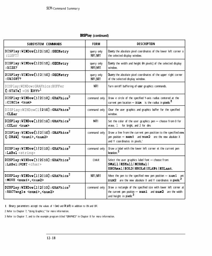
I- I -
SCPI C o m m a n d S u m m a r y
DlSPlay (continued)
SUBSYSTEM COMMANDS
DISPlay:WINDowCll2ll01 :GEOMetry
:LLEFT?
DISPlay:WINDowCll2ll0l:GEOMetry:SIZE?
DISPlay:WINDowCll2ll0l:GEOMetry:URIGHT?
DISPlay:WINDow:GRAPhics:BUFFerC:STATel <ON I OFF>l
DISPlay:WINDow[l~2~10]:GRAPhics2:CIRCle <mm>
DISPlay:WINDowCl I2 I lOl:GRAPhics*:CLEar
DISPlay:WINDow[l(2~10]:GRAPhics2:COLor <nun>
DISPlay:WINDowCl121101:GRAPhics2C:DRAWI <numi>,<num2>
DISPlay:WINDow~l~2~10~:GRAPhics2:LABel <string>
DISPlay:WINDowCl121101:GRAPhics2:LABel:FONT <char>
DISPlay:WINDow[l~2~10]:GRAPhics2:MOVE <numl>,<num2>
DISPlay:WINDowCl121101:GRAPhics2:RECTangle Cnuml>,<num2>
FORM DESCRIPTION
query only tluery the absolute pixel coordinates of the lower left corner o
NRl,NRl the selected display window.
query only Ouery the width and height fin pixels] of the selected display
NRl,NRl window.
query only Cluery the absolute pixel coordinates of the upper right corner
NRl,NRl of the selected display window.
NRl Turn on/off buffering of user graphics commands.
c o m m a n d o n l y Draw e circle of the specified Y-axis radius centered at the
current pen location - nun is the radius in pixelsP
c o m m a n d o n l y Clear the user graphics and graphics buffer for the specified
window.
NRl Set the color of the user graphics pen - choose from 0 for
erase, 1 for bright, and 2 for dim.
c o m m a n d o n l y Draw a l ine from the current pen position to the specified neti
pen position - nun1 and num2 ere the new absolute X
and Y coordinates in pixels. ’
c o m m a n d o n l y Draw a label with the lower left corner et the current pen
location3
C H A R Select the user graphics label font - choose from
SMALllHSMalllNORMallHNORmal~BOLDIHBOLdlSLANtlHSLant.
NRl,NRl Move the pen to the specified new pen position - nun1 ant
nun2 are the new absolute X and Y coordinates in pixels3
c o m m a n d o n l y Draw a rectangle of the specified size with lower left corner at
the current pen position - nun1 and nun2 are the width
a n d h e i g h t i n pixels.3
1 Binary parameters accept the values of 1 Ion1 and 0 loffl in addition to ON and OFF.
2 Refer to Chapter 7, “Using Graphics,” for more information.
3 Refer to Chapter 7, and to the example program titled “GRAPHICS” in Chapter 8 for mora information.
12-18
I-

I -
SCPI C o m m a n d S u m m a r y
DlSPlay (continued)
SUBSYSTEM COMMANDS FORM DESCRIPTION
DISPlay:WINDowCll2llOl:GRAPhics:SCALe NRl Speciiies new coordinates for window.
<xmin>,<xmax>,<ymin,<ymax>
DISPlay:WINDow[l~2~10]:GRAPhics1 query only fluery whether a window is enabled for user graphics
: STATe? NRl commands .
DISPlay:WINDow[l~2]:TRACe: NRl Turn on/off display graticule.
GRATicule:GRID[:STATel <ONIOFF>*
DISPlay:WINDowC1l2l:TRACeCll2l[:STATe] <ONlOFF>*
DISPlay:WINDow[ll2]:TRACe:YC:SCALel:AUTO ONCE
NRl Turn on/off the display of trace and memory data from the
speciiied measurement channel.
c o m m a n d o n l y Scale the measurement data for a best fit display.
DISPlay:WINDowCll2l:TRACe:YC:SCALel:PDIVision <num>3
DISPlay:WINDowCll2l:TRACe:Y[:SCALel:RLEVel <num>3
DISPlay:WINDow[ll2]:TRACe:Y[:SCALe]:RPOSition <num>
DISPlay:WINDowC1l2l1Ol:TRACeCll2l:Y:TRACk <OFFIPEAKIFRElJ>
NR3
NR3
NR3
C H A R
Specify the height IdB or units per division] of each vertical
division of the specified measurement channel.
Specify the value for the Y-axis reference position for the
specified measurement channel.
Specify the Y-axis reference position for the specified
measurement channel.
Selects the method for reference offset tracking.
DISPlay:WINDow[l~2~lO]:TRACe[l~2]:Y:TRACk:FREQuency <num>3
NR3 Selects frequency to track with reference tracking.
1 Rafar to Chapter 7, ‘Using Graphics,” for more information.
2 Binary parameters accept the values of 1 lonl and 0 loffl in addition to ON and OFF.
3 Numeric parameters may include an appropriate suffioc; if no suffLx is included, the default Ill2 for frequency or S for timal is assumed.
FORMat
SUBSYSTEM COMMANDS
FORMat:BORDer <char>
FORM
C H A R
DESCRIPTION
Specify the byte order used for HPIB data transfer - choose
NORMal or SWAPped lfor PC-compatible systems].
FORMatC:DATAl <char>C,Qunn>lI ' I
CHAR[ NRl] Specify the data format for use during data transfer - choose
from REAL,64lREAL,321INTeger,i61 ASCii.
12-19
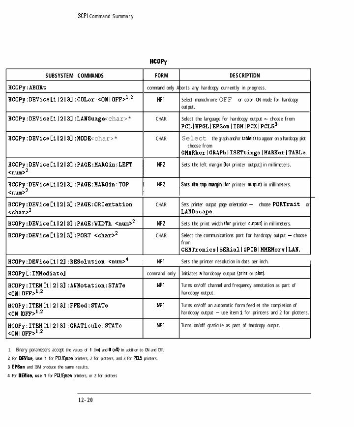
I- I -
SCPI C o m m a n d S u m m a r y
HCOPy
SUBSYSTEM COMMANDS FORM DESCRIPTION
HCOPy:ABORt
HCOPy:DEVice[ll2131:COLor <ONIOFF>ll*
command only Aborts any hardcopy currently in progress.
NRl Select monochrome OFF or color ON mode for hardcopy
output.
HCOPy:DEVice[ll213]:LANGuage <char>*
HCOPy:DEVice~1l2l3l:MODE <char>*
HCOPy:DEViceC11213l:PAGE:MARGin:LEFT
HCOPy:DEViceC1l2131:PAGE:MARGin:TOP
C H A R
C H A R
NR2
Select the language for hardcopy output - choose from
PCLlHPGLlEPSonlIBMlPCXIPCL53
Select the graph and/or tablelsl to appear on a hardcopy plot- choose from
GMARkerlGRAPh~ISETtingslMARHerlTABLe.
Sets the left margin lfor printer output] in mill imeters.
NIV I---Sets the top margin lfor printer output] in millimeters.
HCOPy:DEVice[l~2~3]:PAGE:ORIentation<char>*
HCOPy:DEVice[11213]:PAGE:WIDTh Qmm>*
C H A R
NR2
Sets printer output page orientation - choose PORTrait or
LANDscape.
Sets the print width lfor printer output1 in millimeters.
HCOPy:DEViceCll2l3l:PORT <char>* C H A R Select the communications port for hardcopy output - choose
from
CENTronicslSERiallGPIBIMMEMorvlLAN.
HCOPy:DEVice[ll21:RESolution <IUII>~ I NRl Sets the printer resolution in dots per inch. I
HCOPy[:IMMediate]
HCOPy:ITEM[l~2~3]:ANNotation:STATe<ON 1 OFF+*
HCOPy:ITEMCll2l31:FFEed:STATe<ON 1 OFF>l,*
HCOPy:ITEM[112131:GRATicule:STATe<ONIOFF>'>*
c o m m a n d o n l y Initiates e hardcopy output [print or plot].
NRI Turns on/off channel and frequency annotation as part of
hardcopy output.
NRl Turns on/off an automatic form feed et the completion of
hardcopy output - use item I for printers and 2 for plotters.
NRl Turns on/off graticule as part of hardcopy output.
1 Binary parameters accept the values of 1 Ion1 and 0 [off) in addition to ON and OFF.
2 For DEVice, use 1 for PCUEpson printers, 2 for plotters, and 3 for PCL5 printers.
3 EPSon and IBM produce the same results.
4 For DEVice, use 1 for PCUEpson printers, or 2 for plotters
12-20

I- I -
SCPI C o m m a n d S u m m a r y
HCOPy (continued)
SUBSYSTEM COMMANDS I FORM I DESCRIPTION
I NR' ITurns on/off marker symbols as part of hardcopy output.
NRl Turns on/off title and clock l ines as part of hardcopy output.
HCOPy:ITEM[ll213]:TRACe:STATe<ONIOFF+*
NRI Turns on/off trace data as part of hardcopy output.
1 Binary parameters accept the values of 1 Ion1 and 0 loffl in addition to ON and OFF.
2 For DEVice, use 1 for PCUEpson printers, 2 for plotters, and 3 for PCLS printers.
INlTiate
SUBSYSTEM COMMANDS FORM DESCRIPTION
INITiate[ll2]:CONTinuous <ONlOFF>1 NRl Set the trigger system to continuously sweep or to stop
sweeping.
INITiateCl I21 [:IMMediate] c o m m a n d o n l y Initiate a new measurement sweep.
1 Binary parameters accept the values of 1 Ion1 and 0 loffl in addition to ON and OFF.
1 2 - 2 1
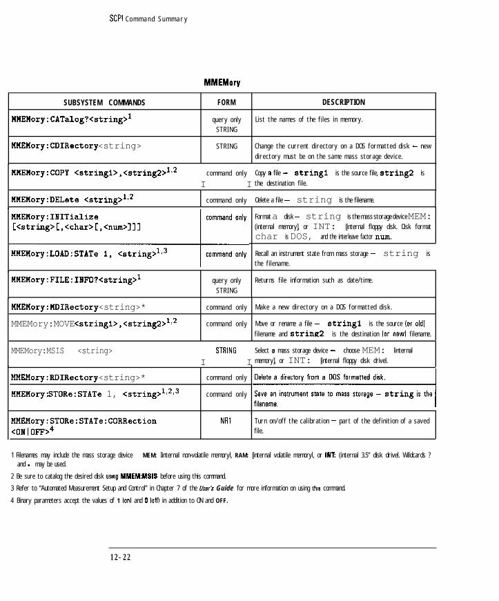
I- I -
SCPI C o m m a n d S u m m a r y
MMEMory
SUBSYSTEM COMMANDS
MMEMory:CATalog?<string>'
FORM DESCRIPTION
query only List the names of the fi les in memory.
S T R I N G
MMEMory:CDIRectory <string> S T R I N G Change the current directory on a DOS formatted disk - new
directory must be on the same mass storage device.
MMEMory:COPY <stringl>,<string2>112I I
c o m m a n d o n l y Copy e file - string1 is the source file, string2 is
the destination file.
MMEMory:DELete <string>'>* c o m m a n d o n l y Oelete a file - string is the filename.
Format a disk - string is the mass storage device MEM:(internal memory], or INT: [internal floppy disk. Disk format
char is DOS, and the interleave factor mm.
Recall an instrument state from mass storage - string is
the filename.
MMEMory:FILE:INFO?<string>' query only Returns file information such as date/time.
S T R I N G
MMEMory:MDIRectory <string>*
MMEMory:MOVE <stringl>,<string2>1~2
c o m m a n d o n l y Make a new directory on a DOS formatted disk.
c o m m a n d o n l y Move or rename a file - string1 is the source (or old1
filename and string2 is the destination lor new1 filename.
MMEMory:MSIS <string>I STRlNG I
Select e mass storage device - choose MEM: linternal
memory], or INT: [internal floppy disk drivel.
MMEMory:RDIRectory <string>* c o m m a n d o n l y
MMEMory: STORe:STATe 1, <string>"*" c o m m a n d o n l y
MMEMory:STORe:STATe:CORRection<ONIOFF>4
NRl Turn on/off the cal ibration - part of the definition of a saved
file.
1 Filenames may include the mass storage device - MEM: Iinternal non-volatile memoryl, RAM: [internal volatile memoryl, or IN1 (internal 3.5” disk drivel. Wildcards ?and l may be used.
2 Be sure to catalog the desired disk usmg MMEMMSIS before using this command.
3 Refer to “Automated Measurement Setup and Control” in Chapter 7 of the User’s Guide for more information on using thus command.
4 Binary parameters accept the values of 1 lonl and 0 loffl in addition to ON and OFF.
12-22
- -

I -
SCPI C o m m a n d S u m m a r y
MMEMory (continued)
T u r n o n / o f f t h e i n s t r u m e n t s t a t e - p e r t o f t h e d e f i n i t i o n o f a
C h o o s e f r o m LOTus o r TOUChstone.
1 Binary parameters accept the values of 1 ford and 0 loffl in addition to ON and OFF.
2 Filenames may include the mass storage device - MEM: I internal non-volati le memoryl, RAM: [ internal volati le memoryl, or INT: [ internal 3.5” disk drivel. Wildcards ?
and l may be used.
3 Refer to “Automated Measurement Setup and Control’ in Chapter 7 of the l/s.& Guide for more information on using this command.
4 Refer to Chapter 8, ‘Example Programs” for more information on using this command.
5 Refer to the example programs PUTFILE and GETFILE in Chapter 8.
OUTPut
SUBSYSTEM COMMANDS FORM
0UTPutC:STATel <ON I OFF>l NRl
1 Binary parameters accept the values of 1 lord and 0 foffl in addition to ON and OFF.
DESCRIPTION
T u r n o n / o f f R F p o w e r f r o m t h e s o u r c e .
1 2 - 2 3

I- I -
SCPI Command Summary
POWer
SUBSYSTEM COMMANDS FORM
POWerC1121:MODE <char> CHAR
DESCRIPTION
Specify either frequency sweep IFIXed] or power sweepISWEePI.
1 2 - 2 4

I- I -
SCPI C o m m a n d S u m m a r y
PROGram
SUBSYSTEM COMMANDS FORM DESCRIPTION
PROGram':CATalog?
PROGram1[:SELected]2:DEFine <block>
query only list the names of the defined IBASIC programs - response is
S T R I N G "PROG" (if a program is present) or the null string (““I.
B U I C K Download an IBASIC program from an external controller.
PROGram1C:SELected12:DELete:ALL c o m m a n d o n l y Delete all IBASIC programs from the program buffer -
equivalent to an HP BASIC SCRATCH A command.
PROGram1C:SELected12:DELete ‘ c o m m a n d o n l y Delete the active IBASIC program - equivalent to an HP BASIC
[:SELectea SCRATCH A command.
PROGram1C:SELected12:EXECute <string> c o m m a n d o n l y E x e c u t e a n IBASIC c o m m a n d .
PROGram1C:SELected12:MALLocate Qunn>I NR' I
Allocate memory space for IBASIC programs - choose from a
real number between 2048 and 4000000 bytes.
S T R I N G Select the IBASIC program in the program buffer to be active.
BLOCK or NR33 load a new value for a numeric variable string in the
active IBASIC oroaram - num is the new value.
PROGram1[:SELected12:STATe <char>I CHAR I
Select the state of the active IBASIC program - choose from
STOPlPAUSelRUNlCONTinue.
PROGram1C:SELected12:STRing<stringl>,<string2>
S T R I N G load a new value for a string variable string1 in the
active IBASIC program - string2 is the new value.
PROGram1[:SELected12:WAIT NRl Wait until the IBASIC program completes.
1 Commands in the PROGram subsystem are only available when the HP Instrument BASIC IIBASICI option is instal led loption lC21. They allow you to generate and
control IBASIC programs in the analyzer.
2 Commands grouped under the SELected mnemonic in the PROGram subsystem operate on the active program buffer.
3 The parameter type of the data is determined by the format selected - FORMat REAL uses BLOCK data, FORMat ASCii uses NR3 data separated by commas.
1 2 - 2 5
-

I- I -
SCPI C o m m a n d S u m m a r y
SUBSYSTEMCOMMANDS
ROUTeClI21:PATH:DEFine:PORT <numl>,<num2>
ROUTe[l12]:PATH:DEFine:PORT?
ROUTeCll21:REFLection:PATH:DEFine:PORT<rum>
ROUTeCll2l:TRANsmission:PATH:DEFine:PORT <mm>
FORM
NRl,NR2
NRl,NR2
NRl
NRI
DESCRIPTION
Selects the measurement ports on the test set. nun1 is the
Selects which port of the test set is connected to the
REFLECTION port of the analyzer. Choose from
1121 . 112.’
Selects which port of the test set is connected to the
TRANSMISSION port of the analyzer. Choose from
1121 112.1
1 For use with the HP 8707X multiport test sat only
12-26

I- I -
SCPI Command Summary
SENSeIl121
SUBSYSTEM COMMANDS
SENSe[ll2]:AVERage:CLEar
SENSe[ll2]:AVERage:COUNt <mm>
FORM DESCRIPTION
command only Restart the trace averaging function.
NRI Specify a count or weighting factor for the averagedmeasurement data.
SENSe[ll2]:AVERage[:STATe] <ONIOFF>'
SENSe[I12]:BWIDth[:RESolutionl <nun0EZ
NRl
NR2
Turn on/off the trace averaging function.
Specify the bandwidth of the IF receiver (fine, narrow, mediumor wide] to be used in the measurement - choose 15 lfinel250 lnarrowl 1200 [medium narrow1 3700 lmediuml4000 fmedium wide) or 6500 (wide].
SENSeCll2l:CORRection:ANNotation?
SENSeCll2l:CORRection:CAPacitance:CONNector <nnm>
query only Returns the current calibration annotation: either “C”,‘V” o r “I’.. I
NR3 Select connector compensating capacitance veiue. For use withstructural return loss measurements on analyzers with Option
100 only.1
SENSe[ll2]:CORRection:COLLect:ABORt commend only Aborts the calibration that is currently in progress.
SENSe[il2]:CORRection:COLLect commend only Measure a calibration standard - select from:
C:ACquirel <char>STANdardI-OpenSTANdard2-ShortSTANdard3-loadSTANdardB-Through cable
SENSe[lj2]:CORRection:COLLect:CKITC:SELectl
STRING Select Cal KitChoose from one of the following strings:‘COAX,7MM,TYPE-N,Xf,FEMALE
‘COAX,7MM,TYPE-N,QMALE‘COAX,35,APC-3.5,50,IMPtlEO
‘USER,IMPtlEtl,lMPtlEG,lMPtlEO, IMPLIEO‘COAX,7MM,TYPE-675,lMPLlEO‘COAX,7MM,TYPE-N,75,FEMALE‘COAX,7MM,TYPE-N,75,MALE
SENSe[ll2]:CORRection:COLLect NRl
:ISTate[:AUTO] <ONlOFF>l
1 Binary parameters accept the values of 1 ion1 and 0 loffl in addition to ON and OFF.
Select the instrument state for calibration - choose Full Band
ION1 or User Defined [OFF].
12 -27
_I

I- I -
SCPI Command Summary
SENSeIl121 (continued)
SUBSYSTEM COMMANDS
3ENSeCIl21 :CORRection:COLLect:METHod <char>
FORM DESCRIPTION
commend only Select the type of calibration - choose from:
TRANl-Transmission response
TRAN2-Transmission response & IsolationTRAN3-Transmission enhanced responseREFL3-Reflection one port
TEST-Test Set Calibration’
VERIFY-Calibration Check
;ENSeCIl21 :CORRection:COLLect:MP:OPEN command only Measures an open on the port selected during a test set:STANIISTANZl . . . ISTAN12> calibration.’
iENSe cl I21 :CORRect ion: COLLect :MP : SHORT commend only Measures a short on the port selected during a test set
:STANIISTANZI . ISTANi2> calibration.’
iENSeCil21:CORRection:COLLect:MP:LOAD commend only Measures a load on the port selected during a test set
:STANlISTANZI . . . ISTANIZ> calibration.’
IENSeCll2l:CORRection:COLLect:NP:THRU commend only Measures a thru on the port selected during a test set
:STANIISTANZI . . . ISTANG> calibration.’
lENSe Cl I21 : CORRection: COLLect :PORTS NRl Selects the number of ports to perform a test set calibration
:2~4~6f8flOf12> 0n.l
lENSeCll21 :CORRection:COLLect:SAVE command only Complete and save current calibration.
lENSeCll21 :CORRection:COLLect:VERify command only Measures a calibration standard during a cal check procedure
REFLection <STANIiSTANZI . ISTANlZ> for reflection measurements.
jENSeC1121 :CORRection:COLLect:VERify command only Measures e calibration standard during a cal check procedure
:TRANsmission GTANIISTAN21 . for transmission measurements.
1 STANIZ>;
5ENSeCll21 :CORRection:CSET: : SELectI DEFault
;ENSe Cl I21 : CORRection: CSET: : SELectI ?
@SENSe cl I 21: CORRection : EDELay : TIME
:num>:!
command only Restore the “factory’ default calibration for the current
measurement end channel.
query only Query the current calibration type - returns DEF lfectory
CHAR defaultl, FULL [full bend1 or USER (user definedl.
NR3 Specifies the electrical delay in seconds.
1 For use with the HP B7075C multiport test set only
2 Numeric parameters may include an appropriate suffkk; 11 no suffii is included, the default ML! for frequency or S for time1 is assumed.
12-28 @I indicates HP 871281148 only

I-
SCPI Command Summary
SENSeIlj21 (continued)
SUBSYSTEM COMMANDS
@SENSeC112l:CORRection:EXTension
:REFLection[:TIME] <mm>'
FORM
NR3
DESCRIPTION
Specifies the port extension at the reflection port, in seconds.
@SENSeCll2l:CORRection:EXTension
[:STATe] <ON10FF>2
NRl Enables port extensions.
@SENSeCl I21 :CORRection:EXTension
:TRANsmission[:TIHE] <num>'
NR3 Speciiies the port extension et the transmission port, in seconds
@SENSeCl I21 :CORRection:IMPedance:
INPut:MAGNitude<nu&
NR3 Specifies the reference impedance for the Smith chart display.The default is the analyzer’s system impedance.
SENSe[il2]:CORRection:IMPedance:1NPut:MAGNitude:SELect 20-50
NRl Selects 50 ohms as the system impedance.
SENSeCll2l:CORRection:IMPedance:1NPut:MAGNitude:SELect 20-75
NRl Selects 75 ohms as the system impedance.
SENSeCll21:CORRection:LENGth:COAX<num>
NRZ Specifies the length of cable to be calibrated, in feet or meters[For use with fault location measurements on analyzers withOption 100 only.1
SENSeCll21:CORRection:LENGth:CONNector <num>
NR2 Specifies the length of an interface connector, in mm or inches
For use with structural return loss measurements on analyzerswith Option 100 only.1
SENSe[ll2]:CORRection:LOSS:COAX <nun0 NR2 Specifies the loss of a cable under test, in dB/lOO ft. [For usewith fault location measurements on analyzers with Option 100
only.1
SENSeC1l2l:CORRection:MODel:CONNector command only Measure the cable connector end determine the optimum value![:IMMediate] for connector length end connector capacitance. [For use with
structural return loss measurements on analyzers with Option100 only.1
1 Numeric parameters may include an appropriate suffoc; if no suffix is included, the default IHZ for frequency or S for time1 is assumed.
2 Binary parameters accept the values of 1 ionI and 0 ioffl in addition to ON and OFF.
I -
@I indicates HP 8712B114B only 12-29

I-
SCPI Command Summary
SENSeIll (continued)
SUBSYSTEM COMMANDS FORM
@SENSe[ll2]:CORRection:OFFSet:PHASe NR3
DESCRIPTION
Specifies the phase offset.
SENSeCll21:CORRection:PEAK:COAX NRI[:STATe] <ONlOFF>'
Turns multi-peek correction on or off. For use with faultlocation measurements on analyzers with Option 100 only.)
@SENSe[ll2]:CORRection:RVELocity:COAX NR3 Specifies the velocity factor to be used when displaying the
distance for electrical length end port extensions. 1.0 - the
<nun>2speed of light.
SENSeCll21:CORRection:RVELocity commend only[:IMMediate]
Measure the cable end determine the optimum values for cable
loss end velocity factor. For use with fault locationmeasurements on analyzers with Option 100 only.1
SENSeCll2l:CORRection:TESTSET command only Brings up the Test Set Cal menu.3
SENSe[il21:CORRection:THReshold NR2 Selects multi-peak threshold value, in dB. For use with fault:COAX <mm> location measurements on analyzers with Option 100 only.1
SENSe[112]:COUPle <char> CHAR Turn on/off the alternate sweep mode - choose ALL lcoupledsweep] or NONE Ialternate sweep].
SENSeC112l:DETectorC:FUNCtionl <char>
SENSeCl I21:DISTance:CENTer <nun>
CHAR
NR3
Specify which detection mode is used to make the meesuremeni
- choose BBANd [broadband) or NBANd Inarrowbandl.
Set the center distance for a fault location measurement, infeet or meters. IFor use with fault location measurements onanalyzers with Option 100 only.1
1 Binary parameters accept the values of 1 lonl and 0 loffl in addition to ON and OFF.
2 Numeric parameters may include an appropriate suffii; if no suffb is included the default IHZ for frequency or S for time1 is assumed.
3 For use with the HP 87075C multiport test set only
1 2 - 3 0 @ indicates HP 8712B114B only

I -
SCPI Command Summary
SENSeIl121 (continued)
SUBSYSTEM COMMANDS FORM DESCRIPTION
SENSe[ll2]:DISTance:STARt <mm> NR3
I I
Sat the start distance for a fault location measurement, in feelor maters. IFor use with fault location measurements onanalvzars with Ootion 100 onlv.1
SENSeCl12l:DISTance:STOP <mm> NR3 Sat the stop distance for a fault location measurement, in feat
or maters. IFor use with fault location measurements onanalyzers with Option 100 only.)
SENSe[l12]:DISTance:UNITs <char> CHAR Specifies distance units. Choose METers or FEET. [For use
with fault location measurements on analyzers with Option 100only.1
SENSeCll2l:FREtJuency:CENTer Gmd
SENSe[ll2]:FREquency:MODE <char>
SENSe[ll2]:FREquency:SPAN <mm>'
SENSeCll2l:FREquency:SPAN:MAXimum <nund
NR3
CHAR
NR3
Sat the canter frequency of the RF source.
Sar the fault location measurement to CENTer lbandpassl OILOWPassdFor use with fault location measurements onanalyzers with Option 100 only.1
Sat the frequency span of the RF source.
NR3 Sat the maximum frequency span of the RF source forbandpass fault location measurements. IFor use with faultlocation measurements on analyzers with Option 100 only.1
SENSe[ll2]:FREquency:STARt <nund
SENSeCl I2l:FREQuency:STOP <nud
SENSe[ll2]:FREquency:ZSTOp <nud
NR3
NR3
NR3
Sat the sfarr frequency of the RF source.
Sat the stop frequency of the RF source.
Sat the Z cutoff frequency for cable impedance calculations.
IFor use with structural raturn loss measurements on analyzerswith Option 100 only.1
SENSeCl I2l:FUNCtion? query only Ouary the measurement function - returns one of the
STRING 'XFR:POW . . .' or 'XFR:POW:RAT . . . Jstrings described below.
SENSe[llZ]:FUNCtion 'XFRequency:POWer <num>'
command only Specify that the receiver will measure the power into a specific
detector on the spaciiiad measurement channel - choose from
detectors 0 [RI, 1 IA], 2 IBI, 11 IEXI XI or 12 IExt YI.
1 Numeric parameters may include an appropriate suffii; if no suffibc is included, the default Ill2 for frequency or S for time) is assumed.
12-31

I- I -SCPI Command Summary
SENSeH121 (continued)
SUBSYSTEM COMMANDS
SENSe[lf2]:FUNCtion 'XFRequency:POWer:RATio <num>,<num>'
SENSeC1121:FUNCtion:FAULt:CONNector[:IMMediate]
SENSe[lf2]:FUNCtion:SRL:IMPedanceCnum>
SENSeCli2l:FUNCtion:SRL:MODE <char>
SENSe[lf2]:FUNCtion:SRL:SCAN[:IMMediate]
SENSe[lf2]:ROSCillator:SOURce <char>
SEkeCIl2l:STATe <ON I OFF>l
SENSeCil2l:SWEep:POINts <num>
SENSe[if2]:SWEep:TIME <num>2
SENSe[if2]:SWEep:TIME:AUTO<ONfOFFfONCE>l
5ENSe:SWEep:TRIGger:SOURce <char>
3ENSe:WINDowC:TYPEl <char>
FORM
command only
command only
NR2
CHAR
command only
CHAR
NRl
NRI
NR3
NRl
CHAR
CHAR
DESCRIPTION
Specify that the receiver will measure a ratio of the power intothe specified measurement channel - choose from ratios I, 0
IAIRI, 2,O IRIRI, 12 ,O IExt Y/RI, 11,12 IExt XlExt YI, or1 2 . 1 1 IExt Y/Ext X I .
Forces a connector veriiication measurement on the alternatechannel. For use with fault location measurement on analyzerswith Option 100 only.1
Set the cable impedance. [For use with structural return loss
measurements on analyzers with Option 100 only.1
Set the auto z function to AUTO or MANual. For use witlstructural return loss measurements on analyzers with Option100 0nlY.l
Start a cable scan. [For use with structural return lossmeasurements on analyzers with Option 100 only.1
Specify the source of the reference oscillator - selectINTernal or EXTernal.
Turn on/off the specified channel.
Set the number of data points for the measurement - choosefrom315111121151110112011401180111601.
Set the sweep time.
Turn on/off the automatic sweep time function.
Set the trigger source for each point in a sweep - chooseIMMediate or EXTernal fused in conjunction withTRIGger[:SEQuence]:SOURcel.
Set the window selection for fault location measurements.Choose from RECTangular [MinimumI, HAMMing[Medium], or KBESsel (Maximum). IFor use with faultlocation measurements on analyzers with Option 100 only.1
L Binary parameters accept the values of 1 fonl end 0 loffl in addition to ON and OFF.
! Numeric parameters may include an appropriate suffii; if no suffii is included, the default IHZ for frequency or S for time) is assumed.
12 -32

I- I -
SCPI Command Summary
SOURce
SUBSYSTEM COMMANDS FORM
[:IMMediatei C:AMPLitudel <mm>'/irml.lll21 POWerC LEVelI1 :'Jl
SOURce[ll2]:POWer:PRESet <mm>
SOURce[il2]:POWer:RANGe <char>
SOURceClI2l:POWer:STARt <mm> NR3
SOURce~ll2~:POWer:STOP <mm> NR3
DESCRIPTION
Set the RF power output from the source.
Sets the power level that the analyzer will always return to
after an instrument preset.
Specifies the power sweep range. Choose from ATTenOIATTenlO~ATTen20~ATTen3O~ATTen40IATTen501ATTen60.
Sets the power sweep start power.
Sets the power sweep stop power.
1 Numeric parameters may include en appropriate suffii; if no suffibc is included, the default [HZ for frequency or S for time1 is assumed.
12 -33
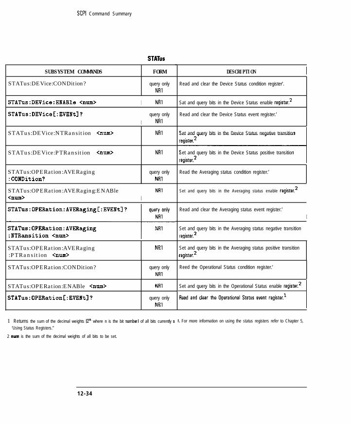
I- I -SCPI Command Summary
STATUS
SUBSYSTEM COMMANDS FORM DESCRIPTION
STATus:DEVice:CONDition? query onlyNRl
STATus:DEVice:ENABle <mm> I NRl
STATus:DEVice[:EVENt]?I
query onlyNRI
STATus:DEVice:NTRansition <mm> NRl
STATus:DEVice:PTRansition <mm> NRl
STATus:OPERation:AVERaging:CONDition?
query onlyNRl
STATus:OPERation:AVERaging:ENABle<mm> I
NRl
STATus:OPERation:AVERaging[:EVENt]?1STATus:OPERation:AVERaging:PTRansition <mm>
NRl
STATus:OPERation:CONDition? query onlyNRl
STATus:OPERation:ENABle <mm>
STATus:OPERation[:EVENt]?
NRI
query onlyNRl
1 Returns the sum of the decimal weights 12” where n is the bit number1 of all bits currently s
‘Using Status Registers.”
2 num is the sum of the decimal weights of all bits to be set.
Read and clear the Device Status condition register’.
Sat and query bits in the Device Status enable register.:!
Read and clear the Device Status event register.’
Set and query bits in the Device Status negative transition
Set and query bits in the Device Status positive transition
Read the Averaging status condition register.’
Set and query bits in the Averaging status enable register.2
Read and clear the Averaging status event register.’
I
Set and query bits in the Averaging status negative transition
register.2
Set and query bits in the Averaging status positive transition
register.2
Reed the Operational Status condition register.’
Set and query bits in the Operational Status enable register.2
t. For more information on using the status registers refer to Chapter 5,
12 -34

I- I -
SCPI Command Summary
SUBSYSTEM COMMANDS
STATUS (continued)
FORM DESCRIPTION
STATus:OPERation:MEASuring:CONDition?
STATus:OPERation:MEASuring:ENABle<nun0
query only Read the Measuring status condition register.’
NRl
NRl Set and query bits in the Measuring status enable register.:!
STATus:OPERation:MEASuring[:EVENt]? query only Read and clear the Measuring status event register.’NRl
STATus:OPERation:MEASuring:NTRansition <nun0
STATus:OPERation:MEASuring:PTRansition <mm>
NRl
NRl
Set and query bits in the Measuring status negative transition
register.:!
Set and query bits in the Measuring status positive transition
register.:!
<nun0 I NRlI
Set and query bits in the Operational Status negative transition.-,
register.’
STATus:OPERation:PTRansition <nun0 NRl Set and query bits in the Operational Status positive transition
register.2
STATus:PRESet command only Set bits in most enable and transition registers to their defaultstate.
STATus:QUEStionable:CONDition? query only Read and clear the Ctuastioneble Status condition register.’
NRl
STATus:QUEStionable:ENABle <mm>
STATus:QUEStionable[:EVENtl?
NRl
query onlyNRl
Set and query bits in the Cluestionable Status enable register.:!
Read and clear the [luestionable Status event register.’
STATus:QUEStionable:LIMit:CONDition?
query only Read and clear the Limit Pail condition register.’
NRl
STATus:QUEStionable:LIMit:ENABle <mm> NRl Set and query bits in the Limit Fail enable register.2
1 Returns the sum of the decimal weights 12” where n is the bit number] of all bits currently set. For more information on using the status registers refer to Chapter 5,
“Using Status Registers.”
2 num is the sum of the decimal weights of all bits to be set.
12-35

I- I -
SCPI Command Summary
STATUS (continued)
STATus:QUEStionable:LIMit[:EVENt]?mSTATus:QUEStionable:LIMit:PTRansition <nun0
NRl
STATus:QUEStionable:NTRansition <mm>TNRl
STATus:QUEStionable:PTRansition <mm> NRl
DESCRIPTION
Read and clear the Limit Fail event register.’
Set and query bits in the Limit Fail negative transition register.’
Set end query bits in the Limit Fail positive transition register.2
Set and query bits in the (luestionable Status negative
transition register.:!
Set and query bits in the Cluestionable Status positive transitior
register.:!
1 Returns the sum of the decimal weights 12” where n is the bit number1 of all bits currently set. For more information on using the status registers refer to Chapter 5,
“Using Status Registers.’
2 num is the sum of the decimal weights of all bits to be set.
12-36

I- I -
SCPI Command Summary
SYSTem
SUBSYSTEM COMMANDS
SYSTem:BEEPer[:IMMediate]C<freq>C,<dur>[, <vol>llll
SYSTem:BEEPer:VOLume <num>
FORM
NR3, NR3, NR3
NR2
SYSTem:COMMunicate:GPIB:CONTroller NRI
C:STATel CONI OFF>2p3
SYSTem:COMMunicate:GPIB:ECHO <ONIOFF>2 NRl
SYSTem:COMMunicate:GPIB:HCOPy NRl
:ADDRess <num>
SYSTem:COMMunicate:GPIB[:SELF] NRI
:ADDRess <num>4
SYSTem:COMMunicate:LAN:EADDress? query only
SYSTem:COMMunicate:LAN:IPADdress STRING
<string>
SYSTem:COMMunicate:LAN:PRINter:HOSTname STRING
<string>
SYSTem:COMMunicate:LAN:ROUTe:GATeway STRING
<string>
SYSTem:COMMunicate:LAN:ROUTe:SMASk STRING
<string>
SYSTem:COMMunicate:LAN:STATe <ONIOFF>2 STRING
SYSTem:COMMunicate:SERial:TRANsmit NRI
:BAUD <num>
SYSTem:COMMunicate:SERial:TRANsmit:HANDshake <char>
CHAR
DESCRIPTION
Instructs the analyzer to beep. Arguments are frequency IHzI,
Makes the analyzer the system controller. 1
Set the address of an HP-IB printer or plotter for hardcopy
Set the analyzer’s HP-IB address - num must be an integer
Guerias the analyzer’s ethernet address.
Sets the analyzer’s Internet Protocol address.
Specifies the IP address of the LAN printer.
I
Sets the IP address for a LAN gateway. 1
Sat the baud rate for hardcopy output to a device on the saria
port - choose from1200~2400~4800~9600~19200. I
Set the handshake for communication to a hardcopy device on
the serial port - choose XON or DTR.
1 <freq>, <dur>, and <vol> are optional <mm> parameters.
2 Binary parameters accept the values of 1 Ion1 end 0 loffl in addition to ON and OFF.3 For use with BASIC - this command cannot be executed from an external controller.
4 A delay of 5 seconds is required before a command is sent to the new address.
12 -37

I-
SCPI Command Summary
SUBSYSTEMCOMMANDS
SYSTem:CO#Municate:TTL:USER:FEED<char>
SYSTem:DATE <numl>,<num2>,<num3>
SYSTem:ERRor?'
SYSTem:KEY <char>
SYSTem:KEY:MASK?
SYSTem:KEY:QUEue:CLEar
SYSTem:KEY:QUEue:COUNt?
SYSTem:KEY:QUEue:MAXimum?
SYSTem:KEY:QUEue[:STATe] <ONlOFF>*
SYSTem:KEY:TYPE?
SYSTem:KEY:USER
SYSTem:KEY[:VALue]?
;Tem (continued)
FORM I DESCRIPTION
CHAR Selects the function of the USER TTL IN/OUT port on the rearpanel of the analyzer. Choose fromDEFaultiKEY(SWEep.
NRl,NRl, NRl Set the year lnumll, month bum21 and day bun31 of thereal time clock.
query only Query the error queue - returns the error number andNR1,STRING message.
Sends key names3 which execute the same functions as front
command only Clears the key queue.I
query only Query the number of key codes in the queue.NRl
query only Guery the size of the key queue [the maximum number of keyNRI codes it can hold].
NRl Turn on/off the key queue.
query only Guery the type of key that was pressed - returns NONE,CHAR RPG, KEY (front panel key1 or ASC Iexternal keyboard].
command only Sets the User Request bit of the Standard Event Status Register
query only Guery the key code value for the last key pressed - RPGNRl type returns the knob count, positive for clockwise rotation,
KEY type returns the front panel keycode, and ASC typereturns the ASCII code number.
1 For more information on errors, refer to Chapter 14, “SCPI Error Messages.”
2 Binary parameters accept the values of 1 lent and 0 loffl in addition to ON and OFF.
3 A list of the analyzer’s front panel keycodes and key names is provided in Chapter 9.
12 -38

I-
SYSTem (continued)
I -
SCPI Command Summary
SUBSYSTEM COMMANDS
SYSTem:PRESet
SYSTem:SET <block>
FORM
command only
command only
SYSTem:SET:LRN? [<usER>]~
SYSTem:SET:LRNLong? CGJSER>]~
BLOCK
BLOCK
SYSTem:TIHE <numi>,<num2>,<num3> NRl,NRl, NRl
SYSTem:VERSion? query only
NRZ
DESCRIPTION
Perform a system preset - this is the same as the front panel
C-1 key.
Send a learn string iobtained using *LRN?I to the analyzer -this command is included in the learn string. I
lluery or set the instrument state.
rluery or set the instrument state, data, and calibration. Similarto save/recall.
Set the hour Inumll, minute lnum21 and second Inum31 ofthe real time clock.
[luery the SCPI version of the analyzer. Sea *IDN? to querythe firmware revision.
1 Refer to “Automated Measurement Setup and Control” in Chapter 7 of the User’s Guide for more information on using this command.
TEST
SUBSYSTEM COMMANDS FORM DESCRIPTION
TEST:RESult? [luery the result of the selected adjustment or self-test - theresponse will be NULLIPASS IFAIL.
TEST:SELect <num> I NRl I Select the adiustment or self-test to execute.
TEST:STATe <char> CHAR Select the state of the active adjustment or self-test - choosefrom RUN 1 CONTinue I STOP for the command. tlueryreturns NULLJRUNIPAUSIDONE.
TEST:VALue <num> NRl Set or query a value for an adjustment or self-test.
12-39

I- I -
SCPI Command Summary
SUBSYSTEM COMMANDS
TRACe[:DATA]? <char>
TRACe
FORM DESCRIPTION
query only Ruery trace data - choose fromBLOCK or NR$ CH<Il2>FDATA formatted date,
CH<I I2>FMEM formatted memory,
CH<I I2>SDATA unformatted data,CH<l I2>SMEM unformatted memory,CH<IlZ><AlBlR>FWD raw data, orCH<I I2>SCORR<I 12 13 I4> correction data. Note:See Chapter 6, “Trace Oata Transfers,’ for data array details.
TRACeC:DATAl <char>,<data> command only Input trace data - choose from the above list of arrays. The
data can be either BLOCK or NR3 type.’ See Chapter 6 formore information.
TRACeC:DATAl <charl>,<char2> command only Move data from one internal array to another - char1 is
the target array ICHKI I2>SMEMI while char2 is thesource array ICH<I I2>SDATAI. Note that the source and
target arrays must be from the same measurement channel.
1 The parameter type of the data is determined by the format selected - FORMat REAL uses BLOCK data, FORMat ASCii uses NR3 data separated by commas.
TRlGger
SUBSYSTEM COMMANDS I FORM I DESCRIPTION
TRIGger[:SEQuence]:SOURce <char> CHAR Set the source for the sweep trigger signal - chooseIMMediate or EXTernal fused in conjunction with
SENSe:SWEeD:TRIGeer:SOURcel.
1 2 - 4 0

I-
13
SCPI ConformanceInformation

I- I -
SCPI Conformance Information
The HP 8711C/12C/13C/14C RF Network Analyzers conform to the1996.0 version of SCPI.
13-2

I-
SCPI Standard Commands
The analyzerimplementsthe following IEEE 488.2 standard commands:
*cLs*ESE*ESE?*ESR?*IDN?*LRN?*opt*OPC?*OPT?*PCB*psc*RST*sRE*SRE?*STB?*TRG*TST?*WA1
The analyzer implements the following SCPI 1996.0 standard commands:
ABORt
CALCulate[112]:DATA?CALCulate[ll2]:FORMatCALCulate[112]:FORMat?@CALCulate[112]:GDAPerture:APERture@CALCulateCl I2l:GDAPerture:SPANCALCulate[112]:LIMit:STATeCALCulate[ll2]:LIMit:STATe?CALCulate[ll2] :MATH[:EXPRession]CALCulate[112]:MATH[:EXPRession]?
CALibration:ZERO:AUTOCALibration:ZERO:AUTO?
DISPlay:CMAP:COLor[ll2l . . . 16l:HSLDISPlay:CMAP:COLor[l~2l . . . 16]:HSL?
@I indicates HP 8712Cl14C only 13-3

I- I -
SCPI Conformance Information
SCPI Standard Commands
DISPlay:CMAP:COLor[ll2l . . . 163:RGBDISPlay:CMAP:COLor[ll2l . . . 16]:RGB?DISPlay:CMAP:DEFaultDISPlay:MENU[ll21:KEY[ll2l . . 7]?DISPlay:WINDowC1l2llOl:GEOMetry:LLEFT?DISPlay:WINDowC1l2l1Ol:GEOMetry:SIZE?DISPlay:WINDowCll2llOl:GEOMetry:URIGHT?DISPlay:WINDow~1l2llOI:GRAPhics:CLEarDISPlay:WINDowCll2llOl:GRAPhics:COLorDISPlay:WINDowCll2l1Ol:GRAPhics:COLor?DISPlay:WINDowC1l211Ol:GRAPhicsC:DRAW1DISPlay:WINDowCll2llOl:GRAPhics:LABelDISPlay:WINDowCll2l1Ol:GRAPhics:MOVEDISPlay:WINDow[ll2l1Ol:GRAPhics:MOVE?DISPlay:WINDowCll2l1Ol:GRAPhics:STATe?DISPlay:WINDow[1l21:TRACe:GRATicule:GRID[:STATe]DISPlay:WINDow[ll2]:TRACe:GRATicule:GRID[:STATe]?DISPlay:WINDowCl I2l:TRACe[ll21[:STATelDISPlay:WINDowCl I2l:TRACeCl I23C:STATe]?DISPlay:WINDowC1l21:TRACe:Y[:SCALel:AUTODISPlay:WINDow[ll21:TRACe:Y[:SCALe]:PDIVisionDISPlay:WINDow[ll21:TRACe:Y[:SCALe]:PDIVision?DISPlay:WINDowCll21:TRACe:Y[:SCALel:RLEVelDISPlay:WINDow[ll21:TRACe:Y[:SCALe]:RLEVel?DISPlay:WINDow[ll2]:TRACe:Y[:SCALe]:RPOSitionDISPlay:WINDowCll21:TRACe:YC:SCALel:RPOSition?
FORMat:BORDerFORMat:BORDer?FORMatC:DATA]FORMat[:DATA]?
13-4 @ indicates HP 8712CI14C only

I- I -
SCPI Conformance Information
SCPI Standard Commands
HCOPy:ABORtHCOPy:DEVice[11213]:COLorHCOPy:DEVice[ll213]:COLor?HCOPy:DEVice[l1213]:LANGuageHCOPy:DEVice[11213] :LANGuage?HCOPy:DEVice[ll2131:MODEHCOPy:DEVice[ll2131:MODE?HCOPy:DEVice[ll213]:RESolutionHCOPy:DEVice[ll2l3]:RESolution?HCOPy[:IMMediate]HCOPy:ITEM:ANNotation:STATeHCOPy:ITEM:ANNotation:STATe?HCOPy:ITEM[11213l:FFEed:STATeHCOPy:ITEM[ll2l3]:FFEed:STATe?
INITiate[llZ]:CONTinuousINITiate[l I2]:CONTinuous?INITiate[ll21[:IMMediatel
MMEMory:CATalog?MMEMory:CDIRectoryMMEMory:CDIRectory?MMEMory:COPYMMEMory:DELeteMMEMory:FILE:INFO?MMEMory:INITializeMMEMory:LOAD:STATeMMEMory:MOVEMMEMory:MSISMMEMory:MSIS?MMEMory:STORe:STATeMMEMory:STORe:TRACeMMEMory:TRANsfer:BDATMMEMory:TRANsfer[:HFSl
OUTPut[:STATelOUTPut[:STATe]?
@ indicates HP 8712W4C only 13 -5
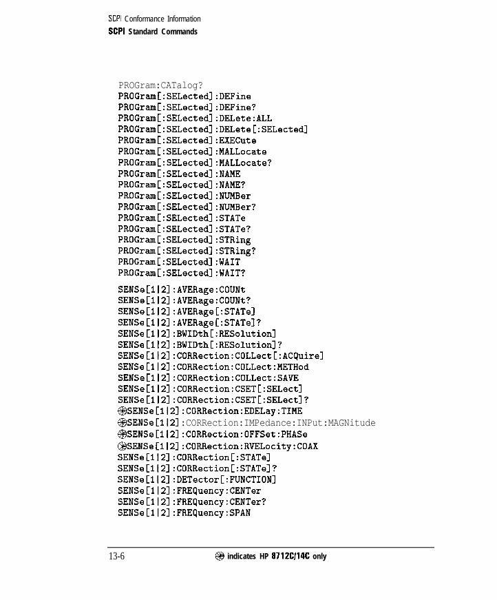
I- I -
SCPI Conformance Information
SCPI Standard Commands
PROGram:CATalog?PROGram[:SELected]:DEFinePROGramC:SELected]:DEFine?PROGram[:SELected]:DELete:ALLPROGram[:SELected]:DELete[:SELected]PROGram[:SELected]:EXECutePROGram[:SELected]:MALLocatePROGrem[:SELected]:MALLocate?PROGramC:SELected]:NAMEPROGram[:SELected]:NAME?PROGram[:SELected]:NUMBerPROGram[:SELected]:NUMBer?PROGram[:SELected]:STATePROGram[:SELected]:STATe?PROGram[:SELected]:STRingPROGramC:SELected]:STRing?PROGram[:SELected]:WAITPROGram[:SELected]:WAIT?
SENSeCll21:AVERage:COUNtSENSe[1121:AVERage:COUNt?SENSeClI2l:AVERageC:STATelSENSeCl I2]:AVERage[:STATe]?SENSe[ll21:BWIDth[:RESolution]SENSeCl I2]:BWIDth[:RESolution]?SENSeCll21:CORRection:COLLect[:ACQuire]SENSeC1121:CORRection:COLLect:METHodSENSe[112l:CORRection:COLLect:SAVESENSe[112]:CORRection:CSETC:SELect]SENSeCll2l:CORRection:CSET[:SELect]?@SENSeCll21:CORRection:EDELay:TIME@SENSeCll2] :CORRection:IMPedance:INPut:MAGNitude@SENSe[112]:CORRection:OFFSet:PHASe@SENSe[ll2]:CORRection:RVELocity:COAXSENSe[ll2]:CORRection[:STATe]SENSeCll21 :CORRection[:STATe]?SENSeCll21 :DETector[:FUNCTION]SENSeCll21:FREQuency:CENTerSENSe[ll2]:FREquency:CENTer?SENSe[ll2]:FREQuency:SPAN
13-6 @I indicates HP 8712CI14C only

I- I -
SCPI Conformance Information
SCPI Standard Commands
SENSe[112]:FREQuency:SPAN?SENSeC1121:FREQuency:STARtSENSe[ll21:FREQuency:STARt?SENSe[ll2]:FREQuency:STOPSENSe[ll21:FREQuency:STOP?SENSeC1121 :FUNCtionSENSe[l I21 :FUNCtion?SENSe:ROSCillator:SOURceSENSe:ROSCillator:SOURce?SENSeCll21:SWEep:POINtsSENSe[ll2]:SWEep:POINts?SENSeCll2l:SWEep:TIMESENSe[ll2]:SWEep:TIME?SENSe[112]:SWEep:TIME:AUTOSENSe[ll2]:SWEep:TIME:AUTO?
SOURce[ll2l:POWer[:LEVel] [:IMMediate] [:AMPLitudelSOURce[112]:POWer[:LEVel][:IMMediate] [:AMPLitude]?SOURce[ll2]:POWer:RANGeSOURce[ll2]:POWer:STARtSOURce[ll2]:POWer:STOP
STATus:OPERation:CONDition?STATus:OPERation:ENABleSTATus:OPERation:ENABle?STATus:OPERation[:EVENtl?STATus:OPERation:NTRansitionSTATus:OPERation:NTRansition?STATus:OPERation:PTRansitionSTATus:OPERation:PTRansition?STATus:qUEStionable:CONDition?STATus:qUEStionable:ENABleSTATus:QUEStionable:ENABle?STATus:QUEStionable[:EVENt]?STATus:LjUEStionable:NTRansitionSTATus:QUEStionable:NTRansition?STATus:LjUEStionable:PTRansitionSTATus:QUEStionable:PTRansition?
SYSTem:BEEPer[:IMMediate]?SYSTem:BEEPer:VOLumeSYSTem:BEEPer:VOLume?
13 -7

I- I -
SCPI Conformance Information
SCPI Standard Commands
SYSTem:COMMunicate:GPIB[:SELF]:ADDRessSYSTem:COMMunicate:GPIB[:SELF]:ADDRess?SYSTem:COMMunicate:SERial:TRANsmit:BAUDSYSTem:COMMunicate:SERial:TRANsmit:BAUD?SYSTem:DATESYSTem:DATE?SYSTem:ERRor?SYSTem:KEY[:VALue]?SYSTem:PRESetSYSTem:SETSYSTem:SET:LRN?SYSTem:TIMESYSTem:TIME?SYSTem:VERSion?
TRACe[:DATA]TRACe[:DATA]?
TRIGger[:SELjuence]:SOURceTRIGger[:SEQuence]:SOURce?
13 -8

I-
Instrument Specific Commands
The following are instrumentspeci6c commands implementedbytheHP 8711C/12C/13C/14C RF Network Analyzers which are not part of thepresent SCPI 1996.0definition.
CALCulate[lI2]:FORMat:UNIT:MLINCALCulate[lI2]:FORMat:UNIT:MLIN?CALCulate[ll2]:FORMat:UNIT:MLOGCALCulate[112]:FORMat:UNIT:MLOG?CALCulate~112~:LIMit:DISPlayCALCulateCl I2]:LIMit:DISPlay?CALCulate[ll21:LIMit:MARKer:FLATness:MAXimumCALCulate[ll2]:LIMit:MARKer:FLATness:MINimumCALCulate[112]:LIMit:MARKer:FLATness[:STATe]CALCulate[ll21:LIMit:MARKer:FREQuency:MAXimumCALCulate[ll2]:LIMit:MARKer:FREquency:MINimumCALCulate[ll21:LIMit:MARKer:FREQuencyC:STATelCALCulate[112]:LIMit:MARKer:STATistic:MEAN:MAXimumCALCulate[112]:LIMit:MARKer:STATistic:MEAN:MINimumCALCulate[112]:LIMit:MARKer:STATistic:MEAN[:STATe]CALCulate[ll2]:LIMit:MARKer:STATistic:PEAK:MAXimumCALCulate[ll2]:LIMit:MARKer:STATistic:PEAK:MINimumCALCulateCll2]:LIMit:MARKer:STATistic:PEAK[:STATe~CALCulate[ll2]:LIMit:MARKer:TILT:MAXimumCALCulate[1l2]:LIMit:MARKer:TILT:MINimumCALCulate[ll21:LIMit:MARKer:TILT[:STATe]CALCulate[1l2]:LIMit:SEGMent[ll2l . . . 121:AMPLitude:STARtCALCulate[ll2]:LIMit:SEGMent[l~2~ . . . 12]:AMPLitude:STARt?CALCulate[ll2]:LIMit:SEGMent[ll2l . . . 121:AMPLitude:STOPCALCulate[ll2]:LIMit:SEGMent[l~2~ . . . 12]:AMPLitude:STOP?CALCulate[ll2]:LIMit:SEGMent:AOFFCALCulate[ll21:LIMit:SEGMent[ll2l . . . 12l:FREQuency:STARtCALCulate[ll2]:LIMit:SEGMent[l~2~ . . . 12]:FREQuency:STARt?CALCulate[1l2]:LIMit:SEGMent[ll2l . . . 121 :FREQuency:STOPCALCulateCl I2l:LIMit:SEGMentClCALCulate[ll2]:LIMit:SEGMent[lCALCulate[ll2]:LIMit:SEGMent[lCALCulateCl I23:LIMit:SEGMentClCALCulate[ll2]:LIMit:SEGMent[l
21 . . lZ]:FREQuency:STOP?21 . . . 12l:POWer:STOP21 . . . 12]:POWer:STOP?21 . . . 121:STATe21 . . . 12]:STATe?
-13-9
-

I- I -
SCPI Conformance Information
Instrument Specific Commands
CALCulateCll2]:LIMit:SEGMent[ll21 . . 121:TYPECALCulateC1l2l:LIMit:SEGMent[ll2l . . . 12]:TYPE?CALCulate[112l:MARKer:AOFFCALCulateCll21:MARKer:BWIDthCALCulate[ll2l:MARKer:BWIDth?CALCulate[ll2l:MARKer:FUNCtion:RESult?CALCulateClI21:MARKer:FUNCtionC:SELectlCALCulate[112]:MARKer:FUNCtion[:SELect]?CALCulateCll21:MARKer:FUNCtion:TRACkingCALCulate[ll2l:MARKer:FUNCtion:TRACking?@CALCulateCl I2l:MARKerCl I2 I . . . 8]:GDELay?CALCulateCl I2l:MARKer[1121 . . . 8l:MAXimumCALCulateCll2]:MARKer[l~2l . . . 8l:MAXimum:LEFTCALCulateCll2]:MARKer[ll2l . . . 81 :MAXimum:RIGHtCALCulate[ll2]:MARKer[ll21 . . . 83:MINimumCALCulateCl ICALCulateCl ICALCulateCl ICALCulateCllCALCulateCl ICALCulateCl ICALCulateCl ICALCulateCl I
2l:MARKerCll21 . . . 8l:MINimum:LEFT2]:MARKer[ll21 . . . 8l:MINimum:RIGHt21:MARKer:MODE21 :MARKer:MODE?2l:MARKer:NOTCh2]:MARKer[1121 . . . 8l:POINt2]:MARKer[1121 . . . 8]:POINt?2]:MARKer:REFerence:X?
CALCulateCll2l:MARKer:REFerence:Y?CALCulateCl I2]:MARKerCll21 . . . 81 [:STATe]CALCulateC112]:MARKer[ll21 . . . 83 [:STATe]?CALCulateCll2]:MARKer[ll2l . . . 8l:TARGetCALCulateCl I21:MARKerCl I2 I . . . 8]:TARGet?CALCulateCl I2]:MARKer[ll21 . . . 81:XCALCulateCll2]:MARKer[ll21 . . . 81:X?CALCulateCll21:MARKer[ll21 . . . 8]:X:ABSCALCulateCl I2l:MARKerCl I2 I . . . 8]:Y?CALCulate[112]:MARKer[l~2~ . . . 8]:Y:INDuctance?CALCulateCll2]:MARKerCll21 . . . 8]:Y:MAGNitude?@$CALCu1ate~112]:MARKer[1121 . . . 8]:Y:PHASe?@CALCulateCl I2l:MARKer[ll21 . . . 8]:Y:REACtance?@CALCulateCll2]:MARKerC1l2l . . . 8]:Y:RESistance?
CALibration:SELFCALibration:SELF:TIMERCALibration:SELF:ALL
13-10 @ indicates HP 87 12C114C only
I-
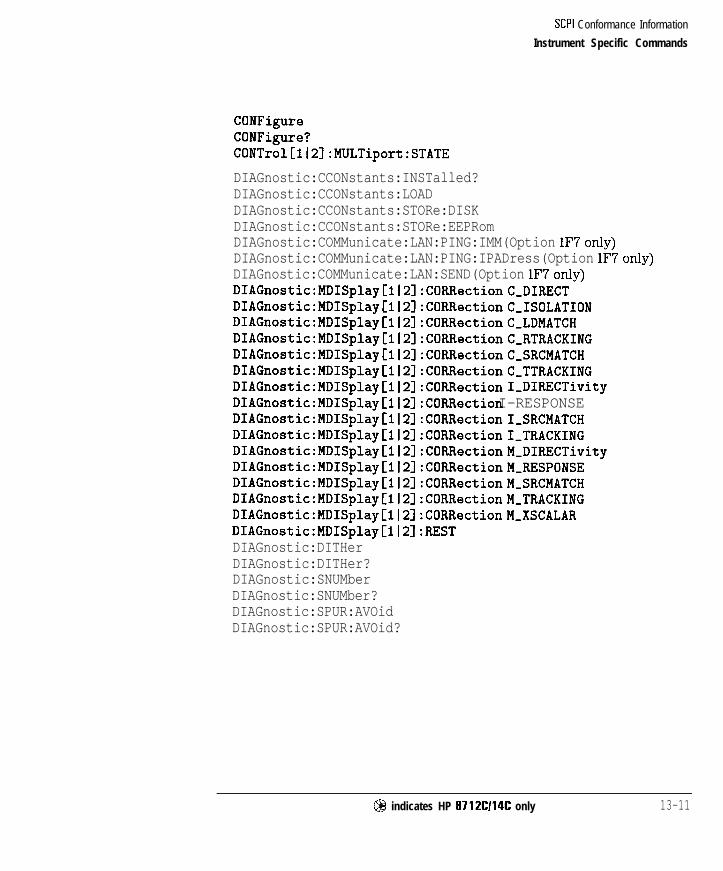
I- I -
SCPI Conformance Information
Instrument Specific Commands
CONFigureCONFigure?CONTrol[112]:MULTiport:STATE
DIAGnostic:CCONstants:INSTalled?DIAGnostic:CCONstants:LOADDIAGnostic:CCONstants:STORe:DISKDIAGnostic:CCONstants:STORe:EEPRomDIAGnostic:COMMunicate:LAN:PING:IMM(Option lF7only)DIAGnostic:COMMunicate:LAN:PING:IPADress(Option lF7only)DIAGnostic:COMMunicate:LAN:SEND(Option lF7only)DIAGnostic:MDISplay~1l21:CORRectionC,DIRECTDIAGnostic:MDISplay[l~2]:CORRectionC,ISOLATIONDIAGnostic:MDISplay~ll21:CORRectionC~LDMATCHDIAGnostic:MDISplay[l12]:CORRectionC,RTRACKINGDIAGnostic:MDISplay~ll2]:CORRectionC~SRCMATCHDIAGnostic:MDISplay[l12]:CORRectionC,TTRACKINGDIAGnostic:MDISplay~ll2~:CORRection 1,DIRECTivityDIAGnostic:MDISplay[il23:CORRection I-RESPONSEDIAGnostic:MDISplay[l12]:CORRectionI,SRCMATCHDIAGnostic:MDISplay[:1l2~:CORRectionI,TRACKINGDIAGnostic:MDISplayCll21:CORRectionM~DIRECTivityDIAGnostic:MDISplayC1l21:CORRectionM~RESPONSEDIAGnostic:MDISplayCll2]:CORRectionM~SRCMATCHDIAGnostic:MDISplay[112]:CORRectionM,TRACKINGDIAGnostic:MDISplay[ll2]:CORRectionM,XSCALARDIAGnostic:MDISplay[ll2]:RESTDIAGnostic:DITHerDIAGnostic:DITHer?DIAGnostic:SNUMberDIAGnostic:SNUMber?DIAGnostic:SPUR:AVOidDIAGnostic:SPUR:AVOid?
@ indicates HP 8712Cl14C only 13-11

I- I -
SCPI Conformance Information
Instrument Specific Commands
DISPlay:ANNotation:CHANnel[ll2] [:STATe]DISP~~~:ANN~~~~~~~:CHAN~~~[~I~]:USER:LAB~~[:DATA]DISPlay:ANNotation:CHANnelCll2l:USER[:STATe]DISPlay:ANNotation:CLOCk:DATE:FORMatDISPlay:ANNotation:CLOCk:DATE:FORMat?DISPlay:ANNotation:CLOCk:DATE:MODEDISPlay:ANNotation:CLOCk:DATE:MODE?DISPlay:ANNotation:CLOCk:MODEDISPlay:ANNotation:CLOCk:MODE?DISPlay:ANNotation:CLOCk:SEConds[:STATe]DISPlay:ANNotation:CLOCk:SEConds[:STATe]?DISPlay:ANNotation:FREQuency[ll2]:MODEDISPlay:ANNotation:FREC)uency[ll2]:MODE?
DISPlay:ANNotation:FREquency:RESolutionDISPlay:ANNotation:FREljuency:RESolution?DISPlay:ANNotation:FREQuencyCll2l[:STATe]DISPlay:ANNotation:FREquency[ll2]:USER:LABel[:DATA]DISPlay:ANNotation:FREQuencyCil2l:USER:STARtDISPlay:ANNotation:FREquency[ll2]:USER[:STATe]DISPlay:ANNotation:FRELjuencyC1121:USER:STOPDISPlay:ANNotation:FREQuencyCil2]:USER:SUFFIXDISPlay:ANNotation:LIMit:ICON[ll2]:FLAGDISPlay:ANNotation:LIMit:ICON[ll2]:POS:XDISPlay:ANNotation:LIMit:ICON[l~2]:POS:YDISPlay:ANNotation:LIMit:ICON[ll2]:TEXTDISPlay:ANNotation:LIMit:ICON[ll2]:STATeDISPlay:ANNotation:MARKer[ll2]:NUMBers[:STATe]DISPlay:ANNotation:MARKer[ll2] [:STATe]DISPlay:ANNotation:MARKer[ll21 C:STATel?DISPlay:ANNotation:MESSage:AOFFDISPlay:ANNotation:MESSage:CLEarDISPlay:ANNotation:MESSage[:DATA]?DISPlay:ANNotation:MESSage:STATeDISPlay:ANNotation:MESSage:STATe?DISPlay:ANNotation:TITLe[ll2]:DATADISPlay:ANNotation:TITLe[ll2] :DATA?DISPlay:ANNotation:TITLe[:STATe]DISPlay:ANNotation:TITLe[:STATe]?DISPlay:ANNotation:YAXis:MODEDISPlay:ANNotation:YAXis:MODE?
13-12
- -

I- I -
SCPI Conformance Information
Instrument Specific Commands
DISPlay:ANNotation:YAXis[:STATe]DISPlay:ANNotation:YAXis[:STATe]?DISPlay:CMAP:COLor[ll2l . . . 16l:GREYscaleDISPlay:CMAP:SCHemeDISPlay:FORMatDISPlay:FORMat?DISPlay:FORMat:EXPANDDISPlay:MENU:RECall:FAST[:STATe]DISPlay:PROGram[:MODE]DISPlay:PROGram[:MODE]?DISPlay:WINDow:GRAPhics:BUFFer[:STATe]DISPlay:WINDow:GRAPhics:BUFFer[:STATe]?DISPlay:WINDow[ll2llO]:GRAPhics:CIRCleDISPlay:WINDow[ll2llO]:GRAPhics:LABel:FONTDISPlay:WINDow[1l2llO]:GRAPhics:LABel:FONT?DISPlay:WINDow[ll2llO]:GRAPhics:RECTangleDISPlay:WINDow[1l2llO]:TRACe[ll2]:Y:TRACk
HCOPy:DEVice:PAGE:MARGin:LEFTHCOPy:DEVice:PAGE:MARGin:TOPHCOPy:DEVice:PAGE:ORIentationHCOPy:DEVice:PAGE:WIDThHCOPy:DEVice:PORTHCOPy:DEVice:PORT?HCOPy:ITEM:GRATicule:STATeHCOPy:ITEM:GRATicule:STATe?HCOPy:ITEM:MARKer:STATeHCOPy:ITEM:MARKer:STATe?HCOPy:ITEM:TITLe:STATeHCOPy:ITEM:TITLe:STATe?HCOPy:ITEM:TRACe:STATeHCOPy:ITEM:TRACe:STATe?HCOPy:PAGE:MARGin:LEFTHCOPy:PAGE:MARGin:LEFT?HCOPy:PAGE:MARGin:TOPHCOPy:PAGE:MARGin:TOP?HCOPy:PAGE:ORIentationHCOPy:PAGE:ORIentation?HCOPy:PAGE:WIDThHCOPy:PAGE:WIDTh?
13 -13

I- I -
SCPI Conformance Information
Instrument Specific Commands
1NPut:GAIN:AUTO1NPut:GAIN:SETTing
MMEMory:MDIRectoryMMEMory:RDIRectoryMMEMory:STORe:STATe:CORRectionMMEMory:STORe:STATe:CORRection?MMEMory:STORe:STATe:ISTateMMEMory:STORe:STATe:ISTate?MMEMory:STORe:STATe:TRACeMMEMory:STORe:STATe:TRACe?MMEMory:STORe:STATe:TSCALMMEMory:STORe:TRACeMMEMory:STORe:TRACe:FORMatMMEMory:TRANsfer:BDATMMEMory:TRANsfer[:HFS]
POWerCl
ROUTeElROUTeClROUTeClROUTeClROUTeClROUTeCl
SENSeClSENSeClSENSeClSENSe[lSENSeClSENSe[lSENSe[lSENSe[lSENSeCl
I 23:MODE
23:PATH:DEFine:PORT2]:PATH:DEFine:PORT?23:REFLection:PATH:DEFine:PORT2]:REFLection:PATH:DEFine:PORT?2l:TRANsmission:PATH:DEFine:PORT2]:TRANsmission:PATH:DEFine:PORT?
2l:AVERage:CLEar2]:CORRection:CAPacitance:CONNector(Option 100 only)2]:CORRection:CAPacitance:CONNector? (Option lOOonly)2l:CORRection:COLLect:ABORt2]:CORRection:COLLect:CKIT[:SELect]2]:CORRection:COLLect:CKIT[:SELect]?21:CORRection:COLLect:ISTate[:AUTO]2]:CORRection:COLLect:ISTate[:AUTO]?21:CORRection:COLLect:PORTS
SENSe[112]:CORRection:COLLect:MP:OPENSENSe[112]:CORRection:COLLect:MP:SHORTSENSe[l2]:CORRection:COLLect:MP:LOADSENSe[112]:CORRection:COLLect:MP:THRUSENSe[ll2]:CORRection:COLLect:VERify:TRANsmissionSENSeCll21:CORRection:COLLect:VERify:REFLection@SENSeClI21:CORRection:EXTension[:STATe]~SENSe[ll2]:CORRection:EXTension:REFLection[:TIMEl
13-14 @ indicates HP 8712C114C only
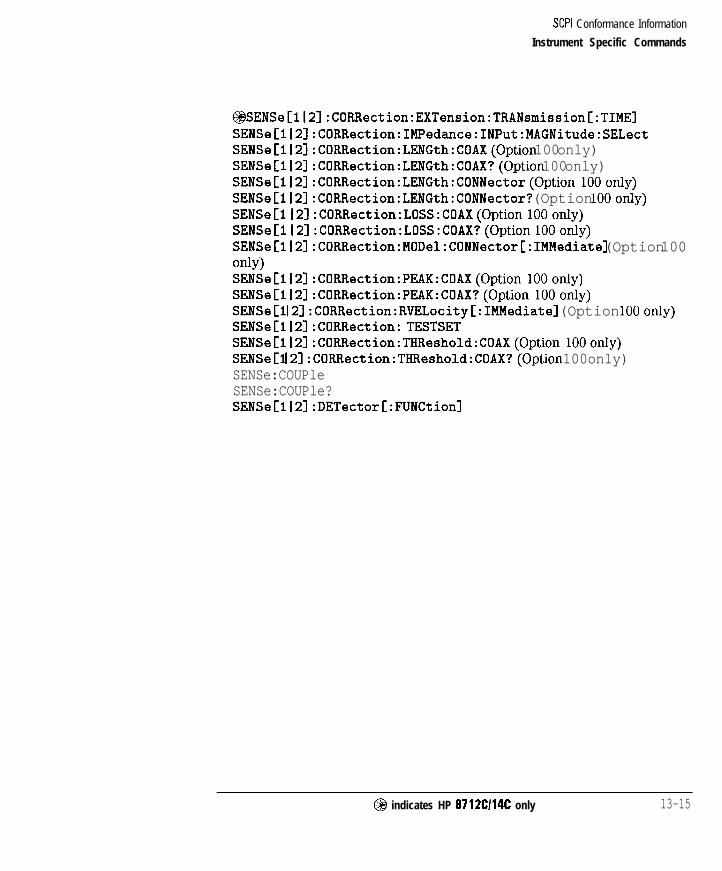
I- I -
SCPI Conformance Information
Instrument Specific Commands
~SENSeCll2]:CORRection:EXTension:TRANsmission[:TIME]SENSeCll2]:CORRection:IMPedance:INPut:MAGNitude:SELectSENSe[ll2]:CORRection:LENGth:COAX(Option 100 only)SENSe[lI2]:CORRection:LENGth:COAX?(Option 100 only)SENSeClI21:CORRection:LENGth:CONNector(Option lOOonly)SENSe[ll2]:CORRection:LENGth:CONNector? (Option lOOonly)SENSeCl I2]:CORRection:LOSS:COAX(Option lOOonly)SENSeCl I2]:CORRection:LOSS:COAX?(Option lOOonly)SENSeCll21:CORRection:MODel:CONNectorC:IMMediate] (Option 100OdY)SENSe[112]:CORRection:PEAK:COAX(Option lOOonly)SENSeClI2]:CORRection:PEAK:COAX?(Option lOOonly)SENSeCl I2]:CORRection:RVELocityC:IMMediate] (Option lOOonly)SENSeCll21:CORRection: TESTSETSENSe[112]:CORRection:THReshold:COAX(Option lOOonly)SENSeCl I2l:CORRection:THReshold:COAX?(Option 100 only)SENSe:COUPleSENSe:COUPle?SENSe[lI2]:DETector[:FUNCtion]
@I indicates HP 8712Cl14C only 13-15

I- I -
SCPI Conformance Information
Instrument Specific Commands
SENSe[ll21:DETector[:FUNCtionl?SENSe:DISTance:STARt (Option lOOonly)SENSe:DISTance:STARt? (Option 100 only)SENSe:DISTance:STOP(Option lOOonly)SENSe:DISTance:STOP?(Option lOOonly)SENSe:DISTance:UNITs(Option 100 only)SENSe:DISTance:UNITs? (Option 100 only)SENSe:FREquency:MODE(Option 100 only)SENSe:FRElJuency:MODE?(Option 100 only)SENSe:FREQuency:SPAN:MAXimum? (Option 100 only)SENSe:FREQuency:SPAN:MAXimum(Option 100 only)SENSe:FREQuency:ZSTop(Option lOOonly)SENSe:FREQuency:ZSTop? (Option lOOonly)SENSe:FUNCtion:SRL:IMPedance(Option lOOonly)SENSe:FUNCtion:SRL:IMPedance? (Option lOOonly)SENSe:FUNCtion:SRL:MODE(Option lOOonly)SENSe:FUNCtion:SRL:MODE?(Option 100 only)SENSe:FUNCtion:SRL:SCAN[:IMMediate] (Option lOOonly)SENSe[l I2l:STATeSENSe[ll2]:STATe?SENSe:SWEep:TRIGger:SOURceSENSe:SWEep:TRIGger:SOURce?SENSe:WINDow[:TYPE] (Option lOOonly)SENSe:WINDow[:TYPE]?(Option lOOonly)
STATus:DEVice:CONDition?STATus:DEVice:ENABleSTATus:DEVice:ENABle?STATus:DEVice[:EVENt]?STATus:DEVice:NTRansitionSTATus:DEVice:NTRansition?STATus:DEVice:PTRansitionSTATus:DEVice:PTRansition?STATus:OPERation:AVERaging:CONDition?STATus:OPERation:AVERaging:ENABleSTATus:OPERation:AVERaging:ENABle?STATus:OPERation:AVERaging[:EVENtl?STATus:OPERation:AVERaging:NTRansitionSTATus:OPERation:AVERaging:NTRansition?STATus:OPERation:AVERaging:PTRansitionSTATus:OPERation:AVERaging:PTRansition?
13-16

I- I -
SCPI Conformance Information
Instrument Specific Commands
STATus:OPERation:MEASuring:CONDition?STATus:OPERation:MEASuring:ENABleSTATus:OPERation:MEASuring:ENABle?STATus:OPERation:MEASuring[:EVENt]?STATus:OPERation:MEASuring:NTRansitionSTATus:OPERation:MEASuring:NTRansition?STATus:OPERation:MEASuring:PTRansitionSTATus:OPERation:MEASuring:PTRansition?STATus:PRESetSTATus:QUEStionable:LIMit:CONDition?STATus:QUEStionable:LIMit:ENABleSTATus:QUEStionable:LIMit:ENABle?STATus:qUEStionable:LIMit[:EVENt]?STATus:QUEStionable:LIMit:NTRansitionSTATus:QUEStionable:LIMit:NTRansition?STATus:qUEStionable:LIMit:PTRansitionSTATus:lJJEStionable:LIMit:PTRansition?
SYSTem:COMMunicate:GPIB:CONTroller[:STATe]SYSTem:COMMunicate:GPIB:CONTroller[:STATe]?SYSTem:COMMunicate:GPIB:ECHOSYSTem:COMMunicate:GPIB:ECHO?SYSTem:COMMunicate:GPIB:HCOPy:ADDRessSYSTem:COMMunicate:GPIB:HCOPy:ADDRess?SYSTem:COMMunicate:GPIB:MMEMory:ADDRessSYSTem:COMMunicate:GPIB:MMEMory:ADDRess?SYSTem:COMMunicate:GPIB:MMEMory:UNITSYSTem:COMMunicate:GPIB:MMEMory:UNIT?SYSTem:COMMunicate:GPIB:MMEMory:VOLumeSYSTem:COMMunicate:GPIB:MMEMory:VOLume?SYSTem:COMMunicate:GPIB:MMEMory:VOLume?SYSTem:COMMunicate:LAN:EADDress? (Option lF7only)SYSTem:COMMunicate:LAN:IPADdress(Option lF7only)SYSTem:COMMunicate:LAN:IPADdress? (Option lF7only)SYSTem:COMMunicate:LAN:PRINter:HOSTname(Option lF7only)SYSTem:COMMunicate:LAN:PRINter:HOSTname? (Option lF7only)SYSTem:COMMunicate:LAN:ROUTe:GATeway(Option lF7only)SYSTem:COMMunicate:LAN:ROUTe:GATeway? (Option lF7only)SYSTem:COMMunicate:LAN:ROUTe:SMASk(Option lF7only)SYSTem:COMMunicate:LAN:ROUTe:SMASk? (Option lF7only)SYSTem:COMMunicate:LAN:STATe(Option lF7only)
13-17

I- I -
SCPI Conformance Information
SYSTem:COMMunicate:LAN:STATe? (Option lF7only)SYSTem:COMMunicate:SERial:TRANsmit:HANDshakeSYSTem:COMMunicate:SERial:TRANsmit:HANDshake?SYSTem:COMMunicate:TTL:USER:FEEDSYSTem:COMMunicate:TTL:USER:FEED?SYSTem:KEY:MASK?SYSTem:KEY:QUEue:CLEarSYSTem:KEY:lJJEue:COUNt?SYSTem:KEY:qUEue:MAXimum?SYSTem:KEY:QUEue[:STATe]SYSTem:KEY:QUEue[:STATe]?SYSTem:KEY:TYPE?SYSTem:KEY:USERSYSTem:SET:LRNLong
TEST:RESult?TEST:SELectTEST:SELect?TEST:STATeTEST:STATe?TEST:VALueTEST:VALue?
13-18

I- I -
14
SCPI Error Messages

I-
SCPI Error Messages
This chapter contains the same error message information that can be foundin the SCPI 1994 Volume 2: Command Reference. There are four sections inthis chapter:
l Command Errors
l Execution Errors
l Device-Specik Errors
l Query Errors
N O T E
Your analyzer does not use all of the error messages listed in this chapter.
14-2

I- I -
Command Errors
An error/event number in the range -199 to -100 indicates that anIEEE 488.2 syntax error has been detected by the instrument’s parser. Theoccurrence of any error in this class shah cause the command error bit (bit 5)in the event status register (IEEE 488.2, section 11.5.1) to be set. One of thefollowing events has occurred:
l An IEEE 488.2 syntax error has been detected by the parser. That is, acontroller-to-device message was received which is in violation of theIEEE 488.2 standard. Possible violations include a data element whichviolates the device listening formats or whose type is unacceptable to thedevice.
l An unrecognized header was received. Unrecognized headers includeincorrect device-specific headers and incorrect or unimplementedIEEE 488.2 common commands.
l A Group Execute Trigger (GET) was entered into the input buffer inside ofan IEEE 488.2 program message.
Events that generate command errors shah not generate execution errors,device-specific errors, or query errors; see the other error definitions in thischapter.
14-3

I- I -
SCPI Error Messages
Command Errors
Table 14-l. SCPI Command Errors
Error Number
- 1 0 0
Error Description
Command error - This is the generic syntax error for devices that cannot detect more specific errors. This code
indicates only that a Command Error has occurred.
- 1 0 1 Invalid character - A syntactic element contains a character which is invalid for that type; for example, a header
containing an ampersand, SETUP&. This error might be used in place of errors -114, -121, -141, and perhapssome others.
- 1 0 2
- 1 0 3
- 1 0 4
Syntax error - An unrecognized command or data type was encountered; for example, a string was received whenthe device does not accept strings.
Invalid separator - The parser was expecting a separator and encountered an illegal character; for example, thesemicolon was omitted after a program message unit, *EMC I : CHl : VOLTS 5.
Data type error - The parser recognized a data element different than one allowed; for example, numeric or stringdata was expected but block data was encountered.
- 1 0 5
- 1 0 8
- 1 0 9
- 1 1 0
GET not allowed - A Group Execute Trigger was received within a program message.
Parameter not allowed - More parameters were received than expected for the header; for example, the *EMCcommon command only accepts one parameter, so receiving *EMC 0,l is not allowed.
Missing parameter - Fewer parameters were received than required for the header; for example, the *EMCcommon command requires one parameter, so receiving *E#C is not allowed.
Command header error - An error was detected in the header. This error message should be used when thedevice cannot detect the more specific errors described for errors -111 through -119.
- 1 1 1 Header separator error - A character which is not a legal header separator was encountered while parsing theheader;.for example, no white space followed the header, thus *GMC"MACRO" is an error.
- 1 1 2
- 1 1 3
Program mnemonic too long - The header contains more that twelve characters.
Undefined header - The header is syntactically correct, but it is undefined for this specific device; for example,*XYZ is not defined for any device.
- 1 1 4 Header suffix out of range - The value of a numeric suffix attached to a program mnemonic makes the headerinvalid.
- 1 2 0 Numeric data error - This error, as well as errors -121 through -129, are generated when parsing a data
element which appears to be numeric, including the nondecimal numeric types. This particular error message shouldbe used if the device cannot detect a more specific error.
- 1 2 1 Invalid character in number - An invalid character for the data type being parsed was encountered; for example, analpha in a decimal numeric or a “9’ in octal data.
- 1 2 3 Exponent too large - The magnitude of the exponent was larger than 32000.
1 4 - 4

I -
SCPI Error Messages
Command Errors
Table 14-l. SCPI Command Errors (continued)
Error Number Error Description
- 1 2 4 Too many digits - The mantissa of a decimal numeric data element contained more than 255 digits excluding
leading zeros.
- 1 2 6 Numeric data not allowed - A legal numeric data element was received, but the device does not accept one inthis oosition for the header.
- 1 3 0 Suffix error - This error, as wall as errors -131 through -139, are generated when parsing a suffix. Thisparticular error massage should be used if the device cannot detect a more specific error.
- 1 3 1 Invalid suffix - The suffix does not follow the correct syntax, or the suffix is inappropriate for this device.
- 1 3 4 Suffix too long - The suffix contained more than 12 characters.
- 1 3 6
- 1 4 0
Suffix not allowed - A suffix was encountered after a numeric adamant which does not allow suffixes.
Character data error - This error, as wall as errors -141 through -149, are generated when parsing a characterdata element. This particular error massage should be used if the device cannot detect a more specific error.
- 1 4 1 Invalid character data - Either the character data element contains an invalid character or the particular elementreceived is not valid for the header.
- 1 4 4 Character data too long - The character data element contains more than twelve characters.
- 1 4 6 Character data not allowed - A legal character data element was encountered where prohibited by the device.
- 1 5 0 String data error - This error, as wall as errors -151 through -159, are generated when parsing a string dataelement. This particular error massage should be used if the device cannot detect a more specific error.
I-- - 1 5 1 I Invalid string data - A string data element was expected, but was invalid for some reason. For example, an END Imassage was received before the terminal quota character.
- 1 5 6 String data not allowed - A string data element was encountered but was not allowed by the device at this point
in oarsino.
I - 1 6 0 Block data error - This error, as wall as errors -161 through -169, are generated when parsing a block data
element. This particular error massage should be used if the device cannot detect a more specific error.
- 1 6 1 Invalid block data - A block data element was expected, but was invalid for some reason. For example, an ENDmassage was received before the length was satisfied.
- 1 6 6
- 1 7 0
Block data not allowed - A legal block data element was encountered but was not allowed by the device at thispoint in parsing.
Expression error - This error, as wall as errors -171 through -179, are generated when parsing an expressiondata element. This oarticular error massaoa should be used if the device cannot detect a more specific error.
14-5

I- I -
SCPI Error Messages
Command Errors
Table 14-1. SCPI Command Errors (continued)
Error Number
- 1 7 1
Error Description
Invalid expression - The expression data element was invalid [for example, unmatched parentheses or an illegal
charactarl.
- 1 7 8 Expression data not allowed - A legal expression data was encountered but was not allowed by the device at thispoint in parsing.
- 1 8 0 Macro error - This error, as wall as errors -181 through -189, are generated when defining or executing amacro. This particular error massage should be used if the device cannot detect a more specific error.
- 1 8 1 Invalid outside macro definition - Indicates that a macro parameter placaholdar lS<numbarl was encounteredoutside of a macro definition.
I - 1 8 3 Invalid inside macro definition - Indicates that the program massage unit sequence, sent with a *DDT or *DMCcommand. is svntacticallv invalid.
I - 1 8 4 Macro parameter error - Indicates that a command inside the macro definition had the wrong number or type ofoaramatars.
14-6

I- I -
Execution Errors
An error/event number in the range -299 to -200 indicates that an error hasbeen detected by the instrument’s execution control block. The occurrence ofany error in this class shall cause the execution error bit (bit 4) in the eventstatus register to be set. One of the following events has occurred:
l A program data element following a header was evaluated by the deviceas outside of its legal input range or is otherwise inconsistent with thedevice’s capabilities.
l A valid program message could not be properly executed due to somedevice condition.
Execution errors shall be reported by the device after rounding andexpression evaluation operations have taken place. Rounding a numeric dataelement, for example, shall not be reported as an execution error. Events thatgenerate execution errors shall not generate Command Errors, device-specihcerrors, or Query Errors; see the other error definitions in this section.
14-7

SCPI Error Messages
Execution Errors
Table 14-2. SCPI Execution Errors
Error Number
- 2 0 0
Error Description
Execution error - This is the generic syntax error for devices that cannot detect more specific errors. This codaindicates only that an Execution Error has occurred.
- 2 0 1 Invalid while in local - Indicates that a command is not executable while the device is in local due to a hard local
control; for example, a device with a rotary switch receives a massage which would change the switches state, but
the device is in local so the massage can not be executed.
- 2 0 2 Settings lost due to rtl - Indicates that a setting associated with a hard local control was lost when the devicechanged to LOCS from REMS or to CvVLS from RWLS.
- 2 0 3 Command protected - Indicates that a legal password-protected program command or query could not be executedbecause the command was disabled.
- 2 1 0
- 2 1 1
- 2 1 2
- 2 1 3
Trigger error
Trigger ignored - Indicates that a GET, *TRG, or triggering signal was received and recognized by the device bu
was ignored because of device timing considerations; for example, the device was not ready to respond.’
Arm ignored - Indicates that an arming signal was received and recognized by the device but was ignored.
lnit ignored - Indicates that a request for a measurement initiation was ignored as another measurement wasalready in progress.
- 2 1 4 Trigger deadlock - Indicates that the trigger source for the initiation of a measurement is sat to GET and
subsequent measurement query is received. The measurement cannot be started until a GET is received, but theGET would cause an INTERRUPTED error.
-215s Arm deadlock - Indicates that the arm source for the initiation of a measurement is sat to GET and subsequentmeasurement query is received. The measurement cannot be started until a GET is received, but the GET would
cause an INTERRUPTED error.
- 2 2 0 Parameter error - Indicates that a program data element related error occurred. This error massage should beused when the device cannot detect the more specific errors -221 through -229.
- 2 2 1 Settings conflict - Indicates that a legal program data element was parsed but could not be executed due to the
currant device state.
- 2 2 2 Data out of range - Indicates that a legal program data element was parsed but could not be executed becausethe interpreted value was outside the legal range as defined by the device.
- 2 2 3 Too much data - Indicates that a legal program data element of block, expression, or string type was receivedthat contained more data than the device could handle due to memory or related device-specific requirements.
- 2 2 4 Illegal parameter value - Used where an exact value, from a list of possible values, was expected.
1 A LIT0 da&e always ignores GET and treats ‘TRG as a Command Error.
1 4 - 8

I- I -
SCPI Error Messages
Execution Errors
Table 14-2. SCPI Execution Errors (continued)
Error Number Error Description
- 2 2 5 Out of memory - The device has insufficient memory to perform the requested operation.
- 2 2 6 Lists not same length - Attempted to use LIST structure having individual LIST’s of unequal lengths.
- 2 3 0 Data corrupt or stale - Possibly invalid data; new reading started but not completed since last access.
- 2 3 1 Data questionable - Indicates that measurement accuracy is suspect.
- 2 3 2 Invalid format - Indicates that a legal program data element was parsed but could not be executed because thedata format or structure is inappropriate, such as when loading memory tables or when sanding a SYSTem: SETparameter from an unknown instrument.
- 2 3 3 Invalid version - Indicates that a legal program data element was parsed but could not be executed because theversion of the data is incorrect to the device. This particular error should be used when file or block data formatsare recognized by the instrument but cannot be executed for reasons of version incompatibility. For example, an
unsupported file version, or an unsupported instrument version.
- 2 4 0 Hardware error - Indicates that a legal program command or query could not be executed because of a hardwareproblem in the device. Definition of what constitutes a hardware problem is completely device-specific. This errormassage should be used when the device cannot detect the more specific errors described for errors -241 through- 2 4 9 .
- 2 4 1 Hardware missing - Indicates that a legal program command or query could not be executed because of missing
device hardware; for example, an option was not installed. Definition of what constitutes missing hardware iscompletely device-specific.
- 2 5 0 Mass storage error - Indicates that a mass storage error occurred. This error massage should be used when thedevice cannot detect the more spacific,arrors described for errors -251 through -259.
- 2 5 1 Missing mass storage - Indicates that a legal program command or query could not be executed because ofmissing mass storage; for example, an option that was not installed. Definition of what constitutes missing mass
storage is device-specific.
- 2 5 2 Missing media - Indicates that a legal program command or query could not be executed because of a missingmedia; for example, no disk. The definition of what constitutes missing media is device-specific
- 2 5 3 Corrupt media - Indicates that a legal program command or query could not be executed because of corrupt mediafor example, bad disk or wrong format. The definition of what constitutes corrupt media is device-specific.
- 2 5 4 Media full - Indicates that a legal program command or query could not be executed because the media was full;for example, there is no room on the disk. The definition of what constitutes a full media is device-specific.
- 2 5 5 Directory full - Indicates that a legal program command or query could not be executed because the media
directory was full. The definition of what constitutes a full media directory is device-specific.
14-9

I- I -
SCPI Error Messages
Execution Errors
Table 14-2. SCPI Execution Errors (continued)
Error Number Error Descriotion
-256 File name not found - indicates that a legal program command or query could not be executed because the filename on the device media was not found; for example, an attempt was made to read or copy a nonexistent file.The definition of what constitutes a file not being found is device-spaciiic.
File name error - Indicates that a legal program command or query could not be executed because the file nameon the device media was in error; for example, an attempt was made to copy to a duplicate file name. The
definition of what constitutes a file name error is device-soaciiic.
- 2 5 8 Media protected - Indicates that a legal program command or query could not be executed because the mediawas protected; for example, the write-protect tab on a disk was present. The definition of what constitutesprotected media is device-speciiic.
- 2 6 0 Expression error - Indicates that an expression program data element related error occurred. This error massageshould be used when the device cannot detect the more spaciiic errors described for errors -261 through -269.
- 2 6 1 Math error in expression - Indicates that a syntactically legal expression program data element could not beexecuted due to a math error; for example, a divide-by-zero was attempted. The definition of math error isdevice-specific.
- 2 7 0 Macro error - indicates that a macro-related execution error occurred. This error massage should be used whenthe device cannot detect the more specific errors -271 through -279.
- 2 7 1 Macro syntax error - Indicates that a syntactically legal macro program data sequence could not be executed dueto a syntax error within the macro definition.
- 2 7 2 Macro execution error - Indicates that a syntactically legal macro program data sequence could not be executed
due to some error in the macro definition.
- 2 7 3 Illegal macro label - indicates that the macro label defined in the *DMC command was a legal string syntax, butcould not be accepted by the device; for example, the label was too long, the same as a common command header,or contained invalid header syntax.
- 2 7 4 Macro parameter error - Indicates that the macro definition improperly used a macro parameter placeholder.
- 2 7 5 Macro definition too long - Indicates that a syntactically legal macro program data sequence could not be executedbecause the string or block contents ware too long for the device to handle.
- 2 7 6 Macro recursion error - Indicates that a syntactically legal macro program data sequence could not be executedbecause the device found it to be recursive.
14 -10
_I

SCPI Error Messages
Execution Errors
Table 14-2. SCPI Execution Errors (continued)
Error Number
- 2 7 7
Error Description
Macro redefinition not allowed - Indicates that a syntactically legal macro label in the *DMC command could notbe executed because the macro label was already defined.
- 2 7 6 Macro header not found - Indicates that a syntactically legal macro label in the *G#C? query could not beexecuted because the header was not previously defined.
- 2 6 0 Program error - Indicates that a downloaded program-related execution error occurred. This error massage shouldbe used when the device cannot detect the more specific errors -261 through -269. A downloaded program is
used to add algorithmic capability to a device. The syntax used in the program and the mechanism fordownloadino a oroaram is device-soacific.
- 2 6 1 Cannot create program - Indicates that an attempt to create a program was unsuccessful. One reason for failuremight include not enough memory.
- 2 6 2 Illegal program name - The name used to reference a program was invalid; for example, redefining an existingprogram, deleting a nonexistent program, or in general, referencing a nonexistent program.
- 2 6 3
- 2 6 4
Illegal variable name - An attempt was made to reference a nonexistent variable in a program.
Program currently running - Certain operations dealing with programs may be illegal while the program is running;for example, deleting a running program might not be possible.
- 2 6 5 Program syntax error - Indicates that a syntax error appears in a downloaded program. The syntax used whenparsing the downloaded program is device-specific.
I - 2 6 6 I Proaram runtima error I
- 2 9 0 Memory use error - Indicates that a user request has directly or indirectly caused an error related to memory ordate-handles (this is not the same as “bad” memory].
- 2 9 1 Out of memory
- 2 9 2 Referenced name does not exist
- 2 9 3 Referenced name already exists
- 2 9 4 Incompatible type - Indicates that the type or structure of a memory item is inadequate.
1 4 - 1 1
I- I -
Device-Specific Errors
An error/event number in the range -399 to -300 or 1 to 32767 indicatesthat the instrument has detected an error which is not a command error, aquery error, or an execution error. It indicates that some device operationsdid not properly complete, possibly due to an abnormal hardware or hrmwarecondition. These codes are also used for self-test response errors. Theoccurrence of any error in this class should cause the device-specific error bit(bit 3) in the event status register to be set.
The meaning of positive error codes is device-dependent and may beenumerated or bit mapped; the error message string for positive error codesis not defined by SCPI and available to the device designer. Note that thestring is not optional; if the designer does not wish to implement a stringfor a particular error, the null string should be sent (for example, 42, ” “).The occurrence of any error in this class should cause the device-specihcerror bit (bit 3) in the event status register to be set. Events that generatedevice-specific errors shall not generate command errors, execution errors, orquery errors; see the other error definitions in this section.
14-12

I-
SCPI Error Messages
Device-Specific Errors
Table 14-3. SCPI Device-Specific Errors
Error Number
- 3 0 0
Error Description
Device-specific error - This is the generic device-dependent error for devices that cannot detect more specific errors.This coda indicates onlv that a Device-Deoandant Error has occurred.
- 3 1 0 System error - Indicates that some error, termed “system error’ by the device, has occurred. This coda is
device-dependent.
- 3 1 1 Memory error - Indicates that en error was detected in the device’s memory. The scope of this error isdevice-dependent.
- 3 1 2 PUD mamorv lost - Indicates that the orotactad user data saved bv the *PUD command has bean lost.
- 3 1 3 Calibration memory lost - Indicates that nonvolatile calibration data used by the *CAL? command has bean lost.
- 3 1 4 Save/recall memory lost - Indicates that the nonvolatile data saved by the *SAV? command has bean lost.
- 3 1 5 Configuration memory lost - Indicates that nonvolatile configuration data saved by the device has bean lost. The
meaning of this error is device-specific.
- 3 3 0 Self-test failedI
- 3 5 0 Ruaua overflow - A specific coda entered into the queue in lieu of the coda that caused the error. This codaindicates that there is no room in the queue and an error occurred but was not recorded.
- 3 6 0 Communication error - This is the generic communication error for devices that cannot detect the more specificerrors -361 throuoh -363.
- 3 6 1
- 3 6 2
Parity error in program massage - parity bit not correct when data received, for example, on a serial port.
Framing error in program massage - A stop bit was not detected when data was received, for example, on aserial oort lfor axamola. a baud rata mismatchl.
- 3 6 3 Input buffer overrun - Software or hardware input buffer on serial port overflows with data caused by improperor nonexistent pacing.
1 4 - 1 3

I- I -
Query Errors
An error/event number in the range -499 to -400 indicates that the outputqueue control of the instrument has detected a problem with the messageexchange protocol. The occurrence of any error in this class shah cause thequery error bit (bit 2) in the event status register to be set. These errorscorrespond to message exchange protocol errors. One of the following is true:
l An attempt is being made to read data from the output queue when nooutput is either present or pending;
l Data in the output queue has been lost.
Events that generate query errors shah not generate command errors,execution errors, or device-specihc errors; see the other error definitions inthis section.
Table 14-4. SCPI Query Errors
Error Number Ermr Description
- 4 0 0 Query error - This is the generic query error for devices that cannot detect more specific errors. This codaindicates only that a [luary Error has occurred.
- 4 1 0 Query INTERRUPTED - Indicates that a condition causing an INTERRUPTED Iluary error occurred; forexample, a query followed by DAB or GET before a response was completely sent.
- 4 2 0 Tluary UNTERMINATED - Indicates that a condition causing an UNTERMINATED Tluary error occurred; forexample, the device was addressed to talk and en incomplete program massage was received.
- 4 3 0 lluary DEADLOCKED - Indicates that a condition causing a DEADLOCKED [luary error occurred; for axamplr
both inout buffer and outout buffer are full and the device cannot continua.
-440 fluary UNTERMINATED after indefinite response - Indicates that a query was received in the same program
massage after an query requesting an indefinite response was executed.
2,
14-14

Index
I -
-

I- I -
Index
3 3.5 mm, 11-30
5 50 Q , 11-30
7 75 Q , 11-30
A A, 11-6abbreviation
of commands, 10-8Abort
hardcopy, 1 l-37ABORt, 10-4, 12-2, 12-3Abort Cal , 11-24
Abort GAL Check, 11-25active controller
defined, 1-2Active Narker Clff, I
Add I&x Line, 11-18
Add Max Point , 11-18
Add Hin Line, 11-18
Add Ain Potit , 1 l-18address
HP-IB, 1-2address capability, l-7AHl, l-8allocate memory, 12-25All Off, 11-16
All Stds Done, ll-24
l-15
Alt Sweep on OFF, 11-11
AM Delay, 11-6cal, 11-29
ANNotation, 12-15, 12-16, 12-1’7Annotation ON off, 11-39aperture, delay, 11-32A/R, 11-6
Index- 2

I- I -
B B, 11-6
B* , 11-7
Band Pass , 11-8
Bant;t Pass Plziz Span,
Bandwidth , 11-17
Baud Rate , 11-37BEEPer, 12-37Beeper Pohue , 11-42
(BEGIN), 11-3, 12-10
Begin Fxm.pncy , ll-
Begin Limit , 11-19binary encoding, 1-4, 4-8<block>, lo- 14block data, 4-5
arraysdata, corrected, 6-25example program to up- and down-load, 8-53formatted, 6-27measurement, 6-2 1memory, corrected, 6-26raw data, 6-22
ASCDA’I’Aexample program, 8-31
ASCii, 4-7ASCII encoding, 4-8ATN, 1-4, l-10attention
control line, 1-4Auto Feed
plotter, 11-39printer, 11-38
Autoscale, 11-14
Autozexo, 1 l-30
Auto I DB off , 1
AWX Input , 11-7AVERage, 12-27Average Factor,
Avexage on OFF,averaging, 6-25
11-29
11-32
11-32
averaging status register set, 5-23m), 11-32
11-8
19
Index-3

I- I -
block lengthdefinite, 4-5indefinite, 4-6
block parameters, lo-14blocks
definite and indefinite length, 4-5, 4-6, lo-14boolean parameters, lo-12B/R, 11-6
B*/R* , 11-7brackets
use of in this manual, 1-3, lo-15branching, 10-5Broadband Ertema1, 11-7
Broadband Internal, 11-7buffer
graphics, 7-6buffering user graphics, 12-18bus
data, 1-4bus management commands, 1-6byte order, 12-19bytes per point, during data transfer, 6-9byte swapping, 4-9
C Cl, 1-8C12, 1-8C2, 1-8C3, 1-8C4, 1-8C8, 1-8Cable Loss, 11-28cables. 1-2m), 11-23
CAL Check, 11-25CALCulate, 10-4, 12-4,Calibrate Cable, 1calibration
12-5, 12-6, 12-7, 12-8, 12-91-28
full band, 12-28reflection, example program, 8.48transmission, example program, 8-46
CALibration, 10-4, 12-10calibration kit
example program, 8-60Cal Kit , 11-30CALKIT
example program, 8-60
Index-4

I- I -
Cal an DFF , 11-33case-sensitivity, 10-8CATalog, 12-25Center , 11-8CHlAFWD, 6-22CHlBFWD, 6-22CHIRFWD, 6-22CH lSCORR1, 6-24CHlSCORR2, 6-24CHlSCORR3, 6-24CHlSCORR4, 6-24CHBAFWD, 6-22CHBBFWD, 6-22CH2RFWD, 6-22CHBSCORRl, 6-24CHSSCORRB, 6-24CHBSCORRS, 6-24CHBSCORR4, 6-24change directory, 12-21<char>, lo-11character data, 4-4character parameters, lo- 11circle
to draw, 12-18clear graphics, 12-18clearing registers, 5-4Clear Program , 11-40clock, 11-42Clock Pamat, 11-42
Clock Off , 11-20*CLS, 2-6, 5-4, lo-17colons
use of, 10-5, lo-16Color , 1 l-37, 11-38color of pen, 12-18Color Options, 11-20command abbreviation, 10-8command errors, 14-3command parser, 1-14commands
bus management, 1-6device, 1-6IEEE 488.2, lo-17overlapped, 2-3SCPI standard, 13-3sequential, 2-2
command sending, 1-6
Index-5

I- I -
command tree, 10-3commas
use of, 10-10, lo-16condition register, 5-4
CO
connec
connec
Continue ( 1 l-40
continuous ( 11-12control
CONFigure, 12-10Configure VOLJAH , 1 l-34configuring measurements, 8-7
bnnector C , 11-29
tar Len@+h , 11-29
tor Model , 11-29
passing, 3-2CONTrol, 12-11controller
active, defined, 1-2delined, 1-2multiple, l-7system, defined, 1-2
controller capabilities, 1-9control lines. 1-4Conversion Loss , 11-6
copy A13. Files, 11-35copy file, 12-23Copy File , 11-35corrected data arrays, 6-25corrected memory arrays, 6-25CORRection, 12-27, 12-28, 12-29correction arrays
up- and down-loading, example program, 8-53COUPle, 11-11COUDlimZ. 11-11. ..,Create “TSET,CAL” , 11-24
CRT Adjust, 11-43
Current Size, 11-34
Custom Colors , 11-20customized procedure
example program, 8-109CW, 11-8
Index-6

I- I -
D da t ablock, 4-5character, 4-4expression, 4-4numeric, 4-3raw, 6-22string. 4-4.,,
Data, 11-18DATA, 12-40Data aad Me~~oxp , 1 l- 18data arrays
corrected, 6-25mnemonics, 6-22
data bus, 1-4data encoding, 4-7data format, 12-19Data/Hem, 11-18
Data on UFF, 11-33data rate, l-7data trace, 12-4data transfer, 4-2
in ASCII, example program, 8-31in REAL format, example program, 8-34using INTEGER format, example program, 8-38
data transfer size, 6-9data types, 4-2, 4-3DCl, l-8DCL, l-10, l-12Default 2 , 11-20
Default C&l , 11-28
Default Type-l(f), 11-30
Def tie Gra@r , 11-39
D&tie Badcopy , 11-39
D e f i n e P l o t t e r , 11-38
Define Printer , 1 l-38
Define Save, ll-33definite length blocks, 4-5, lo-14delay
electrical, 6-26Delay
format, 11-22Delay Aperture, 11-32
Index-7
-1

I- I -
Delete All Piles, 11-35
Delete 133, Limits, 11-18
Delete File, 11-35
Delete Limit, 11-18delete program, 12-25delimiters, lo-13Delta PIkr on OFF, 11-16
Detection Options, 11-6device clear, l-10, 1-12device commands, 1-6device-specific errors, 14-12device status register set, 5-15DIAGnostic, 12-11, 12-12Directory Utilities, 11-36direct-read method of accessing registers, 5-6discrete parameters, lo-11Disp Freq Resolutian, ll-9DISPlay, 10-4, 12-15, 12-16, 12.17, 12.18, 12-19(--I, 11-18display window
pixel coordinates, 12-18width and height, 12-18
Distance, 11-12
Dither, 11-13
Do CAL Check, ll-25double quotes
use of, lo-13download an IBASIC program, 12-25draw
circle, 12-18line, 12-18rectangle, 12-18
DTR/DSR, 11-37
E E2, l-8Edit Limit, 11-19electrical delay, 6-26ElectrybxzZ Delay, 11-14enable register, 5-5encoding data. 4-2. 4-7
-
End Frequency, 11-19
End Limit, 11-19end or identify
Index-8

- I -
control he, l-5IZnhanced Relspmse
cal, 11-23EOI, l-5error coefficient arrays, 6-23error correction, 6-23error messages, 12-38, 14-2error queue, 1-14
to query, 12-38errors
command, 14-3device-specific, 14-12execution, 14-7query, 14-14
*ESE, 5-22, lo-17*ESE?, 5-22, lo-17*ESR?, 5-22, lo-17event register, 5-4example program
ASCDATA, 8-31CALKIT, 8-60FAST-CW ,8-42FAST-PRT, 8-77FAULT, 8-161GETFILE, 8- 103GRAPHICS, 8- 109INTDATA, 8-38LEARNSTR, 8-63LIM-FLAT, 8-140LIMITEST, 8-l 1LIM-MEAN, 8-147LIM-PEAK, 8-143LOADCALS, 8-53MARKERS, 8-20MEAS-SRL, 8- 152MKR-MATH, 8-135PASSCTRL, 8-73POWERSWP, 8-16PRINTPLT, 8-70PLJTFILE, 8-105REALDATA, 8-34REFLCAL, 8-48SAVERCL, 8-66SETUP, 8-8SMITHMKR, 8-24SRL-SRQ, 8- 156SRQ, 8-81SRQ-INT , 8-85TRANCAL, 8-46
Index-9

I-
USR-FLOC, 8- 165example programs, 8-2- 194execute an IBASIC command, 12-25execution errors, 14-7Expannl an OFF , 11-20expression data, 4-4External Point
trigger, 11-12External Sweep
trigger, 11-12Ext Ref on OFF, 11-12
F Factory Default , ll-20FASTXW
example program, 8-42fast cw
examDle Drogram, 8-42FAST-PhT example program, 8-77FastRecall on OFF, 11-36FAULT
example program, 8-161fault location
example program, 8-161, 8-165Fault Location, 11-6fault location cal, 11-28Fault Lot Frequency, 11-8
Fault Window, 11-32
Feet , 11-12file copy, 12-23Pile Type bin ASCII, 11-34
File Utilities, ll-35
Fine , 11-32
Flatness, 11-16flatness, marker limit testing, 8-140font
label, 12-18FORMat. 10-4. 12-19(W),1;.22
Fomat Disk, 11-35format of numerics, 10-l 1formatted arrays, 6-27formatting, 6-27m, 11-8FREQuency, 12-31
Index- 10
I-

I- I -
frequency, stophow to set, lo-10
Fxequency Sweep , 1 l- 11front panel keycodes, 9-2FUl3.
IBASIC display, 1 l-40Full Band Cal , 11-28
G general status register model, 5-3GETFILE
example program, 8- 103go to local, l-10graphics
buffering, 12-18to clear, 12-18user, 7-2
GRAPhics, 12-18GRAPHICS
example program, 8- 109graphics buffer, 7-6Gxaph Only, 11-39
Gsatictie M off, 11-21, 11-39
Grey Scale, 11-20GTL, l-10
H ~;;;;;;yJ;7
Haxdcopy 811, 11-41hardcopy output
example program, 8-70Hardcopy Scxeen , 11-41HCOPy 10-4, 12-20, 12-21Hold, 11-12
Horizontal Back Porch, 11-43
Horizontal Fxnt Porch, 11-43
Horizontal Position, 11-43
HP &‘llrC IP Address, 11-41HP-IB addresses, 1-2HP-IB cables, 1-2BP-I18 Echo, 11-41HP-IB queues, 1-13HP-IB requirements, l-7Hue ) 11-20
Index- 11

I- I -
1 IBASIC , 11-40
IBASIC Display, 11-40IBASIC, Opt. lC2, 8-2IBASIC program
to delete, 12-25to download, 12-25to load a value, 12-25to select, 12-25
*IDN?, lo-17IEEE 488.2 common commands, lo-17IFC. 1-4. l-10Tmaginary
format, 11-22Impedance Hagnitde
format, 11-22implied mnemonics, 10-9
how identified in this manual, 1-3implied variables, 10-9
how identified in this manual, 1-3indefinite block length, 4-6indefinite length blocks, lo-14INITiate, 10-4, 12-21INITIATE, 10-9input queue, 1-13Instrument BASIC, 8-2Tnst State ON off, 11-33INTDATA
example program, 8-38Int Disp Intensity, 11-20INTeger, 4-7interface capabilities, 1-8interface clear, 1-4, l-10Internal
trigger, 11-12Tnternal 3.5" Disk, 11-34internal measurement arrays, 6-2 1Inverse Video , 11-20
L L4, 1-8label
to draw, 12-18label font, 12- 18LAIY, 11-41
Landscape , 11-37language, 12-20
Index- 12

I- I -
LEO, 1-8LEARNSTR
example program, 8-63learn string, 12-39
example program, 8-63Leve l , 11-10LIM-FLAT
example program, 8- 140LIMit, 12-4, 12-5, 12-6limitations
length of HP-IB cables, 1-7number of devices, 1-7
LIMITESTexample program, 8- 11
limit fail register set, 5-16Limit Pcun 01y off, 11-19
Limit Zzon Pos i t i on , 11-19
Limit Line III? off, 11-19limit lines
example program, 8- 11Ltiit Test on OFF, 11-19
Limit Text ON off, 11-19LIM-MEAN
example program, 8- 147LIM-PEAK
example program, 8- 143line
to draw, 12-18Lin HiSg, 11-22Lin Mag Units, 11-22listener
defined, 1-2List Trace Values, 11-39LLO, l-11load a value in an IBASIC program, 12-25LOADCALS
example program, 8-53local lockout, 1 - 11Log Hag ( 11-22Log Mag Units, 11-22Louex
IBASIC display, 1 l-40lower-case
use of, lo-15lower-case lettering, 10-8Low Parss , 11-8
Index- 13
I-

I- I -
*LRN?, 10-17, 12-39LRNLong?, 12-39Luarinance, 11-20
M Mag dHmV, 11-22Mag dRuV, 11-22Mag dBV, 11-22Mag Units , 11-22
Manual 5, 11-29
Hanu~ F&E0 , 11-30
MaTginhardcopy, 11-38
MARKer, 12-6, 12-7, 12-8@ziq,1 1 - 1 5
Maker Funct ions, 11-16marker limits
example program, 8- 140example programs, 8- 143, 8- 147
marker mathexample program, 8- 135
Maxkex Fdath, 11-16
Maker -> Center, 11-16
Marker -> Elec Delay, 11-16
Illarker -> Reference, 11-16MARKERS
example program, 8-20&axkex Seaxcb, 11-16math
trace, 6-26MATH. 12-9Math Off, 11-16
Harkmu , 11-32MAXimum. lo- 10Rax Limit, 11-19
&x Search, 11-16mean amplitude, marker limit testing, 8-147(‘MEAS-,1 1 - 6(m-,1 1 - 6
Heas OFF, 11-7MEAS-SRL
example program, 8- 152Measure Cable , 11-28
Index- 14
-1

I- I -
Heasure Connector , 11-29
Measure Loads , 11-24measurement
basic setup example program, 8-8measurement arrays
internal, 6-21measurements
to configure, 8-7measurement setup
example program, 8-8Meamxe Opezus , 11-24
Beamme Shorts, 11-24
Measure Standarcl , 11-23, 11-25, 11-29
Measuxe Thms , 11-24measuring status register set, 5-23Bedims, 1 l-32
Bed Barrow, 11-32
Ned Vide, 11-32
&mow, 11-18memory allocation, 12-25memory arrays
corrected, 6-25[MENU), 11-12message exchange, 1-13messages
error, 12-38, 14-2message transfer scheme, 1-7message window
clear current, 12-16enable/disable, 12-16off, 12-16remove user-defined, 12-16user-defined, 12-16
Meters, 11-12
Binimum , 11-32MINimum, lo-10Min Limit, 11-19
Hin Search, 11-16
%kr Limit UM off, 11-19
I&r Limits, 11-19Mm-MATH
example program, 8- 135Bx -> &LX, 11-16
Index- 15
-

I- I -
Hlor -> Nia, 11-16
Mkr Symbul ON off , 11-39
Hkr Table Only, 11-39MMEMory, 10-4, 12-22, 12-23mnemonics
implied, 10-9implied, how identified in this manual, 1-3
kdify Size, 11-34
lonochome., 11-37, 11-38
IkXtiIiotch,ll-17
Multi Peak, 11-17
Hulti Peak Corn, 11-28
Multi Fe& Threshold, 11-28multiple commands, 10-7multiple controller capability, 1-7Multipmt on OFF, 11-43
hltiport Selection, 11-7
N Narrow, 11-32
Namovband Internal, 11-6
atext Kin, 11-16
Next Peak, 11-16
NoneIBASIC display, 1 l-40
Non-VoL RAM D~EAL, 11-34no pending operation, 2-5Normalize , 11-18
Notch ( 1 l-17NPO, 2-5NRl, lo-11NR2, 10-11NR3, 10-11tnuml. lo-10
numeric data, 4-3numeric formats, lo- 11numeric parameters, lo-10
Index- 16
I-

I- I -
0 offset and scale, 6-27“One Fort
cal, 11-26<ONIOFF>, lo-12*OPC, 2-5, lo-17*OPC?, 2-5, lo-18Operating Pa;rmters, 11-41operational status register set, 5-24*OPT?, lo-18options, lo-18OUTPut, 10-4, 12-23output queue, 1-14overlapped commands, 2-3
p parallel poll, l-l 1parameters
block, lo-14boolean, lo-12character, lo-11discrete, 10-l 1numeric, lo- 10string, lo-13
parameter types, lo-10parser
command, 1-14pass control, 3-2PASSCTRL
example program, 8-73passing control, 3-2
example program, 8-73*PCB, l-12, lo-18peak-to-peak, marker limit testing, 8-143pen, 11-39
move, 12-18Periodic SelSCal, 11-24
Phaseformat, 11-22
Pharse OffseZ, 11-14pixel coordinates
display window, 12-18plotting and printing
example program, 8-70S o l a r
format, 11-22Port Ezt’a oxl OFP, 11-31
Portrait, 11-37
-1
Index- 17
I-

I- I -
Power, 11-6POWer, 12-24, 12-33@%viK],1 1 - 1 0power sweep
example program, 8-16Power Sweep , 11-11POWERSWP
example program, 8- 16PPC, l-11PPD, l-11PPE, l-11PPU, l-11(M), 11-2, 12-39
Printer Address, 11-37
Printer ResoLution, 11-38printing and plotting
example program, 8-70PRINTPLT
example program, 8-70Print Width, 11-38program
how to download, 12-25PROGram, 10-4, 12-25programming fundamentals, 1-9programs
examples, 8-2-194*PSC, lo-18PUTFILE
example program, 8-105Pwr Sweep Range, 11-10
Q query errors, 14-14query response generation, 1-15query the error queue, 12-38questionable status register set, 5-19queue
error, l-14input, l-13output, l-14
queues, 1-13quotes
use of, lo-13
Index- 18

I- I -
R It, 11-6
R* , 11-7ratio calculations, 6-23raw data arrays, 6-22readable ports, 12-13Real
format, 11-22REAL, 4-7REALDATA
example program, 8-34recalling and saving
example program, 8-66Recall Psogram ( 11-34
Recall State, 11-33rectangle
to draw, 12-18Reference Level., 11-14
Ref exence Position , 1 l- 14REFWAL
example program, 8-48Ref l ec t i on , 11-6reflection cal, 11-26reflection calibration
example program, 8-48Reflection Fort #upl, 11-7
Refl Pa& Extension, 11-31register model
status, 5-3registers, 5-2
how to use, 5-6register sets, 5-10remote enable, l- 11
control line, 1-5REN, 1-5, l-11Rename FiJ.e , 11-35
Re-Save Propam , 11-34
Re-Save St&e , 11-33
ResQonse
cal, 11-23Response k TsolatZi.on
cal. 11-23Restart Byerage , 11-32
Restore Defaul tscal, 11-23
Index- 19
-

I- I -
KF’ Filter Stats , 11-16
RF CM off ) 11-10RLl, l-8ROUTe, 12-26RQS, l-12*RST, 2-6, lo-18Run ( 11-40
S Saturation, 1 l-20
Save ASCII, 11-33
Save AIJTDST , 11-34
Save Prograa~ , 11-34SAVERCL
example program, 8-66[SAVE RECALL), ii-33Save State, 11-33saving and recalling
example program, 8-66
%!‘:;:; 6-27Scab&Xv, 11-14SCPI
defined, 10-2SCPI conformance, 13-2SCPI errors, 14-2SCPI standard commands, 13-3SDC, 1-12S e a r c h l e f t , 11-17
Search Off , 11-17
Search right, 11-17select a program, 12-25Select Copy Port , 11-37
Select Disk , 11-34selected device clear, 1-12Select Item , 11-20SelfCal, 12-10SelfCal All Ports, 11-24{SelfCal Once}}, 11-24
SelfCal Timer , 11-24semicolons
use of, 10-7, lo-16sending commands, 1-6SENSe, 10-4, 12-27, 12-28, 12-29, 12-30, 12-31, 12-32
Index-20

I-
sequential commands, 2-2serial poll, 1-12service request
control line, 1-5method of accessing registers, 5-7
Set Clock , 11-42
Set Dayset clock, 11-42
S e t Wuuxset clock, 11-42
S e t Winuteset clock, 11-42
Set Hanthset clock, 11-42
Set Pen Numbers, 11-39setting the stop frequency, lo-10SETUP
example program, 8-8s e t Y e a r
set clock, 11-42SHl, l-8Show Clock, 11-20
Sir@e, 11-12single quotes
use of, lo-13size
disk, 11-34trace data transfer, 6-9
Smith chart , 11-22
Smith Chart ZO, ll-31SMITHMKR
example program, 8-24softkey labels
user-defined, 12-16SOURce, 10-4, 12-33spaces
use of, 10-10, lo-16Span , 11-8SPD, l-12SPE, 1-12Specify Length, 11-28
Split Display Y'I&L B@tlit , 11-20
Spur Avoid, 11-13
Spux Avoid Options , ll-13
Index-2 1
I-
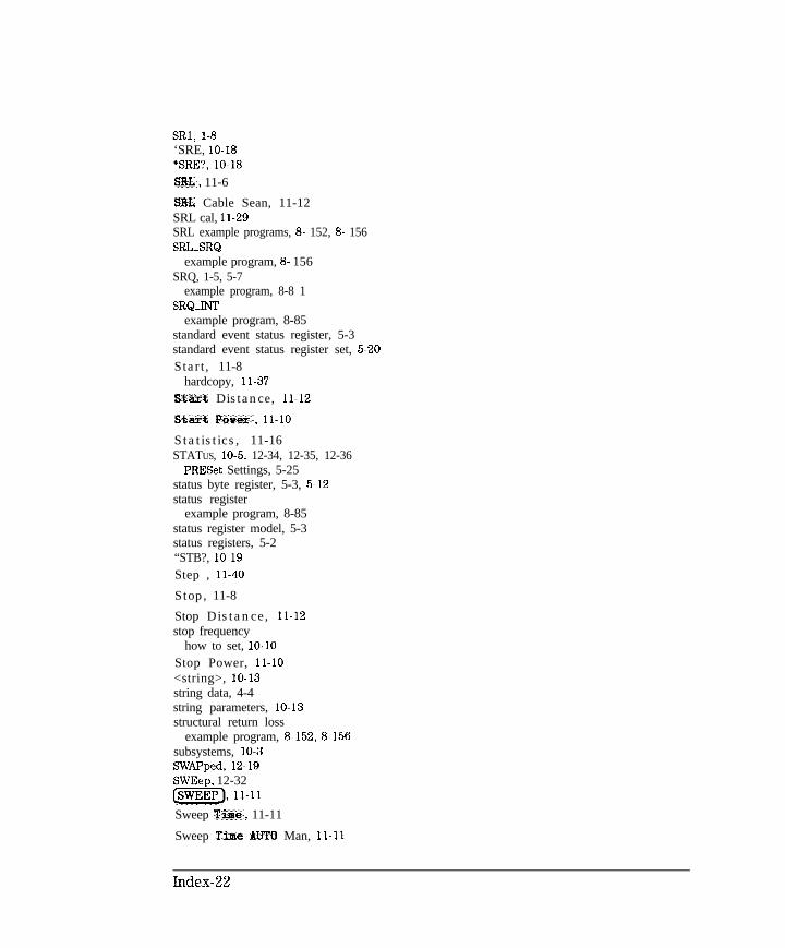
I- I -
SRl, l-8‘SRE, lo-18‘SRE?, lo-18SILL, 11-6
SIG Cable Sean, 11-12SRL cal, 11-29SRL example programs, 8- 152, 8- 156SRL-SRQ
example program, 8- 156SRQ, 1-5, 5-7
example program, 8-8 1SRQ-INT
example program, 8-85standard event status register, 5-3standard event status register set, 5-20Start, 11-8
hardcopy, 11-37Start Distance, 11-12
staxt Pavex, 11-10
Statistics, 11-16STATUS, 10-5, 12-34, 12-35, 12-36
PRESet Settings, 5-25status byte register, 5-3, 5-12status register
example program, 8-85status register model, 5-3status registers, 5-2“STB?, lo-19Step , 11-40
Stop, 11-8
Stop Distance, 11-12stop frequency
how to set, lo-10Stop Power, 11-10<string>, lo-13string data, 4-4string parameters, lo-13structural return loss
example program, 8-152, 8-156subsystems, 10-3SWAPped, 12-19SWEep, 12-32(@%Fj, 11-11
Sweep Time, 11-11
Sweep Tise AUTO Man, 11-11
Index-22

I- I -
Switching Test Set , 11-43
mm, 11-22
Sync Green on OW, 11-43synchronizing, 2-2syntax summary and conventions, lo-15SYSTem, 10-5, 12-37, 12-38, 12-39System &&width , 11-32
System Config , 11-42system controller
defined, 1-2System Coatroller, 11-41@YSTEM OPTIONS), ii-40
System ZO , 11-30
T T6, l-8take control talker, 1-12talker
defined, 1-2Talker Liwbener , 11-41
Target Search, 11-17
T a r g e t Yalue, 11-17TCT, l-12TEO, l-8TEST, 12-39Test Set Cal, 11-24
Title and C3Loct , 11-20
Title * Clk UN off , 11-20, 11-39TRACe, 10-5, 12-40Trace Data ON off, 11-39trace data transfer size, 6-9trace math, 12-9trace math operation, 6-26Tracking on OFF ( 11-17TRANCAL
example program, 8-46transferring data, 4-2
using INTEGER format, example program, 8-38transferring data in ASCII
example program, 8-31transferring data in REAL format
example program, 8-34transform, 6-26transition registers, 5-4
Index-23

I- I -
transmission cal, 11-23transmission calibration
example program, 8-46Transmissn, 11-6
Transmissn Fort Hum, 1
Trans Port Extension,*TRG, lo-19Tr igge r , 11-12TRIGger, 10-5, 12-40Tr igge r Sonxce, 11-12trigger system, 12-21TSet Cal. on OFF, 11-33*TST?, lo-19Type-F, 1 l-30
Type-N(m) , 11-30
1-7
11-31
u upperIBASIC display, 1 l-40
upper-caseuse of, lo-15
upper-case lettering, 10-8User BEGIN key
example program, 8- 160, 8- 165User Defined, 11-30user-defined message, 12-16user graphics
example program, 8- 109using graphics, 7-2USR-FLOC
example program, 8- 165
V variableimplied, 10-9
variablesimplied, how identified in this manual, 1-3
Velocity Factor , ll-28, 11-31
Vertical Back Porch, 11-43
Vertical Font Paz-oh, 11-43
Vertical Position, ll-43
View CAL Check, 11-25
Volatile RAN Disk, 11-34
Index-24
I- I -
w *WAI, 2-5, 8-8, lo-19Wide , 11-32WINDOW, 12-18, 12-19WINDOW 1, 7-2WINDowlO, 7-2WINDow2, 7-2window geometry, 7-4window queries, 7-5
x x, 11-7
Xon/Xoff , 11-37
XX Ports, 11-24
X/Y ( 11-7
y Y, 11-7
Y-Axis Lbl DN off, 11-21
Y-Axis Lb1 rel ABS , 11-21
Y/X ( 11-7
Z Z cutoff Fxequency , 11-29Zeroing
auto, 11-30, 12-10manual, 1 l-30
Index-25
-

I- I -