185 TWINLAP 12C - Laporte Ball-Trap
85
185 TWINLAP 12C 2015 03 OWNERS MANUAL Installation and operation English • Read the instructions carefully before attempting to install or operate the machine! • This manual covers safety, installation and operating instructions and must be used in the maintenance, disassembly or trouble shooting of the machine. • All reproduction, even partial, of this documentation is prohibited without the written authorisation of the Laporte company. France • Lire scrupuleusement les instructions avant l’installation et la mise en marche de la machine ! • Ce manuel technique vous donne toutes les instructions pour le montage, la sécurité et la mise en marche de votre Trap. • La présente notice fait partie intégrante de l’appareil. Elle doit toujours se trouver à proximité immédiate de celui -ci. • Toute reproduction, même partielle, de la documentation technique est interdite sans autorisation écrite de la société LAPORTE. EUROPE SA LAPORTE BALL-TRAP 371 CHEMIN DES PRES 06410 BIOT Tel: 04 93 65 77 77 Fax: 04 93 65 77 78 www.laporte.biz USA LAPORTE AMERICA P.O. Box 492 Pounding Mill. VA 24637 Phone: 800-335-8727 Www.laporteamerica.com www.laporte.biz TIGES MM 400 ET 320MM
-
Upload
khangminh22 -
Category
Documents
-
view
0 -
download
0
Transcript of 185 TWINLAP 12C - Laporte Ball-Trap

185 TWINLAP 12C
2015 03
OWNERS MANUAL Installation and operation
English
• Read the instructions carefully before attempting to install or operate the machine!
• This manual covers safety, installation and operating instructions and must be used in the maintenance,
disassembly or trouble shooting of the machine.
• All reproduction, even partial, of this documentation is prohibited without the written authorisation of the
Laporte company.
France
• Lire scrupuleusement les instructions avant l’installation et la mise en marche de la machine !
• Ce manuel technique vous donne toutes les instructions pour le montage, la sécurité et la mise en marche de votre
Trap.
• La présente notice fait partie intégrante de l’appareil. Elle doit toujours se trouver à proximité immédiate de celui-ci.
• Toute reproduction, même partielle, de la documentation technique est interdite sans autorisation écrite de la société
LAPORTE.
EUROPE
SA LAPORTE BALL-TRAP
371 CHEMIN DES PRES
06410 BIOT
Tel: 04 93 65 77 77
Fax: 04 93 65 77 78
www.laporte.biz
USA
LAPORTE AMERICA
P.O. Box 492
Pounding Mill. VA 24637
Phone: 800-335-8727
Www.laporteamerica.com
www.laporte.biz
TIGES MM 400 ET 320MM
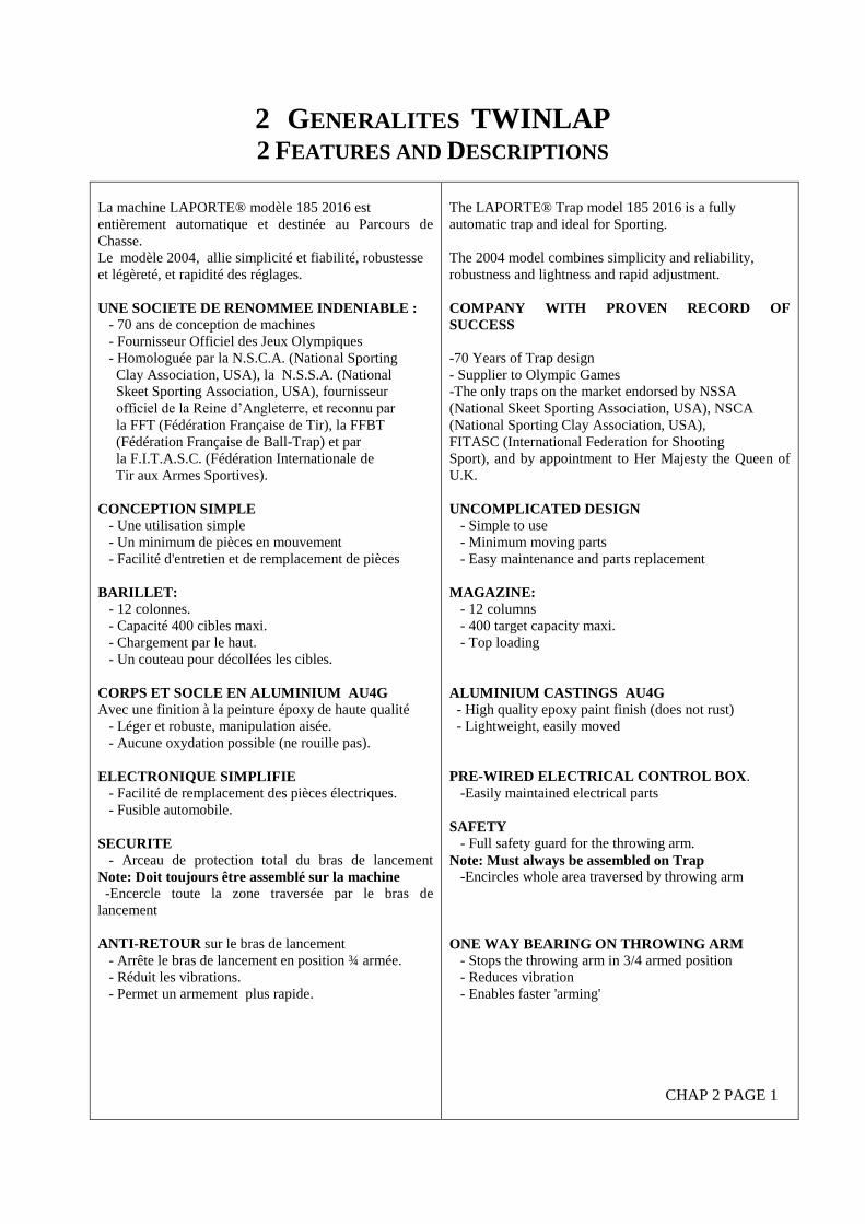
2 GENERALITES TWINLAP 2 FEATURES AND DESCRIPTIONS
La machine LAPORTE® modèle 185 2016 est
entièrement automatique et destinée au Parcours de
Chasse.
Le modèle 2004, allie simplicité et fiabilité, robustesse
et légèreté, et rapidité des réglages.
UNE SOCIETE DE RENOMMEE INDENIABLE :
- 70 ans de conception de machines
- Fournisseur Officiel des Jeux Olympiques
- Homologuée par la N.S.C.A. (National Sporting
Clay Association, USA), la N.S.S.A. (National
Skeet Sporting Association, USA), fournisseur
officiel de la Reine d’Angleterre, et reconnu par
la FFT (Fédération Française de Tir), la FFBT
(Fédération Française de Ball-Trap) et par
la F.I.T.A.S.C. (Fédération Internationale de
Tir aux Armes Sportives).
CONCEPTION SIMPLE
- Une utilisation simple
- Un minimum de pièces en mouvement
- Facilité d'entretien et de remplacement de pièces
BARILLET:
- 12 colonnes.
- Capacité 400 cibles maxi.
- Chargement par le haut.
- Un couteau pour décollées les cibles.
CORPS ET SOCLE EN ALUMINIUM AU4G Avec une finition à la peinture époxy de haute qualité
- Léger et robuste, manipulation aisée.
- Aucune oxydation possible (ne rouille pas).
ELECTRONIQUE SIMPLIFIE - Facilité de remplacement des pièces électriques.
- Fusible automobile.
SECURITE
- Arceau de protection total du bras de lancement
Note: Doit toujours être assemblé sur la machine -Encercle toute la zone traversée par le bras de
lancement
ANTI-RETOUR sur le bras de lancement
- Arrête le bras de lancement en position ¾ armée.
- Réduit les vibrations.
- Permet un armement plus rapide.
The LAPORTE® Trap model 185 2016 is a fully
automatic trap and ideal for Sporting.
The 2004 model combines simplicity and reliability,
robustness and lightness and rapid adjustment.
COMPANY WITH PROVEN RECORD OF
SUCCESS
-70 Years of Trap design
- Supplier to Olympic Games
-The only traps on the market endorsed by NSSA
(National Skeet Sporting Association, USA), NSCA
(National Sporting Clay Association, USA),
FITASC (International Federation for Shooting
Sport), and by appointment to Her Majesty the Queen of
U.K.
UNCOMPLICATED DESIGN - Simple to use
- Minimum moving parts
- Easy maintenance and parts replacement
MAGAZINE: - 12 columns
- 400 target capacity maxi.
- Top loading
ALUMINIUM CASTINGS AU4G - High quality epoxy paint finish (does not rust)
- Lightweight, easily moved
PRE-WIRED ELECTRICAL CONTROL BOX.
-Easily maintained electrical parts
SAFETY
- Full safety guard for the throwing arm.
Note: Must always be assembled on Trap -Encircles whole area traversed by throwing arm
ONE WAY BEARING ON THROWING ARM - Stops the throwing arm in 3/4 armed position
- Reduces vibration
- Enables faster 'arming'
CHAP 2 PAGE 1
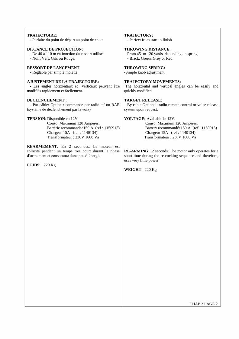
TRAJECTOIRE:
- Parfaite du point de départ au point de chute
DISTANCE DE PROJECTION:
- De 40 à 110 m en fonction du ressort utilisé.
- Noir, Vert, Gris ou Rouge.
RESSORT DE LANCEMENT
- Réglable par simple molette.
AJUSTEMENT DE LA TRAJECTOIRE:
- Les angles horizontaux et verticaux peuvent être
modifiés rapidement et facilement.
DECLENCHEMENT :
- Par câble: Option : commande par radio et/ ou RAR
(système de déclenchement par la voix)
TENSION: Disponible en 12V.
Conso. Maximum 120 Ampères.
Batterie recommandée150 A (ref : 1150915)
Chargeur 15A (ref : 1140134)
Transformateur : 230V 1600 Va
REARMEMENT: En 2 secondes. Le moteur est
sollicité pendant un temps très court durant la phase
d’armement et consomme donc peu d’énergie.
POIDS: 220 Kg
TRAJECTORY: - Perfect from start to finish
THROWING DISTANCE: From 45 to 120 yards depending on spring
- Black, Green, Grey or Red
THROWING SPRING:
-Simple knob adjustment.
TRAJECTORY MOVEMENTS: The horizontal and vertical angles can be easily and
quickly modified
TARGET RELEASE: By cable.Optional: radio remote control or voice release
system upon request.
VOLTAGE: Available in 12V.
Conso. Maximum 120 Ampères.
Battery recommandée150 A (ref : 1150915)
Chargeur 15A (ref : 1140134)
Transformateur : 230V 1600 Va
RE-ARMING: 2 seconds. The motor only operates for a
short time during the re-cocking sequence and therefore,
uses very little power.
WEIGHT: 220 Kg
CHAP 2 PAGE 2
3 CONSEILS DE SECURITE
3 SAFETY ADVICE
DANGER - CES MACHINES PEUVENT
PROVOQUER DE SERIEUSES BLESSURES!
LIRE SCRUPULEUSEMENT LES
INSTRUCTIONS AVANT L’ INSTALLATION
ET LA MISE EN MARCHE DE LA MACHINE!
AVANT DE :
Installer la machine,
Brancher le courant,
Lubrifier,
Charger le barillet
Procéder aux réglages,
VEILLER A ce que le bras de lancement soit en
position désarmée ou que le ressort d’armement ne
soit pas monté et que l’interrupteur "ON-OFF-
UNCOCKED” du coffret électronique soit en
position "OFF" et la machine DECONNECTEE de
la source d’alimentation.
NOTE: La position « désarmée » (“uncocked”)
mentionnée tout le long de ce manuel se réfère à la
position du bras de lancement. Quand la machine
est « désarmée », vu de derrière, le bras de
lancement est visible à gauche de la machine.
Quand on regarde la machine par le dessus depuis
l’arrière, le bras “désarmé” sera visible en
position 8h45. Quand la machine est livrée, le bras
sera en position de “sécurité”.
1. Toute personne habilitée à faire fonctionner la
machine, ou à charger le barillet, doit lire ce
manuel d’instruction et être formée par une
personne connaissant le fonctionnement et les
mesures de sécurité de ce matériel.
2. Ne pas laisser la machine en position “armée”
quand elle n’est pas utilisée. Cette pratique est
non seulement dangereuse mais elle réduit la
durée de vie du ressort d’armement.
3. Une seule personne à la fois doit faire
fonctionner la machine.
4. Ne pas faire fonctionner la machine sans avoir
installé l’arceau de sécurité. Cet arceau de
sécurité définit la zone de danger autour du bras
de lancement.
5. Ne soulever, ni ne déplacer la machine par le bras
de lancement ou l’arceau de sécurité. Ne vous
appuyez pas sur l’arceau de sécurité et n’y poser
aucun poids, telles que les boîtes de cibles.
DANGER - THESE MACHINES CAN CAUSE
SERIOUS INJURY!
READ INSTRUCTIONS THOROUGHLY
BEFORE ATTEMPTING TO INSTALL OR
OPERATE!
1. BEFORE:
Installing the trap,
Connecting power,
Lubricating,
Loading the magazine or
Making any adjustments
Be sure that the throwing arm is in the safe,
unarmed position or that the mainspring is
disconnected, the "ON-OFF-UNCOCK" toggle
switch on the electrical control box is in the "OFF"
position, and the machine is DISCONNECTED from
the power source.
NOTE: The "Decocked" position mentioned
throughout this manual refers to the position of
the throwing arm. When the machine is
“unarmed”, viewed from behind the machine, the
throwing arm is to the left of the machine. When
looking at the machine from on top behind, the
“unarmed” throwing arm is visible in a 8h45
position. When the machine is delivered, the
throwing arm is in the “safety” position.
1. All personnel required to operate the trap, or load
targets into the magazine, should read this instruction
manual and be trained by someone knowledgeable as
to the safe operation of the equipment.
2. Do not leave the trap armed when not in use. Not
only is this practice very hazardous, but, as the
mainspring is stretched, its lifespan will be shortened.
3. Only one person should operate the trap at any
one time.
4. Do not operate the trap without the safety guard
installed on the trap as illustrated in this manual.
This safety guard defines the danger zone of the
throwing arm rotation.
5. Do not lift or move the trap by the throwing arm or
the safety guard. Do not lean on the safety guard or
place any weight on it such as box of targets.
CHAP 3 PAGE 1

6. Des lunettes de protection doivent être portées
par toutes personnes proches de la machine pour
éviter les blessures aux yeux dues à des
fragments de cibles.
7. Eloigner toujours les enfants et les animaux de la
machine.
8. Avant de mettre la machine en marche, se mettre
en position de sécurité à l’arrière gauche de la
machine et s'assurer qu’il n’y a personne dans la
zone de danger à l’avant de la machine. Des
fragments de pigeons cassés peuvent voler
rapidement en dehors de la zone de danger même
en arrière. (Ils peuvent même rebondir sur les
cabanes, etc…). Quand la machine est armée et
prête à l’emploi, quitter toujours la zone de
lancement en restant à l’arrière de la machine.
ATTENTION !!!! certaines machines
( Ex : PCT ) peuvent pivoter sur 360° !!!!
9. Avant d’approcher la machine, pour la
maintenance, les réglages ou le chargement des
cibles, assurez-vous que l’interrupteur "ON-
OFF-UNCOCK" du coffret électronique est en
position "OFF" et que le bras de lancement est
dans la position « Désarmée » ("Decocked")
8h45.
NOTE: POUR DESARMER LE BRAS DE
LANCEMENT ET PLACER LA MACHINE EN
POSITION DE SECURITE, METTRE
L’INTERRUPTEUR "ON-OFF-UNCOCK" DU
COFFRET ELECTRONIQUE EN POSITION
DESARMEE « UNCOCKED » PUIS EN
POSITION « OFF ». LE BRAS DE
LANCEMENT DOIT S’ARMER ET
S’ARRETER DANS LA POSITION
« DESARMEE » A L’AVANT DE LA MACHINE.
PUIS, DEBRANCHER L’ALIMENTATION DU
COFFRET ELECTRONIQUE.
VOIR DESSIN CHAPPITRE POSITION DE
SECURITE.
6. Safety glasses must be worn by all personnel
within close proximity to the trap to prevent eye
injury from flying target fragments.
7. Always keep children and animals away from the
trap machine.
8. Before turning on any switches, move to a safe
position at the left rear of the trap and make sure that
no one is within the danger zone in front of the trap.
High-speed fragments from broken targets being
thrown may fly outside the normal target danger
zone, even backwards. (They may even rebound off
traphouse sides etc.). When trap is armed and ready
for use, always leave the area by keeping to the rear
of the machine.
9. Before approaching the trap, for any maintenance,
adjustments, or for the loading of targets, be sure the
trap is turned off with the "ON-OFF-UNCOCK"
toggle switch on the electrical control box in the
"OFF" position, and the throwing arm is in the
"Decocked" 8:45 position.
NOTE: TO UNARM THE THROWING ARM
AND PLACE THE TRAP IN A SAFE
CONDITION, MOVE THE "ON-OFF-
UNCOCK" TOGGLE SWITCH, ON THE
ELECTRICAL CONTROL BOX, TO THE
"UNCOCK" POSITION, THEN TO THE "OFF"
POSITION. THE THROWING ARM SHOULD
'FIRE” AND STOP IN THE "UNCOCKED"
POSITION OUT IN FRONT OF THE TRAP.
THEN DISCONNECT POWER FROM THE
ELECTRICAL CONTROL BOX.
CHAP 3 PAGE 2
4 INSTRUCTIONS DE DEMARRAGE
4 START-UP INSTRUCTIONS
Ces machines doivent être installées sur une plate-
forme en bois ou en béton ou sur le socle multi
positions LAPORTE.
Fixer fermement la machine sur la base en utilisant la
visserie appropriée au type de plate-forme utilisée.
1. Installer l’arceau de sécurité (Voir plan)
2. Installer le barillet (Voir plan)
3. Raccordement électrique
Pour les machines en 12 V, respecter les polarités
« + rouge » et « – noir ou bleu » sur l’alimentation.
4. Raccorder la commande par câble.
Brancher la prise blanche 4 plots de la télécommande
par câble sur le boîtier déporté à l’endroit “PULL
CORD/REMOTE CONTROL", et verrouiller le
branchement à l’aide du fermoir.
5. Chargement du barillet:
Charger d’abord les colonnes arrière du barillet
Placer une pile de cibles dans la colonne du barillet en
prêtant attention à ne pas les heurter, ni les faire
tomber.
Enlever les cibles cassées ou fendues et assurez-vous
que les cibles ne soient pas collées ensemble.
Vérifier que la cible du bas de la pile pose
parfaitement sur la plaque support barillet.
Continuer de placer des piles de cibles dans cette
colonne jusqu’à ce qu’elle soit pleine.
6. Positionner les interrupteurs des mouvements
horizontaux et verticaux (TAHLB uniquement) sur la
position « OFF » du coffret électronique.
Positionner l’interrupteur "ON-OFF-UNCOCK" du
coffret électronique de la position "OFF" à la
position "ON". La machine va ‘s’armer’, c.à.d. le
bras de lancement va se déplacer de la position
'Uncocked' 8h45 à la position armée 6h30.
Lancer plusieurs cibles pour vérifier la trajectoire.
Positionner l’interrupteur "ON-OFF-UNCOCK" du
coffret électronique sur la position "UNCOCK" et
puis sur la position "OFF" (désarmement de la
machine). Le bras de lancement est maintenant en
position "désarmée" (Uncocked) (8h45).
La procédure de test est maintenant terminée.
Déconnectée la machine de la source d’alimentation.
This trap may be installed on a LAPORTE trolley or a
wooden or concrete platform
Secure the trap to the base using suitable screws
and bolts for the type of platform being used
1. Install the safety guard (see notice).
2. Install the magazine (see notice).
3. Electrical connection (see notice):
For the machines in 12V, control the polarities “+”
and “-”on the power supply.
4. Connect the "Pull Cord".
Plug the white 4-pin plug of the cable release onto
the control box “PULL CORD/REMOTE
CONTROL” and close by the “clip”.
5. Loading the magazine
Firstly load the rear columns of the magazine.
Place a pile of clays into the magazine from the top
being careful not to break them. Do not let them
“fall” into the magazine.
Making sure that there are no broken or cracked clays
and that they are not stuck together.
Check that the last clay in the pile lays perfectly flat
on the magazine support base
6. Position the “ON-OFF-UNCOCK” switch from
the “OFF” position to the “ON” position. The
machine will arm, the throwing arm will move from
the “unarmed” 8H45 position to the armed 6h30
position. Throw a few clays to establish the correct
distance and trajectory.
Position to “ON-OFF-UNCOCK” switch on the
electronic box into the “UNCOCK” position and
then into the “OFF” position (unarming the
machine). The throwing arm is now in the
“unarmed” position (8H45).
The testing procedure is now complete.
Disconnect the machine from the power supply.
CHAP 4 PAGE 1

5 ANOMALIES DE FONCTIONNEMENT
5 TROUBLE SHOOTING ATTENTION: AVANT DE PROCEDER A DES
CHANGEMENTS OU DES REGLAGES,
ASSUREZ-VOUS QUE LE BRAS DE
LANCEMENT EST EN POSITION DESARMEE
ET QUE LA MACHINE EST DECONNECTEE
DE LA SOURCE D ALIMENTATION.
1. LE MOTEUR D’ARMEMENT NE
FONCTIONNE PAS
La prise n’est pas branchée
Le disjoncteur est sur « OFF » ou le fusible a sauté.
Positionner l’interrupteur "ON-OFF-UNCOCK" du
coffret électronique sur la position "OFF". Soulever le
couvercle du coffret et vérifier les fusibles. Si les
fusibles continuent de griller, vérifier les câblages et
l’alimentation pour localiser la cause avant de
continuer.
La puissance électrique est insuffisante (vérifier avec
un multimètre : 12 V, 110 V, ect….).
Les connections électriques sont sales ou desserrées.
Le moteur d’armement est grillé.
Le raccordement électrique est non conforme (voir
instructions de démarrage).
Uniquement si la machine est désarmée :
La vis d’armement est en contact direct avec la vis
d’armement. Le moteur n’aura pas suffisamment de
puissance initiale pour amener le bras de lancement
dans la position armée et le disjoncteur ( ou fusible) va
éventuellement sauter. Pour corriger cela, pousser le
bras de lancement dans le sens contraire au aiguilles
d’une montre d’environ 1.5 cm. Repasser a la position
« ON » et réessayer.
La carte électronique est grillée.
2. LE MOTEUR TOURNE MAIS N’ARME
PAS LE BRAS DE LANCEMENT
La puissance électrique n’est pas adéquate. (vérifier
avec le multimètre : 12 V, 110V etc …...).
Le bras de lancement est bloqué. (INTERVENIR
AVEC EXTREME PRECAUTION !)
La chaîne est cassée.
La vis d’armement du réducteur est cassée.
L’engrenage du réducteur est hors service (le moteur
tourne mais le pignon d’armement ne tourne pas).
L’axe d’entraînement du tirant à œil de l’axe
d’armement est cassé.
L’axe d’armement est cassé.
CAUTION: BEFORE MAKING ANY CHANGES
OR ADJUSTMENTS MAKE SURE THE
THROWING ARM IS IN THE SAFE
UNCOCKED POSITION.
1. THE COCKING MOTOR WILL NOT START
Electricity is not connected.
The circuit breaker is off or the fuse has blown.
Move the switch marked "ON-OFF-UNCOCK" on
the electrical control box to the "OFF" position.
Remove the cover of the control box and check the
fuses. If the fuse continues to blow, check the wiring
and the power supply to locate the cause before
continuing.
The electricity supply is insufficient (check with a 12v
multimeter)
Electrical connections are dirty or loose.
The cocking motor has burnt out.
The electrical connections do not comply (see Start-
Up Instructions).
Only proceed if the machine is uncocked :
The arming screw is in direct contact with the arming
spindle.
The motor does not have enough power to bring the
throwing arm into the armed position and the short
circuit (or fuse) will eventually blow. To correct this,
push the throwing arm is an anti-clockwise direction
by about 1.5cm. Re-start from the position “ON” and
try again.
The electronic card has blown.
2. THE MOTOR TURNS BUT DOES NOT
COCK THE THROWING ARM
The electricity supply is not sufficient (check with a
12v multimeter).
The throwing arm is blocked. (INTERVENE WITH
EXTREME CAUTION!)
The chain is broken.
The gearbox toothed wheel mechanism does not work
(the motor turns but the arming axe does not turn).
The axe between the main spindle and the threaded
eye bolt is broken.
The main spindle is broken.
CHAP 5 PAGE 1
3. LA MACHINE ARMEE NE
DECLENCHE PAS
Il n’y pas d’alimentation.
Le ressort d’armement est cassé.
Le bouton "Pull" ou l’appareil de déclenchement à
distance ne fonctionne pas.
La batterie pour l’émetteur de la radio commande en
option est déchargée et demande à être remplacée.
L’interrupteur "ON-OFF-UNCOCK" est en position
"OFF".
Le bras de lancement est bloqué par 2 cibles, ou par
des pigeons cassés. ATTENTION : Le bras de
lancement appuie trop FORTEMENT sur les
cibles. Désarmer la machine en utilisant le
"désarmement manuel", soyez très PRUDENT, car le
bras de lancement va se relâcher TRES vite. La (es)
cible(s) sur la plaque de lancement vont probablement
voler en éclats dans TOUTES les directions.
Le bras de lancement est tordu ou cassé et coincé
contre une partie de la machine, c.à.d. une vis ou la
base du barillet. CECI EST TRES DANGEREUX!
Comme vous ne pouvez pas désarmer la machine, le
bras doit être enlevé… Appeler LAPORTE.
AVEC ELECTRO- AIMANT (skeet, FO, …):
La pression exercée sur la gâchette par le bras de
Lancement est trop importante. Il est nécessaire de
régler l’arrêt du bras.
--12v, 220v, et 380v : agir sur le potentiomètre situé
sur la carte électronique.
--110v : agir sur le support micro- contact en le
déplaçant vers la gauche lorsque la machine est vue de
l’arrière.
ATTENTION : afin de désarmer manuellement une
Machine équipée d’une gâchette, exercer une
Pression sur le noyau de l’électro- aimant. Avant toute
manipulation, positionner l’interrupteur sur « OFF »
(faire attention aux éclats de pigeon eventuels).
4. LE BRAS DE LANCEMENT NE
S’ARRETE PAS ET LANCE DES CIBLES.
Le micro-contact d’armement est cassé ou déréglé, et
oblige le moteur d’armement à fonctionner en continu.
Le relais est défectueux (il reste collé ) DANGER LA
MACHINE CONTINU A LANCER DES
PLATEAUX MEME EN POSITION OFF .Il faut
déconnectée la machine de la source d’alimentation.
3. THE MACHINE IS COCKED BUT
DOES NOT FIRE
There is no electrical supply
The main spring is broken.
.The "Pull” switch or remote release system is not
working.
The battery in the Optional Radio Control transmitter
is flat or exhausted, and needs replacing.
The switch on the “ON-OFF-UNCOCK” is in the
“OFF"position.
The throwing arm is blocked by two clays or by
fragmented clays. WARNING: The throwing arm
will be pressing against the targets with
TREMENDOUS PRESSURE. Unccocking the trap
using “Manual Uncocking”, be EXTREMELY
CAUTIOUS, as the throwing arm will release VERY
fast. The clay(s) on the throwing plate will most
probably shatter throwing target fragments in all
directions.
The throwing arm is bent or broken and
subsequently jammed against some part of the
trap, e.g. the mobile throwing plate, the magazine
base. THIS IS A VERY DANGEROUS
CONDITION! As you cannot “re-arm” the
machine. The arm will have to be removed…. Call
LAPORTE for help.
WITH SOLENOID (Skeet, OT, …) :
There is too much pressure by the arm on the trigger.
Adjust the stopping of the arm.
- 12V, 220V and 380V: adjust the potentiometer on
the electronic card.
- 110V: adjust the micro-switch support by moving it
to the left from a rear view of the machine.
WARNING: In order to manually disarm a machine
with a solenoid, press on to solenoid core. Before any
intervention, position the switch to “OFF” (be careful
of eventual clay bits being thrown)
4. THE THROWING ARM DOES NOT STOP
DECOCKING AND THROWING TARGETS.
The cocking micro-switch is broken or out of
adjustment, and causes the cocking motor to run
continually. The relay is defective and sticks.
WARNING: THE MACHINE CONTINUES TO
THROW CLAYS EVEN WHEN SWITCHED OFF.
It is imperative to disconnect the power supply.
CHAP 5 PAGE 2

Le bouton "PULL" est bloqué ou le câble est abîmé.
Le bouton de transmission de l’émetteur radio
commande en position est continuellement enclenché
(ex dans la boite à outils, un tiroir de bureau, la poche,
un étui à fusils, etc.). Vérifier en débranchant le
récepteur de la télécommande depuis le coffret
électronique.
Un autre émetteur radio pourrait être réglé sur la
même fréquence que le récepteur et déclencherait la
machine. Vérifier en débranchant le récepteur de la
radio-commande du coffret électronique.
Le circuit électronique du boîtier de commande peut
avoir “grillé".
AVEC ELECTRO- AIMANT (skeet, FO, …):
La gâchette reste en position ouverte :
-le noyau de l’électro- aimant est coincé.
-le ressort de rappel de la gâchette est défectueux ou
n’est pas en place.
La gâchette au repos n’est pas sur la trajectoire du
bras : vérifier la vis de blocage du support gâchette
(support électro-aimant)
5. BRUITS ANORMAUX
Vérifier le serrage des boulons.
Le ressort d’armement est détendu et les spires se
touchent entre elles : il est impératif lorsque le
ressort est détendu à fond, que les spires ne se
touchent pas. Dans le cas contraire, cela pourrait
causer la rupture du corps principal !
Le réducteur manque d’huile.
Anti-retour détérioré ou cassé.
Le bras de lancement est tordu et frotte sous la plaque
SB (Support Barillet) ou sur la plaque de lancement.
La plaque de lancement peut être desserrée.
L’axe arrière du barillet manque de lubrification.
6. LES CIBLES CASSENT AU
LANCEMENT
Les cibles étaient cassées avant le chargement.
Les cibles se sont cassées pendant le chargement.
Cibles mélangées (différents diamètres c.à.d. 107-109-
110 mm).
La réglette est détériorée ou cassée.
Le bras de lancement est tordu. Il peut être redressé
sans le démonter en vérifiant que la réglette se trouve
toujours à même distance de la plaque de lancement
tout au long de sa rotation. Désarmer le bras de
lancement et retirer le ressort d’armement avant toute
vérification ou réglage.
La plaque de lancement est endommagée. Vérifier si
les bords de la plaque ont été déformés et poncer si
nécessaire.
La plaque de lancement est sale, ou il y a du brai
résultant du mauvais positionnement de la cible à
l’armement, la nettoyer avec du solvant ou la poncer.
The “PULL” button is stuck, or the cable is damaged.
The button on the radio remote control is continually
press (e.g. in a tool box, office drawer, pocket etc).
Check by disconnecting the receiver of the radio
remote from the electronic control box.
Another radio transmitter could be adjusted to the
same frequency as the receiver and operate the
machine. Check by disconnecting the receiver of the
radio remote from the electronic control box.
The electronic circuit on the control box could have
“blown”.
WITH SOLENOID (Skeet, OT,….)
The trigger stays in an open position :
- the solenoid core is stuck.
- the trigger spring is defective or is not in the
correct position
The fired trigger is no on the trajectory of the arm:
check the blocking screw on the trigger support
(solenoid support)
5. ABNORMAL NOISES
Check all bolts for tightness.
The mainspring does not have sufficient tension on it,
and the coils are touching each other: it is imperative
that when the spring is totally loose, the coils do
not touch. If they do, this could break the main
body.
The one way bearing is worn out or damaged.
The throwing arm is bent and scrapes on the underside
of the magazine support base plate or on the throwing
plate.
The throwing plate could be loose.
The magazine spindle needs greasing.
6. THE TARGETS BREAK IMMEDIATELY
WHEN FIRING
The targets were damaged prior to loading.
The targets were damaged during loading.
Mixed targets (different diameters in it stack i.e. 107-
109-110mm)
The rubber is damaged or worn.
The throwing arm is bent. It can be straightened
without removing it. Check that the rubber is always
at the same distance from the throwing plate. Uncock
the throwing arm and take out the mainspring before
this inspection and adjustment.
The throwing plate is damaged. Check edges of plate
for 'nicks' and file smooth if necessary.
The throwing plate is dirty or has clay target pitch
build up resulting in the target not being positioned
correct at cocking time. Clean with solvent or sand it.
CHAP 5 PAGE 3
La plaque de lancement est desserrée.
Vérifier qu’il n’y a pas d’obstruction à la trajectoire
du plateau
L’arceau de sécurité est tordu et interfère avec la
trajectoire de la cible.
Un éclat de cible est coincé sur la plaque de lancement
ou tole amortisseur.
Le bras n’est pas en contact avec la cible et quand la
machine tire, le bras se rabat sur la cible et la détruit.
Lors d’un armement correct, la réglette doit être
impérativement en contact avec la cible avant le
lancement. L’anti-retour est détérioré et provoque des vibrations
dues à l’oscillation combinée du bras et du ressort.
L’anti-retour, sur l’axe d’armement, a du jeu dans son
logement.
Le ressort d’armement n’est pas bien réglé, ou le silent
bloc n’est pas installé correctement.
Vérifier TOUTES les causes de la Section ci-dessous.
AVEC ELECTRO- AIMANT (skeet, FO, …):
L’électro-aimant est defectueux.
Le fusible électro-aimant est hors service (sauf 12v).
IMPORTANT : débrancher l’alimentation avant
toutes opérations.
ATTENTION : afin de désarmer manuellement une
Machine équipée d’une gâchette, exercer une
Pression sur le noyau de l’électro- aimant. Avant toute
manipulation, positionner l’interrupteur sur « OFF »
(faire attention aux éclats de pigeon eventuels).
7. LES CIBLES TOMBENT CASSEES SUR
LA PLAQUE
BARILLET 6 COLONNES :
Les cibles étaient cassées avant le chargement.
Les cibles se sont cassées pendant le chargement.
La plaque SB (Support Barillet) est sale, abîmée ou
tordue.
Vérifier que la tôle amortisseur soit libre et qu’elle
puisse vibrer.
Les ressorts lames inox 6c sont endommagés, ou mal
ajustés (trop durs).
Les couteaux de séparation pigeons sont mal réglés.
BARILLET 12 COLONNES :
Les couteaux de séparation pigeons sont mal réglés.
8. IL TOMBE 2 CIBLES DU BARILLET
EN MEME TEMPS
BARILLET 6 COLONNES :
Cibles mélangées (différents diamètres c.à.d. 107-109-
110mm)
Les lames inox 6c sont abîmées ou desserrées ou la
pression des lames est insuffisante.
The throwing plate is loose.
Check that there is nothing in the way of the target
trajectory.
The safety guard is bent and gets in the way of the
clay flight path.
A piece of broken clay is lodged on the throwing plate
or shock absorbing plate.
The arm is not in contact with the clay and when the
machine fires, the arms hits against the clay and
breaks it.
The rubber should always be against the clay
before the machine fires.
The one-way bearing is damaged and causes
vibrations.
The bearing on the arming axe has play.
The arming spring is not correctly fitted, or the silent
bloc is not correctly installed.
Check ALL the causes in section 8 below.
WITH SOLENOID (Skeet, OT ….)
The solenoid is defective.
The solenoid fuse has “blown” (except 12v).
IMPORTANT: Unplug the power supply before any
adjustments
WARNING: In order to manually disarm a machine
with a solenoid, press on to solenoid core. Before any
intervention, position the switch to “OFF” (be careful
of eventual clay bits being thrown)
7. TWO CLAYS FALL AND BREAK ON THE
PLATE
6 COLUMN MAGAZINE
The clays were broken before being loaded.
The clays were broken while loading.
The magazine support plate is dirty, damaged or bent.
Check that the shock absorbing plate is free and can
vibrate.
The 6c target retainer leaf spring are damaged or
incorrectly adjusted (too hard).
The clay separator knives are incorrectly adjusted.
12C MAGAZINE
The clay separator knives are incorrectly adjusted.
8. TWO CLAYS FALL FROM THE MAGAZINE
AT THE SAME TIME
6C MAGAZINE
Mixed clays (different diameters in same stack i.e.
107-109-110mm)
CHAP 5 PAGE 4
La position de l’embase barillet est trop haute par
rapport à la plaque sb (la surface de contact entre le
caoutchouc des lames inox et le pigeon est
insuffisante)
BARILLET 12 COLONNES :
Cibles mélangées (différents diamètres c.à.d. 107-109-
110mm)
Vérifier que les deux couteaux séparateur soit
correctement serrer.
9. LES CIBLES NE TOMBENT PAS DU
BARILLET
Les cibles restent collées entre elles, veiller à décoller
les piles avant de les mettre dans le barillet.
Cibles mélangées (différents diamètres c.à.d. 107-109-
110mm)
Les tiges du barillet sont abîmées ou tordues et
réduisent le jeu latéral autour de la pile de cibles.
les lames inox 6 col sont tordues ou vrillées et
bloquent la première cible et empêche la colonne de
cibles de descendre.
La plaque SB est endommagée.
Le barillet est vrillé.
Le doigt de barillet n’entraîne pas le barillet ou son
ressort est endommagé ou mal réglé.
Vérifier la pression du doigt et sa lubrification.
10. LE MOUVEMENT HORIZONTAL ET/OU
VERTICAL NE FONCTIONNE PAS.
Avant toutes manipulation, désarmé la machine puis
débrancher l’alimentation électrique.
Vérifié le ou les fusibles situés sur la carte partie
basse.
Vérifié qu’aucun obstacle n’interfère avec les
différents mouvements.
The 6c target retainer leaf spring are damaged or loose
or the pressure on the “springs” is insufficient.
The position of the magazine base is too high with
regards the magazine support base plate (the contact
area between the target leaf rubber and the clay is
insufficient).
12 COLUMN MAGAZINE
Mixed clays (different diameters in same stack i.e.
107-109-110mm)
Check that the two knife separators are tightened
correctly.
9. THE TARGETS DO NOT COME OUT OF THE
MAGAZINE
The targets are stuck together. Separate them before
putting them in the magazine.
Mixed targets. (Different diameters in same stack i.e.
107-109-110mm)
Magazine rods are damaged or bent and are restricting
the vertical movement of the target stack.
The 6c target retainer leaf springs are bent or twisted
thus blocking the first clay and prevent the column of
clays from falling down.
The magazine support base is damaged.
The magazine is twisted.
The indexing finger does not move the magazine or its
spring is damaged of incorrectly adjusted.
Check the pressure of the indexing finger and its
lubrication.
10. THE HORIZONTAL AND/OR VERTICAL
MOVEMENT DOES NOT FUNCTION.
Before any adjustments, disarm the machine and
switch of the power supply.
Check the fuses on the lower card.
Check that there is no obstacle interfering with the
different movements.
CHAP 5 PAGE 5
SAFETY FIRST TWINLAP 285
SECURITE TWINLAP 285
DANGER - THESE MACHINES CAN CAUSE SERI-
OUS INJURY !
READ INSTRUCTIONS THOROUGHLY BEFORE
ATTEMPTING TO INSTALL OR OPERATE !
NOTE: THE 285PC COMPRISES TWO MACHINES.
WHEN WORKING ON THE 285PC, REMEMBER
THERE ARE TWO THROWING ARMS AND THE
CAUTIONS DETAILED THOUGHOUT THIS MAN-
UAL APPLY TO BOTH MACHINES. WHEN CHECK-
ING THE MACHINE IS SAFE TO WORK ON, THE
INSTRUCTIONS REGARDING SAFETY APPLY TO
BOTH MACHINES. WHEN TOLD TO CHECK THE
ARM IS UN-COCKED, CHECK BOTH ARMS ARE
UN-COCKED !!!
1 Before installing trap, connecting power, lubricat-
ing, loading or making any adjustments be sure
that the throwing arms are in the safe, un-
cocked position (Fig. 1), or that the main-
springs are disconnected, the "ON-OFF-
UNCOCK" toggle switches on the "Remote
Safety Switch" and on each individual control
box are in the "OFF" position, the switch
marked "TEST-OFF-ON" on the Master Con-
trol box is in the "OFF" position, and the elec-
trical control boxes are disconnected from the
power source.
DANGER - CES MACHINES PEUVENT CAUSER
DE SERIEUSES BLESSURES !
LISEZ LES INSTRUCTIONS COMPLÈTEMENT
AVANT D'ESSAYER D'INSTALLER OU
D’UTILISER LA MACHINE!
NOTE : LA 285 COMPORTE DEUX MACHINES. EN
TRAVAILLANT SUR LA 285, RAPPELEZ-VOUS
QU'IL Y A DEUX BRAS DE LANCEMENT ET LES
PRÉCAUTIONS DÉTAILLÉES DE CE MANUEL
S APPLIQUENT AUX DEUX MACHINES.
LES INSTRUCTIONS CONCERNANT LA SÉCURITÉ
S APPLIQUENT AUX DEUX MACHINES.
VÉRIFIER TOUJOUR QUE LES DEUX BRAS
SOIENT DESARMES UN-COCKED !!!
1 Avant d'installer la Twinlap, de brancher le cou-
rant, de charger les barillets, ou de procéder aux
réglages, assurez vous que LES bras de lance-
ment sont en position de sécurités (fig. 1), et que
les prises sont déconnectées, Utilisez le bouton
"UNCOCK" puis le placez dans la position
OFF.
Vérifiez que les boîtes de contrôle électriques
soient déconnectées de la source d'énergie élec-
trique.
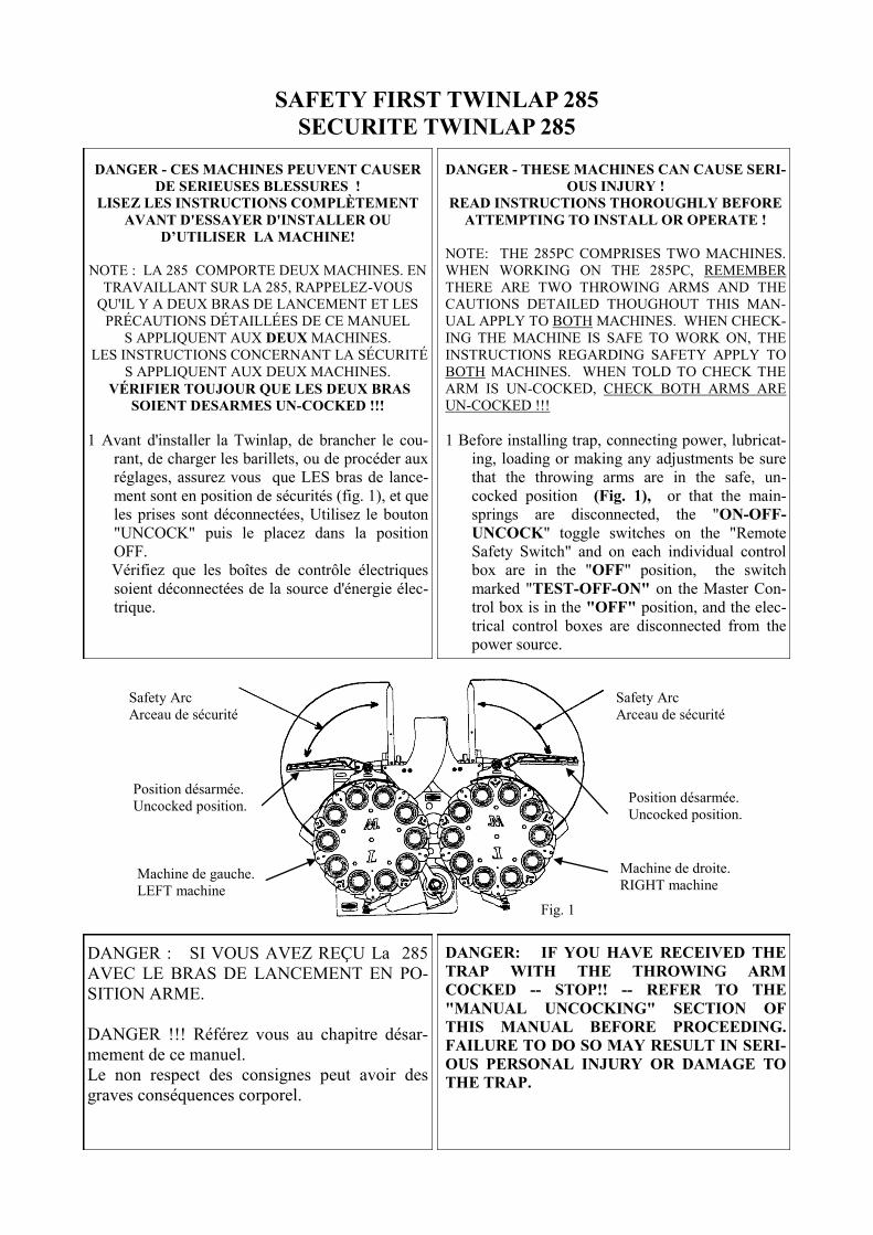
Safety Arc
Arceau de sécurité
Safety Arc
Arceau de sécurité
DANGER: IF YOU HAVE RECEIVED THE
TRAP WITH THE THROWING ARM
COCKED -- STOP!! -- REFER TO THE
"MANUAL UNCOCKING" SECTION OF
THIS MANUAL BEFORE PROCEEDING.
FAILURE TO DO SO MAY RESULT IN SERI-
OUS PERSONAL INJURY OR DAMAGE TO
THE TRAP.
Fig. 1
DANGER : SI VOUS AVEZ REÇU La 285
AVEC LE BRAS DE LANCEMENT EN PO-
SITION ARME.
DANGER !!! Référez vous au chapitre désar-
mement de ce manuel.
Le non respect des consignes peut avoir des
graves conséquences corporel.
Position désarmée.
Uncocked position. Position désarmée.
Uncocked position.
Machine de droite.
RIGHT machine Machine de gauche.
LEFT machine
NOTE: When talking about the two traps, the
LEFT and RIGHT traps are referred to from
the rear of the machine. If standing behind the
machine, the LEFT trap is on the left, the
RIGHT trap is on the right. The "De-cocked" position mentioned through-
out this manual refers to the position of the
throwing arm. When the LEFT trap is "De-
cocked", the throwing arm is visible out in front,
to the left of the trap when viewed from behind.
If looking down on the trap from the rear, the
"De-cocked" arm will be visible in approxi-
mately the 8:45 position. When the RIGHT trap
is "De-cocked", the throwing arm is visible out
in front, to the RIGHT of the trap when viewed
from behind. If looking down on the trap from
the rear, the "De-cocked" arm will be visible in
approximately the 3:15 position.
When the traps are delivered the arms will most
probably be in the "Safe Delivery" position.
Viewed from the top the arm will be laying
across the throwing plate. On the LEFT ma-
chine this will be in the 2:10 position and on the
RIGHT machine this will be in the 9:50 position.
A GENERAL GOOD RULE IS: IF YOU CAN-
NOT CLEARLY SEE THE THROWING ARM
IN A STATIONARY POSITION OUT IN
FRONT OF THE TRAP, ASSUME THE TRAP
IS "COCKED" AND DANGEROUS!!!.
2. All personnel required to operate the trap, or
load targets into the magazine, should read this in-
struction manual and be trained by someone knowl-
edgeable as to the safe operation of the equipment. 3. Do not leave trap cocked when not in use. Not
only is this practice very hazardous, but, as the
mainspring is stretched its useful life will be short-
ened. 4. Only one person should operate the trap at
any one time. 5. Do not operate the trap without the safety guard
ring installed on the trap as illustrated in this man-
ual. This safety guard defines the danger zone of
the throwing arm rotation. 6. Do not lift or move the trap by the throwing arm
or the safety guard. Do not lean on the safety guard
or place any weight on it such as box of targets.
NOTE : En parlant des deux traps 285, les traps
gauches et droites sont mentionnées vues de l'ar-
rière de la machine. Se tenant derrière la machi-
ne, la trap GAUCHE est du côté gauche, la trap
DROIT est du côté droit.
La position désarmée " Uncocked" mentionné
dans ce manuel se rapporte à la position du bras
de lancement.
Quand la machine de GAUCHE est désarmée
" Uncocked", le bras de lancement est visible à
gauche de la machine, (vu de derrière). Désarmé
le bras sera visible en position de 8h45.
Quand la machine de DROITE est désarmée
" Uncocked" le bras de lancement est visible à
droite de la machine (vue de derrière). Le bras
sera visible en position de 3h15.
Quand les machines sont livrées les bras seront le
plus probablement dans la position " Sécurité ".
Vu à partir du dessus, le bras sera à l’avant de la
plaque de lancement. Sur la machine GAUCHE
ce sera en position de 2h10 et sur la machine
DROITE ce sera en position de 9h50.
EN RÈGLE GÉNÉRAL SI VOUS NE POUVEZ
PAS CLAIREMENT VOIR LE BRAS DE LAN-
CEMENT EN POSITION STATIONNAIRE DE-
VANT LA MACHINE, SUPPOSEZ QUE LA
MACHINE EST
" ARMEE " ET DANGEREUSE !!!
2. Tout le personnel requis pour l’utilisation de cette
machine, ou pour charger les cibles, devrait lire ce
manuel d’instruction et être formé par quelqu'un bien
informé pour utiliser ces machines en toute sécurité.
3. Ne laissez pas la machine armée si elle n’est pas
utilisé. Non seulement cette pratique est très dange-
reuse, mais cela aura pour effet de détendre le ressort
d’armement.
4. Seule une personne devrait actionner la 285 en
même temps.
5. N'actionnez pas la 285 sans arceau de sécurité
installé sur la machine comme illustré dans ce ma-
nuel. Cet arceau de sécurité définit la zone dange-
reuse de la rotation du bras de lancement.
6. Ne soulevez pas la 285 par le bras de lancement
ou l’arceau de sécurité. Ne vous penchez pas sur l’ar-
ceau de sécurité et ne posez pas de poids dessus. tel
que la boîte de cibles.
7. Safety glasses must be worn by all personnel
within close proximity to the trap to prevent eye
injury from flying target fragments. 8. Always keep children and animals away from
the trap machine. 9. Before turning on any switches, move to a safe
position at the left rear of the trap and make sure
that no one is within the danger zone in front of the
trap. High speed fragments from broken targets be-
ing thrown, may fly outside the normal target dan-
ger zone, even backwards. (They may even rebound
off trap-house sides etc.). When trap is cocked and
ready for use, always leave the area by keeping to
the rear of machine.
10. Before approaching the trap, for any mainte-
nance, adjustments, or for the loading of targets, be
sure the trap is turned off with the "ON-OFF-
UNCOCK" toggle switch on the "Remote Safety
Switch" in the "OFF" position, and the throwing
arm is in the "De-cocked" position. Also if the optional radio remote control is in-
stalled, ensure:
Radio control is in your possession,
i.e. no one can fire the trap while you
are approaching.
The operating code is set unique to
this trap i.e. no other radio control
has the same DIP switch setting. NOTE: TO DECOCK THE THROWING
ARMS AND PLACE THE TRAPS IN A SAFE
CONDITION, MOVE THE "ON-OFF-
UNCOCK" TOGGLE SWITCH, ON THE
"REMOTE SAFETY SWITCH", TO THE
"UNCOCK" POSITION, THEN TO THE
"OFF" POSITION. THE THROWING ARMS
SHOULD 'FIRE' AND STOP IN THE
"UNCOCKED" POSITION OUT IN FRONT
OF THE TRAP. THEN DISCONNECT
POWER FROM THE ELECTRICAL CON-
TROL BOX. IF THE THROWING ARMS DO
NOT MOVE, THERE MAY BE A PROBLEM
AND YOU SHOULD REFER TO THE FAULT-
FINDING SECTION DESCRIBED LATER IN
THIS MANUAL BEFORE PROCEEDING.
7. Des verres de sûreté doivent être portés par tout le
personnel qui ce trouve à proximité du lanceur, pour
empêcher d’éventuels lésion oculaire due aux frag-
ments de cible qui vol.
8. Gardez toujours les enfants et les animaux éloi-
gnés de la machine.
9. Avant de mettre en marche tous les interrupteurs,
placez-vous dans une position sûre à l'arrière gauche
du lanceur et assurez-vous que personne n'est dans la
zone dangereuse devant le lanceur. Les fragments de
cibles cassées étant propulsées à très grande vitesse,
peuvent voler en dehors de la zone dangereuse nor-
male des cibles, même vers l'arrière. (Ils peuvent
même rebondir les côtés des cabanes etc.). Quand le
lanceur est utilisé, laissez toujours de la place derriè-
re la machine.
10. Avant d'approcher le lanceur, pour tous les en-
tretien, ajustements, ou pour le chargement des ci-
bles, vérifié que le lanceur soit arrêté avec le bouton
" UNCOCK" et le placer dans la position " OFF", le
bras de lancement est dans la position " Désarmé".
Également si la télécommande par radio facultatif est
installé, assurez vous que:
Le contrôle par radio est en votre possession, c.-à-d.
personne ne peut actionner le lanceur tandis que
vous vous approchez.
Le code de fonctionnement doit être unique à ce lan-
ceur c.-à-d. qu'aucun autre contrôle par radio n'a le
même code à positions multiples.
NOTE : POUR DESARMER LE BRAS DE
LANCEMENT ET PLACER LA MACHINE EN
SECURITE, METTRE L’INTERRUPTEUR
"ON-OFF-UNCOCK" DU COFFRET ELEC-
TRONIQUE EN POSITION DESARMEE
« UNCOCKED » PUIS EN POSITION « OFF ».
LE BRAS DE LANCEMENT DOIT S’ARMER
ET S’ARRETER DANS LA POSITION
« DESARMEE » A L’AVANT DE LA MACHI-
NE. PUIS, DEBRANCHER L’ALIMENTATION
DU COFFRET ELECTRONIQUE.
VOIR DESSIN CHAPPITRE POSITION DE SE-
CURITE.

1. The 285PC trap may be installed on a wooden or concrete platform. (See Fig. 2) for the overall di-mensions of the trap and the mounting bolt hole position. 2. If you use an existing mounting platform, re-move all mounting bolts or brackets from the previ-ous machine. NOTE: If you are replacing an exist-ing Western Trap machine, the base of the 285PC has been designed so that the trap base will fit ex-actly on the old Western mounting platform, using existing bolts. BUT, ensure the existing base is in good condition, and the bolts are in a good useable state with no damage to the threads. Also ensure the existing bolts are not too long causing a possible interference problem with the rotating base unit of the 285PC.
INSTALLATION INSTRUCTIONS INSTRUCTIONS D’INSTALLATION
1. La Trap 285 peut être installé sur une plate-forme en bois ou en béton. (Voir la fig. 2) pour les dimen-sions hors-tout de la machine et de la position des vis de fixation. 2. Si vous utilisez une plate-forme déjà existante, enlevez tous les boulons de fixation de la machine précédente. NOTE : Si vous remplacez une machine d’une autre marque, la base du 285PC a été conçue de sorte que la base de la machine s'adapte exactement sur l’ancienne plate-forme, utilisant les boulons exis-tants. MAIS, assurez que la base existante est en bon état, et que les boulons sont dans un bon état. Assurez vous également que les vis existantes ne sont pas trop longues afin qu’il n’y ai pas d'interférence avec l'uni-té centrale tournante du 285PC.
1.10 m 2’ 10’’
1.60 m 4’ 9’’
3. Clean the area and provide ample working room to install the new 285PC. 4. Inspect any existing electrical wiring you intend to use, to ensure it is in good condition, it is ade-quately sized and that it meets all current Federal, State and Local Electrical codes.
3. Nettoyez le secteur et laissez un espace suffisant pour le déplacement de la machine 285. 4. Inspectez tous le réseau électrique existant que vous avez l'intention d'utiliser, assurez vous qu’il est en bon état, et qu’il corresponde au normes électri-ques local.
Fig. 2
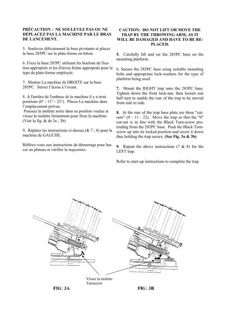
CAUTION: DO NOT LIFT OR MOVE THE TRAP BY THE THROWING ARM, AS IT
WILL BE DAMAGED AND HAVE TO BE RE-PLACED.
5. Carefully lift and set the 285PC base on the mounting platform. 6. Secure the 285PC base using suitable mounting bolts and appropriate lock-washers for the type of platform being used. 7. Mount the RIGHT trap onto the 285PC base. Tighten down the front lock-nut, then loosen one half turn to enable the rear of the trap to be moved from side to side. 8. At the rear of the trap base plate are three "cut-outs" (0 - 11 - 22). Move the trap so that the "0" cut-out is in line with the Black Turn-screw pro-truding from the 285PC base. Push the Black Turn-screw up into its locked position and screw it down thus holding the trap secure. (See Fig. 3a & 3b) 9. Repeat the above instructions (7 & 8) for the LEFT trap.
Refer to start-up instructions to complete the trap
PRÉCAUTION : NE SOULEVEZ PAS OU NE DÉPLACEZ PAS LA MACHINE PAR LE BRAS DE LANCEMENT. 5. Soulevez délicatement la base pivotante et placez la base 285PC sur la plate-forme en béton. 6. Fixez la base 285PC utilisant les boulons de fixa-tion appropriés et les d'écrou freins appropriés pour le type de plate-forme employée. 7. Montez La machine de DROITE sur la base 285PC. Serrez l’écrou à l’avant. 8. À l'arrière de l'embase de la machine il y a trois positions (0° - 11° - 22°). Placez La machine dans l’emplacement prévue. Poussez la molette noire dans sa position voulue et vissez la molette fermement pour fixer la machine. (Voir la fig. & de 3a ; 3b) 9. Répétez les instructions ci-dessus (& 7 ; 8) pour la machine de GAUCHE. Référez-vous aux instructions de démarrage pour lan-cer un plateau et vérifier la trajectoire.
Vissez la molette Turnscrew
START-UP INSTRUCTIONS
INSTRUCTIONS DEMARRAGE
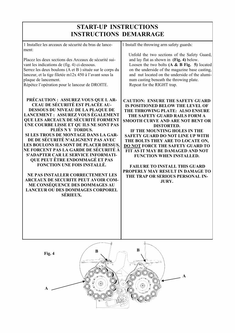
1 Install the throwing arm safety guards:
Unfold the two sections of the Safety Guard,
and lay flat as shown in (Fig. 4) below. Loosen the two bolts (A & B Fig. 5) located
on the underside of the magazine base casting,
and nut located on the underside of the alumi-
num casting beneath the throwing plate. Repeat for the RIGHT trap.
CAUTION: ENSURE THE SAFETY GUARD
IS POSITIONED BELOW THE LEVEL OF
THE THROWING PLATE: ALSO ENSURE
THE SAFETY GUARD RAILS FORM A
SMOOTH CURVE AND ARE NOT BENT OR
DISTORTED. IF THE MOUNTING HOLES IN THE
SAFETY GUARD DO NOT LINE UP WITH
THE BOLTS THEY ARE TO LOCATE ON,
DO NOT FORCE THE SAFETY GUARD TO
FIT AS IT MAY BE DAMAGED AND NOT
FUNCTION WHEN INSTALLED.
FAILURE TO INSTALL THIS GUARD
PROPERLY MAY RESULT IN DAMAGE TO
THE TRAP OR SERIOUS PERSONAL IN-
JURY.
1 Installez les arceaux de sécurité du bras de lance-
ment:
Placez les deux sections des Arceaux de sécurité sui-
vant les indications de (fig. 4) ci-dessous.
Serrez les deux boulons (A et B ) située sur le corps du
lanceur, et la tige filetée m12x 450 à l’avant sous la
plaque de lancement.
Répétez l’opération pour le lanceur de DROITE.
PRÉCAUTION : ASSUREZ VOUS QUE L AR-
CEAU DE SÉCURITÉ EST PLACÉE AU-
DESSOUS DU NIVEAU DE LA PLAQUE DE
LANCEMENT : ASSUREZ VOUS ÉGALEMENT
QUE LES ARCEAUX DE SÉCURITÉ FORMENT
UNE COURBE LISSE ET QU ILS NE SONT PAS
PLIÉS N Y TORDUS.
SI LES TROUS DE MONTAGE DANS LA GAR-
DE DE SÉCURITÉ N'ALIGNENT PAS AVEC
LES BOULONS ILS SONT DE PLACER DESSUS,
NE FORCENT PAS LA GARDE DE SÉCURITÉ À
S'ADAPTER CAR LE SERVICE INFORMATI-
QUE PEUT ÊTRE ENDOMMAGÉ ET PAS
FONCTION UNE FOIS INSTALLÉ.
NE PAS INSTALLER CORRECTEMENT LES
ARCEAUX DE SECURITE PEUT AVOIR COM-
ME CONSÉQUENCE DES DOMMAGES AU
LANCEUR OU DES DOMMAGES CORPOREL
SÉRIEUX.
A
A
B B Fig. 4
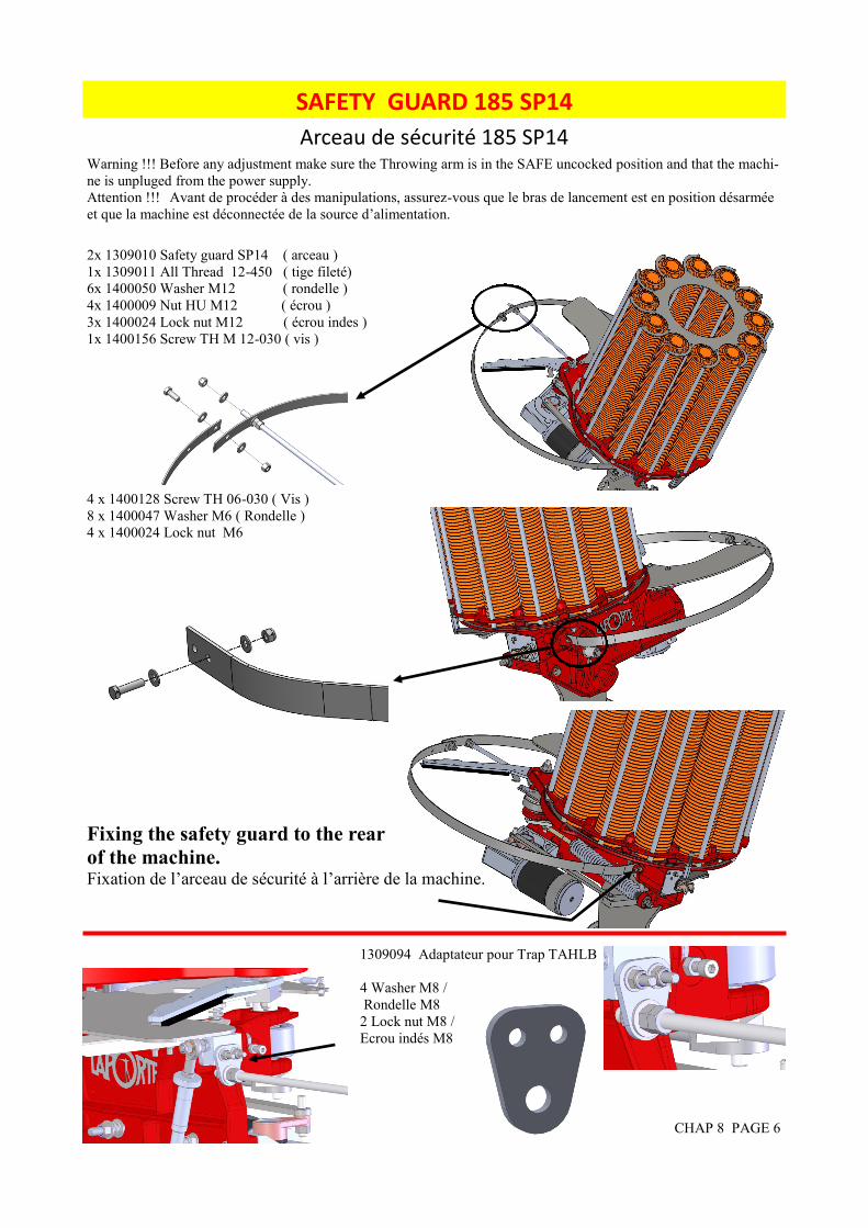
SAFETY GUARD 185 SP14
CHAP 8 PAGE 6
2x 1309010 Safety guard SP14 ( arceau )
1x 1309011 All Thread 12-450 ( tige fileté)
6x 1400050 Washer M12 ( rondelle )
4x 1400009 Nut HU M12 ( écrou )
3x 1400024 Lock nut M12 ( écrou indes )
1x 1400156 Screw TH M 12-030 ( vis )
4 x 1400128 Screw TH 06-030 ( Vis )
8 x 1400047 Washer M6 ( Rondelle )
4 x 1400024 Lock nut M6
Fixing the safety guard to the rear
of the machine. Fixation de l’arceau de sécurité à l’arrière de la machine.
Arceau de sécurité 185 SP14 Warning !!! Before any adjustment make sure the Throwing arm is in the SAFE uncocked position and that the machi-
ne is unpluged from the power supply.
Attention !!! Avant de procéder à des manipulations, assurez-vous que le bras de lancement est en position désarmée
et que la machine est déconnectée de la source d’alimentation.
1309094 Adaptateur pour Trap TAHLB
4 Washer M8 /
Rondelle M8
2 Lock nut M8 /
Ecrou indés M8

UNPACKING INSTRUCTION
INSTRUCTION DE DEBALLAGE
NOTE: There are TWO traps making up the
285PC. The following instructions apply to
each machine. Although there is a LEFT and a
RIGHT machine, the instructions are basically
the same, any differences will be mentioned in
the appropriate places. 1. Examine the cartons and the contents to be sure
there has been no damage in transit. Immediately
report any damage to the shipper and / or carrier. 2. Work in a clean, dry area with enough room to
safely unpack and layout the parts. 3. Carefully remove the magazines, safety guards
and electrical boxes from the shipping carton and
set them aside. 4. Remove the base unit from its packing carton
and ensure there is no damage to the casting or the
horizontal motor or arm assembly. 5. Remove the bolts holding the individual trap
bases to the pallet. 6. Lift the traps high enough to slide the pallet out
from under the traps and carefully set the traps up-
right on their bases on a clean, level surface. At
least two people should lift each trap from the
packing carton. Inspect the traps, magazines, mo-
tors, wiring and electrical boxes to be sure they
arrived in good condition..
CAUTION: DO NOT LIFT OR MOVE THE
TRAP BY THE THROWING ARM, AS IT
WILL BE DAMAGED AND HAVE TO BE
REPLACED.
IF ANY PART MENTIONED IN POINT 6.
ABOVE APPEARS TO BE DAMAGED
"STOP!" DO NOT PROCEED WITH IN-
STALLATION.
7. STOP: Do not attempt to assemble the
trap BEFORE reading the following section!!
NOTE : DEUX machines compose la 285. Les ins-
tructions suivantes appliquent à chaque machine.
Bien qu'il y ait une machine GAUCHE et une ma-
chine DROITE, les instructions sont fondamentale-
ment identiques, toutes les différences seront men-
tionnées dans les endroits appropriés.
1. Examinez les cartons et le contenu, assurez vous
qu'il n'y a eu aucun dommage en transit. Rapportez
immédiatement tous dommages à l'expéditeur et/ou au
transporteur.
2. Travaillez dans un espace suffisant pour déballer la
machine et placez les éléments dans un endroit pro-
pres et secs.
3. Enlevez soigneusement les barillets, les arceaux de
sécurité et les boîtes électriques du carton d’emballa-
ge.
4. Enlevez l'unité centrale de son carton d'emballage
et l'assurez vous qu'il n'y a aucun dommage sur le bâti
ou sur l'ensemble horizontal du moteur ou du bras.
5. Enlevez les boulons tenant les différentes bases de
la machine sur la palette.
6. Soulevez les machines assez haut pour glisser la
palette de dessous les lanceurs et pour placer soigneu-
sement les machines au sol sur leurs bases sur une
surface propre et de niveau. Au moins deux person-
nes devraient soulever chaque machine du carton
d'emballage. Inspectez les lanceurs, barillets, moteurs,
câblage et les boîtes électriques assurez vous qu'ils
sont arrivés en bon état.
PRÉCAUTION : NE SOULEVEZ PAS OU NE
DÉPLACEZ PAS LE LANCEUR PAR LE BRAS
DE LANCEMENT, CAR VOUS RISQUEZ DE L
ENDOMMAGÉ ET IL DEVRA ÊTRE
REMPLACÉ.
SI UNE SEULE PARTIE MENTIONNÉE AU
POINT 6. CI-DESSUS SEMBLE ÊTRE " EN-
DOMMAGÉ ARRÊTEZ ! " NE PROCÉDEZ
PAS À L'INSTALLATION.
7. ARRÊT : N'essayez pas d'assembler le lanceur
AVANT DE lire la section suivante !!

If you have any questions, please call :LAPORTE BALL-TRAP ® 33 (0)4 92 94 77 77 Fax : 33 (0)4 92 94 77 78
e-mail [email protected] www.laporte-shooting.com22/09/00
Machine 285 PC Page: 17/137
Interaction between the Control Boxes
Please examine the diagram below to understand the controls of the two traps. It isimportant to know how these control boxes interact with each other and how they control theoperation of each trap. Without thoroughly understanding this relationship you are exposingyourself to a potential dangerous situation when using these controls to UNCOCK the twomachines and making them safe to approach.
While examining each box, read the instructions below to familiarise yourself with the switch operation oneach box.
Box 1 and Box 2 are the same, i.e. they control an individual trap (Box 1 is the Left trap control, Box 2 is theRight trap control). On each box is a three position toggle switch marked ON-OFF-UNCOCK.
On the Master Control Box, (Box 3), are three switches, but for now, we are only interested in the one markedTEST-OFF-ON.
On Box 4, the External Control Box, is a switch the same as on Box 1 & 2, i.e. ON-OFF-UNCOCK -----
All 4 boxes interact with each other.
i) If the switch marked, "TEST-OFF-ON", on the Master Control Box (Box 3), is in the "OFF"position, all control switches on boxes 1, 2 and 4 are inoperative. i.e. the traps cannot be "COCKED"or "UNCOCKED" from boxes 1, 2 or 4. NOTE: Even if the arms are in the "COCKED" position, theycannot be "UNCOCKED" by using the "ON-OFF-UNCOCK" switch on any of the boxes.
ii). If the switch marked, "TEST-OFF-ON" on the Master Control Box (Box 3), is in the "TEST"position, then the switch on the External Control Box (Box 4), is disabled and control is transferred tothe two switches marked "ON-OFF-UNCOCK" on the Individual Trap Control Boxes (Boxes 1 and 2).The traps can be "Cocked" or "Uncocked" by moving these switches, marked "ON-OFF-UNCOCK",
Left TrapControl
Right TrapControl
MASTERCONTROL
ExternalControl
If you have any questions, please call :LAPORTE BALL-TRAP ® 33 (0)4 92 94 77 77 Fax : 33 (0)4 92 94 77 78
e-mail [email protected] www.laporte-shooting.com22/09/00
Machine 285 PC Page: 19/137
iii). If the switch marked, "TEST-OFF-ON", on the Master Control Box (Box 3), is in the "ON"position, then the switch marked "ON-OFF-UNCOCK", on the External Control Box (Box 4), isoperative. The two traps can only be "COCKED" or "Uncocked" by switching the switch marked"ON-OFF-UNCOCK", on the External Control Box (Box 4), to the "ON" or "UNCOCK" position.The two switches marked "ON-OFF-UNCOCK" on the Individual Trap Control Boxes (Boxes 1 and 2),will not work, and the traps cannot be "Uncocked" by moving either of these switches to the"UNCOCK" position. NOTE:: If the switches marked "ON-OFF-UNCOCK" on the Individual TrapControl Boxes (Boxes 1 and 2), are in the "OFF" position, the switch marked "ON-OFF-UNCOCK" onthe External Control Box (Box 4), will not operate.
NOTE: In these examples, the writer of this manual, assumes that beforefollowing the "Cocking" instructions, the traps are in an "UNCOCKED"condition. Likewise, when following the "Uncock" instructions, the writerassumes the traps were previously "COCKED.
Example: TO "COCK" both traps using the External Control Box (Box 4).
a) Switch the switch marked "TEST-OFF-ON" on the Master Control Box (Box 3) to the "ON"position. i.e. transfer control to the External Control Box (Box 4)
b) Switch the switch marked "ON-OFF-UNCOCK" on the External Control Box (Box 4), to the "OFF"position. i.e. turn “OFF” the "NEW" control box.
c) Switch both switches marked "ON-OFF-UNCOCK" on the Individual Trap Control Boxes (Boxes 1and 2), to the "ON" position. Nothing should happen. i.e. the traps will not "COCK".
d) Switch the switch marked "ON-OFF-UNCOCK", on the External Control Box (Box 4), to the"UNCOCK" then the "ON" position. Both traps will "COCK" and be ready for using.
Example: TO "UNCOCK" both traps using the External Control Box (Box 4).
NOTE: Assuming both traps were "COCKED" from the External Control Box (Box 4), using theprevious example.
a) Switch the switch marked "ON-OFF-UNCOCK", on the External Control Box (Box 4), to the"UNCOCK" position, then back to the "OFF" position. Both traps should "UNCOCK" and be safe toapproach. (Before approaching, check both arms are actually in the "UNCOCKED" position andvisible out in front of each trap as described in the earlier section SAFETY FIRST)
b) Switch the switches marked "ON-OFF-UNCOCK", on both the Individual Trap Control Boxes(Boxes 1 and 2), to the "OFF" position. (This is an added Safety precaution that prevents the trapsbeing "RE-COCKED" by someone else turning on the switch marked "ON-OFF-UNCOCK" on theExternal Control Box (Box 4), to the "ON" position while you are still working on/reloading the traps.

If you have any questions, please call :LAPORTE BALL-TRAP ® 33 (0)4 92 94 77 77 Fax : 33 (0)4 92 94 77 78
e-mail [email protected] www.laporte-shooting.com22/09/00
Machine 285 PC Page: 20/137
Example: TO "COCK" either trap using the Individual Trap Control Box (Box 1 or 2).
a) Switch the switch marked "TEST-OFF-ON", on the Master Control Box (Box 3), to the "TEST"position.b) Switch the switch marked "ON-OFF-UNCOCK", on the Individual Trap Control Box, (Box 1 or Box2), to the "UNCOCK" then to the "ON" position. The trap will "COCK".
Example: TO "UNCOCK" either trap using the Individual Trap Control Box (Box 1 or 2).
a) Switch the switch marked "ON-OFF-UNCOCK", on the Individual Trap Control Box , (Box 1 orBox 2), to the "UNCOCK" position, and then to the "OFF" position.
NOTE: Although the traps may have been "COCKED" using the External Control Box (Box 4), it ispossible to "UNCOCK" them by using the Individual Trap Control Boxes. To do this simply move theswitch marked "TEST-OFF-ON", on the Master Control Box (Box 3), from the "ON" position to the"TEST" position, then follow instruction (a) immediately above.
NOW YOU UNDERSTAND THE INTERACTION OF THE CONTROLBOXES, CONTINUE WITH THE "START-UP PROCEDURE"...
10. Connect the black power cord from the Master Control Box to a power source. Likewise, connect theblack power cords from the Individual Trap Control Boxes to a power source. i.e. 110VAC outlet. Note: Thisis a three prong grounded plug and it must be installed in a suitable outlet. A GFI (Ground Fault Interrupted)circuit is recommended for this installation.
11. Ensure the switch marked "ON-OFF-UNCOCK" on the External Control Box is in the "OFF" position.
12. Move the switch marked "TEST-OFF-ON", on the Master Control Box to the "TEST" position.
The following procedures (13 and 14), apply for each of the two traps (Left and Right).
13. Check that each machine "Cocks". Move the switch marked "ON-OFF-UNCOCK" on the IndividualTrap Control Box, to the "UNCOCK" position then to the "ON" position. Check that the motor starts, themagazine indexing finger moves the magazine one position and the throwing arm "cocks"; (i.e. Left trap armmoves in a "Counter-Clockwise" direction, Right trap arm in a "Clockwise" direction, from the "out-front"position to the "6:30" position below the magazine.) The drive motor should shut off when the throwing arm isfully cocked. A solenoid mechanism, below the magazine, holds the throwing arm in this position. IF ANYOR ALL OF THESE DO NOT HAPPEN, STOP!! MOVE THE SWITCH MARKED "ON-OFF-UNCOCK", ON THE INDIVIDUAL TRAP CONTROL BOX TO THE "OFF" POSITION, ANDDISCONNECT THE POWER SOURCE (I.E. UNPLUG 110volt, OR UNCLIP CLAMPS FROMBATTERY IF 12volt.) GO DIRECTLY TO FAULT FINDING LATER IN THIS MANUAL.

If you have any questions, please call :LAPORTE BALL-TRAP ® 33 (0)4 92 94 77 77 Fax : 33 (0)4 92 94 77 78
e-mail [email protected] www.laporte-shooting.com22/09/00
Machine 285 PC Page: 21/137
Otherwise continue......
14. Now test that each machine "Uncocks". Move the switch marked "ON-OFF-UNCOCK" on theIndividual Trap Control Box, to the "UNCOCK" and then to the "OFF" position. The solenoid should"kick", releasing the firing arm. The arm should spin in a "Counter-Clockwise" direction on the Left trap ora "Clockwise" direction on the Right trap. The arm should come to rest in its "Uncocked" position, stickingout to the side of the trap. On the Left trap this should be approximately the 8:45 position, and on the Righttrap this should be approximately the 3:15 position, when viewed from above and behind the traps. IF THISDOES NOT HAPPEN, STOP!! MOVE THE SWITCH MARKED "ON-OFF-UNCOCK", ON THEINDIVIDUAL TRAP CONTROL BOX TO THE "OFF" POSITION, AND DISCONNECT THEPOWER SOURCE FROM EACH CONTROL BOX (I.E. UNPLUG 110volt, OR UNCLIP CLAMPSFROM BATTERY IF 12volt.) GO DIRECTLY TO FAULT FINDING LATER IN THIS MANUAL.
Otherwise continue......
REPEAT THE ABOVE INSTRUCTIONS (13 and 14) FOR THE OTHER TRAP.
15. "Cock" each machine again by repeating instruction 13 above. Ensure the switch marked "SINGLE-DOUBLE-SINGLE/DOUBLE" on the Master Control box is in the "DOUBLE" position. Press and releasethe "PULL" button located to the right of the "TEST-OFF-ON" button on the Master Control Box. Bothtraps should fire. i.e. the throwing arms should release and the trap machines should cycle as described earlier.IF THIS DOES NOT HAPPEN, STOP!! MOVE THE SWITCH MARKED "TEST-OFF-ON", ON THEMASTER CONTROL BOX TO THE ""OFF" POSITION. AND DISCONNECT THE POWERSOURCE FROM EACH CONTROL BOX (I.E. UNPLUG 110volt, OR UNCLIP CLAMPS FROMBATTERY IF 12volt.) GO DIRECTLY TO FAULT FINDING LATER IN THIS MANUAL.
Otherwise continue......
16. The switch marked "TEST-OFF-ON" on the Master Control Box should be in the "TEST" position fromthe previous test (12). Move it to the "ON" position. Move the switch marked "ON-OFF-UNCOCK" on theExternal Control Box from the "OFF" position to the "ON" position.
17. Press the "PULL" button on the yellow box at the end of the Pull-Cord. Both traps should fire and cycleas in the previous test. IF THIS DOES NOT HAPPEN, STOP!! MOVE THE SWITCH MARKED "ON-OFF-UNCOCK", LOCATED ON THE EXTERNAL CONTROL BOX TO THE "OFF" POSITION,MOVE THE SWITCH MARKED "TEST-OFF-ON" ON THE MASTER CONTROL BOX TO THE"TEST" POSITION, THEN UNCOCK EACH TRAP BY MOVING THE SWITCH MARKED "ON-OFF-UNCOCK" ON THE INDIVIDUAL TRAP CONTROL BOXES TO THE "UNCOCK" ANDTHEN THE "OFF" POSITION, AND DISCONNECT THE POWER SOURCE (I.E. UNPLUG 110volt,OR UNCLIP CLAMPS FROM BATTERY IF 12volt.) GO DIRECTLY TO FAULT FINDINGLATER IN THIS MANUAL.
Otherwise continue......
18. Move the switch marked "ON-OFF-UNCOCK" on the External Control Box from the "ON" position tothe "UNCOCK" position, then to the "OFF" position. This should "Uncock" both traps. as described in (14)above. IF THIS DOES NOT HAPPEN, STOP!! MOVE THE SWITCH MARKED "TEST-OFF-ON"
If you have any questions, please call :LAPORTE BALL-TRAP ® 33 (0)4 92 94 77 77 Fax : 33 (0)4 92 94 77 78
e-mail [email protected] www.laporte-shooting.com22/09/00
Machine 285 PC Page: 22/137
ON THE MASTER CONTROL BOX TO THE "TEST" POSITION, THEN UNCOCK EACH TRAPBY MOVING THE SWITCH MARKED "ON-OFF-UNCOCK" ON THE INDIVIDUAL TRAPCONTROL BOXES TO THE "UNCOCK" AND THEN THE "OFF" POSITION, AND DISCONNECTTHE POWER SOURCE, THEN GO DIRECTLY TO FAULT FINDING LATER IN THIS MANUAL.
Otherwise continue......
19. Load the magazine:
WARNING: DO NOT LOAD THE MAGAZINE WHEN THE TRAP IS "ON"
Ensure the switch marked "ON-OFF-UNCOCK" on the External Control Box is in the "OFF"position, the switch marked "TEST-OFF-ON" on the Master Control Box is in the "TEST"position, the switches marked "ON-OFF-UNCOCK" on the individual Trap Control Boxes arein the "OFF" position, and the throwing arms are at rest sticking out in front of the trap.
I.E. The traps are "Uncocked" and safe to approach.
The following procedure applies to each of the two traps, both left and right.
Look at the top of the magazine, there are 10 columns. Each alternative column has slots in themagazine top-plate, the others have a figure '8' cut-out as mentioned earlier in "MagazineInstallation". (see Fig. 6J) The columns with the slots in the top, allow the outside, grey plastictubes to be slid sideways, allowing targets to be loaded into the magazine from the side, asopposed to be loaded from the top. Load the five columns in the rear of the magazine first, byfollowing these instructions: Push down the cylinder plunger on the top of one magazinecylinder and pull the top of the cylinder outward and to the side, following the guide slot in themagazine top-plate. (see Fig. 6K). Place a stack of targets in the magazine column, beingcareful not to bump or drop them. Remove any broken or cracked targets and make sure thetargets are not stuck together. Check that the bottom target is resting squarely on the magazinebase. Continue to place additional stacks of targets in this column until it is full (40 targets percolumn). Push the top of the magazine cylinder inward until it snaps back into position. To loadthe next column, repeat the previous instructions, but slide the grey cylinder in the otherdirection.
Repeat this process to load the other four columns in the rear half of the magazine
If you have any questions, please call :LAPORTE BALL-TRAP ® 33 (0)4 92 94 77 77 Fax : 33 (0)4 92 94 77 78
e-mail [email protected] www.laporte-shooting.com22/09/00
Machine 285 PC Page: 24/137
NOTE::::: Throughout the following sections, reference is made to"Uncocking" the traps. The method used to "Uncock" the traps differsaccording to the operating mode the traps are in. i.e. The MasterControl Box could be in "ON" mode or "TEST" mode. If in "ON"mode, the traps are "Uncocked" by use of the External Control Box. Ifin "TEST" mode the "Uncocking" is controlled on each IndividualTrap Control Box. The writer of this manual assumes that the user isnow fully aware of how to "Uncock" the trap machines, in either modeand make them safe to work on/reload..
IMPORTANT: BE SURE THE SWITCHES MARKED "ON-OFF-UNCOCK" ON THE "REMOTESAFETY SWITCH" BOX AND THE INDIVIDUAL CONTROL BOXES ARE IN THE "OFF"POSITION, THE SWITCH MARKED "TEST-OFF-ON" ON THE MASTER CONTROL BOX IS INTHE "ON" POSITION AND THE THROWING ARMS ARE UNCOCKED WHEN THE TRAPMACHINES ARE NOT IN USE.
A GENERAL GOOD RULE IS: IF YOU CANNOT CLEARLY SEE THE THROWING ARM IN ASTATIONARY POSITION OUT IN FRONT OF THE TRAP, ASSUME THE TRAP IS "COCKED"AND DANGEROUS!!!.
NOTE: YOU SHOULD NOW ADJUST THE TENSION OF THE MAIN SPRING. IF YOU ARESATISFIED WITH THE TENSION YOU ALREADY SET DURING "INSTALLING THE MAINSPRING", BE SURE TO READ THE FOLLOWING SECTION "SPRING TENSIONADJUSTMENT", MAKING SURE YOU CHECK THE SHOCK ABSORBER AND MICRO SWITCHADJUSTMENT.

If you have any questions, please call :LAPORTE BALL-TRAP ® 33 (0)4 92 94 77 77 Fax : 33 (0)4 92 94 77 78
e-mail [email protected] www.laporte-shooting.com22/09/00
Machine 285 PC Page: 25/137
Spring Tension AdjustmentCAUTION: MAKE SURE ALL PERSONNEL ARE CLEAR OF THE TRAP BEFOREPROCEEDING. WHEN WORKING ON EITHER TRAP ENSURE BOTH TRAPS ARE"DECOCKED", WITH THE THROWING ARMS IN THE SAFE "UNCOCKED" POSITION.
1. BEFORE PROCEEDING: If in the "ON" mode (i.e. the switch on the Master Control Box is in the"ON" position), move the switch marked "ON-OFF-UNCOCK" on the "Remote Safety Switch" to the"UNCOCK" position and then to the "OFF" position to leave the throwing arms in the safe, "Decocked"position. If in the "TEST" mode (i.e. the switch on the Master Control Box is in the "TEST" position),move the switch marked "ON-OFF-UNCOCK" on the Individual Control boxes to the "UNCOCK"position and then to the "OFF" position to leave the throwing arms in the safe, "Decocked" position. Thenmove the switch marked "TEST-OFF-ON" on the Master Control box to the "OFF" position.
ENSURE the switch marked "TEST-OFF-ON" on the Master Control box is in the "TEST"position thus taking control away from the "Remote Safety Switch" and avoiding anyoneaccidentally turning the traps on while you are working on them.
2. Loosen the locknut "A" on the threaded eye-bolt at the front of the mainspring (See Fig. 7).
3. Rotate the Black Turnwheel "C" at the rear of the mainspring. (See Fig. 7).
nClockwise to increase the spring tension (targets will go faster/further)
nCounter-clockwise to decrease the spring tension (targets will go slower/shorter distance)
IMPORTANT: NEVER REDUCE THE MAINSPRING TENSION TO THE POINT WHERE THECOILS OF THE SPRING ARE TOUCHING. A PIECE OF PAPER SHOULD SLIDE EASILYBETWEEN EACH COIL WHEN AT THE MINIMUM ALLOWED TENSION. NOTE : THISCHECK SHOULD ONLY BE MADE WHEN THE THROWING ARM IS DIRECTLY OUT INFRONT OF THE TRAP IN LINE WITH THE SPRING, (i.e. 12:00) NOT IN THE DECOCKEDPOSITION. IF NECESSARY REFER TO THE SECTION "MAIN SPRING REMOVAL" TO ENABLETHE ARM TO BE POSITIONED OUT FRONT (i.e. the 12:00 position when viewed from rear oftrap)
4. After the adjustment is completed, retighten the locknut "A" on the threaded eye rod at the front of themainspring. (See Fig. 7).
If you have any questions, please call :LAPORTE BALL-TRAP ® 33 (0)4 92 94 77 77 Fax : 33 (0)4 92 94 77 78
e-mail [email protected] www.laporte-shooting.com22/09/00
Machine 285 PC Page: 26/137
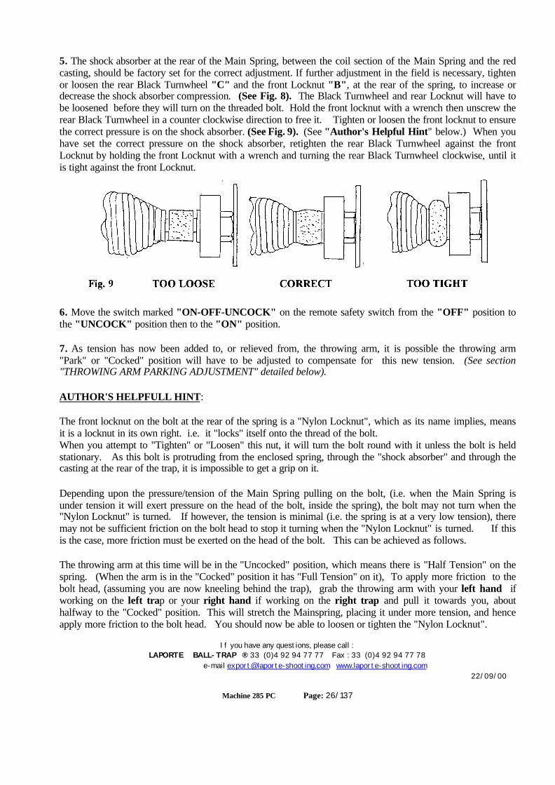
5. The shock absorber at the rear of the Main Spring, between the coil section of the Main Spring and the redcasting, should be factory set for the correct adjustment. If further adjustment in the field is necessary, tightenor loosen the rear Black Turnwheel "C" and the front Locknut "B", at the rear of the spring, to increase ordecrease the shock absorber compression. (See Fig. 8). The Black Turnwheel and rear Locknut will have tobe loosened before they will turn on the threaded bolt. Hold the front locknut with a wrench then unscrew therear Black Turnwheel in a counter clockwise direction to free it. Tighten or loosen the front locknut to ensurethe correct pressure is on the shock absorber. (See Fig. 9). (See "Author's Helpful Hint" below.) When youhave set the correct pressure on the shock absorber, retighten the rear Black Turnwheel against the frontLocknut by holding the front Locknut with a wrench and turning the rear Black Turnwheel clockwise, until itis tight against the front Locknut.
6. Move the switch marked "ON-OFF-UNCOCK" on the remote safety switch from the "OFF" position tothe "UNCOCK" position then to the "ON" position.
7. As tension has now been added to, or relieved from, the throwing arm, it is possible the throwing arm"Park" or "Cocked" position will have to be adjusted to compensate for this new tension. (See section"THROWING ARM PARKING ADJUSTMENT" detailed below).
AUTHOR'S HELPFULL HINT:
The front locknut on the bolt at the rear of the spring is a "Nylon Locknut", which as its name implies, meansit is a locknut in its own right. i.e. it "locks" itself onto the thread of the bolt.When you attempt to "Tighten" or "Loosen" this nut, it will turn the bolt round with it unless the bolt is heldstationary. As this bolt is protruding from the enclosed spring, through the "shock absorber" and through thecasting at the rear of the trap, it is impossible to get a grip on it.
Depending upon the pressure/tension of the Main Spring pulling on the bolt, (i.e. when the Main Spring isunder tension it will exert pressure on the head of the bolt, inside the spring), the bolt may not turn when the"Nylon Locknut" is turned. If however, the tension is minimal (i.e. the spring is at a very low tension), theremay not be sufficient friction on the bolt head to stop it turning when the "Nylon Locknut" is turned. If thisis the case, more friction must be exerted on the head of the bolt. This can be achieved as follows.
The throwing arm at this time will be in the "Uncocked" position, which means there is "Half Tension" on thespring. (When the arm is in the "Cocked" position it has "Full Tension" on it), To apply more friction to thebolt head, (assuming you are now kneeling behind the trap), grab the throwing arm with your left hand ifworking on the left trap or your right hand if working on the right trap and pull it towards you, abouthalfway to the "Cocked" position. This will stretch the Mainspring, placing it under more tension, and henceapply more friction to the bolt head. You should now be able to loosen or tighten the "Nylon Locknut".
If you have any questions, please call :LAPORTE BALL-TRAP ® 33 (0)4 92 94 77 77 Fax : 33 (0)4 92 94 77 78
e-mail [email protected] www.laporte-shooting.com22/09/00
Machine 285 PC Page: 28/137
Throwing Arm "Parking" Adjustment
CAUTION: MAKE SURE ALL PERSONNEL ARE CLEAR OF THE TRAP BEFOREPROCEEDING.
BEFORE PROCEEDING: If in the "ON" mode (i.e. the switch on the Master Control Box is in the "ON"position), move the switch marked "ON-OFF-UNCOCK" on the "Remote Safety Switch" to the"UNCOCK" position and then to the "OFF" position to leave the throwing arms in the safe, "Decocked"position. If in the "TEST" mode (i.e. the switch on the Master Control Box is in the "TEST" position),move the switch marked "ON-OFF-UNCOCK" on the Individual Control boxes to the "UNCOCK"position and then to the "OFF" position to leave the throwing arms in the safe, "Decocked" position.
ENSURE the switch marked "TEST-OFF-ON" on the Master Control box is in the "TEST"position thus taking control away from the "Remote Safety Switch" and avoiding anyoneaccidentally turning the traps on while you are working on them.
The throwing arm micro-switch, and "Thumbwheel" (inside the electrical control box), determine the positionthe throwing arm will come to rest in when the main "cocking" motor stops. Ideally, this will be with thethrowing arm stops in the "6:30" position, just touching the brass throwing arm stop plate, at the rear of thetrap.
WHEN MAKING ANY ADJUSTMENTS TO A TRAP, ENSURE YOU ARE IN "TEST" MODE, BYMAKING SURE THE SWITCH MARKED "TEST-OFF-ON" ON THE MASTER CONTROL BOX ISIN THE "TEST" POSITION. (This will prevent anyone from accidentally turning on the traps, bymeans of the "Remote Safety Switch" when you are working on them.)
Before continuing be sure you only work on one trap at a time. If you are going to work on the LEFT trapensure the RIGHT trap is "UNCOCKED" and the switch marked "ON-OFF-UNCOCK" on the RIGHTtrap Individual Control box is in the "OFF" position. Likewise, if you are going to work on the RIGHT trapensure the LEFT trap is "UNCOCKED" and the switch marked "ON-OFF-UNCOCK" on the LEFT trapIndividual Control box is in the "OFF" position.
For LEFT Trap continue, for RIGHT Trap go to "RIGHT TRAP".

If you have any questions, please call :LAPORTE BALL-TRAP ® 33 (0)4 92 94 77 77 Fax : 33 (0)4 92 94 77 78
e-mail [email protected] www.laporte-shooting.com22/09/00
Machine 285 PC Page: 29/137
LEFT TRAP:There are three conditions to look for:
1. As mentioned above, the throwing arm stops at "6:30" position i.e. just touching the brass throwing arm stop plate. ---- IDEAL! (Fig. 10A)
2. The throwing arm does not travel far enough, say "7:35" position ---- WRONG! (Fig. 10B)
3. The throwing arm travels too far, and strikes the brass throwing arm stop plate too hard, or continually fires. ---- WRONG! (Fig. 10C)
In condition 1, no further action is required ......
In conditions 2 & 3, the throwing arm "Thumbwheel"/Micro-Switch needs to be adjusted.
CAUTION: The following adjustment may have to be made several times, (i.e. "Trial andError"), to get the throwing arm to settle in the correct position (i.e. stopping in the "6:30"position just touching the brass throwing arm stop plate.) Ensure the trap is "Decocked"before each adjustment. (If the Master Control Box switch is in the "ON" position, move theswitch marked "ON-OFF-UNCOCK" on the "Remote Safety Switch" from the "ON" positionto the "UNCOCK" position and then to the "OFF" position. OR, if the Master Control Boxswitch is in the "TEST" position, move the Individual Control ox switch marked "ON-OFF-UNCOCK" to the "UNCOCK" position, then to the "OFF" position. The throwing armshould now be positioned out in front of the trap at approximately the "8:45" position whenviewed from the rear of the trap.
Move the switch marked "TEST-OFF-ON" on the Master Control box to the "TEST" position.
If you have any questions, please call :LAPORTE BALL-TRAP ® 33 (0)4 92 94 77 77 Fax : 33 (0)4 92 94 77 78
e-mail [email protected] www.laporte-shooting.com22/09/00
Machine 285 PC Page: 30/137
Throwing Arm "Parking" adjustment by moving the "Thumbwheel".
As you will need to go "inside" the Individual Control box, ensure the power is disconnected beforecontinuing. Remove the power lead from the 110volt supply.
The "Thumbwheel" is located in the Individual Control box.
Open the lid of the control box and fold it back. Inside the lid is a green circuit board. Look in the top rightcorner and locate the "Thumbwheel" (a small black plastic module 1/2" tall with a 1/2" diameter, white or redcircular disc with notches cut in the circumference on its lower face.) (See Fig. 11). Turn it to the right toget the arm to stop later and park nearer the Brass Stop Plate, or turn it left to get the arm to stop sooner, andpark further away from the Brass Stop Plate.
Note: Only turn it one "click" at a time.
Close the door of the control box.Fig. 11
** Reconnect the power source, then move the switch marked "ON-OFF-UNCOCK" on the IndividualControl box from the "OFF" position to the "UNCOCK" position, then to the "ON" position, "Cocking" thetrap. Note the new position of the throwing arm.
Repeat the check from ..... "There are three conditions to look for." at the start of this section.REMEMBER: Only make a small movement of the "Thumbwheel" each time.
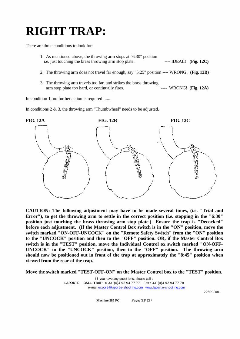
If you have any questions, please call :LAPORTE BALL-TRAP ® 33 (0)4 92 94 77 77 Fax : 33 (0)4 92 94 77 78
e-mail [email protected] www.laporte-shooting.com22/09/00
Machine 285 PC Page: 31/137
RIGHT TRAP:There are three conditions to look for:
1. As mentioned above, the throwing arm stops at "6:30" position i.e. just touching the brass throwing arm stop plate. ---- IDEAL! (Fig. 12C)
2. The throwing arm does not travel far enough, say "5:25" position ---- WRONG! (Fig. 12B)
3. The throwing arm travels too far, and strikes the brass throwing arm stop plate too hard, or continually fires. ---- WRONG! (Fig. 12A)
In condition 1, no further action is required ......
In conditions 2 & 3, the throwing arm "Thumbwheel" needs to be adjusted.
FIG. 12A FIG. 12B FIG. 12C
CAUTION: The following adjustment may have to be made several times, (i.e. "Trial andError"), to get the throwing arm to settle in the correct position (i.e. stopping in the "6:30"position just touching the brass throwing arm stop plate.) Ensure the trap is "Decocked"before each adjustment. (If the Master Control Box switch is in the "ON" position, move theswitch marked "ON-OFF-UNCOCK" on the "Remote Safety Switch" from the "ON" positionto the "UNCOCK" position and then to the "OFF" position. OR, if the Master Control Boxswitch is in the "TEST" position, move the Individual Control ox switch marked "ON-OFF-UNCOCK" to the "UNCOCK" position, then to the "OFF" position. The throwing armshould now be positioned out in front of the trap at approximately the "8:45" position whenviewed from the rear of the trap.
Move the switch marked "TEST-OFF-ON" on the Master Control box to the "TEST" position.
If you have any questions, please call :LAPORTE BALL-TRAP ® 33 (0)4 92 94 77 77 Fax : 33 (0)4 92 94 77 78
e-mail [email protected] www.laporte-shooting.com22/09/00
Machine 285 PC Page: 32/137
Throwing Arm "Parking" adjustment by moving the "Thumbwheel".
As you will need to go "inside" the Individual Control box, ensure the power is disconnected beforecontinuing. Remove the power lead from the 110volt supply.
The "Thumbwheel" located in the Individual Control box.
Open the lid of the control box and fold it back.. Inside the lid is a green circuit board. Look in the top rightcorner and locate the "Thumbwheel" (a small black plastic module 1/2" tall with a 1/2 " diameter, white or redcircular disc, with notches cut in the circumference on its lower face.) (See Fig. 11). Turn it to the left to getthe arm to stop later and park further to the left, or turn it right to get the arm to stop sooner, and park furtherto the right.Note: Only turn it one "click" at a time.
Close the door of the control box.
** Reconnect the power source, then move the switch marked "ON-OFF-UNCOCK" on the trap controlbox from the "OFF" position to the "UNCOCK" position, then to the "ON" position, "Cocking" the trap.Note the new position of the throwing arm.
Repeat the check from ..... "There are three conditions to look for." at the start of this section.
REMEMBER: Only make a small movement of the "Thumbwheel" each time.

If you have any questions, please call :LAPORTE BALL-TRAP ® 33 (0)4 92 94 77 77 Fax : 33 (0)4 92 94 77 78
e-mail [email protected] www.laporte-shooting.com22/09/00
Machine 285 PC Page: 33/137
Spring Removal CAUTION: MAKE SURE ALL PERSONNEL ARE CLEAR OF THE TRAP BEFOREPROCEEDING.
BEFORE PROCEEDING: If in the "ON" mode (i.e. the switch on the Master Control Box is in the "ON"position), move the switch marked "ON-OFF-UNCOCK" on the "Remote Safety Switch" to the"UNCOCK" position and then to the "OFF" position to leave the throwing arms in the safe, "Decocked"position. If in the "TEST" mode (i.e. the switch on the Master Control Box is in the "TEST" position),move the switch marked "ON-OFF-UNCOCK" on the Individual Control boxes to the "UNCOCK"position and then to the "OFF" position to leave the throwing arms in the safe, "Decocked" position.
ENSURE the switch marked "TEST-OFF-ON" on the Master Control box is in the "TEST"position thus taking control away from the "Remote Safety Switch" and avoiding anyoneaccidentally turning the traps on while you are working on them.
Before continuing be sure you only work on one trap at a time. If you are going to work on the LEFT trapensure the RIGHT trap is "UNCOCKED" and the switch marked "ON-OFF-UNCOCK" on the RIGHTtrap Individual Control box is in the "OFF" position. Likewise, if you are going to work on the RIGHT trapensure the LEFT trap is "UNCOCKED" and the switch marked "ON-OFF-UNCOCK" on the LEFT trapIndividual Control box is in the "OFF" position.
CAUTION: Before continuing ensure the trap you are working on is in the "Uncocked" condition.
WARNING: Although the following operation is similar for both machines, it isimportant to follow the individual procedures for each machine as there areminor differences, which if not observed could result in serious injury!
NOTE: Pay special attention to the directions that ask you to rotate the cockingmotor shaft and hence the gearbox cocking stud, and the direction the throwingarm moves in. There are differences between the LEFT and RIGHT machines.
The direction of travel in either:
CLOCKWISE or COUNTER-CLOCKWISE.
The directions in the text are highlighted. e.g.
“Rotate the shaft clockwise which will …….
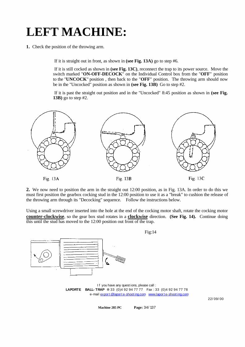
If you have any questions, please call :LAPORTE BALL-TRAP ® 33 (0)4 92 94 77 77 Fax : 33 (0)4 92 94 77 78
e-mail [email protected] www.laporte-shooting.com22/09/00
Machine 285 PC Page: 34/137
LEFT MACHINE:1. Check the position of the throwing arm.
If it is straight out in front, as shown in (see Fig. 13A) go to step #6.
If it is still cocked as shown in (see Fig. 13C), reconnect the trap to its power source. Move theswitch marked "ON-OFF-DECOCK" on the Individual Control box from the "OFF" positionto the "UNCOCK" position , then back to the "OFF" position. The throwing arm should nowbe in the "Uncocked" position as shown in (see Fig. 13B) Go to step #2.
If it is past the straight out position and in the "Uncocked" 8:45 position as shown in (see Fig.13B) go to step #2.
2. We now need to position the arm in the straight out 12:00 position, as in Fig. 13A. In order to do this wemust first position the gearbox cocking stud in the 12:00 position to use it as a "break" to cushion the release ofthe throwing arm through its "Decocking" sequence. Follow the instructions below.
Using a small screwdriver inserted into the hole at the end of the cocking motor shaft, rotate the cocking motorcounter-clockwise, so the gear box stud rotates in a clockwise direction. (See Fig. 14). Continue doingthis until the stud has moved to the 12:00 position out front of the trap.
Fig:14
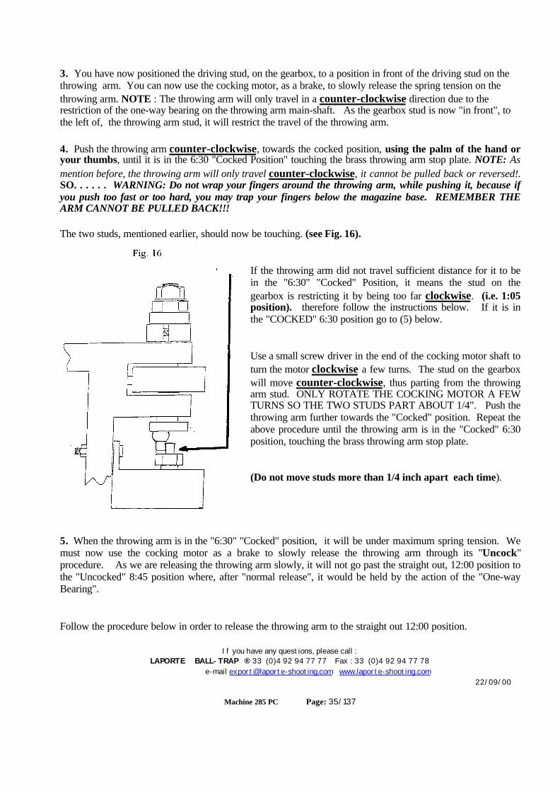
If you have any questions, please call :LAPORTE BALL-TRAP ® 33 (0)4 92 94 77 77 Fax : 33 (0)4 92 94 77 78
e-mail [email protected] www.laporte-shooting.com22/09/00
Machine 285 PC Page: 35/137
3. You have now positioned the driving stud, on the gearbox, to a position in front of the driving stud on thethrowing arm. You can now use the cocking motor, as a brake, to slowly release the spring tension on thethrowing arm. NOTE : The throwing arm will only travel in a counter-clockwise direction due to therestriction of the one-way bearing on the throwing arm main-shaft. As the gearbox stud is now "in front", tothe left of, the throwing arm stud, it will restrict the travel of the throwing arm.
4. Push the throwing arm counter-clockwise, towards the cocked position, using the palm of the hand oryour thumbs, until it is in the 6:30 "Cocked Position" touching the brass throwing arm stop plate. NOTE: Asmention before, the throwing arm will only travel counter-clockwise, it cannot be pulled back or reversed!.SO. . . . . . WARNING: Do not wrap your fingers around the throwing arm, while pushing it, because ifyou push too fast or too hard, you may trap your fingers below the magazine base. REMEMBER THEARM CANNOT BE PULLED BACK!!!
The two studs, mentioned earlier, should now be touching. (see Fig. 16).
If the throwing arm did not travel sufficient distance for it to bein the "6:30" "Cocked" Position, it means the stud on thegearbox is restricting it by being too far clockwise. (i.e. 1:05position). therefore follow the instructions below. If it is inthe "COCKED" 6:30 position go to (5) below.
Use a small screw driver in the end of the cocking motor shaft toturn the motor clockwise a few turns. The stud on the gearboxwill move counter-clockwise, thus parting from the throwingarm stud. ONLY ROTATE THE COCKING MOTOR A FEWTURNS SO THE TWO STUDS PART ABOUT 1/4". Push thethrowing arm further towards the "Cocked" position. Repeat theabove procedure until the throwing arm is in the "Cocked" 6:30position, touching the brass throwing arm stop plate.
(Do not move studs more than 1/4 inch apart each time).
5. When the throwing arm is in the "6:30" "Cocked" position, it will be under maximum spring tension. Wemust now use the cocking motor as a brake to slowly release the throwing arm through its "Uncock"procedure. As we are releasing the throwing arm slowly, it will not go past the straight out, 12:00 position tothe "Uncocked" 8:45 position where, after "normal release", it would be held by the action of the "One-wayBearing".
Follow the procedure below in order to release the throwing arm to the straight out 12:00 position.

If you have any questions, please call :LAPORTE BALL-TRAP ® 33 (0)4 92 94 77 77 Fax : 33 (0)4 92 94 77 78
e-mail [email protected] www.laporte-shooting.com22/09/00
Machine 285 PC Page: 36/137
Use a small screwdriver in the end of the cocking motor shaft to turn the motor clockwise a few turns. Thestud on the gearbox will move counter-clockwise, thus parting from the throwing arm stud. ONLYROTATE THE COCKING MOTOR A FEW TURNS SO THE TWO STUDS PART ABOUT 1/4". Push inthe throwing arm past the "6:30" "Cocked" position into the "Release" position. You will have to move thebrass throwing arm stop plate aside to allow the arm to pass. If the throwing arm does not go into the "release"position, keep repeating the above 1/4" movement followed by pushing the throwing arm until the throwingarm releases and its stud comes to a "hard rest" against the gearbox stud. It is quite safe to do this, becausewhen the throwing arm does eventually release it will only travel about an inch, being restricted by the stud onthe gearbox which will only be 1/4" away from the throwing arm stud. It may appear to "jump" very fast, as iffiring, but it will only travel about one inch. Now the throwing arm stud is "hard" against the gearbox stud.
Insert a small screwdriver in the hole in the end of the cocking motor shaft and rotate the motor shaftclockwise. This will cushion the travel of the throwing arm allowing it to "decock" slowly. Continue rotatingthe shaft until the throwing arm is in the straight out position in front of the trap i.e. "12:00"The main spring is now at its minimum tension.
6. Loosen the locknut "A" on the threaded eye rod at the front of the main spring. (see Fig. 7).
7. Rotate the Black Turnwheel "C" (see Fig. 7), at the rear of the Main Spring counter-clockwise until thethreaded eye rod disengages from the Main Spring. NOTE: As the Main Spring is being unwound, it will benecessary to move the throwing arm in a counter-clockwise direction further, thus allowing the threaded eyebolt to disengage from the Main Spring. If at this time the gearbox stud is restricting the movement of thethrowing arm stud to travel in the counter-clockwise direction, it will be necessary to move the gearbox studfurther counter-clockwise, out of the way. This can be achieved by following the procedure detailed in (4)above when we used the cocking motor as a brake to allow the throwing arm to slowly rotate counter-clockwise through its "Uncocking" sequence. Simply move the gearbox stud further counter-clockwise.This will allow the throwing arm to move further counter-clockwise, thus disengaging the threaded eye-boltfrom the Main Spring.
8. To disconnect the rear of the Main Spring, use a wrench to hold the front Locknut from turning, then loosenthe Black Turnwheel by rotating it counter-clockwise to break the "Lock" between the it and the frontLocknut. Remove the rear Black Turnwheel completely.
9. The front Locknut must now be removed, but as it is "Nylon Locking Nut" it will not be that easy. Whenyou attempt to unscrew it from the thread of the Main Spring Bolt, it will turn the bolt with it. You can try tounscrew this forever, but it will continually turn the bolt with it.
The trick to do this is as follows......
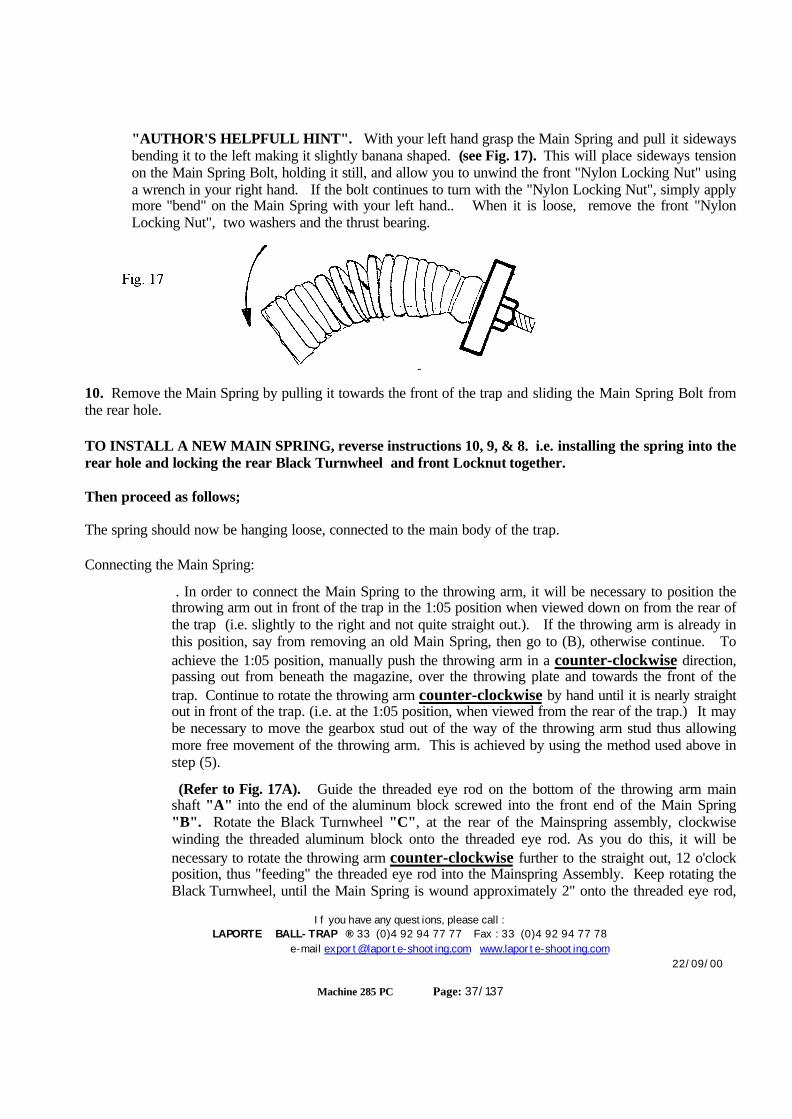
If you have any questions, please call :LAPORTE BALL-TRAP ® 33 (0)4 92 94 77 77 Fax : 33 (0)4 92 94 77 78
e-mail [email protected] www.laporte-shooting.com22/09/00
Machine 285 PC Page: 37/137
"AUTHOR'S HELPFULL HINT". With your left hand grasp the Main Spring and pull it sidewaysbending it to the left making it slightly banana shaped. (see Fig. 17). This will place sideways tensionon the Main Spring Bolt, holding it still, and allow you to unwind the front "Nylon Locking Nut" usinga wrench in your right hand. If the bolt continues to turn with the "Nylon Locking Nut", simply applymore "bend" on the Main Spring with your left hand.. When it is loose, remove the front "NylonLocking Nut", two washers and the thrust bearing.
10. Remove the Main Spring by pulling it towards the front of the trap and sliding the Main Spring Bolt fromthe rear hole.
TO INSTALL A NEW MAIN SPRING, reverse instructions 10, 9, & 8. i.e. installing the spring into therear hole and locking the rear Black Turnwheel and front Locknut together.
Then proceed as follows;
The spring should now be hanging loose, connected to the main body of the trap.
Connecting the Main Spring:
. In order to connect the Main Spring to the throwing arm, it will be necessary to position thethrowing arm out in front of the trap in the 1:05 position when viewed down on from the rear ofthe trap (i.e. slightly to the right and not quite straight out.). If the throwing arm is already inthis position, say from removing an old Main Spring, then go to (B), otherwise continue. Toachieve the 1:05 position, manually push the throwing arm in a counter-clockwise direction,passing out from beneath the magazine, over the throwing plate and towards the front of thetrap. Continue to rotate the throwing arm counter-clockwise by hand until it is nearly straightout in front of the trap. (i.e. at the 1:05 position, when viewed from the rear of the trap.) It maybe necessary to move the gearbox stud out of the way of the throwing arm stud thus allowingmore free movement of the throwing arm. This is achieved by using the method used above instep (5).
(Refer to Fig. 17A). Guide the threaded eye rod on the bottom of the throwing arm mainshaft "A" into the end of the aluminum block screwed into the front end of the Main Spring"B". Rotate the Black Turnwheel "C", at the rear of the Mainspring assembly, clockwisewinding the threaded aluminum block onto the threaded eye rod. As you do this, it will benecessary to rotate the throwing arm counter-clockwise further to the straight out, 12 o'clockposition, thus "feeding" the threaded eye rod into the Mainspring Assembly. Keep rotating theBlack Turnwheel, until the Main Spring is wound approximately 2" onto the threaded eye rod,
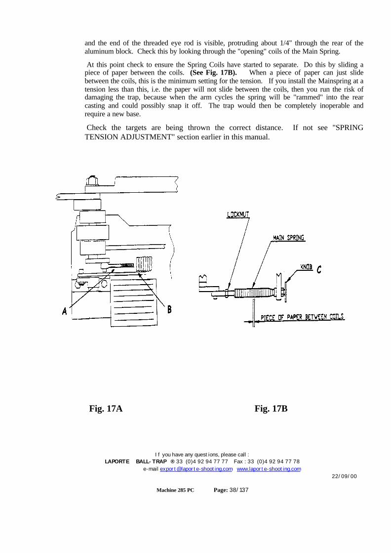
If you have any questions, please call :LAPORTE BALL-TRAP ® 33 (0)4 92 94 77 77 Fax : 33 (0)4 92 94 77 78
e-mail [email protected] www.laporte-shooting.com22/09/00
Machine 285 PC Page: 38/137
and the end of the threaded eye rod is visible, protruding about 1/4" through the rear of thealuminum block. Check this by looking through the "opening" coils of the Main Spring.
At this point check to ensure the Spring Coils have started to separate. Do this by sliding apiece of paper between the coils. (See Fig. 17B). When a piece of paper can just slidebetween the coils, this is the minimum setting for the tension. If you install the Mainspring at atension less than this, i.e. the paper will not slide between the coils, then you run the risk ofdamaging the trap, because when the arm cycles the spring will be "rammed" into the rearcasting and could possibly snap it off. The trap would then be completely inoperable andrequire a new base.
Check the targets are being thrown the correct distance. If not see "SPRINGTENSION ADJUSTMENT" section earlier in this manual.
Fig. 17A Fig. 17B
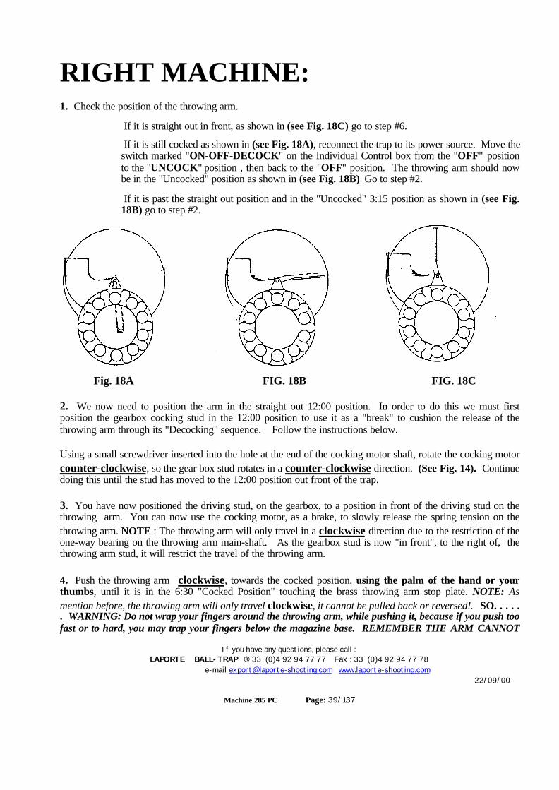
If you have any questions, please call :LAPORTE BALL-TRAP ® 33 (0)4 92 94 77 77 Fax : 33 (0)4 92 94 77 78
e-mail [email protected] www.laporte-shooting.com22/09/00
Machine 285 PC Page: 39/137
RIGHT MACHINE:1. Check the position of the throwing arm.
If it is straight out in front, as shown in (see Fig. 18C) go to step #6.
If it is still cocked as shown in (see Fig. 18A), reconnect the trap to its power source. Move theswitch marked "ON-OFF-DECOCK" on the Individual Control box from the "OFF" positionto the "UNCOCK" position , then back to the "OFF" position. The throwing arm should nowbe in the "Uncocked" position as shown in (see Fig. 18B) Go to step #2.
If it is past the straight out position and in the "Uncocked" 3:15 position as shown in (see Fig.18B) go to step #2.
Fig. 18A FIG. 18B FIG. 18C
2. We now need to position the arm in the straight out 12:00 position. In order to do this we must firstposition the gearbox cocking stud in the 12:00 position to use it as a "break" to cushion the release of thethrowing arm through its "Decocking" sequence. Follow the instructions below.
Using a small screwdriver inserted into the hole at the end of the cocking motor shaft, rotate the cocking motorcounter-clockwise, so the gear box stud rotates in a counter-clockwise direction. (See Fig. 14). Continuedoing this until the stud has moved to the 12:00 position out front of the trap.
3. You have now positioned the driving stud, on the gearbox, to a position in front of the driving stud on thethrowing arm. You can now use the cocking motor, as a brake, to slowly release the spring tension on thethrowing arm. NOTE : The throwing arm will only travel in a clockwise direction due to the restriction of theone-way bearing on the throwing arm main-shaft. As the gearbox stud is now "in front", to the right of, thethrowing arm stud, it will restrict the travel of the throwing arm.
4. Push the throwing arm clockwise, towards the cocked position, using the palm of the hand or yourthumbs, until it is in the 6:30 "Cocked Position" touching the brass throwing arm stop plate. NOTE: Asmention before, the throwing arm will only travel clockwise, it cannot be pulled back or reversed!. SO. . . . .. WARNING: Do not wrap your fingers around the throwing arm, while pushing it, because if you push toofast or to hard, you may trap your fingers below the magazine base. REMEMBER THE ARM CANNOT
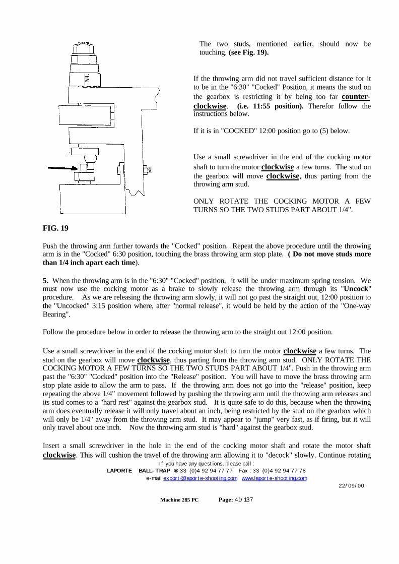
If you have any questions, please call :LAPORTE BALL-TRAP ® 33 (0)4 92 94 77 77 Fax : 33 (0)4 92 94 77 78
e-mail [email protected] www.laporte-shooting.com22/09/00
Machine 285 PC Page: 41/137
The two studs, mentioned earlier, should now betouching. (see Fig. 19).
If the throwing arm did not travel sufficient distance for itto be in the "6:30" "Cocked" Position, it means the stud onthe gearbox is restricting it by being too far counter-clockwise. (i.e. 11:55 position). Therefor follow theinstructions below.
If it is in "COCKED" 12:00 position go to (5) below.
Use a small screwdriver in the end of the cocking motorshaft to turn the motor clockwise a few turns. The stud onthe gearbox will move clockwise, thus parting from thethrowing arm stud.
ONLY ROTATE THE COCKING MOTOR A FEWTURNS SO THE TWO STUDS PART ABOUT 1/4".
FIG. 19
Push the throwing arm further towards the "Cocked" position. Repeat the above procedure until the throwingarm is in the "Cocked" 6:30 position, touching the brass throwing arm stop plate. ( Do not move studs morethan 1/4 inch apart each time).
5. When the throwing arm is in the "6:30" "Cocked" position, it will be under maximum spring tension. Wemust now use the cocking motor as a brake to slowly release the throwing arm through its "Uncock"procedure. As we are releasing the throwing arm slowly, it will not go past the straight out, 12:00 position tothe "Uncocked" 3:15 position where, after "normal release", it would be held by the action of the "One-wayBearing".
Follow the procedure below in order to release the throwing arm to the straight out 12:00 position.
Use a small screwdriver in the end of the cocking motor shaft to turn the motor clockwise a few turns. Thestud on the gearbox will move clockwise, thus parting from the throwing arm stud. ONLY ROTATE THECOCKING MOTOR A FEW TURNS SO THE TWO STUDS PART ABOUT 1/4". Push in the throwing armpast the "6:30" "Cocked" position into the "Release" position. You will have to move the brass throwing armstop plate aside to allow the arm to pass. If the throwing arm does not go into the "release" position, keeprepeating the above 1/4" movement followed by pushing the throwing arm until the throwing arm releases andits stud comes to a "hard rest" against the gearbox stud. It is quite safe to do this, because when the throwingarm does eventually release it will only travel about an inch, being restricted by the stud on the gearbox whichwill only be 1/4" away from the throwing arm stud. It may appear to "jump" very fast, as if firing, but it willonly travel about one inch. Now the throwing arm stud is "hard" against the gearbox stud.
Insert a small screwdriver in the hole in the end of the cocking motor shaft and rotate the motor shaftclockwise. This will cushion the travel of the throwing arm allowing it to "decock" slowly. Continue rotating
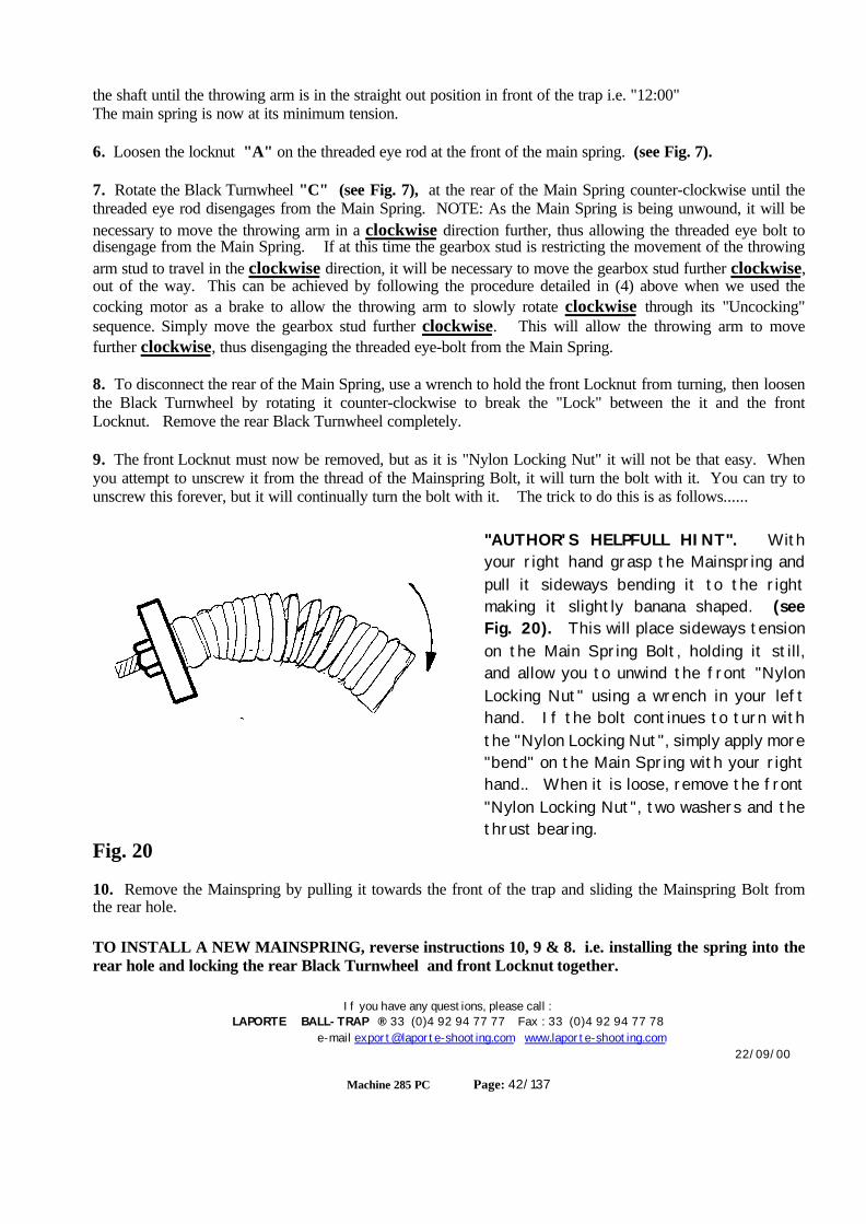
If you have any questions, please call :LAPORTE BALL-TRAP ® 33 (0)4 92 94 77 77 Fax : 33 (0)4 92 94 77 78
e-mail [email protected] www.laporte-shooting.com22/09/00
Machine 285 PC Page: 42/137
the shaft until the throwing arm is in the straight out position in front of the trap i.e. "12:00"The main spring is now at its minimum tension.
6. Loosen the locknut "A" on the threaded eye rod at the front of the main spring. (see Fig. 7).
7. Rotate the Black Turnwheel "C" (see Fig. 7), at the rear of the Main Spring counter-clockwise until thethreaded eye rod disengages from the Main Spring. NOTE: As the Main Spring is being unwound, it will benecessary to move the throwing arm in a clockwise direction further, thus allowing the threaded eye bolt todisengage from the Main Spring. If at this time the gearbox stud is restricting the movement of the throwingarm stud to travel in the clockwise direction, it will be necessary to move the gearbox stud further clockwise,out of the way. This can be achieved by following the procedure detailed in (4) above when we used thecocking motor as a brake to allow the throwing arm to slowly rotate clockwise through its "Uncocking"sequence. Simply move the gearbox stud further clockwise. This will allow the throwing arm to movefurther clockwise, thus disengaging the threaded eye-bolt from the Main Spring.
8. To disconnect the rear of the Main Spring, use a wrench to hold the front Locknut from turning, then loosenthe Black Turnwheel by rotating it counter-clockwise to break the "Lock" between the it and the frontLocknut. Remove the rear Black Turnwheel completely.
9. The front Locknut must now be removed, but as it is "Nylon Locking Nut" it will not be that easy. Whenyou attempt to unscrew it from the thread of the Mainspring Bolt, it will turn the bolt with it. You can try tounscrew this forever, but it will continually turn the bolt with it. The trick to do this is as follows......
"AUTHOR'S HELPFULL HINT". Withyour right hand grasp the Mainspring andpull it sideways bending it to the rightmaking it slightly banana shaped. (seeFig. 20). This will place sideways tensionon the Main Spring Bolt, holding it still,and allow you to unwind the front "NylonLocking Nut" using a wrench in your lefthand. If the bolt continues to turn withthe "Nylon Locking Nut", simply apply more"bend" on the Main Spring with your righthand.. When it is loose, remove the front"Nylon Locking Nut", two washers and thethrust bearing.
Fig. 20
10. Remove the Mainspring by pulling it towards the front of the trap and sliding the Mainspring Bolt fromthe rear hole.
TO INSTALL A NEW MAINSPRING, reverse instructions 10, 9 & 8. i.e. installing the spring into therear hole and locking the rear Black Turnwheel and front Locknut together.
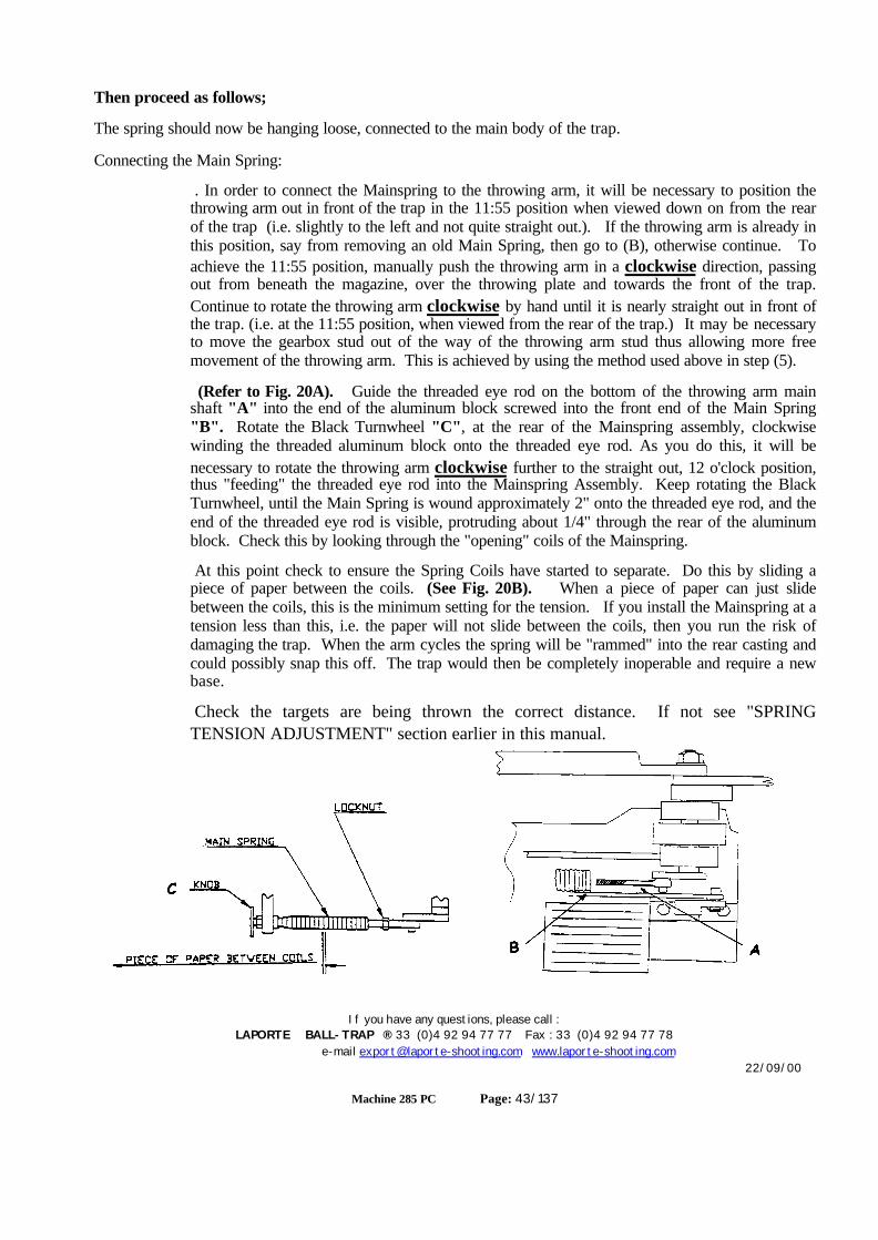
If you have any questions, please call :LAPORTE BALL-TRAP ® 33 (0)4 92 94 77 77 Fax : 33 (0)4 92 94 77 78
e-mail [email protected] www.laporte-shooting.com22/09/00
Machine 285 PC Page: 43/137
Then proceed as follows;
The spring should now be hanging loose, connected to the main body of the trap.
Connecting the Main Spring:
. In order to connect the Mainspring to the throwing arm, it will be necessary to position thethrowing arm out in front of the trap in the 11:55 position when viewed down on from the rearof the trap (i.e. slightly to the left and not quite straight out.). If the throwing arm is already inthis position, say from removing an old Main Spring, then go to (B), otherwise continue. Toachieve the 11:55 position, manually push the throwing arm in a clockwise direction, passingout from beneath the magazine, over the throwing plate and towards the front of the trap.Continue to rotate the throwing arm clockwise by hand until it is nearly straight out in front ofthe trap. (i.e. at the 11:55 position, when viewed from the rear of the trap.) It may be necessaryto move the gearbox stud out of the way of the throwing arm stud thus allowing more freemovement of the throwing arm. This is achieved by using the method used above in step (5).
(Refer to Fig. 20A). Guide the threaded eye rod on the bottom of the throwing arm mainshaft "A" into the end of the aluminum block screwed into the front end of the Main Spring"B". Rotate the Black Turnwheel "C", at the rear of the Mainspring assembly, clockwisewinding the threaded aluminum block onto the threaded eye rod. As you do this, it will benecessary to rotate the throwing arm clockwise further to the straight out, 12 o'clock position,thus "feeding" the threaded eye rod into the Mainspring Assembly. Keep rotating the BlackTurnwheel, until the Main Spring is wound approximately 2" onto the threaded eye rod, and theend of the threaded eye rod is visible, protruding about 1/4" through the rear of the aluminumblock. Check this by looking through the "opening" coils of the Mainspring.
At this point check to ensure the Spring Coils have started to separate. Do this by sliding apiece of paper between the coils. (See Fig. 20B). When a piece of paper can just slidebetween the coils, this is the minimum setting for the tension. If you install the Mainspring at atension less than this, i.e. the paper will not slide between the coils, then you run the risk ofdamaging the trap. When the arm cycles the spring will be "rammed" into the rear casting andcould possibly snap this off. The trap would then be completely inoperable and require a newbase.
Check the targets are being thrown the correct distance. If not see "SPRINGTENSION ADJUSTMENT" section earlier in this manual.
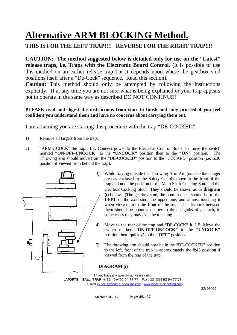
If you have any questions, please call :LAPORTE BALL-TRAP ® 33 (0)4 92 94 77 77 Fax : 33 (0)4 92 94 77 78
e-mail [email protected] www.laporte-shooting.com22/09/00
Machine 285 PC Page: 45/137
Alternative ARM BLOCKING Method.THIS IS FOR THE LEFT TRAP!!!! REVERSE FOR THE RIGHT TRAP!!!!
CAUTION: The method suggested below is detailed only for use on the “Latest”release traps, i.e. Traps with the Electronic Board Control. (It is possible to usethis method on an earlier release trap but it depends upon where the gearbox studpositions itself after a “De-Cock” sequence. Read this section).Caution: This method should only be attempted by following the instructionsexplicitly. If at any time you are not sure what is being explained or your trap appearsnot to operate in the same way as described DO NOT CONTINUE!
PLEASE read and digest the instructions from start to finish and only proceed if you feelconfident you understand them and have no concerns about carrying them out.
I am assuming you are starting this procedure with the trap “DE-COCKED”.
1) Remove all targets from the trap.
2) “ARM / COCK” the trap. I.E. Connect power to the Electrical Control Box then move the switchmarked “ON-OFF-UNCOCK” to the “UNCOCK” position then to the “ON” position. TheThrowing arm should move from the “DE-COCKED” position to the “COCKED” position (i.e. 6:30position if viewed from behind the trap).
3) While staying outside the Throwing Arm Arc (outside the dangerarea as enclosed by the Safety Guard), move to the front of thetrap and note the position of the Main Shaft Cocking Stud and theGearbox Cocking Stud. They should be shown as in diagram(i) below. (The gearbox stud, the bottom one, should be to theLEFT of the axis stud, the upper one, and almost touching itwhen viewed from the front of the trap. The distance betweenthem should be about a quarter to three eighths of an inch, insome cases they may even be touching.
4) Move to the rear of the trap and “DE-COCK” it. I.E. Move theswitch marked “ON-OFF-UNCOCK” to the “UNCOCK”position then ‘quickly’ to the “OFF” position.
5) The throwing arm should now be in the “DE-COCKED” positionto the left, front of the trap in approximately the 8:45 position ifviewed from the rear of the trap.
DIAGRAM (i)
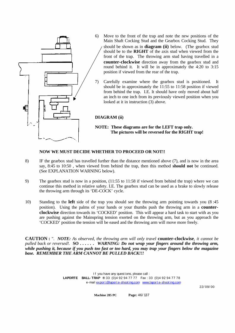
If you have any questions, please call :LAPORTE BALL-TRAP ® 33 (0)4 92 94 77 77 Fax : 33 (0)4 92 94 77 78
e-mail [email protected] www.laporte-shooting.com22/09/00
Machine 285 PC Page: 46/137
6) Move to the front of the trap and note the new positions of theMain Shaft Cocking Stud and the Gearbox Cocking Stud. Theyshould be shown as in diagram (ii) below. (The gearbox studshould be to the RIGHT of the axis stud when viewed from thefront of the trap. The throwing arm stud having travelled in acounter-clockwise direction away from the gearbox stud andround behind it. It will be in approximately the 4:20 to 3:15position if viewed from the rear of the trap.
7) Carefully examine where the gearbox stud is positioned. Itshould be in approximately the 11:55 to 11:58 position if viewedfrom behind the trap. I.E. It should have only moved about halfan inch to one inch from its previously viewed position when youlooked at it in instruction (3) above.
DIAGRAM (ii)
NOTE: These diagrams are for the LEFT trap only. The pictures will be reversed for the RIGHT trap!
NOW WE MUST DECIDE WHETHER TO PROCEED OR NOT!!
8) IF the gearbox stud has travelled further than the distance mentioned above (7), and is now in the areasay, 8:45 to 10:50 , when viewed from behind the trap, then this method should not be continued.(See EXPLANATION WARNING below).
9) The gearbox stud is now in a position, (11:55 to 11:58 if viewed from behind the trap) where we cancontinue this method in relative safety. I.E. The gearbox stud can be used as a brake to slowly releasethe throwing arm through its ‘DE-COCK’ cycle.
10) Standing to the left side of the trap you should see the throwing arm pointing towards you (8 :45position). Using the palms of your hands or your thumbs push the throwing arm in a counter-clockwise direction towards its ‘COCKED’ position. This will appear a hard task to start with as youare pushing against the Mainspring tension exerted on the throwing arm, but as you approach the‘COCKED’ position the tension will be eased and the throwing arm will move more freely.
CAUTION : ". NOTE: As observed, the throwing arm will only travel counter-clockwise, it cannot bepulled back or reversed!. SO . . . . . . WARNING: Do not wrap your fingers around the throwing arm,while pushing it, because if you push too fast or too hard, you may trap your fingers below the magazinebase. REMEMBER THE ARM CANNOT BE PULLED BACK!!!

If you have any questions, please call :LAPORTE BALL-TRAP ® 33 (0)4 92 94 77 77 Fax : 33 (0)4 92 94 77 78
e-mail [email protected] www.laporte-shooting.com22/09/00
Machine 285 PC Page: 47/137
11) BE VERY CAREFULL as you approach the ‘COCKED’ position. As you push the throwing arminto its ‘COCKED’ position just use the tips of your thumbs. Continue pushing the throwing arm untilit passes its ‘COCKED’ position. You will know when this is, because you will have pushed thethrowing arm past the ‘Point of no return’ and it will ‘jump’ away from your thumbs and start its ‘DE-COCK’ sequence. HOWEVER, it will only ‘jump’ an inch or two because the axis stud will now havecome in contact with the gearbox stud and be restricted from travelling further in its counter-clockwise ‘DE-COCK’ path. NOTE: If your trap is fitted with a solenoid release system it will benecessary for you to move the brass release plate backwards out of the way to allow the throwing armto pass.
12) The throwing arm will now be sitting in approximately the 4:20 to 5:25 position with the main axisstud to the left of, (when viewed from the front of the trap), and hard against the gearbox stud.
13) We can now use the Electrical Control Box to slowly release the throwing arm into the straight out,12:00 position when viewed from the rear of the trap.
14) Using short, sharp ‘tweaks’, move the switch marked “ON-OFF-UNCOCK” to the “UNCOCK”position then ‘quickly’ to the “OFF” position. The throwing arm will move in a counter-clockwisedirection in short movements of a few degrees each time.
15) When the throwing arm is in the straight out 12:00 position you can continue with the original task.I.E. Spring removal, Target Height Check etc.. Remember to remove the power from the ElectricalControl Box before continuing any work on the trap.
NOTE: When the throwing arm is in the straight out position, the two studs will still be touching. Bycontinual ‘tweaking’ of the switch marked “ON-OFF-UNCOCK” to the “UNCOCK” position then ‘quickly’to the “OFF” position, you can move the gearbox stud further counter-clockwise out of the way of thethrowing arm / main axis stud.
NOTE: This method can be adopted in other places throughout this manual EXCEPT for the sectionJammed Arm Removal.
If you have any questions, please call :LAPORTE BALL-TRAP ® 33 (0)4 92 94 77 77 Fax : 33 (0)4 92 94 77 78
e-mail [email protected] www.laporte-shooting.com22/09/00
Machine 285 PC Page: 48/137
EXPLANATION WARNING: or “Why not to proceed!”
When the throwing arm releases from the ‘COCKED’ position to the ‘UNCOCKED’ position ittravels at a phenomenal rate. As much as 200 Miles per hour. Anything which is in its waywill suffer a tremendous ‘hit’. Fingers can be broken, arms and legs can receive severe bruisingand heads can receive fatal blows, concussion or ripped skin requiring numerous stitches.(The author can vouch for the last item having received 24 stitches in a head wound just abovethe eye).
When the throwing arm first starts to move into its ‘DECOCKING’ motion, although under tremendoustension, only moves slowly for the first few tenths of a second. During this time the stud on the main axis onlytravels about half an inch. If the gearbox stud is relatively near, the axis stud will jump into the gearbox stud“softly” and come to a halt. HOWEVER, after the first few tenths of a second, the throwing arm is travellingat maximum speed and if the gearbox stud is not near and is say two inches away, the axis stud will slam intothe gearbox stud at maximum pressure and one of two situations will result;
1) There will be a tremendous ‘bang’ and the throwing arm will stop ‘dead’ half way through its‘DECOCKING’ cycle. This will possibly result in either or both the axis stud and the arm stud beingdamaged and having a ‘flat’ spot beaten into them. This will shorten the life of one or other and make foruneven ‘COCKING’.
OR
2) There will be a tremendous “bang” as the throwing arm stud slams against the gearbox stud and one ofthem SNAPS OFF. This will result in the parted stud flying through the air until it hits something orsomeone, but worse, the throwing arm will complete its ‘DECOCK’ cycle and possibly hit the ‘human’arm which has just pushed the throwing arm into its ‘DECOCK’ cycle. A cracked elbow would not be outof the question.
YOU CAN NOW SEE WHY IT IS VERY IMPORTANT TO ENSURE THAT THEGEARBOX STUD IS ONLY ONE HALF INCH TO AN INCH IN FRONT OF, TOTHE RIGHT OF THE AXIS STUD, WHEN VIEWED FROM THE FRONT OF THETRAP. SEE DIAGRAM (ii) ABOVE.
If you have any questions, please call :LAPORTE BALL-TRAP ® 33 (0)4 92 94 77 77 Fax : 33 (0)4 92 94 77 78
e-mail [email protected] www.laporte-shooting.com22/09/00
Machine 285 PC Page: 49/137
Horizontal Adjustment
CAUTION: MAKE SURE ALL PERSONNEL ARE CLEAR OF THE TRAP BEFOREPROCEEDING.
BEFORE PROCEEDING: If in the "ON" mode (i.e. the switch on the Master Control Box is in the "ON"position), move the switch marked "ON-OFF-UNCOCK" on the "Remote Safety Switch" to the"UNCOCK" position and then to the "OFF" position to leave the throwing arms in the safe, "Decocked"position. If in the "TEST" mode (i.e. the switch on the Master Control Box is in the "TEST" position),move the switch marked "ON-OFF-UNCOCK" on the Individual Control boxes to the "UNCOCK"position and then to the "OFF" position to leave the throwing arms in the safe, "Decocked" position.
ENSURE the switch marked "TEST-OFF-ON" on the Master Control box is in the "TEST"position thus taking control away from the "Remote Safety Switch" and avoiding anyoneaccidentally turning the traps on while you are working on them.
Before continuing be sure you only work on one trap at a time. If you are going to work on the LEFT trapensure the RIGHT trap is "UNCOCKED" and the switch marked "ON-OFF-UNCOCK" on the RIGHTtrap Individual Control box is in the "OFF" position. Likewise, if you are going to work on the RIGHT trapensure the LEFT trap is "UNCOCKED" and the switch marked "ON-OFF-UNCOCK" on the LEFT trapIndividual Control box is in the "OFF" position.
There are several adjustments for the HORIZONTAL angles depending upon which mode you areoperating in... DOUBLES or SINGLES.
DOUBLES:
There are two MAIN angle settings for DOUBLES. This is the angle between the two targets asthey leave the trap house. These are 22.5 degrees or 45 degrees.
At the rear of each trap's base plate are three "Cut-Outs" marked 0 / 11 / 22.
If the angle required is 22.5 degrees, then each trap must be set to 11 degrees.If the angle required is 45 degrees, then each trap must be set to 22 degrees.
Loosen the Black Turnscrew at the rear of the base plate and pull it backwards. (See Fig. 21A)
It will disengage from the base plate. Move the whole trap left or right to line up the required cut-outwith the Black Turnscrew. Push the Black Turnscrew back into place (i.e. in the new cut-out), andtighten down. (See Fig. 21B). Repeat this with the other trap.
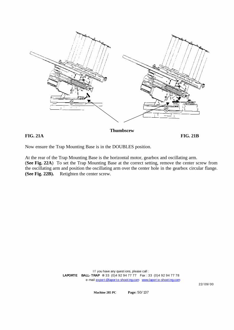
If you have any questions, please call :LAPORTE BALL-TRAP ® 33 (0)4 92 94 77 77 Fax : 33 (0)4 92 94 77 78
e-mail [email protected] www.laporte-shooting.com22/09/00
Machine 285 PC Page: 50/137
ThumbscewFIG. 21A FIG. 21B
Now ensure the Trap Mounting Base is in the DOUBLES position.
At the rear of the Trap Mounting Base is the horizontal motor, gearbox and oscillating arm.(See Fig. 22A) To set the Trap Mounting Base at the correct setting, remove the center screw fromthe oscillating arm and position the oscillating arm over the center hole in the gearbox circular flange.(See Fig. 22B). Retighten the center screw.
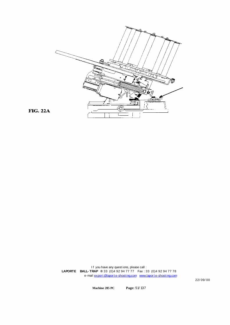
If you have any questions, please call :LAPORTE BALL-TRAP ® 33 (0)4 92 94 77 77 Fax : 33 (0)4 92 94 77 78
e-mail [email protected] www.laporte-shooting.com22/09/00
Machine 285 PC Page: 51/137
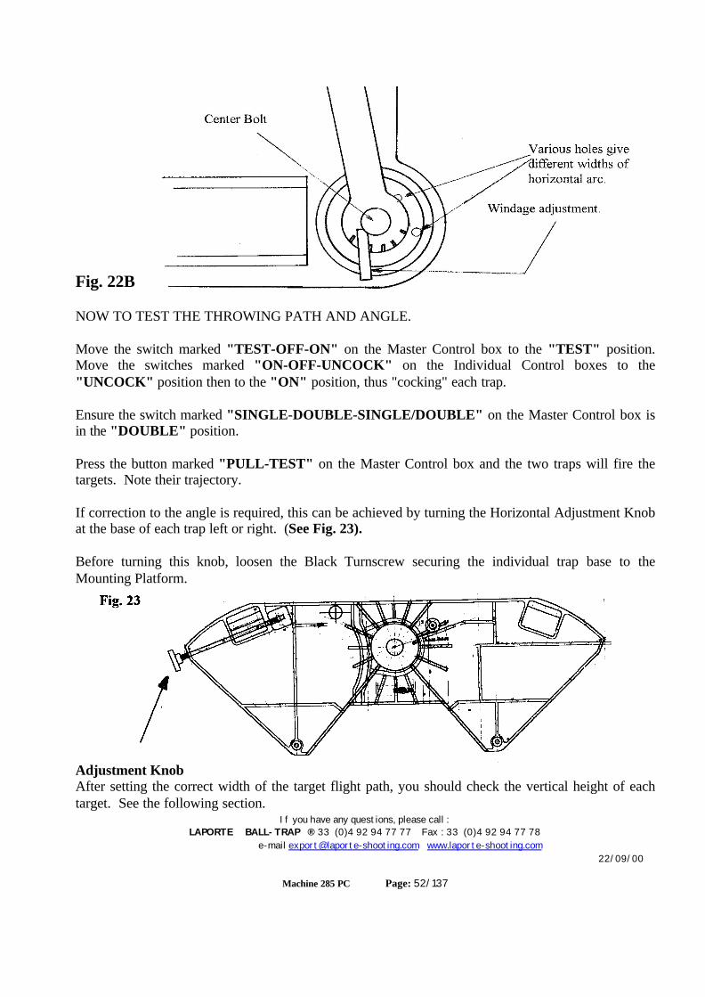
If you have any questions, please call :LAPORTE BALL-TRAP ® 33 (0)4 92 94 77 77 Fax : 33 (0)4 92 94 77 78
e-mail [email protected] www.laporte-shooting.com22/09/00
Machine 285 PC Page: 52/137
Fig. 22B
NOW TO TEST THE THROWING PATH AND ANGLE.
Move the switch marked "TEST-OFF-ON" on the Master Control box to the "TEST" position.Move the switches marked "ON-OFF-UNCOCK" on the Individual Control boxes to the"UNCOCK" position then to the "ON" position, thus "cocking" each trap.
Ensure the switch marked "SINGLE-DOUBLE-SINGLE/DOUBLE" on the Master Control box isin the "DOUBLE" position.
Press the button marked "PULL-TEST" on the Master Control box and the two traps will fire thetargets. Note their trajectory.
If correction to the angle is required, this can be achieved by turning the Horizontal Adjustment Knobat the base of each trap left or right. (See Fig. 23).
Before turning this knob, loosen the Black Turnscrew securing the individual trap base to theMounting Platform.
Adjustment KnobAfter setting the correct width of the target flight path, you should check the vertical height of eachtarget. See the following section.
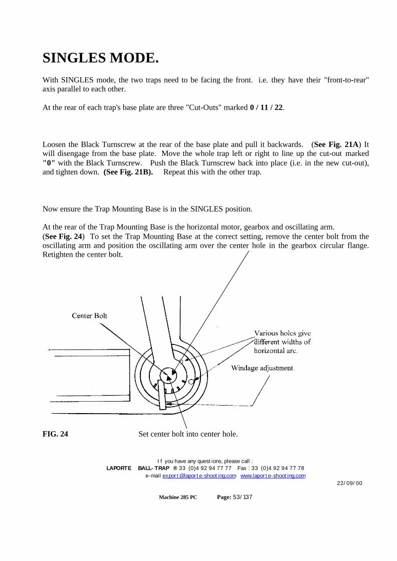
If you have any questions, please call :LAPORTE BALL-TRAP ® 33 (0)4 92 94 77 77 Fax : 33 (0)4 92 94 77 78
e-mail [email protected] www.laporte-shooting.com22/09/00
Machine 285 PC Page: 53/137
SINGLES MODE.With SINGLES mode, the two traps need to be facing the front. i.e. they have their "front-to-rear"axis parallel to each other.
At the rear of each trap's base plate are three "Cut-Outs" marked 0 / 11 / 22.
Loosen the Black Turnscrew at the rear of the base plate and pull it backwards. (See Fig. 21A) Itwill disengage from the base plate. Move the whole trap left or right to line up the cut-out marked"0" with the Black Turnscrew. Push the Black Turnscrew back into place (i.e. in the new cut-out),and tighten down. (See Fig. 21B). Repeat this with the other trap.
Now ensure the Trap Mounting Base is in the SINGLES position.
At the rear of the Trap Mounting Base is the horizontal motor, gearbox and oscillating arm.(See Fig. 24) To set the Trap Mounting Base at the correct setting, remove the center bolt from theoscillating arm and position the oscillating arm over the center hole in the gearbox circular flange.Retighten the center bolt.
FIG. 24 Set center bolt into center hole.

If you have any questions, please call :LAPORTE BALL-TRAP ® 33 (0)4 92 94 77 77 Fax : 33 (0)4 92 94 77 78
e-mail [email protected] www.laporte-shooting.com22/09/00
Machine 285 PC Page: 54/137
NOW TO TEST THE THROWING PATH AND ANGLE.
Move the switch marked "TEST-OFF-ON" on the Master Control box to the "TEST" position.Move the switches marked "ON-OFF-UNCOCK" on the Individual Control boxes to the"UNCOCK" position then to the "ON" position, thus "cocking" each trap.
Ensure the switch marked "SINGLE-DOUBLE-SINGLE/DOUBLE" on the Master Control box isin the "SINGLE" position.
Press the button marked "PULL-TEST" on the Master Control box and the two traps will fire thetargets. Note their trajectory.
If correction to the angle is required, this can be achieved by turning the Horizontal Adjustment Knobat the base of each trap left or right. (See Fig. 23).
Before turning this knob, loosen the Black Turnscrew securing the individual trap base to theMounting Platform.
The two targets are now being thrown on the "same" flight path. We must now adjust the arc thatthey are thrown in!
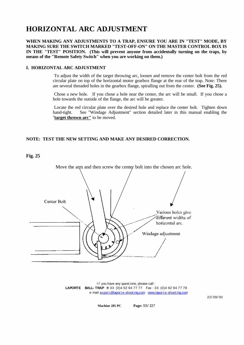
If you have any questions, please call :LAPORTE BALL-TRAP ® 33 (0)4 92 94 77 77 Fax : 33 (0)4 92 94 77 78
e-mail [email protected] www.laporte-shooting.com22/09/00
Machine 285 PC Page: 55/137
HORIZONTAL ARC ADJUSTMENT
WHEN MAKING ANY ADJUSTMENTS TO A TRAP, ENSURE YOU ARE IN "TEST" MODE, BYMAKING SURE THE SWITCH MARKED "TEST-OFF-ON" ON THE MASTER CONTROL BOX ISIN THE "TEST" POSITION. (This will prevent anyone from accidentally turning on the traps, bymeans of the "Remote Safety Switch" when you are working on them.)
I. HORIZONTAL ARC ADJUSTMENT
To adjust the width of the target throwing arc, loosen and remove the center bolt from the redcircular plate on top of the horizontal motor gearbox flange at the rear of the trap. Note: Thereare several threaded holes in the gearbox flange, spiralling out from the center. (See Fig. 25).
Chose a new hole. If you chose a hole near the center, the arc will be small. If you chose ahole towards the outside of the flange, the arc will be greater.
Locate the red circular plate over the desired hole and replace the center bolt. Tighten downhand-tight. See "Windage Adjustment" section detailed later in this manual enabling the"target thrown arc" to be moved.
NOTE: TEST THE NEW SETTING AND MAKE ANY DESIRED CORRECTION.
Fig. 25
Move the arm and then screw the center bolt into the chosen arc hole.
If you have any questions, please call :LAPORTE BALL-TRAP ® 33 (0)4 92 94 77 77 Fax : 33 (0)4 92 94 77 78
e-mail [email protected] www.laporte-shooting.com22/09/00
Machine 285 PC Page: 56/137
Vertical AdjustmentCAUTION: MAKE SURE ALL PERSONNEL ARE CLEAR OF THE TRAP BEFORECONTINUING.
IMPORTANT: BEFORE PROCEEDING WITH THE FOLLOWING ADJUSTMENTS MAKE SURETHE TWO TRAPS ARE SAFE TO WORK ON.
BEFORE PROCEEDING: If in the "ON" mode (i.e. the switch on the Master Control Box is in the "ON"position), move the switch marked "ON-OFF-UNCOCK" on the "Remote Safety Switch" to the"UNCOCK" position and then to the "OFF" position to leave the throwing arms in the safe, "Decocked"position. If in the "TEST" mode (i.e. the switch on the Master Control Box is in the "TEST" position),move the switch marked "ON-OFF-UNCOCK" on the Individual Control boxes to the "UNCOCK"position and then to the "OFF" position to leave the throwing arms in the safe, "Decocked" position. Thenmove the switch marked "TEST-OFF-ON" on the Master Control box to the "OFF" position.
ENSURE the switch marked "TEST-OFF-ON" on the Master Control box is in the "TEST"position thus taking control away from the "Remote Safety Switch" and avoiding anyoneaccidentally turning the traps on while you are working on them.
The adjustment described below is the same for each trap (left or right) and is very easy tounderstand. The drawings shown are for the LEFT trap and should be interpreted in reverse(i.e. mirrored) for the RIGHT trap.
I. VERTICAL ANGLE ADJUSTMENT (See Fig. 26)
Vertical adjustment is achieved by screwing the adjustment rod at the rear right of the trap in orout.
To increase the angle, turn the turnbuckle counter-clockwise.
To decrease the angle, turn the turnbuckle clockwise
. FIG: 26

If you have any questions, please call :LAPORTE BALL-TRAP ® 33 (0)4 92 94 77 77 Fax : 33 (0)4 92 94 77 78
e-mail [email protected] www.laporte-shooting.com22/09/00
Machine 285 PC Page: 57/137
Windage Adjustment
IMPORTANT: BEFORE PROCEEDING WITH THE FOLLOWING ADJUSTMENTS MAKE SURETHE TWO TRAPS ARE SAFE TO WORK ON.
BEFORE PROCEEDING: If in the "ON" mode (i.e. the switch on the Master Control Box is in the "ON"position), move the switch marked "ON-OFF-UNCOCK" on the "Remote Safety Switch" to the"UNCOCK" position and then to the "OFF" position to leave the throwing arms in the safe, "Decocked"position. If in the "TEST" mode (i.e. the switch on the Master Control Box is in the "TEST" position),move the switch marked "ON-OFF-UNCOCK" on the Individual Control boxes to the "UNCOCK"position and then to the "OFF" position to leave the throwing arms in the safe, "Decocked" position. Thenmove the switch marked "TEST-OFF-ON" on the Master Control box to the "OFF" position.
ENSURE the switch marked "TEST-OFF-ON" on the Master Control box is in the "TEST"position thus taking control away from the "Remote Safety Switch" and avoiding anyoneaccidentally turning the traps on while you are working on them.
The adjustment described below is the same for each trap (left or right). The drawings shownare for the LEFT trap and should be interpreted in reverse (i.e. mirrored) for the RIGHT trap.
NOTE: THERE ARE TWO "WINDAGE" ADJUSTMENTS
The first adjusts the "Falling Off" path of the target, i.e. "Does the target veers to oneside or the other when 'settling'?". Windgage 1.
The second allows for "quick" adjustment of the "Target Throwing Arc" should thewind increase or diminish, thus changing the position of the arc where the targetshould drop. Windage 2.

If you have any questions, please call :LAPORTE BALL-TRAP ® 33 (0)4 92 94 77 77 Fax : 33 (0)4 92 94 77 78
e-mail [email protected] www.laporte-shooting.com22/09/00
Machine 285 PC Page: 58/137
WINDAGE 1. When the target is launched from the throwing plate, it should fly in a straight pathand land in a spot directly in front of the trap. If the target veers off to one side or the other, at the end of itsflight path, it is leaving the throwing plate at an incorrect angle.
The flight path of the target can be altered by adjusting the 'windage' on the machine.
At the right side of the trap, is a black windage adjusting knob. (See Fig. 27A).
If the target flys to the 'left', adjust the 'windage' to the right. Turn the black knob counter-clockwise.
If the target flys to the 'right', adjust the 'windage' to the left. Turn the black knob clockwise.
Fig: 27A
Adjust Black Windage Know (Spring Loaded)
WINDAGE 2. The horizontal arc where the target should fall, can be adjusted by moving it to theright or to the left.. When the width of the horizontal arc is set (see section "Horizontal Adjustment"), thetarget will drop within defined set limits. (e.g. 45 degrees to the left of center to 45 degrees to the right ofcenter). However, it is possible that once set the wind at the shooting range could increase or diminish and thearc change (i.e. 30 degrees to the left of center to 60 degrees to the right of center). Instead of resetting theHorizontal Arc, there is a feature on the trap allowing this "Arc" to be moved.
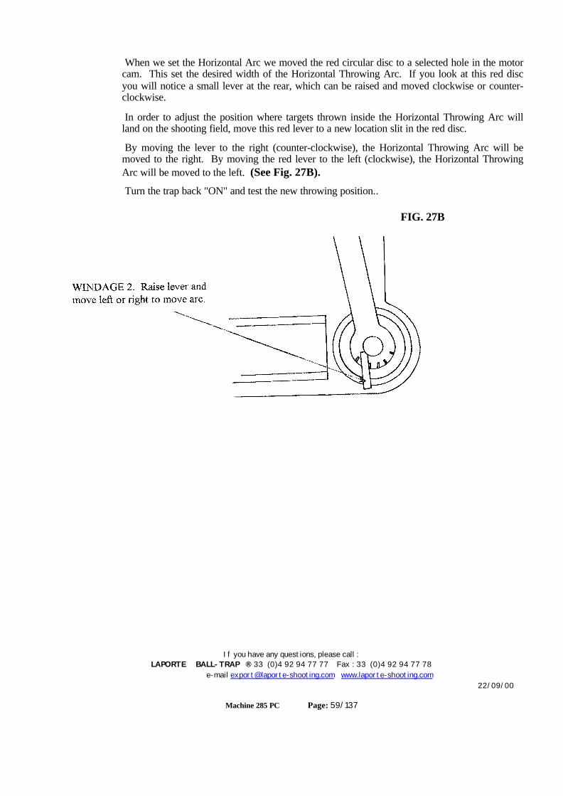
If you have any questions, please call :LAPORTE BALL-TRAP ® 33 (0)4 92 94 77 77 Fax : 33 (0)4 92 94 77 78
e-mail [email protected] www.laporte-shooting.com22/09/00
Machine 285 PC Page: 59/137
When we set the Horizontal Arc we moved the red circular disc to a selected hole in the motorcam. This set the desired width of the Horizontal Throwing Arc. If you look at this red discyou will notice a small lever at the rear, which can be raised and moved clockwise or counter-clockwise.
In order to adjust the position where targets thrown inside the Horizontal Throwing Arc willland on the shooting field, move this red lever to a new location slit in the red disc.
By moving the lever to the right (counter-clockwise), the Horizontal Throwing Arc will bemoved to the right. By moving the red lever to the left (clockwise), the Horizontal ThrowingArc will be moved to the left. (See Fig. 27B).
Turn the trap back "ON" and test the new throwing position..
FIG. 27B

If you have any questions, please call :LAPORTE BALL-TRAP ® 33 (0)4 92 94 77 77 Fax : 33 (0)4 92 94 77 78
e-mail [email protected] www.laporte-shooting.com22/09/00
Machine 285 PC Page: 60/137
Maintenance and Storage
BEFORE PROCEEDING: If in the "ON" mode (i.e. the switch on the Master Control Box is in the "ON"position), move the switch marked "ON-OFF-UNCOCK" on the "Remote Safety Switch" to the"UNCOCK" position and then to the "OFF" position to leave the throwing arms in the safe, "Decocked"position. If in the "TEST" mode (i.e. the switch on the Master Control Box is in the "TEST" position),move the switch marked "ON-OFF-UNCOCK" on the Individual Control boxes to the "UNCOCK"position and then to the "OFF" position to leave the throwing arms in the safe, "Decocked" position. Thenmove the switch marked "TEST-OFF-ON" on the Master Control box to the "OFF" position.
ENSURE the switch marked "TEST-OFF-ON" on the Master Control box is in the "TEST"position thus taking control away from the "Remote Safety Switch" and avoiding anyoneaccidentally turning the traps on while you are working on them.
1. Clean the machine by removing dust and target fragments. A small air-compressor is ideal.
2. Lubricate all moving linkages and parts of the trap using MOBILTAC 375 or equivalent grease as shownbelow. (See Fig. 28).
FIG: 28
3. Check the condition of the throwingarm rubber and replace if there are anycuts, nicks or tears.
4. Check the condition of the targetthrowing plate, and remove any build-up oftarget pitch using a suitable solvent(carburettor cleaner works quite well BUT,do not squirt it in quantity as it dissolvesthe pitch then runs down the trap. If notcleaned immediately the black solutionwill solidify and make a sticky mess to bechipped away at a later date.).Alternatively, fine emery-cloth orsandpaper may be used. Try to keep thethrowing plate in a 'polished' condition.
5. After using the emery-cloth try using "Silver Polish" with wire-wool. It will produce a very smoothsurface. This will help the targets to be launched in a better condition and travel on a more accurateflight path. NOTE: Apart from the "visible" part of the throwing plate, also clean and polish the partunder the carousel and also the "Flipper Plate".
6. To prolong the life of the trap, protect it against weather elements.

If you have any questions, please call :LAPORTE BALL-TRAP ® 33 (0)4 92 94 77 77 Fax : 33 (0)4 92 94 77 78
e-mail [email protected] www.laporte-shooting.com22/09/00
Machine 285 PC Page: 62/137
Trouble Shooting
Remember: There are two Traps and the problems andsolutions apply to either.
Obviously there will be common faults but there may be uniqueproblems that are in the base control or master controller.
CAUTION: BEFORE MAKING ANY CHANGES OR ADJUSTMENTS MAKE SURE THETHROWING ARMS ARE IN THE SAFE, UNCOCKED POSITION.
I. THE COCKING MOTOR WILL NOT START
Electricity is not connected.
The circuit breaker is off or the fuse is blown. Move the switch marked "ON-OFF-DECOCK" on the "Remote Safety Switch" to the "OFF" position. Remove the cover of thecontrol box and see if the BLACK button on the circuit breaker has "Popped". If it has, press itin.. Check the fuses. If the circuit breaker continues to "kick out", or if fuses continue to blow,check all wiring and electrical supply to locate the cause before continuing.
The electric power supply is inadequate. (Check with meter : 100 volt - 130 volt).
Check to electrical connections between the LEFT and RIGHT Control Boxes and theMASTER Control Box, and the Remote Safety Switch. Check all three Control Boxes are“plugged-in” i.e. connected to a power source. (See diagram and explanation on Page 15).
Electrical connections are dirty or loose.
The cocking motor is burnt out.
The cocking motor micro-switch is faulty.
The cocking stud on the gear box is in direct contact with the cocking stud on the throwingarm. The motor will not have sufficient initial power to push the throwing arm into the 'cocked'position, and the circuit breaker will eventually trip. To correct this, turn the "ON-OFF-UNCOCK" switch on the "remote safety switch" to the "OFF" position, then using a smallscrew driver in the hole at the end of the cocking motor shaft, rotate the cocking motor counter-clockwise, so the gear box stud backs in a clockwise (LEFT Trap), counter-clockwise (RIGHTTrap) direction and separates from the cocking arm stud. (1/2" is sufficient).ALTERNATIVELY: This can be achieved by pushing the throwing arm in a counter-clockwise (left trap), clockwise (right trap), direction about 1/2" with the palm of thehand or thumbs Turn power back "ON" and re-try.
The circuit board is "burnt-out". Place your nose near it and see if you can smell thedistinctive "Burnt Plastic" or Ozone smell.
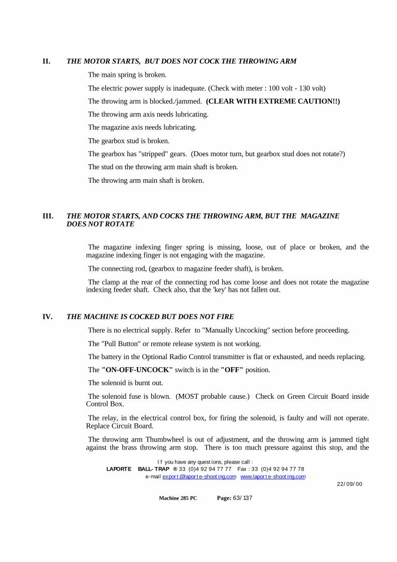
If you have any questions, please call :LAPORTE BALL-TRAP ® 33 (0)4 92 94 77 77 Fax : 33 (0)4 92 94 77 78
e-mail [email protected] www.laporte-shooting.com22/09/00
Machine 285 PC Page: 63/137
II. THE MOTOR STARTS, BUT DOES NOT COCK THE THROWING ARM
The main spring is broken.
The electric power supply is inadequate. (Check with meter : 100 volt - 130 volt)
The throwing arm is blocked./jammed. (CLEAR WITH EXTREME CAUTION!!)
The throwing arm axis needs lubricating.
The magazine axis needs lubricating.
The gearbox stud is broken.
The gearbox has "stripped" gears. (Does motor turn, but gearbox stud does not rotate?)
The stud on the throwing arm main shaft is broken.
The throwing arm main shaft is broken.
III. THE MOTOR STARTS, AND COCKS THE THROWING ARM, BUT THE MAGAZINEDOES NOT ROTATE
The magazine indexing finger spring is missing, loose, out of place or broken, and themagazine indexing finger is not engaging with the magazine.
The connecting rod, (gearbox to magazine feeder shaft), is broken.
The clamp at the rear of the connecting rod has come loose and does not rotate the magazineindexing feeder shaft. Check also, that the 'key' has not fallen out.
IV. THE MACHINE IS COCKED BUT DOES NOT FIRE
There is no electrical supply. Refer to "Manually Uncocking" section before proceeding.
The "Pull Button" or remote release system is not working.
The battery in the Optional Radio Control transmitter is flat or exhausted, and needs replacing.
The "ON-OFF-UNCOCK" switch is in the "OFF" position.
The solenoid is burnt out.
The solenoid fuse is blown. (MOST probable cause.) Check on Green Circuit Board insideControl Box.
The relay, in the electrical control box, for firing the solenoid, is faulty and will not operate.Replace Circuit Board.
The throwing arm Thumbwheel is out of adjustment, and the throwing arm is jammed tightagainst the brass throwing arm stop. There is too much pressure against this stop, and the

If you have any questions, please call :LAPORTE BALL-TRAP ® 33 (0)4 92 94 77 77 Fax : 33 (0)4 92 94 77 78
e-mail [email protected] www.laporte-shooting.com22/09/00
Machine 285 PC Page: 64/137
solenoid cannot release it. Continued efforts to fire the trap, using the Pull-Cord, will cause thecocking motor to build pressure of the throwing arm against the brass throwing arm stop. Asthe solenoid cannot function, the solenoid fuse will eventually blow, followed, possibly by themain circuit-breaker as the cocking motor strains and heats up. CAUTION: At this time thethrowing arm will be pressing against the brass throwing arm stop with TREMENDOUSPRESSURE. When uncocking the trap using the method described in the "ManuallyUncocking" section, be EXTREMELY CAUTIOUS, as the throwing arm will release VERYfast. If there is a target on the throwing plate it will most probably shatter, throwing targetfragments in ALL directions. Refer to the section, "Throwing Arm Removal", detailed at theend of this manual. (Also "Jammed Arm").
The throwing arm is blocked by two targets, or by target fragments. CAUTION: At this timethe throwing arm will be pressing against the targets with TREMENDOUS PRESSURE. Whenuncocking the trap using the method described in the "Manually Uncocking" section, beEXTREMELY CAUTIOUS, as the throwing arm will release VERY fast. The target(s) on thethrowing plate will most probably shatter, throwing target fragments in ALL directions.
The throwing arm is bent or broken and subsequently jammed against some part of the trap,e.g. the throwing plate, the magazine base, the target feeder plate. THIS IS A VERYDANGEROUS CONDITION!! as you cannot "Decock" the machine. The arm will have to beremoved. Follow the procedure detailed at the end of this section "Throwing Arm Removal".
Check to electrical connections between the LEFT and RIGHT Control Boxes and theMASTER Control Box, and the Remote Safety Switch. Check all three Control Boxes are“plugged-in” i.e. connected to a power source. (See diagram and explanation on Page 15).
V. THROWING ARM DOES NOT STOP DECOCKING AND THROWING TARGETS.
The throwing arm micro-switch is broken, and continually causes the cocking motor to run.
The solenoid does not work.
The solenoid trigger spring is disconnected, broken or stretched and does not have sufficienttension to pull the brass throwing arm stop plate back against the solenoid plunger.
The solenoid plunger is damaged and does not slide back into the solenoid housing.
The solenoid plunger is rusty or corroded and stuck in the fire position. NOTE: Never oil orgrease the solenoid plunger. Just keep it clean with alcohol or contact cleaner.
The "PULL" button is stuck, or the cable is damaged.
The throwing arm Thumbwheel is out of adjustment, resulting in the throwing armSLAMMING against the brass throwing arm stop and pushing it out of the way. This results inthe throwing arm not being held and allowed to continually cycle. See section "Throwing ArmThumbwheel Adjustment" detailed earlier in this manual.
The latching stud on the underside of the far end of the throwing arm is missing.
The end of the throwing arm is bent up and the latching stud on the underside of the far end ofthe throwing arm, is by-passing the brass throwing arm stop.
If you have any questions, please call :LAPORTE BALL-TRAP ® 33 (0)4 92 94 77 77 Fax : 33 (0)4 92 94 77 78
e-mail [email protected] www.laporte-shooting.com22/09/00
Machine 285 PC Page: 65/137
The brass throwing arm stop plate on the solenoid is stuck in the 'fired' position and notreturning to rest against the solenoid plunger. It could be damaged, or the rod it pivots on couldbe bent, or it could simply need cleaning and lubricating.
The top catch on the brass throwing arm stop plate (the part that the latching stud, on theunderneath of the far end of the throwing arm, rests against), could be worn, and allows thelatching stud, (on the throwing arm), to slide off and past. Replace or "square-up" with a file.
The relay for 'firing' the solenoid, in the electrical control box, is burnt or faulty and is stuck inthe closed position. This results in the solenoid plunger being continually held out not allowingthe brass throwing arm stop plate to return to its 'home' position. Replace the circuit board.
The solenoid assembly is loose resulting in misalignment of the brass throwing arm stop withthe latching stud on the underneath of the far end of the throwing arm. Check the bolts holdingthis assembly to the underneath of the magazine base.
The Optional Radio Control transmitter is placed somewhere with pressure on the transmitbutton. (e.g. in a tool-box, desk draw, pocket, gun-case etc.) Check by unplugging the RadioControl Receiver from the remote safety switch.
The Optional Radio Control may have its 'code' (dip-switches), set to the same as that beingused on another trap. Check by unplugging the Radio Control Receiver from the "remote safetyswitch".
The Circuit Board in the control box may be "Burnt-Out"
VI. ABNORMAL NOISES
Check all bolts for tightness.
The throwing arm axis (main shaft) needs lubricating.
The mainspring does not have sufficient tension on it, and the coils are touching each other.See section "SPRING TENSION ADJUSTMENT" earlier in this manual.
The gear box is low on oil.
The one way bearing is worn out or damaged.
The one way bearing securing bolt is loose - tighten.
The magazine indexing finger arm is bent or the shaft is tight in its bearing.
The throwing arm is bent and rubbing on the bottom of the magazine assembly or the throwingplate.
The throwing plate is bent causing the throwing arm to rub against it. Use the procedure "ARMHEIGHT CHECK AND ADJUSTMENT", detailed later in this manual, to check the clearanceof the throwing arm with the throwing plate.
The throwing plate may be loose.
The target feeder plate may need lubricating, or be out of adjustment.
The target feeder plate pivot axis, below the feeder plate, may need lubricating.

If you have any questions, please call :LAPORTE BALL-TRAP ® 33 (0)4 92 94 77 77 Fax : 33 (0)4 92 94 77 78
e-mail [email protected] www.laporte-shooting.com22/09/00
Machine 285 PC Page: 66/137
Lack of lubrication on magazine main shaft.
VII. THE TARGETS BREAK IMMEDIATELY WHEN FIRING
The targets were damaged prior to loading.
The targets were damaged during loading.
Mixed targets. (different sizes in same stack i.e. 107-109-110mm)
The throwing arm rubber is damaged or worn.
The throwing arm is bent. It can be straightened without removing it. Check that the rubber isalways at the same distance from the throwing plate. Uncock the throwing arm and disconnectthe mainspring before this inspection and adjustment. See section - "ARM HEIGHT CHECKAND ADJUSTMENT" at the end of this chapter ..
The throwing plate is damaged. Check edges of plate for 'nicks' and file smooth if necessary.
The throwing plate is dirty or has clay target pitch build up resulting in the target not beingpositioned correct at cocking time. Clean with solvent or fine emery cloth.
The throwing plate is loose.
The target positioning finger spring is missing, loose or broken.
The target positioning finger does not move freely. It may need lubricating or the holding boltcould be too tight.
The target positioning finger is bent and rubs on the throwing plate.
The curved target guide at the rear of the throwing plate is out of adjustment or loose, and thetarget is not being guided off the throwing plate correctly. Loosen the 10mm bolt holding theguide to the throwing plate and push the guide, at the bolt end, forward as far as possible, thenre-tighten the bolt.
The machine is leaning too far to one side, or not mounted securely.
The circular safety guard is bent up into target flight path.
Piece of broken target trapped in positioning finger spring.
Feeder plate is badly adjusted and not laying flat when in cocked position.
Feeder plate is badly adjusted and protrudes too high into magazine base when feeding a target.
Safety guard bolts are loose and protrude through magazine base into the target path.
The throwing arm Thumbwheel is out of adjustment and the throwing arm is stopping short ofthe "Cocked" position. The arm is not touching the target, and when the trap is "fired" the armslams into the target and shatters it.
The throwing arm Thumbwheel is out of adjustment and the throwing arm is hitting the brassthrowing arm stop plate too hard. When the trap is "fired", the initial pressure the arm isreleasing onto the target is too great and it shatters the target.

If you have any questions, please call :LAPORTE BALL-TRAP ® 33 (0)4 92 94 77 77 Fax : 33 (0)4 92 94 77 78
e-mail [email protected] www.laporte-shooting.com22/09/00
Machine 285 PC Page: 67/137
The one-way bearing, on the throwing arm main shaft, is internally damaged or shattered, andnot allowing the throwing arm to release in a smooth movement
The one-way bearing, on the throwing arm main-shaft is loose - tighten its bolt and locknut.
The main spring is not adjusted correctly, or the shock absorber is not set correct.
Check ALL reasons in Section VIII below.
VIII. THE TARGETS ARE ALREADY BROKEN WHEN FALLING ON TO THE THROWING PLATE
The targets were damaged prior loading.
The targets were damaged during loading.
The magazine support base is dirty, damaged or bent.
The target pressure roller system is damaged, or badly adjusted (too tight or to loose).
The target pressure rollers do not rotate freely (lubricate if necessary, WD40).
Safety guard bolts are loose and protrude through magazine base plate into target path.
Large rubber rollers on underneath of magazine are damaged.
IX. TWO TARGETS FALL FROM THE MAGAZINE
Mixed targets.
The target pressure roller system is damaged, or badly adjusted.
X. THE TARGETS DO NOT COME OUT OF THE MAGAZINE
The targets are stuck together. Separate them before putting them in the magazine.
Mixed targets.
A magazine cylinder is damaged or bent.
The magazine cylinders are set for the wrong target size and are restricting the verticalmovement of the target stack.
The target roller system is damaged and blocks the last target or prevents the column of targetsfrom moving down.
The magazine base plate is damaged.
The magazine is twisted.
The magazine indexing finger is not engaged with the magazine or its spring is damaged or outof adjustment. Check the bolt holding the finger and spring is not loose or too tight.
The magazine indexing finger needs lubricating and does not easily engage with the magazine.Test by pulling back the arm against the spring pressure then let go. See if it hits the magazine,

If you have any questions, please call :LAPORTE BALL-TRAP ® 33 (0)4 92 94 77 77 Fax : 33 (0)4 92 94 77 78
e-mail [email protected] www.laporte-shooting.com22/09/00
Machine 285 PC Page: 68/137
if it sticks, clean and lubricate.
XI. THE HORIZONTAL OSCILATION DOES NOT WORK.
The Control switches are in the "OFF" position.
The "ON-OFF-UNCOCK" switch on the "Remote Safety Switch" is in the "OFF" position.
There is no power to the trap or the electrical control box.
The fuse has "blown" in the electrical control box. Replace.
The circuit board in the electrical control box is burnt. Check the trap still "Cocks" and"Fires". If it doesn't the board may need replacing.
The grey cable from the electrical control box to the trap may be damaged, or the screw plug(12 volt only) may be loose, or the pins damaged.
The movement motor may be burnt out.
CHECK... Move switch(s) to "DIRECT" mode. See if oscillation works. If it does, but itdoesn't in "TIMER" mode. Check to see if the "PULL" still works the trap i.e. does the"PULL" fire the trap. If it does the circuit board will need replacing as the "Timer" circuit isfaulty and the oscillation only functions in "DIRECT" mode.
If the drive motor appears to be working, (you can hear it), the gearbox may have "stripped"gears and need replacing. Alternatively the gearbox discs may have come loose on the gearboxshaft or the "key" may have fallen out.
When the adjustment to the HORIZONTAL was made, the center bolt which must be locatedinto one of the "spiral" holes around the disc, may have been screwed into the center hole. Thedisc rotates but no movement is transferred to the arm. The MASTER CONTROL Box has the switch marked “"SINGLE-DOUBLE-
SINGLE/DOUBLE" on the Master Control box in the "DOUBLE" position.
XII. TARGETS ARE NOT RELEASED AT THE SAME TIME (DOUBLES MODE).
One of the Traps is turned off.
Uneven Mainspring tension on the Throwing Arm. Check the distance each target is thrownindividually. Uneven tension can produce extra pressure on the Brass release Plate, and/or cancause a faster release.
Both throwing arms are not touching the Brass Release Plate when in the “Cocked” Position.Adjust the micro-switch or Thumbwheel settings. i.e. one could be stopping “short”.
One of the throwing arms may be hitting the Brass Release Plate too hard and binding uponrelease. Check that both Throwing Arms “gently” come into park, just touching the BrassRelease Plates. Each arm should “click” into position, just coming under mainspring tension,resting against the Brass Release Plate, or compressing the spring only about ¼ to ½ inch.Adjust the micro-switch or the Thumbwheel.

If you have any questions, please call :LAPORTE BALL-TRAP ® 33 (0)4 92 94 77 77 Fax : 33 (0)4 92 94 77 78
e-mail [email protected] www.laporte-shooting.com22/09/00
Machine 285 PC Page: 70/137
Throwing Arm Height - Check & Adjustment
IMPORTANT: BEFORE PROCEEDING WITH THE FOLLOWING ADJUSTMENTS MAKE SURETHE TWO TRAPS ARE SAFE TO WORK ON.
BEFORE PROCEEDING: If in the "ON" mode (i.e. the switch on the Master Control Box is in the "ON"position), move the switch marked "ON-OFF-UNCOCK" on the "Remote Safety Switch" to the"UNCOCK" position and then to the "OFF" position to leave the throwing arms in the safe, "Decocked"position.
If in the "TEST" mode (i.e. the switch on the Master Control Box is in the "TEST" position), move the switchmarked "ON-OFF-UNCOCK" on the Individual Control boxes to the "UNCOCK" position and then to the"OFF" position to leave the throwing arms in the safe, "Decocked" position. Then move the switchmarked "TEST-OFF-ON" on the Master Control box to the "OFF" position.
ENSURE the switch marked "TEST-OFF-ON" on the Master Control box is in the "TEST"position thus taking control away from the "Remote Safety Switch" and avoiding anyoneaccidentally turning the traps on while you are working on them.
The adjustments described below are basically the same for each trap, BUT there aredifferences in the way the throwing arm is positioned and made secure; I will thereforedescribe each as an independent trap.
Pay attention to the “direction” of the motor, gearbox and arm. Inthe following sections you are asked to rotate shafts, move arms etc,in a CLOCKWISE or COUNTER-CLOCKWISE direction. Make sure youfollow the guidelines. Any direction will be highlighted to remind you!
e.g. “Turn the motor shaft in a CLOCKWISE direction…”

If you have any questions, please call :LAPORTE BALL-TRAP ® 33 (0)4 92 94 77 77 Fax : 33 (0)4 92 94 77 78
e-mail [email protected] www.laporte-shooting.com22/09/00
Machine 285 PC Page: 71/137
LEFT TRAP1. In order to check to correct height of the throwing arm we need to position the throwing arm across thelaunching plate at approximately the 2:10 position when viewed from the rear of the machine. To do this wemust adopt the same procedures as used for SPRING REMOVAL, by using the gearbox stud to restrict themovement of the throwing arm as it passes through its "Release Position".
In order to do this we must first position the gearbox cocking stud in the 12:00 position to use it as a "break" tocushion the release of the throwing arm through its "Decocking" sequence. Follow the instructions below.
I am assuming you have obeyed the above warning and both traps are "DE-COCKED"!!!!
Using a small screwdriver inserted into the hole at the end of the cocking motor shaft, rotate the cocking motorcounter-clockwise, so the gear box stud rotates in a clockwise direction. Continue doing this until thestud has moved to the 12:00 position out front of the trap.
2. You have now positioned the driving stud, on the gearbox, to a position in front of the driving stud on thethrowing arm. You can now use the cocking motor, as a brake, to slowly release the spring tension on thethrowing arm. NOTE : The throwing arm will only travel in a counter-clockwise direction due to therestriction of the one-way bearing on the throwing arm main-shaft. As the gearbox stud is now "in front", tothe left of, the throwing arm stud, it will restrict the travel of the throwing arm.
3. Push the throwing arm counter-clockwise towards the cocked position, using the palm of the hand oryou thumbs, until it is in the 6:30 "Cocked Position". NOTE: As mention before, the throwing arm will onlytravel counter-clockwise, it cannot be pulled back or reversed!. SO. . . . . . WARNING: Do not wrap yourfingers around the throwing arm, while pushing it, because if you push too fast or too hard, you may trapyour fingers below the magazine base. REMEMBER THE ARM CANNOT BE PULLED BACK!!!
The two studs, mentioned earlier, should now be touching. If the throwing arm did not travel sufficientdistance for it to be in the "6:30" "Cocked" Position, it means the stud on the gearbox is restricting it by beingtoo far clockwise.
Use a small screwdriver in the end of the cocking motor shaft to turn the motor clockwise a few turns. Thestud on the gearbox will move counter-clockwise, thus parting from the throwing arm stud. ONLYROTATE THE COCKING MOTOR A FEW TURNS SO THE TWO STUDS PART ABOUT 1/4". Push thethrowing arm further towards the "Cocked" position. Repeat the above procedure until the throwing arm is inthe "Cocked" 6:30 position. (Do not move studs more than 1/4 inch apart each time).
4. When the throwing arm is in the "6:30" "Cocked" position, it will be under maximum spring tension.We must now use the cocking motor as a brake to slowly release the throwing arm through its "Uncock"procedure. As we are releasing the throwing arm slowly, it will not go past the straight out, 12:00 position tothe "Uncocked" 8:45 position where, after "normal release", it would be held by the action of the "One-wayBearing".
Use a small screwdriver in the end of the cocking motor shaft to turn the motor clockwise a few turns. The
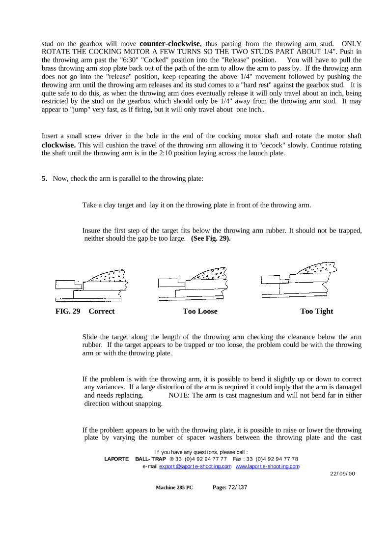
If you have any questions, please call :LAPORTE BALL-TRAP ® 33 (0)4 92 94 77 77 Fax : 33 (0)4 92 94 77 78
e-mail [email protected] www.laporte-shooting.com22/09/00
Machine 285 PC Page: 72/137
stud on the gearbox will move counter-clockwise, thus parting from the throwing arm stud. ONLYROTATE THE COCKING MOTOR A FEW TURNS SO THE TWO STUDS PART ABOUT 1/4". Push inthe throwing arm past the "6:30" "Cocked" position into the "Release" position. You will have to pull thebrass throwing arm stop plate back out of the path of the arm to allow the arm to pass by. If the throwing armdoes not go into the "release" position, keep repeating the above 1/4" movement followed by pushing thethrowing arm until the throwing arm releases and its stud comes to a "hard rest" against the gearbox stud. It isquite safe to do this, as when the throwing arm does eventually release it will only travel about an inch, beingrestricted by the stud on the gearbox which should only be 1/4" away from the throwing arm stud. It mayappear to "jump" very fast, as if firing, but it will only travel about one inch..
Insert a small screw driver in the hole in the end of the cocking motor shaft and rotate the motor shaftclockwise. This will cushion the travel of the throwing arm allowing it to "decock" slowly. Continue rotatingthe shaft until the throwing arm is in the 2:10 position laying across the launch plate.
5. Now, check the arm is parallel to the throwing plate:
Take a clay target and lay it on the throwing plate in front of the throwing arm.
Insure the first step of the target fits below the throwing arm rubber. It should not be trapped,neither should the gap be too large. (See Fig. 29).
FIG. 29 Correct Too Loose Too Tight
Slide the target along the length of the throwing arm checking the clearance below the armrubber. If the target appears to be trapped or too loose, the problem could be with the throwingarm or with the throwing plate.
If the problem is with the throwing arm, it is possible to bend it slightly up or down to correctany variances. If a large distortion of the arm is required it could imply that the arm is damagedand needs replacing. NOTE: The arm is cast magnesium and will not bend far in eitherdirection without snapping.
If the problem appears to be with the throwing plate, it is possible to raise or lower the throwingplate by varying the number of spacer washers between the throwing plate and the cast
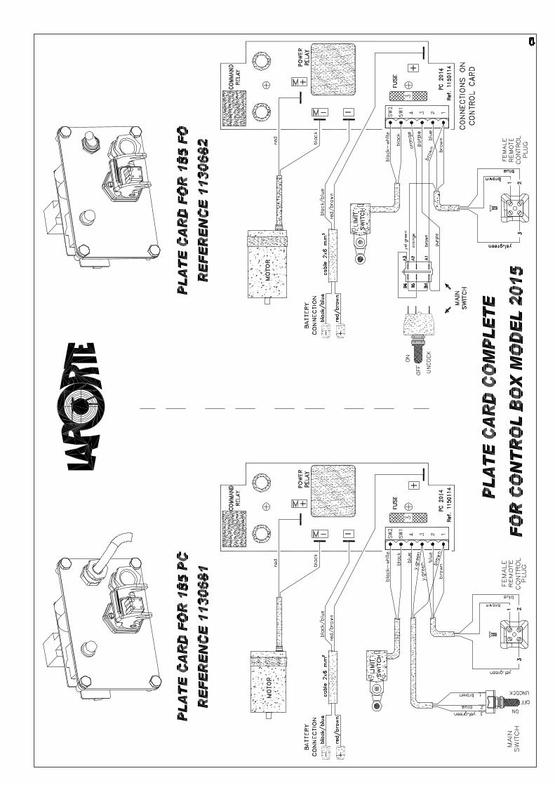
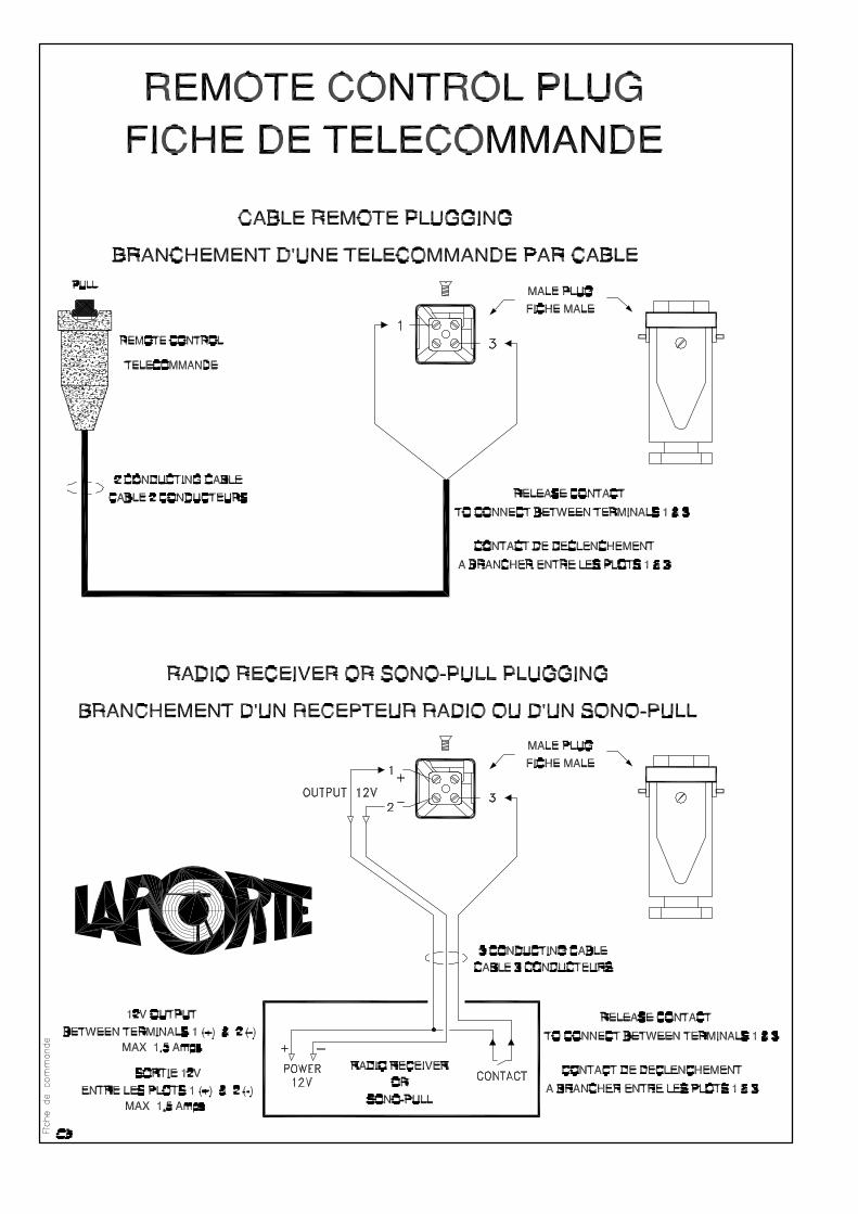


19
13
14
12
14
24
11
21
9
8
18
1
4
16
15
7
5
10
6
6
5
52
3
20
Position PC
22
23
8
17
No. Qu. No.PIÈCE DESCRIPTION1 1 1309057 AXE ARM SOUDE BLANC 2009 320L MAIN SPINDLE WHITE 20092 1 1400068 RD GROWER AZ 08-000 GROWER WASHER AZ 08-0003 1 1400187 VIS TCHC 8Z 08-040 SCREW TCHC 8Z 08-0404 1 1309311 ENTRETOISE SUPPORT BRAS L2 SP14 SPACER SUPPORT THROWING ARM SP145 3 1400038 RONDELLE LARGE 16-040 LARGE WASHER AZ 16-0406 2 1400394 RONDELLE EMB LAITON 23x40x1 BRASS WASHER 23-40-17 1 1400028 ECROU INDES AZ 16-000 LOCK NUT 168 2 1400080 RONDELLE EMBASE 12-24-005 WASHER EMB 12-24-0059 1 1400244 GOUPILLE FENDUE 3.2-025 P PIN SPLIT 3.2-025 P
10 1 1309309 ENTRETOISE 17-22-16 PL SB 12C SP14 A WASHER MAG SUP BASE 12C SP1411 1 1400361 CLAVETTE DISQUE 6-9 WOODRUFF KEY 6x912 1 1307727 BALAIS BRAS LANC D BRUSH ARM13 1 1302070 REGLETTE 185-2001 C ARM RUBBER 185-200114 6 1400139 VIS TH6.8 05-010 SCREW TH6.8 05-01015 1 1309330 L2 SUPPORT BRAS SP14 THROW ARM CON BLOCK L2 SP1416 1 1400025 ECROU INDES AZ 08-000 LOCK NUT 0817 1 1400211 VIS TFHC 1Z 08-040 SCREW TFHC 1Z 08-04018 1 1306096 PALIER IGLI MFM 12x18x12.9 BUSHING IGLIDURE19 1 1309312 BRAS 12C L2AVANT SP14 D THROWING ARM SP1420 1 1302653 TIRANT A OEIL 12-130 + THREADED EYE ROD +21 1 1400009 ECROU HU AZ 12-000 NUT HU AZ 12-00022 1 1309015 DOIGT POSITION BRAS SL06 C CLAY POSITIONING FINGER SP1423 1 1302260 RONDELLE BUTEE AS 2035 WASHER (MAIN SPIN) AS 2035 185 6C24 2 1400343 VIS TFHC 1Z 05-012 SCREW TFHC 1Z 05-012
B
DÉTAIL BECHELLE 1 : 2
PC
Version US placez une rondelle large de 16 en plus sur le bras afin de relever la plaque SB.
POSITION SCREW
USA
C:\
séba
stie
n\T
BALL
TRA
P\TR
AP
185E
201
3\TR
AP
12C
SP1
4 18
5 20
14\S
CH0
4 A
XE A
RMEM
ENT
SP14
\
TRAP 185E 2014 PC 12C SP14SCH04 AXE ARMEMENT SP14 PC 2014 08Note: Certain spare parts are not sold separately
ATTENTION: Certaines pièces ne peuvent êtres vendues séparément.Les pièces précedées du signe + ne sont pas vendables.

17
19
1314
22
11
9
8
20
1
15
21
10
12
14
232
3
164
7
5
6
18
6
5
5
22
TWINLAP : TIRANT A ROULEMENT 1309058 Threaded eye rod
No. Qu. No.PIÈCE DESCRIPTION1 1 1309057 AXE ARM SOUDE BLANC 2009 320L MAIN SPINDLE WHITE 20092 1 1400068 RD GROWER AZ 08-000 GROWER WASHER AZ 08-0003 1 1400187 VIS TCHC 8Z 08-040 SCREW TCHC 8Z 08-0404 1 1309311 ENTRETOISE SUPPORT BRAS L2 SP14 SPACER SUPPORT THROWING ARM SP145 3 1400038 RONDELLE LARGE 16-040 LARGE WASHER AZ 16-0406 2 1400394 RONDELLE EMB LAITON 23x40x1 BRASS WASHER 23-40-17 1 1400028 ECROU INDES AZ 16-000 LOCK NUT 168 1 1400080 RONDELLE EMBASE 12-24-005 WASHER EMB 12-24-0059 1 1400245 GOUPILLE FENDUE 3.2-032 P PIN SPLIT 3.2-032 P
10 1 1400009 ECROU HU AZ 12-000 NUT HU AZ 12-00011 1 1400361 CLAVETTE DISQUE 6-9 WOODRUFF KEY 6x912 1 1307727 BALAIS BRAS LANC D BRUSH ARM13 1 1302070 REGLETTE 185-2001 C ARM RUBBER 185-200114 6 1400139 VIS TH6.8 05-010 SCREW TH6.8 05-01015 1 1309330 L2 SUPPORT BRAS SP14 THROW ARM CON BLOCK L2 SP1416 1 1400025 ECROU INDES AZ 08-000 LOCK NUT 0817 1 1400211 VIS TFHC 1Z 08-040 SCREW TFHC 1Z 08-04018 1 1309309 ENTRETOISE 17-22-16 PL SB 12C SP14 A WASHER MAG SUP BASE 12C SP1419 1 1309345 BRAS LANCEMENT SP14 581 E THROWING ARM SP1420 1 1306096 PALIER IGLI MFM 12x18x12.9 BUSHING IGLIDURE21 1 1302653 TIRANT A OEIL 12-130 + THREADED EYE ROD +22 2 1400343 VIS TFHC 1Z 05-012 SCREW TFHC 1Z 05-01223 1 1309381 DOIGT POSITION BRAS 581 SP14 A CLAY POSITIONING FINGER (ARM) SP14
C:\
séba
stie
n\T
BALL
TRA
P\TR
AP
185E
201
3\TR
AP
12C
SP1
4 58
1 20
15\S
CH0
4 A
XE A
RMEM
ENT
SP14
581
\
TRAP 581E 2014 PC 12C SP14SCH04 AXE ARMEMENT PC SP14 581 2015 08
Note: Certain spare parts are not sold separately
ATTENTION: Certaines pièces ne peuvent êtres vendues séparément.Les pièces précedées du signe + ne sont pas vendables.
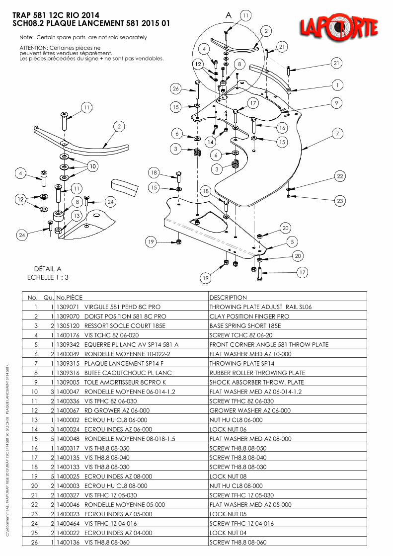
A
21
1
7
22
23
9
16
15
18
20
5
20
17
18
15
19
19
3
6
17
6
3
15
26
11
2
8
4
1212
1414
21
No. Qu. No.PIÈCE DESCRIPTION1 1 1309071 VIRGULE 581 PEHD 8C PRO THROWING PLATE ADJUST RAIL SL062 1 1309070 DOIGT POSITION 581 8C PRO CLAY POSITION FINGER PRO3 2 1305120 RESSORT SOCLE COURT 185E BASE SPRING SHORT 185E4 1 1400176 VIS TCHC 8Z 06-020 SCREW TCHC 8Z 06-205 1 1309342 EQUERRE PL LANC AV SP14 581 A FRONT CORNER ANGLE 581 THROW PLATE6 2 1400049 RONDELLE MOYENNE 10-022-2 FLAT WASHER MED AZ 10-0007 1 1309315 PLAQUE LANCEMENT SP14 F THROWING PLATE SP148 1 1309316 BUTEE CAOUTCHOUC PL LANC RUBBER ROLLER THROWING PLATE9 1 1309005 TOLE AMORTISSEUR 8CPRO K SHOCK ABSORBER THROW. PLATE
10 3 1400047 RONDELLE MOYENNE 06-014-1.2 FLAT WASHER MED AZ 06-014-1.211 2 1400336 VIS TFHC 8Z 06-030 SCREW TFHC 8Z 06-03012 2 1400067 RD GROWER AZ 06-000 GROWER WASHER AZ 06-00013 1 1400002 ECROU HU CL8 06-000 NUT HU CL8 06-00014 3 1400024 ECROU INDES AZ 06-000 LOCK NUT 0615 5 1400048 RONDELLE MOYENNE 08-018-1.5 FLAT WASHER MED AZ 08-00016 1 1400317 VIS TH8.8 08-050 SCREW TH8.8 08-05017 2 1400135 VIS TH8.8 08-040 SCREW TH8.8 08-04018 2 1400133 VIS TH8.8 08-030 SCREW TH8.8 08-03019 5 1400025 ECROU INDES AZ 08-000 LOCK NUT 0820 2 1400003 ECROU HU CL8 08-000 NUT HU CL8 08-00021 2 1400327 VIS TFHC 1Z 05-030 SCREW TFHC 1Z 05-03022 2 1400046 RONDELLE MOYENNE 05-000 FLAT WASHER MED AZ 05-000 23 2 1400023 ECROU INDES AZ 05-000 LOCK NUT 0524 2 1400464 VIS TFHC 1Z 04-016 SCREW TFHC 1Z 04-01625 2 1400022 ECROU INDES AZ 04-000 LOCK NUT 0426 1 1400136 VIS TH8.8 08-060 SCREW TH8.8 08-060
DÉTAIL AECHELLE 1 : 3
101010
11
2
13
8
11
24
4
1212
24
C:\
séba
stie
n\T
BALL
TRA
P\TR
AP
185E
201
3\TR
AP
12C
SP1
4 58
1 20
15\S
CH0
8 P
LAQ
UE L
AN
CEM
ENT
SP14
581
\
TRAP 581 12C RIO 2014SCH08.2 PLAQUE LANCEMENT 581 2015 01
Note: Certain spare parts are not sold separately
ATTENTION: Certaines pièces ne peuvent êtres vendues séparément.Les pièces précedées du signe + ne sont pas vendables.
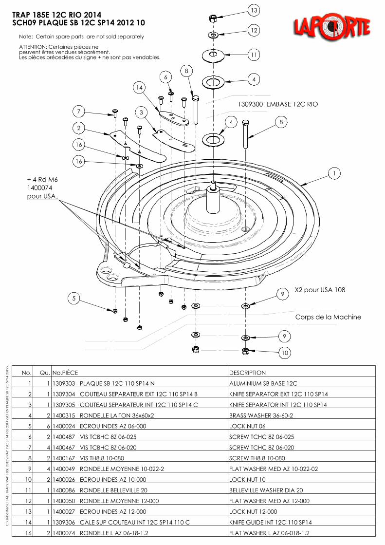
10
9
5
2
7 3
14
84
86 4
11
12
13
Corps de la Machine
1309300 EMBASE 12C RIO
9
+ 4 Rd M6 1400074 pour USA
1309392 COUTEAU EXT USA1309393 COUTEAU INT USA
X2 pour USA 108
X2 Plateau USA 108
16
16
1
...
No. Qu. No.PIÈCE DESCRIPTION
1 1 1309303 PLAQUE SB 12C 110 SP14 N ALUMINIUM SB BASE 12C
2 1 1309304 COUTEAU SEPARATEUR EXT 12C 110 SP14 B KNIFE SEPARATOR EXT 12C 110 SP14
3 1 1309305 COUTEAU SEPARATEUR INT 12C 110 SP14 C KNIFE SEPARATOR INT 12C 110 SP14
4 2 1400315 RONDELLE LAITON 36x60x2 BRASS WASHER 36-60-2
5 6 1400024 ECROU INDES AZ 06-000 LOCK NUT 06
6 2 1400487 VIS TCBHC 8Z 06-025 SCREW TCHC 8Z 06-025
7 4 1400467 VIS TCBHC 8Z 06-020 SCREW TCHC 8Z 06-020
8 2 1400167 VIS TH8.8 10-080 SCREW TH8.8 10-080
9 4 1400049 RONDELLE MOYENNE 10-022-2 FLAT WASHER MED AZ 10-022-02
10 2 1400026 ECROU INDES AZ 10-000 LOCK NUT 10
11 1 1400086 RONDELLE BELLEVILLE 20 BELLEVILLE WASHER DIA 20
12 1 1400050 RONDELLE MOYENNE 12-000 FLAT WASHER MED AZ 12-000
13 1 1400027 ECROU INDES AZ 12-000 LOCK NUT 12-000
14 1 1309306 CALE SUP COUTEAU INT 12C SP14 110 C KNIFE GUIDE INT 12C 110 SP14
16 2 1400074 RONDELLE L AZ 06-18-1.2 FLAT WASHER L AZ 06-018-1.2
C:\
séba
stie
n\T
BALL
TRA
P\TR
AP
185E
201
3\TR
AP
12C
SP1
4 18
5 20
14\S
CH0
9 PL
AQ
UE S
B 12
C S
P14
2012
\
TRAP 185E 12C RIO 2014SCH09 PLAQUE SB 12C SP14 2012 10
Note: Certain spare parts are not sold separately
ATTENTION: Certaines pièces ne peuvent êtres vendues séparément.Les pièces précedées du signe + ne sont pas vendables.
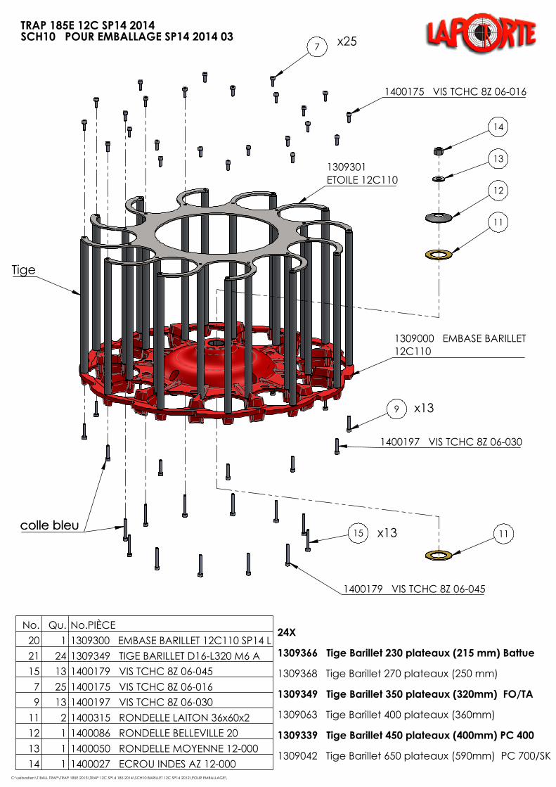
9
15
24X 1309366 Tige Barillet 230 plateaux (215 mm) Battue
1309368 Tige Barillet 270 plateaux (250 mm)
1309349 Tige Barillet 350 plateaux (320mm) FO/TA
1309063 Tige Barillet 400 plateaux (360mm)
1309339 Tige Barillet 450 plateaux (400mm) PC 400 1309042 Tige Barillet 650 plateaux (590mm) PC 700/SK
x13
x25
x13 11
14
13
12
11
1400175 VIS TCHC 8Z 06-016
1400197 VIS TCHC 8Z 06-030
1400179 VIS TCHC 8Z 06-045
colle bleu colle bleu
7
1309000 EMBASE BARILLET 12C110
1309301 ETOILE 12C110
Tige
No. Qu. No.PIÈCE20 1 1309300 EMBASE BARILLET 12C110 SP14 L21 24 1309349 TIGE BARILLET D16-L320 M6 A15 13 1400179 VIS TCHC 8Z 06-0457 25 1400175 VIS TCHC 8Z 06-0169 13 1400197 VIS TCHC 8Z 06-030
11 2 1400315 RONDELLE LAITON 36x60x212 1 1400086 RONDELLE BELLEVILLE 2013 1 1400050 RONDELLE MOYENNE 12-00014 1 1400027 ECROU INDES AZ 12-000
C:\sébastien\T BALL TRAP\TRAP 185E 2013\TRAP 12C SP14 185 2014\SCH10 BARILLET 12C SP14 2012\POUR EMBALLAGE\
TRAP 185E 12C SP14 2014SCH10 POUR EMBALLAGE SP14 2014 03Note: Certain spare parts are not sold separately
ATTENTION: Certaines pièces ne peuvent êtres vendues séparément.Les pièces précedées du signe + ne sont pas vendables.

16
15
14
18
17
2
1
10
13
12
3
23
20192221698
24
25
26
No. Qu. No.PIÈCE DESCRIPTION1 1 1305390 SOCLE EMBASE C BASE SOCLE 285 TWINLAP2 1 1304740 AXE SOCLE LOW BASE A AXIS LOW BASE3 1 1305260 EXCENT MVT HORIZ A OFF CENTER HOR MVT 185LB6 1 1500889 RED DOUBLE HORI HF40 260 56 B14 GEARBOX 1/260 DTL LB8 1 1500891 MOTEUR TOURELLE 12V 2013 VERTICAL MOTOR 12V GB 20139 1 1308305 RONDELLE B56 RED TRAMEC A WASHER RED TRAM B56
10 1 1304745 CONTRE PLAQUE BASE TAHLB AXIS PLATE LOW BASE 18512 1 1305555 SUPPORT EMBASE 285 BASE SUPPORT 28513 4 1400354 VIS TFHC 8.8 M10-030 SCREW TFHC 10-03014 1 1304825 BOUCHON PROTECTION AXE 185LB A WASHER PIVOTING PLATE15 1 1400047 RONDELLE MOYENNE 06-014-1.2 FLAT WASHER MED AZ 06-014-1.216 1 1400176 VIS TCHC 8Z 06-020 SCREW TCHC 8Z 06-2017 1 1304780 ROULEMENT 6011 EE 55x90x18 BEARING 6011 2RS 185LB18 1 1302305 ROULEMENT 6010 EE 50x80x16 ROLLER BEARING 6010 2RS19 4 1400046 RONDELLE MOYENNE 05-000 FLAT WASHER MED AZ 05-000 20 4 1400141 VIS TH6.8 05-020 SCREW TH6.8 05-02021 1 1400314 RONDELLE LARGE 06-025-1 LARGE WASHER AZ 06-018-122 1 1400181 VIS TCHC 8Z 06-055 SCREW TCHC AZ 06-05523 4 1400207 VIS TFHC 1Z 06-020 SCREW TFHC 1Z 06-02024 2 1400160 VIS TH8.8 12-060 SCREW TH8.8 12-06025 2 1400050 RONDELLE MOYENNE 12-000 FLAT WASHER MED AZ 12-00026 2 1400027 ECROU INDES AZ 12-000 LOCK NUT 12-000
C:\
séba
stie
n\T
BALL
TRA
P\TR
AP
185E
199
0 10
CO
LON
NES
\TRA
P 58
1 pl
fix\
TRA
P 28
5 TW
INLA
P\
285 TWINLAP 12C RIO 2014S ENS TW01 PLATEAU 285 2015 04
Note: Certain spare parts are not sold separately
ATTENTION: Certaines pièces ne peuvent êtres vendues séparément.Les pièces précedées du signe + ne sont pas vendables.
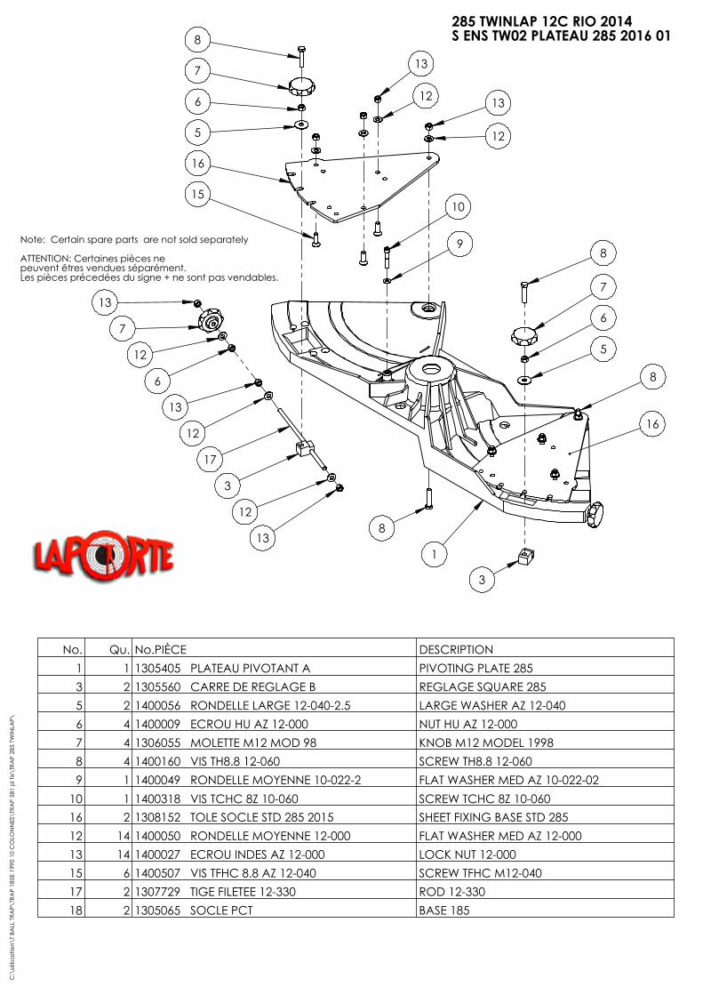
8
7
6
5
13
12
16
1510
9
13
7
12
6
13
12
17
3
12
138
3
16
8
5
6
7
8
12
13
1
No. Qu. No.PIÈCE DESCRIPTION1 1 1305405 PLATEAU PIVOTANT A PIVOTING PLATE 2853 2 1305560 CARRE DE REGLAGE B REGLAGE SQUARE 2855 2 1400056 RONDELLE LARGE 12-040-2.5 LARGE WASHER AZ 12-0406 4 1400009 ECROU HU AZ 12-000 NUT HU AZ 12-0007 4 1306055 MOLETTE M12 MOD 98 KNOB M12 MODEL 19988 4 1400160 VIS TH8.8 12-060 SCREW TH8.8 12-0609 1 1400049 RONDELLE MOYENNE 10-022-2 FLAT WASHER MED AZ 10-022-02
10 1 1400318 VIS TCHC 8Z 10-060 SCREW TCHC 8Z 10-06016 2 1308152 TOLE SOCLE STD 285 2015 SHEET FIXING BASE STD 28512 14 1400050 RONDELLE MOYENNE 12-000 FLAT WASHER MED AZ 12-00013 14 1400027 ECROU INDES AZ 12-000 LOCK NUT 12-00015 6 1400507 VIS TFHC 8.8 AZ 12-040 SCREW TFHC M12-04017 2 1307729 TIGE FILETEE 12-330 ROD 12-33018 2 1305065 SOCLE PCT BASE 185
C:\
séba
stie
n\T
BALL
TRA
P\TR
AP
185E
199
0 10
CO
LON
NES
\TRA
P 58
1 pl
fix\
TRA
P 28
5 TW
INLA
P\
285 TWINLAP 12C RIO 2014S ENS TW02 PLATEAU 285 2016 01
Note: Certain spare parts are not sold separately
ATTENTION: Certaines pièces ne peuvent êtres vendues séparément.Les pièces précedées du signe + ne sont pas vendables.
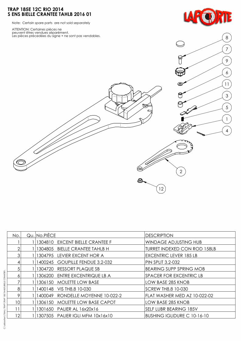
7
8
9
6
11
3
5
4
1
12
2
No. Qu. No.PIÈCE DESCRIPTION1 1 1304810 EXCENT BIELLE CRANTEE F WINDAGE ADJUSTING HUB2 1 1304805 BIELLE CRANTEE TAHLB H TURRET INDEXED CON ROD 158LB3 1 1304795 LEVIER EXCENT HOR A EXCENTRIC LEVER 185 LB4 1 1400245 GOUPILLE FENDUE 3.2-032 PIN SPLIT 3.2-0325 1 1304720 RESSORT PLAQUE SB BEARING SUPP SPRING MOB6 1 1306200 ENTRE EXCENTRIQUE LB A SPACER FOR EXCENTRIC LB7 1 1306150 MOLETTE LOW BASE LOW BASE 285 KNOB8 1 1400148 VIS TH8.8 10-030 SCREW TH8.8 10-0309 1 1400049 RONDELLE MOYENNE 10-022-2 FLAT WASHER MED AZ 10-022-02
10 1 1306150 MOLETTE LOW BASE CAPOT LOW BASE 285 KNOB11 1 1301650 PALIER AL 16x20x16 SELF LUBR BEARING 185V12 1 1307505 PALIER IGLI MFM 10x16x10 BUSHING IGLIDURE C 10-16-10
C:\
séba
stie
n\T
BALL
TRA
P\TR
AP
185
TAHL
B\BI
ELLE
CRA
NTE
E\
TRAP 185E 12C RIO 2014S ENS BIELLE CRANTEE TAHLB 2016 01
Note: Certain spare parts are not sold separately
ATTENTION: Certaines pièces ne peuvent êtres vendues séparément.Les pièces précedées du signe + ne sont pas vendables.

ECLATEES TWINVERT 16
2016 05 05
CONFIDENTIEL Ce plan est la propriété de la Sté LAPORTE, 371 Chemin des Prés 06 410 BIOT FRANCE Tel: +33 (0)4 93 65 77 77 Fax:+33 (0)4 93 65 77 78 [email protected] [email protected] et ne peut être reproduit ou communiqué sans son autorisation.
TIGES BARILLET 320 MM M6 TIGES BARILLET 400 MM M6
PUSH
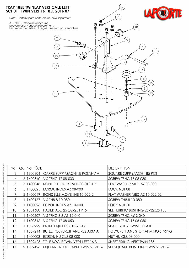
6
5
10
3
17
78
9
7
10
17
16
4
11
4
4
44
12
135
156
14
No. Qu. No.PIÈCE DESCRIPTION3 1 1300806 CARRE SUPP MACHINE PCTAHV A SQUARE SUPP MACH 185 PCT4 6 1400340 VIS TFHC 1Z 08-030 SCREW TFHC 1Z 08-0305 5 1400048 RONDELLE MOYENNE 08-018-1.5 FLAT WASHER MED AZ 08-0006 5 1400025 ECROU INDES AZ 08-000 LOCK NUT 087 2 1400049 RONDELLE MOYENNE 10-022-2 FLAT WASHER MED AZ 10-022-028 1 1400167 VIS TH8.8 10-080 SCREW TH8.8 10-0809 1 1400026 ECROU INDES AZ 10-000 LOCK NUT 10
10 2 1301680 PALIER ALC 25x32x25 FP15 SELF LUBRIC BUSHING 25x32x25 18511 1 1400507 VIS TFHC 8.8 AZ 12-040 SCREW TFHC M12-04012 1 1400316 VIS TFHC 1Z 08-050 SCREW TFHC 1Z 08-05013 1 1308229 ENTRE EQU PLSB 10-25-17 SPACER THROWING PLATE14 1 1307214 BUTEE POLYURETHANE RES ARM A POLYURETHANE STOP ARMING SPRING15 1 1400003 ECROU HU CL8 08-000 NUT HU CL8 08-00016 1 1309425 TOLE SOCLE TWIN VERT LEFT 16 B SHEET FIXING VERT TWIN 185 17 2 1309426 EQUERRE RENF CARRE TWIN VERT 16 SET SQUARE REINFORC TWIN VERT 16
C:\
séba
stie
n\T
BALL
TRA
P\TR
AP
185E
199
0 10
CO
LON
NES
\TRA
P 58
1 pl
fix\
TRA
P 28
5 TW
INLA
P\TR
AP
185E
TW
IN L
EFT
VER
TICA
L\
TRAP 185E TWINLAP VERTICALE LEFTSCH01 TWIN VERT 16 185E 2016 07
Note: Certain spare parts are not sold separately
ATTENTION: Certaines pièces ne peuvent êtres vendues séparément.Les pièces précedées du signe + ne sont pas vendables.
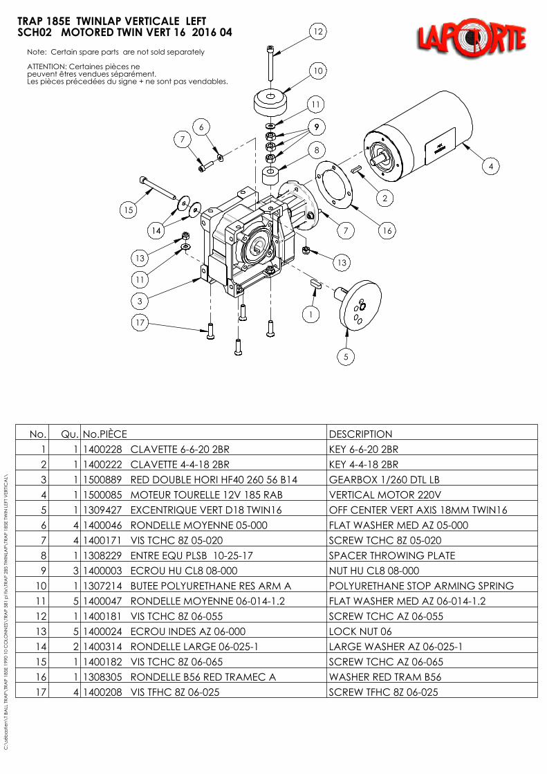
12
10
11
999
8
16
2
4
13
7
1
5
67
1414
15
13
11
17
3
No. Qu. No.PIÈCE DESCRIPTION1 1 1400228 CLAVETTE 6-6-20 2BR KEY 6-6-20 2BR2 1 1400222 CLAVETTE 4-4-18 2BR KEY 4-4-18 2BR3 1 1500889 RED DOUBLE HORI HF40 260 56 B14 GEARBOX 1/260 DTL LB4 1 1500085 MOTEUR TOURELLE 12V 185 RAB VERTICAL MOTOR 220V5 1 1309427 EXCENTRIQUE VERT D18 TWIN16 OFF CENTER VERT AXIS 18MM TWIN166 4 1400046 RONDELLE MOYENNE 05-000 FLAT WASHER MED AZ 05-000 7 4 1400171 VIS TCHC 8Z 05-020 SCREW TCHC 8Z 05-0208 1 1308229 ENTRE EQU PLSB 10-25-17 SPACER THROWING PLATE9 3 1400003 ECROU HU CL8 08-000 NUT HU CL8 08-000
10 1 1307214 BUTEE POLYURETHANE RES ARM A POLYURETHANE STOP ARMING SPRING11 5 1400047 RONDELLE MOYENNE 06-014-1.2 FLAT WASHER MED AZ 06-014-1.212 1 1400181 VIS TCHC 8Z 06-055 SCREW TCHC AZ 06-05513 5 1400024 ECROU INDES AZ 06-000 LOCK NUT 0614 2 1400314 RONDELLE LARGE 06-025-1 LARGE WASHER AZ 06-025-115 1 1400182 VIS TCHC 8Z 06-065 SCREW TCHC AZ 06-06516 1 1308305 RONDELLE B56 RED TRAMEC A WASHER RED TRAM B5617 4 1400208 VIS TFHC 8Z 06-025 SCREW TFHC 8Z 06-025
C:\
séba
stie
n\T
BALL
TRA
P\TR
AP
185E
199
0 10
CO
LON
NES
\TRA
P 58
1 pl
fix\
TRA
P 28
5 TW
INLA
P\TR
AP
185E
TW
IN L
EFT
VER
TICA
L\
TRAP 185E TWINLAP VERTICALE LEFTSCH02 MOTORED TWIN VERT 16 2016 04
Note: Certain spare parts are not sold separately
ATTENTION: Certaines pièces ne peuvent êtres vendues séparément.Les pièces précedées du signe + ne sont pas vendables.

2
13
14
12
11
10
7
8
9
1
15
2
6
2
5
3
4
No. Qu. No.PIÈCE DESCRIPTION1 1 1400026 ECROU INDES AZ 10-000 LOCK NUT 10 2 3 1400049 RONDELLE MOYENNE 10-022-2 FLAT WASHER MED AZ 10-022-023 1 1400150 VIS TH8.8 10-050 SCREW TH6.8 10-0504 1 1306150 MOLETTE LOW BASE CAPOT LOW BASE 285 KNOB5 1 1306150 MOLETTE LOW BASE LOW BASE 285 KNOB6 1 1305160 ROTULE TESC CF10 M10 EYE ROD SI10E 185E THREAD7 1 1400008 ECROU HU AZ 10-000 NUT HU AZ 10-0008 1 1305355 TIGE FILETEE LEFT 10-080 GAUCHE LEFT THREADED ROD 10-0909 1 1305350 TIGE FILETEE 10-080 THREADED ROD 10-07510 1 1309428 AXE REGLABLE MVT VERT TWIN 16 ADJUSTING AXIS 185E11 1 1400042 RONDELLE EVENTAIL 10 WASHER BATWING AZ 04-00012 1 1305155 ECROU BLOCAGE VERIN LEFT JACK LOCK NUT 185E13 1 1304775 ROTULE TESC LEFT CF10 M10 EYE ROD SIL 10E LEFT 185LB14 1 1400148 VIS TH8.8 10-030 SCREW TH8.8 10-03015 1 1306080 ENTR AXE REGL 10 12 12 A SPACER FOR ADJUSTING AXIS MOD 98C
:\sé
bast
ien\
T BA
LL T
RAP\
TRA
P 18
5E 2
004
12 C
OLO
NN
ES\S
CH2
.2 A
XE R
EGLA
BLE
185
MO
D 9
8\
TRAP 185E TWINLAP VERTICALE LEFTSCH03 AXE REGLABLE AV TWIN VERT 16 2016 03
Note: Certain spare parts are not sold separately
ATTENTION: Certaines pièces ne peuvent êtres vendues séparément.Les pièces précedées du signe + ne sont pas vendables.

812
111
2
3
910
92
4
57
2
5
5
8
26
2
8
1309307
No. Qu. No.PIÈCE DESCRIPTION1 1 1309429 PLAQUE FIXATION TWINVERT16 TRAP FIXING PLATE TWINVERT16 1852 5 1400050 RONDELLE MOYENNE 12-000 FLAT WASHER MED AZ 12-0003 1 1400159 VIS TH8.8 12-050 SCREW TH8.8 12-0504 1 1400320 VIS TH8.8 12-080 SCREW TH8.8 12-0805 3 1400056 RONDELLE LARGE 12-040-2.5 LARGE WASHER AZ 12-0406 1 1309415 RESSORT SOCLE COURT RENF BASE SPRING SHORT 185 E7 1 1309137 RESSORT SOCLE LONG A BASE SPRING LONG 185E8 3 1400027 ECROU INDES AZ 12-000 LOCK NUT 12-0009 2 1302265 RONDELLE BUTEE AS 25-42-1 THRUST WASHER AS 25-42-1
10 1 1400249 CIRCLIPS ARBRE 25 CIRCLIPS OUTSIDE DIA2511 1 1305125 ENTRE ROTULE CORPS SOCLE A EYE ROD SPACER BODY BASE12 1 1400364 RONDELLE ETROITE 12-018-02 WASHER AZ 12-018-02
C:\
séba
stie
n\T
BALL
TRA
P\TR
AP
185E
199
0 10
CO
LON
NES
\TRA
P 58
1 pl
fix\
TRA
P 28
5 TW
INLA
P\TR
AP
185E
TW
IN L
EFT
VER
TICA
L\
TRAP 185E TWINLAP VERTICALE LEFTSCH04 PLAQUE FIX MACH TWIN VERT 16
Note: Certain spare parts are not sold separately
ATTENTION: Certaines pièces ne peuvent êtres vendues séparément.Les pièces précedées du signe + ne sont pas vendables.
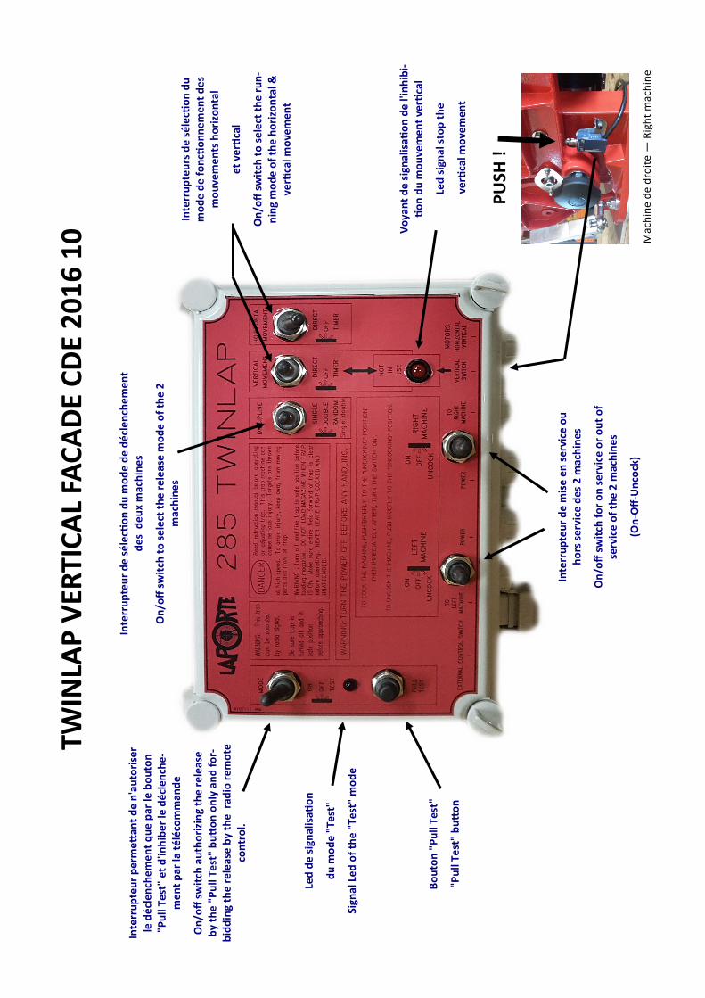
TWIN
LAP
VER
TIC
AL
FAC
AD
E C
DE
20
16
10
Vo
yan
t d
e s
ign
alis
atio
n d
e l'
inh
ibi-
tio
n d
u m
ou
vem
en
t ve
rtica
l
Led
sig
nal
sto
p t
he
ve
rtica
l mo
vem
en
t
Inte
rru
pte
urs
de
sé
lecti
on
du
m
od
e d
e f
on
ctio
nn
em
en
t d
es
mo
uve
me
nts
ho
rizo
nta
l
et
verti
cal
On
/off
sw
itch
to
se
lect
th
e r
un
-n
ing
mo
de
of
the
ho
rizo
nta
l &
verti
cal m
ove
me
nt
Inte
rru
pte
ur
de
sé
lecti
on
du
mo
de
de
dé
cle
nch
em
ent
de
s d
eu
x m
ach
ine
s
On
/off
sw
itch
to
se
lect
th
e r
ele
ase
mo
de
of
the
2
mac
hin
es
Inte
rru
pte
ur
pe
rme
ttan
t d
e n
'au
tori
ser
le d
écl
en
che
me
nt
qu
e p
ar le
bo
uto
n
"Pu
ll Te
st"
et
d'in
hib
er
le d
écl
en
che
-m
en
t p
ar la
té
léco
mm
and
e
On
/off
sw
itch
au
tho
rizi
ng
the
rele
ase
b
y th
e "
Pu
ll Te
st"
bu
tto
n o
nly
an
d f
or-
bid
din
g th
e r
ele
ase
by
the
rad
io r
em
ote
co
ntr
ol.
Led
de
sig
nal
isati
on
du
mo
de
"Te
st"
Sign
al L
ed
of
the
"Te
st"
mo
de
Bo
uto
n "
Pu
ll Te
st"
"Pu
ll Te
st"
bu
tto
n
Inte
rru
pte
ur
de
mis
e e
n s
erv
ice
ou
h
ors
se
rvic
e d
es
2 m
ach
ine
s
On
/off
sw
itch
fo
r o
n s
erv
ice
or
ou
t o
f se
rvic
e o
f th
e 2
mac
hin
es
(On
-Off
-Un
cock
)
PU
SH !
Mac
hin
e d
e d
roit
e —
Rig
ht
mac
hin
e