Ethernet Patch Cord Wiring Ethernet Patch Cords & RJ-45 Connectors
10
Ethernet Patch Cord Wiring C ONTENTS Ethernet Patch Cords & RJ-45 Connectors ............................................................................ 2 Ethernet Patch Cords and UTP Cabling ................................................................................. 3 What’s all the twisting about? ....................................................................................... 4 Ethernet Applications................................................................................................... 5 568A & 568B Wiring Standards........................................................................................... 5 Which one to use?....................................................................................................... 7 Straight-Through and Crossover Cables ............................................................................... 7
-
Upload
independent -
Category
Documents
-
view
1 -
download
0
Transcript of Ethernet Patch Cord Wiring Ethernet Patch Cords & RJ-45 Connectors

Ethernet Patch Cord Wiring
C O N T E N T S
Ethernet Patch Cords & RJ-45 Connectors ............................................................................ 2 Ethernet Patch Cords and UTP Cabling ................................................................................. 3
What’s all the twisting about? ....................................................................................... 4 Ethernet Applications ................................................................................................... 5
568A & 568B Wiring Standards ........................................................................................... 5 Which one to use? ....................................................................................................... 7
Straight-Through and Crossover Cables ............................................................................... 7

As Ethernet systems provide increasingly flexible and cost-effective ways of transmitting voice, data, and
multimedia over integrated networks, Ethernet patch cords are fast becoming a familiar part of our
everyday experience. We can see them in the work areas of commercial and educational buildings as
they trail away from the backs of computers to wall plates and other computers. If we follow their trail, we
can see them snake along the paths leading from wall plates to patch panels, and then sprout up again
from patch panels to meet nearby hubs or switches. These ubiquitous cables have played a central role
in the development of generic and structured cabling systems, and today are used for connecting virtually
all networking components, without regard to a particular application or industry. In all of these ways,
patch cables are the Ether of the Ethernet. But while the modular characteristics and abundance of patch
cables seem to imply that their use is completely universal, they do have some important differences
among them that can limit their interchangeability. Some of these differences stem from variations in the
wiring configurations of their cable conductors and connector pins, and these are the differences that will
be discussed here.
Ethernet Patch Cords & RJ-45 Connectors
Ethernet patch cords are flexible leads fitted
at each end with an 8P8C (“8 position, 8
conductor”) connector plug for joining two
corresponding 8P8C jacks together. Because
they look like modular connectors originally
used in telephone wiring systems, the 8P8C
connectors used in Ethernet systems have
adopted the common name RJ-45, an FCC
designation for a Registered Jack with a
similar 8P8C configuration.
In Ethernet networks, these RJ-45 plugs and
jacks form a modular, gendered connector

system that makes moving work areas and changing network components fast and easy. The male plugs
and female jacks are held together by a spring-loaded tab—called a hook—that keeps them securely in
place while in use, but allows them to be easily unplugged when changes are made to a network system
or work area. This modularization is accomplished through the eight conducting pins located on the top
of RJ-45 plugs (shown in Figure 1), and just inside the tops of RJ-45 jacks. By connecting the ends of the
conducting wires in a patch cable to individual pins in its two RJ-45 end-plugs, electronic data can be
transferred via an 8-conductor Ethernet cable from one jack to another through its 8 connector pins.
Ethernet Patch Cords and UTP Cabling
The patch cords used in most Ethernet systems are constructed
using UTP (Unshielded Twisted-Pair) cable. UTP cable consists of
eight insulated copper-core conductors grouped into four pairs, with
each pair twisted together along the cable’s length. The conductor
pairs and individual conductors in UTP cables are represented by a
color code that assigns a primary color—blue, orange, green, or
brown—to each of the 4 twisted pairs. The insulation of a
conductor within a pair is either a solid primary color, or white
striped with that primary color. In this way, all conductors are
identified as members of a specific twisted pair, and as individual
members within that pair. The conductor pairs are numbered 1 to 4,
with Pair 1 corresponding to the blue pair, Pair 2 to the orange pair,
Pair 3 to the green pair, and Pair 4 to the brown pair.
The individual conductors in UTP cables can be solid copper-core wires with a well-defined thickness, or
bundles of fine copper wire strands. Even though the solid-conductor cables are less expensive and
(much, much) easier to terminate, patch cords are almost always made from stranded cables. This is
because the stranding of the conductors increases the cable’s flexibility and durability. The extra
flexibility of patch cords allows them to be readily switched among various wall outlets and patch panels,
or easily routed through tight spaces between interconnected equipment. Their extra durability allows
them to remain flexible and intact with repeated bending back and forth, giving them a longer lifetime.
This is especially important at the connector ends of the cable, where greater stresses are placed on the
conductors through frequent handling, bending, and moving around at the cable-connector interface.

What’s all the twisting about?
The twisted conductor pairs in UTP cables form a
balanced circuit. This is because the voltages of
each member in a given pair have the same
amplitude (the same voltage magnitude), but their
voltages are opposite in phase (one voltage is
positive, and the other is negative). The uniform
twisting of each of these balanced pairs reduces electromagnetic interference (EMI) and radio frequency
interference (RFI) originating from other conducting pairs inside the cable, or from equipment in the
cable’s environment.
The conductor pairs inside a twisted-pair cable influence one another through a type of EMI called
crosstalk. Crosstalk occurs when the electromagnetic field generated by one pair is large enough (the
pair’s signal is strong enough) to cross over to the location of a neighboring pair. This ‘talking’ is a kind of
co-mingling of the two fields through a constant exchange of energy between them, with some parts of
each signal imparted to the other during each energy exchange. For the smaller signal, the result of all
these exchanges will be the canceling out of its finer details (always the good parts), or an increase in the
level of noise surrounding it. External sources of EMI and RFI interfere with signals in a similar way,
further distorting or degrading them as they travel along cables located near ‘noisy’ office and
communication equipment.
Twisting individual conductors together to form conducting pairs reduces the size of the current-produced
electromagnetic fields surrounding them, limiting their influence on signals traveling inside other
conductors by limiting the field interactions between the conducting pairs. Since the pairs are also
balanced—with the two wires in each pair carrying signals of equal and opposite polarity—their twisting
ensures equal exposure to interference generated by the fields of other pairs or external sources.
Subtracting the magnitudes of the opposite-polarity signals gives the total magnitude of the transmitted
signal as it arrives at the opposite end of the cable, and automatically cancels out the same-magnitude,
same-polarity interference signals. In this way, the twisting and balancing of the conductors in UTP
cables can effectively remove the noise components within transmitted signals without removing or
disturbing the signals themselves.
The greater the number of conductor twists, the better a cable’s immunity to EMI and RFI. This immunity
gets even better when the number of twists per unit length (the twist rate) is varied among the four pairs.
For example, manufacturers of higher-grade cables employ variations in the twist rates of individual

conductor pairs, using a different twist rate for each of the four pairs in order to minimize the crosstalk
between them. But adding any more variety than this to the twists will bring cable performance down
instead of up, since signals traveling along the individual conductors within a pair will no longer be
influenced equally by the interfering fields. This results in interference components for the two signals
that are different in magnitude, and an incomplete cancellation of these components when the signal
voltages are later subtracted. So each of the pairs has to stick with the same twist rate along its entire
length, or any added immunity provided by applying different twist rates to each of the pairs will be lost.
Wrapping each conductor pair with a foil shielding further reduces the crosstalk among pairs, and
wrapping all four of the twisted-pairs in a foil or braided metallic shield reduces a cables susceptibility to
EMI and RFI in noisy cable environments. STP (Shielded Twisted Pair) cables employ both types of
shielding, giving them the highest immunity to all interference types. FTP (Foil Twisted Pair) and ScTP
(Screened Twisted Pair) cables employ only the outer foil or braided-conductor shielding, giving them
enhanced immunity against external EMI and RFI, but no more protection against crosstalk than an
equally-constructed UTP cable.
Ethernet Applications
10Base-T and 100Base-T are the IEEE (Institute of Electrical and Electronics Engineers) standards
defining the electrical and physical characteristics of twisted-pair cabling for use in 10 Mbps (Megabits per
second) and 100 Mbps Ethernet connections. The “T” stands for Twisted pair, and these two Ethernet
connections use wire pairs 2 and 3 to transmit and receive information, corresponding to the orange and
green twisted pair conductors shown in Figure 2, and pins (1,2) and (3,6) in the RJ-45 connector plugs
and jacks shown in Figures 1 and 4. One of these balanced conductor pairs is used for sending
information, and the other is used for receiving information. The two pairs are usually labeled (TX+, TX-)
for the transmitting pair, and (RX+, RX-) for the receiving pair. For 10Base-T and 100Base-T
connections, the other two cable pairs—corresponding to the blue and brown cable pairs and the four
remaining connector pins (4,5) and (7,8) on RJ-45 connectors—are not used. This recently changed with
the introduction of Gigabit Ethernet (or 1000Base-T), in which all four conductor pairs are used to transmit
and receive information simultaneously.
568A & 568B Wiring Standards
568A and 568B are EIA/TIA (Electronics Industry Association/Telecommunications Industry Association)
wiring standards specifying two different RJ-45 pin assignments for the orange and green conductor pairs
in Category-type twisted-pair cables. Since these are the same conducting pairs (pairs 2 and 3) used for
Ethernet connections, having two different conductor/pin configurations might seem like trouble at first.

But for Ethernet patch cords with connectors wired using the same standard on both ends, the actual
differences between them is surprisingly small, both from an electrical and a physical wiring viewpoint.
As shown in the RJ-45 connector plugs and jacks
below, the differences between the 568A and 568B
specifications amounts to a swapping of the green
and orange wire pairs. The striped green and solid
conductors assigned to pin pair (1,2) in the 568A
standard are assigned to pair (3,6) in a plug or jack
wired according to the 568B standard, and the
striped orange and solid orange conductors
assigned to pin pair (3, 6) in 568A are assigned to
pair (1,2) in 568B. This is a symmetric swapping of
stripe-for-stripe and solid-for-solid within the two
conductor pairs, and a symmetric swapping of their
corresponding pin positions on the RJ-45 connector
plug or jack. This means that the positive and
negative voltage signals (corresponding to solid
and striped wires) still alternate in both wiring
schemes. Also, since pairs 2 and 3 in a UTP cable
are adjacent to one another, this swapping
shouldn’t significantly change the distances
between them or their electrical interactions (see
Figure 2). So the end result is that the transmitting
and receiving paths in the cable are switched from
one pair of wires to another pair of adjacent wires,
and that these paths are equal in every respect but
the color of the insulation surrounding the
conductors (which the electrons can’t see anyway).
The only thing that is important for Ethernet patch cables with regard to these two standards is that both
ends of the patch cord be wired according to the same standard. If they aren’t, the cable is a crossover
cable, and will not function correctly with most devices (crossover cables are discussed in more detail in
the next section). To determine the wiring standard used for the connector ends of a patch cable, hold
the cable with the gold contact pins of the connector plug up, and the locking tab down as in the two
figures above. The wire colors will then be visible, and the pins will be numbered 1-8 from left to right.
Which one to use?
Since there are no differences in the electrical properties of Ethernet patch cords wired according to
either one of the 568 specifications, both can be used with impunity in any structured Ethernet cabling
system that is wired under one of these two standards. Looking forward, we see that both are equally
appropriate for high-speed data transmission. Looking backward, we see the reason for the existence of
both configurations lies in the old AT&T 258A wiring standard, which is identical to the 568B standard
described here.
The purpose of the EIA/TIA and other standards organizations has been to develop a common set of
rules for everyone in the various industries using this technology to follow. The EIA/TIA-568-B standard,
in which these two wiring configurations are defined, specifies a commercial premises cabling system that
is not proprietary and not exclusive to a particular vendor or industry. In this way, the standards
committee formed by the two organizations set out to reduce some of the confusion in their industry, but
some of it was put back in with respect to these two wiring standards. Although the standards
documentation specifies T568A as the main standard pin/pair assignment (T568B is specified as an
alternate standard for use only when necessary to maintain backward compatibility), 568B still remains
the predominant wiring standard for cabling systems and patch cords in the United States. In contrast,
both types are used equally throughout the rest of the world, and the International standards do not define
a preferred specification or a technical advantage in using one over the other. So the older AT&T
standard has proven to be very long-lived, and tradition seems to be the primary reason for the
predominance of the 568B standard for cabling systems and patch cables in the United States.
Straight-Through and Crossover Cables
Along with the 568A & B wiring standards, there are two types of patch cord cables commonly used in
Ethernet systems. These are called straight-through cables and crossover cables, and the differences
between them are related to the network interfaces of the various components they connect.
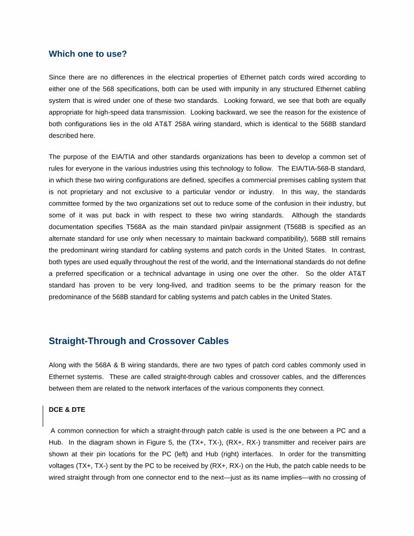
DCE & DTE
A common connection for which a straight-through patch cable is used is the one between a PC and a
Hub. In the diagram shown in Figure 5, the (TX+, TX-), (RX+, RX-) transmitter and receiver pairs are
shown at their pin locations for the PC (left) and Hub (right) interfaces. In order for the transmitting
voltages (TX+, TX-) sent by the PC to be received by (RX+, RX-) on the Hub, the patch cable needs to be
wired straight through from one connector end to the next—just as its name implies—with no crossing of

the conductors at either end. The same is true for
transmitting from the Hub to the PC, with the transmitting
pairs on the Hub interface again corresponding to the
receiving pairs on the PC interface.
For an example of a crossover patch cable, the diagram in
Figure 6 shows how a patch cord needs to be wired at
both ends in order to connect two PCs. The pin
configurations in the two PC interfaces are this time mirror
images of each other, with the first two pins (TX+, TX-)
used for transmitting data, and their third and sixth pins (RX+, RX-) used to receive data. If a patch cord
were wired straight through as in the diagram above, the transmitting pairs for each PC would perpetually
“talk” at each other, and the receiver pairs would perpetually listen for the chatter of the other, but no
information would ever be exchanged between the two PCs. The wires in a crossover cable, then, also
do just what their name implies. The pin positions of individual wires in the transmitting and receiving
conductor pairs are swapped inside the cable’s end connector, so that they will be in the appropriate
positions when they get to the other PC interface.
Straight through cables are the standard patch cables
commonly used to connect computers and other
network components to wall panel jacks, and to
connect wall panel jacks in turn to “keystone” jacks on
patch panels. Crossover cables are generally used for
connecting computers in a network to one another.
DCE & DTE
A kind of general rule of thumb says that straight-through cables patch between different types of
Ethernet equipment—like the connections running from a computer’s network interface card to a hub or a
switch—and crossover cables patch between similar types of equipment having similar interfaces, like two
PCs in a network. This is because the two wiring schemes were originally used to connect two broad
classes of nodes in data communications networks. The first class was comprised of components that
only communicated by forwarding data (Data Communications Equipment, or DCEs), and the second of
components could generate new data by reading and manipulating the data they received (Data Terminal
Equipment, or DTEs). A network with a star topology, for example, would be constructed by connecting a
single DCE device (a hub) to a ton of DTEs (the networked computers and peripherals).

T568A is the pin-out configuration used by DCE devices, and T568B is the configuration used by DTE
devices. In general, DTEs will only communicate directly with DCE components, and vice-versa, so that
crossover cables are needed to connect two like components together. Seen in this way, the swapping of
the transmitting and receiving pairs in a crossover patch cable provides a convenient disguise to make
DTEs look like DCEs for the purpose of connecting them to other DTEs, or to make DCEs look like DTEs
in order to connect them to other DCEs.
The reason for the preponderance of straight-through cables is that most hubs and wall jacks are wired to
perform the crossover internally. In fact, some of the newer hubs are able to differentiate between
crossover and straight-through patch cables, and then make changes to their own internal wiring to match
the type connected to them. But for the most part, you’re on your own in this area, so knowing how to tell
the difference between the two types of patch cables can be very useful, in the same way it proves useful
for these smart new hubs.
The easiest way to tell what kind of patch cord you have is to
look at both of its ends together. If the cable conductors are
configured according to the T568A standard for both connector
ends, then the cable is a straight-through patch cord (Figure 8).
Similarly, if both cable ends are wired according to the T568B
specification, it is also a straight-through patch cord. But if you
have a cable that is wired according to the T568A standard at
one end, and the T568B at the other end, the cable is a
crossover cable (Figure 7). Crossover
cables sometimes have orange or
yellow sheaths to make them easier to
identify.


![Patch Antenna[1]](https://static.fdokumen.com/doc/165x107/63158e4cc32ab5e46f0d5c89/patch-antenna1.jpg)