Deploying a Resilient Converged Plantwide Ethernet ...
124
Deploying a Resilient Converged Plantwide Ethernet Architecture Design and Implementation Guide November 2015 Document Reference Number: ENET-TD010A-EN-P
-
Upload
khangminh22 -
Category
Documents
-
view
4 -
download
0
Transcript of Deploying a Resilient Converged Plantwide Ethernet ...

Deploying a Resilient Converged Plantwide Ethernet Architecture
Design and Implementation Guide
November 2015
Document Reference Number: ENET-TD010A-EN-P


Deploying
ENET-TD010A-EN-P
C O N T E N T S
Preface ii-vii
For More Information ii-vii
A P P E N D I X 1 CPwE Resiliency Overview 1-1
Converged Plantwide Ethernet Resiliency 1-2
CPwE Resiliency Use Cases 1-3
Allen-Bradley® Stratix™ and Cisco Industrial Ethernet Switches (IES) 1-3
Catalyst 4500-X Aggregation/Distribution Switches 1-4
Catalyst 3850 StackWise-480 Aggregation/Distribution Switch 1-5
Catalyst 6500-E Core Switches 1-5
5508 Wireless LAN Controller (WLC) 1-6
Adaptive Security Appliance 5500-X Firewalls with FirePOWER 1-6
Robust Physical Infrastructure 1-7
A P P E N D I X 2 CPwE Resiliency Design Considerations 1-1
Resiliency Architectural Framework 1-1
Industrial Zone 1-1
Network Reference Model 1-1
Virtual Switching System 1-3
StackWise-480 1-5
Hot Standby Redundancy Protocol 1-6
Wireless Infrastructure 1-6
Cell/Area Zone 1-7
Common Industrial Protocol Messaging 1-7
Access Layer Switching 1-7
Redundant Star Topology 1-8
Summary of Resiliency Recommendations 1-25
Redundant Star Topology Recommendation Summary 1-25
Catalyst 4500-X with VSS 1-25
IE 5000/Stratix 5410 with HSRP 1-25
Catalyst 3850 with StackWise-480 1-25
ia Resilient Converged Plantwide Ethernet Architecture

Contents
Ring Topology Recommendation Summary 1-26
Single Ring (Single Media) 1-26
Single Ring (Dual Media) 1-26
Multiple Ring Segments 1-26
Level 3 Site Operations 1-26
Network Services 1-26
Security Services 1-26
IDMZ 1-27
A P P E N D I X 3 CPwE Resiliency Configuration -1
Industrial Zone -1
Distribution Switching -1
Catalyst 4500-X VSS Configuration -1
Catalyst 3850 StackWise-480 Configuration -3
Hot Standby Routing Protocol Configuration -4
Cell/Area Zone -6
Access Layer Switching -6
Redundant Star Topology -6
Ring Topology -6
A P P E N D I X 4 CPwE Resiliency Troubleshooting -1
VSS Troubleshooting -1
StackWise-480 Troubleshooting -2
HSRP Troubleshooting -2
Flex Links Troubleshooting -3
EtherChannel Troubleshooting -4
REP Troubleshooting -4
A P P E N D I X A References A-1
Converged Plantwide Ethernet (CPwE) A-1
Core Switch Architecture A-2
Distribution Switches A-2
Access Layer Switches A-3
Routing Between Zones A-3
Network Time Protocol A-3
Network Infrastructure Hardening A-3
iiDeploying a Resilient Converged Plantwide Ethernet Architecture
ENET-TD010A-EN-P

Contents
A P P E N D I X B Test Hardware and Software A-1
A P P E N D I X C Physical Infrastructure Network Design for CPwE Logical Architecture A-1
Mapping Physical Infrastructure to the CPwE Logical Network Design A-2
Mapping CPwE Logical to Physical A-2
Physical Infrastructure Building Block Systems A-3
Key Requirements and Considerations A-4
Physical Zone Cabling Architecture A-6
Structured and Point-to-Point Cabling Methods A-7
M.I.C.E. Assessment for Industrial Characteristics A-8
Cable Media and Connector Selection A-10
Fiber and Copper Considerations A-11
Optical Fiber Cable Basics A-11
Optical Fiber Link Basics A-11
Copper Network Cabling Basics A-11
Copper Network Channel Basics A-12
Cable Management A-12
Network Cabling Pathways A-13
Grounding and Bonding Industrial Networks A-14
Earthing, Grounding, and Bonding A-14
Grounding for Safety A-14
Ground Loop A-14
Grounding and Bonding for Network Communication A-14
Equalizing Potential Conductor A-14
Applicable Grounding and Bonding Standards A-15
Link Testing A-15
Channel A-16
Wireless Physical Infrastructure Considerations A-17
Site Survey A-17
Wireless Spectrum A-17
Wireless Coverage A-17
RF Parameters A-18
Location of Wireless Access Points A-18
Cabling for Wireless Access Points A-18
Power over Ethernet A-19
Access Points in Harsh Environments A-19
A P P E N D I X D Physical Infrastructure Design for the Cell/Area Zone A-1
Logical to Physical Mapping A-1
iiiDeploying a Resilient Converged Plantwide Ethernet Architecture
ENET-TD010A-EN-P

Contents
Key Requirements and Considerations A-3
Physical Network Design Considerations A-4
Physical Media A-4
On Machine - Device-Level A-4
Cell/Area Zone Cabling - Control Panel A-5
Cell/Area Zone Cabling - Redundant Star Switch-level Topology A-7
Cell/Area Zone Cabling - Switch-Level Ring Topology A-7
Cabling Jacketing Materials A-8
Cable and Connector Ingress Protection A-8
Ethernet Copper Cable Types - Unshielded and Shielded A-9
Connector Types A-9
Fiber Options for the Plant Floor - Cell/Area Zone A-10
Polymer Coated Fiber A-10
Physical Layer Design for WLAN A-11
Deployment Points A-12
PNZS A-13
Control Panel Network Infrastructure Considerations A-13
Panduit List of Materials A-14
A P P E N D I X E Physical Infrastructure Design for the Industrial Zone A-1
Logical to Physical Mapping A-1
Industrial Plant Network Backbone and Distribution Switching Overview A-2
Key Requirements and Considerations A-3
Industrial Network Building Block Systems A-4
Industrial Distribution Frame A-4
PNZS with Distribution/Aggregation Switch A-6
Optical Fiber Overview A-6
Physical Media A-7
Optical Fiber Cable Outer Covering A-8
Fiber Connectors and Adapters A-9
Dielectric Conduited Fiber Armored Cable for Plant Backbone A-9
Physical Network Design Considerations A-10
IDF Physical Deployment Details A-11
Horizontal Cable Service Loop A-11
Thermal Management A-11
Connectivity and Patching A-12
Panduit List of Materials A-12
ivDeploying a Resilient Converged Plantwide Ethernet Architecture
ENET-TD010A-EN-P

Contents
A P P E N D I X F Physical Infrastructure Deployment for Level 3 Site Operations A-1
Key Requirements and Considerations A-2
Industrial Characteristics A-3
Room Environment A-3
Thermal Ducting A-3
Physical Network Infrastructure Life Span A-3
Maintainability A-4
Patching A-4
Bundling A-4
Identification A-4
Scalability A-4
Pathway Decisions - Type and Sizing A-4
Designing for High Availability A-5
Cable Management A-5
Bend Radius Control A-5
Cable Routing and Protection A-6
Network Compatibility and Performance A-6
Cable Media Selection A-6
Fiber and Copper Considerations A-7
Multimode vs Single-mode A-7
Grounding and Bonding A-7
Security A-8
Wireless A-8
Physical Network Design Considerations A-8
Logical to Physical Simplified A-8
Level 3 Site Operations - Large Scale Deployment A-9
Overview A-9
IDC Cabinets A-10
IDMZ Cabinet A-10
Server Cabinets A-11
Core Switching Cabinets A-11
Network Cabinets A-12
Physical to Physical Simplified A-12
IDMZ Cabinet to Core Switching Cabinets A-12
IDC Cabinet to Core Switching Cabinets A-13
Level 3 Site Operations - The Industrial Data Center from Rockwell Automation A-14
Features and Benefits: A-15
Panduit List of Materials A-16
vDeploying a Resilient Converged Plantwide Ethernet Architecture
ENET-TD010A-EN-P

Contents
A P P E N D I X G Acronyms and Initialisms A-1
viDeploying a Resilient Converged Plantwide Ethernet Architecture
ENET-TD010A-EN-P

viiDeploying a Resilient Converged Plantwide Ethernet Architecture
ENET-TD010A-EN-P
Preface
Resilient plant-wide network architectures play a pivotal role in ensuring overall plant uptime and productivity. Industrial Automation and Control System (IACS) application requirements such as availability and performance drive the choice of resiliency technology. A holistic resilient plant-wide network architecture is made up of multiple technologies (logical and physical) deployed at different levels within the plant.
When selecting resiliency technology, various plant application factors should be evaluated, including physical layout of IACS devices (geographic dispersion), resiliency performance, uplink media type, tolerance to data latency and jitter and future-ready requirements.
The Deploying a Resilient Converged Plantwide Ethernet (CPwE) Cisco Validated Design (CVD), which is documented in this Deploying a Resilient Converged Plantwide Ethernet (CPwE) Design and Implementation Guide (DIG), details design considerations to help with the successful design and implementation of a scalable, robust, secure and future-ready CPwE architecture.
Note This release of the CPwE architecture focuses on EtherNet/IP™, which is driven by the ODVA Common Industrial Protocol (CIP™). Refer to the IACS Communication Protocols section of the CPwE Design and Implementation Guide.
For More InformationMore information on CPwE Design and Implementation Guides can be found at the following URLs:
• Rockwell Automation site:
– http://www.rockwellautomation.com/global/products-technologies/network-technology/architectures.pag e?#Whitepapers
• Cisco site:
– http://www.cisco.com/web/strategy/manufacturing/cisco-rockwell_automation.html

Deploying a Resilient Con
ENET-TD010A-EN-P
C H A P T E R 1
CPwE Resiliency OverviewThis chapter includes the following major topics:
• Converged Plantwide Ethernet Resiliency, page 1-2
• CPwE Resiliency Use Cases, page 1-3
Business practices, corporate standards, industry standards, policies and tolerance to risk are key factors in determining the degree of resiliency and application availability required within a plant-wide architecture. A resilient network architecture within an Industrial Automation and Control System (IACS) application plays a pivotal role in helping to minimize the risk of application shutdowns while helping to maximize overall plant uptime.
An IACS is deployed in a wide variety of industries such as automotive, pharmaceuticals, consumer goods, pulp and paper, oil and gas, mining and energy. IACS applications are made up of multiple control and information disciplines such as continuous process, batch, discrete and hybrid combinations. A resilient network architecture can help to increase overall equipment effectiveness (OEE) of the IACS by reducing the impact of a failure and speed recovery from an outage which lowers mean-time-to-repair (MTTR).
A holistic resilient plant-wide network architecture is made up of multiple technologies (logical and physical) deployed at different levels within the plant:
• Robust physical infrastructure
• Topologies and protocols
• Switching and routing
• Wireless LAN Controllers (WLC)
• Firewalls
• Network and device management
Converged Plantwide Ethernet (CPwE) is the underlying architecture that provides standard network services for control and information disciplines, devices and equipment found in modern IACS applications. The CPwE architecture (Figure 1-1) provides design and implementation guidance to achieve the real-time communication, reliability, scalability, security and resiliency requirements of the IACS.
CPwE Resiliency for IACS applications is brought to market through a strategic alliance between Cisco Systems® and Rockwell Automation.
1-1verged Plantwide Ethernet Architecture

Chapter 1 CPwE Resiliency OverviewConverged Plantwide Ethernet Resiliency
Figure 1-1 CPwE Architectures
Converged Plantwide Ethernet ResiliencyThis Deploying a Resilient Converged Plantwide Ethernet Architecture DIG outlines key requirements and design considerations to help with successfully designing and deploying a holistic resilient plant-wide network architecture.
• Industrial Zone:
– Core Switching
– Aggregation/Distribution Switching
– Active/Standby WLC
– Robust Physical Infrastructure
• Cell/Area Zone:
– Redundant Path Topology with Resiliency Protocol
– Industrial Ethernet Switching
– Robust Physical Infrastructure
• Level 3 Site Operations:
– Virtual Servers
– Security and Network Services
– Robust Physical Infrastructure
• Industrial Demilitarized Zone (IDMZ):
– Active/Standby Firewalls
– Robust Physical Infrastructure
Physical or Virtualized Servers •
• ,
•
FactoryTalk Application Servers and Services Platform Network & Security Services – DNSAD, DHCP, Identity Services (AAA) Storage Array
Remote Access Server
Physical or Virtualized Servers ••••
Patch Management AV Server Application Mirror Remote Desktop Gateway Server
Distribution Switch Stack
HMI
Cell/Area Zone - Levels 0–2 Redundant Star Topology - Flex Links Resiliency
Unified Wireless LAN (Lines, Machines, Skids, Equipment)
Cell/Area Zone - Levels 0–2 Linear/Bus/Star Topology
Autonomous Wireless LAN (Lines, Machines, Skids, Equipment)
Industrial Demilitarized Zone
(IDMZ)
Enterprise Zone Levels 4 and 5
Industrial Zone Levels 0–3
(Plant-wide Network)
Core Switches
Phone
Controller
Camera Safety
Controller
Robot
Soft Starter
Cell/Area Zone - Levels 0–2 Ring Topology - Resilient Ethernet Protocol (REP)
Unified Wireless LAN (Lines, Machines, Skids, Equipment)
I/O
Plant Firewalls •••••
Active/Standby Inter-zone traffic segmentation ACLs, IPS and IDS VPN Services Portal and Remote Desktop Services proxy
Wide Area Network (WAN) Physical or Virtualized Servers •••••
ERP - Business Systems Email, Web Services Security Services - Active Directory (AD), Identity Services (AAA)Network Services – DNS, DHCP Call Manager
Enterprise
Safety I/O
Servo Drive
Instrumentation
I/O
Level 3 - Site Operations (Control Room)
Internet
External DMZ/ Firewall
HMI
Active
AP
SSID 5 GHz
WGB
Safety I/O
Controller
WGB
LWAP
SSID 5 GHz WGB
LWAP
Controller
LWAP
SSID 2.4 GHz
Standby
Wireless LAN Controller
(WLC)
Cell/Area Zone
Levels 0–2
Cell/Area Zone
Levels 0–2
Drive
RADIUS (AAA) Server
Distribution Switch Stack
3754
00
CAPWAPCAPWAP
CAPWAP
IESIESIES IES
IES
IESIES
IESIES
IES IES
IESIES
1-2Deploying a Resilient Converged Plantwide Ethernet Architecture
ENET-TD010A-EN-P

Chapter 1 CPwE Resiliency OverviewCPwE Resiliency Use Cases
Note This release of the CPwE architecture focuses on EtherNet/IP, which utilizes the ODVA Common Industrial Protocol (CIP), and is ready for the Industrial Internet of Things. For more information on EtherNet/IP, see odva.org at the following URL:
• http://www.odva.org/Technology-Standards/EtherNet-IP/Overview
CPwE Resiliency Use CasesThe CPwE architecture supports scalability which includes the degree of resiliency applied to a plant-wide network architecture. Scalable resiliency comes in many forms; that is, technology choices in topology and distribution switch. For this Deploying a Resilient Converged Plantwide Ethernet Architecture CVD, the following represents a portion of the use cases that were tested, validated and documented by Cisco and Rockwell Automation.
Allen-Bradley® Stratix™ and Cisco Industrial Ethernet Switches (IES)
Refer to Figure 1-2.
• Form factor:
– DIN rail/panel mount
– 19” rack mount - 1 RU (rack unit)
• Hot Standby Routing Protocol (HSRP) first hop redundancy protocol
• Redundant star switch-level topology:
– Flex Links resiliency protocol
– MSTP resiliency protocol
• Ring switch-level topology:
– Resilient Ethernet Protocol (REP)
– Multiple Spanning Tree Protocol (MSTP) resiliency protocol
– Single and dual media ring
– EtherChannel for dual media ring only
1-3Deploying a Resilient Converged Plantwide Ethernet Architecture
ENET-TD010A-EN-P

Chapter 1 CPwE Resiliency OverviewCPwE Resiliency Use Cases
Figure 1-2 IES Aggregation/Distribution Switch
Catalyst 4500-X Aggregation/Distribution Switches
Refer to Figure 1-3.
• Virtual Switching System (VSS) virtualization technology that pools two physical switch chassis into one virtual switch, with Stateful Switch Over (SSO) and Non-stop forwarding (NSF).
• Redundant star switch-level topology:
– Multi-chassis EtherChannel (MEC) port aggregation
– Flex Links resiliency protocol
– MSTP resiliency protocol
• Ring switch-level topology:
– REP
– MSTP resiliency protocol
– Single and dual media ring
Figure 1-3 Catalyst 4500-X Aggregation/Distribution Switch
3754
01
IES HSRP
Distribution
HMI
Soft Starter
I/O
Instrumentation
I/OController
LWAP
SSID 2.4 GHz
Drive
Cell/Area Zone - Levels 0-2 Redundant Star Topology
(Lines, Machines, Skids, Equipment)
EtherChannel
CAPWAP
Active Standby
IES
IES
IESIES
IES
IES
HMI
Soft Starter
I/O
Instrumentation
I/OController
t t
LWAP
SSID2.4 GHz
Drive
Cell/Area Zone - Levels 0-2Single Ring Single Media Topology(Lines, Machines, Skids, Equipment)
IESHSRP
Distribution
Active Standby
CAPWAP
IES IES
IES
IESIES
IES
HMI
Soft Starter
I/O
Instrumentation
I/OController
LWAP
SSID 2.4 GHz
Drive
IES HSRP
Distribution
CAPWAP
IES IES
IESIES
IESIES
Active Standby
Cell/Area Zone - Levels 0-2Single Ring Dual Media Topology
(Lines, Machines, Skids, Equipment)
Catalyst 4500-XHSRP
Distribution
EtherChannel
Active Standby
HMI
Soft Starter
I/O
Instrumentation
I/OController
Drive
LWAP
SSID 2.4 GHz
CAPWAP
IES
IES
IES IES
IES
IES
Cell/Area Zone - Levels 0-2Redundant Star Topology
(Lines, Machines, Skids, Equipment)
HMI
Soft Starter
I/O
Instrumentation
I/OController
t t
LWAP
SSID2.4 GHz
Drive
Soft Starter
I/O
Instrumentation
I/OController
t t
LWAP
SSID2.4 GHz
Drive
IES IESIESCAPWAP
CAPWAP
IES
IESIES
IESIES
IESIES
IES
Cell/Area Zone 1 - Levels 0-2Ring Topology
(Lines, Machines, Skids, Equipment)
Cell/Area Zone XX - Levels 0-2Ring Topology
(Lines, Machines, Skids, Equipment)
DistributionCatalyst 4500-X
VSS
3754
02
1-4Deploying a Resilient Converged Plantwide Ethernet Architecture
ENET-TD010A-EN-P

Chapter 1 CPwE Resiliency OverviewCPwE Resiliency Use Cases
Catalyst 3850 StackWise-480 Aggregation/Distribution Switch
Refer to Figure 1-4.
• Switch stack, which is a set of up to nine stacking-capable switches, connected through their StackWise Plus or StackWise-480 ports, and united to form a logical unit
• Redundant star switch-level topology:
– MEC port aggregation
– Flex Links resiliency protocol
– MSTP resiliency protocol
• Ring switch-level topology:
– REP
– MSTP resiliency protocol
– Single and dual media ring
Figure 1-4 Catalyst 3850 Aggregation/Distribution Switch
Catalyst 6500-E Core Switches
Refer to Figure 1-5.
• VSS virtualization technology that pools two physical switch chassis into one virtual switch, with SSO
3754
03HMI
Soft Starter
I/O
Instrumentation
I/OController
t t
LWAP
SSID2.4 GHz
Drive
Cell/Area Zone 1 - Levels 0-2Ring Topology
(Lines, Machines, Skids, Equipment)
Soft Starter
I/O
Instrumentation
I/OController
t t
LWAP
SSID2.4 GHz
Drive
Cell/Area Zone XX - Levels 0-2Ring Topology
(Lines, Machines, Skids, Equipment)
…
IES IESIESIESCAPWAP
IES
IES IES
IES
CAPWAP
IES
IES IES
IES
DistributionCatalyst 3850StackWise-480
1-5Deploying a Resilient Converged Plantwide Ethernet Architecture
ENET-TD010A-EN-P

Chapter 1 CPwE Resiliency OverviewCPwE Resiliency Use Cases
Figure 1-5 Core Switches - Traditional versus VSS Design
5508 Wireless LAN Controller (WLC)
Refer to Figure 1-6.
• Unified WLC supports Stateful Switchover of APs and Clients. With unified setup, AP establishes a Control and Provisioning of Wireless Access Points (CAPWAP) tunnel with the Active WLC and shares a mirror copy of the AP database with the Standby WLC.
Figure 1-6 Active/Standby Wireless LAN Controllers (WLC)
Adaptive Security Appliance 5500-X Firewalls with FirePOWER
Refer to Figure 1-7.
• Active/Standby stateful failover mechanism enabling a standby Adaptive Security Appliance (ASA) to take over the functionality of a failed unit. When the active unit fails, the standby unit changes to the active state and the failed unit becomes standby when it comes up.
• Adaptive Security Device Manager (ADSM)
Figure 1-7 Active/Standby Firewalls
Core Switches
Distribution Switches
Typical Redundant Core Design
Virtual Core Switch
Distribution Switches
VSS Design (Physical View)
Virtual Core Switch
Distribution Switches
VSS Design (Logical View)
EtherChannel Multi-chassis EtherChannel
Multi-chassis EtherChannel
VSL
3754
04
Level 3 - Site Operations (Control Room)
Wireless LAN Controllers
(WLC)
Active ISE
Standby Distribution
Switch
3754
05
Industrial Demilitarized Zone
(IDMZ)
Enterprise Zone Levels 4 and 5
Industrial Zone Levels 0–3
(Plant-wide Network)
CoreSwitches
CoreSwitches
3754
06
1-6Deploying a Resilient Converged Plantwide Ethernet Architecture
ENET-TD010A-EN-P

Chapter 1 CPwE Resiliency OverviewCPwE Resiliency Use Cases
Robust Physical Infrastructure
Refer to Figure 1-8.
For this Deploying a Resilient Converged Plantwide Ethernet Architecture CVD, the following use cases were documented by Panduit:
• Robust physical infrastructure design considerations and best practices
• Control Panel:
– Electromagnetic interference (EMI) noise mitigation through bonding, shielding and grounding
– IES deployment within the Cell/Area Zone
• Physical Network Zone System:
– IES and AP deployment within the Cell/Area Zone
• Cable distribution across the Industrial Zone
• IDF:
– Industrial aggregation/distribution switch deployment within the Industrial Zone
• IDC:
– Physical design and deployment of the Level 3 Site Operations
Figure 1-8 Robust Physical Infrastructure for the CPwE Architecture
1-7Deploying a Resilient Converged Plantwide Ethernet Architecture
ENET-TD010A-EN-P

Deploying a Resilient Con
ENET-TD010A-EN-P
C H A P T E R 2
CPwE Resiliency Design ConsiderationsThis chapter, which provides an overview of design considerations for integrating resiliency into an industrial network based on the CPwE architecture, includes the following major topics:
• Resiliency Architectural Framework, page 2-1
• Industrial Zone, page 2-1
• Cell/Area Zone, page 2-7
• Summary of Resiliency Recommendations, page 2-25
• Level 3 Site Operations, page 2-26
Resiliency Architectural FrameworkWithin the CPwE architecture, resiliency is key to preventing network outages and related plant downtime. Resiliency should be incorporated into as many layers of the industrial network as possible, including:
• Industrial Zone (core switching, distribution switching, and wireless infrastructure)
• Cell/Area Zone (access switching)
• Level 3 Site Operations (network and security services)
• IDMZ
The following sections describe the options that are available to design a resilient industrial network, along with recommendations based on testing conducted by Cisco and Rockwell Automation.
Industrial Zone
Network Reference Model
The CPwE logical framework reflects the basic functions of an IACS, which is the key model for this CPwE solution architecture. However, as identified earlier, the goal of this architecture is to integrate the knowledge and expertise from both an IACS perspective and an IT perspective. An important and relevant model for network architectures is the Cisco Enterprise Campus network, which incorporates key networking concepts
2-1verged Plantwide Ethernet Architecture

Chapter 2 CPwE Resiliency Design ConsiderationsIndustrial Zone
and models. The CPwE solution architecture comprises many of the concepts and models of the Enterprise Campus solution architecture, but not the entire scope of that solution since not all concepts are applicable to IACS networks. In essence though, the IACS network can be viewed as a specialized Campus network.
This section briefly introduces the Campus network and some of the key concepts of its solution architecture. The Cisco Enterprise Campus network combines a high-availability core infrastructure of intelligent switching and routing with an overlay of productivity-enhancing technologies, including IP communications, mobility and advanced security. This Design and Implementation Guide refers to the Campus network documentation and the concept of access, distribution and core. Figure 2-1 shows a hierarchical design model that has proven to be effective in a Campus environment consisting of three main layers: access, distribution and core.
Figure 2-1 Campus Network Hierarchical Model
• The access layer provides the first layer of access to the IACS network. Layer 2 (OSI model) switching, security and QoS reside at this layer.
• The distribution layer aggregates the access layer switches and provides security and access level network policy enforcement. Layer 3 protocols are used at this layer to provide load balancing, fast convergence and scalability.
• The core is the backbone of the network. This layer is designed to be fast converging, highly reliable and stable. This layer aggregates the distribution switches and often integrates connectivity to the IDMZ in this CPwE solution architecture. Designed with Layer 3 protocols, the core provides load balancing, fast convergence and scalability. Often, in small-to-medium topologies, the core and distribution layers are consolidated into a single collapsed core/distribution layer. For large topologies, the core is required for scalability, throughput and to interconnect multiple distribution switches to other services (such as security firewalls).
This three-layer design provides high availability with redundant hardware, redundant software features, redundant network connections/paths and automatic procedures for reconfiguring network paths when failures occur.
Note For more information on the Enterprise Campus network, see the following URLs:
• Enterprise Campus Architecture: Overview and Framework: http://www.cisco.com/en/US/docs/solutions/Enterprise/Campus/campover.html
• Campus Network for High Availability Design Guide: http://www.cisco.com/en/US/docs/solutions/Enterprise/Campus/HA_campus_DG/hacampusdg.html
375
555
EnterpriseNetwork
Firewall
Core Switch
Distribution Switch
Access Switch
2-2Deploying a Resilient Converged Plantwide Ethernet Architecture
ENET-TD010A-EN-P

Chapter 2 CPwE Resiliency Design ConsiderationsIndustrial Zone
Note For more information on the Industrial Zone design and topology options, see the "Solution Design-- Manufacturing and Demilitarized Zones" chapter of the Converged Plantwide Ethernet (CPwE) Design and Implementation Guide at the following URLs:
Rockwell Automation site:
• http://literature.rockwellautomation.com/idc/groups/literature/documents/td/enet-td001_-en-p.pdf
Cisco site:
• http://www.cisco.com/en/US/docs/solutions/Verticals/CPwE/CPwE_DIG.html
CPwE architecture introduces the following new distribution layer switches: Catalyst 4500-X, Catalyst 3850, IE 5000/ Stratix5410 and IE 4000/Stratix 5400. The following sections describe the resiliency options available for the distribution layer.
Virtual Switching System
Virtual Switching System Overview
Virtual Switching System (VSS) enables unprecedented functionality and availability of network design by integrating network and systems redundancy into a single device. The end-to-end network that is enabled with VSS capability allows flexibility and availability that is described in this document. The Catalyst 4500-X is the distribution platform that is used within this document that supports VSS technology.
Note The Catalyst 4500-X with VSS can also be used in the core layer, depending on plant size.
The virtualization of two physical chassis into a single logical switch with VSS fundamentally alters the design of the campus topology. One of the most significant changes is that VSS enables the creation of a loop-free topology. In addition, VSS incorporates many other Cisco innovations such as SSO and MEC, which substantially enhance application response time. Key business benefits of VSS include the following:
• Reduced risk associated with a looped topology
• Better return on existing investments via increased bandwidth from the access layer
• Reduced operational expenses (OPEX) through increased flexibility in deploying and managing new services with a single logical device, such as network virtualization
• Reduced configuration errors and elimination of First Hop Redundancy Protocols (FHRPs), such as Virtual Router Redundancy Protocol (VRRP) and Hot Standby Redundancy Protocol (HSRP), resulting in faster convergence at Layer 3 and fewer consumed IP addresses
• Simplified management of a single configuration and fewer operational failure points
Note For more information on VSS design and implementation, see the “Configuring VSS” chapter of the Catalyst 4500 Series Switch Software Configuration Guide, Release IOS XE 3.4.xSG and IOS 15.1(2)SGx at the following URL:
• http://www.cisco.com/c/en/us/td/docs/switches/lan/catalyst4500/15-1-2/XE_340/configuration/guide/config/vss.html
2-3Deploying a Resilient Converged Plantwide Ethernet Architecture
ENET-TD010A-EN-P

Chapter 2 CPwE Resiliency Design ConsiderationsIndustrial Zone
Virtual Switching System Topology
Network operators increase network reliability by configuring switches in redundant pairs and by provisioning links to both switches in the redundant pair. Redundant network elements and redundant links can add complexity to network design and operation. Figure 2-2 shows how VSS simplifies the network by reducing the number of network elements and hiding the complexity of managing redundant switches and links.
Figure 2-2 VSS in the Distribution Network
VSS combines a pair of switches into a single network element. VSS manages the redundant links, which act as a single port-channel for neighboring switches. It also simplifies network configuration and operation by reducing the number of Layer 3 routing neighbors and by providing a loop-free Layer 2 topology.
Active and Standby Chassis
When you create or restart a VSS, the peer chassis negotiate their roles. One chassis becomes the active chassis, and the other chassis becomes the standby.
The active chassis controls the VSS. It runs the Layer 2 and Layer 3 control plane protocols for the switching modules on both chassis. The active chassis also provides management functions for the VSS, such as module online insertion and removal (OIR) and the console interface.
The active and standby chassis perform packet forwarding for ingress data traffic on their locally hosted interfaces. However, the standby chassis sends all control traffic to the active chassis for processing.
Virtual Switch Link
For the two chassis of the VSS to act as one network element, they need to share control information and data traffic. The Virtual Switch Link (VSL) serves as a logical connection that carries critical system control information such as hot-standby supervisor programming, line card status, Distributed Forwarding Card (DFC) programming, system management, diagnostics and more, as shown in the physical view in Figure 2-2.
In addition, VSL is also capable of carrying user data traffic when necessary. Thus, the VSL has a dual purpose: supporting system control synchronization and being a data link. The VSL is implemented as an EtherChannel with up to eight links. The VSL gives control traffic higher priority than data traffic so that control messages are never discarded. Data traffic is load balanced among the VSL links by the EtherChannel load-balancing algorithm.
3755
44
Virtual Distribution Switch
Physical View Logical View
Virtual Distribution Switch
Access Access
IES IES IESIESIESIES
2-4Deploying a Resilient Converged Plantwide Ethernet Architecture
ENET-TD010A-EN-P

Chapter 2 CPwE Resiliency Design ConsiderationsIndustrial Zone
Redundancy and High Availability
In VSS mode, supervisor engine redundancy operates between the active and standby chassis, using SSO and Cisco Nonstop Forwarding (NSF). The peer chassis exchange configuration and state information across the VSL and the standby supervisor engine runs in hot standby mode.
The standby chassis monitors the active chassis using the VSL. If it detects failure, the standby chassis initiates a switchover and takes on the active role. When the failed chassis recovers, it takes on the standby role.
If the VSL fails completely, the standby chassis assumes that the active chassis has failed and initiates a switchover. After the switchover, if both chassis are active, the dual-active detection feature detects this condition and initiates recovery action.
In addition, unlike some other redundancy methods (such as the StackWise-480), the VSS devices can be geographically separated by great distances as long as the connecting media supports signal transmission over that distance.
StackWise-480
Cisco Catalyst 3000 switches define stacking architecture for enterprise networks to expand form factors, switching capacity and redundancy in the wiring closet. Cisco StackWise® Plus is a proven and widely deployed, cost-effective solution that delivers scale, performance, resiliency and operational simplicity. To build the next-generation modular stack product, Cisco made significant changes to the StackWise Plus hardware and software architecture for the Cisco Catalyst 3850 Switch. The new Cisco Catalyst 3850 Switch is built upon high-speed next-generation Cisco application-specific integrated circuit (ASIC) technology and is combined with the feature-rich and powerful Cisco IOS XE Software operating system.
The new StackWise-480 architecture allows you to build a high-speed stack ring with features and services scalability superior to StackWise Plus. To accommodate varying port density requirements, the hardware can support both 48- and 24-port switches in a single stack ring. The Cisco Catalyst 3850 Switch delivers uncompromised hardware-accelerated, rich integrated borderless network services and enterprise-class system resiliency.
Cisco StackWise-480 provides a robust distributed forwarding architecture through each stack member switch and a unified, fully centralized control and management plane to simplify operation in a large-scale network design. One switch in a stack ring is elected to be the active switch. The active switch controls the management plane of the entire stack from both the network and user perspective. The hot standby switch assumes the active role when it detects a failure of the primary active switch. Figure 2-3 illustrates the physical versus logical view of a system in stack configuration mode.
Figure 2-3 StackWise-480 Physical versus Logical Topology
The Cisco Catalyst 3850 Switches support a wide range of Layer 2 and Layer 3 stateful capabilities to provide resilient network communication. In real time, the Cisco IOS XE Software running on the active switch synchronizes its protocol state machines, software forwarding tables and system configuration to the Cisco IOS XE Software instance running on the standby switch.
3755
45
3850-1
3850-2 3850-3 3850-1
Active
Hot-Standby
Member
Physical View Logical View
2-5Deploying a Resilient Converged Plantwide Ethernet Architecture
ENET-TD010A-EN-P

Chapter 2 CPwE Resiliency Design ConsiderationsIndustrial Zone
Note For more details about the StackWise-480 architecture and capabilities of the Catalyst 3850, see the Cisco Catalyst 3850 Series Switches StackWise-480 Architecture White Paper at the following URL:
• http://www.cisco.com/c/en/us/products/collateral/switches/catalyst-3850-series-switches/white-paper-c11-734429.html
Hot Standby Redundancy Protocol
Default gateway redundancy (also known as first hop redundancy) allows a highly available network to recover from the failure of the device acting as the default gateway for the end stations on a physical segment. Cisco developed HSRP to address this need, and the IETF subsequently ratified VRRP as the standards-based method of providing default gateway redundancy. HSRP is supported on a variety of platforms, including the Catalyst 4500-X, IE 5000/Stratix 5410 and IE 4000/Stratix 5400.
In the recommended hierarchical model, the distribution switches are the Layer 2/Layer 3 boundary and also act as the default gateway for the entire Layer 2 domain that they support. Some form of redundancy is required because this environment can be large and a considerable outage could occur if the device acting as the default gateway failed.
HSRP, which provides a robust method of backing up the default gateway, can provide sub-second failover to the redundant distribution switch when tuned properly. HSRP is the recommended protocol because it is a Cisco-owned standard that allows for the rapid development of new features and functionality for HSRP before VRRP.
Note Cisco and Rockwell Automation recommend that the Spanning Tree Protocol (STP) root be configured to be the same as the primary HSRP peer. Therefore, if the STP root and primary HSRP peer are not synchronized due to a switch disruption, a manual switchover to restore the original peer as primary should be initiated during the next maintenance window.
Wireless Infrastructure
The Wireless LAN Controller (WLC) provides redundancy through the use of an active/hot-standby configuration. To provide the backup/failure performance, it is recommended that the controller be connected via a 2x GE port aggregate link (EtherChannel) that provides physical connectivity between the WLC pair.
Note For more information on wireless infrastructure resiliency options, see the Deploying 802.11 Wireless LAN Technology within a Converged Plantwide Ethernet Architecture Design and Implementation Guide at the following URLs:
Rockwell Automation site:
• http://literature.rockwellautomation.com/idc/groups/literature/documents/td/enet-td006_-en-p.pdf
Cisco site:
• http://www.cisco.com/c/en/us/td/docs/solutions/Verticals/CPwE/NovCVD/CPwE_WLAN_CVD.html
2-6Deploying a Resilient Converged Plantwide Ethernet Architecture
ENET-TD010A-EN-P

Chapter 2 CPwE Resiliency Design ConsiderationsCell/Area Zone
Cell/Area Zone
Common Industrial Protocol Messaging
Before discussing resiliency and design recommendations in the Cell/Area Zone, a clear understanding of the different types of Common Industrial Protocol (CIP) traffic that may traverse this area of the network is required, since each of these has its own unique convergence requirements:
• Class 1 (Implicit)—Class 1 connections do not use a reliable transport method so they are less resilient to excessive latency and disruptions in the network. Examples include I/O and produced/consumed connections. Another name for a Class 1 message is implicit messaging. Once the class 1 connection is established the producer sends an "implicit" message every requested packet interval (RPI).
Note Recommendations given in this document focus on Class 1 (implicit) traffic since this type of traffic is more sensitive to network disruptions.
• Class 3 (Explicit)—Class 3 connections use a reliable transport method so they are more resilient to excessive latency and disruptions in the network. Examples include MSG instructions and going online with a controller. Another name for a Class 3 message is explicit messaging. Explicit messages are triggered on demand or in other terms the data is explicitly requested.
Note For more information on convergence requirements for different types of CIP messaging, see the "CPwE Solution - Design Cell/Area Zone" chapter of the Converged Plantwide Ethernet (CPwE) Design and Implementation Guide at the following URLs:
Rockwell Automation site:
• http://literature.rockwellautomation.com/idc/groups/literature/documents/td/enet-td001_-en-p.pdf
Cisco site:
• http://www.cisco.com/en/US/docs/solutions/Verticals/CPwE/CPwE_Design and Implementation Guide.html
Access Layer Switching
The access layer is the first tier or edge of the CPwE architecture. It is the place where IACS network devices (such as PCs, servers, controllers, I/O devices, and drives) attach to the wired portion of the IACS network. The wide variety of possible types of connectable devices and the various necessary services and dynamic configuration mechanisms, make the access layer one of the IACS feature-rich parts of the CPwE architecture.
The access layer provides the intelligent demarcation between the network infrastructure and the devices that leverage that infrastructure. As such, it provides a security, QoS and policy trust boundary. When looking at the overall IACS network design, the access switch provides the majority of these access layer services and is a key element in enabling multiple IACS network services. The Cell/Area Zone can be considered an access layer network specialized and optimized for IACS networks.
2-7Deploying a Resilient Converged Plantwide Ethernet Architecture
ENET-TD010A-EN-P

Chapter 2 CPwE Resiliency Design ConsiderationsCell/Area Zone
This DIG introduces the IE 4000/Stratix 5400 as a new access switch option to supplement the existing IE 2000/Stratix 5700 and IE 3000/Stratix 8000. The IE 4000/Stratix 5400 is available as an all Gigabit Ethernet switch to support advanced applications. In addition, all IE 4000/Stratix 5400 variants support four gigabit uplink ports which allow it to be used in both single and dual media rings (see Ring Topology, page 2-17 for more details on these designs). The IE 4000/Stratix 5400 can also be used as a distribution switch for smaller scale deployments.
A large variety of Cell/Area IACS network topologies must be considered to address a wide range of industrial applications. Table 2-1 summarizes these topology options.
Note Since linear/star topologies are inherently not resilient, they are not discussed in this Design and Implementation Guide.
The following sections describe the redundant star and ring resiliency options available for the access layer.
Redundant Star Topology
Flex Links
Flex Links is a Cisco proprietary resiliency protocol that is an alternative to STP and EtherChannel in redundant star networks. It is used to connect an access switch to a distribution switch. With Flex Links, you define an active uplink interface and a backup uplink interface. Figure 2-4 shows the process by which Flex Links converge a redundant star topology. To begin, the active interface is in the up condition. The interface that is up sends and receives frames just like any other Ethernet port. The backup interface begins in the standby state. The standby interface establishes a link to the other side of the connection (that is, it is up/up by both switches). However, the interface in the standby state does not send or receive any packets. Only the interface that is up sends and receives all of the traffic to and from the switch. When a failure is detected on the forwarding link, the MAC address and multicast entries are transferred to the standby link. When the failed interface is restored, it becomes the standby link.
Note Flex Links, which is configured only on the access switch, does not require any additional configuration on the distribution switch.
Table 2-1 Cell/Area Topology Option Comparison
Type Advantages Disadvantages
Redundant Star • Resiliency from multiple connection failures
• Faster convergence to connection loss
• Consistent number of hops (typically two in a flat design) provides predictable and consistent performance and real-time characteristics
• Fewer bottlenecks in the design reduces chances of segment over-subscription
• Additional wiring (and relevant costs) required to connect Layer 2 access switches directly to a Layer 3 distribution switch
• Additional configuration complexity (for example, Spanning Tree with multiple blocks)
Ring • Resiliency from loss of one network connection
• Less cabling complexity in certain plant floor layouts
• Additional configuration complexity (for example, Spanning Tree with a single block)
• Longer convergence times
• Variable number of hops makes designing predictable performance more complex
Linear/Star • Easy to design, configure, and implement
• Least amount of cabling (and associated cost)
• Loss of network service in case of connection failure (no resiliency)
• Creates bottlenecks on the links closest to Layer 3 device, and varying number of hops make it more difficult to produce reliable performance.
2-8Deploying a Resilient Converged Plantwide Ethernet Architecture
ENET-TD010A-EN-P

Chapter 2 CPwE Resiliency Design ConsiderationsCell/Area Zone
Figure 2-4 Flex Links Basic Operation
Flex Links can be used to replace STP or EtherChannel in specific topologies, namely when the access switch has dual links to the distribution switch.
Note Flex Links does not function in a ring topology.
Flex Links contains two features to improve the recovery of multicast traffic, if present in the network:
1. A switch with Flex Links receives Internet Group Management Protocol (IGMP) queries from the querier and thus assigns that port as the mrouter port. To accelerate multicast convergence, Flex Links will also ensure that the standby port is listed as an mrouter port. However, since that port is blocked, multicast data traffic will not be sent or received on that port.
2. "Leaking" IGMP reports out of the blocked port improves multicast convergence. When the upstream or distribution switch receives these reports on this port, the port is added to the snooping table and multicast traffic is sent in that direction. The Flex Links protocol on the access switch blocks the incoming traffic on the standby port. When a failure occurs and the standby link is unblocked, the port is already an mrouter port and the upstream switch is already forwarding multicast traffic on that interface.
These features enhance the ability of this protocol to converge multicast traffic, resulting in little to no outage to any EtherNet/IP connections that rely on multicast.
Key advantages of Flex Links include the following:
• Ease of use—Simple protocol to manage resilient uplinks between two switches
• Performance—Fast convergence of unicast and multicast traffic, with built-in features to improve multicast convergence
• Compatibility with STP—As Flex Links blocks one port, STP does not identify a loop and inappropriately block any ports
• Interoperability—Although Flex Links is proprietary, the fact that it does not communicate or negotiate with other switches means that the protocol can be used in mixed vendor environments
Key disadvantages of Flex Links include the following:
• Not standards-based—Protocol is Cisco proprietary, so it can only be configured on devices operating Cisco IOS
• Bandwidth—Does not take advantage of the available bandwidth (only one link forwarding traffic)
• Not configurable via Device Manager web interface on IES (must be configured via CLI)
Note For more information about Flex Links, see Configuring Flex Links at the following URL:
• http://www.cisco.com/c/en/us/td/docs/switches/lan/cisco_ie2000/software/release/15_2_2_e/configuration/guide/scg-ie2000/swflink.html
3755
46
Before Disruption
Active Standby Active
After Disruption
Active
After Recovery
Standby
IES IES IES
2-9Deploying a Resilient Converged Plantwide Ethernet Architecture
ENET-TD010A-EN-P

Chapter 2 CPwE Resiliency Design ConsiderationsCell/Area Zone
EtherChannel
Strictly speaking, EtherChannel and Link Aggregation Control Protocol (LACP) are not resiliency protocols. They are designed to provide additional bandwidth between two devices by aggregating multiple Ethernet connections into a higher bandwidth virtual connection. However, these protocols need to quickly recover from the loss of one or more channel members. This fast recovery from a failure of an individual channel member can be used to provide link redundancy between two devices.
EtherChannel bundles multiple Ethernet links between two switches into a single logical link and balances the traffic load across the physical links. As shown in Figure 2-5, when a physical link is lost, the EtherChannel load-balancing algorithm stops using the lost link and uses the other available links. When the link is restored, EtherChannel resumes balancing the load across the available link. In this way, EtherChannel can be used as a resiliency protocol when multiple links exist between two switches. To be used as a resiliency protocol, the switches must have redundant links between each other, such as in the redundant star topology. EtherChannel cannot be used in a ring topology as a resiliency protocol where the switches have one physical link between each switch.
Figure 2-5 EtherChannel Basic Operation
LACP as defined in the IEEE 802.3ad standard. LACP facilitates the automatic creation of EtherChannels by exchanging LACP packets between Ethernet ports. As interoperability is a key requirement for the CPwE solution, Cisco and Rockwell Automation recommend the use of LACP to establish EtherChannel links between switches when multiple physical links exist. The CPwE design guidance below assumes the use of LACP.
Key advantages of EtherChannel include the following:
• Bandwidth—EtherChannel uses all available links simultaneously, adding bandwidth to uplink capacity
• Standards-based—As LACP is defined in an IEEE standard, infrastructure from various vendors can be configured in a topology and inter-operate
• Configurable via Device Manager web interface on IES
Key disadvantages of EtherChannel include the following:
• Performance—Although EtherChannel uses multiple links and converges quickly when a link-loss is detected, it generally does not converge as quickly as Flex Links
Note For more on EtherChannel, see the “Configuring EtherChannels” chapter of the Software Configuration Guide, Cisco IOS Release 15.2(2)E (Industrial Ethernet 2000 Switch) at the following URL:
• http://www.cisco.com/c/en/us/td/docs/switches/lan/cisco_ie2000/software/release/15_2_2_e/configuration/guide/scg-ie2000/swethchl.html
3755
47
Before Disruption After Disruption After Recovery
IESIESIES
2-10Deploying a Resilient Converged Plantwide Ethernet Architecture
ENET-TD010A-EN-P

Chapter 2 CPwE Resiliency Design ConsiderationsCell/Area Zone
Multiple Spanning Tree Protocol
Spanning Tree Protocol (STP) is a Layer 2 protocol designed to run on bridges and switches. Its main purpose is to ensure that loops are avoided when redundant paths by deterministically blocking appropriate interfaces exist. If a link failure occurs in such a network, STP is responsible for establishing a new path for data traffic.
STP is arguably the only standard network protocol commonly available from a wide range of vendors and across any type of topology. It is a reasonable expectation that products from two or more network infrastructure vendors would inter-operate when running STP. Cisco and Rockwell Automation know of no tests to verify the interoperability of STP between vendors.
STP is an IEEE standard that has gone through several revisions since its conception. These revisions are summarized as follows:
1. Original Spanning Tree Protocol incorporated into IEEE 802.1D. STP will recover from a topology change in less than 60 seconds. Generally speaking, STP is too slow to use in IACS networks.
2. Rapid Spanning Tree Protocol (RSTP) known as IEEE 802.1w is now incorporated into IEEE 802.1D-2004, which significantly reduces the convergence time.
3. Multiple Spanning Tree Protocol (MSTP) known as IEEE 802.1s now incorporated into IEEE 802.1Q-2003, which extends the RSTP to work with multiple VLANs.
The standards are backward compatible with each other, but may lose some of the performance advantages. For example, a ring of switches operating with both STP and RSTP, will default to using STP and thereby lose the performance advantages of RSTP. We recommend that when using STP, the switches in a topology are all operating the same STP protocol.
Cisco and Rockwell Automation used MSTP for validation, since it is enabled by default by standard IES and Stratix macros. Using MSTP, multiple VLANs can be mapped to the same Spanning Tree instance, which reduces the number of Spanning Tree instances required to support a large number of Virtual LANs (VLANs). MSTP runs on top of RSTP, which provides for rapid convergence by eliminating the forward delay and quickly transitioning root ports and designated ports to the forwarding state.
The key advantages of STP, in general, include the following:
• Plug-and-Play—STP sends packets to determine whether loops exist in the topology. If a loop is inadvertently created and STP has not been disabled, it will detect the loop and block a port to "close" the loop. For this feature in particular, Cisco and Rockwell Automation recommend that STP be enabled in a topology unless specific conflicts exist.
• Consistency—In the same topology, STP will always choose the same link to block
• Adaptability—STP will function on any redundant topology
• Standards-based—Since STP is defined in various IEEE standards, infrastructure from various vendors can be configured in a topology and inter-operate
Key disadvantages of STP in general include the following:
• Performance—All variants of STP converge more slowly than other protocols. Cisco and Rockwell Automation did not find that MSTP converges fast enough to avoid application outages on a consistent basis to recommend it for anything other than information/process applications
• Fallback issues—STP is the lowest common denominator of the STP variants. It is supported by most hardware vendors and serves as the fallback if two devices are using incompatible STP implementations. If this situation occurs, STP may be unknowingly in effect due to incompatibility between the other STP variants, causing very long network recovery when failures occur.
2-11Deploying a Resilient Converged Plantwide Ethernet Architecture
ENET-TD010A-EN-P

Chapter 2 CPwE Resiliency Design ConsiderationsCell/Area Zone
Note For more information on MSTP and related technologies, see Understanding Multiple Spanning Tree Protocol (802.1s) at the following URL:
• http://www.cisco.com/c/en/us/support/docs/lan-switching/spanning-tree-protocol/24248-147.html
The following section describes the redundant star options available for the access layer with their results. The total number of failure samples for every use case is 250, which includes multiple failure points in the topology for links and switches.
Catalyst 4500-X with VSS
The following use cases represent Catalyst 4500-X in VSS mode as a distribution platform configured with Flex Links and EtherChannel protocols correspondingly. See Figure 2-6 and Figure 2-7 depicting topologies.
Figure 2-6 Catalyst 4500-X VSS with Flex Links Redundant Star Topology
Figure 2-7 Catalyst 4500-X VSS with EtherChannel Redundant Star Topology
Table 2-2 and Table 2-3 summarize the convergence values observed during validation efforts and can be used to select the appropriate resiliency protocols based on application requirements. The results are based on CIP Class 1 (implicit) traffic flows (both unicast and multicast), and the unicast results are further divided into traffic that remains within the VLAN (Layer 2) and traffic that travels across VLANs (Layer 3).
2-12Deploying a Resilient Converged Plantwide Ethernet Architecture
ENET-TD010A-EN-P

Chapter 2 CPwE Resiliency Design ConsiderationsCell/Area Zone
Note Link disruptions in Table 2-2 and Table 2-3 refer to links within the Cell/Area Zone. Switch disruptions refer to the distribution switches only. To help prevent such events from occurring within your network, please refer to Appendix D: Physical Infrastructure Design for the Cell/Area Zone.
Catalyst 4500-X with HSRP
The following use cases represent Catalyst 4500-X in HSRP mode as a distribution platform configured with Flex Links and MSTP protocols correspondingly. See Figure 2-8 and Figure 2-9 depicting topologies.
Figure 2-8 Catalyst 4500-X HSRP with Flex Links Redundant Star Topology
Table 2-2 Redundant Star Topology Resiliency Protocol Selection Criteria (Unicast)
Distribution Platform
Recommended Resiliency Method
Disruption Type
Flex Links Convergence (msec)
EtherChannel Convergence (msec)
MSTP Convergence (msec)
Traffic Type Min Avg Max
Traffic Type Min Avg Max
Traffic Type Min Avg Max
Catalyst 4500-X
VSS Link L2 4 68 272 L2 4 84 180 L2 N/A N/A N/A
L3 4 21 80 L3 4 138 266 L3 N/A N/A N/A
Switch L2 18 126 230 L2 34 53 76 L2 N/A N/A N/A
L3 20 30 40 L3 34 53 76 L3 N/A N/A N/A
Table 2-3 Redundant Star Topology Resiliency Protocol Selection Criteria (Multicast)
Distribution Platform
Recommended Resiliency Method
Disruption Type
Flex Links Convergence (msec)
EtherChannel Convergence (msec)
MSTP Convergence (msec)
Traffic Type Min Avg Max
Traffic Type Min Avg Max
Traffic Type Min Avg Max
Catalyst 4500-X
VSS Link L2 4 21 82 L2 4 102 210 L2 N/A N/A N/A
Switch L2 20 30 42 L2 35 45 76 L2 N/A N/A N/A
2-13Deploying a Resilient Converged Plantwide Ethernet Architecture
ENET-TD010A-EN-P

Chapter 2 CPwE Resiliency Design ConsiderationsCell/Area Zone
Figure 2-9 Catalyst 4500-X HSRP with MSTP Redundant Star Topology
Table 2-4 and Table 2-5 summarize the convergence values observed during validation efforts and can be used to select the appropriate resiliency protocols based on application requirements.
Note Link disruptions in Table 2-4 and Table 2-5 refer to links within the Cell/Area Zone. Switch disruptions refer to the distribution switches only. To help prevent such events from occurring within your network, please refer to Appendix D: Physical Infrastructure Design for the Cell/Area Zone.
Note RESILIENCY RECOMMENDATION:
• With Catalyst 4500-X as the distribution platform, Cisco and Rockwell Automation recommend using VSS as the Layer 3 gateway resiliency protocol and Flex Links as the Layer 2 resiliency protocol for redundant star topology.
Table 2-4 Redundant Star Topology Resiliency Protocol Selection Criteria (Unicast)
Distribution Platform
Recommended Resiliency Method
Disruption Type
Flex Links Convergence (msec)
EtherChannel Convergence (msec)
MSTP Convergence (msec)
Traffic Type Min Avg Max
Traffic Type Min Avg Max
Traffic Type Min Avg Max
Catalyst 4500-X
HSRP Link L2 6 23 70 L2 N/A N/A N/A L2 4 132 2198
L3 6 25 68 L3 N/A N/A N/A L3 4 145 2198
Switch L2 18 36 46 L2 N/A N/A N/A L2 60 85 114
L3 22 518 830 L3 N/A N/A N/A L3 171 521 1024
Table 2-5 Redundant Star Topology Resiliency Protocol Selection Criteria (Multicast)
Distribution Platform
Recommended Resiliency Method
Disruption Type
Flex Links Convergence (msec)
EtherChannel Convergence (msec)
MSTP Convergence (msec)
Traffic Type Min Avg Max
Traffic Type Min Avg Max
Traffic Type Min Avg Max
Catalyst 4500-X
HSRP Link L2 6 22 58 L2 N/A N/A N/A L2 22 2788 43384
Switch L2 17 2705 9810 L2 N/A N/A N/A L2 68 4720 12788
2-14Deploying a Resilient Converged Plantwide Ethernet Architecture
ENET-TD010A-EN-P

Chapter 2 CPwE Resiliency Design ConsiderationsCell/Area Zone
IE5000 / Stratix 5410 with HSRP
The following use cases represent IE 5000/ Stratix 5410 in HSRP mode as a distribution platform configured with Flex Links and MSTP protocols correspondingly. See Figure 2-10 and Figure 2-11 depicting topologies.
Figure 2-10 IE 5000/Stratix 5410 HSRP with Flex Links Redundant Star Topology
Figure 2-11 IE 5000/Stratix 5410 HSRP with MSTP Redundant Star Topology
Table 2-6 and Table 2-7 summarize the convergence values observed during validation efforts and can be used to select the appropriate resiliency protocols based on application requirements.
Note Link disruptions in Table 2-6 and Table 2-7 refer to links within the Cell/Area Zone. Switch disruptions refer to the distribution switches only. To help prevent such events from occurring within your network, please refer to Appendix D: Physical Infrastructure Design for the Cell/Area Zone..
Table 2-6 Redundant Star Topology Resiliency Protocol Selection Criteria (Unicast)
Distribution Platform
Recommended Resiliency Method
Disruption Type
Flex Links Convergence (msec)
EtherChannel Convergence (msec)
MSTP Convergence (msec)
Traffic Type Min Avg Max
Traffic Type Min Avg Max
Traffic Type Min Avg Max
IE 5000/Stratix 5410
HSRP Link L2 6 32 74 L2 N/A N/A N/A L2 68 123 294
L3 6 32 82 L3 N/A N/A N/A L3 68 122 296
Switch L2 28 43 54 L2 N/A N/A N/A L2 107 113 767
L3 28 509 872 L3 N/A N/A N/A L3 436 695 977
2-15Deploying a Resilient Converged Plantwide Ethernet Architecture
ENET-TD010A-EN-P

Chapter 2 CPwE Resiliency Design ConsiderationsCell/Area Zone
Note RESILIENCY RECOMMENDATION:
• With IE 5000/Stratix 5410 as the distribution platform, Cisco and Rockwell Automation recommend using HSRP as the Layer 3 gateway resiliency protocol and Flex Links as the Layer 2 resiliency protocol.
Catalyst 3850 with StackWise-480
The following use cases represent Catalyst 3850 in StackWise-480 as a distribution platform configured with Flex Links, EtherChannels and MSTP protocols correspondingly. See Figure 2-12, Figure 2-13 and Figure 2-14 depicting topologies.
Figure 2-12 Catalyst 3850 StackWise-480 with Flex Links Redundant Star Topology
Figure 2-13 Catalyst 3850 StackWise-480 with EtherChannel Redundant Star Topology
Table 2-7 Redundant Star Topology Resiliency Protocol Selection Criteria (Multicast)
Distribution Platform
Recommended Resiliency Method
Disruption Type
Flex Links Convergence (msec)
EtherChannel Convergence (msec)
MSTP Convergence (msec)
Traffic Type Min Avg Max
Traffic Type Min Avg Max
Traffic Type Min Avg Max
IE 5000/Stratix 5410
HSRP Link L2 6 21 58 L2 N/A N/A N/A L2 94 4247 40038
Switch L2 24 3066 9938 L2 N/A N/A N/A L2 171 3986 9460
2-16Deploying a Resilient Converged Plantwide Ethernet Architecture
ENET-TD010A-EN-P

Chapter 2 CPwE Resiliency Design ConsiderationsCell/Area Zone
Figure 2-14 Catalyst 3850 StackWise-480 with MSTP Redundant Star Topology
Table 2-8 and Table 2-9 summarize the convergence values observed during validation efforts and can be used to select the appropriate resiliency protocols based on application requirements
Note Link and switch disruption locations are defined in Table 2-8 and Table 2-9. To help prevent such events from occurring within your network, please refer to Appendix D: Physical Infrastructure Design for the Cell/Area Zone.
Note RESILIENCY RECOMMENDATION:
• With Catalyst 3850 as the distribution platform, Cisco and Rockwell Automation recommend using StackWise-480 as the Layer 3 gateway resiliency protocol and Flex Links as the Layer 2 resiliency protocol.
Ring Topology
This section describes resiliency protocol and topology options for an access ring design. Several options are available when implementing a ring topology in the access layer (see Figure 2-15):
Table 2-8 Redundant Star Topology Resiliency Protocol Selection Criteria (Unicast)
Distribution Platform
Recommended Resiliency Method
Disruption Type Flex Links Convergence msec)
EtherChannel Convergence (msec)
MSTP Convergence (msec)
Traffic Type Min Avg Max
Traffic Type Min Avg Max
Traffic Type Min Avg Max
Catalyst 3850 StackWise-480 Link L2 4 24 66 L2 4 47 130 L2 74 108 284
L3 4 24 66 L3 4 47 130 L3 74 108 284
Switch L2 22 79 980 L2 10 276 858 L2 24 378 918
L3 22 79 980 L3 10 309 858 L3 24 378 918
Table 2-9 Redundant Star Topology Resiliency Protocol Selection Criteria ( Multicast)
Distribution Platform
Recommended Resiliency Method
Disruption Type
Flex Links Convergence msec)
EtherChannel Convergence (msec)
MSTP Convergence (msec)
Traffic Type Min Avg Max
Traffic Type Min Avg Max
Traffic Type Min Avg Max
Catalyst 3850 StackWise-480 Link L2 4 22 54 L2 4 44 130 L2 86 3752 3272
Switch L2 20 42 90 L2 16 375 858 L2 24 4420 72022
2-17Deploying a Resilient Converged Plantwide Ethernet Architecture
ENET-TD010A-EN-P

Chapter 2 CPwE Resiliency Design ConsiderationsCell/Area Zone
• Single ring with single media is the simplest choice in terms of implementation. All access switches are connected in a linear fashion, with each end of the line connected to the distribution switch. This design can sustain a single disruption within the ring and still maintain connectivity between all switches. It is supported with all IES platforms.
• Single ring with dual media uses the same design as the previous ring, but connects each switch with an EtherChannel, rather than a single link. Therefore, a single link disruption within the ring is converged by EtherChannel, and only a disruption of both links between two switches or a switch failure triggers the underlying resiliency protocol for recovery. This design can sustain multiple disruptions throughout the ring and still maintain connectivity between all switches, provided that at least one link is still active in each EtherChannel connection. Since dual links between each access switch are required, only the IE 4000/Stratix 5400 supports this design.
• For multiple rings (with single or dual media), the access ring contains two Layer 3 access switches that provide redundant gateways for routed traffic and handle Layer 2 resiliency. Routed traffic is then aggregated by the distribution switches, which provide routed connectivity to the core and handle Layer 3 resiliency.
Figure 2-15 Access Ring Topology Design Options
Resilient Ethernet Protocol
Resilient Ethernet Protocol (REP) is a technology implemented on Cisco distribution switches and Cisco and Rockwell Automation IES. This software enhancement extends network resiliency across Cell/Area Zone LAN designs. Requiring no hardware upgrades, REP is designed to provide fast network and application convergence in case of a media or network failure, without a negative impact on most network applications.
REP is a segment protocol that integrates easily into existing CPwE Cell/Area Zone LANs. Although REP disables STP on interfaces where REP is enabled, it can coexist as part of the same Cell/Area Zone LAN. Since REP can also notify STP about potential topology changes, it allows for interoperability between the two.
REP is a distributed and secure control plane protocol since it does not rely on a master switch controlling the status of the ring. Therefore, failures can be detected locally, either through loss of signal (LOS) or loss of connectivity to a neighboring switch. By default, REP elects an alternate port (the switch port being blocked). Any REP port within the REP topology can initiate a switchover to unblock the alternate port.
A REP segment is a chain of switch ports connected to each other and configured with the same segment ID. Each end of a segment terminates on what is called the "edge port" of an edge switch. This basic element makes REP extremely flexible because you can plug this REP segment into an existing ring topology.
3755
97
Distribu�onSwitch(es)
Single RingSingle Media
Single RingDual Media
Multiple RingsSingle/Dual Media
Distribu�onSwitch(es)
Distribu�onSwitch(es)
IES IES
IES IES
IES IES
IES
IES IES
IES IES
IES IES
IES
IES IES
IES
IES
IES
IES
IES
IES
IES
IES IES
IES
IES
IES
IES
IES
IES
IES
2-18Deploying a Resilient Converged Plantwide Ethernet Architecture
ENET-TD010A-EN-P

Chapter 2 CPwE Resiliency Design ConsiderationsCell/Area Zone
With REP, in order to prevent a loop in the network, one switch port (the alternate port) is always blocked in any given segment. The blocked port helps ensure that the traffic within the segment is loop-free by requiring traffic flow to exit only one of the edge ports. Therefore, when a failure occurs in the segment, REP opens the alternate port so traffic can reach the edge of the segment. Figure 2-12 shows the basic operation of REP to converge the network when a disruption occurs.
Figure 2-16 REP Basic Operation
MSTP
For a description of MSTP, please refer to the corresponding subsection of Redundant Star Topology, page 2-8.
Single Ring (Single Media)
Note The recommendations for this use case only apply to a single REP segment connection to the distribution switch; whether a single or dual media ring topology. CVD testing and validation for this use case produced convergence results that are acceptable to most IACS application resiliency requirements. See Table 2-10 and Table 2-11.
The recommendations for this use case do not apply to architectures that require connection of multiple REP segments to the same distribution switch. Proof of concept testing produced convergence results that are not acceptable to most IACS application resiliency requirements. As such, the "Multiple Ring Segments" use case in Multiple Ring Segments, page 2-23 was tested and validated to support architectures requiring connection of multiple REP segments to the same distribution switch; whether a single or dual media ring topology.
In a single access ring design consisting of any IES model with up to 50 switches, REP should generally be used for resiliency, since it provides significantly better reaction time following a disruption than other protocols. The REP segment should be configured with the edges co-located on the primary distribution switch, as shown in Figure 2-17. All other ports in the ring should be configured as members of the segment.
The following use cases represent Catalyst 4500-X, IE 5000/Stratix5410, and IE 4000/Strtaix5400 as a distribution platform configured in HSRP mode with REP. See Figure 2-17 depicting the topology.
3755
51
EdgePort
EdgePort
REP Segment
EdgeSwitch
Blocking Port
Before Disruption
EdgePort
EdgePort
REP Segment
Edge Switch
After Disruption
EdgePort
EdgePort
REP Segment
Edge Switch
Blocking Port
After Recovery
Blocking �Forwarding
IES
IES
IES
IES
IES
IES
IES IES
IES
IES
IES
IES
IES
IES IES
IES
IES
IES
IES
IES
IES
2-19Deploying a Resilient Converged Plantwide Ethernet Architecture
ENET-TD010A-EN-P

Chapter 2 CPwE Resiliency Design ConsiderationsCell/Area Zone
Figure 2-17 Catalyst 4500-X, IE 5000/Stratix 5410 or IE 4000/Stratix 5400 HSRP with REP Ring Topology
Table 2-10 and Table 2-11 summarize the convergence values observed during validation efforts, and can be used to select the appropriate resiliency protocols based on application requirements.
Note Link disruptions in Table 2-10 and Table 2-11 refer to links within the Cell/Area Zone. Switch disruptions refer to the distribution switches only. To help prevent such events from occurring within your network, please refer to Appendix D: Physical Infrastructure Design for the Cell/Area Zone.
Table 2-10 Single Ring (Single Media) Topology Resiliency Protocol Selection Criteria (Unicast)
Distribution Platform
Recommended Resiliency Method Disruption Type
REP Convergence (msec)
Traffic Type Min Avg Max
Catalyst 4500-X HSRP Link L2 4 45 112
L3 4 56 186
Switch L2 16 56 90
L3 16 461 1064
IE 5000/Stratix 5410 HSRP Link L2 6 33 76
L3 6 33 76
Switch L2 18 30 38
L3 18 376 906
IE 4000/Stratix 5400 HSRP Link L2 4 33 78
L3 4 33 78
Switch L2 16 32 40
L3 24 426 952
Table 2-11 Single Ring (Single Media) Topology Resiliency Protocol Selection Criteria (Multicast)
Distribution Platform
Recommended Resiliency Method Disruption Type
REP Convergence (msec)
Traffic Type Min Avg Max
Catalyst 4500-X HSRP Link L2 8 51 220
Switch L3 4 31 74
IE 5000/Stratix 5410 HSRP Link L2 6 30 78
Switch L3 14 65 126
2-20Deploying a Resilient Converged Plantwide Ethernet Architecture
ENET-TD010A-EN-P

Chapter 2 CPwE Resiliency Design ConsiderationsCell/Area Zone
Note RESILIENCY RECOMMENDATION:
• With Catalyst 4500-X, IE 5000/Stratix 5410 or IE 4000/Stratix 5400 as the distribution platform, Cisco and Rockwell Automation recommend using HSRP as the Layer 3 gateway resiliency protocol and REP as the Layer 2 resiliency protocol. This allows for fast convergence of the traffic within the Cell/Area Zone and failover for traffic leaving the Cell/Area Zone.
Note For detailed results for link and switch disruptions with MSTP, see the "Complete Test Data" appendix of the Converged Plantwide Ethernet (CPwE) Design and Implementation Guide at the following URLs:
Rockwell Automation site:
• http://literature.rockwellautomation.com/idc/groups/literature/documents/td/enet-td001_-en-p.pdf
Cisco site:
• http://www.cisco.com/en/US/docs/solutions/Verticals/CPwE/CPwE_DIG.html
Single Ring (Dual Media)
Note These recommendations only apply to a single ring design. If multiple access rings are required, refer to the Multiple Ring Segments section below for recommendations.
If the access ring is constructed entirely from IE 4000/Stratix 5400, which has four SFP gigabit uplinks available, then an alternative to the previous design is a dual media ring. In this design, the access switches have two links between each switch that are grouped into an EtherChannel, as shown in Figure 2-18. REP is still recommended for resiliency and is configured as in the single media case. Multiple network disruption scenarios are accommodated by this design:
• Single Link Disruption—The EtherChannel itself provides the resiliency for a single link disruption, migrating traffic from the disrupted link to the remaining link automatically (see description of EtherChannel in Redundant Star Topology, page 2-8). Because each connection between switches is a separate EtherChannel, the ring is also resilient to multiple link disruptions, provided that the two links within each EtherChannel are not both disrupted at the same time.
• EtherChannel Disruption—While unlikely, if both links within one of the EtherChannels fail simultaneously, causing the entire EtherChannel to go down, REP (or MSTP) is responsible for recovering the network in the same way as the single media ring, providing a backup mechanism for the EtherChannel resiliency.
IE 4000/Stratix 5400 HSRP Link L2 18 29 40
Switch L3 14 31 38
Table 2-11 Single Ring (Single Media) Topology Resiliency Protocol Selection Criteria (Multicast) (continued)
Distribution Platform
Recommended Resiliency Method Disruption Type
REP Convergence (msec)
Traffic Type Min Avg Max
2-21Deploying a Resilient Converged Plantwide Ethernet Architecture
ENET-TD010A-EN-P

Chapter 2 CPwE Resiliency Design ConsiderationsCell/Area Zone
• Switch Disruption—Since a switch disruption (access or distribution switch) causes all links within its connected EtherChannels to be disrupted as well, REP (or MSTP) is responsible for recovering the network in the same way as the single media ring.
The following use cases represent Catalyst 4500-X and IE 5000/Stratix5410 as a distribution platform configured in HSRP mode with EtherChannel(and REP). See Figure 2-18 depicting the topology.
Figure 2-18 Catalyst 4500-X or IE 5000/Stratix 5410 HSRP with REP Dual Media Ring Topology
Table 2-12 and Table 2-13 summarizes the convergence values observed during validation efforts, and can be used to select the appropriate resiliency protocols based on application requirements.
Note Link disruptions in Table 2-12 and Table 2-13 refer to links within the Cell/Area Zone. Switch disruptions refer to the distribution switches only. To help prevent such events from occurring within your network, please refer to Appendix D: Physical Infrastructure Design for the Cell/Area Zone..
Table 2-12 Single Ring (Dual Media) Topology Resiliency Protocol Selection Criteria (Unicast)
Distribution Platform
Recommended Resiliency Method Disruption Type
REP Convergence (msec)
Traffic Type Min Avg Max
Catalyst 4500-X HSRP Link L2 4 94 2204
L3 4 170 2204
Switch L2 30 60 92
L3 30 44 1036
IE 5000/Stratix 5410 HSRP Link L2 4 32 78
L3 4 32 78
Switch L2 20 34 44
L3 30 435 876
2-22Deploying a Resilient Converged Plantwide Ethernet Architecture
ENET-TD010A-EN-P

Chapter 2 CPwE Resiliency Design ConsiderationsCell/Area Zone
Note RESILIENCY RECOMMENDATION:
• With Catalyst 4500-X or IE 5000/Stratix 5410 as the distribution platform, Cisco and Rockwell Automation recommend using HSRP as the Layer 3 gateway resiliency protocol and EtherChannel (with REP) as the Layer 2 resiliency protocol. This allows for fast convergence of the traffic within the Cell/Area Zone and failover for traffic leaving the Cell/Area Zone.
Multiple Ring Segments
When multiple access rings are required, a "Layer 3 access" design is recommended, as shown in Figure 2-19 In this design, two Layer 3-enabled access switches provide both resiliency for the ring and a gateway for routing traffic upstream, and the distribution switches provide consolidation of routed traffic from the access switches into the core. The Layer 3 access design throughput platforms (such as Catalyst 4500-X and Catalyst 3850) to handle routing of traffic from multiple rings and provide Layer 3 resiliency. This approach is highly scalable and customizable based on the network requirements.
The following use cases represent IE5000/Stratix5410 as a distribution platform configured in HSRP mode with REP. Here Catalyst 4500-X VSS and Catalyst 3850 StackWise-480 is used as Layer 3 access. See Figure 2-19 depicting the topology.
Figure 2-19 Catalyst 4500-X VSS or Catalyst 3850 StackWise-480 Distribution with IE 5000/Stratix 5410 Layer 3 Access and REP Ring
Table 2-14 and Table 2-15 summarize the convergence values observed during validation efforts, and can be used to select the appropriate resiliency protocols based on application requirements. For results for link disruptions within the access ring, refer to the Single Ring sections preceding this one.
Table 2-13 Single Ring (Dual Media) Topology Resiliency Protocol Selection Criteria (Multicast)
Distribution Platform
Recommended Resiliency Method Disruption Type
REP Convergence (msec)
Traffic Type Min Avg Max
Catalyst 4500-X HSRP Link L2 4 77 2205
Switch L3 30 70 172
IE 5000/Stratix 5410 HSRP Link L2 4 31 78
Switch L3 22 44 64
2-23Deploying a Resilient Converged Plantwide Ethernet Architecture
ENET-TD010A-EN-P

Chapter 2 CPwE Resiliency Design ConsiderationsCell/Area Zone
Note Link and switch disruption locations are defined in Table 2-14 and Table 2-15. To help prevent such events from occurring within your network, please refer to Appendix D: Physical Infrastructure Design for the Cell/Area Zone.
Note RESILIENCY RECOMMENDATIONS:
• With Catalyst 4500-X as the distribution platform and IE 5000/Stratix 5410 as the Layer 3 access platform, Cisco and Rockwell Automation recommend using VSS on the Catalyst 4500-X for Layer 3 resiliency, as well as HSRP on the IE 5000/Stratix 5410 as the Layer 3 gateway resiliency protocol and REP as the Layer 2 resiliency protocol (as recommended with a single ring). This allows for fast convergence of the traffic within the Cell/Area Zone and failover for traffic leaving the Cell/Area Zone.
Table 2-14 Multiple Ring Topology Resiliency Protocol Selection Criteria (Unicast)
Distribution Platform
Recommended Resiliency Method
Layer 3 Access Platform
Recommended Resiliency Method Disruption Type
Convergence (msec)
Traffic Type Min Avg Max
Catalyst 4500-X VSS IE 5000/Stratix 5410 HSRP Link (Layer 3 Access to Distribution)
L2 N/A N/A N/A
L3 79 94 106
Layer 3 Access Switch L2 8 41 60
L3 16 1208 2186
Distribution Switch L2 N/A N/A N/A
L3 18 34 50
Catalyst 3850 StackWise-480 IE 5000/Stratix 5410 HSRP Link (Layer 3 Access to Distribution)
L2 N/A N/A N/A
L3 12 50 120
Layer 3 Access Switch L2 20 31 44
L3 20 958 2142
Distribution Switch L2 N/A N/A N/A
L3 16 275 964
Table 2-15 Multiple Ring Topology Resiliency Protocol Selection Criteria (Multicast)
Distribution Platform
Recommended Resiliency Method
Layer 3 Access Platform
Recommended Resiliency Method Disruption Type
Convergence (msec)
Min Avg Max
Catalyst 4500-X VSS IE 5000/Stratix 5410 HSRP Link (Layer 3 Access to Distribution)
N/A N/A N/A
Layer 3 Access Switch
4 44 60
Distribution Switch N/A N/A N/A
Catalyst 3850 StackWise-480 IE 5000/Stratix 5410 HSRP Link (Layer 3 Access to Distribution)
N/A N/A N/A
Layer 3 Access Switch
20 31 44
Distribution Switch N/A N/A N/A
2-24Deploying a Resilient Converged Plantwide Ethernet Architecture
ENET-TD010A-EN-P

Chapter 2 CPwE Resiliency Design ConsiderationsSummary of Resiliency Recommendations
• With Catalyst 3850 as the distribution platform and IE 5000/Stratix 5410 as the Layer 3 access platform, Cisco and Rockwell Automation recommend using StackWise-480 on the Catalyst 3850 for Layer 3 resiliency, as well as HSRP on the IE 5000/Stratix 5410 as the Layer 3 gateway resiliency protocol and REP as the Layer 2 resiliency protocol (as recommended with a single ring). This allows for fast convergence of the traffic within the Cell/Area Zone and failover for traffic leaving the Cell/Area Zone.
Summary of Resiliency RecommendationsFigure 2-20 shows the summary of use cases performed with different distribution platform with resiliency recommendation. Please refer to the previous section for detailed information on the topology.
Figure 2-20 Redundant Star and Ring Topology Use Case Summary
Redundant Star Topology Recommendation Summary
The following is the resiliency recommendation summary for redundant star topology.
Catalyst 4500-X with VSS
With Catalyst 4500-X as the distribution platform, Cisco and Rockwell Automation recommend using VSS as the Layer 3 gateway resiliency protocol and Flex Links as the Layer 2 resiliency protocol for redundant star topology.
IE 5000/Stratix 5410 with HSRP
With IE 5000/Stratix 5410 as the distribution platform, Cisco and Rockwell Automation recommend using HSRP as the Layer 3 gateway resiliency protocol and Flex Links as the Layer 2 resiliency protocol.
Catalyst 3850 with StackWise-480
With Catalyst 3850 as the distribution platform, Cisco and Rockwell Automation recommend using StackWise-480 as the Layer 3 gateway resiliency protocol and Flex Links as the Layer 2 resiliency protocol.
3757
20
Distribution Platform L2 ProtocolL3 Protocol MSTP Flex Links EtherChannel REP (Single) REP (Multi )**HSRP � � � � �VSS � � � � �HSRP � � � � �Stack � � � � �
IE 5000/Stratix 5410 HSRP � � � � �IE 4000/Stratix 5400* HSRP � � � � �
* IE4000 SKU # IE-4000-8GS4G-E with IP services license and Stratix 5400 SKU # 1783-HMS8SG4CGR are the only SKU which has ** See Summary of Recommendations for multi-ring topology
� Validated� Not tested� Invalid/Not recommended
Catalyst 4500-X
Catalyst 3850
Redundant Star Ring
2-25Deploying a Resilient Converged Plantwide Ethernet Architecture
ENET-TD010A-EN-P

Chapter 2 CPwE Resiliency Design ConsiderationsLevel 3 Site Operations
Ring Topology Recommendation Summary
The following is the resiliency recommendation summary for ring topology.
Single Ring (Single Media)
With Catalyst 4500-X, IE 5000/Stratix 5410 or IE 4000/Stratix 5400 as the distribution platform, Cisco and Rockwell Automation recommend using HSRP as the Layer 3 gateway resiliency protocol and REP as the Layer 2 resiliency protocol.
Single Ring (Dual Media)
With Catalyst 4500-X or IE 5000/Stratix 5410 as the distribution platform, Cisco and Rockwell Automation recommend using HSRP as the Layer 3 gateway resiliency protocol and EtherChannel (with REP) as the Layer 2 resiliency protocol.
Multiple Ring Segments
With Catalyst 4500-X as the distribution platform and IE 5000/Stratix 5410 as the Layer 3 access platform, Cisco and Rockwell Automation recommend using VSS on the Catalyst 4500-X for Layer 3 resiliency, as well as HSRP on the IE 5000/Stratix 5410 as the Layer 3 gateway resiliency protocol and REP as the Layer 2 resiliency protocol (as recommended with a single ring).
With Catalyst 3850 as the distribution platform and IE 5000/Stratix 5410 as the Layer 3 access platform, Cisco and Rockwell Automation recommend using StackWise-480 on the Catalyst 3850 for Layer 3 resiliency, as well as HSRP on the IE 5000/Stratix 5410 as the Layer 3 gateway resiliency protocol and REP as the Layer 2 resiliency protocol (as recommended with a single ring).
Level 3 Site Operations
Network Services
For information on deploying network services in Level 3, see the Securely Traversing Data across the Industrial Demilitarized Zone Design and Implementation Guide at the following URLs:
Rockwell Automation site:
• http://literature.rockwellautomation.com/idc/groups/literature/documents/td/enet-td009_-en-p.pdf
Cisco site:
• http://www.cisco.com/c/en/us/td/docs/solutions/Verticals/CPwE/3-5-1/IDMZ/Design and Implementation Guide/CPwE_IDMZ_CVD.html
Security Services
For information on deploying security services, including the Cisco Identity Services Engine (ISE), see the Deploying Identity Services within a Converged Plantwide Ethernet Architecture Design and Implementation Guide at the following URLs:
2-26Deploying a Resilient Converged Plantwide Ethernet Architecture
ENET-TD010A-EN-P

Chapter 2 CPwE Resiliency Design ConsiderationsLevel 3 Site Operations
Rockwell Automation site:
• http://literature.rockwellautomation.com/idc/groups/literature/documents/td/enet-td008_-en-p.pdf
Cisco site:
• http://www.cisco.com/c/en/us/td/docs/solutions/Verticals/CPwE/3-5-1/ISE/Design and Implementation Guide/CPwE_ISE_CVD.html
IDMZ
For information on deploying the Industrial Demilitarized Zone (IDMZ), see the Securely Traversing Data across the Industrial Demilitarized Zone Design and Implementation Guide at the following URLs:
Rockwell Automation site:
• http://literature.rockwellautomation.com/idc/groups/literature/documents/td/enet-td009_-en-p.pdf
Cisco site:
• http://www.cisco.com/c/en/us/td/docs/solutions/Verticals/CPwE/3-5-1/IDMZ/Design and Implementation Guide/CPwE_IDMZ_CVD.html
2-27Deploying a Resilient Converged Plantwide Ethernet Architecture
ENET-TD010A-EN-P

Deploying a Resilient Con
ENET-TD010A-EN-P
C H A P T E R 3
CPwE Resiliency ConfigurationThis chapter describes how to configure resiliency in the CPwE architecture based on the design considerations and recommendations of the previous chapters. It covers the configuration of the industrial and cell/area zone switches. The included configurations have been validated during the testing effort.
This chapter includes the following major topics:
• Industrial Zone, page 3-1
• Cell/Area Zone, page 3-6
Industrial Zone
Distribution Switching
Catalyst 4500-X VSS Configuration
By default, the Catalyst 4500-X switch is configured to operate in standalone mode (the switch works independently). The VSS combines two standalone switches into one virtual switch, operating in virtual switch mode.
Note The LAN Base license does not support VSS. You must upgrade to IP Base or higher to support this feature.
VSS is configured and activated as shown in the following sections.
Note The following configurations are needed for a manual conversion to VSS. Starting in IOS XE version 3.6.0E (IOS 15.2(2)E), the Catalyst 4500-X also supports an automated conversion process called Easy VSS. For more details on Easy VSS, please see Configuring Easy VSS at the following URL:
• http://www.cisco.com/c/en/us/td/docs/switches/lan/catalyst4500/XE3-6-0E/15-22E/configuration/guide/xe-360-config/vss.html#pgfId-1480723
3-1verged Plantwide Ethernet Architecture

Chapter 3 CPwE Resiliency ConfigurationIndustrial Zone
Assigning Virtual Switch Domain and Switch Numbers
The same virtual switch domain number must be configured on both switches of the VSS. The virtual switch domain is a number between 1 and 255. In addition, the switch should be given a unique number under the virtual switch domain. The virtual switch domain configuration for each switch is shown below:
switch virtual domain 10 switch 1
switch virtual domain 10 switch 2
Configuring VSL Port-Channel
The VSL is configured with a unique port-channel on each switch. During the conversion, the VSS configures both port-channels on the VSS Active switch. The VSL configuration for each switch is shown below:
int port-channel 5 switchport switch virtual link 1
int port-channel 10 switchport switch virtual link 2
Configuring VSL Ports
The VSL member ports are added to the port-channel as shown in the configuration below:
int range gig7/3 - 4 switchport mode trunk channel-group 5 mode on
int range gig4/45 - 46 switchport mode trunk channel-group 10 mode on
Converting the Switch to Virtual Switch Mode
To convert to VSS mode, enter the switch convert mode virtual command on each switch, as shown below. After confirming the action, the system will create a converted configuration file and save it to the boot flash, then reboot the switch.
switch convert mode virtual
This command will convert all interface names to naming convention interface-type switch-number/slot/port, save the running config to startup-config and reload the switch.
After the reboot, the switch is in virtual switch mode. Verify the switch state using the show switch virtual command.
The following are guidelines for configuring VSS:
1. The VSL port-channel must have more than one port in the channel, preferably distributed on more than one module. If the VSL consists of only one link, its failure causes a Dual-Active operation of the VSS. Also, all VSL links configured on one module may cause a Dual-Active operation, if the module goes down.
2. After SSO, much of the processing power of the VSS active supervisor engine is consumed in bringing up a large number of ports simultaneously in the VSS standby switch. As a result, some links might be brought up before the supervisor engine has configured forwarding for the links, causing traffic to those links to be lost until the configuration is complete. This condition is especially disruptive if the link is a MEC link and it is running in "ON" mode. This is why it is recommended that MEC ports always have either LACP or PAgP configured in active mode.
3-2Deploying a Resilient Converged Plantwide Ethernet Architecture
ENET-TD010A-EN-P

Chapter 3 CPwE Resiliency ConfigurationIndustrial Zone
3. The VSS configurations in the startup-config file must match on both switches; that is, the domain must match, the switch ID must be unique and the VSL ports' information must match the physical connection.
4. SSO and NSF are configured as default on VSS. Cisco NSF is supported by the Enhanced Interior Gateway Routing Protocol (EIGRP) protocol for routing and by CEF for forwarding. EIGRP depends on Cisco Express Forwarding (CEF) to continue forwarding packets during switchover while the routing protocols rebuild the Routing Information Base (RIB) tables. Once the routing protocols have converged, CEF updates the Forwarding Information Base (FIB) table and removes stale route entries. CEF, in turn, updates the line cards with the new FIB information. NSF must be explicitly enabled under the EIGRP process, and once enabled, EIGRP NSF capabilities are exchanged by EIGRP peers in hello packets. The NSF-capable device notifies its neighbors that an NSF restart operation has started by setting the restart (RS) bit in a hello packet. When an NSF-aware device receives notification from an NSF-capable neighbor that an NSF-restart operation is in progress, the NSF-capable and NSF-aware devices immediately exchange their topology tables. The NSF-aware device sends an end-of-table (EOT) update packet when the transmission of its topology table is complete.
5. The virtual switch domain number must be unique for each VSS in your network (the domain number is incorporated into various identifiers to ensure that these identifiers are unique across the network).
Note For more information on VSS configuration, see the Catalyst 4500 Series Switch Software Configuration Guide, Release IOS XE 3.4.xSG and IOS 15.1(2)SGx at the following URL:
• http://www.cisco.com/c/en/us/td/docs/switches/lan/catalyst4500/15-1-2/XE_340/configuration/guide/config/vss.html#wp1020417
Note For VSS-Enabled Campus best practices configuration examples, see the VSS-Enabled Campus Best Practice Configuration Example at the following URL:
• http://www.cisco.com/c/en/us/td/docs/solutions/Enterprise/Campus/VSS30dg/campusVSS_DG/VSS-dg_appa-configs.html
Catalyst 3850 StackWise-480 Configuration
The active switch has the saved and running configuration file for the switch stack. The standby switch automatically receives the synchronized running configuration file. Stack members receive synchronized copies when the running configuration file is saved into the startup configuration file. If the active switch becomes unavailable, the standby switch takes over with the current running configuration.
Once a stacked switch configuration comes up and elects active and standby switches within the stack, some additional configuration is required to assure stability in case of disruptions within the stack.
Stack Member Priority
By default, all switches within the stack have a priority of 1 (configurable up to 15). The desired active switch should be configured with a higher priority than other switches in the stack to prevent changes whenever a re-election occurs.
3-3Deploying a Resilient Converged Plantwide Ethernet Architecture
ENET-TD010A-EN-P

Chapter 3 CPwE Resiliency ConfigurationIndustrial Zone
Note The re-election process only occurs following a reset of the entire switch stack. If Switch 1 (active) is disrupted and Switch 2 (standby) becomes active, Switch 1 will rejoin the stack as the standby and will not preempt Switch 2 from being active.
Switch priority is set using the following command (in EXEC mode):
switch 1 priority 15
Stack MAC Address Persistence
A stacked switch configuration uses a single MAC address for its bridge ID and router MAC. By default, if the active switch in a stack is disrupted, the MAC address of the standby switch replaces the old one once it becomes active. This can result in traffic disruptions since a new MAC address must be learned within the network. To avoid this situation, use the following command to prevent the stack MAC address from changing when new switches become active:
stack-mac persistent timer 0
Stack Member Renumbering
The stack member number (1 to 9) identifies each member in the switch stack. The member number also determines the interface-level configuration that a stack member uses. A new, out-of-the-box switch (one that has not joined a switch stack or has not been manually assigned a stack member number) ships with a default stack member number of 1. When it joins a switch stack, its default stack member number changes to the lowest available member number in the stack.
Stack members in the same switch stack cannot have the same stack member number. Every stack member, including a standalone switch, retains its member number until you manually change the number or unless the number is already being used by another member in the stack.
Switches that are removed from one stack and put into another might have non-contiguous numbering as a result of the behavior mentioned above. If desired, the following command manually configures a stack member with a new number (the change will only take effect once that switch is reloaded):
switch <CURRENT VALUE> renumber <NEW VALUE>
Note For more information on the Catalyst 3850 StackWise-480 configuration, see Stack Manager and High Availability Configuration Guide, Cisco IOS XE Release 3SE (Catalyst 3850 Switches) at the following URL:
• http://www.cisco.com/c/en/us/td/docs/switches/lan/catalyst3850/software/release/3se/ha_stack_manager/configuration_guide/b_hastck_3se_3850_cg.html
Hot Standby Routing Protocol Configuration
Hot Standby Routing Protocol (HSRP) is enabled and configured on the SVI of each distribution switch. The following sections describe how to configure HSRP features.
Note HSRP may be configured on Catalyst 4500-X, IE 5000/Stratix 5410 and IE 4000/Stratix 5400. HSRP can only be configured via the switch CLI, not via the Device Manager web interface.
3-4Deploying a Resilient Converged Plantwide Ethernet Architecture
ENET-TD010A-EN-P

Chapter 3 CPwE Resiliency ConfigurationIndustrial Zone
Virtual IP Address
HSRP is enabled by configuring an instance, specified by an ID value, and the virtual IP that will be shared between the HSRP peers. Generally, the primary HSRP peer should be configured with the lower physical IP address so that it will win elections for protocols that do not rely on the virtual IP, such as IGMP. In addition, the primary HSRP peer should also be the STP root switch (for reasons discussed earlier in this document). The following is a typical configuration for the HSRP primary peer, though different IP addresses may be used if desired:
interface Vlan10 ip address 10.17.10.2 255.255.255.0 standby 1 ip 10.17.10.1
The following is a typical configuration for the HSRP standby peer:
interface Vlan10 ip address 10.17.10.3 255.255.255.0 standby 1 ip 10.17.10.1
Priority
Priority is used to determine which HSRP peer should be active during initial setup (and if preemption is enabled). By default, HSRP peers have a priority of 100. The desired active peer should be configured with a higher priority (max 254) so that it consistently wins the election. HSRP priority is configured as follows:
standby 1 priority 254
HSRP Timers
HSRP relies on two timers: hello interval refers to the frequency that hello packets are sent to the other peer, and hold time refers to the amount of time to wait before declaring the other peer down. The hold time should be configured to be greater than or equal to three times the hello interval to prevent unnecessary flapping between the peers. Cisco and Rockwell Automation recommend configuring the following timer values on both HSRP peers to balance network stability with sub-second convergence:
standby 1 timers msec 200 msec 750
Startup Delay
The HSRP process itself must be delayed on startup to prevent a new HSRP peer from assuming too quickly that it is the only peer in the network and taking on the active role. The following command specifies the minimum delay after HSRP is enabled before it attempts to establish a peer relationship, as well as a longer delay following a reload:
standby 1 preempt
3-5Deploying a Resilient Converged Plantwide Ethernet Architecture
ENET-TD010A-EN-P

Chapter 3 CPwE Resiliency ConfigurationCell/Area Zone
Cell/Area Zone
Access Layer Switching
Redundant Star Topology
Flex Links
Flex Links are simple to configure. On the active interface, the backup interface is specified using a single command, with multicast fast convergence enabled to allow consistent convergence results for all types of network traffic. The feature is enabled using the following command on the access switch:
interface GigabitEthernet1/1 switchport backup interface Gi1/2 multicast fast-convergence
Note If STP is enabled on the distribution switches connected to the access switch running Flex Links, a switch disruption could cause STP to converge, resulting in traffic loss for up to 30 seconds to transition the port through the listening and learning states before forwarding traffic. To prevent this loss and allow the port to immediately forward traffic after a convergence event, enable the following command on the downlinks facing the access switch: spanning-tree portfast edge trunk.
EtherChannel
To configure an EtherChannel using LACP in active mode between the access and distribution switches, configure a port-channel interface on each switch, and then configure the links as members of the port-channel. This configuration is performed using the following commands:
interface Port-channel2!interface GigabitEthernet1/0/3 channel-group 2 mode activeinterface GigabitEthernet2/0/3 channel-group 2 mode active
Ring Topology
Resilient Ethernet Protocol
For all validated ring topologies, REP was configured with the edges of the segment on the same distribution switch (specifically the active HSRP peer).
Note For guidelines for configuring REP in a ring topology, see the Deploying the Resilient Ethernet Protocol (REP) in a Converged Plantwide Ethernet System (CPwE) Design and Implementation Guide at the following URLs:
Rockwell Automation site:
• http://literature.rockwellautomation.com/idc/groups/literature/documents/td/enet-td005_-en-p.pdf
Cisco site:
3-6Deploying a Resilient Converged Plantwide Ethernet Architecture
ENET-TD010A-EN-P

Chapter 3 CPwE Resiliency ConfigurationCell/Area Zone
• http://www.cisco.com/c/en/us/td/docs/solutions/Verticals/CPwE/REP/CPwE_REP_DG/CPwE_REP.html
3-7Deploying a Resilient Converged Plantwide Ethernet Architecture
ENET-TD010A-EN-P

Chapter 3 CPwE Resiliency ConfigurationCell/Area Zone
3-8Deploying a Resilient Converged Plantwide Ethernet Architecture
ENET-TD010A-EN-P

Deploying a Resilient Con
ENET-TD010A-EN-P
C H A P T E R 4
CPwE Resiliency TroubleshootingThis chapter, which describes how to assess and verify the status of the resiliency protocols running on the industrial and cell/area zone switches, includes the following major topics:
• VSS Troubleshooting, page 4-1
• StackWise-480 Troubleshooting, page 4-2
• HSRP Troubleshooting, page 4-2
• Flex Links Troubleshooting, page 4-3
• EtherChannel Troubleshooting, page 4-4
• REP Troubleshooting, page 4-4
VSS TroubleshootingTo investigate problems with VSS, the primary command for confirming the configuration is show switch virtual run on the active switch, as shown below:
SW1#sh switch virtual
Executing the command on VSS member switch role = VSS Active, id = 1
Switch mode : Virtual SwitchVirtual switch domain number : 10Local switch number : 1Local switch operational role: Virtual Switch ActivePeer switch number : 2Peer switch operational role : Virtual Switch Standby
Executing the command on VSS member switch role = VSS Standby, id = 2
Switch mode : Virtual SwitchVirtual switch domain number : 10Local switch number : 2Local switch operational role: Virtual Switch StandbyPeer switch number : 1Peer switch operational role : Virtual Switch Active
4-1verged Plantwide Ethernet Architecture

Chapter 4 CPwE Resiliency TroubleshootingStackWise-480 Troubleshooting
StackWise-480 TroubleshootingTo investigate problems with StackWise, the primary command for confirming the configuration is show switch detail, as shown below:
3850-stack#show switch detailSwitch/Stack Mac Address : 8890.8d52.5100 - Local Mac AddressMac persistency wait time: Indefinite H/W CurrentSwitch# Role Mac Address Priority Version State------------------------------------------------------------*1 Active 8890.8d52.5100 15 V01 Ready 2 Standby 8890.8d6c.0580 1 V01 Ready
Stack Port Status NeighborsSwitch# Port 1 Port 2 Port 1 Port 2-------------------------------------------------------- 1 OK DOWN 2 None 2 DOWN OK None 1
This command shows the following information about the configuration:
• Switch/Stack MAC Address
• MAC persistence setting (should be Indefinite)
• The switch numbers, MAC addresses, priority values, and current states
• The status of the stack ports on each switch, as well as the neighbor to which each port is connected
Note For additional StackWise-480 troubleshooting tips, see “Troubleshooting the Software Configuration” in System Management Configuration Guide, Cisco IOS XE Release 3SE (Catalyst 3850 Switches) at the following URL:
• http://www.cisco.com/c/en/us/td/docs/switches/lan/catalyst3850/software/release/3se/system_management/configuration_guide/b_sm_3se_3850_cg/b_sm_3se_3850_cg_chapter_01110.html
HSRP TroubleshootingTo investigate problems with HSRP, the primary command for confirming the configuration is show standby, as shown below:
SwitchA#sh standbyVlan10 - Group 1 State is Active 5 state changes, last state change 04:12:59 Virtual IP address is 10.17.10.1 Active virtual MAC address is 0000.0c07.ac01 (MAC In Use) Local virtual MAC address is 0000.0c07.ac01 (v1 default) Hello time 200 msec, hold time 750 msec Next hello sent in 0.016 secs Preemption disabled Active router is local Standby router is 10.17.10.3, priority 100 (expires in 0.672 sec) Priority 254 (configured 254) Group name is "hsrp-Vl10-1" (default)
4-2Deploying a Resilient Converged Plantwide Ethernet Architecture
ENET-TD010A-EN-P

Chapter 4 CPwE Resiliency TroubleshootingFlex Links Troubleshooting
The settings shown in this output are as follows:
• State—Indicates whether the switch is Active (current gateway), Standby (backup gateway), or Init (not yet synchronized with HSRP peer)
• Virtual IP Address
• Active virtual MAC Address
• Hello and Hold Times—Shows the configured hello and hold timers
• Preemption—Indicates whether the feature is enabled or disabled
• Active and Standby Routers—Shows the physical IP address of the router (or indicates that it is local), as well as the configured priority value on the remote switch
• Priority—Shows the configured priority value on the local switch
For comparison, the output of show standby on the standby switch is shown below:
SwitchB#sh standbyVlan10 - Group 1 State is Standby 9 state changes, last state change 04:11:31 Virtual IP address is 10.17.10.1 Active virtual MAC address is 0000.0c07.ac01 (MAC Not In Use) Local virtual MAC address is 0000.0c07.ac01 (v1 default) Hello time 200 msec, hold time 750 msec Next hello sent in 0.016 secs Preemption disabled Active router is 10.17.10.2, priority 254 (expires in 0.608 sec) Standby router is local Priority 100 (default 100) Group name is "hsrp-Vl10-1" (default)
Note For additional HSRP troubleshooting tips, see Understanding and Troubleshooting HSRP Problems in Catalyst Switch Networks at the following URL:
• http://www.cisco.com/c/en/us/support/docs/ip/hot-standby-router-protocol-hsrp/10583-62.html
Flex Links TroubleshootingTo investigate problems with Flex Links, the primary command for confirming the configuration is show interface switchport backup, as shown below:
Switch# show interface switchport backup
Switch Backup Interface Pairs:
Active Interface Backup Interface State------------------------------------------------------------------------FastEthernet1/1 FastEthernet1/2 Active Up/Backup Standby
Adding the detail keyword to the end of this command provides more information about the configuration, including preemption, bandwidth, and MAC address move parameters. These are generally not used when configuring Flex Links as part of the CPwE architecture.
4-3Deploying a Resilient Converged Plantwide Ethernet Architecture
ENET-TD010A-EN-P

Chapter 4 CPwE Resiliency TroubleshootingEtherChannel Troubleshooting
EtherChannel TroubleshootingTo investigate problems with EtherChannel, the primary command for confirming the configuration is show etherchannel summary, as shown below:
IE2K-30#show etherchannel summaryFlags: D - down P - bundled in port-channel I - stand-alone s - suspended H - Hot-standby (LACP only) R - Layer3 S - Layer2 U - in use f - failed to allocate aggregator
M - not in use, minimum links not met u - unsuitable for bundling w - waiting to be aggregated d - default port
Number of channel-groups in use: 1Number of aggregators: 1
Group Port-channel Protocol Ports------+-------------+-----------+-----------------------------------------------2 Po2(SU) LACP Gi1/1(P) Gi1/2(P)
Each configured EtherChannel is shown in this output, along with their status (as indicated by the flags next to the port-channel number), protocol (LACP or Cisco Port Aggregation Protocol [PAgP]), and member port status (also indicated by flags). Confirm that all links are up, that the protocol matches on both sides, and that the overall EtherChannel status is up. If not up, use the flags to determine the reason why the links or port-channel are down, and check the logging buffer for any related messages.
Note For additional Etherchannel troubleshooting tips, see Troubleshooting Etherchannel at the following URL:
• http://www.cisco.com/c/en/us/support/docs/lan-switching/ethernet/12006-chapter22.html#treth
REP TroubleshootingFor guidelines for configuring REP in a ring topology, see the Deploying the Resilient Ethernet Protocol (REP) in a Converged Plantwide Ethernet System (CPwE) Design and Implementation Guide at the following URLs:
Rockwell Automation site:
• http://literature.rockwellautomation.com/idc/groups/literature/documents/td/enet-td005_-en-p.pdf
Cisco site:
• http://www.cisco.com/c/en/us/td/docs/solutions/Verticals/CPwE/REP/CPwE_REP_DG/CPwE_REP.html
4-4Deploying a Resilient Converged Plantwide Ethernet Architecture
ENET-TD010A-EN-P

Deploying a Resilient Co
ENET-TD010A-EN-P
A P P E N D I X A
ReferencesThis appendix includes the following major topics:
• Converged Plantwide Ethernet (CPwE), page A-1
• Core Switch Architecture, page A-2
• Distribution Switches, page A-2
• Access Layer Switches, page A-3
• Routing Between Zones, page A-3
• Network Time Protocol, page A-3
• Network Infrastructure Hardening, page A-3
Converged Plantwide Ethernet (CPwE)• Converged Plantwide Ethernet (CPwE) Design and Implementation Guide:
– Rockwell Automation site: http://literature.rockwellautomation.com/idc/groups/literature/documents/td/enet-td001_-en-p.pdf
– Cisco site: http://www.cisco.com/c/en/us/td/docs/solutions/Verticals/CPwE/CPwE_DIG.html
• Deploying the Resilient Ethernet Protocol (REP) in a Converged Plantwide Ethernet System (CPwE) Design Guide:
– Rockwell Automation site: http://literature.rockwellautomation.com/idc/groups/literature/documents/td/enet-td005_-en-p.pdf
– Cisco site: http://www.cisco.com/c/en/us/td/docs/solutions/Verticals/CPwE/REP/CPwE_REP_DG.html
• Deploying 802.11 Wireless LAN Technology within a Converged Plantwide Ethernet Architecture Design and Implementation Guide:
– Rockwell Automation site:http://literature.rockwellautomation.com/idc/groups/literature/documents/td/enet-td006_-en-p.pdf
– Cisco site:http://www.cisco.com/c/en/us/td/docs/solutions/Verticals/CPwE/NovCVD/CPwE_WLAN_CVD.html
A-1nverged Plantwide Ethernet Architecture

Appendix A ReferencesCore Switch Architecture
• Deploying Network Address Translation within a Converged Plantwide Ethernet Architecture Design and Implementation Guide:
– Rockwell Automation site:http://literature.rockwellautomation.com/idc/groups/literature/documents/td/enet-td007_-en-p.pdf
– Cisco site: http://www.cisco.com/c/en/us/td/docs/solutions/Verticals/CPwE/3-5-1/NAT/DIG/CPwE_NAT_CVD.html
• Deploying Identity Services within a Converged Plantwide Ethernet Architecture Design and Implementation Guide:
– Rockwell Automation site:
– http://literature.rockwellautomation.com/idc/groups/literature/documents/td/enet-td008_-en-p.pdf
– Cisco site:
– http://www.cisco.com/c/en/us/td/docs/solutions/Verticals/CPwE/3-5-1/ISE/DIG/CPwE_ISE_CVD.html
• Deploying Industrial DMZ within a Converged Plantwide Ethernet Architecture Design and Implementation Guide:
– Rockwell Automation site:
– http://literature.rockwellautomation.com/idc/groups/literature/documents/td/enet-td009_-en-p.pdf
– Cisco site:
– http://www.cisco.com/c/en/us/td/docs/solutions/Verticals/CPwE/3-5-1/IDMZ/DIG/CPwE_IDMZ_CVD.html
Core Switch Architecture• Virtual Switching Systems Release 15.1SY Supervisor Engine 2T Software Configuration Guide:
– http://www.cisco.com/c/en/us/td/docs/switches/lan/catalyst6500/ios/15-1SY/config_guide/sup2T/15_1_sy_swcg_2T/virtual_switching_systems.html
• Virtual Switching Systems (Catalyst 6500 12.25X Software Configuration Guide:
– http://www.cisco.com/c/en/us/td/docs/switches/lan/catalyst6500/ios/12-2SX/configuration/guide/book/vss.html
Distribution Switches• Catalyst 4500 Series Switch Software Configuration Guide:
– http://www.cisco.com/c/en/us/td/docs/switches/lan/catalyst4500/15-1-2/XE_340/configuration/guide/config.html
• Cisco Catalyst 3850 Switch Deployment Guide:
– http://www.cisco.com/c/en/us/products/collateral/switches/catalyst-3850-series-switches/deployment_guide_c07-727067.html
• Industrial Ethernet 5000 Software Configuration Guide:
A-2Deploying a Resilient Converged Plantwide Ethernet Architecture
ENET-TD010A-EN-P

Appendix A ReferencesAccess Layer Switches
– http://www.cisco.com/c/en/us/td/docs/switches/lan/cisco_ie5000/software/release/15-2_2_eb/configuration/guide/scg-ie5000.html
Access Layer Switches• Industrial Ethernet 4000 Software Configuration Guide:
– http://www.cisco.com/c/en/us/td/docs/switches/lan/cisco_ie4000/software/release/15-2_2_ea/configuration/guide/scg-ie4000.html
• Industrial Ethernet 3000 Software Configuration Guide:
– http://www.cisco.com/c/en/us/td/docs/switches/lan/cisco_ie3000/software/release/15-2_2_e/configuration/guide/scg_ie3000.html
• Industrial Ethernet 2000 Software Configuration Guide:
– http://www.cisco.com/c/en/us/td/docs/switches/lan/cisco_ie2000/software/release/15_2_2_e/configuration/guide/scg-ie2000.html
• Stratix Managed Switches User Manual:
– http://literature.rockwellautomation.com/idc/groups/literature/documents/um/1783-um007_-en-p.pdf
Routing Between Zones• Enhanced Interior Gateway Routing Protocol White Paper:
– http://www.cisco.com/c/en/us/support/docs/ip/enhanced-interior-gateway-routing-protocol-eigrp/16406-eigrp-toc.html
• OSPF Design Guide:
– http://www.cisco.com/c/en/us/support/docs/ip/open-shortest-path-first-ospf/7039-1.html
Network Time Protocol• Network Time Protocol: Best Practices White Paper:
– http://www.cisco.com/c/en/us/support/docs/availability/high-availability/19643-ntpm.html
Network Infrastructure Hardening• Cisco Guide to Harden Cisco IOS Devices:
– http://www.cisco.com/c/en/us/support/docs/ip/access-lists/13608-21.html
A-3Deploying a Resilient Converged Plantwide Ethernet Architecture
ENET-TD010A-EN-P

Deploying a Resilient Co
ENET-TD010A-EN-P
A P P E N D I X B
Test Hardware and SoftwareTable B-1 lists the test hardware and software for the Deploying a Resilient Converged Plantwide Ethernet (CPwE) CVD.
Table B-1 Test Hardware and Software
Role Product Software Version Notes
Access switch IE 2000, Stratix 5700 15.2(3)EA
Access switch IE 3000, Stratix 8000 15.2(3)EA
Access IE 4000, Stratix 5400 15.2(2)EA (Cisco), 15.2(2)EA1 (RA)
Distribution switch IE 5000, Stratix 5410 15.2(2)EB Hot Standby Routing Protocol (HSRP)
Distribution switch Catalyst 3850 03.03.05.SE Switch stack
Distribution switch Catalyst 4500-X 03.08.00.E Virtual Switching System (VSS) and Hot Standby Routing Protocol (HSRP)
Distribution switch IE 4000, Stratix 5400 15.2(2)EA (Cisco), 15.2(2)EA1 (RA)
Hot Standby Routing Protocol (HSRP)
Core switch Catalyst 6500 15.1(1)SY4 Virtual Switching System (VSS)
RS-Link Classic RS-Link Classic 3.73.00
RSLogix 5000 RSLogix 5000 V26
ControlLogix5570 1756-L75 26.013
GuardLogix Safety 1576-L73S 26.013
ControlLogix EtherNet/IP 1756-ENT2T/EN2TR 5.0.28
GuardLogix Safety 1756-L7SP 26.013
CompactLogix 1769-L36ERM 26.013
CompactLogix 1769-L18ERM 26.013
FLEX I/O EtherNet/IP 1794-AENT 4.003
POINT I/O EtherNet/IP 1734-AENT/AENTR 3.012
CompactBlock Guard I/O 1791ES-IB8XOBV4 1.9
B-1nverged Plantwide Ethernet Architecture

Deploying a Resilient Co
ENET-TD010A-EN-P
A P P E N D I X C
Physical Infrastructure Network Design for CPwE Logical ArchitectureSuccessful deployment of a Converged Plantwide Ethernet (CPwE) logical architecture depends on a solid physical infrastructure network design that addresses environmental, performance, and security challenges with best practices from Operational Technology (OT) and Information Technology (IT). Panduit® collaborates with industry leaders such as Rockwell Automation and Cisco® to help customers address deployment complexities that are associated with Industrial Ethernet, from the plant to the Enterprise. As a result, users achieve resilient, scalable networks that support proven and flexible logical CPwE architectures that are designed to optimize industrial network performance. This Appendix provides an overview of the key recommendations and best practices to simplify design and deployment of a standard, highly capable industrial Ethernet physical infrastructure.
This physical infrastructure network design includes four appendices: Appendix C, Appendix D, Appendix E and Appendix F.
Appendix C (this Appendix)—Introduces key concepts and addresses common design elements for the other appendices, specifically:
• Mapping Physical Infrastructure to the CPwE Logical Network Design, page C-2
• Key Requirements and Considerations, page C-4:
– Essential physical infrastructure design considerations
– Physical Network Zone System cabling architecture, the use of structured cabling versus point-to-point cabling and network topology
– M.I.C.E. assessment for industrial characteristics
– Physical infrastructure building block systems
– Cable media and connector selection
– Effective cable management
– Network cabling pathways
– Grounding and bonding industrial networks
• Link Testing, page C-15
• Wireless Physical Infrastructure Considerations, page C-17
C-1nverged Plantwide Ethernet Architecture

Appendix C Physical Infrastructure Network Design for CPwE Logical ArchitectureMapping Physical Infrastructure to the CPwE Logical Network Design
Appendix D—“Physical Infrastructure Design for the Cell/Area Zone”Describes the Cell/Area Zone physical infrastructure for on-machine or process skid applications and the locations for the Cisco and Allen-Bradley® Stratix™ Industrial Ethernet Switches (IES), including IES located in control panels and/or PNZS components.
Appendix E—“Physical Infrastructure Design for the Industrial Zone”—Describes the physical infrastructure for network distribution across the Industrial Zone (one or more Cell/Area Zones) through use of Industrial Distribution Frames (IDF), industrial pathways, and robust media/connectivity.
Appendix F—“Physical Infrastructure Deployment for Level 3 Site Operations”—Describes the physical infrastructure for Level 3 Site Operations, including Industrial Data Centers (IDCs) for compute, storage, and switching resources for manufacturing software and services.
Mapping Physical Infrastructure to the CPwE Logical Network Design
Network designers are being challenged to implement a reliable, secure, and future-ready network infrastructure across the varied and harsh environments of industrial plants. The networking assets must be placed across the plant floor with consideration of difficult environmental factors such as long distances, temperature extremes, humidity, shock/vibration, chemical/climatic conditions, water/dust ingress and electromagnetic threats. These factors introduce threats that can potentially degrade network performance, affect network reliability, and/or shorten asset longevity. Figure C-1 shows the CPwE logical framework mapped to a hypothetical plant footprint.
Mapping CPwE Logical to Physical
The physical impact on network architecture includes:
• Geographic Distribution—The selection of IES and overall logical architecture is also heavily influenced by the geographic dispersion of IACS devices, switches, and compute resources, and the type and amount of traffic anticipated between IACS devices and switches. Figure C-1 shows the network architecture superimposed over the building locations and the campus-type connectivity between buildings that may require the long-reach capabilities of single-mode fiber.
C-2Deploying a Resilient Converged Plantwide Ethernet Architecture
ENET-TD010A-EN-P

Appendix C Physical Infrastructure Network Design for CPwE Logical ArchitectureMapping Physical Infrastructure to the CPwE Logical Network Design
Figure C-1 Network Overlay on Building Locations
• Brownfield or Legacy Network—Additional design considerations are necessary to transition from or work alongside a legacy network. Existing installations have many challenges, including bandwidth concerns, poor grounding/bonding, inadequate media pathways, and limited space for new areas to protect networking gear. Additional cabling and pathways are often needed during the transition to maintain existing production while installing new gear.
• Greenfield or New Construction—Critical deadlines must be met within short installation time frames. In addition, installation risk must be minimized. Mitigating these concerns requires a proven, validated network building block system approach that uses pre-configured, tested, and validated network assets built specifically for the application.
Physical Infrastructure Building Block Systems
Industrial physical infrastructure cabling systems and enclosures are often designed and built without attention to detail. Poorly deployed industrial networks frequently fail because growth, environmental impact, incompatibility and poor construction were not anticipated. A better approach is to specify tested, validated industrial network building block systems that are built for industrial network deployment. A standardized approach to industrial network design speeds deployment and reduces risk, leading to a cost-effective solution. Also, as the network is expanded, the consistency of standardized, validated systems is rewarded with lower maintenance and support costs.
Industrial physical infrastructure network building block systems comprised of integrated active gear can be deployed at most levels of the CPwE logical architecture. An industrial network building block system simplifies deployment of the network infrastructure required at each level of CPwE by containing the specified switching, routing, computing and/or storage elements required for a given zone housed in an enclosure, cabinet, or rack complete with cabling, cable management, identification, grounding, and power. These building block systems can be ordered pre-configured with all the components and parts to be assembled on site or as an integrated, ready-to-install solution.
Figure C-2 shows various building block systems as they relate to the CPwE architecture. At the Level 3 Site Operations or IDMZ, the building block system may consist of a network, compute, and storage system and may be delivered as both pre-configured and integrated. The integrated solution is basically an appliance compute system, such as an IDC, which is described in more detail in Appendix F: “Physical Infrastructure Deployment for Level 3 Site Operations”. In the Cell/Area Zone, a Physical Network Zone System (PNZS)
3754
10
C-3Deploying a Resilient Converged Plantwide Ethernet Architecture
ENET-TD010A-EN-P

Appendix C Physical Infrastructure Network Design for CPwE Logical ArchitectureKey Requirements and Considerations
with a DIN-mount IES can be deployed as a building block system. These building block systems can be both pre-configured and integrated. Building block systems in the Industrial Zone are addressed in Appendix F: “Physical Infrastructure Deployment for Level 3 Site Operations”. The Cell/Area Zone building block systems are described in Appendix E: “Physical Infrastructure Design for the Industrial Zone”.
Figure C-2 Various CPwE Building Block Systems
Key Requirements and ConsiderationsThe following are key considerations for helping to ensure the success of CPwE logical architecture:
• Reach—The distance the cable must travel to form the connections between the IACS device and IES ports. Distance includes all media between ports, including patch cables.
• Industrial Characteristics—Environmental factors that act upon networking assets and cabling infrastructure installed in the plant.
• Physical Infrastructure Life Span—IACS and the plant network backbone can be in service 20 years or more. Therefore, cabling, connectivity, and the PNZS must survive the expected lifespan. During its lifespan, changes and upgrades to the IACS served by the network can occur. As a result, the physical infrastructure and logical aspects of the network must be engineered to adapt.
• Maintainability—Moves, Adds, and Changes (MACs) have dependencies and may affect many Cell/Area Zones. Also, changes must be planned and executed correctly because errors can cause costly outages. Proper cable management practices, such as use of patch panels, secure bundling and routing, clear and legible permanent identification with accurate documentation, and revision control are vital to effective network maintenance and operation and rapid response to outages.
• Scalability—In general, the explosive growth of EtherNet/IP™ and IP connections strains legacy network performance. In addition, rapid IACS device growth causes network sprawl that can threaten uptime and security. A strong physical infrastructure design accounts for current traffic and anticipated growth. Forming this forecast view of network expansion simplifies management and guides installation of additional physical infrastructure components when necessary.
Remote
Switch Stack
CoreSwitchesRADIUS
(AAA) Server
3754
11
Micro / Industrial Data CenterEnterprise to Plant Floor Convergence
Control Panel SolutionsMitigate EMI Noise Risk, Save Space & Optimize EtherNet/IP Connectivity
Enterprise Data CenterPre-configured, Integrated Solutions -Server, switch, MDF (Main Distribution Frame) cabinets
Network Zone SystemRobust, Secure, Scalable Network Distribution
Industrial DistributionFrame(High Density Distribution)
Physical or Virtualized Servers• FactoryTalk Application Servers and
Services Platform• Network & Security Services – DNS,
AD,DHCP, Identity Services (AAA)• Storage Array
AccessServer
Physical or Virtualized Servers• Patch Management• AV Server• Application Mirror• Remote Desktop Gateway Server
Distribution
HMI
Cell/Area Zone - Levels 0–2Redundant Star Topology - Flex Links Resiliency
Unified Wireless LAN(Lines, Machines, Skids, Equipment)
Cell/Area Zone - Levels 0–2Linear/Bus/Star Topology
Autonomous Wireless LAN(Lines, Machines, Skids, Equipment)
IndustrialDemilitarized Zone
(IDMZ)
Enterprise ZoneLevels 4 and 5
Rockwell AutomationStratix 5000/8000
Layer 2 Access Switch
Industrial ZoneLevels 0–3
(Plant-wide Network)
Phone
Controller
ameraSafety
Controller
Robot
Soft Starter
Cell/Area Zone - Levels 0–2Ring Topology - Resilient Ethernet Protocol (REP)
Unified Wireless LAN(Lines, Machines, Skids, Equipment)
I/O
Plant Firewalls• Active/Standby• Inter-zone traffic segmentation• ACLs, IPS and IDS• VPN Services• Portal and Remote Desktop Services proxy
Wide Area Network (WAN)
Physical or Virtualized Servers• ERP - Business Systems• Email, Web Services• Security Services - Active Directory (AD), Identity
Services (AAA)• Network Services – DNS, DHCP• Call Manager
Enterprise
SafetyI/O
ServoDrive
Instrumentation
I/O
Level 3 - Site Operations(Control Room)
Internet
External DMZ/ Firewall
HMI
Active
AP
SSID5 GHz
GB
SafetyI/O
Controllert
WGB
LWAP
SSID5 GHz
WGB
LWAP
Controller
LWAP
SSID2.4 GHz
Standby
WirelessLAN Controller
(WLC)
Cell/Area Zone
Levels 0–2
Cell/Area Zone
Levels 0–2
Drive
DistributionSwitch Stack
CAPWAPCAPWAP
CAPWAP
C-4Deploying a Resilient Converged Plantwide Ethernet Architecture
ENET-TD010A-EN-P

Appendix C Physical Infrastructure Network Design for CPwE Logical ArchitectureKey Requirements and Considerations
• Designing for High Availability—PNZSs can either be connected in rings or redundant star topologies to achieve high availability. Use of an uninterruptable power supply (UPS) for backup of critical switches prevents network downtime from power bumps and outages. New battery-free UPS technologies leverage ultra-capacitors with a wide temperature range and a long lifetime for IACS control panel and PNZSs. Intelligent UPS backup devices with EtherNet/IP ports and embedded CIP™ (ODVA Common Industrial Protocol) object support allow for faceplates and alarm integration with IACS to improve system maintainability and uptime.
• Network Compatibility and Performance—Network compatibility and optimal performance are essential from port to port. This measurement includes port data rate and cabling bandwidth. Network link performance is governed by the poorest performing element within a given link. These parameters take on greater importance when considering the reuse of legacy cabling infrastructure.
• EMI (Noise) Mitigation—The risks from high frequency noise sources (such as variable frequency drives, motors, power supplies and contractors) causing networking disruptions must be addressed with a defense-in-depth approach that includes grounding/bonding/shielding, well-balanced cable design, shielded cables, fiber-optics and cable separation. The importance of cable design and shielding increases for copper cabling as noise susceptibility and communication rates increase. Industry guidelines and standards from Open DeviceNet Vendors Association (ODVA), Telecommunications Industry Association (TIA), and International Electrotechnical Commission (IEC) provide guidance into cable spacing, recommended connectors and cable categories to enable optimum performance.
• Grounding and Bonding—Grounding and bonding is an essential practice not only for noise mitigation but also to help enable worker safety and prevent equipment damage. A well-architected grounding/bonding system, whether internal to control panels, across plants, or between buildings, helps to greatly enhances network reliability and helps to deliver a significant increase in network performance. A single, verifiable grounding network is essential to avoid ground loops that degrade data transmission. Lack of good grounding and bonding practices risks loss of equipment availability and has considerable safety implications.
• Security—A security incident can cause outages resulting in high downtime costs and related business costs. Many industry security practices and all critical infrastructure regulations require physical infrastructure security as a foundation. Network security must address not only intentional security breaches but inadvertent security challenges. One example of an inadvertent challenge is the all-too-frequent practice of plugging into live ports when attempting to recover from an outage. A successful security strategy employs logical security methods and physical infrastructure practices such as lock-in/block-out (LIBO) devices to secure critical ports, keyed patch cords to prevent inappropriate patches, and hardened pathways to protect cabling from tampering.
• Reliability Considerations—Appropriate cabling, connectivity, and enclosure selection is vital for network reliability, which must be considered over the design life span, from installation through operational phase(s) to eventual decommissioning/replacement. Designing in reliability protocols helps prevent or minimizes unexpected failures. Reliability planning may also include over-provisioning the cabling installation. Typically, the cost of spare media is far less than the labor cost of installing new media and is readily offset by avoiding outages.
• Safety—During the physical infrastructure deployment of IES, it is important to consider compliance with local safety standards to avoid electrical shock hazards. IT personnel may occasionally require access to industrial network equipment and may not be familiar with electrical and/or other hazards contained by PNZSs deployed in the industrial network. Standards such as National Fire Protection Association (NFPA) 70E provide definitions that help clarify this issue. Workers are generally categorized by NFPA-70E as qualified or unqualified to work in hazardous environments. In many organizations, IT personnel have not received the required training to be considered qualified per NFPA-70E. Therefore, network planning and design must include policies and procedures that address this safety issue.
C-5Deploying a Resilient Converged Plantwide Ethernet Architecture
ENET-TD010A-EN-P

Appendix C Physical Infrastructure Network Design for CPwE Logical ArchitectureKey Requirements and Considerations
• Wireless—The deployment of wireless in the PNZS requires design decisions on cabling and installation considerations for access points (APs) and Wireless Local Area Networks (WLANs). The PNZS backbone media selection and the selection of cabling for APs using Power over Ethernet (PoE) are critical for future readiness and bandwidth considerations. Another planning aspect in the wireless realm involves legacy cabling connected to current wireless APs. Many wireless APs deployed today are 802.11 a/b/g/n. As higher performance wireless standards such as 802.11ac are considered, it is important to understand that in some cases, existing cabling may not support increased uplink bandwidths necessary to support higher bit rate APs.
• PoE—PoE is a proven method for delivering commercial device power over network copper cabling. DC power, nominally 48 volts, is injected by the network switch. PoE switch capabilities have evolved to help deliver higher levels of power over standards-compliant Ethernet copper cabling. In time, the scope of PoE will expand to become a viable power source for other elements of industrial networks. Accordingly, consideration of conductor gauge and bundling density will grow in importance.
The above considerations are addressed in this Appendix with various design, installation, and maintenance techniques, such as PNZS architecture and cabling methods (structured and point-to-point). The following sections describe these methodologies.
Physical Zone Cabling Architecture
A common approach to deploying industrial Ethernet networks was to cable infrastructure as a home run from the IES back to a centralized IT closet switch, to an IDC, as shown in Figure C-3. This was a reasonable approach because fewer cable runs existed and the Ethernet network was for IACS information only. As industrial networks grew in size and scope, with Ethernet becoming pervasive in many layers of the network (control and information), this home run methodology became difficult to scale and developed into a more expensive choice. Adding a new IES to the edge of the IACS may require a major cable installation to help overcome obstacles, route in pathways, and so on. In addition, this growth in home run networks has led to significant network cabling sprawl, impacting the reliability of the network. A better approach is a PNZS cabling architecture.
Figure C-3 Example of 'Home Run' Cabling from Control Panels and Machines back to IT Closet
PNZS cabling architectures are well proven in Enterprise networks across offices and buildings for distributing networking in a structured, distributed manner. These architectures have evolved to include active switches at the distributed locations. For an IACS application as depicted in Figure C-4, PNZS architecture helps eliminate long home runs by strategically locating IES around the plant to connect equipment more easily. The IES switches are located in control panels, IDF enclosures, and in PNZS enclosures. IDF enclosures house higher density 19" rack-mounted IES and related infrastructure while PNZSs house DIN rail-mounted IES and related infrastructure. PNZS architectures can leverage a robust, resilient fiber
CP CP
AC
AC
CP
E. Control Room/IT
C.2
C.3
C.1
IDC
3754
12
C-6Deploying a Resilient Converged Plantwide Ethernet Architecture
ENET-TD010A-EN-P

Appendix C Physical Infrastructure Network Design for CPwE Logical ArchitectureKey Requirements and Considerations
backbone in a redundant star or ring topology to link the IES in each enclosure location. Shorter copper cable drops can then be installed from each IDF or PNZS to control panels or on-machine IACS devices in the vicinity rather than back to a central IT closet.
Figure C-4 Example Use of PNZS and IDFs to Efficiently Distribute Cabling Using a Physical Zone Cabling Architecture
TIA/EIA and related ISO/IEC standards support PNZS cabling architectures. A specific example of cabling support appears in Work Area Section 6.1 of TIA 568-C.1: "Work area cabling is critical to a well-managed distribution system; however, it is generally non-permanent and easy to change." These standards define work areas to be the locations where end device connections are made. For office buildings, the work area can be desks in offices and cubicles. In industrial settings, the work area is often in harsh areas on the machine or process line within Cell/Area Zones. These standards require structured cabling that eases management and enables performance by connecting equipment with patch cords to horizontal cabling terminated to jacks.
Structured and Point-to-Point Cabling Methods
Networked IACS devices can be connected in two ways for both copper conductor and optical fiber:
• Structured
• Point-to-Point or Direct Attached
The preferred approach to deploy an industrial network is a standards-based (TIA-1005) structured cabling approach. Structured cabling has its roots in Enterprise and data center applications and can be very reliable, maintainable and future-ready. Although point-to-point connectivity was the practice for slower proprietary networks for over 25 years, as networks move to higher-performing industrial Ethernet networks, weaknesses occur. In general, point-to-point is less robust than structured cabling because testable links don't exist, spare ports cannot be installed, and the use of stranded conductors means reduced reach. However, good use cases exist for point-to-point connectivity, such as connecting devices to a switch in a panel or short single-connection runs. See Appendix F: “Physical Infrastructure Deployment for Level 3 Site Operations” for more detail on this topic.
A PNZS cabling architecture addresses the following key considerations:
D. Packaging/Shipping
CP CP
Lightning and Environment
Controls
AC
AC
CP
E. Control Room/IT
F. Building Systems
Equipment Room
C.2
C.3
C.1
C.1
C.2
C.3
Control Room
IDF
PNZS
IDC
PNZS
3754
13
C-7Deploying a Resilient Converged Plantwide Ethernet Architecture
ENET-TD010A-EN-P

Appendix C Physical Infrastructure Network Design for CPwE Logical ArchitectureKey Requirements and Considerations
• Reach—Media selection is a significant aspect of network reach. Standards-compliant copper installations have a maximum link length of 100 m (328 feet). A fiber backbone can reach 400 m to 10 km along with the downlinks. PNZS cabling architecture has a unique ability to extend the practical reach of copper links beyond the 100 m home run copper cabling limitation. For an all-copper installation, the uplink can travel up to 100 m while the downlink can reach another 100 m for a total of 200 m.
• Industrial Characteristics—Media selection can be more granular and cost-effective in a PNZS architecture because only the necessary harsh environment drops from IES to IACS end devices are run in hardened media and connectivity.
• Physical Network Infrastructure Life Span—A PNZS cabling infrastructure has a longer potential life span than home run cabling. Where it may be too expensive to install state-of-the-art cabling to each IACS device in a home run scenario, a physical zoned architecture can have high-bandwidth uplinks in the backbone and downlinks/IES can be upgraded as needed, extending the effective life span of a PNZS cabling infrastructure.
• Maintainability—MACs are faster, easier, and less expensive with a PNZS architecture because only shorter downlink cables are installed, removed, or changed. A home run change requires greater quantities of cable and installation/commissioning labor.
• Scalability—A main feature for a PNZS architecture is the ability to help scale because spares are automatically included in the design with a structured cabling approach.
• Designing for High Availability—PNZSs can be connected in either a resilient ring or redundant star topology to achieve higher availability.
• Network Compatibility and Performance—A key feature of a PNZS-deployed IES is the ability to place the machine/skid IES in a dedicated enclosure with power always on. This helps eliminate network degradation to rebuild address tables caused by powering up/down IES in a control panel for production runs.
• Grounding and Bonding—A PNZS enclosure must have a grounding system with a ground bar tied to the plant ground network. In addition to addressing worker safety considerations, an effective grounding/bonding strategy s maximum transmission quality for the network.
• Security—PNZSs typically have a keyed lock to control access to the equipment housed within. In addition, port blocking and port lock-in accessories can secure IES ports, preventing problems that may be caused by inadvertent connections made when recovering from an outage.
• Reliability Considerations—A PNZS architecture with a structured cabling system helps deliver high reliability because it provides testable links. Built-in spare ports can resolve outages rapidly.
• Safety—An IES in a PNZS enclosure separates personnel from hazardous voltages in a control panel connected to the IES.
• Wireless—APs can be connected to IES in a PNZS architecture.
• PoE—IES can have PoE-powered ports. Typical applications for PoE include cameras, APs, and other IP devices that can use PoE power. PNZS cabling architectures can help easily support the addition of PoE devices from the IES while minimizing cost and complexity of a home run.
M.I.C.E. Assessment for Industrial Characteristics
Cabling in IACS environments frequently is exposed to caustic, wet, vibrating, and electrically noisy conditions. During the design phase, network stakeholders must assess the environmental factors of each area of the plant where the network is to be distributed. A systematic approach to make this assessment, called Mechanical Ingress Chemical/Climatic Electromagnetic (M.I.C.E.), is described in TIA-1005A and other standards ANSI/TIA-568-C.0, ODVA, ISO/IEC24702 and CENELEC EN50173-3.
C-8Deploying a Resilient Converged Plantwide Ethernet Architecture
ENET-TD010A-EN-P

Appendix C Physical Infrastructure Network Design for CPwE Logical ArchitectureKey Requirements and Considerations
M.I.C.E. assessment considers four areas:
• Mechanical—Shock, vibration, crush, impact
• Ingress—Penetration of liquids and dust
• Chemical/Climatic—Temperature, humidity, contaminants, solar radiation
• Electromagnetic—Interference caused by electromagnetic noise on communication and electronic systems
M.I.C.E. factors are graded on a severity scale from 1 to 3, where 1 is negligible, 2 is moderate and 3 is severe (see Figure C-5). Understanding exposure levels helps to enable the appropriate connectivity and pathways are specified to guarantee long-term performance. For example, exposure to shock, vibration, and/or UV light may require use of armored fiber cabling suitable for outdoor environments.
Figure C-5 TIA-1005A MICE Criteria
It is important to understand that M.I.C.E. rates the environment, not the product. The result of a M.I.C.E. evaluation is used as a benchmark for comparing product specifications. Each product used in the system design should at least be equal to or exceed the M.I.C.E. evaluation for that space.
M.I.C.E diagramming allows the design to balance component costs with mitigation costs to build a robust, yet cost-effective system. The process starts by assessing the environmental conditions in each Cell/Area Zone within the Industrial Zone. A score is determined for each factor in each area. For example, the Machine/Line is a harsh environment with a rating of M3I3C3E3. Since the E factor, electromagnetic, is high, the likely cabling would be optical fiber. Since the other factors, M, I and C, are high as well, the cabling would require armor and a durable jacket. Figure C-6 shows an example of M.I.C.E. diagramming.
Par�culate Ingress, Immersion (NEMA or IP Ra�ng systems)
Office Industrial
Increased Environmental Severity
(TIA -1005)
Electro magne�c
Clima�c Chemical
Ingress • Water • Dust
Mechanical • Shock • Vibra�on
E1
C1
I1
M1
E2
C2
I2
M2
E3
C3
I3
M3
3754
14
C-9Deploying a Resilient Converged Plantwide Ethernet Architecture
ENET-TD010A-EN-P

Appendix C Physical Infrastructure Network Design for CPwE Logical ArchitectureKey Requirements and Considerations
Figure C-6 Sample Environmental Analysis Using the M.I.C.E. System
Cable Media and Connector Selection
Many considerations exist for media selection, such as reach, industrial characteristics, life span, maintainability, compatibility, scalability, performance, and reliability, all of which depend on the construction of the cable. The four main options for the cable construction are:
• Media—Copper (shielded or unshielded, solid or stranded) or optical fiber
• Media Performance—For copper, Cat 5e, Cat 6, Cat 6A, Cat 7; for fiber-optic cable, OM1, OM2, OM3, OM4, single-mode
• Inner Covering/Protection—A number of media variants are designed to allow copper and fiber-optic cable to survive in harsh settings. These include loose tube, tight buffer, braided shield, foil, aluminum-clad, and all-dielectric conduited.
• Outer Jacket—TPE, PVC, PUR, PE, LSZH
In addition, regulations and codes may govern the use of cabling in certain areas based on characteristics such as flammability rating, region deployed (such as low-smoke zero-halogen in Europe) and voltage rating (600 v). Table C-1 shows some general cable characteristics.
*Fiber-optic media is inherently noise immune; however, optical transceivers can be susceptible to electrical noise.
M1I1C2E2
M1I1C1E1
Machine/Line
CONTROL ROOMCell / Area Zone
Industrial Zone
M1I2C3E2 M3I3C3E3
Par�culate Ingress, Immersion (NEMA or IP Ra�ng systems)
Office Industrial
Increased Environmental Severity
(TIA -1005)
Electro magne�c
Clima�c Chemical
Ingress • Water • Dust
Mechanical • Shock • Vibra�on
E1
C1
I1
M1
E2
C2
I2
M2
E3
C3
I3
M3
3754
15
Table C-1 General Cable Characteristics
Parameter Copper Cable Multimode Fiber Single-mode Fiber
Reach (maximum) 100 m 2,000 m (1 Gbps)
400 m (10 Gbps)
10 km (1 Gbps)
10 km (10 Gbps)
Noise Mitigation Option Foil shielding Noise immune* Noise immune*
Data Rate (Industrial) 100 Mbps (Cat 5e)
1 Gbps (Cat 6)
10 Gbps (Cat 6a)
1 Gbps
10 Gbps
1 Gbps
10 Gbps
Cable Bundles Large Small Small
Power over Ethernet (PoE) capable Yes Yes, with media conversion Yes, with media conversion
C-10Deploying a Resilient Converged Plantwide Ethernet Architecture
ENET-TD010A-EN-P

Appendix C Physical Infrastructure Network Design for CPwE Logical ArchitectureKey Requirements and Considerations
Fiber and Copper Considerations
When cabling media decisions are made, the most significant constraint is reach (see Table C-1). IIf the required cable reach exceeds 100 m (328 feet), then the cable media choice is optical fiber cable. Copper Ethernet cable is limited to a maximum link length of 100 m. However, other considerations may be important for distances less than 100 m, such as EMI, for which fiber-optic cable is preferred due to its inherent noise immunity. Another consideration is the fact that switch uplinks connected with optical fiber help to provide faster convergence after a switch power interruption, lessening the duration of the network outage. In a comparison of data rates, copper and fiber are similar for typical industrial applications (see Table C-1); however, other higher performing optical fiber cables are available for very high demand networks.
Network life span is a significant consideration for media performance. For instance, installing a network with Cat 5e cabling is not recommended if growth is expected within 10 years, especially if the network will be transporting video. If the expectation is 10 or more years of service, a higher performance category cabling (such as Cat 6a) should be considered.
Optical Fiber Cable Basics
Single-mode and multimode are the two fiber types. Multimode fiber has glass grades of OM1 to OM4. When selecting any optical fiber, the device port must first be considered and must be the same on both ends, (that is, port types cannot be mixed). In general, the port determines the type of fiber and glass grade. If the device port is SFP, it is possible to select compatible transceivers and the optimal transceiver for the application. Also, considerations for number of strands, mechanical protection, and outer jacket protection exist. See Appendix F: “Physical Infrastructure Deployment for Level 3 Site Operations” for a more detailed explanation of optical fiber.
Optical Fiber Link Basics
The optical fiber link (that is, channel) is formed with a patch cord from the device to an adapter. Adapters hold connector ends together to make the connection and are designed for a single fiber (simplex), a pair (duplex), or as a panel containing many adapter pairs. One end of the adapter holds the connector for the horizontal cable that extends to an adapter on the opposite end. A patch cord from the end adapter connects to the device on the opposite end, completing the link. A variety of connectors and adapters exist in the field where Lucent Connector (LC) is the predominate choice due to the SFP and performance. However, many legacy devices may have older-style Subscriber (SC) or Straight Tip (ST) connectors. See Appendix F: “Physical Infrastructure Deployment for Level 3 Site Operations” for a more detailed explanation of connectors and adapters.
Copper Network Cabling Basics
Copper network cabling performance is designated as a category (that is, Cat). Higher category numbers indicate higher performance. Currently, the predominant choice is Cat 6 (especially for video applications) where higher categories are beginning to be deployed. The copper conductor is typically 23 American wire gauge (AWG), although smaller diameter 27 AWG may be used in some cases for patching. Larger gauge wires are available and the conductor can be stranded or solid. Typically, a solid conductor is used to help achieve maximum reach for the horizontal cable/permanent links, while a stranded conductor is used for patching or flex applications. Different strand counts are available in stranded Ethernet cable, and higher strand counts are for high flex applications. Another consideration is EMI shielding. A variety of shielding possibilities can be employed to suppress EMI noise with foil and/or braided outer jacket or pairs with foil. Mechanical protection and outer jacket protection also need to be considered when selecting copper network cables. See Appendix E: “Physical Infrastructure Design for the Industrial Zone” for a more detailed explanation of copper network cabling.
C-11Deploying a Resilient Converged Plantwide Ethernet Architecture
ENET-TD010A-EN-P

Appendix C Physical Infrastructure Network Design for CPwE Logical ArchitectureKey Requirements and Considerations
Copper Network Channel Basics
A structured copper network channel is formed with a patch cord plugged into the device and the other end of the patch cord plugged into a jack in a patch panel. The jack is terminated to solid copper horizontal cable that extends to a jack on the other end. A patch cord is plugged into the jack, and the other end of the patch cord is plugged into the device, completing the channel (see Figure C-7). Two predominant, proven connectors or jacks exist for copper industrial networks:
• RJ45—Part of validated and tested patch cord or field terminable
• M12—Over-molded patch cord or field terminable
The RJ45 plug and jack have been adapted for industrial networks, where they can be deployed in a DIN patch panel. If the connector is located inside a protected space or enclosure, standard RJ45 connectivity is preferred. The plug could be part of a tested and validated patch cord or a durable field-attachable plug. The RJ45 bulkhead versions are available for quick connect/disconnect and versions that are sealed from ingress of liquids and particulates. The M12 is a screw-on sealed connector well suited for splashdown and harsh environments and can be a two-pair D-Code or a four-pair X-Code. See Appendix E: “Physical Infrastructure Design for the Industrial Zone” for a detailed explanation of copper network cabling and connectivity.
Figure C-7 Simplified Example of Copper Structured Cabling
Cable Management
Proper cable management helps to provide a converged network with high system performance, availability, and reliability across all zones of the CPwE architecture. Cable management impacts MACs, signal performance and cable life in infrastructure locations that range from harsh industrial areas to air conditioned, protected areas. Cable management features include:
• Bend Radius Control—Maintaining the cable bend radius (that is, change in direction) within specifications minimizes signal attenuation for both fiber and copper. All bends should be controlled from port to port with slack spools, pathway waterfalls, enclosure spools or features built into products. Cable runs through conduit must maintain bend radius, and some conduit fittings may not be appropriate.
• Panel, Rack, and Cabinet Cable Routing and Protection—Cable routing and protection is essential in server cabinets, switch racks, enclosures, control panels, etc. For cabinets and racks, cables must be managed both horizontally (such as D rings) and vertically (such as cabinet fingers). Network cables in enclosures and control panels should be routed in duct and may need shielding from noise. Standard distribution fiber cabling may need to be routed through a corrugated loom tube or conduit for protection.
• Slack Management—Slack cabling should be properly coiled and secured to prevent tangling, snagging, and poor appearance.
Patch CordJack Horizontal
Cable JackPatch Cord
Permanent Link
Channel 3754
16
C-12Deploying a Resilient Converged Plantwide Ethernet Architecture
ENET-TD010A-EN-P

Appendix C Physical Infrastructure Network Design for CPwE Logical ArchitectureKey Requirements and Considerations
• Bundling—Cable ties specific for network cables, such as hook and loop or elastomeric cable ties, should be used only to prevent cable deformation that can lead to signal loss.
• Identification—Identification can be accomplished with printed labels and color coding of cables, cable ties, labels and icons. Intuitive and standard methods reduce errors for moves/adds/changes and aid in troubleshooting by helping to identify cabling and upgrade planning.
Cable inside PNZS architecture, freestanding enclosures, and control panels are addressed in Appendix E: “Physical Infrastructure Design for the Industrial Zone”. See Appendix F: “Physical Infrastructure Deployment for Level 3 Site Operations” for information about cable management for an IDF and routing to the Cell/Area Zone. See Appendix F: “Physical Infrastructure Deployment for Level 3 Site Operations” for information on network cable management for switches, servers, storage, and other gear.
Network Cabling Pathways
Pathways for cables are critical for distributing copper and fiber cabling securely across the plant floor while protecting it from physical infrastructure threats. The TIA-1005 standard, the ODVA Media Planning and Installation Manual, and other guides provide recommendations on pathways, including cable spacing and installation guidance to minimize risks from environmental threats. Several options of routing cables via pathways simplify deployment using best practices for a variety of environments across the plant. Figure C-8 describes some of these options.
Figure C-8 Pathway Considerations
The simplest and lowest-cost pathways are J-Hooks. J-Hooks can be mounted to a wall, beam, or other surface. Network cables are held in place by the hook feature and are often secured with a cable tie. The J-Hook hook feature is designed to achieve proper bend radius control when transitioning down. J-Hook systems should be used with cables with enough rigidity to have an acceptable bend between spans and are suitable for a small bundle. Standard fiber distribution cable is not suitable for J-Hooks unless supported by corrugated loom tube.
When routing large or many cable bundles, a tray or wire basket can be installed overhead to form a solid and continuous pathway. Since cabling is exposed to the plant environment, cable jackets must be specified for the environment. An enclosed tray, such as a fiber tray, provides a high level of environmental protection for light to heavy cable densities. For the highest protection with few network cables, conduit is the preferred choice and care must be taken to maintain the proper bend radius.
3754
50
Installation Consideration J-Hook
Wyr-Grid®
FiberRunner®
Cable Protection Environment Mild Moderate Moderate to harsh
Cable Density Light to medium Medium to heavy Light to heavy
Applicable in Constrained Spaces Yes No No
Installation Complexity Simple Moderate Moderate to strong
Ease of Moves, Adds, Changes Simple Moderate Moderate
C-13Deploying a Resilient Converged Plantwide Ethernet Architecture
ENET-TD010A-EN-P

Appendix C Physical Infrastructure Network Design for CPwE Logical ArchitectureKey Requirements and Considerations
Grounding and Bonding Industrial Networks
A proper grounding and bonding system is essential for personnel safety, equipment protection, equipment operation, and reliable network communication. An appropriately designed grounding and bonding system is intentional (designed and specified), visually verifiable (such as green and yellow cable jacket), and consists of adequately sized conductors to safely handle expected electrical currents and dissipate electrical noise.
Earthing, Grounding, and Bonding
The terms earthing, grounding, and bonding are often interchanged; however, each has a specific meaning:
• Earthing—Connecting to earth or a conductive body that is connected to earth
• Grounding—The point at which all bonded conductors come together at earth
• Bonding—Electrically connecting all exposed metallic items not designed to carry electricity, such as enclosures, trays, racks, cable armor, etc., to a ground
Figure C-9 Earthing, Grounding, and Bonding
Grounding for Safety
Cable trays, enclosures, communication/control cable, chassis, or metallic surfaces can be inadvertently energized by a power cable short or lightning, potentially leading to shock that causes injury or equipment damage. A dedicated grounding conductor safely directs the hazardous stray electrical current to ground.
Ground Loop
A ground loop is an unwanted current in a conductor connecting two points that should be at the same potential. Ground loops result from multiple ground connections to earth, creating a potential difference.
Grounding and Bonding for Network Communication
Stray electrical noise and ground loops can disrupt electronic equipment, especially Ethernet gear. Varying methods exist to suppress these elements. Unshielded Twisted Pair (UTP) Ethernet cable has limited noise cancellation. Shielded Twisted Pair (STP) cable is more effective because it has a metallic sheath that is bonded to dissipate the electrical noise. The challenge is to maintain equipotential, and an equalizing potential conductor (EPC) may be necessary. Network cable protected by a grounded noise shield or shielded duct is designed to dissipate electrical noise in an enclosure. Also, a flat, wide bonding strap bonded to the enclosure door and side panels dissipates noise more effectively than standard cable (skin effect of high frequency noise). The goal is to implement a single ground reference throughout.
Equalizing Potential Conductor
If a potential difference exists between the cable shield and equipment ground greater than one volt, a ground loop can form, disrupting transmission. An EPC restores ground and limits potential differences between network segments. (See Figure C-10).
Earthing Grounding Bonding37
5420
C-14Deploying a Resilient Converged Plantwide Ethernet Architecture
ENET-TD010A-EN-P

Appendix C Physical Infrastructure Network Design for CPwE Logical ArchitectureLink Testing
Applicable Grounding and Bonding Standards
• NEC Article 250 and 645.15
• IA 607-B and 1005
• BICSI
• Industrial Grounding Network
Figure C-10 Industrial Grounding Network
Link TestingLink testing verifies baseline performance and assists in efficient network maintenance over its life span. Two forms of link testing are utilized:
• Static—Typically used at installation and commissioning phases and some maintenance tasks
• Dynamic—Network monitoring solution that resides on the network and provides real-time performance data and analytics
Static link testing (see Figure C-11) involves test instrumentation attached to each link.
Figure C-11 TIA568 Static Link Testing Set Up
This step is important at installation and commissioning of the network to confirm that any challenges relating to media installation are uncovered before the network moves into the operational phase. Performance measurements are made and recorded for each link. This baseline performance information is archived and can greatly speed diagnosis and correction. Finally, having the installer provide link test data as part of acceptance criteria can greatly reduce the likelihood of billing disputes if the test data is included as acceptance criteria.
Grounding Clamps
Smart-UPS
1 0 0 0
TestI
O
w ww .a pc c.c om
UPS
41
36
31
26
21
16
11
6
1
42
40
39
38
37
35
34
33
32
30
29
28
27
25
24
23
22
20
19
18
17
15
14
13
12
10
9
8
7
5
4
3
2
41
36
31
26
21
16
11
6
1
42
40
39
38
37
35
34
33
32
30
29
28
27
25
24
23
22
20
19
18
17
15
14
13
12
10
9
8
7
5
4
3
2
Equalizing Potential Conductor
Panel Noise Suppression
Braided Bonding Strap
Noise Shield
Shielded Duct
Panel Universal Ground Bar
Grounding Bus Bar
Fiber Armor Grounding
Tray GroundingGrounding Bar
Equipment Jumper
HTAP Splice with Cover
Potential Difference Greater Than 1V Between Network Cable Shield
and Ground
Shielded Network Cable
3754
21
3754
22
Test Instrument A Test Instrument B
Optional Panel Patch Panel Consolidation Point Outlet
(Cross-connect)
Beginning of Channel End of Channel
C-15Deploying a Resilient Converged Plantwide Ethernet Architecture
ENET-TD010A-EN-P

Appendix C Physical Infrastructure Network Design for CPwE Logical ArchitectureLink Testing
Dynamic link testing solutions reside in the network and provide real-time monitoring and analysis of network performance. Dynamic solutions should include discovery and visualization functions in addition to staple functions such as bandwidth indication. Visualization is especially important as a maintenance adjunct to expedite correction of challenges as they are discovered. Many networks are mixture of various manufacturers' equipment, therefore, it is advisable to choose a vendor-neutral solution.
A key advantage of dynamic link testing is that many conventional tools are unable to detect some forms of network interruptions, especially intermittent challenges and/or challenges that manifest only under actual network operation. Dynamic monitoring solutions provide daily around-the-clock performance data and analysis, permitting trending and other forms of long-term analytics that can weed out difficult challenges. Another advantage of dynamic solutions is gaining the ability to detect and respond quickly to issues such as duplicate IP addresses, device or cable moves, connection or applications faults, and unauthorized connections.
Channel
All segments in the cabling system must be subject to link loss testing. A segment consists of media and connectivity, such as connectors, adapters, splice points, and so on, joining different segments of the network. The link testing measurement includes the insertion loss of connectors at the panels (termination bulkheads) on either end of the link, but does not include the attenuation of any short jumpers attached to terminating electronics or to the performance of the connector at the equipment interface. Although the channel is defined as all of the components in the permanent link and additional jumpers attached to terminating electronics, only the permanent link is measured against the standard's expectations.
ISO/IEC and TIA standards define the permanent link as the permanent fiber cabling infrastructure over which the active equipment must communicate. This does not include equipment patch cords to connect the active network devices in control panels or the patch cords in other switch patching areas. ISO/IEC and TIA standards define specific permanent link testing to verify the performance of the fixed (permanent) segments of installed cabling as accurately as possible.
The permanent link segment constitutes the cabling infrastructure: the fiber cabling and the connectivity that joins patch panel to patch panel, and the connectivity residing in the patch panels. A permanent link does not include any patch cords to the line-terminating electronics. Testing of a permanent link should be completed before any patch cords are connected to the panels.
Unless otherwise stated, all permanent link loss testing should be performed with a handheld power meter/source. This equipment measures link attenuation, which is the most important performance parameter when installing components.
For backbone cabling, permanent link testing is recommended for all links at both specified wavelengths. Multimode fibers must be tested in one direction at 850nm (the SX operating window) and at 1300nm to account for fiber attenuation differences due to wavelength and to reveal potential issues associated with installation. Similarly, for LX applications, window testing should first be performed at the application operating wavelength and the second window at the higher wavelength (1550nm).
Significant differences in link test results between these windows can aid in troubleshooting failing links. Link failures predominately at the first window may indicate challenges with connector systems, while second window failures may indicate fiber macrobend sites in the installed cabling; that is, large-radius bends in the cable that can cause incremental attenuation.
To verify that fiber links are tested and cleaned properly according to the standards, Panduit provides the following best practices documents:
C-16Deploying a Resilient Converged Plantwide Ethernet Architecture
ENET-TD010A-EN-P

Appendix C Physical Infrastructure Network Design for CPwE Logical ArchitectureWireless Physical Infrastructure Considerations
• Field Testing Multimode 10 Gbps Fiber Permanent Links—This document provides information on testing the fiber permanent links used to connect Stratix switches. This document also outlines the Panduit recommended procedures for testing multimode and single-mode structured cabling system links.
• Visual Inspection and Cleaning of Multimode and Single-mode Structured Cabling System Interconnect Components—This document outlines the Panduit recommended procedures for visual inspection and cleaning of multimode and single-mode structured cabling system interconnect components (connectors and adapters).
Wireless Physical Infrastructure ConsiderationsSecure and robust wireless access networks have become a necessity in industrial environments. As these networks are being stretched to maximum capacity with various new trends, it is important to consider during the planning and design stages specific tasks that must be accomplished wirelessly. It is also important to have a forecast of future growth. Currently, two main client applications are served wirelessly: mobility and workgroup bridge (WGB) communications. This section discusses important topics relating to the physical infrastructure and deployment of wireless APs.
Site Survey
The first step to the design and successful operation of a WLAN network is the site survey. The survey characterizes and identifies the RF environment over the entire coverage area to confirm that performance requirements of the wireless APs are met. The survey can be conducted using measured data from APs arranged throughout the coverage area, or may be predictive where a computer model of the detailed coverage area is created and performance is determined.
Wireless Spectrum
The 5 GHz frequency band is recommended for industrial wireless applications. Because of the limited number of channels and a much higher chance of interference, the 2.4 GHz band is not recommended for critical IACS applications, such as machine control. However, 2.4 GHz band can be used for personnel access and low throughput, non-critical applications. Use only channels 1, 6, and 11 in the 2.4 GHz band. Use of non-standard channels or more than three channels in a 2.4 GHz band will cause adjacent channel interference and lower throughput.
The guidelines constantly change, therefore it is important to refer to the local regulatory authority and product documentation for the most recent compliance information and channel availability for a particular country.
Many sources of interference are intermittent, and new sources may appear over time. It is important to proactively monitor for radio interference in the industrial environment, before and after the deployment. Properly defined and enforced spectrum policy on site is critical for interference prevention.
Wireless Coverage
The AP coverage area where the desired data rate can be supported depends on many factors and can only be determined during the site survey. Changes in the environment and interference levels also dynamically change the coverage.
C-17Deploying a Resilient Converged Plantwide Ethernet Architecture
ENET-TD010A-EN-P

Appendix C Physical Infrastructure Network Design for CPwE Logical ArchitectureWireless Physical Infrastructure Considerations
For EtherNet/IP applications, confirm that minimum levels of parameters such as Received Signal Strength Indication (RSSI) and Signal to Noise Ratio (SNR) are met. For CIP Sync™ traffic, the cell coverage area should be designed to sustain a 54 Mbps data rate.
RF Parameters
Spatial Division Multiplexing has limited benefit for the real-time EtherNet/IP traffic. Multiple spatial streams make communication less reliable, dependent on higher SNR, and more susceptible to multipath fading. Single spatial stream is more suitable for EtherNet/IP control communication. In this case, 20 MHz channel width (no channel bonding) is recommended with IACS applications.
It is not always desirable to use the maximum transmit power in the Cell/Area Zone. Limiting transmit power creates smaller coverage Cell/Area Zone size with less signal propagation outside the intended area and less chance for distant clients to join the AP.
Note For more information, see the Deploying 802.11 Wireless LAN Technology within a Converged Plantwide Ethernet Architecture Design and Implementation Guide at the following URLs:
• http://www.cisco.com/c/en/us/td/docs/solutions/Verticals/CPwE/NovCVD/CPwE_WLAN_CVD.html
• http://literature.rockwellautomation.com/idc/groups/literature/documents/td/enet-td006_-en-p.pdf
Location of Wireless Access Points
The location of wireless APs is determined by means of wireless coverage and performance modeling software. These findings are then validated during the commissioning phase. On occasion, thorough initial testing of the WLAN during the commissioning phase reveals that the location of the AP has to be moved slightly to accommodate building layouts, obstacles, and so on that were not taken into account. Typically, these interferences were changed or moved after the time of software modeling. The structured cabling used to connect the AP to the IES port can be designed taking into account the need for change by the use of patch cords connecting the AP to fixed equipment outlets (EO) that are connected to the horizontal cable run. This concept is introduced in TIA Technical Services Bulletin (TSB) 162-A, Telecommunications Cabling Guidelines for Wireless Access Points.
TSB-162-A bases initial design on the deployment of APs on a square grid model, and emphasizes that after initial design, software prediction of performance should be carried out to determine any deviation of AP locations from this grid. Frequently, in larger plant floor deployments, vertical structural beams that support the roof and give strength to the overall building are used, and these form a potential array of supporting locations for APs. These beams also can provide convenient support locations for the PNZS enclosure located in the Cell/Area Zone.
Cabling for Wireless Access Points
From the original release of IEEE 802.11 standards for WLAN, IEEE 802.11-1997 was released in 1997 and supported data rates of up to 2 Mbps, the IEEE has been developing and technology has developed WLAN systems capable of increasingly higher data rates. Through progression of 802.11b, 802.11g, 802.11a and 802.11n, the most recent standard to be released is IEEE 802.11ac. Up until IEEE 802.11n, backhaul data rates were less than 1 Gbps, which indicates that Cat 5e or 6 cabling could be used. With the release of IEEE 802.11ac, however, Generation 2 APs (often referred to as the second wave) will experience the backhaul rate
C-18Deploying a Resilient Converged Plantwide Ethernet Architecture
ENET-TD010A-EN-P

Appendix C Physical Infrastructure Network Design for CPwE Logical ArchitectureWireless Physical Infrastructure Considerations
increasing to over 1 Gbps. Therefore, it will be necessary to deploy Cat 6A cabling that will support data rates of up to 10 Gbps and is recommended for new deployments. Some references have been made to the use of two Cat 6A cables for each AP, thereby increasing reliability and availability in the event of channel failure. The IEEE standards development groups are establishing lower data rates that can support Wave 2 data rates, focusing on the use of 2.5 and 5 Gbps and using existing Cat 5e and 6 cabling. The standards are still in development at the time of writing and will need to be reviewed closer to the time of WLAN design and deployment.
Since the original release of IEEE 802.11 standards for WLAN, new technology includes WLAN systems capable of -increasingly higher data rates. The current standard is IEEE 802.11ac. Until the previous standard, IEEE 802.11n, backhaul data rates were less than 1 Gbps, therefore Cat 5e or 6 cabling could be used. With the release of IEEE 802.11ac, however, second-generation APs (often referred to as the second wave) will experience the backhaul rate increasing to over 1 Gbps. As a result, it will be necessary to deploy Cat 6A cabling, which supports data rates of up to 10 Gbps and is recommended for new deployments. Two Cat 6A cables can be used for each AP, thereby increasing reliability and availability in the event of channel failure. The IEEE standards development groups establishing lower backhaul data rates that can support second wave APs, focusing on the use of 2.5 and 5 Gbps and using existing Cat 5e and 6 cabling. The standards are still in development at the time of writing and will need to be reviewed closer to the time of WLAN design and deployment.
Power over Ethernet
Copper cabling used for the backhaul for the AP can also be used to supply power to the AP with PoE. PoE has been developed by the IEEE standards bodies, and currently two versions exist:
• IEEE 802.3af, delivering up to 12.95 watts at the end of a maximum-length channel
• IEEE 802.3at, delivering up to 25.5 watts at the end of a maximum-length channel.
The detailed design of the cabling must be considered since higher data rate APs typically require a higher power feed, and on occasions may require more power than would be available from one PoE source. In this case, two cables would be required and power combining would be used in the AP.
Access Points in Harsh Environments
APs used in plant floor deployments are frequently located in harsh, or even outdoor, environments. In these cases, the APs must be placed into a protective enclosure. Consideration of the design of the enclosure must be made, since the proximity of additional material associated with an enclosure made from metal can affect the radiation pattern and hence the coverage behavior of the AP. In addition, the antennas must be located outside of the enclosure or the enclosure must include an RF-transparent window.
C-19Deploying a Resilient Converged Plantwide Ethernet Architecture
ENET-TD010A-EN-P

Deploying a Resilient Co
ENET-TD010A-EN-P
A P P E N D I X D
Physical Infrastructure Design for the Cell/Area ZoneSuccessful deployment of a Converged Plantwide Ethernet (CPwE) logical architecture depends on a robust network infrastructure design, starting with a solid physical layer that addresses the environmental, performance, and security challenges with best practices from both OT and IT. Through collaboration on technology and physical network infrastructure solutions and services, Panduit teams with Rockwell Automation and Cisco to help customers develop a scalable, robust, secure, future-ready physical network infrastructure from the plant to the Enterprise. The rapid growth in both IACS devices leveraging EtherNet/IP, and non-IACS devices leveraging IP for security, mobility, etc., creating a structured, physical layer deployment.
This Appendix addresses the following key recommendations/best practices to simplify design and deployment of a robust industrial Ethernet physical layer focused on the Cell/Area Zone - Levels 0-2 of the CPwE reference architecture:
• Logical to Physical Mapping, page D-1
• Key Requirements and Considerations, page D-3
• Physical Network Design Considerations, page D-4
• Panduit List of Materials, page D-14
Logical to Physical MappingA Cell/Area Zone consists of machines, skids and equipment to be monitored, managed, and controlled. A Cell/Area Zone consists of Level 0 sensors and actuators, Level 1 controllers, and Level 2 local supervisory function (see Figure D-1). This Appendix discusses aspects of the physical infrastructure deployment in the Cell/Area Zone.
D-1nverged Plantwide Ethernet Architecture

Appendix D Physical Infrastructure Design for the Cell/Area ZoneLogical to Physical Mapping
Figure D-1 CPwE Logical Architecture to Physical Plant Floor
The Cell/Area Zone differs from much of the upper level network in several important areas. Cell/Area Zone requirements affect both the equipment and media deployed in these areas as follows:
• The environment encountered by both equipment and cabling is usually at its most harsh, therefore network cables and connectors, and equipment must withstand these conditions.
• Local cabling architectures in the Cell/Area Zone can take on different forms. For example, the three types shown include Redundant Star, Ring and Linear/Bus topologies.
• Although standards-based structured cabling is almost exclusively used at higher levels within the plant and enterprise networks, frequently in Cell/Area Zone Levels 0 - 2 a point to point cabling method is often encountered. Although variations can exist, this cabling most typically involves the use of stranded Ethernet copper cabling field terminated with RJ45 or M12 plugs. This allows direct connections between pieces of equipment.
• Physical Cisco and Allen-Bradley Stratix IES deployment can range from switches located inside dedicated a PNZS or control panels to machine mounted IP67-rated switches.
• Wireless deployments in plant floor or plant environments may be subject to various factors in the environment that cause reflection or signal attenuation and competition for frequency spectrum. A thorough site survey and spectrum analysis is required.
3754
25
D.
Pa
cka
gin
g/S
hip
pin
g
A C
C R
C.2
C.3C
.1
G.
D.
Pa
cka
gin
g/S
hip
pin
g
A C
C R
C.2
C.3C
.1
G.
Remote
witch Stack
CoreSwitchesRADIUS
(AAA) ServerPhysical or Virtualized Servers• FactoryTalk Application Servers and
Services Platform• Network & Security Services – DNS,
AD,DHCP, Identity Services (AAA)• Storage Array
AccessServer
Physical or Virtualized Servers• Patch Management• AV Server• Application Mirror• Remote Desktop Gateway Server
istribution
HMI
Cell/Area Zone - Levels 0–2Redundant Star Topology - Flex Links Resiliency
Unified Wireless LAN(Lines, Machines, Skids, Equipment)
Cell/Area Zone - Levels 0–2Linear/Bus/Star Topology
Autonomous Wireless LAN(Lines, Machines, Skids, Equipment)
IndustrialDemilitarized Zone
(IDMZ)
Enterprise ZoneLevels 4 and 5
Rockwell AutomationStratix 5000/8000
Layer 2 Access Switch
Industrial ZoneLevels 0–3
(Plant-wide Network)
Phone
Controller
CameraSafety
Controller
Robot
Soft Starter
Cell/Area Zone - Levels 0–2Ring Topology - Resilient Ethernet Protocol (REP)
Unified Wireless LAN(Lines, Machines, Skids, Equipment)
I/O
Plant Firewalls• Active/Standby• Inter-zone traffic segmentation• ACLs, IPS and IDS• VPN Services• Portal and Remote Desktop Services proxy
Wide Area Network (WAN)
Physical or Virtualized Servers• ERP - Business Systems• Email, Web Services• Security Services - Active Directory (AD), Identity
Services (AAA)• Network Services – DNS, DHCP• Call Manager
Enterprise
I/O
ServoDrive
Instrumentation
I/O
Level 3 - Site Operations(Control Room)
Internet
External DMZ/ Firewall
HMI
Active
AP
SSID5 GHz
WGB
SafetyI/O
Controllert
W
LWAP
SSID5 GHz WGB
LWAP
Controller
LWAP
SSID2.4 GHz
Standby
WirelessLAN Controller
(WLC)
Cell/Area Zone
Levels 0 –2
Cell/Area Zone
Levels 0– 2
Drive
CAPWAPCAPWAP
CAPWAP
witch Stackistribution
Enterprise Data Center
Level 3 Site Operations
Industrial Distribution Frame
Cell /Area Zones
D-2Deploying a Resilient Converged Plantwide Ethernet Architecture
ENET-TD010A-EN-P

Appendix D Physical Infrastructure Design for the Cell/Area ZoneKey Requirements and Considerations
Figure D-2 Cell/Area Zone Logical to Physical Mapping
Key Requirements and ConsiderationsMany aspects of the Cell/Area Zone serve an important role and must be considered in the design and implementation of the network:
• Availability—The design of a robust and reliable infrastructure achieves service levels demanded of current and future networks. The use of standards-based cabling together with measured, validated performance confirms reliable data throughput. Use of redundant logical and physical networks assures highest availability.
• Reliability—The harshest environments are often encountered in the Cell/Area Zone. In addition to extreme mechanical and environmental exposure, network cabling is often subject to excessive levels of EMI. Solution choices must be made between unshielded, balanced twisted-pair cabling or shielded, balanced twisted-pair cabling, together with appropriate attention paid to grounding and bonding. In situations where satisfactory performance cannot be achieved, fiber-optic solutions can provide an option for highly reliable, error-free communications.
• Future ready—Consideration of higher performance cabling categories enables the data communications to fully meet current and future Cell/Area Zone requirements. Choices in media between copper and fiber cabling assure higher data rate transport requirements.
• Security—Network security is critical to its uptime and availability. Physical layer security products, such as jack blockouts and plug lock-ins help limit access to and help prevent inadvertent or malicious removal or installation of patch cords to help achieve service level goals.
• Scalability—The use of a physical zone topology together with structured copper and fiber cabling chosen for high data throughput and building block type pre-configured solutions enable a network infrastructure comprised of modular components that scale to meet the increasing data communications needs of discrete and process-orientated IACS applications.
Levels 0–2 Physical Network zone cabling
Levels 0–2 Control panel
Levels 0–1 Machine or Process mounted end points
HMI
Cell/Area Zone - Levels 0–2Redundant Star Topology - Flex Links Resiliency
Unified Wireless LAN(Lines, Machines, Skids, Equipment)
Cell/Area Zone - Levels 0–2Linear/Bus/Star Topology
Autonomous Wireless LAN(Lines, Machines, Skids, Equipment)
Rockwell AutomationStratix 5000/8000
Layer 2 Access SwitchPhone
Controller
ameraSafety
Controller
Robot
Soft Starter
Cell/Area Zone - Levels 0–2Ring Topology - Resilient Ethernet Protocol (REP)
Unified Wireless LAN(Lines, Machines, Skids, Equipment)
I/O
SafetyI/O
ServoDrive
Instrumentation
I/O HMI
AP
SSID5 GHz
WGB
SafetyI/O
Controllert
W
LWAP
SSID5 GHz WGB
LWAP
Controller
LWAP
SSID2.4 GHz
Drive
CAPWAPCAPWAP
CAPWAP
3754
26
D-3Deploying a Resilient Converged Plantwide Ethernet Architecture
ENET-TD010A-EN-P

Appendix D Physical Infrastructure Design for the Cell/Area ZonePhysical Network Design Considerations
Physical Network Design ConsiderationsIn the Cell/Area Zone physical network design, several key areas should be considered for physical network design. This section uses terminology associated with media in the Cell/Area Zone; however, these media types are described in more detail later in this Appendix.
• Physical media—copper and fiber connectivity:
• On Machine—Device Level
• Cell/Area Zone Cabling—Control Panel
• Cell/Area Zone Cabling—Redundant Star
• Resilient Ethernet Protocol (REP) Ring—Zone Deployment
PNZS for housing IES as networks scale to larger node counts.
IDF system for distribution switch infrastructure deployments for the Industrial Zone.
Physical Media
On Machine - Device-Level
Cabling on the machine is often subjected to the harshest environment in the entire network. The M.I.C.E. criteria, which are described in Appendix D: “Physical Infrastructure Design for the Cell/Area Zone” are used to characterize different environment types and guide media and connectivity selection. The image in Figure D-3 shows the topology often used at Level 0 and 1 where I/O devices are connected in a device-level ring topology using the ODVA Device Level Ring (DLR) protocol to provide a redundant path connecting all devices to an IES. If a cable connecting two adjacent devices fails, the ring supervisor detects this fault and forwards traffic in the other direction, maintaining the connection of all devices to the network.
Figure D-3 Device-level Ring Topology37
5427
1 2 3 5 6 74+ - + + --INPSENOUTGND
MODNETCHG
PWR1
0
CON8 9
10
UPSMaintenance- free No battery 24VDC
1234+++-INOUTSENSE
UPS003LSM
LOAD SENSE MODULE
+ + - -
24-28VDCon
®
N LAC 100-240V
1606-XLE80E1606- XLE
+ + - -
24-28VDCon
®
N LAC 100-240V
1606-XLE80E1606- XLE
1
22
1
1
3
5
7
2
4
6
8
IN2IN1
-
+
-
+!
CAD
INI
Dist. < 269' (82m)Stranded Copper Network Cable
Factory Built & TestedRJ45 Patch Cord
(600V Avail)
Hybrid M12 to RJ45 Patch Cord(Field A�ach or Factory Built)
DIN Adapter with RJ45 Jack
ETAP(Fiber/Copper)
FiberPatch CordPCF
ETAP(Fiber/Fiber)
FiberLC Connector
Fiber Distribu�on
D-4Deploying a Resilient Converged Plantwide Ethernet Architecture
ENET-TD010A-EN-P

Appendix D Physical Infrastructure Design for the Cell/Area ZonePhysical Network Design Considerations
Frequently, Cell/Area Zone installations use IP67-rated connector options. Copper cabling using M12 connectivity (see Figure D-4 and Figure D-5) or IP67-rated RJ45 connectivity is applicable in many environments and in many applications.
Optical fiber is also used in the Cell/Area Zone. Here, field installation is prevalent, and personnel less familiar with single-mode (OS type) or multimode (OM type) find that larger glass diameter Polymer Coated Fiber (PCF) using Hard Clad Silica technology offers easier installation.
Figure D-4 Example of M12 Connectivity - Field Terminable M12 D-code Plug
Figure D-5 Example of M12 Connectivity - RJ45 to M12 D-code Adapter)
Cell/Area Zone Cabling - Control Panel
The control panel is typically connected to functional areas within the Cell/Area Zone. Network connections can be made from the control panel to the machine, (for example, to an IES or I/O block located on the machine). On the other side, network connections are made to PNZS or IDF where typically other network connections converge and consolidate before being routed to higher levels within the Converged Plantwide Ethernet architecture.
Figure D-6 illustrates a detailed view of the Cell/Area Zone linear/bus/star topology. In this example, the control panel contains an IES (such as Stratix™ 5400) to connect devices such as Human Machine Interface (HMI), Programmable Automation Controller (PAC), and Variable Frequency Drives (VFD). The uplinks are connected to the PNZS.
3754
2837
5429
D-5Deploying a Resilient Converged Plantwide Ethernet Architecture
ENET-TD010A-EN-P

Appendix D Physical Infrastructure Design for the Cell/Area ZonePhysical Network Design Considerations
Figure D-6 Linear Connectivity Deployment Example
The control panel environment exposes industrial Ethernet cabling to EMI risks from VFD drives, contactors, power supplies, and other sources. The use of shielded cabling, EMI noise shields and shielded patch cords, as shown in Figure D-7, reduce risk of noise coupling causing equipment downtime or damage. 600V rated cabling is useful to comply with standards such as UL508A requirements for control panels with higher voltages (such as 480VAC). Consult your local standards to specify media that addresses safety guidelines in control panels.
Figure D-7 Schematic of Control Panel
Figure D-8 illustrates the cabling configuration for the control panel to a PNZS. In this figure, horizontal copper cable downlinks to devices are routed from the PNZS into the control panel. Entry can be made in a variety of ways, such as through a metal conduit that is attached to the control panel enclosure by means of a conduit gland, or through a cable transit. For uplink connections, individual fibers are terminated and the connectors installed into adapters contained in the surface mount box. The fibers are managed and installed onto slack spools located inside or close to the surface mount box for protection of the fibers. Fiber patch cords are used to connect from the front face of the adapters in the surface mount box to the IES. The IES uplinks typically use SFP pluggable transceivers that in turn are provisioned with duplex LC type connections.
3754
30
DistributionSwitch Stack
Cell/Area Zone - Levels 0–2Linear/Bus/Star Topology
Autonomous Wireless LAN(Lines, Machines, Skids, Equipment)
Safety Controller
Robot
a etyI/O
ServoDrive
HMI
AP
SSID5 GHz
WGB
a e yI/O
Armor Stra�x or IE 2000 Industrial Ethernet Switch
M12 X-Code Connector
Horizontal 4 Pair Copper Cable
M12 D-Code Connector
Horizontal 2 Pair Copper Cable
RJ45 Field Term Plug
PAC
Drive
DIN Patch Panel with RJ45 Jack
1 2 3 5 6 74+ - + + --INP SEN OUT GND
MODNETCHG
PWR1
0
CON
8 9
10
UPSMaintenance-free No battery 24VDC
1 2 3 4+ + + -INOUTSENSE
UPS003LSM
LOAD SENSE MODULE
+ + - -
24-28V
DCon
®
N LAC100-240V
1606-XLE80E1606-XLE
++ - -
24-28V
DCon
®
N LAC100-240V
1606-XLE80E1606-XLE
Console
1
22
1
1
3
5
7
2
4
6
8
SetupEIPNetEIPMod
ExpressSetup
Com
IN2RefIN1
1 4
5 8
DC-
Pwr A
DC+
DC-
Pwr A
DC+IN1 IN2OUT
Alarm
!
Tecnology
TM
Horizontal Mul�mode Distribu�on Fiber
Fiber Patch Cord
Physical Network Zone System
Copper Patch Cord
Surface Mount Box
Fiber Spool
3754
31Drive Panel
Con
sole
1
2
1
3
5
7
2
4
6
8
Setup EIPNet
EIPMod
ExpressSetup
Com
IN2
RefIN1
1 4
5 8
DC -
Pwr A
DC +
DC -
Pwr A
DC +IN1 IN2 OUT
Alarm
!
T e cn o l o g y
TM
1
2
Field A�ach RJ45 Plug Connected to 600V Shielded Ethernet Cable
(custom patch cord)
Horizontal Copper Ethernet Cable
Drive Cable
RJ45 Shielded Jack
RJ45 DIN Adapter
600V Rated Shielded Factory Built and Tested Patch Cord
To Motor Drives
EMI Noise Shield & Barrier
Slo�ed DuctPowerFlex Drive
IES
D-6Deploying a Resilient Converged Plantwide Ethernet Architecture
ENET-TD010A-EN-P

Appendix D Physical Infrastructure Design for the Cell/Area ZonePhysical Network Design Considerations
Figure D-8 Redundant Star Topology
Cell/Area Zone Cabling - Redundant Star Switch-level Topology
The IES shown in Figure D-8 provides network connections to individual applications. A number of individual applications can be connected to the IES (for example, video surveillance camera, voice over IP phone) and then connected to the higher level network. This connection to the network from the IES switch is critical because damage to the connection causes failure to multiple applications. For this reason, it is often necessary to create multiple redundant uplink paths to support traffic, if the primary connection fails. The IES, depending on the model, is provisioned with redundant uplink ports. Two cable runs can be made to a higher level, such as distribution switching. The connection route from the IES to the distribution switch should be different for the main cable and redundant cable runs. If this is not accomplished, the level of redundancy is compromised. For example, if both runs are routed in the same pathway, then catastrophic damage to the pathway would likely sever both cable runs.
A PNZS provides environmental protection for the IES and serves as a consolidation point for multiple network connections. The PNZS contains physical infrastructure that is required to make network connections to the switch and can be pre-configured; that is, supplied with all the required physical infrastructure components assembled into the PNZS or integrated where the active IES is supplied along with the physical infrastructure to constitute a ready to go building block system. The PNZS solution is described in more detail later in this Appendix.
Cell/Area Zone Cabling - Switch-Level Ring Topology
The implementation of the switch-level ring topology within the Cell/Area Zone is similar to the linear/ star topology described previously. However, for the switch-level ring topology, a further industrial Ethernet cable is added that connects the last IES in the linear network back to the distribution switch, which closes the ring to form a redundant path topology. If one industrial Ethernet cable or IES fails, communication is converged in the other direction around the ring to make sure that all other switches are still connected to the network. The switch-level ring topology is highlighted in Figure D-9.
3754
32
Cell/Area Zone - Levels 0–2Redundant Star Topology - Flex Links Resiliency
Unified Wireless LAN(Lines, Machines, Skids, Equipment)
Phone
Controller
amera
W
LWAP
SSID5 GHz WGB
LWAP
Controller
CAPWAPCAPWAP
Switch
Horizontal Copper 4 Pair Cable
Physical Network Zone System
Control Panels
Fiber Horizontal Cable to Distribu�on Switch
Cons
ole
1
2
1
3
5
7
2
4
6
8
Setup EI PNet
EI PMod
Exp re ssSe tup
Com
IN2
Ref
IN1
1 4
5 8
DC -
Pwr A
DC +
DC -
Pwr A
DC +IN1 IN2 OUT
Ala rm
!
T e c no lo gy
TM
1
2
RJ45 DIN Patch Panel
RJ45 DIN Adapter
Copper Patch Cord(600V Rated Available)
Fiber Patch Cord
Copper Patch Cord
Hook & Loop Cable Tie
RJ45 Jack
Fiber Surface Mount Box
DistributionSwitch Stack
D-7Deploying a Resilient Converged Plantwide Ethernet Architecture
ENET-TD010A-EN-P

Appendix D Physical Infrastructure Design for the Cell/Area ZonePhysical Network Design Considerations
Figure D-9 Switch-level Ring Topology in the Cell/Area Zone
Cabling Jacketing Materials
Communications and control networks are expected to operate consistently and reliably in all types of environments that are characterized by the M.I.C.E. criteria that are described in Appendix D: “Physical Infrastructure Design for the Cell/Area Zone”. In harsh environments, industrial networked communications systems are required to be extremely durable. If exposed to harsh environments, physical deterioration in cabling infrastructure can occur and failure in mission critical data transmission components can lead to defective network performance and safety issues, ultimately leading to loss of data transfer, costly downtime, or catastrophic failure. Cable jackets that are used in industrial environments, and guidance for the choice of jacketing material are indicated in Table D-1.
Cable and Connector Ingress Protection
IEC 60529A specifies the degree to which an item can withstand the effects of particle or liquid entry. Ingress Protection, IP rating, is the rating that is based on these tests for the component. In the case of particle ingress, 0 represents the lowest level of ingress and 6 represents the highest level. In the case of liquid ingress, 0 represents the lowest level of ingress and 8 represents the highest level.
The IP69K rating is for applications where high pressure and high temperature washdown is used to sanitize equipment such as food and beverage. The IP69K test specification was initially developed for road vehicles, especially those that need regular intensive cleaning, but has been widely adopted in the food and beverage industries as a test of product ability to withstand sanitary washdown.
3754
33
Horizontal Mul�mode Distribu�on Fiber
Control Panel
Surface Mount Box
1 2 3 5 6 74+ - + + --INP SEN OUTGND
MOD
NET
CHG
PWR
1
0
CON
8 9
10
UPSMaintenance- free No battery 24VDC
1 2 3 4+ + + -INOUTSENSE
UPS003LSM
LOAD SENSE MODULE
+ + - -
24-28V
DCon
®
N LAC100-240V
1606-XLE80E1606-XLE
+ + - -
24-28V
DCon
®
N LAC100-240V
1606-XLE80E1606-XLE
Console
1
22
1
1
3
5
7
2
4
6
8
SetupEIPNetEIPMod
ExpressSetup
Com
IN2RefIN1
1 4
5 8
DC-
Pwr A
DC+
DC-
Pwr A
DC+IN1 IN2 OUT
Alarm!
Tecnology
TM
Con
sole
1
2
1
3
5
7
2
4
6
8
Setup EIPNet
EIPMod
ExpressSetup
Com
IN2
RefIN1
1 4
5 8
DC -
Pwr A
DC +
DC -
Pwr A
DC +IN1 IN2 OUT
Alarm
!
T ecn ol o g y
TM
1
2
Con
sole
1
2
1
3
5
7
2
4
6
8
Setup EIPNet
EIPMod
ExpressSetup
Com
IN2
RefIN1
1 4
5 8
DC -
Pwr A
DC +
DC -
Pwr A
DC +IN1 IN2 OUT
Alarm
!
T ecn ol o g y
TM
1
2
Fiber Patch Cord
Fiber Spool
Drive PanelPhysical Network Zone System
Industrial Distribu�on Frame
Fiber Patch Cord
Fiber Enclosure with Fiber Adapter Panels
Distribu�on Switch
DIN Patch Panel
Copper Patch Cord
Copper Downlinks
Smart-UPS
1 0 0 0
T estI
O
ww w.ap cc.com
UPS
Switch
Drive
HMI
Rockwell AutomationStratix 5000/8000
Layer 2 Access Switch
Soft Starter
Cell/Area Zone - Levels 0–2Ring Topology - Resilient Ethernet Protocol (REP)
Unified Wireless LAN(Lines, Machines, Skids, Equipment)
I/O
Instrumentation
I/OController
t
LWAP
SSID2.4 GHz
Drive
DistributionSwitch Stack
CAPWAP
ZE
Table D-1 Overview of Different Jacketing Types
Function PVC TPE PUR
Oil Resistance Good Very Good Very Good
Abrasion Resistance Good Very Good Excellent
High Flex Applications Good Excellent Excellent
Smoke Rating CM CM CMX Outdoor Zero Halogen (IEC 60332-1)
Relative Cost $ $$$ $$$
D-8Deploying a Resilient Converged Plantwide Ethernet Architecture
ENET-TD010A-EN-P

Appendix D Physical Infrastructure Design for the Cell/Area ZonePhysical Network Design Considerations
Ethernet Copper Cable Types - Unshielded and Shielded
When choosing a shielded cable type, several options should be considered. Figure D-10 shows the three major categories of shielded cables.
• Screened UTP cable includes an overall foil around the pairs
• STP cable includes a shield around each individual pair
• Screened STP cable includes an overall shield, or braid, around all pairs with an additional foil around each individual shield
Figure D-10 Cross Section of Shielded Twisted Pair Cabling Type
Connector Types
Ethernet connectivity makes almost exclusive use of the 4- or 8-pin version of the RJ45 connector. When using 4 pins, pins 1, 2, 3 and 6 two-way data traffic is supported up to and including data rates of 100 Mbps. Four-pair twisted pair cable that is connected to all eight pins of the connector supports higher data rates (such as 1 Gbps) when the channel is rated to Category 5e or higher.
The RJ45 used in Enterprise type environments, such as in the office or data center areas, is rated as being suitable to meet the requirements of IP20. An external housing is required to be fitted around the RJ45 plug and jack if the connector system is to meet higher IP ratings. Various housing types exist, defined in IEC standard 61076-3-106. Variant 1 in this standard is the type that is adopted by the ODVA for EtherNet/IP connectivity. An example of Variant 1 is shown in Figure D-11.
Figure D-11 Quick Connect Variant 1 Example37
5435
S/FTPCable jacket
(4) Twisted pairs
Braided screen
(4) Foil
U/FTPCable jacket
(4) Twisted pairs(4) Foil
SF/UTPCable jacket
(4) Twisted pairs
Braided screen
Cross web
Foil
3754
36
Con
sole
1
2
1
3
5
7
2
4
6
8
Setup EIPNet
EIPMod
ExpressSetup
Com
IN2
RefIN1
1 4
5 8
DC -
Pwr A
DC +
DC -
Pwr A
DC +IN1 IN2 OUT
Alarm
!
Te cn o lo gy
TM
1
2
Industrial Ethernet Access Switch
RJ45 Patch Cord
RJ45 Bulkhead Adapter
RJ45 IP67 Bulkhead PlugQuick Connect/Disconnect
Horizontal Copper Cable to Distribu�on Switch
Physical Network Zone SystemSta�onary
RJ45 DIN Mount Adapter
Control PanelMovable
Industrial Automa�on Control System
Factory Made Patch Cord
D-9Deploying a Resilient Converged Plantwide Ethernet Architecture
ENET-TD010A-EN-P

Appendix D Physical Infrastructure Design for the Cell/Area ZonePhysical Network Design Considerations
In addition to the RJ45 connection types described above, other connector form factors that provide IP65/IP67 ingress protection that are used for twisted-pair cabling. Figure D-12 shows the M12 form factor. ODVA adopted four and eight pin versions in support of EtherNet/IP. Different pin and keying arrangements are possible with these connector types. Specifically, EtherNet/IP uses the D-code for the 4-pin and X-code for the 8-pin connector types. The M12 D-code connector system conforms to IEC 61076-2-101; the M12 X-code connector system conforms to IEC 61076-2-106.
Figure D-12 M12 Industrial Bulkhead to Device
Fiber Options for the Plant Floor - Cell/Area Zone
Appendix F: “Physical Infrastructure Deployment for Level 3 Site Operations” describes the OS and OM fiber types that are used to connect from the Industrial Zone through to the PNZS in great detail. Fiber that is used in the Cell/Area Zone is often required to be easy to install. Electrical contractors are frequently employed to connect control panels to and in the vicinity of the machine using field termination methods. Although these connections generally center on copper cabling, electrician friendly fiber-optic media does exist for use in the Cell/Area Zone. One excellent example is PCF.
Polymer Coated Fiber
Polymer Coated Fiber (PCF) cables are used in applications demanding high mechanical performance. These fibers are the best choice for industrial data links and IACS applications, and for utility applications that require high mechanical integrity and reliability at the fiber level. Ideal applications include control panel, robotics, and DLRs because they make exact patch cord lengths to help minimize bends, loops, and slack. The PCF coating also facilitates easy field terminations and makes possible the vision of electrician friendly field fiber terminations. See the NECA/FOA 301-2009 Standard for Installing and Testing Fiber-optics for fiber-optic installation safety guidelines.
PCF is an optical fiber with a core of pure silica glass (typical diameter of 200 µm), and an optical cladding that is constructed of special plastic (typical diameter of 230 µm). PCF fibers are step or graded index types. The terms step and graded refer to the radial profile of the dielectric constant of the fiber core. The dielectric constant is uniform as a function of radius with step indexed fibers. A step difference exists between the dielectric constants of the core and the cladding. By contrast, for graded index fiber, the dielectric constant
D-10Deploying a Resilient Converged Plantwide Ethernet Architecture
ENET-TD010A-EN-P

Appendix D Physical Infrastructure Design for the Cell/Area ZonePhysical Network Design Considerations
of the core is at maximum in the center of the core and reduces away from the center of the core. This profile decreases mode dispersion in the multimode fiber and helps to increase the maximum reach (link distance) supported.
Manufacturers have introduced PCF with a smaller core diameter (to map to OM1 and OM2 type fiber) and a correspondingly larger cladding diameter. Panduit has introduced PCF types that are available in 50 µm and 62.5 µm core diameters. This cable has greater durability than standard fiber cable, is quick to deploy and is easy to terminate in the field. These two characteristics make this cable a preferred fiber solution when mechanical integrity and reliability are a necessity.
Panduit offers PCF cable that has a graded-index (GI) core that is composed of pure silica (50 µm or 62.5 µm), a silica cladding layer (200 µm), a silica hard coating layer (230 µm),\ and a High-Density Polyethylene (HDPE) primary coating (500 µm). An example of the fiber construction and key characteristics is shown in Figure D-13.
Figure D-13 Polymer Coated Fiber Construction and Key Characteristics
Deployments can be made using a combination of cable types that take into account the rigors of the industrial environment. As the run approaches the localized harsh environment, from the IDF or PNZS towards the control panel, armored or dielectric conduited fiber offer options. PCF is a good option to consider in the control panel to machine and on-machine application where field terminations are desirable.
Physical Layer Design for WLAN
Wireless networks are increasingly being used for critical IACS applications in the Cell/Area Zone. The physical layer provides wired connections to wireless APs that are located in the plant. Wired connections can be made from APs to switch ports that are located in any of the pre-configured building blocks that are used throughout the plant. Wired connections also can be made to either of the WLAN architectures. Typically, wireless APs or WGBs are connected to the PNZS. In some plant deployments, connections for the APs may be direct to the IDF, as is typical in a Level 0-3 deployment, or directly to the IDC. The industrial WLC is commonly located in Level 3 Site Operations.
Note For more information, see the Deploying 802.11 Wireless LAN Technology within a Converged Plantwide Ethernet Architecture Design and Implementation Guide at the following URLs:
• http://www.cisco.com/c/en/us/td/docs/solutions/Verticals/CPwE/NovCVD/CPwE_WLAN_CVD.html
• http://literature.rockwellautomation.com/idc/groups/literature/documents/td/enet-td006_-en-p.pdf
Figure D-14 shows a cabling configuration for an AP (or other device such as PoE camera) where power is supplied to the AP via PoE.
D-11Deploying a Resilient Converged Plantwide Ethernet Architecture
ENET-TD010A-EN-P

Appendix D Physical Infrastructure Design for the Cell/Area ZonePhysical Network Design Considerations
Figure D-14 Cabling Configuration for Wireless Access Point and Other Devices
Uplink fiber termination into the control panel is made into a fiber adapter that is mounted in the surface mount box and connected to the switch by means of a fiber patch cord. Fiber patch cords connect both to internal devices and the Fiber DIN Rail Patching Solution. Downlink copper cables are installed, connected inside the Fiber DIN Rail Patching Solution and proceed out of the control panel to the device. Usually, but not always the cable is terminated with a plug, rather than a jack.
Deployment Points
A number of topics relate to the physical layer and deployment of WAPs and are listed as follows:
• Location of Wireless Access Points:
Industrial environments are highly dynamic with RF reflectors and absorbers present in abundance. The location of WAPs is determined using wireless coverage and performance modeling software, which is then validated during the commissioning phase. On occasion thorough initial testing of the WLAN during the commissioning phase revealed that the location of the AP has to be moved slightly to accommodate building layouts, obstacles, and so on that were not taken into account or changed after software modeling. The structured cabling to connect the AP to the IES can be designed to accommodate some installation variability. Use patch cords to connect APs to fixed Equipment Outlets (EO) that in turn connect to the horizontal cable run. This concept is introduced in the TIA Technical Services Bulletin (TSB): TSB-162-A Telecommunications Cabling Guidelines for Wireless Access Points.
The above referenced TSB bases initial design deployment of APs on a square grid model. It emphasizes software performance prediction and then determines any deviation of AP locations from this grid. Frequently, in larger plant wireless deployments, vertical structural beams that support the roof are used to support APs. These beams form an array of support locations for APs. These beams also can provide convenient support locations for the PNZS (containing IES) found in the Cell/Area Zone area.
• Cabling Used for Wireless Access Points:
The original release of IEEE 802.11 standards for WLAN, IEEE 802.11-1997, supported data rates of up to 2 Mbps. From that starting point, IEEE have developed technology that pushes WLAN systems to ever higher data rates. The most recent standard to be released is IEEE 802.11ac. Through progression of 802.11b, 802.11g, 802.11a, 802.11n, backhaul data rates were less than 1 Gbps meaning that Category 5e or 6 cabling could be used. With the advent of IEEE 802.11ac, however, Generation 2 APs (the Second Wave) have backhaul rates over 1 Gbps. This wireless performance increases makes it necessary to utilize Category 6A cabling for 802.11ac backhaul connections. Category 6A supports data rates of up to
3754
39
Armor Stra�x 5700 or IE 2000 Industrial Ethernet Switch
Stra�x 5400 or IE 4000Industrial Ethernet Switch
Stra�x 5700 or IE 2000 Industrial Ethernet Switch
Stra�x 5410 or IE 5000 Industrial Ethernet Switch
Camera
1 2 3 5 6 74+ - + + --IN
PSEN
OUT
GND
MODNETCHG
PWR
1
0
CON
8 9
10
UPSMaintenan
ce-
free No battery
24VDC
1 2 3 4+ + + -INOU
TSENS
E
UPS003LSM
LOAD SENSE MODULE
++ - -
24-28VD
Co
n
®
N LAC
10
0-24
0V
1606-XL
E80E
1606 -XL
E
++ - -
24-28VD
Co
n
®
N LAC
10
0-24
0V
1606-XL
E80E
1606 -XL
E
Console
1
22
1
1
3
5
7
2
4
6
8
Setup
EIP
Net
EIPMod
Express
Setup
Com
IN2RefIN1
1 4
5 8
DC-Pwr A
DC+
DC-Pwr A
DC+IN1IN2OUT
Alarm
!
Tecnolo
gy
T
M
Camera
Camera
Stra�x 5100
Stra�x 5100
Stra�x 5100
Physical Network Zone System
Smart-UPS
1 0 0 0
TestI
O
www. ap cc. com
UPS
Industrial Distribu�on Frame
Cell/Area Zone - Levels 0–2
Phone
Controller
amera
WGB
LWAP
SSID5 GHz WGB
LWAP
Controller
CAPWAPCAPWAP
D-12Deploying a Resilient Converged Plantwide Ethernet Architecture
ENET-TD010A-EN-P

Appendix D Physical Infrastructure Design for the Cell/Area ZonePhysical Network Design Considerations
10 Gbps. Category 6A cabling is recommended for new deployments. Some references have been made to the use of two Category 6A cables to be used for each AP, thereby increasing reliability and availability in the event of channel failure. The IEEE task groups are working on lower data rates which can support Wave 2 wireless data rates. Development focuses on 2.5 and 5 Gbps wired data rates and avoiding Category 6A cable runs. If successful, this effort could permit the use of existing Category 5e and 6 cabling. The standards are still in development at the time of writing. Companies considering near term utilization of 802.11ac APs should monitor this development.
PNZS
The PNZS is a network building block of the IACS industrial Ethernet network following a physical zone topology. The PNZS, contrasted against the control panel, has relatively low power versus control panels, though it may still involve single phase utility voltages, such as 120 or 240 Vac. The supplied power is used, by means of a step-down transformer, DC power supply, etc., to power an IES. The PNZS serves as a consolidation point in the CPwE architecture, providing communications to a localized group of control panels in the Cell/Area Zone. An example of a PNZS is shown in Figure D-15.
Figure D-15 PNZS
Control Panel Network Infrastructure Considerations
Today's control panels are more connected into the network than in years past. Control panels involve the proximity of power cabling with low voltage data cabling. Electrical noise that is generated by power cabling can be radiated or conducted to data cables. Power cable interference effects such as transients and cabling imbalance can corrupt data, leading to less reliable operation or even cause shutdown of motion control machinery. Another distinguishing factor is that space within the control panel is at a premium. Therefore, connections between active equipment present severe location and routing difficulties. In some situations, increasing the distance between the two cable types reduces the level of radiation noise picked up by the data cable. However, increasing distance to decrease noise is diametrically opposite to the trend within the control panel industry to reduce the envelope size as much as possible.
Some of the factors and components arrangements adopted into the control panel industry are described in more detail in Appendix (NEED CROSS-REF).
• Spatial and Noise Optimization—Considerations for cable segregation, thermal management, cable entry, EMI, cable bend radius and space for future expansion must be addressed when attempting to reduce the size of control panels.
• Noise Shield and Shielded Duct—Noise Shield and Shielded Duct can be used to separate noisy motors or drive cables from sensitive Ethernet or control cables. Both products are effective EMI barriers and provide an equivalent of six inches of air space.
3754
40
D-13Deploying a Resilient Converged Plantwide Ethernet Architecture
ENET-TD010A-EN-P

Appendix D Physical Infrastructure Design for the Cell/Area ZonePanduit List of Materials
• 600 V-Rated Cable and Patch Cords—Typical enterprise-rated cables are rated up to 300V. For higher voltage applications, 600V-rated cables and patch cords are available.
• Physical Security Products—Block-out devices prevent unauthorized access to existing network infrastructure from the data center to the plant floor.
Panduit List of MaterialsTable D-2 is a sample bill of material for best-in-class physical layer solutions for the Cell/Area Zone from Panduit.
Table D-2 Sample Bill of Materials
Part Number Description
PNZS
Z23N-SGABD5 24"x36" integrated system with 16 downlinks, expandable up to 48, Stratix 5400 and UPS
FSPD508-50 12-Fiber OM2 Dielectric multimode Armored Distribution 50 m
FLCDMCXAQY LC Opticam® OM3/OM4 fiber-optic connector
Control Panel
IFC6C04BBL-CEG Shielded Cat6 stranded cable, PVC jacket, CM
CADIN1IG DIN rail mount adapter, international gray
ISTPHCH1MBL 600 volt rated, Category 5e patch cord, 1 meter long
ICAM12DRJS Bulkhead mounted RJ45 to M12 adapter
ISPS688FA Field attached shielded RJ45 plug
IAEBH6 Bulkhead Jack Cat6 UTP RJ45 with cap
IAPNG5EWH IndustrialNet™ Data Access Port, Category 5e, White
Machine or Skid
ISFCH5C02ATL-XG Industrial Copper Cable, Cat5e, 2-pair, 24/7 AWG stranded, SF/UTP, CM, 600V, Teal, 1000ft/305m reel, High Flex, Sun and Oil Resistant
ISFCH5C04ATL-XG Industrial Copper Cable, Cat5e, 4-pair, 24/7 AWG stranded, SF/UTP, CM, 600V, Teal, 1000ft/305m reel, High Flex, Sun and Oil Resistant
ISPS55E44MFA Field attached shielded M12 plug
JP2SBC50-L20 J Hook with screw-on beam clamp for use with flanges up to ½"
WG12BL10 12" wide x 10' long pathway section that is used to carry cables horizontally throughout the system.
IUTPSP10BL Industrial Patch Cord Cat6 UTP RJ45 with caps, 10 Feet
ISX6004AYL-LED Industrial Copper Cable, Cat6, 4-pair, 24/7 AWG Stranded, S/FTP, PUR, Yellow, 500 m RL
D-14Deploying a Resilient Converged Plantwide Ethernet Architecture
ENET-TD010A-EN-P

Deploying a Resilient Co
ENET-TD010A-EN-P
A P P E N D I X E
Physical Infrastructure Design for the Industrial ZoneThis Appendix provides recommendations and best practices to simplify industrial network physical infrastructure design and deployment for the CPwE plant network backbone, switching infrastructure, and industrial compute. The CPwE plant network backbone consists of the Distribution Layer that converges Level 3 Site Operations, one or more Cell/Area Zones to the overall plant network, IACS controllers, and connections to the edge IACS devices. This portion of the network is commonly called the Industrial Zone, which encompasses the CPwE architecture below the Core Switches down to Level 0.
Level 3 Site Operations is discussed in Appendix F: “Physical Infrastructure Deployment for Level 3 Site Operations” Levels 0-2 or the Cell/Area Zone is addressed in Appendix E: “Physical Infrastructure Design for the Industrial Zone”. This Appendix primarily focuses on the plant backbone network distribution and network cabling that ties all the levels together. Five main elements are essential to consider for deployment:
• Logical to Physical Mapping, page E-1
• Key Requirements and Considerations, page E-3
• Industrial Network Building Block Systems, page E-4
• Optical Fiber Overview, page E-6
• Physical Network Design Considerations, page E-10
In addition, this Appendix provides:
• Panduit List of Materials, page E-12
Logical to Physical MappingThe Industrial Zone forms the connectivity between Level 3 Site Operations, the Cell/Area Zones (Levels 0-2), and the space in between (see Figure E-1). This zone covers all plant-wide networking below the IDMZ to the IACS edge devices.
E-1nverged Plantwide Ethernet Architecture

Appendix E Physical Infrastructure Design for the Industrial ZoneLogical to Physical Mapping
Figure E-1 Mapping CPwE Logical to Physical
Industrial Plant Network Backbone and Distribution Switching Overview
In the CPwE architecture, Levels 0-3 are tied together with an Industrial Zone network backbone and distribution switches. The physical network routes critical traffic to coordinate IACS controllers, collect production data and connect to the IDMZ. With the high growth of EtherNet/IP devices for IACS, video, security, and so on, the importance of a structured, hardened physical layer has increased. Longevity and scalability are achieved using proven, validated designs for enclosures, media, connectivity, grounding, pathways and identification. Although machines/lines/skids may produce independently, IACS-critical functions are often tied together at the network distribution layer. Poor design and implementation of the distribution layer can impede decision making and affect the IACS application. These operational functions include inventory transactions, material issues, regulatory data and machine control.
Network distribution switches in the Industrial Zone can be rack mount or DIN mount. Though environmentally-hardened switches are available, most switches that are used for this function are protected by an industrial enclosure. Selecting industrial Ethernet switches as part of a pre-configured or integrated solution that includes the proper enclosure and accompanying cabling infrastructure achieves rapid, low-cost deployment. These pre-configured or integrated solutions are known as physical network building block systems. One type of physical network building block system is an IDF, which is a 19-inch rack-style system. Another type is a PNZS with a DIN mount switch that can either be an Allen-Bradley Stratix 5400 or Cisco IE-4000 IESs.
The cabling for distribution switch uplink and downlink ports is typically fiber to allow for longer reach required from the Level 3 Site Operations and to IES in PNZS or control panels. The topology depends on availability requirements. Special considerations exist for hardening and bandwidth that are specific to harsh environments (for example, cable jacket design, stranded vs. solid conductor, connector protection, enclosure liquid ingress, and EMI).
3754
51
D.
Pa
cka
gin
g/S
hip
pin
g
A C
C R
C.2
C.3C
.1
G.
D.
Pa
cka
gin
g/S
hip
pin
g
A C
C R
C.2
C.3C
.1
G.
Remote
witch Stack
CoreSwitchesRADIUS
(AAA) ServerPhysical or Virtualized Servers• FactoryTalk Application Servers and
Services Platform• Network & Security Services – DNS,
AD,DHCP, Identity Services (AAA)• Storage Array
AccessServer
Physical or Virtualized Servers• Patch Management• AV Server• Application Mirror• Remote Desktop Gateway Server
istribution
HMI
Cell/Area Zone - Levels 0–2Redundant Star Topology - Flex Links Resiliency
Unified Wireless LAN(Lines, Machines, Skids, Equipment)
Cell/Area Zone - Levels 0–2Linear/Bus/Star Topology
Autonomous Wireless LAN(Lines, Machines, Skids, Equipment)
IndustrialDemilitarized Zone
(IDMZ)
Enterprise ZoneLevels 4 and 5
Rockwell AutomationStratix 5000/8000
Layer 2 Access Switch
Industrial ZoneLevels 0–3
(Plant-wide Network)
Phone
Controller
CameraSafety
Controller
Robot
Soft Starter
Cell/Area Zone - Levels 0–2Ring Topology - Resilient Ethernet Protocol (REP)
Unified Wireless LAN(Lines, Machines, Skids, Equipment)
I/O
Plant Firewalls• Active/Standby• Inter-zone traffic segmentation• ACLs, IPS and IDS• VPN Services• Portal and Remote Desktop Services proxy
Wide Area Network (WAN)
Physical or Virtualized Servers• ERP - Business Systems• Email, Web Services• Security Services - Active Directory (AD), Identity
Services (AAA)• Network Services – DNS, DHCP• Call Manager
Enterprise
I/O
ServoDrive
Instrumentation
I/O
Level 3 - Site Operations(Control Room)
Internet
External DMZ/ Firewall
HMI
Active
AP
SSID5 GHz
WGB
SafetyI/O
Controllert
W
LWAP
SSID5 GHz WGB
LWAP
Controller
LWAP
SSID2.4 GHz
Standby
WirelessLAN Controller
(WLC)
Cell/Area Zone
Levels 0 –2
Cell/Area Zone
Levels 0– 2
Drive
CAPWAPCAPWAP
CAPWAP
witch Stackistribution
Enterprise Data Center
Level 3 Site Operations
Industrial Distribution Frame
Cell /Area Zones
E-2Deploying a Resilient Converged Plantwide Ethernet Architecture
ENET-TD010A-EN-P

Appendix E Physical Infrastructure Design for the Industrial ZoneKey Requirements and Considerations
Key Requirements and ConsiderationsKey requirements cover the physical deployment of the Industrial Zone backbone and distribution switching. This section includes requirements for housing network gear, cabling, pathways, cable management, and security. In addition to the common key requirements and considerations that are addressed in Appendix D: “Physical Infrastructure Design for the Cell/Area Zone”, the network distribution layer has these unique requirements and challenges:
• Reach—Cable reach is challenging for the distribution network, especially for large plants.
• Industrial Characteristics—Environmental impacts, as assessed by M.I.C.E. (see Appendix D: “Physical Infrastructure Design for the Cell/Area Zone”) are varied because the distribution layer has network connectivity to different types of environments.
• Physical Network Infrastructure Life Span—The physical infrastructure for the distribution layer has a longer life span compared to other parts of the industrial network, as long as 20 years. Therefore, cabling, connectivity, and enclosures must survive the expected life span.
• Maintainability—MACs in the distribution layer have dependencies, and a change affects many Cell/Area Zones. Changes must be planned and executed correctly because an error can disrupt or halt IACS applications. Therefore, proper cable management, such as bundling, identification, access, etc., is vital to the network distribution layer.
• Scalability—Major changes lower in the architecture have significant impact on the distribution layer because the distribution layer aggregates and routes traffic. Designs must account for traffic growth and additional cabling for equipment.
• Designing for High Availability—A key aspect of high availability is redundancy. Redundancy can be implemented in many ways, with varying degrees of protection. Different strategies at the distribution layer exist to handle redundancy. Another key element is continuous switch power to support network communication after a power outage or short power bump.
• Network Compatibility and Performance—Network compatibility and optimal performance are essential from port to port. This includes port data rates and cabling bandwidth. Network performance is governed by the poorest performing element. As distribution switches are upgraded, the cabling should meet increased performance requirements.
• Grounding and Bonding—The distribution layer travels long distances (that is, between buildings). Therefore, there may be ground voltage differences between locations. A single, verifiable grounding network is essential to avoid ground loops that can degrade data.
• Security—A security threat at the distribution layer can cause a widespread outage, leading to high downtime costs. The distribution network requires security hardening to prevent unauthorized access to ports and gear.
• Reliability Considerations—Cabling, connectivity, and enclosure selection are essential for reliability. Network reliability must be considered for the life cycle, starting with the installation/commissioning phase through the operational phase to help prevent or minimize failures.
• Ease of Deployment/Cost—A building block system approach can facilitate ease of deployment and lower cost. Ease of deployment and cost are impacted by part selection and topology. In addition, part selection can impact required skill level and expertise, affecting ease of deployment for parts such as the RJ45 jack, LC fiber connector or M12 connector.
• PoE and Wireless—Specialized functions such PoE and wireless have additional requirements that impact the physical layer.
E-3Deploying a Resilient Converged Plantwide Ethernet Architecture
ENET-TD010A-EN-P
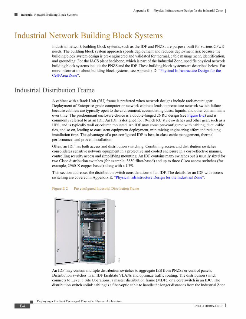
Appendix E Physical Infrastructure Design for the Industrial ZoneIndustrial Network Building Block Systems
Industrial Network Building Block Systems Industrial network building block systems, such as the IDF and PNZS, are purpose-built for various CPwE needs. The building block system approach speeds deployment and reduces deployment risk because the building block system design is pre-engineered and validated for thermal, cable management, identification, and grounding. For the IACS plant backbone, which is part of the Industrial Zone, specific physical network building block systems include the PNZS and the IDF. These building block systems are described below. For more information about building block systems, see Appendix D: “Physical Infrastructure Design for the Cell/Area Zone”.
Industrial Distribution Frame
A cabinet with a Rack Unit (RU) frame is preferred when network designs include rack-mount gear. Deployment of Enterprise-grade computer or network cabinets leads to premature network switch failure because cabinets are typically open to the environment, accumulating dusts, liquids, and other contaminants over time. The predominant enclosure choice is a double-hinged 26 RU design (see Figure E-2) and is commonly referred to as an IDF. An IDF is designed for 19-inch RU style switches and other gear, such as a UPS, and is typically wall or column mounted. An IDF may come pre-configured with cabling, duct, cable ties, and so on, leading to consistent equipment deployment, minimizing engineering effort and reducing installation time. The advantage of a pre-configured IDF is best-in-class cable management, thermal performance, and proven installation.
Often, an IDF has both access and distribution switching. Combining access and distribution switches consolidates sensitive network equipment in a protective and cooled enclosure in a cost-effective manner, controlling security access and simplifying mounting. An IDF contains many switches but is usually sized for two Cisco distribution switches (for example, 3850 fiber-based) and up to three Cisco access switches (for example, 2960-X copper-based) along with a UPS.
This section addresses the distribution switch considerations of an IDF. The details for an IDF with access switching are covered in Appendix E: “Physical Infrastructure Design for the Industrial Zone”.
Figure E-2 Pre-configured Industrial Distribution Frame
An IDF may contain multiple distribution switches to aggregate IES from PNZSs or control panels. Distribution switches in an IDF facilitate VLANs and optimize traffic routing. The distribution switch connects to Level 3 Site Operations, a master distribution frame (MDF), or a core switch in an IDC. The distribution switch uplink cabling is a fiber-optic cable to handle the longer distances from the Industrial Zone
3754
42
E-4Deploying a Resilient Converged Plantwide Ethernet Architecture
ENET-TD010A-EN-P

Appendix E Physical Infrastructure Design for the Industrial ZoneIndustrial Network Building Block Systems
to the IDMZ. By-products of this media choice are faster switch convergence after a network drop-out and higher bandwidth. In addition, the downlinks from the IDF to the PNZSs or control panel are best served with fiber, primarily for faster IES convergence in the event of a network drop-out to help to minimize production downtime and help to protect against EMI.
The following are specific key requirements and considerations for an IDF:
• Reach—An IDF can significantly increase cable reach, especially when deploying fiber uplinks and downlinks.
• Industrial Characteristics—A properly designed IDF mitigates M.I.C.E. hazards because IDF enclosures are IP67-rated with cooling capabilities. IDFs are isolated from Industrial Zone hazards, such as vehicle traffic, and are frequently located on outside walls, at a safe elevation on building columns, in mezzanines or a telecommunication room, and so on. IDF horizontal cabling, on the other hand, traverses harsh areas to reach its destination. The cabling must survive the harshest regions while maintaining end-to-end continuity. Cabling routed in underground troughs or tunnels must be hardened to withstand severe conditions and rodent damage. In these applications, close attention must be paid to cabling outer jacket, and an armor exterior such as aluminum clad or dielectric conduited should be considered. Since fiber-optic cable is inherently noise immune, fiber deployments remove EMI impacts.
• Physical Network Infrastructure Life Span—Network switches have an upgrade interval of three to five years. Cabling infrastructure should meet higher performance capabilities for future active equipment upgrades without the necessity of re-cabling the network.
• Maintainability—Cable management can be a challenge for an IDF. These enclosures host high port count switches and therefore must accommodate sizable cable bundles. Pre-configured solutions address these challenges by providing patching and routing to easily handle the mass of cable. Strain relief and bundling should be applied to horizontal cables routed to the IDF due to the tight quarters and bundle articulation when the cabinet is opened. Cable slack must be kept to a minimum because excessive slack cable leads to entanglement and snags, especially when opening an IDF. Installers sometimes use the enclosure to store slack cable. This practice can impede proper airflow and heat dissipation and makes the enclosure door difficult to close. Fiber-optic cables should be routed through corrugated loom tube for protection. The exception to this rule is dielectric conduited media, for which corrugated loom protection is unnecessary. Labeling and color coding cables facilitate MACs. Exact and shortest length patch cords can minimize cable sprawl. Small-diameter Ethernet patch cords, available in Category 5e and Category 6, reduce space occupied by cabling.
• Scalability—An IDF is the highest-density network distribution system. Growth is usually a feature for a proper IDF design. Network ports should be scaled to serve nodes today and for the next 10 years. For cable management and cable access with some growth, the enclosure should be sized to have at least three free RUs for every RU occupied by network switches.
• Designing for High Availability—Redundant switch uplinks must be present along with redundant star or ring topology downlinks to the IES.
• Network Compatibility and Performance—As distribution switches are upgraded, the cabling infrastructure must deliver compatible performance without re-cabling.
• Grounding and Bonding—All active network gear must be grounded to prevent worker injury and equipment damage. Further, laboratory tests have shown demonstrably better bit error rates when grounding and bonding practices are optimal. Typically, a network switch has a screw hole and pad for bonding. The best practice is to attach a grounding jumper to the switch grounding screw hole/pad with the opposite end connected to the enclosure grounding bar. When selecting grounding jumpers, it is important to consider that a low impedance path to ground delivers the best performance in managing EMI threats. In most cases, a braided grounding strap rather than a wire is the prudent choice. The grounding bar must be tied to the building grounding network. See Appendix D: “Physical Infrastructure Design for the Cell/Area Zone” for more details.
E-5Deploying a Resilient Converged Plantwide Ethernet Architecture
ENET-TD010A-EN-P

Appendix E Physical Infrastructure Design for the Industrial ZoneOptical Fiber Overview
• Security—Part of a defense-in-depth strategy, the physical security surrounding an IDF requires a number of layers of protection. The most effective physical layer measures include enclosure locks to prevent unauthorized access, keyed patch cords to avoid inadvertent patches, and port lock-in/block-out devices to prevent incorrect connections to unused ports.
• Reliability Considerations—Deploying a structured cabling approach enhances reliable communication. In a structured cabling environment, the horizontal (permanent link) cable is not touched, bundles are segregated and secured to ease handling, cable managers such as D-rings are selected to route cables with better access, power cables are secured at both device and power outlet ends to prevent power loss, and cabling and connectivity are selected to withstand the manufacturing environment.
• Ease of Deployment/Cost—Design, procurement, installation, and maintenance are some of the costs to consider. When compared to designing and building enclosures for network assets, a building block system approach leads to lower total costs with faster, proven installation.
PNZS with Distribution/Aggregation Switch
Smaller-footprint applications, where the need is to aggregate a few IES on the plant floor, can employ a DIN mount distribution/aggregation switch, such as a Stratix 5400 or Cisco IE-4000, to connect to the plant backbone. This can be a suitable choice for a modular line or Cell/Area Zone that potentially can be moved in whole (that is, networking is self-contained). These switches are more hardened against a hotter, harsher environment than the rack-mount Enterprise grade switches. DIN-mount IES should be protected using an appropriately specified PNZS. A DIN distribution switch can be deployed in a PNZS in the same manner as a DIN-mounted IES (see Figure E-3). In most cases, external cooling may not be required, reducing cost and minimizing A/C maintenance when compared to an Enterprise switch deployment. Cabling and connectors are the same as those used with Enterprise switches. Cable management and connectivity include DIN mount patch panel, DIN adapter for RJ45 jacks, and slack and strain relief features mounted to backplane or DIN. In addition, a barrier may be included to separate higher voltages from the DC power to the switches. See Appendix E: “Physical Infrastructure Design for the Industrial Zone” for more information.
Figure E-3 Zone Enclosure with a DIN Mount Distribution/Aggregation Switch
Optical Fiber Overview An optical fiber link consists of a transceiver, connector/adapter, and cable. The transceiver converts electrical data packets into light pulses that are transmitted through a glass fiber, which are converted to electrical signals by the receiving transceiver. A fiber connection usually has two fiber cables, one to transmit and the other to receive (that is, duplex). For IACS applications, optical fiber has many advantages over
3754
43
E-6Deploying a Resilient Converged Plantwide Ethernet Architecture
ENET-TD010A-EN-P

Appendix E Physical Infrastructure Design for the Industrial ZoneOptical Fiber Overview
copper channels, such as immunity to electrical noise, faster switch convergence after an interrupt, long reach, and higher bandwidth potential (with state-of-the-art fiber). The various considerations for selecting fiber are described below.
Physical Media
Fiber-optic cable is constructed of a core, cladding, coating, and jacket (see Figure E-4). The geometry of each of these components determines the index grade, or Optical Multimode. The two basic types of optical fiber are single-mode (referred to as OS) and graded index multimode (referred to as OM). Single-mode optical fiber supports data communications over long distances (for example, kilometers) and requires the use of higher-cost laser transceivers. On the other hand, graded index multimode fiber supports data communications up to 550 m but makes use of lower-cost transceivers, helping to lead to a lower-cost fiber deployment.
Figure E-4 Cross-Section of Fiber Construction Types
Although several transceiver types are available, most IES use a transceiver referred to as SFP. Most commonly, the connectivity is a duplex LC connector.
The term "graded index" refers to the dielectric constant of the silica material used in the core. "Graded" means that the dielectric constant is profiled as a function of radial distance from the center of the core to reduce slightly before the cladding material is reached. This parameter decreases the dispersion (a measure of the delay in time of arrival) between different modes within the fiber and helps to increase the maximum distance the fiber can support at a specified data rate.
3754
44
Multimode Graded Index (GI) 50/125µm
50µm GI Core
125µm Silica Clad
250µm Primary Coating
OM2 (500MHz*km), OM3 (2000MHz*km) & OM4 (4700MHz*km)
Multimode Graded Index (GI) 62.5/125µm
62.5µm GI Core
125µm Silica Clad
250µm Primary Coating
OM1 (200MHz*km)
Single -mode 9/125µm
8.5µm Core
125µm Silica Clad
250µm Primary Coating
Multimode Graded Index (GI) Polymer Clad Fiber (PCF) 50/200/230µm
50µm GI Core
200µm Silica Clad
230µm Silica Hard Coat
500µm Primary Coating
OM2 (500MHz*km)
Multimode Graded Index (GI) 50/125µm
62.5µm GI Core
200µm Silica Clad
230µm Silica Hard Coat
500µm Primary Coating
OM1 (200MHz*km)
8
E-7Deploying a Resilient Converged Plantwide Ethernet Architecture
ENET-TD010A-EN-P

Appendix E Physical Infrastructure Design for the Industrial ZoneOptical Fiber Overview
Within multimode, two basic families of core size exist: 62.5 µm and 50 µm. They are defined as Optical Multimode (OM) and are described by four levels: OM1 through OM4. OM1 has a 62.5 µm core and is considered legacy cable. OM2, OM3, and OM4 have a 50 µm core and are deployed more typically. Single-mode (OS) cable used in these applications typically has a core diameter of around 8.5 µm and a cladding diameter of 125µm. The designations for each are as follows:
• OM1—62.5/125µm graded index multimode (200 MHz.km)
• OM2—50/125µm graded index multimode (500 MHz.km)
• OM3—50/125µm graded index multimode (2,000 MHz.km)
• OM4—50/125µm graded index multimode (4,700 MHz.km)
• OS1—9/125µm single-mode
The values in parentheses are referred to as the effective modal bandwidth (EMB) of the fiber. The EMB represents the capacity of the fiber to transmit a certain amount of information over a specific distance and is expressed in MHz per km.
Optical Fiber Cable Outer Covering
This section discusses basic optical fiber outer covering types and performance. Figure E-5 is a M.I.C.E. chart categorizing each cable type by increasing environmental severity. The fiber type listed in the first column, Distribution, has limited protection and bend radius control but is the most cost-effective. The fiber type in the second column, Indoor/Outdoor (Dielectric), has better protection against chemical/climatic effects. The fiber type in the third column, Indoor Armored, has an aluminum clad to protect against crush along with chemical/climatic hazards. The fiber type in the fourth column, Gel-Free Outside Plant (that is, OSP) Armored, has robust protection for all M.I.C.E. levels. Figure E-5 also indicates the type and designation of the compatible SFP module.
Figure E-5 Recommended Fiber-optic Cable Types with Common SFP Modules for Plant-wide Network Applications37
5445
Fiber Type per MICE Level
M1I1C1E3 M1I1C2E3 M2I 2C2E3 M2I2C2E3
SFP Module
Rockwell Automation
SFP Part Number
Core Diameter
Maximum Distance
per Standards
Distribution
Indoor/Outdoor (Dielectric)
Indoor Armored
Gel -Free Outside Plant Armored
100BASE-FX 1783-SFP100FX 62.5µm 2km FSDR6^^Y FSN6R^^Y FSPR6^^Y FSWN6^ ̂
50µm 2km FSDR5^^Y FSNR5^^Y FSPR5^^Y FSWN5^ ̂
100BASE-LX 1783-SFP100LX 9µm 10km FSDR9^^Y FSNR9^^Y FSPR9^^Y FSWN9^ ̂
1000BASE-SX 1783- SFP1GSX
62.5µm 275m FSDR6^^Y FSNR6^^Y FSPR6^^Y FSWN6^ ̂
50µm 550m FSDR5^^Y FSNR5^^Y FSPR5^^Y FSWN5^ ̂
10 Gig 50µm 550km FODRX^^Y FONRX^^Y FOPRX^^Y FOWNX^ ̂
1000BASE -LX/LH 1783- SFP1GLX 9µm 10km FSDR9^^Y FSNR9^^Y FSPR9^^Y FSWN9^ ̂
1000BASE -LX/LH GLC-ZX-SM -RGD 9µm 40km FSDR9^^Y FSNR9^^Y FSPR9^^Y FSWN9^ ̂
Increasing Severity
Panduit part numbers listed above for bulk cable ^^ - fiber count. See
E-8Deploying a Resilient Converged Plantwide Ethernet Architecture
ENET-TD010A-EN-P

Appendix E Physical Infrastructure Design for the Industrial ZoneOptical Fiber Overview
Fiber Connectors and Adapters
Connectors are the physical interface between the cabling media and devices. A number of connector types are used in fiber-optic physical infrastructure. This section discusses three of those connector types:
• Lucent (LC) Connectors—Used in data center environments and some IACS devices. They have a small footprint that allows them to be used on high port density IES and on devices, minimizing real estate. The LC connector interface presents a SFF demountable interface for connection to SFP transceivers. The standard construction of the LC connector consists of a spring-loaded, 1.25 mm diameter zirconia ceramic ferrule housed in a thermoplastic connector back shell. The dimensions for this connector are defined in both domestic (TIA-604 FOCIS-10) and international (IEC 61754-20) standards. The LC connector footprint is approximately half the size of an SC connector and has a back shell to accommodate standard 1.6 mm to 3.0 mm diameter cable designs.
• Subscriber (SC) Connectors—Snap-in connectors that are widely used in single-mode systems for their performance. These connectors are used in the data communication and telecommunication industries. SC connectors are losing ground to LC and other connector types due to their larger size, which is not suitable for high-density applications.
• Straight Tip (ST) Connectors—Bayonet-style connectors that create secure multimode connections. ST connectors are used for inline connections; however, some equipment uses this type of connector because of the stability in the connection. ST connectors were once one of the most popular types of connectors.
Of these three connector types, the LC connector is becoming the most used type due to its high performance and small size, allowing the highest connection densities to be obtained with the smallest footprint. The characteristics of the three connector types are summarized in Table E-1.
*- Connector names vary
Dielectric Conduited Fiber Armored Cable for Plant Backbone
Dielectric Conduited Fiber (DCF) cable (see Figure E-5) may be the best option for plant backbone fiber. Its high crush resistance (six times greater than that of non-armored cable), self-supporting property (that is, can be hung from low-cost J-Hooks) and light weight for easy handling make it the best choice for this application. DCF cable is constructed of a rugged plastic conduit that is extruded over a standard tight buffered fiber distribution cable. The fiber specifications of DCF are the same as non-armored fiber OM1, OM2, and OS1/OS2 fiber cabling. The armored plastic dielectric properties remove the grounding and bonding requirements that govern standard armored metal-clad cable. For more information on DCF, see Appendix E: “Physical Infrastructure Design for the Industrial Zone”.
Table E-1 Fiber-optic Connector Comparison Summary
LC SC ST
Connector Name * Lucent or Little Square or Subscriber Straight Tip
Coupling Type Snap Snap (Push - Pull) Bayonet
Connector Outside Dimensions, mm 4.5 x 4.5 9.0 x 8.3 Diameter 8.6
Ferrule Size, mm 1.25 2.5 2.5
TIA Standard TIA-604 / FOCIS - 10 TIA-604 / FOCIS - 3 TIA-604 / FOCIS -2
IEC Standard IEC 61754-20 IEC 61754-4 IEC 61754-2
Duplex Type Yes, with clip Yes. Connector can mate No
E-9Deploying a Resilient Converged Plantwide Ethernet Architecture
ENET-TD010A-EN-P

Appendix E Physical Infrastructure Design for the Industrial ZonePhysical Network Design Considerations
Figure E-6 Dielectric Conduited Fiber Cable (DCF)
Physical Network Design ConsiderationsFigure E-7 illustrates a simplified Industrial Zone physical deployment between Levels 0-3. Depending on the plant size, the Level 3 Site Operations could connect to the Cell/Area Zone(s) through Core Switches. The links between the core switches in the Level 3 Site Operations and the distribution switch in the IDF use fiber-optic cabling. The distribution layer also connects to control panels that have IES with fiber network cabling.
Figure E-7 Physical Industrial Network Backbone
3754
47
3754
48
1 2 3 5 6 74+ - + + --INP SEN OU T GND
MOD
NET
CHG
PWR
1
0
CON
8 9
10
UPSMaintenance-free No battery 24VDC
1 2 3 4+ + + -IN OUT SENSE
UPS003LSMLO
AD SENSE MODULE
+ + - -
24-
28V
DC
on
®
N LAC 100-240V
1606-XLE80E
1606-XLE
+ + - -
24-
28V
DC
on
®
N LAC 100-240V
1606-XLE80E
1606-XLE
Cons
ole
1
22
1
1
3
5
7
2
4
6
8
Setup EI PNet
EIPMod
ExpressSetup
Co m
I N2
Re f
I N1
1 4
5 8
DC -
Pwr A
DC +
DC -
Pwr A
DC +IN1 IN2 OUT
Alarm
!
ygolonceT
TM
1 2 3 5 6 74+ - + + --INP SEN OU T GND
MOD
NET
CHG
PWR
1
0
CON
8 9
10
UPSMaintenance-free No battery 24VDC
1 2 3 4+ + + -IN OUT SENSE
UPS003LSMLOAD SENSE M
ODULE
+ + - -
24-
28V
DC
on
®
N LAC 100-240V
1606-XLE80E
1606-XLE
+ + - -
24-
28V
DC
on
®
N LAC 100-240V
1606-XLE80E
1606-XLE
Con
sole
1
22
1
1
3
5
7
2
4
6
8
Setup EI PNet
EIPMod
ExpressSetup
Co m
I N2Re f
I N1
1 4
5 8
DC -
Pwr A
DC +
DC -
Pwr A
DC +IN1 IN2 OUT
Alarm
!
ygolonceT
TM
Con
sole
1
2
1
3
5
7
2
4
6
8
Se tup EI PNet
EI PMod
ExpressSetup
Com
IN2Ref
IN1
1 4
5 8
DC -
Pwr A
DC +
DC -
Pwr A
DC +IN1 IN2 OUT
Ala rm
!
Te cno l ogy
TM
1
2
Con
sole
1
2
1
3
5
7
2
4
6
8
Se tup EI PNet
EI PMod
ExpressSetup
Com
IN2Ref
IN1
1 4
5 8
DC -
Pwr A
DC +
DC -
Pwr A
DC +IN1 IN2 OUT
Ala rm
!
Te cno l ogy
TM
1
2
Con
sole
1
2
1
3
5
7
2
4
6
8
Se tup EI PNet
EI PMod
ExpressSetup
Com
IN2Ref
IN1
1 4
5 8
DC -
Pwr A
DC +
DC -
Pwr A
DC +IN1 IN2 OUT
Ala rm
!
Te cno l ogy
TM
1
2
Smart-UPS
1 0 0 0
TestI
O
ww w.ap cc .com
UPS
To Core Switches
Switch Ring
Redundant StarDLR
Star
IDF
Physical Network Zone System
Fiber Network Cable
Copper Network Cable
E-10Deploying a Resilient Converged Plantwide Ethernet Architecture
ENET-TD010A-EN-P

Appendix E Physical Infrastructure Design for the Industrial ZonePhysical Network Design Considerations
IDF Physical Deployment Details
Figure E-8 illustrates IDF physical connectivity, detailing the enclosure cabling, jacks, patch cords, cable management, power, network switches, and cable ties. In general, an IDF is assembled in a similar manner as other RU cabinets and racks. The biggest challenge is to compensate for back articulation, thermal management, tight quarters, and cable sprawl from MACs. Following the best practices described below facilitates maintenance and long life.
Figure E-8 Typical IDF Deployment
Horizontal Cable Service Loop
The horizontal cabling is extended when opening a double-hinged IDF; therefore, a cable service loop is necessary for both fiber and copper. Planned and managed cable slack is required to fully open the enclosure. Although allowing service slack is important, too much extra cabling consumes excess space and can act as a spring when closing the enclosure. Also, the cable length increases from the first to the last copper port across the patch panel. The IDF stationary section uses hook & loop ties in the back to secure cabling. The copper cabling is also secured with hook & loop ties to strain relief bars on the movable side to minimize tugging on the jack when opening the enclosure. Fiber horizontal cable is channeled through duct and loom tube and then into a fiber enclosure for protection.
Thermal Management
The IDF can operate with an ambient temperature of up to 25º C (77º F) without air conditioning. Adding an air conditioner allows the IDF to operate up to 50º C (122º F) ambient air temperature. All cable should be neatly bundled and secured to prevent cabling from impeding airflow.
3754
49
Smart-UPS
1 0 0 0
TestI
O
www.ap cc.com
D-Rings
Distribution Switch
Cat 6 Jack
Access Layer Switch
Uninterruptable Power Supply (UPS) or
Power Distribution Unit (PDU)
Side View
Patch Panel
Movable Side Fixed Side
Small Diameter Patch Cords
Fiber Patch Cords
Front View
Door
Enclosure
A wall or column mount UL Type 4/12, IP66 double hinged enclosure for 2 distribution switches, 2 access switches and UPS.
Power
A conduit is connected to a metallic box with 2 receptacles. Each receptacle has its own 110/220 V circuit. One for switches the other Air Conditioner>
Service Loop Top View
Fiber
Fiber uplink trunk cable is routed to a fiber enclosure and terminated to a Fiber Adapter Panel (FAP). Patch cords connect switch uplink port to FAP connector.
Wall or Column
Hook & Loop Cable Tie
UPS
Standard Jacket Cat 6 Cable
Industrial Grade Jacket Cat 6 Cable
Standard Jacket Cat 6 Cable in ConduitFiber in Conduit
Dielectric Conduit Fiber
Power Cord
Strain Relief
Power cords are held securely with a strain relief bar with integral clips.
Strain Relief Bar
Keyed Latch
Double Hinged
Air Conditioner Access Cover
Door not shown
Conduit with Power
E-11Deploying a Resilient Converged Plantwide Ethernet Architecture
ENET-TD010A-EN-P

Appendix E Physical Infrastructure Design for the Industrial ZonePanduit List of Materials
Connectivity and Patching
The IDF may have both copper and fiber cabling. Typically, all cable enters from the bottom of an IDF to prevent liquid ingress. The holes in the enclosure for the cabling should have a fitting or grommet to prevent chaffing.
For fiber-optic cable, the best practice is to terminate the horizontal fiber cable into a fiber enclosure. The fiber enclosure is similar to an Enterprise enclosure, containing slack spools and strain relief to secure fiber strands, along with Fiber Adapter Panels (FAP). Patching is performed with fiber patch cords from the enclosure FAP to the switch uplink ports.
Copper downlinks from the switch are connected to a patch panel via a patch cord. The best practice is to have switches adjacent to patch panels. This helps to minimize cable sprawl, makes ports more visible, and helps to minimize entanglement. A short (8-inch) small-diameter patch cord (28 AWG) is recommended for easier handling and less space consumption.
Panduit List of MaterialsTable E-2 is a sample list of materials for best in class physical layer solutions for the Industrial Zone.
Table E-2 Sample List of Materials
Part Number Description
Z23N-SGABD5 24"x36" integrated system with 16 downlinks, expandable up to 48, Allen-Bradley Stratix 5400 and Cisco IE 4000 IES and UPS
FSPD508-50 12-Fiber OM2 Dielectric multimode Armored Distribution 50m
FLCDMCXAQY LC Opticam OM3/OM4 fiber-optic connector
Control Panel
IFC6C04BBL-CEG Shielded Cat 6 stranded cable, PVC jacket, CM
CADIN1IG DIN rail mount adapter, international gray
ISTPHCH1MBL 600 volt rated, Cat 5e patch cord, 1 meter long
ICAM12DRJS Bulkhead mounted RJ45 to M12 adaptor
ISPS688FA Field attached shielded RJ45 plug
IAEBH6 Bulkhead Jack Cat 6 UTP RJ45 with cap
IAPNG5EWH IndustrialNet Data Access Port, Cat 5e, White
Machine & Robot
ISFCH5C02ATL-XG Industrial Copper Cable, Cat5e, 2-pair, 24/7 AWG stranded, SF/UTP, CM, 600V, Teal, 1000ft/305m reel, High Flex, Sun and Oil Resistant
ISFCH5C04ATL-XG Industrial Copper Cable, Cat5e, 4-pair, 24/7 AWG stranded, SF/UTP, CM, 600V, Teal, 1000ft/305m reel, High Flex, Sun and Oil Resistant
ISPS55E44MFA Field attached shielded M12 plug
JP2SBC50-L20 J-Hook with screw-on beam clamp for use with flanges up to ½"
WG12BL10 12" wide x 10' long pathway section used to carry cables horizontally throughout the system.
IUTPSP10BL Industrial Patch Cord Cat 6 UTP RJ45 with caps, 10 feet
ISX6004AYL-LED Industrial Copper Cable, Cat6, 4-pair, 24/7 AWG Stranded, S/FTP, PUR, Yellow, 500m RL
E-12Deploying a Resilient Converged Plantwide Ethernet Architecture
ENET-TD010A-EN-P

Deploying a Resilient Co
ENET-TD010A-EN-P
A P P E N D I X F
Physical Infrastructure Deployment for Level 3 Site OperationsThe Level 3 Site Operations Area provides the switching, compute, and storage resources needed to efficiently operate a plant. This area is the foundation for data collection and application hosting in the industrial setting. Level 3 equipment may be physically housed in an industrial data center, in a rack in the control room, or several other locations on the premise. Level 3 Site Operations applications range from MES measures such as Overall Equipment Effectiveness (OEE), lot traceability preventive maintenance schedules, process monitoring/management, safety/security dashboards, and productivity key performance indicators (KPIs). Continuity of service is imperative as these functions are used for daily decision-making on an ever-increasing basis. Manufacturing downtime is readily measured in minutes and in thousands of dollars from missed customer commitments. Reliable and secure network support for these applications keeps operations running and business communication running smoothly.
The successful deployment of Level 3 Site Operations depends on a robust network infrastructure built on a rock solid physical layer that addresses the environmental, performance, and security challenges present when deploying IT assets (servers, storage arrays, and switching) in industrial settings. The Level 3 Site Operations is a key convergence point for IT and OT. Many businesses obtain these functions in a pre-engineered package, Industrial Data Center (IDC). IDC systems include the proper IT assets housed in an appropriate cabinet with patching, power, grounding/bonding, identification and physical security considerations already addressed a plug and play solution.
The Level 3 Site Operations Area presented in this Appendix is a model for integrating a scalable, modular, logical network and compute systems into the physical infrastructure. Some benefits of this approach are listed below:
• Improves network availability, agility, scalability and security
• Reduces operational costs, including energy costs, with improved efficiencies
• Can help to simplify resource provisioning
• Lays the foundation for consolidation and virtualization
• Helps to create a path to future technology requirements such as 10/40GbE
This Appendix includes the following major topics:
• Key Requirements and Considerations, page F-2
• Physical Network Design Considerations, page F-8
• Panduit List of Materials, page F-16
F-1nverged Plantwide Ethernet Architecture

Appendix F Physical Infrastructure Deployment for Level 3 Site OperationsKey Requirements and Considerations
Key Requirements and ConsiderationsIndustrial network deployments have evolved over the years from a network gateway layout to a converged plant-wide architecture. CPwE architecture provides standard network services to the applications, devices, and equipment found in modern IACS applications and integrates them into the wider enterprise network. The CPwE architecture provides design and implementation guidance to achieve the real-time communication and deterministic requirements of the IACS as well as to help provide the scalability, reliability and resiliency required by those systems.
In support of industrial network performance, many physical infrastructure aspects of the Level 3 Site Operations serve an important role, and must be considered in the design and implementation of the network:
• Industrial Characteristics—Plant networking assets and cabling used in Level 3 Site Operations are not environmentally hardened but are almost exclusively installed in IP20 or better environments. Environmental risks at Level 3 Site Operations involve thermal management of heat dissipated by equipment and power quality considerations.
• Physical Network Infrastructure Life Span—IACS and plant backbone can be in service as long as 20 year or more. Hardware used in Level 3 Site Operations being IT gear has a much shorter life span, generally three to five years. The infrastructure used to connect and house the hardware such as cabinets, cabling, connectivity, and enclosures has a much longer life span, generally 10-15 years. Consideration of higher performance cabling enables current and future data communications needs to be fully met. Choices between copper and fiber-optic cabling assure higher data rate transport requirements.
• Maintainability—Note that MACs at Level 3 have dependencies that affect many Cell/Area Zones. Also, changes need to be planned and executed correctly to avoid bringing down the IACS process. Proper cable management such as bundling, identification and access is vital for proper Level 3 Site Operations maintenance.
• Scalability—The high growth of EtherNet/IP and IP connections can strain network performance and cause network sprawl that threatens uptime and security. A strong physical building block design accounts for traffic growth and management of additional cabling to support designed network growth. Use a physical zone topology together with structured copper and fiber-optic cabling chosen for high data throughput. Choose building block pre-configured solutions to enable a network infrastructure comprised of modular components that scale to meet increasing industrial Ethernet communications needs in the IACS network.
• Designing for High Availability—A robust, reliable physical infrastructure achieves service levels required of present and future IACS networks. The use of standards-based cabling together with measured, validated performance confirms reliable data throughput. Use of redundant logical and physical networks assures highest availability. Properly designed and deployed pathways should be employed to insure redundant cable paths are also resilient.
• Network Compatibility and Performance—Cable selection is the key to optimal physical network performance. Network performance is governed by the poorest performing element in any link. Network compatibility and optimal performance is essential from port to port, including port data rate and cabling bandwidth.
• Grounding and Bonding—A well architected grounding/bonding system is crucial for of industrial network performance at every level whether internal to control panels, across plants, or between buildings. A single, verifiable grounding network avoids ground loops that can degrade data and have equipment uptime and safety implications.
• Security—Network security is a critical element of network uptime and availability. Physical layer security measures, such as logical security measures, should follow a defense-in-depth hierarchy. The Level 3 Site Operations physical defense in-depth strategy could take the form of locked access to industrial data center/control room spaces and cabinet key card access to help limit access, use of LIBO
F-2Deploying a Resilient Converged Plantwide Ethernet Architecture
ENET-TD010A-EN-P

Appendix F Physical Infrastructure Deployment for Level 3 Site OperationsKey Requirements and Considerations
devices to control port usage and keyed patch cords to avoid inadvertent cross patching. Using a physical strategy in concert with your logical strategy prevents inadvertent or malicious damage to equipment and connectivity achieving service level goals.
• Wireless—Unified operation of wireless APs requires a WLC at Level 3 Site Operations and distribution of Lightweight Wireless Access Points (LWAPs) across Industrial Zone and Cell/Area Zones. Autonomous wireless APs, typically WGBs, in Cell/Area Zones involve cabling for APs and WGBs. The Industrial Zone backbone media selection and cabling for APs using PoE are critical for future readiness and bandwidth considerations. PoE is evolving to deliver more power over copper cabling, therefore understanding industrial applications with scalability and environmental considerations is critical.
Industrial Characteristics
Room Environment
A sustainable cooling system design that follows industry best practices is essential to the success of modern Level 3 Site Operations deployments. Optimized cooling management and a more efficient energy system are the results, which means IT equipment is safe from unplanned downtime due to overheating and significant operational expense (OpEx) savings are realized.
The Level 3 Site Operations room is divided into a hot aisle/cold aisle arrangement, to separate the cold inlet air on the front side of the cabinets and the hot exhaust air on the rear side of the cabinets. Cold air in this design is fed through the raised floor via a Computer Room Air Conditioning (CRAC) unit. Cold air can be delivered by several different means, as long as it maintains the hot aisle/cold aisle arrangement. Hot air in this design is exhausted through fans in the ceiling.
Thermal Ducting
Network switches deployed in data centers (for example, Catalyst® 4500-X/6800) often utilize side-to-side airflow cooling. This airflow design requires less vertical space and permits high switch port density. Given proper inlet air conditions, these switches are well designed to cool themselves. However, large bundles of cabling driven by high port density impede airflow. Also, hot exhaust air can recirculate to the intake, raising inlet temperatures and inhibiting the switches' self-cooling ability. For network equipment that utilizes side-to-side airflow patterns, in-cabinet ducting optimizes cooling system efficiency by establishing front-to-back airflow patterns throughout the cabinet. Through the use of Computational Fluid Dynamics (CFD) analysis and testing, ducting solutions have been developed that improve inlet air conditions for cabinet applications.
Physical Network Infrastructure Life Span
IACS and plant backbone technologies can have a lifespan of up to 20 years. IT hardware has a much shorter life span, generally in the 3-5 year range. While a three year refresh cycle is commonplace for IT personnel in enterprise and data center domains, it is not routine in current OT domains. Level 3 physical infrastructure that supports IT hardware should have a much longer lifespan, usually three to four IT hardware refresh cycles. As a result, it is important to consider the structural dependability of cabinets, future proof types of cabling, and pathways optimized for capacity growth projections. It is also important to adhere to structured cabling practices and install upgraded and spare media to protect against physical layer obsolescence. Making informed physical infrastructure decisions from the beginning affect the ability to complete future projects in a timely and cost effective manner.
F-3Deploying a Resilient Converged Plantwide Ethernet Architecture
ENET-TD010A-EN-P

Appendix F Physical Infrastructure Deployment for Level 3 Site OperationsKey Requirements and Considerations
Maintainability
Patching
The best practice for patching is to land fiber cable into an enclosure or box following a structured cabling approach. When fiber is terminated, several inches of the glass strand are exposed. This part of the fiber is very fragile and needs the enclosure or box to protect the fiber from damage. Terminating directly to a connector without protection or support can lead to failures. For rack/cabinet installations, a 19" style fiber enclosure is a suitable choice. When installing fiber into a control panel, components such as the DIN Patch Panel or Surface Mount Box provide patching. Another advantage for structured cabling is to build in spares ready for use to accommodate growth or for recovery from link failure.
Bundling
The best practice for bundling numerous standard jacket fiber cables is to use a hook and loop cable tie. This cable tie does not over-tighten the bundle, which can lead to damage. However, the environmental impact on the hook and loop tie is an important consideration and for these instances, a more durable cable tie for fiber is the elastomeric tie. It has the ability to stretch to prevent over tension and guard against weather, oil, salts, etc. The use of nylon cable ties can potentially damage the cable and is not recommended for standard jacket fiber cable but it is appropriate for armored or DCF cabling.
Identification
Identification facilitates MACs and aids in troubleshooting. Fiber cabling identification includes labeling and color coding. Labeling can be applied to enclosures, ports, patch cords, horizontal cables, and so on. Since some fiber cable diameter is small, applying a label can be a challenge. A sleeve can be applied to increase the diameter to make the label readable. The text on the labeling should follow TIA-606A standards. A breakdown usually occurs from the enclosure/rack, RU, port, and so on, that is consistent throughout the facility. For example, CP1.PP1.02 could mean control panel 1, patch panel 1 and port 2. Color coding can identify VLANs, zones, functional areas, network traffic type, and so on, and can be achieved with labels, hook and loop cable ties, and color bands. Although fiber cable is color coded by cable type, additional color coding can be performed for clarity using the methods described above.
Scalability
Pathway Decisions - Type and Sizing
Pathways for cables are critical for distributing copper and fiber cabling securely across the plant floor while protecting from physical threats that can degrade or damage the cable. The TIA-1005 standard, ODVA Media Planning and Installation manual, and TIA resources provide recommendations on pathways including cable spacing and installation guidance to minimize risks from environmental threats. Several options exist for routing cables via pathways that simplify deployment using best practices for a variety of environments across the plant. Figure F-1 describes some of the options.
F-4Deploying a Resilient Converged Plantwide Ethernet Architecture
ENET-TD010A-EN-P

Appendix F Physical Infrastructure Deployment for Level 3 Site OperationsKey Requirements and Considerations
Figure F-1 Pathway Options
The simplest and lowest cost pathways are J-Hooks. J-Hooks can be mounted to a wall, beam or other surface. Network cables are held in place by the hook feature and often secured with a cable tie. The J-Hook hook feature maintains proper bend radius control when transitioning down. J-Hook systems should be utilized with cables that have rigidity to have an acceptable bend between spans and is suitable for a small bundle. Standard fiber distribution cable is not suitable for J-Hooks unless supported by corrugated loom tube.
When routing large or many cable bundles, a tray or wire basket can be installed overhead to form a solid and continuous pathway. Since cabling is exposed to the plant environment, cable jackets need to be specified for the environment. Cable tray material should also be rated for the environment. An enclosed tray such as a fiber tray provides a high level of environmental protection for light to heavy cable densities. For highest protection with few network cables, conduit is the preferred choice. Care needs to be taken to maintain proper bend radius and lineal support to prevent cable sag.
Designing for High Availability
Cable Management
Proper cable management is essential for high system performance, availability, and reliability. A resilient cable management system is critical in areas such as MACs (for example, identification and color coding) to verify the proper action is taken and to aid in troubleshooting. Care also must be taken to protect the cabling from excessive bend, flexing, sag, rubbing, crush, etc. A strong cable management system needs to be designed around the following key elements:
• Bend radius control
• Cable routing and protection
Bend Radius Control
It is important to have a bend radius greater than or equal to manufacturer-specified minimum bend radius when handling fiber-optic cabling to prevent it from excessive bending, which can cause physical damage. Two considerations for bend radius control are:
• Dynamic—Cable flexing (especially during installation)
• Static—Cable held in place
Fiber cable manufacturers specify both radiuses where the dynamic bend radius can be 20 times the Outer Cable Diameter (OD) and the static bend radius is typically 10 times the OD. Although fiber strands are very thin and made of glass, the strand is durable and can withstand some flexing. However, flexing in general can cause deformities in the fiber, leading to signal loss over time (that is, microbend). Therefore, the stricter bend radius is dynamic. Another risk to a properly terminated and validated fiber cable is attenuation due to
3754
50
Installation Consideration J-Hook
Wyr-Grid®
FiberRunner®
Cable Protection Environment Mild Moderate Moderate to harsh
Cable Density Light to medium Medium to heavy Light to heavy
Applicable in Constrained Spaces Yes No No
Installation Complexity Simple Moderate Moderate to strong
Ease of Moves, Adds, Changes Simple Moderate Moderate
F-5Deploying a Resilient Converged Plantwide Ethernet Architecture
ENET-TD010A-EN-P

Appendix F Physical Infrastructure Deployment for Level 3 Site OperationsKey Requirements and Considerations
excessive cable bend (that is, static). Essentially, the bend allows the light to escape the glass, reducing signal strength (that is, macrobend). The bend radius is based on the OD, therefore the minimum bend radius for the application can vary. For example, a fiber patch cord cable has a static bend radius of 1.1" while a 12 fiber distribution cable has 2.4" bend radius. Bend radius is maintained by spools, clips, fins, and product features and proper coiling. In a 19" data center style server or switch rack/cabinet, bend radius accessories can be installed to route fiber cable vertically and horizontally. Fiber enclosures and boxes used in data center cabinets/racks typically have built-in slack spools. Also, supplied adhesive backed clips secure the cabling and provide strain relief.
Cable Routing and Protection
Often, fiber cable is routed through conduit for protection. Although conduit is an excellent safeguard, it is designed for power cabling and has fittings, junction boxes, and so on, where fiber cable under some tension can potentially bend the fiber cable below the minimum bend radius. Pathways such as wire basket and J-hooks have challenges for sagging and bends that can attenuate the signal, especially for unprotected standard distribution cable. Therefore, the cable must be supported and bends must be controlled. Draping unprotected distribution cable over J-Hooks or laying the cable over an open tray with grids can potentially lead to fiber sagging below the minimum bend radius. To avoid this risk, fiber cabling can be pulled through corrugated loom tube, providing rigidity and support. Typically, fibers in interlocking armor or DCF do not encounter these issues because the armor provides support and restricts the bend radius.
To protect fiber cabling when routed in control panels, it needs to be carefully laid in duct or tubing to avoid snags and kinks, maintaining proper bend radius. Adhesive backed mounting clips can hold fiber cabling in place outside of ducts along the panel wall or top.
Network Compatibility and Performance
Cable Media Selection
Depending on cable construction, many considerations exist for cable media selection such as reach, industrial characteristics, life span, maintainability, compatibility, scalability, performance, and reliability. See Table F-1.
*Fiber-optic media is inherently noise immune; however, optical transceivers can be susceptible to electrical noise.
Table F-1 Cable Media Selection Characteristics
Parameter Copper Cable Multimode Fiber Single-mode Fiber
Reach (maximum) 100 m 2,000 m (1 Gbps)
400 m (10 Gbps)
10 km (1 Gbps)
10 km (10 Gbps)
Noise Mitigation Option Foil shielding Noise immune* Noise immune*
Data Rate (Industrial) 100 Mbps (Cat 5e)
1 Gbps (Cat 6)
10 Gbps (Cat 6a)
1 Gbps
10 Gbps
1 Gbps
10 Gbps
Cable Bundles Large Small Small
Power over Ethernet (PoE) capable Yes Yes, with media conversion Yes, with media conversion
F-6Deploying a Resilient Converged Plantwide Ethernet Architecture
ENET-TD010A-EN-P

Appendix F Physical Infrastructure Deployment for Level 3 Site OperationsKey Requirements and Considerations
Fiber and Copper Considerations
When cabling media decisions are made, the most significant constraint is reach. If the required cable reach exceeds 100 m (328 feet), then the cable media choice is optical fiber cable. Copper Ethernet cable is limited to maximum link length of 100 m. However, other considerations exists for distances less than 100 m such as EMI where fiber-optic cable is chosen due to its inherent noise immunity. Another consideration is the fact that IES uplinks connected with optical fiber converge faster after an IES power interruption, lessening the duration of the network outage. When it comes to data rates, copper and fiber are similar for typical industrial applications. However, other higher performing optical fiber are available for very high demand networks.
When it comes to media performance, a major consideration is network lifespan. For instance, installing a network with Cat 5e cabling could be obsolete in a couple of years, especially if transporting video. If the expectation is 10 or more years of service, the fastest category cabling should be considered. Note that upgrading networked equipment and switches in the future may only come with higher data rate ports.
Multimode vs Single-mode
Fiber has two types, single-mode and multimode. Multimode has many glass grades from OM1 - OM4. Single-mode has two glass grades, OS1 and OS2. When selecting any optical fiber, the device port must be considered first and must be the same on both ends (that is, port types cannot be mixed). In general, the port determines the type of fiber and glass grade. If the device port is SFP, flexibility exists to select compatible transceivers and the transceiver best for the application. In addition to different media, the number of strands, mechanical protection, and outer jacket protection should be considered.
Grounding and Bonding
It is essential that robust and clean power be supplied to the Level 3 Site Operations to keep the factory network running smoothly without compromises in communications and equipment performance. The incoming power feed typically includes an UPS and one or more Power Outlet Units (POUs) to distribute power for IT assets where needed. POU voltages range from 100 to 125V or 220V to 250V depending upon the region of the world, with currents ranging from 15 to 30 amp. Connectors may be straight blade or twist locks. Popular IEC configurations are C13 to C14 and C19 to C20. Additionally, POUs may include intelligent features such as power and environmental monitoring to aid in troubleshooting and diagnostics.
Grounding of the Level 3 Site Operations is critical to optimizing performance of all equipment located within the Level, reducing downtime due to equipment failures and reducing the risk of data loss. Exemplary grounding and bonding provides demonstrable improvement in bit error rate in data center and enterprise applications. Given the higher potential for EMI in industrial applications, the improvement stands to be remarkable. Also, Cisco and Rockwell Automation logic components require good grounding practices to maintain warranty support. The use of a single ground path at low impedance is commonly achieved through a busbar.
Bridging the grounding connection from Level 3 Site Operations to busbar can occur in several ways: First, a braided grounding strap connects the rack or cabinet to the building ground network. Second, grounding jumpers connect equipment to the housing structure. Finally, paint piercing screws and washers achieve a direct metal-to-metal connection throughout the Level 3 Site Operations. Unless a clear and deliberate effort to confirm proper grounding has been performed, ground loops can be established that result in lost communication data and compromised equipment performance.
F-7Deploying a Resilient Converged Plantwide Ethernet Architecture
ENET-TD010A-EN-P

Appendix F Physical Infrastructure Deployment for Level 3 Site OperationsPhysical Network Design Considerations
Security
Both physical and logical security should be important considerations when designing Level 3 Site Operations. Physical layer security measures, such as locked access to data center/control room spaces and key card access to cabinets help limit access to and help prevent inadvertent or malicious damage to equipment and connectivity to help achieve service level goals. Often overlooked basics such as labeling, color coding, and use of keyed jacks can prevent crossing channels or removing active links inadvertently. Lock-in connectors can secure connections in switches or patching to control who can make changes and help to protect against cables being disconnected unintentionally.
Note For more information, please see the Securely Traversing IACS Data Across the Industrial Demilitarized Zone Design and Implementation Guide at the following URL:
• http://literature.rockwellautomation.com/idc/groups/literature/documents/td/enet-td009_-en-p.pdf
Wireless
Secure wireless access in Industrial environments is a growing need. Considerations for jobs to be completed wirelessly and an idea of future growth are needed to begin planning and design. Two main applications are served wirelessly today. These are mobility and WGB communications.
Mobility helps knowledge workers and guest workers securely access data to make more timely and accurate decisions, increasing their overall productivity and effectiveness. Therefore, mobility designs must give sufficient coverage to afford access as needed. In addition, knowledge workers such as engineers and technicians employed by the business typically need to access not only the Internet but internal network resources. Guest workers such as contractors and repair personnel deployments are typically used to enable machinery communications. Many times the machinery is dynamic (that is, movement through the facility) and needs to quickly reestablish wireless communications with the network once in place. WGB wireless does an excellent job for this use case.
Note For more information, see the Deploying 802.11 Wireless LAN Technology within a Converged Plantwide Ethernet Architecture Design and Implementation Guide at the following URLs:
• http://www.cisco.com/c/en/us/td/docs/solutions/Verticals/CPwE/NovCVD/CPwE_WLAN_CVD.html
• http://literature.rockwellautomation.com/idc/groups/literature/documents/td/enet-td006_-en-p.pdf
Physical Network Design Considerations
Logical to Physical Simplified
Figure F-2 represents a potential layout of plant floor with enterprise office space. The CPwE logical architecture on the top is mapped to the locations that the different levels of operation could potentially be placed within the plant floor.
F-8Deploying a Resilient Converged Plantwide Ethernet Architecture
ENET-TD010A-EN-P

Appendix F Physical Infrastructure Deployment for Level 3 Site OperationsPhysical Network Design Considerations
Figure F-2 CPwE Logical to Physical Plant Floor
Level 3 Site Operations - Large Scale Deployment
Figure F-3 represents >>>>>>>>>>>>>>>>>>>>>>
Figure F-3 Level 3 Site Operations Logical to Physical Deployment
Overview
The Level 3 Site Operations can function differently in diverse environments and layouts, but generally it houses the networking to connect the plant floor to the enterprise and applications that allow the plant to operate efficiently. The layout described in Figure F-3 demonstrates a larger industrial deployment. This deployment is likely much larger than most plants would require, but demonstrates how the Level 3 Site Operations infrastructure would be deployed if this scale were required. The core of the network is utilizing
3754
41
D.
Pa
cka
gin
g/S
hip
pin
g
A C
C R
C.2
C.3C
.1
G.
D.
Pa
cka
gin
g/S
hip
pin
g
A C
C R
C.2
C.3C
.1
G.
Remote
witch Stack
CoreSwitchesRADIUS
(AAA) ServerPhysical or Virtualized Servers• FactoryTalk Application Servers and
Services Platform• Network & Security Services – DNS,
AD,DHCP, Identity Services (AAA)• Storage Array
AccessServer
Physical or Virtualized Servers• Patch Management• AV Server• Application Mirror• Remote Desktop Gateway Server
istribution
HMI
Cell/Area Zone - Levels 0–2Redundant Star Topology - Flex Links Resiliency
Unified Wireless LAN(Lines, Machines, Skids, Equipment)
Cell/Area Zone - Levels 0–2Linear/Bus/Star Topology
Autonomous Wireless LAN(Lines, Machines, Skids, Equipment)
IndustrialDemilitarized Zone
(IDMZ)
Enterprise ZoneLevels 4 and 5
Rockwell AutomationStratix 5000/8000
Layer 2 Access Switch
Industrial ZoneLevels 0–3
(Plant-wide Network)
Phone
Controller
CameraSafety
Controller
Robot
Soft Starter
Cell/Area Zone - Levels 0–2Ring Topology - Resilient Ethernet Protocol (REP)
Unified Wireless LAN(Lines, Machines, Skids, Equipment)
I/O
Plant Firewalls• Active/Standby• Inter-zone traffic segmentation• ACLs, IPS and IDS• VPN Services• Portal and Remote Desktop Services proxy
Wide Area Network (WAN)
Physical or Virtualized Servers• ERP - Business Systems• Email, Web Services• Security Services - Active Directory (AD), Identity
Services (AAA)• Network Services – DNS, DHCP• Call Manager
Enterprise
I/O
ServoDrive
Instrumentation
I/O
Level 3 - Site Operations(Control Room)
Internet
External DMZ/ Firewall
HMI
Active
AP
SSID5 GHz
WGB
SafetyI/O
Controllert
W
LWAP
SSID5 GHz WGB
LWAP
Controller
LWAP
SSID2.4 GHz
Standby
WirelessLAN Controller
(WLC)
Cell/Area Zone
Levels 0 –2
Cell/Area Zone
Levels 0– 2
Drive
CAPWAPCAPWAP
CAPWAP
witch Stackistribution
Enterprise Data Center
Level 3 Site Operations
Industrial Distribution Frame
Cell /Area Zones
3754
52
Remote
CoreSwitchesRADIUS
(AAA) Server
AccessServer
Active
Standby
WirelessLAN Controller
(WLC)
Catalyst2960
Firewall(Active)
Link
for Failover
Detection
Firewall(Standby)
ASA 5500
F-9Deploying a Resilient Converged Plantwide Ethernet Architecture
ENET-TD010A-EN-P

Appendix F Physical Infrastructure Deployment for Level 3 Site OperationsPhysical Network Design Considerations
two Cisco Catalyst 6800 with a full fiber distribution network. This deployment is employing virtualized servers to provide efficient and resilient compute power to the plant floor and beyond. Four distinct cabinets house equipment for three different areas of the CPwE architecture: Level 3 Site Operations or IDC, IDMZ, and Core Switching Cabinets. Each of the cabinets is detailed further below.
IDC Cabinets
The IDC cabinet (see Figure F-4) houses the Catalyst 3850 switches that provide access to WLC and the virtualized servers that can provide several services and applications to the plant floor.
Figure F-4 IDC Cabinet Logical to Physical Deployment
Within the cabinet, the servers are placed at the bottom of the cabinet, and switches are at or near the top. The servers are the heaviest pieces of equipment within the cabinet and are placed at the bottom to create the lowest center of gravity possible. This prevents the cabinet from tipping over and makes it more stable in case it needs to be moved as a unit. The Catalyst 3850 switches are placed at the top of the cabinet to allow for easy connections to the Catalyst 6800 switches. The 3850 switches have a back to front airflow, which means that the port side of the switch is facing the hot aisle. The 5500 WLCs are placed a few RU below the Catalyst 3850 switches. The 5500 WLCs have their ports on the front side and have an airflow from front to back only. This means that to connect to the Catalyst 3850 switches, which have their ports on the back side, a cable pass-through is required to connect. The servers have their network ports on the hot aisle side (or back side), which allows them to connect easily to the Catalyst 3850 switches.
IDMZ Cabinet
The IDMZ cabinet (see Figure F-51) houses the equipment that logically separates the enterprise from the plant floor.
Remote
RADIUS(AAA) Server
AccessServer
Active
Standby
5500Wireless
LAN Controller (WLC)
3754
53
F-10Deploying a Resilient Converged Plantwide Ethernet Architecture
ENET-TD010A-EN-P

Appendix F Physical Infrastructure Deployment for Level 3 Site OperationsPhysical Network Design Considerations
Figure F-5 IDMZ Cabinet Logical to Physical Deployment
The IDMZ Cabinet has two Cisco Catalyst 2960 switches, two (active/standby) ASA 5500 firewalls, and several virtualized servers that house applications and software which needs to reside within the IDMZ. The servers are the heaviest pieces of equipment within the cabinet and are placed at the bottom to create the lowest center of gravity possible. This prevents the cabinet from tipping over and makes it more stable in case it needs to be moved as a unit. The Catalyst 2960 switches are placed at the top of the cabinet to allow for easy connections to the Catalyst 6800 switches. All the equipment has network ports on the hot aisle (back side), which allows for easy connections between equipment.
Server Cabinets
Server Cabinets offer several features that enhance cable and thermal management and should be used when deploying servers, such as the Cisco UCS C220. Cabinet air seal features and integration with passive hot and cold air containment components drive efficient utilization of cooling capacity and reduce cooling energy consumption. Modular cable management systems available on server cabinets, enable simplified organization of cables and proper bend radius control. Smart cabinet features allow access to environmental, power, and security information.
Core Switching Cabinets
The core switching cabinets (see Figure F-6) house the redundant Cisco Catalyst 6800 switches that serve as the plant floor core switches and the gateway between the plant floor and the enterprise.
Catalyst2960
Firewall(Active)
Firewall(Standby)
ASA5500
3754
54
F-11Deploying a Resilient Converged Plantwide Ethernet Architecture
ENET-TD010A-EN-P

Appendix F Physical Infrastructure Deployment for Level 3 Site OperationsPhysical Network Design Considerations
Figure F-6 Core Switching Cabinets Logical to Physical Deployment
The Catalyst 6800 cabinets use switch cabinets or network cabinets, which provide additional space for cable and thermal management. The switch cabinet has an air dam installed that separates the cold air in the front of the cabinet, from the hot exhaust air that is located on the back side of the cabinet. Because the Cisco Catalyst 6800 switch has a side-to-side airflow, the use of a 6800 thermal ducting system is required to operate within a hot/cold aisle arrangement in the data center. The Cisco Catalyst 6800 switches are located at the bottom of the cabinet because they are the heaviest equipment within the cabinet and create the lowest center of gravity. The patch panels at the top of the cabinet provide connectivity to the plant floor and to the IDMZ cabinet.
Network Cabinets
Network cabinets offer several features that enhance cable and thermal management and should be used when deploying large chassis-based switches, such as the Cisco Catalyst 6800 switch. An inset frame design efficiently manages large quantities of cables and provides space for access maintenance. Cabinet air seal features and integration with passive hot and cold air containment components drive efficient utilization of cooling capacity and reduce cooling energy consumption. Dual-hinged doors reduce time needed to perform MACs. Modular cable management systems available on network cabinets, enable simplified organization of cables and proper bend radius control.
Physical to Physical Simplified
IDMZ Cabinet to Core Switching Cabinets
The IDMZ to Core Switch connections shown in Figure F-7 and Figure F-8 can be copper or fiber depending on the model of firewall and the line card used in the Catalyst switch.
CoreSwitches
3754
55
41
36
31
26
21
16
11
6
1
42
40
39
38
37
35
34
33
32
30
29
28
27
25
24
23
22
20
19
18
17
15
14
13
12
10
9
8
7
5
4
3
2
41
36
31
26
21
16
11
6
1
42
40
39
38
37
35
34
33
32
30
29
28
27
25
24
23
22
20
19
18
17
15
14
13
12
10
9
8
7
5
4
3
2
C6807-XL-FAN
Fan Statu s ID
!
1
2
3
4
5
6
7
CATALYST C6807-XL
PSC 2
PSC 1
Power Supply
AC3
AC1 AC2
AC4
ON OFF
FAULT
OUT
IN
C6800-XL-3KWAC
FAULT
OUT
IN
C6800-XL-3KWAC
3
1
4
2
FAULT
OUT
IN
C6800-XL-3KWAC
FAULT
OUT
IN
C6800-XL-3KWAC
St atus
48 Port Gigabit Ethernet-SFP C6800 - 48P-SFP
A B
33 35
C D
37 39
1 2 3 4 5 6 7 8 9 10 11 12 13 14 15 16 17 18 19 20 21 22 23 24 25 26 27 28 29 30 31 32 33 34 35 36 37 38 39 40 41 42 43 44 45 46 47 48
St atus
48 Port Gigabit Ethernet-SFP C6800 - 48P-SFP
A B
33 35
C D
37 39
1 2 3 4 5 6 7 8 9 10 11 12 13 14 15 16 17 18 19 20 21 22 23 24 25 26 27 28 29 30 31 32 33 34 35 36 37 38 39 40 41 42 43 44 45 46 47 48
St atus
48 Port Gigabit Ethernet-SFP C6800 - 48P-SFP
A B
33 35
C D
37 39
1 2 3 4 5 6 7 8 9 10 11 12 13 14 15 16 17 18 19 20 21 22 23 24 25 26 27 28 29 30 31 32 33 34 35 36 37 38 39 40 41 42 43 44 45 46 47 48
St atus
48 Port Gigabit Ethernet-SFP C6800 - 48P-SFP
A B
33 35
C D
37 39
1 2 3 4 5 6 7 8 9 10 11 12 13 14 15 16 17 18 19 20 21 22 23 24 25 26 27 28 29 30 31 32 33 34 35 36 37 38 39 40 41 42 43 44 45 46 47 48
St atus
48 Port Gigabit Ethernet-SFP C6800 - 48P-SFP
A B
33 35
C D
37 39
1 2 3 4 5 6 7 8 9 10 11 12 13 14 15 16 17 18 19 20 21 22 23 24 25 26 27 28 29 30 31 32 33 34 35 36 37 38 39 40 41 42 43 44 45 46 47 48
48 Port Gigabit Ethernet C6800 - 48P-TXA B
33 35
C D
37 39
1 2 3 4 5 6 7 8 9 10 11 12 13 14 15 16 17 18 19 20 21 22 23 24 25 26 27 28 29 30 31 32 33 34 35 36 37 38 39 40 41 42 43 44 45 46 47 48St atu s
48 Port Gigabit Ethernet C6800 - 48P-TXA B
33 35
C D
37 39
1 2 3 4 5 6 7 8 9 10 11 12 13 14 15 16 17 18 19 20 21 22 23 24 25 26 27 28 29 30 31 32 33 34 35 36 37 38 39 40 41 42 43 44 45 46 47 48St atu s
41
36
31
26
21
16
11
6
1
42
40
39
38
37
35
34
33
32
30
29
28
27
25
24
23
22
20
19
18
17
15
14
13
12
10
9
8
7
5
4
3
2
41
36
31
26
21
16
11
6
1
42
40
39
38
37
35
34
33
32
30
29
28
27
25
24
23
22
20
19
18
17
15
14
13
12
10
9
8
7
5
4
3
2
C6807-XL- FAN
F an Status ID
!
1
2
3
4
5
6
7
CATALYST C 6807-XL
PSC 2
PSC 1
Power Supply
AC3
AC1 AC2
AC4
ON OFF
FAULT
OUT
IN
C6800-XL-3KWAC
FAULT
OUT
IN
C6800-XL-3KWAC
3
1
4
2
FAULT
OUT
IN
C6800-XL-3KWAC
FAULT
OUT
IN
C6800-XL-3KWAC
St atus
48 Port Gigabit Ethernet-SFP C6800 - 48P-SFP
A B
33 35
C D
37 39
1 2 3 4 5 6 7 8 9 10 11 12 13 14 15 16 17 18 19 20 21 22 23 24 25 26 27 28 29 30 31 32 33 34 35 36 37 38 39 40 41 42 43 44 45 46 47 48
St atus
48 Port Gigabit Ethernet-SFP C6800 - 48P-SFP
A B
33 35
C D
37 39
1 2 3 4 5 6 7 8 9 10 11 12 13 14 15 16 17 18 19 20 21 22 23 24 25 26 27 28 29 30 31 32 33 34 35 36 37 38 39 40 41 42 43 44 45 46 47 48
St atus
48 Port Gigabit Ethernet-SFP C6800 - 48P-SFP
A B
33 35
C D
37 39
1 2 3 4 5 6 7 8 9 10 11 12 13 14 15 16 17 18 19 20 21 22 23 24 25 26 27 28 29 30 31 32 33 34 35 36 37 38 39 40 41 42 43 44 45 46 47 48
St atus
48 Port Gigabit Ethernet-SFP C6800 - 48P-SFP
A B
33 35
C D
37 39
1 2 3 4 5 6 7 8 9 10 11 12 13 14 15 16 17 18 19 20 21 22 23 24 25 26 27 28 29 30 31 32 33 34 35 36 37 38 39 40 41 42 43 44 45 46 47 48
St atus
48 Port Gigabit Ethernet-SFP C6800 - 48P-SFP
A B
33 35
C D
37 39
1 2 3 4 5 6 7 8 9 10 11 12 13 14 15 16 17 18 19 20 21 22 23 24 25 26 27 28 29 30 31 32 33 34 35 36 37 38 39 40 41 42 43 44 45 46 47 48
48 Port Gigabit Ethernet C6800 - 48P-TXA B
33 35
C D
37 39
1 2 3 4 5 6 7 8 9 10 11 12 13 14 15 16 17 18 19 20 21 22 23 24 25 26 27 28 29 30 31 32 33 34 35 36 37 38 39 40 41 42 43 44 45 46 47 48St atu s
48 Port Gigabit Ethernet C6800 - 48P-TXA B
33 35
C D
37 39
1 2 3 4 5 6 7 8 9 10 11 12 13 14 15 16 17 18 19 20 21 22 23 24 25 26 27 28 29 30 31 32 33 34 35 36 37 38 39 40 41 42 43 44 45 46 47 48St atu s
F-12Deploying a Resilient Converged Plantwide Ethernet Architecture
ENET-TD010A-EN-P

Appendix F Physical Infrastructure Deployment for Level 3 Site OperationsPhysical Network Design Considerations
Figure F-7 IDMZ Cabinet to Core Switches Cabinets Physical to Physical Deployment
n Figure F-7 and Figure F-8, copper connects the Cisco ASA firewall and the Cisco Catalyst 6800 switch. Starting at the ASA firewall, the one side of the Cat 6 patch cable plugs into the ASA firewall port and the other side plugs into the jack module that is housed in the adapter, which is connected into the patch panel. On the back side of the jack module the Cat 6 horizontal cable is connected and runs to the core switch cabinet. When the Cat 6 horizontal cable reaches the Catalyst cabinet it is attached to the back side of the jack module. On the front of the jack module, the Cat 6 patch cable is plugged in and on the opposite side the Cat 6 patch cable is plugged into the RJ45 port on the Cisco Catalyst 6800 line card.
Figure F-8 ASA 5500 Switch to Catalyst 6800 Switch Single Line
IDC Cabinet to Core Switching Cabinets
The IDC Cabinet-to-Core Cabinets connections shown in Figure F-9 and Figure F-10 can also be copper or fiber depending on the model of switch in the IDC cabinet and the line card used in the Catalyst switch.
3754
56
41
36
31
26
21
16
11
6
1
42
40
39
38
37
35
34
33
32
30
29
28
27
25
24
23
22
20
19
18
17
15
14
13
12
10
9
8
7
5
4
3
2
41
36
31
26
21
16
11
6
1
42
40
39
38
37
35
34
33
32
30
29
28
27
25
24
23
22
20
19
18
17
15
14
13
12
10
9
8
7
5
4
3
2
41
36
31
26
21
16
11
6
1
42
40
39
38
37
35
34
33
32
30
29
28
27
25
24
23
22
20
19
18
17
15
14
13
12
10
9
8
7
5
4
3
2
41
36
31
26
21
16
11
6
1
42
40
39
38
37
35
34
33
32
30
29
28
27
25
24
23
22
20
19
18
17
15
14
13
12
10
9
8
7
5
4
3
2
C6807-XL-FAN
Fan Statu s ID
!
1
2
3
4
5
6
7
CATALYST C6807-XL
PSC 2
PSC 1
Power Supply
AC3
AC1 AC2
AC4
ON OFF
FAULT
OUT
IN
C6800-XL-3KWAC
FAULT
OUT
IN
C6800-XL-3KWAC
3
1
4
2
FAULT
OUT
IN
C6800-XL-3KWAC
FAULT
OUT
IN
C6800-XL-3KWAC
Rear View
To Core Cabinet A
To Core Cabinet B
To Core Cabinet B
St atus
48 Port Gigabit Ethernet-SFP C6800 - 48P-SFP
A B
33 35
C D
37 39
1 2 3 4 5 6 7 8 9 10 11 12 13 14 15 16 17 18 19 20 21 22 23 24 25 26 27 28 29 30 31 32 33 34 35 36 37 38 39 40 41 42 43 44 45 46 47 48
St atus
48 Port Gigabit Ethernet-SFP C6800 - 48P-SFP
A B
33 35
C D
37 39
1 2 3 4 5 6 7 8 9 10 11 12 13 14 15 16 17 18 19 20 21 22 23 24 25 26 27 28 29 30 31 32 33 34 35 36 37 38 39 40 41 42 43 44 45 46 47 48
St atus
48 Port Gigabit Ethernet-SFP C6800 - 48P-SFP
A B
33 35
C D
37 39
1 2 3 4 5 6 7 8 9 10 11 12 13 14 15 16 17 18 19 20 21 22 23 24 25 26 27 28 29 30 31 32 33 34 35 36 37 38 39 40 41 42 43 44 45 46 47 48
St atus
48 Port Gigabit Ethernet-SFP C6800 - 48P-SFP
A B
33 35
C D
37 39
1 2 3 4 5 6 7 8 9 10 11 12 13 14 15 16 17 18 19 20 21 22 23 24 25 26 27 28 29 30 31 32 33 34 35 36 37 38 39 40 41 42 43 44 45 46 47 48
St atus
48 Port Gigabit Ethernet-SFP C6800 - 48P-SFP
A B
33 35
C D
37 39
1 2 3 4 5 6 7 8 9 10 11 12 13 14 15 16 17 18 19 20 21 22 23 24 25 26 27 28 29 30 31 32 33 34 35 36 37 38 39 40 41 42 43 44 45 46 47 48
48 Port Gigabit Ethernet C6800 - 48P-TXA B
33 35
C D
37 39
1 2 3 4 5 6 7 8 9 10 11 12 13 14 15 16 17 18 19 20 21 22 23 24 25 26 27 28 29 30 31 32 33 34 35 36 37 38 39 40 41 42 43 44 45 46 47 48St atu s
48 Port Gigabit Ethernet C6800 - 48P-TXA B
33 35
C D
37 39
1 2 3 4 5 6 7 8 9 10 11 12 13 14 15 16 17 18 19 20 21 22 23 24 25 26 27 28 29 30 31 32 33 34 35 36 37 38 39 40 41 42 43 44 45 46 47 48St atu s
3754
57
Cat 6 Patch Cable
Cisco ASA 5500 Switch
Cisco Catalyst 6807-XL
Cat 6 Jack Module
Cat 6 Cable
Patch Panel with adapter
Cat 6 Jack Module
Patch Panel with adapter
F-13Deploying a Resilient Converged Plantwide Ethernet Architecture
ENET-TD010A-EN-P

Appendix F Physical Infrastructure Deployment for Level 3 Site OperationsPhysical Network Design Considerations
Figure F-9 IDC Cabinet to Core Switching Cabinets Physical to Physical Deployment
In this scenario, copper connects the Cisco Catalyst 3850 switch and the Cisco Catalyst 6800 switch. Starting at the Cisco Catalyst 3850 switch, the one side of the Cat 6 patch cable plugs into the RJ45 port on the Cisco Catalyst 6800 switch and the other side plugs into the jack module that is housed in the adapter, which is connected into the patch panel. On the back side of the jack module, the Cat 6 horizontal cable is connected and runs to the Catalyst cabinet. When the Cat 6 horizontal cable reaches the Catalyst cabinet, it is attached to the back side of the jack module. On the front of the jack module, the Cat 6 patch cable is plugged in. On the opposite side, the Cat 6 patch cable is plugged into the RJ45 port on the Cisco Catalyst 6800 line card.
Figure F-10 Catalyst 3850 Switch to Catalyst 6800 Switch Single Line
Level 3 Site Operations - The Industrial Data Center from Rockwell Automation
The IDC from Rockwell Automation (see Figure F-11) can help your business realize the cost savings of virtualization in a production environment through a pre-engineered, scalable infrastructure offering. All of the hardware you need to run multiple operating systems and multiple applications off of virtualized servers
3754
58
41
36
31
26
21
16
11
6
1
42
40
39
38
37
35
34
33
32
30
29
28
27
25
24
23
22
20
19
18
17
15
14
13
12
10
9
8
7
5
4
3
2
41
36
31
26
21
16
11
6
1
42
40
39
38
37
35
34
33
32
30
29
28
27
25
24
23
22
20
19
18
17
15
14
13
12
10
9
8
7
5
4
3
2
Cable Pass-Thru
41
36
31
26
21
16
11
6
1
42
40
39
38
37
35
34
33
32
30
29
28
27
25
24
23
22
20
19
18
17
15
14
13
12
10
9
8
7
5
4
3
2
41
36
31
26
21
16
11
6
1
42
40
39
38
37
35
34
33
32
30
29
28
27
25
24
23
22
20
19
18
17
15
14
13
12
10
9
8
7
5
4
3
2
To Core Cabinet A
To Core Cabinet B
To Core Cabinet A
To Core Cabinet B
IDMZCabinet
Rear View
41
36
31
26
21
16
11
6
1
42
40
39
38
37
35
34
33
32
30
29
28
27
25
24
23
22
20
19
18
17
15
14
13
12
10
9
8
7
5
4
3
2
41
36
31
26
21
16
11
6
1
42
40
39
38
37
35
34
33
32
30
29
28
27
25
24
23
22
20
19
18
17
15
14
13
12
10
9
8
7
5
4
3
2
C6807-XL-FAN
Fan Statu s ID
!
1
2
3
4
5
6
7
CATALYST C6807-XL
PSC 2
PSC 1
Power Supply
AC3
AC1 AC2
AC4
ON OFF
FAULT
OUT
IN
C6800-XL-3KWAC
FAULT
OUT
IN
C6800-XL-3KWAC
3
1
4
2
FAULT
OUT
IN
C6800-XL-3KWAC
FAULT
OUT
IN
C6800-XL-3KWAC
St atus
48 Port Gigabit Ethernet-SFP C6800 - 48P-SFP
A B
33 35
C D
37 39
1 2 3 4 5 6 7 8 9 10 11 12 13 14 15 16 17 18 19 20 21 22 23 24 25 26 27 28 29 30 31 32 33 34 35 36 37 38 39 40 41 42 43 44 45 46 47 48
St atus
48 Port Gigabit Ethernet-SFP C6800 - 48P-SFP
A B
33 35
C D
37 39
1 2 3 4 5 6 7 8 9 10 11 12 13 14 15 16 17 18 19 20 21 22 23 24 25 26 27 28 29 30 31 32 33 34 35 36 37 38 39 40 41 42 43 44 45 46 47 48
St atus
48 Port Gigabit Ethernet-SFP C6800 - 48P-SFP
A B
33 35
C D
37 39
1 2 3 4 5 6 7 8 9 10 11 12 13 14 15 16 17 18 19 20 21 22 23 24 25 26 27 28 29 30 31 32 33 34 35 36 37 38 39 40 41 42 43 44 45 46 47 48
St atus
48 Port Gigabit Ethernet-SFP C6800 - 48P-SFP
A B
33 35
C D
37 39
1 2 3 4 5 6 7 8 9 10 11 12 13 14 15 16 17 18 19 20 21 22 23 24 25 26 27 28 29 30 31 32 33 34 35 36 37 38 39 40 41 42 43 44 45 46 47 48
St atus
48 Port Gigabit Ethernet-SFP C6800 - 48P-SFP
A B
33 35
C D
37 39
1 2 3 4 5 6 7 8 9 10 11 12 13 14 15 16 17 18 19 20 21 22 23 24 25 26 27 28 29 30 31 32 33 34 35 36 37 38 39 40 41 42 43 44 45 46 47 48
48 Port Gigabit Ethernet C6800 - 48P-TXA B
33 35
C D
37 39
1 2 3 4 5 6 7 8 9 10 11 12 13 14 15 16 17 18 19 20 21 22 23 24 25 26 27 28 29 30 31 32 33 34 35 36 37 38 39 40 41 42 43 44 45 46 47 48St atu s
48 Port Gigabit Ethernet C6800 - 48P-TXA B
33 35
C D
37 39
1 2 3 4 5 6 7 8 9 10 11 12 13 14 15 16 17 18 19 20 21 22 23 24 25 26 27 28 29 30 31 32 33 34 35 36 37 38 39 40 41 42 43 44 45 46 47 48St atu s
41
36
31
26
21
16
11
6
1
42
40
39
38
37
35
34
33
32
30
29
28
27
25
24
23
22
20
19
18
17
15
14
13
12
10
9
8
7
5
4
3
2
41
36
31
26
21
16
11
6
1
42
40
39
38
37
35
34
33
32
30
29
28
27
25
24
23
22
20
19
18
17
15
14
13
12
10
9
8
7
5
4
3
2
C6807-XL- FAN
F an Status ID
!
1
2
3
4
5
6
7
CATALYST C 6807-XL
PSC 2
PSC 1
Power Supply
AC3
AC1 AC2
AC4
ON OFF
FAULT
OUT
IN
C6800-XL-3KWAC
FAULT
OUT
IN
C6800-XL-3KWAC
3
1
4
2
FAULT
OUT
IN
C6800-XL-3KWAC
FAULT
OUT
IN
C6800-XL-3KWAC
St atus
48 Port Gigabit Ethernet-SFP C6800 - 48P-SFP
A B
33 35
C D
37 39
1 2 3 4 5 6 7 8 9 10 11 12 13 14 15 16 17 18 19 20 21 22 23 24 25 26 27 28 29 30 31 32 33 34 35 36 37 38 39 40 41 42 43 44 45 46 47 48
St atus
48 Port Gigabit Ethernet-SFP C6800 - 48P-SFP
A B
33 35
C D
37 39
1 2 3 4 5 6 7 8 9 10 11 12 13 14 15 16 17 18 19 20 21 22 23 24 25 26 27 28 29 30 31 32 33 34 35 36 37 38 39 40 41 42 43 44 45 46 47 48
St atus
48 Port Gigabit Ethernet-SFP C6800 - 48P-SFP
A B
33 35
C D
37 39
1 2 3 4 5 6 7 8 9 10 11 12 13 14 15 16 17 18 19 20 21 22 23 24 25 26 27 28 29 30 31 32 33 34 35 36 37 38 39 40 41 42 43 44 45 46 47 48
St atus
48 Port Gigabit Ethernet-SFP C6800 - 48P-SFP
A B
33 35
C D
37 39
1 2 3 4 5 6 7 8 9 10 11 12 13 14 15 16 17 18 19 20 21 22 23 24 25 26 27 28 29 30 31 32 33 34 35 36 37 38 39 40 41 42 43 44 45 46 47 48
St atus
48 Port Gigabit Ethernet-SFP C6800 - 48P-SFP
A B
33 35
C D
37 39
1 2 3 4 5 6 7 8 9 10 11 12 13 14 15 16 17 18 19 20 21 22 23 24 25 26 27 28 29 30 31 32 33 34 35 36 37 38 39 40 41 42 43 44 45 46 47 48
48 Port Gigabit Ethernet C6800 - 48P-TXA B
33 35
C D
37 39
1 2 3 4 5 6 7 8 9 10 11 12 13 14 15 16 17 18 19 20 21 22 23 24 25 26 27 28 29 30 31 32 33 34 35 36 37 38 39 40 41 42 43 44 45 46 47 48St atu s
48 Port Gigabit Ethernet C6800 - 48P-TXA B
33 35
C D
37 39
1 2 3 4 5 6 7 8 9 10 11 12 13 14 15 16 17 18 19 20 21 22 23 24 25 26 27 28 29 30 31 32 33 34 35 36 37 38 39 40 41 42 43 44 45 46 47 48St atu s
CoreCabinet
A
CoreCabinet
B
3754
59
Cat 6 Patch Cable
Cisco Catalyst 3850 Switch
Cisco Catalyst 6807-XL
Cat 6 Jack Module
Cat 6 Cable
Patch Panel with adapter
Cat 6 Jack Module
Patch Panel with adapter
F-14Deploying a Resilient Converged Plantwide Ethernet Architecture
ENET-TD010A-EN-P

Appendix F Physical Infrastructure Deployment for Level 3 Site OperationsPhysical Network Design Considerations
are included in the cost. Industry-leading collaborators including Cisco, Panduit, EMC, and VMware collaborating with Rockwell Automation to help your business realize the benefits of virtualization through this integrated offering.
As a pre-engineered solution, the IDC from Rockwell Automation is designed to ease the transition to a virtualized environment for your business, saving you time and money. Instead of ordering five different pieces of equipment with five purchase orders, in addition to hiring the correct certified installation professionals to get you up and running, the IDC combines equipment from industry leaders that are pre-configured specifically for the manufacturing and production industries. All equipment is shipped pre-assembled and a Rockwell Automation professional will come to your site and commission the system.
Figure F-11 The Industrial Data Center from Rockwell Automation - Physical Layout
Features and Benefits:
• Reduced Cost of Ownership—Decrease the server footprint in your facility and realize savings over the lifetime of your assets
• Uptime Reliability—Deliver high availability and fault tolerance
• Designed for Your Industry—Engineered specifically for use in production and manufacturing environments
• Ease of Ordering and Commissioning—Pre-assembled solution that includes configuration service. No need to place multiple equipment orders
• One Number for Technical Support—Includes TechConnectSM support so you have one phone number to call. Additional support levels include 24x7 support and remote monitoring
3754
601
5
10
15
20
25
30
35
40
2
3
4
6
7
8
9
11
12
13
14
16
17
18
19
21
22
23
24
26
27
28
29
31
32
33
34
36
37
38
39
41
42
1
5
10
15
20
25
30
35
40
2
3
4
6
7
8
9
11
12
13
14
16
17
18
19
21
22
23
24
26
27
28
29
31
32
33
34
36
37
38
39
41
42
��
1
5
10
15
20
25
30
35
40
2
3
4
6
7
8
9
11
12
13
14
16
17
18
19
21
22
23
24
26
27
28
29
31
32
33
34
36
37
38
39
41
42
1
5
10
15
20
25
30
35
40
2
3
4
6
7
8
9
11
12
13
14
16
17
18
19
21
22
23
24
26
27
28
29
31
32
33
34
36
37
38
39
41
42
Smart-UPS
3 0 0 0
AMERICAN POWER CONVERSION
IT EST
O
Smart-UPS
3 0 0 0
AMERICAN POWER CONVERSION
IT EST
O
IDMZ and Automa�on Network Patch Field
Server access switches
*Reserved for Storage Expansion (up to 3x)
EMC VNXe 3150
*Reserved for Server Expansion (up to 3x)
3x C240 Servers
Uninterrupted Power Supplies (UPS)
F-15Deploying a Resilient Converged Plantwide Ethernet Architecture
ENET-TD010A-EN-P

Appendix F Physical Infrastructure Deployment for Level 3 Site OperationsPanduit List of Materials
Panduit List of MaterialsTable F-2 is a sample list of materials for best in class physical layer solutions for the Level 3 Site Operations from Panduit.
Table F-2 Sample List of Materials
Part Number Description
Cabinets
N8222B Net-Access™ N-Type Cabinets -Network Cabinet, 800mm, 42RU, 1200M Depth, Black
S7222B Net-Access S-Type Cabinets - Server Cabinet, 700mm, 42RU, 1200M Depth, Black
Patch Panels
QPP24BL QuickNet™ Patch Panel
TLBP1S-V 1RU Tool-less Cage Nut Blanking Panel
QPPABL MiniCom® Patch Panel Adapter
CJSK688TGBL Cat 6 MiniCom® Connector
Cable
UTP28SP5BU Cat 6 Patch Cable - 5 ft, Blue
UTP28SP4IG Cat 6 Patch Cable - 5 ft, White
FZE10-10M2 OM4 LC-LC Duplex Fiber Patch Cable - 2M
Cable Management
CMPHHF1 RU D-ring Cable Manager
Pathways
Various WyrGrid® - Overhead Cable Tray Routing System
Various FiberRunner® - Fiber Cable Routing System
F-16Deploying a Resilient Converged Plantwide Ethernet Architecture
ENET-TD010A-EN-P

Appendix F Physical Infrastructure Deployment for Level 3 Site OperationsPanduit List of Materials
F-17Deploying a Resilient Converged Plantwide Ethernet Architecture
ENET-TD010A-EN-P

Deploying a Resilient Co
ENET-TD010A-EN-P
A P P E N D I X G
Acronyms and InitialismsAcronym Definition
AP Access Point
ASIC Cisco application-specific integrated circuit
AWG American wire gauge
CAPWAP Control and Provisioning of Wireless Access Points
CFD Computational Fluid Dynamics
CIP Common Industrial Protocol
CPwE Converged Plantwide Ethernet
CRAC Computer Room Air Conditioning
DCF Dielectric Conduited Fiber
DLR Device Level Ring
EMB effective modal bandwidth
EMI ElectroMagnetic Interference
EO equipment outlet
EPC equalizing potential conductor
FAP Fiber Adapter Panel
FHRP First Hop Redundancy Protocols
FIB Forwarding Information Base
HDPE High-Density Polyethylene
HMI Human Machine Interface
HSRP Hot Standby Routing Protocol
IACS Industrial Automation and Control Systems
IDC Industrial Data Center
IDF Industrial Distribution Frame
IEC International Electrotechnical Commission
IDMZ Industrial Demilitarized Zone
IES Industrial Ethernet Switches
ISE Cisco Identity Services Engine
LACP Link Aggregation Control Protocol
LIBO lock-in/block-out
LOS loss of signal
LWAP Lightweight Wireless Access Points
G-1nverged Plantwide Ethernet Architecture

Appendix G Acronyms and Initialisms
MAC Moves, Adds, and Changes
MDF master distribution frame
MEC Multi-chassis EtherChannel
M.I.C.E. Mechanical Ingress Chemical/Climatic Electromagnetic
MTTR mean-time-to-repair
NAT Network Address Translation
NFPA National Fire Protection Association
NSF nonstop forwarding
OD Outer Cable Diameter
ODVA Open DeviceNet Vendors Association
OEE Overall Equipment Effectiveness
OIR online insertion and removal
OM Optical Multimode
OpEx operational expense
OT Operational Technology
PAC Programmable Automation Controller
PAgP Port Aggregation Protocol
PCF Polymer Coated Fiber
PNZS Physical Network Zone System
PoE Power over Ethernet
POU Power Outlet Unit
REP Resilient Ethernet Protocol
RIB Routing Information Base
RPI requested packet interval
RSSI Received Signal Strength Indication
RU Rack Unit
SFP Small Form-Factor Pluggable
SNR Signal to Noise Ratio
SSO stateful switch over
STP Shielded Twisted Pair
STP Spanning Tree Protocol (STP)
SVI Switched Virtual Interface
TIA Telecommunications Industry Association
TSB TIA Technical Services Bulletin
UPS uninterruptable power supply
UTP Unshielded Twisted Pair
VFD Variable Frequency Drives
VLAN Virtual LAN
VRRP Virtual Router Redundancy Protocol
VSL Virtual Switching Link
VSS Virtual Switching System
WGB Work Group Bridge
WLAN Wireless Local Area Network
WLC Wireless LAN Controller
Acronym Definition
G-2Deploying a Resilient Converged Plantwide Ethernet Architecture
ENET-TD010A-EN-P

Appendix G Acronyms and Initialisms
Cisco is the worldwide leader in networking that transforms how people connect, communicate and collaborate. Information about Cisco can be found at www.cisco.com. For ongoing news, please go to http://newsroom.cisco.com. Cisco equipment in Europe is supplied by Cisco Systems International BV, a wholly owned subsidiary of Cisco Systems, Inc.
www.cisco.com
Americas HeadquartersCisco Systems, Inc.San Jose, CA
Asia Pacific HeadquartersCisco Systems (USA) Pte. Ltd.Singapore
Europe HeadquartersCisco Systems International BVAmsterdam, The Netherlands
Cisco has more than 200 offices worldwide. Addresses, phone numbers, and fax numbers are listed on the Cisco Website at www.cisco.com/go/offices.
CCDE, CCENT, Cisco Eos, Cisco HealthPresence, the Cisco logo, Cisco Lumin, Cisco Nexus, Cisco StadiumVision, Cisco TelePresence, Cisco WebEx, DCE, and Welcome to the Human Network are trademarks; Changing the Way We Work,Live, Play, and Learn and Cisco Store are service marks; and Access Registrar, Aironet, AsyncOS, Bringing the Meeting To You, Catalyst, CCDA, CCDP, CCIE, CCIP, CCNA, CCNP, CCSP, CCVP, Cisco, the Cisco Certified Internetwork Expertlogo, Cisco IOS, Cisco Press, Cisco Systems, Cisco Systems Capital, the Cisco Systems logo, Cisco Unity, Collaboration Without Limitation, EtherFast, EtherSwitch, Event Center, Fast Step, Follow Me Browsing, FormShare, GigaDrive, Home-Link, Internet Quotient, IOS, iPhone, iQuick Study, IronPort, the IronPort logo, LightStream, Linksys, MediaTone, MeetingPlace, MeetingPlace Chime Sound, MGX, Networkers, Networking Academy, Network Registrar, PCNow, PIX, Power-Panels, ProConnect, ScriptShare, SenderBase, SMARTnet, Spectrum Expert, StackWise, The Fastest Way to Increase Your Internet Quotient, TransPath, WebEx, and the WebEx logo are registered trademarks of Cisco Systems, Inc. and/or itsaffiliates in the United States and certain other countries.
All other trademarks mentioned in this document or website are the property of their respective owners. The use of the word partner does not imply a partnership relationship between Cisco and any other company. (0812R)
Rockwell Automation is a leading provider of power, control and information solutions that enable customers to get products to market faster, reduce their total cost of ownership, better utilize plant assets, and minimize risks in their manufacturing environments.
www.rockwellautomation.com
Americas:Rockwell Automation1201 South Second Street Milwaukee, WI 53204-2496 USA Tel: (1) 414.382.2000, Fax: (1) 414.382.4444
Asia Pacific:Rockwell AutomationLevel 14, Core F, Cyberport 3 100 Cyberport Road, Hong Kong Tel: (852) 2887 4788, Fax: (852) 2508 1846
Europe/Middle East/Africa: Rockwell AutomationVorstlaan/Boulevard du Souverain 36 1170 Brussels, Belgium Tel: (32) 2 663 0600, Fax: (32) 2 663 0640
Allen-Bradley, CompactBlock, CompactLogix, ControlLogix, FLEX, Guard I/O, GuardLogix, Stratix, Stratix 5400, Stratix 5410, Stratix 5700, Stratix 8000, Studio 5000 Logix Designer and Rockwell Automation are trademarks of Rockwell Automation, Inc. Cisco and Catalyst are trademarks of Cisco Systems, Inc. FiberRunner, IndustrialNet, LC Opticam, Net-Access, Panduit and QuickNet are trademarks of Panduit Corporation. CIP, CIP Sync and EtherNet/IP are trademarks of the ODVA.
© 2015 Cisco Systems, Inc. and Rockwell Automation, Inc. All rights reserved.
Publication o ENET-TD010A-EN-P November 2015