Application Notes for ServicePilot ISM 8.3.1 with Avaya Aura ...
Upload
khangminh22Category
view
2download
0
Deploying the Avaya Aura® Web Gateway
Release 3.5Issue 1
October 2018

© 2016-2018, Avaya Inc.All Rights Reserved.
NoticeWhile reasonable efforts have been made to ensure that theinformation in this document is complete and accurate at the time ofprinting, Avaya assumes no liability for any errors. Avaya reservesthe right to make changes and corrections to the information in thisdocument without the obligation to notify any person or organizationof such changes.Documentation disclaimer“Documentation” means information published in varying mediumswhich may include product information, operating instructions andperformance specifications that are generally made available to usersof products. Documentation does not include marketing materials.Avaya shall not be responsible for any modifications, additions, ordeletions to the original published version of Documentation unlesssuch modifications, additions, or deletions were performed by or onthe express behalf of Avaya. End User agrees to indemnify and holdharmless Avaya, Avaya's agents, servants and employees against allclaims, lawsuits, demands and judgments arising out of, or inconnection with, subsequent modifications, additions or deletions tothis documentation, to the extent made by End User.Link disclaimerAvaya is not responsible for the contents or reliability of any linkedwebsites referenced within this site or Documentation provided byAvaya. Avaya is not responsible for the accuracy of any information,statement or content provided on these sites and does notnecessarily endorse the products, services, or information describedor offered within them. Avaya does not guarantee that these links willwork all the time and has no control over the availability of the linkedpages.WarrantyAvaya provides a limited warranty on Avaya hardware and software.Refer to your sales agreement to establish the terms of the limitedwarranty. In addition, Avaya’s standard warranty language, as well asinformation regarding support for this product while under warranty isavailable to Avaya customers and other parties through the AvayaSupport website: https://support.avaya.com/helpcenter/getGenericDetails?detailId=C20091120112456651010 under the link“Warranty & Product Lifecycle” or such successor site as designatedby Avaya. Please note that if You acquired the product(s) from anauthorized Avaya Channel Partner outside of the United States andCanada, the warranty is provided to You by said Avaya ChannelPartner and not by Avaya.“Hosted Service” means an Avaya hosted service subscription thatYou acquire from either Avaya or an authorized Avaya ChannelPartner (as applicable) and which is described further in Hosted SASor other service description documentation regarding the applicablehosted service. If You purchase a Hosted Service subscription, theforegoing limited warranty may not apply but You may be entitled tosupport services in connection with the Hosted Service as describedfurther in your service description documents for the applicableHosted Service. Contact Avaya or Avaya Channel Partner (asapplicable) for more information.Hosted ServiceTHE FOLLOWING APPLIES ONLY IF YOU PURCHASE AN AVAYAHOSTED SERVICE SUBSCRIPTION FROM AVAYA OR AN AVAYACHANNEL PARTNER (AS APPLICABLE), THE TERMS OF USEFOR HOSTED SERVICES ARE AVAILABLE ON THE AVAYAWEBSITE, HTTPS://SUPPORT.AVAYA.COM/LICENSEINFO UNDERTHE LINK “Avaya Terms of Use for Hosted Services” OR SUCHSUCCESSOR SITE AS DESIGNATED BY AVAYA, AND AREAPPLICABLE TO ANYONE WHO ACCESSES OR USES THEHOSTED SERVICE. BY ACCESSING OR USING THE HOSTEDSERVICE, OR AUTHORIZING OTHERS TO DO SO, YOU, ONBEHALF OF YOURSELF AND THE ENTITY FOR WHOM YOU AREDOING SO (HEREINAFTER REFERRED TO INTERCHANGEABLYAS “YOU” AND “END USER”), AGREE TO THE TERMS OF USE. IFYOU ARE ACCEPTING THE TERMS OF USE ON BEHALF ACOMPANY OR OTHER LEGAL ENTITY, YOU REPRESENT THATYOU HAVE THE AUTHORITY TO BIND SUCH ENTITY TO THESETERMS OF USE. IF YOU DO NOT HAVE SUCH AUTHORITY, OR IF
YOU DO NOT WISH TO ACCEPT THESE TERMS OF USE, YOUMUST NOT ACCESS OR USE THE HOSTED SERVICE ORAUTHORIZE ANYONE TO ACCESS OR USE THE HOSTEDSERVICE.LicensesTHE SOFTWARE LICENSE TERMS AVAILABLE ON THE AVAYAWEBSITE, HTTPS://SUPPORT.AVAYA.COM/LICENSEINFO,UNDER THE LINK “AVAYA SOFTWARE LICENSE TERMS (AvayaProducts)” OR SUCH SUCCESSOR SITE AS DESIGNATED BYAVAYA, ARE APPLICABLE TO ANYONE WHO DOWNLOADS,USES AND/OR INSTALLS AVAYA SOFTWARE, PURCHASEDFROM AVAYA INC., ANY AVAYA AFFILIATE, OR AN AVAYACHANNEL PARTNER (AS APPLICABLE) UNDER A COMMERCIALAGREEMENT WITH AVAYA OR AN AVAYA CHANNEL PARTNER.UNLESS OTHERWISE AGREED TO BY AVAYA IN WRITING,AVAYA DOES NOT EXTEND THIS LICENSE IF THE SOFTWAREWAS OBTAINED FROM ANYONE OTHER THAN AVAYA, AN AVAYAAFFILIATE OR AN AVAYA CHANNEL PARTNER; AVAYARESERVES THE RIGHT TO TAKE LEGAL ACTION AGAINST YOUAND ANYONE ELSE USING OR SELLING THE SOFTWAREWITHOUT A LICENSE. BY INSTALLING, DOWNLOADING ORUSING THE SOFTWARE, OR AUTHORIZING OTHERS TO DO SO,YOU, ON BEHALF OF YOURSELF AND THE ENTITY FOR WHOMYOU ARE INSTALLING, DOWNLOADING OR USING THESOFTWARE (HEREINAFTER REFERRED TOINTERCHANGEABLY AS “YOU” AND “END USER”), AGREE TOTHESE TERMS AND CONDITIONS AND CREATE A BINDINGCONTRACT BETWEEN YOU AND AVAYA INC. OR THEAPPLICABLE AVAYA AFFILIATE (“AVAYA”).Avaya grants You a license within the scope of the license typesdescribed below, with the exception of Heritage Nortel Software, forwhich the scope of the license is detailed below. Where the orderdocumentation does not expressly identify a license type, theapplicable license will be a Designated System License as set forthbelow in the Designated System(s) License (DS) section asapplicable. The applicable number of licenses and units of capacityfor which the license is granted will be one (1), unless a differentnumber of licenses or units of capacity is specified in thedocumentation or other materials available to You. “Software” meanscomputer programs in object code, provided by Avaya or an AvayaChannel Partner, whether as stand-alone products, pre-installed onhardware products, and any upgrades, updates, patches, bug fixes,or modified versions thereto. “Designated Processor” means a singlestand-alone computing device. “Server” means a set of DesignatedProcessors that hosts (physically or virtually) a software applicationto be accessed by multiple users. “Instance” means a single copy ofthe Software executing at a particular time: (i) on one physicalmachine; or (ii) on one deployed software virtual machine (“VM”) orsimilar deployment.License typesDesignated System(s) License (DS). End User may install and useeach copy or an Instance of the Software only: 1) on a number ofDesignated Processors up to the number indicated in the order; or 2)up to the number of Instances of the Software as indicated in theorder, Documentation, or as authorized by Avaya in writing. Avayamay require the Designated Processor(s) to be identified in the orderby type, serial number, feature key, Instance, location or otherspecific designation, or to be provided by End User to Avaya throughelectronic means established by Avaya specifically for this purpose.Concurrent User License (CU). End User may install and use theSoftware on multiple Designated Processors or one or more Servers,so long as only the licensed number of Units are accessing and usingthe Software at any given time. A “Unit” means the unit on whichAvaya, at its sole discretion, bases the pricing of its licenses and canbe, without limitation, an agent, port or user, an e-mail or voice mailaccount in the name of a person or corporate function (e.g.,webmaster or helpdesk), or a directory entry in the administrativedatabase utilized by the Software that permits one user to interfacewith the Software. Units may be linked to a specific, identified Serveror an Instance of the Software.Named User License (NU). You may: (i) install and use each copy orInstance of the Software on a single Designated Processor or Serverper authorized Named User (defined below); or (ii) install and useeach copy or Instance of the Software on a Server so long as onlyauthorized Named Users access and use the Software. “Named

User”, means a user or device that has been expressly authorized byAvaya to access and use the Software. At Avaya’s sole discretion, a“Named User” may be, without limitation, designated by name,corporate function (e.g., webmaster or helpdesk), an e-mail or voicemail account in the name of a person or corporate function, or adirectory entry in the administrative database utilized by the Softwarethat permits one user to interface with the Software.Shrinkwrap License (SR). You may install and use the Software inaccordance with the terms and conditions of the applicable licenseagreements, such as “shrinkwrap” or “clickthrough” licenseaccompanying or applicable to the Software (“Shrinkwrap License”).Heritage Nortel Software“Heritage Nortel Software” means the software that was acquired byAvaya as part of its purchase of the Nortel Enterprise SolutionsBusiness in December 2009. The Heritage Nortel Software is thesoftware contained within the list of Heritage Nortel Products locatedat https://support.avaya.com/LicenseInfo under the link “HeritageNortel Products” or such successor site as designated by Avaya. ForHeritage Nortel Software, Avaya grants Customer a license to useHeritage Nortel Software provided hereunder solely to the extent ofthe authorized activation or authorized usage level, solely for thepurpose specified in the Documentation, and solely as embedded in,for execution on, or for communication with Avaya equipment.Charges for Heritage Nortel Software may be based on extent ofactivation or use authorized as specified in an order or invoice.CopyrightExcept where expressly stated otherwise, no use should be made ofmaterials on this site, the Documentation, Software, Hosted Service,or hardware provided by Avaya. All content on this site, thedocumentation, Hosted Service, and the product provided by Avayaincluding the selection, arrangement and design of the content isowned either by Avaya or its licensors and is protected by copyrightand other intellectual property laws including the sui generis rightsrelating to the protection of databases. You may not modify, copy,reproduce, republish, upload, post, transmit or distribute in any wayany content, in whole or in part, including any code and softwareunless expressly authorized by Avaya. Unauthorized reproduction,transmission, dissemination, storage, and or use without the expresswritten consent of Avaya can be a criminal, as well as a civil offenseunder the applicable law.VirtualizationThe following applies if the product is deployed on a virtual machine.Each product has its own ordering code and license types. Note,unless otherwise stated, that each Instance of a product must beseparately licensed and ordered. For example, if the end usercustomer or Avaya Channel Partner would like to install twoInstances of the same type of products, then two products of thattype must be ordered.Third Party Components“Third Party Components” mean certain software programs orportions thereof included in the Software or Hosted Service maycontain software (including open source software) distributed underthird party agreements (“Third Party Components”), which containterms regarding the rights to use certain portions of the Software(“Third Party Terms”). As required, information regarding distributedLinux OS source code (for those products that have distributed LinuxOS source code) and identifying the copyright holders of the ThirdParty Components and the Third Party Terms that apply is availablein the products, Documentation or on Avaya’s website at: https://support.avaya.com/Copyright or such successor site as designatedby Avaya. The open source software license terms provided as ThirdParty Terms are consistent with the license rights granted in theseSoftware License Terms, and may contain additional rights benefitingYou, such as modification and distribution of the open sourcesoftware. The Third Party Terms shall take precedence over theseSoftware License Terms, solely with respect to the applicable ThirdParty Components to the extent that these Software License Termsimpose greater restrictions on You than the applicable Third PartyTerms.The following applies only if the H.264 (AVC) codec is distributed withthe product. THIS PRODUCT IS LICENSED UNDER THE AVCPATENT PORTFOLIO LICENSE FOR THE PERSONAL USE OF ACONSUMER OR OTHER USES IN WHICH IT DOES NOT RECEIVE
REMUNERATION TO (i) ENCODE VIDEO IN COMPLIANCE WITHTHE AVC STANDARD (“AVC VIDEO”) AND/OR (ii) DECODE AVCVIDEO THAT WAS ENCODED BY A CONSUMER ENGAGED IN APERSONAL ACTIVITY AND/OR WAS OBTAINED FROM A VIDEOPROVIDER LICENSED TO PROVIDE AVC VIDEO. NO LICENSE ISGRANTED OR SHALL BE IMPLIED FOR ANY OTHER USE.ADDITIONAL INFORMATION MAY BE OBTAINED FROM MPEG LA,L.L.C. SEE HTTP://WWW.MPEGLA.COM.Service ProviderTHE FOLLOWING APPLIES TO AVAYA CHANNEL PARTNER’SHOSTING OF AVAYA PRODUCTS OR SERVICES. THE PRODUCTOR HOSTED SERVICE MAY USE THIRD PARTY COMPONENTSSUBJECT TO THIRD PARTY TERMS AND REQUIRE A SERVICEPROVIDER TO BE INDEPENDENTLY LICENSED DIRECTLY FROMTHE THIRD PARTY SUPPLIER. AN AVAYA CHANNEL PARTNER’SHOSTING OF AVAYA PRODUCTS MUST BE AUTHORIZED INWRITING BY AVAYA AND IF THOSE HOSTED PRODUCTS USEOR EMBED CERTAIN THIRD PARTY SOFTWARE, INCLUDINGBUT NOT LIMITED TO MICROSOFT SOFTWARE OR CODECS,THE AVAYA CHANNEL PARTNER IS REQUIRED TOINDEPENDENTLY OBTAIN ANY APPLICABLE LICENSEAGREEMENTS, AT THE AVAYA CHANNEL PARTNER’S EXPENSE,DIRECTLY FROM THE APPLICABLE THIRD PARTY SUPPLIER.WITH RESPECT TO CODECS, IF THE AVAYA CHANNELPARTNER IS HOSTING ANY PRODUCTS THAT USE OR EMBEDTHE G.729 CODEC, H.264 CODEC, OR H.265 CODEC, THEAVAYA CHANNEL PARTNER ACKNOWLEDGES AND AGREESTHE AVAYA CHANNEL PARTNER IS RESPONSIBLE FOR ANYAND ALL RELATED FEES AND/OR ROYALTIES. THE G.729CODEC IS LICENSED BY SIPRO LAB TELECOM INC. SEE WWW.SIPRO.COM/CONTACT.HTML. THE H.264 (AVC) CODEC ISLICENSED UNDER THE AVC PATENT PORTFOLIO LICENSE FORTHE PERSONAL USE OF A CONSUMER OR OTHER USES INWHICH IT DOES NOT RECEIVE REMUNERATION TO: (I) ENCODEVIDEO IN COMPLIANCE WITH THE AVC STANDARD (“AVCVIDEO”) AND/OR (II) DECODE AVC VIDEO THAT WAS ENCODEDBY A CONSUMER ENGAGED IN A PERSONAL ACTIVITY AND/ORWAS OBTAINED FROM A VIDEO PROVIDER LICENSED TOPROVIDE AVC VIDEO. NO LICENSE IS GRANTED OR SHALL BEIMPLIED FOR ANY OTHER USE. ADDITIONAL INFORMATIONFOR H.264 (AVC) AND H.265 (HEVC) CODECS MAY BEOBTAINED FROM MPEG LA, L.L.C. SEE HTTP://WWW.MPEGLA.COM.Compliance with LawsYou acknowledge and agree that it is Your responsibility forcomplying with any applicable laws and regulations, including, but notlimited to laws and regulations related to call recording, data privacy,intellectual property, trade secret, fraud, and music performancerights, in the country or territory where the Avaya product is used.Preventing Toll Fraud“Toll Fraud” is the unauthorized use of your telecommunicationssystem by an unauthorized party (for example, a person who is not acorporate employee, agent, subcontractor, or is not working on yourcompany's behalf). Be aware that there can be a risk of Toll Fraudassociated with your system and that, if Toll Fraud occurs, it canresult in substantial additional charges for your telecommunicationsservices.Avaya Toll Fraud interventionIf You suspect that You are being victimized by Toll Fraud and Youneed technical assistance or support, call Technical Service CenterToll Fraud Intervention Hotline at +1-800-643-2353 for the UnitedStates and Canada. For additional support telephone numbers, seethe Avaya Support website: https://support.avaya.com or suchsuccessor site as designated by Avaya.Security VulnerabilitiesInformation about Avaya’s security support policies can be found inthe Security Policies and Support section of https://support.avaya.com/security.Suspected Avaya product security vulnerabilities are handled per theAvaya Product Security Support Flow (https://support.avaya.com/css/P8/documents/100161515).

Downloading DocumentationFor the most current versions of Documentation, see the AvayaSupport website: https://support.avaya.com, or such successor siteas designated by Avaya.Contact Avaya SupportSee the Avaya Support website: https://support.avaya.com forproduct or Hosted Service notices and articles, or to report a problemwith your Avaya product or Hosted Service. For a list of supporttelephone numbers and contact addresses, go to the Avaya Supportwebsite: https://support.avaya.com (or such successor site asdesignated by Avaya), scroll to the bottom of the page, and selectContact Avaya Support.TrademarksThe trademarks, logos and service marks (“Marks”) displayed in thissite, the Documentation, Hosted Service(s), and product(s) providedby Avaya are the registered or unregistered Marks of Avaya, itsaffiliates, its licensors, its suppliers, or other third parties. Users arenot permitted to use such Marks without prior written consent fromAvaya or such third party which may own the Mark. Nothingcontained in this site, the Documentation, Hosted Service(s) andproduct(s) should be construed as granting, by implication, estoppel,or otherwise, any license or right in and to the Marks without theexpress written permission of Avaya or the applicable third party.Avaya is a registered trademark of Avaya Inc.All non-Avaya trademarks are the property of their respective owners.Linux® is the registered trademark of Linus Torvalds in the U.S. andother countries.

Contents
Chapter 1: Introduction............................................................................................................ 9Purpose.................................................................................................................................. 9Change history........................................................................................................................ 9
Chapter 2: Avaya Aura® Web Gateway overview................................................................. 11New in this release................................................................................................................ 11Solution architecture.............................................................................................................. 12Topology diagram.................................................................................................................. 12Geographical distribution overview.......................................................................................... 14
General geographical distribution topology........................................................................ 14Signaling and media path topology when clients are located in or near different datacenters........................................................................................................................... 15Signalling and media path topology when both clients are located in or near the same datacenter............................................................................................................................. 17
Interoperability...................................................................................................................... 18Product compatibility........................................................................................................ 18Web browser requirements.............................................................................................. 19
Chapter 3: Deployment process............................................................................................ 20Configuration worksheet........................................................................................................ 20
Chapter 4: Planning and preinstallation............................................................................... 23Planning checklist.................................................................................................................. 23Required skills and knowledge............................................................................................... 25Required FQDNs and certificates............................................................................................ 25Linux alias commands........................................................................................................... 27System layer commands........................................................................................................ 29
sys secconfig command................................................................................................... 30sys versions command.................................................................................................... 30sys volmgt command....................................................................................................... 30sys smcvemgt command.................................................................................................. 34
Resource profile specifications............................................................................................... 37Resource profile specifications for Avaya Aura® Web Gateway on VMware.......................... 37Resources profile specifications for Avaya Aura® Web Gateway on Amazon Web Services... 38
Virtual disk volume specifications............................................................................................ 39External load balancer requirements....................................................................................... 40
Chapter 5: Initial setup for VMware and AWS deployments............................................... 42Deployment process checklist................................................................................................ 42VMware deployments............................................................................................................ 43
Obtaining the Avaya Aura® Web Gateway OVA file............................................................. 43OVA deployment............................................................................................................. 43
Amazon Web Services deployments....................................................................................... 47
October 2018 Deploying the Avaya Aura® Web Gateway 5Comments on this document? [email protected]
Signing in to the Amazon Web Services Management console............................................ 47Configuring AWS details using the AWS CLI...................................................................... 47Creating a key pair.......................................................................................................... 48OVA to AMI conversion.................................................................................................... 49Creating CloudFormation templates.................................................................................. 52Deploying a single-node CloudFormation stack.................................................................. 53AWS cluster deployments................................................................................................ 55Creating a hybrid cloud for client access........................................................................... 59Configuring on-premise DNS resolution of VPC addresses................................................. 60Logging in to the EC2 instance......................................................................................... 61Completing the first-login configuration.............................................................................. 62
Uninstalling the Avaya Aura® Web Gateway............................................................................ 63Chapter 6: Avaya Aura® Web Gateway setup...................................................................... 64
Installing the Avaya Aura® Web Gateway................................................................................ 64Performing a silent installation................................................................................................ 67
Seed node replacement configuration............................................................................... 68Installing additional nodes to create a cluster........................................................................... 68
Configuring RSA public and private keys for SSH connections in a cluster........................... 72Avaya Aura® Web Gateway initial configuration settings........................................................... 73
Front-end host, System Manager, and certificate configuration............................................ 73LDAP configuration.......................................................................................................... 77Cluster configuration........................................................................................................ 90Virtual IP configuration options......................................................................................... 91Advanced configuration................................................................................................... 93
Starting services using a command line................................................................................... 94Configuring OAMP to use Linux account credentials on the Avaya Aura® Web Gatewayadministration portal.............................................................................................................. 95
Chapter 7: Global FQDN configuration................................................................................. 96DNS configuration................................................................................................................. 96Configuring the front-end FQDN............................................................................................. 96Avaya Equinox Conferencing configuration for single FQDN deployments................................. 97
Configuring Avaya Equinox® conference control................................................................. 97Configuring Web Collaboration......................................................................................... 98
Chapter 8: System Manager, Avaya Aura® Device Services, Media Server, and AvayaEquinox Conferencing configurations.................................................................................. 99
Adding the Avaya Aura® Web Gateway to System Manager...................................................... 99Configuring SIP Trunks for the Avaya Aura® Web Gateway on System Manager................ 100Setting up Serviceability Agents for alarms on System Manager........................................ 101Configuring Avaya Aura® Media Server in System Manager.............................................. 102
Configuring Avaya Aura® Media Server settings..................................................................... 103Configuring the Avaya Aura® Web Gateway on Avaya Aura® Device Services.......................... 104
Uploading clients to the web deployment service............................................................. 104Configuring the Avaya Aura® Web Gateway on Avaya Equinox® Conferencing......................... 105
Contents
October 2018 Deploying the Avaya Aura® Web Gateway 6Comments on this document? [email protected]

Route configuration for an external load balancer .................................................................. 106Chapter 9: Avaya Session Border Controller for Enterprise configuration.................... 108
Avaya Session Border Controller for Enterprise configuration checklist.................................... 108Reverse proxy configuration................................................................................................. 109
Reverse proxy configuration checklist for a single FQDN deployment................................ 109Reverse proxy configuration checklist for a multiple FQDN deployment............................. 109Prerequisites................................................................................................................. 110Checklist for creating a TLS server profile for reverse proxy in a single FQDN deployment.. 110Checklist for creating TLS server profiles for reverse proxy in a multiple FQDN deployment. 111Certificate Authority configuration checklist...................................................................... 113Configuring external traffic rules in a single FQDN for all services deployment.................... 113Configuring internal traffic rules in a single FQDN for all services deployment..................... 115Configuring external traffic rules in a multiple FQDN deployment....................................... 117
External client access configuration...................................................................................... 119External client access configuration checklist................................................................... 119Checklist for creation of a TLS server profile for a management interface........................... 120Configuring Avaya SBCE load monitoring........................................................................ 121Adding Avaya Session Border Controller for Enterprise to the Avaya Aura® Web Gateway.. 122Adding Avaya Session Border Controller for Enterprise to Avaya Equinox® ConferencingManagement................................................................................................................. 122WebRTC client side TURN configuration......................................................................... 124External native clients media configuration...................................................................... 128
Certificate setup.................................................................................................................. 135Creating a certificate signing request on Avaya Session Border Controller for Enterprise.... 135Signing certificates with the System Manager CA............................................................. 137Installing a certificate and a key ..................................................................................... 138Installing the Equinox Management CA certificate to Avaya SBCE.................................... 139Installing a CA certificate on Avaya SBCE....................................................................... 140
TLS client and server profiles setup...................................................................................... 141Creating a TLS server profile.......................................................................................... 141Creating a TLS client profile........................................................................................... 141
Configuring Avaya SBCE network interfaces......................................................................... 141Chapter 10: Resources......................................................................................................... 143
Documentation.................................................................................................................... 143Finding documents on the Avaya Support website........................................................... 144Avaya Documentation Portal navigation.......................................................................... 145
Training.............................................................................................................................. 146Viewing Avaya Mentor videos............................................................................................... 146Support.............................................................................................................................. 147
Using the Avaya InSite Knowledge Base......................................................................... 147Appendix A: Certificate configuration using the configuration utility............................. 148
Generating Certificate Signing Requests............................................................................... 148Getting certificates signed by the third-party CA..................................................................... 149
Contents
October 2018 Deploying the Avaya Aura® Web Gateway 7Comments on this document? [email protected]

Applying third-party signed certificates to the Avaya Aura® Web Gateway................................ 150Adding third-party root CA certificates to the Avaya Aura® Web Gateway................................. 151Creating a Certificate Signing Request (CSR) using OpenSSL................................................ 151Signing identity certificates for Avaya Aura® Web Gateway using third-party CA certificates...... 152Configuring System Manager to trust third-party root CA certificates........................................ 154Creating a client certificate................................................................................................... 155
Importing client certificates into web browsers................................................................. 156Glossary................................................................................................................................. 158
Contents
October 2018 Deploying the Avaya Aura® Web Gateway 8Comments on this document? [email protected]
Chapter 1: Introduction
PurposeThis document provides checklists and procedures for planning, installation, and configuration ofthe Avaya Aura® Web Gateway. It is intended for customer installers and administrators.
Note:
This document does not describe SDK developer applications.
After you deploy Avaya Aura® Web Gateway, see Administering the Avaya Aura® Web Gatewayfor administration and maintenance information.
Change historyThis section describes the major changes made in this document:
Issue Date Summary of changesRelease 3.5,Issue 1
October 2018 • Updated New in this release on page 11.
• Updated Avaya Aura Web Gateway overview on page 11.
• Updated the sections under Geographical distribution overview onpage 14.
• Updated Product compatibility on page 18.
• Added a new chapter: Deployment process on page 20.
• Updated Planning checklist on page 23.
• Replaced the required IP address information with RequiredFQDNs and certificates on page 25.
• Added Performing a silent installation on page 67.
• Added Seed node replacement configuration on page 68.
• Updated Front-end host, System Manager, and certificateconfiguration on page 73.
• Listed silent installation parameters in the sections under AvayaAura Web Gateway initial configuration settings on page 73.
October 2018 Deploying the Avaya Aura® Web Gateway 9Comments on this document? [email protected]

Issue Date Summary of changes• Restructured configuration information into separate chapters.
• Added additional information in the sections under Avaya SessionBorder Controller for Enterprise configuration on page 108.
• Updated Documentation on page 143.
• Minor rephrasing throughout the document.
Introduction
October 2018 Deploying the Avaya Aura® Web Gateway 10Comments on this document? [email protected]

Chapter 2: Avaya Aura® Web Gatewayoverview
The Avaya Aura® Web Gateway server acts as a gateway to Avaya Aura® clients and applicationsutilizing WebRTC signaling and media. You can deploy the Avaya Aura® Web Gateway throughAmazon Web Services (AWS) or VMware.You can deploy the Avaya Aura® Web Gateway in the following environments:
• Avaya Aura® (Team Engagement)• Avaya Aura® and Conferencing (Team Engagement and Conferencing)
To access conferencing tools, such as Avaya Equinox® Conferencing, your deployment must includeConferencing.
Note:An Over-The-Top (OTT) or Conferencing-only deployment option is available, but it is notdescribed in this document. The Conferencing-only option follows a different deploymentprocess. For more information, see Deploying Avaya Equinox® Solution.
New in this releaseThe following is a summary of new functionality that has been added to the Avaya Aura® WebGateway in Release 3.5:
Avaya Breeze™ authorizationUsers that previously authenticated using the Avaya Breeze™ Authorization application can nowuse single sign-on (SSO) capabilities for Avaya Aura® Web Gateway.
Web administration portal enhancementsVarious new options and menu items have been added to the Avaya Aura® Web Gateway webadministration portal.
October 2018 Deploying the Avaya Aura® Web Gateway 11Comments on this document? [email protected]

Solution architectureThis section provides a graphical representation of the Avaya Aura® Web Gateway deploymentarchitecture.
SIPSIP
HTTP/HTTPS
JS
WebRTC
iOS SDK
Avaya EquinoxiOS
Android SDK
Avaya EquinoxAndroid
OSX SDK
Avaya EquinoxMac OS
Avaya Equinox Windows
Windows SDK
VantageClient
Android SDK
Avaya Equinoxfor Web
JavaScript SDK
Avaya Equinox Meeting for
Web
Session Border Controller
Avaya Aura® Session Manager
Avaya Aura® SMGR
Avaya Aura® CM
Presence Service
Avaya Aura® Device Services
Avaya Aura® Media Server
Avaya Aura® Web Gateway
Avaya Equinox Unified Portal
Endpoint Service Gateway
Conferencing
Audio, Video, Web
Recording
Figure 1: Avaya Equinox® and Conferencing deployment topology
Topology diagramThis section provides a graphical representation of the Team Engagement + Conferencingdeployment model topology.
Avaya Aura® Web Gateway overview
October 2018 Deploying the Avaya Aura® Web Gateway 12Comments on this document? [email protected]

SIP
/ SIP
UD
P
Sess
ion
Bor
der
Con
trol
ler
STU
N/T
UR
N
Tunn
elin
g:M
eet M
e tu
nnel
Web
Mee
t Me
(Web
RTC
)tu
nnel
Equi
nox
Man
agem
ent
SIP
B2BU
A
UC
CS
MC
U 6
140
Web
RTC
GW
Med
ia S
erve
r WC
S
Use
r Por
tal
Web
GW
Sess
ion
Man
ager
Syst
em M
anag
er
Avay
a Au
raD
evic
e Se
rvic
es
Pres
ence
Ser
ver
Com
mun
icat
ion
Man
ager
Avay
a Au
raM
edia
Ser
ver
Rev
erse
Pro
xy a
ndLo
ad B
alan
cer
UC
CS
Web
Col
labo
ratio
n
Use
r Por
tal
Web
GW
Avay
a Au
raD
evic
e Se
rvic
es
Med
ia S
erve
r MC
U7K
(6K)
Inte
rnet
Web
Zon
eA
pplic
atio
n Zo
neEn
terp
rise
Net
wor
k
Sess
ion
Bord
er C
onto
rller
Man
agem
ent n
etw
ork
Equi
nox
Appl
icat
ion
Zone
net
wor
kIn
tern
et n
etw
orks
Avay
a En
terp
rise
netw
orks
Sess
ion
Bord
er C
ontro
ller
Web
Zon
e ne
twor
k
Clie
nts
in In
tern
etne
twor
ksC
lient
s in
Ent
erpr
ise
netw
orks
UD
P
UD
P
UD
P
UD
P
UD
P
UD
PU
DP
UD
P
UD
P
UD
P
HTT
PS
HTT
PS
HTT
PS
HTT
PSH
TTPS
HTTPS
HTTPS
HTTPS
TCP
TCP
TCP
HTT
PS
HTT
PS
HTT
PS
HTT
PS
HTTPS
HTT
PS SIP
SIP
SIP
HTT
PS
HTT
PS
Topology diagram
October 2018 Deploying the Avaya Aura® Web Gateway 13Comments on this document? [email protected]

For detailed information about ports, go to https://support.avaya.com/security, scroll down, andclick Avaya Product Port Matrix Documents. Navigate to the required solution componentsection and then click on the appropriate Port Matrix document for the release to open it.
Geographical distribution overviewIn a geographically distributed system, resources are deployed in multiple data centers to reducemedia delays. For this purpose, the following components are deployed in each data center:
• Avaya Aura® Media Server• Avaya Aura® Session Border Controller• Avaya Aura® Web Gateway• Web Collaboration Server• Avaya Aura® Session Manager• Avaya Aura® Communication Manager• Avaya Aura® Device Services
In a geographically distributed system, you must also install the following two components:• Global Server Load Balancing (GSLB), which provides different routes and addresses based
on the location of the client.• Load balancer, which balances traffic between two or more Avaya Aura® Web Gateway
nodes, which may be located in the same data center or in different data centers.Avaya Aura® Session Manager and Avaya Aura® Communication Manager are important for callrouting. To optimize media delays for point-to-point calls, deploy these components in a distributedmanner across your data centers. The way in which these components are geographicallydistributed is outside the scope of this document. For more information about configuring SessionManager and Communication Manager, see Administering Avaya Aura® Session Manager andAdministering Avaya Aura® Communication Manager.For more information about configuring a geographically distributed system, see the list of tasksfor multiple data centers in Configuration worksheet on page 20.
General geographical distribution topologyIn this topology example, there are two data centers with one Avaya Aura® Web Gateway in eachdata center. For simplicity, System Manager is deployed in Data Center 1 (DC1), while SessionManager, Communication Manager, and Avaya Aura® Device Services are deployed in all datacenters.
Avaya Aura® Web Gateway overview
October 2018 Deploying the Avaya Aura® Web Gateway 14Comments on this document? [email protected]

DC1
DC1 firewall
DC2
DC2 firewall
GSLB & Load Balancer
Equinox forweb Client
Equinox for web Client
Session Border Controller
Session Border Controller
Avaya Aura®Media Server
Avaya Aura®Web Gateway node 2
System Manager
Session ManagerSession Manager
Communication Manager
Communication Manager
Avaya Aura®Web Gateway node 1
Avaya Aura®Media Server
Avaya Aura® Device Services
Avaya Aura® Device Services
Equinox forweb Client
Signaling and media path topology when clients are located in ornear different data centers
In the following topology example, there are two data centers with one Avaya Aura® Web Gatewayin each data center. Clients are located in different data centers outside of the firewall andregistered on the Avaya Aura® Web Gateway to receive calls. When one client makes a call to theother, the call follows the following flow:
1. Both clients log in to the corresponding Avaya Aura® Web Gateway and activate the callservice.
a. A client in data center 1 (DC1) gets the address of the DC1 load balancer andcommunicates with the Avaya Aura® Web Gateway deployed on that data center. TheAvaya Aura® Web Gateway registers the client to the corresponding Session Managerdeployed on DC1.
Geographical distribution overview
October 2018 Deploying the Avaya Aura® Web Gateway 15Comments on this document? [email protected]

b. A client in data center 2 (DC2) gets the address of the DC2 load balancer andcommunicates with the Avaya Aura® Web Gateway deployed on that data center. TheAvaya Aura® Web Gateway registers the client to the corresponding Session Managerdeployed on DC2.
2. The DC1 Avaya Aura® Web Gateway initiates the call. To route the media, the Avaya Aura®
Web Gateway uses the Session Border Controller and Avaya Aura® Media Serverdeployed on DC1.
3. The Avaya Aura® Web Gateway sends the SIP call to Session Manager deployed on DC1.4. Session Manager deployed on DC1 forwards the call to Session Manager deployed on
DC2.5. Session Manager deployed on DC2 forwards the SIP invite to the Avaya Aura® Web
Gateway from DC2, where the second client is logged in.6. The Avaya Aura® Web Gateway from DC2 uses the Session Border Controller and Avaya
Aura® Media Server deployed on DC2 to pass the media through the firewall to the secondclient.
DC1
DC1 firewall
DC2
DC2 firewall
GSLB & Load Balancer
Load Balancer
Session Border Controller
Session Manager
Communication Manager
Session Manager
Session Border Controller
Equinox forweb Client
Equinox for web Client
Avaya Aura® Device Services
Avaya Aura® Device Services
Communication Manager
System Manager
Avaya Aura®Media Server
Avaya Aura®Media Server
Avaya Aura®Web Gateway node 2
Avaya Aura®Web Gateway node 1
Load Balancer
Media (audio and video)
SIPHTTP
DNS
Avaya Aura® Web Gateway overview
October 2018 Deploying the Avaya Aura® Web Gateway 16Comments on this document? [email protected]

Signalling and media path topology when both clients are locatedin or near the same data center
In the following topology example, there are two data centers with one Avaya Aura® Web Gatewayin each data center. Two clients are located in or near the same data center (DC1):
• The first client is located outside the firewall.• The second client is located inside the enterprise network.
Both clients are registered on the Avaya Aura® Web Gateway to receive calls. When one clientmakes a call to the other, the call follows the following flow:
1. Both clients log in to the Avaya Aura® Web Gateway and activate the call service.Both clients resolve the FQDN to the address of the load balancer deployed on DC1 andcommunicate with the Avaya Aura® Web Gateway deployed on DC1.
2. The external client initiates the call.3. The Avaya Aura® Web Gateway sends the SIP call to Session Manager deployed on DC1.4. Session Manager deployed on DC1 forwards the call to the same Avaya Aura® Web
Gateway deployed on DC1, where the internal client is logged in.5. The Avaya Aura® Web Gateway deployed on DC1 uses the Session Border Controller and
Avaya Aura® Media Server deployed on DC1 to pass the media through to the internalclient.
Geographical distribution overview
October 2018 Deploying the Avaya Aura® Web Gateway 17Comments on this document? [email protected]

DC1
DC1 firewall
DC2
DC2 firewall
GSLB & Load Balancer
Load Balancer
Equinox forweb Client
Equinox for web Client
Session Border Controller
Session Border Controller
Avaya Aura®Media Server
Avaya Aura®Web Gateway node 2
System Manager
Session ManagerSession Manager
Communication Manager
Communication Manager
Avaya Aura®Web Gateway node 1
Avaya Aura®Media Server
Avaya Aura® Device Services
Avaya Aura® Device Services
Load Balancer
Interoperability
Product compatibilityAvaya Aura® Web Gateway interacts with the following components. For information about interoperabilityand supported product versions, see https://secureservices.avaya.com/compatibility-matrix/menus/product.xhtml.
Avaya Aura® Web Gateway overview
October 2018 Deploying the Avaya Aura® Web Gateway 18Comments on this document? [email protected]

Component DescriptionAvaya Aura® infrastructure The following Avaya Aura® components must be installed and
configured to use TLS:
• Avaya Aura® Device Services: Provides centralized contactmanagement services using REST-based APIs.
• Avaya Aura® Media Server: Supports standard mediaprocessing features.
Important:
Avaya Aura® Web Gateway does not support MediaServer High Availability cluster configuration when usingWebRTC.
• System Manager: Manages Avaya Aura® components,certificates, licenses, and checks log and alarm capabilities.
• Session Manager: Enables applications to performregistration and telephony functions, such as call escalation.
Avaya Multimedia Messaging A server that provides messaging services.Conferencing This describes the deployment for Avaya Aura® Web Gateway,
but not Conferencing itself.
The Avaya Equinox® Conferencing solution providesconferencing and collaboration functionality.
Avaya Equinox® Conferencing is not available with the AvayaAura® Web Gateway Avaya Equinox® only deployment option.
Avaya SBCE A component that provides a common element to enablesecure access to the Avaya infrastructure from untrustednetworks, such as the internet. In addition to SIP firewallservices, this component provides the Reverse Proxy servicesrequired for HTTP signaling, media traversal, and access toother data services.
Web browser requirementsThe Avaya Aura® Web Gateway administration portal supports the following web browsers:
• Internet Explorer 9, 10, or 11.• The latest version of Mozilla Firefox or the version before it.• Google Chrome 53 and later.
For information about supported browser versions for AWS deployments, see https://aws.amazon.com/console/faqs/#browser_support.
Interoperability
October 2018 Deploying the Avaya Aura® Web Gateway 19Comments on this document? [email protected]

Chapter 3: Deployment process
The following table shows the high-level tasks for deploying the Avaya Aura® Web Gateway
High-level tasks NotesPerform planning and site preparation tasks. See Planning checklist on page 23.
As part of the site preparation, you must set up therequired infrastructure components in your network.Avaya Aura® is required in Team Engagementdeployments. Your deployment can also includeConferencing.
Complete initial setup and installation. You must deploy the OVA for the VMware or AWSenvironment before you can install the Avaya Aura®
Web Gateway software.
See Deployment process checklist on page 42.Perform configuration. Perform the appropriate configuration tasks for each
deployment option. For more information, see Configuration worksheet on page 20.
Configuration worksheetUse this checklist to determine the configuration requirements for each deployment type. Thedeployment types are:
• Single FQDN, single data center.• Multiple FQDNs, single data center.• Multiple data centers, which is also known as geographical distribution.
The deployment option with multiple data centers requires multiple FQDNs. With this deployment,you require at least one FQDN for each service.
Task Single FQDN, singledata center
Multiple FQDNs, singledata center
Multiple data centers
Configure a globalFQDNs. See Global
—
Table continues…
October 2018 Deploying the Avaya Aura® Web Gateway 20Comments on this document? [email protected]

Task Single FQDN, singledata center
Multiple FQDNs, singledata center
Multiple data centers
FQDN configuration onpage 96Configure Avaya Aura®
Web Gatewaycertificates.
Tip:
When possible,perform certificateconfiguration in theweb administrationportal as describedin Administering theAvaya Aura® WebGateway. If the webadministrationportal is notavailable, see Certificateconfiguration usingthe configurationutility on page 148.
For this deployment, useSystem Managercertificates if possible.
For this deployment,generate a CertificateSigning Request (CSR)and get it signed by apublic CA.
For this deployment, useSystem Managercertificates if possible.
Configure SystemManager. See Addingthe Avaya Aura WebGateway to SystemManager on page 99.Configure Avaya Aura®
Media Server. See Configuring Avaya AuraMedia Server settings onpage 103.Configure Avaya Aura®
Device Services. See Configuring the AvayaAura Web Gateway onAvaya Aura DeviceServices on page 104.If your deploymentincludes Conferencing,configure AvayaEquinox® Conferencing.See Configuring theAvaya Aura WebGateway on Avaya
Table continues…
Configuration worksheet
October 2018 Deploying the Avaya Aura® Web Gateway 21Comments on this document? [email protected]

Task Single FQDN, singledata center
Multiple FQDNs, singledata center
Multiple data centers
EquinoxConferencing onpage 105.Configure the reverseproxy on Avaya SessionBorder Controller forEnterprise. See Reverseproxy configuration onpage 109.If you are planning touse external clientsoutside the enterprisefirewall, configure clientaccess. See Externalclient accessconfiguration onpage 119.Configure an externalload balancer. See Route configuration foran external loadbalancer on page 106.
— —
Deployment process
October 2018 Deploying the Avaya Aura® Web Gateway 22Comments on this document? [email protected]

Chapter 4: Planning and preinstallation
Review this chapter before you start installing the Avaya Aura® Web Gateway. You can either deploythe Avaya Aura® Web Gateway using Amazon Web Services (AWS) or VMware.
Warning:
When you deploy Avaya Aura® Web Gateway, avoid copying and pasting commands directlyfrom this document. This can introduce unwanted characters and errors. Double-check all inputsyou copy or type them manually.
Planning checklistThis checklist outlines planning requirements and tasks that you must complete before deployingthe Avaya Aura® Web Gateway.
No. Task Notes
1 Ensure that you have all requiredskills and knowledge.
Before deploying Avaya Aura® Web Gateway,ensure that you have all required skills andknowledge described in this chapter.
2 Ensure that you have all requiredcomponents and equipment.
Team Engagement deployments requireAvaya Aura®. Your deployment can alsoinclude Conferencing. For more informationabout components, see Productcompatibility on page 18.
You must also have:
• A virtual machine. You can deploy theAvaya Aura® Web Gateway OVA usingvCenter or vSphere. Ensure your systemmeets the specifications outlined in Resource profile specifications for AvayaAura Web Gateway on VMware onpage 37.
• An SSH tool, such as PuTTY.Table continues…
October 2018 Deploying the Avaya Aura® Web Gateway 23Comments on this document? [email protected]

No. Task Notes
Tip:
Configure your SSH tool to properlysee lines in the Avaya Aura® WebGateway configuration utility. Forexample, in the PuTTYReconfiguration screen, navigate toWindow > Translation and do thefollowing:
- Set Remote character set to Usefont encoding.
- Select Use Unicode line drawingcode points.
3 Determine the structure of yourdeployment. Deployment types are:
• A single FQDN with a single datacenter.
• Multiple FQDNs with a single datacenter.
• Multiple data centers.
Consider the following to determine whichdeployment type you require:
• Do you want a single FQDN for all servicesor a separate FQDN for each service? Asingle FQDN has some restrictions andrequires internal traffic to be routed throughthe reverse proxy. However, with a singleFQDN, you can use a single certificate forall services.
• Does your system require a single datacenter or multiple regionally-distributed datacenters?
4 Ensure that you can log in to theAvaya Product Licensing andDelivery System (PLDS) todownload software and to obtainlicences.
Ensure that you have access to PLDS andcan download files. Download the AvayaAura® Web Gateway installation file fromPLDS.
Avaya Aura® Web Gateway software andenhanced user privileges are licensedcapabilities.
You can access PLDS at http://plds.avaya.com/.
5 Obtain the required IP addresses,FQDNs, and certificates.
The IP addresses are used by the interfacesof the different infrastructure components.Certificates are required to ensure secureinteraction between solution components. Formore information, see Required FQDNs andcertificates on page 25.
6 If you are planning to deploy ageographically distributed system,
See External load balancer requirements onpage 40.
Table continues…
Planning and preinstallation
October 2018 Deploying the Avaya Aura® Web Gateway 24Comments on this document? [email protected]

No. Task Notes
review the external load balancerrequirements.
7 Open the required ports on thefirewall.
For detailed information about the ports thatmust be opened, go to http://support.avaya.com/security, scroll down, andclick Avaya Product Port MatrixDocuments. Navigate to the Avaya Aura®
Web Gateway section and then click on theappropriate Port Matrix document for therelease to open it.
Required skills and knowledgeBefore deploying the product, ensure that you know how to do the following:
• Manage VMware or AWS deployments.- For VMware deployments, you must be familiar with virtual machines using vCenter and
vSphere.- For AWS deployments, you must be familiar with Amazon Machine Images (AMIs) and
with the AWS Management console. For a list of supported browsers in AWS, see https://aws.amazon.com/console/faqs/#browser_support.
• Install, deploy, and use key Avaya Aura® components.• Use basic Linux commands.
Related linksProduct compatibility on page 18
Required FQDNs and certificatesRequired FQDNs Required certificatesIn a single FQDN model, you require one FQDNthat represents all services. For example:webservices.company.com.
From the internet, the FQDN resolves to the IPaddress of the external Avaya SBCE interface.Internally, from the enterprise, it resolves to the IPaddress of the internal Avaya SBCE interface.
The certificate includes the FQDN and must besigned by a public CA.
Table continues…
Required skills and knowledge
October 2018 Deploying the Avaya Aura® Web Gateway 25Comments on this document? [email protected]

Required FQDNs Required certificatesFQDN for the Avaya Equinox® ConferencingManagement service. For example:conferencing_management.company.com.
Internally the FQDN resolves to the virtual IPaddress of the Avaya Equinox® ConferencingManagement system.
In a multiple FQDN deployment, the FQDN resolvesexternally to the IP address of the external AvayaSBCE interface.
In a single FQDN deployment, the certificate issigned by the System Manager CA.
In a multiple FQDN deployment, the certificate issigned by a public CA.
FQDN for each Web Collaboration Services serverIP address. For example:webconference1.company.com,webconference2.company.com and so on.
Internally, the FQDN resolves to the IP address ofthe Web Collaboration Services server.
In a multiple FQDN deployment, the FQDN resolvesexternally to the IP address of the external AvayaSBCE interface.
In a single FQDN deployment, the certificate foreach Web Collaboration Services server is signedby the System Manager CA.
In a multiple FQDN deployment, the certificate issigned by a public CA.
FQDN for the Avaya Aura® Web Gateway portalserver virtual IP address. For example:webgateway.company.com.
Internally, the FQDN resolves to the virtual IPaddress of the Avaya Aura® Web Gateway portalservice.
In a multiple FQDN deployment, the FQDN resolvesexternally to the IP address of the external AvayaSBCE interface.
The certificate must include the global servicesFQDN in the SAN.
In a single FQDN deployment, the certificate foreach server IP address is signed by the SystemManager CA.
In a multiple FQDN deployment, the certificate issigned by a public CA.
FQDN for TURN media tunneling. For example:turnmedia.company.com.
The FQDN resolves to the IP address of theexternal Avaya SBCE interface used for TURNmedia.
The certificate is signed by a public CA.
FQDN for HTTP media tunneling. For example:media.company.com.
The FQDN resolves to the IP address of theexternal Avaya SBCE interface used for HTTPmedia tunneling.
The certificate is signed by a public CA.
FQDN for the Avaya SBCE management interface.For example: sbce_management.company.com.
The FQDN resolves to the IP address for theinternal Avaya SBCE interface used formanagement.
The certificate is signed by the System ManagerCA.
Planning and preinstallation
October 2018 Deploying the Avaya Aura® Web Gateway 26Comments on this document? [email protected]

Linux alias commandsLinux aliases are defined to make frequently used commands easier to use. When an alias isavailable for the required operation, you can use the alias instead of typing a long path name andusing sudo. The path name specification and sudo invocation are built into the aliases that Avayaprovides.
Table 1: Three categories of aliases with their functionality description
Alias Descriptioncdto Change to frequently used directories.app Perform application functions, such as install or backup.svc Manage the state of application related services.
Some of the alias commands are only available after the application has been installed.You can type any of the aliases in a Linux shell to list the supported commands.The following image provides an example of how the aliases are used:
Linux alias commands
October 2018 Deploying the Avaya Aura® Web Gateway 27Comments on this document? [email protected]

Each alias category displays the target command, which is in square brackets. The syntax for thecommand is provided in the procedures outlined in this document. Arguments that you specifyafter an alias are passed through to the target command.The system can simultaneously have both an active and inactive installation of the software. Forexample, after an upgrade, the earlier version becomes inactive, but the new version becomesactive. The alias commands operate only on the active installation unless specified.
Table 2: Examples of alias commands to be used in a Linux shell
Alias example Function providedcdto logs Changes to the log directory of the active installation on the system.app install Runs the staged application installer.svc telportal restart Restarts the telportal service.
Note:The aliases must be used only from the command line in a Linux shell. Do not use them in ascript. You must use the actual target command in a script.
Planning and preinstallation
October 2018 Deploying the Avaya Aura® Web Gateway 28Comments on this document? [email protected]

System layer commandsThe sys command line alias facilitates the use and discovery of system layer commands. Typingthis command without arguments provides syntax help, and a list of supported system layercommands. The following is an example:[admin@server-dev ~]$ sys
Execute system layer commands.
-h, --help Command syntax (this help) -hh, --hhelp Verbose help
Available commands: secconfig [Manage security settings] versions [Query version information] volmgt [Manage disk volume sizes] smcvemgt [Manage Spectre/Meltdown patches]
Command invocation syntax: sys <command> <arguments>
Command syntax sys <command> -h
[admin@server-dev ~]$
Verbose help information-hh is used for verbose help information, which provides a brief description of each availablesystem layer command. The following is an example:[admin@server-dev ~]$ sys -hh
The "sys" command line alias facilitates access to the following commandsrelated to the system layer of UCApp appliances. To obtain help witheach of these commands, use the "-h" (or "--help") argument for helpwith command line syntax, and "-hh" (or "--hhelp") for verbose help. secconfig Manages security-related settings. versions Queries the version information of various elements of the system layer. volmgt Queries the sizes of existing disk volumes and extends their sizes.
smcvemgt Manages the enablement status of Linux kernel patches for the Spectre and Meltdown vulnerabilities.
[admin@server-dev ~]$
Any arguments provided after the name of the system layer command are passed through to thatcommand.
System layer commands
October 2018 Deploying the Avaya Aura® Web Gateway 29Comments on this document? [email protected]

sys secconfig commandsys secconfig provides access to the secconfig command, which existed in previousreleases. The following is an example of this command:[admin@server4950csa ~]$ sys secconfig --hhelp This script is used to manage run-time security settings on this appliance.The following command-line arguments are available: --help, -h Prints terse help (command line syntax). --hhelp, -hh Prints verbose help (this help). --sshCBC < --enable | --disable | --query > -cbc < -e | -d | -q > Enables, disables, and queries the current state of SSH daemon CBC-based ciphers. [admin@server4950csa ~]$
sys versions commandThe sys versions command provides a summary of key system layer information, including thetype of appliance (OVA), the version number of the system layer, the version of the currentpartitioning, and the OVA that was originally deployed.[admin@server4889csa ~]$ sys versions Appliance type : AAWG System layer version : 3.4.0.0.2 Partitioning version : 2.0 Original OVA deploy : csa-3.3.0.0.365 [admin@server4889csa ~]$
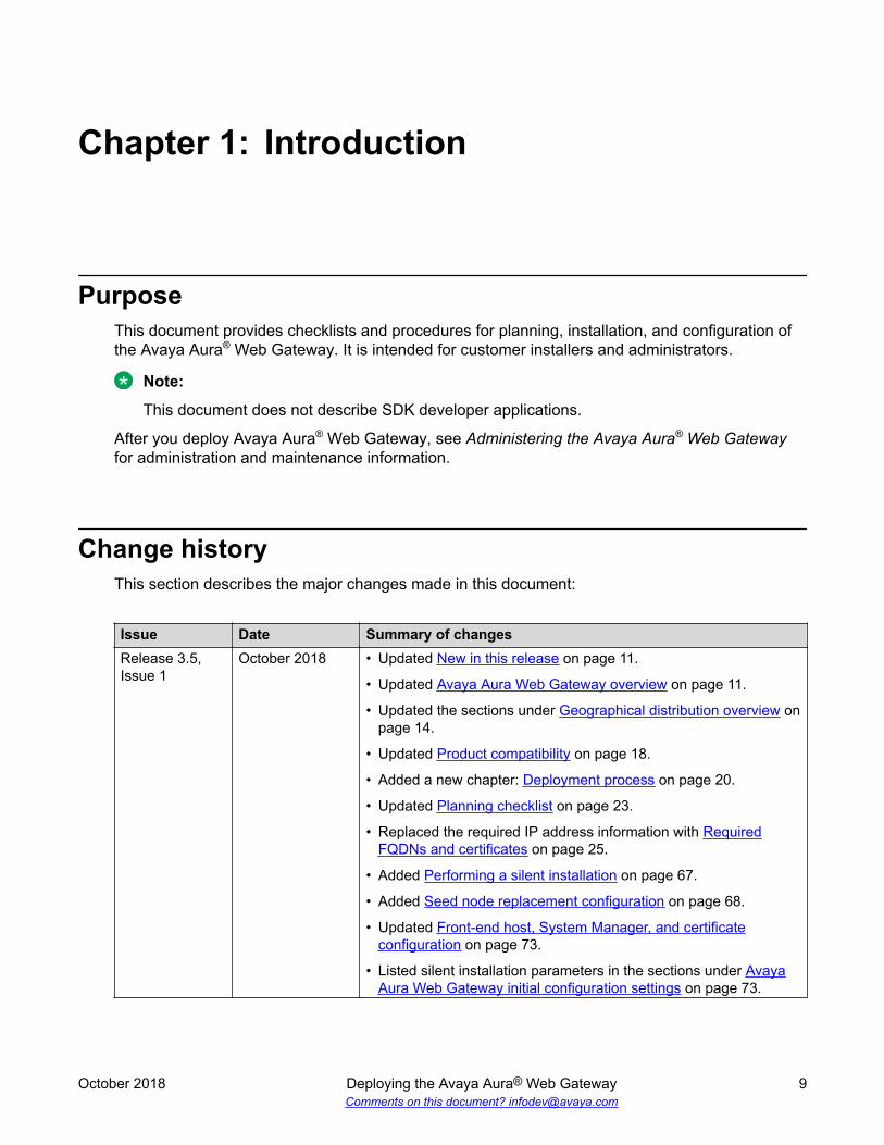
sys volmgt commandSyntax help: sys volmgt --helpThe sys volmgt command is used to query and extend disk volumes on the system. Thefollowing provides the command line syntax for this command:[admin@server4889csa ~]$ sys volmgt --help Syntax: --help, -h --hhelp, -hh --version, -v --status, -st --summary, -s --monitor [tail|less], -m [tail|less] --logs, -l
Planning and preinstallation
October 2018 Deploying the Avaya Aura® Web Gateway 30Comments on this document? [email protected]
--scan --extend <volume> [ <n>m | <n>g | <n>t --remaining ] --extend --all --reset
[admin@server4889csa ~]$
Verbose help: sys volmgt --hhelpThe verbose help information for the scripts provides more information about what the tool is usedfor.[admin@server4889csa ~]$ sys volmgt --hhelp This script provides for the ability to extend the sizes of volumes on thissystem. In order for a volume to be extended in size, the disk that hoststhe volume must first be increased in size using the tools that are usedto manage deployed virtual machines (VMware). The following example illustrates how to add 20 GiB of storage to theapplication log volume (/var/log/Avaya). This volume is located on the seconddisk of the system and so this example assumes that disk 2 has been increasedin size by 20 GiB. sys volmgt --extend /var/log/Avaya 20g The above example will do two things: 1) It will extend the size of the LVM logical volume by 20 GiB. 2) It will then extend the size of the Linux file system that is located inside that volume to the new size of the LVM logical volume. Step (2) above may take several minutes to complete for larger volumes. If,for some reason, this second operation is interrupted, it can be re-runusing the same command, but WITHOUT specifying the size argument. For example,the following command is used to perform step (2) only for the applicationlog volume (/var/log/Avaya). sys volmgt --extend /var/log/Avaya If in doubt as to whether or not all file systems have been fully extended intheir respective volumes, step (2) can be executed across all volumes usinga single command as follows: sys volmgt --extend --all Performing step (2) on a file system that is already fully extended in itsLVM volume is a null operation (does no harm). Note the following general points regarding this script: - The extending of a volume cannot be undone. Make sure the correct volume is being extended, and by the correct size. To confirm any extend operation, the user is required to enter the response "confirm" (case insensitive). - In order to avoid impacting system performance, avoid performing extend operations during periods of high traffic. - Extend operations are performed by a background process, in order to avoid interference due to loss of an SSH connection. Avoid powering down or rebooting a server while there is a background operation in progress. The presence of a running background operation can be queried as follows:
System layer commands
October 2018 Deploying the Avaya Aura® Web Gateway 31Comments on this document? [email protected]

sys volmgt --status - Logical volumes on the system are referenced using their Linux file system mount points, such as /var/log/Avaya and /media/data, with the exception of the volume containing Linux swap, which has no mount point. The Linux swap volume is referenced using "swap". - Sizes are specified in base 2 units rather than base 10 (SI) units. For example, 1g = 1 GiB = 1024 x 1024 x 1024 bytes. - Summary information is displayed in GiB, with a resolution of two decimal places. When extending the sizes of LVM volumes, units can be specified in mebibytes (m), gibibytes (g), or tebibytes (t). - Due to file system overhead allocation by the Linux kernel, the size of a file system will never exactly match the size as reported by the LVM volume that contains that file system. To be certain that a file system is fully extended to the size of the volume that contains it, inspect the log file after issuing the extend operation as follows: sys volmgt --monitor less To perform such a check across all volumes: sys volmgt --extend --all sys volmgt --monitor less The following arguments are supported by this script: --help, -h Terse help. --hhelp, -hh Verbose help (this help). --version, -v Prints the version of this script to stdout. --status, -st Prints the current status of this tool. Use this to determine if there is a background operation in progress, or the results of the last background operation. --summary, -s Prints a summary of disks, the LVM volumes contained on each disk, and the file system contained in each LVM volume. Disk information includes the size of the disk and the amount of free space available for allocation to volumes on the disk. LVM volume information includes the size of the LVM volume. File system information includes the size of the Linux file system and the current amount of space that is in use on that file system. Due to file system overhead allocation by the Linux kernel, the size of a file system will never exactly match the size as reported by the LVM volume that contains that file system. Refer to the top of this help information for more information. --monitor [tail|less] -m [tail|less] Browse the log file for the latest extend operation. Specify "tail" to use the tail browser. Specify "less" to use the less browser, which allows scrolling and searching through the log file. If neither is specified, the browser defaults to the tail browser.
Planning and preinstallation
October 2018 Deploying the Avaya Aura® Web Gateway 32Comments on this document? [email protected]
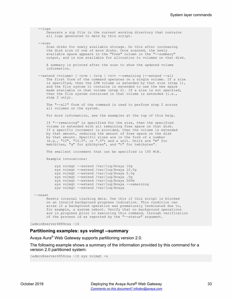
--logs Generate a zip file in the current working directory that contains all logs generated to date by this script. --scan Scan disks for newly available storage. Do this after increasing the disk size of one of more disks. Once scanned, the newly available space appears in the "Free" column in the "--summary" output, and is now available for allocation to volumes on that disk. A summary is printed after the scan to show the updated volume information. --extend <volume> [ <n>m | <n>g | <n>t --remaining ]--extend --all The first form of the command operates on a single volume. If a size is specified, then the LVM volume is extended by that size (step 1), and the file system it contains is extended to use the new space made available in that volume (step 2). If a size is not specfied, then the file system contained in that volume is extended (i.e., step 2 only). The "--all" form of the command is used to perform step 2 across all volumes on the system. For more information, see the examples at the top of this help. If "--remaining" is specified for the size, then the specified volume is extended with all remaining free space on that disk. If a specific increment is provided, then the volume is extended by that amount, reducing the amount of free space on the disk by that amount. Specific sizes are in the form of a number (e.g., "10", "10.5", or ".5") and a unit. Units are "m" for mebibites, "g" for gibibytes", and "t" for tebibytes". The smallest increment that can be specified is 100 MiB. Example invocations: sys volmgt --extend /var/log/Avaya 10g sys volmgt --extend /var/log/Avaya 10.5g sys volmgt --extend /var/log/Avaya 0.5g sys volmgt --extend /var/log/Avaya .5g sys volmgt --extend /var/log/Avaya 500m sys volmgt --extend /var/log/Avaya --remaining sys volmgt --extend /var/log/Avaya
--reset Resets internal tracking data. Use this if this script is blocked on an invalid background progress indication. This condition can arise if a background operation was prematurely terminated due to, for example, a system reboot. Verify that no background operations are in progress prior to executing this command, through verification of the process id as reported by the "--status" argument. [admin@server4889csa ~]$
Partitioning examples: sys volmgt --summaryAvaya Aura® Web Gateway supports partitioning version 2.0.The following example shows a summary of the information provided by this command for aversion 2.0 partitioned system:[admin@server4950csa ~]$ sys volmgt -s
System layer commands
October 2018 Deploying the Avaya Aura® Web Gateway 33Comments on this document? [email protected]

Disk and Volume Summary +----------- Disk ------------+------------------- Volume --------------------+| | LVM File System || Num Name Size Free | Name Size Size Usage |+-----------------------------+-----------------------------------------------+| 1 sda 41.78 0.00 | / 4.00 3.81 1.26 || | /home 4.00 3.81 0.05 || | /opt/Avaya 14.97 14.61 1.14 || | /tmp 2.81 2.71 0.01 || | /var 3.00 2.89 0.03 || | /var/log 2.00 1.91 0.00 || | /var/log/audit 3.00 2.89 0.00 || | swap 8.00 n/a n/a |+-----------------------------+-----------------------------------------------+| 2 sdb 60.00 0.00 | /var/log/Avaya 60.00 58.93 0.05 |+-----------------------------+-----------------------------------------------+| 3 sdc 20.00 0.00 | /media/data 20.00 19.56 0.04 |+-----------------------------+-----------------------------------------------+| 4 sdd 10.00 0.00 | /media/cassandra 10.00 9.71 0.02 |+-----------------------------+-----------------------------------------------+
sys smcvemgt commandThe system layer smcvemgt command is used to manage the Linux kernel patches related to thefollowing vulnerabilities:
• Variant #2/Spectre (CVE-2017–5715)• Variant #3/Meltdown (CVE-2017–5754)
Note:The kernel patch for the Variant #1/Spectre (CVE-2017–5754) vulnerability is permanentlyenabled on the system and cannot be disabled.
The choice to enable or disable these patches is a trade-off between performance and securityimpact:
• If the patches are enabled, the system might experience noticeable performance losses.• If the patches are disabled, the system is not protected against the Variant #2/Spectre and
Variant #3/Meltdown vulnerabilities.By default, Linux patches for Variant #2/Spectre and Variant #3/Meltdown are enabled. TheVariant #2/Spectre patch is enabled with Linux kernel defaults. In default operation mode, theVariant #2/Spectre Linux patch selects the mitigation method that is best suited for the processorarchitecture of the host machine.
Note:To be fully functional, patches for the Variant #2/Spectre vulnerability require hardwaresupport, which is provided by VMware and hardware vendors through microcode updates.
Changes made by the smcvemgt command to the Linux kernel tunalbles always cause a serverreboot. The script does not manage the state of application services. To ensure that theapplication services are stopped before the reboot, run the svc csa stop command before
Planning and preinstallation
October 2018 Deploying the Avaya Aura® Web Gateway 34Comments on this document? [email protected]

using the smcvemgt command. After the reboot, manually start the application services using thesvc csa start command.
For more information about Spectre and Meltdown kernel tunables that are affected by thesmcvemgt command, see https://access.redhat.com/articles/3311301. For more information aboutthe Spectre and Meltdown vulnerabilities, see https://access.redhat.com/security/vulnerabilities/speculativeexecution.
Syntax help: sys smcvemgt --help[admin@server-dev ~]$ sys smcvemgt --help
Version 1.2
Syntax: --help, -h --hhelp, -hh --query, -q --set, -s enabled --set, -s disabled --set, -s [ v2=<v2-mode> ] [ v3=<v3-mode> ] (v2-mode: disabled | default | kernel | user | both | user+retp) (v3-mode: disabled | enabled) --history
Verbose help: sys smcvemgt --hhelp[admin@srvr-dev ~]$ sys smcvemgt --hhelp
Version 1.2
This script manages the enablement status of the Linux kernel patches for thefollowing Spectre and Meltdown vulnerabilities:
Variant #2/Spectre (CVE-2017-5715) Variant #3/Meltdown (CVE-2017-5754)
The kernel patch for the following related vulnerability is permanently enabledon the system (cannot be disabled):
Variant #1/Spectre (CVE-2017-5753)
Note that hardware support is required for Variant #2/Spectre to be fullyfunctional. CPU microcode updates must be applied in order for this hardwaresupport to be provided. The "--query" argument includes an indication as towhether or not hardware support is provided on this server.
For more information on Spectre/Meltdown kernel tunables, refer to:
https://access.redhat.com/articles/3311301
For additional information on the Spectre/Meltdown vulnerabilities, referto:
https://access.redhat.com/security/vulnerabilities/speculativeexecution
Syntax:
--help, -h Provide terse help.
--hhelp, -hh Provide verbose help (this text).
System layer commands
October 2018 Deploying the Avaya Aura® Web Gateway 35Comments on this document? [email protected]

--query, -q Query the configuration of the Variant #2/Spectre and Variant #3/ Meltdown tunables for system reboots, as well as on the running system.
--set, -s enabled --set, -s disabled --set, -s [ v2=<v2-mode> ] [ v3=<v3-mode> ] Enables and disables Variant #2/Spectre ("v2") and/or Variant #3/ Meltdown ("v3") patches.
This immediately reboots the server. Applications on the server are not managed by this script. Ensure that any applications are disabled, as required, prior to changing kernel settings with this script.
If "enabled" is specified, then both v2 and v3 are enabled, with v2 set to kernel default behavior. If "disabled" is specified, then both v2 and v3 are disabled. Otherwise, kernel patches are enabled or disbled as per the specified "v2" and/or "v3" arguments. If a "v2" or "v3" argument is not specified, the current system value for that item is retained.
v2-mode:
disabled Variant #2/Spectre is disabled.
default The kernel decides how to set tunables for Variant #2/ Spectre, based on the processor architecture. Note that for architectures prior to Skylake, the kernel selects retpoline ("return trampoline") over ibrs.
kernel Use "ibrs" (i.e., kernel space only).
user Use "ibrs_user" (i.e., userland only).
both Use "ibrs_always" (i.e., kernel space and userland).
user+retp Use "retpoline,ibrs_user".
v3-mode:
disabled Variant #3/Meltdown is disabled.
enabled Variant #3/Meltdown is enabled. The following two commands are equivalent:
sys smcvemgt enabled sys smcvemgt v2=default v3=enabled
The following two commands are equivalent:
sys smcvemgt disabled sys smcvemgt v2=disabled v3=disabled
--history
Planning and preinstallation
October 2018 Deploying the Avaya Aura® Web Gateway 36Comments on this document? [email protected]
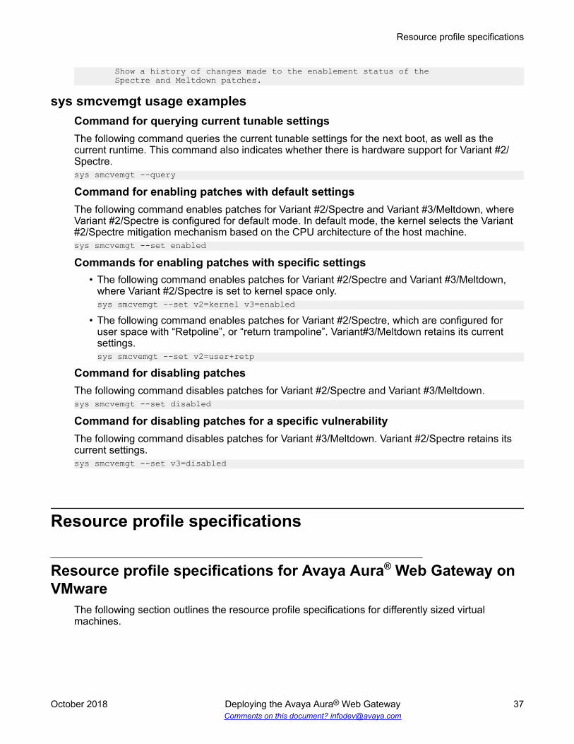
Show a history of changes made to the enablement status of the Spectre and Meltdown patches.
sys smcvemgt usage examplesCommand for querying current tunable settingsThe following command queries the current tunable settings for the next boot, as well as thecurrent runtime. This command also indicates whether there is hardware support for Variant #2/Spectre.sys smcvemgt --query
Command for enabling patches with default settingsThe following command enables patches for Variant #2/Spectre and Variant #3/Meltdown, whereVariant #2/Spectre is configured for default mode. In default mode, the kernel selects the Variant#2/Spectre mitigation mechanism based on the CPU architecture of the host machine.sys smcvemgt --set enabled
Commands for enabling patches with specific settings• The following command enables patches for Variant #2/Spectre and Variant #3/Meltdown,
where Variant #2/Spectre is set to kernel space only.sys smcvemgt --set v2=kernel v3=enabled
• The following command enables patches for Variant #2/Spectre, which are configured foruser space with “Retpoline”, or “return trampoline”. Variant#3/Meltdown retains its currentsettings.sys smcvemgt --set v2=user+retp
Command for disabling patchesThe following command disables patches for Variant #2/Spectre and Variant #3/Meltdown.sys smcvemgt --set disabled
Command for disabling patches for a specific vulnerabilityThe following command disables patches for Variant #3/Meltdown. Variant #2/Spectre retains itscurrent settings.sys smcvemgt --set v3=disabled
Resource profile specifications
Resource profile specifications for Avaya Aura® Web Gateway onVMware
The following section outlines the resource profile specifications for differently sized virtualmachines.
Resource profile specifications
October 2018 Deploying the Avaya Aura® Web Gateway 37Comments on this document? [email protected]

Specifications Small profile Medium profile Large profilevCPU 4 8 16CPU reservation 4600 MHz 9200 MHz 18400 MHzMemory 6 GB 8 GB 16 GBHard disk 100 GBMinimum clockspeed 2600 MHz
Capacity Both of the following:
• 1250 Conferencing orAvaya Equinox®
sessions
• 1250 PortalConferencing users
Both of the following:
• 2500 Conferencing orAvaya Equinox®
sessions
• 2500 PortalConferencing users
Both of the following:
• 5000 Avaya Equinox® orConferencing sessions
• 5000 ConferencingPortal users
Server type Dell R220 or equivalentCPU Intel Xeon CPU [email protected]
1 2 4
Physical core 4NICs 1GBPSLoad supported • 16 Conferencing calls
per second.
• 12500 Avaya Equinox®
Busy Hour Call Attempts(BHCA).
• 20 Portal user requestsper second
• 33 Conferencing callsper second.
• 25000 Avaya Equinox®
BHCA.
• 40 Portal user requestsper second
• 50 Conferencing callsper second.
• 50000 Avaya Equinox®
BHCA.
• 60 Portal user requestsper second
Resources profile specifications for Avaya Aura® Web Gateway onAmazon Web Services
The following table outlines the profiles created by the CloudFormation template generators. Youcan use the CloudFormation template generation tool to create a template for the required profile.The template contains the computing and networking resources required for the profile.
Profile Service size AWS instance typeSmall 1250 sessions c4.xlargeMedium 2500 sessions c4.2xlarge
Planning and preinstallation
October 2018 Deploying the Avaya Aura® Web Gateway 38Comments on this document? [email protected]

Networking considerations for Amazon Web ServicesThere are some limitations for establishing public internet VPNs and direct connections into AWS.For more information about Amazon VPC Limits, see the AWS documentation at http://docs.aws.amazon.com/AmazonVPC/latest/UserGuide/VPC_Appendix_Limits.html.
Important:Use a direct connection along with a private WAN connection with Service Level Agreement(SLA) measures to ensure that the network quality is appropriate for signaling and voicetraffic.Avaya is not responsible for network connections between AWS and the customer premises.
When you deploy Avaya Aura® Web Gateway in an AWS environment, you must also deploy alocal LDAP server in AWS. This LDAP server is a replica server that synchronizes content from amaster LDAP server within the enterprise. To reduce latency for authentication and directorylookup operations, this LDAP server must be collocated with Avaya Aura® Web Gateway in thesame AWS region.
Connection typesYou can connect applications in a hybrid network on the Virtual Private Cloud (VPC) in thefollowing ways:
Connection type ResourceVPN connection For information about VPN connections, see http://docs.aws.amazon.com/
AmazonVPC/latest/UserGuide/vpn-connections.html.Direct connection For information about AWS direct connections, see https://aws.amazon.com/
directconnect/.
Virtual disk volume specificationsThe following table shows the file system layout for systems deployed using Avaya-providedOVAs.
Disk Volume Volume sizecan beincreased
Volume Size (GiB)Disk 1 Disk 2 Disk 3 Disk 4
/boot No 0.2swap Yes 8.0/ Yes 4.0/tmp Yes 2.8/var Yes 3.0/var/log Yes 2.0
Table continues…
Virtual disk volume specifications
October 2018 Deploying the Avaya Aura® Web Gateway 39Comments on this document? [email protected]
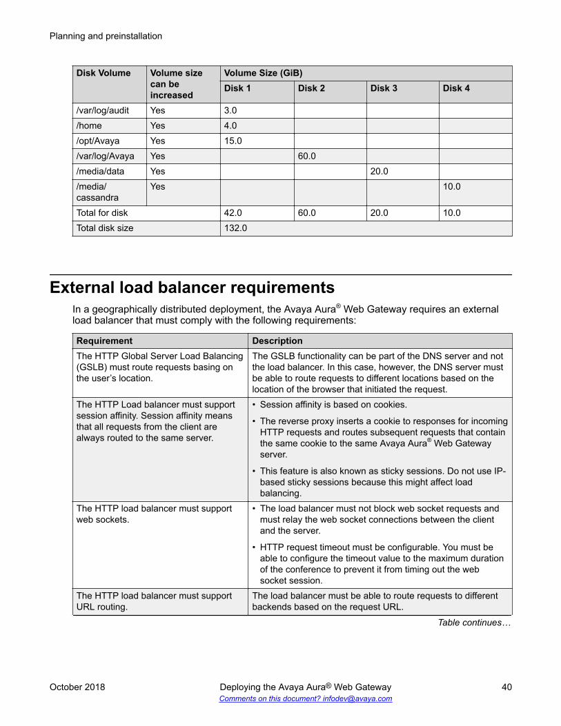
Disk Volume Volume sizecan beincreased
Volume Size (GiB)Disk 1 Disk 2 Disk 3 Disk 4
/var/log/audit Yes 3.0/home Yes 4.0/opt/Avaya Yes 15.0/var/log/Avaya Yes 60.0/media/data Yes 20.0/media/cassandra
Yes 10.0
Total for disk 42.0 60.0 20.0 10.0Total disk size 132.0
External load balancer requirementsIn a geographically distributed deployment, the Avaya Aura® Web Gateway requires an externalload balancer that must comply with the following requirements:
Requirement DescriptionThe HTTP Global Server Load Balancing(GSLB) must route requests basing onthe user’s location.
The GSLB functionality can be part of the DNS server and notthe load balancer. In this case, however, the DNS server mustbe able to route requests to different locations based on thelocation of the browser that initiated the request.
The HTTP Load balancer must supportsession affinity. Session affinity meansthat all requests from the client arealways routed to the same server.
• Session affinity is based on cookies.
• The reverse proxy inserts a cookie to responses for incomingHTTP requests and routes subsequent requests that containthe same cookie to the same Avaya Aura® Web Gatewayserver.
• This feature is also known as sticky sessions. Do not use IP-based sticky sessions because this might affect loadbalancing.
The HTTP load balancer must supportweb sockets.
• The load balancer must not block web socket requests andmust relay the web socket connections between the clientand the server.
• HTTP request timeout must be configurable. You must beable to configure the timeout value to the maximum durationof the conference to prevent it from timing out the websocket session.
The HTTP load balancer must supportURL routing.
The load balancer must be able to route requests to differentbackends based on the request URL.
Table continues…
Planning and preinstallation
October 2018 Deploying the Avaya Aura® Web Gateway 40Comments on this document? [email protected]

Requirement DescriptionThe HTTP load balancer must supportURL rewrite.
The load balancer must be able to modify the URL path of therequest based on simple rules to remove or rename parts ofthe path.
The HTTP load balancer must supportTLS 1.2.
Some services might not support TLS versions other than 1.2.
The HTTP load balancer must support atleast some of the listed ciphers wheninteracting with back-end services.
• ECDHE-RSA-AES128-GCM-SHA256
• ECDHE-ECDSA-AES128-GCM-SHA256
• ECDHE-ECDSA-AES256-GCM-SHA384
• ECDHE-RSA-AES128-SHA256
• ECDHE-ECDSA-AES128-SHA256
• ECDHE-RSA-AES128-SHA
• ECDHE-ECDSA-AES128-SHA
• AES128-GCM-SHA256
• AES256-GCM-SHA384
• AES128-SHAThe HTTP load balancer must be able touse TCP health checks.
The load balancer must be able to perform health checks ofAvaya Aura® Web Gateway servers using TCP responses. Toavoid leaving multple TCP sockets opened, you must be ableto configure TCP health checks to half-opened connections.
The external HTTP load balancer mustbe able to use standard headers todetermine the FQDN from the originalrequest that is used to reach the system.
Avaya Aura® Web Gateway uses the “Host” header to identifythe FQDN that is used by the client to reach the system.
Note:
This behavior is required if the customer requires differentFQDNs per location or uses different FQDNs to reach thesystem. If a single global FQDN is used, you can ignorethis requirement.
The external HTTP load balancer mustrelay the client certificates.
This requirement is only needed for authenticating clientsusing a client certificate.
The HTTP load balancer must be able toinsert custom headers to HTTP requests.
External load balancer requirements
October 2018 Deploying the Avaya Aura® Web Gateway 41Comments on this document? [email protected]

Chapter 5: Initial setup for VMware andAWS deployments
You can deploy Avaya Aura® Web Gateway in a VMware or AWS environment. Use the followingsections to perform the initial VMware or AWS setup.
Deployment process checklistThis checklist describes the high-level deployment process for virtual machine deployments onVMware and AWS.
No. Task Notes
1 Deploy the OVA for VMware or AWSenvironment.
For more information, see:
• VMware deployments on page 43.
• Amazon Web Servicesdeployments on page 47.
The Avaya Aura® Web Gateway OVAfile includes openjdk. Operating systemupdates for virtual machines includeupdates for openjdk.
2 Increase the partitioning volumes forVMware deployments.
In a VMware environment, you mustadjust the virtual disk volumes. Thisprocedure is not required for AWSdeployments.
3 Install or restore the application layer asrequired.
For installation information, see Installing the Avaya Aura WebGateway on page 64.
October 2018 Deploying the Avaya Aura® Web Gateway 42Comments on this document? [email protected]

VMware deploymentsDeploy the Avaya Aura® Web Gateway OVA on a virtual machine using either vCenter or vSphere.The components of the Avaya Aura® Web Gateway, Endpoint Service Gateway, and Unified Portalare provided in a single OVA file.
The supported VMware ESXi versions for this deployment are 5.5, 6.0, and 6.5.
Obtaining the Avaya Aura® Web Gateway OVA fileProcedureDo one of the following:
• Download the Avaya Aura® Web Gateway OVA from the Avaya Product Licensing and DeliverySystem (Avaya PLDS) at https://plds.avaya.com.
• Place an order for the DVDs containing the OVA file using the Material Code ID or description.
For more information about the material ID, see “Product Order Codes and Pricing” in AvayaAura® Web Gateway Offer Definition.
OVA deploymentUse one of the following procedures to deploy the OVA. You can use vCenter, vSphere, orSolution Development Manager (SDM).
Deploying the Avaya Aura® Web Gateway OVA using vCenterProcedure
1. Log in to vCenter.
2. Navigate to File > Deploy OVF Template.
3. From the Source page, click Browse and then select the OVA file.
For example, csa-<version>_OVF10.ova4. Verify the information displayed in OVF Template Details and then click Next.5. Review and accept the End User License Agreement (EULA) and then click Next.6. From the Name and Location page, do the following:
a. Specify a name.
b. Select an inventory location or data store.
c. Click Next.7. From the Deployment Configuration page, select a profile and then click Next.
VMware deployments
October 2018 Deploying the Avaya Aura® Web Gateway 43Comments on this document? [email protected]

You can select one the following profiles from the Configuration drop-down menu:
• AAWG 3.0 Profile 3 Max Sessions 5,000
• AAWG 3.0 Profile 1 Max Sessions 1,250
• AAWG 3.0 Profile 2 Max Sessions 2,500
8. From the Host/Cluster page, do the following:
a. Select the host on which the template will be deployed.
b. Click Next.9. From the Disk Format page, do the following:
a. Select a thick or thin provision option.
If you select a thick provision option, the entire disk space will be reserved andunavailable for other virtual machines to use.
If you select the thin provision option, unused space will be available for other virtualmachines to use.
b. Click Next.10. From the Network Mapping page, do the following:
a. Map the source network used with the appropriate destination network.
b. Click Next.11. From the Properties page, do the following:
a. Complete the required network information, such as your IP address, host name orFQDN, Netmask, and DNS.
b. Enter credentials for a Linux administrator user, which include the user name,password, and group.
The default user name is admin, group is admingrp, and password is avaya123.
12. From the Ready to Complete tab, verify your settings and then click Next to complete theinstallation.
Next stepsInstall the Avaya Aura® Web Gateway.
Deploying the Avaya Aura® Web Gateway OVA using vSphereProcedure
1. Log in to vSphere.
2. Navigate to File > Deploy OVF Template.
3. Perform steps 3 on page 43 to 9 on page 44.
These steps are the same in vCenter and vSphere.
Initial setup for VMware and AWS deployments
October 2018 Deploying the Avaya Aura® Web Gateway 44Comments on this document? [email protected]

4. Turn on your virtual machine, and do the following:
a. Access the VM console.b. Accept the license agreement and continue with the following post-installation steps.
5. Provide the network settings information
The following image provides an example of network and IP settings in the VM console:
6. Ensure that the Default Search List includes the list of domains for:
• Avaya Aura® Web Gateway• Avaya Equinox® Conferencing Management• System Manager and LDAP
Deploying the Avaya Aura® Web Gateway OVA through SolutionDeployment Manager from System Manager
About this taskUse this procedure to create a virtual machine on the ESXi host and deploy the Avaya Aura® WebGateway OVA on the virtual machine.
Before you begin• Ensure that you are familiar with the “Deployment checklist” section in Deploying Avaya
Aura® applications from System Manager.• Add Appliance Virtualization Platform (AVP) or an ESXi host to the location.
Procedure1. Upload the required OVA file to System Manager.
For information about uploading a file to the software library, see Deploying Avaya Aura®
applications from System Manager.
VMware deployments
October 2018 Deploying the Avaya Aura® Web Gateway 45Comments on this document? [email protected]

2. On the System Manager web console, click Services > Solution Deployment Manager,and then click VM Management.
3. In VM Management Tree, select a host.
4. On the Virtual Machines tab, in the VMs for Selected Location <location name> section,click New.
The system displays the VM Deployment window.
5. In the Select Location and Host section, do the following:
a. In Select Location, select a location.
b. In Select Host, select a host.
c. In Host FQDN, type the virtual machine name.
6. In Data Store, select a data store.
7. Click Next.8. On the OVA tab, do the following:
a. In Select Software Library, select Select OVA from software library.
b. In Select Software Library, select the local or remote library where the OVA file islocated.
c. In Select OVAs, select the OVA that you want to deploy.
d. In Flexi Footprint, select the footprint size that the application supports.
9. On the Configuration Parameters page, specify the following:
• Management network settings
• Public network settings
• Admin user details
10. On the Network Parameters page, choose any application.
11. Click Deploy.
12. Click Accept the license terms.
In the Hosts for Selected Location <location name> section, the system displays thedeployment status in the Current Action Status column.
The system displays the virtual machine on the VMs for Selected Location <locationname> page.
13. (Optional) To view details, click Status Details.
Initial setup for VMware and AWS deployments
October 2018 Deploying the Avaya Aura® Web Gateway 46Comments on this document? [email protected]
Amazon Web Services deploymentsAmazon Web Services (AWS) is a cloud services platform that enables enterprises to securely runapplications on the virtual cloud. The key components of AWS are Amazon Elastic Compute Cloud(EC2) and Amazon Simple Storage Service (S3).When you deploy Avaya Aura® Web Gateway in an AWS environment, you must also deploy alocal LDAP server in AWS. This LDAP server is a replica server that synchronizes content from amaster LDAP server within the enterprise. To reduce latency for authentication and directorylookup operations, this LDAP server must be collocated with Avaya Aura® Web Gateway in thesame AWS region.
Note:Use the AWS Command Line Interface (CLI) for managing AWS services from your computer.For more information about setting up the AWS CLI, see https://aws.amazon.com/cli and http://docs.aws.amazon.com/cli/latest/userguide/cli-chap-getting-started.html#cli-quick-configuration.
Signing in to the Amazon Web Services Management consoleBefore you beginEnsure that you have an AWS account.
Procedure1. In your web browser, type the URL https://aws.amazon.com/.
2. Click Sign In to the Console.
The system displays the Amazon Web Service page and auto-populates the Account field.
3. In the User Name field, type the user name or registered email ID.
4. In the Password field, type the password.
5. Click Sign In.
The system displays the AWS Management Console page.
Configuring AWS details using the AWS CLIAbout this taskThe first time that you use the AWS CLI, you must configure the AWS details.
Before you beginSet up the AWS CLI on a computer with access to AWS. For more information, see http://docs.aws.amazon.com/cli/latest/userguide/cli-chap-welcome.html.
Amazon Web Services deployments
October 2018 Deploying the Avaya Aura® Web Gateway 47Comments on this document? [email protected]

Procedure1. Start a command line interpreter on the computer with the installed AWS CLI.
Note:
The AWS CLI supports different Windows and Linux command line interpreters, suchas PowerShell or Bash.
2. From the command line interpreter, run the command aws configure, and do thefollowing:
a. For AWS Access Key ID, type the AWS access key ID.
b. For AWS Secret Access Key, type the AWS secret access key ID.
c. For Default region name, type the region name.
For example: us-west-2.
d. For Default output format, type text or json.
Creating a key pairAbout this taskA key pair is a set of public and private keys. The public key is used to encrypt data, such as thelogin password. The private key is used to decrypt the encrypted data. You provide this key pairwhen you create a CloudFormation stack, and use it for SSH access to the Amazon MachineInstances.
Procedure1. Sign in to the Amazon Web Services Management console.
2. In the left navigation pane, go to NETWORK & SECURITY, and click Key Pairs.
3. Click Create Key Pair.4. In the Create Key Pair dialog box, in the Key pair name field, type a name for the key pair.
5. Click Create.
The system generates a *.pem file and prompts you to save the file on your computer. Youcan also view the created key pair name in the Key pair name column.
6. Save the *.pem file.
Important:
When you create a key pair, save it. If you lose the key, you cannot retrieve it and youwill not be able to access the instance.
Initial setup for VMware and AWS deployments
October 2018 Deploying the Avaya Aura® Web Gateway 48Comments on this document? [email protected]

OVA to AMI conversionCreating a bucket for uploading the OVAs for AMI conversion
Procedure1. Sign in to the Amazon Web Services Management console.
2. Go to Services > Storage, and click S3.
The system displays the S3 Management Console page.
3. Click Create bucket.
The system displays the Create bucket dialog box.
4. In Bucket name, type a unique bucket name.
Only use lowercase letters for the name.
5. In the Region field, click a region for your bucket.
For more information about creating a bucket and selecting a region, see Amazon S3Documentation.
6. Click Create.
Next stepsUpload the Avaya Aura® Web Gateway OVA.
Creating a service roleAbout this taskUse this procedure to create a role named vmimport for importing files into the S3 bucket.
Use the AWS CLI to run the commands in this procedure.
Procedure1. Start a command line interpreter on a computer with the installed AWS CLI.
2. Run the following command to create a role named vmimport and let the AWS imageimport service assume this role:aws iam create-role --role-name vmimport --assume-role-policy-document <file://trust-policy.json>
In this command, <file://trust-policy.json> is a path to the trust-policy.json file. This file is included in the AWS configuration files artifact.
3. Open the role-policy.json file, and in each “Resource”:“arn:aws:s3:::<disk-image-file-bucket>” string, replace <disk-image-file_bucket> with the actual S3 bucket name.
Amazon Web Services deployments
October 2018 Deploying the Avaya Aura® Web Gateway 49Comments on this document? [email protected]

For example:“Resource”: “arn:aws:s3:::my-s3-bucket”
4. Run the following command to allow the vmimport role to perform importing procedures:aws iam put-role-policy --role-name vmimport --policy-name vmimport --policy-document <file://role-policy.json>
In this command, <file://rule-policy.json> is a path to the rule-policy.jsonfile. This file is included in the AWS configuration files artifact.
Uploading the Avaya Aura® Web Gateway OVABefore you beginDownload the OVAs from the Avaya PLDS website at http://plds.avaya.com/.
Procedure1. Sign in to the Amazon Web Services Management console.
2. Go to Services > Storage, and click S3.
The system displays the S3 Management Console page.
3. From the All Buckets area, select a bucket.
4. Click Upload.
5. In the dialog box that is displayed, click Add Files and upload the Avaya Aura® WebGateway OVA with the -aws-001-ova suffix.
Importing the OVA for AMI conversionAbout this taskYou can use files in the JSON format that are included in the AWS configuration files artifact. TheAWS configuration files artifact also contains single-node and multi-node CloudFormation templategenerators that you use for AWS server deployment. The AWS configuration file contains thefollowing:
• trust-policy.json• role-policy.json• Single-Node-Cloud-Template-Gen.html• Multi-Node-Cloud-Template-Gen.html
For more information, see http://docs.aws.amazon.com/vm-import/latest/userguide/vmimport-image-import.html.Use the AWS CLI to run the commands in this procedure.
Before you beginYou need the following to convert the OVA file to an Amazon Machine Image (AMI), to deploy theAMI, and configure Avaya Aura® Web Gateway:
• Avaya Aura® Web Gateway OVAs with the -aws-001.ova suffix has been uploaded to anS3 bucket.
Initial setup for VMware and AWS deployments
October 2018 Deploying the Avaya Aura® Web Gateway 50Comments on this document? [email protected]

Ensure that you also convert the *.pem file to the *.ppk format and configure PuTTY forestablishing an SSH connection.Ensure that you updated AWS details using the AWS CLI. For more information, see ConfiguringAWS details using the AWS CLI on page 47.
Procedure1. Start a command line interpreter on a computer with the installed AWS CLI.
2. Run the following command to check whether the S3 bucket is ready to use:aws s3 ls
The system displays the S3 bucket that you created.
3. To view the content of the S3 bucket, run the aws s3 ls s3://<nameofbucket>command.
4. To import the ova for conversion, run the following command:>aws ec2 import-image --cli-input-json "{ \"Description\": \"<server.ova>\", \"DiskContainers\": [ { \"Description\": \"<text description of task>\", \"UserBucket\": { \"S3Bucket\": \"<your_bucket_name>\", \"S3Key\" : \"<server.ova>\" } } ]}"
The system displays the Status and the ImportTaskId parameters.
In the following example, when the system converts the CM Simplex OVA, ImportTaskId isimport-ami-ffmanv5x.{ "Status": "active", "Description": "<version>-aws-001.ova", "Progress": "2", "SnapshotDetails": [ { "UserBucket": { "S3Bucket": "<version>-dev", "S3Key": "<version>-aws-001.ova" }, "DiskImageSize": 0.0 } ], "StatusMessage": "pending", "ImportTaskId": "import-ami-fftlelct" }
5. To check the status of the import image, run the following command:aws ec2 describe-import-image-tasks --cli-input-json "{ \"ImportTaskIds\": [\"<Your_ImportTaskId>\"], \"NextToken\": \"abc\", \"MaxResults\": 10 } "
The conversion process takes up to 30 minutes. You can run the above commandrepeatedly.
In the following example, the process is preparing the AMI and is 76% complete:IMPORTIMAGETASKS x86_64 CM-Simplex-07.1.0.0.xxx-aws-001.ova import-ami-ffgji45r BYOL Linux 76 active preparing ami
The output format varies depending on the selection of the text or JSON format on theAWS CLI configuration.
Amazon Web Services deployments
October 2018 Deploying the Avaya Aura® Web Gateway 51Comments on this document? [email protected]

6. Sign in to the Amazon Web Services Management console.
7. Go to Services > Compute and then click EC2.
The system displays the EC2 Management Console page.
8. In the left navigation pane, click IMAGES > AMIs.
You can search the converted AMI with ImportTaskId. The system displays the newlyconverted AMI ImageId in the AMI ID column.
Next stepsCreate CloudFormation templates, which can be used to create a stack.
Creating CloudFormation templatesAbout this taskUse CloudFormation templates to create an AWS stack.
Important:To create CloudFormation templates, use one of the following web browsers:
• Google Chrome• Mozilla Firefox
Internet Explorer and Microsoft Edge are not supported.
Before you beginDownload the compressed artifact that contains the configuration files to your computer. Extractthe two CloudFormation generator HTML files from the compressed file.
Procedure• To create a single-node CloudFormation template, do the following:
1. In your web browser, run the template generator by opening the Single-Node-Cloud-Template-Gen.html file.
2. In Product, select the required application and profile size.
3. Click Generate template.
4. Save the file to your computer.
• To create a multi-node CloudFormation template, do the following:
1. In your web browser, run the template generator by opening the Multi-Node-Cloud-Template-Gen.html file.
2. In Product, select the required application and profile size.
3. In Number of nodes, set the number of servers required for the cluster.
4. In Number of subnets, set the number of subnets required for the cluster.
Initial setup for VMware and AWS deployments
October 2018 Deploying the Avaya Aura® Web Gateway 52Comments on this document? [email protected]

You can set two or three subnets.5. If you want to create new subnets for availability zones, select the Create subnets
check box.
Do not select Create subnets if you are planning to use existing subnets.6. If you are planning to use the existing subnets, do not select Create subnets.7. Click Generate template.8. Save the file to your computer.
Next stepsDeploy the CloudFormation stack:
• For a single-node system, see Deploying a single-node CloudFormation stack on page 53.• For a multi-node system, see Deploying a multi-node CloudFormation stack on page 57.
Deploying a single-node CloudFormation stackAbout this taskUse this procedure to deploy a standalone instance by using a single-node CloudFormationtemplate.
Before you begin• Use standard Amazon Web Services procedures to create the required network setup,
including Virtual Private Cloud (VPC) settings and Security Groups.• Generate a single-node CloudFormation template.• Ensure that you have network access to the Amazon VPC before deploying an AMI.
Procedure1. Sign in to the AWS console and navigate to Services > Management Tools >
CloudFormation.
CloudFormation is an AWS service used to create a stack. A stack is a graph of objectssuch as EC2 instances and EBS volumes inside the Amazon cloud. CloudFormation isused to create the objects required for a single-node Avaya Aura® Web Gateway systemwithin a subnet of an existing virtual network.
2. On the CloudFormation page, click Create Stack.
3. On the Create Stack page, click Select Template.
4. On the Select Template page, in the Choose a template area, click Choose file.
5. Select the single-node yaml CloudFormation template file that you generated.
6. Click Next.7. On the Specify Details page, in the Stack name field, type the stack name.
The host name for the node is derived from the stack name.
Amazon Web Services deployments
October 2018 Deploying the Avaya Aura® Web Gateway 53Comments on this document? [email protected]

Note:
The stack name must start with a letter and must contain letters, numbers, anddashes.
8. In Amazon Machine Image ID, type the Amazon Machine Image ID (AMI ID) of theinstance that you created. For example, ami-fda9369d.
Tip:
To obtain the AMI ID of an image, go to Services > EC2 > Images > AMIs9. In the Network area, select the required Virtual Private Cloud and Subnet.
10. In DNS domain, type the name of the private DNS domain to use.
This domain name represents the domain name that clients use to access service.
11. If the domain is a new domain in this VPC, set Create domain to Y. Otherwise, set it to N.
12. In the Security area, select SSH key for administrator login.
13. Click Next.14. (Optional) On the Options page, in the Tag area, add tags that can help you find and
organize your AWS objects.
15. In the Permissions area, leave the default values for both IAM Role and Enter role arn.
16. Click Next.17. On the Review page, confirm the stack information.
18. Click Create to create the stack.
The system displays the Stacks page, which shows the stack creation status.
19. Wait until the status displays CREATE_COMPLETE.
You can monitor the status of the stack creation and review the properties using the tabs atthe bottom of the Stacks page.
20. Click the Resources tab.
21. Click the Physical ID of the EC2 instance for the node, for example,i-0fccb4a222a32dcc9.
The system displays the Instances page using a filter that displays the newly created AMI.
22. (Optional) Click the Actions menu to change the instance state.
For example, you can start, stop, or reboot the AMI virtual machine.
Next stepsTo complete the first-login configuration, log in using [email protected] oradmin@instance_IP as the login credentials are not provided. Accept the license agreementand set the password.
Initial setup for VMware and AWS deployments
October 2018 Deploying the Avaya Aura® Web Gateway 54Comments on this document? [email protected]

AWS cluster deploymentsUse the information in the following subsections for multi-node AWS clusters.For traffic distribution, use the AWS load balancer. A virtual IP address for clusters is not availableon AWS.
Creating and applying load balancer certificatesAbout this taskLoad balancers only appear in the private DNS within AWS. Therefore, certificates generated byexternal certificate authorities might not work. Use this procedure to obtain a certificate fromSystem Manager within AWS.
Procedure1. On the System Manager web console, navigate to Home > Services > Security >
Certificates > Authority.
2. Click Add End Entity and complete the settings in the following fields:
a. End Entity Profile: Type <INBOUND_OUTBOUND_TLS>.
b. Username: Type <FQDN of the load balancer>.
The FQDN of the load balancer is the service FQDN of the cluster. This domain nameportion of the FQDN represents the domain name that clients use to access service.The FQDN must be the combination of the stack name followed by the domain. Forexample, if the stack name is yourStack and the domain is your.domain.com,then the FQDN is yourStack.your.domain.com.
Note:
The stack name must start with a letter and must contain only letters, numbers,and dashes. This stack name must be used during multi-node CloudFormation.
c. Password: Type your password.
d. Confirm Password: Retype your password.
e. CN, Common name: Type <FQDN of the load balancer>.
f. Token: Select the PEM file.
Note:
The remaining fields are optional. For more information, see Administering AvayaAura® System Manager.
3. Click Add.
4. Navigate to Home > Services > Security > Certificates > Authority > Public Web.
The system displays the EJBCA public page.
Amazon Web Services deployments
October 2018 Deploying the Avaya Aura® Web Gateway 55Comments on this document? [email protected]

5. Click Create Keystore.
6. In Username, type the FQDN of the load balancer.
7. In Password, type the End Entity password that you created earlier.
8. Click OK.
The system displays the EJBCA Token Certificate Enrollment page.
9. In Key length, select the required key length.
A length of 2048 bits is recommended.
10. Click Enroll and select a text editor to view the certificate.
11. Save the PEM file to your computer.
12. Sign in to the AWS console and navigate to Services > Security, Identity &Compliance > Certificate Manager.
13. Click Import a certificate.
The system displays a form with three fields: Certificate Body, Certificate private key,and Certificate chain.
14. Open the PEM file you saved earlier with a text editor and do the following:
Note:
You must include the BEGIN and END labels for each section that you paste into theform.
a. In the Private Key section, copy the string from -----BEGIN PRIVATE KEY-----to -----END PRIVATE KEY----- and paste it into the Certificate private keyfield.
b. In the Certificate section, copy the first certificate string from -----BEGINCERTIFICATE----- to -----END CERTIFICATE----- and paste it into theCertificate body field.
c. In the Certificate section, copy the second certificate string from -----BEGINCERTIFICATE----- to -----END CERTIFICATE----- and paste it into theCertificate chain field.
15. Click Review and import.16. Click Import.
The system imports the certificate and displays the status and details of the certificate.
17. Copy and save the ARN value in the Details section.
The ARN is required for the Load balancer certificate ARN field during the multi-nodeCloudFormation deployment.
Initial setup for VMware and AWS deployments
October 2018 Deploying the Avaya Aura® Web Gateway 56Comments on this document? [email protected]

Deploying a multi-node CloudFormation stackAbout this taskUse multi-node CloudFormation to create a cluster.
Note:You cannot expand an AWS single node into a AWS cluster. You must create AWS clustersfrom the beginning. However, after an AWS cluster is created it can be expanded. For moreinformation, see Expanding an existing cluster on page 59.
Before you begin• Use standard Amazon Web Services procedures to create the required network setup,
including Virtual Private Cloud (VPC) settings and Security Groups.• Ensure that you have network access to the Amazon VPC before deploying an AMI.• Create a multi-node CloudFormation template as described in Creating CloudFormation
templates on page 52.• Create and apply load balancer certificates. The ARN value created during the certificate
import is required for this procedure.
Procedure1. Sign in to the Amazon Web Services Management console.
2. Navigate to Services > Management Tools > CloudFormation.
3. Click Create Stack.
The AWS EC2 Management console displays the first page of the Create stack wizard.
4. On the Select Template page, in the Choose a template area, click Choose File.
5. Select the multi-node yaml CloudFormation template file that you generated.
6. Click Next.
The system displays the Specify Details page.
7. In Stack name, type a name for the stack.
This stack name must match the stack name portion of the FQDN of the load balancer.
8. In Amazon Machine Image ID, type the Amazon Machine Image ID (AMI ID) of the imagethat you imported.
For example, ami-fda9369d.
Tip:
You can obtain the AMI ID of an image from the EC2 AMI page. On a separatebrowser tab, navigate to Services > EC2 > Images > AMIs.
9. In Network area, select the required Virtual Private Cloud.
Amazon Web Services deployments
October 2018 Deploying the Avaya Aura® Web Gateway 57Comments on this document? [email protected]

10. Do one of the following depending on whether you selected the Configure subnets checkbox in step 2 on page 52 when creating the multi-node CloudFormation template:
• If you selected the check box, configure the required IPv4 address range in each subnetCIDR block field.
In CIDR notation, the number of bits in the network portion of the address follows aslash. For example, 10.143.11.192/28. The address range for the subnets must fallwithin the address range of the VPC and must not overlap any existing subnet within theVPC.
• If did not select the check box, select the required subnets from each Subnet field.
Note:
When using existing subnets, each subnet must be in a different availability zone.
11. In DNS domain, type the name of the private DNS domain to use.
This domain name must match the domain name used in the FQDN of the load balancer.
12. If the domain is a new domain in this VPC, set Create domain to Y.
Otherwise, set it to N.
13. In the Security area, select SSH key for administrator login.
14. Copy the ARN saved in the Details section and paste it into the Load balancer certificateARN field.
For information on copying the ARN, see Creating and applying load balancercertificates on page 55.
15. Click Next.
The system displays the Options page.
16. (Optional) In the Tags area, add tags to help you find and organize your AWS objects.
17. In the Permissions area, keep the default values for both IAM Role and Enter role arn.
18. Click Next.
The system displays the Review page.
19. Click Create to create the stack.
The system displays the Stacks page, which shows the stack creation status.
20. Wait until the status displays CREATE_COMPLETE.
You can monitor the status of the stack creation and review the properties using the tabs atthe bottom of the Stacks page.
21. Click the Resources tab.
22. Click the Physical ID of the EC2 instance for the node, for example,i-0fccb4a222a32dcc9.
The system displays the Instances page using a filter that displays the newly created AMI.
Initial setup for VMware and AWS deployments
October 2018 Deploying the Avaya Aura® Web Gateway 58Comments on this document? [email protected]

23. (Optional) Click the Actions menu to change the instance state.
For example, you can start, stop, or reboot the AMI virtual machine.
Next stepsTo complete the first-login configuration, log in using [email protected] oradmin@instance_IP as the login credentials are not provided. Accept the license agreementand set the password.
Expanding an existing clusterAbout this taskAn existing AWS cluster can be expanded with additional nodes by updating the stack thatrepresents the cluster.
Note:You cannot expand a single AWS node into an AWS cluster. You must create AWS clustersfrom the beginning.
ProcedureAdd nodes to a cluster by updating the CloudFormation stack that represents the cluster.
Creating a hybrid cloud for client accessAbout this taskServers deployed in AWS are contained within a Virtual Private Cloud (VPC). End user clients arepresent within a separate network but require access to the servers in AWS. You must create aVPN to enable client access.You must configure VPN gateways at both ends of the tunnel:
• The address range assigned to the VPC must route to the gateway on your side of thetunnel.
• Within AWS, the address range that clients use must route to the AWS-side gateway.Use this procedure to configure AWS so that the address range that clients use routes to theAWS-side of the gateway.
Before you begin• Deploy the required EC2 instances.• Assign an IP address range to the VPC that does not overlap with any subnet in your
network.
Procedure1. Sign in to the AWS console.
2. Navigate to Services > Management Tools > CloudFormation and select the requiredstack.
Amazon Web Services deployments
October 2018 Deploying the Avaya Aura® Web Gateway 59Comments on this document? [email protected]

3. Click the Resources tab.
4. Click the physical ID link for one of the nodes.
The system displays a page with the details of the node.
5. Copy the value from the Subnet ID field of the Description tab. For example,subnet-99942eff.
6. Navigate to Services > Networking & Content Delivery > VPC > Subnets.
7. Paste the subnet ID into the Search Subnets filter.
8. Select the subnet that the system displays.
9. Select the row that contains the previously noted ID in the Route Table ID column.
10. Select the Route Table tab.
11. Click the route table ID link that is located next to the Edit button. For example, rtb-bc53a2db.
12. Select the route that the system displays.
13. Select the Routes tab.
14. Click Edit.15. Click Add another route to add each required client address range and do the following:
a. In the Destination column, enter the address range.
b. In the Target column, select an AWS-side gateway that can reach the destination.
16. Click Save.
Configuring on-premise DNS resolution of VPC addressesAbout this taskThis configuration allows on-premise clients to access the servers hosted in the AWS VPC. Usethis procedure to configure your local, on-premise DNS server with a new DNS forwarding zone sothat client DNS resolution requests are forwarded to a DNS server located within the VPC. TheDNS server located within the VPC then performs the final address resolution to the servershosted in the AWS VPC.
Before you beginEnsure that you have:
• Access to your on-premise DNS server so that you can add a new DNS forwarding zone.• Enabled your corporate firewall to permit outgoing UDP traffic toward the AWS VPC.• Routes on your AWS VPC VPN gateway that direct UDP port 53 traffic from the enterprise
toward the VPC.• The IP address of the DNS server in the AWS VPC.
Initial setup for VMware and AWS deployments
October 2018 Deploying the Avaya Aura® Web Gateway 60Comments on this document? [email protected]

• A list of the VPC domains that the on-premise DNS server must resolve to the AWS DNSserver. For example, if your VPC servers must resolve server.example.com andserver.example.net, then the list of required VPC domains is example.com andexample.net.
• A test FQDN that is configured in the VPC DNS.
Procedure1. Log on to your local on-premises DNS server.
2. Add a new “Forward Zone” or “Forward Lookup Zone” DNS by following the instructionsprovided by your DNS server manufacturer.
3. Add a new forward zone with the following details for each required VPC domain:
a. A zone name: Use the same name as the domain name. For example,example.com.
b. The forwarding address: Use the IP address and port of the DNS server in the AWSVPC. For example, 10.1.2.3@53.
c. Forward First: Enable Forward First if your DNS server supports this feature. Thisfeature causes resolution requests for the zone to be forwarded to the VPC DNSserver before attempting to resolve them locally.
4. Enable the DNS server changes by reloading the configuration or restarting the DNSserver.
5. Verify that the DNS resolution completes by performing a lookup of the test FQDN using aDNS resolution utility, such as nslookup or dig.
For example, you can run the following nslookup command:> nslookup server.example.comServer: 192.168.0.1Address: 192.168.0.1#53
Non-authoritative answer:Name: server.example.comAddress: 10.1.2.165
Logging in to the EC2 instanceProcedureLog in to the EC2 instance using the SSH console or PuTTY.
For information about how to use PuTTY, see https://docs.aws.amazon.com/AWSEC2/latest/UserGuide/putty.html?icmpid=docs_ec2_console.
Note:
You must use the key that you specified during stack creation.
Amazon Web Services deployments
October 2018 Deploying the Avaya Aura® Web Gateway 61Comments on this document? [email protected]

Completing the first-login configurationAbout this taskThe first time you access a newly deployed EC2, you must complete a one-time system procedureto accept the license agreement, configure the OS, and select network preferences.
Before you beginAccess the EC2 instance by logging in using PuTTY or SSH from the command line. Use theAvaya Aura® Web Gateway administrator credentials and the EC2 DNS or IP address for the firstlog in as follows:<admin_name>@<instance_dns_or_ip_address>
For example:[email protected]
Procedure1. Do the following when you see the license agreement banner, which is displayed when you
log in for the first time:
a. Press Enter to display the license agreement.
b. Press the Space bar to navigate through the license agreement.
c. When prompted, type yes to accept the license agreement.
2. Enter a password for the system administrator.
3. To configure the NTP servers, do one of the following:
• Press Enter to accept the default Amazon NTP time servers.
• Enter one or more comma separated NTP server IP addresses or FQDNs and thenpress Enter.
Important:
The NTP servers that you configure must be reachable from this server. The defaultAmazon NTP time serves are on the Internet and might not be reachable.
4. Select your time zone preferences.
5. Review the summary of your selections and type one of the following:
• y to apply the settings to the system.
• n to make changes to your selections.
Next stepsInstall the Avaya Aura® Web Gateway application software using the app install command asdescribed in Installing the Avaya Aura Web Gateway on page 64.
Initial setup for VMware and AWS deployments
October 2018 Deploying the Avaya Aura® Web Gateway 62Comments on this document? [email protected]

Complete the required configuration and commissioning procedures after the initial installation. Ifyou are installing a cluster, you must follow the instructions for using an external load balancer.
Uninstalling the Avaya Aura® Web GatewayBefore you beginOpen the Linux shell using the Linux administrator account credentials.
Procedure1. To remove the Avaya Aura® Web Gateway from the system, run the following command:
app uninstall2. When prompted, type the following:
a. uninstall and press Enter.
b. yes and press Enter.
Uninstalling the Avaya Aura® Web Gateway
October 2018 Deploying the Avaya Aura® Web Gateway 63Comments on this document? [email protected]

Chapter 6: Avaya Aura® Web Gatewaysetup
Installing the Avaya Aura® Web GatewayAbout this taskUse this procedure to install a standalone Avaya Aura® Web Gateway or the initial node for anAvaya Aura® Web Gateway cluster.
Important:Do not use this procedure to install additional nodes to a cluster. For more information oninstalling additional nodes, see Installing additional nodes to create a cluster on page 68.
Before you begin• Deploy the Avaya Aura® Web Gateway OVA.• Start the virtual machine.
Procedure1. Open the Linux shell using your Linux administrator account credentials.
The Linux administrator account is created during the deployment process.
2. To install the Avaya Aura® Web Gateway, run the following command:app install
When you run the app install command without specifying a build, then the systemautomatically picks up the current build in opt/Avaya. If you do specify a build by runningapp install csa-<version>.bin, then the system looks for that build first in yourcurrent working directory and then in opt/Avaya.
The system displays the installation screen.
Important:
During the installation, do not resize the screen or the SSH console.
3. If you are installing the initial node for a new cluster, then do the following:
a. Select Cluster Configuration.
b. Ensure that Initial cluster node is set to y (yes) and Local Node IP address is set tothe IP address of the node.
October 2018 Deploying the Avaya Aura® Web Gateway 64Comments on this document? [email protected]

These are the default values.
To return to the previous menu, select Return to Main Menu and press Enter.
c. (Optional) In the Cassandra Encryption menu, enable SSL encryption to secureCassandra database communications between nodes in a cluster.
Important:
If you want to enable Cassandra internode encryption, you must enable it duringthe initial installation. This setting cannot be changed after the initial installation.
4. Select Front-end host, System Manager and Certificate Configuration and do thefollowing:
a. For a standalone node, select Front-end IP or FQDN and enter the FQDN that clientsuse to access services.
The default value is the FQDN assigned to the local server.
For a cluster deployment that uses the internal load balancer, you must configureFront-end IP or FQDN as the FQDN corresponding to the virtual IP address of theinternal load balancer.
For a cluster deployment that uses an external load balancer, you must configureFront-end IP or FQDN as the FQDN corresponding to the external load balancer.
b. Select System Manager FQDN and enter the FQDN of the Avaya Aura® SystemManager that signs the certificates for Avaya Aura® Web Gateway services.
c. (Optional) Select System Manager web admin username (o) and SystemManager web admin password and provide the credentials.
d. Select System Manager HTTPS Port and type the port for contacting the RESTinterface of Avaya Aura® System Manager.
The default port is 443.e. Select System Manager Enrollment Password and type the Avaya Aura® System
Manager enrollment password.f. Select Keystore password and type a password to use for the local keystore.
Important:
You must remember the Keystore password for future references. You need thispassword for any certificate management tasks.
g. Configure additional settings that are required for your system as described in Front-end host, System Manager, and certificate configuration on page 73.
To return to the previous menu, select Return to Main Menu and press Enter.
5. Select Deployment settings and then press the Spacebar to select the deploymentoption that corresponds to the solution that you are installing.
If you have conferencing in your solution, then select Team Engagement + Conferencing.Otherwise, you must select Team Engagement. Do not select Conferencing only.
Installing the Avaya Aura® Web Gateway
October 2018 Deploying the Avaya Aura® Web Gateway 65Comments on this document? [email protected]

6. To review the settings, select Continue and then select Accept and continue.
The system runs pre-install configuration checks.
7. To install the software, select Continue and then accept the license agreement.
Wait for several minutes while the installation proceeds.
8. Select Continue to start the configuration utility.
Important:
Do not change the settings in Front-end host, System Manager and CertificateConfiguration without reentering the System Manager enrollment and keystorepasswords before applying the changes.
9. Select LDAP Configuration, and then configure each of the LDAP settings using theLDAP configuration information for your network.
For more information on LDAP configuration, see LDAP configuration on page 77.
10. (Optional) If this is an initial node for a cluster, and you want to use internal loadbalancing, do the following:
Important:• The virtual IP address is used for redundancy management of the internal load
balancer in a cluster.
• To avoid performance degradation of the cluster, an external load balancer isrecommended for clusters with four or more nodes.
• For a cluster deployment that uses an external load balancer, you must configureFront-end IP or FQDN as the FQDN corresponding to the external load balancer.
• If you use an external load balancer, do not configure the virtual IP settings thatenable the internal load balancer.
a. Select Clustering Configuration > Virtual IP Configuration.
b. Select Enable virtual IP and set the value to y (yes).
The system displays additional Virtual IP configuration.
c. Configure all of the Virtual IP settings as described in Virtual IP configurationoptions on page 91.
You must configure the initial node as the Virtual IP master node. In a cluster, youmust configure one additional node as the Virtual IP backup node.
Important:
You must save the Virtual IP authentication password. You need this passwordwhen configuring the second node in the cluster as the virtual IP backup node.
d. To save the changes on the system, select Apply and then select Continue.
e. Select Return to Main Menu and press Enter.
Avaya Aura® Web Gateway setup
October 2018 Deploying the Avaya Aura® Web Gateway 66Comments on this document? [email protected]

11. To apply the changes, from the main menu, select Continue and then select Yes to startthe services.
The system starts the services.
12. To exit the configuration tool, select Continue.
Next steps• Set up the required certificates as described in Certificate configuration using the
configuration utility on page 148.• Install additional nodes to create a cluster.
Performing a silent installationAbout this taskUse this procedure to perform a silent installation of the Avaya Aura® Web Gateway server.The silent installation consists of configuring most of the settings in a properties file, instead ofusing the installation and the configuration menu for every item.The properties file is called installation.properties. It contains the same settings that youconfigure during the interactive installation. The settings are grouped, and the file containscomments that describe the settings.
Note:The properties file does not contain settings for the following elements:
• The Avaya Aura® Web Gateway cluster• The SSH RSA configuration
You must configure these settings using the configuration utility after the silent installation iscomplete.If errors occur after the installation, you can use the configuration utility to re-configure someof the settings.
Procedure1. From the Avaya Aura® Web Gateway binary file, extract the template file.
./csa-<version>.bin --tar xf -- ./installation.properties2. Configure the settings in the installation.properties file.
The settings are the same as the interactive installation. For more information about thesettings, see Avaya Aura Web Gateway initial configuration settings on page 73.
You can leave some of the settings blank and then configure them manually after theinstallation is complete.
3. Run the Avaya Aura® Web Gateway binary with a parameter that represents the full path tothe properties file.
Performing a silent installation
October 2018 Deploying the Avaya Aura® Web Gateway 67Comments on this document? [email protected]

For example:sudo ./csa-<version>.bin /home/avaya/installation.properties
4. (Optional) To start the Avaya Aura® Web Gateway service, run the following command:svc csa start
5. Manually configure the remaining items.
When possible, use the web administration portal to modify configuration settings insteadof the configuration utility. For more information about using the web administration portal,see Administering the Avaya Aura® Web Gateway.
Seed node replacement configurationIf a seed node is unavailable, you might experience service loss on an Avaya Aura® Web Gatewaycluster. You will also be unavailable to install a new node on the cluster. To prevent this issue fromoccurring, you can specify a list of backup nodes for the seed node while performing silentinstallation. If the initial seed node becomes unavailable, Cassandra replaces it with a node fromthe backup nodes list, so the cluster continues to operate. When you add a new node, Cassandrachecks whether the initial seed node is available. If not, Cassandra tries to connect the new nodeto one of backup nodes.
Important:You cannot configure backup nodes using the standard, interactive installation process.
Specify backup nodes in the SEED_NODE_BACKUP property of theinstallation.properties file. The value of this parameter is a list of IP addresses separatedby commas. For example: SEED_NODE_BACKUP=192.168.150.3,192.168.150.4. If the seednode is unavailable, Cassandra tries to replace it with a node listed in SEED_NODE_BACKUP inthe order specified in the property. On Avaya Aura® Web Gateway, you can review the seed nodesconfiguration in the /opt/Avaya/CallSignallingAgent/<version>/cassandra/<version>/conf/cassandra.yaml file.
Related linksInstalling additional nodes to create a cluster on page 68
Installing additional nodes to create a clusterAbout this taskYou can achieve redundancy and increase capacity by creating a cluster of Avaya Aura® WebGateway nodes.The installation procedure for each additional node is similar to the procedure for a single-serveror initial node installation, with the addition of some cluster specific configuration.The virtual IP address and the IP addresses for all nodes of the cluster must be in the samenetwork.
Avaya Aura® Web Gateway setup
October 2018 Deploying the Avaya Aura® Web Gateway 68Comments on this document? [email protected]

Important:To avoid performance degradation of the cluster, an external load balancer is recommendedfor clusters with four or more nodes.
After installing an initial node, use this procedure to create a cluster of Avaya Aura® Web Gatewaynodes. You can also use this procedure to add nodes to an existing cluster at a later time.
Before you begin• Install an initial Avaya Aura® Web Gateway node. For more information, see Installing the
Avaya Aura Web Gateway on page 64.• Enable the virtual IP configuration on the initial node if you are using the internal load
balancer for the cluster.• Configure the front-end FQDN on the initial node to match the FQDN assigned to the load
balancer. If you need to update the front-end FQDN on the initial node, use the configurationutility.
• Deploy an OVA on the same network as the initial node for each additional node required.For more information, see VMware deployments on page 43.
Procedure1. Open the Linux shell using your Linux administrator account credentials.
The Linux administrator account is created during the deployment process.
2. To install the Avaya Aura® Web Gateway, run the following command:app install
When you run the app install command without specifying a build, then the systemautomatically picks up the current build in opt/Avaya. If you do specify a build by runningapp install csa-<version>.bin, then the system looks for that build first in yourcurrent working directory and then in opt/Avaya.
The system displays the installation screen.
Important:
During the installation, do not resize the screen or the SSH console.
3. Select Cluster Configuration and do the following:
a. Set the Initial cluster node option to n (no).
b. Ensure that Local Node IP address is set to the IP address of the current node.
c. Set Cluster seed node to the IP address of the initial node.
d. Set User ID (UID) of product user on seed node to the user ID of the Linuxadministrator that was used to install the initial Avaya Aura® Web Gateway node.
The default value is 4000.
To determine the required UID, open the Linux shell on the initial node using youradministrator credentials and then run the following command:id -u <adminuser>
Installing additional nodes to create a cluster
October 2018 Deploying the Avaya Aura® Web Gateway 69Comments on this document? [email protected]

e. To save the changes on the system, select Apply and then select Continue.f. Select Return to Main Menu and press Enter.
4. In the Cassandra Encryption menu, enable SSL encryption to secure Cassandradatabase communications between nodes in a cluster.
Important:
If you want to enable Cassandra internode encryption, you must do so during the initialinstallation. This setting cannot be changed after the initial installation.
5. Select Front-end host, System Manager and Certificate Configuration and do thefollowing:
a. Select System Manager FQDN and enter the FQDN of the Avaya Aura® SystemManager that signs the certificates for Avaya Aura® Web Gateway services.
b. (Optional) Select System Manager web admin username (o) and SystemManager web admin password and provide the credentials.
c. Select System Manager HTTPS Port and type the port for contacting Avaya Aura®
System Manager.
The default port is 443.d. Select System Manager Enrollment Password and type the Avaya Aura® System
Manager enrollment password.e. Select Keystore password and type a password for using the local keystore.
The keystore password on additional nodes should match the keystore password forthe initial node.
Important:
You must remember the keystore password for future reference. You need thispassword for other certificate management tasks.
f. Configure additional settings that are required for your system as described in Front-end host, System Manager, and certificate configuration on page 73.
To return to the previous menu, select Return to Main Menu and press Enter.
6. Select Deployment settings and then press the Spacebar to select the deploymentoption that corresponds to the solution that you are installing.
You must configure the same deployment type that you configured on the initial node.
If you have conferencing in your solution, then select Team Engagement + Conferencing.Otherwise, you must select Team Engagement. Do not select Conferencing only.
7. To review the settings, select Continue and then select Accept and continue.
The system runs pre-install configuration checks.
8. To install the software, select Continue and then accept the license agreement.
Wait for several minutes while the installation proceeds.
Avaya Aura® Web Gateway setup
October 2018 Deploying the Avaya Aura® Web Gateway 70Comments on this document? [email protected]

9. Select Continue to start the configuration utility.
Important:
Do not change the settings in Front-end host, System Manager and CertificateConfiguration without reentering the System Manager enrollment and keystorepasswords before applying the changes.
Warning:
Do not configure the LDAP settings on nodes that you add to a cluster. The LDAPconfiguration is automatically configured for additional nodes when they connect to theinitial node.
10. If this is the second node of a cluster and use of virtual IP for internal load balancing isenabled on the initial node, then do the following:
Important:
The virtual IP must be enabled only for the initial node and the second node. Do notenable the virtual IP on any other nodes.
a. Select Clustering Configuration > Virtual IP Configuration.b. Select Enable virtual IP and set the value to y (yes).
The system displays additional Virtual IP configuration.c. Configure all of the Virtual IP settings as described in Virtual IP configuration
options on page 91.
Important:
You must use the same Virtual IP authentication password that you set on theinitial node of the cluster.
d. To save the changes on the system, select Apply and then select Continue.e. Select Return to Main Menu and press Enter.
11. To apply the changes, from the main menu, select Continue and then select Yes to startthe services.
The system starts the services.
12. To exit the configuration tool, select Continue.
Next steps• Set up the required certificates as described in Certificate configuration using the
configuration utility on page 148.• Repeat this procedure to add the required number of nodes to the cluster.• After all of the required cluster nodes are installed or if new nodes are added to an existing
cluster, you must configure the RSA public and private keys on the initial node.Related links
Seed node replacement configuration on page 68
Installing additional nodes to create a cluster
October 2018 Deploying the Avaya Aura® Web Gateway 71Comments on this document? [email protected]

Configuring RSA public and private keys for SSH connections ina cluster
About this taskAfter nodes are added to a cluster, you must configure the RSA public and private keys to enableinternode SSH communications.Use this procedure to configure the RSA public and private keys on the initial node for the entirecluster.
Before you beginInstall all of the required nodes for the cluster.
Procedure1. Log in to the Linux shell on the initial node by using the Linux administrator account
credentials.
2. Run the Avaya Aura® Web Gateway configuration utility using the app configurecommand.
3. Navigate to Clustering Configuration > Cluster Utilities > Configure SSH RSA Public/Private Keys.
The system displays the RSA Public and Private key configuration tool.
4. When the system displays the Add additional hosts to the list? (y/n)prompt, enter y (yes) if you are generating keys for the first time or if you need to generatekeys for a new node in the cluster.
Otherwise, enter n (no).
5. If you chose to update the node list in the previous step, when the system prompts you,enter the IP address of the non-seed node in the cluster you want to generate keys for andthen press Enter.
6. Repeat the previous step for all remaining non-seed nodes.
7. When the system prompts you to enter a user name for a node, enter the username for theLinux administrator account that you used to perform the installation.
8. If the system prompts you to replace the existing keys, enter y (yes).
9. If the system displays the following error, type yes and then press Enter:
The authenticity of the host can't be established.10. When the system prompts you to enter a password, enter the password for the Linux
administrator account that you used to perform the installation.
11. When the configuration is complete, press Enter.
Avaya Aura® Web Gateway setup
October 2018 Deploying the Avaya Aura® Web Gateway 72Comments on this document? [email protected]
12. From the main menu select Continue and then select Yes to restart services and apply thechanges.
Avaya Aura® Web Gateway initial configuration settingsThe following sections describe the initial configuration settings for Avaya Aura® Web Gateway.They also list the equivalent installation.properties file parameters for each setting forsilent installations. If you do not configure a setting during installation, you can configure it later.You can update many of these settings anytime using the Avaya Aura® Web Gatewayadministration portal as described in the “Avaya Aura® Web Gateway management with theadministration portal” chapter in Administering the Avaya Aura® Web Gateway.
Related linksFront-end host, System Manager, and certificate configuration on page 73LDAP configuration on page 77Cluster configuration on page 90Virtual IP configuration options on page 91Advanced configuration on page 93
Front-end host, System Manager, and certificate configurationIf you do not select the Front-end host, System Manager and Certificate Configuration optionduring the installation, then the self-signed certificates are automatically generated. Self-signedcertificates are also generated when:
• The System Manager FQDN option is not set.• The Use System Manager for certificates option is set to n and certificates were not
provided for one of the interfaces: REST, OAMP, SIP, or NODE.You can modify certificate configuration settings from the administration portal anytime. This isuseful if you do not complete the certificate configuration as part of the initial setup process or ifyou generate certificates at a later time.For information about managing certificates through the Avaya Aura® Web Gateway administrationportal, see the managing certificates section in Administering the Avaya Aura® Web Gateway.
Caution:If the system is using System Manager for certificates, then changing the System ManagerFQDN after installation will result in the regeneration of certificates. This might impact theclient and backend server communication with the Avaya Aura® Web Gateway.
Avaya Aura® Web Gateway initial configuration settings
October 2018 Deploying the Avaya Aura® Web Gateway 73Comments on this document? [email protected]

Table 3: Front-end host, System Manager and Certificate Configuration settings
Item name Description Equivalentinstallation.properties fileparameter
Front-end FQDN The front-end FQDN is the address thatend-user clients use to access theservices provided by Avaya Aura® WebGateway .
For a cluster deployment, you mustconfigure the front-end FQDN as theFQDN of the virtual IP address. If anexternal load balancer is used, set thisvalue to the FQDN of the load balancer.
The default value for this field dependson the configuration present inthe /etc/hosts file of the server.
REST_FRONTEND_HOST
System ManagerFQDN
The FQDN of the Avaya Aura® SystemManager that signs the certificates.
SYSTEM_MGR_IP
System Managerweb adminusername (o)
The System Manager web administrationportal user name.
SMGR_USER_NAME
System Managerweb adminpassword
The System Manager web administrationportal password.
SMGR_USER_PASSWORD
System ManagerHTTPS Port
The HTTPS port used for the AlarmAgent for the current Avaya Aura® WebGateway server.
The default value for this setting is 443.
SYSTEM_MGR_HTTPS_PORT
System ManagerEnrollmentPassword
The Avaya Aura® System Managerenrollment password.
Note:
To get the password, log in toSystem Manager and navigate toService > Security > Certificates >Enrollment Password.
SYSTEM_MGR_PW
Override port forremote access
Specifies the port on the Avaya Aura®
Web Gateway server. This port is usedby a reverse proxy, such as AvayaSBCE, that fronts HTTP-based clientswhich are external to the enterprise.
The reverse proxy continues to receiverequests from the external clients on port443, and then forwards them to the
OVERRIDE_FRONTEND_PORTFor the Front-end port for reverseproxy setting, the equivalent parameteris REST_FRONTEND_PORT.
Table continues…
Avaya Aura® Web Gateway setup
October 2018 Deploying the Avaya Aura® Web Gateway 74Comments on this document? [email protected]

Item name Description Equivalentinstallation.properties fileparameter
Avaya Aura® Web Gateway on thereverse proxy port. Clients within theenterprise continue to access AvayaAura® Web Gateway directly using port443.
Select y (yes) to configure the port forthe reverse proxy server or n (no) tokeep the default configuration thatremains disabled.
Important:
If this setting is enabled, you cannotset the port to 443, but you can setit to 8444, which is the defaultsetting, or to any other port.
If you select y (yes), the menu displays anew setting for the reverse proxy port:Front-end port for reverse proxy.
If you override the port for remoteaccess, you must configure this port onthe Avaya SBCE external interface forAvaya Aura® Web Gateway. For moreinformation, see Administering AvayaSession Border Controller for Enterprise.
Note:
You can also set this port on theAvaya Aura® Web Gatewayadministration portal under ExternalAccess > HTTP Reverse Proxy.After selecting the Front-end portfor remote access check box, youcan modify the port value.
Use SystemManager forcertificates
Specifies if the certificates are retrievedfrom Avaya Aura® System Manager orfrom imported files.
Select y (yes) to retrieve certificates fromAvaya Aura® System Manager or n (no)to retrieve certificates from imported files.
If you select n (no), the menu displaysnew settings for configuring thecertificate files. To configure the
USE_SMGRIf the USE_SMGR option is set to n (no),you must configure the followingparameters for importing the certificatefiles:
• REST_KEY_FILE• REST_CRT_FILE• SIP_KEY_FILE• SIP_CERT_FILE
Table continues…
Avaya Aura® Web Gateway initial configuration settings
October 2018 Deploying the Avaya Aura® Web Gateway 75Comments on this document? [email protected]

Item name Description Equivalentinstallation.properties fileparameter
certificate settings, you must provide thecomplete file path name to the:
• REST interface key file
• REST interface certificate file
• SIP interface key file
• SIP interface certificate file
• OAM interface key file
• OAM interface certificate file
• node key file
• node certificate file
• signing authority certificate file
• OAM_KEY_FILE• OAM_CRT_FILE• NODE_KEY_FILE• NODE_CRT_FILE• CA_CRT_FILE
Local frontendhost
The local FQDN of the node.
The configuration utility uses this value togenerate certificates for the node.
Important:
In a clustered configuration, theLocal frontend host is different fromone node to the other and is alsodifferent from the Front-end FQDN.
LOCAL_FRONTEND_HOST
Keystorepassword
The keystore password for the MSS andTomcat certificates.
The minimum length for this password is6 characters. The characters supportedfor the keystore password are:
• a to z
• A to Z
• 0 to 9
• other supported characters:exclamation point (!), at symbol (@),hash (#), percent sign (%), caret (^),star (*), question mark (?), underscore(_), dot (.)
KEYSTORE_PW
Avaya Aura® Web Gateway setup
October 2018 Deploying the Avaya Aura® Web Gateway 76Comments on this document? [email protected]

LDAP configurationIf you do not complete LDAP configuration during the initial Avaya Aura® Web Gateway setup,then you can complete it later using the Avaya Aura® Web Gateway administration portal asdescribed in Administering the Avaya Aura® Web Gateway.
Warning:Changing the LDAP configuration parameters, other than Bind DN and Bind Credential, whenthey are configured, might invalidate the existing user data. For example, changing how userroles are found can remove one or more roles from the existing user, which will block the userfrom accessing the Avaya Aura® Web Gateway system. In addition, do not change the serverURL unless you need to switch the configuration to another replicated instance of the currentLDAP directory. In all the other cases, you must reinstall the Avaya Aura® Web Gatewaysystem.
Table 4: LDAP configuration settings
Item name Description Equivalent properties file parameterLoad LDAPproperties fromfile
The Load LDAP properties from filemenu contains an item called Path toproperties file.
You can create a Java properties file thatcontains the LDAP properties instead ofentering the LDAP configuration settingsmanually. The Path to properties fileoption is for configuring the absolute pathto this file.
The LDAP properties file must containthe equivalent properties file parametersspecified in this table.
The default value for this setting is<install_dir>/config/ldap.properties, where<install_dir> is the installationdirectory.
pathToLdapPropertiesFile
Import SecureLDAP trustedcertificate
The Import Secure LDAP trustedcertificate menu contains the followingitems:
• Certificate file: The path and filenamefor the LDAP trusted certificate. Thecertificate file must be in the .PEMformat.
• Truststore Password: The passwordfor Tomcat truststore.
LDAP_TRUSTSTORE_CERTFILE
LDAP_TRUSTSTORE_PASSWORD
Table continues…
Avaya Aura® Web Gateway initial configuration settings
October 2018 Deploying the Avaya Aura® Web Gateway 77Comments on this document? [email protected]
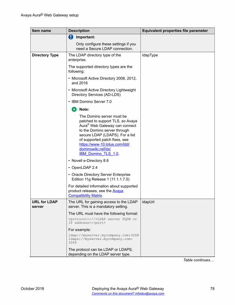
Item name Description Equivalent properties file parameterImportant:
Only configure these settings if youneed a Secure LDAP connection.
Directory Type The LDAP directory type of theenterprise.
The supported directory types are thefollowing:
• Microsoft Active Directory 2008, 2012,and 2016
• Microsoft Active Directory LightweightDirectory Services (AD-LDS)
• IBM Domino Server 7.0
Note:
The Domino server must bepatched to support TLS, so AvayaAura® Web Gateway can connectto the Domino server throughsecure LDAP (LDAPS). For a listof supported patch fixes, see https://www-10.lotus.com/ldd/dominowiki.nsf/dx/IBM_Domino_TLS_1.0.
• Novell e-Directory 8.8
• OpenLDAP 2.4
• Oracle Directory Server EnterpriseEdition 11g Release 1 (11.1.1.7.0)
For detailed information about supportedproduct releases, see the AvayaCompatibility Matrix.
ldapType
URL for LDAPserver
The URL for gaining access to the LDAPserver. This is a mandatory setting.
The URL must have the following format:<protocol>://<LDAP server FQDN or IP address>:<port>
For example:ldap://myserver.mycompany.com:3268ldaps://myserver.mycompany.com:3269
The protocol can be LDAP or LDAPS,depending on the LDAP server type.
ldapUrl
Table continues…
Avaya Aura® Web Gateway setup
October 2018 Deploying the Avaya Aura® Web Gateway 78Comments on this document? [email protected]

Item name Description Equivalent properties file parameterFor Microsoft Active Directory, use thecatalog LDAP ports.
The default global catalog LDAP portvalues are 3268 for LDAP and 3269 forLDAPS.
The default domain LDAP ports valuesare 389 for LDAP and 636 for LDAPS.
Note:
If an FQDN is used to specify theLDAP server, the enterprise mightmap the FQDN to multiple,replicated LDAP servers using theDNS round-robin mechanism as anattempt for load-balance and forredundancy purpose. Sporadicauthentication failures can occur ifone of the LDAP servers is offlineand the DNS round-robinmechanism resolves the FQDN tothe IP of the LDAP server that isoffline.
If this outcome cannot be tolerated,a more reliable load-balancingmechanism, such as a dedicatedload-balancer in front of the LDAPservers, will be needed.
For Active Directory, use the GlobalCatalog service port instead of thedefault LDAP/LDAPS ports.
Bind DN The Distinguished Name (DN) of the userthat has read and search permissions forthe LDAP server users and roles. This isa mandatory setting.
The format of the Bind DN depends onthe configuration of the LDAP server.
Note:
Even though the parameter name isBind DN, the format of its value isnot limited to the DN format. Theformat can be any format that theLDAP server can support for LDAPbind.
bindDN
Table continues…
Avaya Aura® Web Gateway initial configuration settings
October 2018 Deploying the Avaya Aura® Web Gateway 79Comments on this document? [email protected]

Item name Description Equivalent properties file parameter
For example: for Active Directory,you can use "domain\user","user@domain", as well as theactual DN of the user object.
Bind Credential The password that the Avaya Aura® WebGateway server requires for the LDAPbind operation. This is a mandatorysetting.
bindCredential
Important:
If you configure the LDAP settingsusing the properties file, you mustenter the Bind Credential manuallyby running the configureCSA.shscript.
UID Attribute ID The User ID attribute name, asdetermined by the LDAP serverconfiguration. This is a mandatorysetting.
This parameter is used for searchingusers in the LDAP server.
For example: sAMAccountName
uidAttrID
Base Context DN The DN of the context used for LDAPauthentication.
For example:ou=csasusers,dc=example,dc=com
baseCtxDN
AdministratorRole
The list of LDAP roles that match theAvaya Aura® Web Gateway Administratorrole.
For example:
If the role is configured asCSAAdmin,CSAxyz, any user whose listof roles contains CSAAdmin or CSAxyzis mapped to the Avaya Aura® WebGateway Administrator role.
Note:
The values of the roles are case-sensitive when they are mapped tothe application roles. So they mustmatch exactly to the roles namefound for a user in order for themapping of the LDAP roles to theAvaya Aura® Web Gatewayapplication roles to succeed.
adminRole
Table continues…
Avaya Aura® Web Gateway setup
October 2018 Deploying the Avaya Aura® Web Gateway 80Comments on this document? [email protected]
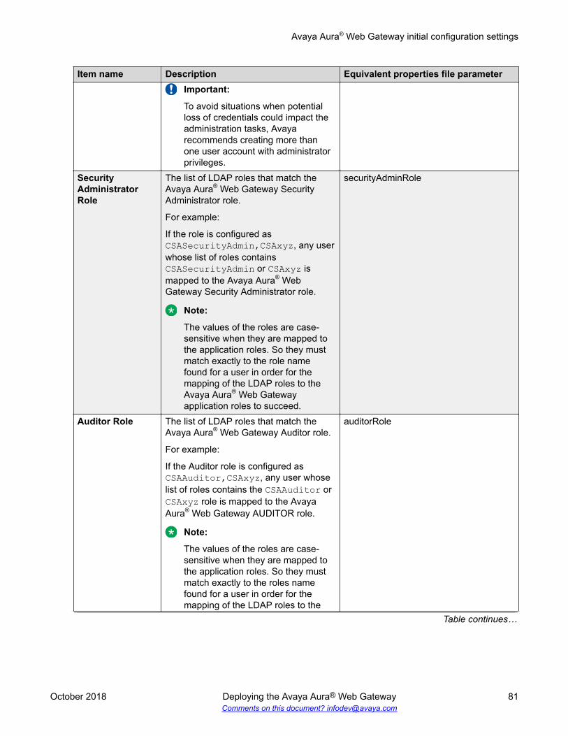
Item name Description Equivalent properties file parameterImportant:
To avoid situations when potentialloss of credentials could impact theadministration tasks, Avayarecommends creating more thanone user account with administratorprivileges.
SecurityAdministratorRole
The list of LDAP roles that match theAvaya Aura® Web Gateway SecurityAdministrator role.
For example:
If the role is configured asCSASecurityAdmin,CSAxyz, any userwhose list of roles containsCSASecurityAdmin or CSAxyz ismapped to the Avaya Aura® WebGateway Security Administrator role.
Note:
The values of the roles are case-sensitive when they are mapped tothe application roles. So they mustmatch exactly to the role namefound for a user in order for themapping of the LDAP roles to theAvaya Aura® Web Gatewayapplication roles to succeed.
securityAdminRole
Auditor Role The list of LDAP roles that match theAvaya Aura® Web Gateway Auditor role.
For example:
If the Auditor role is configured asCSAAuditor,CSAxyz, any user whoselist of roles contains the CSAAuditor orCSAxyz role is mapped to the AvayaAura® Web Gateway AUDITOR role.
Note:
The values of the roles are case-sensitive when they are mapped tothe application roles. So they mustmatch exactly to the roles namefound for a user in order for themapping of the LDAP roles to the
auditorRole
Table continues…
Avaya Aura® Web Gateway initial configuration settings
October 2018 Deploying the Avaya Aura® Web Gateway 81Comments on this document? [email protected]

Item name Description Equivalent properties file parameter
Avaya Aura® Web Gatewayapplication roles to succeed.
User Role The list of LDAP roles that match theAvaya Aura® Web Gateway User role.
For example:
If the User role is configured asCSAUser,CSAxyz, any user whose listof roles contains the CSAUser orCSAxyz role is mapped to the AvayaAura® Web Gateway USER role.
Note:
The values of the roles are case-sensitive when they are mapped tothe application roles. So they mustmatch exactly to the roles namefound for a user for the mapping ofthe LDAP roles to the Avaya Aura®
Web Gateway application roles tosucceed.
usersRole
ServicesAdministratorRole
The list of LDAP roles that match theServices Administrator role.
For example:
If the User role is configured asCSAUser,CSAxyz, any user whose listof roles contains the CSAUser orCSAxyz role is mapped to the AvayaAura® Web Gateway ServicesAdministrator role.
Note:
The values of the roles are case-sensitive when they are mapped tothe application roles. So they mustmatch exactly to the roles namefound for a user for the mapping ofthe LDAP roles to the Avaya Aura®
Web Gateway application roles tosucceed.
serviceAdminRole
Maintenance andSupport Role
The list of LDAP roles that match theMaintenance and Support role.
For example:
serviceMaintenanceRole
Table continues…
Avaya Aura® Web Gateway setup
October 2018 Deploying the Avaya Aura® Web Gateway 82Comments on this document? [email protected]

Item name Description Equivalent properties file parameterIf the User role is configured asCSAUser,CSAxyz, any user whose listof roles contains the CSAUser orCSAxyz role is mapped to the AvayaAura® Web Gateway Maintenance andSupport role.
Note:
The values of the roles are case-sensitive when they are mapped tothe application roles. So they mustmatch exactly to the roles namefound for a user for the mapping ofthe LDAP roles to the Avaya Aura®
Web Gateway application roles tosucceed.
Advanced LDAPparameters
The menu that contains advanced LDAPparameters to configure depending onthe structure of the LDAP server.
Test User If you select testUser and select Apply,this option is used to validate thefollowing LDAP settings:
• Verifies that the user is searchable witha given base DN and search filter.
• Lists the group to which the userbelongs — user, administrator, orauditor.
• Validates the values for Role AttributeID and Role Name Attribute.
• Verifies the Last Updated Timeattribute, role filter syntax, and activeusers search filter syntax.
The configuration is not saved if any ofthese validations fail.
The testUser parameter is optional. If youdo not specify a value, the system skipsvalidation and directly saves theconfiguration in the database.
testUser
Table 5: Advanced LDAP attributes
The following table contains the LDAP configuration settings accessible through the Advanced LDAPattributes menu:
Avaya Aura® Web Gateway initial configuration settings
October 2018 Deploying the Avaya Aura® Web Gateway 83Comments on this document? [email protected]

Item name Description Equivalent properties fileparameter
Role Filter The string to use for role filtering.
The format of the string dependson the LDAP server configuration.
For example:(&(objectClass=group)(member={1}))
roleFilter
Role Attribute ID The Role Attribute ID parameterhas a different meaning,depending on the value ofRoleAttributeIsDN:
• If RoleAttributeIsDN is true, thisis the attribute that contains theDN used to find the object thatcontains the role name.
• If RoleAttributeIsDN is false,this is the name of the attributethat contains the role name.
For example: memberOf
roleAttrID
Roles Context DN The Roles Context DN to use forsearching roles.
The roles search in LDAP isperformed by using the RolesContext DN in combination withthe Role Filter.
For example:ou=csasusers,dc=example,dc=com
rolesCtxDN
Role Name Attribute This parameter has a differentmeaning, depending on the valueof RoleAttributeIsDN:
• If RoleAttributeIsDN is true, thevalue of the attribute set inRoleAttributeID is used to findthe object that contains the roleand this parameter stores thename of the attribute thatcontains the role name.
• If RoleAttributeIsDN is false,this parameter is ignored.
For example: cn
roleNameAttrID
Table continues…
Avaya Aura® Web Gateway setup
October 2018 Deploying the Avaya Aura® Web Gateway 84Comments on this document? [email protected]
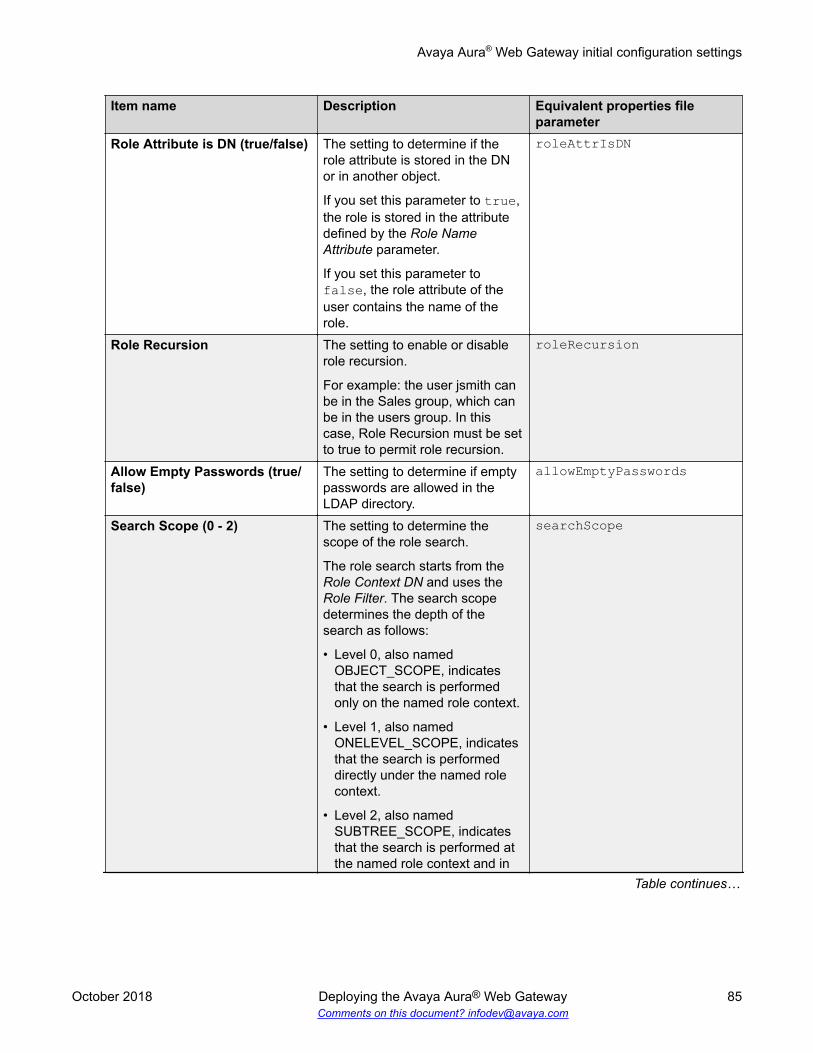
Item name Description Equivalent properties fileparameter
Role Attribute is DN (true/false) The setting to determine if therole attribute is stored in the DNor in another object.
If you set this parameter to true,the role is stored in the attributedefined by the Role NameAttribute parameter.
If you set this parameter tofalse, the role attribute of theuser contains the name of therole.
roleAttrIsDN
Role Recursion The setting to enable or disablerole recursion.
For example: the user jsmith canbe in the Sales group, which canbe in the users group. In thiscase, Role Recursion must be setto true to permit role recursion.
roleRecursion
Allow Empty Passwords (true/false)
The setting to determine if emptypasswords are allowed in theLDAP directory.
allowEmptyPasswords
Search Scope (0 - 2) The setting to determine thescope of the role search.
The role search starts from theRole Context DN and uses theRole Filter. The search scopedetermines the depth of thesearch as follows:
• Level 0, also namedOBJECT_SCOPE, indicatesthat the search is performedonly on the named role context.
• Level 1, also namedONELEVEL_SCOPE, indicatesthat the search is performeddirectly under the named rolecontext.
• Level 2, also namedSUBTREE_SCOPE, indicatesthat the search is performed atthe named role context and in
searchScope
Table continues…
Avaya Aura® Web Gateway initial configuration settings
October 2018 Deploying the Avaya Aura® Web Gateway 85Comments on this document? [email protected]

Item name Description Equivalent properties fileparameter
the sub-tree rooted at thenamed role context.
Language used in Directory The language used in the LDAPdirectory.
The following languages aresupported:
• Russian
• German
• Spanish
• English
• Korean
• French
• Portuguese
• Simplified Chinese
• Japanese
• Italian
language
Active users search filter The search filter string used toidentify active users.
If the LDAP server supports amethod of determining whether auser is active, this setting mustcontain the attribute thatdetermines if a user is active.
If this setting is not configured,the User Managementcomponent handles all the usersas active users.
For example:(&(objectClass=user)(objectCategory=Person)(!(userAccountControl:1.2.840.113556.1.4.803:=2))).
activeUsersFilter
Last updated time attribute The attribute indicating the lasttime an LDAP object wasmodified, in the ASN.1Generalized Time Notation.
lastUpdatedTimeAttr
Table continues…
Avaya Aura® Web Gateway setup
October 2018 Deploying the Avaya Aura® Web Gateway 86Comments on this document? [email protected]

Item name Description Equivalent properties fileparameter
The Avaya Aura® Web GatewayUser Management componentuses this attribute to identifyupdated users whensynchronizing the user data withthe LDAP server.
If this parameter is notconfigured, the UserManagement componentcompares the data of every userto the data that exists in theLDAP server.
Note:
Configuring this parameterimproves the efficiency ofthe user synchronizationprocess and reduces thetraffic between the AvayaAura® Web Gateway serverand the LDAP server duringuser synchronization.
Load parameter defaults The script to load the defaultvalues for the parameters.
—
Multiple authentication and authorization domainsBefore Release 3.4, you could configure multiple LDAPs and have multiple base contexts on eachLDAP, but you could only use one of them for authorization and authentication. With the singleauthentication and authorization domain restriction in place, users had to be provisioned multipletimes so they existed in the authentication and authorization domain and in the other LDAPs usedfor search.As of Release 3.4, the multiple authentication and authorization feature removes the requirementfor a single domain for authentication and authorization and facilitates the following deployments:
• A single LDAP infrastructure belonging to a single organization with multiple configureddomains.
• Two distinct LDAP infrastructures belonging to two separate organizations.The Avaya Aura® Web Gateway supports up to ten LDAP authentication and authorizationdomains.When multiple directories are enabled for authentication, you must provide your FQDN to log in.For example: [email protected]. A short user name is not supported. If you do not haveproper data in user name attributes, such as mail and userPrincipalName, you can assign acustom attribute that is used for the UID mapping of user names. All values in the custom attributemust be a fully qualified user name of the form username@domain, where domain must matchone of the base context DNs defined for the LDAP.
Avaya Aura® Web Gateway initial configuration settings
October 2018 Deploying the Avaya Aura® Web Gateway 87Comments on this document? [email protected]

During the initial Avaya Aura® Web Gateway installation procedure, you can configure only oneLDAP server. If you want to add more LDAP servers, use the web administration portal. For moreinformation, see “Adding a new enterprise LDAP server” in Administering the Avaya Aura® WebGateway.
Configuring the role search parametersAbout this taskThis procedure describes how to configure the LDAP role search parameters when MicrosoftActive Directory (AD) is used.Role search for Avaya Aura® Web Gateway users are really about finding the associated “role”strings for a user in LDAP. For AD, this is about the user group names that a user belongs to.In Microsoft Active Directory, the DNs of the groups that a user belongs to are stored in the“memberOf” attribute of a user. The “memberOf” attribute also stores the Exchange mailing liststhat a user belongs to. Conversely, the group objects that the user belongs to contain a “member”attribute that stores the DNs of all of the users and sub-groups that are members of this group.
Procedure1. Run the Avaya Aura® Web Gateway configuration utility using the app configure
command.
2. Select LDAP Configuration > Advanced LDAP parameters.
3. Configure the parameter settings as described in Parameter settings on page 88.
4. Configure the attributes as described in Role configuration on page 90.
LDAP parameter descriptionsParameter settingsThe following table describes the parameter settings according to the search mechanism that youchoose:
Parameter Search mechanism #1:
Find the user, extract the group DNs fromthe “memberOf” attribute, and get therole strings from each of the groupobjects
Search mechanism #2:
Find the groups that the user belongs toand extract the role string from one ofthe attributes
Example Description Example DescriptionRole Filter (&(objectClass=user)
(objectCategory=Person)(<UID attributeID>={0}))
<UID Attribute ID> isthe value of the “UIDAttribute ID”parameter.
“{0}” is theplaceholder that willbe replaced by theauthenticating userID.
(&(objectClass=group)(member={1}))
“{1}” is theplaceholder to bereplaced by the DNof the user object.The DN is identifiedduring theauthenticationprocess.
Table continues…
Avaya Aura® Web Gateway setup
October 2018 Deploying the Avaya Aura® Web Gateway 88Comments on this document? [email protected]

Parameter Search mechanism #1:
Find the user, extract the group DNs fromthe “memberOf” attribute, and get therole strings from each of the groupobjects
Search mechanism #2:
Find the groups that the user belongs toand extract the role string from one ofthe attributes
Example Description Example DescriptionThis filter looks for agroup object whose“member” attributecontains a value ofthe authenticatinguser DN.
Role ContextDN
ou=Users,dc=global,dc=example,dc=com
The purpose of thesearch is to find theuser and then extractthe role objects fromthe “memberOf” userattribute.
ou=Groups,dc=global,dc=example,dc=com
The purpose of thesearch is to find theroles whose“member” attributecontains the user.
RoleAttribute ID
“memberOf” This attributecontains the list ofDNs of the groups towhich the userbelongs to.
CN This contains thegroup’s name (e.g.“AAWGAdmin”, etc.)
RoleAttribute isDN
true The “memberOf”values are the DNsof the group/mailinglist objects.
false The “Role AttributeID” already containsthe “role” stringname.
Role NameAttribute
CN The attribute definedby Role NameAttribute contains thegroup name.
For example:AAWGAdmin
Leave this emptybecause “RoleAttribute is DN” isfalse.
RoleRecursion
0 This configurationdoes not allowrecursive search.
Note:
Using thisconfiguration, theusers under the“AAWGDelegates”group will not beable to use AvayaAura® WebGateway so this is
1 or higher You must set thisvalue to 0 if thereare no subgroups ora value from 1 to 10to support searchesof users that are insubgroups.
In this example, therecursive search isneeded to find theuser in the“AAWGDelegates”
Table continues…
Avaya Aura® Web Gateway initial configuration settings
October 2018 Deploying the Avaya Aura® Web Gateway 89Comments on this document? [email protected]

Parameter Search mechanism #1:
Find the user, extract the group DNs fromthe “memberOf” attribute, and get therole strings from each of the groupobjects
Search mechanism #2:
Find the groups that the user belongs toand extract the role string from one ofthe attributes
Example Description Example Description
not therecommendedconfiguration forthis example.
group, so this valuemust be set to atleast 1.
Role configurationTo search the role base context and under it, set Search Scope to 2 or SUBTREE_SCOPE . Theconfiguration of the following roles is the same, regardless of the configured search mechanism:
Role Description ExampleAdministrator Role This role specifies the list of the “role” string extracted from
LDAP that would be mapped to the Avaya Aura® WebGateway server ADMIN application role.
AAWGAdmin
User Role This role specifies the list of the “role” string extracted fromLDAP that would be mapped to the Avaya Aura® WebGateway server USERS application role.
AAWGUsers
Auditor Role This role specifies the list of the “role” string extracted fromLDAP that would be mapped to the Avaya Aura® WebGateway server AUDITOR application role.
AAWGAuditor
ServiceAdministrator Role
Avaya Aura® Web Gateway does not currently use this role. Leave this setting blank.
ServicesMaintenance andSupport Role
Avaya Aura® Web Gateway does not currently use this role. Leave this setting blank.
SecurityAdministrator Role
This role is for updating web certificates from the webadministration portal.
AAWGSecurityAdmin
Cluster configurationUsing the Cluster configuration, you can configure the Avaya Aura® Web Gateway nodes in aclustered environment.
Avaya Aura® Web Gateway setup
October 2018 Deploying the Avaya Aura® Web Gateway 90Comments on this document? [email protected]

Item name Description Equivalentinstallation.properties fileparameter
Initial clusternode
The setting to specify if the server whereyou are performing the installation is theinitial node in a cluster.
Select y (yes) to set the current node asthe initial node in the cluster or n (no) toset the current node as an additionalnode.
The default value for this setting is y(yes).
In a standalone installation, set this valueto y (yes).
If you configure this setting to n (no), thefollowing settings become visible andmust be configured:
• The IP address of the initial clusternode.
• The ID of the Linux user performing theinstallation on the initial node.
• The Cassandra database user name forthe initial node.
• The Cassandra database password forthe initial node.
INITIAL_NODEIf you configure this setting to n (no),you must also configure the followingparameters:
• SEED_NODE• REMOTE_UID• CURRENT_CASSANDRA_USER• CURRENT_CASSANDRA_PASSWORD
Local node IPaddress
The IP address of the local node. CLUSTER_IP_ADDR
Virtual IP configuration optionsOption Description Equivalent
installation.properties fileparameter
Enable virtual IP The setting to enable the usage of avirtual IP address.
If you select n (no), the configuration scriptdoes not configure the virtual IP address.
If you select y (yes), new configurationsettings for the virtual IP address aredisplayed in the configuration menu.
KA_ENABLED
Table continues…
Avaya Aura® Web Gateway initial configuration settings
October 2018 Deploying the Avaya Aura® Web Gateway 91Comments on this document? [email protected]

Option Description Equivalentinstallation.properties fileparameter
These settings are listed below in thistable. If you are performing a silentinstallation you must also configure theseparameters in theinstallation.properties file.
Virtual IP address The virtual IP address shared by all thecluster nodes.
KA_VIRTUAL_IP
Virtual IPinterface
The network interface used for the virtualIP address. Unless you are using aconfiguration that has multiple Ethernetinterfaces, you must set this value to eth0(Ethernet-zero).
KA_INTERFACE
Virtual IP masternode
Determines if the current node is thevirtual IP master node. As the initial nodeof the cluster is usually designated thevirtual IP master, set this value to y (yes),on the initial node. In addition, as thesecond node in a cluster is usuallydesignated the virtual IP backup, set thisvalue to n (no) on the second node.
KA_MASTER_YN
Virtual IP routerID
An integer with a value from 1 to 255. Thevalue must be the same for both virtual IPmaster and backup. The default value is71.
This value must be unique across VirtualRouter Redundancy Protocol (VRRP)installations.
KA_ROUTER_ID
Virtual IPauthenticationpassword
The password that the backup node usesfor authentication. This password must bethe same as the virtual IP authenticationpassword configured for the initial node.
KA_AUTHENTICATION_PASSWORD
Related linksAvaya Aura Web Gateway initial configuration settings on page 73
Avaya Aura® Web Gateway setup
October 2018 Deploying the Avaya Aura® Web Gateway 92Comments on this document? [email protected]

Advanced configurationTable 6: Advanced configuration settings
Item name Description Equivalent installation.propertiesfile parameter
CertificateWarningPeriod
The number of days before the expiry dateof a certificate causes the system to raisean alarm.
CERT_WARNING_PERIOD
MaximumMessageCount
The maximum message count that thesystem can return per conversation, whena user performs a database a query to viewa conversation.
If you set the Maximum message countin a query value to NULL, the system usesthe default value in the databaseinitialization settings.
MAX_MESSAGE_COUNT
OS SecurityUtility
The menu for configuring the firewallautomatically on the current node.
Select Run the firewall configurationscript and press Enter to run the firewallconfiguration script.
Avaya recommends that you run this scriptto configure the firewall automatically andnot perform a manual configuration.
Warning:
The firewall configuration scriptreplaces the current configuration ofthe firewall on the server where youare performing the installation, so youmust open any other ports required foryour server manually after you run thisscript.
RUN_FIREWALL_CONFIGIf you set this parameter to y (yes), thefirewall configuration script is run during thesilent installation.
Long PollTimeout
The menu that contains theRecommended Long Poll Timeoutconfiguration option. Use this option forsetting the value to use in the Avaya-Request-Timeout HTTP header for long-poll requests.
Important:
The long poll timeout value can befrom 30 to 120. Lowering this value
AVAYA_REQUEST_TIMEOUT
Table continues…
Avaya Aura® Web Gateway initial configuration settings
October 2018 Deploying the Avaya Aura® Web Gateway 93Comments on this document? [email protected]

Item name Description Equivalent installation.propertiesfile parameter
results in increased traffic on theserver, but network configuration mayrequire that you set a lower value.
If you do not configure this parameter, thedefault database initialization setting isused.
ConfigureHost IP forSNMPmanagement
The menu that contains the IP address formanaging this server setting forconfiguring the IP address of the NetworkInterface to use for SNMP.
SNMP_IP_ADDR
SecurityBanner File
The menu for configuring security bannersettings.
The Security Banner File setting mustcontain the path to the security banner file.
The security banner file is a text file thatcontains the security warnings displayedwhen a user or administrator logs in to theadministration portal or using an SSHconsole.
SECURITY_BANNER_PATH
Starting services using a command lineAbout this taskUse this procedure to start application services after you complete installation.
Procedure1. Open the Linux shell using your Linux administrator account credentials.
The Linux administrator account is created during the deployment process.
2. To start the Avaya Aura® Web Gateway services, run the following command:svc csa start
Avaya Aura® Web Gateway setup
October 2018 Deploying the Avaya Aura® Web Gateway 94Comments on this document? [email protected]

Configuring OAMP to use Linux account credentials onthe Avaya Aura® Web Gateway administration portal
About this taskThis is an optional procedure that you need to perform if you want to log on to the Avaya Aura®
Web Gateway administration portal using Linux account credentials.
Procedure1. Open the Linux shell using your Linux administrator account credentials.
2. Run the following command:cdto activesudo vi tomcat/<tomcatVersion>/conf/catalina.properties
3. Locate the com.avaya.cas.access.groups properties and update the list of groupsallowed to access the web administration portal as required.
Ensure that entries in the group list are separated by a comma. The following is anexample:# OAMP access linux groupscom.avaya.cas.access.groups.admin=admingrpcom.avaya.cas.access.groups.securityadmin=admingrp
Users that are part of the “admingrp ” group have access to the web administration portalby default.
4. Run the following command to apply the changes:svc tomcat restart
Configuring OAMP to use Linux account credentials on the Avaya Aura® Web Gateway administration portal
October 2018 Deploying the Avaya Aura® Web Gateway 95Comments on this document? [email protected]

Chapter 7: Global FQDN configuration
You can use a single for all services or multiple FQDNs for each service. If you are using multipleFQDNs, you require an external interface on the reverse proxy for each FQDN and separatecertificates for each FQDN.In a single FQDN environment, remote clients and endpoints that participate in conferences interactwith multiple components through HTTPS. To eliminate the need for multiple external public IPs,FQDNs, and certificates, the URL rewriting method is used. Using this method, clients andendpoints can access conferences using a single FQDN and a single IP address through port 443.
DNS configuration• For a single FQDN deployment, configure DNS as follows:
- For external DNS configuration, have a single FQDN record, for example,webservices.company.com, that points to the reverse proxy or load balancer interfacefor external traffic.
- For internal DNS configuration, have a single FQDN record, for example,webservices.company.com, that points to the reverse proxy or load balancer interfacefor internal traffic.
• For a multiple FQDNs deployment, configure DNS as follows:- For external DNS configuration, each FQDN points to the external load balancer interface.- For internal DNS configuration, each FQDN points to the individual server components.
Related linksRequired FQDNs and certificates on page 25
Configuring the front-end FQDNProcedure
1. Log in to the Avaya Aura® Web Gateway administration portal.
2. Navigate to External Access > HTTP Reverse Proxy.
3. Configure the following settings:
October 2018 Deploying the Avaya Aura® Web Gateway 96Comments on this document? [email protected]

4. In Host, provide the service FQDN.
For example: You can use webservices.company.com in a single FQDN deployment.In a multiple FQDN deployment, use webgateway.company.com.
5. In Port, enter 443.
6. If you have any external clients, including WebRTC, mobile, or desktop clients outside theenterprise firewall, do the following to enable a remote port:
a. Select the Enable port for remote access check box.
b. In Front-end port for remote access, enter a value between 1024 and 65535.
The default port value is 8444.
This port setting must be configured in the reverse proxy so traffic for clients outside thefirewall is translated from the front-end port to this remote access port.
7. If you are configuring a geographically distributed system, select the Enable use of anexternal load balancer check box.
8. Click Save.
Related linksGeographical distribution overview on page 14
Avaya Equinox Conferencing configuration for singleFQDN deployments
Configuring Avaya Equinox® conference controlProcedure
1. Log in to the Avaya Equinox Management web administration portal.
2. Navigate to Settings > Advanced Parameters.
3. In Property Name, enter com.visionnex.vcms.core.uccp.customizedUCCPURL.
4. In Property Value, enter https://<Service FQDN>:443/uwd/ws?ticket=.
For example: https://webservices.company.com:443/uwd/ws?ticket=.
5. Click Apply.
Avaya Equinox Conferencing configuration for single FQDN deployments
October 2018 Deploying the Avaya Aura® Web Gateway 97Comments on this document? [email protected]

Configuring Web CollaborationProcedure
1. Log in to the Avaya Equinox Management web administration portal.
2. Navigate to Devices > Devices by Type > <Web Collaboration server name> >Configuration.
3. Configure the following settings:
a. In Service FQDN and Local FQDN, enter the service FQDN that resolves to the IPaddress of the selected Web Collaboration node.
For example: webconference1.company.comb. In IP Address, enter the IP address that is resolved from the service and local
FQDNs.
c. In Public URL Branch, enter <Service FQDN>/<Web CollaborationServices node prefix>.
For example: webservices.company.com/webconference1.
Note:
The public branch URL is used to support multiple Web Collaboration Servicesnodes with a single public FQDN.
4. Repeat the previous steps for each Web Collaboration Services server that is part of thedeployment.
Global FQDN configuration
October 2018 Deploying the Avaya Aura® Web Gateway 98Comments on this document? [email protected]
Chapter 8: System Manager, Avaya Aura®Device Services, Media Server,and Avaya EquinoxConferencing configurations
Adding the Avaya Aura® Web Gateway to System ManagerAbout this taskUse this procedure to enable SSO login and add the Avaya Aura® Web Gateway FQDN to theSystem Manager web console.
Note:To set up an Avaya Aura® Web Gateway cluster, use the front-end FQDN for the cluster. If youare using an external oad balancer, the front-end FQDN for the cluster will be the FQDN of theload balancer. If not, it will be the FQDN of the virtual IP assigned to the Avaya Aura® WebGateway cluster.
Before you beginEnsure that you have administrative privileges to access System Manager.For information about accessing System Manager, see Administering Avaya Aura® SystemManager.
Procedure1. On the System Manager web console, click Services > Inventory.
2. In the left navigation pane, click Manage Elements.
3. On the Manage Elements page, click New.
The system displays the New Elements page.
4. In the General section, from Type, select Avaya Aura Web Gateway .
5. On the New Avaya Aura Web Gateway page, in the General section, provide the followinginformation:
• Name: Type a name for the element.
• Type: Retain the default setting of Avaya Aura Web Gateway.
October 2018 Deploying the Avaya Aura® Web Gateway 99Comments on this document? [email protected]

• Description: Type a description for the element.
• Node: Type the FQDN address of the Avaya Aura® Web Gateway server.
6. To enable SSO login, in the Access Profile section, perform the following:
a. Click New.
b. In the Application System Supported Protocol section, in the Protocol field, click URI.c. In the Access Profile Details section, in the Name field, type a name for the access
profile.
d. In the Access Profile Type field, click EMURL.
e. In the Protocol field, click https.
f. In the Host field, type the Avaya Aura® Web Gateway server FQDN.
g. In the Port field, type 8445.
h. In the Path field, type /admin.
i. In the Order field, retain the default value.
j. In the Description field, type a description of the access profile.
k. Click Save.
7. Click Commit.8. On the System Manager console, click Elements > Web Gateway to verify that the Avaya
Aura® Web Gateway element has been added.
Configuring SIP Trunks for the Avaya Aura® Web Gateway onSystem Manager
About this taskThe Avaya Aura® Web Gateway sends SIP messages to Session Manager port 5061 using TLS.Use this procedure to ensure that Session Manager is configured to accept these messages.
Important:For an Avaya Aura® Web Gateway cluster, repeat this procedure for each node in the clusterusing the respective node IP or local FQDN when required.
Before you beginSet up your Avaya Aura® infrastructure, including System Manager.
Procedure1. On the System Manager web console, click Elements > Routing > SIP Entities.
2. In the SIP Entities area, click New to create a new SIP entity for your server.
You can also edit an existing SIP entity using the Edit button.
System Manager, Avaya Aura® Device Services, Media Server, and Avaya Equinox Conferencing configurations
October 2018 Deploying the Avaya Aura® Web Gateway 100Comments on this document? [email protected]

3. On the SIP Entity Details page, configure the following required field settings:
• Name: Type a name for the SIP entity.
• FQDN or IP Address: Type the FQDN or IP address of the Avaya Aura® Web Gateway.
• Type: Select SIP Trunk.
• SIP Timer B/F (in seconds): Retain the default value of 4.
• SIP Link Monitoring: Select Link Monitoring Disabled.
For information about other fields, see the SIP entity field descriptions in AdministeringAvaya Aura® Session Manager.
4. In the Entity Links area, click Add to add entity links between the newly created SIP entityand the entities representing Session Manager.
While mapping the newly created SIP entity with the Session Manager entities,ensure that the following is set:
• Protocol: TLS.
• Port: 5061.
• Connection Policy: trusted.
5. Click Commit to save the changes.
Setting up Serviceability Agents for alarms on System ManagerBefore you beginOn System Manager, set up an SNMPv3 user profile from Services > Inventory > ManageServiceability Agents > SNMPv3 User Profiles.Set up an SNMP target profile from Services > Inventory > Manage Serviceability Agents >SNMP Target Profiles.
About this taskTo receive Avaya Aura® Web Gateway alarms in System Manager, you must set up ServiceabilityAgents.
Procedure1. Log on to System Manager.
2. Click Services > Inventory > Manage Serviceability Agents > Serviceability Agents.
3. Select the Avaya Aura® Web Gateway host name, and click Manage Profiles.
4. Click the SNMP Target Profiles tab.
5. In the Assignable Profiles section, click the SNMP profile you created, and click Assign.
6. Click the SNMPv3 User Profiles tab.
7. In the Assignable Profiles section, select the SNMPv3 profile created, and click Assign.
Adding the Avaya Aura® Web Gateway to System Manager
October 2018 Deploying the Avaya Aura® Web Gateway 101Comments on this document? [email protected]

System Manager is now ready to receive alarms from Avaya Aura® Web Gateway.
Configuring Avaya Aura® Media Server in System ManagerAbout this taskThis procedure outlines the key System Manager configuration required for the Media Server. Usethis procedure to administer locations for all Media Server clusters and assign the EndpointServices Gateway to each Media Server cluster.
Note:• Avaya Aura® Web Gateway only interoperates with Avaya Aura® Media Server Release
7.8.• Avaya Aura® Web Gateway does not support Media Server High Availability cluster
configuration when using WebRTC.
Procedure1. Enroll all Media Server clusters in System Manager.
The enrollment must be done using a System Manager account with administrativeprivileges for adding, changing, deleting, and viewing all Media Server element types. Bydoing this, the configuration of the Media Server and the nodes within the cluster will beavailable on the System Manager server. The Media Server must be enrolled with SystemManager release 7.0.1.1 or higher. For more information about System Managerenrollment, see Implementing and Administering Avaya Aura® Media Server.
2. Administer locations for all Media Server clusters.
a. In System Manager, navigate to Elements > Media Server > Server Administration.
b. In each required Media Server, set the location.
For more information about Media Server clusters location setting, see Managing AvayaAura® Media Server from System Manager.
3. Assign “Endpoint Services Gateway” to each cluster of Media Server that will be used bythe Avaya Aura® Web Gateway.
a. In System Manager, navigate to Elements > Media Server > ApplicationAssignment.
b. Edit the “Endpoint Services Gateway” application.
c. Select the required Media Server clusters.
For more information about Media Server cluster location settings, see Managing AvayaAura® Media Server from System Manager.
System Manager, Avaya Aura® Device Services, Media Server, and Avaya Equinox Conferencing configurations
October 2018 Deploying the Avaya Aura® Web Gateway 102Comments on this document? [email protected]

Configuring Avaya Aura® Media Server settingsAbout this taskThis procedure describes how to configure Avaya Aura® Media Server to enable InteractiveConnectivity Establishment (ICE) and video processing.For more information about setting up Avaya Aura® Media Server, see Implementing andAdministering Avaya Aura® Media Server.
Before you beginEnsure that WebLM server licensing is configured and enabled in Avaya Aura® Media Server.
Procedure1. Log on to the Avaya Aura® Media Server Element Manager using the URL https://
<AMS_EM_FQDN>:8443/emlogin/.
2. Navigate to System Configuration > Server Profile > General Settings.
3. Select Firewall NAT Tunneling Media Processor and Video Media Processor and thenclick Save.
4. Navigate to System Configuration > Signaling Protocols > REST > General Settings.
5. Select Enable TLS Mutual Authentication and click Save.
6. Navigate to System Configuration > Media Processing > ICE > STUN/TURN Serversand select the required STUN and TURN servers.
Tip:
You can verify the network configuration when you are using Avaya Session BorderController for Enterprise (Avaya SBCE) to provide the STUN/TURN service. TheSTUN/TURN address and port configured on the media server must match the STUN/TURN Listen IP & Listen port that are configured for the A1 interface of the AvayaSBCE. You must also use the default values for the following settings:
• Protocol: UDP.
• Priority: 0.
• Weight: 10.
• Account: disabled.
7. Navigate to Licensing > General Settings and ensure that WebLM server licensing isenabled.
8. Navigate to Licensing > Monitoring and ensure that Avaya Aura® Media Server hasacquired licenses.
9. For the changes to take effect, navigate to System Status > Element Status and clickRestart.
Configuring Avaya Aura® Media Server settings
October 2018 Deploying the Avaya Aura® Web Gateway 103Comments on this document? [email protected]

Configuring the Avaya Aura® Web Gateway on AvayaAura® Device Services
About this taskUse this procedure to add the Avaya Aura® Web Gateway FQDN to the Avaya Aura® DeviceServices trusted hosts and to verify HTTP client settings.For more information about Avaya Aura® Device Services, see the following documents:
• Deploying Avaya Aura® Device Services• Administering Avaya Aura® Device Services
Procedure1. On the Avaya Aura® Device Services web administration portal, navigate to Server
Connections > Trusted Hosts and click Add.
2. In Host, type the Avaya Aura® Web Gateway FQDN.
Important:
Avaya Aura® Device Services requires the FQDN or IP address for each Avaya Aura®
Web Gateway cluster node added to the Avaya Aura® Device Services trusted hostslist. Avaya Aura® Device Services also requires the FQDN or IP address of the AvayaAura® Web Gateway cluster.
3. On the HTTP Clients tab, ensure that the REST and OAMP options are not set to NONE.
If these options are set to NONE, then the trusted host relationship between the AvayaAura® Web Gateway and Avaya Aura® Device Services will not work. The Avaya Aura®
Web Gateway will also not be able to communicate with Avaya Aura® Device Services.
Uploading clients to the web deployment serviceAbout this taskUse this procedure to upload Windows and MacOS clients to the web deployment service.For Avaya Equinox® for Windows, you can upload .exe or .msi installation files. For AvayaEquinox® for Mac, you can upload .dmg installation files, which are packaged in a .zip archive.
Note:This procedure applies to Team Engagement and Conferencing deployments. This documentdoes not describe the Conferencing-only deployment model.
For more information about web deployment client installers, see Administering Avaya Aura®
Device Services.
System Manager, Avaya Aura® Device Services, Media Server, and Avaya Equinox Conferencing configurations
October 2018 Deploying the Avaya Aura® Web Gateway 104Comments on this document? [email protected]

Procedure1. Download Avaya Equinox® for Mac or Avaya Equinox® for Windows installation files from
the Avaya Support website.
Note:
You must have PLDS access to download these files.
2. If you are uploading Avaya Equinox® for Mac, pack the Avaya Equinox-<version>.dmg and Avaya Equinox Sparkle Update-<version>.dmg files intoa .zip archive with no intermediate directories.
If the .zip archive contains intermediate directories, re-pack the archive so that it onlycontains the .dmg files in the root directory.
3. Log on to the Avaya Aura® Device Services web administration portal and navigate to WebDeployment > Deployment.
4. In Title, type a name of the updates or appcast for the client installer.
5. In Description, type the description of the client installer updates.
6. In Version, type the version details for the Avaya Equinox® client release.
7. In OS, select the appropriate Avaya Equinox® platform:
• Windows
• Macintosh
8. In File, click Choose File and select one of the following files to upload:
• For Avaya Equinox® for Windows, select the .exe or .msi installation file.
• For Avaya Equinox® for Mac, select the .zip archive containing the .dmg installationfiles.
Configuring the Avaya Aura® Web Gateway on AvayaEquinox® Conferencing
About this taskIf your deployment includes Conferencing, use this procedure to perform the requiredconfiguration on the Avaya Equinox® Conferencing Management portal. For more informationabout Conferencing configuration, see Deploying Avaya Equinox® Solution.
Important:• For the Avaya Aura® Web Gateway and Avaya Equinox® Conferencing to establish a
secure connection, each must trust the Root CA that signed the other's certificates. If theSystem Manager signed certificates are applied in Avaya Equinox® Conferencing, nofurther action is required on the Avaya Aura® Web Gateway.
Configuring the Avaya Aura® Web Gateway on Avaya Equinox® Conferencing
October 2018 Deploying the Avaya Aura® Web Gateway 105Comments on this document? [email protected]

If the certificates applied in Avaya Equinox® Conferencing are signed by a third-party CAother than System Manager, you must follow the steps outlined in Adding third-party rootCA certificates to the Avaya Aura Web Gateway on page 151. For more informationabout certificates in Avaya Equinox® Conferencing, see Administrator Guide for AvayaEquinox® Management.
• A separate User Portal device must be added for each node on the Avaya Aura® WebGateway cluster using its respective IP address and location.
Procedure1. Log on to the Avaya Equinox® Conferencing Management portal.
2. Do the following to add the Avaya Aura® Web Gateway server as a managed server deviceon Avaya Equinox® Conferencing:
a. Navigate to Devices > User Portals.
b. To add the Avaya Aura® Web Gateway server to the list, click Add.
The system displays the Add Management Server dialog box.
c. Enter a unique display name and IP address of the server.
d. From the Location drop-down menu, select location to match the Avaya Aura® WebGateway location assignment on the Avaya Aura® Web Gateway administration portal.
e. Click OK.
3. Wait for a few minutes until the newly added User Portal Device indicator changes fromgray to green.
Route configuration for an external load balancerReverse proxy and load balancer need to accept external and internal connections to the <ServiceFQDN>:443 address. For example: conferencing.avaya.com:443.Usually, the Avaya Aura® Web Gateway uses its own internal load balancer that distributesrequests between cluster nodes. The Avaya Aura® Web Gateway internal load balancer handlesinternal and external requests differently:
• Internal requests use port 443.• External requests use port 8444.
When you use an external load balancer, it redirects internal requests to Avaya Aura® WebGateway port 443 and external requests to Avaya Aura® Web Gateway port 8444.The following table shows URL replacement methods that you must configure on the external loadbalancer to update requests to Web Collaboration services.
System Manager, Avaya Aura® Device Services, Media Server, and Avaya Equinox Conferencing configurations
October 2018 Deploying the Avaya Aura® Web Gateway 106Comments on this document? [email protected]

Request URL Destination Address URL Replace Component/uwd/rest <Equinox Management
Virtual IP FQDN>:443/uwd/rest Avaya Equinox®
Conference Control(UCCS)
/uwd/ws /uwd/wc
/wcs1/ <WCS1 FQDN>:443 / Avaya Aura® MediaServer/wcs2/ <WCS2 FQDN>:443 /
/wcsX/ <WCSX FQDN>:443 //ups • <AAWG Node 1
FQDN>:<port>• <AAWG Node 2
FQDN>:<port>• <AAWG Node X
FQDN>:<port>
For internal requests,use port 443. Forexternal requests, useport 8444.
/ups Avaya Aura® WebGateway/csa /csa
/uwd/dist /uwd/dist/notification /notification/portal /portal
/acs • <AADS Node 1FQDN>:8448
• <AADS Node 2FQDN>:8448
• <AADS Node XFQDN>: 8448
/acs Avaya Aura® DeviceServices
Route configuration for an external load balancer
October 2018 Deploying the Avaya Aura® Web Gateway 107Comments on this document? [email protected]

Chapter 9: Avaya Session BorderController for Enterpriseconfiguration
Use the following sections to configure Avaya Session Border Controller for Enterprise (AvayaSBCE) for the Avaya Aura® Web Gateway. You must have a pool of IP addresses available forAvaya SBCE.For more information about Avaya SBCE configuration, see Administering Avaya Session BorderController for Enterprise.
Related linksRequired FQDNs and certificates on page 25
Avaya Session Border Controller for Enterpriseconfiguration checklist
Perform the tasks in this checklist to configure Avaya SBCE.
No. Task Notes
1 Configure reverse proxy. • In a single FQDN for all servicesdeployment, complete the tasksoutlined in Reverse proxy configurationchecklist for a single FQDNdeployment on page 109.
• In a multiple FQDN deployment,complete the tasks outlined in Reverseproxy configuration checklist for amultiple FQDN deployment onpage 109.
2 If you are planning to use externalclients outside the enterprise firewall,configure external client access.
Complete procedures in External clientaccess configuration on page 119.
October 2018 Deploying the Avaya Aura® Web Gateway 108Comments on this document? [email protected]

Reverse proxy configuration
Reverse proxy configuration checklist for a single FQDNdeployment
Perform the tasks outlined in this checklist to configure reverse proxy on the Avaya SBCE if youare using a single FQDN for all services.
No. Task Notes
1 Verify prerequisites. See Prerequisites on page 110.2 Create a TLS server profile for
reverse proxy.See Checklist for creating a TLS serverprofile for reverse proxy in a single FQDNdeployment on page 110.
3 Configure a CA. See Certificate Authority configurationchecklist on page 113.
You must have the CA that is used to signcertificates for internal components.
4 Configure external and internal trafficrules.
• For configuring external traffic rules,see Configuring external traffic rules ina single FQDN for all servicesdeployment on page 113.
• For configuring internal traffic rules, see Configuring internal traffic rules in asingle FQDN for all servicesdeployment on page 115.
Related linksAvaya Session Border Controller for Enterprise configuration checklist on page 108
Reverse proxy configuration checklist for a multiple FQDNdeployment
Perform the tasks outlined in this checklist to configure reverse proxy on the Avaya SBCE if youare using a multiple FQDNs for services.
No. Task Description
1 Verify prerequisites. See Prerequisites on page 110.
Table continues…
Reverse proxy configuration
October 2018 Deploying the Avaya Aura® Web Gateway 109Comments on this document? [email protected]
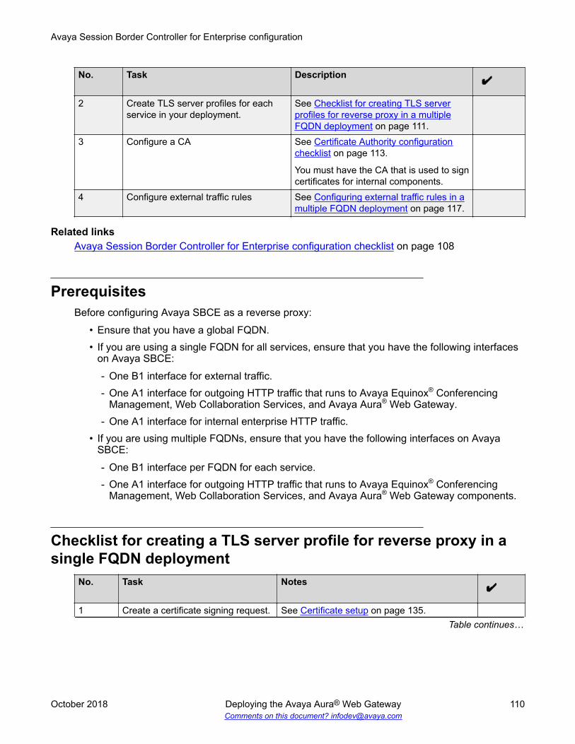
No. Task Description
2 Create TLS server profiles for eachservice in your deployment.
See Checklist for creating TLS serverprofiles for reverse proxy in a multipleFQDN deployment on page 111.
3 Configure a CA See Certificate Authority configurationchecklist on page 113.
You must have the CA that is used to signcertificates for internal components.
4 Configure external traffic rules See Configuring external traffic rules in amultiple FQDN deployment on page 117.
Related linksAvaya Session Border Controller for Enterprise configuration checklist on page 108
PrerequisitesBefore configuring Avaya SBCE as a reverse proxy:
• Ensure that you have a global FQDN.• If you are using a single FQDN for all services, ensure that you have the following interfaces
on Avaya SBCE:- One B1 interface for external traffic.- One A1 interface for outgoing HTTP traffic that runs to Avaya Equinox® Conferencing
Management, Web Collaboration Services, and Avaya Aura® Web Gateway.- One A1 interface for internal enterprise HTTP traffic.
• If you are using multiple FQDNs, ensure that you have the following interfaces on AvayaSBCE:- One B1 interface per FQDN for each service.- One A1 interface for outgoing HTTP traffic that runs to Avaya Equinox® Conferencing
Management, Web Collaboration Services, and Avaya Aura® Web Gateway components.
Checklist for creating a TLS server profile for reverse proxy in asingle FQDN deployment
No. Task Notes
1 Create a certificate signing request. See Certificate setup on page 135.Table continues…
Avaya Session Border Controller for Enterprise configuration
October 2018 Deploying the Avaya Aura® Web Gateway 110Comments on this document? [email protected]

No. Task Notes
Use the following options specific for thisdeployment model:
• For Common Name, use the global FQDN.For example:webservices.company.com.
• For Subject Alternative Name, use theglobal FQDN. For example:DNS:webservices.company.com.
2 Download and save thecreated .KEY and .CSR files.
3 Send the .CSR file to a public CAfor signing.
4 Install the signed certificate and thekey on the Avaya SBCE.
See Installing a certificate and a key onpage 138.
When installing the certificate, use adescriptive name. For example:webservicesCert.
5 Create a TLS server profile usingthe installed certificate.
See Creating a TLS server profile onpage 141.
When creating a profile, use the certificateinstalled on the Avaya SBCE in the previousstep.
Provide a descriptive name for the profile. Forexample: webservicesTlsProfile.
Related linksReverse proxy configuration checklist for a single FQDN deployment on page 109
Checklist for creating TLS server profiles for reverse proxy in amultiple FQDN deployment
No. Task Notes
1 Create certificate signing requestsfor each service FQDNs.
See Certificate setup on page 135.
Create one certificate for each FQDN usedby services deployed in the solution, such asAvaya Equinox® Conferencing Managementservice, Web Collaboration Services, andAvaya Aura® Web Gateway/Portal. If you are
Table continues…
Reverse proxy configuration
October 2018 Deploying the Avaya Aura® Web Gateway 111Comments on this document? [email protected]

No. Task Notes
using several Web Collaboration Servicesservers, you need to create a separate CSRfor each Web Collaboration Services FQDN.Use the following options specific for thisdeployment model:
• For Common Name, use the FQDNassigned to that service. For example:conferencing_management.company.com for Avaya Equinox® ConferencingManagement service.
• For Subject Alternative Name, use theglobal FQDN. For example:DNS:conferencing_management.company.com for Avaya Equinox® ConferencingManagement service.
2 For each CSR, download and savecreated .KEY and .CSR files.
3 Send .CSR files to a public CA forsigning.
4 Install the signed certificates andkeys on the Avaya SBCE.
See Installing a certificate and a key onpage 138.
When installing certificates, use descriptivenames. For example:conferencingManagementCert for theAvaya Equinox® Conferencing Managementservice certificate.
Note:
When installing a certificate, make surethat you use the corresponding key. Donot install keys of another certificates.
5 Create TLS server profiles usingthe installed certificates.
See Creating a TLS server profile onpage 141.
When creating profiles, use certificatesinstalled on the Avaya SBCE in the previousstep.
Provide a descriptive name for each profile.For example:conferenceMgmtTlsProfile for theAvaya Equinox® Conferencing Managementservice profile.
Related linksReverse proxy configuration checklist for a multiple FQDN deployment on page 109
Avaya Session Border Controller for Enterprise configuration
October 2018 Deploying the Avaya Aura® Web Gateway 112Comments on this document? [email protected]

Certificate Authority configuration checklistYou must have the CA that is used to sign certificates for internal components.
• In a single FQDN for all services deployment, certificates for internal components are usuallysigned by the System Manager CA.
• In a multiple FQDN deployment, certificates for internal components are usually signed by apublic CA.
To configure a CA, perform the tasks outlined in the following checklist:
No. Task Notes
1 Install the CA on the Avaya SBCE. See Installing a CA certificate on AvayaSBCE on page 140.
Provide a descriptive name for the CA. Forexample: certificateAuthority.
2 Create a TLS client profile. See Creating a TLS client profile onpage 141.
When creating the profile, use the CA thatyou installed in the previous step.
Provide a descriptive name for the profile.For example:certificateAuthorityTlsProfile.
Related linksReverse proxy configuration checklist for a single FQDN deployment on page 109Reverse proxy configuration checklist for a multiple FQDN deployment on page 109
Configuring external traffic rules in a single FQDN for all servicesdeployment
Before you beginEnsure that you have:
• The TLS server profile for reverse proxy. For more information, see the TLS server profilecreation tasks outlined in Checklist for creating a TLS server profile for reverse proxy in asingle FQDN deployment on page 110.
• The TLS client profile for reverse proxy. For more information, see the CA configuration tasksoutlined in Certificate Authority configuration checklist on page 113.
Use the same TLS server and client profiles when configuring both external and internal trafficrules.
Reverse proxy configuration
October 2018 Deploying the Avaya Aura® Web Gateway 113Comments on this document? [email protected]

Procedure1. Log in to the Avaya SBCE web administration portal.
2. Navigate to Device Specific Settings > DMZ Services > Relay Services > ReverseProxy.
3. Click Add.
4. In Service Name, enter a name for the profile.
5. Select the Enable check box to enable the reverse proxy profile.
6. In Listen IP, select the external B1 interface and the Avaya SBCE external leg IPaddresses.
7. In Listen Port, enter 443.
8. In Listen Protocol, select HTTPS.
9. In Listen TLS Profile, select the TLS server profile that you created.
An example of the TLS profile name is webservicesTLSProfile.
10. Connect IP: Select the internal A1 interface and the Avaya SBCE internal leg IP address.
11. In Server Protocol, select HTTPS.
12. In Server TLS Profile, select the TLS client profile that you created.
An example of the TLS client profile name is certificateAuthorityTLSProfile.
13. Select the Rewrite URL check box.
14. Click Add at the bottom of the page to create a set of rules and configure the rules asdescribed in External traffic rules for a single FQDN deployment on page 114.
15. Click Finish.
Related linksExternal traffic rules for a single FQDN deployment on page 114Reverse proxy configuration checklist for a single FQDN deployment on page 109
External traffic rules for a single FQDN deploymentServer Address White list
URLURLreplace
Description
<Equinox ManagementFQDN>:443
/uwd/rest
/uwd/rest
Equinox Conference Control (UCCS) AvayaEquinox® Conferencing Management FQDNresolves to the virtual IP of the Avaya Equinox®
Conferencing Management Server.
If you are using a standalone system, this FQDNresolves to the virtual IP address. For example:conferencing_management.company.com.
<Equinox ManagementFQDN>:443
/uwd/ws /uwd/rest
Table continues…
Avaya Session Border Controller for Enterprise configuration
October 2018 Deploying the Avaya Aura® Web Gateway 114Comments on this document? [email protected]

Server Address White listURL
URLreplace
Description
<WCS1 FQDN>: 443 /wcs1 / Avaya Aura® Media Server. You must create oneentry per each Web Collaboration Services server.The FQDN is the FQDN of each Avaya Aura® MediaServer, and it resolves to the corresponding AvayaAura® Media Server IP. For example:webconference1.company.com,webconference2.company.com, and so on.
<WCS2 FQDN>: 443 /wcs2 /<WCSX FQDN>: 443 /wcsX /
<Avaya Aura® WebGateway Virtual IPFQDN>: 8444
/acs /acs Avaya Aura® Web Gateway. You must use theFQDN that resolves to the virtual IP address of theAvaya Aura® Web Gateway system. For example:webgateway.company.com.<Avaya Aura® Web
Gateway Virtual IPFQDN>: 8444
/ups /ups
<Avaya Aura® WebGateway Virtual IPFQDN>: 8444
/csa /csa
<Avaya Aura® WebGateway Virtual IPFQDN>: 8444
/uwd/dist
/uwd/dist
<Avaya Aura® WebGateway Virtual IPFQDN>: 8444
/notification
/notification
<Avaya Aura® WebGatewayVirtual IPFQDN>: 8444
/portal /portal
Configuring internal traffic rules in a single FQDN for all servicesdeployment
Before you beginEnsure that you have:
• The TLS server profile for reverse proxy. For more information, see the TLS server profilecreation tasks outlined in Checklist for creating a TLS server profile for reverse proxy in asingle FQDN deployment on page 110.
• The TLS client profile for reverse proxy. For more information, see the CA configuration tasksoutlined in Certificate Authority configuration checklist on page 113.
Use the same TLS server and client profiles when configuring both external and internal trafficrules.
Procedure1. Log in to the Avaya SBCE web administration portal.
Reverse proxy configuration
October 2018 Deploying the Avaya Aura® Web Gateway 115Comments on this document? [email protected]

2. Navigate to Device Specific Settings > DMZ Services > Relay Services > ReverseProxy.
3. Click Add.
4. In Service Name, enter a name for the profile.
5. Select the Enable check box to enable the reverse proxy profile.
6. In Listen IP, select the internal A1 interface and the Avaya SBCE external leg IP address.
7. In Listen Port, enter 443.
8. In Listen Protocol, select HTTPS.
9. In Listen TLS Profile, select the TLS server profile that you created.
An example of the TLS server profile name is webservicesTlsProfile.
10. In Connect IP, select the internal A1 interface and the Avaya SBCE internal leg IPaddresses.
11. In Server Protocol, select HTTPS.
12. In Server TLS Profile, select the TLS client profile that you created.
An example of the TLS client profile name is certificateAuthorityTLSProfile.
13. Select the Rewrite URL check box.
14. Click Add at the bottom of the page to create a set of rules and configure the rules asdescribed in Internal traffic rules for a single FQDN deployment on page 116.
15. Click Finish.
Related linksInternal traffic rules for a single FQDN deployment on page 116Reverse proxy configuration checklist for a single FQDN deployment on page 109
Internal traffic rules for a single FQDN deploymentServer Address White list
URLURLreplace
Description
<Equinox ManagementFQDN>:443
/uwd/rest
/uwd/rest
Equinox Conference Control (UCCS) EquinoxManagement FQDN resolves to the virtual IP of theEquinox Management Server.
If you are using a standalone system, this FQDNresolves to the virtual IP address. For example:conferencing_management.company.com.
<Equinox ManagementFQDN>:443
/uwd/ws /uwd/rest
<WCS1 FQDN>: 443 /wcs1 / Avaya Aura® Media Server. You must create oneentry per each Web Collaboration Services server.The FQDN is the FQDN of each Avaya Aura® MediaServer, and it resolves to the corresponding AvayaAura® Media Server IP. For example:
<WCS2 FQDN>: 443 /wcs2 /<WCSX FQDN>: 443 /wcsX /
Table continues…
Avaya Session Border Controller for Enterprise configuration
October 2018 Deploying the Avaya Aura® Web Gateway 116Comments on this document? [email protected]

Server Address White listURL
URLreplace
Description
webconference1.company.com,webconference2.company.com, and so on.
<Avaya Aura® WebGateway Virtual IPFQDN>: 443
/acs /acs Avaya Aura® Web Gateway. You must use theFQDN that resolves to the virtual IP address of theAvaya Aura® Web Gateway system. For example:webgateway.company.com.<Avaya Aura® Web
Gateway Virtual IPFQDN>: 443
/ups /ups
<Avaya Aura® WebGateway Virtual IPFQDN>: 443
/csa /csa
<Avaya Aura® WebGateway Virtual IPFQDN>: 443
/uwd/dist
/uwd/dist
<Avaya Aura® WebGateway Virtual IPFQDN>: 443
/notification
/notification
<Avaya Aura® WebGatewayVirtual IPFQDN>: 443
/portal /portal
Configuring external traffic rules in a multiple FQDN deploymentAbout this taskPerform this procedure for each service in your deployment. For example, if you have multipleWeb Collaboration Services servers in your deployment, you must perform this procedure for eachserver.
Before you beginEnsure that you have:
• TLS server profiles for each service in your deployment. For more information, see the TLSserver profile creation tasks outlined in Checklist for creating TLS server profiles for reverseproxy in a multiple FQDN deployment on page 111.
• The TLS client profile for reverse proxy. For more information, see the CA configuration tasksoutlined in Reverse proxy configuration checklist for a multiple FQDN deployment onpage 109.
Procedure1. Log in to the Avaya SBCE web administration portal.
2. Navigate to Device Specific Settings > DMZ Services > Relay Services > ReverseProxy.
Reverse proxy configuration
October 2018 Deploying the Avaya Aura® Web Gateway 117Comments on this document? [email protected]

3. Click Add.
4. In Service Name, enter a name for the profile.
5. Select the Enable check box to enable the reverse proxy profile.
6. In Listen IP, select the external B1 interface and the Avaya SBCE external leg IP address.
7. In Listen Port, enter 443.
8. In Listen Protocol, select HTTPS.
9. In Listen TLS Profile, select the TLS server profile that you created.
An example of the TLS server profile name for Web Collaboration Services iswebservicesTLSProfile.
10. In Connect IP, select the internal interface A1 and the Avaya SBCE internal leg IPaddress.
11. In Server Protocol, select HTTPS.
12. In Server TLS Profile, select the TLS client profile that you created.
An example of the TLS client profile name is certificateAuthorityTLSProfile.
13. Select the Rewrite URL check box.
14. Click Add at the bottom of the page to create a set of rules and configure the rules asdescribed in External traffic rules for a single FQDN deployment on page 114.
15. Click Finish.
Related linksExternal traffic rules in a multiple FQDN deployment on page 118Reverse proxy configuration checklist for a multiple FQDN deployment on page 109
External traffic rules in a multiple FQDN deploymentTraffic rules for Avaya Equinox® Conferencing ManagementServer Address White list
URLURLreplace
Description
<Equinox ManagementFQDN>:443
/uwd/rest
/uwd/rest
Equinox Conference Control (UCCS) EquinoxManagement FQDN resolves to the virtual IP of theEquinox Management Server.
If you are using a standalone system, this FQDNresolves to the virtual IP address. For example:conferencing_management.company.com.
<Equinox ManagementFQDN>:443
/uwd/ws /uwd/rest
Traffic rules for Web Collaboration ServicesServer Address White list
URLURLreplace
Description
<WCSX FQDN>: 443 / / Avaya Aura® Media Server. You must create oneentry per each Web Collaboration Services server.
Avaya Session Border Controller for Enterprise configuration
October 2018 Deploying the Avaya Aura® Web Gateway 118Comments on this document? [email protected]

Server Address White listURL
URLreplace
Description
The FQDN is the FQDN of each Avaya Aura® MediaServer, and it resolves to the corresponding AvayaAura® Media Server IP. For example:webconference1.company.com,webconference2.company.com, and so on.
Traffic rules for Avaya Aura® Web Gateway/PortalServer Address White list
URLURLreplace
Description
<Avaya Aura® WebGateway Virtual IPFQDN>: 8444
/ / Avaya Aura® Web Gateway. You must use theFQDN that resolves to the virtual IP address of theAvaya Aura® Web Gateway system. For example:webgateway.company.com.
External client access configurationThe following sections describe how to configure Avaya SBCE if you are planning to use anyexternal clients, including WebRTC, moblile, or desktop clients, outside the enterprise firewall.
External client access configuration checklistPerform the tasks outlined in this checklist if you are planning to use any external clients, includingWebRTC, mobile, or desktop clients, outside the enterprise firewall.
No. Task Notes
1 Create a server TLS profile for amanagement interface.
See Checklist for creation of a TLS serverprofile for a management interface onpage 120.
2 Configure Avaya SBCE loadmonitoring.
See Configuring Avaya SBCE loadmonitoring on page 121.
3 Add Avaya SBCE to the Avaya Aura®
Web Gateway.See Adding Avaya Session BorderController for Enterprise to the AvayaAura Web Gateway on page 122.
4 If you have conferencing, add AvayaSBCE to Avaya Equinox®
Conferencing Management.
See Adding Avaya Session BorderController for Enterprise to AvayaEquinox Conferencing Management onpage 122.
Table continues…
External client access configuration
October 2018 Deploying the Avaya Aura® Web Gateway 119Comments on this document? [email protected]

No. Task Notes
5 Configure WebRTC client side TURN. See WebRTC client side TURNconfiguration on page 124.
6 Configure support for external nativemedia clients.
See External native clients mediaconfiguration on page 128.
Checklist for creation of a TLS server profile for a managementinterface
Perform the tasks in this checklist to configure certificates and create a TLS server profile for amanagement interface. This is required for external client access configuration.
No. Task Notes
1 Create a certificate signing request. See Creating a certificate signing request onAvaya Session Border Controller forEnterprise on page 135.
When creating a CSR, use the followingoptions:
• For Common Name, use the managementinterface FQDN. For example:asbce_management.company.com.
• For Subject Alternative Name, provideboth the FQDN and IP address of themanagement interface. For example:DNS:asbce_management.company.comIP:10.10.10.10
.2 Download and save created .KEY
and .CSR files.
3 Send the .CSR file to the SystemManager CA for signing.
See Signing certificates with the SystemManager CA on page 137.
4 Install the signed certificate and thekey on the Avaya SBCE.
See Installing a certificate and a key onpage 138.
When installing the certificate, use adescriptive name. For example:asbceManagementCert.
5 Create a TLS server profile usingthe installed certificate.
See Creating a TLS server profile onpage 141.
Table continues…
Avaya Session Border Controller for Enterprise configuration
October 2018 Deploying the Avaya Aura® Web Gateway 120Comments on this document? [email protected]

No. Task Notes
When creating a profile, use the certificateinstalled on the Avaya SBCE in the previousstep.
Provide a descriptive name for the profile. Forexample: asbceManagementTlsProfile.
Related linksExternal client access configuration checklist on page 119
Configuring Avaya SBCE load monitoringAbout this taskPerform this procedure if you are using external clients in your deployment.
Before you beginEnsure that you have:
• The internal A1 interface that will be used for load monitoring.
Note:This A1 interface must also be used for the TURN relay setup.
• An FQDN for the Avaya SBCE management interface. For more information, see RequiredFQDNs and certificates on page 25.
• A TLS server profile. For more information about creating this profile, see Checklist forcreation of a TLS server profile for a management interface on page 120.
Procedure1. Log in to the Avaya SBCE web administration portal.
2. Navigate to Device Specific Settings > Advanced Options > Load Monitoring.
3. Click Add to create a new monitoring profile.
4. In Load Balancer Type, select INTERNAL.
This is the load balancer on the A1 side of the network. Avaya Aura® Web Gatewayperforms load balancing towards the internal side. All HTTP requests sent for dialing outuse the internal load balancer logic to identify the appropriate Avaya SBCE.
5. In Transport, select TLS.
6. In TLS Profile, select the TLS server profile that you created.
For more information, see the tasks outlined in Checklist for creation of a TLS serverprofile for a management interface on page 120.
7. In Listen IP, select the internal A1 interface.
External client access configuration
October 2018 Deploying the Avaya Aura® Web Gateway 121Comments on this document? [email protected]

To enable external WebRTC clients, the same interface must be configured for the TURNserver as the A1 interface.
8. In Service Type, select TURN.
9. Click Finish.
Next stepsAdd Avaya SBCE to the Avaya Aura® Web Gateway.
Adding Avaya Session Border Controller for Enterprise to theAvaya Aura® Web Gateway
Procedure1. Log in to the Avaya Aura® Web Gateway web administration portal.
2. Click Add to add a new Avaya SBCE or click Edit to update the information for the existingAvaya SBCE connection.
3. In SIP Address, type the FQDN or IP address of the internal A1 interface of the AvayaSBCE that is used for SIP signaling to interact with Avaya Aura® Web Gateway.
For more information, see External native clients media configuration on page 128.
4. In IP Port, enter 5061.
5. In SIP Protocol, select TLS.
6. In HTTP Address, type the internal Avaya SBCE FQDN specified for the load monitoringentry.
For example: asbce_management.company.com.
7. In HTTP Port, enter 443.
8. In HTTP Protocol, select https.
9. In Location, specify the location of the Avaya SBCE server.
10. Click Save.
Next stepsIf you have conferencing, add Avaya SBCE to Avaya Equinox® Conferencing Management.
Adding Avaya Session Border Controller for Enterprise to AvayaEquinox® Conferencing Management
Procedure1. Log in to the Avaya Equinox® Management web administration portal.
Avaya Session Border Controller for Enterprise configuration
October 2018 Deploying the Avaya Aura® Web Gateway 122Comments on this document? [email protected]

2. Navigate to Devices > Devices by Type > ASBCE.
3. Click Add.
4. On the Add ABSCE page, do the following :
a. In Name, enter a name for the Avaya SBCE server.
b. In IP Address, enter any of the Avaya SBCE IP addresses.
c. In Location, select the location of the Avaya SBCE server.
5. Click OK.
6. Select the Avaya SBCE name from the list and do the following:
a. In Listen/Relay Internal IP, enter the Avaya SBCE IP address of the internal A1interface configured for the load balancer and for STUN/TURN interface.
For more information, see Configuring Avaya SBCE load monitoring on page 121 and WebRTC client side TURN configuration on page 124.
b. In Port, enter 3478.
c. In Listen/Relay Public IP, enter one of the following Avaya SBCE public IPaddresses of the STUN/TURN interface:
• The IP address of the external B1 interface.
• The firewall NAT public IP address of the external B1 interface.
For more information about the B1 interface, see WebRTC client side TURNconfiguration on page 124.
d. In Port, enter 3478.
e. In Internal SIP IP, type the FQDN or IP address of the internal A1 interface of theAvaya SBCE that is used for SIP signaling.
For more information about interaction with Avaya Aura® Web Gateway, see Externalnative clients media configuration on page 128.
f. In SIP Protocol select TLS.
g. In SIP Port, enter 5061.
h. In Local HTTP IP, enter the internal A1 address configured for the load monitoringentry.
For example, asbce_management.company.com.
i. In HTTP protocol, select https.
j. In HTTP port, enter 443.
7. Click OK.
External client access configuration
October 2018 Deploying the Avaya Aura® Web Gateway 123Comments on this document? [email protected]

WebRTC client side TURN configurationUse these sections to enable client side TURN for WebRTC browsers outside your enterprisefirewall. Clients are loaded from your browser and no installation is required on your computer.To enable client side TURN, you need to open TCP port 443 on the external firewall. Server sideTURN uses a range of UDP ports and consumes less Avaya SBCE resources than client sideTURN. However, if a WebRTC browser is behind a firewall that blocks UDP traffic, you mightexperience issues with WebRTC calls if using server side TURN.Avaya recommends using client side TURN instead of sever side TURN whenever possible.
Related linksExternal client access configuration checklist on page 119
Checklist for WebRTC client side TURN configurationPerform the tasks outlined in this checklist to configure external client access.
No. Task Notes
1 Verify prerequisites. See Prerequisites on page 124.2 Create a TLS server profile that is
used if media tunneling requiresbetter readability through firewalls.
See TLS server profile checklist for client sideTURN configuration on page 125.
3 Configure firewall rules. See Firewall configuration on page 125.4 Configure a TURN/STUN profile for
WebRTC calls on Avaya SBCE.See Configuring a TURN/STUN profile forWebRTC calls on Avaya Session BorderController for Enterprise on page 126.
5 Configure the TURN relay servicefor WebRTC calls on Avaya SBCE.
See Configuring the TURN relay service forWebRTC calls on Avaya Session BorderController for Enterprise on page 127.
6 Configure a STUN server on theAvaya Aura® Web Gateway.
See TURN/STUN service configuration on theAvaya Aura Web Gateway on page 128.
7 Enable TURN usage in a WebRTCclient.
See Enabling TURN usage in a WebRTCclient on page 128.
PrerequisitesBefore configuring WebRTC client side TURN settings, do the following:
• Add Avaya SBCE to the Avaya Aura® Web Gateway. For more information, see AddingAvaya Session Border Controller for Enterprise to the Avaya Aura Web Gateway onpage 122.
• Configure one B1 interface IP address on the Avaya SBCE.Additional internal A1 interfaces are not required. Use the same A1 interface IP that you usedfor load monitoring. For more information, see Configuring Avaya SBCE load monitoring onpage 121.
Avaya Session Border Controller for Enterprise configuration
October 2018 Deploying the Avaya Aura® Web Gateway 124Comments on this document? [email protected]
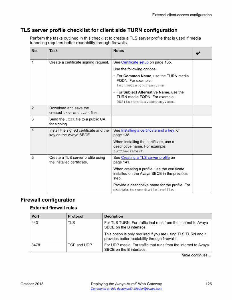
TLS server profile checklist for client side TURN configurationPerform the tasks outlined in this checklist to create a TLS server profile that is used if mediatunneling requires better readability through firewalls.
No. Task Notes
1 Create a certificate signing request. See Certificate setup on page 135.
Use the following options:
• For Common Name, use the TURN mediaFQDN. For example:turnmedia.company.com.
• For Subject Alternative Name, use theTURN media FQDN. For example:DNS:turnmedia.company.com.
2 Download and save thecreated .KEY and .CSR files.
3 Send the .CSR file to a public CAfor signing.
4 Install the signed certificate and thekey on the Avaya SBCE.
See Installing a certificate and a key onpage 138.
When installing the certificate, use adescriptive name. For example:turnmediaCert.
5 Create a TLS server profile usingthe installed certificate.
See Creating a TLS server profile onpage 141.
When creating a profile, use the certificateinstalled on the Avaya SBCE in the previousstep.
Provide a descriptive name for the profile. Forexample: turnmediaTlsProfile.
Firewall configurationExternal firewall rules
Port Protocol Decription443 TLS For TLS TURN. For traffic that runs from the internet to Avaya
SBCE on the B interface.
This option is only required if you are using TLS TURN and itprovides better readability through firewalls.
3478 TCP and UDP For UDP media. For traffic that runs from the internet to AvayaSBCE on the B interface.
Table continues…
External client access configuration
October 2018 Deploying the Avaya Aura® Web Gateway 125Comments on this document? [email protected]

Port Protocol DecriptionThis option is only required if you are using direct WebRTCmedia.
Internal firewall rules
Port Protocol Desciption3478 UDP For UPD media from Avaya SBCE. For traffic that runs from
the A interface of Avaya SBCE to the MCU 7K servers andAvaya Aura® Media Server.
50000 to 55000 UDP For UPD media from Avaya SBCE. For traffic that runs fromthe A interface of Avaya SBCE to the MCU 7K servers andAvaya Aura® Media Server.
12000 to 13200 UDP For UPD media from media servers. For traffic that runs fromMCU 7K servers to the A interface of Avaya SBCE.
16384 to 16984 UDP For UPD media from media servers. For traffic that runs fromMCU 7K servers to the A interface of Avaya SBCE.
6000 to 32588 UDP For UPD media from media servers. For traffic that runs fromAvaya Aura® Media Server to the A interface of Avaya SBCE.
Configuring a TURN/STUN profile for WebRTC calls on Avaya SessionBorder Controller for Enterprise
Procedure1. Log in to the Avaya SBCE web administration interface.
2. Navigate to Device Specific Settings > TURN/STUN Service.
3. From the Application pane, select the Avaya SBCE device for which the new TURN/STUNprofile will be created.
4. Click TURN/STUN Profiles.
5. Click Add.
The system displays the Add TURN/STUN Profile window.
6. In Profile Name, provide a name for the TURN/STUN profile.
For example: turnProfileForWebrtcCalls.
7. In UDP Listen Port, enter 3478.
8. In TCP/TLS Listen Port, enter 443.
9. If TLS TURN media is required, then in TLS Server Profile, specify the TLS server profilefor a management interface that you created.
For more information, see the tasks outlined in TLS server profile checklist for client sideTURN configuration on page 125. An example of the TLS server profile name isturnmediaTlsProfile.
Avaya Session Border Controller for Enterprise configuration
October 2018 Deploying the Avaya Aura® Web Gateway 126Comments on this document? [email protected]

10. In Media Relay Port Range, specify a range that does not overlap with the port rangeused by Avaya SBCE for other protocols, such as SIP.
The default range is 50000 to 55000.
11. Select the Authentication check box.
12. Select the Client Authentication check box.
13. Select the UDP Relay check box.
14. Click Finish.
Configuring the TURN relay service for WebRTC calls on Avaya SessionBorder Controller for Enterprise
Procedure1. Log in to the Avaya SBCE web administration interface.
2. Navigate to Device Specific Settings > TURN/STUN Service.
3. From the Application pane, select the Avaya SBCE device for which you need to create anew TURN relay service.
4. Click TURN/STUN Relay.
5. Click Add.
The system displays the Add TURN/STUN IP Pairing window.
6. In Listen IP, provide the listen IP address of the TURN server from the B1 interface.
Important:
Do not use this IP address for any other interface bound to port 443.
7. In Media Relay, provide the media relay IP address of the TURN server from the internalA1 interface that you used for load monitoring.
8. In Service FQDN, provide the FQDN that resolves to the address specified in the ListenIP field.
For example, turnmedia.company.com.
9. In TURN/STUN Profile, select the TURN/STUN profile that you created for WebRTC calls.
10. Complete the following fields:
In TURN/STUN Profile, select the TURN/STUN profile that you created for WebRTCcalls.
For example: turnProfileForWebrtcCalls. For more information, see Configuring a TURN/STUN profile for WebRTC calls on Avaya Session BorderController for Enterprise on page 126.
11. Click Finish.
External client access configuration
October 2018 Deploying the Avaya Aura® Web Gateway 127Comments on this document? [email protected]

TURN/STUN service configuration on the Avaya Aura® Web GatewayYou can add a new STUN server and set the STUN server priority from External Access > STUNServers in the Avaya Aura® Web Gateway administration portal. For more information see“Managing STUN server settings” in Administering the Avaya Aura® Web Gateway.
Enabling TURN usage in a WebRTC clientProcedure
1. On the Avaya Aura® Web Gateway administration portal, navigate to External Access >Session Border Controller.
2. Select the Enable TURN in WebRTC Client check box.
3. Click Save.
External native clients media configurationUse the following sections if you are planning to use Avaya Equinox® mobile and desktop clientsoutside of your enterprise firewall.
Related linksExternal client access configuration checklist on page 119
External native clients media configuration checklistPerform the tasks outlined in this checklist if you are planning to use Avaya Equinox® mobile anddesktop clients outside of your enterprise firewall.
No. Task TLS server profile required for SIPcommunications with Avaya SBCE
1 Verify prerequisites. See Prerequisites on page 129.1 Create a TLS server profile for
required for SIP communicationswith Avaya SBCE.
See TLS server profile checklist for externalnative clients media configuration onpage 129.
In a multiple FQDN deployment, you can usethe TLS server profile for Avaya Equinox®
Conferencing Management, which youcreated during the reverse proxyconfiguration. For more information, see Checklist for creating TLS server profiles forreverse proxy in a multiple FQDNdeployment on page 111.
2 Create a TLS server profile forHTTP media tunneling.
See TLS server profile checklist for mediatunneling interfaces on page 130.
3 Configure firewall rules. See Firewall configuration on page 131.
Table continues…
Avaya Session Border Controller for Enterprise configuration
October 2018 Deploying the Avaya Aura® Web Gateway 128Comments on this document? [email protected]

No. Task TLS server profile required for SIPcommunications with Avaya SBCE
4 Configure the Avaya SBCEsignaling interface.
See Configuring the Avaya Session BorderController for Enterprise signaling interface onpage 132.
5 Configure the Avaya SBCE mediainterface.
See Configuring the Avaya Session BorderController for Enterprise media interface onpage 132.
6 Configure Avaya SBCE serverflows.
See Configuring Avaya Session BorderController for Enterprise server flows onpage 134.
PrerequisitesBefore configuring support for external native clients media, do the following:
• Add Avaya SBCE to the Avaya Aura® Web Gateway. For more information, see AddingAvaya Session Border Controller for Enterprise to the Avaya Aura Web Gateway onpage 122.
• Configure one A interface IP address and one B interface IP address on the Avaya SBCE.
TLS server profile checklist for external native clients media configurationPerform the following tasks to create a TLS server profile required for SIP communications withAvaya SBCE.
No. Task Notes
1 Create a certificate signing request. See Certificate setup on page 135.
Use the following options:
• For Common Name, use the EquinoxManagement FQDN. For example:conferencing_management.company.com.
• For Subject Alternative Name, use theEquinox Management FQDN. For example:DNS:conferencing_management.company.com.
2 Download and save thecreated .KEY and .CSR files.
3 Send the .CSR file to the SystemManager CA for signing.
See Signing certificates with the SystemManager CA on page 137.
4 Install the signed certificate and thekey on the Avaya SBCE.
See Installing a certificate and a key onpage 138.
Table continues…
External client access configuration
October 2018 Deploying the Avaya Aura® Web Gateway 129Comments on this document? [email protected]

No. Task Notes
When installing the certificate, use adescriptive name. For example:conferencingManagementSipCert.
5 Create a TLS server profile usingthe installed certificate.
See Creating a TLS server profile onpage 141.
When creating a profile, use the certificateinstalled on Avaya SBCE in the previous step.
Provide a descriptive name for the profile. Forexample:conferencingManagementSipTlsProfile.
Related linksExternal native clients media configuration checklist on page 128TLS server profile checklist for media tunneling interfaces on page 130
TLS server profile checklist for media tunneling interfacesPerform the following tasks to create a TLS server profile required for SIP communications withAvaya SBCE.
No. Task Notes
1 Create a certificate signing request. See Certificate setup on page 135.
Use the following options:
• For Common Name, use the HTTP mediatunneling FQDN. For example:media.company.com.
• For Subject Alternative Name, use theHTTPS media tunneling. For example:DNS:media.company.com.
2 Download and save thecreated .KEY and .CSR files.
3 Send the .CSR file to a public CAfor signing.
4 Install the signed certificate and thekey on the Avaya SBCE.
See Installing a certificate and a key onpage 138.
When installing the certificate, use adescriptive name. For example: mediaCert.
5 Create a TLS server profile usingthe installed certificate.
See Creating a TLS server profile onpage 141.
Table continues…
Avaya Session Border Controller for Enterprise configuration
October 2018 Deploying the Avaya Aura® Web Gateway 130Comments on this document? [email protected]
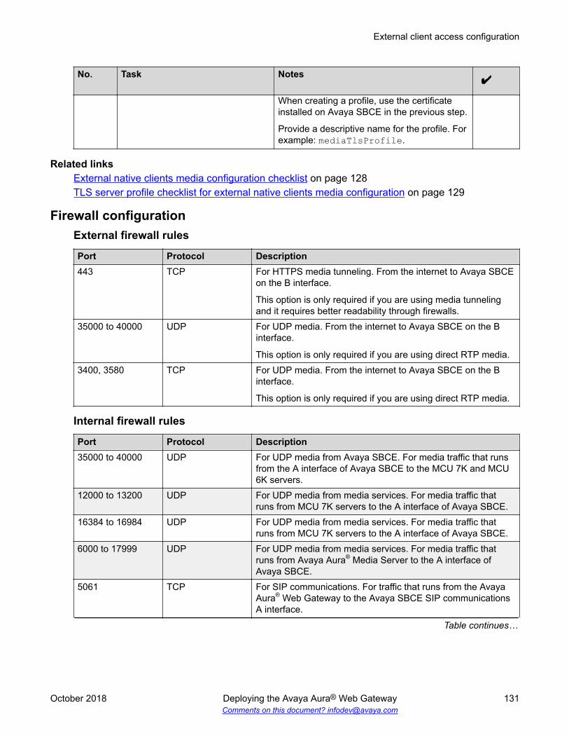
No. Task Notes
When creating a profile, use the certificateinstalled on Avaya SBCE in the previous step.
Provide a descriptive name for the profile. Forexample: mediaTlsProfile.
Related linksExternal native clients media configuration checklist on page 128TLS server profile checklist for external native clients media configuration on page 129
Firewall configurationExternal firewall rules
Port Protocol Description443 TCP For HTTPS media tunneling. From the internet to Avaya SBCE
on the B interface.
This option is only required if you are using media tunnelingand it requires better readability through firewalls.
35000 to 40000 UDP For UDP media. From the internet to Avaya SBCE on the Binterface.
This option is only required if you are using direct RTP media.3400, 3580 TCP For UDP media. From the internet to Avaya SBCE on the B
interface.
This option is only required if you are using direct RTP media.
Internal firewall rules
Port Protocol Description35000 to 40000 UDP For UDP media from Avaya SBCE. For media traffic that runs
from the A interface of Avaya SBCE to the MCU 7K and MCU6K servers.
12000 to 13200 UDP For UDP media from media services. For media traffic thatruns from MCU 7K servers to the A interface of Avaya SBCE.
16384 to 16984 UDP For UDP media from media services. For media traffic thatruns from MCU 7K servers to the A interface of Avaya SBCE.
6000 to 17999 UDP For UDP media from media services. For media traffic thatruns from Avaya Aura® Media Server to the A interface ofAvaya SBCE.
5061 TCP For SIP communications. For traffic that runs from the AvayaAura® Web Gateway to the Avaya SBCE SIP communicationsA interface.
Table continues…
External client access configuration
October 2018 Deploying the Avaya Aura® Web Gateway 131Comments on this document? [email protected]
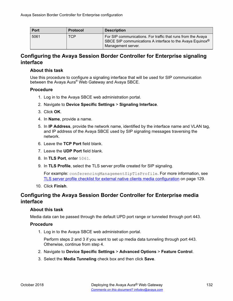
Port Protocol Description5061 TCP For SIP communications. For traffic that runs from the Avaya
SBCE SIP communications A interface to the Avaya Equinox®
Management server.
Configuring the Avaya Session Border Controller for Enterprise signalinginterface
About this taskUse this procedure to configure a signaling interface that will be used for SIP communicationbetween the Avaya Aura® Web Gateway and Avaya SBCE.
Procedure1. Log in to the Avaya SBCE web administration portal.
2. Navigate to Device Specific Settings > Signaling Interface.
3. Click OK.
4. In Name, provide a name.
5. In IP Address, provide the network name, identified by the interface name and VLAN tag,and IP address of the Avaya SBCE used by SIP signaling messages traversing thenetwork.
6. Leave the TCP Port field blank.
7. Leave the UDP Port field blank.
8. In TLS Port, enter 5061.
9. In TLS Profile, select the TLS server profile created for SIP signaling.
For example: conferencingManagementSipTlsProfile. For more information, see TLS server profile checklist for external native clients media configuration on page 129.
10. Click Finish.
Configuring the Avaya Session Border Controller for Enterprise mediainterface
About this taskMedia data can be passed through the default UPD port range or tunneled through port 443.
Procedure1. Log in to the Avaya SBCE web administration portal.
Perform steps 2 and 3 if you want to set up media data tunneling through port 443.Otherwise, continue from step 4.
2. Navigate to Device Specific Settings > Advanced Options > Feature Control.3. Select the Media Tunneling check box and then click Save.
Avaya Session Border Controller for Enterprise configuration
October 2018 Deploying the Avaya Aura® Web Gateway 132Comments on this document? [email protected]

4. To configure an external media interface, do the following:
a. Navigate to Device Specific Settings > Media Interface and then click Add.
b. In Name, provide a name for the media interface.
For example: externalMediaInterfaceProfile.
c. From IP Address, select the B1 IP address.
Important:• Do not use this IP address for any other interface bound to port 443, such as
for HTTP tunneling configuration.
• Do not use VLAN tag for the media tunneled interface.
d. If you are using media tunneling, from TLS Profile, select the required TLS serverprofile for the media interface that you have created when performing TLS serverprofile checklist for media tunneling interfaces on page 130.
For example, mediaTlsProfile.
If media tunneling is disabled, set this field to None.
e. In Buffer Size, provide the required buffer size for media data.
5. To configure the internal media interface, do the following:
a. Navigate to Device Specific Settings > Media Interface and then click Add.
b. In Name, provide a name for the media interface.
For example: internalMediaInterfaceProfile.
c. From IP Address, select the A1 IP address.
6. To enable video media, do the following:
a. Navigate to Domain Policies > Application Rules and then clone an existing mediarule or create a new one.
b. For the new application rule, select In and Out for both the Audio and Videoapplication types.
c. Configure Maximum Concurrent Sessions and Maximum Sessions Per Endpointas required.
d. Click Finish.
7. To configure media encryption and enable Binary Floor Control Protocol (BFCP) or FarEnd Camera Control (FECC), do the following:
a. Navigate to Domain Policies > Media Rules and clone an existing media rule orcreate a new one.
b. For the new media rule, navigate to Encryption > Miscellaneous and select theCapacity Negotiation check box.
c. On the Advanced tab, select the BFCP Enabled and FECC Enabled check boxes.
External client access configuration
October 2018 Deploying the Avaya Aura® Web Gateway 133Comments on this document? [email protected]

8. To configure a policy group using the newly created application and media rules, navigateto Domain policies > End Point Policy Groups , create a new group, and add therequired application and media rules to that group.
Configuring Avaya Session Border Controller for Enterprise server flowsBefore you beginEnsure that you have the TLS client profile created when you configured a certificate authority forreverse proxy. For more information, see Certificate Authority configuration checklist on page 113.An example of the TLS client profile name is certficateAuthorityTlsProfile.
Procedure1. Log in to the Avaya SBCE web administration portal.
2. To create an interworking profile, do the following:
a. Navigate to Global Profiles > Server Interworking and then select Add.
b. For the new profile, use the default options for all settings.
c. In the Advanced Options section, set Has Remote SBC to No (disabled).3. To add a configuration for Avaya Equinox® Management, do the following:
a. Navigate to Global Profiles > Server Configuration and then click Add.
b. From Sever Type, select Trunk Server.c. Leave SIP domain blank.
d. From TLS Client Profile, select the TLS client profile that you created when youconfigured a certificate authority for reverse proxy.
e. Add the Avaya Equinox® Management FQDN with port 5061 and the TLS protocolspecified.
f. In the Advanced Options section, select the Enable Grooming check box and thenselect the previously created interworking profile.
4. To add a configuration for the Avaya Aura® Web Gateway, do the following:
a. Navigate to Global Profiles > Server Configuration and then click Add.
b. From Sever Type, select Trunk Server.c. Leave SIP domain blank.
d. From TLS Client Profile, select the TLS client profile that you created when youconfigured a certificate authority for reverse proxy.
e. Add the Avaya Aura® Web Gateway FQDN with port 5061 and TLS protocol specified.
f. Repeat the previous substep for FQDNs of all Avaya Aura® Web Gateway nodes.
g. In the Advanced Options section, select the Enable Grooming check box and thenselect the interworking profile created in the previous step.
Avaya Session Border Controller for Enterprise configuration
October 2018 Deploying the Avaya Aura® Web Gateway 134Comments on this document? [email protected]

5. To add a flow for Avaya Equinox® Management, do the following:
a. Navigate to Device Specific Settings > End Point Flows > Server Flows and thenselect Add.
b. In Flow Name, provide a name for the flow.
For example: EqMngFlow.
c. From Server Configuration, select the Avaya Equinox® Management configurationthat you created in step 3.
d. From Received Interface, select the internal A1 interface.
e. From Signaling Interface, select the internal A1 interface.
f. From Media Interface, select the internal A1 interface.
g. From End Point Policy Group, select required.
6. To add a flow for the Avaya Aura® Web Gateway, do the following:
a. Navigate to Device Specific Settings > End Point Flows > Server Flows and thenselect Add.
b. In Flow Name, provide a name for the flow.
For example: AAWGFlow.
c. From Server Configuration, select the Avaya Aura® Web Gateway configuration thatyou created in step 4.
d. From Received Interface, select the internal A1 interface.
e. From Signaling Interface, select the internal A1 interface.
f. From Media Interface, select the external B1 interface.
g. From End Point Policy Group, select required.
Certificate setupThe following sections describe how to configure certificates.
Creating a certificate signing request on Avaya Session BorderController for Enterprise
Procedure1. Log in to the Avaya SBCE web administration interface.
2. Navigate to TLS Management > Certificates.
Certificate setup
October 2018 Deploying the Avaya Aura® Web Gateway 135Comments on this document? [email protected]

3. Click Generate CSR.
4. Complete the following fields:
a. Country Name: Provide the name of the country within which the certificate is beingcreated in the ISO 3166 format.
b. State/Province Name: Provide the state or province where the certificate is beingcreated.
c. Locality Name: Provide the city where the certificate is being created.
d. Organization Name: Provide the name of the company or organization creating thecertificate.
e. Organizational Unit: Provide the group within the company or organization creatingthe certificate.
f. Common Name: Provide a FQDN that resolves to the IP address of the server wherethis certificate will be installed. You cannot provide wildcard (*) characters in the field.
g. Algorithm: Select SHA256.
h. Key Size (Modulus Length): Select 2048.
i. Key Usage Extension(s): Select the purpose for which the public key might be used:Key Encipherment, Non-Repudiation, or Digital Signature.
j. Extended Key Usage: Select Server Authentication and Client Authentication.
k. Subject Alt Name: Provide information FQDNs or IP addresses that must be includedinto the certificate.
Use the following format: DNS:<FQDN>,IP:<IP address>.
You can specify multiple FQDNs or IP addresses.
l. Passphrase: Proivde the password used when encrypting the private key.
m. Confirm Passphrase: Reenter the password that you entered in the Passphrasefield.
n. Contact Name: Provide the name of the individual within the issuing organizationacting as the point-of-contact for issues relating to this certificate.
o. Contact E-mail: Provide the email address of the contact.
5. Click Generate CSR.
6. Download and save the CSR request file in the .CSR format.
7. Delete the key file generated and saved on Avaya Session Border Controller forEnterprise.
Next stepsProvide the .CSR file to a CA for signing.
Avaya Session Border Controller for Enterprise configuration
October 2018 Deploying the Avaya Aura® Web Gateway 136Comments on this document? [email protected]

Signing certificates with the System Manager CAProcedure
1. Log in to the System Manager web administration portal.
2. Navigate to Security > Certificates > Authority.
3. Ensure that the certificate profile is set as follows:
a. Key Usage Extension set to Digital Signature and Key Encipherment.
b. Extended Key Usage: set to Server Authentication and Client Authentication.
4. If you do not have an end entity, do the following:
a. Navigate to Add End Entity.
b. Provide a user name and password for the new entity.
The user name and password are required for issuing the certificate.
c. Continue performing the procedure from step 6.
5. If you already configured an end entity, do the following:
a. Navigate to Search End Entity.
b. Enter the user name that you provided when creating the entity and then click EditEnd Entity.
c. In Status, select New and enter the password.
d. Continue performing the procedure from the following step.
6. Configure the end entity fields as follows:
a. Subject DN > CN: FQDN of the server interface that provides TLS support.
b. Subject Alternative Name: For DNS name, enter the FQDN of the server interfacethat provides TLS support, and for IP Address, enter the UP address of the IPrequiring TLS support.
c. Certificate Profile: Enter ID_CLIENT_SERVER with relevant key features.
d. CA: Enter tmdefaultca.
e. Token: Select User Generated.
7. Click Add if you are configuring a new entity or Save if you are configuring the existingentity.
8. Navigate to Public Web > Enroll.9. Click Create Certificate from CSR.
10. Enter the user name and password that you used when creating the end entity.
11. Open the CSR request file in the CSR format in a text editor and copy its content into a textbox on the page.
Certificate setup
October 2018 Deploying the Avaya Aura® Web Gateway 137Comments on this document? [email protected]

12. In Result Type, select PEM certificate only.
13. Click OK.
A certificate file in the .PEM format is created.
14. Save the certificate file on an external storage device.
Next stepsInstall the signed certificate.
Installing a certificate and a keyProcedure
1. Rename the certificate key in the .PEM format and the key file in the .KEY format so thatthese files use the same file name.
For example: certificate1.pem and certificate1.key.
Important:
Do not use the dot (.) symbol in the file name.
2. Log in to the Avaya SBCE web administration portal.
3. Navigate to TLS Management > Certificates.
4. Click Install.5. Configure the following fields:
a. Type: Select a type of the certificate that you want to install.
b. Name: Provide a name for the certificate that you want to install.
This field is optional. If you do not provide a name, then the file name of the uploadedcertificate file will be used as the certificate name.
Note:
If you provide a name that matches the name of one of installed certificates, thesystem replaces that certificate with the certificate that you are installing.
c. Override Existing: Select if you can install a certificate with the name that matchesthe name of one of already installed certificates.
If the check box is cleared, the system displays an error message when you try toinstall a certificate with the same name. If the check box is selected, the systemreplaces the existing certificate with the certificate you are installing.
d. Allow Weak Certificate Key: Select if you can install a certificate signed using aweak key.
Avaya Session Border Controller for Enterprise configuration
October 2018 Deploying the Avaya Aura® Web Gateway 138Comments on this document? [email protected]

If the option is selected, the system bypasses the check that requires strong privatekeys. EMS rejects private keys lesser than 2048 bits or signed with an MD5 basedhash by default.
e. Certificate File: Specify a location of the certificate file on your computer.
Important:
If the third-party CA provides separate Root CA and intermediate certificates, youmust combine these certificates into a single file before installing to Avaya SBCE.To combine the files, append the content of each certificate file one after another.Add the content of the root CA certificate to the end of this single file.
f. Key: Specify the private key that you want to use.
You can opt to use the existing key from the file system or select a file containinganother key.
g. Key File: Specify the key file.
This button is displayed when you select Upload Key File in the Key field.
6. Click Upload.
7. Log in to Avaya SBCE as root using an SSH connection.
The port is 222. Use the ipcs user name and password.
8. Navigate to the /usr/local/ipcs/cert/key directory.
9. Run the enc_key <filename> <passphrase> command.
In this command, <filename> is the name of the encryption key file and <passphrase>is the passphrase you used while generating the CSR.
10. Restart Avaya SBCE.
Installing the Equinox Management CA certificate to Avaya SBCEProcedure
1. Log in to the Equinox Management web administration portal.
2. Navigate to Settings > Security > Certificates.
3. Click on the Equinox Management certificate and download the caroot.crt file.
4. Log in to the Avaya SBCE web administration portal.
5. Navigate to TLS Management > Certificates.
6. Click Install.7. Configure the following fields:
a. Type: Select CA Certificate.
Certificate setup
October 2018 Deploying the Avaya Aura® Web Gateway 139Comments on this document? [email protected]

b. Name: Enter a name for the certificate.
c. Overwrite Existing: Select if you want to overwrite an existing certificate with thename that matches the name of the certificate you are installing.
d. Allow weak Certificate key: Select this check box if the CA certificate is signed witha week key.
e. Certificate File: Select the caroot.crt certificate downloaded from the EquinoxManagement web administration portal.
8. Click Upload.
Installing a CA certificate on Avaya SBCEProcedure
1. Log in to the System Manager web administration portal.
2. Navigate to Security > Certificates > Authority > CA Structure & CRLs.
3. Download the required CA certificate file in the .PEM format.
4. Log in to the Avaya SBCE web administration portal.
5. Navigate to TLS Management > Certificates.
6. Select Install.7. Complete the following fields:
a. Type: Select CA Certificate.
b. Name: Enter a name for the certificate.
If you have not downloaded the Private Key, you must type the name you provided inthe Common Name field while generating CSR. If you have downloaded the PrivateKey, you can type any name for the certificate.
c. Overwrite Existing: Select if you need to replace the existing certificate that has thesame name.
d. Allow Weak Certificate Key: Select if the certificate is signed with a weak key.
e. Certificate File: select the CA certificate file downloaded from Avaya Equinox®
Management.
8. Press Upload.
Avaya Session Border Controller for Enterprise configuration
October 2018 Deploying the Avaya Aura® Web Gateway 140Comments on this document? [email protected]

TLS client and server profiles setup
Creating a TLS server profileProcedure
1. Log in to the Avaya SBCE web administration portal.
2. Navigate to TLS Management > Server Profiles.
3. Click Add.
4. In Profile Name, enter a name for the profile.
5. In Certificate, select the installed CA certificate that you want to associate with the profile.
6. Complete the remaining fields as required and then click Next.7. Select the required TLS versions and then click Finish.
The system displays the new profile on the Server Profile page.
Creating a TLS client profileProcedure
1. Log in to the Avaya SBCE web administration portal.
2. Navigate to TLS Management > Client Profiles.
3. Click Add.
4. In Profile Name, enter a name for the profile.
5. In Certificate, select the installed CA certificate that you want to associate with the profile.
6. Complete the remaining fields as required and then click Next.7. Select the required TLS versions and then click Finish.
The system displays the new profile on the Client Profile page.
Configuring Avaya SBCE network interfacesProcedure
1. Log in to the Avaya SBCE web administration portal.
2. Navigate to Device Specific Settings > Network Management > Networks.
TLS client and server profiles setup
October 2018 Deploying the Avaya Aura® Web Gateway 141Comments on this document? [email protected]

3. Configure the following interfaces:
• Internal interface A1 with at least one IP address associated with it.
• External interface B1 with at least one IP address associated with it.
Avaya Session Border Controller for Enterprise configuration
October 2018 Deploying the Avaya Aura® Web Gateway 142Comments on this document? [email protected]
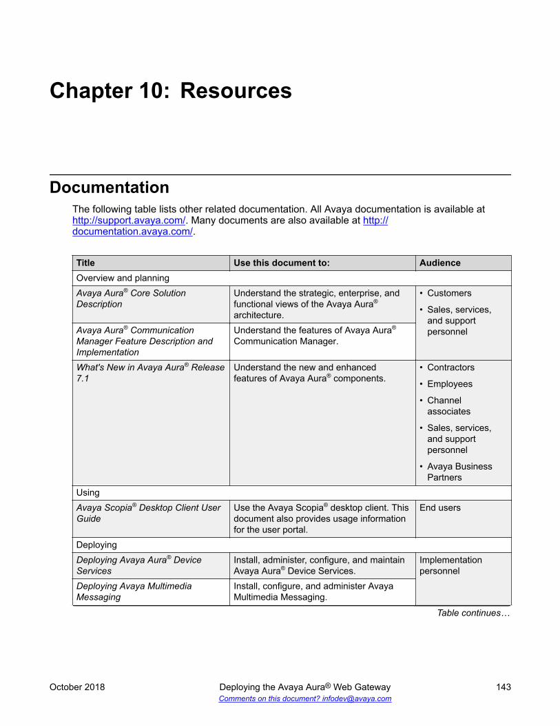
Chapter 10: Resources
DocumentationThe following table lists other related documentation. All Avaya documentation is available at http://support.avaya.com/. Many documents are also available at http://documentation.avaya.com/.
Title Use this document to: AudienceOverview and planningAvaya Aura® Core SolutionDescription
Understand the strategic, enterprise, andfunctional views of the Avaya Aura®
architecture.
• Customers
• Sales, services,and supportpersonnelAvaya Aura® Communication
Manager Feature Description andImplementation
Understand the features of Avaya Aura®
Communication Manager.
What's New in Avaya Aura® Release7.1
Understand the new and enhancedfeatures of Avaya Aura® components.
• Contractors
• Employees
• Channelassociates
• Sales, services,and supportpersonnel
• Avaya BusinessPartners
UsingAvaya Scopia® Desktop Client UserGuide
Use the Avaya Scopia® desktop client. Thisdocument also provides usage informationfor the user portal.
End users
DeployingDeploying Avaya Aura® DeviceServices
Install, administer, configure, and maintainAvaya Aura® Device Services.
Implementationpersonnel
Deploying Avaya MultimediaMessaging
Install, configure, and administer AvayaMultimedia Messaging.
Table continues…
October 2018 Deploying the Avaya Aura® Web Gateway 143Comments on this document? [email protected]

Title Use this document to: AudienceDeploying Avaya Equinox® Solution Install, configure, and maintain the Avaya
Equinox® Solution.AdministeringAdministering Avaya Aura® DeviceServices
Use management tools, manage data andsecurity, and perform periodic maintenancetasks in Avaya Aura® Device Services.
• Systemadministrators
• Implementationpersonnel
• Services andsupport personnel
Administering Avaya Aura®
Communication ManagerAdminister Avaya Aura® CommunicationManager on the following servers:
• Avaya media gateways
• Avaya S8XXX ServersAdministering Network Connectivityon Avaya Aura® CommunicationManager
Understand the network components ofAvaya Aura® Communication Manager.
Administering Avaya Aura® SessionManager
Administer Avaya Aura® Session Manager.
Administering Avaya Aura® SystemManager
Perform configuration and managementtasks in Avaya Aura® System Manager.
Administering Avaya Session BorderController for Enterprise
Perform configuration, systemadministration, and troubleshooting tasks inAvaya Aura® Session Border Controller.
Implementing and AdministeringAvaya Aura® Media Server
Perform configuration, systemadministration, and troubleshooting tasks inAvaya Aura® Media Server.
Finding documents on the Avaya Support websiteProcedure
1. Navigate to http://support.avaya.com/.
2. At the top of the screen, type your username and password and click Login.
3. Click Support by Product > Documents.
4. In Enter your Product Here, type the product name and then select the product from thelist.
5. In Choose Release, select an appropriate release number.
6. In the Content Type filter, click a document type, or click Select All to see a list of allavailable documents.
For example, for user guides, click User Guides in the Content Type filter. The listdisplays the documents only from the selected category.
7. Click Enter.
Resources
October 2018 Deploying the Avaya Aura® Web Gateway 144Comments on this document? [email protected]

Avaya Documentation Portal navigationCustomer documentation for some programs is now available on the Avaya Documentation Portalat http://documentation.avaya.com/.
Important:
For documents that are not available on the Avaya Documentation Portal, click Support onthe top menu to open http://support.avaya.com/.
Using the Avaya Documentation Portal, you can:
• Search for specific content.
To perform a search:
- Type a keyword in the Search field.
- Type a keyword in Search, and select the filters to search for content by product, release,and document type.
- Select the appropriate product or solution and then select the appropriate item from thelist.
• Search for a document from the Publications menu.
• Publish a PDF of the content. You can publish a PDF of the current section only, the sectionand its subsections, or the entire document.
• Add content to your collection using My Docs ( ).
From the My Content > My Docs menu, you can:
- Create, rename, and delete a collection.
- Add content from various documents to a collection.
- Save a PDF of selected content in a collection and download it to your computer.
- Share content in a collection with others through email.
- Receive content that others have shared with you.
• Add yourself as a watcher to the content using the Watch icon ( ).
From the My Content > Watch list menu, you can:
- Set how frequently you want to be notified, starting from every day to every 60 days.
- Unwatch selected content, all content in a book, or all content on the Watch list page.
As a watcher, you will be notified when content is updated or deleted from a document, or ifthe document is removed from the portal.
• Share a section on social media platforms, such as Facebook, LinkedIn, Twitter, andGooglePlus.
Documentation
October 2018 Deploying the Avaya Aura® Web Gateway 145Comments on this document? [email protected]

• Send feedback on a section and rate the content.
Note:
Some functionality is only available when you log in to the portal. The available functionalitydepends on the role with which you are logged in.
TrainingAvaya Equinox® solution courses and credentials, such as ACCS-7240, also include informationabout Avaya Aura® Web Gateway. You can access training courses at http://www.avaya-learning.com.
Viewing Avaya Mentor videosAvaya Mentor videos provide technical content on how to install, configure, and troubleshootAvaya products.
About this taskVideos are available on the Avaya Support website, listed under the video document type, and onthe Avaya-run channel on YouTube.
Procedure• To find videos on the Avaya Support website, go to http://support.avaya.com and perform one
of the following actions:
- In Search, type Avaya Mentor Videos to see a list of the available videos.
- In Search, type the product name. On the Search Results page, select Video in theContent Type column on the left.
• To find the Avaya Mentor videos on YouTube, go to www.youtube.com/AvayaMentor andperform one of the following actions:
- Enter a key word or key words in the Search Channel to search for a specific product ortopic.
- Scroll down Playlists, and click the name of a topic to see the available list of videosposted on the website.
Note:
Videos are not available for all products.
Resources
October 2018 Deploying the Avaya Aura® Web Gateway 146Comments on this document? [email protected]

SupportGo to the Avaya Support website at http://support.avaya.com for the most up-to-datedocumentation, product notices, and knowledge articles. You can also search for release notes,downloads, and resolutions to issues. Use the online service request system to create a servicerequest. Chat with live agents to get answers to questions, or request an agent to connect you to asupport team if an issue requires additional expertise.
Using the Avaya InSite Knowledge BaseThe Avaya InSite Knowledge Base is a web-based search engine that provides:
• Up-to-date troubleshooting procedures and technical tips
• Information about service packs
• Access to customer and technical documentation
• Information about training and certification programs
• Links to other pertinent information
If you are an authorized Avaya Partner or a current Avaya customer with a support contract, youcan access the Knowledge Base without extra cost. You must have a login account and a validSold-To number.
Use the Avaya InSite Knowledge Base for any potential solutions to problems.
1. Go to http://www.avaya.com/support.2. Log on to the Avaya website with a valid Avaya user ID and password.
The system displays the Avaya Support page.3. Click Support by Product > Product Specific Support.4. In Enter Product Name, enter the product, and press Enter.
5. Select the product from the list, and select a release.6. Click the Technical Solutions tab to see articles.7. Select relevant articles.
Support
October 2018 Deploying the Avaya Aura® Web Gateway 147Comments on this document? [email protected]

Appendix A: Certificate configuration usingthe configuration utility
The following sections describe how to configure certificates using the configuration utility process.
You can also manage and update certificates using the Avaya Aura® Web Gateway webadministration portal. For more information about working with the web administration portal, seeAdministering the Avaya Aura® Web Gateway.
Important:
The web administration portal is the preferred method for managing certificates. Use theconfiguration utility process to configure certificates for troubleshooting purposes, but after thisis done, perform certificate management from the web administration portal when possible.
Generating Certificate Signing RequestsAbout this taskUse this procedure to generate a Certificate Signing Request (CSR).
Important:You must use this procedure if you are not using System Manager as the only CertificateAuthority (CA) to sign certificates for all solution components.
Before you beginEnsure that Avaya Aura® Web Gateway is successfully installed with System Manager signedcertificates. This is the default setting for installation.
Procedure1. Run the following command:
sudo mkdir /opt/Avaya/AAWGportalCertssudo chmod 770 /opt/Avaya/AAWGportalCerts
The system creates an AAWGportalCerts directory in /opt/Avaya/ for the output ofthe script that will generate the CSRs.
October 2018 Deploying the Avaya Aura® Web Gateway 148Comments on this document? [email protected]

2. Run the following command to navigate to the directory containing the script:cdto misc
3. To generate a CSR, run the following command:sudo ./createCSR.sh /opt/Avaya/AAWGportalCerts frontEndFQDN localFQDN organizationNameorganizationUnit locality stateOrProvince countryCode emailAddress
Important:
This command is a single Linux command and must be entered as a single line even ifit appears as several lines in the document.
The parameters for this script are:
• frontendFQDN: For a cluster installation, this is the FQDN of the Virtual IP or externalload balancer. For simple, non-clustered installations, this is the FQDN of the serverwhere Avaya Aura® Web Gateway is installed.
• localFQDN: The FQDN of the server.
• orgnizationName: The name of the organization.
• organizationUnit: The name of the unit or sub-organization. For example, “Design”.
• locality: The name of the city or town.
• state: The two-digit state or province code.
• countryCode: The two-digit country code.
• emailAddress: The administrator email address.
4. Verify that /opt/Avaya/AAWGportalCerts contains the .key and .csr files for front-end, node, OAMP, and SIP.
Only the frontEnd.csr and frontEnd.key files are used. You can ignore the sip,oamp & node .csr and .key files.
Getting certificates signed by the third-party CABefore you begin
• Ensure that the CA is configured to include extendedKeyUsage for both the client and theserver in the generated certificates.
• Open the Linux shell using the Linux administrator account credentials.
Procedure1. Transfer the frontEnd.csr file from Avaya Aura® Web Gateway so that it can be used
during signed certificate generation process on your third-party CA.
Getting certificates signed by the third-party CA
October 2018 Deploying the Avaya Aura® Web Gateway 149Comments on this document? [email protected]

2. Transfer certificates to Avaya Aura® Web Gateway.
a. Transfer the signed .crt file to /opt/Avaya/AAWGportalCerts, and name itfrontEnd.crt.
b. Transfer the third-party root CA certificate to /opt/Avaya/AAWGportalCerts, andname it rootCA.crt.
c. Transfer any third-party intermediary CA certificates to /opt/Avaya/AAWGportalCerts, and name them intermediary1.crt, intermediary2.crt,and so on in ascending order of the certificate chain until the root CA.
3. To create a certificate chain containing the front end certificate, arrange all intermediary CAcertificates (if any) and the root CA certificate in the correct order, and then run thefollowing command:cat frontEnd.crt intermediary1.crt intermediary2.crt ... rootCA.crt > frontEndCerts.crt
Applying third-party signed certificates to the Avaya Aura®
Web GatewayProcedure
1. Open the Linux shell using your Linux administrator account credentials.
The Linux administrator account is created during the deployment process.
2. To open the Avaya Aura® Web Gateway configuration utility, run the following command:app configure
3. Select Front-end host, System Manager and Certificate Configuration.
4. Select Use System Manager for Certificates, and then select No.
5. Select the following options, type the file path shown, and then select OK for each option:
a. For REST interface key file, type /opt/Avaya/AAWGportalCerts/frontEnd.key.
b. For REST interface certificate file, type value /opt/Avaya/AAWGportalCerts/frontEndCerts.crt.
c. For OAM interface key file, type value /opt/Avaya/AAWGportalCerts/frontEnd.key.
d. For OAM interface certificate file, type value /opt/Avaya/AAWGportalCerts/frontEndCerts.crt.
e. For Keystore password, type the same keystore password that you used at the timeof installation.
Certificate configuration using the configuration utility
October 2018 Deploying the Avaya Aura® Web Gateway 150Comments on this document? [email protected]

6. Select Apply and Continue for the specified certificates to be processed.
7. Select Exit Configure to exit this menu.
Adding third-party root CA certificates to the Avaya Aura®
Web GatewayAbout this taskUse this procedure to trust additional root CAs. For example, you can add the:
• LDAP root CA certificate if you are using a secure LDAP connection.• SIP CA certificate if Session Manager has certificates signed by the SIP CA.
You can manage truststore certificates by using the Avaya Aura® Web Gateway administrationportal as described in Administering the Avaya Aura® Web Gateway.Do not use this procedure to add the System Manager root CA certificate because that wasalready added during the initial installation.
Procedure1. Run the following command to open the configuration utility:
app configure2. Select Add a Certificate to the TrustStore.
3. To add a certificate, select Certificate file and specify the path to the file.
4. Select Apply.
If the provided file contains certificate chain, then all certificates will be added to thetruststore.
Creating a Certificate Signing Request (CSR) usingOpenSSL
About this taskUse this procedure to generate a CSR using OpenSSL.You can also generate a CSR using the Avaya Aura® Web Gateway web administration portal.
Before you beginEnsure that you have the OpenSSL utility.
Adding third-party root CA certificates to the Avaya Aura® Web Gateway
October 2018 Deploying the Avaya Aura® Web Gateway 151Comments on this document? [email protected]

Procedure1. Create an OpenSSL configuration file.
For example:[ req ]req_extensions = v3_reqdistinguished_name = req_distinguished_name
[req_distinguished_name] [ v3_req ]basicConstraints = CA:FALSEkeyUsage = nonRepudiation, digitalSignature, keyEnciphermentsubjectAltName = @alt_names
[alt_names]DNS.1 = dnsserver10927.company.comDNS.2 = dnsserver10938.company.comDNS.3 = dnsserver10955.company.com
The alt_names section defines the Subject Alternative Names list and must containFQDNs of all nodes in the cluster.
2. Run the following command:openssl req -out <CSR_request_file>.csr -newkey rsa:2048 -nodes –keyout <CSR_key_file>.key -config <configuration_file>
In this command:
• <CSR_request_file>.csr specifies a CSR file name.
• <CSR_key_file>.key specifies a file containing a private key that is used to add thesigned certificate to the system.
• <configuration_file> specifies the OpenSSL configuration file that was created inthe previous step.
For example:openssl req -out createCSR.csr -newkey rsa:2048 -nodes –keyout keyCSR.key -config configCSR.config
Signing identity certificates for Avaya Aura® Web Gatewayusing third-party CA certificates
About this taskYou can use the following procedure to sign identity certificates for Avaya Aura® Web Gatewayusing third-party CA certificates.
Note:In the following procedure, the third-party CA certificate can be a public CA or an internalprivate CA.
Certificate configuration using the configuration utility
October 2018 Deploying the Avaya Aura® Web Gateway 152Comments on this document? [email protected]

Before you begin• Create a CSR with the following X509 extensions:
- keyUsage = nonRepudiation, digitalSignature, keyEncipherment- extendedKeyUsage = serverAuth, clientAuth
• Ensure that the CSR contains the following:- If the certificate is only used on the Avaya SBCE, the request contains the subjectAltName
extension that lists the cluster FQDN in the SAN.- If the certificate is used on both Avaya SBCE and the Avaya Aura® Web Gateway server,
the request contains the subjectAltName extension that lists the cluster FQDN as well asthe FQDN of each cluster member in the SAN.
Note:From the security perspective, Avaya recommends that you generate separatecertificates for each node, including the cluster FQDN and the individual cluster nodeFQDN in subjectAltName.
• Do not provide the password for a key because password protected keys are not supported.• Ensure that the key generated along with the CSR is stored safely.• Ensure that once the certificate is generated, you have received the identity certificate, root
CA certificate, and all intermediate CA certificates in the .PEM format from the certificationauthority. If these certificates are not in the .PEM format, you can convert these certificatesusing the OpenSSL tool.
• Generate the identity certificate chain.
Procedure1. Log on to Avaya Aura® Web Gateway using your SSH credentials.
2. Go to /opt/Avaya/CallSignallingAgent/version/CAS/version/nginx/certs.
3. Run the following command:sudo cat rootCA.pem >> auth_ca.crt
In this command, >> is used to append the root CA certificate file to the end of theauth_ca.crt file.
4. Check that each certificate in the auth_ca.crt file is correct using the OpenSSLcommand.
You should see the new root CA certificate and the System Manager root CA certificate.
5. Import the intermediate CA certificate and the root CA certificate to the Avaya SBCE truststore if you are using reverse proxy on the Avaya SBCE to Avaya Aura® Web Gateway.
6. Run the Avaya Aura® Web Gateway configuration utility using the app configurecommand.
7. Click Front-end host, System Manager and Certificate Configuration.
8. Click Use System Manager for Certificates and type n to not use System Manager forcertificates.
Signing identity certificates for Avaya Aura® Web Gateway using third-party CA certificates
October 2018 Deploying the Avaya Aura® Web Gateway 153Comments on this document? [email protected]

9. Click REST Interface certificate configuration. If the certificate is not in the PKCS12format, type n on the REST Interface certificate configuration screen.
10. Add the key file to the REST interface PEM key file and the certificate chain to the RESTinterface PEM certificate file.
11. Click Signing authority certificate configuration on the Front-end host, SystemManager and Certificate Configuration screen.
12. If the CA root certificate is not in the PKCS12 format, type n.
13. Click Signing Authority PEM certificate file and add the signing authority CA certificate.
14. Click Return to previous menu.
15. Click Apply.
Configuring System Manager to trust third-party root CAcertificates
Procedure1. Log on to the System Manager web console.
2. Click Home > Services > Inventory > Manage Elements .3. Select System Manager from the Elements.
4. Click Configure Trusted Certificates in the More Actions list.
5. Click Add and select Import from file.
6. Click Choose File and browse to the third-party root CA certificate.
7. Click Commit.8. Restart the System Manager JBOSS™ process.
From the SSH session on the System Manager, run the following command as a rootuser:
service jboss restart
Note:
The service jboss restart command affects the service for the SystemManager.
Certificate configuration using the configuration utility
October 2018 Deploying the Avaya Aura® Web Gateway 154Comments on this document? [email protected]

Creating a client certificateAbout this taskUse this procedure to create a client certificate, which can be imported into a web browser forauthenticating automatic login into the Avaya Aura® Web Gateway web administration portal.
Procedure1. Open the Linux shell using your Linux administrator account credentials.
2. Run the following command to create the oamp.csr and oamp.key files:sudo /opt/Avaya/CallSignallingAgent/<version>/CAS/<version>/misc/createCSR.sh
3. To generate the .pem file, on the System Manager web console, navigate to Security >Certificates > Authority.
4. Click the Add End Entity tab and complete the following settings:
a. Set End Entity Profile to Empty.
b. Type your user name and password in Username and Password.
c. Type your user ID in CN, Common name.
The user ID you provide must use the same format that you used for the UIDAttribute ID field on the LDAP Configuration tab.
d. Set Certificate Profile to ENDUSER.
e. Click Add.
A new end entity with the specified user name is created on the System Manager webconsole.
5. In the left navigation pane, click the Public Web tab and complete the following settings:
a. In Username and Enrollment code , type the same user name and password thatyou used to create an end entity.
b. Click Choose File to add the oamp.csr file, which you generated in step 2 onpage 155.
c. Click OK to generate the .pem file .
6. In the SSH console, run the openssl command to convert the .pem file to a .pfx/.p12file.
The following is an example of the command:sudo openssl pkcs12 -export -out <.p12 file name>-in <.pem file name>.pem -inkey oamp.key -passout pass:<password>
Creating a client certificate
October 2018 Deploying the Avaya Aura® Web Gateway 155Comments on this document? [email protected]
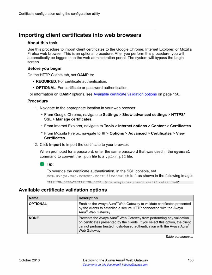
Importing client certificates into web browsersAbout this taskUse this procedure to import client certificates to the Google Chrome, Internet Explorer, or MozillaFirefox web browser. This is an optional procedure. After you perform this procedure, you willautomatically be logged in to the web administration portal. The system will bypass the Loginscreen.
Before you beginOn the HTTP Clients tab, set OAMP to:
• REQUIRED: For certificate authentication.• OPTIONAL: For certificate or password authentication.
For information on OAMP options, see Available certificate validation options on page 156.
Procedure1. Navigate to the appropriate location in your web browser:
• From Google Chrome, navigate to Settings > Show advanced settings > HTTPS/SSL > Manage certificates.
• From Internet Explorer, navigate to Tools > Internet options > Content > Certificates.
• From Mozzila Firefox, navigate to > Options > Advanced > Certificates > ViewCertificates.
2. Click Import to import the certificate to your browser.
When prompted for a password, enter the same password that was used in the opensslcommand to convert the .pem file to a .pfx/.p12 file.
Tip:
To override the certificate authentication, in the SSH console, setcom.avaya.cas.common.certificateauth to 0 as shown in the following image:CATALINA_OPTS="$CATALINA_OPTS -Dcom.avaya.cas.common.certificateauth=0"
Available certificate validation optionsName DescriptionOPTIONAL Enables the Avaya Aura® Web Gateway to validate certificates presented
by the clients to establish a secure HTTP connection with the AvayaAura® Web Gateway.
NONE Prevents the Avaya Aura® Web Gateway from performing any validationon certificates presented by the clients. If you select this option, the clientcannot perform trusted hosts-based authentication with the Avaya Aura®
Web Gateway.
Table continues…
Certificate configuration using the configuration utility
October 2018 Deploying the Avaya Aura® Web Gateway 156Comments on this document? [email protected]

Name DescriptionOPTIONAL_NO_CA Enables the Avaya Aura® Web Gateway to validate certificates presented
by the clients. However, the Avaya Aura® Web Gateway does not requiresuch certificates to be signed or issued by a trusted Certificate Authority(CA).
REQUIRED Ensures that the clients present a valid certificate that is signed or issuedby a trusted CA to establish a secure HTTP connection with the AvayaAura® Web Gateway.
Creating a client certificate
October 2018 Deploying the Avaya Aura® Web Gateway 157Comments on this document? [email protected]

Glossary
Busy Hour CallAttempts
The maximum number of calls supported for one hour in peak trafficconditions.
Cassandra Third party NoSQL database, which is used by Avaya MultimediaMessaging to store messaging data and configuration information. Formore information, see https://cassandra.apache.org/.
Domain NameSystem (DNS)
A system that maps and converts domain and host names to IPaddresses.
Fully QualifiedDomain Name(FQDN)
A domain name that specifies the exact location of the domain in the treehierarchy of the Domain Name System (DNS).
Network TimeProtocol (NTP)
A protocol used to synchronize the real-time clock in a computer.
Secure Shell (SSH) Secure Shell (SSH) is a group of standards and an associated networkprotocol that the system can use to establish a secure channel between alocal and a remote computer. SSH uses public-key cryptography tomutually authenticate a user and a remote computer. SSH usesencryption and message authentication codes to protect theconfidentiality and integrity of the data that is exchanged between the twocomputers.
Simple NetworkManagementProtocol (SNMP)
A protocol for managing devices on IP networks.
SSL (Secure SocketsLayer) Protocol
The SSL protocol is the leading security protocol on the Internet. It runsabove the TCP/IP protocol and below higher-level protocols such asHTTP or IMAP. SSL uses TCP/IP on behalf of the higher-level protocolsand, in the process, allows an SSL-enabled server to authenticate itself toan SSL-enabled client.
TCP Transmission Control Protocol.
TLS Transport Layer Security
UDP User Datagram Protocol. This is a communication method, similar to TCP.
October 2018 Deploying the Avaya Aura® Web Gateway 158Comments on this document? [email protected]

Index
AAADS
uploading Avaya Equinox clients ................................104ABSCE
configuring server flows ..............................................134adding
Avaya Aura Web Gateway ............................................99adding third-party root certificates
Avaya Aura Web Gateway server ...............................151administration portal
Linux account ............................................................... 95advanced configuration ........................................................93applying load balancer certificates .......................................55applying third-party certificates
Avaya Aura Web Gateway server ...............................150architecture
diagram .........................................................................12ASBCE
configuring .................................................................. 108configuring external client access ...............................119configuring external traffic rules
multiple FQDNs deployment ................................117single FQDN deployment .....................................113
configuring internal traffic rules ................................... 115configuring on AAWG ................................................. 122configuring reverse proxy ........................................... 109configuring TURN relay for WebRTC ......................... 127creating CRS .............................................................. 135CSR
creating request on ASBCE ................................ 135installing CA certificates ............................................. 140
available certificate validation options ............................... 156Avaya Equinox
uploading installation files on AADS ...........................104AWS
configuring details using the AWS CLI ......................... 47AWS cluster deployments ....................................................55AWS resource profiles
specifications ................................................................ 38
CCA signed certificates ........................................................ 152certificate
for reverse proxy ................................................. 110, 111installing ......................................................................138setup ...........................................................................148signing identity certificates using CA certificates ........152signing with System Manager CA ...............................137
certificate authorityconfiguring for reverse proxy ...................................... 113
certificate signing requests ................................................ 151
certificate signing requests (continued)generating ...................................................................148
checklistAWS deployment .......................................................... 42configuring
reverse proxy .......................................................109external client access configuration ............................119external native clients media configuration .................128planning ........................................................................ 23reverse proxy configuration ..............................................
multiple FQDNs deployment ............................... 109single FQDN deployment .................................... 109
VMware deployment .....................................................42WebRTC client side TURN configuration ................... 124
clientsuploading Avaya Equinox clients to AADS ................. 104
client side TURN configuration .......................................... 124cluster configuration .............................................................90collection
delete ..........................................................................145edit name ....................................................................145generating PDF .......................................................... 145sharing content ........................................................... 145
commands ........................................................................... 27system layer ................................................................. 29
completingfirst time login ............................................................... 62
components ......................................................................... 18configuration
advanced configuration ................................................ 93Equinox conferencing ................................................. 105LDAP configuration .......................................................77
configuration worksheet .......................................................20configure
ABSCE signaling interface ......................................... 132ASBCE load monitoring ..............................................121ASBCE network interfaces ......................................... 141ASBCE on AAWG .......................................................122ASBCE server flow ..................................................... 134DNS .............................................................................. 96Equinox conference control .......................................... 97external native clients media ...................................... 128front-end FQDN ............................................................ 96media interface for ASBCE .........................................132Web Collaboration ........................................................ 98
configuringASBCE ....................................................................... 108ASBCE on Equinox Conferencing .............................. 122Avaya Aura Device Services ...................................... 104Avaya Aura Media Server ...........................................103Avaya Aura Web Gateway ..........................................104certificates .................................................................. 148external client access ..................................................119
October 2018 Deploying the Avaya Aura® Web Gateway 159Comments on this document? [email protected]
configuring (continued)external native clients media ...................................... 128Media Server .............................................................. 102reverse proxy ..............................................................109role search parameters .................................................88RSA public and private keys .........................................72SIP Trunks .................................................................. 100SSH connections .......................................................... 72STUN on AAWG ......................................................... 128System Manager ........................................................ 102WebRTC client side TURN ......................................... 124
configuring AAWGsettings ......................................................................... 73
configuring on AAWG ........................................................ 128configuring on-premise DNS ................................................60configuring on-premise DNS resolution
VPC addresses .............................................................60connection types ..................................................................39content
publishing PDF output ................................................ 145searching .................................................................... 145sharing ........................................................................145watching for updates .................................................. 145
create a clusterinstalling additional nodes ............................................ 68
creatingclient certificate ...........................................................155server profile for management interface .....................120TLS client profile .........................................................141TLS server profile ....................................................... 141TLS server profile for client side TURN ...................... 125TLS server profile for eternal native clients media ..... 129TLS server profile for media tunneling interface .........130
Creating a bucketOVAs for AMI conversion ..............................................49
creating a hybrid cloudclient access ................................................................. 59
creating a key pair ............................................................... 48Creating CloudFormation templates .................................... 52creating load balancer certificates ....................................... 55creating service role .............................................................49
Ddeploying
Avaya Aura Web Gateway OVA ............................. 44, 45multi-node CloudFormation stack .................................57single-node CloudFormation stack ............................... 53Solution Deployment Manager ..................................... 45using vSphere ...............................................................44vCenter ......................................................................... 43
deploymentAmazon Web Services ................................................. 47AWS ..............................................................................42VMware .................................................................. 42, 43
deployment modelsconfiguration requirements ........................................... 20
deployment process .............................................................20descriptions
LDAP parameter ...........................................................88diagram
solution architecture ..................................................... 12topology ........................................................................ 12
disk partitioning ....................................................................39DNS configuration ................................................................96documentation portal ......................................................... 145
finding content ............................................................ 145navigation ................................................................... 145
document changes ................................................................ 9
EEquinox conference control
configuring .................................................................... 97Equinox Conferencing
configuration ............................................................... 105expanding an existing cluster .............................................. 59external access configuration
creating TLS server profile for management interface.....................................................................................120
external client access configuration ................................... 119external load balancer
routes configuration .................................................... 106external traffic
configuring rules ..................................................113, 117rules for multiple FQDNs model ..................................118rules for single FQDN deployment ..............................114
Ffinding content on documentation portal ............................145firewall configuration
for external native clients media support .................... 131for WebRTC client side TURN support .......................125
first time login .......................................................................62FQDN configuration ............................................................. 96
Ggenerating
certificate signing requests ......................................... 148geo distribution
external load balancer .................................................. 40overview ....................................................................... 14topology for a call between data centers ...................... 15topology for a call within the same data center ............ 17
getting certificatesthird-party CA ............................................................. 149
Iidentity certficates .............................................................. 152importing
Index
October 2018 Deploying the Avaya Aura® Web Gateway 160Comments on this document? [email protected]
importing (continued)OVA for AMI conversion ............................................... 50
importing client certificatesweb browsers ............................................................. 156
importing OVA for conversion .............................................. 50InSite Knowledge Base ......................................................147installer utility
cluster configuration ..................................................... 90installing
Avaya Aura Web Gateway ............................................64certificates on ASBCE ................................................ 138
installing additional nodes ....................................................68installing on AWS
creating service role ..................................................... 49internal traffic
configuring rules ..........................................................115rules for single FQDN deployment ..............................116
Kkey pair
creating .........................................................................48
LLDAP
multiple authentication and authorization domains .......87LDAP parameter
descriptions .................................................................. 88Linux alias commands ......................................................... 27load balancer
requirements .................................................................40routes configuration .................................................... 106
load monitoringconfiguring .................................................................. 121
Logging inEC2 instance ................................................................ 61
Mmultiple authentication domains .......................................... 87My Docs .............................................................................145
Nnetworking considerations
Amazon Web Services ................................................. 39New in this release ...............................................................11
OOAMP configuration
Linux account ............................................................... 95obtaining
Avaya Aura Web Gateway OVA ................................... 43OpenSSL ........................................................................... 151
OVA deployment ..................................................................43overview
Avaya Aura Web Gateway ............................................11
Pplanning ............................................................................... 23preinstallation .......................................................................23prerequisites
certificates .................................................................... 25FQDN ........................................................................... 25IP addresses .................................................................25
Rrelated documentation ....................................................... 143replacing
seed node .....................................................................68required
skills and knowledge .....................................................25requirements
configuration requirements for deployment models ......20external load balancer .................................................. 40
resource profile specifications ............................................. 37reverse proxy
configuring certificate authority ................................... 113configuring external traffic rules
multiple FQDNs deployment ................................117single FQDN deployment .....................................113
configuring internal traffic rules ................................... 115configuring TLS server profile ............................. 110, 111creating security certificate ..................................110, 111installing Equinox Management certificate ................. 139
reverse proxy configuration ............................................... 109prerequisites ............................................................... 110
RSA public and private keys ................................................72
Ssearching for content ......................................................... 145seed node
configuring backup nodes .............................................68service role
creating for AWS deployment ....................................... 49settings
initial AAWG conifugration ............................................ 73setting up
Serviceability Agents .................................................. 101sharing content .................................................................. 145signing certificates with System Manager CA ....................137signing in
Amazon Web Services Management console ..............47silent installation .................................................................. 67skills and knowledge ............................................................25solution architecture .............................................................12specifications
Index
October 2018 Deploying the Avaya Aura® Web Gateway 161Comments on this document? [email protected]

specifications (continued)virtual disk volume ........................................................ 39
SSH connectionscluster ........................................................................... 72
startservices ........................................................................ 94
STUN ................................................................................. 128support ...............................................................................147sys ....................................................................................... 29sys secconfig ....................................................................... 30sys smcvemgt ...................................................................... 34
examples ...................................................................... 37system layer
secconfig ...................................................................... 30smcvemgt ............................................................... 34, 37versions ........................................................................ 30volmgt ........................................................................... 30
system layer commands ...................................................... 29System Manager
settings ....................................................................... 100Solution Deployment Manager ..................................... 45
sys versions ......................................................................... 30sys volmgt ............................................................................30
Tthird-party CA
getting certificates .......................................................149third-party root CA ............................................................. 154TLS client profile
creating .......................................................................141TLS server profile
creating .......................................................................141for client side TURN ................................................... 125for external native clients media ................................. 129for media tunneling interface ...................................... 130for reverse proxy ................................................. 110, 111
topology diagram ................................................................. 12geo distribution
topology diagram ...................................................14training ............................................................................... 146TURN
client side configuration .............................................. 124TURN for a WebRTC client
configuring .................................................................. 128
Uuninstall
Avaya Aura Web Gateway ............................................63uploading
Avaya Equinox clients to AADS ..................................104OVAs .............................................................................50
using alias ............................................................................27utility installer
certificate configuration .................................................73front-end host ............................................................... 73
VvCenter ................................................................................ 43videos ................................................................................ 146virtual IP configuration ......................................................... 91
Wwatch list ............................................................................ 145web browser requirements .................................................. 19web deployment service
uploading Avaya Equinox clients on AADS ................ 104WebRTC
configuring client side TURN ...................................... 124configuring TURN/STUN profile on ASBCE ............... 126
Index
October 2018 Deploying the Avaya Aura® Web Gateway 162Comments on this document? [email protected]
Copyright © 2022 FDOKUMEN